Embed Size (px)
DESCRIPTION
computing
Citation preview
Part No. 208963-GDecember 2005
4655 Great America ParkwaySanta Clara, CA 95054
*208963-G*
Using Enterprise Switch Manager Release 5.1.0.0
2
208963-G
Copyright © 2005 Nortel Networks. All rights reserved.
The information in this document is subject to change without notice. The statements, configurations, technical data, and recommendations in this document are believed to be accurate and reliable, but are presented without express or implied warranty. Users must take full responsibility for their applications of any products specified in this document. The information in this document is proprietary to Nortel Networks.
The software described in this document is furnished under a license agreement and may be used only in accordance with the terms of that license. The software license agreement is included in this document.
Trademarks
*Nortel, Nortel Networks, the Nortel logo, the Globemark, Passport, and BayStack are trademarks of Nortel Networks.
Adobe and Adobe Reader are trademarks of Adobe Systems Incorporated.
Microsoft, Windows, and Windows NT are trademarks of Microsoft Corporation.
The asterisk after a name denotes a trademarked item.
Restricted rights legend
Use, duplication, or disclosure by the United States Government is subject to restrictions as set forth in subparagraph (c)(1)(ii) of the Rights in Technical Data and Computer Software clause at DFARS 252.227-7013.
Notwithstanding any other license agreement that may pertain to, or accompany the delivery of, this computer software, the rights of the United States Government regarding its use, reproduction, and disclosure are as set forth in the Commercial Computer Software-Restricted Rights clause at FAR 52.227-19.
Statement of conditions
In the interest of improving internal design, operational function, and/or reliability, Nortel Networks reserves the right to make changes to the products described in this document without notice.
Nortel Networks does not assume any liability that may occur due to the use or application of the product(s) or circuit layout(s) described herein.
Portions of the code in this software product may be Copyright © 1988, Regents of the University of California. All rights reserved. Redistribution and use in source and binary forms of such portions are permitted, provided that the above copyright notice and this paragraph are duplicated in all such forms and that any documentation, advertising materials, and other materials related to such distribution and use acknowledge that such portions of the software were developed by the University of California, Berkeley. The name of the University may not be used to endorse or promote products derived from such portions of the software without specific prior written permission.
SUCH PORTIONS OF THE SOFTWARE ARE PROVIDED “AS IS” AND WITHOUT ANY EXPRESS OR IMPLIED WARRANTIES, INCLUDING, WITHOUT LIMITATION, THE IMPLIED WARRANTIES OF MERCHANTABILITY AND FITNESS FOR A PARTICULAR PURPOSE.
In addition, the program and information contained herein are licensed only pursuant to a license agreement that contains restrictions on use and disclosure (that may incorporate by reference certain limitations and notices imposed by third parties).
Nortel Networks software license agreement
This Software License Agreement (“License Agreement”) is between you, the end-user (“Customer”) and Nortel Networks Corporation and its subsidiaries and affiliates (“Nortel Networks”). PLEASE READ THE FOLLOWING

3
Using Enterprise Switch Manager Release 5.1.0.0
CAREFULLY. YOU MUST ACCEPT THESE LICENSE TERMS IN ORDER TO DOWNLOAD AND/OR USE THE SOFTWARE. USE OF THE SOFTWARE CONSTITUTES YOUR ACCEPTANCE OF THIS LICENSE AGREEMENT. If you do not accept these terms and conditions, return the Software, unused and in the original shipping container, within 30 days of purchase to obtain a credit for the full purchase price.
“Software” is owned or licensed by Nortel Networks, its parent or one of its subsidiaries or affiliates, and is copyrighted and licensed, not sold. Software consists of machine-readable instructions, its components, data, audio-visual content (such as images, text, recordings or pictures) and related licensed materials including all whole or partial copies. Nortel Networks grants you a license to use the Software only in the country where you acquired the Software. You obtain no rights other than those granted to you under this License Agreement. You are responsible for the selection of the Software and for the installation of, use of, and results obtained from the Software.
1. Licensed Use of Software. Nortel Networks grants Customer a nonexclusive license to use a copy of the Software on only one machine at any one time or to the extent of the activation or authorized usage level, whichever is applicable. To the extent Software is furnished for use with designated hardware or Customer furnished equipment (“CFE”), Customer is granted a nonexclusive license to use Software only on such hardware or CFE, as applicable. Software contains trade secrets and Customer agrees to treat Software as confidential information using the same care and discretion Customer uses with its own similar information that it does not wish to disclose, publish or disseminate. Customer will ensure that anyone who uses the Software does so only in compliance with the terms of this Agreement. Customer shall not a) use, copy, modify, transfer or distribute the Software except as expressly authorized; b) reverse assemble, reverse compile, reverse engineer or otherwise translate the Software; c) create derivative works or modifications unless expressly authorized; or d) sublicense, rent or lease the Software. Licensors of intellectual property to Nortel Networks are beneficiaries of this provision. Upon termination or breach of the license by Customer or in the event designated hardware or CFE is no longer in use, Customer will promptly return the Software to Nortel Networks or certify its destruction. Nortel Networks may audit by remote polling or other reasonable means to determine Customer’s Software activation or usage levels. If suppliers of third party software included in Software require Nortel Networks to include additional or different terms, Customer agrees to abide by such terms provided by Nortel Networks with respect to such third party software.
2. Warranty. Except as may be otherwise expressly agreed to in writing between Nortel Networks and Customer, Software is provided “AS IS” without any warranties (conditions) of any kind. NORTEL NETWORKS DISCLAIMS ALL WARRANTIES (CONDITIONS) FOR THE SOFTWARE, EITHER EXPRESS OR IMPLIED, INCLUDING, BUT NOT LIMITED TO THE IMPLIED WARRANTIES OF MERCHANTABILITY AND FITNESS FOR A PARTICULAR PURPOSE AND ANY WARRANTY OF NON-INFRINGEMENT. Nortel Networks is not obligated to provide support of any kind for the Software. Some jurisdictions do not allow exclusion of implied warranties, and, in such event, the above exclusions may not apply.
3. Limitation of Remedies. IN NO EVENT SHALL NORTEL NETWORKS OR ITS AGENTS OR SUPPLIERS BE LIABLE FOR ANY OF THE FOLLOWING: a) DAMAGES BASED ON ANY THIRD PARTY CLAIM; b) LOSS OF, OR DAMAGE TO, CUSTOMER’S RECORDS, FILES OR DATA; OR c) DIRECT, INDIRECT, SPECIAL, INCIDENTAL, PUNITIVE, OR CONSEQUENTIAL DAMAGES (INCLUDING LOST PROFITS OR SAVINGS), WHETHER IN CONTRACT, TORT OR OTHERWISE (INCLUDING NEGLIGENCE) ARISING OUT OF YOUR USE OF THE SOFTWARE, EVEN IF NORTEL NETWORKS, ITS AGENTS OR SUPPLIERS HAVE BEEN ADVISED OF THEIR POSSIBILITY. The foregoing limitations of remedies also apply to any developer and/or supplier of the Software. Such developer and/or supplier is an intended beneficiary of this Section. Some jurisdictions do not allow these limitations or exclusions and, in such event, they may not apply.
4. General
a. If Customer is the United States Government, the following paragraph shall apply: All Nortel Networks Software available under this License Agreement is commercial computer software and commercial computer software documentation and, in the event Software is licensed for or on behalf of the United States Government, the respective rights to the software and software documentation are governed by Nortel Networks standard commercial license in accordance with U.S. Federal Regulations at 48 C.F.R. Sections 12.212 (for non-DoD entities) and 48 C.F.R. 227.7202 (for DoD entities).

4
208963-G
b. Customer may terminate the license at any time. Nortel Networks may terminate the license if Customer fails to comply with the terms and conditions of this license. In either event, upon termination, Customer must either return the Software to Nortel Networks or certify its destruction.
c. Customer is responsible for payment of any taxes, including personal property taxes, resulting from Customer’s use of the Software. Customer agrees to comply with all applicable laws including all applicable export and import laws and regulations.
d. Neither party may bring an action, regardless of form, more than two years after the cause of the action arose.e. The terms and conditions of this License Agreement form the complete and exclusive agreement between
Customer and Nortel Networks.f. This License Agreement is governed by the laws of the country in which Customer acquires the Software. If
the Software is acquired in the United States, then this License Agreement is governed by the laws of the state of New York.
5
Using Enterprise Switch Manager Release 5.1.0.0
Contents
Preface . . . . . . . . . . . . . . . . . . . . . . . . . . . . . . . . . . . . . . . . . . . . . . . . . . . . . . 39
Before you begin . . . . . . . . . . . . . . . . . . . . . . . . . . . . . . . . . . . . . . . . . . . . . . . . . . . . . 39
Text conventions . . . . . . . . . . . . . . . . . . . . . . . . . . . . . . . . . . . . . . . . . . . . . . . . . . . . . . 40
Related publications . . . . . . . . . . . . . . . . . . . . . . . . . . . . . . . . . . . . . . . . . . . . . . . . . . . 41
How to get help . . . . . . . . . . . . . . . . . . . . . . . . . . . . . . . . . . . . . . . . . . . . . . . . . . . . . . 42
Getting Help from the Nortel web site . . . . . . . . . . . . . . . . . . . . . . . . . . . . . . . . . . 42
Getting Help through a Nortel distributor or reseller . . . . . . . . . . . . . . . . . . . . . . . 42
Getting Help over the phone from a Nortel Solutions Center . . . . . . . . . . . . . . . . 43
Getting Help from a specialist by using an Express Routing Code . . . . . . . . . . . . 43
Chapter 1Introducing Enterprise Switch Manager . . . . . . . . . . . . . . . . . . . . . . . . . . . 45
What is Enterprise Switch Manager? . . . . . . . . . . . . . . . . . . . . . . . . . . . . . . . . . . . . . . 45
Enterprise Switch Manager features . . . . . . . . . . . . . . . . . . . . . . . . . . . . . . . . . . . . . . 46
Supported devices . . . . . . . . . . . . . . . . . . . . . . . . . . . . . . . . . . . . . . . . . . . . . . . . . . . . 47
Topology Manager . . . . . . . . . . . . . . . . . . . . . . . . . . . . . . . . . . . . . . . . . . . . . . . . . . . . 50
Enterprise Switch Manager submanagers . . . . . . . . . . . . . . . . . . . . . . . . . . . . . . . . . . 50
VLAN Manager . . . . . . . . . . . . . . . . . . . . . . . . . . . . . . . . . . . . . . . . . . . . . . . . . . . 51
MultiLink Trunking Manager . . . . . . . . . . . . . . . . . . . . . . . . . . . . . . . . . . . . . . . . . . 51
Multicast Manager . . . . . . . . . . . . . . . . . . . . . . . . . . . . . . . . . . . . . . . . . . . . . . . . . 51
Security Manager . . . . . . . . . . . . . . . . . . . . . . . . . . . . . . . . . . . . . . . . . . . . . . . . . 52
File/Inventory Manager . . . . . . . . . . . . . . . . . . . . . . . . . . . . . . . . . . . . . . . . . . . . . 53
Trap/Log Manager . . . . . . . . . . . . . . . . . . . . . . . . . . . . . . . . . . . . . . . . . . . . . . . . . 53
NSNA Manager . . . . . . . . . . . . . . . . . . . . . . . . . . . . . . . . . . . . . . . . . . . . . . . . . . . 53
Additional Enterprise Switch Manager tools . . . . . . . . . . . . . . . . . . . . . . . . . . . . . . . . 54
Tftp Server . . . . . . . . . . . . . . . . . . . . . . . . . . . . . . . . . . . . . . . . . . . . . . . . . . . . . . . 54
Smart Diff . . . . . . . . . . . . . . . . . . . . . . . . . . . . . . . . . . . . . . . . . . . . . . . . . . . . . . . 54
MIB Browser . . . . . . . . . . . . . . . . . . . . . . . . . . . . . . . . . . . . . . . . . . . . . . . . . . . . . 54
6 Contents
208963-G
Device Manager . . . . . . . . . . . . . . . . . . . . . . . . . . . . . . . . . . . . . . . . . . . . . . . . . . . 56
Chapter 2Using Enterprise Switch Manager . . . . . . . . . . . . . . . . . . . . . . . . . . . . . . . . 57
Starting Enterprise Switch Manager . . . . . . . . . . . . . . . . . . . . . . . . . . . . . . . . . . . . . . 57
Logging in . . . . . . . . . . . . . . . . . . . . . . . . . . . . . . . . . . . . . . . . . . . . . . . . . . . . . . . 58
Managing users . . . . . . . . . . . . . . . . . . . . . . . . . . . . . . . . . . . . . . . . . . . . . . . . . . . 60
Adding a user . . . . . . . . . . . . . . . . . . . . . . . . . . . . . . . . . . . . . . . . . . . . . . . . . 61
Deleting a user . . . . . . . . . . . . . . . . . . . . . . . . . . . . . . . . . . . . . . . . . . . . . . . . 63
Changing password . . . . . . . . . . . . . . . . . . . . . . . . . . . . . . . . . . . . . . . . . . . . . . . . 64
Configuring your e-mail settings . . . . . . . . . . . . . . . . . . . . . . . . . . . . . . . . . . . . . . 65
Using the Enterprise Switch Manager window . . . . . . . . . . . . . . . . . . . . . . . . . . . . . . . 66
Enterprise Switch Manager menu bar commands and toolbar buttons . . . . . . . . . 68
Using the Enterprise Switch Manager shortcut menu . . . . . . . . . . . . . . . . . . . . . . 75
Viewing device properties . . . . . . . . . . . . . . . . . . . . . . . . . . . . . . . . . . . . . . . . . . . 76
Enterprise Switch Manager status bar . . . . . . . . . . . . . . . . . . . . . . . . . . . . . . . . . 77
Configuring color preferences . . . . . . . . . . . . . . . . . . . . . . . . . . . . . . . . . . . . . . . . 78
Enterprise Switch Manager contents pane icons . . . . . . . . . . . . . . . . . . . . . . . . . 80
Using the scale slider . . . . . . . . . . . . . . . . . . . . . . . . . . . . . . . . . . . . . . . . . . . . . . 82
Finding unsaved configurations . . . . . . . . . . . . . . . . . . . . . . . . . . . . . . . . . . . . . . . 82
Upgrading old task files . . . . . . . . . . . . . . . . . . . . . . . . . . . . . . . . . . . . . . . . . . . . . 84
Working with the network topology map . . . . . . . . . . . . . . . . . . . . . . . . . . . . . . . . . . . 84
Saving a topology map . . . . . . . . . . . . . . . . . . . . . . . . . . . . . . . . . . . . . . . . . . . . . 85
Exporting a topology map . . . . . . . . . . . . . . . . . . . . . . . . . . . . . . . . . . . . . . . . . . . 86
Loading a saved network topology map . . . . . . . . . . . . . . . . . . . . . . . . . . . . . . . . 86
Printing a topology map . . . . . . . . . . . . . . . . . . . . . . . . . . . . . . . . . . . . . . . . . . . . . 88
Printing a topology map in one page . . . . . . . . . . . . . . . . . . . . . . . . . . . . . . . . . . . 89
Print preview . . . . . . . . . . . . . . . . . . . . . . . . . . . . . . . . . . . . . . . . . . . . . . . . . . . . . 89
Printing a specific area of the topology map . . . . . . . . . . . . . . . . . . . . . . . . . . . . . 90
Finding devices on the topology map . . . . . . . . . . . . . . . . . . . . . . . . . . . . . . . . . . 91
Selecting devices by type . . . . . . . . . . . . . . . . . . . . . . . . . . . . . . . . . . . . . . . . . . . 92
Arranging devices on the topology map . . . . . . . . . . . . . . . . . . . . . . . . . . . . . . . . . 93
Getting help . . . . . . . . . . . . . . . . . . . . . . . . . . . . . . . . . . . . . . . . . . . . . . . . . . . . . . . . . 95
Contents 7
Using Enterprise Switch Manager Release 5.1.0.0
Chapter 3Configuring Enterprise Switch Manager . . . . . . . . . . . . . . . . . . . . . . . . . . . 97
Discovering your network . . . . . . . . . . . . . . . . . . . . . . . . . . . . . . . . . . . . . . . . . . . . . . . 97
Preferences dialog box . . . . . . . . . . . . . . . . . . . . . . . . . . . . . . . . . . . . . . . . . . . . . 98
Submanager preferences . . . . . . . . . . . . . . . . . . . . . . . . . . . . . . . . . . . . . . . . . . 103
Manage All Discovered Devices . . . . . . . . . . . . . . . . . . . . . . . . . . . . . . . . . . 105
Manage devices by Device Family . . . . . . . . . . . . . . . . . . . . . . . . . . . . . . . . 105
Manage devices by sub-network . . . . . . . . . . . . . . . . . . . . . . . . . . . . . . . . . . 105
Manage selected devices . . . . . . . . . . . . . . . . . . . . . . . . . . . . . . . . . . . . . . . 105
Rediscovering the network map . . . . . . . . . . . . . . . . . . . . . . . . . . . . . . . . . . . . . 105
Stopping the discovery process . . . . . . . . . . . . . . . . . . . . . . . . . . . . . . . . . . . . . . 106
Restricting discovery . . . . . . . . . . . . . . . . . . . . . . . . . . . . . . . . . . . . . . . . . . . . . . 106
Hidden Devices . . . . . . . . . . . . . . . . . . . . . . . . . . . . . . . . . . . . . . . . . . . . . . . . . . 107
Layout slider . . . . . . . . . . . . . . . . . . . . . . . . . . . . . . . . . . . . . . . . . . . . . . . . . . . . 108
Accessing devices with different SNMP communities . . . . . . . . . . . . . . . . . . . . . . . . 109
Accessing NSNAS with different CLI user names and passwords . . . . . . . . . . . . . . . 111
Chapter 4Using VLAN Manager . . . . . . . . . . . . . . . . . . . . . . . . . . . . . . . . . . . . . . . . . 113
What is VLAN Manager? . . . . . . . . . . . . . . . . . . . . . . . . . . . . . . . . . . . . . . . . . . . . . . 113
VLAN . . . . . . . . . . . . . . . . . . . . . . . . . . . . . . . . . . . . . . . . . . . . . . . . . . . . . . . . . . 114
NSNA . . . . . . . . . . . . . . . . . . . . . . . . . . . . . . . . . . . . . . . . . . . . . . . . . . . . . . . . . . 114
Spanning Tree Protocol . . . . . . . . . . . . . . . . . . . . . . . . . . . . . . . . . . . . . . . . . . . . 115
VLAN Manager features . . . . . . . . . . . . . . . . . . . . . . . . . . . . . . . . . . . . . . . . . . . 116
Starting VLAN Manager . . . . . . . . . . . . . . . . . . . . . . . . . . . . . . . . . . . . . . . . . . . . . . . 117
VLAN Manager window . . . . . . . . . . . . . . . . . . . . . . . . . . . . . . . . . . . . . . . . . . . . . . . 117
Menu bar commands and toolbar buttons . . . . . . . . . . . . . . . . . . . . . . . . . . . . . . 118
Navigation pane . . . . . . . . . . . . . . . . . . . . . . . . . . . . . . . . . . . . . . . . . . . . . . . . . . 120
Contents pane . . . . . . . . . . . . . . . . . . . . . . . . . . . . . . . . . . . . . . . . . . . . . . . . . . . 122
Status bar . . . . . . . . . . . . . . . . . . . . . . . . . . . . . . . . . . . . . . . . . . . . . . . . . . . . . . 122
Finding network resources . . . . . . . . . . . . . . . . . . . . . . . . . . . . . . . . . . . . . . . . . 123
Reloading VLAN Manager . . . . . . . . . . . . . . . . . . . . . . . . . . . . . . . . . . . . . . . . . . 124
Working with VLAN Manager . . . . . . . . . . . . . . . . . . . . . . . . . . . . . . . . . . . . . . . . . . . 125
Port membership . . . . . . . . . . . . . . . . . . . . . . . . . . . . . . . . . . . . . . . . . . . . . . . . . 126
Viewing the unassigned ports . . . . . . . . . . . . . . . . . . . . . . . . . . . . . . . . . . . . 126
8 Contents
208963-G
Viewing tagged ports . . . . . . . . . . . . . . . . . . . . . . . . . . . . . . . . . . . . . . . . . . 127
Viewing isolated router ports (IRPs) . . . . . . . . . . . . . . . . . . . . . . . . . . . . . . . 127
Viewing bridge routing ports . . . . . . . . . . . . . . . . . . . . . . . . . . . . . . . . . . . . . 128
Viewing Spanning Tree Groups (STGs) . . . . . . . . . . . . . . . . . . . . . . . . . . . . . . . . 128
Viewing port members . . . . . . . . . . . . . . . . . . . . . . . . . . . . . . . . . . . . . . . . . 130
Adding port members . . . . . . . . . . . . . . . . . . . . . . . . . . . . . . . . . . . . . . . . . . 130
Viewing and configuring STG parameters . . . . . . . . . . . . . . . . . . . . . . . . . . 131
Viewing STG status . . . . . . . . . . . . . . . . . . . . . . . . . . . . . . . . . . . . . . . . . . . . 132
Viewing STG root status . . . . . . . . . . . . . . . . . . . . . . . . . . . . . . . . . . . . . . . . 133
VLAN icons . . . . . . . . . . . . . . . . . . . . . . . . . . . . . . . . . . . . . . . . . . . . . . . . . . 134
Viewing the Default VLAN . . . . . . . . . . . . . . . . . . . . . . . . . . . . . . . . . . . . . . . . . . 136
Viewing VLAN ports . . . . . . . . . . . . . . . . . . . . . . . . . . . . . . . . . . . . . . . . . . . . . . . 137
Configuring VLANs for NSNA . . . . . . . . . . . . . . . . . . . . . . . . . . . . . . . . . . . . . . . 138
Managing Spanning Tree Groups (STGs) . . . . . . . . . . . . . . . . . . . . . . . . . . . . . . . . . 140
Creating a Spanning Tree Group . . . . . . . . . . . . . . . . . . . . . . . . . . . . . . . . . . . . . 141
Editing a Spanning Tree Group . . . . . . . . . . . . . . . . . . . . . . . . . . . . . . . . . . . . . . 142
Deleting a Spanning Tree Group . . . . . . . . . . . . . . . . . . . . . . . . . . . . . . . . . . . . . 143
Adding members to a Spanning Tree Group . . . . . . . . . . . . . . . . . . . . . . . . . . . . 144
Deleting members from a Spanning Tree Group . . . . . . . . . . . . . . . . . . . . . . . . . 144
Editing Spanning Tree Group port membership . . . . . . . . . . . . . . . . . . . . . . . . . 145
Managing VLANs . . . . . . . . . . . . . . . . . . . . . . . . . . . . . . . . . . . . . . . . . . . . . . . . . . . . 145
Creating VLANs . . . . . . . . . . . . . . . . . . . . . . . . . . . . . . . . . . . . . . . . . . . . . . . . . . 145
Creating a port-based VLAN . . . . . . . . . . . . . . . . . . . . . . . . . . . . . . . . . . . . . 147
Creating a source IP subnet-based VLAN . . . . . . . . . . . . . . . . . . . . . . . . . . 149
Creating a protocol-based VLAN . . . . . . . . . . . . . . . . . . . . . . . . . . . . . . . . . 151
User-defined protocols in a protocol-based VLAN . . . . . . . . . . . . . . . . . . . . 153
Creating a source MAC address-based VLAN . . . . . . . . . . . . . . . . . . . . . . . 154
Creating an sVLAN . . . . . . . . . . . . . . . . . . . . . . . . . . . . . . . . . . . . . . . . . . . . 157
Creating an ID-based VLAN . . . . . . . . . . . . . . . . . . . . . . . . . . . . . . . . . . . . . 158
Synchronizing the VLAN Name . . . . . . . . . . . . . . . . . . . . . . . . . . . . . . . . . . . . . . 160
Deleting a VLAN . . . . . . . . . . . . . . . . . . . . . . . . . . . . . . . . . . . . . . . . . . . . . . . . . 161
Highlighting STGs and VLANs on the topology map . . . . . . . . . . . . . . . . . . . . . . . . . 161
Viewing VLAN members in Enterprise Switch Manager . . . . . . . . . . . . . . . . . . . 162
Viewing STG port members . . . . . . . . . . . . . . . . . . . . . . . . . . . . . . . . . . . . . . . . 163
Viewing STG root configuration . . . . . . . . . . . . . . . . . . . . . . . . . . . . . . . . . . . . . . 164
Contents 9
Using Enterprise Switch Manager Release 5.1.0.0
Managing Rapid Spanning Tree Protocol (RSTP) . . . . . . . . . . . . . . . . . . . . . . . . . . . 166
Adding a VLAN to the Rapid Spanning Tree . . . . . . . . . . . . . . . . . . . . . . . . . . . . 166
Editing Rapid Spanning Tree properties . . . . . . . . . . . . . . . . . . . . . . . . . . . . . . . 166
Deleting a VLAN from Rapid Spanning Tree . . . . . . . . . . . . . . . . . . . . . . . . . . . . 167
Managing Multiple Spanning Tree Protocol . . . . . . . . . . . . . . . . . . . . . . . . . . . . . . . . 167
Adding an MSTI in Multiple Spanning Tree . . . . . . . . . . . . . . . . . . . . . . . . . . . . . 168
Deleting an MSTI . . . . . . . . . . . . . . . . . . . . . . . . . . . . . . . . . . . . . . . . . . . . . . . . . 168
Adding a VLAN in Multiple Spanning Tree . . . . . . . . . . . . . . . . . . . . . . . . . . . . . . 169
Viewing VLAN Port Members in MSTP . . . . . . . . . . . . . . . . . . . . . . . . . . . . . . . . 170
Adding port members . . . . . . . . . . . . . . . . . . . . . . . . . . . . . . . . . . . . . . . . . . 170
Deleting a VLAN in Multiple Spanning Tree . . . . . . . . . . . . . . . . . . . . . . . . . . . . . 171
Editing MSTP properties . . . . . . . . . . . . . . . . . . . . . . . . . . . . . . . . . . . . . . . . . . . 171
Editing MSTI properties . . . . . . . . . . . . . . . . . . . . . . . . . . . . . . . . . . . . . . . . . . . . 172
Chapter 5Using MultiLink Trunking Manager . . . . . . . . . . . . . . . . . . . . . . . . . . . . . . 173
What is MultiLink Trunking Manager? . . . . . . . . . . . . . . . . . . . . . . . . . . . . . . . . . . . . 174
MultiLink Trunks in different switch types . . . . . . . . . . . . . . . . . . . . . . . . . . . . . . . 174
MultiLink Trunking Manager features . . . . . . . . . . . . . . . . . . . . . . . . . . . . . . . . . . 174
Starting MultiLink Trunking Manager . . . . . . . . . . . . . . . . . . . . . . . . . . . . . . . . . . . . . 175
MultiLink Trunking Manager window . . . . . . . . . . . . . . . . . . . . . . . . . . . . . . . . . . . . . 176
Menu bar commands and toolbar buttons . . . . . . . . . . . . . . . . . . . . . . . . . . . . . . 177
Navigation pane . . . . . . . . . . . . . . . . . . . . . . . . . . . . . . . . . . . . . . . . . . . . . . . . . . 178
Contents pane . . . . . . . . . . . . . . . . . . . . . . . . . . . . . . . . . . . . . . . . . . . . . . . . . . . 179
Status bar . . . . . . . . . . . . . . . . . . . . . . . . . . . . . . . . . . . . . . . . . . . . . . . . . . . . . . 180
Finding network resources . . . . . . . . . . . . . . . . . . . . . . . . . . . . . . . . . . . . . . . . . 180
Reloading MultiLink Trunking Manager . . . . . . . . . . . . . . . . . . . . . . . . . . . . . . . . 181
Viewing MultiLink Trunking configurations . . . . . . . . . . . . . . . . . . . . . . . . . . . . . . . . . 183
Viewing trunk connections . . . . . . . . . . . . . . . . . . . . . . . . . . . . . . . . . . . . . . . . . . 183
Viewing no trunk configurations . . . . . . . . . . . . . . . . . . . . . . . . . . . . . . . . . . . . . . 185
Viewing isolated devices . . . . . . . . . . . . . . . . . . . . . . . . . . . . . . . . . . . . . . . . . . . 186
Viewing inter-switch trunks . . . . . . . . . . . . . . . . . . . . . . . . . . . . . . . . . . . . . . . . . 187
Viewing SMLTs . . . . . . . . . . . . . . . . . . . . . . . . . . . . . . . . . . . . . . . . . . . . . . . . . . 188
Viewing single-port SMLTs . . . . . . . . . . . . . . . . . . . . . . . . . . . . . . . . . . . . . . . . . 189
Managing MultiLink Trunks . . . . . . . . . . . . . . . . . . . . . . . . . . . . . . . . . . . . . . . . . . . . . 190
10 Contents
208963-G
Creating MLTs on ERS 1424/16xx and ERS 8000 devices . . . . . . . . . . . . . . . . . 190
Insert MLT dialog box . . . . . . . . . . . . . . . . . . . . . . . . . . . . . . . . . . . . . . . . . . . . . 190
Creating an MLT with one device for ERS 8000 . . . . . . . . . . . . . . . . . . . . . . 191
Creating an MLT with one device for ERS 1424/16xx . . . . . . . . . . . . . . . . . . 193
Creating a new MLT on a pair of devices . . . . . . . . . . . . . . . . . . . . . . . . . . . 195
Viewing MLT port information . . . . . . . . . . . . . . . . . . . . . . . . . . . . . . . . . . . . . . . 197
Editing a port on an MLT . . . . . . . . . . . . . . . . . . . . . . . . . . . . . . . . . . . . . . . . . . . 198
Deleting an MLT from ERS 1424/16xx or ERS 8000 . . . . . . . . . . . . . . . . . . . . . . 199
Editing an MLT . . . . . . . . . . . . . . . . . . . . . . . . . . . . . . . . . . . . . . . . . . . . . . . . . . . 199
Managing SMLT configurations . . . . . . . . . . . . . . . . . . . . . . . . . . . . . . . . . . . . . . . . . 200
Configuring IST links . . . . . . . . . . . . . . . . . . . . . . . . . . . . . . . . . . . . . . . . . . . . . . 202
Configuring IST links on pairs of devices . . . . . . . . . . . . . . . . . . . . . . . . . . . 202
Configuring IST links on a single device . . . . . . . . . . . . . . . . . . . . . . . . . . . . 204
Configuring SMLT links . . . . . . . . . . . . . . . . . . . . . . . . . . . . . . . . . . . . . . . . . . . . 206
Configuring SMLT links on peer devices . . . . . . . . . . . . . . . . . . . . . . . . . . . . 206
Configuring SMLT links on non-peer devices . . . . . . . . . . . . . . . . . . . . . . . . 207
Configuring IST peers . . . . . . . . . . . . . . . . . . . . . . . . . . . . . . . . . . . . . . . . . . . . . 207
Configuring a single port SMLT . . . . . . . . . . . . . . . . . . . . . . . . . . . . . . . . . . . . . . 208
Deleting a single-port SMLT . . . . . . . . . . . . . . . . . . . . . . . . . . . . . . . . . . . . . . . . 209
Highlighting devices and MLT links on the topology map . . . . . . . . . . . . . . . . . . . . . . 209
Chapter 6Using Multicast Manager. . . . . . . . . . . . . . . . . . . . . . . . . . . . . . . . . . . . . . . 213
What is Multicast Manager? . . . . . . . . . . . . . . . . . . . . . . . . . . . . . . . . . . . . . . . . . . . . 213
Multicast protocols . . . . . . . . . . . . . . . . . . . . . . . . . . . . . . . . . . . . . . . . . . . . . . . . 214
IGMP and IGMP Snooping . . . . . . . . . . . . . . . . . . . . . . . . . . . . . . . . . . . . . . 214
IGMP with Fast Leave . . . . . . . . . . . . . . . . . . . . . . . . . . . . . . . . . . . . . . . . . . 215
DVMRP . . . . . . . . . . . . . . . . . . . . . . . . . . . . . . . . . . . . . . . . . . . . . . . . . . . . . 215
PIM-SM . . . . . . . . . . . . . . . . . . . . . . . . . . . . . . . . . . . . . . . . . . . . . . . . . . . . . 215
PMBR (PIM Multicast Border Router) . . . . . . . . . . . . . . . . . . . . . . . . . . . . . . 216
Multicast Manager features . . . . . . . . . . . . . . . . . . . . . . . . . . . . . . . . . . . . . . . . . 217
Starting Multicast Manager . . . . . . . . . . . . . . . . . . . . . . . . . . . . . . . . . . . . . . . . . . . . 217
Multicast Manager window . . . . . . . . . . . . . . . . . . . . . . . . . . . . . . . . . . . . . . . . . . . . . 218
Menu bar commands and toolbar buttons . . . . . . . . . . . . . . . . . . . . . . . . . . . . . . 219
Navigation pane . . . . . . . . . . . . . . . . . . . . . . . . . . . . . . . . . . . . . . . . . . . . . . . . . . 221
Contents 11
Using Enterprise Switch Manager Release 5.1.0.0
Contents pane . . . . . . . . . . . . . . . . . . . . . . . . . . . . . . . . . . . . . . . . . . . . . . . . . . . 224
Status bar . . . . . . . . . . . . . . . . . . . . . . . . . . . . . . . . . . . . . . . . . . . . . . . . . . . . . . 224
Finding a network resource . . . . . . . . . . . . . . . . . . . . . . . . . . . . . . . . . . . . . . . . . 225
Finding a routing interface . . . . . . . . . . . . . . . . . . . . . . . . . . . . . . . . . . . . . . . . . . 226
Reloading Multicast Manager . . . . . . . . . . . . . . . . . . . . . . . . . . . . . . . . . . . . . . . 226
Working with Multicast Manager . . . . . . . . . . . . . . . . . . . . . . . . . . . . . . . . . . . . . . . . 228
Inserting a tree node . . . . . . . . . . . . . . . . . . . . . . . . . . . . . . . . . . . . . . . . . . . . . . 228
Deleting a tree node . . . . . . . . . . . . . . . . . . . . . . . . . . . . . . . . . . . . . . . . . . . . . . 229
Inserting a table row . . . . . . . . . . . . . . . . . . . . . . . . . . . . . . . . . . . . . . . . . . . . . . 229
Deleting a table row . . . . . . . . . . . . . . . . . . . . . . . . . . . . . . . . . . . . . . . . . . . . . . . 230
Editing table cells . . . . . . . . . . . . . . . . . . . . . . . . . . . . . . . . . . . . . . . . . . . . . . . . . 231
Editing multiple table cells . . . . . . . . . . . . . . . . . . . . . . . . . . . . . . . . . . . . . . . . . . 231
Configuring DVMRP globals . . . . . . . . . . . . . . . . . . . . . . . . . . . . . . . . . . . . . . . . 231
Configuring PIM-SM globals . . . . . . . . . . . . . . . . . . . . . . . . . . . . . . . . . . . . . . . . 232
Configuring IGMP and IGMP Snoop on a device . . . . . . . . . . . . . . . . . . . . . . . . 232
Viewing IGMP and IGMP Snoop information . . . . . . . . . . . . . . . . . . . . . . . . . . . . 233
Viewing DVMRP information . . . . . . . . . . . . . . . . . . . . . . . . . . . . . . . . . . . . . . . . 233
Viewing PIM-SM information . . . . . . . . . . . . . . . . . . . . . . . . . . . . . . . . . . . . . . . . 233
Viewing MRoute information . . . . . . . . . . . . . . . . . . . . . . . . . . . . . . . . . . . . . . . . 234
Viewing Multicast Manager information on topology map . . . . . . . . . . . . . . . . . . 234
Highlighting a multicast device . . . . . . . . . . . . . . . . . . . . . . . . . . . . . . . . . . . 234
Highlighting a multicast forwarding tree . . . . . . . . . . . . . . . . . . . . . . . . . . . . 235
Understanding the Multicast Manager navigation tree . . . . . . . . . . . . . . . . . . . . . . . . 238
IGMP and IGMP Snoop protocol folder . . . . . . . . . . . . . . . . . . . . . . . . . . . . . . . . 239
Devices folder . . . . . . . . . . . . . . . . . . . . . . . . . . . . . . . . . . . . . . . . . . . . . . . . . . . 240
Interface tab . . . . . . . . . . . . . . . . . . . . . . . . . . . . . . . . . . . . . . . . . . . . . . . . . 240
Cache tab for ERS 1424/16xx . . . . . . . . . . . . . . . . . . . . . . . . . . . . . . . . . . . . 241
Groups tab for ERS 8600 devices . . . . . . . . . . . . . . . . . . . . . . . . . . . . . . . . . 242
Senders tab for ERS 8600 devices . . . . . . . . . . . . . . . . . . . . . . . . . . . . . . . . 243
Snoop folder . . . . . . . . . . . . . . . . . . . . . . . . . . . . . . . . . . . . . . . . . . . . . . . . . . . . 243
Snoop folder for ERS 1424/16xx . . . . . . . . . . . . . . . . . . . . . . . . . . . . . . . . . . 244
Snoop Globals tab for ERS 1424/16xx . . . . . . . . . . . . . . . . . . . . . . . . . . . . . 245
Snoop Control tab for ERS 1424/16xx . . . . . . . . . . . . . . . . . . . . . . . . . . . . . 245
Snoop Group tab for ERS 1424/16xx . . . . . . . . . . . . . . . . . . . . . . . . . . . . . . 247
Snoop Forward tab for ERS 1424/16xx . . . . . . . . . . . . . . . . . . . . . . . . . . . . . 247
12 Contents
208963-G
Snoop Router Ports tab for ERS 1424/16xx . . . . . . . . . . . . . . . . . . . . . . . . . 248
MRDISC folder . . . . . . . . . . . . . . . . . . . . . . . . . . . . . . . . . . . . . . . . . . . . . . . . . . . 248
Fast Leave folder . . . . . . . . . . . . . . . . . . . . . . . . . . . . . . . . . . . . . . . . . . . . . . . . . 249
Access List folder . . . . . . . . . . . . . . . . . . . . . . . . . . . . . . . . . . . . . . . . . . . . . . . . . 249
Static Members folder . . . . . . . . . . . . . . . . . . . . . . . . . . . . . . . . . . . . . . . . . . 249
Group Access folder . . . . . . . . . . . . . . . . . . . . . . . . . . . . . . . . . . . . . . . . . . . 250
Group Access folder for ERS 8600 . . . . . . . . . . . . . . . . . . . . . . . . . . . . . . . . 250
Group Access folder for ERS 8300 . . . . . . . . . . . . . . . . . . . . . . . . . . . . . . . . 251
DVMRP protocol folder . . . . . . . . . . . . . . . . . . . . . . . . . . . . . . . . . . . . . . . . . . . . 252
Globals . . . . . . . . . . . . . . . . . . . . . . . . . . . . . . . . . . . . . . . . . . . . . . . . . . . . . 252
Interfaces folder . . . . . . . . . . . . . . . . . . . . . . . . . . . . . . . . . . . . . . . . . . . . . . . 253
Routes folder . . . . . . . . . . . . . . . . . . . . . . . . . . . . . . . . . . . . . . . . . . . . . . . . . 254
Routes tab . . . . . . . . . . . . . . . . . . . . . . . . . . . . . . . . . . . . . . . . . . . . . . . . . . . 254
Neighbors tab . . . . . . . . . . . . . . . . . . . . . . . . . . . . . . . . . . . . . . . . . . . . . . . . 255
Next Hops tab . . . . . . . . . . . . . . . . . . . . . . . . . . . . . . . . . . . . . . . . . . . . . . . . 256
Dvmrp RPB Trees folder . . . . . . . . . . . . . . . . . . . . . . . . . . . . . . . . . . . . . . . . 257
PIM-SM protocol folder . . . . . . . . . . . . . . . . . . . . . . . . . . . . . . . . . . . . . . . . . . . . 257
Globals . . . . . . . . . . . . . . . . . . . . . . . . . . . . . . . . . . . . . . . . . . . . . . . . . . . . . 258
Interfaces folder . . . . . . . . . . . . . . . . . . . . . . . . . . . . . . . . . . . . . . . . . . . . . . . 258
Candidate RPs folder . . . . . . . . . . . . . . . . . . . . . . . . . . . . . . . . . . . . . . . . . . 259
Static RPs folder . . . . . . . . . . . . . . . . . . . . . . . . . . . . . . . . . . . . . . . . . . . . . . 260
Redundant RPs folder . . . . . . . . . . . . . . . . . . . . . . . . . . . . . . . . . . . . . . . . . . 260
Bootstrap Switches folder . . . . . . . . . . . . . . . . . . . . . . . . . . . . . . . . . . . . . . . 261
Mismatched Switches subfolder . . . . . . . . . . . . . . . . . . . . . . . . . . . . . . . . . . 261
Multicast Route protocol folder . . . . . . . . . . . . . . . . . . . . . . . . . . . . . . . . . . . . . . 262
PIM-DVMRP Gateway folder . . . . . . . . . . . . . . . . . . . . . . . . . . . . . . . . . . . . . 263
Timed Prune folder . . . . . . . . . . . . . . . . . . . . . . . . . . . . . . . . . . . . . . . . . . . . 263
Routes folder . . . . . . . . . . . . . . . . . . . . . . . . . . . . . . . . . . . . . . . . . . . . . . . . . 264
Routes tab . . . . . . . . . . . . . . . . . . . . . . . . . . . . . . . . . . . . . . . . . . . . . . . . . . . 264
Next Hops tab . . . . . . . . . . . . . . . . . . . . . . . . . . . . . . . . . . . . . . . . . . . . . . . . 265
Interfaces tab . . . . . . . . . . . . . . . . . . . . . . . . . . . . . . . . . . . . . . . . . . . . . . . . 266
MRoute RPM Trees folder . . . . . . . . . . . . . . . . . . . . . . . . . . . . . . . . . . . . . . . 266
Contents 13
Using Enterprise Switch Manager Release 5.1.0.0
Chapter 7Using Trap/Log Manager . . . . . . . . . . . . . . . . . . . . . . . . . . . . . . . . . . . . . . . 267
Starting Trap/Log Manager . . . . . . . . . . . . . . . . . . . . . . . . . . . . . . . . . . . . . . . . . . . . 268
Configuring System Log . . . . . . . . . . . . . . . . . . . . . . . . . . . . . . . . . . . . . . . . . . . . . . . 269
Configuring System Log for ERS 8000 devices . . . . . . . . . . . . . . . . . . . . . . . . . . 269
Enabling System Log for ERS 8000 devices . . . . . . . . . . . . . . . . . . . . . . . . . . . . 271
Configuring System Log for ERS 1424/16xx devices . . . . . . . . . . . . . . . . . . . . . 272
Enabling System Log for ERS 16xx devices . . . . . . . . . . . . . . . . . . . . . . . . . . . . 274
Configuring System Log for Ethernet Switch, ERS 55xx/35xx, and Legacy BayStack devices . . . . . . . . . . . . . . . . . . . . . . . . 275
Viewing SysLog . . . . . . . . . . . . . . . . . . . . . . . . . . . . . . . . . . . . . . . . . . . . . . . . . . 277
Configuring Traps . . . . . . . . . . . . . . . . . . . . . . . . . . . . . . . . . . . . . . . . . . . . . . . . . . . . 278
Configuring Trap Receivers for ERS 8000 devices . . . . . . . . . . . . . . . . . . . . . . . 278
Configuring Target Address Table for ERS 8000 devices . . . . . . . . . . . . . . . . . . 280
Configuring Target Params Table for ERS 8000 devices . . . . . . . . . . . . . . . . . . . 281
Configuring Notify Table for ERS 8000 devices . . . . . . . . . . . . . . . . . . . . . . . . . . 283
Configuring Trap Receivers for ERS 55xx/35xx, Ethernet Switch, and Legacy BayStack devices . . . . . . . . . . . . . . . . . . . . . . . 285
Configuring Target Address Table for ERS 55xx/35xxand Ethernet Switch devices . . . . . . . . . . . . . . . . . . . . . . . . . . . . . . . . . . . . . . 287
Configuring Target Params Table for ERS 55xx/35xx and Ethernet Switch devices . . . . . . . . . . . . . . . . . . . . . . . . . . . . . . . . . . . . . . 289
Configuring Notify Table for ERS 55xx/35xx and Ethernet Switch devices . . . . . 291
Configuring Trap Receivers for ERS 1424/16xx devices . . . . . . . . . . . . . . . . . . . 293
Viewing trap log . . . . . . . . . . . . . . . . . . . . . . . . . . . . . . . . . . . . . . . . . . . . . . . . . . 295
Chapter 8Using File/Inventory Manager . . . . . . . . . . . . . . . . . . . . . . . . . . . . . . . . . . 297
Starting File/Inventory Manager . . . . . . . . . . . . . . . . . . . . . . . . . . . . . . . . . . . . . . . . . 301
The File/Inventory Manager Window . . . . . . . . . . . . . . . . . . . . . . . . . . . . . . . . . . . . . 302
Menu bar commands and toolbar buttons . . . . . . . . . . . . . . . . . . . . . . . . . . . . . . 303
Navigation pane . . . . . . . . . . . . . . . . . . . . . . . . . . . . . . . . . . . . . . . . . . . . . . . . . . 306
Content pane . . . . . . . . . . . . . . . . . . . . . . . . . . . . . . . . . . . . . . . . . . . . . . . . . . . . 306
Working with File/Inventory Manager . . . . . . . . . . . . . . . . . . . . . . . . . . . . . . . . . . . . . 307
Using inventory files . . . . . . . . . . . . . . . . . . . . . . . . . . . . . . . . . . . . . . . . . . . . . . . 308
Saving inventory information to a file . . . . . . . . . . . . . . . . . . . . . . . . . . . . . . 308
14 Contents
208963-G
Saving inventory information in a tab-delimited text file . . . . . . . . . . . . . . . . 309
Changing display preferences . . . . . . . . . . . . . . . . . . . . . . . . . . . . . . . . . . . . 310
Loading inventory information from a file . . . . . . . . . . . . . . . . . . . . . . . . . . . 310
Reloading the inventory . . . . . . . . . . . . . . . . . . . . . . . . . . . . . . . . . . . . . . . . . . . . 312
Downloading image and configuration files to devices . . . . . . . . . . . . . . . . . . . . 313
Downloading image and configuration files to Alteon devices . . . . . . . . . . . 314
Downloading image and configuration files to Ethernet Switch,ERS 55xx/35xx and Legacy BayStack devices . . . . . . . . . . . . . . . . . . . . . 316
Downloading image and configuration files to ERS 1424/16xx devices . . . . 318
Downloading image, configuration, or NN Data files to ERS 8000 devices . 320
Downloading image, configuration, or NN Data files to WLAN AP devices . 322
Comparing switch configuration files . . . . . . . . . . . . . . . . . . . . . . . . . . . . . . . . . . 324
Selecting switch configuration Files . . . . . . . . . . . . . . . . . . . . . . . . . . . . . . . 324
Switch configuration files processing . . . . . . . . . . . . . . . . . . . . . . . . . . . . . . 324
Switch Configuration Files Comparison . . . . . . . . . . . . . . . . . . . . . . . . . . . . 324
Compare and Show Report . . . . . . . . . . . . . . . . . . . . . . . . . . . . . . . . . . . . . 325
Uploading files from devices . . . . . . . . . . . . . . . . . . . . . . . . . . . . . . . . . . . . . . . . 327
Uploading files from Alteon devices . . . . . . . . . . . . . . . . . . . . . . . . . . . . . . . 328
Uploading configuration files from Ethernet Switch, ERS 55xx/35xx and Legacy BayStack devices . . . . . . . . . . . . . . . . . . . . . 330
Uploading files from ERS 1424/16xx devices . . . . . . . . . . . . . . . . . . . . . . . . 332
Uploading image and configuration files from ERS 8000 devices . . . . . . . . . 334
Uploading configuration files from WLAN AP Devices . . . . . . . . . . . . . . . . . 336
Backing up configuration files . . . . . . . . . . . . . . . . . . . . . . . . . . . . . . . . . . . . . . . 338
Restoring configuration files to devices . . . . . . . . . . . . . . . . . . . . . . . . . . . . . . . . 339
Archiving configuration files . . . . . . . . . . . . . . . . . . . . . . . . . . . . . . . . . . . . . . . . . 340
Synchronizing configuration files . . . . . . . . . . . . . . . . . . . . . . . . . . . . . . . . . . . . . 342
Upgrading devices . . . . . . . . . . . . . . . . . . . . . . . . . . . . . . . . . . . . . . . . . . . . . . . . 344
Upgrading Alteon devices . . . . . . . . . . . . . . . . . . . . . . . . . . . . . . . . . . . . . . . 344
Upgrading Ethernet Switch, ERS 55xx/35xx and Legacy BayStack devices 346
Upgrading ERS 8000 and 1424/16xx devices . . . . . . . . . . . . . . . . . . . . . . . . 347
Using Upgrade Wizard with ERS 8000 devices . . . . . . . . . . . . . . . . . . . . . . 349
Backing up current configuration files . . . . . . . . . . . . . . . . . . . . . . . . . . . 349
Setting the primary runtime image and the boot image . . . . . . . . . . . . . 350
Setting the loadable images for I/O module (ERS 8300) and R-module (ERS 8600) . . . . . . . . . . . . . . . . . . . . . . . . . . . . . . . . . . . . . 350
Contents 15
Using Enterprise Switch Manager Release 5.1.0.0
Upgrading ERS 8000 Series devices using Upgrade Wizard . . . . . . . . . . . . 352
Upgrading WLAN AP devices . . . . . . . . . . . . . . . . . . . . . . . . . . . . . . . . . . . . 356
Editing configuration files . . . . . . . . . . . . . . . . . . . . . . . . . . . . . . . . . . . . . . . . . . . 357
Scheduling inventory queries . . . . . . . . . . . . . . . . . . . . . . . . . . . . . . . . . . . . . . . 358
Scheduling tasks . . . . . . . . . . . . . . . . . . . . . . . . . . . . . . . . . . . . . . . . . . . . . . . . . 360
Viewing scheduled tasks . . . . . . . . . . . . . . . . . . . . . . . . . . . . . . . . . . . . . . . . 362
Viewing scheduled task log files . . . . . . . . . . . . . . . . . . . . . . . . . . . . . . . . . . 362
Cancelling scheduled tasks . . . . . . . . . . . . . . . . . . . . . . . . . . . . . . . . . . . . . . 363
Deleting scheduled tasks . . . . . . . . . . . . . . . . . . . . . . . . . . . . . . . . . . . . . . . 364
Viewing the File/Inventory Manager log . . . . . . . . . . . . . . . . . . . . . . . . . . . . . . . . 364
Highlighting devices on the topology map . . . . . . . . . . . . . . . . . . . . . . . . . . . . . . 365
Finding elements in the inventory . . . . . . . . . . . . . . . . . . . . . . . . . . . . . . . . . . . . 365
Printing inventory information . . . . . . . . . . . . . . . . . . . . . . . . . . . . . . . . . . . . . . . 366
Understanding the File/Inventory Manager navigation tree . . . . . . . . . . . . . . . . . . . . 367
Alteon folder . . . . . . . . . . . . . . . . . . . . . . . . . . . . . . . . . . . . . . . . . . . . . . . . . . . . . 369
Alteon Hardware table . . . . . . . . . . . . . . . . . . . . . . . . . . . . . . . . . . . . . . . . . . . . . 370
Chassis tab . . . . . . . . . . . . . . . . . . . . . . . . . . . . . . . . . . . . . . . . . . . . . . . . . . 370
Alteon Software table . . . . . . . . . . . . . . . . . . . . . . . . . . . . . . . . . . . . . . . . . . . . . . 370
General tab . . . . . . . . . . . . . . . . . . . . . . . . . . . . . . . . . . . . . . . . . . . . . . . . . . 371
Image/Config tab . . . . . . . . . . . . . . . . . . . . . . . . . . . . . . . . . . . . . . . . . . . . . . 371
Alteon Devices folder . . . . . . . . . . . . . . . . . . . . . . . . . . . . . . . . . . . . . . . . . . . . . . 372
General tab . . . . . . . . . . . . . . . . . . . . . . . . . . . . . . . . . . . . . . . . . . . . . . . . . . 373
Image/Config tab . . . . . . . . . . . . . . . . . . . . . . . . . . . . . . . . . . . . . . . . . . . . . . 373
Chassis tab . . . . . . . . . . . . . . . . . . . . . . . . . . . . . . . . . . . . . . . . . . . . . . . . . . 374
ERS 1424/16xx folder . . . . . . . . . . . . . . . . . . . . . . . . . . . . . . . . . . . . . . . . . . . . . 374
ERS 1424/16xx Hardware table . . . . . . . . . . . . . . . . . . . . . . . . . . . . . . . . . . . . . 374
Chassis tab . . . . . . . . . . . . . . . . . . . . . . . . . . . . . . . . . . . . . . . . . . . . . . . . . . 375
ERS 1424/16xx Software table . . . . . . . . . . . . . . . . . . . . . . . . . . . . . . . . . . . . . . 376
General tab . . . . . . . . . . . . . . . . . . . . . . . . . . . . . . . . . . . . . . . . . . . . . . . . . . 376
Image/Config tab . . . . . . . . . . . . . . . . . . . . . . . . . . . . . . . . . . . . . . . . . . . . . . 377
ERS 1424/16xx Devices folder . . . . . . . . . . . . . . . . . . . . . . . . . . . . . . . . . . . . . . 377
Chassis tab . . . . . . . . . . . . . . . . . . . . . . . . . . . . . . . . . . . . . . . . . . . . . . . . . . 378
General tab . . . . . . . . . . . . . . . . . . . . . . . . . . . . . . . . . . . . . . . . . . . . . . . . . . 378
Image/Config tab . . . . . . . . . . . . . . . . . . . . . . . . . . . . . . . . . . . . . . . . . . . . . . 379
ERS 55xx/35xx folder . . . . . . . . . . . . . . . . . . . . . . . . . . . . . . . . . . . . . . . . . . . . . 379
16 Contents
208963-G
ERS 55xx/35xx Hardware table . . . . . . . . . . . . . . . . . . . . . . . . . . . . . . . . . . . . . . 380
Chassis tab . . . . . . . . . . . . . . . . . . . . . . . . . . . . . . . . . . . . . . . . . . . . . . . . . . 380
ERS 55xx/35xx Software table . . . . . . . . . . . . . . . . . . . . . . . . . . . . . . . . . . . . . . 381
General tab . . . . . . . . . . . . . . . . . . . . . . . . . . . . . . . . . . . . . . . . . . . . . . . . . . 381
Image/Config tab . . . . . . . . . . . . . . . . . . . . . . . . . . . . . . . . . . . . . . . . . . . . . . 382
ERS 55xx/35xx Devices folder . . . . . . . . . . . . . . . . . . . . . . . . . . . . . . . . . . . . . . 382
Chassis tab . . . . . . . . . . . . . . . . . . . . . . . . . . . . . . . . . . . . . . . . . . . . . . . . . . 383
General tab . . . . . . . . . . . . . . . . . . . . . . . . . . . . . . . . . . . . . . . . . . . . . . . . . . 383
Image/Config tab . . . . . . . . . . . . . . . . . . . . . . . . . . . . . . . . . . . . . . . . . . . . . . 384
ERS 8000 folder . . . . . . . . . . . . . . . . . . . . . . . . . . . . . . . . . . . . . . . . . . . . . . . . . 384
ERS 8000 Hardware table . . . . . . . . . . . . . . . . . . . . . . . . . . . . . . . . . . . . . . . . . . 385
Chassis tab . . . . . . . . . . . . . . . . . . . . . . . . . . . . . . . . . . . . . . . . . . . . . . . . . . 385
Card tab . . . . . . . . . . . . . . . . . . . . . . . . . . . . . . . . . . . . . . . . . . . . . . . . . . . . 386
MDA tab . . . . . . . . . . . . . . . . . . . . . . . . . . . . . . . . . . . . . . . . . . . . . . . . . . . . 387
ERS 8000 Software table . . . . . . . . . . . . . . . . . . . . . . . . . . . . . . . . . . . . . . . . . . 388
General tab . . . . . . . . . . . . . . . . . . . . . . . . . . . . . . . . . . . . . . . . . . . . . . . . . . 388
Software tab . . . . . . . . . . . . . . . . . . . . . . . . . . . . . . . . . . . . . . . . . . . . . . . . . 389
Configuration tab . . . . . . . . . . . . . . . . . . . . . . . . . . . . . . . . . . . . . . . . . . . . . . 390
WSM Image tab . . . . . . . . . . . . . . . . . . . . . . . . . . . . . . . . . . . . . . . . . . . . . . 390
ERS 8000 Devices folder . . . . . . . . . . . . . . . . . . . . . . . . . . . . . . . . . . . . . . . . . . . 391
Chassis tab . . . . . . . . . . . . . . . . . . . . . . . . . . . . . . . . . . . . . . . . . . . . . . . . . . 392
Card tab . . . . . . . . . . . . . . . . . . . . . . . . . . . . . . . . . . . . . . . . . . . . . . . . . . . . 393
Mda tab . . . . . . . . . . . . . . . . . . . . . . . . . . . . . . . . . . . . . . . . . . . . . . . . . . . . . 394
General tab . . . . . . . . . . . . . . . . . . . . . . . . . . . . . . . . . . . . . . . . . . . . . . . . . . 394
Software tab . . . . . . . . . . . . . . . . . . . . . . . . . . . . . . . . . . . . . . . . . . . . . . . . . 395
Configuration tab . . . . . . . . . . . . . . . . . . . . . . . . . . . . . . . . . . . . . . . . . . . . . . 395
WSM Image tab . . . . . . . . . . . . . . . . . . . . . . . . . . . . . . . . . . . . . . . . . . . . . . 396
FlashFiles tab . . . . . . . . . . . . . . . . . . . . . . . . . . . . . . . . . . . . . . . . . . . . . . . . 397
Ethernet Switch folder . . . . . . . . . . . . . . . . . . . . . . . . . . . . . . . . . . . . . . . . . . . . . 397
Ethernet Switch Hardware table . . . . . . . . . . . . . . . . . . . . . . . . . . . . . . . . . . . . . 397
Stack tab . . . . . . . . . . . . . . . . . . . . . . . . . . . . . . . . . . . . . . . . . . . . . . . . . . . . 398
MDA tab . . . . . . . . . . . . . . . . . . . . . . . . . . . . . . . . . . . . . . . . . . . . . . . . . . . . 398
Ethernet Switch Software table . . . . . . . . . . . . . . . . . . . . . . . . . . . . . . . . . . . . . . 399
General tab . . . . . . . . . . . . . . . . . . . . . . . . . . . . . . . . . . . . . . . . . . . . . . . . . . 399
Image/Config tab . . . . . . . . . . . . . . . . . . . . . . . . . . . . . . . . . . . . . . . . . . . . . . 400
Contents 17
Using Enterprise Switch Manager Release 5.1.0.0
Ethernet Switch Devices folder . . . . . . . . . . . . . . . . . . . . . . . . . . . . . . . . . . . . . . 401
Stack tab . . . . . . . . . . . . . . . . . . . . . . . . . . . . . . . . . . . . . . . . . . . . . . . . . . . . 401
MDA tab . . . . . . . . . . . . . . . . . . . . . . . . . . . . . . . . . . . . . . . . . . . . . . . . . . . . 402
General tab . . . . . . . . . . . . . . . . . . . . . . . . . . . . . . . . . . . . . . . . . . . . . . . . . . 402
Image/Config tab . . . . . . . . . . . . . . . . . . . . . . . . . . . . . . . . . . . . . . . . . . . . . . 403
Legacy BayStack folder . . . . . . . . . . . . . . . . . . . . . . . . . . . . . . . . . . . . . . . . . . . . 403
Legacy BayStack Hardware table . . . . . . . . . . . . . . . . . . . . . . . . . . . . . . . . . . . . 403
Stack tab . . . . . . . . . . . . . . . . . . . . . . . . . . . . . . . . . . . . . . . . . . . . . . . . . . . . 404
MDA tab . . . . . . . . . . . . . . . . . . . . . . . . . . . . . . . . . . . . . . . . . . . . . . . . . . . . 404
Legacy BayStack Software table . . . . . . . . . . . . . . . . . . . . . . . . . . . . . . . . . . . . . 405
General tab . . . . . . . . . . . . . . . . . . . . . . . . . . . . . . . . . . . . . . . . . . . . . . . . . . 405
Image/Config tab . . . . . . . . . . . . . . . . . . . . . . . . . . . . . . . . . . . . . . . . . . . . . . 406
Legacy BayStack Devices folder . . . . . . . . . . . . . . . . . . . . . . . . . . . . . . . . . . . . . 406
Stack tab . . . . . . . . . . . . . . . . . . . . . . . . . . . . . . . . . . . . . . . . . . . . . . . . . . . . 407
MDA tab . . . . . . . . . . . . . . . . . . . . . . . . . . . . . . . . . . . . . . . . . . . . . . . . . . . . 408
General tab . . . . . . . . . . . . . . . . . . . . . . . . . . . . . . . . . . . . . . . . . . . . . . . . . . 408
Image/Config tab . . . . . . . . . . . . . . . . . . . . . . . . . . . . . . . . . . . . . . . . . . . . . . 409
Passport 1000 folder . . . . . . . . . . . . . . . . . . . . . . . . . . . . . . . . . . . . . . . . . . . . . . 409
Passport 1000 Hardware table . . . . . . . . . . . . . . . . . . . . . . . . . . . . . . . . . . . . . . 409
Chassis tab . . . . . . . . . . . . . . . . . . . . . . . . . . . . . . . . . . . . . . . . . . . . . . . . . . 410
Card tab . . . . . . . . . . . . . . . . . . . . . . . . . . . . . . . . . . . . . . . . . . . . . . . . . . . . 411
Passport 1000 Software table . . . . . . . . . . . . . . . . . . . . . . . . . . . . . . . . . . . . . . . 411
General tab . . . . . . . . . . . . . . . . . . . . . . . . . . . . . . . . . . . . . . . . . . . . . . . . . . 412
Software tab . . . . . . . . . . . . . . . . . . . . . . . . . . . . . . . . . . . . . . . . . . . . . . . . . 412
Configuration tab . . . . . . . . . . . . . . . . . . . . . . . . . . . . . . . . . . . . . . . . . . . . . . 413
Passport 1000 Devices folder . . . . . . . . . . . . . . . . . . . . . . . . . . . . . . . . . . . . . . . 413
Chassis tab . . . . . . . . . . . . . . . . . . . . . . . . . . . . . . . . . . . . . . . . . . . . . . . . . . 414
Card tab . . . . . . . . . . . . . . . . . . . . . . . . . . . . . . . . . . . . . . . . . . . . . . . . . . . . 415
General tab . . . . . . . . . . . . . . . . . . . . . . . . . . . . . . . . . . . . . . . . . . . . . . . . . . 415
Software tab . . . . . . . . . . . . . . . . . . . . . . . . . . . . . . . . . . . . . . . . . . . . . . . . . 416
Configuration tab . . . . . . . . . . . . . . . . . . . . . . . . . . . . . . . . . . . . . . . . . . . . . . 416
FlashFiles tab . . . . . . . . . . . . . . . . . . . . . . . . . . . . . . . . . . . . . . . . . . . . . . . . 417
WLAN AP folder . . . . . . . . . . . . . . . . . . . . . . . . . . . . . . . . . . . . . . . . . . . . . . . . . . 418
WLAN AP Device Hardware table . . . . . . . . . . . . . . . . . . . . . . . . . . . . . . . . . 418
Unit tab . . . . . . . . . . . . . . . . . . . . . . . . . . . . . . . . . . . . . . . . . . . . . . . . . . . . . 418
18 Contents
208963-G
WLAN AP Device Software table . . . . . . . . . . . . . . . . . . . . . . . . . . . . . . . . . . . . . 419
General tab . . . . . . . . . . . . . . . . . . . . . . . . . . . . . . . . . . . . . . . . . . . . . . . . . . 419
Software tab . . . . . . . . . . . . . . . . . . . . . . . . . . . . . . . . . . . . . . . . . . . . . . . . . 420
WLAN AP Devices folder . . . . . . . . . . . . . . . . . . . . . . . . . . . . . . . . . . . . . . . . . . . 420
General tab . . . . . . . . . . . . . . . . . . . . . . . . . . . . . . . . . . . . . . . . . . . . . . . . . . 421
Software tab . . . . . . . . . . . . . . . . . . . . . . . . . . . . . . . . . . . . . . . . . . . . . . . . . 421
Unit tab . . . . . . . . . . . . . . . . . . . . . . . . . . . . . . . . . . . . . . . . . . . . . . . . . . . . . 422
Understanding the File/Inventory Manager interface . . . . . . . . . . . . . . . . . . . . . . . . . 422
Download File to Device(s) dialog box . . . . . . . . . . . . . . . . . . . . . . . . . . . . . . . . . 422
Upload File from Device(s) dialog box . . . . . . . . . . . . . . . . . . . . . . . . . . . . . . . . . 425
Backup Config File dialog box . . . . . . . . . . . . . . . . . . . . . . . . . . . . . . . . . . . . . . . 427
Restore Config File dialog box . . . . . . . . . . . . . . . . . . . . . . . . . . . . . . . . . . . . . . . 429
Archive Config File dialog box . . . . . . . . . . . . . . . . . . . . . . . . . . . . . . . . . . . . . . . 430
Synchronize Config File dialog box . . . . . . . . . . . . . . . . . . . . . . . . . . . . . . . . . . . 431
Device Upgrade dialog box . . . . . . . . . . . . . . . . . . . . . . . . . . . . . . . . . . . . . . . . . 432
Device List for Query Inventory dialog box . . . . . . . . . . . . . . . . . . . . . . . . . . . . . 434
Device List dialog box, schedule or query version . . . . . . . . . . . . . . . . . . . . . . . . 434
Device list dialog box, query-only version . . . . . . . . . . . . . . . . . . . . . . . . . . . . . . 435
Device list dialog box, schedule-only version . . . . . . . . . . . . . . . . . . . . . . . . . . . 435
Schedule dialog box . . . . . . . . . . . . . . . . . . . . . . . . . . . . . . . . . . . . . . . . . . . . . . 436
View Scheduled Task dialog box . . . . . . . . . . . . . . . . . . . . . . . . . . . . . . . . . . . . . 437
Display Preferences dialog box . . . . . . . . . . . . . . . . . . . . . . . . . . . . . . . . . . . . . . 438
Chapter 9Using Security Manager . . . . . . . . . . . . . . . . . . . . . . . . . . . . . . . . . . . . . . . 441
Starting Security Manager . . . . . . . . . . . . . . . . . . . . . . . . . . . . . . . . . . . . . . . . . . . . . 442
Security Manager window . . . . . . . . . . . . . . . . . . . . . . . . . . . . . . . . . . . . . . . . . . . . . 443
Menu bar commands and toolbar buttons . . . . . . . . . . . . . . . . . . . . . . . . . . . . . . 444
Navigation pane . . . . . . . . . . . . . . . . . . . . . . . . . . . . . . . . . . . . . . . . . . . . . . . . . . 445
Content pane . . . . . . . . . . . . . . . . . . . . . . . . . . . . . . . . . . . . . . . . . . . . . . . . . . . . 446
Working with Security Manager . . . . . . . . . . . . . . . . . . . . . . . . . . . . . . . . . . . . . . . . . 446
Reloading Security Manager . . . . . . . . . . . . . . . . . . . . . . . . . . . . . . . . . . . . . . . . 447
Saving security group settings . . . . . . . . . . . . . . . . . . . . . . . . . . . . . . . . . . . . . . . 448
Working with security groups . . . . . . . . . . . . . . . . . . . . . . . . . . . . . . . . . . . . . . . . 448
Creating security groups . . . . . . . . . . . . . . . . . . . . . . . . . . . . . . . . . . . . . . . . 449
Contents 19
Using Enterprise Switch Manager Release 5.1.0.0
Setting security group properties . . . . . . . . . . . . . . . . . . . . . . . . . . . . . . . . . 450
Deleting security groups . . . . . . . . . . . . . . . . . . . . . . . . . . . . . . . . . . . . . . . . 452
Adding devices to a security group . . . . . . . . . . . . . . . . . . . . . . . . . . . . . . . . 452
Removing devices from a security group . . . . . . . . . . . . . . . . . . . . . . . . . . . 454
Highlighting devices on the topology map . . . . . . . . . . . . . . . . . . . . . . . . . . . . . . 454
Highlighting members of a security group . . . . . . . . . . . . . . . . . . . . . . . . . . . 454
Managing security group attributes . . . . . . . . . . . . . . . . . . . . . . . . . . . . . . . . . . . . . . 455
Configuring CLI access . . . . . . . . . . . . . . . . . . . . . . . . . . . . . . . . . . . . . . . . . . . . 455
Configuring SNMP access . . . . . . . . . . . . . . . . . . . . . . . . . . . . . . . . . . . . . . . . . . 457
Configuring Web access . . . . . . . . . . . . . . . . . . . . . . . . . . . . . . . . . . . . . . . . . . . 457
Adding RADIUS servers . . . . . . . . . . . . . . . . . . . . . . . . . . . . . . . . . . . . . . . . . . . 459
Radius Servers tab . . . . . . . . . . . . . . . . . . . . . . . . . . . . . . . . . . . . . . . . . . . . . . . 461
Removing RADIUS servers . . . . . . . . . . . . . . . . . . . . . . . . . . . . . . . . . . . . . . . . . 462
Setting global RADIUS server parameters . . . . . . . . . . . . . . . . . . . . . . . . . . . . . 462
Configuring SNMPv3 access . . . . . . . . . . . . . . . . . . . . . . . . . . . . . . . . . . . . . . . . . . . 463
Configuring USM Access . . . . . . . . . . . . . . . . . . . . . . . . . . . . . . . . . . . . . . . . . . . 464
Adding a USM User . . . . . . . . . . . . . . . . . . . . . . . . . . . . . . . . . . . . . . . . . . . 465
Configuring VACM Group Members . . . . . . . . . . . . . . . . . . . . . . . . . . . . . . . . . . 466
Adding VACM Group Members . . . . . . . . . . . . . . . . . . . . . . . . . . . . . . . . . . . 467
Displaying VACM Group Access . . . . . . . . . . . . . . . . . . . . . . . . . . . . . . . . . . . . . 468
Configuring VACM Group Access . . . . . . . . . . . . . . . . . . . . . . . . . . . . . . . . . 469
Displaying VACM MIB View . . . . . . . . . . . . . . . . . . . . . . . . . . . . . . . . . . . . . . . . . 471
Configuring VACM MIB View . . . . . . . . . . . . . . . . . . . . . . . . . . . . . . . . . . . . . 472
Displaying the Community Table . . . . . . . . . . . . . . . . . . . . . . . . . . . . . . . . . . . . . 473
Configuring the Community Table . . . . . . . . . . . . . . . . . . . . . . . . . . . . . . . . . 474
Displaying the Target Table . . . . . . . . . . . . . . . . . . . . . . . . . . . . . . . . . . . . . . . . . 476
Configuring the Target Table . . . . . . . . . . . . . . . . . . . . . . . . . . . . . . . . . . . . . 477
Displaying the Target Params Table . . . . . . . . . . . . . . . . . . . . . . . . . . . . . . . . . . 479
Configuring the Target Params Table . . . . . . . . . . . . . . . . . . . . . . . . . . . . . . 480
Displaying the Notify Table . . . . . . . . . . . . . . . . . . . . . . . . . . . . . . . . . . . . . . . . . 482
Configuring the Notify Table . . . . . . . . . . . . . . . . . . . . . . . . . . . . . . . . . . . . . 483
Displaying the Notify Filter Profile Table . . . . . . . . . . . . . . . . . . . . . . . . . . . . . . . 484
Configuring the Notify Filter Profile Table . . . . . . . . . . . . . . . . . . . . . . . . . . . 485
Displaying the Notify Filter Table . . . . . . . . . . . . . . . . . . . . . . . . . . . . . . . . . . . . . 486
Configuring the Notify Filter Table . . . . . . . . . . . . . . . . . . . . . . . . . . . . . . . . . 487
20 Contents
208963-G
Configuring SNMPv3 users with the Insert Wizard . . . . . . . . . . . . . . . . . . . . . . . 488
Managing access policies with Security Manager . . . . . . . . . . . . . . . . . . . . . . . . . . . 494
Enabling or disabling access policies . . . . . . . . . . . . . . . . . . . . . . . . . . . . . . . . . 494
Enabling or disabling access policies for devices in a security group . . . . . . 494
Enabling or disabling individual access policies . . . . . . . . . . . . . . . . . . . . . . 495
Adding access policies . . . . . . . . . . . . . . . . . . . . . . . . . . . . . . . . . . . . . . . . . 496
Deleting access policies . . . . . . . . . . . . . . . . . . . . . . . . . . . . . . . . . . . . . . . . 498
Managing SSH security groups and bulk passwords . . . . . . . . . . . . . . . . . . . . . . . . . 499
Creating SSH security groups . . . . . . . . . . . . . . . . . . . . . . . . . . . . . . . . . . . . . . . 499
Deleting SSH security groups . . . . . . . . . . . . . . . . . . . . . . . . . . . . . . . . . . . . . . . 501
Adding devices to an SSH security group . . . . . . . . . . . . . . . . . . . . . . . . . . . . . . 501
Removing devices from an SSH security group . . . . . . . . . . . . . . . . . . . . . . . . . 502
Configuring SSH Bulk Passwords . . . . . . . . . . . . . . . . . . . . . . . . . . . . . . . . . . . . 502
Schedule Password Change dialog box . . . . . . . . . . . . . . . . . . . . . . . . . . . . 505
Configuring SSH properties for ERS 8000 security groups . . . . . . . . . . . . . . . . . 506
Configuring SSH properties for ERS 8000 devices . . . . . . . . . . . . . . . . . . . . . . . 507
Configuring SSH properties for ERS 55xx/35xx and Ethernet Switch security groups . . . . . . . . . . . . . . . . . . . . . . . . . . . . . . . . 508
Configuring SSH properties for ERS 55xx/35xx and Ethernet Switch devices . . . . . . . . . . . . . . . . . . . . . . . . . . . . . . . . . . . . . . 509
Viewing the SSH Password Configuration log file . . . . . . . . . . . . . . . . . . . . . . . . 511
Chapter 10Using NSNA Manager . . . . . . . . . . . . . . . . . . . . . . . . . . . . . . . . . . . . . . . . . 513
What is NSNA Manager? . . . . . . . . . . . . . . . . . . . . . . . . . . . . . . . . . . . . . . . . . . . . . . 514
NSNA . . . . . . . . . . . . . . . . . . . . . . . . . . . . . . . . . . . . . . . . . . . . . . . . . . . . . . . . . . 514
NSNA Manager features . . . . . . . . . . . . . . . . . . . . . . . . . . . . . . . . . . . . . . . . . . . 515
Starting NSNA Manager . . . . . . . . . . . . . . . . . . . . . . . . . . . . . . . . . . . . . . . . . . . . . . 516
NSNA Manager window . . . . . . . . . . . . . . . . . . . . . . . . . . . . . . . . . . . . . . . . . . . . . . . 517
Menu bar commands and toolbar buttons . . . . . . . . . . . . . . . . . . . . . . . . . . . . . . 518
Navigation pane . . . . . . . . . . . . . . . . . . . . . . . . . . . . . . . . . . . . . . . . . . . . . . . . . . 519
Contents pane . . . . . . . . . . . . . . . . . . . . . . . . . . . . . . . . . . . . . . . . . . . . . . . . . . . 520
Status bar . . . . . . . . . . . . . . . . . . . . . . . . . . . . . . . . . . . . . . . . . . . . . . . . . . . . . . 521
Finding network resources . . . . . . . . . . . . . . . . . . . . . . . . . . . . . . . . . . . . . . . . . 521
Reloading NSNA Manager . . . . . . . . . . . . . . . . . . . . . . . . . . . . . . . . . . . . . . . . . 522
Working with NSNA Manager . . . . . . . . . . . . . . . . . . . . . . . . . . . . . . . . . . . . . . . . . . 523
Contents 21
Using Enterprise Switch Manager Release 5.1.0.0
Enabling NSNA on a device . . . . . . . . . . . . . . . . . . . . . . . . . . . . . . . . . . . . . . . . 524
Configuring the NSNAS subnet . . . . . . . . . . . . . . . . . . . . . . . . . . . . . . . . . . . . . . 525
Removing devices from the NSNAS . . . . . . . . . . . . . . . . . . . . . . . . . . . . . . . 527
Displaying NSNAS status . . . . . . . . . . . . . . . . . . . . . . . . . . . . . . . . . . . . . . . 528
Entering IP Phone signatures for NSNA . . . . . . . . . . . . . . . . . . . . . . . . . . . . . . . 530
Removing NSNA IP Phone signatures . . . . . . . . . . . . . . . . . . . . . . . . . . . . . 531
Displaying NSNA VLANs . . . . . . . . . . . . . . . . . . . . . . . . . . . . . . . . . . . . . . . . . . . 532
Enabling NSNA on ports . . . . . . . . . . . . . . . . . . . . . . . . . . . . . . . . . . . . . . . . . . . 533
Displaying information about NSNA clients . . . . . . . . . . . . . . . . . . . . . . . . . . . . . 535
Viewing NSNAS subnet members in Enterprise Switch Manager . . . . . . . . . . . . . . . 537
Chapter 11Using MIB Browser . . . . . . . . . . . . . . . . . . . . . . . . . . . . . . . . . . . . . . . . . . . 539
Starting MIB Browser . . . . . . . . . . . . . . . . . . . . . . . . . . . . . . . . . . . . . . . . . . . . . . . . . 540
MIB Browser window . . . . . . . . . . . . . . . . . . . . . . . . . . . . . . . . . . . . . . . . . . . . . . . . . 540
Configuration . . . . . . . . . . . . . . . . . . . . . . . . . . . . . . . . . . . . . . . . . . . . . . . . . . . . 540
SNMP communications . . . . . . . . . . . . . . . . . . . . . . . . . . . . . . . . . . . . . . . . . . . . 541
Menu bar commands and toolbar buttons . . . . . . . . . . . . . . . . . . . . . . . . . . . . . . 543
Navigation pane . . . . . . . . . . . . . . . . . . . . . . . . . . . . . . . . . . . . . . . . . . . . . . . . . . 545
Node Properties pane . . . . . . . . . . . . . . . . . . . . . . . . . . . . . . . . . . . . . . . . . . . . . 546
Contents pane . . . . . . . . . . . . . . . . . . . . . . . . . . . . . . . . . . . . . . . . . . . . . . . . . . . 546
Loading MIBs . . . . . . . . . . . . . . . . . . . . . . . . . . . . . . . . . . . . . . . . . . . . . . . . . . . . . . . 547
Unloading MIBs . . . . . . . . . . . . . . . . . . . . . . . . . . . . . . . . . . . . . . . . . . . . . . . . . . . . . 548
Finding a node . . . . . . . . . . . . . . . . . . . . . . . . . . . . . . . . . . . . . . . . . . . . . . . . . . . . . . 549
SNMP Operations . . . . . . . . . . . . . . . . . . . . . . . . . . . . . . . . . . . . . . . . . . . . . . . . . . . 549
SNMP Get . . . . . . . . . . . . . . . . . . . . . . . . . . . . . . . . . . . . . . . . . . . . . . . . . . . . . . 550
SNMP GetNext . . . . . . . . . . . . . . . . . . . . . . . . . . . . . . . . . . . . . . . . . . . . . . . . . . 550
SNMP Walk . . . . . . . . . . . . . . . . . . . . . . . . . . . . . . . . . . . . . . . . . . . . . . . . . . . . . 551
SNMP GetBulk . . . . . . . . . . . . . . . . . . . . . . . . . . . . . . . . . . . . . . . . . . . . . . . . . . 551
SNMP Set . . . . . . . . . . . . . . . . . . . . . . . . . . . . . . . . . . . . . . . . . . . . . . . . . . . . . . 553
SNMPv3 Settings . . . . . . . . . . . . . . . . . . . . . . . . . . . . . . . . . . . . . . . . . . . . . . . . 553
Appendix AAdditional reference sources . . . . . . . . . . . . . . . . . . . . . . . . . . . . . . . . . . . 557
Appendix B
22 Contents
208963-G
Troubleshooting and error messages . . . . . . . . . . . . . . . . . . . . . . . . . . . . 559
Resolving problems . . . . . . . . . . . . . . . . . . . . . . . . . . . . . . . . . . . . . . . . . . . . . . . . . . 559
Error messages . . . . . . . . . . . . . . . . . . . . . . . . . . . . . . . . . . . . . . . . . . . . . . . . . . . . . 560
Index . . . . . . . . . . . . . . . . . . . . . . . . . . . . . . . . . . . . . . . . . . . . . . . . . . . . . . . 561
23
Using Enterprise Switch Manager Release 5.1.0.0
Figures
Figure 1 Login dialog box . . . . . . . . . . . . . . . . . . . . . . . . . . . . . . . . . . . . . . . . . . . . 58
Figure 2 Login configuration options dialog box . . . . . . . . . . . . . . . . . . . . . . . . . . . 59
Figure 3 Manage User dialog box . . . . . . . . . . . . . . . . . . . . . . . . . . . . . . . . . . . . . . 61
Figure 4 Add User dialog box . . . . . . . . . . . . . . . . . . . . . . . . . . . . . . . . . . . . . . . . . 62
Figure 5 User summary dialog box . . . . . . . . . . . . . . . . . . . . . . . . . . . . . . . . . . . . . 63
Figure 6 Delete User confirmation dialog box . . . . . . . . . . . . . . . . . . . . . . . . . . . . . 64
Figure 7 Change Password dialog box . . . . . . . . . . . . . . . . . . . . . . . . . . . . . . . . . . 65
Figure 8 Configure Email dialog box . . . . . . . . . . . . . . . . . . . . . . . . . . . . . . . . . . . . 65
Figure 9 Enterprise Switch Manager window . . . . . . . . . . . . . . . . . . . . . . . . . . . . . 67
Figure 10 Shortcut menu . . . . . . . . . . . . . . . . . . . . . . . . . . . . . . . . . . . . . . . . . . . . . 75
Figure 11 Device Properties dialog box (devices with active icons) . . . . . . . . . . . . . 76
Figure 12 Device Properties dialog box (devices with disabled icons) . . . . . . . . . . . 76
Figure 13 Color Preferences dialog box . . . . . . . . . . . . . . . . . . . . . . . . . . . . . . . . . . 78
Figure 14 Choose property color dialog box . . . . . . . . . . . . . . . . . . . . . . . . . . . . . . . 79
Figure 15 Scale slider . . . . . . . . . . . . . . . . . . . . . . . . . . . . . . . . . . . . . . . . . . . . . . . . 82
Figure 16 Find Unsaved Configurations dialog box . . . . . . . . . . . . . . . . . . . . . . . . . 83
Figure 17 Upgrade old task file dialog box . . . . . . . . . . . . . . . . . . . . . . . . . . . . . . . . 84
Figure 18 Save dialog box—saving a topology map . . . . . . . . . . . . . . . . . . . . . . . . . 85
Figure 19 Save dialog box—exporting a topology map . . . . . . . . . . . . . . . . . . . . . . 86
Figure 20 Open File dialog box . . . . . . . . . . . . . . . . . . . . . . . . . . . . . . . . . . . . . . . . . 87
Figure 21 Page Setup dialog box . . . . . . . . . . . . . . . . . . . . . . . . . . . . . . . . . . . . . . . 88
Figure 22 Print Preview dialog box . . . . . . . . . . . . . . . . . . . . . . . . . . . . . . . . . . . . . . 89
Figure 23 Area of interest printing . . . . . . . . . . . . . . . . . . . . . . . . . . . . . . . . . . . . . . 90
Figure 24 Find Device dialog box . . . . . . . . . . . . . . . . . . . . . . . . . . . . . . . . . . . . . . . 91
Figure 25 Select All devices menu and submenus . . . . . . . . . . . . . . . . . . . . . . . . . . 93
Figure 26 Select all devices status bar message . . . . . . . . . . . . . . . . . . . . . . . . . . . 93
Figure 27 Enterprise Switch Manager display before Layout command . . . . . . . . . . 94
Figure 28 Preferences dialog box . . . . . . . . . . . . . . . . . . . . . . . . . . . . . . . . . . . . . . . 98
Figure 29 Discovery alert box . . . . . . . . . . . . . . . . . . . . . . . . . . . . . . . . . . . . . . . . . . 99
24 Figures
208963-G
Figure 30 Submanager Preferences dialog box . . . . . . . . . . . . . . . . . . . . . . . . . . . 104
Figure 31 Restrict Discovery dialog box . . . . . . . . . . . . . . . . . . . . . . . . . . . . . . . . . 107
Figure 32 Hidden Devices dialog box . . . . . . . . . . . . . . . . . . . . . . . . . . . . . . . . . . . 108
Figure 33 Communities/Password dialog box . . . . . . . . . . . . . . . . . . . . . . . . . . . . . 110
Figure 34 CLI tab . . . . . . . . . . . . . . . . . . . . . . . . . . . . . . . . . . . . . . . . . . . . . . . . . . 112
Figure 35 VLAN Manager window . . . . . . . . . . . . . . . . . . . . . . . . . . . . . . . . . . . . . 117
Figure 36 VLAN Manager navigation pane . . . . . . . . . . . . . . . . . . . . . . . . . . . . . . . 120
Figure 37 Default (1) folder view in the contents pane . . . . . . . . . . . . . . . . . . . . . . 122
Figure 38 Find dialog box . . . . . . . . . . . . . . . . . . . . . . . . . . . . . . . . . . . . . . . . . . . . 123
Figure 39 VLAN Manager reload dialog box . . . . . . . . . . . . . . . . . . . . . . . . . . . . . . 124
Figure 40 Typical STG folder tree . . . . . . . . . . . . . . . . . . . . . . . . . . . . . . . . . . . . . . 129
Figure 41 PortMembers dialog box . . . . . . . . . . . . . . . . . . . . . . . . . . . . . . . . . . . . . 131
Figure 42 VLAN Icon elements . . . . . . . . . . . . . . . . . . . . . . . . . . . . . . . . . . . . . . . . 134
Figure 43 Nsna tab . . . . . . . . . . . . . . . . . . . . . . . . . . . . . . . . . . . . . . . . . . . . . . . . . 139
Figure 44 New STG dialog box . . . . . . . . . . . . . . . . . . . . . . . . . . . . . . . . . . . . . . . . 141
Figure 45 Delete STG dialog box . . . . . . . . . . . . . . . . . . . . . . . . . . . . . . . . . . . . . . 143
Figure 46 New VLAN dialog box with byPort selected . . . . . . . . . . . . . . . . . . . . . . 148
Figure 47 New VLAN dialog box with bySubnet selected . . . . . . . . . . . . . . . . . . . . 150
Figure 48 New VLAN dialog box with byProtocolId selected . . . . . . . . . . . . . . . . . 152
Figure 49 New VLAN dialog box with bySrcMac selected . . . . . . . . . . . . . . . . . . . 155
Figure 50 Edit MAC - VLAN dialog box . . . . . . . . . . . . . . . . . . . . . . . . . . . . . . . . . . 156
Figure 51 New VLAN dialog box with bySvlan selected . . . . . . . . . . . . . . . . . . . . . 157
Figure 52 New VLAN dialog box with byIds selected . . . . . . . . . . . . . . . . . . . . . . . 159
Figure 53 Synchronize VLAN Name dialog box . . . . . . . . . . . . . . . . . . . . . . . . . . . 160
Figure 54 VLAN topology in the Enterprise Switch Manager contents pane . . . . . 162
Figure 55 Viewing STG port members . . . . . . . . . . . . . . . . . . . . . . . . . . . . . . . . . . 164
Figure 56 Root topology in the Enterprise Switch Manager contents pane . . . . . . 165
Figure 57 Delete VLAN dialog box . . . . . . . . . . . . . . . . . . . . . . . . . . . . . . . . . . . . . 167
Figure 58 MSTP, Insert MSTI instance dialog box . . . . . . . . . . . . . . . . . . . . . . . . . 168
Figure 59 Delete MSTI dialog box . . . . . . . . . . . . . . . . . . . . . . . . . . . . . . . . . . . . . 169
Figure 60 PortMembers dialog box . . . . . . . . . . . . . . . . . . . . . . . . . . . . . . . . . . . . . 170
Figure 61 MultiLink Trunking Manager window . . . . . . . . . . . . . . . . . . . . . . . . . . . . 176
Figure 62 MultiLink Trunking Manager navigation pane . . . . . . . . . . . . . . . . . . . . . 178
Figure 63 MultiLink Trunking Manager contents pane . . . . . . . . . . . . . . . . . . . . . . 179
Figure 64 MultiLink Trunking Manager Find dialog box . . . . . . . . . . . . . . . . . . . . . 181
Figures 25
Using Enterprise Switch Manager Release 5.1.0.0
Figure 65 MultiLink Trunking Manager reload dialog box . . . . . . . . . . . . . . . . . . . . 182
Figure 66 Opening single-node and two-node Insert MLT dialog boxes . . . . . . . . . 191
Figure 67 Insert MLT dialog box — one device selected (ERS 8000) . . . . . . . . . . 192
Figure 68 Insert MLT dialog box — one device selected (ERS 1424/16xx) . . . . . . 194
Figure 69 Trunk table for a pair of devices . . . . . . . . . . . . . . . . . . . . . . . . . . . . . . . 195
Figure 70 Insert MLT dialog box — pair of devices selected . . . . . . . . . . . . . . . . . 196
Figure 71 Port dialog box . . . . . . . . . . . . . . . . . . . . . . . . . . . . . . . . . . . . . . . . . . . . 197
Figure 72 PortMembers dialog box . . . . . . . . . . . . . . . . . . . . . . . . . . . . . . . . . . . . . 198
Figure 73 Delete MLT dialog box . . . . . . . . . . . . . . . . . . . . . . . . . . . . . . . . . . . . . . 199
Figure 74 Typical triangle SMLT configuration . . . . . . . . . . . . . . . . . . . . . . . . . . . . 201
Figure 75 Insert MLT dialog box, creating an IST on two devices . . . . . . . . . . . . . 203
Figure 76 Insert MLT dialog box, creating an IST on one device . . . . . . . . . . . . . . 205
Figure 77 Insert SSmlt . . . . . . . . . . . . . . . . . . . . . . . . . . . . . . . . . . . . . . . . . . . . . . 208
Figure 78 Trunk table . . . . . . . . . . . . . . . . . . . . . . . . . . . . . . . . . . . . . . . . . . . . . . . 210
Figure 79 Highlight topology view in Enterprise Switch Manager . . . . . . . . . . . . . . 211
Figure 80 Multicast Manager window . . . . . . . . . . . . . . . . . . . . . . . . . . . . . . . . . . . 218
Figure 81 Multicast Manager navigation pane . . . . . . . . . . . . . . . . . . . . . . . . . . . . 222
Figure 82 Enabled Devices folder in the contents pane . . . . . . . . . . . . . . . . . . . . . 224
Figure 83 Multicast Manager - Find dialog box . . . . . . . . . . . . . . . . . . . . . . . . . . . . 225
Figure 84 Multicast Manager - Find Route dialog box . . . . . . . . . . . . . . . . . . . . . . 226
Figure 85 Multicast Manager reload dialog box . . . . . . . . . . . . . . . . . . . . . . . . . . . 227
Figure 86 Tree Editing—adding or deleting a node from the navigation tree . . . . . 229
Figure 87 Table Editing—inserting or deleting table rows or modifying cell values 230
Figure 88 Enterprise Switch Manager with forwarding node highlighted . . . . . . . . 236
Figure 89 Enterprise Switch Manager with devices using DVMRP highlighted . . . 237
Figure 90 Multicast Manager navigation tree hierarchy . . . . . . . . . . . . . . . . . . . . . 238
Figure 91 Trap/Log Manager dialog box . . . . . . . . . . . . . . . . . . . . . . . . . . . . . . . . . 268
Figure 92 Insert Syslog dialog box for ERS 8000 devices . . . . . . . . . . . . . . . . . . . 270
Figure 93 Insert Syslog dialog box for ERS 1424/16xx devices . . . . . . . . . . . . . . . 273
Figure 94 System log tab for Ethernet Switch, ERS 55xx/35xx, and Legacy BayStack devices . . . . . . . . . . . . . . . . . . . . . . . . . . . . . . . . 275
Figure 95 View Syslog dialog box . . . . . . . . . . . . . . . . . . . . . . . . . . . . . . . . . . . . . . 277
Figure 96 Insert Trap Receiver dialog box for ERS 8000 devices . . . . . . . . . . . . . . 279
Figure 97 Insert Target Address Table dialog box for ERS 8000 devices . . . . . . . . 280
Figure 98 Insert Target Params dialog box for ERS 8000 devices . . . . . . . . . . . . . 282
26 Figures
208963-G
Figure 99 Insert Notify Table dialog box for ERS 8000 devices . . . . . . . . . . . . . . . 284
Figure 100 Insert Trap Receiver dialog box for ERS 55xx/35xx, Ethernet Switch,and Legacy BayStack devices . . . . . . . . . . . . . . . . . . . . . . . . . . . . . . . . 286
Figure 101 Insert Target Address Table dialog box ERS 55xx/35xx and Ethernet Switch devices . . . . . . . . . . . . . . . . . . . . . . . . . . . . . . . . . 288
Figure 102 Insert Target Params dialog box for ERS 55xx/35xx and Ethernet Switch devices . . . . . . . . . . . . . . . . . . . . . . . . . . . . . . . . . 290
Figure 103 Insert Notify Table dialog box for ERS 55xx/35xx and Ethernet Switch devices . . . . . . . . . . . . . . . . . . . . . . . . . . . . . . . . . 292
Figure 104 Insert Trap Receiver dialog box for ERS 1424/16xx devices . . . . . . . . . 294
Figure 105 Trap Logs tab . . . . . . . . . . . . . . . . . . . . . . . . . . . . . . . . . . . . . . . . . . . . . 295
Figure 106 Query inventory alert box . . . . . . . . . . . . . . . . . . . . . . . . . . . . . . . . . . . . 301
Figure 107 File/Inventory Manager window . . . . . . . . . . . . . . . . . . . . . . . . . . . . . . . 302
Figure 108 Parts of the File/Inventory Manager navigation pane . . . . . . . . . . . . . . . 306
Figure 109 Parts of the File/Inventory Manager content pane . . . . . . . . . . . . . . . . . 307
Figure 110 File/Inventory Manager keep current data alert box . . . . . . . . . . . . . . . . 311
Figure 111 File/Inventory Manager reload dialog box . . . . . . . . . . . . . . . . . . . . . . . . 312
Figure 112 Results message on download dialog box . . . . . . . . . . . . . . . . . . . . . . . 316
Figure 113 Text comparison of the configuration files . . . . . . . . . . . . . . . . . . . . . . . . 327
Figure 114 Upload confirmation dialog box . . . . . . . . . . . . . . . . . . . . . . . . . . . . . . . 330
Figure 115 Results message on upload dialog box . . . . . . . . . . . . . . . . . . . . . . . . . 330
Figure 116 Target devices dialog box . . . . . . . . . . . . . . . . . . . . . . . . . . . . . . . . . . . . 352
Figure 117 Config Backup/Image Options dialog box . . . . . . . . . . . . . . . . . . . . . . . . 353
Figure 118 Device List for Query Inventory dialog box . . . . . . . . . . . . . . . . . . . . . . . 359
Figure 119 Upload File from Device(s) schedule dialog box . . . . . . . . . . . . . . . . . . . 361
Figure 120 View scheduled task dialog box . . . . . . . . . . . . . . . . . . . . . . . . . . . . . . . 363
Figure 121 Print alert box . . . . . . . . . . . . . . . . . . . . . . . . . . . . . . . . . . . . . . . . . . . . . 366
Figure 122 File/Inventory Manager navigation tree . . . . . . . . . . . . . . . . . . . . . . . . . 367
Figure 123 Security Manager window . . . . . . . . . . . . . . . . . . . . . . . . . . . . . . . . . . . 443
Figure 124 Security Manager navigation pane . . . . . . . . . . . . . . . . . . . . . . . . . . . . . 445
Figure 125 Security Manager content pane . . . . . . . . . . . . . . . . . . . . . . . . . . . . . . . 446
Figure 126 Security Manager reload dialog box . . . . . . . . . . . . . . . . . . . . . . . . . . . . 447
Figure 127 New Group dialog box . . . . . . . . . . . . . . . . . . . . . . . . . . . . . . . . . . . . . . 449
Figure 128 Security group property table . . . . . . . . . . . . . . . . . . . . . . . . . . . . . . . . . 451
Figure 129 Security Manager - New Member dialog box . . . . . . . . . . . . . . . . . . . . . 453
Figure 130 New Radius Server dialog box . . . . . . . . . . . . . . . . . . . . . . . . . . . . . . . . 459
Figures 27
Using Enterprise Switch Manager Release 5.1.0.0
Figure 131 New USM User dialog box . . . . . . . . . . . . . . . . . . . . . . . . . . . . . . . . . . . 465
Figure 132 VACM Group Member dialog box . . . . . . . . . . . . . . . . . . . . . . . . . . . . . . 467
Figure 133 VACM Group Access dialog box . . . . . . . . . . . . . . . . . . . . . . . . . . . . . . . 470
Figure 134 VACM MIB View dialog box . . . . . . . . . . . . . . . . . . . . . . . . . . . . . . . . . . 472
Figure 135 Community Table dialog box . . . . . . . . . . . . . . . . . . . . . . . . . . . . . . . . . . 475
Figure 136 Target Table dialog box . . . . . . . . . . . . . . . . . . . . . . . . . . . . . . . . . . . . . . 478
Figure 137 Target Params Table dialog box . . . . . . . . . . . . . . . . . . . . . . . . . . . . . . . 481
Figure 138 Notify Table dialog box . . . . . . . . . . . . . . . . . . . . . . . . . . . . . . . . . . . . . . 483
Figure 139 Notify Filter Profile Table dialog box . . . . . . . . . . . . . . . . . . . . . . . . . . . . 485
Figure 140 Notify Filter Table dialog box . . . . . . . . . . . . . . . . . . . . . . . . . . . . . . . . . . 487
Figure 141 SNMPv3 User Wizard . . . . . . . . . . . . . . . . . . . . . . . . . . . . . . . . . . . . . . . 488
Figure 142 New USM user dialog box . . . . . . . . . . . . . . . . . . . . . . . . . . . . . . . . . . . 489
Figure 143 SNMPv3 User Wizard with new user . . . . . . . . . . . . . . . . . . . . . . . . . . . 490
Figure 144 MIB View information dialog box . . . . . . . . . . . . . . . . . . . . . . . . . . . . . . 490
Figure 145 Add MIB View dialog box . . . . . . . . . . . . . . . . . . . . . . . . . . . . . . . . . . . . 491
Figure 146 VACM Group Access information dialog box . . . . . . . . . . . . . . . . . . . . . 491
Figure 147 Add VACM Group dialog box . . . . . . . . . . . . . . . . . . . . . . . . . . . . . . . . . 492
Figure 148 VACM Group Member alert dialog box . . . . . . . . . . . . . . . . . . . . . . . . . . 492
Figure 149 VACM Group Membership dialog box . . . . . . . . . . . . . . . . . . . . . . . . . . . 493
Figure 150 Add VACM Group Member dialog box . . . . . . . . . . . . . . . . . . . . . . . . . . 493
Figure 151 New Access Policy dialog box . . . . . . . . . . . . . . . . . . . . . . . . . . . . . . . . 497
Figure 152 SSH - New Group dialog box . . . . . . . . . . . . . . . . . . . . . . . . . . . . . . . . . 500
Figure 153 SSH - New Member dialog box . . . . . . . . . . . . . . . . . . . . . . . . . . . . . . . 501
Figure 154 Change Password tab (ERS 55xx/35xx and Ethernet Switch view) . . . . 503
Figure 155 Schedule Password Change dialog box . . . . . . . . . . . . . . . . . . . . . . . . . 504
Figure 156 SSH tab for ERS 8000 . . . . . . . . . . . . . . . . . . . . . . . . . . . . . . . . . . . . . . 506
Figure 157 SSH device window for ERS 8000 . . . . . . . . . . . . . . . . . . . . . . . . . . . . . 507
Figure 158 SSH tab for ERS 55xx/35xx and Ethernet Switch . . . . . . . . . . . . . . . . . 509
Figure 159 SSH device window for ERS 55xx/35xx and Ethernet Switch . . . . . . . . 510
Figure 160 Select SSH Password Config log dialog box . . . . . . . . . . . . . . . . . . . . . 511
Figure 161 NSNA Manager window . . . . . . . . . . . . . . . . . . . . . . . . . . . . . . . . . . . . . 517
Figure 162 NSNA Manager navigation pane . . . . . . . . . . . . . . . . . . . . . . . . . . . . . . 519
Figure 163 View in the NSNA Manager contents pane . . . . . . . . . . . . . . . . . . . . . . 520
Figure 164 Find dialog box . . . . . . . . . . . . . . . . . . . . . . . . . . . . . . . . . . . . . . . . . . . . 521
Figure 165 NSNA Manager reload dialog box . . . . . . . . . . . . . . . . . . . . . . . . . . . . . 522
28 Figures
208963-G
Figure 166 Globals tab . . . . . . . . . . . . . . . . . . . . . . . . . . . . . . . . . . . . . . . . . . . . . . . 524
Figure 167 NSNAS Configuration tab . . . . . . . . . . . . . . . . . . . . . . . . . . . . . . . . . . . . 525
Figure 168 NSNA Manager - NSNAS Configuration Insert dialog box . . . . . . . . . . . 526
Figure 169 NSNAS entry insertion dialog box . . . . . . . . . . . . . . . . . . . . . . . . . . . . . 527
Figure 170 NSNAS entry deletion dialog box . . . . . . . . . . . . . . . . . . . . . . . . . . . . . . 527
Figure 171 NSNAS Status tab . . . . . . . . . . . . . . . . . . . . . . . . . . . . . . . . . . . . . . . . . 528
Figure 172 IP Phone Signatures tab . . . . . . . . . . . . . . . . . . . . . . . . . . . . . . . . . . . . . 530
Figure 173 NSNA Manager - IP Phone Signatures Insert dialog box . . . . . . . . . . . . 531
Figure 174 NSNA - VLAN tab . . . . . . . . . . . . . . . . . . . . . . . . . . . . . . . . . . . . . . . . . . 532
Figure 175 NSNA - Port tab . . . . . . . . . . . . . . . . . . . . . . . . . . . . . . . . . . . . . . . . . . . 534
Figure 176 NSNA - Client tab . . . . . . . . . . . . . . . . . . . . . . . . . . . . . . . . . . . . . . . . . . 536
Figure 177 NSNAS subnet topology in the ESM contents pane . . . . . . . . . . . . . . . . 538
Figure 178 MIB Browser window . . . . . . . . . . . . . . . . . . . . . . . . . . . . . . . . . . . . . . . 542
Figure 179 MIB Browser navigation pane . . . . . . . . . . . . . . . . . . . . . . . . . . . . . . . . . 545
Figure 180 Node Properties pane . . . . . . . . . . . . . . . . . . . . . . . . . . . . . . . . . . . . . . . 546
Figure 181 MIB information in the contents pane . . . . . . . . . . . . . . . . . . . . . . . . . . . 547
Figure 182 MIB file dialog box . . . . . . . . . . . . . . . . . . . . . . . . . . . . . . . . . . . . . . . . . 548
Figure 183 Confirm Unload dialog box . . . . . . . . . . . . . . . . . . . . . . . . . . . . . . . . . . . 549
Figure 184 GetBulk Settings pane . . . . . . . . . . . . . . . . . . . . . . . . . . . . . . . . . . . . . . 552
Figure 185 SNMPv3 confirmation dialog box . . . . . . . . . . . . . . . . . . . . . . . . . . . . . . 553
Figure 186 SNMP-V3 Settings dialog box . . . . . . . . . . . . . . . . . . . . . . . . . . . . . . . . 554
Figure 187 SNMPv3 properties parts . . . . . . . . . . . . . . . . . . . . . . . . . . . . . . . . . . . . 555
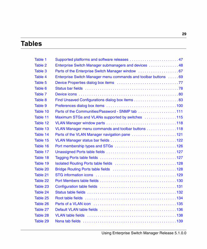
29
Using Enterprise Switch Manager Release 5.1.0.0
Tables
Table 1 Supported platforms and software releases . . . . . . . . . . . . . . . . . . . . . . . 47
Table 2 Enterprise Switch Manager submanagers and devices . . . . . . . . . . . . . . 48
Table 3 Parts of the Enterprise Switch Manager window . . . . . . . . . . . . . . . . . . . 67
Table 4 Enterprise Switch Manager menu commands and toolbar buttons . . . . . 69
Table 5 Device Properties dialog box items . . . . . . . . . . . . . . . . . . . . . . . . . . . . . 77
Table 6 Status bar fields . . . . . . . . . . . . . . . . . . . . . . . . . . . . . . . . . . . . . . . . . . . . 78
Table 7 Device icons . . . . . . . . . . . . . . . . . . . . . . . . . . . . . . . . . . . . . . . . . . . . . . . 80
Table 8 Find Unsaved Configurations dialog box items . . . . . . . . . . . . . . . . . . . . . 83
Table 9 Preferences dialog box items . . . . . . . . . . . . . . . . . . . . . . . . . . . . . . . . . 100
Table 10 Parts of the Communities/Password - SNMP tab . . . . . . . . . . . . . . . . . . 111
Table 11 Maximum STGs and VLANs supported by switches . . . . . . . . . . . . . . . 115
Table 12 VLAN Manager window parts . . . . . . . . . . . . . . . . . . . . . . . . . . . . . . . . . 118
Table 13 VLAN Manager menu commands and toolbar buttons . . . . . . . . . . . . . . 118
Table 14 Parts of the VLAN Manager navigation pane . . . . . . . . . . . . . . . . . . . . . 121
Table 15 VLAN Manager status bar fields . . . . . . . . . . . . . . . . . . . . . . . . . . . . . . . 122
Table 16 Port membership types and STGs . . . . . . . . . . . . . . . . . . . . . . . . . . . . . 126
Table 17 Unassigned Ports table fields . . . . . . . . . . . . . . . . . . . . . . . . . . . . . . . . . 127
Table 18 Tagging Ports table fields . . . . . . . . . . . . . . . . . . . . . . . . . . . . . . . . . . . . 127
Table 19 Isolated Routing Ports table fields . . . . . . . . . . . . . . . . . . . . . . . . . . . . . 128
Table 20 Bridge Routing Ports table fields . . . . . . . . . . . . . . . . . . . . . . . . . . . . . . 128
Table 21 STG information icons . . . . . . . . . . . . . . . . . . . . . . . . . . . . . . . . . . . . . . 129
Table 22 Port Members table fields . . . . . . . . . . . . . . . . . . . . . . . . . . . . . . . . . . . . 130
Table 23 Configuration table fields . . . . . . . . . . . . . . . . . . . . . . . . . . . . . . . . . . . . 131
Table 24 Status table fields . . . . . . . . . . . . . . . . . . . . . . . . . . . . . . . . . . . . . . . . . . 132
Table 25 Root table fields . . . . . . . . . . . . . . . . . . . . . . . . . . . . . . . . . . . . . . . . . . . 134
Table 26 Parts of a VLAN icon . . . . . . . . . . . . . . . . . . . . . . . . . . . . . . . . . . . . . . . 135
Table 27 Default VLAN table fields . . . . . . . . . . . . . . . . . . . . . . . . . . . . . . . . . . . . 136
Table 28 VLAN table fields . . . . . . . . . . . . . . . . . . . . . . . . . . . . . . . . . . . . . . . . . . 138
Table 29 Nsna tab fields . . . . . . . . . . . . . . . . . . . . . . . . . . . . . . . . . . . . . . . . . . . . 139
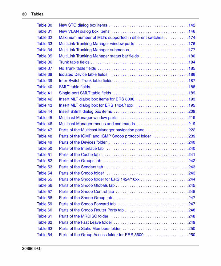
30 Tables
208963-G
Table 30 New STG dialog box items . . . . . . . . . . . . . . . . . . . . . . . . . . . . . . . . . . . 142
Table 31 New VLAN dialog box items . . . . . . . . . . . . . . . . . . . . . . . . . . . . . . . . . . 146
Table 32 Maximum number of MLTs supported in different switches . . . . . . . . . . 174
Table 33 MultiLink Trunking Manager window parts . . . . . . . . . . . . . . . . . . . . . . . 176
Table 34 MultiLink Trunking Manager submenus . . . . . . . . . . . . . . . . . . . . . . . . . 177
Table 35 MultiLink Trunking Manager status bar fields . . . . . . . . . . . . . . . . . . . . . 180
Table 36 Trunk table fields . . . . . . . . . . . . . . . . . . . . . . . . . . . . . . . . . . . . . . . . . . . 184
Table 37 No Trunk table fields . . . . . . . . . . . . . . . . . . . . . . . . . . . . . . . . . . . . . . . . 185
Table 38 Isolated Device table fields . . . . . . . . . . . . . . . . . . . . . . . . . . . . . . . . . . 186
Table 39 Inter-Switch Trunk table fields . . . . . . . . . . . . . . . . . . . . . . . . . . . . . . . . . 187
Table 40 SMLT table fields . . . . . . . . . . . . . . . . . . . . . . . . . . . . . . . . . . . . . . . . . . 188
Table 41 Single-port SMLT table fields . . . . . . . . . . . . . . . . . . . . . . . . . . . . . . . . . 189
Table 42 Insert MLT dialog box items for ERS 8000 . . . . . . . . . . . . . . . . . . . . . . . 193
Table 43 Insert MLT dialog box for ERS 1424/16xx . . . . . . . . . . . . . . . . . . . . . . . 195
Table 44 Insert SSmlt dialog box items . . . . . . . . . . . . . . . . . . . . . . . . . . . . . . . . . 209
Table 45 Multicast Manager window parts . . . . . . . . . . . . . . . . . . . . . . . . . . . . . . 219
Table 46 Multicast Manager menus and commands . . . . . . . . . . . . . . . . . . . . . . . 219
Table 47 Parts of the Multicast Manager navigation pane . . . . . . . . . . . . . . . . . . . 222
Table 48 Parts of the IGMP and IGMP Snoop protocol folder . . . . . . . . . . . . . . . . 239
Table 49 Parts of the Devices folder . . . . . . . . . . . . . . . . . . . . . . . . . . . . . . . . . . . 240
Table 50 Parts of the Interface tab . . . . . . . . . . . . . . . . . . . . . . . . . . . . . . . . . . . . 240
Table 51 Parts of the Cache tab . . . . . . . . . . . . . . . . . . . . . . . . . . . . . . . . . . . . . . 241
Table 52 Parts of the Groups tab . . . . . . . . . . . . . . . . . . . . . . . . . . . . . . . . . . . . . 242
Table 53 Parts of the Senders tab . . . . . . . . . . . . . . . . . . . . . . . . . . . . . . . . . . . . . 243
Table 54 Parts of the Snoop folder . . . . . . . . . . . . . . . . . . . . . . . . . . . . . . . . . . . . 243
Table 55 Parts of the Snoop folder for ERS 1424/16xx . . . . . . . . . . . . . . . . . . . . . 244
Table 56 Parts of the Snoop Globals tab . . . . . . . . . . . . . . . . . . . . . . . . . . . . . . . . 245
Table 57 Parts of the Snoop Control tab . . . . . . . . . . . . . . . . . . . . . . . . . . . . . . . . 245
Table 58 Parts of the Snoop Group tab . . . . . . . . . . . . . . . . . . . . . . . . . . . . . . . . . 247
Table 59 Parts of the Snoop Forward tab . . . . . . . . . . . . . . . . . . . . . . . . . . . . . . . 247
Table 60 Parts of the Snoop Router Ports tab . . . . . . . . . . . . . . . . . . . . . . . . . . . . 248
Table 61 Parts of the MRDISC folder . . . . . . . . . . . . . . . . . . . . . . . . . . . . . . . . . . 248
Table 62 Parts of the Fast Leave folder . . . . . . . . . . . . . . . . . . . . . . . . . . . . . . . . . 249
Table 63 Parts of the Static Members folder . . . . . . . . . . . . . . . . . . . . . . . . . . . . . 250
Table 64 Parts of the Group Access folder for ERS 8600 . . . . . . . . . . . . . . . . . . . 250
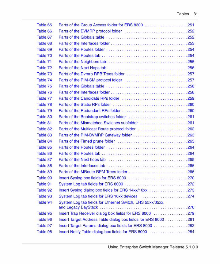
Tables 31
Using Enterprise Switch Manager Release 5.1.0.0
Table 65 Parts of the Group Access folder for ERS 8300 . . . . . . . . . . . . . . . . . . . 251
Table 66 Parts of the DVMRP protocol folder . . . . . . . . . . . . . . . . . . . . . . . . . . . . 252
Table 67 Parts of the Globals table . . . . . . . . . . . . . . . . . . . . . . . . . . . . . . . . . . . . 252
Table 68 Parts of the Interfaces folder . . . . . . . . . . . . . . . . . . . . . . . . . . . . . . . . . . 253
Table 69 Parts of the Routes folder . . . . . . . . . . . . . . . . . . . . . . . . . . . . . . . . . . . . 254
Table 70 Parts of the Routes tab . . . . . . . . . . . . . . . . . . . . . . . . . . . . . . . . . . . . . . 254
Table 71 Parts of the Neighbors tab . . . . . . . . . . . . . . . . . . . . . . . . . . . . . . . . . . . 255
Table 72 Parts of the Next Hops tab . . . . . . . . . . . . . . . . . . . . . . . . . . . . . . . . . . . 256
Table 73 Parts of the Dvmrp RPB Trees folder . . . . . . . . . . . . . . . . . . . . . . . . . . . 257
Table 74 Parts of the PIM-SM protocol folder . . . . . . . . . . . . . . . . . . . . . . . . . . . . 257
Table 75 Parts of the Globals table . . . . . . . . . . . . . . . . . . . . . . . . . . . . . . . . . . . . 258
Table 76 Parts of the Interfaces folder . . . . . . . . . . . . . . . . . . . . . . . . . . . . . . . . . . 258
Table 77 Parts of the Candidate RPs folder . . . . . . . . . . . . . . . . . . . . . . . . . . . . . 259
Table 78 Parts of the Static RPs folder . . . . . . . . . . . . . . . . . . . . . . . . . . . . . . . . . 260
Table 79 Parts of the Redundant RPs folder . . . . . . . . . . . . . . . . . . . . . . . . . . . . . 260
Table 80 Parts of the Bootstrap switches folder . . . . . . . . . . . . . . . . . . . . . . . . . . 261
Table 81 Parts of the Mismatched Switches subfolder . . . . . . . . . . . . . . . . . . . . . 261
Table 82 Parts of the Multicast Route protocol folder . . . . . . . . . . . . . . . . . . . . . . 262
Table 83 Parts of the PIM-DVMRP Gateway folder . . . . . . . . . . . . . . . . . . . . . . . . 263
Table 84 Parts of the Timed prune folder . . . . . . . . . . . . . . . . . . . . . . . . . . . . . . . 263
Table 85 Parts of the Routes folder . . . . . . . . . . . . . . . . . . . . . . . . . . . . . . . . . . . . 264
Table 86 Parts of the Routes tab . . . . . . . . . . . . . . . . . . . . . . . . . . . . . . . . . . . . . . 264
Table 87 Parts of the Next hops tab . . . . . . . . . . . . . . . . . . . . . . . . . . . . . . . . . . . 265
Table 88 Parts of the Interfaces tab . . . . . . . . . . . . . . . . . . . . . . . . . . . . . . . . . . . . 266
Table 89 Parts of the MRoute RPM Trees folder . . . . . . . . . . . . . . . . . . . . . . . . . . 266
Table 90 Insert Syslog box fields for ERS 8000 . . . . . . . . . . . . . . . . . . . . . . . . . . 270
Table 91 System Log tab fields for ERS 8000 . . . . . . . . . . . . . . . . . . . . . . . . . . . . 272
Table 92 Insert Syslog dialog box fields for ERS 14xx/16xx . . . . . . . . . . . . . . . . . 273
Table 93 System Log tab fields for ERS 16xx devices . . . . . . . . . . . . . . . . . . . . . 274
Table 94 System Log tab fields for Ethernet Switch, ERS 55xx/35xx, and Legacy BayStack . . . . . . . . . . . . . . . . . . . . . . . . . . . . . . . . . . . . . . . 276
Table 95 Insert Trap Receiver dialog box fields for ERS 8000 . . . . . . . . . . . . . . . 279
Table 96 Insert Target Address Table dialog box fields for ERS 8000 . . . . . . . . . . 281
Table 97 Insert Target Params dialog box fields for ERS 8000 . . . . . . . . . . . . . . . 282
Table 98 Insert Notify Table dialog box fields for ERS 8000 . . . . . . . . . . . . . . . . . 284
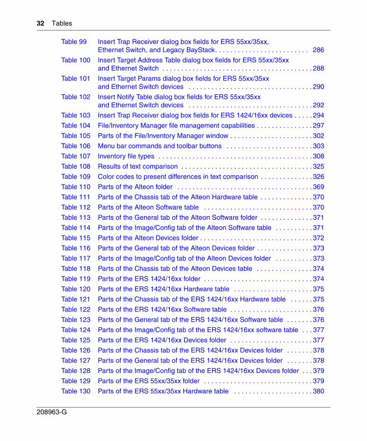
32 Tables
208963-G
Table 99 Insert Trap Receiver dialog box fields for ERS 55xx/35xx, Ethernet Switch, and Legacy BayStack. . . . . . . . . . . . . . . . . . . . . . . . . 286
Table 100 Insert Target Address Table dialog box fields for ERS 55xx/35xx and Ethernet Switch . . . . . . . . . . . . . . . . . . . . . . . . . . . . . . . . . . . . . . . . 288
Table 101 Insert Target Params dialog box fields for ERS 55xx/35xx and Ethernet Switch devices . . . . . . . . . . . . . . . . . . . . . . . . . . . . . . . . . 290
Table 102 Insert Notify Table dialog box fields for ERS 55xx/35xx and Ethernet Switch devices . . . . . . . . . . . . . . . . . . . . . . . . . . . . . . . . . 292
Table 103 Insert Trap Receiver dialog box fields for ERS 1424/16xx devices . . . . . 294
Table 104 File/Inventory Manager file management capabilities . . . . . . . . . . . . . . . 297
Table 105 Parts of the File/Inventory Manager window . . . . . . . . . . . . . . . . . . . . . . 302
Table 106 Menu bar commands and toolbar buttons . . . . . . . . . . . . . . . . . . . . . . . 303
Table 107 Inventory file types . . . . . . . . . . . . . . . . . . . . . . . . . . . . . . . . . . . . . . . . . 308
Table 108 Results of text comparison . . . . . . . . . . . . . . . . . . . . . . . . . . . . . . . . . . . 325
Table 109 Color codes to present differences in text comparison . . . . . . . . . . . . . . 326
Table 110 Parts of the Alteon folder . . . . . . . . . . . . . . . . . . . . . . . . . . . . . . . . . . . . 369
Table 111 Parts of the Chassis tab of the Alteon Hardware table . . . . . . . . . . . . . . 370
Table 112 Parts of the Alteon Software table . . . . . . . . . . . . . . . . . . . . . . . . . . . . . 370
Table 113 Parts of the General tab of the Alteon Software folder . . . . . . . . . . . . . . 371
Table 114 Parts of the Image/Config tab of the Alteon Software table . . . . . . . . . . 371
Table 115 Parts of the Alteon Devices folder . . . . . . . . . . . . . . . . . . . . . . . . . . . . . . 372
Table 116 Parts of the General tab of the Alteon Devices folder . . . . . . . . . . . . . . . 373
Table 117 Parts of the Image/Config tab of the Alteon Devices folder . . . . . . . . . . 373
Table 118 Parts of the Chassis tab of the Alteon Devices table . . . . . . . . . . . . . . . 374
Table 119 Parts of the ERS 1424/16xx folder . . . . . . . . . . . . . . . . . . . . . . . . . . . . . 374
Table 120 Parts of the ERS 1424/16xx Hardware table . . . . . . . . . . . . . . . . . . . . . 375
Table 121 Parts of the Chassis tab of the ERS 1424/16xx Hardware table . . . . . . 375
Table 122 Parts of the ERS 1424/16xx Software table . . . . . . . . . . . . . . . . . . . . . . 376
Table 123 Parts of the General tab of the ERS 1424/16xx Software table . . . . . . . 376
Table 124 Parts of the Image/Config tab of the ERS 1424/16xx software table . . . 377
Table 125 Parts of the ERS 1424/16xx Devices folder . . . . . . . . . . . . . . . . . . . . . . 377
Table 126 Parts of the Chassis tab of the ERS 1424/16xx Devices folder . . . . . . . 378
Table 127 Parts of the General tab of the ERS 1424/16xx Devices folder . . . . . . . 378
Table 128 Parts of the Image/Config tab of the ERS 1424/16xx Devices folder . . . 379
Table 129 Parts of the ERS 55xx/35xx folder . . . . . . . . . . . . . . . . . . . . . . . . . . . . . 379
Table 130 Parts of the ERS 55xx/35xx Hardware table . . . . . . . . . . . . . . . . . . . . . 380
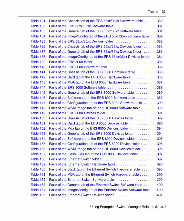
Tables 33
Using Enterprise Switch Manager Release 5.1.0.0
Table 131 Parts of the Chassis tab of the ERS 55xx/35xx Hardware table . . . . . . . 380
Table 132 Parts of the ERS 55xx/35xx Software table . . . . . . . . . . . . . . . . . . . . . . 381
Table 133 Parts of the General tab of the ERS 55xx/35xx Software table . . . . . . . 381
Table 134 Parts of the Image/Config tab of the ERS 55xx/35xx software table . . . 382
Table 135 Parts of the ERS 55xx/35xx Devices folder . . . . . . . . . . . . . . . . . . . . . . 382
Table 136 Parts of the Chassis tab of the ERS 55xx/35xx Devices folder . . . . . . . 383
Table 137 Parts of the General tab of the ERS 55xx/35xx Devices folder . . . . . . . 383
Table 138 Parts of the Image/Config tab of the ERS 55xx/35xx Devices folder . . . 384
Table 139 Parts of the ERS 8000 folder . . . . . . . . . . . . . . . . . . . . . . . . . . . . . . . . . 384
Table 140 Parts of the ERS 8000 Hardware table . . . . . . . . . . . . . . . . . . . . . . . . . . 385
Table 141 Parts of the Chassis tab of the ERS 8000 Hardware table . . . . . . . . . . . 385
Table 142 Parts of the Card tab of the ERS 8000 Hardware table . . . . . . . . . . . . . 386
Table 143 Parts of the MDA tab of the ERS 8000 Hardware table . . . . . . . . . . . . . 387
Table 144 Parts of the ERS 8000 Software table . . . . . . . . . . . . . . . . . . . . . . . . . . 388
Table 145 Parts of the General tab of the ERS 8000 Software table . . . . . . . . . . . 389
Table 146 Parts of the Software tab of the ERS 8000 Software table . . . . . . . . . . . 389
Table 147 Parts of the Configuration tab of the ERS 8000 Software table . . . . . . . 390
Table 148 Parts of the WSM Image tab of the ERS 8000 Software table . . . . . . . . 390
Table 149 Parts of the ERS 8000 Devices folder . . . . . . . . . . . . . . . . . . . . . . . . . . 391
Table 150 Parts of the Chassis tab of the ERS 8000 Devices folder . . . . . . . . . . . . 392
Table 151 Parts of the Card tab of the ERS 8000 Devices folder . . . . . . . . . . . . . . 393
Table 152 Parts of the Mda tab of the ERS 8000 Devices folder . . . . . . . . . . . . . . 394
Table 153 Parts of the General tab of the ERS 8000 Devices folder . . . . . . . . . . . . 394
Table 154 Parts of the Software tab of the ERS 8000 Devices folder . . . . . . . . . . . 395
Table 155 Parts of the Configuration tab of the ERS 8000 Devices folder . . . . . . . 395
Table 156 Parts of the WSM Image tab of the ERS 8000 Devices folder . . . . . . . . 396
Table 157 Parts of the Flash Files tab of the ERS 8000 Devices folder . . . . . . . . . 397
Table 158 Parts of the Ethernet Switch folder . . . . . . . . . . . . . . . . . . . . . . . . . . . . . 397
Table 159 Parts of the Ethernet Switch Hardware table . . . . . . . . . . . . . . . . . . . . . 398
Table 160 Parts of the Stack tab of the Ethernet Switch Hardware table . . . . . . . . 398
Table 161 Parts of the MDA tab of the Ethernet Switch Hardware table . . . . . . . . . 399
Table 162 Parts of the Ethernet Switch Software table . . . . . . . . . . . . . . . . . . . . . . 399
Table 163 Parts of the General tab of the Ethernet Switch Software table . . . . . . . 400
Table 164 Parts of the Image/Config tab of the Ethernet Switch Software table . . . 400
Table 165 Parts of the Ethernet Switch Devices folder . . . . . . . . . . . . . . . . . . . . . . 401
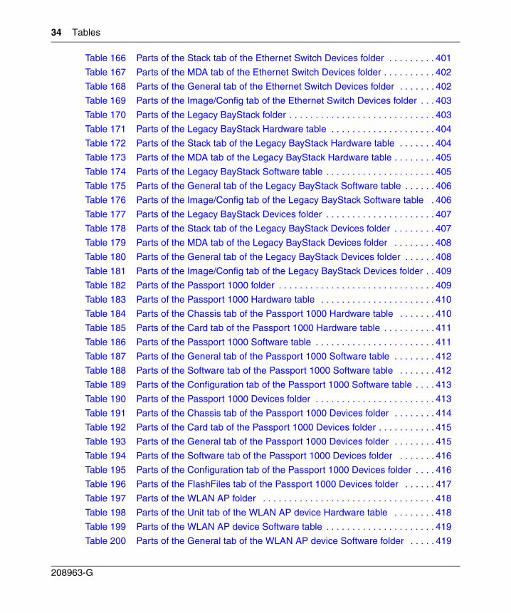
34 Tables
208963-G
Table 166 Parts of the Stack tab of the Ethernet Switch Devices folder . . . . . . . . . 401
Table 167 Parts of the MDA tab of the Ethernet Switch Devices folder . . . . . . . . . . 402
Table 168 Parts of the General tab of the Ethernet Switch Devices folder . . . . . . . 402
Table 169 Parts of the Image/Config tab of the Ethernet Switch Devices folder . . . 403
Table 170 Parts of the Legacy BayStack folder . . . . . . . . . . . . . . . . . . . . . . . . . . . . 403
Table 171 Parts of the Legacy BayStack Hardware table . . . . . . . . . . . . . . . . . . . . 404
Table 172 Parts of the Stack tab of the Legacy BayStack Hardware table . . . . . . . 404
Table 173 Parts of the MDA tab of the Legacy BayStack Hardware table . . . . . . . . 405
Table 174 Parts of the Legacy BayStack Software table . . . . . . . . . . . . . . . . . . . . . 405
Table 175 Parts of the General tab of the Legacy BayStack Software table . . . . . . 406
Table 176 Parts of the Image/Config tab of the Legacy BayStack Software table . 406
Table 177 Parts of the Legacy BayStack Devices folder . . . . . . . . . . . . . . . . . . . . . 407
Table 178 Parts of the Stack tab of the Legacy BayStack Devices folder . . . . . . . . 407
Table 179 Parts of the MDA tab of the Legacy BayStack Devices folder . . . . . . . . 408
Table 180 Parts of the General tab of the Legacy BayStack Devices folder . . . . . . 408
Table 181 Parts of the Image/Config tab of the Legacy BayStack Devices folder . . 409
Table 182 Parts of the Passport 1000 folder . . . . . . . . . . . . . . . . . . . . . . . . . . . . . . 409
Table 183 Parts of the Passport 1000 Hardware table . . . . . . . . . . . . . . . . . . . . . . 410
Table 184 Parts of the Chassis tab of the Passport 1000 Hardware table . . . . . . . 410
Table 185 Parts of the Card tab of the Passport 1000 Hardware table . . . . . . . . . . 411
Table 186 Parts of the Passport 1000 Software table . . . . . . . . . . . . . . . . . . . . . . . 411
Table 187 Parts of the General tab of the Passport 1000 Software table . . . . . . . . 412
Table 188 Parts of the Software tab of the Passport 1000 Software table . . . . . . . 412
Table 189 Parts of the Configuration tab of the Passport 1000 Software table . . . . 413
Table 190 Parts of the Passport 1000 Devices folder . . . . . . . . . . . . . . . . . . . . . . . 413
Table 191 Parts of the Chassis tab of the Passport 1000 Devices folder . . . . . . . . 414
Table 192 Parts of the Card tab of the Passport 1000 Devices folder . . . . . . . . . . . 415
Table 193 Parts of the General tab of the Passport 1000 Devices folder . . . . . . . . 415
Table 194 Parts of the Software tab of the Passport 1000 Devices folder . . . . . . . 416
Table 195 Parts of the Configuration tab of the Passport 1000 Devices folder . . . . 416
Table 196 Parts of the FlashFiles tab of the Passport 1000 Devices folder . . . . . . 417
Table 197 Parts of the WLAN AP folder . . . . . . . . . . . . . . . . . . . . . . . . . . . . . . . . . 418
Table 198 Parts of the Unit tab of the WLAN AP device Hardware table . . . . . . . . 418
Table 199 Parts of the WLAN AP device Software table . . . . . . . . . . . . . . . . . . . . . 419
Table 200 Parts of the General tab of the WLAN AP device Software folder . . . . . 419
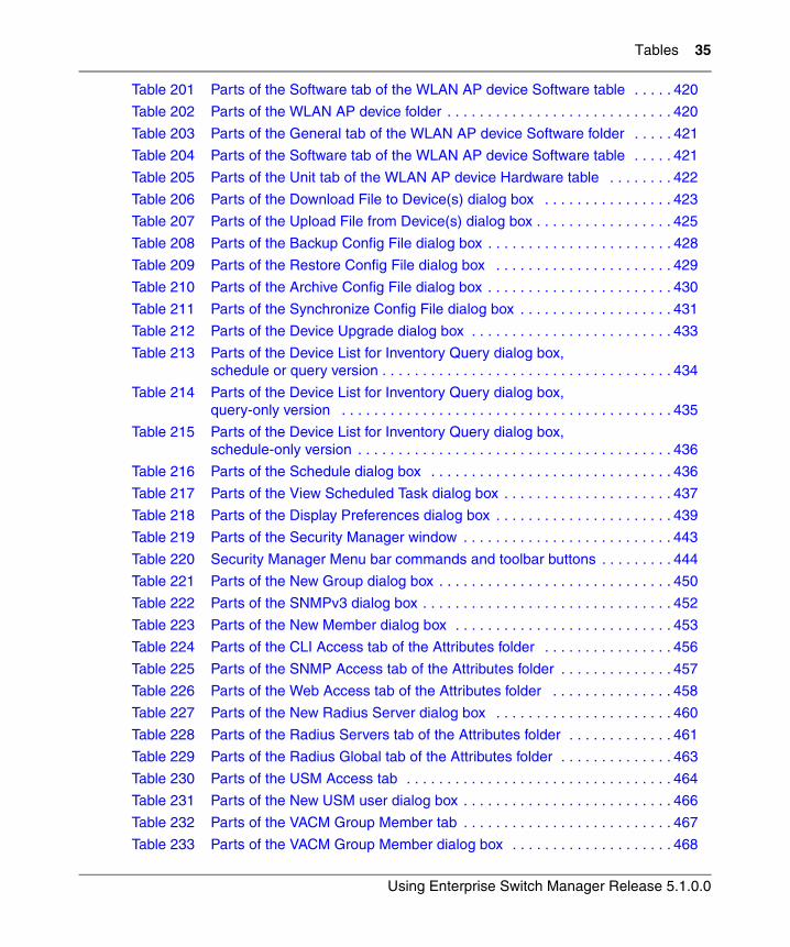
Tables 35
Using Enterprise Switch Manager Release 5.1.0.0
Table 201 Parts of the Software tab of the WLAN AP device Software table . . . . . 420
Table 202 Parts of the WLAN AP device folder . . . . . . . . . . . . . . . . . . . . . . . . . . . . 420
Table 203 Parts of the General tab of the WLAN AP device Software folder . . . . . 421
Table 204 Parts of the Software tab of the WLAN AP device Software table . . . . . 421
Table 205 Parts of the Unit tab of the WLAN AP device Hardware table . . . . . . . . 422
Table 206 Parts of the Download File to Device(s) dialog box . . . . . . . . . . . . . . . . 423
Table 207 Parts of the Upload File from Device(s) dialog box . . . . . . . . . . . . . . . . . 425
Table 208 Parts of the Backup Config File dialog box . . . . . . . . . . . . . . . . . . . . . . . 428
Table 209 Parts of the Restore Config File dialog box . . . . . . . . . . . . . . . . . . . . . . 429
Table 210 Parts of the Archive Config File dialog box . . . . . . . . . . . . . . . . . . . . . . . 430
Table 211 Parts of the Synchronize Config File dialog box . . . . . . . . . . . . . . . . . . . 431
Table 212 Parts of the Device Upgrade dialog box . . . . . . . . . . . . . . . . . . . . . . . . . 433
Table 213 Parts of the Device List for Inventory Query dialog box, schedule or query version . . . . . . . . . . . . . . . . . . . . . . . . . . . . . . . . . . . . 434
Table 214 Parts of the Device List for Inventory Query dialog box, query-only version . . . . . . . . . . . . . . . . . . . . . . . . . . . . . . . . . . . . . . . . . 435
Table 215 Parts of the Device List for Inventory Query dialog box, schedule-only version . . . . . . . . . . . . . . . . . . . . . . . . . . . . . . . . . . . . . . . 436
Table 216 Parts of the Schedule dialog box . . . . . . . . . . . . . . . . . . . . . . . . . . . . . . 436
Table 217 Parts of the View Scheduled Task dialog box . . . . . . . . . . . . . . . . . . . . . 437
Table 218 Parts of the Display Preferences dialog box . . . . . . . . . . . . . . . . . . . . . . 439
Table 219 Parts of the Security Manager window . . . . . . . . . . . . . . . . . . . . . . . . . . 443
Table 220 Security Manager Menu bar commands and toolbar buttons . . . . . . . . . 444
Table 221 Parts of the New Group dialog box . . . . . . . . . . . . . . . . . . . . . . . . . . . . . 450
Table 222 Parts of the SNMPv3 dialog box . . . . . . . . . . . . . . . . . . . . . . . . . . . . . . . 452
Table 223 Parts of the New Member dialog box . . . . . . . . . . . . . . . . . . . . . . . . . . . 453
Table 224 Parts of the CLI Access tab of the Attributes folder . . . . . . . . . . . . . . . . 456
Table 225 Parts of the SNMP Access tab of the Attributes folder . . . . . . . . . . . . . . 457
Table 226 Parts of the Web Access tab of the Attributes folder . . . . . . . . . . . . . . . 458
Table 227 Parts of the New Radius Server dialog box . . . . . . . . . . . . . . . . . . . . . . 460
Table 228 Parts of the Radius Servers tab of the Attributes folder . . . . . . . . . . . . . 461
Table 229 Parts of the Radius Global tab of the Attributes folder . . . . . . . . . . . . . . 463
Table 230 Parts of the USM Access tab . . . . . . . . . . . . . . . . . . . . . . . . . . . . . . . . . 464
Table 231 Parts of the New USM user dialog box . . . . . . . . . . . . . . . . . . . . . . . . . . 466
Table 232 Parts of the VACM Group Member tab . . . . . . . . . . . . . . . . . . . . . . . . . . 467
Table 233 Parts of the VACM Group Member dialog box . . . . . . . . . . . . . . . . . . . . 468
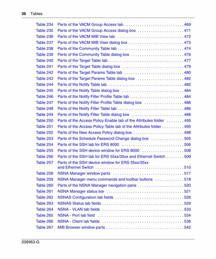
36 Tables
208963-G
Table 234 Parts of the VACM Group Access tab . . . . . . . . . . . . . . . . . . . . . . . . . . . 469
Table 235 Parts of the VACM Group Access dialog box . . . . . . . . . . . . . . . . . . . . . 471
Table 236 Parts of the VACM MIB View tab . . . . . . . . . . . . . . . . . . . . . . . . . . . . . . 472
Table 237 Parts of the VACM MIB View dialog box . . . . . . . . . . . . . . . . . . . . . . . . . 473
Table 238 Parts of the Community Table tab . . . . . . . . . . . . . . . . . . . . . . . . . . . . . . 474
Table 239 Parts of the Community Table dialog box . . . . . . . . . . . . . . . . . . . . . . . . 476
Table 240 Parts of the Target Table tab . . . . . . . . . . . . . . . . . . . . . . . . . . . . . . . . . . 477
Table 241 Parts of the Target Table dialog box . . . . . . . . . . . . . . . . . . . . . . . . . . . . 479
Table 242 Parts of the Target Params Table tab . . . . . . . . . . . . . . . . . . . . . . . . . . . 480
Table 243 Parts of the Target Params Table dialog box . . . . . . . . . . . . . . . . . . . . . 482
Table 244 Parts of the Notify Table tab . . . . . . . . . . . . . . . . . . . . . . . . . . . . . . . . . . 482
Table 245 Parts of the Notify Table dialog box . . . . . . . . . . . . . . . . . . . . . . . . . . . . 484
Table 246 Parts of the Notify Filter Profile Table tab . . . . . . . . . . . . . . . . . . . . . . . . 484
Table 247 Parts of the Notify Filter Profile Table dialog box . . . . . . . . . . . . . . . . . . 486
Table 248 Parts of the Notify Filter Table tab . . . . . . . . . . . . . . . . . . . . . . . . . . . . . . 486
Table 249 Parts of the Notify Filter Table dialog box . . . . . . . . . . . . . . . . . . . . . . . . 488
Table 250 Parts of the Access Policy Enable tab of the Attributes folder . . . . . . . . 495
Table 251 Parts of the Access Policy Table tab of the Attributes folder . . . . . . . . . . 495
Table 252 Parts of the New Access Policy dialog box . . . . . . . . . . . . . . . . . . . . . . . 498
Table 253 Parts of the Schedule Password Change dialog box . . . . . . . . . . . . . . . 505
Table 254 Parts of the SSH tab for ERS 8000 . . . . . . . . . . . . . . . . . . . . . . . . . . . . 506
Table 255 Parts of the SSH device window for ERS 8000 . . . . . . . . . . . . . . . . . . . 508
Table 256 Parts of the SSH tab for ERS 55xx/35xx and Ethernet Switch . . . . . . . . 509
Table 257 Parts of the SSH device window for ERS 55xx/35xx and Ethernet Switch . . . . . . . . . . . . . . . . . . . . . . . . . . . . . . . . . . . . . . . . 510
Table 258 NSNA Manager window parts . . . . . . . . . . . . . . . . . . . . . . . . . . . . . . . . 517
Table 259 NSNA Manager menu commands and toolbar buttons . . . . . . . . . . . . . 518
Table 260 Parts of the NSNA Manager navigation pane . . . . . . . . . . . . . . . . . . . . . 520
Table 261 NSNA Manager status bar . . . . . . . . . . . . . . . . . . . . . . . . . . . . . . . . . . . 521
Table 262 NSNAS Configuration tab fields . . . . . . . . . . . . . . . . . . . . . . . . . . . . . . . 526
Table 263 NSNAS Status tab fields . . . . . . . . . . . . . . . . . . . . . . . . . . . . . . . . . . . . . 529
Table 264 NSNA - VLAN tab fields . . . . . . . . . . . . . . . . . . . . . . . . . . . . . . . . . . . . . 533
Table 265 NSNA - Port tab field . . . . . . . . . . . . . . . . . . . . . . . . . . . . . . . . . . . . . . . 534
Table 266 NSNA - Client tab fields . . . . . . . . . . . . . . . . . . . . . . . . . . . . . . . . . . . . . 536
Table 267 MIB Browser window parts . . . . . . . . . . . . . . . . . . . . . . . . . . . . . . . . . . . 542
Tables 37
Using Enterprise Switch Manager Release 5.1.0.0
Table 268 MIB Browser menu commands and toolbar buttons . . . . . . . . . . . . . . . . 543
Table 269 GetBulk Settings pane . . . . . . . . . . . . . . . . . . . . . . . . . . . . . . . . . . . . . . 552
Table 270 SNMP-V3 Settings dialog box . . . . . . . . . . . . . . . . . . . . . . . . . . . . . . . . 554
Table 271 SNMPv3 Settings parts . . . . . . . . . . . . . . . . . . . . . . . . . . . . . . . . . . . . . 555
Table 272 Enterprise Switch Manager problems and solutions . . . . . . . . . . . . . . . 559
Table 273 Enterprise Switch Manager error messages . . . . . . . . . . . . . . . . . . . . . 560

38 Tables
208963-G
39
Using Enterprise Switch Manager Release 5.1.0.0
Preface
Enterprise Switch Manager™ is a Java-based graphical network management application used to configure and manage certain Nortel Ethernet Routing Switches, Nortel Ethernet Switches, Legacy BayStack switches and Business Policy Switches 2000™ operating within the same local area network. For more information about the devices supported by Enterprise Switch Manager, see “Supported devices” on page 47.
This guide provides information about installing the Enterprise Switch Manager software and using the features and capabilities of Enterprise Switch Manager’s graphical user interface (GUI).
Before you begin
This guide is intended for network administrators with the following background:
• Familiarity with the following networking concepts and terminology:
— Security
— VLANs
— STGs
— MLTs
— Multicast protocols
• Ability to configure and troubleshoot VLANs, STGs, MLTs, and Multicast groups
40 Preface
208963-G
Text conventions
This guide uses the following text conventions:
bold Courier text Indicates command names and options and text that you need to enter.Example: Use the dinfo command. Example: Enter show ip {alerts|routes}.
italic text Indicates new terms, book titles, and variables in command syntax descriptions. Where a variable is two or more words, the words are connected by an underscore.Example: If the command syntax isshow at <valid_route>, valid_route is onevariable and you substitute one value for it.
plain Courier text Indicates command syntax and system output, for example, prompts and system messages.Example: Set Trap Monitor Filters
separator ( > ) Shows menu paths. Example: Protocols > IP identifies the IP option on the Protocols menu.
Preface 41
Using Enterprise Switch Manager Release 5.1.0.0
Related publications
For more information about the protocols used in Enterprise Switch Manager or information about using Device Manager, refer to the publications in this list.
• Installing Enterprise Switch Manager (210274-G)
• Configuring Network Management: Passport 8000 Series Software Release 4.0 (314723-D)
• Configuring IP Routing and Multicast Operations using Device Manager: Ethernet Routing Switch 8300 Software Release 2.2 (317338-B)
• Configuring and Managing Security: Passport 8000 Series Software Release 4.0 (314724-D)
• Configuring VLANs, Spanning Tree, and Link Aggregation: Passport 8000 Series Software Release 4.0 (314725-D)
• Configuring and Managing Security using Device Manager: Ethernet Routing Switch 8300 Software Release 2.2 (317346-B)
• Configuring VLANs, Spanning Tree, and Static Link Aggregation using Device Manager: Ethernet Routing Switch 8300 Software Release 2.2 (316805-B)
• Configuring IP Routing Protocols for Nortel Ethernet Routing Switch 5500 Series, Software Release 4.2 (217465-A)
• Configuring and Managing Security for Nortel Ethernet Routing Switch 5500 Series, Software Release 4.2 (217463-A)
• Configuring VLANs, Spanning Tree, and Multilink Trunking for Nortel Ethernet Routing Switch 5500 Series, Software Release 4.2 (217464-A)
• Configuring and Managing Security: Nortel Ethernet Switches 460 and 470 Software Release 3.6 (217104-A)
• Configuring VLANs, Spanning Tree, and MultiLink Trunking Nortel Ethernet Switches 460 and 470 Software Release 3.6 (217460-A)
• Reference for the BayStack 350/410/450 Management Software Operations Version 5.0 (210245-C)
• Networking Concepts for the Passport 1000 Series Switch (205588-B)
• Reference for the Passport 1000 Series Management Software Switching Operations, Release 2.1 (211192-A)
• Reference for the Passport 1000 Series Management Software Routing Operations, Release 2.1 (211193-A)
42 Preface
208963-G
You can print selected technical manuals and release notes free, directly from the Internet. Go to www.nortel.com/support. Find the product for which you need documentation. Then locate the specific category and model or version for your hardware or software product. Use Adobe* Reader* to open the manuals and release notes, search for the sections you need, and print them on most standard printers. Go to the Adobe Systems web site at www.adobe.com to download a free copy of the Adobe Reader.
How to get help
This section explains how to get help for Nortel products and services.
Getting Help from the Nortel web site
The best way to get technical support for Nortel products is from the Nortel Technical Support web site:
www.nortel.com/support
This site provides quick access to software, documentation, bulletins, and tools to address issues with Nortel products. More specifically, the site enables you to:
• download software, documentation, and product bulletins
• search the Technical Support web site and the Nortel Knowledge Base for answers to technical issues
• sign up for automatic notification of new software and documentation for Nortel equipment
• open and manage technical support cases
Getting Help through a Nortel distributor or reseller
If you purchased a service contract for your Nortel product from a distributor or authorized reseller, contact the technical support staff for that distributor or reseller.
Preface 43
Using Enterprise Switch Manager Release 5.1.0.0
Getting Help over the phone from a Nortel Solutions Center
If you do not find the information you require on the Nortel Technical Support web site, and have a Nortel support contract, you can also get help over the phone from a Nortel Solutions Center.
In North America, call 1-800-4NORTEL (1-800-466-7835).
Outside North America, go to the following web site to obtain the phone number for your region:
www.nortel.com/callus
Getting Help from a specialist by using an Express Routing Code
An Express Routing Code (ERC) is available for many Nortel products and services. When you use an ERC, your call is routed to a technical support person who specializes in supporting that product or service. To locate the ERC for your product or service, go to:
www.nortel.com/erc

44 Preface
208963-G
45
Using Enterprise Switch Manager Release 5.1.0.0
Chapter 1Introducing Enterprise Switch Manager
This chapter introduces Nortel Enterprise Switch Manager features and functions, and it includes the following topics:
• “What is Enterprise Switch Manager?‚” next
• “Enterprise Switch Manager features” on page 46
• “Supported devices” on page 47
• “Enterprise Switch Manager submanagers” on page 50
• “Additional Enterprise Switch Manager tools” on page 54
What is Enterprise Switch Manager?
Enterprise Switch Manager is a Java-based network management application that lets you discover and view network nodes and their physical links on a topology map. Once your network is discovered, you can monitor, manage, and configure protocols and settings in devices in the network using the following submanagers and tools within Enterprise Switch Manager:
• Topology Manager
• VLAN Manager
• MultiLink Trunking Manager
• Multicast Manager
• Security Manager
• File/Inventory Manager
• Trap/Log Manager
• NSNA Manager
• Tftp Server
• Smart Diff
46 Chapter 1 Introducing Enterprise Switch Manager
208963-G
• MIB Browser
In addition to these submanagers and tools, Enterprise Switch Manager has an associated standalone application, Device Manager, that has the ability to completely configure and manage a single device in the network.
Since Enterprise Switch Manager is a Java-based tool, it is platform-independent. Enterprise Switch Manager also allows you to save the topology map, error log, preferences, and communities in the application.
To use ESM, you do not need Java Runtime Environment (JRE). ESM bundles JRE 1.4.2_06, but OS patches are required, particularly for Solaris.
Enterprise Switch Manager features
Enterprise Switch Manager has the following features:
• A consistent look across Solaris, Windows, and Linux platforms.
• Spring algorithm that balances distances between devices and minimizes crossing lines when creating the topology map.
• A consistent Graphical User Interface (GUI) across Enterprise Switch Manager and submanagers and a single point of access to the submanagers.
• Access control and security using community strings, SNMPv3 USM, and SSH.
• Network discovery that you can specify to be as large or small as you want.
Note: For information on operating systems supported by Enterprise Switch Manager, see Installing Enterprise Switch Manager.
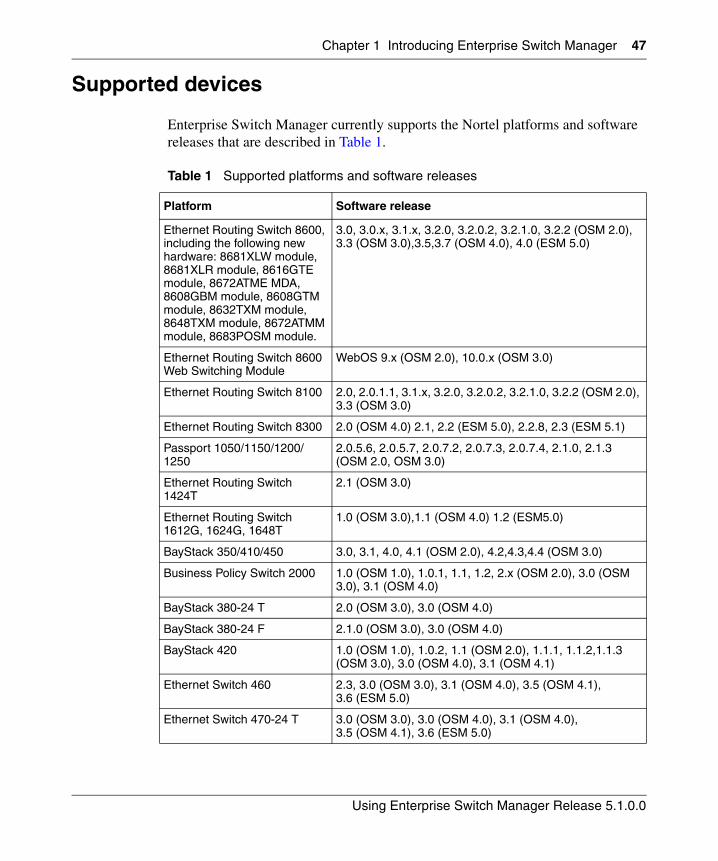
Chapter 1 Introducing Enterprise Switch Manager 47
Using Enterprise Switch Manager Release 5.1.0.0
Supported devices
Enterprise Switch Manager currently supports the Nortel platforms and software releases that are described in Table 1.
Table 1 Supported platforms and software releases
Platform Software release
Ethernet Routing Switch 8600, including the following new hardware: 8681XLW module, 8681XLR module, 8616GTE module, 8672ATME MDA, 8608GBM module, 8608GTM module, 8632TXM module, 8648TXM module, 8672ATMM module, 8683POSM module.
3.0, 3.0.x, 3.1.x, 3.2.0, 3.2.0.2, 3.2.1.0, 3.2.2 (OSM 2.0), 3.3 (OSM 3.0),3.5,3.7 (OSM 4.0), 4.0 (ESM 5.0)
Ethernet Routing Switch 8600 Web Switching Module
WebOS 9.x (OSM 2.0), 10.0.x (OSM 3.0)
Ethernet Routing Switch 8100 2.0, 2.0.1.1, 3.1.x, 3.2.0, 3.2.0.2, 3.2.1.0, 3.2.2 (OSM 2.0), 3.3 (OSM 3.0)
Ethernet Routing Switch 8300 2.0 (OSM 4.0) 2.1, 2.2 (ESM 5.0), 2.2.8, 2.3 (ESM 5.1)
Passport 1050/1150/1200/1250
2.0.5.6, 2.0.5.7, 2.0.7.2, 2.0.7.3, 2.0.7.4, 2.1.0, 2.1.3 (OSM 2.0, OSM 3.0)
Ethernet Routing Switch 1424T
2.1 (OSM 3.0)
Ethernet Routing Switch 1612G, 1624G, 1648T
1.0 (OSM 3.0),1.1 (OSM 4.0) 1.2 (ESM5.0)
BayStack 350/410/450 3.0, 3.1, 4.0, 4.1 (OSM 2.0), 4.2,4.3,4.4 (OSM 3.0)
Business Policy Switch 2000 1.0 (OSM 1.0), 1.0.1, 1.1, 1.2, 2.x (OSM 2.0), 3.0 (OSM 3.0), 3.1 (OSM 4.0)
BayStack 380-24 T 2.0 (OSM 3.0), 3.0 (OSM 4.0)
BayStack 380-24 F 2.1.0 (OSM 3.0), 3.0 (OSM 4.0)
BayStack 420 1.0 (OSM 1.0), 1.0.2, 1.1 (OSM 2.0), 1.1.1, 1.1.2,1.1.3 (OSM 3.0), 3.0 (OSM 4.0), 3.1 (OSM 4.1)
Ethernet Switch 460 2.3, 3.0 (OSM 3.0), 3.1 (OSM 4.0), 3.5 (OSM 4.1), 3.6 (ESM 5.0)
Ethernet Switch 470-24 T 3.0 (OSM 3.0), 3.0 (OSM 4.0), 3.1 (OSM 4.0), 3.5 (OSM 4.1), 3.6 (ESM 5.0)
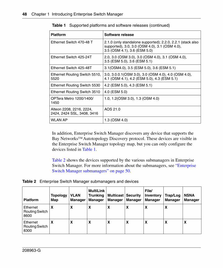
48 Chapter 1 Introducing Enterprise Switch Manager
208963-G
In addition, Enterprise Switch Manager discovers any device that supports the Bay NetworksΤΜ Autotopology Discovery protocol. These devices are visible in the Enterprise Switch Manager topology map, but you can only configure the devices listed in Table 1.
Table 2 shows the devices supported by the various submanagers in Enterprise Switch Manager. For more information about the submanagers, see “Enterprise Switch Manager submanagers” on page 50.
Ethernet Switch 470-48 T 2.1.0 (only standalone supported); 2.2.0, 2.2.1 (stack also supported), 3.0, 3.0 (OSM 4.0), 3.1 (OSM 4.0), 3.5 (OSM 4.1), 3.6 (ESM 5.0)
Ethernet Switch 425-24T 2.0, 3.0 (OSM 3.0), 3.0 (OSM 4.0), 3.1 (OSM 4.0), 3.5 (ESM 5.0), 3.6 (ESM 5.1)
Ethernet Switch 425-48T 3.1(OSM4.0), 3.5 (ESM 5.0), 3.6 (ESM 5.1)
Ethernet Routing Switch 5510, 5520
3.0, 3.0.0.1(OSM 3.0), 3.0 (OSM 4.0), 4.0 (OSM 4.0), 4.1 (OSM 4.1), 4.2 (ESM 5.0), 4.3 (ESM 5.1)
Ethernet Routing Switch 5530 4.2 (ESM 5.0), 4.3 (ESM 5.1)
Ethernet Routing Switch 3510 4.0 (ESM 5.0)
OPTera Metro 1200/1400/1450
1.0, 1.2(OSM 3.0), 1.3 (OSM 4.0)
Alteon 2208, 2216, 2224, 2424, 2424 SSL, 3408, 3416
AOS 21.0
WLAN AP 1.3 (OSM 4.0)
Table 2 Enterprise Switch Manager submanagers and devices
PlatformTopology Map
VLAN Manager
MultiLink Trunking Manager
Multicast Manager
Security Manager
File/Inventory Manager
Trap/Log Manager
NSNA Manager
Ethernet Routing Switch 8600
X X X X X X X
Ethernet Routing Switch 8300
X X X X X X X X
Table 1 Supported platforms and software releases (continued)
Platform Software release
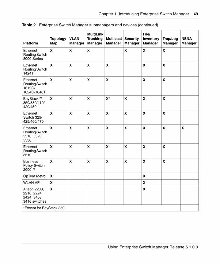
Chapter 1 Introducing Enterprise Switch Manager 49
Using Enterprise Switch Manager Release 5.1.0.0
Ethernet Routing Switch 8000 Series
X X X X X X
Ethernet Routing Switch 1424T
X X X X X X
Ethernet Routing Switch 1612G/ 1624G/1648T
X X X X X X
BayStack™ 350/380/410/420/450
X X X X* X X X
Ethernet Switch 325/425/460/470
X X X X X X X
Ethernet Routing Switch 5510, 5520, 5530
X X X X X X X X
Ethernet Routing Switch 3510
X X X X X X X
Business Policy Switch 2000™
X X X X X X X
OpTera Metro X X
WLAN AP X X
Alteon 2208, 2216, 2224, 2424, 3408, 3416 switches
X X
*Except for BayStack 350
Table 2 Enterprise Switch Manager submanagers and devices (continued)
PlatformTopology Map
VLAN Manager
MultiLink Trunking Manager
Multicast Manager
Security Manager
File/Inventory Manager
Trap/Log Manager
NSNA Manager
50 Chapter 1 Introducing Enterprise Switch Manager
208963-G
Topology Manager
The main Enterprise Switch Manager window is also referred to as the Topology Manager (TM). The Topology Manager provides a graphical view of a network of devices that support the Bay Networks Auto-Topology Discovery Protocol.
Enterprise Switch Manager submanagers
Enterprise Switch Manager supports submanagers that provide detailed device information and management capabilities. The submanagers are designed to provide specialized information in an easy-to-use Graphical User Interface that is consistent in layout across the submanagers. A submanager can query Enterprise Switch Manager and instruct the primary application to update the topology view with information relevant to the submanager view. For example, VLAN Manager can instruct Enterprise Switch Manager to color all the devices in the view that include members of a particular VLAN.
The submanagers open in a separate window from Enterprise Switch Manager. You must have the Enterprise Switch Manager window open to access all the submanagers except Device Manager. The submanagers are described in the following sections:
• “VLAN Manager” on page 51
• “MultiLink Trunking Manager” on page 51
• “Multicast Manager” on page 51
• “Security Manager” on page 52
• “File/Inventory Manager” on page 53
• “Trap/Log Manager” on page 53
• “NSNA Manager” on page 53
Chapter 1 Introducing Enterprise Switch Manager 51
Using Enterprise Switch Manager Release 5.1.0.0
VLAN Manager
VLAN Manager allows you to:
• Create, delete, or modify VLANs and Spanning Tree instances (for Nortel Spanning Tree Groups [STG], Rapid Spanning Tree Protocol [RSTP], and Multiple Spanning Tree Protocol [MSTP]) across one or multiple devices
• View VLAN information, membership, and port configuration information in tabular format
• View Spanning Tree Protocol information such as members of Spanning Tree Groups (STGs) and Spanning Tree Protocol configuration
• View VLAN nodes across the network
For more information on VLAN Manager, see Chapter 4, “Using VLAN Manager,” on page 113.
MultiLink Trunking Manager
MultiLink Trunking Manager allows you to:
• Create, delete, or modify MultiLink Trunks (MLTs) and Split Multilink Trunks (SMLTs)
• View MLT configuration information such as port and VLAN membership
For more information on MultiLink Trunking Manager, see Chapter 5, “Using MultiLink Trunking Manager,” on page 173.
Multicast Manager
Multicast Manager allows you to:
• View the following multicast configuration and protocols found in the network:
— IGMP
— DVMRP
— PIM-SM
— MRDISC with Fast Leave
52 Chapter 1 Introducing Enterprise Switch Manager
208963-G
— DVMRP:PIM Gateway
• Display multicast forwarding paths from a selected source or group
• Configure multicast parameters for the following protocols:
— IGMP and IGMP Snoop
— DVMRP globals
— PIM-SM globals
— MRDISC with Fast Leave
— DVMRP:PIM
For more information on Multicast Manager, refer to Chapter 6, “Using Multicast Manager,” on page 213.
Security Manager
Security Manager allows you to manage access to device and network management functions on network devices discovered by Enterprise Switch Manager. You can set, change, and synchronize security features for the following:
• Command Line Interface (CLI) access
• Web access
• Simple Network Management Protocol (SNMP) access
• Remote Access Dial-In User Services (RADIUS) properties
• SNMPv3 properties
• Access policies
• Secure Shell (SSH) bulk password
You can divide the network into one or more security groups that you manage independently. You use security groups to group together devices that you want to have the same passwords and access features.
Note: For Ethernet Routing Switches 8600 v3.2.1 and later, you cannot use Enterprise Switch Manager to modify CLI user and password. For Ethernet Routing Switches 8600 v3.5 and later, you cannot use Enterprise Switch Manager to modify web user name and password.
Chapter 1 Introducing Enterprise Switch Manager 53
Using Enterprise Switch Manager Release 5.1.0.0
For more information, see Chapter 9, “Using Security Manager,” on page 441.
File/Inventory Manager
File/Inventory Manager displays information about the devices discovered by Enterprise Switch Manager and allows you to browse information about the image and configuration/boot files that apply to those devices.
You can also use File/Inventory Manager to upload and download image and configuration/boot files to and from devices and to back up, restore, archive, and synchronize image and configuration/boot files for those devices as well. In addition, File/Inventory Manager allows you to upgrade devices.
For more information, see Chapter 8, “Using File/Inventory Manager,” on page 297.
Trap/Log Manager
The Trap/Log Manager is a new Enterprise Switch Manager submanager that allows you to configure and view traps, notifications, and the System Log. The Trap/Log Manager combines the functionality of the Trap Receiver and Log Manager submanagers of previous releases, and provides additional capabilities to configure traps, notifications, and syslogs.
For more information, see Chapter 7, “Using Trap/Log Manager,” on page 267.
NSNA Manager
NSNA Manager manages the Nortel Secure Network Access (NSNA) solution in a network. The NSNA solution protects an enterprise network by providing a predefined level of clientless access to users, based on credentials and security features.
NSNA Manager lets you manage NSNA on Nortel Ethernet Routing Switch 8300 Series and Ethernet Routing Switch 55xx devices.
54 Chapter 1 Introducing Enterprise Switch Manager
208963-G
For more information, see Chapter 10, “Using NSNA Manager,” on page 513.
Additional Enterprise Switch Manager tools
In addition to the submanagers, Enterprise Switch Manager provides additional device and network management tools, including the following:
• “Tftp Server” on page 54
• “Smart Diff” on page 54
• “MIB Browser” on page 54
• “Device Manager” on page 56
Tftp Server
Tftp server allows you to:
• transfer files between servers without authentication
• trace information on file transfer when the trace mode feature is enabled
Smart Diff
Smart Diff allows you to:
• compare two ASCII-based switch configuration files
• support configuration files generated from or created for Ethernet Routing Switches 8000, 1424T, and 1600
MIB Browser
MIB Browser allows you to manage SNMP-enabled network devices and applications. MIB Browser enables loading, browsing, and searching MIBs, walking the MIB tree, and performing all other SNMP-related functions. MIB Browser also enables viewing and operating the data available through an SNMP agent in a managed device.

Chapter 1 Introducing Enterprise Switch Manager 55
Using Enterprise Switch Manager Release 5.1.0.0
For more information, see Chapter 11, “Using MIB Browser,” on page 539.
56 Chapter 1 Introducing Enterprise Switch Manager
208963-G
Device Manager
Device Manager is a standalone application that you can launch either from Enterprise Switch Manager or separately. This application allows you to:
• download image and configuration files
• completely manage and configure Layer 2 and, if applicable, Layer 3 protocols and features for a single network device
• monitor traffic flow through the device
• view a device image indicating which ports are active and, for Ethernet Routing Switches, which modules are installed
For more information about Device Manager, refer to the documents listed in “Related publications” on page 41.
57
Using Enterprise Switch Manager Release 5.1.0.0
Chapter 2Using Enterprise Switch Manager
This chapter describes the basic procedures for using Enterprise Switch Manager. For information on how to install Enterprise Switch Manager, see Installing Enterprise Switch Manager.
This chapter includes the following topics:
• “Starting Enterprise Switch Manager‚” next
• “Using the Enterprise Switch Manager window” on page 66
• “Working with the network topology map” on page 84
• “Getting help” on page 95
Starting Enterprise Switch Manager
After you install Enterprise Switch Manager, you can start the application.
To start Enterprise Switch Manager:
• From the Windows 95, Windows 98, Windows 2000, Windows 2003, Windows NT, or Windows XP Start menu, choose Programs > Nortel > Enterprise Switch Manager > Enterprise Switch Manager.
• In a Windows environment, double-click the Enterprise Switch Manager shortcut icon on your desktop, if it is present.
• In a Solaris/Linux terminal window, enter ./ESM in the location where Enterprise Switch Manager has been installed.
Enterprise Switch Manager starts.
Do one of the following:
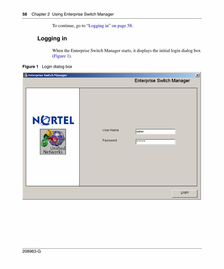
58 Chapter 2 Using Enterprise Switch Manager
208963-G
To continue, go to “Logging in” on page 58.
Logging in
When the Enterprise Switch Manager starts, it displays the initial login dialog box (Figure 1).
Figure 1 Login dialog box
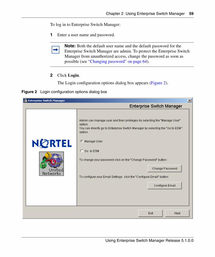
Chapter 2 Using Enterprise Switch Manager 59
Using Enterprise Switch Manager Release 5.1.0.0
To log in to Enterprise Switch Manager:
1 Enter a user name and password.
2 Click Login.
The Login configuration options dialog box appears (Figure 2).
Figure 2 Login configuration options dialog box
Note: Both the default user name and the default password for the Enterprise Switch Manager are admin. To protect the Enterprise Switch Manager from unauthorized access, change the password as soon as possible (see “Changing password” on page 64).
60 Chapter 2 Using Enterprise Switch Manager
208963-G
3 Refer to the following topics for more information on the options provided:
• To manage users, see “Managing users” on page 60.
• To change your password, see “Changing password” on page 64.
• To configure your e-mail, see “Configuring your e-mail settings” on page 65.
• To continue directly to Enterprise Switch Manager, click the Go to ESM radio button, and click Next. (See “Using the Enterprise Switch Manager window” on page 66).
Managing users
To manage users:
1 From the Login configuration options dialog box (Figure 2), click the Manage User radio button, and click Next.
Note: To manage users in ESM, you must have administrator access.
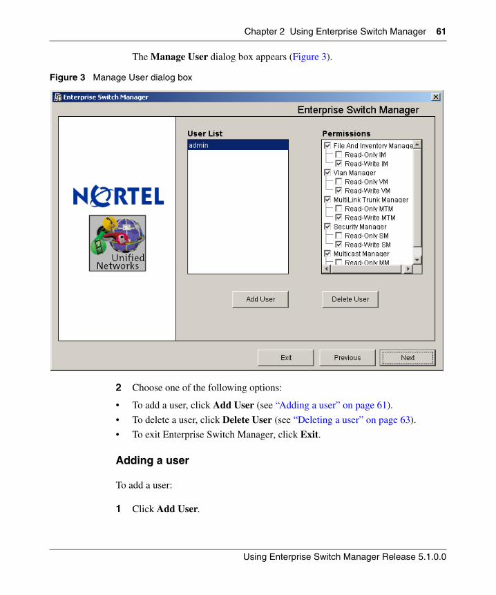
Chapter 2 Using Enterprise Switch Manager 61
Using Enterprise Switch Manager Release 5.1.0.0
The Manage User dialog box appears (Figure 3).
Figure 3 Manage User dialog box
2 Choose one of the following options:
• To add a user, click Add User (see “Adding a user” on page 61).
• To delete a user, click Delete User (see “Deleting a user” on page 63).
• To exit Enterprise Switch Manager, click Exit.
Adding a user
To add a user:
1 Click Add User.
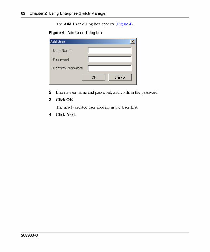
62 Chapter 2 Using Enterprise Switch Manager
208963-G
The Add User dialog box appears (Figure 4).
Figure 4 Add User dialog box
2 Enter a user name and password, and confirm the password.
3 Click OK.
The newly created user appears in the User List.
4 Click Next.
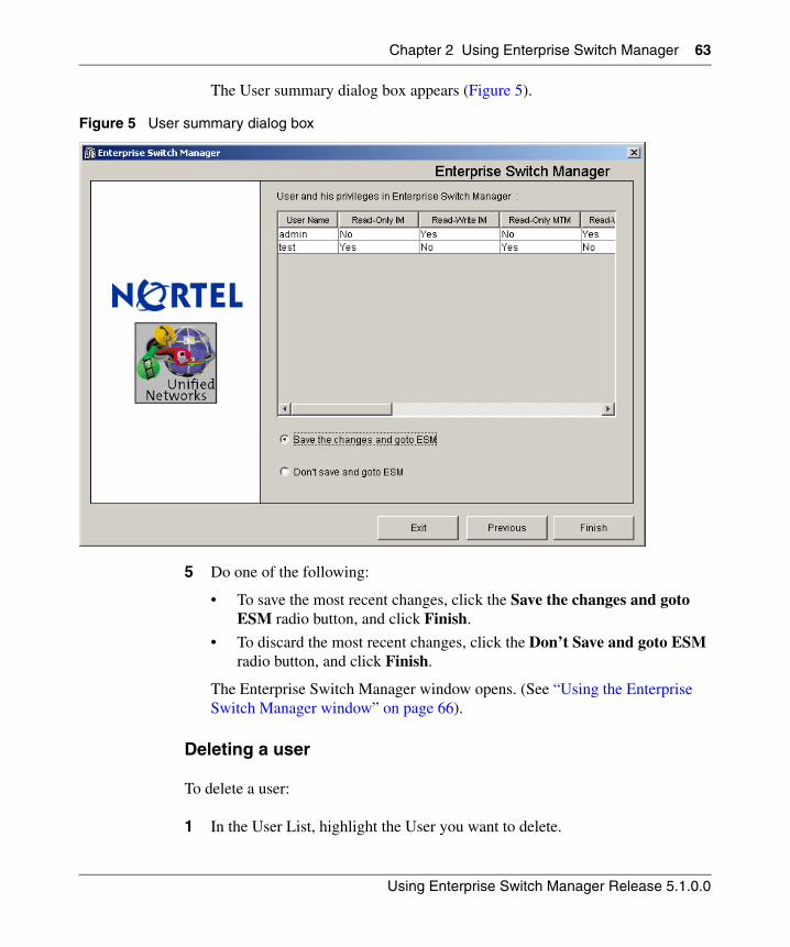
Chapter 2 Using Enterprise Switch Manager 63
Using Enterprise Switch Manager Release 5.1.0.0
The User summary dialog box appears (Figure 5).
Figure 5 User summary dialog box
5 Do one of the following:
• To save the most recent changes, click the Save the changes and goto ESM radio button, and click Finish.
• To discard the most recent changes, click the Don’t Save and goto ESM radio button, and click Finish.
The Enterprise Switch Manager window opens. (See “Using the Enterprise Switch Manager window” on page 66).
Deleting a user
To delete a user:
1 In the User List, highlight the User you want to delete.
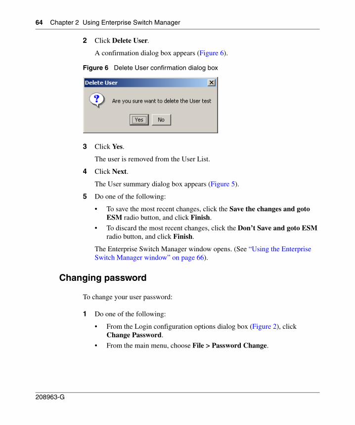
64 Chapter 2 Using Enterprise Switch Manager
208963-G
2 Click Delete User.
A confirmation dialog box appears (Figure 6).
Figure 6 Delete User confirmation dialog box
3 Click Yes.
The user is removed from the User List.
4 Click Next.
The User summary dialog box appears (Figure 5).
5 Do one of the following:
• To save the most recent changes, click the Save the changes and goto ESM radio button, and click Finish.
• To discard the most recent changes, click the Don’t Save and goto ESM radio button, and click Finish.
The Enterprise Switch Manager window opens. (See “Using the Enterprise Switch Manager window” on page 66).
Changing password
To change your user password:
1 Do one of the following:
• From the Login configuration options dialog box (Figure 2), click Change Password.
• From the main menu, choose File > Password Change.
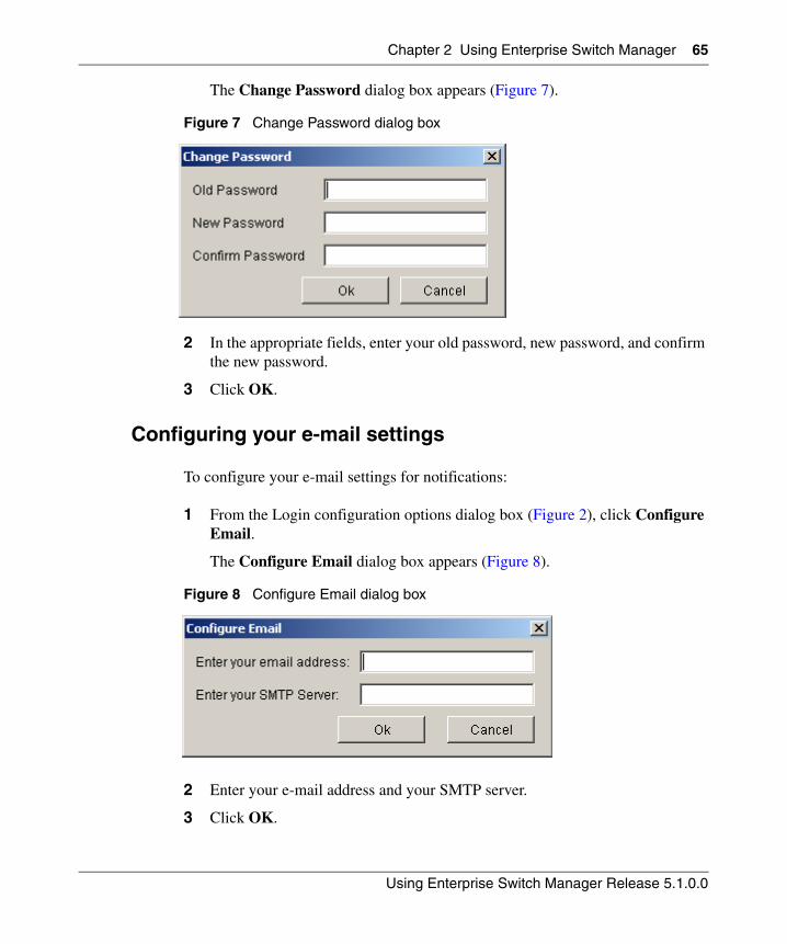
Chapter 2 Using Enterprise Switch Manager 65
Using Enterprise Switch Manager Release 5.1.0.0
The Change Password dialog box appears (Figure 7).
Figure 7 Change Password dialog box
2 In the appropriate fields, enter your old password, new password, and confirm the new password.
3 Click OK.
Configuring your e-mail settings
To configure your e-mail settings for notifications:
1 From the Login configuration options dialog box (Figure 2), click Configure Email.
The Configure Email dialog box appears (Figure 8).
Figure 8 Configure Email dialog box
2 Enter your e-mail address and your SMTP server.
3 Click OK.
66 Chapter 2 Using Enterprise Switch Manager
208963-G
Using the Enterprise Switch Manager window
The Enterprise Switch Manager window:
• Displays a logical map of a network showing physical connectivity between devices.
• Provides tools to access other Enterprise Switch Manager features.
• Allows you to launch Enterprise Switch Manager submanagers.
After the initial discovery, other Enterprise Switch Manager submanager applications allow you to manage discovered devices.
Note: To discover and display a network topology, you need to enter an IP address to a device that acts as a “seed,” and you must have permission to access that seed device. See “Finding devices on the topology map” on page 91 for more information.
Note: The Enterprise Switch Manager window remains open and can display highlighted devices after the Enterprise Switch Manager submanager windows open. If you close the Enterprise Switch Manager window while Enterprise Switch Manager submanager windows are open, the submanagers are also closed.
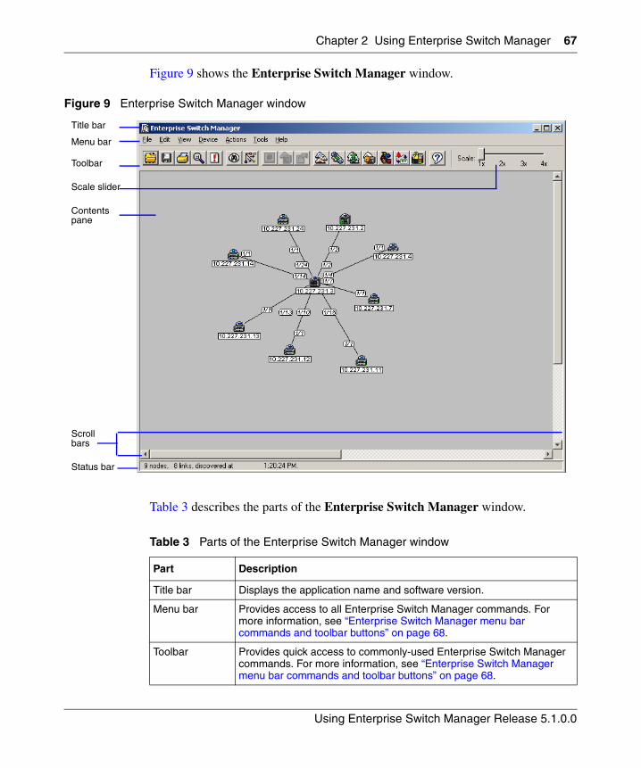
Chapter 2 Using Enterprise Switch Manager 67
Using Enterprise Switch Manager Release 5.1.0.0
Figure 9 shows the Enterprise Switch Manager window.
Figure 9 Enterprise Switch Manager window
Table 3 describes the parts of the Enterprise Switch Manager window.
Table 3 Parts of the Enterprise Switch Manager window
Part Description
Title bar Displays the application name and software version.
Menu bar Provides access to all Enterprise Switch Manager commands. For more information, see “Enterprise Switch Manager menu bar commands and toolbar buttons” on page 68.
Toolbar Provides quick access to commonly-used Enterprise Switch Manager commands. For more information, see “Enterprise Switch Manager menu bar commands and toolbar buttons” on page 68.
Title bar
Menu bar
Toolbar
Scale slider
Contents pane
Scroll bars
Status bar
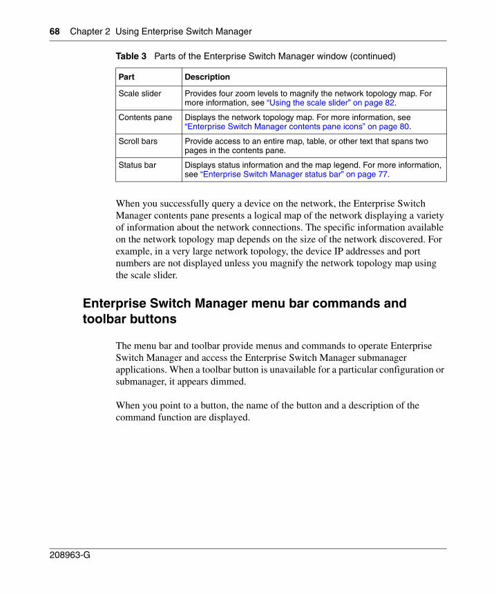
68 Chapter 2 Using Enterprise Switch Manager
208963-G
When you successfully query a device on the network, the Enterprise Switch Manager contents pane presents a logical map of the network displaying a variety of information about the network connections. The specific information available on the network topology map depends on the size of the network discovered. For example, in a very large network topology, the device IP addresses and port numbers are not displayed unless you magnify the network topology map using the scale slider.
Enterprise Switch Manager menu bar commands and toolbar buttons
The menu bar and toolbar provide menus and commands to operate Enterprise Switch Manager and access the Enterprise Switch Manager submanager applications. When a toolbar button is unavailable for a particular configuration or submanager, it appears dimmed.
When you point to a button, the name of the button and a description of the command function are displayed.
Scale slider Provides four zoom levels to magnify the network topology map. For more information, see “Using the scale slider” on page 82.
Contents pane Displays the network topology map. For more information, see “Enterprise Switch Manager contents pane icons” on page 80.
Scroll bars Provide access to an entire map, table, or other text that spans two pages in the contents pane.
Status bar Displays status information and the map legend. For more information, see “Enterprise Switch Manager status bar” on page 77.
Table 3 Parts of the Enterprise Switch Manager window (continued)
Part Description
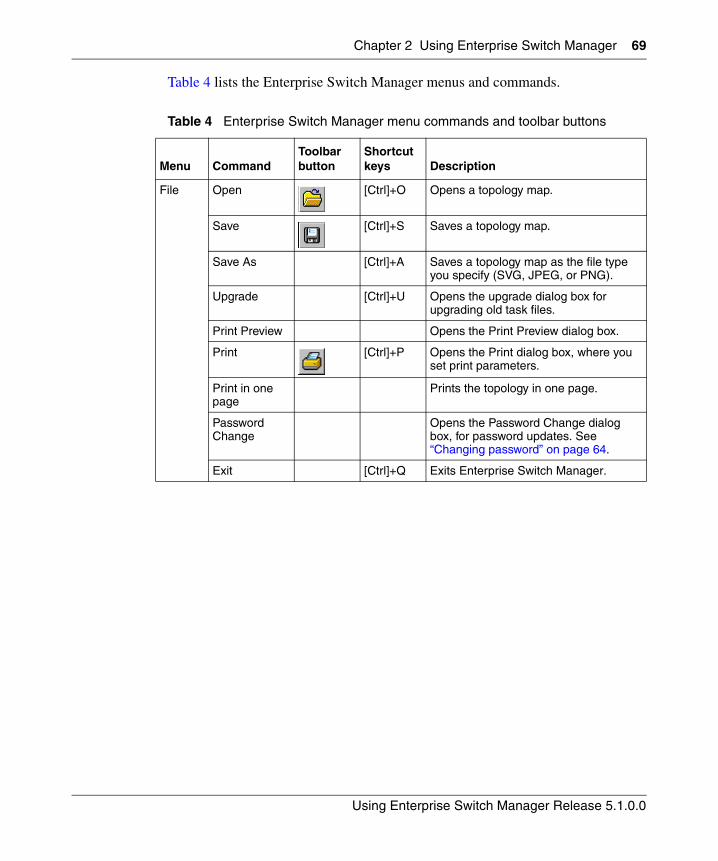
Chapter 2 Using Enterprise Switch Manager 69
Using Enterprise Switch Manager Release 5.1.0.0
Table 4 lists the Enterprise Switch Manager menus and commands.
Table 4 Enterprise Switch Manager menu commands and toolbar buttons
Menu CommandToolbar button
Shortcut keys Description
File Open [Ctrl]+O Opens a topology map.
Save [Ctrl]+S Saves a topology map.
Save As [Ctrl]+A Saves a topology map as the file type you specify (SVG, JPEG, or PNG).
Upgrade [Ctrl]+U Opens the upgrade dialog box for upgrading old task files.
Print Preview Opens the Print Preview dialog box.
Print [Ctrl]+P Opens the Print dialog box, where you set print parameters.
Print in one page
Prints the topology in one page.
Password Change
Opens the Password Change dialog box, for password updates. See “Changing password” on page 64.
Exit [Ctrl]+Q Exits Enterprise Switch Manager.
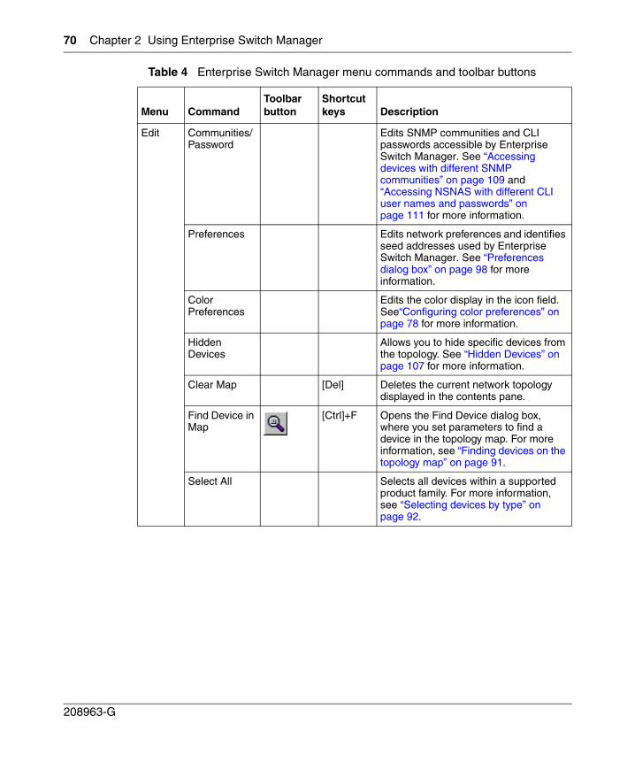
70 Chapter 2 Using Enterprise Switch Manager
208963-G
Edit Communities/Password
Edits SNMP communities and CLI passwords accessible by Enterprise Switch Manager. See “Accessing devices with different SNMP communities” on page 109 and “Accessing NSNAS with different CLI user names and passwords” on page 111 for more information.
Preferences Edits network preferences and identifies seed addresses used by Enterprise Switch Manager. See “Preferences dialog box” on page 98 for more information.
Color Preferences
Edits the color display in the icon field. See“Configuring color preferences” on page 78 for more information.
Hidden Devices
Allows you to hide specific devices from the topology. See “Hidden Devices” on page 107 for more information.
Clear Map [Del] Deletes the current network topology displayed in the contents pane.
Find Device in Map
[Ctrl]+F Opens the Find Device dialog box, where you set parameters to find a device in the topology map. For more information, see “Finding devices on the topology map” on page 91.
Select All Selects all devices within a supported product family. For more information, see “Selecting devices by type” on page 92.
Table 4 Enterprise Switch Manager menu commands and toolbar buttons
Menu CommandToolbar button
Shortcut keys Description
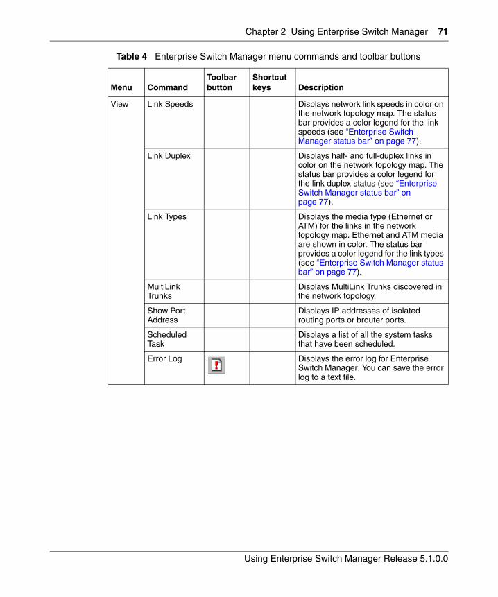
Chapter 2 Using Enterprise Switch Manager 71
Using Enterprise Switch Manager Release 5.1.0.0
View Link Speeds Displays network link speeds in color on the network topology map. The status bar provides a color legend for the link speeds (see “Enterprise Switch Manager status bar” on page 77).
Link Duplex Displays half- and full-duplex links in color on the network topology map. The status bar provides a color legend for the link duplex status (see “Enterprise Switch Manager status bar” on page 77).
Link Types Displays the media type (Ethernet or ATM) for the links in the network topology map. Ethernet and ATM media are shown in color. The status bar provides a color legend for the link types (see “Enterprise Switch Manager status bar” on page 77).
MultiLink Trunks
Displays MultiLink Trunks discovered in the network topology.
Show Port Address
Displays IP addresses of isolated routing ports or brouter ports.
Scheduled Task
Displays a list of all the system tasks that have been scheduled.
Error Log Displays the error log for Enterprise Switch Manager. You can save the error log to a text file.
Table 4 Enterprise Switch Manager menu commands and toolbar buttons
Menu CommandToolbar button
Shortcut keys Description
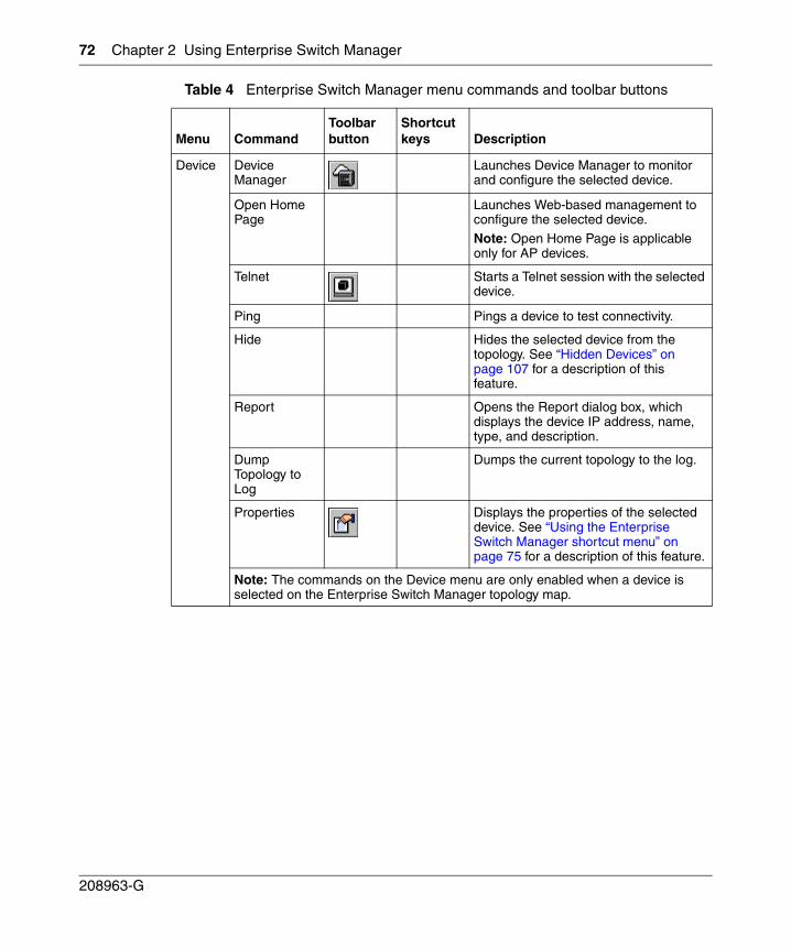
72 Chapter 2 Using Enterprise Switch Manager
208963-G
Device Device Manager
Launches Device Manager to monitor and configure the selected device.
Open Home Page
Launches Web-based management to configure the selected device.
Note: Open Home Page is applicable only for AP devices.
Telnet Starts a Telnet session with the selected device.
Ping Pings a device to test connectivity.
Hide Hides the selected device from the topology. See “Hidden Devices” on page 107 for a description of this feature.
Report Opens the Report dialog box, which displays the device IP address, name, type, and description.
Dump Topology to Log
Dumps the current topology to the log.
Properties Displays the properties of the selected device. See “Using the Enterprise Switch Manager shortcut menu” on page 75 for a description of this feature.
Note: The commands on the Device menu are only enabled when a device is selected on the Enterprise Switch Manager topology map.
Table 4 Enterprise Switch Manager menu commands and toolbar buttons
Menu CommandToolbar button
Shortcut keys Description
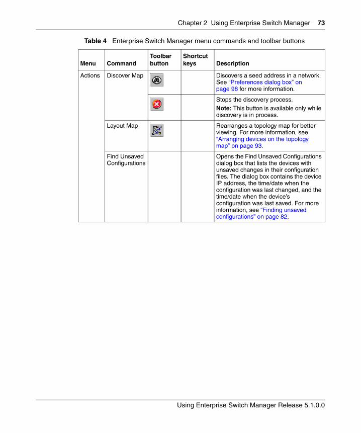
Chapter 2 Using Enterprise Switch Manager 73
Using Enterprise Switch Manager Release 5.1.0.0
Actions Discover Map Discovers a seed address in a network. See “Preferences dialog box” on page 98 for more information.
Stops the discovery process.Note: This button is available only while discovery is in process.
Layout Map Rearranges a topology map for better viewing. For more information, see “Arranging devices on the topology map” on page 93.
Find Unsaved Configurations
Opens the Find Unsaved Configurations dialog box that lists the devices with unsaved changes in their configuration files. The dialog box contains the device IP address, the time/date when the configuration was last changed, and the time/date when the device’s configuration was last saved. For more information, see “Finding unsaved configurations” on page 82.
Table 4 Enterprise Switch Manager menu commands and toolbar buttons
Menu CommandToolbar button
Shortcut keys Description
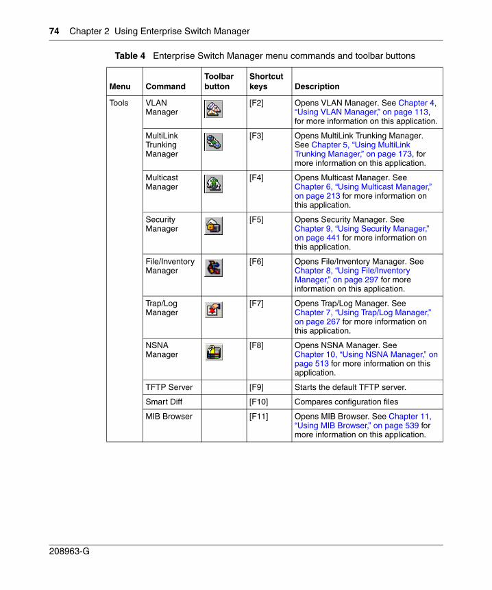
74 Chapter 2 Using Enterprise Switch Manager
208963-G
Tools VLAN Manager
[F2] Opens VLAN Manager. See Chapter 4, “Using VLAN Manager,” on page 113, for more information on this application.
MultiLink Trunking Manager
[F3] Opens MultiLink Trunking Manager. See Chapter 5, “Using MultiLink Trunking Manager,” on page 173, for more information on this application.
Multicast Manager
[F4] Opens Multicast Manager. See Chapter 6, “Using Multicast Manager,” on page 213 for more information on this application.
Security Manager
[F5] Opens Security Manager. See Chapter 9, “Using Security Manager,” on page 441 for more information on this application.
File/Inventory Manager
[F6] Opens File/Inventory Manager. See Chapter 8, “Using File/Inventory Manager,” on page 297 for more information on this application.
Trap/Log Manager
[F7] Opens Trap/Log Manager. See Chapter 7, “Using Trap/Log Manager,” on page 267 for more information on this application.
NSNA Manager
[F8] Opens NSNA Manager. See Chapter 10, “Using NSNA Manager,” on page 513 for more information on this application.
TFTP Server [F9] Starts the default TFTP server.
Smart Diff [F10] Compares configuration files
MIB Browser [F11] Opens MIB Browser. See Chapter 11, “Using MIB Browser,” on page 539 for more information on this application.
Table 4 Enterprise Switch Manager menu commands and toolbar buttons
Menu CommandToolbar button
Shortcut keys Description
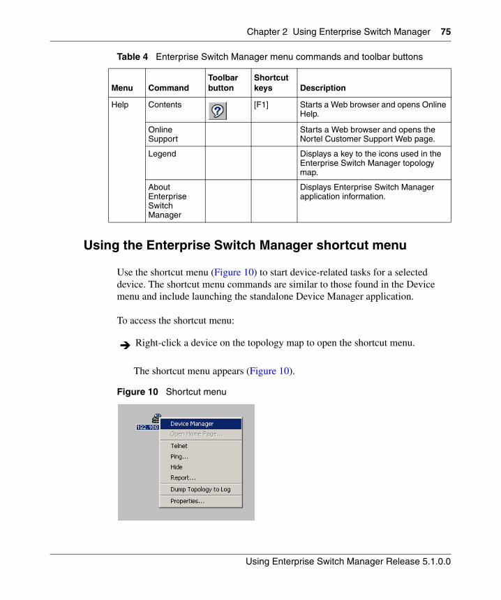
Chapter 2 Using Enterprise Switch Manager 75
Using Enterprise Switch Manager Release 5.1.0.0
Using the Enterprise Switch Manager shortcut menu
Use the shortcut menu (Figure 10) to start device-related tasks for a selected device. The shortcut menu commands are similar to those found in the Device menu and include launching the standalone Device Manager application.
To access the shortcut menu:
The shortcut menu appears (Figure 10).
Figure 10 Shortcut menu
Help Contents [F1] Starts a Web browser and opens Online Help.
Online Support
Starts a Web browser and opens the Nortel Customer Support Web page.
Legend Displays a key to the icons used in the Enterprise Switch Manager topology map.
About Enterprise Switch Manager
Displays Enterprise Switch Manager application information.
Right-click a device on the topology map to open the shortcut menu.
Table 4 Enterprise Switch Manager menu commands and toolbar buttons
Menu CommandToolbar button
Shortcut keys Description
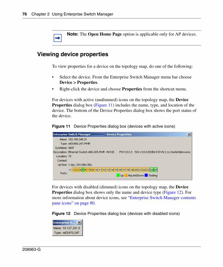
76 Chapter 2 Using Enterprise Switch Manager
208963-G
Viewing device properties
To view properties for a device on the topology map, do one of the following:
• Select the device. From the Enterprise Switch Manager menu bar choose Device > Properties.
• Right-click the device and choose Properties from the shortcut menu.
For devices with active (undimmed) icons on the topology map, the Device Properties dialog box (Figure 11) includes the name, type, and location of the device. The bottom of the Device Properties dialog box shows the port status of the device.
Figure 11 Device Properties dialog box (devices with active icons)
For devices with disabled (dimmed) icons on the topology map, the Device Properties dialog box shows only the name and device type (Figure 12). For more information about device icons, see “Enterprise Switch Manager contents pane icons” on page 80.
Figure 12 Device Properties dialog box (devices with disabled icons)
Note: The Open Home Page option is applicable only for AP devices.
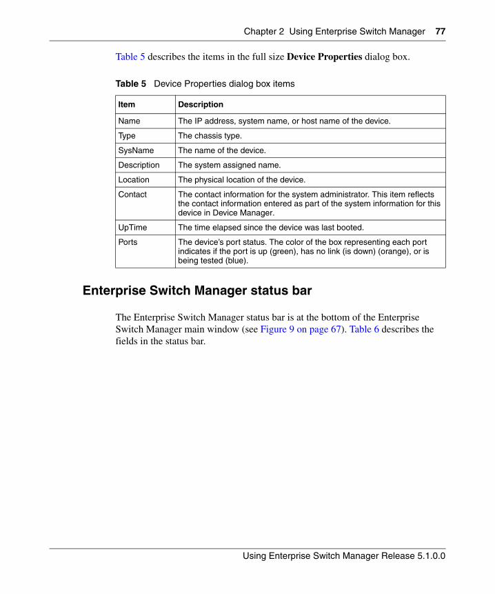
Chapter 2 Using Enterprise Switch Manager 77
Using Enterprise Switch Manager Release 5.1.0.0
Table 5 describes the items in the full size Device Properties dialog box.
Enterprise Switch Manager status bar
The Enterprise Switch Manager status bar is at the bottom of the Enterprise Switch Manager main window (see Figure 9 on page 67). Table 6 describes the fields in the status bar.
Table 5 Device Properties dialog box items
Item Description
Name The IP address, system name, or host name of the device.
Type The chassis type.
SysName The name of the device.
Description The system assigned name.
Location The physical location of the device.
Contact The contact information for the system administrator. This item reflects the contact information entered as part of the system information for this device in Device Manager.
UpTime The time elapsed since the device was last booted.
Ports The device’s port status. The color of the box representing each port indicates if the port is up (green), has no link (is down) (orange), or is being tested (blue).
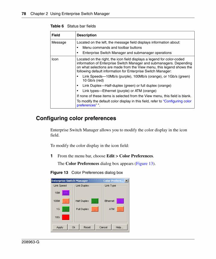
78 Chapter 2 Using Enterprise Switch Manager
208963-G
Configuring color preferences
Enterprise Switch Manager allows you to modify the color display in the icon field.
To modify the color display in the icon field:
1 From the menu bar, choose Edit > Color Preferences.
The Color Preferences dialog box appears (Figure 13).
Figure 13 Color Preferences dialog box
Table 6 Status bar fields
Field Description
Message Located on the left, the message field displays information about:
• Menu commands and toolbar buttons• Enterprise Switch Manager and submanager operations
Icon Located on the right, the icon field displays a legend for color-coded information of Enterprise Switch Manager and submanagers. Depending on what selections are made from the View menu, this legend shows the following default information for Enterprise Switch Manager:
• Link Speeds—10Mb/s (purple), 100Mb/s (orange), or 1Gb/s (green) 10 Gb/s (red)
• Link Duplex—Half-duplex (green) or full duplex (orange)
• Link types—Ethernet (purple) or ATM (orange)If none of these items is selected from the View menu, this field is blank.
To modify the default color display in this field, refer to “Configuring color preferences” ”.
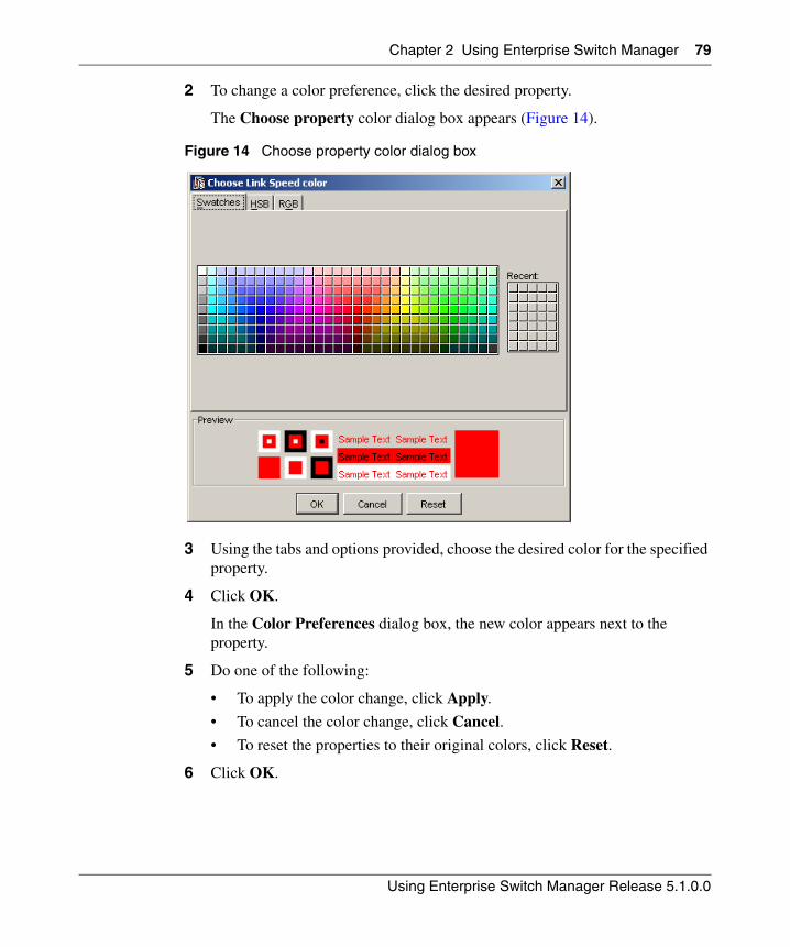
Chapter 2 Using Enterprise Switch Manager 79
Using Enterprise Switch Manager Release 5.1.0.0
2 To change a color preference, click the desired property.
The Choose property color dialog box appears (Figure 14).
Figure 14 Choose property color dialog box
3 Using the tabs and options provided, choose the desired color for the specified property.
4 Click OK.
In the Color Preferences dialog box, the new color appears next to the property.
5 Do one of the following:
• To apply the color change, click Apply.
• To cancel the color change, click Cancel.
• To reset the properties to their original colors, click Reset.
6 Click OK.
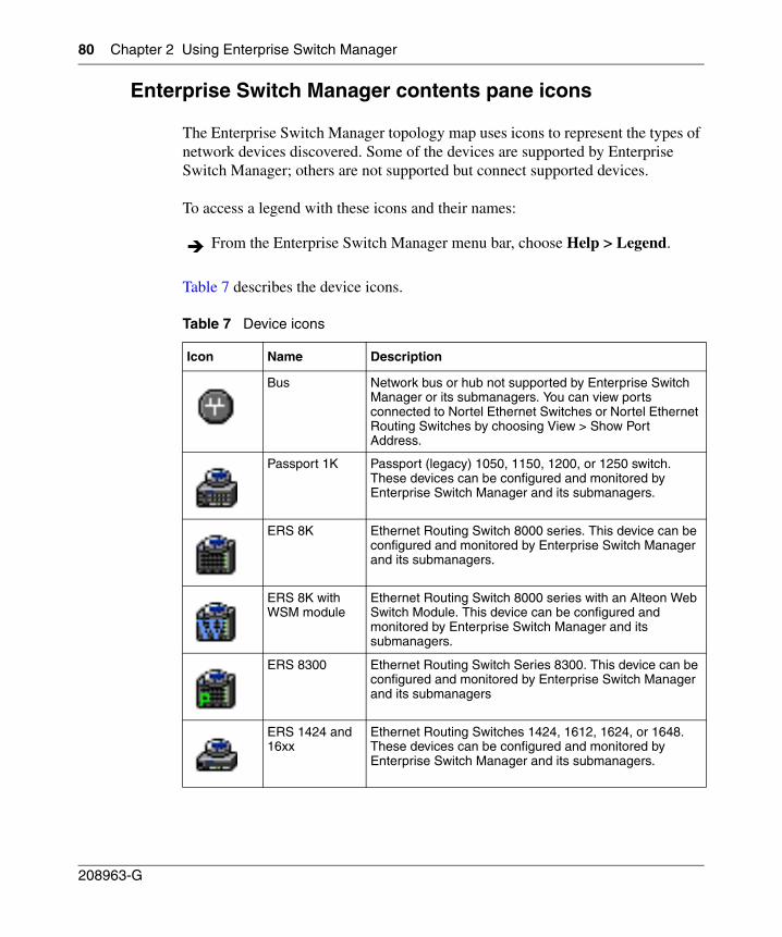
80 Chapter 2 Using Enterprise Switch Manager
208963-G
Enterprise Switch Manager contents pane icons
The Enterprise Switch Manager topology map uses icons to represent the types of network devices discovered. Some of the devices are supported by Enterprise Switch Manager; others are not supported but connect supported devices.
To access a legend with these icons and their names:
Table 7 describes the device icons.
From the Enterprise Switch Manager menu bar, choose Help > Legend.
Table 7 Device icons
Icon Name Description
Bus Network bus or hub not supported by Enterprise Switch Manager or its submanagers. You can view ports connected to Nortel Ethernet Switches or Nortel Ethernet Routing Switches by choosing View > Show Port Address.
Passport 1K Passport (legacy) 1050, 1150, 1200, or 1250 switch. These devices can be configured and monitored by Enterprise Switch Manager and its submanagers.
ERS 8K Ethernet Routing Switch 8000 series. This device can be configured and monitored by Enterprise Switch Manager and its submanagers.
ERS 8K with WSM module
Ethernet Routing Switch 8000 series with an Alteon Web Switch Module. This device can be configured and monitored by Enterprise Switch Manager and its submanagers.
ERS 8300 Ethernet Routing Switch Series 8300. This device can be configured and monitored by Enterprise Switch Manager and its submanagers
ERS 1424 and 16xx
Ethernet Routing Switches 1424, 1612, 1624, or 1648. These devices can be configured and monitored by Enterprise Switch Manager and its submanagers.
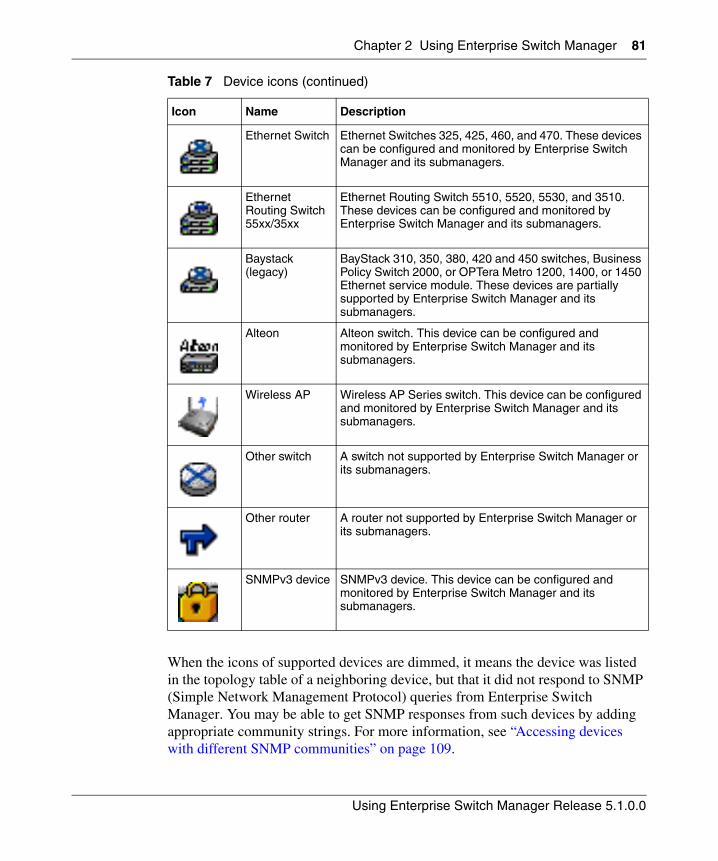
Chapter 2 Using Enterprise Switch Manager 81
Using Enterprise Switch Manager Release 5.1.0.0
When the icons of supported devices are dimmed, it means the device was listed in the topology table of a neighboring device, but that it did not respond to SNMP (Simple Network Management Protocol) queries from Enterprise Switch Manager. You may be able to get SNMP responses from such devices by adding appropriate community strings. For more information, see “Accessing devices with different SNMP communities” on page 109.
Ethernet Switch Ethernet Switches 325, 425, 460, and 470. These devices can be configured and monitored by Enterprise Switch Manager and its submanagers.
Ethernet Routing Switch 55xx/35xx
Ethernet Routing Switch 5510, 5520, 5530, and 3510. These devices can be configured and monitored by Enterprise Switch Manager and its submanagers.
Baystack (legacy)
BayStack 310, 350, 380, 420 and 450 switches, Business Policy Switch 2000, or OPTera Metro 1200, 1400, or 1450 Ethernet service module. These devices are partially supported by Enterprise Switch Manager and its submanagers.
Alteon Alteon switch. This device can be configured and monitored by Enterprise Switch Manager and its submanagers.
Wireless AP Wireless AP Series switch. This device can be configured and monitored by Enterprise Switch Manager and its submanagers.
Other switch A switch not supported by Enterprise Switch Manager or its submanagers.
Other router A router not supported by Enterprise Switch Manager or its submanagers.
SNMPv3 device SNMPv3 device. This device can be configured and monitored by Enterprise Switch Manager and its submanagers.
Table 7 Device icons (continued)
Icon Name Description
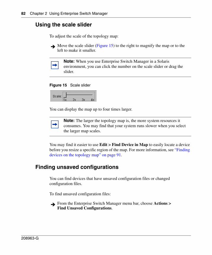
82 Chapter 2 Using Enterprise Switch Manager
208963-G
Using the scale slider
To adjust the scale of the topology map:
Figure 15 Scale slider
You can display the map up to four times larger.
You may find it easier to use Edit > Find Device in Map to easily locate a device before you resize a specific region of the map. For more information, see “Finding devices on the topology map” on page 91.
Finding unsaved configurations
You can find devices that have unsaved configuration files or changed configuration files.
To find unsaved configuration files:
Move the scale slider (Figure 15) to the right to magnify the map or to the left to make it smaller.
Note: When you use Enterprise Switch Manager in a Solaris environment, you can click the number on the scale slider or drag the slider.
Note: The larger the topology map is, the more system resources it consumes. You may find that your system runs slower when you select the larger map scales.
From the Enterprise Switch Manager menu bar, choose Actions > Find Unsaved Configurations.
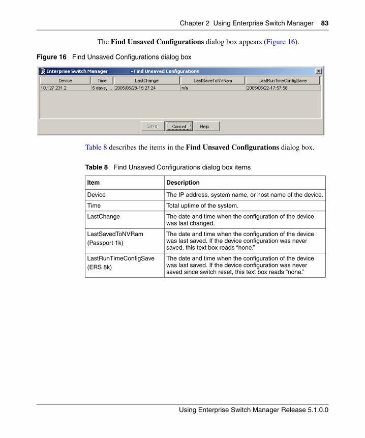
Chapter 2 Using Enterprise Switch Manager 83
Using Enterprise Switch Manager Release 5.1.0.0
The Find Unsaved Configurations dialog box appears (Figure 16).
Figure 16 Find Unsaved Configurations dialog box
Table 8 describes the items in the Find Unsaved Configurations dialog box.
Table 8 Find Unsaved Configurations dialog box items
Item Description
Device The IP address, system name, or host name of the device.
Time Total uptime of the system.
LastChange The date and time when the configuration of the device was last changed.
LastSavedToNVRam
(Passport 1k)
The date and time when the configuration of the device was last saved. If the device configuration was never saved, this text box reads “none.”
LastRunTimeConfigSave
(ERS 8k)
The date and time when the configuration of the device was last saved. If the device configuration was never saved since switch reset, this text box reads “none.”
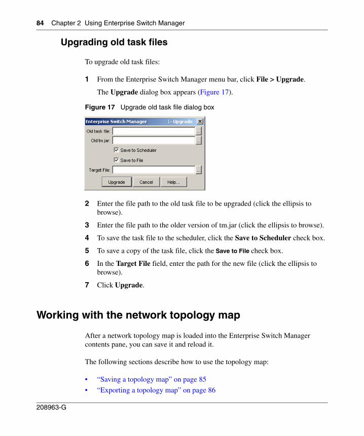
84 Chapter 2 Using Enterprise Switch Manager
208963-G
Upgrading old task files
To upgrade old task files:
1 From the Enterprise Switch Manager menu bar, click File > Upgrade.
The Upgrade dialog box appears (Figure 17).
Figure 17 Upgrade old task file dialog box
2 Enter the file path to the old task file to be upgraded (click the ellipsis to browse).
3 Enter the file path to the older version of tm.jar (click the ellipsis to browse).
4 To save the task file to the scheduler, click the Save to Scheduler check box.
5 To save a copy of the task file, click the Save to File check box.
6 In the Target File field, enter the path for the new file (click the ellipsis to browse).
7 Click Upgrade.
Working with the network topology map
After a network topology map is loaded into the Enterprise Switch Manager contents pane, you can save it and reload it.
The following sections describe how to use the topology map:
• “Saving a topology map” on page 85
• “Exporting a topology map” on page 86
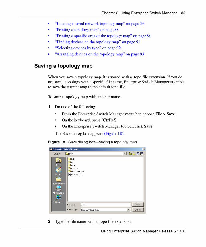
Chapter 2 Using Enterprise Switch Manager 85
Using Enterprise Switch Manager Release 5.1.0.0
• “Loading a saved network topology map” on page 86
• “Printing a topology map” on page 88
• “Printing a specific area of the topology map” on page 90
• “Finding devices on the topology map” on page 91
• “Selecting devices by type” on page 92
• “Arranging devices on the topology map” on page 93
Saving a topology map
When you save a topology map, it is stored with a .topo file extension. If you do not save a topology with a specific file name, Enterprise Switch Manager attempts to save the current map to the default.topo file.
To save a topology map with another name:
1 Do one of the following:
• From the Enterprise Switch Manager menu bar, choose File > Save.
• On the keyboard, press [Ctrl]+S.
• On the Enterprise Switch Manager toolbar, click Save.
The Save dialog box appears (Figure 18).
Figure 18 Save dialog box—saving a topology map
2 Type the file name with a .topo file extension.
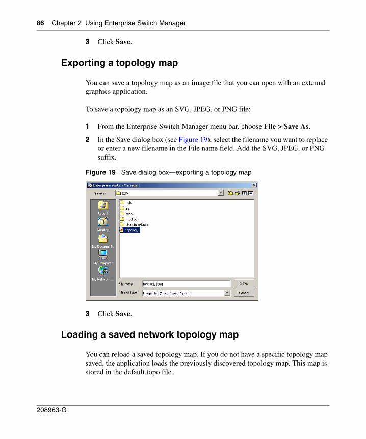
86 Chapter 2 Using Enterprise Switch Manager
208963-G
3 Click Save.
Exporting a topology map
You can save a topology map as an image file that you can open with an external graphics application.
To save a topology map as an SVG, JPEG, or PNG file:
1 From the Enterprise Switch Manager menu bar, choose File > Save As.
2 In the Save dialog box (see Figure 19), select the filename you want to replace or enter a new filename in the File name field. Add the SVG, JPEG, or PNG suffix.
Figure 19 Save dialog box—exporting a topology map
3 Click Save.
Loading a saved network topology map
You can reload a saved topology map. If you do not have a specific topology map saved, the application loads the previously discovered topology map. This map is stored in the default.topo file.
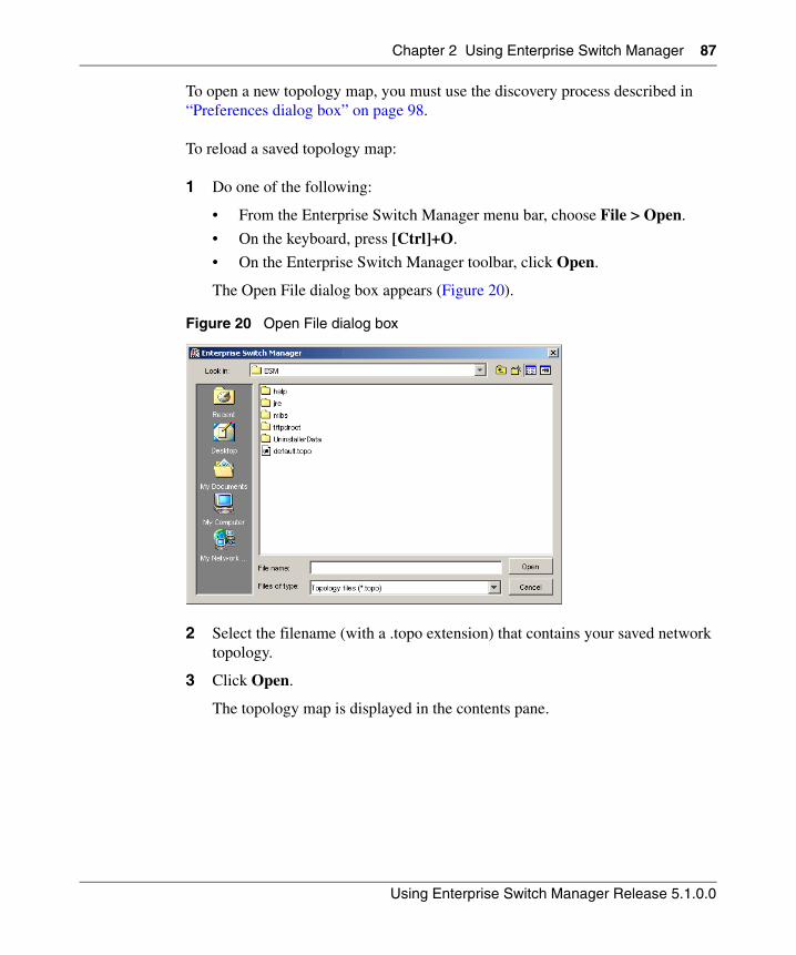
Chapter 2 Using Enterprise Switch Manager 87
Using Enterprise Switch Manager Release 5.1.0.0
To open a new topology map, you must use the discovery process described in “Preferences dialog box” on page 98.
To reload a saved topology map:
1 Do one of the following:
• From the Enterprise Switch Manager menu bar, choose File > Open.
• On the keyboard, press [Ctrl]+O.
• On the Enterprise Switch Manager toolbar, click Open.
The Open File dialog box appears (Figure 20).
Figure 20 Open File dialog box
2 Select the filename (with a .topo extension) that contains your saved network topology.
3 Click Open.
The topology map is displayed in the contents pane.
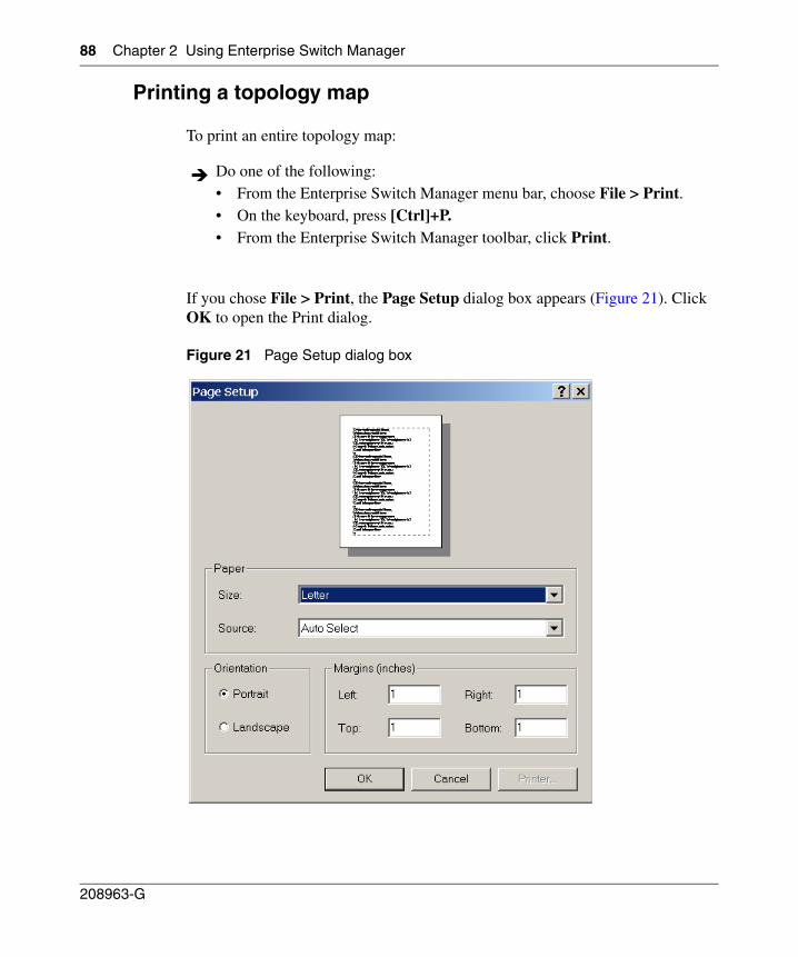
88 Chapter 2 Using Enterprise Switch Manager
208963-G
Printing a topology map
To print an entire topology map:
If you chose File > Print, the Page Setup dialog box appears (Figure 21). Click OK to open the Print dialog.
Figure 21 Page Setup dialog box
Do one of the following:• From the Enterprise Switch Manager menu bar, choose File > Print.• On the keyboard, press [Ctrl]+P.• From the Enterprise Switch Manager toolbar, click Print.
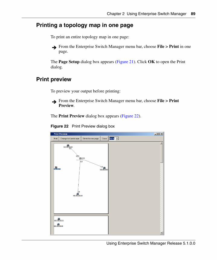
Chapter 2 Using Enterprise Switch Manager 89
Using Enterprise Switch Manager Release 5.1.0.0
Printing a topology map in one page
To print an entire topology map in one page:
The Page Setup dialog box appears (Figure 21). Click OK to open the Print dialog.
Print preview
To preview your output before printing:
The Print Preview dialog box appears (Figure 22).
Figure 22 Print Preview dialog box
From the Enterprise Switch Manager menu bar, choose File > Print in one page.
From the Enterprise Switch Manager menu bar, choose File > Print Preview.
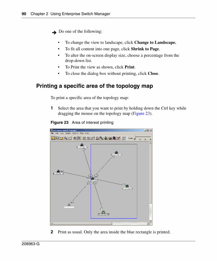
90 Chapter 2 Using Enterprise Switch Manager
208963-G
• To change the view to landscape, click Change to Landscape.
• To fit all content into one page, click Shrink to Page.
• To alter the on-screen display size, choose a percentage from the drop-down list.
• To Print the view as shown, click Print.
• To close the dialog box without printing, click Close.
Printing a specific area of the topology map
To print a specific area of the topology map:
1 Select the area that you want to print by holding down the Ctrl key while dragging the mouse on the topology map (Figure 23).
Figure 23 Area of interest printing
2 Print as usual. Only the area inside the blue rectangle is printed.
Do one of the following:
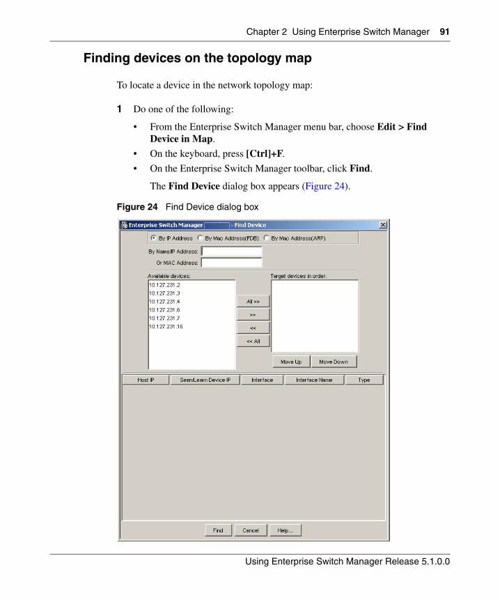
Chapter 2 Using Enterprise Switch Manager 91
Using Enterprise Switch Manager Release 5.1.0.0
Finding devices on the topology map
To locate a device in the network topology map:
1 Do one of the following:
• From the Enterprise Switch Manager menu bar, choose Edit > Find Device in Map.
• On the keyboard, press [Ctrl]+F.
• On the Enterprise Switch Manager toolbar, click Find.
The Find Device dialog box appears (Figure 24).
Figure 24 Find Device dialog box
92 Chapter 2 Using Enterprise Switch Manager
208963-G
2 Click the By IP Address radio button if find IP is required.
3 Enter the IP Address/Name in the By Name/IP Address field. If no device is selected in the target device list, ESM tries to find the device on the topology map to match the IP Address/Name and highlights the device, if found.
4 If the device is not found, select the target devices list to query the ARP table for these device(s).
5 Select By Mac Address(FDB) or By Mac Address(ARP) radio button if find MAC address is desired.
6 Make sure that a device is selected in the target device list before entering the MAC Address in the OR MAC Address field.
7 By Mac Address(FDB) will query FDB table (layer 2).
8 By Mac Address(ARP) will query ARP table (layer 3).
9 Click Find. The search result is displayed in the table, and either the devices are highlighted or an address not found message is displayed.
Selecting devices by type
Enterprise Switch Manager lets you select all of the devices on the network map that are of a certain type. You can use this feature to identify devices on the network map, and to locate devices of the available device types.
To select devices by type:
1 On the Enterprise Switch Manager menu bar, choose Edit > Select All.
A submenu appears.
2 Choose the device type that you want to select.
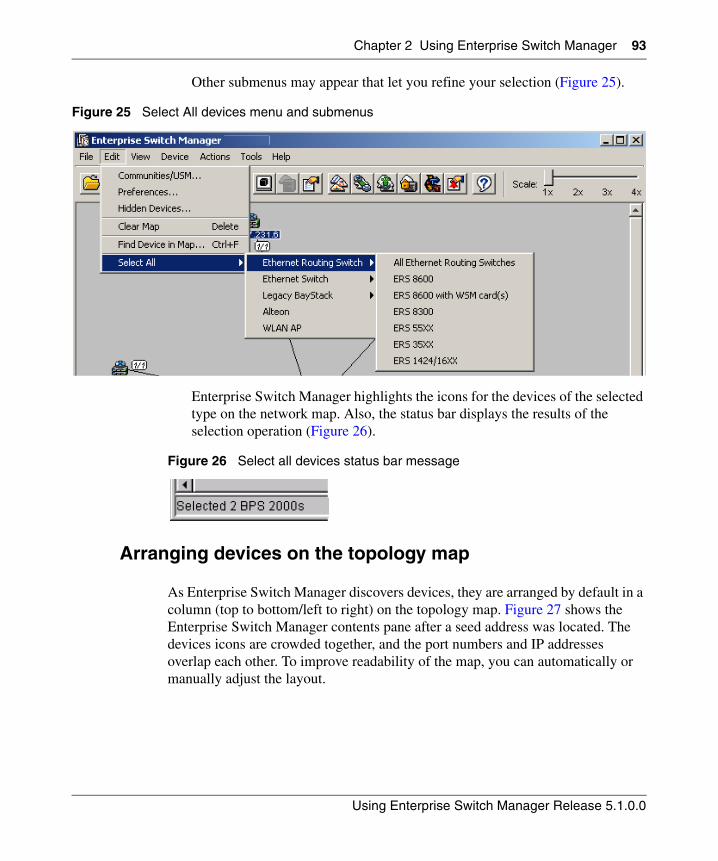
Chapter 2 Using Enterprise Switch Manager 93
Using Enterprise Switch Manager Release 5.1.0.0
Other submenus may appear that let you refine your selection (Figure 25).
Figure 25 Select All devices menu and submenus
Enterprise Switch Manager highlights the icons for the devices of the selected type on the network map. Also, the status bar displays the results of the selection operation (Figure 26).
Figure 26 Select all devices status bar message
Arranging devices on the topology map
As Enterprise Switch Manager discovers devices, they are arranged by default in a column (top to bottom/left to right) on the topology map. Figure 27 shows the Enterprise Switch Manager contents pane after a seed address was located. The devices icons are crowded together, and the port numbers and IP addresses overlap each other. To improve readability of the map, you can automatically or manually adjust the layout.
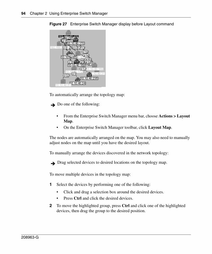
94 Chapter 2 Using Enterprise Switch Manager
208963-G
Figure 27 Enterprise Switch Manager display before Layout command
To automatically arrange the topology map:
• From the Enterprise Switch Manager menu bar, choose Actions > Layout Map.
• On the Enterprise Switch Manager toolbar, click Layout Map.
The nodes are automatically arranged on the map. You may also need to manually adjust nodes on the map until you have the desired layout.
To manually arrange the devices discovered in the network topology:
To move multiple devices in the topology map:
1 Select the devices by performing one of the following:
• Click and drag a selection box around the desired devices.
• Press Ctrl and click the desired devices.
2 To move the highlighted group, press Ctrl and click one of the highlighted devices, then drag the group to the desired position.
Do one of the following:
Drag selected devices to desired locations on the topology map.
Chapter 2 Using Enterprise Switch Manager 95
Using Enterprise Switch Manager Release 5.1.0.0
Getting help
Help in Enterprise Switch Manager is arranged by subject. A Web browser, such as Netscape Navigator or Microsoft Internet Explorer, opens to display Help files. You can use the contents frame or the Help index to locate information.
To access Help:
Do one of the following:• From the Enterprise Switch Manager menu bar, choose Help > Contents.• On the keyboard, press [F1].• On the Enterprise Switch Manager toolbar, click Help.
The Help files open in a Web browser.

96 Chapter 2 Using Enterprise Switch Manager
208963-G
97
Using Enterprise Switch Manager Release 5.1.0.0
Chapter 3Configuring Enterprise Switch Manager
This chapter describes configuration tools for Enterprise Switch Manager, and includes the following topics:
• “Discovering your network‚” next
• “Accessing devices with different SNMP communities” on page 109
Discovering your network
Enterprise Switch Manager builds its logical map of the network by querying the topology table of the seed device, using the Bay Autotopology Protocol (BTP). A seed device is a device from which you start learning about the topology of the network. After getting the information about neighbors of the seed device from the seed devices topology table, Enterprise Switch Manager queries the neighbor devices for their own topology tables. Enterprise Switch Manager then selects the appropriate icon to represent each device, determines the links between devices, and represents the device and link information on a network topology map.
Discovery continues until no more devices can be reached within the maximum number of hops specified. By default, Enterprise Switch Manager does not query neighbors more than five hops away from the seed device. You can set the number of hops, up to a maximum of 20 hops.
While the discovery process is occurring, the Discover Map button on the Enterprise Switch Manager toolbar becomes the Stop Discovery button ( ). You can stop the discovery process at any time by clicking this button.
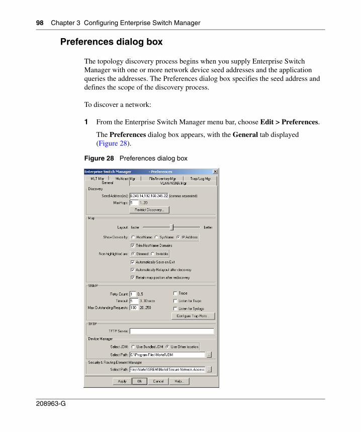
98 Chapter 3 Configuring Enterprise Switch Manager
208963-G
Preferences dialog box
The topology discovery process begins when you supply Enterprise Switch Manager with one or more network device seed addresses and the application queries the addresses. The Preferences dialog box specifies the seed address and defines the scope of the discovery process.
To discover a network:
1 From the Enterprise Switch Manager menu bar, choose Edit > Preferences.
The Preferences dialog box appears, with the General tab displayed (Figure 28).
Figure 28 Preferences dialog box
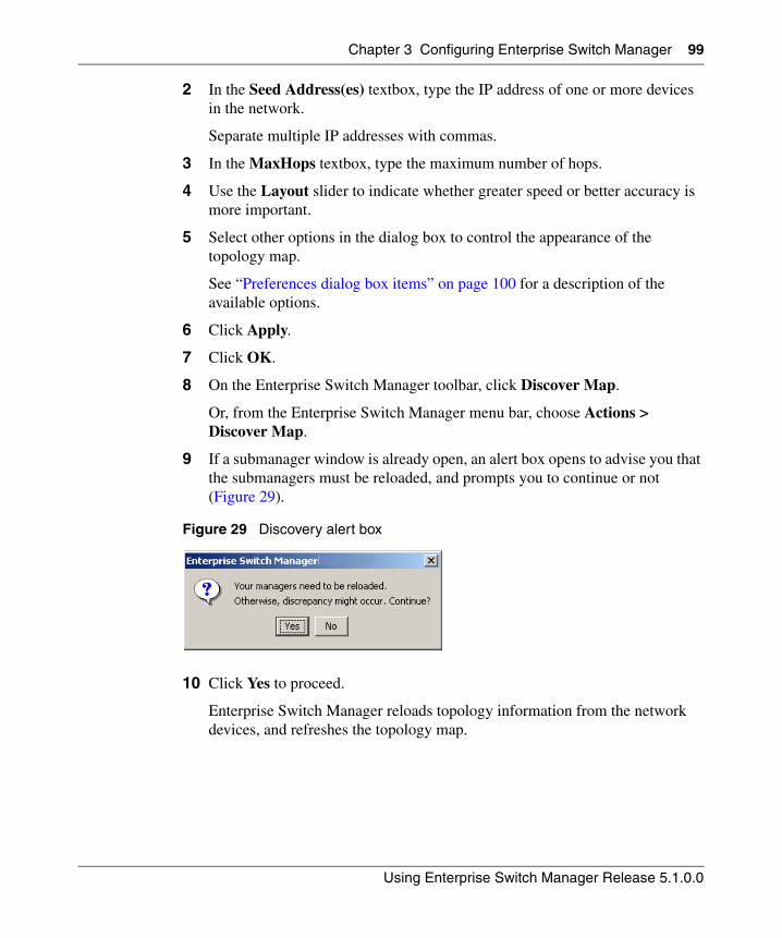
Chapter 3 Configuring Enterprise Switch Manager 99
Using Enterprise Switch Manager Release 5.1.0.0
2 In the Seed Address(es) textbox, type the IP address of one or more devices in the network.
Separate multiple IP addresses with commas.
3 In the MaxHops textbox, type the maximum number of hops.
4 Use the Layout slider to indicate whether greater speed or better accuracy is more important.
5 Select other options in the dialog box to control the appearance of the topology map.
See “Preferences dialog box items” on page 100 for a description of the available options.
6 Click Apply.
7 Click OK.
8 On the Enterprise Switch Manager toolbar, click Discover Map.
Or, from the Enterprise Switch Manager menu bar, choose Actions > Discover Map.
9 If a submanager window is already open, an alert box opens to advise you that the submanagers must be reloaded, and prompts you to continue or not (Figure 29).
Figure 29 Discovery alert box
10 Click Yes to proceed.
Enterprise Switch Manager reloads topology information from the network devices, and refreshes the topology map.
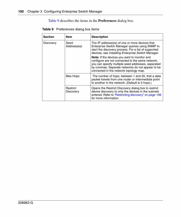
100 Chapter 3 Configuring Enterprise Switch Manager
208963-G
Table 9 describes the items in the Preferences dialog box.
Table 9 Preferences dialog box items
Section Item Description
Discovery Seed Address(es)
The IP address(es) of one or more devices that Enterprise Switch Manager queries using SNMP to start the discovery process. For a list of supported devices, see Installing Enterprise Switch Manager.Note: If the devices you want to monitor and configure are not connected to the same network, you can specify multiple seed addresses, separated by commas. Separate networks do not appear to be connected in the network topology map.
Max Hops The number of hops, between 1 and 20, that a data packet travels from one router or intermediate point to another in the network. (Default is 5 hops.)
Restrict Discovery
Opens the Restrict Discovery dialog box to restrict device discovery to only the devices in the subnets entered. Refer to “Restricting discovery” on page 106 for more information.
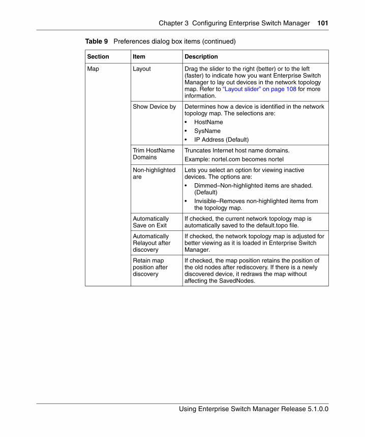
Chapter 3 Configuring Enterprise Switch Manager 101
Using Enterprise Switch Manager Release 5.1.0.0
Map Layout Drag the slider to the right (better) or to the left (faster) to indicate how you want Enterprise Switch Manager to lay out devices in the network topology map. Refer to “Layout slider” on page 108 for more information.
Show Device by Determines how a device is identified in the network topology map. The selections are:
• HostName
• SysName • IP Address (Default)
Trim HostName Domains
Truncates Internet host name domains.
Example: nortel.com becomes nortel
Non-highlighted are
Lets you select an option for viewing inactive devices. The options are:
• Dimmed–Non-highlighted items are shaded. (Default)
• Invisible–Removes non-highlighted items from the topology map.
Automatically Save on Exit
If checked, the current network topology map is automatically saved to the default.topo file.
Automatically Relayout after discovery
If checked, the network topology map is adjusted for better viewing as it is loaded in Enterprise Switch Manager.
Retain map position after discovery
If checked, the map position retains the position of the old nodes after rediscovery. If there is a newly discovered device, it redraws the map without affecting the SavedNodes.
Table 9 Preferences dialog box items (continued)
Section Item Description
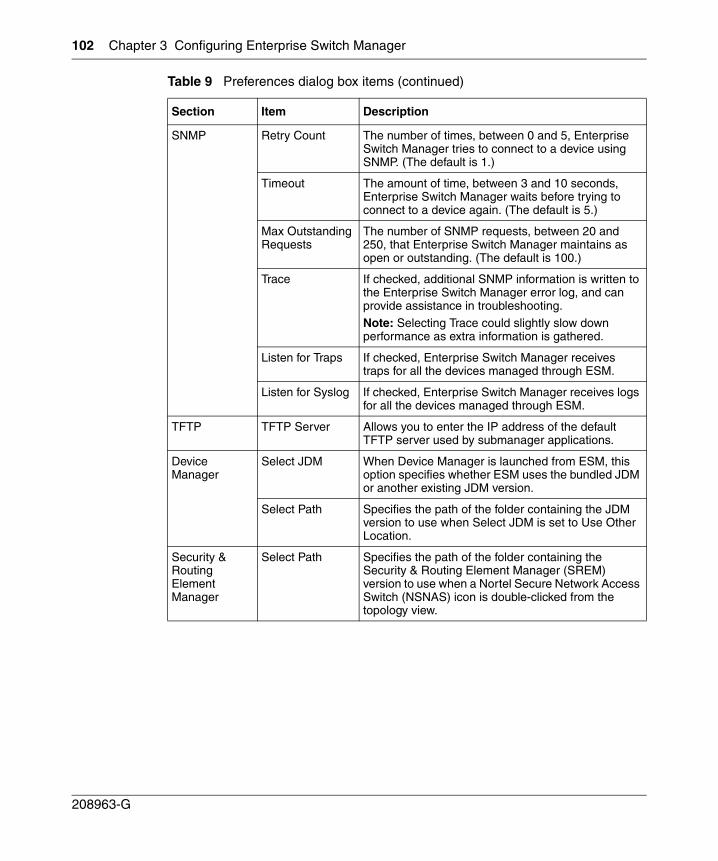
102 Chapter 3 Configuring Enterprise Switch Manager
208963-G
SNMP Retry Count The number of times, between 0 and 5, Enterprise Switch Manager tries to connect to a device using SNMP. (The default is 1.)
Timeout The amount of time, between 3 and 10 seconds, Enterprise Switch Manager waits before trying to connect to a device again. (The default is 5.)
Max Outstanding Requests
The number of SNMP requests, between 20 and 250, that Enterprise Switch Manager maintains as open or outstanding. (The default is 100.)
Trace If checked, additional SNMP information is written to the Enterprise Switch Manager error log, and can provide assistance in troubleshooting.Note: Selecting Trace could slightly slow down performance as extra information is gathered.
Listen for Traps If checked, Enterprise Switch Manager receives traps for all the devices managed through ESM.
Listen for Syslog If checked, Enterprise Switch Manager receives logs for all the devices managed through ESM.
TFTP TFTP Server Allows you to enter the IP address of the default TFTP server used by submanager applications.
Device Manager
Select JDM When Device Manager is launched from ESM, this option specifies whether ESM uses the bundled JDM or another existing JDM version.
Select Path Specifies the path of the folder containing the JDM version to use when Select JDM is set to Use Other Location.
Security & Routing Element Manager
Select Path Specifies the path of the folder containing the Security & Routing Element Manager (SREM) version to use when a Nortel Secure Network Access Switch (NSNAS) icon is double-clicked from the topology view.
Table 9 Preferences dialog box items (continued)
Section Item Description
Chapter 3 Configuring Enterprise Switch Manager 103
Using Enterprise Switch Manager Release 5.1.0.0
Submanager preferences
The Preferences dialog box also contains tabs to configure preferences for the submanagers. To access these preferences in each submanager’s menu, click Edit > Preferences.
These preferences allow you to select, for each submanager, specific devices to configure and manage, based on device family, subnet, or individual device. Therefore, the preferences allow you to configure a small group of devices within a larger network.
The submanager preferences that you set are independent of one another.
To configure submanager preferences:
1 Do one of the following:
• From the main menu, choose Edit > Preferences. Then, from the Preferences dialog box, choose the appropriate tab for the submanager you want to configure.
• From a submanager menu, choose Edit > Preferences.
The submanager Preferences dialog box opens (Figure 30 shows the Preferences dialog box for VLAN manager).
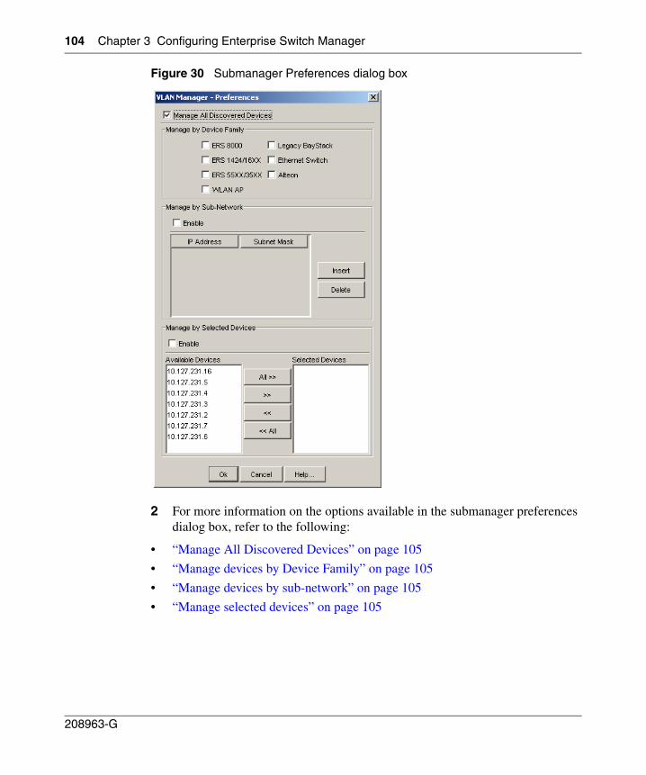
104 Chapter 3 Configuring Enterprise Switch Manager
208963-G
Figure 30 Submanager Preferences dialog box
2 For more information on the options available in the submanager preferences dialog box, refer to the following:
• “Manage All Discovered Devices” on page 105
• “Manage devices by Device Family” on page 105
• “Manage devices by sub-network” on page 105
• “Manage selected devices” on page 105
Chapter 3 Configuring Enterprise Switch Manager 105
Using Enterprise Switch Manager Release 5.1.0.0
Manage All Discovered Devices
To manage all devices, choose Manage All Discovered Devices. This option is mutually exclusive from the other options: if this option is selected, all other options are deselected, and if any other option is selected, this option is deselected.
Manage devices by Device Family
To manage devices by Device Family, choose the appropriate product families in the Manage by Device Family pane.
Manage devices by sub-network
To manage devices by sub-network, choose Enable in the Manage by Sub-Network pane and click Insert. In the IP address and Subnet Mask cells, enter the appropriate addresses for the subnets you want to manage. This action selects all the devices belonging to that subnet.
If the Enable option is selected and no IP and subnet mask are specified, then no devices are selected (managed) based on sub-network.
Manage selected devices
To manage selected devices, select Enable in the Manage by Selected Devices pane, and use the arrows to move devices from the Available Devices box to the Selected Devices box. The Available Devices box contains the list of devices discovered by each submanager.
If the Enable option is checked and no device is selected in the Selected Devices box, then this means no device is selected (managed).
Rediscovering the network map
After you have specified discovery preferences on the Preferences dialog box, you can rediscover the network at any time using those settings.
To rediscover the network:
106 Chapter 3 Configuring Enterprise Switch Manager
208963-G
1 On the Enterprise Switch Manager toolbar, click Discover Map.
Or, from the Enterprise Switch Manager menu bar, choose Actions > Discover Map.
An alert box appears to advise you that the submanagers must be reloaded, and to prompt whether you want to continue (Figure 29).
2 Click Yes to proceed.
Enterprise Switch Manager reloads topology information from the network devices, and refreshes the topology map with it.
See “Enterprise Switch Manager menu bar commands and toolbar buttons” on page 68 for more information.
Stopping the discovery process
Once you have started a discovery process, you can stop it at any time. Stopping the process discards the results of the incomplete discovery.
To stop a discovery process:
See “Enterprise Switch Manager menu bar commands and toolbar buttons” on page 68 for more information.
Restricting discovery
You can restrict the discovery process to specific devices or specific subnets. Use the Restrict Discovery dialog box to enter IP addresses or subnets that are available for discovery by Enterprise Switch Manager. Only devices within the listed IP addressees or subnets are displayed in the Enterprise Switch Manager contents pane.
To restrict discovery to certain subnets or devices:
1 From the Enterprise Switch Manager menu bar, choose Edit > Preferences.
2 Click Restrict Discovery.
Click Stop on the Enterprise Switch Manager toolbar.
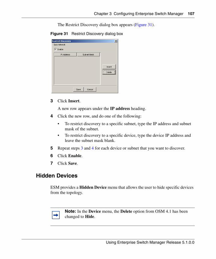
Chapter 3 Configuring Enterprise Switch Manager 107
Using Enterprise Switch Manager Release 5.1.0.0
The Restrict Discovery dialog box appears (Figure 31).
Figure 31 Restrict Discovery dialog box
3 Click Insert.
A new row appears under the IP address heading.
4 Click the new row, and do one of the following:
• To restrict discovery to a specific subnet, type the IP address and subnet mask of the subnet.
• To restrict discovery to a specific device, type the device IP address and leave the subnet mask blank.
5 Repeat steps 3 and 4 for each device or subnet that you want to discover.
6 Click Enable.
7 Click Save.
Hidden Devices
ESM provides a Hidden Device menu that allows the user to hide specific devices from the topology.
Note: In the Device menu, the Delete option from OSM 4.1 has been changed to Hide.
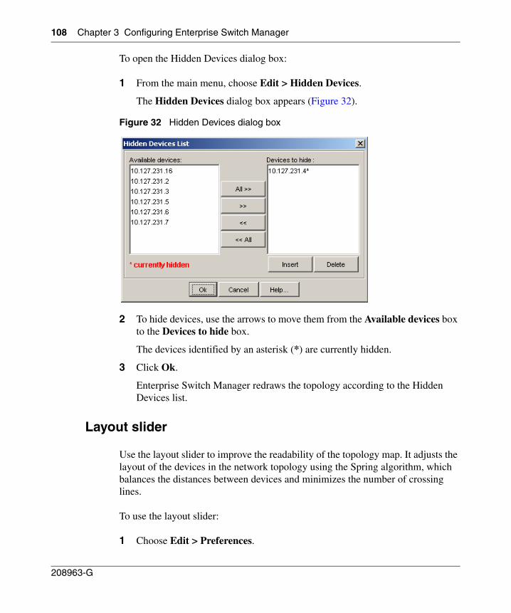
108 Chapter 3 Configuring Enterprise Switch Manager
208963-G
To open the Hidden Devices dialog box:
1 From the main menu, choose Edit > Hidden Devices.
The Hidden Devices dialog box appears (Figure 32).
Figure 32 Hidden Devices dialog box
2 To hide devices, use the arrows to move them from the Available devices box to the Devices to hide box.
The devices identified by an asterisk (*) are currently hidden.
3 Click Ok.
Enterprise Switch Manager redraws the topology according to the Hidden Devices list.
Layout slider
Use the layout slider to improve the readability of the topology map. It adjusts the layout of the devices in the network topology using the Spring algorithm, which balances the distances between devices and minimizes the number of crossing lines.
To use the layout slider:
1 Choose Edit > Preferences.
Chapter 3 Configuring Enterprise Switch Manager 109
Using Enterprise Switch Manager Release 5.1.0.0
The Preferences dialog box appears (Figure 28 on page 98).
2 In the Map area, slide the ruler between faster and better to adjust the layout display.
Enterprise Switch Manager retains the locations of nodes until you rediscover the network.
3 Click Apply.
4 To rediscover the network topology map with a new layout, do one of the following:
• From the Enterprise Switch Manager menu bar, choose Actions > Discover Map.
• On the Enterprise Switch Manager toolbar, click Discover Network.
Accessing devices with different SNMP communities
SNMP community passwords can provide a level of protection by limiting access to devices. In Enterprise Switch Manager, you can access devices or subnets with different communities by adding the correct SNMP passwords in the Communities/Password dialog box. ESM supports all SNMP versions including v1/v2c and v3. SNMPv3 allows network administrators to securely configure and manage their network devices. SNMP devices, which include those devices supported by Enterprise Switch Manager, typically have two passwords or communities for read and write operations on that device. The default passwords are public (open access) and private (restrictive access).
You cannot access devices that are configured with different SNMP community passwords unless you know their passwords and enter those passwords into the Enterprise Switch Manager using the Communities/Password dialog box.
To assign a different SNMP community password to a group or single device:
1 From the Enterprise Switch Manager menu bar, choose Edit > Communities/Password.
The Communities/Password dialog box appears, with the SNMP tab displayed (Figure 33).
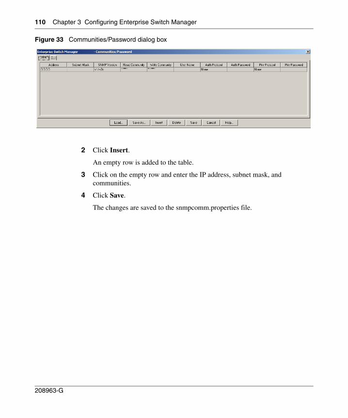
110 Chapter 3 Configuring Enterprise Switch Manager
208963-G
Figure 33 Communities/Password dialog box
2 Click Insert.
An empty row is added to the table.
3 Click on the empty row and enter the IP address, subnet mask, and communities.
4 Click Save.
The changes are saved to the snmpcomm.properties file.
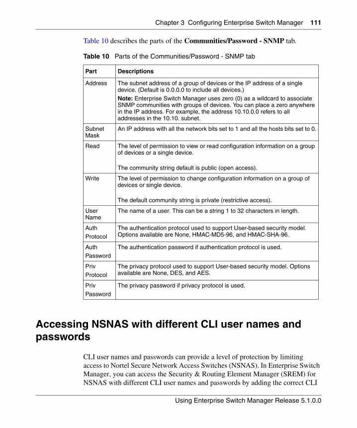
Chapter 3 Configuring Enterprise Switch Manager 111
Using Enterprise Switch Manager Release 5.1.0.0
Table 10 describes the parts of the Communities/Password - SNMP tab.
Accessing NSNAS with different CLI user names and passwords
CLI user names and passwords can provide a level of protection by limiting access to Nortel Secure Network Access Switches (NSNAS). In Enterprise Switch Manager, you can access the Security & Routing Element Manager (SREM) for NSNAS with different CLI user names and passwords by adding the correct CLI
Table 10 Parts of the Communities/Password - SNMP tab
Part Descriptions
Address The subnet address of a group of devices or the IP address of a single device. (Default is 0.0.0.0 to include all devices.)
Note: Enterprise Switch Manager uses zero (0) as a wildcard to associate SNMP communities with groups of devices. You can place a zero anywhere in the IP address. For example, the address 10.10.0.0 refers to all addresses in the 10.10. subnet.
Subnet Mask
An IP address with all the network bits set to 1 and all the hosts bits set to 0.
Read The level of permission to view or read configuration information on a group of devices or a single device.
The community string default is public (open access).
Write The level of permission to change configuration information on a group of devices or single device.
The default community string is private (restrictive access).
User Name
The name of a user. This can be a string 1 to 32 characters in length.
Auth
Protocol
The authentication protocol used to support User-based security model. Options available are None, HMAC-MD5-96, and HMAC-SHA-96.
AuthPassword
The authentication password if authentication protocol is used.
Priv
Protocol
The privacy protocol used to support User-based security model. Options available are None, DES, and AES.
Priv
Password
The privacy password if privacy protocol is used.
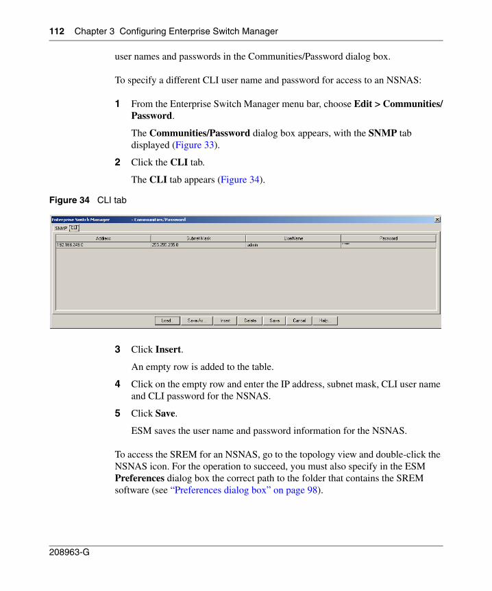
112 Chapter 3 Configuring Enterprise Switch Manager
208963-G
user names and passwords in the Communities/Password dialog box.
To specify a different CLI user name and password for access to an NSNAS:
1 From the Enterprise Switch Manager menu bar, choose Edit > Communities/Password.
The Communities/Password dialog box appears, with the SNMP tab displayed (Figure 33).
2 Click the CLI tab.
The CLI tab appears (Figure 34).
Figure 34 CLI tab
3 Click Insert.
An empty row is added to the table.
4 Click on the empty row and enter the IP address, subnet mask, CLI user name and CLI password for the NSNAS.
5 Click Save.
ESM saves the user name and password information for the NSNAS.
To access the SREM for an NSNAS, go to the topology view and double-click the NSNAS icon. For the operation to succeed, you must also specify in the ESM Preferences dialog box the correct path to the folder that contains the SREM software (see “Preferences dialog box” on page 98).
113
Using Enterprise Switch Manager Release 5.1.0.0
Chapter 4Using VLAN Manager
VLAN Manager manages Spanning Tree Groups (STG), Rapid Spanning Tree Protocol (RSTP), Multiple Spanning Tree Protocol (MSTP), and VLANs across devices in a network. Enterprise Switch Manager is the starting point for VLAN Manager, and Enterprise Switch Manager must be open to use VLAN Manager.
This chapter describes using VLAN Manager to manage VLANs on Nortel Ethernet Switches and Nortel Ethernet Routing Switches. It includes the following information:
• “What is VLAN Manager?‚” next
• “Starting VLAN Manager” on page 117
• “VLAN Manager window” on page 117
• “Working with VLAN Manager” on page 125
• “Managing Spanning Tree Groups (STGs)” on page 140
• “Managing VLANs” on page 145
• “Highlighting STGs and VLANs on the topology map” on page 161
• “Managing Rapid Spanning Tree Protocol (RSTP)” on page 166
• “Managing Multiple Spanning Tree Protocol” on page 167
What is VLAN Manager?
VLAN Manager enables you to manage VLAN and STG configurations across a single device or multiple devices. It supports the rcVlan and rcStg MIBs. The following sections describe VLAN Manager conventions and features:
• “VLAN” on page 114
• “NSNA” on page 114
114 Chapter 4 Using VLAN Manager
208963-G
• “Spanning Tree Protocol” on page 115
• “VLAN Manager features” on page 116
VLAN
VLAN is a collection of ports on one or more switches that defines a broadcast domain. You can assign ports to a VLAN or you can create a policy VLAN, which determines the port’s membership in the VLAN based on the traffic entering that port. For example, in an IP subnet-based VLAN, the port belongs to the VLAN only if the traffic passing through the port is on the specified IP subnet.
You control path redundancy for VLANs by implementing the Spanning Tree Protocol (STP).
NSNA
With ESM 5.1, you can also use VLAN Manager to configure VLAN properties for networks and devices that support the Nortel Secure Network Access (NSNA) solution. The NSNA solution protects an enterprise network by providing a predefined level of clientless access to users, based on credentials and security features.
For more information about configuring NSNA with ESM, refer to “Configuring VLANs for NSNA” on page 138 and Chapter 10, “Using NSNA Manager,” on page 513.
For detailed information about the NSNA solution and deployment scenarios, refer to Nortel Secure Network Access Solution Guide (320817-A). For information about configuring the NSNAS, refer to Nortel Secure Network Access Switch 4050 User Guide (320818-A). For switch-specific configuration information, refer to your switch documentation.
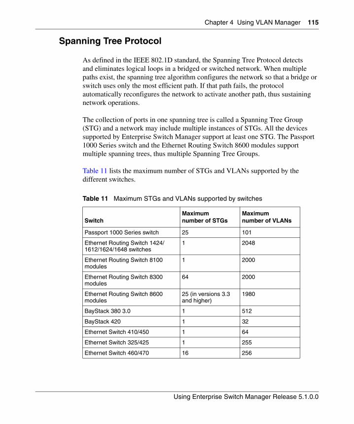
Chapter 4 Using VLAN Manager 115
Using Enterprise Switch Manager Release 5.1.0.0
Spanning Tree Protocol
As defined in the IEEE 802.1D standard, the Spanning Tree Protocol detects and eliminates logical loops in a bridged or switched network. When multiple paths exist, the spanning tree algorithm configures the network so that a bridge or switch uses only the most efficient path. If that path fails, the protocol automatically reconfigures the network to activate another path, thus sustaining network operations.
The collection of ports in one spanning tree is called a Spanning Tree Group (STG) and a network may include multiple instances of STGs. All the devices supported by Enterprise Switch Manager support at least one STG. The Passport 1000 Series switch and the Ethernet Routing Switch 8600 modules support multiple spanning trees, thus multiple Spanning Tree Groups.
Table 11 lists the maximum number of STGs and VLANs supported by the different switches.
Table 11 Maximum STGs and VLANs supported by switches
SwitchMaximumnumber of STGs
Maximumnumber of VLANs
Passport 1000 Series switch 25 101
Ethernet Routing Switch 1424/1612/1624/1648 switches
1 2048
Ethernet Routing Switch 8100 modules
1 2000
Ethernet Routing Switch 8300 modules
64 2000
Ethernet Routing Switch 8600 modules
25 (in versions 3.3 and higher)
1980
BayStack 380 3.0 1 512
BayStack 420 1 32
Ethernet Switch 410/450 1 64
Ethernet Switch 325/425 1 255
Ethernet Switch 460/470 16 256
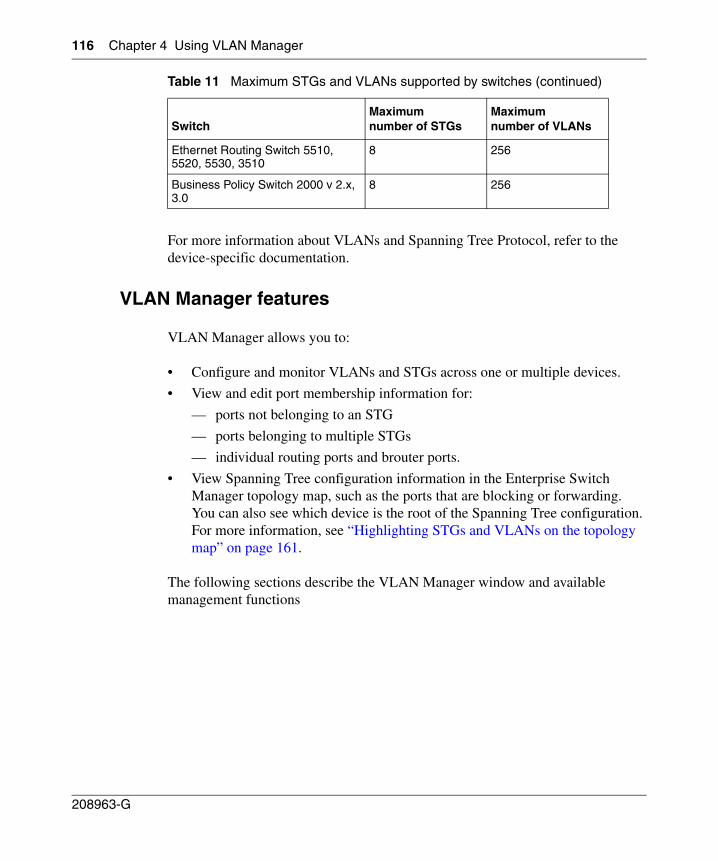
116 Chapter 4 Using VLAN Manager
208963-G
For more information about VLANs and Spanning Tree Protocol, refer to the device-specific documentation.
VLAN Manager features
VLAN Manager allows you to:
• Configure and monitor VLANs and STGs across one or multiple devices.
• View and edit port membership information for:
— ports not belonging to an STG
— ports belonging to multiple STGs
— individual routing ports and brouter ports.
• View Spanning Tree configuration information in the Enterprise Switch Manager topology map, such as the ports that are blocking or forwarding. You can also see which device is the root of the Spanning Tree configuration. For more information, see “Highlighting STGs and VLANs on the topology map” on page 161.
The following sections describe the VLAN Manager window and available management functions
Ethernet Routing Switch 5510, 5520, 5530, 3510
8 256
Business Policy Switch 2000 v 2.x, 3.0
8 256
Table 11 Maximum STGs and VLANs supported by switches (continued)
SwitchMaximumnumber of STGs
Maximumnumber of VLANs
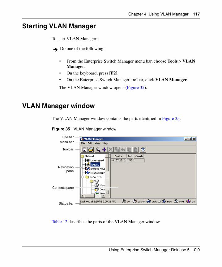
Chapter 4 Using VLAN Manager 117
Using Enterprise Switch Manager Release 5.1.0.0
Starting VLAN Manager
To start VLAN Manager:
• From the Enterprise Switch Manager menu bar, choose Tools > VLAN Manager.
• On the keyboard, press [F2].
• On the Enterprise Switch Manager toolbar, click VLAN Manager.
The VLAN Manager window opens (Figure 35).
VLAN Manager window
The VLAN Manager window contains the parts identified in Figure 35.
Figure 35 VLAN Manager window
Table 12 describes the parts of the VLAN Manager window.
Do one of the following:
Title bar
Menu bar
Toolbar
Navigation
Status bar
Contents pane
pane
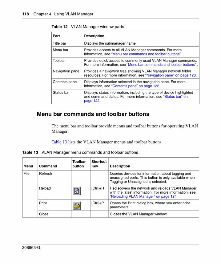
118 Chapter 4 Using VLAN Manager
208963-G
Menu bar commands and toolbar buttons
The menu bar and toolbar provide menus and toolbar buttons for operating VLAN Manager.
Table 13 lists the VLAN Manager menus and toolbar buttons.
Table 12 VLAN Manager window parts
Part Description
Title bar Displays the submanager name.
Menu bar Provides access to all VLAN Manager commands. For more information, see “Menu bar commands and toolbar buttons” .
Toolbar Provides quick access to commonly used VLAN Manager commands. For more information, see “Menu bar commands and toolbar buttons” .
Navigation pane Provides a navigation tree showing VLAN Manager network folder resources. For more information, see “Navigation pane” on page 120.
Contents pane Displays information selected in the navigation pane. For more information, see “Contents pane” on page 122.
Status bar Displays status information, including the type of device highlighted and command status. For more information, see “Status bar” on page 122.
Table 13 VLAN Manager menu commands and toolbar buttons
Menu CommandToolbar button
Shortcut Key Description
File Refresh Queries devices for information about tagging and unassigned ports. This button is only available when Tagging or Unassigned is selected.
Reload [Ctrl]+R Rediscovers the network and reloads VLAN Manager with the latest information. For more information, see “Reloading VLAN Manager” on page 124.
Print [Ctrl]+P Opens the Print dialog box, where you enter print parameters.
Close Closes the VLAN Manager window.
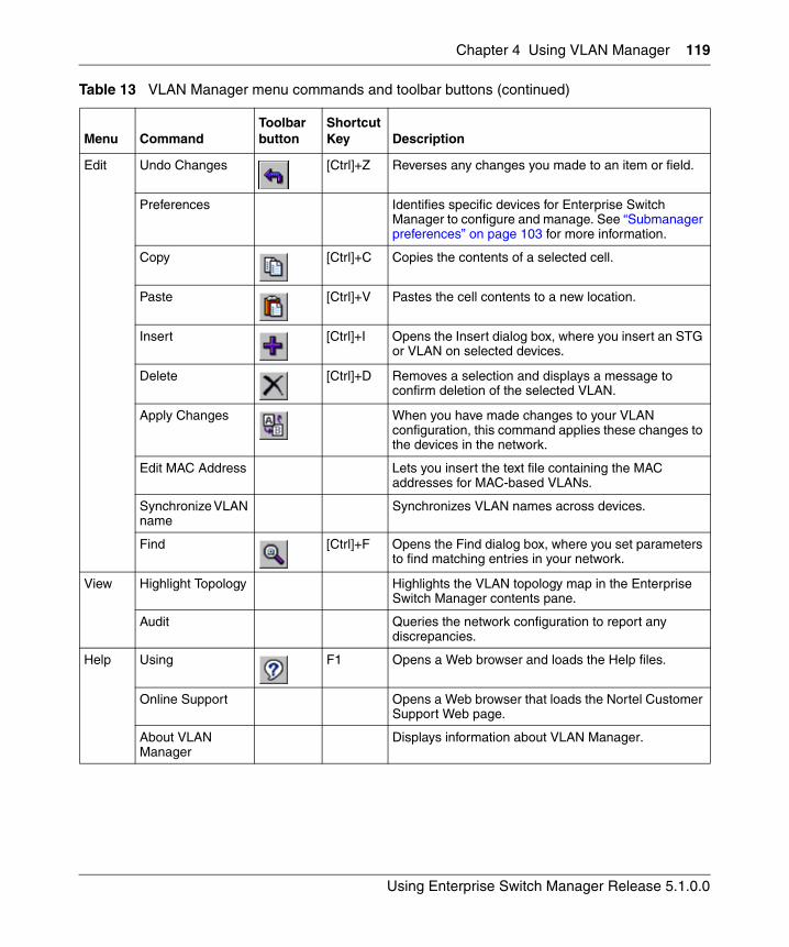
Chapter 4 Using VLAN Manager 119
Using Enterprise Switch Manager Release 5.1.0.0
Edit Undo Changes [Ctrl]+Z Reverses any changes you made to an item or field.
Preferences Identifies specific devices for Enterprise Switch Manager to configure and manage. See “Submanager preferences” on page 103 for more information.
Copy [Ctrl]+C Copies the contents of a selected cell.
Paste [Ctrl]+V Pastes the cell contents to a new location.
Insert [Ctrl]+I Opens the Insert dialog box, where you insert an STG or VLAN on selected devices.
Delete [Ctrl]+D Removes a selection and displays a message to confirm deletion of the selected VLAN.
Apply Changes When you have made changes to your VLAN configuration, this command applies these changes to the devices in the network.
Edit MAC Address Lets you insert the text file containing the MAC addresses for MAC-based VLANs.
Synchronize VLAN name
Synchronizes VLAN names across devices.
Find [Ctrl]+F Opens the Find dialog box, where you set parameters to find matching entries in your network.
View Highlight Topology Highlights the VLAN topology map in the Enterprise Switch Manager contents pane.
Audit Queries the network configuration to report any discrepancies.
Help Using F1 Opens a Web browser and loads the Help files.
Online Support Opens a Web browser that loads the Nortel Customer Support Web page.
About VLAN Manager
Displays information about VLAN Manager.
Table 13 VLAN Manager menu commands and toolbar buttons (continued)
Menu CommandToolbar button
Shortcut Key Description
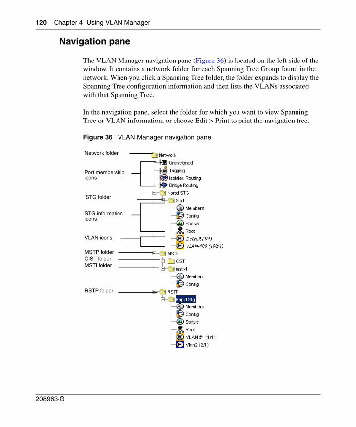
120 Chapter 4 Using VLAN Manager
208963-G
Navigation pane
The VLAN Manager navigation pane (Figure 36) is located on the left side of the window. It contains a network folder for each Spanning Tree Group found in the network. When you click a Spanning Tree folder, the folder expands to display the Spanning Tree configuration information and then lists the VLANs associated with that Spanning Tree.
In the navigation pane, select the folder for which you want to view Spanning Tree or VLAN information, or choose Edit > Print to print the navigation tree.
Figure 36 VLAN Manager navigation pane
Network folder
Port membership icons
STG folder
VLAN icons
MSTP folder CIST folderMSTI folder
RSTP folder
STG information icons
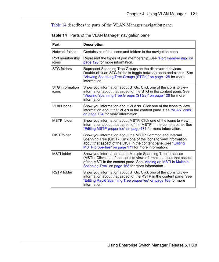
Chapter 4 Using VLAN Manager 121
Using Enterprise Switch Manager Release 5.1.0.0
Table 14 describes the parts of the VLAN Manager navigation pane.
Table 14 Parts of the VLAN Manager navigation pane
Part Description
Network folder Contains all of the icons and folders in the navigation pane
Port membership icons
Represent the types of port membership. See “Port membership” on page 126 for more information.
STG folders Represent Spanning Tree Groups on the discovered devices. Double-click an STG folder to toggle between open and closed. See “Viewing Spanning Tree Groups (STGs)” on page 128 for more information.
STG information icons
Show you information about STGs. Click one of the icons to view information about that aspect of the STG in the content pane. See “Viewing Spanning Tree Groups (STGs)” on page 128 for more information.
VLAN icons Show you information about VLANs. Click one of the icons to view information about that VLAN in the content pane. See “VLAN icons” on page 134 for more information.
MSTP folder Show you information about MSTP. Click one of the icons to view information about that aspect of the MSTP in the content pane. See “Editing MSTP properties” on page 171 for more information.
CIST folder Show you information about the MSTP Common and Internal Spanning Tree (CIST). Click one of the icons to view information about that aspect of the CIST in the content pane. See “Editing MSTP properties” on page 171 for more information.
MSTI folder Show you information about Multiple Spanning Tree instances (MSTI). Click one of the icons to view information about that aspect of the MSTI in the content pane. See “Adding an MSTI in Multiple Spanning Tree” on page 168 for more information.
RSTP folder Show you information about STGs. Click one of the icons to view information about that aspect of the RSTP in the content pane. See “Editing Rapid Spanning Tree properties” on page 166 for more information.
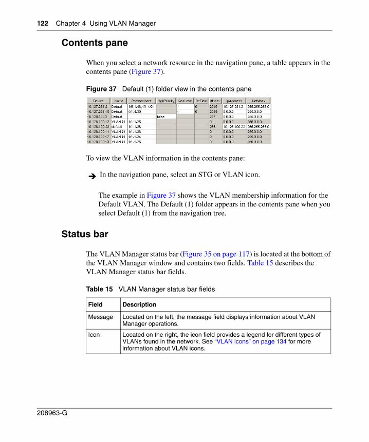
122 Chapter 4 Using VLAN Manager
208963-G
Contents pane
When you select a network resource in the navigation pane, a table appears in the contents pane (Figure 37).
Figure 37 Default (1) folder view in the contents pane
To view the VLAN information in the contents pane:
The example in Figure 37 shows the VLAN membership information for the Default VLAN. The Default (1) folder appears in the contents pane when you select Default (1) from the navigation tree.
Status bar
The VLAN Manager status bar (Figure 35 on page 117) is located at the bottom of the VLAN Manager window and contains two fields. Table 15 describes the VLAN Manager status bar fields.
In the navigation pane, select an STG or VLAN icon.
Table 15 VLAN Manager status bar fields
Field Description
Message Located on the left, the message field displays information about VLAN Manager operations.
Icon Located on the right, the icon field provides a legend for different types of VLANs found in the network. See “VLAN icons” on page 134 for more information about VLAN icons.
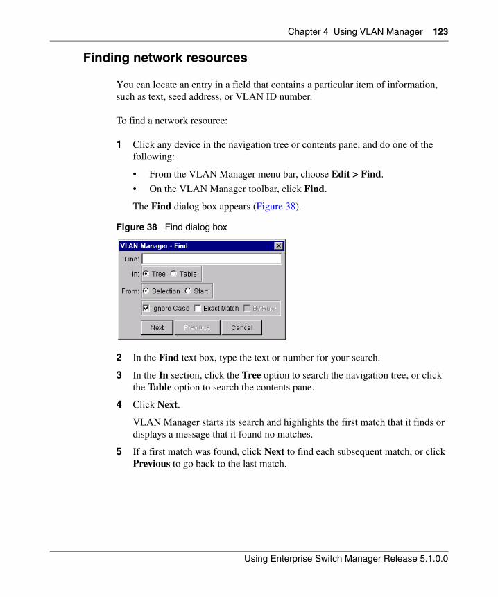
Chapter 4 Using VLAN Manager 123
Using Enterprise Switch Manager Release 5.1.0.0
Finding network resources
You can locate an entry in a field that contains a particular item of information, such as text, seed address, or VLAN ID number.
To find a network resource:
1 Click any device in the navigation tree or contents pane, and do one of the following:
• From the VLAN Manager menu bar, choose Edit > Find.
• On the VLAN Manager toolbar, click Find.
The Find dialog box appears (Figure 38).
Figure 38 Find dialog box
2 In the Find text box, type the text or number for your search.
3 In the In section, click the Tree option to search the navigation tree, or click the Table option to search the contents pane.
4 Click Next.
VLAN Manager starts its search and highlights the first match that it finds or displays a message that it found no matches.
5 If a first match was found, click Next to find each subsequent match, or click Previous to go back to the last match.
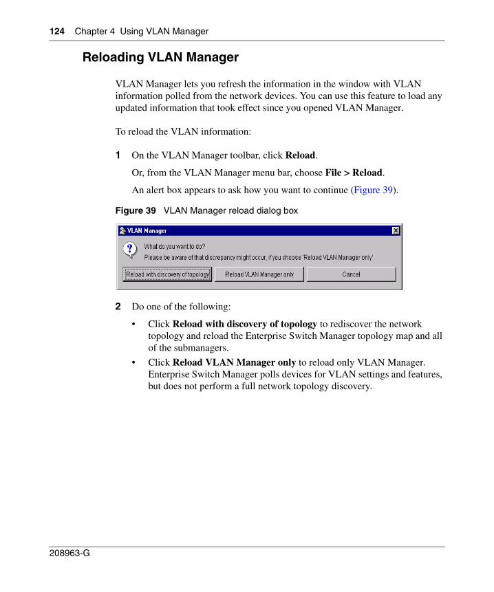
124 Chapter 4 Using VLAN Manager
208963-G
Reloading VLAN Manager
VLAN Manager lets you refresh the information in the window with VLAN information polled from the network devices. You can use this feature to load any updated information that took effect since you opened VLAN Manager.
To reload the VLAN information:
1 On the VLAN Manager toolbar, click Reload.
Or, from the VLAN Manager menu bar, choose File > Reload.
An alert box appears to ask how you want to continue (Figure 39).
Figure 39 VLAN Manager reload dialog box
2 Do one of the following:
• Click Reload with discovery of topology to rediscover the network topology and reload the Enterprise Switch Manager topology map and all of the submanagers.
• Click Reload VLAN Manager only to reload only VLAN Manager. Enterprise Switch Manager polls devices for VLAN settings and features, but does not perform a full network topology discovery.
Chapter 4 Using VLAN Manager 125
Using Enterprise Switch Manager Release 5.1.0.0
• Click Cancel to abandon the reload operation.
Enterprise Switch Manager reloads topology information from the network devices, and refreshes the VLAN Manager window with it.
Working with VLAN Manager
Using VLAN Manager, you can monitor, configure, and troubleshoot STGs and VLANs found in the network.
This section includes the information about the following topics:
• “Port membership‚” next (ports not belonging to STGs or ports belonging to multiple STGs)
• “Viewing Spanning Tree Groups (STGs)” on page 128
• “Viewing the Default VLAN” on page 136
• “Viewing VLAN ports” on page 137
• “Configuring VLANs for NSNA” on page 138
Note: Reloading just VLAN Manager takes less time than reloading with topology discovery. However, if there are any changes in network topology, it might result in discrepancies between the information in VLAN Manager and the information on the topology map. Such discrepancies might cause incorrect operation when you perform operations (such as highlighting the network map) that involve interactions between the submanagers and the topology map.
If you observe such incorrect operation, reload the network map. For more information, see “Rediscovering the network map” on page 105.
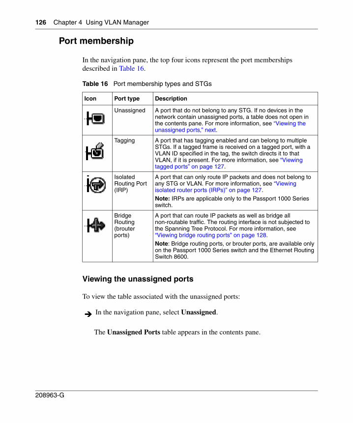
126 Chapter 4 Using VLAN Manager
208963-G
Port membership
In the navigation pane, the top four icons represent the port memberships described in Table 16.
Viewing the unassigned ports
To view the table associated with the unassigned ports:
The Unassigned Ports table appears in the contents pane.
Table 16 Port membership types and STGs
Icon Port type Description
Unassigned A port that do not belong to any STG. If no devices in the network contain unassigned ports, a table does not open in the contents pane. For more information, see “Viewing the unassigned ports‚” next.
Tagging A port that has tagging enabled and can belong to multiple STGs. If a tagged frame is received on a tagged port, with a VLAN ID specified in the tag, the switch directs it to that VLAN, if it is present. For more information, see “Viewing tagged ports” on page 127.
Isolated Routing Port (IRP)
A port that can only route IP packets and does not belong to any STG or VLAN. For more information, see “Viewing isolated router ports (IRPs)” on page 127.
Note: IRPs are applicable only to the Passport 1000 Series switch.
Bridge Routing (brouter ports)
A port that can route IP packets as well as bridge all non-routable traffic. The routing interface is not subjected to the Spanning Tree Protocol. For more information, see “Viewing bridge routing ports” on page 128.
Note: Bridge routing ports, or brouter ports, are available only on the Passport 1000 Series switch and the Ethernet Routing Switch 8600.
In the navigation pane, select Unassigned.
Chapter 4 Using VLAN Manager 127
Using Enterprise Switch Manager Release 5.1.0.0
Table 17 describes the Unassigned Ports table fields.
Viewing tagged ports
To view the devices and ports associated with tagged ports:
The Tagging Ports table appears in the contents pane.
Table 18 describes the fields in the Tagging Ports table.
Viewing isolated router ports (IRPs)
To view IRPs on Passport 1000 Series switch:
The Isolated Routing Ports table appears in the contents pane.
Table 17 Unassigned Ports table fields
Field Description
Device IP address, system name, or host name of the device.
Ports Ports not currently assigned to an STG.
In the navigation pane, select Tagging.
Table 18 Tagging Ports table fields
Field Description
Device IP address, system name, or host name of the device.
Port Ports on which tagging is enabled.
VlanIds VLAN ID(s) of which the port is a member.
In the navigation pane, select Isolated Routing.
128 Chapter 4 Using VLAN Manager
208963-G
Table 19 describes the fields in the Isolated Routing Ports table.
Viewing bridge routing ports
To view bridge routing (brouter) ports on Passport 1000 Series switches and Ethernet Routing Switch 8000 Series:
The Bridge Routing Ports table appears in the contents pane.
Table 20 describes the fields in the Bridge Routing Ports table.
Viewing Spanning Tree Groups (STGs)
All devices supported by Enterprise Switch Manager support the IEEE 802.1D Spanning Tree Protocol and at least one instance of a Spanning Tree Group. Refer to “Spanning Tree Protocol” on page 115 for the maximum STGs supported by each switch.
Table 19 Isolated Routing Ports table fields
Field Descriptions
Device IP address, system name, or host name of the device.
Ports Ports that route only IP packets.
In the navigation pane, select Bridge Routing.
Table 20 Bridge Routing Ports table fields
Field Descriptions
Device IP address, system name, or host name of the device.
Ports Port numbers of the port on which frames are received.
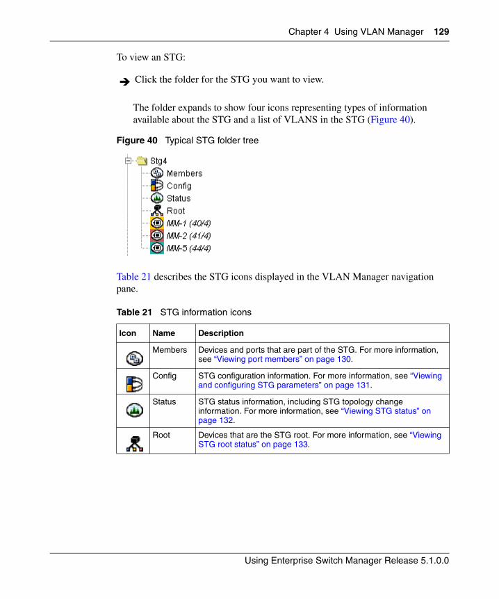
Chapter 4 Using VLAN Manager 129
Using Enterprise Switch Manager Release 5.1.0.0
To view an STG:
The folder expands to show four icons representing types of information available about the STG and a list of VLANS in the STG (Figure 40).
Figure 40 Typical STG folder tree
Table 21 describes the STG icons displayed in the VLAN Manager navigation pane.
Click the folder for the STG you want to view.
Table 21 STG information icons
Icon Name Description
Members Devices and ports that are part of the STG. For more information, see “Viewing port members” on page 130.
Config STG configuration information. For more information, see “Viewing and configuring STG parameters” on page 131.
Status STG status information, including STG topology change information. For more information, see “Viewing STG status” on page 132.
Root Devices that are the STG root. For more information, see “Viewing STG root status” on page 133.
130 Chapter 4 Using VLAN Manager
208963-G
Viewing port members
Use the Port Members table to view the ports that are members of the specified STG. To open the Port Members table:
The Port Members table appears in the contents pane.
Table 22 describes the fields in the Port Members table.
Adding port members
To add ports to an STG:
1 In the Port Members table, select a device in the list.
2 Double-click in the PortMembers cell for the device to which you want to add port membership.
The PortMembers dialog box appears (Figure 41).
In the navigation pane, open an STG and select Members.
Table 22 Port Members table fields
Field Description
Device IP address, system name, or host name of the device.
PortMembers Ports on the device that are members of the STG.
Note: On Ethernet Switch, Ethernet Routing Switch 55xx/35xx and Legacy BayStack devices, port members cannot be added from the STG Port Members table. This table can only display ports that are members of the VLANs belonging to the STG. With these switches, you must add or remove the port members using the VLAN tables.
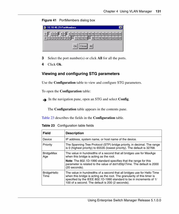
Chapter 4 Using VLAN Manager 131
Using Enterprise Switch Manager Release 5.1.0.0
Figure 41 PortMembers dialog box
3 Select the port number(s) or click All for all the ports.
4 Click Ok.
Viewing and configuring STG parameters
Use the Configuration table to view and configure STG parameters.
To open the Configuration table:
The Configuration table appears in the contents pane.
Table 23 describes the fields in the Configuration table.
In the navigation pane, open an STG and select Config.
Table 23 Configuration table fields
Field Description
Device IP address, system name, or host name of the device.
Priority The Spanning Tree Protocol (STP) bridge priority, in decimal. The range is 0 (highest priority) to 65535 (lowest priority). The default is 32768.
BridgeMaxAge
The value in hundredths of a second that all bridges use for MaxAge when this bridge is acting as the root. Note: The 802.1D-1990 standard specifies that the range for this parameter is related to the value of dot1dStp\Time. The default is 2000 (20 seconds).
BridgeHelloTime
The value in hundredths of a second that all bridges use for Hello Time when this bridge is acting as the root. The granularity of this timer is specified by the IEEE 802.1D-1990 standard to be in increments of 1/100 of a second. The default is 200 (2 seconds).
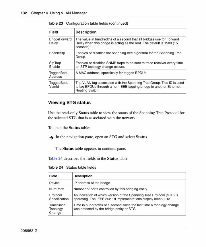
132 Chapter 4 Using VLAN Manager
208963-G
Viewing STG status
Use the read-only Status table to view the status of the Spanning Tree Protocol for the selected STG that is associated with the network.
To open the Status table:
The Status table appears in contents pane.
Table 24 describes the fields in the Status table.
BridgeForwardDelay
The value in hundredths of a second that all bridges use for Forward Delay when this bridge is acting as the root. The default is 1500 (15 seconds).
EnableStp Enables or disables the spanning tree algorithm for the Spanning Tree Group.
StpTrapEnable
Enables or disables SNMP traps to be sent to trace receiver every time an STP topology change occurs.
TaggedBpduAddress
A MAC address; specifically for tagged BPDUs.
TaggedBpduVlanId
The VLAN tag associated with the Spanning Tree Group. This ID is used to tag BPDUs through a non-IEEE tagging bridge to another Ethernet Routing Switch.
In the navigation pane, open an STG and select Status.
Table 24 Status table fields
Field Description
Device IP address of the bridge.
NumPorts Number of ports controlled by this bridging entity.
ProtocolSpecification
An indication of which version of the Spanning Tree Protocol (STP) is operating. The IEEE 802.1d implementations display ieee8021d.
TimeSinceTopologyChange
Time in hundredths of a second since the last time a topology change was detected by the bridge entity or STG.
Table 23 Configuration table fields (continued)
Field Description
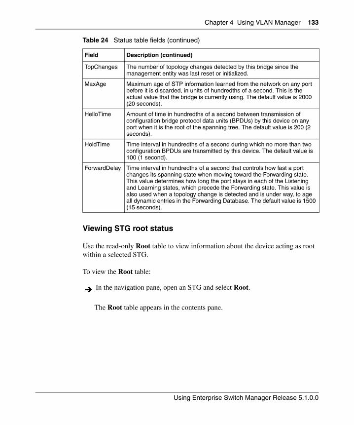
Chapter 4 Using VLAN Manager 133
Using Enterprise Switch Manager Release 5.1.0.0
Viewing STG root status
Use the read-only Root table to view information about the device acting as root within a selected STG.
To view the Root table:
The Root table appears in the contents pane.
TopChanges The number of topology changes detected by this bridge since the management entity was last reset or initialized.
MaxAge Maximum age of STP information learned from the network on any port before it is discarded, in units of hundredths of a second. This is the actual value that the bridge is currently using. The default value is 2000 (20 seconds).
HelloTime Amount of time in hundredths of a second between transmission of configuration bridge protocol data units (BPDUs) by this device on any port when it is the root of the spanning tree. The default value is 200 (2 seconds).
HoldTime Time interval in hundredths of a second during which no more than two configuration BPDUs are transmitted by this device. The default value is 100 (1 second).
ForwardDelay Time interval in hundredths of a second that controls how fast a port changes its spanning state when moving toward the Forwarding state. This value determines how long the port stays in each of the Listening and Learning states, which precede the Forwarding state. This value is also used when a topology change is detected and is under way, to age all dynamic entries in the Forwarding Database. The default value is 1500 (15 seconds).
In the navigation pane, open an STG and select Root.
Table 24 Status table fields (continued)
Field Description (continued)
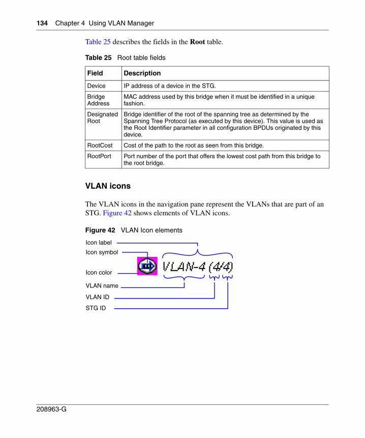
134 Chapter 4 Using VLAN Manager
208963-G
Table 25 describes the fields in the Root table.
VLAN icons
The VLAN icons in the navigation pane represent the VLANs that are part of an STG. Figure 42 shows elements of VLAN icons.
Figure 42 VLAN Icon elements
Table 25 Root table fields
Field Description
Device IP address of a device in the STG.
BridgeAddress
MAC address used by this bridge when it must be identified in a unique fashion.
DesignatedRoot
Bridge identifier of the root of the spanning tree as determined by the Spanning Tree Protocol (as executed by this device). This value is used as the Root Identifier parameter in all configuration BPDUs originated by this device.
RootCost Cost of the path to the root as seen from this bridge.
RootPort Port number of the port that offers the lowest cost path from this bridge to the root bridge.
Icon label
Icon symbol
Icon color
VLAN name
VLAN ID
STG ID
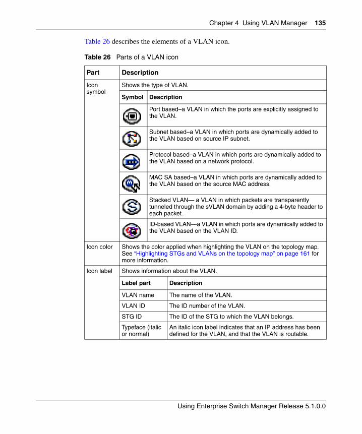
Chapter 4 Using VLAN Manager 135
Using Enterprise Switch Manager Release 5.1.0.0
Table 26 describes the elements of a VLAN icon.
Table 26 Parts of a VLAN icon
Part Description
Icon symbol
Shows the type of VLAN.
Symbol Description
Port based–a VLAN in which the ports are explicitly assigned to the VLAN.
Subnet based–a VLAN in which ports are dynamically added to the VLAN based on source IP subnet.
Protocol based–a VLAN in which ports are dynamically added to the VLAN based on a network protocol.
MAC SA based–a VLAN in which ports are dynamically added to the VLAN based on the source MAC address.
Stacked VLAN— a VLAN in which packets are transparently tunneled through the sVLAN domain by adding a 4-byte header to each packet.
ID-based VLAN—a VLAN in which ports are dynamically added to the VLAN based on the VLAN ID.
Icon color Shows the color applied when highlighting the VLAN on the topology map. See “Highlighting STGs and VLANs on the topology map” on page 161 for more information.
Icon label Shows information about the VLAN.
Label part Description
VLAN name The name of the VLAN.
VLAN ID The ID number of the VLAN.
STG ID The ID of the STG to which the VLAN belongs.
Typeface (italic or normal)
An italic icon label indicates that an IP address has been defined for the VLAN, and that the VLAN is routable.
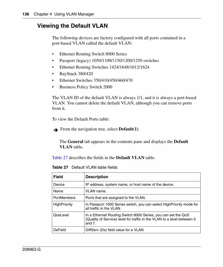
136 Chapter 4 Using VLAN Manager
208963-G
Viewing the Default VLAN
The following devices are factory configured with all ports contained in a port-based VLAN called the default VLAN:
• Ethernet Routing Switch 8000 Series
• Passport (legacy) 1050/1100/1150/1200/1250 switches
• Ethernet Routing Switches 1424/1648/1612/1624
• BayStack 380/420
• Ethernet Switches 350/410/450/460/470
• Business Policy Switch 2000
The VLAN ID of the default VLAN is always 1/1, and it is always a port-based VLAN. You cannot delete the default VLAN, although you can remove ports from it.
To view the Default Ports table:
The General tab appears in the contents pane and displays the Default VLAN table.
Table 27 describes the fields in the Default VLAN table.
From the navigation tree, select Default(1).
Table 27 Default VLAN table fields
Field Description
Device IP address, system name, or host name of the device.
Name VLAN name.
PortMembers Ports that are assigned to the VLAN.
HighPriority In Passport 1000 Series switch, you can select HighPriority mode for all traffic in the VLAN.
QosLevel In a Ethernet Routing Switch 8000 Series, you can set the QoS (Quality of Service) level for traffic in the VLAN to a level between 0 and 7.
DsField DiffServ (Ds) field value for a VLAN
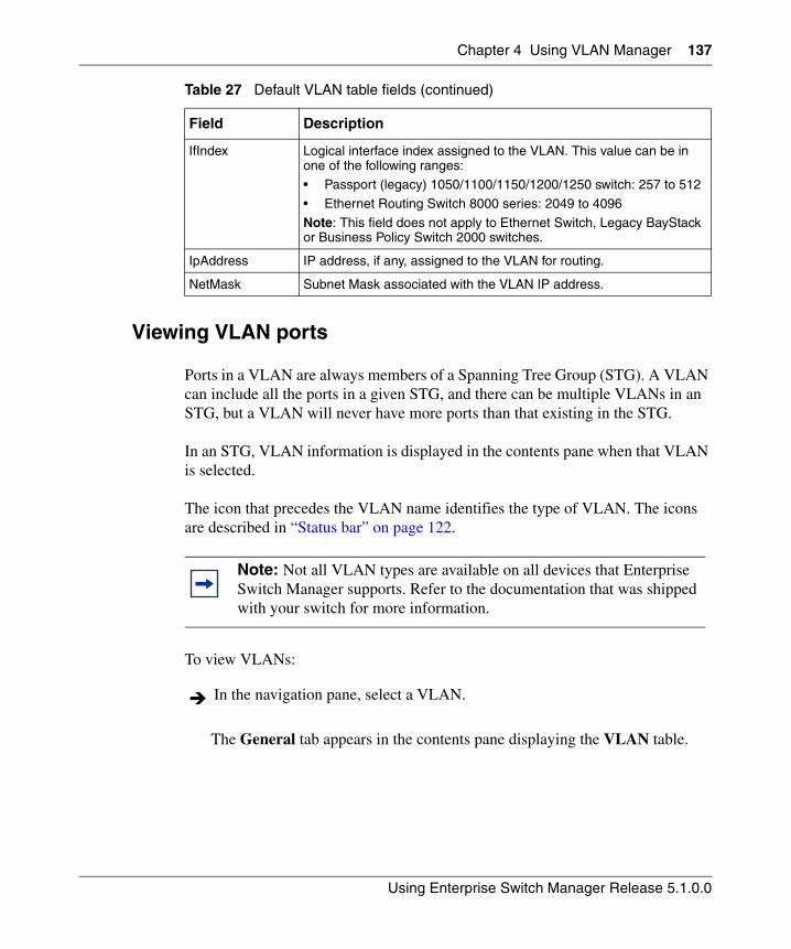
Chapter 4 Using VLAN Manager 137
Using Enterprise Switch Manager Release 5.1.0.0
Viewing VLAN ports
Ports in a VLAN are always members of a Spanning Tree Group (STG). A VLAN can include all the ports in a given STG, and there can be multiple VLANs in an STG, but a VLAN will never have more ports than that existing in the STG.
In an STG, VLAN information is displayed in the contents pane when that VLAN is selected.
The icon that precedes the VLAN name identifies the type of VLAN. The icons are described in “Status bar” on page 122.
To view VLANs:
The General tab appears in the contents pane displaying the VLAN table.
IfIndex Logical interface index assigned to the VLAN. This value can be in one of the following ranges:• Passport (legacy) 1050/1100/1150/1200/1250 switch: 257 to 512
• Ethernet Routing Switch 8000 series: 2049 to 4096
Note: This field does not apply to Ethernet Switch, Legacy BayStack or Business Policy Switch 2000 switches.
IpAddress IP address, if any, assigned to the VLAN for routing.
NetMask Subnet Mask associated with the VLAN IP address.
Note: Not all VLAN types are available on all devices that Enterprise Switch Manager supports. Refer to the documentation that was shipped with your switch for more information.
In the navigation pane, select a VLAN.
Table 27 Default VLAN table fields (continued)
Field Description
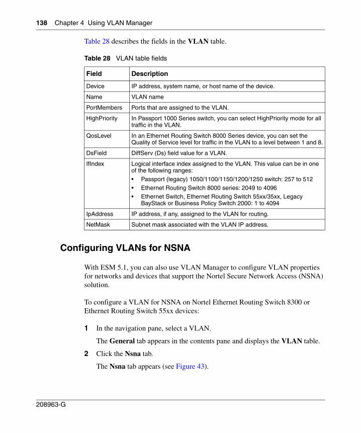
138 Chapter 4 Using VLAN Manager
208963-G
Table 28 describes the fields in the VLAN table.
Configuring VLANs for NSNA
With ESM 5.1, you can also use VLAN Manager to configure VLAN properties for networks and devices that support the Nortel Secure Network Access (NSNA) solution.
To configure a VLAN for NSNA on Nortel Ethernet Routing Switch 8300 or Ethernet Routing Switch 55xx devices:
1 In the navigation pane, select a VLAN.
The General tab appears in the contents pane and displays the VLAN table.
2 Click the Nsna tab.
The Nsna tab appears (see Figure 43).
Table 28 VLAN table fields
Field Description
Device IP address, system name, or host name of the device.
Name VLAN name
PortMembers Ports that are assigned to the VLAN.
HighPriority In Passport 1000 Series switch, you can select HighPriority mode for all traffic in the VLAN.
QosLevel In an Ethernet Routing Switch 8000 Series device, you can set the Quality of Service level for traffic in the VLAN to a level between 1 and 8.
DsField DiffServ (Ds) field value for a VLAN.
IfIndex Logical interface index assigned to the VLAN. This value can be in one of the following ranges:
• Passport (legacy) 1050/1100/1150/1200/1250 switch: 257 to 512
• Ethernet Routing Switch 8000 series: 2049 to 4096• Ethernet Switch, Ethernet Routing Switch 55xx/35xx, Legacy
BayStack or Business Policy Switch 2000: 1 to 4094
IpAddress IP address, if any, assigned to the VLAN for routing.
NetMask Subnet mask associated with the VLAN IP address.
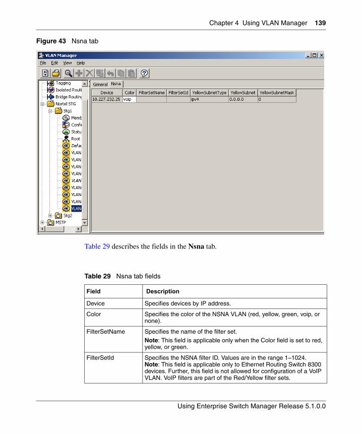
Chapter 4 Using VLAN Manager 139
Using Enterprise Switch Manager Release 5.1.0.0
Figure 43 Nsna tab
Table 29 describes the fields in the Nsna tab.
Table 29 Nsna tab fields
Field Description
Device Specifies devices by IP address.
Color Specifies the color of the NSNA VLAN (red, yellow, green, voip, or none).
FilterSetName Specifies the name of the filter set.
Note: This field is applicable only when the Color field is set to red, yellow, or green.
FilterSetId Specifies the NSNA filter ID. Values are in the range 1–1024. Note: This field is applicable only to Ethernet Routing Switch 8300 devices. Further, this field is not allowed for configuration of a VoIP VLAN. VoIP filters are part of the Red/Yellow filter sets.
140 Chapter 4 Using VLAN Manager
208963-G
3 Click the Color field for each VLAN to select the color from the drop-down menu (create, select, and configure the VLANs based on your network design).
4 Click the FilterSetName field for each VLAN to enter the filter set name of your choice.
5 Click Apply Changes.
Managing Spanning Tree Groups (STGs)
The following sections describe how to edit STG and gives information about STG membership:
• “Creating a Spanning Tree Group‚” next
• “Editing a Spanning Tree Group” on page 142
• “Deleting a Spanning Tree Group” on page 143
• “Adding members to a Spanning Tree Group” on page 144
• “Deleting members from a Spanning Tree Group” on page 144
YellowSubnetType Specifies the Ethernet type for the Yellow VLAN subnet (IPv4 is currently the only available option).
Note: This field is applicable only when the Color field is set to yellow.
YellowSubnet Specifies the subnet of the Yellow VLAN.
Note: This field is applicable only when the Color field is set to yellow.
YellowSubnetMask Specifies the mask for the Yellow VLAN subnet.
Note: This field is applicable only when the Color field is set to yellow.
Note: You must have only one Red VLAN per switch. You can, however, have multiple Yellow and Green VLANs per switch. Currently, five Yellow and five Green VLANs per switch are supported.
Table 29 Nsna tab fields (continued)
Field Description
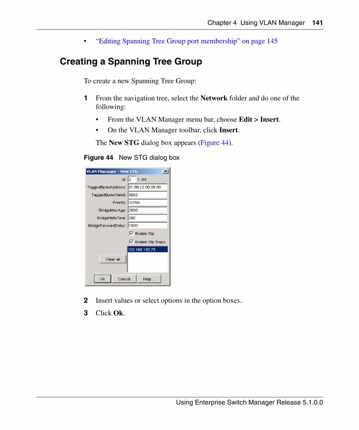
Chapter 4 Using VLAN Manager 141
Using Enterprise Switch Manager Release 5.1.0.0
• “Editing Spanning Tree Group port membership” on page 145
Creating a Spanning Tree Group
To create a new Spanning Tree Group:
1 From the navigation tree, select the Network folder and do one of the following:
• From the VLAN Manager menu bar, choose Edit > Insert.
• On the VLAN Manager toolbar, click Insert.
The New STG dialog box appears (Figure 44).
Figure 44 New STG dialog box
2 Insert values or select options in the option boxes.
3 Click Ok.
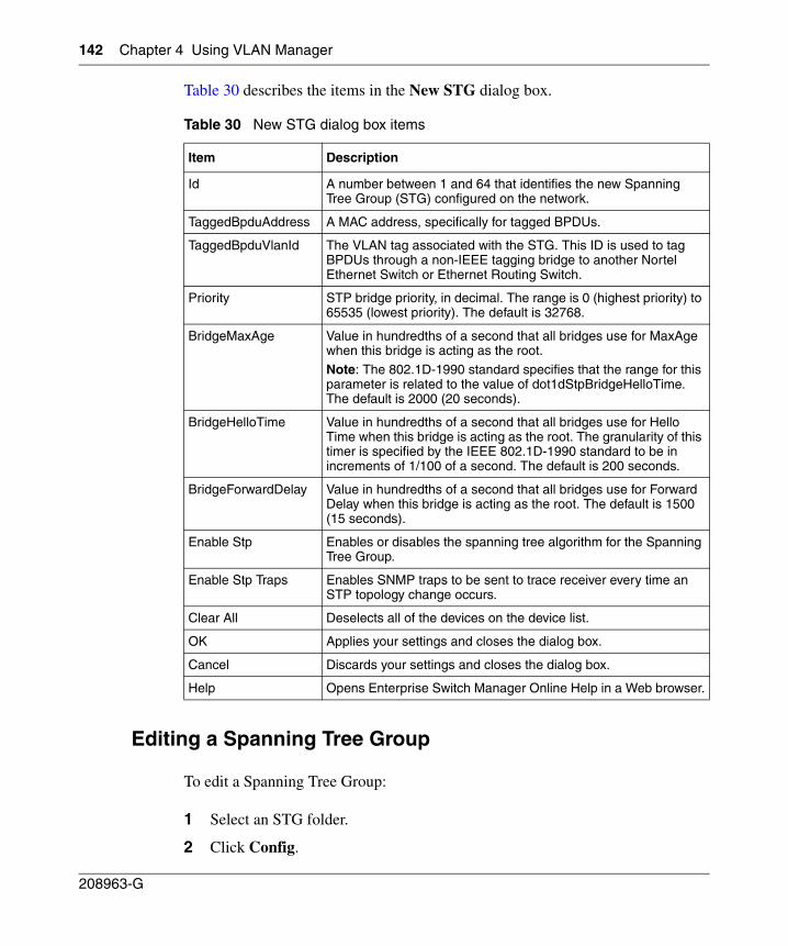
142 Chapter 4 Using VLAN Manager
208963-G
Table 30 describes the items in the New STG dialog box.
Editing a Spanning Tree Group
To edit a Spanning Tree Group:
1 Select an STG folder.
2 Click Config.
Table 30 New STG dialog box items
Item Description
Id A number between 1 and 64 that identifies the new Spanning Tree Group (STG) configured on the network.
TaggedBpduAddress A MAC address, specifically for tagged BPDUs.
TaggedBpduVlanId The VLAN tag associated with the STG. This ID is used to tag BPDUs through a non-IEEE tagging bridge to another Nortel Ethernet Switch or Ethernet Routing Switch.
Priority STP bridge priority, in decimal. The range is 0 (highest priority) to 65535 (lowest priority). The default is 32768.
BridgeMaxAge Value in hundredths of a second that all bridges use for MaxAge when this bridge is acting as the root.
Note: The 802.1D-1990 standard specifies that the range for this parameter is related to the value of dot1dStpBridgeHelloTime. The default is 2000 (20 seconds).
BridgeHelloTime Value in hundredths of a second that all bridges use for Hello Time when this bridge is acting as the root. The granularity of this timer is specified by the IEEE 802.1D-1990 standard to be in increments of 1/100 of a second. The default is 200 seconds.
BridgeForwardDelay Value in hundredths of a second that all bridges use for Forward Delay when this bridge is acting as the root. The default is 1500 (15 seconds).
Enable Stp Enables or disables the spanning tree algorithm for the Spanning Tree Group.
Enable Stp Traps Enables SNMP traps to be sent to trace receiver every time an STP topology change occurs.
Clear All Deselects all of the devices on the device list.
OK Applies your settings and closes the dialog box.
Cancel Discards your settings and closes the dialog box.
Help Opens Enterprise Switch Manager Online Help in a Web browser.
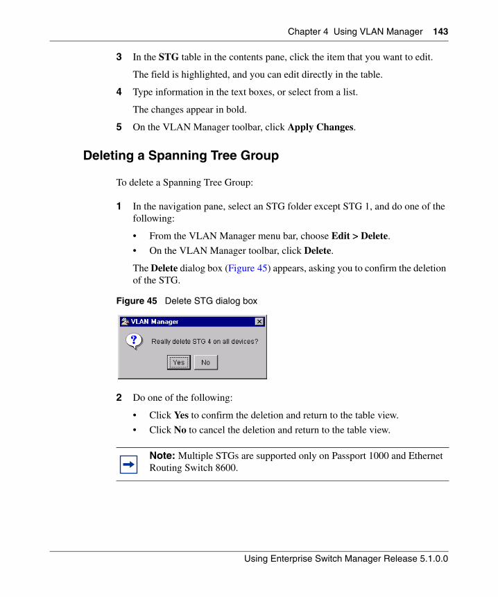
Chapter 4 Using VLAN Manager 143
Using Enterprise Switch Manager Release 5.1.0.0
3 In the STG table in the contents pane, click the item that you want to edit.
The field is highlighted, and you can edit directly in the table.
4 Type information in the text boxes, or select from a list.
The changes appear in bold.
5 On the VLAN Manager toolbar, click Apply Changes.
Deleting a Spanning Tree Group
To delete a Spanning Tree Group:
1 In the navigation pane, select an STG folder except STG 1, and do one of the following:
• From the VLAN Manager menu bar, choose Edit > Delete.
• On the VLAN Manager toolbar, click Delete.
The Delete dialog box (Figure 45) appears, asking you to confirm the deletion of the STG.
Figure 45 Delete STG dialog box
2 Do one of the following:
• Click Yes to confirm the deletion and return to the table view.
• Click No to cancel the deletion and return to the table view.
Note: Multiple STGs are supported only on Passport 1000 and Ethernet Routing Switch 8600.
144 Chapter 4 Using VLAN Manager
208963-G
Adding members to a Spanning Tree Group
To add members to an existing Spanning Tree Group:
1 Under an existing STG, click the Members folder and do one of the following:
• From the VLAN Manager menu bar, choose Edit > Insert.
• On the VLAN Manager toolbar, click Insert.
The New STG dialog box appears (Figure 44).
2 Select the desired additional members from the device list.
3 Insert values or select options in the option boxes, as required.
4 Click Ok.
5 The new members are added to the STG.
Deleting members from a Spanning Tree Group
To delete members from an existing Spanning Tree Group
1 Under an existing STG, click the Members folder.
2 In the contents pane, select the device to remove, and do one of the following:
• From the VLAN Manager menu bar, choose Edit > Delete.
• On the VLAN Manager toolbar, click Delete.
The Delete dialog box (Figure 45) appears, asking you to confirm the removal of the device from the STG.
3 Do one of the following:
• Click Yes to confirm the deletion and return to the table view.
• Click No to cancel the deletion and return to the table view.
Chapter 4 Using VLAN Manager 145
Using Enterprise Switch Manager Release 5.1.0.0
Editing Spanning Tree Group port membership
To edit port membership in a Spanning Tree Group:
1 From the navigation tree, select the STG folder.
2 Click Members.
3 In the contents pane, the port members for each device in the STG appear.
4 To change the port membership for a device, double-click the associated PortMembers entry, and choose the ports to include.
5 Click Ok.
6 Click Apply Changes.
Managing VLANs
This section contains information about common operations you can perform when managing VLANs with VLAN Manager.
The following sections tells you how to perform the following operations:
• “Creating VLANs‚” next
• “Synchronizing the VLAN Name” on page 160
• “Deleting a VLAN” on page 161
Creating VLANs
When you create VLANs using VLAN Manager, follow these rules:
• VLANs must have unique VLAN IDs and names.
• Trunk (tagged) ports can belong to multiple VLANs and multiple Spanning Tree Groups.
• VLANs cannot belong to multiple Spanning Tree Groups.
• An access (untagged) port can belong to one and only one port-based VLAN or it can belong to one and only one policy-based VLAN for the given protocol.
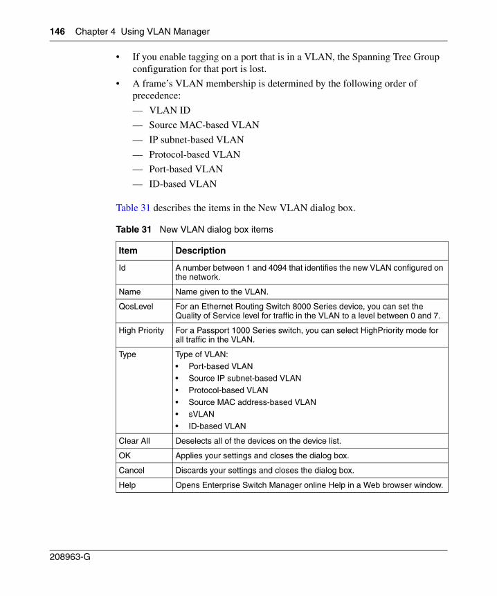
146 Chapter 4 Using VLAN Manager
208963-G
• If you enable tagging on a port that is in a VLAN, the Spanning Tree Group configuration for that port is lost.
• A frame’s VLAN membership is determined by the following order of precedence:
— VLAN ID
— Source MAC-based VLAN
— IP subnet-based VLAN
— Protocol-based VLAN
— Port-based VLAN
— ID-based VLAN
Table 31 describes the items in the New VLAN dialog box.
Table 31 New VLAN dialog box items
Item Description
Id A number between 1 and 4094 that identifies the new VLAN configured on the network.
Name Name given to the VLAN.
QosLevel For an Ethernet Routing Switch 8000 Series device, you can set the Quality of Service level for traffic in the VLAN to a level between 0 and 7.
High Priority For a Passport 1000 Series switch, you can select HighPriority mode for all traffic in the VLAN.
Type Type of VLAN:
• Port-based VLAN• Source IP subnet-based VLAN
• Protocol-based VLAN
• Source MAC address-based VLAN• sVLAN
• ID-based VLAN
Clear All Deselects all of the devices on the device list.
OK Applies your settings and closes the dialog box.
Cancel Discards your settings and closes the dialog box.
Help Opens Enterprise Switch Manager online Help in a Web browser window.
Chapter 4 Using VLAN Manager 147
Using Enterprise Switch Manager Release 5.1.0.0
Refer to the following sections for additional information about specific VLAN types:
• “Creating a port-based VLAN”
• “Creating a source IP subnet-based VLAN” on page 149
• “Creating a protocol-based VLAN” on page 151
• “Creating a source MAC address-based VLAN” on page 154
• “Creating an sVLAN” on page 157
• “Creating an ID-based VLAN” on page 158
Creating a port-based VLAN
To create a port-based VLAN:
1 In the navigation pane, select an STG.
2 Do one of the following:
• From the menu bar, choose Edit > Insert.
• On the toolbar, click Insert.
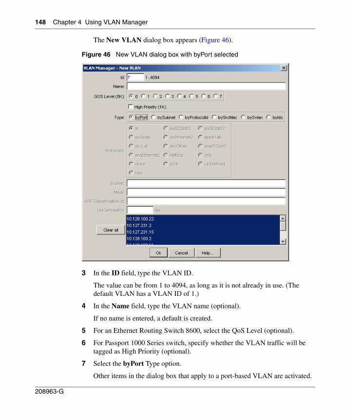
148 Chapter 4 Using VLAN Manager
208963-G
The New VLAN dialog box appears (Figure 46).
Figure 46 New VLAN dialog box with byPort selected
3 In the ID field, type the VLAN ID.
The value can be from 1 to 4094, as long as it is not already in use. (The default VLAN has a VLAN ID of 1.)
4 In the Name field, type the VLAN name (optional).
If no name is entered, a default is created.
5 For an Ethernet Routing Switch 8600, select the QoS Level (optional).
6 For Passport 1000 Series switch, specify whether the VLAN traffic will be tagged as High Priority (optional).
7 Select the byPort Type option.
Other items in the dialog box that apply to a port-based VLAN are activated.
Chapter 4 Using VLAN Manager 149
Using Enterprise Switch Manager Release 5.1.0.0
8 Select the device to be configured on the VLAN by doing one of the following:
• Select from the device list.
• Click the Clear all button to toggle between all devices selected and all devices deselected.
9 Click Ok.
Creating a source IP subnet-based VLAN
Source IP subnet-based VLANs are supported only on Passport (legacy) 1050/1100/1150/1200/1250 and Ethernet Routing Switch 8000 series.
To create a source IP subnet-based VLAN:
1 In the navigation pane, select an STG.
2 Do one of the following:
• From the menu bar, choose Edit > Insert.
• On the toolbar, click Insert.
Note: Not all VLAN types are available on all devices that Enterprise Switch Manager supports. Devices that do not support port-based VLANs will be absent from the device list.
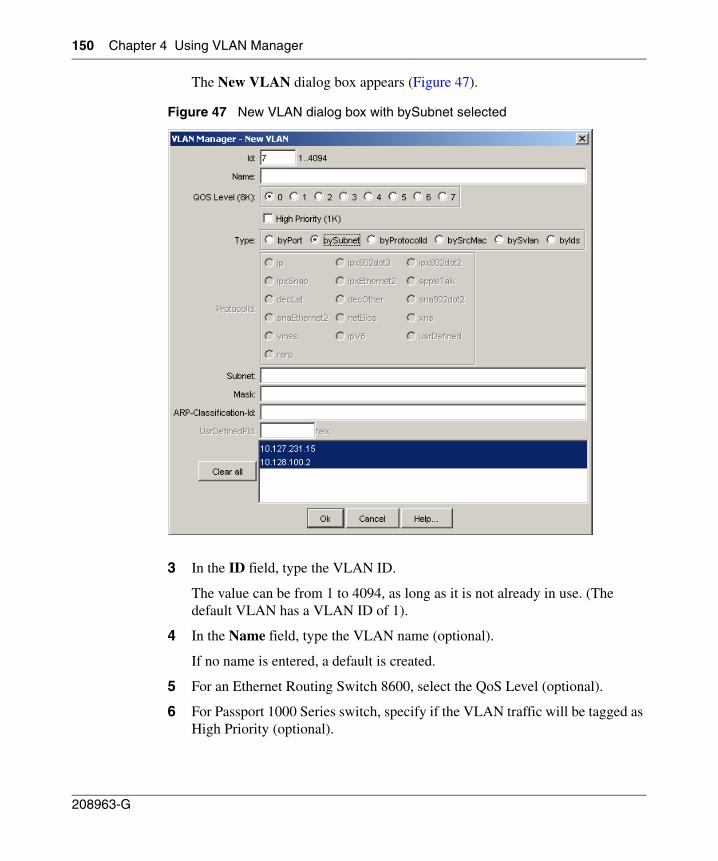
150 Chapter 4 Using VLAN Manager
208963-G
The New VLAN dialog box appears (Figure 47).
Figure 47 New VLAN dialog box with bySubnet selected
3 In the ID field, type the VLAN ID.
The value can be from 1 to 4094, as long as it is not already in use. (The default VLAN has a VLAN ID of 1).
4 In the Name field, type the VLAN name (optional).
If no name is entered, a default is created.
5 For an Ethernet Routing Switch 8600, select the QoS Level (optional).
6 For Passport 1000 Series switch, specify if the VLAN traffic will be tagged as High Priority (optional).
Chapter 4 Using VLAN Manager 151
Using Enterprise Switch Manager Release 5.1.0.0
7 Select the by Subnet Type option.
Other items in the dialog box that apply to a subnet-based VLAN are activated.
8 In the Subnet text box, type the source IP subnet address.
9 In the Mask text box, type the IP subnet mask.
10 Select the device to be configured on the VLAN by doing one of the following:
• Select from the device list.
• Click the Clear all button to toggle between all selected devices and all deselected devices.
11 Click Ok.
Creating a protocol-based VLAN
To create a protocol-based VLAN:
1 In the navigation pane, select an STG.
2 Do one of the following:
• From the menu bar, choose Edit > Insert.
• On the toolbar, click Insert.
Note: Not all VLAN types are available on all devices that Enterprise Switch Manager supports. Devices that do not support source IP subnet-based VLANs will be absent from the device list.
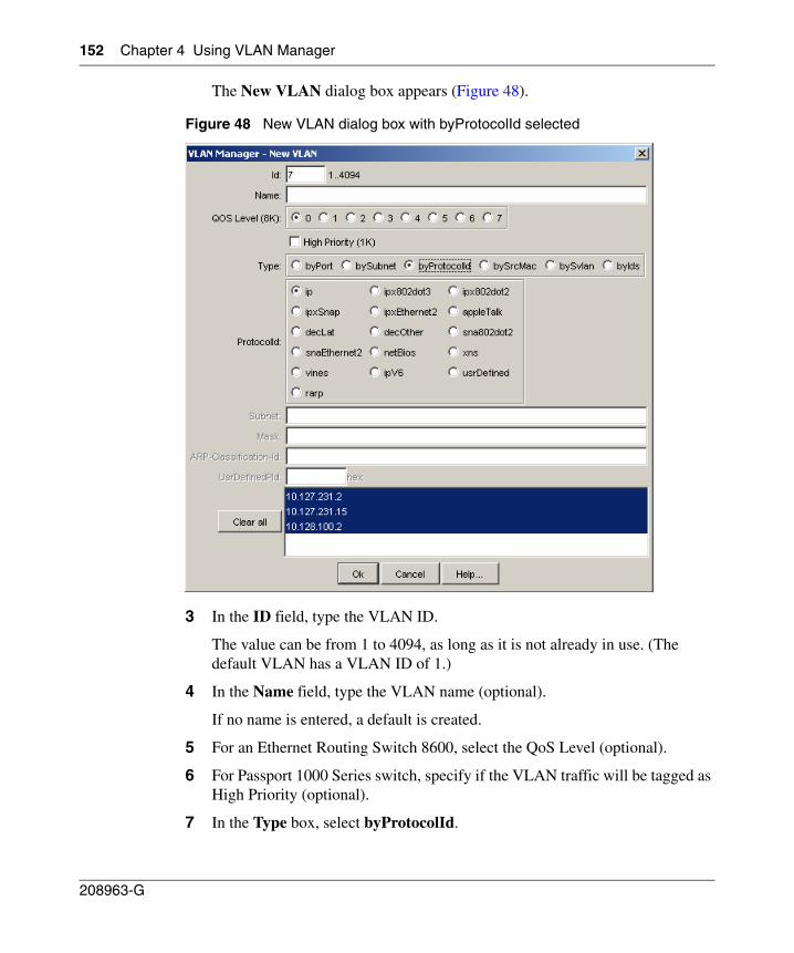
152 Chapter 4 Using VLAN Manager
208963-G
The New VLAN dialog box appears (Figure 48).
Figure 48 New VLAN dialog box with byProtocolId selected
3 In the ID field, type the VLAN ID.
The value can be from 1 to 4094, as long as it is not already in use. (The default VLAN has a VLAN ID of 1.)
4 In the Name field, type the VLAN name (optional).
If no name is entered, a default is created.
5 For an Ethernet Routing Switch 8600, select the QoS Level (optional).
6 For Passport 1000 Series switch, specify if the VLAN traffic will be tagged as High Priority (optional).
7 In the Type box, select byProtocolId.
Chapter 4 Using VLAN Manager 153
Using Enterprise Switch Manager Release 5.1.0.0
Other items in the dialog box that apply to protocol based VLANs are activated.
8 In the ProtocolId box, select the protocol.
If you select UsrDefined, refer to “User-defined protocols in a protocol-based VLAN” on page 153 for more information.
9 Select the device to be configured on the VLAN by doing one of the following:
• Select from the device list.
• Click the Clear all button to toggle between all devices selected and all devices deselected.
10 Click Ok.
11 In the Ports table, specify the port membership by clicking on one or all of the following columns and specifying ports:
• ActiveMember
• PotentialMembers
• StaticMembers
• NotAllowedToJoin
User-defined protocols in a protocol-based VLAN
You can create a protocol-based VLAN with a user-defined protocol for integration into existing networks where nonstandard protocols are used.
In the UserDefinedPId text box, enter the PID of the protocol in the format 0x (protocol type in decimal value).
• For an Ethernet Routing Switch 8600 and Passport 1000 Series switch, the 16-bit PID assigned to a protocol-based VLAN specifies either an Ethertype, a DSAP/SSAP, or a SNAP PID, depending on whether the frame encapsulation is Ethernet 2, 802.2, or LLC-SNAP, respectively.
Note: Not all VLAN types are available on all devices that Enterprise Switch Manager supports. Devices that do not support protocol-based VLANs will be absent from the device list.
154 Chapter 4 Using VLAN Manager
208963-G
• For an Ethernet Routing Switch 8100, the 16-bit PID assigned to a protocol-based VLAN specifies only an Ethertype for Ethernet 2 frame encapsulation.
Refer to the section on user-defined protocols in Networking Concepts for the Passport 1000 Series Switch (205588-B) and Configuring VLANs, Spanning Tree, and Link Aggregation: Passport 8000 Series Software Release 4.0 (314725-D) for more information about this topic or to see the actual values and how they are assigned.
The following PIDs are not valid:
• PID0x0000 through 0x05dc: overlap with the 802.3 frame length
• PIDs of predefined protocols (for example, IP, IPX, AppleTalk)
• PID 0x8100: reserved by 802.1Q to identify tagged frames
• PID0x9000: used by the diagnostic loopback frames
• PID0x8808: used by 802.3x pause frames
• PID0x4242: overlaps with the BPDU DSAP/SSAP
Creating a source MAC address-based VLAN
To create a source Media Access Control (MAC) address-based VLAN:
1 In the navigation pane, select an STG.
2 Do one of the following:
• From the menu bar, choose Edit > Insert.
• On the VLAN Manager toolbar, click Insert.
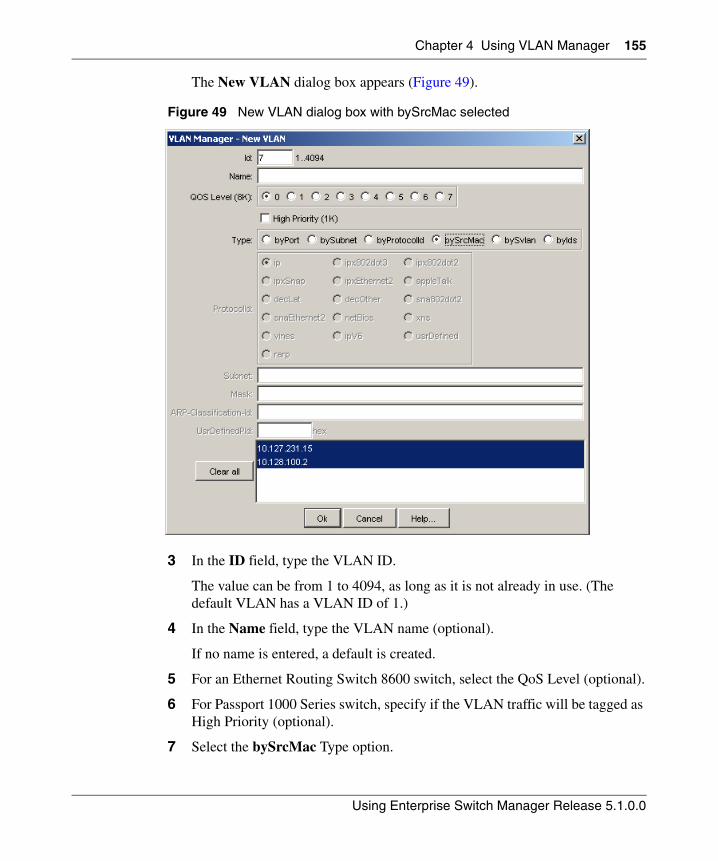
Chapter 4 Using VLAN Manager 155
Using Enterprise Switch Manager Release 5.1.0.0
The New VLAN dialog box appears (Figure 49).
Figure 49 New VLAN dialog box with bySrcMac selected
3 In the ID field, type the VLAN ID.
The value can be from 1 to 4094, as long as it is not already in use. (The default VLAN has a VLAN ID of 1.)
4 In the Name field, type the VLAN name (optional).
If no name is entered, a default is created.
5 For an Ethernet Routing Switch 8600 switch, select the QoS Level (optional).
6 For Passport 1000 Series switch, specify if the VLAN traffic will be tagged as High Priority (optional).
7 Select the bySrcMac Type option.
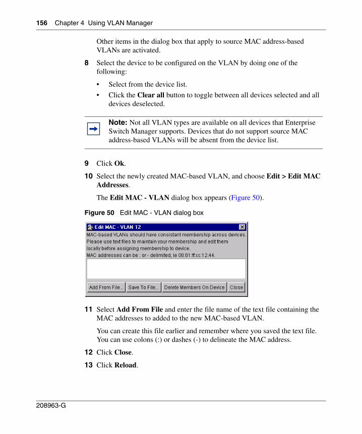
156 Chapter 4 Using VLAN Manager
208963-G
Other items in the dialog box that apply to source MAC address-based VLANs are activated.
8 Select the device to be configured on the VLAN by doing one of the following:
• Select from the device list.
• Click the Clear all button to toggle between all devices selected and all devices deselected.
9 Click Ok.
10 Select the newly created MAC-based VLAN, and choose Edit > Edit MAC Addresses.
The Edit MAC - VLAN dialog box appears (Figure 50).
Figure 50 Edit MAC - VLAN dialog box
11 Select Add From File and enter the file name of the text file containing the MAC addresses to added to the new MAC-based VLAN.
You can create this file earlier and remember where you saved the text file. You can use colons (:) or dashes (-) to delineate the MAC address.
12 Click Close.
13 Click Reload.
Note: Not all VLAN types are available on all devices that Enterprise Switch Manager supports. Devices that do not support source MAC address-based VLANs will be absent from the device list.
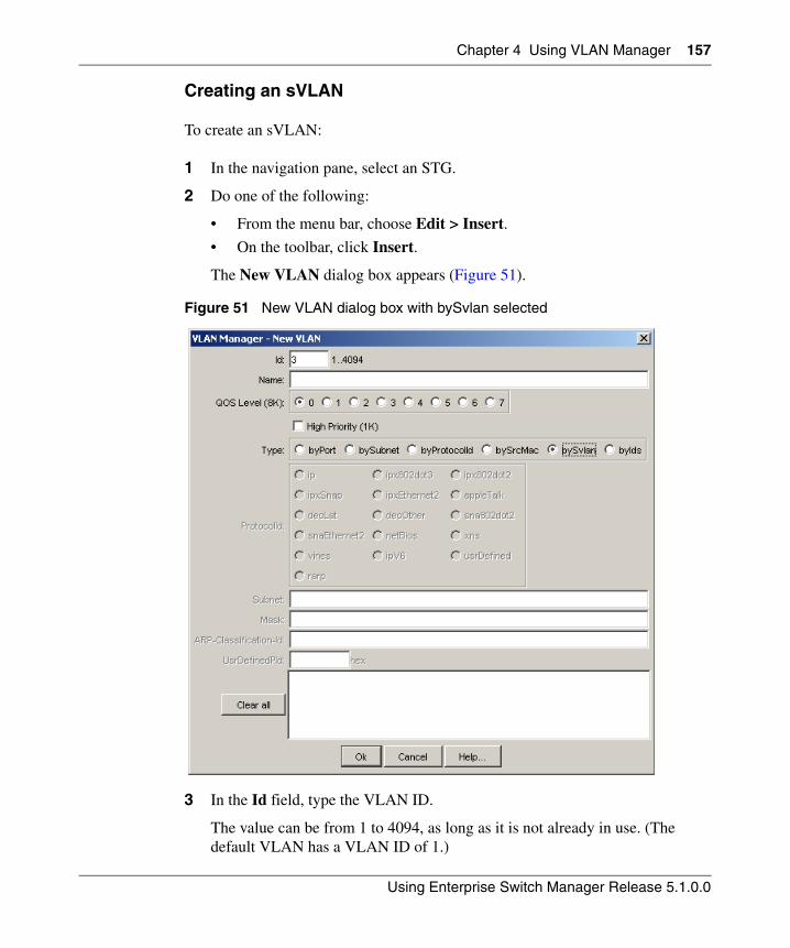
Chapter 4 Using VLAN Manager 157
Using Enterprise Switch Manager Release 5.1.0.0
Creating an sVLAN
To create an sVLAN:
1 In the navigation pane, select an STG.
2 Do one of the following:
• From the menu bar, choose Edit > Insert.
• On the toolbar, click Insert.
The New VLAN dialog box appears (Figure 51).
Figure 51 New VLAN dialog box with bySvlan selected
3 In the Id field, type the VLAN ID.
The value can be from 1 to 4094, as long as it is not already in use. (The default VLAN has a VLAN ID of 1.)
158 Chapter 4 Using VLAN Manager
208963-G
4 In the Name field, type the VLAN name (optional).
If no name is entered, a default is created.
5 For an Ethernet Routing Switch 8600, select the QoS Level (optional).
6 For Passport 1000 Series switch, specify whether the VLAN traffic will be tagged as High Priority (optional).
7 Select the bySvlan Type option.
Other items in the dialog box that apply to a Svlan-based VLAN are activated.
8 Select the device to be configured on the VLAN by doing one of the following:
• Select from the device list.
• Click the Clear all button to toggle between all devices selected and all devices deselected.
9 Click Ok.
Creating an ID-based VLAN
To create an ID-based VLAN:
1 In the navigation pane, select an STG.
2 Do one of the following:
• From the menu bar, choose Edit > Insert.
• On the toolbar, click Insert.
Note: Not all VLAN types are available on all devices that Enterprise Switch Manager supports. Devices that do not support port-based VLANs will be absent from the device list.
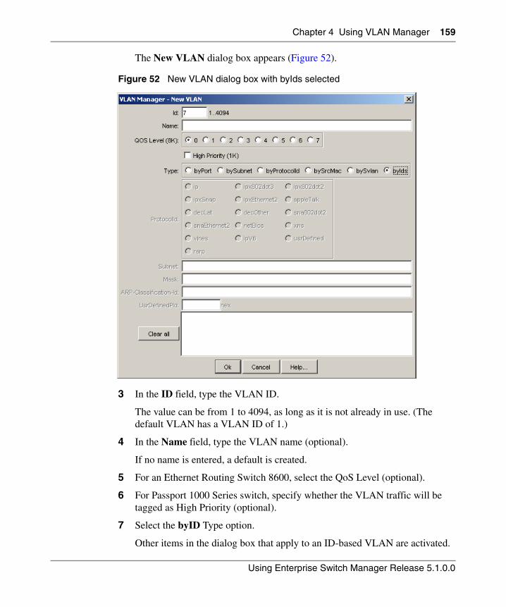
Chapter 4 Using VLAN Manager 159
Using Enterprise Switch Manager Release 5.1.0.0
The New VLAN dialog box appears (Figure 52).
Figure 52 New VLAN dialog box with byIds selected
3 In the ID field, type the VLAN ID.
The value can be from 1 to 4094, as long as it is not already in use. (The default VLAN has a VLAN ID of 1.)
4 In the Name field, type the VLAN name (optional).
If no name is entered, a default is created.
5 For an Ethernet Routing Switch 8600, select the QoS Level (optional).
6 For Passport 1000 Series switch, specify whether the VLAN traffic will be tagged as High Priority (optional).
7 Select the byID Type option.
Other items in the dialog box that apply to an ID-based VLAN are activated.
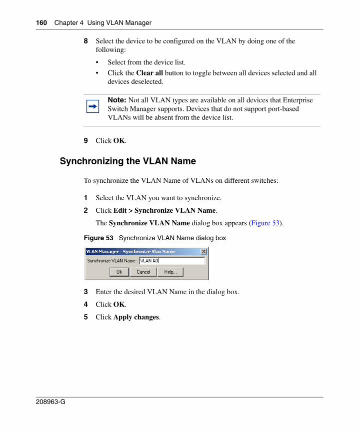
160 Chapter 4 Using VLAN Manager
208963-G
8 Select the device to be configured on the VLAN by doing one of the following:
• Select from the device list.
• Click the Clear all button to toggle between all devices selected and all devices deselected.
9 Click OK.
Synchronizing the VLAN Name
To synchronize the VLAN Name of VLANs on different switches:
1 Select the VLAN you want to synchronize.
2 Click Edit > Synchronize VLAN Name.
The Synchronize VLAN Name dialog box appears (Figure 53).
Figure 53 Synchronize VLAN Name dialog box
3 Enter the desired VLAN Name in the dialog box.
4 Click OK.
5 Click Apply changes.
Note: Not all VLAN types are available on all devices that Enterprise Switch Manager supports. Devices that do not support port-based VLANs will be absent from the device list.
Chapter 4 Using VLAN Manager 161
Using Enterprise Switch Manager Release 5.1.0.0
Deleting a VLAN
To delete a VLAN:
1 Do one of the following:
• To delete a VLAN from all devices, select the VLAN in the navigation pane.
• To delete a VLAN from one or more specific devices, select the VLAN in the navigation pane, then highlight the devices in the contents pane.
2 Do one of the following:
• From the VLAN Manager menu bar, choose Edit > Delete.
• On the VLAN Manager toolbar, click Delete.
The Delete dialog box appears.
3 Click Yes.
Highlighting STGs and VLANs on the topology map
Enterprise Switch Manager provides dynamic discovery of active STG devices in a network. From Enterprise Switch Manager, you can view the following information about:
• Ports in the network that are configured as unassigned, tagging, or Isolated Routing Ports (IRPs) and brouter ports
• Ports that are assigned to a particular Spanning Tree Group (STG)
• Ports that are in the forwarding and blocking states and device that has the root of an STG
• Ports that are members of a VLAN or multiple VLANs.
For more information, see the following sections:
• “Viewing VLAN members in Enterprise Switch Manager‚” next
• “Viewing STG port members” on page 163
• “Viewing STG root configuration” on page 164
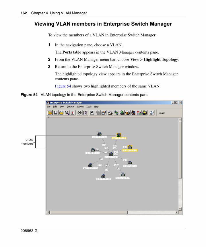
162 Chapter 4 Using VLAN Manager
208963-G
Viewing VLAN members in Enterprise Switch Manager
To view the members of a VLAN in Enterprise Switch Manager:
1 In the navigation pane, choose a VLAN.
The Ports table appears in the VLAN Manager contents pane.
2 From the VLAN Manager menu bar, choose View > Highlight Topology.
3 Return to the Enterprise Switch Manager window.
The highlighted topology view appears in the Enterprise Switch Manager contents pane.
Figure 54 shows two highlighted members of the same VLAN.
Figure 54 VLAN topology in the Enterprise Switch Manager contents pane
VLANmembers
Chapter 4 Using VLAN Manager 163
Using Enterprise Switch Manager Release 5.1.0.0
Viewing STG port members
When you select an STG in the VLAN Manager navigation pane, you can view the devices and ports associated with that STG in the Enterprise Switch Manager network topology map. This view can assist you in troubleshooting by identifying which ports are already members of the STG selected.
To view STG ports:
1 In the VLAN Manager navigation pane, choose an STG Members icon.
The STG Members table appears in the VLAN Manager contents pane.
2 From the VLAN Manager menu bar, choose View > Highlight Topology.
3 Return to the Enterprise Switch Manager window.
The devices containing STG ports are highlighted (Figure 55) with a color and the device IP address.
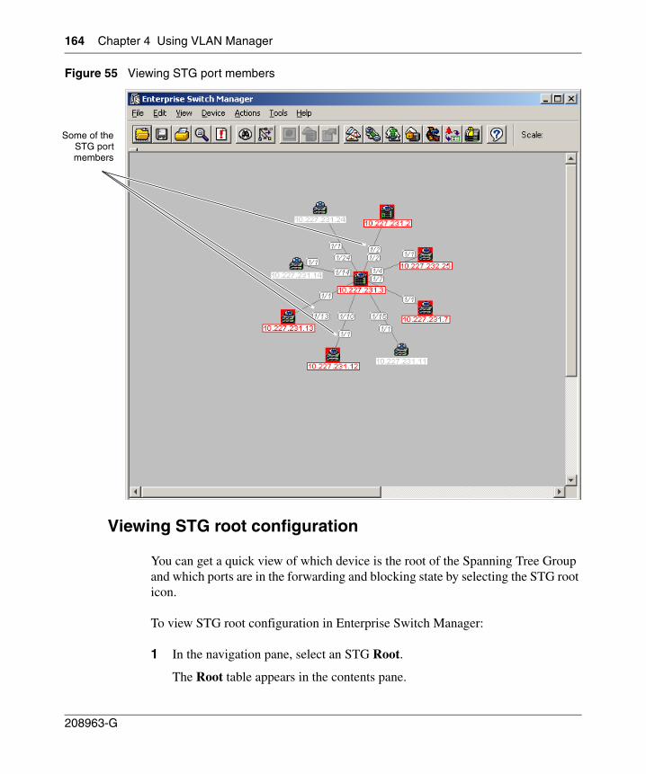
164 Chapter 4 Using VLAN Manager
208963-G
Figure 55 Viewing STG port members
Viewing STG root configuration
You can get a quick view of which device is the root of the Spanning Tree Group and which ports are in the forwarding and blocking state by selecting the STG root icon.
To view STG root configuration in Enterprise Switch Manager:
1 In the navigation pane, select an STG Root.
The Root table appears in the contents pane.
Some of theSTG portmembers
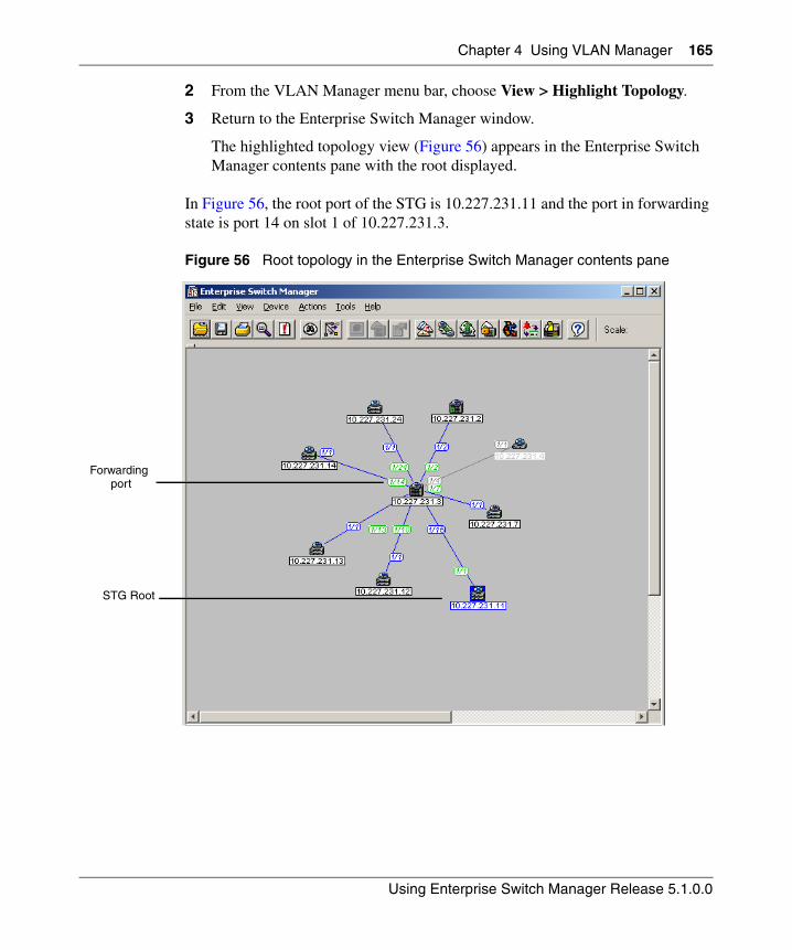
Chapter 4 Using VLAN Manager 165
Using Enterprise Switch Manager Release 5.1.0.0
2 From the VLAN Manager menu bar, choose View > Highlight Topology.
3 Return to the Enterprise Switch Manager window.
The highlighted topology view (Figure 56) appears in the Enterprise Switch Manager contents pane with the root displayed.
In Figure 56, the root port of the STG is 10.227.231.11 and the port in forwarding state is port 14 on slot 1 of 10.227.231.3.
Figure 56 Root topology in the Enterprise Switch Manager contents pane
Forwarding
STG Root
port
166 Chapter 4 Using VLAN Manager
208963-G
Managing Rapid Spanning Tree Protocol (RSTP)
The following sections describe how to edit RSTP and gives information about RSTP membership:
• “Adding a VLAN to the Rapid Spanning Tree”
• “Editing Rapid Spanning Tree properties” on page 166
• “Deleting a VLAN from Rapid Spanning Tree” on page 167
Adding a VLAN to the Rapid Spanning Tree
To add a VLAN to the RSTP:
1 From the navigation tree, select the RSTP folder.
2 Highlight the CIST folder and do one of the following:
• From the VLAN Manager menu bar, choose Edit > Insert.
• On the VLAN Manager toolbar, click Insert.
The New VLAN dialog box appears (Figure 46).
3 Insert values or select options in the option boxes (see “Creating VLANs” on page 145 for details).
4 Click Ok.
Editing Rapid Spanning Tree properties
To edit the Rapid Spanning Tree properties:
1 Under the CIST folder, select the Config item.
2 In the contents pane, click the item that you want to edit.
The field is highlighted, and you can edit directly in the table.
3 Type information in the text boxes, or select from a list.
Note: In release 5.1.0.0, ESM support for RSTP and MSTP is applicable only for Ethernet Switches 325, 425, 460, and 470.
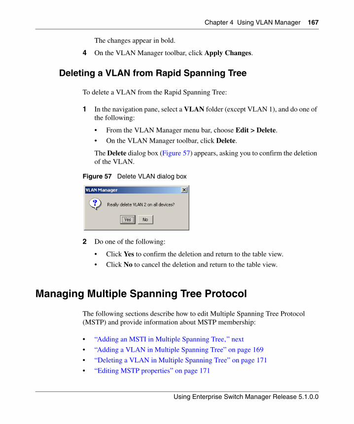
Chapter 4 Using VLAN Manager 167
Using Enterprise Switch Manager Release 5.1.0.0
The changes appear in bold.
4 On the VLAN Manager toolbar, click Apply Changes.
Deleting a VLAN from Rapid Spanning Tree
To delete a VLAN from the Rapid Spanning Tree:
1 In the navigation pane, select a VLAN folder (except VLAN 1), and do one of the following:
• From the VLAN Manager menu bar, choose Edit > Delete.
• On the VLAN Manager toolbar, click Delete.
The Delete dialog box (Figure 57) appears, asking you to confirm the deletion of the VLAN.
Figure 57 Delete VLAN dialog box
2 Do one of the following:
• Click Yes to confirm the deletion and return to the table view.
• Click No to cancel the deletion and return to the table view.
Managing Multiple Spanning Tree Protocol
The following sections describe how to edit Multiple Spanning Tree Protocol (MSTP) and provide information about MSTP membership:
• “Adding an MSTI in Multiple Spanning Tree‚” next
• “Adding a VLAN in Multiple Spanning Tree” on page 169
• “Deleting a VLAN in Multiple Spanning Tree” on page 171
• “Editing MSTP properties” on page 171
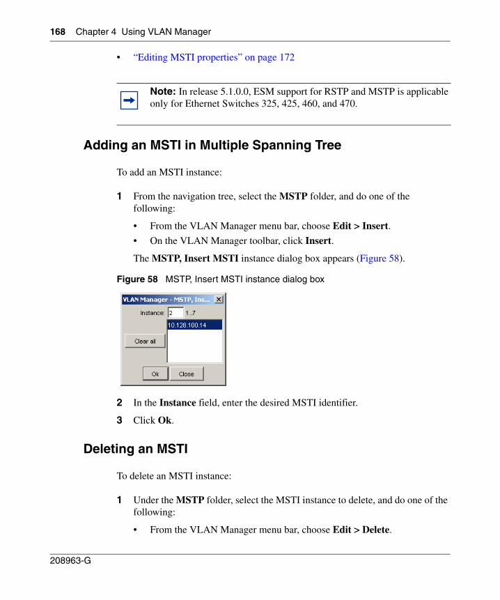
168 Chapter 4 Using VLAN Manager
208963-G
• “Editing MSTI properties” on page 172
Adding an MSTI in Multiple Spanning Tree
To add an MSTI instance:
1 From the navigation tree, select the MSTP folder, and do one of the following:
• From the VLAN Manager menu bar, choose Edit > Insert.
• On the VLAN Manager toolbar, click Insert.
The MSTP, Insert MSTI instance dialog box appears (Figure 58).
Figure 58 MSTP, Insert MSTI instance dialog box
2 In the Instance field, enter the desired MSTI identifier.
3 Click Ok.
Deleting an MSTI
To delete an MSTI instance:
1 Under the MSTP folder, select the MSTI instance to delete, and do one of the following:
• From the VLAN Manager menu bar, choose Edit > Delete.
Note: In release 5.1.0.0, ESM support for RSTP and MSTP is applicable only for Ethernet Switches 325, 425, 460, and 470.
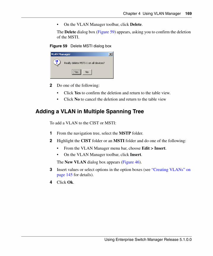
Chapter 4 Using VLAN Manager 169
Using Enterprise Switch Manager Release 5.1.0.0
• On the VLAN Manager toolbar, click Delete.
The Delete dialog box (Figure 59) appears, asking you to confirm the deletion of the MSTI.
Figure 59 Delete MSTI dialog box
2 Do one of the following:
• Click Yes to confirm the deletion and return to the table view.
• Click No to cancel the deletion and return to the table view
Adding a VLAN in Multiple Spanning Tree
To add a VLAN to the CIST or MSTI:
1 From the navigation tree, select the MSTP folder.
2 Highlight the CIST folder or an MSTI folder and do one of the following:
• From the VLAN Manager menu bar, choose Edit > Insert.
• On the VLAN Manager toolbar, click Insert.
The New VLAN dialog box appears (Figure 46).
3 Insert values or select options in the option boxes (see “Creating VLANs” on page 145 for details).
4 Click Ok.
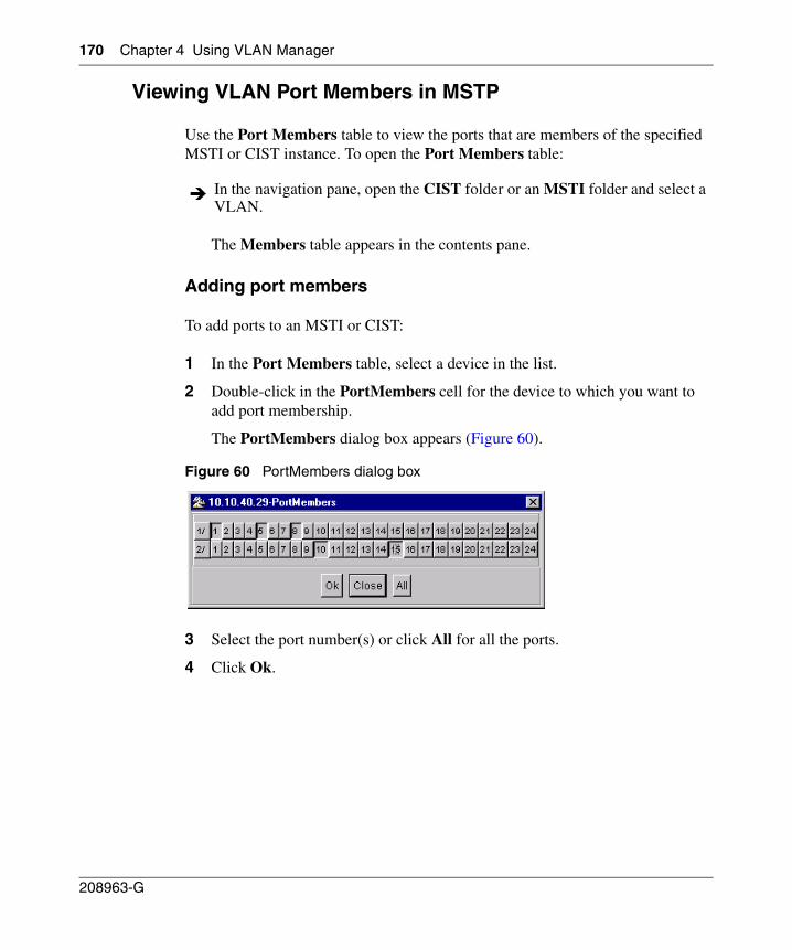
170 Chapter 4 Using VLAN Manager
208963-G
Viewing VLAN Port Members in MSTP
Use the Port Members table to view the ports that are members of the specified MSTI or CIST instance. To open the Port Members table:
The Members table appears in the contents pane.
Adding port members
To add ports to an MSTI or CIST:
1 In the Port Members table, select a device in the list.
2 Double-click in the PortMembers cell for the device to which you want to add port membership.
The PortMembers dialog box appears (Figure 60).
Figure 60 PortMembers dialog box
3 Select the port number(s) or click All for all the ports.
4 Click Ok.
In the navigation pane, open the CIST folder or an MSTI folder and select a VLAN.
Chapter 4 Using VLAN Manager 171
Using Enterprise Switch Manager Release 5.1.0.0
Deleting a VLAN in Multiple Spanning Tree
To delete a VLAN in Multiple Spanning Tree:
1 Under the CIST or MSTI folder, select the VLAN to delete, and do one of the following:
• From the VLAN Manager menu bar, choose Edit > Delete.
• On the VLAN Manager toolbar, click Delete.
The Delete VLAN dialog box (Figure 57) appears, asking you to confirm the deletion of the VLAN.
2 Do one of the following:
• Click Yes to confirm the deletion and return to the table view.
• Click No to cancel the deletion and return to the table view
Editing MSTP properties
To edit the MSTP properties:
1 Under the CIST folder, select the Config item.
2 Choose one of the following:
• To edit the MSTP properties, choose the MSTP tab.
• To edit the CIST properties, choose the CIST tab.
• To edit the MSTI Region properties, choose the MSTI Region tab.
3 In the contents pane, click the item that you want to edit.
The field is highlighted, and you can edit directly in the table.
4 Type information in the text boxes, or select from a list.
The changes appear in bold.
5 On the VLAN Manager toolbar, click Apply Changes.
172 Chapter 4 Using VLAN Manager
208963-G
Editing MSTI properties
To edit the MSTI properties:
1 Under the MSTI folder, select the Config item.
2 In the contents pane, click the item that you want to edit.
The field is highlighted, and you can edit directly in the table.
3 Type information in the text boxes, or select from a list.
The changes appear in bold.
4 On the VLAN Manager toolbar, click Apply Changes.
173
Using Enterprise Switch Manager Release 5.1.0.0
Chapter 5Using MultiLink Trunking Manager
MultiLink Trunking is a point-to-point connection that aggregates multiple ports so that they logically act like a single port with the aggregated bandwidth. Grouping multiple ports into one logical link allows you to achieve higher aggregate throughput on a switch-to-switch or server-to-server application.
MultiLink Trunking Manager manages MultiLink Trunks (MLTs) across devices in a network. You can also use MultiLink Trunking Manager to manage Split MultiLink Trunking (SMLT).
This chapter describes using MultiLink Trunking Manager to manage single and multiple device configurations on switches. It includes the following information:
• “What is MultiLink Trunking Manager?‚” next
• “Starting MultiLink Trunking Manager” on page 175
• “MultiLink Trunking Manager window” on page 176
• “Viewing MultiLink Trunking configurations” on page 183
• “Managing MultiLink Trunks” on page 190
• “Managing SMLT configurations” on page 200
• “Highlighting devices and MLT links on the topology map” on page 209
For more information about MLT concepts, refer to Networking Concepts for the Passport 1000 Series Switch (205588-B) and Configuring VLANs, Spanning Tree, and Link Aggregation: Passport 8000 Series Software Release 4.0 (314725-D).
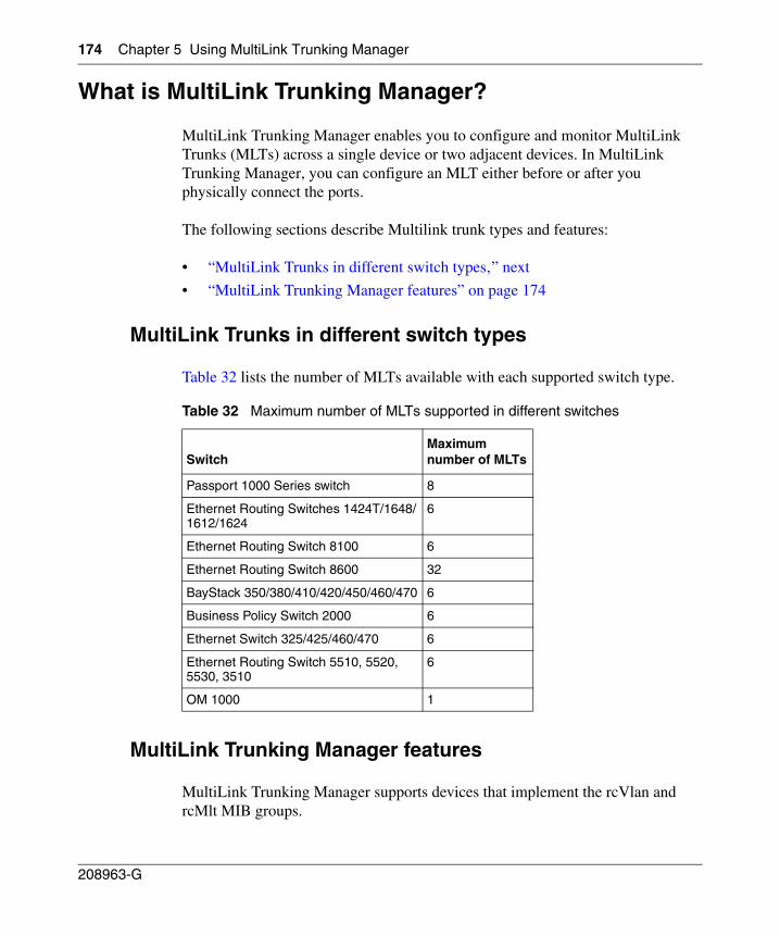
174 Chapter 5 Using MultiLink Trunking Manager
208963-G
What is MultiLink Trunking Manager?
MultiLink Trunking Manager enables you to configure and monitor MultiLink Trunks (MLTs) across a single device or two adjacent devices. In MultiLink Trunking Manager, you can configure an MLT either before or after you physically connect the ports.
The following sections describe Multilink trunk types and features:
• “MultiLink Trunks in different switch types‚” next
• “MultiLink Trunking Manager features” on page 174
MultiLink Trunks in different switch types
Table 32 lists the number of MLTs available with each supported switch type.
MultiLink Trunking Manager features
MultiLink Trunking Manager supports devices that implement the rcVlan and rcMlt MIB groups.
Table 32 Maximum number of MLTs supported in different switches
SwitchMaximumnumber of MLTs
Passport 1000 Series switch 8
Ethernet Routing Switches 1424T/1648/1612/1624
6
Ethernet Routing Switch 8100 6
Ethernet Routing Switch 8600 32
BayStack 350/380/410/420/450/460/470 6
Business Policy Switch 2000 6
Ethernet Switch 325/425/460/470 6
Ethernet Routing Switch 5510, 5520, 5530, 3510
6
OM 1000 1
Chapter 5 Using MultiLink Trunking Manager 175
Using Enterprise Switch Manager Release 5.1.0.0
MultiLink Trunking Manager allows you to:
• Create, delete, or modify MLTs across one or two devices.
• View MLT configuration information such as port and MLT membership.
• View MLT links in the network topology map.
Starting MultiLink Trunking Manager
To start MultiLink Trunking Manager:
• From the Enterprise Switch Manager menu bar, choose Tools > MultiLink Trunking Manager.
• On the keyboard, press [F3].
• On the Enterprise Switch Manager toolbar, click the MultiLink Trunking Manager toolbar button.
The MultiLink Trunking Manager window appears (Figure 61).
Do one of the following:
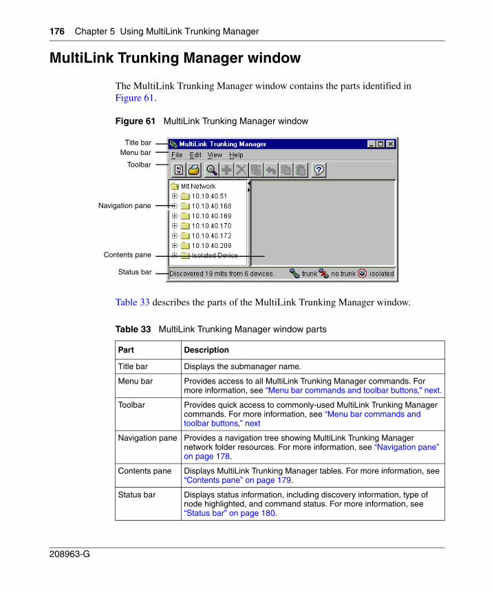
176 Chapter 5 Using MultiLink Trunking Manager
208963-G
MultiLink Trunking Manager window
The MultiLink Trunking Manager window contains the parts identified in Figure 61.
Figure 61 MultiLink Trunking Manager window
Table 33 describes the parts of the MultiLink Trunking Manager window.
Table 33 MultiLink Trunking Manager window parts
Part Description
Title bar Displays the submanager name.
Menu bar Provides access to all MultiLink Trunking Manager commands. For more information, see “Menu bar commands and toolbar buttons‚” next.
Toolbar Provides quick access to commonly-used MultiLink Trunking Manager commands. For more information, see “Menu bar commands and toolbar buttons‚” next
Navigation pane Provides a navigation tree showing MultiLink Trunking Manager network folder resources. For more information, see “Navigation pane” on page 178.
Contents pane Displays MultiLink Trunking Manager tables. For more information, see “Contents pane” on page 179.
Status bar Displays status information, including discovery information, type of node highlighted, and command status. For more information, see “Status bar” on page 180.
Title barMenu bar
Toolbar
Navigation pane
Status bar
Contents pane
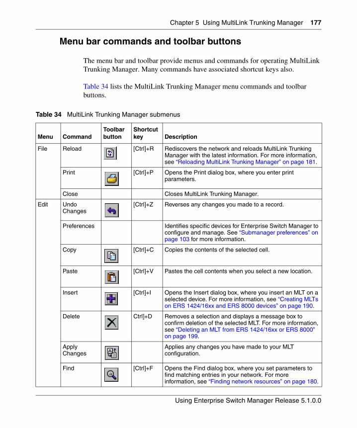
Chapter 5 Using MultiLink Trunking Manager 177
Using Enterprise Switch Manager Release 5.1.0.0
Menu bar commands and toolbar buttons
The menu bar and toolbar provide menus and commands for operating MultiLink Trunking Manager. Many commands have associated shortcut keys also.
Table 34 lists the MultiLink Trunking Manager menu commands and toolbar buttons.
Table 34 MultiLink Trunking Manager submenus
Menu CommandToolbar button
Shortcut key Description
File Reload [Ctrl]+R Rediscovers the network and reloads MultiLink Trunking Manager with the latest information. For more information, see “Reloading MultiLink Trunking Manager” on page 181.
Print [Ctrl]+P Opens the Print dialog box, where you enter print parameters.
Close Closes MultiLink Trunking Manager.
Edit Undo Changes
[Ctrl]+Z Reverses any changes you made to a record.
Preferences Identifies specific devices for Enterprise Switch Manager to configure and manage. See “Submanager preferences” on page 103 for more information.
Copy [Ctrl]+C Copies the contents of the selected cell.
Paste [Ctrl]+V Pastes the cell contents when you select a new location.
Insert [Ctrl]+I Opens the Insert dialog box, where you insert an MLT on a selected device. For more information, see “Creating MLTs on ERS 1424/16xx and ERS 8000 devices” on page 190.
Delete Ctrl]+D Removes a selection and displays a message box to confirm deletion of the selected MLT. For more information, see “Deleting an MLT from ERS 1424/16xx or ERS 8000” on page 199.
Apply Changes
Applies any changes you have made to your MLT configuration.
Find [Ctrl]+F Opens the Find dialog box, where you set parameters to find matching entries in your network. For more information, see “Finding network resources” on page 180.
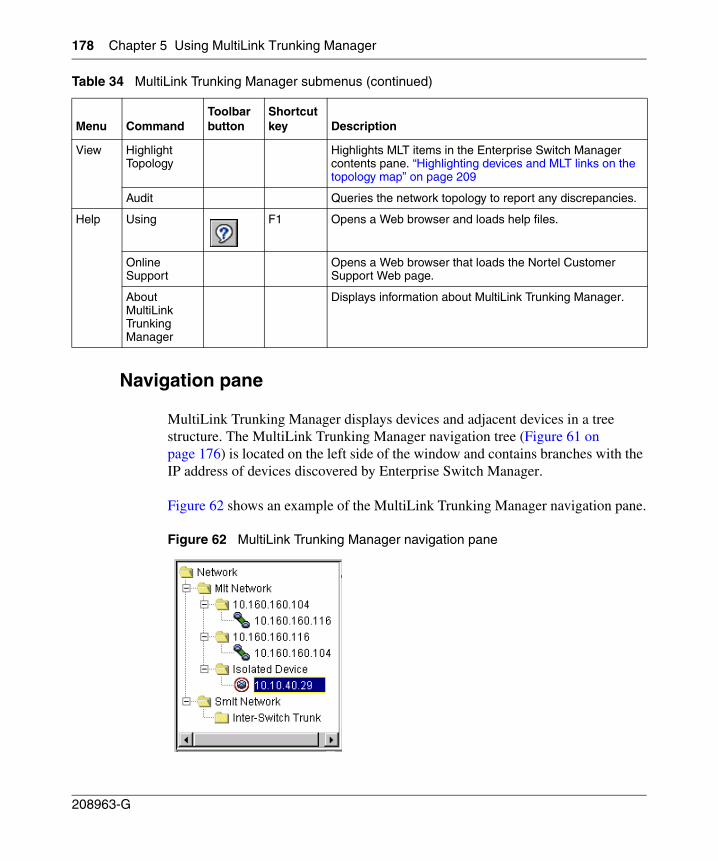
178 Chapter 5 Using MultiLink Trunking Manager
208963-G
Navigation pane
MultiLink Trunking Manager displays devices and adjacent devices in a tree structure. The MultiLink Trunking Manager navigation tree (Figure 61 on page 176) is located on the left side of the window and contains branches with the IP address of devices discovered by Enterprise Switch Manager.
Figure 62 shows an example of the MultiLink Trunking Manager navigation pane.
Figure 62 MultiLink Trunking Manager navigation pane
View Highlight Topology
Highlights MLT items in the Enterprise Switch Manager contents pane. “Highlighting devices and MLT links on the topology map” on page 209
Audit Queries the network topology to report any discrepancies.
Help Using F1 Opens a Web browser and loads help files.
Online Support
Opens a Web browser that loads the Nortel Customer Support Web page.
About MultiLink Trunking Manager
Displays information about MultiLink Trunking Manager.
Table 34 MultiLink Trunking Manager submenus (continued)
Menu CommandToolbar button
Shortcut key Description
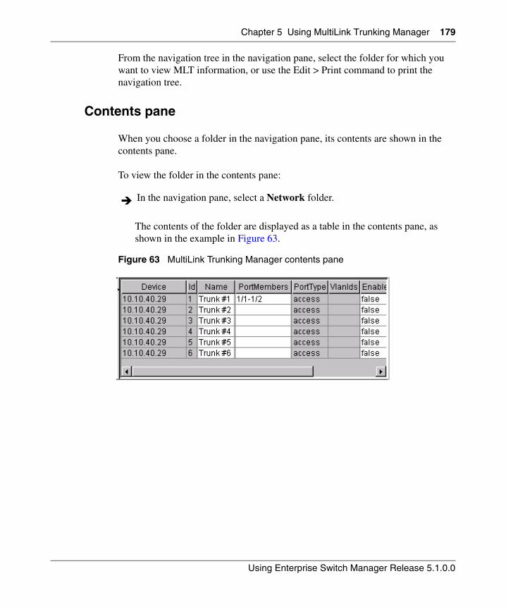
Chapter 5 Using MultiLink Trunking Manager 179
Using Enterprise Switch Manager Release 5.1.0.0
From the navigation tree in the navigation pane, select the folder for which you want to view MLT information, or use the Edit > Print command to print the navigation tree.
Contents pane
When you choose a folder in the navigation pane, its contents are shown in the contents pane.
To view the folder in the contents pane:
The contents of the folder are displayed as a table in the contents pane, as shown in the example in Figure 63.
Figure 63 MultiLink Trunking Manager contents pane
In the navigation pane, select a Network folder.
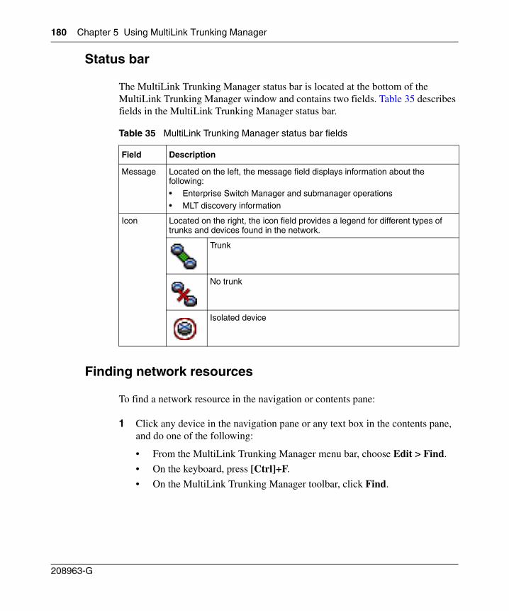
180 Chapter 5 Using MultiLink Trunking Manager
208963-G
Status bar
The MultiLink Trunking Manager status bar is located at the bottom of the MultiLink Trunking Manager window and contains two fields. Table 35 describes fields in the MultiLink Trunking Manager status bar.
Finding network resources
To find a network resource in the navigation or contents pane:
1 Click any device in the navigation pane or any text box in the contents pane, and do one of the following:
• From the MultiLink Trunking Manager menu bar, choose Edit > Find.
• On the keyboard, press [Ctrl]+F.
• On the MultiLink Trunking Manager toolbar, click Find.
Table 35 MultiLink Trunking Manager status bar fields
Field Description
Message Located on the left, the message field displays information about the following:
• Enterprise Switch Manager and submanager operations
• MLT discovery information
Icon Located on the right, the icon field provides a legend for different types of trunks and devices found in the network.
Trunk
No trunk
Isolated device
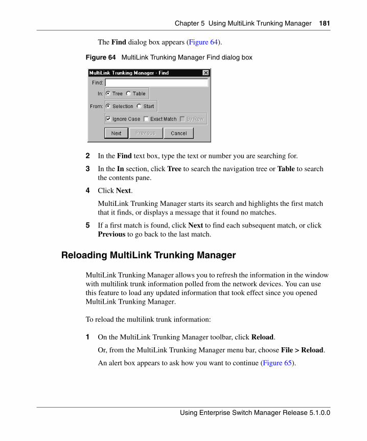
Chapter 5 Using MultiLink Trunking Manager 181
Using Enterprise Switch Manager Release 5.1.0.0
The Find dialog box appears (Figure 64).
Figure 64 MultiLink Trunking Manager Find dialog box
2 In the Find text box, type the text or number you are searching for.
3 In the In section, click Tree to search the navigation tree or Table to search the contents pane.
4 Click Next.
MultiLink Trunking Manager starts its search and highlights the first match that it finds, or displays a message that it found no matches.
5 If a first match is found, click Next to find each subsequent match, or click Previous to go back to the last match.
Reloading MultiLink Trunking Manager
MultiLink Trunking Manager allows you to refresh the information in the window with multilink trunk information polled from the network devices. You can use this feature to load any updated information that took effect since you opened MultiLink Trunking Manager.
To reload the multilink trunk information:
1 On the MultiLink Trunking Manager toolbar, click Reload.
Or, from the MultiLink Trunking Manager menu bar, choose File > Reload.
An alert box appears to ask how you want to continue (Figure 65).
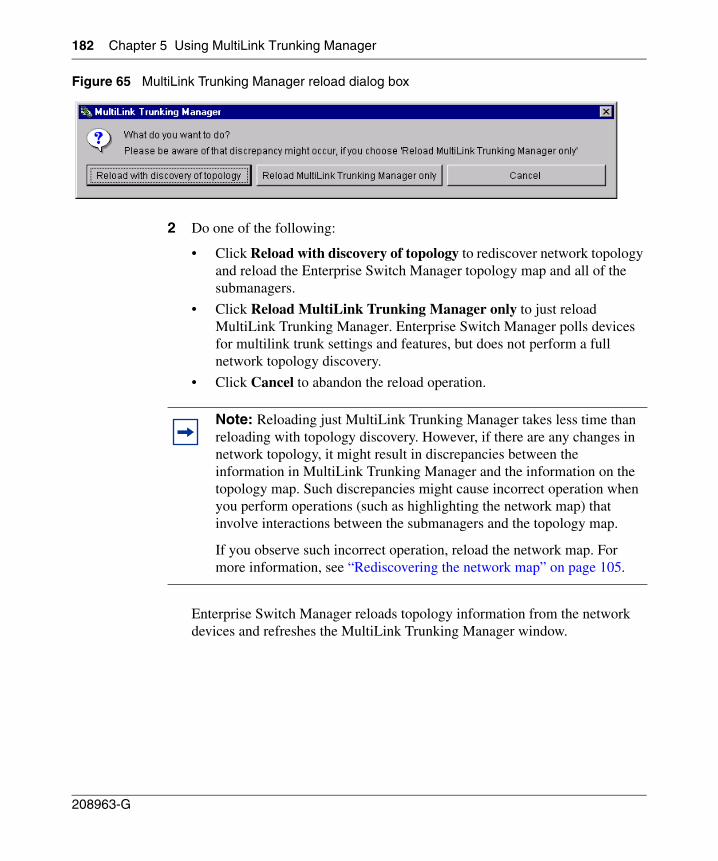
182 Chapter 5 Using MultiLink Trunking Manager
208963-G
Figure 65 MultiLink Trunking Manager reload dialog box
2 Do one of the following:
• Click Reload with discovery of topology to rediscover network topology and reload the Enterprise Switch Manager topology map and all of the submanagers.
• Click Reload MultiLink Trunking Manager only to just reload MultiLink Trunking Manager. Enterprise Switch Manager polls devices for multilink trunk settings and features, but does not perform a full network topology discovery.
• Click Cancel to abandon the reload operation.
Enterprise Switch Manager reloads topology information from the network devices and refreshes the MultiLink Trunking Manager window.
Note: Reloading just MultiLink Trunking Manager takes less time than reloading with topology discovery. However, if there are any changes in network topology, it might result in discrepancies between the information in MultiLink Trunking Manager and the information on the topology map. Such discrepancies might cause incorrect operation when you perform operations (such as highlighting the network map) that involve interactions between the submanagers and the topology map.
If you observe such incorrect operation, reload the network map. For more information, see “Rediscovering the network map” on page 105.
Chapter 5 Using MultiLink Trunking Manager 183
Using Enterprise Switch Manager Release 5.1.0.0
Viewing MultiLink Trunking configurations
In the MultiLink Trunking Manager navigation pane, the navigation tree shows the IP addresses of discovered devices. Icons associated with IP addresses on the branches indicate the following types of MLTs:
• Trunk—a switch that links to another device in the network and has MLT configurations.
• No trunk—a switch that links to another device in the network but does not have an active MLT configured.
• Isolated—a switch connected only to a hub.
The following sections describe how to use MultiLink Trunking Manager:
• “Viewing trunk connections‚” next
• “Viewing no trunk configurations” on page 185
• “Viewing isolated devices” on page 186
• “Viewing inter-switch trunks” on page 187
• “Viewing SMLTs” on page 188
• “Viewing single-port SMLTs” on page 189
Viewing trunk connections
You can view the trunk connections for an MLT and configure new trunks to increase bandwidth.
To view trunk connections:
In the navigation pane, select a device that is represented by a trunk icon.
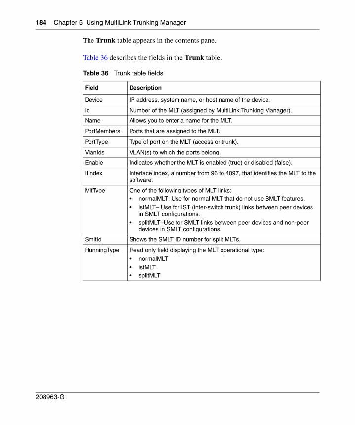
184 Chapter 5 Using MultiLink Trunking Manager
208963-G
The Trunk table appears in the contents pane.
Table 36 describes the fields in the Trunk table.
Table 36 Trunk table fields
Field Description
Device IP address, system name, or host name of the device.
Id Number of the MLT (assigned by MultiLink Trunking Manager).
Name Allows you to enter a name for the MLT.
PortMembers Ports that are assigned to the MLT.
PortType Type of port on the MLT (access or trunk).
VlanIds VLAN(s) to which the ports belong.
Enable Indicates whether the MLT is enabled (true) or disabled (false).
IfIndex Interface index, a number from 96 to 4097, that identifies the MLT to the software.
MltType One of the following types of MLT links:• normalMLT–Use for normal MLT that do not use SMLT features.
• istMLT– Use for IST (inter-switch trunk) links between peer devices in SMLT configurations.
• splitMLT–Use for SMLT links between peer devices and non-peer devices in SMLT configurations.
SmltId Shows the SMLT ID number for split MLTs.
RunningType Read only field displaying the MLT operational type:
• normalMLT
• istMLT• splitMLT
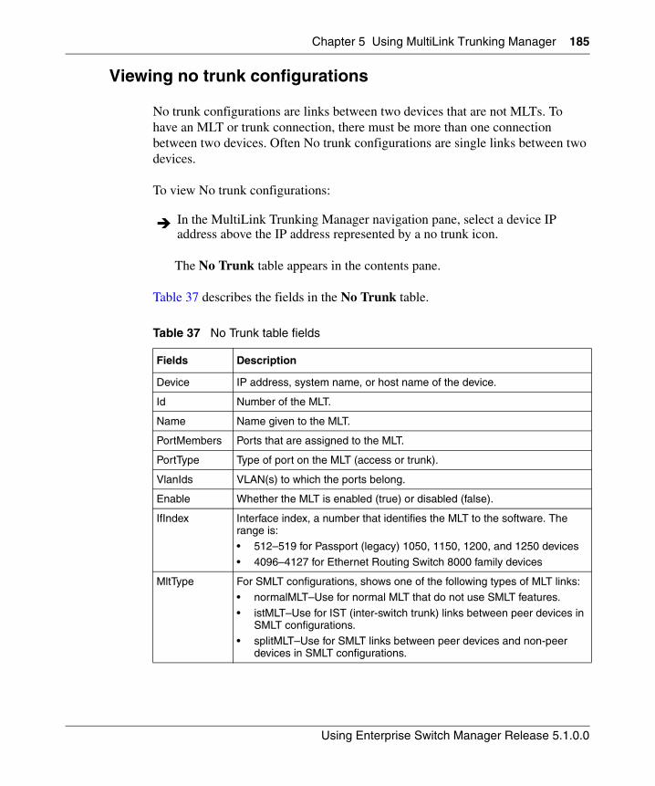
Chapter 5 Using MultiLink Trunking Manager 185
Using Enterprise Switch Manager Release 5.1.0.0
Viewing no trunk configurations
No trunk configurations are links between two devices that are not MLTs. To have an MLT or trunk connection, there must be more than one connection between two devices. Often No trunk configurations are single links between two devices.
To view No trunk configurations:
The No Trunk table appears in the contents pane.
Table 37 describes the fields in the No Trunk table.
In the MultiLink Trunking Manager navigation pane, select a device IP address above the IP address represented by a no trunk icon.
Table 37 No Trunk table fields
Fields Description
Device IP address, system name, or host name of the device.
Id Number of the MLT.
Name Name given to the MLT.
PortMembers Ports that are assigned to the MLT.
PortType Type of port on the MLT (access or trunk).
VlanIds VLAN(s) to which the ports belong.
Enable Whether the MLT is enabled (true) or disabled (false).
IfIndex Interface index, a number that identifies the MLT to the software. The range is:• 512–519 for Passport (legacy) 1050, 1150, 1200, and 1250 devices
• 4096–4127 for Ethernet Routing Switch 8000 family devices
MltType For SMLT configurations, shows one of the following types of MLT links:• normalMLT–Use for normal MLT that do not use SMLT features.
• istMLT–Use for IST (inter-switch trunk) links between peer devices in SMLT configurations.
• splitMLT–Use for SMLT links between peer devices and non-peer devices in SMLT configurations.
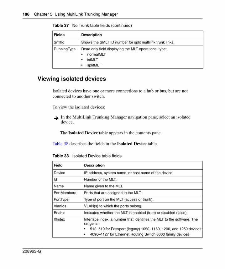
186 Chapter 5 Using MultiLink Trunking Manager
208963-G
Viewing isolated devices
Isolated devices have one or more connections to a hub or bus, but are not connected to another switch.
To view the isolated devices:
The Isolated Device table appears in the contents pane.
Table 38 describes the fields in the Isolated Device table.
SmltId Shows the SMLT ID number for split multilink trunk links.
RunningType Read only field displaying the MLT operational type:
• normalMLT• istMLT
• splitMLT
In the MultiLink Trunking Manager navigation pane, select an isolated device.
Table 38 Isolated Device table fields
Field Description
Device IP address, system name, or host name of the device.
Id Number of the MLT.
Name Name given to the MLT.
PortMembers Ports that are assigned to the MLT.
PortType Type of port on the MLT (access or trunk).
VlanIds VLAN(s) to which the ports belong.
Enable Indicates whether the MLT is enabled (true) or disabled (false).
IfIndex Interface index, a number that identifies the MLT to the software. The range is:
• 512–519 for Passport (legacy) 1050, 1150, 1200, and 1250 devices• 4096–4127 for Ethernet Routing Switch 8000 family devices
Table 37 No Trunk table fields (continued)
Fields Description
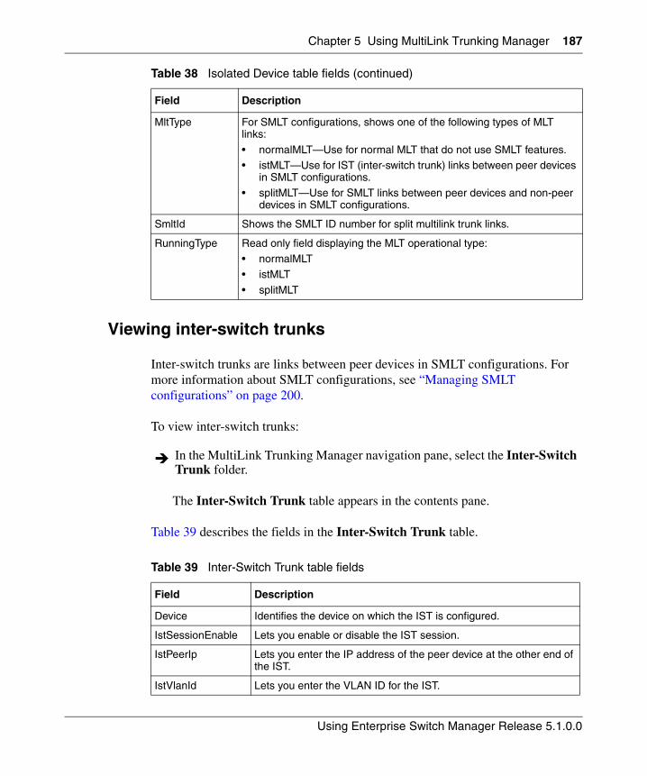
Chapter 5 Using MultiLink Trunking Manager 187
Using Enterprise Switch Manager Release 5.1.0.0
Viewing inter-switch trunks
Inter-switch trunks are links between peer devices in SMLT configurations. For more information about SMLT configurations, see “Managing SMLT configurations” on page 200.
To view inter-switch trunks:
The Inter-Switch Trunk table appears in the contents pane.
Table 39 describes the fields in the Inter-Switch Trunk table.
MltType For SMLT configurations, shows one of the following types of MLT links:
• normalMLT—Use for normal MLT that do not use SMLT features.• istMLT—Use for IST (inter-switch trunk) links between peer devices
in SMLT configurations.
• splitMLT—Use for SMLT links between peer devices and non-peer devices in SMLT configurations.
SmltId Shows the SMLT ID number for split multilink trunk links.
RunningType Read only field displaying the MLT operational type:• normalMLT
• istMLT
• splitMLT
In the MultiLink Trunking Manager navigation pane, select the Inter-Switch Trunk folder.
Table 39 Inter-Switch Trunk table fields
Field Description
Device Identifies the device on which the IST is configured.
IstSessionEnable Lets you enable or disable the IST session.
IstPeerIp Lets you enter the IP address of the peer device at the other end of the IST.
IstVlanId Lets you enter the VLAN ID for the IST.
Table 38 Isolated Device table fields (continued)
Field Description
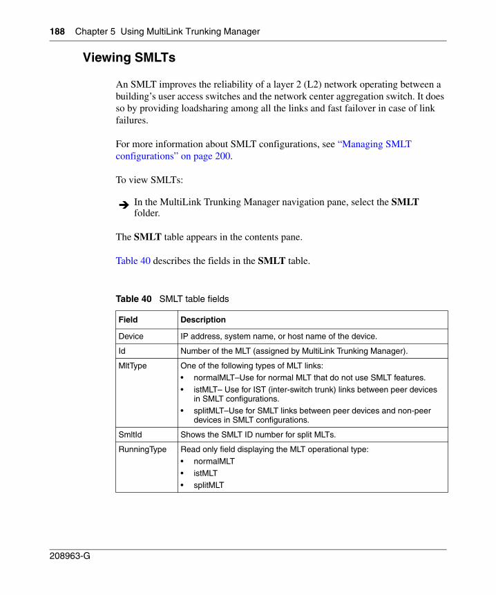
188 Chapter 5 Using MultiLink Trunking Manager
208963-G
Viewing SMLTs
An SMLT improves the reliability of a layer 2 (L2) network operating between a building’s user access switches and the network center aggregation switch. It does so by providing loadsharing among all the links and fast failover in case of link failures.
For more information about SMLT configurations, see “Managing SMLT configurations” on page 200.
To view SMLTs:
The SMLT table appears in the contents pane.
Table 40 describes the fields in the SMLT table.
In the MultiLink Trunking Manager navigation pane, select the SMLT folder.
Table 40 SMLT table fields
Field Description
Device IP address, system name, or host name of the device.
Id Number of the MLT (assigned by MultiLink Trunking Manager).
MltType One of the following types of MLT links:• normalMLT–Use for normal MLT that do not use SMLT features.
• istMLT– Use for IST (inter-switch trunk) links between peer devices in SMLT configurations.
• splitMLT–Use for SMLT links between peer devices and non-peer devices in SMLT configurations.
SmltId Shows the SMLT ID number for split MLTs.
RunningType Read only field displaying the MLT operational type:
• normalMLT
• istMLT• splitMLT
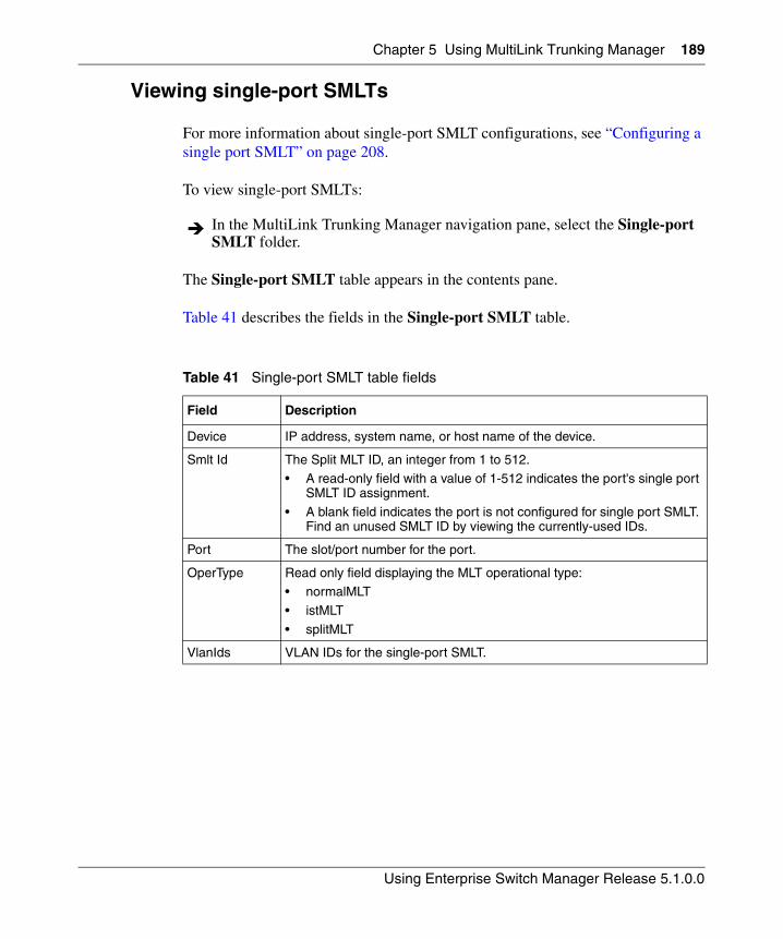
Chapter 5 Using MultiLink Trunking Manager 189
Using Enterprise Switch Manager Release 5.1.0.0
Viewing single-port SMLTs
For more information about single-port SMLT configurations, see “Configuring a single port SMLT” on page 208.
To view single-port SMLTs:
The Single-port SMLT table appears in the contents pane.
Table 41 describes the fields in the Single-port SMLT table.
In the MultiLink Trunking Manager navigation pane, select the Single-port SMLT folder.
Table 41 Single-port SMLT table fields
Field Description
Device IP address, system name, or host name of the device.
Smlt Id The Split MLT ID, an integer from 1 to 512.• A read-only field with a value of 1-512 indicates the port's single port
SMLT ID assignment.
• A blank field indicates the port is not configured for single port SMLT. Find an unused SMLT ID by viewing the currently-used IDs.
Port The slot/port number for the port.
OperType Read only field displaying the MLT operational type:• normalMLT
• istMLT
• splitMLT
VlanIds VLAN IDs for the single-port SMLT.
190 Chapter 5 Using MultiLink Trunking Manager
208963-G
Managing MultiLink Trunks
This following sections describe common operations you can perform using MultiLink Trunking Manager:
• “Creating MLTs on ERS 1424/16xx and ERS 8000 devices”
• “Viewing MLT port information” on page 197
• “Editing a port on an MLT” on page 198
• “Deleting an MLT from ERS 1424/16xx or ERS 8000” on page 199
• “Editing an MLT” on page 199
Creating MLTs on ERS 1424/16xx and ERS 8000 devices
To create an MLT on Ethernet Routing Switch 1424/16xx and Ethernet Routing Switch 8000 devices, the device must have more than one connection to another device. With MultiLink Trunking Manager, you can create an MLT on a device and then physically connect the ports, or you can connect the ports first and then configure the MLT.
Insert MLT dialog box
The appearance of the Insert MLT dialog box differs depending on how you open it.
• If you select a device folder and click Insert, the single-node Insert MLT dialog box appears. For more information, see “Creating an MLT with one device for ERS 8000‚” next.
You can use the single-node Insert MLT dialog box to create MLT configurations even in situations where the physical connections are absent or have not been detected by Enterprise Switch Manager.
Note: The procedures in this section do not apply to Ethernet Switch, Ethernet Routing Switch 55xx/35xx, or Legacy BayStack devices which are preconfigured with six MLTs. You cannot delete or add MLTs to these switches. To edit MLTs on these switches, see “Editing an MLT” on page 199 and “Editing a port on an MLT” on page 198.
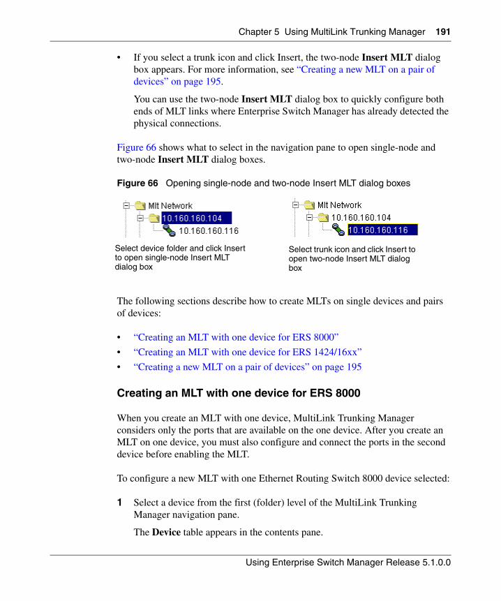
Chapter 5 Using MultiLink Trunking Manager 191
Using Enterprise Switch Manager Release 5.1.0.0
• If you select a trunk icon and click Insert, the two-node Insert MLT dialog box appears. For more information, see “Creating a new MLT on a pair of devices” on page 195.
You can use the two-node Insert MLT dialog box to quickly configure both ends of MLT links where Enterprise Switch Manager has already detected the physical connections.
Figure 66 shows what to select in the navigation pane to open single-node and two-node Insert MLT dialog boxes.
Figure 66 Opening single-node and two-node Insert MLT dialog boxes
The following sections describe how to create MLTs on single devices and pairs of devices:
• “Creating an MLT with one device for ERS 8000”
• “Creating an MLT with one device for ERS 1424/16xx”
• “Creating a new MLT on a pair of devices” on page 195
Creating an MLT with one device for ERS 8000
When you create an MLT with one device, MultiLink Trunking Manager considers only the ports that are available on the one device. After you create an MLT on one device, you must also configure and connect the ports in the second device before enabling the MLT.
To configure a new MLT with one Ethernet Routing Switch 8000 device selected:
1 Select a device from the first (folder) level of the MultiLink Trunking Manager navigation pane.
The Device table appears in the contents pane.
Select device folder and click Insert to open single-node Insert MLT dialog box
Select trunk icon and click Insert to open two-node Insert MLT dialog box
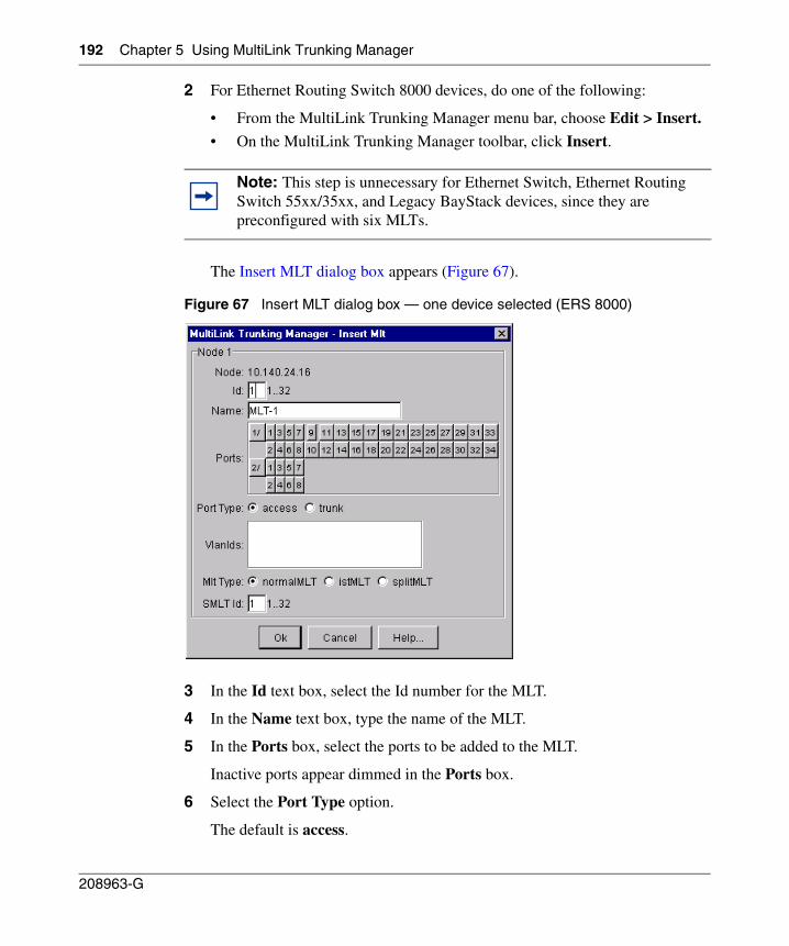
192 Chapter 5 Using MultiLink Trunking Manager
208963-G
2 For Ethernet Routing Switch 8000 devices, do one of the following:
• From the MultiLink Trunking Manager menu bar, choose Edit > Insert.
• On the MultiLink Trunking Manager toolbar, click Insert.
The Insert MLT dialog box appears (Figure 67).
Figure 67 Insert MLT dialog box — one device selected (ERS 8000)
3 In the Id text box, select the Id number for the MLT.
4 In the Name text box, type the name of the MLT.
5 In the Ports box, select the ports to be added to the MLT.
Inactive ports appear dimmed in the Ports box.
6 Select the Port Type option.
The default is access.
Note: This step is unnecessary for Ethernet Switch, Ethernet Routing Switch 55xx/35xx, and Legacy BayStack devices, since they are preconfigured with six MLTs.
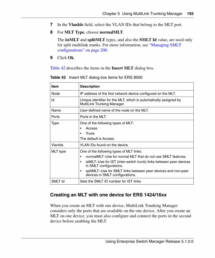
Chapter 5 Using MultiLink Trunking Manager 193
Using Enterprise Switch Manager Release 5.1.0.0
7 In the VlanIds field, select the VLAN IDs that belong to the MLT port.
8 For MLT Type, choose normalMLT.
The istMLT and splitMLT types, and also the SMLT Id value, are used only for split multilink trunks. For more information, see “Managing SMLT configurations” on page 200.
9 Click Ok.
Table 42 describes the items in the Insert MLT dialog box.
Creating an MLT with one device for ERS 1424/16xx
When you create an MLT with one device, MultiLink Trunking Manager considers only the ports that are available on the one device. After you create an MLT on one device, you must also configure and connect the ports in the second device before enabling the MLT.
Table 42 Insert MLT dialog box items for ERS 8000
Item Description
Node IP address of the first network device configured on the MLT.
Id Unique identifier for the MLT, which is automatically assigned by MultiLink Trunking Manager.
Name User-defined name of the node on the MLT.
Ports Ports in the MLT.
Type One of the following types of MLT:
• Access
• TrunkThe default is Access.
VlanIds VLAN IDs found on the device.
MLT type One of the following types of MLT links:• normalMLT–Use for normal MLT that do not use SMLT features.
• istMLT–Use for IST (inter-switch trunk) links between peer devices in SMLT configurations.
• splitMLT–Use for SMLT links between peer devices and non-peer devices in SMLT configurations.
SMLT Id Sets the SMLT ID number for IST links.
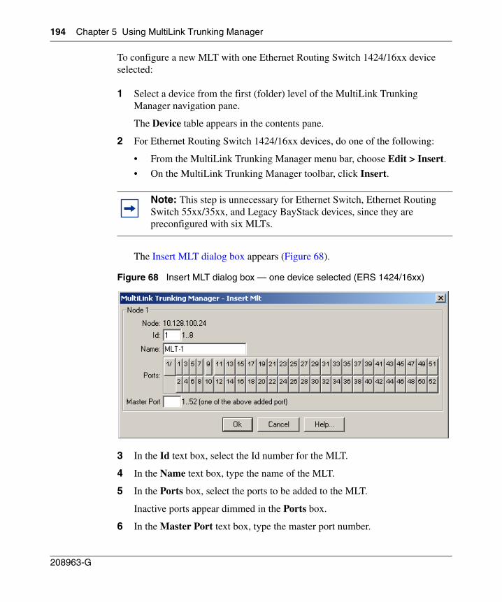
194 Chapter 5 Using MultiLink Trunking Manager
208963-G
To configure a new MLT with one Ethernet Routing Switch 1424/16xx device selected:
1 Select a device from the first (folder) level of the MultiLink Trunking Manager navigation pane.
The Device table appears in the contents pane.
2 For Ethernet Routing Switch 1424/16xx devices, do one of the following:
• From the MultiLink Trunking Manager menu bar, choose Edit > Insert.
• On the MultiLink Trunking Manager toolbar, click Insert.
The Insert MLT dialog box appears (Figure 68).
Figure 68 Insert MLT dialog box — one device selected (ERS 1424/16xx)
3 In the Id text box, select the Id number for the MLT.
4 In the Name text box, type the name of the MLT.
5 In the Ports box, select the ports to be added to the MLT.
Inactive ports appear dimmed in the Ports box.
6 In the Master Port text box, type the master port number.
Note: This step is unnecessary for Ethernet Switch, Ethernet Routing Switch 55xx/35xx, and Legacy BayStack devices, since they are preconfigured with six MLTs.
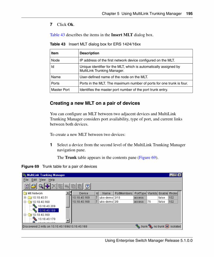
Chapter 5 Using MultiLink Trunking Manager 195
Using Enterprise Switch Manager Release 5.1.0.0
7 Click Ok.
Table 43 describes the items in the Insert MLT dialog box.
Creating a new MLT on a pair of devices
You can configure an MLT between two adjacent devices and MultiLink Trunking Manager considers port availability, type of port, and current links between both devices.
To create a new MLT between two devices:
1 Select a device from the second level of the MultiLink Trunking Manager navigation pane.
The Trunk table appears in the contents pane (Figure 69).
Figure 69 Trunk table for a pair of devices
Table 43 Insert MLT dialog box for ERS 1424/16xx
Item Description
Node IP address of the first network device configured on the MLT.
Id Unique identifier for the MLT, which is automatically assigned by MultiLink Trunking Manager.
Name User-defined name of the node on the MLT.
Ports Ports in the MLT. The maximum number of ports for one trunk is four.
Master Port Identifies the master port number of the port trunk entry.
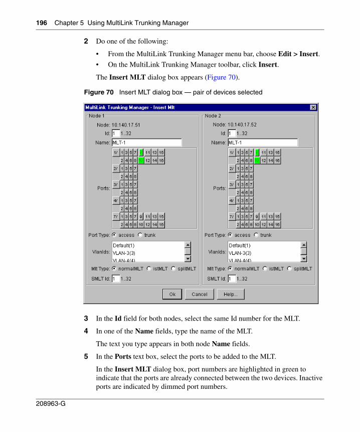
196 Chapter 5 Using MultiLink Trunking Manager
208963-G
2 Do one of the following:
• From the MultiLink Trunking Manager menu bar, choose Edit > Insert.
• On the MultiLink Trunking Manager toolbar, click Insert.
The Insert MLT dialog box appears (Figure 70).
Figure 70 Insert MLT dialog box — pair of devices selected
3 In the Id field for both nodes, select the same Id number for the MLT.
4 In one of the Name fields, type the name of the MLT.
The text you type appears in both node Name fields.
5 In the Ports text box, select the ports to be added to the MLT.
In the Insert MLT dialog box, port numbers are highlighted in green to indicate that the ports are already connected between the two devices. Inactive ports are indicated by dimmed port numbers.
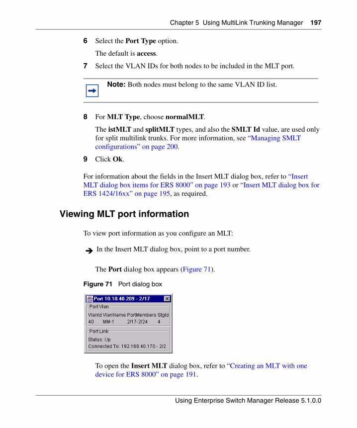
Chapter 5 Using MultiLink Trunking Manager 197
Using Enterprise Switch Manager Release 5.1.0.0
6 Select the Port Type option.
The default is access.
7 Select the VLAN IDs for both nodes to be included in the MLT port.
8 For MLT Type, choose normalMLT.
The istMLT and splitMLT types, and also the SMLT Id value, are used only for split multilink trunks. For more information, see “Managing SMLT configurations” on page 200.
9 Click Ok.
For information about the fields in the Insert MLT dialog box, refer to “Insert MLT dialog box items for ERS 8000” on page 193 or “Insert MLT dialog box for ERS 1424/16xx” on page 195, as required.
Viewing MLT port information
To view port information as you configure an MLT:
The Port dialog box appears (Figure 71).
Figure 71 Port dialog box
To open the Insert MLT dialog box, refer to “Creating an MLT with one device for ERS 8000” on page 191.
Note: Both nodes must belong to the same VLAN ID list.
In the Insert MLT dialog box, point to a port number.
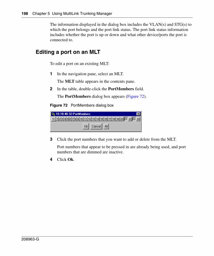
198 Chapter 5 Using MultiLink Trunking Manager
208963-G
The information displayed in the dialog box includes the VLAN(s) and STG(s) to which the port belongs and the port link status. The port link status information includes whether the port is up or down and what other device/ports the port is connected to.
Editing a port on an MLT
To edit a port on an existing MLT:
1 In the navigation pane, select an MLT.
The MLT table appears in the contents pane.
2 In the table, double-click the PortMembers field.
The PortMembers dialog box appears (Figure 72).
Figure 72 PortMembers dialog box
3 Click the port numbers that you want to add or delete from the MLT.
Port numbers that appear to be pressed in are already being used, and port numbers that are dimmed are inactive.
4 Click Ok.
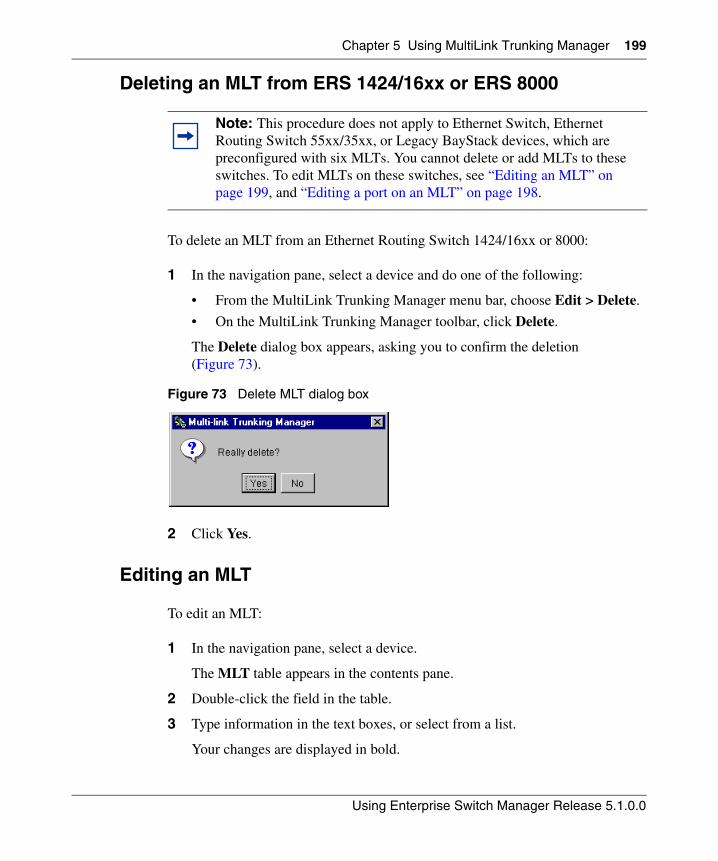
Chapter 5 Using MultiLink Trunking Manager 199
Using Enterprise Switch Manager Release 5.1.0.0
Deleting an MLT from ERS 1424/16xx or ERS 8000
To delete an MLT from an Ethernet Routing Switch 1424/16xx or 8000:
1 In the navigation pane, select a device and do one of the following:
• From the MultiLink Trunking Manager menu bar, choose Edit > Delete.
• On the MultiLink Trunking Manager toolbar, click Delete.
The Delete dialog box appears, asking you to confirm the deletion (Figure 73).
Figure 73 Delete MLT dialog box
2 Click Yes.
Editing an MLT
To edit an MLT:
1 In the navigation pane, select a device.
The MLT table appears in the contents pane.
2 Double-click the field in the table.
3 Type information in the text boxes, or select from a list.
Your changes are displayed in bold.
Note: This procedure does not apply to Ethernet Switch, Ethernet Routing Switch 55xx/35xx, or Legacy BayStack devices, which are preconfigured with six MLTs. You cannot delete or add MLTs to these switches. To edit MLTs on these switches, see “Editing an MLT” on page 199, and “Editing a port on an MLT” on page 198.
200 Chapter 5 Using MultiLink Trunking Manager
208963-G
4 On the MultiLink Trunking Manager toolbar, click Apply Changes.
Managing SMLT configurations
Mission critical networks require resiliency, and as a result, must be designed with a number of redundancy features. Within the Passport 8000 Series switch, such features include CPU redundancy and link redundancy using MLT.
In order to provide device redundancy, most enterprise networks are designed with redundant connections between aggregation (core) switches and user access switches. For networks with just one aggregation switch, MLT provides redundancy and load sharing.
SMLT improves the reliability of a layer 2 (L2) network operating between a building’s user access switches and the network center aggregation switch. It does so by providing loadsharing among all the links and fast failover in case of link failures.
An Inter Switch Trunk (IST) operates between the aggregation switches and allows them to exchange information. This permits the rapid detection of any faults and the modification of forwarding paths.
For more information about SMLT, see Configuring VLANs, Spanning Tree, and Link Aggregation: Passport 8000 Series Software Release 4.0 (314725-D).
To configure SMLT, you must establish three sets of configurations on the devices:
• On the two peer aggregation switches, you configure an IST (inter-switch trunk). For more information, see “Configuring IST links‚” next.
• On the two peer aggregation switches, you configure SMLT links to the edge switch. For more information, see “Configuring SMLT links on peer devices” on page 206.
Note: Although SMLT is primarily designed for layer 2 networks, it provides benefits for layer 3 networks as well.
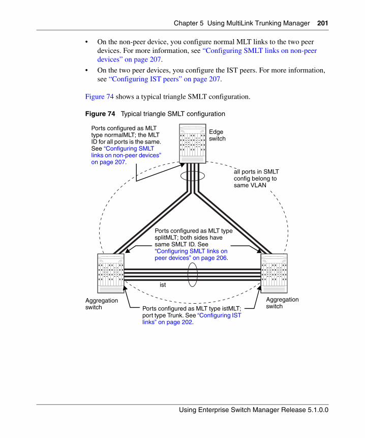
Chapter 5 Using MultiLink Trunking Manager 201
Using Enterprise Switch Manager Release 5.1.0.0
• On the non-peer device, you configure normal MLT links to the two peer devices. For more information, see “Configuring SMLT links on non-peer devices” on page 207.
• On the two peer devices, you configure the IST peers. For more information, see “Configuring IST peers” on page 207.
Figure 74 shows a typical triangle SMLT configuration.
Figure 74 Typical triangle SMLT configuration
ist
all ports in SMLT config belong to same VLAN
Ports configured as MLT type istMLT; port type Trunk. See “Configuring IST links” on page 202.
Ports configured as MLT type splitMLT; both sides have same SMLT ID. See “Configuring SMLT links on peer devices” on page 206.
Ports configured as MLT type normalMLT; the MLT ID for all ports is the same. See “Configuring SMLT links on non-peer devices” on page 207.
Aggregation switch
Edge switch
Aggregation switch
202 Chapter 5 Using MultiLink Trunking Manager
208963-G
Configuring IST links
You can configure IST links in SMLT configurations in either of two ways:
• On a pair of devices. For more information, see “Configuring IST links on pairs of devices” on page 202.
• On a single device. For more information, see “Configuring IST links on a single device” on page 204.
When you configure IST links on a single device, you must also repeat the same procedure to configure the IST links on the device at the other end of the IST.
Configuring IST links on pairs of devices
If Enterprise Switch Manager determines that the physical connections you are configuring as an IST already exist, you can configure both ends of the IST at the same time. However, if you have not yet established the network connections that will constitute the IST, you must configure each end of the IST separately. For more information, see “Configuring IST links on a single device” on page 204.
To configure IST links on a pair of devices:
1 In the MultiLink Trunking Manager navigation pane, open a folder for one of the devices on which you want to configure the IST.
2 In the folder, select the device at the other end of the IST.
3 On the MultiLink Trunking Manager toolbar, click Insert.
4 The Insert MLT dialog box for a pair of nodes appears (Figure 75).
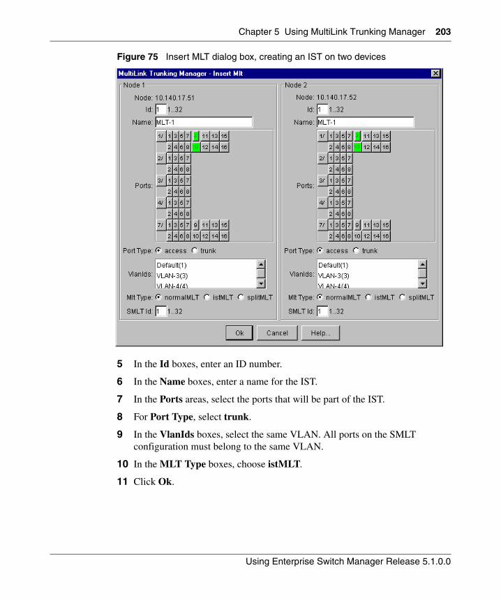
Chapter 5 Using MultiLink Trunking Manager 203
Using Enterprise Switch Manager Release 5.1.0.0
Figure 75 Insert MLT dialog box, creating an IST on two devices
5 In the Id boxes, enter an ID number.
6 In the Name boxes, enter a name for the IST.
7 In the Ports areas, select the ports that will be part of the IST.
8 For Port Type, select trunk.
9 In the VlanIds boxes, select the same VLAN. All ports on the SMLT configuration must belong to the same VLAN.
10 In the MLT Type boxes, choose istMLT.
11 Click Ok.
204 Chapter 5 Using MultiLink Trunking Manager
208963-G
Configuring IST links on a single device
The following procedure describes how to configure an IST link on a single device. You must also perform this procedure to configure the other end of the IST.
Alternatively, you may be able to use the procedure described in “Configuring IST links on pairs of devices” on page 202 to configure both ends of the IST at the same time. However, you can only do that if Enterprise Switch Manager determines that the physical connections you are configuring as an IST already exist.
To configure an IST link on a single device:
1 In the MultiLink Trunking Manager navigation pane, select a folder for one of the devices on which you want to configure the IST.
2 On the MultiLink Trunking Manager toolbar, click Insert.
3 The Insert MLT dialog box for a single node appears (Figure 76).
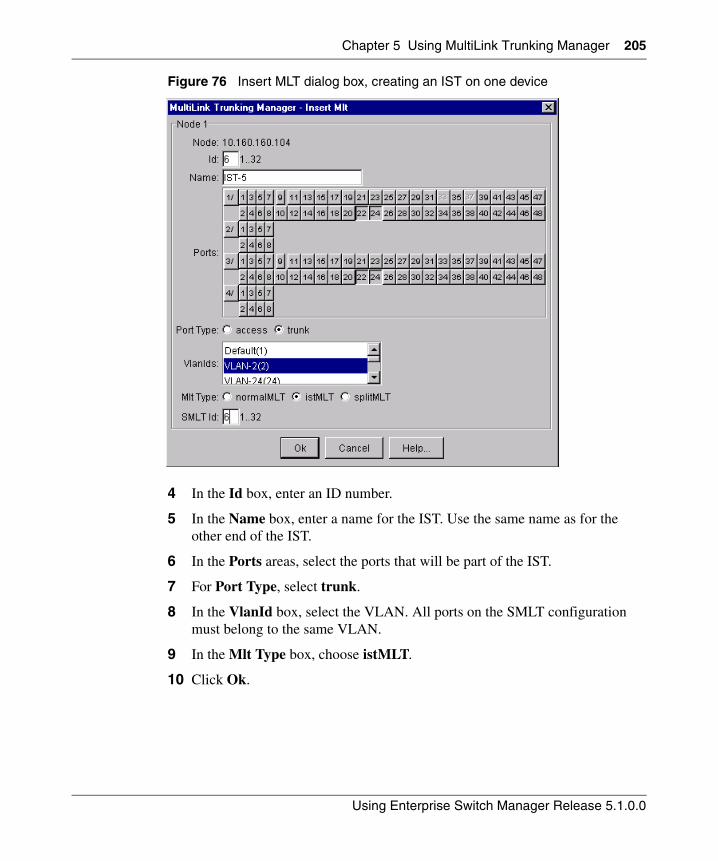
Chapter 5 Using MultiLink Trunking Manager 205
Using Enterprise Switch Manager Release 5.1.0.0
Figure 76 Insert MLT dialog box, creating an IST on one device
4 In the Id box, enter an ID number.
5 In the Name box, enter a name for the IST. Use the same name as for the other end of the IST.
6 In the Ports areas, select the ports that will be part of the IST.
7 For Port Type, select trunk.
8 In the VlanId box, select the VLAN. All ports on the SMLT configuration must belong to the same VLAN.
9 In the Mlt Type box, choose istMLT.
10 Click Ok.
206 Chapter 5 Using MultiLink Trunking Manager
208963-G
Configuring SMLT links
When you configure SMLT links, you must configure the two ends of the link separately:
• You configure a splitMLT link on the peer device. For more information, see “Configuring SMLT links on peer devices‚” next.
• You configure a normalMLT link on the non-peer device. For more information, see “Configuring SMLT links on non-peer devices” on page 207.
Configuring SMLT links on peer devices
To configure SMLT links on peer devices:
1 In the MultiLink Trunking Manager navigation pane, select a folder for the peer device on which you are configuring the link.
2 On the MultiLink Trunking Manager toolbar, click Insert.
3 The Insert MLT dialog box for a single node appears. For more information, see “Insert MLT dialog box items for ERS 8000” on page 193.
4 In the Id box, enter a MLT ID. For SMLT links on peer devices, the MLT ID is ignored.
5 In the Smlt Id box, enter an SMLT ID number.
The SMLT ID for the SMLT links on both peer devices must be the same.
6 In the Name box, enter a name for the MLT.
7 In the Ports area, select the ports on the peer device that will be part of the SMLT link.
8 In the VlanIds box, select the VLAN. All ports on the SMLT configuration must belong to the same VLAN.
9 For the MLT Type, choose splitMLT.
10 Click Ok.
Chapter 5 Using MultiLink Trunking Manager 207
Using Enterprise Switch Manager Release 5.1.0.0
Configuring SMLT links on non-peer devices
You can configure all of the ports for both SMLT links of an SMLT configuration at the same time. For the MLT type, you choose normalMLT.
To configure SMLT links on a non-peer device:
1 In the MultiLink Trunking Manager navigation pane, select a folder for the non-peer device on which you are configuring the link.
2 On the MultiLink Trunking Manager toolbar, click Insert.
3 The Insert MLT dialog box for a single node appears. For more information, see See “Insert MLT dialog box items for ERS 8000” on page 193.
4 In the Id box, enter an MLT ID.
5 In the Name box, enter a name for the MLT.
6 In the Ports area, select all of the ports on the non-peer device that will be part of the SMLT configuration.
7 In the VlanIds box, select the VLAN. All ports on the SMLT configuration must belong to the same VLAN.
8 For the MLT Type, choose normalMLT.
9 Click Ok.
Configuring IST peers
After configuring the IST links using the procedure in “Configuring IST links” on page 202, you must configure the IST peers.
To configure IST peers:
1 In the MultiLink Trunking Manager navigation pane, open the Smlt Network folder.
2 In the Smlt Network folder, click the Inter-Switch Trunk folder.
The contents pane shows all of the devices with inter switch trunks configured.
3 For the IstPeerIp of each peer device, enter the IP address associated with the VLAN on the other peer in the SMLT configuration.
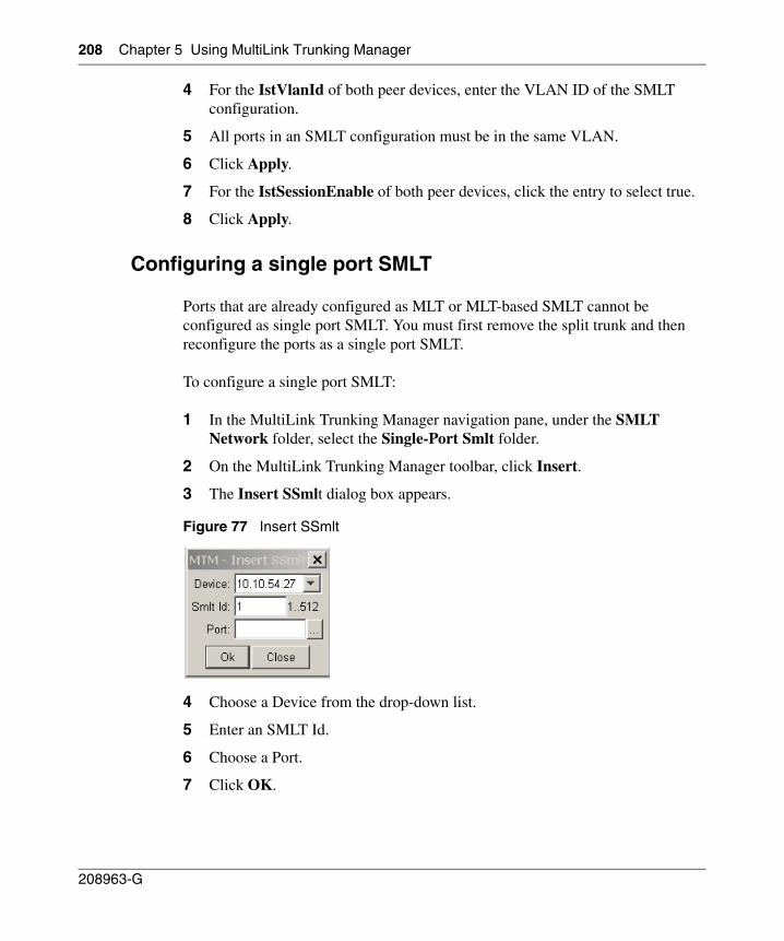
208 Chapter 5 Using MultiLink Trunking Manager
208963-G
4 For the IstVlanId of both peer devices, enter the VLAN ID of the SMLT configuration.
5 All ports in an SMLT configuration must be in the same VLAN.
6 Click Apply.
7 For the IstSessionEnable of both peer devices, click the entry to select true.
8 Click Apply.
Configuring a single port SMLT
Ports that are already configured as MLT or MLT-based SMLT cannot be configured as single port SMLT. You must first remove the split trunk and then reconfigure the ports as a single port SMLT.
To configure a single port SMLT:
1 In the MultiLink Trunking Manager navigation pane, under the SMLT Network folder, select the Single-Port Smlt folder.
2 On the MultiLink Trunking Manager toolbar, click Insert.
3 The Insert SSmlt dialog box appears.
Figure 77 Insert SSmlt
4 Choose a Device from the drop-down list.
5 Enter an SMLT Id.
6 Choose a Port.
7 Click OK.
Chapter 5 Using MultiLink Trunking Manager 209
Using Enterprise Switch Manager Release 5.1.0.0
Table 44 describes the items in the Insert SSmlt dialog box.
Deleting a single-port SMLT
To delete a single-port SMLT:
1 In the navigation pane, select the single-port SMLT folder.
2 In the contents pane, select a device and do one of the following:
• From the MultiLink Trunking Manager menu bar, choose Edit > Delete.
• On the MultiLink Trunking Manager toolbar, click Delete.
The Delete dialog box appears, asking you to confirm the deletion.
3 Click Yes.
Highlighting devices and MLT links on the topology map
Enterprise Switch Manager displays the topology information from MultiLink Trunking Manager in the contents pane.
To highlight devices and their MLTs in Enterprise Switch Manager:
1 In the navigation pane, select a device with a trunk connection.
The Trunk table appears in the MultiLink Trunking Manager contents pane (Figure 78).
Table 44 Insert SSmlt dialog box items
Item Description
Device IP address of the network device.
Smlt Id The Split MLT ID, an integer from 1 to 512.
• A read-only field with a value of 1-512 indicates the port's single port SMLT ID assignment.
• A blank field indicates the port is not configured for single port SMLT. Find an unused SMLT ID by viewing the currently-used IDs.
Port The slot/port number for the port.
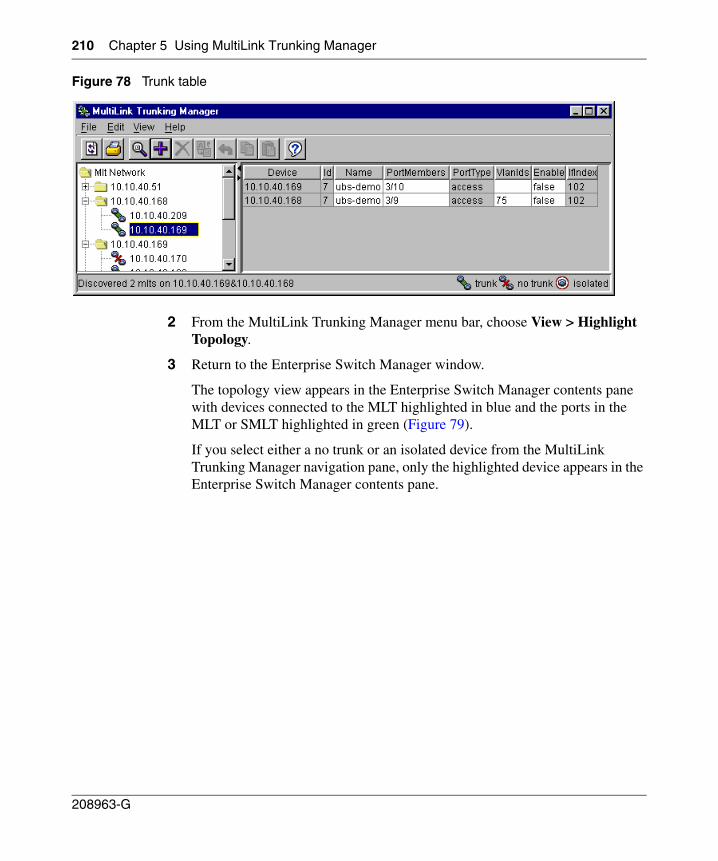
210 Chapter 5 Using MultiLink Trunking Manager
208963-G
Figure 78 Trunk table
2 From the MultiLink Trunking Manager menu bar, choose View > Highlight Topology.
3 Return to the Enterprise Switch Manager window.
The topology view appears in the Enterprise Switch Manager contents pane with devices connected to the MLT highlighted in blue and the ports in the MLT or SMLT highlighted in green (Figure 79).
If you select either a no trunk or an isolated device from the MultiLink Trunking Manager navigation pane, only the highlighted device appears in the Enterprise Switch Manager contents pane.
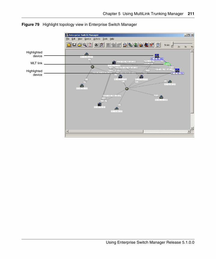
Chapter 5 Using MultiLink Trunking Manager 211
Using Enterprise Switch Manager Release 5.1.0.0
Figure 79 Highlight topology view in Enterprise Switch Manager
Highlighted
Highlighted
MLT link
device
device

212 Chapter 5 Using MultiLink Trunking Manager
208963-G
213
Using Enterprise Switch Manager Release 5.1.0.0
Chapter 6Using Multicast Manager
This chapter describes Multicast Manager, which you can use to monitor multicast protocols deployed across Ethernet Routing Switch 8600, Ethernet Routing Switch 55xx/35xx, Ethernet Routing Switch 1424/16xx, Ethernet Switch, and Legacy BayStack devices discovered by Enterprise Switch Manager.
The chapter includes information about the following topics:
• “What is Multicast Manager?‚” next
• “Starting Multicast Manager” on page 217
• “Multicast Manager window” on page 218
• “Working with Multicast Manager” on page 228
• “Understanding the Multicast Manager navigation tree” on page 238
What is Multicast Manager?
Multicast Manager allows you to view devices within a network that are configured to run or use multicast protocols. Multicast Manager also allows you to view multicast delivery trees as well as devices that participate in the delivery. In addition, you can use Multicast Manager to configure multicast parameters. Internet Group Management Protocol (IGMP) is fully configurable and Distance Vector Multicast Routing Protocol (DVMRP) and Protocol Independent Multicast-Sparse Mode (PIM-SM) are partially configurable.
Note: Multicast Manager only allows you to monitor existing multicast configurations. To configure or modify multicast settings, you must use other management tools such as Device Manager.
214 Chapter 6 Using Multicast Manager
208963-G
Multicast protocols
Ethernet Routing Switch 8600 supports the following multicast protocols:
• Internet Group Management Protocol (IGMP) and IGMP Snooping—see “IGMP and IGMP Snooping”
• IGMP with Fast Leave—see “IGMP with Fast Leave” on page 215
• Distance Vector Multicast Routing Protocol—see “DVMRP” on page 215
• PIM-SM—see “PIM-SM” on page 215
• PMBR (PIM Multicast Border Router) —see “PMBR (PIM Multicast Border Router)” on page 216
Ethernet Routing Switches 1600 support the following multicast protocols and features:
• IGMP and IGMP snooping—see “IGMP and IGMP Snooping”
• Distance Vector Multicast Routing Protocol—see “DVMRP” on page 215
• Multicast Route
Ethernet Switch, Ethernet Routing Switch 55xx/35xx, and Legacy BayStack support IGMP and IGMP snooping—see “IGMP and IGMP Snooping” .
At its most basic, IP multicast is the communication of data and services to multiple destinations with a single transmission. Refer to Networking Concepts for the Passport 8000 Series Switch for more information about multicast and multicast protocols.
IGMP and IGMP Snooping
IGMP allows a host to register group memberships with the local querying router to receive any datagrams sent to this router and targeted to a group with a specific IP Multicast address. The protocol also allows a router to learn the existence of group members on its directly attached networks. The router periodically sends a general query message to each of its local networks. Any host that is a member of any multicasting group identifies itself by a sending a response.
Chapter 6 Using Multicast Manager 215
Using Enterprise Switch Manager Release 5.1.0.0
IGMP Snooping uses IGMP messages to prune group membership per port within a VLAN. The switch listens to group reports for each port and builds a database of multicast group members per port. Only those ports that are specified in the database receive multicast traffic, instead of all ports in the VLAN.
IGMP with Fast Leave
IGMP with Fast Leave Mode is an added proprietary feature to the existing IGMP behavior. This mode allows a switch to immediately stop forwarding a specific group- Multicast traffic as soon as an IGMPv2 Leave Group message is received on interface. This either assumes that there is only receiver for this group on this interface or that all receivers agree to stop receiving traffic for the group when one of them leaves the group. Only when configured on a port, Fast Leave Mode changes the normal behavior of the existing IGMP protocol for that port. Using the fast leave Mode appropriately allows the reduction of unnecessary multicast traffic on the port. When used with IGMPv3, the mode remains valid, but stopping traffic will be based on the group state at the switch’s interface.
To facilitate the configuration Fast Leave Mode should be configurable on a VLAN and /or port basis. Enabling the feature for a given VLAN enables the feature on all ports of that VLAN.
DVMRP
Distance Vector Multicast Routing Protocol (DVMRP) advertises shortest-path routes to multicasting source networks (any network containing hosts with the capability to issue multicast datagrams). When DVMRP is coupled with IGMP membership, a multicast stream is learned from both the routers and directly attached hosts.
PIM-SM
Protocol Independent Multicast-Sparse Mode (PIM-SM), as defined in RFC 2362, was designed to support multicast groups spread out across large areas of a company or the Internet. PIM-SM routes multicast packets to multicast groups, and establishes distribution trees across wide area networks.
216 Chapter 6 Using Multicast Manager
208963-G
Unlike dense mode protocols, such as DVMRP, that initially flood multicast traffic to all routers over an entire internetwork, PIM-SM sends multicast traffic only to routers that have specifically joined a multicast group. This technique reduces traffic flow over WAN links and overhead costs for processing unwanted multicast packets.
Dense-mode protocols use a “flood-and-prune” technique, which is efficient where receivers are densely populated. However, for sparsely populated networks, PIM-SM is more efficient because it sends multicast traffic only to those routers that belong to a specific multicast group and that choose to receive the traffic. PIM-SM is independent of any specific unicast routing protocol, but it does require the presence of a unicast routing protocol, such as RIP or OSPF. PIM-SM uses the information from the unicast routing table to create and maintain multicast trees that enables PIM-enabled routers to communicate.
PMBR (PIM Multicast Border Router)
A PMBR (PIM Multicast Border Router) is a router that sits at the boundary of a PIM-SM (Sparse Mode) domain and inter-operates with other types of multicast routers such as those that run DVMRP (Distance Vector Multicast Routing Protocol). That is, in order to inter-operate with networks that run dense-mode, broadcast and prune, protocols such as DVMRP, all packets generated within a PIM-SM region must be pulled out to that region’s PIM Multicast Border Routers (PMBRs).
Generally a PMBR would use both protocols (PIM-SM and DVMRP) and implement inter-operability functions that are not required by regular PIM routers. To support inter-operability, a special entry type, referred to as (*,*,RP), must be supported by all PIM routers. PMBRs are also responsible for delivering externally generated packets to routers within the PIM domain. All PIM routers must be capable of supporting (*,*,RP) state and interpreting associated Join/Prune messages.
Chapter 6 Using Multicast Manager 217
Using Enterprise Switch Manager Release 5.1.0.0
Multicast Manager features
Multicast Manager allows you to:
• View and configure multicast parameters supported by devices discovered by Enterprise Switch Manager.
• Highlight all devices in the topology network map if the multicast protocol is selected from the Multicast Manager navigation tree.
• Provide information about multicast groups with active members, including information about group address, source subnet, and last reporters.
• Display the multicast forwarding path for a selected source/group to all destination devices or to a selected intermediate device.
The following sections describe the Multicast Manager window and the monitoring features available:
• “Starting Multicast Manager‚” next
• “Multicast Manager window” on page 218
• “Working with Multicast Manager” on page 228
• “Viewing Multicast Manager information on topology map” on page 234
Starting Multicast Manager
To start Multicast Manager:
• From the Enterprise Switch Manager menu bar, choose Tools > Multicast Manager.
• On the keyboard, press [F4].
• On the Enterprise Switch Manager toolbar, click Multicast Manager.
The Multicast Manager window opens (Figure 80).
Do one of the following:
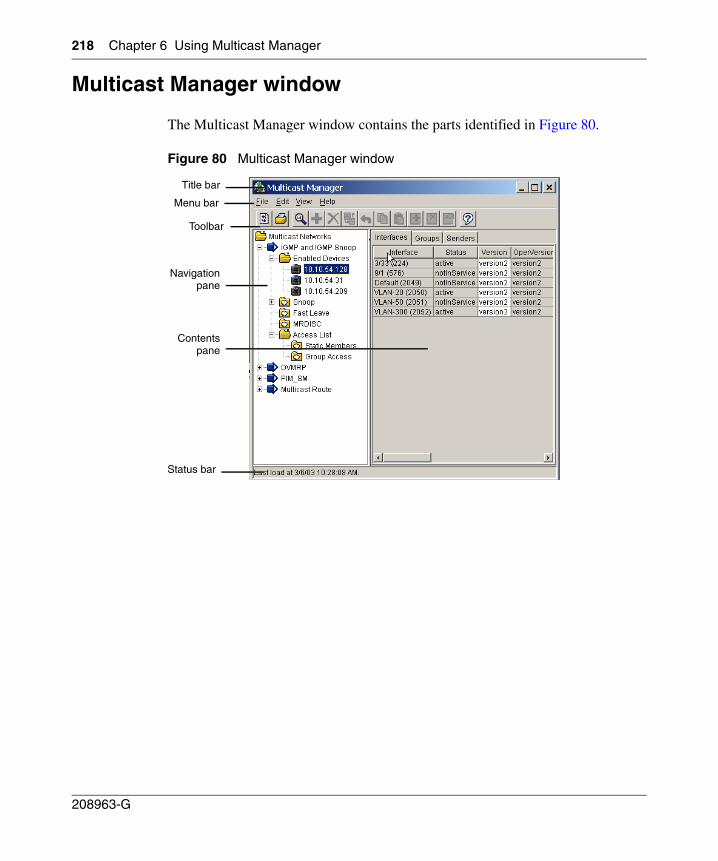
218 Chapter 6 Using Multicast Manager
208963-G
Multicast Manager window
The Multicast Manager window contains the parts identified in Figure 80.
Figure 80 Multicast Manager window
Contents
Title bar
Menu bar
Navigation
Status bar
pane
pane
Toolbar
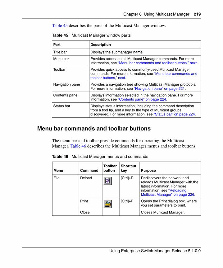
Chapter 6 Using Multicast Manager 219
Using Enterprise Switch Manager Release 5.1.0.0
Table 45 describes the parts of the Multicast Manager window.
Menu bar commands and toolbar buttons
The menu bar and toolbar provide commands for operating the Multicast Manager. Table 46 describes the Multicast Manager menus and toolbar buttons.
Table 45 Multicast Manager window parts
Part Description
Title bar Displays the submanager name.
Menu bar Provides access to all Multicast Manager commands. For more information, see “Menu bar commands and toolbar buttons‚” next.
Toolbar Provides quick access to commonly-used Multicast Manager commands. For more information, see “Menu bar commands and toolbar buttons‚” next.
Navigation pane Provides a navigation tree showing Multicast Manager protocols. For more information, see “Navigation pane” on page 221.
Contents pane Displays information selected in the navigation pane. For more information, see “Contents pane” on page 224.
Status bar Displays status information, including the command description from a tool tip, and a key to the type of Multicast groups discovered. For more information, see “Status bar” on page 224.
Table 46 Multicast Manager menus and commands
Menu CommandToolbar button
Shortcut key Purpose
File Reload [Ctrl]+R Rediscovers the network and reloads Multicast Manager with the latest information. For more information, see “Reloading Multicast Manager” on page 226.
Print [Ctrl]+P Opens the Print dialog box, where you set parameters to print.
Close Closes Multicast Manager.
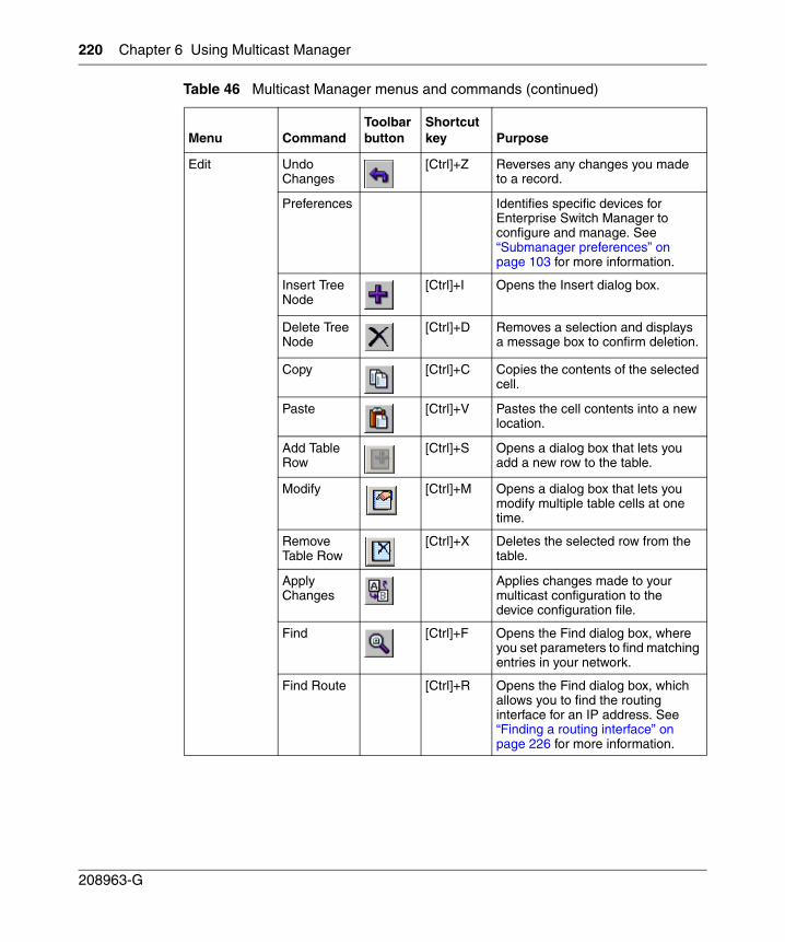
220 Chapter 6 Using Multicast Manager
208963-G
Edit Undo Changes
[Ctrl]+Z Reverses any changes you made to a record.
Preferences Identifies specific devices for Enterprise Switch Manager to configure and manage. See “Submanager preferences” on page 103 for more information.
Insert Tree Node
[Ctrl]+I Opens the Insert dialog box.
Delete Tree Node
[Ctrl]+D Removes a selection and displays a message box to confirm deletion.
Copy [Ctrl]+C Copies the contents of the selected cell.
Paste [Ctrl]+V Pastes the cell contents into a new location.
Add Table Row
[Ctrl]+S Opens a dialog box that lets you add a new row to the table.
Modify [Ctrl]+M Opens a dialog box that lets you modify multiple table cells at one time.
Remove Table Row
[Ctrl]+X Deletes the selected row from the table.
Apply Changes
Applies changes made to your multicast configuration to the device configuration file.
Find [Ctrl]+F Opens the Find dialog box, where you set parameters to find matching entries in your network.
Find Route [Ctrl]+R Opens the Find dialog box, which allows you to find the routing interface for an IP address. See “Finding a routing interface” on page 226 for more information.
Table 46 Multicast Manager menus and commands (continued)
Menu CommandToolbar button
Shortcut key Purpose
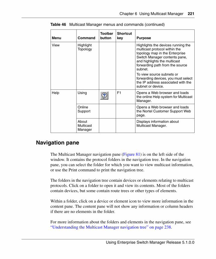
Chapter 6 Using Multicast Manager 221
Using Enterprise Switch Manager Release 5.1.0.0
Navigation pane
The Multicast Manager navigation pane (Figure 81) is on the left side of the window. It contains the protocol folders in the navigation tree. In the navigation pane, you can select the folder for which you want to view multicast information, or use the Print command to print the navigation tree.
The folders in the navigation tree contain devices or elements relating to multicast protocols. Click on a folder to open it and view its contents. Most of the folders contain devices, but some contain route trees or other types of elements.
Within a folder, click on a device or element icon to view more information in the content pane. The content pane will not show any information or column headers if there are no elements in the folder.
For more information about the folders and elements in the navigation pane, see “Understanding the Multicast Manager navigation tree” on page 238.
View Highlight Topology
Highlights the devices running the multicast protocol within the topology map in the Enterprise Switch Manager contents pane, and highlights the multicast forwarding path from the source subnet. To view source subnets or forwarding devices, you must select the IP address associated with the subnet or device.
Help Using F1 Opens a Web browser and loads the online Help system for Multicast Manager.
Online Support
Opens a Web browser and loads the Nortel Customer Support Web page.
About Multicast Manager
Displays information about Multicast Manager.
Table 46 Multicast Manager menus and commands (continued)
Menu CommandToolbar button
Shortcut key Purpose
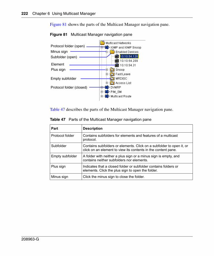
222 Chapter 6 Using Multicast Manager
208963-G
Figure 81 shows the parts of the Multicast Manager navigation pane.
Figure 81 Multicast Manager navigation pane
Table 47 describes the parts of the Multicast Manager navigation pane.
Table 47 Parts of the Multicast Manager navigation pane
Part Description
Protocol folder Contains subfolders for elements and features of a multicast protocol.
Subfolder Contains subfolders or elements. Click on a subfolder to open it, or click on an element to view its contents in the content pane.
Empty subfolder A folder with neither a plus sign or a minus sign is empty, and contains neither subfolders nor elements.
Plus sign Indicates that a closed folder or subfolder contains folders or elements. Click the plus sign to open the folder.
Minus sign Click the minus sign to close the folder.
Protocol folder (open)
Subfolder (open)
Plus sign
Minus sign
Empty subfolder
Element
Protocol folder (closed)
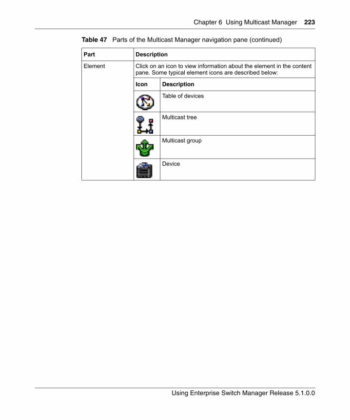
Chapter 6 Using Multicast Manager 223
Using Enterprise Switch Manager Release 5.1.0.0
Element Click on an icon to view information about the element in the content pane. Some typical element icons are described below:
Icon Description
Table of devices
Multicast tree
Multicast group
Device
Table 47 Parts of the Multicast Manager navigation pane (continued)
Part Description
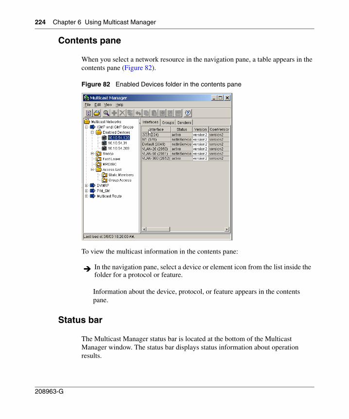
224 Chapter 6 Using Multicast Manager
208963-G
Contents pane
When you select a network resource in the navigation pane, a table appears in the contents pane (Figure 82).
Figure 82 Enabled Devices folder in the contents pane
To view the multicast information in the contents pane:
Information about the device, protocol, or feature appears in the contents pane.
Status bar
The Multicast Manager status bar is located at the bottom of the Multicast Manager window. The status bar displays status information about operation results.
In the navigation pane, select a device or element icon from the list inside the folder for a protocol or feature.
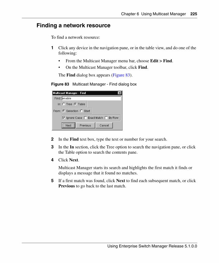
Chapter 6 Using Multicast Manager 225
Using Enterprise Switch Manager Release 5.1.0.0
Finding a network resource
To find a network resource:
1 Click any device in the navigation pane, or in the table view, and do one of the following:
• From the Multicast Manager menu bar, choose Edit > Find.
• On the Multicast Manager toolbar, click Find.
The Find dialog box appears (Figure 83).
Figure 83 Multicast Manager - Find dialog box
2 In the Find text box, type the text or number for your search.
3 In the In section, click the Tree option to search the navigation pane, or click the Table option to search the contents pane.
4 Click Next.
Multicast Manager starts its search and highlights the first match it finds or displays a message that it found no matches.
5 If a first match was found, click Next to find each subsequent match, or click Previous to go back to the last match.
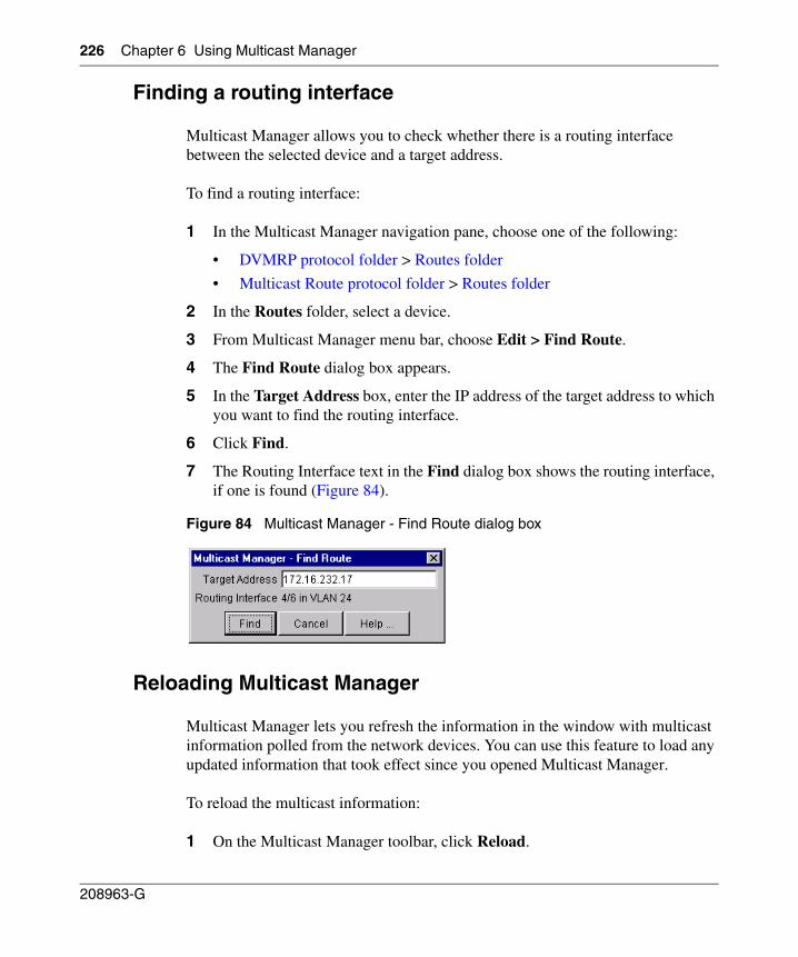
226 Chapter 6 Using Multicast Manager
208963-G
Finding a routing interface
Multicast Manager allows you to check whether there is a routing interface between the selected device and a target address.
To find a routing interface:
1 In the Multicast Manager navigation pane, choose one of the following:
• DVMRP protocol folder > Routes folder
• Multicast Route protocol folder > Routes folder
2 In the Routes folder, select a device.
3 From Multicast Manager menu bar, choose Edit > Find Route.
4 The Find Route dialog box appears.
5 In the Target Address box, enter the IP address of the target address to which you want to find the routing interface.
6 Click Find.
7 The Routing Interface text in the Find dialog box shows the routing interface, if one is found (Figure 84).
Figure 84 Multicast Manager - Find Route dialog box
Reloading Multicast Manager
Multicast Manager lets you refresh the information in the window with multicast information polled from the network devices. You can use this feature to load any updated information that took effect since you opened Multicast Manager.
To reload the multicast information:
1 On the Multicast Manager toolbar, click Reload.
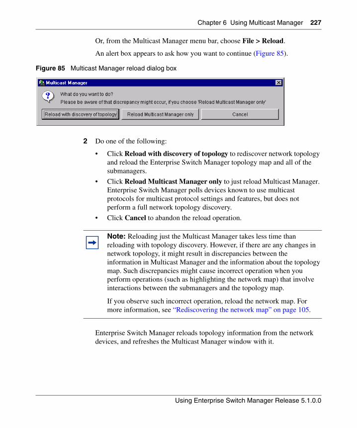
Chapter 6 Using Multicast Manager 227
Using Enterprise Switch Manager Release 5.1.0.0
Or, from the Multicast Manager menu bar, choose File > Reload.
An alert box appears to ask how you want to continue (Figure 85).
Figure 85 Multicast Manager reload dialog box
2 Do one of the following:
• Click Reload with discovery of topology to rediscover network topology and reload the Enterprise Switch Manager topology map and all of the submanagers.
• Click Reload Multicast Manager only to just reload Multicast Manager. Enterprise Switch Manager polls devices known to use multicast protocols for multicast protocol settings and features, but does not perform a full network topology discovery.
• Click Cancel to abandon the reload operation.
Enterprise Switch Manager reloads topology information from the network devices, and refreshes the Multicast Manager window with it.
Note: Reloading just the Multicast Manager takes less time than reloading with topology discovery. However, if there are any changes in network topology, it might result in discrepancies between the information in Multicast Manager and the information about the topology map. Such discrepancies might cause incorrect operation when you perform operations (such as highlighting the network map) that involve interactions between the submanagers and the topology map.
If you observe such incorrect operation, reload the network map. For more information, see “Rediscovering the network map” on page 105.
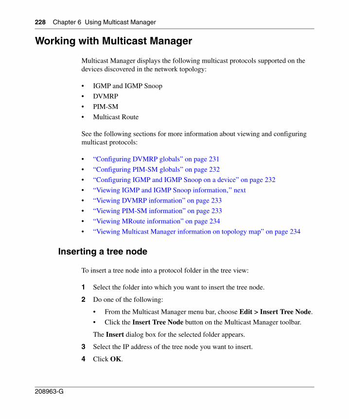
228 Chapter 6 Using Multicast Manager
208963-G
Working with Multicast Manager
Multicast Manager displays the following multicast protocols supported on the devices discovered in the network topology:
• IGMP and IGMP Snoop
• DVMRP
• PIM-SM
• Multicast Route
See the following sections for more information about viewing and configuring multicast protocols:
• “Configuring DVMRP globals” on page 231
• “Configuring PIM-SM globals” on page 232
• “Configuring IGMP and IGMP Snoop on a device” on page 232
• “Viewing IGMP and IGMP Snoop information‚” next
• “Viewing DVMRP information” on page 233
• “Viewing PIM-SM information” on page 233
• “Viewing MRoute information” on page 234
• “Viewing Multicast Manager information on topology map” on page 234
Inserting a tree node
To insert a tree node into a protocol folder in the tree view:
1 Select the folder into which you want to insert the tree node.
2 Do one of the following:
• From the Multicast Manager menu bar, choose Edit > Insert Tree Node.
• Click the Insert Tree Node button on the Multicast Manager toolbar.
The Insert dialog box for the selected folder appears.
3 Select the IP address of the tree node you want to insert.
4 Click OK.
Chapter 6 Using Multicast Manager 229
Using Enterprise Switch Manager Release 5.1.0.0
The new tree node appears in the navigation pane tree view under the folder into which you inserted the tree node.
Deleting a tree node
To delete a tree node from a protocol folder in the tree view:
1 Select the tree node that you want to delete.
2 Do one of the following:
• From the Multicast Manager menu bar, choose Edit > Delete Tree Node.
• Click the Delete Tree Node button on the Multicast Manager toolbar.
3 Multicast Manager removes the node from the navigation pane tree view
Figure 86 Tree Editing—adding or deleting a node from the navigation tree
Inserting a table row
To insert a row into a table in the contents pane:
1 Click in the table in which you want to insert a row.
2 Do one of the following:
• From the Multicast Manager menu bar, choose Edit > Add Table Row.
• On the Multicast Manager toolbar, click the Add Table Row button.
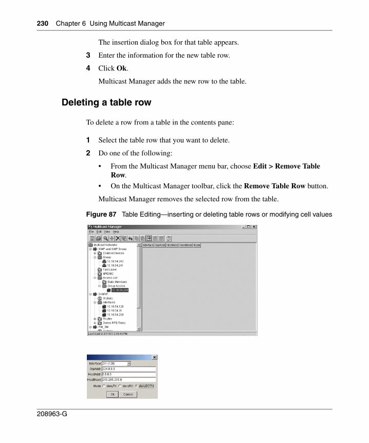
230 Chapter 6 Using Multicast Manager
208963-G
The insertion dialog box for that table appears.
3 Enter the information for the new table row.
4 Click Ok.
Multicast Manager adds the new row to the table.
Deleting a table row
To delete a row from a table in the contents pane:
1 Select the table row that you want to delete.
2 Do one of the following:
• From the Multicast Manager menu bar, choose Edit > Remove Table Row.
• On the Multicast Manager toolbar, click the Remove Table Row button.
Multicast Manager removes the selected row from the table.
Figure 87 Table Editing—inserting or deleting table rows or modifying cell values
Chapter 6 Using Multicast Manager 231
Using Enterprise Switch Manager Release 5.1.0.0
Editing table cells
To edit a table cell:
1 Double-click the cell you want to edit in the table.
The edit dialog box for the table appears.
2 Make the changes in the dialog box.
3 Click Ok.
Multicast Manager applies the changes to the cell.
Editing multiple table cells
To edit multiple table cells:
1 Select the cells you want to edit in the table.
2 Do one of the following:
• From the Multicast Manager menu bar, choose Edit > Modify.
• On the Multicast Manager toolbar, click the Modify button.
The table modification dialog box appears.
3 Make the changes in the dialog box.
4 Click Ok.
Multicast Manager applies the changes to all the selected cells.
Configuring DVMRP globals
DVMRP routers listen to all IGMP host membership reports, even if they are not the designated querier, and keep a local database of every host membership reporter.
To configure DVMRP globals:
1 In the Multicast Manager navigation pane tree view, click Globals under the DVMRP folder.
232 Chapter 6 Using Multicast Manager
208963-G
2 In the Enabled column of the table on the right, change the value for the selected device to Enabled.
3 Do one of the following:
• From the Multicast Manager menu bar, choose Edit > Apply Changes.
• On the Multicast Manager toolbar, click the Apply Changes button.
The enabled devices appear in the Interfaces folder of the DVMRP tree and in the Enabled Devices folder of the IGMP and IGMP Snoop tree.
See “DVMRP protocol folder” on page 252 for more information.
Configuring PIM-SM globals
Protocol Independent Multicast-Sparse Mode (PIM-SM) routes multicast packets to multicast groups, and establishes distribution trees across wide area networks.
To configure PIM-SM globals:
1 In the Multicast Manager navigation pane tree view, click Globals under the PIM-SM folder.
2 In the Enable column of the table on the right, change the value for the selected device to Enabled.
3 Do one of the following:
• From the Multicast Manager menu bar, choose Edit > Apply Changes.
• On the Multicast Manager toolbar, click the Apply Changes button.
The devices appear in the Enabled Devices folder in the tree view.
See “PIM-SM protocol folder” on page 257 for more information.
Configuring IGMP and IGMP Snoop on a device
Internet Group Management Protocol (IGMP) allows an IP Multicast router to learn the existence of host group members on their directly connected subnets.
To configure IGMP or IGMP Snoop for a device:
1 Select the device in the Enabled Devices folder.
Chapter 6 Using Multicast Manager 233
Using Enterprise Switch Manager Release 5.1.0.0
If the device does not appear in the Enabled Devices folder, ensure that DVMRP or PIM-SM is enabled for that device (see “Configuring DVMRP globals” on page 231 or “Configuring PIM-SM globals” on page 232).
2 Use the table cells in the right pane to configure IGMP or IGMP Snoop on the device. You can modify all table cells that are not dimmed.
3 Do one of the following:
• From the Multicast Manager menu bar, choose Edit > Apply Changes.
• On the Multicast Manager toolbar, click the Apply Changes button.
See “IGMP and IGMP Snoop protocol folder” on page 239 for more information.
Viewing IGMP and IGMP Snoop information
To view the information associated with IGMP and IGMP Snoop:
See “IGMP and IGMP Snoop protocol folder” on page 239 for more information.
Viewing DVMRP information
To view (Distance Vector Multicast Routing Protocol) DVMRP information:
See “DVMRP protocol folder” on page 252 for more information.
Viewing PIM-SM information
To view the information associated with PIM-SM (Protocol Independent Multicast-Sparse Mode):
See “PIM-SM protocol folder” on page 257 for more information.
Select a subfolder listed under the IGMP and IGMP Snoop protocol folder.
Select a subfolder listed under the DVMRP protocol folder.
Select a subfolder listed under the PIM-SM protocol folder.
234 Chapter 6 Using Multicast Manager
208963-G
Viewing MRoute information
Multicast Route (MRoute) information contains the details about the multicast routes found in the network.
To view Multicast Route information:
See “Multicast Route protocol folder” on page 262 for more information.
Viewing Multicast Manager information on topology map
While the Multicast Manager window is open, you can highlight the following information on the topology map in the Enterprise Switch Manager main window:
• Location of a particular multicast device
• Multicast tree from a source subnet to all multicast nodes within a group
• Devices actively using a selected multicast protocol
The following sections describe procedures for viewing Multicast Manager information on the topology map:
• “Highlighting a multicast device‚” next
• “Highlighting a multicast forwarding tree” on page 235
Highlighting a multicast device
To highlight a multicast device:
1 In the Multicast Manager navigation pane, do one of the following:
• Select a subfolder under a protocol folder.
• Select a single device.
Devices supported by the protocol are highlighted.
2 From Multicast Manager menu bar, choose View > Highlight Topology.
The Highlight Topology option remains selected until you deselect it.
Select a subfolder listed under the Multicast Route protocol folder.
Chapter 6 Using Multicast Manager 235
Using Enterprise Switch Manager Release 5.1.0.0
3 Return to the Enterprise Switch Manager window.
— If you selected a subfolder under a protocol folder, all devices that support the feature are highlighted.
— If you selected a single device, the device is highlighted.
Highlighting a multicast forwarding tree
To highlight a multicast tree rooted at a source subnet within a multicast group:
1 In the Multicast Manager navigation pane, select a tree icon in either the Dvmrp RPB Trees folder or the MRoute RPM Trees folder.
See “Dvmrp RPB Trees folder” on page 257 and “MRoute RPM Trees folder” on page 266 for more information.
2 From Multicast Manager menu bar, choose View > Highlight Topology.
3 Return to the Enterprise Switch Manager window.
The devices and forwarding path are highlighted (Figure 88).
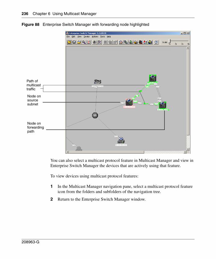
236 Chapter 6 Using Multicast Manager
208963-G
Figure 88 Enterprise Switch Manager with forwarding node highlighted
You can also select a multicast protocol feature in Multicast Manager and view in Enterprise Switch Manager the devices that are actively using that feature.
To view devices using multicast protocol features:
1 In the Multicast Manager navigation pane, select a multicast protocol feature icon from the folders and subfolders of the navigation tree.
2 Return to the Enterprise Switch Manager window.
Path of multicast traffic
Node on source subnet
Node on forwarding path
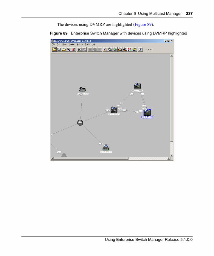
Chapter 6 Using Multicast Manager 237
Using Enterprise Switch Manager Release 5.1.0.0
The devices using DVMRP are highlighted (Figure 89).
Figure 89 Enterprise Switch Manager with devices using DVMRP highlighted
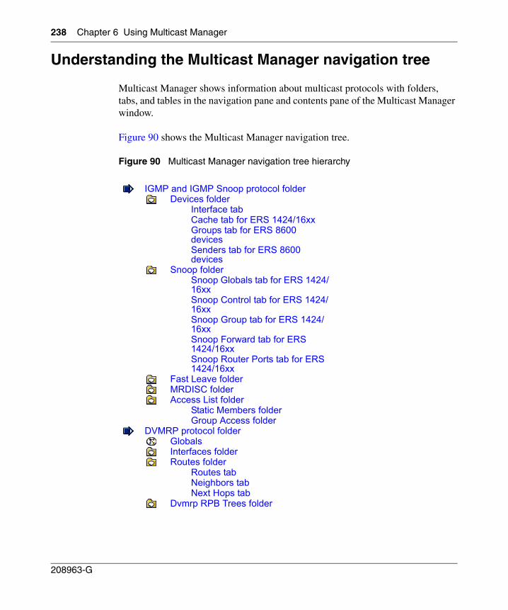
238 Chapter 6 Using Multicast Manager
208963-G
Understanding the Multicast Manager navigation tree
Multicast Manager shows information about multicast protocols with folders, tabs, and tables in the navigation pane and contents pane of the Multicast Manager window.
Figure 90 shows the Multicast Manager navigation tree.
Figure 90 Multicast Manager navigation tree hierarchy
IGMP and IGMP Snoop protocol folderDevices folder
Interface tabCache tab for ERS 1424/16xxGroups tab for ERS 8600 devicesSenders tab for ERS 8600 devices
Snoop folderSnoop Globals tab for ERS 1424/16xxSnoop Control tab for ERS 1424/16xxSnoop Group tab for ERS 1424/16xxSnoop Forward tab for ERS 1424/16xxSnoop Router Ports tab for ERS 1424/16xx
Fast Leave folderMRDISC folderAccess List folder
Static Members folderGroup Access folder
DVMRP protocol folderGlobalsInterfaces folderRoutes folder
Routes tabNeighbors tabNext Hops tab
Dvmrp RPB Trees folder
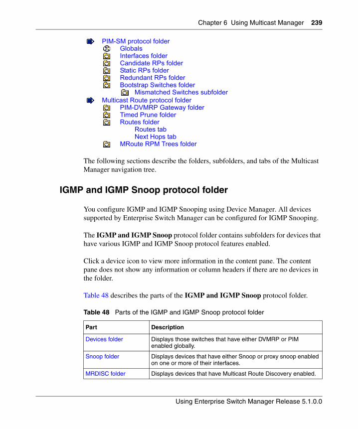
Chapter 6 Using Multicast Manager 239
Using Enterprise Switch Manager Release 5.1.0.0
The following sections describe the folders, subfolders, and tabs of the Multicast Manager navigation tree.
IGMP and IGMP Snoop protocol folder
You configure IGMP and IGMP Snooping using Device Manager. All devices supported by Enterprise Switch Manager can be configured for IGMP Snooping.
The IGMP and IGMP Snoop protocol folder contains subfolders for devices that have various IGMP and IGMP Snoop protocol features enabled.
Click a device icon to view more information in the content pane. The content pane does not show any information or column headers if there are no devices in the folder.
Table 48 describes the parts of the IGMP and IGMP Snoop protocol folder.
PIM-SM protocol folderGlobalsInterfaces folderCandidate RPs folderStatic RPs folderRedundant RPs folderBootstrap Switches folder
Mismatched Switches subfolderMulticast Route protocol folder
PIM-DVMRP Gateway folderTimed Prune folderRoutes folder
Routes tabNext Hops tab
MRoute RPM Trees folder
Table 48 Parts of the IGMP and IGMP Snoop protocol folder
Part Description
Devices folder Displays those switches that have either DVMRP or PIM enabled globally.
Snoop folder Displays devices that have either Snoop or proxy snoop enabled on one or more of their interfaces.
MRDISC folder Displays devices that have Multicast Route Discovery enabled.
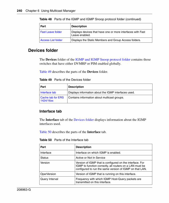
240 Chapter 6 Using Multicast Manager
208963-G
Devices folder
The Devices folder of the IGMP and IGMP Snoop protocol folder contains those switches that have either DVMRP or PIM enabled globally.
Table 49 describes the parts of the Devices folder.
Interface tab
The Interface tab of the Devices folder displays information about the IGMP interfaces used.
Table 50 describes the parts of the Interface tab.
Fast Leave folder Displays devices that have one or more interfaces with Fast Leave enabled.
Access List folder Displays the Static Members and Group Access folders.
Table 49 Parts of the Devices folder
Part Description
Interface tab Displays information about the IGMP interfaces used.
Cache tab for ERS 1424/16xx
Contains information about multicast groups.
Table 50 Parts of the Interface tab
Part Description
Interface Interface on which IGMP is enabled.
Status Active or Not In Service
Version Version of IGMP that is configured on the interface. For IGMP to function correctly, all routers on a LAN must be configured to run the same version of IGMP on that LAN.
OperVersion Version of IGMP that is running on this interface.
Query Interval Frequency with which IGMP Host-Query packets are transmitted on this interface.
Table 48 Parts of the IGMP and IGMP Snoop protocol folder (continued)
Part Description
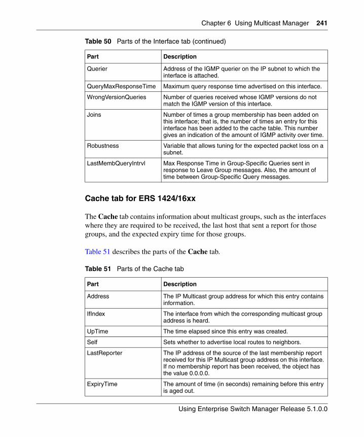
Chapter 6 Using Multicast Manager 241
Using Enterprise Switch Manager Release 5.1.0.0
Cache tab for ERS 1424/16xx
The Cache tab contains information about multicast groups, such as the interfaces where they are required to be received, the last host that sent a report for those groups, and the expected expiry time for those groups.
Table 51 describes the parts of the Cache tab.
Querier Address of the IGMP querier on the IP subnet to which the interface is attached.
QueryMaxResponseTime Maximum query response time advertised on this interface.
WrongVersionQueries Number of queries received whose IGMP versions do not match the IGMP version of this interface.
Joins Number of times a group membership has been added on this interface; that is, the number of times an entry for this interface has been added to the cache table. This number gives an indication of the amount of IGMP activity over time.
Robustness Variable that allows tuning for the expected packet loss on a subnet.
LastMembQueryIntrvl Max Response Time in Group-Specific Queries sent in response to Leave Group messages. Also, the amount of time between Group-Specific Query messages.
Table 51 Parts of the Cache tab
Part Description
Address The IP Multicast group address for which this entry contains information.
IfIndex The interface from which the corresponding multicast group address is heard.
UpTime The time elapsed since this entry was created.
Self Sets whether to advertise local routes to neighbors.
LastReporter The IP address of the source of the last membership report received for this IP Multicast group address on this interface. If no membership report has been received, the object has the value 0.0.0.0.
ExpiryTime The amount of time (in seconds) remaining before this entry is aged out.
Table 50 Parts of the Interface tab (continued)
Part Description
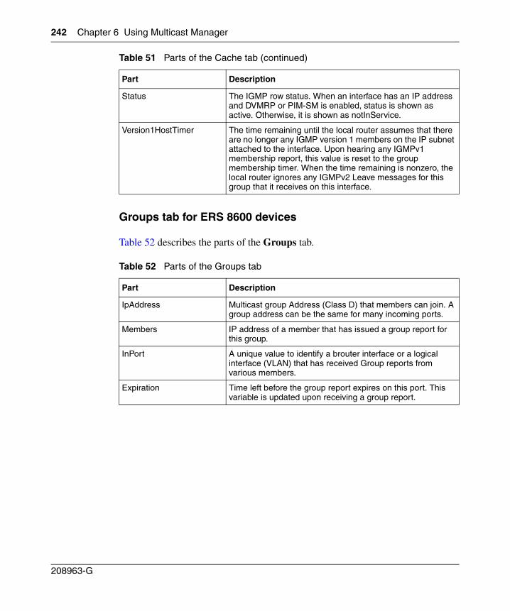
242 Chapter 6 Using Multicast Manager
208963-G
Groups tab for ERS 8600 devices
Table 52 describes the parts of the Groups tab.
Status The IGMP row status. When an interface has an IP address and DVMRP or PIM-SM is enabled, status is shown as active. Otherwise, it is shown as notInService.
Version1HostTimer The time remaining until the local router assumes that there are no longer any IGMP version 1 members on the IP subnet attached to the interface. Upon hearing any IGMPv1 membership report, this value is reset to the group membership timer. When the time remaining is nonzero, the local router ignores any IGMPv2 Leave messages for this group that it receives on this interface.
Table 52 Parts of the Groups tab
Part Description
IpAddress Multicast group Address (Class D) that members can join. A group address can be the same for many incoming ports.
Members IP address of a member that has issued a group report for this group.
InPort A unique value to identify a brouter interface or a logical interface (VLAN) that has received Group reports from various members.
Expiration Time left before the group report expires on this port. This variable is updated upon receiving a group report.
Table 51 Parts of the Cache tab (continued)
Part Description
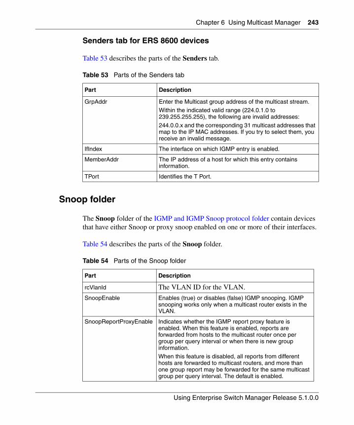
Chapter 6 Using Multicast Manager 243
Using Enterprise Switch Manager Release 5.1.0.0
Senders tab for ERS 8600 devices
Table 53 describes the parts of the Senders tab.
Snoop folder
The Snoop folder of the IGMP and IGMP Snoop protocol folder contain devices that have either Snoop or proxy snoop enabled on one or more of their interfaces.
Table 54 describes the parts of the Snoop folder.
Table 53 Parts of the Senders tab
Part Description
GrpAddr Enter the Multicast group address of the multicast stream.Within the indicated valid range (224.0.1.0 to 239.255.255.255), the following are invalid addresses:
244.0.0.x and the corresponding 31 multicast addresses that map to the IP MAC addresses. If you try to select them, you receive an invalid message.
IfIndex The interface on which IGMP entry is enabled.
MemberAddr The IP address of a host for which this entry contains information.
TPort Identifies the T Port.
Table 54 Parts of the Snoop folder
Part Description
rcVlanId The VLAN ID for the VLAN.
SnoopEnable Enables (true) or disables (false) IGMP snooping. IGMP snooping works only when a multicast router exists in the VLAN.
SnoopReportProxyEnable Indicates whether the IGMP report proxy feature is enabled. When this feature is enabled, reports are forwarded from hosts to the multicast router once per group per query interval or when there is new group information.When this feature is disabled, all reports from different hosts are forwarded to multicast routers, and more than one group report may be forwarded for the same multicast group per query interval. The default is enabled.
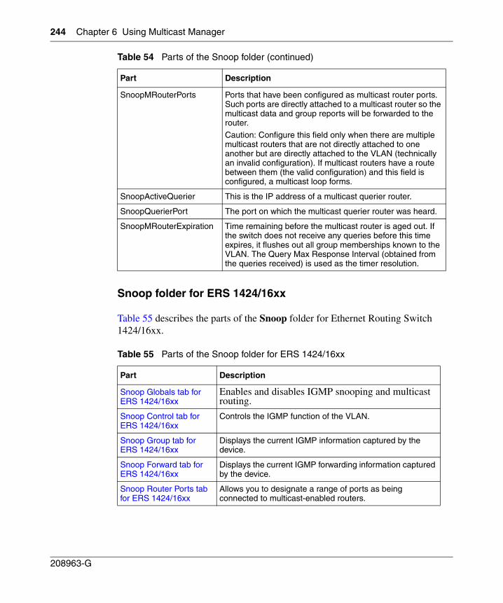
244 Chapter 6 Using Multicast Manager
208963-G
Snoop folder for ERS 1424/16xx
Table 55 describes the parts of the Snoop folder for Ethernet Routing Switch 1424/16xx.
SnoopMRouterPorts Ports that have been configured as multicast router ports. Such ports are directly attached to a multicast router so the multicast data and group reports will be forwarded to the router.
Caution: Configure this field only when there are multiple multicast routers that are not directly attached to one another but are directly attached to the VLAN (technically an invalid configuration). If multicast routers have a route between them (the valid configuration) and this field is configured, a multicast loop forms.
SnoopActiveQuerier This is the IP address of a multicast querier router.
SnoopQuerierPort The port on which the multicast querier router was heard.
SnoopMRouterExpiration Time remaining before the multicast router is aged out. If the switch does not receive any queries before this time expires, it flushes out all group memberships known to the VLAN. The Query Max Response Interval (obtained from the queries received) is used as the timer resolution.
Table 55 Parts of the Snoop folder for ERS 1424/16xx
Part Description
Snoop Globals tab for ERS 1424/16xx
Enables and disables IGMP snooping and multicast routing.
Snoop Control tab for ERS 1424/16xx
Controls the IGMP function of the VLAN.
Snoop Group tab for ERS 1424/16xx
Displays the current IGMP information captured by the device.
Snoop Forward tab for ERS 1424/16xx
Displays the current IGMP forwarding information captured by the device.
Snoop Router Ports tab for ERS 1424/16xx
Allows you to designate a range of ports as being connected to multicast-enabled routers.
Table 54 Parts of the Snoop folder (continued)
Part Description
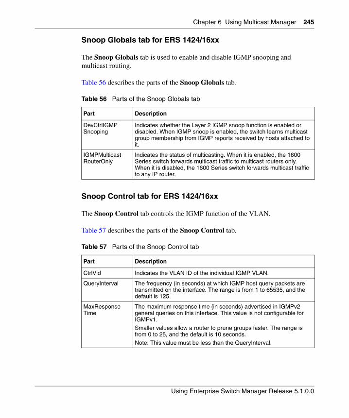
Chapter 6 Using Multicast Manager 245
Using Enterprise Switch Manager Release 5.1.0.0
Snoop Globals tab for ERS 1424/16xx
The Snoop Globals tab is used to enable and disable IGMP snooping and multicast routing.
Table 56 describes the parts of the Snoop Globals tab.
Snoop Control tab for ERS 1424/16xx
The Snoop Control tab controls the IGMP function of the VLAN.
Table 57 describes the parts of the Snoop Control tab.
Table 56 Parts of the Snoop Globals tab
Part Description
DevCtrlIGMPSnooping
Indicates whether the Layer 2 IGMP snoop function is enabled or disabled. When IGMP snoop is enabled, the switch learns multicast group membership from IGMP reports received by hosts attached to it.
IGMPMulticastRouterOnly
Indicates the status of multicasting. When it is enabled, the 1600 Series switch forwards multicast traffic to multicast routers only. When it is disabled, the 1600 Series switch forwards multicast traffic to any IP router.
Table 57 Parts of the Snoop Control tab
Part Description
CtrlVid Indicates the VLAN ID of the individual IGMP VLAN.
QueryInterval The frequency (in seconds) at which IGMP host query packets are transmitted on the interface. The range is from 1 to 65535, and the default is 125.
MaxResponseTime
The maximum response time (in seconds) advertised in IGMPv2 general queries on this interface. This value is not configurable for IGMPv1.
Smaller values allow a router to prune groups faster. The range is from 0 to 25, and the default is 10 seconds.Note: This value must be less than the QueryInterval.
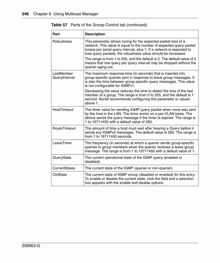
246 Chapter 6 Using Multicast Manager
208963-G
Robustness This parameter allows tuning for the expected packet loss of a network. This value is equal to the number of expected query packet losses per serial query interval, plus 1. If a network is expected to lose query packets, the robustness value should be increased.
The range is from 1 to 255, and the default is 2. The default value of 2 means that one query per query interval may be dropped without the querier aging out.
LastMemberQueryInterval
The maximum response time (in seconds) that is inserted into group-specific queries sent in response to leave group messages. It is also the time between group-specific query messages. This value is not configurable for IGMPv1.
Decreasing the value reduces the time to detect the loss of the last member of a group. The range is from 0 to 255, and the default is 1 second. Nortel recommends configuring this parameter to values above 1.
HostTimeout The timer value for sending IGMP query packet when none was sent by the host in the LAN. The timer works on a per-VLAN basis. The device sends the query message if the timer is expired. The range is 1 to 16711450 with a default value of 260.
RouteTimeout The amount of time a host must wait after hearing a Query before it sends any IGMPv2 messages. The default value is 260. The range is from 1 to 16711450 seconds.
LeaveTimer The frequency (in seconds) at which a querier sends group-specific queries to group members when the querier receives a leave group message. The range is from 1 to 16711450 with a default value of 1.
QueryState The current operational state of the IGMP query (enabled or disabled).
CurrentStates The current state of the IGMP (querier or non-querier).
CtrlState The current state of IGMP snoop (disabled or enabled) for this entry. To enable or disable the current state, click the field and a selection box appears with the enable and disable options.
Table 57 Parts of the Snoop Control tab (continued)
Part Description
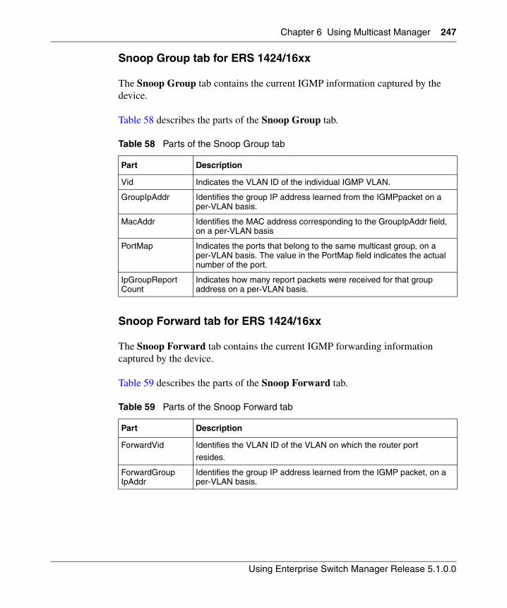
Chapter 6 Using Multicast Manager 247
Using Enterprise Switch Manager Release 5.1.0.0
Snoop Group tab for ERS 1424/16xx
The Snoop Group tab contains the current IGMP information captured by the device.
Table 58 describes the parts of the Snoop Group tab.
Snoop Forward tab for ERS 1424/16xx
The Snoop Forward tab contains the current IGMP forwarding information captured by the device.
Table 59 describes the parts of the Snoop Forward tab.
Table 58 Parts of the Snoop Group tab
Part Description
Vid Indicates the VLAN ID of the individual IGMP VLAN.
GroupIpAddr Identifies the group IP address learned from the IGMPpacket on a per-VLAN basis.
MacAddr Identifies the MAC address corresponding to the GroupIpAddr field, on a per-VLAN basis
PortMap Indicates the ports that belong to the same multicast group, on a per-VLAN basis. The value in the PortMap field indicates the actual number of the port.
IpGroupReportCount
Indicates how many report packets were received for that group address on a per-VLAN basis.
Table 59 Parts of the Snoop Forward tab
Part Description
ForwardVid Identifies the VLAN ID of the VLAN on which the router port
resides.
ForwardGroupIpAddr
Identifies the group IP address learned from the IGMP packet, on a per-VLAN basis.
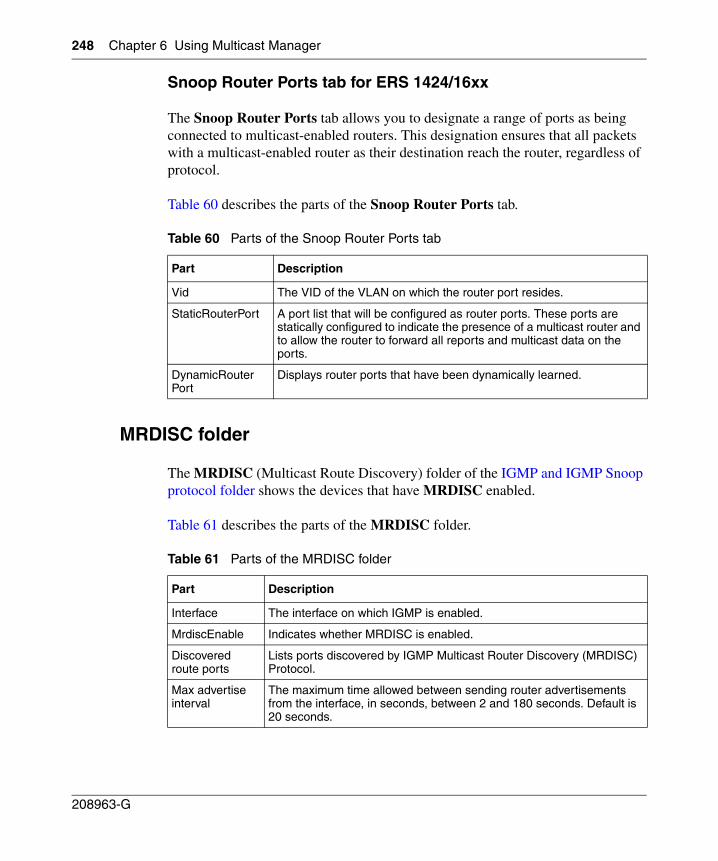
248 Chapter 6 Using Multicast Manager
208963-G
Snoop Router Ports tab for ERS 1424/16xx
The Snoop Router Ports tab allows you to designate a range of ports as being connected to multicast-enabled routers. This designation ensures that all packets with a multicast-enabled router as their destination reach the router, regardless of protocol.
Table 60 describes the parts of the Snoop Router Ports tab.
MRDISC folder
The MRDISC (Multicast Route Discovery) folder of the IGMP and IGMP Snoop protocol folder shows the devices that have MRDISC enabled.
Table 61 describes the parts of the MRDISC folder.
Table 60 Parts of the Snoop Router Ports tab
Part Description
Vid The VID of the VLAN on which the router port resides.
StaticRouterPort A port list that will be configured as router ports. These ports are statically configured to indicate the presence of a multicast router and to allow the router to forward all reports and multicast data on the ports.
DynamicRouterPort
Displays router ports that have been dynamically learned.
Table 61 Parts of the MRDISC folder
Part Description
Interface The interface on which IGMP is enabled.
MrdiscEnable Indicates whether MRDISC is enabled.
Discovered route ports
Lists ports discovered by IGMP Multicast Router Discovery (MRDISC) Protocol.
Max advertise interval
The maximum time allowed between sending router advertisements from the interface, in seconds, between 2 and 180 seconds. Default is 20 seconds.
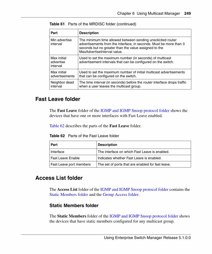
Chapter 6 Using Multicast Manager 249
Using Enterprise Switch Manager Release 5.1.0.0
Fast Leave folder
The Fast Leave folder of the IGMP and IGMP Snoop protocol folder shows the devices that have one or more interfaces with Fast Leave enabled.
Table 62 describes the parts of the Fast Leave folder.
Access List folder
The Access List folder of the IGMP and IGMP Snoop protocol folder contains the Static Members folder and the Group Access folder.
Static Members folder
The Static Members folder of the IGMP and IGMP Snoop protocol folder shows the devices that have static members configured for any multicast group.
Min advertise interval
The minimum time allowed between sending unsolicited router advertisements from the interface, in seconds. Must be more than 3 seconds but no greater than the value assigned to the MaxAdvertiseInterval value.
Max initial advertise interval
Used to set the maximum number (in seconds) of multicast advertisement intervals that can be configured on the switch.
Max initial advertisements
Used to set the maximum number of initial multicast advertisements that can be configured on the switch.
Neighbor dead interval
The time interval (in seconds) before the router interface drops traffic when a user leaves the multicast group.
Table 62 Parts of the Fast Leave folder
Part Description
Interface The interface on which Fast Leave is enabled.
Fast Leave Enable Indicates whether Fast Leave is enabled.
Fast Leave port members The set of ports that are enabled for fast leave.
Table 61 Parts of the MRDISC folder (continued)
Part Description
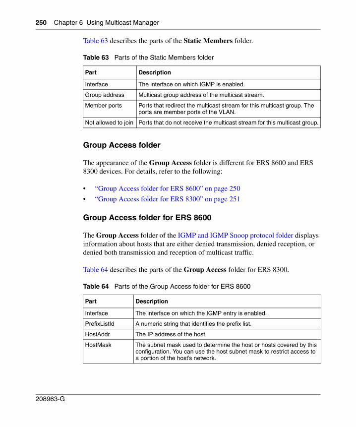
250 Chapter 6 Using Multicast Manager
208963-G
Table 63 describes the parts of the Static Members folder.
Group Access folder
The appearance of the Group Access folder is different for ERS 8600 and ERS 8300 devices. For details, refer to the following:
• “Group Access folder for ERS 8600” on page 250
• “Group Access folder for ERS 8300” on page 251
Group Access folder for ERS 8600
The Group Access folder of the IGMP and IGMP Snoop protocol folder displays information about hosts that are either denied transmission, denied reception, or denied both transmission and reception of multicast traffic.
Table 64 describes the parts of the Group Access folder for ERS 8300.
Table 63 Parts of the Static Members folder
Part Description
Interface The interface on which IGMP is enabled.
Group address Multicast group address of the multicast stream.
Member ports Ports that redirect the multicast stream for this multicast group. The ports are member ports of the VLAN.
Not allowed to join Ports that do not receive the multicast stream for this multicast group.
Table 64 Parts of the Group Access folder for ERS 8600
Part Description
Interface The interface on which the IGMP entry is enabled.
PrefixListId A numeric string that identifies the prefix list.
HostAddr The IP address of the host.
HostMask The subnet mask used to determine the host or hosts covered by this configuration. You can use the host subnet mask to restrict access to a portion of the host’s network.
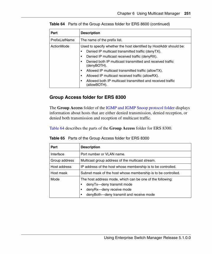
Chapter 6 Using Multicast Manager 251
Using Enterprise Switch Manager Release 5.1.0.0
Group Access folder for ERS 8300
The Group Access folder of the IGMP and IGMP Snoop protocol folder displays information about hosts that are either denied transmission, denied reception, or denied both transmission and reception of multicast traffic.
Table 64 describes the parts of the Group Access folder for ERS 8300.
PrefixListName The name of the prefix list.
ActionMode Used to specify whether the host identified by HostAddr should be:
• Denied IP multicast transmitted traffic (denyTX).• Denied IP multicast received traffic (denyRX).
• Denied both IP multicast transmitted and received traffic (denyBOTH).
• Allowed IP multicast transmitted traffic (allowTX).
• Allowed IP multicast received traffic (allowRX).
• Allowed both IP multicast transmitted and received traffic (allowBOTH).
Table 65 Parts of the Group Access folder for ERS 8300
Part Description
Interface Port number or VLAN name.
Group address Multicast group address of the multicast stream.
Host address IP address of the host whose membership is to be controlled.
Host mask Subnet mask of the host whose membership is to be controlled.
Mode The host address mode, which can be one of the following:
• denyTx—deny transmit mode• denyRx—deny receive mode
• denyBoth—deny transmit and receive mode
Table 64 Parts of the Group Access folder for ERS 8600 (continued)
Part Description
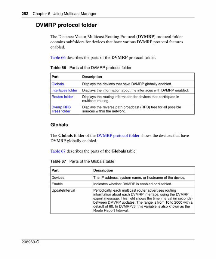
252 Chapter 6 Using Multicast Manager
208963-G
DVMRP protocol folder
The Distance Vector Multicast Routing Protocol (DVMRP) protocol folder contains subfolders for devices that have various DVMRP protocol features enabled.
Table 66 describes the parts of the DVMRP protocol folder.
Globals
The Globals folder of the DVMRP protocol folder shows the devices that have DVMRP globally enabled.
Table 67 describes the parts of the Globals table.
Table 66 Parts of the DVMRP protocol folder
Part Description
Globals Displays the devices that have DVMRP globally enabled.
Interfaces folder Displays the information about the interfaces with DVMRP enabled.
Routes folder Displays the routing information for devices that participate in multicast routing.
Dvmrp RPB Trees folder
Displays the reverse path broadcast (RPB) tree for all possible sources within the network.
Table 67 Parts of the Globals table
Part Description
Devices The IP address, system name, or hostname of the device.
Enable Indicates whether DVMRP is enabled or disabled.
UpdateInterval Periodically, each multicast router advertises routing information about each DVMRP interface, using the DVMRP export message. This field shows the time interval (in seconds) between DMVRP updates. The range is from 10 to 2000 with a default of 60. In DVMRPv3, this variable is also known as the Route Report Interval.
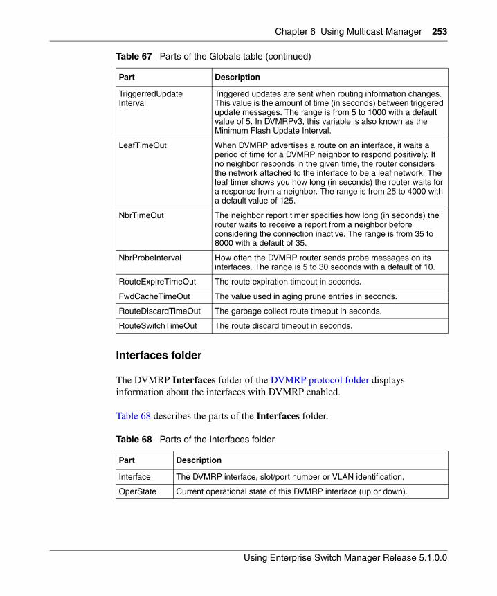
Chapter 6 Using Multicast Manager 253
Using Enterprise Switch Manager Release 5.1.0.0
Interfaces folder
The DVMRP Interfaces folder of the DVMRP protocol folder displays information about the interfaces with DVMRP enabled.
Table 68 describes the parts of the Interfaces folder.
TriggerredUpdateInterval
Triggered updates are sent when routing information changes. This value is the amount of time (in seconds) between triggered update messages. The range is from 5 to 1000 with a default value of 5. In DVMRPv3, this variable is also known as the Minimum Flash Update Interval.
LeafTimeOut When DVMRP advertises a route on an interface, it waits a period of time for a DVMRP neighbor to respond positively. If no neighbor responds in the given time, the router considers the network attached to the interface to be a leaf network. The leaf timer shows you how long (in seconds) the router waits for a response from a neighbor. The range is from 25 to 4000 with a default value of 125.
NbrTimeOut The neighbor report timer specifies how long (in seconds) the router waits to receive a report from a neighbor before considering the connection inactive. The range is from 35 to 8000 with a default of 35.
NbrProbeInterval How often the DVMRP router sends probe messages on its interfaces. The range is 5 to 30 seconds with a default of 10.
RouteExpireTimeOut The route expiration timeout in seconds.
FwdCacheTimeOut The value used in aging prune entries in seconds.
RouteDiscardTimeOut The garbage collect route timeout in seconds.
RouteSwitchTimeOut The route discard timeout in seconds.
Table 68 Parts of the Interfaces folder
Part Description
Interface The DVMRP interface, slot/port number or VLAN identification.
OperState Current operational state of this DVMRP interface (up or down).
Table 67 Parts of the Globals table (continued)
Part Description
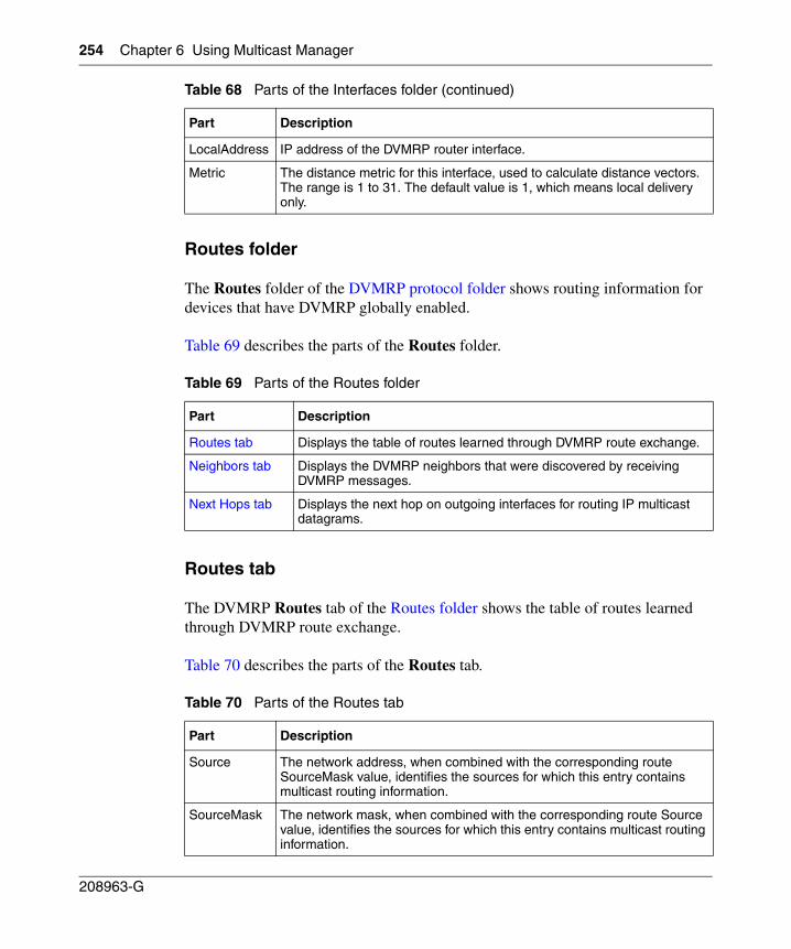
254 Chapter 6 Using Multicast Manager
208963-G
Routes folder
The Routes folder of the DVMRP protocol folder shows routing information for devices that have DVMRP globally enabled.
Table 69 describes the parts of the Routes folder.
Routes tab
The DVMRP Routes tab of the Routes folder shows the table of routes learned through DVMRP route exchange.
Table 70 describes the parts of the Routes tab.
LocalAddress IP address of the DVMRP router interface.
Metric The distance metric for this interface, used to calculate distance vectors. The range is 1 to 31. The default value is 1, which means local delivery only.
Table 69 Parts of the Routes folder
Part Description
Routes tab Displays the table of routes learned through DVMRP route exchange.
Neighbors tab Displays the DVMRP neighbors that were discovered by receiving DVMRP messages.
Next Hops tab Displays the next hop on outgoing interfaces for routing IP multicast datagrams.
Table 70 Parts of the Routes tab
Part Description
Source The network address, when combined with the corresponding route SourceMask value, identifies the sources for which this entry contains multicast routing information.
SourceMask The network mask, when combined with the corresponding route Source value, identifies the sources for which this entry contains multicast routing information.
Table 68 Parts of the Interfaces folder (continued)
Part Description
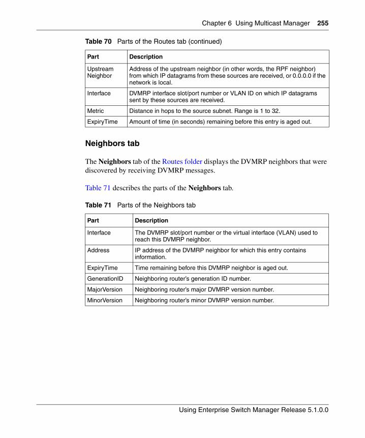
Chapter 6 Using Multicast Manager 255
Using Enterprise Switch Manager Release 5.1.0.0
Neighbors tab
The Neighbors tab of the Routes folder displays the DVMRP neighbors that were discovered by receiving DVMRP messages.
Table 71 describes the parts of the Neighbors tab.
UpstreamNeighbor
Address of the upstream neighbor (in other words, the RPF neighbor) from which IP datagrams from these sources are received, or 0.0.0.0 if the network is local.
Interface DVMRP interface slot/port number or VLAN ID on which IP datagrams sent by these sources are received.
Metric Distance in hops to the source subnet. Range is 1 to 32.
ExpiryTime Amount of time (in seconds) remaining before this entry is aged out.
Table 71 Parts of the Neighbors tab
Part Description
Interface The DVMRP slot/port number or the virtual interface (VLAN) used to reach this DVMRP neighbor.
Address IP address of the DVMRP neighbor for which this entry contains information.
ExpiryTime Time remaining before this DVMRP neighbor is aged out.
GenerationID Neighboring router’s generation ID number.
MajorVersion Neighboring router’s major DVMRP version number.
MinorVersion Neighboring router’s minor DVMRP version number.
Table 70 Parts of the Routes tab (continued)
Part Description
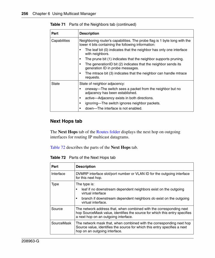
256 Chapter 6 Using Multicast Manager
208963-G
Next Hops tab
The Next Hops tab of the Routes folder displays the next hop on outgoing interfaces for routing IP multicast datagrams.
Table 72 describes the parts of the Next Hops tab.
Capabilities Neighboring router’s capabilities. The probe flag is 1 byte long with the lower 4 bits containing the following information:
• The leaf bit (0) indicates that the neighbor has only one interface with neighbors.
• The prune bit (1) indicates that the neighbor supports pruning.
• The generationID bit (2) indicates that the neighbor sends its generation ID in probe messages.
• The mtrace bit (3) indicates that the neighbor can handle mtrace requests.
State State of neighbor adjacency:
• oneway—The switch sees a packet from the neighbor but no adjacency has been established.
• active—Adjacency exists in both directions.
• ignoring—The switch ignores neighbor packets.
• down—The interface is not enabled.
Table 72 Parts of the Next Hops tab
Part Description
Interface DVMRP interface slot/port number or VLAN ID for the outgoing interface for this next hop.
Type The type is:
• leaf if no downstream dependent neighbors exist on the outgoing virtual interface
• branch if downstream dependent neighbors do exist on the outgoing virtual interface.
Source The network address that, when combined with the corresponding next hop SourceMask value, identifies the source for which this entry specifies a next hop on an outgoing interface.
SourceMask The network mask that, when combined with the corresponding next hop Source value, identifies the source for which this entry specifies a next hop on an outgoing interface.
Table 71 Parts of the Neighbors tab (continued)
Part Description
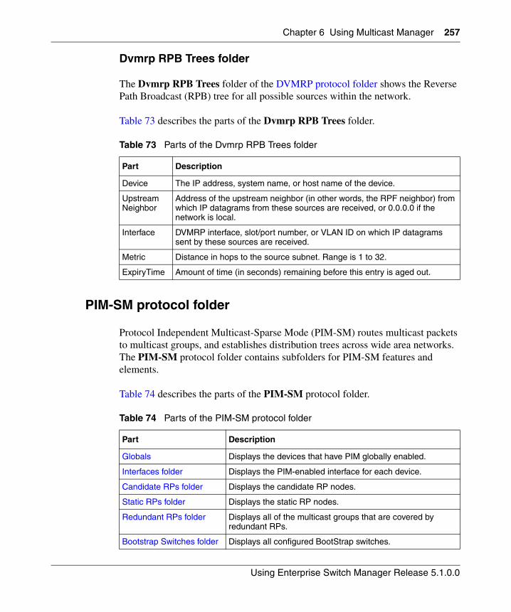
Chapter 6 Using Multicast Manager 257
Using Enterprise Switch Manager Release 5.1.0.0
Dvmrp RPB Trees folder
The Dvmrp RPB Trees folder of the DVMRP protocol folder shows the Reverse Path Broadcast (RPB) tree for all possible sources within the network.
Table 73 describes the parts of the Dvmrp RPB Trees folder.
PIM-SM protocol folder
Protocol Independent Multicast-Sparse Mode (PIM-SM) routes multicast packets to multicast groups, and establishes distribution trees across wide area networks. The PIM-SM protocol folder contains subfolders for PIM-SM features and elements.
Table 74 describes the parts of the PIM-SM protocol folder.
Table 73 Parts of the Dvmrp RPB Trees folder
Part Description
Device The IP address, system name, or host name of the device.
UpstreamNeighbor
Address of the upstream neighbor (in other words, the RPF neighbor) from which IP datagrams from these sources are received, or 0.0.0.0 if the network is local.
Interface DVMRP interface, slot/port number, or VLAN ID on which IP datagrams sent by these sources are received.
Metric Distance in hops to the source subnet. Range is 1 to 32.
ExpiryTime Amount of time (in seconds) remaining before this entry is aged out.
Table 74 Parts of the PIM-SM protocol folder
Part Description
Globals Displays the devices that have PIM globally enabled.
Interfaces folder Displays the PIM-enabled interface for each device.
Candidate RPs folder Displays the candidate RP nodes.
Static RPs folder Displays the static RP nodes.
Redundant RPs folder Displays all of the multicast groups that are covered by redundant RPs.
Bootstrap Switches folder Displays all configured BootStrap switches.
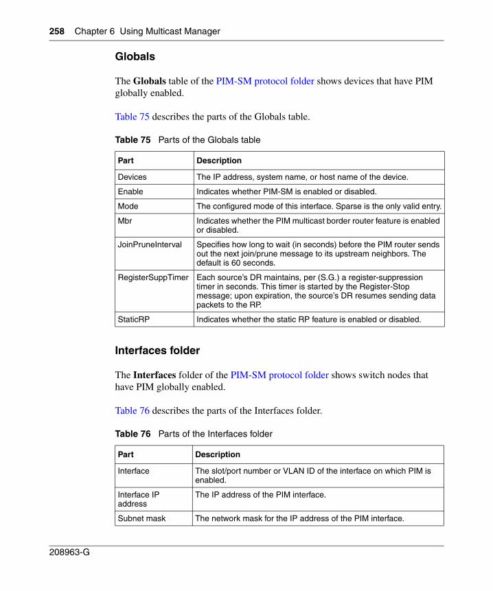
258 Chapter 6 Using Multicast Manager
208963-G
Globals
The Globals table of the PIM-SM protocol folder shows devices that have PIM globally enabled.
Table 75 describes the parts of the Globals table.
Interfaces folder
The Interfaces folder of the PIM-SM protocol folder shows switch nodes that have PIM globally enabled.
Table 76 describes the parts of the Interfaces folder.
Table 75 Parts of the Globals table
Part Description
Devices The IP address, system name, or host name of the device.
Enable Indicates whether PIM-SM is enabled or disabled.
Mode The configured mode of this interface. Sparse is the only valid entry.
Mbr Indicates whether the PIM multicast border router feature is enabled or disabled.
JoinPruneInterval Specifies how long to wait (in seconds) before the PIM router sends out the next join/prune message to its upstream neighbors. The default is 60 seconds.
RegisterSuppTimer Each source’s DR maintains, per (S.G.) a register-suppression timer in seconds. This timer is started by the Register-Stop message; upon expiration, the source’s DR resumes sending data packets to the RP.
StaticRP Indicates whether the static RP feature is enabled or disabled.
Table 76 Parts of the Interfaces folder
Part Description
Interface The slot/port number or VLAN ID of the interface on which PIM is enabled.
Interface IP address
The IP address of the PIM interface.
Subnet mask The network mask for the IP address of the PIM interface.
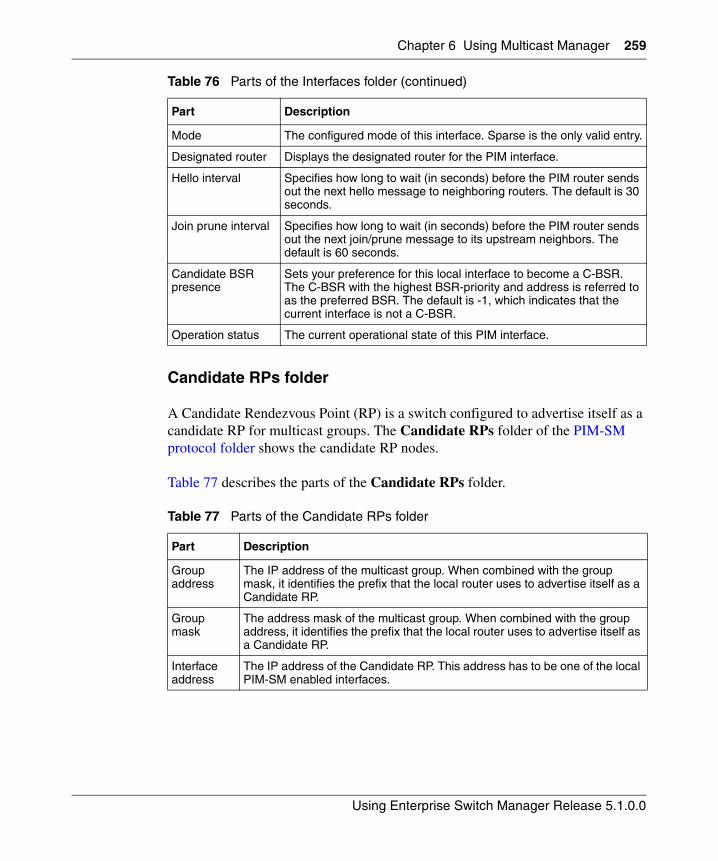
Chapter 6 Using Multicast Manager 259
Using Enterprise Switch Manager Release 5.1.0.0
Candidate RPs folder
A Candidate Rendezvous Point (RP) is a switch configured to advertise itself as a candidate RP for multicast groups. The Candidate RPs folder of the PIM-SM protocol folder shows the candidate RP nodes.
Table 77 describes the parts of the Candidate RPs folder.
Mode The configured mode of this interface. Sparse is the only valid entry.
Designated router Displays the designated router for the PIM interface.
Hello interval Specifies how long to wait (in seconds) before the PIM router sends out the next hello message to neighboring routers. The default is 30 seconds.
Join prune interval Specifies how long to wait (in seconds) before the PIM router sends out the next join/prune message to its upstream neighbors. The default is 60 seconds.
Candidate BSR presence
Sets your preference for this local interface to become a C-BSR. The C-BSR with the highest BSR-priority and address is referred to as the preferred BSR. The default is -1, which indicates that the current interface is not a C-BSR.
Operation status The current operational state of this PIM interface.
Table 77 Parts of the Candidate RPs folder
Part Description
Group address
The IP address of the multicast group. When combined with the group mask, it identifies the prefix that the local router uses to advertise itself as a Candidate RP.
Group mask
The address mask of the multicast group. When combined with the group address, it identifies the prefix that the local router uses to advertise itself as a Candidate RP.
Interface address
The IP address of the Candidate RP. This address has to be one of the local PIM-SM enabled interfaces.
Table 76 Parts of the Interfaces folder (continued)
Part Description
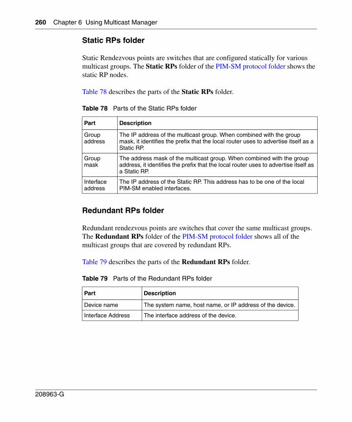
260 Chapter 6 Using Multicast Manager
208963-G
Static RPs folder
Static Rendezvous points are switches that are configured statically for various multicast groups. The Static RPs folder of the PIM-SM protocol folder shows the static RP nodes.
Table 78 describes the parts of the Static RPs folder.
Redundant RPs folder
Redundant rendezvous points are switches that cover the same multicast groups. The Redundant RPs folder of the PIM-SM protocol folder shows all of the multicast groups that are covered by redundant RPs.
Table 79 describes the parts of the Redundant RPs folder.
Table 78 Parts of the Static RPs folder
Part Description
Group address
The IP address of the multicast group. When combined with the group mask, it identifies the prefix that the local router uses to advertise itself as a Static RP.
Group mask
The address mask of the multicast group. When combined with the group address, it identifies the prefix that the local router uses to advertise itself as a Static RP.
Interface address
The IP address of the Static RP. This address has to be one of the local PIM-SM enabled interfaces.
Table 79 Parts of the Redundant RPs folder
Part Description
Device name The system name, host name, or IP address of the device.
Interface Address The interface address of the device.
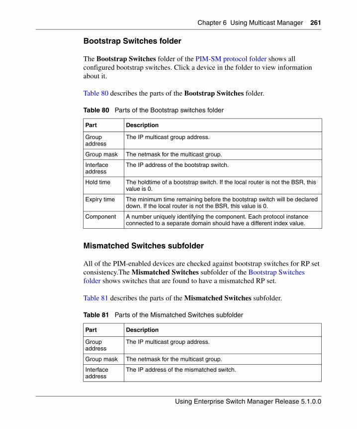
Chapter 6 Using Multicast Manager 261
Using Enterprise Switch Manager Release 5.1.0.0
Bootstrap Switches folder
The Bootstrap Switches folder of the PIM-SM protocol folder shows all configured bootstrap switches. Click a device in the folder to view information about it.
Table 80 describes the parts of the Bootstrap Switches folder.
Mismatched Switches subfolder
All of the PIM-enabled devices are checked against bootstrap switches for RP set consistency.The Mismatched Switches subfolder of the Bootstrap Switches folder shows switches that are found to have a mismatched RP set.
Table 81 describes the parts of the Mismatched Switches subfolder.
Table 80 Parts of the Bootstrap switches folder
Part Description
Group address
The IP multicast group address.
Group mask The netmask for the multicast group.
Interface address
The IP address of the bootstrap switch.
Hold time The holdtime of a bootstrap switch. If the local router is not the BSR, this value is 0.
Expiry time The minimum time remaining before the bootstrap switch will be declared down. If the local router is not the BSR, this value is 0.
Component A number uniquely identifying the component. Each protocol instance connected to a separate domain should have a different index value.
Table 81 Parts of the Mismatched Switches subfolder
Part Description
Group address
The IP multicast group address.
Group mask The netmask for the multicast group.
Interface address
The IP address of the mismatched switch.
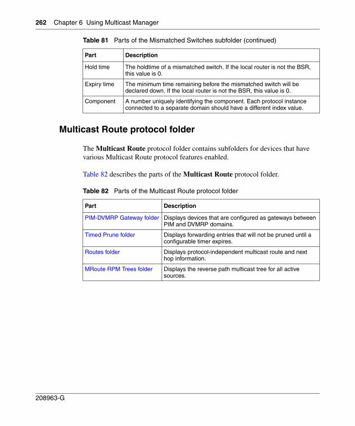
262 Chapter 6 Using Multicast Manager
208963-G
Multicast Route protocol folder
The Multicast Route protocol folder contains subfolders for devices that have various Multicast Route protocol features enabled.
Table 82 describes the parts of the Multicast Route protocol folder.
Hold time The holdtime of a mismatched switch. If the local router is not the BSR, this value is 0.
Expiry time The minimum time remaining before the mismatched switch will be declared down. If the local router is not the BSR, this value is 0.
Component A number uniquely identifying the component. Each protocol instance connected to a separate domain should have a different index value.
Table 82 Parts of the Multicast Route protocol folder
Part Description
PIM-DVMRP Gateway folder Displays devices that are configured as gateways between PIM and DVMRP domains.
Timed Prune folder Displays forwarding entries that will not be pruned until a configurable timer expires.
Routes folder Displays protocol-independent multicast route and next hop information.
MRoute RPM Trees folder Displays the reverse path multicast tree for all active sources.
Table 81 Parts of the Mismatched Switches subfolder (continued)
Part Description
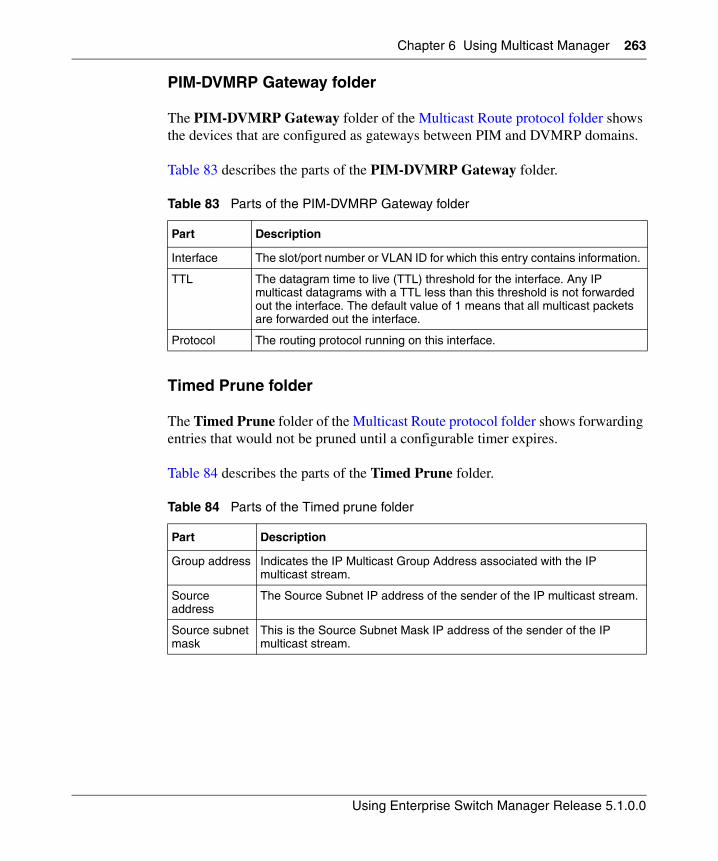
Chapter 6 Using Multicast Manager 263
Using Enterprise Switch Manager Release 5.1.0.0
PIM-DVMRP Gateway folder
The PIM-DVMRP Gateway folder of the Multicast Route protocol folder shows the devices that are configured as gateways between PIM and DVMRP domains.
Table 83 describes the parts of the PIM-DVMRP Gateway folder.
Timed Prune folder
The Timed Prune folder of the Multicast Route protocol folder shows forwarding entries that would not be pruned until a configurable timer expires.
Table 84 describes the parts of the Timed Prune folder.
Table 83 Parts of the PIM-DVMRP Gateway folder
Part Description
Interface The slot/port number or VLAN ID for which this entry contains information.
TTL The datagram time to live (TTL) threshold for the interface. Any IP multicast datagrams with a TTL less than this threshold is not forwarded out the interface. The default value of 1 means that all multicast packets are forwarded out the interface.
Protocol The routing protocol running on this interface.
Table 84 Parts of the Timed prune folder
Part Description
Group address Indicates the IP Multicast Group Address associated with the IP multicast stream.
Source address
The Source Subnet IP address of the sender of the IP multicast stream.
Source subnet mask
This is the Source Subnet Mask IP address of the sender of the IP multicast stream.
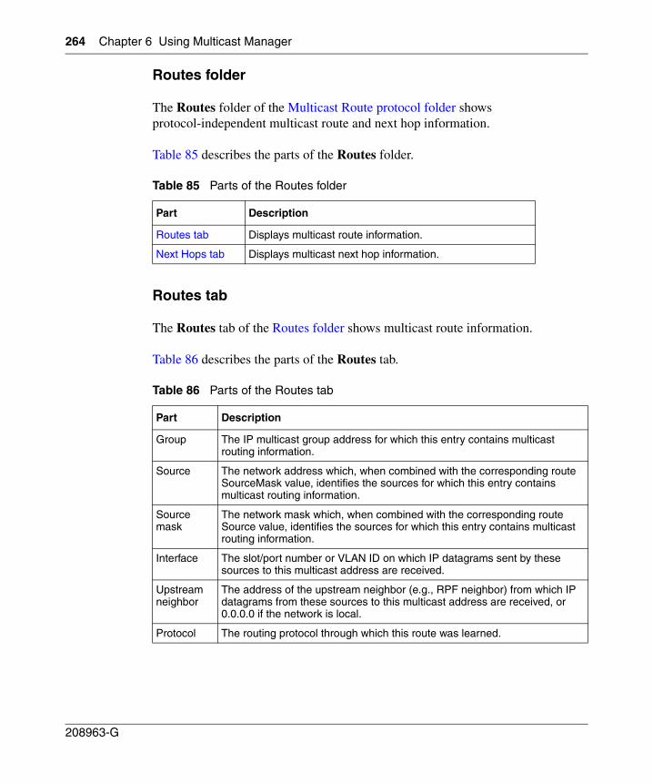
264 Chapter 6 Using Multicast Manager
208963-G
Routes folder
The Routes folder of the Multicast Route protocol folder shows protocol-independent multicast route and next hop information.
Table 85 describes the parts of the Routes folder.
Routes tab
The Routes tab of the Routes folder shows multicast route information.
Table 86 describes the parts of the Routes tab.
Table 85 Parts of the Routes folder
Part Description
Routes tab Displays multicast route information.
Next Hops tab Displays multicast next hop information.
Table 86 Parts of the Routes tab
Part Description
Group The IP multicast group address for which this entry contains multicast routing information.
Source The network address which, when combined with the corresponding route SourceMask value, identifies the sources for which this entry contains multicast routing information.
Source mask
The network mask which, when combined with the corresponding route Source value, identifies the sources for which this entry contains multicast routing information.
Interface The slot/port number or VLAN ID on which IP datagrams sent by these sources to this multicast address are received.
Upstream neighbor
The address of the upstream neighbor (e.g., RPF neighbor) from which IP datagrams from these sources to this multicast address are received, or 0.0.0.0 if the network is local.
Protocol The routing protocol through which this route was learned.
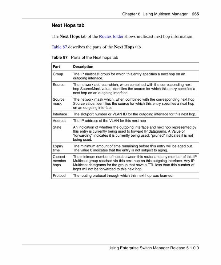
Chapter 6 Using Multicast Manager 265
Using Enterprise Switch Manager Release 5.1.0.0
Next Hops tab
The Next Hops tab of the Routes folder shows multicast next hop information.
Table 87 describes the parts of the Next Hops tab.
Table 87 Parts of the Next hops tab
Part Description
Group The IP multicast group for which this entry specifies a next hop on an outgoing interface.
Source The network address which, when combined with the corresponding next hop SourceMask value, identifies the source for which this entry specifies a next hop on an outgoing interface.
Source mask
The network mask which, when combined with the corresponding next hop Source value, identifies the source for which this entry specifies a next hop on an outgoing interface.
Interface The slot/port number or VLAN ID for the outgoing interface for this next hop.
Address The IP address of the VLAN for this next hop
State An indication of whether the outgoing interface and next hop represented by this entry is currently being used to forward IP datagrams. A Value of “forwarding” indicates it is currently being used; “pruned” indicates it is not being used.
Expiry time
The minimum amount of time remaining before this entry will be aged out. The value 0 indicates that the entry is not subject to aging.
Closest member hops
The minimum number of hops between this router and any member of this IP Multicast group reached via this next hop on this outgoing interface. Any IP Multicast datagrams for the group that have a TTL less than this number of hops will not be forwarded to this next hop.
Protocol The routing protocol through which this next hop was learned.
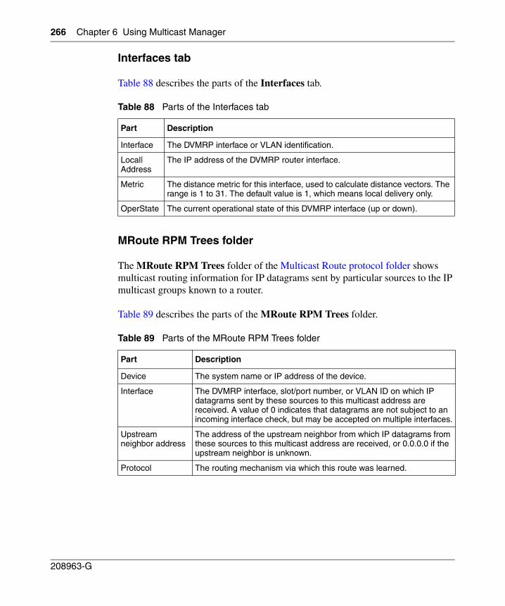
266 Chapter 6 Using Multicast Manager
208963-G
Interfaces tab
Table 88 describes the parts of the Interfaces tab.
MRoute RPM Trees folder
The MRoute RPM Trees folder of the Multicast Route protocol folder shows multicast routing information for IP datagrams sent by particular sources to the IP multicast groups known to a router.
Table 89 describes the parts of the MRoute RPM Trees folder.
Table 88 Parts of the Interfaces tab
Part Description
Interface The DVMRP interface or VLAN identification.
Local|Address
The IP address of the DVMRP router interface.
Metric The distance metric for this interface, used to calculate distance vectors. The range is 1 to 31. The default value is 1, which means local delivery only.
OperState The current operational state of this DVMRP interface (up or down).
Table 89 Parts of the MRoute RPM Trees folder
Part Description
Device The system name or IP address of the device.
Interface The DVMRP interface, slot/port number, or VLAN ID on which IP datagrams sent by these sources to this multicast address are received. A value of 0 indicates that datagrams are not subject to an incoming interface check, but may be accepted on multiple interfaces.
Upstream neighbor address
The address of the upstream neighbor from which IP datagrams from these sources to this multicast address are received, or 0.0.0.0 if the upstream neighbor is unknown.
Protocol The routing mechanism via which this route was learned.
267
Using Enterprise Switch Manager Release 5.1.0.0
Chapter 7Using Trap/Log Manager
The Trap/Log Manager is a new ESM submanager that allows you to configure and view the traps and notifications and the system log. This submanager combines the functionality of the original Trap Receiver and Log Manager, and adds trap/notification configuration and syslog configuration.
You can configure the network manager to which the traps are sent using this submanager.
You can also configure the severity of the log, the host and port to which the log is sent.
Also the trap receiver shows the traps received from the configured devices.
Similarly, the syslog receiver shows the system Log for the configured devices.
Note: To enable traps and logs in ESM, you must select the Listen for Traps and Listen for Syslogs options, respectively, in the Preferences menu. (See “Preferences dialog box items” on page 100 for details.)
This chapter contains information about the following topics:
• “Starting Trap/Log Manager” on page 268
• “Configuring System Log” on page 269
• “Configuring Traps” on page 278
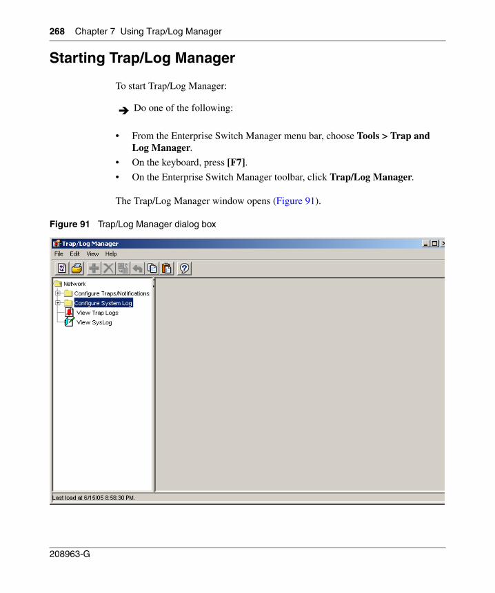
268 Chapter 7 Using Trap/Log Manager
208963-G
Starting Trap/Log Manager
To start Trap/Log Manager:
• From the Enterprise Switch Manager menu bar, choose Tools > Trap and Log Manager.
• On the keyboard, press [F7].
• On the Enterprise Switch Manager toolbar, click Trap/Log Manager.
The Trap/Log Manager window opens (Figure 91).
Figure 91 Trap/Log Manager dialog box
Do one of the following:
Chapter 7 Using Trap/Log Manager 269
Using Enterprise Switch Manager Release 5.1.0.0
Configuring System Log
The Trap/Log Manager lists the devices that support System Log configuration that have been discovered using the Topology Manager.
To display the devices, expand the Configure System Log tree.
Note: The create icon in the tool bar is enabled only on clicking a device.
For information about configuring the System Log for particular switch families, refer to the following:
• Configuring System Log for ERS 8000 devices
• Enabling System Log for ERS 8000 devices
• Configuring System Log for ERS 1424/16xx devices
• Enabling System Log for ERS 16xx devices
• Configuring System Log for Ethernet Switch, ERS 55xx/35xx, and Legacy BayStack devices
Configuring System Log for ERS 8000 devices
To create a system log for a host
1 Under the Configure System Log folder, choose a device for which to create a system log.
2 Choose the System Log Table tab.
3 Click the Create icon in the tool bar, or choose Edit > Create from the Trap/Log Manager menu.
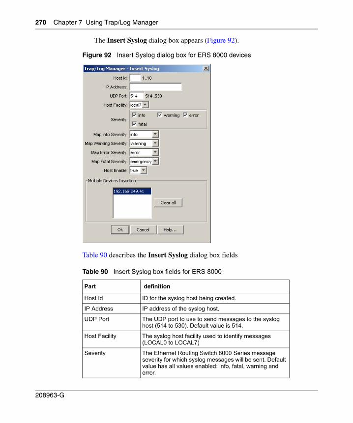
270 Chapter 7 Using Trap/Log Manager
208963-G
The Insert Syslog dialog box appears (Figure 92).
Figure 92 Insert Syslog dialog box for ERS 8000 devices
Table 90 describes the Insert Syslog dialog box fields
Table 90 Insert Syslog box fields for ERS 8000
Part definition
Host Id ID for the syslog host being created.
IP Address IP address of the syslog host.
UDP Port The UDP port to use to send messages to the syslog host (514 to 530). Default value is 514.
Host Facility The syslog host facility used to identify messages (LOCAL0 to LOCAL7)
Severity The Ethernet Routing Switch 8000 Series message severity for which syslog messages will be sent. Default value has all values enabled: info, fatal, warning and error.
Chapter 7 Using Trap/Log Manager 271
Using Enterprise Switch Manager Release 5.1.0.0
4 Populate the fields as required.
5 Click OK.
You can modify the existing SyslogHost properties by editing the corresponding cells in the table. To apply the changes, click the Apply Changes button in the tool bar.
Enabling System Log for ERS 8000 devices
To enable the system log:
1 Under the Configure System Log folder, choose a device for which to enable the system log.
2 Under the System Log tab, choose true from the Enable column.
3 To apply the changes, click the Apply Changes button in the tool bar.
Map Info Severity The fields that map the Ethernet Routing Switch 8000 Series severity levels to syslog severity. Default value is info.
Map Warning Severity
The fields that map Ethernet Routing Switch 8000 Series warning severity levels to syslog severity. Default value is warning.
Map Error Severity The fields that map Ethernet Routing Switch 8000 error severity levels to syslog severity. Default value is error.
Map Fatal Severity The fields that map Ethernet Routing Switch 8000 fatal severity levels to syslog severity. Default value is emergency.
Host Enable Enables or disables sending messages to the syslog host. Default value is true.
Multiple Devices Insertion
Allows you to set these values for other similar devices.
Table 90 Insert Syslog box fields for ERS 8000 (continued)
Part definition
272 Chapter 7 Using Trap/Log Manager
208963-G
Table 91 describes the System Log tab fields
Configuring System Log for ERS 1424/16xx devices
To create a system log for a host
1 Under the Configure System Log folder, choose a device for which to create a system log.
2 Choose the System Log tab.
3 Click the Create icon in the tool bar, or choose Edit > Create from the Trap/Log Manager menu.
Table 91 System Log tab fields for ERS 8000
Part definition
Enable Used to enable/disable the syslog feature.
Maximum Hosts The maximum number of remote hosts considered active and able to receive messages from the syslog service.
Operation State The operational state of the syslog service.
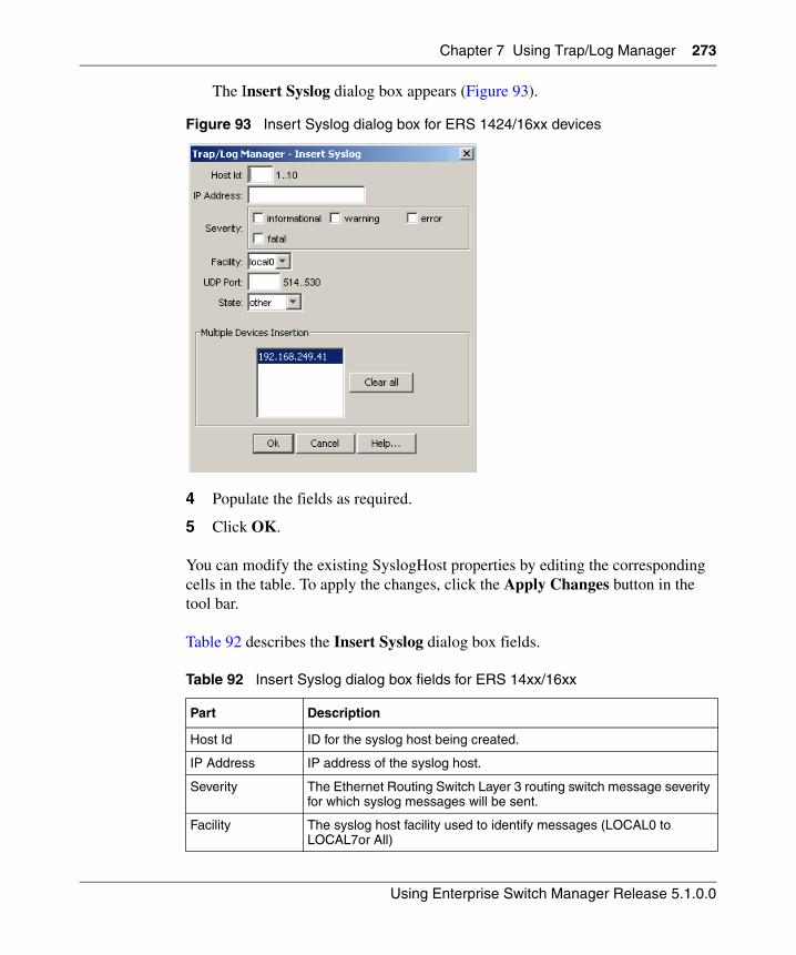
Chapter 7 Using Trap/Log Manager 273
Using Enterprise Switch Manager Release 5.1.0.0
The Insert Syslog dialog box appears (Figure 93).
Figure 93 Insert Syslog dialog box for ERS 1424/16xx devices
4 Populate the fields as required.
5 Click OK.
You can modify the existing SyslogHost properties by editing the corresponding cells in the table. To apply the changes, click the Apply Changes button in the tool bar.
Table 92 describes the Insert Syslog dialog box fields.
Table 92 Insert Syslog dialog box fields for ERS 14xx/16xx
Part Description
Host Id ID for the syslog host being created.
IP Address IP address of the syslog host.
Severity The Ethernet Routing Switch Layer 3 routing switch message severity for which syslog messages will be sent.
Facility The syslog host facility used to identify messages (LOCAL0 to LOCAL7or All)
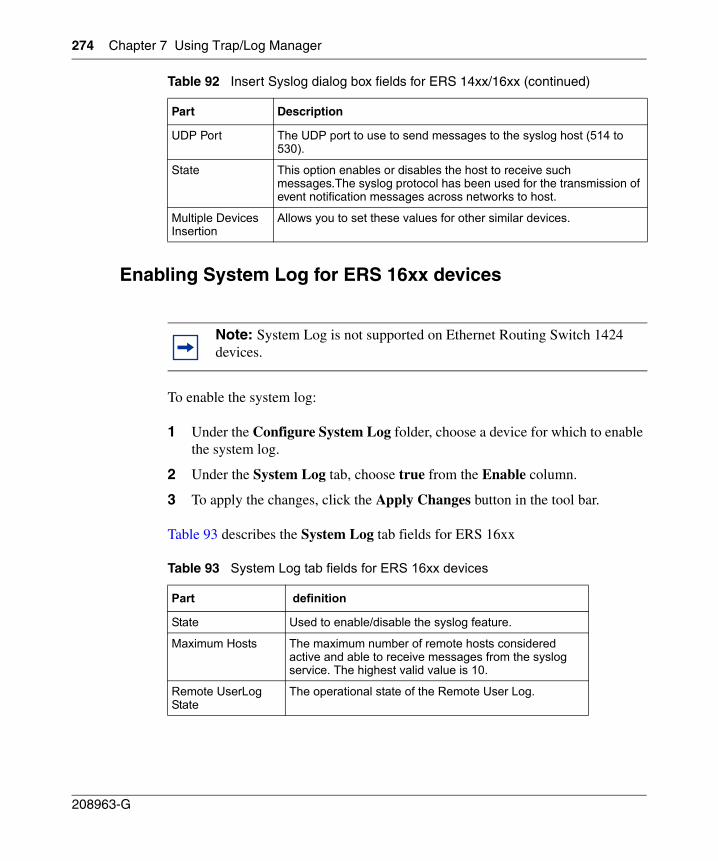
274 Chapter 7 Using Trap/Log Manager
208963-G
Enabling System Log for ERS 16xx devices
To enable the system log:
1 Under the Configure System Log folder, choose a device for which to enable the system log.
2 Under the System Log tab, choose true from the Enable column.
3 To apply the changes, click the Apply Changes button in the tool bar.
Table 93 describes the System Log tab fields for ERS 16xx
UDP Port The UDP port to use to send messages to the syslog host (514 to 530).
State This option enables or disables the host to receive such messages.The syslog protocol has been used for the transmission of event notification messages across networks to host.
Multiple Devices Insertion
Allows you to set these values for other similar devices.
Note: System Log is not supported on Ethernet Routing Switch 1424 devices.
Table 93 System Log tab fields for ERS 16xx devices
Part definition
State Used to enable/disable the syslog feature.
Maximum Hosts The maximum number of remote hosts considered active and able to receive messages from the syslog service. The highest valid value is 10.
Remote UserLog State
The operational state of the Remote User Log.
Table 92 Insert Syslog dialog box fields for ERS 14xx/16xx (continued)
Part Description
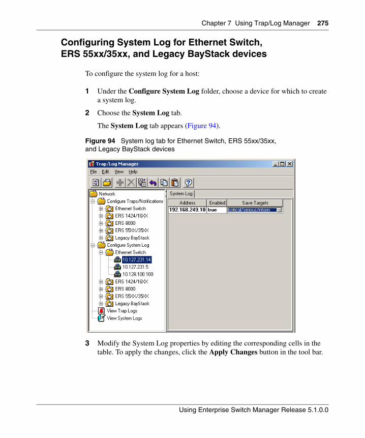
Chapter 7 Using Trap/Log Manager 275
Using Enterprise Switch Manager Release 5.1.0.0
Configuring System Log for Ethernet Switch, ERS 55xx/35xx, and Legacy BayStack devices
To configure the system log for a host:
1 Under the Configure System Log folder, choose a device for which to create a system log.
2 Choose the System Log tab.
The System Log tab appears (Figure 94).
Figure 94 System log tab for Ethernet Switch, ERS 55xx/35xx, and Legacy BayStack devices
3 Modify the System Log properties by editing the corresponding cells in the table. To apply the changes, click the Apply Changes button in the tool bar.
276 Chapter 7 Using Trap/Log Manager
208963-G
Table 94 describes the System Log tab fields.
Table 94 System Log tab fields for Ethernet Switch, ERS 55xx/35xx, and Legacy BayStack
Part Description
Address The IP address where log messages are sent using the remote syslog facility.
Enabled Specifies that the remote logging feature is enabled.
Save Targets Specifies the type of log messages to be sent to a remote syslog server when they occur. Messages are classified based on their type:
• Critical - Specifies that only critical messages are sent to the remote syslog server.
• Critical/Serious - Specifies that both critical and serious messages are sent to the remote syslog server.
• Critical/Serious/Informational - Causes all log messages are sent to the remote syslog server.
• None - Specifies that no log messages are sent to the remote syslog server.
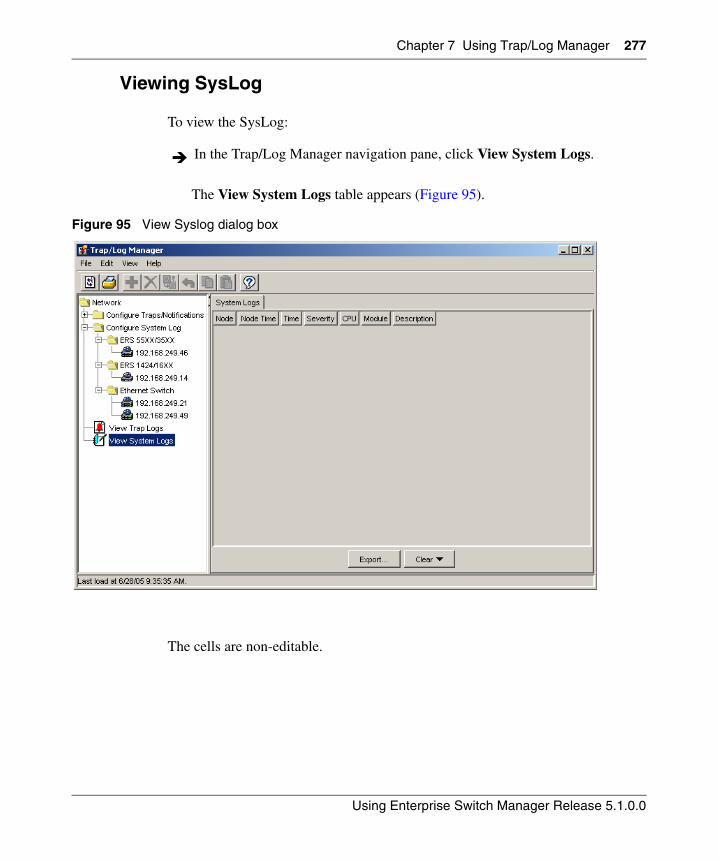
Chapter 7 Using Trap/Log Manager 277
Using Enterprise Switch Manager Release 5.1.0.0
Viewing SysLog
To view the SysLog:
The View System Logs table appears (Figure 95).
Figure 95 View Syslog dialog box
The cells are non-editable.
In the Trap/Log Manager navigation pane, click View System Logs.
278 Chapter 7 Using Trap/Log Manager
208963-G
Configuring Traps
For instructions on configuring traps for different switch families, refer to the following:
• “Configuring Trap Receivers for ERS 8000 devices” on page 278
• “Configuring Target Address Table for ERS 8000 devices” on page 280
• “Configuring Target Params Table for ERS 8000 devices” on page 281
• “Configuring Notify Table for ERS 8000 devices” on page 283
• “Configuring Trap Receivers for ERS 55xx/35xx, Ethernet Switch, and Legacy BayStack devices” on page 285
• “Configuring Target Address Table for ERS 55xx/35xx and Ethernet Switch devices” on page 287
• “Configuring Target Params Table for ERS 55xx/35xx and Ethernet Switch devices” on page 289
• “Configuring Notify Table for ERS 55xx/35xx and Ethernet Switch devices” on page 291
• “Configuring Trap Receivers for ERS 1424/16xx devices” on page 293
• “Viewing trap log” on page 295
Configuring Trap Receivers for ERS 8000 devices
To configure trap receivers:
1 In the Trap/Log Manager navigation pane, click Configure Traps/Notifications.
2 Choose the switch for which you want to configure trap receivers.
3 In the content pane, click the Trap Receivers tab.
Note: If the ERS 8000 device is running software prior to the 3.7.0 release, only the Trap Receivers tab appears in the contents pane. For ERS 8000 devices running release 3.7.0 software and later, the Target Address Table, Target Params Table, and Notify Table tabs appear in the contents pane.
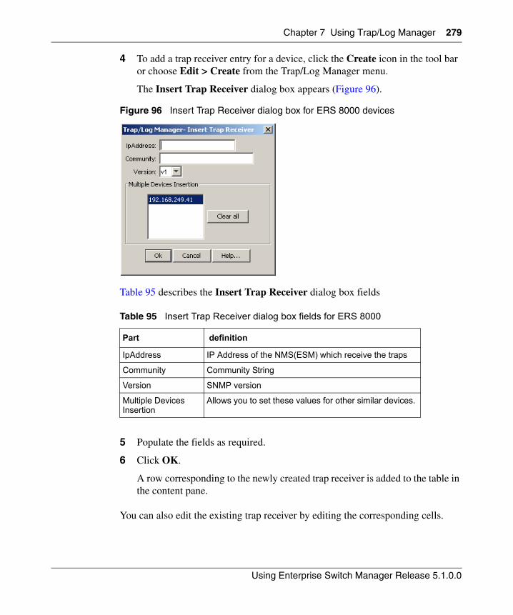
Chapter 7 Using Trap/Log Manager 279
Using Enterprise Switch Manager Release 5.1.0.0
4 To add a trap receiver entry for a device, click the Create icon in the tool bar or choose Edit > Create from the Trap/Log Manager menu.
The Insert Trap Receiver dialog box appears (Figure 96).
Figure 96 Insert Trap Receiver dialog box for ERS 8000 devices
Table 95 describes the Insert Trap Receiver dialog box fields
5 Populate the fields as required.
6 Click OK.
A row corresponding to the newly created trap receiver is added to the table in the content pane.
You can also edit the existing trap receiver by editing the corresponding cells.
Table 95 Insert Trap Receiver dialog box fields for ERS 8000
Part definition
IpAddress IP Address of the NMS(ESM) which receive the traps
Community Community String
Version SNMP version
Multiple Devices Insertion
Allows you to set these values for other similar devices.
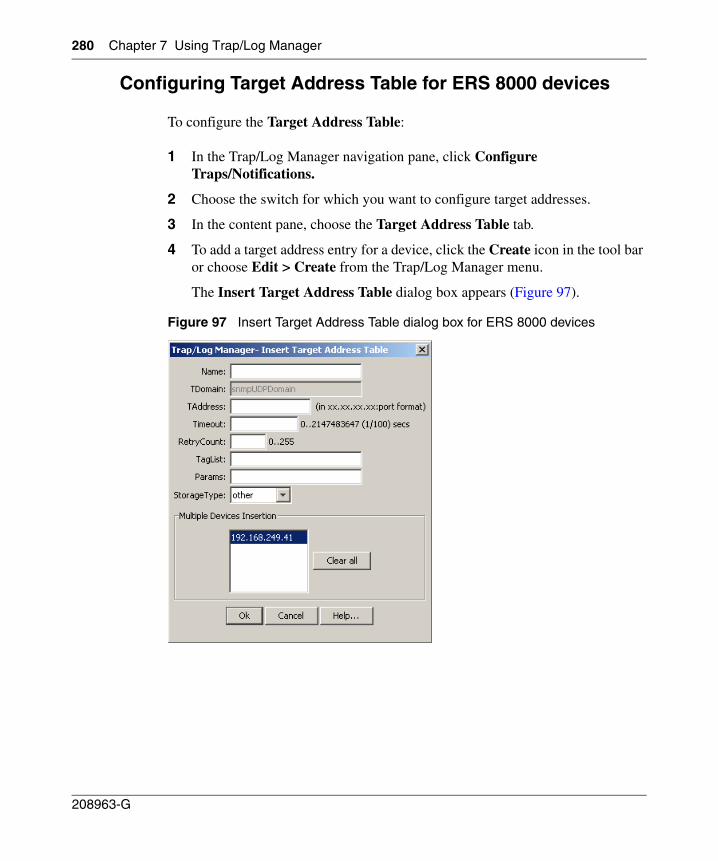
280 Chapter 7 Using Trap/Log Manager
208963-G
Configuring Target Address Table for ERS 8000 devices
To configure the Target Address Table:
1 In the Trap/Log Manager navigation pane, click Configure Traps/Notifications.
2 Choose the switch for which you want to configure target addresses.
3 In the content pane, choose the Target Address Table tab.
4 To add a target address entry for a device, click the Create icon in the tool bar or choose Edit > Create from the Trap/Log Manager menu.
The Insert Target Address Table dialog box appears (Figure 97).
Figure 97 Insert Target Address Table dialog box for ERS 8000 devices
Chapter 7 Using Trap/Log Manager 281
Using Enterprise Switch Manager Release 5.1.0.0
Table 96 describes the Insert Target Address Table dialog box fields
5 Populate the fields as required.
6 Click OK.
A row corresponding to the newly created Target Address is added to the table in the content pane.
You can also edit the existing Target Address entries by editing the corresponding cells.
Configuring Target Params Table for ERS 8000 devices
To configure the Target Params Table:
1 In the Trap/Log Manager navigation pane, click Configure Traps/Notifications.
Table 96 Insert Target Address Table dialog box fields for ERS 8000
Part definition
Name Specifies the name of the target table.
TDomain Specifies the TDomain for the target table.
TAddress The IP address and the host of the target and the UDPport number.Note: Port 162 is reserved for SNMP traps.
Timeout The maximum round trip time required for communicating with the transport address defined by this row.
RetryCount The number of retries to be attempted when a response is not received for a generated message.
TagList Specifies a list of tag values. A tag value refers to a class of targets to which the messages may be sent
Params The string value that identifies snmpTargetParamsTable entries.
StorageType Specifies the storage type, volatile or non-volatile. Default value is other.
Multiple Devices Insertion
Allows you to set these values for other similar devices.
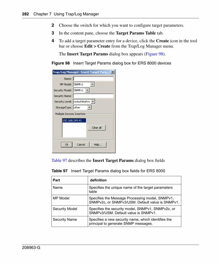
282 Chapter 7 Using Trap/Log Manager
208963-G
2 Choose the switch for which you want to configure target parameters.
3 In the content pane, choose the Target Params Table tab.
4 To add a target parameter entry for a device, click the Create icon in the tool bar or choose Edit > Create from the Trap/Log Manager menu.
The Insert Target Params dialog box appears (Figure 98).
Figure 98 Insert Target Params dialog box for ERS 8000 devices
Table 97 describes the Insert Target Params dialog box fields
Table 97 Insert Target Params dialog box fields for ERS 8000
Part definition
Name Specifies the unique name of the target parameters table
MP Model Specifies the Message Processing model, SNMPv1, SNMPv2c, or SNMPv3/USM. Default value is SNMPv1.
Security Model Specifies the security model, SNMPv1, SNMPv2c, or SNMPv3/USM. Default value is SNMPv1.
Security Name Specifies a new security name, which identifies the principal to generate SNMP messages.
Chapter 7 Using Trap/Log Manager 283
Using Enterprise Switch Manager Release 5.1.0.0
5 Populate the fields as required.
6 Click OK.
A row corresponding to the newly created Target Params entry is added to the table in the content pane.
You can also edit the existing target parameters by editing the corresponding cells.
Configuring Notify Table for ERS 8000 devices
To configure the Notify Table:
1 In the Trap/Log Manager navigation pane, click Configure Traps/Notifications.
2 Choose the switch for which you want to configure notifications.
3 In the content pane, click the Notify Table tab.
4 To add a notification entry for a device, click the Create icon in the tool bar or choose Edit > Create from the Trap/Log Manager menu.
Security Level The security level. The valid options are noAuthNoPriv, authNoPriv, and authPriv. Default value is noAuthNoPriv.
StorageType Specifies the storage type, volatile or non-volatile. Default value is other.
Multiple Devices Insertion
Allows you to set these values for other similar devices.
Table 97 Insert Target Params dialog box fields for ERS 8000 (continued)
Part definition
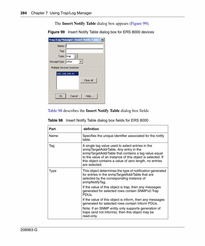
284 Chapter 7 Using Trap/Log Manager
208963-G
The Insert Notify Table dialog box appears (Figure 99).
Figure 99 Insert Notify Table dialog box for ERS 8000 devices
Table 98 describes the Insert Notify Table dialog box fields
Table 98 Insert Notify Table dialog box fields for ERS 8000
Part definition
Name Specifies the unique identifier associated for the notify table.
Tag A single tag value used to select entries in the snmpTargetAddrTable. Any entry in the snmpTargetAddrTable that contains a tag value equal to the value of an instance of this object is selected. If this object contains a value of zero length, no entries are selected.
Type This object determines the type of notification generated for entries in the snmpTargetAddrTable that are selected by the corresponding instance of snmpNotifyTag.If the value of this object is trap, then any messages generated for selected rows contain SNMPv2-Trap PDUs.If the value of this object is inform, then any messages generated for selected rows contain Inform PDUs.
Note: If an SNMP entity only supports generation of traps (and not informs), then this object may be read-only.
Chapter 7 Using Trap/Log Manager 285
Using Enterprise Switch Manager Release 5.1.0.0
5 Populate the fields as required.
6 Click OK.
A row corresponding to the newly created notification is added to the table in the content pane.
You can also edit the existing notifications by editing the corresponding cells.
Configuring Trap Receivers for ERS 55xx/35xx, Ethernet Switch, and Legacy BayStack devices
To configure trap receivers:
1 In the Trap/Log Manager navigation pane, click Configure Traps/Notifications.
2 Choose the switch for which you want to configure trap receivers.
3 In the content pane, click the Trap Receivers tab.
4 To add a trap receiver entry for a device, click the Create icon in the tool bar or choose Edit > Create from the Trap/Log Manager menu.
StorageType Specifies the storage type, volatile, non-volatile, or other. Default value is other.
Multiple Devices Insertion
Allows you to set these values for other similar devices.
Table 98 Insert Notify Table dialog box fields for ERS 8000 (continued)
Part definition
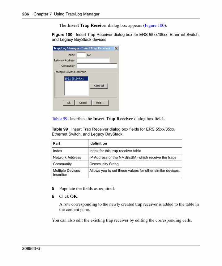
286 Chapter 7 Using Trap/Log Manager
208963-G
The Insert Trap Receiver dialog box appears (Figure 100).
Figure 100 Insert Trap Receiver dialog box for ERS 55xx/35xx, Ethernet Switch,and Legacy BayStack devices
Table 99 describes the Insert Trap Receiver dialog box fields
5 Populate the fields as required.
6 Click OK.
A row corresponding to the newly created trap receiver is added to the table in the content pane.
You can also edit the existing trap receiver by editing the corresponding cells.
Table 99 Insert Trap Receiver dialog box fields for ERS 55xx/35xx, Ethernet Switch, and Legacy BayStack
Part definition
Index Index for this trap receiver table
Network Address IP Address of the NMS(ESM) which receive the traps
Community Community String
Multiple Devices Insertion
Allows you to set these values for other similar devices.
Chapter 7 Using Trap/Log Manager 287
Using Enterprise Switch Manager Release 5.1.0.0
Configuring Target Address Table for ERS 55xx/35xxand Ethernet Switch devices
The notification table, target address table and target address param table entries for a device can be added by clicking the create icon in the tool bar or by choosing from the menu item.
A row corresponding to the newly created table will be added to the table in the right panel.The device also can be configured for the existing entry by editing the corresponding cells.
To configure the Target Address Table:
1 In the Trap/Log Manager navigation pane, click Configure Traps/Notifications.
2 Choose the switch for which you want to configure target addresses.
3 In the content pane, click the Target Address Table tab.
4 To add a target address entry for a device, click the Create icon in the tool bar or choose Edit > Create from the Trap/Log Manager menu.
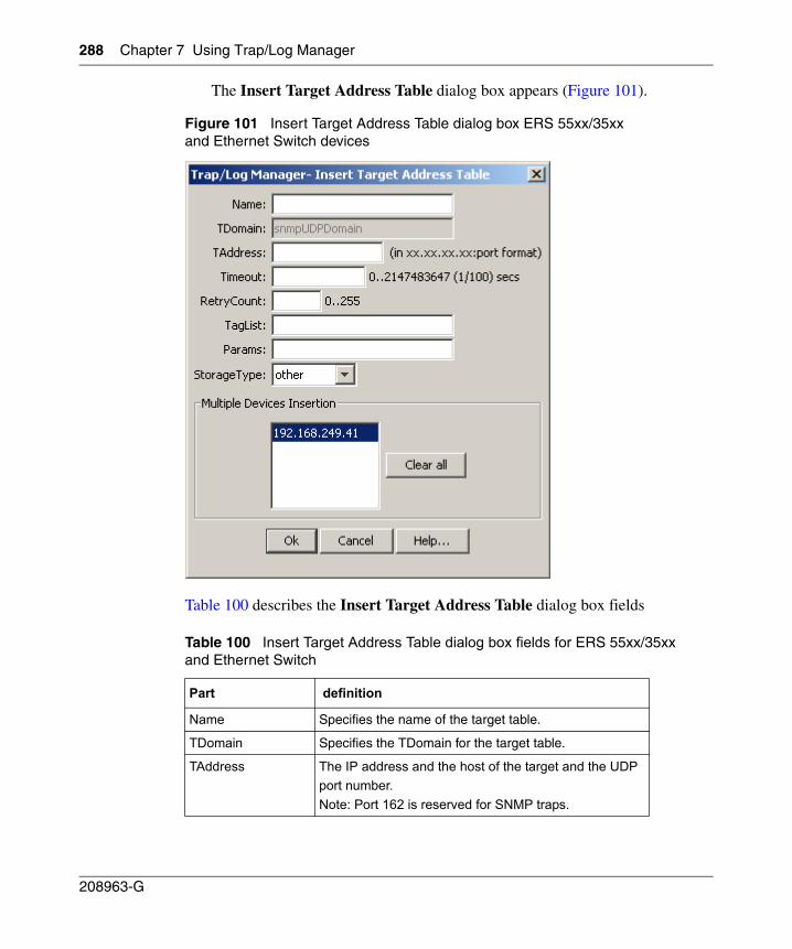
288 Chapter 7 Using Trap/Log Manager
208963-G
The Insert Target Address Table dialog box appears (Figure 101).
Figure 101 Insert Target Address Table dialog box ERS 55xx/35xx and Ethernet Switch devices
Table 100 describes the Insert Target Address Table dialog box fields
Table 100 Insert Target Address Table dialog box fields for ERS 55xx/35xx and Ethernet Switch
Part definition
Name Specifies the name of the target table.
TDomain Specifies the TDomain for the target table.
TAddress The IP address and the host of the target and the UDPport number.Note: Port 162 is reserved for SNMP traps.
Chapter 7 Using Trap/Log Manager 289
Using Enterprise Switch Manager Release 5.1.0.0
5 Populate the fields as required.
6 Click OK.
A row corresponding to the newly created Target Address is added to the table in the content pane.
You can also edit the existing Target Address entries by editing the corresponding cells.
Configuring Target Params Table for ERS 55xx/35xx and Ethernet Switch devices
To configure the Target Params Table:
1 In the Trap/Log Manager navigation pane, click Configure Traps/Notifications.
2 Choose the switch for which you want to configure target parameters.
3 In the content pane, click the Target Params Table tab.
4 To add a target parameter entry for a device, click the Create icon in the tool bar or choose Edit > Create from the Trap/Log Manager menu.
Timeout The maximum round trip time required for communicating with the transport address defined by this row.
RetryCount The number of retries to be attempted when a response is not received for a generated message.
TagList Specifies a list of tag values. A tag value refers to a class of targets to which the messages may be sent
Params The string value that identifies snmpTargetParamsTable entries.
StorageType Specifies the storage type, volatile or non-volatile. Default value is other.
Multiple Devices Insertion
Allows you to set these values for other similar devices.
Table 100 Insert Target Address Table dialog box fields for ERS 55xx/35xx and Ethernet Switch (continued)
Part definition
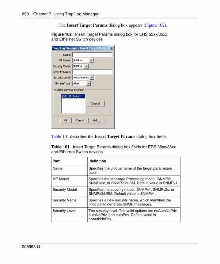
290 Chapter 7 Using Trap/Log Manager
208963-G
The Insert Target Params dialog box appears (Figure 102).
Figure 102 Insert Target Params dialog box for ERS 55xx/35xx and Ethernet Switch devices
Table 101 describes the Insert Target Params dialog box fields
Table 101 Insert Target Params dialog box fields for ERS 55xx/35xx and Ethernet Switch devices
Part definition
Name Specifies the unique name of the target parameters table
MP Model Specifies the Message Processing model, SNMPv1, SNMPv2c, or SNMPv3/USM. Default value is SNMPv1.
Security Model Specifies the security model, SNMPv1, SNMPv2c, or SNMPv3/USM. Default value is SNMPv1.
Security Name Specifies a new security name, which identifies the principal to generate SNMP messages.
Security Level The security level. The valid options are noAuthNoPriv, authNoPriv, and authPriv. Default value is noAuthNoPriv.
Chapter 7 Using Trap/Log Manager 291
Using Enterprise Switch Manager Release 5.1.0.0
5 Populate the fields as required.
6 Click OK.
A row corresponding to the newly created Target Params entry is added to the table in the content pane.
You can also edit the existing target parameters by editing the corresponding cells.
Configuring Notify Table for ERS 55xx/35xx and Ethernet Switch devices
To configure the Notify Table:
1 In the Trap/Log Manager navigation pane, click Configure Traps/Notifications.
2 Choose the switch for which you want to configure notifications.
3 In the content pane, click the Notify Table tab.
4 To add a notification entry for a device, click the Create icon in the tool bar or choose Edit > Create from the Trap/Log Manager menu.
StorageType Specifies the storage type, volatile or non-volatile. Default value is other.
Multiple Devices Insertion
Allows you to set these values for other similar devices.
Table 101 Insert Target Params dialog box fields for ERS 55xx/35xx and Ethernet Switch devices (continued)
Part definition
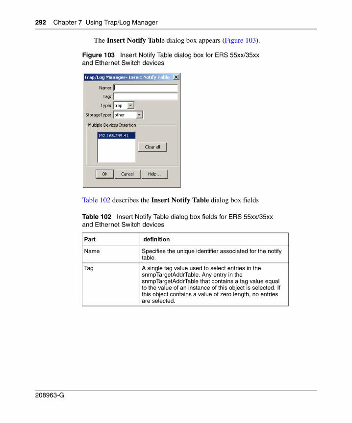
292 Chapter 7 Using Trap/Log Manager
208963-G
The Insert Notify Table dialog box appears (Figure 103).
Figure 103 Insert Notify Table dialog box for ERS 55xx/35xx and Ethernet Switch devices
Table 102 describes the Insert Notify Table dialog box fields
Table 102 Insert Notify Table dialog box fields for ERS 55xx/35xx and Ethernet Switch devices
Part definition
Name Specifies the unique identifier associated for the notify table.
Tag A single tag value used to select entries in the snmpTargetAddrTable. Any entry in the snmpTargetAddrTable that contains a tag value equal to the value of an instance of this object is selected. If this object contains a value of zero length, no entries are selected.
Chapter 7 Using Trap/Log Manager 293
Using Enterprise Switch Manager Release 5.1.0.0
5 Populate the fields as required.
6 Click OK.
A row corresponding to the newly created notification is added to the table in the content pane.
You can also edit the existing notifications by editing the corresponding cells.
Configuring Trap Receivers for ERS 1424/16xx devices
To configure trap receivers:
1 In the Trap/Log Manager navigation pane, click Configure Traps/Notifications.
2 Choose the switch for which you want to configure trap receivers.
3 To add a trap receiver entry for a device, click the Create icon in the tool bar or choose Edit > Create from the Trap/Log Manager menu.
Type This object determines the type of notification generated for entries in the snmpTargetAddrTable that are selected by the corresponding instance of snmpNotifyTag.
If the value of this object is trap, then any messages generated for selected rows contain SNMPv2-Trap PDUs.
If the value of this object is inform, then any messages generated for selected rows contain Inform PDUs.The default value is trap.
Note: If an SNMP entity only supports generation of traps (and not informs), then this object may be read-only.
StorageType Specifies the storage type, volatile or non-volatile.
Multiple Devices Insertion
Allows you to set these values for other similar devices.
Table 102 Insert Notify Table dialog box fields for ERS 55xx/35xx and Ethernet Switch devices (continued)
Part definition
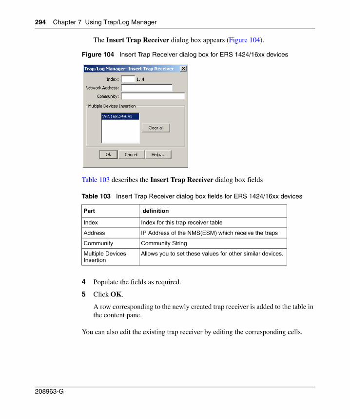
294 Chapter 7 Using Trap/Log Manager
208963-G
The Insert Trap Receiver dialog box appears (Figure 104).
Figure 104 Insert Trap Receiver dialog box for ERS 1424/16xx devices
Table 103 describes the Insert Trap Receiver dialog box fields
4 Populate the fields as required.
5 Click OK.
A row corresponding to the newly created trap receiver is added to the table in the content pane.
You can also edit the existing trap receiver by editing the corresponding cells.
Table 103 Insert Trap Receiver dialog box fields for ERS 1424/16xx devices
Part definition
Index Index for this trap receiver table
Address IP Address of the NMS(ESM) which receive the traps
Community Community String
Multiple Devices Insertion
Allows you to set these values for other similar devices.
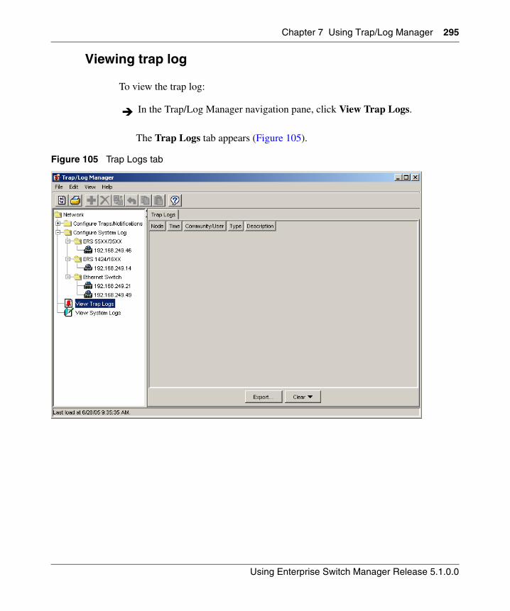
Chapter 7 Using Trap/Log Manager 295
Using Enterprise Switch Manager Release 5.1.0.0
Viewing trap log
To view the trap log:
The Trap Logs tab appears (Figure 105).
Figure 105 Trap Logs tab
In the Trap/Log Manager navigation pane, click View Trap Logs.
296 Chapter 7 Using Trap/Log Manager
208963-G
The cells are non-editable.
Note: This tab shows the traps that are received from the devices in case of any events. The right-hand panel displays the Trap or Notifications tab based on the version of the device. Older versions support the Trap tab and newer versions support the Notifications tab.
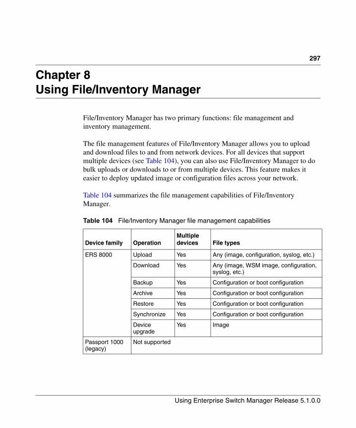
297
Using Enterprise Switch Manager Release 5.1.0.0
Chapter 8Using File/Inventory Manager
File/Inventory Manager has two primary functions: file management and inventory management.
The file management features of File/Inventory Manager allows you to upload and download files to and from network devices. For all devices that support multiple devices (see Table 104), you can also use File/Inventory Manager to do bulk uploads or downloads to or from multiple devices. This feature makes it easier to deploy updated image or configuration files across your network.
Table 104 summarizes the file management capabilities of File/Inventory Manager.
Table 104 File/Inventory Manager file management capabilities
Device family OperationMultiple devices File types
ERS 8000 Upload Yes Any (image, configuration, syslog, etc.)
Download Yes Any (image, WSM image, configuration, syslog, etc.)
Backup Yes Configuration or boot configuration
Archive Yes Configuration or boot configuration
Restore Yes Configuration or boot configuration
Synchronize Yes Configuration or boot configuration
Device upgrade
Yes Image
Passport 1000 (legacy)
Not supported
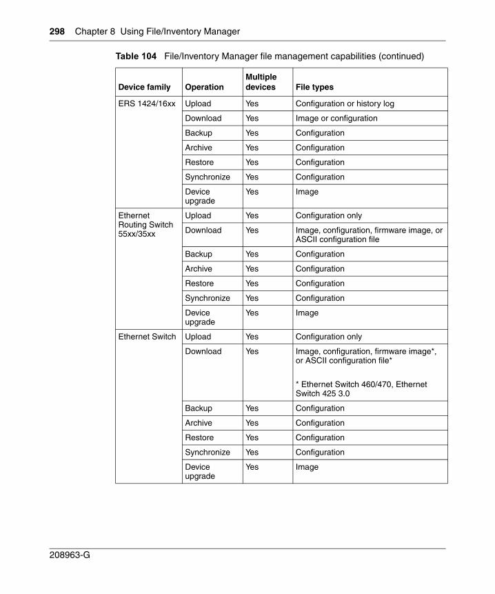
298 Chapter 8 Using File/Inventory Manager
208963-G
ERS 1424/16xx Upload Yes Configuration or history log
Download Yes Image or configuration
Backup Yes Configuration
Archive Yes Configuration
Restore Yes Configuration
Synchronize Yes Configuration
Device upgrade
Yes Image
Ethernet Routing Switch 55xx/35xx
Upload Yes Configuration only
Download Yes Image, configuration, firmware image, or ASCII configuration file
Backup Yes Configuration
Archive Yes Configuration
Restore Yes Configuration
Synchronize Yes Configuration
Device upgrade
Yes Image
Ethernet Switch Upload Yes Configuration only
Download Yes Image, configuration, firmware image*, or ASCII configuration file*
* Ethernet Switch 460/470, Ethernet Switch 425 3.0
Backup Yes Configuration
Archive Yes Configuration
Restore Yes Configuration
Synchronize Yes Configuration
Device upgrade
Yes Image
Table 104 File/Inventory Manager file management capabilities (continued)
Device family OperationMultiple devices File types
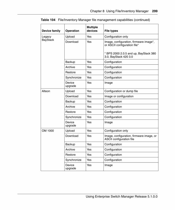
Chapter 8 Using File/Inventory Manager 299
Using Enterprise Switch Manager Release 5.1.0.0
Legacy BayStack
Upload Yes Configuration only
Download Yes Image, configuration, firmware image*, or ASCII configuration file*
* BPS 2000 2.0.5 and up, BayStack 380 3.0, BayStack 420 3.0
Backup Yes Configuration
Archive Yes Configuration
Restore Yes Configuration
Synchronize Yes Configuration
Device upgrade
Yes Image
Alteon Upload Yes Configuration or dump file
Download Yes Image or configuration
Backup Yes Configuration
Archive Yes Configuration
Restore Yes Configuration
Synchronize Yes Configuration
Device upgrade
Yes Image
OM 1000 Upload Yes Configuration only
Download Yes Image, configuration, firmware image, or ASCII configuration file
Backup Yes Configuration
Archive Yes Configuration
Restore Yes Configuration
Synchronize Yes Configuration
Device upgrade
Yes Image
Table 104 File/Inventory Manager file management capabilities (continued)
Device family OperationMultiple devices File types
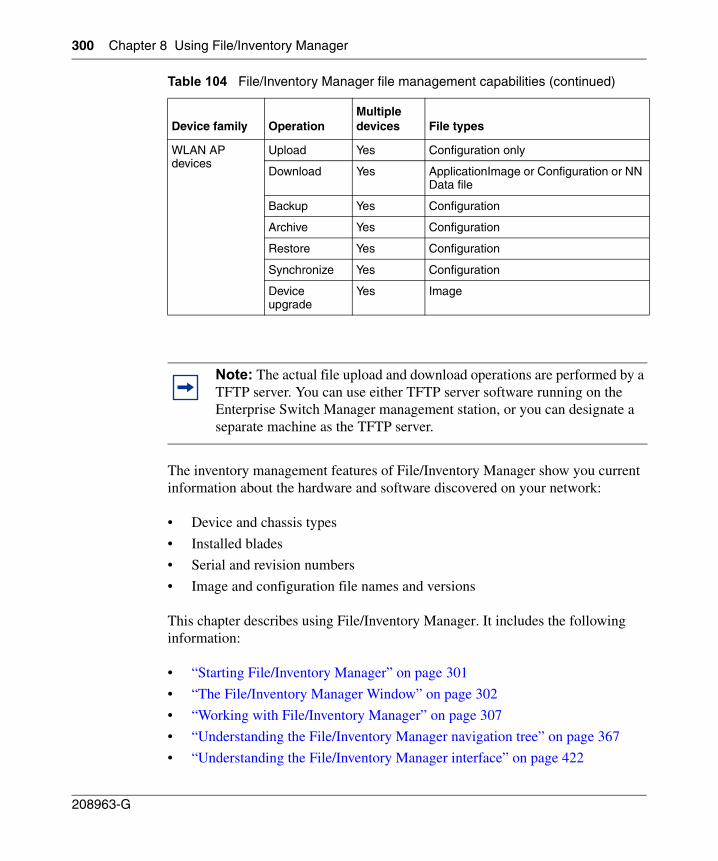
300 Chapter 8 Using File/Inventory Manager
208963-G
The inventory management features of File/Inventory Manager show you current information about the hardware and software discovered on your network:
• Device and chassis types
• Installed blades
• Serial and revision numbers
• Image and configuration file names and versions
This chapter describes using File/Inventory Manager. It includes the following information:
• “Starting File/Inventory Manager” on page 301
• “The File/Inventory Manager Window” on page 302
• “Working with File/Inventory Manager” on page 307
• “Understanding the File/Inventory Manager navigation tree” on page 367
• “Understanding the File/Inventory Manager interface” on page 422
WLAN AP devices
Upload Yes Configuration only
Download Yes ApplicationImage or Configuration or NN Data file
Backup Yes Configuration
Archive Yes Configuration
Restore Yes Configuration
Synchronize Yes Configuration
Device upgrade
Yes Image
Note: The actual file upload and download operations are performed by a TFTP server. You can use either TFTP server software running on the Enterprise Switch Manager management station, or you can designate a separate machine as the TFTP server.
Table 104 File/Inventory Manager file management capabilities (continued)
Device family OperationMultiple devices File types
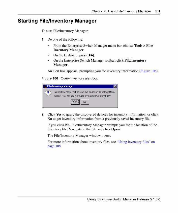
Chapter 8 Using File/Inventory Manager 301
Using Enterprise Switch Manager Release 5.1.0.0
Starting File/Inventory Manager
To start File/Inventory Manager:
1 Do one of the following:
• From the Enterprise Switch Manager menu bar, choose Tools > File/Inventory Manager.
• On the keyboard, press [F6].
• On the Enterprise Switch Manager toolbar, click File/Inventory Manager.
An alert box appears, prompting you for inventory information (Figure 106).
Figure 106 Query inventory alert box
2 Click Yes to query the discovered devices for inventory information, or click No to get inventory information from a previously saved inventory file.
If you click No, File/Inventory Manager prompts you for the location of the inventory file. Navigate to the file and click Open.
The File/Inventory Manager window opens.
For more information about inventory files, see “Using inventory files” on page 308.
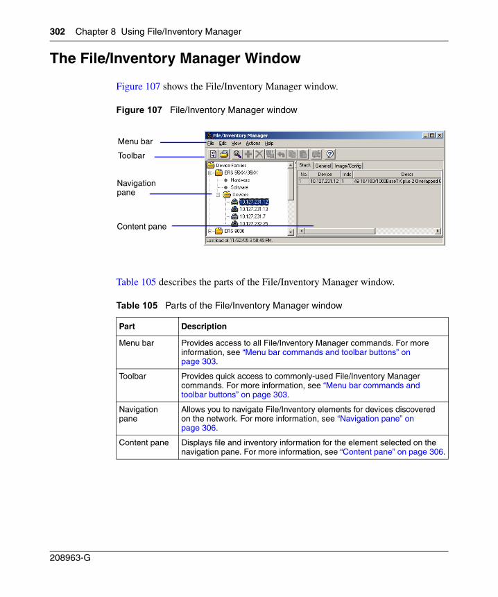
302 Chapter 8 Using File/Inventory Manager
208963-G
The File/Inventory Manager Window
Figure 107 shows the File/Inventory Manager window.
Figure 107 File/Inventory Manager window
Table 105 describes the parts of the File/Inventory Manager window.
Table 105 Parts of the File/Inventory Manager window
Part Description
Menu bar Provides access to all File/Inventory Manager commands. For more information, see “Menu bar commands and toolbar buttons” on page 303.
Toolbar Provides quick access to commonly-used File/Inventory Manager commands. For more information, see “Menu bar commands and toolbar buttons” on page 303.
Navigation pane
Allows you to navigate File/Inventory elements for devices discovered on the network. For more information, see “Navigation pane” on page 306.
Content pane Displays file and inventory information for the element selected on the navigation pane. For more information, see “Content pane” on page 306.
Menu bar
Toolbar
Navigation pane
Content pane
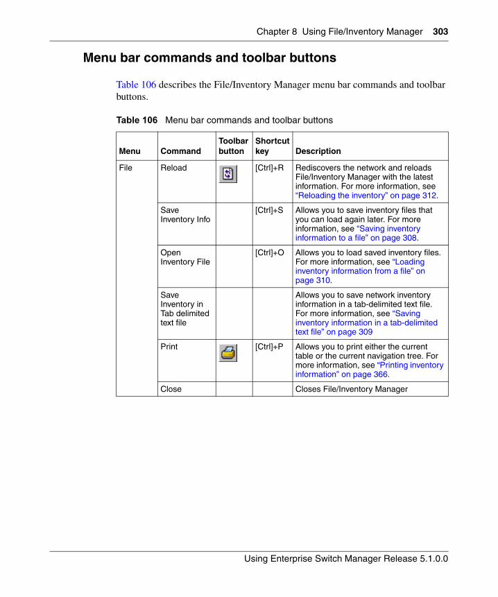
Chapter 8 Using File/Inventory Manager 303
Using Enterprise Switch Manager Release 5.1.0.0
Menu bar commands and toolbar buttons
Table 106 describes the File/Inventory Manager menu bar commands and toolbar buttons.
Table 106 Menu bar commands and toolbar buttons
Menu CommandToolbar button
Shortcut key Description
File Reload [Ctrl]+R Rediscovers the network and reloads File/Inventory Manager with the latest information. For more information, see “Reloading the inventory” on page 312.
Save Inventory Info
[Ctrl]+S Allows you to save inventory files that you can load again later. For more information, see “Saving inventory information to a file” on page 308.
Open Inventory File
[Ctrl]+O Allows you to load saved inventory files. For more information, see “Loading inventory information from a file” on page 310.
Save Inventory in Tab delimited text file
Allows you to save network inventory information in a tab-delimited text file. For more information, see “Saving inventory information in a tab-delimited text file” on page 309
Print [Ctrl]+P Allows you to print either the current table or the current navigation tree. For more information, see “Printing inventory information” on page 366.
Close Closes File/Inventory Manager
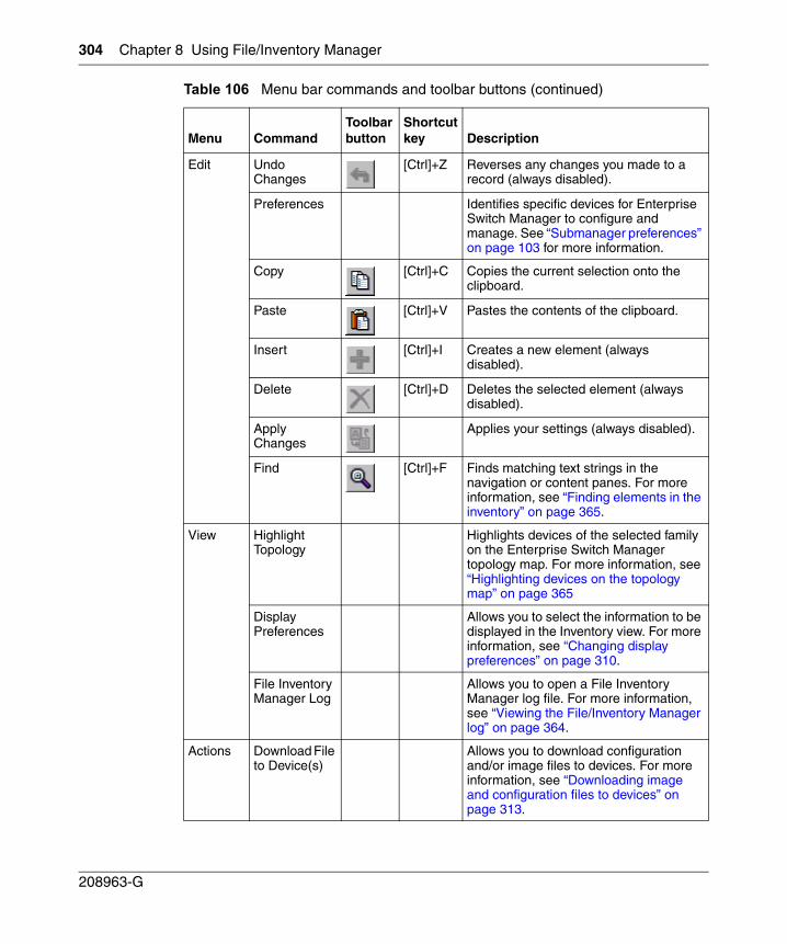
304 Chapter 8 Using File/Inventory Manager
208963-G
Edit Undo Changes
[Ctrl]+Z Reverses any changes you made to a record (always disabled).
Preferences Identifies specific devices for Enterprise Switch Manager to configure and manage. See “Submanager preferences” on page 103 for more information.
Copy [Ctrl]+C Copies the current selection onto the clipboard.
Paste [Ctrl]+V Pastes the contents of the clipboard.
Insert [Ctrl]+I Creates a new element (always disabled).
Delete [Ctrl]+D Deletes the selected element (always disabled).
Apply Changes
Applies your settings (always disabled).
Find [Ctrl]+F Finds matching text strings in the navigation or content panes. For more information, see “Finding elements in the inventory” on page 365.
View Highlight Topology
Highlights devices of the selected family on the Enterprise Switch Manager topology map. For more information, see “Highlighting devices on the topology map” on page 365
Display Preferences
Allows you to select the information to be displayed in the Inventory view. For more information, see “Changing display preferences” on page 310.
File Inventory Manager Log
Allows you to open a File Inventory Manager log file. For more information, see “Viewing the File/Inventory Manager log” on page 364.
Actions Download File to Device(s)
Allows you to download configuration and/or image files to devices. For more information, see “Downloading image and configuration files to devices” on page 313.
Table 106 Menu bar commands and toolbar buttons (continued)
Menu CommandToolbar button
Shortcut key Description
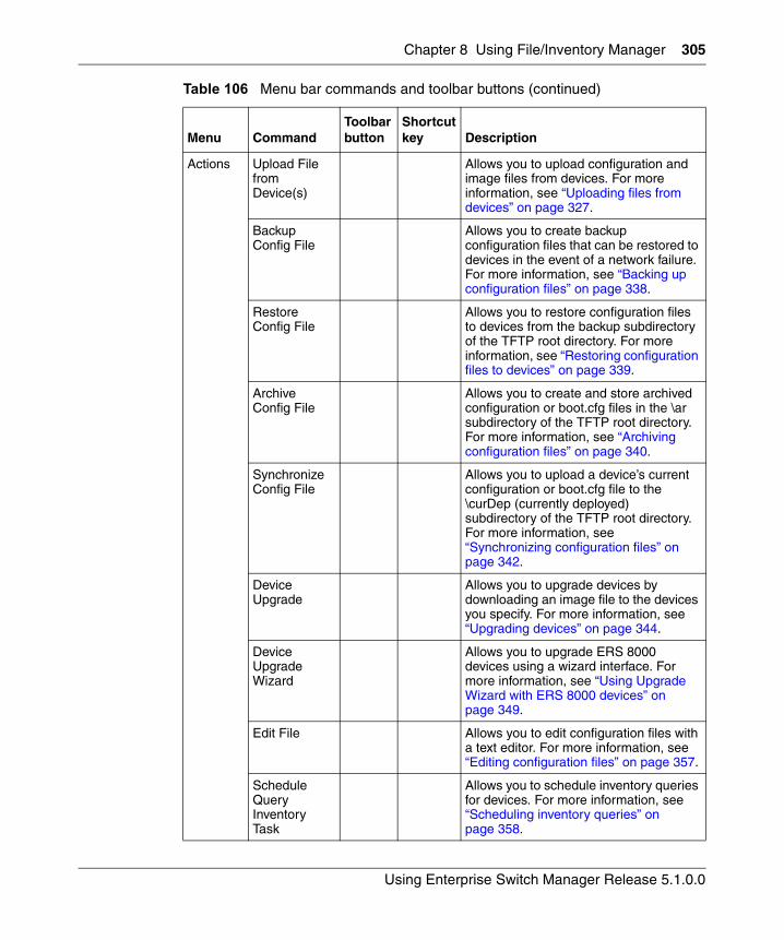
Chapter 8 Using File/Inventory Manager 305
Using Enterprise Switch Manager Release 5.1.0.0
Actions Upload File from Device(s)
Allows you to upload configuration and image files from devices. For more information, see “Uploading files from devices” on page 327.
Backup Config File
Allows you to create backup configuration files that can be restored to devices in the event of a network failure. For more information, see “Backing up configuration files” on page 338.
Restore Config File
Allows you to restore configuration files to devices from the backup subdirectory of the TFTP root directory. For more information, see “Restoring configuration files to devices” on page 339.
Archive Config File
Allows you to create and store archived configuration or boot.cfg files in the \ar subdirectory of the TFTP root directory. For more information, see “Archiving configuration files” on page 340.
Synchronize Config File
Allows you to upload a device’s current configuration or boot.cfg file to the \curDep (currently deployed) subdirectory of the TFTP root directory. For more information, see “Synchronizing configuration files” on page 342.
Device Upgrade
Allows you to upgrade devices by downloading an image file to the devices you specify. For more information, see “Upgrading devices” on page 344.
Device Upgrade Wizard
Allows you to upgrade ERS 8000 devices using a wizard interface. For more information, see “Using Upgrade Wizard with ERS 8000 devices” on page 349.
Edit File Allows you to edit configuration files with a text editor. For more information, see “Editing configuration files” on page 357.
Schedule Query Inventory Task
Allows you to schedule inventory queries for devices. For more information, see “Scheduling inventory queries” on page 358.
Table 106 Menu bar commands and toolbar buttons (continued)
Menu CommandToolbar button
Shortcut key Description
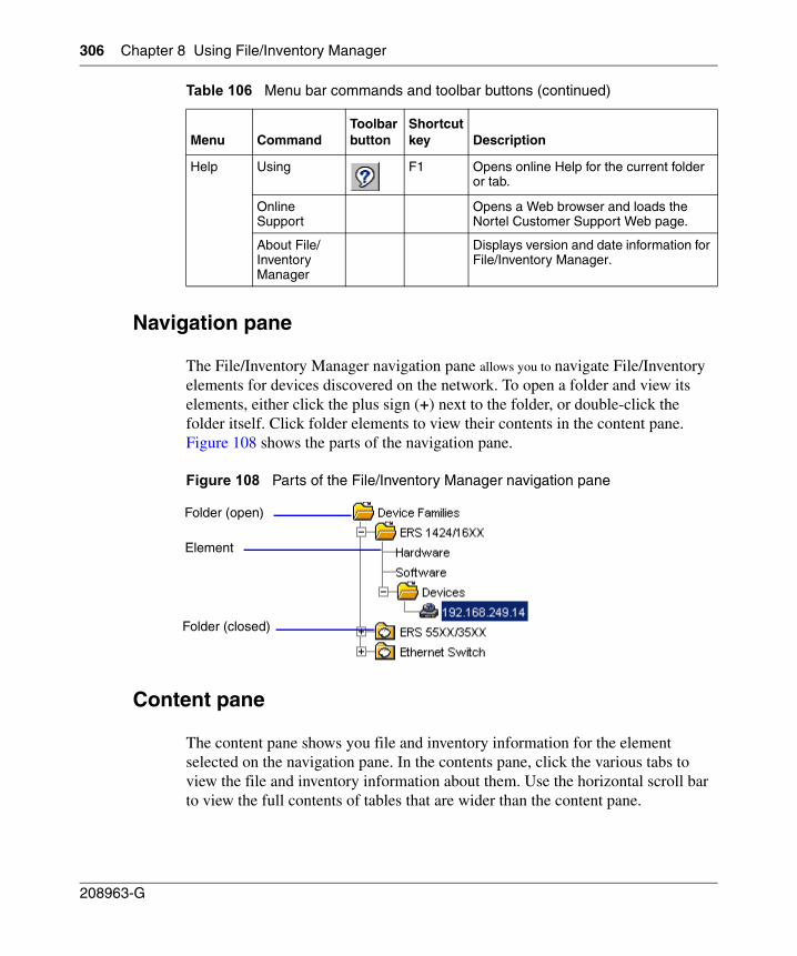
306 Chapter 8 Using File/Inventory Manager
208963-G
Navigation pane
The File/Inventory Manager navigation pane allows you to navigate File/Inventory elements for devices discovered on the network. To open a folder and view its elements, either click the plus sign (+) next to the folder, or double-click the folder itself. Click folder elements to view their contents in the content pane. Figure 108 shows the parts of the navigation pane.
Figure 108 Parts of the File/Inventory Manager navigation pane
Content pane
The content pane shows you file and inventory information for the element selected on the navigation pane. In the contents pane, click the various tabs to view the file and inventory information about them. Use the horizontal scroll bar to view the full contents of tables that are wider than the content pane.
Help Using F1 Opens online Help for the current folder or tab.
Online Support
Opens a Web browser and loads the Nortel Customer Support Web page.
About File/Inventory Manager
Displays version and date information for File/Inventory Manager.
Table 106 Menu bar commands and toolbar buttons (continued)
Menu CommandToolbar button
Shortcut key Description
Folder (open)
Folder (closed)
Element
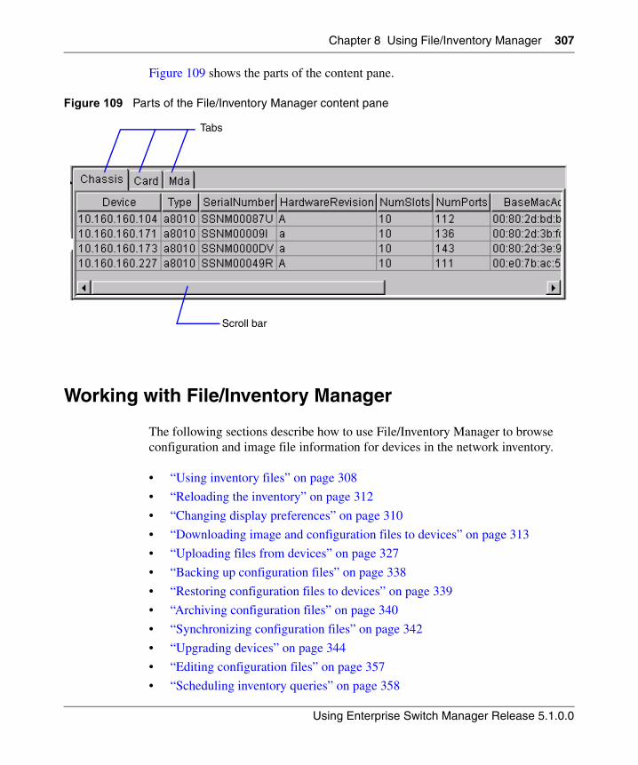
Chapter 8 Using File/Inventory Manager 307
Using Enterprise Switch Manager Release 5.1.0.0
Figure 109 shows the parts of the content pane.
Figure 109 Parts of the File/Inventory Manager content pane
Working with File/Inventory Manager
The following sections describe how to use File/Inventory Manager to browse configuration and image file information for devices in the network inventory.
• “Using inventory files” on page 308
• “Reloading the inventory” on page 312
• “Changing display preferences” on page 310
• “Downloading image and configuration files to devices” on page 313
• “Uploading files from devices” on page 327
• “Backing up configuration files” on page 338
• “Restoring configuration files to devices” on page 339
• “Archiving configuration files” on page 340
• “Synchronizing configuration files” on page 342
• “Upgrading devices” on page 344
• “Editing configuration files” on page 357
• “Scheduling inventory queries” on page 358
Tabs
Scroll bar
308 Chapter 8 Using File/Inventory Manager
208963-G
• “Viewing the File/Inventory Manager log” on page 364
• “Highlighting devices on the topology map” on page 365
• “Finding elements in the inventory” on page 365
• “Printing inventory information” on page 366
Using inventory files
You can save network inventory information to inventory files. Later, you can reload the inventory information back into File/Inventory Manager, or into third-party spreadsheet or database applications.
You can create two different types of files with File/Inventory Manager.
Table 107 describes the file types.
The following sections describe the various operations that you can perform with inventory files:
• “Saving inventory information to a file” on page 308
• “Saving inventory information in a tab-delimited text file” on page 309
• “Loading inventory information from a file” on page 310
Saving inventory information to a file
File/Inventory Manager allows you to save inventory information to a file. You can use this feature to create inventory files that you can load again later.
Table 107 Inventory file types
File type Description
Inventory file (.inv) Allows you to save inventory information that you can later reload back into File/Inventory Manager.
Tab-delimited text file
Allows you to save inventory information in tab-delimited text file format that you can later load into third-party spreadsheet and database applications.
Chapter 8 Using File/Inventory Manager 309
Using Enterprise Switch Manager Release 5.1.0.0
To save the network inventory to a file:
1 From the File/Inventory Manager menu bar, choose File > Save Inventory Info.
A Save dialog box appears.
2 Navigate to the folder where you want to save the inventory information.
3 In the File Name box, enter a name for the file.
The default filename extension is .inv. You can change the extension if you prefer.
4 Click Save.
File/Inventory Manager saves the inventory information in the specified folder and file.
Saving inventory information in a tab-delimited text file
File/Inventory Manager allows you to save network inventory information in a tab-delimited text file. You can use this feature to export network inventory information to spreadsheet or database software applications.
To save the network inventory to a tab-delimited text file:
1 From the File/Inventory Manager menu bar, choose File > Save Inventory in Tab delimited text file.
A Save dialog box appears.
2 Navigate to the folder where you want to save the inventory information.
In the File Name box, enter a name for the file. The default filename extension is .txt. You can use a different extension if you want to.
3 Click Save.
File/Inventory Manager saves the inventory information in the specified folder and file.
Note: You cannot open tab-delimited files using File/Inventory Manager.
310 Chapter 8 Using File/Inventory Manager
208963-G
Changing display preferences
File/Inventory Manager allows you to select the information to display in the Inventory view.
To change the Inventory view display preferences:
1 From the File/Inventory Manager menu bar, choose View > Display Preferences.
The Display Preferences dialog box appears (see “Display Preferences dialog box” on page 438).
2 Click the Expand Devices folder in Device Families tree check box if you want the Devices folders to appear in the Device Families tree view.
3 Use the Device Family radio buttons to configure the view preferences for the device family selected in the Device Families tree view.
4 Use the Hardware Category pull-down menu and Column Header list to choose the columns to show in the Hardware tables for each device family.
5 Use the Software Category pull-down menu and Column Header list to choose the columns to show in the Software tables for each device family.
6 Click OK to save your settings and close the dialog box.
Loading inventory information from a file
File/Inventory Manager allows you to load inventory information from inventory files that you previously created. You can use this feature to quickly load inventory information without having to poll it from the network devices. You can also use it to load inventory information for previous network configurations, or for devices that no longer appear on the network.
To load inventory information from a file:
1 From the File/Inventory Manager menu bar, choose File > Open Inventory File.
An Open File dialog box appears.
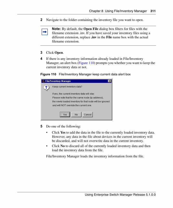
Chapter 8 Using File/Inventory Manager 311
Using Enterprise Switch Manager Release 5.1.0.0
2 Navigate to the folder containing the inventory file you want to open.
3 Click Open.
4 If there is any inventory information already loaded in File/Inventory Manager, an alert box (Figure 110) prompts you whether you want to keep the current inventory data or not.
Figure 110 File/Inventory Manager keep current data alert box
5 Do one of the following:
• Click Yes to add the data in the file to the currently loaded inventory data. However, any data in the file about devices in the current inventory will be discarded, and will not overwrite data in the current inventory.
• Click No to discard all of the currently loaded inventory data and then load the inventory data from the file.
File/Inventory Manager loads the inventory information from the file.
Note: By default, the Open File dialog box filters for files with the filename extension .inv. If you have saved your inventory files using a different extension, replace .inv in the File name box with the actual filename extension.
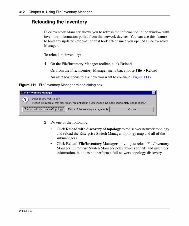
312 Chapter 8 Using File/Inventory Manager
208963-G
Reloading the inventory
File/Inventory Manager allows you to refresh the information in the window with inventory information polled from the network devices. You can use this feature to load any updated information that took effect since you opened File/Inventory Manager.
To reload the inventory:
1 On the File/Inventory Manager toolbar, click Reload.
Or, from the File/Inventory Manager menu bar, choose File > Reload.
An alert box opens to ask how you want to continue (Figure 111).
Figure 111 File/Inventory Manager reload dialog box
2 Do one of the following:
• Click Reload with discovery of topology to rediscover network topology and reload the Enterprise Switch Manager topology map and all of the submanagers.
• Click Reload File/Inventory Manager only to just reload File/Inventory Manager. Enterprise Switch Manager polls devices for file and inventory information, but does not perform a full network topology discovery.
Chapter 8 Using File/Inventory Manager 313
Using Enterprise Switch Manager Release 5.1.0.0
• Click Cancel to abandon the reload operation.
Enterprise Switch Manager reloads topology information from the network devices, and refreshes the File/Inventory Manager window with it.
Downloading image and configuration files to devices
File/Inventory Manager allows you to download image and configuration files from a TFTP server to network devices. You can use this feature to upgrade or modify agent software or configuration settings on the devices.
The procedure for downloading image and configuration files differs slightly, depending on the device family:
• For Alteon devices, use the procedure described in “Downloading image and configuration files to Alteon devices” on page 314.
• For the following devices, use the procedure described in “Downloading image and configuration files to Ethernet Switch, ERS 55xx/35xx and Legacy BayStack devices” on page 316:
— Ethernet Switch
— Ethernet Routing Switch 55xx/35xx
— Legacy BayStack
— Business Policy Switch 2000
— OPTera Metro 1200, 1400, and 1450 Ethernet Service Module
• For Ethernet Routing Switch 1424, 1612, 1624, and 1648 devices, use the procedure described in “Downloading image and configuration files to ERS 1424/16xx devices” on page 318.
Note: Reloading just File/Inventory Manager takes less time than reloading with topology discovery. However, any changes in network topology might result in discrepancies between the information in File/Inventory Manager and the information on the topology map. Such discrepancies might cause incorrect operation when you perform operations (such as highlighting the network map) that involve interactions between the submanagers and the topology map.
If you observe such incorrect operation, reload the network map. For more information, see “Rediscovering the network map” on page 105.
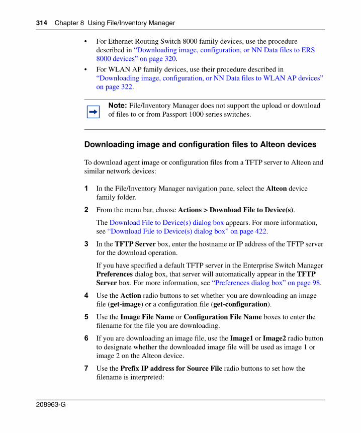
314 Chapter 8 Using File/Inventory Manager
208963-G
• For Ethernet Routing Switch 8000 family devices, use the procedure described in “Downloading image, configuration, or NN Data files to ERS 8000 devices” on page 320.
• For WLAN AP family devices, use their procedure described in “Downloading image, configuration, or NN Data files to WLAN AP devices” on page 322.
Downloading image and configuration files to Alteon devices
To download agent image or configuration files from a TFTP server to Alteon and similar network devices:
1 In the File/Inventory Manager navigation pane, select the Alteon device family folder.
2 From the menu bar, choose Actions > Download File to Device(s).
The Download File to Device(s) dialog box appears. For more information, see “Download File to Device(s) dialog box” on page 422.
3 In the TFTP Server box, enter the hostname or IP address of the TFTP server for the download operation.
If you have specified a default TFTP server in the Enterprise Switch Manager Preferences dialog box, that server will automatically appear in the TFTP Server box. For more information, see “Preferences dialog box” on page 98.
4 Use the Action radio buttons to set whether you are downloading an image file (get-image) or a configuration file (get-configuration).
5 Use the Image File Name or Configuration File Name boxes to enter the filename for the file you are downloading.
6 If you are downloading an image file, use the Image1 or Image2 radio button to designate whether the downloaded image file will be used as image 1 or image 2 on the Alteon device.
7 Use the Prefix IP address for Source File radio buttons to set how the filename is interpreted:
Note: File/Inventory Manager does not support the upload or download of files to or from Passport 1000 series switches.
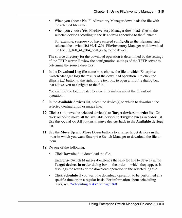
Chapter 8 Using File/Inventory Manager 315
Using Enterprise Switch Manager Release 5.1.0.0
• When you choose No, File/Inventory Manager downloads the file with the selected filename.
• When you choose Yes, File/Inventory Manager downloads files to the selected device according to the IP address appended to the filename.
For example, suppose you have entered config.cfg as the filename, and selected the device 10.160.41.204. File/Inventory Manager will download the file 10_160_41_204_config.cfg to the device.
The source directory for the download operation is determined by the settings of the TFTP server. Review the configuration settings of the TFTP server to determine the source directory.
8 In the Download Log file name box, choose the file to which Enterprise Switch Manager logs the results of the download operation. Or, click the ellipsis (...) button to the right of the text box to open a find file dialog box that allows you to navigate to the file.
You can use the log file later to view information about the download operation.
9 In the Available devices list, select the device(s) to which to download the selected configuration or image file.
10 Click >> to move the selected device(s) to Target devices in order list. Or, click All >> to move all the available devices to Target devices in order list. Use the << and << All buttons to move devices back to the Available devices list.
11 Use the Move Up and Move Down buttons to arrange target devices in the order in which you want Enterprise Switch Manager to download the file to them.
12 Do one of the following:
• Click Download to download the file.
Enterprise Switch Manager downloads the selected file to devices in the Target devices in order dialog box in the order in which they appear. It also logs the results of the download operation to the selected log file.
• Click Schedule if you want the download operation to be performed at a specific time or on a regular basis. For information about scheduling tasks, see “Scheduling tasks” on page 360.
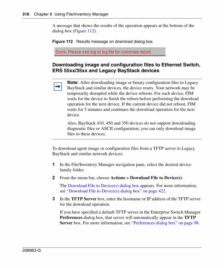
316 Chapter 8 Using File/Inventory Manager
208963-G
A message that shows the results of the operation appears at the bottom of the dialog box (Figure 112).
Figure 112 Results message on download dialog box
Downloading image and configuration files to Ethernet Switch,ERS 55xx/35xx and Legacy BayStack devices
To download agent image or configuration files from a TFTP server to Legacy BayStack and similar network devices:
1 In the File/Inventory Manager navigation pane, select the desired device family folder.
2 From the menu bar, choose Actions > Download File to Device(s).
The Download File to Device(s) dialog box appears. For more information, see “Download File to Device(s) dialog box” on page 422.
3 In the TFTP Server box, enter the hostname or IP address of the TFTP server for the download operation.
If you have specified a default TFTP server in the Enterprise Switch Manager Preferences dialog box, that server will automatically appear in the TFTP Server box. For more information, see “Preferences dialog box” on page 98.
Note: After downloading image or binary configuration files to Legacy BayStack and similar devices, the device resets. Your network may be temporarily disrupted while the device reboots. For each device, FIM waits for the device to finish the reboot before performing the download operation for the next device. If the current device did not reboot, FIM waits for 5 minutes and continues the download operation for the next device.
Also, BayStack 410, 450 and 350 devices do not support downloading diagnostic files or ASCII configuration; you can only download image files to these devices.
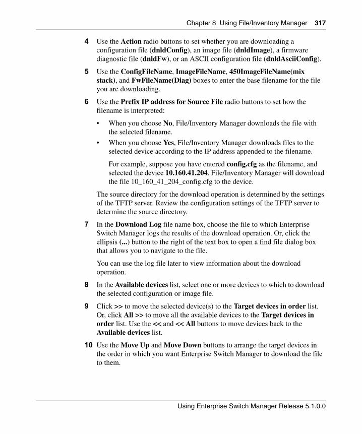
Chapter 8 Using File/Inventory Manager 317
Using Enterprise Switch Manager Release 5.1.0.0
4 Use the Action radio buttons to set whether you are downloading a configuration file (dnldConfig), an image file (dnldImage), a firmware diagnostic file (dnldFw), or an ASCII configuration file (dnldAsciiConfig).
5 Use the ConfigFileName, ImageFileName, 450ImageFileName(mix stack), and FwFileName(Diag) boxes to enter the base filename for the file you are downloading.
6 Use the Prefix IP address for Source File radio buttons to set how the filename is interpreted:
• When you choose No, File/Inventory Manager downloads the file with the selected filename.
• When you choose Yes, File/Inventory Manager downloads files to the selected device according to the IP address appended to the filename.
For example, suppose you have entered config.cfg as the filename, and selected the device 10.160.41.204. File/Inventory Manager will download the file 10_160_41_204_config.cfg to the device.
The source directory for the download operation is determined by the settings of the TFTP server. Review the configuration settings of the TFTP server to determine the source directory.
7 In the Download Log file name box, choose the file to which Enterprise Switch Manager logs the results of the download operation. Or, click the ellipsis (...) button to the right of the text box to open a find file dialog box that allows you to navigate to the file.
You can use the log file later to view information about the download operation.
8 In the Available devices list, select one or more devices to which to download the selected configuration or image file.
9 Click >> to move the selected device(s) to the Target devices in order list. Or, click All >> to move all the available devices to the Target devices in order list. Use the << and << All buttons to move devices back to the Available devices list.
10 Use the Move Up and Move Down buttons to arrange the target devices in the order in which you want Enterprise Switch Manager to download the file to them.
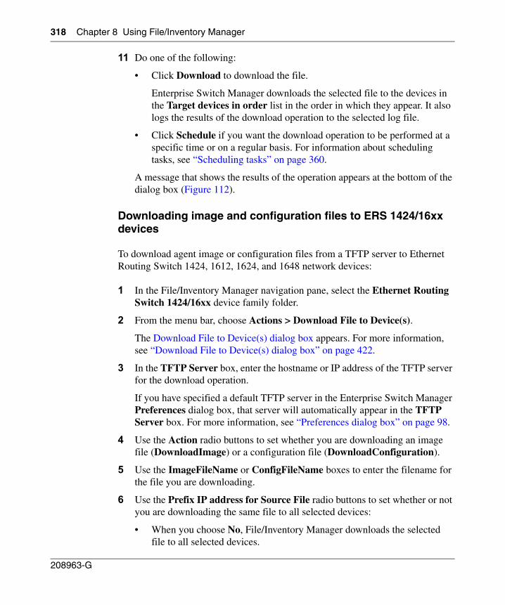
318 Chapter 8 Using File/Inventory Manager
208963-G
11 Do one of the following:
• Click Download to download the file.
Enterprise Switch Manager downloads the selected file to the devices in the Target devices in order list in the order in which they appear. It also logs the results of the download operation to the selected log file.
• Click Schedule if you want the download operation to be performed at a specific time or on a regular basis. For information about scheduling tasks, see “Scheduling tasks” on page 360.
A message that shows the results of the operation appears at the bottom of the dialog box (Figure 112).
Downloading image and configuration files to ERS 1424/16xx devices
To download agent image or configuration files from a TFTP server to Ethernet Routing Switch 1424, 1612, 1624, and 1648 network devices:
1 In the File/Inventory Manager navigation pane, select the Ethernet Routing Switch 1424/16xx device family folder.
2 From the menu bar, choose Actions > Download File to Device(s).
The Download File to Device(s) dialog box appears. For more information, see “Download File to Device(s) dialog box” on page 422.
3 In the TFTP Server box, enter the hostname or IP address of the TFTP server for the download operation.
If you have specified a default TFTP server in the Enterprise Switch Manager Preferences dialog box, that server will automatically appear in the TFTP Server box. For more information, see “Preferences dialog box” on page 98.
4 Use the Action radio buttons to set whether you are downloading an image file (DownloadImage) or a configuration file (DownloadConfiguration).
5 Use the ImageFileName or ConfigFileName boxes to enter the filename for the file you are downloading.
6 Use the Prefix IP address for Source File radio buttons to set whether or not you are downloading the same file to all selected devices:
• When you choose No, File/Inventory Manager downloads the selected file to all selected devices.
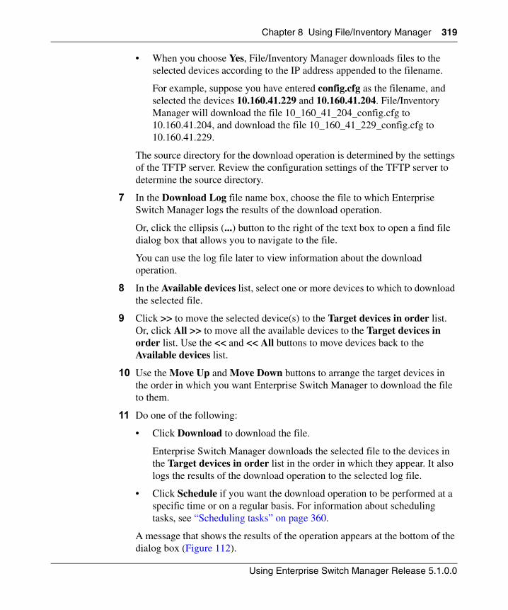
Chapter 8 Using File/Inventory Manager 319
Using Enterprise Switch Manager Release 5.1.0.0
• When you choose Yes, File/Inventory Manager downloads files to the selected devices according to the IP address appended to the filename.
For example, suppose you have entered config.cfg as the filename, and selected the devices 10.160.41.229 and 10.160.41.204. File/Inventory Manager will download the file 10_160_41_204_config.cfg to 10.160.41.204, and download the file 10_160_41_229_config.cfg to 10.160.41.229.
The source directory for the download operation is determined by the settings of the TFTP server. Review the configuration settings of the TFTP server to determine the source directory.
7 In the Download Log file name box, choose the file to which Enterprise Switch Manager logs the results of the download operation.
Or, click the ellipsis (...) button to the right of the text box to open a find file dialog box that allows you to navigate to the file.
You can use the log file later to view information about the download operation.
8 In the Available devices list, select one or more devices to which to download the selected file.
9 Click >> to move the selected device(s) to the Target devices in order list. Or, click All >> to move all the available devices to the Target devices in order list. Use the << and << All buttons to move devices back to the Available devices list.
10 Use the Move Up and Move Down buttons to arrange the target devices in the order in which you want Enterprise Switch Manager to download the file to them.
11 Do one of the following:
• Click Download to download the file.
Enterprise Switch Manager downloads the selected file to the devices in the Target devices in order list in the order in which they appear. It also logs the results of the download operation to the selected log file.
• Click Schedule if you want the download operation to be performed at a specific time or on a regular basis. For information about scheduling tasks, see “Scheduling tasks” on page 360.
A message that shows the results of the operation appears at the bottom of the dialog box (Figure 112).
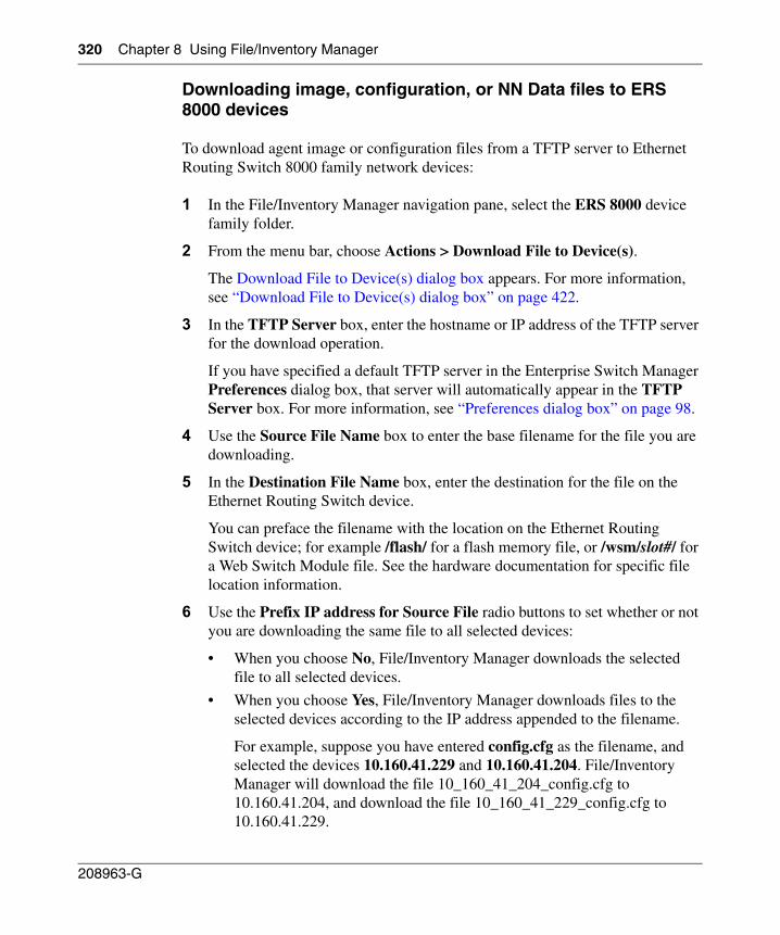
320 Chapter 8 Using File/Inventory Manager
208963-G
Downloading image, configuration, or NN Data files to ERS 8000 devices
To download agent image or configuration files from a TFTP server to Ethernet Routing Switch 8000 family network devices:
1 In the File/Inventory Manager navigation pane, select the ERS 8000 device family folder.
2 From the menu bar, choose Actions > Download File to Device(s).
The Download File to Device(s) dialog box appears. For more information, see “Download File to Device(s) dialog box” on page 422.
3 In the TFTP Server box, enter the hostname or IP address of the TFTP server for the download operation.
If you have specified a default TFTP server in the Enterprise Switch Manager Preferences dialog box, that server will automatically appear in the TFTP Server box. For more information, see “Preferences dialog box” on page 98.
4 Use the Source File Name box to enter the base filename for the file you are downloading.
5 In the Destination File Name box, enter the destination for the file on the Ethernet Routing Switch device.
You can preface the filename with the location on the Ethernet Routing Switch device; for example /flash/ for a flash memory file, or /wsm/slot#/ for a Web Switch Module file. See the hardware documentation for specific file location information.
6 Use the Prefix IP address for Source File radio buttons to set whether or not you are downloading the same file to all selected devices:
• When you choose No, File/Inventory Manager downloads the selected file to all selected devices.
• When you choose Yes, File/Inventory Manager downloads files to the selected devices according to the IP address appended to the filename.
For example, suppose you have entered config.cfg as the filename, and selected the devices 10.160.41.229 and 10.160.41.204. File/Inventory Manager will download the file 10_160_41_204_config.cfg to 10.160.41.204, and download the file 10_160_41_229_config.cfg to 10.160.41.229.
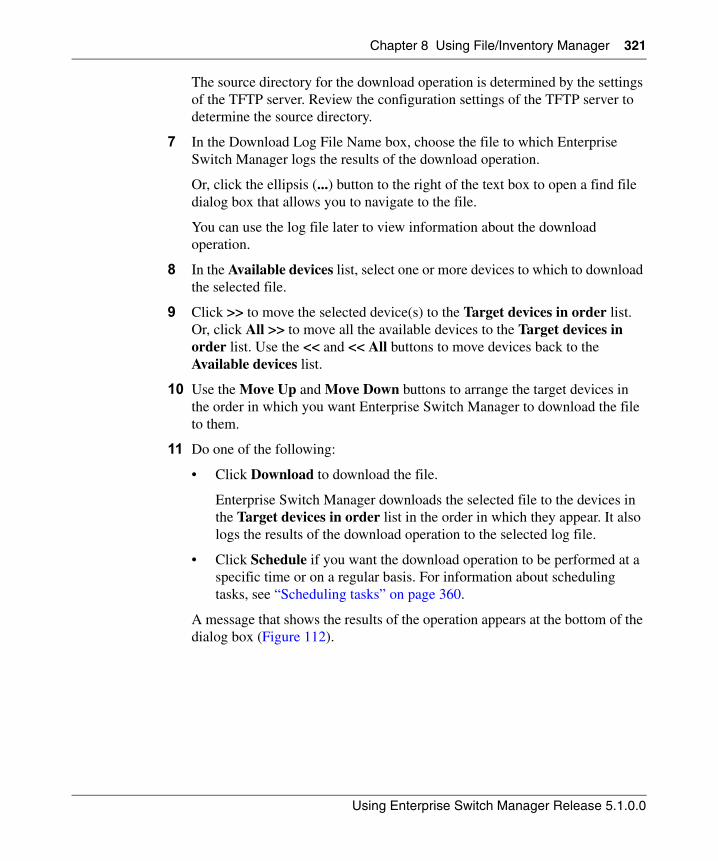
Chapter 8 Using File/Inventory Manager 321
Using Enterprise Switch Manager Release 5.1.0.0
The source directory for the download operation is determined by the settings of the TFTP server. Review the configuration settings of the TFTP server to determine the source directory.
7 In the Download Log File Name box, choose the file to which Enterprise Switch Manager logs the results of the download operation.
Or, click the ellipsis (...) button to the right of the text box to open a find file dialog box that allows you to navigate to the file.
You can use the log file later to view information about the download operation.
8 In the Available devices list, select one or more devices to which to download the selected file.
9 Click >> to move the selected device(s) to the Target devices in order list. Or, click All >> to move all the available devices to the Target devices in order list. Use the << and << All buttons to move devices back to the Available devices list.
10 Use the Move Up and Move Down buttons to arrange the target devices in the order in which you want Enterprise Switch Manager to download the file to them.
11 Do one of the following:
• Click Download to download the file.
Enterprise Switch Manager downloads the selected file to the devices in the Target devices in order list in the order in which they appear. It also logs the results of the download operation to the selected log file.
• Click Schedule if you want the download operation to be performed at a specific time or on a regular basis. For information about scheduling tasks, see “Scheduling tasks” on page 360.
A message that shows the results of the operation appears at the bottom of the dialog box (Figure 112).
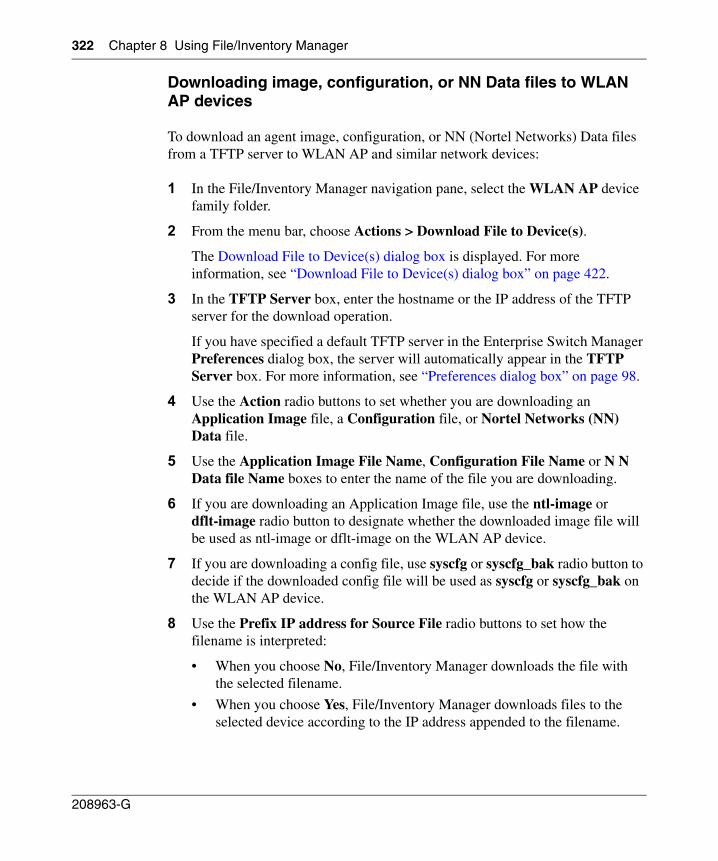
322 Chapter 8 Using File/Inventory Manager
208963-G
Downloading image, configuration, or NN Data files to WLAN AP devices
To download an agent image, configuration, or NN (Nortel Networks) Data files from a TFTP server to WLAN AP and similar network devices:
1 In the File/Inventory Manager navigation pane, select the WLAN AP device family folder.
2 From the menu bar, choose Actions > Download File to Device(s).
The Download File to Device(s) dialog box is displayed. For more information, see “Download File to Device(s) dialog box” on page 422.
3 In the TFTP Server box, enter the hostname or the IP address of the TFTP server for the download operation.
If you have specified a default TFTP server in the Enterprise Switch Manager Preferences dialog box, the server will automatically appear in the TFTP Server box. For more information, see “Preferences dialog box” on page 98.
4 Use the Action radio buttons to set whether you are downloading an Application Image file, a Configuration file, or Nortel Networks (NN) Data file.
5 Use the Application Image File Name, Configuration File Name or N N Data file Name boxes to enter the name of the file you are downloading.
6 If you are downloading an Application Image file, use the ntl-image or dflt-image radio button to designate whether the downloaded image file will be used as ntl-image or dflt-image on the WLAN AP device.
7 If you are downloading a config file, use syscfg or syscfg_bak radio button to decide if the downloaded config file will be used as syscfg or syscfg_bak on the WLAN AP device.
8 Use the Prefix IP address for Source File radio buttons to set how the filename is interpreted:
• When you choose No, File/Inventory Manager downloads the file with the selected filename.
• When you choose Yes, File/Inventory Manager downloads files to the selected device according to the IP address appended to the filename.
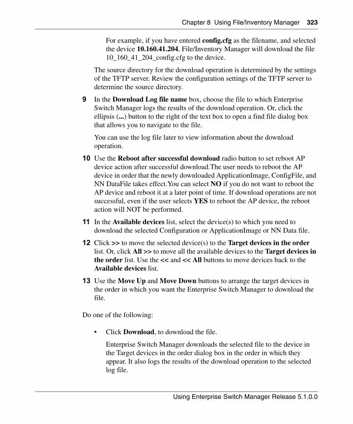
Chapter 8 Using File/Inventory Manager 323
Using Enterprise Switch Manager Release 5.1.0.0
For example, if you have entered config.cfg as the filename, and selected the device 10.160.41.204, File/Inventory Manager will download the file 10_160_41_204_config.cfg to the device.
The source directory for the download operation is determined by the settings of the TFTP server. Review the configuration settings of the TFTP server to determine the source directory.
9 In the Download Log file name box, choose the file to which Enterprise Switch Manager logs the results of the download operation. Or, click the ellipsis (...) button to the right of the text box to open a find file dialog box that allows you to navigate to the file.
You can use the log file later to view information about the download operation.
10 Use the Reboot after successful download radio button to set reboot AP device action after successful download.The user needs to reboot the AP device in order that the newly downloaded ApplicationImage, ConfigFile, and NN DataFile takes effect.You can select NO if you do not want to reboot the AP device and reboot it at a later point of time. If download operations are not successful, even if the user selects YES to reboot the AP device, the reboot action will NOT be performed.
11 In the Available devices list, select the device(s) to which you need to download the selected Configuration or ApplicationImage or NN Data file.
12 Click >> to move the selected device(s) to the Target devices in the order list. Or, click All >> to move all the available devices to the Target devices in the order list. Use the << and << All buttons to move devices back to the Available devices list.
13 Use the Move Up and Move Down buttons to arrange the target devices in the order in which you want the Enterprise Switch Manager to download the file.
Do one of the following:
• Click Download, to download the file.
Enterprise Switch Manager downloads the selected file to the device in the Target devices in the order dialog box in the order in which they appear. It also logs the results of the download operation to the selected log file.
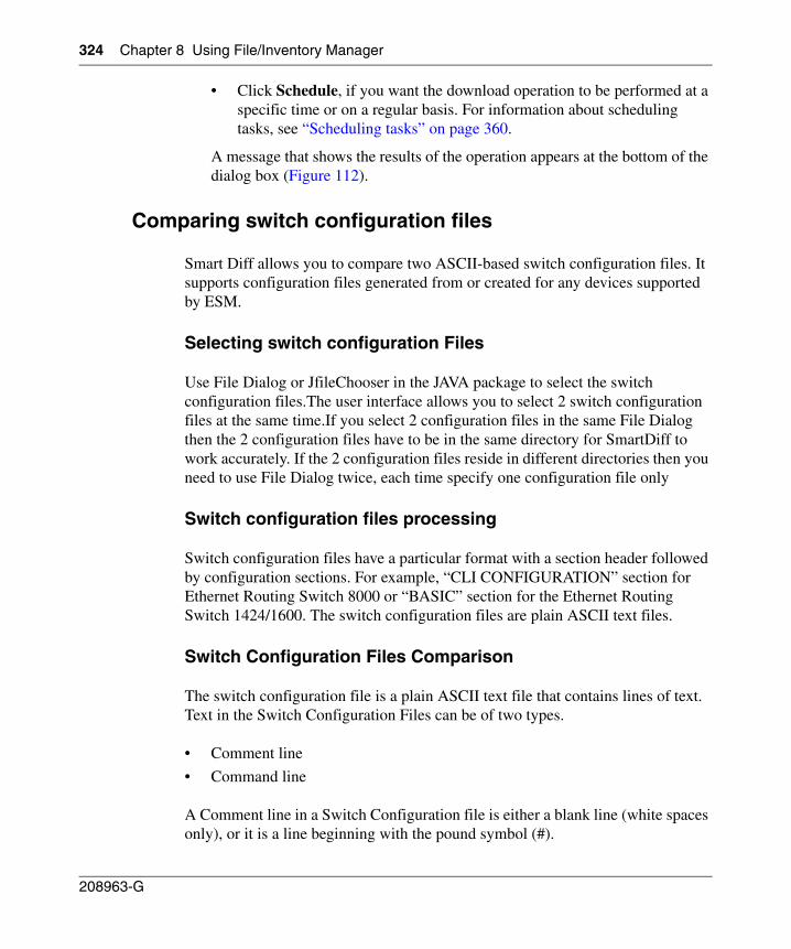
324 Chapter 8 Using File/Inventory Manager
208963-G
• Click Schedule, if you want the download operation to be performed at a specific time or on a regular basis. For information about scheduling tasks, see “Scheduling tasks” on page 360.
A message that shows the results of the operation appears at the bottom of the dialog box (Figure 112).
Comparing switch configuration files
Smart Diff allows you to compare two ASCII-based switch configuration files. It supports configuration files generated from or created for any devices supported by ESM.
Selecting switch configuration Files
Use File Dialog or JfileChooser in the JAVA package to select the switch configuration files.The user interface allows you to select 2 switch configuration files at the same time.If you select 2 configuration files in the same File Dialog then the 2 configuration files have to be in the same directory for SmartDiff to work accurately. If the 2 configuration files reside in different directories then you need to use File Dialog twice, each time specify one configuration file only
Switch configuration files processing
Switch configuration files have a particular format with a section header followed by configuration sections. For example, “CLI CONFIGURATION” section for Ethernet Routing Switch 8000 or “BASIC” section for the Ethernet Routing Switch 1424/1600. The switch configuration files are plain ASCII text files.
Switch Configuration Files Comparison
The switch configuration file is a plain ASCII text file that contains lines of text. Text in the Switch Configuration Files can be of two types.
• Comment line
• Command line
A Comment line in a Switch Configuration file is either a blank line (white spaces only), or it is a line beginning with the pound symbol (#).
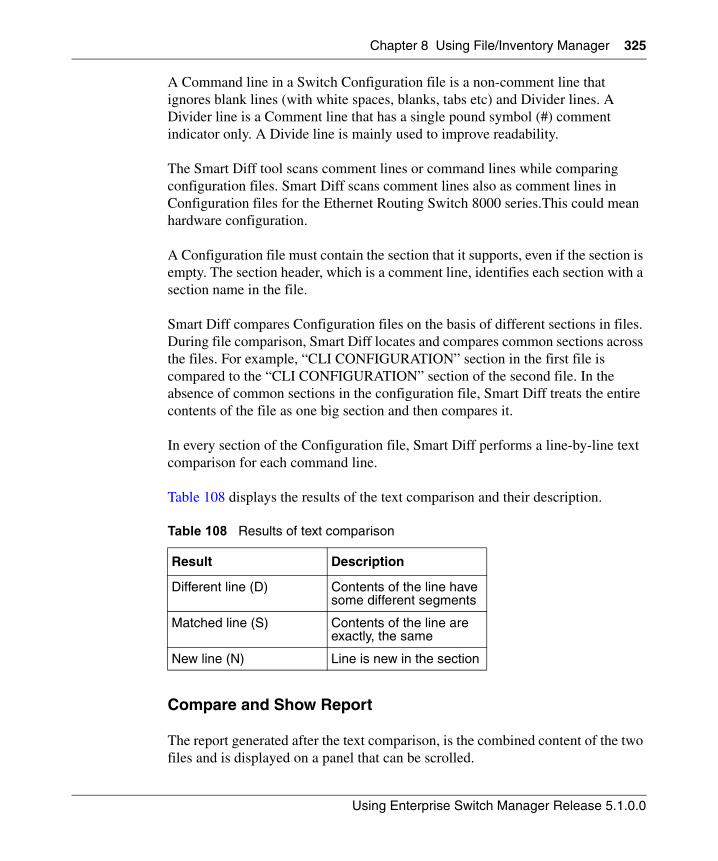
Chapter 8 Using File/Inventory Manager 325
Using Enterprise Switch Manager Release 5.1.0.0
A Command line in a Switch Configuration file is a non-comment line that ignores blank lines (with white spaces, blanks, tabs etc) and Divider lines. A Divider line is a Comment line that has a single pound symbol (#) comment indicator only. A Divide line is mainly used to improve readability.
The Smart Diff tool scans comment lines or command lines while comparing configuration files. Smart Diff scans comment lines also as comment lines in Configuration files for the Ethernet Routing Switch 8000 series.This could mean hardware configuration.
A Configuration file must contain the section that it supports, even if the section is empty. The section header, which is a comment line, identifies each section with a section name in the file.
Smart Diff compares Configuration files on the basis of different sections in files. During file comparison, Smart Diff locates and compares common sections across the files. For example, “CLI CONFIGURATION” section in the first file is compared to the “CLI CONFIGURATION” section of the second file. In the absence of common sections in the configuration file, Smart Diff treats the entire contents of the file as one big section and then compares it.
In every section of the Configuration file, Smart Diff performs a line-by-line text comparison for each command line.
Table 108 displays the results of the text comparison and their description.
Compare and Show Report
The report generated after the text comparison, is the combined content of the two files and is displayed on a panel that can be scrolled.
Table 108 Results of text comparison
Result Description
Different line (D) Contents of the line have some different segments
Matched line (S) Contents of the line are exactly, the same
New line (N) Line is new in the section
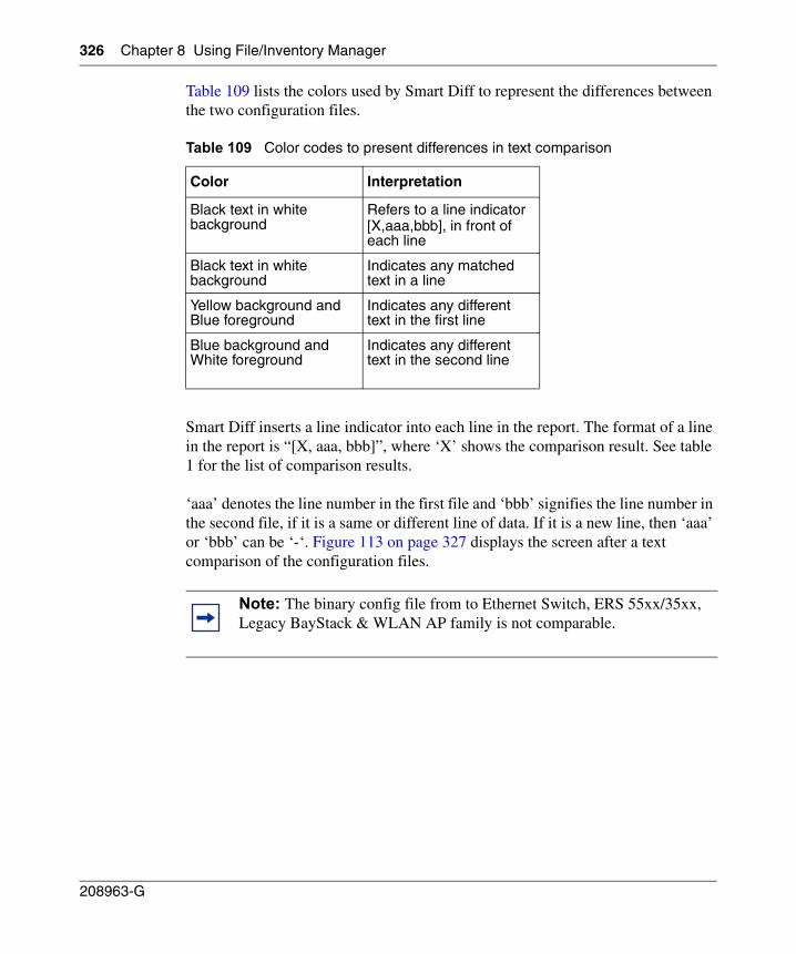
326 Chapter 8 Using File/Inventory Manager
208963-G
Table 109 lists the colors used by Smart Diff to represent the differences between the two configuration files.
Smart Diff inserts a line indicator into each line in the report. The format of a line in the report is “[X, aaa, bbb]”, where ‘X’ shows the comparison result. See table 1 for the list of comparison results.
‘aaa’ denotes the line number in the first file and ‘bbb’ signifies the line number in the second file, if it is a same or different line of data. If it is a new line, then ‘aaa’ or ‘bbb’ can be ‘-‘. Figure 113 on page 327 displays the screen after a text comparison of the configuration files.
Table 109 Color codes to present differences in text comparison
Color Interpretation
Black text in white background
Refers to a line indicator[X,aaa,bbb], in front of each line
Black text in white background
Indicates any matched text in a line
Yellow background and Blue foreground
Indicates any different text in the first line
Blue background and White foreground
Indicates any different text in the second line
Note: The binary config file from to Ethernet Switch, ERS 55xx/35xx, Legacy BayStack & WLAN AP family is not comparable.
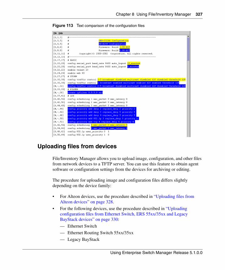
Chapter 8 Using File/Inventory Manager 327
Using Enterprise Switch Manager Release 5.1.0.0
Figure 113 Text comparison of the configuration files
Uploading files from devices
File/Inventory Manager allows you to upload image, configuration, and other files from network devices to a TFTP server. You can use this feature to obtain agent software or configuration settings from the devices for archiving or editing.
The procedure for uploading image and configuration files differs slightly depending on the device family:
• For Alteon devices, use the procedure described in “Uploading files from Alteon devices” on page 328.
• For the following devices, use the procedure described in “Uploading configuration files from Ethernet Switch, ERS 55xx/35xx and Legacy BayStack devices” on page 330:
— Ethernet Switch
— Ethernet Routing Switch 55xx/35xx
— Legacy BayStack
328 Chapter 8 Using File/Inventory Manager
208963-G
— Business Policy Switch 2000
— OPTera Metro 1200, 1400, and 1450 Ethernet Service Module
• For Ethernet Routing Switch 1424, 1612, 1624, and 1648 devices, use the procedure described in “Uploading files from ERS 1424/16xx devices” on page 332.
• For Ethernet Routing Switch 8000 family devices, use the procedure described in “Uploading image and configuration files from ERS 8000 devices” on page 334.
• For WLAN AP devices, use the procedure described in “Uploading configuration files from WLAN AP Devices” on page 336
Uploading files from Alteon devices
You can use File/Inventory Manager to upload configuration and dump files from Alteon devices to a TFTP server. You can upload configuration and dump files from more than one device at a time.
When uploading configuration and dump files, the actual upload operation is performed by a TFTP server. The destination directory for upload operations is determined by the settings of the TFTP server.
To upload configuration files from Alteon network devices to a TFTP server:
1 In the File/Inventory Manager navigation pane, select the Alteon device family folder.
2 From the menu bar, choose Actions > Upload File from Device(s).
The Upload File from Device(s) dialog box appears. For more information, see “Upload File from Device(s) dialog box” on page 425.
3 In the TFTP Server box, enter the hostname or IP address of the TFTP server for the upload operation.
Note: File/Inventory Manager does not support upload or download of files to or from Passport 1000 switches.
Chapter 8 Using File/Inventory Manager 329
Using Enterprise Switch Manager Release 5.1.0.0
If you have specified a default TFTP server in the Enterprise Switch Manager Preferences dialog box, that server will automatically appear in the TFTP Server box. For more information, see “Preferences dialog box” on page 98.
4 Use the Action radio buttons to set whether to upload configuration files (put-configuration) or dump files (put-dump) from multiple Alteon devices to a workstation accessible by the TFTP server.
5 Use the Configuration File Name or Dump File Name boxes to enter the base filename for the configuration or dump filename. Observe the following points regarding the configuration filename:
• During the upload operation, the IP address of the device(s) are appended to the base filename. This feature helps you upload configuration files from multiple devices without overwriting the destination files.
For example, suppose you have entered config.cfg as the filename, and selected two devices, 10.160.41.204 and 10.160.41.229. The actual destination files will be named 10_160_41_204_config.cfg and 10_160_41_229_config.cfg.
• The destination directory for the upload operation is determined by the settings of the TFTP server. Review the configuration settings of the TFTP server to determine the destination directory.
6 In the Upload Log file name box, choose the file to which Enterprise Switch Manager logs the results of the download operation.
Or, click the ellipsis (...) button to the right of the text box to open a find file dialog box that allows you to navigate to the file.
You can use the log file later to view information about the upload operation.
7 In the Available devices list, select one or more devices from which to upload the selected configuration or dump file.
8 Click >> to move the selected device(s) to the Target devices in order list. Or, click All >> to move all the available devices to the Target devices in order list. Use the << and << All buttons to move devices back to the Available devices list.
9 Use the Move Up and Move Down buttons to arrange the target devices in the order in which you want Enterprise Switch Manager to upload their files.
10 Do one of the following:
• Click Upload to upload the file(s).
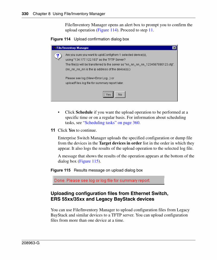
330 Chapter 8 Using File/Inventory Manager
208963-G
File/Inventory Manager opens an alert box to prompt you to confirm the upload operation (Figure 114). Proceed to step 11.
Figure 114 Upload confirmation dialog box
• Click Schedule if you want the upload operation to be performed at a specific time or on a regular basis. For information about scheduling tasks, see “Scheduling tasks” on page 360.
11 Click Yes to continue.
Enterprise Switch Manager uploads the specified configuration or dump file from the devices in the Target devices in order list in the order in which they appear. It also logs the results of the upload operation to the selected log file.
A message that shows the results of the operation appears at the bottom of the dialog box (Figure 115).
Figure 115 Results message on upload dialog box
Uploading configuration files from Ethernet Switch, ERS 55xx/35xx and Legacy BayStack devices
You can use File/Inventory Manager to upload configuration files from Legacy BayStack and similar devices to a TFTP server. You can upload configuration files from more than one device at a time.
Chapter 8 Using File/Inventory Manager 331
Using Enterprise Switch Manager Release 5.1.0.0
When uploading configuration files, the actual upload operation is performed by a TFTP server. The destination directory for upload operations is determined by the settings of the TFTP server.
To upload configuration files from Legacy BayStack or similar network devices to a TFTP server:
1 In the File/Inventory Manager navigation pane, select the desired device family folder.
2 From the menu bar, choose Actions > Upload File from Device(s).
The Upload File from Device(s) dialog box appears. For more information, see “Upload File from Device(s) dialog box” on page 425.
3 In the TFTP Server box, enter the hostname or IP address of the TFTP server for the upload operation.
If you have specified a default TFTP server in the Enterprise Switch Manager Preferences dialog box, that server will automatically appear in the TFTP Server box. For more information, see “Preferences dialog box” on page 98.
4 Use the ConfigFileName box to enter the base filename for the configuration filename. Observe the following points regarding the configuration filename:
• During the upload operation, the IP address of the device(s) are appended to the base filename. This feature helps you upload configuration files from multiple devices without overwriting the destination files.
For example, suppose you have entered config.cfg as the filename, and selected two devices, 10.160.41.204 and 10.160.41.229. The actual destination files will be named 10_160_41_204_config.cfg and 10_160_41_229_config.cfg.
• The destination directory for the upload operation is determined by the settings of the TFTP server. Review the configuration settings of the TFTP server to determine the destination directory.
5 In the Upload Log file name box, choose the file to which Enterprise Switch Manager logs the results of the download operation.
Or, click the ellipsis (...) button to the right of the text box to open a find file dialog box that allows you to navigate to the file.
You can use the log file later to view information about the upload operation.
332 Chapter 8 Using File/Inventory Manager
208963-G
6 In the Available Devices list, select one or more devices from which to upload the selected configuration file.
7 Click >> to move the selected device(s) to the Target devices in order list. Or, click All >> to move all the available devices to the Target devices in order list. Use the << and << All buttons to move devices back to the Available devices list.
8 Use the Move Up and Move Down buttons to arrange the target devices in the order in which you want Enterprise Switch Manager to upload the files.
9 Do one of the following:
• Click Upload to upload the file(s).
File/Inventory Manager opens an alert box to prompt you to confirm the upload operation (Figure 114). Proceed to step 10.
• Click Schedule if you want the upload operation to be performed at a specific time or on a regular basis. For information about scheduling tasks, see “Scheduling tasks” on page 360.
10 Click Yes to continue.
Enterprise Switch Manager uploads the configuration file from the devices in the Target devices in order list in the order in which they appear. It also logs the results of the upload operation to the selected log file.
A message that shows the results of the operation appears at the bottom of the dialog box (Figure 115).
Uploading files from ERS 1424/16xx devices
To upload agent image or configuration files from Ethernet Routing Switch 1424, 1612, 1624, and 1648 network devices to a TFTP server:
1 In the File/Inventory Manager navigation pane, select the ERS 1424/16xx device family folder.
2 From the menu bar, choose Actions > Upload File from Device(s).
The Upload File from Device(s) dialog box appears. For more information, see “Upload File from Device(s) dialog box” on page 425.
3 In the TFTP Server box, enter the hostname or IP address of the TFTP server for the upload operation.
Chapter 8 Using File/Inventory Manager 333
Using Enterprise Switch Manager Release 5.1.0.0
If you have specified a default TFTP server in the Enterprise Switch Manager Preferences dialog box, that server will automatically appear in the TFTP Server box. For more information, see “Preferences dialog box” on page 98.
4 Use the Action radio buttons to set whether to upload configuration files (UploadConfiguration) or history log files (UploadHistoryLog).
5 Use the ConfigFileName or HistoryLogFileName box to enter the base filename. Observe the following points regarding the configuration filename:
• During the upload operation, the IP address of the device(s) are appended to the base filename. This feature helps you upload configuration files from multiple devices without overwriting the destination files.
For example, suppose you have entered config.cfg as the filename, and selected two devices, 10.160.41.204 and 10.160.41.229. The actual destination files will be named 10_160_41_204_config.cfg and 10_160_41_229_config.cfg.
• The destination directory for the upload operation is determined by the settings of the TFTP server. Review the configuration settings of the TFTP server to determine the destination directory.
6 In the Upload Log file name box, choose the file to which Enterprise Switch Manager logs the results of the upload operation. Or, click the ellipsis (...) button to the right of the text box to open a find file dialog box that allows you to navigate to the file.
You can use the log file later to view information about the upload operation.
7 In the Available devices list, select one or more devices from which to upload the selected file.
8 Click >> to move the selected device(s) to the Target devices in order list. Or, click All >> to move all the available devices to the Target devices in order list. Use the << and << All buttons to move devices back to the Available devices list.
9 Use the Move Up and Move Down buttons to arrange the target devices in the order in which you want Enterprise Switch Manager to upload files.
10 Do one of the following:
• Click Upload to upload the file(s).
File/Inventory Manager opens an alert box to prompt you to confirm the upload operation (Figure 114). Proceed to step 11.
334 Chapter 8 Using File/Inventory Manager
208963-G
• Click Schedule if you want the upload operation to be performed at a specific time or on a regular basis. For information about scheduling tasks, see “Scheduling tasks” on page 360.
11 Click Yes to continue.
Enterprise Switch Manager uploads the specified file from the devices in the Target devices in order list in the order in which they appear. It also logs the results of the upload operation to the selected log file.
A message that shows the results of the operation appears at the bottom of the dialog box (Figure 115).
Uploading image and configuration files from ERS 8000 devices
To upload agent image or configuration files from ERS 8000 family network devices to a TFTP server:
1 In the File/Inventory Manager navigation pane, select the ERS 8000 device family folder.
2 From the menu bar, choose Actions > Upload File from Device(s).
The Upload File from Device(s) dialog box appears. For more information, see “Upload File from Device(s) dialog box” on page 425.
3 In the TFTP Server box, enter the hostname or IP address of the TFTP server for the upload operation.
If you have specified a default TFTP server in the Enterprise Switch Manager Preferences dialog box, that server will automatically appear in the TFTP Server box. For more information, see “Preferences dialog box” on page 98.
4 In the Source File Name box, enter the source for the file on the Ethernet Routing Switch device.
You can preface the filename with the location on the Ethernet Routing Switch device; for example /flash/ for a flash memory file, or /wsm/slot#/ for a Web Switch Module file. See the hardware documentation for specific file location information.
Chapter 8 Using File/Inventory Manager 335
Using Enterprise Switch Manager Release 5.1.0.0
5 Use the Destination File Postfix box to enter the base filename for the configuration filename. Observe the following points regarding the destination filename:
• During the upload operation, the IP address of the device(s) are appended to the base filename. This feature helps you upload configuration files from multiple devices without overwriting the destination files.
For example, suppose you have entered config.cfg as the filename, and selected two devices, 10.160.41.204 and 10.160.41.229. The actual destination files will be named 10_160_41_204_config.cfg and 10_160_41_229_config.cfg.
• The destination directory for the upload operation is determined by the settings of the TFTP server. Review the configuration settings of the TFTP server to determine the destination directory.
6 In the Upload Log file name box, choose the file to which Enterprise Switch Manager logs the results of the upload operation. Or, click the ellipsis (...) button to the right of the text box to open a find file dialog box that allows you to navigate to the file.
You can use the log file later to view information about the upload operation.
7 In the Available devices list, select one or more devices from which to upload the selected file.
8 Click >> to move the selected device(s) to the Target devices in order list. Or, click All >> to move all the available devices to the Target devices in order list. Use the << and << All buttons to move devices back to the Available devices list.
9 Use the Move Up and Move Down buttons to arrange the target devices in the order in which you want Enterprise Switch Manager to upload their files.
10 Do one of the following:
• Click Upload to upload the file(s).
File/Inventory Manager opens an alert box to prompt you to confirm the upload operation (Figure 114). Proceed to step 11.
• Click Schedule if you want the upload operation to be performed at a specific time or on a regular basis. For information about scheduling tasks, see “Scheduling tasks” on page 360.
11 Click Yes to continue.
336 Chapter 8 Using File/Inventory Manager
208963-G
Enterprise Switch Manager uploads the specified file from the devices in the Target devices in order list in the order in which they appear. It also logs the results of the upload operation to the selected log file.
A message that shows the results of the operation appears at the bottom of the dialog box (Figure 115).
Uploading configuration files from WLAN AP Devices
You can use File/Inventory Manager to upload configuration files from WLAN AP devices to a TFTP server. You can upload configuration files from more than one device at a time.
When uploading configuration files, the actual upload operation is performed by a TFTP server. The destination directory for upload operations are determined by the settings of the TFTP server.
To upload configuration files from WLAN AP or similar network devices to a TFTP server:
1 In the File/Inventory Manager navigation pane, select the WLAN AP device family folder.
2 From the menu bar, choose Actions > Upload File from Device(s).
The Upload File from Device(s) dialog box appears. For more information, see “Upload File from Device(s) dialog box” on page 425.
3 In the TFTP Server box, enter the hostname or IP address of the TFTP server for the upload operation.
If you have specified a default TFTP server in the Enterprise Switch Manager Preferences dialog box, the server will automatically appear in the TFTP Server box. For more information, see “Preferences dialog box” on page 98.
4 Use the ConfigFileName box to enter the base filename for the configuration filename. Observe the following points regarding the configuration filename:
• During the upload operation, the IP address of the device(s) are appended to the base filename. This feature helps you upload configuration files from multiple devices without overwriting the destination files.
Chapter 8 Using File/Inventory Manager 337
Using Enterprise Switch Manager Release 5.1.0.0
For example, suppose you have entered config.cfg as the filename, and selected two devices, 10.160.41.204 and 10.160.41.229. The actual destination files will be named 10_160_41_204_config.cfg and 10_160_41_229_config.cfg.
• The destination directory for the upload operation is determined by the settings of the TFTP server. Review the configuration settings of the TFTP server to determine the destination directory.
5 In the Upload Log file name box, choose the file to which Enterprise Switch Manager logs the results of the download operation.
Or, click the ellipsis (...) button to the right of the text box to open a find file dialog box that allows you to navigate to the file.
You can use the log file later to view information about the upload operation.
6 In the Available devices list, select one or more devices from which to upload the selected configuration file.
7 Click >> to move the selected device(s) to the Target devices in the order list. Or, click All >> to move all the available devices to the Target devices in the order list. Use the << and << All buttons to move devices back to the Available devices list.
8 Use the Move Up and Move Down buttons to arrange the target devices in the order in which you want Enterprise Switch Manager to upload the files.
9 Do one of the following:
• Click Upload to upload the file(s).
File/Inventory Manager opens an alert box to prompt you to confirm the upload operation (Figure 114). Proceed to step 10.
• Click Schedule if you want the upload operation to be performed at a specific time or on a regular basis. For information about scheduling tasks, see “Scheduling tasks” on page 360.
10 Click Yes to continue.
Enterprise Switch Manager uploads the configuration file from the devices in the Target devices in the order list in the order in which they appear. It also logs the results of the upload operation to the selected log file.
A message that shows the results of the operation appears at the bottom of the dialog box (Figure 115).
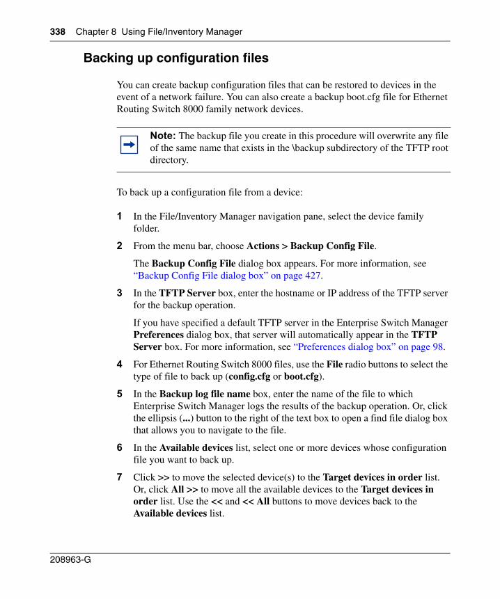
338 Chapter 8 Using File/Inventory Manager
208963-G
Backing up configuration files
You can create backup configuration files that can be restored to devices in the event of a network failure. You can also create a backup boot.cfg file for Ethernet Routing Switch 8000 family network devices.
To back up a configuration file from a device:
1 In the File/Inventory Manager navigation pane, select the device family folder.
2 From the menu bar, choose Actions > Backup Config File.
The Backup Config File dialog box appears. For more information, see “Backup Config File dialog box” on page 427.
3 In the TFTP Server box, enter the hostname or IP address of the TFTP server for the backup operation.
If you have specified a default TFTP server in the Enterprise Switch Manager Preferences dialog box, that server will automatically appear in the TFTP Server box. For more information, see “Preferences dialog box” on page 98.
4 For Ethernet Routing Switch 8000 files, use the File radio buttons to select the type of file to back up (config.cfg or boot.cfg).
5 In the Backup log file name box, enter the name of the file to which Enterprise Switch Manager logs the results of the backup operation. Or, click the ellipsis (...) button to the right of the text box to open a find file dialog box that allows you to navigate to the file.
6 In the Available devices list, select one or more devices whose configuration file you want to back up.
7 Click >> to move the selected device(s) to the Target devices in order list. Or, click All >> to move all the available devices to the Target devices in order list. Use the << and << All buttons to move devices back to the Available devices list.
Note: The backup file you create in this procedure will overwrite any file of the same name that exists in the \backup subdirectory of the TFTP root directory.
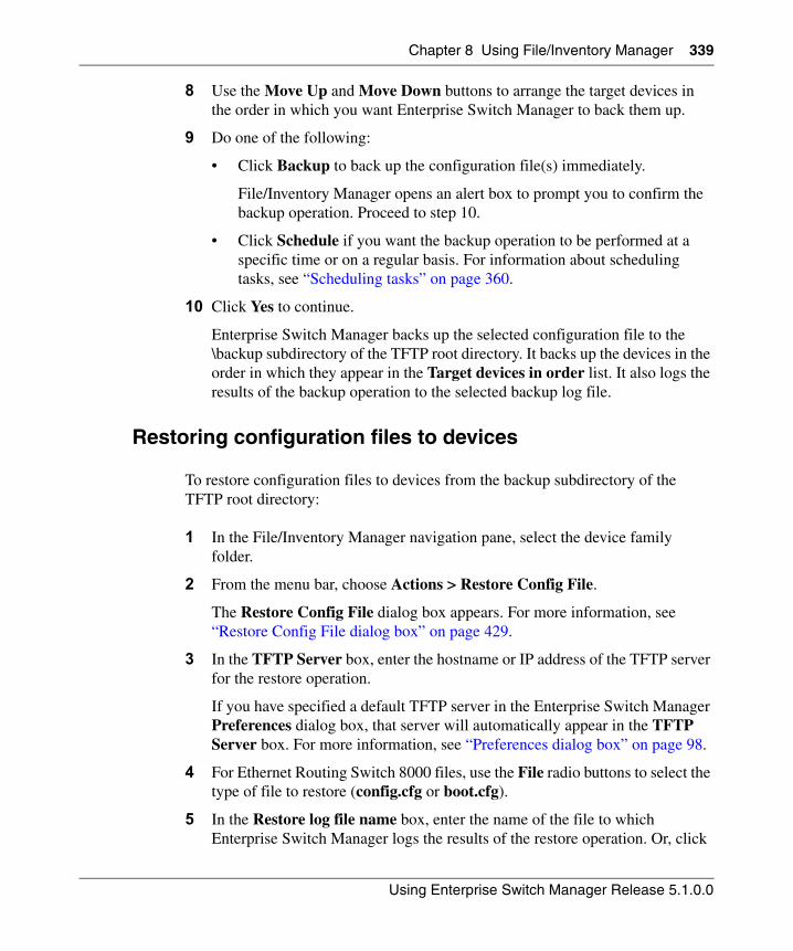
Chapter 8 Using File/Inventory Manager 339
Using Enterprise Switch Manager Release 5.1.0.0
8 Use the Move Up and Move Down buttons to arrange the target devices in the order in which you want Enterprise Switch Manager to back them up.
9 Do one of the following:
• Click Backup to back up the configuration file(s) immediately.
File/Inventory Manager opens an alert box to prompt you to confirm the backup operation. Proceed to step 10.
• Click Schedule if you want the backup operation to be performed at a specific time or on a regular basis. For information about scheduling tasks, see “Scheduling tasks” on page 360.
10 Click Yes to continue.
Enterprise Switch Manager backs up the selected configuration file to the \backup subdirectory of the TFTP root directory. It backs up the devices in the order in which they appear in the Target devices in order list. It also logs the results of the backup operation to the selected backup log file.
Restoring configuration files to devices
To restore configuration files to devices from the backup subdirectory of the TFTP root directory:
1 In the File/Inventory Manager navigation pane, select the device family folder.
2 From the menu bar, choose Actions > Restore Config File.
The Restore Config File dialog box appears. For more information, see “Restore Config File dialog box” on page 429.
3 In the TFTP Server box, enter the hostname or IP address of the TFTP server for the restore operation.
If you have specified a default TFTP server in the Enterprise Switch Manager Preferences dialog box, that server will automatically appear in the TFTP Server box. For more information, see “Preferences dialog box” on page 98.
4 For Ethernet Routing Switch 8000 files, use the File radio buttons to select the type of file to restore (config.cfg or boot.cfg).
5 In the Restore log file name box, enter the name of the file to which Enterprise Switch Manager logs the results of the restore operation. Or, click
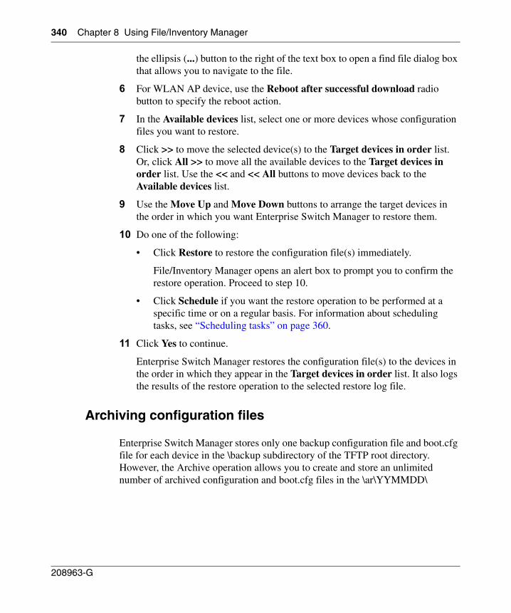
340 Chapter 8 Using File/Inventory Manager
208963-G
the ellipsis (...) button to the right of the text box to open a find file dialog box that allows you to navigate to the file.
6 For WLAN AP device, use the Reboot after successful download radio button to specify the reboot action.
7 In the Available devices list, select one or more devices whose configuration files you want to restore.
8 Click >> to move the selected device(s) to the Target devices in order list. Or, click All >> to move all the available devices to the Target devices in order list. Use the << and << All buttons to move devices back to the Available devices list.
9 Use the Move Up and Move Down buttons to arrange the target devices in the order in which you want Enterprise Switch Manager to restore them.
10 Do one of the following:
• Click Restore to restore the configuration file(s) immediately.
File/Inventory Manager opens an alert box to prompt you to confirm the restore operation. Proceed to step 10.
• Click Schedule if you want the restore operation to be performed at a specific time or on a regular basis. For information about scheduling tasks, see “Scheduling tasks” on page 360.
11 Click Yes to continue.
Enterprise Switch Manager restores the configuration file(s) to the devices in the order in which they appear in the Target devices in order list. It also logs the results of the restore operation to the selected restore log file.
Archiving configuration files
Enterprise Switch Manager stores only one backup configuration file and boot.cfg file for each device in the \backup subdirectory of the TFTP root directory. However, the Archive operation allows you to create and store an unlimited number of archived configuration and boot.cfg files in the \ar\YYMMDD\
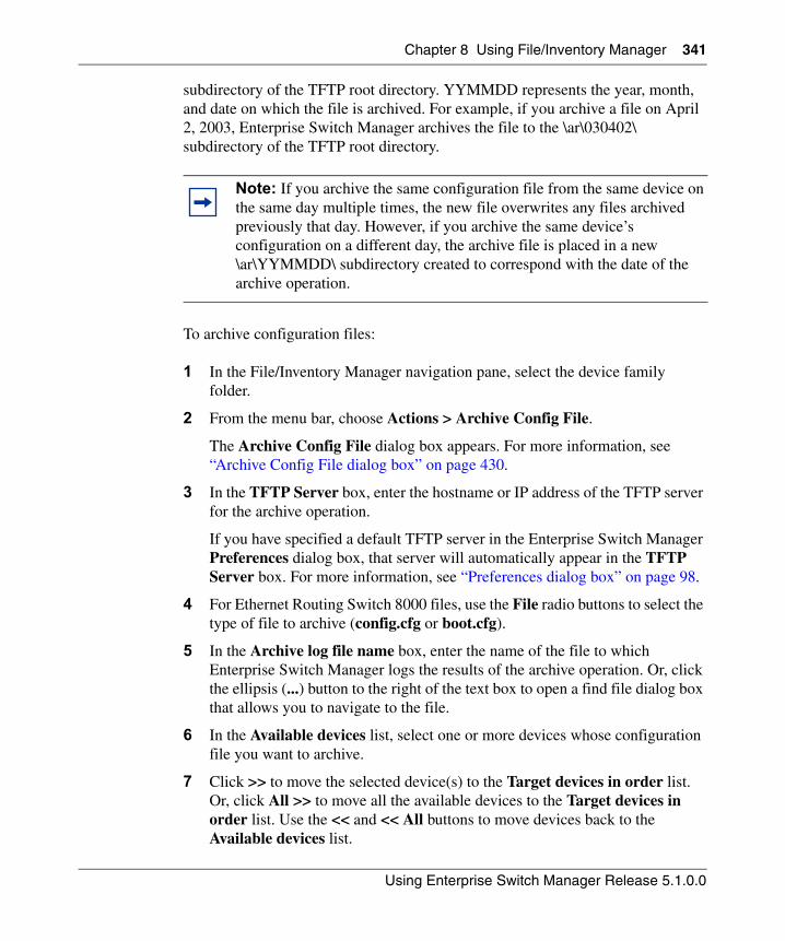
Chapter 8 Using File/Inventory Manager 341
Using Enterprise Switch Manager Release 5.1.0.0
subdirectory of the TFTP root directory. YYMMDD represents the year, month, and date on which the file is archived. For example, if you archive a file on April 2, 2003, Enterprise Switch Manager archives the file to the \ar\030402\ subdirectory of the TFTP root directory.
To archive configuration files:
1 In the File/Inventory Manager navigation pane, select the device family folder.
2 From the menu bar, choose Actions > Archive Config File.
The Archive Config File dialog box appears. For more information, see “Archive Config File dialog box” on page 430.
3 In the TFTP Server box, enter the hostname or IP address of the TFTP server for the archive operation.
If you have specified a default TFTP server in the Enterprise Switch Manager Preferences dialog box, that server will automatically appear in the TFTP Server box. For more information, see “Preferences dialog box” on page 98.
4 For Ethernet Routing Switch 8000 files, use the File radio buttons to select the type of file to archive (config.cfg or boot.cfg).
5 In the Archive log file name box, enter the name of the file to which Enterprise Switch Manager logs the results of the archive operation. Or, click the ellipsis (...) button to the right of the text box to open a find file dialog box that allows you to navigate to the file.
6 In the Available devices list, select one or more devices whose configuration file you want to archive.
7 Click >> to move the selected device(s) to the Target devices in order list. Or, click All >> to move all the available devices to the Target devices in order list. Use the << and << All buttons to move devices back to the Available devices list.
Note: If you archive the same configuration file from the same device on the same day multiple times, the new file overwrites any files archived previously that day. However, if you archive the same device’s configuration on a different day, the archive file is placed in a new \ar\YYMMDD\ subdirectory created to correspond with the date of the archive operation.
342 Chapter 8 Using File/Inventory Manager
208963-G
8 Use the Move Up and Move Down buttons to arrange the target devices in the order in which you want Enterprise Switch Manager to archive them.
9 Do one of the following:
• Click Archive to archive the file(s) immediately.
File/Inventory Manager opens an alert box to prompt you to confirm the archive operation. Proceed to step 10.
• Click Schedule if you want the archive operation to be performed at a specific time or on a regular basis. For information about scheduling tasks, see “Scheduling tasks” on page 360.
10 Click Yes to continue.
Enterprise Switch Manager archives the selected configuration file(s) to the \ar\YYMMDD\ subdirectory of the TFTP root directory. Enterprise Switch Manager archives the files in the order in which the devices appear in the Target devices in order list. It also logs the results of the archive operation to the selected archive log file.
Synchronizing configuration files
File/Inventory Manager allows you to upload the current configuration or boot.cfg file of a device to the \curDep\ (currently deployed) subdirectory of the TFTP root directory.
To upload the current configuration or boot.cfg file:
1 In the File/Inventory Manager navigation pane, select the device family folder.
2 From the menu bar, choose Actions > Synchronize Config File.
The Synchronize Config File dialog box appears. For more information, see “Synchronize Config File dialog box” on page 431.
3 In the TFTP Server box, enter the hostname or IP address of the TFTP server for the synchronize operation.
Note: The configuration or boot.cfg file you upload in this procedure will overwrite any file of the same name that exists in the \curDep subdirectory of the TFTP root directory.
Chapter 8 Using File/Inventory Manager 343
Using Enterprise Switch Manager Release 5.1.0.0
If you have specified a default TFTP server in the Enterprise Switch Manager Preferences dialog box, that server will automatically appear in the TFTP Server box. For more information, see “Preferences dialog box” on page 98.
4 For Ethernet Routing Switch 8000 files, use the File radio buttons to select the type of file to synchronize (config.cfg or boot.cfg).
5 In the Synchronize log file name box, enter the name of the file to which Enterprise Switch Manager logs the results of the synchronize operation. Or, click the ellipsis (...) button to the right of the text box to open a find file dialog box that allows you to navigate to the file.
6 In the Available devices list, select one or more devices whose configuration file you want to synchronize.
7 Click >> to move the selected device(s) to the Target devices in order list. Or, click All >> to move all the available devices to the Target devices in order list. Use the << and << All buttons to move devices back to the Available devices list.
8 Use the Move Up and Move Down buttons to arrange the target devices in the order in which you want Enterprise Switch Manager to synchronize them.
9 Do one of the following:
• Click Synchronize to upload the configuration file(s) immediately.
File/Inventory Manager opens an alert box to prompt you to confirm the synchronize operation. Proceed to step 10.
• Click Schedule if you want the synchronize operation to be performed at a specific time or on a regular basis. For information about scheduling tasks, see “Scheduling tasks” on page 360.
10 Click Yes to continue.
Enterprise Switch Manager uploads the selected configuration file(s) to the \curDep\ subdirectory of the TFTP root directory in the order in which the devices appear in the Target devices in order list and logs the results of the synchronize operation to the selected synchronize log file.
344 Chapter 8 Using File/Inventory Manager
208963-G
Upgrading devices
File/Inventory Manager allows you to upgrade devices by downloading an image file to the devices you specify. You can specify the order in which Enterprise Switch Manager upgrades the devices, and the results of the upgrade operation are stored in a log file to which you can refer later.
The procedure for upgrading devices differs slightly depending on the device family:
• For Alteon devices, use the procedure described in “Upgrading Alteon devices” on page 344.
• For Ethernet Switch, Ethernet Routing Switch 55xx/35xx, and Legacy Baystack devices, use the procedure described in “Upgrading Ethernet Switch, ERS 55xx/35xx and Legacy BayStack devices” on page 346.
• For Ethernet Routing Switch 8000, 1424, 1612, 1624, and 1648 devices, use the procedure described in “Upgrading ERS 8000 and 1424/16xx devices” on page 347. Or, for Ethernet Routing Switch 8000 only, you can also use the procedure described in “Using Upgrade Wizard with ERS 8000 devices” on page 349.
Upgrading Alteon devices
To upgrade one or more Alteon devices:
1 In the File/Inventory Manager navigation pane, select the Alteon device family folder.
2 From the menu bar, choose Actions > Device Upgrade.
The Device Upgrade dialog box appears. For more information, see “Device Upgrade dialog box” on page 432.
3 In the TFTP Server box, enter the hostname or IP address of the TFTP server for the upgrade operation.
If you have specified a default TFTP server in the Enterprise Switch Manager Preferences dialog box, that server will automatically appear in the TFTP Server box. For more information, see “Preferences dialog box” on page 98.
Chapter 8 Using File/Inventory Manager 345
Using Enterprise Switch Manager Release 5.1.0.0
4 In the Image File Name box, enter the name of the image file to download. Or, click the ellipsis (...) button to the right of the text box to open a find file dialog box that allows you to navigate to the file.
5 Use the Image radio buttons to set the target image.
6 In the Device Upgrade Log file name box, enter the name of the log file to which Enterprise Switch Manager logs the results of the upgrade operation. Or, click the ellipsis (...) button to the right of the text box to open a find file dialog box that allows you to navigate to the file.
7 In the Available devices list, select one or more devices to upgrade.
8 Click >> to move the selected device(s) to the Target devices in order list. Or, click All >> to move all the available devices to the Target devices in order list. Use the << and << All buttons to move devices back to the Available devices list.
9 Use the Move Up and Move Down buttons to arrange the target devices in the order in which you want Enterprise Switch Manager to upgrade them.
10 Do one of the following:
• Click Device Upgrade to upgrade the devices immediately.
File/Inventory Manager opens an alert box to prompt you to confirm the upgrade operation. Proceed to step 11.
• Click Schedule if you want the upgrade operation to be performed at a specific time or on a regular basis. For information about scheduling tasks, see “Scheduling tasks” on page 360.
11 Click Yes to continue.
Enterprise Switch Manager upgrades the selected devices in the order in which they appear in the Target devices in order list and logs the results of the upgrade operation to the selected device upgrade log file.
346 Chapter 8 Using File/Inventory Manager
208963-G
Upgrading Ethernet Switch, ERS 55xx/35xx and Legacy BayStack devices
To upgrade one or more Legacy Baystack or similar devices:
1 In the File/Inventory Manager navigation pane, select the desired device family folder.
2 From the menu bar, choose Actions > Device Upgrade.
The Device Upgrade dialog box appears. For more information, see “Device Upgrade dialog box” on page 432.
3 In the TFTP Server box, enter the hostname or IP address of the TFTP server for the upgrade operation.
If you have specified a default TFTP server in the Enterprise Switch Manager Preferences dialog box, that server will automatically appear in the TFTP Server box. For more information, see “Preferences dialog box” on page 98.
4 In the Image File Name box, enter the name of the image file to download. Or, click the ellipsis (...) button to the right of the text box to open a find file dialog box that allows you to navigate to the file.
5 In the Image File Name (mix stack) box, enter the name of the image file to download in mixed stack configurations.
6 In the Device Upgrade Log file name box, enter the name of the log file to which Enterprise Switch Manager logs the results of the upgrade operation. Or, click the ellipsis (...) button to the right of the text box to open a find file dialog box that allows you to navigate to the file.
7 In the Available devices list, select one or more devices to upgrade.
8 Click >> to move the selected device(s) to the Target devices in order list. Or, click All >> to move all the available devices to the Target devices in
Note: When upgrading Legacy BayStack and similar devices, the device resets after you download image files to the devices. Your network may be temporarily disrupted while the device reboots.
If a device fails to resume running, File/Inventory Manager waits for 5 minutes and continue device upgrade operation for other devices listed in the Target devices in order list box.
Chapter 8 Using File/Inventory Manager 347
Using Enterprise Switch Manager Release 5.1.0.0
order list. Use the << and << All buttons to move devices back to the Available devices list.
9 Use the Move Up and Move Down buttons to arrange the target devices in the order in which you want Enterprise Switch Manager to upgrade them.
10 Do one of the following:
• Click Device Upgrade to upgrade the devices immediately.
File/Inventory Manager opens an alert box to prompt you to confirm the upgrade operation. Proceed to step 11.
• Click Schedule if you want the upgrade operation to be performed at a specific time or on a regular basis. For information about scheduling tasks, see “Scheduling tasks” on page 360.
11 Click Yes to continue.
Enterprise Switch Manager upgrades the selected devices in the order in which they appear in the Target devices in order list and logs the results of the upgrade operation to the selected device upgrade log file.
Upgrading ERS 8000 and 1424/16xx devices
To upgrade one or more Ethernet Routing Switch 8000, 1424, 1612, 1624, and 1648 devices:
1 In the File/Inventory Manager navigation pane, select the desired Ethernet Routing Switch device family folder.
2 From the menu bar, choose Actions > Device Upgrade.
Note: When upgrading Ethernet Routing Switch 1424, 1612, 1624, or 1648 devices, the device resets after you download image or binary configuration files to an Ethernet Routing Switch 1424, 1612, 1624, or 1648 device. Your network may be temporarily disrupted while the device reboots.
Also, File/Inventory Manager waits until the download to one device is complete and that device is running again before it proceeds to the next device in the Target devices order list. If a device fails to resume running, File/Inventory Manager does not process the rest of the devices in the list.
348 Chapter 8 Using File/Inventory Manager
208963-G
The Device Upgrade dialog box appears. For more information, see “Device Upgrade dialog box” on page 432.
3 In the TFTP Server box, enter the hostname or IP address of the TFTP server for the upgrade operation.
If you have specified a default TFTP server in the Enterprise Switch Manager Preferences dialog box, that server will automatically appear in the TFTP Server box. For more information, see “Preferences dialog box” on page 98.
4 In the Image File Name box, enter the name of the image file to download. Or, click the ellipsis (...) button to the right of the text box to open a find file dialog box that allows you to navigate to the file.
5 In the Device Upgrade Log file name box, enter the name of the log file to which Enterprise Switch Manager logs the results of the upgrade operation. Or, click the ellipsis (...) button to the right of the text box to open a find file dialog box that allows you to navigate to the file.
6 In the Available devices list, select one or more devices to upgrade.
7 Click >> to move the selected device(s) to the Target devices in order list. Or, click All >> to move all the available devices to the Target devices in order list. Use the << and << All buttons to move devices back to the Available devices list.
8 Use the Move Up and Move Down buttons to arrange the target devices in the order in which you want Enterprise Switch Manager to upgrade them.
9 Do one of the following:
• Click Device Upgrade to upgrade the devices immediately.
File/Inventory Manager opens an alert box to prompt you to confirm the upgrade operation. Proceed to step 10.
• Click Schedule if you want the upgrade operation to be performed at a specific time or on a regular basis. For information about scheduling tasks, see “Scheduling tasks” on page 360.
10 Click Yes to continue.
Enterprise Switch Manager upgrades the selected devices in the order in which they appear in the Target devices in order list and logs the results of the upgrade operation to the selected device upgrade log file.
Chapter 8 Using File/Inventory Manager 349
Using Enterprise Switch Manager Release 5.1.0.0
Using Upgrade Wizard with ERS 8000 devices
File/Inventory Manager provides an Upgrade Wizard for ERS 8000 devices. The Upgrade Wizard lets you upgrade multiple ERS 8000 devices using one interface.
The Upgrade Wizard allows you to perform the following:
• back up your current configuration files
• set the primary runtime image from flash, PCMCIA, or TFTP
• set the boot image from flash, PCMCIA, or TFTP
• set the loadable image from flash or PCMCIA (required for ERS 8300 I/O module and ERS 8600 R-module only)
• boot the device with the specified images
Backing up current configuration files
The backup operation backs up configurations that are known to be operational, so that these configurations can be restored in case of any network failure.
The backup operation lets you back up the configuration files to flash, and upload the configuration files to the \backup sub-directory of the TFTP root directory of the TFTP server.
You can create backups of the configuration files (config.cfg) and boot configuration files (boot.cfg).
Note: Before you initiate the Upgrade Wizard, you must load the desired primary runtime image file and the boot image file to either flash, PCMCIA, or TFTP server, and load the loadable image file (required for ERS 8300 I/O module and ERS 8600 R-module only) to either flash or PCMCIA. Otherwise, the upgrade cannot function properly.
350 Chapter 8 Using File/Inventory Manager
208963-G
When performing the backup of config.cfg and boot.cfg files to a TFTP server, the backup config.cfg file name is saved as <device_ip_address>_c.c and the backup boot.cfg file name is saved as <device_ip_address>_b.c. For example, for a device with an IP address of 10.10.40.30, the backup config.cfg file and backup boot.cfg file are uploaded as 10_10_40_30_c.c and 10_10_40_30_b.c, respectively.
When you back up to flash, the files are not prefixed with the device IP address. You should therefore provide different destination file names for the config.cfg and boot.cfg backup files. By default the destination file names are ESM_AutoImageUpgrade_boot.cfg for boot.cfg and ESM_AutoImageUpgrade_config.cfg for config.cfg.
If you do not specify a location for the backup operation, ESM automatically instructs the device to save a backup of the boot.cfg file in flash as ESM_AutoImageUpgrade_boot.cfg. This is because a workable boot.cfg file is required in case of malfunction during the booting process.
Setting the primary runtime image and the boot image
When you upgrade a device with the Upgrade Wizard, you must specify both the primary runtime image and the boot image for the process to complete successfully.
The format for the boot file name is p83bxxxx.img for an ERS 8300 device and p80bxxxx.img for an ERS 8600 device (where xxxx is the version number). The format for the primary runtime image file name is p83axxxx.img for an ERS 8300 device and p80axxxx.img for an ERS 8600 device.
Setting the loadable images for I/O module (ERS 8300) and R-module (ERS 8600)
With the ERS 8000 Upgrade Wizard you can specify the loadable images (.dld) for I/O modules (for Ethernet Routing Switch 8300) and R-modules (for Ethernet Routing Switch 8600, release 4.0.0.0 and above).
Note: If you choose to upload the backup file to TFTP, the newly uploaded file will overwrite any file of the same name that exists in the \backup subdirectory of the TFTP root directory.
Chapter 8 Using File/Inventory Manager 351
Using Enterprise Switch Manager Release 5.1.0.0
To upgrade I/O modules and R-modules successfully, you must transfer the necessary loadable images to the local storage of the switch, either in flash memory or on the PCMCIA card, before the image upgrade.
For the I/O modules and R-modules to function properly following the upgrade, the loadable image version must match the boot image version.
The file name format for the 8300 loadable image is p83rxxxx.dld, where xxxx is the version number (for example, p83r2300.dld). The file name format for the 8600 loadable image is p80jxxxx.dld, (for example, p80j4000.dld).
When you upgrade the loadable image, you can do so using two different methods.
• Specify the image in the Dld Image field.
If you specify the location of the loadable file in the Dld Image field, the device uses the specified file to upgrade the module, and the filename is saved in the boot.cfg file.
• Leave the Dld Image field blank
It is not mandatory to specify the loadable image in the Dld Image field. If you do not specify the location of the loadable file, the device uses the default loadable image: the switch searches in flash and PCMCIA for the .dld file that matches with the version of the boot image. For example, if an ERS 8300 switch uses p83b2300.img and p83a2300.img to boot, the device searches in flash and PCMCIA for the p83r2300.dld file, and uses that file for the upgrade.
If you have previously specified a loadable filename during an upgrade, that filename is saved in the boot.cfg file. This instructs the device to use that particular filename during the next upgrade. However, to avoid any potential image version conflicts, when no loadable image is specified, ESM removes the loadable filename reference from the boot.cfg file. As a result, the device still upgrades using the default loadable file that matches the new boot.cfg file.
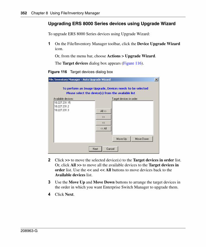
352 Chapter 8 Using File/Inventory Manager
208963-G
Upgrading ERS 8000 Series devices using Upgrade Wizard
To upgrade ERS 8000 Series devices using Upgrade Wizard:
1 On the File/Inventory Manager toolbar, click the Device Upgrade Wizard icon.
Or, from the menu bar, choose Actions > Upgrade Wizard.
The Target devices dialog box appears (Figure 116).
Figure 116 Target devices dialog box
2 Click >> to move the selected device(s) to the Target devices in order list. Or, click All >> to move all the available devices to the Target devices in order list. Use the << and << All buttons to move devices back to the Available devices list.
3 Use the Move Up and Move Down buttons to arrange the target devices in the order in which you want Enterprise Switch Manager to upgrade them.
4 Click Next.
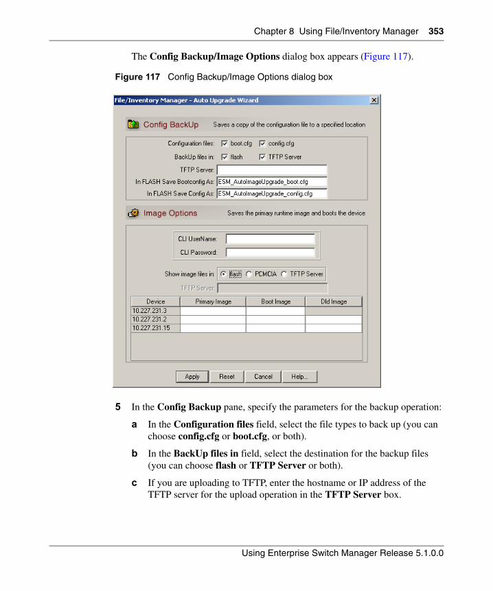
Chapter 8 Using File/Inventory Manager 353
Using Enterprise Switch Manager Release 5.1.0.0
The Config Backup/Image Options dialog box appears (Figure 117).
Figure 117 Config Backup/Image Options dialog box
5 In the Config Backup pane, specify the parameters for the backup operation:
a In the Configuration files field, select the file types to back up (you can choose config.cfg or boot.cfg, or both).
b In the BackUp files in field, select the destination for the backup files (you can choose flash or TFTP Server or both).
c If you are uploading to TFTP, enter the hostname or IP address of the TFTP server for the upload operation in the TFTP Server box.
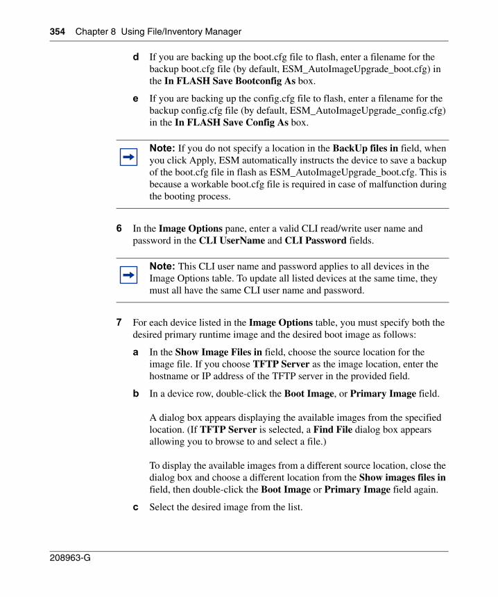
354 Chapter 8 Using File/Inventory Manager
208963-G
d If you are backing up the boot.cfg file to flash, enter a filename for the backup boot.cfg file (by default, ESM_AutoImageUpgrade_boot.cfg) in the In FLASH Save Bootconfig As box.
e If you are backing up the config.cfg file to flash, enter a filename for the backup config.cfg file (by default, ESM_AutoImageUpgrade_config.cfg) in the In FLASH Save Config As box.
6 In the Image Options pane, enter a valid CLI read/write user name and password in the CLI UserName and CLI Password fields.
7 For each device listed in the Image Options table, you must specify both the desired primary runtime image and the desired boot image as follows:
a In the Show Image Files in field, choose the source location for the image file. If you choose TFTP Server as the image location, enter the hostname or IP address of the TFTP server in the provided field.
b In a device row, double-click the Boot Image, or Primary Image field.
A dialog box appears displaying the available images from the specified location. (If TFTP Server is selected, a Find File dialog box appears allowing you to browse to and select a file.)
To display the available images from a different source location, close the dialog box and choose a different location from the Show images files in field, then double-click the Boot Image or Primary Image field again.
c Select the desired image from the list.
Note: If you do not specify a location in the BackUp files in field, when you click Apply, ESM automatically instructs the device to save a backup of the boot.cfg file in flash as ESM_AutoImageUpgrade_boot.cfg. This is because a workable boot.cfg file is required in case of malfunction during the booting process.
Note: This CLI user name and password applies to all devices in the Image Options table. To update all listed devices at the same time, they must all have the same CLI user name and password.
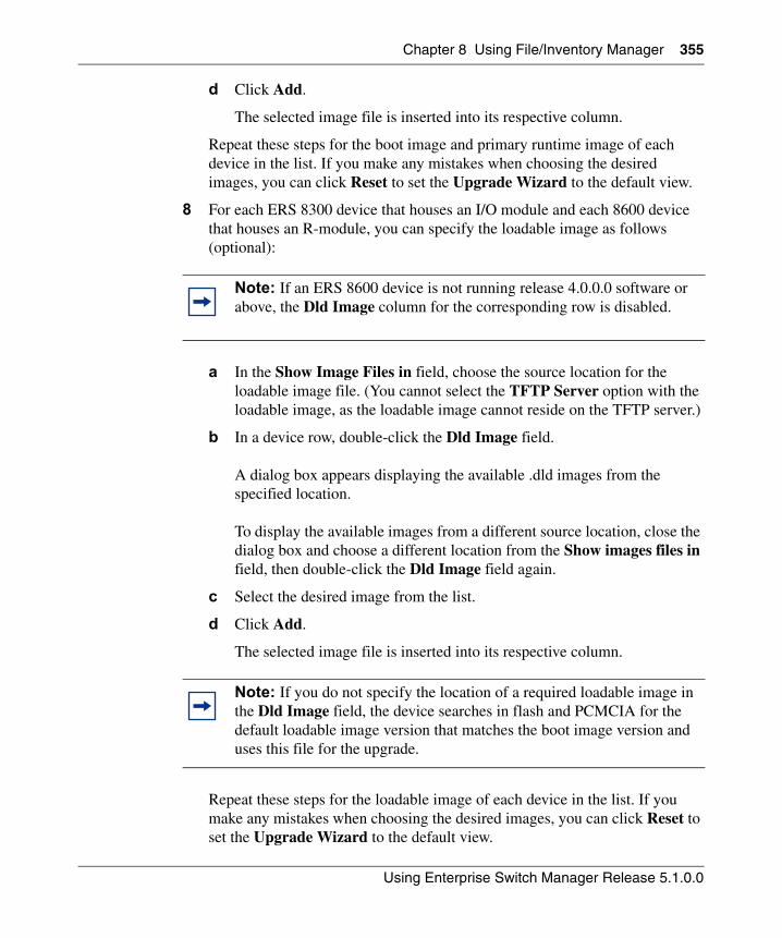
Chapter 8 Using File/Inventory Manager 355
Using Enterprise Switch Manager Release 5.1.0.0
d Click Add.
The selected image file is inserted into its respective column.
Repeat these steps for the boot image and primary runtime image of each device in the list. If you make any mistakes when choosing the desired images, you can click Reset to set the Upgrade Wizard to the default view.
8 For each ERS 8300 device that houses an I/O module and each 8600 device that houses an R-module, you can specify the loadable image as follows (optional):
a In the Show Image Files in field, choose the source location for the loadable image file. (You cannot select the TFTP Server option with the loadable image, as the loadable image cannot reside on the TFTP server.)
b In a device row, double-click the Dld Image field.
A dialog box appears displaying the available .dld images from the specified location.
To display the available images from a different source location, close the dialog box and choose a different location from the Show images files in field, then double-click the Dld Image field again.
c Select the desired image from the list.
d Click Add.
The selected image file is inserted into its respective column.
Repeat these steps for the loadable image of each device in the list. If you make any mistakes when choosing the desired images, you can click Reset to set the Upgrade Wizard to the default view.
Note: If an ERS 8600 device is not running release 4.0.0.0 software or above, the Dld Image column for the corresponding row is disabled.
Note: If you do not specify the location of a required loadable image in the Dld Image field, the device searches in flash and PCMCIA for the default loadable image version that matches the boot image version and uses this file for the upgrade.
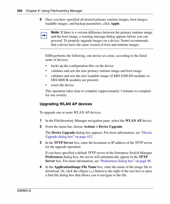
356 Chapter 8 Using File/Inventory Manager
208963-G
9 Once you have specified all desired primary runtime images, boot images, loadable images, and backup parameters, click Apply.
ESM performs the following, one device at a time, according to the listed order of devices:
• backs up the configuration files on the device
• validates and sets the new primary runtime image and boot image
• validates and sets the new loadable image (if ERS 8300 I/O modules or ERS 8600 R-modules are present)
• resets the device
This operation takes time to complete (approximately 3 minutes to complete for one switch).
Upgrading WLAN AP devices
To upgrade one or more WLAN AP devices:
1 In the File/Inventory Manager navigation pane, select the WLAN AP device.
2 From the menu bar, choose Actions > Device Upgrade.
The Device Upgrade dialog box appears. For more information, see “Device Upgrade dialog box” on page 432.
3 In the TFTP Server box, enter the hostname or IP address of the TFTP server for the upgrade operation.
If you have specified a default TFTP server in the Enterprise Switch Manager Preferences dialog box, the server will automatically appear in the TFTP Server box. For more information, see “Preferences dialog box” on page 98.
4 In the ApplicationImage File Name box, enter the name of the image file to download. Or, click the ellipsis (...) button to the right of the text box to open a find file dialog box that allows you to navigate to the file.
Note: If there is a version difference between the primary runtime image and the boot image, a warning message dialog appears before you can proceed. To properly upgrade images on a device, Nortel recommends that a device have the same version of boot and runtime images.
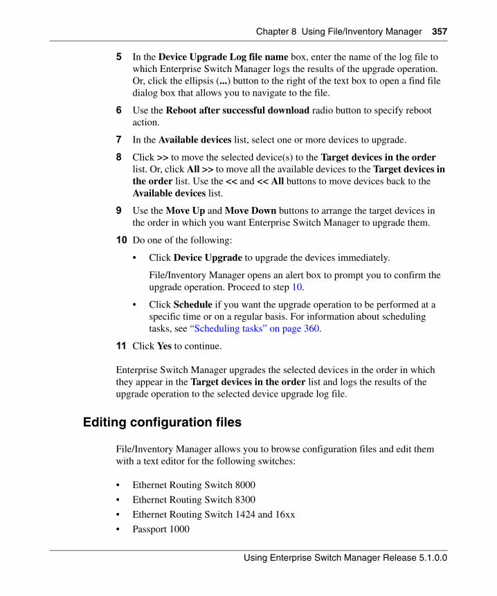
Chapter 8 Using File/Inventory Manager 357
Using Enterprise Switch Manager Release 5.1.0.0
5 In the Device Upgrade Log file name box, enter the name of the log file to which Enterprise Switch Manager logs the results of the upgrade operation. Or, click the ellipsis (...) button to the right of the text box to open a find file dialog box that allows you to navigate to the file.
6 Use the Reboot after successful download radio button to specify reboot action.
7 In the Available devices list, select one or more devices to upgrade.
8 Click >> to move the selected device(s) to the Target devices in the order list. Or, click All >> to move all the available devices to the Target devices in the order list. Use the << and << All buttons to move devices back to the Available devices list.
9 Use the Move Up and Move Down buttons to arrange the target devices in the order in which you want Enterprise Switch Manager to upgrade them.
10 Do one of the following:
• Click Device Upgrade to upgrade the devices immediately.
File/Inventory Manager opens an alert box to prompt you to confirm the upgrade operation. Proceed to step 10.
• Click Schedule if you want the upgrade operation to be performed at a specific time or on a regular basis. For information about scheduling tasks, see “Scheduling tasks” on page 360.
11 Click Yes to continue.
Enterprise Switch Manager upgrades the selected devices in the order in which they appear in the Target devices in the order list and logs the results of the upgrade operation to the selected device upgrade log file.
Editing configuration files
File/Inventory Manager allows you to browse configuration files and edit them with a text editor for the following switches:
• Ethernet Routing Switch 8000
• Ethernet Routing Switch 8300
• Ethernet Routing Switch 1424 and 16xx
• Passport 1000
358 Chapter 8 Using File/Inventory Manager
208963-G
• BPS 2000 (v2.0.5 and later, for ASCII config file only)
• Legacy BayStack 380/420 (v300 and later, for ASCII config file only)
• Ethernet Switch 325/425/460/470 (for ASCII config file only)
• Ethernet Routing Switch 55xx/35xx (for ASCII config file only)
To open a configuration file for editing:
1 From the File/Inventory Manager menu bar, choose Actions > Edit File.
An open file dialog box appears.
2 Browse to the configuration file you want to edit, and click Open.
File/Inventory Manager opens the configuration file in a text editor:
• On a Windows machine, the file opens in Wordpad.
• On a UNIX machine, the file opens in vi.
Scheduling inventory queries
You can schedule an inventory query task to occur at a specific time in the future, once or on a recurring basis.
To schedule an inventory query:
1 From the File/Inventory Manager menu bar, choose Actions > Schedule Query Inventory Task.
The Device List for Query Inventory dialog box appears (Figure 118). For more information, see “Device List for Query Inventory dialog box” on page 434.
Note: Binary configuration files for Legacy BayStack, Ethernet Switch, Ethernet Routing Switch 55xx/35xx, and WLAN AP devices are stored in a proprietary binary format that you cannot edit using a text editor.
Note: In order to schedule tasks, Scheduler Server must be installed and running on your system. For information about installing Scheduler Server, see Installing Enterprise Switch Manager.
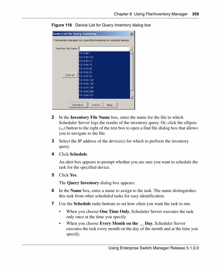
Chapter 8 Using File/Inventory Manager 359
Using Enterprise Switch Manager Release 5.1.0.0
Figure 118 Device List for Query Inventory dialog box
2 In the Inventory File Name box, enter the name for the file to which Scheduler Server logs the results of the inventory query. Or, click the ellipsis (...) button to the right of the text box to open a find file dialog box that allows you to navigate to the file.
3 Select the IP address of the device(s) for which to perform the inventory query.
4 Click Schedule.
An alert box appears to prompt whether you are sure you want to schedule the task for the specified device.
5 Click Yes.
The Query Inventory dialog box appears.
6 In the Name box, enter a name to assign to the task. The name distinguishes this task from other scheduled tasks for easy identification.
7 Use the Schedule radio buttons to set how often you want the task to run.
• When you choose One Time Only, Scheduler Server executes the task only once at the time you specify.
• When you choose Every Month on the __ Day, Scheduler Server executes the task every month on the day of the month and at the time you specify.
360 Chapter 8 Using File/Inventory Manager
208963-G
• When you choose Every Week on __, Scheduler Server executes the task every week on the day of the week and at the time you specify.
• When you choose Every __ Days, Scheduler Server executes the task at the interval and time you specify.
• When you choose Every Day, Scheduler Server executes the task every day at the time you specify.
8 In the Starting date/time boxes, set the date and time you want Scheduler Server to execute the task.
9 Click Set.
Scheduler Server schedules the task and will execute it at the set time.
Scheduling tasks
You can schedule upload, download, backup, restore, archive, synchronize, and device upgrade operations to occur at a specific time, either once or on a recurring basis. The Scheduler server stores information about all scheduled tasks and runs in the background, letting Scheduler Server perform scheduled tasks even when Enterprise Switch Manager is not running. Scheduler Server maintains a list of all scheduled tasks, even after an operating system reboot.
To schedule a task:
1 Complete the upload, download, backup, restore, archive, synchronize, or device upgrade procedure steps for the specific device type until you reach the step in which you have the option of completing the procedure or clicking Schedule.
2 Click Schedule.
An alert box appears to prompt whether you want to schedule the task for that device.
3 Click Yes.
Note: In order to schedule tasks, Scheduler Server must be installed and running on your system. For information about installing Scheduler Server, see Installing Enterprise Switch Manager.
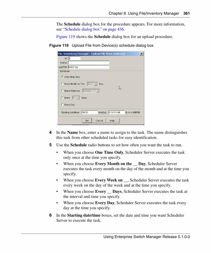
Chapter 8 Using File/Inventory Manager 361
Using Enterprise Switch Manager Release 5.1.0.0
The Schedule dialog box for the procedure appears. For more information, see “Schedule dialog box” on page 436.
Figure 119 shows the Schedule dialog box for an upload procedure.
Figure 119 Upload File from Device(s) schedule dialog box
4 In the Name box, enter a name to assign to the task. The name distinguishes this task from other scheduled tasks for easy identification.
5 Use the Schedule radio buttons to set how often you want the task to run.
• When you choose One Time Only, Scheduler Server executes the task only once at the time you specify.
• When you choose Every Month on the __ Day, Scheduler Server executes the task every month on the day of the month and at the time you specify.
• When you choose Every Week on __, Scheduler Server executes the task every week on the day of the week and at the time you specify.
• When you choose Every __ Days, Scheduler Server executes the task at the interval and time you specify.
• When you choose Every Day, Scheduler Server executes the task every day at the time you specify.
6 In the Starting date/time boxes, set the date and time you want Scheduler Server to execute the task.
362 Chapter 8 Using File/Inventory Manager
208963-G
7 Click Set.
Scheduler Server schedules the task and executes it at the set time. To view the log file Scheduler Server creates when it executes this task, see “Viewing scheduled task log files”.
Viewing scheduled tasks
Enterprise Switch Manager allows you to view a list of all the tasks you schedule. From the View Scheduled Task dialog box you can also cancel tasks and view the task log file that Enterprise Switch Manager creates when it executes a scheduled task.
To view the list of scheduled tasks:
The View Scheduled Task dialog box appears. For more information about the View Scheduled Task dialog box, see “View Scheduled Task dialog box” on page 437.
Viewing scheduled task log files
To view the log file that Enterprise Switch Manager creates when it executes a scheduled task:
1 From the Enterprise Switch Manager menu bar, choose View > Scheduled Task.
Note: In order to schedule tasks, Scheduler Server must be installed and running on your system. For information about installing Scheduler Server, see Installing Enterprise Switch Manager.
From the Enterprise Switch Manager menu bar, choose View > Scheduled Task.
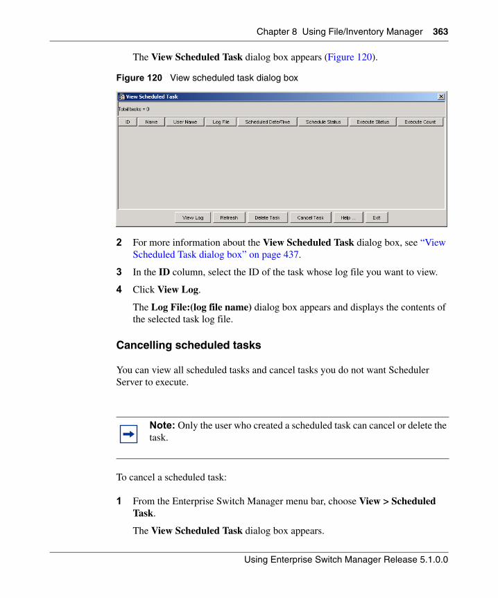
Chapter 8 Using File/Inventory Manager 363
Using Enterprise Switch Manager Release 5.1.0.0
The View Scheduled Task dialog box appears (Figure 120).
Figure 120 View scheduled task dialog box
2 For more information about the View Scheduled Task dialog box, see “View Scheduled Task dialog box” on page 437.
3 In the ID column, select the ID of the task whose log file you want to view.
4 Click View Log.
The Log File:(log file name) dialog box appears and displays the contents of the selected task log file.
Cancelling scheduled tasks
You can view all scheduled tasks and cancel tasks you do not want Scheduler Server to execute.
To cancel a scheduled task:
1 From the Enterprise Switch Manager menu bar, choose View > Scheduled Task.
The View Scheduled Task dialog box appears.
Note: Only the user who created a scheduled task can cancel or delete the task.
364 Chapter 8 Using File/Inventory Manager
208963-G
2 Select the ID of the task that you want to cancel.
3 Click Cancel Task.
Scheduler Server will not execute the task. However, the task remains in the task list until you delete it (See “Deleting scheduled tasks” on page 364).
Deleting scheduled tasks
The View Scheduled Task dialog box maintains a list of all scheduled tasks and does not remove tasks from the list after it executes them. To remove a task from the task list, you must delete it.
To delete a task from the View Scheduled Task dialog box:
1 From the Enterprise Switch Manager menu bar, choose View > Scheduled Task.
The View Scheduled Task dialog box appears. For more information, see “View Scheduled Task dialog box” on page 437.
2 Select the ID of the task that you want to delete.
3 Click Delete.
The Scheduler removes the task from the list of scheduled tasks.
Viewing the File/Inventory Manager log
The File/Inventory Manager log allows you to view the log file to which File/Inventory Manager writes the results of all download, upload, backup, restore, archive, synchronize, and device upgrade operations.
To view the File/Inventory Manager log:
A dialog box appears to let you select the log file to view.
On the File/Inventory Manager menu bar, choose View > File Inventory Manager Log.
Chapter 8 Using File/Inventory Manager 365
Using Enterprise Switch Manager Release 5.1.0.0
Highlighting devices on the topology map
File/Inventory Manager allows you to highlight devices of the selected family (Ethernet Routing Switch 8000, Ethernet Routing Switch 1424/16xx, Ethernet Routing Switch 55xx/35xx, Passport 1000, WLAN AP, Legacy BayStack, Ethernet Switch, or Alteon) or an individual device on the Enterprise Switch Manager topology view.
To view network inventory devices on the Enterprise Switch Manager topology map:
Enterprise Switch Manager highlights devices of the selected family or the individual device on the topology map.
Finding elements in the inventory
File/Inventory Manager allows you to find devices and elements in the network inventory.
To find a device or element in the inventory:
1 On the File/Inventory Manager toolbar, click Find.
Or, from the menu bar, choose Edit > Find.
The Find dialog box appears.
2 In the Find text box, type the text or number for your search.
3 In the In section, click the Tree option to search the navigation pane, or click the Table option to search the contents pane.
4 In the From section, choose whether you want to start the search from the current selection or from the start of the table or tree.
5 Click Next.
File/Inventory Manager starts its search and highlights the first match it finds.
On the File/Inventory Manager menu bar, choose View > Highlight Topology.
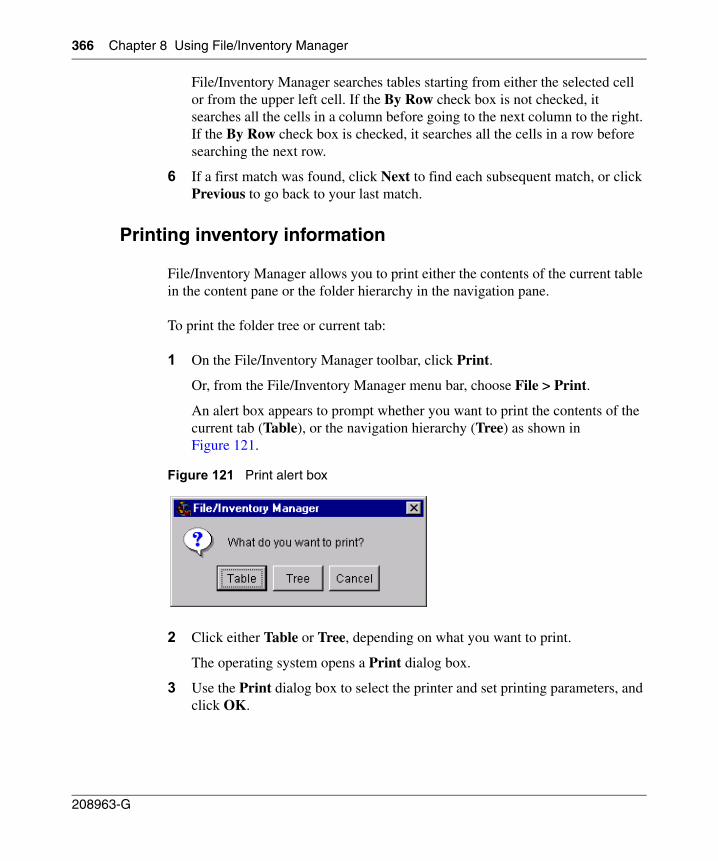
366 Chapter 8 Using File/Inventory Manager
208963-G
File/Inventory Manager searches tables starting from either the selected cell or from the upper left cell. If the By Row check box is not checked, it searches all the cells in a column before going to the next column to the right. If the By Row check box is checked, it searches all the cells in a row before searching the next row.
6 If a first match was found, click Next to find each subsequent match, or click Previous to go back to your last match.
Printing inventory information
File/Inventory Manager allows you to print either the contents of the current table in the content pane or the folder hierarchy in the navigation pane.
To print the folder tree or current tab:
1 On the File/Inventory Manager toolbar, click Print.
Or, from the File/Inventory Manager menu bar, choose File > Print.
An alert box appears to prompt whether you want to print the contents of the current tab (Table), or the navigation hierarchy (Tree) as shown in Figure 121.
Figure 121 Print alert box
2 Click either Table or Tree, depending on what you want to print.
The operating system opens a Print dialog box.
3 Use the Print dialog box to select the printer and set printing parameters, and click OK.
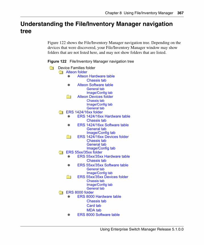
Chapter 8 Using File/Inventory Manager 367
Using Enterprise Switch Manager Release 5.1.0.0
Understanding the File/Inventory Manager navigation tree
Figure 122 shows the File/Inventory Manager navigation tree. Depending on the devices that were discovered, your File/Inventory Manager window may show folders that are not listed here, and may not show folders that are listed.
Figure 122 File/Inventory Manager navigation tree
Device Families folderAlteon folder
Alteon Hardware tableChassis tab
Alteon Software tableGeneral tabImage/Config tab
Alteon Devices folderChassis tabImage/Config tabGeneral tab
ERS 1424/16xx folderERS 1424/16xx Hardware table
Chassis tabERS 1424/16xx Software table
General tabImage/Config tab
ERS 1424/16xx Devices folderChassis tabGeneral tabImage/Config tab
ERS 55xx/35xx folderERS 55xx/35xx Hardware table
Chassis tabERS 55xx/35xx Software table
General tabImage/Config tab
ERS 55xx/35xx Devices folderChassis tabImage/Config tabGeneral tab
ERS 8000 folderERS 8000 Hardware table
Chassis tabCard tabMDA tab
ERS 8000 Software table
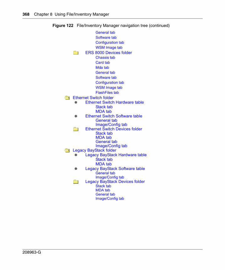
368 Chapter 8 Using File/Inventory Manager
208963-G
General tabSoftware tabConfiguration tabWSM Image tab
ERS 8000 Devices folderChassis tabCard tabMda tabGeneral tabSoftware tabConfiguration tabWSM Image tabFlashFiles tab
Ethernet Switch folderEthernet Switch Hardware table
Stack tabMDA tab
Ethernet Switch Software tableGeneral tabImage/Config tab
Ethernet Switch Devices folderStack tabMDA tabGeneral tabImage/Config tab
Legacy BayStack folderLegacy BayStack Hardware table
Stack tabMDA tab
Legacy BayStack Software tableGeneral tabImage/Config tab
Legacy BayStack Devices folderStack tabMDA tabGeneral tabImage/Config tab
Figure 122 File/Inventory Manager navigation tree (continued)
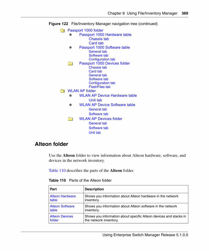
Chapter 8 Using File/Inventory Manager 369
Using Enterprise Switch Manager Release 5.1.0.0
Alteon folder
Use the Alteon folder to view information about Alteon hardware, software, and devices in the network inventory.
Table 110 describes the parts of the Alteon folder.
Passport 1000 folderPassport 1000 Hardware table
Chassis tabCard tab
Passport 1000 Software tableGeneral tabSoftware tabConfiguration tab
Passport 1000 Devices folderChassis tabCard tabGeneral tabSoftware tabConfiguration tabFlashFiles tab
WLAN AP folderWLAN AP Device Hardware table
Unit tabWLAN AP Device Software table
General tabSoftware tab
WLAN AP Devices folderGeneral tabSoftware tabUnit tab
Table 110 Parts of the Alteon folder
Part Description
Alteon Hardware table
Shows you information about Alteon hardware in the network inventory.
Alteon Software table
Shows you information about Alteon software in the network inventory.
Alteon Devices folder
Shows you information about specific Alteon devices and stacks in the network inventory.
Figure 122 File/Inventory Manager navigation tree (continued)
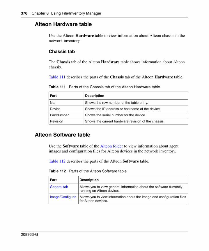
370 Chapter 8 Using File/Inventory Manager
208963-G
Alteon Hardware table
Use the Alteon Hardware table to view information about Alteon chassis in the network inventory.
Chassis tab
The Chassis tab of the Alteon Hardware table shows information about Alteon chassis.
Table 111 describes the parts of the Chassis tab of the Alteon Hardware table.
Alteon Software table
Use the Software table of the Alteon folder to view information about agent images and configuration files for Alteon devices in the network inventory.
Table 112 describes the parts of the Alteon Software table.
Table 111 Parts of the Chassis tab of the Alteon Hardware table
Part Description
No. Shows the row number of the table entry.
Device Shows the IP address or hostname of the device.
PartNumber Shows the serial number for the device.
Revision Shows the current hardware revision of the chassis.
Table 112 Parts of the Alteon Software table
Part Description
General tab Allows you to view general information about the software currently running on Alteon devices.
Image/Config tab Allows you to view information about the image and configuration files for Alteon devices.
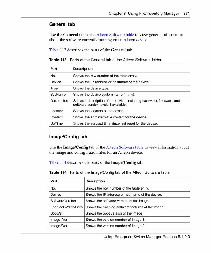
Chapter 8 Using File/Inventory Manager 371
Using Enterprise Switch Manager Release 5.1.0.0
General tab
Use the General tab of the Alteon Software table to view general information about the software currently running on an Alteon device.
Table 113 describes the parts of the General tab.
Image/Config tab
Use the Image/Config tab of the Alteon Software table to view information about the image and configuration files for an Alteon device.
Table 114 describes the parts of the Image/Config tab.
Table 113 Parts of the General tab of the Alteon Software folder
Part Description
No. Shows the row number of the table entry.
Device Shows the IP address or hostname of the device.
Type Shows the device type.
SysName Shows the device system name (if any).
Description Shows a description of the device, including hardware, firmware, and software version levels if available.
Location Shows the location of the device.
Contact Shows the administrative contact for the device.
UpTime Shows the elapsed time since last reset for the device.
Table 114 Parts of the Image/Config tab of the Alteon Software table
Part Description
No. Shows the row number of the table entry.
Device Shows the IP address or hostname of the device.
SoftwareVersion Shows the software version of the image.
EnabledSWFeatures Shows the enabled software features of the image.
BootVer Shows the boot version of the image.
Image1Ver Shows the version number of image 1.
Image2Ver Shows the version number of image 2.
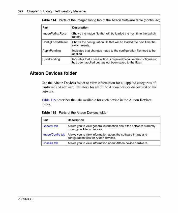
372 Chapter 8 Using File/Inventory Manager
208963-G
Alteon Devices folder
Use the Alteon Devices folder to view information for all applied categories of hardware and software inventory for all of the Alteon devices discovered on the network.
Table 115 describes the tabs available for each device in the Alteon Devices folder.
ImageForNxtReset Shows the image file that will be loaded the next time the switch resets.
ConfigForNxtReset Shows the configuration file that will be loaded the next time the switch resets.
ApplyPending Indicates that changes made to the configuration file need to be applied.
SavePending Indicates that a save action is required because the configuration has been applied but has not been saved to the flash.
Table 115 Parts of the Alteon Devices folder
Part Description
General tab Allows you to view general information about the software currently running on Alteon devices.
Image/Config tab Allows you to view information about the software image and configuration files for Alteon devices.
Chassis tab Allows you to view information about Alteon device hardware.
Table 114 Parts of the Image/Config tab of the Alteon Software table (continued)
Part Description
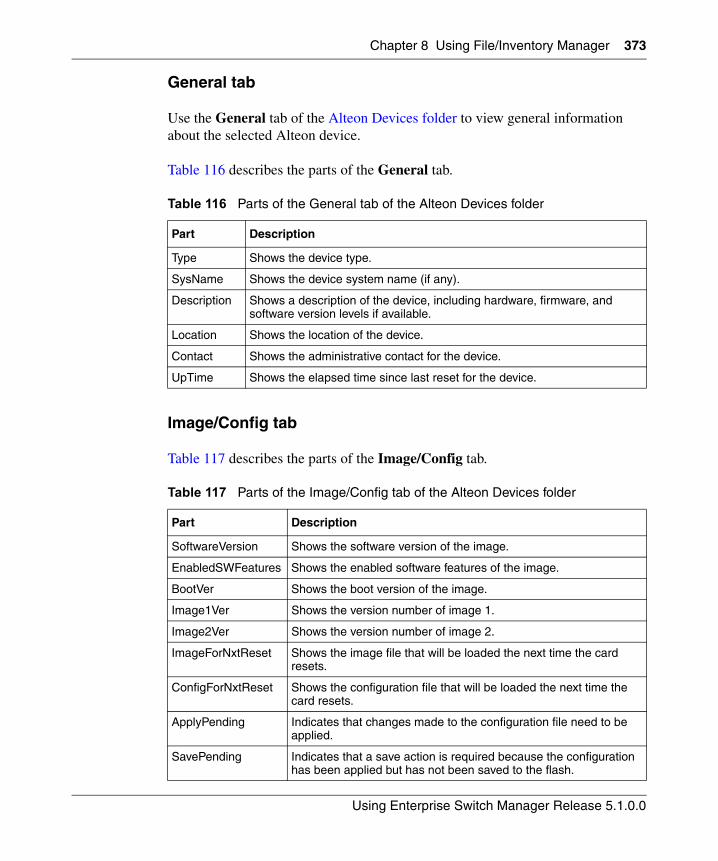
Chapter 8 Using File/Inventory Manager 373
Using Enterprise Switch Manager Release 5.1.0.0
General tab
Use the General tab of the Alteon Devices folder to view general information about the selected Alteon device.
Table 116 describes the parts of the General tab.
Image/Config tab
Table 117 describes the parts of the Image/Config tab.
Table 116 Parts of the General tab of the Alteon Devices folder
Part Description
Type Shows the device type.
SysName Shows the device system name (if any).
Description Shows a description of the device, including hardware, firmware, and software version levels if available.
Location Shows the location of the device.
Contact Shows the administrative contact for the device.
UpTime Shows the elapsed time since last reset for the device.
Table 117 Parts of the Image/Config tab of the Alteon Devices folder
Part Description
SoftwareVersion Shows the software version of the image.
EnabledSWFeatures Shows the enabled software features of the image.
BootVer Shows the boot version of the image.
Image1Ver Shows the version number of image 1.
Image2Ver Shows the version number of image 2.
ImageForNxtReset Shows the image file that will be loaded the next time the card resets.
ConfigForNxtReset Shows the configuration file that will be loaded the next time the card resets.
ApplyPending Indicates that changes made to the configuration file need to be applied.
SavePending Indicates that a save action is required because the configuration has been applied but has not been saved to the flash.
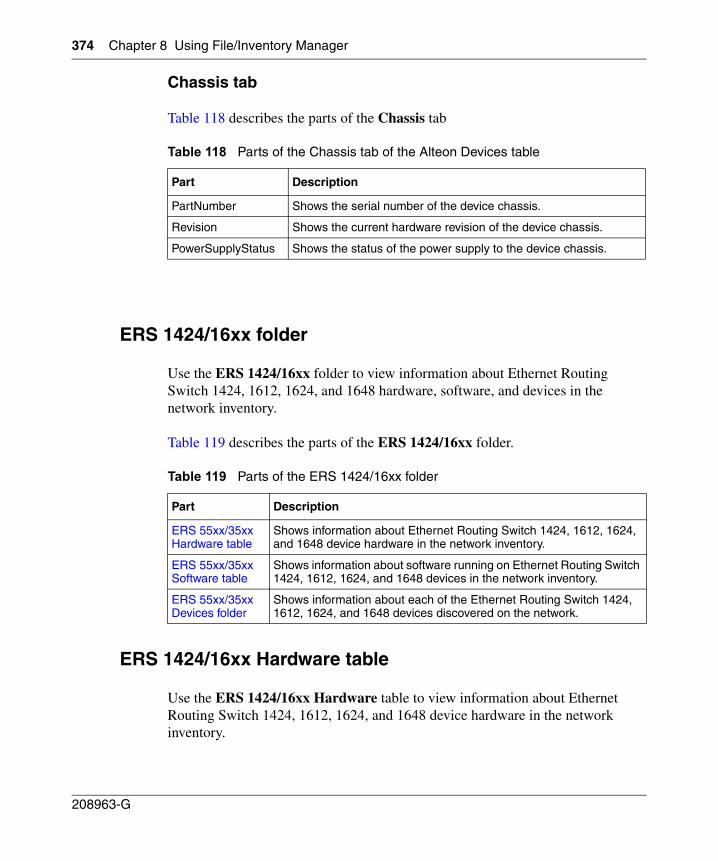
374 Chapter 8 Using File/Inventory Manager
208963-G
Chassis tab
Table 118 describes the parts of the Chassis tab
ERS 1424/16xx folder
Use the ERS 1424/16xx folder to view information about Ethernet Routing Switch 1424, 1612, 1624, and 1648 hardware, software, and devices in the network inventory.
Table 119 describes the parts of the ERS 1424/16xx folder.
ERS 1424/16xx Hardware table
Use the ERS 1424/16xx Hardware table to view information about Ethernet Routing Switch 1424, 1612, 1624, and 1648 device hardware in the network inventory.
Table 118 Parts of the Chassis tab of the Alteon Devices table
Part Description
PartNumber Shows the serial number of the device chassis.
Revision Shows the current hardware revision of the device chassis.
PowerSupplyStatus Shows the status of the power supply to the device chassis.
Table 119 Parts of the ERS 1424/16xx folder
Part Description
ERS 55xx/35xx Hardware table
Shows information about Ethernet Routing Switch 1424, 1612, 1624, and 1648 device hardware in the network inventory.
ERS 55xx/35xx Software table
Shows information about software running on Ethernet Routing Switch 1424, 1612, 1624, and 1648 devices in the network inventory.
ERS 55xx/35xx Devices folder
Shows information about each of the Ethernet Routing Switch 1424, 1612, 1624, and 1648 devices discovered on the network.
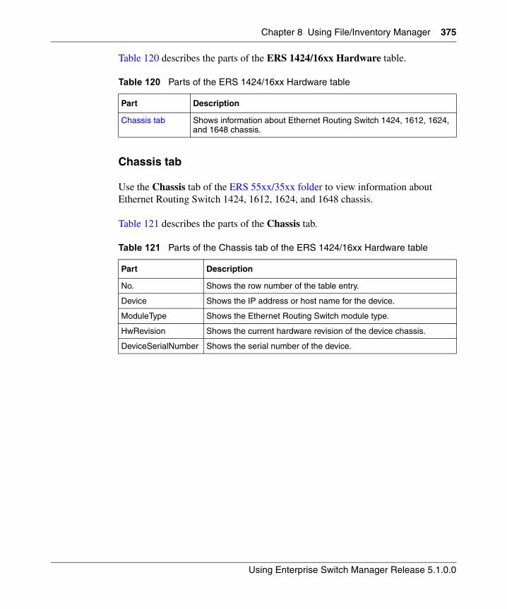
Chapter 8 Using File/Inventory Manager 375
Using Enterprise Switch Manager Release 5.1.0.0
Table 120 describes the parts of the ERS 1424/16xx Hardware table.
Chassis tab
Use the Chassis tab of the ERS 55xx/35xx folder to view information about Ethernet Routing Switch 1424, 1612, 1624, and 1648 chassis.
Table 121 describes the parts of the Chassis tab.
Table 120 Parts of the ERS 1424/16xx Hardware table
Part Description
Chassis tab Shows information about Ethernet Routing Switch 1424, 1612, 1624, and 1648 chassis.
Table 121 Parts of the Chassis tab of the ERS 1424/16xx Hardware table
Part Description
No. Shows the row number of the table entry.
Device Shows the IP address or host name for the device.
ModuleType Shows the Ethernet Routing Switch module type.
HwRevision Shows the current hardware revision of the device chassis.
DeviceSerialNumber Shows the serial number of the device.
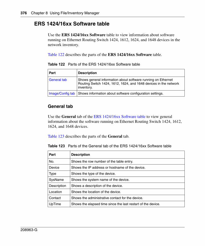
376 Chapter 8 Using File/Inventory Manager
208963-G
ERS 1424/16xx Software table
Use the ERS 1424/16xx Software table to view information about software running on Ethernet Routing Switch 1424, 1612, 1624, and 1648 devices in the network inventory.
Table 122 describes the parts of the ERS 1424/16xx Software table.
General tab
Use the General tab of the ERS 1424/16xx Software table to view general information about the software running on Ethernet Routing Switch 1424, 1612, 1624, and 1648 devices.
Table 123 describes the parts of the General tab.
Table 122 Parts of the ERS 1424/16xx Software table
Part Description
General tab Shows general information about software running on Ethernet Routing Switch 1424, 1612, 1624, and 1648 devices in the network inventory.
Image/Config tab Shows information about software configuration settings.
Table 123 Parts of the General tab of the ERS 1424/16xx Software table
Part Description
No. Shows the row number of the table entry.
Device Shows the IP address or hostname of the device.
Type Shows the type of the device.
SysName Shows the system name of the device.
Description Shows a description of the device.
Location Shows the location of the device.
Contact Shows the administrative contact for the device.
UpTime Shows the elapsed time since the last restart of the device.
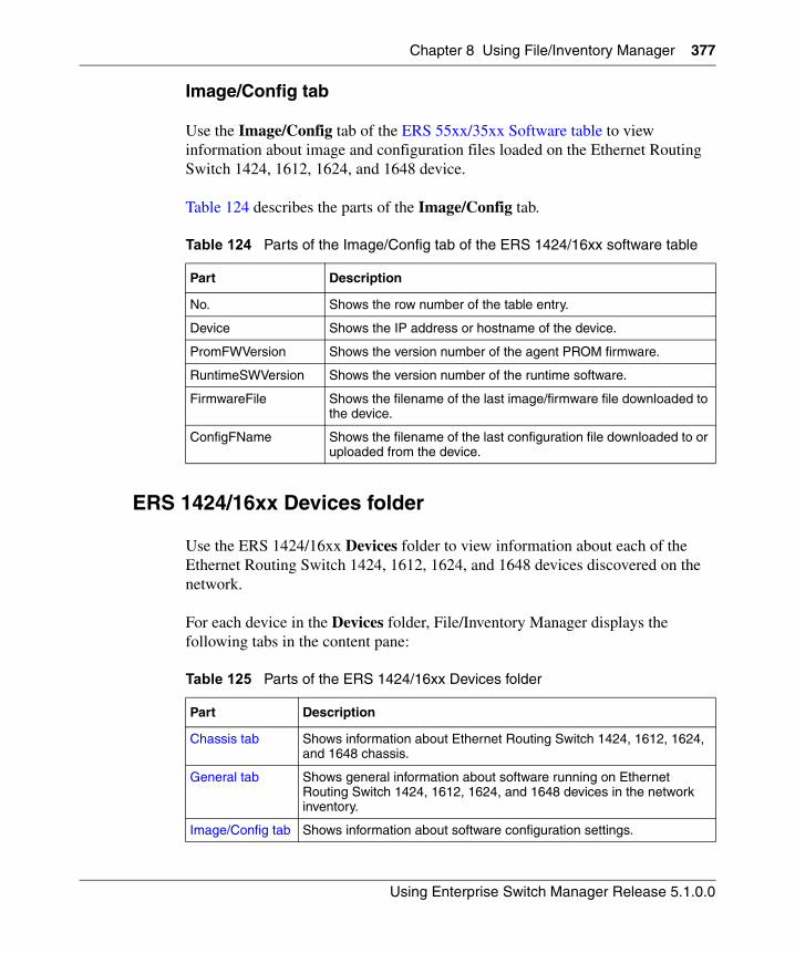
Chapter 8 Using File/Inventory Manager 377
Using Enterprise Switch Manager Release 5.1.0.0
Image/Config tab
Use the Image/Config tab of the ERS 55xx/35xx Software table to view information about image and configuration files loaded on the Ethernet Routing Switch 1424, 1612, 1624, and 1648 device.
Table 124 describes the parts of the Image/Config tab.
ERS 1424/16xx Devices folder
Use the ERS 1424/16xx Devices folder to view information about each of the Ethernet Routing Switch 1424, 1612, 1624, and 1648 devices discovered on the network.
For each device in the Devices folder, File/Inventory Manager displays the following tabs in the content pane:
Table 124 Parts of the Image/Config tab of the ERS 1424/16xx software table
Part Description
No. Shows the row number of the table entry.
Device Shows the IP address or hostname of the device.
PromFWVersion Shows the version number of the agent PROM firmware.
RuntimeSWVersion Shows the version number of the runtime software.
FirmwareFile Shows the filename of the last image/firmware file downloaded to the device.
ConfigFName Shows the filename of the last configuration file downloaded to or uploaded from the device.
Table 125 Parts of the ERS 1424/16xx Devices folder
Part Description
Chassis tab Shows information about Ethernet Routing Switch 1424, 1612, 1624, and 1648 chassis.
General tab Shows general information about software running on Ethernet Routing Switch 1424, 1612, 1624, and 1648 devices in the network inventory.
Image/Config tab Shows information about software configuration settings.
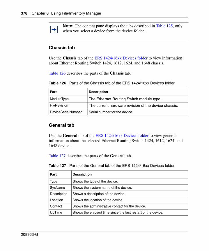
378 Chapter 8 Using File/Inventory Manager
208963-G
Chassis tab
Use the Chassis tab of the ERS 1424/16xx Devices folder to view information about Ethernet Routing Switch 1424, 1612, 1624, and 1648 chassis.
Table 126 describes the parts of the Chassis tab.
General tab
Use the General tab of the ERS 1424/16xx Devices folder to view general information about the selected Ethernet Routing Switch 1424, 1612, 1624, and 1648 device.
Table 127 describes the parts of the General tab.
Note: The content pane displays the tabs described in Table 125, only when you select a device from the device folder.
Table 126 Parts of the Chassis tab of the ERS 1424/16xx Devices folder
Part Description
ModuleType The Ethernet Routing Switch module type.
HwRevision The current hardware revision of the device chassis.
DeviceSerialNumber Serial number for the device.
Table 127 Parts of the General tab of the ERS 1424/16xx Devices folder
Part Description
Type Shows the type of the device.
SysName Shows the system name of the device.
Description Shows a description of the device.
Location Shows the location of the device.
Contact Shows the administrative contact for the device.
UpTime Shows the elapsed time since the last restart of the device.
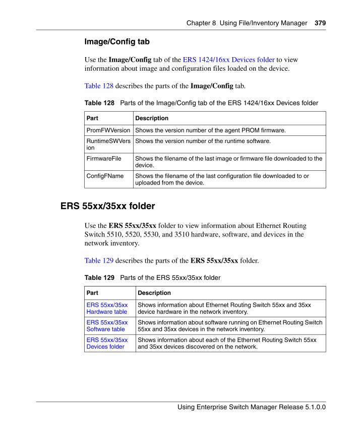
Chapter 8 Using File/Inventory Manager 379
Using Enterprise Switch Manager Release 5.1.0.0
Image/Config tab
Use the Image/Config tab of the ERS 1424/16xx Devices folder to view information about image and configuration files loaded on the device.
Table 128 describes the parts of the Image/Config tab.
ERS 55xx/35xx folder
Use the ERS 55xx/35xx folder to view information about Ethernet Routing Switch 5510, 5520, 5530, and 3510 hardware, software, and devices in the network inventory.
Table 129 describes the parts of the ERS 55xx/35xx folder.
Table 128 Parts of the Image/Config tab of the ERS 1424/16xx Devices folder
Part Description
PromFWVersion Shows the version number of the agent PROM firmware.
RuntimeSWVersion
Shows the version number of the runtime software.
FirmwareFile Shows the filename of the last image or firmware file downloaded to the device.
ConfigFName Shows the filename of the last configuration file downloaded to or uploaded from the device.
Table 129 Parts of the ERS 55xx/35xx folder
Part Description
ERS 55xx/35xx Hardware table
Shows information about Ethernet Routing Switch 55xx and 35xx device hardware in the network inventory.
ERS 55xx/35xx Software table
Shows information about software running on Ethernet Routing Switch 55xx and 35xx devices in the network inventory.
ERS 55xx/35xx Devices folder
Shows information about each of the Ethernet Routing Switch 55xx and 35xx devices discovered on the network.
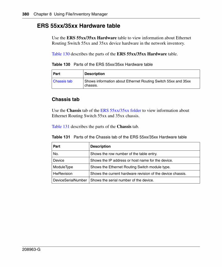
380 Chapter 8 Using File/Inventory Manager
208963-G
ERS 55xx/35xx Hardware table
Use the ERS 55xx/35xx Hardware table to view information about Ethernet Routing Switch 55xx and 35xx device hardware in the network inventory.
Table 130 describes the parts of the ERS 55xx/35xx Hardware table.
Chassis tab
Use the Chassis tab of the ERS 55xx/35xx folder to view information about Ethernet Routing Switch 55xx and 35xx chassis.
Table 131 describes the parts of the Chassis tab.
Table 130 Parts of the ERS 55xx/35xx Hardware table
Part Description
Chassis tab Shows information about Ethernet Routing Switch 55xx and 35xx chassis.
Table 131 Parts of the Chassis tab of the ERS 55xx/35xx Hardware table
Part Description
No. Shows the row number of the table entry.
Device Shows the IP address or host name for the device.
ModuleType Shows the Ethernet Routing Switch module type.
HwRevision Shows the current hardware revision of the device chassis.
DeviceSerialNumber Shows the serial number of the device.
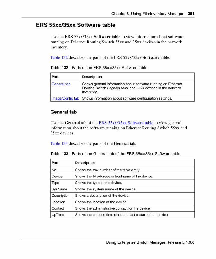
Chapter 8 Using File/Inventory Manager 381
Using Enterprise Switch Manager Release 5.1.0.0
ERS 55xx/35xx Software table
Use the ERS 55xx/35xx Software table to view information about software running on Ethernet Routing Switch 55xx and 35xx devices in the network inventory.
Table 132 describes the parts of the ERS 55xx/35xx Software table.
General tab
Use the General tab of the ERS 55xx/35xx Software table to view general information about the software running on Ethernet Routing Switch 55xx and 35xx devices.
Table 133 describes the parts of the General tab.
Table 132 Parts of the ERS 55xx/35xx Software table
Part Description
General tab Shows general information about software running on Ethernet Routing Switch (legacy) 55xx and 35xx devices in the network inventory.
Image/Config tab Shows information about software configuration settings.
Table 133 Parts of the General tab of the ERS 55xx/35xx Software table
Part Description
No. Shows the row number of the table entry.
Device Shows the IP address or hostname of the device.
Type Shows the type of the device.
SysName Shows the system name of the device.
Description Shows a description of the device.
Location Shows the location of the device.
Contact Shows the administrative contact for the device.
UpTime Shows the elapsed time since the last restart of the device.
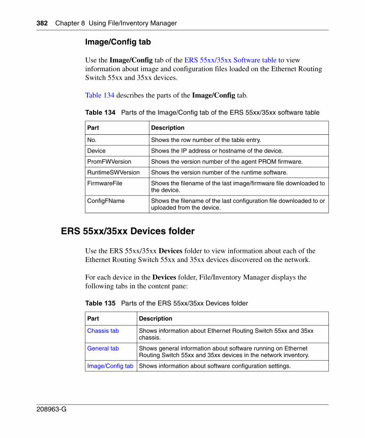
382 Chapter 8 Using File/Inventory Manager
208963-G
Image/Config tab
Use the Image/Config tab of the ERS 55xx/35xx Software table to view information about image and configuration files loaded on the Ethernet Routing Switch 55xx and 35xx devices.
Table 134 describes the parts of the Image/Config tab.
ERS 55xx/35xx Devices folder
Use the ERS 55xx/35xx Devices folder to view information about each of the Ethernet Routing Switch 55xx and 35xx devices discovered on the network.
For each device in the Devices folder, File/Inventory Manager displays the following tabs in the content pane:
Table 134 Parts of the Image/Config tab of the ERS 55xx/35xx software table
Part Description
No. Shows the row number of the table entry.
Device Shows the IP address or hostname of the device.
PromFWVersion Shows the version number of the agent PROM firmware.
RuntimeSWVersion Shows the version number of the runtime software.
FirmwareFile Shows the filename of the last image/firmware file downloaded to the device.
ConfigFName Shows the filename of the last configuration file downloaded to or uploaded from the device.
Table 135 Parts of the ERS 55xx/35xx Devices folder
Part Description
Chassis tab Shows information about Ethernet Routing Switch 55xx and 35xx chassis.
General tab Shows general information about software running on Ethernet Routing Switch 55xx and 35xx devices in the network inventory.
Image/Config tab Shows information about software configuration settings.
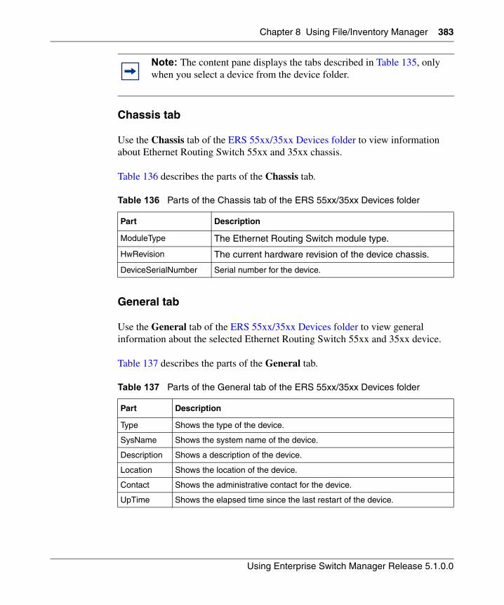
Chapter 8 Using File/Inventory Manager 383
Using Enterprise Switch Manager Release 5.1.0.0
Chassis tab
Use the Chassis tab of the ERS 55xx/35xx Devices folder to view information about Ethernet Routing Switch 55xx and 35xx chassis.
Table 136 describes the parts of the Chassis tab.
General tab
Use the General tab of the ERS 55xx/35xx Devices folder to view general information about the selected Ethernet Routing Switch 55xx and 35xx device.
Table 137 describes the parts of the General tab.
Note: The content pane displays the tabs described in Table 135, only when you select a device from the device folder.
Table 136 Parts of the Chassis tab of the ERS 55xx/35xx Devices folder
Part Description
ModuleType The Ethernet Routing Switch module type.
HwRevision The current hardware revision of the device chassis.
DeviceSerialNumber Serial number for the device.
Table 137 Parts of the General tab of the ERS 55xx/35xx Devices folder
Part Description
Type Shows the type of the device.
SysName Shows the system name of the device.
Description Shows a description of the device.
Location Shows the location of the device.
Contact Shows the administrative contact for the device.
UpTime Shows the elapsed time since the last restart of the device.
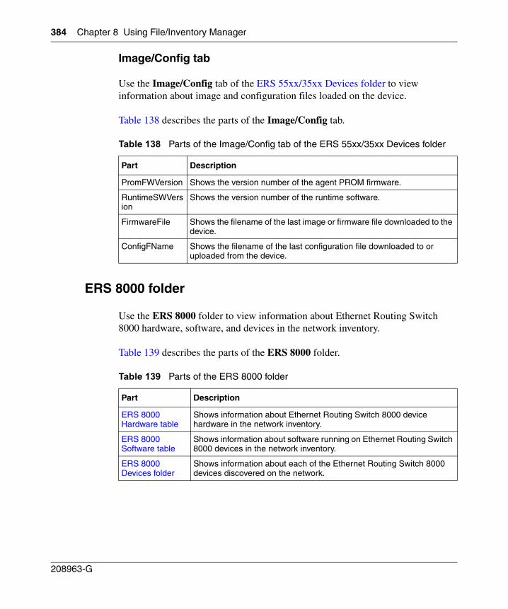
384 Chapter 8 Using File/Inventory Manager
208963-G
Image/Config tab
Use the Image/Config tab of the ERS 55xx/35xx Devices folder to view information about image and configuration files loaded on the device.
Table 138 describes the parts of the Image/Config tab.
ERS 8000 folder
Use the ERS 8000 folder to view information about Ethernet Routing Switch 8000 hardware, software, and devices in the network inventory.
Table 139 describes the parts of the ERS 8000 folder.
Table 138 Parts of the Image/Config tab of the ERS 55xx/35xx Devices folder
Part Description
PromFWVersion Shows the version number of the agent PROM firmware.
RuntimeSWVersion
Shows the version number of the runtime software.
FirmwareFile Shows the filename of the last image or firmware file downloaded to the device.
ConfigFName Shows the filename of the last configuration file downloaded to or uploaded from the device.
Table 139 Parts of the ERS 8000 folder
Part Description
ERS 8000 Hardware table
Shows information about Ethernet Routing Switch 8000 device hardware in the network inventory.
ERS 8000 Software table
Shows information about software running on Ethernet Routing Switch 8000 devices in the network inventory.
ERS 8000 Devices folder
Shows information about each of the Ethernet Routing Switch 8000 devices discovered on the network.
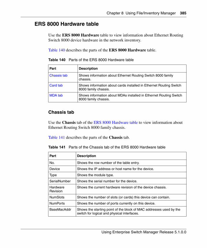
Chapter 8 Using File/Inventory Manager 385
Using Enterprise Switch Manager Release 5.1.0.0
ERS 8000 Hardware table
Use the ERS 8000 Hardware table to view information about Ethernet Routing Switch 8000 device hardware in the network inventory.
Table 140 describes the parts of the ERS 8000 Hardware table.
Chassis tab
Use the Chassis tab of the ERS 8000 Hardware table to view information about Ethernet Routing Switch 8000 family chassis.
Table 141 describes the parts of the Chassis tab.
Table 140 Parts of the ERS 8000 Hardware table
Part Description
Chassis tab Shows information about Ethernet Routing Switch 8000 family chassis.
Card tab Shows information about cards installed in Ethernet Routing Switch 8000 family chassis.
MDA tab Shows information about MDAs installed in Ethernet Routing Switch 8000 family chassis.
Table 141 Parts of the Chassis tab of the ERS 8000 Hardware table
Part Description
No. Shows the row number of the table entry.
Device Shows the IP address or host name for the device.
Type Shows the module type.
SerialNumber Shows the serial number for the device.
HardwareRevision
Shows the current hardware revision of the device chassis.
NumSlots Shows the number of slots (or cards) this device can contain.
NumPorts Shows the number of ports currently on this device.
BaseMacAddr Shows the starting point of the block of MAC addresses used by the switch for logical and physical interfaces.
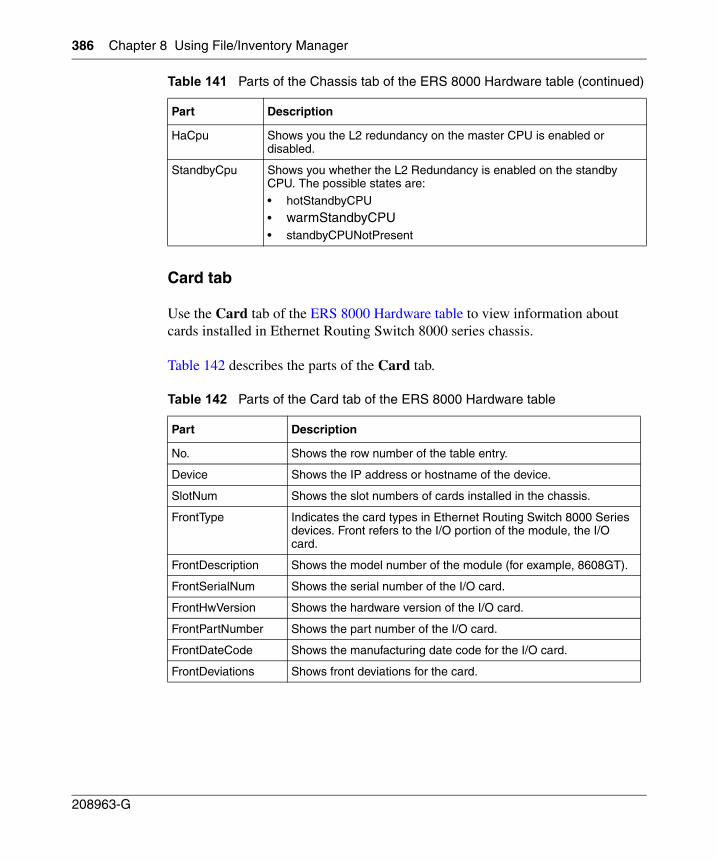
386 Chapter 8 Using File/Inventory Manager
208963-G
Card tab
Use the Card tab of the ERS 8000 Hardware table to view information about cards installed in Ethernet Routing Switch 8000 series chassis.
Table 142 describes the parts of the Card tab.
HaCpu Shows you the L2 redundancy on the master CPU is enabled or disabled.
StandbyCpu Shows you whether the L2 Redundancy is enabled on the standby CPU. The possible states are:
• hotStandbyCPU
• warmStandbyCPU • standbyCPUNotPresent
Table 142 Parts of the Card tab of the ERS 8000 Hardware table
Part Description
No. Shows the row number of the table entry.
Device Shows the IP address or hostname of the device.
SlotNum Shows the slot numbers of cards installed in the chassis.
FrontType Indicates the card types in Ethernet Routing Switch 8000 Series devices. Front refers to the I/O portion of the module, the I/O card.
FrontDescription Shows the model number of the module (for example, 8608GT).
FrontSerialNum Shows the serial number of the I/O card.
FrontHwVersion Shows the hardware version of the I/O card.
FrontPartNumber Shows the part number of the I/O card.
FrontDateCode Shows the manufacturing date code for the I/O card.
FrontDeviations Shows front deviations for the card.
Table 141 Parts of the Chassis tab of the ERS 8000 Hardware table (continued)
Part Description
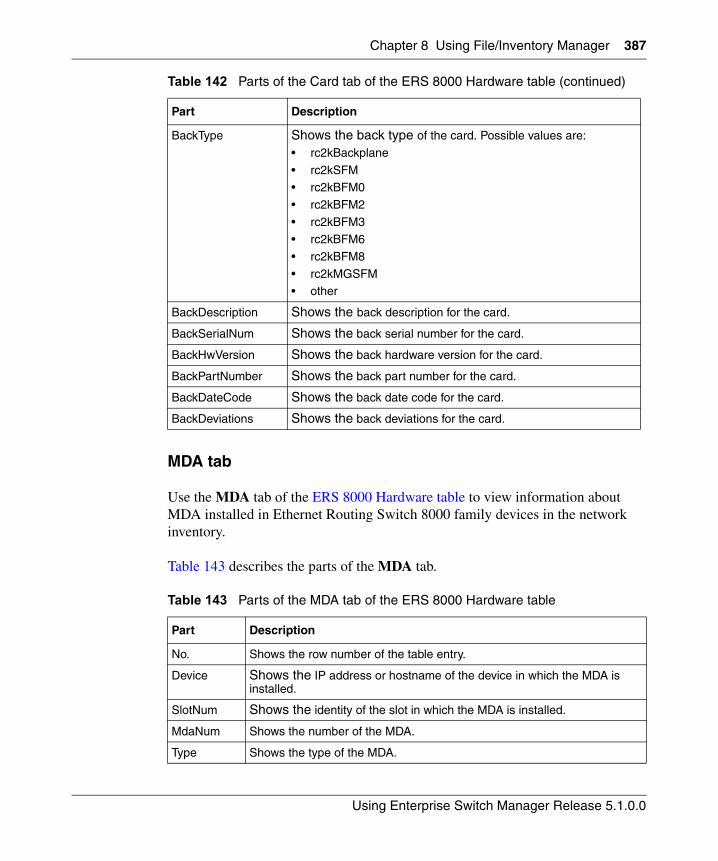
Chapter 8 Using File/Inventory Manager 387
Using Enterprise Switch Manager Release 5.1.0.0
MDA tab
Use the MDA tab of the ERS 8000 Hardware table to view information about MDA installed in Ethernet Routing Switch 8000 family devices in the network inventory.
Table 143 describes the parts of the MDA tab.
BackType Shows the back type of the card. Possible values are:
• rc2kBackplane
• rc2kSFM• rc2kBFM0
• rc2kBFM2
• rc2kBFM3• rc2kBFM6
• rc2kBFM8
• rc2kMGSFM• other
BackDescription Shows the back description for the card.
BackSerialNum Shows the back serial number for the card.
BackHwVersion Shows the back hardware version for the card.
BackPartNumber Shows the back part number for the card.
BackDateCode Shows the back date code for the card.
BackDeviations Shows the back deviations for the card.
Table 143 Parts of the MDA tab of the ERS 8000 Hardware table
Part Description
No. Shows the row number of the table entry.
Device Shows the IP address or hostname of the device in which the MDA is installed.
SlotNum Shows the identity of the slot in which the MDA is installed.
MdaNum Shows the number of the MDA.
Type Shows the type of the MDA.
Table 142 Parts of the Card tab of the ERS 8000 Hardware table (continued)
Part Description
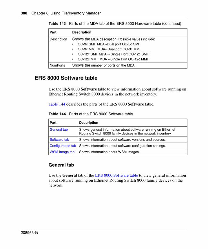
388 Chapter 8 Using File/Inventory Manager
208963-G
ERS 8000 Software table
Use the ERS 8000 Software table to view information about software running on Ethernet Routing Switch 8000 devices in the network inventory.
Table 144 describes the parts of the ERS 8000 Software table.
General tab
Use the General tab of the ERS 8000 Software table to view general information about software running on Ethernet Routing Switch 8000 family devices on the network.
Description Shows the MDA description. Possible values include:
• OC-3c SMF MDA--Dual port OC-3c SMF
• OC-3c MMF MDA--Dual port OC-3c MMF • OC-12c SMF MDA -- Single Port OC-12c SMF
• OC-12c MMF MDA --Single Port OC-12c MMF
NumPorts Shows the number of ports on the MDA.
Table 144 Parts of the ERS 8000 Software table
Part Description
General tab Shows general information about software running on Ethernet Routing Switch 8000 family devices in the network inventory.
Software tab Shows information about software versions and sources.
Configuration tab Shows information about software configuration settings.
WSM Image tab Shows information about WSM images.
Table 143 Parts of the MDA tab of the ERS 8000 Hardware table (continued)
Part Description
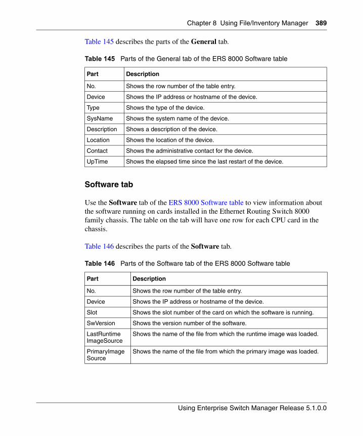
Chapter 8 Using File/Inventory Manager 389
Using Enterprise Switch Manager Release 5.1.0.0
Table 145 describes the parts of the General tab.
Software tab
Use the Software tab of the ERS 8000 Software table to view information about the software running on cards installed in the Ethernet Routing Switch 8000 family chassis. The table on the tab will have one row for each CPU card in the chassis.
Table 146 describes the parts of the Software tab.
Table 145 Parts of the General tab of the ERS 8000 Software table
Part Description
No. Shows the row number of the table entry.
Device Shows the IP address or hostname of the device.
Type Shows the type of the device.
SysName Shows the system name of the device.
Description Shows a description of the device.
Location Shows the location of the device.
Contact Shows the administrative contact for the device.
UpTime Shows the elapsed time since the last restart of the device.
Table 146 Parts of the Software tab of the ERS 8000 Software table
Part Description
No. Shows the row number of the table entry.
Device Shows the IP address or hostname of the device.
Slot Shows the slot number of the card on which the software is running.
SwVersion Shows the version number of the software.
LastRuntimeImageSource
Shows the name of the file from which the runtime image was loaded.
PrimaryImageSource
Shows the name of the file from which the primary image was loaded.
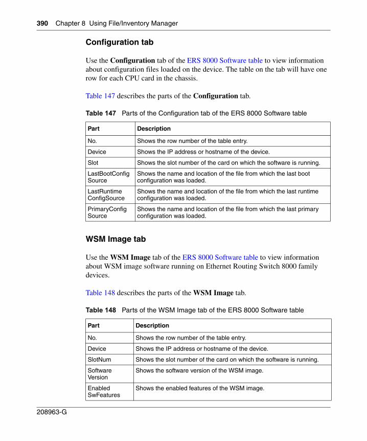
390 Chapter 8 Using File/Inventory Manager
208963-G
Configuration tab
Use the Configuration tab of the ERS 8000 Software table to view information about configuration files loaded on the device. The table on the tab will have one row for each CPU card in the chassis.
Table 147 describes the parts of the Configuration tab.
WSM Image tab
Use the WSM Image tab of the ERS 8000 Software table to view information about WSM image software running on Ethernet Routing Switch 8000 family devices.
Table 148 describes the parts of the WSM Image tab.
Table 147 Parts of the Configuration tab of the ERS 8000 Software table
Part Description
No. Shows the row number of the table entry.
Device Shows the IP address or hostname of the device.
Slot Shows the slot number of the card on which the software is running.
LastBootConfigSource
Shows the name and location of the file from which the last boot configuration was loaded.
LastRuntimeConfigSource
Shows the name and location of the file from which the last runtime configuration was loaded.
PrimaryConfigSource
Shows the name and location of the file from which the last primary configuration was loaded.
Table 148 Parts of the WSM Image tab of the ERS 8000 Software table
Part Description
No. Shows the row number of the table entry.
Device Shows the IP address or hostname of the device.
SlotNum Shows the slot number of the card on which the software is running.
SoftwareVersion
Shows the software version of the WSM image.
EnabledSwFeatures
Shows the enabled features of the WSM image.
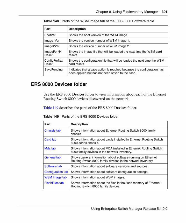
Chapter 8 Using File/Inventory Manager 391
Using Enterprise Switch Manager Release 5.1.0.0
ERS 8000 Devices folder
Use the ERS 8000 Devices folder to view information about each of the Ethernet Routing Switch 8000 devices discovered on the network.
Table 149 describes the parts of the ERS 8000 Devices folder.
BootVer Shows the boot version of the WSM image.
Image1Ver Shows the version number of WSM image 1.
Image2Ver Shows the version number of WSM image 2.
ImageForNxtReset
Shows the image file that will be loaded the next time the WSM card resets.
ConfigForNxtReset
Shows the configuration file that will be loaded the next time the WSM card resets.
SavePending Indicates that a save action is required because the configuration has been applied but has not been saved to the flash.
Table 149 Parts of the ERS 8000 Devices folder
Part Description
Chassis tab Shows information about Ethernet Routing Switch 8000 family chassis.
Card tab Shows information about cards installed in Ethernet Routing Switch 8000 series chassis.
Mda tab Shows information about MDA installed in Ethernet Routing Switch 8000 family devices in the network inventory.
General tab Shows general information about software running on Ethernet Routing Switch 8000 family devices in the network inventory.
Software tab Shows information about software versions and sources.
Configuration tab Shows information about software configuration settings.
WSM Image tab Shows information about WSM images.
FlashFiles tab Shows information about the files in the flash memory of Ethernet Routing Switch 8000 family devices.
Table 148 Parts of the WSM Image tab of the ERS 8000 Software table
Part Description
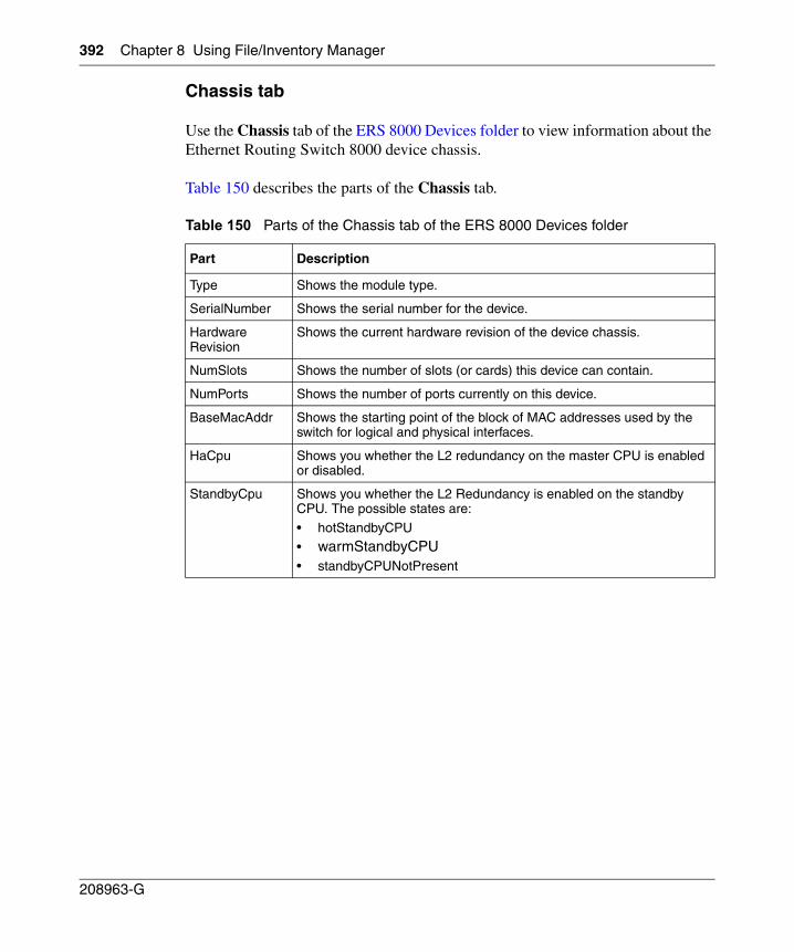
392 Chapter 8 Using File/Inventory Manager
208963-G
Chassis tab
Use the Chassis tab of the ERS 8000 Devices folder to view information about the Ethernet Routing Switch 8000 device chassis.
Table 150 describes the parts of the Chassis tab.
Table 150 Parts of the Chassis tab of the ERS 8000 Devices folder
Part Description
Type Shows the module type.
SerialNumber Shows the serial number for the device.
HardwareRevision
Shows the current hardware revision of the device chassis.
NumSlots Shows the number of slots (or cards) this device can contain.
NumPorts Shows the number of ports currently on this device.
BaseMacAddr Shows the starting point of the block of MAC addresses used by the switch for logical and physical interfaces.
HaCpu Shows you whether the L2 redundancy on the master CPU is enabled or disabled.
StandbyCpu Shows you whether the L2 Redundancy is enabled on the standby CPU. The possible states are:
• hotStandbyCPU • warmStandbyCPU
• standbyCPUNotPresent
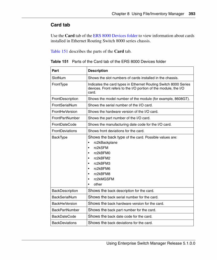
Chapter 8 Using File/Inventory Manager 393
Using Enterprise Switch Manager Release 5.1.0.0
Card tab
Use the Card tab of the ERS 8000 Devices folder to view information about cards installed in Ethernet Routing Switch 8000 series chassis.
Table 151 describes the parts of the Card tab.
Table 151 Parts of the Card tab of the ERS 8000 Devices folder
Part Description
SlotNum Shows the slot numbers of cards installed in the chassis.
FrontType Indicates the card types in Ethernet Routing Switch 8000 Series devices. Front refers to the I/O portion of the module, the I/O card.
FrontDescription Shows the model number of the module (for example, 8608GT).
FrontSerialNum Shows the serial number of the I/O card.
FrontHwVersion Shows the hardware version of the I/O card.
FrontPartNumber Shows the part number of the I/O card.
FrontDateCode Shows the manufacturing date code for the I/O card.
FrontDeviations Shows front deviations for the card.
BackType Shows the back type of the card. Possible values are:
• rc2kBackplane
• rc2kSFM• rc2kBFM0
• rc2kBFM2
• rc2kBFM3• rc2kBFM6
• rc2kBFM8
• rc2kMGSFM• other
BackDescription Shows the back description for the card.
BackSerialNum Shows the back serial number for the card.
BackHwVersion Shows the back hardware version for the card.
BackPartNumber Shows the back part number for the card.
BackDateCode Shows the back date code for the card.
BackDeviations Shows the back deviations for the card.
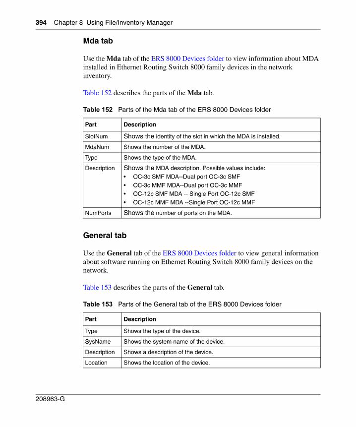
394 Chapter 8 Using File/Inventory Manager
208963-G
Mda tab
Use the Mda tab of the ERS 8000 Devices folder to view information about MDA installed in Ethernet Routing Switch 8000 family devices in the network inventory.
Table 152 describes the parts of the Mda tab.
General tab
Use the General tab of the ERS 8000 Devices folder to view general information about software running on Ethernet Routing Switch 8000 family devices on the network.
Table 153 describes the parts of the General tab.
Table 152 Parts of the Mda tab of the ERS 8000 Devices folder
Part Description
SlotNum Shows the identity of the slot in which the MDA is installed.
MdaNum Shows the number of the MDA.
Type Shows the type of the MDA.
Description Shows the MDA description. Possible values include:
• OC-3c SMF MDA--Dual port OC-3c SMF
• OC-3c MMF MDA--Dual port OC-3c MMF • OC-12c SMF MDA -- Single Port OC-12c SMF
• OC-12c MMF MDA --Single Port OC-12c MMF
NumPorts Shows the number of ports on the MDA.
Table 153 Parts of the General tab of the ERS 8000 Devices folder
Part Description
Type Shows the type of the device.
SysName Shows the system name of the device.
Description Shows a description of the device.
Location Shows the location of the device.
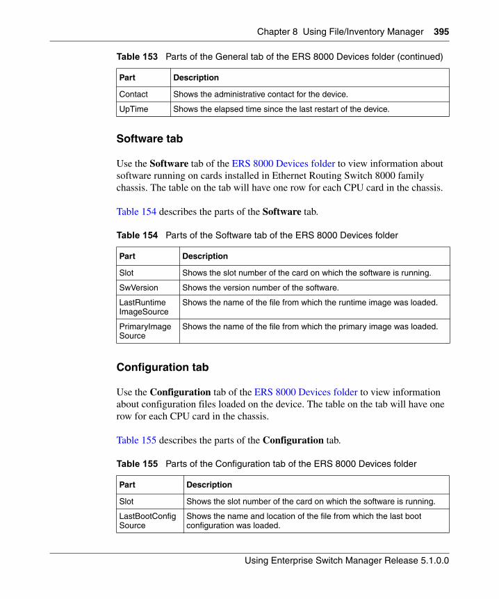
Chapter 8 Using File/Inventory Manager 395
Using Enterprise Switch Manager Release 5.1.0.0
Software tab
Use the Software tab of the ERS 8000 Devices folder to view information about software running on cards installed in Ethernet Routing Switch 8000 family chassis. The table on the tab will have one row for each CPU card in the chassis.
Table 154 describes the parts of the Software tab.
Configuration tab
Use the Configuration tab of the ERS 8000 Devices folder to view information about configuration files loaded on the device. The table on the tab will have one row for each CPU card in the chassis.
Table 155 describes the parts of the Configuration tab.
Contact Shows the administrative contact for the device.
UpTime Shows the elapsed time since the last restart of the device.
Table 154 Parts of the Software tab of the ERS 8000 Devices folder
Part Description
Slot Shows the slot number of the card on which the software is running.
SwVersion Shows the version number of the software.
LastRuntimeImageSource
Shows the name of the file from which the runtime image was loaded.
PrimaryImageSource
Shows the name of the file from which the primary image was loaded.
Table 155 Parts of the Configuration tab of the ERS 8000 Devices folder
Part Description
Slot Shows the slot number of the card on which the software is running.
LastBootConfigSource
Shows the name and location of the file from which the last boot configuration was loaded.
Table 153 Parts of the General tab of the ERS 8000 Devices folder (continued)
Part Description
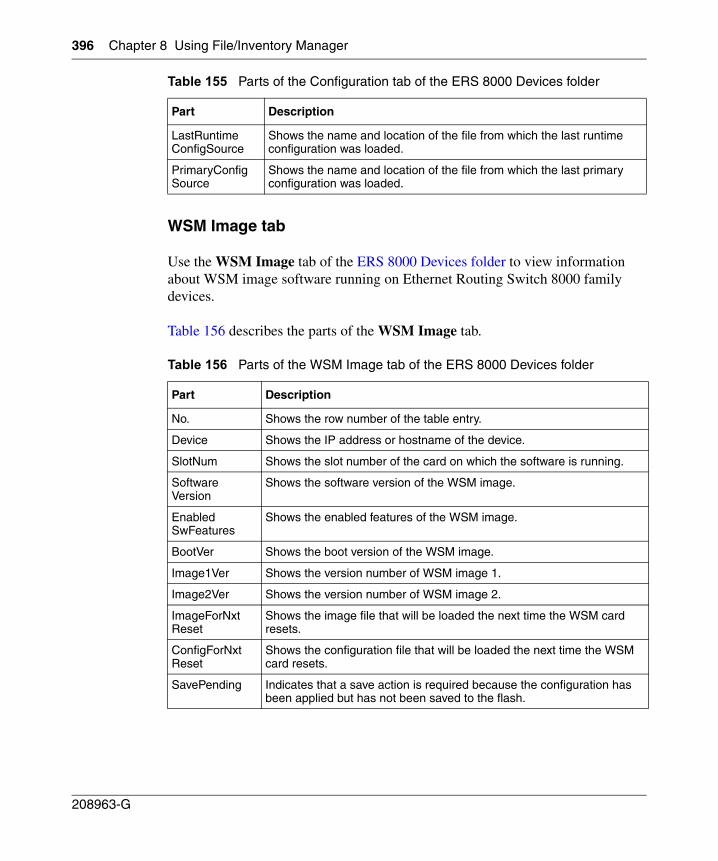
396 Chapter 8 Using File/Inventory Manager
208963-G
WSM Image tab
Use the WSM Image tab of the ERS 8000 Devices folder to view information about WSM image software running on Ethernet Routing Switch 8000 family devices.
Table 156 describes the parts of the WSM Image tab.
LastRuntimeConfigSource
Shows the name and location of the file from which the last runtime configuration was loaded.
PrimaryConfigSource
Shows the name and location of the file from which the last primary configuration was loaded.
Table 156 Parts of the WSM Image tab of the ERS 8000 Devices folder
Part Description
No. Shows the row number of the table entry.
Device Shows the IP address or hostname of the device.
SlotNum Shows the slot number of the card on which the software is running.
SoftwareVersion
Shows the software version of the WSM image.
EnabledSwFeatures
Shows the enabled features of the WSM image.
BootVer Shows the boot version of the WSM image.
Image1Ver Shows the version number of WSM image 1.
Image2Ver Shows the version number of WSM image 2.
ImageForNxtReset
Shows the image file that will be loaded the next time the WSM card resets.
ConfigForNxtReset
Shows the configuration file that will be loaded the next time the WSM card resets.
SavePending Indicates that a save action is required because the configuration has been applied but has not been saved to the flash.
Table 155 Parts of the Configuration tab of the ERS 8000 Devices folder
Part Description
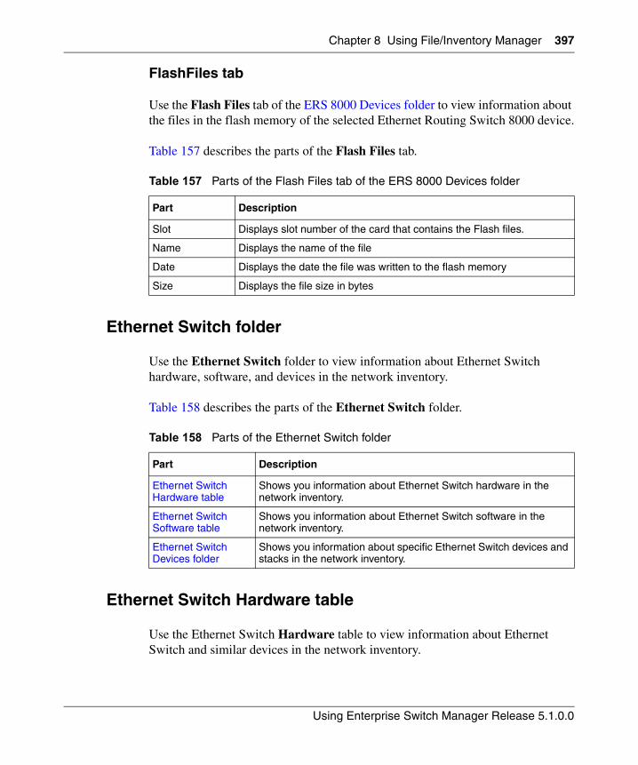
Chapter 8 Using File/Inventory Manager 397
Using Enterprise Switch Manager Release 5.1.0.0
FlashFiles tab
Use the Flash Files tab of the ERS 8000 Devices folder to view information about the files in the flash memory of the selected Ethernet Routing Switch 8000 device.
Table 157 describes the parts of the Flash Files tab.
Ethernet Switch folder
Use the Ethernet Switch folder to view information about Ethernet Switch hardware, software, and devices in the network inventory.
Table 158 describes the parts of the Ethernet Switch folder.
Ethernet Switch Hardware table
Use the Ethernet Switch Hardware table to view information about Ethernet Switch and similar devices in the network inventory.
Table 157 Parts of the Flash Files tab of the ERS 8000 Devices folder
Part Description
Slot Displays slot number of the card that contains the Flash files.
Name Displays the name of the file
Date Displays the date the file was written to the flash memory
Size Displays the file size in bytes
Table 158 Parts of the Ethernet Switch folder
Part Description
Ethernet Switch Hardware table
Shows you information about Ethernet Switch hardware in the network inventory.
Ethernet Switch Software table
Shows you information about Ethernet Switch software in the network inventory.
Ethernet Switch Devices folder
Shows you information about specific Ethernet Switch devices and stacks in the network inventory.
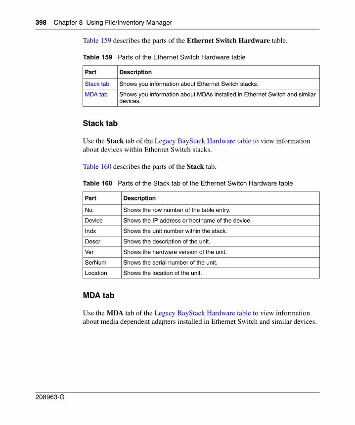
398 Chapter 8 Using File/Inventory Manager
208963-G
Table 159 describes the parts of the Ethernet Switch Hardware table.
Stack tab
Use the Stack tab of the Legacy BayStack Hardware table to view information about devices within Ethernet Switch stacks.
Table 160 describes the parts of the Stack tab.
MDA tab
Use the MDA tab of the Legacy BayStack Hardware table to view information about media dependent adapters installed in Ethernet Switch and similar devices.
Table 159 Parts of the Ethernet Switch Hardware table
Part Description
Stack tab Shows you information about Ethernet Switch stacks.
MDA tab Shows you information about MDAs installed in Ethernet Switch and similar devices.
Table 160 Parts of the Stack tab of the Ethernet Switch Hardware table
Part Description
No. Shows the row number of the table entry.
Device Shows the IP address or hostname of the device.
Indx Shows the unit number within the stack.
Descr Shows the description of the unit.
Ver Shows the hardware version of the unit.
SerNum Shows the serial number of the unit.
Location Shows the location of the unit.
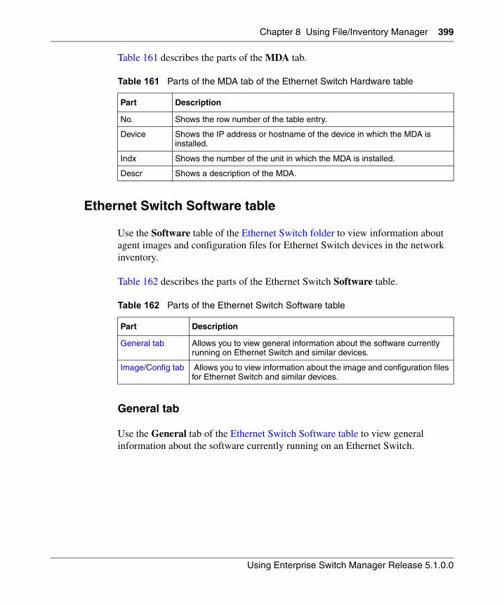
Chapter 8 Using File/Inventory Manager 399
Using Enterprise Switch Manager Release 5.1.0.0
Table 161 describes the parts of the MDA tab.
Ethernet Switch Software table
Use the Software table of the Ethernet Switch folder to view information about agent images and configuration files for Ethernet Switch devices in the network inventory.
Table 162 describes the parts of the Ethernet Switch Software table.
General tab
Use the General tab of the Ethernet Switch Software table to view general information about the software currently running on an Ethernet Switch.
Table 161 Parts of the MDA tab of the Ethernet Switch Hardware table
Part Description
No. Shows the row number of the table entry.
Device Shows the IP address or hostname of the device in which the MDA is installed.
Indx Shows the number of the unit in which the MDA is installed.
Descr Shows a description of the MDA.
Table 162 Parts of the Ethernet Switch Software table
Part Description
General tab Allows you to view general information about the software currently running on Ethernet Switch and similar devices.
Image/Config tab Allows you to view information about the image and configuration files for Ethernet Switch and similar devices.
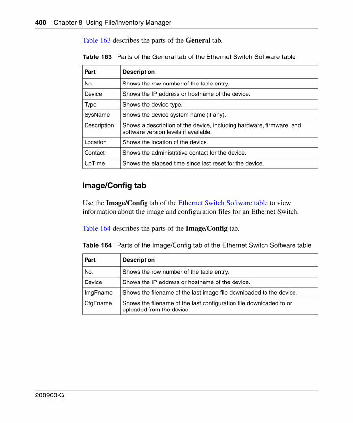
400 Chapter 8 Using File/Inventory Manager
208963-G
Table 163 describes the parts of the General tab.
Image/Config tab
Use the Image/Config tab of the Ethernet Switch Software table to view information about the image and configuration files for an Ethernet Switch.
Table 164 describes the parts of the Image/Config tab.
Table 163 Parts of the General tab of the Ethernet Switch Software table
Part Description
No. Shows the row number of the table entry.
Device Shows the IP address or hostname of the device.
Type Shows the device type.
SysName Shows the device system name (if any).
Description Shows a description of the device, including hardware, firmware, and software version levels if available.
Location Shows the location of the device.
Contact Shows the administrative contact for the device.
UpTime Shows the elapsed time since last reset for the device.
Table 164 Parts of the Image/Config tab of the Ethernet Switch Software table
Part Description
No. Shows the row number of the table entry.
Device Shows the IP address or hostname of the device.
ImgFname Shows the filename of the last image file downloaded to the device.
CfgFname Shows the filename of the last configuration file downloaded to or uploaded from the device.
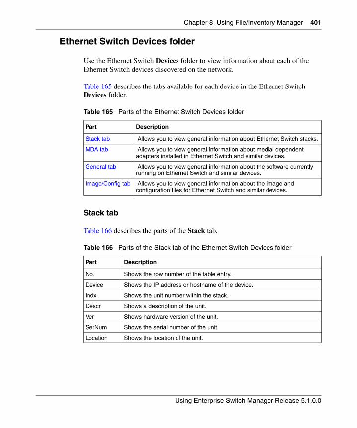
Chapter 8 Using File/Inventory Manager 401
Using Enterprise Switch Manager Release 5.1.0.0
Ethernet Switch Devices folder
Use the Ethernet Switch Devices folder to view information about each of the Ethernet Switch devices discovered on the network.
Table 165 describes the tabs available for each device in the Ethernet Switch Devices folder.
Stack tab
Table 166 describes the parts of the Stack tab.
Table 165 Parts of the Ethernet Switch Devices folder
Part Description
Stack tab Allows you to view general information about Ethernet Switch stacks.
MDA tab Allows you to view general information about medial dependent adapters installed in Ethernet Switch and similar devices.
General tab Allows you to view general information about the software currently running on Ethernet Switch and similar devices.
Image/Config tab Allows you to view general information about the image and configuration files for Ethernet Switch and similar devices.
Table 166 Parts of the Stack tab of the Ethernet Switch Devices folder
Part Description
No. Shows the row number of the table entry.
Device Shows the IP address or hostname of the device.
Indx Shows the unit number within the stack.
Descr Shows a description of the unit.
Ver Shows hardware version of the unit.
SerNum Shows the serial number of the unit.
Location Shows the location of the unit.
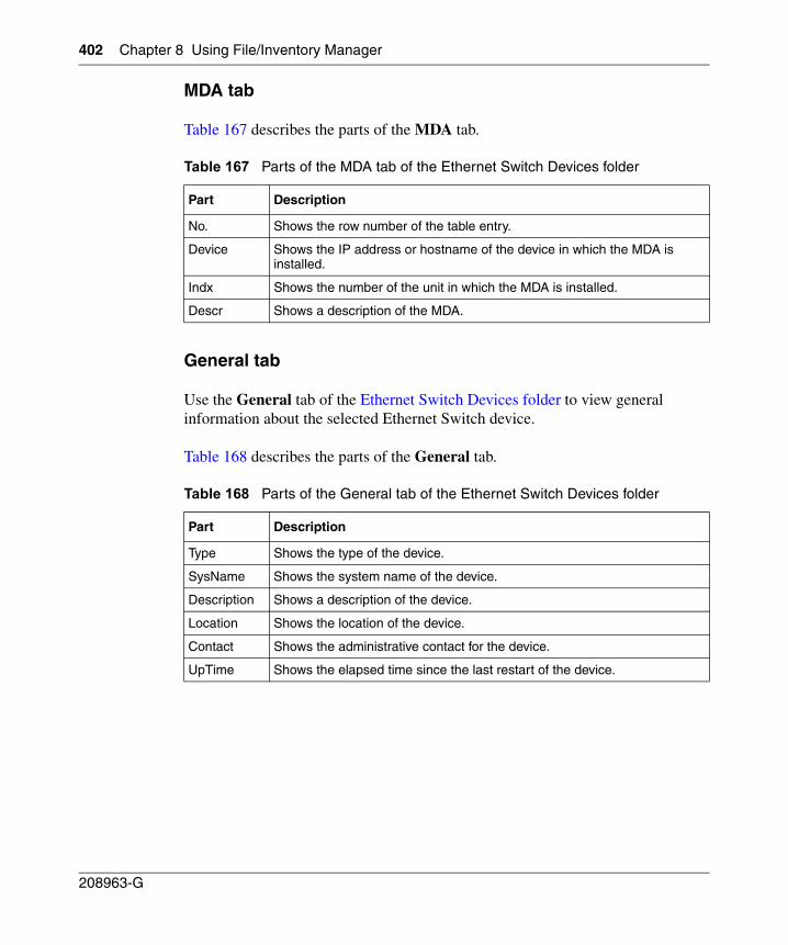
402 Chapter 8 Using File/Inventory Manager
208963-G
MDA tab
Table 167 describes the parts of the MDA tab.
General tab
Use the General tab of the Ethernet Switch Devices folder to view general information about the selected Ethernet Switch device.
Table 168 describes the parts of the General tab.
Table 167 Parts of the MDA tab of the Ethernet Switch Devices folder
Part Description
No. Shows the row number of the table entry.
Device Shows the IP address or hostname of the device in which the MDA is installed.
Indx Shows the number of the unit in which the MDA is installed.
Descr Shows a description of the MDA.
Table 168 Parts of the General tab of the Ethernet Switch Devices folder
Part Description
Type Shows the type of the device.
SysName Shows the system name of the device.
Description Shows a description of the device.
Location Shows the location of the device.
Contact Shows the administrative contact for the device.
UpTime Shows the elapsed time since the last restart of the device.
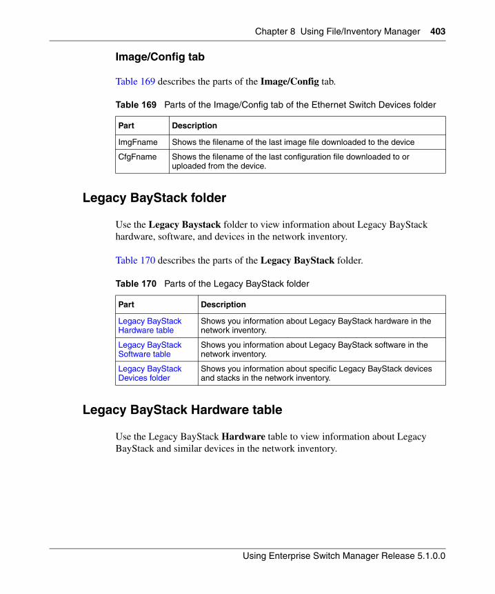
Chapter 8 Using File/Inventory Manager 403
Using Enterprise Switch Manager Release 5.1.0.0
Image/Config tab
Table 169 describes the parts of the Image/Config tab.
Legacy BayStack folder
Use the Legacy Baystack folder to view information about Legacy BayStack hardware, software, and devices in the network inventory.
Table 170 describes the parts of the Legacy BayStack folder.
Legacy BayStack Hardware table
Use the Legacy BayStack Hardware table to view information about Legacy BayStack and similar devices in the network inventory.
Table 169 Parts of the Image/Config tab of the Ethernet Switch Devices folder
Part Description
ImgFname Shows the filename of the last image file downloaded to the device
CfgFname Shows the filename of the last configuration file downloaded to or uploaded from the device.
Table 170 Parts of the Legacy BayStack folder
Part Description
Legacy BayStack Hardware table
Shows you information about Legacy BayStack hardware in the network inventory.
Legacy BayStack Software table
Shows you information about Legacy BayStack software in the network inventory.
Legacy BayStack Devices folder
Shows you information about specific Legacy BayStack devices and stacks in the network inventory.
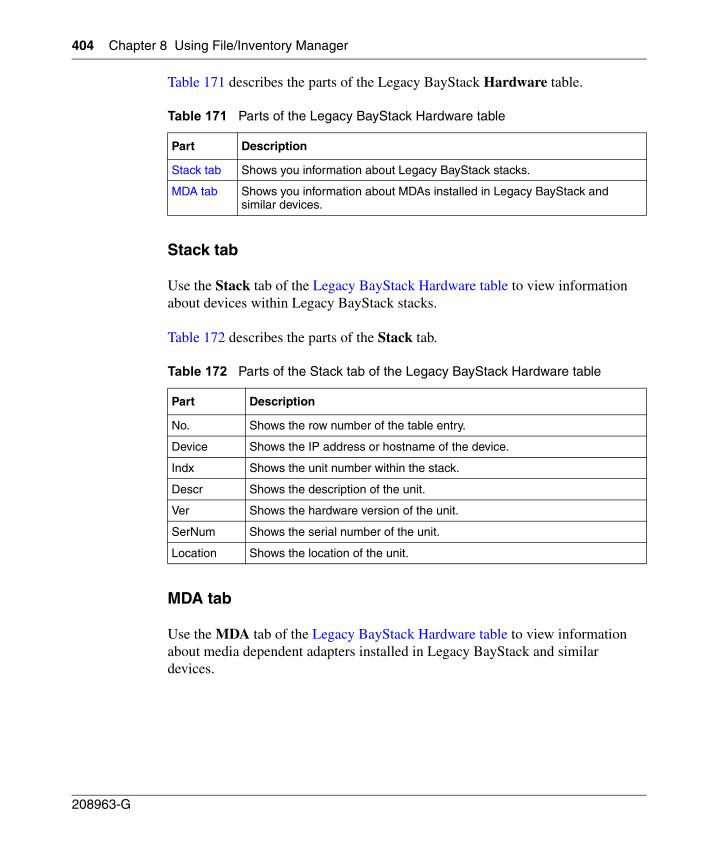
404 Chapter 8 Using File/Inventory Manager
208963-G
Table 171 describes the parts of the Legacy BayStack Hardware table.
Stack tab
Use the Stack tab of the Legacy BayStack Hardware table to view information about devices within Legacy BayStack stacks.
Table 172 describes the parts of the Stack tab.
MDA tab
Use the MDA tab of the Legacy BayStack Hardware table to view information about media dependent adapters installed in Legacy BayStack and similar devices.
Table 171 Parts of the Legacy BayStack Hardware table
Part Description
Stack tab Shows you information about Legacy BayStack stacks.
MDA tab Shows you information about MDAs installed in Legacy BayStack and similar devices.
Table 172 Parts of the Stack tab of the Legacy BayStack Hardware table
Part Description
No. Shows the row number of the table entry.
Device Shows the IP address or hostname of the device.
Indx Shows the unit number within the stack.
Descr Shows the description of the unit.
Ver Shows the hardware version of the unit.
SerNum Shows the serial number of the unit.
Location Shows the location of the unit.
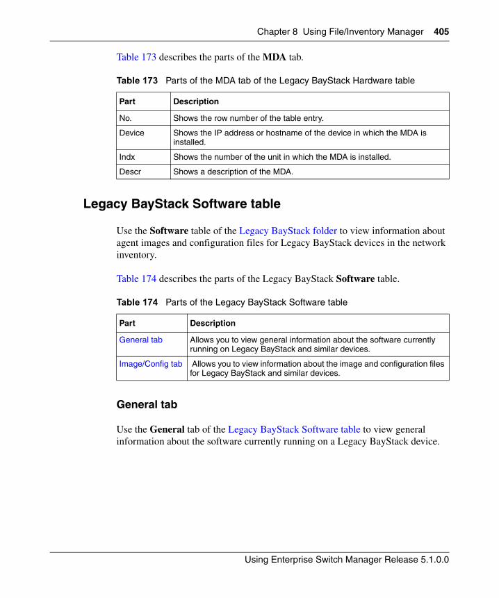
Chapter 8 Using File/Inventory Manager 405
Using Enterprise Switch Manager Release 5.1.0.0
Table 173 describes the parts of the MDA tab.
Legacy BayStack Software table
Use the Software table of the Legacy BayStack folder to view information about agent images and configuration files for Legacy BayStack devices in the network inventory.
Table 174 describes the parts of the Legacy BayStack Software table.
General tab
Use the General tab of the Legacy BayStack Software table to view general information about the software currently running on a Legacy BayStack device.
Table 173 Parts of the MDA tab of the Legacy BayStack Hardware table
Part Description
No. Shows the row number of the table entry.
Device Shows the IP address or hostname of the device in which the MDA is installed.
Indx Shows the number of the unit in which the MDA is installed.
Descr Shows a description of the MDA.
Table 174 Parts of the Legacy BayStack Software table
Part Description
General tab Allows you to view general information about the software currently running on Legacy BayStack and similar devices.
Image/Config tab Allows you to view information about the image and configuration files for Legacy BayStack and similar devices.
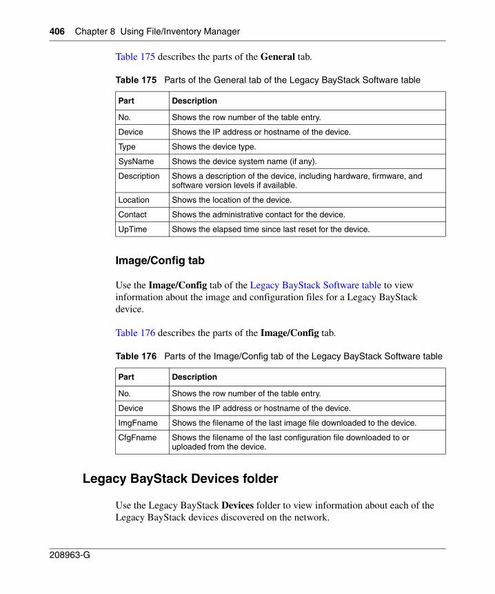
406 Chapter 8 Using File/Inventory Manager
208963-G
Table 175 describes the parts of the General tab.
Image/Config tab
Use the Image/Config tab of the Legacy BayStack Software table to view information about the image and configuration files for a Legacy BayStack device.
Table 176 describes the parts of the Image/Config tab.
Legacy BayStack Devices folder
Use the Legacy BayStack Devices folder to view information about each of the Legacy BayStack devices discovered on the network.
Table 175 Parts of the General tab of the Legacy BayStack Software table
Part Description
No. Shows the row number of the table entry.
Device Shows the IP address or hostname of the device.
Type Shows the device type.
SysName Shows the device system name (if any).
Description Shows a description of the device, including hardware, firmware, and software version levels if available.
Location Shows the location of the device.
Contact Shows the administrative contact for the device.
UpTime Shows the elapsed time since last reset for the device.
Table 176 Parts of the Image/Config tab of the Legacy BayStack Software table
Part Description
No. Shows the row number of the table entry.
Device Shows the IP address or hostname of the device.
ImgFname Shows the filename of the last image file downloaded to the device.
CfgFname Shows the filename of the last configuration file downloaded to or uploaded from the device.
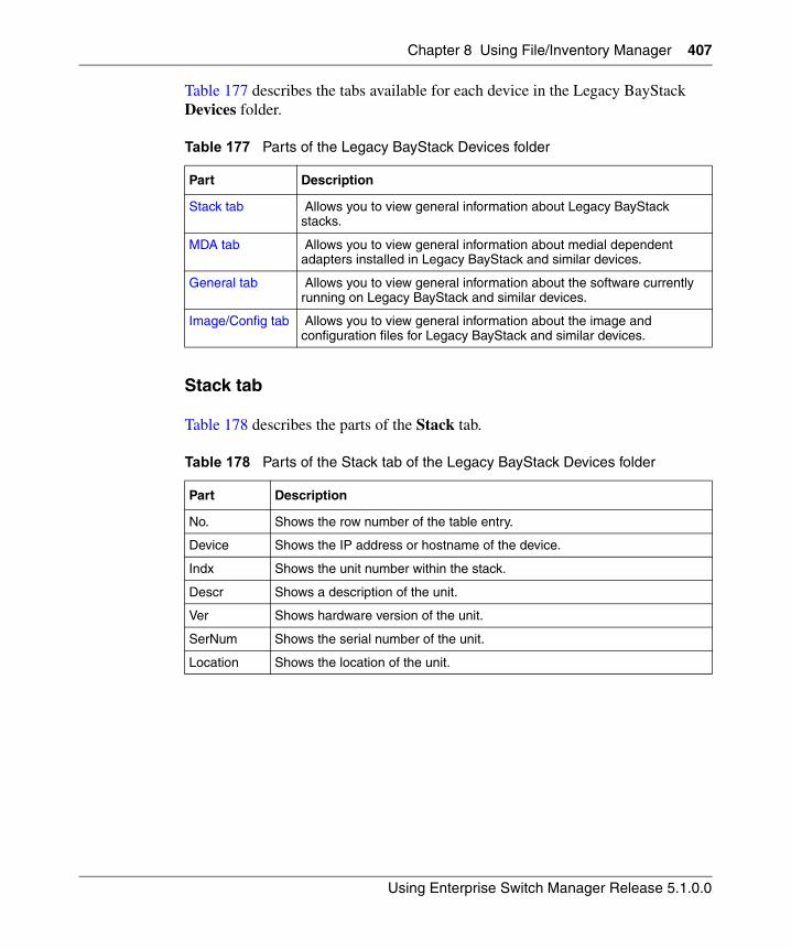
Chapter 8 Using File/Inventory Manager 407
Using Enterprise Switch Manager Release 5.1.0.0
Table 177 describes the tabs available for each device in the Legacy BayStack Devices folder.
Stack tab
Table 178 describes the parts of the Stack tab.
Table 177 Parts of the Legacy BayStack Devices folder
Part Description
Stack tab Allows you to view general information about Legacy BayStack stacks.
MDA tab Allows you to view general information about medial dependent adapters installed in Legacy BayStack and similar devices.
General tab Allows you to view general information about the software currently running on Legacy BayStack and similar devices.
Image/Config tab Allows you to view general information about the image and configuration files for Legacy BayStack and similar devices.
Table 178 Parts of the Stack tab of the Legacy BayStack Devices folder
Part Description
No. Shows the row number of the table entry.
Device Shows the IP address or hostname of the device.
Indx Shows the unit number within the stack.
Descr Shows a description of the unit.
Ver Shows hardware version of the unit.
SerNum Shows the serial number of the unit.
Location Shows the location of the unit.
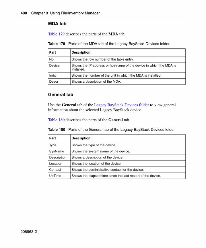
408 Chapter 8 Using File/Inventory Manager
208963-G
MDA tab
Table 179 describes the parts of the MDA tab.
General tab
Use the General tab of the Legacy BayStack Devices folder to view general information about the selected Legacy BayStack device.
Table 180 describes the parts of the General tab.
Table 179 Parts of the MDA tab of the Legacy BayStack Devices folder
Part Description
No. Shows the row number of the table entry.
Device Shows the IP address or hostname of the device in which the MDA is installed.
Indx Shows the number of the unit in which the MDA is installed.
Descr Shows a description of the MDA.
Table 180 Parts of the General tab of the Legacy BayStack Devices folder
Part Description
Type Shows the type of the device.
SysName Shows the system name of the device.
Description Shows a description of the device.
Location Shows the location of the device.
Contact Shows the administrative contact for the device.
UpTime Shows the elapsed time since the last restart of the device.
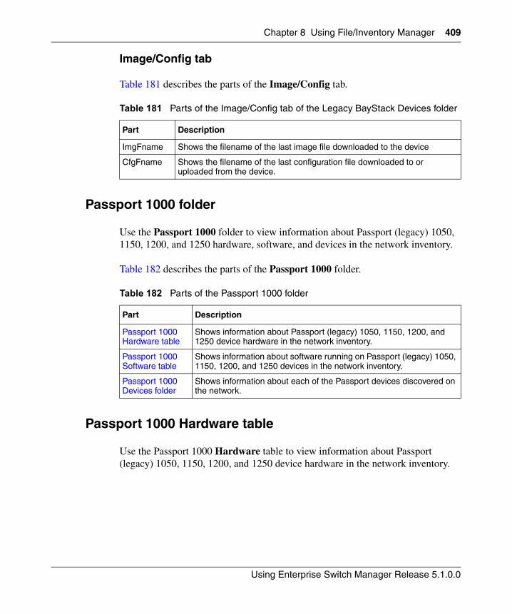
Chapter 8 Using File/Inventory Manager 409
Using Enterprise Switch Manager Release 5.1.0.0
Image/Config tab
Table 181 describes the parts of the Image/Config tab.
Passport 1000 folder
Use the Passport 1000 folder to view information about Passport (legacy) 1050, 1150, 1200, and 1250 hardware, software, and devices in the network inventory.
Table 182 describes the parts of the Passport 1000 folder.
Passport 1000 Hardware table
Use the Passport 1000 Hardware table to view information about Passport (legacy) 1050, 1150, 1200, and 1250 device hardware in the network inventory.
Table 181 Parts of the Image/Config tab of the Legacy BayStack Devices folder
Part Description
ImgFname Shows the filename of the last image file downloaded to the device
CfgFname Shows the filename of the last configuration file downloaded to or uploaded from the device.
Table 182 Parts of the Passport 1000 folder
Part Description
Passport 1000 Hardware table
Shows information about Passport (legacy) 1050, 1150, 1200, and 1250 device hardware in the network inventory.
Passport 1000 Software table
Shows information about software running on Passport (legacy) 1050, 1150, 1200, and 1250 devices in the network inventory.
Passport 1000 Devices folder
Shows information about each of the Passport devices discovered on the network.
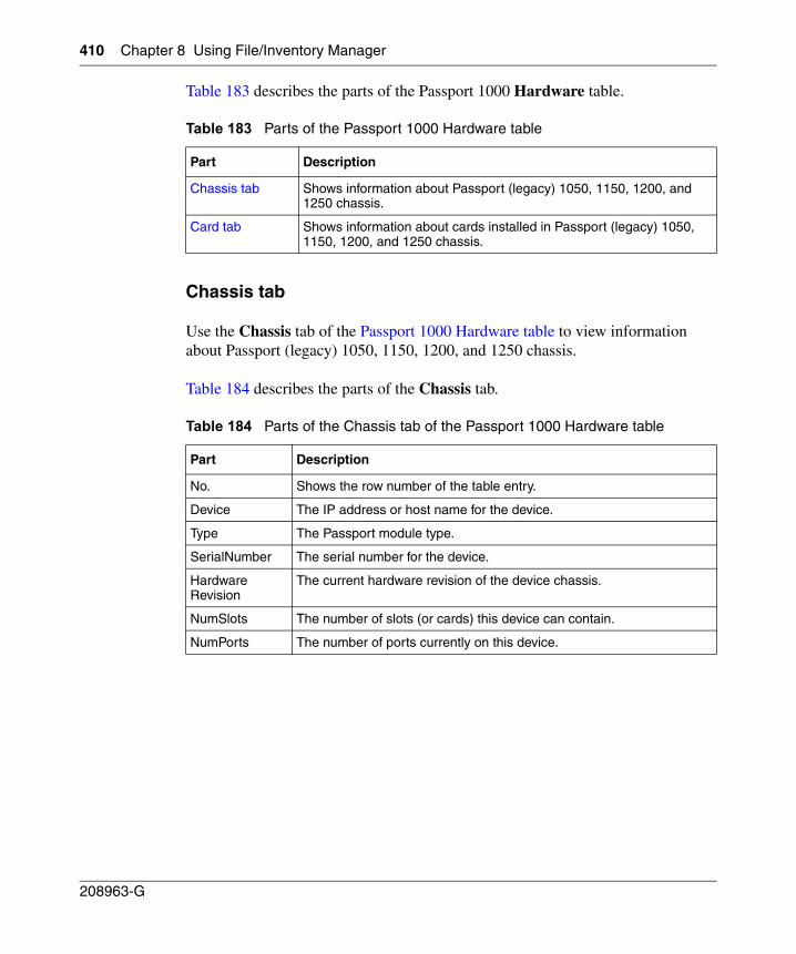
410 Chapter 8 Using File/Inventory Manager
208963-G
Table 183 describes the parts of the Passport 1000 Hardware table.
Chassis tab
Use the Chassis tab of the Passport 1000 Hardware table to view information about Passport (legacy) 1050, 1150, 1200, and 1250 chassis.
Table 184 describes the parts of the Chassis tab.
Table 183 Parts of the Passport 1000 Hardware table
Part Description
Chassis tab Shows information about Passport (legacy) 1050, 1150, 1200, and 1250 chassis.
Card tab Shows information about cards installed in Passport (legacy) 1050, 1150, 1200, and 1250 chassis.
Table 184 Parts of the Chassis tab of the Passport 1000 Hardware table
Part Description
No. Shows the row number of the table entry.
Device The IP address or host name for the device.
Type The Passport module type.
SerialNumber The serial number for the device.
HardwareRevision
The current hardware revision of the device chassis.
NumSlots The number of slots (or cards) this device can contain.
NumPorts The number of ports currently on this device.
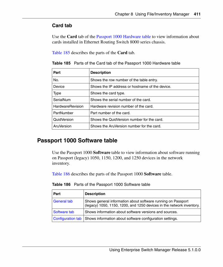
Chapter 8 Using File/Inventory Manager 411
Using Enterprise Switch Manager Release 5.1.0.0
Card tab
Use the Card tab of the Passport 1000 Hardware table to view information about cards installed in Ethernet Routing Switch 8000 series chassis.
Table 185 describes the parts of the Card tab.
Passport 1000 Software table
Use the Passport 1000 Software table to view information about software running on Passport (legacy) 1050, 1150, 1200, and 1250 devices in the network inventory.
Table 186 describes the parts of the Passport 1000 Software table.
Table 185 Parts of the Card tab of the Passport 1000 Hardware table
Part Description
No. Shows the row number of the table entry.
Device Shows the IP address or hostname of the device.
Type Shows the card type.
SerialNum Shows the serial number of the card.
HardwareRevision Hardware revision number of the card.
PartNumber Part number of the card.
QuidVersion Shows the QuidVersion number for the card.
AruVersion Shows the AruVersion number for the card.
Table 186 Parts of the Passport 1000 Software table
Part Description
General tab Shows general information about software running on Passport (legacy) 1050, 1150, 1200, and 1250 devices in the network inventory.
Software tab Shows information about software versions and sources.
Configuration tab Shows information about software configuration settings.
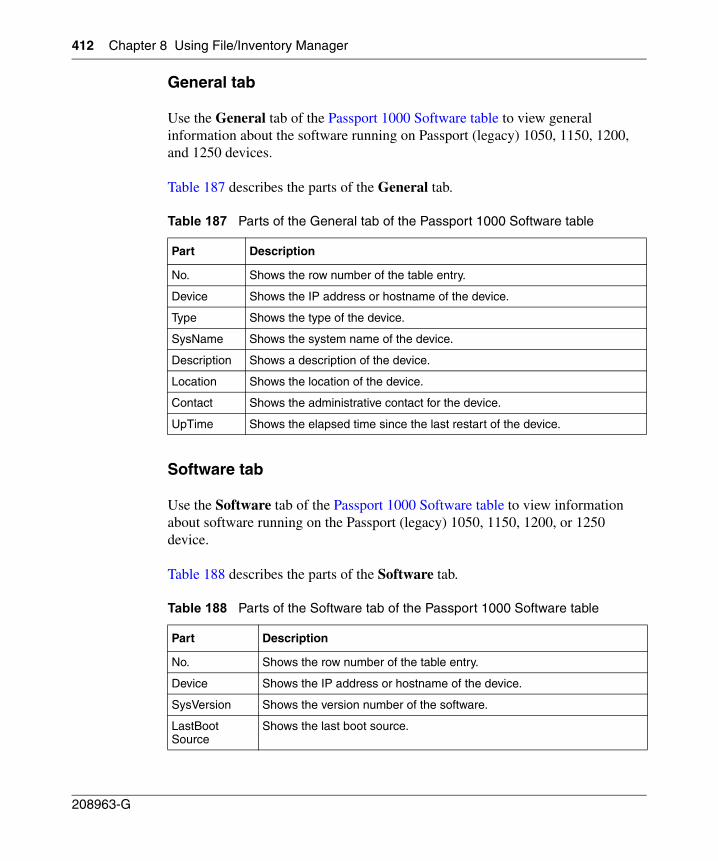
412 Chapter 8 Using File/Inventory Manager
208963-G
General tab
Use the General tab of the Passport 1000 Software table to view general information about the software running on Passport (legacy) 1050, 1150, 1200, and 1250 devices.
Table 187 describes the parts of the General tab.
Software tab
Use the Software tab of the Passport 1000 Software table to view information about software running on the Passport (legacy) 1050, 1150, 1200, or 1250 device.
Table 188 describes the parts of the Software tab.
Table 187 Parts of the General tab of the Passport 1000 Software table
Part Description
No. Shows the row number of the table entry.
Device Shows the IP address or hostname of the device.
Type Shows the type of the device.
SysName Shows the system name of the device.
Description Shows a description of the device.
Location Shows the location of the device.
Contact Shows the administrative contact for the device.
UpTime Shows the elapsed time since the last restart of the device.
Table 188 Parts of the Software tab of the Passport 1000 Software table
Part Description
No. Shows the row number of the table entry.
Device Shows the IP address or hostname of the device.
SysVersion Shows the version number of the software.
LastBootSource
Shows the last boot source.
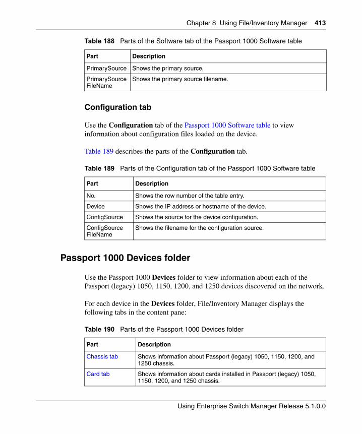
Chapter 8 Using File/Inventory Manager 413
Using Enterprise Switch Manager Release 5.1.0.0
Configuration tab
Use the Configuration tab of the Passport 1000 Software table to view information about configuration files loaded on the device.
Table 189 describes the parts of the Configuration tab.
Passport 1000 Devices folder
Use the Passport 1000 Devices folder to view information about each of the Passport (legacy) 1050, 1150, 1200, and 1250 devices discovered on the network.
For each device in the Devices folder, File/Inventory Manager displays the following tabs in the content pane:
PrimarySource Shows the primary source.
PrimarySourceFileName
Shows the primary source filename.
Table 189 Parts of the Configuration tab of the Passport 1000 Software table
Part Description
No. Shows the row number of the table entry.
Device Shows the IP address or hostname of the device.
ConfigSource Shows the source for the device configuration.
ConfigSourceFileName
Shows the filename for the configuration source.
Table 190 Parts of the Passport 1000 Devices folder
Part Description
Chassis tab Shows information about Passport (legacy) 1050, 1150, 1200, and 1250 chassis.
Card tab Shows information about cards installed in Passport (legacy) 1050, 1150, 1200, and 1250 chassis.
Table 188 Parts of the Software tab of the Passport 1000 Software table
Part Description
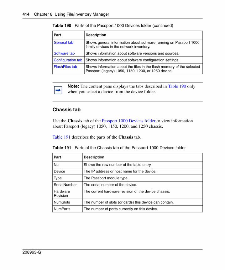
414 Chapter 8 Using File/Inventory Manager
208963-G
Chassis tab
Use the Chassis tab of the Passport 1000 Devices folder to view information about Passport (legacy) 1050, 1150, 1200, and 1250 chassis.
Table 191 describes the parts of the Chassis tab.
General tab Shows general information about software running on Passport 1000 family devices in the network inventory.
Software tab Shows information about software versions and sources.
Configuration tab Shows information about software configuration settings.
FlashFiles tab Shows information about the files in the flash memory of the selected Passport (legacy) 1050, 1150, 1200, or 1250 device.
Note: The content pane displays the tabs described in Table 190 only when you select a device from the device folder.
Table 191 Parts of the Chassis tab of the Passport 1000 Devices folder
Part Description
No. Shows the row number of the table entry.
Device The IP address or host name for the device.
Type The Passport module type.
SerialNumber The serial number of the device.
HardwareRevision
The current hardware revision of the device chassis.
NumSlots The number of slots (or cards) this device can contain.
NumPorts The number of ports currently on this device.
Table 190 Parts of the Passport 1000 Devices folder (continued)
Part Description
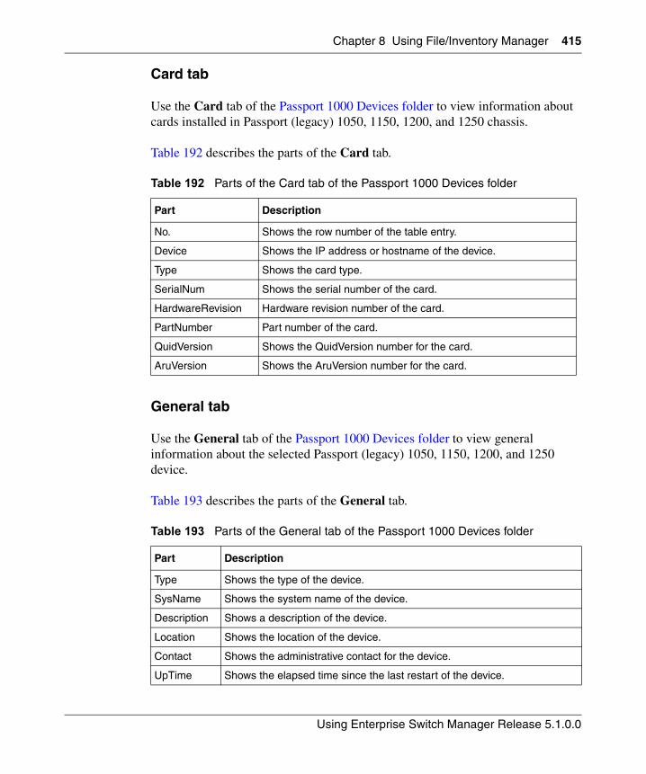
Chapter 8 Using File/Inventory Manager 415
Using Enterprise Switch Manager Release 5.1.0.0
Card tab
Use the Card tab of the Passport 1000 Devices folder to view information about cards installed in Passport (legacy) 1050, 1150, 1200, and 1250 chassis.
Table 192 describes the parts of the Card tab.
General tab
Use the General tab of the Passport 1000 Devices folder to view general information about the selected Passport (legacy) 1050, 1150, 1200, and 1250 device.
Table 193 describes the parts of the General tab.
Table 192 Parts of the Card tab of the Passport 1000 Devices folder
Part Description
No. Shows the row number of the table entry.
Device Shows the IP address or hostname of the device.
Type Shows the card type.
SerialNum Shows the serial number of the card.
HardwareRevision Hardware revision number of the card.
PartNumber Part number of the card.
QuidVersion Shows the QuidVersion number for the card.
AruVersion Shows the AruVersion number for the card.
Table 193 Parts of the General tab of the Passport 1000 Devices folder
Part Description
Type Shows the type of the device.
SysName Shows the system name of the device.
Description Shows a description of the device.
Location Shows the location of the device.
Contact Shows the administrative contact for the device.
UpTime Shows the elapsed time since the last restart of the device.
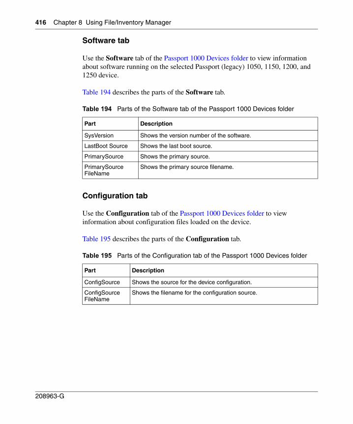
416 Chapter 8 Using File/Inventory Manager
208963-G
Software tab
Use the Software tab of the Passport 1000 Devices folder to view information about software running on the selected Passport (legacy) 1050, 1150, 1200, and 1250 device.
Table 194 describes the parts of the Software tab.
Configuration tab
Use the Configuration tab of the Passport 1000 Devices folder to view information about configuration files loaded on the device.
Table 195 describes the parts of the Configuration tab.
Table 194 Parts of the Software tab of the Passport 1000 Devices folder
Part Description
SysVersion Shows the version number of the software.
LastBoot Source Shows the last boot source.
PrimarySource Shows the primary source.
PrimarySourceFileName
Shows the primary source filename.
Table 195 Parts of the Configuration tab of the Passport 1000 Devices folder
Part Description
ConfigSource Shows the source for the device configuration.
ConfigSourceFileName
Shows the filename for the configuration source.
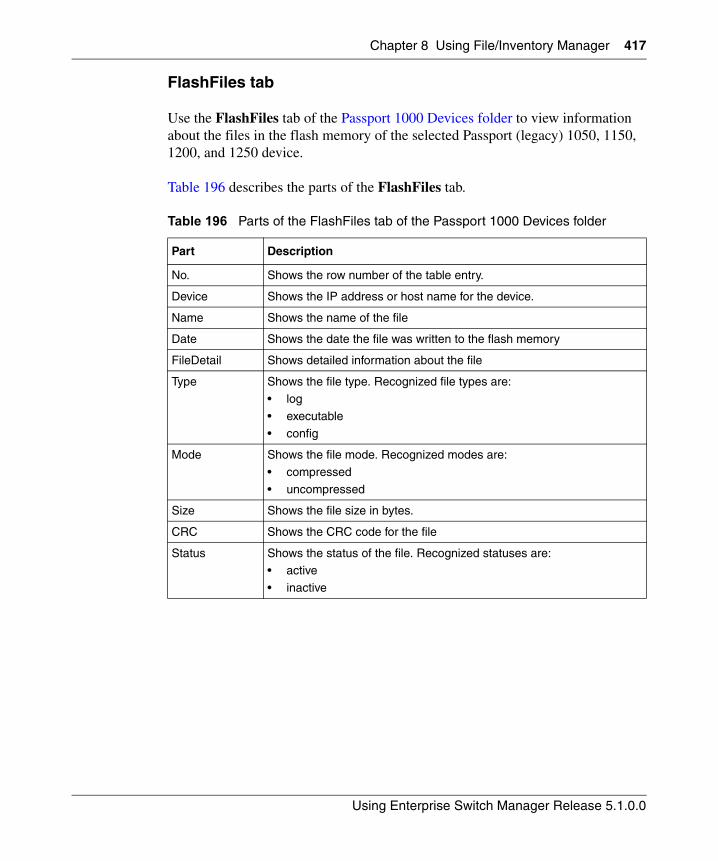
Chapter 8 Using File/Inventory Manager 417
Using Enterprise Switch Manager Release 5.1.0.0
FlashFiles tab
Use the FlashFiles tab of the Passport 1000 Devices folder to view information about the files in the flash memory of the selected Passport (legacy) 1050, 1150, 1200, and 1250 device.
Table 196 describes the parts of the FlashFiles tab.
Table 196 Parts of the FlashFiles tab of the Passport 1000 Devices folder
Part Description
No. Shows the row number of the table entry.
Device Shows the IP address or host name for the device.
Name Shows the name of the file
Date Shows the date the file was written to the flash memory
FileDetail Shows detailed information about the file
Type Shows the file type. Recognized file types are:• log
• executable
• config
Mode Shows the file mode. Recognized modes are:
• compressed
• uncompressed
Size Shows the file size in bytes.
CRC Shows the CRC code for the file
Status Shows the status of the file. Recognized statuses are:• active
• inactive
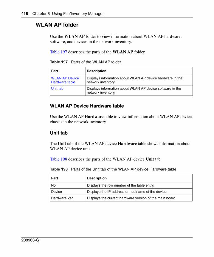
418 Chapter 8 Using File/Inventory Manager
208963-G
WLAN AP folder
Use the WLAN AP folder to view information about WLAN AP hardware, software, and devices in the network inventory.
Table 197 describes the parts of the WLAN AP folder.
WLAN AP Device Hardware table
Use the WLAN AP Hardware table to view information about WLAN AP device chassis in the network inventory.
Unit tab
The Unit tab of the WLAN AP device Hardware table shows information about WLAN AP device unit
Table 198 describes the parts of the WLAN AP device Unit tab.
Table 197 Parts of the WLAN AP folder
Part Description
WLAN AP Device Hardware table
Displays information about WLAN AP device hardware in the network inventory.
Unit tab Displays information about WLAN AP device software in the network inventory.
Table 198 Parts of the Unit tab of the WLAN AP device Hardware table
Part Description
No. Displays the row number of the table entry.
Device Displays the IP address or hostname of the device.
Hardware Ver Displays the current hardware version of the main board
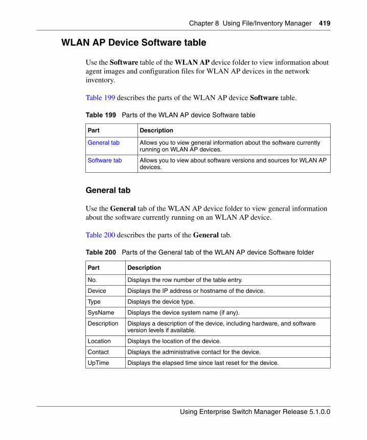
Chapter 8 Using File/Inventory Manager 419
Using Enterprise Switch Manager Release 5.1.0.0
WLAN AP Device Software table
Use the Software table of the WLAN AP device folder to view information about agent images and configuration files for WLAN AP devices in the network inventory.
Table 199 describes the parts of the WLAN AP device Software table.
General tab
Use the General tab of the WLAN AP device folder to view general information about the software currently running on an WLAN AP device.
Table 200 describes the parts of the General tab.
Table 199 Parts of the WLAN AP device Software table
Part Description
General tab Allows you to view general information about the software currently running on WLAN AP devices.
Software tab Allows you to view about software versions and sources for WLAN AP devices.
Table 200 Parts of the General tab of the WLAN AP device Software folder
Part Description
No. Displays the row number of the table entry.
Device Displays the IP address or hostname of the device.
Type Displays the device type.
SysName Displays the device system name (if any).
Description Displays a description of the device, including hardware, and software version levels if available.
Location Displays the location of the device.
Contact Displays the administrative contact for the device.
UpTime Displays the elapsed time since last reset for the device.
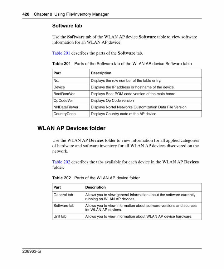
420 Chapter 8 Using File/Inventory Manager
208963-G
Software tab
Use the Software tab of the WLAN AP device Software table to view software information for an WLAN AP device.
Table 201 describes the parts of the Software tab.
WLAN AP Devices folder
Use the WLAN AP Devices folder to view information for all applied categories of hardware and software inventory for all WLAN AP devices discovered on the network.
Table 202 describes the tabs available for each device in the WLAN AP Devices folder.
Table 201 Parts of the Software tab of the WLAN AP device Software table
Part Description
No. Displays the row number of the table entry.
Device Displays the IP address or hostname of the device.
BootRomVer Displays Boot ROM code version of the main board
OpCodeVer Displays Op Code version
NNDataFileVer Displays Nortel Networks Customization Data File Version
CountryCode Displays Country code of the AP device
Table 202 Parts of the WLAN AP device folder
Part Description
General tab Allows you to view general information about the software currently running on WLAN AP devices.
Software tab Allows you to view information about software versions and sources for WLAN AP devices.
Unit tab Allows you to view information about WLAN AP device hardware.
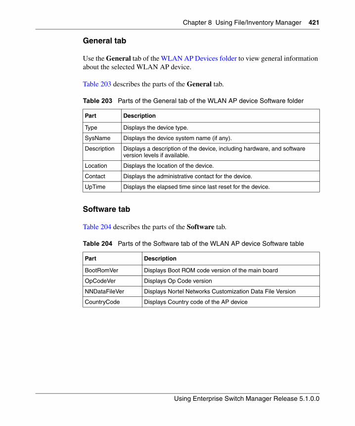
Chapter 8 Using File/Inventory Manager 421
Using Enterprise Switch Manager Release 5.1.0.0
General tab
Use the General tab of the WLAN AP Devices folder to view general information about the selected WLAN AP device.
Table 203 describes the parts of the General tab.
Software tab
Table 204 describes the parts of the Software tab.
Table 203 Parts of the General tab of the WLAN AP device Software folder
Part Description
Type Displays the device type.
SysName Displays the device system name (if any).
Description Displays a description of the device, including hardware, and software version levels if available.
Location Displays the location of the device.
Contact Displays the administrative contact for the device.
UpTime Displays the elapsed time since last reset for the device.
Table 204 Parts of the Software tab of the WLAN AP device Software table
Part Description
BootRomVer Displays Boot ROM code version of the main board
OpCodeVer Displays Op Code version
NNDataFileVer Displays Nortel Networks Customization Data File Version
CountryCode Displays Country code of the AP device
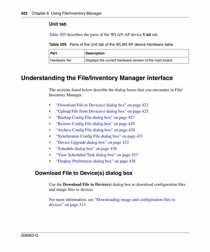
422 Chapter 8 Using File/Inventory Manager
208963-G
Unit tab
Table 205 describes the parts of the WLAN AP device Unit tab.
Understanding the File/Inventory Manager interface
The sections listed below describe the dialog boxes that you encounter in File/Inventory Manager.
• “Download File to Device(s) dialog box” on page 422
• “Upload File from Device(s) dialog box” on page 425
• “Backup Config File dialog box” on page 427
• “Restore Config File dialog box” on page 429
• “Archive Config File dialog box” on page 430
• “Synchronize Config File dialog box” on page 431
• “Device Upgrade dialog box” on page 432
• “Schedule dialog box” on page 436
• “View Scheduled Task dialog box” on page 437
• “Display Preferences dialog box” on page 438
Download File to Device(s) dialog box
Use the Download File to Device(s) dialog box to download configuration files and image files to devices
For more information, see “Downloading image and configuration files to devices” on page 313.
Table 205 Parts of the Unit tab of the WLAN AP device Hardware table
Part Description
Hardware Ver Displays the current hardware version of the main board
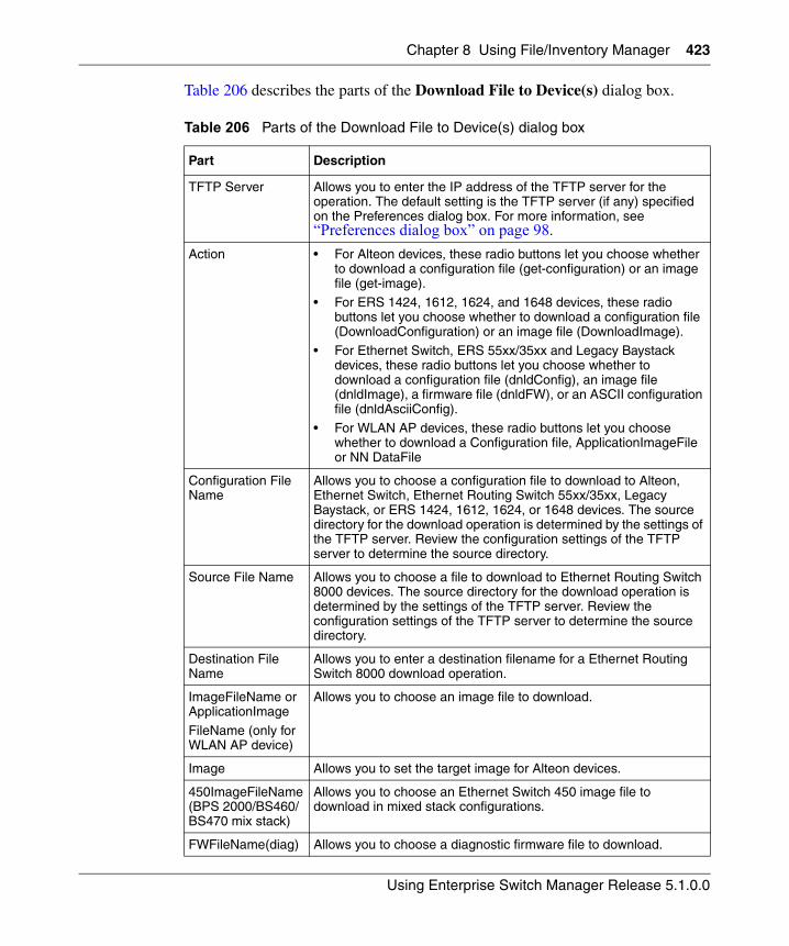
Chapter 8 Using File/Inventory Manager 423
Using Enterprise Switch Manager Release 5.1.0.0
Table 206 describes the parts of the Download File to Device(s) dialog box.
Table 206 Parts of the Download File to Device(s) dialog box
Part Description
TFTP Server Allows you to enter the IP address of the TFTP server for the operation. The default setting is the TFTP server (if any) specified on the Preferences dialog box. For more information, see “Preferences dialog box” on page 98.
Action • For Alteon devices, these radio buttons let you choose whether to download a configuration file (get-configuration) or an image file (get-image).
• For ERS 1424, 1612, 1624, and 1648 devices, these radio buttons let you choose whether to download a configuration file (DownloadConfiguration) or an image file (DownloadImage).
• For Ethernet Switch, ERS 55xx/35xx and Legacy Baystack devices, these radio buttons let you choose whether to download a configuration file (dnldConfig), an image file (dnldImage), a firmware file (dnldFW), or an ASCII configuration file (dnldAsciiConfig).
• For WLAN AP devices, these radio buttons let you choose whether to download a Configuration file, ApplicationImageFile or NN DataFile
Configuration File Name
Allows you to choose a configuration file to download to Alteon, Ethernet Switch, Ethernet Routing Switch 55xx/35xx, Legacy Baystack, or ERS 1424, 1612, 1624, or 1648 devices. The source directory for the download operation is determined by the settings of the TFTP server. Review the configuration settings of the TFTP server to determine the source directory.
Source File Name Allows you to choose a file to download to Ethernet Routing Switch 8000 devices. The source directory for the download operation is determined by the settings of the TFTP server. Review the configuration settings of the TFTP server to determine the source directory.
Destination File Name
Allows you to enter a destination filename for a Ethernet Routing Switch 8000 download operation.
ImageFileName or ApplicationImage
FileName (only for WLAN AP device)
Allows you to choose an image file to download.
Image Allows you to set the target image for Alteon devices.
450ImageFileName (BPS 2000/BS460/BS470 mix stack)
Allows you to choose an Ethernet Switch 450 image file to download in mixed stack configurations.
FWFileName(diag) Allows you to choose a diagnostic firmware file to download.
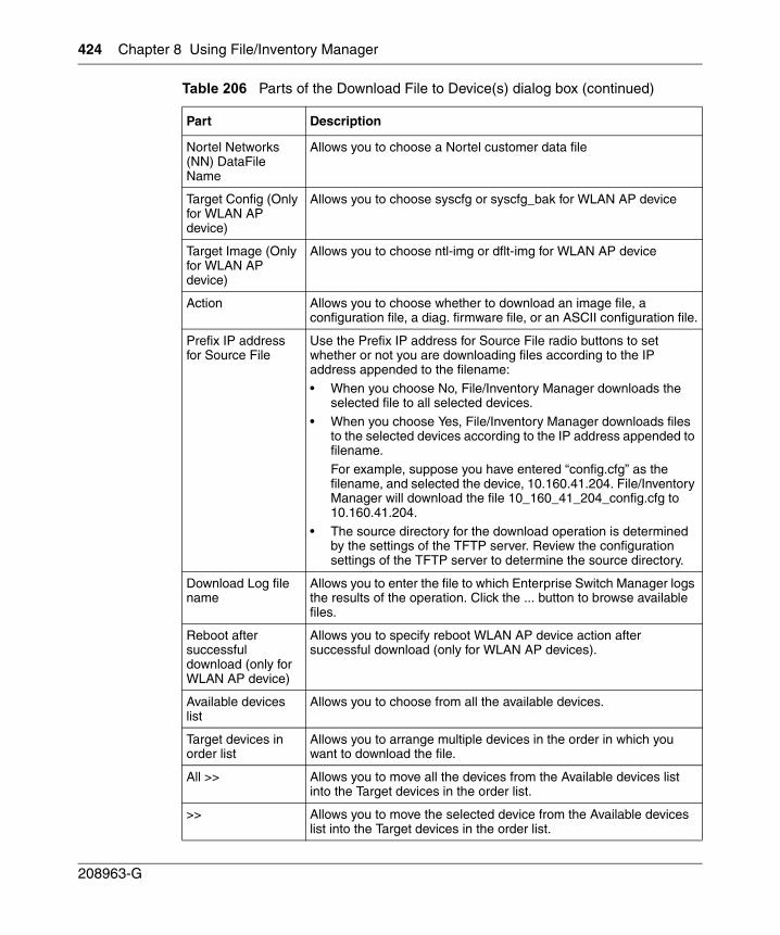
424 Chapter 8 Using File/Inventory Manager
208963-G
Nortel Networks (NN) DataFile Name
Allows you to choose a Nortel customer data file
Target Config (Only for WLAN AP device)
Allows you to choose syscfg or syscfg_bak for WLAN AP device
Target Image (Only for WLAN AP device)
Allows you to choose ntl-img or dflt-img for WLAN AP device
Action Allows you to choose whether to download an image file, a configuration file, a diag. firmware file, or an ASCII configuration file.
Prefix IP address for Source File
Use the Prefix IP address for Source File radio buttons to set whether or not you are downloading files according to the IP address appended to the filename:
• When you choose No, File/Inventory Manager downloads the selected file to all selected devices.
• When you choose Yes, File/Inventory Manager downloads files to the selected devices according to the IP address appended to filename.
For example, suppose you have entered “config.cfg” as the filename, and selected the device, 10.160.41.204. File/Inventory Manager will download the file 10_160_41_204_config.cfg to 10.160.41.204.
• The source directory for the download operation is determined by the settings of the TFTP server. Review the configuration settings of the TFTP server to determine the source directory.
Download Log file name
Allows you to enter the file to which Enterprise Switch Manager logs the results of the operation. Click the ... button to browse available files.
Reboot after successful download (only for WLAN AP device)
Allows you to specify reboot WLAN AP device action after successful download (only for WLAN AP devices).
Available devices list
Allows you to choose from all the available devices.
Target devices in order list
Allows you to arrange multiple devices in the order in which you want to download the file.
All >> Allows you to move all the devices from the Available devices list into the Target devices in the order list.
>> Allows you to move the selected device from the Available devices list into the Target devices in the order list.
Table 206 Parts of the Download File to Device(s) dialog box (continued)
Part Description
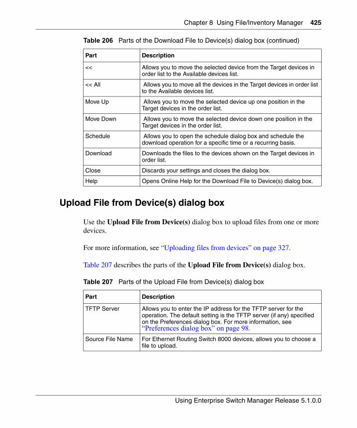
Chapter 8 Using File/Inventory Manager 425
Using Enterprise Switch Manager Release 5.1.0.0
Upload File from Device(s) dialog box
Use the Upload File from Device(s) dialog box to upload files from one or more devices.
For more information, see “Uploading files from devices” on page 327.
Table 207 describes the parts of the Upload File from Device(s) dialog box.
<< Allows you to move the selected device from the Target devices in order list to the Available devices list.
<< All Allows you to move all the devices in the Target devices in order list to the Available devices list.
Move Up Allows you to move the selected device up one position in the Target devices in the order list.
Move Down Allows you to move the selected device down one position in the Target devices in the order list.
Schedule Allows you to open the schedule dialog box and schedule the download operation for a specific time or a recurring basis.
Download Downloads the files to the devices shown on the Target devices in order list.
Close Discards your settings and closes the dialog box.
Help Opens Online Help for the Download File to Device(s) dialog box.
Table 207 Parts of the Upload File from Device(s) dialog box
Part Description
TFTP Server Allows you to enter the IP address for the TFTP server for the operation. The default setting is the TFTP server (if any) specified on the Preferences dialog box. For more information, see “Preferences dialog box” on page 98.
Source File Name For Ethernet Routing Switch 8000 devices, allows you to choose a file to upload.
Table 206 Parts of the Download File to Device(s) dialog box (continued)
Part Description
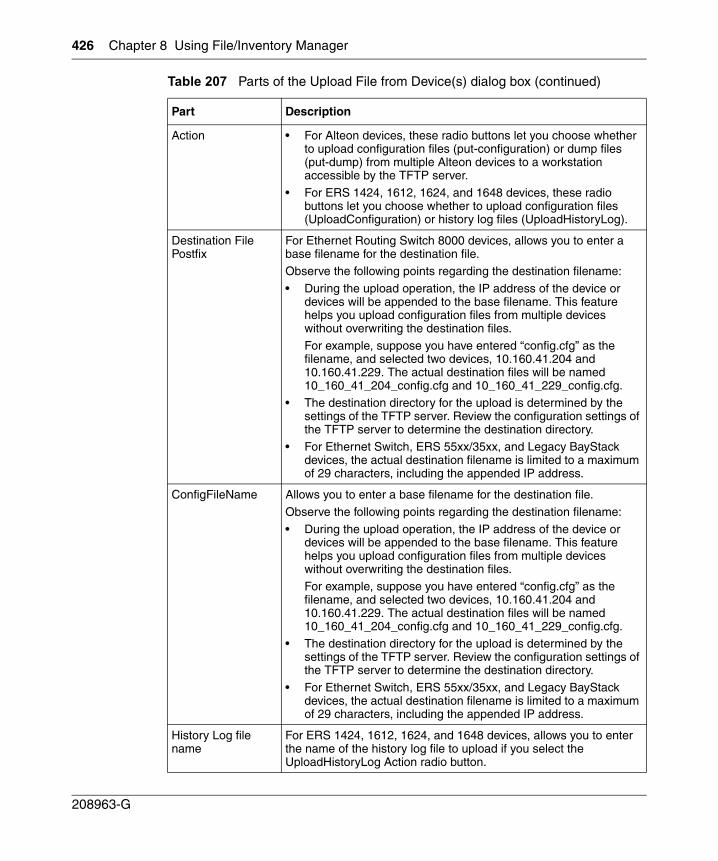
426 Chapter 8 Using File/Inventory Manager
208963-G
Action • For Alteon devices, these radio buttons let you choose whether to upload configuration files (put-configuration) or dump files (put-dump) from multiple Alteon devices to a workstation accessible by the TFTP server.
• For ERS 1424, 1612, 1624, and 1648 devices, these radio buttons let you choose whether to upload configuration files (UploadConfiguration) or history log files (UploadHistoryLog).
Destination File Postfix
For Ethernet Routing Switch 8000 devices, allows you to enter a base filename for the destination file. Observe the following points regarding the destination filename:
• During the upload operation, the IP address of the device or devices will be appended to the base filename. This feature helps you upload configuration files from multiple devices without overwriting the destination files.
For example, suppose you have entered “config.cfg” as the filename, and selected two devices, 10.160.41.204 and 10.160.41.229. The actual destination files will be named 10_160_41_204_config.cfg and 10_160_41_229_config.cfg.
• The destination directory for the upload is determined by the settings of the TFTP server. Review the configuration settings of the TFTP server to determine the destination directory.
• For Ethernet Switch, ERS 55xx/35xx, and Legacy BayStack devices, the actual destination filename is limited to a maximum of 29 characters, including the appended IP address.
ConfigFileName Allows you to enter a base filename for the destination file.
Observe the following points regarding the destination filename:
• During the upload operation, the IP address of the device or devices will be appended to the base filename. This feature helps you upload configuration files from multiple devices without overwriting the destination files.For example, suppose you have entered “config.cfg” as the filename, and selected two devices, 10.160.41.204 and 10.160.41.229. The actual destination files will be named 10_160_41_204_config.cfg and 10_160_41_229_config.cfg.
• The destination directory for the upload is determined by the settings of the TFTP server. Review the configuration settings of the TFTP server to determine the destination directory.
• For Ethernet Switch, ERS 55xx/35xx, and Legacy BayStack devices, the actual destination filename is limited to a maximum of 29 characters, including the appended IP address.
History Log file name
For ERS 1424, 1612, 1624, and 1648 devices, allows you to enter the name of the history log file to upload if you select the UploadHistoryLog Action radio button.
Table 207 Parts of the Upload File from Device(s) dialog box (continued)
Part Description
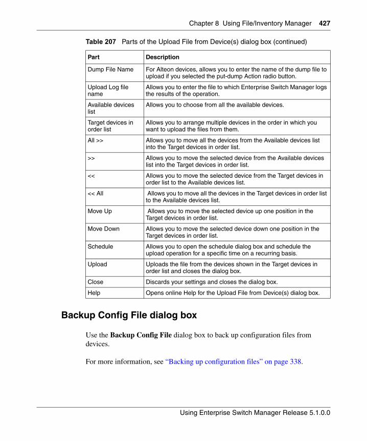
Chapter 8 Using File/Inventory Manager 427
Using Enterprise Switch Manager Release 5.1.0.0
Backup Config File dialog box
Use the Backup Config File dialog box to back up configuration files from devices.
For more information, see “Backing up configuration files” on page 338.
Dump File Name For Alteon devices, allows you to enter the name of the dump file to upload if you selected the put-dump Action radio button.
Upload Log file name
Allows you to enter the file to which Enterprise Switch Manager logs the results of the operation.
Available devices list
Allows you to choose from all the available devices.
Target devices in order list
Allows you to arrange multiple devices in the order in which you want to upload the files from them.
All >> Allows you to move all the devices from the Available devices list into the Target devices in order list.
>> Allows you to move the selected device from the Available devices list into the Target devices in order list.
<< Allows you to move the selected device from the Target devices in order list to the Available devices list.
<< All Allows you to move all the devices in the Target devices in order list to the Available devices list.
Move Up Allows you to move the selected device up one position in the Target devices in order list.
Move Down Allows you to move the selected device down one position in the Target devices in order list.
Schedule Allows you to open the schedule dialog box and schedule the upload operation for a specific time on a recurring basis.
Upload Uploads the file from the devices shown in the Target devices in order list and closes the dialog box.
Close Discards your settings and closes the dialog box.
Help Opens online Help for the Upload File from Device(s) dialog box.
Table 207 Parts of the Upload File from Device(s) dialog box (continued)
Part Description
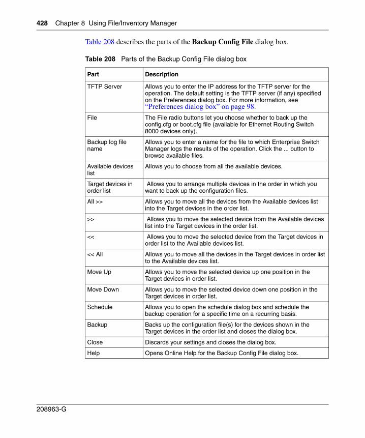
428 Chapter 8 Using File/Inventory Manager
208963-G
Table 208 describes the parts of the Backup Config File dialog box.
Table 208 Parts of the Backup Config File dialog box
Part Description
TFTP Server Allows you to enter the IP address for the TFTP server for the operation. The default setting is the TFTP server (if any) specified on the Preferences dialog box. For more information, see “Preferences dialog box” on page 98.
File The File radio buttons let you choose whether to back up the config.cfg or boot.cfg file (available for Ethernet Routing Switch 8000 devices only).
Backup log file name
Allows you to enter a name for the file to which Enterprise Switch Manager logs the results of the operation. Click the ... button to browse available files.
Available devices list
Allows you to choose from all the available devices.
Target devices in order list
Allows you to arrange multiple devices in the order in which you want to back up the configuration files.
All >> Allows you to move all the devices from the Available devices list into the Target devices in the order list.
>> Allows you to move the selected device from the Available devices list into the Target devices in the order list.
<< Allows you to move the selected device from the Target devices in order list to the Available devices list.
<< All Allows you to move all the devices in the Target devices in order list to the Available devices list.
Move Up Allows you to move the selected device up one position in the Target devices in order list.
Move Down Allows you to move the selected device down one position in the Target devices in order list.
Schedule Allows you to open the schedule dialog box and schedule the backup operation for a specific time on a recurring basis.
Backup Backs up the configuration file(s) for the devices shown in the Target devices in the order list and closes the dialog box.
Close Discards your settings and closes the dialog box.
Help Opens Online Help for the Backup Config File dialog box.
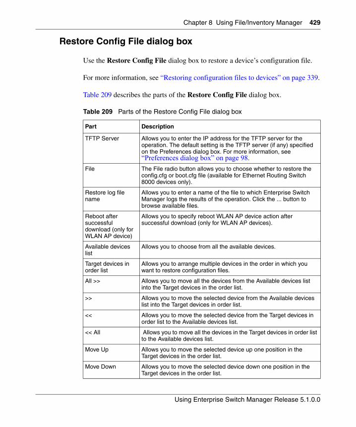
Chapter 8 Using File/Inventory Manager 429
Using Enterprise Switch Manager Release 5.1.0.0
Restore Config File dialog box
Use the Restore Config File dialog box to restore a device’s configuration file.
For more information, see “Restoring configuration files to devices” on page 339.
Table 209 describes the parts of the Restore Config File dialog box.
Table 209 Parts of the Restore Config File dialog box
Part Description
TFTP Server Allows you to enter the IP address for the TFTP server for the operation. The default setting is the TFTP server (if any) specified on the Preferences dialog box. For more information, see “Preferences dialog box” on page 98.
File The File radio button allows you to choose whether to restore the config.cfg or boot.cfg file (available for Ethernet Routing Switch 8000 devices only).
Restore log file name
Allows you to enter a name of the file to which Enterprise Switch Manager logs the results of the operation. Click the ... button to browse available files.
Reboot after successful download (only for WLAN AP device)
Allows you to specify reboot WLAN AP device action after successful download (only for WLAN AP devices).
Available devices list
Allows you to choose from all the available devices.
Target devices in order list
Allows you to arrange multiple devices in the order in which you want to restore configuration files.
All >> Allows you to move all the devices from the Available devices list into the Target devices in the order list.
>> Allows you to move the selected device from the Available devices list into the Target devices in order list.
<< Allows you to move the selected device from the Target devices in order list to the Available devices list.
<< All Allows you to move all the devices in the Target devices in order list to the Available devices list.
Move Up Allows you to move the selected device up one position in the Target devices in the order list.
Move Down Allows you to move the selected device down one position in the Target devices in the order list.
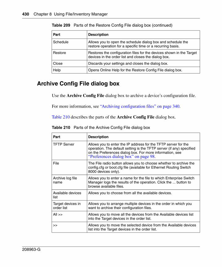
430 Chapter 8 Using File/Inventory Manager
208963-G
Archive Config File dialog box
Use the Archive Config File dialog box to archive a device’s configuration file.
For more information, see “Archiving configuration files” on page 340.
Table 210 describes the parts of the Archive Config File dialog box.
Schedule Allows you to open the schedule dialog box and schedule the restore operation for a specific time or a recurring basis.
Restore Restores the configuration files for the devices shown in the Target devices in the order list and closes the dialog box.
Close Discards your settings and closes the dialog box.
Help Opens Online Help for the Restore Config File dialog box.
Table 210 Parts of the Archive Config File dialog box
Part Description
TFTP Server Allows you to enter the IP address for the TFTP server for the operation. The default setting is the TFTP server (if any) specified on the Preferences dialog box. For more information, see “Preferences dialog box” on page 98.
File The File radio button allows you to choose whether to archive the config.cfg or boot.cfg file (available for Ethernet Routing Switch 8000 devices only).
Archive log file name
Allows you to enter a name for the file to which Enterprise Switch Manager logs the results of the operation. Click the ... button to browse available files.
Available devices list
Allows you to choose from all the available devices.
Target devices in order list
Allows you to arrange multiple devices in the order in which you want to archive their configuration files.
All >> Allows you to move all the devices from the Available devices list into the Target devices in the order list.
>> Allows you to move the selected device from the Available devices list into the Target devices in the order list.
Table 209 Parts of the Restore Config File dialog box (continued)
Part Description
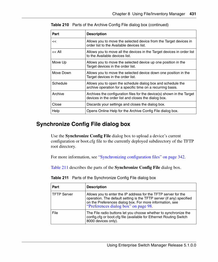
Chapter 8 Using File/Inventory Manager 431
Using Enterprise Switch Manager Release 5.1.0.0
Synchronize Config File dialog box
Use the Synchronize Config File dialog box to upload a device’s current configuration or boot.cfg file to the currently deployed subdirectory of the TFTP root directory.
For more information, see “Synchronizing configuration files” on page 342.
Table 211 describes the parts of the Synchronize Config File dialog box.
<< Allows you to move the selected device from the Target devices in order list to the Available devices list.
<< All Allows you to move all the devices in the Target devices in order list to the Available devices list.
Move Up Allows you to move the selected device up one position in the Target devices in the order list.
Move Down Allows you to move the selected device down one position in the Target devices in the order list.
Schedule Allows you to open the schedule dialog box and schedule the archive operation for a specific time on a recurring basis.
Archive Archives the configuration files for the device(s) shown in the Target devices in the order list and closes the dialog box.
Close Discards your settings and closes the dialog box.
Help Opens Online Help for the Archive Config File dialog box.
Table 211 Parts of the Synchronize Config File dialog box
Part Description
TFTP Server Allows you to enter the IP address for the TFTP server for the operation. The default setting is the TFTP server (if any) specified on the Preferences dialog box. For more information, see “Preferences dialog box” on page 98.
File The File radio buttons let you choose whether to synchronize the config.cfg or boot.cfg file (available for Ethernet Routing Switch 8000 devices only).
Table 210 Parts of the Archive Config File dialog box (continued)
Part Description
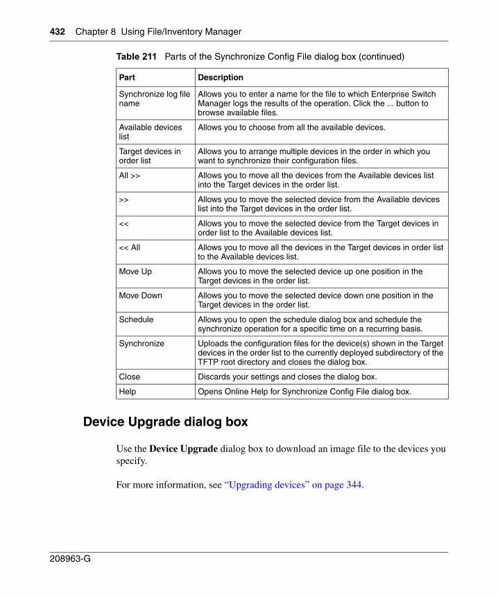
432 Chapter 8 Using File/Inventory Manager
208963-G
Device Upgrade dialog box
Use the Device Upgrade dialog box to download an image file to the devices you specify.
For more information, see “Upgrading devices” on page 344.
Synchronize log file name
Allows you to enter a name for the file to which Enterprise Switch Manager logs the results of the operation. Click the ... button to browse available files.
Available devices list
Allows you to choose from all the available devices.
Target devices in order list
Allows you to arrange multiple devices in the order in which you want to synchronize their configuration files.
All >> Allows you to move all the devices from the Available devices list into the Target devices in the order list.
>> Allows you to move the selected device from the Available devices list into the Target devices in the order list.
<< Allows you to move the selected device from the Target devices in order list to the Available devices list.
<< All Allows you to move all the devices in the Target devices in order list to the Available devices list.
Move Up Allows you to move the selected device up one position in the Target devices in the order list.
Move Down Allows you to move the selected device down one position in the Target devices in the order list.
Schedule Allows you to open the schedule dialog box and schedule the synchronize operation for a specific time on a recurring basis.
Synchronize Uploads the configuration files for the device(s) shown in the Target devices in the order list to the currently deployed subdirectory of the TFTP root directory and closes the dialog box.
Close Discards your settings and closes the dialog box.
Help Opens Online Help for Synchronize Config File dialog box.
Table 211 Parts of the Synchronize Config File dialog box (continued)
Part Description
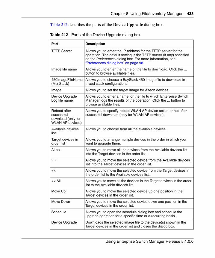
Chapter 8 Using File/Inventory Manager 433
Using Enterprise Switch Manager Release 5.1.0.0
Table 212 describes the parts of the Device Upgrade dialog box.
Table 212 Parts of the Device Upgrade dialog box
Part Description
TFTP Server Allows you to enter the IP address for the TFTP server for the operation. The default setting is the TFTP server (if any) specified on the Preferences dialog box. For more information, see “Preferences dialog box” on page 98.
Image file name Allows you to enter the name of the file to download. Click the ... button to browse available files.
450ImageFileName (Mix Stack)
Allows you to choose a BayStack 450 image file to download in mixed stack configurations.
Image Allows you to set the target image for Alteon devices.
Device Upgrade Log file name
Allows you to enter a name for the file to which Enterprise Switch Manager logs the results of the operation. Click the ... button to browse available files.
Reboot after successful download (only for WLAN AP devices)
Allows you to specify reboot WLAN AP device action or not after successful download (only for WLAN AP devices).
Available devices list
Allows you to choose from all the available devices.
Target devices in order list
Allows you to arrange multiple devices in the order in which you want to upgrade them.
All >> Allows you to move all the devices from the Available devices list into the Target devices in the order list.
>> Allows you to move the selected device from the Available devices list into the Target devices in the order list.
<< Allows you to move the selected device from the Target devices in the order list to the Available devices list.
<< All Allows you to move all the devices in the Target devices in the order list to the Available devices list.
Move Up Allows you to move the selected device up one position in the Target devices in the order list.
Move Down Allows you to move the selected device down one position in the Target devices in the order list.
Schedule Allows you to open the schedule dialog box and schedule the upgrade operation for a specific time or a recurring basis.
Device Upgrade Downloads the selected image file to the device(s) shown in the Target devices in the order list and closes the dialog box.
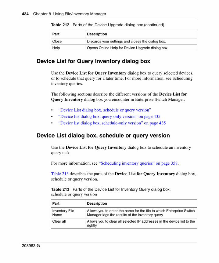
434 Chapter 8 Using File/Inventory Manager
208963-G
Device List for Query Inventory dialog box
Use the Device List for Query Inventory dialog box to query selected devices, or to schedule that query for a later time. For more information, see Scheduling inventory queries.
The following sections describe the different versions of the Device List for Query Inventory dialog box you encounter in Enterprise Switch Manager:
• “Device List dialog box, schedule or query version”
• “Device list dialog box, query-only version” on page 435
• “Device list dialog box, schedule-only version” on page 435
Device List dialog box, schedule or query version
Use the Device List for Query Inventory dialog box to schedule an inventory query task.
For more information, see “Scheduling inventory queries” on page 358.
Table 213 describes the parts of the Device List for Query Inventory dialog box, schedule or query version.
Close Discards your settings and closes the dialog box.
Help Opens Online Help for Device Upgrade dialog box.
Table 213 Parts of the Device List for Inventory Query dialog box, schedule or query version
Part Description
Inventory File Name
Allows you to enter the name for the file to which Enterprise Switch Manager logs the results of the inventory query.
Clear all Allows you to clear all selected IP addresses in the device list to the rightly.
Table 212 Parts of the Device Upgrade dialog box (continued)
Part Description
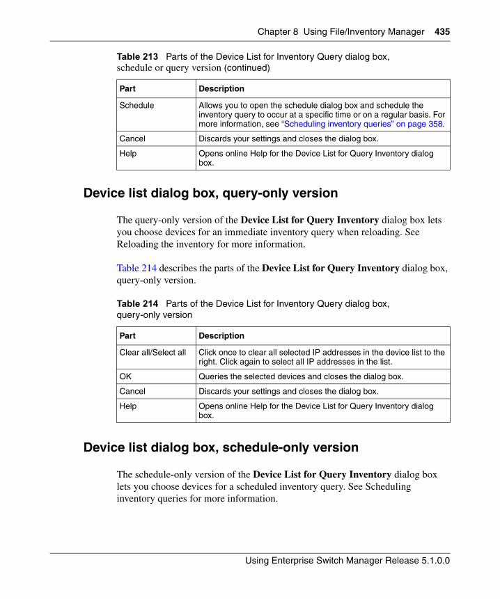
Chapter 8 Using File/Inventory Manager 435
Using Enterprise Switch Manager Release 5.1.0.0
Device list dialog box, query-only version
The query-only version of the Device List for Query Inventory dialog box lets you choose devices for an immediate inventory query when reloading. See Reloading the inventory for more information.
Table 214 describes the parts of the Device List for Query Inventory dialog box, query-only version.
Device list dialog box, schedule-only version
The schedule-only version of the Device List for Query Inventory dialog box lets you choose devices for a scheduled inventory query. See Scheduling inventory queries for more information.
Schedule Allows you to open the schedule dialog box and schedule the inventory query to occur at a specific time or on a regular basis. For more information, see “Scheduling inventory queries” on page 358.
Cancel Discards your settings and closes the dialog box.
Help Opens online Help for the Device List for Query Inventory dialog box.
Table 214 Parts of the Device List for Inventory Query dialog box, query-only version
Part Description
Clear all/Select all Click once to clear all selected IP addresses in the device list to the right. Click again to select all IP addresses in the list.
OK Queries the selected devices and closes the dialog box.
Cancel Discards your settings and closes the dialog box.
Help Opens online Help for the Device List for Query Inventory dialog box.
Table 213 Parts of the Device List for Inventory Query dialog box, schedule or query version (continued)
Part Description
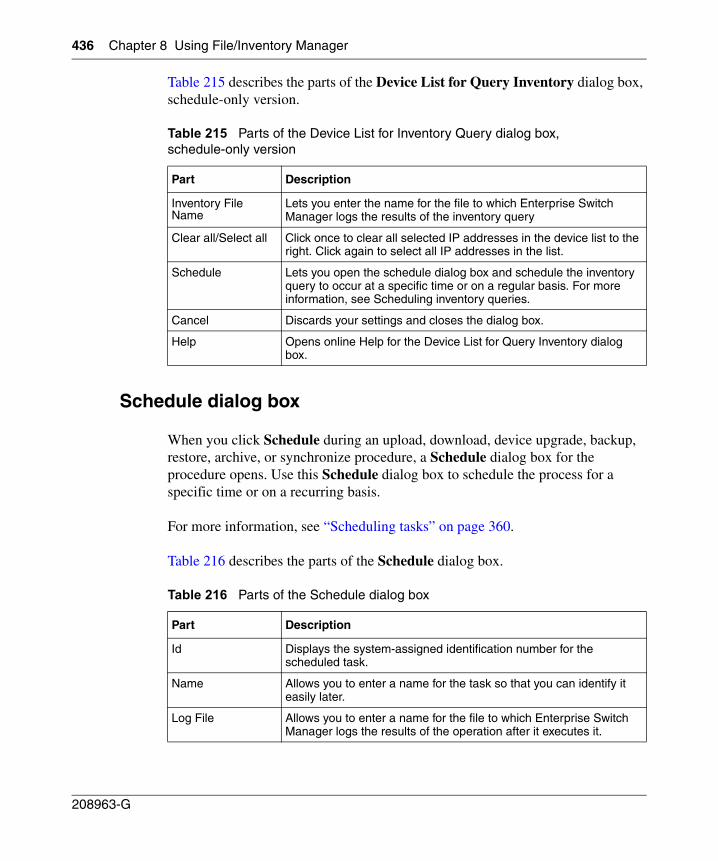
436 Chapter 8 Using File/Inventory Manager
208963-G
Table 215 describes the parts of the Device List for Query Inventory dialog box, schedule-only version.
Schedule dialog box
When you click Schedule during an upload, download, device upgrade, backup, restore, archive, or synchronize procedure, a Schedule dialog box for the procedure opens. Use this Schedule dialog box to schedule the process for a specific time or on a recurring basis.
For more information, see “Scheduling tasks” on page 360.
Table 216 describes the parts of the Schedule dialog box.
Table 215 Parts of the Device List for Inventory Query dialog box, schedule-only version
Part Description
Inventory File Name
Lets you enter the name for the file to which Enterprise Switch Manager logs the results of the inventory query
Clear all/Select all Click once to clear all selected IP addresses in the device list to the right. Click again to select all IP addresses in the list.
Schedule Lets you open the schedule dialog box and schedule the inventory query to occur at a specific time or on a regular basis. For more information, see Scheduling inventory queries.
Cancel Discards your settings and closes the dialog box.
Help Opens online Help for the Device List for Query Inventory dialog box.
Table 216 Parts of the Schedule dialog box
Part Description
Id Displays the system-assigned identification number for the scheduled task.
Name Allows you to enter a name for the task so that you can identify it easily later.
Log File Allows you to enter a name for the file to which Enterprise Switch Manager logs the results of the operation after it executes it.
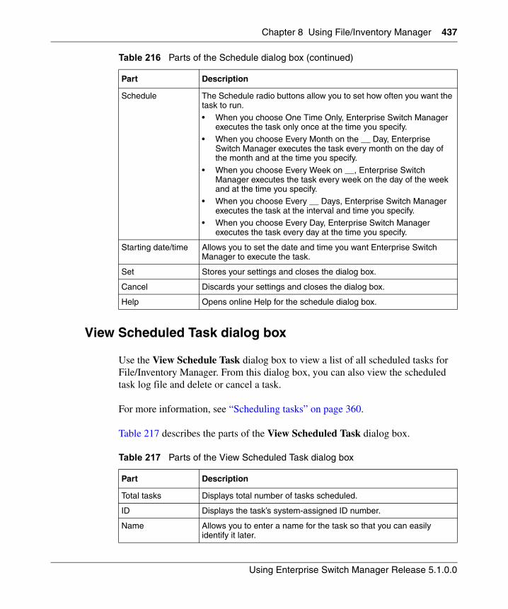
Chapter 8 Using File/Inventory Manager 437
Using Enterprise Switch Manager Release 5.1.0.0
View Scheduled Task dialog box
Use the View Schedule Task dialog box to view a list of all scheduled tasks for File/Inventory Manager. From this dialog box, you can also view the scheduled task log file and delete or cancel a task.
For more information, see “Scheduling tasks” on page 360.
Table 217 describes the parts of the View Scheduled Task dialog box.
Schedule The Schedule radio buttons allow you to set how often you want the task to run.
• When you choose One Time Only, Enterprise Switch Manager executes the task only once at the time you specify.
• When you choose Every Month on the __ Day, Enterprise Switch Manager executes the task every month on the day of the month and at the time you specify.
• When you choose Every Week on __, Enterprise Switch Manager executes the task every week on the day of the week and at the time you specify.
• When you choose Every __ Days, Enterprise Switch Manager executes the task at the interval and time you specify.
• When you choose Every Day, Enterprise Switch Manager executes the task every day at the time you specify.
Starting date/time Allows you to set the date and time you want Enterprise Switch Manager to execute the task.
Set Stores your settings and closes the dialog box.
Cancel Discards your settings and closes the dialog box.
Help Opens online Help for the schedule dialog box.
Table 217 Parts of the View Scheduled Task dialog box
Part Description
Total tasks Displays total number of tasks scheduled.
ID Displays the task’s system-assigned ID number.
Name Allows you to enter a name for the task so that you can easily identify it later.
Table 216 Parts of the Schedule dialog box (continued)
Part Description
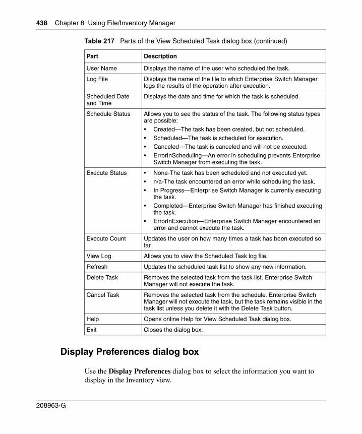
438 Chapter 8 Using File/Inventory Manager
208963-G
Display Preferences dialog box
Use the Display Preferences dialog box to select the information you want to display in the Inventory view.
User Name Displays the name of the user who scheduled the task.
Log File Displays the name of the file to which Enterprise Switch Manager logs the results of the operation after execution.
Scheduled Date and Time
Displays the date and time for which the task is scheduled.
Schedule Status Allows you to see the status of the task. The following status types are possible:
• Created—The task has been created, but not scheduled.
• Scheduled—The task is scheduled for execution.• Canceled—The task is canceled and will not be executed.
• ErrorInScheduling—An error in scheduling prevents Enterprise Switch Manager from executing the task.
Execute Status • None-The task has been scheduled and not executed yet.
• n/a-The task encountered an error while scheduling the task.
• In Progress—Enterprise Switch Manager is currently executing the task.
• Completed—Enterprise Switch Manager has finished executing the task.
• ErrorInExecution—Enterprise Switch Manager encountered an error and cannot execute the task.
Execute Count Updates the user on how many times a task has been executed so far
View Log Allows you to view the Scheduled Task log file.
Refresh Updates the scheduled task list to show any new information.
Delete Task Removes the selected task from the task list. Enterprise Switch Manager will not execute the task.
Cancel Task Removes the selected task from the schedule. Enterprise Switch Manager will not execute the task, but the task remains visible in the task list unless you delete it with the Delete Task button.
Help Opens online Help for View Scheduled Task dialog box.
Exit Closes the dialog box.
Table 217 Parts of the View Scheduled Task dialog box (continued)
Part Description
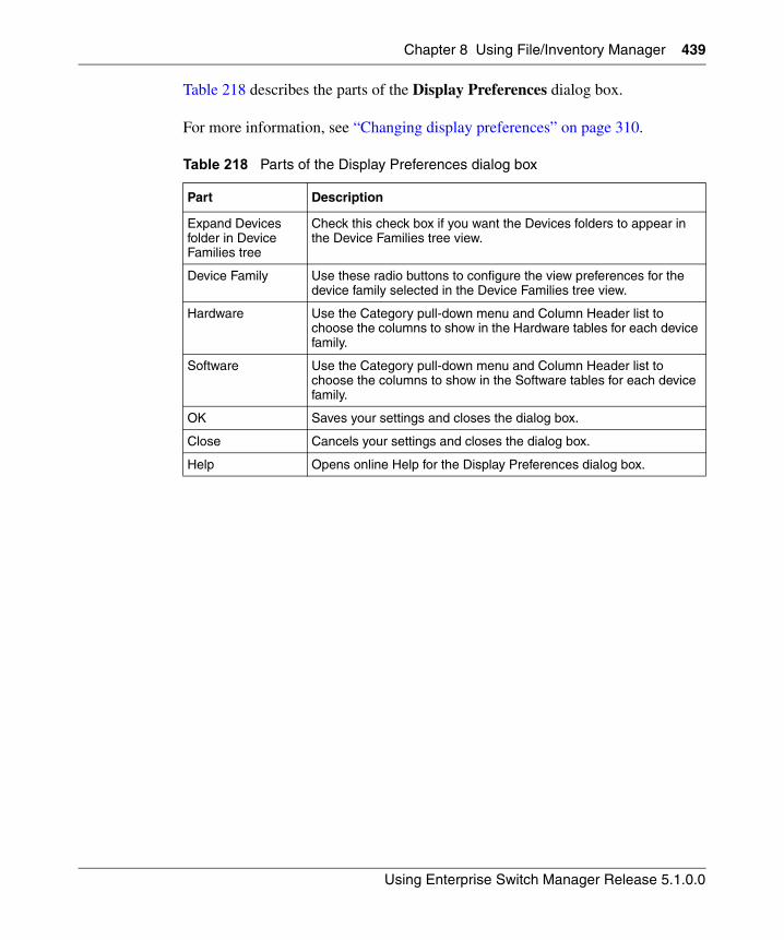
Chapter 8 Using File/Inventory Manager 439
Using Enterprise Switch Manager Release 5.1.0.0
Table 218 describes the parts of the Display Preferences dialog box.
For more information, see “Changing display preferences” on page 310.
Table 218 Parts of the Display Preferences dialog box
Part Description
Expand Devices folder in Device Families tree
Check this check box if you want the Devices folders to appear in the Device Families tree view.
Device Family Use these radio buttons to configure the view preferences for the device family selected in the Device Families tree view.
Hardware Use the Category pull-down menu and Column Header list to choose the columns to show in the Hardware tables for each device family.
Software Use the Category pull-down menu and Column Header list to choose the columns to show in the Software tables for each device family.
OK Saves your settings and closes the dialog box.
Close Cancels your settings and closes the dialog box.
Help Opens online Help for the Display Preferences dialog box.

440 Chapter 8 Using File/Inventory Manager
208963-G
441
Using Enterprise Switch Manager Release 5.1.0.0
Chapter 9Using Security Manager
Security Manager allows you to manage access to device and network management functions on Ethernet Routing Switch 8000 series, Ethernet Routing Switch 55xx/35xx series, Ethernet Switch, and Legacy BayStack devices discovered by Enterprise Switch Manager. You can set, change, and synchronize passwords and security features for:
• Command Line Interface (CLI) access
• Web access
• Simple Network Management Protocol (SNMP) access
• Remote Access Dial-In User Services (RADIUS) properties
• SNMPv3 properties
• Access policies
• Secure Shell (SSH) bulk password
You can configure the network access for each application using one or more security groups that you manage independently. You use security groups to group together devices that you want to have the same passwords and access features.
This chapter describes using Security Manager. It includes the following topics:
• “Starting Security Manager”
• “Security Manager window” on page 443
• “Working with Security Manager” on page 446
Note: For Ethernet Routing Switches 8600 v3.2.1 and later, you cannot use Enterprise Switch Manager to modify the CLI user name and password. For Ethernet Routing Switches 8600 switches v3.5 and later, you cannot use Enterprise Switch Manager to modify the web user name and password.
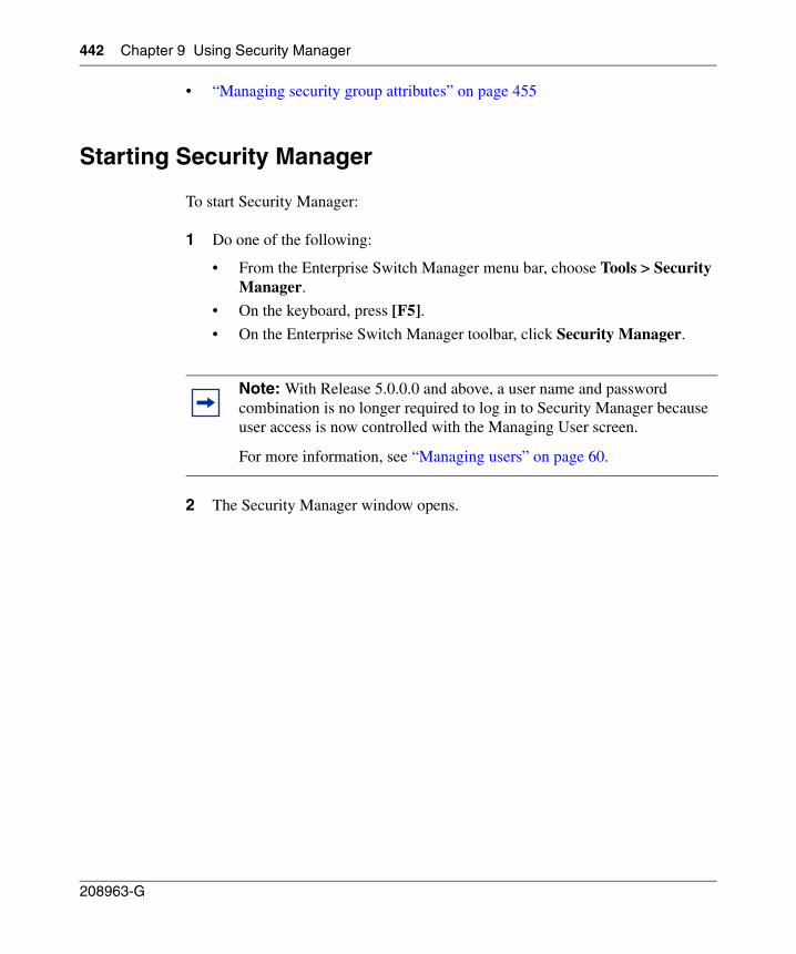
442 Chapter 9 Using Security Manager
208963-G
• “Managing security group attributes” on page 455
Starting Security Manager
To start Security Manager:
1 Do one of the following:
• From the Enterprise Switch Manager menu bar, choose Tools > Security Manager.
• On the keyboard, press [F5].
• On the Enterprise Switch Manager toolbar, click Security Manager.
2 The Security Manager window opens.
Note: With Release 5.0.0.0 and above, a user name and password combination is no longer required to log in to Security Manager because user access is now controlled with the Managing User screen.
For more information, see “Managing users” on page 60.
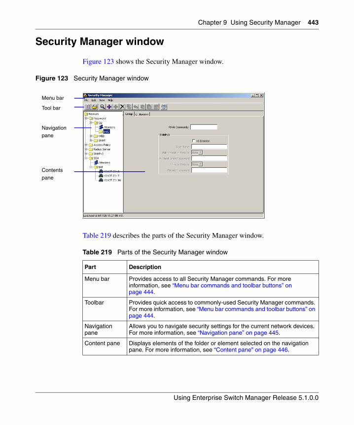
Chapter 9 Using Security Manager 443
Using Enterprise Switch Manager Release 5.1.0.0
Security Manager window
Figure 123 shows the Security Manager window.
Figure 123 Security Manager window
Table 219 describes the parts of the Security Manager window.
Table 219 Parts of the Security Manager window
Part Description
Menu bar Provides access to all Security Manager commands. For more information, see “Menu bar commands and toolbar buttons” on page 444.
Toolbar Provides quick access to commonly-used Security Manager commands. For more information, see “Menu bar commands and toolbar buttons” on page 444.
Navigation pane
Allows you to navigate security settings for the current network devices. For more information, see “Navigation pane” on page 445.
Content pane Displays elements of the folder or element selected on the navigation pane. For more information, see “Content pane” on page 446.
Menu bar
Tool bar
Navigationpane
Contents
pane
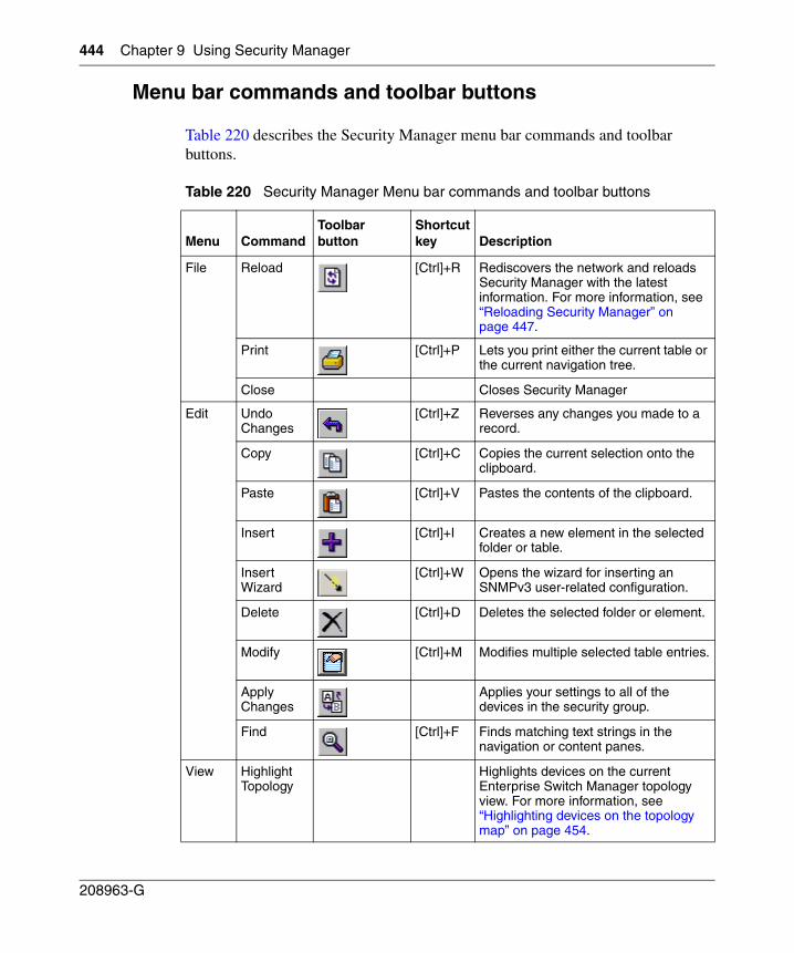
444 Chapter 9 Using Security Manager
208963-G
Menu bar commands and toolbar buttons
Table 220 describes the Security Manager menu bar commands and toolbar buttons.
Table 220 Security Manager Menu bar commands and toolbar buttons
Menu CommandToolbar button
Shortcut key Description
File Reload [Ctrl]+R Rediscovers the network and reloads Security Manager with the latest information. For more information, see “Reloading Security Manager” on page 447.
Print [Ctrl]+P Lets you print either the current table or the current navigation tree.
Close Closes Security Manager
Edit Undo Changes
[Ctrl]+Z Reverses any changes you made to a record.
Copy [Ctrl]+C Copies the current selection onto the clipboard.
Paste [Ctrl]+V Pastes the contents of the clipboard.
Insert [Ctrl]+I Creates a new element in the selected folder or table.
Insert Wizard
[Ctrl]+W Opens the wizard for inserting an SNMPv3 user-related configuration.
Delete [Ctrl]+D Deletes the selected folder or element.
Modify [Ctrl]+M Modifies multiple selected table entries.
Apply Changes
Applies your settings to all of the devices in the security group.
Find [Ctrl]+F Finds matching text strings in the navigation or content panes.
View Highlight Topology
Highlights devices on the current Enterprise Switch Manager topology view. For more information, see “Highlighting devices on the topology map” on page 454.
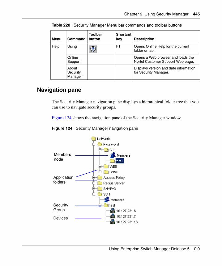
Chapter 9 Using Security Manager 445
Using Enterprise Switch Manager Release 5.1.0.0
Navigation pane
The Security Manager navigation pane displays a hierarchical folder tree that you can use to navigate security groups.
Figure 124 shows the navigation pane of the Security Manager window.
Figure 124 Security Manager navigation pane
Help Using F1 Opens Online Help for the current folder or tab.
Online Support
Opens a Web browser and loads the Nortel Customer Support Web page.
About Security Manager
Displays version and date information for Security Manager.
Table 220 Security Manager Menu bar commands and toolbar buttons
Menu CommandToolbar button
Shortcut key Description
Security Group
Devices
Application folders
Members node
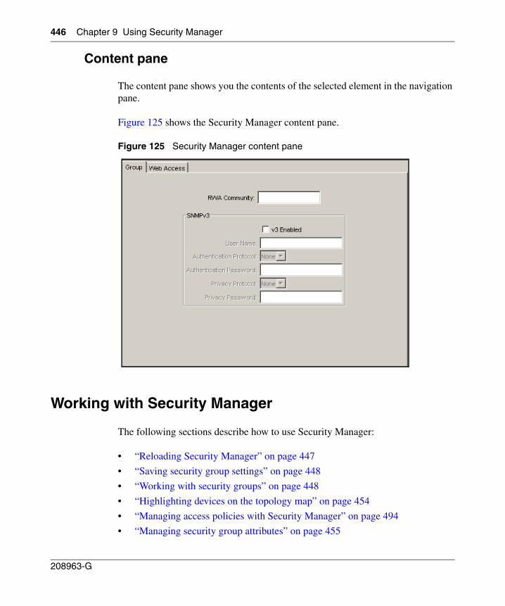
446 Chapter 9 Using Security Manager
208963-G
Content pane
The content pane shows you the contents of the selected element in the navigation pane.
Figure 125 shows the Security Manager content pane.
Figure 125 Security Manager content pane
Working with Security Manager
The following sections describe how to use Security Manager:
• “Reloading Security Manager” on page 447
• “Saving security group settings” on page 448
• “Working with security groups” on page 448
• “Highlighting devices on the topology map” on page 454
• “Managing access policies with Security Manager” on page 494
• “Managing security group attributes” on page 455
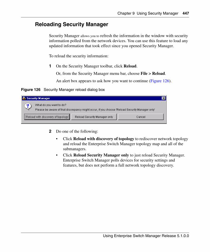
Chapter 9 Using Security Manager 447
Using Enterprise Switch Manager Release 5.1.0.0
Reloading Security Manager
Security Manager allows you to refresh the information in the window with security information polled from the network devices. You can use this feature to load any updated information that took effect since you opened Security Manager.
To reload the security information:
1 On the Security Manager toolbar, click Reload.
Or, from the Security Manager menu bar, choose File > Reload.
An alert box appears to ask how you want to continue (Figure 126).
Figure 126 Security Manager reload dialog box
2 Do one of the following:
• Click Reload with discovery of topology to rediscover network topology and reload the Enterprise Switch Manager topology map and all of the submanagers.
• Click Reload Security Manager only to just reload Security Manager. Enterprise Switch Manager polls devices for security settings and features, but does not perform a full network topology discovery.
448 Chapter 9 Using Security Manager
208963-G
• Click Cancel to abandon the reload operation.
Enterprise Switch Manager reloads topology information from the network devices, and refreshes the Security Manager window with it.
Saving security group settings
Security Manager saves all security group information to the local hard disk when you close the Security Manager window. When you restart Security Manager, it reloads the saved security group settings.
Working with security groups
The following sections describe how to manage security groups with Security Manager:
• “Creating security groups‚” next
• “Setting security group properties” on page 450
• “Deleting security groups” on page 452
• “Adding devices to a security group” on page 452
• “Removing devices from a security group” on page 454
Note: Reloading just Security Manager takes less time than reloading with topology discovery. However, if there are any changes in network topology, discrepancies between the information in Security Manager and the information on the topology map may result. Such discrepancies might cause incorrect operation when you perform operations (such as highlighting the network map) that involve interactions between the submanagers and the topology map.
If you observe such incorrect operation, reload the network map. For more information, see “Rediscovering the network map” on page 105.
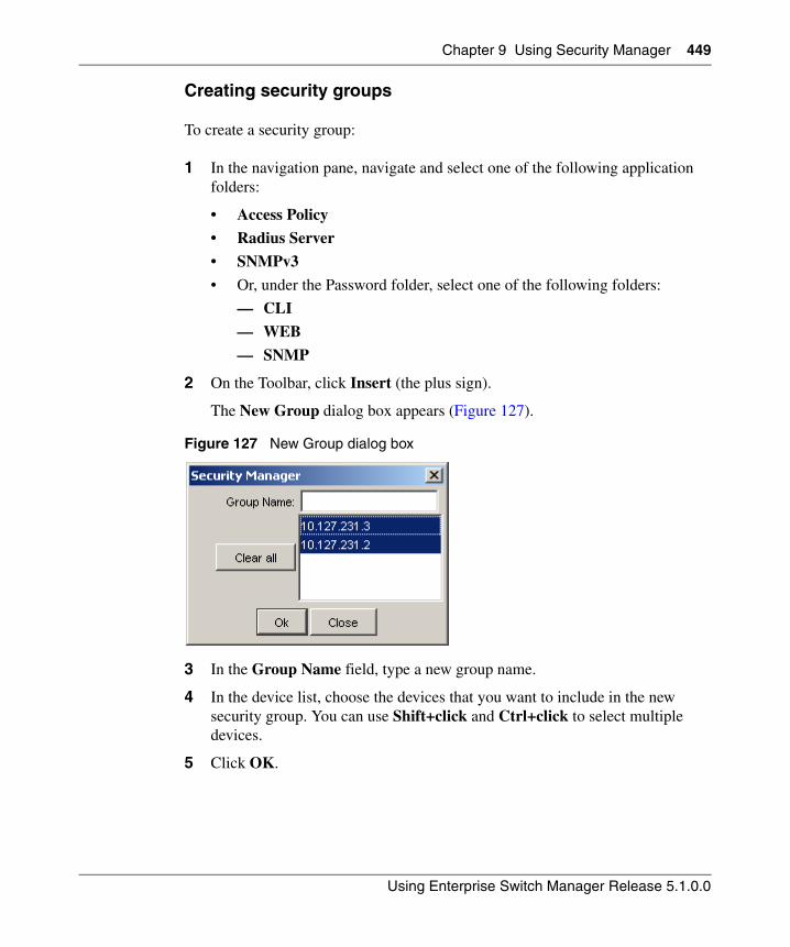
Chapter 9 Using Security Manager 449
Using Enterprise Switch Manager Release 5.1.0.0
Creating security groups
To create a security group:
1 In the navigation pane, navigate and select one of the following application folders:
• Access Policy
• Radius Server
• SNMPv3
• Or, under the Password folder, select one of the following folders:
— CLI
— WEB
— SNMP
2 On the Toolbar, click Insert (the plus sign).
The New Group dialog box appears (Figure 127).
Figure 127 New Group dialog box
3 In the Group Name field, type a new group name.
4 In the device list, choose the devices that you want to include in the new security group. You can use Shift+click and Ctrl+click to select multiple devices.
5 Click OK.
450 Chapter 9 Using Security Manager
208963-G
Security Manager creates a new security group containing the selected devices.
Table 221 describes the parts of the New Group dialog box.
Setting security group properties
All the devices in a security group use the same SNMP parameters to communicate with the switches. Either SNMPv1/v2c or SNMPv3.
Security Manager applies the properties of a security group to all the devices that are members of that group. To view and change the properties of a security group:
1 In the navigation pane, click the folder for a security group.
Note: After creating a security group, you must set the RWA community for the group before you can use the security group. For more information, see “Setting security group properties‚” next.
Table 221 Parts of the New Group dialog box
Part Description
Group Name Allows you to enter a name for the new security group.
Device list Displays a list of devices that you can add to the new security group. Use Ctrl+click and Shift+click to select multiple devices
Clear All Deselects all the devices on the device list.
OK Creates the new security group and adds the devices as members.
Close Closes the dialog box without applying your settings.
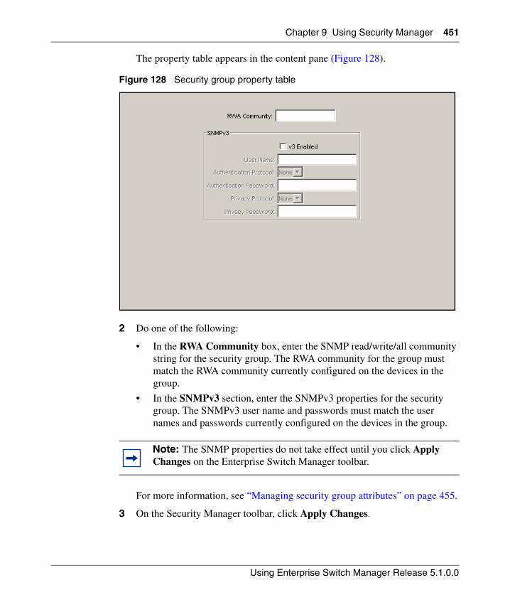
Chapter 9 Using Security Manager 451
Using Enterprise Switch Manager Release 5.1.0.0
The property table appears in the content pane (Figure 128).
Figure 128 Security group property table
2 Do one of the following:
• In the RWA Community box, enter the SNMP read/write/all community string for the security group. The RWA community for the group must match the RWA community currently configured on the devices in the group.
• In the SNMPv3 section, enter the SNMPv3 properties for the security group. The SNMPv3 user name and passwords must match the user names and passwords currently configured on the devices in the group.
For more information, see “Managing security group attributes” on page 455.
3 On the Security Manager toolbar, click Apply Changes.
Note: The SNMP properties do not take effect until you click Apply Changes on the Enterprise Switch Manager toolbar.
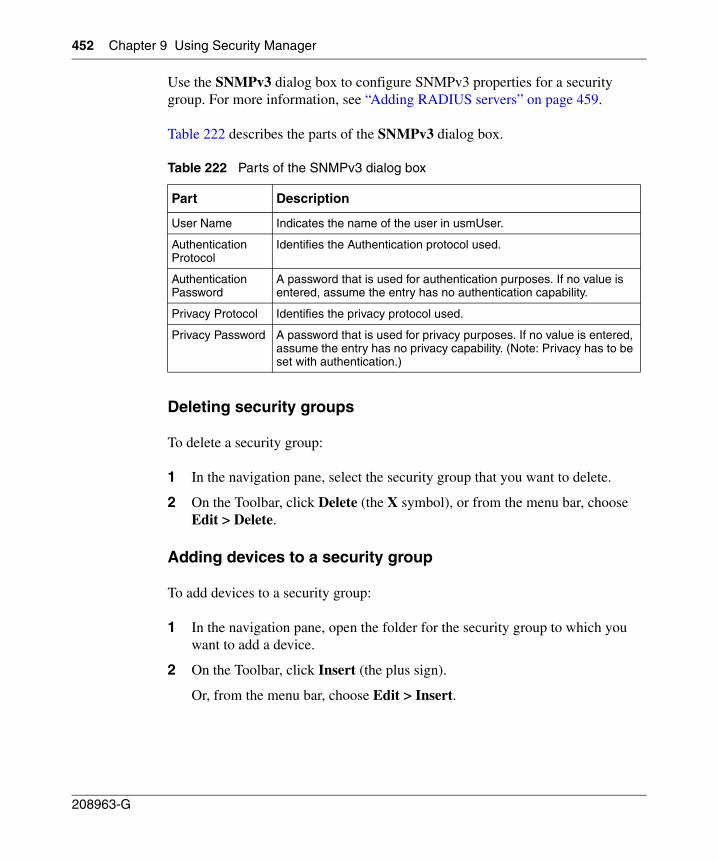
452 Chapter 9 Using Security Manager
208963-G
Use the SNMPv3 dialog box to configure SNMPv3 properties for a security group. For more information, see “Adding RADIUS servers” on page 459.
Table 222 describes the parts of the SNMPv3 dialog box.
Deleting security groups
To delete a security group:
1 In the navigation pane, select the security group that you want to delete.
2 On the Toolbar, click Delete (the X symbol), or from the menu bar, choose Edit > Delete.
Adding devices to a security group
To add devices to a security group:
1 In the navigation pane, open the folder for the security group to which you want to add a device.
2 On the Toolbar, click Insert (the plus sign).
Or, from the menu bar, choose Edit > Insert.
Table 222 Parts of the SNMPv3 dialog box
Part Description
User Name Indicates the name of the user in usmUser.
Authentication Protocol
Identifies the Authentication protocol used.
Authentication Password
A password that is used for authentication purposes. If no value is entered, assume the entry has no authentication capability.
Privacy Protocol Identifies the privacy protocol used.
Privacy Password A password that is used for privacy purposes. If no value is entered, assume the entry has no privacy capability. (Note: Privacy has to be set with authentication.)
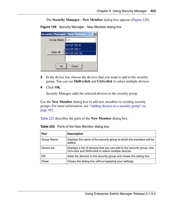
Chapter 9 Using Security Manager 453
Using Enterprise Switch Manager Release 5.1.0.0
The Security Manager - New Member dialog box appears (Figure 129).
Figure 129 Security Manager - New Member dialog box
3 In the device list, choose the devices that you want to add to the security group. You can use Shift+click and Ctrl+click to select multiple devices.
4 Click OK.
Security Manager adds the selected devices to the security group.
Use the New Member dialog box to add new members to existing security groups. For more information, see “Adding devices to a security group” on page 452.
Table 223 describes the parts of the New Member dialog box.
Table 223 Parts of the New Member dialog box
Part Description
Group Name Displays the name of the security group to which the members will be added.
Device list Displays a list of devices that you can add to the security group. Use Ctrl+click and Shift+click to select multiple devices
OK Adds the devices to the security group and closes the dialog box.
Close Closes the dialog box without applying your settings.
454 Chapter 9 Using Security Manager
208963-G
Removing devices from a security group
To remove devices from a security group:
1 In the navigation pane, open the folder for the security group from which you want to remove devices.
2 In the security group folder, click the device you want to remove from the group.
3 On the Toolbar, click Delete (the X symbol).
Or, from the menu bar, choose Edit > Delete.
Highlighting devices on the topology map
You can highlight the Enterprise Switch Manager topology map to show information relating to devices in security groups. For more information, see the following sections:
• “Highlighting members of a security group‚” next
Highlighting members of a security group
To highlight the Enterprise Switch Manager topology map to show which devices are members of a security group:
1 In the navigation pane, open the folder for the security group for which you want to highlight devices.
2 In the security group folder, click the icon for the Members Folder of the group.
3 On the Security Manager Menu bar, choose View > Highlight Topology.
A check mark appears next to the Highlight Topology menu item to show that it is selected, and Enterprise Switch Manager highlights devices of the selected group on the topology map.
Chapter 9 Using Security Manager 455
Using Enterprise Switch Manager Release 5.1.0.0
Managing security group attributes
The following sections describe how to manage security group attributes for each specific application folder:
• “Configuring CLI access” on page 455
• “Configuring SNMP access” on page 457
• “Configuring Web access” on page 457
• “Adding RADIUS servers” on page 459
• “Removing RADIUS servers” on page 462
• “Setting global RADIUS server parameters” on page 462
• “Configuring SNMPv3 access” on page 463
• “Managing access policies with Security Manager” on page 494
• “Managing SSH security groups and bulk passwords” on page 499
Configuring CLI access
You can use Security Manager to configure the Command Line Interface (CLI) user names and passwords for all of the devices in a security group.
To configure CLI access for a security group:
1 Under the CLI folder in the navigation pane, click the folder for the security group for which you want to configure CLI access.
2 In the contents pane, click the CLI Access tab.
3 On the CLI Access tab, edit the CLI user name and password.
4 On the Security Manager toolbar, click Apply Changes.
Or, from the menu bar, choose Edit > Apply Changes.
Security Manager applies your changes to the devices in the security group.
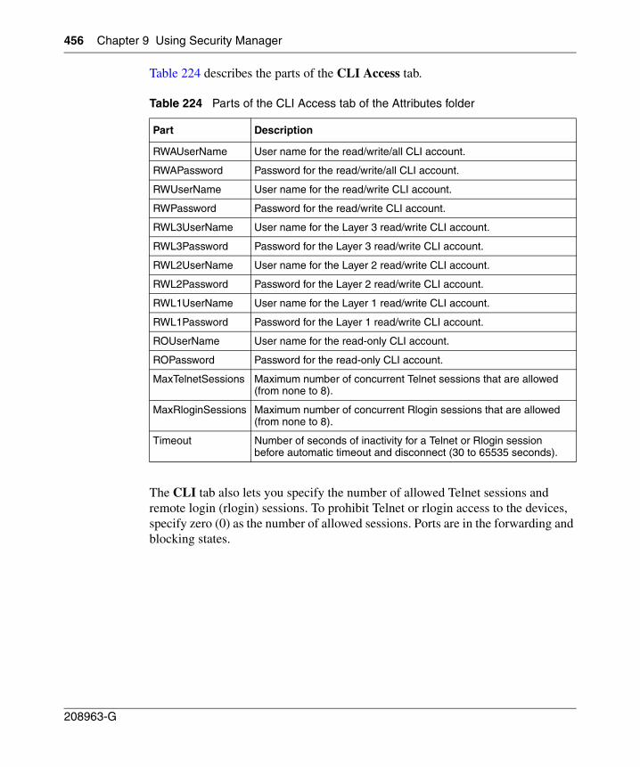
456 Chapter 9 Using Security Manager
208963-G
Table 224 describes the parts of the CLI Access tab.
The CLI tab also lets you specify the number of allowed Telnet sessions and remote login (rlogin) sessions. To prohibit Telnet or rlogin access to the devices, specify zero (0) as the number of allowed sessions. Ports are in the forwarding and blocking states.
Table 224 Parts of the CLI Access tab of the Attributes folder
Part Description
RWAUserName User name for the read/write/all CLI account.
RWAPassword Password for the read/write/all CLI account.
RWUserName User name for the read/write CLI account.
RWPassword Password for the read/write CLI account.
RWL3UserName User name for the Layer 3 read/write CLI account.
RWL3Password Password for the Layer 3 read/write CLI account.
RWL2UserName User name for the Layer 2 read/write CLI account.
RWL2Password Password for the Layer 2 read/write CLI account.
RWL1UserName User name for the Layer 1 read/write CLI account.
RWL1Password Password for the Layer 1 read/write CLI account.
ROUserName User name for the read-only CLI account.
ROPassword Password for the read-only CLI account.
MaxTelnetSessions Maximum number of concurrent Telnet sessions that are allowed (from none to 8).
MaxRloginSessions Maximum number of concurrent Rlogin sessions that are allowed (from none to 8).
Timeout Number of seconds of inactivity for a Telnet or Rlogin session before automatic timeout and disconnect (30 to 65535 seconds).
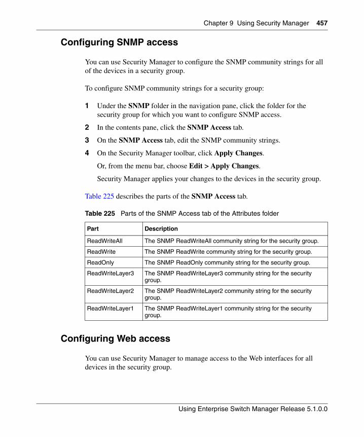
Chapter 9 Using Security Manager 457
Using Enterprise Switch Manager Release 5.1.0.0
Configuring SNMP access
You can use Security Manager to configure the SNMP community strings for all of the devices in a security group.
To configure SNMP community strings for a security group:
1 Under the SNMP folder in the navigation pane, click the folder for the security group for which you want to configure SNMP access.
2 In the contents pane, click the SNMP Access tab.
3 On the SNMP Access tab, edit the SNMP community strings.
4 On the Security Manager toolbar, click Apply Changes.
Or, from the menu bar, choose Edit > Apply Changes.
Security Manager applies your changes to the devices in the security group.
Table 225 describes the parts of the SNMP Access tab.
Configuring Web access
You can use Security Manager to manage access to the Web interfaces for all devices in the security group.
Table 225 Parts of the SNMP Access tab of the Attributes folder
Part Description
ReadWriteAll The SNMP ReadWriteAll community string for the security group.
ReadWrite The SNMP ReadWrite community string for the security group.
ReadOnly The SNMP ReadOnly community string for the security group.
ReadWriteLayer3 The SNMP ReadWriteLayer3 community string for the security group.
ReadWriteLayer2 The SNMP ReadWriteLayer2 community string for the security group.
ReadWriteLayer1 The SNMP ReadWriteLayer1 community string for the security group.
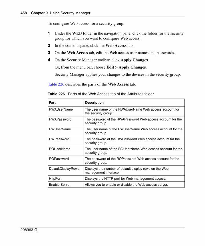
458 Chapter 9 Using Security Manager
208963-G
To configure Web access for a security group:
1 Under the WEB folder in the navigation pane, click the folder for the security group for which you want to configure Web access.
2 In the contents pane, click the Web Access tab.
3 On the Web Access tab, edit the Web access user names and passwords.
4 On the Security Manager toolbar, click Apply Changes.
Or, from the menu bar, choose Edit > Apply Changes.
Security Manager applies your changes to the devices in the security group.
Table 226 describes the parts of the Web Access tab.
Table 226 Parts of the Web Access tab of the Attributes folder
Part Description
RWAUserName The user name of the RWAUserName Web access account for the security group.
RWAPassword The password of the RWAPassword Web access account for the security group.
RWUserName The user name of the RWUserName Web access account for the security group.
RWPassword The password of the RWPassword Web access account for the security group.
ROUserName The user name of the ROUserName Web access account for the security group.
ROPassword The password of the ROPassword Web access account for the security group.
DefaultDisplayRows Displays the number of default display rows on the Web management interface.
HttpPort Displays the HTTP port for Web management access.
Enable Server Allows you to enable or disable the Web access server.
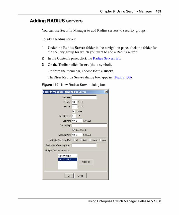
Chapter 9 Using Security Manager 459
Using Enterprise Switch Manager Release 5.1.0.0
Adding RADIUS servers
You can use Security Manager to add Radius servers to security groups.
To add a Radius server:
1 Under the Radius Server folder in the navigation pane, click the folder for the security group for which you want to add a Radius server.
2 In the Contents pane, click the Radius Servers tab.
3 On the Toolbar, click Insert (the + symbol).
Or, from the menu bar, choose Edit > Insert.
The New Radius Server dialog box appears (Figure 130).
Figure 130 New Radius Server dialog box
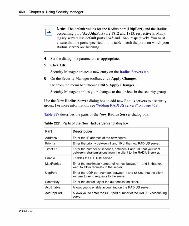
460 Chapter 9 Using Security Manager
208963-G
4 Set the dialog box parameters as appropriate.
5 Click OK.
Security Manager creates a new entry on the Radius Servers tab.
6 On the Security Manager toolbar, click Apply Changes.
Or, from the menu bar, choose Edit > Apply Changes.
Security Manager applies your changes to the devices in the security group.
Use the New Radius Server dialog box to add new Radius servers to a security group. For more information, see “Adding RADIUS servers” on page 459.
Table 227 describes the parts of the New Radius Server dialog box.
Note: The default values for the Radius port (UdpPort) and the Radius accounting port (AccUdpPort) are 1812 and 1813, respectively. Many legacy servers use default ports 1645 and 1646, respectively. You must ensure that the ports specified in this table match the ports on which your Radius servers are listening.
Table 227 Parts of the New Radius Server dialog box
Part Description
Address Enter the IP address of the new server.
Priority Enter the priority between 1 and 10 of the new RADIUS server.
TimeOut Enter the number of seconds, between 1 and 10, that you want between retransmissions from the client to the RADIUS server.
Enable Enables the RADIUS server.
MaxRetries Enter the maximum number of retries, between 1 and 6, that you want to allow requests to the server.
UdpPort Enter the UDP port number, between 1 and 65536, that the client will use to send requests to the server.
SecretKey Enter the secret key of the authentication client.
AccEnable Allows you to enable accounting on the RADIUS server.
AccUdpPort Allows you to enter the UDP port number of the RADIUS accounting server.
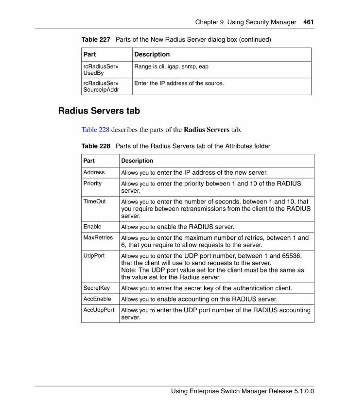
Chapter 9 Using Security Manager 461
Using Enterprise Switch Manager Release 5.1.0.0
Radius Servers tab
Table 228 describes the parts of the Radius Servers tab.
rcRadiusServUsedBy
Range is cli, igap, snmp, eap
rcRadiusServSourceIpAddr
Enter the IP address of the source.
Table 228 Parts of the Radius Servers tab of the Attributes folder
Part Description
Address Allows you to enter the IP address of the new server.
Priority Allows you to enter the priority between 1 and 10 of the RADIUS server.
TimeOut Allows you to enter the number of seconds, between 1 and 10, that you require between retransmissions from the client to the RADIUS server.
Enable Allows you to enable the RADIUS server.
MaxRetries Allows you to enter the maximum number of retries, between 1 and 6, that you require to allow requests to the server.
UdpPort Allows you to enter the UDP port number, between 1 and 65536, that the client will use to send requests to the server. Note: The UDP port value set for the client must be the same as the value set for the Radius server.
SecretKey Allows you to enter the secret key of the authentication client.
AccEnable Allows you to enable accounting on this RADIUS server.
AccUdpPort Allows you to enter the UDP port number of the RADIUS accounting server.
Table 227 Parts of the New Radius Server dialog box (continued)
Part Description
462 Chapter 9 Using Security Manager
208963-G
Removing RADIUS servers
To remove a RADIUS server from a security group:
1 Under the Radius Server folder in the navigation pane, open the folder for the security group for which you want to remove a Radius server.
2 In the Contents pane, click the Radius Servers tab.
3 On the Radius Servers tab, click any cell on the entry for the Radius server that you want to remove.
4 On the Toolbar, click Delete (the X symbol).
Or, from the menu bar, choose Edit > Delete.
Security Manager deletes the selected Radius server.
5 On the Security Manager toolbar, click Apply Changes.
Or, from the menu bar, choose Edit > Apply Changes.
Security Manager applies your changes to the devices in the security group.
Setting global RADIUS server parameters
To set global RADIUS server parameters:
1 Under the Radius Server folder in the navigation pane, open the folder for the security group for which you want to set global Radius server parameters.
2 In the Contents pane, click the Radius Global tab.
3 Set the parameters as appropriate.
4 On the Security Manager toolbar, click Apply Changes.
Or, from the menu bar, choose Edit > Apply Changes.
Security Manager applies your changes to the devices in the security group.
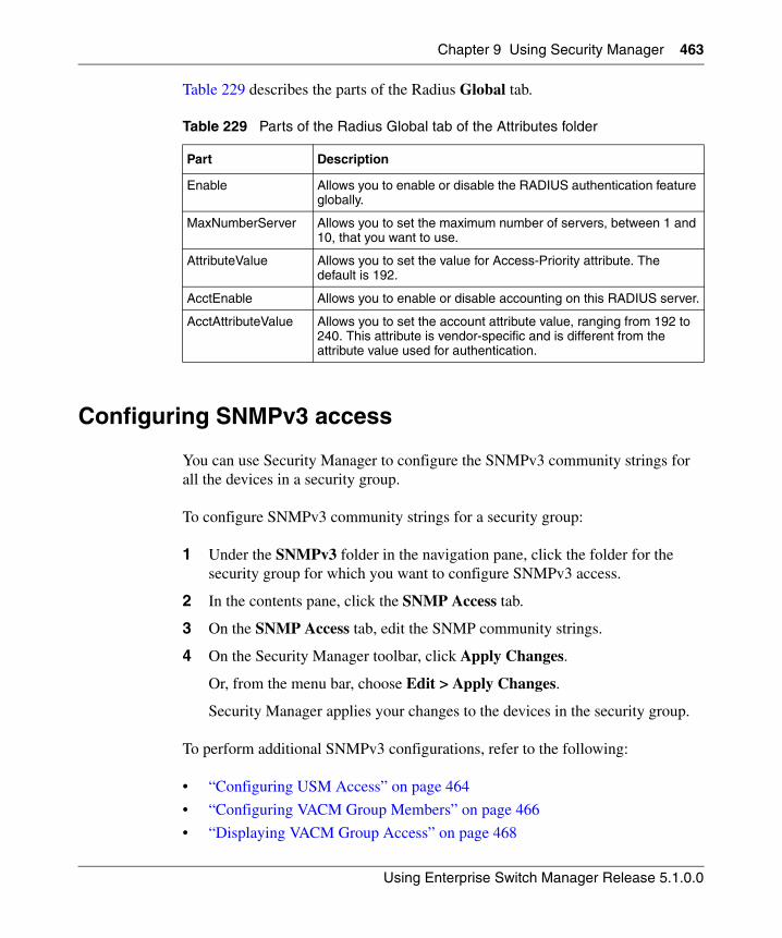
Chapter 9 Using Security Manager 463
Using Enterprise Switch Manager Release 5.1.0.0
Table 229 describes the parts of the Radius Global tab.
Configuring SNMPv3 access
You can use Security Manager to configure the SNMPv3 community strings for all the devices in a security group.
To configure SNMPv3 community strings for a security group:
1 Under the SNMPv3 folder in the navigation pane, click the folder for the security group for which you want to configure SNMPv3 access.
2 In the contents pane, click the SNMP Access tab.
3 On the SNMP Access tab, edit the SNMP community strings.
4 On the Security Manager toolbar, click Apply Changes.
Or, from the menu bar, choose Edit > Apply Changes.
Security Manager applies your changes to the devices in the security group.
To perform additional SNMPv3 configurations, refer to the following:
• “Configuring USM Access” on page 464
• “Configuring VACM Group Members” on page 466
• “Displaying VACM Group Access” on page 468
Table 229 Parts of the Radius Global tab of the Attributes folder
Part Description
Enable Allows you to enable or disable the RADIUS authentication feature globally.
MaxNumberServer Allows you to set the maximum number of servers, between 1 and 10, that you want to use.
AttributeValue Allows you to set the value for Access-Priority attribute. The default is 192.
AcctEnable Allows you to enable or disable accounting on this RADIUS server.
AcctAttributeValue Allows you to set the account attribute value, ranging from 192 to 240. This attribute is vendor-specific and is different from the attribute value used for authentication.
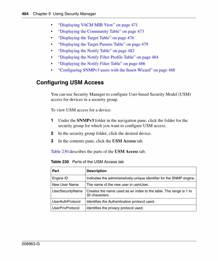
464 Chapter 9 Using Security Manager
208963-G
• “Displaying VACM MIB View” on page 471
• “Displaying the Community Table” on page 473
• “Displaying the Target Table” on page 476
• “Displaying the Target Params Table” on page 479
• “Displaying the Notify Table” on page 482
• “Displaying the Notify Filter Profile Table” on page 484
• “Displaying the Notify Filter Table” on page 486
• “Configuring SNMPv3 users with the Insert Wizard” on page 488
Configuring USM Access
You can use Security Manager to configure User-based Security Model (USM) access for devices in a security group.
To view USM access for a device:
1 Under the SNMPv3 folder in the navigation pane, click the folder for the security group for which you want to configure USM access.
2 In the security group folder, click the desired device.
3 In the contents pane, click the USM Access tab.
Table 230 describes the parts of the USM Access tab.
Table 230 Parts of the USM Access tab
Part Description
Engine ID Indicates the administratively-unique identifier for the SNMP engine.
New User Name The name of the new user in usmUser.
UserSecurityName Creates the name used as an index to the table. The range is 1 to 32 characters.
UserAuthProtocol Identifies the Authentication protocol used.
UserPrivProtocol Identifies the privacy protocol used.
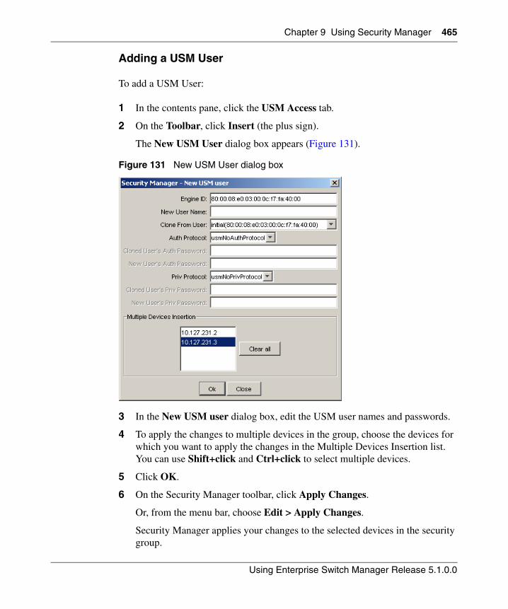
Chapter 9 Using Security Manager 465
Using Enterprise Switch Manager Release 5.1.0.0
Adding a USM User
To add a USM User:
1 In the contents pane, click the USM Access tab.
2 On the Toolbar, click Insert (the plus sign).
The New USM User dialog box appears (Figure 131).
Figure 131 New USM User dialog box
3 In the New USM user dialog box, edit the USM user names and passwords.
4 To apply the changes to multiple devices in the group, choose the devices for which you want to apply the changes in the Multiple Devices Insertion list. You can use Shift+click and Ctrl+click to select multiple devices.
5 Click OK.
6 On the Security Manager toolbar, click Apply Changes.
Or, from the menu bar, choose Edit > Apply Changes.
Security Manager applies your changes to the selected devices in the security group.
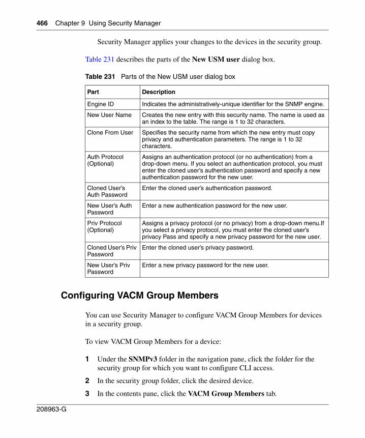
466 Chapter 9 Using Security Manager
208963-G
Security Manager applies your changes to the devices in the security group.
Table 231 describes the parts of the New USM user dialog box.
Configuring VACM Group Members
You can use Security Manager to configure VACM Group Members for devices in a security group.
To view VACM Group Members for a device:
1 Under the SNMPv3 folder in the navigation pane, click the folder for the security group for which you want to configure CLI access.
2 In the security group folder, click the desired device.
3 In the contents pane, click the VACM Group Members tab.
Table 231 Parts of the New USM user dialog box
Part Description
Engine ID Indicates the administratively-unique identifier for the SNMP engine.
New User Name Creates the new entry with this security name. The name is used as an index to the table. The range is 1 to 32 characters.
Clone From User Specifies the security name from which the new entry must copy privacy and authentication parameters. The range is 1 to 32 characters.
Auth Protocol (Optional)
Assigns an authentication protocol (or no authentication) from a drop-down menu. If you select an authentication protocol, you must enter the cloned user’s authentication password and specify a new authentication password for the new user.
Cloned User’s Auth Password
Enter the cloned user’s authentication password.
New User’s Auth Password
Enter a new authentication password for the new user.
Priv Protocol (Optional)
Assigns a privacy protocol (or no privacy) from a drop-down menu.If you select a privacy protocol, you must enter the cloned user’s privacy Pass and specify a new privacy password for the new user.
Cloned User’s Priv Password
Enter the cloned user’s privacy password.
New User’s Priv Password
Enter a new privacy password for the new user.
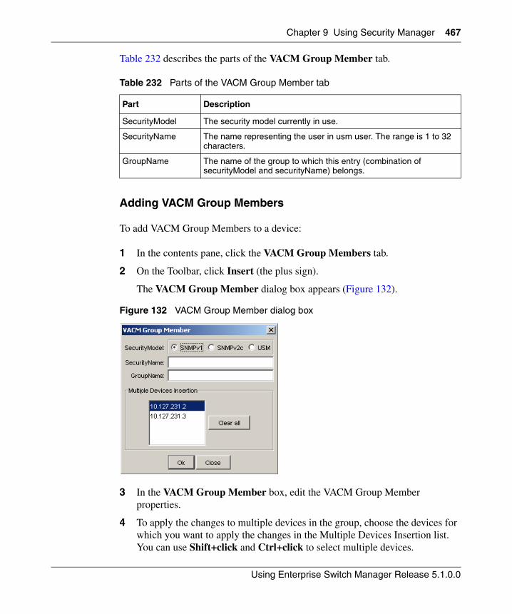
Chapter 9 Using Security Manager 467
Using Enterprise Switch Manager Release 5.1.0.0
Table 232 describes the parts of the VACM Group Member tab.
Adding VACM Group Members
To add VACM Group Members to a device:
1 In the contents pane, click the VACM Group Members tab.
2 On the Toolbar, click Insert (the plus sign).
The VACM Group Member dialog box appears (Figure 132).
Figure 132 VACM Group Member dialog box
3 In the VACM Group Member box, edit the VACM Group Member properties.
4 To apply the changes to multiple devices in the group, choose the devices for which you want to apply the changes in the Multiple Devices Insertion list. You can use Shift+click and Ctrl+click to select multiple devices.
Table 232 Parts of the VACM Group Member tab
Part Description
SecurityModel The security model currently in use.
SecurityName The name representing the user in usm user. The range is 1 to 32 characters.
GroupName The name of the group to which this entry (combination of securityModel and securityName) belongs.
468 Chapter 9 Using Security Manager
208963-G
5 Click OK.
6 On the Security Manager toolbar, click Apply Changes.
Or, from the menu bar, choose Edit > Apply Changes.
Security Manager applies your changes to the selected devices in the security group.
Security Manager applies your changes to the devices in the security group.
Table 233 describes the parts of the VACM Group Member dialog box.
Displaying VACM Group Access
You can use Security Manager to view VACM Group Access for devices in a security group.
To view VACM Group Access for a device:
1 Under the SNMPv3 folder in the navigation pane, click the folder for the security group for which you want to configure CLI access.
2 In the security group folder, click the desired device.
3 In the contents pane, click the VACM Group Access tab.
Table 233 Parts of the VACM Group Member dialog box
Part Description
SecurityModel The security model currently to use
SecurityName The name representing the user in USM user. The range is 1 to 32 characters.
GroupName The name of the group to which this entry (combination of securityModel and securityName) belongs.
Chapter 9 Using Security Manager 469
Using Enterprise Switch Manager Release 5.1.0.0
Table 234 describes the parts of the VACM Group Access tab.
Configuring VACM Group Access
To configure VACM Group Access for a device:
1 In the contents pane, click the VACM Group Access tab to bring it to the front.
2 On the Toolbar, click Insert (the plus sign).
Table 234 Parts of the VACM Group Access tab
Part Description
vacmGroupName The name of the group name in the VACM table. The name is a numeral. The range is 1 to 32 characters.
ContextPrefix The contextName of an incoming SNMP packet must match exactly or partially the value of the instance of this object. The range is an SnmpAdminString, 1 to 32 characters.
SecurityModel The security model of the entry, either SNMPv1, SNMPv2, or SNMPv3.
SecurityLevel The minimum level of security required to gain access rights.
The security levels are:
• noAuthNoPriv• authNoPriv
• authpriv
ReadViewName Specifies the MIB view to which read access is authorized.
WriteViewName Specifies the MIB view to which write access is authorized.
NotifyViewName Specifies the MIB view name to which notification access is authorized.
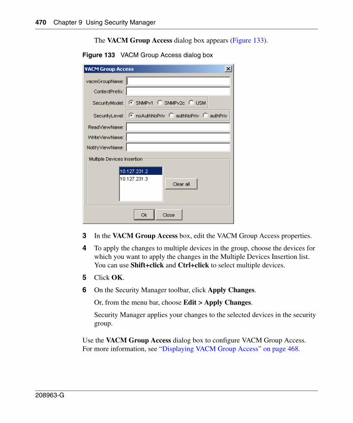
470 Chapter 9 Using Security Manager
208963-G
The VACM Group Access dialog box appears (Figure 133).
Figure 133 VACM Group Access dialog box
3 In the VACM Group Access box, edit the VACM Group Access properties.
4 To apply the changes to multiple devices in the group, choose the devices for which you want to apply the changes in the Multiple Devices Insertion list. You can use Shift+click and Ctrl+click to select multiple devices.
5 Click OK.
6 On the Security Manager toolbar, click Apply Changes.
Or, from the menu bar, choose Edit > Apply Changes.
Security Manager applies your changes to the selected devices in the security group.
Use the VACM Group Access dialog box to configure VACM Group Access. For more information, see “Displaying VACM Group Access” on page 468.
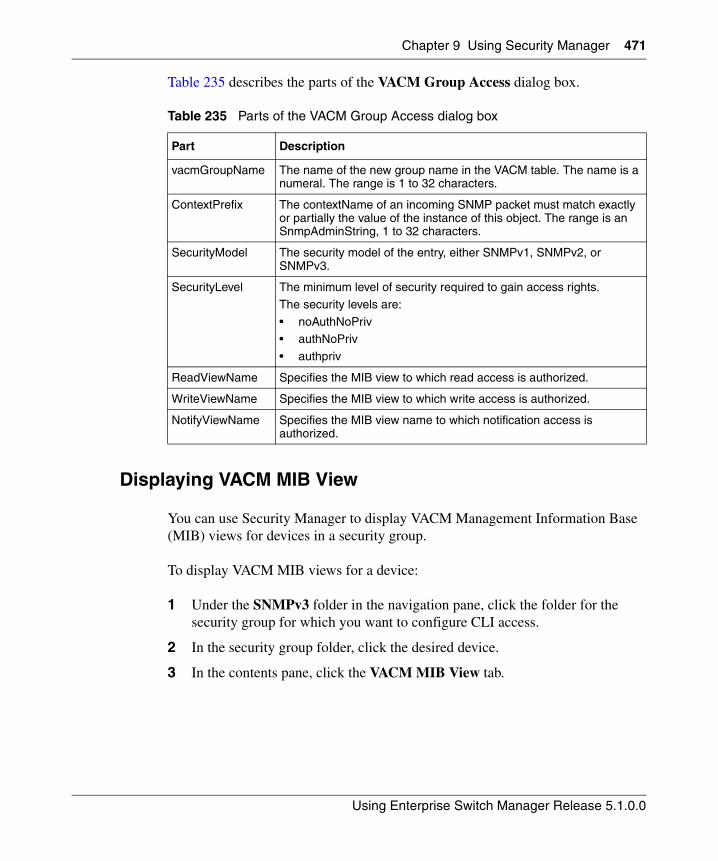
Chapter 9 Using Security Manager 471
Using Enterprise Switch Manager Release 5.1.0.0
Table 235 describes the parts of the VACM Group Access dialog box.
Displaying VACM MIB View
You can use Security Manager to display VACM Management Information Base (MIB) views for devices in a security group.
To display VACM MIB views for a device:
1 Under the SNMPv3 folder in the navigation pane, click the folder for the security group for which you want to configure CLI access.
2 In the security group folder, click the desired device.
3 In the contents pane, click the VACM MIB View tab.
Table 235 Parts of the VACM Group Access dialog box
Part Description
vacmGroupName The name of the new group name in the VACM table. The name is a numeral. The range is 1 to 32 characters.
ContextPrefix The contextName of an incoming SNMP packet must match exactly or partially the value of the instance of this object. The range is an SnmpAdminString, 1 to 32 characters.
SecurityModel The security model of the entry, either SNMPv1, SNMPv2, or SNMPv3.
SecurityLevel The minimum level of security required to gain access rights.
The security levels are:
• noAuthNoPriv• authNoPriv
• authpriv
ReadViewName Specifies the MIB view to which read access is authorized.
WriteViewName Specifies the MIB view to which write access is authorized.
NotifyViewName Specifies the MIB view name to which notification access is authorized.
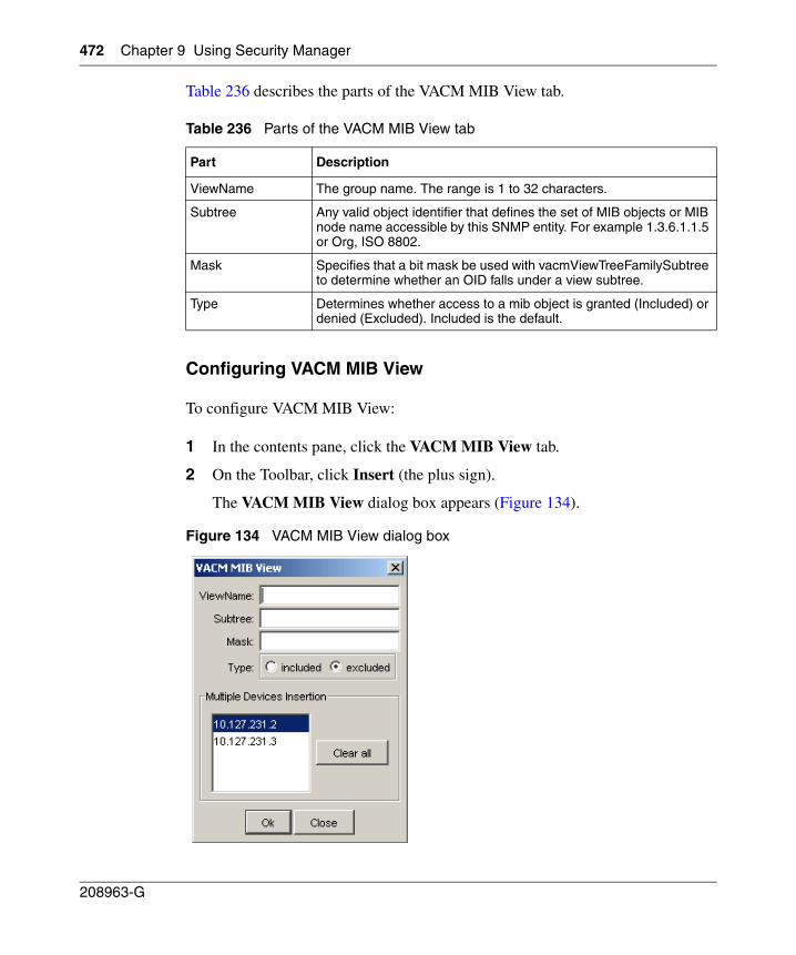
472 Chapter 9 Using Security Manager
208963-G
Table 236 describes the parts of the VACM MIB View tab.
Configuring VACM MIB View
To configure VACM MIB View:
1 In the contents pane, click the VACM MIB View tab.
2 On the Toolbar, click Insert (the plus sign).
The VACM MIB View dialog box appears (Figure 134).
Figure 134 VACM MIB View dialog box
Table 236 Parts of the VACM MIB View tab
Part Description
ViewName The group name. The range is 1 to 32 characters.
Subtree Any valid object identifier that defines the set of MIB objects or MIB node name accessible by this SNMP entity. For example 1.3.6.1.1.5 or Org, ISO 8802.
Mask Specifies that a bit mask be used with vacmViewTreeFamilySubtree to determine whether an OID falls under a view subtree.
Type Determines whether access to a mib object is granted (Included) or denied (Excluded). Included is the default.
Chapter 9 Using Security Manager 473
Using Enterprise Switch Manager Release 5.1.0.0
3 In the VACM MIB View dialog box, edit the VACM MIB View properties.
4 To apply the changes to multiple devices in the group, choose the devices for which you want to apply the changes in the Multiple Devices Insertion list. You can use Shift+click and Ctrl+click to select multiple devices.
5 Click OK.
6 On the Security Manager toolbar, click Apply Changes.
Or, from the menu bar, choose Edit > Apply Changes.
Security Manager applies your changes to the selected devices in the security group.
Table 237 describes the parts of the VACM MIB View dialog box.
Displaying the Community Table
You can use Security Manager to configure the Community Table for devices in a security group.
To configure the Community Table for a device:
1 Under the SNMPv3 folder in the navigation pane, click the folder for the security group for which you want to configure CLI access.
2 In the security group folder, click the desired device.
3 In the contents pane, click the Community Table tab.
Table 237 Parts of the VACM MIB View dialog box
Part Description
ViewName Creates a new entry with this group name. The range is 1 to 32 characters.
Subtree Any valid object identifier that defines the set of MIB objects or MIB node name accessible by this SNMP entity. For example 1.3.6.1.1.5 or Org, ISO 8802.
Mask Specifies that a bit mask be used with vacmViewTreeFamilySubtree to determine whether an OID falls under a view subtree.
Type Determines whether access to a mib object is granted (Included) or denied (Excluded). Included is the default.
474 Chapter 9 Using Security Manager
208963-G
Table 238 describes the parts of the Community Table tab.
Configuring the Community Table
To configure the Community Table:
1 In the contents pane, click the Community Table tab.
2 On the Toolbar, click Insert (the plus sign).
Table 238 Parts of the Community Table tab
Part Description
Index The unique index value of a row in this table. SnmpAdminString 1-32 characters.
Name The community string for which a row in this table represents a configuration.
SecurityName The security name assigned to this entry in the Community table. The range is 1 to 32 characters.
ContextEngineID The contextEngineID indicating the location of the context in which management information is accessed.
TransportTag The transport endpoints that are associated with the community string. The community string is only valid when found in an SNMPv1 (or SNMPv2c) message received from one of these transport endpoints, or when used in an SNMPv1 (or SNMPv2c) message to be sent to one of these transport endpoints.The value of this object identifies a set of entries in the snmpTargetAddrTable.
If the value of this object has zero-length, transport endpoints are not checked when attempting to choose an entry in the snmpCommunityTable (that is, the community string is valid for use with any transport endpoint).
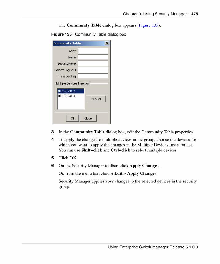
Chapter 9 Using Security Manager 475
Using Enterprise Switch Manager Release 5.1.0.0
The Community Table dialog box appears (Figure 135).
Figure 135 Community Table dialog box
3 In the Community Table dialog box, edit the Community Table properties.
4 To apply the changes to multiple devices in the group, choose the devices for which you want to apply the changes in the Multiple Devices Insertion list. You can use Shift+click and Ctrl+click to select multiple devices.
5 Click OK.
6 On the Security Manager toolbar, click Apply Changes.
Or, from the menu bar, choose Edit > Apply Changes.
Security Manager applies your changes to the selected devices in the security group.
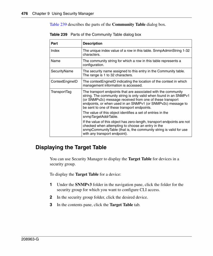
476 Chapter 9 Using Security Manager
208963-G
Table 239 describes the parts of the Community Table dialog box.
Displaying the Target Table
You can use Security Manager to display the Target Table for devices in a security group.
To display the Target Table for a device:
1 Under the SNMPv3 folder in the navigation pane, click the folder for the security group for which you want to configure CLI access.
2 In the security group folder, click the desired device.
3 In the contents pane, click the Target Table tab.
Table 239 Parts of the Community Table dialog box
Part Description
Index The unique index value of a row in this table. SnmpAdminString 1-32 characters.
Name The community string for which a row in this table represents a configuration.
SecurityName The security name assigned to this entry in the Community table. The range is 1 to 32 characters.
ContextEngineID The contextEngineID indicating the location of the context in which management information is accessed.
TransportTag The transport endpoints that are associated with the community string. The community string is only valid when found in an SNMPv1 (or SNMPv2c) message received from one of these transport endpoints, or when used in an SNMPv1 (or SNMPv2c) message to be sent to one of these transport endpoints.The value of this object identifies a set of entries in the snmpTargetAddrTable.
If the value of this object has zero-length, transport endpoints are not checked when attempting to choose an entry in the snmpCommunityTable (that is, the community string is valid for use with any transport endpoint).
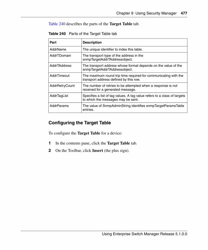
Chapter 9 Using Security Manager 477
Using Enterprise Switch Manager Release 5.1.0.0
Table 240 describes the parts of the Target Table tab.
Configuring the Target Table
To configure the Target Table for a device:
1 In the contents pane, click the Target Table tab.
2 On the Toolbar, click Insert (the plus sign).
Table 240 Parts of the Target Table tab
Part Description
AddrName The unique identifier to index this table.
AddrTDomain The transport type of the address in the snmpTargetAddrTAddressobject.
AddrTAddress The transport address whose format depends on the value of the snmpTargetAddrTAddressobject.
AddrTimeout The maximum round trip time required for communicating with the transport address defined by this row.
AddrRetryCount The number of retries to be attempted when a response is not received for a generated message.
AddrTagList Specifies a list of tag values. A tag value refers to a class of targets to which the messages may be sent.
AddrParams The value of SnmpAdminString identifies snmpTargetParamsTable entries.
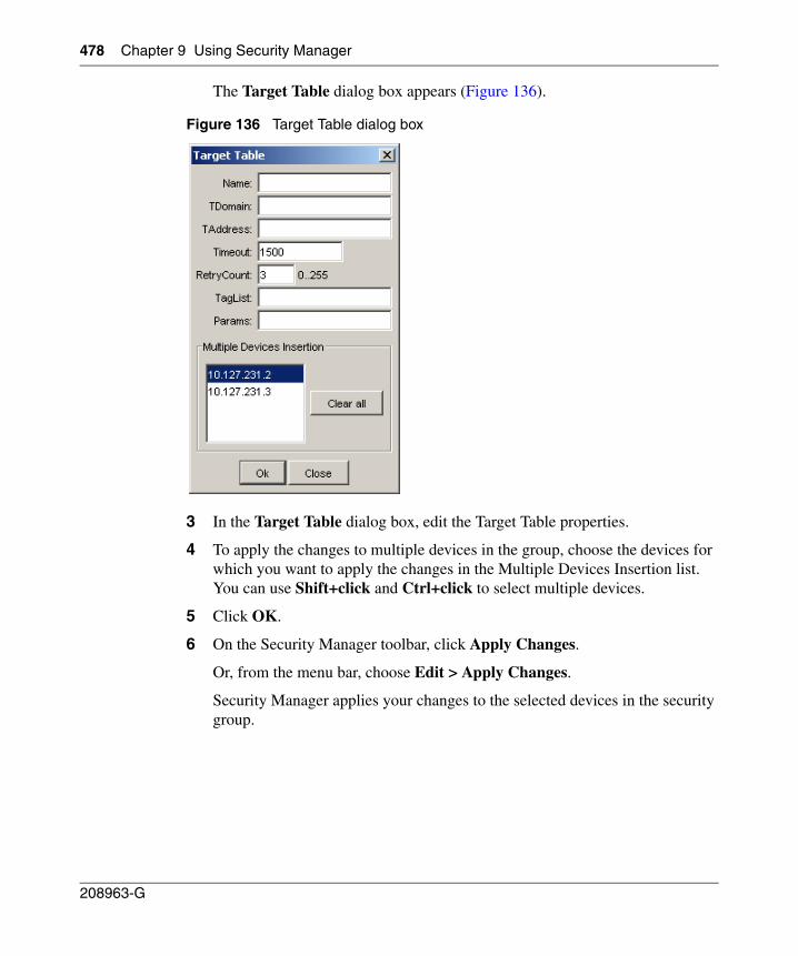
478 Chapter 9 Using Security Manager
208963-G
The Target Table dialog box appears (Figure 136).
Figure 136 Target Table dialog box
3 In the Target Table dialog box, edit the Target Table properties.
4 To apply the changes to multiple devices in the group, choose the devices for which you want to apply the changes in the Multiple Devices Insertion list. You can use Shift+click and Ctrl+click to select multiple devices.
5 Click OK.
6 On the Security Manager toolbar, click Apply Changes.
Or, from the menu bar, choose Edit > Apply Changes.
Security Manager applies your changes to the selected devices in the security group.
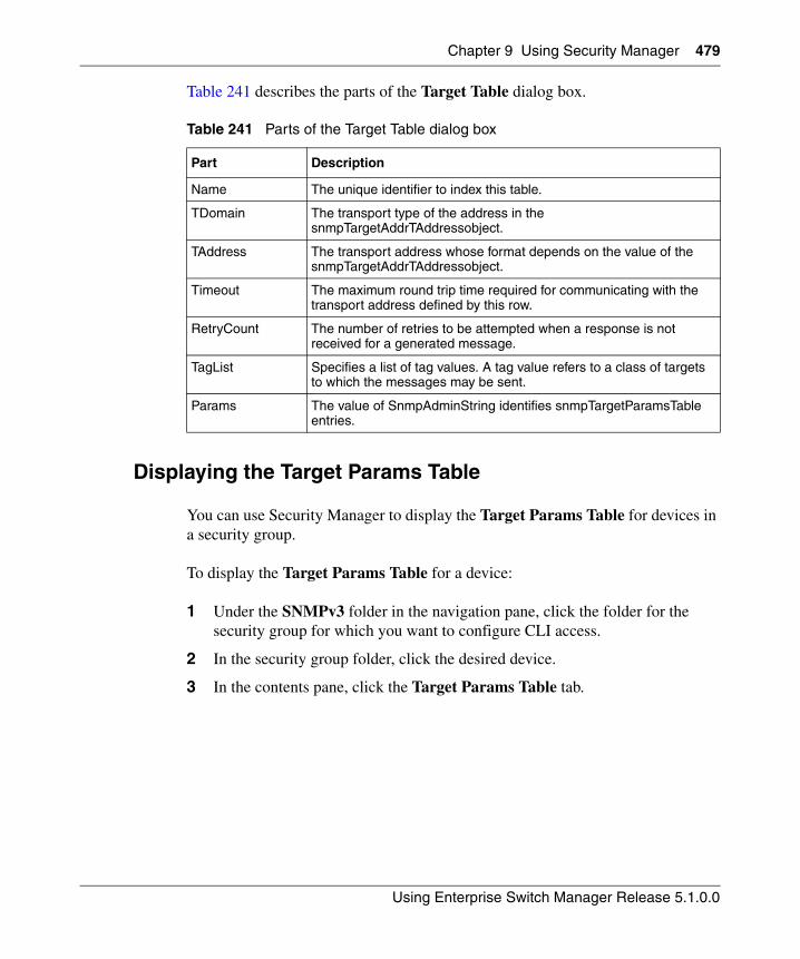
Chapter 9 Using Security Manager 479
Using Enterprise Switch Manager Release 5.1.0.0
Table 241 describes the parts of the Target Table dialog box.
Displaying the Target Params Table
You can use Security Manager to display the Target Params Table for devices in a security group.
To display the Target Params Table for a device:
1 Under the SNMPv3 folder in the navigation pane, click the folder for the security group for which you want to configure CLI access.
2 In the security group folder, click the desired device.
3 In the contents pane, click the Target Params Table tab.
Table 241 Parts of the Target Table dialog box
Part Description
Name The unique identifier to index this table.
TDomain The transport type of the address in the snmpTargetAddrTAddressobject.
TAddress The transport address whose format depends on the value of the snmpTargetAddrTAddressobject.
Timeout The maximum round trip time required for communicating with the transport address defined by this row.
RetryCount The number of retries to be attempted when a response is not received for a generated message.
TagList Specifies a list of tag values. A tag value refers to a class of targets to which the messages may be sent.
Params The value of SnmpAdminString identifies snmpTargetParamsTable entries.
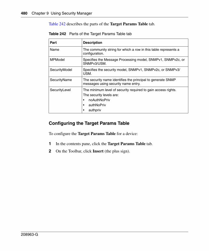
480 Chapter 9 Using Security Manager
208963-G
Table 242 describes the parts of the Target Params Table tab.
Configuring the Target Params Table
To configure the Target Params Table for a device:
1 In the contents pane, click the Target Params Table tab.
2 On the Toolbar, click Insert (the plus sign).
Table 242 Parts of the Target Params Table tab
Part Description
Name The community string for which a row in this table represents a configuration.
MPModel Specifies the Message Processing model, SNMPv1, SNMPv2c, or SNMPv3/USM.
SecurityModel Specifies the security model, SNMPv1, SNMPv2c, or SNMPv3/USM.
SecurityName The security name identifies the principal to generate SNMP messages using security name entry.
SecurityLevel The minimum level of security required to gain access rights.
The security levels are:• noAuthNoPriv
• authNoPriv
• authpriv
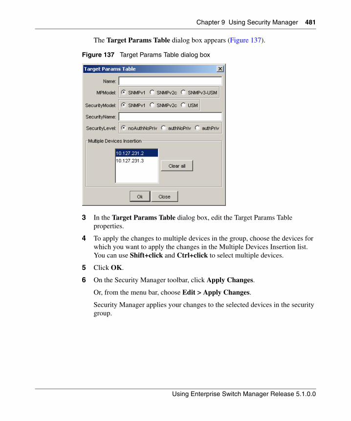
Chapter 9 Using Security Manager 481
Using Enterprise Switch Manager Release 5.1.0.0
The Target Params Table dialog box appears (Figure 137).
Figure 137 Target Params Table dialog box
3 In the Target Params Table dialog box, edit the Target Params Table properties.
4 To apply the changes to multiple devices in the group, choose the devices for which you want to apply the changes in the Multiple Devices Insertion list. You can use Shift+click and Ctrl+click to select multiple devices.
5 Click OK.
6 On the Security Manager toolbar, click Apply Changes.
Or, from the menu bar, choose Edit > Apply Changes.
Security Manager applies your changes to the selected devices in the security group.
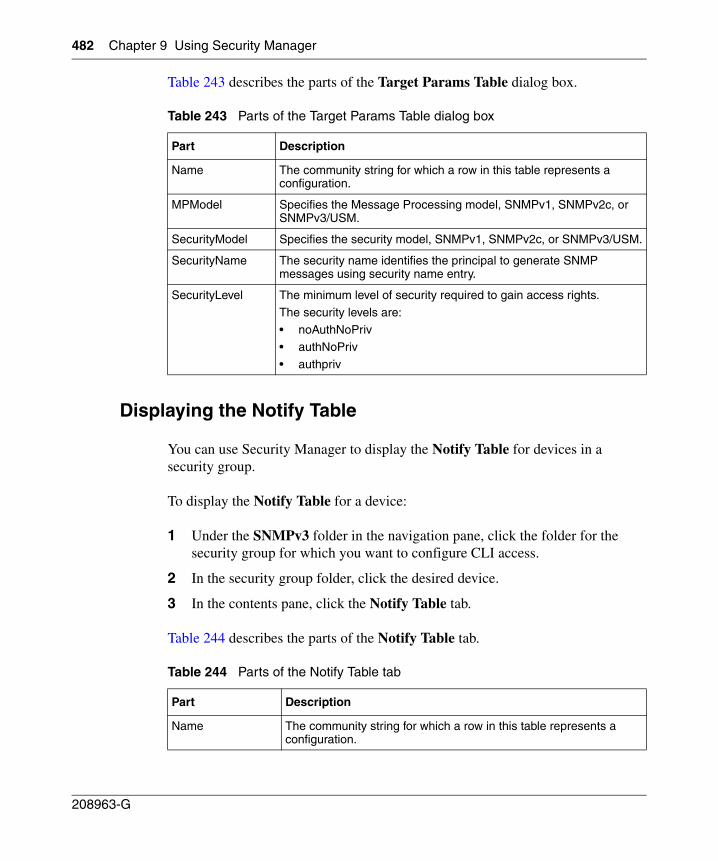
482 Chapter 9 Using Security Manager
208963-G
Table 243 describes the parts of the Target Params Table dialog box.
Displaying the Notify Table
You can use Security Manager to display the Notify Table for devices in a security group.
To display the Notify Table for a device:
1 Under the SNMPv3 folder in the navigation pane, click the folder for the security group for which you want to configure CLI access.
2 In the security group folder, click the desired device.
3 In the contents pane, click the Notify Table tab.
Table 244 describes the parts of the Notify Table tab.
Table 243 Parts of the Target Params Table dialog box
Part Description
Name The community string for which a row in this table represents a configuration.
MPModel Specifies the Message Processing model, SNMPv1, SNMPv2c, or SNMPv3/USM.
SecurityModel Specifies the security model, SNMPv1, SNMPv2c, or SNMPv3/USM.
SecurityName The security name identifies the principal to generate SNMP messages using security name entry.
SecurityLevel The minimum level of security required to gain access rights.
The security levels are:
• noAuthNoPriv• authNoPriv
• authpriv
Table 244 Parts of the Notify Table tab
Part Description
Name The community string for which a row in this table represents a configuration.
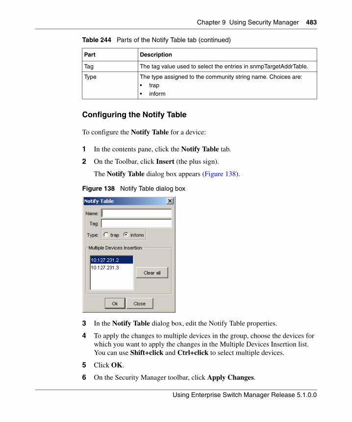
Chapter 9 Using Security Manager 483
Using Enterprise Switch Manager Release 5.1.0.0
Configuring the Notify Table
To configure the Notify Table for a device:
1 In the contents pane, click the Notify Table tab.
2 On the Toolbar, click Insert (the plus sign).
The Notify Table dialog box appears (Figure 138).
Figure 138 Notify Table dialog box
3 In the Notify Table dialog box, edit the Notify Table properties.
4 To apply the changes to multiple devices in the group, choose the devices for which you want to apply the changes in the Multiple Devices Insertion list. You can use Shift+click and Ctrl+click to select multiple devices.
5 Click OK.
6 On the Security Manager toolbar, click Apply Changes.
Tag The tag value used to select the entries in snmpTargetAddrTable.
Type The type assigned to the community string name. Choices are:
• trap• inform
Table 244 Parts of the Notify Table tab (continued)
Part Description
484 Chapter 9 Using Security Manager
208963-G
Or, from the menu bar, choose Edit > Apply Changes.
Security Manager applies your changes to the selected devices in the security group.
Security Manager applies your changes to the devices in the security group.
Table 245 describes the parts of the Notify Table dialog box.
Displaying the Notify Filter Profile Table
You can use Security Manager to display the Notify Filter Profile Table for devices in a security group.
To display the Notify Filter Profile Table for a device:
1 Under the SNMPv3 folder in the navigation pane, click the folder for the security group for which you want to configure CLI access.
2 In the security group folder, click the desired device.
3 In the contents pane, click the Notify Filter Profile Table tab.
Table 246 describes the parts of the Notify Filter Profile Table tab.
Table 245 Parts of the Notify Table dialog box
Part Description
Name The community string for which a row in this table represents a configuration.
Tag The tag value used to select the entries in snmpTargetAddrTable.
Type The type assigned to the community string name. Choices are:
• trap• inform
Table 246 Parts of the Notify Filter Profile Table tab
Part Description
TargetParamsName The unique identifier associated with this entry. This value is an SnmpAdminString of 1-32 characters.
NotifyFilterProfileName The name of the filter profile used while generating notifications in snmpTargetAddrTable.
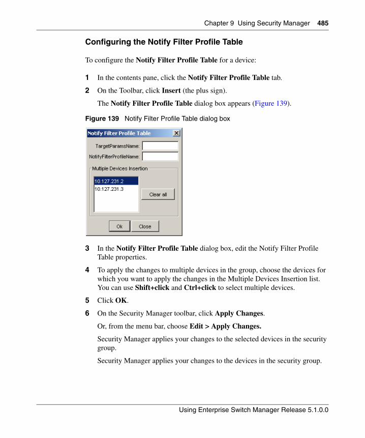
Chapter 9 Using Security Manager 485
Using Enterprise Switch Manager Release 5.1.0.0
Configuring the Notify Filter Profile Table
To configure the Notify Filter Profile Table for a device:
1 In the contents pane, click the Notify Filter Profile Table tab.
2 On the Toolbar, click Insert (the plus sign).
The Notify Filter Profile Table dialog box appears (Figure 139).
Figure 139 Notify Filter Profile Table dialog box
3 In the Notify Filter Profile Table dialog box, edit the Notify Filter Profile Table properties.
4 To apply the changes to multiple devices in the group, choose the devices for which you want to apply the changes in the Multiple Devices Insertion list. You can use Shift+click and Ctrl+click to select multiple devices.
5 Click OK.
6 On the Security Manager toolbar, click Apply Changes.
Or, from the menu bar, choose Edit > Apply Changes.
Security Manager applies your changes to the selected devices in the security group.
Security Manager applies your changes to the devices in the security group.
486 Chapter 9 Using Security Manager
208963-G
Table 247 describes the parts of the Notify Filter Profile Table dialog box.
Displaying the Notify Filter Table
You can use Security Manager to display the Notify Filter Table for devices in a security group.
To display the Notify Filter Table for a device:
1 Under the SNMPv3 folder in the navigation pane, click the folder for the security group for which you want to configure CLI access.
2 In the security group folder, click the desired device.
3 In the contents pane, click the Notify Filter Table tab
Table 248 describes the parts of the Notify Filter Table tab.
Table 247 Parts of the Notify Filter Profile Table dialog box
Part Description
TargetParamsName The unique identifier associated with this entry. This value is an SnmpAdminString of 1-32 characters.
NotifyFilterProfileName The name of the filter profile used while generating notifications in snmpTargetAddrTable.
Table 248 Parts of the Notify Filter Table tab
Part Description
ProfileName The name of the filter profile used while generating notifications in snmpTargetAddrTable.
Subtree MIB subtree with the corresponding instance of snmpNotifyFilterMask defines a family of subtrees.
Mask Bit mask in combination with snmpNotifyFilterMask defines a family of subtrees.
Type Indicates whether the family of filter subtrees defined by this entry are included or excluded from a filter. The valid options are included and excluded.
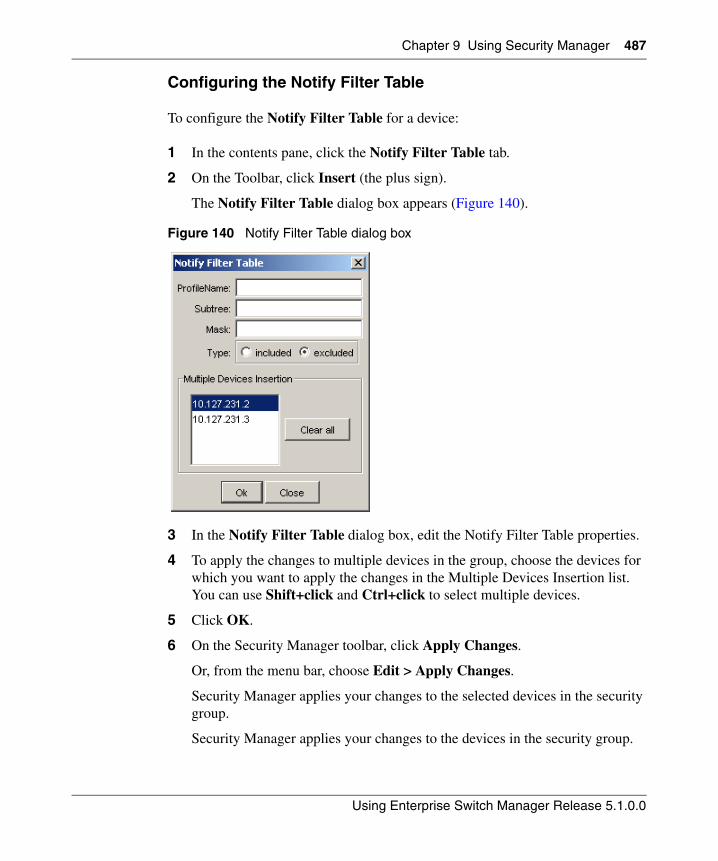
Chapter 9 Using Security Manager 487
Using Enterprise Switch Manager Release 5.1.0.0
Configuring the Notify Filter Table
To configure the Notify Filter Table for a device:
1 In the contents pane, click the Notify Filter Table tab.
2 On the Toolbar, click Insert (the plus sign).
The Notify Filter Table dialog box appears (Figure 140).
Figure 140 Notify Filter Table dialog box
3 In the Notify Filter Table dialog box, edit the Notify Filter Table properties.
4 To apply the changes to multiple devices in the group, choose the devices for which you want to apply the changes in the Multiple Devices Insertion list. You can use Shift+click and Ctrl+click to select multiple devices.
5 Click OK.
6 On the Security Manager toolbar, click Apply Changes.
Or, from the menu bar, choose Edit > Apply Changes.
Security Manager applies your changes to the selected devices in the security group.
Security Manager applies your changes to the devices in the security group.
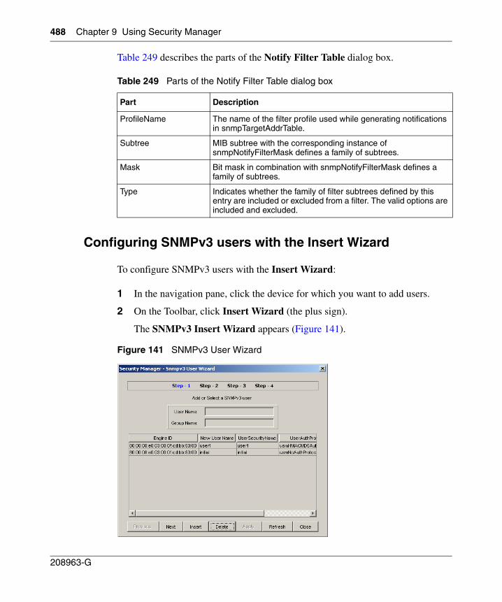
488 Chapter 9 Using Security Manager
208963-G
Table 249 describes the parts of the Notify Filter Table dialog box.
Configuring SNMPv3 users with the Insert Wizard
To configure SNMPv3 users with the Insert Wizard:
1 In the navigation pane, click the device for which you want to add users.
2 On the Toolbar, click Insert Wizard (the plus sign).
The SNMPv3 Insert Wizard appears (Figure 141).
Figure 141 SNMPv3 User Wizard
Table 249 Parts of the Notify Filter Table dialog box
Part Description
ProfileName The name of the filter profile used while generating notifications in snmpTargetAddrTable.
Subtree MIB subtree with the corresponding instance of snmpNotifyFilterMask defines a family of subtrees.
Mask Bit mask in combination with snmpNotifyFilterMask defines a family of subtrees.
Type Indicates whether the family of filter subtrees defined by this entry are included or excluded from a filter. The valid options are included and excluded.
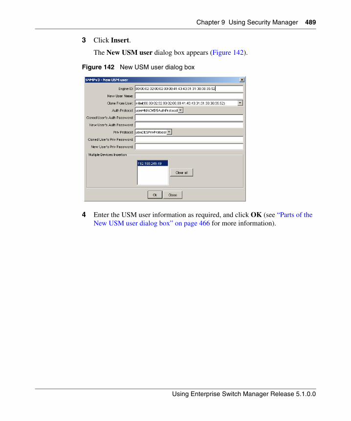
Chapter 9 Using Security Manager 489
Using Enterprise Switch Manager Release 5.1.0.0
3 Click Insert.
The New USM user dialog box appears (Figure 142).
Figure 142 New USM user dialog box
4 Enter the USM user information as required, and click OK (see “Parts of the New USM user dialog box” on page 466 for more information).
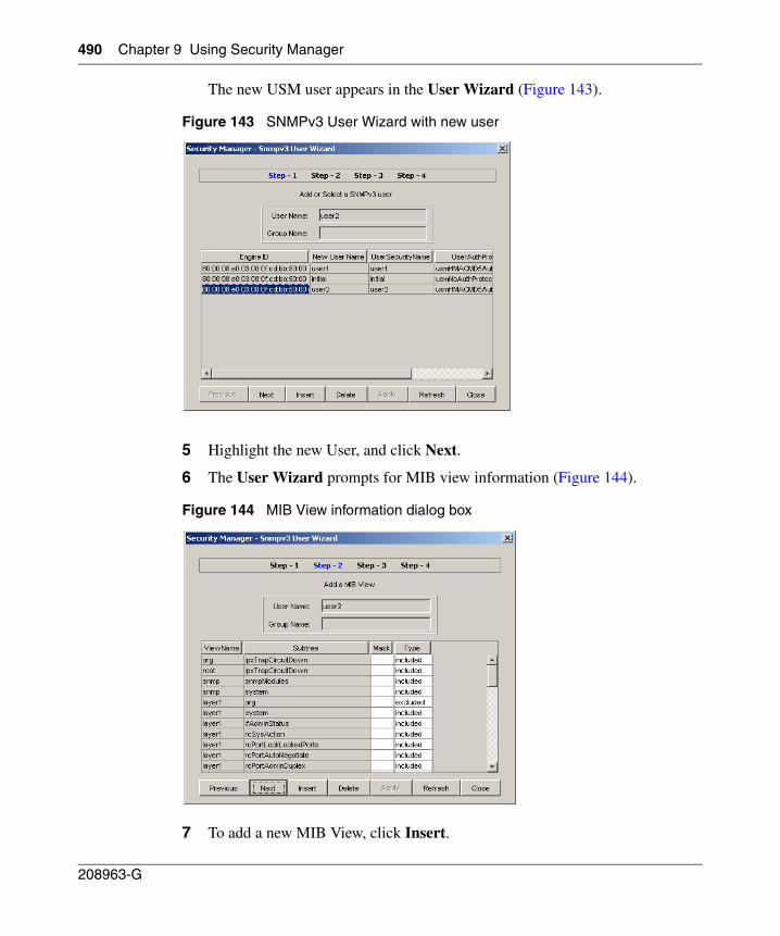
490 Chapter 9 Using Security Manager
208963-G
The new USM user appears in the User Wizard (Figure 143).
Figure 143 SNMPv3 User Wizard with new user
5 Highlight the new User, and click Next.
6 The User Wizard prompts for MIB view information (Figure 144).
Figure 144 MIB View information dialog box
7 To add a new MIB View, click Insert.
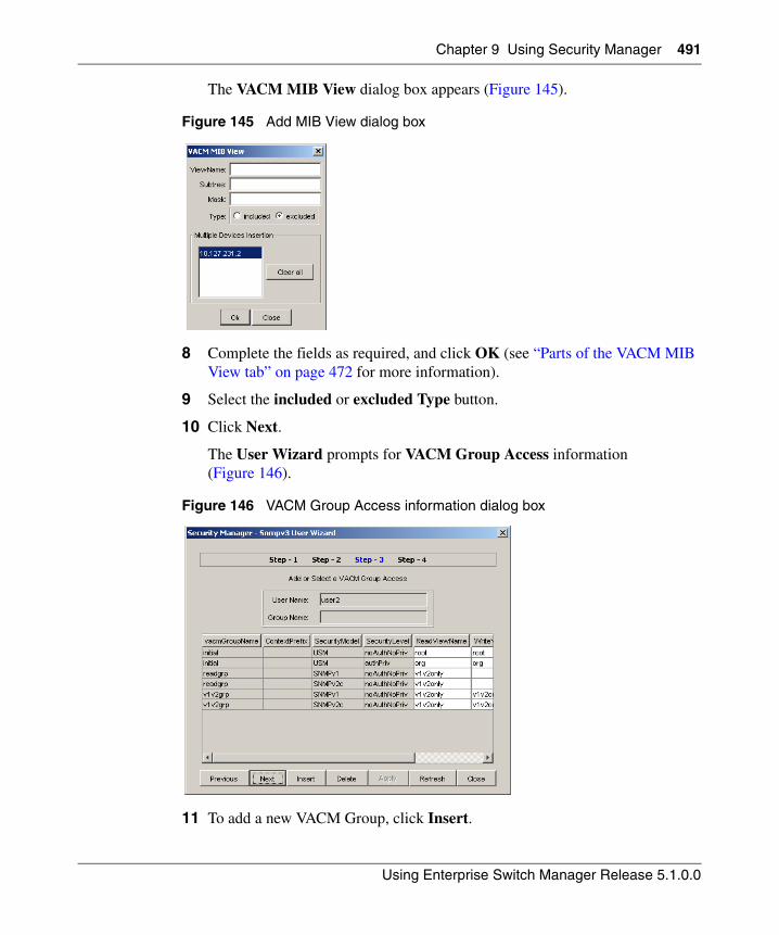
Chapter 9 Using Security Manager 491
Using Enterprise Switch Manager Release 5.1.0.0
The VACM MIB View dialog box appears (Figure 145).
Figure 145 Add MIB View dialog box
8 Complete the fields as required, and click OK (see “Parts of the VACM MIB View tab” on page 472 for more information).
9 Select the included or excluded Type button.
10 Click Next.
The User Wizard prompts for VACM Group Access information (Figure 146).
Figure 146 VACM Group Access information dialog box
11 To add a new VACM Group, click Insert.
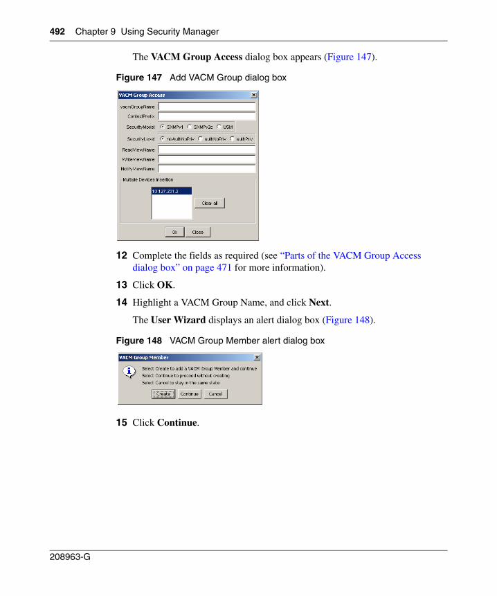
492 Chapter 9 Using Security Manager
208963-G
The VACM Group Access dialog box appears (Figure 147).
Figure 147 Add VACM Group dialog box
12 Complete the fields as required (see “Parts of the VACM Group Access dialog box” on page 471 for more information).
13 Click OK.
14 Highlight a VACM Group Name, and click Next.
The User Wizard displays an alert dialog box (Figure 148).
Figure 148 VACM Group Member alert dialog box
15 Click Continue.
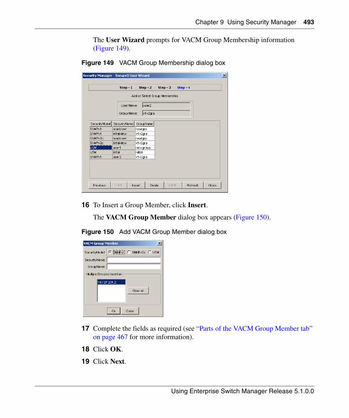
Chapter 9 Using Security Manager 493
Using Enterprise Switch Manager Release 5.1.0.0
The User Wizard prompts for VACM Group Membership information (Figure 149).
Figure 149 VACM Group Membership dialog box
16 To Insert a Group Member, click Insert.
The VACM Group Member dialog box appears (Figure 150).
Figure 150 Add VACM Group Member dialog box
17 Complete the fields as required (see “Parts of the VACM Group Member tab” on page 467 for more information).
18 Click OK.
19 Click Next.
494 Chapter 9 Using Security Manager
208963-G
Managing access policies with Security Manager
You can use Security Manager to add, delete, monitor, and synchronize access policies for all the devices in a security group.
Enabling or disabling access policies
Security Manager allows you to enable and disable access policies at a variety of levels within a security group. See the following sections for more information:
• “Enabling or disabling access policies for devices in a security group” on page 494
• “Enabling or disabling individual access policies” on page 495
• “Adding access policies” on page 496
• “Deleting access policies” on page 498
Enabling or disabling access policies for devices in a security group
To enable or disable access policies for a device in a security group:
1 Under the Access Policy folder in the navigation pane, open the folder for the security group for which you want to set access policies.
2 In the security group folder, click the desired device.
3 In the content pane, click the Access Policy Enable tab.
4 On the Access Policy Enable tab, click the box in the Enable column and choose True to enable access policies or False to disable access policies.
5 To apply the changes to multiple devices in the group, choose the devices for which you want to apply the changes in the Multiple Devices Insertion list. You can use Shift+click and Ctrl+click to select multiple devices.
6 On the Security Manager toolbar, click Apply.
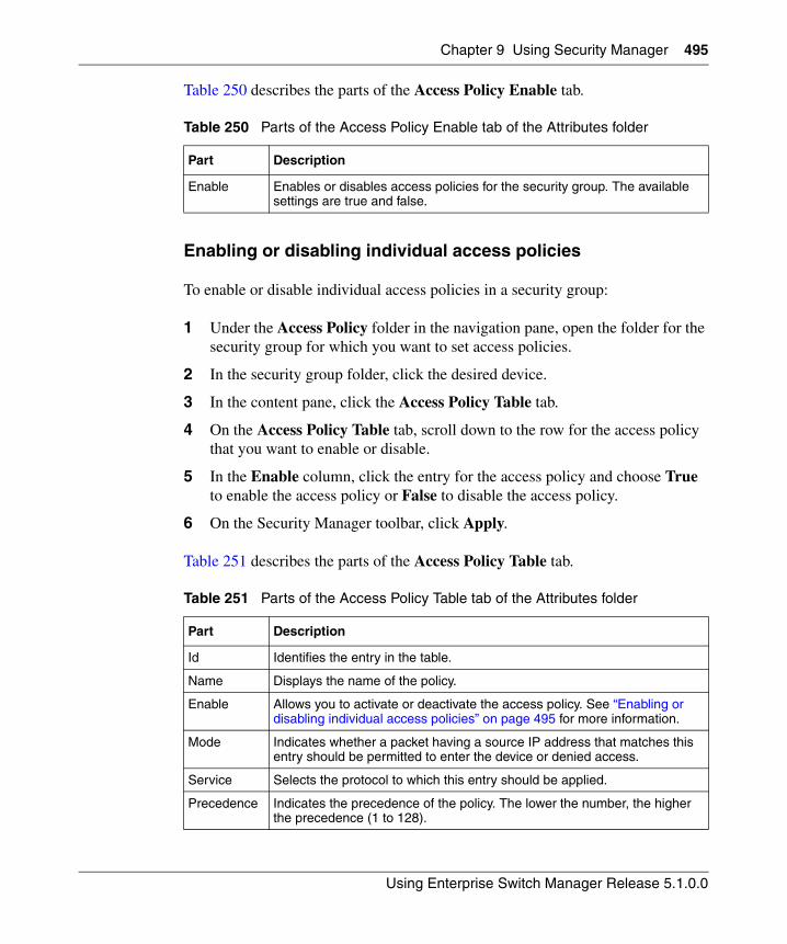
Chapter 9 Using Security Manager 495
Using Enterprise Switch Manager Release 5.1.0.0
Table 250 describes the parts of the Access Policy Enable tab.
Enabling or disabling individual access policies
To enable or disable individual access policies in a security group:
1 Under the Access Policy folder in the navigation pane, open the folder for the security group for which you want to set access policies.
2 In the security group folder, click the desired device.
3 In the content pane, click the Access Policy Table tab.
4 On the Access Policy Table tab, scroll down to the row for the access policy that you want to enable or disable.
5 In the Enable column, click the entry for the access policy and choose True to enable the access policy or False to disable the access policy.
6 On the Security Manager toolbar, click Apply.
Table 251 describes the parts of the Access Policy Table tab.
Table 250 Parts of the Access Policy Enable tab of the Attributes folder
Part Description
Enable Enables or disables access policies for the security group. The available settings are true and false.
Table 251 Parts of the Access Policy Table tab of the Attributes folder
Part Description
Id Identifies the entry in the table.
Name Displays the name of the policy.
Enable Allows you to activate or deactivate the access policy. See “Enabling or disabling individual access policies” on page 495 for more information.
Mode Indicates whether a packet having a source IP address that matches this entry should be permitted to enter the device or denied access.
Service Selects the protocol to which this entry should be applied.
Precedence Indicates the precedence of the policy. The lower the number, the higher the precedence (1 to 128).
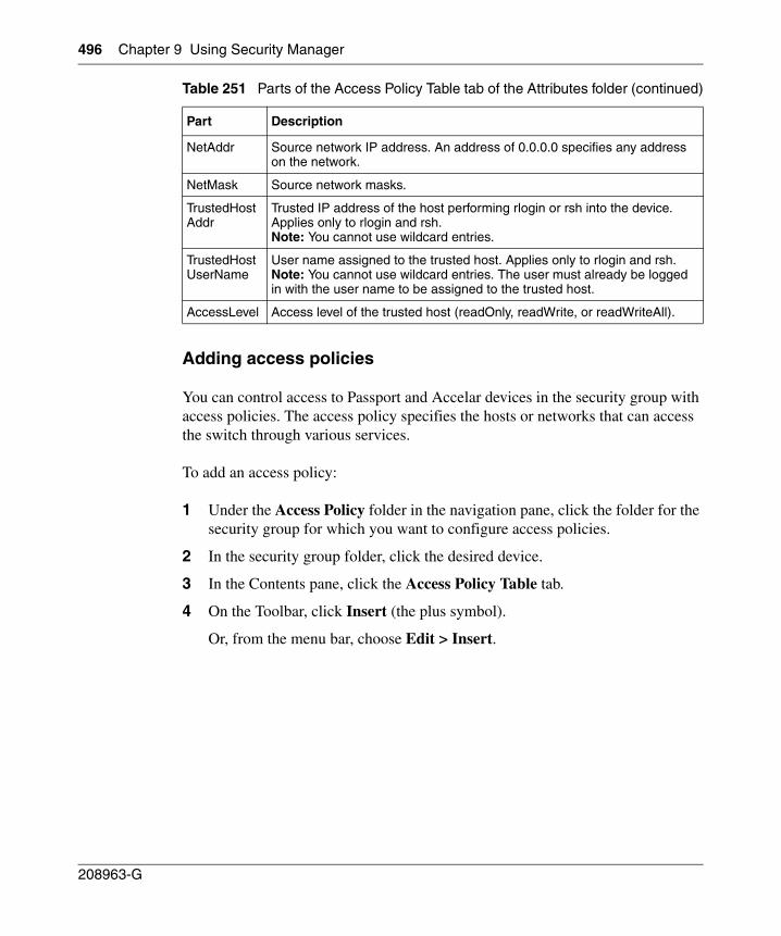
496 Chapter 9 Using Security Manager
208963-G
Adding access policies
You can control access to Passport and Accelar devices in the security group with access policies. The access policy specifies the hosts or networks that can access the switch through various services.
To add an access policy:
1 Under the Access Policy folder in the navigation pane, click the folder for the security group for which you want to configure access policies.
2 In the security group folder, click the desired device.
3 In the Contents pane, click the Access Policy Table tab.
4 On the Toolbar, click Insert (the plus symbol).
Or, from the menu bar, choose Edit > Insert.
NetAddr Source network IP address. An address of 0.0.0.0 specifies any address on the network.
NetMask Source network masks.
TrustedHostAddr
Trusted IP address of the host performing rlogin or rsh into the device. Applies only to rlogin and rsh.Note: You cannot use wildcard entries.
TrustedHostUserName
User name assigned to the trusted host. Applies only to rlogin and rsh. Note: You cannot use wildcard entries. The user must already be logged in with the user name to be assigned to the trusted host.
AccessLevel Access level of the trusted host (readOnly, readWrite, or readWriteAll).
Table 251 Parts of the Access Policy Table tab of the Attributes folder (continued)
Part Description
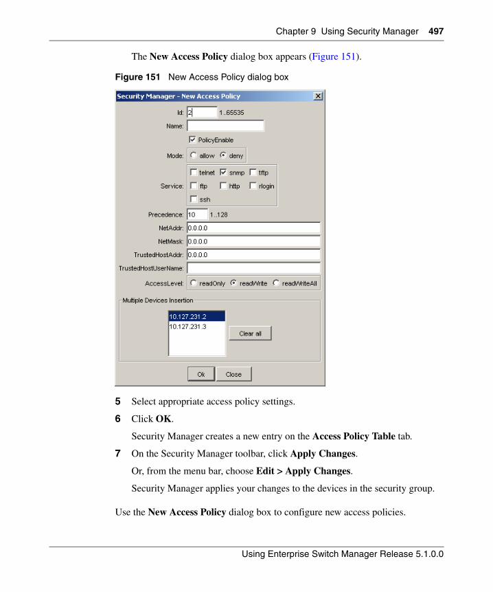
Chapter 9 Using Security Manager 497
Using Enterprise Switch Manager Release 5.1.0.0
The New Access Policy dialog box appears (Figure 151).
Figure 151 New Access Policy dialog box
5 Select appropriate access policy settings.
6 Click OK.
Security Manager creates a new entry on the Access Policy Table tab.
7 On the Security Manager toolbar, click Apply Changes.
Or, from the menu bar, choose Edit > Apply Changes.
Security Manager applies your changes to the devices in the security group.
Use the New Access Policy dialog box to configure new access policies.
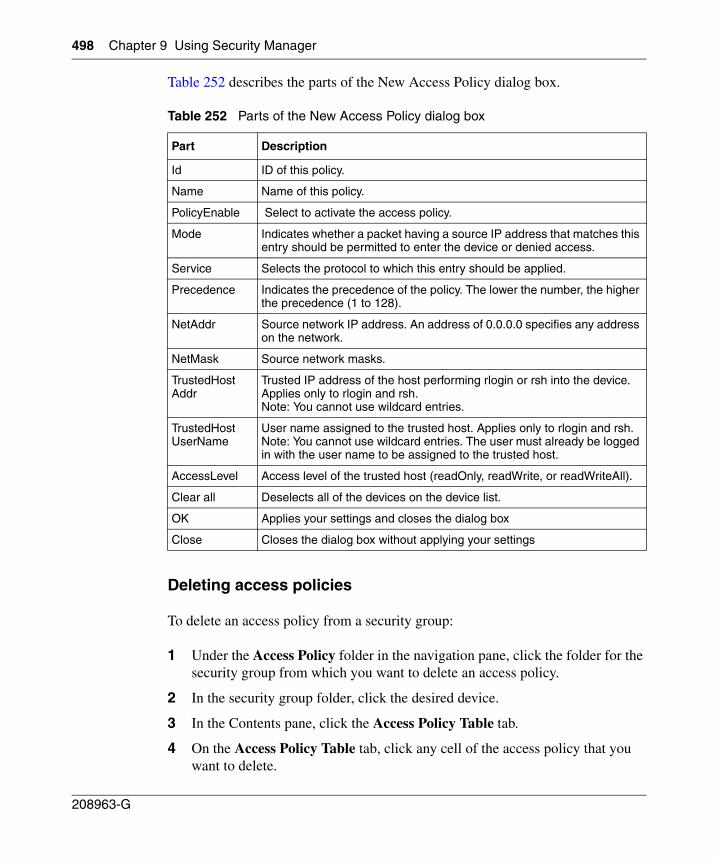
498 Chapter 9 Using Security Manager
208963-G
Table 252 describes the parts of the New Access Policy dialog box.
Deleting access policies
To delete an access policy from a security group:
1 Under the Access Policy folder in the navigation pane, click the folder for the security group from which you want to delete an access policy.
2 In the security group folder, click the desired device.
3 In the Contents pane, click the Access Policy Table tab.
4 On the Access Policy Table tab, click any cell of the access policy that you want to delete.
Table 252 Parts of the New Access Policy dialog box
Part Description
Id ID of this policy.
Name Name of this policy.
PolicyEnable Select to activate the access policy.
Mode Indicates whether a packet having a source IP address that matches this entry should be permitted to enter the device or denied access.
Service Selects the protocol to which this entry should be applied.
Precedence Indicates the precedence of the policy. The lower the number, the higher the precedence (1 to 128).
NetAddr Source network IP address. An address of 0.0.0.0 specifies any address on the network.
NetMask Source network masks.
TrustedHostAddr
Trusted IP address of the host performing rlogin or rsh into the device. Applies only to rlogin and rsh.Note: You cannot use wildcard entries.
TrustedHostUserName
User name assigned to the trusted host. Applies only to rlogin and rsh. Note: You cannot use wildcard entries. The user must already be logged in with the user name to be assigned to the trusted host.
AccessLevel Access level of the trusted host (readOnly, readWrite, or readWriteAll).
Clear all Deselects all of the devices on the device list.
OK Applies your settings and closes the dialog box
Close Closes the dialog box without applying your settings
Chapter 9 Using Security Manager 499
Using Enterprise Switch Manager Release 5.1.0.0
5 On the Toolbar, click Delete (the X symbol).
Or, from the menu bar, choose Edit > Delete.
Security Manager deletes the selected access policy.
6 On the Security Manager toolbar, click Apply Changes.
Or, from the menu bar, choose Edit > Apply Changes.
Security Manager applies your changes to the devices in the security group.
Managing SSH security groups and bulk passwords
This section describes how to configure SSH security groups, SSH Bulk passwords, and related properties.
It contains the following topics:
• “Creating SSH security groups” on page 499
• “Deleting SSH security groups” on page 501
• “Adding devices to an SSH security group” on page 501
• “Removing devices from an SSH security group” on page 502
• “Configuring SSH properties for ERS 8000 security groups” on page 506
• “Configuring SSH properties for ERS 8000 devices” on page 507
• “Configuring SSH properties for ERS 55xx/35xx and Ethernet Switch security groups” on page 508
• “Configuring SSH properties for ERS 55xx/35xx and Ethernet Switch devices” on page 509
• “Viewing the SSH Password Configuration log file” on page 511
Creating SSH security groups
To create an SSH security group:
1 In the navigation pane, select the SSH folder.
2 On the Toolbar, click Insert (the plus sign).
The New Group dialog box appears (Figure 152).
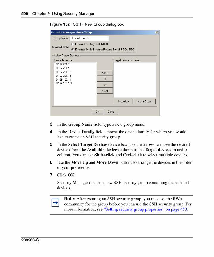
500 Chapter 9 Using Security Manager
208963-G
Figure 152 SSH - New Group dialog box
3 In the Group Name field, type a new group name.
4 In the Device Family field, choose the device family for which you would like to create an SSH security group.
5 In the Select Target Devices device box, use the arrows to move the desired devices from the Available devices column to the Target devices in order column. You can use Shift+click and Ctrl+click to select multiple devices.
6 Use the Move Up and Move Down buttons to arrange the devices in the order of your preference.
7 Click OK.
Security Manager creates a new SSH security group containing the selected devices.
Note: After creating an SSH security group, you must set the RWA community for the group before you can use the SSH security group. For more information, see “Setting security group properties” on page 450.
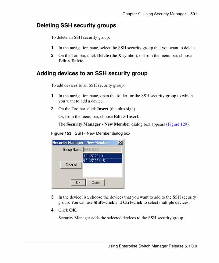
Chapter 9 Using Security Manager 501
Using Enterprise Switch Manager Release 5.1.0.0
Deleting SSH security groups
To delete an SSH security group:
1 In the navigation pane, select the SSH security group that you want to delete.
2 On the Toolbar, click Delete (the X symbol), or from the menu bar, choose Edit > Delete.
Adding devices to an SSH security group
To add devices to an SSH security group:
1 In the navigation pane, open the folder for the SSH security group to which you want to add a device.
2 On the Toolbar, click Insert (the plus sign).
Or, from the menu bar, choose Edit > Insert.
The Security Manager - New Member dialog box appears (Figure 129).
Figure 153 SSH - New Member dialog box
3 In the device list, choose the devices that you want to add to the SSH security group. You can use Shift+click and Ctrl+click to select multiple devices.
4 Click OK.
Security Manager adds the selected devices to the SSH security group.
502 Chapter 9 Using Security Manager
208963-G
Removing devices from an SSH security group
To remove devices from an SSH security group:
1 In the navigation pane, open the folder for the SSH security group from which you want to remove devices.
2 In the SSH security group folder, click the device you want to remove from the group.
3 On the Toolbar, click Delete (the X symbol).
Or, from the menu bar, choose Edit > Delete.
Configuring SSH Bulk Passwords
In Security Manager, you can use Secure Shell (SSH) to configure the CLI user name and password for all the devices in a security group. With ERS 55xx/35xx and Ethernet Switch devices, you can also use SSH to configure the SNMP communities for the security group.
To configure SSH access for a security group:
1 Under the SSH folder in the navigation pane, click the folder for the security group for which you want to configure SSH access.
2 In the contents pane, click the Change Password tab.
The Change Password tab appears (Figure 154).
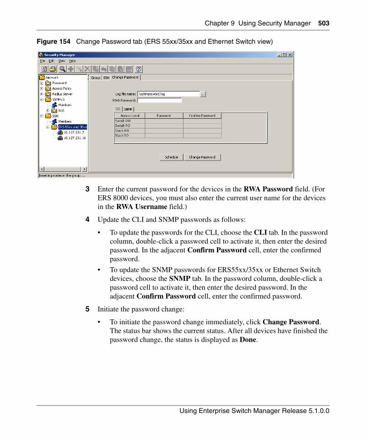
Chapter 9 Using Security Manager 503
Using Enterprise Switch Manager Release 5.1.0.0
Figure 154 Change Password tab (ERS 55xx/35xx and Ethernet Switch view)
3 Enter the current password for the devices in the RWA Password field. (For ERS 8000 devices, you must also enter the current user name for the devices in the RWA Username field.)
4 Update the CLI and SNMP passwords as follows:
• To update the passwords for the CLI, choose the CLI tab. In the password column, double-click a password cell to activate it, then enter the desired password. In the adjacent Confirm Password cell, enter the confirmed password.
• To update the SNMP passwords for ERS55xx/35xx or Ethernet Switch devices, choose the SNMP tab. In the password column, double-click a password cell to activate it, then enter the desired password. In the adjacent Confirm Password cell, enter the confirmed password.
5 Initiate the password change:
• To initiate the password change immediately, click Change Password. The status bar shows the current status. After all devices have finished the password change, the status is displayed as Done.
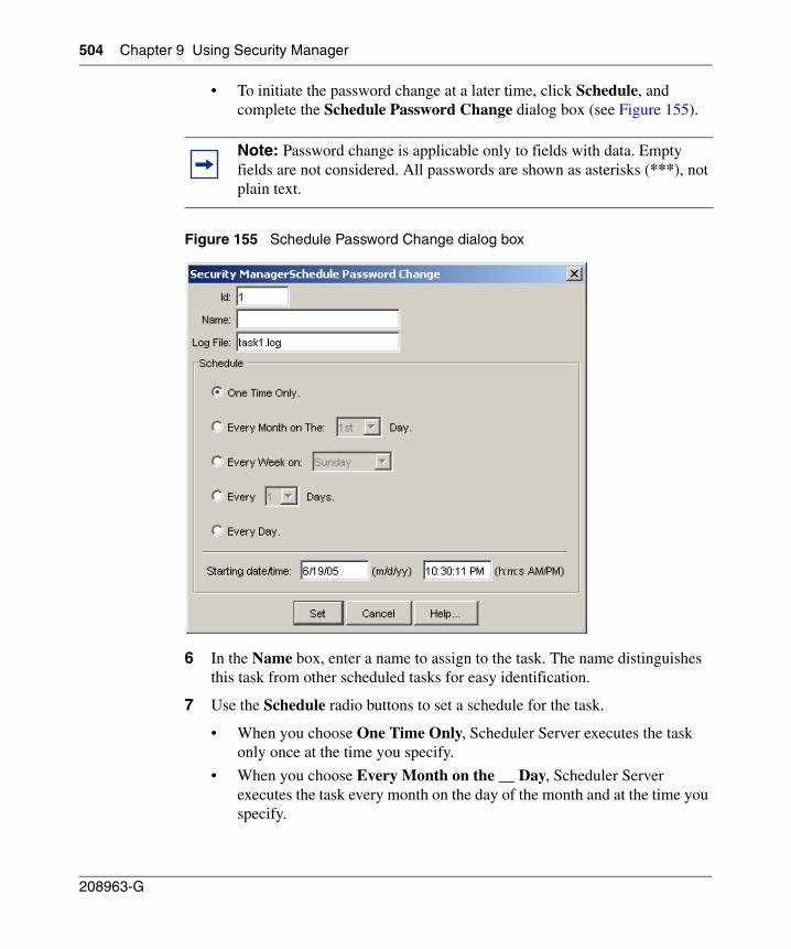
504 Chapter 9 Using Security Manager
208963-G
• To initiate the password change at a later time, click Schedule, and complete the Schedule Password Change dialog box (see Figure 155).
Figure 155 Schedule Password Change dialog box
6 In the Name box, enter a name to assign to the task. The name distinguishes this task from other scheduled tasks for easy identification.
7 Use the Schedule radio buttons to set a schedule for the task.
• When you choose One Time Only, Scheduler Server executes the task only once at the time you specify.
• When you choose Every Month on the __ Day, Scheduler Server executes the task every month on the day of the month and at the time you specify.
Note: Password change is applicable only to fields with data. Empty fields are not considered. All passwords are shown as asterisks (***), not plain text.
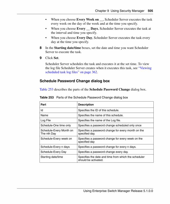
Chapter 9 Using Security Manager 505
Using Enterprise Switch Manager Release 5.1.0.0
• When you choose Every Week on __, Scheduler Server executes the task every week on the day of the week and at the time you specify.
• When you choose Every __ Days, Scheduler Server executes the task at the interval and time you specify.
• When you choose Every Day, Scheduler Server executes the task every day at the time you specify.
8 In the Starting date/time boxes, set the date and time you want Scheduler Server to execute the task.
9 Click Set.
Scheduler Server schedules the task and executes it at the set time. To view the log file Scheduler Server creates when it executes this task, see “Viewing scheduled task log files” on page 362.
Schedule Password Change dialog box
Table 253 describes the parts of the Schedule Password Change dialog box.
Table 253 Parts of the Schedule Password Change dialog box
Part Description
Id Specifies the ID of this schedule.
Name Specifies the name of this schedule.
Log File Specifies the name of the Log file.
Schedule-One time only Specifies a password change scheduled only once
Schedule-Every Month on The nth Day
Specifies a password change for every month on the specified day.
Schedule-Every week on Specifies a password change for every week on the specified day
Schedule-Every n days Specifies a password change for every n days.
Schedule-Every Day Specifies a password change every day.
Starting date/time Specifies the date and time from which the scheduler should be activated.
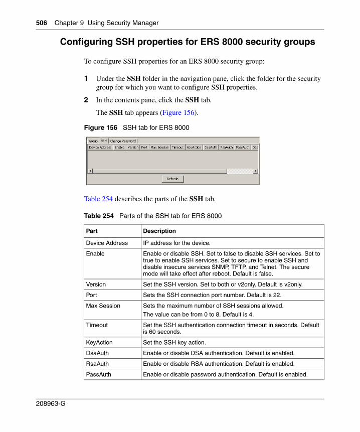
506 Chapter 9 Using Security Manager
208963-G
Configuring SSH properties for ERS 8000 security groups
To configure SSH properties for an ERS 8000 security group:
1 Under the SSH folder in the navigation pane, click the folder for the security group for which you want to configure SSH properties.
2 In the contents pane, click the SSH tab.
The SSH tab appears (Figure 156).
Figure 156 SSH tab for ERS 8000
Table 254 describes the parts of the SSH tab.
Table 254 Parts of the SSH tab for ERS 8000
Part Description
Device Address IP address for the device.
Enable Enable or disable SSH. Set to false to disable SSH services. Set to true to enable SSH services. Set to secure to enable SSH and disable insecure services SNMP, TFTP, and Telnet. The secure mode will take effect after reboot. Default is false.
Version Set the SSH version. Set to both or v2only. Default is v2only.
Port Sets the SSH connection port number. Default is 22.
Max Session Sets the maximum number of SSH sessions allowed.
The value can be from 0 to 8. Default is 4.
Timeout Set the SSH authentication connection timeout in seconds. Default is 60 seconds.
KeyAction Set the SSH key action.
DsaAuth Enable or disable DSA authentication. Default is enabled.
RsaAuth Enable or disable RSA authentication. Default is enabled.
PassAuth Enable or disable password authentication. Default is enabled.
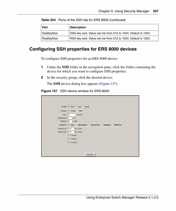
Chapter 9 Using Security Manager 507
Using Enterprise Switch Manager Release 5.1.0.0
Configuring SSH properties for ERS 8000 devices
To configure SSH properties for an ERS 8000 device:
1 Under the SSH folder in the navigation pane, click the folder containing the device for which you want to configure SSH properties.
2 In the security group, click the desired device.
The SSH device dialog box appears (Figure 157).
Figure 157 SSH device window for ERS 8000
DsaKeySize DSA key size. Value can be from 512 to 1024. Default is 1024.
RsaKeySize RSA key size. Value can be from 512 to 1024. Default is 1024.
Table 254 Parts of the SSH tab for ERS 8000 (continued)
Part Description
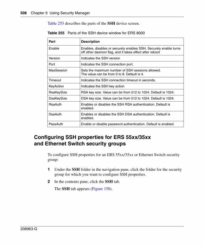
508 Chapter 9 Using Security Manager
208963-G
Table 255 describes the parts of the SSH device screen.
Configuring SSH properties for ERS 55xx/35xx and Ethernet Switch security groups
To configure SSH properties for an ERS 55xx/35xx or Ethernet Switch security group:
1 Under the SSH folder in the navigation pane, click the folder for the security group for which you want to configure SSH properties.
2 In the contents pane, click the SSH tab.
The SSH tab appears (Figure 158).
Table 255 Parts of the SSH device window for ERS 8000
Part Description
Enable Enables, disables or securely enables SSH. Securely enable turns off other daemon flag, and it takes effect after reboot
Version Indicates the SSH version
Port Indicates the SSH connection port.
MaxSession Sets the maximum number of SSH sessions allowed.The value can be from 0 to 8. Default is 4.
Timeout Indicates the SSH connection timeout in seconds.
KeyAction Indicates the SSH key action
RsaKeySize RSA key size. Value can be from 512 to 1024. Default is 1024.
DsaKeySize DSA key size. Value can be from 512 to 1024. Default is 1024.
RsaAuth Enables or disables the SSH RSA authentication. Default is enabled.
DsaAuth Enables or disables the SSH DSA authentication. Default is enabled.
PassAuth Enable or disable password authentication. Default is enabled.
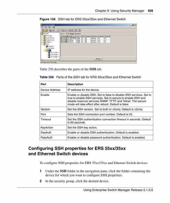
Chapter 9 Using Security Manager 509
Using Enterprise Switch Manager Release 5.1.0.0
Figure 158 SSH tab for ERS 55xx/35xx and Ethernet Switch
Table 256 describes the parts of the SSH tab.
Configuring SSH properties for ERS 55xx/35xx and Ethernet Switch devices
To configure SSH properties for ERS 55xx/35xx and Ethernet Switch devices:
1 Under the SSH folder in the navigation pane, click the folder containing the device for which you want to configure SSH properties.
2 In the security group, click the desired device.
Table 256 Parts of the SSH tab for ERS 55xx/35xx and Ethernet Switch
Part Description
Device Address IP address for the device.
Enable Enable or disable SSH. Set to false to disable SSH services. Set to true to enable SSH services. Set to secure to enable SSH and disable insecure services SNMP, TFTP, and Telnet. The secure mode will take effect after reboot. Default is false.
Version Set the SSH version. Set to both or v2only. Default is v2only.
Port Sets the SSH connection port number. Default is 22.
Timeout Set the SSH authentication connection timeout in seconds. Default is 60 seconds.
KeyAction Set the SSH key action.
DsaAuth Enable or disable DSA authentication. Default is enabled.
PassAuth Enable or disable password authentication. Default is enabled.
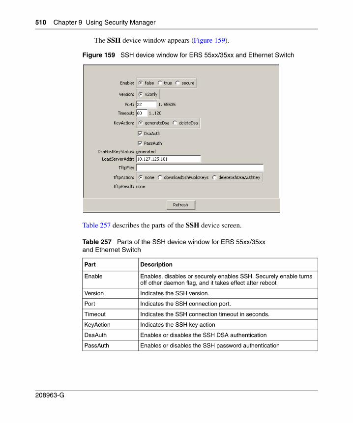
510 Chapter 9 Using Security Manager
208963-G
The SSH device window appears (Figure 159).
Figure 159 SSH device window for ERS 55xx/35xx and Ethernet Switch
Table 257 describes the parts of the SSH device screen.
Table 257 Parts of the SSH device window for ERS 55xx/35xx and Ethernet Switch
Part Description
Enable Enables, disables or securely enables SSH. Securely enable turns off other daemon flag, and it takes effect after reboot
Version Indicates the SSH version.
Port Indicates the SSH connection port.
Timeout Indicates the SSH connection timeout in seconds.
KeyAction Indicates the SSH key action
DsaAuth Enables or disables the SSH DSA authentication
PassAuth Enables or disables the SSH password authentication
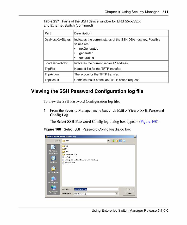
Chapter 9 Using Security Manager 511
Using Enterprise Switch Manager Release 5.1.0.0
Viewing the SSH Password Configuration log file
To view the SSH Password Configuration log file:
1 From the Security Manager menu bar, click Edit > View > SSH Password Config Log.
The Select SSH Password Config log dialog box appears (Figure 160).
Figure 160 Select SSH Password Config log dialog box
DsaHostKeyStatus Indicates the current status of the SSH DSA host key. Possible
values are:
• notGenerated• generated
• generating
LoadServerAddr Indicates the current server IP address.
TftpFile Name of file for the TFTP transfer.
TftpAction The action for the TFTP transfer.
TftpResult Contains result of the last TFTP action request.
Table 257 Parts of the SSH device window for ERS 55xx/35xx and Ethernet Switch (continued)
Part Description

512 Chapter 9 Using Security Manager
208963-G
2 Specify the log file to open (by default, this is sshPassword.log).
3 Click Open
4 The Password Configuration log file appears.
513
Using Enterprise Switch Manager Release 5.1.0.0
Chapter 10Using NSNA Manager
NSNA Manager manages the Nortel Secure Network Access (NSNA) solution in a network. Enterprise Switch Manager (ESM) is the starting point for NSNA Manager, and ESM must be open to use NSNA Manager.
This chapter describes how to use NSNA Manager to manage NSNA on Nortel Ethernet Routing Switch 8300 and Ethernet Routing Switch 55xx devices. It includes the following information:
• “What is NSNA Manager?” on page 514
• “Starting NSNA Manager” on page 516
• “NSNA Manager window” on page 517
• “Working with NSNA Manager” on page 523
• “Enabling NSNA on a device” on page 524
• “Configuring the NSNAS subnet” on page 525
• “Entering IP Phone signatures for NSNA” on page 530
Note: You can open the Security & Routing Element Manager (SREM) for the Nortel Secure Network Access Switch (NSNAS) by double-clicking the NSNAS icon from the topology view. For this action to complete successfully, you must do the following:
• Specify the correct path to the folder containing the SREM software in the ESM Preferences dialog box (see “Preferences dialog box” on page 98).
• If the NSNAS CLI user name and password are not the default values (admin/admin), specify the updated user name and password in the Communities/Password dialog box (see “Accessing NSNAS with different CLI user names and passwords” on page 111).
514 Chapter 10 Using NSNA Manager
208963-G
• “Displaying NSNA VLANs” on page 532
• “Enabling NSNA on ports” on page 533
• “Displaying information about NSNA clients” on page 535
• “Viewing NSNAS subnet members in Enterprise Switch Manager” on page 537
What is NSNA Manager?
NSNA Manager enables you to manage NSNA configurations in a single device or across multiple devices. The following sections describe NSNA Manager conventions and features:
• “NSNA”
• “NSNA Manager features” on page 515
NSNA
The Nortel Secure Network Access (NSNA) solution is a protective framework to completely secure the network from endpoint vulnerability. The NSNA solution addresses endpoint security and enforces policy compliance. NSNA delivers endpoint security by enabling only trusted, role-based access privileges premised on the security level of the device, user identity, and session context. NSNA enforces policy compliance such as for Sarbanes-Oxley, and COBIT, ensuring the required anti-virus applications or software patches are installed before a user is granted network access.
The NSNA solution provides a policy-based, clientless approach to corporate network access. The NSNA solution provides both authentication and enforcement (operating system/antivirus/firewall code revision enforcement, Windows* registry content verification and enforcement, file system verification and enforcement).
A PC user gains access into the corporate network by passing through:
• authentication
• host integrity check and remediation (if needed)
Chapter 10 Using NSNA Manager 515
Using Enterprise Switch Manager Release 5.1.0.0
Before authentication, the user is given restricted access within the whole network (Red VLAN). By default, the restrictions allow access to the Nortel Secure Network Access Switch (NSNAS) and to the Windows domain controller network only (this is based on the default NSNA Red filter set). This is necessary to allow the authentication traffic. You can customize the filter sets to allow greater access, if necessary.
After the client’s credentials are checked with an authentication server, a TunnelGuard applet (the security agent) is downloaded to every PC client. TunnelGuard provides continual device integrity checking.
If the host integrity check fails after password authentication, the user is given access to the remediation network only (Yellow VLAN).
After successful completion of all of these phases, the user is given full access to the network, depending on the user profile (Green VLAN).
IP phones are given access to one of the preconfigured VoIP subnets, and are permitted a prespecified type of communication. The VoIP filters are constructed to prevent the VoIP traffic from going anywhere but to a specific subnet. This subnet is specified by the VoIP VLAN.
For detailed information about the NSNA solution and deployment scenarios, refer to Nortel Secure Network Access Solution Guide (320817-A). For information about configuring the NSNAS, refer to Nortel Secure Network Access Switch 4050 User Guide (320818-A). For switch-specific configuration information, refer to your switch documentation.
NSNA Manager features
You can use NSNA Manager to:
• configure the NSNAS subnet
• enable NSNA on a device
• enable NSNA on ports
• enter IP Phone Signatures for NSNA
• display information about NSNA clients
• display NSNA per VLAN
516 Chapter 10 Using NSNA Manager
208963-G
You cannot use NSNA Manager to configure VLAN properties. To configure NSNA VLAN properties, you must use VLAN Manager. See “Configuring VLANs for NSNA” on page 138.
The following sections describe the NSNA Manager window and available management functions.
Starting NSNA Manager
To start NSNA Manager:
• From the Enterprise Switch Manager menu bar, choose Tools > NSNA Manager.
• On the keyboard, press [F8].
• On the Enterprise Switch Manager toolbar, click NSNA Manager.
The NSNA Manager window opens (Figure 161).
Do one of the following:
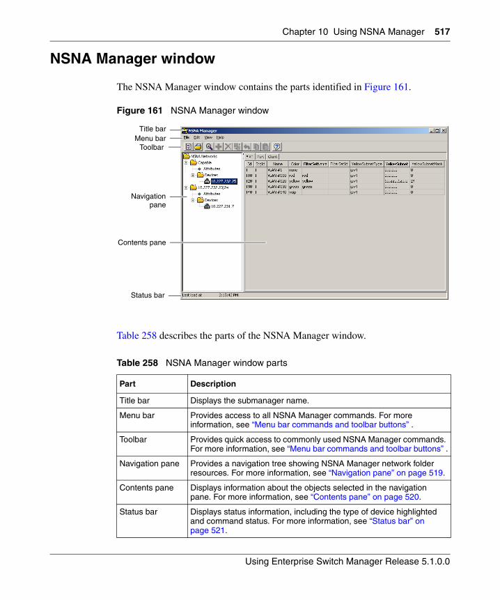
Chapter 10 Using NSNA Manager 517
Using Enterprise Switch Manager Release 5.1.0.0
NSNA Manager window
The NSNA Manager window contains the parts identified in Figure 161.
Figure 161 NSNA Manager window
Table 258 describes the parts of the NSNA Manager window.
Table 258 NSNA Manager window parts
Part Description
Title bar Displays the submanager name.
Menu bar Provides access to all NSNA Manager commands. For more information, see “Menu bar commands and toolbar buttons” .
Toolbar Provides quick access to commonly used NSNA Manager commands. For more information, see “Menu bar commands and toolbar buttons” .
Navigation pane Provides a navigation tree showing NSNA Manager network folder resources. For more information, see “Navigation pane” on page 519.
Contents pane Displays information about the objects selected in the navigation pane. For more information, see “Contents pane” on page 520.
Status bar Displays status information, including the type of device highlighted and command status. For more information, see “Status bar” on page 521.
Title barMenu bar
Toolbar
Navigation
Status bar
Contents pane
pane
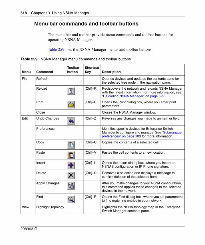
518 Chapter 10 Using NSNA Manager
208963-G
Menu bar commands and toolbar buttons
The menu bar and toolbar provide menu commands and toolbar buttons for operating NSNA Manager.
Table 259 lists the NSNA Manager menus and toolbar buttons.
Table 259 NSNA Manager menu commands and toolbar buttons
Menu CommandToolbar button
Shortcut Key Description
File Refresh Queries devices and updates the contents pane for the selected tree node in the navigation pane.
Reload [Ctrl]+R Rediscovers the network and reloads NSNA Manager with the latest information. For more information, see “Reloading NSNA Manager” on page 522.
Print [Ctrl]+P Opens the Print dialog box, where you enter print parameters.
Close Closes the NSNA Manager window.
Edit Undo Changes [Ctrl]+Z Reverses any changes you made to an item or field.
Preferences Identifies specific devices for Enterprise Switch Manager to configure and manage. See “Submanager preferences” on page 103 for more information.
Copy [Ctrl]+C Copies the contents of a selected cell.
Paste [Ctrl]+V Pastes the cell contents to a new location.
Insert [Ctrl]+I Opens the Insert dialog box, where you insert an NSNAS configuration or IP Phone signature.
Delete [Ctrl]+D Removes a selection and displays a message to confirm deletion of the selected item.
Apply Changes After you make changes to your NSNA configuration, this command applies these changes to the selected devices in the network.
Find [Ctrl]+F Opens the Find dialog box, where you set parameters to find matching entries in your network.
View Highlight Topology Highlights the NSNA topology map in the Enterprise Switch Manager contents pane.
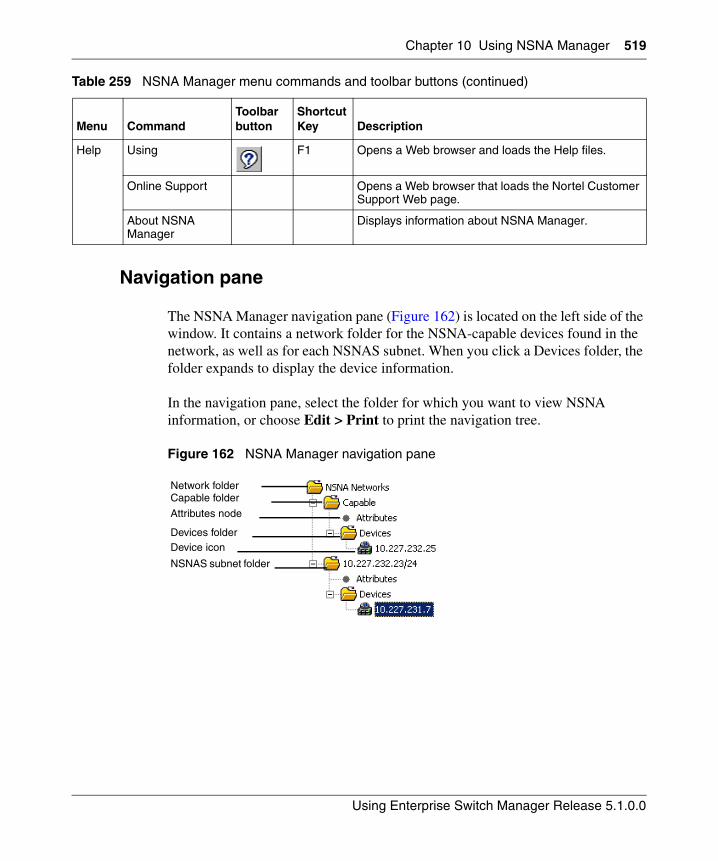
Chapter 10 Using NSNA Manager 519
Using Enterprise Switch Manager Release 5.1.0.0
Navigation pane
The NSNA Manager navigation pane (Figure 162) is located on the left side of the window. It contains a network folder for the NSNA-capable devices found in the network, as well as for each NSNAS subnet. When you click a Devices folder, the folder expands to display the device information.
In the navigation pane, select the folder for which you want to view NSNA information, or choose Edit > Print to print the navigation tree.
Figure 162 NSNA Manager navigation pane
Help Using F1 Opens a Web browser and loads the Help files.
Online Support Opens a Web browser that loads the Nortel Customer Support Web page.
About NSNA Manager
Displays information about NSNA Manager.
Table 259 NSNA Manager menu commands and toolbar buttons (continued)
Menu CommandToolbar button
Shortcut Key Description
Network folderCapable folder
Devices folder Device icon
NSNAS subnet folder
Attributes node
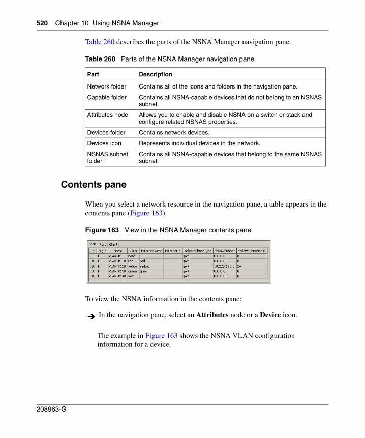
520 Chapter 10 Using NSNA Manager
208963-G
Table 260 describes the parts of the NSNA Manager navigation pane.
Contents pane
When you select a network resource in the navigation pane, a table appears in the contents pane (Figure 163).
Figure 163 View in the NSNA Manager contents pane
To view the NSNA information in the contents pane:
The example in Figure 163 shows the NSNA VLAN configuration information for a device.
Table 260 Parts of the NSNA Manager navigation pane
Part Description
Network folder Contains all of the icons and folders in the navigation pane.
Capable folder Contains all NSNA-capable devices that do not belong to an NSNAS subnet.
Attributes node Allows you to enable and disable NSNA on a switch or stack and configure related NSNAS properties.
Devices folder Contains network devices.
Devices icon Represents individual devices in the network.
NSNAS subnet folder
Contains all NSNA-capable devices that belong to the same NSNAS subnet.
In the navigation pane, select an Attributes node or a Device icon.
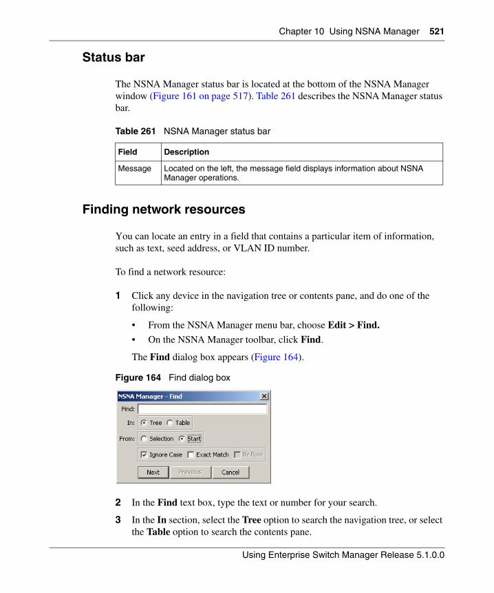
Chapter 10 Using NSNA Manager 521
Using Enterprise Switch Manager Release 5.1.0.0
Status bar
The NSNA Manager status bar is located at the bottom of the NSNA Manager window (Figure 161 on page 517). Table 261 describes the NSNA Manager status bar.
Finding network resources
You can locate an entry in a field that contains a particular item of information, such as text, seed address, or VLAN ID number.
To find a network resource:
1 Click any device in the navigation tree or contents pane, and do one of the following:
• From the NSNA Manager menu bar, choose Edit > Find.
• On the NSNA Manager toolbar, click Find.
The Find dialog box appears (Figure 164).
Figure 164 Find dialog box
2 In the Find text box, type the text or number for your search.
3 In the In section, select the Tree option to search the navigation tree, or select the Table option to search the contents pane.
Table 261 NSNA Manager status bar
Field Description
Message Located on the left, the message field displays information about NSNA Manager operations.
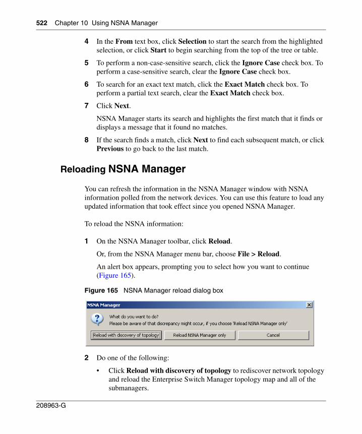
522 Chapter 10 Using NSNA Manager
208963-G
4 In the From text box, click Selection to start the search from the highlighted selection, or click Start to begin searching from the top of the tree or table.
5 To perform a non-case-sensitive search, click the Ignore Case check box. To perform a case-sensitive search, clear the Ignore Case check box.
6 To search for an exact text match, click the Exact Match check box. To perform a partial text search, clear the Exact Match check box.
7 Click Next.
NSNA Manager starts its search and highlights the first match that it finds or displays a message that it found no matches.
8 If the search finds a match, click Next to find each subsequent match, or click Previous to go back to the last match.
Reloading NSNA Manager
You can refresh the information in the NSNA Manager window with NSNA information polled from the network devices. You can use this feature to load any updated information that took effect since you opened NSNA Manager.
To reload the NSNA information:
1 On the NSNA Manager toolbar, click Reload.
Or, from the NSNA Manager menu bar, choose File > Reload.
An alert box appears, prompting you to select how you want to continue (Figure 165).
Figure 165 NSNA Manager reload dialog box
2 Do one of the following:
• Click Reload with discovery of topology to rediscover network topology and reload the Enterprise Switch Manager topology map and all of the submanagers.
Chapter 10 Using NSNA Manager 523
Using Enterprise Switch Manager Release 5.1.0.0
• Click Reload NSNA Manager only to just reload NSNA Manager. Enterprise Switch Manager polls devices for settings and features, but does not perform a full network topology discovery.
• Click Cancel to abandon the reload operation.
Working with NSNA Manager
Using NSNA Manager, you can configure the Ethernet Routing Switch 8300 and the Ethernet Routing Switch 55xx devices as network access devices in the NSNA solution.
This section includes the information about the following topics:
• “Enabling NSNA on a device” on page 524
• “Configuring the NSNAS subnet” on page 525
• “Entering IP Phone signatures for NSNA” on page 530
• “Displaying NSNA VLANs” on page 532
• “Enabling NSNA on ports” on page 533
• “Displaying information about NSNA clients” on page 535
Note: Reloading only NSNA Manager takes less time than reloading with topology discovery. However, if there are any changes in network topology, it can result in discrepancies between the information in NSNA Manager and the information about the topology map. Such discrepancies can cause incorrect operation when you perform operations (such as highlighting the network map) that involve interactions between the submanagers and the topology map.
If you observe such incorrect operations, reload the network map. For more information, see “Rediscovering the network map” on page 105.
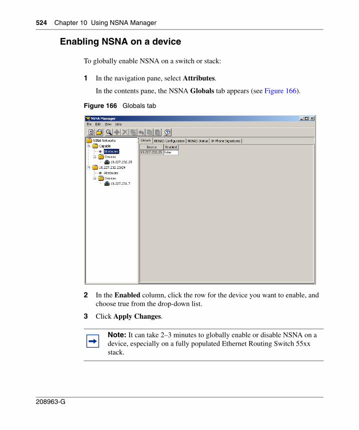
524 Chapter 10 Using NSNA Manager
208963-G
Enabling NSNA on a device
To globally enable NSNA on a switch or stack:
1 In the navigation pane, select Attributes.
In the contents pane, the NSNA Globals tab appears (see Figure 166).
Figure 166 Globals tab
2 In the Enabled column, click the row for the device you want to enable, and choose true from the drop-down list.
3 Click Apply Changes.
Note: It can take 2–3 minutes to globally enable or disable NSNA on a device, especially on a fully populated Ethernet Routing Switch 55xx stack.
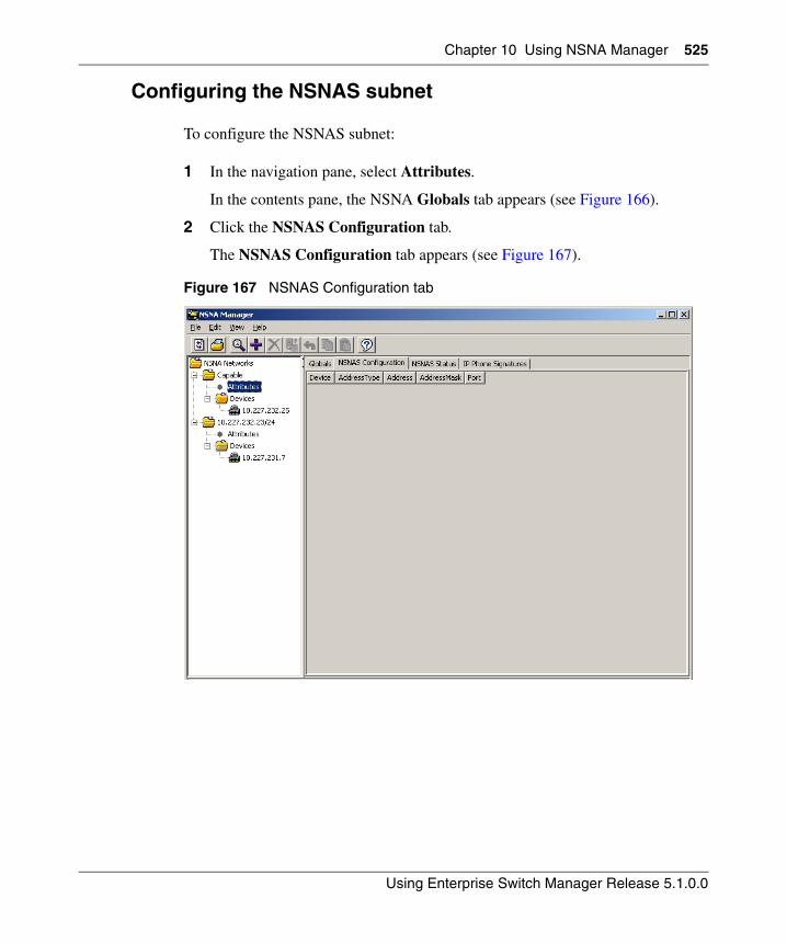
Chapter 10 Using NSNA Manager 525
Using Enterprise Switch Manager Release 5.1.0.0
Configuring the NSNAS subnet
To configure the NSNAS subnet:
1 In the navigation pane, select Attributes.
In the contents pane, the NSNA Globals tab appears (see Figure 166).
2 Click the NSNAS Configuration tab.
The NSNAS Configuration tab appears (see Figure 167).
Figure 167 NSNAS Configuration tab
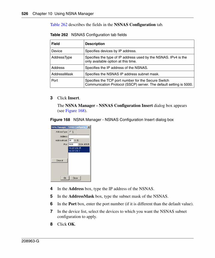
526 Chapter 10 Using NSNA Manager
208963-G
Table 262 describes the fields in the NSNAS Configuration tab.
3 Click Insert.
The NSNA Manager - NSNAS Configuration Insert dialog box appears (see Figure 168).
Figure 168 NSNA Manager - NSNAS Configuration Insert dialog box
4 In the Address box, type the IP address of the NSNAS.
5 In the AddressMask box, type the subnet mask of the NSNAS.
6 In the Port box, enter the port number (if it is different than the default value).
7 In the device list, select the devices to which you want the NSNAS subnet configuration to apply.
8 Click OK.
Table 262 NSNAS Configuration tab fields
Field Description
Device Specifies devices by IP address.
AddressType Specifies the type of IP address used by the NSNAS. IPv4 is the only available option at this time.
Address Specifies the IP address of the NSNAS.
AddressMask Specifies the NSNAS IP address subnet mask.
Port Specifies the TCP port number for the Secure Switch Communication Protocol (SSCP) server. The default setting is 5000.
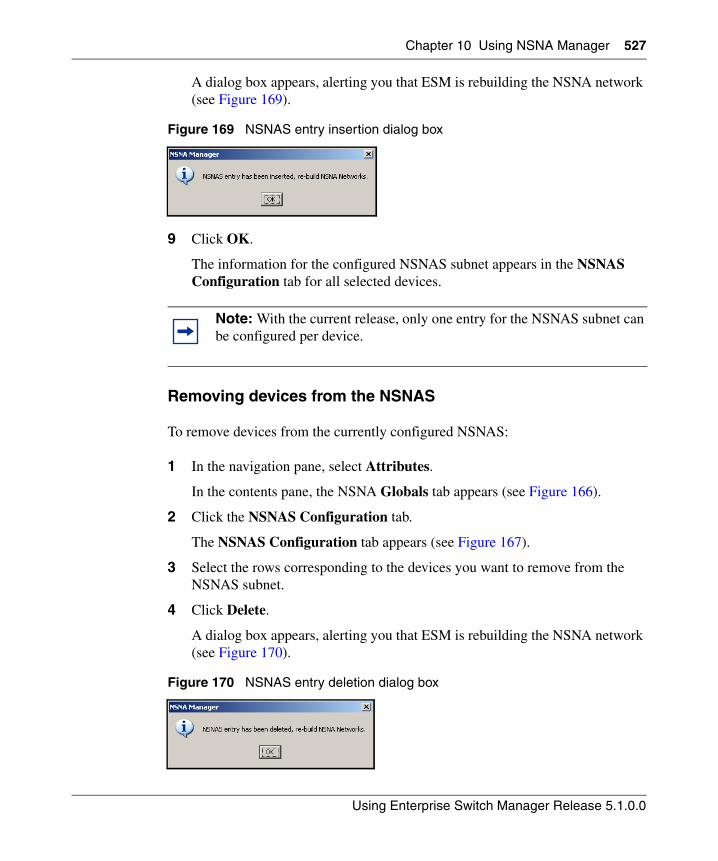
Chapter 10 Using NSNA Manager 527
Using Enterprise Switch Manager Release 5.1.0.0
A dialog box appears, alerting you that ESM is rebuilding the NSNA network (see Figure 169).
Figure 169 NSNAS entry insertion dialog box
9 Click OK.
The information for the configured NSNAS subnet appears in the NSNAS Configuration tab for all selected devices.
Removing devices from the NSNAS
To remove devices from the currently configured NSNAS:
1 In the navigation pane, select Attributes.
In the contents pane, the NSNA Globals tab appears (see Figure 166).
2 Click the NSNAS Configuration tab.
The NSNAS Configuration tab appears (see Figure 167).
3 Select the rows corresponding to the devices you want to remove from the NSNAS subnet.
4 Click Delete.
A dialog box appears, alerting you that ESM is rebuilding the NSNA network (see Figure 170).
Figure 170 NSNAS entry deletion dialog box
Note: With the current release, only one entry for the NSNAS subnet can be configured per device.
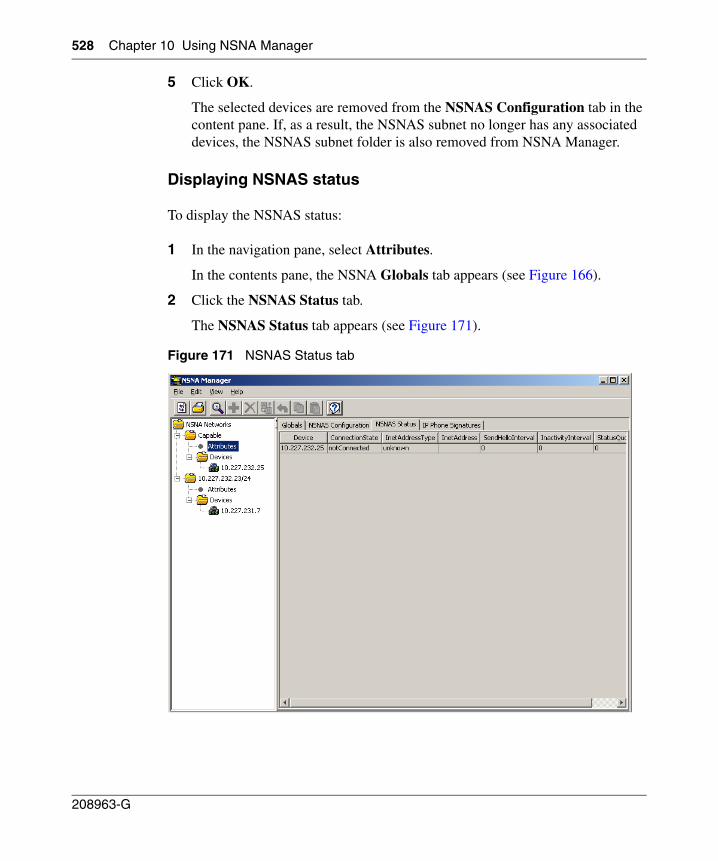
528 Chapter 10 Using NSNA Manager
208963-G
5 Click OK.
The selected devices are removed from the NSNAS Configuration tab in the content pane. If, as a result, the NSNAS subnet no longer has any associated devices, the NSNAS subnet folder is also removed from NSNA Manager.
Displaying NSNAS status
To display the NSNAS status:
1 In the navigation pane, select Attributes.
In the contents pane, the NSNA Globals tab appears (see Figure 166).
2 Click the NSNAS Status tab.
The NSNAS Status tab appears (see Figure 171).
Figure 171 NSNAS Status tab
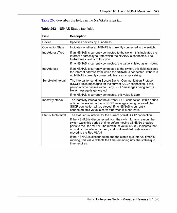
Chapter 10 Using NSNA Manager 529
Using Enterprise Switch Manager Release 5.1.0.0
Table 263 describes the fields in the NSNAS Status tab.
Table 263 NSNAS Status tab fields
Field Description
Device Specifies devices by IP address.
ConnectionState Indicates whether an NSNAS is currently connected to the switch.
InetAddressType If an NSNAS is currently connected to the switch, this indicates the Internet address type from which the NSNAS is connected. The InetAddress field is of this type.
If no NSNAS is currently connected, the value is listed as unknown.
InetAddress If an NSNAS is currently connected to the switch, this field indicates the internet address from which the NSNAS is connected. If there is no NSNAS currently connected, this is an empty string.
SendHelloInterval The interval for sending Secure Switch Communication Protocol (SSCP) Hello messages for the current SSCP connection. If this period of time passes without any SSCP messages being sent, a Hello message is generated. If no NSNAS is currently connected, this value is zero.
InactivityInterval The inactivity interval for the current SSCP connection. If this period of time passes without any SSCP messages being received, the SSCP connection will be closed. If no NSNAS is currently connected, this value is zero; otherwise it is non-zero.
StatusQuoInterval The status-quo interval for the current or last SSCP connection.If the NSNAS is disconnected from the switch for any reason, the switch waits this period of time before moving all NSNA-enabled ports to the Red VLAN. The maximum value, 65535, indicates that no status quo interval is used, and SSA-enabled ports are not moved to the Red VLAN.
If the NSNAS is disconnected and the status-quo interval timer is running, this value reflects the time remaining until the status-quo timer expires.
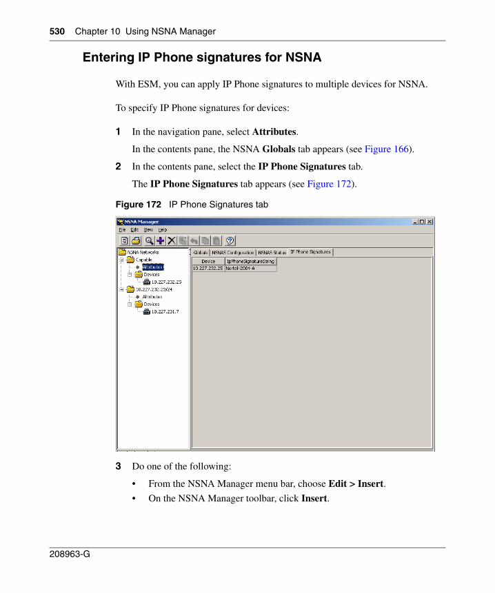
530 Chapter 10 Using NSNA Manager
208963-G
Entering IP Phone signatures for NSNA
With ESM, you can apply IP Phone signatures to multiple devices for NSNA.
To specify IP Phone signatures for devices:
1 In the navigation pane, select Attributes.
In the contents pane, the NSNA Globals tab appears (see Figure 166).
2 In the contents pane, select the IP Phone Signatures tab.
The IP Phone Signatures tab appears (see Figure 172).
Figure 172 IP Phone Signatures tab
3 Do one of the following:
• From the NSNA Manager menu bar, choose Edit > Insert.
• On the NSNA Manager toolbar, click Insert.
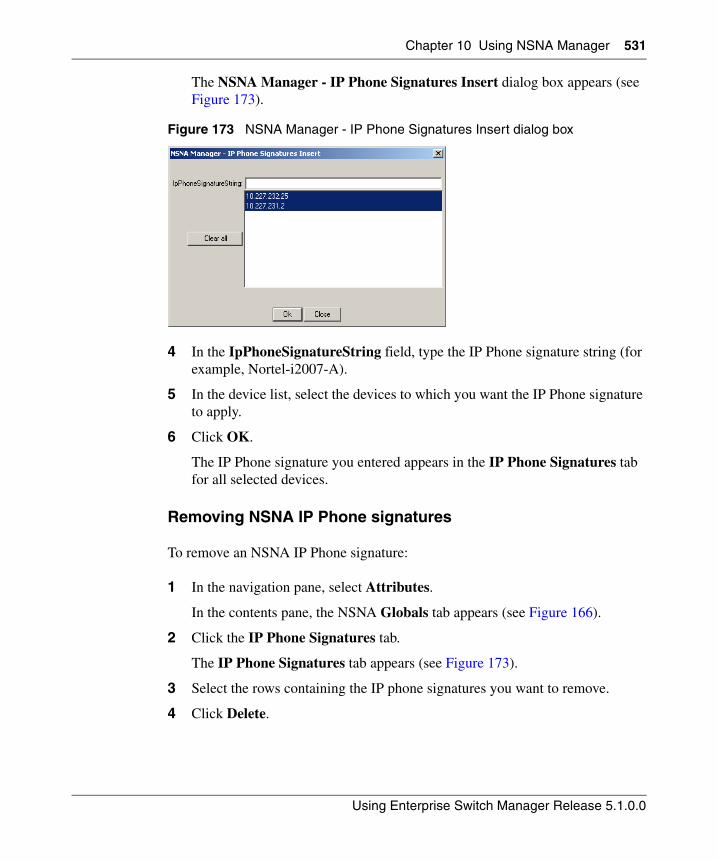
Chapter 10 Using NSNA Manager 531
Using Enterprise Switch Manager Release 5.1.0.0
The NSNA Manager - IP Phone Signatures Insert dialog box appears (see Figure 173).
Figure 173 NSNA Manager - IP Phone Signatures Insert dialog box
4 In the IpPhoneSignatureString field, type the IP Phone signature string (for example, Nortel-i2007-A).
5 In the device list, select the devices to which you want the IP Phone signature to apply.
6 Click OK.
The IP Phone signature you entered appears in the IP Phone Signatures tab for all selected devices.
Removing NSNA IP Phone signatures
To remove an NSNA IP Phone signature:
1 In the navigation pane, select Attributes.
In the contents pane, the NSNA Globals tab appears (see Figure 166).
2 Click the IP Phone Signatures tab.
The IP Phone Signatures tab appears (see Figure 173).
3 Select the rows containing the IP phone signatures you want to remove.
4 Click Delete.
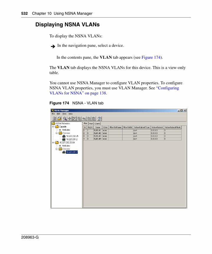
532 Chapter 10 Using NSNA Manager
208963-G
Displaying NSNA VLANs
To display the NSNA VLANs:
In the contents pane, the VLAN tab appears (see Figure 174).
The VLAN tab displays the NSNA VLANs for this device. This is a view-only table.
You cannot use NSNA Manager to configure VLAN properties. To configure NSNA VLAN properties, you must use VLAN Manager. See “Configuring VLANs for NSNA” on page 138.
Figure 174 NSNA - VLAN tab
In the navigation pane, select a device.
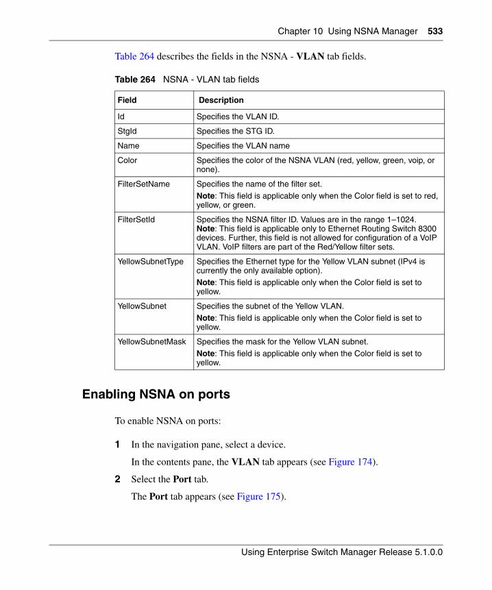
Chapter 10 Using NSNA Manager 533
Using Enterprise Switch Manager Release 5.1.0.0
Table 264 describes the fields in the NSNA - VLAN tab fields.
Enabling NSNA on ports
To enable NSNA on ports:
1 In the navigation pane, select a device.
In the contents pane, the VLAN tab appears (see Figure 174).
2 Select the Port tab.
The Port tab appears (see Figure 175).
Table 264 NSNA - VLAN tab fields
Field Description
Id Specifies the VLAN ID.
StgId Specifies the STG ID.
Name Specifies the VLAN name
Color Specifies the color of the NSNA VLAN (red, yellow, green, voip, or none).
FilterSetName Specifies the name of the filter set.
Note: This field is applicable only when the Color field is set to red, yellow, or green.
FilterSetId Specifies the NSNA filter ID. Values are in the range 1–1024. Note: This field is applicable only to Ethernet Routing Switch 8300 devices. Further, this field is not allowed for configuration of a VoIP VLAN. VoIP filters are part of the Red/Yellow filter sets.
YellowSubnetType Specifies the Ethernet type for the Yellow VLAN subnet (IPv4 is currently the only available option).
Note: This field is applicable only when the Color field is set to yellow.
YellowSubnet Specifies the subnet of the Yellow VLAN.
Note: This field is applicable only when the Color field is set to yellow.
YellowSubnetMask Specifies the mask for the Yellow VLAN subnet.
Note: This field is applicable only when the Color field is set to yellow.
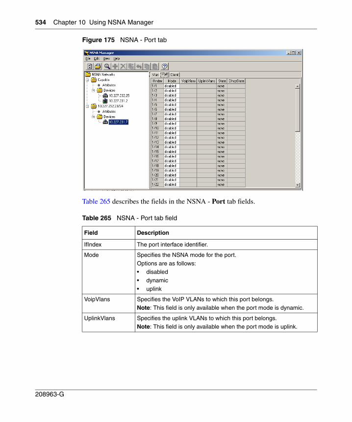
534 Chapter 10 Using NSNA Manager
208963-G
Figure 175 NSNA - Port tab
Table 265 describes the fields in the NSNA - Port tab fields.
Table 265 NSNA - Port tab field
Field Description
IfIndex The port interface identifier.
Mode Specifies the NSNA mode for the port.
Options are as follows:• disabled
• dynamic
• uplink
VoipVlans Specifies the VoIP VLANs to which this port belongs.
Note: This field is only available when the port mode is dynamic.
UplinkVlans Specifies the uplink VLANs to which this port belongs.Note: This field is only available when the port mode is uplink.
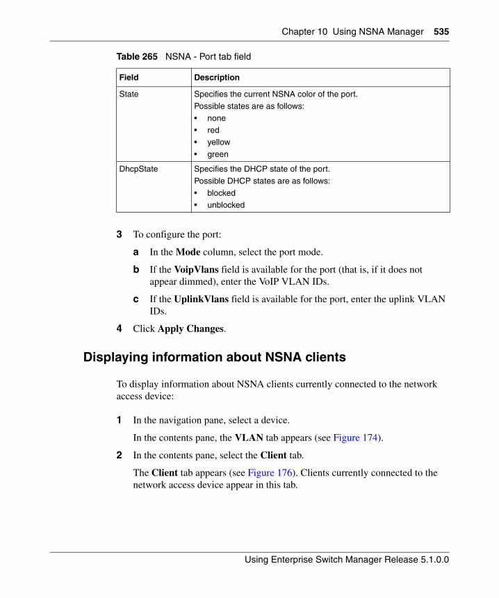
Chapter 10 Using NSNA Manager 535
Using Enterprise Switch Manager Release 5.1.0.0
3 To configure the port:
a In the Mode column, select the port mode.
b If the VoipVlans field is available for the port (that is, if it does not appear dimmed), enter the VoIP VLAN IDs.
c If the UplinkVlans field is available for the port, enter the uplink VLAN IDs.
4 Click Apply Changes.
Displaying information about NSNA clients
To display information about NSNA clients currently connected to the network access device:
1 In the navigation pane, select a device.
In the contents pane, the VLAN tab appears (see Figure 174).
2 In the contents pane, select the Client tab.
The Client tab appears (see Figure 176). Clients currently connected to the network access device appear in this tab.
State Specifies the current NSNA color of the port.
Possible states are as follows:
• none• red
• yellow
• green
DhcpState Specifies the DHCP state of the port.
Possible DHCP states are as follows:
• blocked• unblocked
Table 265 NSNA - Port tab field
Field Description
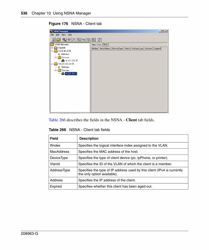
536 Chapter 10 Using NSNA Manager
208963-G
Figure 176 NSNA - Client tab
Table 266 describes the fields in the NSNA - Client tab fields.
Table 266 NSNA - Client tab fields
Field Description
IfIndex Specifies the logical interface index assigned to the VLAN.
MacAddress Specifies the MAC address of the host.
DeviceType Specifies the type of client device (pc, ipPhone, or printer).
VlanId Specifies the ID of the VLAN of which the client is a member.
AddressType Specifies the type of IP address used by this client (IPv4 is currently the only option available).
Address Specifies the IP address of the client.
Expired Specifies whether this client has been aged-out.
Chapter 10 Using NSNA Manager 537
Using Enterprise Switch Manager Release 5.1.0.0
Viewing NSNAS subnet members in Enterprise Switch Manager
To view the members of an NSNAS subnet in Enterprise Switch Manager:
1 In the navigation pane, choose a device under the Devices folder, or choose an Attributes node.
2 From the NSNA Manager menu bar, choose View > Highlight Topology.
3 Return to the Enterprise Switch Manager window.
The selected topology view appears in the Enterprise Switch Manager contents pane.
Figure 177 shows two devices that are members of the same NSNAS subnet.
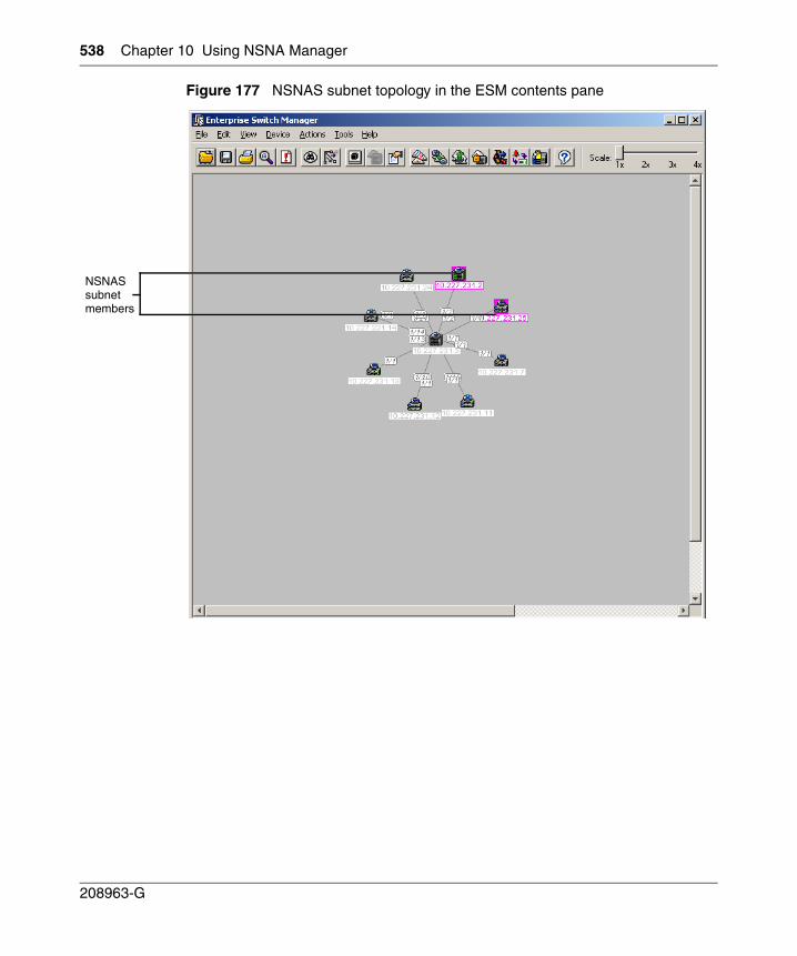
538 Chapter 10 Using NSNA Manager
208963-G
Figure 177 NSNAS subnet topology in the ESM contents pane
NSNASsubnetmembers
539
Using Enterprise Switch Manager Release 5.1.0.0
Chapter 11Using MIB Browser
The Management Information Base (MIB) Browser allows you to manage SNMP-enabled network devices and applications. MIB Browser enables loading, browsing, and searching MIBs, walking the MIB tree, and performing all other SNMP-related functions. MIB Browser also enables viewing and operating the data available through an SNMP agent in a managed device.
This chapter describes how to use MIB Browser to manage MIBs on Nortel Ethernet Switches and Nortel Ethernet Routing Switches. It includes the following information:
• “Starting MIB Browser” on page 540
• “MIB Browser window” on page 540
• “Loading MIBs” on page 547
• “Unloading MIBs” on page 548
• “Finding a node” on page 549
• “SNMP Operations” on page 549
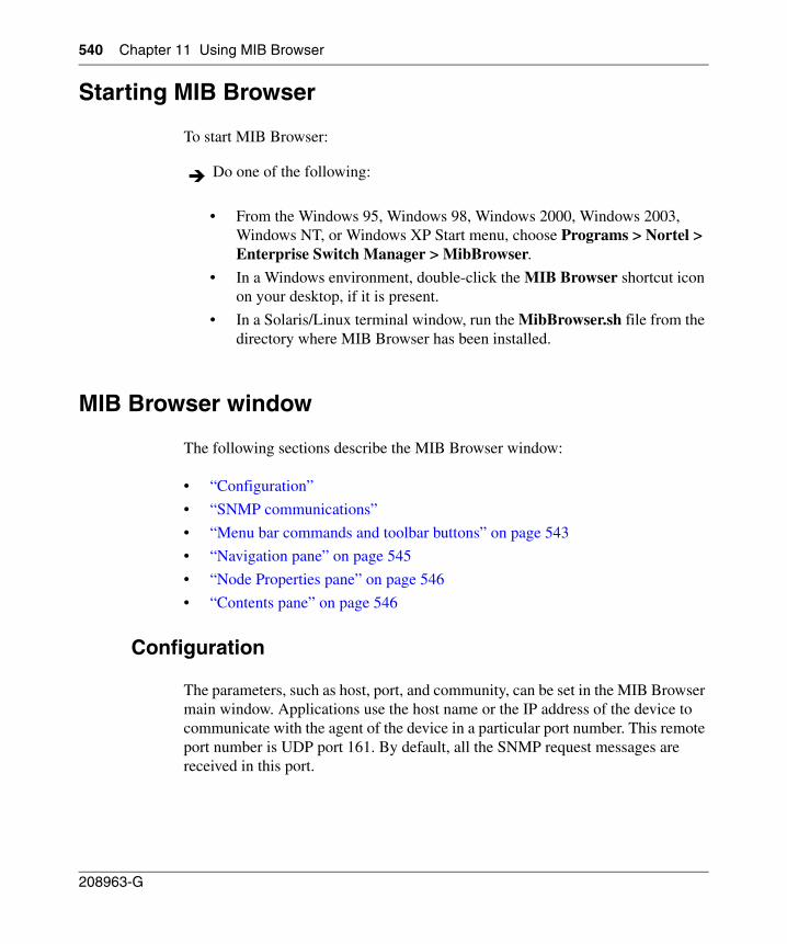
540 Chapter 11 Using MIB Browser
208963-G
Starting MIB Browser
To start MIB Browser:
• From the Windows 95, Windows 98, Windows 2000, Windows 2003, Windows NT, or Windows XP Start menu, choose Programs > Nortel > Enterprise Switch Manager > MibBrowser.
• In a Windows environment, double-click the MIB Browser shortcut icon on your desktop, if it is present.
• In a Solaris/Linux terminal window, run the MibBrowser.sh file from the directory where MIB Browser has been installed.
MIB Browser window
The following sections describe the MIB Browser window:
• “Configuration”
• “SNMP communications”
• “Menu bar commands and toolbar buttons” on page 543
• “Navigation pane” on page 545
• “Node Properties pane” on page 546
• “Contents pane” on page 546
Configuration
The parameters, such as host, port, and community, can be set in the MIB Browser main window. Applications use the host name or the IP address of the device to communicate with the agent of the device in a particular port number. This remote port number is UDP port 161. By default, all the SNMP request messages are received in this port.
Do one of the following:
Chapter 11 Using MIB Browser 541
Using Enterprise Switch Manager Release 5.1.0.0
SNMP communications
SNMP mandates that SNMP agents must accept request messages only if the community string in the message matches its community name. Therefore, the management application must always communicate with the agents using the associated community name. The default SNMP community names are "public" for read-only (Get) operations and "private" for read-write (Set) operations. Management applications must have provision to include the community names in their request messages.
Community strings are used to authenticate SNMP Protocol Data Units (PDU). Since SNMP packets are usually sent using UDP packets, there is no connection established as in the case of TCP/IP packets. Therefore, when a UDP packet is sent to the agent, the agent validates the packet. It accepts and sends a response if the community string of the PDU is equal to that set on the agent, or else drops the packet. The agent does not change the community name after communicating. Applications typically communicate with the SNMP agents by specifying the community name of the agent.
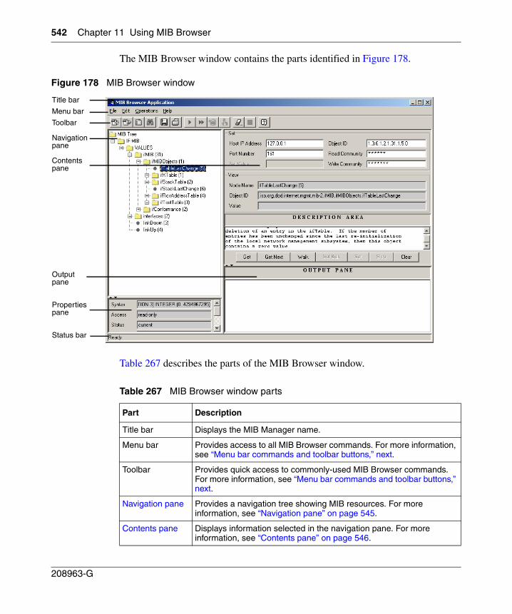
542 Chapter 11 Using MIB Browser
208963-G
The MIB Browser window contains the parts identified in Figure 178.
Figure 178 MIB Browser window
Table 267 describes the parts of the MIB Browser window.
Table 267 MIB Browser window parts
Part Description
Title bar Displays the MIB Manager name.
Menu bar Provides access to all MIB Browser commands. For more information, see “Menu bar commands and toolbar buttons‚” next.
Toolbar Provides quick access to commonly-used MIB Browser commands. For more information, see “Menu bar commands and toolbar buttons‚” next.
Navigation pane Provides a navigation tree showing MIB resources. For more information, see “Navigation pane” on page 545.
Contents pane Displays information selected in the navigation pane. For more information, see “Contents pane” on page 546.
Title bar
Menu bar
Toolbar
Navigation pane
Contentspane
Output pane
Propertiespane
Status bar
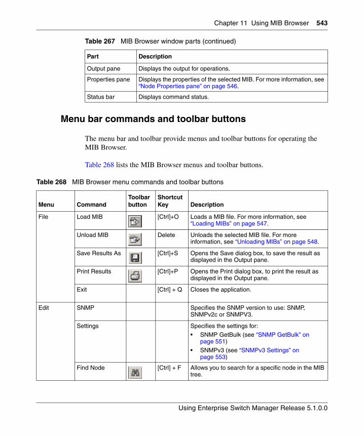
Chapter 11 Using MIB Browser 543
Using Enterprise Switch Manager Release 5.1.0.0
Menu bar commands and toolbar buttons
The menu bar and toolbar provide menus and toolbar buttons for operating the MIB Browser.
Table 268 lists the MIB Browser menus and toolbar buttons.
Output pane Displays the output for operations.
Properties pane Displays the properties of the selected MIB. For more information, see “Node Properties pane” on page 546.
Status bar Displays command status.
Table 268 MIB Browser menu commands and toolbar buttons
Menu CommandToolbar button
Shortcut Key Description
File Load MIB [Ctrl]+O Loads a MIB file. For more information, see “Loading MIBs” on page 547.
Unload MIB Delete Unloads the selected MIB file. For more information, see “Unloading MIBs” on page 548.
Save Results As [Ctrl]+S Opens the Save dialog box, to save the result as displayed in the Output pane.
Print Results [Ctrl]+P Opens the Print dialog box, to print the result as displayed in the Output pane.
Exit [Ctrl] + Q Closes the application.
Edit SNMP Specifies the SNMP version to use: SNMP, SNMPv2c or SNMPV3.
Settings Specifies the settings for:• SNMP GetBulk (see “SNMP GetBulk” on
page 551)
• SNMPv3 (see “SNMPv3 Settings” on page 553)
Find Node [Ctrl] + F Allows you to search for a specific node in the MIB tree.
Table 267 MIB Browser window parts (continued)
Part Description
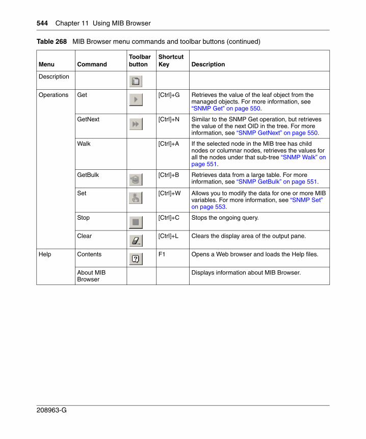
544 Chapter 11 Using MIB Browser
208963-G
Description
Operations Get [Ctrl]+G Retrieves the value of the leaf object from the managed objects. For more information, see “SNMP Get” on page 550.
GetNext [Ctrl]+N Similar to the SNMP Get operation, but retrieves the value of the next OID in the tree. For more information, see “SNMP GetNext” on page 550.
Walk [Ctrl]+A If the selected node in the MIB tree has child nodes or columnar nodes, retrieves the values for all the nodes under that sub-tree “SNMP Walk” on page 551.
GetBulk [Ctrl]+B Retrieves data from a large table. For more information, see “SNMP GetBulk” on page 551.
Set [Ctrl]+W Allows you to modify the data for one or more MIB variables. For more information, see “SNMP Set” on page 553.
Stop [Ctrl]+C Stops the ongoing query.
Clear [Ctrl]+L Clears the display area of the output pane.
Help Contents F1 Opens a Web browser and loads the Help files.
About MIB Browser
Displays information about MIB Browser.
Table 268 MIB Browser menu commands and toolbar buttons (continued)
Menu CommandToolbar button
Shortcut Key Description
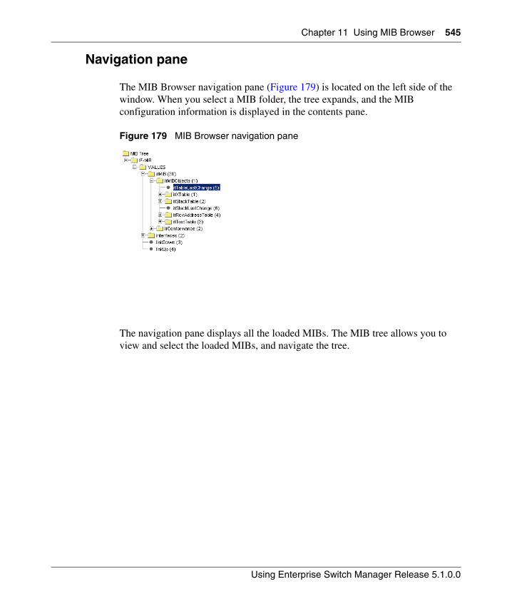
Chapter 11 Using MIB Browser 545
Using Enterprise Switch Manager Release 5.1.0.0
Navigation pane
The MIB Browser navigation pane (Figure 179) is located on the left side of the window. When you select a MIB folder, the tree expands, and the MIB configuration information is displayed in the contents pane.
Figure 179 MIB Browser navigation pane
The navigation pane displays all the loaded MIBs. The MIB tree allows you to view and select the loaded MIBs, and navigate the tree.
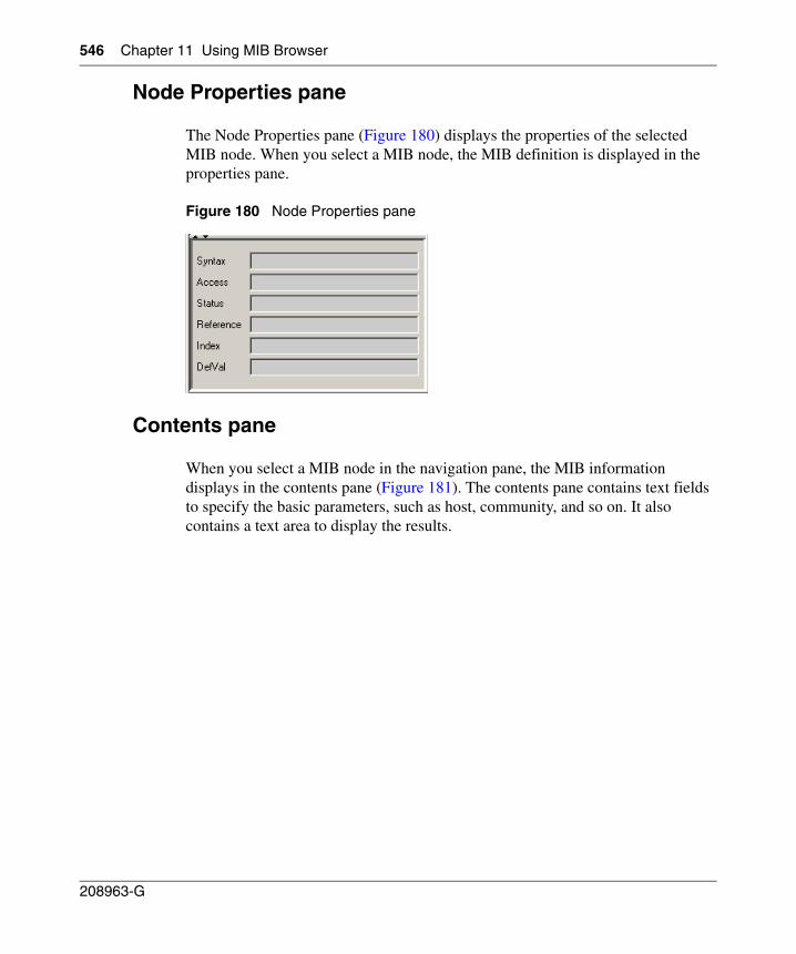
546 Chapter 11 Using MIB Browser
208963-G
Node Properties pane
The Node Properties pane (Figure 180) displays the properties of the selected MIB node. When you select a MIB node, the MIB definition is displayed in the properties pane.
Figure 180 Node Properties pane
Contents pane
When you select a MIB node in the navigation pane, the MIB information displays in the contents pane (Figure 181). The contents pane contains text fields to specify the basic parameters, such as host, community, and so on. It also contains a text area to display the results.
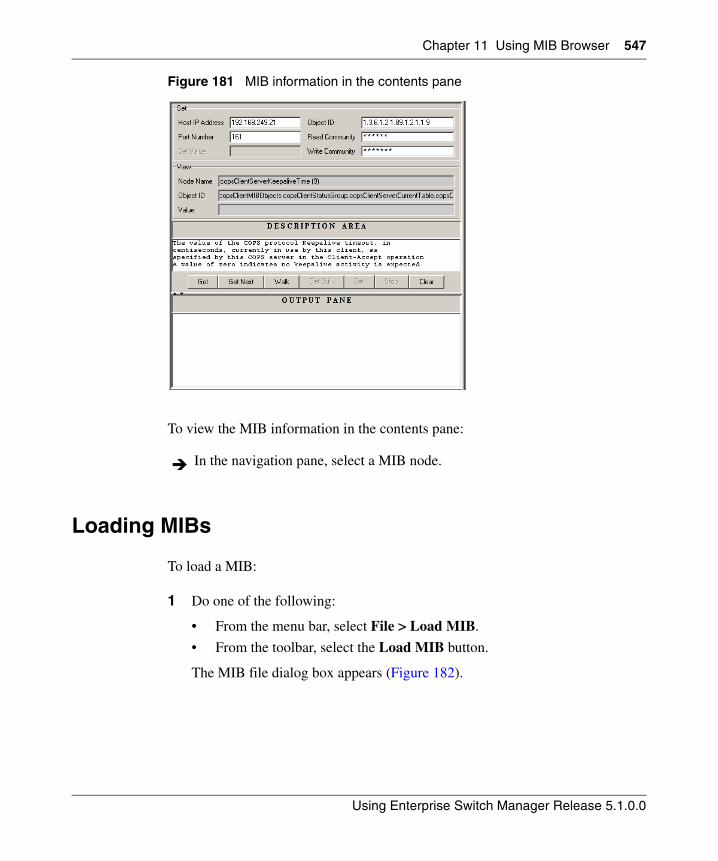
Chapter 11 Using MIB Browser 547
Using Enterprise Switch Manager Release 5.1.0.0
Figure 181 MIB information in the contents pane
To view the MIB information in the contents pane:
Loading MIBs
To load a MIB:
1 Do one of the following:
• From the menu bar, select File > Load MIB.
• From the toolbar, select the Load MIB button.
The MIB file dialog box appears (Figure 182).
In the navigation pane, select a MIB node.
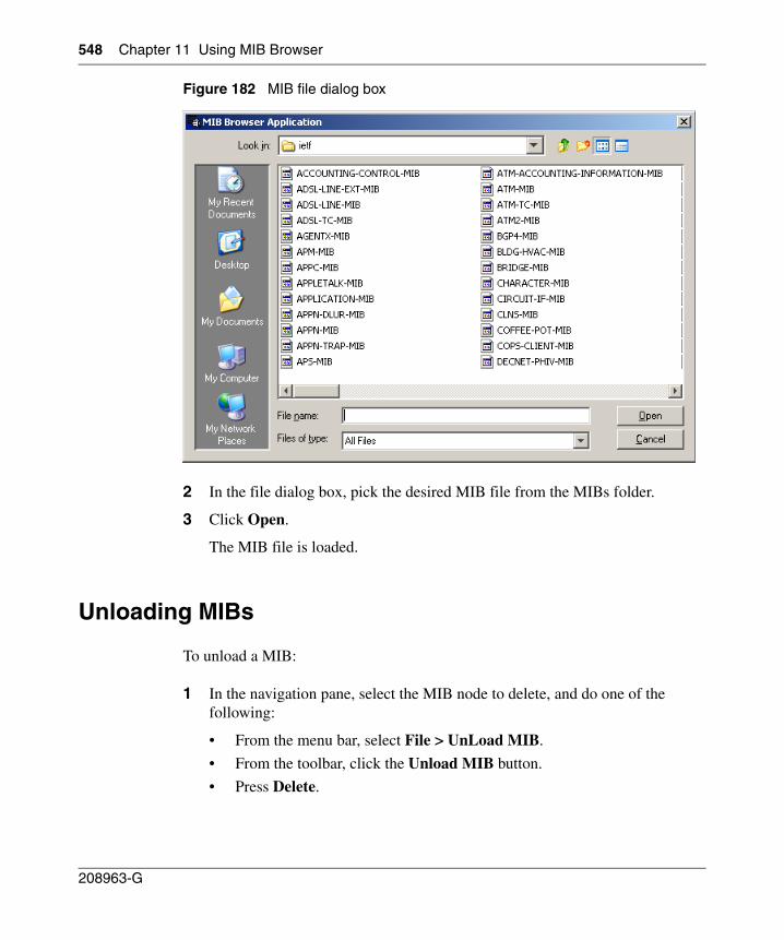
548 Chapter 11 Using MIB Browser
208963-G
Figure 182 MIB file dialog box
2 In the file dialog box, pick the desired MIB file from the MIBs folder.
3 Click Open.
The MIB file is loaded.
Unloading MIBs
To unload a MIB:
1 In the navigation pane, select the MIB node to delete, and do one of the following:
• From the menu bar, select File > UnLoad MIB.
• From the toolbar, click the Unload MIB button.
• Press Delete.
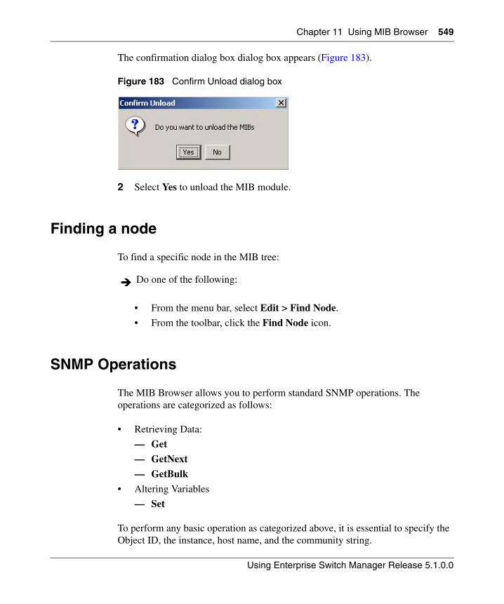
Chapter 11 Using MIB Browser 549
Using Enterprise Switch Manager Release 5.1.0.0
The confirmation dialog box dialog box appears (Figure 183).
Figure 183 Confirm Unload dialog box
2 Select Yes to unload the MIB module.
Finding a node
To find a specific node in the MIB tree:
• From the menu bar, select Edit > Find Node.
• From the toolbar, click the Find Node icon.
SNMP Operations
The MIB Browser allows you to perform standard SNMP operations. The operations are categorized as follows:
• Retrieving Data:
— Get
— GetNext
— GetBulk
• Altering Variables
— Set
To perform any basic operation as categorized above, it is essential to specify the Object ID, the instance, host name, and the community string.
Do one of the following:
550 Chapter 11 Using MIB Browser
208963-G
Changes can also be made to the parameters in the MIB Browser's Set panel in the contents pane.
• Host IP Address: To enter the IP Address or the Host name of the SNMP agent.
• Port Number: To enter the port number of the SNMP agent
• Object ID: To enter the OID of the variable on which the SNMP operation is to be carried
• Read Community: To enter the read community string of the SNMP agent
• Write Community: To enter the write community string of the SNMP agent.
SNMP Get
The Get operation is performed to get the value of the leaf object from the managed objects.
To perform SNMP Get:
1 In the navigation pane, select the desired node from the MIB tree.
2 Do one of the following:
• From the menu bar, select Operations > Get.
• From the toolbar, click Get SNMP variable
The MIB Browser gets the specified object, or the specific object instance, if a MIB node is specified.
SNMP GetNext
This operation is similar to the SNMP Get operation, but it retrieves the value of the next OID in the tree. This operation is used for traversing the MIB tree.
To perform SNMP GetNext:
1 In the navigation pane, select the desired node from the MIB tree.
2 Do one of the following:
• From the menu bar, select Operations > GetNext.
Chapter 11 Using MIB Browser 551
Using Enterprise Switch Manager Release 5.1.0.0
• From the toolbar, click the Get Next SNMP variable button.
The MIB Browser gets the next object after the specified object, or the specific object instance, if a MIB node is specified.
SNMP Walk
This operation is similar to the SNMP GetNext operation, which gets all objects under the selected MIB object. If the selected node in the MIB tree has child nodes or columnar nodes, this operation is performed to retrieve the values for all the nodes under that sub-tree.
To perform SNMP Walk:
1 In the navigation pane, select the desired node from the MIB tree.
2 From the menu bar, select Operations > Walk.
The MIB Browser retrieves the values for all the nodes under the sub-tree.
SNMP GetBulk
To retrieve voluminous data from a large table, use the GetBulk operation. A GetBulk request is performed by specifying an OID along with two additional parameters, Max-Repetitions and Non-Repeaters. The GetBulk operation is performed only on SNMPv2c and SNMPv3.
To perform SNMP GetBulk.
1 Select the desired node in the MIB tree.
2 Ensure that the SNMP version is set to either SNMPv2c or SNMPv3.
• From the menu bar, choose Edit > SNMP, and select SNMPv2c or SNMPV3.
3 From the menu bar, select Edit > Settings > SNMP BULK.
The GetBulk Settings pane appears, replacing the output pane (Figure 184).
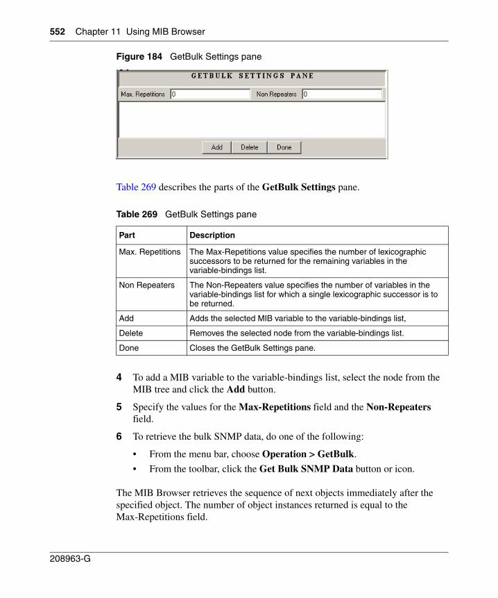
552 Chapter 11 Using MIB Browser
208963-G
Figure 184 GetBulk Settings pane
Table 269 describes the parts of the GetBulk Settings pane.
4 To add a MIB variable to the variable-bindings list, select the node from the MIB tree and click the Add button.
5 Specify the values for the Max-Repetitions field and the Non-Repeaters field.
6 To retrieve the bulk SNMP data, do one of the following:
• From the menu bar, choose Operation > GetBulk.
• From the toolbar, click the Get Bulk SNMP Data button or icon.
The MIB Browser retrieves the sequence of next objects immediately after the specified object. The number of object instances returned is equal to the Max-Repetitions field.
Table 269 GetBulk Settings pane
Part Description
Max. Repetitions The Max-Repetitions value specifies the number of lexicographic successors to be returned for the remaining variables in the variable-bindings list.
Non Repeaters The Non-Repeaters value specifies the number of variables in the variable-bindings list for which a single lexicographic successor is to be returned.
Add Adds the selected MIB variable to the variable-bindings list,
Delete Removes the selected node from the variable-bindings list.
Done Closes the GetBulk Settings pane.
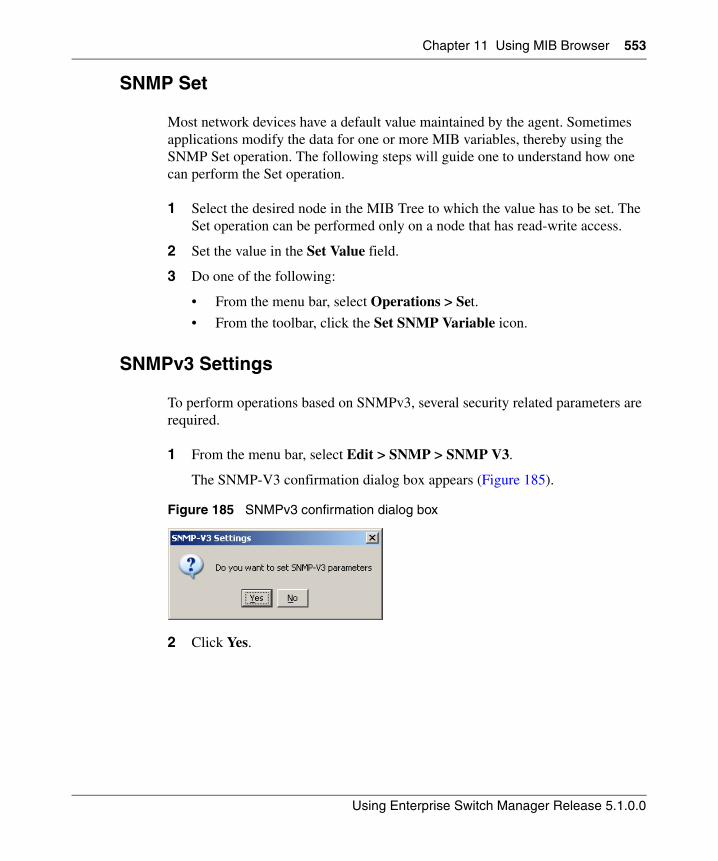
Chapter 11 Using MIB Browser 553
Using Enterprise Switch Manager Release 5.1.0.0
SNMP Set
Most network devices have a default value maintained by the agent. Sometimes applications modify the data for one or more MIB variables, thereby using the SNMP Set operation. The following steps will guide one to understand how one can perform the Set operation.
1 Select the desired node in the MIB Tree to which the value has to be set. The Set operation can be performed only on a node that has read-write access.
2 Set the value in the Set Value field.
3 Do one of the following:
• From the menu bar, select Operations > Set.
• From the toolbar, click the Set SNMP Variable icon.
SNMPv3 Settings
To perform operations based on SNMPv3, several security related parameters are required.
1 From the menu bar, select Edit > SNMP > SNMP V3.
The SNMP-V3 confirmation dialog box appears (Figure 185).
Figure 185 SNMPv3 confirmation dialog box
2 Click Yes.
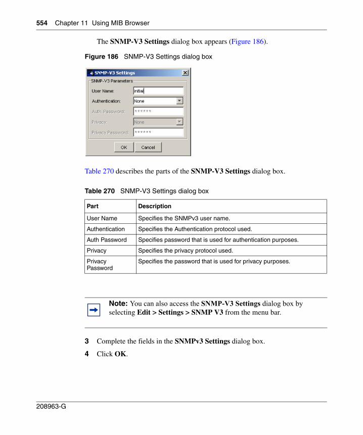
554 Chapter 11 Using MIB Browser
208963-G
The SNMP-V3 Settings dialog box appears (Figure 186).
Figure 186 SNMP-V3 Settings dialog box
Table 270 describes the parts of the SNMP-V3 Settings dialog box.
3 Complete the fields in the SNMPv3 Settings dialog box.
4 Click OK.
Table 270 SNMP-V3 Settings dialog box
Part Description
User Name Specifies the SNMPv3 user name.
Authentication Specifies the Authentication protocol used.
Auth Password Specifies password that is used for authentication purposes.
Privacy Specifies the privacy protocol used.
Privacy Password
Specifies the password that is used for privacy purposes.
Note: You can also access the SNMP-V3 Settings dialog box by selecting Edit > Settings > SNMP V3 from the menu bar.
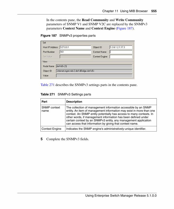
Chapter 11 Using MIB Browser 555
Using Enterprise Switch Manager Release 5.1.0.0
In the contents pane, the Read Community and Write Community parameters of SNMP V1 and SNMP V2C are replaced by the SNMPv3 parameters Context Name and Context Engine (Figure 187).
Figure 187 SNMPv3 properties parts
Table 271 describes the SNMPv3 settings parts in the contents pane.
5 Complete the SNMPv3 fields.
Table 271 SNMPv3 Settings parts
Part Description
SNMP context name
The collection of management information accessible by an SNMP entity. An item of management information may exist in more than one context. An SNMP entity potentially has access to many contexts. In other words, if management information has been defined under certain context by an SNMPv3 entity, any management application can access that information by giving that context name.
Context Engine Indicates the SNMP engine's administratively-unique identifier.

556 Chapter 11 Using MIB Browser
208963-G
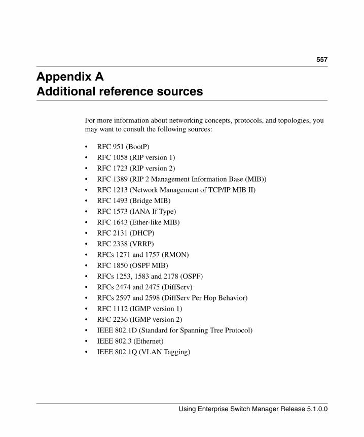
557
Using Enterprise Switch Manager Release 5.1.0.0
Appendix AAdditional reference sources
For more information about networking concepts, protocols, and topologies, you may want to consult the following sources:
• RFC 951 (BootP)
• RFC 1058 (RIP version 1)
• RFC 1723 (RIP version 2)
• RFC 1389 (RIP 2 Management Information Base (MIB))
• RFC 1213 (Network Management of TCP/IP MIB II)
• RFC 1493 (Bridge MIB)
• RFC 1573 (IANA If Type)
• RFC 1643 (Ether-like MIB)
• RFC 2131 (DHCP)
• RFC 2338 (VRRP)
• RFCs 1271 and 1757 (RMON)
• RFC 1850 (OSPF MIB)
• RFCs 1253, 1583 and 2178 (OSPF)
• RFCs 2474 and 2475 (DiffServ)
• RFCs 2597 and 2598 (DiffServ Per Hop Behavior)
• RFC 1112 (IGMP version 1)
• RFC 2236 (IGMP version 2)
• IEEE 802.1D (Standard for Spanning Tree Protocol)
• IEEE 802.3 (Ethernet)
• IEEE 802.1Q (VLAN Tagging)

558 Additional reference sources
208963-G
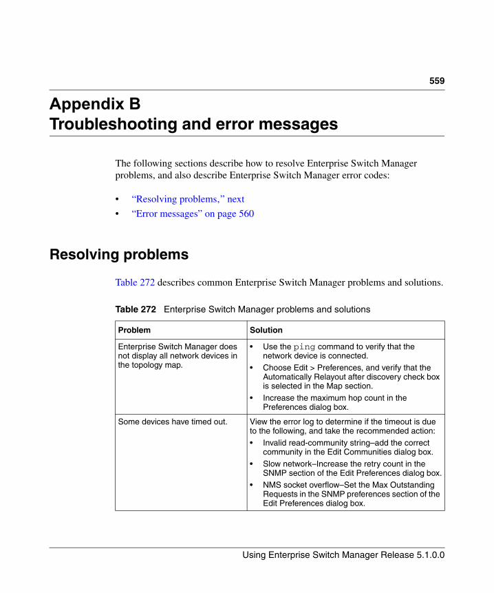
559
Using Enterprise Switch Manager Release 5.1.0.0
Appendix BTroubleshooting and error messages
The following sections describe how to resolve Enterprise Switch Manager problems, and also describe Enterprise Switch Manager error codes:
• “Resolving problems‚” next
• “Error messages” on page 560
Resolving problems
Table 272 describes common Enterprise Switch Manager problems and solutions.
Table 272 Enterprise Switch Manager problems and solutions
Problem Solution
Enterprise Switch Manager does not display all network devices in the topology map.
• Use the ping command to verify that the network device is connected.
• Choose Edit > Preferences, and verify that the Automatically Relayout after discovery check box is selected in the Map section.
• Increase the maximum hop count in the Preferences dialog box.
Some devices have timed out. View the error log to determine if the timeout is due to the following, and take the recommended action:
• Invalid read-community string–add the correct community in the Edit Communities dialog box.
• Slow network–Increase the retry count in the SNMP section of the Edit Preferences dialog box.
• NMS socket overflow–Set the Max Outstanding Requests in the SNMP preferences section of the Edit Preferences dialog box.
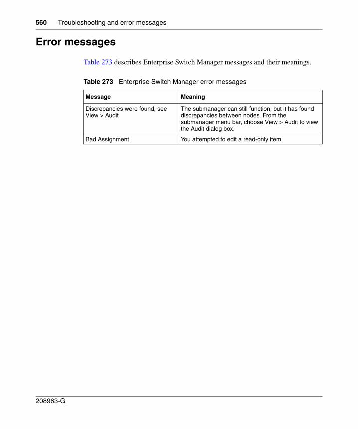
560 Troubleshooting and error messages
208963-G
Error messages
Table 273 describes Enterprise Switch Manager messages and their meanings.
Table 273 Enterprise Switch Manager error messages
Message Meaning
Discrepancies were found, see View > Audit
The submanager can still function, but it has found discrepancies between nodes. From the submanager menu bar, choose View > Audit to view the Audit dialog box.
Bad Assignment You attempted to edit a read-only item.
Using Enterprise Switch Manager Release 5.1.0.0
561
Index
Aaccess policies
adding to a security group 496deleting from a security group 498
adding a user 61
Address fieldin the Communities dialog box 111
Asynchronous Transfer Mode. See ATM
ATM 71
Automatically Relayout after discovery option 101
Automatically Save on Exit option 101
BBay Auto Topology Protocol. See BTP
BayStack 450 switchnumber of MLTs supported 174
BridgeAddress field 134
BridgeForwardDelay field 132
BridgeForwardDelay item 142
BridgeHelloTime field 131
BridgeHelloTime item 142
BridgeMaxAge field 131
BridgeMaxAge item 142
brouter portsabout 126viewing 128VLAN 116
BTP 97
Business Policy Switch 2000
number of MLTs supported 174
Cchanging password 64
CLI accessconfiguring for a security group 455
color displayconfiguring 78
Communitieschanges to SNMP communities 110
communitiesSNMP passwords 109using a wildcard 111
Communities/Password dialog box 109
Comparing 324
configurationID-based VLAN 158port-based VLAN 147protocol-based VLAN 151source IP subnet-based VLAN 149source MAC address-based VLAN 154sVLAN 157
configuring color display 78
configuring e-mail settings 65
Contact item 77
contents paneEnterprise Switch Manager 68Multicast Manager 224MultiLink Trunking Manager 179NSNA Manager 520VLAN Manager 122, 546
customer support 42
562 Index
208963-G
DDefault Ports table 136
default VLAN, definition 136
Delete dialog box 161
deleting a user 63
deleting table rows 229
deleting tree nodes 229
Description item 77
DesignatedRoot field 134
devicearranging on a topology map 93finding on the topology map 91
Device fieldin the Configuration table 131in the Isolated Device table 186in the No Trunk table 185in the Root table 134in the Status table 132in the Trunk table 184, 188, 189
device icons 80dimmed 81
Device itemin the Bridge Routing Ports table 128in the Default Ports table 136in the Isolated Routing Ports table 128in the Members table 130in the Ports table 138in the Tagging Ports table 127in the Unassigned Ports table 127
device itemfinding unsaved or changed configuration
files 82selecting by type 92
Device Managerdocumentation 56features 56reference guides 557standalone application 56
device properties 76
Device Properties dialog box
viewing device properties 76viewing port status 77
discovery process. See network topology map
DVMRPand Multicast Manager 228coupled with layer 3 IGMP 215definition 215globals, configuring 231Interface tab 253Neighbor tab 255Next Hop tab 256Route tab 254viewing information 233
EEdit Mac - VLAN dialog box 156
Edit Mac Addresses command 156
editing multiple table cells 231
editing table cells 231
e-mailconfiguring 65
Enable fieldin the Isolated Device table 186in the No Trunk table 185in the Trunk table 184
Enable Stp item 142
Enable Stp Traps item 142
EnableStp field 132
Enterprise Switch Managercontents pane 68contents pane icons 80devices supported 47discovering network topology mapfeatures 46help 95introduction 45menu bar 68MLT links 209Multicast Manager information, viewing 234shortcut menu 75
Index 563
Using Enterprise Switch Manager Release 5.1.0.0
size of network discovered 68starting 57status bar 77submanager support 48submanagers 50window 66
error messages 559
Ethernet 71
Ethernet Routing Switch 1424 and 16xx switchesnumber of MLTs supported 174
Ethernet Routing Switch 8100IGMP Snoop support 239
Ethernet Routing Switch 8100 modulecreating protocol-based VLANs 154
Ethernet Routing Switch 8600IGMP Snoop support 239
Ethernet Routing Switch 8600 modulecreating protocol-based VLANs 153number of MLTs supported 174
Ethernet SwitchIGMP Snoop support 239
ExpiryTime fieldin the Next Hop tab 257
FFile/Inventory Manager
Alteon folder 369Archive Config File dialog box 430archiving configuration and boot.cfg files 340backing up configuration files 338, 349
Ethernet Routing Switch 8000 349Backup Config from Device dialog box 427cancelling scheduled tasks 363changing display preferences 310content pane 306definition 297deleting scheduled tasks 364Device Upgrade dialog box 432Display Preferences dialog box 438Download File to Device(s) dialog box 422downloading image and configuration files
Alteon devices 314Ethernet Routing Switch 1424 devices 318Ethernet Routing Switch 16xx devices 318Ethernet Routing Switch 55xx/35xx
devices 316Ethernet Routing Switch 8000 devices 320Ethernet Switch devices 316Legacy BayStack devices 316WLAN AP devices 322
downloading image and configuration files to devices 313
editing configuration files 357ERS 1424/16xx folder 374ERS 55xx/35xx folder 379ERS 8000 folder 384Ethernet Switch folder 397features 53file management capabilities by product 297Find dialog box 365finding inventory elements 365inventory file types 308Legacy BayStack folder 403loading inventory information 310navigation pane 306navigation tree 367network topology map
viewing devices on 365Passport 1000 folder 409printing inventory information 366refreshing window 312reloading inventory 312Restore Config to Device dialog box 429restoring configuration files to devices 339saving inventory information 308saving inventory information in tab-delimited
text file 309Schedule dialog box 436schedule dialog box 361scheduling tasks 360
cancelling scheduled tasks 363deleting scheduled tasks 364inventory query 358viewing scheduled tasks 362viewing scheduled tasks log files 362
564 Index
208963-G
standalone application 53starting 301Synchronize Config File dialog box 431synchronizing configuration files 342Upgrade Wizard
Ethernet Routing Switch 8000 349upgrading devices 344
Alteon devices 344, 349Ethernet Routing Switch 55xx/35xx
devices 346Ethernet Routing Switch 8000 349Ethernet Routing Switch 8000, 1424, and
16xx devices 347Ethernet Switch devices 346Legacy Baystack devices 346WLAN AP devices 356
Upload File from Device dialog box 425uploading configuration files
Alteon devices 328Ethernet Routing Switch 1424 devices 332Ethernet Routing Switch 16xx devices 332Ethernet Routing Switch 55xx/35xx
devices 330Ethernet Routing Switch 8000 devices 334Ethernet Switch devices 330Legacy BayStack devices 330WLAN AP devices 336
uploading image and configuration files 327View Scheduled Task dialog box 437viewing log file 364viewing scheduled tasks 362viewing scheduled tasks log files 362window 302WLAN AP folder 418
findunsaved or changed device configuration
files 82
Find dialog boxFile/Inventory Manager 365Multicast Manager 225MultiLink Trunking Manager 181NSNA Manager 521VLAN Manager 123
Find Unsaved Configurations dialog box 83
finding devices on the topology map 91
Finding resources 225
ForwardDelay field 133
GGroup Access tab for ERS 8300 251
Group Access tab for ERS 8600 250
HHelloTime field 133
Help 95
help, accessing 95
hidden devices 107
hide devices 107
highlighted topology view 162, 537
HighPriority itemin the Default Ports table 136in the Ports table 138
HoldTime field 133
Iicons
device 80dimmed 81VLAN 134
Id fieldin the Isolated Device table 186in the No Trunk table 185in the Trunk table 184, 188
Id itemin the Insert MLT dialog box 193, 195in the STG dialog box 142
ID-based VLANscreating 158
IfIndex fieldin the No Trunk table 185, 186in the Trunk table 184
Index 565
Using Enterprise Switch Manager Release 5.1.0.0
IfIndex itemin the Default Ports table 137in the Ports table 138
IGMPconfiguring 232view information about 233
IGMP and IGMP Snoopand Multicast Manager 228
IGMP SnoopGroup Access folder for ERS 8300 251Group Access folder for ERS 8600 250
IGMP Snoop support 239
IGMP Snooping, definition 215
IGMP, definition 214
individual routing ports, VLAN 116
Insert MLT dialog boxone device 192, 194pair of devices 196viewing port status 197
inserting table rows 229
inserting tree nodes 228
Inter switch trunk . See IST
Interface tabdisplaying DVMRP enabled devices 253displaying L3-IGMP interface statistics 240
inter-switch trunksviewing 187
IpAddress itemin the Default Ports table 137in the Ports table 138
IRP, viewing information 127
Italic text on VLAN icon label 135
LL3-IGMP
Interface tab 240
Layout slider 108
Link Types, definition 71
Location item 77
logging in 58
MMAC address 156
managing users 60
Mask item 151
Max Hops field 100
MaxAge field 133
menu bardefinition 67Enterprise Switch Manager 68Multicast Manager 219MultiLink Trunking Manager 177
Metric field 257in the Route tab DVMRP table 257
MIB Browserfinding a node 549loading MIBs 547SNMP operations 549starting 540unloading MIBs 548window 540
MLTdefinition 173icon 183No trunk configurations 185viewing 183
MLT Manager commandsApply Changes 177Audit 178Close 177Copy 177Delete 177Edit 177File 177Find 177Help 178Highlight Topology 178Insert 177Online Support 178
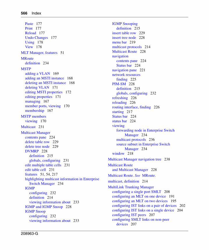
566 Index
208963-G
Paste 177Print 177Reload 177Undo Changes 177Using 178View 178
MLT Manager, features 51
MRoutedefinition 234
MSTPadding a VLAN 169adding an MSTI instance 168deleting an MSTI instance 168deleting VLAN 171editing MSTI properties 172editing properties 171managing 167member ports, viewing 170membership 167
MSTP membersviewing 170
Multicast 231
Multicast Managercontents pane 224delete table row 229delete tree node 229DVMRP 228
definition 215globals, configuring 231
edit multiple table cells 231edit table cell 231features 51, 54, 217highlighting multicast information in Enterprise
Switch Manager 234IGMP
configuring 232definition 214viewing information about 233
IGMP and IGMP Snoop 228IGMP Snoop
configuring 232viewing information about 233
IGMP Snoopingdefinition 215
insert table row 229insert tree node 228menu bar 219multicast protocols 214Multicast Route 228navigation
contents pane 224Status bar 224
navigation pane 221network resources
finding 225PIM-SM 228
definition 215globals, configuring 232
refreshing 226reloading 226routing interface, finding 226starting 217Status bar 224status bar 224viewing
forwarding node in Enterprise Switch Manager 234
multicast protocols 236source subnet in Enterprise Switch
Manager 234window 218
Multicast Manager navigation tree 238
Multicast Routeand Multicast Manager 228
Multicast Route. See MRoute.
multicast, definition 214
MultiLink Trunking Managerconfiguring a single port SMLT 208configuring an MLT on one device 191configuring an MLT on two devices 195configuring IST links on a pair of devices 202configuring IST links on a single device 204configuring IST peers 207configuring SMLT links on non-peer
devices 207
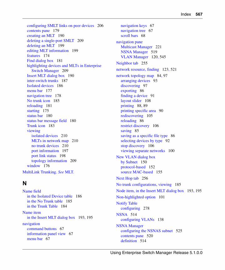
Index 567
Using Enterprise Switch Manager Release 5.1.0.0
configuring SMLT links on peer devices 206contents pane 179creating an MLT 190deleting a single-port SMLT 209deleting an MLT 199editing MLT information 199features 174Find dialog box 181highlighting devices and MLTs in Enterprise
Switch Manager 209Insert MLT dialog box 190inter-switch trunks 187Isolated devices 186menu bar 177navigation tree 178No trunk icon 185reloading 181starting 175status bar 180status bar message field 180Trunk icon 183viewing
isolated devices 210MLTs in network map 210no trunk devices 210port information 197port link status 198topology information 209
window 176
MultiLink Trunking. See MLT.
NName field
in the Isolated Device table 186in the No Trunk table 185in the Trunk Table 184
Name itemin the Insert MLT dialog box 193, 195
navigationcommand buttons 67information panel view 67menu bar 67
navigation keys 67navigation tree 67scroll bars 68
navigation paneMulticast Manager 221NSNA Manager 519VLAN Manager 120, 545
Neighbor tab 255
network resource, finding 123, 521
network topology map 84, 97arranging devices 93discovering 97exporting 86finding a device 91layout slider 108printing 88, 89printing specific area 90rediscovering 105reloading 86restrict discovery 106saving 85saving as a specific file type 86selecting devices by type 92stop discovery 106viewing separate networks 100
New VLAN dialog boxby Subnet 150protocol-based 152source MAC-based 155
Next Hop tab 256
No trunk configurations, viewing 185
Node item, in the Insert MLT dialog box 193, 195
Non-highlighted option 101
Notify Tableconfiguring 278
NSNA 514configuring VLANs 138
NSNA Managerconfiguring the NSNAS subnet 525contents pane 520definition 514
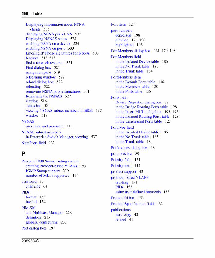
568 Index
208963-G
Displaying information about NSNA clients 535
displaying NSNA per VLAN 532Displaying NSNAS status 528enabling NSNA on a device 524enabling NSNA on ports 533Entering IP Phone signatures for NSNA 530features 515, 517find a network resource 521Find dialog box 521navigation pane 519refreshing window 522reload dialog box 522reloading 522removing NSNA phone signatures 531Removing the NSNAS 527starting 516status bar 521viewing NSNAS subnet members in ESM 537window 517
NSNASusername and password 111
NSNAS subnet membersin Enterprise Switch Manager, viewing 537
NumPorts field 132
PPassport 1000 Series routing switch
creating Protocol-based VLANs 153IGMP Snoop support 239number of MLTs supported 174
password 59changing 64
PIDsformat 153invalid 154
PIM-SMand Multicast Manager 228definition 215globals, configuring 232
Port dialog box 197
Port item 127
port numbersdepressed 198dimmed 196, 198highlighted 196
PortMembers dialog box 131, 170, 198
PortMembers fieldin the Isolated Device table 186in the No Trunk table 185in the Trunk table 184
PortMembers itemin the Default Ports table 136in the Members table 130in the Ports table 138
Ports itemDevice Properties dialog box 77in the Bridge Routing Ports table 128in the Insert MLT dialog box 193, 195in the Isolated Routing Ports table 128in the Unassigned Ports table 127
PortType fieldin the Isolated Device table 186in the No Trunk table 185in the Trunk table 184
Preferences dialog box 98
print preview 89
Priority field 131
Priority item 142
product support 42
protocol-based VLANscreating 151PIDs 153using user-defined protocols 153
ProtocolId box 153
ProtocolSpecification field 132
publicationshard copy 42related 41
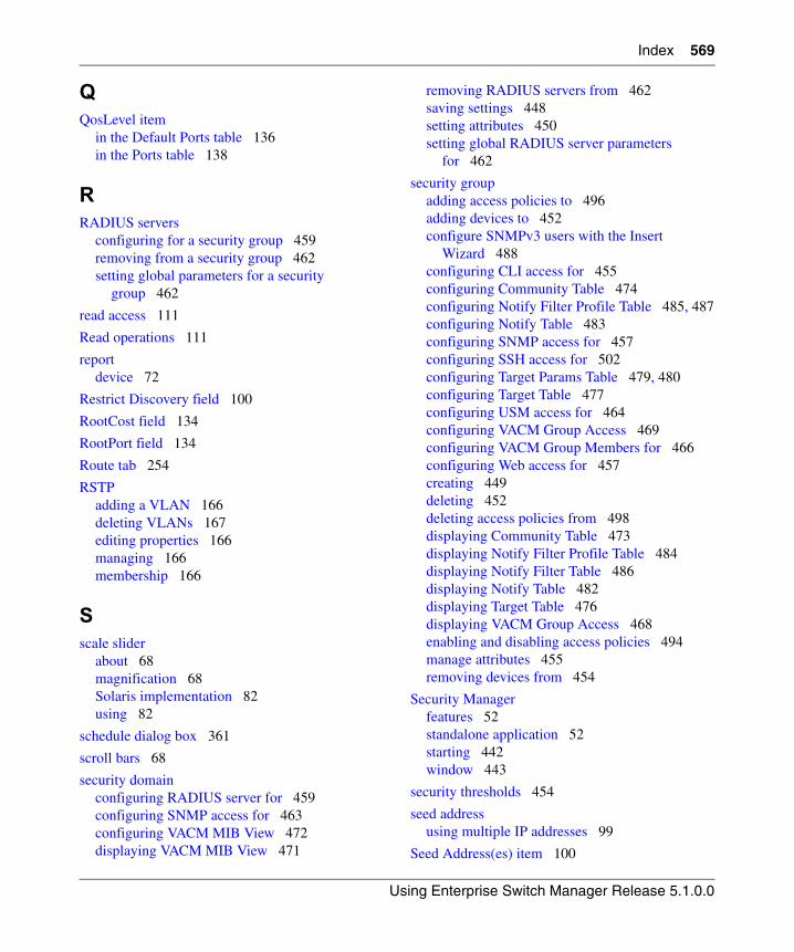
Index 569
Using Enterprise Switch Manager Release 5.1.0.0
QQosLevel item
in the Default Ports table 136in the Ports table 138
RRADIUS servers
configuring for a security group 459removing from a security group 462setting global parameters for a security
group 462
read access 111
Read operations 111
reportdevice 72
Restrict Discovery field 100
RootCost field 134
RootPort field 134
Route tab 254
RSTPadding a VLAN 166deleting VLANs 167editing properties 166managing 166membership 166
Sscale slider
about 68magnification 68Solaris implementation 82using 82
schedule dialog box 361
scroll bars 68
security domainconfiguring RADIUS server for 459configuring SNMP access for 463configuring VACM MIB View 472displaying VACM MIB View 471
removing RADIUS servers from 462saving settings 448setting attributes 450setting global RADIUS server parameters
for 462
security groupadding access policies to 496adding devices to 452configure SNMPv3 users with the Insert
Wizard 488configuring CLI access for 455configuring Community Table 474configuring Notify Filter Profile Table 485, 487configuring Notify Table 483configuring SNMP access for 457configuring SSH access for 502configuring Target Params Table 479, 480configuring Target Table 477configuring USM access for 464configuring VACM Group Access 469configuring VACM Group Members for 466configuring Web access for 457creating 449deleting 452deleting access policies from 498displaying Community Table 473displaying Notify Filter Profile Table 484displaying Notify Filter Table 486displaying Notify Table 482displaying Target Table 476displaying VACM Group Access 468enabling and disabling access policies 494manage attributes 455removing devices from 454
Security Managerfeatures 52standalone application 52starting 442window 443
security thresholds 454
seed addressusing multiple IP addresses 99
Seed Address(es) item 100
570 Index
208963-G
seed device 97
Select all devices menu 92
Setting security group properties 450
shortcut menu 75
Show DeviceHostName 101IP Address 101SysName 101
Show Device by, setting 101
SNMPlevel of access 111read and write operations 109
SNMP accessconfiguring for a security group 457
SNMP Listen for Traps item 102
SNMP Max Outstanding Requests item 102
SNMP Retry Count item 102
SNMP Timeout item 102
SNMP Trace item 102
SNMPv3 accessconfiguring for a security group 463
Source IP subnet-based VLANs 149
source MAC address-based VLANsadding MAC addresses 156creating 154
spanning tree groupsdefinition 115viewing configuration information 116viewing root information 116
Spanning Tree Protocolabout 115
Spanning Tree Protocol. See STP
SSH accessconfiguring for a security group 502
SSH security groupadding devices to 501creating 499deleting 501removing devices from 502
starting Enterprise Switch Manager 57
status barEnterprise Switch Manager 68, 77, 78Multicast Manager 224MultiLink Trunk Manager 180NSNA Manager 521VLAN Manager 122
status bar icon fieldVLAN Manager 122, 180
status bar message fieldMultiLink Trunking Manager 180VLAN Manager 122
Status table 132
STGadding members to existing STGs 144Config 131configuration information 131creating STGs 141deleting STGs 143editing port membership 145editing STGs 142forwarding ports 164information, viewing 128maximum number of STGs per product 115member ports, viewing 130membership 140port members 163ports
adding 130, 170blocking 164
root 133root configuration 164status, viewing 132STG members in Enterprise Switch Manager,
viewing 163STG root configuration, viewing 164STG roots in Enterprise Switch Manager,
viewing 161STGs in Enterprise Switch Manager,
viewing 161
STG membersadding ports 130, 170
Index 571
Using Enterprise Switch Manager Release 5.1.0.0
viewing 130
STPabout 115controlling path redundancy 114spanning tree algorithm 115viewing Root information 133
StpTrapEnable field 132
submanager preferences 103
submanager, windows and Enterprise Switch Manager 66
subnet address 111
subnet discovery 106
Subnet item 151
support, Nortel Networks 42
sVLANscreating 157
synchronizing VLANs 160
SysLogviewing 277
SysName item 77
System Logconfiguring 269
TTaggedBpduAddress field 132
TaggedBpduAddress item 142
TaggedBpduVlanId field 132
TaggedBpduVlanId item 142
tagging VLAN 126, 127
Target Address Tableconfiguring 278
Target Params Tableconfiguring 278
task filesupgrading 84
technical publications 42
technical support 42
TFTP Serversetting default for 102
TimeSinceTopologyChange field 132
title bar 67
toolbar 67
TopChanges field 133
topologydumping to log 72
topology map, magnifying 82
trap logviewing 295
Trap/Log Manager 267starting 268System Log
configuring 269
trapsconfiguring 278
Trim HostName Domains item 101
troubleshooting 163, 559
trunk, definition 183
Type fieldin the New VLAN dialog box 146
Type itemin the Device Properties dialog box 77in the Insert MLT dialog box 193
Uunassigned VLAN
about 126viewing information 126
Upgrade WizardEthernet Routing Switch 8000 349
upgrading old task files 84
UpstreamNeighbor fieldin the Route tab DVMRP table 257
UpTime item 77
useradding 61
572 Index
208963-G
deleting 63
user-defined protocols 153
UserDefinedPId text box 153
Vviewing device properties 76
virtual LAN. See VLAN
VLANand IGMP Snooping 215configurations, viewing 116configuring for NSNA 138creating
ID-based 158port-based 147, 157, 158port-based VLANs 147protocol-based VLANs 151source IP-subnet-based 149source MAC-based 154sVLANs 157
default 136definition 114deleting 161determining frame’s membership 146enabling tagging and STGs 146ID 126information, viewing 137maximum number of VLANs by product 115member of STG 137members in Enterprise Switch Manager,
viewing 162membership 116policy-based
network protocol 135source IP subnet 135source MAC address 135
port-based 135rules 145synchronizing 160viewing information 137viewing ports 137
VLAN icons 134
VLAN Manager
brouter ports 128contents pane 122, 546definition 113features 51, 116, 117, 540find a network resource 123Find dialog box 123highlighting STGs and VLANs in Enterprise
Switch Manager 161icons 137IRPs 127navigation pane 120, 545refreshing window 124reload dialog box 124reloading 124starting 117status bar 122status bar icon field 122, 180status bar message field 122STG
add ports 130, 170viewing and configuring parameters 131viewing status 132
STG member ports 130STGs 128tagged ports 127unassigned ports 126VLAN icons 126VLAN table 137window 117, 542
VLAN table 137
VlanIds fieldin the Isolated Device table 186in the No Trunk table 185in the Trunk table 184
VlanIds itemin the Insert MLT dialog box 193in the Tagging Ports table 127
WWeb access
configuring for a security group 457
write access 111

Index 573
Using Enterprise Switch Manager Release 5.1.0.0
write operations 111

574 Index
208963-G
![G F G U G ª G N G D G ? G N G R G N G G G G G …¼ º ½ ¼ » º ¹ n ¸ X f G i l O G ` ^ G u l · G ` [ ] Y ± ^ G Y \ a [ c > G ` ^ [ ] S G c a ] Y c h N G p Æ Á ¼ » º](https://img.pdfslide.us/doc/110x75/5bd4832f09d3f214338c2f79/g-f-g-u-g-a-g-n-g-d-g-g-n-g-r-g-n-g-g-g-g-g-o-o-n-x-f-g-i.jpg)
![G AIR BALA CER Manual.pdf · 2015. 1. 17. · G G G G G G G G G G G G G G G G G G G G G G G G G AIR BALA CER B-Series WARNING BYjYf igY h\Y 5]f6U`UbWYf Zcf `]Zh]b[ cf `ckYf]b[ dYcd`Y"](https://img.pdfslide.us/doc/110x75/606de4b12fc4d440435e0e77/g-air-bala-manualpdf-2015-1-17-g-g-g-g-g-g-g-g-g-g-g-g-g-g-g-g-g-g-g-g-g.jpg)


![Mozart Horn Concerto No.4 [K 495] - Free-scores.com · HornConcertoinE ÌMajor,K.495 Orchestra Wolfgang Amadeus Mozart (1756-1791) g g g g g g g g g g gg g g g g g g g g g g Bass](https://img.pdfslide.us/doc/110x75/60fa843d18755778c27d3b3e/mozart-horn-concerto-no4-k-495-free-hornconcertoine-oemajork495-orchestra.jpg)