Embed Size (px)
DESCRIPTION
7.2 Tuning of MPFI Engines 7.0 Objectives 7.1 Introduction After going through this lesson, you will be able to: i. Tune an MPFI engine for optimum performance. ii. Understand the procedure of trouble diagnosis of an MPFI engine. The basic engine tuning exercises comprise the following - at the OEM prescribed time/distance intervals - which can vary from make to make: Also keep in mind that to get the best out of an MPFI system, one should use
Citation preview

7. TUNING AND DIAGNOSIS OF MPFI ENGINES - I
In the previous lesson we studied the tuning of carbureted engines. MPFI
engines are entirely different from carbureted engines. MPFI engines are computer controlled and as such a lot of diagnostics is involved which is not required in carburetor systems. Even then some inspection, adjustment, and replacement are also required in MPFI systems. We will study some of that in this lesson. Also we will study the diagnosis of MPFI engines.
7.0 Objectives
After going through this lesson, you will be able to:
i. Tune an MPFI engine for optimum performance. ii. Understand the procedure of trouble diagnosis of an MPFI engine.
7.1 Introduction
MPFI engines have more of electronics and are computer controlled.
Therefore tuning an MPFI engine is, in a way, simpler than a carbureted engine, in the sense that if its various 'Sensors' are intact the system, by and large, stays tuned by itself - courtesy its electronic control module (ECM) or electronic control unit (ECU). Even then some general procedures are to be followed at the manufacturer’s prescribed time/km intervals.
Also keep in mind that to get the best out of an MPFI system, one should use
• the recommended petrol additives or the new generation premium petrol fuel only
• never tamper with the OE wiring harness of the car to install the readily available music system or any other electrical accessory other than those approved by the OEM/dealer and designed to suit the car’s wiring harness/couplers.
7.2 Tuning of MPFI Engines
The basic engine tuning exercises comprise the following - at the OEM
prescribed time/distance intervals - which can vary from make to make:
i. cleaning/replacing fuel/oil/air filters ii. cleaning/replacing spark plugs iii. resetting tappet clearances - wherever adjustable iv. 're-torqueing' cylinder head bolts v. cleaning 'throttle body', 'idle speed control' and other associated devices vi. fuel injector cleaning vii. checking/resetting idling speed

viii. checking/resetting ignition timing ix. troubleshooting
While items at S. No. i to v above can be done with the standard tools available in a present day automobile workshop, the rest of the items require special equipment and expertise. For example, against S. No. vi, there are suitable rigs available which must be used to clean injectors. For S. No. vii & viii, one needs digital instruments suitable for MPFI engines - by way of an additional earthing facility they require for hooking-up with the car's designated terminal on its wiring harness for such purposes. These are called Scan Tools and are available in two classes Tech-1 and Tech-2. Now only Tech-2 level tools are used as they can cater to Euro 2 and later model of cars.
Engine diagnosis can be done by reading the Diagnosis Trouble Code (DTC)
with the help of scan tool mentioned above or as indicated by the Malfunction Indicator Lamp (MIL). We have used the DTCs as indicated by the MIL so that even if the scan tool is not available trouble diagnosis may be done.
Self-check Questions 1. Fuel injection systems get faulty due to adulterated fuel. State whether
True/False. 2. List the items of MPFI engines which can be attended to in an automobile
workshop. 3. Fuel injector can be cleaned with petrol and wire brush. State whether
True/False. 4. __________ is required for diagnosing troubles in MPFI engines. 5. Give the full forms of ECM, MIL and DTC.
7.3 Engine Diagnosis
The Maruti 800 car is equipped with an engine and emission control system,
which controls the air:fuel mixture, ignition timing, emission etc. suitably to engine
conditions by ECM. The ECM has an On-Board Diagnostic system which detects a
malfunction in this system.
7.3.1 On-Board Diagnostic System
ECM performs on-board diagnosis (self-diagnosis) on the system and operates malfunction indicator lamp as follows.
• Malfunction indicator lamp (MIL) lights when the ignition switch is turned ON (but the engine is not running) regardless of the condition of engine and
emission control system. This is only to check the malfunction indicator lamp
bulb and its circuit (as any computer self-check).
• If the areas monitored by ECM are free from any trouble after the engine
starts (while engine is running), malfunction indicator lamp turns OFF.

• When ECM detects a trouble which has occurred in
malfunction indicator lamp turn ON while the en
driver of such occurrence of trouble and at the same time it stores the exact
trouble area in ECM back
7.3.2 Precaution in Diagnosing Troubles
• Before identifying diagnostic trouble code, don't disconnect cou
ECM, battery cable from battery, ECM ground wire harness from e
Such disconnection will erase memorized trouble in ECM memory.
• ECM replacement: When substituting a known
conditions. Neglecting this check may cause damage to known
o Resistance value of all relays, actuators
o TP sensor and MAP sensor are in good condition and none of
power circuits of these
7.3.3 Engine Diagnostic Flow Table
Refer to the following
the details of each step. Table 7.
Step Action
1 Customer Complaint Analysis1) Perform customer complaint analysis. Was customer complaint analysis performed?
2 Diagnostic Trouble Code (DTC) Check, Record andClearance 1) Check for DTC referring to "DTC Check" Is there any malfunction DTC(s)?
When ECM detects a trouble which has occurred in some
malfunction indicator lamp turn ON while the engine is running, to warn the
driver of such occurrence of trouble and at the same time it stores the exact
rouble area in ECM back-up memory.
Fig. 7.1: MIL location on dashboard.
Precaution in Diagnosing Troubles
Before identifying diagnostic trouble code, don't disconnect cou
ECM, battery cable from battery, ECM ground wire harness from e
Such disconnection will erase memorized trouble in ECM memory.
When substituting a known-good ECM, check for follow
conditions. Neglecting this check may cause damage to known
Resistance value of all relays, actuators is as specified
TP sensor and MAP sensor are in good condition and none of
power circuits of these sensors is shorted to ground.
Engine Diagnostic Flow Table
following table for diagnostic steps and the following pages for
Table 7.1: Engine Diagnostic Flow Table
Action Yes
Customer Complaint Analysis 1) Perform customer complaint
Was customer complaint analysis
Go to Step 2. Perform customercomplaint analysis.
Trouble Code (DTC) Check, Record and
1) Check for DTC referring to "DTC
Is there any malfunction DTC(s)?
1) Print DTC or write it down and clear it by referring to "DTC Clearance" 2) Go to Step 3.
Go to Step 4.
some areas, it makes
gine is running, to warn the
driver of such occurrence of trouble and at the same time it stores the exact
Before identifying diagnostic trouble code, don't disconnect couplers from
ECM, battery cable from battery, ECM ground wire harness from engine.
Such disconnection will erase memorized trouble in ECM memory.
good ECM, check for following
conditions. Neglecting this check may cause damage to known-good ECM.
is as specified.
TP sensor and MAP sensor are in good condition and none of the
table for diagnostic steps and the following pages for
No
Perform customer complaint analysis.
Go to Step 4.

3 Visual Inspection 1) Perform visual inspection referring to the "Visual Inspection" in this section. Is there any faulty condition?
1) Repair or replace malfunction part. 2) Go to Step 11.
Go to Step 5.
4 Visual Inspection 1) Perform visual inspection referring to the "Visual Inspection" in this section. Is there any faulty condition?
Go to Step 8.
5 Trouble Symptom Confirmation 1) Confirm trouble symptom referring to the "Trouble- Symptom Confirmation" in this section. Is trouble symptom identified?
Go to Step 6. Go to Step 7.
6 Rechecking and Record of DTC 1) Recheck for DTC referring to "DTC Check" Is there any DTC(s)?
Go to Step 9. Go to Step 8.
7 Rechecking and Record of DTC 1) Recheck for DTC referring to "DTC Check" Is there any malfunction DTC{s)?
Go to Step 10.
8 Engine Basic Inspection and Engine Diagnosis Table 1) Check and repair according to "Engine Basic Check" and "Engine Diagnosis Table" in this section. Are checks and repair complete?
Go to Step 11. 1) Check and repair malfunction part(s). 2) Go to Step 11.
9 Trouble shooting for DTC 1) Check and repair according to applicable DTC diagnostic flow table. Are checks and repair complete?
10 Check for Intermittent Problems 1) Check for intermittent problems referring to "Check for Intermittent Problem" in this section. Is there any faulty condition?
1) Repair or replace malfunction part(s). 2) Go to Step 11.
Go to Step 11.
11 Final Confirmation Test 1) Clear DTC if any. 2) Perform final confirmation test referring to "Final Confirmation Test" in this section. Is there any problem symptom, malfunction DTC or abnormal condition?
Go to Step 6. End.

1. Customer Complaint Analysis- Record details of the problem (failure, complaint) and
how it occurred as described by the customer. For this purpose, use of such an
inspection form as given below will facilitate collecting information required for proper
analysis and diagnosis.
Table 7.2: Sample ‘Problem Inspection Form’
User name: Model: VIN:
Date of issue: Date of Reg.: Date of problem: Mileage:
Problem Symptoms
Difficult Starting
• No cranking
• No initial combustion
• No combustion
• Poor starting at ( cold/warm/always)
• Other
Poor Driveability
• Hesitation on acceleration
• Back fire/After fire
• Lack of power
• Surging
• Abnormal knocking
• Other
Poor idling
• Poor fast idle
• Abnormal idling speed (High/Low) ( rpm)
• Unstable
• Hunting ( rpm to rpm)
• Other
Engine Stall when
• Immediately after start
• Accel. pedal is depressed
• Accel. pedal is released
• Load is applied
• A/C / Electric load / PIS
• Other
Others
Then we make note of the environmental conditions when the problem occurs, for e.g. weather, ambient temperature, frequency of occurrence, road condition and vehicle condition viz. engine- cold/warm, immediately after start or when racing etc. and vehicle condition such as during driving at constant speed/accelerating/ decelerating and the speed at which the problem occurs.
2. Diagnostic Trouble Code (DTC) Check, Record and Clearance- First, check DTC
referring to ‘DTC Check’. If DTC is indicated, print it or write it down and then clear it
by referring to ‘DTC Clearance’. DTC indicates malfunction that occurred in the
system but does not indicate whether it exists now or it occurred in the past and the
normal condition has been restored. To check which case applies, check the
symptom in question according to Step 5 and recheck DTC according to Step 6 or 7.
Note- Attempt to diagnose a trouble based on DTC in this step only or failure
to clear the DTC in this step will lead to incorrect diagnosis, trouble diagnosis of a
normal circuit or difficulty in troubleshooting.
i. Diagnostic Trouble Code (DTC) Check [Not Using Suzuki Scan Tool]
a. Check that the malfunction indicator lamp lights up on engine ON and it
turns off when the engine is started.

b. Using service wire, ground diagnosis switch terminal in monitor coupler.
c. Read DTC from flashing pattern of malfunction indicator lamp. For this
refer to DTC Table. An example pattern is shown below.
Fig. 7.2: Sample DTC code (No. 13) and pattern.
NOTE:
• If abnormality or malfunction lies in two or more areas, malfunction indicator lamp indicates applicable codes three times each.
• Flashing of these codes is repeated as long as diagnosis terminal is grounded and ignition switch is held at ON position.
• Take a note of diagnostic trouble code indicated first.
Table 7.3: Diagnostic Trouble Code (DTC) record
MIL condition Always ON / Sometimes ON/ Always OFF / Good condition
DTC First check: No code / Normal code / Malfunction code ( )
Second check: No code / Normal code / Malfunction code ( )
d. After completing the check, turn ignition switch OFF and disconnect
service wire from monitor connector.
Self-check Questions 6. Give the full forms of OBD. 7. Malfunction indicator lamp lights up when the ignition switch is turned ON and the
engine is not running even if there is no fault in the system. State whether True/False.
8. While engine is running, malfunction indicator lamp turns OFF if there is no fault in the system. State whether True/False.
9. DTC Check indicates the current malfunction. State whether True/False. 10. DTC is read from the _____________________________________. 11. If malfunction lies in two or more areas, malfunction indicator lamp indicates
applicable codes _________ times each. 12. Flashing of these codes (DTC) is repeated till the ______________
__________________ and _______________________________.

Table 7.4: Diagnostic Trouble Codes and Patterns
ii. Diagnostic Trouble Code (DTC) Clearance [Not using SUZUKI scan tool] a. Turn OFF ignition switch.
b. Disconnect battery negative cable for specified time given below to erase
diagnostic trouble code stored in ECM memory and then reconnect it.
Table 7.5: Time required for erasing DTC
Ambient temperature Time to cut power to ECM
Over 0OC 30 sec. or longer
Under 0OC (32°F) Not specifiable. Select a place with higher than 0OC temperature.
3. and 4. Visual Inspection- Be sure to perform visual check of the following items that
support proper functioning of the engine.

Table 7.6: Inspection item
• Engine oil - - - - - level, leakage
• Engine coolant - - - - - level, leakage
• Fuel - - - - - level, leakage
• A/T fluid - - - - - level, leakage
• Air cleaner filter- - - - - dirt, clogging
• Battery - - - - - fluid level, corrosion of terminal
• Water pump belt and/or cooling fan belt - - - - - tension, damage
• Throttle cable - - - - - play, installation
• Vacuum hoses of air intake system - - - - - disconnection, looseness, deterioration, bend
• Connectors of electric wire harness - - - - - disconnection, friction
• Fuses - - - - - burning
• Parts - - - - - installation, bolt - - - - - looseness
• Parts - - - - - deformation
• Other parts that can be checked visually
Also check following items at engine start, if possible
• Malfunction indicator lamp ("CHECK ENGINE" lamp)
• Charge warning lamp
• Engine oil pressure warning lamp
• Engine coolant temp. meter
• Fuel lever meter
• Abnormal air being inhaled from air intake system
• Exhaust system - - - - - leakage of exhaust gas, noise
Other parts that can be checked visually
5. Trouble Symptom Confirmation- Based on information obtained in Step 1 Customer Complaint Analysis and Step 2 DTC Check, confirm trouble symptoms. Also, reconfirm DTC according to "DTC Confirmation Procedure".
In the Diagnostic Trouble Code (DTC) Confirmation Procedure the following steps are followed-
i. Clear DTC stored in ECM memory referring to “DTC CLEARANCE”. ii. Perform DTC confirmation test under different conditions as specified for
various sensor circuits viz. MAP, TP, Oxygen, CMP, VSS, IAT, and ECT. For Oxygen sensor circuit and VSS circuit road test is to be performed.
iii. Check DTC referring to “DTC CHECK”.
6. and 7. Rechecking and Record of DTC- Refer to "DTC Check" for checking procedure.
All this checking, confirmation and rechecking are done in order to correctly pinpoint the actual problem.
8. Engine Basic Inspection and Engine Diagnosis Table- Perform basic engine check according to the "Engine Basic Inspection Flow Table" first. When the end of the flow table has been reached, check the parts of the system suspected as a possible cause referring to ENGINE DIAGNOSIS TABLE and based on symptoms appearing

on the vehicle (symptoms obtained through steps of customer complaint analysis, trouble symptom confirmation and/or basic engine check) and repair or replace faulty parts, if any.
Table 7.7: Engine basic inspection flow table
Step Action Yes No
1 Was "ENGINE DIAG. FLOW TABLE" performed?
Go to Step 2. Go to "ENGINE DIAG. FLOW TABLE".
2 Check battery voltage. Is it 11 V or more?
Go to Step 3. Charge or replace battery.
3 Is engine cranked? Go to Step 4. Diagnose cause of starting system trouble
4 Does engine start? Go to Step 5. Go to Step 7.
5 Check engine idle speed/IAC duty referring to "Idle Speed/IAC Duty Inspection". Is check result as specified?
Go to Step 6. Go to "ENGINE DIAGNOSIS TABLE" in this section.
6 Check ignition timing. Is check result as specified?
Go to "ENGINE DIAGNOSIS TABLE" in this section.
Adjust ignition timing.
7 Check fuel supply as follows: 1) Check to make sure that enough fuel is filled in fuel tank. 2) Turn the ignition switch to ON position for 3 seconds and then turn it to OFF position. Repeat this a few times. Is fuel return pressure (returning sounds) felt from fuel return hose when the ignition switch is turned to ON position?
Go to Step 9. Go to Step 8.
8 Check fuel pump for operation. 1) Was fuel pump operating sound heard from fuel filler for about 3 seconds after turning the ignition switch to ON position and stopping?
Check fuel pressure Check fuel pump and its circuit.
9 Check ignition spark. Go to Step 10. Diagnose whether no spark, incorrect ignition timing etc. 10 Check fuel injector.
Is it in good condition? Go to "ENGINE DIAGNOSIS TABLE" in this section.

9. Troubleshooting for DTC- Based on the DTC indicated in Step 6 or 7 and referring to
the applicable DTC diagnostic flow table, locate the cause of the trouble, namely in a
sensor, switch, wire harness, connector, actuator, ECM or other part and repair or
replace faulty parts.
10. Check for Intermittent Problem- Check parts where an intermittent trouble is easy to
occur (e.g., wire harness, connector, etc.) and related circuit of DTC recorded in step
2.
11. Final Confirmation Test- Confirm that the problem symptom has gone and the
engine is free from any abnormal conditions. If what has been repaired is related to
the DTC, clear the DTC once, perform DTC confirmation procedure and confirm that
no malfunction DTC (a normal code) is indicated.
Self-check Questions
13. Give the DTC Clearance procedure. 14. Time required for erasing the DTC depends on _________________. 15. If ambient temperature is above 0OC, time required for erasing the DTC is
________. 16. Below 0OC, time required for erasing the DTC is _______________. 17. Give a list of few items which are to be visually inspected. (Hint- Refer Table 7.)
7.4 Assignments
7.4.1 Class Assignment
1. Discuss the DTC Check, Clearance, and Confirmation procedures.
7.4.2 Home Assignment
1. Study the DTC patterns and deduce their coding. Hence write the patterns for
code 17 and 20.
7.5 Summing Up
MPFI engines are computer controlled. As with any computer, they first check themselves. They also have a system to diagnose system faults and indicate these to the driver or mechanic for rectification. In a sense these vehicles are easier to maintain and efficient to use. But once something goes wrong, they cannot be attended to by a roadside mechanic. It needs skill to attend to these vehicles. Now, all metros and other important cities can get only Euro 3 compliant vehicles registered. Hence their numbers will only increase. Therefore you must make yourself proficient in attending to these vehicles.

7.6 Possible Answers to Self-check Questions
1. True 2. cleaning/replacing fuel/oil/air filters, cleaning/replacing spark plugs, resetting
tappet clearances - wherever adjustable, 're-torqueing' cylinder head bolts, cleaning 'throttle body', 'idle speed control' and other associated devices
3. False. 4. Scan Tool 5. Electronic Control Unit, Malfunction Indicator Lamp, Diagnosis Trouble Code. 6. On-Board Diagnosis. 7. True 8. True 9. False 10. flashing pattern of malfunction indicator lamp 11. three 12. diagnosis terminal is grounded, ignition switch is held at ON position 13. Ignition switch is turned OFF and the battery negative cable is disconnected
for a specified time to erase diagnostic trouble code stored in ECM memory and then reconnected.
14. ambient temperature 15. 30 sec 16. not specifiable 17. Refer Table 7.
7.7 Terminal Questions
1. Explain OBD and list the precautions while diagnosing engine troubles. 2. List the major steps of engine diagnosis. (Hint- Refer Table 7.) 3. Give a sample Problem Inspection Form.
7.8 References
1. Maruti MRF 308/410 Service Manual.
7.9 Glossary
Diagnosis Refers to determination of cause of improper function of parts or system of a vehicle by use of instruments.
Petrol additives These are specially formulated detergent compounds. They prevent petrol - especially the unleaded one - from leaving behind any residues upon evaporation in the fuel intake/delivery system - which mainly comprises gums and varnishes. In doing so, they also help better/complete combustion within the cylinders - thus actually
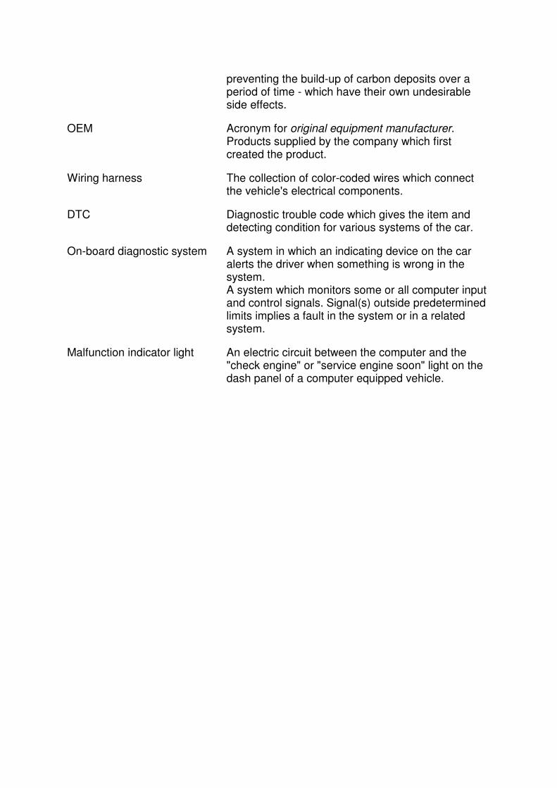
preventing the build-up of carbon deposits over a period of time - which have their own undesirable side effects.
OEM Acronym for original equipment manufacturer. Products supplied by the company which first created the product.
Wiring harness The collection of color-coded wires which connect the vehicle's electrical components.
DTC Diagnostic trouble code which gives the item and detecting condition for various systems of the car.
On-board diagnostic system A system in which an indicating device on the car alerts the driver when something is wrong in the system. A system which monitors some or all computer input and control signals. Signal(s) outside predetermined limits implies a fault in the system or in a related system.
Malfunction indicator light An electric circuit between the computer and the "check engine" or "service engine soon" light on the dash panel of a computer equipped vehicle.