Embed Size (px)
Citation preview
2033-15
Joint ICTP/IAEA Advanced School on Dosimetry in DiagnosticRadiology and its Clinical Implementation
Donald McLean
11 - 15 May 2009
IAEAViennaAustria
Dosimetry for Dental Radiography
IAEAInternational Atomic Energy Agency
Dosimetry for Dental Radiography
Donald McLeanDosimetry and Medical Radiation Physics Section
Division of Human Health
Joint ICTP-IAEA Advanced school on Dosimetry in Diagnostic Radiology: And its Clinical Implementation
11 - 15 May 2009; Miramare, Trieste, Italy
IAEA
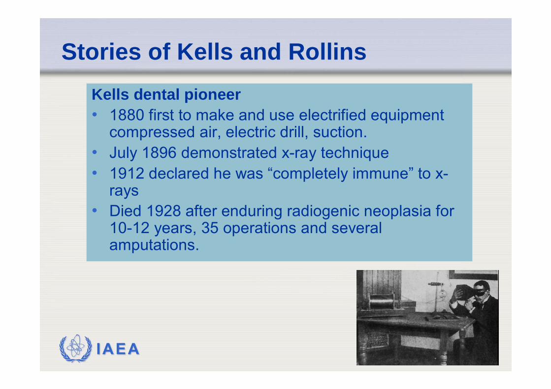
Stories of Kells and RollinsKells dental pioneer• 1880 first to make and use electrified equipment
compressed air, electric drill, suction.• July 1896 demonstrated x-ray technique• 1912 declared he was “completely immune” to x-
rays• Died 1928 after enduring radiogenic neoplasia for
10-12 years, 35 operations and several amputations.
IAEA
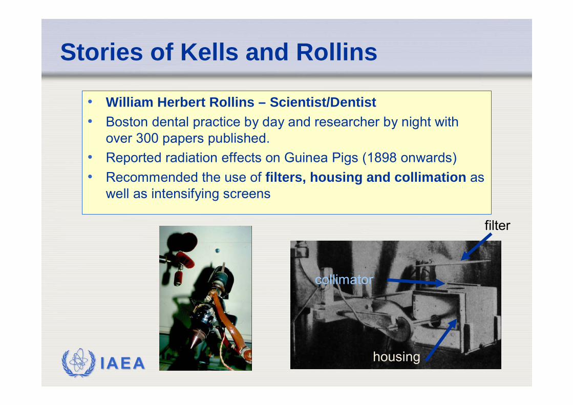
Stories of Kells and Rollins
• William Herbert Rollins – Scientist/Dentist• Boston dental practice by day and researcher by night with
over 300 papers published.• Reported radiation effects on Guinea Pigs (1898 onwards)• Recommended the use of filters, housing and collimation as
well as intensifying screens
housing
collimator
filter
IAEA
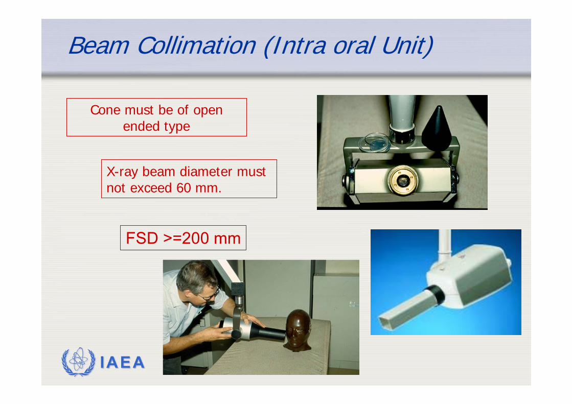
Beam Collimation (Intra oral Unit)
X-ray beam diameter must not exceed 60 mm.
Cone must be of open ended type
FSD >=200 mm
IAEA
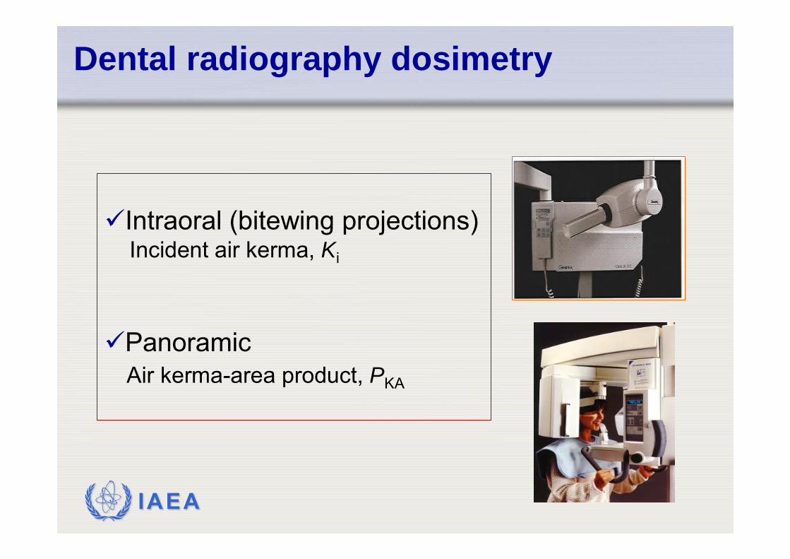
Intraoral (bitewing projections)Incident air kerma, Ki
Panoramic Air kerma-area product, PKA
Dental radiography dosimetry
IAEA
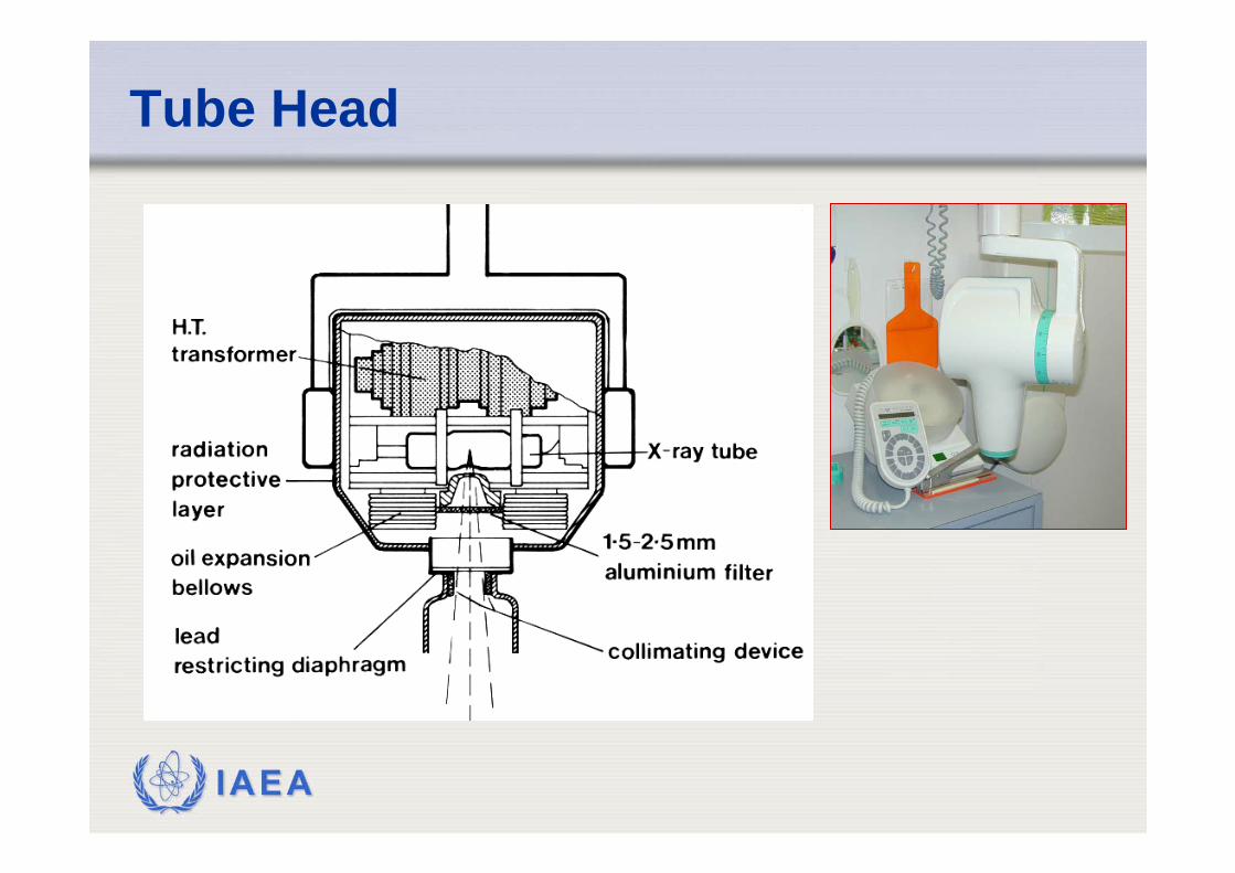
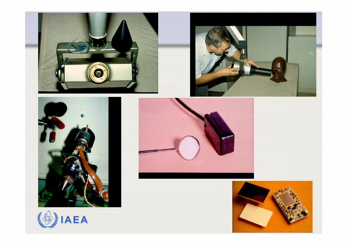
Tube Head
IAEA
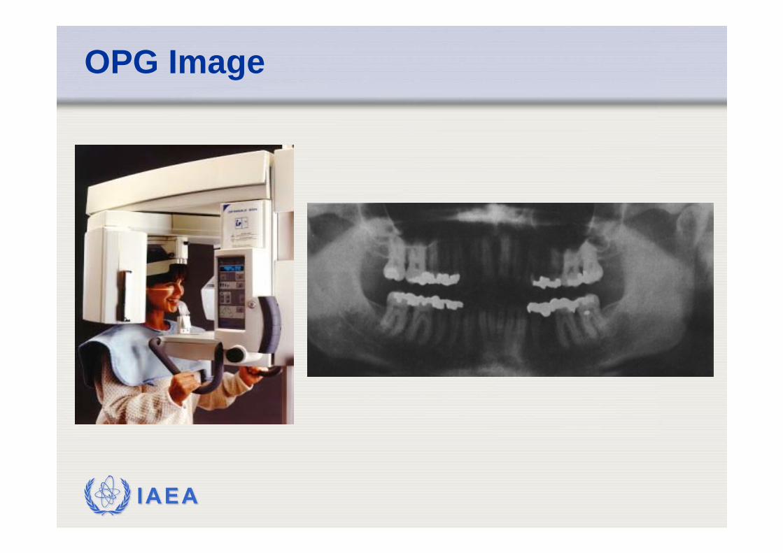
OPG Image
IAEA
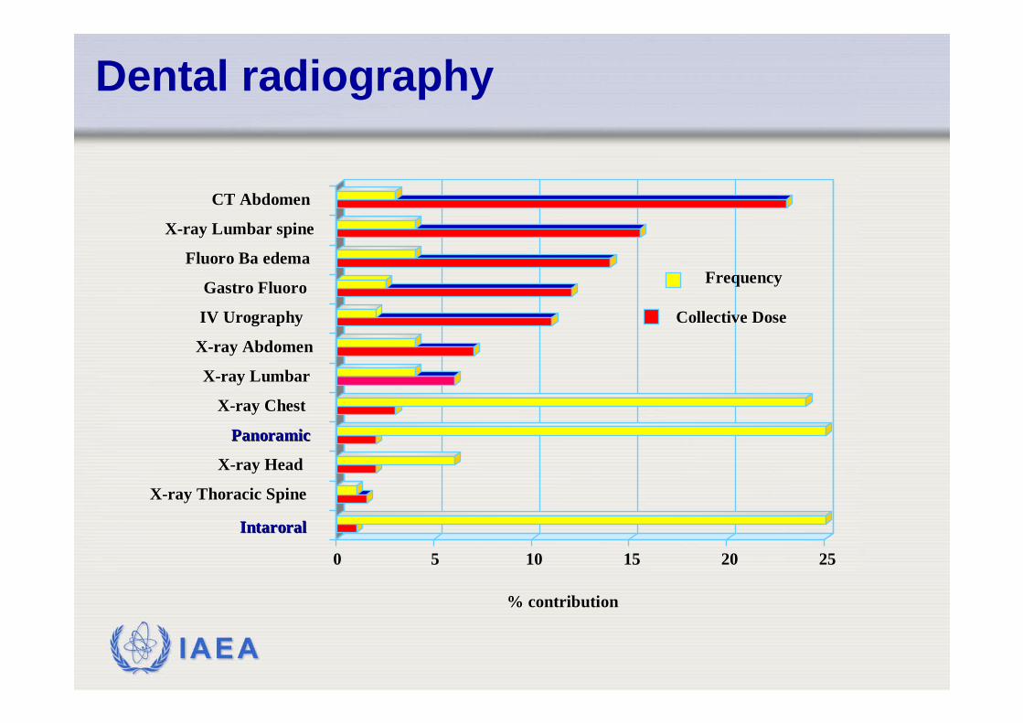
0 5 10 15 20 25
% contribution% contribution
XX--ray Thoracic Spineray Thoracic Spine
XX--ray Headray Head
PanoramicPanoramic
XX--ray Chest ray Chest
XX--ray Lumbarray Lumbar
XX--ray Abdomenray Abdomen
IV IV UrographyUrography
Gastro FluoroGastro Fluoro
Fluoro Ba edemaFluoro Ba edema
XX--ray Lumbar spineray Lumbar spine
CT AbdomenCT Abdomen
FrequencyFrequency
Collective DoseCollective Dose
IntaroralIntaroral
Dental radiography
IAEA
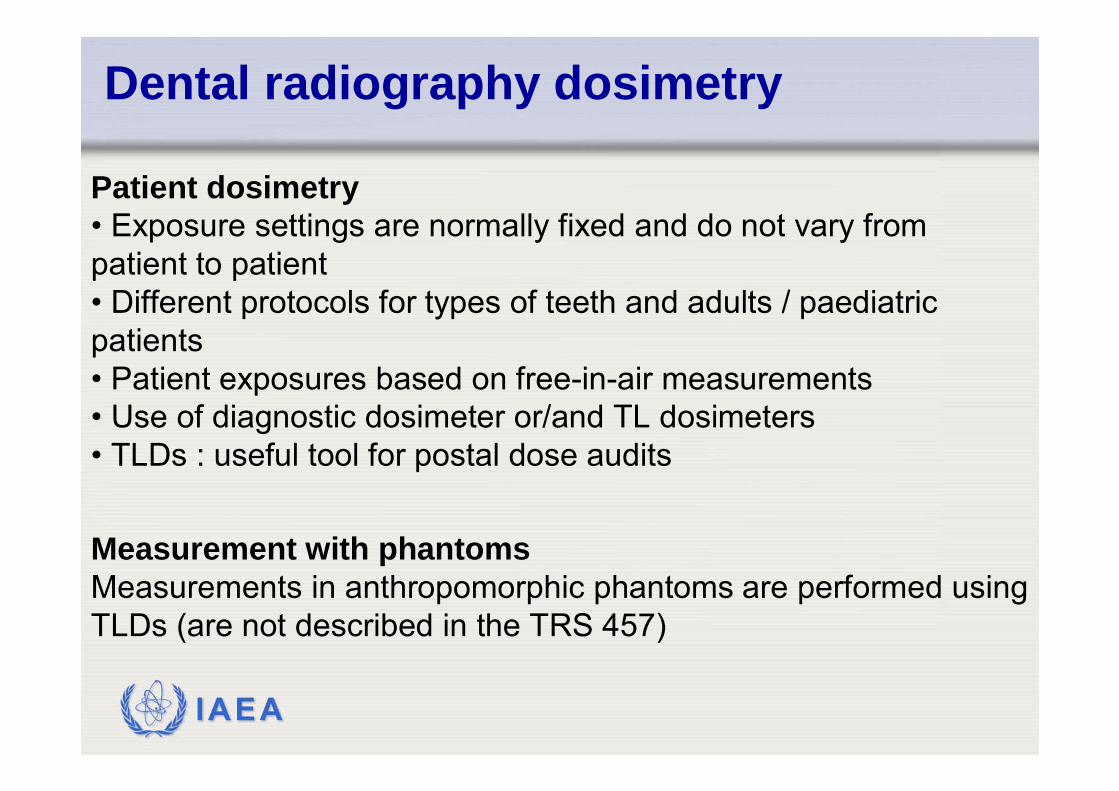
Measurement with phantomsMeasurements in anthropomorphic phantoms are performed using TLDs (are not described in the TRS 457)
Patient dosimetry• Exposure settings are normally fixed and do not vary from patient to patient • Different protocols for types of teeth and adults / paediatric patients • Patient exposures based on free-in-air measurements • Use of diagnostic dosimeter or/and TL dosimeters • TLDs : useful tool for postal dose audits
Dental radiography dosimetry
IAEA
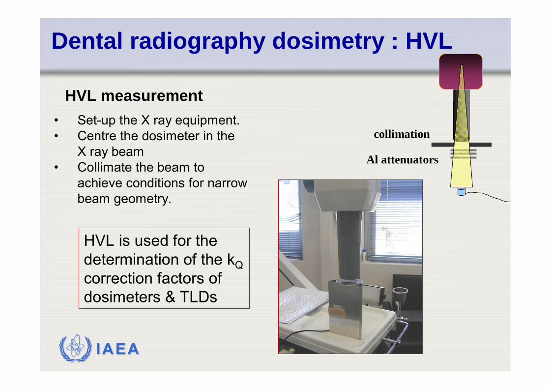
HVL measurement• Set-up the X ray equipment. • Centre the dosimeter in the
X ray beam• Collimate the beam to
achieve conditions for narrow beam geometry.
Dental radiography dosimetry : HVL
HVL is used for the determination of the kQcorrection factors of dosimeters & TLDs
collimation
Al attenuators
IAEA
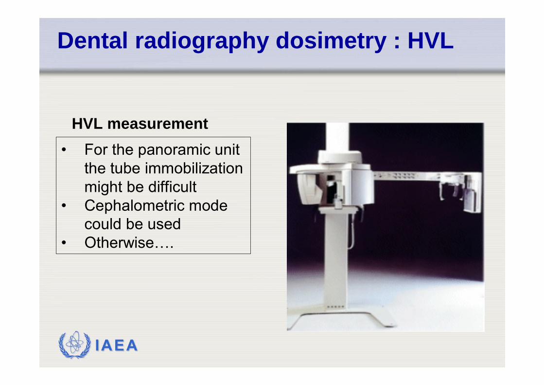
HVL measurement• For the panoramic unit
the tube immobilization might be difficult
• Cephalometric mode could be used
• Otherwise….
Dental radiography dosimetry : HVL
IAEA
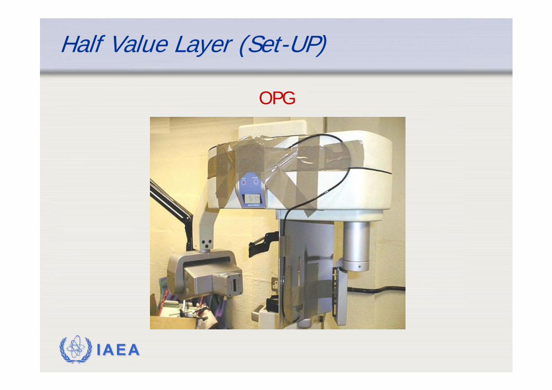
Half Value Layer (Set-UP)
OPG
IAEA
Dental radiography dosimetry : Bitewing projection
List of equipment
• Calibrated diagnostic dosimeter;• Chamber support stand;• Thermometer and barometer (for measurements with ion chambers);• Calibrated TL dosimeters (for measurements using TLDs);
IAEA
Dental radiography dosimetry : Bitewing projection
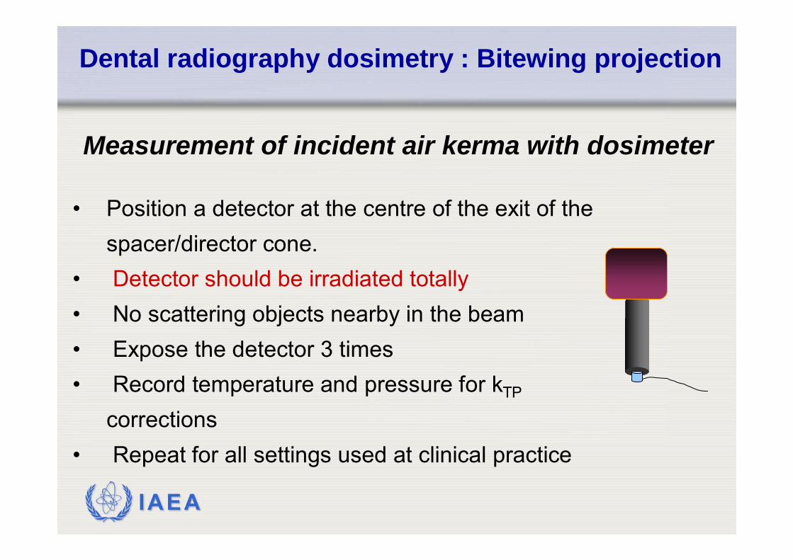
Measurement of incident air kerma with dosimeter
• Position a detector at the centre of the exit of the spacer/director cone.
• Detector should be irradiated totally• No scattering objects nearby in the beam• Expose the detector 3 times• Record temperature and pressure for kTP
corrections• Repeat for all settings used at clinical practice
IAEA
Dental radiography dosimetry : Bitewing projection
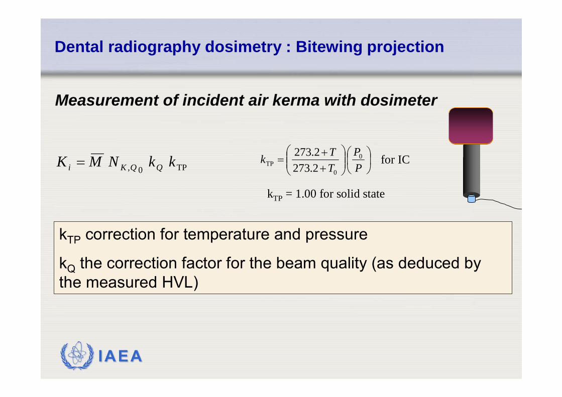
Measurement of incident air kerma with dosimeter
TP0, kkNMK QQKi = ⎟⎠⎞
⎜⎝⎛
⎟⎟⎠
⎞⎜⎜⎝
⎛++
=PP
TTk 0
0TP 2.273
2.273
kTP = 1.00 for solid state
for IC
kTP correction for temperature and pressure
kQ the correction factor for the beam quality (as deduced by the measured HVL)
IAEA
Dental radiography dosimetry : Bitewing projection
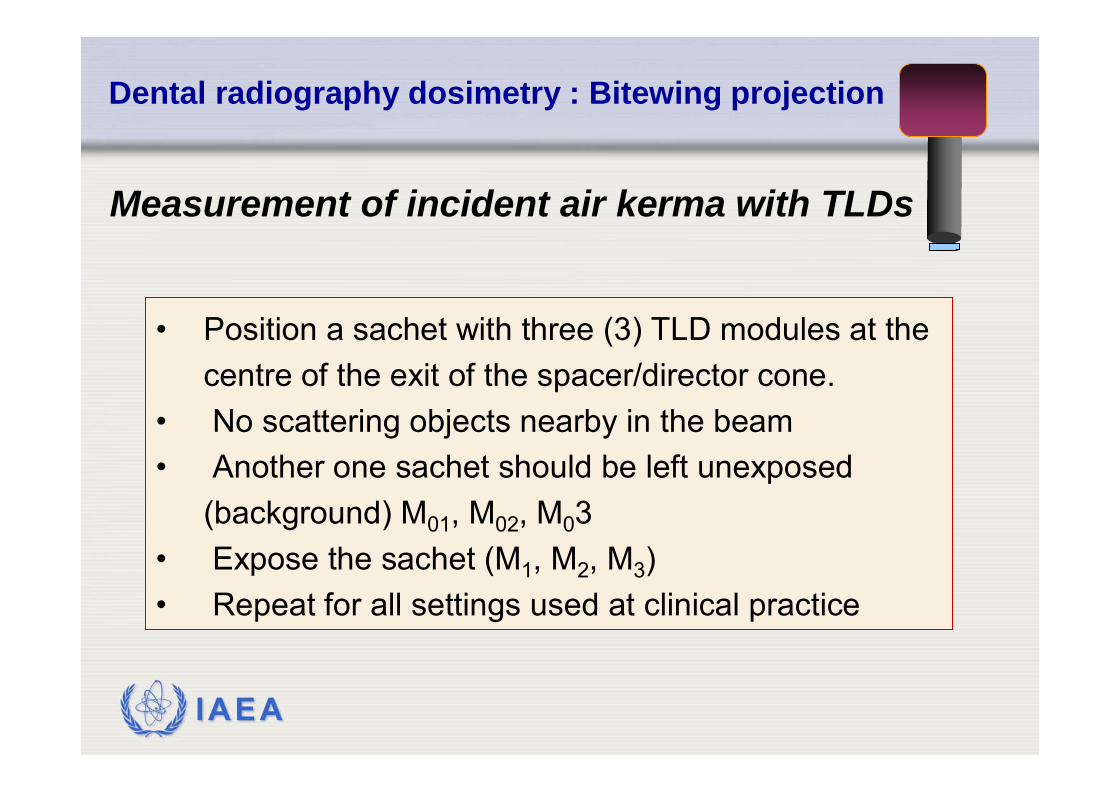
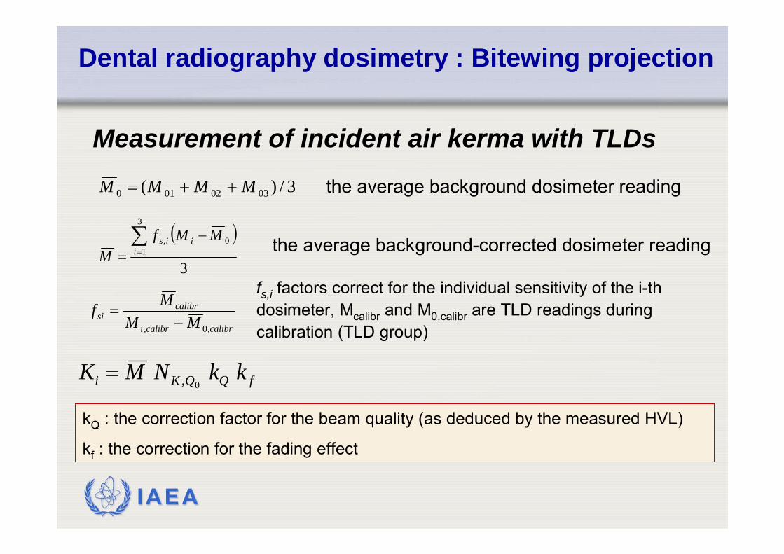
Measurement of incident air kerma with TLDs
• Position a sachet with three (3) TLD modules at the centre of the exit of the spacer/director cone.
• No scattering objects nearby in the beam• Another one sachet should be left unexposed
(background) M01, M02, M03• Expose the sachet (M1, M2, M3) • Repeat for all settings used at clinical practice
IAEA
Dental radiography dosimetry : Bitewing projection
Measurement of incident air kerma with TLDs3/)( 0302010 MMMM ++=
the average background-corrected dosimeter reading ( )3
3
10,∑
=
−= i
iis MMfM
fs,i factors correct for the individual sensitivity of the i-thdosimeter, Mcalibr and M0,calibr are TLD readings during calibration (TLD group) calibrcalibri
calibrsi MM
Mf,0, −
=
the average background dosimeter reading
fQQKi kkNMK0,=
kQ : the correction factor for the beam quality (as deduced by the measured HVL)
kf : the correction for the fading effect
IAEA
Dental radiography dosimetry : Panoramic projection
List of equipment
• Calibrated pencil type ionisation chamber (CT chamber) and electrometer;• Chamber support;• Thermometer and barometer;• TLD dosimeters 1 mm thick and 3 mm diameter• Jig for mounting the dosimeters Film and a ruler (for screen-film systems)• Film and a ruler (for screen-film systems).
IAEA
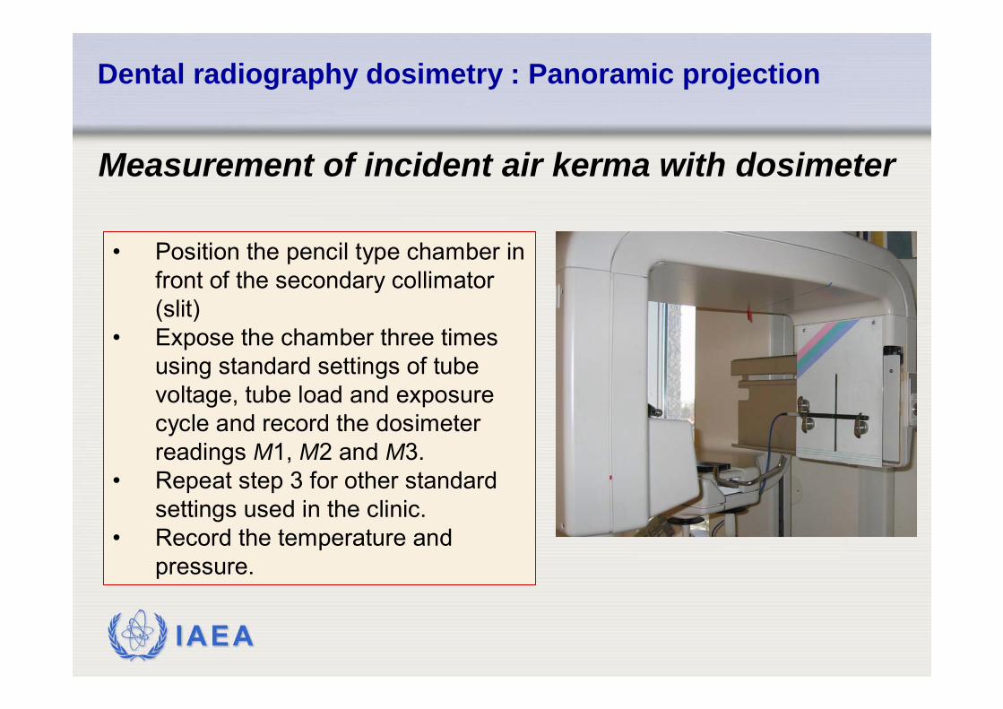
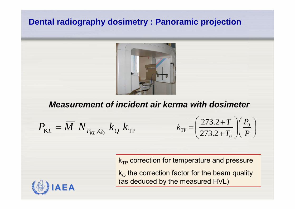
Measurement of incident air kerma with dosimeter
Dental radiography dosimetry : Panoramic projection
• Position the pencil type chamber in front of the secondary collimator (slit)
• Expose the chamber three times using standard settings of tube voltage, tube load and exposure cycle and record the dosimeter readings M1, M2 and M3.
• Repeat step 3 for other standard settings used in the clinic.
• Record the temperature and pressure.
IAEA
Measurement of incident air kerma with dosimeter
⎟⎠⎞
⎜⎝⎛
⎟⎟⎠
⎞⎜⎜⎝
⎛++
=PP
TTk 0
0TP 2.273
2.273
kTP correction for temperature and pressure
kQ the correction factor for the beam quality (as deduced by the measured HVL)
Dental radiography dosimetry : Panoramic projection
TP,K 0kkNMP QQPL KL
=
IAEA
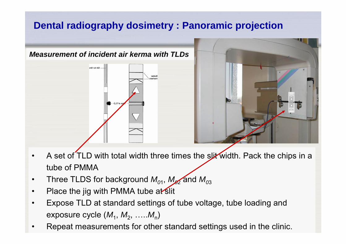
Measurement of incident air kerma with TLDs
• A set of TLD with total width three times the slit width. Pack the chips in a tube of PMMA
• Three TLDS for background M01, M02 and M03
• Place the jig with PMMA tube at slit • Expose TLD at standard settings of tube voltage, tube loading and
exposure cycle (M1, M2, …..Mn)• Repeat measurements for other standard settings used in the clinic.
Dental radiography dosimetry : Panoramic projection
IAEA
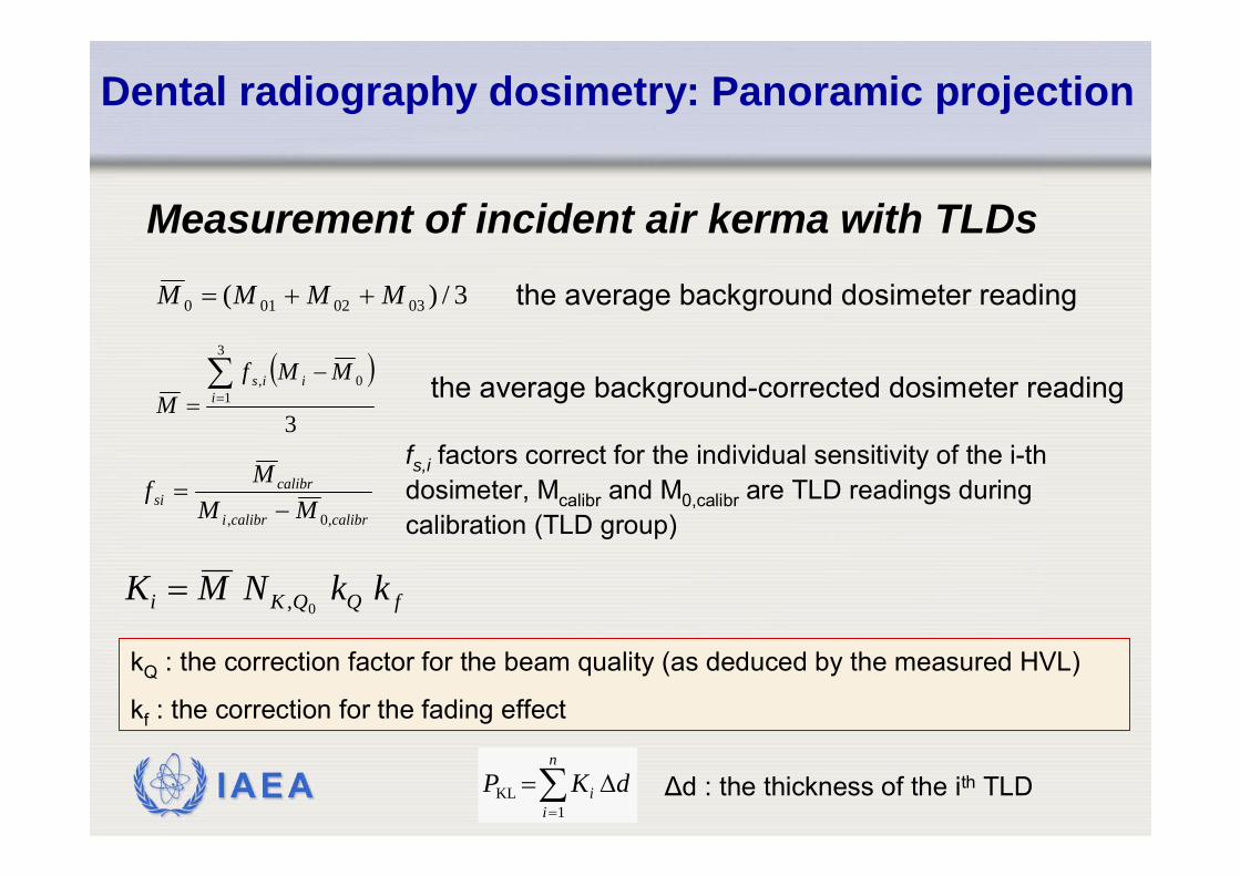
Dental radiography dosimetry: Panoramic projection
Measurement of incident air kerma with TLDs3/)( 0302010 MMMM ++=
the average background-corrected dosimeter reading ( )3
3
10,∑
=
−= i
iis MMfM
fs,i factors correct for the individual sensitivity of the i-thdosimeter, Mcalibr and M0,calibr are TLD readings during calibration (TLD group) calibrcalibri
calibrsi MM
Mf,0, −
=
the average background dosimeter reading
fQQKi kkNMK0,=
kQ : the correction factor for the beam quality (as deduced by the measured HVL)
kf : the correction for the fading effect
∑=
Δ=n
ii dKP
1KL Δd : the thickness of the ith TLD
IAEA
Dental radiography dosimetry: Panoramic projection
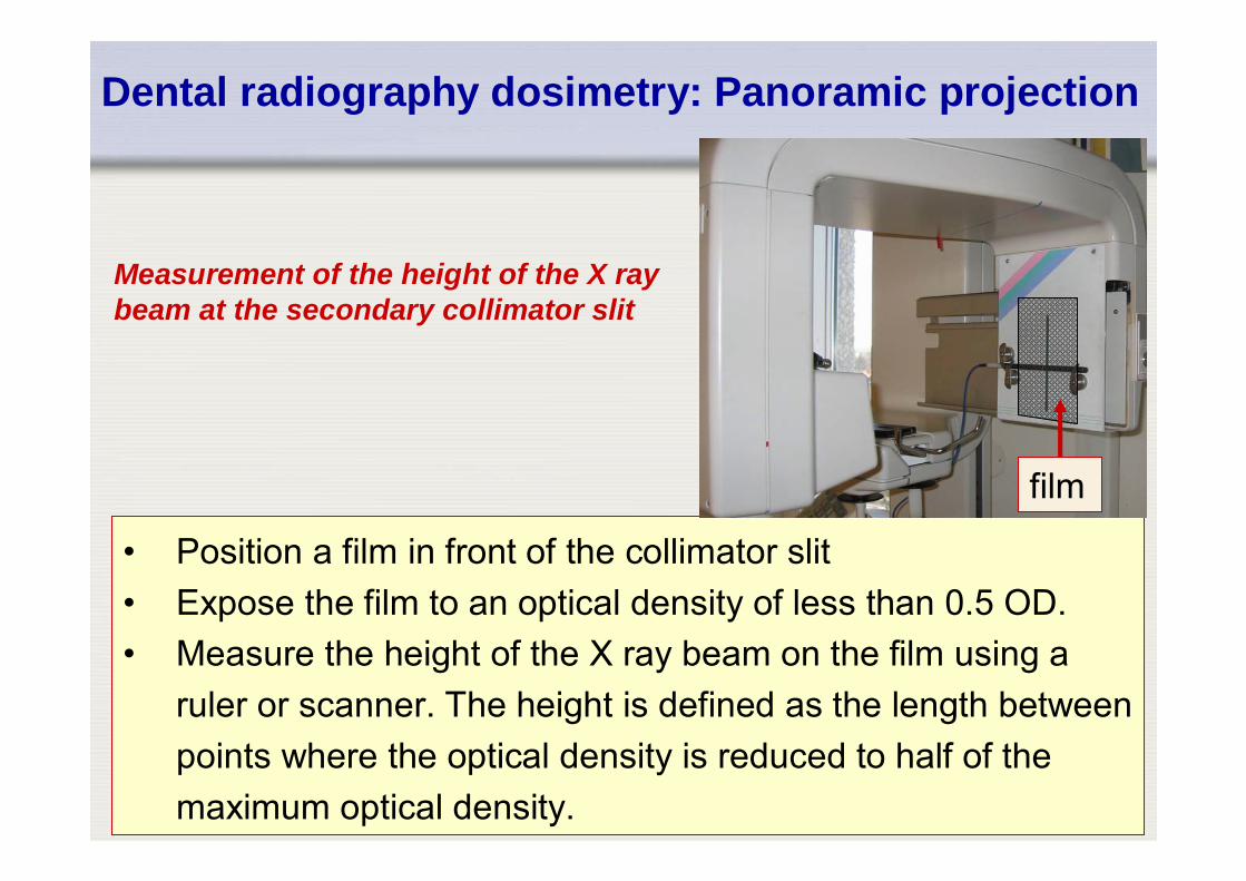
• Position a film in front of the collimator slit• Expose the film to an optical density of less than 0.5 OD.• Measure the height of the X ray beam on the film using a
ruler or scanner. The height is defined as the length between points where the optical density is reduced to half of the maximum optical density.
Measurement of the height of the X ray beam at the secondary collimator slit
film
IAEA
Dental radiography dosimetry: Panoramic projection
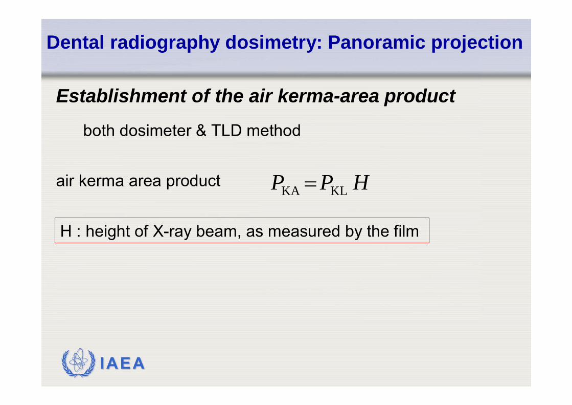
Establishment of the air kerma-area product
both dosimeter & TLD method
HPP KLKA =
H : height of X-ray beam, as measured by the film
air kerma area product
IAEA
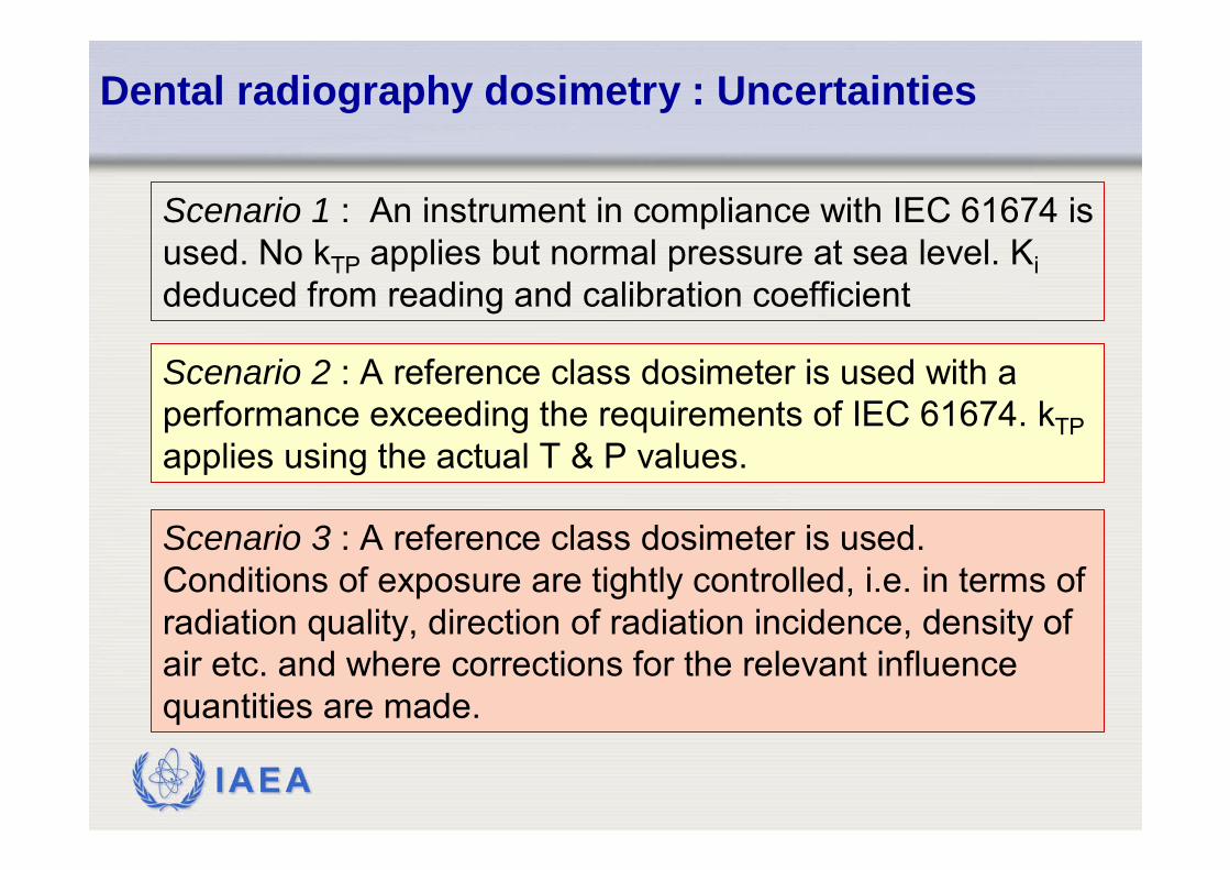
Scenario 1 : An instrument in compliance with IEC 61674 is used. No kTP applies but normal pressure at sea level. Kideduced from reading and calibration coefficient
Scenario 2 : A reference class dosimeter is used with a performance exceeding the requirements of IEC 61674. kTPapplies using the actual T & P values.
Scenario 3 : A reference class dosimeter is used. Conditions of exposure are tightly controlled, i.e. in terms of radiation quality, direction of radiation incidence, density of air etc. and where corrections for the relevant influence quantities are made.
Dental radiography dosimetry : Uncertainties

IAEA
Dental radiography dosimetry : Uncertainties
5,47,012,6Relative expanded uncertainty (k=2)2,73,56,3
Relative combined standard uncertainty (k=1)
0,51,01.152Long term stability of user's instrument1,01,21,152Operating voltage1,01,01,733Field size/field homogeneity1,01,52,895Electromagnetic compatibility0,50,51,733Temperature and humidity0,50,51,152Air pressure0,51,01,733Direction of radiation incidence0,50,51,152Kerma rate0,51,52,895
Radiation quality, i.e. differences between SSDL and user
1,61,62,895Intrinsic error, NK,Q or NK,Q0*kQ
Scenario3
Scenario2
Scenario1±L in %
Uncertainty (k=1)/%IEC 61674Influence quantity
IAEA
Dental radiography dosimetry : Uncertainties
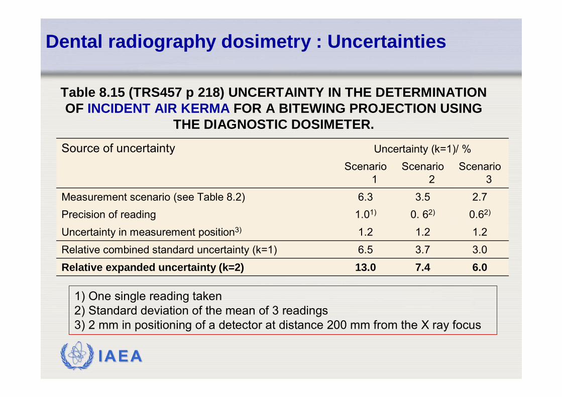
6.07.413.0Relative expanded uncertainty (k=2)3.03.76.5Relative combined standard uncertainty (k=1)1.21.21.2Uncertainty in measurement position3)
0.62)0. 62)1.01)Precision of reading2.73.56.3Measurement scenario (see Table 8.2)
Scenario 3
Scenario 2
Scenario 1
Uncertainty (k=1)/ %Source of uncertainty
Table 8.15 (TRS457 p 218) UNCERTAINTY IN THE DETERMINATION OF INCIDENT AIR KERMA FOR A BITEWING PROJECTION USING
THE DIAGNOSTIC DOSIMETER.
1) One single reading taken2) Standard deviation of the mean of 3 readings3) 2 mm in positioning of a detector at distance 200 mm from the X ray focus
IAEA
Dental radiography dosimetry : Uncertainties
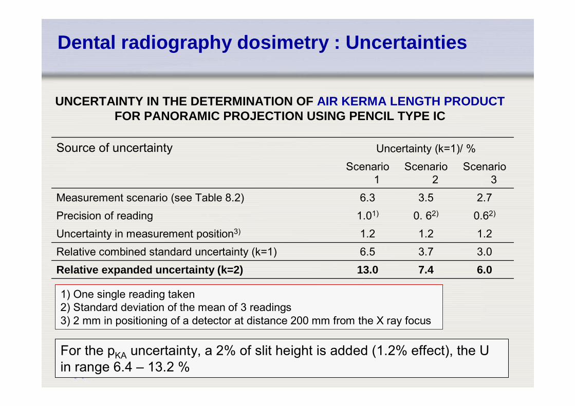
6.07.413.0Relative expanded uncertainty (k=2)3.03.76.5Relative combined standard uncertainty (k=1)1.21.21.2Uncertainty in measurement position3)
0.62)0. 62)1.01)Precision of reading2.73.56.3Measurement scenario (see Table 8.2)
Scenario 3
Scenario 2
Scenario 1
Uncertainty (k=1)/ %Source of uncertainty
UNCERTAINTY IN THE DETERMINATION OF AIR KERMA LENGTH PRODUCTFOR PANORAMIC PROJECTION USING PENCIL TYPE IC
1) One single reading taken2) Standard deviation of the mean of 3 readings3) 2 mm in positioning of a detector at distance 200 mm from the X ray focus
For the pKA uncertainty, a 2% of slit height is added (1.2% effect), the U in range 6.4 – 13.2 %
IAEA
Thanks to
• This presentation was compiled by several authors. Credits belong especially to
• Costas Hourdakis
IAEA
IAEA