Embed Size (px)
Citation preview
User´s and Installer´s Manual
Fully Adjustable Solar Charge ControllerSpecially designed for hybrid and telecommunication systems
Steca Tarom
700.784 | V07.51
PHOTOVOLTAIK - PHOTOVOLTAIC - PHOTOVOLTAIQUE - FOTOVOLTAICA
EN
System-Manager TAROM page 2 V07-51
1 Safety Instructions and Waiver of Liability..........................................................................................................3 1.1 Symbol of Safety Instructions ..................................................................................................................................3 1.2 How to Use This Manual..........................................................................................................................................3 1.3 General Safety Instructions .....................................................................................................................................3 1.4 Waiver of Liability.....................................................................................................................................................4 2 Range of Applications ...........................................................................................................................................4 2.1 Performance ............................................................................................................................................................4 2.2 Options ....................................................................................................................................................................5 3 Functioning ............................................................................................................................................................7 3.1 General Description .................................................................................................................................................7 3.2 .................................................................................................................................................8Detailed Description
3.2.1 SOC (State Of Charge) Calculation...........................................................................................................................................8 3.2.2 Overcharge Protection...............................................................................................................................................................8 3.2.3 Temperature Compensation of Final Charge Voltage................................................................................................................8 3.2.4 Voltage Determination ...............................................................................................................................................................9 3.2.5 Energy Determination................................................................................................................................................................9 3.2.6 Boost Charging (Lead&Sealed) and Equalisation Charging (Only Lead) ...................................................................................9 3.2.7 Automatic Monthly Mixture of Electrolyte...................................................................................................................................9 3.2.8 Display.......................................................................................................................................................................................9 3.2.9 Overdischarge Protection ..........................................................................................................................................................9 3.2.10 Control Keyboard ................................................................................................................................................................10 3.2.11 System Voltage...................................................................................................................................................................10
4 Indication of Status..............................................................................................................................................10 5 Operating the System-Manager..........................................................................................................................11 5.1 Safety Cover ..........................................................................................................................................................11 5.2 Factory Pre-Set Configurations .............................................................................................................................11 5.3 Main Menu .............................................................................................................................................................11 5.4 Menu MANU ..........................................................................................................................................................12 5.5 Menu LOGG ..........................................................................................................................................................12 5.6 Menu CONF...........................................................................................................................................................13 5.7 Menu PROG ..........................................................................................................................................................14 5.8 ......................................................................................................................................15Example of Configuration
5.8.1 Factory Pre-Set Configuration .................................................................................................................................................15 5.8.2 Battery Type ............................................................................................................................................................................15 5.8.3 Reset to Factory Pre-Set Configuration ...................................................................................................................................16
5.9 Example of Programming ......................................................................................................................................16 6 Installation............................................................................................................................................................16 6.1 Precautions............................................................................................................................................................16 6.2 ...........................................................................................................................................17 Location of Installation
6.2.1 Installation on Walls ................................................................................................................................................................17 6.2.2 Rules for mounting ..................................................................................................................................................................18
6.3 ..........................................................................................................................................................18Preparations 6.3.1 Assemblies ..............................................................................................................................................................................18 6.3.2 Preparation of Wiring...............................................................................................................................................................18 6.3.3 Cabling ....................................................................................................................................................................................18
6.4 ......................................................................................................................................19 Installation and Operation6.4.1 Connecting the Battery Bank...................................................................................................................................................19 6.4.2 Connecting the Solar PV Module Array ...................................................................................................................................19 6.4.3 Connecting the Loads..............................................................................................................................................................19
6.5 Uninstalling ............................................................................................................................................................19 6.6 Measures....................................................................................................................................................20Safety
6.6.1 Electronic Short Circuit Safety.................................................................................................................................................20 6.6.2 Hardware Safety......................................................................................................................................................................20 6.6.3 Flammability ............................................................................................................................................................................20 6.6.4 Overvoltage Protection ............................................................................................................................................................20 6.6.5 Simple and Double Errors .......................................................................................................................................................20
6.7 ..............................................................................................................................................................20 Grounding6.7.1 Positive Grounding ..................................................................................................................................................................20 6.7.2 Negative Grounding.................................................................................................................................................................21
7 Maintenance .........................................................................................................................................................21 8 Technical Data .....................................................................................................................................................21 8.1 Performance Data..................................................................................................................................................21 8.2 Controlling Data at 25°C ........................................................................................................................................21 9 Malfunctions and Errors......................................................................................................................................23 10 Legal Guarantee...................................................................................................................................................24 11 Accessories..........................................................................................................................................................24
© Steca GmbH; Version 07-51; S.Nr. 700.784
1 Safety Instructions and Waiver of Liability
1.1 Symbol of Safety Instructions
Safety instructions for personal protection and instructions that refer to the safety functions of the system are marked with this sign and are printed in bold letters.
For safe installation of other components which are not mentioned in the PV System-Manager instructions, please see the corresponding safety manual of the component manufacturer.
1.2 How to Use This Manual
This manual describes the functions and installation of a PV System-Manager - a solar charge/load controller in a PV system with a battery as storage.
For safe installation of other components, e.g. solar modules, electrical accessories and battery, please see the corresponding manual of the manufacturer.
Hint: Before you start your work, read the instructions for Installation (chapter 6; page 16). Make sure that all preparatory measures are taken.
Only start to install the System-Manager when you are sure that you have understood all the technical details of this manual. Please make sure that all steps are done in the sequence that is described in this manual.
These instructions must be handed out to all persons that work with this system. These instructions are part of the System-Manager and must be handed over in case the System-Manager is sold.
This manual has to be made accessible for any third party or parties working on the PV system.
Before you start work: • Read the chapter Installation (chapter 6; page 16) • Make sure that all Precautions (chapter 6.1; page 16) are taken. • Only start to install your System-Manager when you are sure that you have understood all technical instructions. • Only proceed in the order started in this manual!
1.3 General Safety Instructions
For your own safety, please note the following for installation:
Avoid generating sparks!
Solar modules produce current whenever light strikes them. Even at a small light level, the full voltage can be present. Therefore, work carefully and pay attention to the corresponding safety precautions. Cover the modules with something to block the light while connecting the system.
During installation and wiring of the photovoltaic system, the system voltage may double (with the 12 V system up to 24 V, with the 24 V system up to 48 V, and within the 48 V system up to 96 V)
Therefore: Do not ever touch bare wire ends even in DC Systems! This habit can cause injury or even death!
Only use well insulated tools!
Do not use technical tools that are defective or broken!
The safety features of the System-Manager can be defeated when it is operated in a way not specified by the manufacturer.
Restriction of ventilation can lead to overheating of the System-Manager and thus failure. Do not cover any ventilating slots or cooling ribs.
The System-Manager must not be installed and used in moist damp areas (e. g. bathrooms) or in rooms in which there are flammable gas mixtures (from gas bottles, paint, solvents etc.)!
Do not allow anyone to store any of the above-mentioned hazardous items, or similar items in rooms where the System-Manager is installed!
System-Manager TAROM page 3 V07-51
The pre-set signs and marks must not be changed, removed, or made illegible.
All operations must be conducted in accordance with your national electricity regulations and local rules!
For installation in your country, please see your corresponding institutions for information on regulations and safety measures.
Keep children away from any and all electronics! Fatal accidents can occur!
1.4 Waiver of Liability
The manufacturer (STECA and its assigned representatives) cannot check that this manual is strictly followed, nor the conditions and methods for installation, operation, use and maintenance of the System-Manager.
Improper installation can lead to physical damage to the System-Manager and its safety features, and thus can endanger persons.
Therefore, we the manufacturer do not take any liability and responsibility for losses, damages and costs which are due to an improper installation, operation, use and maintenance or any other consequences resulting from such damage.
Furthermore, we do not take any liability for infringements of patent rights, or rights of third persons, which result from the use of this System-Manager.
The manufacturer reserves the right to make alterations, without prior notice, to the product itself, technical data or the installation and instruction manual.
If other components, which are not prescribed by manufacturer, are connected to this System-Manager, the user has to accept the consequences.
CAUTION: Opening the System-Manager (connecting cover excluded) as well as use other than prescribed by the manufacturer, will cause the warranty to be voided.
2 Range of Applications The System-Manager is designed for a wide range of applications from private use to professional use: private homes or leisure market (like recreational vehicles or weekend/seasonal cottages, etc.) or in locations where trade, business or commerce is done (like workshops, stores, offices etc.) or industrial applications or telecom systems.
The System-Manager can NOT be used outdoors, where it would not be protected against rain or sun.
Unless further measures are taken, (see Options chapter 2.2, page 5) the System-Manager must be installed in the same room as the battery due to the following reasons:
• an integrated temperature sensor registers the ambient temperature of the room, which is almost identical to the battery temperature.
• In order to keep the voltage drop between System-Manager and battery to a minimum, please only use the shortest possible battery cables.
The System-Manager’s PV input should only be connected to solar modules. However, the battery can also be charged in parallel by other sources with appropriate battery charge functions. Never connect several regulators to one solar generator. But several regulators with independent solar generators can be connected in parallel to one battery.
Hint: The System-Manager is able to adapt to customised applications. We will optimise your product concerning your special requirements. With these modifications the System-Manager will withstand strong ambient conditions like advanced temperature range, mechanical and climatic ambient conditions or advanced interference resistance.
2.1 Performance
The System-Manager uses a heat sink (the black aluminium back plate) to dissipate heat produced by the electronics during high amperage charging. The System-Manager can be used in a wide range of conditions and temperatures. It automatically detects the maximum permissible temperature of the heat sink and disconnects the loads in the case that temperature is exceeded. Therefore, the heat sink can be shared for the heat produced during charging and powering the loads. However, it is necessary to stay within the “Safe Operating ARea“ (SOAR) for sizing the system in order to avoid undesired switch-off of the loads in the case the temperature is exceeded.
System-Manager TAROM page 4 V07-51
nominal load current / %
nom
inal
mod
ule
curre
nt /
%
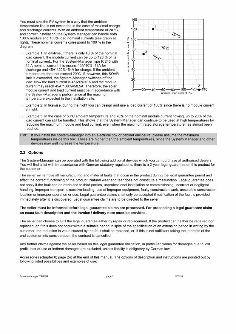
You must size the PV system in a way that the ambient temperature line is not exceeded in the case of maximal charge and discharge currents. With an ambient temperature of 20 °C and correct installation, the System-Manager can handle both 100% module and 100% load nominal currents (see graph at right). These nominal currents correspond to 100 % in the diagram
⇒ Example 1: In daytime, if there is only 40 % of the nominal load current, the module current can be up to 120 % of its nominal current.. For the System-Manager type R 245 with 45 A nominal current this means 45A*40%=18A for discharge and 45A*120%=54A for charge, If the ambient temperature does not exceed 20°C. If, however, this SOAR limit is exceeded, the System-Manager switches off the load. Now the load current is 45A*0%=0A and the module current may reach 45A*130%=58.5A. Therefore, the solar module current and load current must be in accordance with the System-Manager’s performance at the maximum temperature expected in the installation site.
⇒ Example 2: In likewise, during the night you can design and use a load current of 130% since there is no module current at night.
⇒ Example 3: In the case of 50°C ambient temperature and 70% of the nominal module current flowing, up to 20% of the load current can still be handled. This shows that the System-Manager can continue to be used at high temperatures by reducing the maximum module and load current, even when the maximum rated storage temperature has almost been reached.
Hint: If you install the System-Manager into an electrical box or cabinet enclosure, please assume the maximum temperatures inside this box. These are higher than the ambient temperatures, since the System-Manager and other devices may well increase the temperature.
2.2 Options
The System-Manager can be operated with the following additional devices which you can purchase at authorised dealers. You will find a list with In accordance with German statutory regulations, there is a 2-year legal guarantee on this product for the customer.
The seller will remove all manufacturing and material faults that occur in the product during the legal guarantee period and affect the correct functioning of the product. Natural wear and tear does not constitute a malfunction. Legal guarantee does not apply if the fault can be attributed to third parties, unprofessional installation or commissioning, incorrect or negligent handling, improper transport, excessive loading, use of improper equipment, faulty construction work, unsuitable construction location or improper operation or use. Legal guarantee claims shall only be accepted if notification of the fault is provided immediately after it is discovered. Legal guarantee claims are to be directed to the seller.
The seller must be informed before legal guarantee claims are processed. For processing a legal guarantee claim an exact fault description and the invoice / delivery note must be provided.
The seller can choose to fulfil the legal guarantee either by repair or replacement. If the product can neither be repaired nor replaced, or if this does not occur within a suitable period in spite of the specification of an extension period in writing by the customer, the reduction in value caused by the fault shall be replaced, or, if this is not sufficient taking the interests of the end customer into consideration, the contract is cancelled.
Any further claims against the seller based on this legal guarantee obligation, in particular claims for damages due to lost profit, loss-of-use or indirect damages are excluded, unless liability is obligatory by German law.
Accessories (chapter 0; page 24) at the end of this manual. The options of description and instructions are pointed out by following listed possibilities and examples of use:
System-Manager TAROM page 5 V07-51
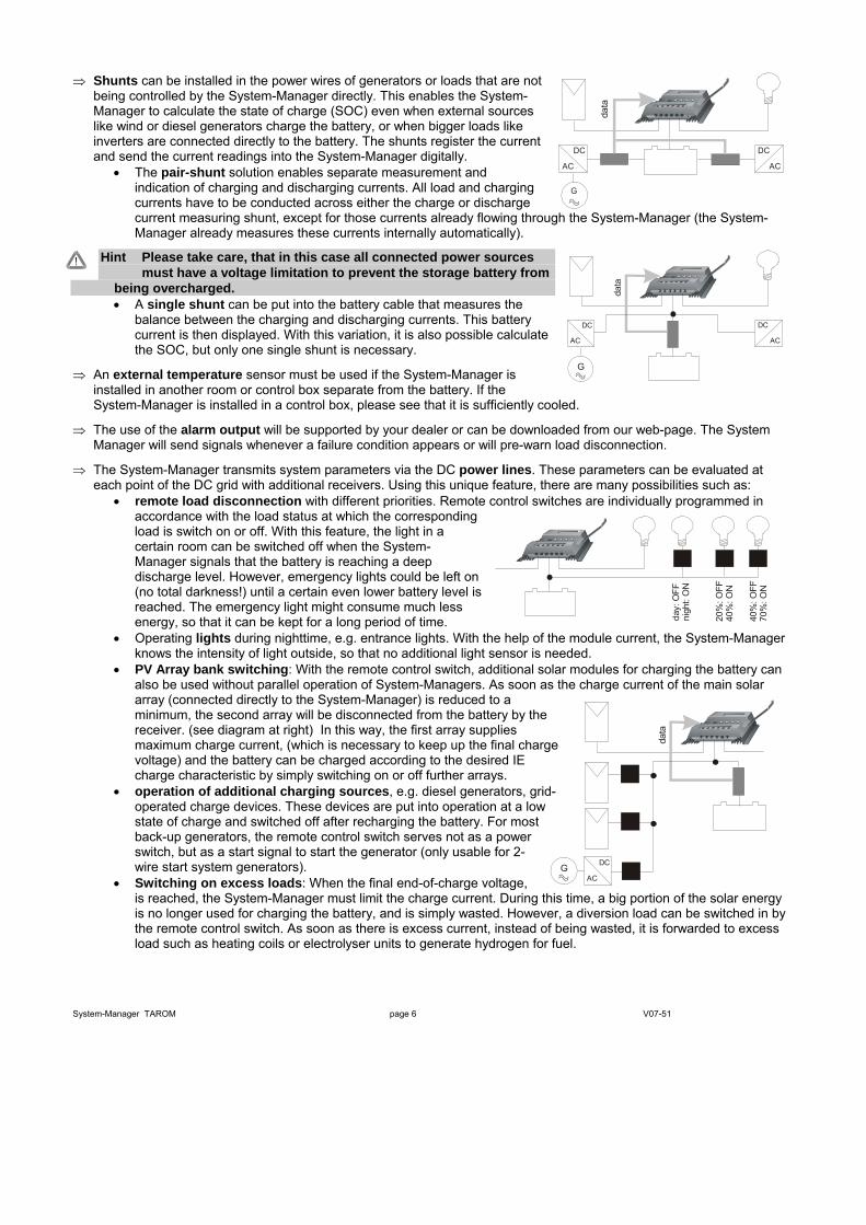
⇒ Shunts can be installed in the power wires of generators or loads that are not being controlled by the System-Manager directly. This enables the System-Manager to calculate the state of charge (SOC) even when external sources like wind or diesel generators charge the battery, or when bigger loads like inverters are connected directly to the battery. The shunts register the current and send the current readings into the System-Manager digitally.
• The pair-shunt solution enables separate measurement and indication of charging and discharging currents. All load and charging currents have to be conducted across either the charge or discharge current measuring shunt, except for those currents already flowing through the System-Manager (the System-Manager already measures these currents internally automatically).
G
AC
DC
AC
DC
data
Hint Please take care, that in this case all connected power sources must have a voltage limitation to prevent the storage battery from
being overcharged.
System-Manager TAROM page 6 V07-51
GAC
DC
data
• A single shunt can be put into the battery cable that measures the balance between the charging and discharging currents. This battery current is then displayed. With this variation, it is also possible calculate the SOC, but only one single shunt is necessary.
⇒ An external temperature sensor must be used if the System-Manager is installed in another room or control box separate from the battery. If the System-Manager is installed in a control box, please see that it is sufficiently cooled.
G
AC
DC
AC
DC
data
⇒ The use of the alarm output will be supported by your dealer or can be downloaded from our web-page. The System Manager will send signals whenever a failure condition appears or will pre-warn load disconnection.
⇒ The System-Manager transmits system parameters via the DC power lines. These parameters can be evaluated at each point of the DC grid with additional receivers. Using this unique feature, there are many possibilities such as:
• remote load disconnection with different priorities. Remote control switches are individually programmed in accordance with the load status at which the corresponding load is switch on or off. With this feature, the light in a certain room can be switched off when the System-Manager signals that the battery is reaching a deep discharge level. However, emergency lights could be left on (no total darkness!) until a certain even lower battery level is reached. The emergency light might consume much less energy, so that it can be kept for a long period of time. da
y: O
FFni
ght:
ON
20%
: OFF
40%
: ON
40%
: OFF
70%
: ON
• Operating lights during nighttime, e.g. entrance lights. With the help of the module current, the System-Manager knows the intensity of light outside, so that no additional light sensor is needed.
• PV Array bank switching: With the remote control switch, additional solar modules for charging the battery can also be used without parallel operation of System-Managers. As soon as the charge current of the main solar array (connected directly to the System-Manager) is reduced to a minimum, the second array will be disconnected from the battery by the receiver. (see diagram at right) In this way, the first array supplies maximum charge current, (which is necessary to keep up the final charge voltage) and the battery can be charged according to the desired IE charge characteristic by simply switching on or off further arrays.
• operation of additional charging sources, e.g. diesel generators, grid-operated charge devices. These devices are put into operation at a low state of charge and switched off after recharging the battery. For most back-up generators, the remote control switch serves not as a power switch, but as a start signal to start the generator (only usable for 2-wire start system generators).
• Switching on excess loads: When the final end-of-charge voltage, is reached, the System-Manager must limit the charge current. During this time, a big portion of the solar energy is no longer used for charging the battery, and is simply wasted. However, a diversion load can be switched in by the remote control switch. As soon as there is excess current, instead of being wasted, it is forwarded to excess load such as heating coils or electrolyser units to generate hydrogen for fuel.

loggerGSM
⇒ An external data logger can be connected to the System-Manager. It stores essential system parameters that can be forwarded to a PC via a serial interface. Data collection frequency and number of data points collected can be chosen freely to determine the data collection period. In addition, there analogue inputs on the data logger. These inputs can register parameters that cannot be measured by the System-Manager itself ,like wind speed, module temperature, solar radiation, etc.). The logger comes with the necessary software to operate all the above features.
• The logger is able to be programmed by the PC • The logger is available with an integrated cable modem for remote
monitoring • Instead of a cable modem you could order a GSM modem as
well. With this modem you are complete independent to any infrastructure
• You can also use our internet-server to store all data. The server will do data administration as well and is able to send you a SMS in case of any alarm.
3 Functioning The System-Manager monitors the charge status of the battery, regulates the charge process as well as it switches the loads on -off in order to make full use of the battery and to extend its life.
On delivery, the system is set for use with lead accumulators (batteries) with liquid electrolyte and can be set for accumulators with fixed electrolyte like gel batteries. The System-Manager can be used for all types of solar modules.
3.1 General Description
The System-Manager is an intelligent System-Manager in which a microprocessor has been employed for all regulating, controlling and indicating functions. The main power switching components consist of low-loss MOSFET type-transistors that have a long operating life and guarantee high performance due to their excellent conductivity, thus leading to a low degree of internal heat generation in the System-Manager. The customer can configure all parameters without opening the System-Manager or adjusting the electronic components. Due to the unique feature of the System-Manager to send and receive data transmission via the power cable itself, a minimum number of extra sensor and data cables is required. The System-Manager is therefore easy to install even for a person without technical education, and errors caused by defective cables or sensor wires are greatly reduced.
The overcharge protection is accomplished by a pulse-width modulation parallel (shunting type) controller which is equipped with a MOSFET switch element and with a reverse diode in order to prevent current flowing back from the battery to the module at night. While following the standard IE curve, the charging process is also adjusted according to the temperature. Moreover, the history of the battery’s depth of cycling over the last few days itself also determines a temporary limitation on excess final charge voltage and also limits the time of boost of equalising charges. Voltage drops of the battery cabling and connections and due to the internal resistance of the battery itself are compensated automatically in the sophisticated patented software inside the System-Manager, without using extra sensor cables.
In order to protect the battery from being totally discharged, the loads are automatically disconnected from the battery under certain conditions. The System-Manager’s microprocessor determines the remaining capacity at which no more consumption is possible without damaging the battery and shuts off the loads if the remaining capacity in the battery falls below this limit. Furthermore, the loads are switched off in the case of excess current or temperature for the protection of the System-Manager, and in the case of excess voltage for the protection of the loads, and in the case of low voltage for the protection of the battery.
The integrated temperature compensated equalisation charge function automatically does preventive maintenance on the battery from time to time via electrolyte circulation (controlled gassing) and increases battery life by preventing harmful acid or sulphate layers. This increase in the final charge voltage is time-triggered after the battery has reached a certain level of voltage in normal charging. After this equalisation charge time is completed, the System-Manager returns to normal charging. In addition, equalisation charging enables a faster full charging during bad weather periods e.g., in winter, as only part of the energy is need for gassing, whereas the remaining energy can be used for fast charging. This timed equalisation charge function is activated by either undershooting of a determined SOC, or by exceeding a certain period of time after the last equalisation charge. Equalisation charging can also be activated manually.
An LCD display indicates important information on the current operating status. The first line informs briefly on the most important basic parameters and the second line displays fine parameters or system information. This line is changing its information every third seconds.
System-Manager TAROM page 7 V07-51

The System-Manager has a reverse battery protection and is secure against no-load operation and short circuit. The load output is protected against over-current. However, it is very likely that the System-Manager is damaged if components are not connected to the correct terminals (e.g. if battery is connected in reverse polarity to the module input terminals).
3.2 Detailed Description
3.2.1 SOC (State Of Charge) Calculation
The SOC reading is very accurate and therefore is the basis for most controlling and monitoring functions. However, if system components are directly connected to the battery, the state of charge can only be determined with the help of optional shunts. The state of charge always refers to the actual capacity which the battery has in accordance to its age. So a SOC of 50 % does not mean that half of the battery’s nominal rated capacity can be used, but that only half of the battery’s REAL MEASURED capacity is remaining.
The state of charge is not dependant on the battery voltage, but on the amount of energy taken out. Traditional controllers usually determine a final load voltage that hardly ever corresponds to the discharge depth. During discharge, nominal acid density is being reduced and sulphates are placed on the battery plates. If discharge is too deep, this growth leads to harmful sulphation that reduces the battery’s capacity considerably, thus making the battery useless for energy storage. The traditional measuring procedures (Ah balancing, acid density measuring) are time-consuming and cost intensive and are seldom integrated in charge controllers.
If generators or loads are directly connected to the battery without shunts, the SOC gets “tricked” and its determination is wrong. However, despite erroneously measured SOC values., the System-Manager still prevents the battery from falling below certain voltage values, in order to protect the battery from a too-deep damaging discharge
The System-Manager is able to convert to a voltage regulation mode (chapter 5.6, page 13). Now System-Manager will operate like a conventional charge controller. We recommend this conversion when using additional generators (diesel, wind, etc.) or loads which are connected direct to the battery (inverter, etc.)
3.2.2 Overcharge Protection
The overcharge protection prevents uncontrolled gassing within the battery cells. The gas development is depending on the acid temperature and cell voltage. So the System-Manager monitors the ambient temperatures and adjusts the battery’s maximum allowed charge voltage. The overcharge protection and voltage limitation is independent on the battery’s state of charge, since the decomposition of electrolyte is exclusively depending on the voltage and the temperature. This means that charging is already limited even though the battery is not completely charged.
Overcharging the battery leads to uncontrolled gassing. Here the electrolyte is decomposed into oxygen and hydrogen. The consequences are harmful oxidation processes and mechanical damages since the gas blisters may knock out active lead material from the lead plates.
What is even worse is that the uncontrolled gassing in closed batteries e. g. sealed or fluid batteries where the gas pressure can even burst or crack the battery case. Frequent overcharging damages the battery casing. The charging process and the overcharge protection are thus regulated by a new hybrid System-Manager utilising pulse width modulation in order to insure smooth battery charging. The user in particular should not choose a float voltage too high via user settings. If you want to program this value individually from the System-Manager’s factory setting, please take note of the battery manufacturers' recommendations.
3.2.3 Temperature Compensation of Final Charge Voltage
-20-40
-10-14
-032
1050
2068
3086
40104
50122
[°C][°F]
2,20
2,25
2,30
2,35
2,40
2,45
2,50
2,55
2,60
13,2
13,5
13,8
14,1
14,4
14,7
15,0
15,3
15,6As the battery temperature increases, the acid/lead battery’s optimal final load voltage decreases. A constant final charge voltage leads to uncontrolled gassing in the case of higher battery temperatures, and undercharging in case of low temperatures. The temperature compensation software algorithm automatically decreases the final charge voltage at higher temperatures and increases them at lower ones. The temperature compensation system with the sensor integrated in the System-Manager influences all three overcharge thresholds.
The integrated sensor makes maintenance and installation easier and can be properly used under the following circumstances:
• System-Manager and battery must be in the same room • the System-Manager’s own warming-up is compensated by
substantial calculations. However, even if the sensor was outside the System-Manager, the room temperature itself only
System-Manager TAROM page 8 V07-51
corresponds to the battery pole temperature, so actual electrolyte temperature inside the battery may be actually different by a bigger margin of error.
• However, an external sensor can be installed if the most accurate sensing is desired.
3.2.4 Voltage Determination
Due to a special measuring method, battery sensor wires are no longer needed. The drop in voltage on the battery cable is compensated after the first full charge process. This is why no further sensor or wiring is needed, the installation is simplified, and the reliability of the system is increased due to the fact that sensors and wiring cannot break. However, measurements may not be as precise as with sensor wires. We would like to mention that – for a temperature coefficient factor of approx. 25mV per 1°C (changing of the final charge voltage with the ambient temperature within the 12V system) – a tolerance of 100mV corresponds to a temperature deviation of 4°C. There are no negative influences on the battery charging curves with such low deviations.
3.2.5 Energy Determination
The energy determination (SOC and Current readings) are calibrated on the lower energy range so within the maximum currents possible there may be deviations from an accurate electronic test meter. Please remember that this System-Manager is not a measuring device, but we have put these indications for your convenience.
3.2.6 Boost Charging (Lead&Sealed) and Equalisation Charging (Only Lead)
For this charging cycle, the System-Manager increases the battery charge voltage for a certain period of time after the battery has fallen below a certain SOC. The Boost Charge countdown is only activated when the desired battery voltage has been reached. This is the reason why it is important to pay attention to the fact that the solar module will be able give out sufficient charge energy with the corresponding final voltages.
You can manually activate the time limited boost charging.
If the Boost Charge voltage level is too high in comparison with the module voltage (reduced by wire losses) the countdown may never be started and your battery is therefore charged at a higher
voltage with no time control.
Equalising charge works similar to the above Boost Charging but is at an even higher voltage. Using equalisation charging is only possible and can only then be programmed if the battery has been configured to be of liquid electrolyte type. It is activated when the battery falls below a certain SOC status
3.2.7 Automatic Monthly Mixture of Electrolyte
Batteries that are shallow cycled will never trigger the equalisation cycle, so an automatic function has been added so the final charge voltage is increased for a limited time every month. In this case, either Boost or Equalise charging is activated depending on the electrolyte configuration. This function prevents harmful acid layering which occurs especially after remaining a long time at a certain charge status.
3.2.8 Display
A double-line liquid crystal display (LCD) informs the user about important system parameters using various digital readouts. The first line of the LCD indicates SOC, battery voltage, load current and charging current in approximated “rough” values. The second line scrolls through various information and system parameters and current status with more detailed values and descriptions. The LCD works correctly only within the operating temperature range specified by the manufacturer. When this temperature range is exceeded, disturbances may occur which prevent reading the display. The display will return to normal when the operating temperature range is again reached. The storing temperature range, however, must not be exceeded or permanent damage may occur.
3.2.9 Overdischarge Protection
Overdischarging leads to sulphation and results a loss of your battery’s capacity. The overdischarge protection feature disconnects the loads if the battery is becoming too discharged and re-connects them after sufficient re-charging. The loads can also be manually switched on/off, so the System-Manager can be used as a main DC load disconnect switch. If the battery voltage falls under a certain voltage, the loads will be switched off, regardless of whatever values or manual adjustments have been programmed (emergency cut-off).
The System-Manager is able to be converted into voltage regulation. After this configuration all values are able to program with voltage values. The discharge protection is now based on voltage and no longer on SOC which represent the acid density much better than voltage levels.
System-Manager TAROM page 9 V07-51
3.2.10 Control Keyboard
By using the tact switches underneath the LCD screen, the factory set values can be configured to the user’s custom requirement. Freely programmable values can only be changed within a pre-set window. These minimum-maximum values are selected in a way that even extreme adjustments do not lead to severe damage to the lead batteries. However, the operating elements are not protected or locked with a child-proof lock (code). For this and many other safety reasons, we would highly recommend that you make the System-Manager as well as the battery room inaccessible to children
3.2.11 System Voltage
The System-Manager adjusts itself automatically to 12 or 24 V system. For this it is necessary that the battery of the proper voltage is connected to the System-Manager first.
There are two variants of the System-Manager: one for the system voltages of 12/24V and another 48V version. The 12/24V System-Manager only adjusts itself for system voltages below 30 V. For 48 V systems you will need another model with more voltage-stable components. Please have a look at the marks on the case for information if your System-Manager fits the desired system voltage.
4 Indication of Status The two-line display indicates all present system values in short form on the top line, and the values are without units (Volt, Amp, etc) due to a lack of space. The printing above each value serves as a reminder:
State of charge SOC
battery voltage Bat
charging currents IN
discharge currents OUT
The second line constantly changes its information. All values and system information are indicated alpha-numerically. The following displays can only be seen during regular operation (not while programming).
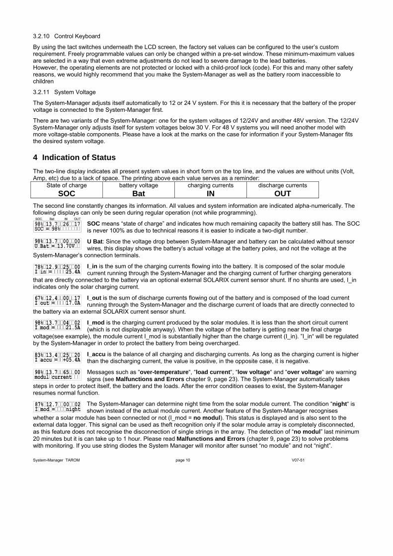
SOC means “state of charge” and indicates how much remaining capacity the battery still has. The SOC is never 100% as due to technical reasons it is easier to indicate a two-digit number.
U Bat: Since the voltage drop between System-Manager and battery can be calculated without sensor wires, this display shows the battery’s actual voltage at the battery poles, and not the voltage at the
System-Manager’s connection terminals.
I_in is the sum of the charging currents flowing into the battery. It is composed of the solar module current running through the System-Manager and the charging current of further charging generators
that are directly connected to the battery via an optional external SOLARIX current sensor shunt. If no shunts are used, I_in indicates only the solar charging current.
I_out is the sum of discharge currents flowing out of the battery and is composed of the load current running through the System-Manager and the discharge current of loads that are directly connected to
the battery via an external SOLARIX current sensor shunt.
I_mod is the charging current produced by the solar modules. It is less than the short circuit current (which is not displayable anyway). When the voltage of the battery is getting near the final charge
voltage(see example), the module current I_mod is substantially higher than the charge current (I_in). ”I_in“ will be regulated by the System-Manager in order to protect the battery from being overcharged.
I_accu is the balance of all charging and discharging currents. As long as the charging current is higher than the discharging current, the value is positive, in the opposite case, it is negative.
Messages such as “over-temperature“, “load current“, “low voltage“ and “over voltage“ are warning signs (see Malfunctions and Errors chapter 9, page 23). The System-Manager automatically takes
steps in order to protect itself, the battery and the loads. After the error condition ceases to exist, the System-Manager resumes normal function.
The System-Manager can determine night time from the solar module current. The condition “night“ is shown instead of the actual module current. Another feature of the System-Manager recognises
whether a solar module has been connected or not (I_mod = no modul). This status is displayed and is also sent to the external data logger. This signal can be used as theft recognition only if the solar module array is completely disconnected, as this feature does not recognise the disconnection of single strings in the array. The detection of “no modul” last minimum 20 minutes but it is can take up to 1 hour. Please read Malfunctions and Errors (chapter 9, page 23) to solve problems with monitoring. If you use string diodes the System Manager will monitor after sunset “no module” and not “night”.
System-Manager TAROM page 10 V07-51
System-Manager status such as “normal charge”, “boost charge” and “equal charge” indicate which stage of charging is in process. After a certain period of time of operating in the “boost” and “equal”
charging modes, the normal charge mode is resumed. “Deep protection” (meaning the System-Manager has decided to disconnect the loads to protect the battery from deep discharge) is also indicated on the display, even when automatic load disconnection has been de-activated.
System configuration settings such as the selection of the electrolyte ”liquid electrolyte“ for liquid batteries or ”fixed electrolyte“ for sealed batteries as well as manual load disconnection ”manual auto”,
”manual load off“ or ”manual load on“ are indicated.
5 Operating the System-Manager
5.1 Safety Cover
The safety cover is a plastic lid covering the programming keys and safety fuses. The lid can be removed if desired. In order to avoid undesired modification of important settings, however, it is recommended that the lid be left on the System-Manager. Intentionally, the lid is designed to be difficult to open. This is to prevent unwanted changes from being easily made. The lid can be easily opened with following trick.
Hint: To open the cover, using your left-hand, stick your fingernail into the slot, move it along the slot and pull open the cover.
When putting the lid on the case again, please make sure to put the turning joint into the case first and then into the snap-in hole.
Using one of the option you can break the rated point on the left side.
5.2 Factory Pre-Set Configurations
With the factory pre-set configurations, the System-Manager can be used in most applications without further programming. On delivery, the System-Manager is always set with these pre-set basic configurations that enable immediate use of most typical solar systems after installation. This pre-set configuration matches most PV systems´ demands. We recommend only specialists and authorised dealers to change this factory configuration. The System-Manager can at any time be reset to the factory pre-set configurations with the Menu CONF (chapter 5.6, page 13 facility. NOTE: you must set the battery type with the Menu CONF. Since this setting is even necessary when no custom programming is desired, this manual provides a detailed Example of Configuration (chapter 5.8, page 15) for your convenience. All other parameters should only be changed if you have sufficient information on the battery in use.
With this System-Manager, the user of a photovoltaic solar system has the possibility to design his own unique solar power system. This is made possible by various configuration alternatives for parameters and functions. In the following section you will find information on how to change readings, parameters and functions. Menu windows clarify possibilities on what to select and give an overview on the menu-driven use of the System-Manager.
5.3 Main Menu Set values and functions can be adjusted with the four control keys under the safety cover lid. By pressing any one of these keys, a Main Menu appears in the display – MANU (manual adjustments during operation), LOGG (inquiry of internal data logger), CONF (configuration of system components) and PROG (programming set values). By pressing the key below the corresponding abbreviation, you can enter the corresponding menu. Other than this Main Menu, the keys always have the normal functions described below to navigate through the menus:
⇒ With the arrow keys you can scroll through the submenu items, but no values appear and no parameters can be changed by this scrolling action.
⇒ By pressing OK the displayed menu window is activated, and the value is indicated. Pressing OK once again leads to a closure of the window without adjustment.
⇒ After a menu window is activated and its value is displayed, use the arrow keys to can change the value. When the maximum value has been reached, the parameter starts at the lowest value again. By constantly pressing the key, the value starts to scroll in small steps.
⇒ Confirmation and storage of the new value is done by pressing OK
System-Manager TAROM page 11 V07-51
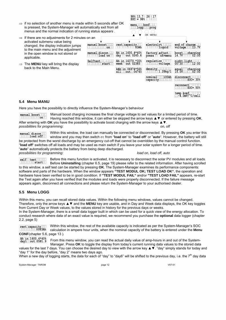
⇒ if no selection of another menu is made within 5 seconds after OK is pressed, the System-Manager will automatically exit from all menus and the normal indication of running status appears .
MENUOK⇒ If there are no adjustments for 2 minutes on an
activated submenu value being changed, the display indication jumps to the main menu and the adjustment in the open window is not stored or applicable.
⇒ The MENU key will bring the display back to the Main Menu.
5.4 Menu MANU Here you have the possibility to directly influence the System-Manager’s behaviour
Manual boost charging increases the final charge voltage to set values for a limited period of time. Having reached this window, it can either be skipped the arrow keys or entered by pressing OK.
After entering with OK you have the possibility to activate boost charging with the arrow keys . possibilities for programming: on, off
Within this window, the load can manually be connected or disconnected. By pressing OK you enter this window and you may then switch στ from “load on“ to “load off“ or ”auto“. However, the battery will still
be protected from the worst discharge by an emergency cut-off that cannot be overridden by the manual control function. “load off“ switches off all loads and may be used as main switch if you leave your solar system for a longer period of time. “auto“ automatically protects the battery from being deep discharged. possibilities for programming: load on, load off, auto
Before this menu function is activated, it is necessary to disconnect the solar PV modules and all loads. Before Uninstalling (chapter 6.5, page 19) please refer to the related information. After having scrolled
to this window, a self test can be started by pressing OK. The System-Manager examines its performance components: software and parts of the hardware. When the window appears “TEST MODUL OK; TEST LOAD OK“, the operation and hardware have been verified to be in good condition. If ”TEST MODUL FAIL“ and/or "TEST LOAD FAIL" appears, re-start the Test again after you have verified that the modules and loads were properly disconnected. If the failure message appears again, disconnect all connections and please return the System-Manager to your authorised dealer.
5.5 Menu LOGG
Within this menu, you can recall stored data values. Within the following menu windows, values cannot be changed. Therefore, only the arrow keys and the MENU key are usable, and in Day and Week data displays, the OK key toggles from Current Day or Week values, to the values stored in history for the previous days or weeks. In the System-Manager, there is a small data logger built in which can be used for a quick view of the energy allocation. To conduct research where data of an exact value is required, we recommend you purchase the optional data logger (chapter 2.2, page 5)
Within this window, the rest of the available capacity is indicated as per the System-Manager’s SOC calculation in ampere hour units, when the nominal capacity of the battery is entered under the Menu
CONF(chapter 5.6, page 13 ).
From this menu window, you can read the actual daily value of amp-hours in and out of the System-Manager. Press OK to toggle the display from today’s current running data values to the stored data
values for the last 7 days. You can choose the desired day to view with the arrow key . ”day“ simply stands for today and “day 1“ for the day before, “day 2” means two days ago. When a new day of logging starts, the data for each of “day” to “day6” will be shifted to the previous day, i.e. the 7th day data
System-Manager TAROM page 12 V07-51

will be replaced with the data for the 6th day, 6th day replaced by 5th day, etc. An external data logger can be linked to this system as an additional option. See Options (chapter 2.2, page 5). The daily readout always shows the Ah which have flowed into the System-Manager and the remaining amount of battery energy in percentage of capacity afterwards (SOC). The energy which has flowed out of the System-Manager is shown on the second line.
Similarly, the weekly value indicated by “week“ shows the accumulated Ah value from the last 7 weeks, battery SOC, as well as energy spent (OUT) during the week.
This window shows the accumulated values of energy in and out of the system since the day of installation, plus battery in the upper right corner. You can reset all these values during a new
installation. Please use the key sequence described in Installation and Operation (chapter 6.4, page 19) and Uninstalling (chapter 6.4, page 19) to reset this window’s values.
Daily and weekly values can only be counted whenever the System Manager is able to detect “night”. Please study Malfunctions and Errors (chapter 9, page 23) if no values are stored in “day2” to “day7” after one week of installation.
5.6 Menu CONF
Within this menu, you can configure your system components. Here you can review all programming changes and also activate pre-set configurations. Within this menu, the type of battery has to be set. Please find detailed information on programming the type of battery in Example of Configuration (chapter 5.8, page 15)
Within this menu, the battery electrolyte type can be set. After having entered this menu, by pressing OK you may toggle between fixed to liquid electrolyte. Setting this to fixed deactivates the
window for programming the acid density as well as disabling the equal charging mode since gassing must be prevented where sealed batteries are used. possibilities for programming: liquid, fixed
In order to reset the System-Manager to the original factory pre-set configuration, you can use this reset window. Press OK to activate the window. The display will indicate "press ok+menu" to inform you to
press the two right keys OK and MENU simultaneously to reset the System-Manager. In case that you do not wish the reset all the settings to the factory pre-set state, you can leave this function by pressing any key. If you press ok+menu however, all settings and values will be reset and the execution will be confirmed by "done".
The System-Manager is able to convert to a voltage regulation mode. After programming this mode the System-Manager will adapt it’s regulation only to voltage values. We recommend this conversion when
using additional generators (diesel, wind, etc.) or loads which are connected direct to the battery (inverter, etc.). After choosing "voltage" all parameters for discharge protection will convert to voltage values. Programming SOC the discharge protection is related to the calculated state of charge of the battery. After entering this menu, by pressing OK you may switch with the keys between SOC and voltage. possibilities for programming: SOC, voltage
Within this window, the acid density can be configured. After having entered this menu, press OK and the acid density can be edited using the arrow keys . and press OK again to save the value. When
the System-Manager is set for the use of sealed batteries, this window is not accessible, since the acid density cannot be configured for sealed batteries. possibilities for programming: 1,20...1,30kg/l
Within this window, you can register the battery’s nominal capacity. press arrow keys for changing the nominal capacity and press OK for entering the new value.
Hint: We recommend this reset in case you are using a second-hand System-Manager, or if you intend to move the System-Manager to another system or change the battery.
System-Manager TAROM page 13 V07-51
5.7 Menu PROG
Within this menu, various charging and special function settings can be changed within the below windows. We have tried to insure that the values are limited within ranges that do not damage the battery immediately. However, certain skills are needed as far as battery behaviour is concerned to prevent long-term damage or poor system performance. If you are unsure about any of these settings, please refer to your authorised dealer or leave the pre-set configurations as they are. In order to adjust the values, first press OK to enter the edit mode for any of the below windows, then edit the value with the arrow keys and press OK to enter and store the value. You will find a detailed Example of Configuration (chapter 5.8, page 15) describing how to proceed.
The end of charge “float” voltage serves for maintaining the charge in the battery for long periods and preventing self-discharge. This voltage should not be too high, since this may lead to permanent
gassing, which damages the battery. Maximum values are stated on the battery data sheet of your battery. For most types of lead battery, this float value is 13.7 volts. possibilities for programming: 13,0V...14,5V 26,0V...29,0V 52,0V...58,0V
Increasing the charge voltage over a limited period of time (boost or “bulk” charging) is not harmful for lead battery types, if within certain parameters. Maximum values are stated on the battery data sheet.
Within this window, both the boost charge voltage and the period can be programmed, how long the boost charge should be activated. After having entered the window by pressing OK, the first line shows “Boost___voltage“ and you may alter the voltage appearing in the second line by pressing the arrow keys . By pressing OK, the window “Boost___time“ appears and you may adjust the time period. Both of these settings are confirmed by OK and stored. Possibilities for programming: in the period from 00:30...05:00 13,5V...15,0V 27,0V...30,0V 54,0V...60,0V
The equalisation charging can be programmed similar to adjusting the boost charging. Press OK to enter, edit the equalisation charge voltage by pressing the arrow keys , then press OK to edit the
adjustable time period, and confirm both settings by pressing OK. The equalisation charging can only be adjusted for batteries with liquid electrolyte, since high equalising voltages are harmful for sealed batteries. The maximum equalising voltage value should be stated on the battery manufacturers’ data sheet. This window is deactivated if you have selected “Fixed“ within the menu CONF (under selection of electrolyte). Factory Pre-Set Configuration presumes liquid electrolyte batteries. You will find a detailed description in chapter 5.8.1, page 15 Possibilities for programming: in the period from 14,0V...15,5V 28,0V...31,0V 56,0V...62,0V
Battery charging voltage is passed on directly to the loads by the System-Manager! Therefore, during equalise charging, high charging voltages can be programmed that may damage some
loads. Please select this equalise charge voltage very carefully and compare the desired value to the battery and load (appliance) manufacturers' data sheets.
The discharge threshold at which the loads are automatically disconnected can be programmed by the user. When you have reached this window by pressing the arrow keys , you may open it for editing
by pressing OK. Afterwards you may alter the disconnect threshold by pressing the arrow keys within given values. Press OK to store the setting. NOTE: the difference between disconnect and reconnect threshold must be at least 20%. If you wish disconnect at higher state of charge you have to first adjust the reconnect threshold (as per below) to 20 % above the desired disconnect threshold. Possibilities for programming by SOC: 20%...70% Whenever you configure voltage regulation (chapter 5.6; page 13) you will find in this window voltage values instead of SOC values for programming the disconnection voltage level. Be aware that the System-Manager allows only these values for disconnect and reconnect in order that a minimum difference of 0,8V (12V), 1,6V (24V) und 3,2V (48V) is assured. If you want to program a high level for disconnection you must first increase the reconnection level. Possibilities for programming by voltage regulation: 11,0V...12,5V 22,0V...25,0V 44,0V...50,0V
The charge threshold at which the loads are automatically reconnected, can also be programmed by the user. The reconnect setting window is reached by pressing the arrow keys . Enter the window by
pressing OK, and alter the values within the window. Press OK to store the setting. The reconnect level can only be reduced to 20% above disconnect threshold (see above). Possibilities for programming: by SOC: 40%...90%
System-Manager TAROM page 14 V07-51
Whenever you configure voltage regulation (chapter 5.6; page 13) you will find voltage values instead of SOC in this window. The System-Manager will only allow to program values which are possible to guarantee the minimum hysteresis Possibilities for programming: by voltage regulation: 11,8V...13,3V 23,6V...26,6V 47,2V...53,2V
The System-Manager can control night lighting automatically by evaluating the density of outside light with the help of the solar PV module array. Depending on the PV array alignment or shading, it may well
be that night recognition is activated even though twilight has not yet come to an end. By the programmable time adjustment ”night delay“, the night light switch-on may be shifted to a later time. When you have entered the window by pressing OK, the first line displays ”night___delay“ and you may change the time of delay by pressing the arrow keys . After confirmation by pressing OK, the display “night___timer“ appears and you may enter the period of time for the light to remain on after dawn. By pressing OK both of these settings are confirmed and stored. This configuration setting has no actual effect on the System-Manager or its load output terminals. However, loads which are required for night time use, can be especially connected with the SOLARIX remote control switch units and the remote control switches have to be programmed to nightlight and the System-Manager sends a signal which activates the loads. Possibilities for programming: timer 00:00...12:00 and delay of 00:00...03:00
The gassing which occurs in the battery (only in liquid acid vented cap type batteries) is proportionate to the voltage and the temperature. The higher the voltage and/or temperature goes, the more gas will be
produced inside the battery. So in accordance with the temperature, the voltage value has to be changed to control the gassing process to occur only during the equalising charge. The charge voltage settings (float, boost, equal) refer to the setting at room temperature (25° C) and are altered internally by the programmable coefficient in accordance with the ambient temperature registered by the System-Manager’s temperature sensor. Possibilities for programming: -2mV/K/Zelle...-8mV/K/Zelle
5.8 Example of Configuration
5.8.1 Factory Pre-Set Configuration After a DC power failure from an occurrence such as blown safety fuses or disconnecting the battery, usually no parameter values or functions have to be programmed again, since these values are stored in the System-Manager’s EEPROM (a special memory chip that does not lose its data on power failure). Please note that these configurations are even stored when you remove the System-Manager and reinstall into a new system.
Hint: Used System-Managers should always be Reset to Factory Pre-Set Configuration (chapter 5.8.3; page 16) before putting into operation in a new system.
For details of the factory pre-set values please see (chapter 8.2, page 21). The user can reset to this factory configuration at any time. However, any previous configuration settings that were stored in the System-Manager will be lost.
Hint: Adjust the battery type after reset!
On delivery, the System-Manager is factory pre-set for vented batteries with liquid electrolyte “liquid“. This configuration is applicable for most typical vented-cap lead acid batteries. However, setting this parameter to the other setting for closed batteries with gel electrolyte “fixed“) leads to optimal charging and safe maintenance function (no equalise charge or gassing allowed).
Only with the configuration “liquid“ will you have the possibility to program the acid density and the equalising charging “equal charging“. When the configuration is set to “fixed” these windows are not activated.
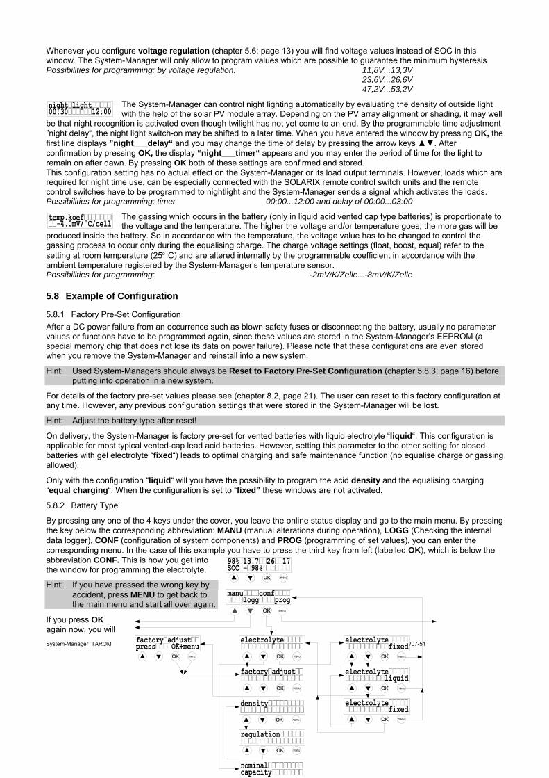
5.8.2 Battery Type
By pressing any one of the 4 keys under the cover, you leave the online status display and go to the main menu. By pressing the key below the corresponding abbreviation: MANU (manual alterations during operation), LOGG (Checking the internal data logger), CONF (configuration of system components) and PROG (programming of set values), you can enter the corresponding menu. In the case of this example you have to press the third key from left (labelled OK), which is below the abbreviation CONF. This is how you get into the window for programming the electrolyte.
Hint: If you have pressed the wrong key by accident, press MENU to get back to the main menu and start all over again.
System-Manager TAROM page 15 V07-51
If you press OK again now, you will
enter the electrolyte setting window and you may toggle between the settings “fixed“ and “liquid“ by pressing the arrow keys . After having selected the desired configuration, press OK to confirm the configuration. Now you are free to either enter further windows by pressing the arrow keys or to get back to the main menu by pressing the menu key.
5.8.3 Reset to Factory Pre-Set Configuration
In the previous section, it is described how to enter the window electrolyte. The next window down is for resetting the System-Manager to the factory pre-set configuration (factory adjust). If you use the UP arrow key , however, you will wrap around to the nominal capacity setting window instead, and only by repeated pressing of the arrow key via regulation and density you will get to factory adjust (see the menu tree chart). By pressing OK you can enter the factory adjust window. The instruction to press the MENU key plus the OK key appears immediately. Only by pressing both of these keys simultaneously will the factory pre-set configurations be set.
5.9 Example of Programming
This example shows how pre-set configurations can be altered within the main menu item “PROG”. Changes are displayed in black letters.
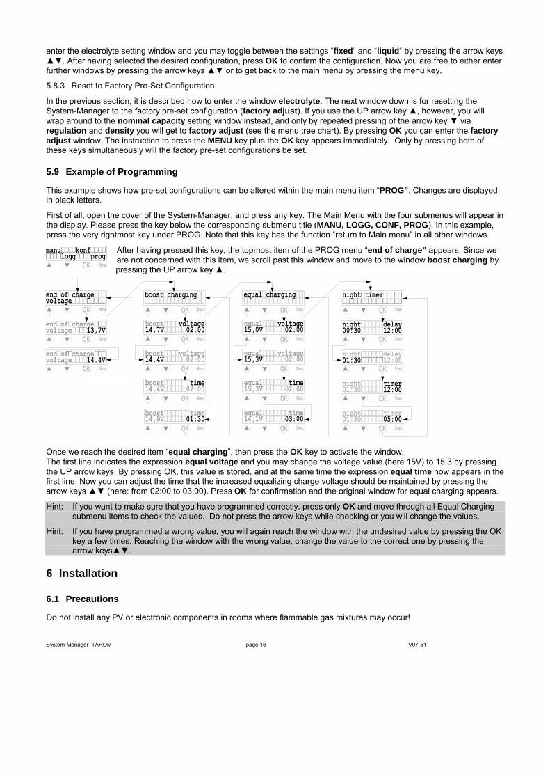
First of all, open the cover of the System-Manager, and press any key. The Main Menu with the four submenus will appear in the display. Please press the key below the corresponding submenu title (MANU, LOGG, CONF, PROG). In this example, press the very rightmost key under PROG. Note that this key has the function “return to Main menu” in all other windows.
After having pressed this key, the topmost item of the PROG menu “end of charge” appears. Since we are not concerned with this item, we scroll past this window and move to the window boost charging by pressing the UP arrow key .
Once we reach the desired item “equal charging”, then press the OK key to activate the window. The first line indicates the expression equal voltage and you may change the voltage value (here 15V) to 15.3 by pressing the UP arrow keys. By pressing OK, this value is stored, and at the same time the expression equal time now appears in the first line. Now you can adjust the time that the increased equalizing charge voltage should be maintained by pressing the arrow keys (here: from 02:00 to 03:00). Press OK for confirmation and the original window for equal charging appears.
Hint: If you want to make sure that you have programmed correctly, press only OK and move through all Equal Charging submenu items to check the values. Do not press the arrow keys while checking or you will change the values.
Hint: If you have programmed a wrong value, you will again reach the window with the undesired value by pressing the OK key a few times. Reaching the window with the wrong value, change the value to the correct one by pressing the arrow keys.
6 Installation
6.1 Precautions
Do not install any PV or electronic components in rooms where flammable gas mixtures may occur!
System-Manager TAROM page 16 V07-51
Within the battery’s immediate surroundings, explosive gases may be generated. So please see that the battery room is adequately ventilated and avoid generating sparks.
The following instructions for batteries must be adhered. We recommend these basic precautions for any country. Check your local electric and safety codes for all applicable precautions in
dealing with DC wiring and battery installations.
⇒ DIN (German) VDE 0510 part 2, sections: • 7. Precautions against explosion danger • 8. Precautions against risks occurring by electrolyte gas (hydrogen sulphide) • 9. Location
⇒ National Electric Code including article No. 690. The unit shall be installed according to this regulation
6.2 Location of Installation
The System-Manager must be connected to the solar PV array, the battery and the loads. The line loss and drops in voltage should be kept to a minimum, so the System-Manager must be installed in a way that the shortest cable possible and the most direct access can be used. This is a major decisive factor for the battery’s location as well as for the solar PV array’s location. The cable lengths to the loads have a lesser effect on System-Manager site selection since distribution throughout the building or site is necessary.
The ideal location for the battery is a well-ventilated battery room (keeping a minimum safety distance of 30 cm from the System-Manager) inside the building but nearest to the solar PV array. Since both charging and discharging currents are running via the battery cable connections, close proximity and short thick cables to the battery are recommended. This battery cable connection is the point where the losses have the worst effect on the PV system’s efficiency and performance.
The solar PV array should be installed in a way that – in the most unfavourable case – the voltage drop is not so high that the battery can not be charged completely again. Within the limited period of time for equalise charging, the battery is charged at a high voltage level. However, if the drop in voltage along the PV array cables is too high, this equalizing charge voltage cannot be reached. The timer for the equalize charge stage will not start running until the equalize voltage is reached, so the timer will be “stuck” and the System-Manager will stay in equalise mode permanently until the situation is corrected. For example, if the MPP voltage at the PV array connection is 16.5V, minus 1.0V drop in voltage on the PV array-to-System-Manager wiring, minus 0.3V drop in voltage at the System-Manager and the safety fuses, the maximum voltage reaching the battery is only 15.2V.
The System-Manager must not be installed in locations with easily flammable liquids or mixtures such as gas bottles, paint, varnish, solvents etc. Installation is only permitted in areas where the System-Manager’s environmental specifications are not exceeded (see technical data) . Furthermore, the System-Manager must not be installed and operated in very humid rooms e. g. bathrooms.
The System-Manager must be protected from direct exposure to weather. Sun and external warming from nearby devices should also be avoided.
The battery and the System-Manager must be installed in a place out of reach of children’s and unauthorised persons. Therefore, we have not taken any precautions on the System-Manager itself
in order to prevent unauthorised use.
The surface on which the System-Manager is to be installed should not be easily flammable. During operation, the backside of the System-Manager heats up. So the materials at the location
for installation should be able to withstand a constant temperature of 85°C without damage or risk of fire.
6.2.1 Installation on Walls
System-Manager TAROM page 17 V07-51
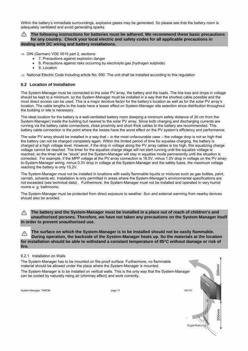
The System-Manager has to be mounted on fire-proof surface. Furthermore, no flammable material should be allowed under the place where the System-Manager is mounted. The System-Manager is to be installed on vertical walls. This is the only way that the System-Manager can be cooled by naturally rising air (chimney effect) and work correctly.
The System-Manager is screwed to the wall with the four holes drilled into the heat sink flanges. The System-Manager is designed without an integrated strain relief, so that the unit can be adapted to the prevailing conditions of various types of installations. For this reason, you must install a strain relief (e. g. cable clips) approx. 200 mm below the System-Manager before the cables spread out to the individual components.
When the System-Manager is in operation, the high currents being regulated by the System-Manager warm up the heat sink and air naturally rising past the heat sink fins extracts the heat. This chimney effect is necessary for proper cooling and System-Manager operation. Do not confine the System-Manager in a closed space, since this would make ventilation and cooling impossible. Adhere to a safety distance of min. 200 mm below and above the unit.
After screwing the System-Manager to the wall, you can start wiring.
6.2.2 Rules for mounting
The System-Manager must be installed with cable openings down.
For marking the mounting holes use the System-Manager as a stencil, but never as a stencil for drilling!
Make sure that the heat sink is well ventilated when mounting.
6.3 Preparations
6.3.1 Assemblies
Before installation, lay out all cables, junction boxes and safety fuses: • cut into sections • isolate on both sides and press on end sleeves for strands • prepare junction boxes
6.3.2 Preparation of Wiring
Wires that are not permanently connected to the building must be strain-relieved outside the System-Manager!
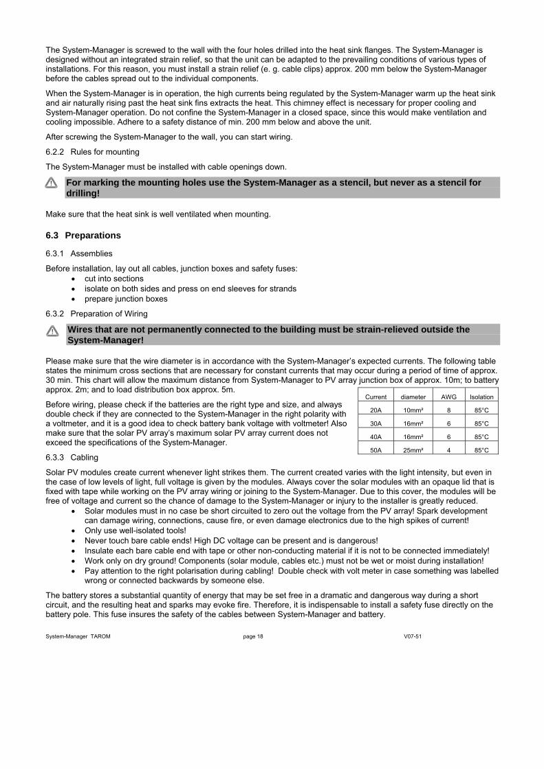
Please make sure that the wire diameter is in accordance with the System-Manager’s expected currents. The following table states the minimum cross sections that are necessary for constant currents that may occur during a period of time of approx. 30 min. This chart will allow the maximum distance from System-Manager to PV array junction box of approx. 10m; to battery approx. 2m; and to load distribution box approx. 5m.
Current diameter AWG Isolation
20A 10mm² 8 85°C
30A 16mm² 6 85°C
40A 16mm² 6 85°C
50A 25mm² 4 85°C
Before wiring, please check if the batteries are the right type and size, and always double check if they are connected to the System-Manager in the right polarity with a voltmeter, and it is a good idea to check battery bank voltage with voltmeter! Also make sure that the solar PV array’s maximum solar PV array current does not exceed the specifications of the System-Manager.
6.3.3 Cabling
Solar PV modules create current whenever light strikes them. The current created varies with the light intensity, but even in the case of low levels of light, full voltage is given by the modules. Always cover the solar modules with an opaque lid that is fixed with tape while working on the PV array wiring or joining to the System-Manager. Due to this cover, the modules will be free of voltage and current so the chance of damage to the System-Manager or injury to the installer is greatly reduced.
• Solar modules must in no case be short circuited to zero out the voltage from the PV array! Spark development can damage wiring, connections, cause fire, or even damage electronics due to the high spikes of current!
• Only use well-isolated tools! • Never touch bare cable ends! High DC voltage can be present and is dangerous! • Insulate each bare cable end with tape or other non-conducting material if it is not to be connected immediately! • Work only on dry ground! Components (solar module, cables etc.) must not be wet or moist during installation! • Pay attention to the right polarisation during cabling! Double check with volt meter in case something was labelled
wrong or connected backwards by someone else.
The battery stores a substantial quantity of energy that may be set free in a dramatic and dangerous way during a short circuit, and the resulting heat and sparks may evoke fire. Therefore, it is indispensable to install a safety fuse directly on the battery pole. This fuse insures the safety of the cables between System-Manager and battery.
System-Manager TAROM page 18 V07-51
System-Manager TAROM page 19 V07-51
Hint: For isolated systems, it is not necessary, common or even permitted by some countries’ laws to ground-connect the components (e. g. DIN 57100 part 410). For further instructions, please see Safety Measures (chapter 6.6, page 20)
6.4 Installation and Operation
It is absolutely necessary to adhere to all our General Safety Instructions (chapter 1.3, page 3 ). To guarantee a faultless working of the System-Manager, it is necessary to follow the chronological sequence described in the following chapters.
6.4.1 Connecting the Battery Bank • open the safety lid of the System-Manager and remove both safety fuses . • Lay both battery cables (B+, B-) between the System-Manager and battery bank in parallel. • Insert the battery cable bare ends to the System-Manager’s battery connection terminals (the symbol shows a
rectangular battery with + and – indicators) and tighten securely with a proper slot screwdriver. • Pay attention to the right polarity and make sure the battery cables have been labelled and connected correctly. • Fix a fuse holder block for an external safety fuse ( not included ) for the battery cable near the battery’s pole with
a short length of battery cable: DO NOT INSTALL THE SAFETY FUSE YET! • Connect battery cable B+ to the battery’s positive pole. • Connect battery connecting cable B- to the fuseholder block at the battery’s negative pole
⇒ Install external safety fuse on the battery pole, and double verify that the battery voltage now appears at the System-Manager’s battery connection terminals, in the right polarity.
⇒ Install one fuse after the other in the System-Manager. Now the System-Manager should start operation.
6.4.2 Connecting the Solar PV Module Array • Insert the module array’s M+ and M- bare wires into the System-Manager’s PV terminals (labelled with a symbol
of a slanted PV module) and tighten the screws securely. Pay attention to the right polarity. • Remember the + and – terminals are shorted to each other internally by the System-Manager to regulate current.
Therefore, it is IMPORTANT to connect ONLY solar PV modules as charging energy source. NO grid-operated battery charging or DC power devices, diesel sets, or wind generators should be connected, as these will be shorted out and severe damage to these devices and the System-Manager can result.
6.4.3 Connecting the Loads • Protect each load circuit by a safety fuse • Disconnect all loads before joining the load cables in order to prevent spark development which may damage
sensitive loads. • Connect the main load cables to the System-Manager’s Load terminals (labelled with a round light bulb) and
securely tighten the screws. Pay attention to the right polarity!
Connect any vital urgent loads that must never be disconnected by the System-Manager (e.g. emergency light, radio link) directly to the battery! Note that there is increased risk of damaging discharge to the battery since the System-Manager no longer controls these loads! Here user training and awareness is vital to protect the customer’s batteries from damage. Protect these direct loads by installation of safety fuses. Finally, secure all cables within the System-Manager’s immediate surrounding by strain reliefs. All other components must also have their wiring be strain-relieved.
6.5 Uninstalling
Uninstall the System-Manager in the opposite way like installing. Firstly all consumer appliances and loads must be switched off by hand and then the L+/L- main load cables disconnected from the System-Manager. Secondly, the PV modules’ M+/M- cable must be disconnected. To avoid any sparking, the modules must be disconnected at night or covered with opaque material before disconnecting the wires. Now, the safety fuses can be removed and the System-Manager's display should go blank.
In order to avoid short circuits while removing the B+/B- cables, you have to remove the safety fuse from the block installed at the – battery pole, and also it is a good idea to remove the B+/B- cables from the battery poles before you disconnect the cables from the System-Manager. Before reinstalling the System-Manager, it should be reset to the factory pre-set adjustments and reprogrammed for the site.
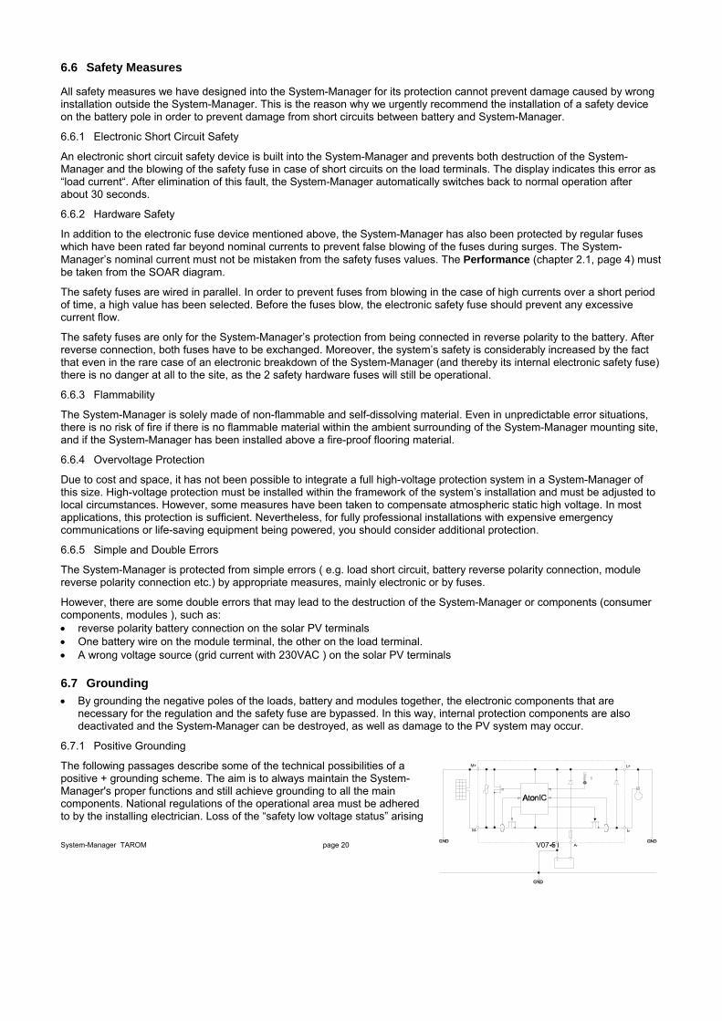
6.6 Safety Measures
All safety measures we have designed into the System-Manager for its protection cannot prevent damage caused by wrong installation outside the System-Manager. This is the reason why we urgently recommend the installation of a safety device on the battery pole in order to prevent damage from short circuits between battery and System-Manager.
6.6.1 Electronic Short Circuit Safety
An electronic short circuit safety device is built into the System-Manager and prevents both destruction of the System-Manager and the blowing of the safety fuse in case of short circuits on the load terminals. The display indicates this error as “load current“. After elimination of this fault, the System-Manager automatically switches back to normal operation after about 30 seconds.
6.6.2 Hardware Safety
In addition to the electronic fuse device mentioned above, the System-Manager has also been protected by regular fuses which have been rated far beyond nominal currents to prevent false blowing of the fuses during surges. The System-Manager’s nominal current must not be mistaken from the safety fuses values. The Performance (chapter 2.1, page 4) must be taken from the SOAR diagram.
The safety fuses are wired in parallel. In order to prevent fuses from blowing in the case of high currents over a short period of time, a high value has been selected. Before the fuses blow, the electronic safety fuse should prevent any excessive current flow.
The safety fuses are only for the System-Manager’s protection from being connected in reverse polarity to the battery. After reverse connection, both fuses have to be exchanged. Moreover, the system’s safety is considerably increased by the fact that even in the rare case of an electronic breakdown of the System-Manager (and thereby its internal electronic safety fuse) there is no danger at all to the site, as the 2 safety hardware fuses will still be operational.
6.6.3 Flammability
The System-Manager is solely made of non-flammable and self-dissolving material. Even in unpredictable error situations, there is no risk of fire if there is no flammable material within the ambient surrounding of the System-Manager mounting site, and if the System-Manager has been installed above a fire-proof flooring material.
6.6.4 Overvoltage Protection
Due to cost and space, it has not been possible to integrate a full high-voltage protection system in a System-Manager of this size. High-voltage protection must be installed within the framework of the system’s installation and must be adjusted to local circumstances. However, some measures have been taken to compensate atmospheric static high voltage. In most applications, this protection is sufficient. Nevertheless, for fully professional installations with expensive emergency communications or life-saving equipment being powered, you should consider additional protection.
6.6.5 Simple and Double Errors
The System-Manager is protected from simple errors ( e.g. load short circuit, battery reverse polarity connection, module reverse polarity connection etc.) by appropriate measures, mainly electronic or by fuses.
However, there are some double errors that may lead to the destruction of the System-Manager or components (consumer components, modules ), such as: • reverse polarity battery connection on the solar PV terminals • One battery wire on the module terminal, the other on the load terminal. • A wrong voltage source (grid current with 230VAC ) on the solar PV terminals
6.7 Grounding • By grounding the negative poles of the loads, battery and modules together, the electronic components that are
necessary for the regulation and the safety fuse are bypassed. In this way, internal protection components are also deactivated and the System-Manager can be destroyed, as well as damage to the PV system may occur.
6.7.1 Positive Grounding
The following passages describe some of the technical possibilities of a positive + grounding scheme. The aim is to always maintain the System-Manager's proper functions and still achieve grounding to all the main components. National regulations of the operational area must be adhered to by the installing electrician. Loss of the “safety low voltage status” arising
System-Manager TAROM page 20 V07-51 A+ A-
L-
L+M+
M-

from grounding has to be compensated by corresponding insulation methods of active parts (protection against direct contact).
When grounding at the plus-side is done, it can also be considered as common ground for all system components. All plus connections are internally connected anyway in the System-Manager.
6.7.2 Negative Grounding
If Negative Grounding is used, only one minus connection from any one the components, i.e. module, battery or load can be grounded.
A+ A-
L-
L+M+
M-
When your solar system requires a minus ground (e. g. battery minus) only this component can be connected to ground. A connection with further minus poles (module or load) bypasses the control elements and the fuse. This can lead to a malfunction and destruction of the System-Manager.
In systems with required load-minus-grounding (e.g. grounding of aerials), all further components have to be connected with the grounds floating.
7 Maintenance The System-Manager depends on its heat sink’s cooling area to meet its technical specifications. Therefore, the heat sink must be kept clean of dust and debris that hampers cooling efficiency.
As far as the fuse and the cables are concerned, they must be checked for corrosion periodically. Due to corrosion, the transfer resistance increases and the contacts could become so hot that damage occurs.
8 Technical Data
8.1 Performance Data Type of controller 235 245 440 System voltage 12/24V 48V max. input voltage 48V 90V Nominal module current at 20°C 35A 45A 40A Nominal load current at 20°C 35A 45A 40A max. current for 10s 45A 58A 52A Surge current for 0,5s 56A 72A 64A max. pulse current (10ms) 140A 180A 160A Temp. range during operation -10°C...60°C storage temperature -25°C...80°C Connecting terminals 16/25mm² Weight 550g Dimensions 188x128x49mm Own consumption 14mA Type of protection IP32
8.2 Controlling Data at 25°C Types of controllers 235 245 440
Factory adjustment 13,7V / 27,4V 54,8V end of charge (float) voltage programmable 13,0V...14,5V ∪ 26,0V...29,0V 52,0V...58,0V
14,4V / 28,8V @ 2:00 57,6V @ 2:00 Factory adjustment activation SOC < 70% (fixed value)
13,5V...15,0V ∪ 27,0V...30,0V 54,0V...60,0V
boost charging
programmable 0:30...5:00
14,7V / 29,4V @ 2:00 58,8V @ 2:00 Factory adjustment activation SOC < 40% (fixed value) programmable 14,0V...15,5V resp. 28,0V...31,0V 56,0V...62,0V
equal charging
0:30...5:00
System-Manager TAROM page 21 V07-51
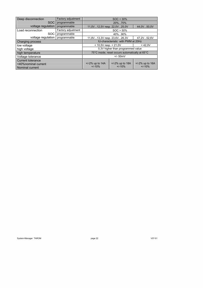
System-Manager TAROM page 22 V07-51
Factory adjustment SOC < 30% programmable 20%...70%
Deep disconnection SOC
voltage regulation programmable 11,0V...12,5V resp. 22,0V...25,0V 44,0V...50,0V Factory adjustment SOC > 50% programmable 40%...90%
Load reconnection SOC
voltage regulation programmable 11,8V...13,3V resp. 23,6V...26,3V 47,2V...52,6V Charging process IU-characteristic with PWM at 20Hz
< 10,5V resp. < 21,0V < 42,0V low voltage high voltage 0,3V higher than programmed value high temperature 75°C inside, reset occurs automatically at 65°C Voltage tolerance +/- 50mV Current tolerance <40%nominal current Nominal current
+/-2% up to 14A
+/-10%
+/-2% up to 18A
+/-10%
+/-2% up to 16A
+/-10%

System-Manager TAROM page 23 V07-51
9 Malfunctions and Errors The System-Manager is designed for many years of constant use. Nevertheless, there may be faults. It is very often, however, that the causes for these faults and errors do not occur in the System-Manager itself, but in the peripheral system components. The following description should be used as a helpful guide to find the sources of malfunctions and to put the device into operation as soon as possible so that unnecessary costs can be avoided. Certainly not all errors are listed below. You will find the most common errors and symptoms covering the major part of all possible errors. Send in the System-Manager only when you are sure that none of the below-described errors has occurred.
The System-Manager is protected against damage by various measures. Nevertheless, always take utmost care in the proper operation of the System-Manager. Short hints of the malfunctions are indicated with the help of the LCD display. However, errors are only properly indicated in which the system has been properly installed. If there are other malfunctions than the ones described below, please check first of all if the System-Manager has been connected to the battery, the module and the loads correctly in the right polarity. Afterwards, check the safety fuses. In each case of malfunction, the System-Manager automatically switches off the load.
Error message / Symptoms
Meaning Remedy
Defective fuses
Usually caused by wrong polarity at the battery connections • Check the proper polarity of the connections and after having fixed the error, install the spare fuses
The indication on the LCD display went out
• There is no current or voltage feed from the battery, the reason could be a defective fuse
• current operating temperature is too high or too low above/below the operating temperature, causing LCD not to function
• Check the battery connections and fuses • Check the working temperature • Reinstall the System-Manager disconnect everything
and connect it again in the right order
“module current”
The PV module current exceeds the max. currents allowed. Although this will not cause an immediate defect, the heat sink will become very hot and could cause injury. The load is disconnected in order to avoid further self-heating. After the current has decreased, the load will be reconnected automatically and the error message disappears.
• The solar PV array exceeds the nominal currents. The system must be split into smaller PV arrays units on separate System-Managers.
“load current” • The load current is too high and the output is disconnected. Either the whole consumption exceeds the max. discharge currents or the max. pulse currents were exceeded by using high surge appliances.
• A short circuit has been caused. After the problem has been solved, the System-Manager reconnects the load about 30 seconds later.
• Switch off some loads by hand • Clear the short circuit
“over temperature”
The maximum allowable temperature has been exceeded. In order to reduce further heat generation the loads are disconnected automatically. As soon as the System-Manager has cooled down, normal operation will resume.
• Check the ventilation at the back heat sink and clean it if necessary
• Protect the System-Manager from direct sunshine • Reduce warming caused by appliances near the
System-Manager • Reduce the loads or PV modules.
“over voltage” In particular, the recharge process through back-up generators or chargers tied directly to the battery causes voltages which are harmful for some appliances. Therefore these loads are disconnected when high battery voltages are present.
• Disconnect external chargers • adjust external chargers for less voltage
“low voltage” To protect the battery, all loads powered by the System-Manager will be disconnected. They will be reconnected automatically after the battery SOC has reached the load reconnecting level.
• Reduce loads or hours of operation of loads to keep the battery from being discharged deeply, or increase solar array to add energy to the system
• Connect all loads through the System-Manager to avoid strong discharge of the battery
“no module” No module is connected, otherwise module, module internal blocking diodes, or array is defective.
• Check contacts and junctions
System-Manager TAROM page 24 V07-51
no module is connected but there is no detection of “no modul”
• disconnect both wire (M+ and M-) at the terminal of the regulator
• wait up to 1 hour “EEProm defect”
The EEPROM memory chip inside of the System-Manager cannot be read or accessed any longer by the System-Manager’s circuitry.
• Disconnect the System-Manager and reconnect it in the order described. If the indication remains, the System-Manager must return to the dealer for repair.
“self test failure”
The self-test could not be carried out correctly, since the solar PV array or the load was not disconnected, or one of the components in the System-Manager is defective
• Disconnect all components, except the battery and try again.
• If the self-test still failed, the System-Manager should be sent to the dealer for service.
"Night" appears at daytime • wrong polarity module night "Night" appears not at night only "no module" • string diodes block measurement
• 20kΩ parallel to string diode
10 Legal Guarantee In accordance with German statutory regulations, there is a 2-year legal guarantee on this product for the customer.
The seller will remove all manufacturing and material faults that occur in the product during the legal guarantee period and affect the correct functioning of the product. Natural wear and tear does not constitute a malfunction. Legal guarantee does not apply if the fault can be attributed to third parties, unprofessional installation or commissioning, incorrect or negligent handling, improper transport, excessive loading, use of improper equipment, faulty construction work, unsuitable construction location or improper operation or use. Legal guarantee claims shall only be accepted if notification of the fault is provided immediately after it is discovered. Legal guarantee claims are to be directed to the seller.
The seller must be informed before legal guarantee claims are processed. For processing a legal guarantee claim an exact fault description and the invoice / delivery note must be provided.
The seller can choose to fulfil the legal guarantee either by repair or replacement. If the product can neither be repaired nor replaced, or if this does not occur within a suitable period in spite of the specification of an extension period in writing by the customer, the reduction in value caused by the fault shall be replaced, or, if this is not sufficient taking the interests of the end customer into consideration, the contract is cancelled.
Any further claims against the seller based on this legal guarantee obligation, in particular claims for damages due to lost profit, loss-of-use or indirect damages are excluded, unless liability is obligatory by German law.
11 Accessories Shunt: PA HS200
Power-Line receiver: PA15
High power relay for PA15: PA EV200
External temperature sensor: PA Temp
Data logger: PA TARCOM
Data logger with cable modem: PA Tarcom RM
Data logger with GSM: PA Tarcom GSM
Software for data logger: TARCOM (freeware)

700784


