Embed Size (px)
Citation preview

2028-18
Joint ICTP/IAEA Workshop on Atomic and Molecular Data forFusion
Detlev REITER
20 - 30 April 2009
Forschungzentrum Juelich, Institute for Energy Research, Plasma Physics52425 Juelich
GERMANY
WHAT - Can we tend the fire?

Forschungszentrum Jülichin der Helmholtz-Gemeinschaft
Detlev ReiterForschungszentrum Jülich GmbH, Institut für Energieforschung-4
52425 Jülich, Germany
Can we tend the fire?
Joint ICTP-IAEA Workshop on Atomic and Molecular Data for Fusion, Trieste 20-30 April 2009
Thanks to: V. Philipps, A. Kirschner, R. Janev
Three lectures course on plasma surface interaction and edge physics
I Introduction: WHAT happens in a fusion plasma near the walls

Chemical process:CxHy….+O2+… COz + H2O+… Nuclear process:
d + t He + n
Mankind learning to tend a fire, again….

The Energy source of the sun and the stars in the universe is: Nuclear Fusion
The vision of nuclear fusion research:
A miniatur star in a solid container
The Sun: T=15 Mill. degrees in the center
p + p d, d + p He3 , He3 + He3 He4 + p + p, Reaction time 1/(np< v>fus)=tfus approx. 109 years
Fusion Reactor: T=100 Mill. degrees
d + t He + n
Much too cold !

What these lectures are NOT about:
Fusion reactor

The correct way: a magnetic bottle Here: the JET Tokamak
2 meters

Euratom - TEKES (1995)Finland (incl. Estonia)
Euratom - DCU (1996)Ireland
Euratom - ÖAW (1996)Austria
Eur - Hellenic Rep (1999)Greece (incl. Cyprus)
Euratom - IPP.CR (1999)Czech Rep.
Euratom - HAS (1999)Hungary
Euratom – MEdC (1999)Romania
Euratom – Univ. Latvia Latvia (2002)
Euratom - IPPLM (2005)Poland
Euratom - MHEST (2005)Slovenia
Euratom – CU (2007)Slovakia
Euratom – INRNE (2007)Bulgaria
Euratom – LEI (2007)Lithuania
Euratom - CEA (1958)France
Euratom – ENEA (1960)Italy (incl. Malta)
Euratom - IPP (1961)Germany
Euratom - FOM (1962)The Netherlands
Euratom - FZJ (1962)Germany
Euratom - Belgian State Belgium (1969)(incl. Luxembourg)
Euratom - RISØ (1973)Denmark
Euratom – UKAEA (1973)United Kingdom
Euratom - VR (1976)Sweden
Euratom - Conf. SuisseSwitzerland (1979)
Euratom - FZK (1982)Germany
Euratom –CIEMAT (1986)Spain
Euratom – IST (1990)Portugal
Euratom 26 Fusion AssociationsJoint construction of JET (1978)Joint construction of JET (1978)

HGF
GermanyHelmholtz AssociationDFG / Universities
EuropeTrilateral Euregio Cluster (B, Nl, Jül)EURATOM AssociationEFDA (JET, Technol.)F4E (ITER)
WorldIEA Implementing Agreement
“Plasma-Wall Interaction” (J, USA, Canada)ITPA International Expert Groups
FZ Jülich: in Germany fusion research is organized in the Helmholtz Association
TEXTOR
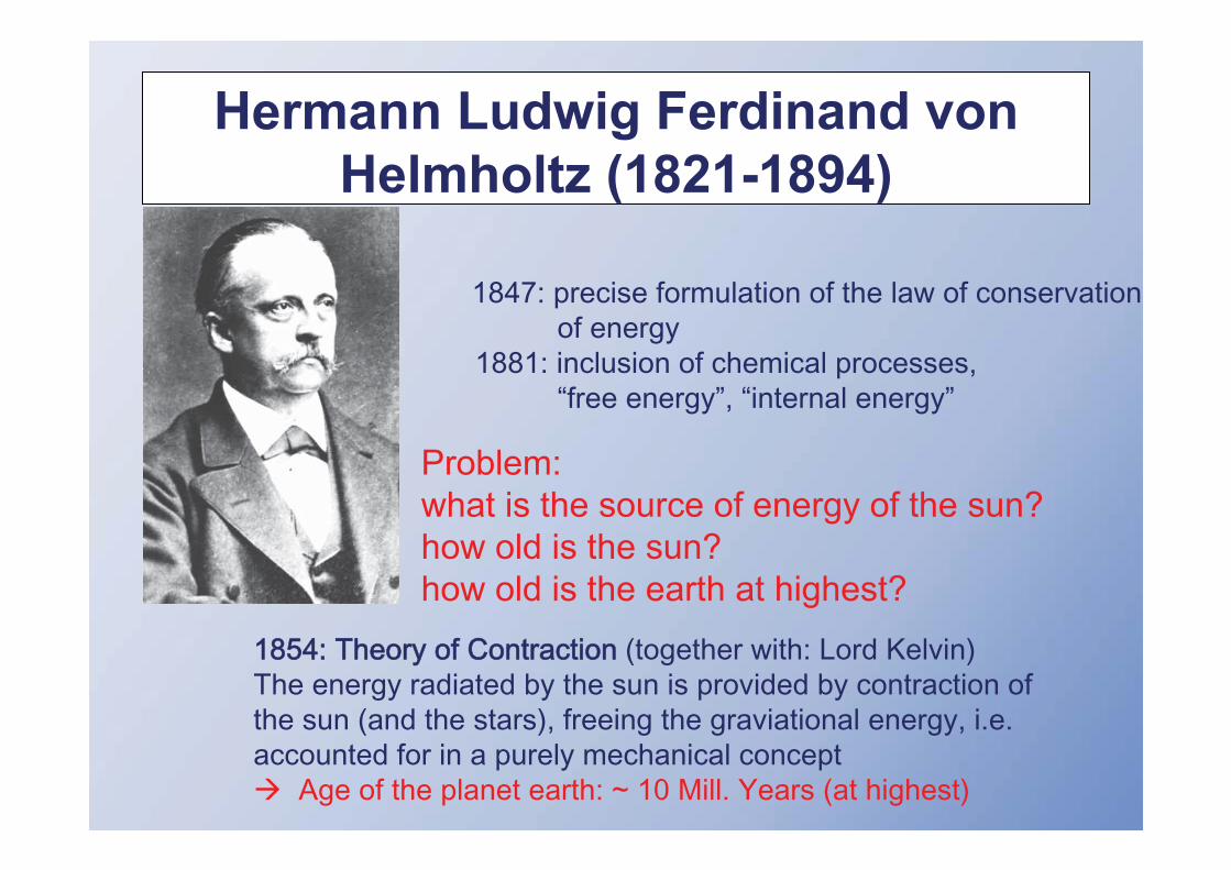
Hermann Ludwig Ferdinand von Helmholtz (1821-1894)
Problem: what is the source of energy of the sun? how old is the sun?how old is the earth at highest?

Ca. 1925: Sir Arthur Eddington : Nuclear Fusion as energy source of the sun and the stars(E=m c2)
Ca. 1935: Hans Bethe und Carl Friedrich von Weizsäcker: final resolution of the nuclear fusion processes in the sun (“Bethe- Weizsäcker cycle”)
(age of sun and earth: 4-5 billion years well possible)

1933: Oliphant und Rutherford fuse Deuteron atoms, discovery of tritium

Inventing the stellarator

Progress in Tokamak research:
Compare: Moore’s Law mirco processors

Forschungszentrum Jülichin der Helmholtz-Gemeinschaft
Introduction: Fusion Research & Plasma-Wall Interaction
I.) WHAT : basic plasma-wall interaction processesII.) HOW : …can we make the application work? ITER
III.) WHY : understanding the edge plasma, A&M processes
Outline of course:

Forschungszentrum Jülichin der Helmholtz-Gemeinschaft
Role of Edge Plasma Science
Early days of magnetic fusion (sometimes still today?):
Hope that a fusion plasma would not be strongly influenced by boundary:
“The edge region takes care of itself”.
Single goal: optimize fusion plasma performance
Now:man made fusion plasmas are now powerful enough to be dangerous for the integrity of the container:
The edge region does NOT take care of itself. It requires significant attention!
The ITER lifetime, performance and availability will not only be influenced, it will be controlled by the edge region

Forschungszentrum Jülichin der Helmholtz-Gemeinschaft
Role of Edge Plasma Science, cont.
It turned out unfortunately (early 1990th):
THE LAYMAN IS RIGHT !
Almost...
The layman’s response to the idea:
“A miniature star (100 Mill degrees) in a solid container”:
THIS MUST BE IMPOSSIBLE !

Forschungszentrum Jülichin der Helmholtz-Gemeinschaft
Physics of hot plasmacore
Atomic/Molecularprocesses,Plasma material interaction
ITER

Forschungszentrum Jülichin der Helmholtz-Gemeinschaft
Candle, on earth
Convection,driven by buoyancy
(i.e. gravity)
Only Diffusion (no convection)
Candle, under mircogravity
(only small, dim burn,at best)
Fresh air
Used air
e.g.: parabola flight,g 0
Can we hope that magnetic confinement core plasma physics progresswill mitigate plasma-surface problems ?

Forschungszentrum Jülichin der Helmholtz-Gemeinschaft
IP
ID
IDID
Magnetic Fusion: how to produce convection ? DIVERTOR
Increase convection increase plasma surface interaction

L. Spitzer “A proposed stellarator”, US Fusionsprojekt: “Matterhorn”AEC Report No. NYO-993 (PM-S-1) 1951
Original report has two figures !

JET (Joint European Torus) : Ø 8.5 m, 2.5 m high, 3.4 T, 7 MA, 1 min
Key area for plasma wall interaction

AUG
JET
ITER
Major Radius
TorusAxis
Core:plasma similarity:present experimentsare “wind tunnel experiments”for ITER
Extrapolation: present experiments ITER

Forschungszentrum Jülichin der Helmholtz-Gemeinschaft
Extrapolation of core plasma confinement to ITER
ITER referencescenario

div(nv )+div(nv )= ionization/recombination/charge exchange
Core
Relative importance of plasma flow forces over chemistry and PWII Plasma Core
(collisional +turbulent) cross field flow, D , V
(empirical) ion transport scaling from spectroscopy on surfacereleased impurities (interpretation,line shape modelling):
Spectroscopy : nZ*CR Model : nZ* nZTransport Model : nZ D , V
(advanced plasma scenario development)
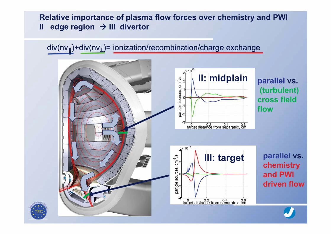
div(nv )+div(nv )= ionization/recombination/charge exchange
II: midplain
III: target
Relative importance of plasma flow forces over chemistry and PWIII edge region III divertor
parallel vs.(turbulent)cross fieldflow
parallel vs.chemistry and PWIdriven flow
div(nv )+div(nv )= ionization/recombination/charge exchange

Forschungszentrum Jülichin der Helmholtz-Gemeinschaft
AUG
JET
ITER
Major Radius
TorusAxis
Core:plasma similarity:present experimentsare “wind tunnel experiments”for ITER
Edge:Computational plasma edge modelling(lecture III)
Extrapolation: present experiments ITER

Forschungszentrum Jülichin der Helmholtz-Gemeinschaft
Edge/divertor science
• interdisciplinary• already a highly integrated field
- plasma physics- CFD - rarefied gas dynamics- opacity- plasma wall interaction- atomic physics- molecular physics- .....
fusion, technical-, astro plasmasfluid-dynamicsaero-dynamics, vacuumlighting, inertial fusion
Atomic & Surface data(database: IAEA fusion data unit)
this lecture I

Plasma-wall interaction in fusion devices
Impinging plasma and impurity particles
- erosion of wall elementslifetime of wall elements is reduced
- eroded wall particles can penetrate into core plasmadilution and radiation cooling of core plasma
- re-deposition of eroded particlestritium retention in deposited layers(retained T has to be limited to 350g due to safety rule in ITER)
Erosion, transport and redeposition of impurities is a crucial (show stopping ?) issue in fusion research

Control of plasma-wall interaction: the limiter concept
Limiter:A material piece protruding from the mainwall intercept the closed field lines to extractpower and particles.
Poloidal limiter
Poloidallimiters
Toroidal beltpump limiter
TEXTOR

Control of plasma-wall interaction: the divertor concept
Divertor:A separate chamber in the vacuum vessel to which particles and energy are directed
JET divertor

Next 2 slides: JUMPING AHEAD
see again 3rd lecture

PPFR: average neutral pressure in Private Flux Region
ITER divertor engineering parameter: target heat flux vs. divertor gas pressure
1996 (ITER physics basis1999)
2003, neutral - neutral collisions ….+ molecular kinetics (D2(v)+D+, MAR)2005, + photon opacity
Consequences for ITER design (B2-EIRENE): shift towards higher divertor gas pressure to maintain a given peak heat flux (Kotov et al., CPP, July 2006)
ITER design review2007-2009:“Dome“ re-designnow ongoing

Compare: re-entry problems e.g. Space shuttle)

Scrape-off layer
Plasma impact
e -, X n+,X 0
Solid Wall Material
Boundary plasma
Reflection
Rec
yclin
g
Retention
n
Plasma - Wall Interactions
Main plasma
Erosion
Re-deposition and co-deposition

Void
Sputtering
Energy dissipation by elastic (withatoms) and ineleastic (with electrons) collisions
(10-13 sec, range 10-7 m, 200 eV D+)
Elastic collisons: Creation of vacanciesand interstitials
elastic collisions(energy transfer > threshold energy for
damage)
Diffusion of vacancies and interstitials
voids, dislocations, swelling, radiation, embrittlement
Sputtering of surface atoms
(energy transfer > surface binding energy)
Transmutationformation of nuclear reaction products(including H isotopes and He)
Self-interstitial
Vacancy
Dislocation
Reflection
Projectile, E
o
I-interstitial
Implantation
Basic Processes Induced in Materials by Plasma Particle Impact

heat lattice defectsconductivity scattering of phonons
swelling void formation, gas bubbles agglomeration of vacancies and helium
ductility neutron and helium induced embrittlementdensification of dislocation network, agglomeration of helium bubbles on grain boundaries
composition transmutation products
The 14 MeV fusion neutrons heat an external material (for energy conversion) and they breed Tritium in the blanket.
Unfortunately:
14 MeV fusion neutrons also produce volumetric radiation damage, and change and deteriorate the material properties
Science of irradiated materials (not further discussed here)

Basic PSI Processes
I.) Sublimation
II.) Physical sputtering
III.) Chemical erosion
IV.) Radiation Enhanced Sublimation (RES)
V.) Backscattering
Only briefly discussed here:
VI.) Retention (hydrogen isotopes)
VII.) Desorption/Adsorption
VIII.) Blistering
IX.) Secondary electron emission
Springer, 2006
Springer, 2005

I.) Sublimation

Heat diffusion time
t = d2/2D D= / c
D: diffusivity conductivity density heat capacity
4 s 5 10-5 m2/s
In steady state
Ts -Tw = T = Q * d /
Q=10 MW/m2, =200[W/(m K)], d=0.02m
T= 1000 °C
Armormaterial: thickness dwith thermal conductivity
Ts
Plasma input : Q (W/m2)
d
Water cooling
Power exhaust steadysteady statestate heatheat loadsloads
Monoblock concept
Tw

Power exhaust transienttransient heatheat loadsloads (1)(1)
In transient events, like disruptions or ELMs, part of theplasma stored energy is deposited in very short pulsesto the walls
example: type I Elms in ITER:Wthermal (Plasma) 350 MJ
energy loss during ELM 2-6 %
Energy per ELM 20 MJ (~30 hand grenades at 150g TNT each)
deposition time 0.2 ms
deposition area 10 m2
power density 10 GW/m2

In transient events the energy must be absorbed bythe heat capacity ( inertial cooling )
T ( t) = P * ( 2 / c ) 0.5 * t 0.5
temperature power conductivity density heat capacity
t = 0.25 ms Tsmax = 6000 C Penetration depth: 0.15 mm
Sublimation threshold: 2200 C
Graphite Target will sublimate quickly
With duration of 0.2 ms and area 10 m2 the maximal energy per ELM in ITER must limited to < 1-2 % of stored energy to avoidmaterial loss by sublimation
Metals will melt leading to loss of melt layer by MHD effects in melt layer
Type I ELM operation critical for ITER
transienttransient heatheat loadsloads (2)(2)
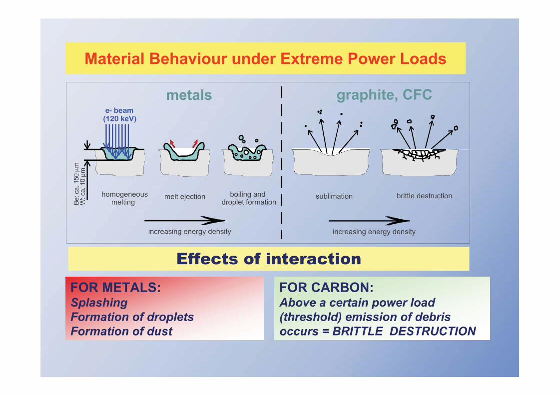
Material Behaviour under Extreme Power LoadsBe
:ca.
150
mW
:ca.
10μ m
e- beam(120 keV)
boiling and droplet formation
melt ejection
metals graphite, CFC
homogeneousmelting
increasing energy density increasing energy density
brittle destructionsublimation
FOR METALS:SplashingFormation of dropletsFormation of dust
FOR CARBON:Above a certain power load (threshold) emission of debris occurs = BRITTLE DESTRUCTION
Effects of interaction

MELTING observed commonly in present machines
Beryllium antenna screenat JET
Tm(Be) = 1278 oC
Limiter from FTU TZM coated with 2 mm VPS Tungsten
TEXTOR: Melting of 170 mm B4C coating on copper

The TEXTOR PWI Test Facility with air locka tool (user facility) for PWI research
viewing lines for diagnosticsTEXTOR PWI Test FacilityAir locks for PWI components
< 15 cm diameter (enlargement foreseen)• external heating (up to 1800K) or cooling
(down to RT)• radial movement (+- 5 cm around LCFS)• rotatable• electrical biasing of limiters• exchange time for samples <½ day• local gas injection systems
Comprehensive diagnostics
• overview spectroscopy (UV-VIS-IR) • 2D imaging (D , CII etc.),• high resolution spectroscopy• laser-induced fluorescence• 2D thermography, thermocouples• colorimetry• laser desorption/ablation• edge diagnostics for ne, Te (Langmuir probesand atomic beams)
Test Limiterinserted through air lock
Presently used in cooperation with Japan (TEXTOR-IEA), VR, IPPWL, Slovenia, Universities,….
ASIDE:

Inside the TEXTOR Tokamak @ FZ-Jülich

Focus on Plasma Surface interaction research
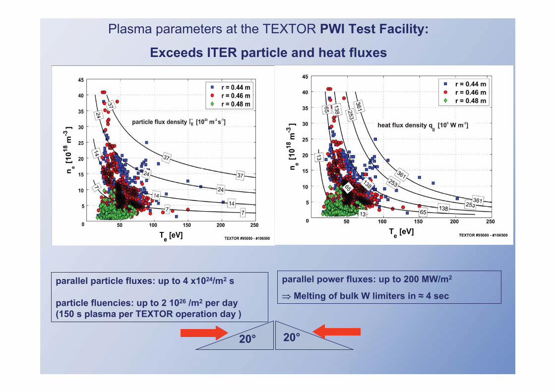
parallel particle fluxes: up to 4 x1024/m2 s
particle fluencies: up to 2 1026 /m2 per day(150 s plasma per TEXTOR operation day )
parallel power fluxes: up to 200 MW/m2
Melting of bulk W limiters in 4 sec
20° 20°
Plasma parameters at the TEXTOR PWI Test Facility:
Exceeds ITER particle and heat fluxes

II.) Physical sputtering

II.) Physical sputtering
Mechanism: energy transfer from projectile to solid atom at surface
D+projectile
sputtered particle
W
W0
collisioncascade
Impinging projectile ion initiates collision cascade inside the solid energy transfer to surface solid atom which is released
Plasma-Wall Interaction Processes: Basic Processes

II.) Physical sputtering
Collision cascades: different regimes
single collisionregime
linear cascade regime
thermal spike regime
Single collision: light ions at low energies, atomic motion stopped after few collisions, binary collision approximation (BCA) valid
Linear cascade: collisions only between fast particles and atoms at rest, BCA
Thermal spike: dense cascade, collisions between fast particles important
Plasma-Wall Interaction Processes: Basic Processes

II.) Physical sputtering
Simulation of collision cascades: example “linear cascade” regime
Monte Carlo simulation, Binary Collision Approximation
5 typical cascades of 3 keV Ar+
ions into graphite
— Ion trajectory
O Vacancies
Interstitials
+ Phonons
Plasma-Wall Interaction Processes: Basic Proceses

II.) Physical sputtering
In general: definition of erosion yield Y
:Y yieldErosion
timeareaparticles eroded ofnumber :particles eroded offlux Emitting
timeareasprojectile incoming ofnumber :sprojectile offlux Impinging
ero
in
Erosion yield Y:
average number of eroded target atoms per incident projectile
Plasma-Wall Interaction Processes: Basic Processes

II.) Physical sputtering
Main features of physical sputtering
• Occurs for all combinations of projectile – substrate
• Existence of threshold energy Eth. If Ein < Eth: Ysputter = 0
• Sputter yield Ysputter depends on energy and angle of incomingprojectile
• Sputter yield Ysputter depends on projectile – material combination. Maximal energy transfer factor = 4 M1 M2 /(M1+ M2)2
• No significant dependence of Ysputter on surface temperature
• Sputtered species: atoms or small clusters of substrate particles
Plasma-Wall Interaction Processes: Basic Processes

II.) Physical sputtering
Typical dependence of sputter yield Y on incident energy of projectile
Ein < Eth: Y = 0. Increasing Ein Y increases until maximum. Further increase of Ein Y decreases (collision cascade penetrates deeper into solid).
H on Fe(normal incidence)
Ein [eV]
Y
Eth ~ 8 eV
Plasma-Wall Interaction Processes: Basic Processes

II.) Physical sputtering
Typical dependence of sputter yield Y on incident angle of projectile
Y first increases with increasing in (with grazing incidence more energy is deposited near surface). After reaching maximum Y decreases (reflection).
Y
H on Fe(Ein = 200 eV)
in [°]
in
Plasma-Wall Interaction Processes: Basic Processes

II.) Physical sputtering
Energy distribution of sputtered particles
In many cases:
sputtered particles have Thompson distributed energy
N(E) E/(E + ES)3
ES: sublimation energy
Most probable energy E = ES/2
Rare gas beam (45°, 1–5keV) on Ag
Deviations from Thompson distribution for light ion bombardment and/or non-normal incidenceES/2
Plasma-Wall Interaction Processes: Basic Processes

II.) Physical sputtering
Angle distribution of sputtered particles
In many cases: sputtered particles have cosine distributionDeviations: for light ions and non-normal incidence
30
60300
330
0.0
0.2
0.4
0.6
0.8
1.0
0.0 90°
60°
30°0°
30°
60°
90°
N [a.u.]
in
Plasma-Wall Interaction Processes: Basic Processes

TEXTOR limiterJET Divertor
D Be
D Mo
D W
D C
Physical sputtering : deuterium impact on different first wall materials• Maxwellian energy distribution
shifted by the sheath potential (3 kTe): Ein ~ 6-7 kTe
• largest physical sputter yields and low threshold for Be
• small yields and large threshold for high Z materials
threshold for D impact
Be C W 3 eV 8 eV 80 eV
D B

Total erosion Yield of Graphite, Be and W by D impact
For beryllium and tungsten theoretical and experimental curvesoverlap.
Carbon shows additional erosion, not dependenton impact energy.
CHEMICAL EROSIONW
C
Be
D+

III.) Chemical erosion

III.) Chemical erosion
Mechanism: formation of molecules from projectiles and solid atoms
Impinging deuterium penetrates into graphite and forms hydrocarbon molecule after thermalisation molecule “diffuses”
through porosity to surface of the solid and desorbs
D+ or D0projectile eroded hydrocarbon
graphite
CxDy
Penetration of D
Formation of CxDy
Plasma-Wall Interaction Processes
III.) Chemical erosion
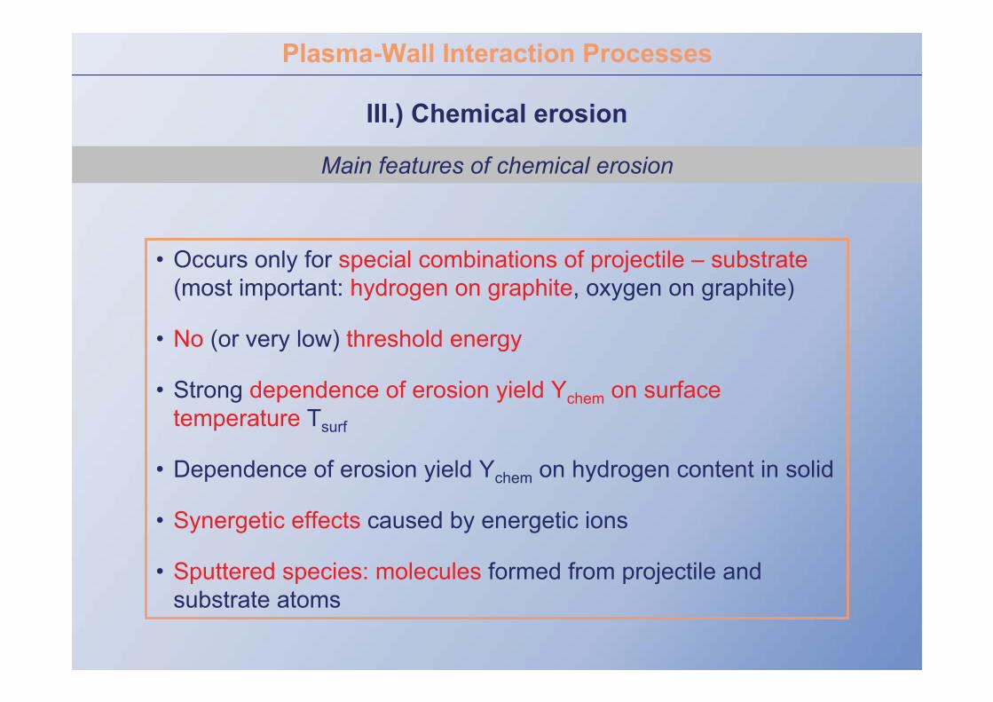
Main features of chemical erosion
• Occurs only for special combinations of projectile – substrate(most important: hydrogen on graphite, oxygen on graphite)
• No (or very low) threshold energy
• Strong dependence of erosion yield Ychem on surface temperature Tsurf
• Dependence of erosion yield Ychem on hydrogen content in solid
• Synergetic effects caused by energetic ions
• Sputtered species: molecules formed from projectile and substrate atoms
Plasma-Wall Interaction Processes

III.) Chemical erosion
Fusion research: Importance of chemical erosion of carbon-based materials
Main disadvantage of carbon-based materials:
- chemical erosion due to hydrogen & its isotopes even at lowest plasma Te
- in a fusion reactor: tritium (T) as fuel erosion of CxTy molecules
re-deposition of CxTy molecules leads to formation of T-containinglayers. Amount of permitted radioactive T limited to 350g in ITER
removal of T-containing layers necessary after having reached 350g
Advantages of carbon-based materials:
- no melting even under extremely high power loads (in ITER: 10 MW/m2)
- high sublimation temperature (~3800°C)
therefore carbon-based materials are foreseen to use at areas of high power loads in ITER (divertor plates)
Plasma-Wall Interaction Processes

III.) Chemical erosion of carbon-based materials
Dependence of chemical erosion yield on surface temperature Tsurf
• Maximum erosion yield @ ~950K
• Erosion yield decreases with elevated Tsurf
400 600 800 1000 1200 14001
2
3
4
5
Met
hane
Yie
ld [%
]
Tsurf [K]
1
2
3
4
5
950 K
Plasma-Wall Interaction Processes

III.) Chemical erosion of carbon-based materials
Flux dependence of chemical erosion yield
1019 1020 1021 1022 1023 102410-3
10-2
10-1
Che
mic
al E
rosi
on Y
ield
(at/i
on)
Ion Flux (m-2s-1)
Ion Beams IPP PSI1 JT-60U outer div ToreS 2001 ToreS 2002 TEXTOR PISCES JET 2001
Chemical erosion yield decreases with increasing deuterium flux
Plasma-Wall Interaction Processes

1.E+00
1.E-05
1.E-04
1.E-03
1.E-02
1.E-01
200 400 600 800 1000Temperature [K]
Tota
l Ero
sion
Yie
ld [C
/Ho
or C
/Do ]
1.E-05
1.E-04
1.E-03
1.E-02
1.E-01
Ho on graphite
Do on a-C:H
hard
more soft
Ho on diamond films
1000
III.) Chemical erosion of carbon-based materials
Chemical erosion yield in dependence on properties of carbon material
Soft (hydrogen-rich) carbon layers suffer from an
enhanced chemical erosion
a-C:Hamorphous
hydrocarbon layer

III.) Chemical erosion of carbon-based materials
Energy and angle distribution of eroded particles
Angle distribution of chemically eroded molecules:
as for physical sputtering: good choice cosine distribution
Chemically eroded particles have Maxwell
distributed energy
(E ~ kTsurf ~ 0.05 eV @RT)
0.0 0.1 0.2 0.3 0.4 0.50
1
2
3
4 300K 2000K
E [eV]
N [a
.u.]
Plasma-Wall Interaction Processes

IV.) Radiation Enhanced Sublimation (RES)

IV.) Radiation Enhanced Sublimation (RES)
Erosion yield from beam experiments in dependence on surface temperatures
Ueda et al.
5 keV Ar+ on graphite
For carbon-based materials:
increasing erosion yield at surface temperatures larger than ~1000K
radiation enhanced sublimation
physical sputtering
Plasma-Wall Interaction Processes

IV.) Radiation Enhanced Sublimation (RES)
Mechanism of RES
• During diffusion of C interstitials to surface: probability of recombination with vacancies or stable defects ( annihilation of interstitial)
• Density of vacancies increases with increasing ion fluxflux dependence of RES
• So far RES not clearly seen in tokamak experiments (not yet clarified)
ion
C interstitial
impinging ion produces C interstitial
C interstitial diffuses to surface and sublimes
sublimated C
graphite
Plasma-Wall Interaction Processes

V.) Backscattering

V.) Backscattering
Reflection of impinging particles at the surface
in out
solid
reflected particle
incoming particle
particles incoming ofamount particles reflected ofamount R
Reflection coefficient R:
• In most cases: reflected particles are neutrals
• Reflection coefficient depends on:
- mass of projectile and target
- energy and angle of incident particles
Deposition = 1 - R
Plasma-Wall Interaction Processes
V.) Backscattering
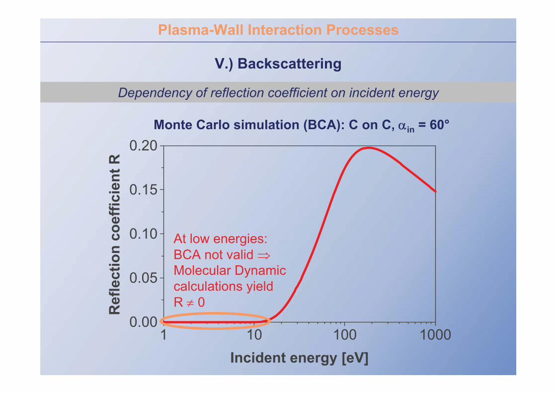
Dependency of reflection coefficient on incident energy
1 10 100 10000.00
0.05
0.10
0.15
0.20
Ref
lect
ion
coef
ficie
nt R
Incident energy [eV]
Monte Carlo simulation (BCA): C on C, in = 60°
At low energies: BCA not valid Molecular Dynamic calculations yield R 0
Plasma-Wall Interaction Processes

V.) Backscattering
Dependency of reflection coefficient on incident angle
Monte Carlo simulation (BCA): C on C, Ein = 100 eV
in
0 20 40 60 800.0
0.2
0.4
0.6
Ref
lect
ion
coef
ficie
nt R
Incident angle in[°C]
Plasma-Wall Interaction Processes

V.) Backscattering
Energy and angle distribution of reflected particles
Plasma-Wall Interaction Processes
Reasonable assumptions:
Energy: exponential decrease for reflected particles if incoming particle energy is Maxwell-distributed
Angle: cosine distribution for reflected particles if isotropic bombardment

further important Plasma-Wall Interaction
Processes

Plasma-Wall Interaction Processes
VI.) Retention
Hydrogen retention in graphite and co-deposited layers
Four retention mechanisms have been identified:
– Build-up of a saturated surface layer during hydrogen implantation
– Chemisorption on grain boundaries and inner porosity surfaces
– Intergranular diffusion and trapping at temperatures > 1000K
– Co-deposition of hydrogen with carbon
Based on experimental data:
– Co-deposition is expected to be most important mechanism for long-term tritium retention in ITER
Licensing: in-vessel tritium inventory in ITER limited to 350g

Plasma-Wall Interaction Processes
V.) Retention
Hydrogen retention via co-deposition
physical & chemicalerosion yields: 1 - 3 %
re-deposited carbon can be re-eroded much stronger (10 - 20%)
D CxDyD
CXDyCxDy+
shadowedareas
build-up of hydrogencontaining layers

Plasma-Wall Interaction Processes
VII.) Adsorption/Desorption
Definition of the processes
Adsorption: binding of particles or molecules to a solid surface(adsorption from residual gas O2, H2O, CO …orfrom impurities segregated at surface at elevated temperatures)
physisorption: binding due to van der Waals forces (EB <~0.5eV)
chemisorption: binding via exchange/sharing of electrons (EB ~ eV)
Desorption: adsorbed species leave the surface and return into gas phase
impurity release process
Ion-induced desorption most important desorption process for fusion.

Plasma-Wall Interaction Processes
VIII.) Blistering
Trapping of gas atoms in bubbles of high pressure
Example: blistering in tungsten
Pressure in bubble too high repetitive exfoliation of micron-thick flakes
Plasma-Wall Interaction Processes
IX.) Secondary Electron Emission
Mechanisms of secondary electron emission
• reflection of electrons which impinge the surface, mostly elastic scattering
• true electron-induced secondary electron emission from the solid
• ion-induced electron emission
Why important in fusion research?
Secondary electron emission coefficient influences the the sheath potential in front of target surface exposed to
plasma (later in these lectures …)

The Impurity Transport Code ERO: see also: lecture III
radialdirection
toroidaldirection
limiter-surface
background plasma
incoming flux(D+, C4+, O5+)
reflected and eroded particles
reflected anderoded particles
deposition re-deposition
B
E C0
CD4
Cx+ CDy0,+
Detailed book-keeping of PWI processes (and local transport)

Plasma wall interaction is unavoidable and necessary for particle and energy exhaust
WHAT happens:
Low Z materials are favourable since higher concentrations can be tolerated in the plasma due to lower radiation losses but the erosion of low Z materials is stronger. A compromise between impurity release and acceptable impurity concentration must be found, which is connected by impurity transport.
Graphite has large advantages for off- normal heat loads in ELMS and disruptions, since it does not melt, but the disadvantage of high erosionand which can lead to large fuel retention by co-deposition
High Z metals have much lower erosion and show much lower hydrogen retention but metal walls can suffer from melt layer loss in off normal heat loads.
Next lecture: HOW can we make ITER work despite these issues