Embed Size (px)
Citation preview

1
2021 PRODUCTSCatalogue
A Division Of
TM
A DIVIS ION OF NORSAT INTERNATIONAL INC.
Region United States Europe, Middle East and Africa Caribbean and Latin America Canada and rest of the world
Telephone USA: 1 800 263 3275 International: +44 (0) 1487 84 28 19 International: +1 905 726 7676 Canada: 1 800 263 3275International: +1 905 727 0165
E-mail [email protected] [email protected] [email protected] [email protected]
Copyright © Sinclair Technologies
www.
sinct
ech.
com
Products Catalogue
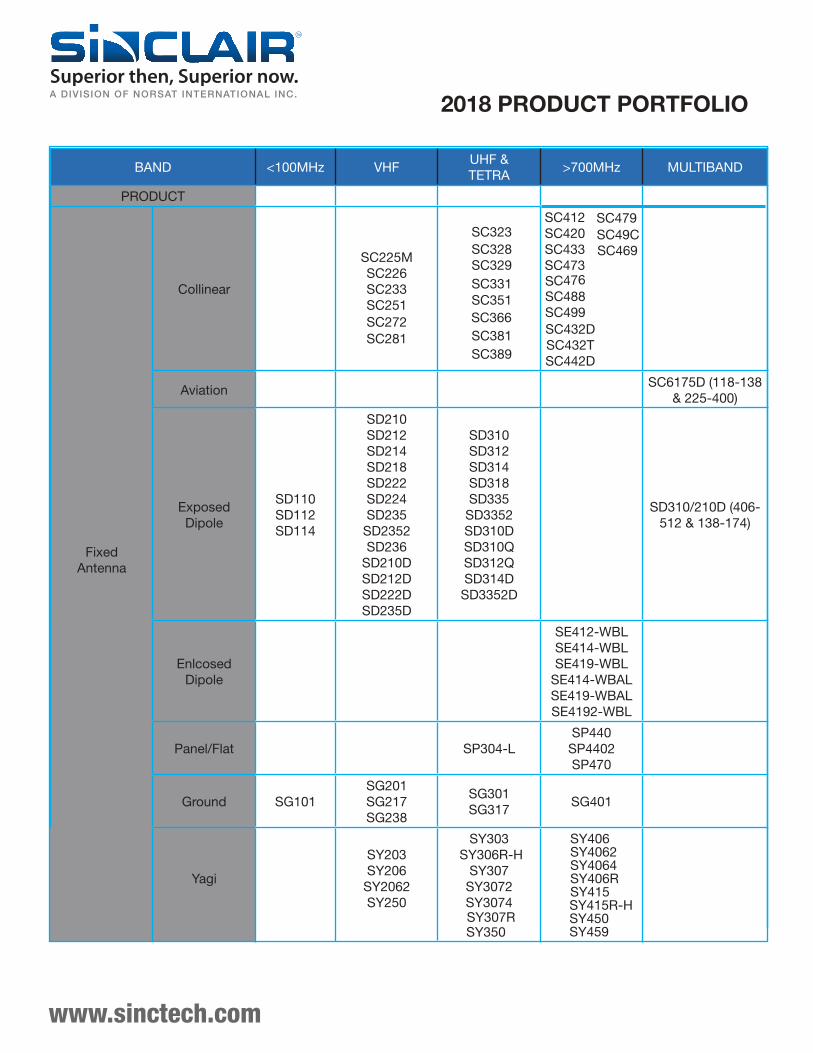
BAND <100MHz VHFUHF & TETRA
>700MHz MULTIBAND
PRODUCT
Fixed Antenna
Collinear
SC225MSC226SC233SC251SC272SC281
SC323SC328SC329SC331
SC381
SC412SC420SC433SC473SC476
SC49C
SC499SC432DSC432TSC442D
AviationSC6175D (118-138
& 225-400)
Exposed Dipole
SD110SD112SD114
SD210SD212SD214SD218SD222SD224SD235SD2352SD236
SD210DSD212DSD222DSD235D
SD310SD312SD314SD318SD335SD3352SD310DSD310QSD312QSD314DSD3352D
SD310/210D (406-512 & 138-174)
Enlcosed Dipole
SE412-WBLSE414-WBLSE419-WBL
SE414-WBALSE419-WBALSE4192-WBL
Panel/Flat SP304-LSP440SP4402SP470
Ground SG101SG201SG217SG238
SG301SG317
SG401
Yagi
SY203SY206SY2062SY250
SY303SY306R-H
SY307SY3072SY3074SY307R
TM
A DIVISION OF NORSAT INTERNATIONAL INC.
www.sinctech.com
2018 PRODUCT PORTFOLIO
SY406SY4062SY4064SY406RSY415SY415R-HSY450SY459
SC351
SC389
SC366
SC469
SC488
SC479
SY350
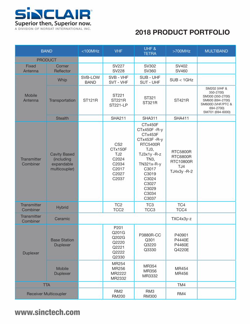
Fixed Antenna
Corner Reflector
SV227SV228
SV302SV360
SV402SV460
Mobile Antenna
WhipSVB-LOW
BANDSVB - VHFSVT - VHF
SUB - UHFSUT - UHF
SUB < 1GHz
Transportation ST121RST221
ST221RST221-LP
ST321ST321R
ST421R
SM202 (VHF & 350-2700)
SM300 (350-2700) SM600 (694-2700)
SM600D (VHF/PTC & 694-2700)
SM701 (694-6000)
Stealth SHA211 SHA311 SHA411
Transmitter Combiner
Cavity Based (including
expandable multicoupler)
CS2CTx150F
TJ2C2024C2034C2017C2027C2037
CTx450FCTx450F -R-y
CTx453FCTx453F -R-y
RTC5400RTJ3,
TJ3x1y -R-z TN3,
TN321x-R-yC3017C3019C3024C3027C3029C3034C3037
RTC5800RRTC6800RRTC10800R
TJ4TJ4x3y -R-2
Transmitter Combiner
HybridTC2
TCC2TC3
TCC3TC4
TCC4
Transmitter Combiner
Ceramic TXC4x3y-z
Duplexer
Base Station Duplexer
P201Q201GQ202GQ2220Q2221Q2222Q2330
P3880R-CCQ301Q3220Q3330
P40901P4440EP4460EQ4220E
Mobile Duplexer
MR254MR256MR2222MR2332
MR354MR356MR3332
MR454MR456
TTA TM4
Receiver MulticouplerRM2
RM200RM3
RM300RM4
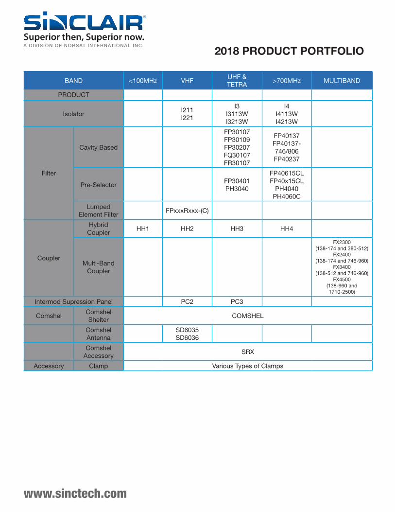
BAND <100MHz VHFUHF & TETRA
>700MHz MULTIBAND
PRODUCT
www.sinctech.com
TM
A DIVISION OF NORSAT INTERNATIONAL INC.
2018 PRODUCT PORTFOLIO
BAND <100MHz VHFUHF & TETRA
>700MHz MULTIBAND
PRODUCT
IsolatorI211I221
I3I3113WI3213W
I4I4113WI4213W
Filter
Cavity Based
FP30107FP30109FP30207FQ30107FR30107
FP40137FP40137-746/806FP40237
Pre-SelectorFP30401PH3040
FP40615CLFP40x15CL
PH4040PH4060C
Lumped Element Filter
FPxxxRxxx-(C)
Coupler
Hybrid Coupler
HH1 HH2 HH3 HH4
Multi-Band Coupler
FX2300 (138-174 and 380-512)
FX2400 (138-174 and 746-960)
FX3400 (138-512 and 746-960)
FX4500 (138-960 and 1710-2500)
Intermod Supression Panel PC2 PC3
ComshelComshel Shelter
COMSHEL
Comshel Antenna
SD6035SD6036
Comshel Accessory
SRX
Accessory Clamp Various Types of Clamps
www.sinctech.com
TM
A DIVISION OF NORSAT INTERNATIONAL INC.
2018 PRODUCT PORTFOLIO
700-1000 MHz Catalogue
Table of Contents
Page
Region United States Europe, Middle East and Africa Caribbean and Latin America
Telephone USA: 1 800 263 3275 International: +44 (0) 1487 84 28 19 International: +1 905 726 7676 Canada: 1 800 263 3275International: +1 905 727 0165
E-mail [email protected] [email protected] [email protected] [email protected]
Copyright © Sinclair Technologies
www.
sinct
ech.
com
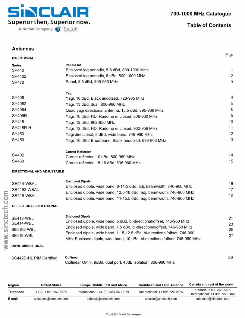
Antennas
DIRECTIONAL
SeriesSP440 1SP4402 2SP470 3
SY406 4SY4062 6SY4064 8SY406R 9SY415 10SY415R-H 11SY450 12SY459 13
SV402 14SV460 15
DIRECTIONAL AND ADJUSTABLE
SE414-WBAL 16SE4192-WBAL 17SE419-WBAL 19
OFFSET OR BI- DIRECTIONAL
2123
SE4192-WBL 25SE419-WBL 27
OMNI- DIRECTIONAL
SC442D-HL PIM Certified
Panel/FlatEnclosed log periodic, 5-6 dBd, 800-1000 MHz Enclosed log periodic, 8 dBd, 800-1000 MHz Panel, 8.5 dBd, 806-960 MHz
YagiYagi, 10 dBd, Black anodized, 728-985 MHzYagi, 13 dBd, dual, 806-966 MHzQuad yagi directional antenna, 15.5 dBd, 895-966 MHzYagi, 10 dBd, HD, Radome enclosed, 806-960 MHzYagi, 12 dBd, 902-956 MHzYagi, 12 dBd, HD, Radome enclosed, 902-956 MHzYagi directional, 8 dBd, wide band, 746-960 MHzYagi, 10 dBd, Broadband, Black anodized, 698-806 MHz
Corner ReflectorCorner reflector, 10 dBd, 800-960 MHzCorner reflector, 15-16 dBd, 806-960 MHz
Enclosed DipoleEnclosed dipole, wide band, 8-11.5 dBd, adj. beamwidth, 746-960 MHz Enclosed dipole, wide band, 13.5-18 dBd, adj. beamwidth, 746-960 MHz Enclosed dipole, wide band, 11-15.5 dBd, adj. beamwidth, 746-960 MHz
Enclosed DipoleEnclosed dipole, wide band, 5 dBd, bi-directional/offset, 746-960 MHz Enclosed dipole, wide band, 7.5 dBd, bi-directional/offset, 746-960 MHz Enclosed dipole, wide band, 11.5-12.5 dBd, bi-directional/offset, 746-960 MHz Enclosed dipole, wide band, 10 dBd, bi-directional/offset, 746-960 MHz
CollinearCollinear Omni, 9dBd, dual port, 40dB isolation, 806-960 MHz
SE412-WBLSE414-WBL
Canada and rest of the world
29
700-1000 MHz Catalogue
Table of Contents
Page
Region United States Europe, Middle East and Africa Caribbean and Latin America Canada and rest of the world
Telephone USA: 1 800 263 3275 International: +44 (0) 1487 84 28 19 International: +1 905 726 7676 Canada: 1 800 263 3275International: +1 905 727 0165
E-mail [email protected] [email protected] [email protected] [email protected]
Copyright © Sinclair Technologies
www.
sinct
ech.
com
3032
3436
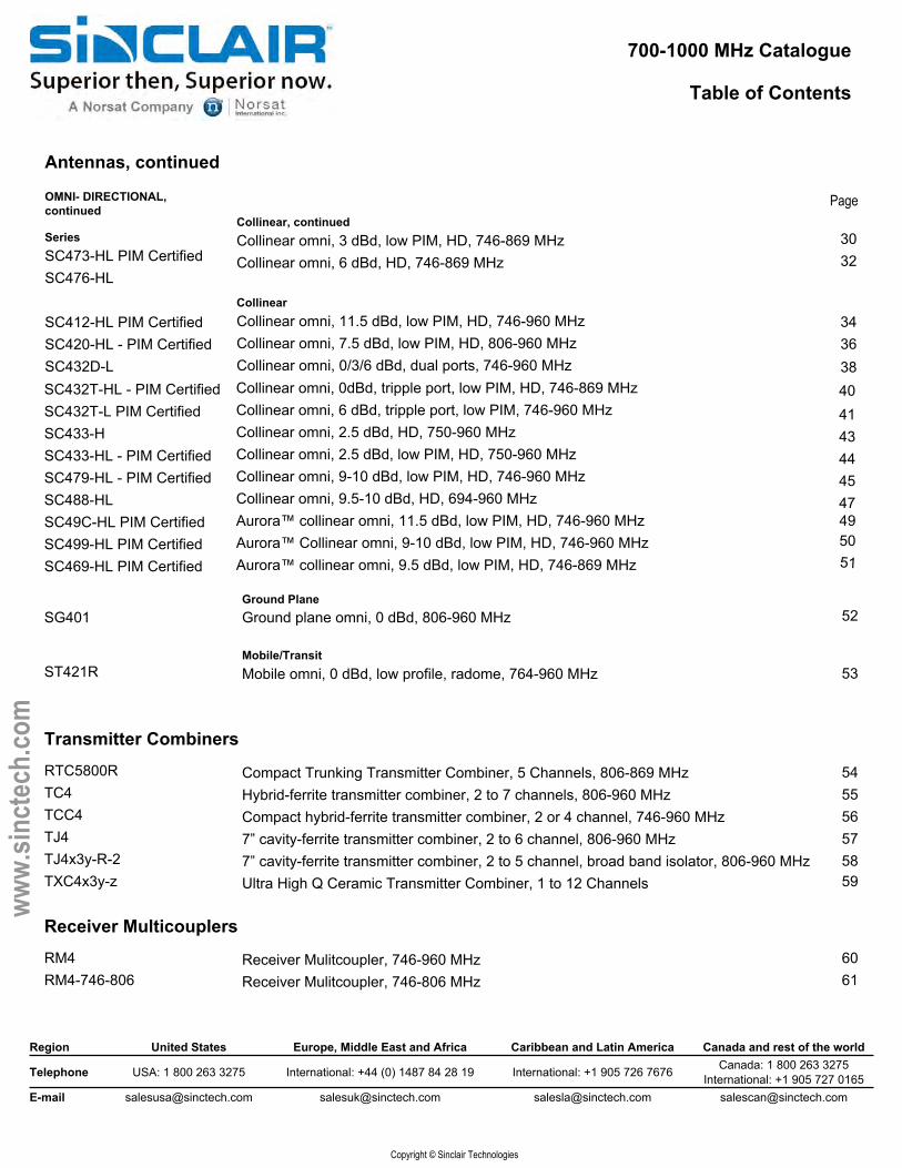
Antennas, continued
OMNI- DIRECTIONAL, continued
SeriesSC473-HL PIM Certified SC476-HL
SC412-HL PIM Certified SC420-HL - PIM Certified SC432D-L
Collinear, continuedCollinear omni, 3 dBd, low PIM, HD, 746-869 MHz Collinear omni, 6 dBd, HD, 746-869 MHz
CollinearCollinear omni, 11.5 dBd, low PIM, HD, 746-960 MHz Collinear omni, 7.5 dBd, low PIM, HD, 806-960 MHz Collinear omni, 0/3/6 dBd, dual ports, 746-960 MHz 38
4041434445
SC432T-HL - PIM Certified SC432T-L PIM Certified SC433-HSC433-HL - PIM Certified SC479-HL - PIM Certified SC488-HLSC49C-HL PIM Certified SC499-HL PIM CertifiedSC469-HL PIM Certified
Collinear omni, 0dBd, tripple port, low PIM, HD, 746-869 MHz Collinear omni, 6 dBd, tripple port, low PIM, 746-960 MHz Collinear omni, 2.5 dBd, HD, 750-960 MHzCollinear omni, 2.5 dBd, low PIM, HD, 750-960 MHz Collinear omni, 9-10 dBd, low PIM, HD, 746-960 MHz Collinear omni, 9.5-10 dBd, HD, 694-960 MHzAurora™ collinear omni, 11.5 dBd, low PIM, HD, 746-960 MHz Aurora™ Collinear omni, 9-10 dBd, low PIM, HD, 746-960 MHzAurora™ collinear omni, 9.5 dBd, low PIM, HD, 746-869 MHz
47
52
53
5455565758
Ground PlaneGround plane omni, 0 dBd, 806-960 MHz
Mobile/TransitMobile omni, 0 dBd, low profile, radome, 764-960 MHz
Compact Trunking Transmitter Combiner, 5 Channels, 806-869 MHzHybrid-ferrite transmitter combiner, 2 to 7 channels, 806-960 MHzCompact hybrid-ferrite transmitter combiner, 2 or 4 channel, 746-960 MHz7” cavity-ferrite transmitter combiner, 2 to 6 channel, 806-960 MHz7” cavity-ferrite transmitter combiner, 2 to 5 channel, broad band isolator, 806-960 MHz Ultra High Q Ceramic Transmitter Combiner, 1 to 12 Channels 59
Receiver Mulitcoupler, 746-960 MHz 60
SG401
ST421R
Transmitter Combiners
RTC5800RTC4TCC4TJ4TJ4x3y-R-2TXC4x3y-z
Receiver Multicouplers
RM4RM4-746-806 Receiver Mulitcoupler, 746-806 MHz 61
495051
700-1000 MHz Catalogue
Table of Contents
Page
Region United States Europe, Middle East and Africa Caribbean and Latin America Canada and rest of the world
Telephone USA: 1 800 263 3275 International: +44 (0) 1487 84 28 19 International: +1 905 726 7676 Canada: 1 800 263 3275International: +1 905 727 0165
E-mail [email protected] [email protected] [email protected] [email protected]
Copyright © Sinclair Technologies
www.
sinct
ech.
com
Duplexers
Series
MR454 63MR456 64P40901 65P4440E 66P4460E 67Q4220E 68
Cavity Filters
FP40137 69
FP40137-746/806 70
FP40237 71
Preselector Filters
FP40615CL 72
FP40x15CL 73PH4040 74PH4060C 75
Tower Top Amplifiers
TM4 76
Hybrid Couplers
HH4
Heavy duty 700/800 MHz vehicle mounted duplexerDuplexer, mobile, 4 cavity, 45/24 MHz separation, 806-960 MHzDuplexer, mobile, 6 cavity, 45/24/9 MHz separation, 746-960 MHzCombline bandpass duplexer, high selectivity, 806-824 & 851-869 MHzLow Loss High Selectivity Bandpass Duplexer, 4 Cavity, 806-940 MHzDuplexer, bandpass, 4 cavity Tx, 6 pole Combline Rx, 806-960 MHzDuplexer, Q-Circuit, Res-Lok, 4 cavity, rack mount, 746-960 MHz
High Q, 3/4 Wave Bandpass Cavity, Single 7" Cavity, 806-960 MHzHigh Q, 3/4 Wave Bandpass Cavity, Single 7" Cavity, 746-806 MHzHigh Q, 3/4 Wave Bandpass Cavity, Dual 7" Cavities, 806-960 MHz
Combline preselector, various bandwidths, 763-880 MHzCombline preselector, various bandwidths, 746-941 MHzBandpass Preselector, Res-Lok, 4 cavity, 763-940 MHzBandpass Preselector, Res-Lok, 5 MHz Bandwidth, 6 cavity, 806-960 MHz
Tower Top Amp/Receiver Multicoupler, Test Port, 12/18 Mhz Bandwidth, 776-901 MHz
Hybrid Coupler, balanced and unbalanced, 500-1000 MHz 77
Isolators and Circulators
I4 Single/Dual Stage Isolator/Circulator, 806-960 MHz 78I4W Single/Dula Stage Wide Band Isolator/Circulator, 746-960 MHz 79
PR4330 62
UHF and Tetra Catalogue
Table of Contents
Page
Region United States Europe, Middle East and Africa Caribbean and Latin America Canada and rest of the world
Telephone USA: 1 800 263 3275 International: +44 (0) 1487 84 28 19 International: +1 905 726 7676 Canada: 1 800 263 3275International: +1 905 727 0165
E-mail [email protected] [email protected] [email protected] [email protected]
Copyright © Sinclair Technologies
www.
sinct
ech.
com
Antennas
Exposed DipoleSD312Q-H 2 dipole, 4.8 dBd, quad ports, HD, 406-512 MHz 96 SD314D Dual port, 4 dipole, 8.0/8.5 dBd, 406-512 MHz 97
Series
SP304-L series 80
SY303 82SY306R-H 84SY307 85SY3072 87SY3074 89SY307R 90SY350 92
SV302-H 93SV360
PanelUHF Panel, 9.5-12 dBd, 65-120º beamwidths, low PIM, 380-512 MHz
YagiYagi, 6 dBd, 380-490 MHzYagi, 10 dBd, radome enclosed, HD, 406-512 MHzYagi, 10 dBd, black anodized, 335-520 MHzYagi, 12.5 dBd, dual array, black anodized, 340-512 MHzYagi, 15 dBd, quad array, black anodized, 340-512 MHzYagi, 10 dBd, radome enclosed, HD, 403-470 MHzYagi directional, 7.5 dBd, wide band, 380-512 MHz
Corner ReflectorCorner reflector directive, 9.5 dBd, 406-512 MHzParabolic reflector directive, 15 dBd, 335-470 MHz 94
OFFSET OR BI- DIRECTIONAL, MULTIPLE PORTS
Exposed DipoleSD310D-H Series Dual 1 dipole antennas, 2.0/2.5 dBd, HD, 406-512 MHz 99
OFFSET/ BI-DIRECTIONAL
Exposed DipoleSD310-H 1 dipole, 2/2.5 dBd, HD, 370-512 MHz 100
SD310-HL- PIM Certified 1 dipole, 1.5/2.0 dBd, low PIM, HD, 370-512 MHz 102SD312-H 2 dipole, 5.0/5.5 dBd, HD, 370-512 MHz 104SD312-HL 2 dipole, 4.0/4.5dBd, HD, 370-512 MHz 106SD314D-HL- PIM Certified Dual port, 4 dipole, 7.0/7.5 dBd, HD, 406-512 MHz 108SD314-H 4 dipole, 8.0/8.5 dBd, HD, 370-512 MHz 110SD314-HL- PIM Certified 4 dipole, 7.0/7.5 dBd, low PIM, HD, 370-512 MHz 112SD318-H 8 dipole, 10/10.5 dBd, HD, 380-512 MHz 114SD318-HL- PIM Certified 8 dipole, 10/10.5 dBd, low PIM, HD, 370-512 MHz 116
DIRECTIONAL
UHF and Tetra Catalogue
Table of Contents
Page
Region United States Europe, Middle East and Africa Caribbean and Latin America Canada and rest of the world
Telephone USA: 1 800 263 3275 International: +44 (0) 1487 84 28 19 International: +1 905 726 7676 Canada: 1 800 263 3275International: +1 905 727 0165
E-mail [email protected] [email protected] [email protected] [email protected]
Copyright © Sinclair Technologies
www.
sinct
ech.
com
Antennas, continued
127128130
OMNI OR BI-DIRECTIONAL, ADJUSTABLE
118119120
131133135137139
141143
144146148149
151152154155157
SERIES
SD3352DSD3352-HSD335-HL- PIM Certified
OMNI- DIRECTIONAL
SC351-HL-PIM/PIP CertifiedSC366-HL PIM Certified
Exposed DipoleQuad array, exposed dipole 2 cables, 6/8.5 dBd, field adj, 406-512 MHzDual array, exposed dipole, 1 cable, 6 dBd/8.5 dBd, field adj, HD, 406-512 MHz Exposed dipole array, 2.5/5.0 dBd, low PIM, field adj, HD, 370-512 MHz
CollinearCollinear omni, 4 or 6 dBd gain, low PIM, PIP rated, HD, 380-512 MHz Aurora™ collinear omni, 6 dBd gain, HD, 380-520 MHzCollinear omni, 9 dBd, low PIM, PIP rated, HD, 380-512 MHzCollinear omni antenna, 7.5 dBd gain, 350-368 MHzCollinear omni, 10 dBd, straight radome, 406-480 MHzCollinear omni, 10 dBd, straight radome, low PIM, 406-420 MHzCollinear omni, 3 dBd, HD, 311-512 MHz Collinear omni, 3 dBd, low PIM, HD, 380-512 MHz Collinear omni, 6 dBd, HD, 380-480 MHz Collinear omni, 6 dBd, low PIM, HD, 380-490 MHz Collinear omni, 6 dBd, low PIM, HD, 380-512 MHz
Ground PlaneGround plane omni, 0 dBd, 360-512 MHzGround plane omni, 2.5 dBd, 5 MHz bandwidth, 406-512 MHz
Mobile/TransitMobile omni, 0 dBd, 10-20 MHz bandwidth, 380-520 MHzMobile omni, 0 dBd, 14-22 MHz bandwidth, radome, 380-520 MHzMobile omni antenna, 2-6 dBd gain, 406-512 MHzMobile omni, 0 dBd, 406-512 and 512-970 MHz
Cavity Based
Open cabinet cavity-ferrite combiner, high Q 10" 1/4 wave cavity, 406-512 MHz Open cabinet cavity-ferrite combiner, high Q 10" 1/4 wave cavity, 406-512 MHz Open cabinet cavity-ferrite combiner, high Q 10" 3/4 wave cavity, 406-512 MHz Open cabinet cavity-ferrite combiner, high Q 10" 3/4 wave cavity, 406-512 MHz Compact Trunking Transmitter Combiner, 5 Channels, 406-470 MHz
SC389-HL- PIM Certified SC328-HSC331SC331-L PIM Certified SC323-HSC323-HL- PIM Certified SC329-HSC329-HL- PIM Certified SC381-HL- PIM Certified
SG301SG317
ST321ST321RSUB- UHFSUT- UHF
Transmitter Combiners
CTx450FCTx450F-R-yCTx453FCTx453F-R-yRTC5400R
122
125
124
UHF and Tetra Catalogue
Table of Contents
Page
Region United States Europe, Middle East and Africa Caribbean and Latin America Canada and rest of the world
Telephone USA: 1 800 263 3275 International: +44 (0) 1487 84 28 19 International: +1 905 726 7676 Canada: 1 800 263 3275International: +1 905 727 0165
E-mail [email protected] [email protected] [email protected] [email protected]
Copyright © Sinclair Technologies
www.
sinct
ech.
com
Transmitter Combiners, continued
Series
TJ3 157TJ3x1y-R-z 158TN3 160TN321x-R-y
7" cavity-ferrite transmitter combiner, 2 to 6 channel, 406-512 MHz7" cavity-ferrite transmitter combiner, pannel mount, 361-512 MHz8.5" cavity-ferrite transmitter combiner, 406-512 MHz8.5" cavity-ferrite transmitter combiner, 406-512 MHz 161
Receiver Multicouplers
RM3 Receiver Mulitcoupler, 350-512 MHz 166RM300 UHF Receiver Multicoupler with Advanced Features, 350-512 MHz 167
Duplexers
MR3332 168MR354 169MR356 170
P3880R-CC 171Q301 174Q3220C 175Q3220E 176Q3330C 177Q3330E
Tetra Band Base Station Duplexer, 380-435 MHzQ-Circuit 6 Cavity Base Station DuplexerDuplexer, Q-Circuit, Res-Lok, compact, 4 cavity, rack mount, 406-512 MHzDuplexer, Q-Circuit, Res-Lok, 4 cavity, rack mount, 406-512 MHzDuplexer, Q-Circuit, Res-Lok, compact, 6 cavity, rack mount, 406-512 MHzDuplexer, Q-Circuit, Res-Lok, 6 cavity, rack mount, 380-512 MHz 178
Cavity Filters
FP30107 Cavity filter, bandpass, high Q, one 7" cavity, 225-512 MHz 179FP30109 High-Q Bandpass 1/4 Wave Cavity Filter, Single 8.5" Cavity, 406-512 MHz 180FP30207 Cavity filter, bandpass, high Q, two 7" cavities, 300-512 MHz 181FQ30107 Cavity filter, Q circuit, high Q, one 7" cavity, 406-512 MHz 182FR30107 Cavity filter, reject, high Q, one 7" cavity, 406-512 MHz 183
Preselector Filters
FP30401 Preselector, 1, 3, or 5 MHz bandwidth, compact, 350-525 MHz 184PH3040 Highly Versatile Res-Lok Preselector, 406-512 MHz 185
TCC3 164TC3 163
HybridHybrid-ferrite transmitter combiner, 2 to 4 channels, 406-512 MHz Compact hybrid-ferrite transmitter combiner, 2 or 4 channel, 350-512 MHz
Mobile Duplexer, 6 cavity extremely compact, BNC con., 5 MHz separation, 406-512 MHz Duplexer, mobile, 4 cavity, 5 MHz (min)/ 10 MHz (max) sep., 380-512 MHz Duplexer, mobile, 6 cavity, 5 MHz (min)/ 10 MHz (max) sep., 350-512 MHz
Base Station
Cavity Based
UHF and Tetra Catalogue
Table of Contents
Page
Region United States Europe, Middle East and Africa Caribbean and Latin America Canada and rest of the world
Telephone USA: 1 800 263 3275 International: +44 (0) 1487 84 28 19 International: +1 905 726 7676 Canada: 1 800 263 3275International: +1 905 727 0165
E-mail [email protected] [email protected] [email protected] [email protected]
Copyright © Sinclair Technologies
www.
sinct
ech.
com
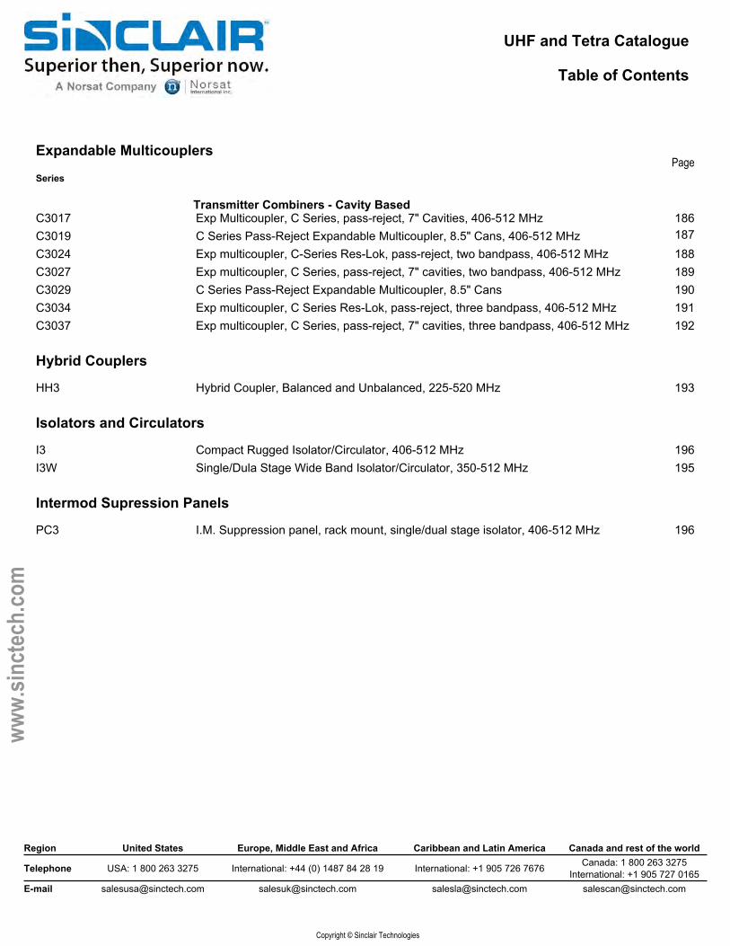
Expandable Multicouplers
Series
C3017 Exp Multicoupler, C Series, pass-reject, 7" Cavities, 406-512 MHz 186C3019 C Series Pass-Reject Expandable Multicoupler, 8.5" Cans, 406-512 MHz 187C3024 Exp multicoupler, C-Series Res-Lok, pass-reject, two bandpass, 406-512 MHz 188C3027 Exp multicoupler, C Series, pass-reject, 7" cavities, two bandpass, 406-512 MHz 189C3029 C Series Pass-Reject Expandable Multicoupler, 8.5" Cans 190C3034 Exp multicoupler, C Series Res-Lok, pass-reject, three bandpass, 406-512 MHz 191C3037 Exp multicoupler, C Series, pass-reject, 7" cavities, three bandpass, 406-512 MHz 192
Hybrid Couplers
HH3 Hybrid Coupler, Balanced and Unbalanced, 225-520 MHz 193
Isolators and Circulators
I3 Compact Rugged Isolator/Circulator, 406-512 MHz 196I3W Single/Dula Stage Wide Band Isolator/Circulator, 350-512 MHz 195
Intermod Supression Panels
PC3 I.M. Suppression panel, rack mount, single/dual stage isolator, 406-512 MHz 196
Transmitter Combiners - Cavity Based
VHF, UHF, 600-6000 MHz Multiband Catalogue
Table of Contents
Page
Region United States Europe, Middle East and Africa Caribbean and Latin America Canada and rest of the world
Telephone USA: 1 800 263 3275 International: +44 (0) 1487 84 28 19 International: +1 905 726 7676 Canada: 1 800 263 3275International: +1 905 727 0165
E-mail [email protected] [email protected] [email protected] [email protected]
Copyright © Sinclair Technologies
www.
sinct
ech.
com
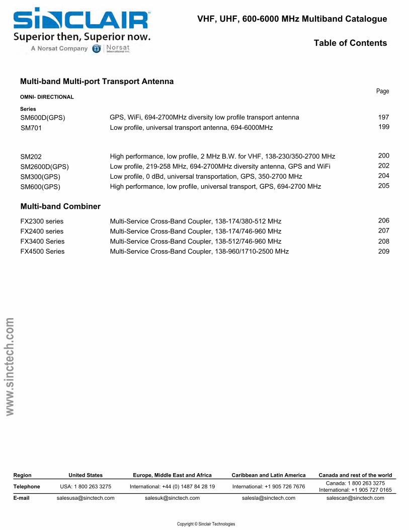
Multi-band Multi-port Transport Antenna
GPS, WiFi, 694-2700MHz diversity low profile transport antenna 197Low profile, universal transport antenna, 694-6000MHz 199
200202204
High performance, low profile, 2 MHz B.W. for VHF, 138-230/350-2700 MHzLow profile, 219-258 MHz, 694-2700MHz diversity antenna, GPS and WiFiLow profile, 0 dBd, universal transportation, GPS, 350-2700 MHzHigh performance, low profile, universal transport, GPS, 694-2700 MHz 205
OMNI- DIRECTIONAL
SeriesSM600D(GPS)SM701
SM202SM2600D(GPS)SM300(GPS)SM600(GPS)
Multi-band Combiner206207
Multi-Service Cross-Band Coupler, 138-174/380-512 MHzMulti-Service Cross-Band Coupler, 138-174/746-960 MHzMulti-Service Cross-Band Coupler, 138-512/746-960 MHz 208
FX2300 seriesFX2400 seriesFX3400 SeriesFX4500 Series Multi-Service Cross-Band Coupler, 138-960/1710-2500 MHz 209
VHF, UHF, and 800 MHz Catalogue
Table of Contents
Page
Region United States Europe, Middle East and Africa Caribbean and Latin America Canada and rest of the world
Telephone USA: 1 800 263 3275 International: +44 (0) 1487 84 28 19 International: +1 905 726 7676 Canada: 1 800 263 3275International: +1 905 727 0165
E-mail [email protected] [email protected] [email protected] [email protected]
Copyright © Sinclair Technologies
www.
sinct
ech.
com
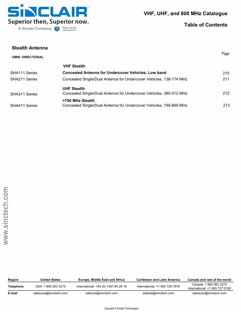
Stealth Antenna
OMNI- DIRECTIONAL
211
212
213
SHA211 Series
SHA311 Series
SHA411 Series>700 MHz StealthConcealed Single/Dual Antenna for Undercover Vehicles, 746-869 MHz
VHF StealthConcealed Antenna for Undercover Vehicles, Low bandConcealed Single/Dual Antenna for Undercover Vehicles, 138-174 MHz
UHF StealthConcealed Single/Dual Antenna for Undercover Vehicles, 380-512 MHz
SHA111 Series 210
VHF & UHF Catalogue
Table of Contents
Page
Region United States Europe, Middle East and Africa Caribbean and Latin America Canada and rest of the world
Telephone USA: 1 800 263 3275 International: +44 (0) 1487 84 28 19 International: +1 905 726 7676 Canada: 1 800 263 3275International: +1 905 727 0165
E-mail [email protected] [email protected] [email protected] [email protected]
Copyright © Sinclair Technologies
www.
sinct
ech.
com
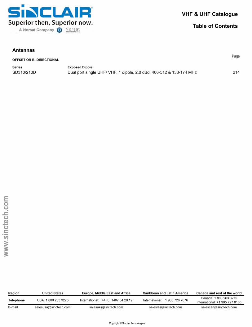
Antennas
OFFSET OR BI-DIRECTIONAL
Series Exposed DipoleSD310/210D Dual port single UHF/ VHF, 1 dipole, 2.0 dBd, 406-512 & 138-174 MHz 214
Low Band, Aviation, and VHF Catalogue
Table of Contents
Region United States Europe, Middle East and Africa Caribbean and Latin America Canada and rest of the world
Telephone USA: 1 800 263 3275 International: +44 (0) 1487 84 28 19 International: +1 905 726 7676 Canada: 1 800 263 3275International: +1 905 727 0165
E-mail [email protected] [email protected] [email protected] [email protected]
Copyright © Sinclair Technologies
www.
sinct
ech.
com
PageLumped Element Filter
SeriesFPxxxRxxx-(C) Pass and Reject two VHF close frequency bands 215
Antennas
BI- DIRECTIONAL
SD236Exposed DipoleExposed dipole array, 7dBd, Bidirectional, 190-225 MHz 216
DIRECTIONAL
217218
SD210R-L - PIM CertifiedSD212R-LSD214R-L - PIM Certified
Exposed DipoleLow PIM VHF reflector single dipole antenna, 138-174 MHzLow PIM VHF reflector two dipole antenna, 138-174MHzLow PIM VHF reflector four dipole antenna, 138-174 MHz. 219
SY203(C) 220SY203(E) 222SY206(C) 224SY206(E) 226SY2062(C) 228SY2062(E) 229SY250(C) 231SY250(E) 232SY250-H
YagiYagi directional, 5.5 dBd, center mount, 138-174 MHzYagi directional, 5.5 dBd, end mount, 138-174 MHzYagi directional, 9.5 dBd, center mount, 108-225 MHzYagi directional, 9.5 dBd, end mount, 138-225 MHzYagi dual stacked, 12 dBd, center mount, 137-174 MHzYagi dual stacked, 6.5/12 dBd, end mount, 138-225 MHzYagi directional, 7 dBd, broad band, 138-174 MHzYagi directional, 7 dBd gain, end mount, 138-174 MHzYagi directional, 8 dBd gain, broad band, 138-174 MHz 233
SV227 234SV228
Corner ReflectorCorner reflector directional antenna, 7 dBd, 130-174 MHzCorner reflector directional antenna, 10 dBd, 132-225 MHz 235
OFFSET
SD110 236SD112 237SD114
Exposed DipoleExposed dipole, 2.5 dBd, 10% bandwidth, 27-88 MHzDual stacked exposed dipole, 5.5 dBd, 10% band width, 27-88 MHzQuad stacked exposed dipole, 7.5 dBd, 10% band width, 27-88 MHz 238
OFFSET OR BI- DIRECTIONAL
SD210-HExposed Dipole1 dipole, 2.0/2.5 dBd, Heavy duty, 118-225 MHz 239
Low Band, Aviation, and VHF Catalogue
Table of Contents
Page
Region United States Europe, Middle East and Africa Caribbean and Latin America Canada and rest of the world
Telephone USA: 1 800 263 3275 International: +44 (0) 1487 84 28 19 International: +1 905 726 7676 Canada: 1 800 263 3275International: +1 905 727 0165
E-mail [email protected] [email protected] [email protected] [email protected]
Copyright © Sinclair Technologies
www.
sinct
ech.
com
Antennas, continued
OFFSET OR BI- DIRECTIONAL, continued
SeriesSD212 242
SD210 243SD210D 245SD210-HL - PIM Certified 247SD210-L - PIM Certified 249SD212D-H 251SD212-H 253SD212-HL - PIM Certified 255SD212-L - PIM Certified 257SD214 259SD214-H 260SD214-HL - PIM Certified 262SD214-L - PIM Certified 264SD218 266SD218-L - PIM Certified 268
OMNI- DIRECTIONAL
SD222D
Exposed Dipole, continued2 dipole, 5.0/5.5 dBd, 118-225 MHz
1 dipole, 2.0/2.5 dBd, 118-225 MHz1 dipole, 2.0/2.5 dBd, dual feed cables, 118-174 MHz1 dipole antenna, 1.5/2.0 dBd gain, low PIM, HD, 118-225 MHz 1 dipole antenna, 1.5/2.0 dBd gain, low PIM, 118-225 MHz2 dipole 5.0/5.5 dBd gain, dual, HD, 138-225 MHz2 dipole antenna, 5.0/5.5 dBd gain, HD, 118-225 MHz2 dipole, 4.5/5.0 dBd, low PIM, HD, 118-225 MHz2 dipole, 4.5/5.0 dBd, low PIM, bi-directional/ offset, 118-225 MHz 4 dipole, 8.0/8.5 dBd, 118-245 MHz4 dipole, 8.0/8.5 dBd, HD, 118-174 MHz4 dipole, 7.0/7.5 dBd, low PIM, HD, 118-225 MHz4 dipole antenna, 7.0/7.5 dBd gain, low PIM, 118-225 MHz8 dipole, 11.0/11.5 dBd, 118-225 MHz8 dipole, 9.5/10 dBd, low PIM, 138-174 MHz
Exposed DipoleDual exposed dipole, Omni directional, 3 dBd, 158-168/215-225 MHz 269
OMNI OR BI-DIRECTIONAL, ADJUSTABLE
Exposed DipoleSD235 Exposed dipole array, 3/5.5 dBd gain, field adj., 118-174 MHz 270SD2352 Exposed dipole array, 6/8.5 dBd gain, field adj., 108-174 MHz 271SD235D Exposed dipole array, 3/5.5 dBd, dual, field adj., 118-174 MHz 272SD235-H Exposed dipole array, 3/5.5 dBd gain, HD, field adj., 118-138 MHz 273
OMNI OR OFFSET, ADJUSTABLE
SeriesSD222 274SD224
Exposed DipoleExposed dipole, 3/6 dBd, field adj., 132-225 MHzExposed dipole, 6/9 dBd, field adjustable, 128-174 MHz 276
Low Band, Aviation, and VHF Catalogue
Table of Contents
Page
Region United States Europe, Middle East and Africa Caribbean and Latin America Canada and rest of the world
Telephone USA: 1 800 263 3275 International: +44 (0) 1487 84 28 19 International: +1 905 726 7676 Canada: 1 800 263 3275International: +1 905 727 0165
E-mail [email protected] [email protected] [email protected] [email protected]
Copyright © Sinclair Technologies
www.
sinct
ech.
com
Antennas, continued
OMNI/BI-DIRECTIONAL, ADJ.
278
285286288289
291292293294295
296297298299300301302
303
305
306
281
Exposed DipoleExposed dipole array, 2.5/5 dBd gain, low PIM, 118-174 MHz
CollinearCollinear omni antenna, 2.3-3.5 dBd gain, low PIM, PIP rated, HD, 138-174 MHzCollinear Omni, 6 dBd, 6 MHz B.W., Straight radome, 138-225 MHzCollinear Omni, 6 dBd, 6 MHz B.W., Straight radome, Low PIM, 138-225 MHz Collinear omni antenna, 0 dBd gain, HD, 130-174 MHz Collinear omni antenna, 3 dBd gain, 2 MHz B.W., 138-174 MHz Collinear omni, 0 dBd, 118-137 MHzCollinear omni antenna, 5 dBd gain, low PIM, HD, 138-174 MHz
Ground PlaneGround plane omni, 0 dBd, 2.5-5% bandwidth, 30-88 MHzGround plane omni, 0 dBd, 3% bandwidth, 118-174 MHzGround plane omni antenna, 2.5 dBd gain, 118-174 MHzGround plane omni, 0 dBd, 118-174 MHzGround plane omni antenna, 0 dBd gain, HD, 118-174 MHz
Mobile/TransitMobile omni, 0 dBd, 0.2% B.W., low profile, 25-50 MHzMobile omni, 0 dBd, 138-223 MHzMobile omni, 0 dBd, Low Profile, 2 MHz B.W., 170-225 MHzMobile omni, 0 dBd, radome, 132-174 MHzMobile whip antenna, 0 dBd gain, 27-118 MHzMobile whip, 0/2/3 dBd, 132-250 MHzMobile whip antenna
VHF AviationAviation band antenna, 1 dBi gain, dual port, HD, 118-138 MHzMultiband Aviation
Aviation band, 1 dBi, dual band/dual port antenna, HD, 118-138 & 225-400 MHzUHF Aviation
Aviation band, 3 dBd, HD, 225-400 MHz
283
OMNI-DIRECTIONAL
SC251-HL-PIM/PIP CertifiedSC226SC226-L - PIM Certified SC225M-HSC233SC272SC281-HL - PIM Certified
SG101SG201SG217SG238SG238-H
ST121RST221ST221-LPST221RSVB- Low BandSVB- VHFSVT- VHF
SC6172D
SC6175D
SC6185
SD235-L - PIM Certified
279
Low Band, Aviation, and VHF Catalogue
Table of Contents
Page
Region United States Europe, Middle East and Africa Caribbean and Latin America Canada and rest of the world
Telephone USA: 1 800 263 3275 International: +44 (0) 1487 84 28 19 International: +1 905 726 7676 Canada: 1 800 263 3275International: +1 905 727 0165
E-mail [email protected] [email protected] [email protected] [email protected]
Copyright © Sinclair Technologies
www.
sinct
ech.
com
Transmitter Combiners
SeriesCS2 307CTx150F 309
TC2 311TCC2 312
TJ2
8.5" Cavity-ferrite Pass Thru Transmitter Combiner, 132-174 MHzOpen Cabinet Cavity-Ferrite Transmitter Combiner7" cavity-ferrite transmitter combiner, 138-174 MHzHybrid-ferrite transmitter combiner, 2 to 4 channels, 132-174 MHz Compact hybrid-ferrite transmitter combiner, 2 or 4 channel, 130-180 MHz
310
Receiver Multicouplers
RM2 Receiver Mulitcoupler, 138-174 MHz 313RM200 VHF Receiver Multicoupler with Advanced Features, 132-174 MHz 314
Duplexers
MR2222 315MR2332 316MR254 317MR256 318
P201 319Q201G 320Q202G 321Q2220 322Q2221 323Q2222 324Q2330
4 Cavity Extremely Compact VHF Mobile Duplexer6 Cavity Extremely Compact High Isolation Mobile Duplexer 4 Cavity Compact VHF Mobile Duplexer6 Cavity Compact VHF Mobile Duplexer
Base Station Duplexer
4 Cavity High Selectivity Bandpass DuplexerQ-Circuit 6 Cavity Base Station DuplexerFour Cavity Q-Circuit Base Station Duplexer4 Cavity Res-Lok Q-Circuit VHF Duplexer, 138-174 MHz4 Cavity Res-Lok Q-Circuit Duplexer, 220-225 MHz4 Cavity Compact Res-Lok Q-Circuit Duplexer, 139-216 MHz6 Cavity Res-Lok Q-Circuit VHF Duplexer, 138-174 MHz 325
Cavity Filters
FP20107 326FP20207 327FQ20107 328FR20107
Lumped Element Filter
Cavity filter, bandpass, high Q, one 7" cavity, 108-174 MHz Cavity filter, bandpass, high Q, two 7" cavities, 132-230 MHz Cavity filter, Q circuit, high Q, one 7" cavity, 108-174 MHz Cavity filter, reject, high Q, one 7" cavity, 108-174 MHz 329
Mobile Duplexer
Low Band, Aviation, and VHF Catalogue
Table of Contents
Page
Region United States Europe, Middle East and Africa Caribbean and Latin America Canada and rest of the world
Telephone USA: 1 800 263 3275 International: +44 (0) 1487 84 28 19 International: +1 905 726 7676 Canada: 1 800 263 3275International: +1 905 727 0165
E-mail [email protected] [email protected] [email protected]
Copyright © Sinclair Technologies
www.
sinct
ech.
com
PH2040
Lumped Element Filter
Preselector, 1/2.5 MHz bandwidth, compact, BNC con., 138-222 MHz Preselector, High Performance, N-Female, 130-170 MHzCompact high performance VHF Tx/ Rx filter, 1 or 2 MHz bandwidth, 132-174 MHz Highly Versatile Res-Lok 1 or 2 MHz Preselector 333
Expandable Multicouplers
C2017 334C2024 335C2027 336C2034 338C2037
Cavity BasedExpandable multicoupler, 7" cans, pass-reject, 108-174 MHzExp multicoupler, C-Series Res-Lok, pass-reject, 118-174 MHzC Series Pass-Reject Expandable Multicoupler, 7" Cavities, 108-174 MHzExp multicoupler, C-Series Res-Lok, pass-reject, 118-174 MHzExp multicoupler, C Series, pass-reject, 7" cavities, three bandpass, 108-174 MHz 339
Hybrid Couplers
HH1 Hybrid Coupler, 66-100 MHz 341HH2 Hybrid Coupler, 132-174 MHz 342
Isolators and Circulators
I2 Compact Rugged Isolator/Circulator, 132-174 MHz 343
Intermod Supression Panels
PC2 Rack Mounted Ferrite Intermod Suppression Panel, 132-174 MHz 344
Preselector Filters
FP20401 330FP20402 331FP20603 332
Series
All Markets Catalogue
Table of Contents
Page
Region United States Europe, Middle East and Africa Caribbean and Latin America Canada and rest of the world
Telephone USA: 1 800 263 3275 International: +44 (0) 1487 84 28 19 International: +1 905 726 7676 Canada: 1 800 263 3275International: +1 905 727 0165
E-mail [email protected] [email protected] [email protected] [email protected]
Copyright © Sinclair Technologies
www.
sinct
ech.
com
Comshel Shelters
SeriesComshel Heavy duty fiberglass Antenna and Radio Equipment Shelter 345
Clamp Selection Guide 346
Antennas700-1000 MHz Antennas
SP440 Series
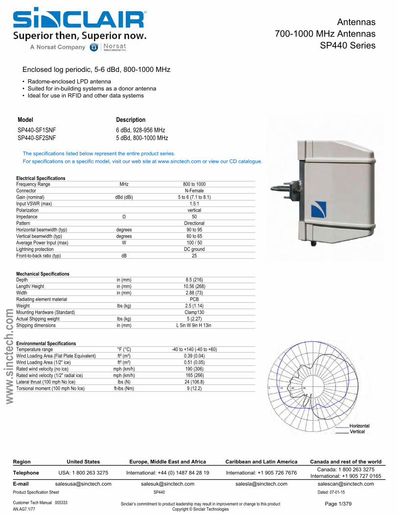
Enclosed log periodic, 5-6 dBd, 800-1000 MHz• Radome-enclosed LPD antenna• Suited for in-building systems as a donor antenna• Ideal for use in RFID and other data systems
Model DescriptionSP440-SF1SNF 6 dBd, 928-956 MHzSP440-SF2SNF 5 dBd, 800-1000 MHz
The specifications listed below represent the entire product series.For specifications on a specific model, visit our web site at www.sinctech.com or view our CD catalogue.
Electrical SpecificationsFrequency Range MHz 800 to 1000Connector N-FemaleGain (nominal) dBd (dBi) 5 to 6 (7.1 to 8.1)Input VSWR (max) 1.5:1Polarization verticalImpedance Ω 50Pattern DirectionalHorizontal beamwidth (typ) degrees 90 to 95Vertical beamwidth (typ) degrees 60 to 65Average Power Input (max) W 100 / 50Lightning protection DC groundFront-to-back ratio (typ) dB 25
Mechanical SpecificationsDepth in (mm) 8.5 (216)Length/ Height in (mm) 10.56 (268)Width in (mm) 2.88 (73)Radiating element material PCBWeight lbs (kg) 2.5 (1.14)Mounting Hardware (Standard) Clamp130Actual Shipping weight lbs (kg) 5 (2.27)Shipping dimensions in (mm) L 5in W 9in H 13in
Environmental SpecificationsTemperature range °F (°C) -40 to +140 (-40 to +60)Wind Loading Area (Flat Plate Equivalent) ft² (m²) 0.39 (0.04)Wind Loading Area (1/2" ice) ft² (m²) 0.51 (0.05)Rated wind velocity (no ice) mph (km/h) 190 (306)Rated wind velocity (1/2" radial ice) mph (km/h)Lateral thrust (100 mph No Ice) lbs (N) 24 (106.8)Torsional moment (100 mph No Ice) ft-lbs (Nm) 9 (12.2)
Region United States Europe, Middle East and Africa Caribbean and Latin America Canada and rest of the world
Telephone USA: 1 800 263 3275 International: +44 (0) 1487 84 28 19 International: +1 905 726 7676 Canada: 1 800 263 3275International: +1 905 727 0165
E-mail [email protected] [email protected] [email protected] [email protected] Specification Sheet SP440 Dated: 07-01-15
Customer Tech Manual 005333 Sinclair’s commitment to product leadership may result in improvement or change to this productCopyright © Sinclair TechnologiesAN.AG7.1/77
www.
sinct
ech.
com
165 (266)
Page 1/379
Antennas700-1000 MHz Antennas
SP4402 Series
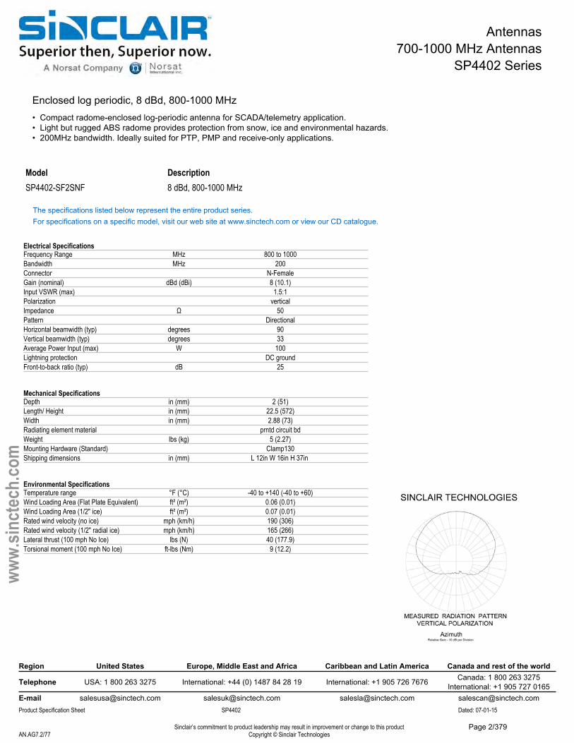
Enclosed log periodic, 8 dBd, 800-1000 MHz• Compact radome-enclosed log-periodic antenna for SCADA/telemetry application.• Light but rugged ABS radome provides protection from snow, ice and environmental hazards.• 200MHz bandwidth. Ideally suited for PTP, PMP and receive-only applications.
Model DescriptionSP4402-SF2SNF 8 dBd, 800-1000 MHz
The specifications listed below represent the entire product series.For specifications on a specific model, visit our web site at www.sinctech.com or view our CD catalogue.
Electrical SpecificationsFrequency Range MHz 800 to 1000Bandwidth MHz 200Connector N-FemaleGain (nominal) dBd (dBi) 8 (10.1)Input VSWR (max) 1.5:1Polarization verticalImpedance Ω 50Pattern DirectionalHorizontal beamwidth (typ) degrees 90Vertical beamwidth (typ) degrees 33Average Power Input (max) W 100Lightning protection DC groundFront-to-back ratio (typ) dB 25
Mechanical SpecificationsDepth in (mm) 2 (51)Length/ Height in (mm) 22.5 (572)Width in (mm) 2.88 (73)Radiating element material prntd circuit bdWeight lbs (kg) 5 (2.27)Mounting Hardware (Standard) Clamp130Shipping dimensions in (mm) L 12in W 16in H 37in
Environmental SpecificationsTemperature range °F (°C) -40 to +140 (-40 to +60)Wind Loading Area (Flat Plate Equivalent) ft² (m²) 0.06 (0.01)Wind Loading Area (1/2" ice) ft² (m²) 0.07 (0.01)Rated wind velocity (no ice) mph (km/h) 190 (306)Rated wind velocity (1/2" radial ice) mph (km/h) 165 (266)Lateral thrust (100 mph No Ice) lbs (N) 40 (177.9)Torsional moment (100 mph No Ice) ft-lbs (Nm) 9 (12.2)
Region United States Europe, Middle East and Africa Caribbean and Latin America Canada and rest of the world
Telephone USA: 1 800 263 3275 International: +44 (0) 1487 84 28 19 International: +1 905 726 7676 Canada: 1 800 263 3275International: +1 905 727 0165
E-mail [email protected] [email protected] [email protected] [email protected] Specification Sheet SP4402 Dated: 07-01-15
Sinclair’s commitment to product leadership may result in improvement or change to this productCopyright © Sinclair TechnologiesAN.AG7.2/77
www.
sinct
ech.
com
Page 2/379
Antennas700-1000 MHz Antennas
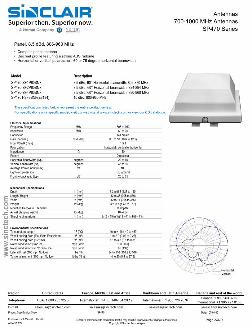
SP470 Series
Panel, 8.5 dBd, 806-960 MHz• Compact panel antenna• Discreet profile featuring a strong ABS radome• Horizontal or vertical polarization, 60 or 75 degree horizontal beamwidth
ModelSP470-SF1P60SNFSP470-SF2P60SNFSP470-SF4P60SNFSP4701-SF3SNF(E8134)
Description8.5 dBd, 60° Horizontal beamwidth, 806-870 MHz 8.5 dBd, 60° Horizontal beamwidth, 824-894 MHz 8.5 dBd, 60° Horizontal beamwidth, 890-960 MHz 10 dBd, 900-960 MHz
The specifications listed below represent the entire product series.For specifications on a specific model, visit our web site at www.sinctech.com or view our CD catalogue.
Electrical SpecificationsFrequency Range MHz 806 to 960Bandwidth MHz 60 to 70Connector N-FemaleGain (nominal) dBd (dBi) 8.5 to 10 (10.6 to 12.1)Input VSWR (max) 1.5:1Polarization horizontal / vertical or horizontalImpedance Ω 50Pattern DirectionalHorizontal beamwidth (typ) degrees 20 to 60Vertical beamwidth (typ) degrees 45 to 95Average Power Input (max) W 100Lightning protection DC groundFront-to-back ratio (typ) dB 20 to 25
Mechanical SpecificationsDepth in (mm) 5.3 to 5.5 (135 to 140)Length/ Height in (mm) 12 to 35 (305 to 889)Width in (mm) 12 to 14 (305 to 356)Weight lbs (kg) 3.2 to 7 (1.45 to 3.18)Mounting Hardware (Standard) Clamp166Actual Shipping weight lbs (kg) 10 (4.54)Shipping dimensions in (mm) L(12 - 19)in W(13 - 41)in H(6 - 7)in
Environmental SpecificationsTemperature range °F (°C) -40 to +140 (-40 to +60)Wind Loading Area (Flat Plate Equivalent) ft² (m²) 1 to 2.9 (0.09 to 0.27)Wind Loading Area (1/2" ice) ft² (m²) 1.1 to 3.3 (0.1 to 0.31)Rated wind velocity (no ice) mph (km/h) 100 (161)Rated wind velocity (1/2" radial ice) mph (km/h) 85 (137)Lateral thrust (100 mph No Ice) lbs (N) 34 to 116 (151.2 to 516)Torsional moment (100 mph No Ice) ft-lbs (Nm) 4 to 50 (5.4 to 67.5)
Region United States Europe, Middle East and Africa Caribbean and Latin America Canada and rest of the world
Telephone USA: 1 800 263 3275 International: +44 (0) 1487 84 28 19 International: +1 905 726 7676 Canada: 1 800 263 3275International: +1 905 727 0165
E-mail [email protected] [email protected] [email protected] [email protected] Specification Sheet SP470 Dated: 07-01-15
Customer Tech Manual 005076 Sinclair’s commitment to product leadership may result in improvement or change to this productCopyright © Sinclair TechnologiesAN.AG7.3/77
www.
sinct
ech.
com
Page 3/379
Antennas700-1000 MHz Antennas
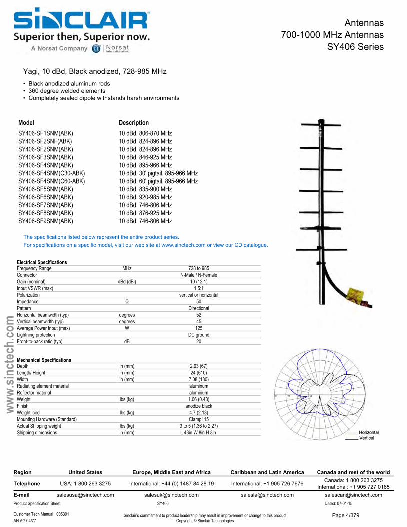
SY406 Series
Yagi, 10 dBd, Black anodized, 728-985 MHz• Black anodized aluminum rods• 360 degree welded elements• Completely sealed dipole withstands harsh environments
Model DescriptionSY406-SF1SNM(ABK) 10 dBd, 806-870 MHzSY406-SF2SNF(ABK) 10 dBd, 824-896 MHzSY406-SF2SNM(ABK) 10 dBd, 824-896 MHzSY406-SF3SNM(ABK) 10 dBd, 846-925 MHzSY406-SF4SNM(ABK) 10 dBd, 895-966 MHzSY406-SF4SNM(C30-ABK) 10 dBd, 30' pigtail, 895-966 MHzSY406-SF4SNM(C60-ABK) 10 dBd, 60' pigtail, 895-966 MHzSY406-SF5SNM(ABK) 10 dBd, 835-900 MHzSY406-SF6SNM(ABK) 10 dBd, 920-985 MHzSY406-SF7SNM(ABK) 10 dBd, 746-806 MHzSY406-SF8SNM(ABK) 10 dBd, 876-925 MHzSY406-SF9SNM(ABK) 10 dBd, 746-806 MHz
The specifications listed below represent the entire product series.For specifications on a specific model, visit our web site at www.sinctech.com or view our CD catalogue.
Electrical SpecificationsFrequency Range MHz 728 to 985Connector N-Male / N-FemaleGain (nominal) dBd (dBi) 10 (12.1)Input VSWR (max) 1.5:1Polarization vertical or horizontalImpedance Ω 50Pattern DirectionalHorizontal beamwidth (typ) degrees 52Vertical beamwidth (typ) degrees 45Average Power Input (max) W 125Lightning protection DC groundFront-to-back ratio (typ) dB 20
Mechanical SpecificationsDepth in (mm) 2.63 (67)Length/ Height in (mm) 24 (610)Width in (mm) 7.08 (180)Radiating element material aluminumReflector material aluminumWeight lbs (kg) 1.06 (0.48)Finish anodize blackWeight iced lbs (kg) 4.7 (2.13)Mounting Hardware (Standard) Clamp115Actual Shipping weight lbs (kg) 3 to 5 (1.36 to 2.27)Shipping dimensions in (mm) L 43in W 8in H 3in
Region United States Europe, Middle East and Africa Caribbean and Latin America Canada and rest of the world
Telephone USA: 1 800 263 3275 International: +44 (0) 1487 84 28 19 International: +1 905 726 7676 Canada: 1 800 263 3275International: +1 905 727 0165
E-mail [email protected] [email protected] [email protected] [email protected] Specification Sheet SY406 Dated: 07-01-15
Customer Tech Manual 005391 Sinclair’s commitment to product leadership may result in improvement or change to this productCopyright © Sinclair TechnologiesAN.AG7.4/77
www.
sinct
ech.
com
Page 4/379
Antennas700-1000 MHz Antennas
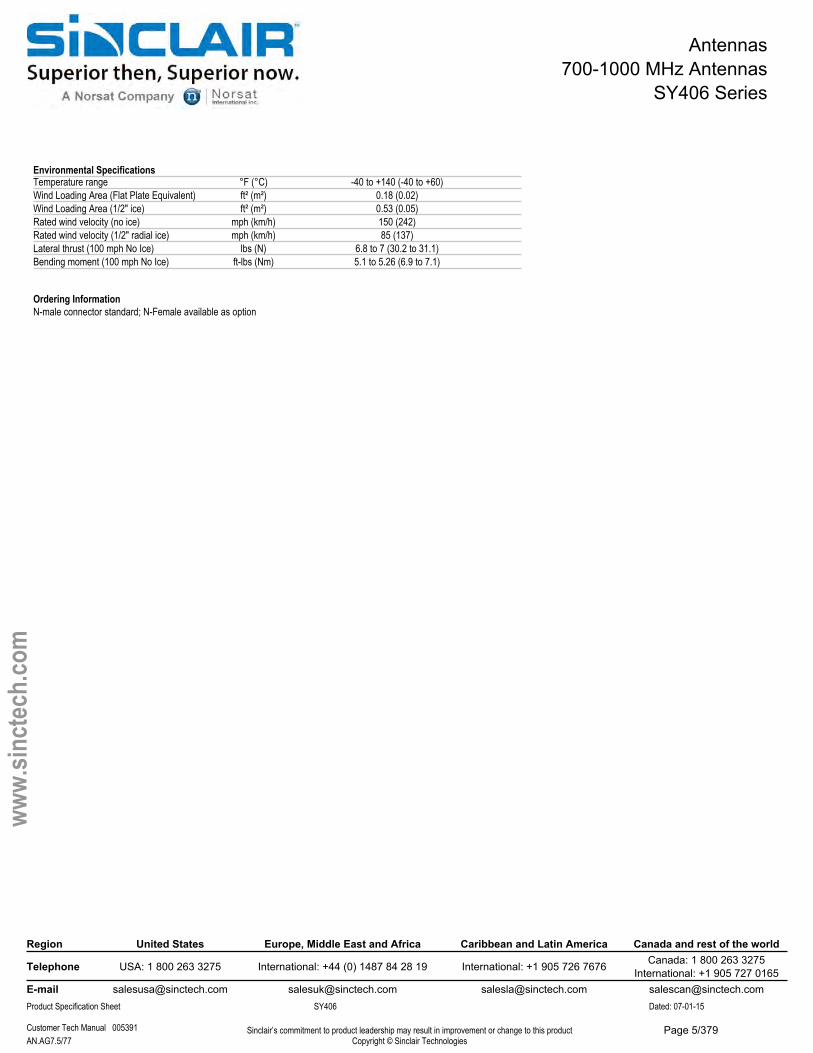
SY406 Series
Environmental SpecificationsTemperature range °F (°C) -40 to +140 (-40 to +60)Wind Loading Area (Flat Plate Equivalent) ft² (m²) 0.18 (0.02)Wind Loading Area (1/2" ice) ft² (m²) 0.53 (0.05)Rated wind velocity (no ice) mph (km/h) 150 (242)Rated wind velocity (1/2" radial ice) mph (km/h) 85 (137)Lateral thrust (100 mph No Ice) lbs (N) 6.8 to 7 (30.2 to 31.1)Bending moment (100 mph No Ice) ft-lbs (Nm) 5.1 to 5.26 (6.9 to 7.1)
Ordering InformationN-male connector standard; N-Female available as option
Region United States Europe, Middle East and Africa Caribbean and Latin America Canada and rest of the world
Telephone USA: 1 800 263 3275 International: +44 (0) 1487 84 28 19 International: +1 905 726 7676 Canada: 1 800 263 3275International: +1 905 727 0165
E-mail [email protected] [email protected] [email protected] [email protected] Specification Sheet SY406 Dated: 07-01-15
Customer Tech Manual 005391 Sinclair’s commitment to product leadership may result in improvement or change to this productCopyright © Sinclair TechnologiesAN.AG7.5/77
www.
sinct
ech.
com
Page 5/379
Antennas700-1000 MHz Antennas
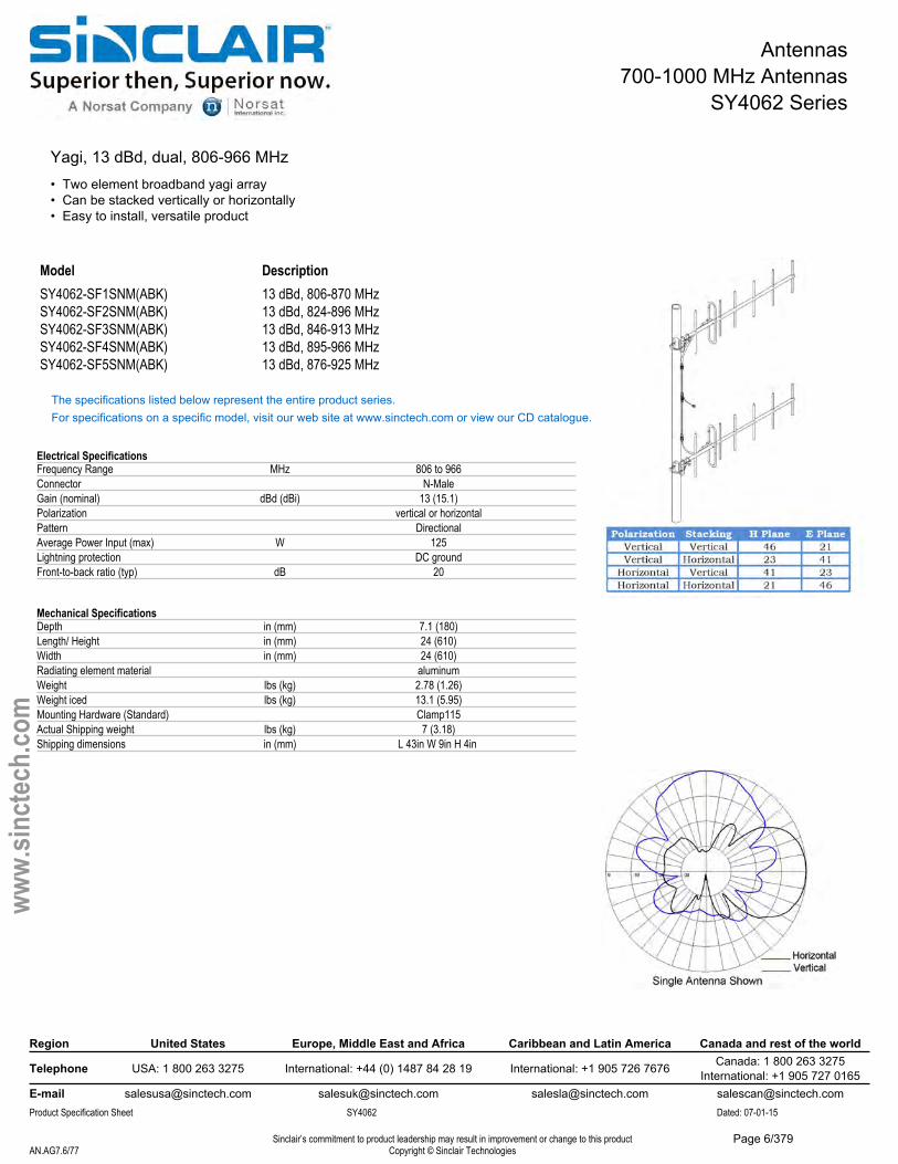
SY4062 Series
Yagi, 13 dBd, dual, 806-966 MHz• Two element broadband yagi array• Can be stacked vertically or horizontally• Easy to install, versatile product
Model DescriptionSY4062-SF1SNM(ABK) 13 dBd, 806-870 MHzSY4062-SF2SNM(ABK) 13 dBd, 824-896 MHzSY4062-SF3SNM(ABK) 13 dBd, 846-913 MHzSY4062-SF4SNM(ABK) 13 dBd, 895-966 MHzSY4062-SF5SNM(ABK) 13 dBd, 876-925 MHz
The specifications listed below represent the entire product series.For specifications on a specific model, visit our web site at www.sinctech.com or view our CD catalogue.
Electrical SpecificationsFrequency Range MHz 806 to 966Connector N-MaleGain (nominal) dBd (dBi) 13 (15.1)Polarization vertical or horizontalPattern DirectionalAverage Power Input (max) W 125Lightning protection DC groundFront-to-back ratio (typ) dB 20
Mechanical SpecificationsDepth in (mm) 7.1 (180)Length/ Height in (mm) 24 (610)Width in (mm) 24 (610)Radiating element material aluminumWeight lbs (kg) 2.78 (1.26)Weight iced lbs (kg) 13.1 (5.95)Mounting Hardware (Standard) Clamp115Actual Shipping weight lbs (kg) 7 (3.18)Shipping dimensions in (mm) L 43in W 9in H 4in
Region United States Europe, Middle East and Africa Caribbean and Latin America Canada and rest of the world
Telephone USA: 1 800 263 3275 International: +44 (0) 1487 84 28 19 International: +1 905 726 7676 Canada: 1 800 263 3275International: +1 905 727 0165
E-mail [email protected] [email protected] [email protected] [email protected] Specification Sheet SY4062 Dated: 07-01-15
Sinclair’s commitment to product leadership may result in improvement or change to this productCopyright © Sinclair TechnologiesAN.AG7.6/77
www.
sinct
ech.
com
Page 6/379
Antennas700-1000 MHz Antennas
SY4062 Series
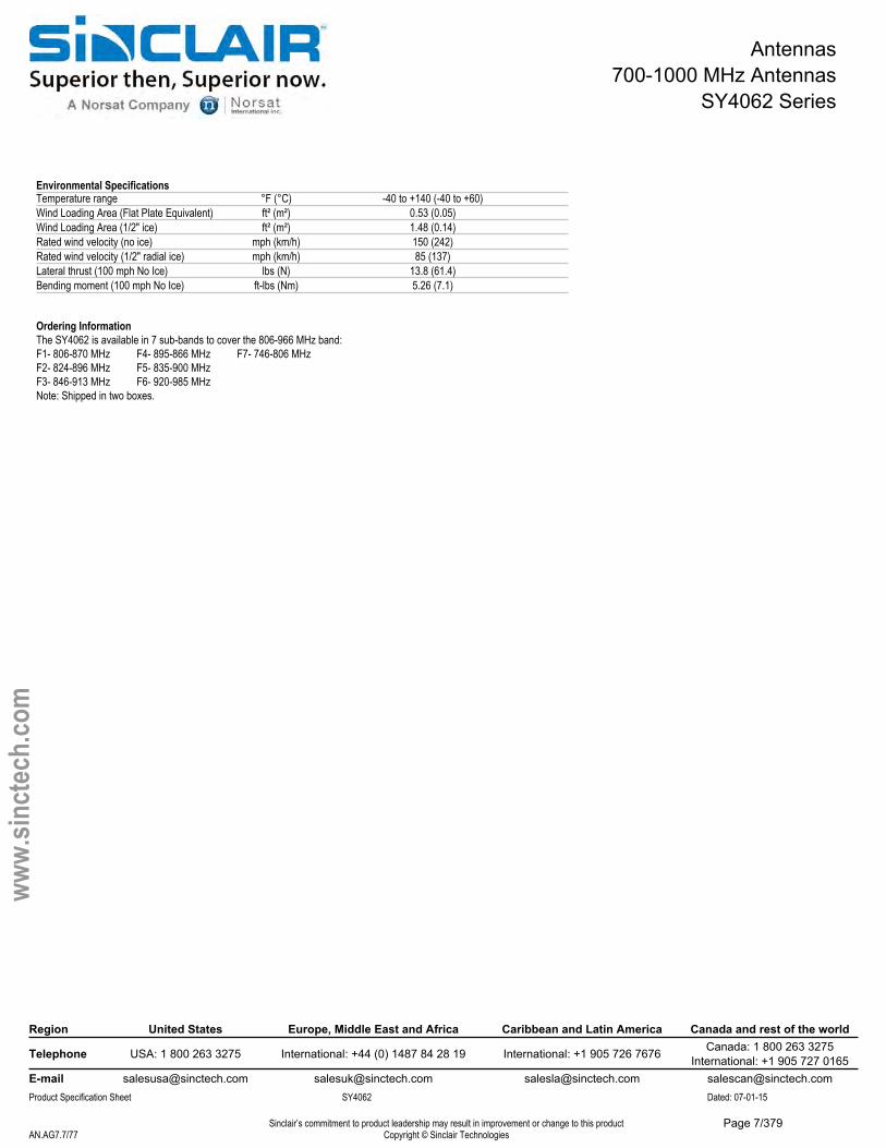
Environmental SpecificationsTemperature range °F (°C) -40 to +140 (-40 to +60)Wind Loading Area (Flat Plate Equivalent) ft² (m²) 0.53 (0.05)Wind Loading Area (1/2" ice) ft² (m²) 1.48 (0.14)Rated wind velocity (no ice) mph (km/h) 150 (242)Rated wind velocity (1/2" radial ice) mph (km/h) 85 (137)Lateral thrust (100 mph No Ice) lbs (N) 13.8 (61.4)Bending moment (100 mph No Ice) ft-lbs (Nm) 5.26 (7.1)
Ordering InformationThe SY4062 is available in 7 sub-bands to cover the 806-966 MHz band:F1- 806-870 MHz F4- 895-866 MHz F7- 746-806 MHzF2- 824-896 MHz F5- 835-900 MHzF3- 846-913 MHz F6- 920-985 MHzNote: Shipped in two boxes.
Region United States Europe, Middle East and Africa Caribbean and Latin America Canada and rest of the world
Telephone USA: 1 800 263 3275 International: +44 (0) 1487 84 28 19 International: +1 905 726 7676 Canada: 1 800 263 3275International: +1 905 727 0165
E-mail [email protected] [email protected] [email protected] [email protected] Specification Sheet SY4062 Dated: 07-01-15
Sinclair’s commitment to product leadership may result in improvement or change to this productCopyright © Sinclair TechnologiesAN.AG7.7/77
www.
sinct
ech.
com
Page 7/379
Antennas700-1000 MHz Antennas
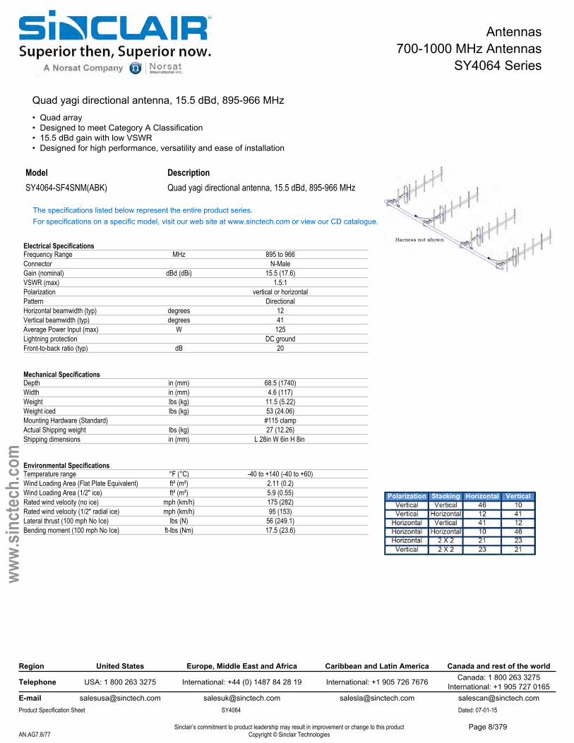
SY4064 Series
Quad yagi directional antenna, 15.5 dBd, 895-966 MHz• Quad array• Designed to meet Category A Classification• 15.5 dBd gain with low VSWR• Designed for high performance, versatility and ease of installation
Model DescriptionSY4064-SF4SNM(ABK) Quad yagi directional antenna, 15.5 dBd, 895-966 MHz
The specifications listed below represent the entire product series.For specifications on a specific model, visit our web site at www.sinctech.com or view our CD catalogue.
Electrical SpecificationsFrequency Range MHz 895 to 966Connector N-MaleGain (nominal) dBd (dBi) 15.5 (17.6)VSWR (max) 1.5:1Polarization vertical or horizontalPattern DirectionalHorizontal beamwidth (typ) degrees 12Vertical beamwidth (typ) degrees 41Average Power Input (max) W 125Lightning protection DC groundFront-to-back ratio (typ) dB 20
Mechanical SpecificationsDepth in (mm) 68.5 (1740)Width in (mm) 4.6 (117)Weight lbs (kg) 11.5 (5.22)Weight iced lbs (kg) 53 (24.06)Mounting Hardware (Standard) #115 clampActual Shipping weight lbs (kg) 27 (12.26)Shipping dimensions in (mm) L 28in W 6in H 8in
Environmental SpecificationsTemperature range °F (°C) -40 to +140 (-40 to +60)Wind Loading Area (Flat Plate Equivalent) ft² (m²) 2.11 (0.2)Wind Loading Area (1/2" ice) ft² (m²) 5.9 (0.55)Rated wind velocity (no ice) mph (km/h) 175 (282)Rated wind velocity (1/2" radial ice) mph (km/h) 95 (153)Lateral thrust (100 mph No Ice) lbs (N) 56 (249.1)Bending moment (100 mph No Ice) ft-lbs (Nm) 17.5 (23.6)
Region United States Europe, Middle East and Africa Caribbean and Latin America Canada and rest of the world
Telephone USA: 1 800 263 3275 International: +44 (0) 1487 84 28 19 International: +1 905 726 7676 Canada: 1 800 263 3275International: +1 905 727 0165
E-mail [email protected] [email protected] [email protected] [email protected] Specification Sheet SY4064 Dated: 07-01-15
Sinclair’s commitment to product leadership may result in improvement or change to this productCopyright © Sinclair TechnologiesAN.AG7.8/77
www.
sinct
ech.
com
Page 8/379
Antennas700-1000 MHz Antennas
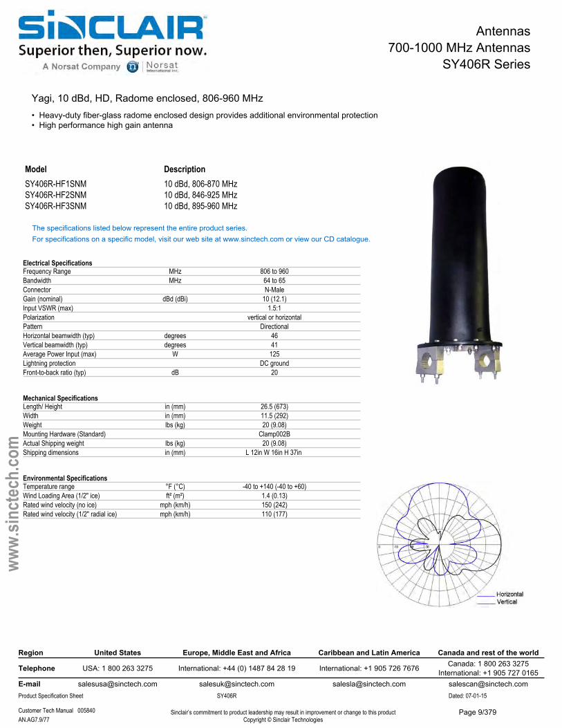
SY406R Series
Yagi, 10 dBd, HD, Radome enclosed, 806-960 MHz• Heavy-duty fiber-glass radome enclosed design provides additional environmental protection• High performance high gain antenna
Model DescriptionSY406R-HF1SNM 10 dBd, 806-870 MHzSY406R-HF2SNM 10 dBd, 846-925 MHzSY406R-HF3SNM 10 dBd, 895-960 MHz
The specifications listed below represent the entire product series.For specifications on a specific model, visit our web site at www.sinctech.com or view our CD catalogue.
Electrical SpecificationsFrequency Range MHz 806 to 960Bandwidth MHz 64 to 65Connector N-MaleGain (nominal) dBd (dBi) 10 (12.1)Input VSWR (max) 1.5:1Polarization vertical or horizontalPattern DirectionalHorizontal beamwidth (typ) degrees 46Vertical beamwidth (typ) degrees 41Average Power Input (max) W 125Lightning protection DC groundFront-to-back ratio (typ) dB 20
Mechanical SpecificationsLength/ Height in (mm) 26.5 (673)Width in (mm) 11.5 (292)Weight lbs (kg) 20 (9.08)Mounting Hardware (Standard) Clamp002BActual Shipping weight lbs (kg) 20 (9.08)Shipping dimensions in (mm) L 12in W 16in H 37in
Environmental SpecificationsTemperature range °F (°C) -40 to +140 (-40 to +60)Wind Loading Area (1/2" ice) ft² (m²) 1.4 (0.13)Rated wind velocity (no ice) mph (km/h) 150 (242)Rated wind velocity (1/2" radial ice) mph (km/h) 110 (177)
Region United States Europe, Middle East and Africa Caribbean and Latin America Canada and rest of the world
Telephone USA: 1 800 263 3275 International: +44 (0) 1487 84 28 19 International: +1 905 726 7676 Canada: 1 800 263 3275International: +1 905 727 0165
E-mail [email protected] [email protected] [email protected] [email protected] Specification Sheet SY406R Dated: 07-01-15
Customer Tech Manual 005840 Sinclair’s commitment to product leadership may result in improvement or change to this productCopyright © Sinclair TechnologiesAN.AG7.9/77
www.
sinct
ech.
com
Page 9/379
Antennas700-1000 MHz Antennas
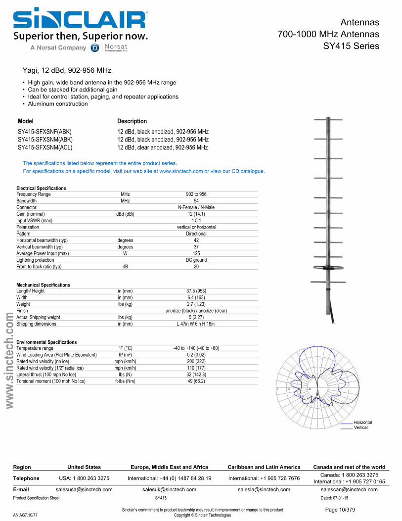
SY415 Series
Yagi, 12 dBd, 902-956 MHz• High gain, wide band antenna in the 902-956 MHz range• Can be stacked for additional gain• Ideal for control station, paging, and repeater applications• Aluminum construction
Model DescriptionSY415-SFXSNF(ABK) 12 dBd, black anodized, 902-956 MHzSY415-SFXSNM(ABK) 12 dBd, black anodized, 902-956 MHzSY415-SFXSNM(ACL) 12 dBd, clear anodized, 902-956 MHz
The specifications listed below represent the entire product series.For specifications on a specific model, visit our web site at www.sinctech.com or view our CD catalogue.
Electrical SpecificationsFrequency Range MHz 902 to 956Bandwidth MHz 54Connector N-Female / N-MaleGain (nominal) dBd (dBi) 12 (14.1)Input VSWR (max) 1.5:1Polarization vertical or horizontalPattern DirectionalHorizontal beamwidth (typ) degrees 42Vertical beamwidth (typ) degrees 37Average Power Input (max) W 125Lightning protection DC groundFront-to-back ratio (typ) dB 20
Mechanical SpecificationsLength/ Height in (mm) 37.5 (953)Width in (mm) 6.4 (163)Weight lbs (kg) 2.7 (1.23)Finish anodize (black) / anodize (clear)Actual Shipping weight lbs (kg) 5 (2.27)Shipping dimensions in (mm) L 47in W 6in H 18in
Environmental SpecificationsTemperature range °F (°C) -40 to +140 (-40 to +60)Wind Loading Area (Flat Plate Equivalent) ft² (m²) 0.2 (0.02)Rated wind velocity (no ice) mph (km/h) 200 (322)Rated wind velocity (1/2" radial ice) mph (km/h) 110 (177)Lateral thrust (100 mph No Ice) lbs (N) 32 (142.3)Torsional moment (100 mph No Ice) ft-lbs (Nm) 49 (66.2)
Region United States Europe, Middle East and Africa Caribbean and Latin America Canada and rest of the world
Telephone USA: 1 800 263 3275 International: +44 (0) 1487 84 28 19 International: +1 905 726 7676 Canada: 1 800 263 3275International: +1 905 727 0165
E-mail [email protected] [email protected] [email protected] [email protected] Specification Sheet SY415 Dated: 07-01-15
Sinclair’s commitment to product leadership may result in improvement or change to this productCopyright © Sinclair TechnologiesAN.AG7.10/77
www.
sinct
ech.
com
Page 10/379
Antennas700-1000 MHz Antennas
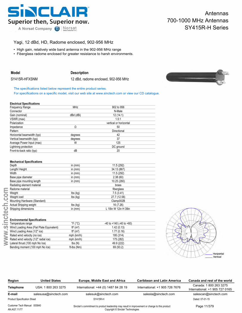
SY415R-H Series
Yagi, 12 dBd, HD, Radome enclosed, 902-956 MHz• High gain, relatively wide band antenna in the 902-956 MHz range• Fiberglass radome enclosed for greater resistance to harsh environments.
Model DescriptionSY415R-HFXSNM 12 dBd, radome enclosed, 902-956 MHz
The specifications listed below represent the entire product series.For specifications on a specific model, visit our web site at www.sinctech.com or view our CD catalogue.
Electrical SpecificationsFrequency Range MHz 902 to 956Connector N-MaleGain (nominal) dBd (dBi) 12 (14.1)VSWR (max) 1.5:1Polarization vertical or horizontalImpedance Ω 50Pattern DirectionalHorizontal beamwidth (typ) degrees 42Vertical beamwidth (typ) degrees 37Average Power Input (max) W 125Lightning protection DC groundFront-to-back ratio (typ) dB 20
Mechanical SpecificationsDepth in (mm) 11.5 (292)Length/ Height in (mm) 34.13 (867)Width in (mm) 11.5 (292)Base pipe diameter in (mm) 2.38 (60)Base pipe mounting length in (mm) 10.25 (260)Radiating element material brassRadome material fiberglassWeight lbs (kg) 7.5 (3.41)Weight iced lbs (kg) 27.7 (12.58)Mounting Hardware (Standard) Clamp002BActual Shipping weight lbs (kg) 16 (7.26)Shipping dimensions in (mm) L 18in W 12in H 39in
Environmental SpecificationsTemperature range °F (°C) -40 to +140 (-40 to +60)Wind Loading Area (Flat Plate Equivalent) ft² (m²) 1.42 (0.13)Wind Loading Area (1/2" ice) ft² (m²) 1.77 (0.16)Rated wind velocity (no ice) mph (km/h) 195 (314)Rated wind velocity (1/2" radial ice) mph (km/h) 175 (282)Lateral thrust (100 mph No Ice) lbs (N) 49.9 (222)Bending moment (100 mph No Ice) ft-lbs (Nm) 69 (93.2)
Region United States Europe, Middle East and Africa Caribbean and Latin America Canada and rest of the world
Telephone USA: 1 800 263 3275 International: +44 (0) 1487 84 28 19 International: +1 905 726 7676 Canada: 1 800 263 3275International: +1 905 727 0165
E-mail [email protected] [email protected] [email protected] [email protected] Specification Sheet SY415R-H Dated: 07-01-15
Customer Tech Manual 005840 Sinclair’s commitment to product leadership may result in improvement or change to this productCopyright © Sinclair TechnologiesAN.AG7.11/77
www.
sinct
ech.
com
Page 11/379
Antennas700-1000 MHz Antennas
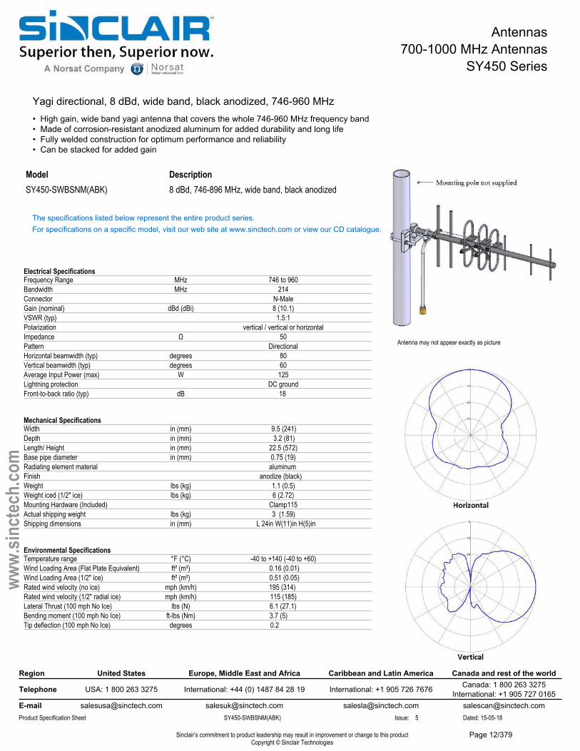
SY450 Series
Yagi directional, 8 dBd, wide band, black anodized, 746-960 MHz• High gain, wide band yagi antenna that covers the whole 746-960 MHz frequency band• Made of corrosion-resistant anodized aluminum for added durability and long life• Fully welded construction for optimum performance and reliability• Can be stacked for added gain
Antenna may not appear exactly as picture
ModelSY450-SWBSNM(ABK)
Description8 dBd, 746-896 MHz, wide band, black anodized
The specifications listed below represent the entire product series.For specifications on a specific model, visit our web site at www.sinctech.com or view our CD catalogue.
Electrical SpecificationsFrequency Range MHz 746 to 960Bandwidth MHz 214Connector N-MaleGain (nominal) dBd (dBi) 8 (10.1)VSWR (typ) 1.5:1Polarization vertical / vertical or horizontalImpedance Ω 50Pattern DirectionalHorizontal beamwidth (typ) degrees 80Vertical beamwidth (typ) degrees 60Average Input Power (max) W 125Lightning protection DC groundFront-to-back ratio (typ) dB 18
Mechanical SpecificationsWidth in (mm) 9.5 (241)Depth in (mm) 3.2 (81)Length/ Height in (mm) 22.5 (572)Base pipe diameter in (mm) 0.75 (19)Radiating element material aluminumFinish anodize (black)Weight lbs (kg) 1.1 (0.5)Weight iced (1/2" ice) lbs (kg) 6 (2.72)Mounting Hardware (Included) Clamp115Actual shipping weight lbs (kg) 3 (1.59)Shipping dimensions in (mm) L 24in W(11)in H(5)in
Environmental SpecificationsTemperature range °F (°C) -40 to +140 (-40 to +60)Wind Loading Area (Flat Plate Equivalent) ft² (m²) 0.16 (0.01)Wind Loading Area (1/2" ice) ft² (m²) 0.51 (0.05)Rated wind velocity (no ice) mph (km/h) 195 (314)Rated wind velocity (1/2" radial ice) mph (km/h) 115 (185)Lateral Thrust (100 mph No Ice) lbs (N) 6.1 (27.1)Bending moment (100 mph No Ice) ft-lbs (Nm) 3.7 (5)Tip deflection (100 mph No Ice) degrees 0.2
Region United States Europe, Middle East and Africa Caribbean and Latin America Canada and rest of the world
Telephone USA: 1 800 263 3275 International: +44 (0) 1487 84 28 19 International: +1 905 726 7676 Canada: 1 800 263 3275International: +1 905 727 0165
E-mail [email protected] [email protected] [email protected] [email protected] Specification Sheet SY450-SWBSNM(ABK) Issue: 5 Dated: 15-05-18
Sinclair’s commitment to product leadership may result in improvement or change to this productCopyright © Sinclair Technologies
www.
sinct
ech.
com
Page 12/379
Antennas700-1000 MHz Antennas
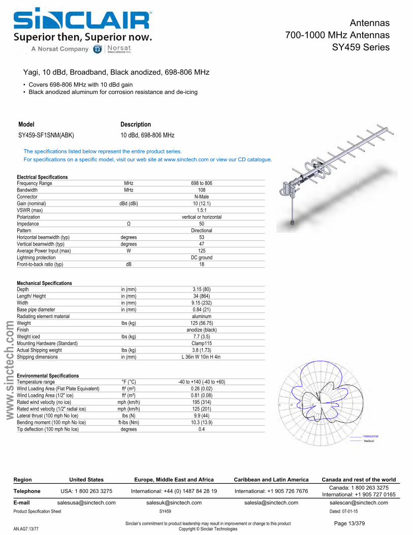
SY459 Series
Yagi, 10 dBd, Broadband, Black anodized, 698-806 MHz• Covers 698-806 MHz with 10 dBd gain• Black anodized aluminum for corrosion resistance and de-icing
Model DescriptionSY459-SF1SNM(ABK) 10 dBd, 698-806 MHz
The specifications listed below represent the entire product series.For specifications on a specific model, visit our web site at www.sinctech.com or view our CD catalogue.
Electrical SpecificationsFrequency Range MHz 698 to 806Bandwidth MHz 108Connector N-MaleGain (nominal) dBd (dBi) 10 (12.1)VSWR (max) 1.5:1Polarization vertical or horizontalImpedance Ω 50Pattern DirectionalHorizontal beamwidth (typ) degrees 53Vertical beamwidth (typ) degrees 47Average Power Input (max) W 125Lightning protection DC groundFront-to-back ratio (typ) dB 18
Mechanical SpecificationsDepth in (mm) 3.15 (80)Length/ Height in (mm) 34 (864)Width in (mm) 9.15 (232)Base pipe diameter in (mm) 0.84 (21)Radiating element material aluminumWeight lbs (kg) 125 (56.75)Finish anodize (black)Weight iced lbs (kg) 7.7 (3.5)Mounting Hardware (Standard) Clamp115Actual Shipping weight lbs (kg) 3.8 (1.73)Shipping dimensions in (mm) L 36in W 10in H 4in
Environmental SpecificationsTemperature range °F (°C) -40 to +140 (-40 to +60)Wind Loading Area (Flat Plate Equivalent) ft² (m²) 0.26 (0.02)Wind Loading Area (1/2" ice) ft² (m²) 0.81 (0.08)Rated wind velocity (no ice) mph (km/h) 195 (314)Rated wind velocity (1/2" radial ice) mph (km/h) 125 (201)Lateral thrust (100 mph No Ice) lbs (N) 9.9 (44)Bending moment (100 mph No Ice) ft-lbs (Nm) 10.3 (13.9)Tip deflection (100 mph No Ice) degrees 0.4
Region United States Europe, Middle East and Africa Caribbean and Latin America Canada and rest of the world
Telephone USA: 1 800 263 3275 International: +44 (0) 1487 84 28 19 International: +1 905 726 7676 Canada: 1 800 263 3275International: +1 905 727 0165
E-mail [email protected] [email protected] [email protected] [email protected] Specification Sheet SY459 Dated: 07-01-15
Sinclair’s commitment to product leadership may result in improvement or change to this productCopyright © Sinclair TechnologiesAN.AG7.13/77
www.
sinct
ech.
com
Page 13/379
Antennas700-1000 MHz Antennas
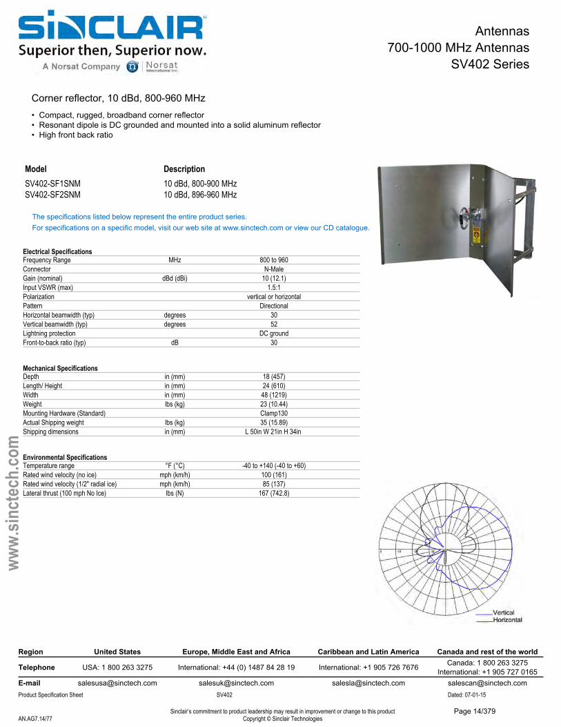
SV402 Series
Corner reflector, 10 dBd, 800-960 MHz• Compact, rugged, broadband corner reflector• Resonant dipole is DC grounded and mounted into a solid aluminum reflector• High front back ratio
Model DescriptionSV402-SF1SNM 10 dBd, 800-900 MHzSV402-SF2SNM 10 dBd, 896-960 MHz
The specifications listed below represent the entire product series.For specifications on a specific model, visit our web site at www.sinctech.com or view our CD catalogue.
Electrical SpecificationsFrequency Range MHz 800 to 960Connector N-MaleGain (nominal) dBd (dBi) 10 (12.1)Input VSWR (max) 1.5:1Polarization vertical or horizontalPattern DirectionalHorizontal beamwidth (typ) degrees 30Vertical beamwidth (typ) degrees 52Lightning protection DC groundFront-to-back ratio (typ) dB 30
Mechanical SpecificationsDepth in (mm) 18 (457)Length/ Height in (mm) 24 (610)Width in (mm) 48 (1219)Weight lbs (kg) 23 (10.44)Mounting Hardware (Standard) Clamp130Actual Shipping weight lbs (kg) 35 (15.89)Shipping dimensions in (mm) L 50in W 21in H 34in
Environmental SpecificationsTemperature range °F (°C) -40 to +140 (-40 to +60)Rated wind velocity (no ice) mph (km/h) 100 (161)Rated wind velocity (1/2" radial ice) mph (km/h) 85 (137)Lateral thrust (100 mph No Ice) lbs (N) 167 (742.8)
Region United States Europe, Middle East and Africa Caribbean and Latin America Canada and rest of the world
Telephone USA: 1 800 263 3275 International: +44 (0) 1487 84 28 19 International: +1 905 726 7676 Canada: 1 800 263 3275International: +1 905 727 0165
E-mail [email protected] [email protected] [email protected] [email protected] Specification Sheet SV402 Dated: 07-01-15
Sinclair’s commitment to product leadership may result in improvement or change to this productCopyright © Sinclair TechnologiesAN.AG7.14/77
www.
sinct
ech.
com
Page 14/379
Antennas700-1000 MHz Antennas
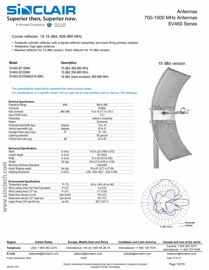
SV460 Series
Corner reflector, 15-16 dBd, 806-960 MHz• Parabolic cylinder reflector with a dipole-reflector assembly and back-firing primary radiator• Wideband, high gain antenna• Meshed reflector for 15 dBd version; Solid reflector for 16 dBd version
Description15 dBd, 806-890 MHz 15 dBd, 890-960 MHz
ModelSV460-SF1SNMSV460-SF2SNMSV460-SF2SNM(G16-ABK) 16 dBd, black anodized, 890-960 MHz
The specifications listed below represent the entire product series.For specifications on a specific model, visit our web site at www.sinctech.com or view our CD catalogue.
Electrical SpecificationsFrequency Range MHz 806 to 960Connector N-MaleGain (nominal) dBd (dBi) 15 to 16 (17.1 to 18.1)Input VSWR (max) 1.5:1Polarization vertical or horizontalPattern DirectionalHorizontal beamwidth (typ) degrees 14 to 16Vertical beamwidth (typ) degrees 30 to 31Average Power Input (max) W 75 / 125Lightning protection DC groundFront-to-back ratio (typ) dB 24 to 25
Mechanical SpecificationsDepth in (mm) 18.3 to 22.5 (465 to 572)Length/ Height in (mm) 56 (1422)Width in (mm) 24 to 25 (610 to 635)Weight lbs (kg) 20 to 27.8 (9.08 to 12.62)Mounting Hardware (Standard) Clamp004Actual Shipping weight lbs (kg) 50 to 61 (22.7 to 27.69)Shipping dimensions in (mm) L(58 - 59)in W(21 - 30)in H 28in
Environmental SpecificationsTemperature range °F (°C) -40 to +140 (-40 to +60)Wind Loading Area (Flat Plate Equivalent) ft² (m²) 5.4 (0.5)Wind Loading Area (1/2" ice) ft² (m²) 5.7 (0.53)Rated wind velocity (no ice) mph (km/h) 100 (161)Rated wind velocity (1/2" radial ice) mph (km/h) 85 (137)Lateral thrust (100 mph No Ice) lbs (N) 297 (1321.1)
Region United States Europe, Middle East and Africa Caribbean and Latin America Canada and rest of the world
Telephone USA: 1 800 263 3275 International: +44 (0) 1487 84 28 19 International: +1 905 726 7676 Canada: 1 800 263 3275International: +1 905 727 0165
E-mail [email protected] [email protected] [email protected] [email protected] Specification Sheet SV460 Dated: 07-01-15
Sinclair’s commitment to product leadership may result in improvement or change to this productCopyright © Sinclair TechnologiesAN.AG7.15/77
www.
sinct
ech.
com
Page 15/379
Antennas700-1000 MHz Antennas
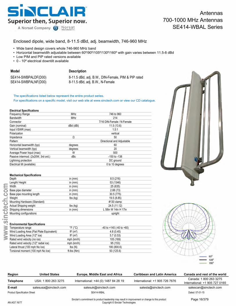
SE414-WBAL Series
Enclosed dipole, wide band, 8-11.5 dBd, adj. beamwidth, 746-960 MHz• Wide band design covers whole 746-960 MHz band• Horizontal beamwidth adjustable between 60º/90º/105º/130º/160º with gain varies between 11.5-8 dBd• Low PIM and PIP rated versions available• 0 - 10º electrical downtilt available
Model DescriptionSE414-SWBPALDF(D00) SE414-SWBPALNF(D00)
8-11.5 dBd, adj. B.W., DIN-Female, PIM & PIP rated8-11.5 dBd, adj. B.W., N-Female
The specifications listed below represent the entire product series.For specifications on a specific model, visit our web site at www.sinctech.com or view our CD catalogue.
Electrical SpecificationsFrequency Range MHz 746 to 960Bandwidth MHz 214Connector 7/16 DIN-Female / N-FemaleGain (nominal) dBd (dBi) 11.5 (13.6)Input VSWR (max) 1.5:1Polarization verticalImpedance Ω 50Pattern Directional and AdjustableHorizontal beamwidth (typ) degrees 60Vertical beamwidth (typ) degrees 20Average Power Input (max) W 500Passive intermod. (2x20W, 3rd ord.) dBc -150 to -138Lightning protection DC groundElectrical tilt (available) 0 to 10 degrees
Mechanical SpecificationsDepth in (mm) 8.5 (216)Length/ Height in (mm) 53 (1346)Width in (mm) 25 (635)Base pipe diameter in (mm) 2.88 (73)Base pipe mounting length in (mm) 30.5 (775)Weight lbs (kg) 19.5 (8.85)Mounting Hardware (Standard) #130 clampActual Shipping weight lbs (kg) 24.5 (11.12)Shipping dimensions in (mm) L 58in W 14in H 17in Mounting configurations upright
Environmental SpecificationsTemperature range °F (°C) -40 to +140 (-40 to +60)Wind Loading Area (Flat Plate Equivalent) ft² (m²) 4.8 (0.45)Wind Loading Area (1/2" ice) ft² (m²) 5.7 (0.53)Rated wind velocity (no ice) mph (km/h) 105 (169)Rated wind velocity (1/2" radial ice) mph (km/h) 95 (153)Lateral thrust (100 mph No Ice) lbs (N) 180 (800.6)Torsional moment (100 mph No Ice) ft-lbs (Nm) 93 (125.6)
Region United States Europe, Middle East and Africa Caribbean and Latin America Canada and rest of the world
Telephone USA: 1 800 263 3275 International: +44 (0) 1487 84 28 19 International: +1 905 726 7676 Canada: 1 800 263 3275International: +1 905 727 0165
E-mail [email protected] [email protected] [email protected] [email protected] Specification Sheet SE414-WBAL Dated: 07-01-15
Sinclair’s commitment to product leadership may result in improvement or change to this productCopyright © Sinclair TechnologiesAN.AG7.16/77
www.
sinct
ech.
com
Page 16/379
Antennas700-1000 MHz Antennas
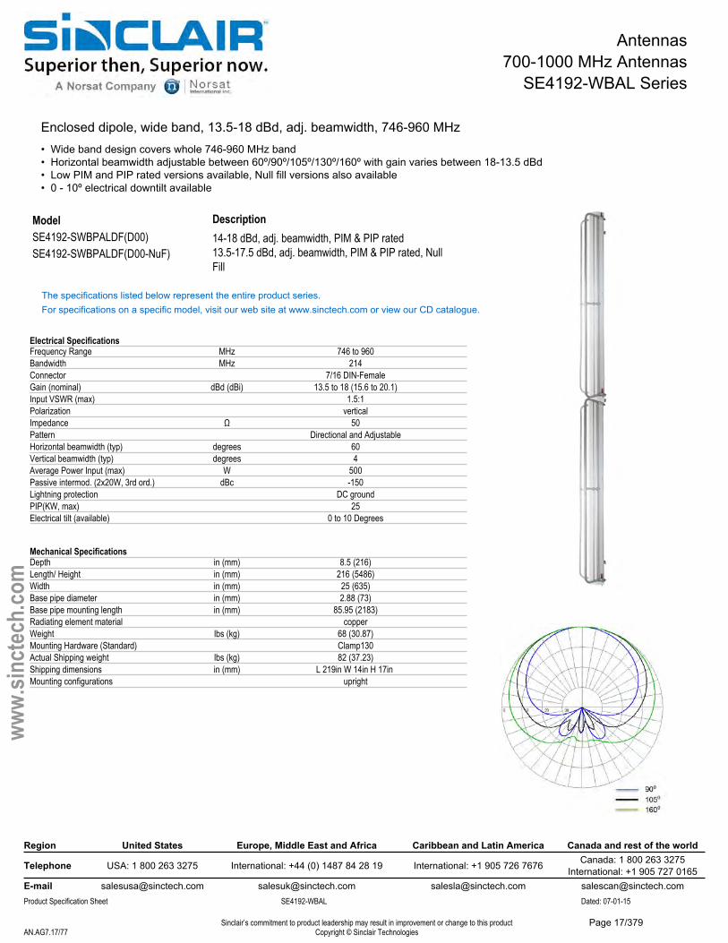
SE4192-WBAL Series
Enclosed dipole, wide band, 13.5-18 dBd, adj. beamwidth, 746-960 MHz• Wide band design covers whole 746-960 MHz band• Horizontal beamwidth adjustable between 60º/90º/105º/130º/160º with gain varies between 18-13.5 dBd• Low PIM and PIP rated versions available, Null fill versions also available• 0 - 10º electrical downtilt available
Description14-18 dBd, adj. beamwidth, PIM & PIP rated
ModelSE4192-SWBPALDF(D00) SE4192-SWBPALDF(D00-NuF) 13.5-17.5 dBd, adj. beamwidth, PIM & PIP rated, Null
Fill
The specifications listed below represent the entire product series.For specifications on a specific model, visit our web site at www.sinctech.com or view our CD catalogue.
Electrical SpecificationsFrequency Range MHz 746 to 960Bandwidth MHz 214Connector 7/16 DIN-FemaleGain (nominal) dBd (dBi) 13.5 to 18 (15.6 to 20.1)Input VSWR (max) 1.5:1Polarization verticalImpedance Ω 50Pattern Directional and AdjustableHorizontal beamwidth (typ) degrees 60Vertical beamwidth (typ) degrees 4Average Power Input (max) W 500Passive intermod. (2x20W, 3rd ord.) dBc -150Lightning protection DC groundPIP(KW, max) 25Electrical tilt (available) 0 to 10 Degrees
Mechanical SpecificationsDepth in (mm) 8.5 (216)Length/ Height in (mm) 216 (5486)Width in (mm) 25 (635)Base pipe diameter in (mm) 2.88 (73)Base pipe mounting length in (mm) 85.95 (2183)Radiating element material copperWeight lbs (kg) 68 (30.87)Mounting Hardware (Standard) Clamp130Actual Shipping weight lbs (kg) 82 (37.23)Shipping dimensions in (mm) L 219in W 14in H 17in Mounting configurations upright
Region United States Europe, Middle East and Africa Caribbean and Latin America Canada and rest of the world
Telephone USA: 1 800 263 3275 International: +44 (0) 1487 84 28 19 International: +1 905 726 7676 Canada: 1 800 263 3275International: +1 905 727 0165
E-mail [email protected] [email protected] [email protected] [email protected] Specification Sheet SE4192-WBAL Dated: 07-01-15
Sinclair’s commitment to product leadership may result in improvement or change to this productCopyright © Sinclair TechnologiesAN.AG7.17/77
www.
sinct
ech.
com
Page 17/379

Antennas700-1000 MHz Antennas
SE4192-WBAL Series
Environmental SpecificationsTemperature range °F (°C) -40 to +140 (-40 to +60)Wind Loading Area (Flat Plate Equivalent) ft² (m²) 9.81 (0.91)Wind Loading Area (1/2" ice) ft² (m²) 11.77 (1.09)Rated wind velocity (no ice) mph (km/h) 100 (161)Rated wind velocity (1/2" radial ice) mph (km/h) 85 (137)Lateral thrust (100 mph No Ice) lbs (N) 438 (1948.2)Torsional moment (100 mph No Ice) ft-lbs (Nm) 188 (253.8)
Ordering InformationN-type connectors are available (with degraded PIM rating).
Region United States Europe, Middle East and Africa Caribbean and Latin America Canada and rest of the world
Telephone USA: 1 800 263 3275 International: +44 (0) 1487 84 28 19 International: +1 905 726 7676 Canada: 1 800 263 3275International: +1 905 727 0165
E-mail [email protected] [email protected] [email protected] [email protected] Specification Sheet SE4192-WBAL Dated: 07-01-15
Sinclair’s commitment to product leadership may result in improvement or change to this productCopyright © Sinclair TechnologiesAN.AG7.18/77
www.
sinct
ech.
com
Page 18/379
Antennas700-1000 MHz Antennas
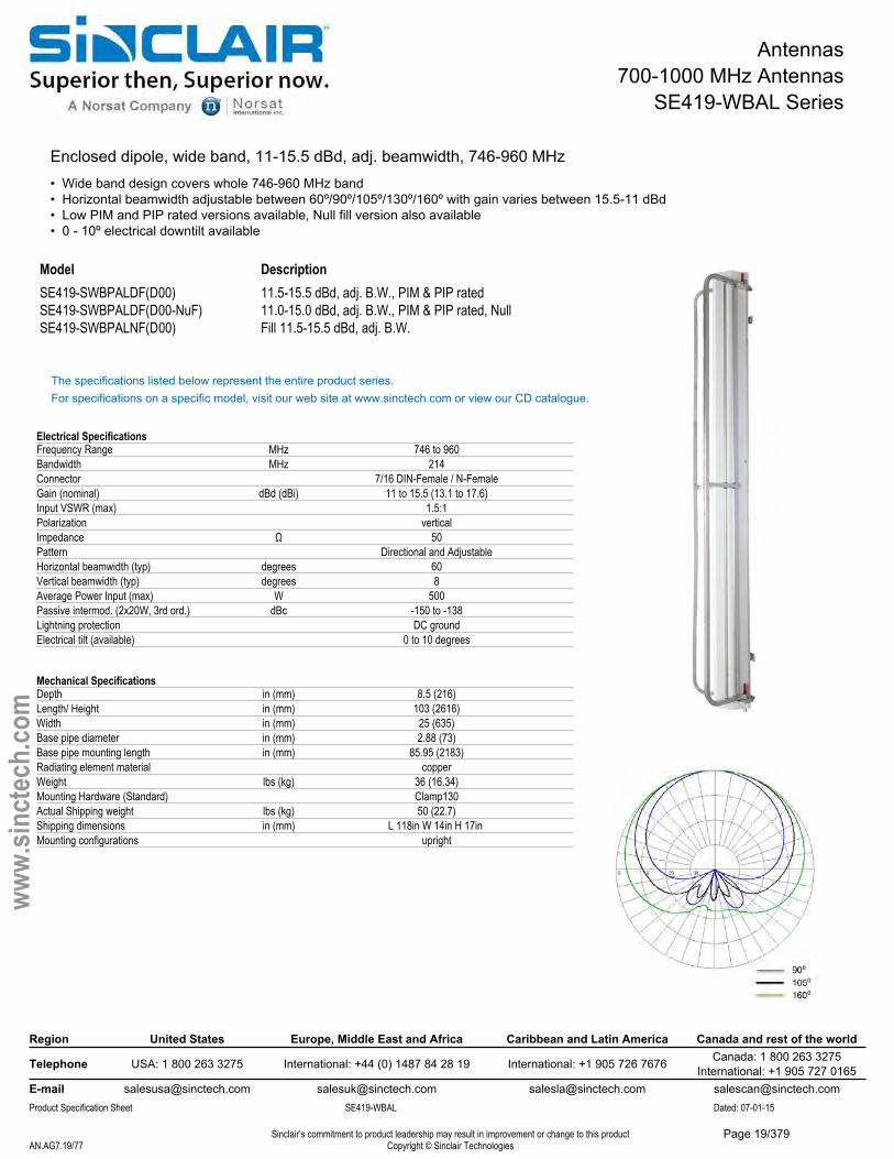
SE419-WBAL Series
Enclosed dipole, wide band, 11-15.5 dBd, adj. beamwidth, 746-960 MHz• Wide band design covers whole 746-960 MHz band• Horizontal beamwidth adjustable between 60º/90º/105º/130º/160º with gain varies between 15.5-11 dBd• Low PIM and PIP rated versions available, Null fill version also available• 0 - 10º electrical downtilt available
ModelSE419-SWBPALDF(D00) SE419-SWBPALDF(D00-NuF) SE419-SWBPALNF(D00)
Description11.5-15.5 dBd, adj. B.W., PIM & PIP rated11.0-15.0 dBd, adj. B.W., PIM & PIP rated, Null Fill 11.5-15.5 dBd, adj. B.W.
The specifications listed below represent the entire product series.For specifications on a specific model, visit our web site at www.sinctech.com or view our CD catalogue.
Electrical SpecificationsFrequency Range MHz 746 to 960Bandwidth MHz 214Connector 7/16 DIN-Female / N-FemaleGain (nominal) dBd (dBi) 11 to 15.5 (13.1 to 17.6)Input VSWR (max) 1.5:1Polarization verticalImpedance Ω 50Pattern Directional and AdjustableHorizontal beamwidth (typ) degrees 60Vertical beamwidth (typ) degrees 8Average Power Input (max) W 500Passive intermod. (2x20W, 3rd ord.) dBc -150 to -138Lightning protection DC groundElectrical tilt (available) 0 to 10 degrees
Mechanical SpecificationsDepth in (mm) 8.5 (216)Length/ Height in (mm) 103 (2616)Width in (mm) 25 (635)Base pipe diameter in (mm) 2.88 (73)Base pipe mounting length in (mm) 85.95 (2183)Radiating element material copperWeight lbs (kg) 36 (16.34)Mounting Hardware (Standard) Clamp130Actual Shipping weight lbs (kg) 50 (22.7)Shipping dimensions in (mm) L 118in W 14in H 17in Mounting configurations upright
Region United States Europe, Middle East and Africa Caribbean and Latin America Canada and rest of the world
Telephone USA: 1 800 263 3275 International: +44 (0) 1487 84 28 19 International: +1 905 726 7676 Canada: 1 800 263 3275International: +1 905 727 0165
E-mail [email protected] [email protected] [email protected] [email protected] Specification Sheet SE419-WBAL Dated: 07-01-15
Sinclair’s commitment to product leadership may result in improvement or change to this productCopyright © Sinclair TechnologiesAN.AG7.19/77
www.
sinct
ech.
com
Page 19/379

Antennas700-1000 MHz Antennas
SE419-WBAL Series
Environmental SpecificationsTemperature range °F (°C) -40 to +140 (-40 to +60)Wind Loading Area (Flat Plate Equivalent) ft² (m²) 7.93 (0.74)Wind Loading Area (1/2" ice) ft² (m²) 11.1 (1.03)Rated wind velocity (no ice) mph (km/h) 100 (161)Rated wind velocity (1/2" radial ice) mph (km/h) 85 (137)Lateral thrust (100 mph No Ice) lbs (N) 265 (1178.7)Torsional moment (100 mph No Ice) ft-lbs (Nm) 141 (190.4)
Ordering InformationN-type connectors are available (with degraded PIM rating).
Region United States Europe, Middle East and Africa Caribbean and Latin America Canada and rest of the world
Telephone USA: 1 800 263 3275 International: +44 (0) 1487 84 28 19 International: +1 905 726 7676 Canada: 1 800 263 3275International: +1 905 727 0165
E-mail [email protected] [email protected] [email protected] [email protected] Specification Sheet SE419-WBAL Dated: 07-01-15
Sinclair’s commitment to product leadership may result in improvement or change to this productCopyright © Sinclair TechnologiesAN.AG7.20/77
www.
sinct
ech.
com
Page 20/379
Antennas700-1000 MHz Antennas
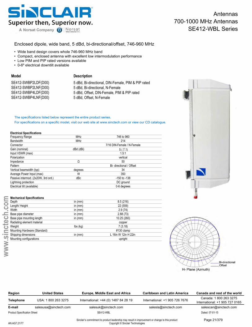
SE412-WBL Series
Enclosed dipole, wide band, 5 dBd, bi-directional/offset, 746-960 MHz• Wide band design covers whole 746-960 MHz band• Compact, enclosed antenna with excellent low intermodulation performance• Low PIM and PIP rated versions available• 0-6º electrical downtilt available
ModelSE412-SWBP2LDF(D00) SE412-SWBP2LNF(D00) SE412-SWBP4LDF(D00) SE412-SWBP4LNF(D00)
Description5 dBd, Bi-directional, DIN-Female, PIM & PIP rated 5 dBd, Bi-directional, N-Female5 dBd, Offset, DIN-Female, PIM & PIP rated5 dBd, Offset, N-Female
The specifications listed below represent the entire product series.For specifications on a specific model, visit our web site at www.sinctech.com or view our CD catalogue.
Electrical SpecificationsFrequency Range MHz 746 to 960Bandwidth MHz 214Connector 7/16 DIN-Female / N-FemaleGain (nominal) dBd (dBi) 5 ( 7.1)Input VSWR (max) 1.5:1Polarization verticalImpedance Ω 50Pattern Bi- directional / OffsetVertical beamwidth (typ) degrees 34Average Power Input (max) W 350Passive intermod. (2x20W, 3rd ord.) dBc -150 to -138Lightning protection DC groundElectrical tilt (available) 0-6 degrees
Mechanical SpecificationsDepth in (mm) 8.5 (216)Length/ Height in (mm) 22 (559)Width in (mm) 2.9 (74)Base pipe diameter in (mm) 2.88 (73)Base pipe mounting length in (mm) 10.25 (260)Radiating element material copperWeight lbs (kg) 7 (3.18)Mounting Hardware (Standard) #130 clampShipping dimensions in (mm) L 16in W 12in H 22in Mounting configurations upright
Region United States Europe, Middle East and Africa Caribbean and Latin America Canada and rest of the world
Telephone USA: 1 800 263 3275 International: +44 (0) 1487 84 28 19 International: +1 905 726 7676 Canada: 1 800 263 3275International: +1 905 727 0165
E-mail [email protected] [email protected] [email protected] [email protected] Specification Sheet SE412-WBL Dated: 07-01-15
Sinclair’s commitment to product leadership may result in improvement or change to this productCopyright © Sinclair TechnologiesAN.AG7.21/77
www.
sinct
ech.
com
Page 21/379

Antennas700-1000 MHz Antennas
SE412-WBL Series
Environmental SpecificationsTemperature range °F (°C) -40 to +140 (-40 to +60)Wind Loading Area (Flat Plate Equivalent) ft² (m²) 1.4 (0.13)Wind Loading Area (1/2" ice) ft² (m²) 1.6 (0.15)Rated wind velocity (no ice) mph (km/h) 110 (177)Rated wind velocity (1/2" radial ice) mph (km/h) 95 (153)Lateral thrust (100 mph No Ice) lbs (N) 56 (249.1)Torsional moment (100 mph No Ice) ft-lbs (Nm) 22 (29.7)
Region United States Europe, Middle East and Africa Caribbean and Latin America Canada and rest of the world
Telephone USA: 1 800 263 3275 International: +44 (0) 1487 84 28 19 International: +1 905 726 7676 Canada: 1 800 263 3275International: +1 905 727 0165
E-mail [email protected] [email protected] [email protected] [email protected] Specification Sheet SE412-WBL Dated: 07-01-15
Sinclair’s commitment to product leadership may result in improvement or change to this productCopyright © Sinclair TechnologiesAN.AG7.22/77
www.
sinct
ech.
com
Page 22/379
Antennas700-1000 MHz Antennas
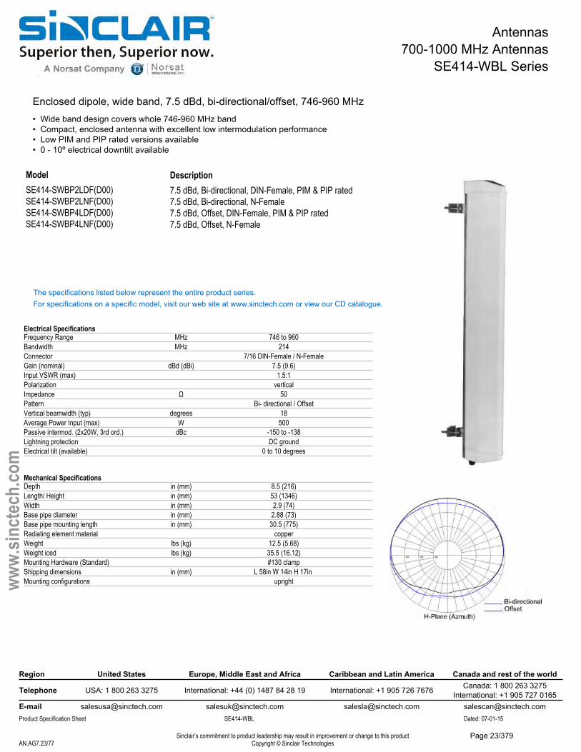
SE414-WBL Series
Enclosed dipole, wide band, 7.5 dBd, bi-directional/offset, 746-960 MHz• Wide band design covers whole 746-960 MHz band• Compact, enclosed antenna with excellent low intermodulation performance• Low PIM and PIP rated versions available• 0 - 10º electrical downtilt available
ModelSE414-SWBP2LDF(D00) SE414-SWBP2LNF(D00) SE414-SWBP4LDF(D00) SE414-SWBP4LNF(D00)
Description7.5 dBd, Bi-directional, DIN-Female, PIM & PIP rated 7.5 dBd, Bi-directional, N-Female7.5 dBd, Offset, DIN-Female, PIM & PIP rated 7.5 dBd, Offset, N-Female
The specifications listed below represent the entire product series.For specifications on a specific model, visit our web site at www.sinctech.com or view our CD catalogue.
Electrical SpecificationsFrequency Range MHz 746 to 960Bandwidth MHz 214Connector 7/16 DIN-Female / N-FemaleGain (nominal) dBd (dBi) 7.5 (9.6)Input VSWR (max) 1.5:1Polarization verticalImpedance Ω 50Pattern Bi- directional / OffsetVertical beamwidth (typ) degrees 18Average Power Input (max) W 500Passive intermod. (2x20W, 3rd ord.) dBc -150 to -138Lightning protection DC groundElectrical tilt (available) 0 to 10 degrees
Mechanical SpecificationsDepth in (mm) 8.5 (216)Length/ Height in (mm) 53 (1346)Width in (mm) 2.9 (74)Base pipe diameter in (mm) 2.88 (73)Base pipe mounting length in (mm) 30.5 (775)Radiating element material copperWeight lbs (kg) 12.5 (5.68)Weight iced lbs (kg) 35.5 (16.12)Mounting Hardware (Standard) #130 clampShipping dimensions in (mm) L 58in W 14in H 17in Mounting configurations upright
Region United States Europe, Middle East and Africa Caribbean and Latin America Canada and rest of the world
Telephone USA: 1 800 263 3275 International: +44 (0) 1487 84 28 19 International: +1 905 726 7676 Canada: 1 800 263 3275International: +1 905 727 0165
E-mail [email protected] [email protected] [email protected] [email protected] Specification Sheet SE414-WBL Dated: 07-01-15
Sinclair’s commitment to product leadership may result in improvement or change to this productCopyright © Sinclair TechnologiesAN.AG7.23/77
www.
sinct
ech.
com
Page 23/379

Antennas700-1000 MHz Antennas
SE414-WBL Series
Environmental SpecificationsTemperature range °F (°C) -40 to +140 (-40 to +60)Wind Loading Area (Flat Plate Equivalent) ft² (m²) 3 (0.28)Wind Loading Area (1/2" ice) ft² (m²) 3.8 (0.35)Rated wind velocity (no ice) mph (km/h) 105 (169)Rated wind velocity (1/2" radial ice) mph (km/h) 90 (145)Lateral thrust (100 mph No Ice) lbs (N) 112 (498.2)Torsional moment (100 mph No Ice) ft-lbs (Nm) 40 (54)
Region United States Europe, Middle East and Africa Caribbean and Latin America Canada and rest of the world
Telephone USA: 1 800 263 3275 International: +44 (0) 1487 84 28 19 International: +1 905 726 7676 Canada: 1 800 263 3275International: +1 905 727 0165
E-mail [email protected] [email protected] [email protected] [email protected] Specification Sheet SE414-WBL Dated: 07-01-15
Sinclair’s commitment to product leadership may result in improvement or change to this productCopyright © Sinclair TechnologiesAN.AG7.24/77
www.
sinct
ech.
com
Page 24/379
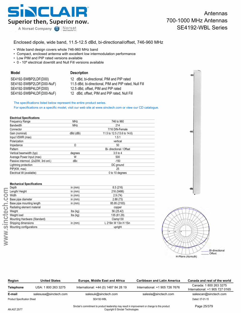
Antennas700-1000 MHz Antennas
SE4192-WBL Series
Enclosed dipole, wide band, 11.5-12.5 dBd, bi-directional/offset, 746-960 MHz• Wide band design covers whole 746-960 MHz band• Compact, enclosed antenna with excellent low intermodulation performance• Low PIM and PIP rated versions available• 0 - 10º electrical downtilt and Null Fill versions available
Description12 dBd, bi-directional, PIM and PIP rated11.5 dBd, bi-directional, PIM and PIP rated, Null Fill12.5 dBd, offset, PIM and PIP rated
ModelSE4192-SWBP2LDF(D00) SE4192-SWBP2LDF(D00-NuF) SE4192-SWBP4LDF(D00) SE4192-SWBP4LDF(D00-NuF) 12 dBd, offset, PIM and PIP rated, Null Fill
The specifications listed below represent the entire product series.For specifications on a specific model, visit our web site at www.sinctech.com or view our CD catalogue.
Electrical SpecificationsFrequency Range MHz 746 to 960Bandwidth MHz 214Connector 7/16 DIN-FemaleGain (nominal) dBd (dBi) 11.5 to 12.5 (13.6 to 14.6)Input VSWR (max) 1.5:1Polarization verticalImpedance Ω 50Pattern Bi- directional / OffsetVertical beamwidth (typ) degrees 3.5 to 4Average Power Input (max) W 500Passive intermod. (2x20W, 3rd ord.) dBc -150Lightning protection DC groundPIP(KW, max) 25Electrical tilt (available) 0 to 10 degrees
Mechanical SpecificationsDepth in (mm) 8.5 (216)Length/ Height in (mm) 216 (5486)Width in (mm) 2.9 (74)Base pipe diameter in (mm) 2.88 (73)Base pipe mounting length in (mm) 85.95 (2183)Radiating element material copperWeight lbs (kg) 56 (25.42)Weight iced lbs (kg) 135 (61.29)Mounting Hardware (Standard) Clamp130Shipping dimensions in (mm) L 219in W 13in H 15in Mounting configurations upright
Region United States Europe, Middle East and Africa Caribbean and Latin America Canada and rest of the world
Telephone USA: 1 800 263 3275 International: +44 (0) 1487 84 28 19 International: +1 905 726 7676 Canada: 1 800 263 3275International: +1 905 727 0165
E-mail [email protected] [email protected] [email protected] [email protected] Specification Sheet SE4192-WBL Dated: 07-01-15
Sinclair’s commitment to product leadership may result in improvement or change to this productCopyright © Sinclair TechnologiesAN.AG7.25/77
www.
sinct
ech.
com
Page 25/379
Antennas700-1000 MHz Antennas
SE4192-WBL Series
Environmental SpecificationsTemperature range °F (°C) -40 to +140 (-40 to +60)Wind Loading Area (Flat Plate Equivalent) ft² (m²) 8.37 (0.78)Wind Loading Area (1/2" ice) ft² (m²) 10.59 (0.98)Rated wind velocity (no ice) mph (km/h) 100 (161)Rated wind velocity (1/2" radial ice) mph (km/h) 85 (137)Lateral thrust (100 mph No Ice) lbs (N) 438 (1948.2)Torsional moment (100 mph No Ice) ft-lbs (Nm) 188 (253.8)
Ordering InformationN-type connectors are available (with degraded PIM rating).
Region United States Europe, Middle East and Africa Caribbean and Latin America Canada and rest of the world
Telephone USA: 1 800 263 3275 International: +44 (0) 1487 84 28 19 International: +1 905 726 7676 Canada: 1 800 263 3275International: +1 905 727 0165
E-mail [email protected] [email protected] [email protected] [email protected] Specification Sheet SE4192-WBL Dated: 07-01-15
Sinclair’s commitment to product leadership may result in improvement or change to this productCopyright © Sinclair TechnologiesAN.AG7.26/77
www.
sinct
ech.
com
Page 26/379
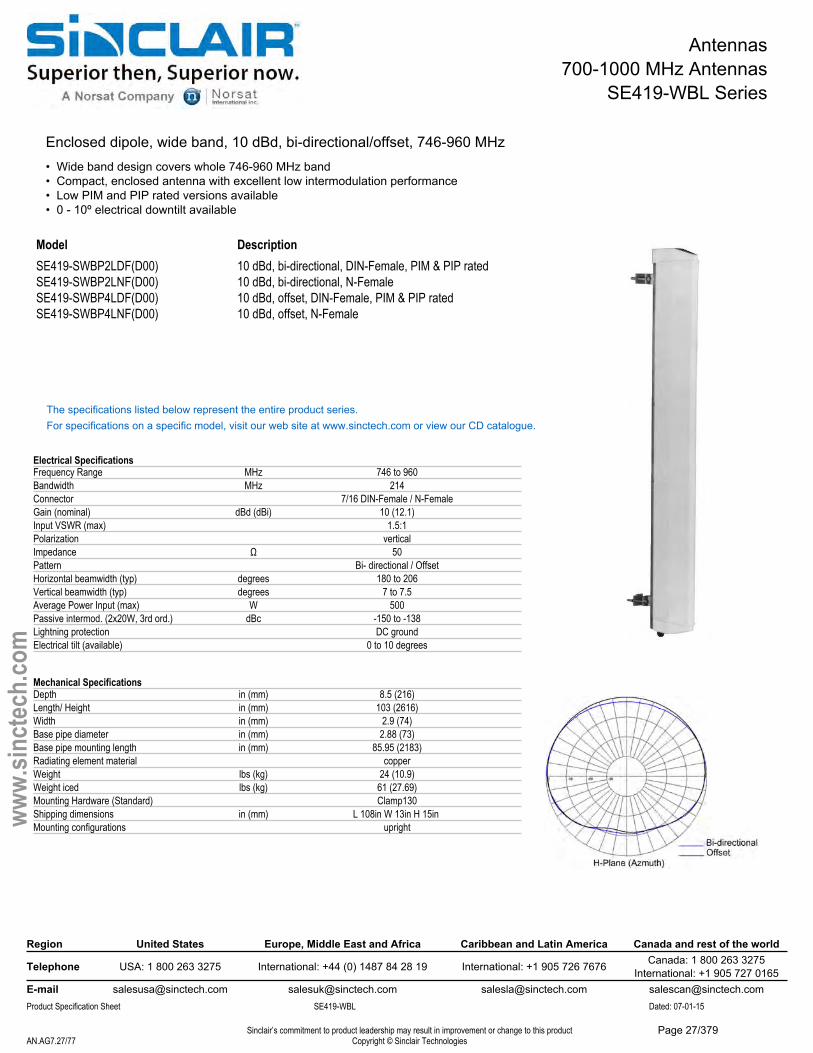
Antennas700-1000 MHz Antennas
SE419-WBL Series
Enclosed dipole, wide band, 10 dBd, bi-directional/offset, 746-960 MHz• Wide band design covers whole 746-960 MHz band• Compact, enclosed antenna with excellent low intermodulation performance• Low PIM and PIP rated versions available• 0 - 10º electrical downtilt available
ModelSE419-SWBP2LDF(D00) SE419-SWBP2LNF(D00) SE419-SWBP4LDF(D00) SE419-SWBP4LNF(D00)
Description10 dBd, bi-directional, DIN-Female, PIM & PIP rated 10 dBd, bi-directional, N-Female10 dBd, offset, DIN-Female, PIM & PIP rated10 dBd, offset, N-Female
The specifications listed below represent the entire product series.For specifications on a specific model, visit our web site at www.sinctech.com or view our CD catalogue.
Electrical SpecificationsFrequency Range MHz 746 to 960Bandwidth MHz 214Connector 7/16 DIN-Female / N-FemaleGain (nominal) dBd (dBi) 10 (12.1)Input VSWR (max) 1.5:1Polarization verticalImpedance Ω 50Pattern Bi- directional / OffsetHorizontal beamwidth (typ) degrees 180 to 206Vertical beamwidth (typ) degrees 7 to 7.5Average Power Input (max) W 500Passive intermod. (2x20W, 3rd ord.) dBc -150 to -138Lightning protection DC groundElectrical tilt (available) 0 to 10 degrees
Mechanical SpecificationsDepth in (mm) 8.5 (216)Length/ Height in (mm) 103 (2616)Width in (mm) 2.9 (74)Base pipe diameter in (mm) 2.88 (73)Base pipe mounting length in (mm) 85.95 (2183)Radiating element material copperWeight lbs (kg) 24 (10.9)Weight iced lbs (kg) 61 (27.69)Mounting Hardware (Standard) Clamp130Shipping dimensions in (mm) L 108in W 13in H 15in Mounting configurations upright
Region United States Europe, Middle East and Africa Caribbean and Latin America Canada and rest of the world
Telephone USA: 1 800 263 3275 International: +44 (0) 1487 84 28 19 International: +1 905 726 7676 Canada: 1 800 263 3275International: +1 905 727 0165
E-mail [email protected] [email protected] [email protected] [email protected] Specification Sheet SE419-WBL Dated: 07-01-15
Sinclair’s commitment to product leadership may result in improvement or change to this productCopyright © Sinclair TechnologiesAN.AG7.27/77
www.
sinct
ech.
com
Page 27/379

Antennas700-1000 MHz Antennas
SE419-WBL Series
Environmental SpecificationsTemperature range °F (°C) -40 to +140 (-40 to +60)Wind Loading Area (Flat Plate Equivalent) ft² (m²) 5.9 (0.55)Wind Loading Area (1/2" ice) ft² (m²) 7.5 (0.7)Rated wind velocity (no ice) mph (km/h) 100 (161)Rated wind velocity (1/2" radial ice) mph (km/h) 85 (137)Lateral thrust (100 mph No Ice) lbs (N) 239 (1063.1)Torsional moment (100 mph No Ice) ft-lbs (Nm) 97 (131)
Region United States Europe, Middle East and Africa Caribbean and Latin America Canada and rest of the world
Telephone USA: 1 800 263 3275 International: +44 (0) 1487 84 28 19 International: +1 905 726 7676 Canada: 1 800 263 3275International: +1 905 727 0165
E-mail [email protected] [email protected] [email protected] [email protected] Specification Sheet SE419-WBL Dated: 07-01-15
Sinclair’s commitment to product leadership may result in improvement or change to this productCopyright © Sinclair TechnologiesAN.AG7.28/77
www.
sinct
ech.
com
Page 28/379
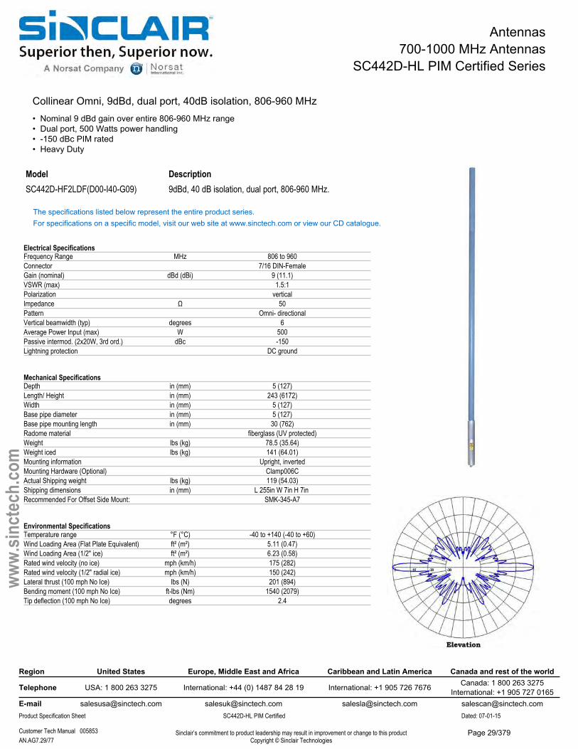
Antennas700-1000 MHz Antennas
SC442D-HL PIM Certified Series
Collinear Omni, 9dBd, dual port, 40dB isolation, 806-960 MHz• Nominal 9 dBd gain over entire 806-960 MHz range• Dual port, 500 Watts power handling• -150 dBc PIM rated• Heavy Duty
Model DescriptionSC442D-HF2LDF(D00-I40-G09) 9dBd, 40 dB isolation, dual port, 806-960 MHz.
The specifications listed below represent the entire product series.For specifications on a specific model, visit our web site at www.sinctech.com or view our CD catalogue.
Electrical SpecificationsFrequency Range MHz 806 to 960Connector 7/16 DIN-FemaleGain (nominal) dBd (dBi) 9 (11.1)VSWR (max) 1.5:1Polarization verticalImpedance Ω 50Pattern Omni- directionalVertical beamwidth (typ) degrees 6Average Power Input (max) W 500Passive intermod. (2x20W, 3rd ord.) dBc -150Lightning protection DC ground
Mechanical SpecificationsDepth in (mm) 5 (127)Length/ Height in (mm) 243 (6172)Width in (mm) 5 (127)Base pipe diameter in (mm) 5 (127)Base pipe mounting length in (mm) 30 (762)Radome material fiberglass (UV protected)Weight lbs (kg) 78.5 (35.64)Weight iced lbs (kg) 141 (64.01)Mounting information Upright, invertedMounting Hardware (Optional) Clamp006CActual Shipping weight lbs (kg) 119 (54.03)Shipping dimensions in (mm) L 255in W 7in H 7in Recommended For Offset Side Mount: SMK-345-A7
Environmental SpecificationsTemperature range °F (°C) -40 to +140 (-40 to +60)Wind Loading Area (Flat Plate Equivalent) ft² (m²) 5.11 (0.47)Wind Loading Area (1/2" ice) ft² (m²) 6.23 (0.58)Rated wind velocity (no ice) mph (km/h) 175 (282)Rated wind velocity (1/2" radial ice) mph (km/h) 150 (242)Lateral thrust (100 mph No Ice) lbs (N) 201 (894)Bending moment (100 mph No Ice) ft-lbs (Nm) 1540 (2079)Tip deflection (100 mph No Ice) degrees 2.4
Region United States Europe, Middle East and Africa Caribbean and Latin America Canada and rest of the world
Telephone USA: 1 800 263 3275 International: +44 (0) 1487 84 28 19 International: +1 905 726 7676 Canada: 1 800 263 3275International: +1 905 727 0165
E-mail [email protected] [email protected] [email protected] [email protected] Specification Sheet SC442D-HL PIM Certified Dated: 07-01-15
Customer Tech Manual 005853 Sinclair’s commitment to product leadership may result in improvement or change to this productCopyright © Sinclair TechnologiesAN.AG7.29/77
www.
sinct
ech.
com
Page 29/379
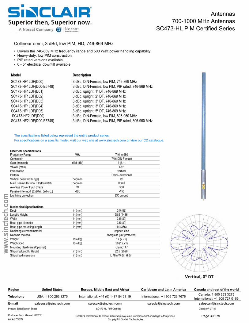
Antennas700-1000 MHz Antennas
SC473-HL PIM Certified Series
Collinear omni, 3 dBd, low PIM, HD, 746-869 MHz • Covers the 746-869 MHz frequency range and 500 Watt power handling capability• Heavy-duty, low PIM construction• PIP rated versions available• 0 - 5° electrical downtilt available
Model DescriptionSC473-HF1LDF(D00) 3 dBd, DIN-Female, low PIM, 746-869 MHzSC473-HF1LDF(D00-E5749) 3 dBd, DIN-Female, low PIM, PIP rated, 746-869 MHzSC473-HF1LDF(D01) 3 dBd, upright, 1º DT, 746-869 MHzSC473-HF1LDF(D02) 3 dBd, upright, 2º DT, 746-869 MHzSC473-HF1LDF(D03) 3 dBd, upright, 3º DT, 746-869 MHzSC473-HF1LDF(D04) 3 dBd, upright, 3º DT, 746-869 MHzSC473-HF1LDF(D05) 3 dBd, upright, 5º DT, 746-869 MHz SC473-HF2LDF(D00) SC473-HF2LDF(D00-E5749)
3 dBd, DIN-Female, low PIM, 806-960 MHz3 dBd, DIN-Female, low PIM, PIP rated, 806-960 MHz
The specifications listed below represent the entire product series.For specifications on a specific model, visit our web site at www.sinctech.com or view our CD catalogue.
Electrical SpecificationsFrequency Range MHz 746 to 960Connector 7/16 DIN-FemaleGain (nominal) dBd (dBi) 3 (5.1)VSWR (max) 1.5:1Polarization verticalPattern Omni- directionalVertical beamwidth (typ) degrees 28Main Beam Electrical Tilt (Downtilt) degrees 0 to 5Average Power Input (max) W 500Passive intermod. (2x20W, 3rd ord.) dBc -150Lightning protection DC ground
Mechanical SpecificationsDepth in (mm) 3.5 (89)Length/ Height in (mm) 58.5 (1486)Width in (mm) 3.5 (89)Base pipe diameter in (mm) 3.5 (89)Base pipe mounting length in (mm) 14 (356)Radiating element material copper/ zincRadome material fiberglass (UV protected)Weight lbs (kg) 17 (7.72)Weight iced lbs (kg) 28 (12.71)Mounting Hardware (Optional) Clamp147Shipping Length/ Height in (mm) 82.5 (2096)Shipping dimensions in (mm) L 78in W 6in H 6in
Region United States Europe, Middle East and Africa Caribbean and Latin America Canada and rest of the world
Telephone USA: 1 800 263 3275 International: +44 (0) 1487 84 28 19 International: +1 905 726 7676 Canada: 1 800 263 3275International: +1 905 727 0165
E-mail [email protected] [email protected] [email protected] [email protected] Specification Sheet SC473-HL PIM Certified Dated: 07-01-15
Customer Tech Manual 006216 Sinclair’s commitment to product leadership may result in improvement or change to this productCopyright © Sinclair TechnologiesAN.AG7.30/77
www.
sinct
ech.
com
Page 30/379

Antennas700-1000 MHz Antennas
SC473-HL PIM Certified Series
Environmental SpecificationsTemperature range °F (°C) -40 to +140 (-40 to +60)Wind Loading Area (Flat Plate Equivalent) ft² (m²) 0.83 (0.08)Wind Loading Area (1/2" ice) ft² (m²) 1.1 (0.1)Rated wind velocity (no ice) mph (km/h) 370 (596)Rated wind velocity (1/2" radial ice) mph (km/h) 325 (523)Lateral thrust (100 mph No Ice) lbs (N) 33 (146.8)Bending moment (100 mph No Ice) ft-lbs (Nm) 51.1 (69)Tip deflection (100 mph No Ice) degrees 0.048
Ordering InformationUnits with no downtilt can be mounted both inverted and upright
Region United States Europe, Middle East and Africa Caribbean and Latin America Canada and rest of the world
Telephone USA: 1 800 263 3275 International: +44 (0) 1487 84 28 19 International: +1 905 726 7676 Canada: 1 800 263 3275International: +1 905 727 0165
E-mail [email protected] [email protected] [email protected] [email protected] Specification Sheet SC473-HL PIM Certified Dated: 07-01-15
Customer Tech Manual 006216 Sinclair’s commitment to product leadership may result in improvement or change to this productCopyright © Sinclair TechnologiesAN.AG7.31/77
www.
sinct
ech.
com
Page 31/379
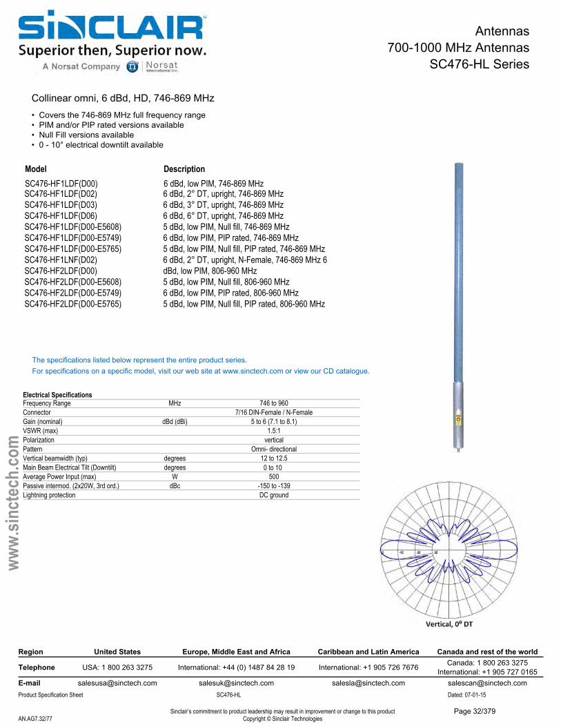
Antennas700-1000 MHz Antennas
SC476-HL Series
Collinear omni, 6 dBd, HD, 746-869 MHz • Covers the 746-869 MHz full frequency range• PIM and/or PIP rated versions available• Null Fill versions available• 0 - 10° electrical downtilt available
Model DescriptionSC476-HF1LDF(D00) 6 dBd, low PIM, 746-869 MHzSC476-HF1LDF(D02) 6 dBd, 2° DT, upright, 746-869 MHzSC476-HF1LDF(D03) 6 dBd, 3° DT, upright, 746-869 MHzSC476-HF1LDF(D06) 6 dBd, 6° DT, upright, 746-869 MHzSC476-HF1LDF(D00-E5608) SC476-HF1LDF(D00-E5749) SC476-HF1LDF(D00-E5765) SC476-HF1LNF(D02) SC476-HF2LDF(D00) SC476-HF2LDF(D00-E5608) SC476-HF2LDF(D00-E5749) SC476-HF2LDF(D00-E5765)
5 dBd, low PIM, Null fill, 746-869 MHz6 dBd, low PIM, PIP rated, 746-869 MHz5 dBd, low PIM, Null fill, PIP rated, 746-869 MHz 6 dBd, 2° DT, upright, N-Female, 746-869 MHz 6 dBd, low PIM, 806-960 MHz5 dBd, low PIM, Null fill, 806-960 MHz6 dBd, low PIM, PIP rated, 806-960 MHz5 dBd, low PIM, Null fill, PIP rated, 806-960 MHz
The specifications listed below represent the entire product series.For specifications on a specific model, visit our web site at www.sinctech.com or view our CD catalogue.
Electrical SpecificationsFrequency Range MHz 746 to 960Connector 7/16 DIN-Female / N-FemaleGain (nominal) dBd (dBi) 5 to 6 (7.1 to 8.1)VSWR (max) 1.5:1Polarization verticalPattern Omni- directionalVertical beamwidth (typ) degrees 12 to 12.5Main Beam Electrical Tilt (Downtilt) degrees 0 to 10Average Power Input (max) W 500Passive intermod. (2x20W, 3rd ord.) dBc -150 to -139Lightning protection DC ground
Region United States Europe, Middle East and Africa Caribbean and Latin America Canada and rest of the world
Telephone USA: 1 800 263 3275 International: +44 (0) 1487 84 28 19 International: +1 905 726 7676 Canada: 1 800 263 3275International: +1 905 727 0165
E-mail [email protected] [email protected] [email protected] [email protected] Specification Sheet SC476-HL Dated: 07-01-15
Sinclair’s commitment to product leadership may result in improvement or change to this productCopyright © Sinclair TechnologiesAN.AG7.32/77
www.
sinct
ech.
com
Page 32/379
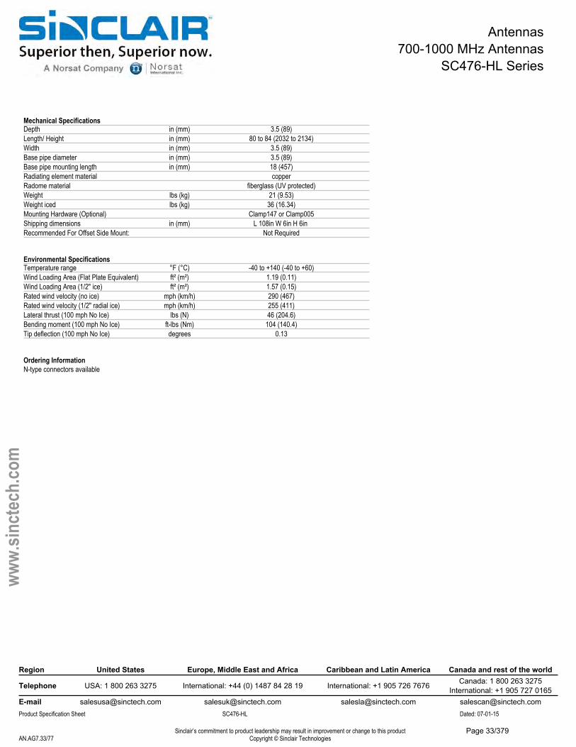
Antennas700-1000 MHz Antennas
SC476-HL Series
Mechanical SpecificationsDepth in (mm) 3.5 (89)Length/ Height in (mm) 80 to 84 (2032 to 2134)Width in (mm) 3.5 (89)Base pipe diameter in (mm) 3.5 (89)Base pipe mounting length in (mm) 18 (457)Radiating element material copperRadome material fiberglass (UV protected)Weight lbs (kg) 21 (9.53)Weight iced lbs (kg) 36 (16.34)Mounting Hardware (Optional) Clamp147 or Clamp005Shipping dimensions in (mm) L 108in W 6in H 6in Recommended For Offset Side Mount: Not Required
Environmental SpecificationsTemperature range °F (°C) -40 to +140 (-40 to +60)Wind Loading Area (Flat Plate Equivalent) ft² (m²) 1.19 (0.11)Wind Loading Area (1/2" ice) ft² (m²) 1.57 (0.15)Rated wind velocity (no ice) mph (km/h) 290 (467)Rated wind velocity (1/2" radial ice) mph (km/h) 255 (411)Lateral thrust (100 mph No Ice) lbs (N) 46 (204.6)Bending moment (100 mph No Ice) ft-lbs (Nm) 104 (140.4)Tip deflection (100 mph No Ice) degrees 0.13
Ordering InformationN-type connectors available
Region United States Europe, Middle East and Africa Caribbean and Latin America Canada and rest of the world
Telephone USA: 1 800 263 3275 International: +44 (0) 1487 84 28 19 International: +1 905 726 7676 Canada: 1 800 263 3275International: +1 905 727 0165
E-mail [email protected] [email protected] [email protected] [email protected] Specification Sheet SC476-HL Dated: 07-01-15
Sinclair’s commitment to product leadership may result in improvement or change to this productCopyright © Sinclair TechnologiesAN.AG7.33/77
www.
sinct
ech.
com
Page 33/379
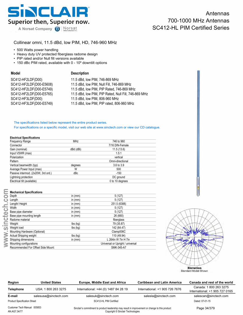
Antennas700-1000 MHz Antennas
SC412-HL PIM Certified Series
Collinear omni, 11.5 dBd, low PIM, HD, 746-960 MHz • 500 Watts power handling• Heavy duty UV protected fiberglass radome design• PIP rated and/or Null fill versions available• 150 dBc PIM rated, available with 0 - 10º downtilt options
Model DescriptionSC412-HF2LDF(D00) SC412-HF2LDF(D00-E5608) SC412-HF2LDF(D00-E5749) SC412-HF2LDF(D00-E5765) SC412-HF3LDF(D00) SC412-HF3LDF(D00-E5749)
11.5 dBd, low PIM, 746-869 MHz11.5 dBd, low PIM, Null Fill, 746-869 MHz11.5 dBd, low PIM, PIP Rated, 746-869 MHz11.5 dBd, low PIM, PIP Rated, Null Fill, 746-869 MHz 11.5 dBd, low PIM, 806-960 MHz11.5 dBd, low PIM, PIP rated, 806-960 MHz
The specifications listed below represent the entire product series.For specifications on a specific model, visit our web site at www.sinctech.com or view our CD catalogue.
Electrical SpecificationsFrequency Range MHz 746 to 960Connector 7/16 DIN-FemaleGain (nominal) dBd (dBi) 11.5 (13.6)Input VSWR (max) 1.5:1Polarization verticalPattern Omni-directionalVertical beamwidth (typ) degrees 3.6 to 3.9Average Power Input (max) W 500Passive intermod. (2x20W, 3rd ord.) dBc -150Lightning protection DC groundElectrical tilt (available) 0 to 10 degrees
Mechanical SpecificationsDepth in (mm) 5 (127)Length in (mm) 5 (127)Length/ Height in (mm) 251.5 (6388)Width in (mm) 5 (127)Base pipe diameter in (mm) 5 (127)Base pipe mounting length in (mm) 26 (660)Radome material fiberglassWeight lbs (kg) 79 (35.87)Weight iced lbs (kg) 142 (64.47)Mounting Hardware (Optional) Clamp006CActual Shipping weight lbs (kg) 110 (49.94)Shipping dimensions in (mm) L 264in W 7in H 7in Mounting configurations Universal or Upright / universalRecommended For Offset Side Mount: SMK-345-A7
Region United States Europe, Middle East and Africa Caribbean and Latin America Canada and rest of the world
Telephone USA: 1 800 263 3275 International: +44 (0) 1487 84 28 19 International: +1 905 726 7676 Canada: 1 800 263 3275International: +1 905 727 0165
E-mail [email protected] [email protected] [email protected] [email protected] Specification Sheet SC412-HL PIM Certified Dated: 07-01-15
Customer Tech Manual 005853 Sinclair’s commitment to product leadership may result in improvement or change to this productCopyright © Sinclair TechnologiesAN.AG7.34/77
www.
sinct
ech.
com
Page 34/379
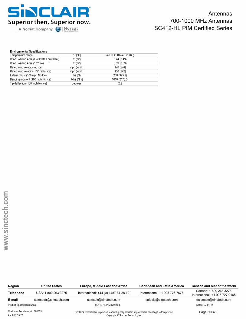
Antennas700-1000 MHz Antennas
SC412-HL PIM Certified Series
Environmental SpecificationsTemperature range °F (°C) -40 to +140 (-40 to +60)Wind Loading Area (Flat Plate Equivalent) ft² (m²) 5.24 (0.49)Wind Loading Area (1/2" ice) ft² (m²) 6.39 (0.59)Rated wind velocity (no ice) mph (km/h) 170 (274)Rated wind velocity (1/2" radial ice) mph (km/h) 150 (242)Lateral thrust (100 mph No Ice) lbs (N) 208 (925.2)Bending moment (100 mph No Ice) ft-lbs (Nm) 1610 (2173.5)Tip deflection (100 mph No Ice) degrees 2.2
Region United States Europe, Middle East and Africa Caribbean and Latin America Canada and rest of the world
Telephone USA: 1 800 263 3275 International: +44 (0) 1487 84 28 19 International: +1 905 726 7676 Canada: 1 800 263 3275International: +1 905 727 0165
E-mail [email protected] [email protected] [email protected] [email protected] Specification Sheet SC412-HL PIM Certified Dated: 07-01-15
Customer Tech Manual 005853 Sinclair’s commitment to product leadership may result in improvement or change to this productCopyright © Sinclair TechnologiesAN.AG7.35/77
www.
sinct
ech.
com
Page 35/379
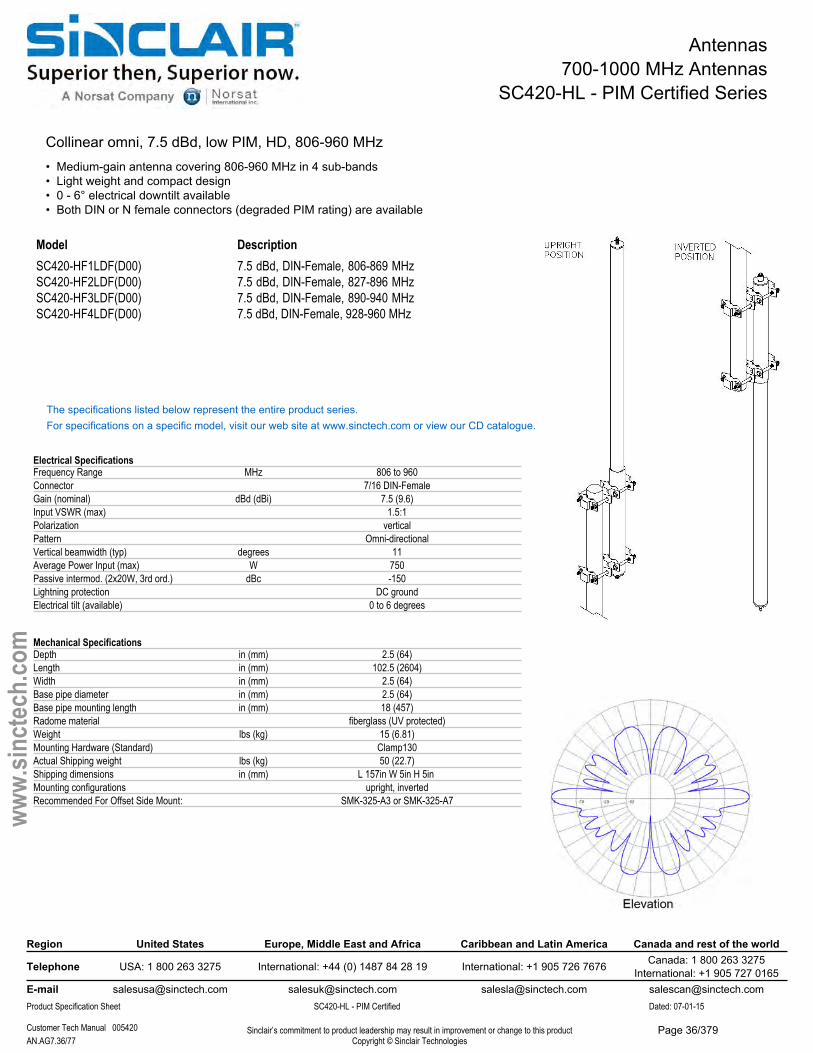
Antennas700-1000 MHz Antennas
SC420-HL - PIM Certified Series
Collinear omni, 7.5 dBd, low PIM, HD, 806-960 MHz• Medium-gain antenna covering 806-960 MHz in 4 sub-bands• Light weight and compact design• 0 - 6° electrical downtilt available• Both DIN or N female connectors (degraded PIM rating) are available
Model DescriptionSC420-HF1LDF(D00) SC420-HF2LDF(D00) SC420-HF3LDF(D00) SC420-HF4LDF(D00)
7.5 dBd, DIN-Female, 806-869 MHz 7.5 dBd, DIN-Female, 827-896 MHz 7.5 dBd, DIN-Female, 890-940 MHz 7.5 dBd, DIN-Female, 928-960 MHz
The specifications listed below represent the entire product series.For specifications on a specific model, visit our web site at www.sinctech.com or view our CD catalogue.
Electrical SpecificationsFrequency Range MHz 806 to 960Connector 7/16 DIN-FemaleGain (nominal) dBd (dBi) 7.5 (9.6)Input VSWR (max) 1.5:1Polarization verticalPattern Omni-directionalVertical beamwidth (typ) degrees 11Average Power Input (max) W 750Passive intermod. (2x20W, 3rd ord.) dBc -150Lightning protection DC groundElectrical tilt (available) 0 to 6 degrees
Mechanical SpecificationsDepth in (mm) 2.5 (64)Length in (mm) 102.5 (2604)Width in (mm) 2.5 (64)Base pipe diameter in (mm) 2.5 (64)Base pipe mounting length in (mm) 18 (457)Radome material fiberglass (UV protected)Weight lbs (kg) 15 (6.81)Mounting Hardware (Standard) Clamp130Actual Shipping weight lbs (kg) 50 (22.7)Shipping dimensions in (mm) L 157in W 5in H 5in Mounting configurations upright, invertedRecommended For Offset Side Mount: SMK-325-A3 or SMK-325-A7
Region United States Europe, Middle East and Africa Caribbean and Latin America Canada and rest of the world
Telephone USA: 1 800 263 3275 International: +44 (0) 1487 84 28 19 International: +1 905 726 7676 Canada: 1 800 263 3275International: +1 905 727 0165
E-mail [email protected] [email protected] [email protected] [email protected] Specification Sheet SC420-HL - PIM Certified Dated: 07-01-15
Customer Tech Manual 005420 Sinclair’s commitment to product leadership may result in improvement or change to this productCopyright © Sinclair TechnologiesAN.AG7.36/77
www.
sinct
ech.
com
Page 36/379

Antennas700-1000 MHz Antennas
SC420-HL - PIM Certified Series
Environmental SpecificationsTemperature range °F (°C) -22 to +140 (-30 to +60)Wind Loading Area (Flat Plate Equivalent) ft² (m²) 1.1 (0.1)Wind Loading Area (1/2" ice) ft² (m²) 2.5 (0.23)Rated wind velocity (no ice) mph (km/h) 150 (242)Rated wind velocity (1/2" radial ice) mph (km/h) 110 (177)Lateral thrust (100 mph No Ice) lbs (N) 41.6 (185)Bending moment (100 mph No Ice) ft-lbs (Nm) 108.9 (147)
Ordering Information7/16 DIN connector standard. N-Female also available. PIM and power may vary.
Region United States Europe, Middle East and Africa Caribbean and Latin America Canada and rest of the world
Telephone USA: 1 800 263 3275 International: +44 (0) 1487 84 28 19 International: +1 905 726 7676 Canada: 1 800 263 3275International: +1 905 727 0165
E-mail [email protected] [email protected] [email protected] [email protected] Specification Sheet SC420-HL - PIM Certified Dated: 07-01-15
Customer Tech Manual 005420 Sinclair’s commitment to product leadership may result in improvement or change to this productCopyright © Sinclair TechnologiesAN.AG7.37/77
www.
sinct
ech.
com
Page 37/379
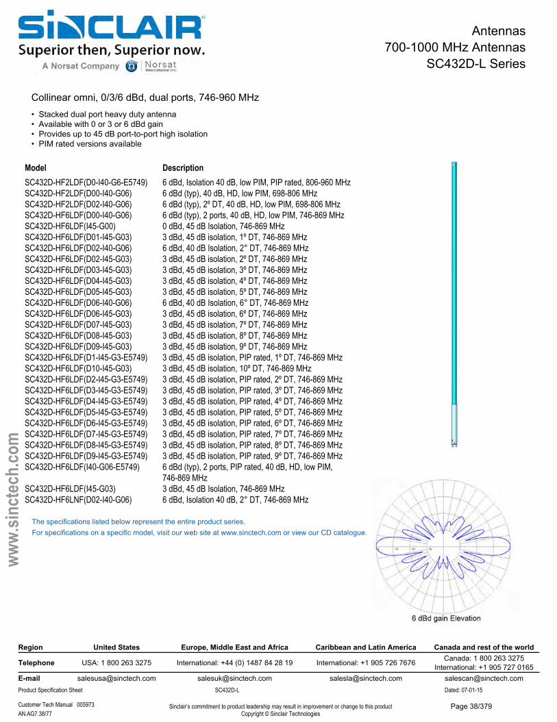
Antennas700-1000 MHz Antennas
SC432D-L Series
Collinear omni, 0/3/6 dBd, dual ports, 746-960 MHz• Stacked dual port heavy duty antenna• Available with 0 or 3 or 6 dBd gain• Provides up to 45 dB port-to-port high isolation• PIM rated versions available
Model DescriptionSC432D-HF2LDF(D0-I40-G6-E5749) 6 dBd, Isolation 40 dB, low PIM, PIP rated, 806-960 MHz
6 dBd (typ), 40 dB, HD, low PIM, 698-806 MHz6 dBd (typ), 2º DT, 40 dB, HD, low PIM, 698-806 MHz6 dBd (typ), 2 ports, 40 dB, HD, low PIM, 746-869 MHz0 dBd, 45 dB Isolation, 746-869 MHz3 dBd, 45 dB isolation, 1º DT, 746-869 MHz6 dBd, 40 dB Isolation, 2° DT, 746-869 MHz3 dBd, 45 dB isolation, 2º DT, 746-869 MHz3 dBd, 45 dB isolation, 3º DT, 746-869 MHz3 dBd, 45 dB isolation, 4º DT, 746-869 MHz3 dBd, 45 dB isolation, 5º DT, 746-869 MHz6 dBd, 40 dB Isolation, 6° DT, 746-869 MHz3 dBd, 45 dB isolation, 6º DT, 746-869 MHz3 dBd, 45 dB isolation, 7º DT, 746-869 MHz3 dBd, 45 dB isolation, 8º DT, 746-869 MHz
SC432D-HF2LDF(D00-I40-G06) SC432D-HF2LDF(D02-I40-G06) SC432D-HF6LDF(D00-I40-G06) SC432D-HF6LDF(I45-G00) SC432D-HF6LDF(D01-I45-G03) SC432D-HF6LDF(D02-I40-G06) SC432D-HF6LDF(D02-I45-G03) SC432D-HF6LDF(D03-I45-G03) SC432D-HF6LDF(D04-I45-G03) SC432D-HF6LDF(D05-I45-G03) SC432D-HF6LDF(D06-I40-G06) SC432D-HF6LDF(D06-I45-G03) SC432D-HF6LDF(D07-I45-G03) SC432D-HF6LDF(D08-I45-G03) SC432D-HF6LDF(D09-I45-G03) 3 dBd, 45 dB isolation, 9º DT, 746-869 MHzSC432D-HF6LDF(D1-I45-G3-E5749) 3 dBd, 45 dB isolation, PIP rated, 1º DT, 746-869 MHzSC432D-HF6LDF(D10-I45-G03) 3 dBd, 45 dB isolation, 10º DT, 746-869 MHzSC432D-HF6LDF(D2-I45-G3-E5749) 3 dBd, 45 dB isolation, PIP rated, 2º DT, 746-869 MHzSC432D-HF6LDF(D3-I45-G3-E5749) 3 dBd, 45 dB isolation, PIP rated, 3º DT, 746-869 MHzSC432D-HF6LDF(D4-I45-G3-E5749) 3 dBd, 45 dB isolation, PIP rated, 4º DT, 746-869 MHzSC432D-HF6LDF(D5-I45-G3-E5749) 3 dBd, 45 dB isolation, PIP rated, 5º DT, 746-869 MHzSC432D-HF6LDF(D6-I45-G3-E5749) 3 dBd, 45 dB isolation, PIP rated, 6º DT, 746-869 MHzSC432D-HF6LDF(D7-I45-G3-E5749) 3 dBd, 45 dB isolation, PIP rated, 7º DT, 746-869 MHzSC432D-HF6LDF(D8-I45-G3-E5749) 3 dBd, 45 dB isolation, PIP rated, 8º DT, 746-869 MHzSC432D-HF6LDF(D9-I45-G3-E5749) 3 dBd, 45 dB isolation, PIP rated, 9º DT, 746-869 MHzSC432D-HF6LDF(I40-G06-E5749) 6 dBd (typ), 2 ports, PIP rated, 40 dB, HD, low PIM,
746-869 MHzSC432D-HF6LDF(I45-G03) 3 dBd, 45 dB Isolation, 746-869 MHzSC432D-HF6LNF(D02-I40-G06) 6 dBd, Isolation 40 dB, 2° DT, 746-869 MHz
The specifications listed below represent the entire product series.For specifications on a specific model, visit our web site at www.sinctech.com or view our CD catalogue.
Region United States Europe, Middle East and Africa Caribbean and Latin America Canada and rest of the world
Telephone USA: 1 800 263 3275 International: +44 (0) 1487 84 28 19 International: +1 905 726 7676 Canada: 1 800 263 3275International: +1 905 727 0165
E-mail [email protected] [email protected] [email protected] [email protected] Specification Sheet SC432D-L Dated: 07-01-15
Customer Tech Manual 005973 Sinclair’s commitment to product leadership may result in improvement or change to this productCopyright © Sinclair TechnologiesAN.AG7.38/77
www.
sinct
ech.
com
Page 38/379
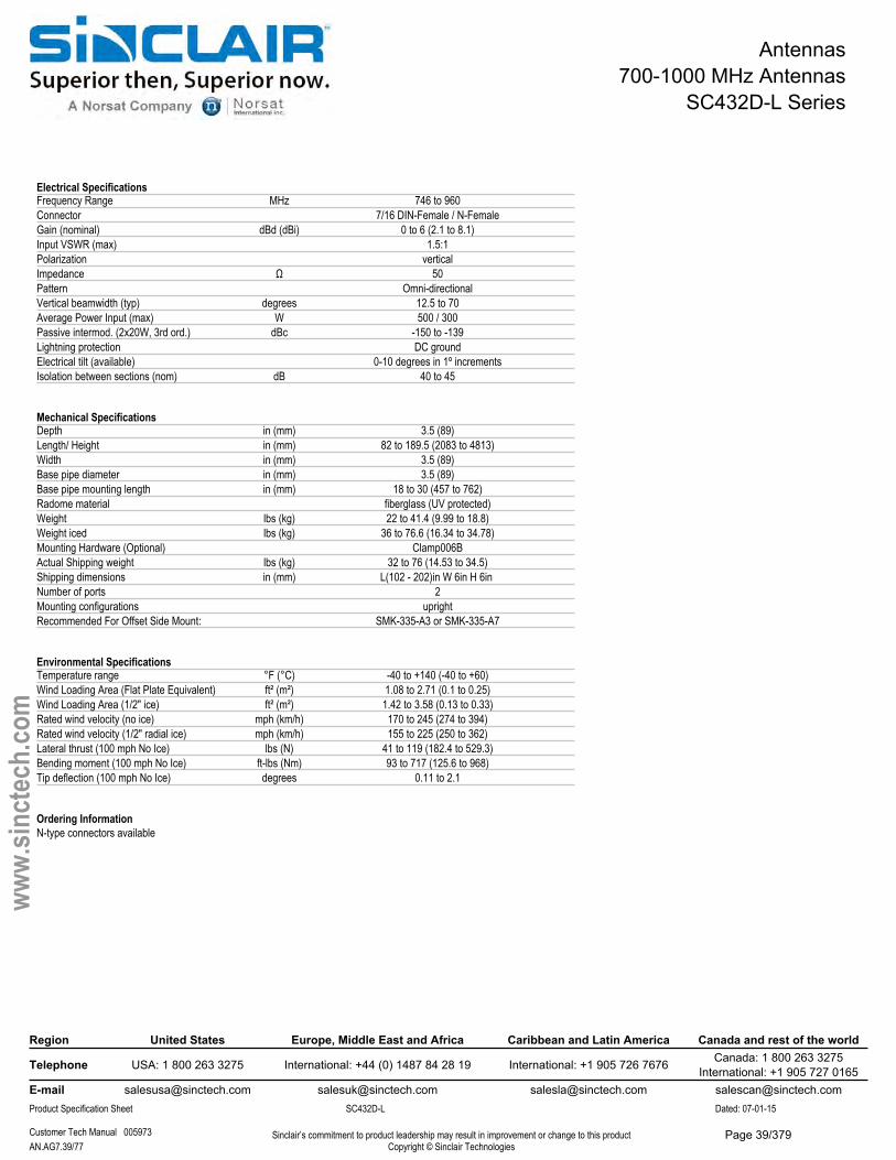
Antennas700-1000 MHz Antennas
SC432D-L Series
Electrical SpecificationsFrequency Range MHz 746 to 960Connector 7/16 DIN-Female / N-FemaleGain (nominal) dBd (dBi) 0 to 6 (2.1 to 8.1)Input VSWR (max) 1.5:1Polarization verticalImpedance Ω 50Pattern Omni-directionalVertical beamwidth (typ) degrees 12.5 to 70Average Power Input (max) W 500 / 300Passive intermod. (2x20W, 3rd ord.) dBc -150 to -139Lightning protection DC groundElectrical tilt (available) 0-10 degrees in 1º incrementsIsolation between sections (nom) dB 40 to 45
Mechanical SpecificationsDepth in (mm) 3.5 (89)Length/ Height in (mm) 82 to 189.5 (2083 to 4813)Width in (mm) 3.5 (89)Base pipe diameter in (mm) 3.5 (89)Base pipe mounting length in (mm) 18 to 30 (457 to 762)Radome material fiberglass (UV protected)Weight lbs (kg) 22 to 41.4 (9.99 to 18.8)Weight iced lbs (kg) 36 to 76.6 (16.34 to 34.78)Mounting Hardware (Optional) Clamp006BActual Shipping weight lbs (kg) 32 to 76 (14.53 to 34.5)Shipping dimensions in (mm) L(102 - 202)in W 6in H 6in Number of ports 2Mounting configurations uprightRecommended For Offset Side Mount: SMK-335-A3 or SMK-335-A7
Environmental SpecificationsTemperature range °F (°C) -40 to +140 (-40 to +60)Wind Loading Area (Flat Plate Equivalent) ft² (m²) 1.08 to 2.71 (0.1 to 0.25)Wind Loading Area (1/2" ice) ft² (m²) 1.42 to 3.58 (0.13 to 0.33)Rated wind velocity (no ice) mph (km/h) 170 to 245 (274 to 394)Rated wind velocity (1/2" radial ice) mph (km/h) 155 to 225 (250 to 362)Lateral thrust (100 mph No Ice) lbs (N) 41 to 119 (182.4 to 529.3)Bending moment (100 mph No Ice) ft-lbs (Nm) 93 to 717 (125.6 to 968)Tip deflection (100 mph No Ice) degrees 0.11 to 2.1
Ordering InformationN-type connectors available
Region United States Europe, Middle East and Africa Caribbean and Latin America Canada and rest of the world
Telephone USA: 1 800 263 3275 International: +44 (0) 1487 84 28 19 International: +1 905 726 7676 Canada: 1 800 263 3275International: +1 905 727 0165
E-mail [email protected] [email protected] [email protected] [email protected] Specification Sheet SC432D-L Dated: 07-01-15
Customer Tech Manual 005973 Sinclair’s commitment to product leadership may result in improvement or change to this productCopyright © Sinclair TechnologiesAN.AG7.39/77
www.
sinct
ech.
com
Page 39/379
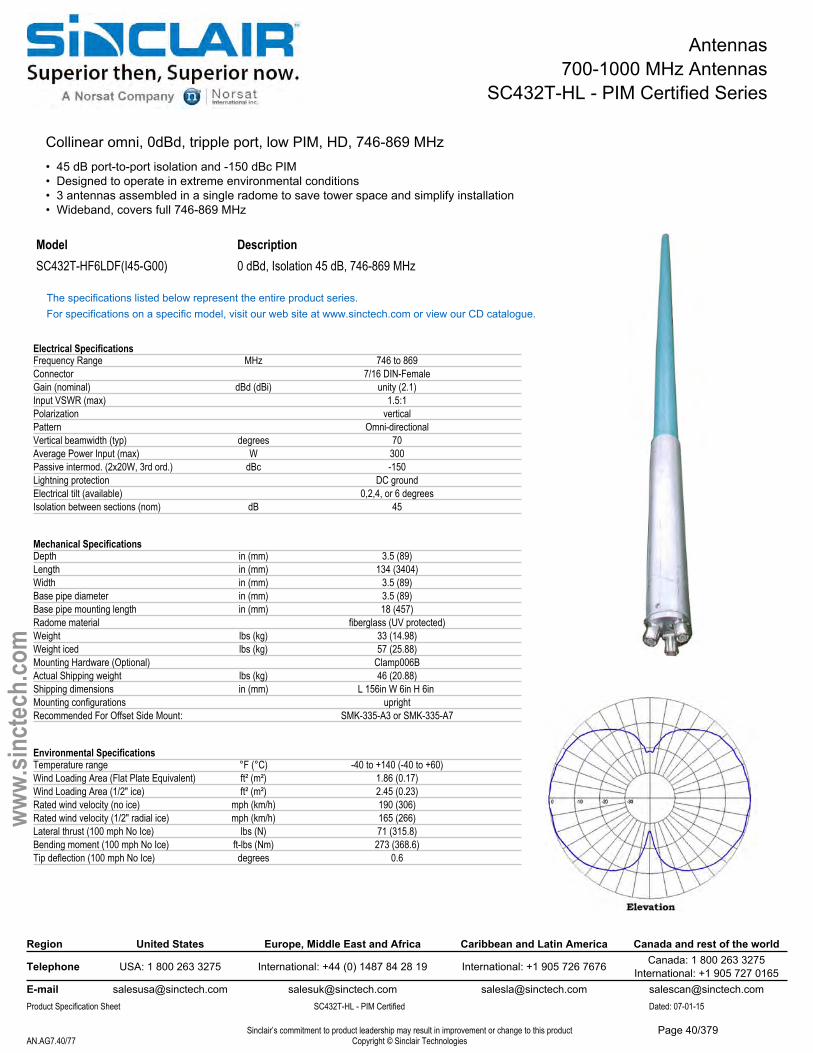
Antennas700-1000 MHz Antennas
SC432T-HL - PIM Certified Series
Collinear omni, 0dBd, tripple port, low PIM, HD, 746-869 MHz• 45 dB port-to-port isolation and -150 dBc PIM• Designed to operate in extreme environmental conditions• 3 antennas assembled in a single radome to save tower space and simplify installation• Wideband, covers full 746-869 MHz
Model DescriptionSC432T-HF6LDF(I45-G00) 0 dBd, Isolation 45 dB, 746-869 MHz
The specifications listed below represent the entire product series.For specifications on a specific model, visit our web site at www.sinctech.com or view our CD catalogue.
Electrical SpecificationsFrequency Range MHz 746 to 869Connector 7/16 DIN-FemaleGain (nominal) dBd (dBi) unity (2.1)Input VSWR (max) 1.5:1Polarization verticalPattern Omni-directionalVertical beamwidth (typ) degrees 70Average Power Input (max) W 300Passive intermod. (2x20W, 3rd ord.) dBc -150Lightning protection DC groundElectrical tilt (available) 0,2,4, or 6 degreesIsolation between sections (nom) dB 45
Mechanical SpecificationsDepth in (mm) 3.5 (89)Length in (mm) 134 (3404)Width in (mm) 3.5 (89)Base pipe diameter in (mm) 3.5 (89)Base pipe mounting length in (mm) 18 (457)Radome material fiberglass (UV protected)Weight lbs (kg) 33 (14.98)Weight iced lbs (kg) 57 (25.88)Mounting Hardware (Optional) Clamp006BActual Shipping weight lbs (kg) 46 (20.88)Shipping dimensions in (mm) L 156in W 6in H 6in Mounting configurations uprightRecommended For Offset Side Mount: SMK-335-A3 or SMK-335-A7
Environmental SpecificationsTemperature range °F (°C) -40 to +140 (-40 to +60)Wind Loading Area (Flat Plate Equivalent) ft² (m²) 1.86 (0.17)Wind Loading Area (1/2" ice) ft² (m²) 2.45 (0.23)Rated wind velocity (no ice) mph (km/h) 190 (306)Rated wind velocity (1/2" radial ice) mph (km/h) 165 (266)Lateral thrust (100 mph No Ice) lbs (N) 71 (315.8)Bending moment (100 mph No Ice) ft-lbs (Nm) 273 (368.6)Tip deflection (100 mph No Ice) degrees 0.6
Region United States Europe, Middle East and Africa Caribbean and Latin America Canada and rest of the world
Telephone USA: 1 800 263 3275 International: +44 (0) 1487 84 28 19 International: +1 905 726 7676 Canada: 1 800 263 3275International: +1 905 727 0165
E-mail [email protected] [email protected] [email protected] [email protected] Specification Sheet SC432T-HL - PIM Certified Dated: 07-01-15
Sinclair’s commitment to product leadership may result in improvement or change to this productCopyright © Sinclair TechnologiesAN.AG7.40/77
www.
sinct
ech.
com
Page 40/379
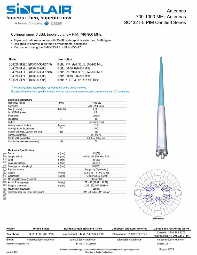
Antennas700-1000 MHz Antennas
SC432T-L PIM Certified Series
Collinear omni, 6 dBd, tripple port, low PIM, 746-960 MHz• Triple port collinear antenna with 30 dB port-to-port isolation and 6 dBd gain• Designed to operate in extreme environmental conditions• Recommend using the SMK-335-A3 or SMK-335-A7
Model DescriptionSC432T-SF2LDF(D0-I30-G6-E5749) 6 dBd, PIP rated, 30 dB, 806-960 MHzSC432T-SF2LDF(D00-I30-G06) 6 dBd, 30 dB, 698-806 MHzSC432T-SF6LDF(D0-I30-G6-E5749) 6 dBd, PIP rated, 30 dB, 746-869 MHzSC432T-SF6LDF(D00-I30-G06) 6 dBd, 30 dB, 746-869 MHzSC432T-SF6LDF(D06-I30-G06) 6 dBd, 6° DT, 30 dB, 746-869 MHz
The specifications listed below represent the entire product series.For specifications on a specific model, visit our web site at www.sinctech.com or view our CD catalogue.
Electrical SpecificationsFrequency Range MHz 746 to 960Connector 7/16 DIN-FemaleGain (nominal) dBd (dBi) 6 (8.1)Input VSWR (max) 1.5:1Polarization verticalImpedance Ω 50Pattern Omni-directionalVertical beamwidth (typ) degrees 12.7Average Power Input (max) W 500Passive intermod. (2x20W, 3rd ord.) dBc -150Lightning protection DC groundElectrical tilt (available) 0,2,4, or 6 degreesIsolation between sections (nom) dB 30
Mechanical SpecificationsDepth in (mm) 3.5 (89)Length/ Height in (mm) 200.5 to 214.5 (5093 to 5448)Width in (mm) 3.5 (89)Base pipe diameter in (mm) 3.5 (89)Base pipe mounting length in (mm) 30 (762)Radome material fiberglass (UV protected)Weight lbs (kg) 40.5 to 43 (18.39 to 19.52)Weight iced lbs (kg) 77.3 to 87 (35.09 to 39.5)Mounting Hardware (Optional) Clamp006BActual Shipping weight lbs (kg) 72 to 92 (32.69 to 41.77)Shipping dimensions in (mm) L(219 - 252)in W 6in H 6in Mounting configurations uprightRecommended For Offset Side Mount: SMK-335-A3 or SMK-335-A7
Region United States Europe, Middle East and Africa Caribbean and Latin America Canada and rest of the world
Telephone USA: 1 800 263 3275 International: +44 (0) 1487 84 28 19 International: +1 905 726 7676 Canada: 1 800 263 3275International: +1 905 727 0165
E-mail [email protected] [email protected] [email protected] [email protected] Specification Sheet SC432T-L PIM Certified Dated: 07-01-15
Sinclair’s commitment to product leadership may result in improvement or change to this productCopyright © Sinclair TechnologiesAN.AG7.41/77
www.
sinct
ech.
com
Page 41/379
Antennas700-1000 MHz Antennas
SC432T-L PIM Certified Series
Environmental SpecificationsTemperature range °F (°C) -40 to +140 (-40 to +60)Rated wind velocity (no ice) mph (km/h) 140 to 165 (225 to 266)Rated wind velocity (1/2" radial ice) mph (km/h) 115 to 135 (185 to 217)Lateral thrust (100 mph No Ice) lbs (N) 113 to 132 (502.6 to 587.1)Bending moment (100 mph No Ice) ft-lbs (Nm) 681 to 983 (919.4 to 1327.1)Tip deflection (100 mph No Ice) degrees 2.5 to 4.2
Region United States Europe, Middle East and Africa Caribbean and Latin America Canada and rest of the world
Telephone USA: 1 800 263 3275 International: +44 (0) 1487 84 28 19 International: +1 905 726 7676 Canada: 1 800 263 3275International: +1 905 727 0165
E-mail [email protected] [email protected] [email protected] [email protected] Specification Sheet SC432T-L PIM Certified Dated: 07-01-15
Sinclair’s commitment to product leadership may result in improvement or change to this productCopyright © Sinclair TechnologiesAN.AG7.42/77
www.
sinct
ech.
com
Page 42/379
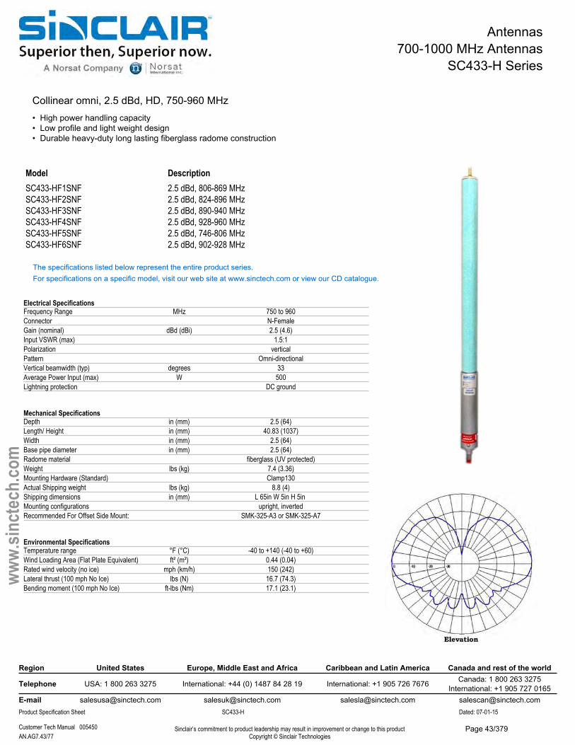
Antennas700-1000 MHz Antennas
SC433-H Series
Collinear omni, 2.5 dBd, HD, 750-960 MHz• High power handling capacity• Low profile and light weight design• Durable heavy-duty long lasting fiberglass radome construction
Model DescriptionSC433-HF1SNF 2.5 dBd, 806-869 MHzSC433-HF2SNF 2.5 dBd, 824-896 MHzSC433-HF3SNF 2.5 dBd, 890-940 MHzSC433-HF4SNF 2.5 dBd, 928-960 MHzSC433-HF5SNF 2.5 dBd, 746-806 MHzSC433-HF6SNF 2.5 dBd, 902-928 MHz
The specifications listed below represent the entire product series.For specifications on a specific model, visit our web site at www.sinctech.com or view our CD catalogue.
Electrical SpecificationsFrequency Range MHz 750 to 960Connector N-FemaleGain (nominal) dBd (dBi) 2.5 (4.6)Input VSWR (max) 1.5:1Polarization verticalPattern Omni-directionalVertical beamwidth (typ) degrees 33Average Power Input (max) W 500Lightning protection DC ground
Mechanical SpecificationsDepth in (mm) 2.5 (64)Length/ Height in (mm) 40.83 (1037)Width in (mm) 2.5 (64)Base pipe diameter in (mm) 2.5 (64)Radome material fiberglass (UV protected)Weight lbs (kg) 7.4 (3.36)Mounting Hardware (Standard) Clamp130Actual Shipping weight lbs (kg) 8.8 (4)Shipping dimensions in (mm) L 65in W 5in H 5in Mounting configurations upright, invertedRecommended For Offset Side Mount: SMK-325-A3 or SMK-325-A7
Environmental SpecificationsTemperature range °F (°C) -40 to +140 (-40 to +60)Wind Loading Area (Flat Plate Equivalent) ft² (m²) 0.44 (0.04)Rated wind velocity (no ice) mph (km/h) 150 (242)Lateral thrust (100 mph No Ice) lbs (N) 16.7 (74.3)Bending moment (100 mph No Ice) ft-lbs (Nm) 17.1 (23.1)
Region United States Europe, Middle East and Africa Caribbean and Latin America Canada and rest of the world
Telephone USA: 1 800 263 3275 International: +44 (0) 1487 84 28 19 International: +1 905 726 7676 Canada: 1 800 263 3275International: +1 905 727 0165
E-mail [email protected] [email protected] [email protected] [email protected] Specification Sheet SC433-H Dated: 07-01-15
Customer Tech Manual 005450 Sinclair’s commitment to product leadership may result in improvement or change to this productCopyright © Sinclair TechnologiesAN.AG7.43/77
www.
sinct
ech.
com
Page 43/379
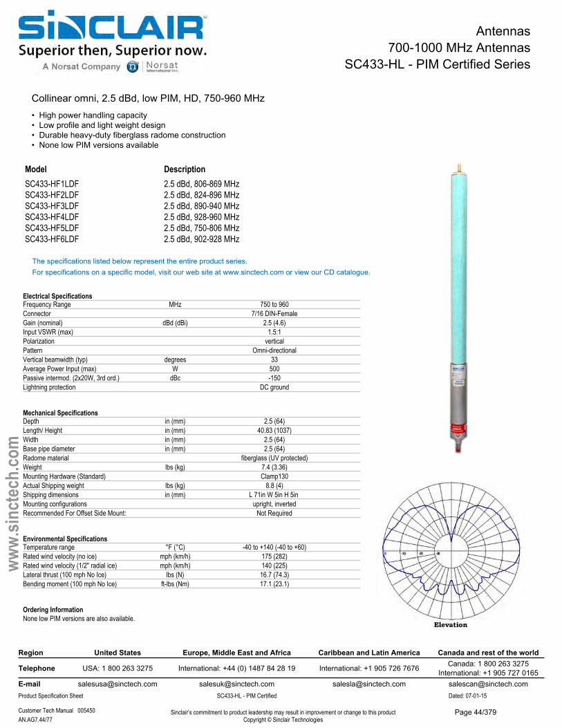
Antennas700-1000 MHz Antennas
SC433-HL - PIM Certified Series
Collinear omni, 2.5 dBd, low PIM, HD, 750-960 MHz• High power handling capacity• Low profile and light weight design• Durable heavy-duty fiberglass radome construction• None low PIM versions available
Model DescriptionSC433-HF1LDF 2.5 dBd, 806-869 MHzSC433-HF2LDF 2.5 dBd, 824-896 MHzSC433-HF3LDF 2.5 dBd, 890-940 MHzSC433-HF4LDF 2.5 dBd, 928-960 MHzSC433-HF5LDF 2.5 dBd, 750-806 MHzSC433-HF6LDF 2.5 dBd, 902-928 MHz
The specifications listed below represent the entire product series.For specifications on a specific model, visit our web site at www.sinctech.com or view our CD catalogue.
Electrical SpecificationsFrequency Range MHz 750 to 960Connector 7/16 DIN-FemaleGain (nominal) dBd (dBi) 2.5 (4.6)Input VSWR (max) 1.5:1Polarization verticalPattern Omni-directionalVertical beamwidth (typ) degrees 33Average Power Input (max) W 500Passive intermod. (2x20W, 3rd ord.) dBc -150Lightning protection DC ground
Mechanical SpecificationsDepth in (mm) 2.5 (64)Length/ Height in (mm) 40.83 (1037)Width in (mm) 2.5 (64)Base pipe diameter in (mm) 2.5 (64)Radome material fiberglass (UV protected)Weight lbs (kg) 7.4 (3.36)Mounting Hardware (Standard) Clamp130Actual Shipping weight lbs (kg) 8.8 (4)Shipping dimensions in (mm) L 71in W 5in H 5in Mounting configurations upright, invertedRecommended For Offset Side Mount: Not Required
Environmental SpecificationsTemperature range °F (°C) -40 to +140 (-40 to +60)Rated wind velocity (no ice) mph (km/h) 175 (282)Rated wind velocity (1/2" radial ice) mph (km/h) 140 (225)Lateral thrust (100 mph No Ice) lbs (N) 16.7 (74.3)Bending moment (100 mph No Ice) ft-lbs (Nm) 17.1 (23.1)
Ordering InformationNone low PIM versions are also available.
Region United States Europe, Middle East and Africa Caribbean and Latin America Canada and rest of the world
Telephone USA: 1 800 263 3275 International: +44 (0) 1487 84 28 19 International: +1 905 726 7676 Canada: 1 800 263 3275International: +1 905 727 0165
E-mail [email protected] [email protected] [email protected] [email protected] Specification Sheet SC433-HL - PIM Certified Dated: 07-01-15
Customer Tech Manual 005450 Sinclair’s commitment to product leadership may result in improvement or change to this productCopyright © Sinclair TechnologiesAN.AG7.44/77
www.
sinct
ech.
com
Page 44/379
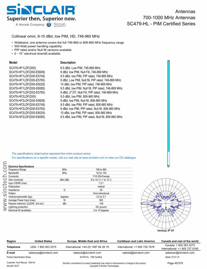
Antennas700-1000 MHz Antennas
SC479-HL - PIM Certified Series
Collinear omni, 9-10 dBd, low PIM, HD, 746-960 MHz• Wideband, one antenna covers the full 746-869 or 806-960 MHz frequency range• 500-Watt power handling capability• PIP rated and/or Null fill versions available• 0 - 10° electrical downtilt available
Model DescriptionSC479-HF1LDF(D00)SC479-HF1LDF(D00-E5608)SC479-HF1LDF(D00-E5749)SC479-HF1LDF(D00-E5765)SC479-HF1LDF(D00-E6029)SC479-HF1LDF(D00-E6085)SC479-HF1LDF(D02-E5765)SC479-HF2LDF(D00) SC479-HF2LDF(D00-E5608) SC479-HF2LDF(D00-E5749) SC479-HF2LDF(D00-E5765) SC479-HF2LDF(D00-E6029) SC479-HF2LDF(D00-E6085)
9.5 dBd, Low PIM, 746-869 MHz9 dBd, low PIM, Null Fill, 746-869 MHz9.5 dBd, low PIM, PIP rated, 746-869 MHz9 dBd, Low PIM, Null fill, PIP rated, 746-869 MHz 10 dBd, low PIM, PIP rated, 746-869 MHz9.5 dBd, low PIM, Null fill, PIP rated, 746-869 MHz 9 dBd, 2º DT, Null Fill, PIP rated, 746-869 MHz 9.5 dBd, low PIM, 806-960 MHz9 dBd, low PIM, Null fill, 806-960 MHz9.5 dBd, low PIM, PIP rated, 806-960 MHz9 dBd, low PIM, PIP rated, Null fill, 806-960 MHz 10 dBd, low PIM, PIP rated, 806-960 MHz9.5 dBd, low PIM, PIP rated, Null fill, 806-960 MHz
The specifications listed below represent the entire product series.For specifications on a specific model, visit our web site at www.sinctech.com or view our CD catalogue.
Electrical SpecificationsFrequency Range MHz 746 to 960Bandwidth MHz 123 to 154Connector 7/16 DIN-FemaleGain (nominal) dBd (dBi) 9 to 10 (11.1 to 12.1)Input VSWR (max) 1.5:1Polarization verticalImpedance Ω 50Pattern Omni-directionalVertical beamwidth (typ) degrees 5.2 to 5.7Average Power Input (max) W 500Passive intermod. (2x20W, 3rd ord.) dBc -150Lightning protection DC groundElectrical tilt (available) 0 to 10 degrees
Region United States Europe, Middle East and Africa Caribbean and Latin America Canada and rest of the world
Telephone USA: 1 800 263 3275 International: +44 (0) 1487 84 28 19 International: +1 905 726 7676 Canada: 1 800 263 3275International: +1 905 727 0165
E-mail [email protected] [email protected] [email protected] [email protected] Specification Sheet SC479-HL - PIM Certified Dated: 07-01-15
Customer Tech Manual 006134 Sinclair’s commitment to product leadership may result in improvement or change to this productCopyright © Sinclair TechnologiesAN.AG7.45/77
www.
sinct
ech.
com
Page 45/379
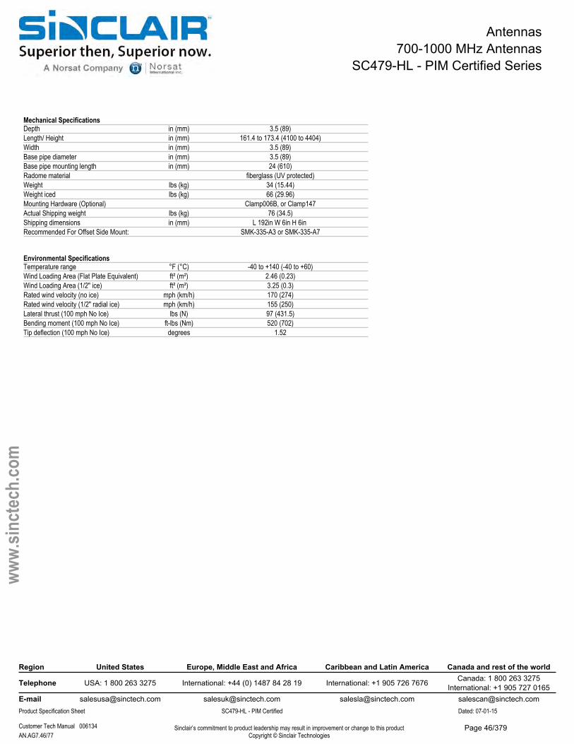
Antennas700-1000 MHz Antennas
SC479-HL - PIM Certified Series
Mechanical SpecificationsDepth in (mm) 3.5 (89)Length/ Height in (mm) 161.4 to 173.4 (4100 to 4404)Width in (mm) 3.5 (89)Base pipe diameter in (mm) 3.5 (89)Base pipe mounting length in (mm) 24 (610)Radome material fiberglass (UV protected)Weight lbs (kg) 34 (15.44)Weight iced lbs (kg) 66 (29.96)Mounting Hardware (Optional) Clamp006B, or Clamp147Actual Shipping weight lbs (kg) 76 (34.5)Shipping dimensions in (mm) L 192in W 6in H 6in Recommended For Offset Side Mount: SMK-335-A3 or SMK-335-A7
Environmental SpecificationsTemperature range °F (°C) -40 to +140 (-40 to +60)Wind Loading Area (Flat Plate Equivalent) ft² (m²) 2.46 (0.23)Wind Loading Area (1/2" ice) ft² (m²) 3.25 (0.3)Rated wind velocity (no ice) mph (km/h) 170 (274)Rated wind velocity (1/2" radial ice) mph (km/h) 155 (250)Lateral thrust (100 mph No Ice) lbs (N) 97 (431.5)Bending moment (100 mph No Ice) ft-lbs (Nm) 520 (702)Tip deflection (100 mph No Ice) degrees 1.52
Region United States Europe, Middle East and Africa Caribbean and Latin America Canada and rest of the world
Telephone USA: 1 800 263 3275 International: +44 (0) 1487 84 28 19 International: +1 905 726 7676 Canada: 1 800 263 3275International: +1 905 727 0165
E-mail [email protected] [email protected] [email protected] [email protected] Specification Sheet SC479-HL - PIM Certified Dated: 07-01-15
Customer Tech Manual 006134 Sinclair’s commitment to product leadership may result in improvement or change to this productCopyright © Sinclair TechnologiesAN.AG7.46/77
www.
sinct
ech.
com
Page 46/379
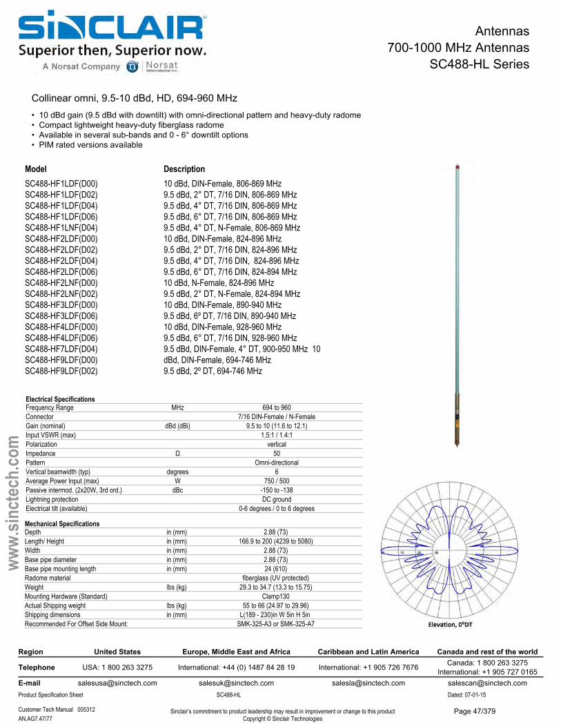
Antennas700-1000 MHz Antennas
SC488-HL Series
Collinear omni, 9.5-10 dBd, HD, 694-960 MHz• 10 dBd gain (9.5 dBd with downtilt) with omni-directional pattern and heavy-duty radome• Compact lightweight heavy-duty fiberglass radome• Available in several sub-bands and 0 - 6° downtilt options• PIM rated versions available
Model DescriptionSC488-HF1LDF(D00) SC488-HF1LDF(D02) SC488-HF1LDF(D04) SC488-HF1LDF(D06) SC488-HF1LNF(D04) SC488-HF2LDF(D00) SC488-HF2LDF(D02) SC488-HF2LDF(D04) SC488-HF2LDF(D06) SC488-HF2LNF(D00) SC488-HF2LNF(D02) SC488-HF3LDF(D00) SC488-HF3LDF(D06) SC488-HF4LDF(D00) SC488-HF4LDF(D06) SC488-HF7LDF(D04) SC488-HF9LDF(D00) SC488-HF9LDF(D02)
10 dBd, DIN-Female, 806-869 MHz9.5 dBd, 2° DT, 7/16 DIN, 806-869 MHz9.5 dBd, 4° DT, 7/16 DIN, 806-869 MHz9.5 dBd, 6° DT, 7/16 DIN, 806-869 MHz9.5 dBd, 4° DT, N-Female, 806-869 MHz10 dBd, DIN-Female, 824-896 MHz9.5 dBd, 2° DT, 7/16 DIN, 824-896 MHz9.5 dBd, 4° DT, 7/16 DIN, 824-896 MHz9.5 dBd, 6° DT, 7/16 DIN, 824-894 MHz10 dBd, N-Female, 824-896 MHz9.5 dBd, 2° DT, N-Female, 824-894 MHz10 dBd, DIN-Female, 890-940 MHz9.5 dBd, 6º DT, 7/16 DIN, 890-940 MHz10 dBd, DIN-Female, 928-960 MHz9.5 dBd, 6° DT, 7/16 DIN, 928-960 MHz9.5 dBd, DIN-Female, 4° DT, 900-950 MHz 10 dBd, DIN-Female, 694-746 MHz9.5 dBd, 2º DT, 694-746 MHz
Region United States Europe, Middle East and Africa Caribbean and Latin America Canada and rest of the world
Telephone USA: 1 800 263 3275 International: +44 (0) 1487 84 28 19 International: +1 905 726 7676 Canada: 1 800 263 3275International: +1 905 727 0165
E-mail [email protected] [email protected] [email protected] [email protected] Specification Sheet SC488-HL Dated: 07-01-15
Customer Tech Manual 005312 Sinclair’s commitment to product leadership may result in improvement or change to this productCopyright © Sinclair TechnologiesAN.AG7.47/77
www.
sinct
ech.
com
Mechanical SpecificationsDepth in (mm) 2.88 (73)Length/ Height in (mm) 166.9 to 200 (4239 to 5080)Width in (mm) 2.88 (73)Base pipe diameter in (mm) 2.88 (73)Base pipe mounting length in (mm) 24 (610)Radome material fiberglass (UV protected)Weight lbs (kg) 29.3 to 34.7 (13.3 to 15.75)Mounting Hardware (Standard) Clamp130Actual Shipping weight lbs (kg) 55 to 66 (24.97 to 29.96)Shipping dimensions in (mm) L(189 - 230)in W 5in H 5in Recommended For Offset Side Mount: SMK-325-A3 or SMK-325-A7
Electrical SpecificationsFrequency Range MHz 694 to 960Connector 7/16 DIN-Female / N-FemaleGain (nominal) dBd (dBi) 9.5 to 10 (11.6 to 12.1)Input VSWR (max) 1.5:1 / 1.4:1Polarization verticalImpedance Ω 50Pattern Omni-directionalVertical beamwidth (typ) degrees 6Average Power Input (max) W 750 / 500Passive intermod. (2x20W, 3rd ord.) dBc -150 to -138Lightning protection DC groundElectrical tilt (available) 0-6 degrees / 0 to 6 degrees
Page 47/379
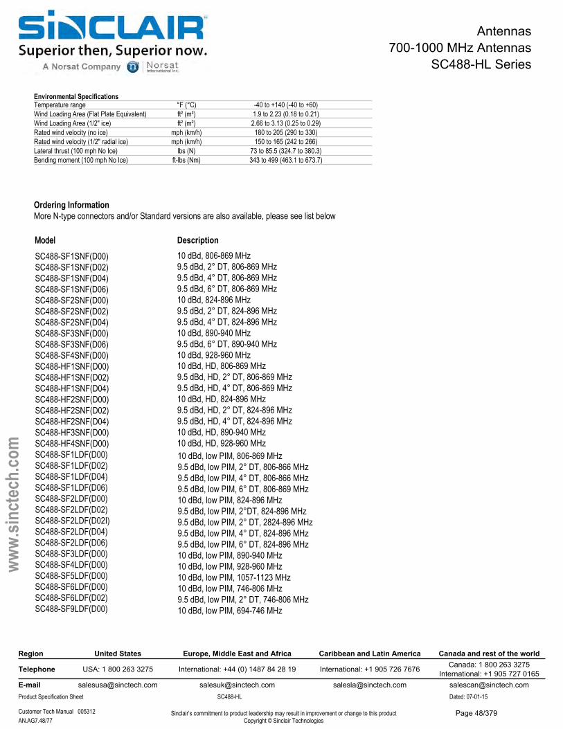
Antennas700-1000 MHz Antennas
SC488-HL Series
Ordering InformationMore N-type connectors and/or Standard versions are also available, please see list below
Region United States Europe, Middle East and Africa Caribbean and Latin America Canada and rest of the world
Telephone USA: 1 800 263 3275 International: +44 (0) 1487 84 28 19 International: +1 905 726 7676 Canada: 1 800 263 3275International: +1 905 727 0165
E-mail [email protected] [email protected] [email protected] [email protected] Specification Sheet SC488-HL Dated: 07-01-15
Customer Tech Manual 005312 Sinclair’s commitment to product leadership may result in improvement or change to this productCopyright © Sinclair TechnologiesAN.AG7.48/77
www.
sinct
ech.
com
10 dBd, low PIM, 806-869 MHz9.5 dBd, low PIM, 2° DT, 806-866 MHz9.5 dBd, low PIM, 4° DT, 806-866 MHz9.5 dBd, low PIM, 6° DT, 806-869 MHz10 dBd, low PIM, 824-896 MHz9.5 dBd, low PIM, 2°DT, 824-896 MHz9.5 dBd, low PIM, 2° DT, 2824-896 MHz9.5 dBd, low PIM, 4° DT, 824-896 MHz9.5 dBd, low PIM, 6° DT, 824-896 MHz10 dBd, low PIM, 890-940 MHz10 dBd, low PIM, 928-960 MHz10 dBd, low PIM, 1057-1123 MHz10 dBd, low PIM, 746-806 MHz9.5 dBd, low PIM, 2° DT, 746-806 MHz10 dBd, low PIM, 694-746 MHz
10 dBd, 806-869 MHz9.5 dBd, 2° DT, 806-869 MHz9.5 dBd, 4° DT, 806-869 MHz9.5 dBd, 6° DT, 806-869 MHz10 dBd, 824-896 MHz9.5 dBd, 2° DT, 824-896 MHz9.5 dBd, 4° DT, 824-896 MHz10 dBd, 890-940 MHz9.5 dBd, 6° DT, 890-940 MHz10 dBd, 928-960 MHz10 dBd, HD, 806-869 MHz9.5 dBd, HD, 2° DT, 806-869 MHz9.5 dBd, HD, 4° DT, 806-869 MHz10 dBd, HD, 824-896 MHz9.5 dBd, HD, 2° DT, 824-896 MHz9.5 dBd, HD, 4° DT, 824-896 MHz10 dBd, HD, 890-940 MHz10 dBd, HD, 928-960 MHz
Environmental SpecificationsTemperature range °F (°C) -40 to +140 (-40 to +60)Wind Loading Area (Flat Plate Equivalent) ft² (m²) 1.9 to 2.23 (0.18 to 0.21)Wind Loading Area (1/2" ice) ft² (m²) 2.66 to 3.13 (0.25 to 0.29)Rated wind velocity (no ice) mph (km/h) 180 to 205 (290 to 330)Rated wind velocity (1/2" radial ice) mph (km/h) 150 to 165 (242 to 266)Lateral thrust (100 mph No Ice) lbs (N) 73 to 85.5 (324.7 to 380.3)Bending moment (100 mph No Ice) ft-lbs (Nm) 343 to 499 (463.1 to 673.7)
SC488-SF1SNF(D00) SC488-SF1SNF(D02) SC488-SF1SNF(D04) SC488-SF1SNF(D06) SC488-SF2SNF(D00) SC488-SF2SNF(D02) SC488-SF2SNF(D04) SC488-SF3SNF(D00) SC488-SF3SNF(D06) SC488-SF4SNF(D00) SC488-HF1SNF(D00) SC488-HF1SNF(D02) SC488-HF1SNF(D04) SC488-HF2SNF(D00) SC488-HF2SNF(D02) SC488-HF2SNF(D04) SC488-HF3SNF(D00) SC488-HF4SNF(D00) SC488-SF1LDF(D00) SC488-SF1LDF(D02) SC488-SF1LDF(D04) SC488-SF1LDF(D06) SC488-SF2LDF(D00) SC488-SF2LDF(D02) SC488-SF2LDF(D02I) SC488-SF2LDF(D04) SC488-SF2LDF(D06) SC488-SF3LDF(D00) SC488-SF4LDF(D00) SC488-SF5LDF(D00) SC488-SF6LDF(D00) SC488-SF6LDF(D02) SC488-SF9LDF(D00)
Model Description
Page 48/379
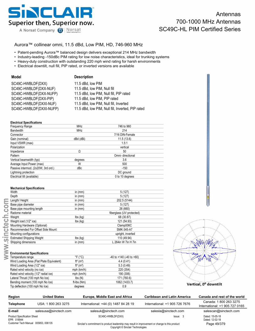
Antennas700-1000 MHz Antennas
SC49C-HL PIM Certified Series
Aurora™ collinear omni, 11.5 dBd, Low PIM, HD, 746-960 MHz• Patent-pending Aurora™ balanced design delivers exceptional 214 MHz bandwidth• Industry-leading -150dBc PIM rating for low noise characteristics, ideal for trunking systems• Heavy-duty construction with outstanding 220 mph wind rating for harsh environments• Electrical downtilt, null fill, PIP rated, or inverted versions are available
ModelSC49C-HWBLDF(DXX)SC49C-HWBLDF(DXX-NUF)SC49C-HWBLDF(DXX-NUFP)SC49C-HWBLDF(DXX-PIP)SC49C-HWBLDF(DXXI-NUF)SC49C-HWBLDF(DXXI-NUFP)
Description11.5 dBd, low PIM11.5 dBd, low PIM, Null fill11.5 dBd, low PIM, Null fill, PIP rated11.5 dBd, low PIM, PIP rated 11.5 dBd, low PIM, Null fill, Inverted11.5 dBd, low PIM, Null fill, Inverted, PIP rated
Electrical SpecificationsFrequency Range MHz 746 to 960Bandwidth MHz 214Connector 7/16 DIN-FemaleGain (nominal) dBd (dBi) 11.5 (13.6)Input VSWR (max) 1.5:1Polarization verticalImpedance Ω 50Pattern Omni- directionalVertical beamwidth (typ) degrees 3.6Average Input Power (max) W 500Passive intermod. (2x20W, 3rd ord.) dBc -150Lightning protection DC groundElectrical tilt (available) 0 to 10 degrees
Mechanical SpecificationsWidth in (mm) 5 (127)Depth in (mm) 5 (127)Length/ Height in (mm) 202.5 (5144)Base pipe diameter in (mm) 5 (127)Base pipe mounting length in (mm) 26 (660)Radome material fiberglass (UV protected)Weight lbs (kg) 68 (30.87)Weight iced (1/2" ice) lbs (kg) 121 (54.93)Mounting Hardware (Optional) Clamp006CRecommended For Offset Side Mount: SMK-345-A7Mounting configurations upright, inverted Estimated Shipping Weight lbs (kg) 110 (49.94)Shipping dimensions in (mm) L 264in W 7in H 7in
Region United States Europe, Middle East and Africa Caribbean and Latin America Canada and rest of the world
Telephone USA: 1 800 263 3275 International: +44 (0) 1487 84 28 19 International: +1 905 726 7676 Canada: 1 800 263 3275International: +1 905 727 0165
E-mail [email protected] [email protected] [email protected] [email protected] Specification Sheet SC49C-HWBLDF(DXX) Issue: 3 Dated: 15-05-18EPR 018944 Dated: 12-02-18Customer Tech Manual 005853, 006135 Sinclair’s commitment to product leadership may result in improvement or change to this product
Copyright © Sinclair Technologies
www.
sinct
ech.
com
Environmental SpecificationsTemperature range °F (°C) -40 to +140 (-40 to +60)Wind Loading Area (Flat Plate Equivalent) ft² (m²) 4.4 (0.41)Wind Loading Area (1/2" ice) ft² (m²) 5.3 (0.49)Rated wind velocity (no ice) mph (km/h) 220 (354)Rated wind velocity (1/2" radial ice) mph (km/h) 190 (306)Lateral Thrust (100 mph No Ice) lbs (N) 171 (760.6)Bending moment (100 mph No Ice) ft-lbs (Nm) 1062 (1433.7)Tip deflection (100 mph No Ice) degrees 0.9
Page 49/379
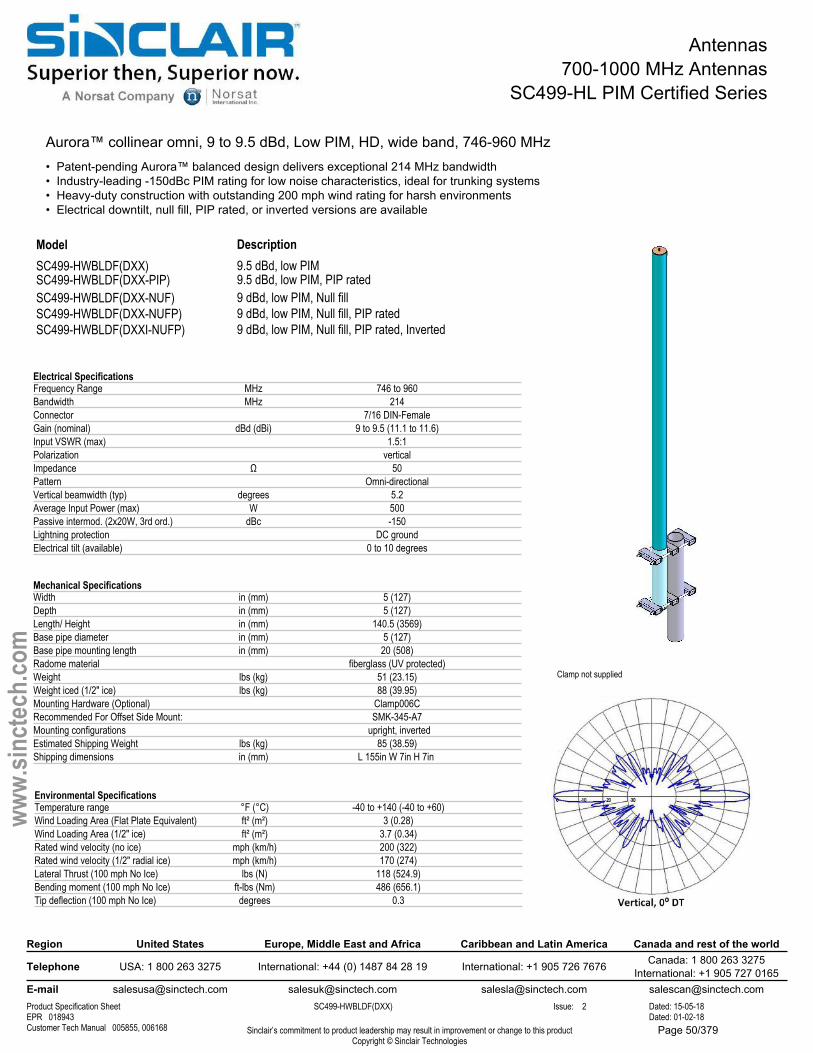
Antennas700-1000 MHz Antennas
SC499-HL PIM Certified Series
Aurora™ collinear omni, 9 to 9.5 dBd, Low PIM, HD, wide band, 746-960 MHz• Patent-pending Aurora™ balanced design delivers exceptional 214 MHz bandwidth• Industry-leading -150dBc PIM rating for low noise characteristics, ideal for trunking systems• Heavy-duty construction with outstanding 200 mph wind rating for harsh environments• Electrical downtilt, null fill, PIP rated, or inverted versions are available
Clamp not supplied
ModelSC499-HWBLDF(DXX) SC499-HWBLDF(DXX-PIP)SC499-HWBLDF(DXX-NUF) SC499-HWBLDF(DXX-NUFP) SC499-HWBLDF(DXXI-NUFP)
Description9.5 dBd, low PIM9.5 dBd, low PIM, PIP rated9 dBd, low PIM, Null fill 9 dBd, low PIM, Null fill, PIP rated9 dBd, low PIM, Null fill, PIP rated, Inverted
Electrical SpecificationsFrequency Range MHz 746 to 960Bandwidth MHz 214Connector 7/16 DIN-FemaleGain (nominal) dBd (dBi) 9 to 9.5 (11.1 to 11.6)Input VSWR (max) 1.5:1Polarization verticalImpedance Ω 50Pattern Omni-directionalVertical beamwidth (typ) degrees 5.2Average Input Power (max) W 500Passive intermod. (2x20W, 3rd ord.) dBc -150Lightning protection DC groundElectrical tilt (available) 0 to 10 degrees
Mechanical SpecificationsWidth in (mm) 5 (127)Depth in (mm) 5 (127)Length/ Height in (mm) 140.5 (3569)Base pipe diameter in (mm) 5 (127)Base pipe mounting length in (mm) 20 (508)Radome material fiberglass (UV protected)Weight lbs (kg) 51 (23.15)Weight iced (1/2" ice) lbs (kg) 88 (39.95)Mounting Hardware (Optional) Clamp006CRecommended For Offset Side Mount: SMK-345-A7Mounting configurations upright, inverted Estimated Shipping Weight lbs (kg) 85 (38.59)Shipping dimensions in (mm) L 155in W 7in H 7in
Region United States Europe, Middle East and Africa Caribbean and Latin America Canada and rest of the world
Telephone USA: 1 800 263 3275 International: +44 (0) 1487 84 28 19 International: +1 905 726 7676 Canada: 1 800 263 3275International: +1 905 727 0165
E-mail [email protected] [email protected] [email protected] [email protected] Specification Sheet SC499-HWBLDF(DXX) Issue: 2 Dated: 15-05-18EPR 018943 Dated: 01-02-18Customer Tech Manual 005855, 006168 Sinclair’s commitment to product leadership may result in improvement or change to this product
Copyright © Sinclair Technologies
www.
sinct
ech.
com
Environmental SpecificationsTemperature range °F (°C) -40 to +140 (-40 to +60)Wind Loading Area (Flat Plate Equivalent) ft² (m²) 3 (0.28)Wind Loading Area (1/2" ice) ft² (m²) 3.7 (0.34)Rated wind velocity (no ice) mph (km/h) 200 (322)Rated wind velocity (1/2" radial ice) mph (km/h) 170 (274)Lateral Thrust (100 mph No Ice) lbs (N) 118 (524.9)Bending moment (100 mph No Ice) ft-lbs (Nm) 486 (656.1)Tip deflection (100 mph No Ice) degrees 0.3
Page 50/379
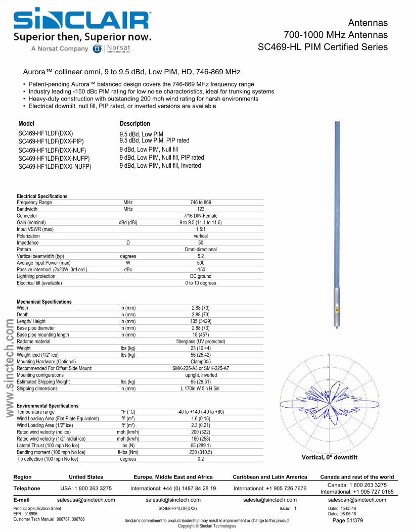
Antennas700-1000 MHz Antennas
SC469-HL PIM Certified Series
Aurora™ collinear omni, 9 to 9.5 dBd, Low PIM, HD, 746-869 MHz• Patent-pending Aurora™ balanced design covers the 746-869 MHz frequency range• Industry leading -150 dBc PIM rating for low noise characteristics, ideal for trunking systems• Heavy-duty construction with outstanding 200 mph wind rating for harsh environments• Electrical downtilt, null fill, PIP rated, or inverted versions are available
ModelSC469-HF1LDF(DXX) SC469-HF1LDF(DXX-PIP) SC469-HF1LDF(DXX-NUF) SC469-HF1LDF(DXX-NUFP) SC469-HF1LDF(DXXI-NUFP)
Description9.5 dBd, Low PIM9.5 dBd, Low PIM, PIP rated9 dBd, Low PIM, Null fill9 dBd, Low PIM, Null fill, PIP rated9 dBd, Low PIM, Null fill, Inverted
Electrical SpecificationsFrequency Range MHz 746 to 869Bandwidth MHz 123Connector 7/16 DIN-FemaleGain (nominal) dBd (dBi) 9 to 9.5 (11.1 to 11.6)Input VSWR (max) 1.5:1Polarization verticalImpedance Ω 50Pattern Omni-directionalVertical beamwidth (typ) degrees 5.2Average Input Power (max) W 500Passive intermod. (2x20W, 3rd ord.) dBc -150Lightning protection DC groundElectrical tilt (available) 0 to 10 degrees
Mechanical SpecificationsWidth in (mm) 2.88 (73)Depth in (mm) 2.88 (73)Length/ Height in (mm) 135 (3429)Base pipe diameter in (mm) 2.88 (73)Base pipe mounting length in (mm) 18 (457)Radome material fiberglass (UV protected)Weight lbs (kg) 23 (10.44)Weight iced (1/2" ice) lbs (kg) 56 (25.42)Mounting Hardware (Optional) Clamp005Recommended For Offset Side Mount: SMK-225-A3 or SMK-225-A7Mounting configurations upright, inverted Estimated Shipping Weight lbs (kg) 65 (29.51)Shipping dimensions in (mm) L 170in W 5in H 5in
Region United States Europe, Middle East and Africa Caribbean and Latin America Canada and rest of the world
Telephone USA: 1 800 263 3275 International: +44 (0) 1487 84 28 19 International: +1 905 726 7676 Canada: 1 800 263 3275International: +1 905 727 0165
E-mail [email protected] [email protected] [email protected] [email protected] Specification Sheet SC469-HF1LDF(DXX) Issue: 1 Dated: 15-05-18EPR 018996 Dated: 08-05-18Customer Tech Manual 006787, 006788 Sinclair’s commitment to product leadership may result in improvement or change to this product
Copyright © Sinclair Technologies
www.
sinct
ech.
com
Environmental SpecificationsTemperature range °F (°C) -40 to +140 (-40 to +60)Wind Loading Area (Flat Plate Equivalent) ft² (m²) 1.6 (0.15)Wind Loading Area (1/2" ice) ft² (m²) 2.3 (0.21)Rated wind velocity (no ice) mph (km/h) 200 (322)Rated wind velocity (1/2" radial ice) mph (km/h) 160 (258)Lateral Thrust (100 mph No Ice) lbs (N) 65 (289.1)Bending moment (100 mph No Ice) ft-lbs (Nm) 230 (310.5)Tip deflection (100 mph No Ice) degrees 0.2
Page 51/379
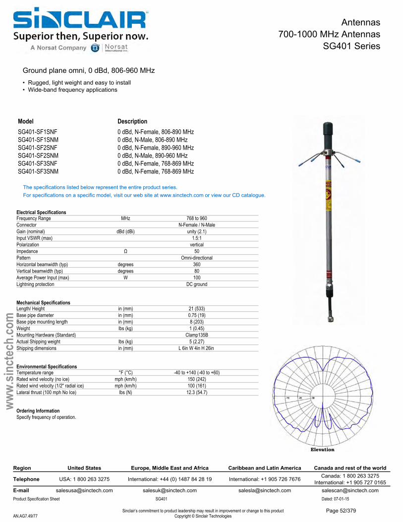
Antennas700-1000 MHz Antennas
SG401 Series
Ground plane omni, 0 dBd, 806-960 MHz• Rugged, light weight and easy to install• Wide-band frequency applications
Model DescriptionSG401-SF1SNF 0 dBd, N-Female, 806-890 MHzSG401-SF1SNM 0 dBd, N-Male, 806-890 MHzSG401-SF2SNF 0 dBd, N-Female, 890-960 MHzSG401-SF2SNM 0 dBd, N-Male, 890-960 MHzSG401-SF3SNF 0 dBd, N-Female, 768-869 MHzSG401-SF3SNM 0 dBd, N-Female, 768-869 MHz
The specifications listed below represent the entire product series.For specifications on a specific model, visit our web site at www.sinctech.com or view our CD catalogue.
Electrical SpecificationsFrequency Range MHz 768 to 960Connector N-Female / N-MaleGain (nominal) dBd (dBi) unity (2.1)Input VSWR (max) 1.5:1Polarization verticalImpedance Ω 50Pattern Omni-directionalHorizontal beamwidth (typ) degrees 360Vertical beamwidth (typ) degrees 80Average Power Input (max) W 100Lightning protection DC ground
Mechanical SpecificationsLength/ Height in (mm) 21 (533)Base pipe diameter in (mm) 0.75 (19)Base pipe mounting length in (mm) 8 (203)Weight lbs (kg) 1 (0.45)Mounting Hardware (Standard) Clamp135BActual Shipping weight lbs (kg) 5 (2.27)Shipping dimensions in (mm) L 6in W 4in H 26in
Environmental SpecificationsTemperature range °F (°C) -40 to +140 (-40 to +60)Rated wind velocity (no ice) mph (km/h) 150 (242)Rated wind velocity (1/2" radial ice) mph (km/h) 100 (161)Lateral thrust (100 mph No Ice) lbs (N) 12.3 (54.7)
Ordering InformationSpecify frequency of operation.
Region United States Europe, Middle East and Africa Caribbean and Latin America Canada and rest of the world
Telephone USA: 1 800 263 3275 International: +44 (0) 1487 84 28 19 International: +1 905 726 7676 Canada: 1 800 263 3275International: +1 905 727 0165
E-mail [email protected] [email protected] [email protected] [email protected] Specification Sheet SG401 Dated: 07-01-15
Sinclair’s commitment to product leadership may result in improvement or change to this productCopyright © Sinclair TechnologiesAN.AG7.49/77
www.
sinct
ech.
com
Page 52/379
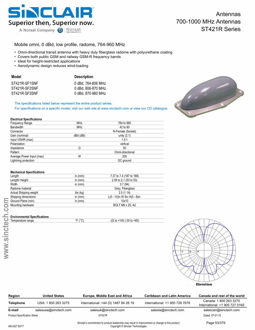
Antennas700-1000 MHz Antennas
ST421R Series
Mobile omni, 0 dBd, low profile, radome, 764-960 MHz• Omni-directional transit antenna with heavy duty fiberglass radome with polyurethane coating• Covers both public GSM and railway GSM-R frequency bands• Ideal for height-restricted applications• Aerodynamic design reduces wind-loading
Model DescriptionST421R-SF1SNF 0 dBd, 764-806 MHzST421R-SF2SNF 0 dBd, 806-870 MHz.ST421R-SF3SNF 0 dBd, 870-960 MHz
The specifications listed below represent the entire product series.For specifications on a specific model, visit our web site at www.sinctech.com or view our CD catalogue.
Electrical SpecificationsFrequency Range MHz 764 to 960Bandwidth MHz 42 to 90Connector N-Female (Socket)Gain (nominal) dBd (dBi) unity (2.1)Input VSWR (max) 1.5:1Polarization verticalImpedance Ω 50Pattern Omni-directionalAverage Power Input (max) W 200Lightning protection DC ground
Mechanical SpecificationsLength in (mm) 7.37 to 7.4 (187 to 188)Length/ Height in (mm) 2.09 to 2.1 (53 to 53)Width in (mm) 3.7 (94)Radome material Grey, FiberglassActual Shipping weight lbs (kg) 2.5 (1.14)Shipping dimensions in (mm) L(5 - 10)in W 5in H(5 - 8)in Ground Plane (min) in (mm) 10x10Mounting hardware BOLT M6 x 25, A2
Environmental SpecificationsTemperature range °F (°C) -22 to +140 (-30 to +60)
Region United States Europe, Middle East and Africa Caribbean and Latin America Canada and rest of the world
Telephone USA: 1 800 263 3275 International: +44 (0) 1487 84 28 19 International: +1 905 726 7676 Canada: 1 800 263 3275International: +1 905 727 0165
E-mail [email protected] [email protected] [email protected] [email protected] Specification Sheet ST421R Dated: 07-01-15
Sinclair’s commitment to product leadership may result in improvement or change to this productCopyright © Sinclair TechnologiesAN.AG7.50/77
www.
sinct
ech.
com
Page 53/379

Transmitter Combiners700 -1000 MHz Transmitter Combiners
RTC5800R Series
Compact Trunking Transmitter Combiner, 5 Channels, 806-869 MHz• Different versions support frequency spacings of 1 MHz, 500 KHz and 250 KHz• 125 watts per channel• Fits easily into 19 inch rack - only 12.25 inches vertical height• 6 and 10 channel models available
Model DescriptionRTC5800RA-1 1 MHz channel spacing, 806-824 MHzRTC5800RA-2 1 MHz channel spacing, 851-869 MHzRTC5800RB-1 0.5 MHz channel spacing, 806-824 MHzRTC5800RB-2 0.5 MHz channel spacing, 851-869 MHzRTC5800RC-1 0.25 MHz channel spacing, 806-824 MHzRTC5800RC-2 0.25 MHz channel spacing, 851-869 MHz
The specifications listed below represent the entire product series.For specifications on a specific model, visit our web site at www.sinctech.com or view our CD catalogue.
Electrical SpecificationsFrequency Range MHz 806 to 869Input VSWR (max) 1.25:1Input Connectors N-FemaleOutput Connectors N-FemalePower (Per Channel) W 125Isolation Tx to Tx dB 70Isolation antenna to Tx dB 60Output VSWR 2:1Number of channels 5
Mechanical SpecificationsDepth in (mm) 15 (381)Length/ Height in (mm) 12.25 (311)Width in (mm) 19 (483)Weight lbs (kg) 50 (22.7)Actual Shipping weight lbs (kg) 55 (24.97)Shipping dimensions in (mm) L(22 - 24)in W(15 - 17)in H(19 - 21)in
Environmental SpecificationsTemperature range °F (°C) -22 to +140 (-30 to +60)
Ordering InformationRA = 1 MHz separation with insertion loss of 2.6 dBRB = 0.5 MHz separation with insertion loss of 2.8 dBRC = 0.25 MHz separation with insertion loss of 4.0 dB
6 and 10 channel models are also available, please contact your Sinclair Sales Representative for more information.
Region United States Europe, Middle East and Africa Caribbean and Latin America Canada and rest of the world
Telephone USA: 1 800 263 3275 International: +44 (0) 1487 84 28 19 International: +1 905 726 7676 Canada: 1 800 263 3275International: +1 905 727 0165
E-mail [email protected] [email protected] [email protected] [email protected] Specification Sheet RTC5800R Dated: 07-01-15
Sinclair’s commitment to product leadership may result in improvement or change to this productCopyright © Sinclair TechnologiesAN.AG7.52/77
www.
sinct
ech.
com
Page 54/379
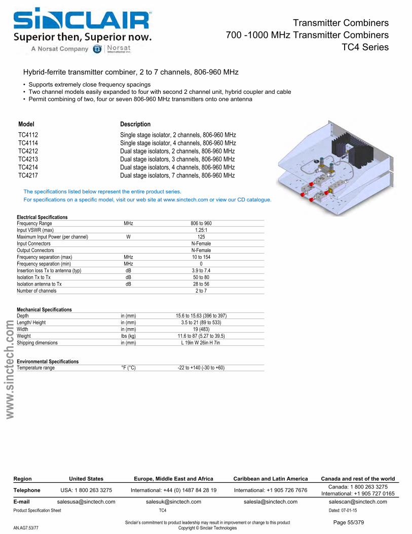
Transmitter Combiners700 -1000 MHz Transmitter Combiners
TC4 Series
Hybrid-ferrite transmitter combiner, 2 to 7 channels, 806-960 MHz• Supports extremely close frequency spacings• Two channel models easily expanded to four with second 2 channel unit, hybrid coupler and cable• Permit combining of two, four or seven 806-960 MHz transmitters onto one antenna
Model DescriptionTC4112 Single stage isolator, 2 channels, 806-960 MHzTC4114 Single stage isolator, 4 channels, 806-960 MHzTC4212 Dual stage isolators, 2 channels, 806-960 MHzTC4213 Dual stage isolators, 3 channels, 806-960 MHzTC4214 Dual stage isolators, 4 channels, 806-960 MHzTC4217 Dual stage isolators, 7 channels, 806-960 MHz
The specifications listed below represent the entire product series.For specifications on a specific model, visit our web site at www.sinctech.com or view our CD catalogue.
Electrical SpecificationsFrequency Range MHz 806 to 960Input VSWR (max) 1.25:1Maximum Input Power (per channel) W 125Input Connectors N-FemaleOutput Connectors N-FemaleFrequency separation (max) MHz 10 to 154Frequency separation (min) MHz 0Insertion loss Tx to antenna (typ) dB 3.9 to 7.4Isolation Tx to Tx dB 50 to 80Isolation antenna to Tx dB 28 to 56Number of channels 2 to 7
Mechanical SpecificationsDepth in (mm) 15.6 to 15.63 (396 to 397)Length/ Height in (mm) 3.5 to 21 (89 to 533)Width in (mm) 19 (483)Weight lbs (kg) 11.6 to 87 (5.27 to 39.5)Shipping dimensions in (mm) L 19in W 26in H 7in
Environmental SpecificationsTemperature range °F (°C) -22 to +140 (-30 to +60)
Region United States Europe, Middle East and Africa Caribbean and Latin America Canada and rest of the world
Telephone USA: 1 800 263 3275 International: +44 (0) 1487 84 28 19 International: +1 905 726 7676 Canada: 1 800 263 3275International: +1 905 727 0165
E-mail [email protected] [email protected] [email protected] [email protected] Specification Sheet TC4 Dated: 07-01-15
Sinclair’s commitment to product leadership may result in improvement or change to this productCopyright © Sinclair TechnologiesAN.AG7.53/77
www.
sinct
ech.
com
Page 55/379
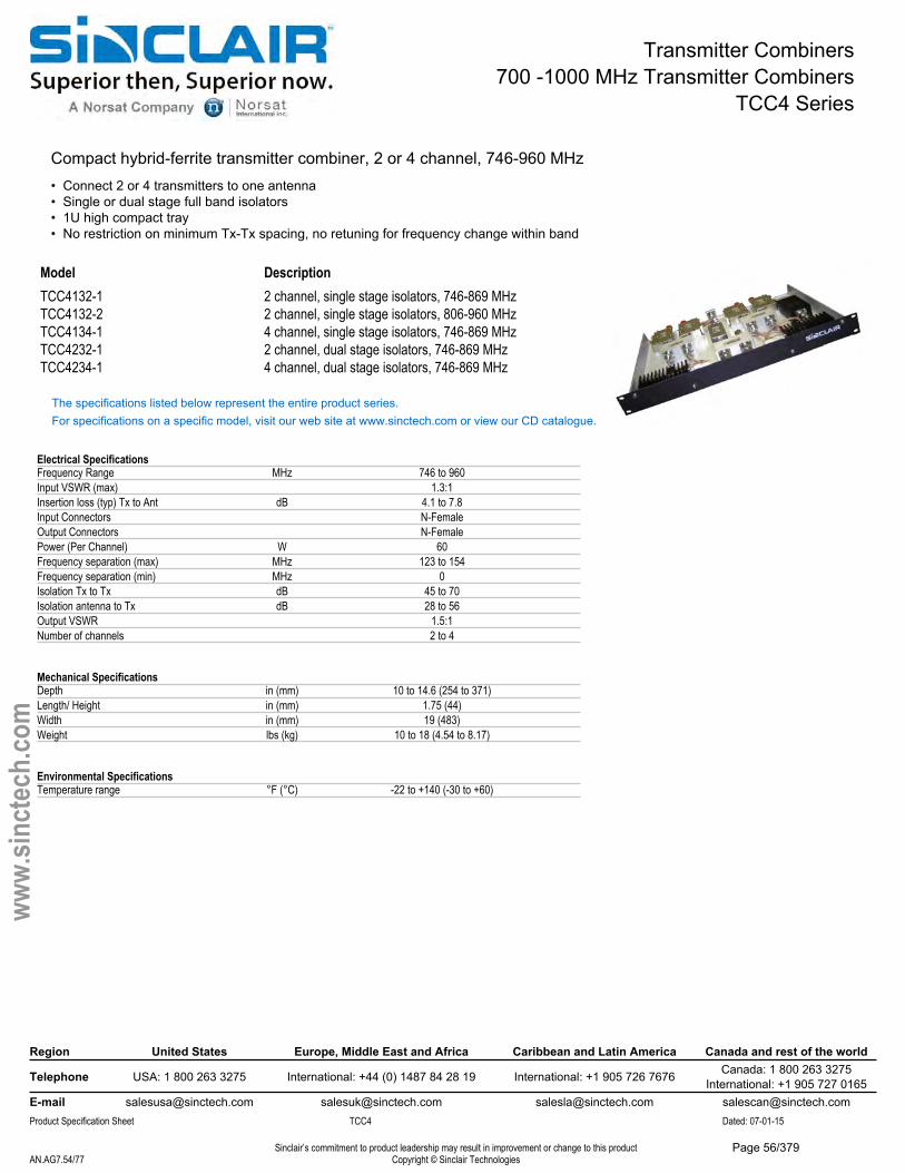
Transmitter Combiners700 -1000 MHz Transmitter Combiners
TCC4 Series
Compact hybrid-ferrite transmitter combiner, 2 or 4 channel, 746-960 MHz• Connect 2 or 4 transmitters to one antenna• Single or dual stage full band isolators• 1U high compact tray• No restriction on minimum Tx-Tx spacing, no retuning for frequency change within band
Model DescriptionTCC4132-1 2 channel, single stage isolators, 746-869 MHzTCC4132-2 2 channel, single stage isolators, 806-960 MHzTCC4134-1 4 channel, single stage isolators, 746-869 MHzTCC4232-1 2 channel, dual stage isolators, 746-869 MHzTCC4234-1 4 channel, dual stage isolators, 746-869 MHz
The specifications listed below represent the entire product series.For specifications on a specific model, visit our web site at www.sinctech.com or view our CD catalogue.
Electrical SpecificationsFrequency Range MHz 746 to 960Input VSWR (max) 1.3:1Insertion loss (typ) Tx to Ant dB 4.1 to 7.8Input Connectors N-FemaleOutput Connectors N-FemalePower (Per Channel) W 60Frequency separation (max) MHz 123 to 154Frequency separation (min) MHz 0Isolation Tx to Tx dB 45 to 70Isolation antenna to Tx dB 28 to 56Output VSWR 1.5:1Number of channels 2 to 4
Mechanical SpecificationsDepth in (mm) 10 to 14.6 (254 to 371)Length/ Height in (mm) 1.75 (44)Width in (mm) 19 (483)Weight lbs (kg) 10 to 18 (4.54 to 8.17)
Environmental SpecificationsTemperature range °F (°C) -22 to +140 (-30 to +60)
Region United States Europe, Middle East and Africa Caribbean and Latin America Canada and rest of the world
Telephone USA: 1 800 263 3275 International: +44 (0) 1487 84 28 19 International: +1 905 726 7676 Canada: 1 800 263 3275International: +1 905 727 0165
E-mail [email protected] [email protected] [email protected] [email protected] Specification Sheet TCC4 Dated: 07-01-15
Sinclair’s commitment to product leadership may result in improvement or change to this productCopyright © Sinclair TechnologiesAN.AG7.54/77
www.
sinct
ech.
com
Page 56/379
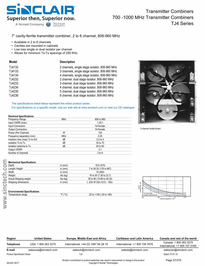
Transmitter Combiners700 -1000 MHz Transmitter Combiners
TJ4 Series
7” cavity-ferrite transmitter combiner, 2 to 6 channel, 806-960 MHz• Available in 2 to 6 channels• Cavities are mounted in cabinets• Low loss single or dual isolator per channel• Allows for minimum Tx-Tx spacings of 250 KHz
5 channel model shown
Model DescriptionTJ4132 2 channels, single stage isolator, 806-960 MHzTJ4133 3 channels, single stage isolator, 806-960 MHzTJ4134 4 channels, single stage isolator, 806-960 MHzTJ4232 2 channel, dual stage isolator, 806-960 MHzTJ4233 3 channel, dual stage isolator, 806-960 MHzTJ4234 4 channel, dual stage isolator, 806-960 MHzTJ4235 5 channel, dual stage isolator, 806-960 MHzTJ4236 6 channel, dual stage isolator, 806-960 MHz
The specifications listed below represent the entire product series.For specifications on a specific model, visit our web site at www.sinctech.com or view our CD catalogue.
Electrical SpecificationsFrequency Range MHz 806 to 960Input VSWR (max) 1.25:1Input Connectors N-FemaleOutput Connectors N-FemalePower (Per Channel) W 125Frequency separation (min) MHz 0.25Insertion loss (max) Tx to Ant dB 3.2 to 4Isolation Tx to Tx dB 35 to 70Isolation antenna to Tx dB 25 to 60Output VSWR 2:1Number of channels 2 to 6
Mechanical SpecificationsDepth in (mm) 18.5 (470)Length/ Height in (mm) 7 to 26.25 (178 to 667)Width in (mm) 19 (483)Weight lbs (kg) 16 to 50 (7.26 to 22.7)Actual Shipping weight lbs (kg) 35 to 80 (15.89 to 36.32)Shipping dimensions in (mm) L 23in W 23in H(12 - 18)in
Environmental SpecificationsTemperature range °F (°C) -22 to +140 (-30 to +60)
Region United States Europe, Middle East and Africa Caribbean and Latin America Canada and rest of the world
Telephone USA: 1 800 263 3275 International: +44 (0) 1487 84 28 19 International: +1 905 726 7676 Canada: 1 800 263 3275International: +1 905 727 0165
E-mail [email protected] [email protected] [email protected] [email protected] Specification Sheet TJ4 Dated: 07-01-15
Sinclair’s commitment to product leadership may result in improvement or change to this productCopyright © Sinclair TechnologiesAN.AG7.55/77
www.
sinct
ech.
com
Page 57/379
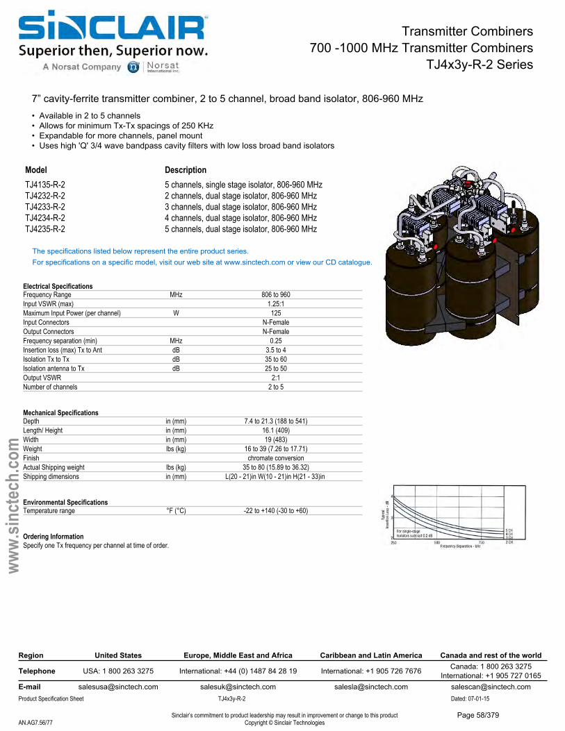
Transmitter Combiners700 -1000 MHz Transmitter Combiners
TJ4x3y-R-2 Series
7” cavity-ferrite transmitter combiner, 2 to 5 channel, broad band isolator, 806-960 MHz• Available in 2 to 5 channels• Allows for minimum Tx-Tx spacings of 250 KHz• Expandable for more channels, panel mount• Uses high 'Q' 3/4 wave bandpass cavity filters with low loss broad band isolators
Model DescriptionTJ4135-R-2 5 channels, single stage isolator, 806-960 MHzTJ4232-R-2 2 channels, dual stage isolator, 806-960 MHzTJ4233-R-2 3 channels, dual stage isolator, 806-960 MHzTJ4234-R-2 4 channels, dual stage isolator, 806-960 MHzTJ4235-R-2 5 channels, dual stage isolator, 806-960 MHz
The specifications listed below represent the entire product series.For specifications on a specific model, visit our web site at www.sinctech.com or view our CD catalogue.
Electrical SpecificationsFrequency Range MHz 806 to 960Input VSWR (max) 1.25:1Maximum Input Power (per channel) W 125Input Connectors N-FemaleOutput Connectors N-FemaleFrequency separation (min) MHz 0.25Insertion loss (max) Tx to Ant dB 3.5 to 4Isolation Tx to Tx dB 35 to 60Isolation antenna to Tx dB 25 to 50Output VSWR 2:1Number of channels 2 to 5
Mechanical SpecificationsDepth in (mm) 7.4 to 21.3 (188 to 541)Length/ Height in (mm) 16.1 (409)Width in (mm) 19 (483)Weight lbs (kg) 16 to 39 (7.26 to 17.71)Finish chromate conversionActual Shipping weight lbs (kg) 35 to 80 (15.89 to 36.32)Shipping dimensions in (mm) L(20 - 21)in W(10 - 21)in H(21 - 33)in
Environmental SpecificationsTemperature range °F (°C) -22 to +140 (-30 to +60)
Ordering InformationSpecify one Tx frequency per channel at time of order.
Region United States Europe, Middle East and Africa Caribbean and Latin America Canada and rest of the world
Telephone USA: 1 800 263 3275 International: +44 (0) 1487 84 28 19 International: +1 905 726 7676 Canada: 1 800 263 3275International: +1 905 727 0165
E-mail [email protected] [email protected] [email protected] [email protected] Specification Sheet TJ4x3y-R-2 Dated: 07-01-15
Sinclair’s commitment to product leadership may result in improvement or change to this productCopyright © Sinclair TechnologiesAN.AG7.56/77
www.
sinct
ech.
com
Page 58/379
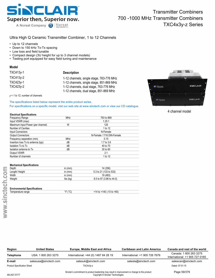
Transmitter Combiners700 -1000 MHz Transmitter Combiners
TXC4x3y-z Series
Ultra High Q Ceramic Transmitter Combiner, 1 to 12 Channels• Up to 12 channels• Down to 150 kHz Tx-Tx spacing• Low loss and field tunable• Compact design (3U height for up to 3 channel models)• Testing port equipped for easy field tuning and maintenance
ModelTXC413y-1TXC413y-2
Description1-12 channels, single stage, 763-776 MHz1-12 channels, single stage, 851-869 MHz1-12 channels, dual stage, 763-776 MHz1-12 channels, dual stage, 851-869 MHz
Region United States Europe, Middle East and Africa Caribbean and Latin America Canada and rest of the world
Telephone USA: 1 800 263 3275 International: +44 (0) 1487 84 28 19 International: +1 905 726 7676 Canada: 1 800 263 3275International: +1 905 727 0165
E-mail [email protected] [email protected] [email protected] [email protected] Specification Sheet TXC4x3y-z Dated: 07-01-15
Sinclair’s commitment to product leadership may result in improvement or change to this productCopyright © Sinclair TechnologiesAN.AG7.57/77
www.
sinct
ech.
com
Mechanical SpecificationsDepth in (mm) 14 (356)Length/ Height in (mm) 5.3 to 21 (133 to 533)Width in (mm) 19 (483)Weight lbs (kg) 8.5 to 97 (3.86 to 44.0)
Environmental SpecificationsTemperature range °F (°C) +14 to +140 (-10 to +60)
The specifications listed below represent the entire product series.For specifications on a specific model, visit our web site at www.sinctech.com or view our CD catalogue.
Electrical SpecificationsFrequency Range MHz 763 to 869Input VSWR (max) 1.25:1Maximum Input Power (per channel) W 125Number of Cavities 1 to 12Input Connectors N-FemaleOutput Connectors N-Female / 7/16 DIN-FemaleFrequency separation (min) MHz 0.15Insertion loss Tx to antenna (typ) dB 1.7 to 3.6Isolation Tx to Tx dB 40 to 70Isolation antenna to Tx dB 30 to 60Output VSWR 2:1Number of channels 1 to 12
TXC423y-1TXC423y-2
y = 1 to 12, number of channels.
4 channel model
Page 59/379
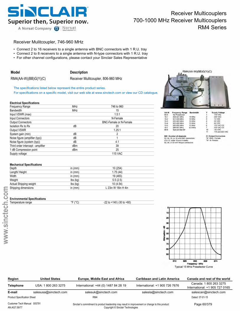
Receiver Multicouplers700-1000 MHz Receiver Multicouplers
RM4 Series
Receiver Mulitcoupler, 746-960 MHz • Connect 2 to 16 receivers to a single antenna with BNC connectors with 1 R.U. tray• Connect 2 to 8 receivers to a single antenna with N-type connectors with 1 R.U. tray• For other channel configurations, please contact your Sinclair Sales Representative
Model DescriptionRM4(AA-W)(BB)G(Y)(C) Receiver Mulitcoupler, 806-960 MHz
The specifications listed below represent the entire product series.For specifications on a specific model, visit our web site at www.sinctech.com or view our CD catalogue.
Electrical SpecificationsFrequency Range MHz 746 to 960Bandwidth MHz 15Input VSWR (max) 1.5:1Input Connectors N-FemaleOutput Connectors BNC-Female or N-FemaleIsolation Rx to Rx dB 20Output VSWR 1.25:1System gain (min) dB 2Noise figure (amplifier (typ)) dB 1Noise figure (system (typ)) dB 4.1Third order intercept - amplifier dBm 391 dB Compression point dBm 25Supply voltage 115 VAC
Mechanical SpecificationsDepth in (mm) 10 (254)Length/ Height in (mm) 1.75 (44)Width in (mm) 19 (483)Weight lbs (kg) 5.5 (2.5)Actual Shipping weight lbs (kg) 10 (4.54)Shipping dimensions in (mm) L 23in W 18in H 4in
Environmental SpecificationsTemperature range °F (°C) -22 to +140 (-30 to +60)
Region United States Europe, Middle East and Africa Caribbean and Latin America Canada and rest of the world
Telephone USA: 1 800 263 3275 International: +44 (0) 1487 84 28 19 International: +1 905 726 7676 Canada: 1 800 263 3275International: +1 905 727 0165
E-mail [email protected] [email protected] [email protected] [email protected] Specification Sheet RM4 Dated: 07-01-15
Customer Tech Manual 005791 Sinclair’s commitment to product leadership may result in improvement or change to this productCopyright © Sinclair TechnologiesAN.AG7.59/77
www.
sinct
ech.
com
Page 60/379
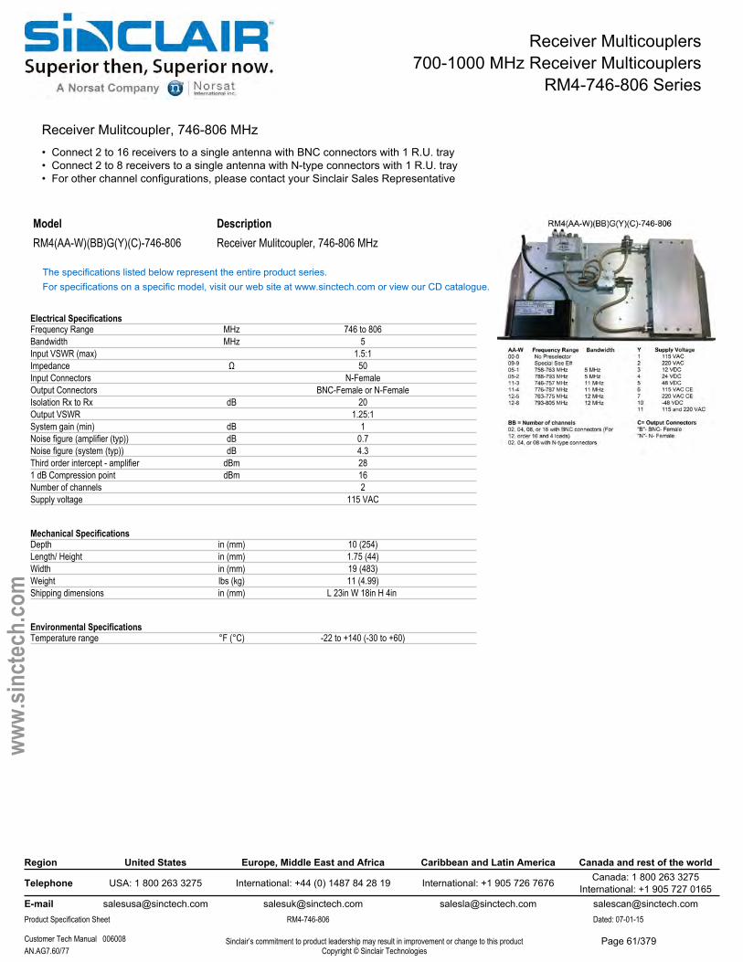
Receiver Multicouplers700-1000 MHz Receiver Multicouplers
RM4-746-806 Series
Receiver Mulitcoupler, 746-806 MHz • Connect 2 to 16 receivers to a single antenna with BNC connectors with 1 R.U. tray• Connect 2 to 8 receivers to a single antenna with N-type connectors with 1 R.U. tray• For other channel configurations, please contact your Sinclair Sales Representative
Model DescriptionRM4(AA-W)(BB)G(Y)(C)-746-806 Receiver Mulitcoupler, 746-806 MHz
The specifications listed below represent the entire product series.For specifications on a specific model, visit our web site at www.sinctech.com or view our CD catalogue.
Electrical SpecificationsFrequency Range MHz 746 to 806Bandwidth MHz 5Input VSWR (max) 1.5:1Impedance Ω 50Input Connectors N-FemaleOutput Connectors BNC-Female or N-FemaleIsolation Rx to Rx dB 20Output VSWR 1.25:1System gain (min) dB 1Noise figure (amplifier (typ)) dB 0.7Noise figure (system (typ)) dB 4.3Third order intercept - amplifier dBm 281 dB Compression point dBm 16Number of channels 2Supply voltage 115 VAC
Mechanical SpecificationsDepth in (mm) 10 (254)Length/ Height in (mm) 1.75 (44)Width in (mm) 19 (483)Weight lbs (kg) 11 (4.99)Shipping dimensions in (mm) L 23in W 18in H 4in
Environmental SpecificationsTemperature range °F (°C) -22 to +140 (-30 to +60)
Region United States Europe, Middle East and Africa Caribbean and Latin America Canada and rest of the world
Telephone USA: 1 800 263 3275 International: +44 (0) 1487 84 28 19 International: +1 905 726 7676 Canada: 1 800 263 3275International: +1 905 727 0165
E-mail [email protected] [email protected] [email protected] [email protected] Specification Sheet RM4-746-806 Dated: 07-01-15
Customer Tech Manual 006008 Sinclair’s commitment to product leadership may result in improvement or change to this productCopyright © Sinclair TechnologiesAN.AG7.60/77
www.
sinct
ech.
com
Page 61/379
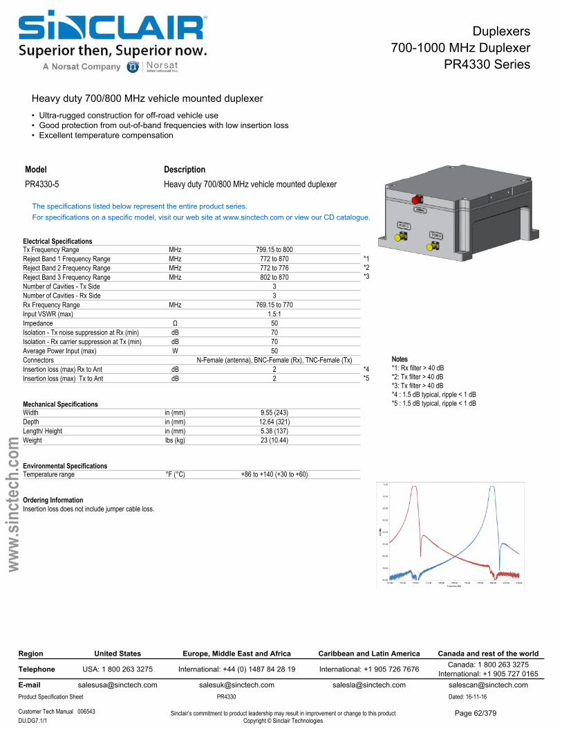
Duplexers700-1000 MHz Duplexer
PR4330 Series
Heavy duty 700/800 MHz vehicle mounted duplexer• Ultra-rugged construction for off-road vehicle use• Good protection from out-of-band frequencies with low insertion loss• Excellent temperature compensation
Model DescriptionPR4330-5 Heavy duty 700/800 MHz vehicle mounted duplexer
The specifications listed below represent the entire product series.For specifications on a specific model, visit our web site at www.sinctech.com or view our CD catalogue.
Electrical SpecificationsTx Frequency Range MHz 799.15 to 800Reject Band 1 Frequency Range MHz 772 to 870Reject Band 2 Frequency Range MHz 772 to 776Reject Band 3 Frequency Range MHz 802 to 870Number of Cavities - Tx Side 3Number of Cavities - Rx Side 3Rx Frequency Range MHz 769.15 to 770Input VSWR (max) 1.5:1Impedance Ω 50Isolation - Tx noise suppression at Rx (min) dB 70Isolation - Rx carrier suppression at Tx (min) dB 70Average Power Input (max) W 50Connectors N-Female (antenna), BNC-Female (Rx), TNC-Female (Tx)Insertion loss (max) Rx to Ant dB 2Insertion loss (max) Tx to Ant dB 2
Mechanical SpecificationsWidth in (mm) 9.55 (243)Depth in (mm) 12.64 (321)Length/ Height in (mm) 5.38 (137)Weight lbs (kg) 23 (10.44)
Environmental SpecificationsTemperature range °F (°C) +86 to +140 (+30 to +60)
Ordering InformationInsertion loss does not include jumper cable loss.
Region United States Europe, Middle East and Africa Caribbean and Latin America Canada and rest of the world
Telephone USA: 1 800 263 3275 International: +44 (0) 1487 84 28 19 International: +1 905 726 7676 Canada: 1 800 263 3275International: +1 905 727 0165
E-mail [email protected] [email protected] [email protected] [email protected] Specification Sheet PR4330 Dated: 16-11-16
Customer Tech Manual 006543 Sinclair’s commitment to product leadership may result in improvement or change to this productCopyright © Sinclair TechnologiesDU.DG7.1/1
www.
sinct
ech.
com
*1*2*3
Notes*1: Rx filter > 40 dB*2: Tx filter > 40 dB*3: Tx filter > 40 dB*4 : 1.5 dB typical, ripple < 1 dB*5 : 1.5 dB typical, ripple < 1 dB
*4*5
Page 62/379
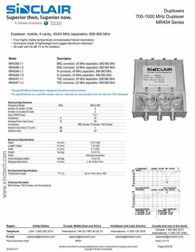
Duplexers700-1000 MHz Duplexer
MR454 Series
Duplexer, mobile, 4 cavity, 45/24 MHz separation, 806-960 MHz• Four highly stable temperature compensated helical resonators• Enclosure made of lightweight and rugged aluminum extrusion• 50 watt with 50 dB Tx to Rx isolation
ModelMR454B-1-1MR454B-1-2MR454N-1-1MR454N-1-2MR454T-1-1MR454T-1-2
DescriptionBNC connector, 45 MHz separation, 806-960 MHz BNC connector, 24 MHz separation, 806-960 MHz N connector, 45 MHz separation, 806-960 MHz N connector, 24 MHz separation, 806-960 MHzTNC connector, 45 MHz separation, 806-960 MHz TNC connector, 24 MHz separation, 806-960 MHz
The specifications listed below represent the entire product series.For specifications on a specific model, visit our web site at www.sinctech.com or view our CD catalogue.
Electrical SpecificationsFrequency Range MHz 806 to 960Number of cavites Tx Side 2Number of Cavities Rx Side 2Input VSWR (max) 1.5:1Impedance Ω 50Average Power Input (max) W 50Connectors BNC female / N female / TNC femaleInsertion loss (max) Tx to Ant dB 1Isolation (min) dB 50
Mechanical SpecificationsDepth in (mm) 5.75 (146)Length/ Height in (mm) 1.25 (32)Width in (mm) 4.1 (104)Weight lbs (kg) 1.6 (0.73)Finish chemical conversionActual Shipping weight lbs (kg) 1.6 (0.73)Shipping dimensions in (mm) L 9in W 6in H 3in
Environmental SpecificationsTemperature range °F (°C) -22 to +140 (-30 to +60)
Ordering InformationBNC-Female, TNC-Female, and N connectors.
Region United States Europe, Middle East and Africa Caribbean and Latin America Canada and rest of the world
Telephone USA: 1 800 263 3275 International: +44 (0) 1487 84 28 19 International: +1 905 726 7676 Canada: 1 800 263 3275International: +1 905 727 0165
E-mail [email protected] [email protected] [email protected] [email protected] Specification Sheet MR454 Dated: 07-01-15
Sinclair’s commitment to product leadership may result in improvement or change to this productCopyright © Sinclair TechnologiesAN.AG7.61/77
www.
sinct
ech.
com
Page 63/379
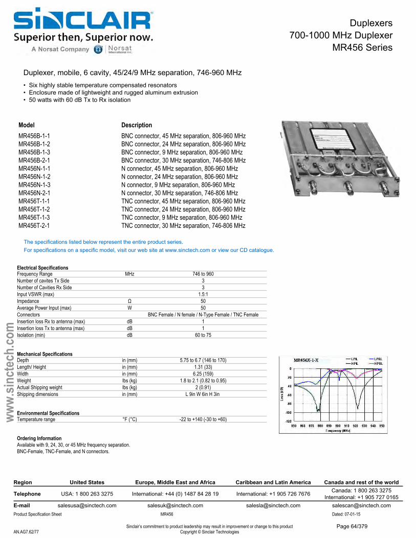
Duplexers700-1000 MHz Duplexer
MR456 Series
Duplexer, mobile, 6 cavity, 45/24/9 MHz separation, 746-960 MHz• Six highly stable temperature compensated resonators• Enclosure made of lightweight and rugged aluminum extrusion• 50 watts with 60 dB Tx to Rx isolation
Model DescriptionMR456B-1-1 BNC connector, 45 MHz separation, 806-960 MHzMR456B-1-2 BNC connector, 24 MHz separation, 806-960 MHzMR456B-1-3 BNC connector, 9 MHz separation, 806-960 MHzMR456B-2-1 BNC connector, 30 MHz separation, 746-806 MHzMR456N-1-1 N connector, 45 MHz separation, 806-960 MHzMR456N-1-2 N connector, 24 MHz separation, 806-960 MHzMR456N-1-3 N connector, 9 MHz separation, 806-960 MHzMR456N-2-1 N connector, 30 MHz separation, 746-806 MHzMR456T-1-1 TNC connector, 45 MHz separation, 806-960 MHzMR456T-1-2 TNC connector, 24 MHz separation, 806-960 MHzMR456T-1-3 TNC connector, 9 MHz separation, 806-960 MHzMR456T-2-1 TNC connector, 30 MHz separation, 746-806 MHz
The specifications listed below represent the entire product series.For specifications on a specific model, visit our web site at www.sinctech.com or view our CD catalogue.
Electrical SpecificationsFrequency Range MHz 746 to 960Number of cavites Tx Side 3Number of Cavities Rx Side 3Input VSWR (max) 1.5:1Impedance Ω 50Average Power Input (max) W 50Connectors BNC Female / N female / N-Type Female / TNC FemaleInsertion loss Rx to antenna (max) dB 1Insertion loss Tx to antenna (max) dB 1Isolation (min) dB 60 to 75
Mechanical SpecificationsDepth in (mm) 5.75 to 6.7 (146 to 170)Length/ Height in (mm) 1.31 (33)Width in (mm) 6.25 (159)Weight lbs (kg) 1.8 to 2.1 (0.82 to 0.95)Actual Shipping weight lbs (kg) 2 (0.91)Shipping dimensions in (mm) L 9in W 6in H 3in
Environmental SpecificationsTemperature range °F (°C) -22 to +140 (-30 to +60)
Ordering InformationAvailable with 9, 24, 30, or 45 MHz frequency separation.BNC-Female, TNC-Female, and N connectors.
Region United States Europe, Middle East and Africa Caribbean and Latin America Canada and rest of the world
Telephone USA: 1 800 263 3275 International: +44 (0) 1487 84 28 19 International: +1 905 726 7676 Canada: 1 800 263 3275International: +1 905 727 0165
E-mail [email protected] [email protected] [email protected] [email protected] Specification Sheet MR456 Dated: 07-01-15
Sinclair’s commitment to product leadership may result in improvement or change to this productCopyright © Sinclair TechnologiesAN.AG7.62/77
www.
sinct
ech.
com
Page 64/379
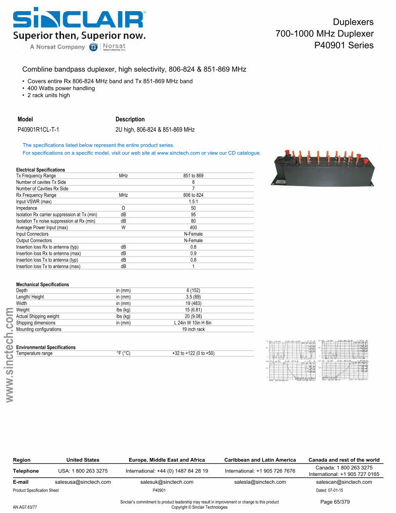
Duplexers700-1000 MHz Duplexer
P40901 Series
Combline bandpass duplexer, high selectivity, 806-824 & 851-869 MHz• Covers entire Rx 806-824 MHz band and Tx 851-869 MHz band• 400 Watts power handling• 2 rack units high
Model DescriptionP40901R1CL-T-1 2U high, 806-824 & 851-869 MHz
The specifications listed below represent the entire product series.For specifications on a specific model, visit our web site at www.sinctech.com or view our CD catalogue.
Electrical SpecificationsTx Frequency Range MHz 851 to 869Number of cavites Tx Side 8Number of Cavities Rx Side 7Rx Frequency Range MHz 806 to 824Input VSWR (max) 1.5:1Impedance Ω 50Isolation Rx carrier suppression at Tx (min) dB 95Isolation Tx noise suppression at Rx (min) dB 80Average Power Input (max) W 400Input Connectors N-FemaleOutput Connectors N-FemaleInsertion loss Rx to antenna (typ) dB 0.8Insertion loss Rx to antenna (max) dB 0.9Insertion loss Tx to antenna (typ) dB 0.8Insertion loss Tx to antenna (max) dB 1
Mechanical SpecificationsDepth in (mm) 6 (152)Length/ Height in (mm) 3.5 (89)Width in (mm) 19 (483)Weight lbs (kg) 15 (6.81)Actual Shipping weight lbs (kg) 20 (9.08)Shipping dimensions in (mm) L 24in W 10in H 8in Mounting configurations 19 inch rack
Environmental SpecificationsTemperature range °F (°C) +32 to +122 (0 to +50)
Region United States Europe, Middle East and Africa Caribbean and Latin America Canada and rest of the world
Telephone USA: 1 800 263 3275 International: +44 (0) 1487 84 28 19 International: +1 905 726 7676 Canada: 1 800 263 3275International: +1 905 727 0165
E-mail [email protected] [email protected] [email protected] [email protected] Specification Sheet P40901 Dated: 07-01-15
Sinclair’s commitment to product leadership may result in improvement or change to this productCopyright © Sinclair TechnologiesAN.AG7.63/77
www.
sinct
ech.
com
Page 65/379
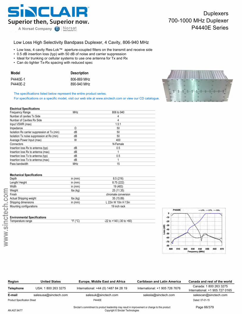
Duplexers700-1000 MHz Duplexer
P4440E Series
Low Loss High Selectivity Bandpass Duplexer, 4 Cavity, 806-940 MHz• Low loss, 4 cavity Res-Lok™ aperture-coupled filters on the transmit and receive side• 0.5 dB insertion loss (typ) with 50 dB of noise and carrier suppression• Ideal for trunking or cellular systems to use one antenna for Tx and Rx• Can do tighter Tx-Rx spacing with reduced spec
Model DescriptionP4440E-1 806-869 MHzP4440E-2 890-940 MHz
The specifications listed below represent the entire product series.For specifications on a specific model, visit our web site at www.sinctech.com or view our CD catalogue.
Electrical SpecificationsFrequency Range MHz 806 to 940Number of cavites Tx Side 4Number of Cavities Rx Side 4Input VSWR (max) 1.5:1Impedance Ω 50Isolation Rx carrier suppression at Tx (min) dB 50Isolation Tx noise suppression at Rx (min) dB 50Average Power Input (max) W 400Connectors N-FemaleInsertion loss Rx to antenna (typ) dB 0.5Insertion loss Rx to antenna (max) dB 1Insertion loss Tx to antenna (typ) dB 0.5Insertion loss Tx to antenna (max) dB 1Pass bandwidth MHz 15
Mechanical SpecificationsDepth in (mm) 8.5 (216)Length/ Height in (mm) 8.75 (222)Width in (mm) 19 (483)Weight lbs (kg) 25 (11.35)Finish chromate conversionActual Shipping weight lbs (kg) 35 (15.89)Shipping dimensions in (mm) L 22in W 10in H 13in Mounting configurations 19 inch rack
Environmental SpecificationsTemperature range °F (°C) -22 to +140 (-30 to +60)
Region United States Europe, Middle East and Africa Caribbean and Latin America Canada and rest of the world
Telephone USA: 1 800 263 3275 International: +44 (0) 1487 84 28 19 International: +1 905 726 7676 Canada: 1 800 263 3275International: +1 905 727 0165
E-mail [email protected] [email protected] [email protected] [email protected] Specification Sheet P4440E Dated: 07-01-15
Sinclair’s commitment to product leadership may result in improvement or change to this productCopyright © Sinclair TechnologiesAN.AG7.64/77
www.
sinct
ech.
com
Page 66/379
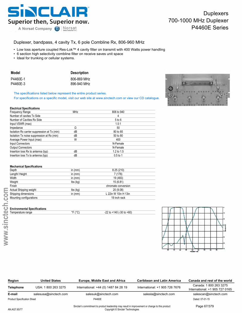
Duplexers700-1000 MHz Duplexer
P4460E Series
Duplexer, bandpass, 4 cavity Tx, 6 pole Combline Rx, 806-960 MHz• Low loss aperture coupled Res-Lok™ 4 cavity filter on transmit with 400 Watts power handling• 6 section high selectivity combline filter on receive saves unit space• Ideal for trunking or cellular systems.
Model DescriptionP4460E-1 806-869 MHzP4460E-3 896-940 MHz
The specifications listed below represent the entire product series.For specifications on a specific model, visit our web site at www.sinctech.com or view our CD catalogue.
Electrical SpecificationsFrequency Range MHz 806 to 940Number of cavites Tx Side 4Number of Cavities Rx Side 5 to 6Input VSWR (max) 1.5:1Impedance Ω 50Isolation Rx carrier suppression at Tx (min) dB 80 to 85Isolation Tx noise suppression at Rx (min) dB 50 to 80Average Power Input (max) W 400Input Connectors N-FemaleOutput Connectors N-FemaleInsertion loss Rx to antenna (typ) dB 1.2 to 1.5Insertion loss Tx to antenna (typ) dB 0.5 to 1
Mechanical SpecificationsDepth in (mm) 8.25 (210)Length/ Height in (mm) 7 (178)Width in (mm) 19 (483)Weight lbs (kg) 15 (6.81)Finish chromate conversionActual Shipping weight lbs (kg) 20 (9.08)Shipping dimensions in (mm) L 22in W 10in H 13in Mounting configurations 19 inch rack
Environmental SpecificationsTemperature range °F (°C) -22 to +140 (-30 to +60)
Region United States Europe, Middle East and Africa Caribbean and Latin America Canada and rest of the world
Telephone USA: 1 800 263 3275 International: +44 (0) 1487 84 28 19 International: +1 905 726 7676 Canada: 1 800 263 3275International: +1 905 727 0165
E-mail [email protected] [email protected] [email protected] [email protected] Specification Sheet P4460E Dated: 07-01-15
Sinclair’s commitment to product leadership may result in improvement or change to this productCopyright © Sinclair TechnologiesAN.AG7.65/77
www.
sinct
ech.
com
Page 67/379
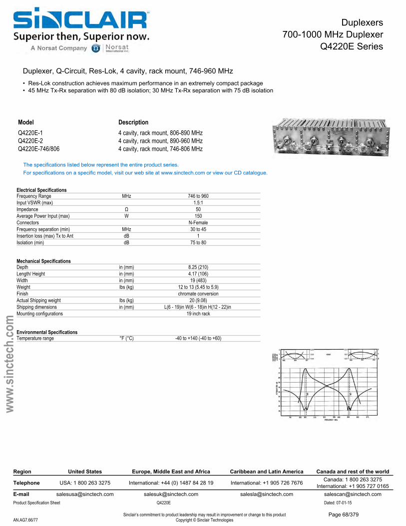
Duplexers700-1000 MHz Duplexer
Q4220E Series
Duplexer, Q-Circuit, Res-Lok, 4 cavity, rack mount, 746-960 MHz• Res-Lok construction achieves maximum performance in an extremely compact package• 45 MHz Tx-Rx separation with 80 dB isolation; 30 MHz Tx-Rx separation with 75 dB isolation
Model DescriptionQ4220E-1 4 cavity, rack mount, 806-890 MHzQ4220E-2 4 cavity, rack mount, 890-960 MHzQ4220E-746/806 4 cavity, rack mount, 746-806 MHz
The specifications listed below represent the entire product series.For specifications on a specific model, visit our web site at www.sinctech.com or view our CD catalogue.
Electrical SpecificationsFrequency Range MHz 746 to 960Input VSWR (max) 1.5:1Impedance Ω 50Average Power Input (max) W 150Connectors N-FemaleFrequency separation (min) MHz 30 to 45Insertion loss (max) Tx to Ant dB 1Isolation (min) dB 75 to 80
Mechanical SpecificationsDepth in (mm) 8.25 (210)Length/ Height in (mm) 4.17 (106)Width in (mm) 19 (483)Weight lbs (kg) 12 to 13 (5.45 to 5.9)Finish chromate conversionActual Shipping weight lbs (kg) 20 (9.08)Shipping dimensions in (mm) L(6 - 19)in W(6 - 18)in H(12 - 22)in Mounting configurations 19 inch rack
Environmental SpecificationsTemperature range °F (°C) -40 to +140 (-40 to +60)
Region United States Europe, Middle East and Africa Caribbean and Latin America Canada and rest of the world
Telephone USA: 1 800 263 3275 International: +44 (0) 1487 84 28 19 International: +1 905 726 7676 Canada: 1 800 263 3275International: +1 905 727 0165
E-mail [email protected] [email protected] [email protected] [email protected] Specification Sheet Q4220E Dated: 07-01-15
Sinclair’s commitment to product leadership may result in improvement or change to this productCopyright © Sinclair TechnologiesAN.AG7.66/77
www.
sinct
ech.
com
Page 68/379

Cavity Filters700-1000 MHz Bandpass Cavities
FP40137 Series
High Q, 3/4 Wave Bandpass Cavity, Single 7" Cavity, 806-960 MHz• Aluminum cylinder with brass and copper coaxial inner conductor• Silver plating and chromate conversion coating, limit corrosion and enhance performance• Temperature compensated for extremely low frequency drift
Model DescriptionFP40137 806-960 MHz
The specifications listed below represent the entire product series.For specifications on a specific model, visit our web site at www.sinctech.com or view our CD catalogue.
Electrical SpecificationsFrequency Range MHz 806 to 960Input VSWR (max) 1.5:1Impedance Ω 50Number of Cavities 1Average Power Input (max) W 280Input Connectors N-FemaleOutput Connectors N-FemaleInsertion loss (min) dB 0.8
Mechanical SpecificationsDepth in (mm) 7 (178)Length/ Height in (mm) 16.7 (424)Width in (mm) 7 (178)Weight lbs (kg) 5.5 (2.5)
Environmental SpecificationsTemperature range °F (°C) -40 to +140 (-40 to +60)
Region United States Europe, Middle East and Africa Caribbean and Latin America Canada and rest of the world
Telephone USA: 1 800 263 3275 International: +44 (0) 1487 84 28 19 International: +1 905 726 7676 Canada: 1 800 263 3275International: +1 905 727 0165
E-mail [email protected] [email protected] [email protected] [email protected] Specification Sheet FP40137 Dated: 07-01-15
Sinclair’s commitment to product leadership may result in improvement or change to this productCopyright © Sinclair TechnologiesAN.AG7.67/77
www.
sinct
ech.
com
Page 69/379
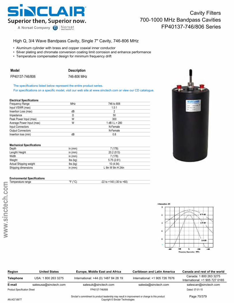
Cavity Filters700-1000 MHz Bandpass Cavities
FP40137-746/806 Series
High Q, 3/4 Wave Bandpass Cavity, Single 7" Cavity, 746-806 MHz• Aluminum cylinder with brass and copper coaxial inner conductor• Silver plating and chromate conversion coating limit corrosion and enhance performance• Temperature compensated design for minimum frequency drift
Model DescriptionFP40137-746/806 746-806 MHz
The specifications listed below represent the entire product series.For specifications on a specific model, visit our web site at www.sinctech.com or view our CD catalogue.
Electrical SpecificationsFrequency Range MHz 746 to 806Input VSWR (max) 1.5:1Insertion Loss (max) dB 2Impedance Ω 50Peak Power Input (max) W 300Average Power Input (max) W 1 dB I.L.= 280Input Connectors N-FemaleOutput Connectors N-FemaleInsertion loss (min) dB 0.8
Mechanical SpecificationsDepth in (mm) 7 (178)Length/ Height in (mm) 20.2 (513)Width in (mm) 7 (178)Weight lbs (kg) 5.75 (2.61)Actual Shipping weight lbs (kg) 10 (4.54)Shipping dimensions in (mm) L 9in W 9in H 24in
Environmental SpecificationsTemperature range °F (°C) -22 to +140 (-30 to +60)
Region United States Europe, Middle East and Africa Caribbean and Latin America Canada and rest of the world
Telephone USA: 1 800 263 3275 International: +44 (0) 1487 84 28 19 International: +1 905 726 7676 Canada: 1 800 263 3275International: +1 905 727 0165
E-mail [email protected] [email protected] [email protected] [email protected] Specification Sheet FP40137-746/806 Dated: 07-01-15
Sinclair’s commitment to product leadership may result in improvement or change to this productCopyright © Sinclair TechnologiesAN.AG7.68/77
www.
sinct
ech.
com
Page 70/379
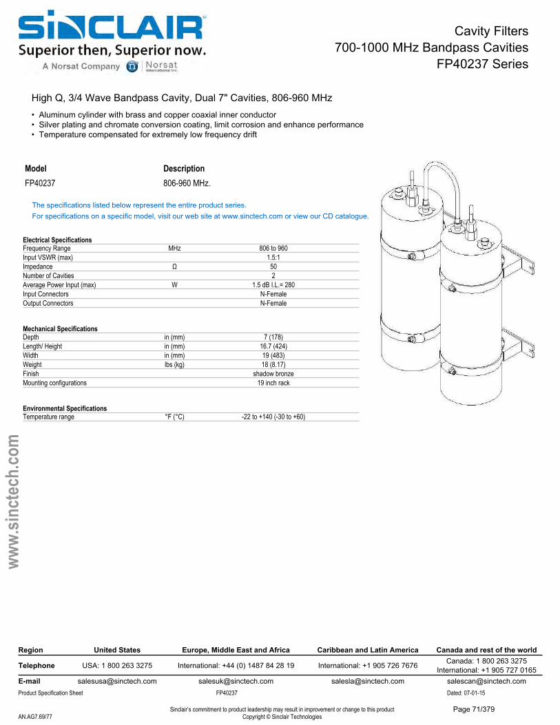
Cavity Filters700-1000 MHz Bandpass Cavities
FP40237 Series
High Q, 3/4 Wave Bandpass Cavity, Dual 7" Cavities, 806-960 MHz• Aluminum cylinder with brass and copper coaxial inner conductor• Silver plating and chromate conversion coating, limit corrosion and enhance performance• Temperature compensated for extremely low frequency drift
Model DescriptionFP40237 806-960 MHz.
The specifications listed below represent the entire product series.For specifications on a specific model, visit our web site at www.sinctech.com or view our CD catalogue.
Electrical SpecificationsFrequency Range MHz 806 to 960Input VSWR (max) 1.5:1Impedance Ω 50Number of Cavities 2Average Power Input (max) W 1.5 dB I.L.= 280Input Connectors N-FemaleOutput Connectors N-Female
Mechanical SpecificationsDepth in (mm) 7 (178)Length/ Height in (mm) 16.7 (424)Width in (mm) 19 (483)Weight lbs (kg) 18 (8.17)Finish shadow bronzeMounting configurations 19 inch rack
Environmental SpecificationsTemperature range °F (°C) -22 to +140 (-30 to +60)
Region United States Europe, Middle East and Africa Caribbean and Latin America Canada and rest of the world
Telephone USA: 1 800 263 3275 International: +44 (0) 1487 84 28 19 International: +1 905 726 7676 Canada: 1 800 263 3275International: +1 905 727 0165
E-mail [email protected] [email protected] [email protected] [email protected] Specification Sheet FP40237 Dated: 07-01-15
Sinclair’s commitment to product leadership may result in improvement or change to this productCopyright © Sinclair TechnologiesAN.AG7.69/77
www.
sinct
ech.
com
Page 71/379
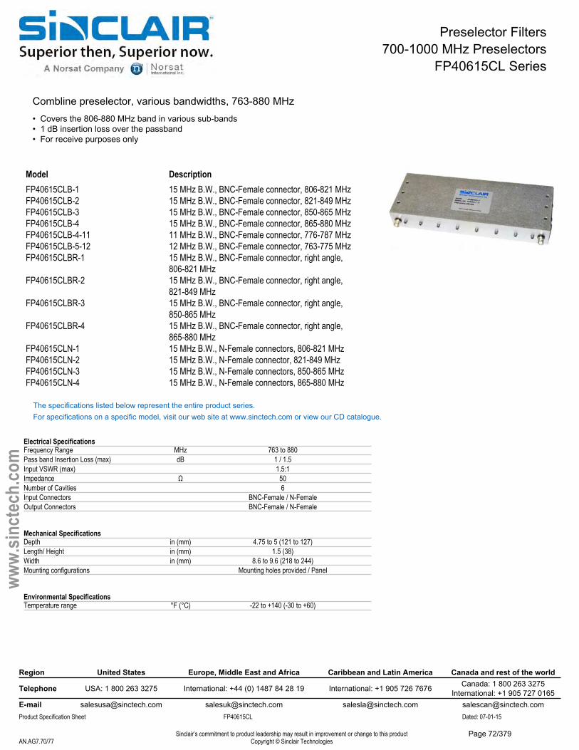
Preselector Filters700-1000 MHz Preselectors
FP40615CL Series
Combline preselector, various bandwidths, 763-880 MHz• Covers the 806-880 MHz band in various sub-bands• 1 dB insertion loss over the passband• For receive purposes only
Model DescriptionFP40615CLB-1 15 MHz B.W., BNC-Female connector, 806-821 MHzFP40615CLB-2 15 MHz B.W., BNC-Female connector, 821-849 MHzFP40615CLB-3 15 MHz B.W., BNC-Female connector, 850-865 MHzFP40615CLB-4 15 MHz B.W., BNC-Female connector, 865-880 MHzFP40615CLB-4-11 11 MHz B.W., BNC-Female connector, 776-787 MHzFP40615CLB-5-12 12 MHz B.W., BNC-Female connector, 763-775 MHzFP40615CLBR-1 15 MHz B.W., BNC-Female connector, right angle,
806-821 MHzFP40615CLBR-2 15 MHz B.W., BNC-Female connector, right angle,
821-849 MHzFP40615CLBR-3 15 MHz B.W., BNC-Female connector, right angle,
850-865 MHzFP40615CLBR-4 15 MHz B.W., BNC-Female connector, right angle,
865-880 MHzFP40615CLN-1 15 MHz B.W., N-Female connectors, 806-821 MHzFP40615CLN-2 15 MHz B.W., N-Female connector, 821-849 MHzFP40615CLN-3 15 MHz B.W., N-Female connectors, 850-865 MHzFP40615CLN-4 15 MHz B.W., N-Female connectors, 865-880 MHz
The specifications listed below represent the entire product series.For specifications on a specific model, visit our web site at www.sinctech.com or view our CD catalogue.
Electrical SpecificationsFrequency Range MHz 763 to 880Pass band Insertion Loss (max) dB 1 / 1.5Input VSWR (max) 1.5:1Impedance Ω 50Number of Cavities 6Input Connectors BNC-Female / N-FemaleOutput Connectors BNC-Female / N-Female
Mechanical SpecificationsDepth in (mm) 4.75 to 5 (121 to 127)Length/ Height in (mm) 1.5 (38)Width in (mm) 8.6 to 9.6 (218 to 244)Mounting configurations Mounting holes provided / Panel
Environmental SpecificationsTemperature range °F (°C) -22 to +140 (-30 to +60)
Region United States Europe, Middle East and Africa Caribbean and Latin America Canada and rest of the world
Telephone USA: 1 800 263 3275 International: +44 (0) 1487 84 28 19 International: +1 905 726 7676 Canada: 1 800 263 3275International: +1 905 727 0165
E-mail [email protected] [email protected] [email protected] [email protected] Specification Sheet FP40615CL Dated: 07-01-15
Sinclair’s commitment to product leadership may result in improvement or change to this productCopyright © Sinclair TechnologiesAN.AG7.70/77
www.
sinct
ech.
com
Page 72/379
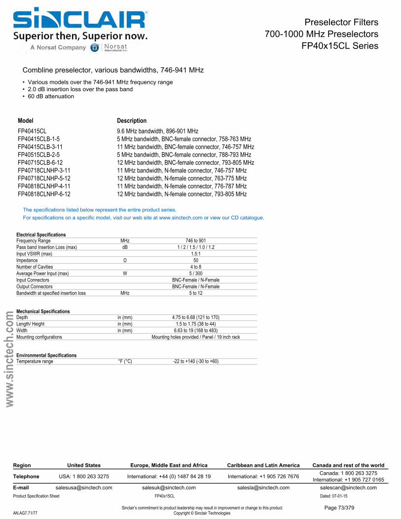
Preselector Filters700-1000 MHz Preselectors
FP40x15CL Series
Combline preselector, various bandwidths, 746-941 MHz• Various models over the 746-941 MHz frequency range• 2.0 dB insertion loss over the pass band• 60 dB attenuation
Model DescriptionFP40415CL 9.6 MHz bandwidth, 896-901 MHzFP40415CLB-1-5 5 MHz bandwidth, BNC-female connector, 758-763 MHzFP40415CLB-3-11 11 MHz bandwidth, BNC-female connector, 746-757 MHzFP40515CLB-2-5 5 MHz bandwidth, BNC-female connector, 788-793 MHzFP40715CLB-6-12 12 MHz bandwidth, BNC-female connector, 793-805 MHzFP40718CLNHP-3-11 11 MHz bandwidth, N-female connector, 746-757 MHzFP40718CLNHP-5-12 12 MHz bandwidth, N-female connector, 763-775 MHzFP40818CLNHP-4-11 11 MHz bandwidth, N-female connector, 776-787 MHzFP40818CLNHP-6-12 12 MHz bandwidth, N-female connector, 793-805 MHz
The specifications listed below represent the entire product series.For specifications on a specific model, visit our web site at www.sinctech.com or view our CD catalogue.
Electrical SpecificationsFrequency Range MHz 746 to 901Pass band Insertion Loss (max) dB 1 / 2 / 1.5 / 1.0 / 1.2Input VSWR (max) 1.5:1Impedance Ω 50Number of Cavities 4 to 8Average Power Input (max) W 5 / 300Input Connectors BNC-Female / N-FemaleOutput Connectors BNC-Female / N-FemaleBandwidth at specified insertion loss MHz 5 to 12
Mechanical SpecificationsDepth in (mm) 4.75 to 6.68 (121 to 170)Length/ Height in (mm) 1.5 to 1.75 (38 to 44)Width in (mm) 6.63 to 19 (168 to 483)Mounting configurations Mounting holes provided / Panel / 19 inch rack
Environmental SpecificationsTemperature range °F (°C) -22 to +140 (-30 to +60)
Region United States Europe, Middle East and Africa Caribbean and Latin America Canada and rest of the world
Telephone USA: 1 800 263 3275 International: +44 (0) 1487 84 28 19 International: +1 905 726 7676 Canada: 1 800 263 3275International: +1 905 727 0165
E-mail [email protected] [email protected] [email protected] [email protected] Specification Sheet FP40x15CL Dated: 07-01-15
Sinclair’s commitment to product leadership may result in improvement or change to this productCopyright © Sinclair TechnologiesAN.AG7.71/77
www.
sinct
ech.
com
Page 73/379
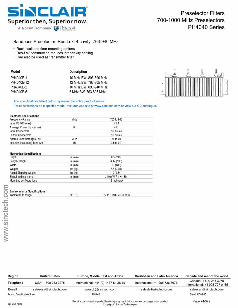
Preselector Filters700-1000 MHz Preselectors
PH4040 Series
Bandpass Preselector, Res-Lok, 4 cavity, 763-940 MHz• Rack, wall and floor mounting options• Res-Lok construction reduces inter-cavity cabling• Can also be used as transmitter filter
Model DescriptionPH4040E-1 10 MHz BW, 806-890 MHzPH4040E-12 12 MHz BW, 763-805 MHzPH4040E-2 10 MHz BW, 890-940 MHzPH4040E-6 6 MHz BW, 763-805 MHz
The specifications listed below represent the entire product series.For specifications on a specific model, visit our web site at www.sinctech.com or view our CD catalogue.
Electrical SpecificationsFrequency Range MHz 763 to 940Input VSWR (max) 1.5:1Average Power Input (max) W 400Input Connectors N-FemaleOutput Connectors N-FemaleApprox Bandwidth @ 50 dB MHz 34 to 60Insertion loss (max) Tx to Ant dB 0.5 to 0.7
Mechanical SpecificationsDepth in (mm) 8.5 (216)Length/ Height in (mm) 4.17 (106)Width in (mm) 19 (483)Weight lbs (kg) 6.5 (2.95)Actual Shipping weight lbs (kg) 10 (4.54)Shipping dimensions in (mm) L 19in W 7in H 18in Mounting configurations 19 inch rack
Environmental SpecificationsTemperature range °F (°C) -22 to +140 (-30 to +60)
Region United States Europe, Middle East and Africa Caribbean and Latin America Canada and rest of the world
Telephone USA: 1 800 263 3275 International: +44 (0) 1487 84 28 19 International: +1 905 726 7676 Canada: 1 800 263 3275International: +1 905 727 0165
E-mail [email protected] [email protected] [email protected] [email protected] Specification Sheet PH4040 Dated: 07-01-15
Sinclair’s commitment to product leadership may result in improvement or change to this productCopyright © Sinclair TechnologiesAN.AG7.72/77
www.
sinct
ech.
com
Page 74/379
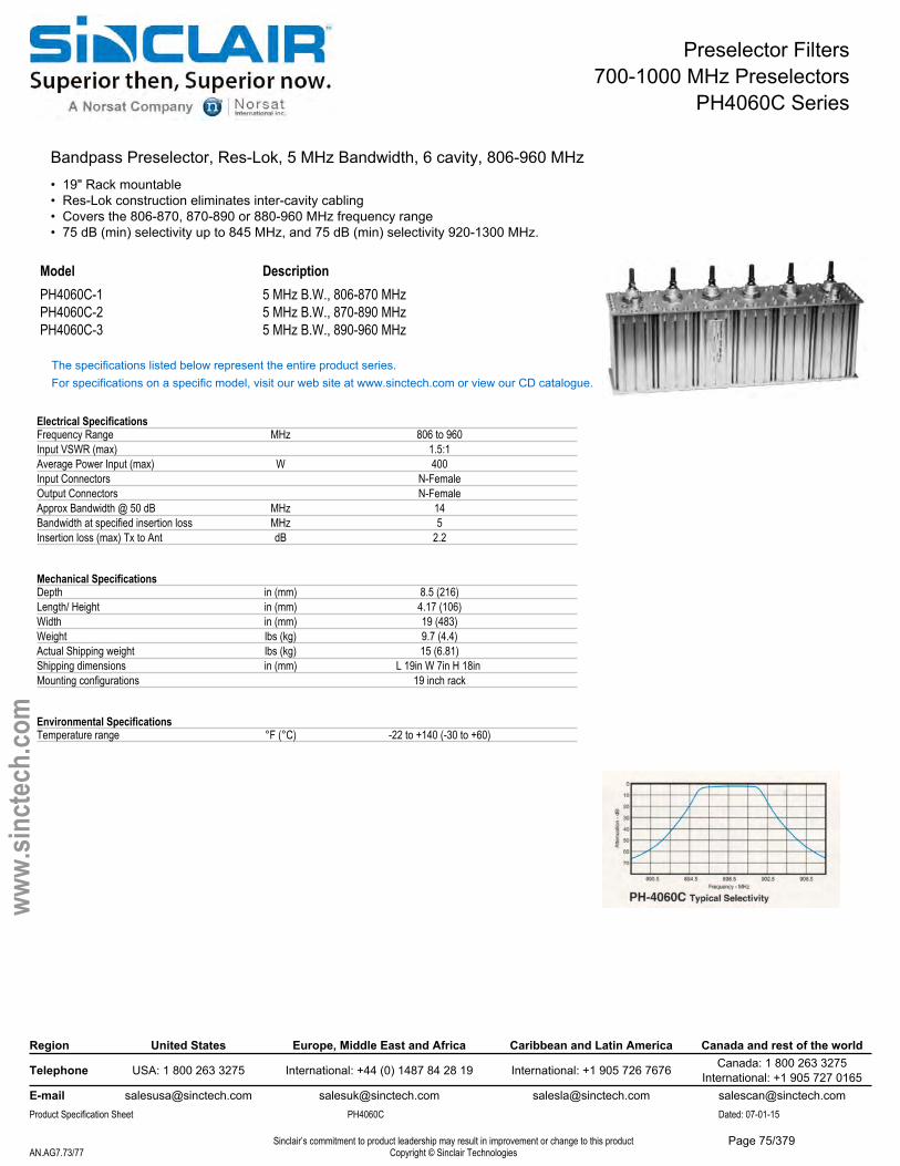
Preselector Filters700-1000 MHz Preselectors
PH4060C Series
Bandpass Preselector, Res-Lok, 5 MHz Bandwidth, 6 cavity, 806-960 MHz• 19" Rack mountable• Res-Lok construction eliminates inter-cavity cabling• Covers the 806-870, 870-890 or 880-960 MHz frequency range• 75 dB (min) selectivity up to 845 MHz, and 75 dB (min) selectivity 920-1300 MHz.
Model DescriptionPH4060C-1 5 MHz B.W., 806-870 MHzPH4060C-2 5 MHz B.W., 870-890 MHzPH4060C-3 5 MHz B.W., 890-960 MHz
The specifications listed below represent the entire product series.For specifications on a specific model, visit our web site at www.sinctech.com or view our CD catalogue.
Electrical SpecificationsFrequency Range MHz 806 to 960Input VSWR (max) 1.5:1Average Power Input (max) W 400Input Connectors N-FemaleOutput Connectors N-FemaleApprox Bandwidth @ 50 dB MHz 14Bandwidth at specified insertion loss MHz 5Insertion loss (max) Tx to Ant dB 2.2
Mechanical SpecificationsDepth in (mm) 8.5 (216)Length/ Height in (mm) 4.17 (106)Width in (mm) 19 (483)Weight lbs (kg) 9.7 (4.4)Actual Shipping weight lbs (kg) 15 (6.81)Shipping dimensions in (mm) L 19in W 7in H 18in Mounting configurations 19 inch rack
Environmental SpecificationsTemperature range °F (°C) -22 to +140 (-30 to +60)
Region United States Europe, Middle East and Africa Caribbean and Latin America Canada and rest of the world
Telephone USA: 1 800 263 3275 International: +44 (0) 1487 84 28 19 International: +1 905 726 7676 Canada: 1 800 263 3275International: +1 905 727 0165
E-mail [email protected] [email protected] [email protected] [email protected] Specification Sheet PH4060C Dated: 07-01-15
Sinclair’s commitment to product leadership may result in improvement or change to this productCopyright © Sinclair TechnologiesAN.AG7.73/77
www.
sinct
ech.
com
Page 75/379
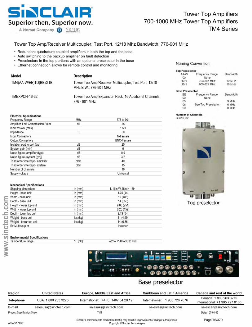
Tower Top Amplifiers700-1000 MHz Tower Top Amplifiers
TM4 Series
Tower Top Amp/Receiver Multicoupler, Test Port, 12/18 Mhz Bandwidth, 776-901 MHz• Redundant quadrature coupled amplifiers in both the top and the base• Auto switching to the backup amplifier on fault detection• Preselectors in the top portions with an optional preselector in the base• Ethernet connection allows for remote control and monitoring
Model DescriptionTM4(AA-W/EE)TD(BB)G1B Tower Top Amp/Receiver Multicoupler, Test Port, 12/18
MHz B.W., 776-901 MHz
Electrical SpecificationsFrequency Range MHz 776 to 901Amplifier 1 dB Compression Point dB 25Input VSWR (max) 1.5:1Impedance Ω 50Input Connectors N-FemaleOutput Connectors BNC-FemaleIsolation port to port (typ) dB 25System gain (min) dB 0Noise figure (amplifier (typ)) dB 0.9Noise figure (system (typ)) dB 3.2Third order intercept - amplifier dBm 40Third order intercept - system dBm 15Number of channels 16Supply voltage Universal
Mechanical SpecificationsShipping dimensions in (mm) L 16in W 28in H 18in Height - base unit in (mm) 1.75 (44)Width - base unit in (mm) 19 (483)Depth - base unit in (mm) 14 (356)Height - tower top unit in (mm) 9.88 (251)Width - tower top unit in (mm) 6.25 (159)Depth - tower top unit in (mm) 2.13 (54)Weight - base unit lbs (kg) 11 (4.99)Weight - tower top unit lbs (kg) 14 (6.36)Rx Multicoupler Included
Environmental SpecificationsTemperature range °F (°C) -22 to +140 (-30 to +60)
Region United States Europe, Middle East and Africa Caribbean and Latin America Canada and rest of the world
Telephone USA: 1 800 263 3275 International: +44 (0) 1487 84 28 19 International: +1 905 726 7676 Canada: 1 800 263 3275International: +1 905 727 0165
E-mail [email protected] [email protected] [email protected] [email protected] Specification Sheet TM4 Dated: 07-01-15
Sinclair’s commitment to product leadership may result in improvement or change to this productCopyright © Sinclair TechnologiesAN.AG7.74/77
www.
sinct
ech.
com
TMEXPCH-16-32 Tower Top Amp Expansion Pack, 16 Additional Channels, 776 - 901 MHz
Page 76/379
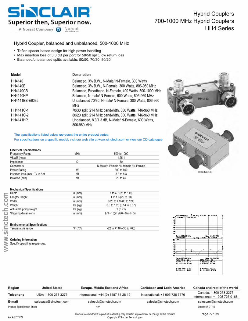
Hybrid Couplers700-1000 MHz Hybrid Couplers
HH4 Series
Hybrid Coupler, balanced and unbalanced, 500-1000 MHz• Teflon spacer based design for high power handling• Max insertion loss of 3.3 dB per port for 50/50 split, low return loss• Balanced/unbalanced splits available: 50/50, 70/30, 80/20
Model DescriptionHH4140 Balanced, 3% B.W., N-Male/ N-Female, 300 WattsHH4140B Balanced, 3% B.W., N-Female, 300 Watts, 806-960 MHzHH4140CB Balanced, Broadband, N-Female, 400 Watts, 500-1000 MHzHH4140HP Balanced, N-male/ N-Female, 600 Watts, 806-960 MHzHH4141BB-E6035 Unbalanced 70/30, N-male/ N-Female, 300 Watts, 806-960
MHzHH4141C-1 70/30 split, 214 MHz bandwidth, 300 Watts, 746-960 MHzHH4141C-2 80/20 split, 214 MHz bandwidth, 300 Watts, 746-960 MHzHH4141HP Unbalanced, 8.3/1.3 dB, N-Male/ N-Female, 600 Watts,
806-960 MHz
The specifications listed below represent the entire product series.For specifications on a specific model, visit our web site at www.sinctech.com or view our CD catalogue.
Electrical SpecificationsFrequency Range MHz 500 to 1000VSWR (max) 1.25:1Impedance Ω 50Connectors N-Male/N-Female / N-female / N-FemalePower Rating W 300 to 600Insertion loss (max) Tx to Ant dB 3.3 to 8.3Isolation (min) dB 20 to 45
Mechanical SpecificationsDepth in (mm) 1 to 4.7 (25 to 119)Length/ Height in (mm) 1 to 1.3 (25 to 33)Width in (mm) 3.25 to 4.9 (83 to 124)Weight lbs (kg) 0.3 to 1.25 (0.14 to 0.57)Actual Shipping weight lbs (kg) 2 (0.91)Shipping dimensions in (mm) L(9 - 13)in W(6 - 9)in H 3in
Environmental SpecificationsTemperature range °F (°C) -22 to +140 (-30 to +60)
Ordering InformationSpecify operating frequencies.
Region United States Europe, Middle East and Africa Caribbean and Latin America Canada and rest of the world
Telephone USA: 1 800 263 3275 International: +44 (0) 1487 84 28 19 International: +1 905 726 7676 Canada: 1 800 263 3275International: +1 905 727 0165
E-mail [email protected] [email protected] [email protected] [email protected] Specification Sheet HH4 Dated: 07-01-15
Sinclair’s commitment to product leadership may result in improvement or change to this productCopyright © Sinclair TechnologiesAN.AG7.75/77
www.
sinct
ech.
com
Page 77/379
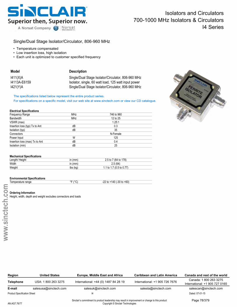
Isolators and Circulators700-1000 MHz Isolators & Circulators
I4 Series
Single/Dual Stage Isolator/Circulator, 806-960 MHz• Temperature compensated• Low insertion loss, high isolation• Each unit is optimized to customer specified frequency
Model DescriptionI411(X)A Single/Dual Stage Isolator/Circulator, 806-960 MHzI4113A-E6159 Isolator, single, 60 watt load, 125 watt input powerI421(Y)A Single/Dual Stage Isolator/Circulator, 806-960 MHz
The specifications listed below represent the entire product series.For specifications on a specific model, visit our web site at www.sinctech.com or view our CD catalogue.
Electrical SpecificationsFrequency Range MHz 746 to 960Bandwidth MHz 12 to 25VSWR (max) 1.25:1Insertion loss (typ) Tx to Ant dB 0.3Isolation (typ) dB 35Connectors N-FemalePower Input W 125Insertion loss (max) Tx to Ant dB 0.4Isolation (min) dB 25
Mechanical SpecificationsLength/ Height in (mm) 2.5 to 7 (64 to 178)Width in (mm) 2.5 (64)Weight lbs (kg) 1.1 to 1.7 (0.5 to 0.77)
Environmental SpecificationsTemperature range °F (°C) -22 to +140 (-30 to +60)
Ordering InformationHeight, width, depth and weight excludes connectors and loads
Region United States Europe, Middle East and Africa Caribbean and Latin America Canada and rest of the world
Telephone USA: 1 800 263 3275 International: +44 (0) 1487 84 28 19 International: +1 905 726 7676 Canada: 1 800 263 3275International: +1 905 727 0165
E-mail [email protected] [email protected] [email protected] [email protected] Specification Sheet I4 Dated: 07-01-15
Sinclair’s commitment to product leadership may result in improvement or change to this productCopyright © Sinclair TechnologiesAN.AG7.76/77
www.
sinct
ech.
com
Page 78/379
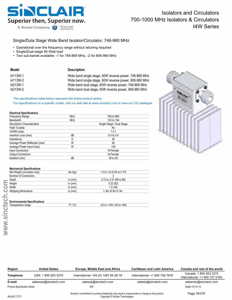
Isolators and Circulators700-1000 MHz Isolators & Circulators
I4W Series
Single/Dula Stage Wide Band Isolator/Circulator, 746-960 MHz• Operational over the frequency range without retuning required• Single/Dual stage 60 Watt load• Two sub-bands available: -1 for 746-869 MHz, -2 for 806-960 MHz
Model DescriptionI4113W-1 Wide band single stage, 60W reverse power, 746-869 MHzI4113W-2 Wide band single stage, 60W reverse power, 806-960 MHzI4213W-1 Wide band dual stage, 60W reverse power, 746-869 MHzI4213W-2 Wide band dual stage, 60W reverse power, 806-960 MHz
The specifications listed below represent the entire product series.For specifications on a specific model, visit our web site at www.sinctech.com or view our CD catalogue.
Electrical SpecificationsFrequency Range MHz 746 to 960Bandwidth MHz 123 to 154Discription/ Characteristics Single Stage / Dual StageField Tunable NoVSWR (max) 1.2:1Insertion Loss (max) dB 0.4 to 0.8Impedance Ω 50Average Power Reflected (max) W 60Average Power Input (max) W 125Input Connectors N-FemaleOutput Connectors N-FemaleIsolation (min) dB 25 to 50
Mechanical SpecificationsNet Weight (circulator only) lbs (kg) 1.2 to 1.6 (0.54 to 0.73)Number of Connectors 2Depth in (mm) 2.72 to 3.37 (69 to 86)Height in (mm) 3.22 (82)Width in (mm) 1.5 (38)Shipping dimensions in (mm) L 9in W 6in H 3in
Environmental SpecificationsTemperature range °F (°C) -22 to +140 (-30 to +60)
Region United States Europe, Middle East and Africa Caribbean and Latin America Canada and rest of the world
Telephone USA: 1 800 263 3275 International: +44 (0) 1487 84 28 19 International: +1 905 726 7676 Canada: 1 800 263 3275International: +1 905 727 0165
E-mail [email protected] [email protected] [email protected] [email protected] Specification Sheet I4W Dated: 07-01-15
Sinclair’s commitment to product leadership may result in improvement or change to this productCopyright © Sinclair TechnologiesAN.AG7.77/77
www.
sinct
ech.
com
Page 79/379
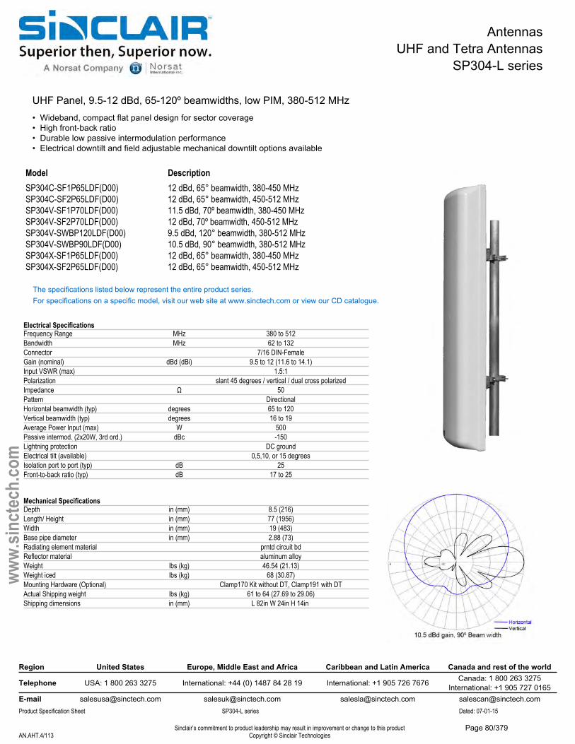
AntennasUHF and Tetra Antennas
SP304-L series
UHF Panel, 9.5-12 dBd, 65-120º beamwidths, low PIM, 380-512 MHz• Wideband, compact flat panel design for sector coverage• High front-back ratio• Durable low passive intermodulation performance• Electrical downtilt and field adjustable mechanical downtilt options available
Model DescriptionSP304C-SF1P65LDF(D00) 12 dBd, 65° beamwidth, 380-450 MHzSP304C-SF2P65LDF(D00) 12 dBd, 65° beamwidth, 450-512 MHzSP304V-SF1P70LDF(D00) 11.5 dBd, 70º beamwidth, 380-450 MHzSP304V-SF2P70LDF(D00) 12 dBd, 70º beamwidth, 450-512 MHzSP304V-SWBP120LDF(D00) 9.5 dBd, 120° beamwidth, 380-512 MHzSP304V-SWBP90LDF(D00) 10.5 dBd, 90° beamwidth, 380-512 MHzSP304X-SF1P65LDF(D00) 12 dBd, 65° beamwidth, 380-450 MHzSP304X-SF2P65LDF(D00) 12 dBd, 65° beamwidth, 450-512 MHz
The specifications listed below represent the entire product series.For specifications on a specific model, visit our web site at www.sinctech.com or view our CD catalogue.
Electrical SpecificationsFrequency Range MHz 380 to 512Bandwidth MHz 62 to 132Connector 7/16 DIN-FemaleGain (nominal) dBd (dBi) 9.5 to 12 (11.6 to 14.1)Input VSWR (max) 1.5:1Polarization slant 45 degrees / vertical / dual cross polarizedImpedance Ω 50Pattern DirectionalHorizontal beamwidth (typ) degrees 65 to 120Vertical beamwidth (typ) degrees 16 to 19Average Power Input (max) W 500Passive intermod. (2x20W, 3rd ord.) dBc -150Lightning protection DC groundElectrical tilt (available) 0,5,10, or 15 degreesIsolation port to port (typ) dB 25Front-to-back ratio (typ) dB 17 to 25
Mechanical SpecificationsDepth in (mm) 8.5 (216)Length/ Height in (mm) 77 (1956)Width in (mm) 19 (483)Base pipe diameter in (mm) 2.88 (73)Radiating element material prntd circuit bdReflector material aluminum alloyWeight lbs (kg) 46.54 (21.13)Weight iced lbs (kg) 68 (30.87)Mounting Hardware (Optional) Clamp170 Kit without DT, Clamp191 with DTActual Shipping weight lbs (kg) 61 to 64 (27.69 to 29.06)Shipping dimensions in (mm) L 82in W 24in H 14in
Region United States Europe, Middle East and Africa Caribbean and Latin America Canada and rest of the world
Telephone USA: 1 800 263 3275 International: +44 (0) 1487 84 28 19 International: +1 905 726 7676 Canada: 1 800 263 3275International: +1 905 727 0165
E-mail [email protected] [email protected] [email protected] [email protected] Specification Sheet SP304-L series Dated: 07-01-15
Sinclair’s commitment to product leadership may result in improvement or change to this productCopyright © Sinclair TechnologiesAN.AHT.4/113
www.
sinct
ech.
com
Page 80/379
AntennasUHF and Tetra Antennas
SP304-L series
Environmental SpecificationsTemperature range °F (°C) -40 to +158 (-40 to +70)Rated wind velocity (no ice) mph (km/h) 135 (217)Rated wind velocity (1/2" radial ice) mph (km/h) 110 (177)Lateral thrust (100 mph No Ice) lbs (N) 220 (978.6)Torsional moment (100 mph No Ice) ft-lbs (Nm) 140 (189)
Ordering InformationPlease contact Sinclair CSR to order regular clamps Clamp170 or mechanical tilt clamps Clamp191.
Region United States Europe, Middle East and Africa Caribbean and Latin America Canada and rest of the world
Telephone USA: 1 800 263 3275 International: +44 (0) 1487 84 28 19 International: +1 905 726 7676 Canada: 1 800 263 3275International: +1 905 727 0165
E-mail [email protected] [email protected] [email protected] [email protected] Specification Sheet SP304-L series Dated: 07-01-15
Sinclair’s commitment to product leadership may result in improvement or change to this productCopyright © Sinclair TechnologiesAN.AHT.5/113
www.
sinct
ech.
com
Page 81/379
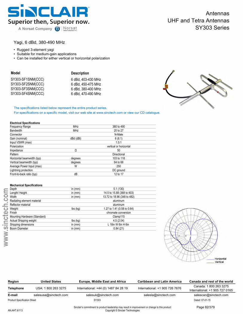
AntennasUHF and Tetra Antennas
SY303 Series
Yagi, 6 dBd, 380-490 MHz• Rugged 3-element yagi• Suitable for medium-gain applications• Can be installed for either vertical or horizontal polarization
ModelSY303-SF1SNM(CCC) SY303-SF2SNM(CCC) SY303-SF3SNM(CCC) SY303-SF4SNM(CCC)
Description6 dBd, 403-430 MHz6 dBd, 450-475 MHz6 dBd, 380-400 MHz6 dBd, 470-490 MHz
The specifications listed below represent the entire product series.For specifications on a specific model, visit our web site at www.sinctech.com or view our CD catalogue.
Electrical SpecificationsFrequency Range MHz 380 to 490Bandwidth MHz 20 to 27Connector N-MaleGain (nominal) dBd (dBi) 6 (8.1)Input VSWR (max) 1.5:1Polarization vertical or horizontalImpedance Ω 50Pattern DirectionalHorizontal beamwidth (typ) degrees 103 to 118Vertical beamwidth (typ) degrees 64 to 66Average Power Input (max) W 250Lightning protection DC groundFront-to-back ratio (typ) dB 12 to 17
Mechanical SpecificationsDepth in (mm) 5.1 (130)Length/ Height in (mm) 14.5 to 15.88 (368 to 403)Width in (mm) 13.72 to 18.96 (348 to 482)Radiating element material aluminumReflector material aluminumWeight lbs (kg) 1.27 to 1.41 (0.58 to 0.64)Finish chromate conversion Mounting Hardware (Standard) Clamp115Actual Shipping weight lbs (kg) 4.5 (2.04)Shipping dimensions in (mm) L 18in W 6in H 6in Boom Diameter in (mm) 0.84 (21)
Region United States Europe, Middle East and Africa Caribbean and Latin America Canada and rest of the world
Telephone USA: 1 800 263 3275 International: +44 (0) 1487 84 28 19 International: +1 905 726 7676 Canada: 1 800 263 3275International: +1 905 727 0165
E-mail [email protected] [email protected] [email protected] [email protected] Specification Sheet SY303 Dated: 07-01-15
Sinclair’s commitment to product leadership may result in improvement or change to this productCopyright © Sinclair TechnologiesAN.AHT.6/113
www.
sinct
ech.
com
Page 82/379

AntennasUHF and Tetra Antennas
SY303 Series
Environmental SpecificationsTemperature range °F (°C) -40 to +140 (-40 to +60)Wind Loading Area (Flat Plate Equivalent) ft² (m²) 0.16 to 0.2 (0.01 to 0.02)Wind Loading Area (1/2" ice) ft² (m²) 0.42 to 0.51 (0.04 to 0.05)Rated wind velocity (no ice) mph (km/h) 185 to 215 (298 to 346)Rated wind velocity (1/2" radial ice) mph (km/h) 108 to 145 (174 to 233)Lateral thrust (100 mph No Ice) lbs (N) 7.6 to 7.9 (33.8 to 35.3)Bending moment (100 mph No Ice) ft-lbs (Nm) 3.9 to 4.86 (5.3 to 6.6)
Region United States Europe, Middle East and Africa Caribbean and Latin America Canada and rest of the world
Telephone USA: 1 800 263 3275 International: +44 (0) 1487 84 28 19 International: +1 905 726 7676 Canada: 1 800 263 3275International: +1 905 727 0165
E-mail [email protected] [email protected] [email protected] [email protected] Specification Sheet SY303 Dated: 07-01-15
Sinclair’s commitment to product leadership may result in improvement or change to this productCopyright © Sinclair TechnologiesAN.AHT.7/113
www.
sinct
ech.
com
Page 83/379
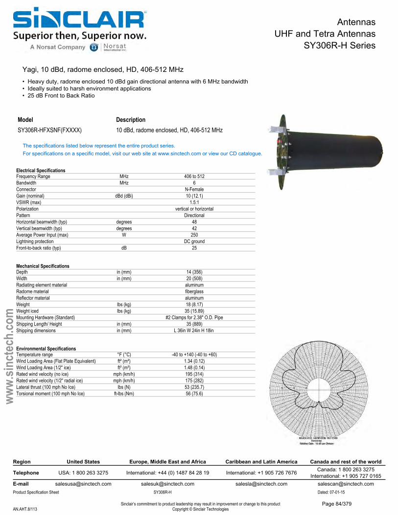
AntennasUHF and Tetra Antennas
SY306R-H Series
Yagi, 10 dBd, radome enclosed, HD, 406-512 MHz• Heavy duty, radome enclosed 10 dBd gain directional antenna with 6 MHz bandwidth• Ideally suited to harsh environment applications• 25 dB Front to Back Ratio
Model DescriptionSY306R-HFXSNF(FXXXX) 10 dBd, radome enclosed, HD, 406-512 MHz
The specifications listed below represent the entire product series.For specifications on a specific model, visit our web site at www.sinctech.com or view our CD catalogue.
Electrical SpecificationsFrequency Range MHz 406 to 512Bandwidth MHz 6Connector N-FemaleGain (nominal) dBd (dBi) 10 (12.1)VSWR (max) 1.5:1Polarization vertical or horizontalPattern DirectionalHorizontal beamwidth (typ) degrees 48Vertical beamwidth (typ) degrees 42Average Power Input (max) W 250Lightning protection DC groundFront-to-back ratio (typ) dB 25
Mechanical SpecificationsDepth in (mm) 14 (356)Width in (mm) 20 (508)Radiating element material aluminumRadome material fiberglassReflector material aluminumWeight lbs (kg) 18 (8.17)Weight iced lbs (kg) 35 (15.89)Mounting Hardware (Standard) #2 Clamps for 2.38" O.D. PipeShipping Length/ Height in (mm) 35 (889)Shipping dimensions in (mm) L 36in W 24in H 18in
Environmental SpecificationsTemperature range °F (°C) -40 to +140 (-40 to +60)Wind Loading Area (Flat Plate Equivalent) ft² (m²) 1.34 (0.12)Wind Loading Area (1/2" ice) ft² (m²) 1.48 (0.14)Rated wind velocity (no ice) mph (km/h) 195 (314)Rated wind velocity (1/2" radial ice) mph (km/h) 175 (282)Lateral thrust (100 mph No Ice) lbs (N) 53 (235.7)Torsional moment (100 mph No Ice) ft-lbs (Nm) 56 (75.6)
Region United States Europe, Middle East and Africa Caribbean and Latin America Canada and rest of the world
Telephone USA: 1 800 263 3275 International: +44 (0) 1487 84 28 19 International: +1 905 726 7676 Canada: 1 800 263 3275International: +1 905 727 0165
E-mail [email protected] [email protected] [email protected] [email protected] Specification Sheet SY306R-H Dated: 07-01-15
Sinclair’s commitment to product leadership may result in improvement or change to this productCopyright © Sinclair TechnologiesAN.AHT.8/113
www.
sinct
ech.
com
Page 84/379
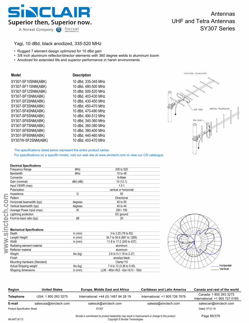
AntennasUHF and Tetra Antennas
SY307 Series
Yagi, 10 dBd, black anodized, 335-520 MHz• Rugged 7 element design optimized for 10 dBd gain• 3/8 inch aluminum reflector/director elements with 360 degree welds to aluminum boom• Anodized for extended life and superior performance in harsh environments
Model DescriptionSY307-SF10SNM(ABK) 10 dBd, 335-345 MHzSY307-SF11SNM(ABK) 10 dBd, 480-500 MHzSY307-SF12SNM(ABK) 10 dBd, 500-520 MHzSY307-SF1SNM(ABK) 10 dBd, 403-430 MHzSY307-SF2SNM(ABK) 10 dBd, 430-450 MHzSY307-SF3SNM(ABK) 10 dBd, 450-470 MHzSY307-SF4SNM(ABK) 10 dBd, 470-490 MHzSY307-SF5SNM(ABK) 10 dBd, 490-512 MHzSY307-SF6SNM(ABK) 10 dBd, 340-360 MHzSY307-SF7SNM(ABK) 10 dBd, 360-380 MHzSY307-SF8SNM(ABK) 10 dBd, 380-400 MHzSY307-SF9SNM(ABK) 10 dBd, 440-460 MHzSY307W-SF2SNM(ABK) 10 dBd, 403-470 MHz
The specifications listed below represent the entire product series.For specifications on a specific model, visit our web site at www.sinctech.com or view our CD catalogue.
Electrical SpecificationsFrequency Range MHz 335 to 520Bandwidth MHz 10 to 48Connector N-MaleGain (nominal) dBd (dBi) 10 (12.1)Input VSWR (max) 1.5:1Polarization vertical or horizontalImpedance Ω 50Pattern DirectionalHorizontal beamwidth (typ) degrees 45 to 55Vertical beamwidth (typ) degrees 40 to 44Average Power Input (max) W 250 / 150Lightning protection DC groundFront-to-back ratio (typ) dB 20
Mechanical SpecificationsDepth in (mm) 3 to 3.25 (76 to 83)Length/ Height in (mm) 34.7 to 50.6 (881 to 1285)Width in (mm) 11.8 to 17.2 (300 to 437)Radiating element material aluminumReflector material aluminumWeight lbs (kg) 2.6 to 5 (1.18 to 2.27)Finish anodize blackMounting Hardware (Standard) Clamp115Actual Shipping weight lbs (kg) 7.4 to 12 (3.36 to 5.45)Shipping dimensions in (mm) L(36 - 48)in W(3 - 6)in H(13 - 18)in
Region United States Europe, Middle East and Africa Caribbean and Latin America Canada and rest of the world
Telephone USA: 1 800 263 3275 International: +44 (0) 1487 84 28 19 International: +1 905 726 7676 Canada: 1 800 263 3275International: +1 905 727 0165
E-mail [email protected] [email protected] [email protected] [email protected] Specification Sheet SY307 Dated: 07-01-15
Sinclair’s commitment to product leadership may result in improvement or change to this productCopyright © Sinclair TechnologiesAN.AHT.9/113
www.
sinct
ech.
com
Page 85/379
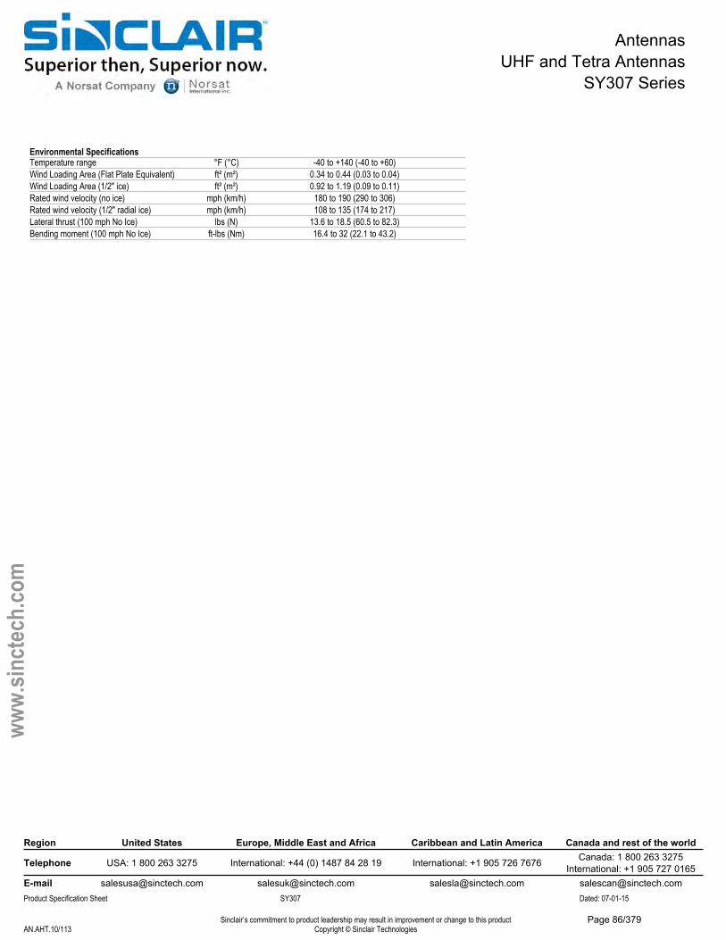
AntennasUHF and Tetra Antennas
SY307 Series
Environmental SpecificationsTemperature range °F (°C) -40 to +140 (-40 to +60)Wind Loading Area (Flat Plate Equivalent) ft² (m²) 0.34 to 0.44 (0.03 to 0.04)Wind Loading Area (1/2" ice) ft² (m²) 0.92 to 1.19 (0.09 to 0.11)Rated wind velocity (no ice) mph (km/h) 180 to 190 (290 to 306)Rated wind velocity (1/2" radial ice) mph (km/h) 108 to 135 (174 to 217)Lateral thrust (100 mph No Ice) lbs (N) 13.6 to 18.5 (60.5 to 82.3)Bending moment (100 mph No Ice) ft-lbs (Nm) 16.4 to 32 (22.1 to 43.2)
Region United States Europe, Middle East and Africa Caribbean and Latin America Canada and rest of the world
Telephone USA: 1 800 263 3275 International: +44 (0) 1487 84 28 19 International: +1 905 726 7676 Canada: 1 800 263 3275International: +1 905 727 0165
E-mail [email protected] [email protected] [email protected] [email protected] Specification Sheet SY307 Dated: 07-01-15
Sinclair’s commitment to product leadership may result in improvement or change to this productCopyright © Sinclair TechnologiesAN.AHT.10/113
www.
sinct
ech.
com
Page 86/379
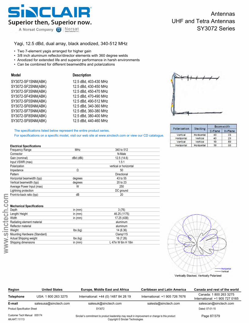
AntennasUHF and Tetra Antennas
SY3072 Series
Yagi, 12.5 dBd, dual array, black anodized, 340-512 MHz• Two 7-element yagis arranged for higher gain• 3/8 inch aluminum reflector/director elements with 360 degree welds• Anodized for extended life and superior performance in harsh environments• Can be combined for different beamwidths and polarizations
Model DescriptionSY3072-SF1SNM(ABK) 12.5 dBd, 403-430 MHzSY3072-SF2SNM(ABK) 12.5 dBd, 430-450 MHzSY3072-SF3SNM(ABK) 12.5 dBd, 450-470 MHzSY3072-SF4SNM(ABK) 12.5 dBd, 470-490 MHzSY3072-SF5SNM(ABK) 12.5 dBd, 490-512 MHzSY3072-SF6SNM(ABK) 12.5 dBd, 340-360 MHzSY3072-SF7SNM(ABK) 12.5 dBd, 360-380 MHzSY3072-SF8SNM(ABK) 12.5 dBd, 380-400 MHzSY3072-SF9SNM(ABK) 12.5 dBd, 440-460 MHz
The specifications listed below represent the entire product series.For specifications on a specific model, visit our web site at www.sinctech.com or view our CD catalogue.
Electrical SpecificationsFrequency Range MHz 340 to 512Connector N-MaleGain (nominal) dBd (dBi) 12.5 (14.6)Input VSWR (max) 1.5:1Polarization vertical or horizontalImpedance Ω 50Pattern DirectionalHorizontal beamwidth (typ) degrees 43 to 55Vertical beamwidth (typ) degrees 20 to 23Average Power Input (max) W 250Lightning protection DC groundFront-to-back ratio (typ) dB 20
Mechanical SpecificationsDepth in (mm) 3 (76)Length/ Height in (mm) 46.25 (1175)Width in (mm) 17.25 (438)Radiating element material aluminumReflector material aluminumWeight lbs (kg) 14 (6.36)Mounting Hardware (Standard) Clamp115Actual Shipping weight lbs (kg) 16 (7.26)Shipping dimensions in (mm) L 47in W 6in H 18in
Region United States Europe, Middle East and Africa Caribbean and Latin America Canada and rest of the world
Telephone USA: 1 800 263 3275 International: +44 (0) 1487 84 28 19 International: +1 905 726 7676 Canada: 1 800 263 3275International: +1 905 727 0165
E-mail [email protected] [email protected] [email protected] [email protected] Specification Sheet SY3072 Dated: 07-01-15
Customer Tech Manual 005174 Sinclair’s commitment to product leadership may result in improvement or change to this productCopyright © Sinclair TechnologiesAN.AHT.11/113
www.
sinct
ech.
com
Page 87/379

AntennasUHF and Tetra Antennas
SY3072 Series
Environmental SpecificationsTemperature range °F (°C) -40 to +140 (-40 to +60)Wind Loading Area (Flat Plate Equivalent) ft² (m²) 0.94 (0.09)Wind Loading Area (1/2" ice) ft² (m²) 2.52 (0.23)Lateral thrust (100 mph No Ice) lbs (N) 36.4 (161.9)Bending moment (100 mph No Ice) ft-lbs (Nm) 28.1 (37.9)
Ordering InformationQty 2- Clamp115 clamps and one support pipe included.
Region United States Europe, Middle East and Africa Caribbean and Latin America Canada and rest of the world
Telephone USA: 1 800 263 3275 International: +44 (0) 1487 84 28 19 International: +1 905 726 7676 Canada: 1 800 263 3275International: +1 905 727 0165
E-mail [email protected] [email protected] [email protected] [email protected] Specification Sheet SY3072 Dated: 07-01-15
Customer Tech Manual 005174 Sinclair’s commitment to product leadership may result in improvement or change to this productCopyright © Sinclair TechnologiesAN.AHT.12/113
www.
sinct
ech.
com
Page 88/379
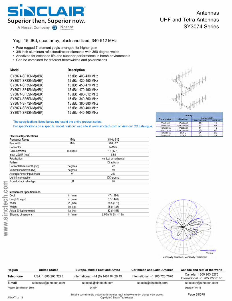
AntennasUHF and Tetra Antennas
SY3074 Series
Yagi, 15 dBd, quad array, black anodized, 340-512 MHz• Four rugged 7-element yagis arranged for higher gain• 3/8 inch aluminum reflector/director elements with 360 degree welds• Anodized for extended life and superior performance in harsh environments• Can be combined for different beamwidths and polarizations
Model DescriptionSY3074-SF1SNM(ABK) 15 dBd, 403-430 MHzSY3074-SF2SNM(ABK) 15 dBd, 430-450 MHzSY3074-SF3SNM(ABK) 15 dBd, 450-470 MHzSY3074-SF4SNM(ABK) 15 dBd, 470-490 MHzSY3074-SF5SNM(ABK) 15 dBd, 490-512 MHzSY3074-SF6SNM(ABK) 15 dBd, 340-360 MHzSY3074-SF7SNM(ABK) 15 dBd, 360-380 MHzSY3074-SF8SNM(ABK) 15 dBd, 380-400 MHzSY3074-SF9SNM(ABK) 15 dBd, 440-460 MHz
The specifications listed below represent the entire product series.For specifications on a specific model, visit our web site at www.sinctech.com or view our CD catalogue.
Electrical SpecificationsFrequency Range MHz 340 to 512Bandwidth MHz 20 to 27Connector N-MaleGain (nominal) dBd (dBi) 15 (17.1)Input VSWR (max) 1.5:1Polarization vertical or horizontalPattern DirectionalHorizontal beamwidth (typ) degrees 22Vertical beamwidth (typ) degrees 19Average Power Input (max) W 250Lightning protection DC groundFront-to-back ratio (typ) dB 20
Mechanical SpecificationsDepth in (mm) 47 (1194)Length/ Height in (mm) 57 (1448)Width in (mm) 38.5 (978)Weight lbs (kg) 25 (11.35)Actual Shipping weight lbs (kg) 32 (14.53)Shipping dimensions in (mm) L 60in W 8in H 18in
Region United States Europe, Middle East and Africa Caribbean and Latin America Canada and rest of the world
Telephone USA: 1 800 263 3275 International: +44 (0) 1487 84 28 19 International: +1 905 726 7676 Canada: 1 800 263 3275International: +1 905 727 0165
E-mail [email protected] [email protected] [email protected] [email protected] Specification Sheet SY3074 Dated: 07-01-15
Sinclair’s commitment to product leadership may result in improvement or change to this productCopyright © Sinclair TechnologiesAN.AHT.13/113
www.
sinct
ech.
com
Page 89/379
AntennasUHF and Tetra Antennas
SY3074 Series
Environmental SpecificationsTemperature range °F (°C) -40 to +140 (-40 to +60)Wind Loading Area (Flat Plate Equivalent) ft² (m²) 2.42 (0.22)Wind Loading Area (1/2" ice) ft² (m²) 5.95 (0.55)Rated wind velocity (no ice) mph (km/h) 165 (266)Rated wind velocity (1/2" radial ice) mph (km/h) 92 (148)Lateral thrust (100 mph No Ice) lbs (N) 95 (422.6)Torsional moment (100 mph No Ice) ft-lbs (Nm) 141 (190.4)
Ordering InformationQty 4- Clamp115 clamps and three support pipes included.
Region United States Europe, Middle East and Africa Caribbean and Latin America Canada and rest of the world
Telephone USA: 1 800 263 3275 International: +44 (0) 1487 84 28 19 International: +1 905 726 7676 Canada: 1 800 263 3275International: +1 905 727 0165
E-mail [email protected] [email protected] [email protected] [email protected] Specification Sheet SY3074 Dated: 07-01-15
Sinclair’s commitment to product leadership may result in improvement or change to this productCopyright © Sinclair TechnologiesAN.AHT.14/113
www.
sinct
ech.
com
Page 90/379
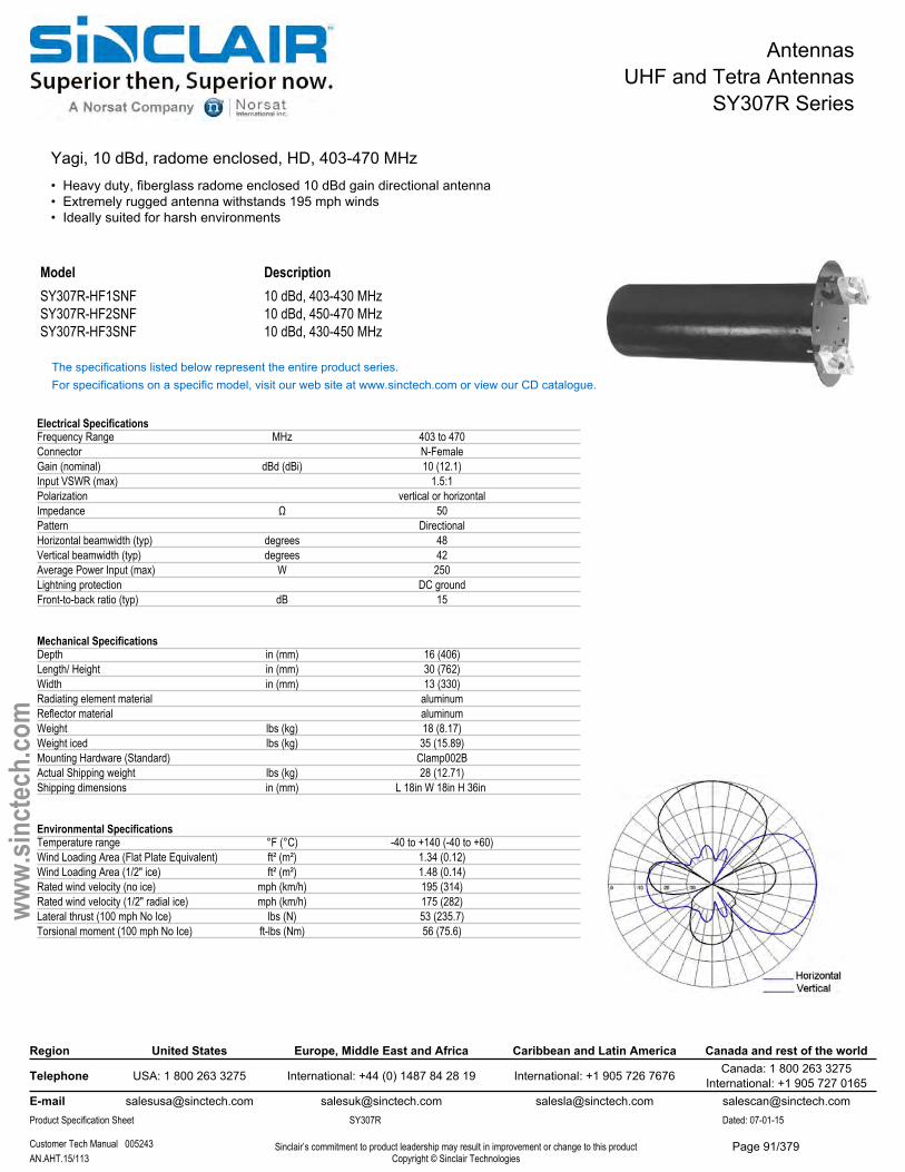
AntennasUHF and Tetra Antennas
SY307R Series
Yagi, 10 dBd, radome enclosed, HD, 403-470 MHz• Heavy duty, fiberglass radome enclosed 10 dBd gain directional antenna• Extremely rugged antenna withstands 195 mph winds• Ideally suited for harsh environments
Model DescriptionSY307R-HF1SNF 10 dBd, 403-430 MHzSY307R-HF2SNF 10 dBd, 450-470 MHzSY307R-HF3SNF 10 dBd, 430-450 MHz
The specifications listed below represent the entire product series.For specifications on a specific model, visit our web site at www.sinctech.com or view our CD catalogue.
Electrical SpecificationsFrequency Range MHz 403 to 470Connector N-FemaleGain (nominal) dBd (dBi) 10 (12.1)Input VSWR (max) 1.5:1Polarization vertical or horizontalImpedance Ω 50Pattern DirectionalHorizontal beamwidth (typ) degrees 48Vertical beamwidth (typ) degrees 42Average Power Input (max) W 250Lightning protection DC groundFront-to-back ratio (typ) dB 15
Mechanical SpecificationsDepth in (mm) 16 (406)Length/ Height in (mm) 30 (762)Width in (mm) 13 (330)Radiating element material aluminumReflector material aluminumWeight lbs (kg) 18 (8.17)Weight iced lbs (kg) 35 (15.89)Mounting Hardware (Standard) Clamp002BActual Shipping weight lbs (kg) 28 (12.71)Shipping dimensions in (mm) L 18in W 18in H 36in
Environmental SpecificationsTemperature range °F (°C) -40 to +140 (-40 to +60)Wind Loading Area (Flat Plate Equivalent) ft² (m²) 1.34 (0.12)Wind Loading Area (1/2" ice) ft² (m²) 1.48 (0.14)Rated wind velocity (no ice) mph (km/h) 195 (314)Rated wind velocity (1/2" radial ice) mph (km/h) 175 (282)Lateral thrust (100 mph No Ice) lbs (N) 53 (235.7)Torsional moment (100 mph No Ice) ft-lbs (Nm) 56 (75.6)
Region United States Europe, Middle East and Africa Caribbean and Latin America Canada and rest of the world
Telephone USA: 1 800 263 3275 International: +44 (0) 1487 84 28 19 International: +1 905 726 7676 Canada: 1 800 263 3275International: +1 905 727 0165
E-mail [email protected] [email protected] [email protected] [email protected] Specification Sheet SY307R Dated: 07-01-15
Customer Tech Manual 005243 Sinclair’s commitment to product leadership may result in improvement or change to this productCopyright © Sinclair TechnologiesAN.AHT.15/113
www.
sinct
ech.
com
Page 91/379
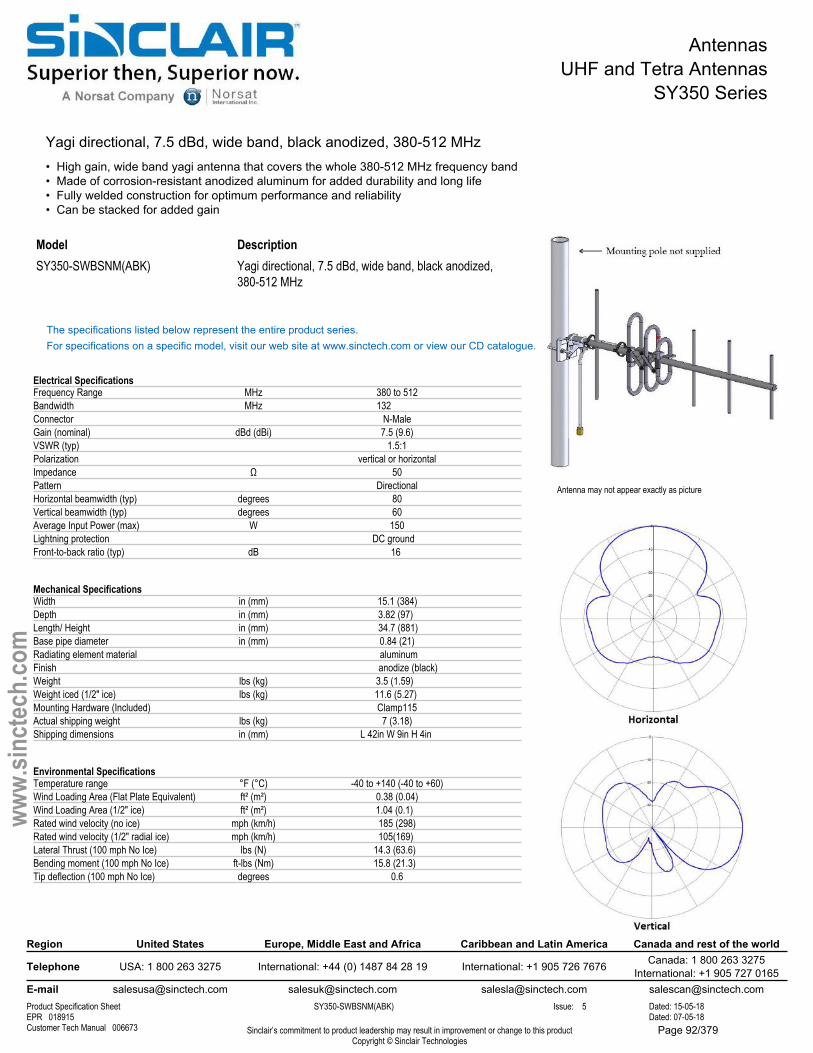
AntennasUHF and Tetra Antennas
SY350 Series
Yagi directional, 7.5 dBd, wide band, black anodized, 380-512 MHz• High gain, wide band yagi antenna that covers the whole 380-512 MHz frequency band• Made of corrosion-resistant anodized aluminum for added durability and long life• Fully welded construction for optimum performance and reliability• Can be stacked for added gain
Antenna may not appear exactly as picture
ModelSY350-SWBSNM(ABK)
DescriptionYagi directional, 7.5 dBd, wide band, black anodized, 380-512 MHz
The specifications listed below represent the entire product series.For specifications on a specific model, visit our web site at www.sinctech.com or view our CD catalogue.
Electrical SpecificationsFrequency Range MHz 380 to 512Bandwidth MHz 132Connector N-MaleGain (nominal) dBd (dBi) 7.5 (9.6)VSWR (typ) 1.5:1Polarization vertical or horizontalImpedance Ω 50Pattern DirectionalHorizontal beamwidth (typ) degrees 80Vertical beamwidth (typ) degrees 60Average Input Power (max) W 150Lightning protection DC groundFront-to-back ratio (typ) dB 16
Mechanical SpecificationsWidth in (mm) 15.1 (384)Depth in (mm) 3.82 (97)Length/ Height in (mm) 34.7 (881)Base pipe diameter in (mm) 0.84 (21)Radiating element material aluminumFinish anodize (black)Weight lbs (kg) 3.5 (1.59)Weight iced (1/2" ice) lbs (kg) 11.6 (5.27)Mounting Hardware (Included) Clamp115Actual shipping weight lbs (kg) 7 (3.18)Shipping dimensions in (mm) L 42in W 9in H 4in
Environmental SpecificationsTemperature range °F (°C) -40 to +140 (-40 to +60)Wind Loading Area (Flat Plate Equivalent) ft² (m²) 0.38 (0.04)Wind Loading Area (1/2" ice) ft² (m²) 1.04 (0.1)Rated wind velocity (no ice) mph (km/h) 185 (298)Rated wind velocity (1/2" radial ice) mph (km/h) 105(169)Lateral Thrust (100 mph No Ice) lbs (N) 14.3 (63.6)Bending moment (100 mph No Ice) ft-lbs (Nm) 15.8 (21.3)Tip deflection (100 mph No Ice) degrees 0.6
Region United States Europe, Middle East and Africa Caribbean and Latin America Canada and rest of the world
Telephone USA: 1 800 263 3275 International: +44 (0) 1487 84 28 19 International: +1 905 726 7676 Canada: 1 800 263 3275International: +1 905 727 0165
E-mail [email protected] [email protected] [email protected] [email protected] Specification Sheet SY350-SWBSNM(ABK) Issue: 5 Dated: 15-05-18EPR 018915 Dated: 07-05-18Customer Tech Manual 006673 Sinclair’s commitment to product leadership may result in improvement or change to this product
Copyright © Sinclair Technologies
www.
sinct
ech.
com
Page 92/379
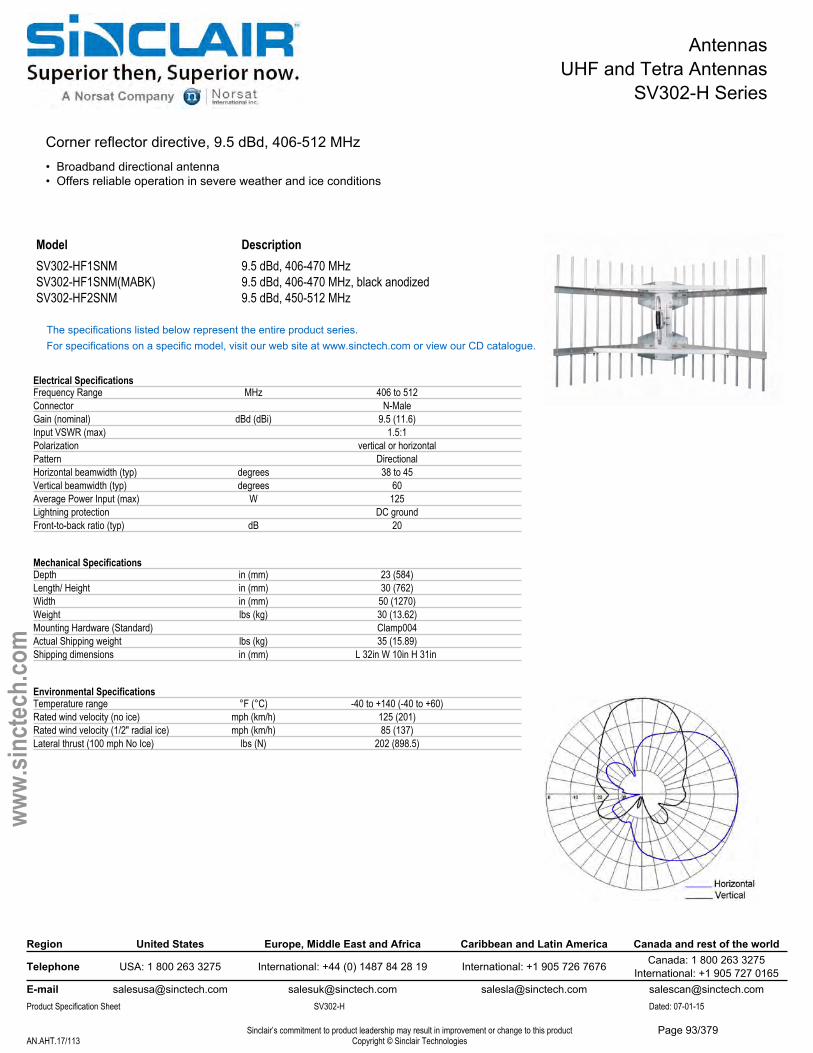
AntennasUHF and Tetra Antennas
SV302-H Series
Corner reflector directive, 9.5 dBd, 406-512 MHz• Broadband directional antenna• Offers reliable operation in severe weather and ice conditions
ModelSV302-HF1SNMSV302-HF1SNM(MABK)SV302-HF2SNM
Description9.5 dBd, 406-470 MHz 9.5 dBd, 406-470 MHz, black anodized9.5 dBd, 450-512 MHz
The specifications listed below represent the entire product series.For specifications on a specific model, visit our web site at www.sinctech.com or view our CD catalogue.
Electrical SpecificationsFrequency Range MHz 406 to 512Connector N-MaleGain (nominal) dBd (dBi) 9.5 (11.6)Input VSWR (max) 1.5:1Polarization vertical or horizontalPattern DirectionalHorizontal beamwidth (typ) degrees 38 to 45Vertical beamwidth (typ) degrees 60Average Power Input (max) W 125Lightning protection DC groundFront-to-back ratio (typ) dB 20
Mechanical SpecificationsDepth in (mm) 23 (584)Length/ Height in (mm) 30 (762)Width in (mm) 50 (1270)Weight lbs (kg) 30 (13.62)Mounting Hardware (Standard) Clamp004Actual Shipping weight lbs (kg) 35 (15.89)Shipping dimensions in (mm) L 32in W 10in H 31in
Environmental SpecificationsTemperature range °F (°C) -40 to +140 (-40 to +60)Rated wind velocity (no ice) mph (km/h) 125 (201)Rated wind velocity (1/2" radial ice) mph (km/h) 85 (137)Lateral thrust (100 mph No Ice) lbs (N) 202 (898.5)
Region United States Europe, Middle East and Africa Caribbean and Latin America Canada and rest of the world
Telephone USA: 1 800 263 3275 International: +44 (0) 1487 84 28 19 International: +1 905 726 7676 Canada: 1 800 263 3275International: +1 905 727 0165
E-mail [email protected] [email protected] [email protected] [email protected] Specification Sheet SV302-H Dated: 07-01-15
Sinclair’s commitment to product leadership may result in improvement or change to this productCopyright © Sinclair TechnologiesAN.AHT.17/113
www.
sinct
ech.
com
Page 93/379
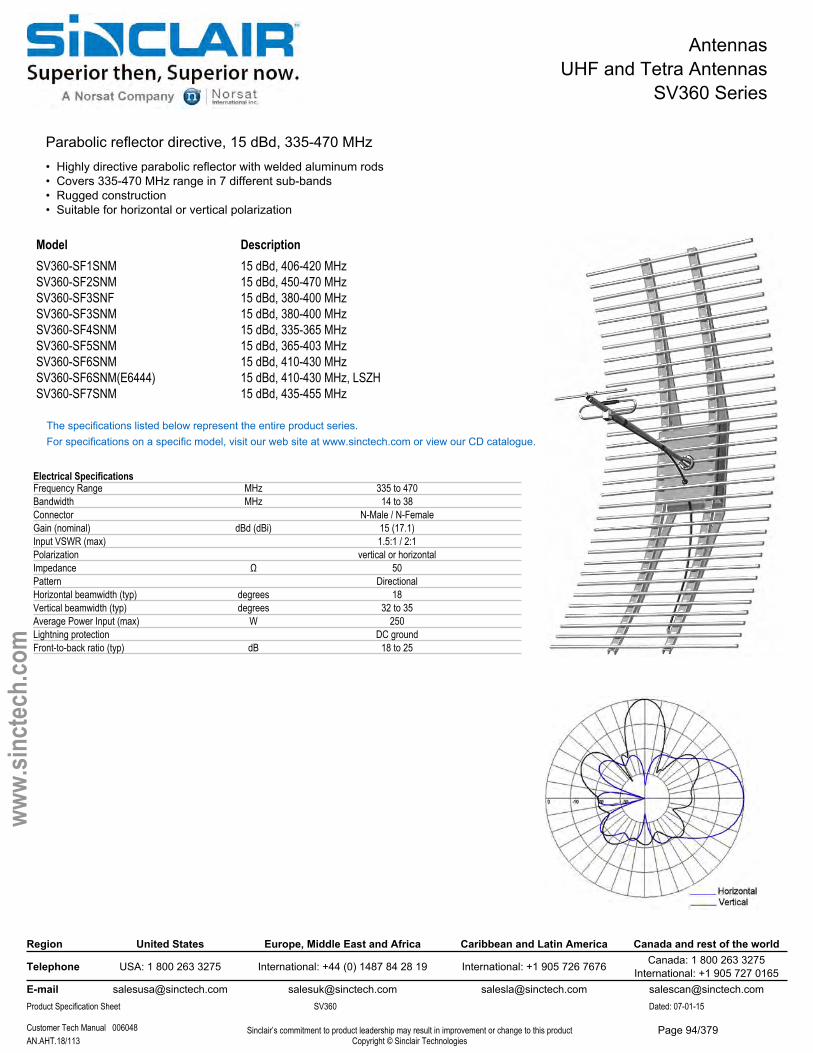
AntennasUHF and Tetra Antennas
SV360 Series
Parabolic reflector directive, 15 dBd, 335-470 MHz• Highly directive parabolic reflector with welded aluminum rods• Covers 335-470 MHz range in 7 different sub-bands• Rugged construction• Suitable for horizontal or vertical polarization
ModelSV360-SF1SNMSV360-SF2SNMSV360-SF3SNFSV360-SF3SNMSV360-SF4SNMSV360-SF5SNMSV360-SF6SNMSV360-SF6SNM(E6444)SV360-SF7SNM
Description15 dBd, 406-420 MHz 15 dBd, 450-470 MHz 15 dBd, 380-400 MHz 15 dBd, 380-400 MHz 15 dBd, 335-365 MHz 15 dBd, 365-403 MHz 15 dBd, 410-430 MHz 15 dBd, 410-430 MHz, LSZH15 dBd, 435-455 MHz
The specifications listed below represent the entire product series.For specifications on a specific model, visit our web site at www.sinctech.com or view our CD catalogue.
Electrical SpecificationsFrequency Range MHz 335 to 470Bandwidth MHz 14 to 38Connector N-Male / N-FemaleGain (nominal) dBd (dBi) 15 (17.1)Input VSWR (max) 1.5:1 / 2:1Polarization vertical or horizontalImpedance Ω 50Pattern DirectionalHorizontal beamwidth (typ) degrees 18Vertical beamwidth (typ) degrees 32 to 35Average Power Input (max) W 250Lightning protection DC groundFront-to-back ratio (typ) dB 18 to 25
Region United States Europe, Middle East and Africa Caribbean and Latin America Canada and rest of the world
Telephone USA: 1 800 263 3275 International: +44 (0) 1487 84 28 19 International: +1 905 726 7676 Canada: 1 800 263 3275International: +1 905 727 0165
E-mail [email protected] [email protected] [email protected] [email protected] Specification Sheet SV360 Dated: 07-01-15
Customer Tech Manual 006048 Sinclair’s commitment to product leadership may result in improvement or change to this productCopyright © Sinclair TechnologiesAN.AHT.18/113
www.
sinct
ech.
com
Page 94/379
AntennasUHF and Tetra Antennas
SV360 Series
Mechanical SpecificationsDepth in (mm) 25 to 37 (635 to 940)Length/ Height in (mm) 45.8 to 82 (1163 to 2083)Width in (mm) 41 to 91 (1041 to 2311)Radiating element material aluminumWeight lbs (kg) 33 to 43 (14.98 to 19.52)Mounting Hardware (Standard) Clamp004Actual Shipping weight lbs (kg) 43 to 53 (19.52 to 24.06)Shipping dimensions in (mm) L(47 - 56)in W(9 - 50)in H(9 - 50)in
Environmental SpecificationsTemperature range °F (°C) -40 to +167 (-40 to +75)Rated wind velocity (no ice) mph (km/h) 100 (161)Rated wind velocity (1/2" radial ice) mph (km/h) 85 (137)Lateral thrust (100 mph No Ice) lbs (N) 422 to 674 (1877.1 to 2998)
Region United States Europe, Middle East and Africa Caribbean and Latin America Canada and rest of the world
Telephone USA: 1 800 263 3275 International: +44 (0) 1487 84 28 19 International: +1 905 726 7676 Canada: 1 800 263 3275International: +1 905 727 0165
E-mail [email protected] [email protected] [email protected] [email protected] Specification Sheet SV360 Dated: 07-01-15
Customer Tech Manual 006048 Sinclair’s commitment to product leadership may result in improvement or change to this productCopyright © Sinclair TechnologiesAN.AHT.19/113
www.
sinct
ech.
com
Page 95/379
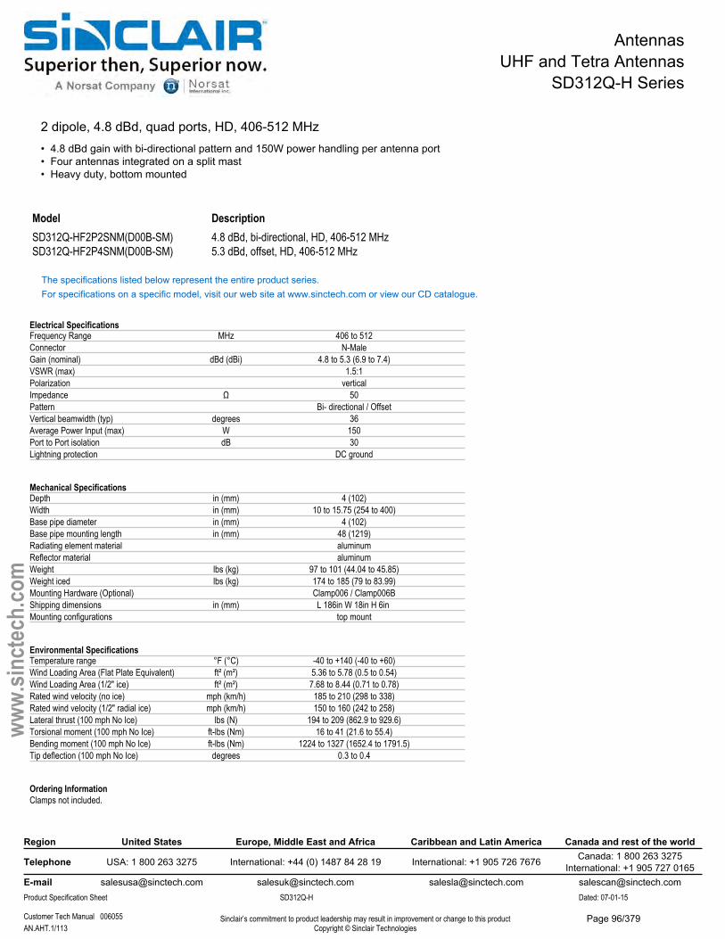
AntennasUHF and Tetra Antennas
SD312Q-H Series
2 dipole, 4.8 dBd, quad ports, HD, 406-512 MHz• 4.8 dBd gain with bi-directional pattern and 150W power handling per antenna port• Four antennas integrated on a split mast• Heavy duty, bottom mounted
Model DescriptionSD312Q-HF2P2SNM(D00B-SM) 4.8 dBd, bi-directional, HD, 406-512 MHzSD312Q-HF2P4SNM(D00B-SM) 5.3 dBd, offset, HD, 406-512 MHz
The specifications listed below represent the entire product series.For specifications on a specific model, visit our web site at www.sinctech.com or view our CD catalogue.
Electrical SpecificationsFrequency Range MHz 406 to 512Connector N-MaleGain (nominal) dBd (dBi) 4.8 to 5.3 (6.9 to 7.4)VSWR (max) 1.5:1Polarization verticalImpedance Ω 50Pattern Bi- directional / OffsetVertical beamwidth (typ) degrees 36Average Power Input (max) W 150Port to Port isolation dB 30Lightning protection DC ground
Mechanical SpecificationsDepth in (mm) 4 (102)Width in (mm) 10 to 15.75 (254 to 400)Base pipe diameter in (mm) 4 (102)Base pipe mounting length in (mm) 48 (1219)Radiating element material aluminumReflector material aluminumWeight lbs (kg) 97 to 101 (44.04 to 45.85)Weight iced lbs (kg) 174 to 185 (79 to 83.99)Mounting Hardware (Optional) Clamp006 / Clamp006BShipping dimensions in (mm) L 186in W 18in H 6in Mounting configurations top mount
Environmental SpecificationsTemperature range °F (°C) -40 to +140 (-40 to +60)Wind Loading Area (Flat Plate Equivalent) ft² (m²) 5.36 to 5.78 (0.5 to 0.54)Wind Loading Area (1/2" ice) ft² (m²) 7.68 to 8.44 (0.71 to 0.78)Rated wind velocity (no ice) mph (km/h) 185 to 210 (298 to 338)Rated wind velocity (1/2" radial ice) mph (km/h) 150 to 160 (242 to 258)Lateral thrust (100 mph No Ice) lbs (N) 194 to 209 (862.9 to 929.6)Torsional moment (100 mph No Ice) ft-lbs (Nm) 16 to 41 (21.6 to 55.4)Bending moment (100 mph No Ice) ft-lbs (Nm) 1224 to 1327 (1652.4 to 1791.5)Tip deflection (100 mph No Ice) degrees 0.3 to 0.4
Ordering InformationClamps not included.
Region United States Europe, Middle East and Africa Caribbean and Latin America Canada and rest of the world
Telephone USA: 1 800 263 3275 International: +44 (0) 1487 84 28 19 International: +1 905 726 7676 Canada: 1 800 263 3275International: +1 905 727 0165
E-mail [email protected] [email protected] [email protected] [email protected] Specification Sheet SD312Q-H Dated: 07-01-15
Customer Tech Manual 006055 Sinclair’s commitment to product leadership may result in improvement or change to this productCopyright © Sinclair TechnologiesAN.AHT.1/113
www.
sinct
ech.
com
Page 96/379
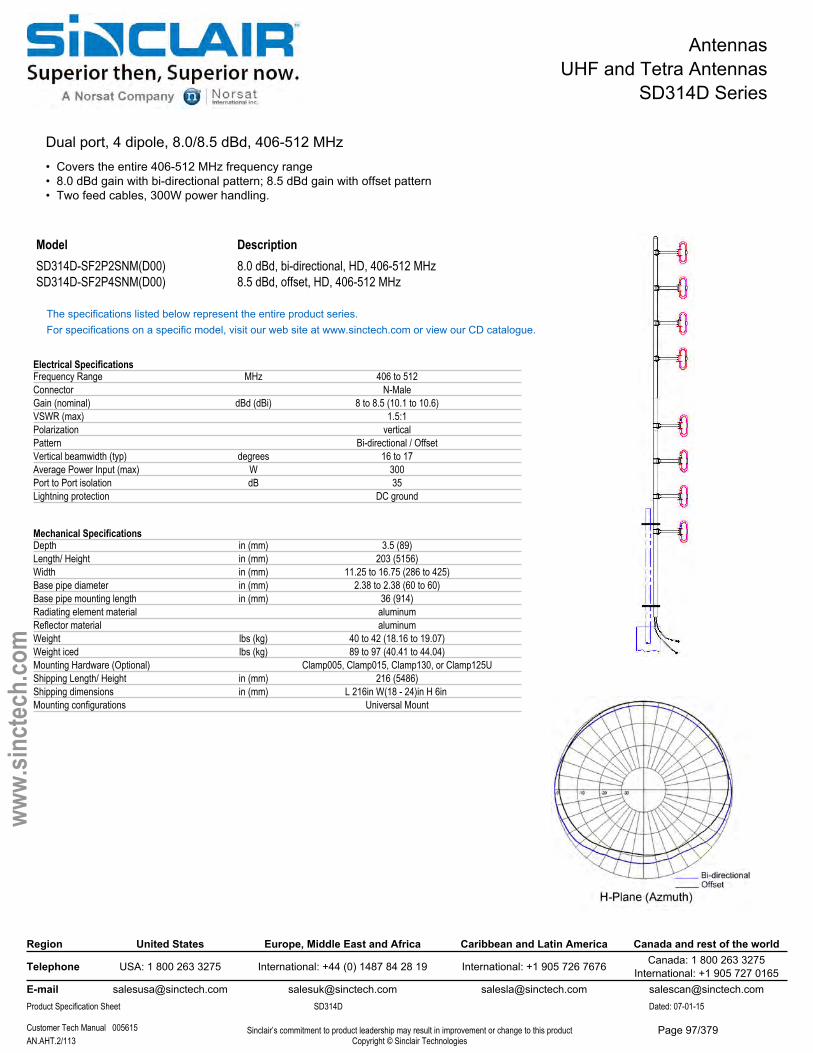
AntennasUHF and Tetra Antennas
SD314D Series
Dual port, 4 dipole, 8.0/8.5 dBd, 406-512 MHz• Covers the entire 406-512 MHz frequency range• 8.0 dBd gain with bi-directional pattern; 8.5 dBd gain with offset pattern• Two feed cables, 300W power handling.
Model DescriptionSD314D-SF2P2SNM(D00) 8.0 dBd, bi-directional, HD, 406-512 MHzSD314D-SF2P4SNM(D00) 8.5 dBd, offset, HD, 406-512 MHz
The specifications listed below represent the entire product series.For specifications on a specific model, visit our web site at www.sinctech.com or view our CD catalogue.
Electrical SpecificationsFrequency Range MHz 406 to 512Connector N-MaleGain (nominal) dBd (dBi) 8 to 8.5 (10.1 to 10.6)VSWR (max) 1.5:1Polarization verticalPattern Bi-directional / OffsetVertical beamwidth (typ) degrees 16 to 17Average Power Input (max) W 300Port to Port isolation dB 35Lightning protection DC ground
Mechanical SpecificationsDepth in (mm) 3.5 (89)Length/ Height in (mm) 203 (5156)Width in (mm) 11.25 to 16.75 (286 to 425)Base pipe diameter in (mm) 2.38 to 2.38 (60 to 60)Base pipe mounting length in (mm) 36 (914)Radiating element material aluminumReflector material aluminumWeight lbs (kg) 40 to 42 (18.16 to 19.07)Weight iced lbs (kg) 89 to 97 (40.41 to 44.04)Mounting Hardware (Optional) Clamp005, Clamp015, Clamp130, or Clamp125UShipping Length/ Height in (mm) 216 (5486)Shipping dimensions in (mm) L 216in W(18 - 24)in H 6in Mounting configurations Universal Mount
Region United States Europe, Middle East and Africa Caribbean and Latin America Canada and rest of the world
Telephone USA: 1 800 263 3275 International: +44 (0) 1487 84 28 19 International: +1 905 726 7676 Canada: 1 800 263 3275International: +1 905 727 0165
E-mail [email protected] [email protected] [email protected] [email protected] Specification Sheet SD314D Dated: 07-01-15
Customer Tech Manual 005615 Sinclair’s commitment to product leadership may result in improvement or change to this productCopyright © Sinclair TechnologiesAN.AHT.2/113
www.
sinct
ech.
com
Page 97/379

AntennasUHF and Tetra Antennas
SD314D Series
Environmental SpecificationsTemperature range °F (°C) -40 to +140 (-40 to +60)Wind Loading Area (Flat Plate Equivalent) ft² (m²) 3.16 to 3.51 (0.29 to 0.33)Wind Loading Area (1/2" ice) ft² (m²) 5.29 to 5.91 (0.49 to 0.55)Rated wind velocity (no ice) mph (km/h) 135 to 145 (217 to 233)Rated wind velocity (1/2" radial ice) mph (km/h) 95 to 105 (153 to 169)Lateral thrust (100 mph No Ice) lbs (N) 101 to 114 (449.2 to 507.1)Torsional moment (100 mph No Ice) ft-lbs (Nm) 23 to 46 (31.1 to 62.1)Bending moment (100 mph No Ice) ft-lbs (Nm) 599 to 667 (808.7 to 900.5)Tip deflection (100 mph No Ice) degrees 0.39 to 0.43
Ordering InformationClamps must be ordered separately.
Region United States Europe, Middle East and Africa Caribbean and Latin America Canada and rest of the world
Telephone USA: 1 800 263 3275 International: +44 (0) 1487 84 28 19 International: +1 905 726 7676 Canada: 1 800 263 3275International: +1 905 727 0165
E-mail [email protected] [email protected] [email protected] [email protected] Specification Sheet SD314D Dated: 07-01-15
Customer Tech Manual 005615 Sinclair’s commitment to product leadership may result in improvement or change to this productCopyright © Sinclair TechnologiesAN.AHT.3/113
www.
sinct
ech.
com
Page 98/379
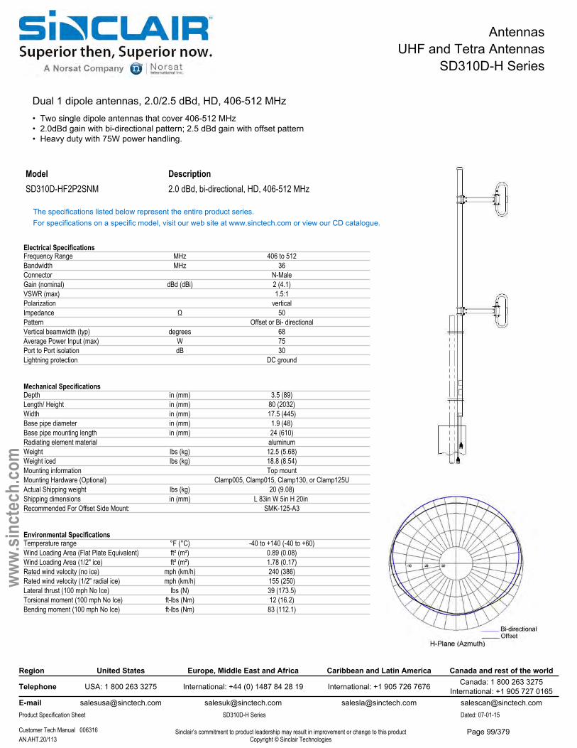
AntennasUHF and Tetra Antennas
SD310D-H Series
Dual 1 dipole antennas, 2.0/2.5 dBd, HD, 406-512 MHz• Two single dipole antennas that cover 406-512 MHz• 2.0dBd gain with bi-directional pattern; 2.5 dBd gain with offset pattern• Heavy duty with 75W power handling.
Model DescriptionSD310D-HF2P2SNM 2.0 dBd, bi-directional, HD, 406-512 MHz
The specifications listed below represent the entire product series.For specifications on a specific model, visit our web site at www.sinctech.com or view our CD catalogue.
Electrical SpecificationsFrequency Range MHz 406 to 512Bandwidth MHz 36Connector N-MaleGain (nominal) dBd (dBi) 2 (4.1)VSWR (max) 1.5:1Polarization verticalImpedance Ω 50Pattern Offset or Bi- directionalVertical beamwidth (typ) degrees 68Average Power Input (max) W 75Port to Port isolation dB 30Lightning protection DC ground
Mechanical SpecificationsDepth in (mm) 3.5 (89)Length/ Height in (mm) 80 (2032)Width in (mm) 17.5 (445)Base pipe diameter in (mm) 1.9 (48)Base pipe mounting length in (mm) 24 (610)Radiating element material aluminumWeight lbs (kg) 12.5 (5.68)Weight iced lbs (kg) 18.8 (8.54)Mounting information Top mountMounting Hardware (Optional) Clamp005, Clamp015, Clamp130, or Clamp125UActual Shipping weight lbs (kg) 20 (9.08)Shipping dimensions in (mm) L 83in W 5in H 20in Recommended For Offset Side Mount: SMK-125-A3
Environmental SpecificationsTemperature range °F (°C) -40 to +140 (-40 to +60)Wind Loading Area (Flat Plate Equivalent) ft² (m²) 0.89 (0.08)Wind Loading Area (1/2" ice) ft² (m²) 1.78 (0.17)Rated wind velocity (no ice) mph (km/h) 240 (386)Rated wind velocity (1/2" radial ice) mph (km/h) 155 (250)Lateral thrust (100 mph No Ice) lbs (N) 39 (173.5)Torsional moment (100 mph No Ice) ft-lbs (Nm) 12 (16.2)Bending moment (100 mph No Ice) ft-lbs (Nm) 83 (112.1)
Region United States Europe, Middle East and Africa Caribbean and Latin America Canada and rest of the world
Telephone USA: 1 800 263 3275 International: +44 (0) 1487 84 28 19 International: +1 905 726 7676 Canada: 1 800 263 3275International: +1 905 727 0165
E-mail [email protected] [email protected] [email protected] [email protected] Specification Sheet SD310D-H Series Dated: 07-01-15
Customer Tech Manual 006316 Sinclair’s commitment to product leadership may result in improvement or change to this productCopyright © Sinclair TechnologiesAN.AHT.20/113
www.
sinct
ech.
com
Page 99/379
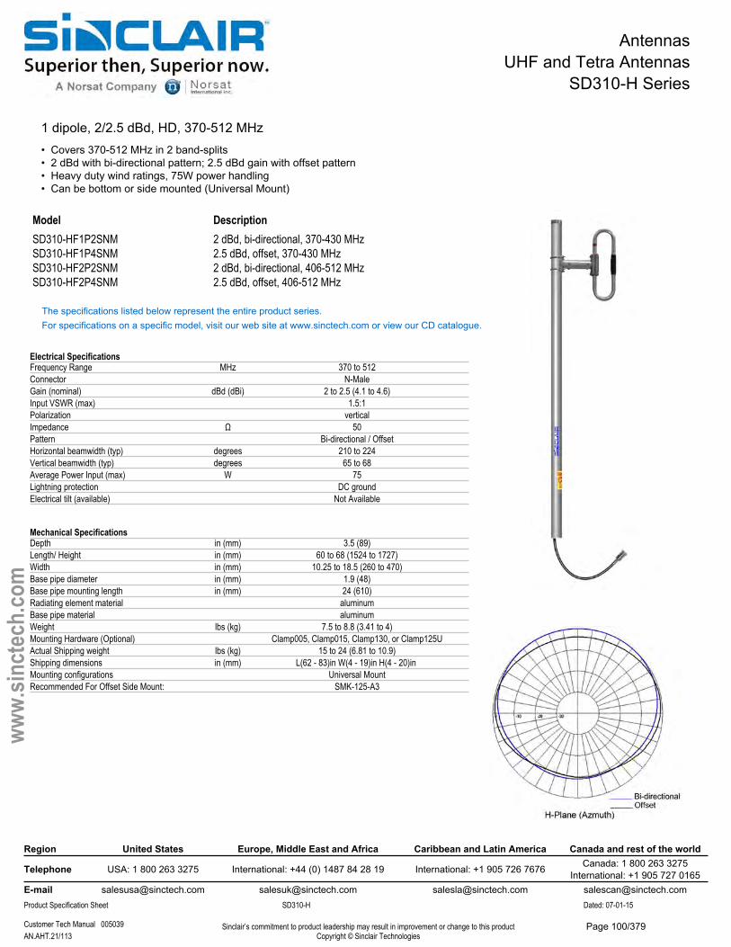
AntennasUHF and Tetra Antennas
SD310-H Series
1 dipole, 2/2.5 dBd, HD, 370-512 MHz• Covers 370-512 MHz in 2 band-splits• 2 dBd with bi-directional pattern; 2.5 dBd gain with offset pattern• Heavy duty wind ratings, 75W power handling• Can be bottom or side mounted (Universal Mount)
Model DescriptionSD310-HF1P2SNM 2 dBd, bi-directional, 370-430 MHzSD310-HF1P4SNM 2.5 dBd, offset, 370-430 MHzSD310-HF2P2SNM 2 dBd, bi-directional, 406-512 MHzSD310-HF2P4SNM 2.5 dBd, offset, 406-512 MHz
The specifications listed below represent the entire product series.For specifications on a specific model, visit our web site at www.sinctech.com or view our CD catalogue.
Electrical SpecificationsFrequency Range MHz 370 to 512Connector N-MaleGain (nominal) dBd (dBi) 2 to 2.5 (4.1 to 4.6)Input VSWR (max) 1.5:1Polarization verticalImpedance Ω 50Pattern Bi-directional / OffsetHorizontal beamwidth (typ) degrees 210 to 224Vertical beamwidth (typ) degrees 65 to 68Average Power Input (max) W 75Lightning protection DC groundElectrical tilt (available) Not Available
Mechanical SpecificationsDepth in (mm) 3.5 (89)Length/ Height in (mm) 60 to 68 (1524 to 1727)Width in (mm) 10.25 to 18.5 (260 to 470)Base pipe diameter in (mm) 1.9 (48)Base pipe mounting length in (mm) 24 (610)Radiating element material aluminumBase pipe material aluminumWeight lbs (kg) 7.5 to 8.8 (3.41 to 4)Mounting Hardware (Optional) Clamp005, Clamp015, Clamp130, or Clamp125UActual Shipping weight lbs (kg) 15 to 24 (6.81 to 10.9)Shipping dimensions in (mm) L(62 - 83)in W(4 - 19)in H(4 - 20)in Mounting configurations Universal MountRecommended For Offset Side Mount: SMK-125-A3
Region United States Europe, Middle East and Africa Caribbean and Latin America Canada and rest of the world
Telephone USA: 1 800 263 3275 International: +44 (0) 1487 84 28 19 International: +1 905 726 7676 Canada: 1 800 263 3275International: +1 905 727 0165
E-mail [email protected] [email protected] [email protected] [email protected] Specification Sheet SD310-H Dated: 07-01-15
Customer Tech Manual 005039 Sinclair’s commitment to product leadership may result in improvement or change to this productCopyright © Sinclair TechnologiesAN.AHT.21/113
www.
sinct
ech.
com
Page 100/379

AntennasUHF and Tetra Antennas
SD310-H Series
Environmental SpecificationsTemperature range °F (°C) -40 to +140 (-40 to +60)Wind Loading Area (Flat Plate Equivalent) ft² (m²) 0.65 to 0.8 (0.06 to 0.07)Wind Loading Area (1/2" ice) ft² (m²) 1.22 to 2.49 (0.11 to 0.23)Rated wind velocity (no ice) mph (km/h) 240 to 265 (386 to 427)Rated wind velocity (1/2" radial ice) mph (km/h) 190 to 205 (306 to 330)Lateral thrust (100 mph No Ice) lbs (N) 26.1 to 30 (116.1 to 133.4)Torsional moment (100 mph No Ice) ft-lbs (Nm) 2.5 to 7.5 (3.4 to 10.1)Bending moment (100 mph No Ice) ft-lbs (Nm) 14.1 to 53 (19 to 71.6)
Region United States Europe, Middle East and Africa Caribbean and Latin America Canada and rest of the world
Telephone USA: 1 800 263 3275 International: +44 (0) 1487 84 28 19 International: +1 905 726 7676 Canada: 1 800 263 3275International: +1 905 727 0165
E-mail [email protected] [email protected] [email protected] [email protected] Specification Sheet SD310-H Dated: 07-01-15
Customer Tech Manual 005039 Sinclair’s commitment to product leadership may result in improvement or change to this productCopyright © Sinclair TechnologiesAN.AHT.22/113
www.
sinct
ech.
com
Page 101/379
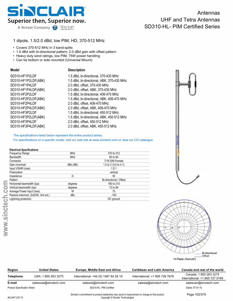
AntennasUHF and Tetra Antennas
SD310-HL- PIM Certified Series
1 dipole, 1.5/2.0 dBd, low PIM, HD, 370-512 MHz• Covers 370-512 MHz in 3 band-splits• 1.5 dBd with bi-directional pattern; 2.0 dBd gain with offset pattern• Heavy duty wind ratings, low PIM, 75W power handling• Can be bottom or side mounted (Universal Mount)
Model DescriptionSD310-HF1P2LDF 1.5 dBd, bi-directional, 370-430 MHzSD310-HF1P2LDF(ABK) 1.5 dBd, bi-directional, ABK, 370-430 MHzSD310-HF1P4LDF 2.0 dBd, offset, 370-430 MHzSD310-HF1P4LDF(ABK) 2.0 dBd, offset, ABK, 370-430 MHzSD310-HF2P2LDF 1.5 dBd, bi-directional, 406-470 MHzSD310-HF2P2LDF(ABK) 1.5 dBd, bi-directional, ABK, 406-470 MHzSD310-HF2P4LDF 2.0 dBd, offset, 406-470 MHzSD310-HF2P4LDF(ABK) 2.0 dBd, offset, ABK, 406-470 MHzSD310-HF3P2LDF 1.5 dBd, bi-directional, 450-512 MHzSD310-HF3P2LDF(ABK) 1.5 dBd, bi-directional, ABK, 450-512 MHzSD310-HF3P4LDF 2.0 dBd, offset, 450-512 MHzSD310-HF3P4LDF(ABK) 2.0 dBd, offset, ABK, 450-512 MHz
The specifications listed below represent the entire product series.For specifications on a specific model, visit our web site at www.sinctech.com or view our CD catalogue.
Electrical SpecificationsFrequency Range MHz 370 to 512Bandwidth MHz 60 to 64Connector 7/16 DIN-FemaleGain (nominal) dBd (dBi) 1.5 to 2 (3.6 to 4.1)Input VSWR (max) 1.5:1Polarization verticalImpedance Ω 50Pattern Bi-directional / OffsetHorizontal beamwidth (typ) degrees 180 to 210Vertical beamwidth (typ) degrees 73 to 84Average Power Input (max) W 75Passive intermod. (2x20W, 3rd ord.) dBc -150Lightning protection DC ground
Region United States Europe, Middle East and Africa Caribbean and Latin America Canada and rest of the world
Telephone USA: 1 800 263 3275 International: +44 (0) 1487 84 28 19 International: +1 905 726 7676 Canada: 1 800 263 3275International: +1 905 727 0165
E-mail [email protected] [email protected] [email protected] [email protected] Specification Sheet SD310-HL- PIM Certified Dated: 07-01-15
Sinclair’s commitment to product leadership may result in improvement or change to this productCopyright © Sinclair TechnologiesAN.AHT.23/113
www.
sinct
ech.
com
Page 102/379
AntennasUHF and Tetra Antennas
SD310-HL- PIM Certified Series
Mechanical SpecificationsDepth in (mm) 3.5 (89)Length/ Height in (mm) 48.13 (1223)Width in (mm) 11.84 to 18.75 (301 to 476)Base pipe diameter in (mm) 1.9 (48)Base pipe mounting length in (mm) 18 (457)Radiating element material aluminumBase pipe material aluminumWeight lbs (kg) 6.5 to 7.1 (2.95 to 3.22)Weight iced lbs (kg) 9.5 to 11 (4.31 to 4.99)Mounting Hardware (Optional) Clamp005, Clamp015, Clamp130, or Clamp125UActual Shipping weight lbs (kg) 11 to 14 (4.99 to 6.36)Shipping dimensions in (mm) L 63in W(19 - 22)in H 4in Mounting configurations Universal MountRecommended For Offset Side Mount: SMK-125-A3
Environmental SpecificationsTemperature range °F (°C) -40 to +140 (-40 to +60)Wind Loading Area (Flat Plate Equivalent) ft² (m²) 0.56 to 0.64 (0.05 to 0.06)Wind Loading Area (1/2" ice) ft² (m²) 0.91 to 1.1 (0.08 to 0.1)Rated wind velocity (no ice) mph (km/h) 265 (427)Rated wind velocity (1/2" radial ice) mph (km/h) 210 (338)Lateral thrust (100 mph No Ice) lbs (N) 21 to 23.1 (93.4 to 102.7)Torsional moment (100 mph No Ice) ft-lbs (Nm) 3.46 to 8.1 (4.7 to 10.9)Bending moment (100 mph No Ice) ft-lbs (Nm) 26.3 to 29.6 (35.5 to 40)Tip deflection (100 mph No Ice) degrees 0.03 to 0.04
Region United States Europe, Middle East and Africa Caribbean and Latin America Canada and rest of the world
Telephone USA: 1 800 263 3275 International: +44 (0) 1487 84 28 19 International: +1 905 726 7676 Canada: 1 800 263 3275International: +1 905 727 0165
E-mail [email protected] [email protected] [email protected] [email protected] Specification Sheet SD310-HL- PIM Certified Dated: 07-01-15
Sinclair’s commitment to product leadership may result in improvement or change to this productCopyright © Sinclair TechnologiesAN.AHT.24/113
www.
sinct
ech.
com
Page 103/379
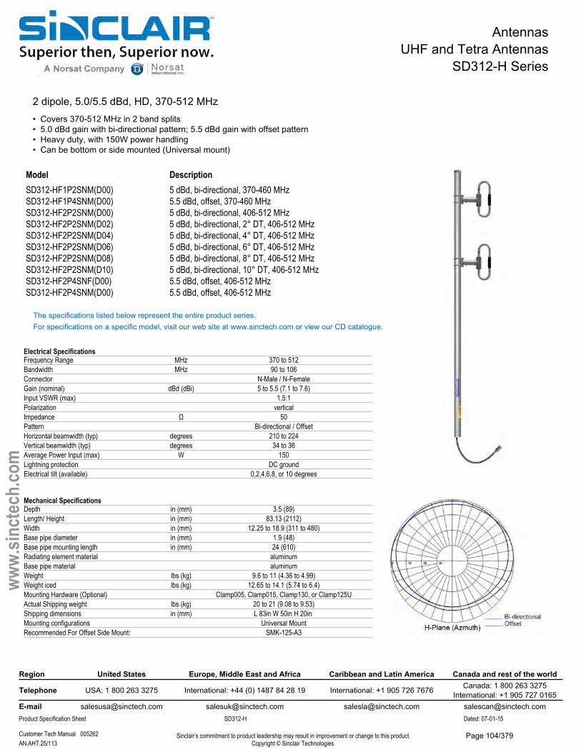
AntennasUHF and Tetra Antennas
SD312-H Series
2 dipole, 5.0/5.5 dBd, HD, 370-512 MHz• Covers 370-512 MHz in 2 band splits• 5.0 dBd gain with bi-directional pattern; 5.5 dBd gain with offset pattern• Heavy duty, with 150W power handling• Can be bottom or side mounted (Universal mount)
Description5 dBd, bi-directional, 370-460 MHz5.5 dBd, offset, 370-460 MHz5 dBd, bi-directional, 406-512 MHz5 dBd, bi-directional, 2° DT, 406-512 MHz5 dBd, bi-directional, 4° DT, 406-512 MHz5 dBd, bi-directional, 6° DT, 406-512 MHz5 dBd, bi-directional, 8° DT, 406-512 MHz5 dBd, bi-directional, 10° DT, 406-512 MHz5.5 dBd, offset, 406-512 MHz
ModelSD312-HF1P2SNM(D00) SD312-HF1P4SNM(D00) SD312-HF2P2SNM(D00) SD312-HF2P2SNM(D02) SD312-HF2P2SNM(D04) SD312-HF2P2SNM(D06) SD312-HF2P2SNM(D08) SD312-HF2P2SNM(D10) SD312-HF2P4SNF(D00) SD312-HF2P4SNM(D00) 5.5 dBd, offset, 406-512 MHz
The specifications listed below represent the entire product series.For specifications on a specific model, visit our web site at www.sinctech.com or view our CD catalogue.
Electrical SpecificationsFrequency Range MHz 370 to 512Bandwidth MHz 90 to 106Connector N-Male / N-FemaleGain (nominal) dBd (dBi) 5 to 5.5 (7.1 to 7.6)Input VSWR (max) 1.5:1Polarization verticalImpedance Ω 50Pattern Bi-directional / OffsetHorizontal beamwidth (typ) degrees 210 to 224Vertical beamwidth (typ) degrees 34 to 36Average Power Input (max) W 150Lightning protection DC groundElectrical tilt (available) 0,2,4,6,8, or 10 degrees
Mechanical SpecificationsDepth in (mm) 3.5 (89)Length/ Height in (mm) 83.13 (2112)Width in (mm) 12.25 to 18.9 (311 to 480)Base pipe diameter in (mm) 1.9 (48)Base pipe mounting length in (mm) 24 (610)Radiating element material aluminumBase pipe material aluminumWeight lbs (kg) 9.6 to 11 (4.36 to 4.99)Weight iced lbs (kg) 12.65 to 14.1 (5.74 to 6.4)Mounting Hardware (Optional) Clamp005, Clamp015, Clamp130, or Clamp125UActual Shipping weight lbs (kg) 20 to 21 (9.08 to 9.53)Shipping dimensions in (mm) L 83in W 50in H 20in Mounting configurations Universal MountRecommended For Offset Side Mount: SMK-125-A3
Region United States Europe, Middle East and Africa Caribbean and Latin America Canada and rest of the world
Telephone USA: 1 800 263 3275 International: +44 (0) 1487 84 28 19 International: +1 905 726 7676 Canada: 1 800 263 3275International: +1 905 727 0165
E-mail [email protected] [email protected] [email protected] [email protected] Specification Sheet SD312-H Dated: 07-01-15
Customer Tech Manual 005262 Sinclair’s commitment to product leadership may result in improvement or change to this productCopyright © Sinclair TechnologiesAN.AHT.25/113
www.
sinct
ech.
com
Page 104/379
AntennasUHF and Tetra Antennas
SD312-H Series
Environmental SpecificationsTemperature range °F (°C) -40 to +140 (-40 to +60)Wind Loading Area (Flat Plate Equivalent) ft² (m²) 0.88 to 0.97 (0.08 to 0.09)Wind Loading Area (1/2" ice) ft² (m²) 1.69 to 3.53 (0.16 to 0.33)Rated wind velocity (no ice) mph (km/h) 230 to 245 (370 to 394)Rated wind velocity (1/2" radial ice) mph (km/h) 165 to 175 (266 to 282)Lateral thrust (100 mph No Ice) lbs (N) 37.2 to 42.5 (165.5 to 189)Torsional moment (100 mph No Ice) ft-lbs (Nm) 3.4 to 8.11 (4.6 to 10.9)Bending moment (100 mph No Ice) ft-lbs (Nm) 105 to 122 (141.8 to 164.7)Tip deflection (100 mph No Ice) degrees 0.22 to 0.3
Region United States Europe, Middle East and Africa Caribbean and Latin America Canada and rest of the world
Telephone USA: 1 800 263 3275 International: +44 (0) 1487 84 28 19 International: +1 905 726 7676 Canada: 1 800 263 3275International: +1 905 727 0165
E-mail [email protected] [email protected] [email protected] [email protected] Specification Sheet SD312-H Dated: 07-01-15
Customer Tech Manual 005262 Sinclair’s commitment to product leadership may result in improvement or change to this productCopyright © Sinclair TechnologiesAN.AHT.26/113
www.
sinct
ech.
com
Page 105/379
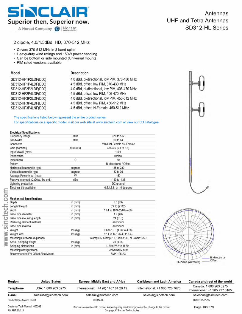
AntennasUHF and Tetra Antennas
SD312-HL Series
2 dipole, 4.0/4.5dBd, HD, 370-512 MHz• Covers 370-512 MHz in 3 band splits• Heavy-duty wind ratings and 150W power handling• Can be bottom or side mounted (Universal mount)• PIM rated versions available
Model Description4.0 dBd, bi-directional, low PIM, 370-430 MHz4.5 dBd, offset, low PIM, 370-430 MHz4.0 dBd, bi-directional, low PIM, 406-470 MHz4.5 dBd, offset, low PIM, 406-470 MHz4.0 dBd, bi-directional, low PIM, 450-512 MHz4.5 dBd, offset, low PIM, 450-512 MHz
SD312-HF1P2LDF(D00) SD312-HF1P4LDF(D00) SD312-HF2P2LDF(D00) SD312-HF2P4LDF(D00) SD312-HF3P2LDF(D00) SD312-HF3P4LDF(D00) SD312-HF3P4LNF(D00) 4.5 dBd, offset, N-Female, 450-512 MHz
The specifications listed below represent the entire product series.For specifications on a specific model, visit our web site at www.sinctech.com or view our CD catalogue.
Electrical SpecificationsFrequency Range MHz 370 to 512Bandwidth MHz 60 to 64Connector 7/16 DIN-Female / N-FemaleGain (nominal) dBd (dBi) 4 to 4.5 (6.1 to 6.6)Input VSWR (max) 1.5:1Polarization verticalImpedance Ω 50Pattern Bi-directional / OffsetHorizontal beamwidth (typ) degrees 185 to 230Vertical beamwidth (typ) degrees 32 to 36Average Power Input (max) W 150Passive intermod. (2x20W, 3rd ord.) dBc -150 to -138Lightning protection DC groundElectrical tilt (available) 0,2,4,6,8, or 10 degrees
Mechanical SpecificationsDepth in (mm) 3.5 (89)Length/ Height in (mm) 83.13 (2112)Width in (mm) 11.4 to 18.9 (290 to 480)Base pipe diameter in (mm) 1.9 (48)Base pipe mounting length in (mm) 24 (610)Radiating element material aluminumBase pipe material aluminumWeight lbs (kg) 9.6 to 10.3 (4.36 to 4.68)Weight iced lbs (kg) 12.1 to 14.1 (5.49 to 6.4)Mounting Hardware (Optional) Clamp005, Clamp015, Clamp130, or Clamp125UActual Shipping weight lbs (kg) 20 (9.08)Shipping dimensions in (mm) L 89in W 21in H 6in Mounting configurations Universal MountRecommended For Offset Side Mount: SMK-125-A3
Region United States Europe, Middle East and Africa Caribbean and Latin America Canada and rest of the world
Telephone USA: 1 800 263 3275 International: +44 (0) 1487 84 28 19 International: +1 905 726 7676 Canada: 1 800 263 3275International: +1 905 727 0165
E-mail [email protected] [email protected] [email protected] [email protected] Specification Sheet SD312-HL Dated: 07-01-15
Customer Tech Manual 005262 Sinclair’s commitment to product leadership may result in improvement or change to this productCopyright © Sinclair TechnologiesAN.AHT.27/113
www.
sinct
ech.
com
Page 106/379

AntennasUHF and Tetra Antennas
SD312-HL Series
Environmental SpecificationsTemperature range °F (°C) -40 to +140 (-40 to +60)Wind Loading Area (Flat Plate Equivalent) ft² (m²) 0.86 to 0.96 (0.08 to 0.09)Wind Loading Area (1/2" ice) ft² (m²) 1.66 to 1.96 (0.15 to 0.18)Rated wind velocity (no ice) mph (km/h) 230 to 250 (370 to 403)Rated wind velocity (1/2" radial ice) mph (km/h) 165 to 180 (266 to 290)Lateral thrust (100 mph No Ice) lbs (N) 36.8 to 42.5 (163.7 to 189)Torsional moment (100 mph No Ice) ft-lbs (Nm) 3 to 8.11 (4.1 to 10.9)Bending moment (100 mph No Ice) ft-lbs (Nm) 103 to 122 (139.1 to 164.7)
Ordering InformationN-type connectors available
Region United States Europe, Middle East and Africa Caribbean and Latin America Canada and rest of the world
Telephone USA: 1 800 263 3275 International: +44 (0) 1487 84 28 19 International: +1 905 726 7676 Canada: 1 800 263 3275International: +1 905 727 0165
E-mail [email protected] [email protected] [email protected] [email protected] Specification Sheet SD312-HL Dated: 07-01-15
Customer Tech Manual 005262 Sinclair’s commitment to product leadership may result in improvement or change to this productCopyright © Sinclair TechnologiesAN.AHT.28/113
www.
sinct
ech.
com
Page 107/379
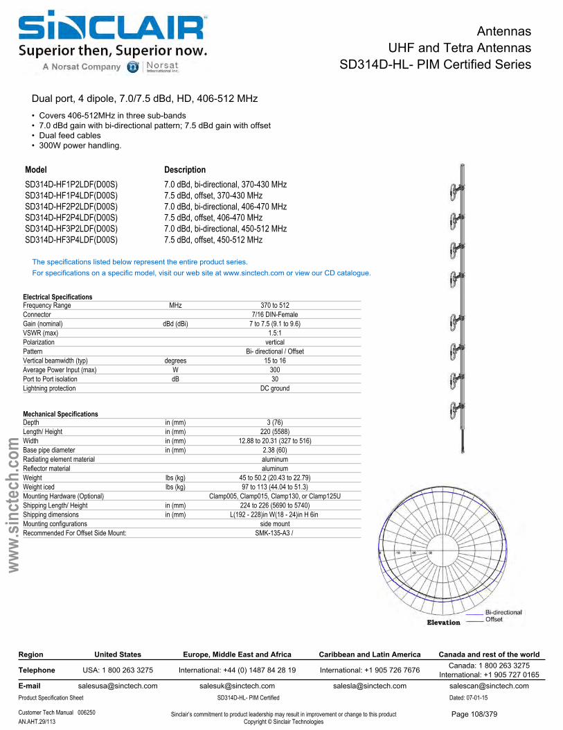
AntennasUHF and Tetra Antennas
SD314D-HL- PIM Certified Series
Dual port, 4 dipole, 7.0/7.5 dBd, HD, 406-512 MHz• Covers 406-512MHz in three sub-bands• 7.0 dBd gain with bi-directional pattern; 7.5 dBd gain with offset• Dual feed cables• 300W power handling.
Model DescriptionSD314D-HF1P2LDF(D00S) 7.0 dBd, bi-directional, 370-430 MHzSD314D-HF1P4LDF(D00S) 7.5 dBd, offset, 370-430 MHzSD314D-HF2P2LDF(D00S) 7.0 dBd, bi-directional, 406-470 MHzSD314D-HF2P4LDF(D00S) 7.5 dBd, offset, 406-470 MHzSD314D-HF3P2LDF(D00S) 7.0 dBd, bi-directional, 450-512 MHzSD314D-HF3P4LDF(D00S) 7.5 dBd, offset, 450-512 MHz
The specifications listed below represent the entire product series.For specifications on a specific model, visit our web site at www.sinctech.com or view our CD catalogue.
Electrical SpecificationsFrequency Range MHz 370 to 512Connector 7/16 DIN-FemaleGain (nominal) dBd (dBi) 7 to 7.5 (9.1 to 9.6)VSWR (max) 1.5:1Polarization verticalPattern Bi- directional / OffsetVertical beamwidth (typ) degrees 15 to 16Average Power Input (max) W 300Port to Port isolation dB 30Lightning protection DC ground
Mechanical SpecificationsDepth in (mm) 3 (76)Length/ Height in (mm) 220 (5588)Width in (mm) 12.88 to 20.31 (327 to 516)Base pipe diameter in (mm) 2.38 (60)Radiating element material aluminumReflector material aluminumWeight lbs (kg) 45 to 50.2 (20.43 to 22.79)Weight iced lbs (kg) 97 to 113 (44.04 to 51.3)Mounting Hardware (Optional) Clamp005, Clamp015, Clamp130, or Clamp125UShipping Length/ Height in (mm) 224 to 226 (5690 to 5740)Shipping dimensions in (mm) L(192 - 228)in W(18 - 24)in H 6in Mounting configurations side mountRecommended For Offset Side Mount: SMK-135-A3 /
Region United States Europe, Middle East and Africa Caribbean and Latin America Canada and rest of the world
Telephone USA: 1 800 263 3275 International: +44 (0) 1487 84 28 19 International: +1 905 726 7676 Canada: 1 800 263 3275International: +1 905 727 0165
E-mail [email protected] [email protected] [email protected] [email protected] Specification Sheet SD314D-HL- PIM Certified Dated: 07-01-15
Customer Tech Manual 006250 Sinclair’s commitment to product leadership may result in improvement or change to this productCopyright © Sinclair TechnologiesAN.AHT.29/113
www.
sinct
ech.
com
Page 108/379

AntennasUHF and Tetra Antennas
SD314D-HL- PIM Certified Series
Environmental SpecificationsTemperature range °F (°C) -40 to +140 (-40 to +60)Wind Loading Area (Flat Plate Equivalent) ft² (m²) 3.66 to 4.3 (0.34 to 0.4)Wind Loading Area (1/2" ice) ft² (m²) 5.94 to 7.1 (0.55 to 0.66)Rated wind velocity (no ice) mph (km/h) 225 to 235 (362 to 378)Rated wind velocity (1/2" radial ice) mph (km/h) 165 to 175 (266 to 282)Lateral thrust (100 mph No Ice) lbs (N) 134 to 156 (596 to 693.9)Torsional moment (100 mph No Ice) ft-lbs (Nm) 26 to 68 (35.1 to 91.8)
Ordering InformationClamps must be ordered separately.
Region United States Europe, Middle East and Africa Caribbean and Latin America Canada and rest of the world
Telephone USA: 1 800 263 3275 International: +44 (0) 1487 84 28 19 International: +1 905 726 7676 Canada: 1 800 263 3275International: +1 905 727 0165
E-mail [email protected] [email protected] [email protected] [email protected] Specification Sheet SD314D-HL- PIM Certified Dated: 07-01-15
Customer Tech Manual 006250 Sinclair’s commitment to product leadership may result in improvement or change to this productCopyright © Sinclair TechnologiesAN.AHT.30/113
www.
sinct
ech.
com
Page 109/379
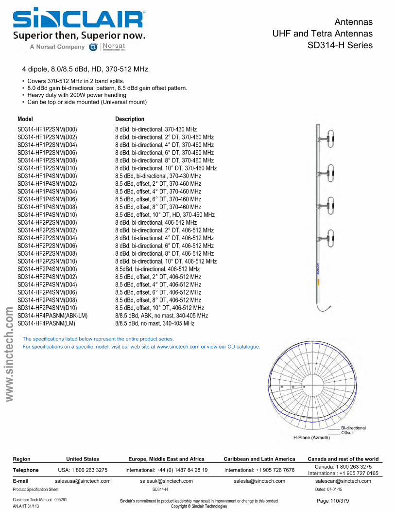
AntennasUHF and Tetra Antennas
SD314-H Series
4 dipole, 8.0/8.5 dBd, HD, 370-512 MHz• Covers 370-512 MHz in 2 band splits.• 8.0 dBd gain bi-directional pattern, 8.5 dBd gain offset pattern.• Heavy duty with 200W power handling• Can be top or side mounted (Universal mount)
Model DescriptionSD314-HF1P2SNM(D00) 8 dBd, bi-directional, 370-430 MHzSD314-HF1P2SNM(D02) 8 dBd, bi-directional, 2° DT, 370-460 MHzSD314-HF1P2SNM(D04) 8 dBd, bi-directional, 4° DT, 370-460 MHzSD314-HF1P2SNM(D06) 8 dBd, bi-directional, 6° DT, 370-460 MHzSD314-HF1P2SNM(D08) 8 dBd, bi-directional, 8° DT, 370-460 MHzSD314-HF1P2SNM(D10) 8 dBd, bi-directional, 10° DT, 370-460 MHzSD314-HF1P4SNM(D00) 8.5 dBd, bi-directional, 370-430 MHzSD314-HF1P4SNM(D02) 8.5 dBd, offset, 2° DT, 370-460 MHzSD314-HF1P4SNM(D04) 8.5 dBd, offset, 4° DT, 370-460 MHzSD314-HF1P4SNM(D06) 8.5 dBd, offset, 6° DT, 370-460 MHzSD314-HF1P4SNM(D08) 8.5 dBd, offset, 8° DT, 370-460 MHzSD314-HF1P4SNM(D10) 8.5 dBd, offset, 10° DT, HD, 370-460 MHzSD314-HF2P2SNM(D00) 8 dBd, bi-directional, 406-512 MHzSD314-HF2P2SNM(D02) 8 dBd, bi-directional, 2° DT, 406-512 MHzSD314-HF2P2SNM(D04) 8 dBd, bi-directional, 4° DT, 406-512 MHzSD314-HF2P2SNM(D06) 8 dBd, bi-directional, 6° DT, 406-512 MHzSD314-HF2P2SNM(D08) 8 dBd, bi-directional, 8° DT, 406-512 MHzSD314-HF2P2SNM(D10) 8 dBd, bi-directional, 10° DT, 406-512 MHzSD314-HF2P4SNM(D00) 8.5dBd, bi-directional, 406-512 MHzSD314-HF2P4SNM(D02) 8.5 dBd, offset, 2° DT, 406-512 MHzSD314-HF2P4SNM(D04) 8.5 dBd, offset, 4° DT, 406-512 MHzSD314-HF2P4SNM(D06) 8.5 dBd, offset, 6° DT, 406-512 MHzSD314-HF2P4SNM(D08) 8.5 dBd, offset, 8° DT, 406-512 MHzSD314-HF2P4SNM(D10) 8.5 dBd, offset, 10° DT, 406-512 MHzSD314-HF4PASNM(ABK-LM) 8/8.5 dBd, ABK, no mast, 340-405 MHzSD314-HF4PASNM(LM) 8/8.5 dBd, no mast, 340-405 MHz
The specifications listed below represent the entire product series.For specifications on a specific model, visit our web site at www.sinctech.com or view our CD catalogue.
Region United States Europe, Middle East and Africa Caribbean and Latin America Canada and rest of the world
Telephone USA: 1 800 263 3275 International: +44 (0) 1487 84 28 19 International: +1 905 726 7676 Canada: 1 800 263 3275International: +1 905 727 0165
E-mail [email protected] [email protected] [email protected] [email protected] Specification Sheet SD314-H Dated: 07-01-15
Customer Tech Manual 005261 Sinclair’s commitment to product leadership may result in improvement or change to this productCopyright © Sinclair TechnologiesAN.AHT.31/113
www.
sinct
ech.
com
Page 110/379
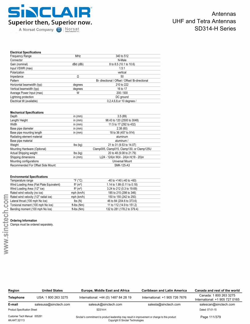
AntennasUHF and Tetra Antennas
SD314-H Series
Electrical SpecificationsFrequency Range MHz 340 to 512Connector N-MaleGain (nominal) dBd (dBi) 8 to 8.5 (10.1 to 10.6)Input VSWR (max) 1.5:1Polarization verticalImpedance Ω 50Pattern Bi- directional / Offset / Offset/ Bi-directionalHorizontal beamwidth (typ) degrees 210 to 222Vertical beamwidth (typ) degrees 16 to 17Average Power Input (max) W 200 / 500Lightning protection DC groundElectrical tilt (available) 0,2,4,6,8,or 10 degrees /
Mechanical SpecificationsDepth in (mm) 3.5 (89)Length/ Height in (mm) 98.43 to 120 (2500 to 3048)Width in (mm) 11.5 to 17 (292 to 432)Base pipe diameter in (mm) 2.38 (60)Base pipe mounting length in (mm) 18 to 36 (457 to 914)Radiating element material aluminumBase pipe material aluminum / Weight lbs (kg) 21 to 31 (9.53 to 14.07)Mounting Hardware (Optional) Clamp005, Clamp015, Clamp130, or Clamp125UActual Shipping weight lbs (kg) 20 to 48 (9.08 to 21.79)Shipping dimensions in (mm) L(24 - 124)in W(4 - 24)in H(18 - 20)in Mounting configurations Universal MountRecommended For Offset Side Mount: SMK-125-A3
Environmental SpecificationsTemperature range °F (°C) -40 to +140 (-40 to +60)Wind Loading Area (Flat Plate Equivalent) ft² (m²) 1.14 to 1.99 (0.11 to 0.18)Wind Loading Area (1/2" ice) ft² (m²) 3.24 to 212 (0.3 to 19.69)Rated wind velocity (no ice) mph (km/h) 185 to 215 (298 to 346)Rated wind velocity (1/2" radial ice) mph (km/h) 150 to 155 (242 to 250)Lateral thrust (100 mph No Ice) lbs (N) 46 to 84 (204.6 to 373.6)Torsional moment (100 mph No Ice) ft-lbs (Nm) 11 to 112 (14.9 to 151.2)Bending moment (100 mph No Ice) ft-lbs (Nm) 132 to 281 (178.2 to 379.4)
Ordering InformationClamps must be ordered separately.
Region United States Europe, Middle East and Africa Caribbean and Latin America Canada and rest of the world
Telephone USA: 1 800 263 3275 International: +44 (0) 1487 84 28 19 International: +1 905 726 7676 Canada: 1 800 263 3275International: +1 905 727 0165
E-mail [email protected] [email protected] [email protected] [email protected] Specification Sheet SD314-H Dated: 07-01-15
Customer Tech Manual 005261 Sinclair’s commitment to product leadership may result in improvement or change to this productCopyright © Sinclair TechnologiesAN.AHT.32/113
www.
sinct
ech.
com
Page 111/379
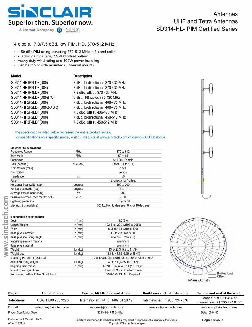
AntennasUHF and Tetra Antennas
SD314-HL- PIM Certified Series
4 dipole, 7.0/7.5 dBd, low PIM, HD, 370-512 MHz• -150 dBc PIM rating, covering 370-512 MHz in 3 band splits• 7.0 dBd gain pattern, 7.5 dBd offset pattern• Heavy duty wind rating and 300W power handling• Can be top or side mounted (Universal mount)
Model DescriptionSD314-HF1P2LDF(D00) 7 dBd, bi-directional, 370-430 MHzSD314-HF1P2LDF(D04) 7 dBd, bi-directional, 370-430 MHzSD314-HF1P4LDF(D00) 7.5 dBd, offset, 370-430 MHzSD314-HF1P8LDF(D00B-W) 9 dBd, 1/8 wave, 380-430 MHzSD314-HF2P2LDF(D00) 7 dBd, bi-directional, 406-470 MHzSD314-HF2P2LDF(D00B-ABK) 7 dBd, bi-directional, 406-470 MHzSD314-HF2P4LDF(D00) 7.5 dBd, offset, 406-470 MHzSD314-HF3P2LDF(D00) 7 dBd, bi-directional, 450-512 MHzSD314-HF3P4LDF(D00) 7.5 dBd, offset, 450-512 MHz
The specifications listed below represent the entire product series.For specifications on a specific model, visit our web site at www.sinctech.com or view our CD catalogue.
Electrical SpecificationsFrequency Range MHz 370 to 512Bandwidth MHz 50 to 64Connector 7/16 DIN-FemaleGain (nominal) dBd (dBi) 7 to 9 (9.1 to 11.1)Input VSWR (max) 1.5:1Polarization verticalImpedance Ω 50Pattern Bi-directional / OffsetHorizontal beamwidth (typ) degrees 160 to 200Vertical beamwidth (typ) degrees 15 to 17Average Power Input (max) W 300Passive intermod. (2x20W, 3rd ord.) dBc -150Lightning protection DC groundElectrical tilt (available) 0,2,4,6,8,or 10 degrees / 0,5, or 10 degrees
Mechanical SpecificationsDepth in (mm) 3.5 (89)Length/ Height in (mm) 102.3 to 120.3 (2598 to 3056)Width in (mm) 8.25 to 18.5 (210 to 470)Base pipe diameter in (mm) 1.9 to 2.38 (48 to 60)Base pipe mounting length in (mm) 6 to 26 (152 to 660)Radiating element material aluminumBase pipe material aluminumWeight lbs (kg) 13 to 25.3 (5.9 to 11.49)Weight iced lbs (kg) 15.3 to 42.75 (6.95 to 19.41)Mounting Hardware (Optional) Clamp005, Clamp015, Clamp130, or Clamp125UActual Shipping weight lbs (kg) 30 to 43 (13.62 to 19.52)Shipping dimensions in (mm) L(118 - 125)in W 6in H(10 - 20)in Mounting configurations Universal Mount / Bottom mountRecommended For Offset Side Mount: SMK-125-A3 / Not Required
Region United States Europe, Middle East and Africa Caribbean and Latin America Canada and rest of the world
Telephone USA: 1 800 263 3275 International: +44 (0) 1487 84 28 19 International: +1 905 726 7676 Canada: 1 800 263 3275International: +1 905 727 0165
E-mail [email protected] [email protected] [email protected] [email protected] Specification Sheet SD314-HL- PIM Certified Dated: 07-01-15
Customer Tech Manual 005851 Sinclair’s commitment to product leadership may result in improvement or change to this productCopyright © Sinclair TechnologiesAN.AHT.33/113
www.
sinct
ech.
com
Page 112/379

AntennasUHF and Tetra Antennas
SD314-HL- PIM Certified Series
Environmental SpecificationsTemperature range °F (°C) -40 to +140 (-40 to +60)Rated wind velocity (no ice) mph (km/h) 170 to 182 (274 to 293)Rated wind velocity (1/2" radial ice) mph (km/h) 130 to 150 (209 to 242)Lateral thrust (100 mph No Ice) lbs (N) 59.6 to 79.2 (265.1 to 352.3)Torsional moment (100 mph No Ice) ft-lbs (Nm) 1.35 to 32 (1.8 to 43.2)Bending moment (100 mph No Ice) ft-lbs (Nm) 26.9 to 302 (36.3 to 407.7)
Ordering InformationClamps must be ordered separately.
Region United States Europe, Middle East and Africa Caribbean and Latin America Canada and rest of the world
Telephone USA: 1 800 263 3275 International: +44 (0) 1487 84 28 19 International: +1 905 726 7676 Canada: 1 800 263 3275International: +1 905 727 0165
E-mail [email protected] [email protected] [email protected] [email protected] Specification Sheet SD314-HL- PIM Certified Dated: 07-01-15
Customer Tech Manual 005851 Sinclair’s commitment to product leadership may result in improvement or change to this productCopyright © Sinclair TechnologiesAN.AHT.34/113
www.
sinct
ech.
com
Page 113/379
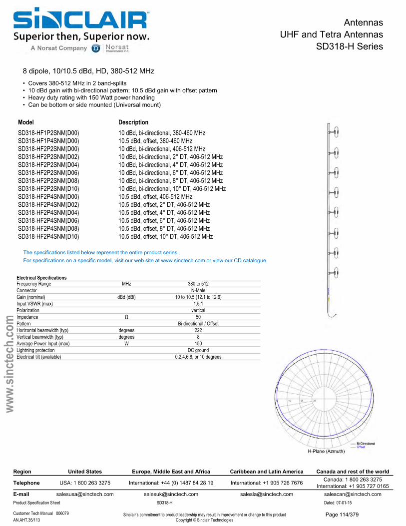
AntennasUHF and Tetra Antennas
SD318-H Series
8 dipole, 10/10.5 dBd, HD, 380-512 MHz• Covers 380-512 MHz in 2 band-splits• 10 dBd gain with bi-directional pattern; 10.5 dBd gain with offset pattern• Heavy duty rating with 150 Watt power handling• Can be bottom or side mounted (Universal mount)
Model DescriptionSD318-HF1P2SNM(D00) 10 dBd, bi-directional, 380-460 MHzSD318-HF1P4SNM(D00) 10.5 dBd, offset, 380-460 MHzSD318-HF2P2SNM(D00) 10 dBd, bi-directional, 406-512 MHzSD318-HF2P2SNM(D02) 10 dBd, bi-directional, 2° DT, 406-512 MHzSD318-HF2P2SNM(D04) 10 dBd, bi-directional, 4° DT, 406-512 MHzSD318-HF2P2SNM(D06) 10 dBd, bi-directional, 6° DT, 406-512 MHzSD318-HF2P2SNM(D08) 10 dBd, bi-directional, 8° DT, 406-512 MHzSD318-HF2P2SNM(D10) 10 dBd, bi-directional, 10° DT, 406-512 MHzSD318-HF2P4SNM(D00) 10.5 dBd, offset, 406-512 MHzSD318-HF2P4SNM(D02) 10.5 dBd, offset, 2° DT, 406-512 MHzSD318-HF2P4SNM(D04) 10.5 dBd, offset, 4° DT, 406-512 MHzSD318-HF2P4SNM(D06) 10.5 dBd, offset, 6° DT, 406-512 MHzSD318-HF2P4SNM(D08) 10.5 dBd, offset, 8° DT, 406-512 MHzSD318-HF2P4SNM(D10) 10.5 dBd, offset, 10° DT, 406-512 MHz
The specifications listed below represent the entire product series.For specifications on a specific model, visit our web site at www.sinctech.com or view our CD catalogue.
Electrical SpecificationsFrequency Range MHz 380 to 512Connector N-MaleGain (nominal) dBd (dBi) 10 to 10.5 (12.1 to 12.6)Input VSWR (max) 1.5:1Polarization verticalImpedance Ω 50Pattern Bi-directional / OffsetHorizontal beamwidth (typ) degrees 222Vertical beamwidth (typ) degrees 8Average Power Input (max) W 150Lightning protection DC groundElectrical tilt (available) 0,2,4,6,8, or 10 degrees
Region United States Europe, Middle East and Africa Caribbean and Latin America Canada and rest of the world
Telephone USA: 1 800 263 3275 International: +44 (0) 1487 84 28 19 International: +1 905 726 7676 Canada: 1 800 263 3275International: +1 905 727 0165
E-mail [email protected] [email protected] [email protected] [email protected] Specification Sheet SD318-H Dated: 07-01-15
Customer Tech Manual 006079 Sinclair’s commitment to product leadership may result in improvement or change to this productCopyright © Sinclair TechnologiesAN.AHT.35/113
www.
sinct
ech.
com
Page 114/379
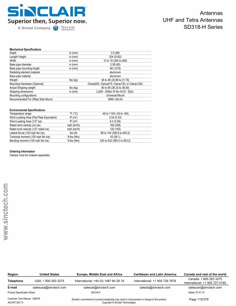
AntennasUHF and Tetra Antennas
SD318-H Series
Mechanical SpecificationsDepth in (mm) 3.5 (89)Length/ Height in (mm) 204 (5182)Width in (mm) 12 to 16 (305 to 406)Base pipe diameter in (mm) 2.38 (60)Base pipe mounting length in (mm) 48 (1219)Radiating element material aluminumBase pipe material aluminumWeight lbs (kg) 46 to 48 (20.88 to 21.79)Mounting Hardware (Optional) Clamp005, Clamp015, Clamp130, or Clamp125UActual Shipping weight lbs (kg) 80 to 85 (36.32 to 38.59)Shipping dimensions in (mm) L(206 - 209)in W 6in H(16 - 20)in Mounting configurations Universal MountRecommended For Offset Side Mount: SMK-135-A3
Environmental SpecificationsTemperature range °F (°C) -40 to +140 (-40 to +60)Wind Loading Area (Flat Plate Equivalent) ft² (m²) 3.54 (0.33)Wind Loading Area (1/2" ice) ft² (m²) 6.3 (0.59)Rated wind velocity (no ice) mph (km/h) 160 (258)Rated wind velocity (1/2" radial ice) mph (km/h) 120 (193)Lateral thrust (100 mph No Ice) lbs (N) 69 to 144 (306.9 to 640.5)Torsional moment (100 mph No Ice) ft-lbs (Nm) 43 (58.1)Bending moment (100 mph No Ice) ft-lbs (Nm) 430 to 632 (580.5 to 853.2)
Ordering InformationClamps must be ordered separately
Region United States Europe, Middle East and Africa Caribbean and Latin America Canada and rest of the world
Telephone USA: 1 800 263 3275 International: +44 (0) 1487 84 28 19 International: +1 905 726 7676 Canada: 1 800 263 3275International: +1 905 727 0165
E-mail [email protected] [email protected] [email protected] [email protected] Specification Sheet SD318-H Dated: 07-01-15
Customer Tech Manual 006079 Sinclair’s commitment to product leadership may result in improvement or change to this productCopyright © Sinclair TechnologiesAN.AHT.36/113
www.
sinct
ech.
com
Page 115/379
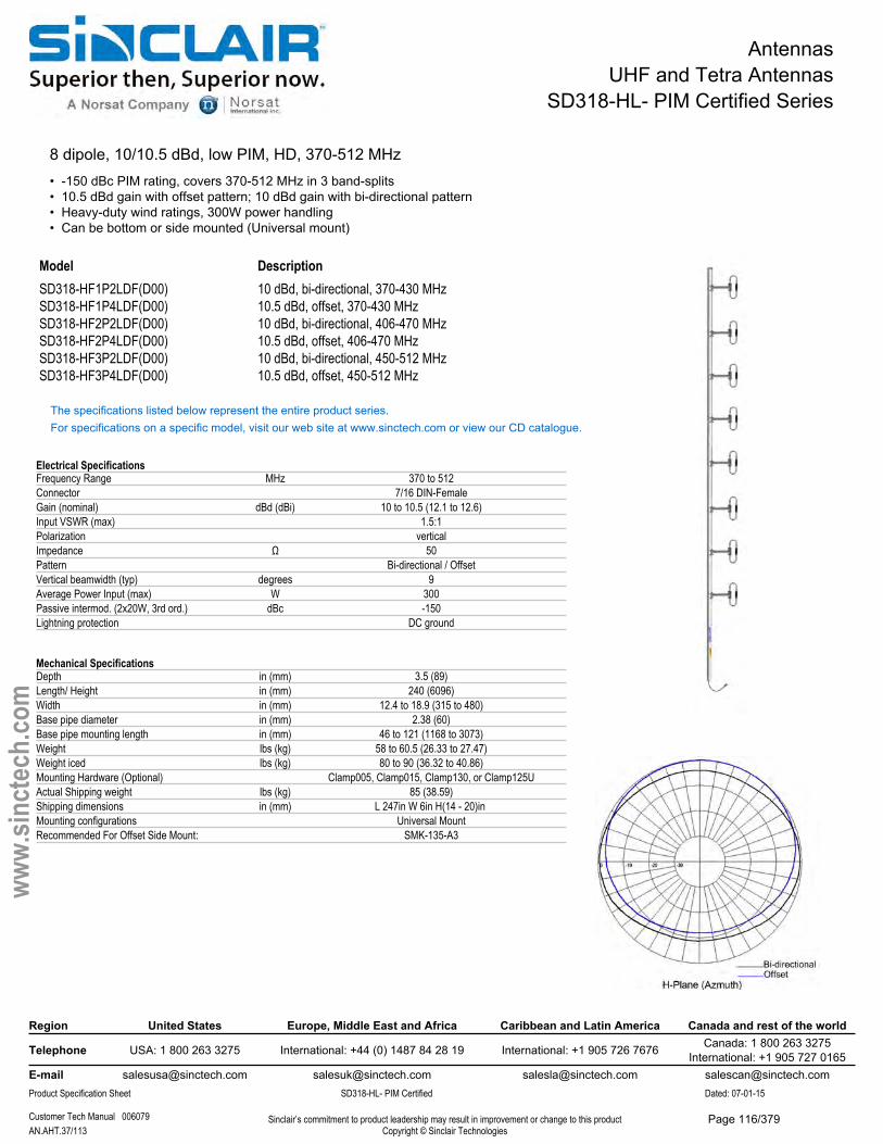
AntennasUHF and Tetra Antennas
SD318-HL- PIM Certified Series
8 dipole, 10/10.5 dBd, low PIM, HD, 370-512 MHz• -150 dBc PIM rating, covers 370-512 MHz in 3 band-splits• 10.5 dBd gain with offset pattern; 10 dBd gain with bi-directional pattern• Heavy-duty wind ratings, 300W power handling• Can be bottom or side mounted (Universal mount)
Model DescriptionSD318-HF1P2LDF(D00) 10 dBd, bi-directional, 370-430 MHzSD318-HF1P4LDF(D00) 10.5 dBd, offset, 370-430 MHzSD318-HF2P2LDF(D00) 10 dBd, bi-directional, 406-470 MHzSD318-HF2P4LDF(D00) 10.5 dBd, offset, 406-470 MHzSD318-HF3P2LDF(D00) 10 dBd, bi-directional, 450-512 MHzSD318-HF3P4LDF(D00) 10.5 dBd, offset, 450-512 MHz
The specifications listed below represent the entire product series.For specifications on a specific model, visit our web site at www.sinctech.com or view our CD catalogue.
Electrical SpecificationsFrequency Range MHz 370 to 512Connector 7/16 DIN-FemaleGain (nominal) dBd (dBi) 10 to 10.5 (12.1 to 12.6)Input VSWR (max) 1.5:1Polarization verticalImpedance Ω 50Pattern Bi-directional / OffsetVertical beamwidth (typ) degrees 9Average Power Input (max) W 300Passive intermod. (2x20W, 3rd ord.) dBc -150Lightning protection DC ground
Mechanical SpecificationsDepth in (mm) 3.5 (89)Length/ Height in (mm) 240 (6096)Width in (mm) 12.4 to 18.9 (315 to 480)Base pipe diameter in (mm) 2.38 (60)Base pipe mounting length in (mm) 46 to 121 (1168 to 3073)Weight lbs (kg) 58 to 60.5 (26.33 to 27.47)Weight iced lbs (kg) 80 to 90 (36.32 to 40.86)Mounting Hardware (Optional) Clamp005, Clamp015, Clamp130, or Clamp125UActual Shipping weight lbs (kg) 85 (38.59)Shipping dimensions in (mm) L 247in W 6in H(14 - 20)in Mounting configurations Universal MountRecommended For Offset Side Mount: SMK-135-A3
Region United States Europe, Middle East and Africa Caribbean and Latin America Canada and rest of the world
Telephone USA: 1 800 263 3275 International: +44 (0) 1487 84 28 19 International: +1 905 726 7676 Canada: 1 800 263 3275International: +1 905 727 0165
E-mail [email protected] [email protected] [email protected] [email protected] Specification Sheet SD318-HL- PIM Certified Dated: 07-01-15
Customer Tech Manual 006079 Sinclair’s commitment to product leadership may result in improvement or change to this productCopyright © Sinclair TechnologiesAN.AHT.37/113
www.
sinct
ech.
com
Page 116/379

AntennasUHF and Tetra Antennas
SD318-HL- PIM Certified Series
Environmental SpecificationsTemperature range °F (°C) -40 to +140 (-40 to +60)Wind Loading Area (Flat Plate Equivalent) ft² (m²) 4.42 (0.41)Wind Loading Area (1/2" ice) ft² (m²) 7.25 (0.67)Rated wind velocity (no ice) mph (km/h) 110 to 120 (177 to 193)Rated wind velocity (1/2" radial ice) mph (km/h) 90 (145)Lateral thrust (100 mph No Ice) lbs (N) 161 (716.1)Torsional moment (100 mph No Ice) ft-lbs (Nm) 64 (86.4)Bending moment (100 mph No Ice) ft-lbs (Nm) 1260 (1701)
Ordering InformationClamps must be ordered separately
Region United States Europe, Middle East and Africa Caribbean and Latin America Canada and rest of the world
Telephone USA: 1 800 263 3275 International: +44 (0) 1487 84 28 19 International: +1 905 726 7676 Canada: 1 800 263 3275International: +1 905 727 0165
E-mail [email protected] [email protected] [email protected] [email protected] Specification Sheet SD318-HL- PIM Certified Dated: 07-01-15
Customer Tech Manual 006079 Sinclair’s commitment to product leadership may result in improvement or change to this productCopyright © Sinclair TechnologiesAN.AHT.38/113
www.
sinct
ech.
com
Page 117/379
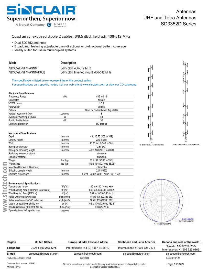
AntennasUHF and Tetra Antennas
SD3352D Series
Quad array, exposed dipole 2 cables, 6/8.5 dBd, field adj, 406-512 MHz• Dual SD3352 antennas• Broadband, featuring adjustable omni-directional or bi-directional pattern coverage• Ideally suited for use in multicoupled systems
Model DescriptionSD3352D-SF1PASNM 6/8.5 dBd, 406-512 MHzSD3352D-SF1PASNM(D00I) 6/8.5 dBd, Inverted mount, 406-512 MHz
The specifications listed below represent the entire product series.For specifications on a specific model, visit our web site at www.sinctech.com or view our CD catalogue.
Electrical SpecificationsFrequency Range MHz 406 to 512Connector N-MaleVSWR (max) 1.5:1Polarization verticalPattern Omni or Bi-directional, AdjustableVertical beamwidth (typ) degrees 8Average Power Input (max) W 300Port to Port isolation dB 30Lightning protection DC ground
Mechanical SpecificationsDepth in (mm) 4 to 13.75 (102 to 349)Length/ Height in (mm) 220 (5588)Width in (mm) 13.75 to 15 (349 to 381)Base pipe diameter in (mm) 2.88 (73)Base pipe mounting length in (mm) 40 to 160 (1016 to 4064)Radiating element material aluminumReflector material aluminumWeight lbs (kg) 83 to 87 (37.68 to 39.5)Weight iced lbs (kg) 159 to 194 (72.19 to 88.08)Mounting Hardware (Standard) Clamp005Shipping Length/ Height in (mm) 224 (5690)Shipping dimensions in (mm) L(224 - 228)in W(15 - 18)in H(6 - 15)in
Environmental SpecificationsTemperature range °F (°C) -40 to +140 (-40 to +60)Wind Loading Area (Flat Plate Equivalent) ft² (m²) 4.98 to 5.63 (0.46 to 0.52)Wind Loading Area (1/2" ice) ft² (m²) 7.82 to 10.79 (0.73 to 1)Rated wind velocity (no ice) mph (km/h) 145 to 175 (233 to 282)Rated wind velocity (1/2" radial ice) mph (km/h) 105 to 135 (169 to 217)Lateral thrust (100 mph No Ice) lbs (N) 164 to 176 (729.5 to 782.8)Bending moment (100 mph No Ice) ft-lbs (Nm) 1058 (1428.3)Tip deflection (100 mph No Ice) degrees 1.31
Region United States Europe, Middle East and Africa Caribbean and Latin America Canada and rest of the world
Telephone USA: 1 800 263 3275 International: +44 (0) 1487 84 28 19 International: +1 905 726 7676 Canada: 1 800 263 3275International: +1 905 727 0165
E-mail [email protected] [email protected] [email protected] [email protected] Specification Sheet SD3352D Dated: 07-01-15
Customer Tech Manual 006182 Sinclair’s commitment to product leadership may result in improvement or change to this productCopyright © Sinclair TechnologiesAN.AHT.43/113
www.
sinct
ech.
com
Page 118/379
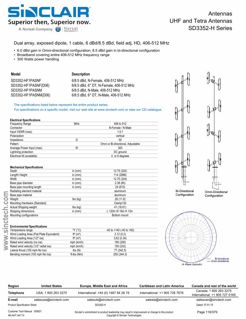
AntennasUHF and Tetra Antennas
SD3352-H Series
Dual array, exposed dipole, 1 cable, 6 dBd/8.5 dBd, field adj, HD, 406-512 MHz• 6.0 dBd gain in Omni-directional configuration; 8.5 dBd gain in bi-directional configuration• Broadband covering entire 406-512 MHz frequency range• 300 Watts power handling
Model DescriptionSD3352-HF1PASNF 6/8.5 dBd, N-Female, 406-512 MHzSD3352-HF1PASNF(D06) 6/8.5 dBd, 6° DT, N-Female, 406-512 MHzSD3352-HF1PASNM 6/8.5 dBd, N-Male, 406-512 MHzSD3352-HF1PASNM(D06) 6/8.5 dBd, 6° DT, N-Male, 406-512 MHz
The specifications listed below represent the entire product series.For specifications on a specific model, visit our web site at www.sinctech.com or view our CD catalogue.
Electrical SpecificationsFrequency Range MHz 406 to 512Connector N-Female / N-MaleInput VSWR (max) 1.5:1Polarization verticalImpedance Ω 50Pattern Omni or Bi-directional, AdjustableAverage Power Input (max) W 300Lightning protection DC groundElectrical tilt (available) 0 or 6 degrees
Mechanical SpecificationsDepth in (mm) 12.75 (324)Length/ Height in (mm) 114 (2896)Width in (mm) 12.75 (324)Base pipe diameter in (mm) 2.38 (60)Base pipe mounting length in (mm) 24 (610)Radiating element material aluminumBase pipe material aluminumWeight lbs (kg) 26 (11.8)Mounting Hardware (Standard) Clamp130Actual Shipping weight lbs (kg) 41 (18.61)Shipping dimensions in (mm) L 120in W 18in H 12in Mounting configurations Bottom mount
Environmental SpecificationsTemperature range °F (°C) -40 to +140 (-40 to +60)Wind Loading Area (Flat Plate Equivalent) ft² (m²) 2.12 (0.2)Wind Loading Area (1/2" ice) ft² (m²) 3.62 (0.34)Rated wind velocity (no ice) mph (km/h) 180 (290)Rated wind velocity (1/2" radial ice) mph (km/h) 150 (242)Lateral thrust (100 mph No Ice) lbs (N) 77 (342.5)Bending moment (100 mph No Ice) ft-lbs (Nm) 255 (344.3)
Region United States Europe, Middle East and Africa Caribbean and Latin America Canada and rest of the world
Telephone USA: 1 800 263 3275 International: +44 (0) 1487 84 28 19 International: +1 905 726 7676 Canada: 1 800 263 3275International: +1 905 727 0165
E-mail [email protected] [email protected] [email protected] [email protected] Specification Sheet SD3352-H Dated: 07-01-15
Customer Tech Manual 005631 Sinclair’s commitment to product leadership may result in improvement or change to this productCopyright © Sinclair TechnologiesAN.AHT.44/113
www.
sinct
ech.
com
Page 119/379
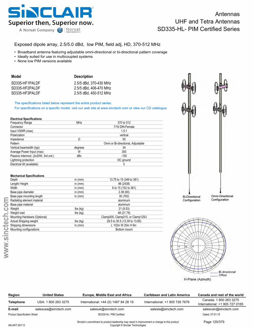
AntennasUHF and Tetra Antennas
SD335-HL- PIM Certified Series
Exposed dipole array, 2.5/5.0 dBd, low PIM, field adj, HD, 370-512 MHz• Broadband antenna featuring adjustable omni-directional or bi-directional pattern coverage• Ideally suited for use in multicoupled systems• None low PIM versions available
Model DescriptionSD335-HF1PALDF 2.5/5 dBd, 370-430 MHzSD335-HF2PALDF 2.5/5 dBd, 406-470 MHzSD335-HF3PALDF 2.5/5 dBd, 450-512 MHz
The specifications listed below represent the entire product series.For specifications on a specific model, visit our web site at www.sinctech.com or view our CD catalogue.
Electrical SpecificationsFrequency Range MHz 370 to 512Connector 7/16 DIN-FemaleInput VSWR (max) 1.5:1Polarization verticalImpedance Ω 50Pattern Omni or Bi-directional, AdjustableVertical beamwidth (typ) degrees 34Average Power Input (max) W 300Passive intermod. (2x20W, 3rd ord.) dBc -150Lightning protection DC groundElectrical tilt (available) 0
Mechanical SpecificationsDepth in (mm) 13.75 to 15 (349 to 381)Length/ Height in (mm) 96 (2438)Width in (mm) 6 to 15 (152 to 381)Base pipe diameter in (mm) 2.38 (60)Base pipe mounting length in (mm) 30 (762)Radiating element material aluminumBase pipe material aluminumWeight lbs (kg) 21 (9.53)Weight iced lbs (kg) 48 (21.79)Mounting Hardware (Optional) Clamp005, Clamp015, or Clamp125UActual Shipping weight lbs (kg) 29.5 to 30.5 (13.39 to 13.85)Shipping dimensions in (mm) L 102in W 20in H 6in Mounting configurations Bottom mount
Region United States Europe, Middle East and Africa Caribbean and Latin America Canada and rest of the world
Telephone USA: 1 800 263 3275 International: +44 (0) 1487 84 28 19 International: +1 905 726 7676 Canada: 1 800 263 3275International: +1 905 727 0165
E-mail [email protected] [email protected] [email protected] [email protected] Specification Sheet SD335-HL- PIM Certified Dated: 07-01-15
Sinclair’s commitment to product leadership may result in improvement or change to this productCopyright © Sinclair TechnologiesAN.AHT.45/113
www.
sinct
ech.
com
Page 120/379

AntennasUHF and Tetra Antennas
SD335-HL- PIM Certified Series
Environmental SpecificationsTemperature range °F (°C) -40 to +140 (-40 to +60)Wind Loading Area (Flat Plate Equivalent) ft² (m²) 1.88 to 1.91 (0.17 to 0.18)Wind Loading Area (1/2" ice) ft² (m²) 3.2 to 3.22 (0.3 to 0.3)Rated wind velocity (no ice) mph (km/h) 150 to 205 (242 to 330)Rated wind velocity (1/2" radial ice) mph (km/h) 120 to 170 (193 to 274)Lateral thrust (100 mph No Ice) lbs (N) 59 to 63 (262.4 to 280.2)
Ordering InformationNone low PIM and/or N-type versions are also available, please contact your Sinclair Sales Representative for more information.
Region United States Europe, Middle East and Africa Caribbean and Latin America Canada and rest of the world
Telephone USA: 1 800 263 3275 International: +44 (0) 1487 84 28 19 International: +1 905 726 7676 Canada: 1 800 263 3275International: +1 905 727 0165
E-mail [email protected] [email protected] [email protected] [email protected] Specification Sheet SD335-HL- PIM Certified Dated: 07-01-15
Sinclair’s commitment to product leadership may result in improvement or change to this productCopyright © Sinclair TechnologiesAN.AHT.46/113
www.
sinct
ech.
com
Page 121/379
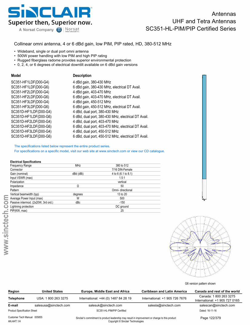
AntennasUHF and Tetra Antennas
SC351-HL-PIM/PIP Certified Series
Collinear omni antenna, 4 or 6 dBd gain, low PIM, PIP rated, HD, 380-512 MHz• Wideband, single or dual port omni antenna• 500W power handling with low PIM and high PIP rating• Rugged fiberglass radome provides superior environmental protection• 0, 2, 4, or 6 degrees of electrical downtilt available on 6 dBd gain versions
Model DescriptionSC351-HF1LDF(D00-G4) 4 dBd gain, 380-430 MHzSC351-HF1LDF(D00-G6) 6 dBd gain, 380-430 MHz, electrical DT Avail.SC351-HF2LDF(D00-G4) 4 dBd gain, 403-470 MHzSC351-HF2LDF(D00-G6) 6 dBd gain, 403-470 MHz, electrical DT Avail.SC351-HF3LDF(D00-G4) 4 dBd gain, 450-512 MHzSC351-HF3LDF(D00-G6) 6 dBd gain, 450-512 MHz, electrical DT Avail.SC351D-HF1LDF(D00-G4) 4 dBd, dual port, 380-430 MHzSC351D-HF1LDF(D00-G6) 6 dBd, dual port, 380-430 MHz, electrical DT Avail.SC351D-HF2LDF(D00-G4) 4 dBd, dual port, 403-470 MHzSC351D-HF2LDF(D00-G6) 6 dBd, dual port, 403-470 MHz, electrical DT Avail.SC351D-HF3LDF(D00-G4) 4 dBd, dual port, 450-512 MHzSC351D-HF3LDF(D00-G6) 6 dBd, dual port, 450-512 MHz, electrical DT Avail.
The specifications listed below represent the entire product series.For specifications on a specific model, visit our web site at www.sinctech.com or view our CD catalogue.
Electrical SpecificationsFrequency Range MHz 380 to 512Connector 7/16 DIN-FemaleGain (nominal) dBd (dBi) 4 to 6 (6.1 to 8.1)Input VSWR (max) 1.5:1Polarization verticalImpedance Ω 50Pattern Omni- directionalVertical beamwidth (typ) degrees 13 to 20Average Power Input (max) W 500Passive intermod. (2x20W, 3rd ord.) dBc -150Lightning protection DC groundPIP(KW, max) 25
Region United States Europe, Middle East and Africa Caribbean and Latin America Canada and rest of the world
Telephone USA: 1 800 263 3275 International: +44 (0) 1487 84 28 19 International: +1 905 726 7676 Canada: 1 800 263 3275International: +1 905 727 0165
E-mail [email protected] [email protected] [email protected] [email protected] Specification Sheet SC351-HL-PIM/PIP Certified Dated: 16-11-16
Customer Tech Manual 005855 Sinclair’s commitment to product leadership may result in improvement or change to this productCopyright © Sinclair TechnologiesAN.AHT.1/4
www.
sinct
ech.
com
G6 version pattern shown
Page 122/379
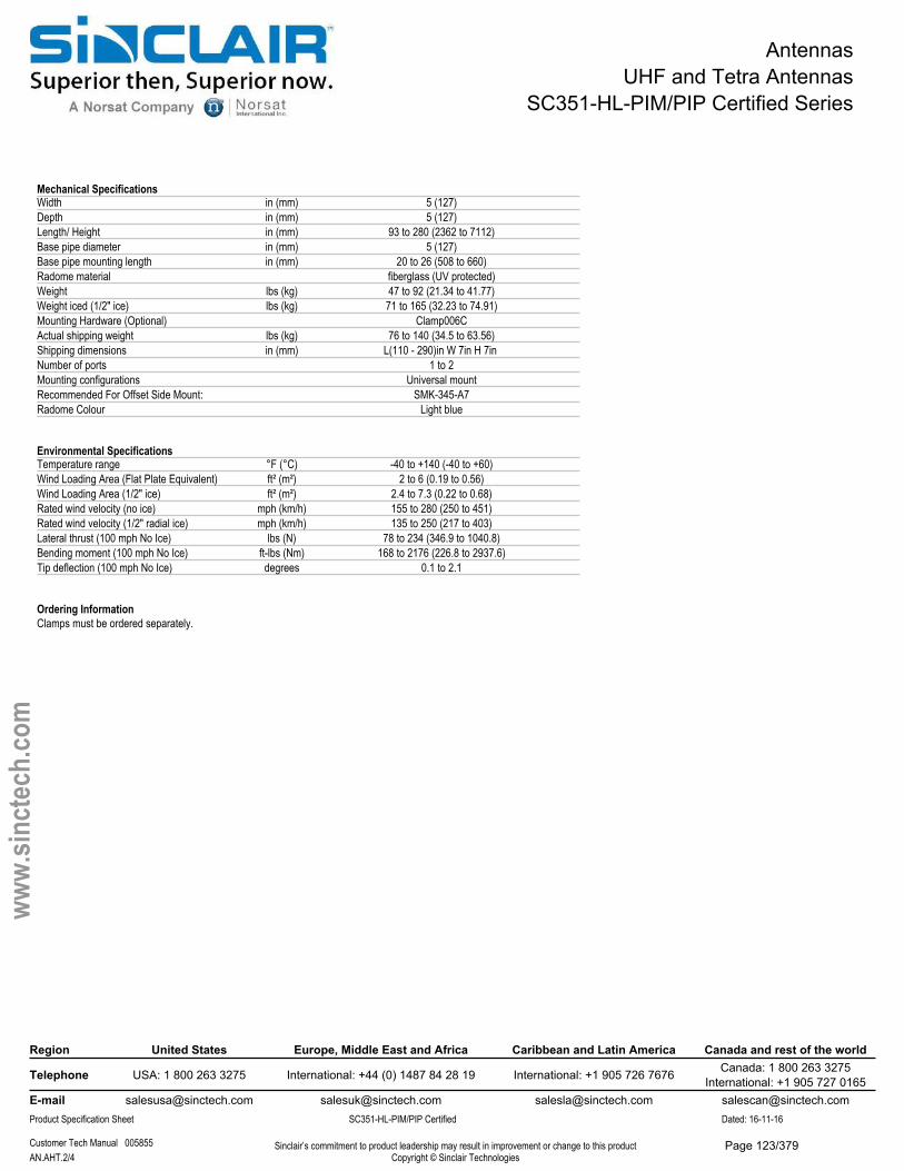
AntennasUHF and Tetra Antennas
SC351-HL-PIM/PIP Certified Series
Mechanical SpecificationsWidth in (mm) 5 (127)Depth in (mm) 5 (127)Length/ Height in (mm) 93 to 280 (2362 to 7112)Base pipe diameter in (mm) 5 (127)Base pipe mounting length in (mm) 20 to 26 (508 to 660)Radome material fiberglass (UV protected)Weight lbs (kg) 47 to 92 (21.34 to 41.77)Weight iced (1/2" ice) lbs (kg) 71 to 165 (32.23 to 74.91)Mounting Hardware (Optional) Clamp006CActual shipping weight lbs (kg) 76 to 140 (34.5 to 63.56)Shipping dimensions in (mm) L(110 - 290)in W 7in H 7in Number of ports 1 to 2Mounting configurations Universal mountRecommended For Offset Side Mount: SMK-345-A7Radome Colour Light blue
Environmental SpecificationsTemperature range °F (°C) -40 to +140 (-40 to +60)Wind Loading Area (Flat Plate Equivalent) ft² (m²) 2 to 6 (0.19 to 0.56)Wind Loading Area (1/2" ice) ft² (m²) 2.4 to 7.3 (0.22 to 0.68)Rated wind velocity (no ice) mph (km/h) 155 to 280 (250 to 451)Rated wind velocity (1/2" radial ice) mph (km/h) 135 to 250 (217 to 403)Lateral thrust (100 mph No Ice) lbs (N) 78 to 234 (346.9 to 1040.8)Bending moment (100 mph No Ice) ft-lbs (Nm) 168 to 2176 (226.8 to 2937.6)Tip deflection (100 mph No Ice) degrees 0.1 to 2.1
Ordering InformationClamps must be ordered separately.
Region United States Europe, Middle East and Africa Caribbean and Latin America Canada and rest of the world
Telephone USA: 1 800 263 3275 International: +44 (0) 1487 84 28 19 International: +1 905 726 7676 Canada: 1 800 263 3275International: +1 905 727 0165
E-mail [email protected] [email protected] [email protected] [email protected] Specification Sheet SC351-HL-PIM/PIP Certified Dated: 16-11-16
Customer Tech Manual 005855 Sinclair’s commitment to product leadership may result in improvement or change to this productCopyright © Sinclair TechnologiesAN.AHT.2/4
www.
sinct
ech.
com
Page 123/379
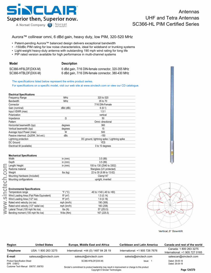
AntennasUHF and Tetra Antennas
SC366-HL PIM Certified Series
Aurora™ collinear omni, 6 dBd gain, heavy duty, low PIM, 320-520 MHz• Patent-pending Aurora™ balanced design delivers exceptional bandwidth• -150dBc PIM rating for low noise characteristics, ideal for wideband or trunking systems• Light-weight heavy-duty antenna with outstanding 190 mph wind rating for long life• PIP rated version available for high performance in multi-channel systems
Model DescriptionSC366-HF6LDF(DXX-M) 6 dBd gain, 7/16 DIN-female connector, 320-355 MHzSC366-HTBLDF(DXX-M) 6 dBd gain, 7/16 DIN-female connector, 380-430 MHz
The specifications listed below represent the entire product series.For specifications on a specific model, visit our web site at www.sinctech.com or view our CD catalogue.
Electrical SpecificationsFrequency Range MHz 320 to 520Bandwidth MHz 35 to 70Connector 7/16 DIN-FemaleGain (nominal) dBd (dBi) 6 (8.1)Input VSWR (max) 1.5:1Polarization verticalImpedance Ω 50Pattern Omni- directionalHorizontal beamwidth (typ) degrees 360Vertical beamwidth (typ) degrees 15Average Input Power (max) W 500Passive intermod. (2x20W, 3rd ord.) dBc -150Lightning protection DC ground, lightning spike / Lightning spikeDC Ground YESElectrical tilt (available) 0 to 10 degrees
Mechanical SpecificationsWidth in (mm) 3.5 (89)Depth in (mm) 3.5 (89)Length/ Height in (mm) 100 to 130 (2540 to 3302)Radome material fiberglass (UV protected)Weight lbs (kg) 22 to 30 (9.99 to 13.62)Mounting Hardware (Included) Clamp147Mounting configurations upright, inverted
Environmental SpecificationsTemperature range °F (°C) -40 to +140 (-40 to +60)Wind Loading Area (Flat Plate Equivalent) ft² (m²) 1.5 (0.14)Wind Loading Area (1/2" ice) ft² (m²) 1.9 (0.18)Rated wind velocity (no ice) mph (km/h) 190 (306)Rated wind velocity (1/2" radial ice) mph (km/h) 160 (258)Lateral Thrust (100 mph No Ice) lbs (N) 57 (253.5)Bending moment (100 mph No Ice) ft-lbs (Nm) 167 (225.5)
Region United States Europe, Middle East and Africa Caribbean and Latin America Canada and rest of the world
Telephone USA: 1 800 263 3275 International: +44 (0) 1487 84 28 19 International: +1 905 726 7676 Canada: 1 800 263 3275International: +1 905 727 0165
E-mail [email protected] [email protected] [email protected] [email protected] Specification Sheet SC366-HF6LDF(DXX-M) Issue: 1 Dated: 29-05-18EPR 018972 Dated: 26-04-18Customer Tech Manual 006757, 006763 Sinclair’s commitment to product leadership may result in improvement or change to this product
Copyright © Sinclair Technologies Page 124/379
www.
sinct
ech.
com
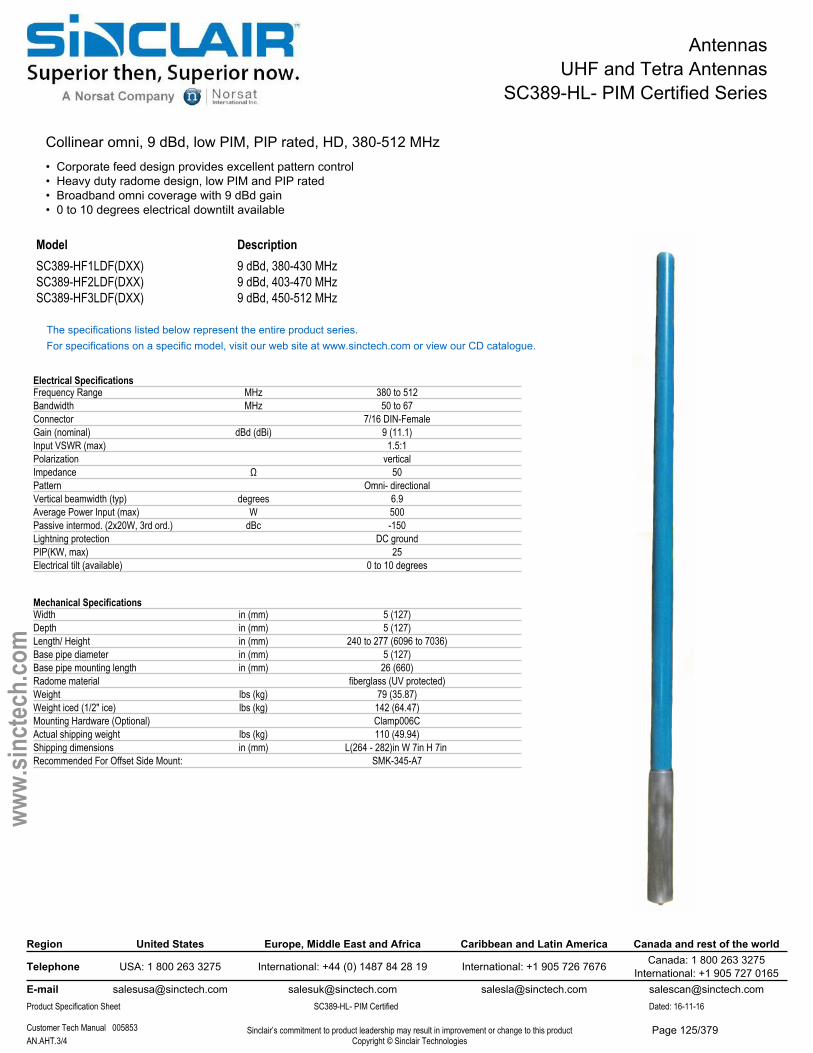
AntennasUHF and Tetra Antennas
SC389-HL- PIM Certified Series
Collinear omni, 9 dBd, low PIM, PIP rated, HD, 380-512 MHz• Corporate feed design provides excellent pattern control• Heavy duty radome design, low PIM and PIP rated• Broadband omni coverage with 9 dBd gain• 0 to 10 degrees electrical downtilt available
Model DescriptionSC389-HF1LDF(DXX) 9 dBd, 380-430 MHzSC389-HF2LDF(DXX) 9 dBd, 403-470 MHzSC389-HF3LDF(DXX) 9 dBd, 450-512 MHz
The specifications listed below represent the entire product series.For specifications on a specific model, visit our web site at www.sinctech.com or view our CD catalogue.
Electrical SpecificationsFrequency Range MHz 380 to 512Bandwidth MHz 50 to 67Connector 7/16 DIN-FemaleGain (nominal) dBd (dBi) 9 (11.1)Input VSWR (max) 1.5:1Polarization verticalImpedance Ω 50Pattern Omni- directionalVertical beamwidth (typ) degrees 6.9Average Power Input (max) W 500Passive intermod. (2x20W, 3rd ord.) dBc -150Lightning protection DC groundPIP(KW, max) 25Electrical tilt (available) 0 to 10 degrees
Mechanical SpecificationsWidth in (mm) 5 (127)Depth in (mm) 5 (127)Length/ Height in (mm) 240 to 277 (6096 to 7036)Base pipe diameter in (mm) 5 (127)Base pipe mounting length in (mm) 26 (660)Radome material fiberglass (UV protected)Weight lbs (kg) 79 (35.87)Weight iced (1/2" ice) lbs (kg) 142 (64.47)Mounting Hardware (Optional) Clamp006CActual shipping weight lbs (kg) 110 (49.94)Shipping dimensions in (mm) L(264 - 282)in W 7in H 7in Recommended For Offset Side Mount: SMK-345-A7
Region United States Europe, Middle East and Africa Caribbean and Latin America Canada and rest of the world
Telephone USA: 1 800 263 3275 International: +44 (0) 1487 84 28 19 International: +1 905 726 7676 Canada: 1 800 263 3275International: +1 905 727 0165
E-mail [email protected] [email protected] [email protected] [email protected] Specification Sheet SC389-HL- PIM Certified Dated: 16-11-16
Customer Tech Manual 005853 Sinclair’s commitment to product leadership may result in improvement or change to this productCopyright © Sinclair TechnologiesAN.AHT.3/4
www.
sinct
ech.
com
Page 125/379

AntennasUHF and Tetra Antennas
SC389-HL- PIM Certified Series
Environmental SpecificationsTemperature range °F (°C) -40 to +140 (-40 to +60)Wind Loading Area (Flat Plate Equivalent) ft² (m²) 5.24 (0.49)Wind Loading Area (1/2" ice) ft² (m²) 6.39 (0.59)Rated wind velocity (no ice) mph (km/h) 170 (274)Rated wind velocity (1/2" radial ice) mph (km/h) 150 (242)Lateral thrust (100 mph No Ice) lbs (N) 208 (925.2)Bending moment (100 mph No Ice) ft-lbs (Nm) 1610 (2173.5)Tip deflection (100 mph No Ice) degrees 2.2
Ordering InformationClamps must be ordered separately.
Region United States Europe, Middle East and Africa Caribbean and Latin America Canada and rest of the world
Telephone USA: 1 800 263 3275 International: +44 (0) 1487 84 28 19 International: +1 905 726 7676 Canada: 1 800 263 3275International: +1 905 727 0165
E-mail [email protected] [email protected] [email protected] [email protected] Specification Sheet SC389-HL- PIM Certified Dated: 16-11-16
Customer Tech Manual 005853 Sinclair’s commitment to product leadership may result in improvement or change to this productCopyright © Sinclair TechnologiesAN.AHT.4/4
www.
sinct
ech.
com
Page 126/379
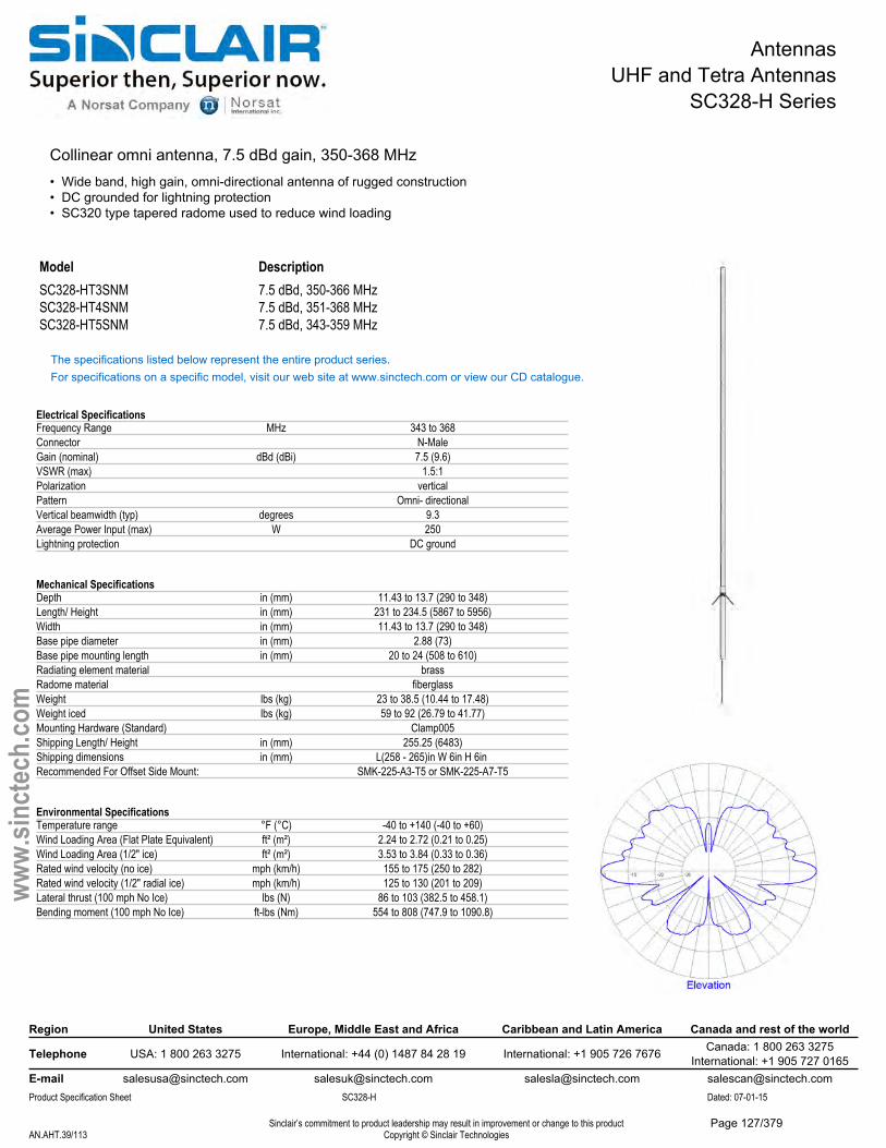
AntennasUHF and Tetra Antennas
SC328-H Series
Collinear omni antenna, 7.5 dBd gain, 350-368 MHz• Wide band, high gain, omni-directional antenna of rugged construction• DC grounded for lightning protection• SC320 type tapered radome used to reduce wind loading
Model DescriptionSC328-HT3SNM 7.5 dBd, 350-366 MHzSC328-HT4SNM 7.5 dBd, 351-368 MHzSC328-HT5SNM 7.5 dBd, 343-359 MHz
The specifications listed below represent the entire product series.For specifications on a specific model, visit our web site at www.sinctech.com or view our CD catalogue.
Electrical SpecificationsFrequency Range MHz 343 to 368Connector N-MaleGain (nominal) dBd (dBi) 7.5 (9.6)VSWR (max) 1.5:1Polarization verticalPattern Omni- directionalVertical beamwidth (typ) degrees 9.3Average Power Input (max) W 250Lightning protection DC ground
Mechanical SpecificationsDepth in (mm) 11.43 to 13.7 (290 to 348)Length/ Height in (mm) 231 to 234.5 (5867 to 5956)Width in (mm) 11.43 to 13.7 (290 to 348)Base pipe diameter in (mm) 2.88 (73)Base pipe mounting length in (mm) 20 to 24 (508 to 610)Radiating element material brassRadome material fiberglassWeight lbs (kg) 23 to 38.5 (10.44 to 17.48)Weight iced lbs (kg) 59 to 92 (26.79 to 41.77)Mounting Hardware (Standard) Clamp005Shipping Length/ Height in (mm) 255.25 (6483)Shipping dimensions in (mm) L(258 - 265)in W 6in H 6in Recommended For Offset Side Mount: SMK-225-A3-T5 or SMK-225-A7-T5
Environmental SpecificationsTemperature range °F (°C) -40 to +140 (-40 to +60)Wind Loading Area (Flat Plate Equivalent) ft² (m²) 2.24 to 2.72 (0.21 to 0.25)Wind Loading Area (1/2" ice) ft² (m²) 3.53 to 3.84 (0.33 to 0.36)Rated wind velocity (no ice) mph (km/h) 155 to 175 (250 to 282)Rated wind velocity (1/2" radial ice) mph (km/h) 125 to 130 (201 to 209)Lateral thrust (100 mph No Ice) lbs (N) 86 to 103 (382.5 to 458.1)Bending moment (100 mph No Ice) ft-lbs (Nm) 554 to 808 (747.9 to 1090.8)
Region United States Europe, Middle East and Africa Caribbean and Latin America Canada and rest of the world
Telephone USA: 1 800 263 3275 International: +44 (0) 1487 84 28 19 International: +1 905 726 7676 Canada: 1 800 263 3275International: +1 905 727 0165
E-mail [email protected] [email protected] [email protected] [email protected] Specification Sheet SC328-H Dated: 07-01-15
Sinclair’s commitment to product leadership may result in improvement or change to this productCopyright © Sinclair TechnologiesAN.AHT.39/113
www.
sinct
ech.
com
Page 127/379
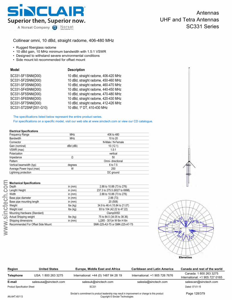
AntennasUHF and Tetra Antennas
SC331 Series
Collinear omni, 10 dBd, straight radome, 406-480 MHz• Rugged fiberglass radome• 10 dBd gain, 10 MHz minimum bandwidth with 1.5:1 VSWR• Designed to withstand severe environmental conditions• Side mount kit recommended for offset mount
Model DescriptionSC331-SF1SNM(D00) 10 dBd, straight radome, 406-420 MHzSC331-SF2SNM(D00) 10 dBd, straight radome, 450-460 MHzSC331-SF3SNM(D00) 10 dBd, straight radome, 460-470 MHzSC331-SF4SNM(D00) 10 dBd, straight radome, 440-450 MHzSC331-SF5SNM(D00) 10 dBd, straight radome, 470-480 MHzSC331-SF6SNM(D00) 10 dBd, straight radome, 420-430 MHzSC331-SF7SNM(D00) 10 dBd, straight radome, 412-426 MHzSC331-ST2SNF(D01-G10) 10 dBd, 1º DT, 410-430 MHz
The specifications listed below represent the entire product series.For specifications on a specific model, visit our web site at www.sinctech.com or view our CD catalogue.
Electrical SpecificationsFrequency Range MHz 406 to 480Bandwidth MHz 10 to 20Connector N-Male / N-FemaleGain (nominal) dBd (dBi) 10 (12.1)VSWR (max) 1.5:1Polarization verticalImpedance Ω 50Pattern Omni- directionalVertical beamwidth (typ) degrees 6 to 7.5Average Power Input (max) W 250Lightning protection DC ground
Mechanical SpecificationsDepth in (mm) 2.88 to 10.88 (73 to 276)Length/ Height in (mm) 237.3 to 275.5 (6027 to 6998)Width in (mm) 2.88 to 10.88 (73 to 276)Base pipe diameter in (mm) 2.88 (73)Base pipe mounting length in (mm) 20 (508)Weight lbs (kg) 34.9 to 46.4 (15.84 to 21.07)Weight iced lbs (kg) 93 to 104 (42.22 to 47.22)Mounting Hardware (Standard) Clamp005DActual Shipping weight lbs (kg) 75 to 84.5 (34.05 to 38.36)Shipping dimensions in (mm) L(265 - 301)in W 6in H 6in Recommended For Offset Side Mount: SMK-225-A3-T5 or SMK-225-A7-T5
Region United States Europe, Middle East and Africa Caribbean and Latin America Canada and rest of the world
Telephone USA: 1 800 263 3275 International: +44 (0) 1487 84 28 19 International: +1 905 726 7676 Canada: 1 800 263 3275International: +1 905 727 0165
E-mail [email protected] [email protected] [email protected] [email protected] Specification Sheet SC331 Dated: 07-01-15
Sinclair’s commitment to product leadership may result in improvement or change to this productCopyright © Sinclair TechnologiesAN.AHT.40/113
www.
sinct
ech.
com
Page 128/379

AntennasUHF and Tetra Antennas
SC331 Series
Environmental SpecificationsTemperature range °F (°C) -40 to +140 (-40 to +60)Wind Loading Area (Flat Plate Equivalent) ft² (m²) 2.73 to 3.51 (0.25 to 0.33)Rated wind velocity (no ice) mph (km/h) 125 to 150 (201 to 242)Rated wind velocity (1/2" radial ice) mph (km/h) 100 to 120 (161 to 193)Lateral thrust (100 mph No Ice) lbs (N) 102 to 135 (453.7 to 600.5)Bending moment (100 mph No Ice) ft-lbs (Nm) 796 to 1309 (1074.6 to 1767.2)Tip deflection (100 mph No Ice) degrees 5.8 to 9.6
Region United States Europe, Middle East and Africa Caribbean and Latin America Canada and rest of the world
Telephone USA: 1 800 263 3275 International: +44 (0) 1487 84 28 19 International: +1 905 726 7676 Canada: 1 800 263 3275International: +1 905 727 0165
E-mail [email protected] [email protected] [email protected] [email protected] Specification Sheet SC331 Dated: 07-01-15
Sinclair’s commitment to product leadership may result in improvement or change to this productCopyright © Sinclair TechnologiesAN.AHT.41/113
www.
sinct
ech.
com
Page 129/379
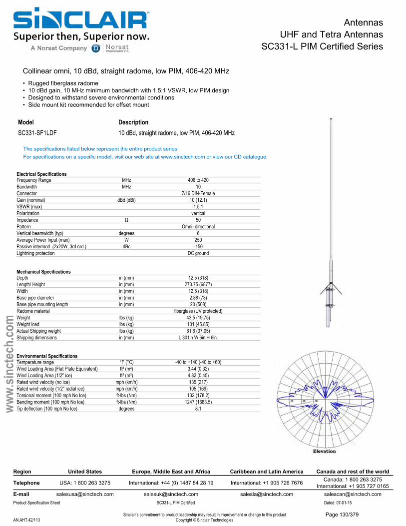
AntennasUHF and Tetra Antennas
SC331-L PIM Certified Series
Collinear omni, 10 dBd, straight radome, low PIM, 406-420 MHz• Rugged fiberglass radome• 10 dBd gain, 10 MHz minimum bandwidth with 1.5:1 VSWR, low PIM design• Designed to withstand severe environmental conditions• Side mount kit recommended for offset mount
Model DescriptionSC331-SF1LDF 10 dBd, straight radome, low PIM, 406-420 MHz
The specifications listed below represent the entire product series.For specifications on a specific model, visit our web site at www.sinctech.com or view our CD catalogue.
Electrical SpecificationsFrequency Range MHz 406 to 420Bandwidth MHz 10Connector 7/16 DIN-FemaleGain (nominal) dBd (dBi) 10 (12.1)VSWR (max) 1.5:1Polarization verticalImpedance Ω 50Pattern Omni- directionalVertical beamwidth (typ) degrees 6Average Power Input (max) W 250Passive intermod. (2x20W, 3rd ord.) dBc -150Lightning protection DC ground
Mechanical SpecificationsDepth in (mm) 12.5 (318)Length/ Height in (mm) 270.75 (6877)Width in (mm) 12.5 (318)Base pipe diameter in (mm) 2.88 (73)Base pipe mounting length in (mm) 20 (508)Radome material fiberglass (UV protected)Weight lbs (kg) 43.5 (19.75)Weight iced lbs (kg) 101 (45.85)Actual Shipping weight lbs (kg) 81.6 (37.05)Shipping dimensions in (mm) L 301in W 6in H 6in
Environmental SpecificationsTemperature range °F (°C) -40 to +140 (-40 to +60)Wind Loading Area (Flat Plate Equivalent) ft² (m²) 3.44 (0.32)Wind Loading Area (1/2" ice) ft² (m²) 4.82 (0.45)Rated wind velocity (no ice) mph (km/h) 135 (217)Rated wind velocity (1/2" radial ice) mph (km/h) 105 (169)Torsional moment (100 mph No Ice) ft-lbs (Nm) 132 (178.2)Bending moment (100 mph No Ice) ft-lbs (Nm) 1247 (1683.5)Tip deflection (100 mph No Ice) degrees 8.1
Region United States Europe, Middle East and Africa Caribbean and Latin America Canada and rest of the world
Telephone USA: 1 800 263 3275 International: +44 (0) 1487 84 28 19 International: +1 905 726 7676 Canada: 1 800 263 3275International: +1 905 727 0165
E-mail [email protected] [email protected] [email protected] [email protected] Specification Sheet SC331-L PIM Certified Dated: 07-01-15
Sinclair’s commitment to product leadership may result in improvement or change to this productCopyright © Sinclair TechnologiesAN.AHT.42/113
www.
sinct
ech.
com
Page 130/379
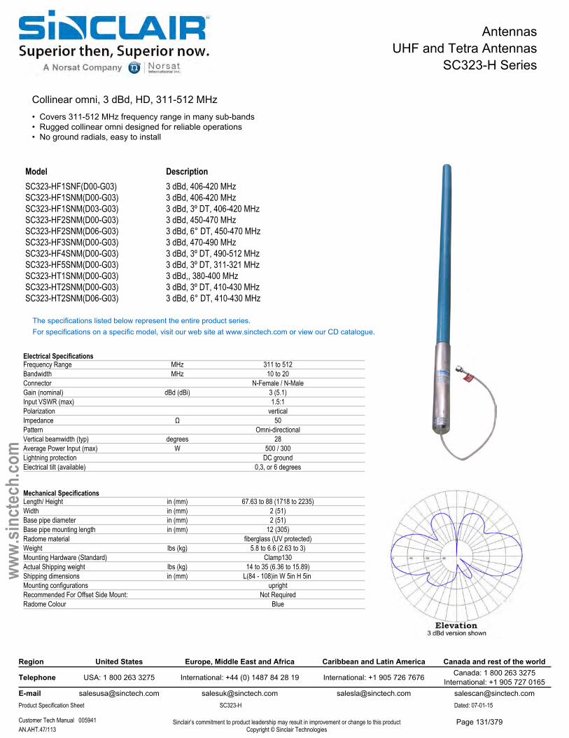
AntennasUHF and Tetra Antennas
SC323-H Series
Collinear omni, 3 dBd, HD, 311-512 MHz• Covers 311-512 MHz frequency range in many sub-bands• Rugged collinear omni designed for reliable operations• No ground radials, easy to install
Model DescriptionSC323-HF1SNF(D00-G03) 3 dBd, 406-420 MHzSC323-HF1SNM(D00-G03) 3 dBd, 406-420 MHzSC323-HF1SNM(D03-G03) 3 dBd, 3º DT, 406-420 MHzSC323-HF2SNM(D00-G03) 3 dBd, 450-470 MHzSC323-HF2SNM(D06-G03) 3 dBd, 6° DT, 450-470 MHzSC323-HF3SNM(D00-G03) 3 dBd, 470-490 MHzSC323-HF4SNM(D00-G03) 3 dBd, 3º DT, 490-512 MHzSC323-HF5SNM(D00-G03) 3 dBd, 3º DT, 311-321 MHzSC323-HT1SNM(D00-G03) 3 dBd,, 380-400 MHzSC323-HT2SNM(D00-G03) 3 dBd, 3º DT, 410-430 MHzSC323-HT2SNM(D06-G03) 3 dBd, 6° DT, 410-430 MHz
The specifications listed below represent the entire product series.For specifications on a specific model, visit our web site at www.sinctech.com or view our CD catalogue.
Electrical SpecificationsFrequency Range MHz 311 to 512Bandwidth MHz 10 to 20Connector N-Female / N-MaleGain (nominal) dBd (dBi) 3 (5.1)Input VSWR (max) 1.5:1Polarization verticalImpedance Ω 50Pattern Omni-directionalVertical beamwidth (typ) degrees 28Average Power Input (max) W 500 / 300Lightning protection DC groundElectrical tilt (available) 0,3, or 6 degrees
Mechanical SpecificationsLength/ Height in (mm) 67.63 to 88 (1718 to 2235)Width in (mm) 2 (51)Base pipe diameter in (mm) 2 (51)Base pipe mounting length in (mm) 12 (305)Radome material fiberglass (UV protected)Weight lbs (kg) 5.8 to 6.6 (2.63 to 3)Mounting Hardware (Standard) Clamp130Actual Shipping weight lbs (kg) 14 to 35 (6.36 to 15.89)Shipping dimensions in (mm) L(84 - 108)in W 5in H 5in Mounting configurations uprightRecommended For Offset Side Mount: Not RequiredRadome Colour Blue
Region United States Europe, Middle East and Africa Caribbean and Latin America Canada and rest of the world
Telephone USA: 1 800 263 3275 International: +44 (0) 1487 84 28 19 International: +1 905 726 7676 Canada: 1 800 263 3275International: +1 905 727 0165
E-mail [email protected] [email protected] [email protected] [email protected] Specification Sheet SC323-H Dated: 07-01-15
Customer Tech Manual 005941 Sinclair’s commitment to product leadership may result in improvement or change to this productCopyright © Sinclair TechnologiesAN.AHT.47/113
www.
sinct
ech.
com
Page 131/379

AntennasUHF and Tetra Antennas
SC323-H Series
Environmental SpecificationsTemperature range °F (°C) -40 to +140 (-40 to +60)Wind Loading Area (Flat Plate Equivalent) ft² (m²) 0.6 to 0.77 (0.06 to 0.07)Wind Loading Area (1/2" ice) ft² (m²) 0.93 to 1.63 (0.09 to 0.15)Rated wind velocity (no ice) mph (km/h) 185 to 220 (298 to 354)Rated wind velocity (1/2" radial ice) mph (km/h) 165 to 175 (266 to 282)Lateral thrust (100 mph No Ice) lbs (N) 24.9 to 31 (110.8 to 137.9)Bending moment (100 mph No Ice) ft-lbs (Nm) 42.7 to 64 (57.6 to 86.4)Tip deflection (100 mph No Ice) degrees 0.44 to 0.8
Region United States Europe, Middle East and Africa Caribbean and Latin America Canada and rest of the world
Telephone USA: 1 800 263 3275 International: +44 (0) 1487 84 28 19 International: +1 905 726 7676 Canada: 1 800 263 3275International: +1 905 727 0165
E-mail [email protected] [email protected] [email protected] [email protected] Specification Sheet SC323-H Dated: 07-01-15
Customer Tech Manual 005941 Sinclair’s commitment to product leadership may result in improvement or change to this productCopyright © Sinclair TechnologiesAN.AHT.48/113
www.
sinct
ech.
com
Page 132/379
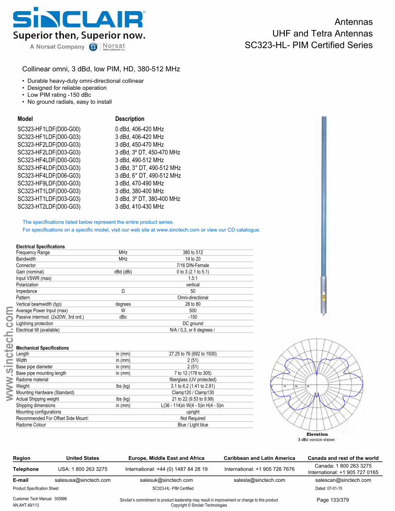
AntennasUHF and Tetra Antennas
SC323-HL- PIM Certified Series
Collinear omni, 3 dBd, low PIM, HD, 380-512 MHz• Durable heavy-duty omni-directional collinear• Designed for reliable operation• Low PIM rating -150 dBc• No ground radials, easy to install
Model DescriptionSC323-HF1LDF(D00-G00) 0 dBd, 406-420 MHzSC323-HF1LDF(D00-G03) 3 dBd, 406-420 MHzSC323-HF2LDF(D00-G03) 3 dBd, 450-470 MHzSC323-HF2LDF(D03-G03) 3 dBd, 3º DT, 450-470 MHzSC323-HF4LDF(D00-G03) 3 dBd, 490-512 MHzSC323-HF4LDF(D03-G03) 3 dBd, 3° DT, 490-512 MHzSC323-HF4LDF(D06-G03) 3 dBd, 6° DT, 490-512 MHzSC323-HF9LDF(D00-G03) 3 dBd, 470-490 MHzSC323-HT1LDF(D00-G03) 3 dBd, 380-400 MHzSC323-HT1LDF(D03-G03) 3 dBd, 3º DT, 380-400 MHzSC323-HT2LDF(D00-G03) 3 dBd, 410-430 MHz
The specifications listed below represent the entire product series.For specifications on a specific model, visit our web site at www.sinctech.com or view our CD catalogue.
Electrical SpecificationsFrequency Range MHz 380 to 512Bandwidth MHz 14 to 20Connector 7/16 DIN-FemaleGain (nominal) dBd (dBi) 0 to 3 (2.1 to 5.1)Input VSWR (max) 1.5:1Polarization verticalImpedance Ω 50Pattern Omni-directionalVertical beamwidth (typ) degrees 28 to 80Average Power Input (max) W 500Passive intermod. (2x20W, 3rd ord.) dBc -150Lightning protection DC groundElectrical tilt (available) N/A / 0,3, or 6 degrees /
Mechanical SpecificationsLength in (mm) 27.25 to 76 (692 to 1930)Width in (mm) 2 (51)Base pipe diameter in (mm) 2 (51)Base pipe mounting length in (mm) 7 to 12 (178 to 305)Radome material fiberglass (UV protected)Weight lbs (kg) 3.1 to 6.2 (1.41 to 2.81)Mounting Hardware (Standard) Clamp120 / Clamp130Actual Shipping weight lbs (kg) 21 to 22 (9.53 to 9.99)Shipping dimensions in (mm) L(36 - 114)in W(4 - 5)in H(4 - 5)in Mounting configurations uprightRecommended For Offset Side Mount: Not RequiredRadome Colour Blue / Light blue
Region United States Europe, Middle East and Africa Caribbean and Latin America Canada and rest of the world
Telephone USA: 1 800 263 3275 International: +44 (0) 1487 84 28 19 International: +1 905 726 7676 Canada: 1 800 263 3275International: +1 905 727 0165
E-mail [email protected] [email protected] [email protected] [email protected] Specification Sheet SC323-HL- PIM Certified Dated: 07-01-15
Customer Tech Manual 005886 Sinclair’s commitment to product leadership may result in improvement or change to this productCopyright © Sinclair TechnologiesAN.AHT.49/113
www.
sinct
ech.
com
Page 133/379
AntennasUHF and Tetra Antennas
SC323-HL- PIM Certified Series
Environmental SpecificationsTemperature range °F (°C) -40 to +140 (-40 to +60)Wind Loading Area (Flat Plate Equivalent) ft² (m²) 0.25 to 0.66 (0.02 to 0.06)Wind Loading Area (1/2" ice) ft² (m²) 0.39 to 1.15 (0.04 to 0.11)Rated wind velocity (no ice) mph (km/h) 205 to 265 (330 to 427)Rated wind velocity (1/2" radial ice) mph (km/h) 165 to 215 (266 to 346)Lateral thrust (100 mph No Ice) lbs (N) 10.5 to 26 (46.7 to 115.6)Bending moment (100 mph No Ice) ft-lbs (Nm) 6.2 to 53 (8.4 to 71.6)Tip deflection (100 mph No Ice) degrees 0.02 to 0.7
Region United States Europe, Middle East and Africa Caribbean and Latin America Canada and rest of the world
Telephone USA: 1 800 263 3275 International: +44 (0) 1487 84 28 19 International: +1 905 726 7676 Canada: 1 800 263 3275International: +1 905 727 0165
E-mail [email protected] [email protected] [email protected] [email protected] Specification Sheet SC323-HL- PIM Certified Dated: 07-01-15
Customer Tech Manual 005886 Sinclair’s commitment to product leadership may result in improvement or change to this productCopyright © Sinclair TechnologiesAN.AHT.50/113
www.
sinct
ech.
com
Page 134/379
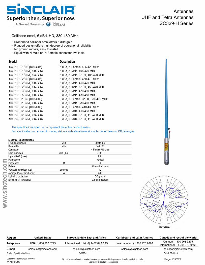
AntennasUHF and Tetra Antennas
SC329-H Series
Collinear omni, 6 dBd, HD, 380-480 MHz• Broadband collinear omni offers 6 dBd gain• Rugged design offers high degree of operational reliability• No ground radials, easy to install• Pigtail with N-Male or N-Female connector available
Model DescriptionSC329-HF1SNF(D00-G06) 6 dBd, N-Female, 406-420 MHzSC329-HF1SNM(D00-G06) 6 dBd, N-Male, 406-420 MHzSC329-HF1SNM(D03-G06) 6 dBd, N-Male, 3° DT, 406-420 MHzSC329-HF2SNF(D00-G06) 6 dBd, N-Female, 450-470 MHzSC329-HF2SNM(D00-G06) 6 dBd, N-Male, 450-470 MHzSC329-HF2SNM(D06-G06) 6 dBd, N-male, 6° DT, 450-470 MHzSC329-HF3SNM(D00-G06) 6 dBd, N-Male, 470-490 MHzSC329-HF5SNM(D00-G06) 6 dBd, N-Male, 430-450 MHzSC329-HT1SNF(D03-G06) 6 dBd, N-Female, 3° DT, 380-400 MHzSC329-HT1SNM(D00-G06) 6 dBd, N-Male, 380-400 MHzSC329-HT2SNF(D00-G06) 6 dBd, N-Female, 410-430 MHzSC329-HT2SNM(D00-G06) 6 dBd, N-Male, 410-430 MHzSC329-HT2SNM(D03-G06) 6 dBd, N-Male, 3° DT, 410-430 MHzSC329-HT2SNM(D06-G06) 6 dBd, N-Male, 6° DT, 410-430 MHz
The specifications listed below represent the entire product series.For specifications on a specific model, visit our web site at www.sinctech.com or view our CD catalogue.
Electrical SpecificationsFrequency Range MHz 380 to 490Bandwidth MHz 14 to 20Connector N-Female / N-MaleGain (nominal) dBd (dBi) 6 (8.1)Input VSWR (max) 1.5:1Polarization verticalImpedance Ω 50Pattern Omni-directionalVertical beamwidth (typ) degrees 12Average Power Input (max) W 500Lightning protection DC groundElectrical tilt (available) 0,3, or 6 degrees
Region United States Europe, Middle East and Africa Caribbean and Latin America Canada and rest of the world
Telephone USA: 1 800 263 3275 International: +44 (0) 1487 84 28 19 International: +1 905 726 7676 Canada: 1 800 263 3275International: +1 905 727 0165
E-mail [email protected] [email protected] [email protected] [email protected] Specification Sheet SC329-H Dated: 07-01-15
Customer Tech Manual 005941 Sinclair’s commitment to product leadership may result in improvement or change to this productCopyright © Sinclair TechnologiesAN.AHT.51/113
www.
sinct
ech.
com
Page 135/379
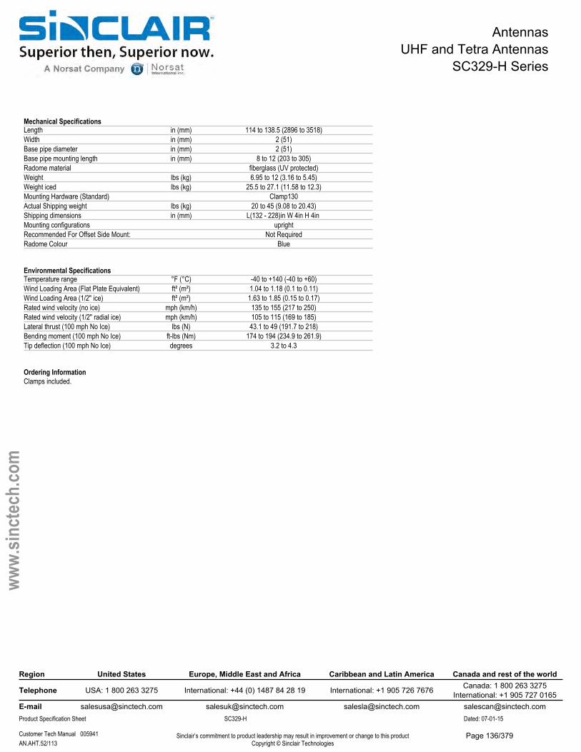
AntennasUHF and Tetra Antennas
SC329-H Series
Mechanical SpecificationsLength in (mm) 114 to 138.5 (2896 to 3518)Width in (mm) 2 (51)Base pipe diameter in (mm) 2 (51)Base pipe mounting length in (mm) 8 to 12 (203 to 305)Radome material fiberglass (UV protected)Weight lbs (kg) 6.95 to 12 (3.16 to 5.45)Weight iced lbs (kg) 25.5 to 27.1 (11.58 to 12.3)Mounting Hardware (Standard) Clamp130Actual Shipping weight lbs (kg) 20 to 45 (9.08 to 20.43)Shipping dimensions in (mm) L(132 - 228)in W 4in H 4in Mounting configurations uprightRecommended For Offset Side Mount: Not RequiredRadome Colour Blue
Environmental SpecificationsTemperature range °F (°C) -40 to +140 (-40 to +60)Wind Loading Area (Flat Plate Equivalent) ft² (m²) 1.04 to 1.18 (0.1 to 0.11)Wind Loading Area (1/2" ice) ft² (m²) 1.63 to 1.85 (0.15 to 0.17)Rated wind velocity (no ice) mph (km/h) 135 to 155 (217 to 250)Rated wind velocity (1/2" radial ice) mph (km/h) 105 to 115 (169 to 185)Lateral thrust (100 mph No Ice) lbs (N) 43.1 to 49 (191.7 to 218)Bending moment (100 mph No Ice) ft-lbs (Nm) 174 to 194 (234.9 to 261.9)Tip deflection (100 mph No Ice) degrees 3.2 to 4.3
Ordering InformationClamps included.
Region United States Europe, Middle East and Africa Caribbean and Latin America Canada and rest of the world
Telephone USA: 1 800 263 3275 International: +44 (0) 1487 84 28 19 International: +1 905 726 7676 Canada: 1 800 263 3275International: +1 905 727 0165
E-mail [email protected] [email protected] [email protected] [email protected] Specification Sheet SC329-H Dated: 07-01-15
Customer Tech Manual 005941 Sinclair’s commitment to product leadership may result in improvement or change to this productCopyright © Sinclair TechnologiesAN.AHT.52/113
www.
sinct
ech.
com
Page 136/379

AntennasUHF and Tetra Antennas
SC329-HL- PIM Certified Series
Collinear omni, 6 dBd, low PIM, HD, 380-490 MHz• Low PIM, collinear 6 dBd gain, fiberglass omni• 20 MHz bandwidth, available with 0,3 and 6 degree downtilits• No ground rods, simplify installation and provide reliable weatherproofing
Model DescriptionSC329-HF1LDF(D00-G06) 6 dBd, 406-420 MHzSC329-HF1LDF(D03-G06) 6 dBd, 3° DT, 406-420 MHzSC329-HF1LDF(D06-G06) 6 dBd, 6° DT, 406-420 MHzSC329-HF2LDF(D00-G06) 6 dBd, 450-470 MHzSC329-HF2LDF(D03-G06) 6 dBd, 3° DT, 450-470 MHzSC329-HF2LDF(D06-G06) 6 dBd, 6° DT, 450-470 MHzSC329-HF3LDF(D00-G06) 6 dBd, 470-490 MHzSC329-HF5LDF(D00-G06) 6 dBd, 430-450 MHzSC329-HT1LDF(D00-G06) 6 dBd, 380-400 MHzSC329-HT1LDF(D03-G06) 6 dBd, 3° DT, 380-400 MHzSC329-HT1LDF(D06-G06) 6 dBd, 6° DT, 380-400 MHzSC329-HT2LDF(D00-G06) 6 dBd, 410-430 MHz
The specifications listed below represent the entire product series.For specifications on a specific model, visit our web site at www.sinctech.com or view our CD catalogue.
Electrical SpecificationsFrequency Range MHz 380 to 490Bandwidth MHz 14 to 20Connector 7/16 DIN-FemaleGain (nominal) dBd (dBi) 6 (8.1)Input VSWR (max) 1.5:1Polarization verticalImpedance Ω 50Pattern Omni-directionalVertical beamwidth (typ) degrees 12Average Power Input (max) W 500Passive intermod. (2x20W, 3rd ord.) dBc -150Lightning protection DC groundElectrical tilt (available) 0, 3, or 6 degrees
Region United States Europe, Middle East and Africa Caribbean and Latin America Canada and rest of the world
Telephone USA: 1 800 263 3275 International: +44 (0) 1487 84 28 19 International: +1 905 726 7676 Canada: 1 800 263 3275International: +1 905 727 0165
E-mail [email protected] [email protected] [email protected] [email protected] Specification Sheet SC329-HL- PIM Certified Dated: 07-01-15
Sinclair’s commitment to product leadership may result in improvement or change to this productCopyright © Sinclair TechnologiesAN.AHT.53/113
www.
sinct
ech.
com
Page 137/379
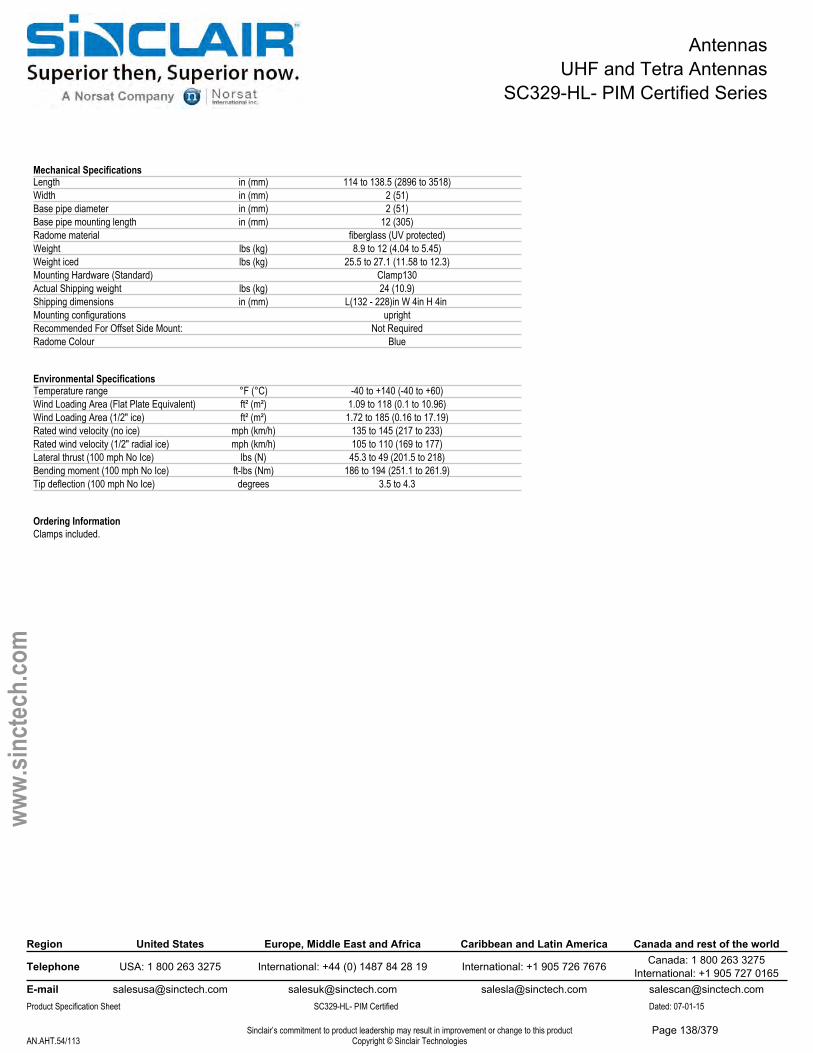
AntennasUHF and Tetra Antennas
SC329-HL- PIM Certified Series
Mechanical SpecificationsLength in (mm) 114 to 138.5 (2896 to 3518)Width in (mm) 2 (51)Base pipe diameter in (mm) 2 (51)Base pipe mounting length in (mm) 12 (305)Radome material fiberglass (UV protected)Weight lbs (kg) 8.9 to 12 (4.04 to 5.45)Weight iced lbs (kg) 25.5 to 27.1 (11.58 to 12.3)Mounting Hardware (Standard) Clamp130Actual Shipping weight lbs (kg) 24 (10.9)Shipping dimensions in (mm) L(132 - 228)in W 4in H 4in Mounting configurations uprightRecommended For Offset Side Mount: Not RequiredRadome Colour Blue
Environmental SpecificationsTemperature range °F (°C) -40 to +140 (-40 to +60)Wind Loading Area (Flat Plate Equivalent) ft² (m²) 1.09 to 118 (0.1 to 10.96)Wind Loading Area (1/2" ice) ft² (m²) 1.72 to 185 (0.16 to 17.19)Rated wind velocity (no ice) mph (km/h) 135 to 145 (217 to 233)Rated wind velocity (1/2" radial ice) mph (km/h) 105 to 110 (169 to 177)Lateral thrust (100 mph No Ice) lbs (N) 45.3 to 49 (201.5 to 218)Bending moment (100 mph No Ice) ft-lbs (Nm) 186 to 194 (251.1 to 261.9)Tip deflection (100 mph No Ice) degrees 3.5 to 4.3
Ordering InformationClamps included.
Region United States Europe, Middle East and Africa Caribbean and Latin America Canada and rest of the world
Telephone USA: 1 800 263 3275 International: +44 (0) 1487 84 28 19 International: +1 905 726 7676 Canada: 1 800 263 3275International: +1 905 727 0165
E-mail [email protected] [email protected] [email protected] [email protected] Specification Sheet SC329-HL- PIM Certified Dated: 07-01-15
Sinclair’s commitment to product leadership may result in improvement or change to this productCopyright © Sinclair TechnologiesAN.AHT.54/113
www.
sinct
ech.
com
Page 138/379
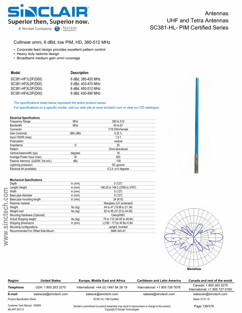
AntennasUHF and Tetra Antennas
SC381-HL- PIM Certified Series
Collinear omni, 6 dBd, low PIM, HD, 380-512 MHz• Corporate feed design provides excellent pattern control• Heavy duty radome design• Broadband medium gain omni coverage
Model DescriptionSC381-HF1LDF(D00) 6 dBd, 380-420 MHzSC381-HF2LDF(D00) 6 dBd, 403-470 MHzSC381-HF3LDF(D00) 6 dBd, 450-512 MHzSC381-HF4LDF(D00) 6 dBd, 430-490 MHz
The specifications listed below represent the entire product series.For specifications on a specific model, visit our web site at www.sinctech.com or view our CD catalogue.
Electrical SpecificationsFrequency Range MHz 380 to 512Bandwidth MHz 40 to 67Connector 7/16 DIN-FemaleGain (nominal) dBd (dBi) 6 (8.1)Input VSWR (max) 1.5:1Polarization verticalImpedance Ω 50Pattern Omni-directionalVertical beamwidth (typ) degrees 18Average Power Input (max) W 500Passive intermod. (2x20W, 3rd ord.) dBc -150Lightning protection DC groundElectrical tilt (available) 0,2,4, or 6 degrees
Mechanical SpecificationsDepth in (mm) 5 (127)Length/ Height in (mm) 148.25 to 148.3 (3766 to 3767)Width in (mm) 5 (127)Base pipe diameter in (mm) 5 (127)Base pipe mounting length in (mm) 24 (610)Radome material fiberglass (UV protected)Weight lbs (kg) 44 to 47 (19.98 to 21.34)Weight iced lbs (kg) 82 to 99 (37.23 to 44.95)Mounting Hardware (Optional) Clamp006CActual Shipping weight lbs (kg) 75 to 110 (34.05 to 49.94)Shipping dimensions in (mm) L(165 - 171)in W 8in H 8in Mounting configurations upright, invertedRecommended For Offset Side Mount: SMK-345-A7
Region United States Europe, Middle East and Africa Caribbean and Latin America Canada and rest of the world
Telephone USA: 1 800 263 3275 International: +44 (0) 1487 84 28 19 International: +1 905 726 7676 Canada: 1 800 263 3275International: +1 905 727 0165
E-mail [email protected] [email protected] [email protected] [email protected] Specification Sheet SC381-HL- PIM Certified Dated: 07-01-15
Customer Tech Manual 005855 Sinclair’s commitment to product leadership may result in improvement or change to this productCopyright © Sinclair TechnologiesAN.AHT.55/113
www.
sinct
ech.
com
Page 139/379
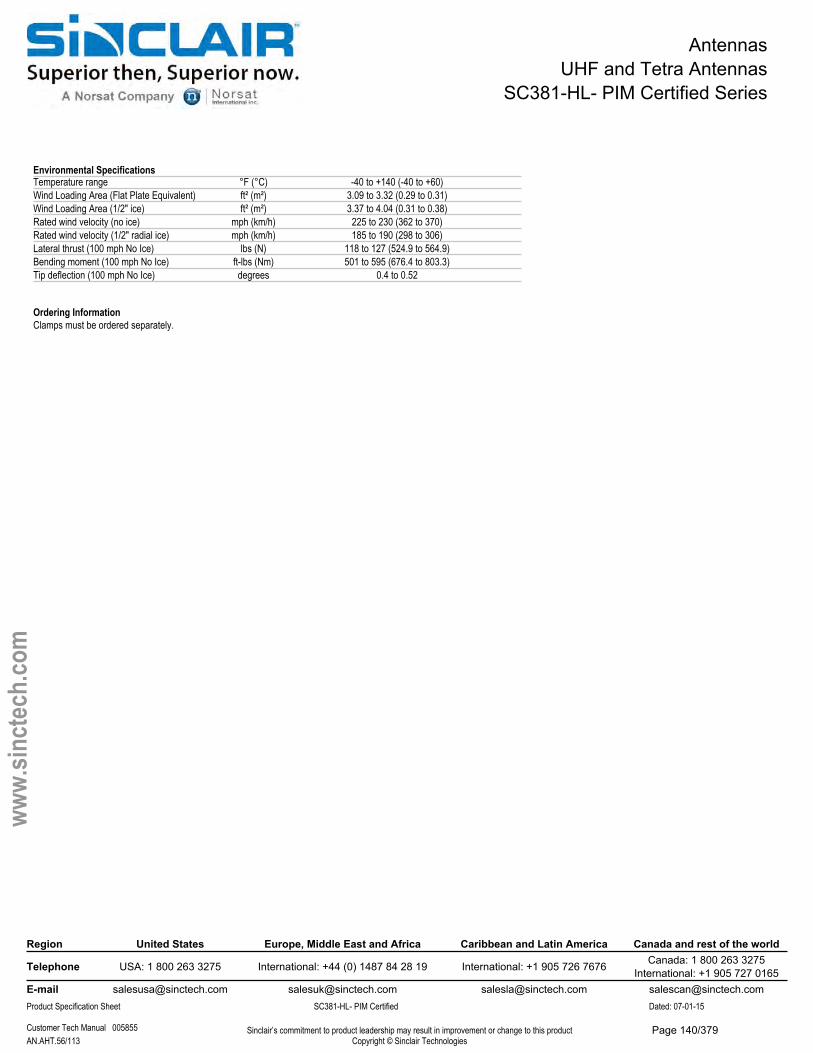
AntennasUHF and Tetra Antennas
SC381-HL- PIM Certified Series
Environmental SpecificationsTemperature range °F (°C) -40 to +140 (-40 to +60)Wind Loading Area (Flat Plate Equivalent) ft² (m²) 3.09 to 3.32 (0.29 to 0.31)Wind Loading Area (1/2" ice) ft² (m²) 3.37 to 4.04 (0.31 to 0.38)Rated wind velocity (no ice) mph (km/h) 225 to 230 (362 to 370)Rated wind velocity (1/2" radial ice) mph (km/h) 185 to 190 (298 to 306)Lateral thrust (100 mph No Ice) lbs (N) 118 to 127 (524.9 to 564.9)Bending moment (100 mph No Ice) ft-lbs (Nm) 501 to 595 (676.4 to 803.3)Tip deflection (100 mph No Ice) degrees 0.4 to 0.52
Ordering InformationClamps must be ordered separately.
Region United States Europe, Middle East and Africa Caribbean and Latin America Canada and rest of the world
Telephone USA: 1 800 263 3275 International: +44 (0) 1487 84 28 19 International: +1 905 726 7676 Canada: 1 800 263 3275International: +1 905 727 0165
E-mail [email protected] [email protected] [email protected] [email protected] Specification Sheet SC381-HL- PIM Certified Dated: 07-01-15
Customer Tech Manual 005855 Sinclair’s commitment to product leadership may result in improvement or change to this productCopyright © Sinclair TechnologiesAN.AHT.56/113
www.
sinct
ech.
com
Page 140/379
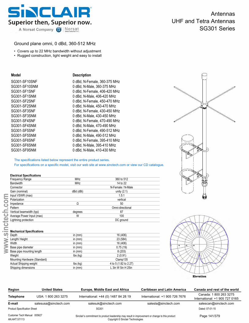
AntennasUHF and Tetra Antennas
SG301 Series
Ground plane omni, 0 dBd, 360-512 MHz• Covers up to 22 MHz bandwidth without adjustment• Rugged construction, light weight and easy to install
Model DescriptionSG301-SF10SNF 0 dBd, N-Female, 360-375 MHzSG301-SF10SNM 0 dBd, N-Male, 360-375 MHzSG301-SF1SNF 0 dBd, N-Female, 406-420 MHzSG301-SF1SNM 0 dBd, N-Male, 406-420 MHzSG301-SF2SNF 0 dBd, N-Female, 450-470 MHzSG301-SF2SNM 0 dBd, N-Male, 450-470 MHzSG301-SF3SNF 0 dBd, N-Female, 430-450 MHzSG301-SF3SNM 0 dBd, N-Male, 430-450 MHzSG301-SF4SNF 0 dBd, N-Female, 470-490 MHzSG301-SF4SNM 0 dBd, N-Male, 470-490 MHzSG301-SF5SNF 0 dBd, N-Female, 490-512 MHzSG301-SF5SNM 0 dBd, N-Male, 490-512 MHzSG301-SF6SNF 0 dBd, N-Female, 395-410 MHzSG301-SF6SNM 0 dBd, N-Male, 395-410 MHzSG301-SF9SNM 0 dBd, N-Male, 410-430 MHz
The specifications listed below represent the entire product series.For specifications on a specific model, visit our web site at www.sinctech.com or view our CD catalogue.
Electrical SpecificationsFrequency Range MHz 360 to 512Bandwidth MHz 14 to 22Connector N-Female / N-MaleGain (nominal) dBd (dBi) unity (2.1)Input VSWR (max) 1.5:1Polarization verticalImpedance Ω 50Pattern Omni-directionalVertical beamwidth (typ) degrees 87Average Power Input (max) W 100Lightning protection DC ground
Mechanical SpecificationsDepth in (mm) 16 (406)Length/ Height in (mm) 23 (584)Width in (mm) 16 (406)Base pipe diameter in (mm) 0.75 (19)Base pipe mounting length in (mm) 8 (203)Weight lbs (kg) 2 (0.91)Mounting Hardware (Standard) Clamp135Actual Shipping weight lbs (kg) 4 to 5 (1.82 to 2.27)Shipping dimensions in (mm) L 3in W 5in H 25in
Region United States Europe, Middle East and Africa Caribbean and Latin America Canada and rest of the world
Telephone USA: 1 800 263 3275 International: +44 (0) 1487 84 28 19 International: +1 905 726 7676 Canada: 1 800 263 3275International: +1 905 727 0165
E-mail [email protected] [email protected] [email protected] [email protected] Specification Sheet SG301 Dated: 07-01-15
Customer Tech Manual 005627 Sinclair’s commitment to product leadership may result in improvement or change to this productCopyright © Sinclair TechnologiesAN.AHT.57/113
www.
sinct
ech.
com
Page 141/379

AntennasUHF and Tetra Antennas
SG301 Series
Environmental SpecificationsTemperature range °F (°C) -40 to +140 (-40 to +60)Wind Loading Area (Flat Plate Equivalent) ft² (m²) 0.09 (0.01)Wind Loading Area (1/2" ice) ft² (m²) 0.33 (0.03)Rated wind velocity (no ice) mph (km/h) 100 (161)Rated wind velocity (1/2" radial ice) mph (km/h) 85 (137)Lateral thrust (100 mph No Ice) lbs (N) 3.4 (15.3)Bending moment (100 mph No Ice) ft-lbs (Nm) 0.52 (0.7)
Region United States Europe, Middle East and Africa Caribbean and Latin America Canada and rest of the world
Telephone USA: 1 800 263 3275 International: +44 (0) 1487 84 28 19 International: +1 905 726 7676 Canada: 1 800 263 3275International: +1 905 727 0165
E-mail [email protected] [email protected] [email protected] [email protected] Specification Sheet SG301 Dated: 07-01-15
Customer Tech Manual 005627 Sinclair’s commitment to product leadership may result in improvement or change to this productCopyright © Sinclair TechnologiesAN.AHT.58/113
www.
sinct
ech.
com
Page 142/379
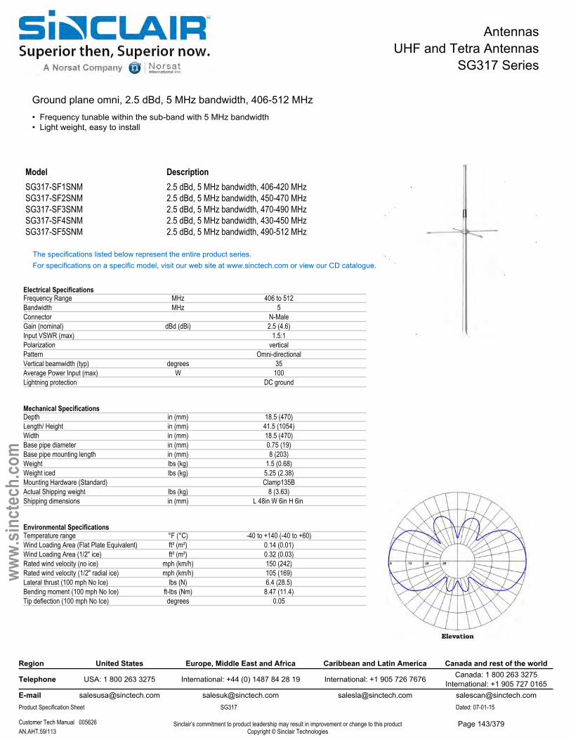
AntennasUHF and Tetra Antennas
SG317 Series
Ground plane omni, 2.5 dBd, 5 MHz bandwidth, 406-512 MHz• Frequency tunable within the sub-band with 5 MHz bandwidth• Light weight, easy to install
Model DescriptionSG317-SF1SNM 2.5 dBd, 5 MHz bandwidth, 406-420 MHzSG317-SF2SNM 2.5 dBd, 5 MHz bandwidth, 450-470 MHzSG317-SF3SNM 2.5 dBd, 5 MHz bandwidth, 470-490 MHzSG317-SF4SNM 2.5 dBd, 5 MHz bandwidth, 430-450 MHzSG317-SF5SNM 2.5 dBd, 5 MHz bandwidth, 490-512 MHz
The specifications listed below represent the entire product series.For specifications on a specific model, visit our web site at www.sinctech.com or view our CD catalogue.
Electrical SpecificationsFrequency Range MHz 406 to 512Bandwidth MHz 5Connector N-MaleGain (nominal) dBd (dBi) 2.5 (4.6)Input VSWR (max) 1.5:1Polarization verticalPattern Omni-directionalVertical beamwidth (typ) degrees 35Average Power Input (max) W 100Lightning protection DC ground
Mechanical SpecificationsDepth in (mm) 18.5 (470)Length/ Height in (mm) 41.5 (1054)Width in (mm) 18.5 (470)Base pipe diameter in (mm) 0.75 (19)Base pipe mounting length in (mm) 8 (203)Weight lbs (kg) 1.5 (0.68)Weight iced lbs (kg) 5.25 (2.38)Mounting Hardware (Standard) Clamp135BActual Shipping weight lbs (kg) 8 (3.63)Shipping dimensions in (mm) L 48in W 6in H 6in
Environmental SpecificationsTemperature range °F (°C) -40 to +140 (-40 to +60)Wind Loading Area (Flat Plate Equivalent) ft² (m²) 0.14 (0.01)Wind Loading Area (1/2" ice) ft² (m²) 0.32 (0.03)Rated wind velocity (no ice) mph (km/h) 150 (242)Rated wind velocity (1/2" radial ice) mph (km/h) 105 (169)Lateral thrust (100 mph No Ice) lbs (N) 6.4 (28.5)Bending moment (100 mph No Ice) ft-lbs (Nm) 8.47 (11.4)Tip deflection (100 mph No Ice) degrees 0.05
Region United States Europe, Middle East and Africa Caribbean and Latin America Canada and rest of the world
Telephone USA: 1 800 263 3275 International: +44 (0) 1487 84 28 19 International: +1 905 726 7676 Canada: 1 800 263 3275International: +1 905 727 0165
E-mail [email protected] [email protected] [email protected] [email protected] Specification Sheet SG317 Dated: 07-01-15
Customer Tech Manual 005626 Sinclair’s commitment to product leadership may result in improvement or change to this productCopyright © Sinclair TechnologiesAN.AHT.59/113
www.
sinct
ech.
com
Page 143/379
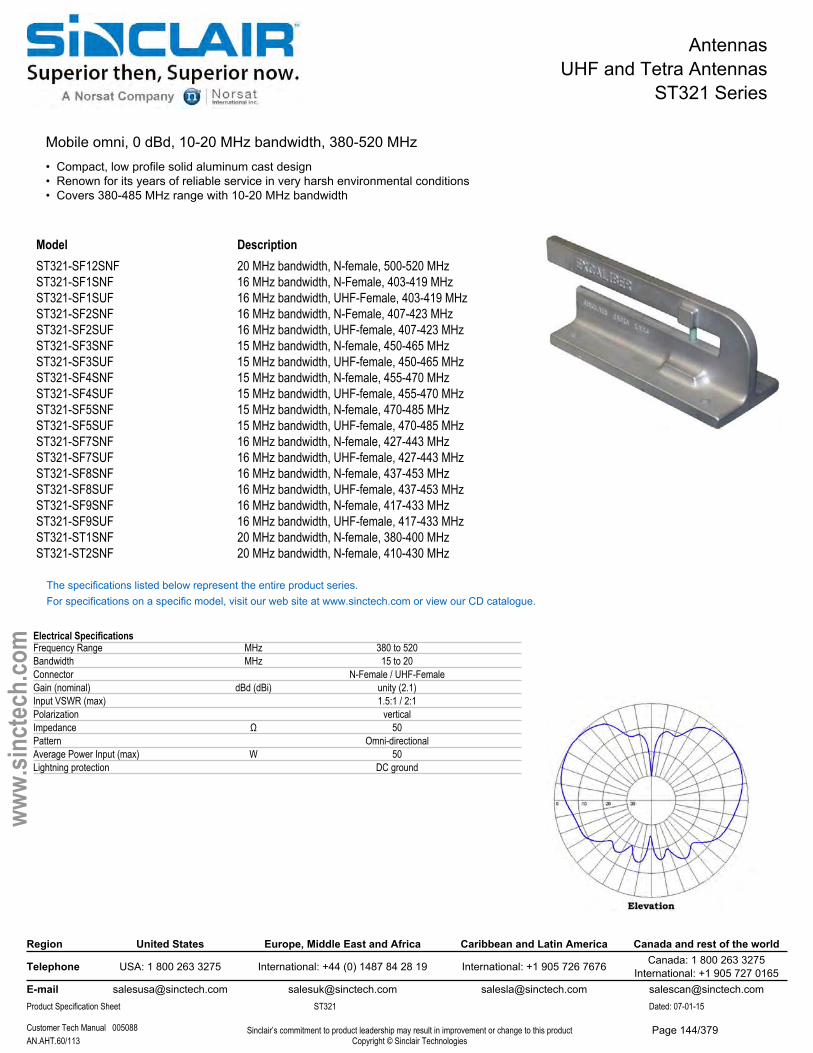
AntennasUHF and Tetra Antennas
ST321 Series
Mobile omni, 0 dBd, 10-20 MHz bandwidth, 380-520 MHz• Compact, low profile solid aluminum cast design• Renown for its years of reliable service in very harsh environmental conditions• Covers 380-485 MHz range with 10-20 MHz bandwidth
Model DescriptionST321-SF12SNF 20 MHz bandwidth, N-female, 500-520 MHzST321-SF1SNF 16 MHz bandwidth, N-Female, 403-419 MHzST321-SF1SUF 16 MHz bandwidth, UHF-Female, 403-419 MHzST321-SF2SNF 16 MHz bandwidth, N-Female, 407-423 MHzST321-SF2SUF 16 MHz bandwidth, UHF-female, 407-423 MHzST321-SF3SNF 15 MHz bandwidth, N-female, 450-465 MHzST321-SF3SUF 15 MHz bandwidth, UHF-female, 450-465 MHzST321-SF4SNF 15 MHz bandwidth, N-female, 455-470 MHzST321-SF4SUF 15 MHz bandwidth, UHF-female, 455-470 MHzST321-SF5SNF 15 MHz bandwidth, N-female, 470-485 MHzST321-SF5SUF 15 MHz bandwidth, UHF-female, 470-485 MHzST321-SF7SNF 16 MHz bandwidth, N-female, 427-443 MHzST321-SF7SUF 16 MHz bandwidth, UHF-female, 427-443 MHzST321-SF8SNF 16 MHz bandwidth, N-female, 437-453 MHzST321-SF8SUF 16 MHz bandwidth, UHF-female, 437-453 MHzST321-SF9SNF 16 MHz bandwidth, N-female, 417-433 MHzST321-SF9SUF 16 MHz bandwidth, UHF-female, 417-433 MHzST321-ST1SNF 20 MHz bandwidth, N-female, 380-400 MHzST321-ST2SNF 20 MHz bandwidth, N-female, 410-430 MHz
The specifications listed below represent the entire product series.For specifications on a specific model, visit our web site at www.sinctech.com or view our CD catalogue.
Electrical SpecificationsFrequency Range MHz 380 to 520Bandwidth MHz 15 to 20Connector N-Female / UHF-FemaleGain (nominal) dBd (dBi) unity (2.1)Input VSWR (max) 1.5:1 / 2:1Polarization verticalImpedance Ω 50Pattern Omni-directionalAverage Power Input (max) W 50Lightning protection DC ground
Region United States Europe, Middle East and Africa Caribbean and Latin America Canada and rest of the world
Telephone USA: 1 800 263 3275 International: +44 (0) 1487 84 28 19 International: +1 905 726 7676 Canada: 1 800 263 3275International: +1 905 727 0165
E-mail [email protected] [email protected] [email protected] [email protected] Specification Sheet ST321 Dated: 07-01-15
Customer Tech Manual 005088 Sinclair’s commitment to product leadership may result in improvement or change to this productCopyright © Sinclair TechnologiesAN.AHT.60/113
www.
sinct
ech.
com
Page 144/379

AntennasUHF and Tetra Antennas
ST321 Series
Mechanical SpecificationsDepth in (mm) 7.5 (191)Length/ Height in (mm) 2.5 (64)Width in (mm) 2.5 (64)Actual Shipping weight lbs (kg) 3 (1.36)Shipping dimensions in (mm) L 5in W 7in H 11in Ground Plane (min) in (mm) 30x30Mounting hardware Supplied
Environmental SpecificationsTemperature range °F (°C) -40 to +140 (-40 to +60)
Ordering InformationSpecify exact operating frequency to the nearest 0.5 MHz.
Region United States Europe, Middle East and Africa Caribbean and Latin America Canada and rest of the world
Telephone USA: 1 800 263 3275 International: +44 (0) 1487 84 28 19 International: +1 905 726 7676 Canada: 1 800 263 3275International: +1 905 727 0165
E-mail [email protected] [email protected] [email protected] [email protected] Specification Sheet ST321 Dated: 07-01-15
Customer Tech Manual 005088 Sinclair’s commitment to product leadership may result in improvement or change to this productCopyright © Sinclair TechnologiesAN.AHT.61/113
www.
sinct
ech.
com
Page 145/379
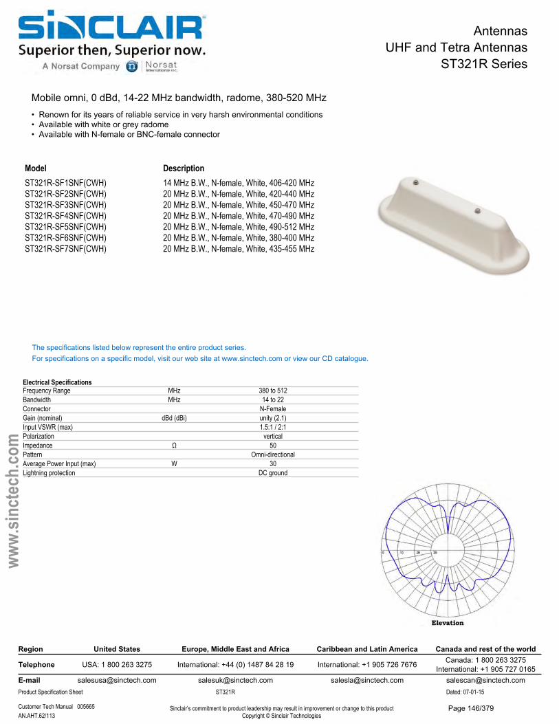
AntennasUHF and Tetra Antennas
ST321R Series
Mobile omni, 0 dBd, 14-22 MHz bandwidth, radome, 380-520 MHz• Renown for its years of reliable service in very harsh environmental conditions• Available with white or grey radome• Available with N-female or BNC-female connector
ModelST321R-SF1SNF(CWH) ST321R-SF2SNF(CWH) ST321R-SF3SNF(CWH) ST321R-SF4SNF(CWH) ST321R-SF5SNF(CWH) ST321R-SF6SNF(CWH) ST321R-SF7SNF(CWH)
Description14 MHz B.W., N-female, White, 406-420 MHz 20 MHz B.W., N-female, White, 420-440 MHz 20 MHz B.W., N-female, White, 450-470 MHz 20 MHz B.W., N-female, White, 470-490 MHz 20 MHz B.W., N-female, White, 490-512 MHz 20 MHz B.W., N-female, White, 380-400 MHz 20 MHz B.W., N-female, White, 435-455 MHz
The specifications listed below represent the entire product series.For specifications on a specific model, visit our web site at www.sinctech.com or view our CD catalogue.
Electrical SpecificationsFrequency Range MHz 380 to 512Bandwidth MHz 14 to 22Connector N-FemaleGain (nominal) dBd (dBi) unity (2.1)Input VSWR (max) 1.5:1 / 2:1Polarization verticalImpedance Ω 50Pattern Omni-directionalAverage Power Input (max) W 30Lightning protection DC ground
Region United States Europe, Middle East and Africa Caribbean and Latin America Canada and rest of the world
Telephone USA: 1 800 263 3275 International: +44 (0) 1487 84 28 19 International: +1 905 726 7676 Canada: 1 800 263 3275International: +1 905 727 0165
E-mail [email protected] [email protected] [email protected] [email protected] Specification Sheet ST321R Dated: 07-01-15
Customer Tech Manual 005665 Sinclair’s commitment to product leadership may result in improvement or change to this productCopyright © Sinclair TechnologiesAN.AHT.62/113
www.
sinct
ech.
com
Page 146/379

AntennasUHF and Tetra Antennas
ST321R Series
Mechanical SpecificationsLength in (mm) 11.8 (300)Length/ Height in (mm) 3 (76)Width in (mm) 3.8 (97)Radome material ABS (gray) / ABS (white)Actual Shipping weight lbs (kg) 5 (2.27)Shipping dimensions in (mm) L 13in W 8in H 5in Ground Plane (min) in (mm) 30x30Mounting hardware Supplied
Environmental SpecificationsTemperature range °F (°C) -40 to +140 (-40 to +60)
Ordering InformationSpecify operating frequency to the nearest 0.5 MHz.
Region United States Europe, Middle East and Africa Caribbean and Latin America Canada and rest of the world
Telephone USA: 1 800 263 3275 International: +44 (0) 1487 84 28 19 International: +1 905 726 7676 Canada: 1 800 263 3275International: +1 905 727 0165
E-mail [email protected] [email protected] [email protected] [email protected] Specification Sheet ST321R Dated: 07-01-15
Customer Tech Manual 005665 Sinclair’s commitment to product leadership may result in improvement or change to this productCopyright © Sinclair TechnologiesAN.AHT.63/113
www.
sinct
ech.
com
Page 147/379
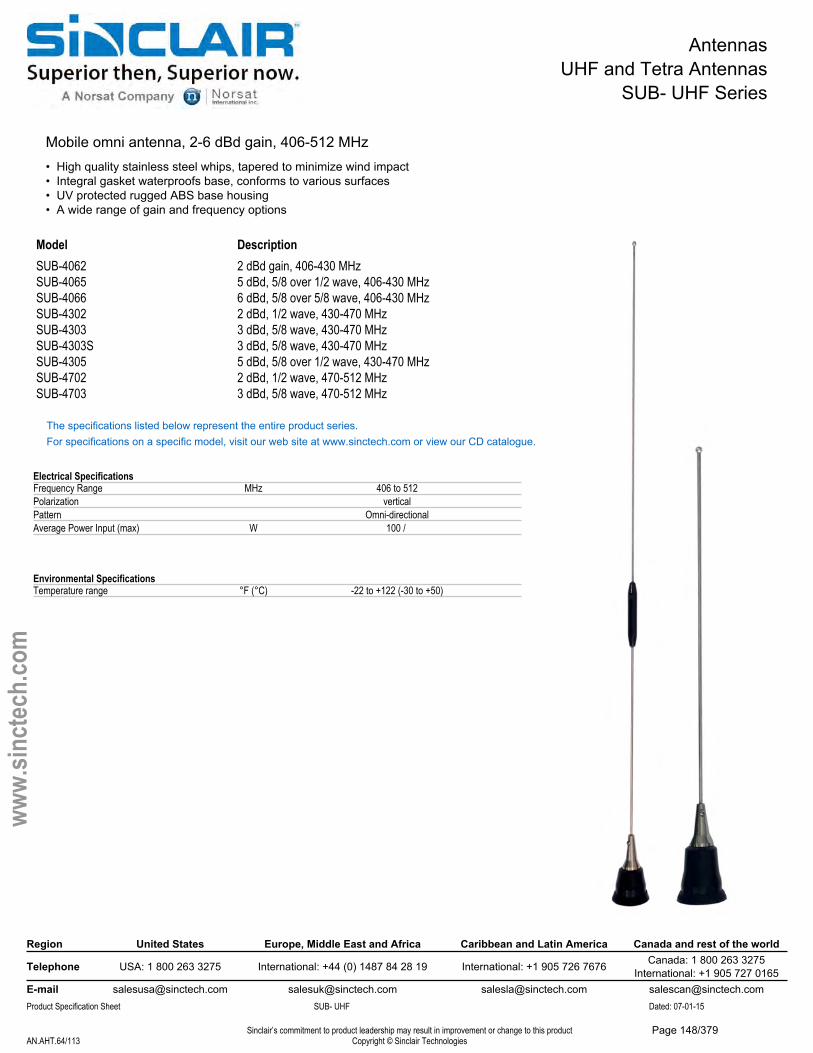
AntennasUHF and Tetra Antennas
SUB- UHF Series
Mobile omni antenna, 2-6 dBd gain, 406-512 MHz• High quality stainless steel whips, tapered to minimize wind impact• Integral gasket waterproofs base, conforms to various surfaces• UV protected rugged ABS base housing• A wide range of gain and frequency options
Model DescriptionSUB-4062 2 dBd gain, 406-430 MHzSUB-4065 5 dBd, 5/8 over 1/2 wave, 406-430 MHzSUB-4066 6 dBd, 5/8 over 5/8 wave, 406-430 MHzSUB-4302 2 dBd, 1/2 wave, 430-470 MHzSUB-4303 3 dBd, 5/8 wave, 430-470 MHzSUB-4303S 3 dBd, 5/8 wave, 430-470 MHzSUB-4305 5 dBd, 5/8 over 1/2 wave, 430-470 MHzSUB-4702 2 dBd, 1/2 wave, 470-512 MHzSUB-4703 3 dBd, 5/8 wave, 470-512 MHz
The specifications listed below represent the entire product series.For specifications on a specific model, visit our web site at www.sinctech.com or view our CD catalogue.
Electrical SpecificationsFrequency Range MHz 406 to 512Polarization verticalPattern Omni-directionalAverage Power Input (max) W 100 /
Environmental SpecificationsTemperature range °F (°C) -22 to +122 (-30 to +50)
Region United States Europe, Middle East and Africa Caribbean and Latin America Canada and rest of the world
Telephone USA: 1 800 263 3275 International: +44 (0) 1487 84 28 19 International: +1 905 726 7676 Canada: 1 800 263 3275International: +1 905 727 0165
E-mail [email protected] [email protected] [email protected] [email protected] Specification Sheet SUB- UHF Dated: 07-01-15
Sinclair’s commitment to product leadership may result in improvement or change to this productCopyright © Sinclair TechnologiesAN.AHT.64/113
www.
sinct
ech.
com
Page 148/379
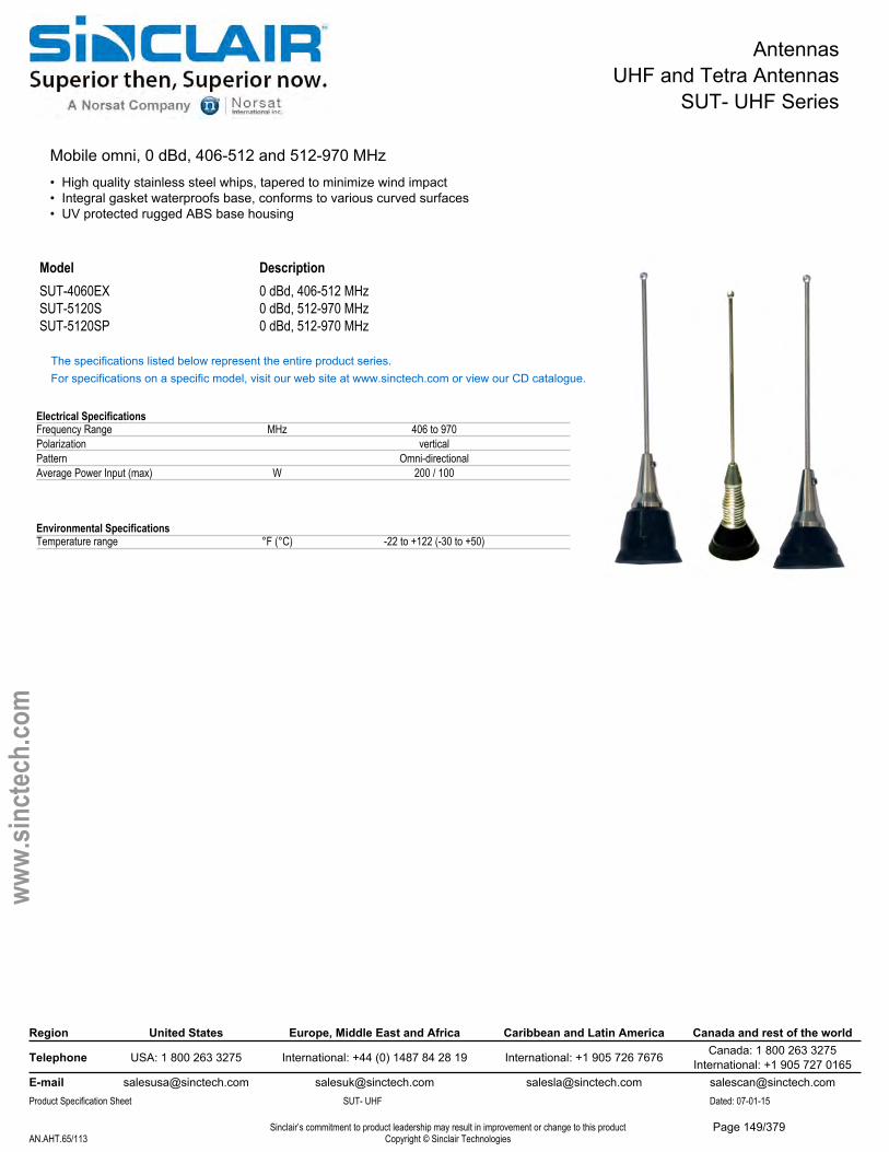
AntennasUHF and Tetra Antennas
SUT- UHF Series
Mobile omni, 0 dBd, 406-512 and 512-970 MHz• High quality stainless steel whips, tapered to minimize wind impact• Integral gasket waterproofs base, conforms to various curved surfaces• UV protected rugged ABS base housing
Model DescriptionSUT-4060EX 0 dBd, 406-512 MHzSUT-5120S 0 dBd, 512-970 MHzSUT-5120SP 0 dBd, 512-970 MHz
The specifications listed below represent the entire product series.For specifications on a specific model, visit our web site at www.sinctech.com or view our CD catalogue.
Electrical SpecificationsFrequency Range MHz 406 to 970Polarization verticalPattern Omni-directionalAverage Power Input (max) W 200 / 100
Environmental SpecificationsTemperature range °F (°C) -22 to +122 (-30 to +50)
Region United States Europe, Middle East and Africa Caribbean and Latin America Canada and rest of the world
Telephone USA: 1 800 263 3275 International: +44 (0) 1487 84 28 19 International: +1 905 726 7676 Canada: 1 800 263 3275International: +1 905 727 0165
E-mail [email protected] [email protected] [email protected] [email protected] Specification Sheet SUT- UHF Dated: 07-01-15
Sinclair’s commitment to product leadership may result in improvement or change to this productCopyright © Sinclair TechnologiesAN.AHT.65/113
www.
sinct
ech.
com
Page 149/379
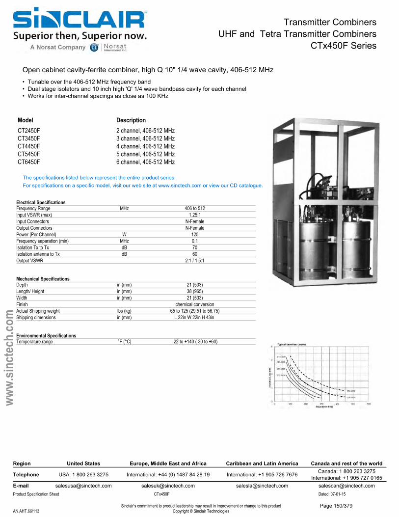
Transmitter CombinersUHF and Tetra Transmitter Combiners
CTx450F Series
Open cabinet cavity-ferrite combiner, high Q 10" 1/4 wave cavity, 406-512 MHz• Tunable over the 406-512 MHz frequency band• Dual stage isolators and 10 inch high 'Q' 1/4 wave bandpass cavity for each channel• Works for inter-channel spacings as close as 100 KHz
Model DescriptionCT2450F 2 channel, 406-512 MHzCT3450F 3 channel, 406-512 MHzCT4450F 4 channel, 406-512 MHzCT5450F 5 channel, 406-512 MHzCT6450F 6 channel, 406-512 MHz
The specifications listed below represent the entire product series.For specifications on a specific model, visit our web site at www.sinctech.com or view our CD catalogue.
Electrical SpecificationsFrequency Range MHz 406 to 512Input VSWR (max) 1.25:1Input Connectors N-FemaleOutput Connectors N-FemalePower (Per Channel) W 125Frequency separation (min) MHz 0.1Isolation Tx to Tx dB 70Isolation antenna to Tx dB 60Output VSWR 2:1 / 1.5:1
Mechanical SpecificationsDepth in (mm) 21 (533)Length/ Height in (mm) 38 (965)Width in (mm) 21 (533)Finish chemical conversionActual Shipping weight lbs (kg) 65 to 125 (29.51 to 56.75)Shipping dimensions in (mm) L 22in W 22in H 43in
Environmental SpecificationsTemperature range °F (°C) -22 to +140 (-30 to +60)
Region United States Europe, Middle East and Africa Caribbean and Latin America Canada and rest of the world
Telephone USA: 1 800 263 3275 International: +44 (0) 1487 84 28 19 International: +1 905 726 7676 Canada: 1 800 263 3275International: +1 905 727 0165
E-mail [email protected] [email protected] [email protected] [email protected] Specification Sheet CTx450F Dated: 07-01-15
Sinclair’s commitment to product leadership may result in improvement or change to this productCopyright © Sinclair TechnologiesAN.AHT.66/113
www.
sinct
ech.
com
Page 150/379
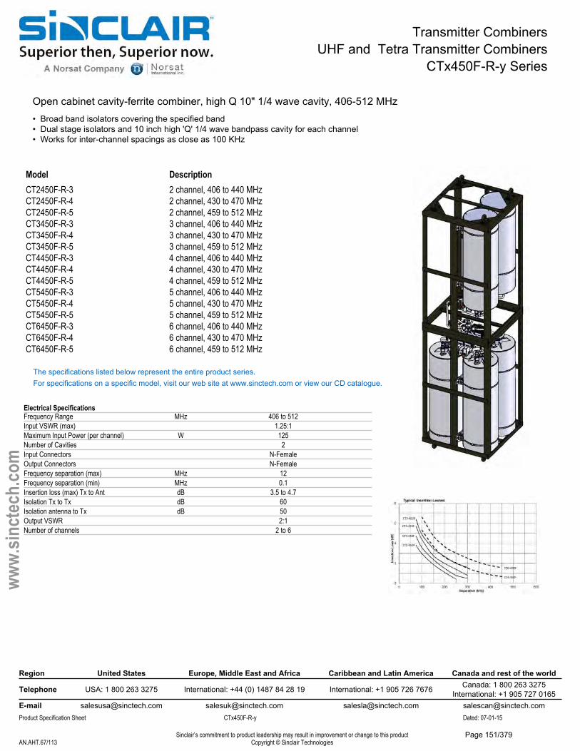
Transmitter CombinersUHF and Tetra Transmitter Combiners
CTx450F-R-y Series
Open cabinet cavity-ferrite combiner, high Q 10" 1/4 wave cavity, 406-512 MHz• Broad band isolators covering the specified band• Dual stage isolators and 10 inch high 'Q' 1/4 wave bandpass cavity for each channel• Works for inter-channel spacings as close as 100 KHz
Model DescriptionCT2450F-R-3 2 channel, 406 to 440 MHzCT2450F-R-4 2 channel, 430 to 470 MHzCT2450F-R-5 2 channel, 459 to 512 MHzCT3450F-R-3 3 channel, 406 to 440 MHzCT3450F-R-4 3 channel, 430 to 470 MHzCT3450F-R-5 3 channel, 459 to 512 MHzCT4450F-R-3 4 channel, 406 to 440 MHzCT4450F-R-4 4 channel, 430 to 470 MHzCT4450F-R-5 4 channel, 459 to 512 MHzCT5450F-R-3 5 channel, 406 to 440 MHzCT5450F-R-4 5 channel, 430 to 470 MHzCT5450F-R-5 5 channel, 459 to 512 MHzCT6450F-R-3 6 channel, 406 to 440 MHzCT6450F-R-4 6 channel, 430 to 470 MHzCT6450F-R-5 6 channel, 459 to 512 MHz
The specifications listed below represent the entire product series.For specifications on a specific model, visit our web site at www.sinctech.com or view our CD catalogue.
Electrical SpecificationsFrequency Range MHz 406 to 512Input VSWR (max) 1.25:1Maximum Input Power (per channel) W 125Number of Cavities 2Input Connectors N-FemaleOutput Connectors N-FemaleFrequency separation (max) MHz 12Frequency separation (min) MHz 0.1Insertion loss (max) Tx to Ant dB 3.5 to 4.7Isolation Tx to Tx dB 60Isolation antenna to Tx dB 50Output VSWR 2:1Number of channels 2 to 6
Region United States Europe, Middle East and Africa Caribbean and Latin America Canada and rest of the world
Telephone USA: 1 800 263 3275 International: +44 (0) 1487 84 28 19 International: +1 905 726 7676 Canada: 1 800 263 3275International: +1 905 727 0165
E-mail [email protected] [email protected] [email protected] [email protected] Specification Sheet CTx450F-R-y Dated: 07-01-15
Sinclair’s commitment to product leadership may result in improvement or change to this productCopyright © Sinclair TechnologiesAN.AHT.67/113
www.
sinct
ech.
com
Page 151/379
Transmitter CombinersUHF and Tetra Transmitter Combiners
CTx450F-R-y Series
Mechanical SpecificationsDepth in (mm) 21 (533)Length/ Height in (mm) 38 (965)Width in (mm) 21 (533)Weight lbs (kg) 60 to 120 (27.24 to 54.48)Finish chemical conversionActual Shipping weight lbs (kg) 65 to 125 (29.51 to 56.75)Shipping dimensions in (mm) L 22in W 22in H 43in
Environmental SpecificationsTemperature range °F (°C) -22 to +140 (-30 to +60)
Region United States Europe, Middle East and Africa Caribbean and Latin America Canada and rest of the world
Telephone USA: 1 800 263 3275 International: +44 (0) 1487 84 28 19 International: +1 905 726 7676 Canada: 1 800 263 3275International: +1 905 727 0165
E-mail [email protected] [email protected] [email protected] [email protected] Specification Sheet CTx450F-R-y Dated: 07-01-15
Sinclair’s commitment to product leadership may result in improvement or change to this productCopyright © Sinclair TechnologiesAN.AHT.68/113
www.
sinct
ech.
com
Page 152/379
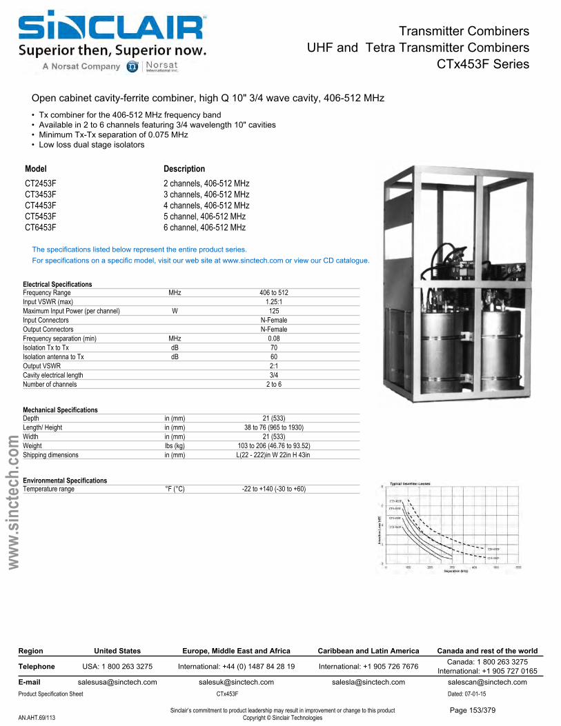
Transmitter CombinersUHF and Tetra Transmitter Combiners
CTx453F Series
Open cabinet cavity-ferrite combiner, high Q 10" 3/4 wave cavity, 406-512 MHz• Tx combiner for the 406-512 MHz frequency band• Available in 2 to 6 channels featuring 3/4 wavelength 10" cavities• Minimum Tx-Tx separation of 0.075 MHz• Low loss dual stage isolators
Model DescriptionCT2453F 2 channels, 406-512 MHzCT3453F 3 channels, 406-512 MHzCT4453F 4 channels, 406-512 MHzCT5453F 5 channel, 406-512 MHzCT6453F 6 channel, 406-512 MHz
The specifications listed below represent the entire product series.For specifications on a specific model, visit our web site at www.sinctech.com or view our CD catalogue.
Electrical SpecificationsFrequency Range MHz 406 to 512Input VSWR (max) 1.25:1Maximum Input Power (per channel) W 125Input Connectors N-FemaleOutput Connectors N-FemaleFrequency separation (min) MHz 0.08Isolation Tx to Tx dB 70Isolation antenna to Tx dB 60Output VSWR 2:1Cavity electrical length 3/4Number of channels 2 to 6
Mechanical SpecificationsDepth in (mm) 21 (533)Length/ Height in (mm) 38 to 76 (965 to 1930)Width in (mm) 21 (533)Weight lbs (kg) 103 to 206 (46.76 to 93.52)Shipping dimensions in (mm) L(22 - 222)in W 22in H 43in
Environmental SpecificationsTemperature range °F (°C) -22 to +140 (-30 to +60)
Region United States Europe, Middle East and Africa Caribbean and Latin America Canada and rest of the world
Telephone USA: 1 800 263 3275 International: +44 (0) 1487 84 28 19 International: +1 905 726 7676 Canada: 1 800 263 3275International: +1 905 727 0165
E-mail [email protected] [email protected] [email protected] [email protected] Specification Sheet CTx453F Dated: 07-01-15
Sinclair’s commitment to product leadership may result in improvement or change to this productCopyright © Sinclair TechnologiesAN.AHT.69/113
www.
sinct
ech.
com
Page 153/379
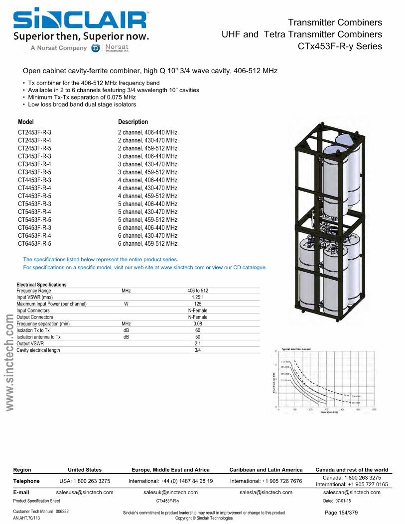
Transmitter CombinersUHF and Tetra Transmitter Combiners
CTx453F-R-y Series
Open cabinet cavity-ferrite combiner, high Q 10" 3/4 wave cavity, 406-512 MHz• Tx combiner for the 406-512 MHz frequency band• Available in 2 to 6 channels featuring 3/4 wavelength 10" cavities• Minimum Tx-Tx separation of 0.075 MHz• Low loss broad band dual stage isolators
Model DescriptionCT2453F-R-3 2 channel, 406-440 MHzCT2453F-R-4 2 channel, 430-470 MHzCT2453F-R-5 2 channel, 459-512 MHzCT3453F-R-3 3 channel, 406-440 MHzCT3453F-R-4 3 channel, 430-470 MHzCT3453F-R-5 3 channel, 459-512 MHzCT4453F-R-3 4 channel, 406-440 MHzCT4453F-R-4 4 channel, 430-470 MHzCT4453F-R-5 4 channel, 459-512 MHzCT5453F-R-3 5 channel, 406-440 MHzCT5453F-R-4 5 channel, 430-470 MHzCT5453F-R-5 5 channel, 459-512 MHzCT6453F-R-3 6 channel, 406-440 MHzCT6453F-R-4 6 channel, 430-470 MHzCT6453F-R-5 6 channel, 459-512 MHz
The specifications listed below represent the entire product series.For specifications on a specific model, visit our web site at www.sinctech.com or view our CD catalogue.
Electrical SpecificationsFrequency Range MHz 406 to 512Input VSWR (max) 1.25:1Maximum Input Power (per channel) W 125Input Connectors N-FemaleOutput Connectors N-FemaleFrequency separation (min) MHz 0.08Isolation Tx to Tx dB 60Isolation antenna to Tx dB 50Output VSWR 2:1Cavity electrical length 3/4
Region United States Europe, Middle East and Africa Caribbean and Latin America Canada and rest of the world
Telephone USA: 1 800 263 3275 International: +44 (0) 1487 84 28 19 International: +1 905 726 7676 Canada: 1 800 263 3275International: +1 905 727 0165
E-mail [email protected] [email protected] [email protected] [email protected] Specification Sheet CTx453F-R-y Dated: 07-01-15
Customer Tech Manual 006282 Sinclair’s commitment to product leadership may result in improvement or change to this productCopyright © Sinclair TechnologiesAN.AHT.70/113
www.
sinct
ech.
com
Page 154/379

Transmitter CombinersUHF and Tetra Transmitter Combiners
CTx453F-R-y Series
Mechanical SpecificationsDepth in (mm) 21 (533)Length/ Height in (mm) 38 to 76 (965 to 1930)Width in (mm) 21 (533)Weight lbs (kg) 103 to 206 (46.76 to 93.52)
Environmental SpecificationsTemperature range °F (°C) -22 to +140 (-30 to +60)
Ordering InformationSpecify one Tx frequency per channel
Region United States Europe, Middle East and Africa Caribbean and Latin America Canada and rest of the world
Telephone USA: 1 800 263 3275 International: +44 (0) 1487 84 28 19 International: +1 905 726 7676 Canada: 1 800 263 3275International: +1 905 727 0165
E-mail [email protected] [email protected] [email protected] [email protected] Specification Sheet CTx453F-R-y Dated: 07-01-15
Customer Tech Manual 006282 Sinclair’s commitment to product leadership may result in improvement or change to this productCopyright © Sinclair TechnologiesAN.AHT.71/113
www.
sinct
ech.
com
Page 155/379
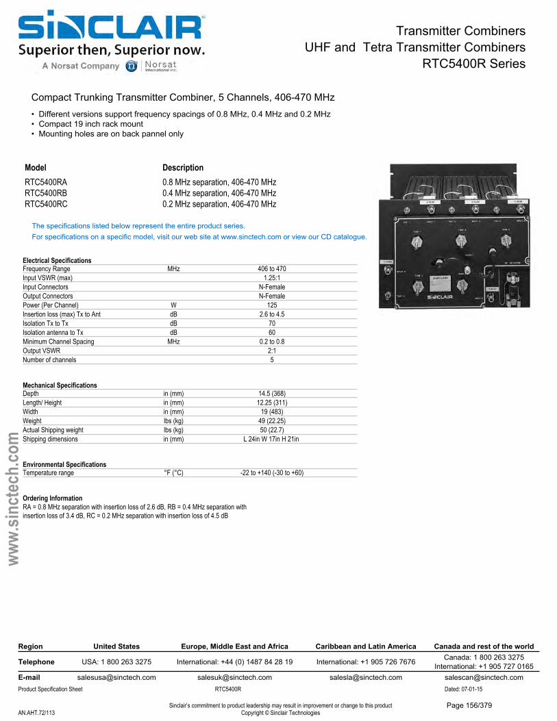
Transmitter CombinersUHF and Tetra Transmitter Combiners
RTC5400R Series
Compact Trunking Transmitter Combiner, 5 Channels, 406-470 MHz• Different versions support frequency spacings of 0.8 MHz, 0.4 MHz and 0.2 MHz• Compact 19 inch rack mount• Mounting holes are on back pannel only
Model DescriptionRTC5400RA 0.8 MHz separation, 406-470 MHzRTC5400RB 0.4 MHz separation, 406-470 MHzRTC5400RC 0.2 MHz separation, 406-470 MHz
The specifications listed below represent the entire product series.For specifications on a specific model, visit our web site at www.sinctech.com or view our CD catalogue.
Electrical SpecificationsFrequency Range MHz 406 to 470Input VSWR (max) 1.25:1Input Connectors N-FemaleOutput Connectors N-FemalePower (Per Channel) W 125Insertion loss (max) Tx to Ant dB 2.6 to 4.5Isolation Tx to Tx dB 70Isolation antenna to Tx dB 60Minimum Channel Spacing MHz 0.2 to 0.8Output VSWR 2:1Number of channels 5
Mechanical SpecificationsDepth in (mm) 14.5 (368)Length/ Height in (mm) 12.25 (311)Width in (mm) 19 (483)Weight lbs (kg) 49 (22.25)Actual Shipping weight lbs (kg) 50 (22.7)Shipping dimensions in (mm) L 24in W 17in H 21in
Environmental SpecificationsTemperature range °F (°C) -22 to +140 (-30 to +60)
Ordering InformationRA = 0.8 MHz separation with insertion loss of 2.6 dB, RB = 0.4 MHz separation withinsertion loss of 3.4 dB, RC = 0.2 MHz separation with insertion loss of 4.5 dB
Region United States Europe, Middle East and Africa Caribbean and Latin America Canada and rest of the world
Telephone USA: 1 800 263 3275 International: +44 (0) 1487 84 28 19 International: +1 905 726 7676 Canada: 1 800 263 3275International: +1 905 727 0165
E-mail [email protected] [email protected] [email protected] [email protected] Specification Sheet RTC5400R Dated: 07-01-15
Sinclair’s commitment to product leadership may result in improvement or change to this productCopyright © Sinclair TechnologiesAN.AHT.72/113
www.
sinct
ech.
com
Page 156/379
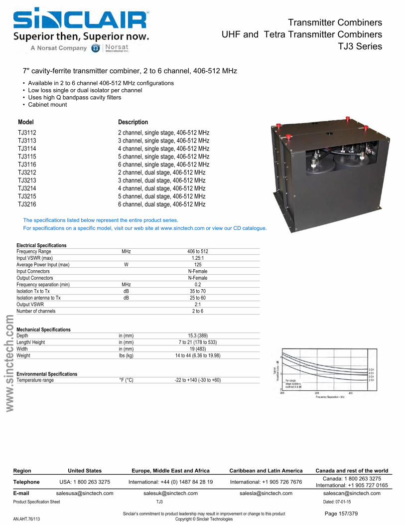
Transmitter CombinersUHF and Tetra Transmitter Combiners
TJ3 Series
7" cavity-ferrite transmitter combiner, 2 to 6 channel, 406-512 MHz• Available in 2 to 6 channel 406-512 MHz configurations• Low loss single or dual isolator per channel• Uses high Q bandpass cavity filters• Cabinet mount
Model DescriptionTJ3112 2 channel, single stage, 406-512 MHzTJ3113 3 channel, single stage, 406-512 MHzTJ3114 4 channel, single stage, 406-512 MHzTJ3115 5 channel, single stage, 406-512 MHzTJ3116 6 channel, single stage, 406-512 MHzTJ3212 2 channel, dual stage, 406-512 MHzTJ3213 3 channel, dual stage, 406-512 MHzTJ3214 4 channel, dual stage, 406-512 MHzTJ3215 5 channel, dual stage, 406-512 MHzTJ3216 6 channel, dual stage, 406-512 MHz
The specifications listed below represent the entire product series.For specifications on a specific model, visit our web site at www.sinctech.com or view our CD catalogue.
Electrical SpecificationsFrequency Range MHz 406 to 512Input VSWR (max) 1.25:1Average Power Input (max) W 125Input Connectors N-FemaleOutput Connectors N-FemaleFrequency separation (min) MHz 0.2Isolation Tx to Tx dB 35 to 70Isolation antenna to Tx dB 25 to 60Output VSWR 2:1Number of channels 2 to 6
Mechanical SpecificationsDepth in (mm) 15.3 (389)Length/ Height in (mm) 7 to 21 (178 to 533)Width in (mm) 19 (483)Weight lbs (kg) 14 to 44 (6.36 to 19.98)
Environmental SpecificationsTemperature range °F (°C) -22 to +140 (-30 to +60)
Region United States Europe, Middle East and Africa Caribbean and Latin America Canada and rest of the world
Telephone USA: 1 800 263 3275 International: +44 (0) 1487 84 28 19 International: +1 905 726 7676 Canada: 1 800 263 3275International: +1 905 727 0165
E-mail [email protected] [email protected] [email protected] [email protected] Specification Sheet TJ3 Dated: 07-01-15
Sinclair’s commitment to product leadership may result in improvement or change to this productCopyright © Sinclair TechnologiesAN.AHT.76/113
www.
sinct
ech.
com
Page 157/379
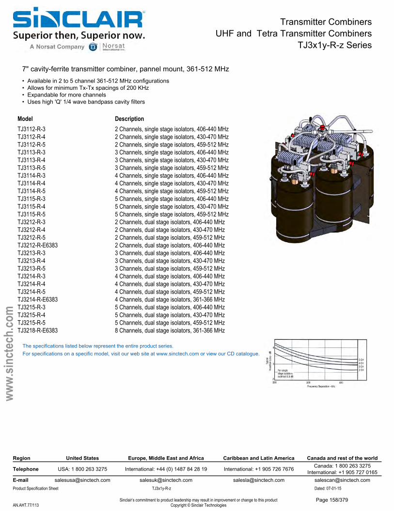
Transmitter CombinersUHF and Tetra Transmitter Combiners
TJ3x1y-R-z Series
7" cavity-ferrite transmitter combiner, pannel mount, 361-512 MHz• Available in 2 to 5 channel 361-512 MHz configurations• Allows for minimum Tx-Tx spacings of 200 KHz• Expandable for more channels• Uses high 'Q' 1/4 wave bandpass cavity filters
Model DescriptionTJ3112-R-3 2 Channels, single stage isolators, 406-440 MHzTJ3112-R-4 2 Channels, single stage isolators, 430-470 MHzTJ3112-R-5 2 Channels, single stage isolators, 459-512 MHzTJ3113-R-3 3 Channels, single stage isolators, 406-440 MHzTJ3113-R-4 3 Channels, single stage isolators, 430-470 MHzTJ3113-R-5 3 Channels, single stage isolators, 459-512 MHzTJ3114-R-3 4 Channels, single stage isolators, 406-440 MHzTJ3114-R-4 4 Channels, single stage isolators, 430-470 MHzTJ3114-R-5 4 Channels, single stage isolators, 459-512 MHzTJ3115-R-3 5 Channels, single stage isolators, 406-440 MHzTJ3115-R-4 5 Channels, single stage isolators, 430-470 MHzTJ3115-R-5 5 Channels, single stage isolators, 459-512 MHzTJ3212-R-3 2 Channels, dual stage isolators, 406-440 MHzTJ3212-R-4 2 Channels, dual stage isolators, 430-470 MHzTJ3212-R-5 2 Channels, dual stage isolators, 459-512 MHzTJ3212-R-E6383 2 Channels, dual stage isolators, 406-440 MHzTJ3213-R-3 3 Channels, dual stage isolators, 406-440 MHzTJ3213-R-4 3 Channels, dual stage isolators, 430-470 MHzTJ3213-R-5 3 Channels, dual stage isolators, 459-512 MHzTJ3214-R-3 4 Channels, dual stage isolators, 406-440 MHzTJ3214-R-4 4 Channels, dual stage isolators, 430-470 MHzTJ3214-R-5 4 Channels, dual stage isolators, 459-512 MHzTJ3214-R-E6383 4 Channels, dual stage isolators, 361-366 MHzTJ3215-R-3 5 Channels, dual stage isolators, 406-440 MHzTJ3215-R-4 5 Channels, dual stage isolators, 430-470 MHzTJ3215-R-5 5 Channels, dual stage isolators, 459-512 MHzTJ3218-R-E6383 8 Channels, dual stage isolators, 361-366 MHz
The specifications listed below represent the entire product series.For specifications on a specific model, visit our web site at www.sinctech.com or view our CD catalogue.
Region United States Europe, Middle East and Africa Caribbean and Latin America Canada and rest of the world
Telephone USA: 1 800 263 3275 International: +44 (0) 1487 84 28 19 International: +1 905 726 7676 Canada: 1 800 263 3275International: +1 905 727 0165
E-mail [email protected] [email protected] [email protected] [email protected] Specification Sheet TJ3x1y-R-z Dated: 07-01-15
Sinclair’s commitment to product leadership may result in improvement or change to this productCopyright © Sinclair TechnologiesAN.AHT.77/113
www.
sinct
ech.
com
Page 158/379
Transmitter CombinersUHF and Tetra Transmitter Combiners
TJ3x1y-R-z Series
Electrical SpecificationsFrequency Range MHz 361 to 512Input VSWR (max) 1.25:1Maximum Input Power (per channel) W 125Number of Cavities 2 to 8Input Connectors N-FemaleOutput Connectors N-FemaleFrequency separation (min) MHz 0.2 to 0.25Isolation Tx to Tx dB 35 to 70Isolation antenna to Tx dB 25 to 60Output VSWR 2:1Cavity electrical length 1/4Number of channels 2 to 5
Region United States Europe, Middle East and Africa Caribbean and Latin America Canada and rest of the world
Telephone USA: 1 800 263 3275 International: +44 (0) 1487 84 28 19 International: +1 905 726 7676 Canada: 1 800 263 3275International: +1 905 727 0165
E-mail [email protected] [email protected] [email protected] [email protected] Specification Sheet TJ3x1y-R-z Dated: 07-01-15
Sinclair’s commitment to product leadership may result in improvement or change to this productCopyright © Sinclair TechnologiesAN.AHT.78/113
www.
sinct
ech.
com
Mechanical SpecificationsDepth in (mm) 7 to 20.8 (178 to 528)Length/ Height in (mm) 15.3 to 40 (389 to 1016)Width in (mm) 19 (483)
Environmental SpecificationsTemperature range °F (°C) -22 to +140 (-30 to +60)
Ordering InformationSpecify one Tx frequency per channel at time of order.
Page 159/379
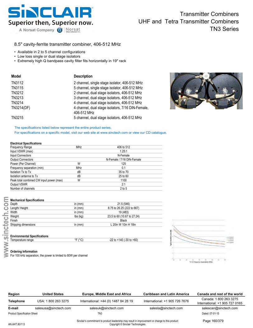
Transmitter CombinersUHF and Tetra Transmitter Combiners
TN3 Series
8.5" cavity-ferrite transmitter combiner, 406-512 MHz• Available in 2 to 5 channel configurations• Low loss single or dual stage isolators• Extremely high Q bandpass cavity filter fits horizontally in 19" rack
Model DescriptionTN3112 2 channel, single stage isolator, 406-512 MHzTN3115 5 channel, single stage isolator, 406-512 MHzTN3212 2 channel, dual stage isolators, 406-512 MHzTN3213 3 channel, dual stage isolators, 406-512 MHzTN3214 4 channel, dual stage isolators, 406-512 MHzTN3214(DF) 4 channel, dual stage isolators, 7/16 DIN-Female,
406-512 MHzTN3215 5 channel, dual stage isolators, 406-512 MHz
The specifications listed below represent the entire product series.For specifications on a specific model, visit our web site at www.sinctech.com or view our CD catalogue.
Electrical SpecificationsFrequency Range MHz 406 to 512Input VSWR (max) 1.25:1Input Connectors N-FemaleOutput Connectors N-Female / 7/16 DIN-FemalePower (Per Channel) W 125Frequency separation (min) MHz 0.1Isolation Tx to Tx dB 35 to 70Isolation antenna to Tx dB 25 to 60Peak total combined CW input power (max) W 1100Output VSWR 2:1Number of channels 2 to 5
Mechanical SpecificationsDepth in (mm) 21.5 (546)Length/ Height in (mm) 8.75 to 26.25 (222 to 667)Width in (mm) 19 (483)Weight lbs (kg) 23.5 to 60 (10.67 to 27.24)Finish BlackShipping dimensions in (mm) L 20in W 10in H 18in
Environmental SpecificationsTemperature range °F (°C) -22 to +140 (-30 to +60)
Ordering InformationFor 100 kHz separation, the power is limited to 80W per channel
Region United States Europe, Middle East and Africa Caribbean and Latin America Canada and rest of the world
Telephone USA: 1 800 263 3275 International: +44 (0) 1487 84 28 19 International: +1 905 726 7676 Canada: 1 800 263 3275International: +1 905 727 0165
E-mail [email protected] [email protected] [email protected] [email protected] Specification Sheet TN3 Dated: 07-01-15
Sinclair’s commitment to product leadership may result in improvement or change to this productCopyright © Sinclair TechnologiesAN.AHT.80/113
www.
sinct
ech.
com
Page 160/379
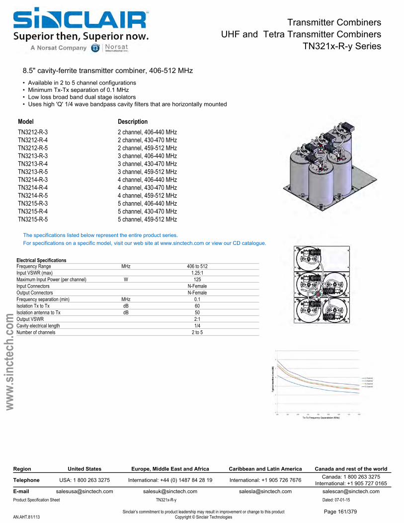
Transmitter CombinersUHF and Tetra Transmitter Combiners
TN321x-R-y Series
8.5" cavity-ferrite transmitter combiner, 406-512 MHz• Available in 2 to 5 channel configurations• Minimum Tx-Tx separation of 0.1 MHz• Low loss broad band dual stage isolators• Uses high 'Q' 1/4 wave bandpass cavity filters that are horizontally mounted
Model DescriptionTN3212-R-3 2 channel, 406-440 MHzTN3212-R-4 2 channel, 430-470 MHzTN3212-R-5 2 channel, 459-512 MHzTN3213-R-3 3 channel, 406-440 MHzTN3213-R-4 3 channel, 430-470 MHzTN3213-R-5 3 channel, 459-512 MHzTN3214-R-3 4 channel, 406-440 MHzTN3214-R-4 4 channel, 430-470 MHzTN3214-R-5 4 channel, 459-512 MHzTN3215-R-3 5 channel, 406-440 MHzTN3215-R-4 5 channel, 430-470 MHzTN3215-R-5 5 channel, 459-512 MHz
The specifications listed below represent the entire product series.For specifications on a specific model, visit our web site at www.sinctech.com or view our CD catalogue.
Electrical SpecificationsFrequency Range MHz 406 to 512Input VSWR (max) 1.25:1Maximum Input Power (per channel) W 125Input Connectors N-FemaleOutput Connectors N-FemaleFrequency separation (min) MHz 0.1Isolation Tx to Tx dB 60Isolation antenna to Tx dB 50Output VSWR 2:1Cavity electrical length 1/4Number of channels 2 to 5
Region United States Europe, Middle East and Africa Caribbean and Latin America Canada and rest of the world
Telephone USA: 1 800 263 3275 International: +44 (0) 1487 84 28 19 International: +1 905 726 7676 Canada: 1 800 263 3275International: +1 905 727 0165
E-mail [email protected] [email protected] [email protected] [email protected] Specification Sheet TN321x-R-y Dated: 07-01-15
Sinclair’s commitment to product leadership may result in improvement or change to this productCopyright © Sinclair TechnologiesAN.AHT.81/113
www.
sinct
ech.
com
Page 161/379

Transmitter CombinersUHF and Tetra Transmitter Combiners
TN321x-R-y Series
Mechanical SpecificationsDepth in (mm) 21.5 (546)Length/ Height in (mm) 8.75 to 26.25 (222 to 667)Width in (mm) 19 (483)Weight lbs (kg) 23.5 to 60 (10.67 to 27.24)Finish BlackShipping dimensions in (mm) L 17in W 22in H 22in
Environmental SpecificationsTemperature range °F (°C) -22 to +140 (-30 to +60)
Ordering InformationSpecify one Tx frequency per channel.For 100 kHz separation, the power is limited to 80W per channel.
Region United States Europe, Middle East and Africa Caribbean and Latin America Canada and rest of the world
Telephone USA: 1 800 263 3275 International: +44 (0) 1487 84 28 19 International: +1 905 726 7676 Canada: 1 800 263 3275International: +1 905 727 0165
E-mail [email protected] [email protected] [email protected] [email protected] Specification Sheet TN321x-R-y Dated: 07-01-15
Sinclair’s commitment to product leadership may result in improvement or change to this productCopyright © Sinclair TechnologiesAN.AHT.82/113
www.
sinct
ech.
com
Page 162/379
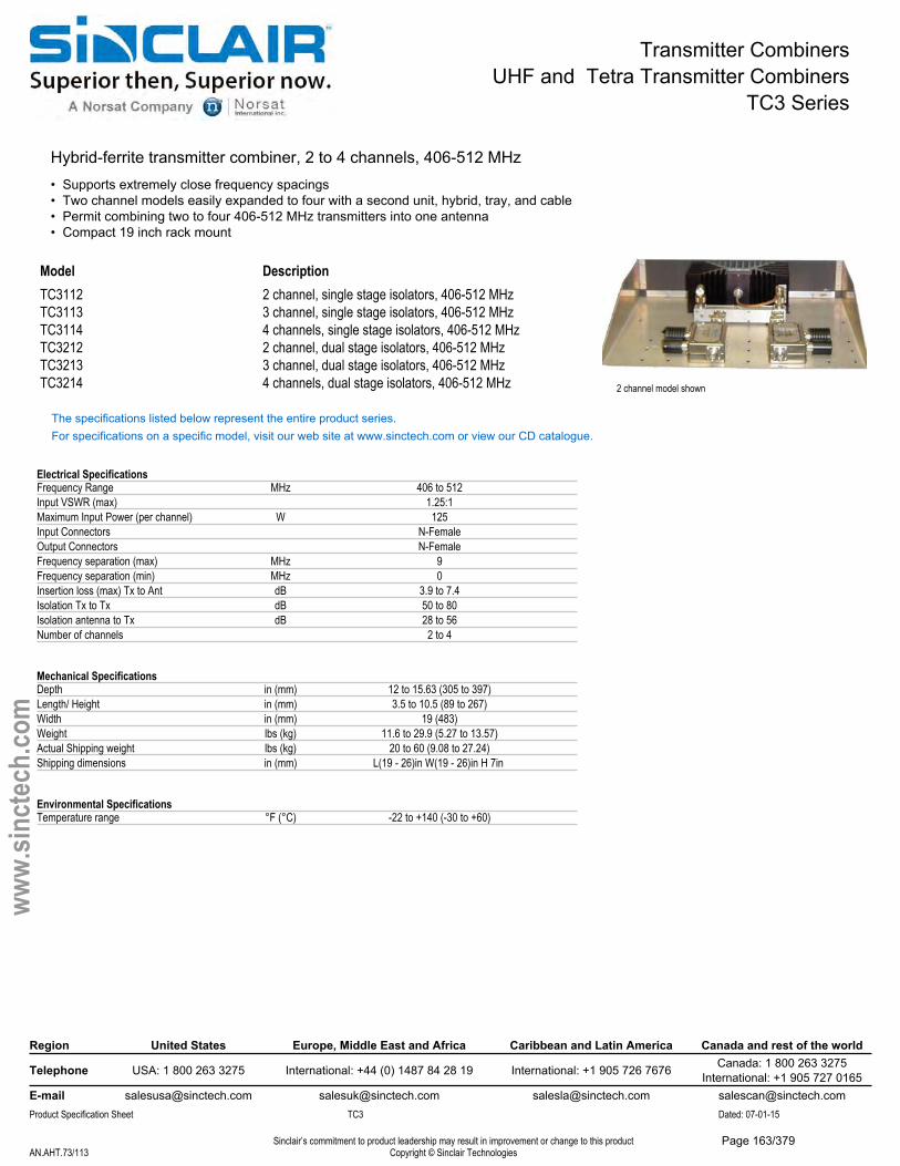
Transmitter CombinersUHF and Tetra Transmitter Combiners
TC3 Series
Hybrid-ferrite transmitter combiner, 2 to 4 channels, 406-512 MHz• Supports extremely close frequency spacings• Two channel models easily expanded to four with a second unit, hybrid, tray, and cable• Permit combining two to four 406-512 MHz transmitters into one antenna• Compact 19 inch rack mount
2 channel model shown
Model DescriptionTC3112 2 channel, single stage isolators, 406-512 MHzTC3113 3 channel, single stage isolators, 406-512 MHzTC3114 4 channels, single stage isolators, 406-512 MHzTC3212 2 channel, dual stage isolators, 406-512 MHzTC3213 3 channel, dual stage isolators, 406-512 MHzTC3214 4 channels, dual stage isolators, 406-512 MHz
The specifications listed below represent the entire product series.For specifications on a specific model, visit our web site at www.sinctech.com or view our CD catalogue.
Electrical SpecificationsFrequency Range MHz 406 to 512Input VSWR (max) 1.25:1Maximum Input Power (per channel) W 125Input Connectors N-FemaleOutput Connectors N-FemaleFrequency separation (max) MHz 9Frequency separation (min) MHz 0Insertion loss (max) Tx to Ant dB 3.9 to 7.4Isolation Tx to Tx dB 50 to 80Isolation antenna to Tx dB 28 to 56Number of channels 2 to 4
Mechanical SpecificationsDepth in (mm) 12 to 15.63 (305 to 397)Length/ Height in (mm) 3.5 to 10.5 (89 to 267)Width in (mm) 19 (483)Weight lbs (kg) 11.6 to 29.9 (5.27 to 13.57)Actual Shipping weight lbs (kg) 20 to 60 (9.08 to 27.24)Shipping dimensions in (mm) L(19 - 26)in W(19 - 26)in H 7in
Environmental SpecificationsTemperature range °F (°C) -22 to +140 (-30 to +60)
Region United States Europe, Middle East and Africa Caribbean and Latin America Canada and rest of the world
Telephone USA: 1 800 263 3275 International: +44 (0) 1487 84 28 19 International: +1 905 726 7676 Canada: 1 800 263 3275International: +1 905 727 0165
E-mail [email protected] [email protected] [email protected] [email protected] Specification Sheet TC3 Dated: 07-01-15
Sinclair’s commitment to product leadership may result in improvement or change to this productCopyright © Sinclair TechnologiesAN.AHT.73/113
www.
sinct
ech.
com
Page 163/379
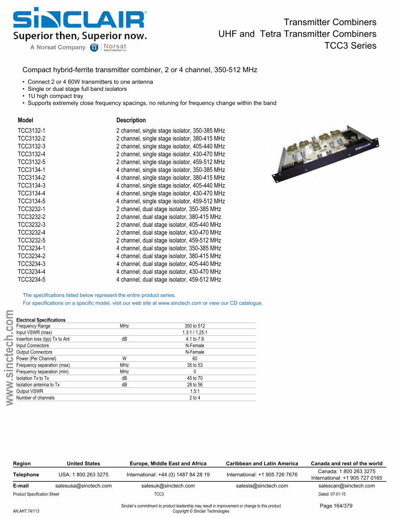
Transmitter CombinersUHF and Tetra Transmitter Combiners
TCC3 Series
Compact hybrid-ferrite transmitter combiner, 2 or 4 channel, 350-512 MHz• Connect 2 or 4 60W transmitters to one antenna• Single or dual stage full band isolators• 1U high compact tray• Supports extremely close frequency spacings, no retuning for frequency change within the band
Model DescriptionTCC3132-1 2 channel, single stage isolator, 350-385 MHzTCC3132-2 2 channel, single stage isolator, 380-415 MHzTCC3132-3 2 channel, single stage isolator, 405-440 MHzTCC3132-4 2 channel, single stage isolator, 430-470 MHzTCC3132-5 2 channel, single stage isolator, 459-512 MHzTCC3134-1 4 channel, single stage isolator, 350-385 MHzTCC3134-2 4 channel, single stage isolator, 380-415 MHzTCC3134-3 4 channel, single stage isolator, 405-440 MHzTCC3134-4 4 channel, single stage isolator, 430-470 MHzTCC3134-5 4 channel, single stage isolator, 459-512 MHzTCC3232-1 2 channel, dual stage isolator, 350-385 MHzTCC3232-2 2 channel, dual stage isolator, 380-415 MHzTCC3232-3 2 channel, dual stage isolator, 405-440 MHzTCC3232-4 2 channel, dual stage isolator, 430-470 MHzTCC3232-5 2 channel, dual stage isolator, 459-512 MHzTCC3234-1 4 channel, dual stage isolator, 350-385 MHzTCC3234-2 4 channel, dual stage isolator, 380-415 MHzTCC3234-3 4 channel, dual stage isolator, 405-440 MHzTCC3234-4 4 channel, dual stage isolator, 430-470 MHzTCC3234-5 4 channel, dual stage isolator, 459-512 MHz
The specifications listed below represent the entire product series.For specifications on a specific model, visit our web site at www.sinctech.com or view our CD catalogue.
Electrical SpecificationsFrequency Range MHz 350 to 512Input VSWR (max) 1.3:1 / 1.25:1Insertion loss (typ) Tx to Ant dB 4.1 to 7.8Input Connectors N-FemaleOutput Connectors N-FemalePower (Per Channel) W 60Frequency separation (max) MHz 35 to 53Frequency separation (min) MHz 0Isolation Tx to Tx dB 45 to 70Isolation antenna to Tx dB 28 to 56Output VSWR 1.5:1Number of channels 2 to 4
Region United States Europe, Middle East and Africa Caribbean and Latin America Canada and rest of the world
Telephone USA: 1 800 263 3275 International: +44 (0) 1487 84 28 19 International: +1 905 726 7676 Canada: 1 800 263 3275International: +1 905 727 0165
E-mail [email protected] [email protected] [email protected] [email protected] Specification Sheet TCC3 Dated: 07-01-15
Sinclair’s commitment to product leadership may result in improvement or change to this productCopyright © Sinclair TechnologiesAN.AHT.74/113
www.
sinct
ech.
com
Page 164/379

Transmitter CombinersUHF and Tetra Transmitter Combiners
TCC3 Series
Mechanical SpecificationsDepth in (mm) 10 to 14.6 (254 to 371)Length/ Height in (mm) 1.75 (44)Width in (mm) 19 (483)Weight lbs (kg) 10 to 18 (4.54 to 8.17)Shipping dimensions in (mm) L 26in W 19in H 7in
Environmental SpecificationsTemperature range °F (°C) -22 to +140 (-30 to +60)
Region United States Europe, Middle East and Africa Caribbean and Latin America Canada and rest of the world
Telephone USA: 1 800 263 3275 International: +44 (0) 1487 84 28 19 International: +1 905 726 7676 Canada: 1 800 263 3275International: +1 905 727 0165
E-mail [email protected] [email protected] [email protected] [email protected] Specification Sheet TCC3 Dated: 07-01-15
Sinclair’s commitment to product leadership may result in improvement or change to this productCopyright © Sinclair TechnologiesAN.AHT.75/113
www.
sinct
ech.
com
Page 165/379
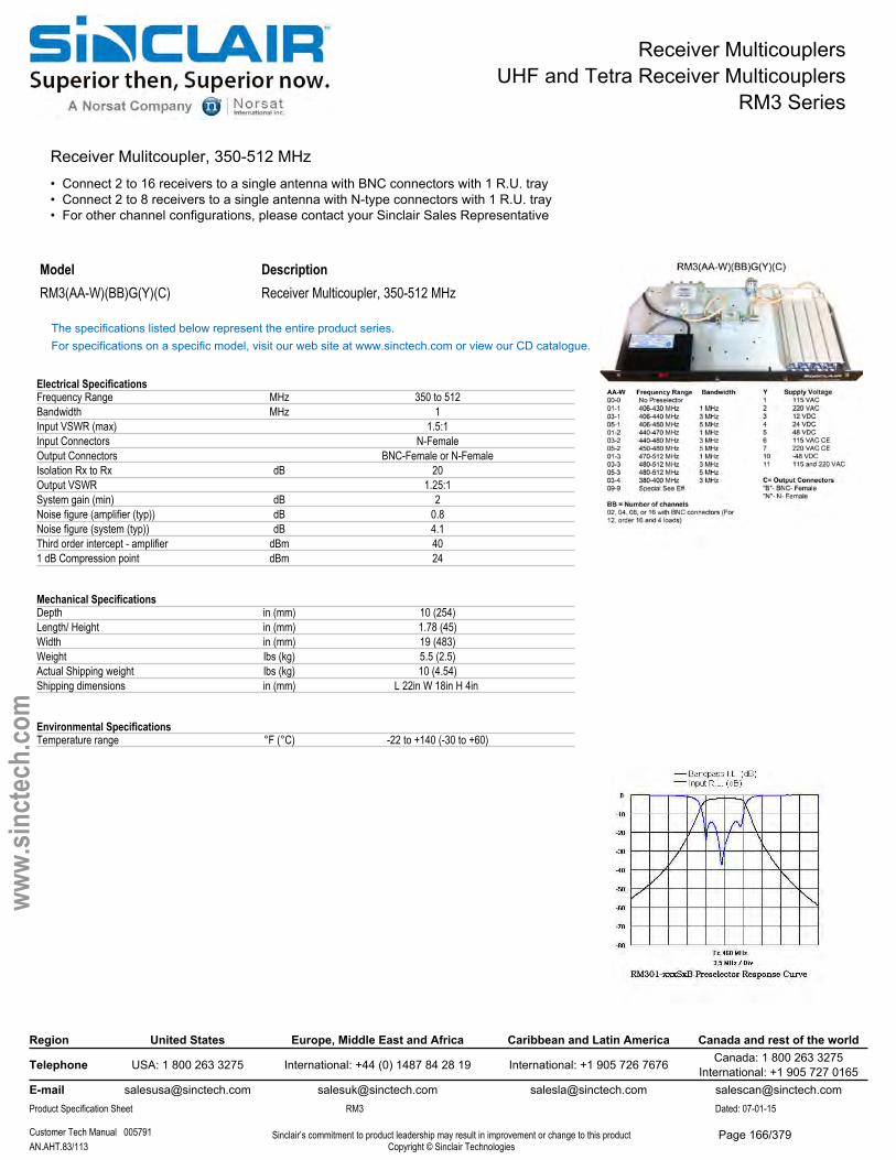
Receiver MulticouplersUHF and Tetra Receiver Multicouplers
RM3 Series
Receiver Mulitcoupler, 350-512 MHz• Connect 2 to 16 receivers to a single antenna with BNC connectors with 1 R.U. tray• Connect 2 to 8 receivers to a single antenna with N-type connectors with 1 R.U. tray• For other channel configurations, please contact your Sinclair Sales Representative
Model DescriptionRM3(AA-W)(BB)G(Y)(C) Receiver Multicoupler, 350-512 MHz
The specifications listed below represent the entire product series.For specifications on a specific model, visit our web site at www.sinctech.com or view our CD catalogue.
Electrical SpecificationsFrequency Range MHz 350 to 512Bandwidth MHz 1Input VSWR (max) 1.5:1Input Connectors N-FemaleOutput Connectors BNC-Female or N-FemaleIsolation Rx to Rx dB 20Output VSWR 1.25:1System gain (min) dB 2Noise figure (amplifier (typ)) dB 0.8Noise figure (system (typ)) dB 4.1Third order intercept - amplifier dBm 401 dB Compression point dBm 24
Mechanical SpecificationsDepth in (mm) 10 (254)Length/ Height in (mm) 1.78 (45)Width in (mm) 19 (483)Weight lbs (kg) 5.5 (2.5)Actual Shipping weight lbs (kg) 10 (4.54)Shipping dimensions in (mm) L 22in W 18in H 4in
Environmental SpecificationsTemperature range °F (°C) -22 to +140 (-30 to +60)
Region United States Europe, Middle East and Africa Caribbean and Latin America Canada and rest of the world
Telephone USA: 1 800 263 3275 International: +44 (0) 1487 84 28 19 International: +1 905 726 7676 Canada: 1 800 263 3275International: +1 905 727 0165
E-mail [email protected] [email protected] [email protected] [email protected] Specification Sheet RM3 Dated: 07-01-15
Customer Tech Manual 005791 Sinclair’s commitment to product leadership may result in improvement or change to this productCopyright © Sinclair TechnologiesAN.AHT.83/113
www.
sinct
ech.
com
Page 166/379
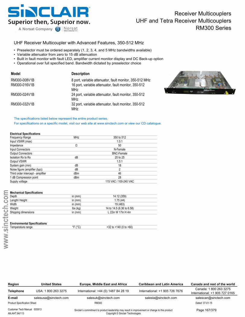
Receiver MulticouplersUHF and Tetra Receiver Multicouplers
RM300 Series
UHF Receiver Multicoupler with Advanced Features, 350-512 MHz• Preselector must be ordered separately (1, 2, 3, 4, and 5 MHz bandwidths available)• Variable attenuator from zero to 15 dB attenuation• Built in fault monitor with fault LED, amplifier current monitor display and DC Back-up option• Operational over full specified band. Bandwidth dictated by preselector choice
Model DescriptionRM300-008V1B 8 port, variable attenuator, fault monitor, 350-512 MHzRM300-016V1B 16 port, variable attenuator, fault monitor, 350-512
MHzRM300-024V1B 24 port, variable attenuator, fault monitor, 350-512
MHzRM300-032V1B 32 port, variable attenuator, fault monitor, 350-512
MHz
The specifications listed below represent the entire product series.For specifications on a specific model, visit our web site at www.sinctech.com or view our CD catalogue.
Electrical SpecificationsFrequency Range MHz 350 to 512Input VSWR (max) 1.5:1Impedance Ω 50Input Connectors N-FemaleOutput Connectors BNC-FemaleIsolation Rx to Rx dB 20 to 25Output VSWR 1.5:1System gain (min) dB 18Noise figure (amplifier (typ)) dB 2Third order intercept - amplifier dBm 461 dB Compression point dBm 28Supply voltage 115 VAC / 100-240 VAC
Mechanical SpecificationsDepth in (mm) 14.12 (359)Length/ Height in (mm) 1.75 (44)Width in (mm) 19 (483)Weight lbs (kg) 14 to 14.5 (6.36 to 6.58)Shipping dimensions in (mm) L 22in W 17in H 4in
Environmental SpecificationsTemperature range °F (°C) +32 to +140 (0 to +60)
Region United States Europe, Middle East and Africa Caribbean and Latin America Canada and rest of the world
Telephone USA: 1 800 263 3275 International: +44 (0) 1487 84 28 19 International: +1 905 726 7676 Canada: 1 800 263 3275International: +1 905 727 0165
E-mail [email protected] [email protected] [email protected] [email protected] Specification Sheet RM300 Dated: 07-01-15
Customer Tech Manual 005913 Sinclair’s commitment to product leadership may result in improvement or change to this productCopyright © Sinclair TechnologiesAN.AHT.84/113
www.
sinct
ech.
com
Page 167/379
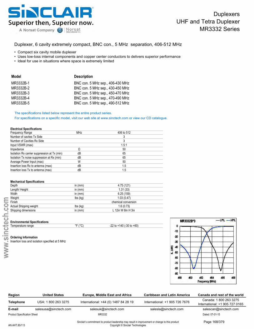
DuplexersUHF and Tetra Duplexer
MR3332 Series
Duplexer, 6 cavity extremely compact, BNC con., 5 MHz separation, 406-512 MHz• Compact six cavity mobile duplexer• Uses low-loss internal components and copper center conductors to delivers superior performance• Ideal for use in situations where space is extremely limited
Model DescriptionMR3332B-1 BNC con. 5 MHz sep., 406-430 MHzMR3332B-2 BNC con. 5 MHz sep., 430-450 MHzMR3332B-3 BNC con. 5 MHz sep., 450-470 MHzMR3332B-4 BNC con. 5 MHz sep., 470-490 MHzMR3332B-5 BNC con. 5 MHz sep., 490-512 MHz
The specifications listed below represent the entire product series.For specifications on a specific model, visit our web site at www.sinctech.com or view our CD catalogue.
Electrical SpecificationsFrequency Range MHz 406 to 512Number of cavites Tx Side 3Number of Cavities Rx Side 3Input VSWR (max) 1.5:1Impedance Ω 50Isolation Rx carrier suppression at Tx (min) dB 65Isolation Tx noise suppression at Rx (min) dB 65Average Power Input (max) W 50Insertion loss Rx to antenna (max) dB 1.5Insertion loss Tx to antenna (max) dB 1.5
Mechanical SpecificationsDepth in (mm) 4.75 (121)Length/ Height in (mm) 1.31 (33)Width in (mm) 6.25 (159)Weight lbs (kg) 1.03 (0.47)Finish chemical conversionActual Shipping weight lbs (kg) 1.6 (0.73)Shipping dimensions in (mm) L 12in W 8in H 3in
Environmental SpecificationsTemperature range °F (°C) -22 to +140 (-30 to +60)
Ordering InformationInsertion loss and isolation specified at 5 MHz
Region United States Europe, Middle East and Africa Caribbean and Latin America Canada and rest of the world
Telephone USA: 1 800 263 3275 International: +44 (0) 1487 84 28 19 International: +1 905 726 7676 Canada: 1 800 263 3275International: +1 905 727 0165
E-mail [email protected] [email protected] [email protected] [email protected] Specification Sheet MR3332 Dated: 07-01-15
Sinclair’s commitment to product leadership may result in improvement or change to this productCopyright © Sinclair TechnologiesAN.AHT.85/113
www.
sinct
ech.
com
Page 168/379
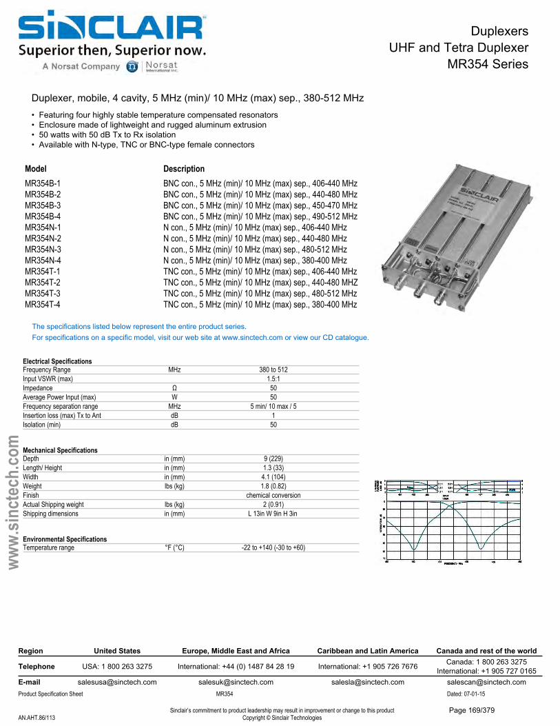
DuplexersUHF and Tetra Duplexer
MR354 Series
Duplexer, mobile, 4 cavity, 5 MHz (min)/ 10 MHz (max) sep., 380-512 MHz• Featuring four highly stable temperature compensated resonators• Enclosure made of lightweight and rugged aluminum extrusion• 50 watts with 50 dB Tx to Rx isolation• Available with N-type, TNC or BNC-type female connectors
Model DescriptionMR354B-1 BNC con., 5 MHz (min)/ 10 MHz (max) sep., 406-440 MHzMR354B-2 BNC con., 5 MHz (min)/ 10 MHz (max) sep., 440-480 MHzMR354B-3 BNC con., 5 MHz (min)/ 10 MHz (max) sep., 450-470 MHzMR354B-4 BNC con., 5 MHz (min)/ 10 MHz (max) sep., 490-512 MHzMR354N-1 N con., 5 MHz (min)/ 10 MHz (max) sep., 406-440 MHzMR354N-2 N con., 5 MHz (min)/ 10 MHz (max) sep., 440-480 MHzMR354N-3 N con., 5 MHz (min)/ 10 MHz (max) sep., 480-512 MHzMR354N-4 N con., 5 MHz (min)/ 10 MHz (max) sep., 380-400 MHzMR354T-1 TNC con., 5 MHz (min)/ 10 MHz (max) sep., 406-440 MHzMR354T-2 TNC con., 5 MHz (min)/ 10 MHz (max) sep., 440-480 MHZMR354T-3 TNC con., 5 MHz (min)/ 10 MHz (max) sep., 480-512 MHzMR354T-4 TNC con., 5 MHz (min)/ 10 MHz (max) sep., 380-400 MHz
The specifications listed below represent the entire product series.For specifications on a specific model, visit our web site at www.sinctech.com or view our CD catalogue.
Electrical SpecificationsFrequency Range MHz 380 to 512Input VSWR (max) 1.5:1Impedance Ω 50Average Power Input (max) W 50Frequency separation range MHz 5 min/ 10 max / 5Insertion loss (max) Tx to Ant dB 1Isolation (min) dB 50
Mechanical SpecificationsDepth in (mm) 9 (229)Length/ Height in (mm) 1.3 (33)Width in (mm) 4.1 (104)Weight lbs (kg) 1.8 (0.82)Finish chemical conversionActual Shipping weight lbs (kg) 2 (0.91)Shipping dimensions in (mm) L 13in W 9in H 3in
Environmental SpecificationsTemperature range °F (°C) -22 to +140 (-30 to +60)
Region United States Europe, Middle East and Africa Caribbean and Latin America Canada and rest of the world
Telephone USA: 1 800 263 3275 International: +44 (0) 1487 84 28 19 International: +1 905 726 7676 Canada: 1 800 263 3275International: +1 905 727 0165
E-mail [email protected] [email protected] [email protected] [email protected] Specification Sheet MR354 Dated: 07-01-15
Sinclair’s commitment to product leadership may result in improvement or change to this productCopyright © Sinclair TechnologiesAN.AHT.86/113
www.
sinct
ech.
com
Page 169/379
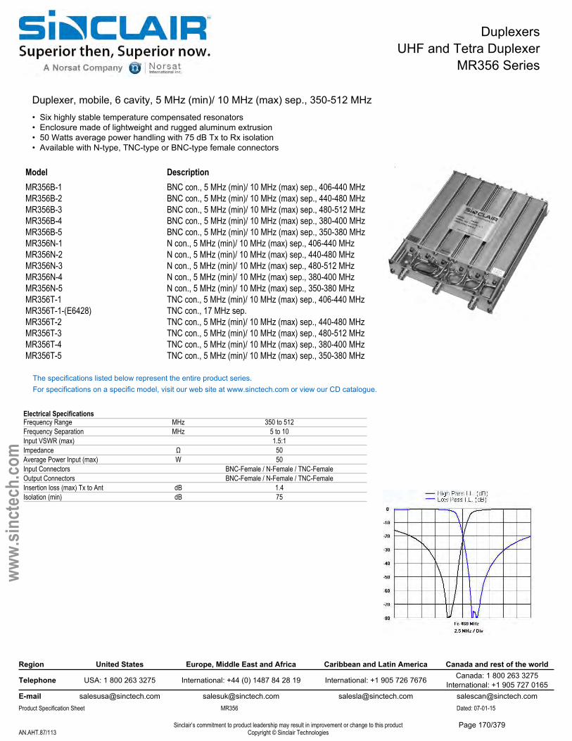
DuplexersUHF and Tetra Duplexer
MR356 Series
Duplexer, mobile, 6 cavity, 5 MHz (min)/ 10 MHz (max) sep., 350-512 MHz• Six highly stable temperature compensated resonators• Enclosure made of lightweight and rugged aluminum extrusion• 50 Watts average power handling with 75 dB Tx to Rx isolation• Available with N-type, TNC-type or BNC-type female connectors
Model DescriptionMR356B-1 BNC con., 5 MHz (min)/ 10 MHz (max) sep., 406-440 MHzMR356B-2 BNC con., 5 MHz (min)/ 10 MHz (max) sep., 440-480 MHzMR356B-3 BNC con., 5 MHz (min)/ 10 MHz (max) sep., 480-512 MHzMR356B-4 BNC con., 5 MHz (min)/ 10 MHz (max) sep., 380-400 MHzMR356B-5 BNC con., 5 MHz (min)/ 10 MHz (max) sep., 350-380 MHzMR356N-1 N con., 5 MHz (min)/ 10 MHz (max) sep., 406-440 MHzMR356N-2 N con., 5 MHz (min)/ 10 MHz (max) sep., 440-480 MHzMR356N-3 N con., 5 MHz (min)/ 10 MHz (max) sep., 480-512 MHzMR356N-4 N con., 5 MHz (min)/ 10 MHz (max) sep., 380-400 MHzMR356N-5 N con., 5 MHz (min)/ 10 MHz (max) sep., 350-380 MHzMR356T-1 TNC con., 5 MHz (min)/ 10 MHz (max) sep., 406-440 MHzMR356T-1-(E6428) TNC con., 17 MHz sep.MR356T-2 TNC con., 5 MHz (min)/ 10 MHz (max) sep., 440-480 MHzMR356T-3 TNC con., 5 MHz (min)/ 10 MHz (max) sep., 480-512 MHzMR356T-4 TNC con., 5 MHz (min)/ 10 MHz (max) sep., 380-400 MHzMR356T-5 TNC con., 5 MHz (min)/ 10 MHz (max) sep., 350-380 MHz
The specifications listed below represent the entire product series.For specifications on a specific model, visit our web site at www.sinctech.com or view our CD catalogue.
Electrical SpecificationsFrequency Range MHz 350 to 512Frequency Separation MHz 5 to 10Input VSWR (max) 1.5:1Impedance Ω 50Average Power Input (max) W 50Input Connectors BNC-Female / N-Female / TNC-FemaleOutput Connectors BNC-Female / N-Female / TNC-FemaleInsertion loss (max) Tx to Ant dB 1.4Isolation (min) dB 75
Region United States Europe, Middle East and Africa Caribbean and Latin America Canada and rest of the world
Telephone USA: 1 800 263 3275 International: +44 (0) 1487 84 28 19 International: +1 905 726 7676 Canada: 1 800 263 3275International: +1 905 727 0165
E-mail [email protected] [email protected] [email protected] [email protected] Specification Sheet MR356 Dated: 07-01-15
Sinclair’s commitment to product leadership may result in improvement or change to this productCopyright © Sinclair TechnologiesAN.AHT.87/113
www.
sinct
ech.
com
Page 170/379
DuplexersUHF and Tetra Duplexer
MR356 Series
Mechanical SpecificationsDepth in (mm) 9 (229)Length/ Height in (mm) 1.3 (33)Width in (mm) 6.25 (159)Weight lbs (kg) 2.5 (1.14)Finish chemical conversionActual Shipping weight lbs (kg) 3 (1.36)Shipping dimensions in (mm) L 13in W 9in H 3in Mounting configurations mounting holes provided
Environmental SpecificationsTemperature range °F (°C) -22 to +140 (-30 to +60)
Region United States Europe, Middle East and Africa Caribbean and Latin America Canada and rest of the world
Telephone USA: 1 800 263 3275 International: +44 (0) 1487 84 28 19 International: +1 905 726 7676 Canada: 1 800 263 3275International: +1 905 727 0165
E-mail [email protected] [email protected] [email protected] [email protected] Specification Sheet MR356 Dated: 07-01-15
Sinclair’s commitment to product leadership may result in improvement or change to this productCopyright © Sinclair TechnologiesAN.AHT.88/113
www.
sinct
ech.
com
Page 171/379
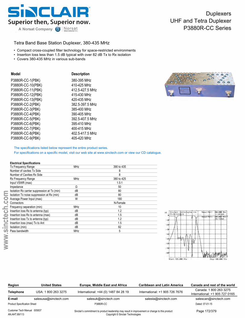
DuplexersUHF and Tetra Duplexer
P3880R-CC Series
Tetra Band Base Station Duplexer, 380-435 MHz• Compact cross-coupled filter technology for space-restricted environments• Insertion loss less than 1.5 dB typical with over 82 dB Tx to Rx isolation• Covers 380-435 MHz in various sub-bands
Model DescriptionP3880R-CC-1(PBK) 380-395 MHzP3880R-CC-10(PBK) 410-425 MHzP3880R-CC-11(PBK) 412.5-427.5 MHzP3880R-CC-12(PBK) 415-430 MHzP3880R-CC-13(PBK) 420-435 MHzP3880R-CC-2(PBK) 382.5-397.5 MHzP3880R-CC-3(PBK) 385-400 MHzP3880R-CC-4(PBK) 390-405 MHzP3880R-CC-5(PBK) 392.5-407.5 MHzP3880R-CC-6(PBK) 395-410 MHzP3880R-CC-7(PBK) 400-415 MHzP3880R-CC-8(PBK) 402.5-417.5 MHzP3880R-CC-9(PBK) 405-420 MHz
The specifications listed below represent the entire product series.For specifications on a specific model, visit our web site at www.sinctech.com or view our CD catalogue.
Electrical SpecificationsTx Frequency Range MHz 390 to 435Number of cavites Tx Side 8Number of Cavities Rx Side 8Rx Frequency Range MHz 380 to 425Input VSWR (max) 1.5:1Impedance Ω 50Isolation Rx carrier suppression at Tx (min) dB 80Isolation Tx noise suppression at Rx (min) dB 80Average Power Input (max) W 180Connectors N-FemaleFrequency separation (min) MHz 10Insertion loss Rx to antenna (typ) dB 1.2Insertion loss Rx to antenna (max) dB 1.5Insertion loss Tx to antenna (typ) dB 1.2Insertion loss (max) Tx to Ant dB 1.5Isolation (min) dB 82Pass bandwidth MHz 5
Region United States Europe, Middle East and Africa Caribbean and Latin America Canada and rest of the world
Telephone USA: 1 800 263 3275 International: +44 (0) 1487 84 28 19 International: +1 905 726 7676 Canada: 1 800 263 3275International: +1 905 727 0165
E-mail [email protected] [email protected] [email protected] [email protected] Specification Sheet P3880R-CC Dated: 07-01-15
Customer Tech Manual 005837 Sinclair’s commitment to product leadership may result in improvement or change to this productCopyright © Sinclair TechnologiesAN.AHT.89/113
www.
sinct
ech.
com
Page 172/379
DuplexersUHF and Tetra Duplexer
P3880R-CC Series
Mechanical SpecificationsDepth in (mm) 7.35 (187)Length/ Height in (mm) 3.3 (84)Width in (mm) 15.7 (399)Weight lbs (kg) 14.3 (6.49)Actual Shipping weight lbs (kg) 50 (22.7)Shipping dimensions in (mm) L 26in W 19in H 6in Mounting configurations 6 by 6M threaded underside holes
Environmental SpecificationsTemperature range °F (°C) -22 to +140 (-30 to +60)
Ordering InformationMounting tray not included.
Region United States Europe, Middle East and Africa Caribbean and Latin America Canada and rest of the world
Telephone USA: 1 800 263 3275 International: +44 (0) 1487 84 28 19 International: +1 905 726 7676 Canada: 1 800 263 3275International: +1 905 727 0165
E-mail [email protected] [email protected] [email protected] [email protected] Specification Sheet P3880R-CC Dated: 07-01-15
Customer Tech Manual 005837 Sinclair’s commitment to product leadership may result in improvement or change to this productCopyright © Sinclair TechnologiesAN.AHT.90/113
www.
sinct
ech.
com
Page 173/379
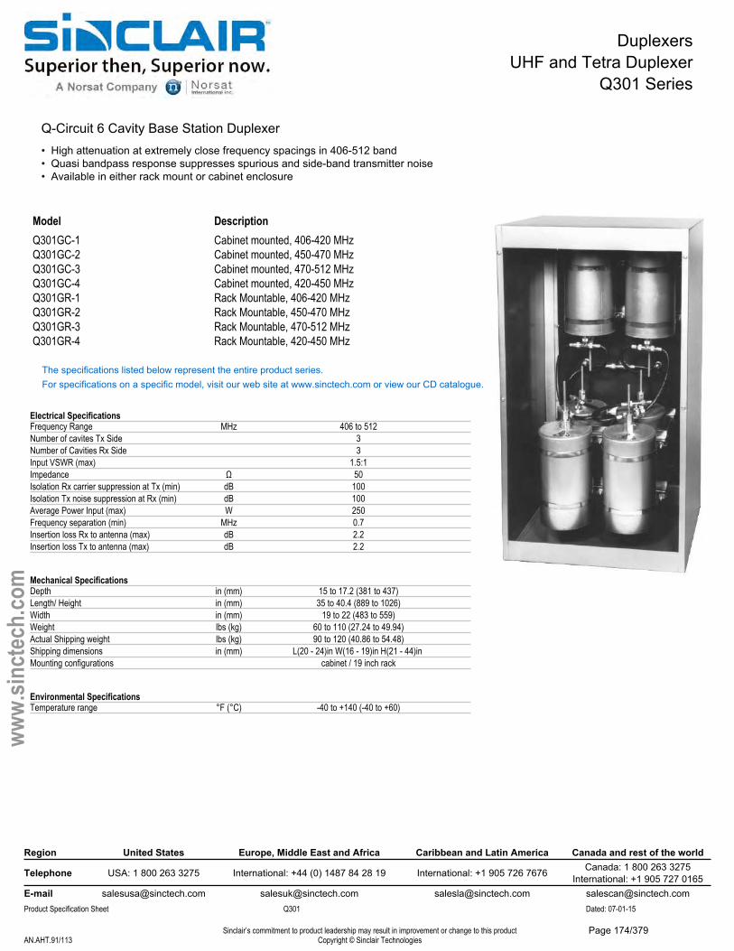
DuplexersUHF and Tetra Duplexer
Q301 Series
Q-Circuit 6 Cavity Base Station Duplexer• High attenuation at extremely close frequency spacings in 406-512 band• Quasi bandpass response suppresses spurious and side-band transmitter noise• Available in either rack mount or cabinet enclosure
Model DescriptionQ301GC-1 Cabinet mounted, 406-420 MHzQ301GC-2 Cabinet mounted, 450-470 MHzQ301GC-3 Cabinet mounted, 470-512 MHzQ301GC-4 Cabinet mounted, 420-450 MHzQ301GR-1 Rack Mountable, 406-420 MHzQ301GR-2 Rack Mountable, 450-470 MHzQ301GR-3 Rack Mountable, 470-512 MHzQ301GR-4 Rack Mountable, 420-450 MHz
The specifications listed below represent the entire product series.For specifications on a specific model, visit our web site at www.sinctech.com or view our CD catalogue.
Electrical SpecificationsFrequency Range MHz 406 to 512Number of cavites Tx Side 3Number of Cavities Rx Side 3Input VSWR (max) 1.5:1Impedance Ω 50Isolation Rx carrier suppression at Tx (min) dB 100Isolation Tx noise suppression at Rx (min) dB 100Average Power Input (max) W 250Frequency separation (min) MHz 0.7Insertion loss Rx to antenna (max) dB 2.2Insertion loss Tx to antenna (max) dB 2.2
Mechanical SpecificationsDepth in (mm) 15 to 17.2 (381 to 437)Length/ Height in (mm) 35 to 40.4 (889 to 1026)Width in (mm) 19 to 22 (483 to 559)Weight lbs (kg) 60 to 110 (27.24 to 49.94)Actual Shipping weight lbs (kg) 90 to 120 (40.86 to 54.48)Shipping dimensions in (mm) L(20 - 24)in W(16 - 19)in H(21 - 44)in Mounting configurations cabinet / 19 inch rack
Environmental SpecificationsTemperature range °F (°C) -40 to +140 (-40 to +60)
Region United States Europe, Middle East and Africa Caribbean and Latin America Canada and rest of the world
Telephone USA: 1 800 263 3275 International: +44 (0) 1487 84 28 19 International: +1 905 726 7676 Canada: 1 800 263 3275International: +1 905 727 0165
E-mail [email protected] [email protected] [email protected] [email protected] Specification Sheet Q301 Dated: 07-01-15
Sinclair’s commitment to product leadership may result in improvement or change to this productCopyright © Sinclair TechnologiesAN.AHT.91/113
www.
sinct
ech.
com
Page 174/379
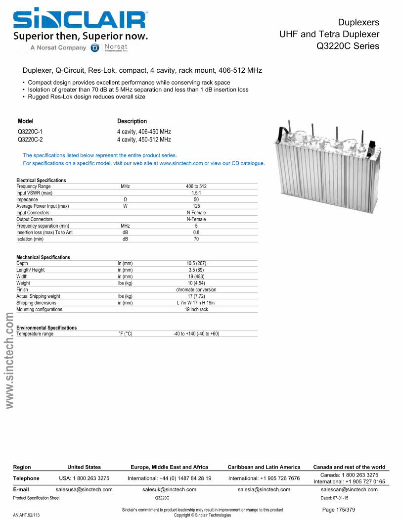
DuplexersUHF and Tetra Duplexer
Q3220C Series
Duplexer, Q-Circuit, Res-Lok, compact, 4 cavity, rack mount, 406-512 MHz• Compact design provides excellent performance while conserving rack space• Isolation of greater than 70 dB at 5 MHz separation and less than 1 dB insertion loss• Rugged Res-Lok design reduces overall size
Model DescriptionQ3220C-1 4 cavity, 406-450 MHzQ3220C-2 4 cavity, 450-512 MHz
The specifications listed below represent the entire product series.For specifications on a specific model, visit our web site at www.sinctech.com or view our CD catalogue.
Electrical SpecificationsFrequency Range MHz 406 to 512Input VSWR (max) 1.5:1Impedance Ω 50Average Power Input (max) W 125Input Connectors N-FemaleOutput Connectors N-FemaleFrequency separation (min) MHz 5Insertion loss (max) Tx to Ant dB 0.8Isolation (min) dB 70
Mechanical SpecificationsDepth in (mm) 10.5 (267)Length/ Height in (mm) 3.5 (89)Width in (mm) 19 (483)Weight lbs (kg) 10 (4.54)Finish chromate conversionActual Shipping weight lbs (kg) 17 (7.72)Shipping dimensions in (mm) L 7in W 17in H 19in Mounting configurations 19 inch rack
Environmental SpecificationsTemperature range °F (°C) -40 to +140 (-40 to +60)
Region United States Europe, Middle East and Africa Caribbean and Latin America Canada and rest of the world
Telephone USA: 1 800 263 3275 International: +44 (0) 1487 84 28 19 International: +1 905 726 7676 Canada: 1 800 263 3275International: +1 905 727 0165
E-mail [email protected] [email protected] [email protected] [email protected] Specification Sheet Q3220C Dated: 07-01-15
Sinclair’s commitment to product leadership may result in improvement or change to this productCopyright © Sinclair TechnologiesAN.AHT.92/113
www.
sinct
ech.
com
Page 175/379
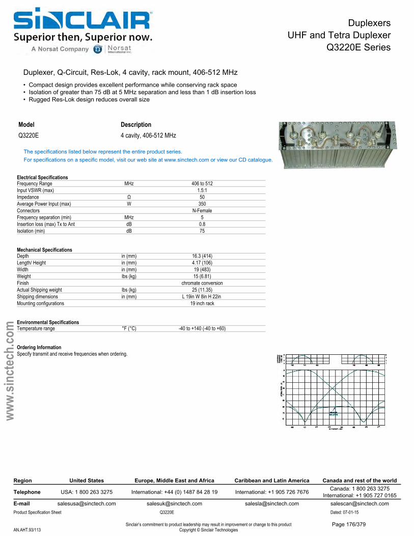
DuplexersUHF and Tetra Duplexer
Q3220E Series
Duplexer, Q-Circuit, Res-Lok, 4 cavity, rack mount, 406-512 MHz• Compact design provides excellent performance while conserving rack space• Isolation of greater than 75 dB at 5 MHz separation and less than 1 dB insertion loss• Rugged Res-Lok design reduces overall size
Model DescriptionQ3220E 4 cavity, 406-512 MHz
The specifications listed below represent the entire product series.For specifications on a specific model, visit our web site at www.sinctech.com or view our CD catalogue.
Electrical SpecificationsFrequency Range MHz 406 to 512Input VSWR (max) 1.5:1Impedance Ω 50Average Power Input (max) W 350Connectors N-FemaleFrequency separation (min) MHz 5Insertion loss (max) Tx to Ant dB 0.8Isolation (min) dB 75
Mechanical SpecificationsDepth in (mm) 16.3 (414)Length/ Height in (mm) 4.17 (106)Width in (mm) 19 (483)Weight lbs (kg) 15 (6.81)Finish chromate conversionActual Shipping weight lbs (kg) 25 (11.35)Shipping dimensions in (mm) L 19in W 8in H 22in Mounting configurations 19 inch rack
Environmental SpecificationsTemperature range °F (°C) -40 to +140 (-40 to +60)
Ordering InformationSpecify transmit and receive frequencies when ordering.
Region United States Europe, Middle East and Africa Caribbean and Latin America Canada and rest of the world
Telephone USA: 1 800 263 3275 International: +44 (0) 1487 84 28 19 International: +1 905 726 7676 Canada: 1 800 263 3275International: +1 905 727 0165
E-mail [email protected] [email protected] [email protected] [email protected] Specification Sheet Q3220E Dated: 07-01-15
Sinclair’s commitment to product leadership may result in improvement or change to this productCopyright © Sinclair TechnologiesAN.AHT.93/113
www.
sinct
ech.
com
Page 176/379
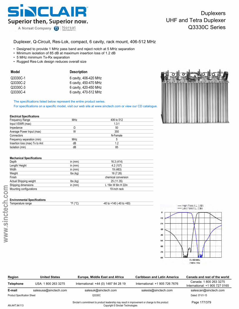
DuplexersUHF and Tetra Duplexer
Q3330C Series
Duplexer, Q-Circuit, Res-Lok, compact, 6 cavity, rack mount, 406-512 MHz• Designed to provide 1 MHz pass band and reject notch at 5 MHz separation• Minimum isolation of 85 dB at maximum insertion loss of 1.2 dB• 5 MHz minimum Tx-Rx separation• Rugged Res-Lok design reduces overall size
Model DescriptionQ3330C-1 6 cavity, 406-420 MHzQ3330C-2 6 cavity, 450-470 MHzQ3330C-3 6 cavity, 420-450 MHzQ3330C-4 6 cavity, 470-512 MHz
The specifications listed below represent the entire product series.For specifications on a specific model, visit our web site at www.sinctech.com or view our CD catalogue.
Electrical SpecificationsFrequency Range MHz 406 to 512Input VSWR (max) 1.3:1Impedance Ω 50Average Power Input (max) W 350Connectors N-FemaleFrequency separation (min) MHz 5Insertion loss (max) Tx to Ant dB 1.2Isolation (min) dB 85
Mechanical SpecificationsDepth in (mm) 16.3 (414)Length/ Height in (mm) 4.2 (107)Width in (mm) 19 (483)Weight lbs (kg) 16 (7.26)Finish chemical conversionActual Shipping weight lbs (kg) 25 (11.35)Shipping dimensions in (mm) L 19in W 8in H 22in Mounting configurations 19 inch rack
Environmental SpecificationsTemperature range °F (°C) -40 to +140 (-40 to +60)
Region United States Europe, Middle East and Africa Caribbean and Latin America Canada and rest of the world
Telephone USA: 1 800 263 3275 International: +44 (0) 1487 84 28 19 International: +1 905 726 7676 Canada: 1 800 263 3275International: +1 905 727 0165
E-mail [email protected] [email protected] [email protected] [email protected] Specification Sheet Q3330C Dated: 07-01-15
Sinclair’s commitment to product leadership may result in improvement or change to this productCopyright © Sinclair TechnologiesAN.AHT.94/113
www.
sinct
ech.
com
Page 177/379
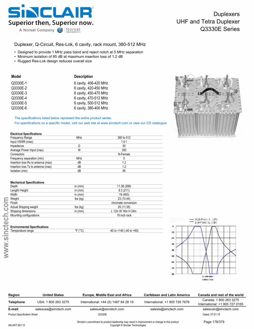
DuplexersUHF and Tetra Duplexer
Q3330E Series
Duplexer, Q-Circuit, Res-Lok, 6 cavity, rack mount, 380-512 MHz• Designed to provide 1 MHz pass band and reject notch at 5 MHz separation• Minimum isolation of 85 dB at maximum insertion loss of 1.2 dB• Rugged Res-Lok design reduces overall size
Model DescriptionQ3330E-1 6 cavity, 406-420 MHzQ3330E-2 6 cavity, 420-450 MHzQ3330E-3 6 cavity, 450-470 MHzQ3330E-4 6 cavity, 470-512 MHzQ3330E-5 6 cavity, 500-512 MHzQ3330E-6 6 cavity, 380-400 MHz
The specifications listed below represent the entire product series.For specifications on a specific model, visit our web site at www.sinctech.com or view our CD catalogue.
Electrical SpecificationsFrequency Range MHz 380 to 512Input VSWR (max) 1.5:1Impedance Ω 50Average Power Input (max) W 350Connectors N-FemaleFrequency separation (min) MHz 5Insertion loss Rx to antenna (max) dB 1.2Insertion loss Tx to antenna (max) dB 1.2Isolation (min) dB 85
Mechanical SpecificationsDepth in (mm) 11.38 (289)Length/ Height in (mm) 8.3 (211)Width in (mm) 19 (483)Weight lbs (kg) 23 (10.44)Finish chromate conversionActual Shipping weight lbs (kg) 25 (11.35)Shipping dimensions in (mm) L 12in W 16in H 24in Mounting configurations 19 inch rack
Environmental SpecificationsTemperature range °F (°C) -40 to +140 (-40 to +60)
Region United States Europe, Middle East and Africa Caribbean and Latin America Canada and rest of the world
Telephone USA: 1 800 263 3275 International: +44 (0) 1487 84 28 19 International: +1 905 726 7676 Canada: 1 800 263 3275International: +1 905 727 0165
E-mail [email protected] [email protected] [email protected] [email protected] Specification Sheet Q3330E Dated: 07-01-15
Sinclair’s commitment to product leadership may result in improvement or change to this productCopyright © Sinclair TechnologiesAN.AHT.95/113
www.
sinct
ech.
com
Page 178/379
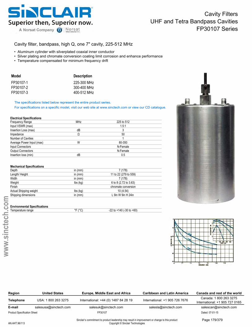
Cavity FiltersUHF and Tetra Bandpass Cavities
FP30107 Series
Cavity filter, bandpass, high Q, one 7" cavity, 225-512 MHz• Aluminum cylinder with silverplated coaxial inner conductor• Silver plating and chromate conversion coating limit corrosion and enhance performance• Temperature compensated for minimum frequency drift
Model DescriptionFP30107-1 225-300 MHzFP30107-2 300-400 MHzFP30107-3 400-512 MHz
The specifications listed below represent the entire product series.For specifications on a specific model, visit our web site at www.sinctech.com or view our CD catalogue.
Electrical SpecificationsFrequency Range MHz 225 to 512Input VSWR (max) 1.5:1Insertion Loss (max) dB 3Impedance Ω 50Number of Cavities 1Average Power Input (max) W 80-350Input Connectors N-FemaleOutput Connectors N-FemaleInsertion loss (min) dB 0.5
Mechanical SpecificationsDepth in (mm) 7 (178)Length/ Height in (mm) 11 to 22 (279 to 559)Width in (mm) 7 (178)Weight lbs (kg) 6 to 8 (2.72 to 3.63)Finish chromate conversionActual Shipping weight lbs (kg) 10 (4.54)Shipping dimensions in (mm) L 9in W 9in H 24in
Environmental SpecificationsTemperature range °F (°C) -22 to +140 (-30 to +60)
Region United States Europe, Middle East and Africa Caribbean and Latin America Canada and rest of the world
Telephone USA: 1 800 263 3275 International: +44 (0) 1487 84 28 19 International: +1 905 726 7676 Canada: 1 800 263 3275International: +1 905 727 0165
E-mail [email protected] [email protected] [email protected] [email protected] Specification Sheet FP30107 Dated: 07-01-15
Sinclair’s commitment to product leadership may result in improvement or change to this productCopyright © Sinclair TechnologiesAN.AHT.96/113
www.
sinct
ech.
com
Page 179/379
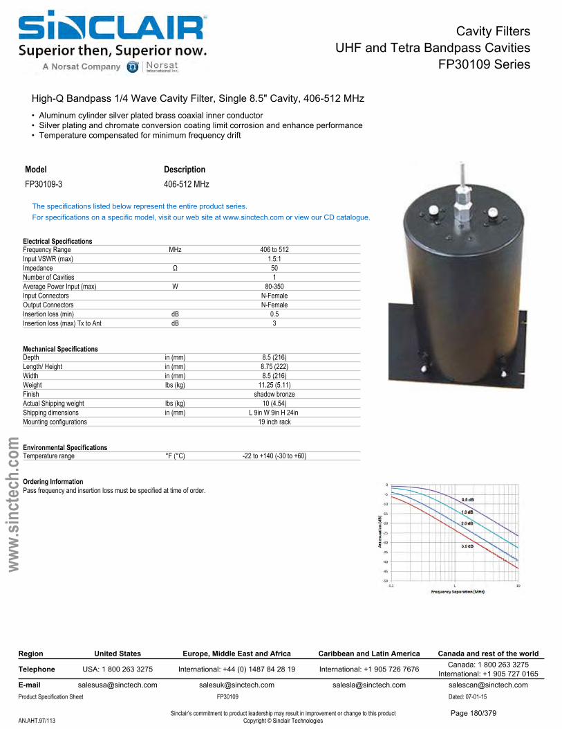
Cavity FiltersUHF and Tetra Bandpass Cavities
FP30109 Series
High-Q Bandpass 1/4 Wave Cavity Filter, Single 8.5" Cavity, 406-512 MHz• Aluminum cylinder silver plated brass coaxial inner conductor• Silver plating and chromate conversion coating limit corrosion and enhance performance• Temperature compensated for minimum frequency drift
Model DescriptionFP30109-3 406-512 MHz
The specifications listed below represent the entire product series.For specifications on a specific model, visit our web site at www.sinctech.com or view our CD catalogue.
Electrical SpecificationsFrequency Range MHz 406 to 512Input VSWR (max) 1.5:1Impedance Ω 50Number of Cavities 1Average Power Input (max) W 80-350Input Connectors N-FemaleOutput Connectors N-FemaleInsertion loss (min) dB 0.5Insertion loss (max) Tx to Ant dB 3
Mechanical SpecificationsDepth in (mm) 8.5 (216)Length/ Height in (mm) 8.75 (222)Width in (mm) 8.5 (216)Weight lbs (kg) 11.25 (5.11)Finish shadow bronzeActual Shipping weight lbs (kg) 10 (4.54)Shipping dimensions in (mm) L 9in W 9in H 24in Mounting configurations 19 inch rack
Environmental SpecificationsTemperature range °F (°C) -22 to +140 (-30 to +60)
Ordering InformationPass frequency and insertion loss must be specified at time of order.
Region United States Europe, Middle East and Africa Caribbean and Latin America Canada and rest of the world
Telephone USA: 1 800 263 3275 International: +44 (0) 1487 84 28 19 International: +1 905 726 7676 Canada: 1 800 263 3275International: +1 905 727 0165
E-mail [email protected] [email protected] [email protected] [email protected] Specification Sheet FP30109 Dated: 07-01-15
Sinclair’s commitment to product leadership may result in improvement or change to this productCopyright © Sinclair TechnologiesAN.AHT.97/113
www.
sinct
ech.
com
Page 180/379
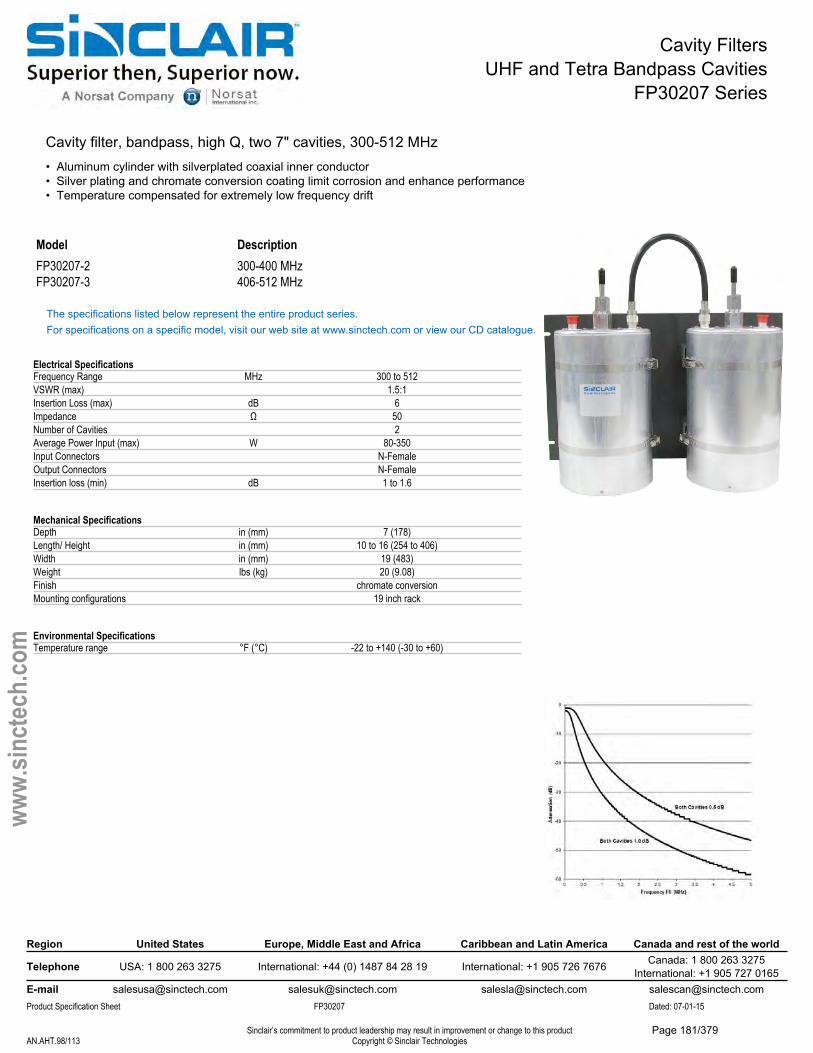
Cavity FiltersUHF and Tetra Bandpass Cavities
FP30207 Series
Cavity filter, bandpass, high Q, two 7" cavities, 300-512 MHz• Aluminum cylinder with silverplated coaxial inner conductor• Silver plating and chromate conversion coating limit corrosion and enhance performance• Temperature compensated for extremely low frequency drift
Model DescriptionFP30207-2 300-400 MHzFP30207-3 406-512 MHz
The specifications listed below represent the entire product series.For specifications on a specific model, visit our web site at www.sinctech.com or view our CD catalogue.
Electrical SpecificationsFrequency Range MHz 300 to 512VSWR (max) 1.5:1Insertion Loss (max) dB 6Impedance Ω 50Number of Cavities 2Average Power Input (max) W 80-350Input Connectors N-FemaleOutput Connectors N-FemaleInsertion loss (min) dB 1 to 1.6
Mechanical SpecificationsDepth in (mm) 7 (178)Length/ Height in (mm) 10 to 16 (254 to 406)Width in (mm) 19 (483)Weight lbs (kg) 20 (9.08)Finish chromate conversionMounting configurations 19 inch rack
Environmental SpecificationsTemperature range °F (°C) -22 to +140 (-30 to +60)
Region United States Europe, Middle East and Africa Caribbean and Latin America Canada and rest of the world
Telephone USA: 1 800 263 3275 International: +44 (0) 1487 84 28 19 International: +1 905 726 7676 Canada: 1 800 263 3275International: +1 905 727 0165
E-mail [email protected] [email protected] [email protected] [email protected] Specification Sheet FP30207 Dated: 07-01-15
Sinclair’s commitment to product leadership may result in improvement or change to this productCopyright © Sinclair TechnologiesAN.AHT.98/113
www.
sinct
ech.
com
Page 181/379
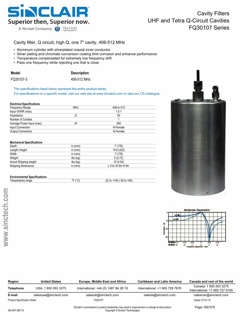
Cavity FiltersUHF and Tetra Q-Circuit Cavities
FQ30107 Series
Cavity filter, Q circuit, high Q, one 7" cavity, 406-512 MHz• Aluminum cylinder with silverplated coaxial inner conductor• Silver plating and chromate conversion coating limit corrosion and enhance performance• Temperature compensated for extremely low frequency drift• Pass one frequency while rejecting one that is close
Model DescriptionFQ30107-3 406-512 MHz
The specifications listed below represent the entire product series.For specifications on a specific model, visit our web site at www.sinctech.com or view our CD catalogue.
Electrical SpecificationsFrequency Range MHz 406 to 512Input VSWR (max) 1.5:1Impedance Ω 50Number of Cavities 1Average Power Input (max) W 350Input Connectors N-FemaleOutput Connectors N-Female
Mechanical SpecificationsDepth in (mm) 7 (178)Length/ Height in (mm) 16.6 (422)Width in (mm) 7 (178)Weight lbs (kg) 6 (2.72)Actual Shipping weight lbs (kg) 10 (4.54)Shipping dimensions in (mm) L 21in W 9in H 9in
Environmental SpecificationsTemperature range °F (°C) -22 to +140 (-30 to +60)
Region United States Europe, Middle East and Africa Caribbean and Latin America Canada and rest of the world
Telephone USA: 1 800 263 3275 International: +44 (0) 1487 84 28 19 International: +1 905 726 7676 Canada: 1 800 263 3275International: +1 905 727 0165
E-mail [email protected] [email protected] [email protected] [email protected] Specification Sheet FQ30107 Dated: 07-01-15
Sinclair’s commitment to product leadership may result in improvement or change to this productCopyright © Sinclair TechnologiesAN.AHT.99/113
www.
sinct
ech.
com
Page 182/379
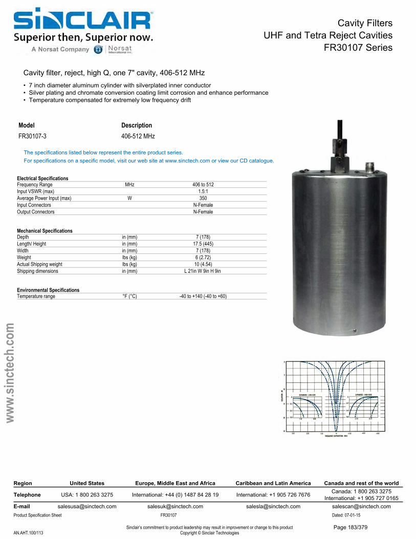
Cavity FiltersUHF and Tetra Reject Cavities
FR30107 Series
Cavity filter, reject, high Q, one 7" cavity, 406-512 MHz• 7 inch diameter aluminum cylinder with silverplated inner conductor• Silver plating and chromate conversion coating limit corrosion and enhance performance• Temperature compensated for extremely low frequency drift
Model DescriptionFR30107-3 406-512 MHz
The specifications listed below represent the entire product series.For specifications on a specific model, visit our web site at www.sinctech.com or view our CD catalogue.
Electrical SpecificationsFrequency Range MHz 406 to 512Input VSWR (max) 1.5:1Average Power Input (max) W 350Input Connectors N-FemaleOutput Connectors N-Female
Mechanical SpecificationsDepth in (mm) 7 (178)Length/ Height in (mm) 17.5 (445)Width in (mm) 7 (178)Weight lbs (kg) 6 (2.72)Actual Shipping weight lbs (kg) 10 (4.54)Shipping dimensions in (mm) L 21in W 9in H 9in
Environmental SpecificationsTemperature range °F (°C) -40 to +140 (-40 to +60)
Region United States Europe, Middle East and Africa Caribbean and Latin America Canada and rest of the world
Telephone USA: 1 800 263 3275 International: +44 (0) 1487 84 28 19 International: +1 905 726 7676 Canada: 1 800 263 3275International: +1 905 727 0165
E-mail [email protected] [email protected] [email protected] [email protected] Specification Sheet FR30107 Dated: 07-01-15
Sinclair’s commitment to product leadership may result in improvement or change to this productCopyright © Sinclair TechnologiesAN.AHT.100/113
www.
sinct
ech.
com
Page 183/379
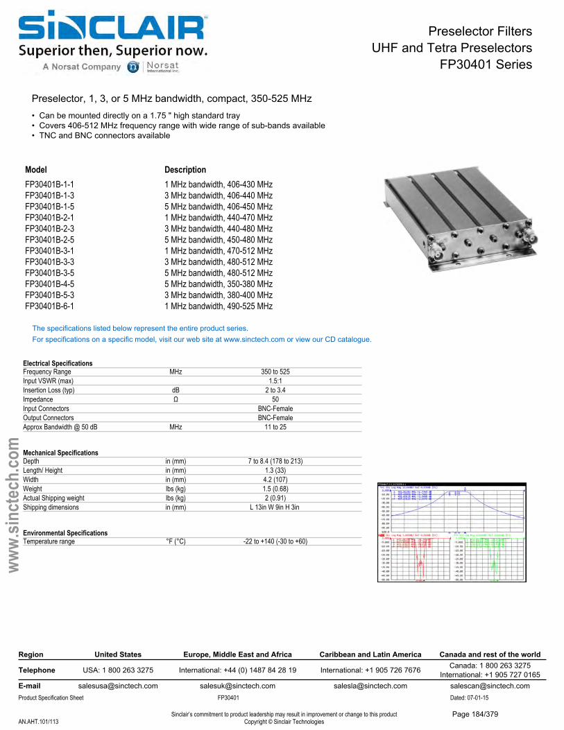
Preselector FiltersUHF and Tetra Preselectors
FP30401 Series
Preselector, 1, 3, or 5 MHz bandwidth, compact, 350-525 MHz• Can be mounted directly on a 1.75 " high standard tray• Covers 406-512 MHz frequency range with wide range of sub-bands available• TNC and BNC connectors available
Model DescriptionFP30401B-1-1 1 MHz bandwidth, 406-430 MHzFP30401B-1-3 3 MHz bandwidth, 406-440 MHzFP30401B-1-5 5 MHz bandwidth, 406-450 MHzFP30401B-2-1 1 MHz bandwidth, 440-470 MHzFP30401B-2-3 3 MHz bandwidth, 440-480 MHzFP30401B-2-5 5 MHz bandwidth, 450-480 MHzFP30401B-3-1 1 MHz bandwidth, 470-512 MHzFP30401B-3-3 3 MHz bandwidth, 480-512 MHzFP30401B-3-5 5 MHz bandwidth, 480-512 MHzFP30401B-4-5 5 MHz bandwidth, 350-380 MHzFP30401B-5-3 3 MHz bandwidth, 380-400 MHzFP30401B-6-1 1 MHz bandwidth, 490-525 MHz
The specifications listed below represent the entire product series.For specifications on a specific model, visit our web site at www.sinctech.com or view our CD catalogue.
Electrical SpecificationsFrequency Range MHz 350 to 525Input VSWR (max) 1.5:1Insertion Loss (typ) dB 2 to 3.4Impedance Ω 50Input Connectors BNC-FemaleOutput Connectors BNC-FemaleApprox Bandwidth @ 50 dB MHz 11 to 25
Mechanical SpecificationsDepth in (mm) 7 to 8.4 (178 to 213)Length/ Height in (mm) 1.3 (33)Width in (mm) 4.2 (107)Weight lbs (kg) 1.5 (0.68)Actual Shipping weight lbs (kg) 2 (0.91)Shipping dimensions in (mm) L 13in W 9in H 3in
Environmental SpecificationsTemperature range °F (°C) -22 to +140 (-30 to +60)
Region United States Europe, Middle East and Africa Caribbean and Latin America Canada and rest of the world
Telephone USA: 1 800 263 3275 International: +44 (0) 1487 84 28 19 International: +1 905 726 7676 Canada: 1 800 263 3275International: +1 905 727 0165
E-mail [email protected] [email protected] [email protected] [email protected] Specification Sheet FP30401 Dated: 07-01-15
Sinclair’s commitment to product leadership may result in improvement or change to this productCopyright © Sinclair TechnologiesAN.AHT.101/113
www.
sinct
ech.
com
Page 184/379
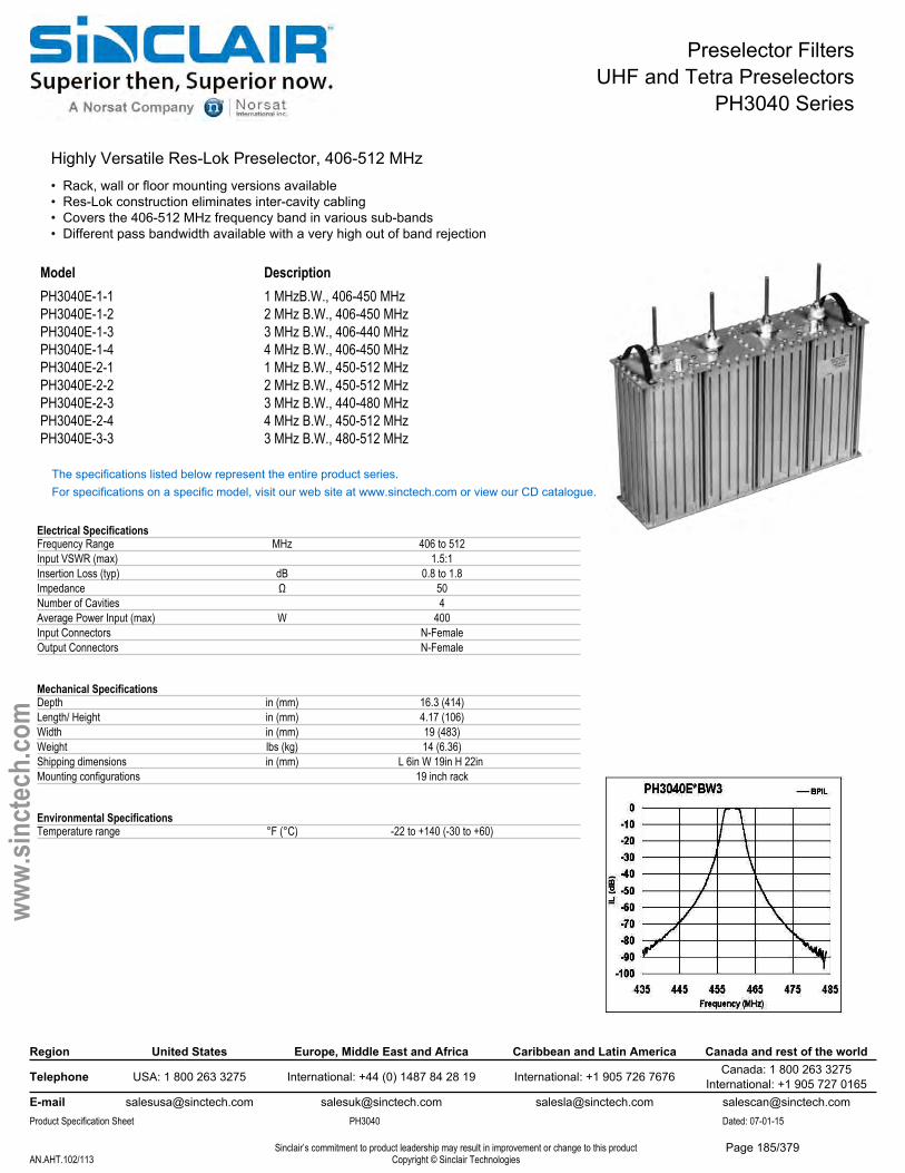
Preselector FiltersUHF and Tetra Preselectors
PH3040 Series
Highly Versatile Res-Lok Preselector, 406-512 MHz• Rack, wall or floor mounting versions available• Res-Lok construction eliminates inter-cavity cabling• Covers the 406-512 MHz frequency band in various sub-bands• Different pass bandwidth available with a very high out of band rejection
Model DescriptionPH3040E-1-1 1 MHzB.W., 406-450 MHzPH3040E-1-2 2 MHz B.W., 406-450 MHzPH3040E-1-3 3 MHz B.W., 406-440 MHzPH3040E-1-4 4 MHz B.W., 406-450 MHzPH3040E-2-1 1 MHz B.W., 450-512 MHzPH3040E-2-2 2 MHz B.W., 450-512 MHzPH3040E-2-3 3 MHz B.W., 440-480 MHzPH3040E-2-4 4 MHz B.W., 450-512 MHzPH3040E-3-3 3 MHz B.W., 480-512 MHz
The specifications listed below represent the entire product series.For specifications on a specific model, visit our web site at www.sinctech.com or view our CD catalogue.
Electrical SpecificationsFrequency Range MHz 406 to 512Input VSWR (max) 1.5:1Insertion Loss (typ) dB 0.8 to 1.8Impedance Ω 50Number of Cavities 4Average Power Input (max) W 400Input Connectors N-FemaleOutput Connectors N-Female
Mechanical SpecificationsDepth in (mm) 16.3 (414)Length/ Height in (mm) 4.17 (106)Width in (mm) 19 (483)Weight lbs (kg) 14 (6.36)Shipping dimensions in (mm) L 6in W 19in H 22in Mounting configurations 19 inch rack
Environmental SpecificationsTemperature range °F (°C) -22 to +140 (-30 to +60)
Region United States Europe, Middle East and Africa Caribbean and Latin America Canada and rest of the world
Telephone USA: 1 800 263 3275 International: +44 (0) 1487 84 28 19 International: +1 905 726 7676 Canada: 1 800 263 3275International: +1 905 727 0165
E-mail [email protected] [email protected] [email protected] [email protected] Specification Sheet PH3040 Dated: 07-01-15
Sinclair’s commitment to product leadership may result in improvement or change to this productCopyright © Sinclair TechnologiesAN.AHT.102/113
www.
sinct
ech.
com
Page 185/379
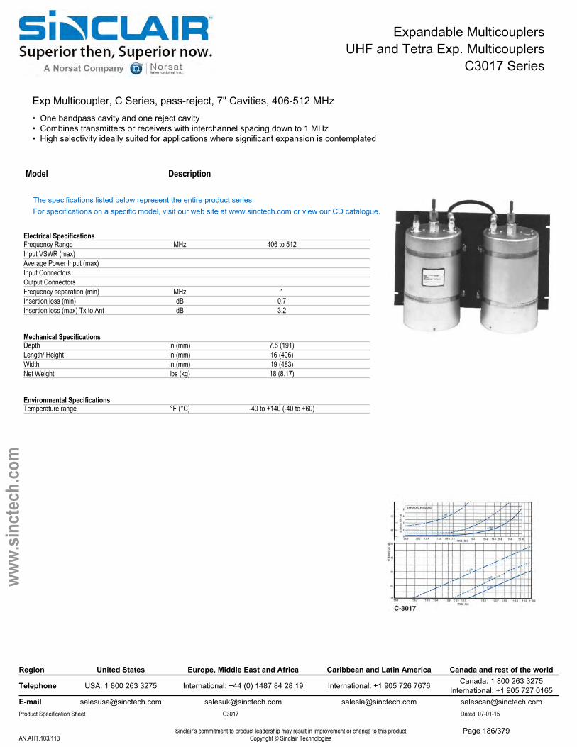
Expandable MulticouplersUHF and Tetra Exp. Multicouplers
C3017 Series
Exp Multicoupler, C Series, pass-reject, 7" Cavities, 406-512 MHz• One bandpass cavity and one reject cavity• Combines transmitters or receivers with interchannel spacing down to 1 MHz• High selectivity ideally suited for applications where significant expansion is contemplated
Model Description
The specifications listed below represent the entire product series.For specifications on a specific model, visit our web site at www.sinctech.com or view our CD catalogue.
Electrical SpecificationsFrequency Range MHz 406 to 512Input VSWR (max)Average Power Input (max)Input ConnectorsOutput ConnectorsFrequency separation (min) MHz 1Insertion loss (min) dB 0.7Insertion loss (max) Tx to Ant dB 3.2
Mechanical SpecificationsDepth in (mm) 7.5 (191)Length/ Height in (mm) 16 (406)Width in (mm) 19 (483)Net Weight lbs (kg) 18 (8.17)
Environmental SpecificationsTemperature range °F (°C) -40 to +140 (-40 to +60)
Region United States Europe, Middle East and Africa Caribbean and Latin America Canada and rest of the world
Telephone USA: 1 800 263 3275 International: +44 (0) 1487 84 28 19 International: +1 905 726 7676 Canada: 1 800 263 3275International: +1 905 727 0165
E-mail [email protected] [email protected] [email protected] [email protected] Specification Sheet C3017 Dated: 07-01-15
Sinclair’s commitment to product leadership may result in improvement or change to this productCopyright © Sinclair TechnologiesAN.AHT.103/113
www.
sinct
ech.
com
Page 186/379
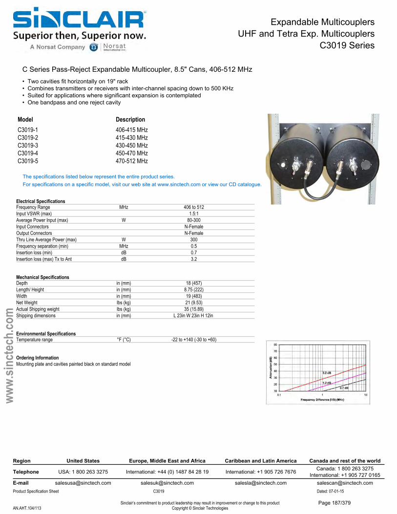
Expandable MulticouplersUHF and Tetra Exp. Multicouplers
C3019 Series
C Series Pass-Reject Expandable Multicoupler, 8.5" Cans, 406-512 MHz• Two cavities fit horizontally on 19" rack• Combines transmitters or receivers with inter-channel spacing down to 500 KHz• Suited for applications where significant expansion is contemplated• One bandpass and one reject cavity
Model DescriptionC3019-1 406-415 MHzC3019-2 415-430 MHzC3019-3 430-450 MHzC3019-4 450-470 MHzC3019-5 470-512 MHz
The specifications listed below represent the entire product series.For specifications on a specific model, visit our web site at www.sinctech.com or view our CD catalogue.
Electrical SpecificationsFrequency Range MHz 406 to 512Input VSWR (max) 1.5:1Average Power Input (max) W 80-300Input Connectors N-FemaleOutput Connectors N-FemaleThru Line Average Power (max) W 300Frequency separation (min) MHz 0.5Insertion loss (min) dB 0.7Insertion loss (max) Tx to Ant dB 3.2
Mechanical SpecificationsDepth in (mm) 18 (457)Length/ Height in (mm) 8.75 (222)Width in (mm) 19 (483)Net Weight lbs (kg) 21 (9.53)Actual Shipping weight lbs (kg) 35 (15.89)Shipping dimensions in (mm) L 23in W 23in H 12in
Environmental SpecificationsTemperature range °F (°C) -22 to +140 (-30 to +60)
Ordering InformationMounting plate and cavities painted black on standard model
Region United States Europe, Middle East and Africa Caribbean and Latin America Canada and rest of the world
Telephone USA: 1 800 263 3275 International: +44 (0) 1487 84 28 19 International: +1 905 726 7676 Canada: 1 800 263 3275International: +1 905 727 0165
E-mail [email protected] [email protected] [email protected] [email protected] Specification Sheet C3019 Dated: 07-01-15
Sinclair’s commitment to product leadership may result in improvement or change to this productCopyright © Sinclair TechnologiesAN.AHT.104/113
www.
sinct
ech.
com
Page 187/379
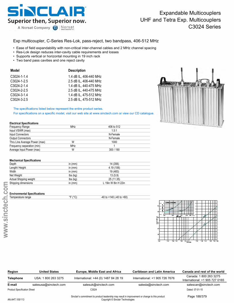
Expandable MulticouplersUHF and Tetra Exp. Multicouplers
C3024 Series
Exp multicoupler, C-Series Res-Lok, pass-reject, two bandpass, 406-512 MHz• Ease of field expandability with non-critical inter-channel cables and 2 MHz channel spacing• Res-Lok design reduces inter-cavity cable requirements and losses• Supports vertical or horizontal mounting in 19 inch rack• Two band pass cavities and one reject cavity
Model DescriptionC3024-1-1.4 1.4 dB IL, 406-440 MHzC3024-1-2.5 2.5 dB IL, 406-440 MHzC3024-2-1.4 1.4 dB IL, 440-475 MHzC3024-2-2.5 2.5 dB IL, 440-475 MHzC3024-3-1.4 1.4 dB IL, 475-512 MHzC3024-3-2.5 2.5 dB IL, 475-512 MHz
The specifications listed below represent the entire product series.For specifications on a specific model, visit our web site at www.sinctech.com or view our CD catalogue.
Electrical SpecificationsFrequency Range MHz 406 to 512Input VSWR (max) 1.5:1Input Connectors N-FemaleOutput Connectors N-FemaleThru Line Average Power (max) W 1000Frequency separation (min) MHz 1Average Input Power (max) W 300 / 190
Mechanical SpecificationsDepth in (mm) 14 (356)Length/ Height in (mm) 4.19 (106)Width in (mm) 19 (483)Net Weight lbs (kg) 13 (5.9)Actual Shipping weight lbs (kg) 25 (11.35)Shipping dimensions in (mm) L 19in W 8in H 22in
Environmental SpecificationsTemperature range °F (°C) -40 to +140 (-40 to +60)
Region United States Europe, Middle East and Africa Caribbean and Latin America Canada and rest of the world
Telephone USA: 1 800 263 3275 International: +44 (0) 1487 84 28 19 International: +1 905 726 7676 Canada: 1 800 263 3275International: +1 905 727 0165
E-mail [email protected] [email protected] [email protected] [email protected] Specification Sheet C3024 Dated: 07-01-15
Sinclair’s commitment to product leadership may result in improvement or change to this productCopyright © Sinclair TechnologiesAN.AHT.105/113
www.
sinct
ech.
com
Page 188/379
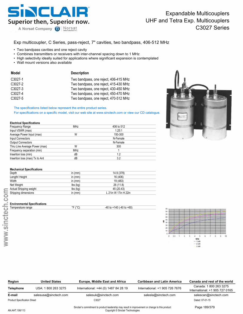
Expandable MulticouplersUHF and Tetra Exp. Multicouplers
C3027 Series
Exp multicoupler, C Series, pass-reject, 7" cavities, two bandpass, 406-512 MHz• Two bandpass cavities and one reject cavity• Combines transmitters or receivers with inter-channel spacing down to 1 MHz• High selectivity ideally suited for applications where significant expansion is contemplated• Wall mount versions also available
Model DescriptionC3027-1 Two bandpass, one reject, 406-415 MHzC3027-2 Two bandpass, one reject, 415-430 MHzC3027-3 Two bandpass, one reject, 430-450 MHzC3027-4 Two bandpass, one reject, 450-470 MHzC3027-5 Two bandpass, one reject, 470-512 MHz
The specifications listed below represent the entire product series.For specifications on a specific model, visit our web site at www.sinctech.com or view our CD catalogue.
Electrical SpecificationsFrequency Range MHz 406 to 512Input VSWR (max) 1.25:1Average Power Input (max) W 150-300Input Connectors N-FemaleOutput Connectors N-FemaleThru Line Average Power (max) W 300Frequency separation (min) MHz 1Insertion loss (min) dB 1.2Insertion loss (max) Tx to Ant dB 3.2
Mechanical SpecificationsDepth in (mm) 14.9 (378)Length/ Height in (mm) 16 (406)Width in (mm) 19 (483)Net Weight lbs (kg) 26 (11.8)Actual Shipping weight lbs (kg) 45 (20.43)Shipping dimensions in (mm) L 21in W 17in H 22in
Environmental SpecificationsTemperature range °F (°C) -40 to +140 (-40 to +60)
Region United States Europe, Middle East and Africa Caribbean and Latin America Canada and rest of the world
Telephone USA: 1 800 263 3275 International: +44 (0) 1487 84 28 19 International: +1 905 726 7676 Canada: 1 800 263 3275International: +1 905 727 0165
E-mail [email protected] [email protected] [email protected] [email protected] Specification Sheet C3027 Dated: 07-01-15
Sinclair’s commitment to product leadership may result in improvement or change to this productCopyright © Sinclair TechnologiesAN.AHT.106/113
www.
sinct
ech.
com
Page 189/379
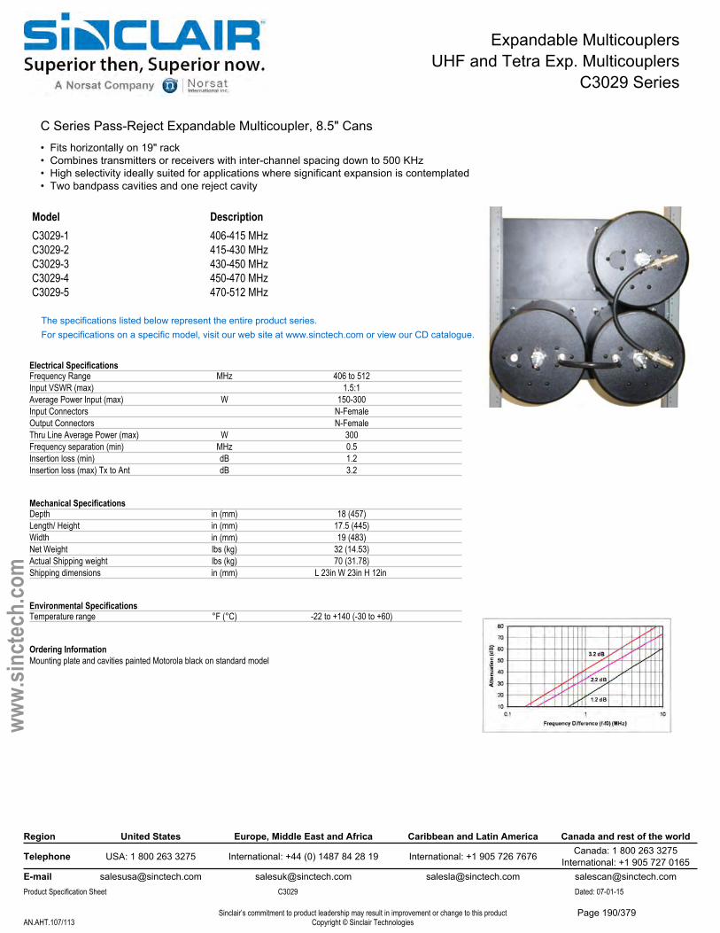
Expandable MulticouplersUHF and Tetra Exp. Multicouplers
C3029 Series
C Series Pass-Reject Expandable Multicoupler, 8.5" Cans• Fits horizontally on 19" rack• Combines transmitters or receivers with inter-channel spacing down to 500 KHz• High selectivity ideally suited for applications where significant expansion is contemplated• Two bandpass cavities and one reject cavity
Model DescriptionC3029-1 406-415 MHzC3029-2 415-430 MHzC3029-3 430-450 MHzC3029-4 450-470 MHzC3029-5 470-512 MHz
The specifications listed below represent the entire product series.For specifications on a specific model, visit our web site at www.sinctech.com or view our CD catalogue.
Electrical SpecificationsFrequency Range MHz 406 to 512Input VSWR (max) 1.5:1Average Power Input (max) W 150-300Input Connectors N-FemaleOutput Connectors N-FemaleThru Line Average Power (max) W 300Frequency separation (min) MHz 0.5Insertion loss (min) dB 1.2Insertion loss (max) Tx to Ant dB 3.2
Mechanical SpecificationsDepth in (mm) 18 (457)Length/ Height in (mm) 17.5 (445)Width in (mm) 19 (483)Net Weight lbs (kg) 32 (14.53)Actual Shipping weight lbs (kg) 70 (31.78)Shipping dimensions in (mm) L 23in W 23in H 12in
Environmental SpecificationsTemperature range °F (°C) -22 to +140 (-30 to +60)
Ordering InformationMounting plate and cavities painted Motorola black on standard model
Region United States Europe, Middle East and Africa Caribbean and Latin America Canada and rest of the world
Telephone USA: 1 800 263 3275 International: +44 (0) 1487 84 28 19 International: +1 905 726 7676 Canada: 1 800 263 3275International: +1 905 727 0165
E-mail [email protected] [email protected] [email protected] [email protected] Specification Sheet C3029 Dated: 07-01-15
Sinclair’s commitment to product leadership may result in improvement or change to this productCopyright © Sinclair TechnologiesAN.AHT.107/113
www.
sinct
ech.
com
Page 190/379

Expandable MulticouplersUHF and Tetra Exp. Multicouplers
C3034 Series
Exp multicoupler, C Series Res-Lok, pass-reject, three bandpass, 406-512 MHz• Ease of field expandability with non-critical cable lengths• Reduces inter-cavity cable requirements• Supports vertical or horizontal mounting in a 19 inch rack• Three band pass cavities and one reject cavity
Model DescriptionC3034-1-1.6 1.6 dB IL, 406-440 MHzC3034-1-3.1 3.1 dB IL, 406-440 MHzC3034-2-1.6 1.6 dB IL, 440-475 MHzC3034-2-3.1 3.1 dB IL, 440-475 MHzC3034-3-1.6 1.6 dB IL, 475-512 MHzC3034-3-3.1 3.1 dB IL, 475-512 MHz
The specifications listed below represent the entire product series.For specifications on a specific model, visit our web site at www.sinctech.com or view our CD catalogue.
Electrical SpecificationsFrequency Range MHz 406 to 512Input VSWR (max) 1.5:1Average Power Input (max) W 300 / 160Input Connectors N-FemaleOutput Connectors N-FemaleThru Line Average Power (max) W 1000Frequency separation (min) MHz 1
Mechanical SpecificationsDepth in (mm) 14 (356)Length/ Height in (mm) 4.19 (106)Width in (mm) 19 (483)Net Weight lbs (kg) 13 (5.9)Actual Shipping weight lbs (kg) 25 (11.35)Shipping dimensions in (mm) L 6in W 19in H 22in
Environmental SpecificationsTemperature range °F (°C) -40 to +140 (-40 to +60)
Region United States Europe, Middle East and Africa Caribbean and Latin America Canada and rest of the world
Telephone USA: 1 800 263 3275 International: +44 (0) 1487 84 28 19 International: +1 905 726 7676 Canada: 1 800 263 3275International: +1 905 727 0165
E-mail [email protected] [email protected] [email protected] [email protected] Specification Sheet C3034 Dated: 07-01-15
Sinclair’s commitment to product leadership may result in improvement or change to this productCopyright © Sinclair TechnologiesAN.AHT.108/113
www.
sinct
ech.
com
Page 191/379
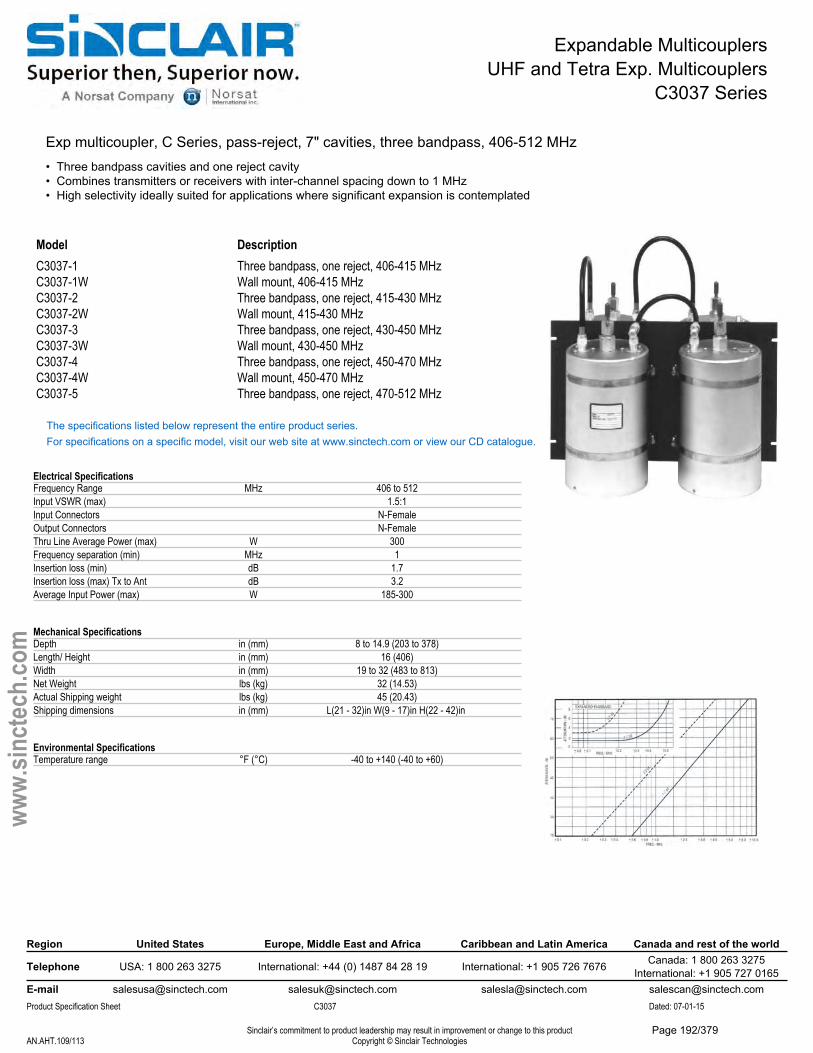
Expandable MulticouplersUHF and Tetra Exp. Multicouplers
C3037 Series
Exp multicoupler, C Series, pass-reject, 7" cavities, three bandpass, 406-512 MHz• Three bandpass cavities and one reject cavity• Combines transmitters or receivers with inter-channel spacing down to 1 MHz• High selectivity ideally suited for applications where significant expansion is contemplated
Model DescriptionC3037-1 Three bandpass, one reject, 406-415 MHzC3037-1W Wall mount, 406-415 MHzC3037-2 Three bandpass, one reject, 415-430 MHzC3037-2W Wall mount, 415-430 MHzC3037-3 Three bandpass, one reject, 430-450 MHzC3037-3W Wall mount, 430-450 MHzC3037-4 Three bandpass, one reject, 450-470 MHzC3037-4W Wall mount, 450-470 MHzC3037-5 Three bandpass, one reject, 470-512 MHz
The specifications listed below represent the entire product series.For specifications on a specific model, visit our web site at www.sinctech.com or view our CD catalogue.
Electrical SpecificationsFrequency Range MHz 406 to 512Input VSWR (max) 1.5:1Input Connectors N-FemaleOutput Connectors N-FemaleThru Line Average Power (max) W 300Frequency separation (min) MHz 1Insertion loss (min) dB 1.7Insertion loss (max) Tx to Ant dB 3.2Average Input Power (max) W 185-300
Mechanical SpecificationsDepth in (mm) 8 to 14.9 (203 to 378)Length/ Height in (mm) 16 (406)Width in (mm) 19 to 32 (483 to 813)Net Weight lbs (kg) 32 (14.53)Actual Shipping weight lbs (kg) 45 (20.43)Shipping dimensions in (mm) L(21 - 32)in W(9 - 17)in H(22 - 42)in
Environmental SpecificationsTemperature range °F (°C) -40 to +140 (-40 to +60)
Region United States Europe, Middle East and Africa Caribbean and Latin America Canada and rest of the world
Telephone USA: 1 800 263 3275 International: +44 (0) 1487 84 28 19 International: +1 905 726 7676 Canada: 1 800 263 3275International: +1 905 727 0165
E-mail [email protected] [email protected] [email protected] [email protected] Specification Sheet C3037 Dated: 07-01-15
Sinclair’s commitment to product leadership may result in improvement or change to this productCopyright © Sinclair TechnologiesAN.AHT.109/113
www.
sinct
ech.
com
Page 192/379
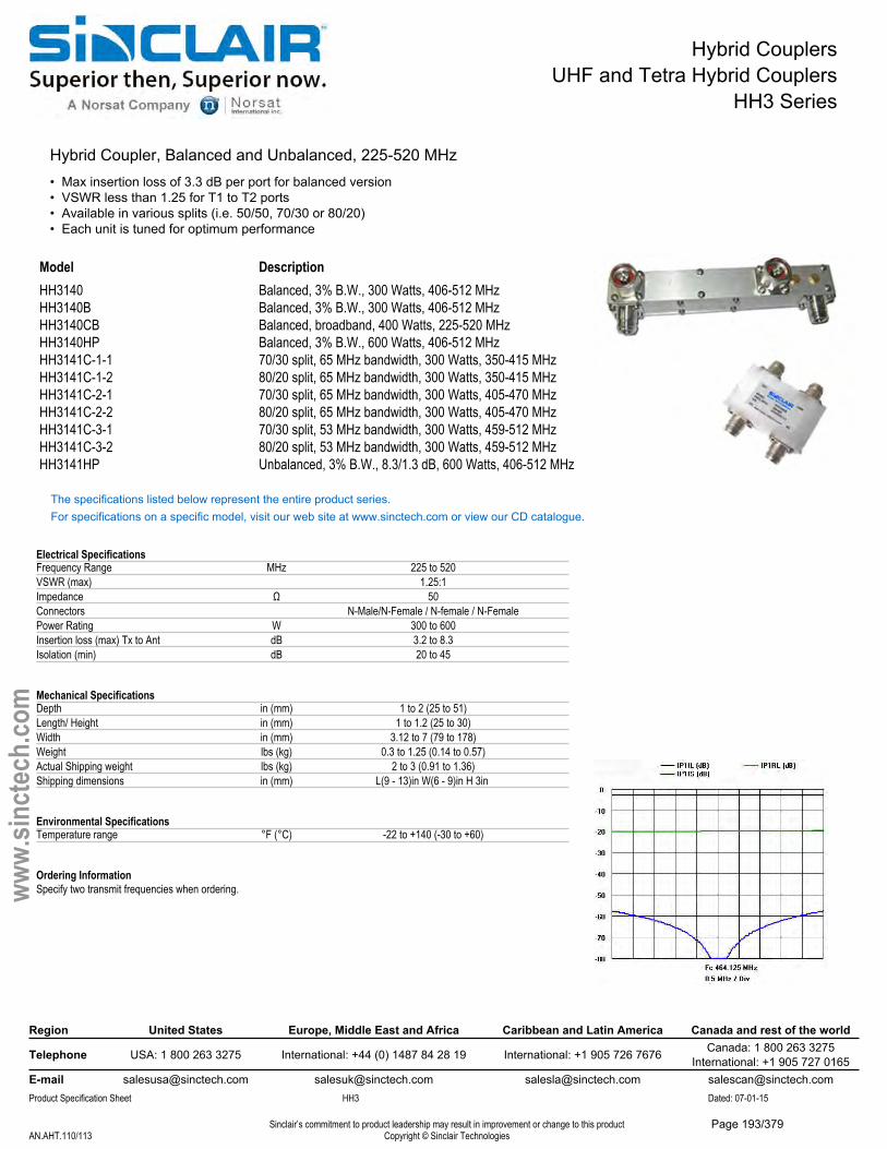
Hybrid CouplersUHF and Tetra Hybrid Couplers
HH3 Series
Hybrid Coupler, Balanced and Unbalanced, 225-520 MHz• Max insertion loss of 3.3 dB per port for balanced version• VSWR less than 1.25 for T1 to T2 ports• Available in various splits (i.e. 50/50, 70/30 or 80/20)• Each unit is tuned for optimum performance
Model DescriptionHH3140 Balanced, 3% B.W., 300 Watts, 406-512 MHzHH3140B Balanced, 3% B.W., 300 Watts, 406-512 MHzHH3140CB Balanced, broadband, 400 Watts, 225-520 MHzHH3140HP Balanced, 3% B.W., 600 Watts, 406-512 MHzHH3141C-1-1 70/30 split, 65 MHz bandwidth, 300 Watts, 350-415 MHzHH3141C-1-2 80/20 split, 65 MHz bandwidth, 300 Watts, 350-415 MHzHH3141C-2-1 70/30 split, 65 MHz bandwidth, 300 Watts, 405-470 MHzHH3141C-2-2 80/20 split, 65 MHz bandwidth, 300 Watts, 405-470 MHzHH3141C-3-1 70/30 split, 53 MHz bandwidth, 300 Watts, 459-512 MHzHH3141C-3-2 80/20 split, 53 MHz bandwidth, 300 Watts, 459-512 MHzHH3141HP Unbalanced, 3% B.W., 8.3/1.3 dB, 600 Watts, 406-512 MHz
The specifications listed below represent the entire product series.For specifications on a specific model, visit our web site at www.sinctech.com or view our CD catalogue.
Electrical SpecificationsFrequency Range MHz 225 to 520VSWR (max) 1.25:1Impedance Ω 50Connectors N-Male/N-Female / N-female / N-FemalePower Rating W 300 to 600Insertion loss (max) Tx to Ant dB 3.2 to 8.3Isolation (min) dB 20 to 45
Mechanical SpecificationsDepth in (mm) 1 to 2 (25 to 51)Length/ Height in (mm) 1 to 1.2 (25 to 30)Width in (mm) 3.12 to 7 (79 to 178)Weight lbs (kg) 0.3 to 1.25 (0.14 to 0.57)Actual Shipping weight lbs (kg) 2 to 3 (0.91 to 1.36)Shipping dimensions in (mm) L(9 - 13)in W(6 - 9)in H 3in
Environmental SpecificationsTemperature range °F (°C) -22 to +140 (-30 to +60)
Ordering InformationSpecify two transmit frequencies when ordering.
Region United States Europe, Middle East and Africa Caribbean and Latin America Canada and rest of the world
Telephone USA: 1 800 263 3275 International: +44 (0) 1487 84 28 19 International: +1 905 726 7676 Canada: 1 800 263 3275International: +1 905 727 0165
E-mail [email protected] [email protected] [email protected] [email protected] Specification Sheet HH3 Dated: 07-01-15
Sinclair’s commitment to product leadership may result in improvement or change to this productCopyright © Sinclair TechnologiesAN.AHT.110/113
www.
sinct
ech.
com
Page 193/379
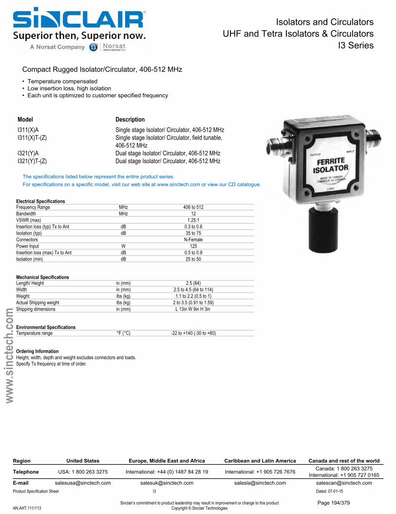
Isolators and CirculatorsUHF and Tetra Isolators & Circulators
I3 Series
Compact Rugged Isolator/Circulator, 406-512 MHz• Temperature compensated• Low insertion loss, high isolation• Each unit is optimized to customer specified frequency
Model DescriptionI311(X)A Single stage Isolator/ Circulator, 406-512 MHzI311(X)T-(Z) Single stage Isolator/ Circulator, field tunable,
406-512 MHzI321(Y)A Dual stage Isolator/ Circulator, 406-512 MHzI321(Y)T-(Z) Dual stage Isolator/ Circulator, 406-512 MHz
The specifications listed below represent the entire product series.For specifications on a specific model, visit our web site at www.sinctech.com or view our CD catalogue.
Electrical SpecificationsFrequency Range MHz 406 to 512Bandwidth MHz 12VSWR (max) 1.25:1Insertion loss (typ) Tx to Ant dB 0.3 to 0.6Isolation (typ) dB 35 to 75Connectors N-FemalePower Input W 125Insertion loss (max) Tx to Ant dB 0.5 to 0.9Isolation (min) dB 25 to 50
Mechanical SpecificationsLength/ Height in (mm) 2.5 (64)Width in (mm) 2.5 to 4.5 (64 to 114)Weight lbs (kg) 1.1 to 2.2 (0.5 to 1)Actual Shipping weight lbs (kg) 2 to 3.5 (0.91 to 1.59)Shipping dimensions in (mm) L 13in W 9in H 3in
Environmental SpecificationsTemperature range °F (°C) -22 to +140 (-30 to +60)
Ordering InformationHeight, width, depth and weight excludes connectors and loads.Specify Tx frequency at time of order.
Region United States Europe, Middle East and Africa Caribbean and Latin America Canada and rest of the world
Telephone USA: 1 800 263 3275 International: +44 (0) 1487 84 28 19 International: +1 905 726 7676 Canada: 1 800 263 3275International: +1 905 727 0165
E-mail [email protected] [email protected] [email protected] [email protected] Specification Sheet I3 Dated: 07-01-15
Sinclair’s commitment to product leadership may result in improvement or change to this productCopyright © Sinclair TechnologiesAN.AHT.111/113
www.
sinct
ech.
com
Page 194/379
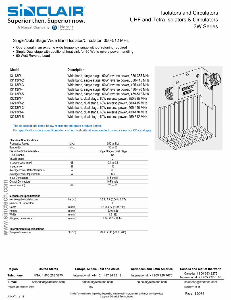
Isolators and CirculatorsUHF and Tetra Isolators & Circulators
I3W Series
Single/Dula Stage Wide Band Isolator/Circulator, 350-512 MHz• Operational in an extreme wide frequency range without retuning required• Single/Dual stage with additional heat sink for 60 Watts revers power handling• 60 Watt Reverse Load
Model DescriptionI3113W-1 Wide band, single stage, 60W reverse power, 350-385 MHzI3113W-2 Wide band, single stage, 60W reverse power, 380-415 MHzI3113W-3 Wide band, single stage, 60W reverse power, 405-440 MHzI3113W-4 Wide band, single stage, 60W reverse power, 430-470 MHzI3113W-5 Wide band, single stage, 60W reverse power, 459-512 MHzI3213W-1 Wide band, dual stage, 60W reverse power, 350-385 MHzI3213W-2 Wide band, dual stage, 60W reverse power, 380-415 MHzI3213W-3 Wide band, dual stage, 60W reverse power, 405-440 MHzI3213W-4 Wide band, dual stage, 60W reverse power, 430-470 MHzI3213W-5 Wide band, dual stage, 60W reverse power, 459-512 MHz
The specifications listed below represent the entire product series.For specifications on a specific model, visit our web site at www.sinctech.com or view our CD catalogue.
Electrical SpecificationsFrequency Range MHz 350 to 512Bandwidth MHz 35 to 53Discription/ Characteristics Single Stage / Dual StageField Tunable NoVSWR (max) 1.2:1Insertion Loss (max) dB 0.4 to 0.8Impedance Ω 50Average Power Reflected (max) W 60Average Power Input (max) W 125Input Connectors N-FemaleOutput Connectors N-FemaleIsolation (min) dB 25 to 50
Mechanical SpecificationsNet Weight (circulator only) lbs (kg) 1.2 to 1.7 (0.54 to 0.77)Number of Connectors 2Depth in (mm) 2.5 to 4.27 (64 to 108)Height in (mm) 3.46 (88)Width in (mm) 1.5 (38)Shipping dimensions in (mm) L 6in W 5in H 4in
Environmental SpecificationsTemperature range °F (°C) -22 to +140 (-30 to +60)
Region United States Europe, Middle East and Africa Caribbean and Latin America Canada and rest of the world
Telephone USA: 1 800 263 3275 International: +44 (0) 1487 84 28 19 International: +1 905 726 7676 Canada: 1 800 263 3275International: +1 905 727 0165
E-mail [email protected] [email protected] [email protected] [email protected] Specification Sheet I3W Dated: 07-01-15
Sinclair’s commitment to product leadership may result in improvement or change to this productCopyright © Sinclair TechnologiesAN.AHT.112/113
www.
sinct
ech.
com
Page 195/379
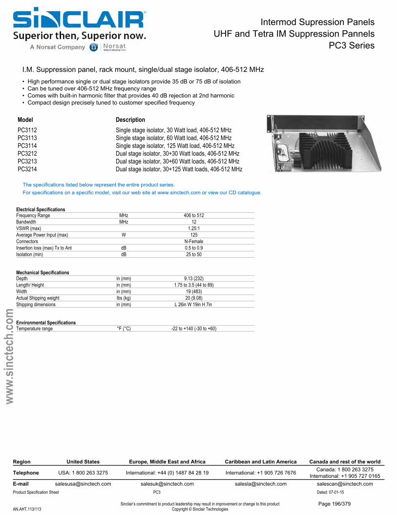
Intermod Supression PanelsUHF and Tetra IM Suppression Pannels
PC3 Series
I.M. Suppression panel, rack mount, single/dual stage isolator, 406-512 MHz• High performance single or dual stage isolators provide 35 dB or 75 dB of isolation• Can be tuned over 406-512 MHz frequency range• Comes with built-in harmonic filter that provides 40 dB rejection at 2nd harmonic• Compact design precisely tuned to customer specified frequency
Model DescriptionPC3112 Single stage isolator, 30 Watt load, 406-512 MHzPC3113 Single stage isolator, 60 Watt load, 406-512 MHzPC3114 Single stage isolator, 125 Watt load, 406-512 MHzPC3212 Dual stage isolator, 30+30 Watt loads, 406-512 MHzPC3213 Dual stage isolator, 30+60 Watt loads, 406-512 MHzPC3214 Dual stage isolator, 30+125 Watt loads, 406-512 MHz
The specifications listed below represent the entire product series.For specifications on a specific model, visit our web site at www.sinctech.com or view our CD catalogue.
Electrical SpecificationsFrequency Range MHz 406 to 512Bandwidth MHz 12VSWR (max) 1.25:1Average Power Input (max) W 125Connectors N-FemaleInsertion loss (max) Tx to Ant dB 0.5 to 0.9Isolation (min) dB 25 to 50
Mechanical SpecificationsDepth in (mm) 9.13 (232)Length/ Height in (mm) 1.75 to 3.5 (44 to 89)Width in (mm) 19 (483)Actual Shipping weight lbs (kg) 20 (9.08)Shipping dimensions in (mm) L 26in W 19in H 7in
Environmental SpecificationsTemperature range °F (°C) -22 to +140 (-30 to +60)
Region United States Europe, Middle East and Africa Caribbean and Latin America Canada and rest of the world
Telephone USA: 1 800 263 3275 International: +44 (0) 1487 84 28 19 International: +1 905 726 7676 Canada: 1 800 263 3275International: +1 905 727 0165
E-mail [email protected] [email protected] [email protected] [email protected] Specification Sheet PC3 Dated: 07-01-15
Sinclair’s commitment to product leadership may result in improvement or change to this productCopyright © Sinclair TechnologiesAN.AHT.113/113
www.
sinct
ech.
com
Page 196/379
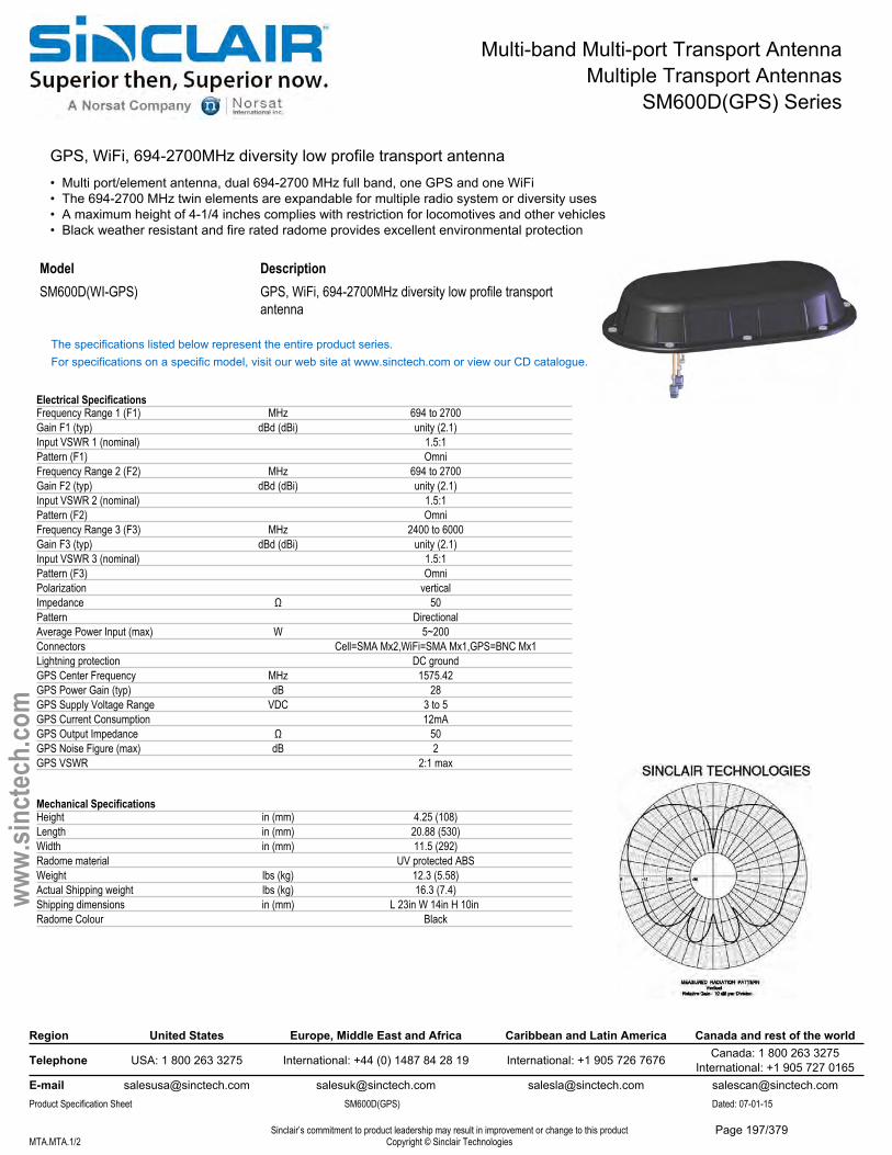
Multi-band Multi-port Transport AntennaMultiple Transport Antennas
SM600D(GPS) Series
GPS, WiFi, 694-2700MHz diversity low profile transport antenna• Multi port/element antenna, dual 694-2700 MHz full band, one GPS and one WiFi• The 694-2700 MHz twin elements are expandable for multiple radio system or diversity uses• A maximum height of 4-1/4 inches complies with restriction for locomotives and other vehicles• Black weather resistant and fire rated radome provides excellent environmental protection
Model DescriptionSM600D(WI-GPS) GPS, WiFi, 694-2700MHz diversity low profile transport
antenna
The specifications listed below represent the entire product series.For specifications on a specific model, visit our web site at www.sinctech.com or view our CD catalogue.
Electrical SpecificationsFrequency Range 1 (F1) MHz 694 to 2700Gain F1 (typ) dBd (dBi) unity (2.1)Input VSWR 1 (nominal) 1.5:1Pattern (F1) OmniFrequency Range 2 (F2) MHz 694 to 2700Gain F2 (typ) dBd (dBi) unity (2.1)Input VSWR 2 (nominal) 1.5:1Pattern (F2) OmniFrequency Range 3 (F3) MHz 2400 to 6000Gain F3 (typ) dBd (dBi) unity (2.1)Input VSWR 3 (nominal) 1.5:1Pattern (F3) OmniPolarization verticalImpedance Ω 50Pattern DirectionalAverage Power Input (max) W 5~200Connectors Cell=SMA Mx2,WiFi=SMA Mx1,GPS=BNC Mx1Lightning protection DC groundGPS Center Frequency MHz 1575.42GPS Power Gain (typ) dB 28GPS Supply Voltage Range VDC 3 to 5GPS Current Consumption 12mAGPS Output Impedance Ω 50GPS Noise Figure (max) dB 2GPS VSWR 2:1 max
Mechanical SpecificationsHeight in (mm) 4.25 (108)Length in (mm) 20.88 (530)Width in (mm) 11.5 (292)Radome material UV protected ABSWeight lbs (kg) 12.3 (5.58)Actual Shipping weight lbs (kg) 16.3 (7.4)Shipping dimensions in (mm) L 23in W 14in H 10in Radome Colour Black
Region United States Europe, Middle East and Africa Caribbean and Latin America Canada and rest of the world
Telephone USA: 1 800 263 3275 International: +44 (0) 1487 84 28 19 International: +1 905 726 7676 Canada: 1 800 263 3275International: +1 905 727 0165
E-mail [email protected] [email protected] [email protected] [email protected] Specification Sheet SM600D(GPS) Dated: 07-01-15
Sinclair’s commitment to product leadership may result in improvement or change to this productCopyright © Sinclair TechnologiesMTA.MTA.1/2
www.
sinct
ech.
com
Page 197/379
Multi-band Multi-port Transport AntennaMultiple Transport Antennas
SM600D(GPS) Series
Environmental SpecificationsHorizontal Wind Resistance 5.03lb@100mphTemperature range °F (°C) -40 to +140 (-40 to +60)Wind Loading Area (Flat Plate Equivalent) ft² (m²) 0.02 (0)
Ordering InformationSpecify connector options at time of order.
Region United States Europe, Middle East and Africa Caribbean and Latin America Canada and rest of the world
Telephone USA: 1 800 263 3275 International: +44 (0) 1487 84 28 19 International: +1 905 726 7676 Canada: 1 800 263 3275International: +1 905 727 0165
E-mail [email protected] [email protected] [email protected] [email protected] Specification Sheet SM600D(GPS) Dated: 07-01-15
Sinclair’s commitment to product leadership may result in improvement or change to this productCopyright © Sinclair TechnologiesMTA.MTA.2/2
www.
sinct
ech.
com
Page 198/379
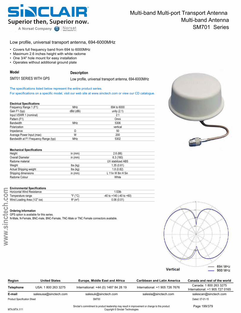
Multi-band Multi-port Transport Antenna Multi-band Antenna
SM701 Series
Low profile, universal transport antenna, 694-6000MHz• Covers full frequency band from 694 to 6000MHz• Maximum 2.6 inches height with white radome• One 3/4" hole mount for easy installation• Operates without additional ground plate
DescriptionModelSM701 SERIES WITH GPS Low profile, universal transport antenna, 694-6000MHz
The specifications listed below represent the entire product series.For specifications on a specific model, visit our web site at www.sinctech.com or view our CD catalogue.
Electrical SpecificationsFrequency Range 1 (F1) MHz 694 to 6000Gain F1 (typ) dBd (dBi) unity (2.1)Input VSWR 1 (nominal) 2:1Pattern (F1) OmniBandwidth MHz 5306Polarization verticalImpedance Ω 50Average Power Input (max) W 200Bandwidth at F1 Frequency Range (typ) MHz 5302
Mechanical SpecificationsHeight in (mm) 2.6 (66)Overall Diameter in (mm) 6.3 (160)Radome material UV stabilized ABSWeight lbs (kg) 1.35 (0.61)Actual Shipping weight lbs (kg) 1.8 (0.82)Shipping dimensions in (mm) L 11in W 8in H 5in Radome Colour White
Environmental SpecificationsHorizontal Wind Resistance 1.53lbTemperature range °F (°C) -40 to +140 (-40 to +60)Wind Loading Area (1/2" ice) ft² (m²) 0.06 (0.01)
Ordering InformationGPS option is available for this series.N-Male, N-Female, BNC-male, BNC-Female, TNC-Male or TNC Female connectors available.
Region United States Europe, Middle East and Africa Caribbean and Latin America Canada and rest of the world
Telephone USA: 1 800 263 3275 International: +44 (0) 1487 84 28 19 International: +1 905 726 7676 Canada: 1 800 263 3275International: +1 905 727 0165
E-mail [email protected] [email protected] [email protected] [email protected] Specification Sheet SM700 Dated: 07-01-15
Sinclair’s commitment to product leadership may result in improvement or change to this productCopyright © Sinclair TechnologiesMTA.MTA.1/11
www.
sinct
ech.
com
Page 199/379
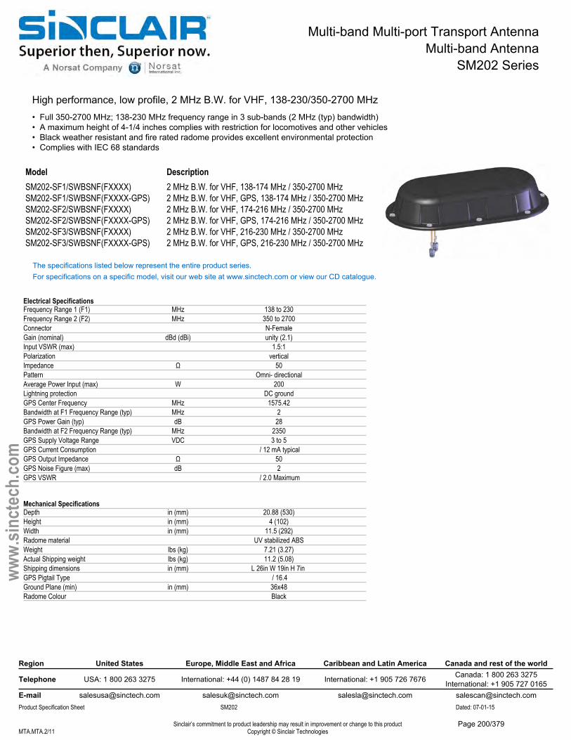
Multi-band Multi-port Transport AntennaMulti-band Antenna
SM202 Series
High performance, low profile, 2 MHz B.W. for VHF, 138-230/350-2700 MHz • Full 350-2700 MHz; 138-230 MHz frequency range in 3 sub-bands (2 MHz (typ) bandwidth)• A maximum height of 4-1/4 inches complies with restriction for locomotives and other vehicles• Black weather resistant and fire rated radome provides excellent environmental protection• Complies with IEC 68 standards
Model DescriptionSM202-SF1/SWBSNF(FXXXX) 2 MHz B.W. for VHF, 138-174 MHz / 350-2700 MHzSM202-SF1/SWBSNF(FXXXX-GPS) 2 MHz B.W. for VHF, GPS, 138-174 MHz / 350-2700 MHzSM202-SF2/SWBSNF(FXXXX) 2 MHz B.W. for VHF, 174-216 MHz / 350-2700 MHzSM202-SF2/SWBSNF(FXXXX-GPS) 2 MHz B.W. for VHF, GPS, 174-216 MHz / 350-2700 MHzSM202-SF3/SWBSNF(FXXXX) 2 MHz B.W. for VHF, 216-230 MHz / 350-2700 MHzSM202-SF3/SWBSNF(FXXXX-GPS) 2 MHz B.W. for VHF, GPS, 216-230 MHz / 350-2700 MHz
The specifications listed below represent the entire product series.For specifications on a specific model, visit our web site at www.sinctech.com or view our CD catalogue.
Electrical SpecificationsFrequency Range 1 (F1) MHz 138 to 230Frequency Range 2 (F2) MHz 350 to 2700Connector N-FemaleGain (nominal) dBd (dBi) unity (2.1)Input VSWR (max) 1.5:1Polarization verticalImpedance Ω 50Pattern Omni- directionalAverage Power Input (max) W 200Lightning protection DC groundGPS Center Frequency MHz 1575.42Bandwidth at F1 Frequency Range (typ) MHz 2GPS Power Gain (typ) dB 28Bandwidth at F2 Frequency Range (typ) MHz 2350GPS Supply Voltage Range VDC 3 to 5GPS Current Consumption / 12 mA typicalGPS Output Impedance Ω 50GPS Noise Figure (max) dB 2GPS VSWR / 2.0 Maximum
Mechanical SpecificationsDepth in (mm) 20.88 (530)Height in (mm) 4 (102)Width in (mm) 11.5 (292)Radome material UV stabilized ABSWeight lbs (kg) 7.21 (3.27)Actual Shipping weight lbs (kg) 11.2 (5.08)Shipping dimensions in (mm) L 26in W 19in H 7in GPS Pigtail Type / 16.4Ground Plane (min) in (mm) 36x48Radome Colour Black
Region United States Europe, Middle East and Africa Caribbean and Latin America Canada and rest of the world
Telephone USA: 1 800 263 3275 International: +44 (0) 1487 84 28 19 International: +1 905 726 7676 Canada: 1 800 263 3275International: +1 905 727 0165
E-mail [email protected] [email protected] [email protected] [email protected] Specification Sheet SM202 Dated: 07-01-15
Sinclair’s commitment to product leadership may result in improvement or change to this productCopyright © Sinclair TechnologiesMTA.MTA.2/11
www.
sinct
ech.
com
Page 200/379

Multi-band Multi-port Transport AntennaMulti-band Antenna
SM202 Series
Environmental SpecificationsHorizontal Wind Resistance 5.03 lb @ 100 mphTemperature range °F (°C) -40 to +140 (-40 to +60)Wind Loading Area (Flat Plate Equivalent) ft² (m²) 0.17 (0.02)GPS Operating Temperature °F (°C) -22 to 140 (-30 to 60)
Ordering InformationPlease specify VHF center frequency, connector and GPS options in your order. TNC and BNC Connector option available.
Region United States Europe, Middle East and Africa Caribbean and Latin America Canada and rest of the world
Telephone USA: 1 800 263 3275 International: +44 (0) 1487 84 28 19 International: +1 905 726 7676 Canada: 1 800 263 3275International: +1 905 727 0165
E-mail [email protected] [email protected] [email protected] [email protected] Specification Sheet SM202 Dated: 07-01-15
Sinclair’s commitment to product leadership may result in improvement or change to this productCopyright © Sinclair TechnologiesMTA.MTA.3/11
www.
sinct
ech.
com
Page 201/379
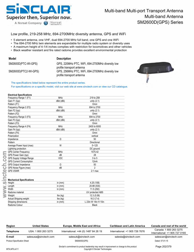
Multi-band Multi-port Transport AntennaMulti-band Antenna
SM2600D(GPS) Series
Low profile, 219-258 MHz, 694-2700MHz diversity antenna, GPS and WiFi• 5 element antenna, one VHF, dual 694-2700 MHz full band, one GPS and one WiFi• The 694-2700 MHz twin elements are expandable for multiple radio system or diversity uses• A maximum height of 4-1/4 inches complies with restriction for locomotives and other vehicles• Black weather resistant and fire rated radome provides excellent environmental protection
Model DescriptionSM2600D(PTC-WI-GPS) GPS, 220MHz PTC, WiFi, 694-2700MHz diversity low
profile transport antennaSM2600D(PTC2-WI-GPS) GPS, 256MHz PTC, WiFi, 694-2700MHz diversity low
profile transport antenna
The specifications listed below represent the entire product series.For specifications on a specific model, visit our web site at www.sinctech.com or view our CD catalogue.
Electrical SpecificationsFrequency Range 1 (F1) MHz 219 to 258Gain F1 (typ) dBd (dBi) unity (2.1)Pattern (F1) OmniFrequency Range 2 (F2) MHz 694 to 2700Gain F2 (typ) dBd (dBi) unity (2.1)Pattern (F2) OmniFrequency Range 3 (F3) MHz 694 to 2700Gain F3 (typ) dBd (dBi) unity (2.1)Pattern (F3) OmniFrequency Range 4 (F4) MHz 2400 to 6000Gain F4 (typ) dBd (dBi) unity (2.1)Pattern (F4) OmniPolarization verticalImpedance Ω 50Pattern DirectionalAverage Power Input (max) W 5~125Lightning protection DC groundGPS Center Frequency MHz 1575.42GPS Power Gain (typ) dB 28GPS Supply Voltage Range VDC 3 to 5GPS Current Consumption 12mAGPS Output Impedance Ω 50GPS Noise Figure (max) dB 2GPS VSWR 2:1 max
Mechanical SpecificationsHeight in (mm) 4.25 (108)Length in (mm) 20.88 (530)Width in (mm) 11.5 (292)Radome material UV protected ABSWeight lbs (kg) 12.3 (5.58)Actual Shipping weight lbs (kg) 16.3 (7.4)Shipping dimensions in (mm) L 23in W 14in H 10in Radome Colour Black
Region United States Europe, Middle East and Africa Caribbean and Latin America Canada and rest of the world
Telephone USA: 1 800 263 3275 International: +44 (0) 1487 84 28 19 International: +1 905 726 7676 Canada: 1 800 263 3275International: +1 905 727 0165
E-mail [email protected] [email protected] [email protected] [email protected] Specification Sheet SM2600D(GPS) Dated: 07-01-15
Sinclair’s commitment to product leadership may result in improvement or change to this productCopyright © Sinclair TechnologiesMTA.MTA.4/11
www.
sinct
ech.
com
Page 202/379
Multi-band Multi-port Transport AntennaMulti-band Antenna
SM2600D(GPS) Series
Environmental SpecificationsHorizontal Wind Resistance 5.03lb@100mphTemperature range °F (°C) -40 to +140 (-40 to +60)Wind Loading Area (Flat Plate Equivalent) ft² (m²) 0.02 (0)
Ordering InformationSpecify VHF center frequency, connector type and GPS option at time of order.
Region United States Europe, Middle East and Africa Caribbean and Latin America Canada and rest of the world
Telephone USA: 1 800 263 3275 International: +44 (0) 1487 84 28 19 International: +1 905 726 7676 Canada: 1 800 263 3275International: +1 905 727 0165
E-mail [email protected] [email protected] [email protected] [email protected] Specification Sheet SM2600D(GPS) Dated: 07-01-15
Sinclair’s commitment to product leadership may result in improvement or change to this productCopyright © Sinclair TechnologiesMTA.MTA.5/11
www.
sinct
ech.
com
Page 203/379
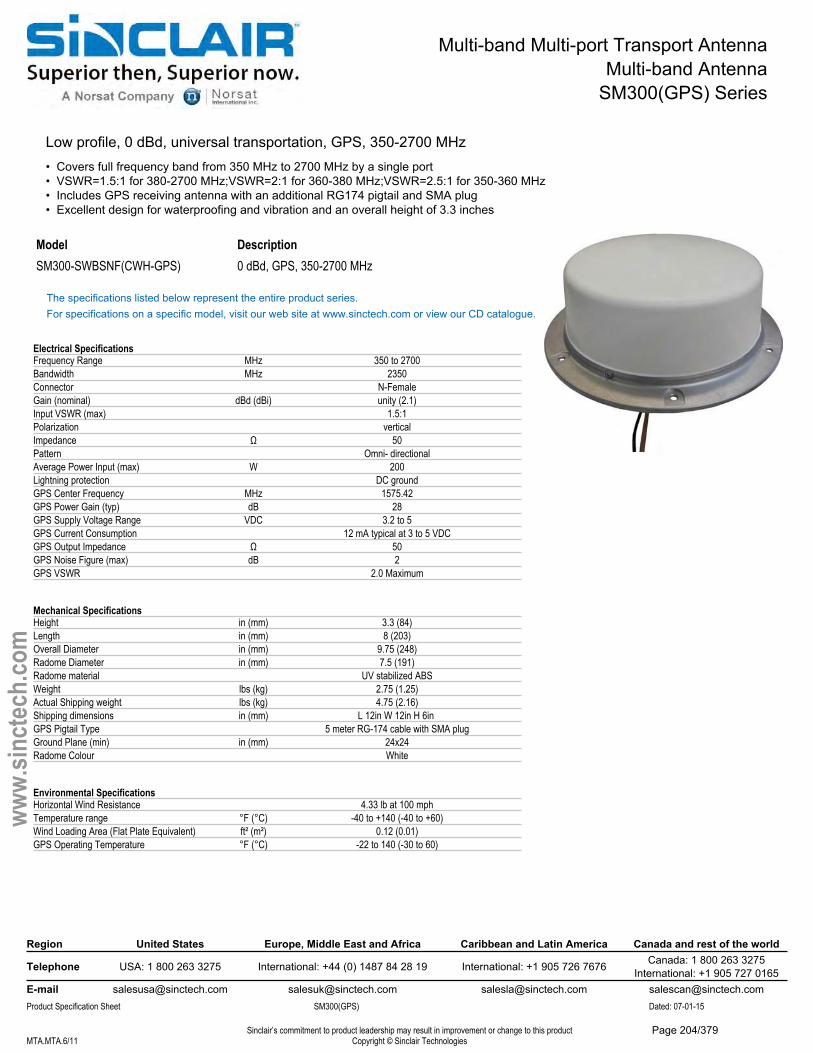
Multi-band Multi-port Transport AntennaMulti-band Antenna
SM300(GPS) Series
Low profile, 0 dBd, universal transportation, GPS, 350-2700 MHz• Covers full frequency band from 350 MHz to 2700 MHz by a single port• VSWR=1.5:1 for 380-2700 MHz;VSWR=2:1 for 360-380 MHz;VSWR=2.5:1 for 350-360 MHz• Includes GPS receiving antenna with an additional RG174 pigtail and SMA plug• Excellent design for waterproofing and vibration and an overall height of 3.3 inches
Model DescriptionSM300-SWBSNF(CWH-GPS) 0 dBd, GPS, 350-2700 MHz
The specifications listed below represent the entire product series.For specifications on a specific model, visit our web site at www.sinctech.com or view our CD catalogue.
Electrical SpecificationsFrequency Range MHz 350 to 2700Bandwidth MHz 2350Connector N-FemaleGain (nominal) dBd (dBi) unity (2.1)Input VSWR (max) 1.5:1Polarization verticalImpedance Ω 50Pattern Omni- directionalAverage Power Input (max) W 200Lightning protection DC groundGPS Center Frequency MHz 1575.42GPS Power Gain (typ) dB 28GPS Supply Voltage Range VDC 3.2 to 5GPS Current Consumption 12 mA typical at 3 to 5 VDCGPS Output Impedance Ω 50GPS Noise Figure (max) dB 2GPS VSWR 2.0 Maximum
Mechanical SpecificationsHeight in (mm) 3.3 (84)Length in (mm) 8 (203)Overall Diameter in (mm) 9.75 (248)Radome Diameter in (mm) 7.5 (191)Radome material UV stabilized ABSWeight lbs (kg) 2.75 (1.25)Actual Shipping weight lbs (kg) 4.75 (2.16)Shipping dimensions in (mm) L 12in W 12in H 6in GPS Pigtail Type 5 meter RG-174 cable with SMA plugGround Plane (min) in (mm) 24x24Radome Colour White
Environmental SpecificationsHorizontal Wind Resistance 4.33 lb at 100 mphTemperature range °F (°C) -40 to +140 (-40 to +60)Wind Loading Area (Flat Plate Equivalent) ft² (m²) 0.12 (0.01)GPS Operating Temperature °F (°C) -22 to 140 (-30 to 60)
Region United States Europe, Middle East and Africa Caribbean and Latin America Canada and rest of the world
Telephone USA: 1 800 263 3275 International: +44 (0) 1487 84 28 19 International: +1 905 726 7676 Canada: 1 800 263 3275International: +1 905 727 0165
E-mail [email protected] [email protected] [email protected] [email protected] Specification Sheet SM300(GPS) Dated: 07-01-15
Sinclair’s commitment to product leadership may result in improvement or change to this productCopyright © Sinclair TechnologiesMTA.MTA.6/11
www.
sinct
ech.
com
Page 204/379
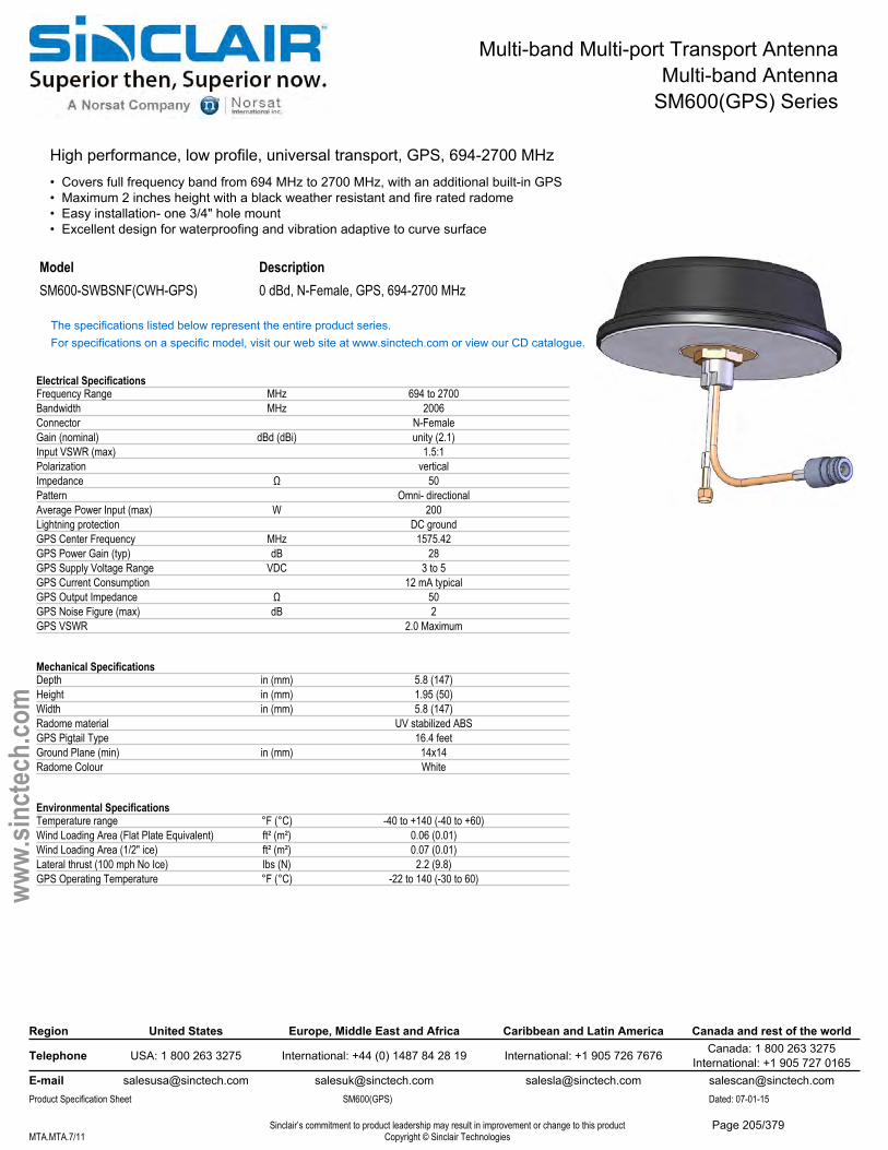
Multi-band Multi-port Transport AntennaMulti-band Antenna
SM600(GPS) Series
High performance, low profile, universal transport, GPS, 694-2700 MHz• Covers full frequency band from 694 MHz to 2700 MHz, with an additional built-in GPS• Maximum 2 inches height with a black weather resistant and fire rated radome• Easy installation- one 3/4" hole mount• Excellent design for waterproofing and vibration adaptive to curve surface
Model DescriptionSM600-SWBSNF(CWH-GPS) 0 dBd, N-Female, GPS, 694-2700 MHz
The specifications listed below represent the entire product series.For specifications on a specific model, visit our web site at www.sinctech.com or view our CD catalogue.
Electrical SpecificationsFrequency Range MHz 694 to 2700Bandwidth MHz 2006Connector N-FemaleGain (nominal) dBd (dBi) unity (2.1)Input VSWR (max) 1.5:1Polarization verticalImpedance Ω 50Pattern Omni- directionalAverage Power Input (max) W 200Lightning protection DC groundGPS Center Frequency MHz 1575.42GPS Power Gain (typ) dB 28GPS Supply Voltage Range VDC 3 to 5GPS Current Consumption 12 mA typicalGPS Output Impedance Ω 50GPS Noise Figure (max) dB 2GPS VSWR 2.0 Maximum
Mechanical SpecificationsDepth in (mm) 5.8 (147)Height in (mm) 1.95 (50)Width in (mm) 5.8 (147)Radome material UV stabilized ABSGPS Pigtail Type 16.4 feetGround Plane (min) in (mm) 14x14Radome Colour White
Environmental SpecificationsTemperature range °F (°C) -40 to +140 (-40 to +60)Wind Loading Area (Flat Plate Equivalent) ft² (m²) 0.06 (0.01)Wind Loading Area (1/2" ice) ft² (m²) 0.07 (0.01)Lateral thrust (100 mph No Ice) lbs (N) 2.2 (9.8)GPS Operating Temperature °F (°C) -22 to 140 (-30 to 60)
Region United States Europe, Middle East and Africa Caribbean and Latin America Canada and rest of the world
Telephone USA: 1 800 263 3275 International: +44 (0) 1487 84 28 19 International: +1 905 726 7676 Canada: 1 800 263 3275International: +1 905 727 0165
E-mail [email protected] [email protected] [email protected] [email protected] Specification Sheet SM600(GPS) Dated: 07-01-15
Sinclair’s commitment to product leadership may result in improvement or change to this productCopyright © Sinclair TechnologiesMTA.MTA.7/11
www.
sinct
ech.
com
Page 205/379
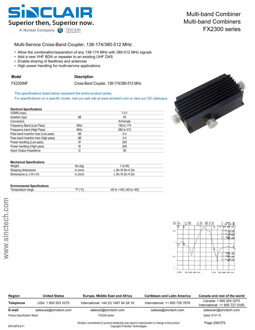
Multi-band CombinerMulti-band Combiners
FX2300 series
Multi-Service Cross-Band Coupler, 138-174/380-512 MHz• Allow the combination/separation of any 138-174 MHz with 380-512 MHz signals• Add a new VHF BDA or repeater to an existing UHF DAS• Enable sharing of feedlines and antennas• High power handling for multi-service applications
Model DescriptionFX2300NF Cross-Band Coupler, 138-174/380-512 MHz
The specifications listed below represent the entire product series.For specifications on a specific model, visit our web site at www.sinctech.com or view our CD catalogue.
Electrical SpecificationsVSWR (max) 1.5:1Isolation (typ) dB 40Connectors N-FemaleFrequency Band (Low Pass) MHz 138 to 174Frequency band (High Pass) MHz 380 to 512Pass band insertion loss (Low pass) dB 0.4Pass band insertion loss (High pass) dB 0.4Power handling (Low pass) W 200Power handling (High pass) W 200Input/ Output Impedance Ω 50
Mechanical SpecificationsWeight lbs (kg) 1 (0.45)Shipping dimensions in (mm) L 9in W 6in H 3in Dimensions (L x W x H) in (mm) L 5in W 2in H 2in
Environmental SpecificationsTemperature range °F (°C) -40 to +140 (-40 to +60)
Region United States Europe, Middle East and Africa Caribbean and Latin America Canada and rest of the world
Telephone USA: 1 800 263 3275 International: +44 (0) 1487 84 28 19 International: +1 905 726 7676 Canada: 1 800 263 3275International: +1 905 727 0165
E-mail [email protected] [email protected] [email protected] [email protected] Specification Sheet FX2300 series Dated: 07-01-15
Sinclair’s commitment to product leadership may result in improvement or change to this productCopyright © Sinclair TechnologiesMTA.MTA.8/11
www.
sinct
ech.
com
Page 206/379
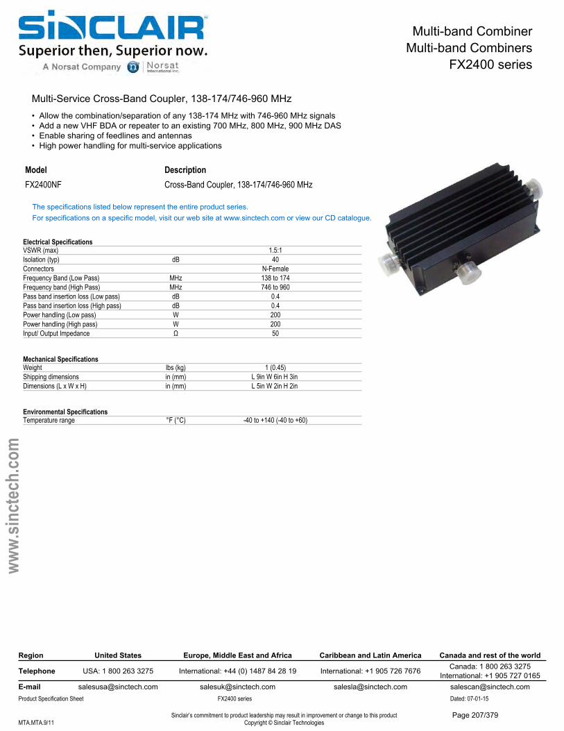
Multi-band CombinerMulti-band Combiners
FX2400 series
Multi-Service Cross-Band Coupler, 138-174/746-960 MHz• Allow the combination/separation of any 138-174 MHz with 746-960 MHz signals• Add a new VHF BDA or repeater to an existing 700 MHz, 800 MHz, 900 MHz DAS• Enable sharing of feedlines and antennas• High power handling for multi-service applications
Model DescriptionFX2400NF Cross-Band Coupler, 138-174/746-960 MHz
The specifications listed below represent the entire product series.For specifications on a specific model, visit our web site at www.sinctech.com or view our CD catalogue.
Electrical SpecificationsVSWR (max) 1.5:1Isolation (typ) dB 40Connectors N-FemaleFrequency Band (Low Pass) MHz 138 to 174Frequency band (High Pass) MHz 746 to 960Pass band insertion loss (Low pass) dB 0.4Pass band insertion loss (High pass) dB 0.4Power handling (Low pass) W 200Power handling (High pass) W 200Input/ Output Impedance Ω 50
Mechanical SpecificationsWeight lbs (kg) 1 (0.45)Shipping dimensions in (mm) L 9in W 6in H 3in Dimensions (L x W x H) in (mm) L 5in W 2in H 2in
Environmental SpecificationsTemperature range °F (°C) -40 to +140 (-40 to +60)
Region United States Europe, Middle East and Africa Caribbean and Latin America Canada and rest of the world
Telephone USA: 1 800 263 3275 International: +44 (0) 1487 84 28 19 International: +1 905 726 7676 Canada: 1 800 263 3275International: +1 905 727 0165
E-mail [email protected] [email protected] [email protected] [email protected] Specification Sheet FX2400 series Dated: 07-01-15
Sinclair’s commitment to product leadership may result in improvement or change to this productCopyright © Sinclair TechnologiesMTA.MTA.9/11
www.
sinct
ech.
com
Page 207/379

Multi-band CombinerMulti-band Combiners
FX3400 Series
Multi-Service Cross-Band Coupler, 138-512/746-960 MHz• Allow the combination/separation of any 138-512 MHz with 746-960 MHz signals• Add a new VHF or UHF BDA or repeater to an existing 700 MHz, 800 MHz, 900 MHz DAS• Enable sharing of feedlines and antennas• High power handling for multi-service applications
Model DescriptionFX3400NF Cross-Band Coupler, 138-512/746-960 MHz
The specifications listed below represent the entire product series.For specifications on a specific model, visit our web site at www.sinctech.com or view our CD catalogue.
Electrical SpecificationsVSWR (max) 1.5:1Isolation (typ) dB 40Connectors N-FemaleFrequency Band (Low Pass) MHz 138 to 512Frequency band (High Pass) MHz 746 to 960Pass band insertion loss (Low pass) dB 0.4Pass band insertion loss (High pass) dB 0.4Power handling (Low pass) W 200Power handling (High pass) W 200Input/ Output Impedance Ω 50
Mechanical SpecificationsWeight lbs (kg) 1 (0.45)Shipping dimensions in (mm) L 9in W 6in H 3in Dimensions (L x W x H) in (mm) L 5in W 2in H 2in
Environmental SpecificationsTemperature range °F (°C) -40 to +140 (-40 to +60)
Region United States Europe, Middle East and Africa Caribbean and Latin America Canada and rest of the world
Telephone USA: 1 800 263 3275 International: +44 (0) 1487 84 28 19 International: +1 905 726 7676 Canada: 1 800 263 3275International: +1 905 727 0165
E-mail [email protected] [email protected] [email protected] [email protected] Specification Sheet FX3400 Series Dated: 07-01-15
Sinclair’s commitment to product leadership may result in improvement or change to this productCopyright © Sinclair TechnologiesMTA.MTA.10/11
www.
sinct
ech.
com
Page 208/379

Multi-band CombinerMulti-band Combiners
FX4500 Series
Multi-Service Cross-Band Coupler, 138-960/1710-2500 MHz• Allow the combination/separation of any 138-960MHz with 1710-2500MHz signals• Add a CDMA, UMTS, DCS, PCS, or AWS BDA or repeater to an existing Cellular and SMR DAS• Enable sharing of feedlines and antennas• High power handling for multi-service applications
Model DescriptionFX4500NF Cross-Band Coupler, 138-960/1710-2500 MHz
The specifications listed below represent the entire product series.For specifications on a specific model, visit our web site at www.sinctech.com or view our CD catalogue.
Electrical SpecificationsVSWR (max) 1.5:1Isolation (typ) dB 40Connectors N-FemaleFrequency Band (Low Pass) MHz 138 to 960Frequency band (High Pass) MHz 1710 to 2500Pass band insertion loss (Low pass) dB 0.4Pass band insertion loss (High pass) dB 0.4Power handling (Low pass) W 250Power handling (High pass) W 50Input/ Output Impedance Ω 50
Mechanical SpecificationsWeight lbs (kg) 1 (0.45)Shipping dimensions in (mm) L 9in W 6in H 3in Dimensions (L x W x H) in (mm) L 5in W 2in H 1in
Environmental SpecificationsTemperature range °F (°C) -40 to +140 (-40 to +60)
Region United States Europe, Middle East and Africa Caribbean and Latin America Canada and rest of the world
Telephone USA: 1 800 263 3275 International: +44 (0) 1487 84 28 19 International: +1 905 726 7676 Canada: 1 800 263 3275International: +1 905 727 0165
E-mail [email protected] [email protected] [email protected] [email protected] Specification Sheet FX4500 Series Dated: 07-01-15
Sinclair’s commitment to product leadership may result in improvement or change to this productCopyright © Sinclair TechnologiesMTA.MTA.11/11
www.
sinct
ech.
com
Page 209/379
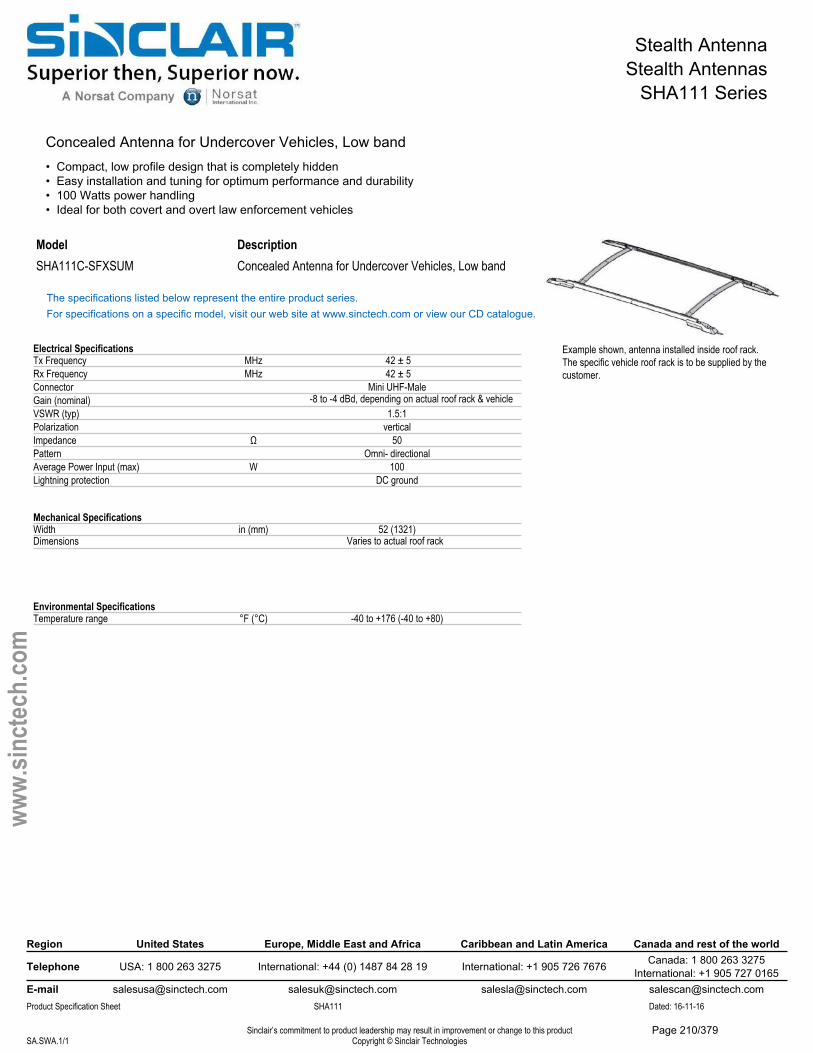
Stealth AntennaStealth Antennas
SHA111 Series
Concealed Antenna for Undercover Vehicles, Low band• Compact, low profile design that is completely hidden• Easy installation and tuning for optimum performance and durability• 100 Watts power handling• Ideal for both covert and overt law enforcement vehicles
Model DescriptionSHA111C-SFXSUM Concealed Antenna for Undercover Vehicles, Low band
The specifications listed below represent the entire product series.For specifications on a specific model, visit our web site at www.sinctech.com or view our CD catalogue.
Electrical SpecificationsTx Frequency MHz 42 ± 5Rx Frequency MHz 42 ± 5Connector Mini UHF-MaleGain (nominal) -8 to -4 dBd, depending on actual roof rack & vehicleVSWR (typ) 1.5:1Polarization verticalImpedance Ω 50Pattern Omni- directionalAverage Power Input (max) W 100Lightning protection DC ground
Mechanical SpecificationsWidth in (mm) 52 (1321)Dimensions Varies to actual roof rack
Environmental SpecificationsTemperature range °F (°C) -40 to +176 (-40 to +80)
Region United States Europe, Middle East and Africa Caribbean and Latin America Canada and rest of the world
Telephone USA: 1 800 263 3275 International: +44 (0) 1487 84 28 19 International: +1 905 726 7676 Canada: 1 800 263 3275International: +1 905 727 0165
E-mail [email protected] [email protected] [email protected] [email protected] Specification Sheet SHA111 Dated: 16-11-16
Sinclair’s commitment to product leadership may result in improvement or change to this productCopyright © Sinclair TechnologiesSA.SWA.1/1
www.
sinct
ech.
com
Example shown, antenna installed inside roof rack.The specific vehicle roof rack is to be supplied by the customer.
Page 210/379

Stealth AntennaStealth Antennas
SHA211 Series
Concealed Single/Dual Antenna for Undercover Vehicles, 138-174 MHz• Compact design that is completely hidden• Single unit can handle 150 Watts, dual can handle 300 Watts• Easy installation and tuning for optimum performance and durability• Ideal for both covert and overt law enforcement vehicles
Model DescriptionSHA211-SF1SNM 3-6 MHz B.W., 150-174MHzSHA211-SF2SNM 3-6 MHz B.W., 150-174MHzSHA2112-SF1SNM Dual, 138-150 MHzSHA2112-SF2SNM Dual, 150-174 MHz
The specifications listed below represent the entire product series.For specifications on a specific model, visit our web site at www.sinctech.com or view our CD catalogue.
Electrical SpecificationsFrequency Range MHz 138 to 174Connector N-MaleGain (nominal) dBd (dBi) unity (2.1)Input VSWR (max) 2:1Polarization verticalImpedance Ω 50Pattern Omni- directionalAverage Power Input (max) W 150 / 300Bandwidth (Min-Max) MHz 3 to 6
Mechanical SpecificationsDepth in (mm) 2 (51)Length/ Height in (mm) 22 (559)Width in (mm) 3 (76)Shipping dimensions in (mm) L 9in W 14in H 5in Mounting hardware #8-32 screws (4)
Environmental SpecificationsTemperature range °F (°C) -40 to +140 (-40 to +60)
Ordering InformationClips are supplied to temporarily secure the radiator to the bumper. VA250 glue should be used for added support (may be ordered separately Sinclair part number 6500295).
Region United States Europe, Middle East and Africa Caribbean and Latin America Canada and rest of the world
Telephone USA: 1 800 263 3275 International: +44 (0) 1487 84 28 19 International: +1 905 726 7676 Canada: 1 800 263 3275International: +1 905 727 0165
E-mail [email protected] [email protected] [email protected] [email protected] Specification Sheet SHA211 Series Dated: 07-01-15
Sinclair’s commitment to product leadership may result in improvement or change to this productCopyright © Sinclair TechnologiesSA.SWA.1/3
www.
sinct
ech.
com
Page 211/379
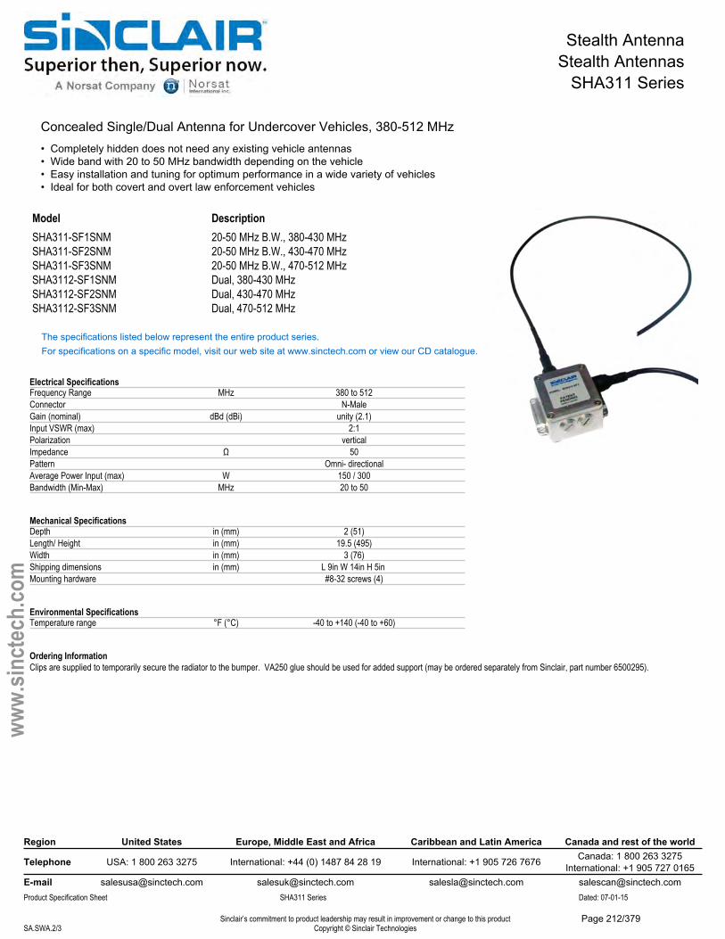
Stealth AntennaStealth Antennas
SHA311 Series
Concealed Single/Dual Antenna for Undercover Vehicles, 380-512 MHz• Completely hidden does not need any existing vehicle antennas• Wide band with 20 to 50 MHz bandwidth depending on the vehicle• Easy installation and tuning for optimum performance in a wide variety of vehicles• Ideal for both covert and overt law enforcement vehicles
Model DescriptionSHA311-SF1SNM 20-50 MHz B.W., 380-430 MHzSHA311-SF2SNM 20-50 MHz B.W., 430-470 MHzSHA311-SF3SNM 20-50 MHz B.W., 470-512 MHzSHA3112-SF1SNM Dual, 380-430 MHzSHA3112-SF2SNM Dual, 430-470 MHzSHA3112-SF3SNM Dual, 470-512 MHz
The specifications listed below represent the entire product series.For specifications on a specific model, visit our web site at www.sinctech.com or view our CD catalogue.
Electrical SpecificationsFrequency Range MHz 380 to 512Connector N-MaleGain (nominal) dBd (dBi) unity (2.1)Input VSWR (max) 2:1Polarization verticalImpedance Ω 50Pattern Omni- directionalAverage Power Input (max) W 150 / 300Bandwidth (Min-Max) MHz 20 to 50
Mechanical SpecificationsDepth in (mm) 2 (51)Length/ Height in (mm) 19.5 (495)Width in (mm) 3 (76)Shipping dimensions in (mm) L 9in W 14in H 5in Mounting hardware #8-32 screws (4)
Environmental SpecificationsTemperature range °F (°C) -40 to +140 (-40 to +60)
Ordering InformationClips are supplied to temporarily secure the radiator to the bumper. VA250 glue should be used for added support (may be ordered separately from Sinclair, part number 6500295).
Region United States Europe, Middle East and Africa Caribbean and Latin America Canada and rest of the world
Telephone USA: 1 800 263 3275 International: +44 (0) 1487 84 28 19 International: +1 905 726 7676 Canada: 1 800 263 3275International: +1 905 727 0165
E-mail [email protected] [email protected] [email protected] [email protected] Specification Sheet SHA311 Series Dated: 07-01-15
Sinclair’s commitment to product leadership may result in improvement or change to this productCopyright © Sinclair TechnologiesSA.SWA.2/3
www.
sinct
ech.
com
Page 212/379
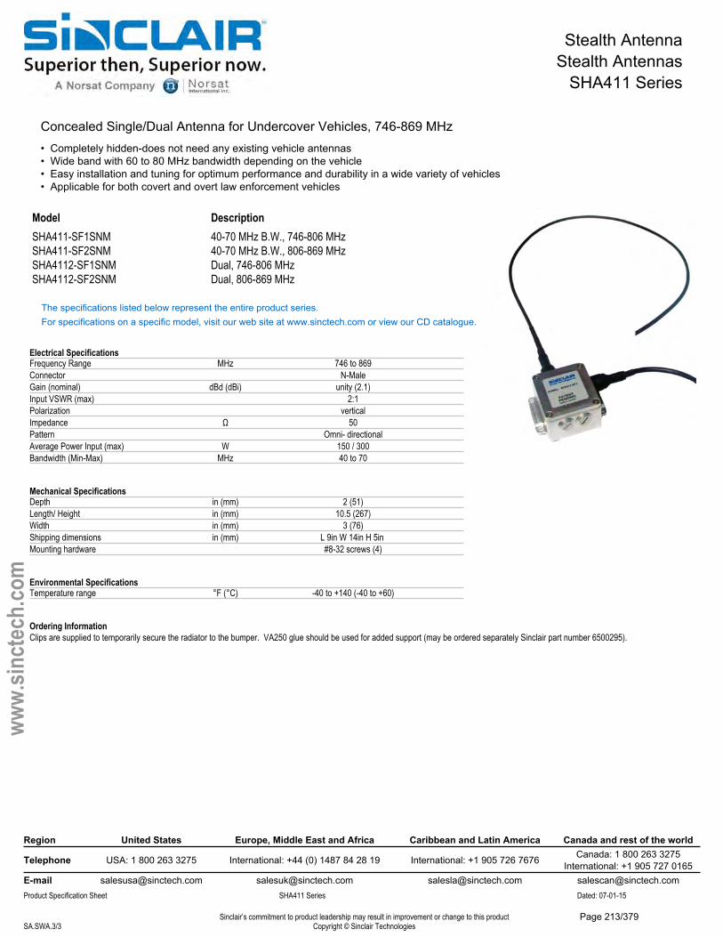
Stealth AntennaStealth Antennas
SHA411 Series
Concealed Single/Dual Antenna for Undercover Vehicles, 746-869 MHz• Completely hidden-does not need any existing vehicle antennas• Wide band with 60 to 80 MHz bandwidth depending on the vehicle• Easy installation and tuning for optimum performance and durability in a wide variety of vehicles• Applicable for both covert and overt law enforcement vehicles
Model DescriptionSHA411-SF1SNM 40-70 MHz B.W., 746-806 MHzSHA411-SF2SNM 40-70 MHz B.W., 806-869 MHzSHA4112-SF1SNM Dual, 746-806 MHzSHA4112-SF2SNM Dual, 806-869 MHz
The specifications listed below represent the entire product series.For specifications on a specific model, visit our web site at www.sinctech.com or view our CD catalogue.
Electrical SpecificationsFrequency Range MHz 746 to 869Connector N-MaleGain (nominal) dBd (dBi) unity (2.1)Input VSWR (max) 2:1Polarization verticalImpedance Ω 50Pattern Omni- directionalAverage Power Input (max) W 150 / 300Bandwidth (Min-Max) MHz 40 to 70
Mechanical SpecificationsDepth in (mm) 2 (51)Length/ Height in (mm) 10.5 (267)Width in (mm) 3 (76)Shipping dimensions in (mm) L 9in W 14in H 5in Mounting hardware #8-32 screws (4)
Environmental SpecificationsTemperature range °F (°C) -40 to +140 (-40 to +60)
Ordering InformationClips are supplied to temporarily secure the radiator to the bumper. VA250 glue should be used for added support (may be ordered separately Sinclair part number 6500295).
Region United States Europe, Middle East and Africa Caribbean and Latin America Canada and rest of the world
Telephone USA: 1 800 263 3275 International: +44 (0) 1487 84 28 19 International: +1 905 726 7676 Canada: 1 800 263 3275International: +1 905 727 0165
E-mail [email protected] [email protected] [email protected] [email protected] Specification Sheet SHA411 Series Dated: 07-01-15
Sinclair’s commitment to product leadership may result in improvement or change to this productCopyright © Sinclair TechnologiesSA.SWA.3/3
www.
sinct
ech.
com
Page 213/379
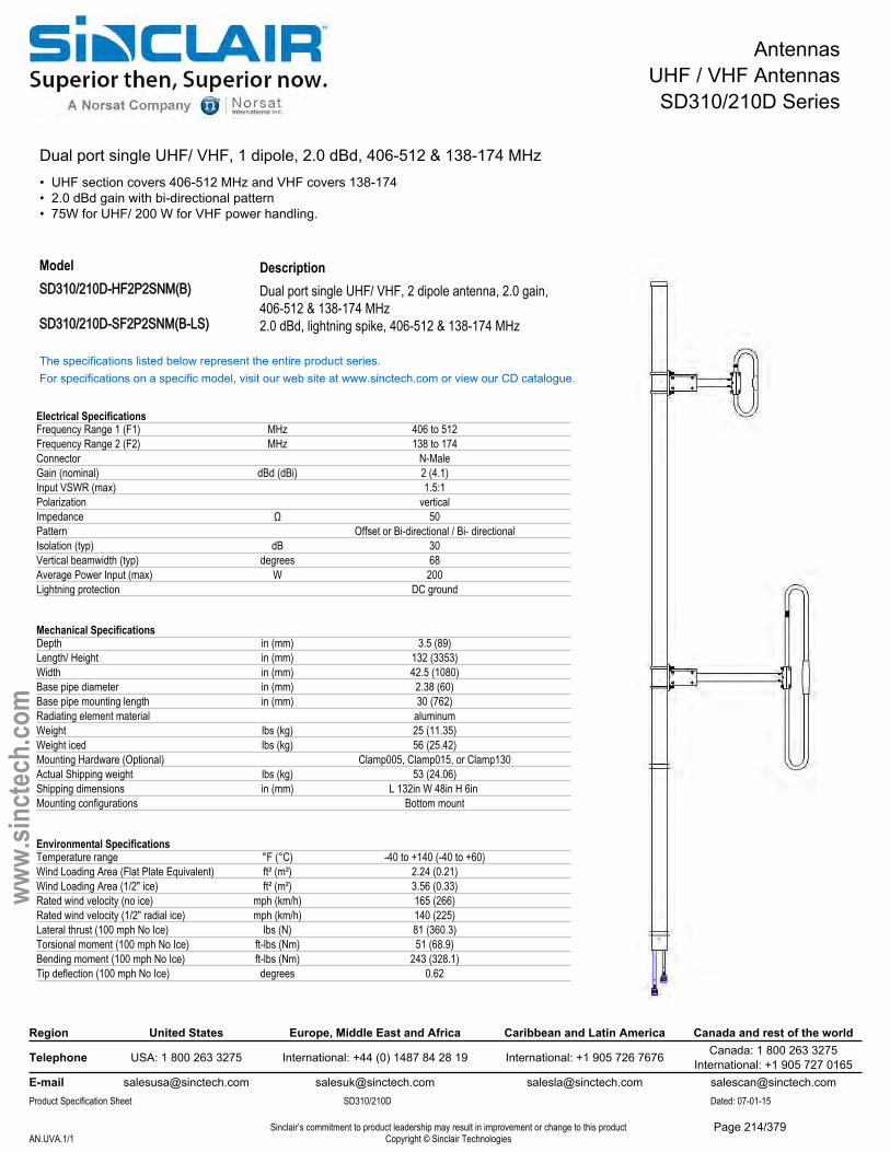
AntennasUHF / VHF AntennasSD310/210D Series
Dual port single UHF/ VHF, 1 dipole, 2.0 dBd, 406-512 & 138-174 MHz• UHF section covers 406-512 MHz and VHF covers 138-174• 2.0 dBd gain with bi-directional pattern• 75W for UHF/ 200 W for VHF power handling.
DescriptionDual port single UHF/ VHF, 2 dipole antenna, 2.0 gain,406-512 & 138-174 MHz
ModelSD310/210D-HF2P2SNM(B)
SD310/210D-SF2P2SNM(B-LS) 2.0 dBd, lightning spike, 406-512 & 138-174 MHz
The specifications listed below represent the entire product series.For specifications on a specific model, visit our web site at www.sinctech.com or view our CD catalogue.
Electrical SpecificationsFrequency Range 1 (F1) MHz 406 to 512Frequency Range 2 (F2) MHz 138 to 174Connector N-MaleGain (nominal) dBd (dBi) 2 (4.1)Input VSWR (max) 1.5:1Polarization verticalImpedance Ω 50Pattern Offset or Bi-directional / Bi- directionalIsolation (typ) dB 30Vertical beamwidth (typ) degrees 68Average Power Input (max) W 200Lightning protection DC ground
Mechanical SpecificationsDepth in (mm) 3.5 (89)Length/ Height in (mm) 132 (3353)Width in (mm) 42.5 (1080)Base pipe diameter in (mm) 2.38 (60)Base pipe mounting length in (mm) 30 (762)Radiating element material aluminumWeight lbs (kg) 25 (11.35)Weight iced lbs (kg) 56 (25.42)Mounting Hardware (Optional) Clamp005, Clamp015, or Clamp130Actual Shipping weight lbs (kg) 53 (24.06)Shipping dimensions in (mm) L 132in W 48in H 6in Mounting configurations Bottom mount
Environmental SpecificationsTemperature range °F (°C) -40 to +140 (-40 to +60)Wind Loading Area (Flat Plate Equivalent) ft² (m²) 2.24 (0.21)Wind Loading Area (1/2" ice) ft² (m²) 3.56 (0.33)Rated wind velocity (no ice) mph (km/h) 165 (266)Rated wind velocity (1/2" radial ice) mph (km/h) 140 (225)Lateral thrust (100 mph No Ice) lbs (N) 81 (360.3)Torsional moment (100 mph No Ice) ft-lbs (Nm) 51 (68.9)Bending moment (100 mph No Ice) ft-lbs (Nm) 243 (328.1)Tip deflection (100 mph No Ice) degrees 0.62
Region United States Europe, Middle East and Africa Caribbean and Latin America Canada and rest of the world
Telephone USA: 1 800 263 3275 International: +44 (0) 1487 84 28 19 International: +1 905 726 7676 Canada: 1 800 263 3275International: +1 905 727 0165
E-mail [email protected] [email protected] [email protected] [email protected] Specification Sheet SD310/210D Dated: 07-01-15
Sinclair’s commitment to product leadership may result in improvement or change to this productCopyright © Sinclair TechnologiesAN.UVA.1/1
www.
sinct
ech.
com
Page 214/379
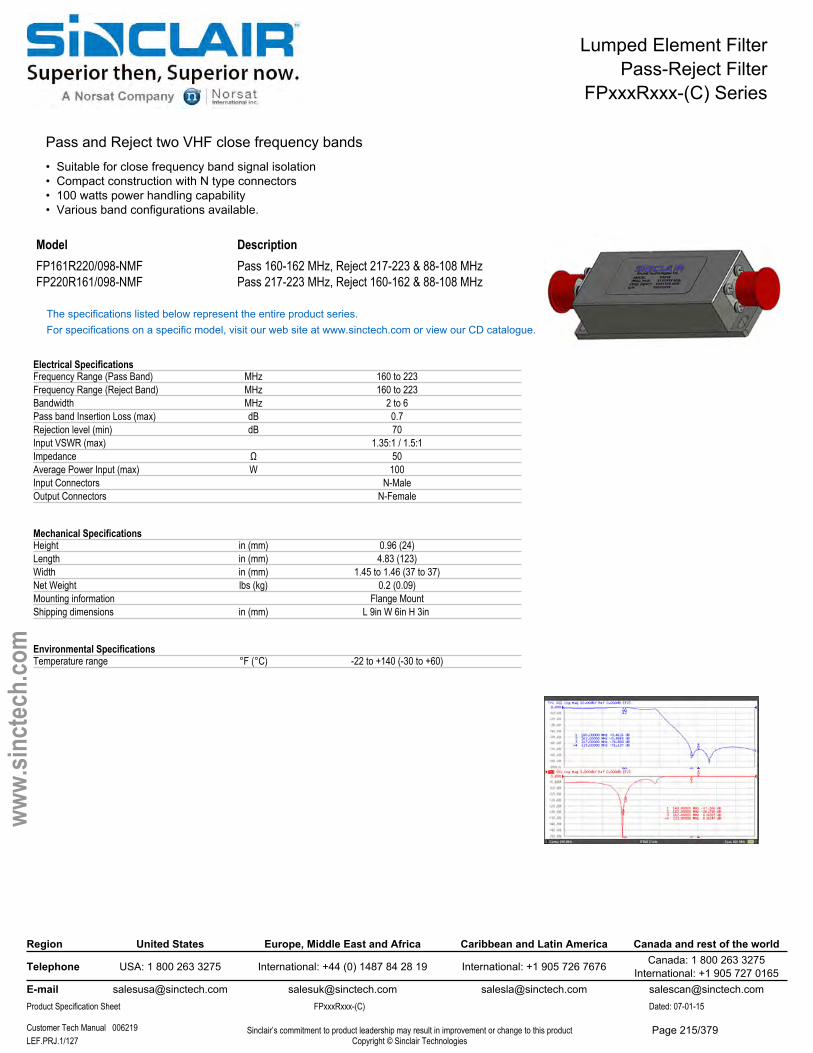
Lumped Element FilterPass-Reject Filter
FPxxxRxxx-(C) Series
Pass and Reject two VHF close frequency bands• Suitable for close frequency band signal isolation• Compact construction with N type connectors• 100 watts power handling capability• Various band configurations available.
Model DescriptionFP161R220/098-NMF Pass 160-162 MHz, Reject 217-223 & 88-108 MHzFP220R161/098-NMF Pass 217-223 MHz, Reject 160-162 & 88-108 MHz
The specifications listed below represent the entire product series.For specifications on a specific model, visit our web site at www.sinctech.com or view our CD catalogue.
Electrical SpecificationsFrequency Range (Pass Band) MHz 160 to 223Frequency Range (Reject Band) MHz 160 to 223Bandwidth MHz 2 to 6Pass band Insertion Loss (max) dB 0.7Rejection level (min) dB 70Input VSWR (max) 1.35:1 / 1.5:1Impedance Ω 50Average Power Input (max) W 100Input Connectors N-MaleOutput Connectors N-Female
Mechanical SpecificationsHeight in (mm) 0.96 (24)Length in (mm) 4.83 (123)Width in (mm) 1.45 to 1.46 (37 to 37)Net Weight lbs (kg) 0.2 (0.09)Mounting information Flange MountShipping dimensions in (mm) L 9in W 6in H 3in
Environmental SpecificationsTemperature range °F (°C) -22 to +140 (-30 to +60)
Region United States Europe, Middle East and Africa Caribbean and Latin America Canada and rest of the world
Telephone USA: 1 800 263 3275 International: +44 (0) 1487 84 28 19 International: +1 905 726 7676 Canada: 1 800 263 3275International: +1 905 727 0165
E-mail [email protected] [email protected] [email protected] [email protected] Specification Sheet FPxxxRxxx-(C) Dated: 07-01-15
Customer Tech Manual 006219 Sinclair’s commitment to product leadership may result in improvement or change to this productCopyright © Sinclair TechnologiesLEF.PRJ.1/127
www.
sinct
ech.
com
Page 215/379
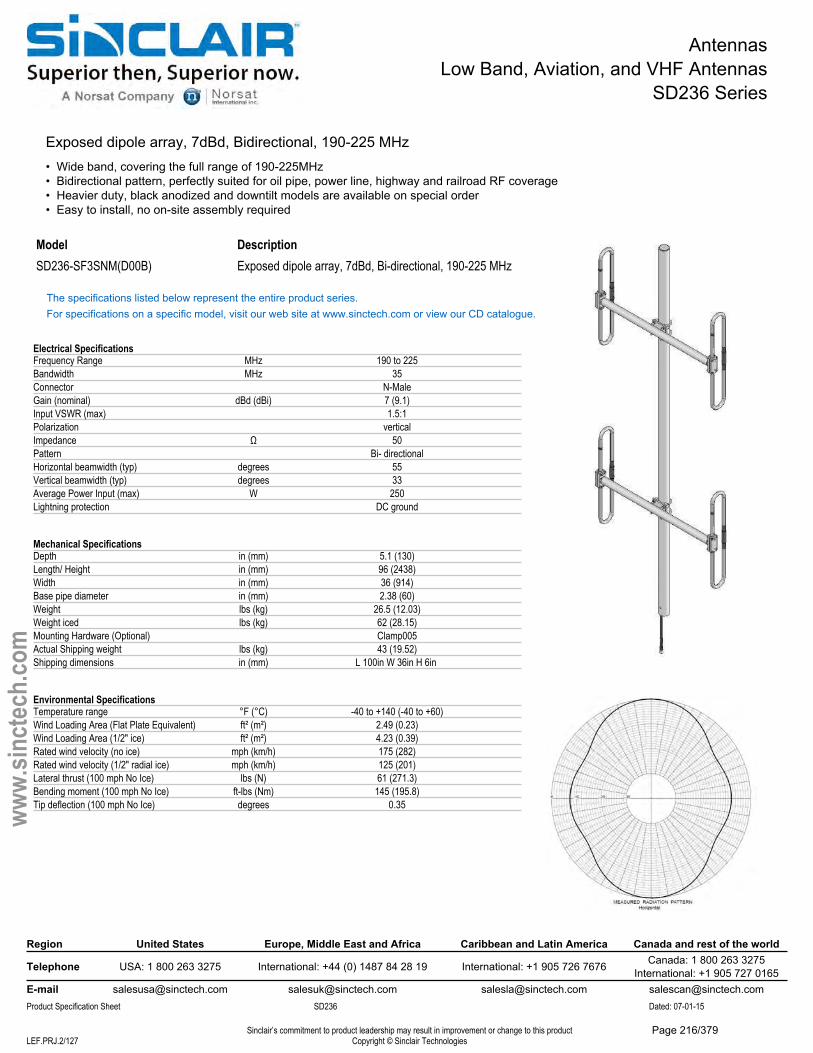
AntennasLow Band, Aviation, and VHF Antennas
SD236 Series
Exposed dipole array, 7dBd, Bidirectional, 190-225 MHz• Wide band, covering the full range of 190-225MHz• Bidirectional pattern, perfectly suited for oil pipe, power line, highway and railroad RF coverage• Heavier duty, black anodized and downtilt models are available on special order• Easy to install, no on-site assembly required
Model DescriptionSD236-SF3SNM(D00B) Exposed dipole array, 7dBd, Bi-directional, 190-225 MHz
The specifications listed below represent the entire product series.For specifications on a specific model, visit our web site at www.sinctech.com or view our CD catalogue.
Electrical SpecificationsFrequency Range MHz 190 to 225Bandwidth MHz 35Connector N-MaleGain (nominal) dBd (dBi) 7 (9.1)Input VSWR (max) 1.5:1Polarization verticalImpedance Ω 50Pattern Bi- directionalHorizontal beamwidth (typ) degrees 55Vertical beamwidth (typ) degrees 33Average Power Input (max) W 250Lightning protection DC ground
Mechanical SpecificationsDepth in (mm) 5.1 (130)Length/ Height in (mm) 96 (2438)Width in (mm) 36 (914)Base pipe diameter in (mm) 2.38 (60)Weight lbs (kg) 26.5 (12.03)Weight iced lbs (kg) 62 (28.15)Mounting Hardware (Optional) Clamp005Actual Shipping weight lbs (kg) 43 (19.52)Shipping dimensions in (mm) L 100in W 36in H 6in
Environmental SpecificationsTemperature range °F (°C) -40 to +140 (-40 to +60)Wind Loading Area (Flat Plate Equivalent) ft² (m²) 2.49 (0.23)Wind Loading Area (1/2" ice) ft² (m²) 4.23 (0.39)Rated wind velocity (no ice) mph (km/h) 175 (282)Rated wind velocity (1/2" radial ice) mph (km/h) 125 (201)Lateral thrust (100 mph No Ice) lbs (N) 61 (271.3)Bending moment (100 mph No Ice) ft-lbs (Nm) 145 (195.8)Tip deflection (100 mph No Ice) degrees 0.35
Region United States Europe, Middle East and Africa Caribbean and Latin America Canada and rest of the world
Telephone USA: 1 800 263 3275 International: +44 (0) 1487 84 28 19 International: +1 905 726 7676 Canada: 1 800 263 3275International: +1 905 727 0165
E-mail [email protected] [email protected] [email protected] [email protected] Specification Sheet SD236 Dated: 07-01-15
Sinclair’s commitment to product leadership may result in improvement or change to this productCopyright © Sinclair TechnologiesLEF.PRJ.2/127
www.
sinct
ech.
com
Page 216/379
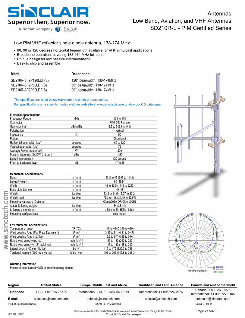
AntennasLow Band, Aviation, and VHF Antennas
SD210R-L - PIM Certified Series
Low PIM VHF reflector single dipole antenna, 138-174 MHz• 60, 90 or 120 degrees horizontal beamwidth available for VHF simulcast applications• Broadband operation, covering 138-174 MHz full band• Unique design for low passive intermodulation• Easy to ship and assemble
Model DescriptionSD210R-SF2P120LDF(S) 120° beamwidth, 138-174MHzSD210R-SF2P60LDF(S) 60° beamwidth, 138-174MHzSD210R-SF2P90LDF(S) 90° beamwidth, 138-174MHz
The specifications listed below represent the entire product series.For specifications on a specific model, visit our web site at www.sinctech.com or view our CD catalogue.
Electrical SpecificationsFrequency Range MHz 138 to 174Connector 7/16 DIN-FemaleGain (nominal) dBd (dBi) 4.5 to 7 (6.6 to 9.1)Polarization verticalImpedance Ω 50Pattern DirectionalHorizontal beamwidth (typ) degrees 60 to 120Vertical beamwidth (typ) degrees 72Average Power Input (max) W 300Passive intermod. (2x20W, 3rd ord.) dBc -150Lightning protection DC groundFront-to-back ratio (typ) dB 17 to 25
Mechanical SpecificationsDepth in (mm) 23.8 to 45 (605 to 1143)Length/ Height in (mm) 60 (1524)Width in (mm) 45 to 87.5 (1143 to 2223)Base pipe diameter in (mm) 1.9 (48)Weight lbs (kg) 33.2 to 44.5 (15.07 to 20.2)Weight iced lbs (kg) 75.3 to 118 (34.19 to 53.57)Mounting Hardware (Optional) Clamp006A OR Clamp006BActual Shipping weight lbs (kg) 84 (38.14)Shipping dimensions in (mm) L 66in W 6in H(38 - 62)in Mounting configurations side mount
Environmental SpecificationsTemperature range °F (°C) -40 to +140 (-40 to +60)Wind Loading Area (Flat Plate Equivalent) ft² (m²) 3.37 to 5.1 (0.31 to 0.47)Wind Loading Area (1/2" ice) ft² (m²) 5.9 to 9.7 (0.55 to 0.9)Rated wind velocity (no ice) mph (km/h) 155 to 180 (250 to 290)Rated wind velocity (1/2" radial ice) mph (km/h) 115 to 130 (185 to 209)Lateral thrust (100 mph No Ice) lbs (N) 119 to 172 (529.3 to 765.1)Torsional moment (100 mph No Ice) ft-lbs (Nm) 108 to 295 (145.8 to 398.3)
Ordering InformationPlease contact Sinclair CSR to order mounting clamps.
Region United States Europe, Middle East and Africa Caribbean and Latin America Canada and rest of the world
Telephone USA: 1 800 263 3275 International: +44 (0) 1487 84 28 19 International: +1 905 726 7676 Canada: 1 800 263 3275International: +1 905 727 0165
E-mail [email protected] [email protected] [email protected] [email protected] Specification Sheet SD210R-L - PIM Certified Dated: 07-01-15
Sinclair’s commitment to product leadership may result in improvement or change to this productCopyright © Sinclair TechnologiesLEF.PRJ.3/127
www.
sinct
ech.
com
Page 217/379
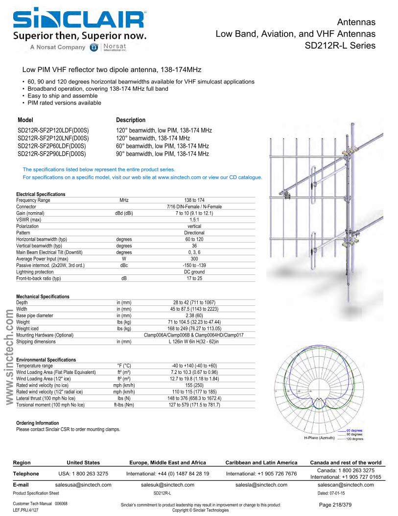
AntennasLow Band, Aviation, and VHF Antennas
SD212R-L Series
Low PIM VHF reflector two dipole antenna, 138-174MHz• 60, 90 and 120 degrees horizontal beamwidths available for VHF simulcast applications• Broadband operation, covering 138-174 MHz full band• Easy to ship and assemble• PIM rated versions available
Model DescriptionSD212R-SF2P120LDF(D00S) 120° beamwidth, low PIM, 138-174 MHzSD212R-SF2P120LNF(D00S) 120° beamwidth, 138-174 MHzSD212R-SF2P60LDF(D00S) 60° beamwidth, low PIM, 138-174 MHzSD212R-SF2P90LDF(D00S) 90° beamwidth, low PIM, 138-174 MHz
The specifications listed below represent the entire product series.For specifications on a specific model, visit our web site at www.sinctech.com or view our CD catalogue.
Electrical SpecificationsFrequency Range MHz 138 to 174Connector 7/16 DIN-Female / N-FemaleGain (nominal) dBd (dBi) 7 to 10 (9.1 to 12.1)VSWR (max) 1.5:1Polarization verticalPattern DirectionalHorizontal beamwidth (typ) degrees 60 to 120Vertical beamwidth (typ) degrees 36Main Beam Electrical Tilt (Downtilt) degrees 0, 3, 6Average Power Input (max) W 300Passive intermod. (2x20W, 3rd ord.) dBc -150 to -139Lightning protection DC groundFront-to-back ratio (typ) dB 17 to 25
Mechanical SpecificationsDepth in (mm) 28 to 42 (711 to 1067)Width in (mm) 45 to 87.5 (1143 to 2223)Base pipe diameter in (mm) 2.38 (60)Weight lbs (kg) 71 to 104.5 (32.23 to 47.44)Weight iced lbs (kg) 168 to 249 (76.27 to 113.05)Mounting Hardware (Optional) Clamp006A/Clamp006B & Clamp0064HD/Clamp017 Shipping dimensions in (mm) L 126in W 6in H(32 - 62)in
Environmental SpecificationsTemperature range °F (°C) -40 to +140 (-40 to +60)Wind Loading Area (Flat Plate Equivalent) ft² (m²) 7.2 to 10.3 (0.67 to 0.96)Wind Loading Area (1/2" ice) ft² (m²) 12.7 to 19.8 (1.18 to 1.84)Rated wind velocity (no ice) mph (km/h) 155 (250)Rated wind velocity (1/2" radial ice) mph (km/h) 110 to 115 (177 to 185)Lateral thrust (100 mph No Ice) lbs (N) 148 to 376 (658.3 to 1672.4)Torsional moment (100 mph No Ice) ft-lbs (Nm) 127 to 579 (171.5 to 781.7)
Ordering InformationPlease contact Sinclair CSR to order mounting clamps.
Region United States Europe, Middle East and Africa Caribbean and Latin America Canada and rest of the world
Telephone USA: 1 800 263 3275 International: +44 (0) 1487 84 28 19 International: +1 905 726 7676 Canada: 1 800 263 3275International: +1 905 727 0165
E-mail [email protected] [email protected] [email protected] [email protected] Specification Sheet SD212R-L Dated: 07-01-15
Customer Tech Manual 006068 Sinclair’s commitment to product leadership may result in improvement or change to this productCopyright © Sinclair TechnologiesLEF.PRJ.4/127
www.
sinct
ech.
com
Page 218/379
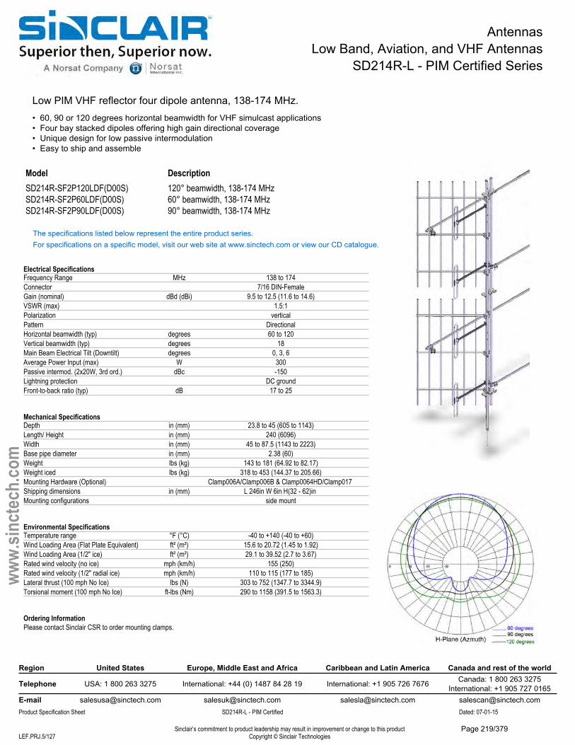
AntennasLow Band, Aviation, and VHF Antennas
SD214R-L - PIM Certified Series
Low PIM VHF reflector four dipole antenna, 138-174 MHz.• 60, 90 or 120 degrees horizontal beamwidth for VHF simulcast applications• Four bay stacked dipoles offering high gain directional coverage• Unique design for low passive intermodulation• Easy to ship and assemble
Model DescriptionSD214R-SF2P120LDF(D00S) 120° beamwidth, 138-174 MHzSD214R-SF2P60LDF(D00S) 60° beamwidth, 138-174 MHzSD214R-SF2P90LDF(D00S) 90° beamwidth, 138-174 MHz
The specifications listed below represent the entire product series.For specifications on a specific model, visit our web site at www.sinctech.com or view our CD catalogue.
Electrical SpecificationsFrequency Range MHz 138 to 174Connector 7/16 DIN-FemaleGain (nominal) dBd (dBi) 9.5 to 12.5 (11.6 to 14.6)VSWR (max) 1.5:1Polarization verticalPattern DirectionalHorizontal beamwidth (typ) degrees 60 to 120Vertical beamwidth (typ) degrees 18Main Beam Electrical Tilt (Downtilt) degrees 0, 3, 6Average Power Input (max) W 300Passive intermod. (2x20W, 3rd ord.) dBc -150Lightning protection DC groundFront-to-back ratio (typ) dB 17 to 25
Mechanical SpecificationsDepth in (mm) 23.8 to 45 (605 to 1143)Length/ Height in (mm) 240 (6096)Width in (mm) 45 to 87.5 (1143 to 2223)Base pipe diameter in (mm) 2.38 (60)Weight lbs (kg) 143 to 181 (64.92 to 82.17)Weight iced lbs (kg) 318 to 453 (144.37 to 205.66)Mounting Hardware (Optional) Clamp006A/Clamp006B & Clamp0064HD/Clamp017 Shipping dimensions in (mm) L 246in W 6in H(32 - 62)in Mounting configurations side mount
Environmental SpecificationsTemperature range °F (°C) -40 to +140 (-40 to +60)Wind Loading Area (Flat Plate Equivalent) ft² (m²) 15.6 to 20.72 (1.45 to 1.92)Wind Loading Area (1/2" ice) ft² (m²) 29.1 to 39.52 (2.7 to 3.67)Rated wind velocity (no ice) mph (km/h) 155 (250)Rated wind velocity (1/2" radial ice) mph (km/h) 110 to 115 (177 to 185)Lateral thrust (100 mph No Ice) lbs (N) 303 to 752 (1347.7 to 3344.9)Torsional moment (100 mph No Ice) ft-lbs (Nm) 290 to 1158 (391.5 to 1563.3)
Ordering InformationPlease contact Sinclair CSR to order mounting clamps.
Region United States Europe, Middle East and Africa Caribbean and Latin America Canada and rest of the world
Telephone USA: 1 800 263 3275 International: +44 (0) 1487 84 28 19 International: +1 905 726 7676 Canada: 1 800 263 3275International: +1 905 727 0165
E-mail [email protected] [email protected] [email protected] [email protected] Specification Sheet SD214R-L - PIM Certified Dated: 07-01-15
Sinclair’s commitment to product leadership may result in improvement or change to this productCopyright © Sinclair TechnologiesLEF.PRJ.5/127
www.
sinct
ech.
com
Page 219/379
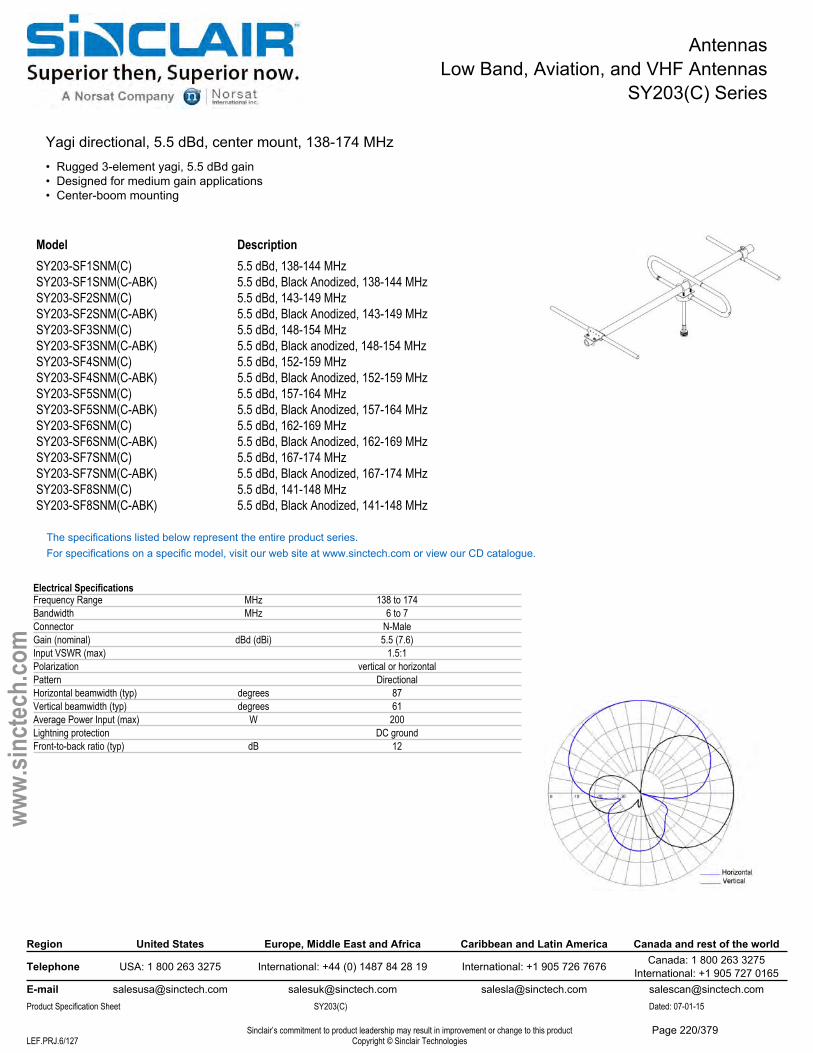
AntennasLow Band, Aviation, and VHF Antennas
SY203(C) Series
Yagi directional, 5.5 dBd, center mount, 138-174 MHz• Rugged 3-element yagi, 5.5 dBd gain• Designed for medium gain applications• Center-boom mounting
Model DescriptionSY203-SF1SNM(C) 5.5 dBd, 138-144 MHzSY203-SF1SNM(C-ABK) 5.5 dBd, Black Anodized, 138-144 MHzSY203-SF2SNM(C) 5.5 dBd, 143-149 MHzSY203-SF2SNM(C-ABK) 5.5 dBd, Black Anodized, 143-149 MHzSY203-SF3SNM(C) 5.5 dBd, 148-154 MHzSY203-SF3SNM(C-ABK) 5.5 dBd, Black anodized, 148-154 MHzSY203-SF4SNM(C) 5.5 dBd, 152-159 MHzSY203-SF4SNM(C-ABK) 5.5 dBd, Black Anodized, 152-159 MHzSY203-SF5SNM(C) 5.5 dBd, 157-164 MHzSY203-SF5SNM(C-ABK) 5.5 dBd, Black Anodized, 157-164 MHzSY203-SF6SNM(C) 5.5 dBd, 162-169 MHzSY203-SF6SNM(C-ABK) 5.5 dBd, Black Anodized, 162-169 MHzSY203-SF7SNM(C) 5.5 dBd, 167-174 MHzSY203-SF7SNM(C-ABK) 5.5 dBd, Black Anodized, 167-174 MHzSY203-SF8SNM(C) 5.5 dBd, 141-148 MHzSY203-SF8SNM(C-ABK) 5.5 dBd, Black Anodized, 141-148 MHz
The specifications listed below represent the entire product series.For specifications on a specific model, visit our web site at www.sinctech.com or view our CD catalogue.
Electrical SpecificationsFrequency Range MHz 138 to 174Bandwidth MHz 6 to 7Connector N-MaleGain (nominal) dBd (dBi) 5.5 (7.6)Input VSWR (max) 1.5:1Polarization vertical or horizontalPattern DirectionalHorizontal beamwidth (typ) degrees 87Vertical beamwidth (typ) degrees 61Average Power Input (max) W 200Lightning protection DC groundFront-to-back ratio (typ) dB 12
Region United States Europe, Middle East and Africa Caribbean and Latin America Canada and rest of the world
Telephone USA: 1 800 263 3275 International: +44 (0) 1487 84 28 19 International: +1 905 726 7676 Canada: 1 800 263 3275International: +1 905 727 0165
E-mail [email protected] [email protected] [email protected] [email protected] Specification Sheet SY203(C) Dated: 07-01-15
Sinclair’s commitment to product leadership may result in improvement or change to this productCopyright © Sinclair TechnologiesLEF.PRJ.6/127
www.
sinct
ech.
com
Page 220/379
AntennasLow Band, Aviation, and VHF Antennas
SY203(C) Series
Mechanical SpecificationsDepth in (mm) 6.5 (165)Length/ Height in (mm) 40.1 (1019)Width in (mm) 42 (1067)Radiating element material aluminumReflector material aluminumWeight lbs (kg) 3.2 (1.45)Mounting Hardware (Standard) Clamp001Actual Shipping weight lbs (kg) 15 (6.81)Shipping dimensions in (mm) L(47 - 85)in W 6in H(6 - 18)in
Environmental SpecificationsWind Loading Area (Flat Plate Equivalent) ft² (m²) 0.8 (0.07)Wind Loading Area (1/2" ice) ft² (m²) 1.68 (0.16)Rated wind velocity (no ice) mph (km/h) 150 (242)Rated wind velocity (1/2" radial ice) mph (km/h) 110 (177)Lateral thrust (100 mph No Ice) lbs (N) 29.5 (131.2)Bending moment (100 mph No Ice) ft-lbs (Nm) 8.1 (10.9)
Region United States Europe, Middle East and Africa Caribbean and Latin America Canada and rest of the world
Telephone USA: 1 800 263 3275 International: +44 (0) 1487 84 28 19 International: +1 905 726 7676 Canada: 1 800 263 3275International: +1 905 727 0165
E-mail [email protected] [email protected] [email protected] [email protected] Specification Sheet SY203(C) Dated: 07-01-15
Sinclair’s commitment to product leadership may result in improvement or change to this productCopyright © Sinclair TechnologiesLEF.PRJ.7/127
www.
sinct
ech.
com
Page 221/379
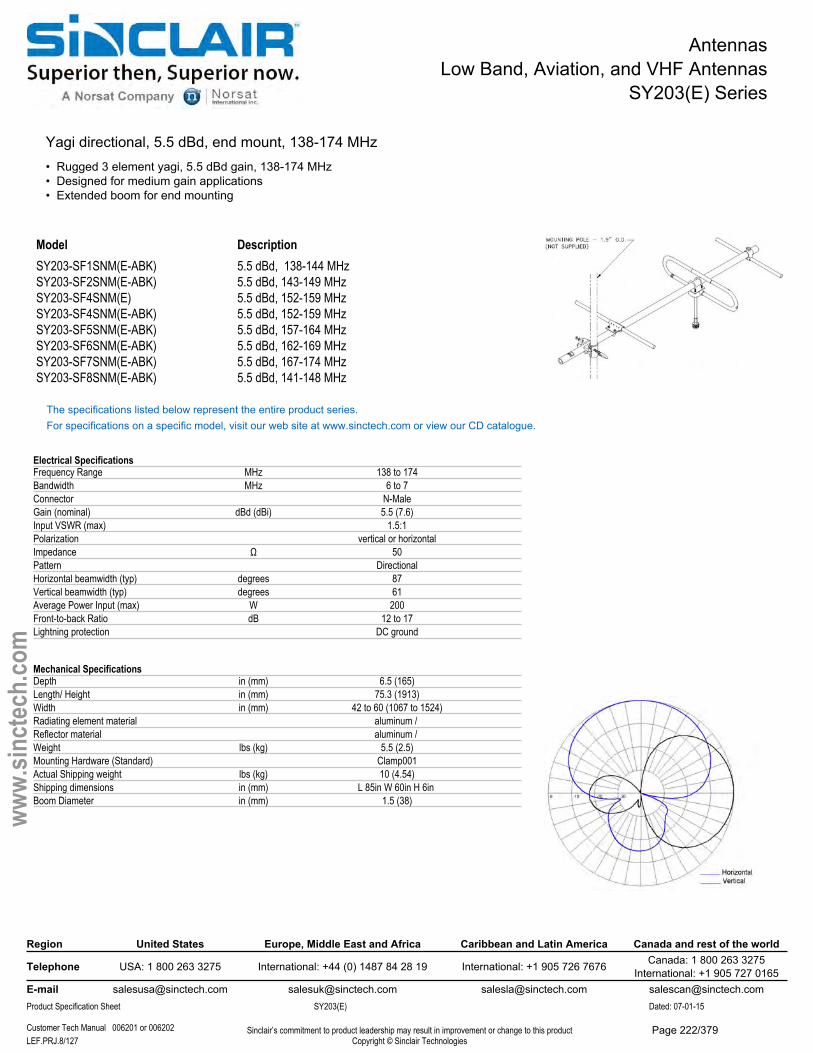
AntennasLow Band, Aviation, and VHF Antennas
SY203(E) Series
Yagi directional, 5.5 dBd, end mount, 138-174 MHz• Rugged 3 element yagi, 5.5 dBd gain, 138-174 MHz• Designed for medium gain applications• Extended boom for end mounting
Model DescriptionSY203-SF1SNM(E-ABK) 5.5 dBd, 138-144 MHzSY203-SF2SNM(E-ABK) 5.5 dBd, 143-149 MHzSY203-SF4SNM(E) 5.5 dBd, 152-159 MHzSY203-SF4SNM(E-ABK) 5.5 dBd, 152-159 MHzSY203-SF5SNM(E-ABK) 5.5 dBd, 157-164 MHzSY203-SF6SNM(E-ABK) 5.5 dBd, 162-169 MHzSY203-SF7SNM(E-ABK) 5.5 dBd, 167-174 MHzSY203-SF8SNM(E-ABK) 5.5 dBd, 141-148 MHz
The specifications listed below represent the entire product series.For specifications on a specific model, visit our web site at www.sinctech.com or view our CD catalogue.
Electrical SpecificationsFrequency Range MHz 138 to 174Bandwidth MHz 6 to 7Connector N-MaleGain (nominal) dBd (dBi) 5.5 (7.6)Input VSWR (max) 1.5:1Polarization vertical or horizontalImpedance Ω 50Pattern DirectionalHorizontal beamwidth (typ) degrees 87Vertical beamwidth (typ) degrees 61Average Power Input (max) W 200Front-to-back Ratio dB 12 to 17Lightning protection DC ground
Mechanical SpecificationsDepth in (mm) 6.5 (165)Length/ Height in (mm) 75.3 (1913)Width in (mm) 42 to 60 (1067 to 1524)Radiating element material aluminum / Reflector material aluminum / Weight lbs (kg) 5.5 (2.5)Mounting Hardware (Standard) Clamp001Actual Shipping weight lbs (kg) 10 (4.54)Shipping dimensions in (mm) L 85in W 60in H 6in Boom Diameter in (mm) 1.5 (38)
Region United States Europe, Middle East and Africa Caribbean and Latin America Canada and rest of the world
Telephone USA: 1 800 263 3275 International: +44 (0) 1487 84 28 19 International: +1 905 726 7676 Canada: 1 800 263 3275International: +1 905 727 0165
E-mail [email protected] [email protected] [email protected] [email protected] Specification Sheet SY203(E) Dated: 07-01-15
Customer Tech Manual 006201 or 006202 Sinclair’s commitment to product leadership may result in improvement or change to this productCopyright © Sinclair TechnologiesLEF.PRJ.8/127
www.
sinct
ech.
com
Page 222/379

AntennasLow Band, Aviation, and VHF Antennas
SY203(E) Series
Environmental SpecificationsTemperature range °F (°C) -40 to +140 (-40 to +60)Wind Loading Area (Flat Plate Equivalent) ft² (m²) 1.05 (0.1)Wind Loading Area (1/2" ice) ft² (m²) 2.1 (0.2)Rated wind velocity (no ice) mph (km/h) 135 (217)Rated wind velocity (1/2" radial ice) mph (km/h) 90 (145)Lateral thrust (100 mph No Ice) lbs (N) 38.7 (172.1)Bending moment (100 mph No Ice) ft-lbs (Nm) 126 (170.1)
Region United States Europe, Middle East and Africa Caribbean and Latin America Canada and rest of the world
Telephone USA: 1 800 263 3275 International: +44 (0) 1487 84 28 19 International: +1 905 726 7676 Canada: 1 800 263 3275International: +1 905 727 0165
E-mail [email protected] [email protected] [email protected] [email protected] Specification Sheet SY203(E) Dated: 07-01-15
Customer Tech Manual 006201 or 006202 Sinclair’s commitment to product leadership may result in improvement or change to this productCopyright © Sinclair TechnologiesLEF.PRJ.9/127
www.
sinct
ech.
com
Page 223/379
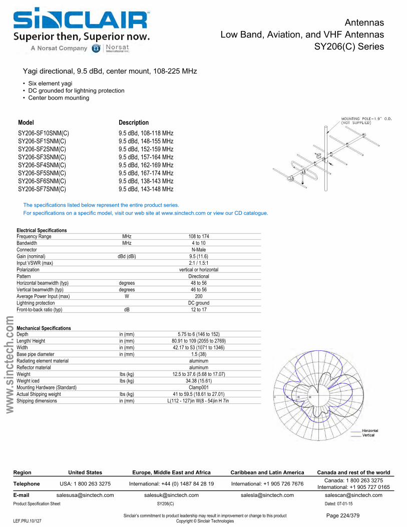
AntennasLow Band, Aviation, and VHF Antennas
SY206(C) Series
Yagi directional, 9.5 dBd, center mount, 108-225 MHz• Six element yagi• DC grounded for lightning protection• Center boom mounting
Model DescriptionSY206-SF10SNM(C) 9.5 dBd, 108-118 MHzSY206-SF1SNM(C) 9.5 dBd, 148-155 MHzSY206-SF2SNM(C) 9.5 dBd, 152-159 MHzSY206-SF3SNM(C) 9.5 dBd, 157-164 MHzSY206-SF4SNM(C) 9.5 dBd, 162-169 MHzSY206-SF5SNM(C) 9.5 dBd, 167-174 MHzSY206-SF6SNM(C) 9.5 dBd, 138-143 MHzSY206-SF7SNM(C) 9.5 dBd, 143-148 MHz
The specifications listed below represent the entire product series.For specifications on a specific model, visit our web site at www.sinctech.com or view our CD catalogue.
Electrical SpecificationsFrequency Range MHz 108 to 174Bandwidth MHz 4 to 10Connector N-MaleGain (nominal) dBd (dBi) 9.5 (11.6)Input VSWR (max) 2:1 / 1.5:1Polarization vertical or horizontalPattern DirectionalHorizontal beamwidth (typ) degrees 48 to 56Vertical beamwidth (typ) degrees 46 to 56Average Power Input (max) W 200Lightning protection DC groundFront-to-back ratio (typ) dB 12 to 17
Mechanical SpecificationsDepth in (mm) 5.75 to 6 (146 to 152)Length/ Height in (mm) 80.91 to 109 (2055 to 2769)Width in (mm) 42.17 to 53 (1071 to 1346)Base pipe diameter in (mm) 1.5 (38)Radiating element material aluminumReflector material aluminumWeight lbs (kg) 12.5 to 37.6 (5.68 to 17.07)Weight iced lbs (kg) 34.38 (15.61)Mounting Hardware (Standard) Clamp001Actual Shipping weight lbs (kg) 41 to 59.5 (18.61 to 27.01)Shipping dimensions in (mm) L(112 - 127)in W(8 - 54)in H 7in
Region United States Europe, Middle East and Africa Caribbean and Latin America Canada and rest of the world
Telephone USA: 1 800 263 3275 International: +44 (0) 1487 84 28 19 International: +1 905 726 7676 Canada: 1 800 263 3275International: +1 905 727 0165
E-mail [email protected] [email protected] [email protected] [email protected] Specification Sheet SY206(C) Dated: 07-01-15
Sinclair’s commitment to product leadership may result in improvement or change to this productCopyright © Sinclair TechnologiesLEF.PRJ.10/127
www.
sinct
ech.
com
Page 224/379

AntennasLow Band, Aviation, and VHF Antennas
SY206(C) Series
Environmental SpecificationsTemperature range °F (°C) -40 to +140 (-40 to +60)Wind Loading Area (Flat Plate Equivalent) ft² (m²) 1.41 to 2.44 (0.13 to 0.23)Wind Loading Area (1/2" ice) ft² (m²) 2.9 to 4.41 (0.27 to 0.41)Rated wind velocity (no ice) mph (km/h) 115 to 145 (185 to 233)Rated wind velocity (1/2" radial ice) mph (km/h) 85 to 95 (137 to 153)Lateral thrust (100 mph No Ice) lbs (N) 31 to 120 (137.9 to 533.8)Bending moment (100 mph No Ice) ft-lbs (Nm) 81 to 141 (109.4 to 190.4)
Region United States Europe, Middle East and Africa Caribbean and Latin America Canada and rest of the world
Telephone USA: 1 800 263 3275 International: +44 (0) 1487 84 28 19 International: +1 905 726 7676 Canada: 1 800 263 3275International: +1 905 727 0165
E-mail [email protected] [email protected] [email protected] [email protected] Specification Sheet SY206(C) Dated: 07-01-15
Sinclair’s commitment to product leadership may result in improvement or change to this productCopyright © Sinclair TechnologiesLEF.PRJ.11/127
www.
sinct
ech.
com
Page 225/379
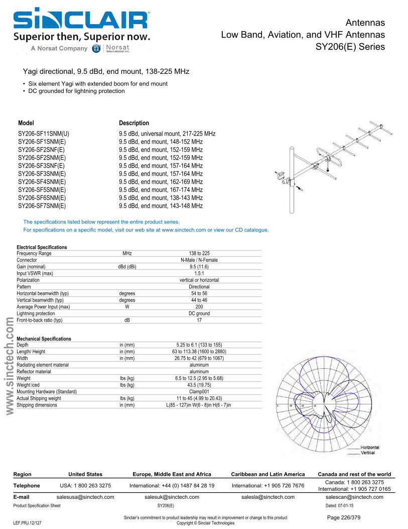
AntennasLow Band, Aviation, and VHF Antennas
SY206(E) Series
Yagi directional, 9.5 dBd, end mount, 138-225 MHz• Six element Yagi with extended boom for end mount• DC grounded for lightning protection
Model DescriptionSY206-SF11SNM(U) 9.5 dBd, universal mount, 217-225 MHzSY206-SF1SNM(E) 9.5 dBd, end mount, 148-152 MHzSY206-SF2SNF(E) 9.5 dBd, end mount, 152-159 MHzSY206-SF2SNM(E) 9.5 dBd, end mount, 152-159 MHzSY206-SF3SNF(E) 9.5 dBd, end mount, 157-164 MHzSY206-SF3SNM(E) 9.5 dBd, end mount, 157-164 MHzSY206-SF4SNM(E) 9.5 dBd, end mount, 162-169 MHzSY206-SF5SNM(E) 9.5 dBd, end mount, 167-174 MHzSY206-SF6SNM(E) 9.5 dBd, end mount, 138-143 MHzSY206-SF7SNM(E) 9.5 dBd, end mount, 143-148 MHz
The specifications listed below represent the entire product series.For specifications on a specific model, visit our web site at www.sinctech.com or view our CD catalogue.
Electrical SpecificationsFrequency Range MHz 138 to 225Connector N-Male / N-FemaleGain (nominal) dBd (dBi) 9.5 (11.6)Input VSWR (max) 1.5:1Polarization vertical or horizontalPattern DirectionalHorizontal beamwidth (typ) degrees 54 to 56Vertical beamwidth (typ) degrees 44 to 46Average Power Input (max) W 200Lightning protection DC groundFront-to-back ratio (typ) dB 17
Mechanical SpecificationsDepth in (mm) 5.25 to 6.1 (133 to 155)Length/ Height in (mm) 63 to 113.38 (1600 to 2880)Width in (mm) 26.75 to 42 (679 to 1067)Radiating element material aluminumReflector material aluminumWeight lbs (kg) 6.5 to 12.5 (2.95 to 5.68)Weight iced lbs (kg) 43.5 (19.75)Mounting Hardware (Standard) Clamp001Actual Shipping weight lbs (kg) 11 to 45 (4.99 to 20.43)Shipping dimensions in (mm) L(85 - 127)in W(6 - 8)in H(6 - 7)in
Region United States Europe, Middle East and Africa Caribbean and Latin America Canada and rest of the world
Telephone USA: 1 800 263 3275 International: +44 (0) 1487 84 28 19 International: +1 905 726 7676 Canada: 1 800 263 3275International: +1 905 727 0165
E-mail [email protected] [email protected] [email protected] [email protected] Specification Sheet SY206(E) Dated: 07-01-15
Sinclair’s commitment to product leadership may result in improvement or change to this productCopyright © Sinclair TechnologiesLEF.PRJ.12/127
www.
sinct
ech.
com
Page 226/379

AntennasLow Band, Aviation, and VHF Antennas
SY206(E) Series
Environmental SpecificationsTemperature range °F (°C) -40 to +140 (-40 to +60)Wind Loading Area (Flat Plate Equivalent) ft² (m²) 1.1 to 1.92 (0.1 to 0.18)Wind Loading Area (1/2" ice) ft² (m²) 2.2 to 3.75 (0.2 to 0.35)Rated wind velocity (no ice) mph (km/h) 130 to 135 (209 to 217)Rated wind velocity (1/2" radial ice) mph (km/h) 85 to 90 (137 to 145)Lateral thrust (100 mph No Ice) lbs (N) 72 to 81 (320.3 to 360.3)Bending moment (100 mph No Ice) ft-lbs (Nm) 216 to 333 (291.6 to 449.6)
Region United States Europe, Middle East and Africa Caribbean and Latin America Canada and rest of the world
Telephone USA: 1 800 263 3275 International: +44 (0) 1487 84 28 19 International: +1 905 726 7676 Canada: 1 800 263 3275International: +1 905 727 0165
E-mail [email protected] [email protected] [email protected] [email protected] Specification Sheet SY206(E) Dated: 07-01-15
Sinclair’s commitment to product leadership may result in improvement or change to this productCopyright © Sinclair TechnologiesLEF.PRJ.13/127
www.
sinct
ech.
com
Page 227/379
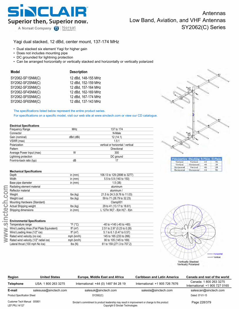
AntennasLow Band, Aviation, and VHF Antennas
SY2062(C) Series
Yagi dual stacked, 12 dBd, center mount, 137-174 MHz• Dual stacked six element Yagi for higher gain• Does not includes mounting pipe• DC grounded for lightning protection• Can be arranged horizontally or vertically stacked and horizontally or vertically polarized
Model DescriptionSY2062-SF1SNM(C) 12 dBd, 148-155 MHzSY2062-SF2SNM(C) 12 dBd, 152-159 MHzSY2062-SF3SNM(C) 12 dBd, 157-164 MHzSY2062-SF4SNM(C) 12 dBd, 162-169 MHzSY2062-SF5SNM(C) 12 dBd, 167-174 MHzSY2062-SF6SNM(C) 12 dBd, 137-143 MHz
The specifications listed below represent the entire product series.For specifications on a specific model, visit our web site at www.sinctech.com or view our CD catalogue.
Electrical SpecificationsFrequency Range MHz 137 to 174Connector N-MaleGain (nominal) dBd (dBi) 12 (14.1)VSWR (max) 1.5:1Polarization vertical or horizontal / verticalPattern DirectionalAverage Power Input (max) W 300Lightning protection DC groundFront-to-back ratio (typ) dB 17
Mechanical SpecificationsDepth in (mm) 106.13 to 129 (2696 to 3277)Width in (mm) 5.5 to 5.9 (140 to 150)Base pipe diameter in (mm) 1.5 (38)Radiating element material aluminumReflector material aluminum / Weight lbs (kg) 21.5 to 24.3 (9.76 to 11.03)Weight iced lbs (kg) 59 to 71 (26.79 to 32.23)Mounting Hardware (Standard) Clamp001Actual Shipping weight lbs (kg) 29 to 41 (13.17 to 18.61)Shipping dimensions in (mm) L 127in W(7 - 8)in H(7 - 8)in
Environmental SpecificationsTemperature range °F (°C) -40 to +140 (-40 to +60)Wind Loading Area (Flat Plate Equivalent) ft² (m²) 2.51 to 2.97 (0.23 to 0.28)Wind Loading Area (1/2" ice) ft² (m²) 5.1 to 6.1 (0.47 to 0.57)Rated wind velocity (no ice) mph (km/h) 145 to 165 (233 to 266)Rated wind velocity (1/2" radial ice) mph (km/h) 90 to 105 (145 to 169)Lateral thrust (100 mph No Ice) lbs (N) 61 to 159 (271.3 to 707.2)
Region United States Europe, Middle East and Africa Caribbean and Latin America Canada and rest of the world
Telephone USA: 1 800 263 3275 International: +44 (0) 1487 84 28 19 International: +1 905 726 7676 Canada: 1 800 263 3275International: +1 905 727 0165
E-mail [email protected] [email protected] [email protected] [email protected] Specification Sheet SY2062(C) Dated: 07-01-15
Customer Tech Manual 005801 Sinclair’s commitment to product leadership may result in improvement or change to this productCopyright © Sinclair TechnologiesLEF.PRJ.14/127
www.
sinct
ech.
com
Page 228/379
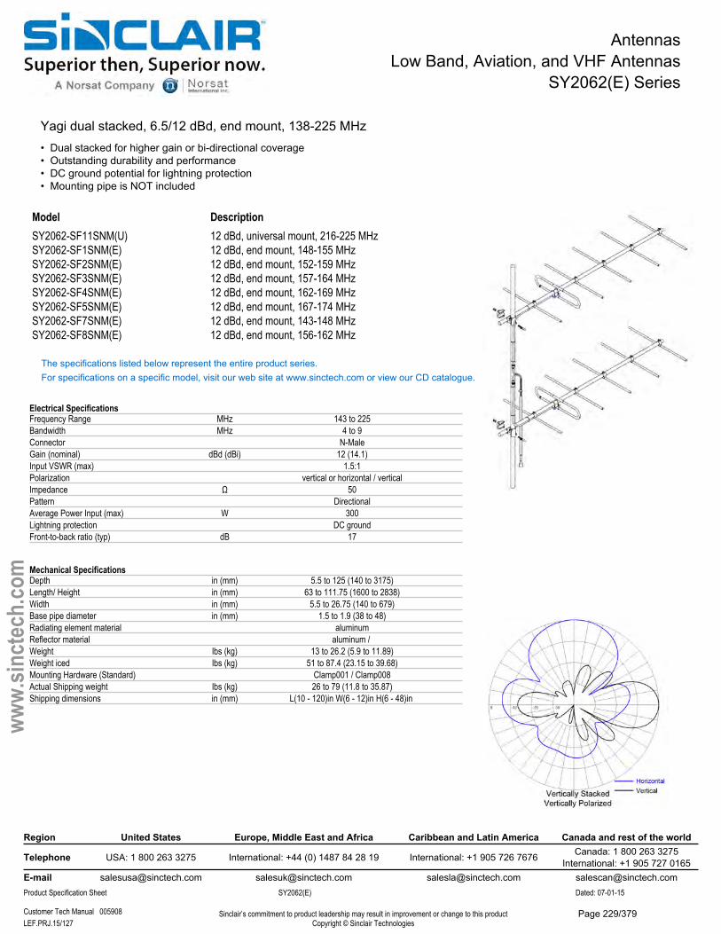
AntennasLow Band, Aviation, and VHF Antennas
SY2062(E) Series
Yagi dual stacked, 6.5/12 dBd, end mount, 138-225 MHz• Dual stacked for higher gain or bi-directional coverage• Outstanding durability and performance• DC ground potential for lightning protection• Mounting pipe is NOT included
Model DescriptionSY2062-SF11SNM(U) 12 dBd, universal mount, 216-225 MHzSY2062-SF1SNM(E) 12 dBd, end mount, 148-155 MHzSY2062-SF2SNM(E) 12 dBd, end mount, 152-159 MHzSY2062-SF3SNM(E) 12 dBd, end mount, 157-164 MHzSY2062-SF4SNM(E) 12 dBd, end mount, 162-169 MHzSY2062-SF5SNM(E) 12 dBd, end mount, 167-174 MHzSY2062-SF7SNM(E) 12 dBd, end mount, 143-148 MHzSY2062-SF8SNM(E) 12 dBd, end mount, 156-162 MHz
The specifications listed below represent the entire product series.For specifications on a specific model, visit our web site at www.sinctech.com or view our CD catalogue.
Electrical SpecificationsFrequency Range MHz 143 to 225Bandwidth MHz 4 to 9Connector N-MaleGain (nominal) dBd (dBi) 12 (14.1)Input VSWR (max) 1.5:1Polarization vertical or horizontal / verticalImpedance Ω 50Pattern DirectionalAverage Power Input (max) W 300Lightning protection DC groundFront-to-back ratio (typ) dB 17
Mechanical SpecificationsDepth in (mm) 5.5 to 125 (140 to 3175)Length/ Height in (mm) 63 to 111.75 (1600 to 2838)Width in (mm) 5.5 to 26.75 (140 to 679)Base pipe diameter in (mm) 1.5 to 1.9 (38 to 48)Radiating element material aluminumReflector material aluminum / Weight lbs (kg) 13 to 26.2 (5.9 to 11.89)Weight iced lbs (kg) 51 to 87.4 (23.15 to 39.68)Mounting Hardware (Standard) Clamp001 / Clamp008Actual Shipping weight lbs (kg) 26 to 79 (11.8 to 35.87)Shipping dimensions in (mm) L(10 - 120)in W(6 - 12)in H(6 - 48)in
Region United States Europe, Middle East and Africa Caribbean and Latin America Canada and rest of the world
Telephone USA: 1 800 263 3275 International: +44 (0) 1487 84 28 19 International: +1 905 726 7676 Canada: 1 800 263 3275International: +1 905 727 0165
E-mail [email protected] [email protected] [email protected] [email protected] Specification Sheet SY2062(E) Dated: 07-01-15
Customer Tech Manual 005908 Sinclair’s commitment to product leadership may result in improvement or change to this productCopyright © Sinclair TechnologiesLEF.PRJ.15/127
www.
sinct
ech.
com
Page 229/379

AntennasLow Band, Aviation, and VHF Antennas
SY2062(E) Series
Environmental SpecificationsTemperature range °F (°C) -40 to +140 (-40 to +60)Wind Loading Area (Flat Plate Equivalent) ft² (m²) 2.08 to 3.76 (0.19 to 0.35)Wind Loading Area (1/2" ice) ft² (m²) 3.88 to 7.32 (0.36 to 0.68)Rated wind velocity (no ice) mph (km/h) 120 to 175 (193 to 282)Rated wind velocity (1/2" radial ice) mph (km/h) 85 to 125 (137 to 201)Lateral thrust (100 mph No Ice) lbs (N) 77 to 142 (342.5 to 631.6)Bending moment (100 mph No Ice) ft-lbs (Nm) 162 to 652 (218.7 to 880.2)Tip deflection (100 mph No Ice) degrees 1.5 to 2.4
Ordering InformationMounting pipe is not included.
Region United States Europe, Middle East and Africa Caribbean and Latin America Canada and rest of the world
Telephone USA: 1 800 263 3275 International: +44 (0) 1487 84 28 19 International: +1 905 726 7676 Canada: 1 800 263 3275International: +1 905 727 0165
E-mail [email protected] [email protected] [email protected] [email protected] Specification Sheet SY2062(E) Dated: 07-01-15
Customer Tech Manual 005908 Sinclair’s commitment to product leadership may result in improvement or change to this productCopyright © Sinclair TechnologiesLEF.PRJ.16/127
www.
sinct
ech.
com
Page 230/379
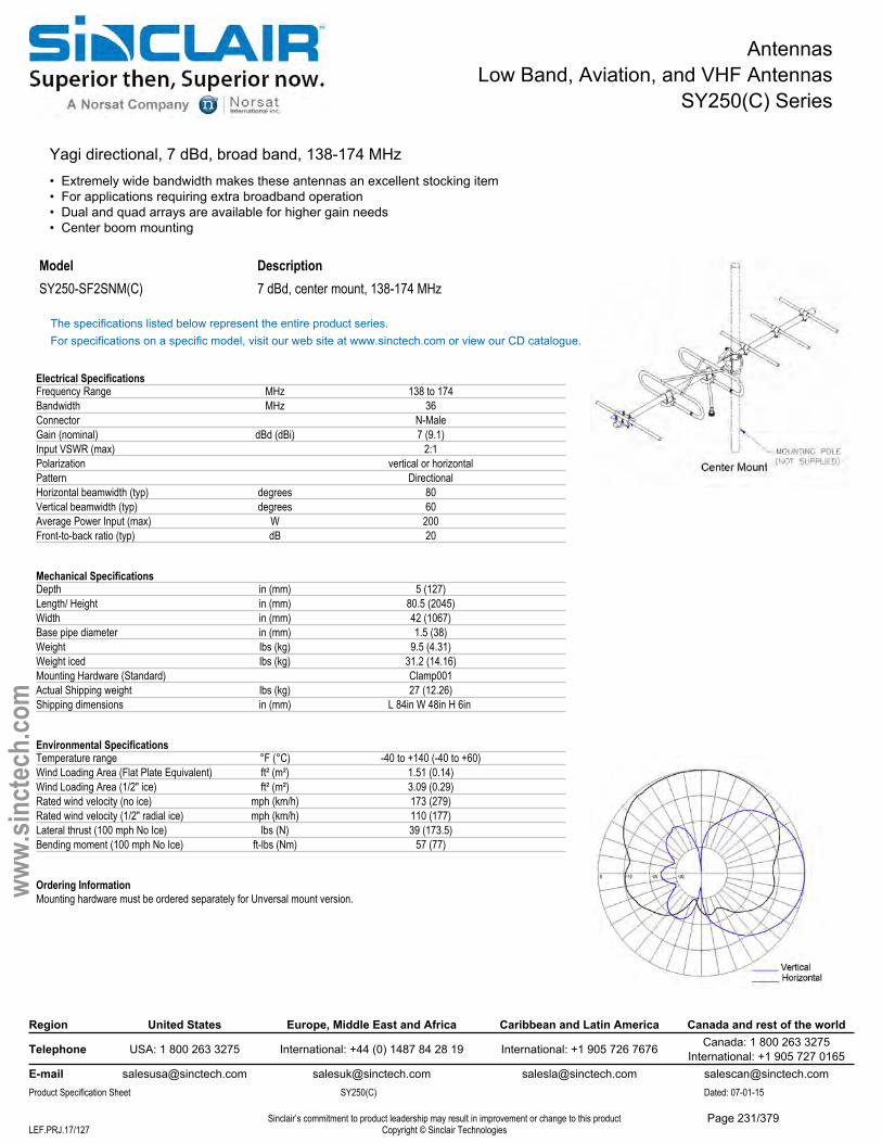
AntennasLow Band, Aviation, and VHF Antennas
SY250(C) Series
Yagi directional, 7 dBd, broad band, 138-174 MHz• Extremely wide bandwidth makes these antennas an excellent stocking item• For applications requiring extra broadband operation• Dual and quad arrays are available for higher gain needs• Center boom mounting
Model DescriptionSY250-SF2SNM(C) 7 dBd, center mount, 138-174 MHz
The specifications listed below represent the entire product series.For specifications on a specific model, visit our web site at www.sinctech.com or view our CD catalogue.
Electrical SpecificationsFrequency Range MHz 138 to 174Bandwidth MHz 36Connector N-MaleGain (nominal) dBd (dBi) 7 (9.1)Input VSWR (max) 2:1Polarization vertical or horizontalPattern DirectionalHorizontal beamwidth (typ) degrees 80Vertical beamwidth (typ) degrees 60Average Power Input (max) W 200Front-to-back ratio (typ) dB 20
Mechanical SpecificationsDepth in (mm) 5 (127)Length/ Height in (mm) 80.5 (2045)Width in (mm) 42 (1067)Base pipe diameter in (mm) 1.5 (38)Weight lbs (kg) 9.5 (4.31)Weight iced lbs (kg) 31.2 (14.16)Mounting Hardware (Standard) Clamp001Actual Shipping weight lbs (kg) 27 (12.26)Shipping dimensions in (mm) L 84in W 48in H 6in
Environmental SpecificationsTemperature range °F (°C) -40 to +140 (-40 to +60)Wind Loading Area (Flat Plate Equivalent) ft² (m²) 1.51 (0.14)Wind Loading Area (1/2" ice) ft² (m²) 3.09 (0.29)Rated wind velocity (no ice) mph (km/h) 173 (279)Rated wind velocity (1/2" radial ice) mph (km/h) 110 (177)Lateral thrust (100 mph No Ice) lbs (N) 39 (173.5)Bending moment (100 mph No Ice) ft-lbs (Nm) 57 (77)
Ordering InformationMounting hardware must be ordered separately for Unversal mount version.
Region United States Europe, Middle East and Africa Caribbean and Latin America Canada and rest of the world
Telephone USA: 1 800 263 3275 International: +44 (0) 1487 84 28 19 International: +1 905 726 7676 Canada: 1 800 263 3275International: +1 905 727 0165
E-mail [email protected] [email protected] [email protected] [email protected] Specification Sheet SY250(C) Dated: 07-01-15
Sinclair’s commitment to product leadership may result in improvement or change to this productCopyright © Sinclair TechnologiesLEF.PRJ.17/127
www.
sinct
ech.
com
Page 231/379
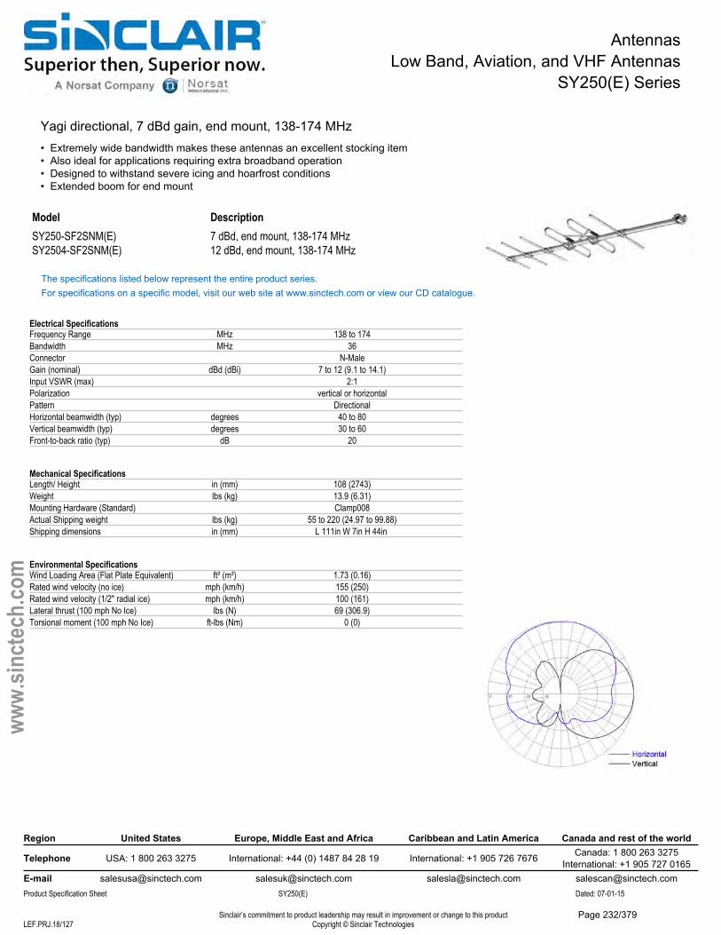
AntennasLow Band, Aviation, and VHF Antennas
SY250(E) Series
Yagi directional, 7 dBd gain, end mount, 138-174 MHz• Extremely wide bandwidth makes these antennas an excellent stocking item• Also ideal for applications requiring extra broadband operation• Designed to withstand severe icing and hoarfrost conditions• Extended boom for end mount
Model DescriptionSY250-SF2SNM(E) 7 dBd, end mount, 138-174 MHzSY2504-SF2SNM(E) 12 dBd, end mount, 138-174 MHz
The specifications listed below represent the entire product series.For specifications on a specific model, visit our web site at www.sinctech.com or view our CD catalogue.
Electrical SpecificationsFrequency Range MHz 138 to 174Bandwidth MHz 36Connector N-MaleGain (nominal) dBd (dBi) 7 to 12 (9.1 to 14.1)Input VSWR (max) 2:1Polarization vertical or horizontalPattern DirectionalHorizontal beamwidth (typ) degrees 40 to 80Vertical beamwidth (typ) degrees 30 to 60Front-to-back ratio (typ) dB 20
Mechanical SpecificationsLength/ Height in (mm) 108 (2743)Weight lbs (kg) 13.9 (6.31)Mounting Hardware (Standard) Clamp008Actual Shipping weight lbs (kg) 55 to 220 (24.97 to 99.88)Shipping dimensions in (mm) L 111in W 7in H 44in
Environmental SpecificationsWind Loading Area (Flat Plate Equivalent) ft² (m²) 1.73 (0.16)Rated wind velocity (no ice) mph (km/h) 155 (250)Rated wind velocity (1/2" radial ice) mph (km/h) 100 (161)Lateral thrust (100 mph No Ice) lbs (N) 69 (306.9)Torsional moment (100 mph No Ice) ft-lbs (Nm) 0 (0)
Region United States Europe, Middle East and Africa Caribbean and Latin America Canada and rest of the world
Telephone USA: 1 800 263 3275 International: +44 (0) 1487 84 28 19 International: +1 905 726 7676 Canada: 1 800 263 3275International: +1 905 727 0165
E-mail [email protected] [email protected] [email protected] [email protected] Specification Sheet SY250(E) Dated: 07-01-15
Sinclair’s commitment to product leadership may result in improvement or change to this productCopyright © Sinclair TechnologiesLEF.PRJ.18/127
www.
sinct
ech.
com
Page 232/379
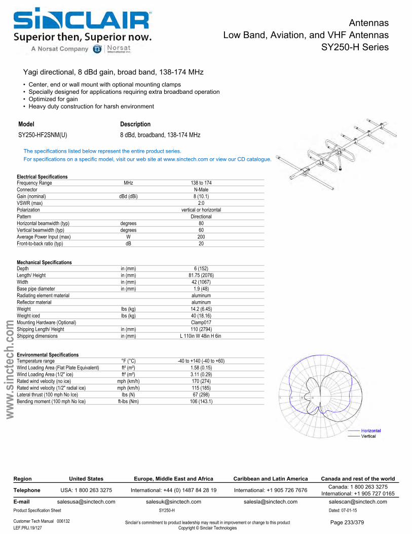
AntennasLow Band, Aviation, and VHF Antennas
SY250-H Series
Yagi directional, 8 dBd gain, broad band, 138-174 MHz• Center, end or wall mount with optional mounting clamps• Specially designed for applications requiring extra broadband operation• Optimized for gain• Heavy duty construction for harsh environment
Model DescriptionSY250-HF2SNM(U) 8 dBd, broadband, 138-174 MHz
The specifications listed below represent the entire product series.For specifications on a specific model, visit our web site at www.sinctech.com or view our CD catalogue.
Electrical SpecificationsFrequency Range MHz 138 to 174Connector N-MaleGain (nominal) dBd (dBi) 8 (10.1)VSWR (max) 2:0Polarization vertical or horizontalPattern DirectionalHorizontal beamwidth (typ) degrees 80Vertical beamwidth (typ) degrees 60Average Power Input (max) W 200Front-to-back ratio (typ) dB 20
Mechanical SpecificationsDepth in (mm) 6 (152)Length/ Height in (mm) 81.75 (2076)Width in (mm) 42 (1067)Base pipe diameter in (mm) 1.9 (48)Radiating element material aluminumReflector material aluminumWeight lbs (kg) 14.2 (6.45)Weight iced lbs (kg) 40 (18.16)Mounting Hardware (Optional) Clamp017Shipping Length/ Height in (mm) 110 (2794)Shipping dimensions in (mm) L 110in W 48in H 6in
Environmental SpecificationsTemperature range °F (°C) -40 to +140 (-40 to +60)Wind Loading Area (Flat Plate Equivalent) ft² (m²) 1.58 (0.15)Wind Loading Area (1/2" ice) ft² (m²) 3.11 (0.29)Rated wind velocity (no ice) mph (km/h) 170 (274)Rated wind velocity (1/2" radial ice) mph (km/h) 115 (185)Lateral thrust (100 mph No Ice) lbs (N) 67 (298)Bending moment (100 mph No Ice) ft-lbs (Nm) 106 (143.1)
Region United States Europe, Middle East and Africa Caribbean and Latin America Canada and rest of the world
Telephone USA: 1 800 263 3275 International: +44 (0) 1487 84 28 19 International: +1 905 726 7676 Canada: 1 800 263 3275International: +1 905 727 0165
E-mail [email protected] [email protected] [email protected] [email protected] Specification Sheet SY250-H Dated: 07-01-15
Customer Tech Manual 006132 Sinclair’s commitment to product leadership may result in improvement or change to this productCopyright © Sinclair TechnologiesLEF.PRJ.19/127
www.
sinct
ech.
com
Page 233/379
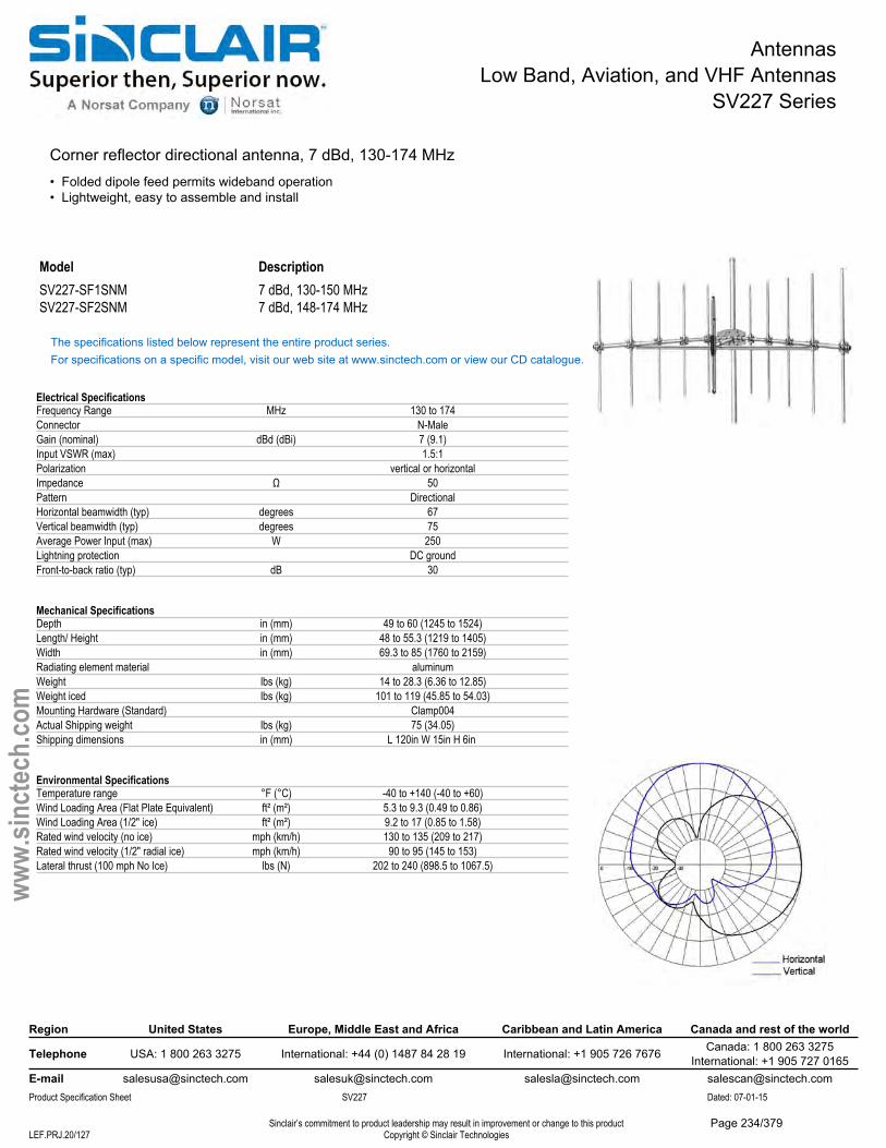
AntennasLow Band, Aviation, and VHF Antennas
SV227 Series
Corner reflector directional antenna, 7 dBd, 130-174 MHz• Folded dipole feed permits wideband operation• Lightweight, easy to assemble and install
Model DescriptionSV227-SF1SNM 7 dBd, 130-150 MHzSV227-SF2SNM 7 dBd, 148-174 MHz
The specifications listed below represent the entire product series.For specifications on a specific model, visit our web site at www.sinctech.com or view our CD catalogue.
Electrical SpecificationsFrequency Range MHz 130 to 174Connector N-MaleGain (nominal) dBd (dBi) 7 (9.1)Input VSWR (max) 1.5:1Polarization vertical or horizontalImpedance Ω 50Pattern DirectionalHorizontal beamwidth (typ) degrees 67Vertical beamwidth (typ) degrees 75Average Power Input (max) W 250Lightning protection DC groundFront-to-back ratio (typ) dB 30
Mechanical SpecificationsDepth in (mm) 49 to 60 (1245 to 1524)Length/ Height in (mm) 48 to 55.3 (1219 to 1405)Width in (mm) 69.3 to 85 (1760 to 2159)Radiating element material aluminumWeight lbs (kg) 14 to 28.3 (6.36 to 12.85)Weight iced lbs (kg) 101 to 119 (45.85 to 54.03)Mounting Hardware (Standard) Clamp004Actual Shipping weight lbs (kg) 75 (34.05)Shipping dimensions in (mm) L 120in W 15in H 6in
Environmental SpecificationsTemperature range °F (°C) -40 to +140 (-40 to +60)Wind Loading Area (Flat Plate Equivalent) ft² (m²) 5.3 to 9.3 (0.49 to 0.86)Wind Loading Area (1/2" ice) ft² (m²) 9.2 to 17 (0.85 to 1.58)Rated wind velocity (no ice) mph (km/h) 130 to 135 (209 to 217)Rated wind velocity (1/2" radial ice) mph (km/h) 90 to 95 (145 to 153)Lateral thrust (100 mph No Ice) lbs (N) 202 to 240 (898.5 to 1067.5)
Region United States Europe, Middle East and Africa Caribbean and Latin America Canada and rest of the world
Telephone USA: 1 800 263 3275 International: +44 (0) 1487 84 28 19 International: +1 905 726 7676 Canada: 1 800 263 3275International: +1 905 727 0165
E-mail [email protected] [email protected] [email protected] [email protected] Specification Sheet SV227 Dated: 07-01-15
Sinclair’s commitment to product leadership may result in improvement or change to this productCopyright © Sinclair TechnologiesLEF.PRJ.20/127
www.
sinct
ech.
com
Page 234/379
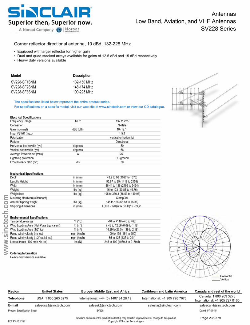
AntennasLow Band, Aviation, and VHF Antennas
SV228 Series
Corner reflector directional antenna, 10 dBd, 132-225 MHz• Equipped with larger reflector for higher gain• Dual and quad stacked arrays available for gains of 12.5 dBd and 15 dBd respectively• Heavy duty versions available
Model DescriptionSV228-SF1SNM 132-150 MHzSV228-SF2SNM 148-174 MHzSV228-SF3SNM 190-225 MHz
The specifications listed below represent the entire product series.For specifications on a specific model, visit our web site at www.sinctech.com or view our CD catalogue.
Electrical SpecificationsFrequency Range MHz 132 to 225Connector N-MaleGain (nominal) dBd (dBi) 10 (12.1)Input VSWR (max) 1.5:1Polarization vertical or horizontalPattern DirectionalHorizontal beamwidth (typ) degrees 50Vertical beamwidth (typ) degrees 66Average Power Input (max) W 250Lightning protection DC groundFront-to-back ratio (typ) dB 30
Mechanical SpecificationsDepth in (mm) 43.2 to 66 (1097 to 1676)Length/ Height in (mm) 55.87 to 85 (1419 to 2159)Width in (mm) 86.44 to 136 (2196 to 3454)Weight lbs (kg) 46 to 103 (20.88 to 46.76)Weight iced lbs (kg) 195 to 330.3 (88.53 to 149.96)Mounting Hardware (Standard) Clamp004Actual Shipping weight lbs (kg) 145 to 166 (65.83 to 75.36)Shipping dimensions in (mm) L(108 - 120)in W 6in H(15 - 24)in
Environmental SpecificationsTemperature range °F (°C) -40 to +140 (-40 to +60)Wind Loading Area (Flat Plate Equivalent) ft² (m²) 7.48 to 12.66 (0.69 to 1.18)Wind Loading Area (1/2" ice) ft² (m²) 14.99 to 23.5 (1.39 to 2.18)Rated wind velocity (no ice) mph (km/h) 100 to 155 (161 to 250)Rated wind velocity (1/2" radial ice) mph (km/h) 85 to 125 (137 to 201)Lateral thrust (100 mph No Ice) lbs (N) 245 to 490 (1089.8 to 2179.5)
Ordering InformationHeavy duty versions available
Region United States Europe, Middle East and Africa Caribbean and Latin America Canada and rest of the world
Telephone USA: 1 800 263 3275 International: +44 (0) 1487 84 28 19 International: +1 905 726 7676 Canada: 1 800 263 3275International: +1 905 727 0165
E-mail [email protected] [email protected] [email protected] [email protected] Specification Sheet SV228 Dated: 07-01-15
Sinclair’s commitment to product leadership may result in improvement or change to this productCopyright © Sinclair TechnologiesLEF.PRJ.21/127
www.
sinct
ech.
com
Page 235/379
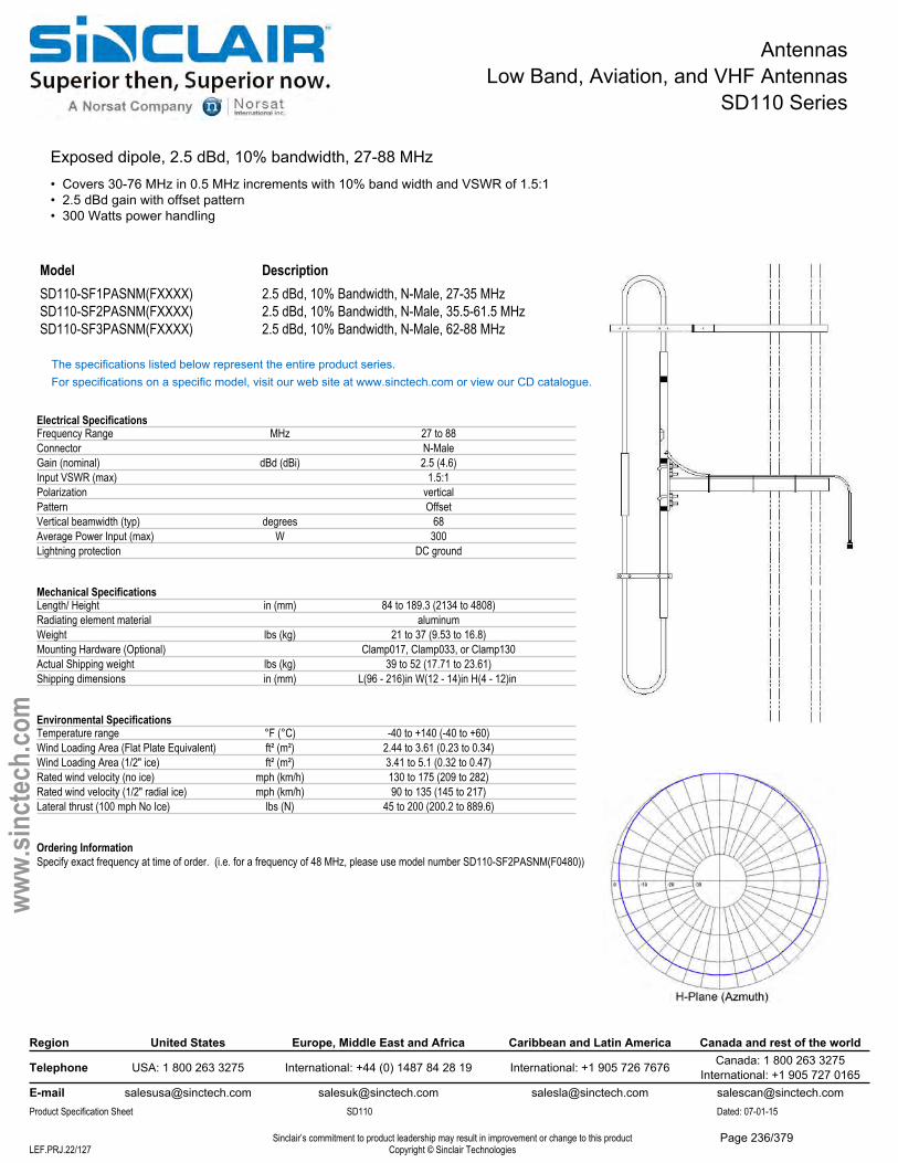
AntennasLow Band, Aviation, and VHF Antennas
SD110 Series
Exposed dipole, 2.5 dBd, 10% bandwidth, 27-88 MHz• Covers 30-76 MHz in 0.5 MHz increments with 10% band width and VSWR of 1.5:1• 2.5 dBd gain with offset pattern• 300 Watts power handling
Model DescriptionSD110-SF1PASNM(FXXXX) 2.5 dBd, 10% Bandwidth, N-Male, 27-35 MHzSD110-SF2PASNM(FXXXX) 2.5 dBd, 10% Bandwidth, N-Male, 35.5-61.5 MHzSD110-SF3PASNM(FXXXX) 2.5 dBd, 10% Bandwidth, N-Male, 62-88 MHz
The specifications listed below represent the entire product series.For specifications on a specific model, visit our web site at www.sinctech.com or view our CD catalogue.
Electrical SpecificationsFrequency Range MHz 27 to 88Connector N-MaleGain (nominal) dBd (dBi) 2.5 (4.6)Input VSWR (max) 1.5:1Polarization verticalPattern OffsetVertical beamwidth (typ) degrees 68Average Power Input (max) W 300Lightning protection DC ground
Mechanical SpecificationsLength/ Height in (mm) 84 to 189.3 (2134 to 4808)Radiating element material aluminumWeight lbs (kg) 21 to 37 (9.53 to 16.8)Mounting Hardware (Optional) Clamp017, Clamp033, or Clamp130Actual Shipping weight lbs (kg) 39 to 52 (17.71 to 23.61)Shipping dimensions in (mm) L(96 - 216)in W(12 - 14)in H(4 - 12)in
Environmental SpecificationsTemperature range °F (°C) -40 to +140 (-40 to +60)Wind Loading Area (Flat Plate Equivalent) ft² (m²) 2.44 to 3.61 (0.23 to 0.34)Wind Loading Area (1/2" ice) ft² (m²) 3.41 to 5.1 (0.32 to 0.47)Rated wind velocity (no ice) mph (km/h) 130 to 175 (209 to 282)Rated wind velocity (1/2" radial ice) mph (km/h) 90 to 135 (145 to 217)Lateral thrust (100 mph No Ice) lbs (N) 45 to 200 (200.2 to 889.6)
Ordering InformationSpecify exact frequency at time of order. (i.e. for a frequency of 48 MHz, please use model number SD110-SF2PASNM(F0480))
Region United States Europe, Middle East and Africa Caribbean and Latin America Canada and rest of the world
Telephone USA: 1 800 263 3275 International: +44 (0) 1487 84 28 19 International: +1 905 726 7676 Canada: 1 800 263 3275International: +1 905 727 0165
E-mail [email protected] [email protected] [email protected] [email protected] Specification Sheet SD110 Dated: 07-01-15
Sinclair’s commitment to product leadership may result in improvement or change to this productCopyright © Sinclair TechnologiesLEF.PRJ.22/127
www.
sinct
ech.
com
Page 236/379
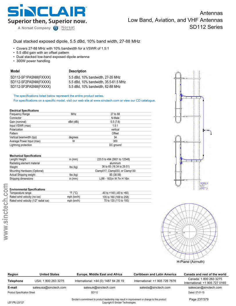
AntennasLow Band, Aviation, and VHF Antennas
SD112 Series
Dual stacked exposed dipole, 5.5 dBd, 10% band width, 27-88 MHz• Covers 27-88 MHz with 10% bandwidth for a VSWR of 1.5:1• 5.5 dBd gain with an offset pattern• Dual stacked low-band exposed dipole antenna• 300W power handling
Model DescriptionSD112-SF1PASNM(FXXXX) 5.5 dBd, 10% bandwidth, 27-35 MHzSD112-SF2PASNM(FXXXX) 5.5 dBd, 10% bandwidth, 35.5-61.5 MHzSD112-SF3PASNM(FXXXX) 5.5 dBd, 10% bandwidth, 62-88 MHz
The specifications listed below represent the entire product series.For specifications on a specific model, visit our web site at www.sinctech.com or view our CD catalogue.
Electrical SpecificationsFrequency Range MHz 27 to 88Connector N-MaleGain (nominal) dBd (dBi) 5.5 (7.6)Input VSWR (max) 1.5:1Polarization verticalPattern OffsetVertical beamwidth (typ) degrees 34Average Power Input (max) W 300Lightning protection DC ground
Mechanical SpecificationsLength/ Height in (mm) 220.5 to 494 (5601 to 12548)Radiating element material aluminumWeight lbs (kg) 36 to 65 (16.34 to 29.51)Mounting Hardware (Optional) Clamp017, Clamp033, or Clamp130Actual Shipping weight lbs (kg) 85 (38.59)Shipping dimensions in (mm) L(86 - 183)in W 7in H 16in
Environmental SpecificationsTemperature range °F (°C) -40 to +140 (-40 to +60)Rated wind velocity (no ice) mph (km/h) 105 to 160 (169 to 258)Rated wind velocity (1/2" radial ice) mph (km/h) 70 to 120 (113 to 193)
Region United States Europe, Middle East and Africa Caribbean and Latin America Canada and rest of the world
Telephone USA: 1 800 263 3275 International: +44 (0) 1487 84 28 19 International: +1 905 726 7676 Canada: 1 800 263 3275International: +1 905 727 0165
E-mail [email protected] [email protected] [email protected] [email protected] Specification Sheet SD112 Dated: 07-01-15
Sinclair’s commitment to product leadership may result in improvement or change to this productCopyright © Sinclair TechnologiesLEF.PRJ.23/127
www.
sinct
ech.
com
Page 237/379
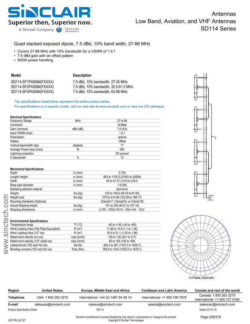
AntennasLow Band, Aviation, and VHF Antennas
SD114 Series
Quad stacked exposed dipole, 7.5 dBd, 10% band width, 27-88 MHz • Covers 27-88 MHz with 10% bandwidth for a VSWR of 1.5:1• 7.5 dBd gain with an offset pattern• 500W power handling
Model DescriptionSD114-SF1PASNM(FXXXX) 7.5 dBd, 10% bandwidth, 27-35 MHzSD114-SF2PASNM(FXXXX) 7.5 dBd, 10% bandwidth, 35.5-61.5 MHzSD114-SF3PASNM(FXXXX) 7.5 dBd, 10% bandwidth, 62-88 MHz
The specifications listed below represent the entire product series.For specifications on a specific model, visit our web site at www.sinctech.com or view our CD catalogue.
Electrical SpecificationsFrequency Range MHz 27 to 88Connector N-MaleGain (nominal) dBd (dBi) 7.5 (9.6)Input VSWR (max) 1.5:1Polarization verticalPattern OffsetVertical beamwidth (typ) degrees 17Average Power Input (max) W 500Lightning protection DC ground% Bandwidth % 10
Mechanical SpecificationsDepth in (mm) 3 (76)Length/ Height in (mm) 863 to 1153.5 (21920 to 29299)Width in (mm) 48 to 91.37 (1219 to 2321)Base pipe diameter in (mm) 1.9 (48)Radiating element material aluminumWeight lbs (kg) 103 to 149.6 (46.76 to 67.92)Weight iced lbs (kg) 270 to 414.48 (122.58 to 188.17)Mounting Hardware (Optional) Clamp017, Clamp033, or Clamp130Actual Shipping weight lbs (kg) 141 to 236 (64.01 to 107.14)Shipping dimensions in (mm) L(150 - 216)in W(14 - 24)in H(4 - 12)in
Environmental SpecificationsTemperature range °F (°C) -40 to +140 (-40 to +60)Wind Loading Area (Flat Plate Equivalent) ft² (m²) 11.88 to 14.6 (1.1 to 1.36)Wind Loading Area (1/2" ice) ft² (m²) 16.4 to 21.1 (1.52 to 1.96)Rated wind velocity (no ice) mph (km/h) 125 to 135 (201 to 217)Rated wind velocity (1/2" radial ice) mph (km/h) 90 to 105 (145 to 169)Lateral thrust (100 mph No Ice) lbs (N) 262.4 to 361 (1167.2 to 1605.7)Bending moment (100 mph No Ice) ft-lbs (Nm) 766.8 to 1243 (1035.2 to 1678.1)
Region United States Europe, Middle East and Africa Caribbean and Latin America Canada and rest of the world
Telephone USA: 1 800 263 3275 International: +44 (0) 1487 84 28 19 International: +1 905 726 7676 Canada: 1 800 263 3275International: +1 905 727 0165
E-mail [email protected] [email protected] [email protected] [email protected] Specification Sheet SD114 Dated: 07-01-15
Sinclair’s commitment to product leadership may result in improvement or change to this productCopyright © Sinclair TechnologiesLEF.PRJ.24/127
www.
sinct
ech.
com
Page 238/379
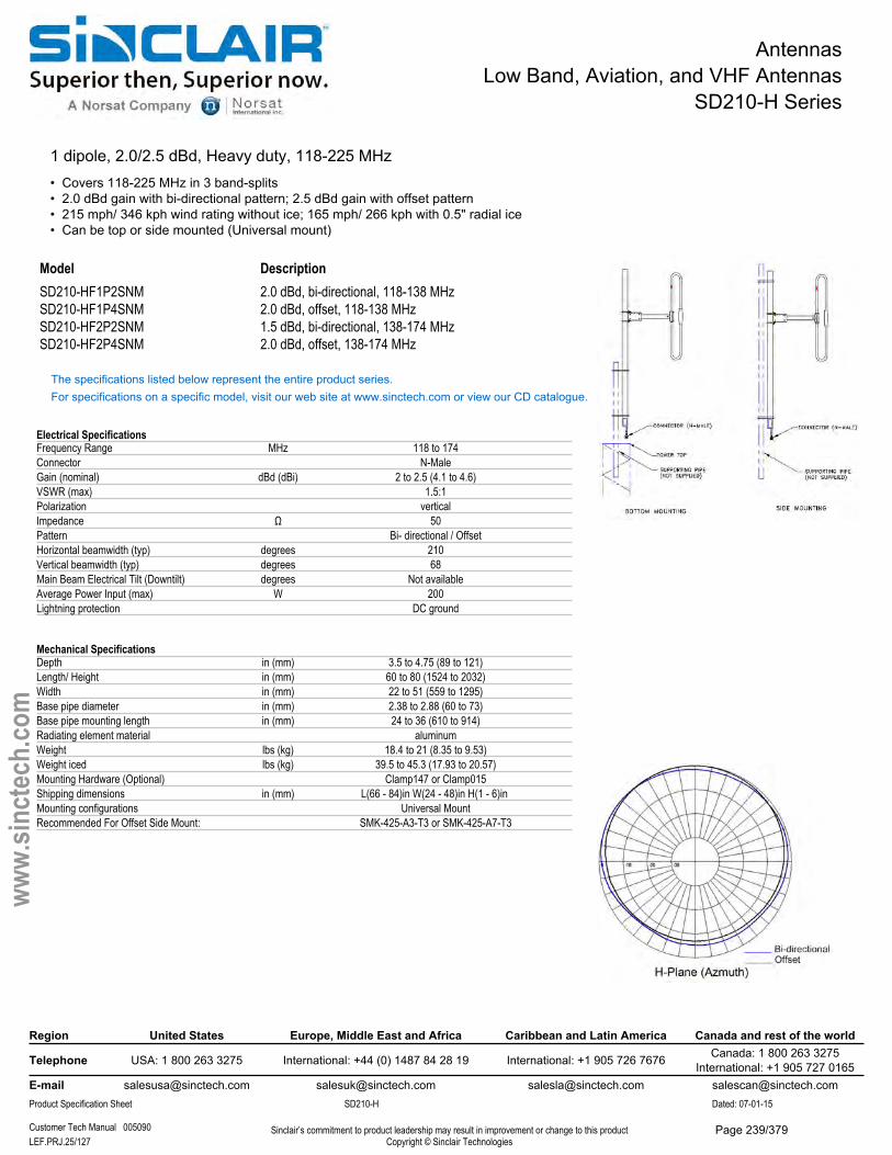
AntennasLow Band, Aviation, and VHF Antennas
SD210-H Series
1 dipole, 2.0/2.5 dBd, Heavy duty, 118-225 MHz• Covers 118-225 MHz in 3 band-splits• 2.0 dBd gain with bi-directional pattern; 2.5 dBd gain with offset pattern• 215 mph/ 346 kph wind rating without ice; 165 mph/ 266 kph with 0.5" radial ice• Can be top or side mounted (Universal mount)
Model DescriptionSD210-HF1P2SNM 2.0 dBd, bi-directional, 118-138 MHzSD210-HF1P4SNM 2.0 dBd, offset, 118-138 MHzSD210-HF2P2SNM 1.5 dBd, bi-directional, 138-174 MHzSD210-HF2P4SNM 2.0 dBd, offset, 138-174 MHz
The specifications listed below represent the entire product series.For specifications on a specific model, visit our web site at www.sinctech.com or view our CD catalogue.
Electrical SpecificationsFrequency Range MHz 118 to 174Connector N-MaleGain (nominal) dBd (dBi) 2 to 2.5 (4.1 to 4.6)VSWR (max) 1.5:1Polarization verticalImpedance Ω 50Pattern Bi- directional / OffsetHorizontal beamwidth (typ) degrees 210Vertical beamwidth (typ) degrees 68Main Beam Electrical Tilt (Downtilt) degrees Not availableAverage Power Input (max) W 200Lightning protection DC ground
Mechanical SpecificationsDepth in (mm) 3.5 to 4.75 (89 to 121)Length/ Height in (mm) 60 to 80 (1524 to 2032)Width in (mm) 22 to 51 (559 to 1295)Base pipe diameter in (mm) 2.38 to 2.88 (60 to 73)Base pipe mounting length in (mm) 24 to 36 (610 to 914)Radiating element material aluminumWeight lbs (kg) 18.4 to 21 (8.35 to 9.53)Weight iced lbs (kg) 39.5 to 45.3 (17.93 to 20.57)Mounting Hardware (Optional) Clamp147 or Clamp015Shipping dimensions in (mm) L(66 - 84)in W(24 - 48)in H(1 - 6)in Mounting configurations Universal MountRecommended For Offset Side Mount: SMK-425-A3-T3 or SMK-425-A7-T3
Region United States Europe, Middle East and Africa Caribbean and Latin America Canada and rest of the world
Telephone USA: 1 800 263 3275 International: +44 (0) 1487 84 28 19 International: +1 905 726 7676 Canada: 1 800 263 3275International: +1 905 727 0165
E-mail [email protected] [email protected] [email protected] [email protected] Specification Sheet SD210-H Dated: 07-01-15
Customer Tech Manual 005090 Sinclair’s commitment to product leadership may result in improvement or change to this productCopyright © Sinclair TechnologiesLEF.PRJ.25/127
www.
sinct
ech.
com
Page 239/379

AntennasLow Band, Aviation, and VHF Antennas
SD210-H Series
Environmental SpecificationsTemperature range °F (°C) -40 to +140 (-40 to +60)Wind Loading Area (Flat Plate Equivalent) ft² (m²) 1.25 to 1.77 (0.12 to 0.16)Wind Loading Area (1/2" ice) ft² (m²) 1.97 to 2.82 (0.18 to 0.26)Rated wind velocity (no ice) mph (km/h) 215 to 225 (346 to 362)Rated wind velocity (1/2" radial ice) mph (km/h) 165 to 175 (266 to 282)Lateral thrust (100 mph No Ice) lbs (N) 45.6 to 66.3 (202.8 to 294.9)Torsional moment (100 mph No Ice) ft-lbs (Nm) 22.8 to 81.6 (30.8 to 110.2)Bending moment (100 mph No Ice) ft-lbs (Nm) 50.5 to 96.3 (68.2 to 130)Tip deflection (100 mph No Ice) degrees 0.02 to 0.5
Ordering InformationClamps must be ordered separately.
Region United States Europe, Middle East and Africa Caribbean and Latin America Canada and rest of the world
Telephone USA: 1 800 263 3275 International: +44 (0) 1487 84 28 19 International: +1 905 726 7676 Canada: 1 800 263 3275International: +1 905 727 0165
E-mail [email protected] [email protected] [email protected] [email protected] Specification Sheet SD210-H Dated: 07-01-15
Customer Tech Manual 005090 Sinclair’s commitment to product leadership may result in improvement or change to this productCopyright © Sinclair TechnologiesLEF.PRJ.26/127
www.
sinct
ech.
com
Page 240/379
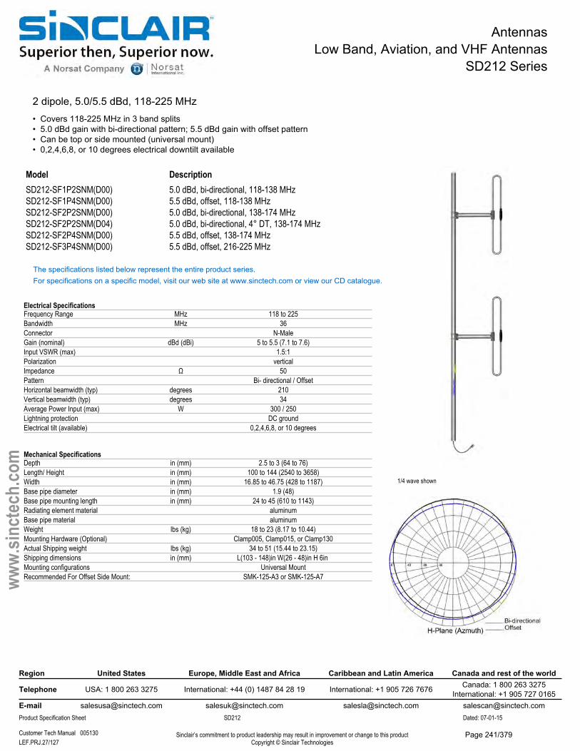
AntennasLow Band, Aviation, and VHF Antennas
SD212 Series
2 dipole, 5.0/5.5 dBd, 118-225 MHz• Covers 118-225 MHz in 3 band splits• 5.0 dBd gain with bi-directional pattern; 5.5 dBd gain with offset pattern• Can be top or side mounted (universal mount)• 0,2,4,6,8, or 10 degrees electrical downtilt available
1/4 wave shown
Model DescriptionSD212-SF1P2SNM(D00) 5.0 dBd, bi-directional, 118-138 MHzSD212-SF1P4SNM(D00) 5.5 dBd, offset, 118-138 MHzSD212-SF2P2SNM(D00) 5.0 dBd, bi-directional, 138-174 MHzSD212-SF2P2SNM(D04) 5.0 dBd, bi-directional, 4° DT, 138-174 MHzSD212-SF2P4SNM(D00) 5.5 dBd, offset, 138-174 MHzSD212-SF3P4SNM(D00) 5.5 dBd, offset, 216-225 MHz
The specifications listed below represent the entire product series.For specifications on a specific model, visit our web site at www.sinctech.com or view our CD catalogue.
Electrical SpecificationsFrequency Range MHz 118 to 225Bandwidth MHz 36Connector N-MaleGain (nominal) dBd (dBi) 5 to 5.5 (7.1 to 7.6)Input VSWR (max) 1.5:1Polarization verticalImpedance Ω 50Pattern Bi- directional / OffsetHorizontal beamwidth (typ) degrees 210Vertical beamwidth (typ) degrees 34Average Power Input (max) W 300 / 250Lightning protection DC groundElectrical tilt (available) 0,2,4,6,8, or 10 degrees
Mechanical SpecificationsDepth in (mm) 2.5 to 3 (64 to 76)Length/ Height in (mm) 100 to 144 (2540 to 3658)Width in (mm) 16.85 to 46.75 (428 to 1187)Base pipe diameter in (mm) 1.9 (48)Base pipe mounting length in (mm) 24 to 45 (610 to 1143)Radiating element material aluminumBase pipe material aluminumWeight lbs (kg) 18 to 23 (8.17 to 10.44)Mounting Hardware (Optional) Clamp005, Clamp015, or Clamp130Actual Shipping weight lbs (kg) 34 to 51 (15.44 to 23.15)Shipping dimensions in (mm) L(103 - 148)in W(26 - 48)in H 6in Mounting configurations Universal MountRecommended For Offset Side Mount: SMK-125-A3 or SMK-125-A7
Region United States Europe, Middle East and Africa Caribbean and Latin America Canada and rest of the world
Telephone USA: 1 800 263 3275 International: +44 (0) 1487 84 28 19 International: +1 905 726 7676 Canada: 1 800 263 3275International: +1 905 727 0165
E-mail [email protected] [email protected] [email protected] [email protected] Specification Sheet SD212 Dated: 07-01-15
Customer Tech Manual 005130 Sinclair’s commitment to product leadership may result in improvement or change to this productCopyright © Sinclair TechnologiesLEF.PRJ.27/127
www.
sinct
ech.
com
Page 241/379

AntennasLow Band, Aviation, and VHF Antennas
SD212 Series
Environmental SpecificationsTemperature range °F (°C) -40 to +140 (-40 to +60)Wind Loading Area (Flat Plate Equivalent) ft² (m²) 1.41 to 2.49 (0.13 to 0.23)Wind Loading Area (1/2" ice) ft² (m²) 2.46 to 4.37 (0.23 to 0.41)Rated wind velocity (no ice) mph (km/h) 140 to 175 (225 to 282)Rated wind velocity (1/2" radial ice) mph (km/h) 95 to 125 (153 to 201)Lateral thrust (100 mph No Ice) lbs (N) 52 to 96 (231.3 to 427)Torsional moment (100 mph No Ice) ft-lbs (Nm) 17 to 125 (23 to 168.8)Bending moment (100 mph No Ice) ft-lbs (Nm) 162 to 288 (218.7 to 388.8)Tip deflection (100 mph No Ice) degrees 0.46 to 1.52
Ordering InformationClamps must be ordered separately.
Region United States Europe, Middle East and Africa Caribbean and Latin America Canada and rest of the world
Telephone USA: 1 800 263 3275 International: +44 (0) 1487 84 28 19 International: +1 905 726 7676 Canada: 1 800 263 3275International: +1 905 727 0165
E-mail [email protected] [email protected] [email protected] [email protected] Specification Sheet SD212 Dated: 07-01-15
Customer Tech Manual 005130 Sinclair’s commitment to product leadership may result in improvement or change to this productCopyright © Sinclair TechnologiesLEF.PRJ.28/127
www.
sinct
ech.
com
Page 242/379
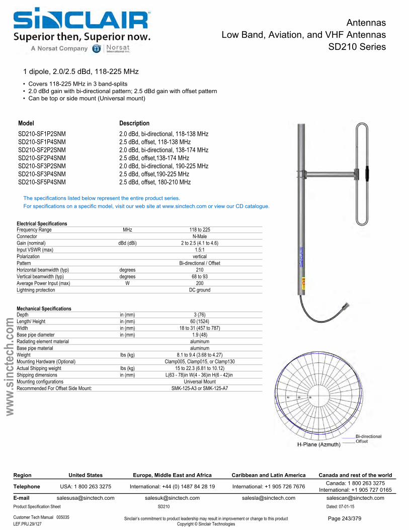
AntennasLow Band, Aviation, and VHF Antennas
SD210 Series
1 dipole, 2.0/2.5 dBd, 118-225 MHz• Covers 118-225 MHz in 3 band-splits• 2.0 dBd gain with bi-directional pattern; 2.5 dBd gain with offset pattern• Can be top or side mount (Universal mount)
Model DescriptionSD210-SF1P2SNM 2.0 dBd, bi-directional, 118-138 MHzSD210-SF1P4SNM 2.5 dBd, offset, 118-138 MHzSD210-SF2P2SNM 2.0 dBd, bi-directional, 138-174 MHzSD210-SF2P4SNM 2.5 dBd, offset,138-174 MHzSD210-SF3P2SNM 2.0 dBd, bi-directional, 190-225 MHzSD210-SF3P4SNM 2.5 dBd, offset,190-225 MHzSD210-SF5P4SNM 2.5 dBd, offset, 180-210 MHz
The specifications listed below represent the entire product series.For specifications on a specific model, visit our web site at www.sinctech.com or view our CD catalogue.
Electrical SpecificationsFrequency Range MHz 118 to 225Connector N-MaleGain (nominal) dBd (dBi) 2 to 2.5 (4.1 to 4.6)Input VSWR (max) 1.5:1Polarization verticalPattern Bi-directional / OffsetHorizontal beamwidth (typ) degrees 210Vertical beamwidth (typ) degrees 68 to 93Average Power Input (max) W 200Lightning protection DC ground
Mechanical SpecificationsDepth in (mm) 3 (76)Length/ Height in (mm) 60 (1524)Width in (mm) 18 to 31 (457 to 787)Base pipe diameter in (mm) 1.9 (48)Radiating element material aluminumBase pipe material aluminumWeight lbs (kg) 8.1 to 9.4 (3.68 to 4.27)Mounting Hardware (Optional) Clamp005, Clamp015, or Clamp130Actual Shipping weight lbs (kg) 15 to 22.3 (6.81 to 10.12)Shipping dimensions in (mm) L(63 - 78)in W(4 - 36)in H(6 - 42)in Mounting configurations Universal MountRecommended For Offset Side Mount: SMK-125-A3 or SMK-125-A7
Region United States Europe, Middle East and Africa Caribbean and Latin America Canada and rest of the world
Telephone USA: 1 800 263 3275 International: +44 (0) 1487 84 28 19 International: +1 905 726 7676 Canada: 1 800 263 3275International: +1 905 727 0165
E-mail [email protected] [email protected] [email protected] [email protected] Specification Sheet SD210 Dated: 07-01-15
Customer Tech Manual 005035 Sinclair’s commitment to product leadership may result in improvement or change to this productCopyright © Sinclair TechnologiesLEF.PRJ.29/127
www.
sinct
ech.
com
Page 243/379
AntennasLow Band, Aviation, and VHF Antennas
SD210 Series
Environmental SpecificationsTemperature range °F (°C) -40 to +140 (-40 to +60)Wind Loading Area (Flat Plate Equivalent) ft² (m²) 0.81 to 0.93 (0.08 to 0.09)Wind Loading Area (1/2" ice) ft² (m²) 1.46 to 1.66 (0.14 to 0.15)Rated wind velocity (no ice) mph (km/h) 175 to 240 (282 to 386)Rated wind velocity (1/2" radial ice) mph (km/h) 85 to 175 (137 to 282)Lateral thrust (100 mph No Ice) lbs (N) 29.8 to 55 (132.6 to 244.6)
Ordering InformationClamps must be ordered separately.
Region United States Europe, Middle East and Africa Caribbean and Latin America Canada and rest of the world
Telephone USA: 1 800 263 3275 International: +44 (0) 1487 84 28 19 International: +1 905 726 7676 Canada: 1 800 263 3275International: +1 905 727 0165
E-mail [email protected] [email protected] [email protected] [email protected] Specification Sheet SD210 Dated: 07-01-15
Customer Tech Manual 005035 Sinclair’s commitment to product leadership may result in improvement or change to this productCopyright © Sinclair TechnologiesLEF.PRJ.30/127
www.
sinct
ech.
com
Page 244/379
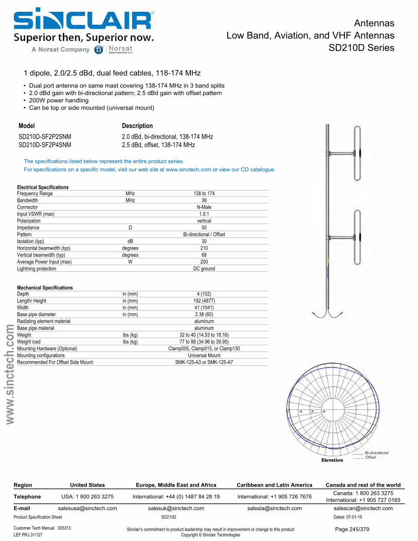
AntennasLow Band, Aviation, and VHF Antennas
SD210D Series
1 dipole, 2.0/2.5 dBd, dual feed cables, 118-174 MHz• Dual port antenna on same mast covering 138-174 MHz in 3 band splits• 2.0 dBd gain with bi-directional pattern; 2.5 dBd gain with offset pattern• 200W power handling• Can be top or side mounted (universal mount)
Model DescriptionSD210D-SF2P2SNM 2.0 dBd, bi-directional, 138-174 MHzSD210D-SF2P4SNM 2.5 dBd, offset, 138-174 MHz
The specifications listed below represent the entire product series.For specifications on a specific model, visit our web site at www.sinctech.com or view our CD catalogue.
Electrical SpecificationsFrequency Range MHz 138 to 174Bandwidth MHz 36Connector N-MaleInput VSWR (max) 1.5:1Polarization verticalImpedance Ω 50Pattern Bi-directional / OffsetIsolation (typ) dB 30Horizontal beamwidth (typ) degrees 210Vertical beamwidth (typ) degrees 68Average Power Input (max) W 200Lightning protection DC ground
Mechanical SpecificationsDepth in (mm) 4 (102)Length/ Height in (mm) 192 (4877)Width in (mm) 41 (1041)Base pipe diameter in (mm) 2.38 (60)Radiating element material aluminumBase pipe material aluminumWeight lbs (kg) 32 to 40 (14.53 to 18.16)Weight iced lbs (kg) 77 to 88 (34.96 to 39.95)Mounting Hardware (Optional) Clamp005, Clamp015, or Clamp130Mounting configurations Universal MountRecommended For Offset Side Mount: SMK-125-A3 or SMK-125-A7
Region United States Europe, Middle East and Africa Caribbean and Latin America Canada and rest of the world
Telephone USA: 1 800 263 3275 International: +44 (0) 1487 84 28 19 International: +1 905 726 7676 Canada: 1 800 263 3275International: +1 905 727 0165
E-mail [email protected] [email protected] [email protected] [email protected] Specification Sheet SD210D Dated: 07-01-15
Customer Tech Manual 005313 Sinclair’s commitment to product leadership may result in improvement or change to this productCopyright © Sinclair TechnologiesLEF.PRJ.31/127
www.
sinct
ech.
com
Page 245/379

AntennasLow Band, Aviation, and VHF Antennas
SD210D Series
Environmental SpecificationsTemperature range °F (°C) -40 to +140 (-40 to +60)Wind Loading Area (Flat Plate Equivalent) ft² (m²) 1.83 to 3.12 (0.17 to 0.29)Wind Loading Area (1/2" ice) ft² (m²) 3.25 to 5.02 (0.3 to 0.47)Rated wind velocity (no ice) mph (km/h) 145 (233)Rated wind velocity (1/2" radial ice) mph (km/h) 110 (177)Lateral thrust (100 mph No Ice) lbs (N) 114 (507.1)Torsional moment (100 mph No Ice) ft-lbs (Nm) 34 to 81 (45.9 to 109.4)Bending moment (100 mph No Ice) ft-lbs (Nm) 218 to 719 (294.3 to 970.7)Tip deflection (100 mph No Ice) degrees 0.3
Ordering InformationClamps must be ordered separately.
Region United States Europe, Middle East and Africa Caribbean and Latin America Canada and rest of the world
Telephone USA: 1 800 263 3275 International: +44 (0) 1487 84 28 19 International: +1 905 726 7676 Canada: 1 800 263 3275International: +1 905 727 0165
E-mail [email protected] [email protected] [email protected] [email protected] Specification Sheet SD210D Dated: 07-01-15
Customer Tech Manual 005313 Sinclair’s commitment to product leadership may result in improvement or change to this productCopyright © Sinclair TechnologiesLEF.PRJ.32/127
www.
sinct
ech.
com
Page 246/379
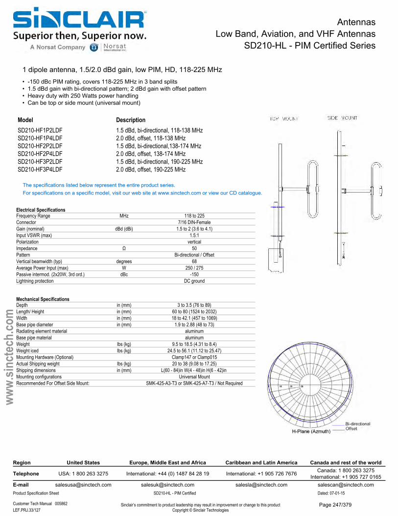
AntennasLow Band, Aviation, and VHF Antennas
SD210-HL - PIM Certified Series
1 dipole antenna, 1.5/2.0 dBd gain, low PIM, HD, 118-225 MHz• -150 dBc PIM rating, covers 118-225 MHz in 3 band splits• 1.5 dBd gain with bi-directional pattern; 2 dBd gain with offset pattern• Heavy duty with 250 Watts power handling• Can be top or side mount (universal mount)
Model DescriptionSD210-HF1P2LDF 1.5 dBd, bi-directional, 118-138 MHzSD210-HF1P4LDF 2.0 dBd, offset, 118-138 MHzSD210-HF2P2LDF 1.5 dBd, bi-directional,138-174 MHzSD210-HF2P4LDF 2.0 dBd, offset, 138-174 MHzSD210-HF3P2LDF 1.5 dBd, bi-directional, 190-225 MHzSD210-HF3P4LDF 2.0 dBd, offset, 190-225 MHz
The specifications listed below represent the entire product series.For specifications on a specific model, visit our web site at www.sinctech.com or view our CD catalogue.
Electrical SpecificationsFrequency Range MHz 118 to 225Connector 7/16 DIN-FemaleGain (nominal) dBd (dBi) 1.5 to 2 (3.6 to 4.1)Input VSWR (max) 1.5:1Polarization verticalImpedance Ω 50Pattern Bi-directional / OffsetVertical beamwidth (typ) degrees 68Average Power Input (max) W 250 / 275Passive intermod. (2x20W, 3rd ord.) dBc -150Lightning protection DC ground
Mechanical SpecificationsDepth in (mm) 3 to 3.5 (76 to 89)Length/ Height in (mm) 60 to 80 (1524 to 2032)Width in (mm) 18 to 42.1 (457 to 1069)Base pipe diameter in (mm) 1.9 to 2.88 (48 to 73)Radiating element material aluminumBase pipe material aluminumWeight lbs (kg) 9.5 to 18.5 (4.31 to 8.4)Weight iced lbs (kg) 24.5 to 56.1 (11.12 to 25.47)Mounting Hardware (Optional) Clamp147 or Clamp015Actual Shipping weight lbs (kg) 20 to 38 (9.08 to 17.25)Shipping dimensions in (mm) L(60 - 84)in W(4 - 48)in H(6 - 42)in Mounting configurations Universal MountRecommended For Offset Side Mount: SMK-425-A3-T3 or SMK-425-A7-T3 / Not Required
Region United States Europe, Middle East and Africa Caribbean and Latin America Canada and rest of the world
Telephone USA: 1 800 263 3275 International: +44 (0) 1487 84 28 19 International: +1 905 726 7676 Canada: 1 800 263 3275International: +1 905 727 0165
E-mail [email protected] [email protected] [email protected] [email protected] Specification Sheet SD210-HL - PIM Certified Dated: 07-01-15
Customer Tech Manual 005862 Sinclair’s commitment to product leadership may result in improvement or change to this productCopyright © Sinclair TechnologiesLEF.PRJ.33/127
www.
sinct
ech.
com
Page 247/379
AntennasLow Band, Aviation, and VHF Antennas
SD210-HL - PIM Certified Series
Environmental SpecificationsTemperature range °F (°C) -40 to +140 (-40 to +60)Wind Loading Area (Flat Plate Equivalent) ft² (m²) 0.84 to 1.46 (0.08 to 0.14)Wind Loading Area (1/2" ice) ft² (m²) 1.46 to 2.73 (0.14 to 0.25)Rated wind velocity (no ice) mph (km/h) 190 to 230 (306 to 370)Rated wind velocity (1/2" radial ice) mph (km/h) 115 to 175 (185 to 282)Lateral thrust (100 mph No Ice) lbs (N) 31 to 53.5 (137.9 to 238)Torsional moment (100 mph No Ice) ft-lbs (Nm) 11.5 to 52.1 (15.5 to 70.3)Bending moment (100 mph No Ice) ft-lbs (Nm) 31 to 93.5 (41.9 to 126.2)
Ordering InformationClamps must be ordered separately.
Region United States Europe, Middle East and Africa Caribbean and Latin America Canada and rest of the world
Telephone USA: 1 800 263 3275 International: +44 (0) 1487 84 28 19 International: +1 905 726 7676 Canada: 1 800 263 3275International: +1 905 727 0165
E-mail [email protected] [email protected] [email protected] [email protected] Specification Sheet SD210-HL - PIM Certified Dated: 07-01-15
Customer Tech Manual 005862 Sinclair’s commitment to product leadership may result in improvement or change to this productCopyright © Sinclair TechnologiesLEF.PRJ.34/127
www.
sinct
ech.
com
Page 248/379
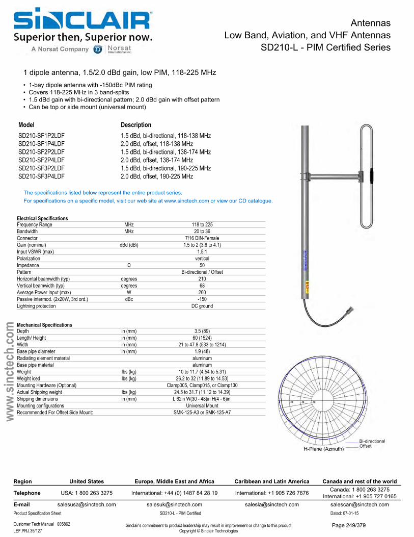
AntennasLow Band, Aviation, and VHF Antennas
SD210-L - PIM Certified Series
1 dipole antenna, 1.5/2.0 dBd gain, low PIM, 118-225 MHz• 1-bay dipole antenna with -150dBc PIM rating• Covers 118-225 MHz in 3 band-splits• 1.5 dBd gain with bi-directional pattern; 2.0 dBd gain with offset pattern• Can be top or side mount (universal mount)
Model DescriptionSD210-SF1P2LDF 1.5 dBd, bi-directional, 118-138 MHzSD210-SF1P4LDF 2.0 dBd, offset, 118-138 MHzSD210-SF2P2LDF 1.5 dBd, bi-directional, 138-174 MHzSD210-SF2P4LDF 2.0 dBd, offset, 138-174 MHzSD210-SF3P2LDF 1.5 dBd, bi-directional, 190-225 MHzSD210-SF3P4LDF 2.0 dBd, offset, 190-225 MHz
The specifications listed below represent the entire product series.For specifications on a specific model, visit our web site at www.sinctech.com or view our CD catalogue.
Electrical SpecificationsFrequency Range MHz 118 to 225Bandwidth MHz 20 to 36Connector 7/16 DIN-FemaleGain (nominal) dBd (dBi) 1.5 to 2 (3.6 to 4.1)Input VSWR (max) 1.5:1Polarization verticalImpedance Ω 50Pattern Bi-directional / OffsetHorizontal beamwidth (typ) degrees 210Vertical beamwidth (typ) degrees 68Average Power Input (max) W 200Passive intermod. (2x20W, 3rd ord.) dBc -150Lightning protection DC ground
Mechanical SpecificationsDepth in (mm) 3.5 (89)Length/ Height in (mm) 60 (1524)Width in (mm) 21 to 47.8 (533 to 1214)Base pipe diameter in (mm) 1.9 (48)Radiating element material aluminumBase pipe material aluminumWeight lbs (kg) 10 to 11.7 (4.54 to 5.31)Weight iced lbs (kg) 26.2 to 32 (11.89 to 14.53)Mounting Hardware (Optional) Clamp005, Clamp015, or Clamp130Actual Shipping weight lbs (kg) 24.5 to 31.7 (11.12 to 14.39)Shipping dimensions in (mm) L 62in W(30 - 48)in H(4 - 6)in Mounting configurations Universal MountRecommended For Offset Side Mount: SMK-125-A3 or SMK-125-A7
Region United States Europe, Middle East and Africa Caribbean and Latin America Canada and rest of the world
Telephone USA: 1 800 263 3275 International: +44 (0) 1487 84 28 19 International: +1 905 726 7676 Canada: 1 800 263 3275International: +1 905 727 0165
E-mail [email protected] [email protected] [email protected] [email protected] Specification Sheet SD210-L - PIM Certified Dated: 07-01-15
Customer Tech Manual 005862 Sinclair’s commitment to product leadership may result in improvement or change to this productCopyright © Sinclair TechnologiesLEF.PRJ.35/127
www.
sinct
ech.
com
Page 249/379

AntennasLow Band, Aviation, and VHF Antennas
SD210-L - PIM Certified Series
Environmental SpecificationsTemperature range °F (°C) -40 to +140 (-40 to +60)Wind Loading Area (Flat Plate Equivalent) ft² (m²) 1.01 to 1.09 (0.09 to 0.1)Wind Loading Area (1/2" ice) ft² (m²) 1.79 to 192 (0.17 to 17.84)Rated wind velocity (no ice) mph (km/h) 175 to 195 (282 to 314)Rated wind velocity (1/2" radial ice) mph (km/h) 105 to 125 (169 to 201)Lateral thrust (100 mph No Ice) lbs (N) 34.1 to 60.8 (151.7 to 270.4)Torsional moment (100 mph No Ice) ft-lbs (Nm) 17.6 to 64 (23.8 to 86.4)Bending moment (100 mph No Ice) ft-lbs (Nm) 33.5 to 76.3 (45.2 to 103)
Ordering InformationClamps must be ordered separately.
Region United States Europe, Middle East and Africa Caribbean and Latin America Canada and rest of the world
Telephone USA: 1 800 263 3275 International: +44 (0) 1487 84 28 19 International: +1 905 726 7676 Canada: 1 800 263 3275International: +1 905 727 0165
E-mail [email protected] [email protected] [email protected] [email protected] Specification Sheet SD210-L - PIM Certified Dated: 07-01-15
Customer Tech Manual 005862 Sinclair’s commitment to product leadership may result in improvement or change to this productCopyright © Sinclair TechnologiesLEF.PRJ.36/127
www.
sinct
ech.
com
Page 250/379
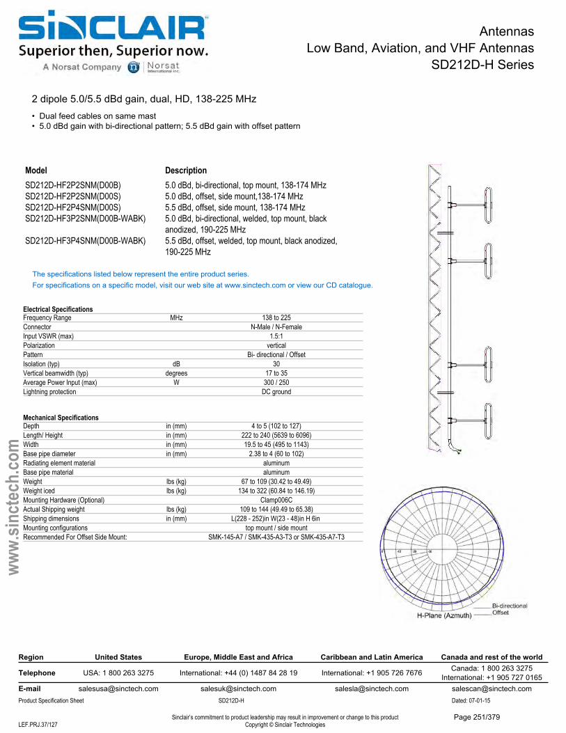
AntennasLow Band, Aviation, and VHF Antennas
SD212D-H Series
2 dipole 5.0/5.5 dBd gain, dual, HD, 138-225 MHz• Dual feed cables on same mast• 5.0 dBd gain with bi-directional pattern; 5.5 dBd gain with offset pattern
Model DescriptionSD212D-HF2P2SNM(D00B) 5.0 dBd, bi-directional, top mount, 138-174 MHzSD212D-HF2P2SNM(D00S) 5.0 dBd, offset, side mount,138-174 MHzSD212D-HF2P4SNM(D00S) 5.5 dBd, offset, side mount, 138-174 MHzSD212D-HF3P2SNM(D00B-WABK) 5.0 dBd, bi-directional, welded, top mount, black
anodized, 190-225 MHzSD212D-HF3P4SNM(D00B-WABK) 5.5 dBd, offset, welded, top mount, black anodized,
190-225 MHz
The specifications listed below represent the entire product series.For specifications on a specific model, visit our web site at www.sinctech.com or view our CD catalogue.
Electrical SpecificationsFrequency Range MHz 138 to 225Connector N-Male / N-FemaleInput VSWR (max) 1.5:1Polarization verticalPattern Bi- directional / OffsetIsolation (typ) dB 30Vertical beamwidth (typ) degrees 17 to 35Average Power Input (max) W 300 / 250Lightning protection DC ground
Mechanical SpecificationsDepth in (mm) 4 to 5 (102 to 127)Length/ Height in (mm) 222 to 240 (5639 to 6096)Width in (mm) 19.5 to 45 (495 to 1143)Base pipe diameter in (mm) 2.38 to 4 (60 to 102)Radiating element material aluminumBase pipe material aluminumWeight lbs (kg) 67 to 109 (30.42 to 49.49)Weight iced lbs (kg) 134 to 322 (60.84 to 146.19)Mounting Hardware (Optional) Clamp006CActual Shipping weight lbs (kg) 109 to 144 (49.49 to 65.38)Shipping dimensions in (mm) L(228 - 252)in W(23 - 48)in H 6in Mounting configurations top mount / side mountRecommended For Offset Side Mount: SMK-145-A7 / SMK-435-A3-T3 or SMK-435-A7-T3
Region United States Europe, Middle East and Africa Caribbean and Latin America Canada and rest of the world
Telephone USA: 1 800 263 3275 International: +44 (0) 1487 84 28 19 International: +1 905 726 7676 Canada: 1 800 263 3275International: +1 905 727 0165
E-mail [email protected] [email protected] [email protected] [email protected] Specification Sheet SD212D-H Dated: 07-01-15
Sinclair’s commitment to product leadership may result in improvement or change to this productCopyright © Sinclair TechnologiesLEF.PRJ.37/127
www.
sinct
ech.
com
Page 251/379

AntennasLow Band, Aviation, and VHF Antennas
SD212D-H Series
Environmental SpecificationsTemperature range °F (°C) -40 to +140 (-40 to +60)Wind Loading Area (Flat Plate Equivalent) ft² (m²) 4.81 to 6.12 (0.45 to 0.57)Wind Loading Area (1/2" ice) ft² (m²) 6.98 to 9.51 (0.65 to 0.88)Rated wind velocity (no ice) mph (km/h) 185 to 205 (298 to 330)Rated wind velocity (1/2" radial ice) mph (km/h) 155 (250)Lateral thrust (100 mph No Ice) lbs (N) 173 to 202 (769.5 to 898.5)Torsional moment (100 mph No Ice) ft-lbs (Nm) 41 to 205 (55.4 to 276.8)
Ordering InformationClamps must be ordered separately.
Region United States Europe, Middle East and Africa Caribbean and Latin America Canada and rest of the world
Telephone USA: 1 800 263 3275 International: +44 (0) 1487 84 28 19 International: +1 905 726 7676 Canada: 1 800 263 3275International: +1 905 727 0165
E-mail [email protected] [email protected] [email protected] [email protected] Specification Sheet SD212D-H Dated: 07-01-15
Sinclair’s commitment to product leadership may result in improvement or change to this productCopyright © Sinclair TechnologiesLEF.PRJ.38/127
www.
sinct
ech.
com
Page 252/379
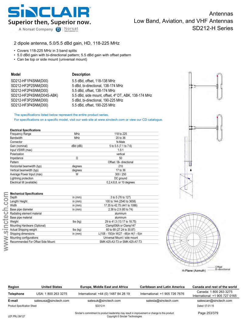
AntennasLow Band, Aviation, and VHF Antennas
SD212-H Series
2 dipole antenna, 5.0/5.5 dBd gain, HD, 118-225 MHz• Covers 118-225 MHz in 3 band splits• 5.0 dBd gain with bi-directional pattern; 5.5 dBd gain with offset pattern• Can be top or side mount (universal mount)
Model DescriptionSD212-HF1P4SNM(D00) 5.5 dBd, offset, 118-138 MHzSD212-HF2P2SNM(D00) 5 dBd, bi-directional, 138-174 MHzSD212-HF2P4SNM(D00) 5.5 dBd, offset, 138-174 MHzSD212-HF2P4SNM(D04S-ABK) 5.5 dBd, side mount, offset, 4º DT, ABK, 138-174 MHzSD212-HF3P2SNM(D00) 5 dBd, bi-directional, 190-225 MHzSD212-HF3P4SNM(D00) 5.5 dBd, offset, 190-225 MHz
The specifications listed below represent the entire product series.For specifications on a specific model, visit our web site at www.sinctech.com or view our CD catalogue.
Electrical SpecificationsFrequency Range MHz 118 to 225Bandwidth MHz 20 to 36Connector N-MaleGain (nominal) dBd (dBi) 5 to 5.5 (7.1 to 7.6)Input VSWR (max) 1.5:1Polarization verticalImpedance Ω 50Pattern Offset / Bi- directionalHorizontal beamwidth (typ) degrees 210Vertical beamwidth (typ) degrees 17 to 36Average Power Input (max) W 300 / 250Lightning protection DC groundElectrical tilt (available) 0,2,4,6,8, or 10 degrees
Mechanical SpecificationsDepth in (mm) 3 to 5 (76 to 127)Length/ Height in (mm) 100 to 144 (2540 to 3658)Width in (mm) 17.35 to 42.75 (441 to 1086)Base pipe diameter in (mm) 2.38 to 2.9 (60 to 74)Radiating element material aluminumBase pipe material aluminumWeight lbs (kg) 29 to 41.3 (13.17 to 18.75)Mounting Hardware (Optional) Clamp006A or Clamp147Actual Shipping weight lbs (kg) 60 to 68 (27.24 to 30.87)Shipping dimensions in (mm) L(108 - 150)in W(27 - 48)in H(1 - 6)in Mounting configurations Universal Mount / side mountRecommended For Offset Side Mount: SMK-425-A3-T3 or SMK-425-A7-T3
Region United States Europe, Middle East and Africa Caribbean and Latin America Canada and rest of the world
Telephone USA: 1 800 263 3275 International: +44 (0) 1487 84 28 19 International: +1 905 726 7676 Canada: 1 800 263 3275International: +1 905 727 0165
E-mail [email protected] [email protected] [email protected] [email protected] Specification Sheet SD212-H Dated: 07-01-15
Sinclair’s commitment to product leadership may result in improvement or change to this productCopyright © Sinclair TechnologiesLEF.PRJ.39/127
www.
sinct
ech.
com
Page 253/379

AntennasLow Band, Aviation, and VHF Antennas
SD212-H Series
Environmental SpecificationsTemperature range °F (°C) -40 to +140 (-40 to +60)Wind Loading Area (Flat Plate Equivalent) ft² (m²) 1.66 to 2.91 (0.15 to 0.27)Wind Loading Area (1/2" ice) ft² (m²) 2.74 to 4.47 (0.25 to 0.42)Rated wind velocity (no ice) mph (km/h) 175 to 205 (282 to 330)Rated wind velocity (1/2" radial ice) mph (km/h) 150 to 165 (242 to 266)Lateral thrust (100 mph No Ice) lbs (N) 61 to 106 (271.3 to 471.5)Torsional moment (100 mph No Ice) ft-lbs (Nm) 19 to 102 (25.7 to 137.7)Bending moment (100 mph No Ice) ft-lbs (Nm) 182 to 440 (245.7 to 594)Tip deflection (100 mph No Ice) degrees 0.28 to 0.58
Ordering InformationClamps must be ordered separately.
Region United States Europe, Middle East and Africa Caribbean and Latin America Canada and rest of the world
Telephone USA: 1 800 263 3275 International: +44 (0) 1487 84 28 19 International: +1 905 726 7676 Canada: 1 800 263 3275International: +1 905 727 0165
E-mail [email protected] [email protected] [email protected] [email protected] Specification Sheet SD212-H Dated: 07-01-15
Sinclair’s commitment to product leadership may result in improvement or change to this productCopyright © Sinclair TechnologiesLEF.PRJ.40/127
www.
sinct
ech.
com
Page 254/379
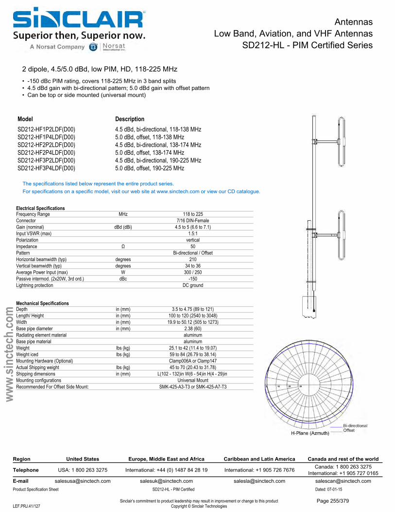
AntennasLow Band, Aviation, and VHF Antennas
SD212-HL - PIM Certified Series
2 dipole, 4.5/5.0 dBd, low PIM, HD, 118-225 MHz• -150 dBc PIM rating, covers 118-225 MHz in 3 band splits• 4.5 dBd gain with bi-directional pattern; 5.0 dBd gain with offset pattern• Can be top or side mounted (universal mount)
Model DescriptionSD212-HF1P2LDF(D00) 4.5 dBd, bi-directional, 118-138 MHzSD212-HF1P4LDF(D00) 5.0 dBd, offset, 118-138 MHzSD212-HF2P2LDF(D00) 4.5 dBd, bi-directional, 138-174 MHzSD212-HF2P4LDF(D00) 5.0 dBd, offset, 138-174 MHzSD212-HF3P2LDF(D00) 4.5 dBd, bi-directional, 190-225 MHzSD212-HF3P4LDF(D00) 5.0 dBd, offset, 190-225 MHz
The specifications listed below represent the entire product series.For specifications on a specific model, visit our web site at www.sinctech.com or view our CD catalogue.
Electrical SpecificationsFrequency Range MHz 118 to 225Connector 7/16 DIN-FemaleGain (nominal) dBd (dBi) 4.5 to 5 (6.6 to 7.1)Input VSWR (max) 1.5:1Polarization verticalImpedance Ω 50Pattern Bi-directional / OffsetHorizontal beamwidth (typ) degrees 210Vertical beamwidth (typ) degrees 34 to 36Average Power Input (max) W 300 / 250Passive intermod. (2x20W, 3rd ord.) dBc -150Lightning protection DC ground
Mechanical SpecificationsDepth in (mm) 3.5 to 4.75 (89 to 121)Length/ Height in (mm) 100 to 120 (2540 to 3048)Width in (mm) 19.9 to 50.12 (505 to 1273)Base pipe diameter in (mm) 2.38 (60)Radiating element material aluminumBase pipe material aluminumWeight lbs (kg) 25.1 to 42 (11.4 to 19.07)Weight iced lbs (kg) 59 to 84 (26.79 to 38.14)Mounting Hardware (Optional) Clamp006A or Clamp147Actual Shipping weight lbs (kg) 45 to 70 (20.43 to 31.78)Shipping dimensions in (mm) L(102 - 132)in W(6 - 54)in H(4 - 29)in Mounting configurations Universal MountRecommended For Offset Side Mount: SMK-425-A3-T3 or SMK-425-A7-T3
Region United States Europe, Middle East and Africa Caribbean and Latin America Canada and rest of the world
Telephone USA: 1 800 263 3275 International: +44 (0) 1487 84 28 19 International: +1 905 726 7676 Canada: 1 800 263 3275International: +1 905 727 0165
E-mail [email protected] [email protected] [email protected] [email protected] Specification Sheet SD212-HL - PIM Certified Dated: 07-01-15
Sinclair’s commitment to product leadership may result in improvement or change to this productCopyright © Sinclair TechnologiesLEF.PRJ.41/127
www.
sinct
ech.
com
Page 255/379

AntennasLow Band, Aviation, and VHF Antennas
SD212-HL - PIM Certified Series
Environmental SpecificationsTemperature range °F (°C) -40 to +140 (-40 to +60)Wind Loading Area (Flat Plate Equivalent) ft² (m²) 1.69 to 2.84 (0.16 to 0.26)Wind Loading Area (1/2" ice) ft² (m²) 2.78 to 4.63 (0.26 to 0.43)Rated wind velocity (no ice) mph (km/h) 185 to 195 (298 to 314)Rated wind velocity (1/2" radial ice) mph (km/h) 150 to 165 (242 to 266)Lateral thrust (100 mph No Ice) lbs (N) 61.5 to 104 (273.6 to 462.6)Torsional moment (100 mph No Ice) ft-lbs (Nm) 19.9 to 155 (26.9 to 209.3)Bending moment (100 mph No Ice) ft-lbs (Nm) 208 to 184185 (280.8 to 248649.8)Tip deflection (100 mph No Ice) degrees 0.34 to 0.4
Ordering InformationClamps must be ordered separately
Region United States Europe, Middle East and Africa Caribbean and Latin America Canada and rest of the world
Telephone USA: 1 800 263 3275 International: +44 (0) 1487 84 28 19 International: +1 905 726 7676 Canada: 1 800 263 3275International: +1 905 727 0165
E-mail [email protected] [email protected] [email protected] [email protected] Specification Sheet SD212-HL - PIM Certified Dated: 07-01-15
Sinclair’s commitment to product leadership may result in improvement or change to this productCopyright © Sinclair TechnologiesLEF.PRJ.42/127
www.
sinct
ech.
com
Page 256/379
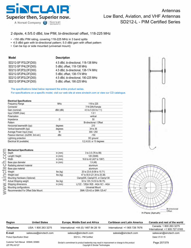
AntennasLow Band, Aviation, and VHF Antennas
SD212-L - PIM Certified Series
2 dipole, 4.5/5.0 dBd, low PIM, bi-directional/ offset, 118-225 MHz• -150 dBc PIM rating, covering 118-225 MHz in 3 band splits• 4.5 dBd gain with bi-directional pattern; 5.0 dBd gain with offset pattern• Can be top or side mounted (universal mount)
Model DescriptionSD212-SF1P2LDF(D00) 4.5 dBd, bi-directional, 118-138 MHzSD212-SF1P4LDF(D00) 5 dBd, offset, 118-138 MHzSD212-SF2P2LDF(D00) 4.5 dBd, bi-directional, 138-174 MHzSD212-SF2P4LDF(D00) 5 dBd, offset, 138-174 MHzSD212-SF3P2LDF(D00) 4.5 dBd, bi-directional, 190-225 MHzSD212-SF3P4LDF(D00) 5 dBd, offset, 190-225 MHz
The specifications listed below represent the entire product series.For specifications on a specific model, visit our web site at www.sinctech.com or view our CD catalogue.
Electrical SpecificationsFrequency Range MHz 118 to 225Connector 7/16 DIN-FemaleGain (nominal) dBd (dBi) 4.5 to 5 (6.6 to 7.1)Input VSWR (max) 1.5:1Polarization verticalImpedance Ω 50Pattern Bi-directional / OffsetHorizontal beamwidth (typ) degrees 210Vertical beamwidth (typ) degrees 34 to 36Average Power Input (max) W 300 / 250Passive intermod. (2x20W, 3rd ord.) dBc -150Lightning protection DC groundElectrical tilt (available) 0,2,4,6,8, or 10 degrees
Mechanical SpecificationsDepth in (mm) 3 to 3.5 (76 to 89)Length/ Height in (mm) 120 (3048)Width in (mm) 16.8 to 42 (427 to 1067)Base pipe diameter in (mm) 1.9 (48)Radiating element material aluminumBase pipe material aluminumWeight lbs (kg) 20 to 23.6 (9.08 to 10.71)Weight iced lbs (kg) 47 to 55.9 (21.34 to 25.38)Mounting Hardware (Optional) Clamp005, Clamp015, or Clamp130Actual Shipping weight lbs (kg) 32 to 125 (14.53 to 56.75)Shipping dimensions in (mm) L(122 - 126)in W(6 - 44)in H(1 - 44)in Mounting configurations Universal MountRecommended For Offset Side Mount: SMK-125-A3 or SMK-125-A7
Region United States Europe, Middle East and Africa Caribbean and Latin America Canada and rest of the world
Telephone USA: 1 800 263 3275 International: +44 (0) 1487 84 28 19 International: +1 905 726 7676 Canada: 1 800 263 3275International: +1 905 727 0165
E-mail [email protected] [email protected] [email protected] [email protected] Specification Sheet SD212-L - PIM Certified Dated: 07-01-15
Customer Tech Manual 005849, 005865 Sinclair’s commitment to product leadership may result in improvement or change to this productCopyright © Sinclair TechnologiesLEF.PRJ.43/127
www.
sinct
ech.
com
Page 257/379

AntennasLow Band, Aviation, and VHF Antennas
SD212-L - PIM Certified Series
Environmental SpecificationsTemperature range °F (°C) -40 to +140 (-40 to +60)Wind Loading Area (Flat Plate Equivalent) ft² (m²) 1.62 to 1.86 (0.15 to 0.17)Wind Loading Area (1/2" ice) ft² (m²) 2.79 to 3.31 (0.26 to 0.31)Rated wind velocity (no ice) mph (km/h) 150 to 170 (242 to 274)Rated wind velocity (1/2" radial ice) mph (km/h) 105 to 115 (169 to 185)Lateral thrust (100 mph No Ice) lbs (N) 59.1 to 79.9 (262.9 to 355.4)Torsional moment (100 mph No Ice) ft-lbs (Nm) 17.6 to 95.3 (23.8 to 128.7)Bending moment (100 mph No Ice) ft-lbs (Nm) 200.5 to 249 (270.7 to 336.2)
Ordering InformationClamps must be orderd separately.
Region United States Europe, Middle East and Africa Caribbean and Latin America Canada and rest of the world
Telephone USA: 1 800 263 3275 International: +44 (0) 1487 84 28 19 International: +1 905 726 7676 Canada: 1 800 263 3275International: +1 905 727 0165
E-mail [email protected] [email protected] [email protected] [email protected] Specification Sheet SD212-L - PIM Certified Dated: 07-01-15
Customer Tech Manual 005849, 005865 Sinclair’s commitment to product leadership may result in improvement or change to this productCopyright © Sinclair TechnologiesLEF.PRJ.44/127
www.
sinct
ech.
com
Page 258/379
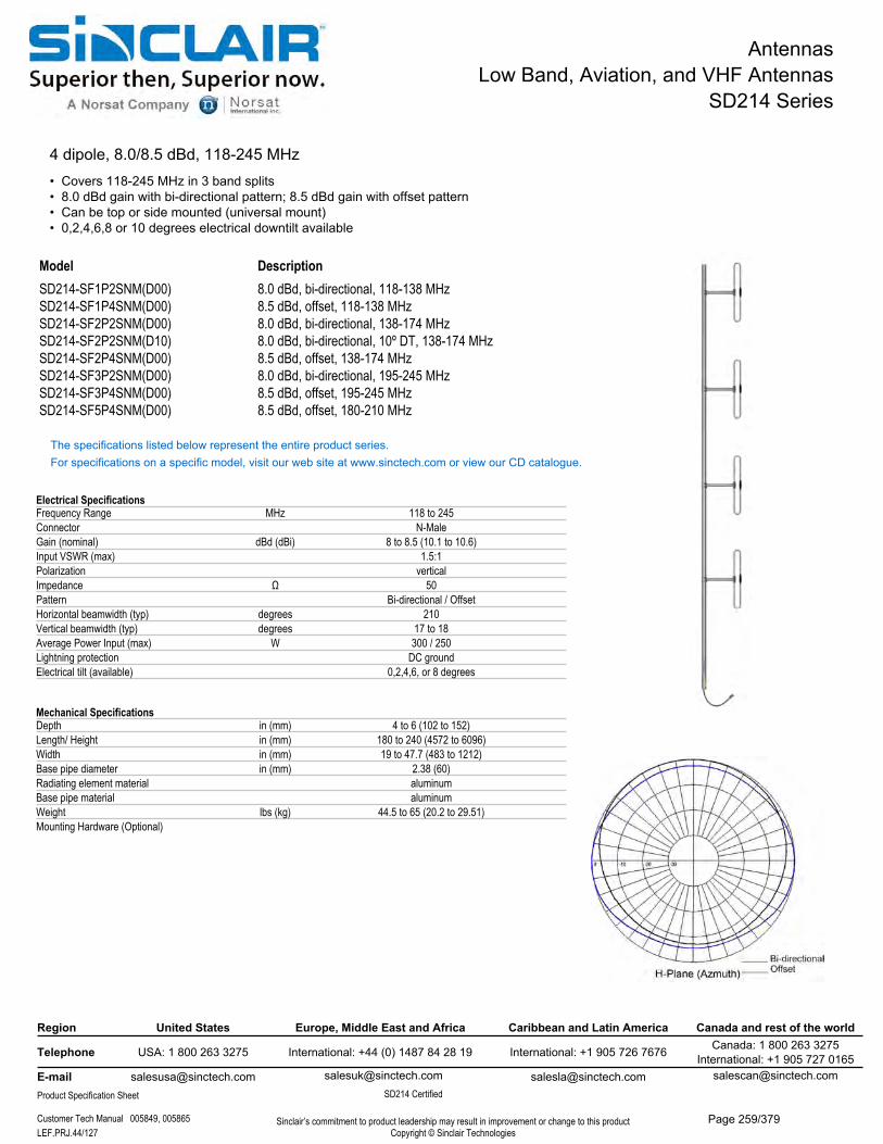
AntennasLow Band, Aviation, and VHF Antennas
SD214 Series
4 dipole, 8.0/8.5 dBd, 118-245 MHz• Covers 118-245 MHz in 3 band splits• 8.0 dBd gain with bi-directional pattern; 8.5 dBd gain with offset pattern• Can be top or side mounted (universal mount)• 0,2,4,6,8 or 10 degrees electrical downtilt available
Model DescriptionSD214-SF1P2SNM(D00) 8.0 dBd, bi-directional, 118-138 MHzSD214-SF1P4SNM(D00) 8.5 dBd, offset, 118-138 MHzSD214-SF2P2SNM(D00) 8.0 dBd, bi-directional, 138-174 MHzSD214-SF2P2SNM(D10) 8.0 dBd, bi-directional, 10º DT, 138-174 MHzSD214-SF2P4SNM(D00) 8.5 dBd, offset, 138-174 MHzSD214-SF3P2SNM(D00) 8.0 dBd, bi-directional, 195-245 MHzSD214-SF3P4SNM(D00) 8.5 dBd, offset, 195-245 MHzSD214-SF5P4SNM(D00) 8.5 dBd, offset, 180-210 MHz
The specifications listed below represent the entire product series.For specifications on a specific model, visit our web site at www.sinctech.com or view our CD catalogue.
Electrical SpecificationsFrequency Range MHz 118 to 245Connector N-MaleGain (nominal) dBd (dBi) 8 to 8.5 (10.1 to 10.6)Input VSWR (max) 1.5:1Polarization verticalImpedance Ω 50Pattern Bi-directional / OffsetHorizontal beamwidth (typ) degrees 210Vertical beamwidth (typ) degrees 17 to 18Average Power Input (max) W 300 / 250Lightning protection DC groundElectrical tilt (available) 0,2,4,6, or 8 degrees
Mechanical SpecificationsDepth in (mm) 4 to 6 (102 to 152)Length/ Height in (mm) 180 to 240 (4572 to 6096)Width in (mm) 19 to 47.7 (483 to 1212)Base pipe diameter in (mm) 2.38 (60)Radiating element material aluminumBase pipe material aluminumWeight lbs (kg) 44.5 to 65 (20.2 to 29.51)Mounting Hardware (Optional)
Region United States Europe, Middle East and Africa Caribbean and Latin America Canada and rest of the world
Telephone USA: 1 800 263 3275 International: +44 (0) 1487 84 28 19 International: +1 905 726 7676 Canada: 1 800 263 3275International: +1 905 727 0165
[email protected] [email protected] Specification Sheet
[email protected] SD214 Certified
Sinclair’s commitment to product leadership may result in improvement or change to this productCopyright © Sinclair Technologies
Customer Tech Manual 005849, 005865LEF.PRJ.44/127
Page 259/379
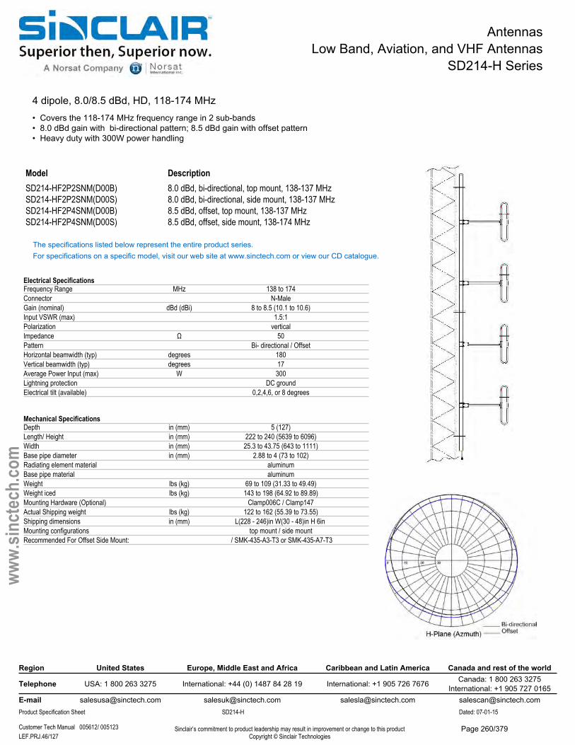
AntennasLow Band, Aviation, and VHF Antennas
SD214-H Series
4 dipole, 8.0/8.5 dBd, HD, 118-174 MHz• Covers the 118-174 MHz frequency range in 2 sub-bands• 8.0 dBd gain with bi-directional pattern; 8.5 dBd gain with offset pattern• Heavy duty with 300W power handling
Model DescriptionSD214-HF2P2SNM(D00B) 8.0 dBd, bi-directional, top mount, 138-137 MHzSD214-HF2P2SNM(D00S) 8.0 dBd, bi-directional, side mount, 138-137 MHzSD214-HF2P4SNM(D00B) 8.5 dBd, offset, top mount, 138-137 MHzSD214-HF2P4SNM(D00S) 8.5 dBd, offset, side mount, 138-174 MHz
The specifications listed below represent the entire product series.For specifications on a specific model, visit our web site at www.sinctech.com or view our CD catalogue.
Electrical SpecificationsFrequency Range MHz 138 to 174Connector N-MaleGain (nominal) dBd (dBi) 8 to 8.5 (10.1 to 10.6)Input VSWR (max) 1.5:1Polarization verticalImpedance Ω 50Pattern Bi- directional / OffsetHorizontal beamwidth (typ) degrees 180Vertical beamwidth (typ) degrees 17Average Power Input (max) W 300Lightning protection DC groundElectrical tilt (available) 0,2,4,6, or 8 degrees
Mechanical SpecificationsDepth in (mm) 5 (127)Length/ Height in (mm) 222 to 240 (5639 to 6096)Width in (mm) 25.3 to 43.75 (643 to 1111)Base pipe diameter in (mm) 2.88 to 4 (73 to 102)Radiating element material aluminumBase pipe material aluminumWeight lbs (kg) 69 to 109 (31.33 to 49.49)Weight iced lbs (kg) 143 to 198 (64.92 to 89.89)Mounting Hardware (Optional) Clamp006C / Clamp147Actual Shipping weight lbs (kg) 122 to 162 (55.39 to 73.55)Shipping dimensions in (mm) L(228 - 246)in W(30 - 48)in H 6in Mounting configurations top mount / side mountRecommended For Offset Side Mount: / SMK-435-A3-T3 or SMK-435-A7-T3
Region United States Europe, Middle East and Africa Caribbean and Latin America Canada and rest of the world
Telephone USA: 1 800 263 3275 International: +44 (0) 1487 84 28 19 International: +1 905 726 7676 Canada: 1 800 263 3275International: +1 905 727 0165
E-mail [email protected] [email protected] [email protected] [email protected] Specification Sheet SD214-H Dated: 07-01-15
Customer Tech Manual 005612/ 005123 Sinclair’s commitment to product leadership may result in improvement or change to this productCopyright © Sinclair TechnologiesLEF.PRJ.46/127
www.
sinct
ech.
com
Page 260/379

AntennasLow Band, Aviation, and VHF Antennas
SD214-H Series
Environmental SpecificationsTemperature range °F (°C) -40 to +140 (-40 to +60)Wind Loading Area (Flat Plate Equivalent) ft² (m²) 5.03 to 6.01 (0.47 to 0.56)Wind Loading Area (1/2" ice) ft² (m²) 7.81 to 8.96 (0.73 to 0.83)Rated wind velocity (no ice) mph (km/h) 195 to 205 (314 to 330)Rated wind velocity (1/2" radial ice) mph (km/h) 155 to 160 (250 to 258)Lateral thrust (100 mph No Ice) lbs (N) 182 to 223 (809.5 to 991.9)Torsional moment (100 mph No Ice) ft-lbs (Nm) 79 to 199 (106.7 to 268.7)Bending moment (100 mph No Ice) ft-lbs (Nm) 341 to 1164 (460.4 to 1571.4)Tip deflection (100 mph No Ice) degrees 0.3 to 0.5
Ordering InformationClamps must be ordered separately.Note: For top mount, recommend Qty 2- Clamp006C. For side mount, Qty 3 Clamp147
Region United States Europe, Middle East and Africa Caribbean and Latin America Canada and rest of the world
Telephone USA: 1 800 263 3275 International: +44 (0) 1487 84 28 19 International: +1 905 726 7676 Canada: 1 800 263 3275International: +1 905 727 0165
E-mail [email protected] [email protected] [email protected] [email protected] Specification Sheet SD214-H Dated: 07-01-15
Customer Tech Manual 005612/ 005123 Sinclair’s commitment to product leadership may result in improvement or change to this productCopyright © Sinclair TechnologiesLEF.PRJ.47/127
www.
sinct
ech.
com
Page 261/379
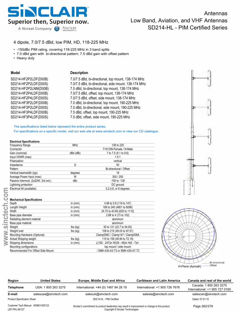
AntennasLow Band, Aviation, and VHF Antennas
SD214-HL - PIM Certified Series
4 dipole, 7.0/7.5 dBd, low PIM, HD, 118-225 MHz• -150dBc PIM rating, covering 118-225 MHz in 3 band splits• 7.0 dBd gain with bi-directional pattern; 7.5 dBd gain with offset pattern• Heavy duty
Model DescriptionSD214-HF2P2LDF(D00B) 7.0/7.5 dBd, bi-directional, top mount, 138-174 MHzSD214-HF2P2LDF(D00S) 7.0/7.5 dBd, bi-directional, side mount, 138-174 MHzSD214-HF2P2LNM(D00B) 7.0 dBd, bi-directional, top mount, 138-174 MHzSD214-HF2P4LDF(D00B) 7.0/7.5 dBd, offset, top mount, 138-174 MHzSD214-HF2P4LDF(D00S) 7.0/7.5 dBd, offset, side mount, 138-174 MHzSD214-HF3P2LDF(D00B) 7.0 dBd, bi-directional, top mount, 190-225 MHzSD214-HF3P2LDF(D00S) 7.0 dBd, bi-directional, side mount, 190-225 MHzSD214-HF3P4LDF(D00B) 7.5 dBd, offset, top mount, 190-225 MHzSD214-HF3P4LDF(D00S) 7.5 dBd, offset, side mount, 190-225 MHz
The specifications listed below represent the entire product series.For specifications on a specific model, visit our web site at www.sinctech.com or view our CD catalogue.
Electrical SpecificationsFrequency Range MHz 138 to 225Connector 7/16 DIN-Female / N-MaleGain (nominal) dBd (dBi) 7 to 7.5 (9.1 to 9.6)Input VSWR (max) 1.5:1Polarization verticalImpedance Ω 50Pattern Bi-directional / OffsetVertical beamwidth (typ) degrees 18Average Power Input (max) W 300 / 250Passive intermod. (2x20W, 3rd ord.) dBc -150 to -138Lightning protection DC groundElectrical tilt (available) 0,2,4,6, or 8 degrees
Mechanical SpecificationsDepth in (mm) 4.68 to 5.8 (119 to 147)Length/ Height in (mm) 189 to 240 (4801 to 6096)Width in (mm) 24.75 to 43.69 (629 to 1110)Base pipe diameter in (mm) 2.88 to 4 (73 to 102)Radiating element material aluminumBase pipe material aluminumWeight lbs (kg) 50 to 121 (22.7 to 54.93)Weight iced lbs (kg) 108 to 215 (49.03 to 97.61)Mounting Hardware (Optional) Clamp006C / Clamp147 / Clamp006AActual Shipping weight lbs (kg) 110 to 159 (49.94 to 72.19)Shipping dimensions in (mm) L(192 - 247)in W(29 - 48)in H(6 - 7)in Mounting configurations top mount / side mountRecommended For Offset Side Mount: / SMK-435-A3-T3 or SMK-435-A7-T3
Region United States Europe, Middle East and Africa Caribbean and Latin America Canada and rest of the world
Telephone USA: 1 800 263 3275 International: +44 (0) 1487 84 28 19 International: +1 905 726 7676 Canada: 1 800 263 3275International: +1 905 727 0165
E-mail [email protected] [email protected] [email protected] [email protected] Specification Sheet SD214-HL - PIM Certified Dated: 07-01-15
Customer Tech Manual 005861/005123 Sinclair’s commitment to product leadership may result in improvement or change to this productCopyright © Sinclair TechnologiesLEF.PRJ.48/127
www.
sinct
ech.
com
Page 262/379

AntennasLow Band, Aviation, and VHF Antennas
SD214-HL - PIM Certified Series
Environmental SpecificationsTemperature range °F (°C) -40 to +140 (-40 to +60)Wind Loading Area (Flat Plate Equivalent) ft² (m²) 2.96 to 6.29 (0.27 to 0.58)Wind Loading Area (1/2" ice) ft² (m²) 5.07 to 9.94 (0.47 to 0.92)Rated wind velocity (no ice) mph (km/h) 185 to 205 (298 to 330)Rated wind velocity (1/2" radial ice) mph (km/h) 155 to 175 (250 to 282)Lateral thrust (100 mph No Ice) lbs (N) 126 to 234 (560.4 to 1040.8)Torsional moment (100 mph No Ice) ft-lbs (Nm) 62 to 192 (83.7 to 259.2)Bending moment (100 mph No Ice) ft-lbs (Nm) 391 to 1615 (527.9 to 2180.3)Tip deflection (100 mph No Ice) degrees 0.41 to 0.5
Ordering InformationClamps must be ordered separately.Note: For top mount, recommend Qty 2- Clamp006C. For side, Qty 3 Clamp147
Region United States Europe, Middle East and Africa Caribbean and Latin America Canada and rest of the world
Telephone USA: 1 800 263 3275 International: +44 (0) 1487 84 28 19 International: +1 905 726 7676 Canada: 1 800 263 3275International: +1 905 727 0165
E-mail [email protected] [email protected] [email protected] [email protected] Specification Sheet SD214-HL - PIM Certified Dated: 07-01-15
Customer Tech Manual 005861/005123 Sinclair’s commitment to product leadership may result in improvement or change to this productCopyright © Sinclair TechnologiesLEF.PRJ.49/127
www.
sinct
ech.
com
Page 263/379
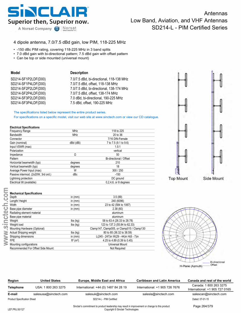
AntennasLow Band, Aviation, and VHF Antennas
SD214-L - PIM Certified Series
4 dipole antenna, 7.0/7.5 dBd gain, low PIM, 118-225 MHz• -150 dBc PIM rating, covering 118-225 MHz in 3 band splits• 7.0 dBd gain with bi-directional pattern; 7.5 dBd gain with offset pattern• Can be top or side mounted (universal mount)
Model DescriptionSD214-SF1P2LDF(D00) 7.0/7.5 dBd, bi-directional, 118-138 MHzSD214-SF1P4LDF(D00) 7.0/7.5 dBd, offset, 118-138 MHzSD214-SF2P2LDF(D00) 7.0/7.5 dBd, bi-directional, 138-174 MHzSD214-SF2P4LDF(D00) 7.0/7.5 dBd, offset, 138-174 MHzSD214-SF3P2LDF(D00) 7.0 dBd, bi-directional, 190-225 MHzSD214-SF3P4LDF(D00) 7.5 dBd, offset, 190-225 MHz
The specifications listed below represent the entire product series.For specifications on a specific model, visit our web site at www.sinctech.com or view our CD catalogue.
Electrical SpecificationsFrequency Range MHz 118 to 225Bandwidth MHz 20 to 36Connector 7/16 DIN-FemaleGain (nominal) dBd (dBi) 7 to 7.5 (9.1 to 9.6)Input VSWR (max) 1.5:1Polarization verticalImpedance Ω 50Pattern Bi-directional / OffsetHorizontal beamwidth (typ) degrees 210Vertical beamwidth (typ) degrees 18Average Power Input (max) W 300 / 250Passive intermod. (2x20W, 3rd ord.) dBc -150Lightning protection DC groundElectrical tilt (available) 0,2,4,6, or 8 degrees
Mechanical SpecificationsDepth in (mm) 3.5 (89)Length/ Height in (mm) 240 (6096)Width in (mm) 23 to 42 (584 to 1067)Base pipe diameter in (mm) 2.38 (60)Radiating element material aluminumBase pipe material aluminumWeight lbs (kg) 58 to 63.4 (26.33 to 28.78)Weight iced lbs (kg) 123 to 137.3 (55.84 to 62.33)Mounting Hardware (Optional) Clamp147, Clamp005, or Clamp015 / Clamp130Actual Shipping weight lbs (kg) 80 to 85 (36.32 to 38.59)Shipping dimensions in (mm) L(245 - 247)in W(29 - 44)in H(6 - 7)in FPE ft² (m²) 4.25 to 4.89 (0.39 to 0.45)Mounting configurations Universal MountRecommended For Offset Side Mount: Not Required
Region United States Europe, Middle East and Africa Caribbean and Latin America Canada and rest of the world
Telephone USA: 1 800 263 3275 International: +44 (0) 1487 84 28 19 International: +1 905 726 7676 Canada: 1 800 263 3275International: +1 905 727 0165
E-mail [email protected] [email protected] [email protected] [email protected] Specification Sheet SD214-L - PIM Certified Dated: 07-01-15
Sinclair’s commitment to product leadership may result in improvement or change to this productCopyright © Sinclair TechnologiesLEF.PRJ.50/127
www.
sinct
ech.
com
Page 264/379

AntennasLow Band, Aviation, and VHF Antennas
SD214-L - PIM Certified Series
Environmental SpecificationsTemperature range °F (°C) -40 to +140 (-40 to +60)Wind Loading Area (Flat Plate Equivalent) ft² (m²) 4.3 to 4.9 (0.4 to 0.46)Wind Loading Area (1/2" ice) ft² (m²) 7.2 to 8.2 (0.67 to 0.76)Rated wind velocity (no ice) mph (km/h) 125 (201)Rated wind velocity (1/2" radial ice) mph (km/h) 90 (145)Lateral thrust (100 mph No Ice) lbs (N) 158 to 179 (702.8 to 796.2)Torsional moment (100 mph No Ice) ft-lbs (Nm) 81.4 to 192 (109.9 to 259.2)Bending moment (100 mph No Ice) ft-lbs (Nm) 919 to 1025 (1240.7 to 1383.8)
Ordering InformationClamps must be ordered separately.
Region United States Europe, Middle East and Africa Caribbean and Latin America Canada and rest of the world
Telephone USA: 1 800 263 3275 International: +44 (0) 1487 84 28 19 International: +1 905 726 7676 Canada: 1 800 263 3275International: +1 905 727 0165
E-mail [email protected] [email protected] [email protected] [email protected] Specification Sheet SD214-L - PIM Certified Dated: 07-01-15
Sinclair’s commitment to product leadership may result in improvement or change to this productCopyright © Sinclair TechnologiesLEF.PRJ.51/127
www.
sinct
ech.
com
Page 265/379
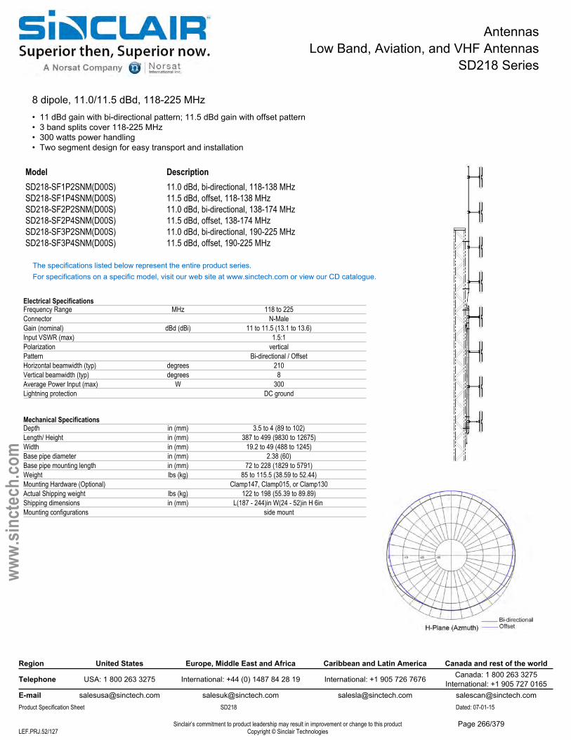
AntennasLow Band, Aviation, and VHF Antennas
SD218 Series
8 dipole, 11.0/11.5 dBd, 118-225 MHz• 11 dBd gain with bi-directional pattern; 11.5 dBd gain with offset pattern• 3 band splits cover 118-225 MHz• 300 watts power handling• Two segment design for easy transport and installation
Model DescriptionSD218-SF1P2SNM(D00S) 11.0 dBd, bi-directional, 118-138 MHzSD218-SF1P4SNM(D00S) 11.5 dBd, offset, 118-138 MHzSD218-SF2P2SNM(D00S) 11.0 dBd, bi-directional, 138-174 MHzSD218-SF2P4SNM(D00S) 11.5 dBd, offset, 138-174 MHzSD218-SF3P2SNM(D00S) 11.0 dBd, bi-directional, 190-225 MHzSD218-SF3P4SNM(D00S) 11.5 dBd, offset, 190-225 MHz
The specifications listed below represent the entire product series.For specifications on a specific model, visit our web site at www.sinctech.com or view our CD catalogue.
Electrical SpecificationsFrequency Range MHz 118 to 225Connector N-MaleGain (nominal) dBd (dBi) 11 to 11.5 (13.1 to 13.6)Input VSWR (max) 1.5:1Polarization verticalPattern Bi-directional / OffsetHorizontal beamwidth (typ) degrees 210Vertical beamwidth (typ) degrees 8Average Power Input (max) W 300Lightning protection DC ground
Mechanical SpecificationsDepth in (mm) 3.5 to 4 (89 to 102)Length/ Height in (mm) 387 to 499 (9830 to 12675)Width in (mm) 19.2 to 49 (488 to 1245)Base pipe diameter in (mm) 2.38 (60)Base pipe mounting length in (mm) 72 to 228 (1829 to 5791)Weight lbs (kg) 85 to 115.5 (38.59 to 52.44)Mounting Hardware (Optional) Clamp147, Clamp015, or Clamp130Actual Shipping weight lbs (kg) 122 to 198 (55.39 to 89.89)Shipping dimensions in (mm) L(187 - 244)in W(24 - 52)in H 6in Mounting configurations side mount
Region United States Europe, Middle East and Africa Caribbean and Latin America Canada and rest of the world
Telephone USA: 1 800 263 3275 International: +44 (0) 1487 84 28 19 International: +1 905 726 7676 Canada: 1 800 263 3275International: +1 905 727 0165
E-mail [email protected] [email protected] [email protected] [email protected] Specification Sheet SD218 Dated: 07-01-15
Sinclair’s commitment to product leadership may result in improvement or change to this productCopyright © Sinclair TechnologiesLEF.PRJ.52/127
www.
sinct
ech.
com
Page 266/379
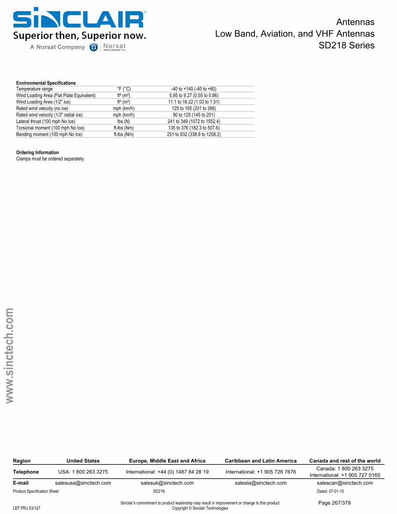
AntennasLow Band, Aviation, and VHF Antennas
SD218 Series
Environmental SpecificationsTemperature range °F (°C) -40 to +140 (-40 to +60)Wind Loading Area (Flat Plate Equivalent) ft² (m²) 5.95 to 9.27 (0.55 to 0.86)Wind Loading Area (1/2" ice) ft² (m²) 11.1 to 16.22 (1.03 to 1.51)Rated wind velocity (no ice) mph (km/h) 125 to 165 (201 to 266)Rated wind velocity (1/2" radial ice) mph (km/h) 90 to 125 (145 to 201)Lateral thrust (100 mph No Ice) lbs (N) 241 to 349 (1072 to 1552.4)Torsional moment (100 mph No Ice) ft-lbs (Nm) 135 to 376 (182.3 to 507.6)Bending moment (100 mph No Ice) ft-lbs (Nm) 251 to 932 (338.9 to 1258.2)
Ordering InformationClamps must be ordered separately.
Region United States Europe, Middle East and Africa Caribbean and Latin America Canada and rest of the world
Telephone USA: 1 800 263 3275 International: +44 (0) 1487 84 28 19 International: +1 905 726 7676 Canada: 1 800 263 3275International: +1 905 727 0165
E-mail [email protected] [email protected] [email protected] [email protected] Specification Sheet SD218 Dated: 07-01-15
Sinclair’s commitment to product leadership may result in improvement or change to this productCopyright © Sinclair TechnologiesLEF.PRJ.53/127
www.
sinct
ech.
com
Page 267/379
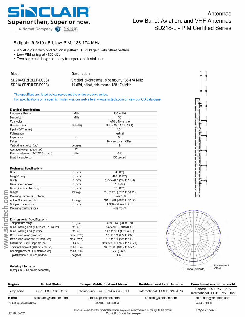
AntennasLow Band, Aviation, and VHF Antennas
SD218-L - PIM Certified Series
8 dipole, 9.5/10 dBd, low PIM, 138-174 MHz• 9.5 dBd gain with bi-directional pattern; 10 dBd gain with offset pattern• Low PIM rating at -150 dBc• Two segment design for easy transport and installation
Model DescriptionSD218-SF2P2LDF(D00S) 9.5 dBd, bi-directional, side mount, 138-174 MHzSD218-SF2P4LDF(D00S) 10 dBd, offset, side mount, 138-174 MHz
The specifications listed below represent the entire product series.For specifications on a specific model, visit our web site at www.sinctech.com or view our CD catalogue.
Electrical SpecificationsFrequency Range MHz 138 to 174Bandwidth MHz 36Connector 7/16 DIN-FemaleGain (nominal) dBd (dBi) 9.5 to 10 (11.6 to 12.1)Input VSWR (max) 1.5:1Polarization verticalImpedance Ω 50Pattern Bi- directional / OffsetVertical beamwidth (typ) degrees 9Average Power Input (max) WPassive intermod. (2x20W, 3rd ord.) dBc -150Lightning protection DC ground
Mechanical SpecificationsDepth in (mm) 4 (102)Length/ Height in (mm) 480 (12192)Width in (mm) 23.5 to 44.5 (597 to 1130)Base pipe diameter in (mm) 2.38 (60)Base pipe mounting length in (mm) 72 (1829)Weight lbs (kg) 115 to 128 (52.21 to 58.11)Mounting Hardware (Optional) Clamp130Actual Shipping weight lbs (kg) 161 to 204 (73.09 to 92.62)Shipping dimensions in (mm) L 300in W 24in H 7in Mounting configurations side mount
Environmental SpecificationsTemperature range °F (°C) -40 to +140 (-40 to +60)Wind Loading Area (Flat Plate Equivalent) ft² (m²) 8.4 to 9.6 (0.78 to 0.89)Wind Loading Area (1/2" ice) ft² (m²) 14.1 to 16.1 (1.31 to 1.5)Rated wind velocity (no ice) mph (km/h) 170 to 175 (274 to 282)Rated wind velocity (1/2" radial ice) mph (km/h) 115 to 120 (185 to 193)Lateral thrust (100 mph No Ice) lbs (N) 313 to 361 (1392.2 to 1605.7)Torsional moment (100 mph No Ice) ft-lbs (Nm) 139 to 383 (187.7 to 517.1)Bending moment (100 mph No Ice) ft-lbs (Nm) 250 (337.5)Tip deflection (100 mph No Ice) degrees 0.66
Ordering InformationClamps must be orderd separately.
Region United States Europe, Middle East and Africa Caribbean and Latin America Canada and rest of the world
Telephone USA: 1 800 263 3275 International: +44 (0) 1487 84 28 19 International: +1 905 726 7676 Canada: 1 800 263 3275International: +1 905 727 0165
E-mail [email protected] [email protected] [email protected] [email protected] Specification Sheet SD218-L - PIM Certified Dated: 07-01-15
Sinclair’s commitment to product leadership may result in improvement or change to this productCopyright © Sinclair TechnologiesLEF.PRJ.54/127
www.
sinct
ech.
com
Page 268/379
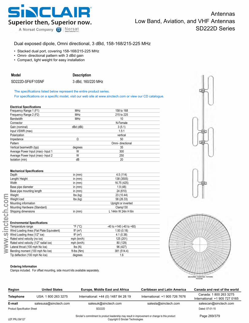
AntennasLow Band, Aviation, and VHF Antennas
SD222D Series
Dual exposed dipole, Omni directional, 3 dBd, 158-168/215-225 MHz• Stacked dual port, covering 158-168/215-225 MHz• Omni- directional pattern with 3 dBd gain• Compact, light weight for easy installation
Model DescriptionSD222D-SF6/F10SNF 3 dBd, 160/220 MHz
The specifications listed below represent the entire product series.For specifications on a specific model, visit our web site at www.sinctech.com or view our CD catalogue.
Electrical SpecificationsFrequency Range 1 (F1) MHz 158 to 168Frequency Range 2 (F2) MHz 215 to 225Bandwidth MHz 10Connector N-FemaleGain (nominal) dBd (dBi) 3 (5.1)Input VSWR (max) 1.5:1Polarization verticalImpedance Ω 50Pattern Omni- directionalVertical beamwidth (typ) degrees 35Average Power Input (max)- Input 1 W 300Average Power Input (max)- Input 2 W 250Isolation (min) dB 20
Mechanical SpecificationsDepth in (mm) 4.5 (114)Length/ Height in (mm) 138 (3505)Width in (mm) 16.75 (425)Base pipe diameter in (mm) 1.9 (48)Base pipe mounting length in (mm) 24 (610)Weight lbs (kg) 23 (10.44)Weight iced lbs (kg) 58 (26.33)Mounting information Upright or invertedMounting Hardware (Standard) Clamp130Shipping dimensions in (mm) L 144in W 24in H 6in
Environmental SpecificationsTemperature range °F (°C) -40 to +140 (-40 to +60)Wind Loading Area (Flat Plate Equivalent) ft² (m²) 1.93 (0.18)Wind Loading Area (1/2" ice) ft² (m²) 4.1 (0.38)Rated wind velocity (no ice) mph (km/h) 125 (201)Rated wind velocity (1/2" radial ice) mph (km/h) 80 (129)Lateral thrust (100 mph No Ice) lbs (N) 96 (427)Bending moment (100 mph No Ice) ft-lbs (Nm) 381 (514.4)Tip deflection (100 mph No Ice) degrees 1.6
Ordering InformationClamps included. For offset mounting, side mount kits available separately.
Region United States Europe, Middle East and Africa Caribbean and Latin America Canada and rest of the world
Telephone USA: 1 800 263 3275 International: +44 (0) 1487 84 28 19 International: +1 905 726 7676 Canada: 1 800 263 3275International: +1 905 727 0165
E-mail [email protected] [email protected] [email protected] [email protected] Specification Sheet SD222D Dated: 07-01-15
Sinclair’s commitment to product leadership may result in improvement or change to this productCopyright © Sinclair TechnologiesLEF.PRJ.59/127
www.
sinct
ech.
com
Page 269/379
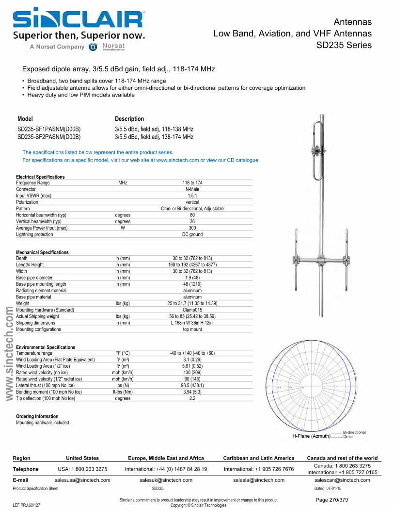
AntennasLow Band, Aviation, and VHF Antennas
SD235 Series
Exposed dipole array, 3/5.5 dBd gain, field adj., 118-174 MHz• Broadband, two band splits cover 118-174 MHz range• Field adjustable antenna allows for either omni-directional or bi-directional patterns for coverage optimization• Heavy duty and low PIM models available
Model DescriptionSD235-SF1PASNM(D00B) 3/5.5 dBd, field adj, 118-138 MHzSD235-SF2PASNM(D00B) 3/5.5 dBd, field adj, 138-174 MHz
The specifications listed below represent the entire product series.For specifications on a specific model, visit our web site at www.sinctech.com or view our CD catalogue.
Electrical SpecificationsFrequency Range MHz 118 to 174Connector N-MaleInput VSWR (max) 1.5:1Polarization verticalPattern Omni or Bi-directional, AdjustableHorizontal beamwidth (typ) degrees 80Vertical beamwidth (typ) degrees 36Average Power Input (max) W 300Lightning protection DC ground
Mechanical SpecificationsDepth in (mm) 30 to 32 (762 to 813)Length/ Height in (mm) 168 to 192 (4267 to 4877)Width in (mm) 30 to 32 (762 to 813)Base pipe diameter in (mm) 1.9 (48)Base pipe mounting length in (mm) 48 (1219)Radiating element material aluminumBase pipe material aluminumWeight lbs (kg) 25 to 31.7 (11.35 to 14.39)Mounting Hardware (Standard) Clamp015Actual Shipping weight lbs (kg) 56 to 85 (25.42 to 38.59)Shipping dimensions in (mm) L 168in W 36in H 12in Mounting configurations top mount
Environmental SpecificationsTemperature range °F (°C) -40 to +140 (-40 to +60)Wind Loading Area (Flat Plate Equivalent) ft² (m²) 3.1 (0.29)Wind Loading Area (1/2" ice) ft² (m²) 5.61 (0.52)Rated wind velocity (no ice) mph (km/h) 130 (209)Rated wind velocity (1/2" radial ice) mph (km/h) 90 (145)Lateral thrust (100 mph No Ice) lbs (N) 98.5 (438.1)Bending moment (100 mph No Ice) ft-lbs (Nm) 3.94 (5.3)Tip deflection (100 mph No Ice) degrees 2.2
Ordering InformationMounting hardware included.
Region United States Europe, Middle East and Africa Caribbean and Latin America Canada and rest of the world
Telephone USA: 1 800 263 3275 International: +44 (0) 1487 84 28 19 International: +1 905 726 7676 Canada: 1 800 263 3275International: +1 905 727 0165
E-mail [email protected] [email protected] [email protected] [email protected] Specification Sheet SD235 Dated: 07-01-15
Sinclair’s commitment to product leadership may result in improvement or change to this productCopyright © Sinclair TechnologiesLEF.PRJ.60/127
www.
sinct
ech.
com
Page 270/379
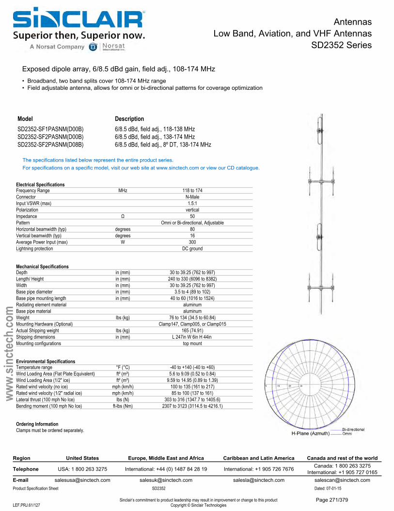
AntennasLow Band, Aviation, and VHF Antennas
SD2352 Series
Exposed dipole array, 6/8.5 dBd gain, field adj., 108-174 MHz• Broadband, two band splits cover 108-174 MHz range• Field adjustable antenna, allows for omni or bi-directional patterns for coverage optimization
Model DescriptionSD2352-SF1PASNM(D00B) 6/8.5 dBd, field adj., 118-138 MHzSD2352-SF2PASNM(D00B) 6/8.5 dBd, field adj., 138-174 MHzSD2352-SF2PASNM(D08B) 6/8.5 dBd, field adj., 8º DT, 138-174 MHz
The specifications listed below represent the entire product series.For specifications on a specific model, visit our web site at www.sinctech.com or view our CD catalogue.
Electrical SpecificationsFrequency Range MHz 118 to 174Connector N-MaleInput VSWR (max) 1.5:1Polarization verticalImpedance Ω 50Pattern Omni or Bi-directional, AdjustableHorizontal beamwidth (typ) degrees 80Vertical beamwidth (typ) degrees 16Average Power Input (max) W 300Lightning protection DC ground
Mechanical SpecificationsDepth in (mm) 30 to 39.25 (762 to 997)Length/ Height in (mm) 240 to 330 (6096 to 8382)Width in (mm) 30 to 39.25 (762 to 997)Base pipe diameter in (mm) 3.5 to 4 (89 to 102)Base pipe mounting length in (mm) 40 to 60 (1016 to 1524)Radiating element material aluminumBase pipe material aluminumWeight lbs (kg) 76 to 134 (34.5 to 60.84)Mounting Hardware (Optional) Clamp147, Clamp005, or Clamp015Actual Shipping weight lbs (kg) 165 (74.91)Shipping dimensions in (mm) L 247in W 6in H 44in Mounting configurations top mount
Environmental SpecificationsTemperature range °F (°C) -40 to +140 (-40 to +60)Wind Loading Area (Flat Plate Equivalent) ft² (m²) 5.6 to 9.09 (0.52 to 0.84)Wind Loading Area (1/2" ice) ft² (m²) 9.59 to 14.95 (0.89 to 1.39)Rated wind velocity (no ice) mph (km/h) 100 to 135 (161 to 217)Rated wind velocity (1/2" radial ice) mph (km/h) 85 to 100 (137 to 161)Lateral thrust (100 mph No Ice) lbs (N) 303 to 316 (1347.7 to 1405.6)Bending moment (100 mph No Ice) ft-lbs (Nm) 2307 to 3123 (3114.5 to 4216.1)
Ordering InformationClamps must be ordered separately.
Region United States Europe, Middle East and Africa Caribbean and Latin America Canada and rest of the world
Telephone USA: 1 800 263 3275 International: +44 (0) 1487 84 28 19 International: +1 905 726 7676 Canada: 1 800 263 3275International: +1 905 727 0165
E-mail [email protected] [email protected] [email protected] [email protected] Specification Sheet SD2352 Dated: 07-01-15
Sinclair’s commitment to product leadership may result in improvement or change to this productCopyright © Sinclair TechnologiesLEF.PRJ.61/127
www.
sinct
ech.
com
Page 271/379
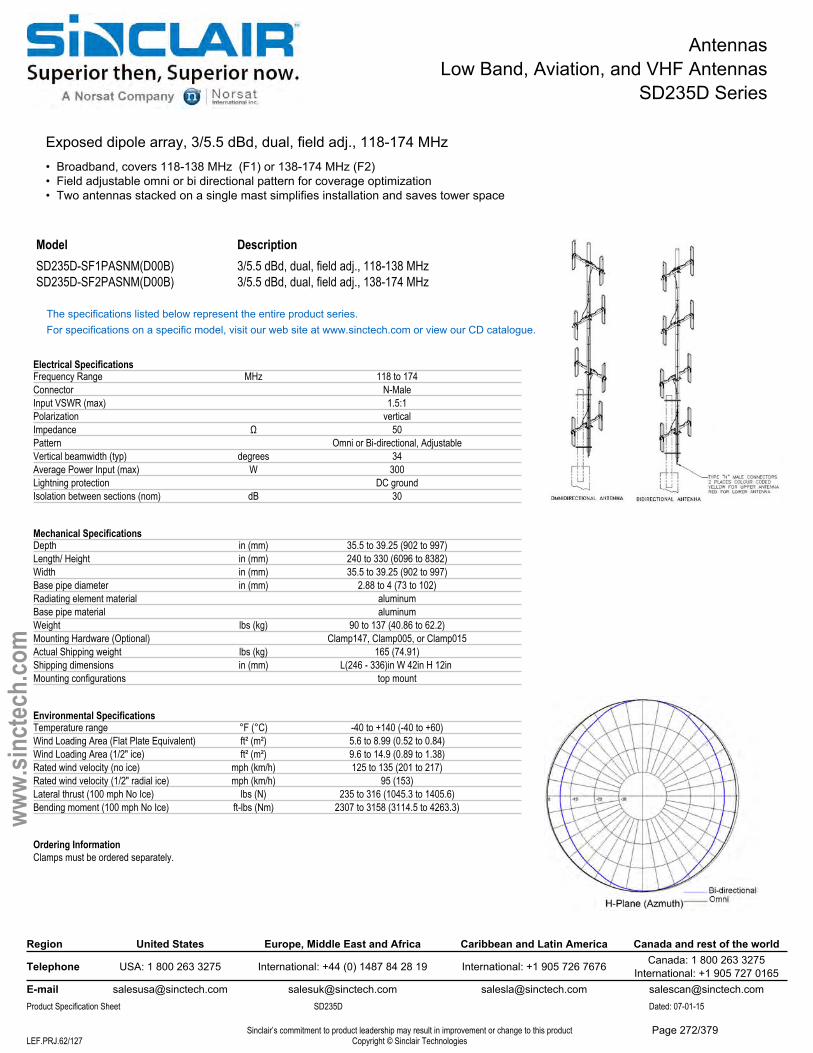
AntennasLow Band, Aviation, and VHF Antennas
SD235D Series
Exposed dipole array, 3/5.5 dBd, dual, field adj., 118-174 MHz• Broadband, covers 118-138 MHz (F1) or 138-174 MHz (F2)• Field adjustable omni or bi directional pattern for coverage optimization• Two antennas stacked on a single mast simplifies installation and saves tower space
Model DescriptionSD235D-SF1PASNM(D00B) 3/5.5 dBd, dual, field adj., 118-138 MHzSD235D-SF2PASNM(D00B) 3/5.5 dBd, dual, field adj., 138-174 MHz
The specifications listed below represent the entire product series.For specifications on a specific model, visit our web site at www.sinctech.com or view our CD catalogue.
Electrical SpecificationsFrequency Range MHz 118 to 174Connector N-MaleInput VSWR (max) 1.5:1Polarization verticalImpedance Ω 50Pattern Omni or Bi-directional, AdjustableVertical beamwidth (typ) degrees 34Average Power Input (max) W 300Lightning protection DC groundIsolation between sections (nom) dB 30
Mechanical SpecificationsDepth in (mm) 35.5 to 39.25 (902 to 997)Length/ Height in (mm) 240 to 330 (6096 to 8382)Width in (mm) 35.5 to 39.25 (902 to 997)Base pipe diameter in (mm) 2.88 to 4 (73 to 102)Radiating element material aluminumBase pipe material aluminumWeight lbs (kg) 90 to 137 (40.86 to 62.2)Mounting Hardware (Optional) Clamp147, Clamp005, or Clamp015Actual Shipping weight lbs (kg) 165 (74.91)Shipping dimensions in (mm) L(246 - 336)in W 42in H 12in Mounting configurations top mount
Environmental SpecificationsTemperature range °F (°C) -40 to +140 (-40 to +60)Wind Loading Area (Flat Plate Equivalent) ft² (m²) 5.6 to 8.99 (0.52 to 0.84)Wind Loading Area (1/2" ice) ft² (m²) 9.6 to 14.9 (0.89 to 1.38)Rated wind velocity (no ice) mph (km/h) 125 to 135 (201 to 217)Rated wind velocity (1/2" radial ice) mph (km/h) 95 (153)Lateral thrust (100 mph No Ice) lbs (N) 235 to 316 (1045.3 to 1405.6)Bending moment (100 mph No Ice) ft-lbs (Nm) 2307 to 3158 (3114.5 to 4263.3)
Ordering InformationClamps must be ordered separately.
Region United States Europe, Middle East and Africa Caribbean and Latin America Canada and rest of the world
Telephone USA: 1 800 263 3275 International: +44 (0) 1487 84 28 19 International: +1 905 726 7676 Canada: 1 800 263 3275International: +1 905 727 0165
E-mail [email protected] [email protected] [email protected] [email protected] Specification Sheet SD235D Dated: 07-01-15
Sinclair’s commitment to product leadership may result in improvement or change to this productCopyright © Sinclair TechnologiesLEF.PRJ.62/127
www.
sinct
ech.
com
Page 272/379
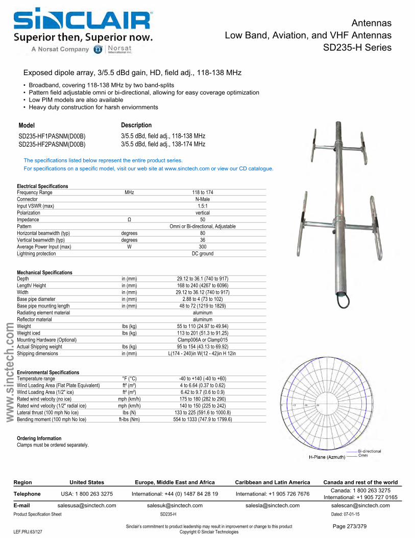
AntennasLow Band, Aviation, and VHF Antennas
SD235-H Series
Exposed dipole array, 3/5.5 dBd gain, HD, field adj., 118-138 MHz• Broadband, covering 118-138 MHz by two band-splits• Pattern field adjustable omni or bi-directional, allowing for easy coverage optimization• Low PIM models are also available• Heavy duty construction for harsh enviornments
Description3/5.5 dBd, field adj., 118-138 MHz
ModelSD235-HF1PASNM(D00B) SD235-HF2PASNM(D00B) 3/5.5 dBd, field adj., 138-174 MHz
The specifications listed below represent the entire product series.For specifications on a specific model, visit our web site at www.sinctech.com or view our CD catalogue.
Electrical SpecificationsFrequency Range MHz 118 to 174Connector N-MaleInput VSWR (max) 1.5:1Polarization verticalImpedance Ω 50Pattern Omni or Bi-directional, AdjustableHorizontal beamwidth (typ) degrees 80Vertical beamwidth (typ) degrees 36Average Power Input (max) W 300Lightning protection DC ground
Mechanical SpecificationsDepth in (mm) 29.12 to 36.1 (740 to 917)Length/ Height in (mm) 168 to 240 (4267 to 6096)Width in (mm) 29.12 to 36.12 (740 to 917)Base pipe diameter in (mm) 2.88 to 4 (73 to 102)Base pipe mounting length in (mm) 48 to 72 (1219 to 1829)Radiating element material aluminumReflector material aluminumWeight lbs (kg) 55 to 110 (24.97 to 49.94)Weight iced lbs (kg) 113 to 201 (51.3 to 91.25)Mounting Hardware (Optional) Clamp006A or Clamp015Actual Shipping weight lbs (kg) 95 to 154 (43.13 to 69.92)Shipping dimensions in (mm) L(174 - 240)in W(12 - 42)in H 12in
Environmental SpecificationsTemperature range °F (°C) -40 to +140 (-40 to +60)Wind Loading Area (Flat Plate Equivalent) ft² (m²) 4 to 6.64 (0.37 to 0.62)Wind Loading Area (1/2" ice) ft² (m²) 6.42 to 9.7 (0.6 to 0.9)Rated wind velocity (no ice) mph (km/h) 175 to 180 (282 to 290)Rated wind velocity (1/2" radial ice) mph (km/h) 140 to 150 (225 to 242)Lateral thrust (100 mph No Ice) lbs (N) 133 to 225 (591.6 to 1000.8)Bending moment (100 mph No Ice) ft-lbs (Nm) 554 to 1333 (747.9 to 1799.6)
Ordering InformationClamps must be ordered separately.
Region United States Europe, Middle East and Africa Caribbean and Latin America Canada and rest of the world
Telephone USA: 1 800 263 3275 International: +44 (0) 1487 84 28 19 International: +1 905 726 7676 Canada: 1 800 263 3275International: +1 905 727 0165
E-mail [email protected] [email protected] [email protected] [email protected] Specification Sheet SD235-H Dated: 07-01-15
Sinclair’s commitment to product leadership may result in improvement or change to this productCopyright © Sinclair TechnologiesLEF.PRJ.63/127
www.
sinct
ech.
com
Page 273/379
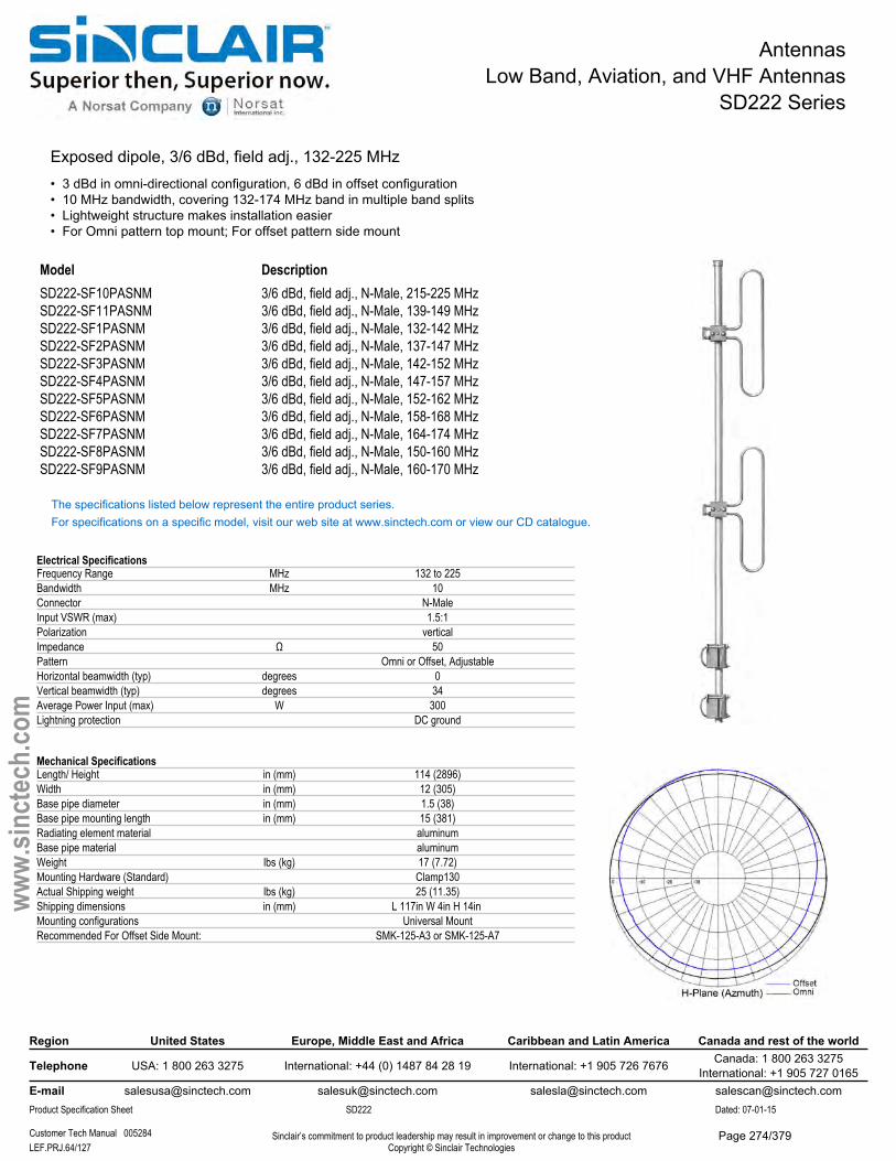
AntennasLow Band, Aviation, and VHF Antennas
SD222 Series
Exposed dipole, 3/6 dBd, field adj., 132-225 MHz• 3 dBd in omni-directional configuration, 6 dBd in offset configuration• 10 MHz bandwidth, covering 132-174 MHz band in multiple band splits• Lightweight structure makes installation easier• For Omni pattern top mount; For offset pattern side mount
Model DescriptionSD222-SF10PASNM 3/6 dBd, field adj., N-Male, 215-225 MHzSD222-SF11PASNM 3/6 dBd, field adj., N-Male, 139-149 MHzSD222-SF1PASNM 3/6 dBd, field adj., N-Male, 132-142 MHzSD222-SF2PASNM 3/6 dBd, field adj., N-Male, 137-147 MHzSD222-SF3PASNM 3/6 dBd, field adj., N-Male, 142-152 MHzSD222-SF4PASNM 3/6 dBd, field adj., N-Male, 147-157 MHzSD222-SF5PASNM 3/6 dBd, field adj., N-Male, 152-162 MHzSD222-SF6PASNM 3/6 dBd, field adj., N-Male, 158-168 MHzSD222-SF7PASNM 3/6 dBd, field adj., N-Male, 164-174 MHzSD222-SF8PASNM 3/6 dBd, field adj., N-Male, 150-160 MHzSD222-SF9PASNM 3/6 dBd, field adj., N-Male, 160-170 MHz
The specifications listed below represent the entire product series.For specifications on a specific model, visit our web site at www.sinctech.com or view our CD catalogue.
Electrical SpecificationsFrequency Range MHz 132 to 225Bandwidth MHz 10Connector N-MaleInput VSWR (max) 1.5:1Polarization verticalImpedance Ω 50Pattern Omni or Offset, AdjustableHorizontal beamwidth (typ) degrees 0Vertical beamwidth (typ) degrees 34Average Power Input (max) W 300Lightning protection DC ground
Mechanical SpecificationsLength/ Height in (mm) 114 (2896)Width in (mm) 12 (305)Base pipe diameter in (mm) 1.5 (38)Base pipe mounting length in (mm) 15 (381)Radiating element material aluminumBase pipe material aluminumWeight lbs (kg) 17 (7.72)Mounting Hardware (Standard) Clamp130Actual Shipping weight lbs (kg) 25 (11.35)Shipping dimensions in (mm) L 117in W 4in H 14in Mounting configurations Universal MountRecommended For Offset Side Mount: SMK-125-A3 or SMK-125-A7
Region United States Europe, Middle East and Africa Caribbean and Latin America Canada and rest of the world
Telephone USA: 1 800 263 3275 International: +44 (0) 1487 84 28 19 International: +1 905 726 7676 Canada: 1 800 263 3275International: +1 905 727 0165
E-mail [email protected] [email protected] [email protected] [email protected] Specification Sheet SD222 Dated: 07-01-15
Customer Tech Manual 005284 Sinclair’s commitment to product leadership may result in improvement or change to this productCopyright © Sinclair TechnologiesLEF.PRJ.64/127
www.
sinct
ech.
com
Page 274/379

AntennasLow Band, Aviation, and VHF Antennas
SD222 Series
Environmental SpecificationsTemperature range °F (°C) -40 to +140 (-40 to +60)Wind Loading Area (Flat Plate Equivalent) ft² (m²) 1.13 (0.1)Wind Loading Area (1/2" ice) ft² (m²) 2.45 (0.23)Rated wind velocity (no ice) mph (km/h) 120 (193)Rated wind velocity (1/2" radial ice) mph (km/h) 80 (129)Lateral thrust (100 mph No Ice) lbs (N) 65.1 (289.6)Bending moment (100 mph No Ice) ft-lbs (Nm) 12.8 (17.3)
Region United States Europe, Middle East and Africa Caribbean and Latin America Canada and rest of the world
Telephone USA: 1 800 263 3275 International: +44 (0) 1487 84 28 19 International: +1 905 726 7676 Canada: 1 800 263 3275International: +1 905 727 0165
E-mail [email protected] [email protected] [email protected] [email protected] Specification Sheet SD222 Dated: 07-01-15
Customer Tech Manual 005284 Sinclair’s commitment to product leadership may result in improvement or change to this productCopyright © Sinclair TechnologiesLEF.PRJ.65/127
www.
sinct
ech.
com
Page 275/379
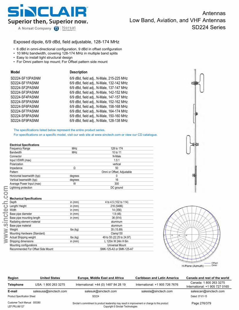
AntennasLow Band, Aviation, and VHF Antennas
SD224 Series
Exposed dipole, 6/9 dBd, field adjustable, 128-174 MHz• 6 dBd in omni-directional configuration, 9 dBd in offset configuration• 10 MHz bandwidth, covering 128-174 MHz in multiple band splits• Easy to install light structural design• For Omni pattern top mount; For Offset pattern side mount
Model DescriptionSD224-SF10PASNM 6/9 dBd, field adj., N-Male, 215-225 MHzSD224-SF1PASNM 6/9 dBd, field adj., N-Male, 132-142 MHzSD224-SF2PASNM 6/9 dBd, field adj., N-Male, 137-147 MHzSD224-SF3PASNM 6/9 dBd, field adj., N-Male, 142-152 MHzSD224-SF4PASNM 6/9 dBd, field adj., N-Male, 147-157 MHzSD224-SF5PASNM 6/9 dBd, field adj., N-Male, 152-162 MHzSD224-SF6PASNM 6/9 dBd, field adj., N-Male, 158-168 MHzSD224-SF7PASNM 6/9 dBd, field adj., N-Male, 164-174 MHzSD224-SF8PASNM 6/9 dBd, field adj., N-Male, 150-160 MHzSD224-SF9PASNM 6/9 dBd, field adj., N-Male, 128-138 MHz
The specifications listed below represent the entire product series.For specifications on a specific model, visit our web site at www.sinctech.com or view our CD catalogue.
Electrical SpecificationsFrequency Range MHz 128 to 174Bandwidth MHz 10 to 11Connector N-MaleInput VSWR (max) 1.5:1Polarization verticalImpedance Ω 50Pattern Omni or Offset, AdjustableHorizontal beamwidth (typ) degrees 0Vertical beamwidth (typ) degrees 16Average Power Input (max) W 300Lightning protection DC ground
Mechanical SpecificationsDepth in (mm) 4 to 4.5 (102 to 114)Length/ Height in (mm) 216 (5486)Width in (mm) 14 (356)Base pipe diameter in (mm) 1.9 (48)Base pipe mounting length in (mm) 36 (914)Radiating element material aluminumBase pipe material aluminumWeight lbs (kg) 35 (15.89)Mounting Hardware (Standard) Clamp130Actual Shipping weight lbs (kg) 49 to 55 (22.25 to 24.97)Shipping dimensions in (mm) L 120in W 24in H 6in Mounting configurations Universal MountRecommended For Offset Side Mount: SMK-125-A3 or SMK-125-A7
Region United States Europe, Middle East and Africa Caribbean and Latin America Canada and rest of the world
Telephone USA: 1 800 263 3275 International: +44 (0) 1487 84 28 19 International: +1 905 726 7676 Canada: 1 800 263 3275International: +1 905 727 0165
E-mail [email protected] [email protected] [email protected] [email protected] Specification Sheet SD224 Dated: 07-01-15
Customer Tech Manual 005380 Sinclair’s commitment to product leadership may result in improvement or change to this productCopyright © Sinclair TechnologiesLEF.PRJ.66/127
www.
sinct
ech.
com
Page 276/379

AntennasLow Band, Aviation, and VHF Antennas
SD224 Series
Environmental SpecificationsTemperature range °F (°C) -40 to +140 (-40 to +60)Wind Loading Area (Flat Plate Equivalent) ft² (m²) 3.2 to 3.3 (0.3 to 0.31)Wind Loading Area (1/2" ice) ft² (m²) 6.5 to 6.6 (0.6 to 0.61)Rated wind velocity (no ice) mph (km/h) 105 to 130 (169 to 209)Rated wind velocity (1/2" radial ice) mph (km/h) 80 to 95 (129 to 153)Lateral thrust (100 mph No Ice) lbs (N) 116 (516)Bending moment (100 mph No Ice) ft-lbs (Nm) 539 to 549 (727.7 to 741.2)
Region United States Europe, Middle East and Africa Caribbean and Latin America Canada and rest of the world
Telephone USA: 1 800 263 3275 International: +44 (0) 1487 84 28 19 International: +1 905 726 7676 Canada: 1 800 263 3275International: +1 905 727 0165
E-mail [email protected] [email protected] [email protected] [email protected] Specification Sheet SD224 Dated: 07-01-15
Customer Tech Manual 005380 Sinclair’s commitment to product leadership may result in improvement or change to this productCopyright © Sinclair TechnologiesLEF.PRJ.67/127
www.
sinct
ech.
com
Page 277/379
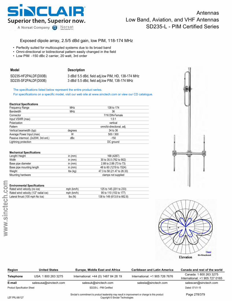
AntennasLow Band, Aviation, and VHF Antennas
SD235-L - PIM Certified Series
Exposed dipole array, 2.5/5 dBd gain, low PIM, 118-174 MHz• Perfectly suited for multicoupled systems due to its broad band• Omni-directional or bidirectional pattern easily changed in the field• Low PIM -150 dBc 2 carrier, 20 watt, 3rd order
Model DescriptionSD235-HF2PALDF(D00B) 3 dBd/ 5.5 dBd, field adj,low PIM, HD, 138-174 MHzSD235-SF2PALDF(D00B) 3 dBd/ 5.5 dBd, field adj,low PIM, 138-174 MHz
The specifications listed below represent the entire product series.For specifications on a specific model, visit our web site at www.sinctech.com or view our CD catalogue.
Electrical SpecificationsFrequency Range MHz 138 to 174Bandwidth MHz 36Connector 7/16 DIN-FemaleInput VSWR (max) 1.5:1Polarization verticalPattern omni/bi-directional, adj.Vertical beamwidth (typ) degrees 34 to 36Average Power Input (max) W 500 / 300Passive intermod. (2x20W, 3rd ord.) dBc -150Lightning protection DC ground
Mechanical SpecificationsLength/ Height in (mm) 168 (4267)Width in (mm) 30 to 35.5 (762 to 902)Base pipe diameter in (mm) 2.88 to 2.88 (73 to 73)Base pipe mounting length in (mm) 48 to 60 (1219 to 1524)Weight lbs (kg) 47.3 to 58 (21.47 to 26.33)Mounting hardware clamps not supplied
Environmental SpecificationsRated wind velocity (no ice) mph (km/h) 125 to 145 (201 to 233)Rated wind velocity (1/2" radial ice) mph (km/h) 95 to 110 (153 to 177)Lateral thrust (100 mph No Ice) lbs (N) 138 to 149 (613.8 to 662.8)
Region United States Europe, Middle East and Africa Caribbean and Latin America Canada and rest of the world
Telephone USA: 1 800 263 3275 International: +44 (0) 1487 84 28 19 International: +1 905 726 7676 Canada: 1 800 263 3275International: +1 905 727 0165
E-mail [email protected] [email protected] [email protected] [email protected] Specification Sheet SD235-L - PIM Certified Dated: 07-01-15
Sinclair’s commitment to product leadership may result in improvement or change to this productCopyright © Sinclair TechnologiesLEF.PRJ.68/127
www.
sinct
ech.
com
Page 278/379
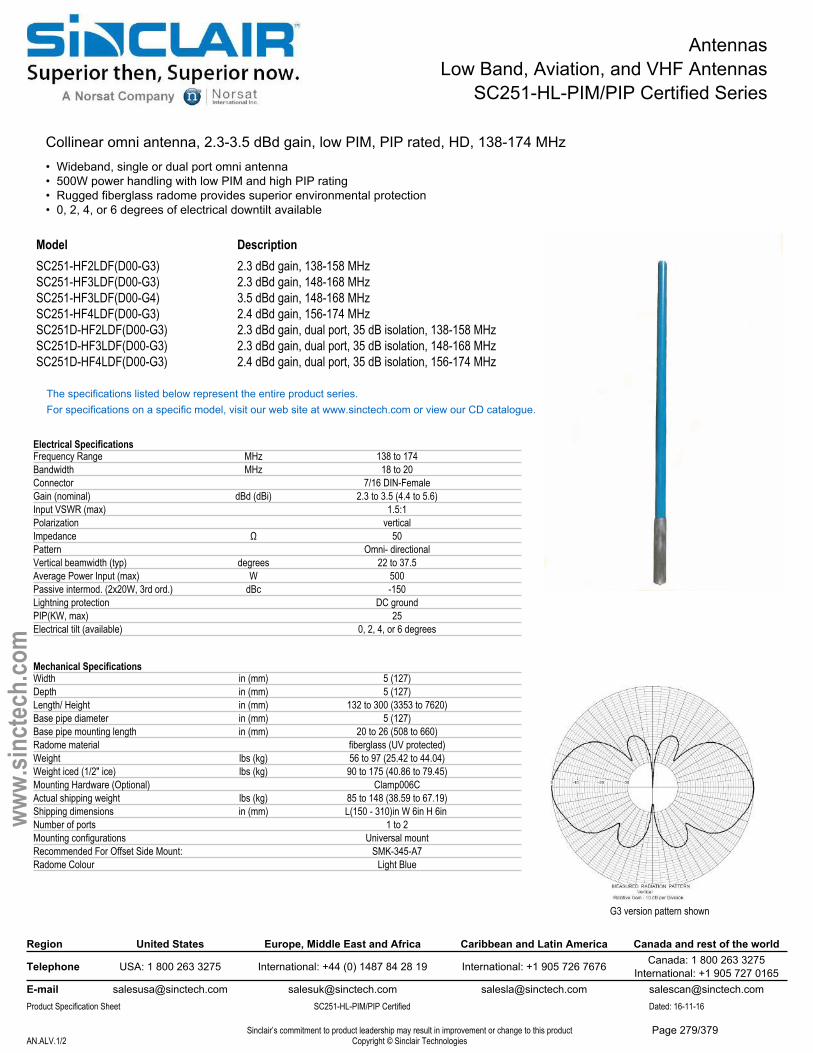
AntennasLow Band, Aviation, and VHF Antennas
SC251-HL-PIM/PIP Certified Series
Collinear omni antenna, 2.3-3.5 dBd gain, low PIM, PIP rated, HD, 138-174 MHz• Wideband, single or dual port omni antenna• 500W power handling with low PIM and high PIP rating• Rugged fiberglass radome provides superior environmental protection• 0, 2, 4, or 6 degrees of electrical downtilt available
Model DescriptionSC251-HF2LDF(D00-G3) 2.3 dBd gain, 138-158 MHzSC251-HF3LDF(D00-G3) 2.3 dBd gain, 148-168 MHzSC251-HF3LDF(D00-G4) 3.5 dBd gain, 148-168 MHzSC251-HF4LDF(D00-G3) 2.4 dBd gain, 156-174 MHzSC251D-HF2LDF(D00-G3) 2.3 dBd gain, dual port, 35 dB isolation, 138-158 MHzSC251D-HF3LDF(D00-G3) 2.3 dBd gain, dual port, 35 dB isolation, 148-168 MHzSC251D-HF4LDF(D00-G3) 2.4 dBd gain, dual port, 35 dB isolation, 156-174 MHz
The specifications listed below represent the entire product series.For specifications on a specific model, visit our web site at www.sinctech.com or view our CD catalogue.
Electrical SpecificationsFrequency Range MHz 138 to 174Bandwidth MHz 18 to 20Connector 7/16 DIN-FemaleGain (nominal) dBd (dBi) 2.3 to 3.5 (4.4 to 5.6)Input VSWR (max) 1.5:1Polarization verticalImpedance Ω 50Pattern Omni- directionalVertical beamwidth (typ) degrees 22 to 37.5Average Power Input (max) W 500Passive intermod. (2x20W, 3rd ord.) dBc -150Lightning protection DC groundPIP(KW, max) 25Electrical tilt (available) 0, 2, 4, or 6 degrees
Mechanical SpecificationsWidth in (mm) 5 (127)Depth in (mm) 5 (127)Length/ Height in (mm) 132 to 300 (3353 to 7620)Base pipe diameter in (mm) 5 (127)Base pipe mounting length in (mm) 20 to 26 (508 to 660)Radome material fiberglass (UV protected)Weight lbs (kg) 56 to 97 (25.42 to 44.04)Weight iced (1/2" ice) lbs (kg) 90 to 175 (40.86 to 79.45)Mounting Hardware (Optional) Clamp006CActual shipping weight lbs (kg) 85 to 148 (38.59 to 67.19)Shipping dimensions in (mm) L(150 - 310)in W 6in H 6in Number of ports 1 to 2Mounting configurations Universal mountRecommended For Offset Side Mount: SMK-345-A7Radome Colour Light Blue
Region United States Europe, Middle East and Africa Caribbean and Latin America Canada and rest of the world
Telephone USA: 1 800 263 3275 International: +44 (0) 1487 84 28 19 International: +1 905 726 7676 Canada: 1 800 263 3275International: +1 905 727 0165
E-mail [email protected] [email protected] [email protected] [email protected] Specification Sheet SC251-HL-PIM/PIP Certified Dated: 16-11-16
Sinclair’s commitment to product leadership may result in improvement or change to this productCopyright © Sinclair TechnologiesAN.ALV.1/2
www.
sinct
ech.
com
G3 version pattern shown
Page 279/379

AntennasLow Band, Aviation, and VHF Antennas
SC251-HL-PIM/PIP Certified Series
Environmental SpecificationsTemperature range °F (°C) -40 to +140 (-40 to +60)Wind Loading Area (Flat Plate Equivalent) ft² (m²) 2.8 to 6.4 (0.26 to 0.59)Wind Loading Area (1/2" ice) ft² (m²) 3.4 to 7.8 (0.32 to 0.72)Rated wind velocity (no ice) mph (km/h) 145 to 225 (233 to 362)Rated wind velocity (1/2" radial ice) mph (km/h) 125 to 195 (201 to 314)Lateral thrust (100 mph No Ice) lbs (N) 110 to 251 (489.3 to 1116.4)Bending moment (100 mph No Ice) ft-lbs (Nm) 407 to 2540 (549.5 to 3429)Tip deflection (100 mph No Ice) degrees 0.2 to 3.1
Ordering InformationClamps must be ordered separately
Region United States Europe, Middle East and Africa Caribbean and Latin America Canada and rest of the world
Telephone USA: 1 800 263 3275 International: +44 (0) 1487 84 28 19 International: +1 905 726 7676 Canada: 1 800 263 3275International: +1 905 727 0165
E-mail [email protected] [email protected] [email protected] [email protected] Specification Sheet SC251-HL-PIM/PIP Certified Dated: 16-11-16
Sinclair’s commitment to product leadership may result in improvement or change to this productCopyright © Sinclair TechnologiesAN.ALV.2/2
www.
sinct
ech.
com
Page 280/379
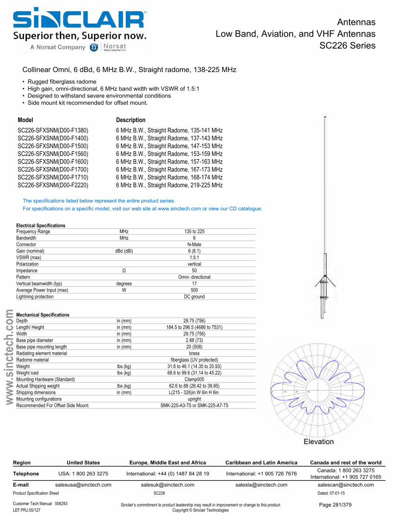
AntennasLow Band, Aviation, and VHF Antennas
SC226 Series
Collinear Omni, 6 dBd, 6 MHz B.W., Straight radome, 138-225 MHz• Rugged fiberglass radome• High gain, omni-directional, 6 MHz band width with VSWR of 1.5:1• Designed to withstand severe environmental conditions• Side mount kit recommended for offset mount.
Model DescriptionSC226-SFXSNM(D00-F1380) 6 MHz B.W., Straight Radome, 135-141 MHzSC226-SFXSNM(D00-F1400) 6 MHz B.W., Straight Radome, 137-143 MHzSC226-SFXSNM(D00-F1500) 6 MHz B.W., Straight Radome, 147-153 MHzSC226-SFXSNM(D00-F1560) 6 MHz B.W., Straight Radome, 153-159 MHzSC226-SFXSNM(D00-F1600) 6 MHz B.W., Straight Radome, 157-163 MHzSC226-SFXSNM(D00-F1700) 6 MHz B.W., Straight Radome, 167-173 MHzSC226-SFXSNM(D00-F1710) 6 MHz B.W., Straight Radome, 168-174 MHzSC226-SFXSNM(D00-F2220) 6 MHz B.W., Straight Radome, 219-225 MHz
The specifications listed below represent the entire product series.For specifications on a specific model, visit our web site at www.sinctech.com or view our CD catalogue.
Electrical SpecificationsFrequency Range MHz 135 to 225Bandwidth MHz 6Connector N-MaleGain (nominal) dBd (dBi) 6 (8.1)VSWR (max) 1.5:1Polarization verticalImpedance Ω 50Pattern Omni- directionalVertical beamwidth (typ) degrees 17Average Power Input (max) W 500Lightning protection DC ground
Mechanical SpecificationsDepth in (mm) 29.75 (756)Length/ Height in (mm) 184.5 to 296.5 (4686 to 7531)Width in (mm) 29.75 (756)Base pipe diameter in (mm) 2.88 (73)Base pipe mounting length in (mm) 20 (508)Radiating element material brassRadome material fiberglass (UV protected)Weight lbs (kg) 31.6 to 46.1 (14.35 to 20.93)Weight iced lbs (kg) 68.6 to 99.6 (31.14 to 45.22)Mounting Hardware (Standard) Clamp005Actual Shipping weight lbs (kg) 62.6 to 88 (28.42 to 39.95)Shipping dimensions in (mm) L(215 - 326)in W 6in H 6in Mounting configurations uprightRecommended For Offset Side Mount: SMK-225-A3-T5 or SMK-225-A7-T5
Region United States Europe, Middle East and Africa Caribbean and Latin America Canada and rest of the world
Telephone USA: 1 800 263 3275 International: +44 (0) 1487 84 28 19 International: +1 905 726 7676 Canada: 1 800 263 3275International: +1 905 727 0165
E-mail [email protected] [email protected] [email protected] [email protected] Specification Sheet SC226 Dated: 07-01-15
Customer Tech Manual 006293 Sinclair’s commitment to product leadership may result in improvement or change to this productCopyright © Sinclair TechnologiesLEF.PRJ.55/127
www.
sinct
ech.
com
Page 281/379
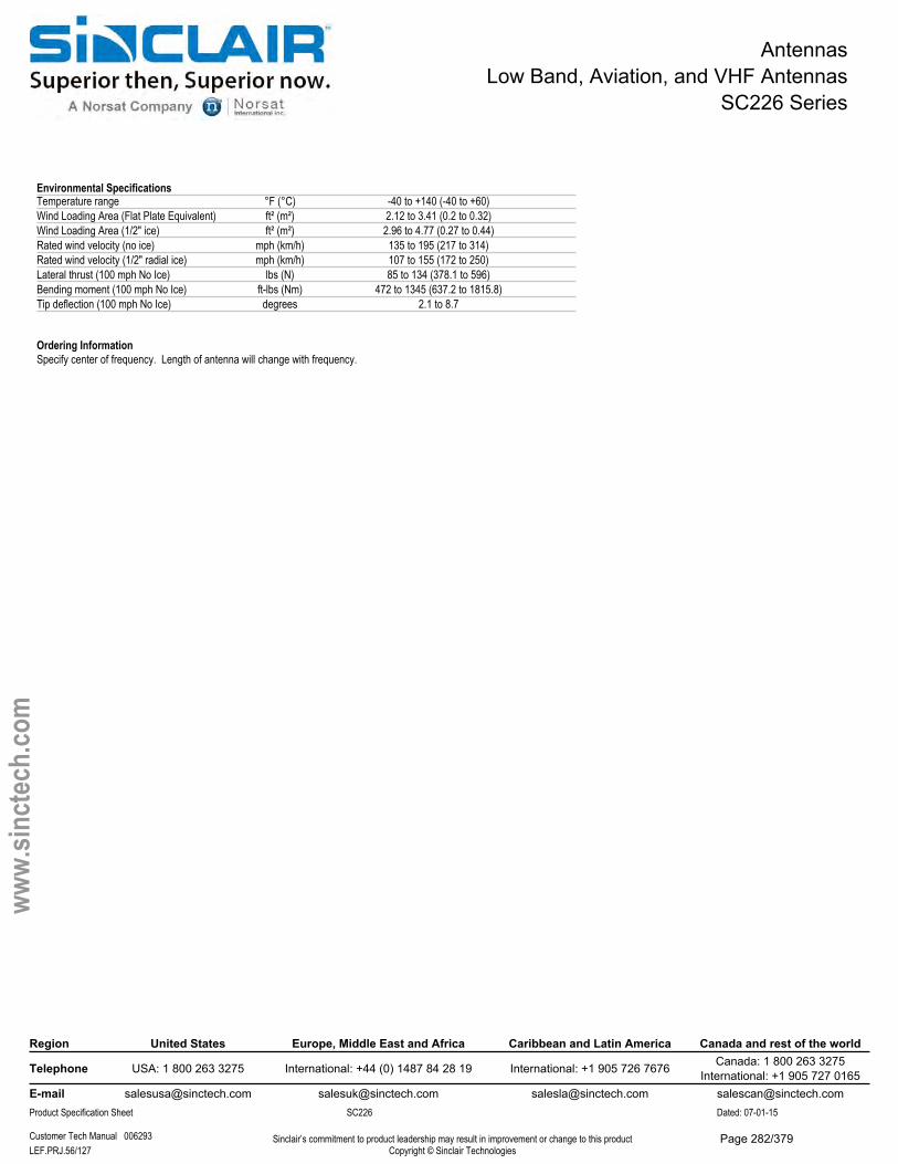
AntennasLow Band, Aviation, and VHF Antennas
SC226 Series
Environmental SpecificationsTemperature range °F (°C) -40 to +140 (-40 to +60)Wind Loading Area (Flat Plate Equivalent) ft² (m²) 2.12 to 3.41 (0.2 to 0.32)Wind Loading Area (1/2" ice) ft² (m²) 2.96 to 4.77 (0.27 to 0.44)Rated wind velocity (no ice) mph (km/h) 135 to 195 (217 to 314)Rated wind velocity (1/2" radial ice) mph (km/h) 107 to 155 (172 to 250)Lateral thrust (100 mph No Ice) lbs (N) 85 to 134 (378.1 to 596)Bending moment (100 mph No Ice) ft-lbs (Nm) 472 to 1345 (637.2 to 1815.8)Tip deflection (100 mph No Ice) degrees 2.1 to 8.7
Ordering InformationSpecify center of frequency. Length of antenna will change with frequency.
Region United States Europe, Middle East and Africa Caribbean and Latin America Canada and rest of the world
Telephone USA: 1 800 263 3275 International: +44 (0) 1487 84 28 19 International: +1 905 726 7676 Canada: 1 800 263 3275International: +1 905 727 0165
E-mail [email protected] [email protected] [email protected] [email protected] Specification Sheet SC226 Dated: 07-01-15
Customer Tech Manual 006293 Sinclair’s commitment to product leadership may result in improvement or change to this productCopyright © Sinclair TechnologiesLEF.PRJ.56/127
www.
sinct
ech.
com
Page 282/379
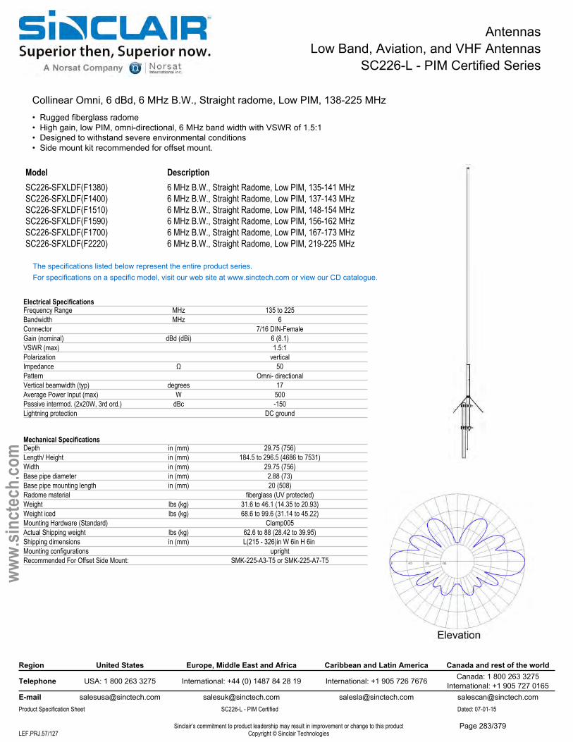
AntennasLow Band, Aviation, and VHF Antennas
SC226-L - PIM Certified Series
Collinear Omni, 6 dBd, 6 MHz B.W., Straight radome, Low PIM, 138-225 MHz• Rugged fiberglass radome• High gain, low PIM, omni-directional, 6 MHz band width with VSWR of 1.5:1• Designed to withstand severe environmental conditions• Side mount kit recommended for offset mount.
Model DescriptionSC226-SFXLDF(F1380) 6 MHz B.W., Straight Radome, Low PIM, 135-141 MHzSC226-SFXLDF(F1400) 6 MHz B.W., Straight Radome, Low PIM, 137-143 MHzSC226-SFXLDF(F1510) 6 MHz B.W., Straight Radome, Low PIM, 148-154 MHzSC226-SFXLDF(F1590) 6 MHz B.W., Straight Radome, Low PIM, 156-162 MHzSC226-SFXLDF(F1700) 6 MHz B.W., Straight Radome, Low PIM, 167-173 MHzSC226-SFXLDF(F2220) 6 MHz B.W., Straight Radome, Low PIM, 219-225 MHz
The specifications listed below represent the entire product series.For specifications on a specific model, visit our web site at www.sinctech.com or view our CD catalogue.
Electrical SpecificationsFrequency Range MHz 135 to 225Bandwidth MHz 6Connector 7/16 DIN-FemaleGain (nominal) dBd (dBi) 6 (8.1)VSWR (max) 1.5:1Polarization verticalImpedance Ω 50Pattern Omni- directionalVertical beamwidth (typ) degrees 17Average Power Input (max) W 500Passive intermod. (2x20W, 3rd ord.) dBc -150Lightning protection DC ground
Mechanical SpecificationsDepth in (mm) 29.75 (756)Length/ Height in (mm) 184.5 to 296.5 (4686 to 7531)Width in (mm) 29.75 (756)Base pipe diameter in (mm) 2.88 (73)Base pipe mounting length in (mm) 20 (508)Radome material fiberglass (UV protected)Weight lbs (kg) 31.6 to 46.1 (14.35 to 20.93)Weight iced lbs (kg) 68.6 to 99.6 (31.14 to 45.22)Mounting Hardware (Standard) Clamp005Actual Shipping weight lbs (kg) 62.6 to 88 (28.42 to 39.95)Shipping dimensions in (mm) L(215 - 326)in W 6in H 6in Mounting configurations uprightRecommended For Offset Side Mount: SMK-225-A3-T5 or SMK-225-A7-T5
Region United States Europe, Middle East and Africa Caribbean and Latin America Canada and rest of the world
Telephone USA: 1 800 263 3275 International: +44 (0) 1487 84 28 19 International: +1 905 726 7676 Canada: 1 800 263 3275International: +1 905 727 0165
E-mail [email protected] [email protected] [email protected] [email protected] Specification Sheet SC226-L - PIM Certified Dated: 07-01-15
Sinclair’s commitment to product leadership may result in improvement or change to this productCopyright © Sinclair TechnologiesLEF.PRJ.57/127
www.
sinct
ech.
com
Page 283/379
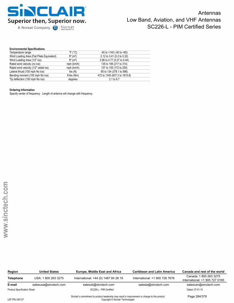
AntennasLow Band, Aviation, and VHF Antennas
SC226-L - PIM Certified Series
Environmental SpecificationsTemperature range °F (°C) -40 to +140 (-40 to +60)Wind Loading Area (Flat Plate Equivalent) ft² (m²) 2.12 to 3.41 (0.2 to 0.32)Wind Loading Area (1/2" ice) ft² (m²) 2.96 to 4.77 (0.27 to 0.44)Rated wind velocity (no ice) mph (km/h) 135 to 195 (217 to 314)Rated wind velocity (1/2" radial ice) mph (km/h) 107 to 155 (172 to 250)Lateral thrust (100 mph No Ice) lbs (N) 85 to 134 (378.1 to 596)Bending moment (100 mph No Ice) ft-lbs (Nm) 472 to 1345 (637.2 to 1815.8)Tip deflection (100 mph No Ice) degrees 2.1 to 8.7
Ordering InformationSpecify center of frequency. Length of antenna will change with frequency.
Region United States Europe, Middle East and Africa Caribbean and Latin America Canada and rest of the world
Telephone USA: 1 800 263 3275 International: +44 (0) 1487 84 28 19 International: +1 905 726 7676 Canada: 1 800 263 3275International: +1 905 727 0165
E-mail [email protected] [email protected] [email protected] [email protected] Specification Sheet SC226-L - PIM Certified Dated: 07-01-15
Sinclair’s commitment to product leadership may result in improvement or change to this productCopyright © Sinclair TechnologiesLEF.PRJ.58/127
www.
sinct
ech.
com
Page 284/379
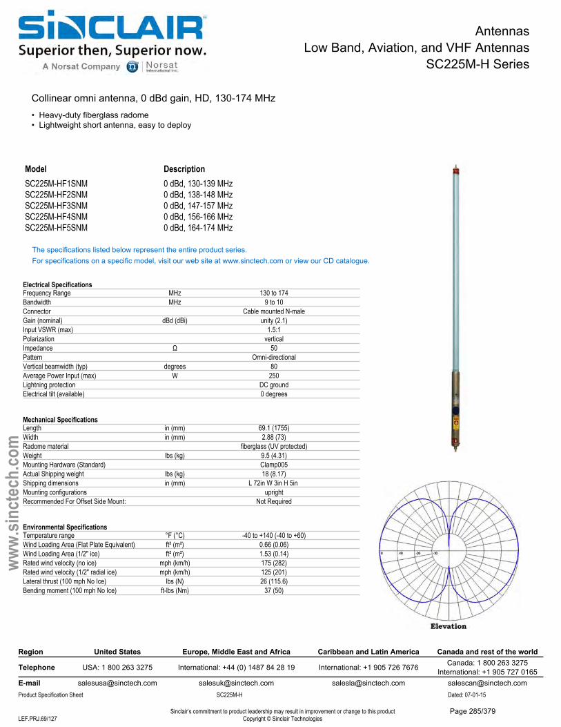
AntennasLow Band, Aviation, and VHF Antennas
SC225M-H Series
Collinear omni antenna, 0 dBd gain, HD, 130-174 MHz• Heavy-duty fiberglass radome• Lightweight short antenna, easy to deploy
Model DescriptionSC225M-HF1SNM 0 dBd, 130-139 MHzSC225M-HF2SNM 0 dBd, 138-148 MHzSC225M-HF3SNM 0 dBd, 147-157 MHzSC225M-HF4SNM 0 dBd, 156-166 MHzSC225M-HF5SNM 0 dBd, 164-174 MHz
The specifications listed below represent the entire product series.For specifications on a specific model, visit our web site at www.sinctech.com or view our CD catalogue.
Electrical SpecificationsFrequency Range MHz 130 to 174Bandwidth MHz 9 to 10Connector Cable mounted N-maleGain (nominal) dBd (dBi) unity (2.1)Input VSWR (max) 1.5:1Polarization verticalImpedance Ω 50Pattern Omni-directionalVertical beamwidth (typ) degrees 80Average Power Input (max) W 250Lightning protection DC groundElectrical tilt (available) 0 degrees
Mechanical SpecificationsLength in (mm) 69.1 (1755)Width in (mm) 2.88 (73)Radome material fiberglass (UV protected)Weight lbs (kg) 9.5 (4.31)Mounting Hardware (Standard) Clamp005Actual Shipping weight lbs (kg) 18 (8.17)Shipping dimensions in (mm) L 72in W 3in H 5in Mounting configurations uprightRecommended For Offset Side Mount: Not Required
Environmental SpecificationsTemperature range °F (°C) -40 to +140 (-40 to +60)Wind Loading Area (Flat Plate Equivalent) ft² (m²) 0.66 (0.06)Wind Loading Area (1/2" ice) ft² (m²) 1.53 (0.14)Rated wind velocity (no ice) mph (km/h) 175 (282)Rated wind velocity (1/2" radial ice) mph (km/h) 125 (201)Lateral thrust (100 mph No Ice) lbs (N) 26 (115.6)Bending moment (100 mph No Ice) ft-lbs (Nm) 37 (50)
Region United States Europe, Middle East and Africa Caribbean and Latin America Canada and rest of the world
Telephone USA: 1 800 263 3275 International: +44 (0) 1487 84 28 19 International: +1 905 726 7676 Canada: 1 800 263 3275International: +1 905 727 0165
E-mail [email protected] [email protected] [email protected] [email protected] Specification Sheet SC225M-H Dated: 07-01-15
Sinclair’s commitment to product leadership may result in improvement or change to this productCopyright © Sinclair TechnologiesLEF.PRJ.69/127
www.
sinct
ech.
com
Page 285/379
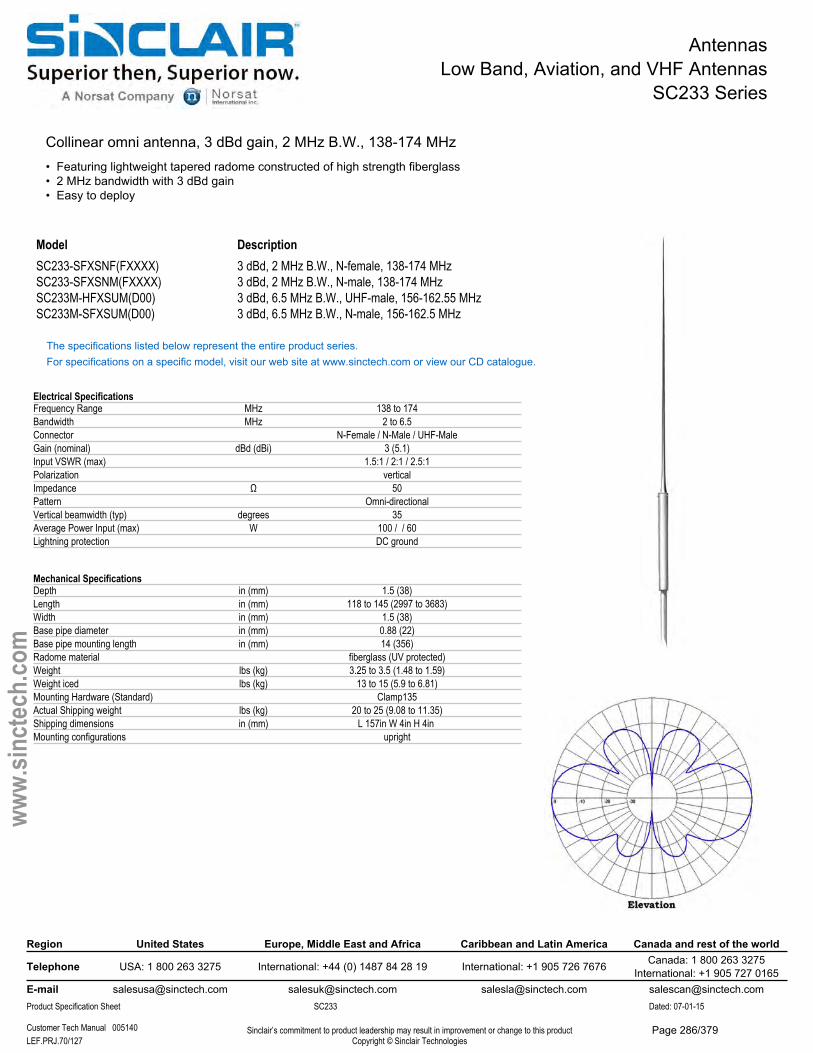
AntennasLow Band, Aviation, and VHF Antennas
SC233 Series
Collinear omni antenna, 3 dBd gain, 2 MHz B.W., 138-174 MHz• Featuring lightweight tapered radome constructed of high strength fiberglass• 2 MHz bandwidth with 3 dBd gain• Easy to deploy
Model DescriptionSC233-SFXSNF(FXXXX) 3 dBd, 2 MHz B.W., N-female, 138-174 MHzSC233-SFXSNM(FXXXX) 3 dBd, 2 MHz B.W., N-male, 138-174 MHzSC233M-HFXSUM(D00) 3 dBd, 6.5 MHz B.W., UHF-male, 156-162.55 MHzSC233M-SFXSUM(D00) 3 dBd, 6.5 MHz B.W., N-male, 156-162.5 MHz
The specifications listed below represent the entire product series.For specifications on a specific model, visit our web site at www.sinctech.com or view our CD catalogue.
Electrical SpecificationsFrequency Range MHz 138 to 174Bandwidth MHz 2 to 6.5Connector N-Female / N-Male / UHF-MaleGain (nominal) dBd (dBi) 3 (5.1)Input VSWR (max) 1.5:1 / 2:1 / 2.5:1Polarization verticalImpedance Ω 50Pattern Omni-directionalVertical beamwidth (typ) degrees 35Average Power Input (max) W 100 / / 60Lightning protection DC ground
Mechanical SpecificationsDepth in (mm) 1.5 (38)Length in (mm) 118 to 145 (2997 to 3683)Width in (mm) 1.5 (38)Base pipe diameter in (mm) 0.88 (22)Base pipe mounting length in (mm) 14 (356)Radome material fiberglass (UV protected)Weight lbs (kg) 3.25 to 3.5 (1.48 to 1.59)Weight iced lbs (kg) 13 to 15 (5.9 to 6.81)Mounting Hardware (Standard) Clamp135Actual Shipping weight lbs (kg) 20 to 25 (9.08 to 11.35)Shipping dimensions in (mm) L 157in W 4in H 4in Mounting configurations upright
Region United States Europe, Middle East and Africa Caribbean and Latin America Canada and rest of the world
Telephone USA: 1 800 263 3275 International: +44 (0) 1487 84 28 19 International: +1 905 726 7676 Canada: 1 800 263 3275International: +1 905 727 0165
E-mail [email protected] [email protected] [email protected] [email protected] Specification Sheet SC233 Dated: 07-01-15
Customer Tech Manual 005140 Sinclair’s commitment to product leadership may result in improvement or change to this productCopyright © Sinclair TechnologiesLEF.PRJ.70/127
www.
sinct
ech.
com
Page 286/379

AntennasLow Band, Aviation, and VHF Antennas
SC233 Series
Environmental SpecificationsTemperature range °F (°C) -40 to +140 (-40 to +60)Wind Loading Area (Flat Plate Equivalent) ft² (m²) 0.55 to 0.61 (0.05 to 0.06)Wind Loading Area (1/2" ice) ft² (m²) 1.15 to 1.33 (0.11 to 0.12)Rated wind velocity (no ice) mph (km/h) 115 to 170 (185 to 274)Rated wind velocity (1/2" radial ice) mph (km/h) 85 (137)Lateral thrust (100 mph No Ice) lbs (N) 21 to 21.5 (93.4 to 95.6)Bending moment (100 mph No Ice) ft-lbs (Nm) 52 to 66 (70.2 to 89.1)Tip deflection (100 mph No Ice) degrees 1.5 to 2
Ordering InformationSpecify center frequency at time of order.
Region United States Europe, Middle East and Africa Caribbean and Latin America Canada and rest of the world
Telephone USA: 1 800 263 3275 International: +44 (0) 1487 84 28 19 International: +1 905 726 7676 Canada: 1 800 263 3275International: +1 905 727 0165
E-mail [email protected] [email protected] [email protected] [email protected] Specification Sheet SC233 Dated: 07-01-15
Customer Tech Manual 005140 Sinclair’s commitment to product leadership may result in improvement or change to this productCopyright © Sinclair TechnologiesLEF.PRJ.71/127
www.
sinct
ech.
com
Page 287/379
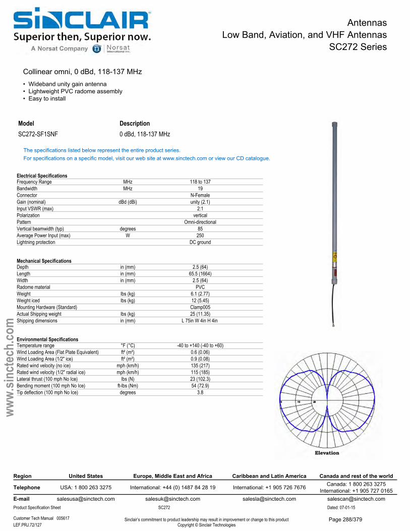
AntennasLow Band, Aviation, and VHF Antennas
SC272 Series
Collinear omni, 0 dBd, 118-137 MHz• Wideband unity gain antenna• Lightweight PVC radome assembly• Easy to install
Model DescriptionSC272-SF1SNF 0 dBd, 118-137 MHz
The specifications listed below represent the entire product series.For specifications on a specific model, visit our web site at www.sinctech.com or view our CD catalogue.
Electrical SpecificationsFrequency Range MHz 118 to 137Bandwidth MHz 19Connector N-FemaleGain (nominal) dBd (dBi) unity (2.1)Input VSWR (max) 2:1Polarization verticalPattern Omni-directionalVertical beamwidth (typ) degrees 85Average Power Input (max) W 250Lightning protection DC ground
Mechanical SpecificationsDepth in (mm) 2.5 (64)Length in (mm) 65.5 (1664)Width in (mm) 2.5 (64)Radome material PVCWeight lbs (kg) 6.1 (2.77)Weight iced lbs (kg) 12 (5.45)Mounting Hardware (Standard) Clamp005Actual Shipping weight lbs (kg) 25 (11.35)Shipping dimensions in (mm) L 75in W 4in H 4in
Environmental SpecificationsTemperature range °F (°C) -40 to +140 (-40 to +60)Wind Loading Area (Flat Plate Equivalent) ft² (m²) 0.6 (0.06)Wind Loading Area (1/2" ice) ft² (m²) 0.9 (0.08)Rated wind velocity (no ice) mph (km/h) 135 (217)Rated wind velocity (1/2" radial ice) mph (km/h) 115 (185)Lateral thrust (100 mph No Ice) lbs (N) 23 (102.3)Bending moment (100 mph No Ice) ft-lbs (Nm) 54 (72.9)Tip deflection (100 mph No Ice) degrees 3.8
Region United States Europe, Middle East and Africa Caribbean and Latin America Canada and rest of the world
Telephone USA: 1 800 263 3275 International: +44 (0) 1487 84 28 19 International: +1 905 726 7676 Canada: 1 800 263 3275International: +1 905 727 0165
E-mail [email protected] [email protected] [email protected] [email protected] Specification Sheet SC272 Dated: 07-01-15
Customer Tech Manual 005617 Sinclair’s commitment to product leadership may result in improvement or change to this productCopyright © Sinclair TechnologiesLEF.PRJ.72/127
www.
sinct
ech.
com
Page 288/379
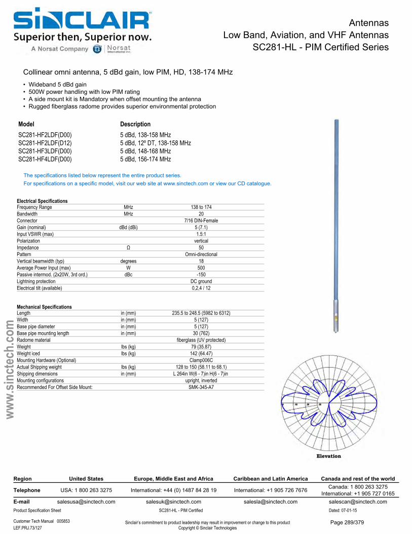
AntennasLow Band, Aviation, and VHF Antennas
SC281-HL - PIM Certified Series
Collinear omni antenna, 5 dBd gain, low PIM, HD, 138-174 MHz• Wideband 5 dBd gain• 500W power handling with low PIM rating• A side mount kit is Mandatory when offset mounting the antenna• Rugged fiberglass radome provides superior environmental protection
Model DescriptionSC281-HF2LDF(D00) 5 dBd, 138-158 MHzSC281-HF2LDF(D12) 5 dBd, 12º DT, 138-158 MHzSC281-HF3LDF(D00) 5 dBd, 148-168 MHzSC281-HF4LDF(D00) 5 dBd, 156-174 MHz
The specifications listed below represent the entire product series.For specifications on a specific model, visit our web site at www.sinctech.com or view our CD catalogue.
Electrical SpecificationsFrequency Range MHz 138 to 174Bandwidth MHz 20Connector 7/16 DIN-FemaleGain (nominal) dBd (dBi) 5 (7.1)Input VSWR (max) 1.5:1Polarization verticalImpedance Ω 50Pattern Omni-directionalVertical beamwidth (typ) degrees 18Average Power Input (max) W 500Passive intermod. (2x20W, 3rd ord.) dBc -150Lightning protection DC groundElectrical tilt (available) 0,2,4 / 12
Mechanical SpecificationsLength in (mm) 235.5 to 248.5 (5982 to 6312)Width in (mm) 5 (127)Base pipe diameter in (mm) 5 (127)Base pipe mounting length in (mm) 30 (762)Radome material fiberglass (UV protected)Weight lbs (kg) 79 (35.87)Weight iced lbs (kg) 142 (64.47)Mounting Hardware (Optional) Clamp006CActual Shipping weight lbs (kg) 128 to 150 (58.11 to 68.1)Shipping dimensions in (mm) L 264in W(6 - 7)in H(6 - 7)in Mounting configurations upright, invertedRecommended For Offset Side Mount: SMK-345-A7
Region United States Europe, Middle East and Africa Caribbean and Latin America Canada and rest of the world
Telephone USA: 1 800 263 3275 International: +44 (0) 1487 84 28 19 International: +1 905 726 7676 Canada: 1 800 263 3275International: +1 905 727 0165
E-mail [email protected] [email protected] [email protected] [email protected] Specification Sheet SC281-HL - PIM Certified Dated: 07-01-15
Customer Tech Manual 005853 Sinclair’s commitment to product leadership may result in improvement or change to this productCopyright © Sinclair TechnologiesLEF.PRJ.73/127
www.
sinct
ech.
com
Page 289/379

AntennasLow Band, Aviation, and VHF Antennas
SC281-HL - PIM Certified Series
Environmental SpecificationsTemperature range °F (°C) -40 to +140 (-40 to +60)Wind Loading Area (Flat Plate Equivalent) ft² (m²) 5.3 (0.49)Wind Loading Area (1/2" ice) ft² (m²) 6.4 (0.59)Rated wind velocity (no ice) mph (km/h) 170 (274)Rated wind velocity (1/2" radial ice) mph (km/h) 150 (242)Lateral thrust (100 mph No Ice) lbs (N) 208 (925.2)Bending moment (100 mph No Ice) ft-lbs (Nm) 1610 (2173.5)Tip deflection (100 mph No Ice) degrees 2.2
Region United States Europe, Middle East and Africa Caribbean and Latin America Canada and rest of the world
Telephone USA: 1 800 263 3275 International: +44 (0) 1487 84 28 19 International: +1 905 726 7676 Canada: 1 800 263 3275International: +1 905 727 0165
E-mail [email protected] [email protected] [email protected] [email protected] Specification Sheet SC281-HL - PIM Certified Dated: 07-01-15
Customer Tech Manual 005853 Sinclair’s commitment to product leadership may result in improvement or change to this productCopyright © Sinclair TechnologiesLEF.PRJ.74/127
www.
sinct
ech.
com
Page 290/379
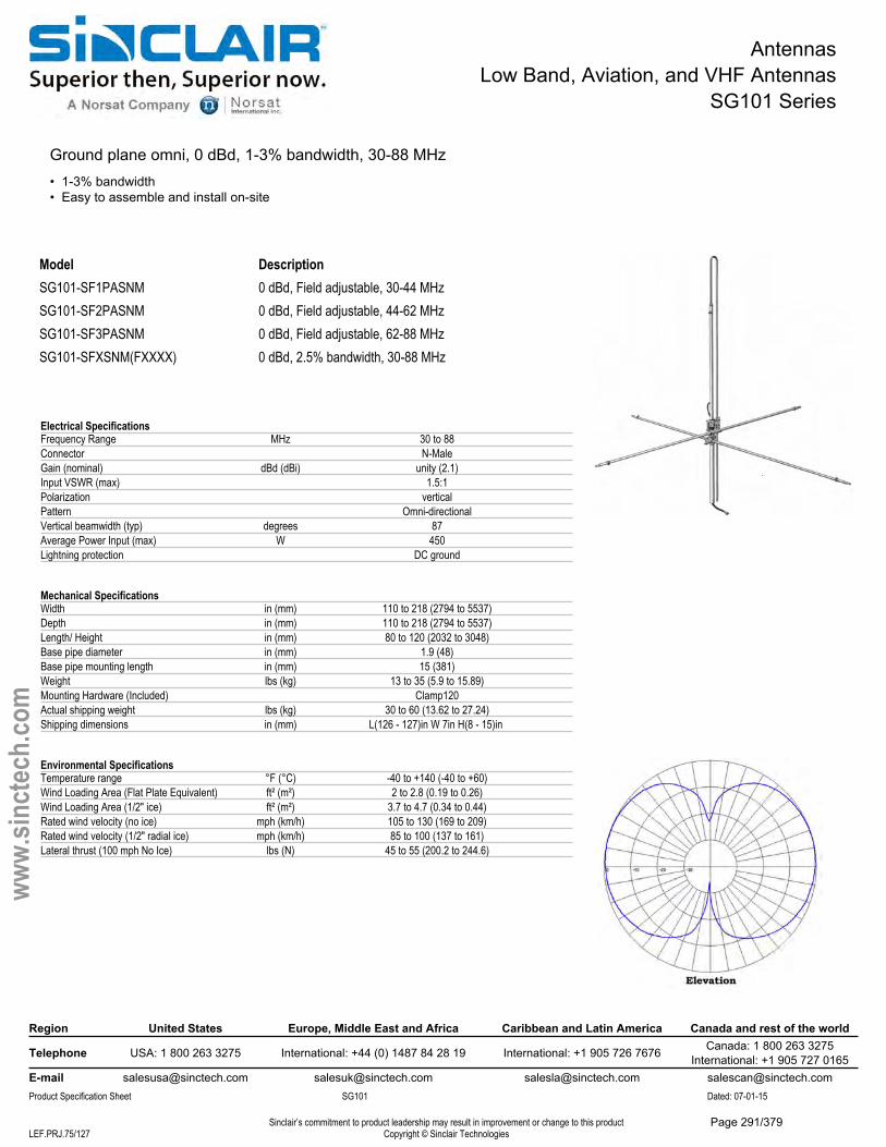
AntennasLow Band, Aviation, and VHF Antennas
SG101 Series
Ground plane omni, 0 dBd, 1-3% bandwidth, 30-88 MHz• 1-3% bandwidth• Easy to assemble and install on-site
ModelSG101-SF1PASNMSG101-SF2PASNMSG101-SF3PASNMSG101-SFXSNM(FXXXX)
Description0 dBd, Field adjustable, 30-44 MHz0 dBd, Field adjustable, 44-62 MHz0 dBd, Field adjustable, 62-88 MHz0 dBd, 2.5% bandwidth, 30-88 MHz
Region United States Europe, Middle East and Africa Caribbean and Latin America Canada and rest of the world
Telephone USA: 1 800 263 3275 International: +44 (0) 1487 84 28 19 International: +1 905 726 7676 Canada: 1 800 263 3275International: +1 905 727 0165
E-mail [email protected] [email protected] [email protected] [email protected] Specification Sheet SG101 Dated: 07-01-15
Sinclair’s commitment to product leadership may result in improvement or change to this productCopyright © Sinclair TechnologiesLEF.PRJ.75/127
www.
sinct
ech.
com
Electrical SpecificationsFrequency Range MHz 30 to 88Connector N-MaleGain (nominal) dBd (dBi) unity (2.1)Input VSWR (max) 1.5:1Polarization verticalPattern Omni-directionalVertical beamwidth (typ) degrees 87Average Power Input (max) W 450Lightning protection DC ground
Mechanical SpecificationsWidth in (mm) 110 to 218 (2794 to 5537)Depth in (mm) 110 to 218 (2794 to 5537)Length/ Height in (mm) 80 to 120 (2032 to 3048)Base pipe diameter in (mm) 1.9 (48)Base pipe mounting length in (mm) 15 (381)Weight lbs (kg) 13 to 35 (5.9 to 15.89)Mounting Hardware (Included) Clamp120Actual shipping weight lbs (kg) 30 to 60 (13.62 to 27.24)Shipping dimensions in (mm) L(126 - 127)in W 7in H(8 - 15)in
Environmental SpecificationsTemperature range °F (°C) -40 to +140 (-40 to +60)Wind Loading Area (Flat Plate Equivalent) ft² (m²) 2 to 2.8 (0.19 to 0.26)Wind Loading Area (1/2" ice) ft² (m²) 3.7 to 4.7 (0.34 to 0.44)Rated wind velocity (no ice) mph (km/h) 105 to 130 (169 to 209)Rated wind velocity (1/2" radial ice) mph (km/h) 85 to 100 (137 to 161)Lateral thrust (100 mph No Ice) lbs (N) 45 to 55 (200.2 to 244.6)
Page 291/379
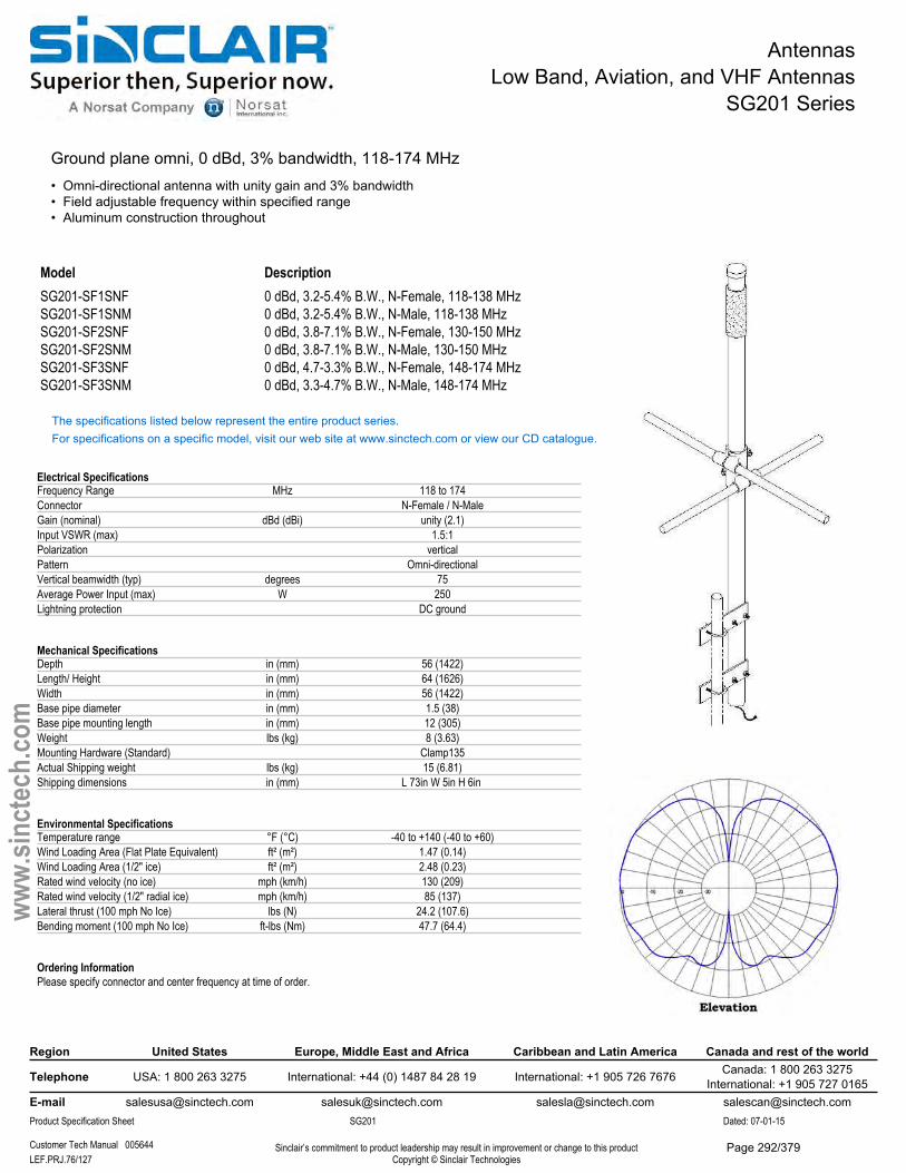
AntennasLow Band, Aviation, and VHF Antennas
SG201 Series
Ground plane omni, 0 dBd, 3% bandwidth, 118-174 MHz• Omni-directional antenna with unity gain and 3% bandwidth• Field adjustable frequency within specified range• Aluminum construction throughout
Model DescriptionSG201-SF1SNF 0 dBd, 3.2-5.4% B.W., N-Female, 118-138 MHzSG201-SF1SNM 0 dBd, 3.2-5.4% B.W., N-Male, 118-138 MHzSG201-SF2SNF 0 dBd, 3.8-7.1% B.W., N-Female, 130-150 MHzSG201-SF2SNM 0 dBd, 3.8-7.1% B.W., N-Male, 130-150 MHzSG201-SF3SNF 0 dBd, 4.7-3.3% B.W., N-Female, 148-174 MHzSG201-SF3SNM 0 dBd, 3.3-4.7% B.W., N-Male, 148-174 MHz
The specifications listed below represent the entire product series.For specifications on a specific model, visit our web site at www.sinctech.com or view our CD catalogue.
Electrical SpecificationsFrequency Range MHz 118 to 174Connector N-Female / N-MaleGain (nominal) dBd (dBi) unity (2.1)Input VSWR (max) 1.5:1Polarization verticalPattern Omni-directionalVertical beamwidth (typ) degrees 75Average Power Input (max) W 250Lightning protection DC ground
Mechanical SpecificationsDepth in (mm) 56 (1422)Length/ Height in (mm) 64 (1626)Width in (mm) 56 (1422)Base pipe diameter in (mm) 1.5 (38)Base pipe mounting length in (mm) 12 (305)Weight lbs (kg) 8 (3.63)Mounting Hardware (Standard) Clamp135Actual Shipping weight lbs (kg) 15 (6.81)Shipping dimensions in (mm) L 73in W 5in H 6in
Environmental SpecificationsTemperature range °F (°C) -40 to +140 (-40 to +60)Wind Loading Area (Flat Plate Equivalent) ft² (m²) 1.47 (0.14)Wind Loading Area (1/2" ice) ft² (m²) 2.48 (0.23)Rated wind velocity (no ice) mph (km/h) 130 (209)Rated wind velocity (1/2" radial ice) mph (km/h) 85 (137)Lateral thrust (100 mph No Ice) lbs (N) 24.2 (107.6)Bending moment (100 mph No Ice) ft-lbs (Nm) 47.7 (64.4)
Ordering InformationPlease specify connector and center frequency at time of order.
Region United States Europe, Middle East and Africa Caribbean and Latin America Canada and rest of the world
Telephone USA: 1 800 263 3275 International: +44 (0) 1487 84 28 19 International: +1 905 726 7676 Canada: 1 800 263 3275International: +1 905 727 0165
E-mail [email protected] [email protected] [email protected] [email protected] Specification Sheet SG201 Dated: 07-01-15
Customer Tech Manual 005644 Sinclair’s commitment to product leadership may result in improvement or change to this productCopyright © Sinclair TechnologiesLEF.PRJ.76/127
www.
sinct
ech.
com
Page 292/379
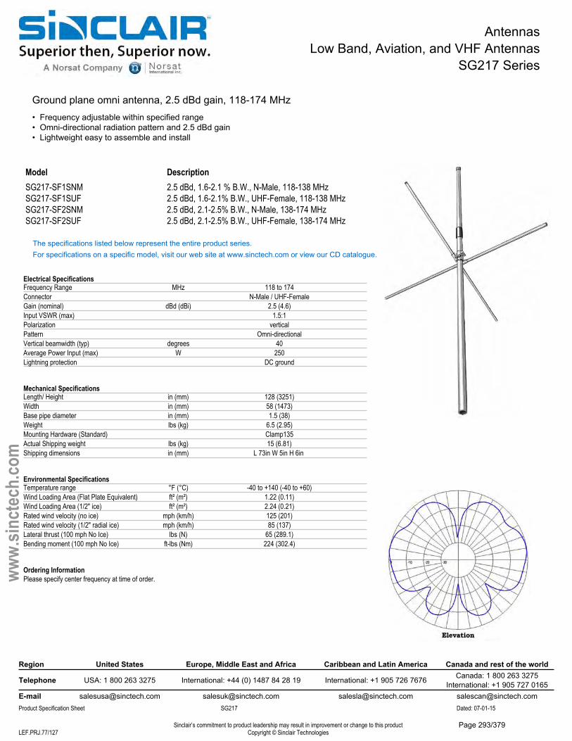
AntennasLow Band, Aviation, and VHF Antennas
SG217 Series
Ground plane omni antenna, 2.5 dBd gain, 118-174 MHz• Frequency adjustable within specified range• Omni-directional radiation pattern and 2.5 dBd gain• Lightweight easy to assemble and install
Model DescriptionSG217-SF1SNM 2.5 dBd, 1.6-2.1 % B.W., N-Male, 118-138 MHzSG217-SF1SUF 2.5 dBd, 1.6-2.1% B.W., UHF-Female, 118-138 MHzSG217-SF2SNM 2.5 dBd, 2.1-2.5% B.W., N-Male, 138-174 MHzSG217-SF2SUF 2.5 dBd, 2.1-2.5% B.W., UHF-Female, 138-174 MHz
The specifications listed below represent the entire product series.For specifications on a specific model, visit our web site at www.sinctech.com or view our CD catalogue.
Electrical SpecificationsFrequency Range MHz 118 to 174Connector N-Male / UHF-FemaleGain (nominal) dBd (dBi) 2.5 (4.6)Input VSWR (max) 1.5:1Polarization verticalPattern Omni-directionalVertical beamwidth (typ) degrees 40Average Power Input (max) W 250Lightning protection DC ground
Mechanical SpecificationsLength/ Height in (mm) 128 (3251)Width in (mm) 58 (1473)Base pipe diameter in (mm) 1.5 (38)Weight lbs (kg) 6.5 (2.95)Mounting Hardware (Standard) Clamp135Actual Shipping weight lbs (kg) 15 (6.81)Shipping dimensions in (mm) L 73in W 5in H 6in
Environmental SpecificationsTemperature range °F (°C) -40 to +140 (-40 to +60)Wind Loading Area (Flat Plate Equivalent) ft² (m²) 1.22 (0.11)Wind Loading Area (1/2" ice) ft² (m²) 2.24 (0.21)Rated wind velocity (no ice) mph (km/h) 125 (201)Rated wind velocity (1/2" radial ice) mph (km/h) 85 (137)Lateral thrust (100 mph No Ice) lbs (N) 65 (289.1)Bending moment (100 mph No Ice) ft-lbs (Nm) 224 (302.4)
Ordering InformationPlease specify center frequency at time of order.
Region United States Europe, Middle East and Africa Caribbean and Latin America Canada and rest of the world
Telephone USA: 1 800 263 3275 International: +44 (0) 1487 84 28 19 International: +1 905 726 7676 Canada: 1 800 263 3275International: +1 905 727 0165
E-mail [email protected] [email protected] [email protected] [email protected] Specification Sheet SG217 Dated: 07-01-15
Sinclair’s commitment to product leadership may result in improvement or change to this productCopyright © Sinclair TechnologiesLEF.PRJ.77/127
www.
sinct
ech.
com
Page 293/379
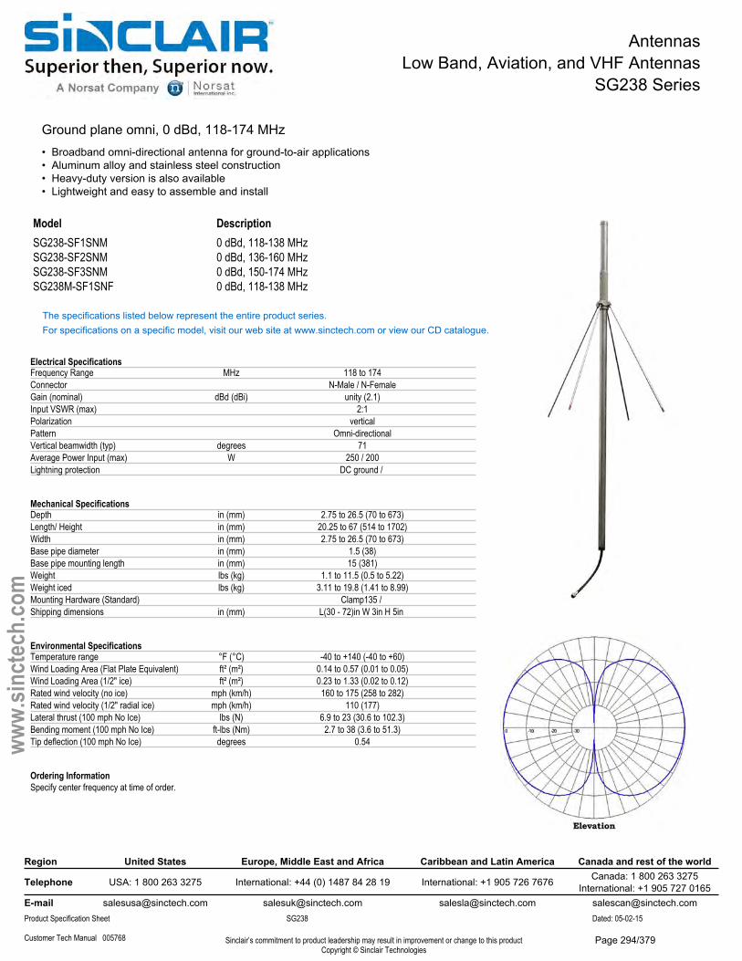
AntennasLow Band, Aviation, and VHF Antennas
SG238 Series
Ground plane omni, 0 dBd, 118-174 MHz• Broadband omni-directional antenna for ground-to-air applications• Aluminum alloy and stainless steel construction• Heavy-duty version is also available• Lightweight and easy to assemble and install
Model DescriptionSG238-SF1SNM 0 dBd, 118-138 MHzSG238-SF2SNM 0 dBd, 136-160 MHzSG238-SF3SNM 0 dBd, 150-174 MHzSG238M-SF1SNF 0 dBd, 118-138 MHz
The specifications listed below represent the entire product series.For specifications on a specific model, visit our web site at www.sinctech.com or view our CD catalogue.
Electrical SpecificationsFrequency Range MHz 118 to 174Connector N-Male / N-FemaleGain (nominal) dBd (dBi) unity (2.1)Input VSWR (max) 2:1Polarization verticalPattern Omni-directionalVertical beamwidth (typ) degrees 71Average Power Input (max) W 250 / 200Lightning protection DC ground /
Mechanical SpecificationsDepth in (mm) 2.75 to 26.5 (70 to 673)Length/ Height in (mm) 20.25 to 67 (514 to 1702)Width in (mm) 2.75 to 26.5 (70 to 673)Base pipe diameter in (mm) 1.5 (38)Base pipe mounting length in (mm) 15 (381)Weight lbs (kg) 1.1 to 11.5 (0.5 to 5.22)Weight iced lbs (kg) 3.11 to 19.8 (1.41 to 8.99)Mounting Hardware (Standard) Clamp135 / Shipping dimensions in (mm) L(30 - 72)in W 3in H 5in
Environmental SpecificationsTemperature range °F (°C) -40 to +140 (-40 to +60)Wind Loading Area (Flat Plate Equivalent) ft² (m²) 0.14 to 0.57 (0.01 to 0.05)Wind Loading Area (1/2" ice) ft² (m²) 0.23 to 1.33 (0.02 to 0.12)Rated wind velocity (no ice) mph (km/h) 160 to 175 (258 to 282)Rated wind velocity (1/2" radial ice) mph (km/h) 110 (177)Lateral thrust (100 mph No Ice) lbs (N) 6.9 to 23 (30.6 to 102.3)Bending moment (100 mph No Ice) ft-lbs (Nm) 2.7 to 38 (3.6 to 51.3)Tip deflection (100 mph No Ice) degrees 0.54
Ordering InformationSpecify center frequency at time of order.
Region United States Europe, Middle East and Africa Caribbean and Latin America Canada and rest of the world
Telephone USA: 1 800 263 3275 International: +44 (0) 1487 84 28 19 International: +1 905 726 7676 Canada: 1 800 263 3275International: +1 905 727 0165
E-mail [email protected] [email protected] [email protected] [email protected] Specification Sheet SG238 Dated: 05-02-15
Customer Tech Manual 005768 Sinclair’s commitment to product leadership may result in improvement or change to this productCopyright © Sinclair Technologies
www.
sinct
ech.
com
Page 294/379
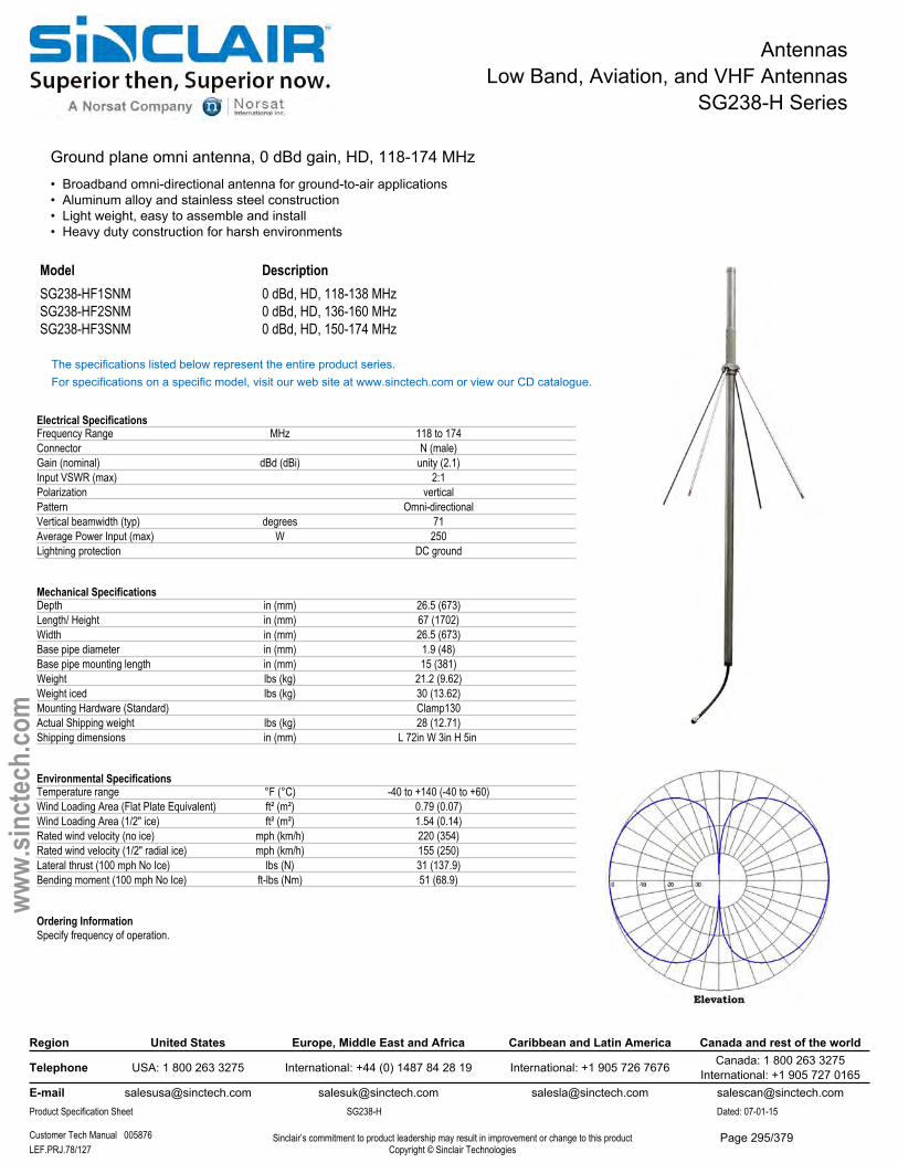
AntennasLow Band, Aviation, and VHF Antennas
SG238-H Series
Ground plane omni antenna, 0 dBd gain, HD, 118-174 MHz• Broadband omni-directional antenna for ground-to-air applications• Aluminum alloy and stainless steel construction• Light weight, easy to assemble and install• Heavy duty construction for harsh environments
Model DescriptionSG238-HF1SNM 0 dBd, HD, 118-138 MHzSG238-HF2SNM 0 dBd, HD, 136-160 MHzSG238-HF3SNM 0 dBd, HD, 150-174 MHz
The specifications listed below represent the entire product series.For specifications on a specific model, visit our web site at www.sinctech.com or view our CD catalogue.
Electrical SpecificationsFrequency Range MHz 118 to 174Connector N (male)Gain (nominal) dBd (dBi) unity (2.1)Input VSWR (max) 2:1Polarization verticalPattern Omni-directionalVertical beamwidth (typ) degrees 71Average Power Input (max) W 250Lightning protection DC ground
Mechanical SpecificationsDepth in (mm) 26.5 (673)Length/ Height in (mm) 67 (1702)Width in (mm) 26.5 (673)Base pipe diameter in (mm) 1.9 (48)Base pipe mounting length in (mm) 15 (381)Weight lbs (kg) 21.2 (9.62)Weight iced lbs (kg) 30 (13.62)Mounting Hardware (Standard) Clamp130Actual Shipping weight lbs (kg) 28 (12.71)Shipping dimensions in (mm) L 72in W 3in H 5in
Environmental SpecificationsTemperature range °F (°C) -40 to +140 (-40 to +60)Wind Loading Area (Flat Plate Equivalent) ft² (m²) 0.79 (0.07)Wind Loading Area (1/2" ice) ft² (m²) 1.54 (0.14)Rated wind velocity (no ice) mph (km/h) 220 (354)Rated wind velocity (1/2" radial ice) mph (km/h) 155 (250)Lateral thrust (100 mph No Ice) lbs (N) 31 (137.9)Bending moment (100 mph No Ice) ft-lbs (Nm) 51 (68.9)
Ordering InformationSpecify frequency of operation.
Region United States Europe, Middle East and Africa Caribbean and Latin America Canada and rest of the world
Telephone USA: 1 800 263 3275 International: +44 (0) 1487 84 28 19 International: +1 905 726 7676 Canada: 1 800 263 3275International: +1 905 727 0165
E-mail [email protected] [email protected] [email protected] [email protected] Specification Sheet SG238-H Dated: 07-01-15
Customer Tech Manual 005876 Sinclair’s commitment to product leadership may result in improvement or change to this productCopyright © Sinclair TechnologiesLEF.PRJ.78/127
www.
sinct
ech.
com
Page 295/379
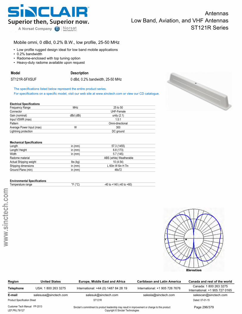
AntennasLow Band, Aviation, and VHF Antennas
ST121R Series
Mobile omni, 0 dBd, 0.2% B.W., low profile, 25-50 MHz• Low profile rugged design ideal for low band mobile applications• 0.2% bandwidth• Radome-enclosed with top tuning option• Heavy-duty radome available upon request
Model DescriptionST121R-SFXSUF 0 dBd, 0.2% bandwidth, 25-50 MHz
The specifications listed below represent the entire product series.For specifications on a specific model, visit our web site at www.sinctech.com or view our CD catalogue.
Electrical SpecificationsFrequency Range MHz 25 to 50Connector UHF-FemaleGain (nominal) dBd (dBi) unity (2.1)Input VSWR (max) 1.5:1Pattern Omni-directionalAverage Power Input (max) W 300Lightning protection DC ground
Mechanical SpecificationsLength in (mm) 57.3 (1455)Length/ Height in (mm) 6.8 (173)Width in (mm) 5.7 (145)Radome material ABS (white) WeatherableActual Shipping weight lbs (kg) 10 (4.54)Shipping dimensions in (mm) L 60in W 6in H 7in Ground Plane (min) in (mm) 48x72
Environmental SpecificationsTemperature range °F (°C) -40 to +140 (-40 to +60)
Region United States Europe, Middle East and Africa Caribbean and Latin America Canada and rest of the world
Telephone USA: 1 800 263 3275 International: +44 (0) 1487 84 28 19 International: +1 905 726 7676 Canada: 1 800 263 3275International: +1 905 727 0165
E-mail [email protected] [email protected] [email protected] [email protected] Specification Sheet ST121R Dated: 07-01-15
Customer Tech Manual FP-2013 Sinclair’s commitment to product leadership may result in improvement or change to this productCopyright © Sinclair TechnologiesLEF.PRJ.79/127
www.
sinct
ech.
com
Page 296/379
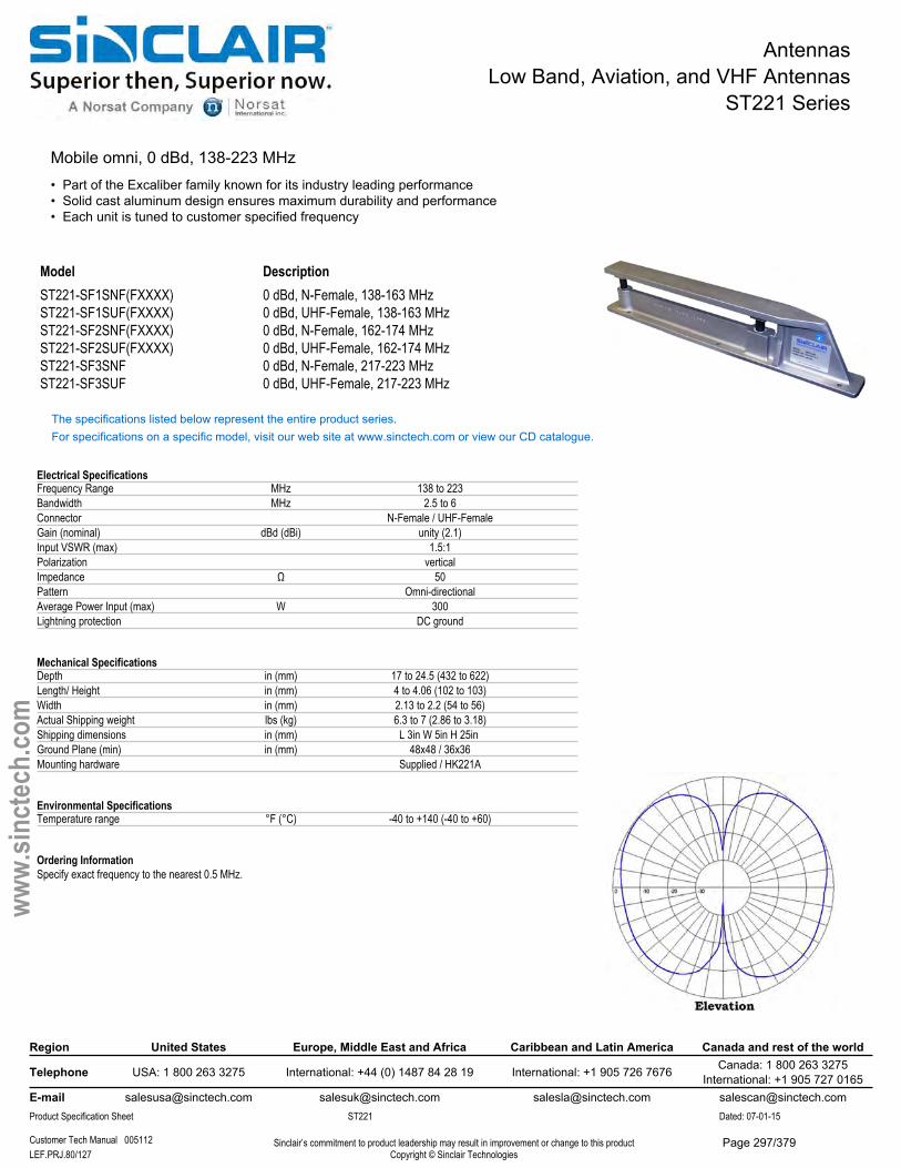
AntennasLow Band, Aviation, and VHF Antennas
ST221 Series
Mobile omni, 0 dBd, 138-223 MHz• Part of the Excaliber family known for its industry leading performance• Solid cast aluminum design ensures maximum durability and performance• Each unit is tuned to customer specified frequency
Model DescriptionST221-SF1SNF(FXXXX) 0 dBd, N-Female, 138-163 MHzST221-SF1SUF(FXXXX) 0 dBd, UHF-Female, 138-163 MHzST221-SF2SNF(FXXXX) 0 dBd, N-Female, 162-174 MHzST221-SF2SUF(FXXXX) 0 dBd, UHF-Female, 162-174 MHzST221-SF3SNF 0 dBd, N-Female, 217-223 MHzST221-SF3SUF 0 dBd, UHF-Female, 217-223 MHz
The specifications listed below represent the entire product series.For specifications on a specific model, visit our web site at www.sinctech.com or view our CD catalogue.
Electrical SpecificationsFrequency Range MHz 138 to 223Bandwidth MHz 2.5 to 6Connector N-Female / UHF-FemaleGain (nominal) dBd (dBi) unity (2.1)Input VSWR (max) 1.5:1Polarization verticalImpedance Ω 50Pattern Omni-directionalAverage Power Input (max) W 300Lightning protection DC ground
Mechanical SpecificationsDepth in (mm) 17 to 24.5 (432 to 622)Length/ Height in (mm) 4 to 4.06 (102 to 103)Width in (mm) 2.13 to 2.2 (54 to 56)Actual Shipping weight lbs (kg) 6.3 to 7 (2.86 to 3.18)Shipping dimensions in (mm) L 3in W 5in H 25in Ground Plane (min) in (mm) 48x48 / 36x36Mounting hardware Supplied / HK221A
Environmental SpecificationsTemperature range °F (°C) -40 to +140 (-40 to +60)
Ordering InformationSpecify exact frequency to the nearest 0.5 MHz.
Region United States Europe, Middle East and Africa Caribbean and Latin America Canada and rest of the world
Telephone USA: 1 800 263 3275 International: +44 (0) 1487 84 28 19 International: +1 905 726 7676 Canada: 1 800 263 3275International: +1 905 727 0165
E-mail [email protected] [email protected] [email protected] [email protected] Specification Sheet ST221 Dated: 07-01-15
Customer Tech Manual 005112 Sinclair’s commitment to product leadership may result in improvement or change to this productCopyright © Sinclair TechnologiesLEF.PRJ.80/127
www.
sinct
ech.
com
Page 297/379
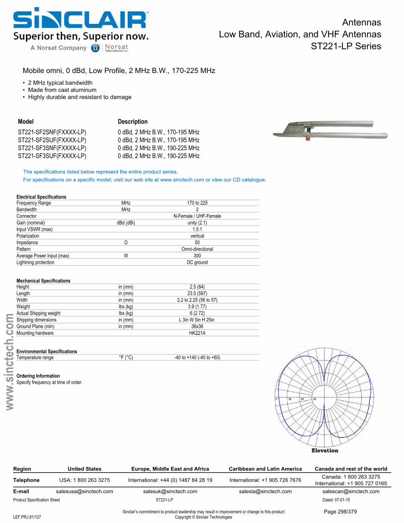
AntennasLow Band, Aviation, and VHF Antennas
ST221-LP Series
Mobile omni, 0 dBd, Low Profile, 2 MHz B.W., 170-225 MHz• 2 MHz typical bandwidth• Made from cast aluminum• Highly durable and resistant to damage
Model DescriptionST221-SF2SNF(FXXXX-LP) 0 dBd, 2 MHz B.W., 170-195 MHzST221-SF2SUF(FXXXX-LP) 0 dBd, 2 MHz B.W., 170-195 MHzST221-SF3SNF(FXXXX-LP) 0 dBd, 2 MHz B.W., 190-225 MHzST221-SF3SUF(FXXXX-LP) 0 dBd, 2 MHz B.W., 190-225 MHz
The specifications listed below represent the entire product series.For specifications on a specific model, visit our web site at www.sinctech.com or view our CD catalogue.
Electrical SpecificationsFrequency Range MHz 170 to 225Bandwidth MHz 2Connector N-Female / UHF-FemaleGain (nominal) dBd (dBi) unity (2.1)Input VSWR (max) 1.5:1Polarization verticalImpedance Ω 50Pattern Omni-directionalAverage Power Input (max) W 300Lightning protection DC ground
Mechanical SpecificationsHeight in (mm) 2.5 (64)Length in (mm) 23.5 (597)Width in (mm) 2.2 to 2.25 (56 to 57)Weight lbs (kg) 3.9 (1.77)Actual Shipping weight lbs (kg) 6 (2.72)Shipping dimensions in (mm) L 3in W 5in H 25in Ground Plane (min) in (mm) 36x36Mounting hardware HK221A
Environmental SpecificationsTemperature range °F (°C) -40 to +140 (-40 to +60)
Ordering InformationSpecify frequency at time of order.
Region United States Europe, Middle East and Africa Caribbean and Latin America Canada and rest of the world
Telephone USA: 1 800 263 3275 International: +44 (0) 1487 84 28 19 International: +1 905 726 7676 Canada: 1 800 263 3275International: +1 905 727 0165
E-mail [email protected] [email protected] [email protected] [email protected] Specification Sheet ST221-LP Dated: 07-01-15
Sinclair’s commitment to product leadership may result in improvement or change to this productCopyright © Sinclair TechnologiesLEF.PRJ.81/127
www.
sinct
ech.
com
Page 298/379
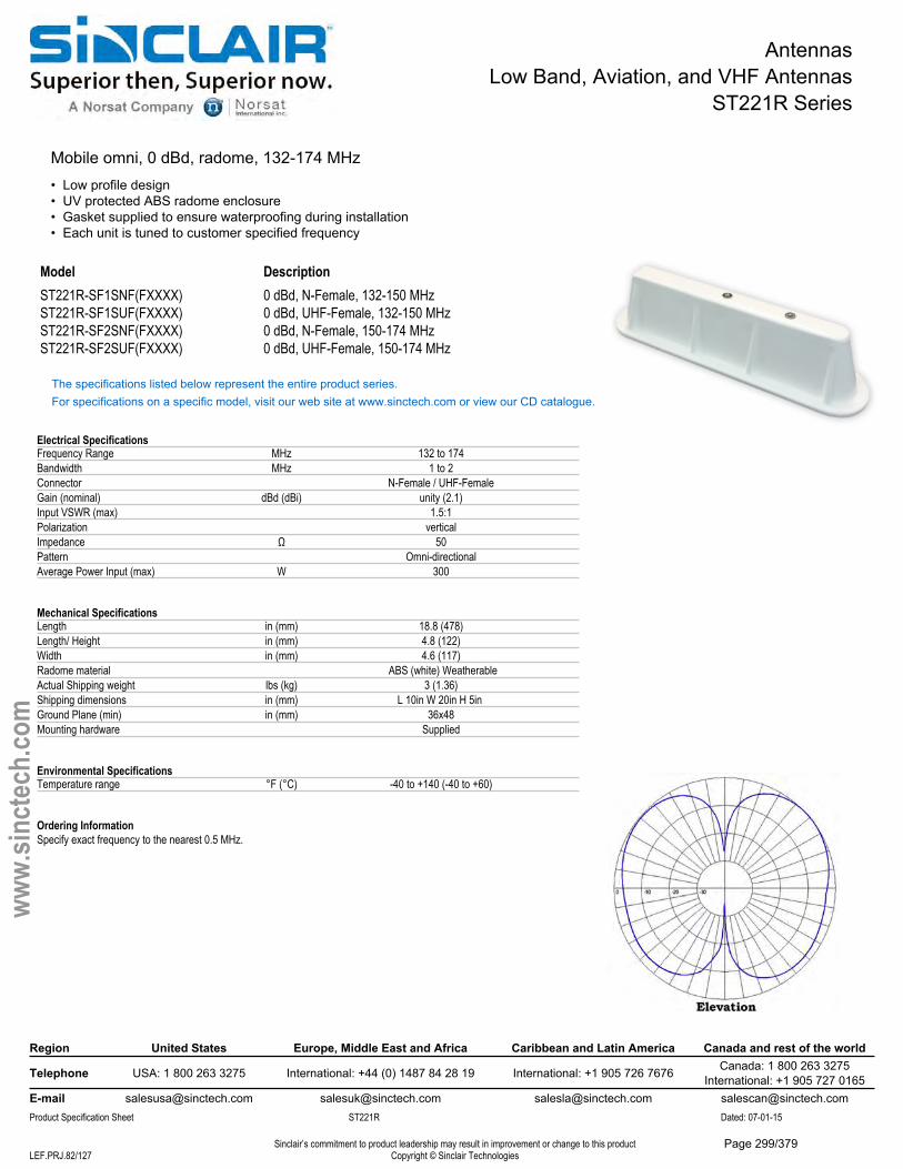
AntennasLow Band, Aviation, and VHF Antennas
ST221R Series
Mobile omni, 0 dBd, radome, 132-174 MHz• Low profile design• UV protected ABS radome enclosure• Gasket supplied to ensure waterproofing during installation• Each unit is tuned to customer specified frequency
Model DescriptionST221R-SF1SNF(FXXXX) 0 dBd, N-Female, 132-150 MHzST221R-SF1SUF(FXXXX) 0 dBd, UHF-Female, 132-150 MHzST221R-SF2SNF(FXXXX) 0 dBd, N-Female, 150-174 MHzST221R-SF2SUF(FXXXX) 0 dBd, UHF-Female, 150-174 MHz
The specifications listed below represent the entire product series.For specifications on a specific model, visit our web site at www.sinctech.com or view our CD catalogue.
Electrical SpecificationsFrequency Range MHz 132 to 174Bandwidth MHz 1 to 2Connector N-Female / UHF-FemaleGain (nominal) dBd (dBi) unity (2.1)Input VSWR (max) 1.5:1Polarization verticalImpedance Ω 50Pattern Omni-directionalAverage Power Input (max) W 300
Mechanical SpecificationsLength in (mm) 18.8 (478)Length/ Height in (mm) 4.8 (122)Width in (mm) 4.6 (117)Radome material ABS (white) WeatherableActual Shipping weight lbs (kg) 3 (1.36)Shipping dimensions in (mm) L 10in W 20in H 5in Ground Plane (min) in (mm) 36x48Mounting hardware Supplied
Environmental SpecificationsTemperature range °F (°C) -40 to +140 (-40 to +60)
Ordering InformationSpecify exact frequency to the nearest 0.5 MHz.
Region United States Europe, Middle East and Africa Caribbean and Latin America Canada and rest of the world
Telephone USA: 1 800 263 3275 International: +44 (0) 1487 84 28 19 International: +1 905 726 7676 Canada: 1 800 263 3275International: +1 905 727 0165
E-mail [email protected] [email protected] [email protected] [email protected] Specification Sheet ST221R Dated: 07-01-15
Sinclair’s commitment to product leadership may result in improvement or change to this productCopyright © Sinclair TechnologiesLEF.PRJ.82/127
www.
sinct
ech.
com
Page 299/379
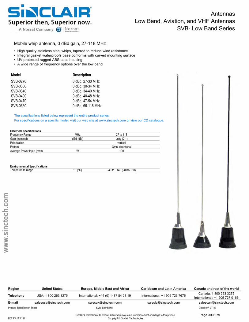
AntennasLow Band, Aviation, and VHF Antennas
SVB- Low Band Series
Mobile whip antenna, 0 dBd gain, 27-118 MHz• High quality stainless steel whips, tapered to reduce wind resistance• Integral gasket waterproofs base conforms with curved mounting surface• UV protected rugged ABS base housing• A wide range of frequency options over the low band
Model DescriptionSVB-0270 0 dBd, 27-30 MHzSVB-0300 0 dBd, 30-34 MHzSVB-0340 0 dBd, 34-40 MHzSVB-0400 0 dBd, 40-48 MHzSVB-0470 0 dBd, 47-54 MHzSVB-0660 0 dBd, 66-118 MHz
The specifications listed below represent the entire product series.For specifications on a specific model, visit our web site at www.sinctech.com or view our CD catalogue.
Electrical SpecificationsFrequency Range MHz 27 to 118Gain (nominal) dBd (dBi) unity (2.1)Polarization verticalPattern Omni-directionalAverage Power Input (max) W 100
Environmental SpecificationsTemperature range °F (°C) -40 to +140 (-40 to +60)
Region United States Europe, Middle East and Africa Caribbean and Latin America Canada and rest of the world
Telephone USA: 1 800 263 3275 International: +44 (0) 1487 84 28 19 International: +1 905 726 7676 Canada: 1 800 263 3275International: +1 905 727 0165
E-mail [email protected] [email protected] [email protected] [email protected] Specification Sheet SVB- Low Band Dated: 07-01-15
Sinclair’s commitment to product leadership may result in improvement or change to this productCopyright © Sinclair TechnologiesLEF.PRJ.83/127
www.
sinct
ech.
com
Page 300/379
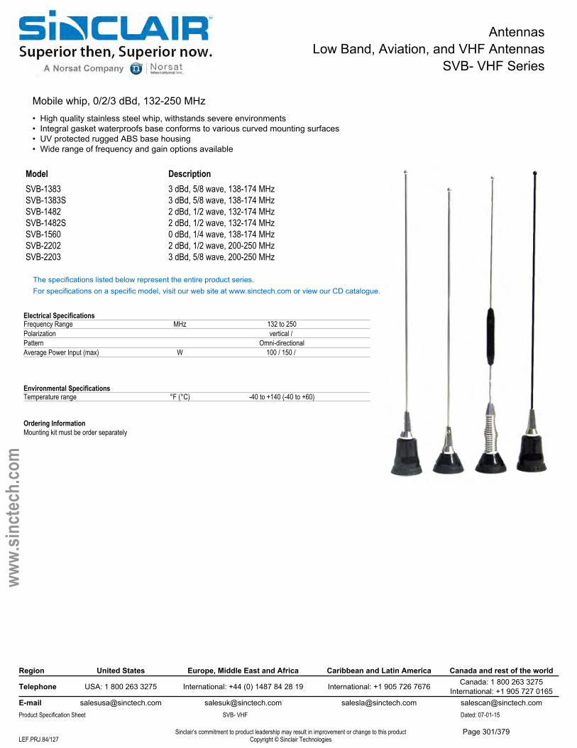
AntennasLow Band, Aviation, and VHF Antennas
SVB- VHF Series
Mobile whip, 0/2/3 dBd, 132-250 MHz• High quality stainless steel whip, withstands severe environments• Integral gasket waterproofs base conforms to various curved mounting surfaces• UV protected rugged ABS base housing• Wide range of frequency and gain options available
Model DescriptionSVB-1383 3 dBd, 5/8 wave, 138-174 MHzSVB-1383S 3 dBd, 5/8 wave, 138-174 MHzSVB-1482 2 dBd, 1/2 wave, 132-174 MHzSVB-1482S 2 dBd, 1/2 wave, 132-174 MHzSVB-1560 0 dBd, 1/4 wave, 138-174 MHzSVB-2202 2 dBd, 1/2 wave, 200-250 MHzSVB-2203 3 dBd, 5/8 wave, 200-250 MHz
The specifications listed below represent the entire product series.For specifications on a specific model, visit our web site at www.sinctech.com or view our CD catalogue.
Electrical SpecificationsFrequency Range MHz 132 to 250Polarization vertical / Pattern Omni-directionalAverage Power Input (max) W 100 / 150 /
Environmental SpecificationsTemperature range °F (°C) -40 to +140 (-40 to +60)
Ordering InformationMounting kit must be order separately
Region United States Europe, Middle East and Africa Caribbean and Latin America Canada and rest of the world
Telephone USA: 1 800 263 3275 International: +44 (0) 1487 84 28 19 International: +1 905 726 7676 Canada: 1 800 263 3275International: +1 905 727 0165
E-mail [email protected] [email protected] [email protected] [email protected] Specification Sheet SVB- VHF Dated: 07-01-15
Sinclair’s commitment to product leadership may result in improvement or change to this productCopyright © Sinclair TechnologiesLEF.PRJ.84/127
www.
sinct
ech.
com
Page 301/379
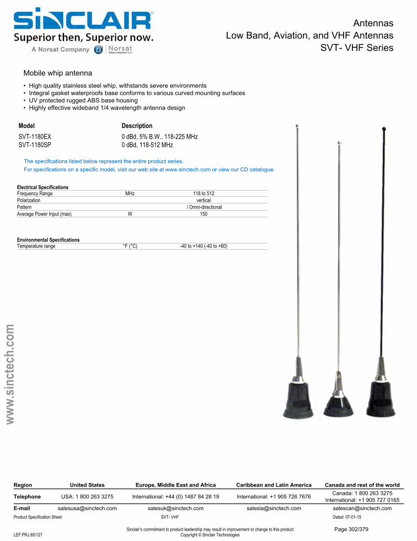
AntennasLow Band, Aviation, and VHF Antennas
SVT- VHF Series
Mobile whip antenna• High quality stainless steel whip, withstands severe environments• Integral gasket waterproofs base conforms to various curved mounting surfaces• UV protected rugged ABS base housing• Highly effective wideband 1/4 wavelength antenna design
Model DescriptionSVT-1180EX 0 dBd, 5% B.W., 118-225 MHzSVT-1180SP 0 dBd, 118-512 MHz
The specifications listed below represent the entire product series.For specifications on a specific model, visit our web site at www.sinctech.com or view our CD catalogue.
Electrical SpecificationsFrequency Range MHz 118 to 512Polarization verticalPattern / Omni-directionalAverage Power Input (max) W 150
Environmental SpecificationsTemperature range °F (°C) -40 to +140 (-40 to +60)
Region United States Europe, Middle East and Africa Caribbean and Latin America Canada and rest of the world
Telephone USA: 1 800 263 3275 International: +44 (0) 1487 84 28 19 International: +1 905 726 7676 Canada: 1 800 263 3275International: +1 905 727 0165
E-mail [email protected] [email protected] [email protected] [email protected] Specification Sheet SVT- VHF Dated: 07-01-15
Sinclair’s commitment to product leadership may result in improvement or change to this productCopyright © Sinclair TechnologiesLEF.PRJ.85/127
www.
sinct
ech.
com
Page 302/379
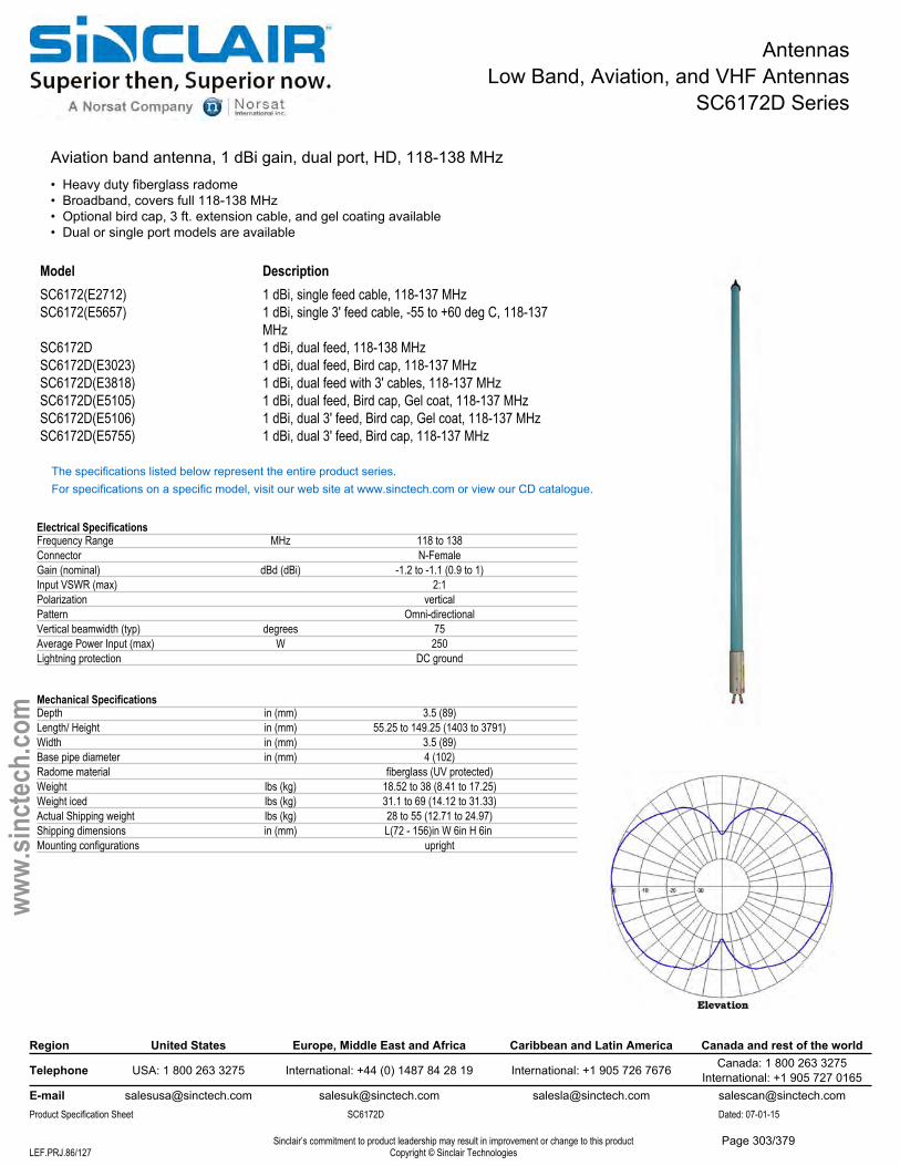
AntennasLow Band, Aviation, and VHF Antennas
SC6172D Series
Aviation band antenna, 1 dBi gain, dual port, HD, 118-138 MHz• Heavy duty fiberglass radome• Broadband, covers full 118-138 MHz• Optional bird cap, 3 ft. extension cable, and gel coating available• Dual or single port models are available
Model DescriptionSC6172(E2712) 1 dBi, single feed cable, 118-137 MHzSC6172(E5657) 1 dBi, single 3' feed cable, -55 to +60 deg C, 118-137
MHzSC6172D 1 dBi, dual feed, 118-138 MHzSC6172D(E3023) 1 dBi, dual feed, Bird cap, 118-137 MHzSC6172D(E3818) 1 dBi, dual feed with 3' cables, 118-137 MHzSC6172D(E5105) 1 dBi, dual feed, Bird cap, Gel coat, 118-137 MHzSC6172D(E5106) 1 dBi, dual 3' feed, Bird cap, Gel coat, 118-137 MHzSC6172D(E5755) 1 dBi, dual 3' feed, Bird cap, 118-137 MHz
The specifications listed below represent the entire product series.For specifications on a specific model, visit our web site at www.sinctech.com or view our CD catalogue.
Electrical SpecificationsFrequency Range MHz 118 to 138Connector N-FemaleGain (nominal) dBd (dBi) -1.2 to -1.1 (0.9 to 1)Input VSWR (max) 2:1Polarization verticalPattern Omni-directionalVertical beamwidth (typ) degrees 75Average Power Input (max) W 250Lightning protection DC ground
Mechanical SpecificationsDepth in (mm) 3.5 (89)Length/ Height in (mm) 55.25 to 149.25 (1403 to 3791)Width in (mm) 3.5 (89)Base pipe diameter in (mm) 4 (102)Radome material fiberglass (UV protected)Weight lbs (kg) 18.52 to 38 (8.41 to 17.25)Weight iced lbs (kg) 31.1 to 69 (14.12 to 31.33)Actual Shipping weight lbs (kg) 28 to 55 (12.71 to 24.97)Shipping dimensions in (mm) L(72 - 156)in W 6in H 6in Mounting configurations upright
Region United States Europe, Middle East and Africa Caribbean and Latin America Canada and rest of the world
Telephone USA: 1 800 263 3275 International: +44 (0) 1487 84 28 19 International: +1 905 726 7676 Canada: 1 800 263 3275International: +1 905 727 0165
E-mail [email protected] [email protected] [email protected] [email protected] Specification Sheet SC6172D Dated: 07-01-15
Sinclair’s commitment to product leadership may result in improvement or change to this productCopyright © Sinclair TechnologiesLEF.PRJ.86/127
www.
sinct
ech.
com
Page 303/379

AntennasLow Band, Aviation, and VHF Antennas
SC6172D Series
Environmental SpecificationsTemperature range °F (°C) -67 to +140 (-55 to +60)Wind Loading Area (Flat Plate Equivalent) ft² (m²) 0.9 to 2.42 (0.08 to 0.22)Wind Loading Area (1/2" ice) ft² (m²) 1.15 to 4.62 (0.11 to 0.43)Rated wind velocity (no ice) mph (km/h) 265 to 395 (427 to 636)Rated wind velocity (1/2" radial ice) mph (km/h) 225 to 285 (362 to 459)Lateral thrust (100 mph No Ice) lbs (N) 35 to 96 (155.7 to 427)Bending moment (100 mph No Ice) ft-lbs (Nm) 71 to 550 (95.9 to 742.5)Tip deflection (100 mph No Ice) degrees 0.1 to 0.61
Region United States Europe, Middle East and Africa Caribbean and Latin America Canada and rest of the world
Telephone USA: 1 800 263 3275 International: +44 (0) 1487 84 28 19 International: +1 905 726 7676 Canada: 1 800 263 3275International: +1 905 727 0165
E-mail [email protected] [email protected] [email protected] [email protected] Specification Sheet SC6172D Dated: 07-01-15
Sinclair’s commitment to product leadership may result in improvement or change to this productCopyright © Sinclair TechnologiesLEF.PRJ.87/127
www.
sinct
ech.
com
Page 304/379
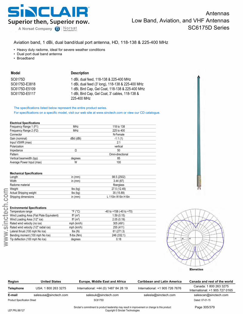
AntennasLow Band, Aviation, and VHF Antennas
SC6175D Series
Aviation band, 1 dBi, dual band/dual port antenna, HD, 118-138 & 225-400 MHz• Heavy duty radome, ideal for severe weather conditions• Dual port dual band antenna• Broadband
Model DescriptionSC6175D 1 dBi, dual feed, 118-138 & 225-400 MHzSC6175D-E3818 1 dBi, dual feed (3' long), 118-138 & 225-400 MHzSC6175D-E5109 1 dBi, Bird Cap, Gel Coat, 118-138 & 225-400 MHzSC6175D-E5117 1 dBi, Bird Cap, Gel Coat, 3' cables, 118-138 &
225-400 MHz
The specifications listed below represent the entire product series.For specifications on a specific model, visit our web site at www.sinctech.com or view our CD catalogue.
Electrical SpecificationsFrequency Range 1 (F1) MHz 118 to 138Frequency Range 2 (F2) MHz 225 to 400Connector N-FemaleGain (nominal) dBd (dBi) -1.1 (1)Input VSWR (max) 2:1Polarization verticalImpedance Ω 50Pattern Omni-directionalVertical beamwidth (typ) degrees 85Average Power Input (max) W 100
Mechanical SpecificationsLength in (mm) 98.5 (2502)Width in (mm) 3.44 (87)Radome material fiberglassWeight lbs (kg) 27.5 (12.49)Actual Shipping weight lbs (kg) 35 (15.89)Shipping dimensions in (mm) L 110in W 6in H 6in
Environmental SpecificationsTemperature range °F (°C) -40 to +158 (-40 to +70)Wind Loading Area (Flat Plate Equivalent) ft² (m²) 1.59 (0.15)Wind Loading Area (1/2" ice) ft² (m²) 2.05 (0.19)Rated wind velocity (no ice) mph (km/h) 305 (491)Rated wind velocity (1/2" radial ice) mph (km/h) 255 (411)Lateral thrust (100 mph No Ice) lbs (N) 61 (271.3)Bending moment (100 mph No Ice) ft-lbs (Nm) 246 (332.1)Tip deflection (100 mph No Ice) degrees 0.18
Region United States Europe, Middle East and Africa Caribbean and Latin America Canada and rest of the world
Telephone USA: 1 800 263 3275 International: +44 (0) 1487 84 28 19 International: +1 905 726 7676 Canada: 1 800 263 3275International: +1 905 727 0165
E-mail [email protected] [email protected] [email protected] [email protected] Specification Sheet SC6175D Dated: 07-01-15
Sinclair’s commitment to product leadership may result in improvement or change to this productCopyright © Sinclair TechnologiesLEF.PRJ.88/127
www.
sinct
ech.
com
Page 305/379
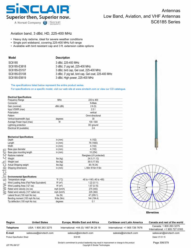
AntennasLow Band, Aviation, and VHF Antennas
SC6185 Series
Aviation band, 3 dBd, HD, 225-400 MHz• Heavy duty radome, ideal for severe weather conditions• Single port wideband, covering 225-400 MHz full range• Available with bird resistant cap and 3 ft. extension cable options
Model DescriptionSC6185 3 dBd, 225-400 MHzSC6185-E3818 3 dBd, 3' pig tail, 225-400 MHzSC6185-E5107 3 dBd, bird cap, Gel coat, 225-400 MHzSC6185-E5108 3 dBd, 3' pig tail, bird cap, Gel coat, 225-400 MHzSC6185-E5619 3 dBd, High power, 225-400 MHz
The specifications listed below represent the entire product series.For specifications on a specific model, visit our web site at www.sinctech.com or view our CD catalogue.
Electrical SpecificationsFrequency Range MHz 225 to 400Connector N-MaleGain (nominal) dBd (dBi) 2.9 (5)Input VSWR (max) 2.5:1Polarization verticalPattern Omni-directionalVertical beamwidth (typ) degrees 30Average Power Input (max) W 100 / 500Lightning protection DC groundElectrical tilt (available) 2-6
Mechanical SpecificationsDepth in (mm) 4 (102)Length in (mm) 76 (1930)Width in (mm) 4 (102)Base pipe diameter in (mm) 4 (102)Base pipe mounting length in (mm) 10 (254)Radome material fiberglass (UV protected)Weight lbs (kg) 24.5 (11.12)Weight iced lbs (kg) 39.5 (17.93)Actual Shipping weight lbs (kg) 36 (16.34)Shipping dimensions in (mm) L 90in W 6in H 6in
Environmental SpecificationsTemperature range °F (°C) -40 to +140 (-40 to +60)Wind Loading Area (Flat Plate Equivalent) ft² (m²) 1.22 (0.11)Wind Loading Area (1/2" ice) ft² (m²) 1.57 (0.15)Rated wind velocity (no ice) mph (km/h) 275 (443)Rated wind velocity (1/2" radial ice) mph (km/h) 225 (362)Lateral thrust (100 mph No Ice) lbs (N) 47 (209.1)Bending moment (100 mph No Ice) ft-lbs (Nm) 144 (194.4)Tip deflection (100 mph No Ice) degrees 0.1
Region United States Europe, Middle East and Africa Caribbean and Latin America Canada and rest of the world
Telephone USA: 1 800 263 3275 International: +44 (0) 1487 84 28 19 International: +1 905 726 7676 Canada: 1 800 263 3275International: +1 905 727 0165
E-mail [email protected] [email protected] [email protected] [email protected] Specification Sheet SC6185 Dated: 07-01-15
Sinclair’s commitment to product leadership may result in improvement or change to this productCopyright © Sinclair TechnologiesLEF.PRJ.89/127
www.
sinct
ech.
com
Page 306/379
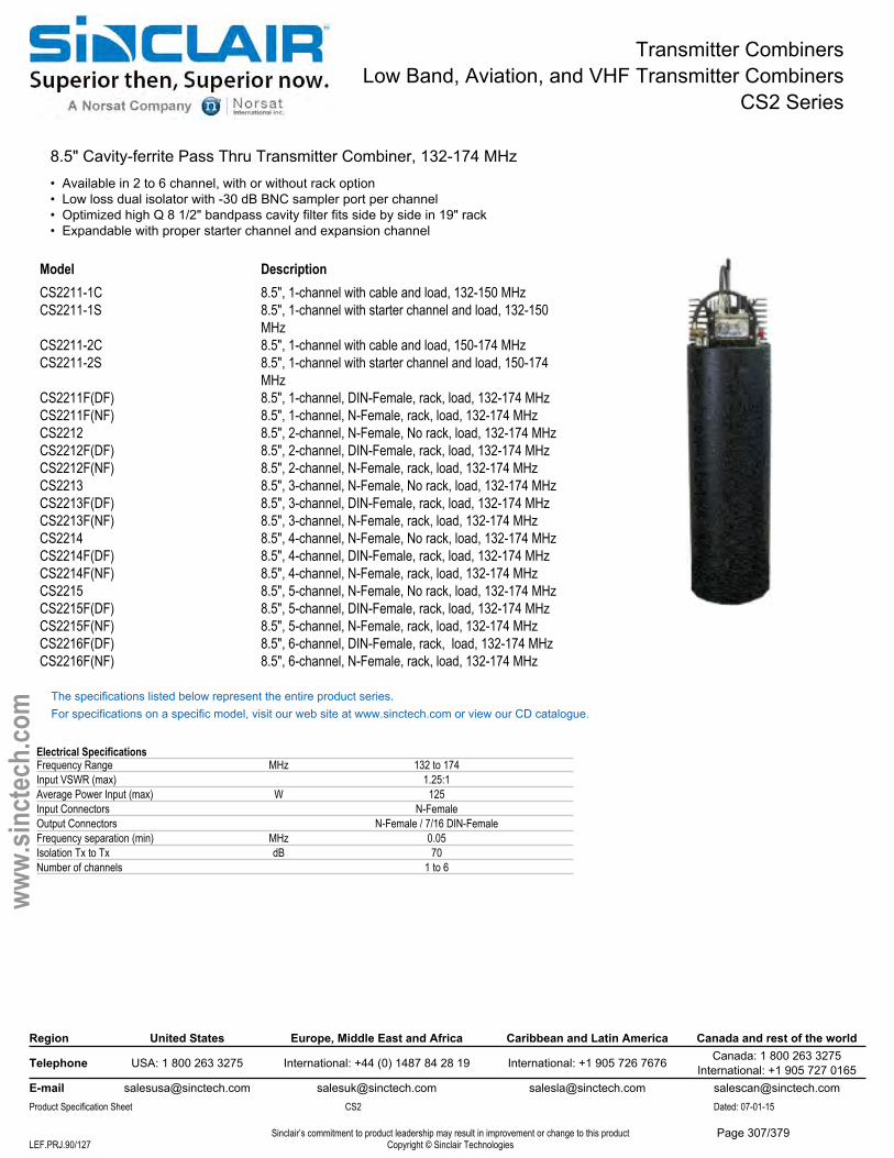
Transmitter CombinersLow Band, Aviation, and VHF Transmitter Combiners
CS2 Series
8.5" Cavity-ferrite Pass Thru Transmitter Combiner, 132-174 MHz• Available in 2 to 6 channel, with or without rack option• Low loss dual isolator with -30 dB BNC sampler port per channel• Optimized high Q 8 1/2" bandpass cavity filter fits side by side in 19" rack• Expandable with proper starter channel and expansion channel
Model DescriptionCS2211-1C 8.5", 1-channel with cable and load, 132-150 MHzCS2211-1S 8.5", 1-channel with starter channel and load, 132-150
MHzCS2211-2C 8.5", 1-channel with cable and load, 150-174 MHzCS2211-2S 8.5", 1-channel with starter channel and load, 150-174
MHzCS2211F(DF) 8.5", 1-channel, DIN-Female, rack, load, 132-174 MHzCS2211F(NF) 8.5", 1-channel, N-Female, rack, load, 132-174 MHzCS2212 8.5", 2-channel, N-Female, No rack, load, 132-174 MHzCS2212F(DF) 8.5", 2-channel, DIN-Female, rack, load, 132-174 MHzCS2212F(NF) 8.5", 2-channel, N-Female, rack, load, 132-174 MHzCS2213 8.5", 3-channel, N-Female, No rack, load, 132-174 MHzCS2213F(DF) 8.5", 3-channel, DIN-Female, rack, load, 132-174 MHzCS2213F(NF) 8.5", 3-channel, N-Female, rack, load, 132-174 MHzCS2214 8.5", 4-channel, N-Female, No rack, load, 132-174 MHzCS2214F(DF) 8.5", 4-channel, DIN-Female, rack, load, 132-174 MHzCS2214F(NF) 8.5", 4-channel, N-Female, rack, load, 132-174 MHzCS2215 8.5", 5-channel, N-Female, No rack, load, 132-174 MHzCS2215F(DF) 8.5", 5-channel, DIN-Female, rack, load, 132-174 MHzCS2215F(NF) 8.5", 5-channel, N-Female, rack, load, 132-174 MHzCS2216F(DF) 8.5", 6-channel, DIN-Female, rack, load, 132-174 MHzCS2216F(NF) 8.5", 6-channel, N-Female, rack, load, 132-174 MHz
The specifications listed below represent the entire product series.For specifications on a specific model, visit our web site at www.sinctech.com or view our CD catalogue.
Electrical SpecificationsFrequency Range MHz 132 to 174Input VSWR (max) 1.25:1Average Power Input (max) W 125Input Connectors N-FemaleOutput Connectors N-Female / 7/16 DIN-FemaleFrequency separation (min) MHz 0.05Isolation Tx to Tx dB 70Number of channels 1 to 6
Region United States Europe, Middle East and Africa Caribbean and Latin America Canada and rest of the world
Telephone USA: 1 800 263 3275 International: +44 (0) 1487 84 28 19 International: +1 905 726 7676 Canada: 1 800 263 3275International: +1 905 727 0165
E-mail [email protected] [email protected] [email protected] [email protected] Specification Sheet CS2 Dated: 07-01-15
Sinclair’s commitment to product leadership may result in improvement or change to this productCopyright © Sinclair TechnologiesLEF.PRJ.90/127
www.
sinct
ech.
com
Page 307/379
Transmitter CombinersLow Band, Aviation, and VHF Transmitter Combiners
CS2 Series
Mechanical SpecificationsDepth in (mm) 26 to 36 (660 to 914)Length/ Height in (mm) 8.5 to 74 (216 to 1880)Width in (mm) 8.5 to 21 (216 to 533)Outer Conductor Material aluminumFinish BlackCavity width or diameter in (mm) 8.5 (216)
Environmental SpecificationsTemperature range °F (°C) -22 to +140 (-30 to +60)
Ordering InformationConsult with Sinclair Systems Engineer before purchase.
Region United States Europe, Middle East and Africa Caribbean and Latin America Canada and rest of the world
Telephone USA: 1 800 263 3275 International: +44 (0) 1487 84 28 19 International: +1 905 726 7676 Canada: 1 800 263 3275International: +1 905 727 0165
E-mail [email protected] [email protected] [email protected] [email protected] Specification Sheet CS2 Dated: 07-01-15
Sinclair’s commitment to product leadership may result in improvement or change to this productCopyright © Sinclair TechnologiesLEF.PRJ.91/127
www.
sinct
ech.
com
Page 308/379
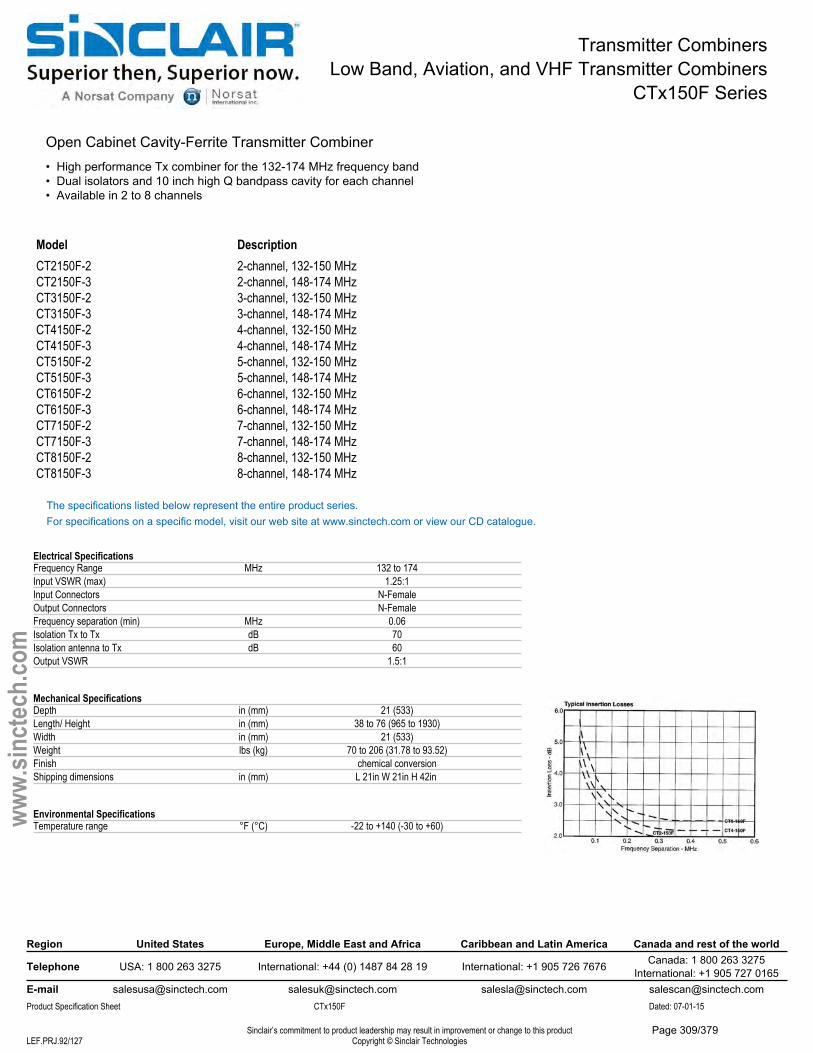
Transmitter CombinersLow Band, Aviation, and VHF Transmitter Combiners
CTx150F Series
Open Cabinet Cavity-Ferrite Transmitter Combiner• High performance Tx combiner for the 132-174 MHz frequency band• Dual isolators and 10 inch high Q bandpass cavity for each channel• Available in 2 to 8 channels
Model DescriptionCT2150F-2 2-channel, 132-150 MHzCT2150F-3 2-channel, 148-174 MHzCT3150F-2 3-channel, 132-150 MHzCT3150F-3 3-channel, 148-174 MHzCT4150F-2 4-channel, 132-150 MHzCT4150F-3 4-channel, 148-174 MHzCT5150F-2 5-channel, 132-150 MHzCT5150F-3 5-channel, 148-174 MHzCT6150F-2 6-channel, 132-150 MHzCT6150F-3 6-channel, 148-174 MHzCT7150F-2 7-channel, 132-150 MHzCT7150F-3 7-channel, 148-174 MHzCT8150F-2 8-channel, 132-150 MHzCT8150F-3 8-channel, 148-174 MHz
The specifications listed below represent the entire product series.For specifications on a specific model, visit our web site at www.sinctech.com or view our CD catalogue.
Electrical SpecificationsFrequency Range MHz 132 to 174Input VSWR (max) 1.25:1Input Connectors N-FemaleOutput Connectors N-FemaleFrequency separation (min) MHz 0.06Isolation Tx to Tx dB 70Isolation antenna to Tx dB 60Output VSWR 1.5:1
Mechanical SpecificationsDepth in (mm) 21 (533)Length/ Height in (mm) 38 to 76 (965 to 1930)Width in (mm) 21 (533)Weight lbs (kg) 70 to 206 (31.78 to 93.52)Finish chemical conversionShipping dimensions in (mm) L 21in W 21in H 42in
Environmental SpecificationsTemperature range °F (°C) -22 to +140 (-30 to +60)
Region United States Europe, Middle East and Africa Caribbean and Latin America Canada and rest of the world
Telephone USA: 1 800 263 3275 International: +44 (0) 1487 84 28 19 International: +1 905 726 7676 Canada: 1 800 263 3275International: +1 905 727 0165
E-mail [email protected] [email protected] [email protected] [email protected] Specification Sheet CTx150F Dated: 07-01-15
Sinclair’s commitment to product leadership may result in improvement or change to this productCopyright © Sinclair TechnologiesLEF.PRJ.92/127
www.
sinct
ech.
com
Page 309/379
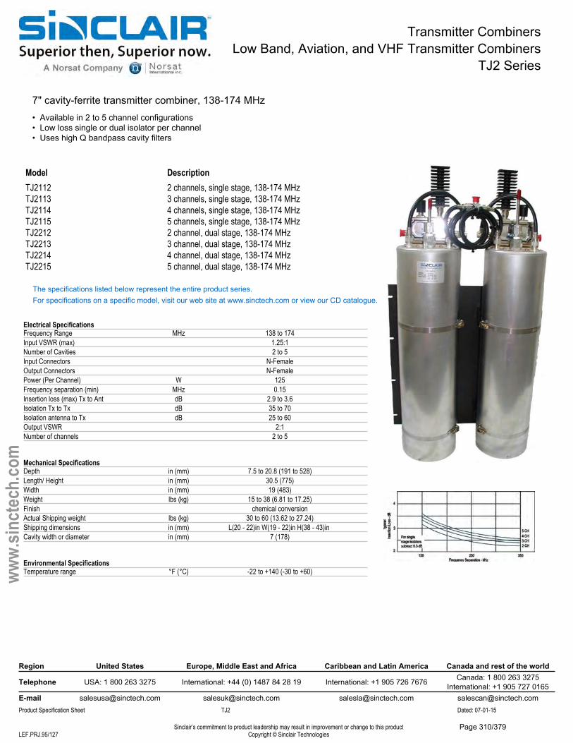
Transmitter CombinersLow Band, Aviation, and VHF Transmitter Combiners
TJ2 Series
7" cavity-ferrite transmitter combiner, 138-174 MHz• Available in 2 to 5 channel configurations• Low loss single or dual isolator per channel• Uses high Q bandpass cavity filters
Model DescriptionTJ2112 2 channels, single stage, 138-174 MHzTJ2113 3 channels, single stage, 138-174 MHzTJ2114 4 channels, single stage, 138-174 MHzTJ2115 5 channels, single stage, 138-174 MHzTJ2212 2 channel, dual stage, 138-174 MHzTJ2213 3 channel, dual stage, 138-174 MHzTJ2214 4 channel, dual stage, 138-174 MHzTJ2215 5 channel, dual stage, 138-174 MHz
The specifications listed below represent the entire product series.For specifications on a specific model, visit our web site at www.sinctech.com or view our CD catalogue.
Electrical SpecificationsFrequency Range MHz 138 to 174Input VSWR (max) 1.25:1Number of Cavities 2 to 5Input Connectors N-FemaleOutput Connectors N-FemalePower (Per Channel) W 125Frequency separation (min) MHz 0.15Insertion loss (max) Tx to Ant dB 2.9 to 3.6Isolation Tx to Tx dB 35 to 70Isolation antenna to Tx dB 25 to 60Output VSWR 2:1Number of channels 2 to 5
Mechanical SpecificationsDepth in (mm) 7.5 to 20.8 (191 to 528)Length/ Height in (mm) 30.5 (775)Width in (mm) 19 (483)Weight lbs (kg) 15 to 38 (6.81 to 17.25)Finish chemical conversionActual Shipping weight lbs (kg) 30 to 60 (13.62 to 27.24)Shipping dimensions in (mm) L(20 - 22)in W(19 - 22)in H(38 - 43)in Cavity width or diameter in (mm) 7 (178)
Environmental SpecificationsTemperature range °F (°C) -22 to +140 (-30 to +60)
Region United States Europe, Middle East and Africa Caribbean and Latin America Canada and rest of the world
Telephone USA: 1 800 263 3275 International: +44 (0) 1487 84 28 19 International: +1 905 726 7676 Canada: 1 800 263 3275International: +1 905 727 0165
E-mail [email protected] [email protected] [email protected] [email protected] Specification Sheet TJ2 Dated: 07-01-15
Sinclair’s commitment to product leadership may result in improvement or change to this productCopyright © Sinclair TechnologiesLEF.PRJ.95/127
www.
sinct
ech.
com
Page 310/379
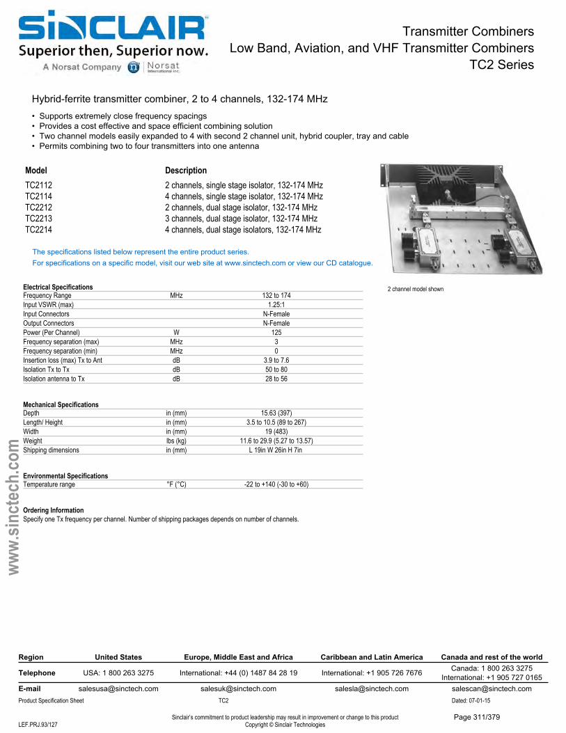
Transmitter CombinersLow Band, Aviation, and VHF Transmitter Combiners
TC2 Series
Hybrid-ferrite transmitter combiner, 2 to 4 channels, 132-174 MHz• Supports extremely close frequency spacings• Provides a cost effective and space efficient combining solution• Two channel models easily expanded to 4 with second 2 channel unit, hybrid coupler, tray and cable• Permits combining two to four transmitters into one antenna
2 channel model shown
Model DescriptionTC2112 2 channels, single stage isolator, 132-174 MHzTC2114 4 channels, single stage isolator, 132-174 MHzTC2212 2 channels, dual stage isolator, 132-174 MHzTC2213 3 channels, dual stage isolator, 132-174 MHzTC2214 4 channels, dual stage isolators, 132-174 MHz
The specifications listed below represent the entire product series.For specifications on a specific model, visit our web site at www.sinctech.com or view our CD catalogue.
Electrical SpecificationsFrequency Range MHz 132 to 174Input VSWR (max) 1.25:1Input Connectors N-FemaleOutput Connectors N-FemalePower (Per Channel) W 125Frequency separation (max) MHz 3Frequency separation (min) MHz 0Insertion loss (max) Tx to Ant dB 3.9 to 7.6Isolation Tx to Tx dB 50 to 80Isolation antenna to Tx dB 28 to 56
Mechanical SpecificationsDepth in (mm) 15.63 (397)Length/ Height in (mm) 3.5 to 10.5 (89 to 267)Width in (mm) 19 (483)Weight lbs (kg) 11.6 to 29.9 (5.27 to 13.57)Shipping dimensions in (mm) L 19in W 26in H 7in
Environmental SpecificationsTemperature range °F (°C) -22 to +140 (-30 to +60)
Ordering InformationSpecify one Tx frequency per channel. Number of shipping packages depends on number of channels.
Region United States Europe, Middle East and Africa Caribbean and Latin America Canada and rest of the world
Telephone USA: 1 800 263 3275 International: +44 (0) 1487 84 28 19 International: +1 905 726 7676 Canada: 1 800 263 3275International: +1 905 727 0165
E-mail [email protected] [email protected] [email protected] [email protected] Specification Sheet TC2 Dated: 07-01-15
Sinclair’s commitment to product leadership may result in improvement or change to this productCopyright © Sinclair TechnologiesLEF.PRJ.93/127
www.
sinct
ech.
com
Page 311/379
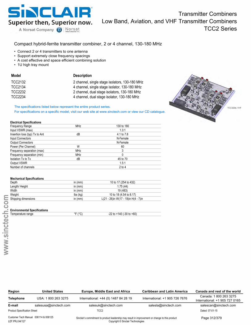
Transmitter CombinersLow Band, Aviation, and VHF Transmitter Combiners
TCC2 Series
Compact hybrid-ferrite transmitter combiner, 2 or 4 channel, 130-180 MHz• Connect 2 or 4 transmitters to one antenna• Support extremely close frequency spacings• A cost effective and space efficient combining solution• 1U high tray mount
Model DescriptionTCC2132 2 channel, single stage isolators, 130-180 MHzTCC2134 4 channel, single stage isolator, 130-180 MHzTCC2232 2 channel, dual stage isolators, 130-180 MHzTCC2234 4 channel, dual stage isolator, 130-180 MHz
The specifications listed below represent the entire product series.For specifications on a specific model, visit our web site at www.sinctech.com or view our CD catalogue.
Electrical SpecificationsFrequency Range MHz 130 to 180Input VSWR (max) 1.3:1Insertion loss (typ) Tx to Ant dB 4.1 to 7.8Input Connectors N-FemaleOutput Connectors N-FemalePower (Per Channel) W 60Frequency separation (max) MHz 3Frequency separation (min) MHz 0Isolation Tx to Tx dB 45 to 70Output VSWR 1.5:1Number of channels 2 to 4
Mechanical SpecificationsDepth in (mm) 10 to 17 (254 to 432)Length/ Height in (mm) 1.75 (44)Width in (mm) 19 (483)Weight lbs (kg) 10 to 18 (4.54 to 8.17)Shipping dimensions in (mm) L(21 - 26)in W(17 - 19)in H(4 - 7)in
Environmental SpecificationsTemperature range °F (°C) -22 to +140 (-30 to +60)
Region United States Europe, Middle East and Africa Caribbean and Latin America Canada and rest of the world
Telephone USA: 1 800 263 3275 International: +44 (0) 1487 84 28 19 International: +1 905 726 7676 Canada: 1 800 263 3275International: +1 905 727 0165
E-mail [email protected] [email protected] [email protected] [email protected] Specification Sheet TCC2 Dated: 07-01-15
Customer Tech Manual 006114 & 006125 Sinclair’s commitment to product leadership may result in improvement or change to this productCopyright © Sinclair TechnologiesLEF.PRJ.94/127
www.
sinct
ech.
com
Page 312/379
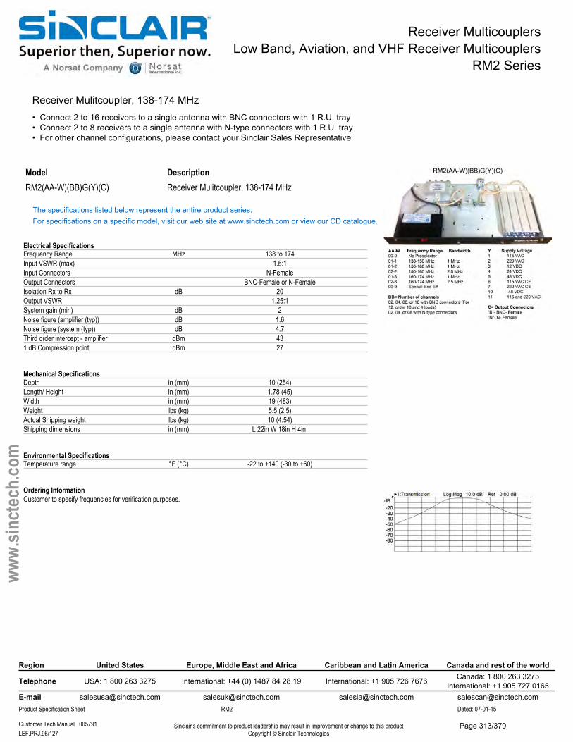
Receiver MulticouplersLow Band, Aviation, and VHF Receiver Multicouplers
RM2 Series
Receiver Mulitcoupler, 138-174 MHz• Connect 2 to 16 receivers to a single antenna with BNC connectors with 1 R.U. tray• Connect 2 to 8 receivers to a single antenna with N-type connectors with 1 R.U. tray• For other channel configurations, please contact your Sinclair Sales Representative
Model DescriptionRM2(AA-W)(BB)G(Y)(C) Receiver Mulitcoupler, 138-174 MHz
The specifications listed below represent the entire product series.For specifications on a specific model, visit our web site at www.sinctech.com or view our CD catalogue.
Electrical SpecificationsFrequency Range MHz 138 to 174Input VSWR (max) 1.5:1Input Connectors N-FemaleOutput Connectors BNC-Female or N-FemaleIsolation Rx to Rx dB 20Output VSWR 1.25:1System gain (min) dB 2Noise figure (amplifier (typ)) dB 1.6Noise figure (system (typ)) dB 4.7Third order intercept - amplifier dBm 431 dB Compression point dBm 27
Mechanical SpecificationsDepth in (mm) 10 (254)Length/ Height in (mm) 1.78 (45)Width in (mm) 19 (483)Weight lbs (kg) 5.5 (2.5)Actual Shipping weight lbs (kg) 10 (4.54)Shipping dimensions in (mm) L 22in W 18in H 4in
Environmental SpecificationsTemperature range °F (°C) -22 to +140 (-30 to +60)
Ordering InformationCustomer to specify frequencies for verification purposes.
Region United States Europe, Middle East and Africa Caribbean and Latin America Canada and rest of the world
Telephone USA: 1 800 263 3275 International: +44 (0) 1487 84 28 19 International: +1 905 726 7676 Canada: 1 800 263 3275International: +1 905 727 0165
E-mail [email protected] [email protected] [email protected] [email protected] Specification Sheet RM2 Dated: 07-01-15
Customer Tech Manual 005791 Sinclair’s commitment to product leadership may result in improvement or change to this productCopyright © Sinclair TechnologiesLEF.PRJ.96/127
www.
sinct
ech.
com
Page 313/379
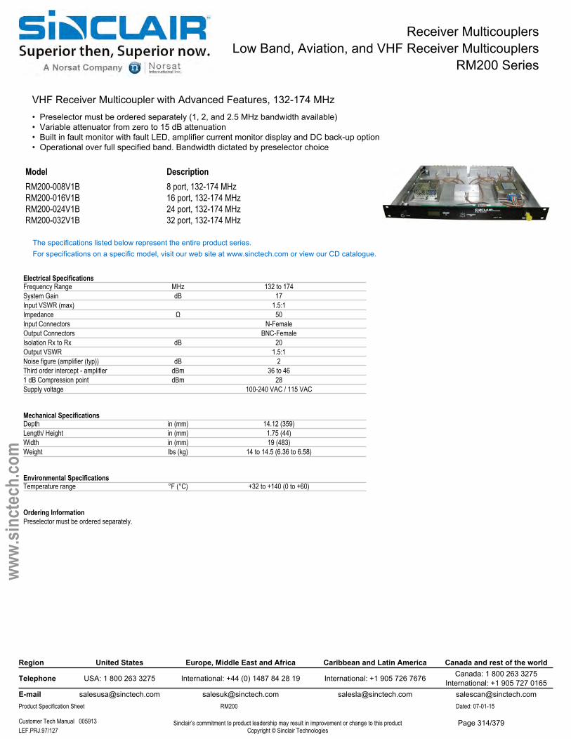
Receiver MulticouplersLow Band, Aviation, and VHF Receiver Multicouplers
RM200 Series
VHF Receiver Multicoupler with Advanced Features, 132-174 MHz• Preselector must be ordered separately (1, 2, and 2.5 MHz bandwidth available)• Variable attenuator from zero to 15 dB attenuation• Built in fault monitor with fault LED, amplifier current monitor display and DC back-up option• Operational over full specified band. Bandwidth dictated by preselector choice
Model DescriptionRM200-008V1B 8 port, 132-174 MHzRM200-016V1B 16 port, 132-174 MHzRM200-024V1B 24 port, 132-174 MHzRM200-032V1B 32 port, 132-174 MHz
The specifications listed below represent the entire product series.For specifications on a specific model, visit our web site at www.sinctech.com or view our CD catalogue.
Electrical SpecificationsFrequency Range MHz 132 to 174System Gain dB 17Input VSWR (max) 1.5:1Impedance Ω 50Input Connectors N-FemaleOutput Connectors BNC-FemaleIsolation Rx to Rx dB 20Output VSWR 1.5:1Noise figure (amplifier (typ)) dB 2Third order intercept - amplifier dBm 36 to 461 dB Compression point dBm 28Supply voltage 100-240 VAC / 115 VAC
Mechanical SpecificationsDepth in (mm) 14.12 (359)Length/ Height in (mm) 1.75 (44)Width in (mm) 19 (483)Weight lbs (kg) 14 to 14.5 (6.36 to 6.58)
Environmental SpecificationsTemperature range °F (°C) +32 to +140 (0 to +60)
Ordering InformationPreselector must be ordered separately.
Region United States Europe, Middle East and Africa Caribbean and Latin America Canada and rest of the world
Telephone USA: 1 800 263 3275 International: +44 (0) 1487 84 28 19 International: +1 905 726 7676 Canada: 1 800 263 3275International: +1 905 727 0165
E-mail [email protected] [email protected] [email protected] [email protected] Specification Sheet RM200 Dated: 07-01-15
Customer Tech Manual 005913 Sinclair’s commitment to product leadership may result in improvement or change to this productCopyright © Sinclair TechnologiesLEF.PRJ.97/127
www.
sinct
ech.
com
Page 314/379
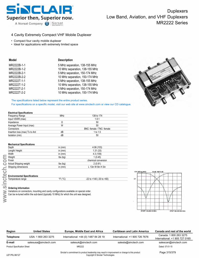
DuplexersLow Band, Aviation, and VHF Duplexers
MR2222 Series
4 Cavity Extremely Compact VHF Mobile Duplexer• Compact four cavity mobile duplexer• Ideal for applications with extremely limited space
Model DescriptionMR2222B-1-1 5 MHz separation, 138-155 MHzMR2222B-1-2 10 MHz separation, 138-155 MHzMR2222B-2-1 5 MHz separation, 150-174 MHzMR2222B-2-2 10 MHz separation, 150-174 MHzMR2222T-1-1 5 MHz separation, 138-155 MHzMR2222T-1-2 10 MHz separation, 138-155 MHzMR2222T-2-1 5 MHz separation, 150-174 MHzMR2222T-2-2 10 MHz separation, 150-174 MHz
The specifications listed below represent the entire product series.For specifications on a specific model, visit our web site at www.sinctech.com or view our CD catalogue.
Electrical SpecificationsFrequency Range MHz 138 to 174Input VSWR (max) 1.5:1Impedance Ω 50Average Power Input (max) W 50Connectors BNC- female / TNC- femaleInsertion loss (max) Tx to Ant dB 1 to 1.5Isolation (min) dB 50
Mechanical SpecificationsDepth in (mm) 4.06 (103)Length/ Height in (mm) 1.31 (33)Width in (mm) 4.3 (109)Weight lbs (kg) 1 (0.45)Finish chemical conversionActual Shipping weight lbs (kg) 2 (0.91)Shipping dimensions in (mm) L 13in W 9in H 3in
Environmental SpecificationsTemperature range °F (°C) -22 to +140 (-30 to +60)
Ordering InformationVariations on connectors, mounting and cavity configurations available on special order.Can be re-tuned within the sub-band (typically 10 MHz) for which the unit was designed.
Region United States Europe, Middle East and Africa Caribbean and Latin America Canada and rest of the world
Telephone USA: 1 800 263 3275 International: +44 (0) 1487 84 28 19 International: +1 905 726 7676 Canada: 1 800 263 3275International: +1 905 727 0165
E-mail [email protected] [email protected] [email protected] [email protected] Specification Sheet MR2222 Dated: 07-01-15
Sinclair’s commitment to product leadership may result in improvement or change to this productCopyright © Sinclair TechnologiesLEF.PRJ.98/127
www.
sinct
ech.
com
Page 315/379
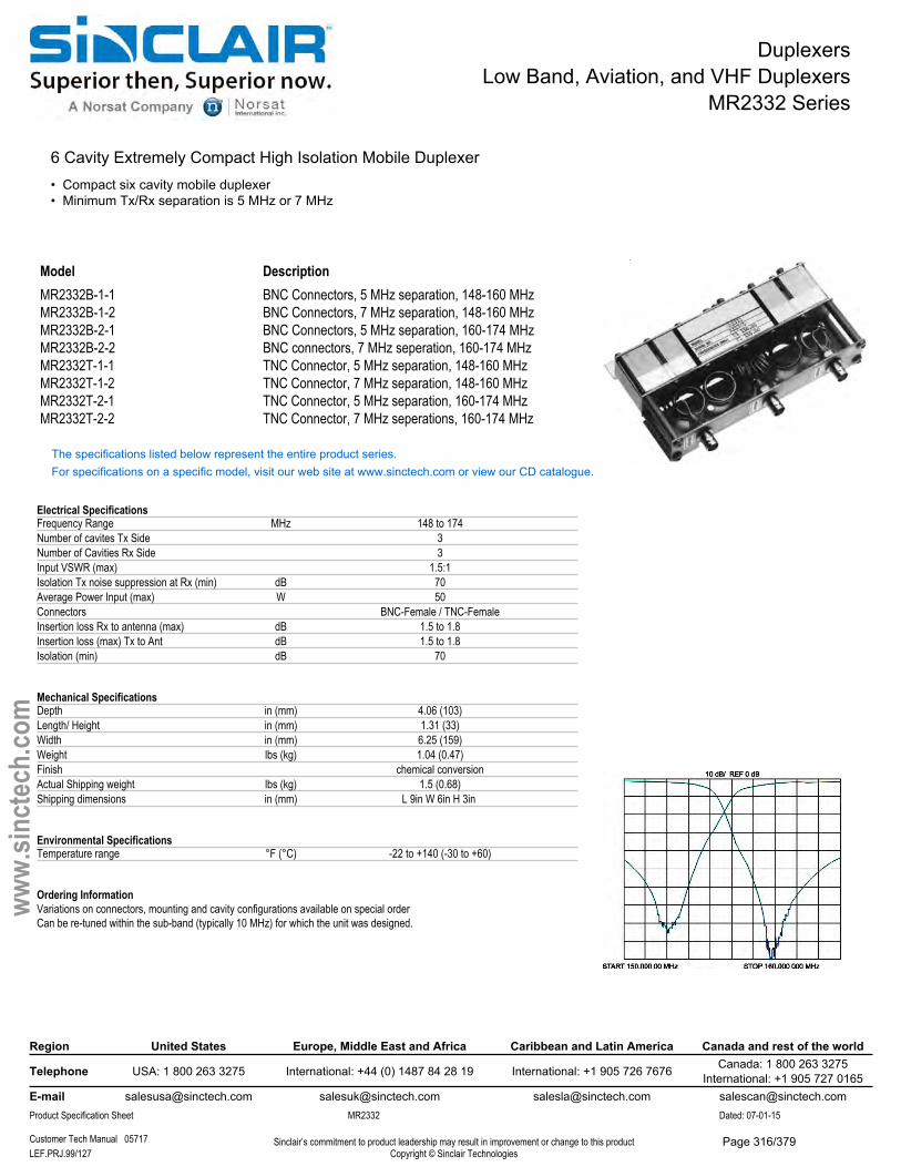
DuplexersLow Band, Aviation, and VHF Duplexers
MR2332 Series
6 Cavity Extremely Compact High Isolation Mobile Duplexer• Compact six cavity mobile duplexer• Minimum Tx/Rx separation is 5 MHz or 7 MHz
Model DescriptionMR2332B-1-1 BNC Connectors, 5 MHz separation, 148-160 MHzMR2332B-1-2 BNC Connectors, 7 MHz separation, 148-160 MHzMR2332B-2-1 BNC Connectors, 5 MHz separation, 160-174 MHzMR2332B-2-2 BNC connectors, 7 MHz seperation, 160-174 MHzMR2332T-1-1 TNC Connector, 5 MHz separation, 148-160 MHzMR2332T-1-2 TNC Connector, 7 MHz separation, 148-160 MHzMR2332T-2-1 TNC Connector, 5 MHz separation, 160-174 MHzMR2332T-2-2 TNC Connector, 7 MHz seperations, 160-174 MHz
The specifications listed below represent the entire product series.For specifications on a specific model, visit our web site at www.sinctech.com or view our CD catalogue.
Electrical SpecificationsFrequency Range MHz 148 to 174Number of cavites Tx Side 3Number of Cavities Rx Side 3Input VSWR (max) 1.5:1Isolation Tx noise suppression at Rx (min) dB 70Average Power Input (max) W 50Connectors BNC-Female / TNC-FemaleInsertion loss Rx to antenna (max) dB 1.5 to 1.8Insertion loss (max) Tx to Ant dB 1.5 to 1.8Isolation (min) dB 70
Mechanical SpecificationsDepth in (mm) 4.06 (103)Length/ Height in (mm) 1.31 (33)Width in (mm) 6.25 (159)Weight lbs (kg) 1.04 (0.47)Finish chemical conversionActual Shipping weight lbs (kg) 1.5 (0.68)Shipping dimensions in (mm) L 9in W 6in H 3in
Environmental SpecificationsTemperature range °F (°C) -22 to +140 (-30 to +60)
Ordering InformationVariations on connectors, mounting and cavity configurations available on special orderCan be re-tuned within the sub-band (typically 10 MHz) for which the unit was designed.
Region United States Europe, Middle East and Africa Caribbean and Latin America Canada and rest of the world
Telephone USA: 1 800 263 3275 International: +44 (0) 1487 84 28 19 International: +1 905 726 7676 Canada: 1 800 263 3275International: +1 905 727 0165
E-mail [email protected] [email protected] [email protected] [email protected] Specification Sheet MR2332 Dated: 07-01-15
Customer Tech Manual 05717 Sinclair’s commitment to product leadership may result in improvement or change to this productCopyright © Sinclair TechnologiesLEF.PRJ.99/127
www.
sinct
ech.
com
Page 316/379
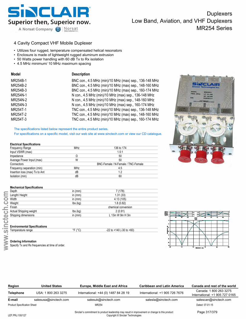
DuplexersLow Band, Aviation, and VHF Duplexers
MR254 Series
4 Cavity Compact VHF Mobile Duplexer• Utilizes four rugged, temperature compensated helical resonators• Enclosure is made of lightweight rugged aluminum extrusion• 50 Watts power handling with 60 dB Tx to Rx isolation• 4.5 MHz minimum/ 10 MHz maximum spacing
Model DescriptionMR254B-1 BNC con., 4.5 MHz (min)/10 MHz (max) sep., 136-148 MHzMR254B-2 BNC con., 4.5 MHz (min)/10 MHz (max) sep., 148-160 MHzMR254B-3 BNC con., 4.5 MHz (min)/10 MHz (max) sep., 160-174 MHzMR254N-1 N con., 4.5 MHz (min)/10 MHz (max) sep., 136-148 MHzMR254N-2 N con., 4.5 MHz (min)/10 MHz (max) sep., 148-160 MHzMR254N-3 N con., 4.5 MHz (min)/10 MHz (max) sep., 160-174 MHzMR254T-1 TNC con., 4.5 MHz (min)/10 MHz (max) sep., 136-148 MHzMR254T-2 TNC con., 4.5 MHz (min)/10 MHz (max) sep., 148-160 MHzMR254T-3 TNC con., 4.5 MHz (min)/10 MHz (max) sep., 160-174 MHz
The specifications listed below represent the entire product series.For specifications on a specific model, visit our web site at www.sinctech.com or view our CD catalogue.
Electrical SpecificationsFrequency Range MHz 136 to 174Input VSWR (max) 1.5:1Impedance Ω 50Average Power Input (max) W 50Connectors BNC-Female / N-Female / TNC-FemaleFrequency separation (min) MHz 4.5Insertion loss (max) Tx to Ant dB 1.2Isolation (min) dB 60
Mechanical SpecificationsDepth in (mm) 7 (178)Length/ Height in (mm) 1.31 (33)Width in (mm) 4.13 (105)Weight lbs (kg) 1.8 (0.82)Finish chemical conversionActual Shipping weight lbs (kg) 2 (0.91)Shipping dimensions in (mm) L 13in W 9in H 3in
Environmental SpecificationsTemperature range °F (°C) -22 to +140 (-30 to +60)
Ordering InformationSpecify Tx and Rx frequencies at time of order.
Region United States Europe, Middle East and Africa Caribbean and Latin America Canada and rest of the world
Telephone USA: 1 800 263 3275 International: +44 (0) 1487 84 28 19 International: +1 905 726 7676 Canada: 1 800 263 3275International: +1 905 727 0165
E-mail [email protected] [email protected] [email protected] [email protected] Specification Sheet MR254 Dated: 07-01-15
Sinclair’s commitment to product leadership may result in improvement or change to this productCopyright © Sinclair TechnologiesLEF.PRJ.100/127
www.
sinct
ech.
com
Page 317/379
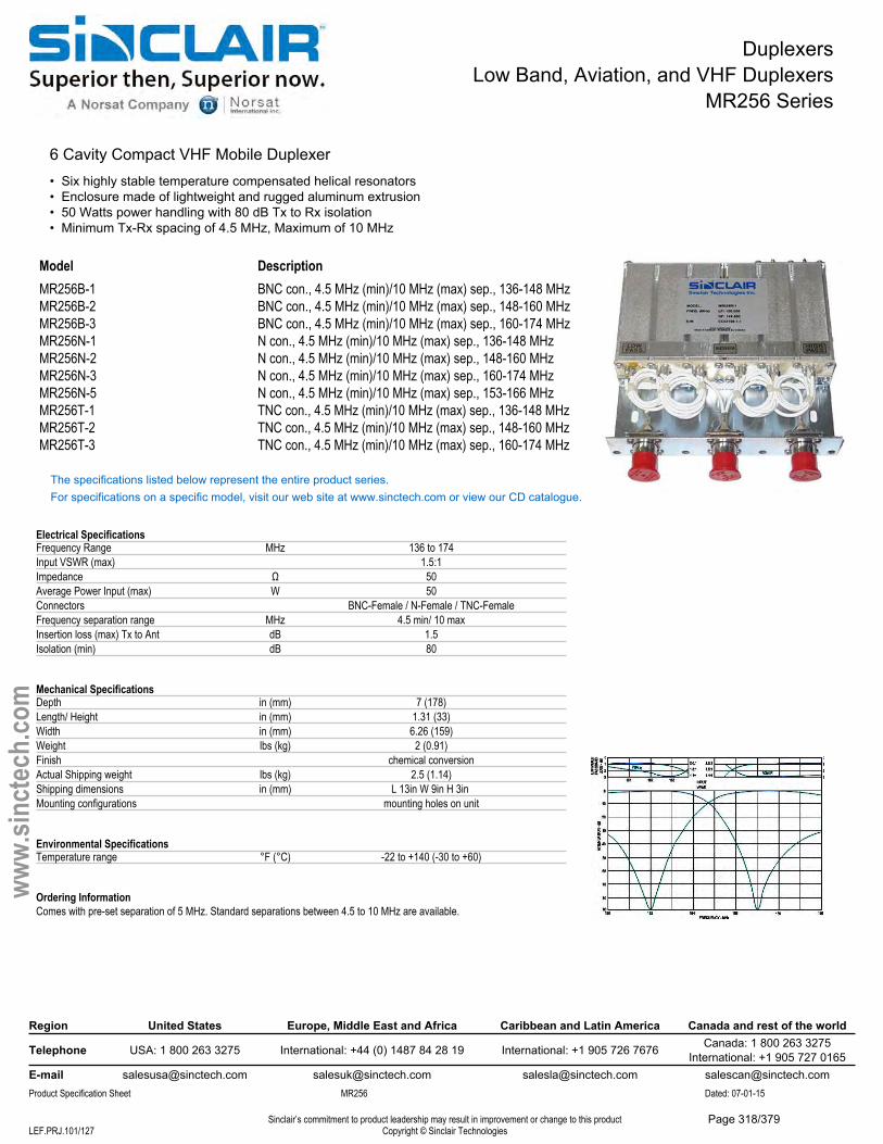
DuplexersLow Band, Aviation, and VHF Duplexers
MR256 Series
6 Cavity Compact VHF Mobile Duplexer• Six highly stable temperature compensated helical resonators• Enclosure made of lightweight and rugged aluminum extrusion• 50 Watts power handling with 80 dB Tx to Rx isolation• Minimum Tx-Rx spacing of 4.5 MHz, Maximum of 10 MHz
Model DescriptionMR256B-1 BNC con., 4.5 MHz (min)/10 MHz (max) sep., 136-148 MHzMR256B-2 BNC con., 4.5 MHz (min)/10 MHz (max) sep., 148-160 MHzMR256B-3 BNC con., 4.5 MHz (min)/10 MHz (max) sep., 160-174 MHzMR256N-1 N con., 4.5 MHz (min)/10 MHz (max) sep., 136-148 MHzMR256N-2 N con., 4.5 MHz (min)/10 MHz (max) sep., 148-160 MHzMR256N-3 N con., 4.5 MHz (min)/10 MHz (max) sep., 160-174 MHzMR256N-5 N con., 4.5 MHz (min)/10 MHz (max) sep., 153-166 MHzMR256T-1 TNC con., 4.5 MHz (min)/10 MHz (max) sep., 136-148 MHzMR256T-2 TNC con., 4.5 MHz (min)/10 MHz (max) sep., 148-160 MHzMR256T-3 TNC con., 4.5 MHz (min)/10 MHz (max) sep., 160-174 MHz
The specifications listed below represent the entire product series.For specifications on a specific model, visit our web site at www.sinctech.com or view our CD catalogue.
Electrical SpecificationsFrequency Range MHz 136 to 174Input VSWR (max) 1.5:1Impedance Ω 50Average Power Input (max) W 50Connectors BNC-Female / N-Female / TNC-FemaleFrequency separation range MHz 4.5 min/ 10 maxInsertion loss (max) Tx to Ant dB 1.5Isolation (min) dB 80
Mechanical SpecificationsDepth in (mm) 7 (178)Length/ Height in (mm) 1.31 (33)Width in (mm) 6.26 (159)Weight lbs (kg) 2 (0.91)Finish chemical conversionActual Shipping weight lbs (kg) 2.5 (1.14)Shipping dimensions in (mm) L 13in W 9in H 3in Mounting configurations mounting holes on unit
Environmental SpecificationsTemperature range °F (°C) -22 to +140 (-30 to +60)
Ordering InformationComes with pre-set separation of 5 MHz. Standard separations between 4.5 to 10 MHz are available.
Region United States Europe, Middle East and Africa Caribbean and Latin America Canada and rest of the world
Telephone USA: 1 800 263 3275 International: +44 (0) 1487 84 28 19 International: +1 905 726 7676 Canada: 1 800 263 3275International: +1 905 727 0165
E-mail [email protected] [email protected] [email protected] [email protected] Specification Sheet MR256 Dated: 07-01-15
Sinclair’s commitment to product leadership may result in improvement or change to this productCopyright © Sinclair TechnologiesLEF.PRJ.101/127
www.
sinct
ech.
com
Page 318/379
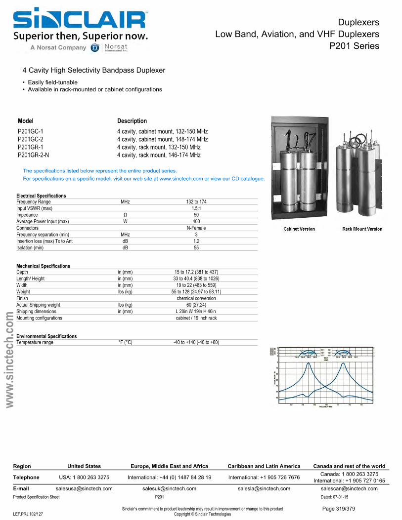
DuplexersLow Band, Aviation, and VHF Duplexers
P201 Series
4 Cavity High Selectivity Bandpass Duplexer• Easily field-tunable• Available in rack-mounted or cabinet configurations
Model DescriptionP201GC-1 4 cavity, cabinet mount, 132-150 MHzP201GC-2 4 cavity, cabinet mount, 148-174 MHzP201GR-1 4 cavity, rack mount, 132-150 MHzP201GR-2-N 4 cavity, rack mount, 146-174 MHz
The specifications listed below represent the entire product series.For specifications on a specific model, visit our web site at www.sinctech.com or view our CD catalogue.
Electrical SpecificationsFrequency Range MHz 132 to 174Input VSWR (max) 1.5:1Impedance Ω 50Average Power Input (max) W 400Connectors N-FemaleFrequency separation (min) MHz 3Insertion loss (max) Tx to Ant dB 1.2Isolation (min) dB 55
Mechanical SpecificationsDepth in (mm) 15 to 17.2 (381 to 437)Length/ Height in (mm) 33 to 40.4 (838 to 1026)Width in (mm) 19 to 22 (483 to 559)Weight lbs (kg) 55 to 128 (24.97 to 58.11)Finish chemical conversionActual Shipping weight lbs (kg) 60 (27.24)Shipping dimensions in (mm) L 20in W 19in H 40in Mounting configurations cabinet / 19 inch rack
Environmental SpecificationsTemperature range °F (°C) -40 to +140 (-40 to +60)
Region United States Europe, Middle East and Africa Caribbean and Latin America Canada and rest of the world
Telephone USA: 1 800 263 3275 International: +44 (0) 1487 84 28 19 International: +1 905 726 7676 Canada: 1 800 263 3275International: +1 905 727 0165
E-mail [email protected] [email protected] [email protected] [email protected] Specification Sheet P201 Dated: 07-01-15
Sinclair’s commitment to product leadership may result in improvement or change to this productCopyright © Sinclair TechnologiesLEF.PRJ.102/127
www.
sinct
ech.
com
Page 319/379
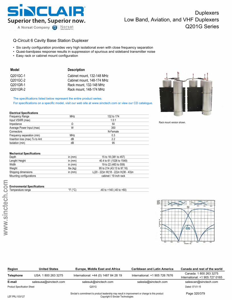
DuplexersLow Band, Aviation, and VHF Duplexers
Q201G Series
Q-Circuit 6 Cavity Base Station Duplexer• Six cavity configuration provides very high isolationat even with close frequency separation• Quasi-bandpass response results in suppression of spurious and sideband transmitter noise• Easy rack or cabinet mount configuration
Rack mount version shown.
Model DescriptionQ201GC-1 Cabinet mount, 132-148 MHzQ201GC-2 Cabinet mount, 148-174 MHzQ201GR-1 Rack mount, 132-148 MHzQ201GR-2 Rack mount, 148-174 MHz
The specifications listed below represent the entire product series.For specifications on a specific model, visit our web site at www.sinctech.com or view our CD catalogue.
Electrical SpecificationsFrequency Range MHz 132 to 174Input VSWR (max) 1.5:1Impedance Ω 50Average Power Input (max) W 350Connectors N-FemaleFrequency separation (min) MHz 0.3Insertion loss (max) Tx to Ant dB 2.2Isolation (min) dB 95
Mechanical SpecificationsDepth in (mm) 15 to 18 (381 to 457)Length/ Height in (mm) 40.4 to 61 (1026 to 1549)Width in (mm) 19 to 22 (483 to 559)Weight lbs (kg) 95 to 214 (43.13 to 97.16)Shipping dimensions in (mm) L(20 - 22)in W(18 - 22)in H(38 - 43)in Mounting configurations cabinet / 19 inch rack
Environmental SpecificationsTemperature range °F (°C) -40 to +140 (-40 to +60)
Region United States Europe, Middle East and Africa Caribbean and Latin America Canada and rest of the world
Telephone USA: 1 800 263 3275 International: +44 (0) 1487 84 28 19 International: +1 905 726 7676 Canada: 1 800 263 3275International: +1 905 727 0165
E-mail [email protected] [email protected] [email protected] [email protected] Specification Sheet Q201G Dated: 07-01-15
Sinclair’s commitment to product leadership may result in improvement or change to this productCopyright © Sinclair TechnologiesLEF.PRJ.103/127
www.
sinct
ech.
com
Page 320/379
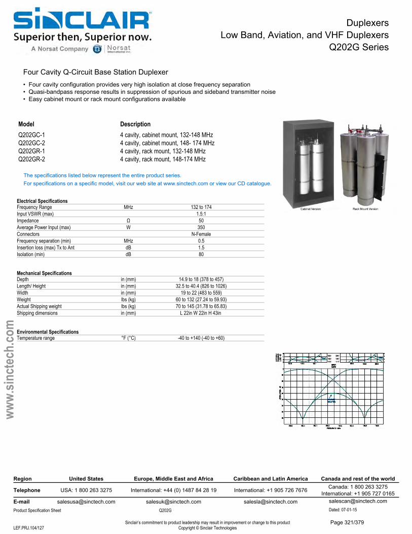
DuplexersLow Band, Aviation, and VHF Duplexers
Q202G Series
Four Cavity Q-Circuit Base Station Duplexer • Four cavity configuration provides very high isolation at close frequency separation• Quasi-bandpass response results in suppression of spurious and sideband transmitter noise• Easy cabinet mount or rack mount configurations available
Model DescriptionQ202GC-1 4 cavity, cabinet mount, 132-148 MHzQ202GC-2 4 cavity, cabinet mount, 148- 174 MHzQ202GR-1 4 cavity, rack mount, 132-148 MHzQ202GR-2 4 cavity, rack mount, 148-174 MHz
The specifications listed below represent the entire product series.For specifications on a specific model, visit our web site at www.sinctech.com or view our CD catalogue.
Electrical SpecificationsFrequency Range MHz 132 to 174Input VSWR (max) 1.5:1Impedance Ω 50Average Power Input (max) W 350Connectors N-FemaleFrequency separation (min) MHz 0.5Insertion loss (max) Tx to Ant dB 1.5Isolation (min) dB 80
Mechanical SpecificationsDepth in (mm) 14.9 to 18 (378 to 457)Length/ Height in (mm) 32.5 to 40.4 (826 to 1026)Width in (mm) 19 to 22 (483 to 559)Weight lbs (kg) 60 to 132 (27.24 to 59.93)Actual Shipping weight lbs (kg) 70 to 145 (31.78 to 65.83)Shipping dimensions in (mm) L 22in W 22in H 43in
Environmental SpecificationsTemperature range °F (°C) -40 to +140 (-40 to +60)
Region United States Europe, Middle East and Africa Caribbean and Latin America Canada and rest of the world
Telephone USA: 1 800 263 3275 International: +44 (0) 1487 84 28 19 International: +1 905 726 7676 Canada: 1 800 263 3275International: +1 905 727 0165
E-mail [email protected] [email protected] [email protected] Specification Sheet Q202G
[email protected] Dated: 07-01-15
Sinclair’s commitment to product leadership may result in improvement or change to this productCopyright © Sinclair TechnologiesLEF.PRJ.104/127
www.
sinct
ech.
com
Page 321/379

DuplexersLow Band, Aviation, and VHF Duplexers
Q2220 Series
4 Cavity Res-Lok Q-Circuit VHF Duplexer, 138-174 MHz• Can be tuned over the entire 138-174 MHz frequency range• 70 dB isolation and 1.5 dB insertion loss at 0.5 MHz spacing
Model DescriptionQ2220E 4 cavity, 138-174 MHz
The specifications listed below represent the entire product series.For specifications on a specific model, visit our web site at www.sinctech.com or view our CD catalogue.
Electrical SpecificationsFrequency Range MHz 138 to 174Number of cavites Tx Side 2Number of Cavities Rx Side 2Input VSWR (max) 1.5:1Impedance Ω 50Average Power Input (max) W 350Input Connectors N-FemaleOutput Connectors N-FemaleFrequency separation (min) MHz 0.5Insertion loss (max) Tx to Ant dB 1.5Isolation (min) dB 70
Mechanical SpecificationsDepth in (mm) 30.3 (770)Length/ Height in (mm) 4.17 (106)Width in (mm) 19 (483)Weight lbs (kg) 28 (12.71)Finish chromate conversionActual Shipping weight lbs (kg) 33 (14.98)Shipping dimensions in (mm) L 19in W 7in H 31in Mounting configurations 19 inch rack
Environmental SpecificationsTemperature range °F (°C) -40 to +140 (-40 to +60)
Region United States Europe, Middle East and Africa Caribbean and Latin America Canada and rest of the world
Telephone USA: 1 800 263 3275 International: +44 (0) 1487 84 28 19 International: +1 905 726 7676 Canada: 1 800 263 3275International: +1 905 727 0165
E-mail [email protected] [email protected] [email protected] [email protected] Specification Sheet Q2220 Dated: 07-01-15
Customer Tech Manual 005658 Sinclair’s commitment to product leadership may result in improvement or change to this productCopyright © Sinclair TechnologiesLEF.PRJ.105/127
www.
sinct
ech.
com
Page 322/379
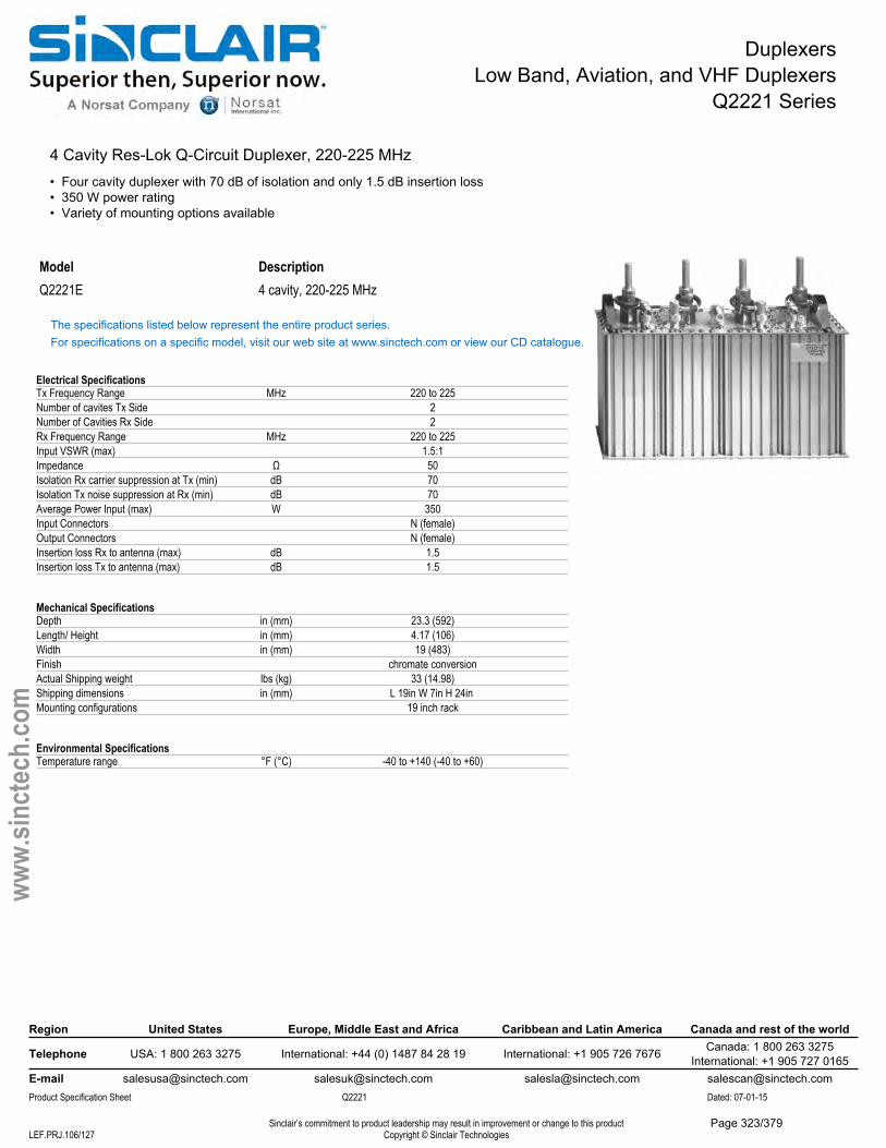
DuplexersLow Band, Aviation, and VHF Duplexers
Q2221 Series
4 Cavity Res-Lok Q-Circuit Duplexer, 220-225 MHz• Four cavity duplexer with 70 dB of isolation and only 1.5 dB insertion loss• 350 W power rating• Variety of mounting options available
Model DescriptionQ2221E 4 cavity, 220-225 MHz
The specifications listed below represent the entire product series.For specifications on a specific model, visit our web site at www.sinctech.com or view our CD catalogue.
Electrical SpecificationsTx Frequency Range MHz 220 to 225Number of cavites Tx Side 2Number of Cavities Rx Side 2Rx Frequency Range MHz 220 to 225Input VSWR (max) 1.5:1Impedance Ω 50Isolation Rx carrier suppression at Tx (min) dB 70Isolation Tx noise suppression at Rx (min) dB 70Average Power Input (max) W 350Input Connectors N (female)Output Connectors N (female)Insertion loss Rx to antenna (max) dB 1.5Insertion loss Tx to antenna (max) dB 1.5
Mechanical SpecificationsDepth in (mm) 23.3 (592)Length/ Height in (mm) 4.17 (106)Width in (mm) 19 (483)Finish chromate conversionActual Shipping weight lbs (kg) 33 (14.98)Shipping dimensions in (mm) L 19in W 7in H 24in Mounting configurations 19 inch rack
Environmental SpecificationsTemperature range °F (°C) -40 to +140 (-40 to +60)
Region United States Europe, Middle East and Africa Caribbean and Latin America Canada and rest of the world
Telephone USA: 1 800 263 3275 International: +44 (0) 1487 84 28 19 International: +1 905 726 7676 Canada: 1 800 263 3275International: +1 905 727 0165
E-mail [email protected] [email protected] [email protected] [email protected] Specification Sheet Q2221 Dated: 07-01-15
Sinclair’s commitment to product leadership may result in improvement or change to this productCopyright © Sinclair TechnologiesLEF.PRJ.106/127
www.
sinct
ech.
com
Page 323/379
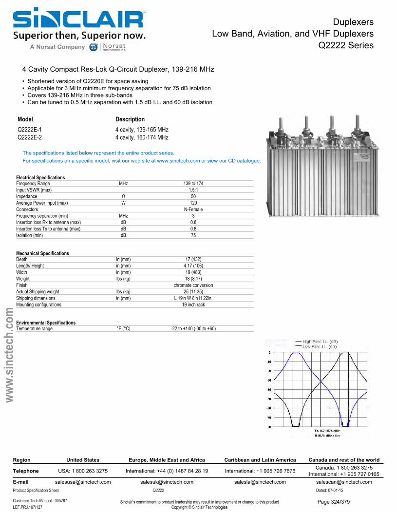
DuplexersLow Band, Aviation, and VHF Duplexers
Q2222 Series
4 Cavity Compact Res-Lok Q-Circuit Duplexer, 139-216 MHz• Shortened version of Q2220E for space saving• Applicable for 3 MHz minimum frequency separation for 75 dB isolation• Covers 139-216 MHz in three sub-bands• Can be tuned to 0.5 MHz separation with 1.5 dB I.L. and 60 dB isolation
Model DescriptionQ2222E-1 4 cavity, 139-165 MHzQ2222E-2 4 cavity, 160-174 MHz
The specifications listed below represent the entire product series.For specifications on a specific model, visit our web site at www.sinctech.com or view our CD catalogue.
Electrical SpecificationsFrequency Range MHz 139 to 174Input VSWR (max) 1.5:1Impedance Ω 50Average Power Input (max) W 120Connectors N-FemaleFrequency separation (min) MHz 3Insertion loss Rx to antenna (max) dB 0.8Insertion loss Tx to antenna (max) dB 0.8Isolation (min) dB 75
Mechanical SpecificationsDepth in (mm) 17 (432)Length/ Height in (mm) 4.17 (106)Width in (mm) 19 (483)Weight lbs (kg) 18 (8.17)Finish chromate conversionActual Shipping weight lbs (kg) 25 (11.35)Shipping dimensions in (mm) L 19in W 8in H 22in Mounting configurations 19 inch rack
Environmental SpecificationsTemperature range °F (°C) -22 to +140 (-30 to +60)
Region United States Europe, Middle East and Africa Caribbean and Latin America Canada and rest of the world
Telephone USA: 1 800 263 3275 International: +44 (0) 1487 84 28 19 International: +1 905 726 7676 Canada: 1 800 263 3275International: +1 905 727 0165
E-mail [email protected] [email protected] [email protected] [email protected] Specification Sheet Q2222 Dated: 07-01-15
Customer Tech Manual 005787 Sinclair’s commitment to product leadership may result in improvement or change to this productCopyright © Sinclair TechnologiesLEF.PRJ.107/127
www.
sinct
ech.
com
Page 324/379
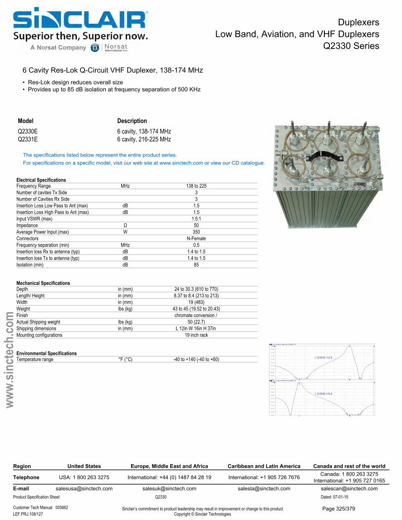
DuplexersLow Band, Aviation, and VHF Duplexers
Q2330 Series
6 Cavity Res-Lok Q-Circuit VHF Duplexer, 138-174 MHz• Res-Lok design reduces overall size• Provides up to 85 dB isolation at frequency separation of 500 KHz
Model DescriptionQ2330E 6 cavity, 138-174 MHzQ2331E 6 cavity, 216-225 MHz
The specifications listed below represent the entire product series.For specifications on a specific model, visit our web site at www.sinctech.com or view our CD catalogue.
Electrical SpecificationsFrequency Range MHz 138 to 225Number of cavites Tx Side 3Number of Cavities Rx Side 3Insertion Loss Low Pass to Ant (max) dB 1.5Insertion Loss High Pass to Ant (max) dB 1.5Input VSWR (max) 1.5:1Impedance Ω 50Average Power Input (max) W 350Connectors N-FemaleFrequency separation (min) MHz 0.5Insertion loss Rx to antenna (typ) dB 1.4 to 1.5Insertion loss Tx to antenna (typ) dB 1.4 to 1.5Isolation (min) dB 85
Mechanical SpecificationsDepth in (mm) 24 to 30.3 (610 to 770)Length/ Height in (mm) 8.37 to 8.4 (213 to 213)Width in (mm) 19 (483)Weight lbs (kg) 43 to 45 (19.52 to 20.43)Finish chromate conversion / Actual Shipping weight lbs (kg) 50 (22.7)Shipping dimensions in (mm) L 12in W 16in H 37in Mounting configurations 19 inch rack
Environmental SpecificationsTemperature range °F (°C) -40 to +140 (-40 to +60)
Region United States Europe, Middle East and Africa Caribbean and Latin America Canada and rest of the world
Telephone USA: 1 800 263 3275 International: +44 (0) 1487 84 28 19 International: +1 905 726 7676 Canada: 1 800 263 3275International: +1 905 727 0165
E-mail [email protected] [email protected] [email protected] [email protected] Specification Sheet Q2330 Dated: 07-01-15
Customer Tech Manual 005662 Sinclair’s commitment to product leadership may result in improvement or change to this productCopyright © Sinclair TechnologiesLEF.PRJ.108/127
www.
sinct
ech.
com
Page 325/379
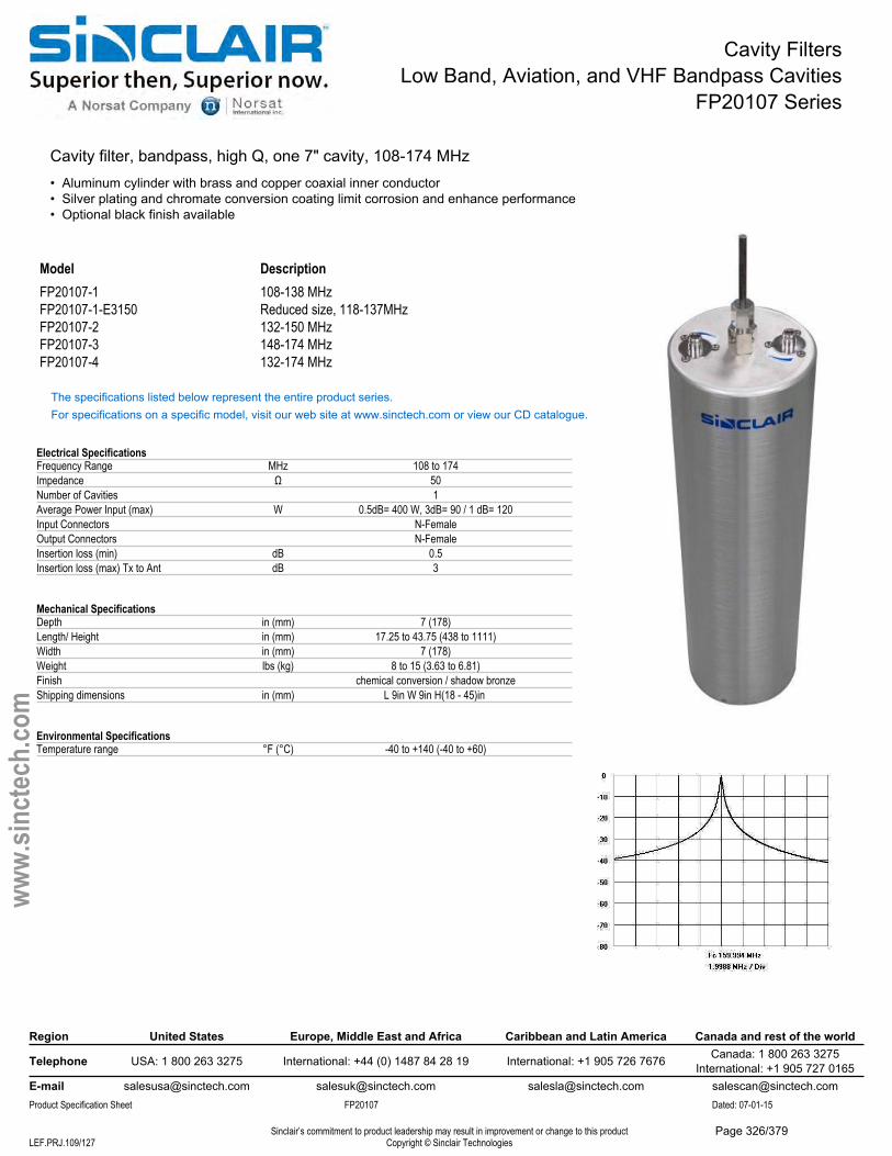
Cavity FiltersLow Band, Aviation, and VHF Bandpass Cavities
FP20107 Series
Cavity filter, bandpass, high Q, one 7" cavity, 108-174 MHz• Aluminum cylinder with brass and copper coaxial inner conductor• Silver plating and chromate conversion coating limit corrosion and enhance performance• Optional black finish available
Model DescriptionFP20107-1 108-138 MHzFP20107-1-E3150 Reduced size, 118-137MHzFP20107-2 132-150 MHzFP20107-3 148-174 MHzFP20107-4 132-174 MHz
The specifications listed below represent the entire product series.For specifications on a specific model, visit our web site at www.sinctech.com or view our CD catalogue.
Electrical SpecificationsFrequency Range MHz 108 to 174Impedance Ω 50Number of Cavities 1Average Power Input (max) W 0.5dB= 400 W, 3dB= 90 / 1 dB= 120Input Connectors N-FemaleOutput Connectors N-FemaleInsertion loss (min) dB 0.5Insertion loss (max) Tx to Ant dB 3
Mechanical SpecificationsDepth in (mm) 7 (178)Length/ Height in (mm) 17.25 to 43.75 (438 to 1111)Width in (mm) 7 (178)Weight lbs (kg) 8 to 15 (3.63 to 6.81)Finish chemical conversion / shadow bronzeShipping dimensions in (mm) L 9in W 9in H(18 - 45)in
Environmental SpecificationsTemperature range °F (°C) -40 to +140 (-40 to +60)
Region United States Europe, Middle East and Africa Caribbean and Latin America Canada and rest of the world
Telephone USA: 1 800 263 3275 International: +44 (0) 1487 84 28 19 International: +1 905 726 7676 Canada: 1 800 263 3275International: +1 905 727 0165
E-mail [email protected] [email protected] [email protected] [email protected] Specification Sheet FP20107 Dated: 07-01-15
Sinclair’s commitment to product leadership may result in improvement or change to this productCopyright © Sinclair TechnologiesLEF.PRJ.109/127
www.
sinct
ech.
com
Page 326/379
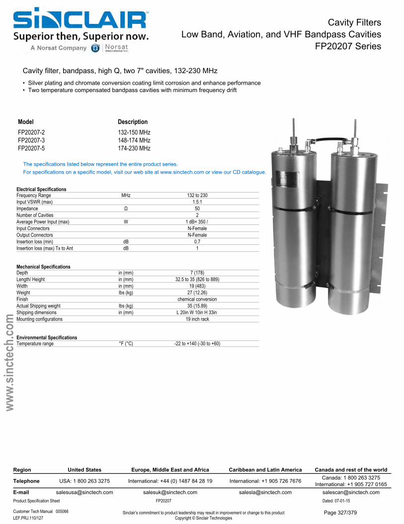
Cavity FiltersLow Band, Aviation, and VHF Bandpass Cavities
FP20207 Series
Cavity filter, bandpass, high Q, two 7" cavities, 132-230 MHz• Silver plating and chromate conversion coating limit corrosion and enhance performance• Two temperature compensated bandpass cavities with minimum frequency drift
Model DescriptionFP20207-2 132-150 MHzFP20207-3 148-174 MHzFP20207-5 174-230 MHz
The specifications listed below represent the entire product series.For specifications on a specific model, visit our web site at www.sinctech.com or view our CD catalogue.
Electrical SpecificationsFrequency Range MHz 132 to 230Input VSWR (max) 1.5:1Impedance Ω 50Number of Cavities 2Average Power Input (max) W 1 dB= 350 / Input Connectors N-FemaleOutput Connectors N-FemaleInsertion loss (min) dB 0.7Insertion loss (max) Tx to Ant dB 1
Mechanical SpecificationsDepth in (mm) 7 (178)Length/ Height in (mm) 32.5 to 35 (826 to 889)Width in (mm) 19 (483)Weight lbs (kg) 27 (12.26)Finish chemical conversionActual Shipping weight lbs (kg) 35 (15.89)Shipping dimensions in (mm) L 20in W 10in H 33in Mounting configurations 19 inch rack
Environmental SpecificationsTemperature range °F (°C) -22 to +140 (-30 to +60)
Region United States Europe, Middle East and Africa Caribbean and Latin America Canada and rest of the world
Telephone USA: 1 800 263 3275 International: +44 (0) 1487 84 28 19 International: +1 905 726 7676 Canada: 1 800 263 3275International: +1 905 727 0165
E-mail [email protected] [email protected] [email protected] [email protected] Specification Sheet FP20207 Dated: 07-01-15
Customer Tech Manual 005066 Sinclair’s commitment to product leadership may result in improvement or change to this productCopyright © Sinclair TechnologiesLEF.PRJ.110/127
www.
sinct
ech.
com
Page 327/379
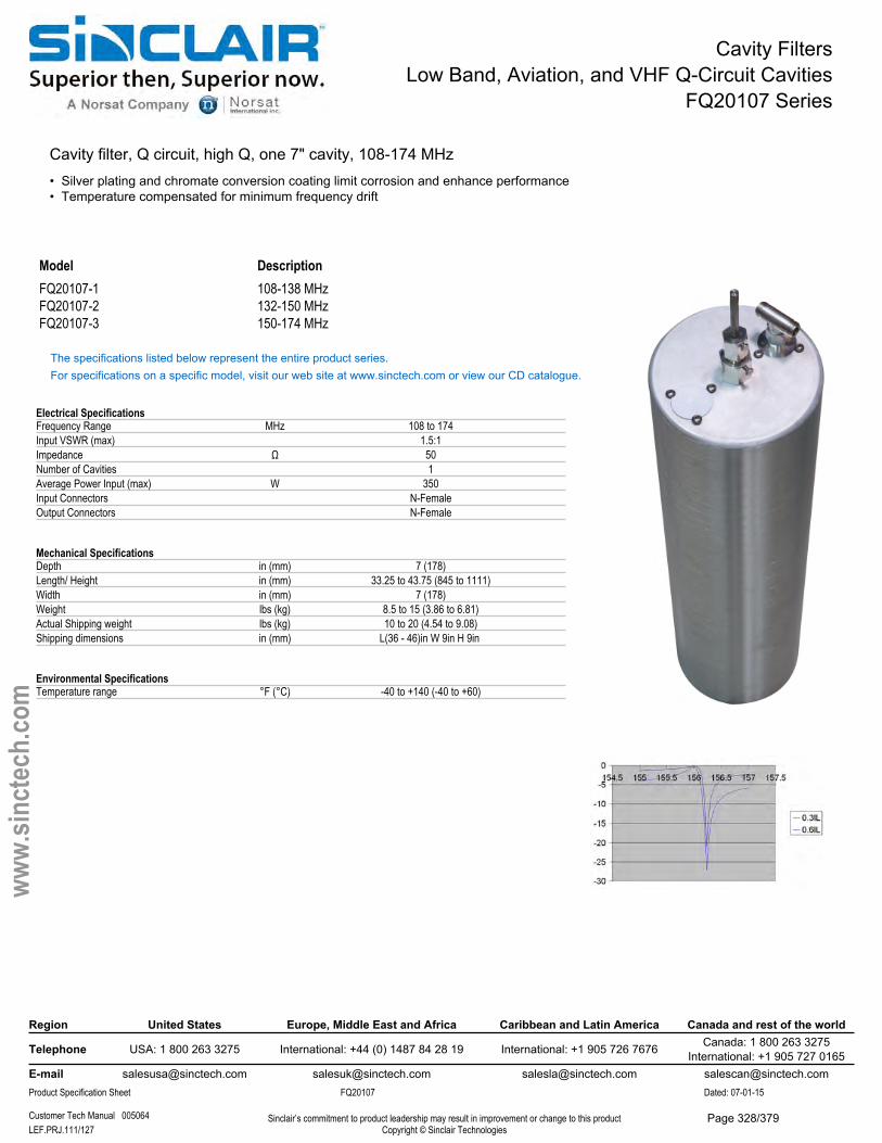
Cavity FiltersLow Band, Aviation, and VHF Q-Circuit Cavities
FQ20107 Series
Cavity filter, Q circuit, high Q, one 7" cavity, 108-174 MHz• Silver plating and chromate conversion coating limit corrosion and enhance performance• Temperature compensated for minimum frequency drift
Model DescriptionFQ20107-1 108-138 MHzFQ20107-2 132-150 MHzFQ20107-3 150-174 MHz
The specifications listed below represent the entire product series.For specifications on a specific model, visit our web site at www.sinctech.com or view our CD catalogue.
Electrical SpecificationsFrequency Range MHz 108 to 174Input VSWR (max) 1.5:1Impedance Ω 50Number of Cavities 1Average Power Input (max) W 350Input Connectors N-FemaleOutput Connectors N-Female
Mechanical SpecificationsDepth in (mm) 7 (178)Length/ Height in (mm) 33.25 to 43.75 (845 to 1111)Width in (mm) 7 (178)Weight lbs (kg) 8.5 to 15 (3.86 to 6.81)Actual Shipping weight lbs (kg) 10 to 20 (4.54 to 9.08)Shipping dimensions in (mm) L(36 - 46)in W 9in H 9in
Environmental SpecificationsTemperature range °F (°C) -40 to +140 (-40 to +60)
Region United States Europe, Middle East and Africa Caribbean and Latin America Canada and rest of the world
Telephone USA: 1 800 263 3275 International: +44 (0) 1487 84 28 19 International: +1 905 726 7676 Canada: 1 800 263 3275International: +1 905 727 0165
E-mail [email protected] [email protected] [email protected] [email protected] Specification Sheet FQ20107 Dated: 07-01-15
Customer Tech Manual 005064 Sinclair’s commitment to product leadership may result in improvement or change to this productCopyright © Sinclair TechnologiesLEF.PRJ.111/127
www.
sinct
ech.
com
Page 328/379
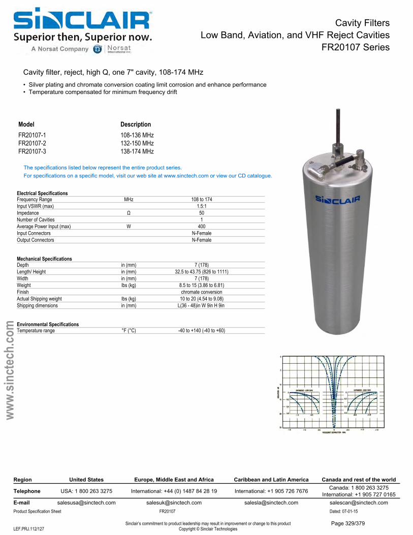
Cavity FiltersLow Band, Aviation, and VHF Reject Cavities
FR20107 Series
Cavity filter, reject, high Q, one 7" cavity, 108-174 MHz• Silver plating and chromate conversion coating limit corrosion and enhance performance• Temperature compensated for minimum frequency drift
Model DescriptionFR20107-1 108-136 MHzFR20107-2 132-150 MHzFR20107-3 138-174 MHz
The specifications listed below represent the entire product series.For specifications on a specific model, visit our web site at www.sinctech.com or view our CD catalogue.
Electrical SpecificationsFrequency Range MHz 108 to 174Input VSWR (max) 1.5:1Impedance Ω 50Number of Cavities 1Average Power Input (max) W 400Input Connectors N-FemaleOutput Connectors N-Female
Mechanical SpecificationsDepth in (mm) 7 (178)Length/ Height in (mm) 32.5 to 43.75 (826 to 1111)Width in (mm) 7 (178)Weight lbs (kg) 8.5 to 15 (3.86 to 6.81)Finish chromate conversionActual Shipping weight lbs (kg) 10 to 20 (4.54 to 9.08)Shipping dimensions in (mm) L(36 - 48)in W 9in H 9in
Environmental SpecificationsTemperature range °F (°C) -40 to +140 (-40 to +60)
Region United States Europe, Middle East and Africa Caribbean and Latin America Canada and rest of the world
Telephone USA: 1 800 263 3275 International: +44 (0) 1487 84 28 19 International: +1 905 726 7676 Canada: 1 800 263 3275International: +1 905 727 0165
E-mail [email protected] [email protected] [email protected] [email protected] Specification Sheet FR20107 Dated: 07-01-15
Sinclair’s commitment to product leadership may result in improvement or change to this productCopyright © Sinclair TechnologiesLEF.PRJ.112/127
www.
sinct
ech.
com
Page 329/379
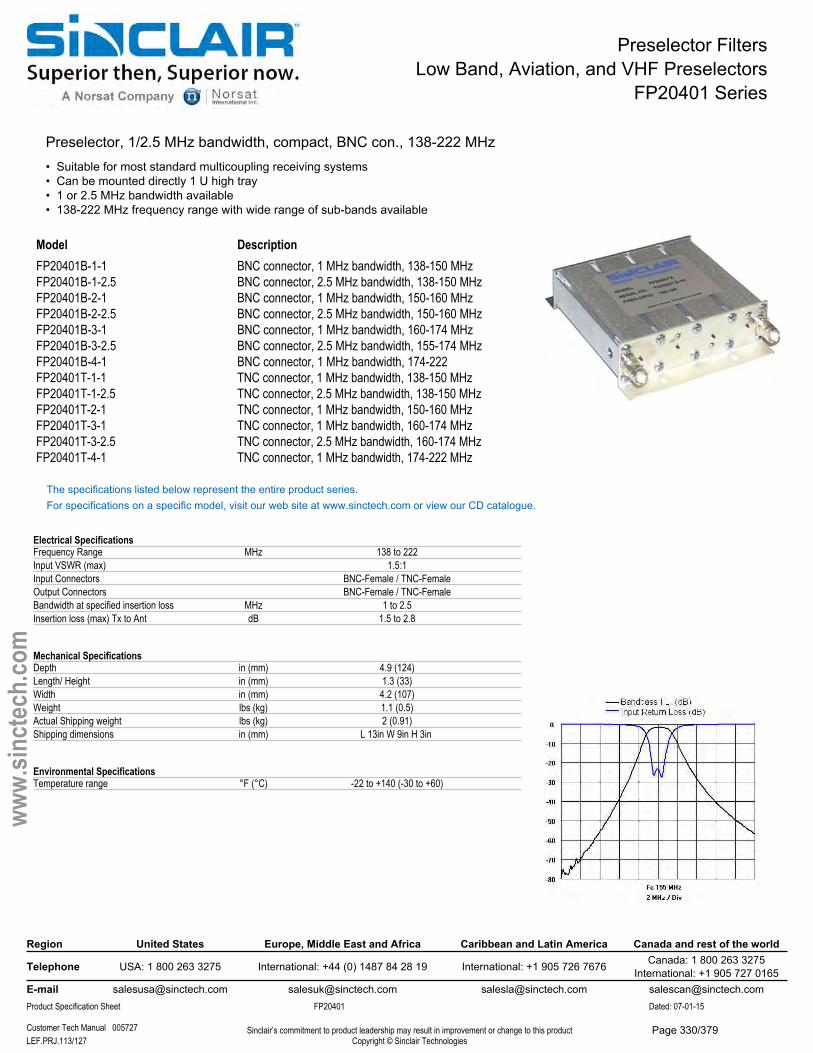
Preselector FiltersLow Band, Aviation, and VHF Preselectors
FP20401 Series
Preselector, 1/2.5 MHz bandwidth, compact, BNC con., 138-222 MHz• Suitable for most standard multicoupling receiving systems• Can be mounted directly 1 U high tray• 1 or 2.5 MHz bandwidth available• 138-222 MHz frequency range with wide range of sub-bands available
ModelFP20401B-1-1FP20401B-1-2.5FP20401B-2-1FP20401B-2-2.5FP20401B-3-1FP20401B-3-2.5FP20401B-4-1FP20401T-1-1FP20401T-1-2.5FP20401T-2-1FP20401T-3-1FP20401T-3-2.5FP20401T-4-1
DescriptionBNC connector, 1 MHz bandwidth, 138-150 MHz BNC connector, 2.5 MHz bandwidth, 138-150 MHz BNC connector, 1 MHz bandwidth, 150-160 MHz BNC connector, 2.5 MHz bandwidth, 150-160 MHz BNC connector, 1 MHz bandwidth, 160-174 MHz BNC connector, 2.5 MHz bandwidth, 155-174 MHz BNC connector, 1 MHz bandwidth, 174-222 TNC connector, 1 MHz bandwidth, 138-150 MHz TNC connector, 2.5 MHz bandwidth, 138-150 MHz TNC connector, 1 MHz bandwidth, 150-160 MHz TNC connector, 1 MHz bandwidth, 160-174 MHz TNC connector, 2.5 MHz bandwidth, 160-174 MHz TNC connector, 1 MHz bandwidth, 174-222 MHz
The specifications listed below represent the entire product series.For specifications on a specific model, visit our web site at www.sinctech.com or view our CD catalogue.
Electrical SpecificationsFrequency Range MHz 138 to 222Input VSWR (max) 1.5:1Input Connectors BNC-Female / TNC-FemaleOutput Connectors BNC-Female / TNC-FemaleBandwidth at specified insertion loss MHz 1 to 2.5Insertion loss (max) Tx to Ant dB 1.5 to 2.8
Mechanical SpecificationsDepth in (mm) 4.9 (124)Length/ Height in (mm) 1.3 (33)Width in (mm) 4.2 (107)Weight lbs (kg) 1.1 (0.5)Actual Shipping weight lbs (kg) 2 (0.91)Shipping dimensions in (mm) L 13in W 9in H 3in
Environmental SpecificationsTemperature range °F (°C) -22 to +140 (-30 to +60)
Region United States Europe, Middle East and Africa Caribbean and Latin America Canada and rest of the world
Telephone USA: 1 800 263 3275 International: +44 (0) 1487 84 28 19 International: +1 905 726 7676 Canada: 1 800 263 3275International: +1 905 727 0165
E-mail [email protected] [email protected] [email protected] [email protected] Specification Sheet FP20401 Dated: 07-01-15
Customer Tech Manual 005727 Sinclair’s commitment to product leadership may result in improvement or change to this productCopyright © Sinclair TechnologiesLEF.PRJ.113/127
www.
sinct
ech.
com
Page 330/379
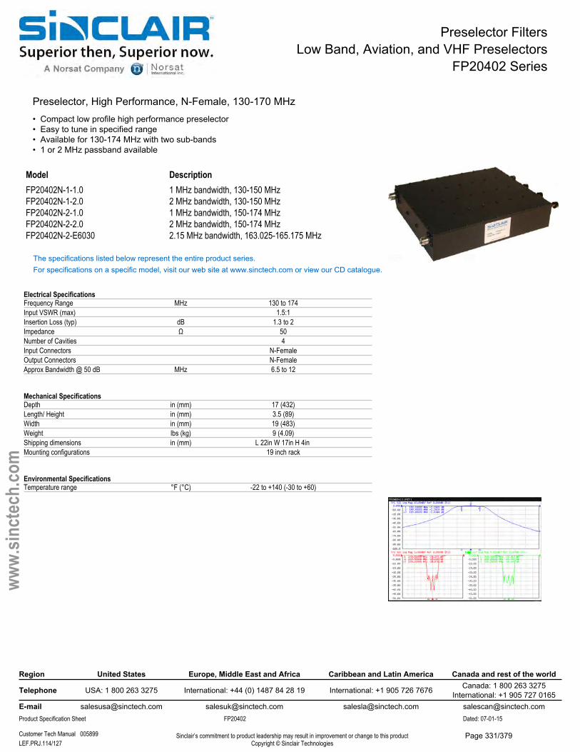
Preselector FiltersLow Band, Aviation, and VHF Preselectors
FP20402 Series
Preselector, High Performance, N-Female, 130-170 MHz• Compact low profile high performance preselector• Easy to tune in specified range• Available for 130-174 MHz with two sub-bands• 1 or 2 MHz passband available
Model DescriptionFP20402N-1-1.0 1 MHz bandwidth, 130-150 MHzFP20402N-1-2.0 2 MHz bandwidth, 130-150 MHzFP20402N-2-1.0 1 MHz bandwidth, 150-174 MHzFP20402N-2-2.0 2 MHz bandwidth, 150-174 MHzFP20402N-2-E6030 2.15 MHz bandwidth, 163.025-165.175 MHz
The specifications listed below represent the entire product series.For specifications on a specific model, visit our web site at www.sinctech.com or view our CD catalogue.
Electrical SpecificationsFrequency Range MHz 130 to 174Input VSWR (max) 1.5:1Insertion Loss (typ) dB 1.3 to 2Impedance Ω 50Number of Cavities 4Input Connectors N-FemaleOutput Connectors N-FemaleApprox Bandwidth @ 50 dB MHz 6.5 to 12
Mechanical SpecificationsDepth in (mm) 17 (432)Length/ Height in (mm) 3.5 (89)Width in (mm) 19 (483)Weight lbs (kg) 9 (4.09)Shipping dimensions in (mm) L 22in W 17in H 4in Mounting configurations 19 inch rack
Environmental SpecificationsTemperature range °F (°C) -22 to +140 (-30 to +60)
Region United States Europe, Middle East and Africa Caribbean and Latin America Canada and rest of the world
Telephone USA: 1 800 263 3275 International: +44 (0) 1487 84 28 19 International: +1 905 726 7676 Canada: 1 800 263 3275International: +1 905 727 0165
E-mail [email protected] [email protected] [email protected] [email protected] Specification Sheet FP20402 Dated: 07-01-15
Customer Tech Manual 005899 Sinclair’s commitment to product leadership may result in improvement or change to this productCopyright © Sinclair TechnologiesLEF.PRJ.114/127
www.
sinct
ech.
com
Page 331/379
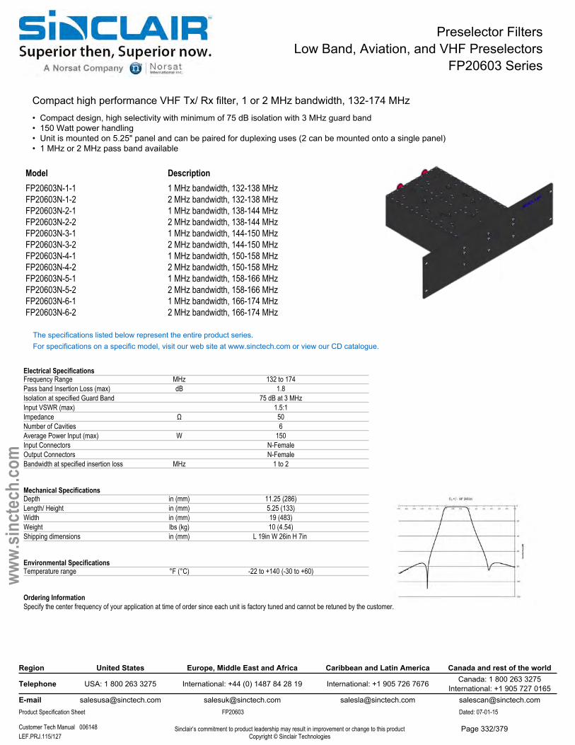
Preselector FiltersLow Band, Aviation, and VHF Preselectors
FP20603 Series
Compact high performance VHF Tx/ Rx filter, 1 or 2 MHz bandwidth, 132-174 MHz• Compact design, high selectivity with minimum of 75 dB isolation with 3 MHz guard band• 150 Watt power handling• Unit is mounted on 5.25" panel and can be paired for duplexing uses (2 can be mounted onto a single panel)• 1 MHz or 2 MHz pass band available
Model DescriptionFP20603N-1-1 1 MHz bandwidth, 132-138 MHzFP20603N-1-2 2 MHz bandwidth, 132-138 MHzFP20603N-2-1 1 MHz bandwidth, 138-144 MHzFP20603N-2-2 2 MHz bandwidth, 138-144 MHzFP20603N-3-1 1 MHz bandwidth, 144-150 MHzFP20603N-3-2 2 MHz bandwidth, 144-150 MHzFP20603N-4-1 1 MHz bandwidth, 150-158 MHzFP20603N-4-2 2 MHz bandwidth, 150-158 MHzFP20603N-5-1 1 MHz bandwidth, 158-166 MHzFP20603N-5-2 2 MHz bandwidth, 158-166 MHzFP20603N-6-1 1 MHz bandwidth, 166-174 MHzFP20603N-6-2 2 MHz bandwidth, 166-174 MHz
The specifications listed below represent the entire product series.For specifications on a specific model, visit our web site at www.sinctech.com or view our CD catalogue.
Electrical SpecificationsFrequency Range MHz 132 to 174Pass band Insertion Loss (max) dB 1.8Isolation at specified Guard Band 75 dB at 3 MHzInput VSWR (max) 1.5:1Impedance Ω 50Number of Cavities 6Average Power Input (max) W 150Input Connectors N-FemaleOutput Connectors N-FemaleBandwidth at specified insertion loss MHz 1 to 2
Mechanical SpecificationsDepth in (mm) 11.25 (286)Length/ Height in (mm) 5.25 (133)Width in (mm) 19 (483)Weight lbs (kg) 10 (4.54)Shipping dimensions in (mm) L 19in W 26in H 7in
Environmental SpecificationsTemperature range °F (°C) -22 to +140 (-30 to +60)
Ordering InformationSpecify the center frequency of your application at time of order since each unit is factory tuned and cannot be retuned by the customer.
Region United States Europe, Middle East and Africa Caribbean and Latin America Canada and rest of the world
Telephone USA: 1 800 263 3275 International: +44 (0) 1487 84 28 19 International: +1 905 726 7676 Canada: 1 800 263 3275International: +1 905 727 0165
E-mail [email protected] [email protected] [email protected] [email protected] Specification Sheet FP20603 Dated: 07-01-15
Customer Tech Manual 006148 Sinclair’s commitment to product leadership may result in improvement or change to this productCopyright © Sinclair TechnologiesLEF.PRJ.115/127
www.
sinct
ech.
com
Page 332/379
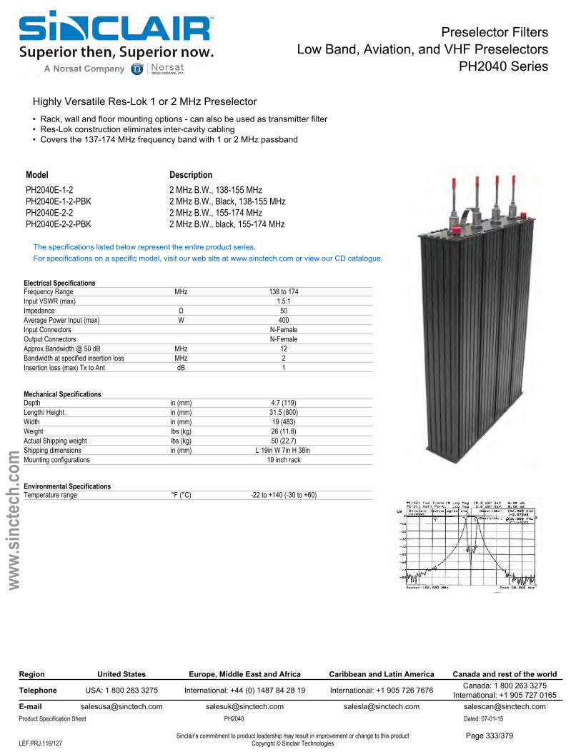
Preselector FiltersLow Band, Aviation, and VHF Preselectors
PH2040 Series
Highly Versatile Res-Lok 1 or 2 MHz Preselector• Rack, wall and floor mounting options - can also be used as transmitter filter• Res-Lok construction eliminates inter-cavity cabling• Covers the 137-174 MHz frequency band with 1 or 2 MHz passband
Model DescriptionPH2040E-1-2 2 MHz B.W., 138-155 MHzPH2040E-1-2-PBK 2 MHz B.W., Black, 138-155 MHzPH2040E-2-2 2 MHz B.W., 155-174 MHzPH2040E-2-2-PBK 2 MHz B.W., black, 155-174 MHz
The specifications listed below represent the entire product series.For specifications on a specific model, visit our web site at www.sinctech.com or view our CD catalogue.
Electrical SpecificationsFrequency Range MHz 138 to 174Input VSWR (max) 1.5:1Impedance Ω 50Average Power Input (max) W 400Input Connectors N-FemaleOutput Connectors N-FemaleApprox Bandwidth @ 50 dB MHz 12Bandwidth at specified insertion loss MHz 2Insertion loss (max) Tx to Ant dB 1
Mechanical SpecificationsDepth in (mm) 4.7 (119)Length/ Height in (mm) 31.5 (800)Width in (mm) 19 (483)Weight lbs (kg) 26 (11.8)Actual Shipping weight lbs (kg) 50 (22.7)Shipping dimensions in (mm) L 19in W 7in H 38in Mounting configurations 19 inch rack
Environmental SpecificationsTemperature range °F (°C) -22 to +140 (-30 to +60)
Region United States Europe, Middle East and Africa Caribbean and Latin America Canada and rest of the world
Telephone USA: 1 800 263 3275 International: +44 (0) 1487 84 28 19 International: +1 905 726 7676 Canada: 1 800 263 3275International: +1 905 727 0165
E-mail [email protected] [email protected] [email protected] [email protected] Specification Sheet PH2040 Dated: 07-01-15
Sinclair’s commitment to product leadership may result in improvement or change to this productCopyright © Sinclair TechnologiesLEF.PRJ.116/127
www.
sinct
ech.
com
Page 333/379
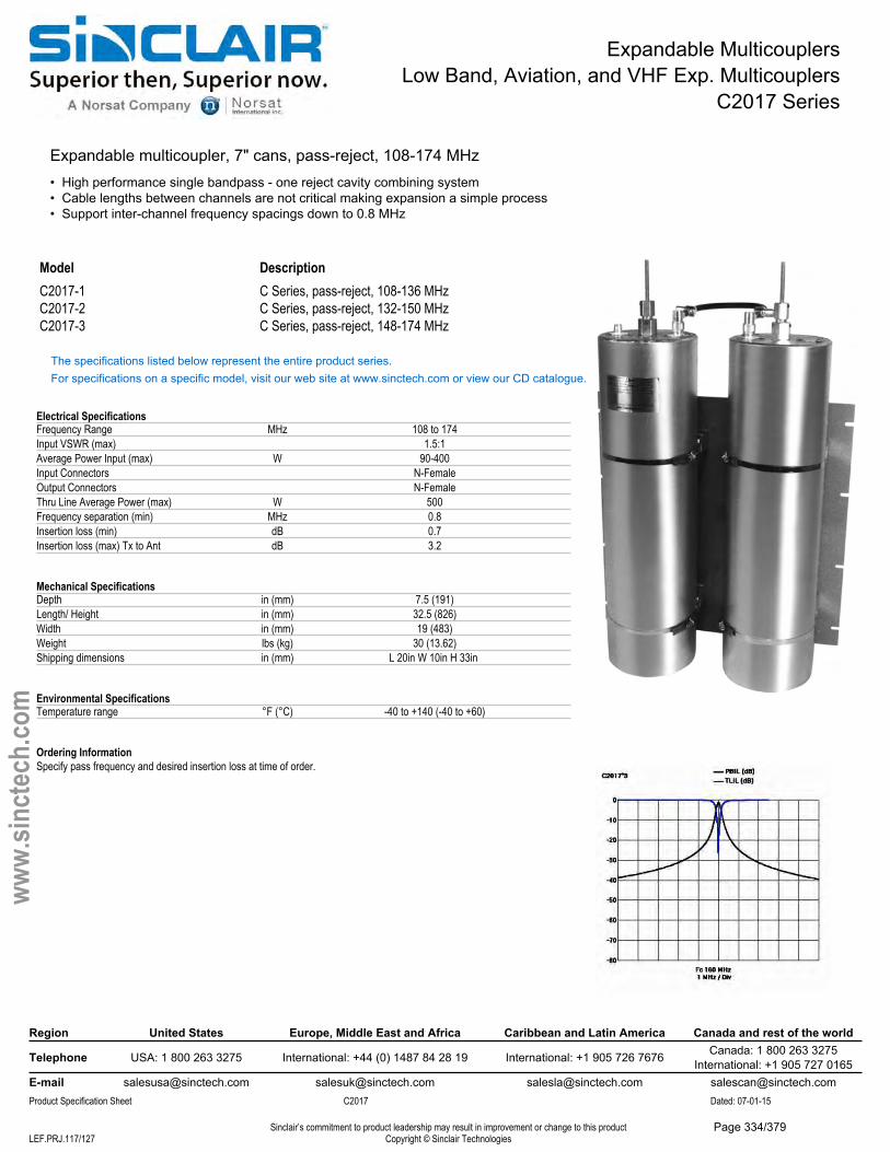
Expandable MulticouplersLow Band, Aviation, and VHF Exp. Multicouplers
C2017 Series
Expandable multicoupler, 7" cans, pass-reject, 108-174 MHz• High performance single bandpass - one reject cavity combining system• Cable lengths between channels are not critical making expansion a simple process• Support inter-channel frequency spacings down to 0.8 MHz
Model DescriptionC2017-1 C Series, pass-reject, 108-136 MHzC2017-2 C Series, pass-reject, 132-150 MHzC2017-3 C Series, pass-reject, 148-174 MHz
The specifications listed below represent the entire product series.For specifications on a specific model, visit our web site at www.sinctech.com or view our CD catalogue.
Electrical SpecificationsFrequency Range MHz 108 to 174Input VSWR (max) 1.5:1Average Power Input (max) W 90-400Input Connectors N-FemaleOutput Connectors N-FemaleThru Line Average Power (max) W 500Frequency separation (min) MHz 0.8Insertion loss (min) dB 0.7Insertion loss (max) Tx to Ant dB 3.2
Mechanical SpecificationsDepth in (mm) 7.5 (191)Length/ Height in (mm) 32.5 (826)Width in (mm) 19 (483)Weight lbs (kg) 30 (13.62)Shipping dimensions in (mm) L 20in W 10in H 33in
Environmental SpecificationsTemperature range °F (°C) -40 to +140 (-40 to +60)
Ordering InformationSpecify pass frequency and desired insertion loss at time of order.
Region United States Europe, Middle East and Africa Caribbean and Latin America Canada and rest of the world
Telephone USA: 1 800 263 3275 International: +44 (0) 1487 84 28 19 International: +1 905 726 7676 Canada: 1 800 263 3275International: +1 905 727 0165
E-mail [email protected] [email protected] [email protected] [email protected] Specification Sheet C2017 Dated: 07-01-15
Sinclair’s commitment to product leadership may result in improvement or change to this productCopyright © Sinclair TechnologiesLEF.PRJ.117/127
www.
sinct
ech.
com
Page 334/379
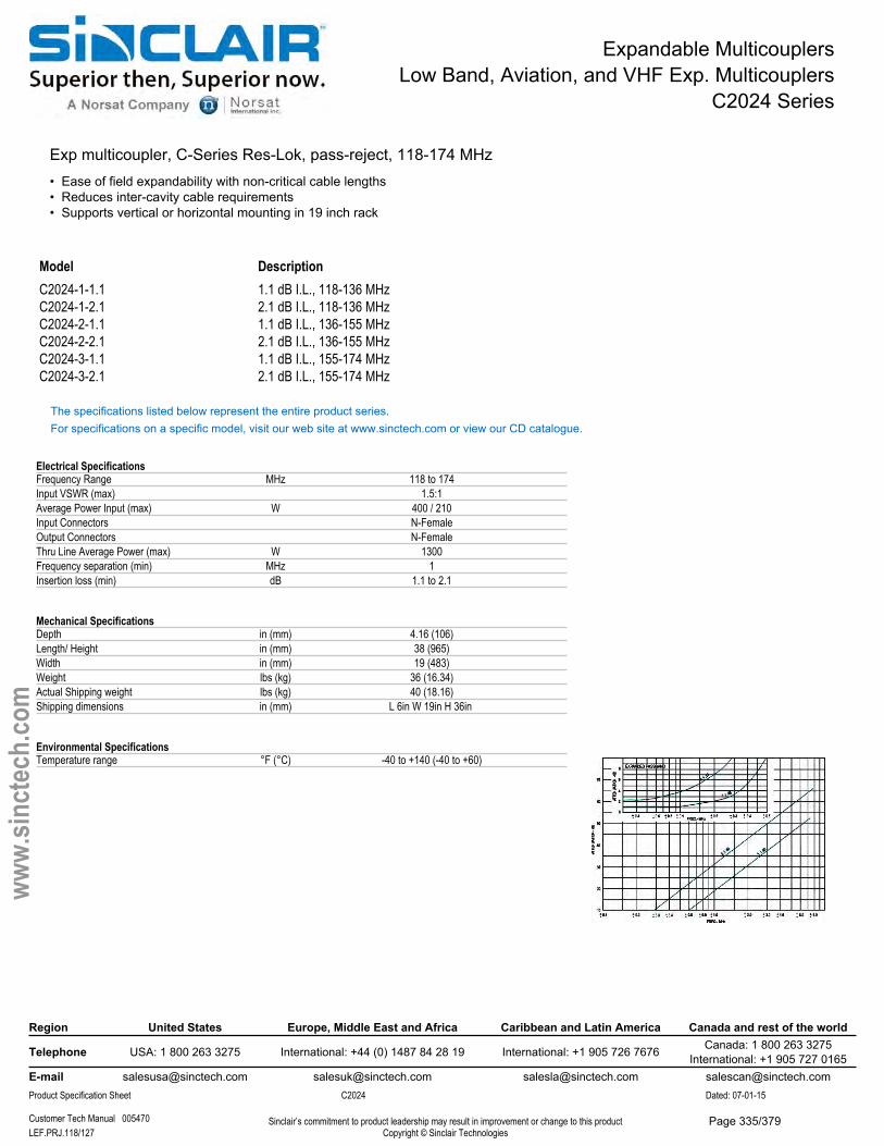
Expandable MulticouplersLow Band, Aviation, and VHF Exp. Multicouplers
C2024 Series
Exp multicoupler, C-Series Res-Lok, pass-reject, 118-174 MHz• Ease of field expandability with non-critical cable lengths• Reduces inter-cavity cable requirements• Supports vertical or horizontal mounting in 19 inch rack
Model DescriptionC2024-1-1.1 1.1 dB I.L., 118-136 MHzC2024-1-2.1 2.1 dB I.L., 118-136 MHzC2024-2-1.1 1.1 dB I.L., 136-155 MHzC2024-2-2.1 2.1 dB I.L., 136-155 MHzC2024-3-1.1 1.1 dB I.L., 155-174 MHzC2024-3-2.1 2.1 dB I.L., 155-174 MHz
The specifications listed below represent the entire product series.For specifications on a specific model, visit our web site at www.sinctech.com or view our CD catalogue.
Electrical SpecificationsFrequency Range MHz 118 to 174Input VSWR (max) 1.5:1Average Power Input (max) W 400 / 210Input Connectors N-FemaleOutput Connectors N-FemaleThru Line Average Power (max) W 1300Frequency separation (min) MHz 1Insertion loss (min) dB 1.1 to 2.1
Mechanical SpecificationsDepth in (mm) 4.16 (106)Length/ Height in (mm) 38 (965)Width in (mm) 19 (483)Weight lbs (kg) 36 (16.34)Actual Shipping weight lbs (kg) 40 (18.16)Shipping dimensions in (mm) L 6in W 19in H 36in
Environmental SpecificationsTemperature range °F (°C) -40 to +140 (-40 to +60)
Region United States Europe, Middle East and Africa Caribbean and Latin America Canada and rest of the world
Telephone USA: 1 800 263 3275 International: +44 (0) 1487 84 28 19 International: +1 905 726 7676 Canada: 1 800 263 3275International: +1 905 727 0165
E-mail [email protected] [email protected] [email protected] [email protected] Specification Sheet C2024 Dated: 07-01-15
Customer Tech Manual 005470 Sinclair’s commitment to product leadership may result in improvement or change to this productCopyright © Sinclair TechnologiesLEF.PRJ.118/127
www.
sinct
ech.
com
Page 335/379
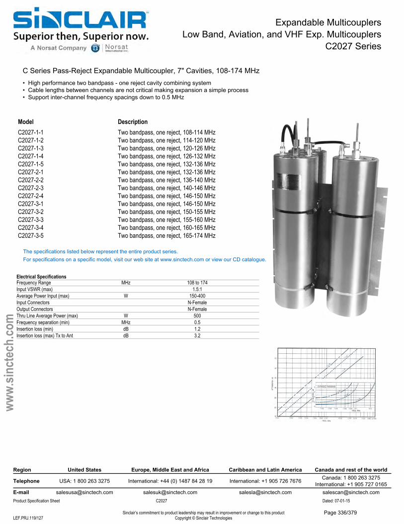
Expandable MulticouplersLow Band, Aviation, and VHF Exp. Multicouplers
C2027 Series
C Series Pass-Reject Expandable Multicoupler, 7" Cavities, 108-174 MHz• High performance two bandpass - one reject cavity combining system• Cable lengths between channels are not critical making expansion a simple process• Support inter-channel frequency spacings down to 0.5 MHz
Model DescriptionC2027-1-1 Two bandpass, one reject, 108-114 MHzC2027-1-2 Two bandpass, one reject, 114-120 MHzC2027-1-3 Two bandpass, one reject, 120-126 MHzC2027-1-4 Two bandpass, one reject, 126-132 MHzC2027-1-5 Two bandpass, one reject, 132-136 MHzC2027-2-1 Two bandpass, one reject, 132-136 MHzC2027-2-2 Two bandpass, one reject, 136-140 MHzC2027-2-3 Two bandpass, one reject, 140-146 MHzC2027-2-4 Two bandpass, one reject, 146-150 MHzC2027-3-1 Two bandpass, one reject, 146-150 MHzC2027-3-2 Two bandpass, one reject, 150-155 MHzC2027-3-3 Two bandpass, one reject, 155-160 MHzC2027-3-4 Two bandpass, one reject, 160-165 MHzC2027-3-5 Two bandpass, one reject, 165-174 MHz
The specifications listed below represent the entire product series.For specifications on a specific model, visit our web site at www.sinctech.com or view our CD catalogue.
Electrical SpecificationsFrequency Range MHz 108 to 174Input VSWR (max) 1.5:1Average Power Input (max) W 150-400Input Connectors N-FemaleOutput Connectors N-FemaleThru Line Average Power (max) W 500Frequency separation (min) MHz 0.5Insertion loss (min) dB 1.2Insertion loss (max) Tx to Ant dB 3.2
Region United States Europe, Middle East and Africa Caribbean and Latin America Canada and rest of the world
Telephone USA: 1 800 263 3275 International: +44 (0) 1487 84 28 19 International: +1 905 726 7676 Canada: 1 800 263 3275International: +1 905 727 0165
E-mail [email protected] [email protected] [email protected] [email protected] Specification Sheet C2027 Dated: 07-01-15
Sinclair’s commitment to product leadership may result in improvement or change to this productCopyright © Sinclair TechnologiesLEF.PRJ.119/127
www.
sinct
ech.
com
Page 336/379
Expandable MulticouplersLow Band, Aviation, and VHF Exp. Multicouplers
C2027 Series
Mechanical SpecificationsDepth in (mm) 14.9 (378)Length/ Height in (mm) 33.25 to 43.75 (845 to 1111)Width in (mm) 19 (483)Net Weight lbs (kg) 41 (18.61)Actual Shipping weight lbs (kg) 50 (22.7)Shipping dimensions in (mm) L 20in W 18in H 38in
Environmental SpecificationsTemperature range °F (°C) -40 to +140 (-40 to +60)
Ordering InformationSpecify pass frequency and desired insertion loss at time of order.
Region United States Europe, Middle East and Africa Caribbean and Latin America Canada and rest of the world
Telephone USA: 1 800 263 3275 International: +44 (0) 1487 84 28 19 International: +1 905 726 7676 Canada: 1 800 263 3275International: +1 905 727 0165
E-mail [email protected] [email protected] [email protected] [email protected] Specification Sheet C2027 Dated: 07-01-15
Sinclair’s commitment to product leadership may result in improvement or change to this productCopyright © Sinclair TechnologiesLEF.PRJ.120/127
www.
sinct
ech.
com
Page 337/379
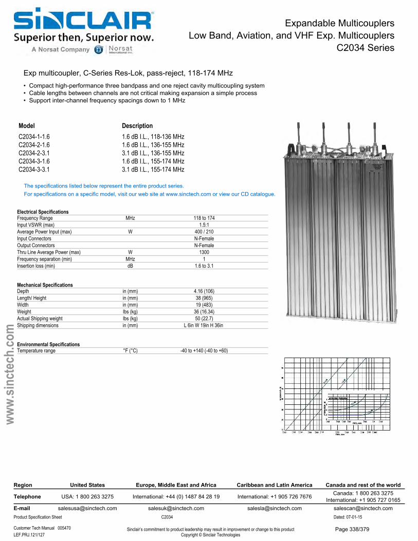
Expandable MulticouplersLow Band, Aviation, and VHF Exp. Multicouplers
C2034 Series
Exp multicoupler, C-Series Res-Lok, pass-reject, 118-174 MHz• Compact high-performance three bandpass and one reject cavity multicoupling system• Cable lengths between channels are not critical making expansion a simple process• Support inter-channel frequency spacings down to 1 MHz
Model DescriptionC2034-1-1.6 1.6 dB I.L., 118-136 MHzC2034-2-1.6 1.6 dB I.L., 136-155 MHzC2034-2-3.1 3.1 dB I.L., 136-155 MHzC2034-3-1.6 1.6 dB I.L., 155-174 MHzC2034-3-3.1 3.1 dB I.L., 155-174 MHz
The specifications listed below represent the entire product series.For specifications on a specific model, visit our web site at www.sinctech.com or view our CD catalogue.
Electrical SpecificationsFrequency Range MHz 118 to 174Input VSWR (max) 1.5:1Average Power Input (max) W 400 / 210Input Connectors N-FemaleOutput Connectors N-FemaleThru Line Average Power (max) W 1300Frequency separation (min) MHz 1Insertion loss (min) dB 1.6 to 3.1
Mechanical SpecificationsDepth in (mm) 4.16 (106)Length/ Height in (mm) 38 (965)Width in (mm) 19 (483)Weight lbs (kg) 36 (16.34)Actual Shipping weight lbs (kg) 50 (22.7)Shipping dimensions in (mm) L 6in W 19in H 36in
Environmental SpecificationsTemperature range °F (°C) -40 to +140 (-40 to +60)
Region United States Europe, Middle East and Africa Caribbean and Latin America Canada and rest of the world
Telephone USA: 1 800 263 3275 International: +44 (0) 1487 84 28 19 International: +1 905 726 7676 Canada: 1 800 263 3275International: +1 905 727 0165
E-mail [email protected] [email protected] [email protected] [email protected] Specification Sheet C2034 Dated: 07-01-15
Customer Tech Manual 005470 Sinclair’s commitment to product leadership may result in improvement or change to this productCopyright © Sinclair TechnologiesLEF.PRJ.121/127
www.
sinct
ech.
com
Page 338/379
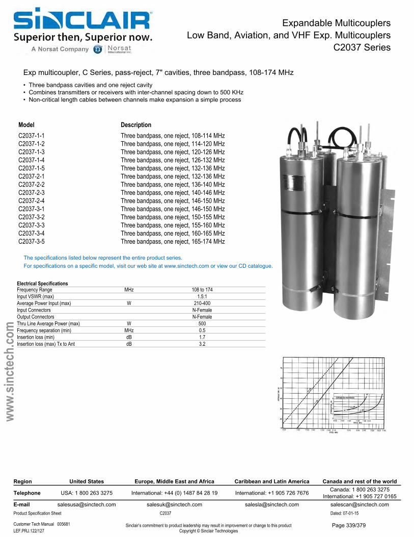
Expandable MulticouplersLow Band, Aviation, and VHF Exp. Multicouplers
C2037 Series
Exp multicoupler, C Series, pass-reject, 7" cavities, three bandpass, 108-174 MHz• Three bandpass cavities and one reject cavity• Combines transmitters or receivers with inter-channel spacing down to 500 KHz• Non-critical length cables between channels make expansion a simple process
Model DescriptionC2037-1-1 Three bandpass, one reject, 108-114 MHzC2037-1-2 Three bandpass, one reject, 114-120 MHzC2037-1-3 Three bandpass, one reject, 120-126 MHzC2037-1-4 Three bandpass, one reject, 126-132 MHzC2037-1-5 Three bandpass, one reject, 132-136 MHzC2037-2-1 Three bandpass, one reject, 132-136 MHzC2037-2-2 Three bandpass, one reject, 136-140 MHzC2037-2-3 Three bandpass, one reject, 140-146 MHzC2037-2-4 Three bandpass, one reject, 146-150 MHzC2037-3-1 Three bandpass, one reject, 146-150 MHzC2037-3-2 Three bandpass, one reject, 150-155 MHzC2037-3-3 Three bandpass, one reject, 155-160 MHzC2037-3-4 Three bandpass, one reject, 160-165 MHzC2037-3-5 Three bandpass, one reject, 165-174 MHz
The specifications listed below represent the entire product series.For specifications on a specific model, visit our web site at www.sinctech.com or view our CD catalogue.
Electrical SpecificationsFrequency Range MHz 108 to 174Input VSWR (max) 1.5:1Average Power Input (max) W 210-400Input Connectors N-FemaleOutput Connectors N-FemaleThru Line Average Power (max) W 500Frequency separation (min) MHz 0.5Insertion loss (min) dB 1.7Insertion loss (max) Tx to Ant dB 3.2
Region United States Europe, Middle East and Africa Caribbean and Latin America Canada and rest of the world
Telephone USA: 1 800 263 3275 International: +44 (0) 1487 84 28 19 International: +1 905 726 7676 Canada: 1 800 263 3275International: +1 905 727 0165
E-mail [email protected] [email protected] [email protected] [email protected] Specification Sheet C2037 Dated: 07-01-15
Customer Tech Manual 005681 Sinclair’s commitment to product leadership may result in improvement or change to this productCopyright © Sinclair TechnologiesLEF.PRJ.122/127
www.
sinct
ech.
com
Page 339/379

Expandable MulticouplersLow Band, Aviation, and VHF Exp. Multicouplers
C2037 Series
Mechanical SpecificationsDepth in (mm) 15.5 (394)Length/ Height in (mm) 35 to 43.75 (889 to 1111)Width in (mm) 19 (483)Net Weight lbs (kg) 51 (23.15)Actual Shipping weight lbs (kg) 50 to 60 (22.7 to 27.24)Shipping dimensions in (mm) L 20in W 18in H 38in
Environmental SpecificationsTemperature range °F (°C) -40 to +140 (-40 to +60)
Ordering InformationSpecify pass frequency and desired insertion loss at time of order.
Region United States Europe, Middle East and Africa Caribbean and Latin America Canada and rest of the world
Telephone USA: 1 800 263 3275 International: +44 (0) 1487 84 28 19 International: +1 905 726 7676 Canada: 1 800 263 3275International: +1 905 727 0165
E-mail [email protected] [email protected] [email protected] [email protected] Specification Sheet C2037 Dated: 07-01-15
Customer Tech Manual 005681 Sinclair’s commitment to product leadership may result in improvement or change to this productCopyright © Sinclair TechnologiesLEF.PRJ.123/127
www.
sinct
ech.
com
Page 340/379
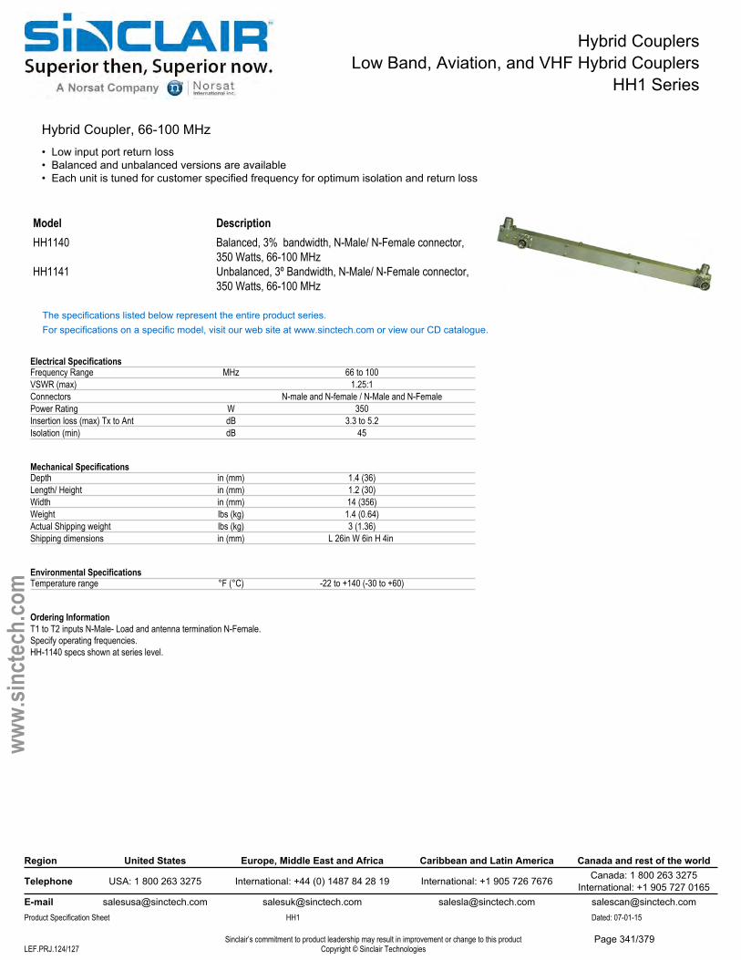
Hybrid CouplersLow Band, Aviation, and VHF Hybrid Couplers
HH1 Series
Hybrid Coupler, 66-100 MHz• Low input port return loss• Balanced and unbalanced versions are available• Each unit is tuned for customer specified frequency for optimum isolation and return loss
Model DescriptionHH1140 Balanced, 3% bandwidth, N-Male/ N-Female connector,
350 Watts, 66-100 MHzHH1141 Unbalanced, 3º Bandwidth, N-Male/ N-Female connector,
350 Watts, 66-100 MHz
The specifications listed below represent the entire product series.For specifications on a specific model, visit our web site at www.sinctech.com or view our CD catalogue.
Electrical SpecificationsFrequency Range MHz 66 to 100VSWR (max) 1.25:1Connectors N-male and N-female / N-Male and N-FemalePower Rating W 350Insertion loss (max) Tx to Ant dB 3.3 to 5.2Isolation (min) dB 45
Mechanical SpecificationsDepth in (mm) 1.4 (36)Length/ Height in (mm) 1.2 (30)Width in (mm) 14 (356)Weight lbs (kg) 1.4 (0.64)Actual Shipping weight lbs (kg) 3 (1.36)Shipping dimensions in (mm) L 26in W 6in H 4in
Environmental SpecificationsTemperature range °F (°C) -22 to +140 (-30 to +60)
Ordering InformationT1 to T2 inputs N-Male- Load and antenna termination N-Female.Specify operating frequencies.HH-1140 specs shown at series level.
Region United States Europe, Middle East and Africa Caribbean and Latin America Canada and rest of the world
Telephone USA: 1 800 263 3275 International: +44 (0) 1487 84 28 19 International: +1 905 726 7676 Canada: 1 800 263 3275International: +1 905 727 0165
E-mail [email protected] [email protected] [email protected] [email protected] Specification Sheet HH1 Dated: 07-01-15
Sinclair’s commitment to product leadership may result in improvement or change to this productCopyright © Sinclair TechnologiesLEF.PRJ.124/127
www.
sinct
ech.
com
Page 341/379
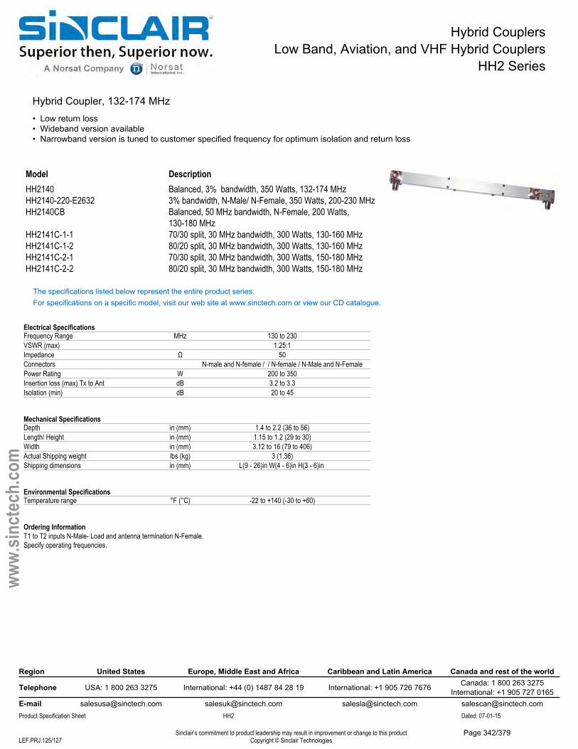
Hybrid CouplersLow Band, Aviation, and VHF Hybrid Couplers
HH2 Series
Hybrid Coupler, 132-174 MHz• Low return loss• Wideband version available• Narrowband version is tuned to customer specified frequency for optimum isolation and return loss
Model DescriptionHH2140 Balanced, 3% bandwidth, 350 Watts, 132-174 MHzHH2140-220-E2632 3% bandwidth, N-Male/ N-Female, 350 Watts, 200-230 MHzHH2140CB Balanced, 50 MHz bandwidth, N-Female, 200 Watts,
130-180 MHzHH2141C-1-1 70/30 split, 30 MHz bandwidth, 300 Watts, 130-160 MHzHH2141C-1-2 80/20 split, 30 MHz bandwidth, 300 Watts, 130-160 MHzHH2141C-2-1 70/30 split, 30 MHz bandwidth, 300 Watts, 150-180 MHzHH2141C-2-2 80/20 split, 30 MHz bandwidth, 300 Watts, 150-180 MHz
The specifications listed below represent the entire product series.For specifications on a specific model, visit our web site at www.sinctech.com or view our CD catalogue.
Electrical SpecificationsFrequency Range MHz 130 to 230VSWR (max) 1.25:1Impedance Ω 50Connectors N-male and N-female / / N-female / N-Male and N-FemalePower Rating W 200 to 350Insertion loss (max) Tx to Ant dB 3.2 to 3.3Isolation (min) dB 20 to 45
Mechanical SpecificationsDepth in (mm) 1.4 to 2.2 (36 to 56)Length/ Height in (mm) 1.15 to 1.2 (29 to 30)Width in (mm) 3.12 to 16 (79 to 406)Actual Shipping weight lbs (kg) 3 (1.36)Shipping dimensions in (mm) L(9 - 26)in W(4 - 6)in H(3 - 6)in
Environmental SpecificationsTemperature range °F (°C) -22 to +140 (-30 to +60)
Ordering InformationT1 to T2 inputs N-Male- Load and antenna termination N-Female.Specify operating frequencies.
Region United States Europe, Middle East and Africa Caribbean and Latin America Canada and rest of the world
Telephone USA: 1 800 263 3275 International: +44 (0) 1487 84 28 19 International: +1 905 726 7676 Canada: 1 800 263 3275International: +1 905 727 0165
E-mail [email protected] [email protected] [email protected] [email protected] Specification Sheet HH2 Dated: 07-01-15
Sinclair’s commitment to product leadership may result in improvement or change to this productCopyright © Sinclair TechnologiesLEF.PRJ.125/127
www.
sinct
ech.
com
Page 342/379
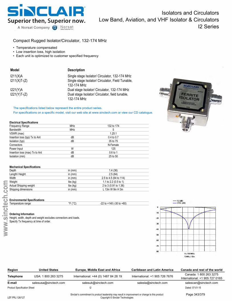
Isolators and CirculatorsLow Band, Aviation, and VHF Isolator & Circulators
I2 Series
Compact Rugged Isolator/Circulator, 132-174 MHz• Temperature compensated• Low insertion loss, high isolation• Each unit is optimized to customer specified frequency
Model DescriptionI211(X)A Single stage Isolator/ Circulator, 132-174 MHzI211(X)T-(Z) Single stage Isolator/ Circulator, Field Tunable,
132-174 MHzI221(Y)A Dual stage Isolator/ Circulator, 132-174 MHzI221(Y)T-(Z) Dual stage Isolator/ Circulator, field tunable,
132-174 MHz
The specifications listed below represent the entire product series.For specifications on a specific model, visit our web site at www.sinctech.com or view our CD catalogue.
Electrical SpecificationsFrequency Range MHz 132 to 174Bandwidth MHz 5VSWR (max) 1.25:1Insertion loss (typ) Tx to Ant dB 0.4 to 0.7Isolation (typ) dB 35 to 75Connectors N-FemalePower Input W 125Insertion loss (max) Tx to Ant dB 0.6 to 1Isolation (min) dB 25 to 50
Mechanical SpecificationsDepth in (mm) 1.4 (36)Length/ Height in (mm) 2.5 (64)Width in (mm) 2.5 to 4.5 (64 to 114)Weight lbs (kg) 1.1 to 2.2 (0.5 to 1)Actual Shipping weight lbs (kg) 2 to 3 (0.91 to 1.36)Shipping dimensions in (mm) L 13in W 9in H 3in
Environmental SpecificationsTemperature range °F (°C) -22 to +140 (-30 to +60)
Ordering InformationHeight, width, depth and weight excludes connectors and loads.Specify Tx frequency at time of order.
Region United States Europe, Middle East and Africa Caribbean and Latin America Canada and rest of the world
Telephone USA: 1 800 263 3275 International: +44 (0) 1487 84 28 19 International: +1 905 726 7676 Canada: 1 800 263 3275International: +1 905 727 0165
E-mail [email protected] [email protected] [email protected] [email protected] Specification Sheet I2 Dated: 07-01-15
Sinclair’s commitment to product leadership may result in improvement or change to this productCopyright © Sinclair TechnologiesLEF.PRJ.126/127
www.
sinct
ech.
com
Page 343/379

Intermod Supression PanelsLow Band, Aviation, and VHF IM Suppression Pannels
PC2 Series
Rack Mounted Ferrite Intermod Suppression Panel, 132-174 MHz• High performance single or dual stage isolators provide 35 dB or 75 dB of isolation• Covers 132-174 MHz band and comes with built-in harmonic filters providing 40 dB attenuation at 2nd harmonic• Compact design precisely tuned to customer specified frequency
Model DescriptionPC2112 Single stage isolator, 30 watt load 132-174 MHzPC2113 Single stage isolator, 60 watt load 132-174 MHzPC2114 Single stage isolator, 125 watt load 132-174 MHzPC2212 Dual stage isolator, two 30 Watt loads, 132-174 MHzPC2213 Dual stage isolator, 30+60 Watt loads, 132-174 MHzPC2214 Dual stage isolator, 30+125 Watt loads, 132-174 MHz
The specifications listed below represent the entire product series.For specifications on a specific model, visit our web site at www.sinctech.com or view our CD catalogue.
Electrical SpecificationsFrequency Range MHz 132 to 174Bandwidth MHz 4.6 to 5VSWR (max) 1.25:1Insertion loss (typ) Tx to Ant dB 0.4 to 0.7Isolation (typ) dB 35 to 75Average Power Input (max) W 125Connectors N-Female
Mechanical SpecificationsDepth in (mm) 9.13 (232)Length/ Height in (mm) 1.75 to 3.5 (44 to 89)Width in (mm) 19 (483)Actual Shipping weight lbs (kg) 20 (9.08)Shipping dimensions in (mm) L 19in W 26in H 7in
Environmental SpecificationsTemperature range °F (°C) -22 to +140 (-30 to +60)
Region United States Europe, Middle East and Africa Caribbean and Latin America Canada and rest of the world
Telephone USA: 1 800 263 3275 International: +44 (0) 1487 84 28 19 International: +1 905 726 7676 Canada: 1 800 263 3275International: +1 905 727 0165
E-mail [email protected] [email protected] [email protected] [email protected] Specification Sheet PC2 Dated: 07-01-15
Sinclair’s commitment to product leadership may result in improvement or change to this productCopyright © Sinclair TechnologiesLEF.PRJ.127/127
www.
sinct
ech.
com
Page 344/379
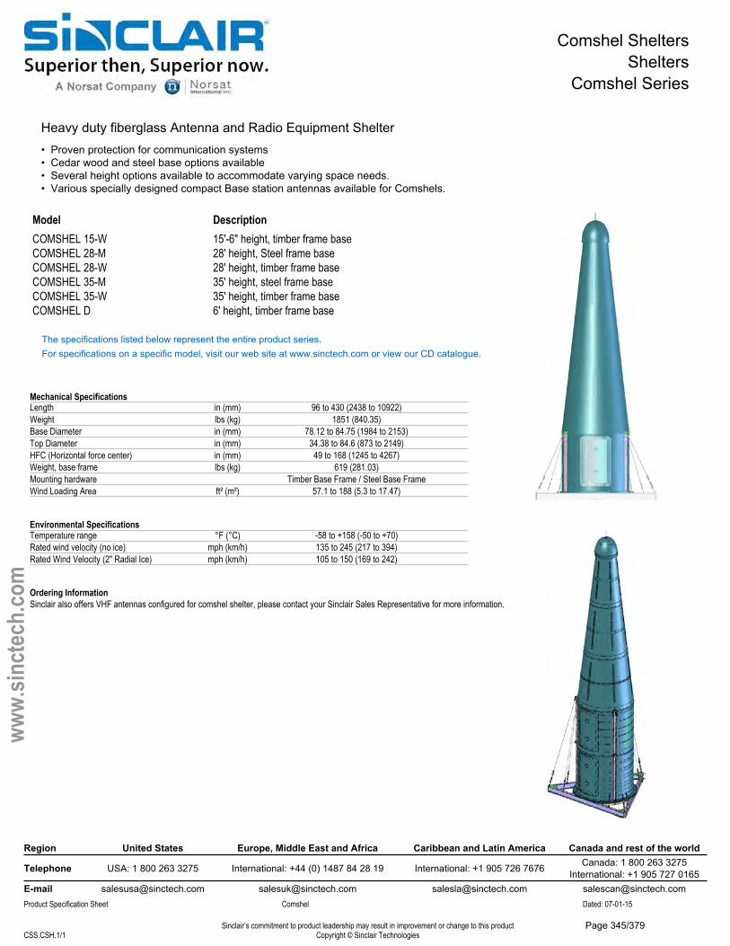
Comshel SheltersShelters
Comshel Series
Heavy duty fiberglass Antenna and Radio Equipment Shelter• Proven protection for communication systems• Cedar wood and steel base options available• Several height options available to accommodate varying space needs.• Various specially designed compact Base station antennas available for Comshels.
Model DescriptionCOMSHEL 15-W 15'-6" height, timber frame baseCOMSHEL 28-M 28' height, Steel frame baseCOMSHEL 28-W 28' height, timber frame baseCOMSHEL 35-M 35' height, steel frame baseCOMSHEL 35-W 35' height, timber frame baseCOMSHEL D 6' height, timber frame base
The specifications listed below represent the entire product series.For specifications on a specific model, visit our web site at www.sinctech.com or view our CD catalogue.
Mechanical SpecificationsLength in (mm) 96 to 430 (2438 to 10922)Weight lbs (kg) 1851 (840.35)Base Diameter in (mm) 78.12 to 84.75 (1984 to 2153)Top Diameter in (mm) 34.38 to 84.6 (873 to 2149)HFC (Horizontal force center) in (mm) 49 to 168 (1245 to 4267)Weight, base frame lbs (kg) 619 (281.03)Mounting hardware Timber Base Frame / Steel Base FrameWind Loading Area ft² (m²) 57.1 to 188 (5.3 to 17.47)
Environmental SpecificationsTemperature range °F (°C) -58 to +158 (-50 to +70)Rated wind velocity (no ice) mph (km/h) 135 to 245 (217 to 394)Rated Wind Velocity (2" Radial Ice) mph (km/h) 105 to 150 (169 to 242)
Ordering InformationSinclair also offers VHF antennas configured for comshel shelter, please contact your Sinclair Sales Representative for more information.
Region United States Europe, Middle East and Africa Caribbean and Latin America Canada and rest of the world
Telephone USA: 1 800 263 3275 International: +44 (0) 1487 84 28 19 International: +1 905 726 7676 Canada: 1 800 263 3275International: +1 905 727 0165
E-mail [email protected] [email protected] [email protected] [email protected] Specification Sheet Comshel Dated: 07-01-15
Sinclair’s commitment to product leadership may result in improvement or change to this productCopyright © Sinclair TechnologiesCSS.CSH.1/1
www.
sinct
ech.
com
Page 345/379
www.sinctech.com | Page 1
How To Use The Sinclair Clamp Selection Guide
Rev 10.1 August 24, 2012
1
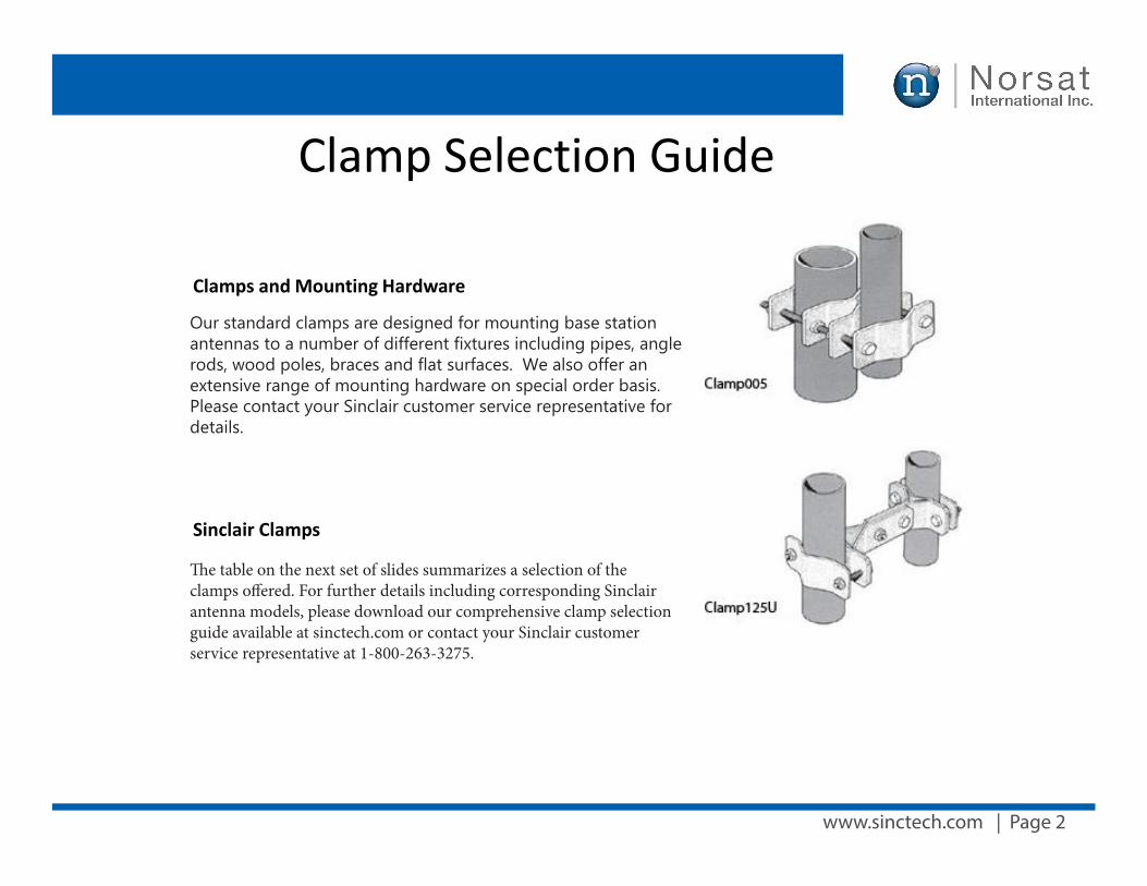
www.sinctech.com | Page 2
Clamp Selection Guide
Clamps and Mounting Hardware
Our standard clamps are designed for mounting base station antennas to a number of different fixtures including pipes, angle rods, wood poles, braces and flat surfaces. These clamps are also ideal for many other clamping applications. We also offer an extensive range of mounting hardware on special order basis, please contact your Sinclair customer service representative for details.
Sinclair Clamps
The table on the next set of slides summarizes a selection of the clamps offered. For further details including corresponding Sinclair antenna models please download our comprehensive clamp selection guide available at: sinctech.com or contact your Sinclair customer service representative at 1-800-263-3275.
Our standard clamps are designed for mounting base station antennas to a number of different fixtures including pipes, angle rods, wood poles, braces and flat surfaces. We also offer an extensive range of mounting hardware on special order basis. Please contact your Sinclair customer service representative for details.
The table on the next set of slides summarizes a selection of the clamps offered. For further details including corresponding Sinclair antenna models, please download our comprehensive clamp selection guide available at sinctech.com or contact your Sinclair customer service representative at 1-800-263-3275.
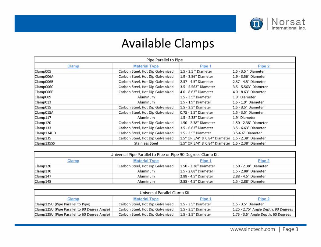
www.sinctech.com | Page 3
Available ClampsClamp Material Type Pipe 1 Pipe 2
Clamp005 Carbon Steel, Hot Dip Galvanized 1.5 - 3.5 " Diameter 1.5 - 3.5 " DiameterClamp006A Carbon Steel, Hot Dip Galvanized 1.9 - 3.56" Diameter 1.9 - 3.56" DiameterClamp006B Carbon Steel, Hot Dip Galvanized 2.37 - 4.5" Diameter 2.37 - 4.5" DiameterClamp006C Carbon Steel, Hot Dip Galvanized 3.5 - 5.563" Diameter 3.5 - 5.563" DiameterClamp006E Carbon Steel, Hot Dip Galvanized 4.0 - 8.63" Diameter 4.0 - 8.63" DiameterClamp009 Aluminum 1.5 - 3.5" Diameter 1.9" DiameterClamp013 Aluminum 1.5 - 1.9" Diameter 1.5 - 1.9" DiameterClamp015 Carbon Steel, Hot Dip Galvanized 1.5 - 3.5" Diameter 1.5 - 3.5" DiameterClamp015A Carbon Steel, Hot Dip Galvanized 0.75 - 1.5" Diameter 1.5 - 3.5" DiameterClamp117 Aluminum 1.5 - 2.38" Diameter 1.9" DiameterClamp120 Carbon Steel, Hot Dip Galvanized 1.50 - 2.38" Diameter 1.50 - 2.38" DiameterClamp133 Carbon Steel, Hot Dip Galvanized 3.5 - 6.63" Diameter 3.5 - 6.63" DiameterClamp134HD Carbon Steel, Hot Dip Galvanized 1.5 - 3.5" Diameter 3.5-6.6" DiameterClamp135 Carbon Steel, Hot Dip Galvanized 1.5" OR 3/4" & 0.84" Diameter 1.5 - 2.38" DiameterClamp135SS Stainless Steel 1.5" OR 3/4" & 0.84" Diameter 1.5 - 2.38" Diameter
Clamp Material Type Pipe 1 Pipe 2Clamp120 Carbon Steel, Hot Dip Galvanized 1.50 - 2.38" Diameter 1.50 - 2.38" DiameterClamp130 Aluminum 1.5 - 2.88" Diameter 1.5 - 2.88" DiameterClamp147 Aluminum 2.88 - 4.5" Diameter 2.88 - 4.5" DiameterClamp148 Aluminum 2.88 - 4.5" Diameter 1.5 - 2.88" Diameter
Clamp Material Type Pipe 1 Pipe 2Clamp125U (Pipe Parallel to Pipe) Carbon Steel, Hot Dip Galvanized 1.5 - 3.5" Diameter 1.5 - 3.5" DiameterClamp125U (Pipe Parallel to 90 Degree Angle) Carbon Steel, Hot Dip Galvanized 1.5 - 3.5" Diameter 1.25 - 2.75" Angle Depth, 90 DegreesClamp125U (Pipe Parallel to 60 Degree Angle) Carbon Steel, Hot Dip Galvanized 1.5 - 3.5" Diameter 1.75 - 3.5" Angle Depth, 60 Degrees
Pipe Parallel to Pipe
Universal Parallel Clamp Kit
Universal Pipe Parallel to Pipe or Pipe 90 Degrees Clamp Kit
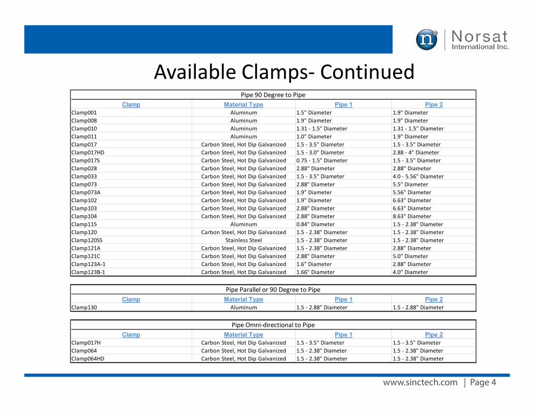
www.sinctech.com | Page 4
Available Clamps- ContinuedClamp Material Type Pipe 1 Pipe 2
Clamp001 Aluminum 1.5" Diameter 1.9" DiameterClamp008 Aluminum 1.9" Diameter 1.9" DiameterClamp010 Aluminum 1.31 - 1.5" Diameter 1.31 - 1.5" DiameterClamp011 Aluminum 1.0" Diameter 1.9" DiameterClamp017 Carbon Steel, Hot Dip Galvanized 1.5 - 3.5" Diameter 1.5 - 3.5" DiameterClamp017HD Carbon Steel, Hot Dip Galvanized 1.5 - 3.0" Diameter 2.88 - 4" DiameterClamp017S Carbon Steel, Hot Dip Galvanized 0.75 - 1.5" Diameter 1.5 - 3.5" DiameterClamp028 Carbon Steel, Hot Dip Galvanized 2.88" Diameter 2.88" DiameterClamp033 Carbon Steel, Hot Dip Galvanized 1.5 - 3.5" Diameter 4.0 - 5.56" DiameterClamp073 Carbon Steel, Hot Dip Galvanized 2.88" Diameter 5.5" DiameterClamp073A Carbon Steel, Hot Dip Galvanized 1.9" Diameter 5.56" DiameterClamp102 Carbon Steel, Hot Dip Galvanized 1.9" Diameter 6.63" DiameterClamp103 Carbon Steel, Hot Dip Galvanized 2.88" Diameter 6.63" DiameterClamp104 Carbon Steel, Hot Dip Galvanized 2.88" Diameter 8.63" DiameterClamp115 Aluminum 0.84" Diameter 1.5 - 2.38" DiameterClamp120 Carbon Steel, Hot Dip Galvanized 1.5 - 2.38" Diameter 1.5 - 2.38" DiameterClamp120SS Stainless Steel 1.5 - 2.38" Diameter 1.5 - 2.38" DiameterClamp121A Carbon Steel, Hot Dip Galvanized 1.5 - 2.38" Diameter 2.88" DiameterClamp121C Carbon Steel, Hot Dip Galvanized 2.88" Diameter 5.0" DiameterClamp123A-1 Carbon Steel, Hot Dip Galvanized 1.6" Diameter 2.88" DiameterClamp123B-1 Carbon Steel, Hot Dip Galvanized 1.66" Diameter 4.0" Diameter
Clamp Material Type Pipe 1 Pipe 2Clamp130 Aluminum 1.5 - 2.88" Diameter 1.5 - 2.88" Diameter
Clamp Material Type Pipe 1 Pipe 2Clamp017H Carbon Steel, Hot Dip Galvanized 1.5 - 3.5" Diameter 1.5 - 3.5" DiameterClamp064 Carbon Steel, Hot Dip Galvanized 1.5 - 2.38" Diameter 1.5 - 2.38" DiameterClamp064HD Carbon Steel, Hot Dip Galvanized 1.5 - 2.38" Diameter 1.5 - 2.38" Diameter
Pipe 90 Degree to Pipe
Pipe Parallel or 90 Degree to Pipe
Pipe Omni-directional to Pipe
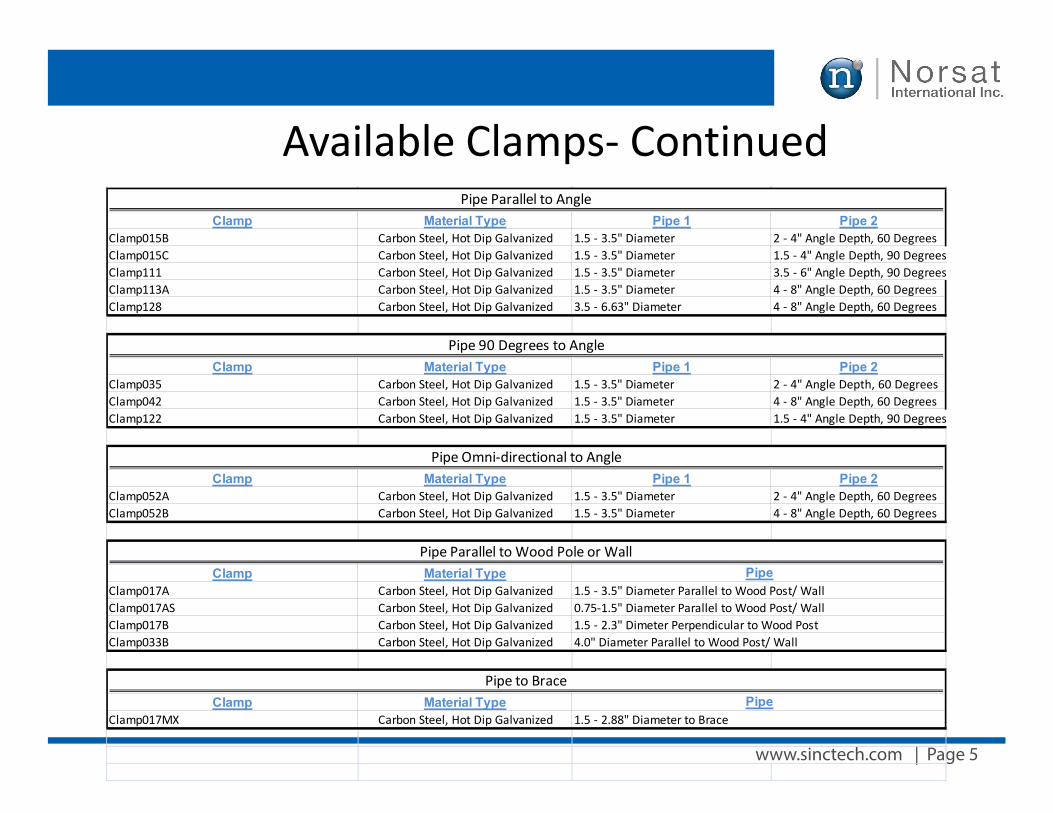
www.sinctech.com | Page 5
Available Clamps- ContinuedClamp Material Type Pipe 1 Pipe 2
Clamp015B Carbon Steel, Hot Dip Galvanized 1.5 - 3.5" Diameter 2 - 4" Angle Depth, 60 DegreesClamp015C Carbon Steel, Hot Dip Galvanized 1.5 - 3.5" Diameter 1.5 - 4" Angle Depth, 90 DegreesClamp111 Carbon Steel, Hot Dip Galvanized 1.5 - 3.5" Diameter 3.5 - 6" Angle Depth, 90 DegreesClamp113A Carbon Steel, Hot Dip Galvanized 1.5 - 3.5" Diameter 4 - 8" Angle Depth, 60 DegreesClamp128 Carbon Steel, Hot Dip Galvanized 3.5 - 6.63" Diameter 4 - 8" Angle Depth, 60 Degrees
Clamp Material Type Pipe 1 Pipe 2Clamp035 Carbon Steel, Hot Dip Galvanized 1.5 - 3.5" Diameter 2 - 4" Angle Depth, 60 DegreesClamp042 Carbon Steel, Hot Dip Galvanized 1.5 - 3.5" Diameter 4 - 8" Angle Depth, 60 DegreesClamp122 Carbon Steel, Hot Dip Galvanized 1.5 - 3.5" Diameter 1.5 - 4" Angle Depth, 90 Degrees
Clamp Material Type Pipe 1 Pipe 2Clamp052A Carbon Steel, Hot Dip Galvanized 1.5 - 3.5" Diameter 2 - 4" Angle Depth, 60 DegreesClamp052B Carbon Steel, Hot Dip Galvanized 1.5 - 3.5" Diameter 4 - 8" Angle Depth, 60 Degrees
Clamp Material TypeClamp017A Carbon Steel, Hot Dip GalvanizedClamp017AS Carbon Steel, Hot Dip GalvanizedClamp017B Carbon Steel, Hot Dip GalvanizedClamp033B Carbon Steel, Hot Dip Galvanized
Clamp Material TypeClamp017MX Carbon Steel, Hot Dip Galvanized
1.5 - 3.5" Diameter Parallel to Wood Post/ Wall
Pipe Parallel to Angle
Pipe 90 Degrees to Angle
Pipe Omni-directional to Angle
Pipe Parallel to Wood Pole or WallPipe
0.75-1.5" Diameter Parallel to Wood Post/ Wall1.5 - 2.3" Dimeter Perpendicular to Wood Post4.0" Diameter Parallel to Wood Post/ Wall
Pipe to BracePipe
1.5 - 2.88" Diameter to Brace
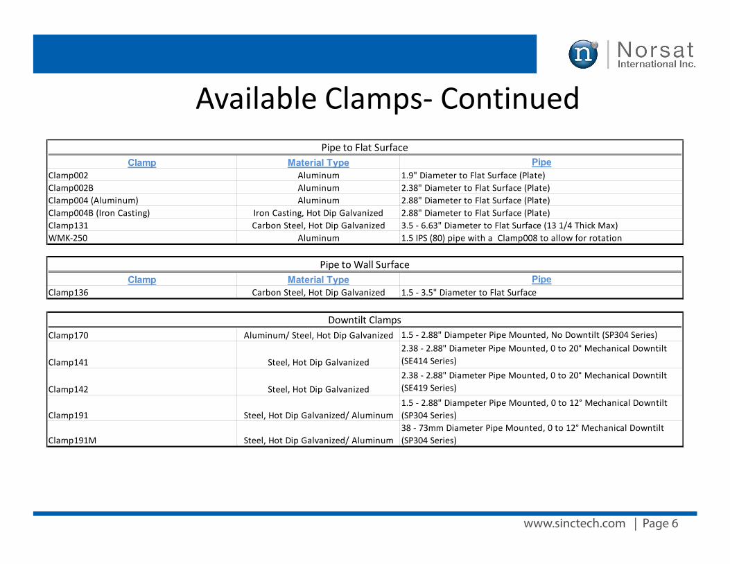
www.sinctech.com | Page 6
Available Clamps- Continued
Clamp Material TypeClamp002 AluminumClamp002B AluminumClamp004 (Aluminum) AluminumClamp004B (Iron Casting) Iron Casting, Hot Dip GalvanizedClamp131 Carbon Steel, Hot Dip GalvanizedWMK-250 Aluminum
Clamp Material TypeClamp136 Carbon Steel, Hot Dip Galvanized
Clamp170 Aluminum/ Steel, Hot Dip Galvanized
Clamp141 Steel, Hot Dip Galvanized
Clamp142 Steel, Hot Dip Galvanized
Clamp191 Steel, Hot Dip Galvanized/ Aluminum
Clamp191M Steel, Hot Dip Galvanized/ Aluminum
Pipe1.5 - 3.5" Diameter to Flat Surface
1.5 - 2.88" Diampeter Pipe Mounted, No Downtilt (SP304 Series)2.38 - 2.88" Diameter Pipe Mounted, 0 to 20° Mechanical Downtilt (SE414 Series)2.38 - 2.88" Diameter Pipe Mounted, 0 to 20° Mechanical Downtilt (SE419 Series)1.5 - 2.88" Diampeter Pipe Mounted, 0 to 12° Mechanical Downtilt (SP304 Series)38 - 73mm Diameter Pipe Mounted, 0 to 12° Mechanical Downtilt (SP304 Series)
Downtilt Clamps
Pipe to Flat SurfacePipe
1.9" Diameter to Flat Surface (Plate)2.38" Diameter to Flat Surface (Plate)2.88" Diameter to Flat Surface (Plate)2.88" Diameter to Flat Surface (Plate)3.5 - 6.63" Diameter to Flat Surface (13 1/4 Thick Max)1.5 IPS (80) pipe with a Clamp008 to allow for rotation
Pipe to Wall Surface
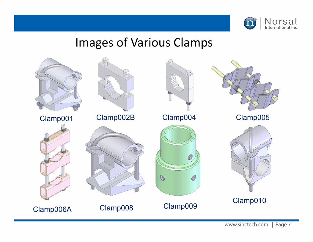
www.sinctech.com | Page 7
Images of Various Clamps
Clamp001 Clamp002B Clamp004 Clamp005
Clamp006A Clamp008 Clamp009Clamp010
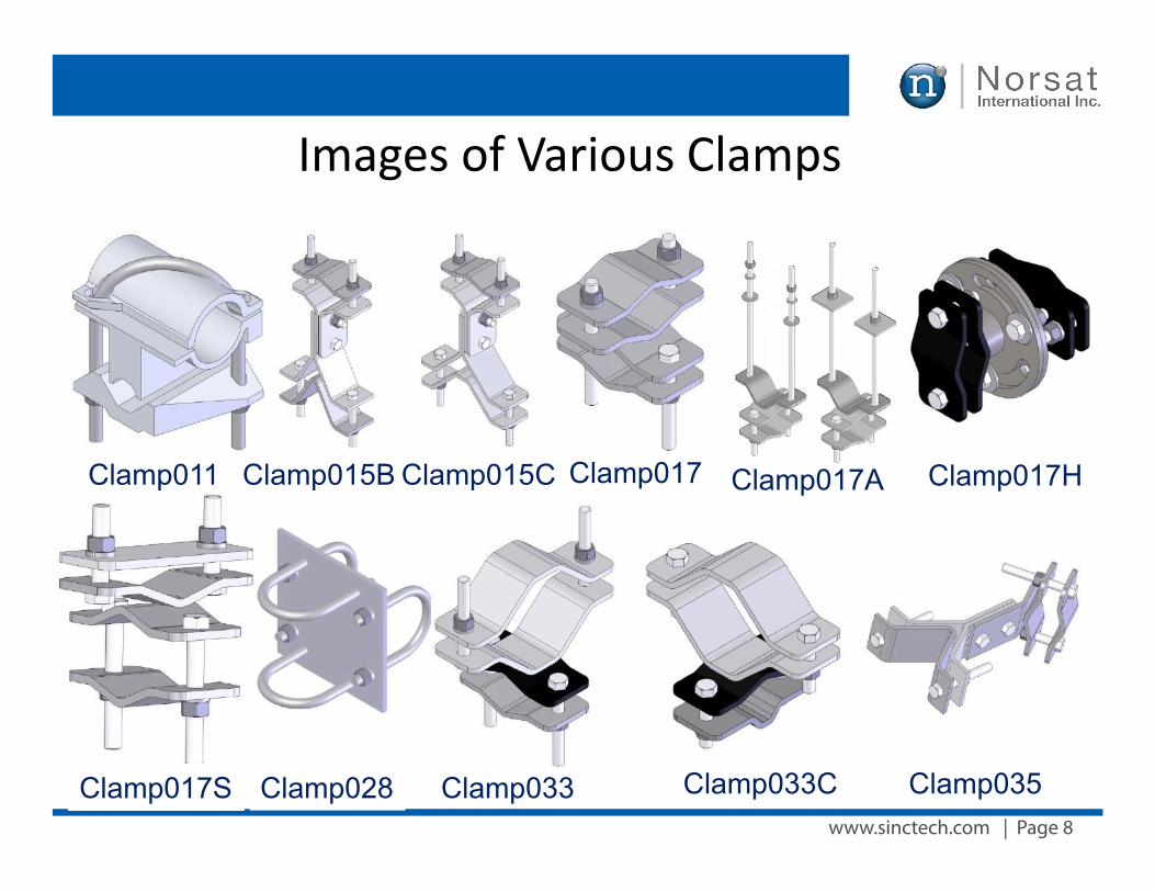
www.sinctech.com | Page 8
Clamp011 Clamp015B Clamp015C Clamp017 Clamp017A Clamp017H
Clamp017S Clamp028 Clamp033 Clamp033C Clamp035
Images of Various Clamps
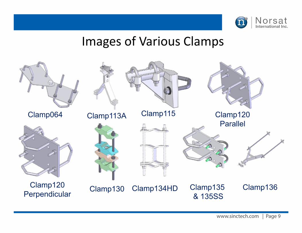
www.sinctech.com | Page 9
Images of Various Clamps
Clamp064 Clamp113A Clamp115
Clamp120Perpendicular
Clamp130 Clamp134HD Clamp135 & 135SS
Clamp136
Clamp120Parallel
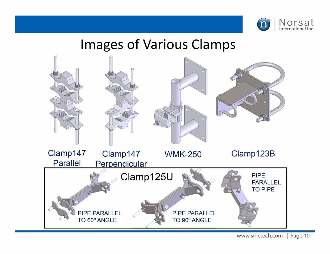
www.sinctech.com | Page 10
Images of Various Clamps
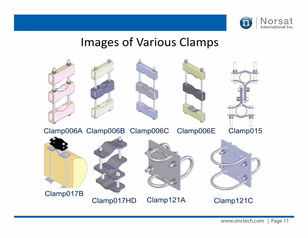
www.sinctech.com | Page 11
Images of Various Clamps
Clamp006A Clamp006B Clamp006C Clamp006E Clamp015
Clamp017HD Clamp121A Clamp121CClamp017B
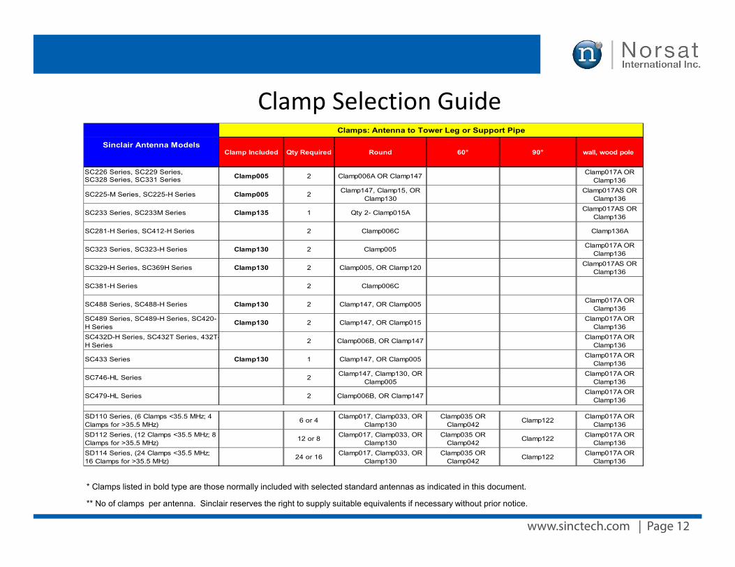
www.sinctech.com | Page 12
Clamp Selection Guide
Clamp Included Qty Required Round 60° 90° wall, wood pole
SC226 Series, SC229 Series, SC328 Series, SC331 Series Clamp005 2 Clamp006A OR Clamp147 Clamp017A OR
Clamp136
SC225-M Series, SC225-H Series Clamp005 2 Clamp147, Clamp15, OR Clamp130
Clamp017AS OR Clamp136
SC233 Series, SC233M Series Clamp135 1 Qty 2- Clamp015A Clamp017AS OR Clamp136
SC281-H Series, SC412-H Series 2 Clamp006C Clamp136A
SC323 Series, SC323-H Series Clamp130 2 Clamp005 Clamp017A OR Clamp136
SC329-H Series, SC369H Series Clamp130 2 Clamp005, OR Clamp120 Clamp017AS OR Clamp136
SC381-H Series 2 Clamp006C
SC488 Series, SC488-H Series Clamp130 2 Clamp147, OR Clamp005 Clamp017A OR Clamp136
SC489 Series, SC489-H Series, SC420-H Series
Clamp130 2 Clamp147, OR Clamp015 Clamp017A OR Clamp136
SC432D-H Series, SC432T Series, 432T-H Series
2 Clamp006B, OR Clamp147 Clamp017A OR Clamp136
SC433 Series Clamp130 1 Clamp147, OR Clamp005 Clamp017A OR Clamp136
SC746-HL Series 2 Clamp147, Clamp130, OR Clamp005
Clamp017A OR Clamp136
SC479-HL Series 2 Clamp006B, OR Clamp147 Clamp017A OR Clamp136
SD110 Series, (6 Clamps <35.5 MHz; 4 Clamps for >35.5 MHz)
6 or 4 Clamp017, Clamp033, OR Clamp130
Clamp035 OR Clamp042
Clamp122 Clamp017A OR Clamp136
SD112 Series, (12 Clamps <35.5 MHz; 8 Clamps for >35.5 MHz)
12 or 8 Clamp017, Clamp033, OR Clamp130
Clamp035 OR Clamp042
Clamp122 Clamp017A OR Clamp136
SD114 Series, (24 Clamps <35.5 MHz; 16 Clamps for >35.5 MHz)
24 or 16 Clamp017, Clamp033, OR Clamp130
Clamp035 OR Clamp042
Clamp122 Clamp017A OR Clamp136
Clamps: Antenna to Tower Leg or Support Pipe
Sinclair Antenna Models
* Clamps listed in bold type are those normally included with selected standard antennas as indicated in this document.
** No of clamps per antenna. Sinclair reserves the right to supply suitable equivalents if necessary without prior notice.
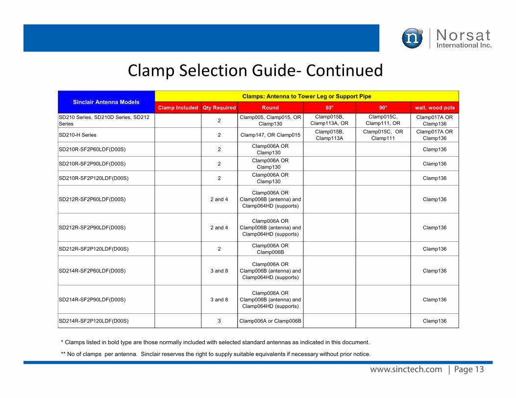
www.sinctech.com | Page 13
Clamp Selection Guide- Continued
Clamp Included Qty Required Round 60° 90° wall, wood pole
SD210 Series, SD210D Series, SD212 Series 2 Clamp005, Clamp015, OR
Clamp130Clamp015B,
Clamp113A, OR Clamp125U
Clamp015C, Clamp111, OR
Clamp125U
Clamp017A OR Clamp136
SD210-H Series 2 Clamp147, OR Clamp015 Clamp015B, Clamp113A
Clamp015C, OR Clamp111
Clamp017A OR Clamp136
SD210R-SF2P60LDF(D00S) 2 Clamp006A OR Clamp130 Clamp136
SD210R-SF2P90LDF(D00S) 2 Clamp006A OR Clamp130 Clamp136
SD210R-SF2P120LDF(D00S) 2 Clamp006A OR Clamp130 Clamp136
SD212R-SF2P60LDF(D00S) 2 and 4Clamp006A OR
Clamp006B (antenna) and Clamp064HD (supports)
Clamp136
SD212R-SF2P90LDF(D00S) 2 and 4Clamp006A OR
Clamp006B (antenna) and Clamp064HD (supports)
Clamp136
SD212R-SF2P120LDF(D00S) 2 Clamp006A OR Clamp006B Clamp136
SD214R-SF2P60LDF(D00S) 3 and 8Clamp006A OR
Clamp006B (antenna) and Clamp064HD (supports)
Clamp136
SD214R-SF2P90LDF(D00S) 3 and 8Clamp006A OR
Clamp006B (antenna) and Clamp064HD (supports)
Clamp136
SD214R-SF2P120LDF(D00S) 3 Clamp006A or Clamp006B Clamp136
Sinclair Antenna ModelsClamps: Antenna to Tower Leg or Support Pipe
* Clamps listed in bold type are those normally included with selected standard antennas as indicated in this document.
** No of clamps per antenna. Sinclair reserves the right to supply suitable equivalents if necessary without prior notice.
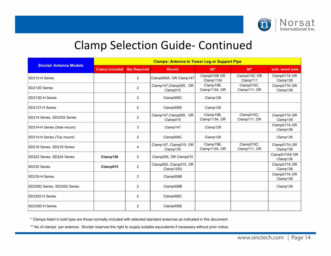
www.sinctech.com | Page 14
Clamp Selection Guide- Continued
Clamp Included Qty Required Round 60° 90° wall, wood pole
SD212-H Series 2 Clamp006A, OR Clamp147 Clamp015B OR Clamp113A
Clamp015C OR Clamp111
Clamp017A OR Clamp136
SD212D Series 2 Clamp147,Clamp005, OR Clamp015
Clamp15B, Clamp113A, OR
Clamp125U
Clamp015C, Clamp111, OR
Clamp125U
Clamp017A OR Clamp136
SD212D-H Series 2 Clamp006C Clamp128
SD212T-H Series 2 Clamp006E Clamp128
SD214 Series, SD2352 Series 2 Clamp147,Clamp005, OR Clamp015
Clamp15B, Clamp113A, OR
Clamp125U
Clamp015C, Clamp111, OR
Clamp125U
Clamp017A OR Clamp136
SD214-H Series (Side mount) 3 Clamp147 Clamp128 Clamp017A OR Clamp136
SD214-H Series (Top mount) 2 Clamp006C Clamp128 Clamp136
SD218 Series, SD218 Series 4 Clamp147, Clamp015, OR Clamp130
Clamp15B, Clamp113A, OR
Clamp125U
Clamp015C, Clamp111, OR
Clamp125U
Clamp017A OR Clamp136
SD222 Series, SD224 Series Clamp130 2 Clamp005, OR Clamp015 Clamp017AS OR Clamp136
SD235 Series Clamp015 2 Clamp005, Clamp015, OR Clamp125U
Clamp017A OR Clamp136
SD235-H Series 2 Clamp006B Clamp017A OR Clamp136
SD235D Series, SD2352 Series 2 Clamp006B Clamp136
SD2352-H Series 2 Clamp006C
SD235D-H Series 2 Clamp006E
Sinclair Antenna ModelsClamps: Antenna to Tower Leg or Support Pipe
* Clamps listed in bold type are those normally included with selected standard antennas as indicated in this document.
** No of clamps per antenna. Sinclair reserves the right to supply suitable equivalents if necessary without prior notice.
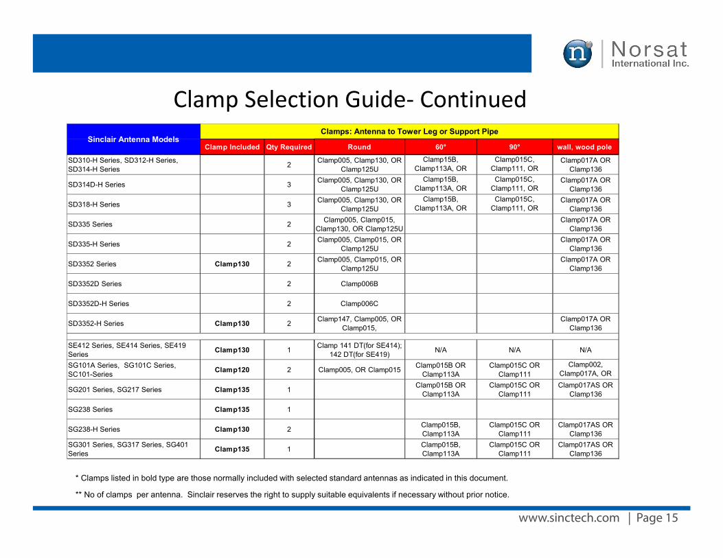
www.sinctech.com | Page 15
Clamp Selection Guide- Continued
Clamp Included Qty Required Round 60° 90° wall, wood pole
SD310-H Series, SD312-H Series, SD314-H Series 2 Clamp005, Clamp130, OR
Clamp125UClamp15B,
Clamp113A, OR Clamp125U
Clamp015C, Clamp111, OR
Clamp125U
Clamp017A OR Clamp136
SD314D-H Series 3 Clamp005, Clamp130, OR Clamp125U
Clamp15B, Clamp113A, OR
Clamp125U
Clamp015C, Clamp111, OR
Clamp125U
Clamp017A OR Clamp136
SD318-H Series 3 Clamp005, Clamp130, OR Clamp125U
Clamp15B, Clamp113A, OR
Clamp125U
Clamp015C, Clamp111, OR
Clamp125U
Clamp017A OR Clamp136
SD335 Series 2 Clamp005, Clamp015, Clamp130, OR Clamp125U
Clamp017A OR Clamp136
SD335-H Series 2 Clamp005, Clamp015, OR Clamp125U
Clamp017A OR Clamp136
SD3352 Series Clamp130 2 Clamp005, Clamp015, OR Clamp125U
Clamp017A OR Clamp136
SD3352D Series 2 Clamp006B
SD3352D-H Series 2 Clamp006C
SD3352-H Series Clamp130 2 Clamp147, Clamp005, OR Clamp015,
Clamp017A OR Clamp136
SE412 Series, SE414 Series, SE419 Series Clamp130 1 Clamp 141 DT(for SE414);
142 DT(for SE419) N/A N/A N/A
SG101A Series, SG101C Series, SC101-Series Clamp120 2 Clamp005, OR Clamp015 Clamp015B OR
Clamp113AClamp015C OR
Clamp111Clamp002,
Clamp017A, OR Clamp136
SG201 Series, SG217 Series Clamp135 1 Clamp015B OR Clamp113A
Clamp015C OR Clamp111
Clamp017AS OR Clamp136
SG238 Series Clamp135 1
SG238-H Series Clamp130 2 Clamp015B, Clamp113A
Clamp015C OR Clamp111
Clamp017AS OR Clamp136
SG301 Series, SG317 Series, SG401 Series Clamp135 1 Clamp015B,
Clamp113AClamp015C OR
Clamp111Clamp017AS OR
Clamp136
Sinclair Antenna ModelsClamps: Antenna to Tower Leg or Support Pipe
* Clamps listed in bold type are those normally included with selected standard antennas as indicated in this document.
** No of clamps per antenna. Sinclair reserves the right to supply suitable equivalents if necessary without prior notice.
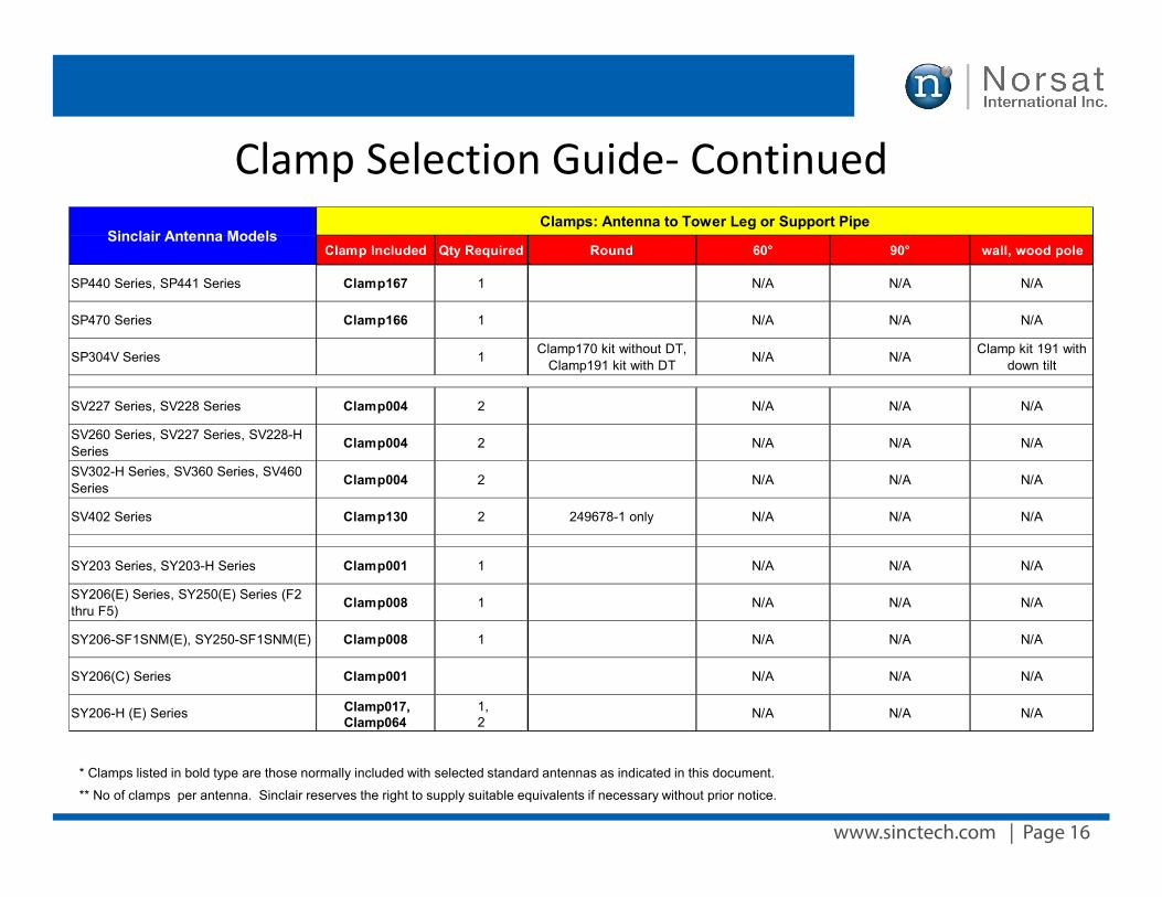
www.sinctech.com | Page 16
Clamp Selection Guide- Continued
Clamp Included Qty Required Round 60° 90° wall, wood pole
SP440 Series, SP441 Series Clamp167 1 N/A N/A N/A
SP470 Series Clamp166 1 N/A N/A N/A
SP304V Series 1 Clamp170 kit without DT, Clamp191 kit with DT N/A N/A Clamp kit 191 with
down tilt
SV227 Series, SV228 Series Clamp004 2 N/A N/A N/A
SV260 Series, SV227 Series, SV228-H Series Clamp004 2 N/A N/A N/A
SV302-H Series, SV360 Series, SV460 Series Clamp004 2 N/A N/A N/A
SV402 Series Clamp130 2 249678-1 only N/A N/A N/A
SY203 Series, SY203-H Series Clamp001 1 N/A N/A N/A
SY206(E) Series, SY250(E) Series (F2 thru F5) Clamp008 1 N/A N/A N/A
SY206-SF1SNM(E), SY250-SF1SNM(E) Clamp008 1 N/A N/A N/A
SY206(C) Series Clamp001 N/A N/A N/A
SY206-H (E) Series Clamp017,Clamp064
1,2
N/A N/A N/A
Sinclair Antenna ModelsClamps: Antenna to Tower Leg or Support Pipe
* Clamps listed in bold type are those normally included with selected standard antennas as indicated in this document.
** No of clamps per antenna. Sinclair reserves the right to supply suitable equivalents if necessary without prior notice.
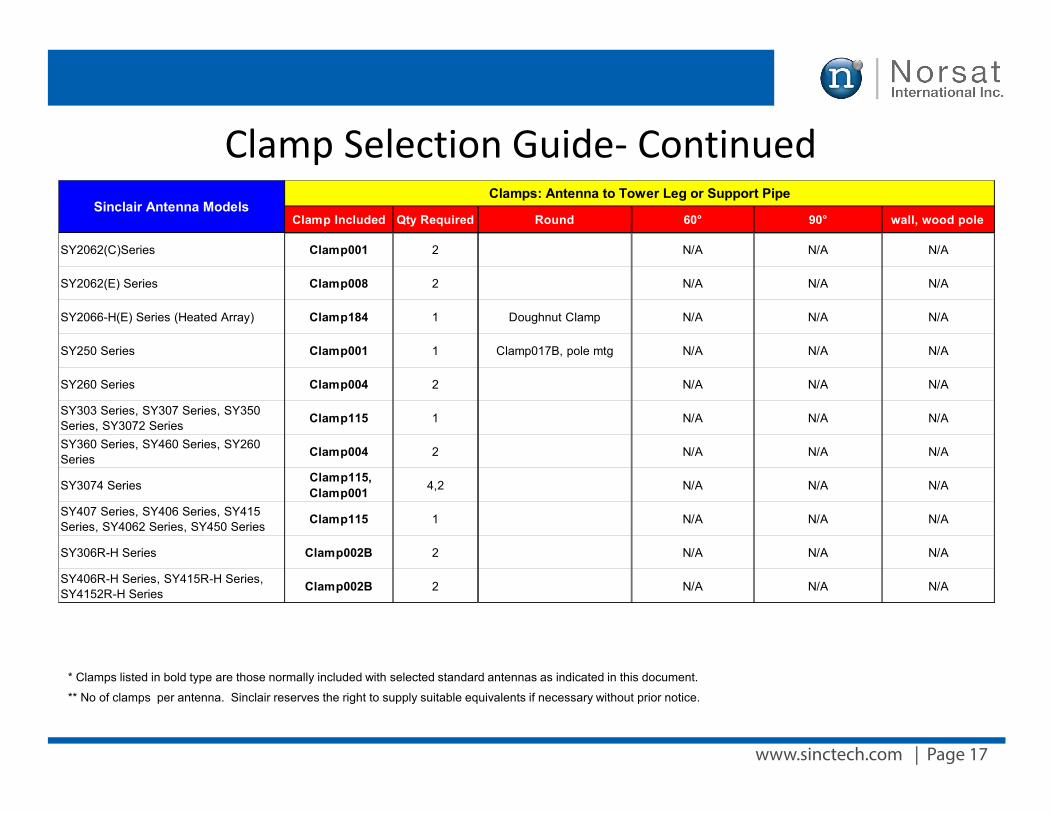
www.sinctech.com | Page 17
Clamp Selection Guide- ContinuedClamp Included Qty Required Round 60° 90° wall, wood pole
SY2062(C)Series Clamp001 2 N/A N/A N/A
SY2062(E) Series Clamp008 2 N/A N/A N/A
SY2066-H(E) Series (Heated Array) Clamp184 1 Doughnut Clamp N/A N/A N/A
SY250 Series Clamp001 1 Clamp017B, pole mtg N/A N/A N/A
SY260 Series Clamp004 2 N/A N/A N/A
SY303 Series, SY307 Series, SY350 Series, SY3072 Series Clamp115 1 N/A N/A N/A
SY360 Series, SY460 Series, SY260 Series Clamp004 2 N/A N/A N/A
SY3074 SeriesClamp115, Clamp001 4,2 N/A N/A N/A
SY407 Series, SY406 Series, SY415 Series, SY4062 Series, SY450 Series Clamp115 1 N/A N/A N/A
SY306R-H Series Clamp002B 2 N/A N/A N/A
SY406R-H Series, SY415R-H Series, SY4152R-H Series Clamp002B 2 N/A N/A N/A
Sinclair Antenna ModelsClamps: Antenna to Tower Leg or Support Pipe
* Clamps listed in bold type are those normally included with selected standard antennas as indicated in this document.
** No of clamps per antenna. Sinclair reserves the right to supply suitable equivalents if necessary without prior notice.
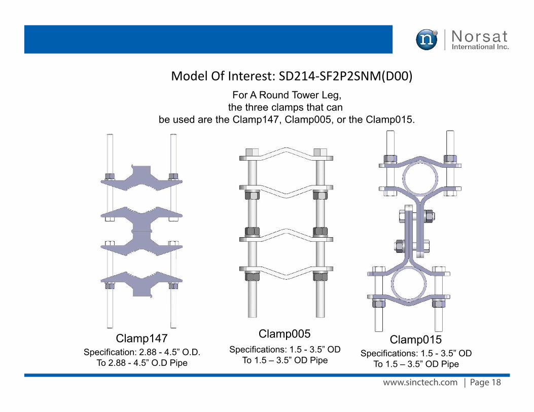
www.sinctech.com | Page 18
Model Of Interest: SD214-SF2P2SNM(D00)
Clamp147 Clamp015
For A Round Tower Leg,the three clamps that can
be used are the Clamp147, Clamp005, or the Clamp015.
Specification: 2.88 - 4.5” O.D. To 2.88 - 4.5” O.D Pipe
Specifications: 1.5 - 3.5” OD To 1.5 – 3.5” OD Pipe
Clamp005Specifications: 1.5 - 3.5” OD
To 1.5 – 3.5” OD Pipe
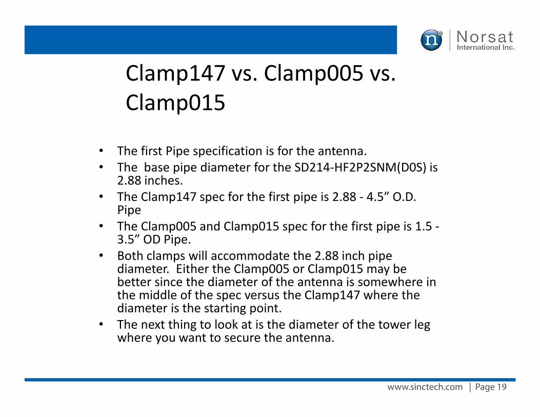
www.sinctech.com | Page 19
Clamp147 vs. Clamp005 vs. Clamp015
• The first Pipe specification is for the antenna.• The base pipe diameter for the SD214-HF2P2SNM(D0S) is
2.88 inches.• The Clamp147 spec for the first pipe is 2.88 - 4.5” O.D.
Pipe• The Clamp005 and Clamp015 spec for the first pipe is 1.5 -
3.5” OD Pipe.• Both clamps will accommodate the 2.88 inch pipe
diameter. Either the Clamp005 or Clamp015 may bebetter since the diameter of the antenna is somewhere inthe middle of the spec versus the Clamp147 where thediameter is the starting point.
• The next thing to look at is the diameter of the tower legwhere you want to secure the antenna.
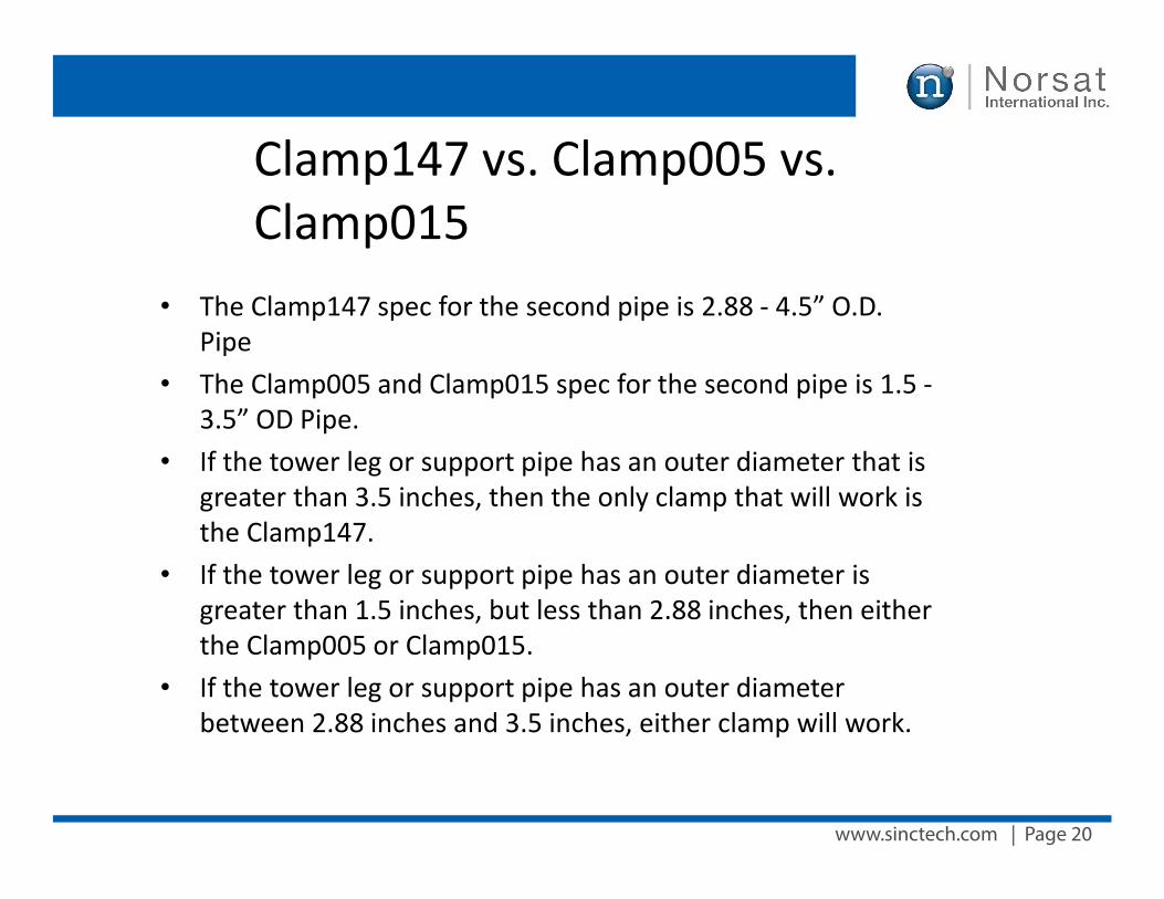
www.sinctech.com | Page 20
• The Clamp147 spec for the second pipe is 2.88 - 4.5” O.D.Pipe
• The Clamp005 and Clamp015 spec for the second pipe is 1.5 -3.5” OD Pipe.
• If the tower leg or support pipe has an outer diameter that isgreater than 3.5 inches, then the only clamp that will work isthe Clamp147.
• If the tower leg or support pipe has an outer diameter isgreater than 1.5 inches, but less than 2.88 inches, then eitherthe Clamp005 or Clamp015.
• If the tower leg or support pipe has an outer diameterbetween 2.88 inches and 3.5 inches, either clamp will work.
Clamp147 vs. Clamp005 vs. Clamp015
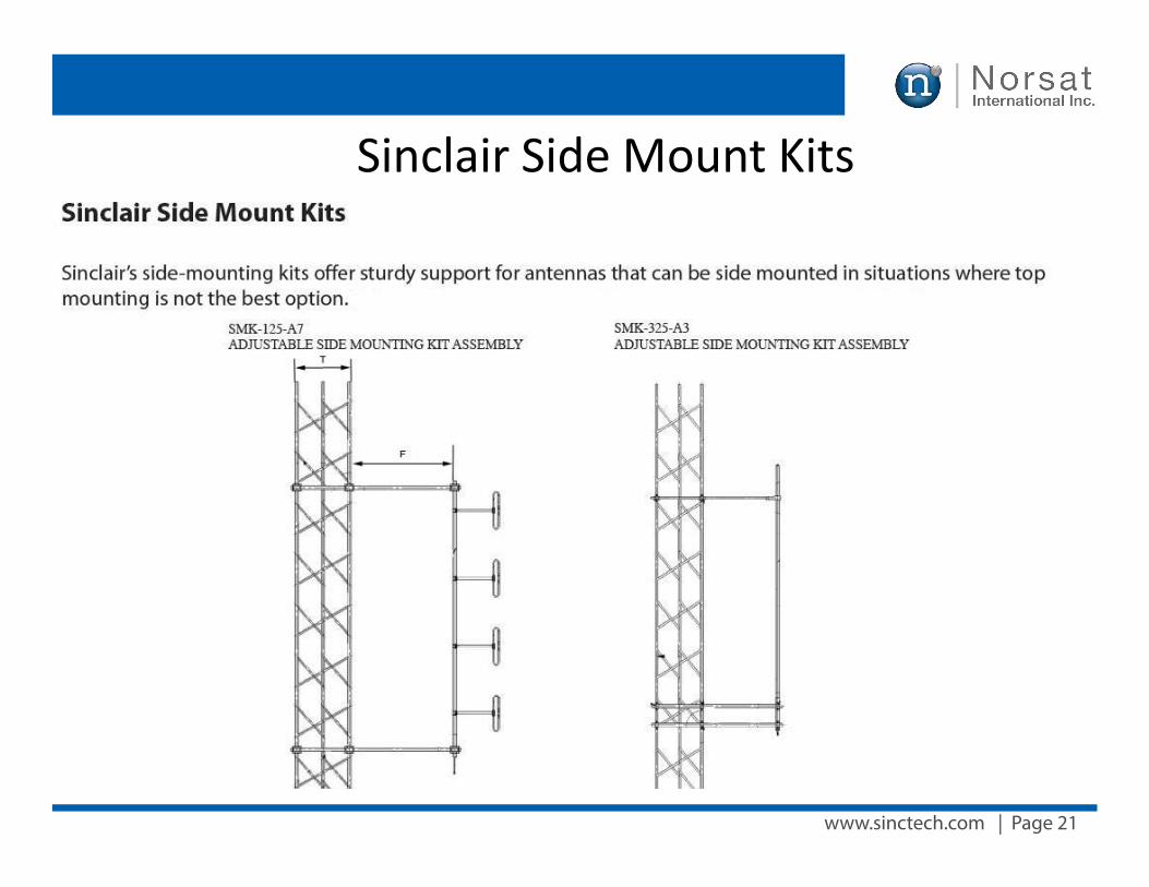
www.sinctech.com | Page 21
Sinclair Side Mount Kits
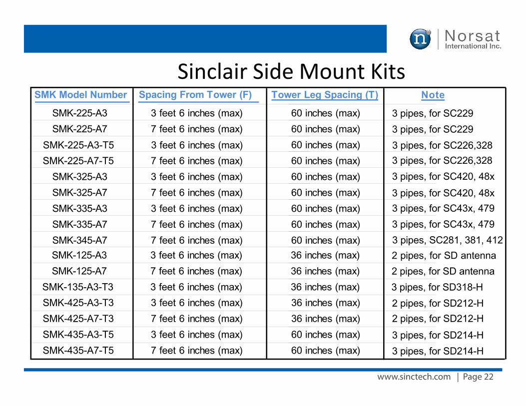
www.sinctech.com | Page 22
Sinclair Side Mount KitsSMK Model Number Spacing From Tower (F) Tower Leg Spacing (T)
SMK-125-A3 3 feet 6 inches (max) 36 inches (max)SMK-125-A7 7 feet 6 inches (max) 36 inches (max)
SMK-135-A3-T3 3 feet 6 inches (max) 36 inches (max)
SMK-225-A3 3 feet 6 inches (max) 60 inches (max)
SMK-225-A3-T5 3 feet 6 inches (max)60 inches (max)SMK-225-A7 7 feet 6 inches (max)60 inches (max)
SMK-225-A7-T5 7 feet 6 inches (max) 60 inches (max)SMK-325-A3 3 feet 6 inches (max) 60 inches (max)SMK-325-A7 7 feet 6 inches (max) 60 inches (max)SMK-335-A3 3 feet 6 inches (max) 60 inches (max)SMK-335-A7 7 feet 6 inches (max) 60 inches (max)SMK-345-A7 7 feet 6 inches (max) 60 inches (max)
SMK-425-A3-T3 3 feet 6 inches (max) 36 inches (max)SMK-425-A7-T3 7 feet 6 inches (max) 36 inches (max)SMK-435-A3-T5 3 feet 6 inches (max) 60 inches (max)SMK-435-A7-T5 7 feet 6 inches (max) 60 inches (max)
Note
2 pipes, for SD antenna2 pipes, for SD antenna3 pipes, for SD318-H
3 pipes, for SC229 3 pipes, for SC2293 pipes, for SC226,3283 pipes, for SC226,3283 pipes, for SC420, 48x
3 pipes, for SC420, 48x3 pipes, for SC43x, 4793 pipes, for SC43x, 4793 pipes, SC281, 381, 412
2 pipes, for SD212-H2 pipes, for SD212-H
3 pipes, for SD214-H3 pipes, for SD214-H
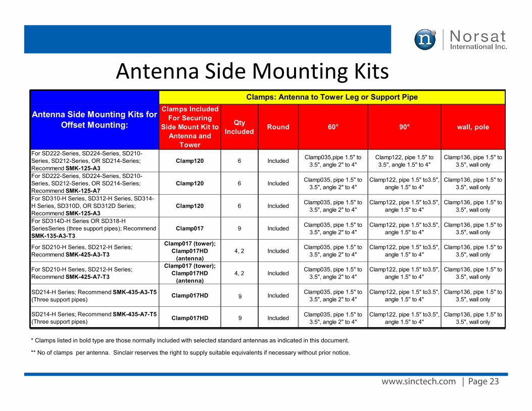
www.sinctech.com | Page 23
Antenna Side Mounting Kits
* Clamps listed in bold type are those normally included with selected standard antennas as indicated in this document.
** No of clamps per antenna. Sinclair reserves the right to supply suitable equivalents if necessary without prior notice.
Clamps Included For Securing
Side Mount Kit to Antenna and
Tower
Qty Included Round 60° 90° wall, pole
For SD222-Series, SD224-Series, SD210-Series, SD212-Series, OR SD214-Series; Recommend SMK-125-A3
Clamp120 6 Included Clamp035,pipe 1.5" to 3.5", angle 2" to 4"
Clamp122, pipe 1.5" to 3.5", angle 1.5" to 4"
Clamp136, pipe 1.5" to 3.5", wall only
For SD222-Series, SD224-Series, SD210-Series, SD212-Series, OR SD214-Series; Recommend SMK-125-A7
Clamp120 6 Included Clamp035, pipe 1.5" to 3.5", angle 2" to 4"
Clamp122, pipe 1.5" to3.5", angle 1.5" to 4"
Clamp136, pipe 1.5" to 3.5", wall only
For SD310-H Series, SD312-H Series, SD314-H Series, SD310D, OR SD312D Series; Recommend SMK-125-A3
Clamp120 6 Included Clamp035, pipe 1.5" to 3.5", angle 2" to 4"
Clamp122, pipe 1.5" to3.5", angle 1.5" to 4"
Clamp136, pipe 1.5" to 3.5", wall only
For SD314D-H Series OR SD318-H SeriesSeries (three support pipes); Recommend SMK-135-A3-T3
Clamp017 9 Included Clamp035, pipe 1.5" to 3.5", angle 2" to 4"
Clamp122, pipe 1.5" to3.5", angle 1.5" to 4"
Clamp136, pipe 1.5" to 3.5", wall only
For SD210-H Series, SD212-H Series; Recommend SMK-425-A3-T3
Clamp017 (tower); Clamp017HD
(antenna)4, 2 Included Clamp035, pipe 1.5" to
3.5", angle 2" to 4" Clamp122, pipe 1.5" to3.5",
angle 1.5" to 4" Clamp136, pipe 1.5" to
3.5", wall only
For SD210-H Series, SD212-H Series; Recommend SMK-425-A7-T3
Clamp017 (tower); Clamp017HD
(antenna)4, 2 Included Clamp035, pipe 1.5" to
3.5", angle 2" to 4" Clamp122, pipe 1.5" to3.5",
angle 1.5" to 4" Clamp136, pipe 1.5" to
3.5", wall only
SD214-H Series; Recommend SMK-435-A3-T5 (Three support pipes)
Clamp017HD 9 Included Clamp035, pipe 1.5" to 3.5", angle 2" to 4"
Clamp122, pipe 1.5" to3.5", angle 1.5" to 4"
Clamp136, pipe 1.5" to 3.5", wall only
SD214-H Series; Recommend SMK-435-A7-T5 (Three support pipes) Clamp017HD 9 Included Clamp035, pipe 1.5" to
3.5", angle 2" to 4" Clamp122, pipe 1.5" to3.5",
angle 1.5" to 4" Clamp136, pipe 1.5" to
3.5", wall only
Antenna Side Mounting Kits for Offset Mounting:
Clamps: Antenna to Tower Leg or Support Pipe
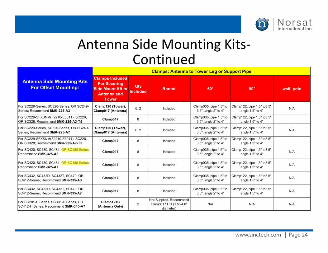
www.sinctech.com | Page 24
Antenna Side Mounting Kits-Continued
Clamps Included For Securing
Side Mount Kit to Antenna and
Tower
Qty Included Round 60° 90° wall, pole
For SC229-Series, SC320-Series, OR SC249-Series; Recommend SMK-225-A3
Clamp120 (Tower), Clamp017 (Antenna) 6, 2 Included Clamp035, pipe 1.5" to
3.5", angle 2" to 4" Clamp122, pipe 1.5" to3.5",
angle 1.5" to 4" N/A
For SC229-SFXSNM(F2210-E6011), SC226, OR SC328; Recommend SMK-225-A3-T5 Clamp017 8 Included Clamp035, pipe 1.5" to
3.5", angle 2" to 4" Clamp122, pipe 1.5" to3.5",
angle 1.5" to 4"
For SC229-Series, SC320-Series, OR SC249-Series; Recommend SMK-225-A7
Clamp120 (Tower), Clamp017 (Antenna) 6, 2 Included Clamp035, pipe 1.5" to
3.5", angle 2" to 4" Clamp122, pipe 1.5" to3.5",
angle 1.5" to 4" N/A
For SC229-SFXSNM(F2210-E6011), SC226, OR SC328; Recommend SMK-225-A7-T5 Clamp017 8 Included Clamp035, pipe 1.5" to
3.5", angle 2" to 4" Clamp122, pipe 1.5" to3.5",
angle 1.5" to 4"
For SC420, SC480, SC481, OR SC488 Series; Recommend SMK-325-A3 Clamp017 8 Included Clamp035, pipe 1.5" to
3.5", angle 2" to 4" Clamp122, pipe 1.5" to3.5",
angle 1.5" to 4" N/A
For SC420, SC480, SC481, OR SC488 Series; Recommend SMK-325-A7 Clamp017 8 Included Clamp035, pipe 1.5" to
3.5", angle 2" to 4" Clamp122, pipe 1.5" to3.5",
angle 1.5" to 4" N/A
For SC432, SC432D, SC432T, SC479, OR SC412-Series; Recommend SMK-335-A3 Clamp017 8 Included Clamp035, pipe 1.5" to
3.5", angle 2" to 4" Clamp122, pipe 1.5" to3.5",
angle 1.5" to 4" N/A
For SC432, SC432D, SC432T, SC479, OR SC412-Series; Recommend SMK-335-A7 Clamp017 8 Included Clamp035, pipe 1.5" to
3.5", angle 2" to 4" Clamp122, pipe 1.5" to3.5",
angle 1.5" to 4" N/A
For SC281-H Series, SC381-H Series, OR SC412-H Series; Recommend SMK-345-A7
Clamp121C (Antenna Only) 2
Not Supplied. Recommend Clamp017 HD (1.5"-4.0"
diameter)N/A N/A N/A
Antenna Side Mounting Kits For Offset Mounting:
Clamps: Antenna to Tower Leg or Support Pipe
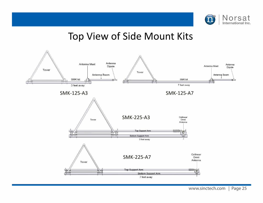
www.sinctech.com | Page 25
Top View of Side Mount Kits
SMK-225-A3
SMK-125-A3 SMK-125-A7
SMK-225-A7
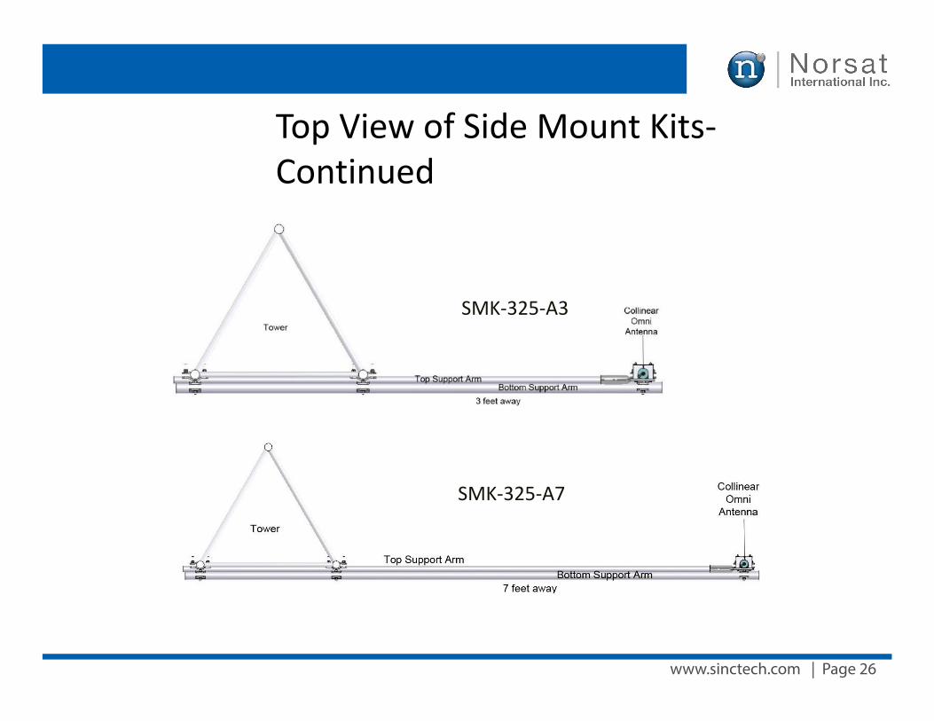
www.sinctech.com | Page 26
Top View of Side Mount Kits-Continued
SMK-325-A3
SMK-325-A7
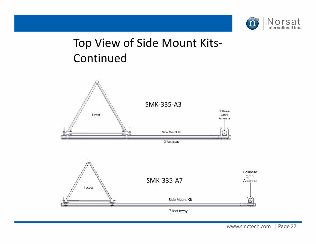
www.sinctech.com | Page 27
SMK-335-A3
SMK-335-A7
Top View of Side Mount Kits-Continued
www.sinctech.com | Page 28
Selecting the right Side Mount Kit
When side mounting the SD222-SF, SD224-SF, SD210-SF, SD212-SF, or SD214-SF series, we recommend that the customer supports the antenna at both the top and bottom of the mast. The Sinclair SMK kits should be recommended to the customer when they order any antenna.
For the above mentioned series, there are two kits that can be recommended:
SMK-125-A3 or SMK-125-A7
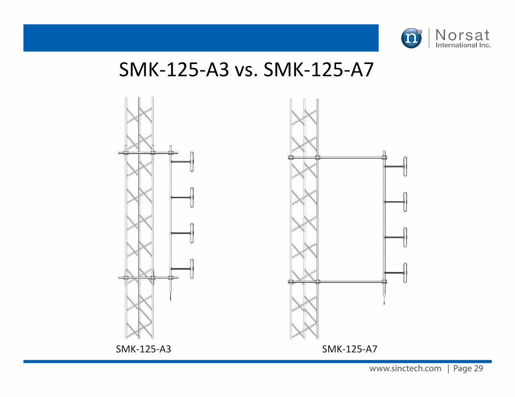
www.sinctech.com | Page 29
SMK-125-A3 vs. SMK-125-A7
SMK-125-A3 SMK-125-A7
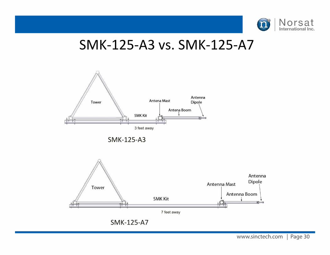
www.sinctech.com | Page 30
SMK-125-A3 vs. SMK-125-A7
SMK-125-A3
SMK-125-A7
3 feet away
7 feet away
www.sinctech.com | Page 31
SMK-125-A3 vs. SMK-125-A7
• Difference between the two is how far the antenna will be away from the tower.
• For the A3, it will be 3 feet away.• For the A7, it will be 7 feet away.• Both include a top and bottom support arm
for the antenna• Only for Exposed Dipole type of antenna
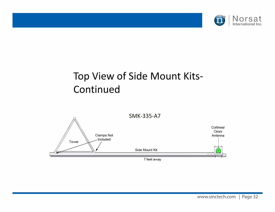
www.sinctech.com | Page 32
SMK-335-A7
Top View of Side Mount Kits-Continued

TM
A DIVISION OF NORSAT INTERNATIONAL INC.
A Division Of
SALES CONTACTCaribbean and Latin America
+1 (905) 726 7676
Other Countries
+1 (905) 727 0165
Canada
+1 (800) 263 3275
Fax +1 (905) 727 0861
South & Central America
+1 (800) 263 3275
Fax +1 (905) 727 0861
Europe, Middle East and Africa
+44 (0) 1487 84 28 19
Europe, Middle East and Africa
+44 (0) 1487 84 28 19
United States &Canada
+1 (800) 263 3275
United States
+1 (800) 228 2763Fax + 1 (716) 874 4007
Asia Pacific
+1 (905) 727 0165Fax + 1 (905) 727 8061
[email protected] [email protected]
[email protected]@sinctech.com
Fax +44 (0) 1487 84 28 78
TECHNICAL SUPPORT
Sinclair remains committed to staying at the forefront of innovation by tailoring solutions that meet specific customer needs.