Embed Size (px)
Citation preview

2021LEGACY ELITE & LEGACY ELITE II
OWNER’SMANUAL
VIEW THIS MANUAL ONLINE AT OLIVERTRAVELTRAILERS.COM


Thank you for investing in an Oliver Travel Trailer. There are many choices out there, but we firmly believe you have made the best one. We are not only committed to building the best quality travel trailers on the road, but we back it up with the best customer service we can offer.
Since we first started building travel trailers in 2008, we have come a long way with the help of our owners. Our direct relationship with our owners allows us to gather feedback and make our travel trailers better every year. We look forward to you being a part of the Oliver family of owners.
If you’d like to learn more about how to use your new Oliver Travel Trailer, we have created a library of videos that include just about every aspect of using your Oliver and maintaining it. See the video section on our website for more details.
As an owner, we encourage you to take part in some of the activities and communication outlets that are available to you. With transparency in mind, we have created a forum on our website. This is a great place to meet people with similar interests, discuss places to go during your adventures and advice on how to use or modify your Ollie to your needs. Oliver Travel Trailer owners have also created a private Facebook group. Search “Oliver Trailer Owners” on Facebook and request to join.
The purpose of this manual is to answer questions that commonly occur. Read it in its entirety. We want you to enjoy your Oliver Travel Trailer to the fullest and to help make your road to vacationing freedom more pleasant and relaxing.
If you have any questions or concerns, please don’t hesitate to contact us!
Sincerely,
Scott Oliver, PresidentOliver Travel Trailers Sales, Inc.
WELCOME TO THE OLIVER FAMILY

TABLE OF CONTENTSINTRODUCTION6 OVERVIEW
6 GETTING ACQUAINTED
7 USING THIS MANUAL
7 CAUTION AND INFORMATION SYMBOLS
8 WEIGHT RATING DEFINITIONS
8 DECALS & VIN INFORMATION
8 FEDERAL CERTIFICATION TAG
8 INCLUDED ITEMS
9 MODEL SPECIFICATIONS
LIMITED WARRANTIES10 WHAT IS COVERED
10 LIFETIME LIMITED BODY WARRANTY
11 ALUMINUM CHASSIS WARRANTY
12 TWO-YEAR LIMITED PARTS WARRANTY
13 HOW TO OBTAIN SERVICE
13 NON-OLIVER PART
14 WHAT IS NOT COVERED
14 DEALER REPRESENTATIONS EXCLUDED
COMPONENTS15 OPERATING INSTRUCTIONS
SAFETY16 OCCUPANT SAFETY
18 OWNER OBLIGATIONS
18 FIRE SAFETY
20 REPORTING SAFETY DEFECTS
TOWING & SETUP21 TOWING VEHICLE REQUIREMENTS
21 DRIVING TIPS
22 LOADING AND WEIGHT DISTRIBUTION
26 COUPLING
28 ELECTRIC JACK STABILIZATION SYSTEM
28 BRAKING AND BURNISHING BRAKES
29 BRAKE CONTROLLER
29 TOWING CHECK LIST
30 SET UP CHECK LIST
ELECTRICAL31 OVERVIEW31 CONNECTING TO SHORE POWER32 CONNECTING TO A GENERATOR32 BATTERY COMPARTMENT33 TYPICAL AMP PEAK DRAWS33 BATTERY CHARGING35 BATTERY SAFETY35 INVERTER35 SOLAR PACKAGE34 CIRCUIT BREAKERS34 POWER CONVERTER36 STANDARD 120-VOLT PANEL DIAGRAM36 120-VOLT PANEL W/2000W INVERTER 36 120-VOLT PANEL W/3000W INVERTER 37 12-VOLT FUSES & DIAGRAM38 OUTLETS AND CHARGING STATIONS39 FANS39 ELECTRICAL DIAGRAMS52 LIGHTING & SWITCHES52 AWNING REMOTE
54 BATTERY CONFIGURATIONS

TABLE OF CONTENTSPLUMBING62 OVERVIEW
62 INLETS
65 WATER PUMP
65 FAUCETS AND SHOWER
66 TOILET
67 TANK MONITORING
67 DUMPING WASTE
69 WATER SYSTEM TROUBLESHOOTING
70 WINTERIZATION OVERVIEW
71 PLUMBING DIAGRAMS
PROPANE72 OVERVIEW
72 PURGING THE SYSTEM
72 PROPANE TANK HOUSING
72 USING THE REGULATOR
73 USING THE QUICK CONNECTS OPTION
73 REPLACING OR REMOVING THE TANKS
EXTERIOR74 ENTRY STEPS
74 ENTRY DOOR
74 EXTERIOR STORAGE
74 AWNING
75 STORAGE BASKET
75 ACCESSORY RECEIVER
76 WHEELS AND TIRES
76 TIRE SAFETY INFORMATION
83 SPEED RATING
86 CHANGING A TIRE
INTERIOR88 FANS
88 HEATING AND COOLING
88 KITCHEN
90 BATH
91 ENTERTAINMENT SYSTEM
92 INTERIOR STORAGE
93 SEATING AND SLEEPING
94 LEGACY ELITE FLOOR PLAN DIAGRAMS
95 LEGACY ELITE II FLOOR PLAN DIAGRAMS
MAINTENANCE97 OVERVIEW
97 FIBERGLASS
98 FRAMES
98 SEALS AND ADHESIVES
99 WINDOWS AND DOORS
99 TIRES AND WHEEL BEARINGS
99 DRAINAGE SYSTEM
100 UPHOLSTERY
100 ELECTRICAL
100 PROPANE
100 CABINETS, COUNTERTOPS AND APPLIANCES
102 ROOF VENTS
102 LIGHTING
102 CONDENSATION
103 STORING YOUR OLIVER
104 WINTERIZATION
107 SANITIZATION/DE-WINTERIZATION
108 MAINTENANCE SCHEDULE

6
OVERVIEWThis manual has been prepared by the manufacturer to provide information and instructions covering the operation and maintenance of your travel trailer.
Nothing in this manual creates any warranty, either expressed or implied. The only warranty offered by the manufacturer is set forth in the limited warranty applicable to your vehicle. For detailed information on how to operate any of the installed appliances or components please refer to your component manual.
The limited warranty provided by the manufacturer and the limited warranties issued by component manufacturers require periodic service and maintenance, and the owner’s failure to do this service and maintenance may result in the loss of warranty coverage.
The owner should review the manufacturer’s limited warranty and the limited warranty of all other manufacturers.
We reserve the right to change the construction or material of any part(s) at any time without incurring the obligation to install such changes on delivered units.
GETTING ACQUAINTEDThroughout the manufacturing process, your travel trailer has been inspected by trained personnel and then again prior to delivery. Along with the new smell comes the knowledge that you will be the first to set up camp and extensively use all the standard and optional systems.
When traveling far from home you definitely do not want any unexpected surprises or frustrating questions. Spend a weekend camping at home. Make a point to use and become familiar with all the systems both inside and out. How long does the stored water last? How much propane does it take to keep your beverages ice cold? Why didn’t the satellite system pick up the big game? Find out what camping items are really needed, or not needed at all.
Take note of any concerns or ideas you might have that would make things better. Call us with your questions or suggestions, we would love to hear from you. The better acquainted you become at home, the more enjoyable your first trip will be.
Best Regards, The Oliver Family
INTRODUCTION

7
USING THIS MANUALThe purpose of this document is to explain several of the features of your trailer. While most of these features are similar between models, some features mentioned in this guide may not apply to your specific travel trailer. Review this manual with your dealer. Be sure to ask any questions you have at that time. Go over all warranty and registration information carefully. Read all supplied component manufacturers manuals and validate any individual warranties by completing and mailing the individual warranty cards as required. Always keep this owner’s manual with your travel trailer for easy reference, making sure to comply with all notes and warnings. A careful owner is the best insurance against an accident. This owner’s manual is as current as possible at the time your travel trailer was produced. However, since our products are constantly being upgraded and improved, some standard items and/or options may vary. If this occurs, follow the separate component manufacturers instructions provided in their literature.
To download a copy of this manual, component manual or for videos covering your travel trailer and its features please visit:
https://olivertraveltrailers.com/oliver-university/
To read about the experience of camping in an Oliver from other Oliver Owners please visit our forums and/or join the Oliver Owner’s Facebook group.
CAUTION AND INFORMATION SYMBOLSThroughout this manual we have placed special emphasis on information that requires your absolute attention. These symbols designate information that the user must be acutely aware of since failure to heed these cautions or warnings may result in product damage, property damage, serious injury or death.
WARNING: SPECIAL ATTENTION SHOULD BE GIVEN TO ALL INFORMATION PRECEDED BY THIS SYMBOL. FAILURE TO DO SO MAY RESULT IN PRODUCT DAMAGE, SERIOUS INJURY OR DEATH.
READ THE ENTIRE MANUAL AND HEED ALL CAUTION AND WARNING STATEMENTS PRIOR TO OPERATION OF YOUR OLIVER TRAVEL TRAILER.
This travel trailer has been designed for short-term vacationing and recreational use. Using this vehicle as a permanent dwelling is not a consideration of the original design. If you intend to use your travel trailer in a commercial setting or as a permanent dwelling, it could cause your mechanical systems, electrical systems, installed components, upholstery and interior surfaces to deteriorate prematurely. This premature wear caused by permanent residency may, under the terms of the travel trailer warranty, be considered abnormal and abusive and could reduce or void your warranty coverage.
INTRODUCTION

8
WEIGHT RATING DEFINITIONSGVWR (Gross Vehicle Weight Rating) - The maximum permissible weight of this trailer when fully loaded, including all weight at the trailer’s axle, plus tongue.
GAWR (Gross Axle Weight Rating) - The maximum allowable weight that an axle system is designed to carry.
UVW (Unloaded Vehicle Weight) - The weight of the trailer as manufactured at the factory, this includes all the weight of the trailer axle and the tongue.
CCC (Cargo Carrying Capacity) - Equal to GVWR minus each of the following; UVW, full potable water weight and full LP Gas weight.
DECALS & VIN INFORMATIONDecals throughout the trailer aid in its safe and efficient operation.
Some giving warnings, some give service instructions while others are used for identification. Read all decals and instruction plates before operating your recreational vehicle.
The Oliver Travel Trailer VIN (Vehicle Identification Number) is located on the driver’s side, towards the lower front of the trailer in the area of the reflector.
FEDERAL CERTIFICATION TAGThe Federal Certification Tag on travel trailers and fifth wheels can be located on the Road Side near the front of the unit and contains the GVWR, GAWR (front and rear) and tire pressure limits.
INCLUDED ITEMSYou will receive the following items at delivery:• Owner’s Manual• Component Manuals• Cutting Board• TV and Stereo Remotes• Maxx Air Fan Remote• Powered Awning Remote• Water Hose• Sewage Drain Kit• 30-AMP Shore Power Cord• Lug Wrench• Manual Jack Wrench• Water Inlet Quick Connect Kit• Water Inlet Adapter• (2) Propane Quick Connect Fittings (if purchased the LP Quick Connection option)• Water Inlet Pressure Regulator
INTRODUCTION

9
TRAVEL TRAILER SPECIFICATIONS
LEGACY ELITE
LEGACY ELITE II
GVWR 5,000 LBS 7,000 LBS
DRY WEIGHT (APPROX.) 3,700 LBS 4,900 LBS
TONGUE WEIGHT (APPROX.) 370 LBS 490 LBS
OUTSIDE LENGTH 18’ 5” 23’ 6”
OUTSIDE HEIGHT 8’ 3” 8’ 6”
OUTSIDE HEIGHT (TOP OF A/C UNIT) 9’ 9’ 7”
OUTSIDE WIDTH 6’ 6” 7’
INSIDE HEIGHT 6’ 1” 6‘ 6”
INSIDE WIDTH 6’ 2” 6’ 7”
FRESH WATER TANK CAPACITY 32 GAL DESIGN CAPACITY 30 GAL USABLE
GREY WATER TANK CAPACITY 32 GAL DESIGN CAPACITY 30 GAL USABLE
BLACK WATER TANK CAPACITY 15 GAL 15 GAL
SEATS 6 7
SLEEPS 3 3
INTRODUCTION

10
WHAT IS COVEREDOliver Travel Trailers Inc. (Oliver) provides the following limited warranties with its recreational vehicle (“RV”) which sets forth what Oliver will cover and what Oliver will do if a defect exists. Neither limited warranty is a guarantee about the RV for any time period. Please read them closely prior to your purchase of the RV.
Oliver Travel Trailers are manufactured for recreational purposes only, and are not intended for commercial, residential or rental purposes. Use for these purposes will void your warranty. Oliver Travel Trailers are built in accordance with manufacturer’s specifications and any modifications not performed by Oliver will potentially void your warranty.
These warranties only extend to the original retail purchaser, are not transferable, and begin on the date of original retail delivery.
LIFETIME LIMITED BODY WARRANTY A Lifetime Limited Body Warranty covers manufacturer’s defects in material and workmanship on the fiberglass body when the RV is used solely for its intended purposes of recreational travel.
In addition, since it is reasonable to expect that the RV will need some service during the warranty period, this Lifetime Limited Body Warranty does not extend to future performance. It only sets forth what Oliver will do if a defect exists and does not guarantee anything about the RV for any time period. Oliver is not responsible for any undertaking, representation, service agreement, or warranty beyond what is expressly set forth in this Lifetime Limited Body Warranty.
LIMITATIONS AND DISCLAIMERS: THE LIFETIME LIMITED BODY WARRANTY IS PROVIDED EXPRESSLY IN LIEU OF ALL OTHER WARRANTIES, EXPRESS OR IMPLIED, INCLUDING ANY IMPLIED WARRANTY OF MERCHANTABILITY OR FITNESS FOR ANY PARTICULAR PURPOSE, AND IN LIEU OF ALL OTHER OBLIGATIONS OR LIABILITIES ON THE PART OF OLIVER. IMPLIED WARRANTIES, INCLUDING IMPLIED WARRANTY OF MERCHANTABILITY OR FITNESS FOR A PARTICULAR PURPOSE, IF ANY, GIVEN BY LAW, WILL BE LIMITED TO AND NOT EXTEND BEYOND THE SCOPE OF COVERAGE AND BEYOND THE DURATION OF THE ABOVE LIFETIME LIMITED BODY WARRANTY.
LIMITED WARRANTIES

11
LIMITED WARRANTIESOLIVER WILL NOT BE RESPONSIBLE OR LIABLE FOR INCIDENTAL OR CONSEQUENTIAL DAMAGES OF ANY KIND OR NATURE THAT RESULT FROM ANY DEFECT IN THE RECREATIONAL VEHICLE. THE DISCLAIMER OF CONSEQUENTIAL DAMAGES IS NOT DEPENDENT UPON THE LIFETIME LIMITED BODY WARRANTY FULFILLING ITS ESSENTIAL PURPOSE.
SOME STATES DO NOT ALLOW LIMITATIONS OF HOW LONG AN IMPLIED WARRANTY LASTS, OR ALLOW THE EXCLUSION OF LIMITATION OF INCIDENTAL OR CONSEQUENTIAL DAMAGES, SO THE ABOVE LIMITATION OR EXCLUSIONS MAY NOT APPLY TO YOU.
FIVE-YEAR LIMITED ALUMINUM CHASSIS UNDERCARRIAGE WARRANTY The Limited Aluminum Chassis Undercarriage Warranty covers this RV for a period of five (5) years from the date of purchase by the original retail purchaser. The Limited Aluminum Chassis Undercarriage Warranty covers defects in material and workmanship on the aluminum chassis undercarriage when the RV is used solely for its intended purposes of recreational travel. Attached components such as tires, wheels, axles, springs, jacks, and hitches have their own specified manufacturer’s warranty.
In addition, since it is reasonable to expect that the RV will need some service during the warranty period, this Limited Aluminum Chassis Undercarriage Warranty does not extend to future performance. It only sets forth what Oliver will do if a defect exists and does not guarantee anything about the RV for any time period. Oliver is not responsible for any undertaking, representation, service agreement, or warranty beyond what is expressly set forth in this Limited Aluminum Chassis Undercarriage Warranty.
PLEASE NOTE: The Five-Year Limited Aluminum Chassis Undercarriage Warranty is not part of the separate Lifetime Limited Body Warranty or Two-Year Limited Body Warranty provided with the RV. The Five-Year Limited Aluminum Chassis Undercarriage Warranty will expire on the fifth-year anniversary date from the date of the first retail purchase.
LIMITATIONS AND DISCLAIMERS: THE FIVE-YEAR LIMITED ALUMINUM CHASSIS UNDERCARRIAGE WARRANTY IS PROVIDED EXPRESSLY IN LIEU OF ALL OTHER WARRANTIES, EXPRESS OR IMPLIED, INCLUDING ANY IMPLIED WARRANTY OF MERCHANTABILITY OR FITNESS FOR ANY PARTICULAR PURPOSE, AND IN LIEU OF ALL OTHER OBLIGATIONS OR LIABILITIES ON THE PART OF OLIVER. IMPLIED WARRANTIES, INCLUDING IMPLIED WARRANTY OF MERCHANTABILITY
LIMITED WARRANTIES
12
LIMITED WARRANTIES
OR FITNESS FOR A PARTICULAR PURPOSE, IF ANY, GIVEN BY LAW, WILL BE LIMITED TO AND NOT EXTEND BEYOND THE SCOPE OF COVERAGE AND BEYOND THE DURATION OF THE ABOVE FIVE-YEAR LIMITED ALUMINUM CHASSIS UNDERCARRIAGE WARRANTY.
OLIVER WILL NOT BE RESPONSIBLE OR LIABLE FOR INCIDENTAL OR CONSEQUENTIAL DAMAGES OF ANY KIND OR NATURE THAT RESULT FROM ANY DEFECT IN THE RECREATIONAL VEHICLE. THE DISCLAIMER OF CONSEQUENTIAL DAMAGES IS NOT DEPENDENT UPON THE FIVE-YEAR LIMITED ALUMINUM CHASSIS UNDERCARRIAGE WARRANTY FULFILLING ITS ESSENTIAL PURPOSE.
SOME STATES DO NOT ALLOW LIMITATIONS OF HOW LONG AN IMPLIED WARRANTY LASTS, OR ALLOW THE EXCLUSION OF LIMITATION OF INCIDENTAL OR CONSEQUENTIAL DAMAGES, SO THE ABOVE LIMITATION OR EXCLUSIONS MAY NOT APPLY TO YOU.
TWO-YEAR LIMITED PARTS WARRANTY The Limited Parts Warranty covers this RV for a period of two (2) years from the date of purchase by the original retail purchaser. The Limited Travel Trailer Warranty covers manufacturer’s defects in material and workmanship on Parts manufactured and installed by Oliver when the RV is used solely for its intended purposes of recreational travel and under normal use. Parts shall include attachment points, furniture, plumbing, heating and electrical systems, LP gas lines, doors, cabinet doors, windows and related hardware.
In addition, since it is reasonable to expect that the RV will need some service during the warranty period, this Limited Parts Warranty does not extend to future performance. It only sets forth what Oliver will do if a defect exists and does not guarantee anything about the RV for any time period. Oliver is not responsible for any undertaking, representation, service agreement, or warranty beyond what is expressly set forth in this Limited Parts Warranty.
PLEASE NOTE: The Two-Year Limited Parts Warranty is not part of the separate Lifetime Limited Body Warranty or Five-Year Limited Aluminum Chassis Undercarriage Warranty provided with the RV. The Two-Year Limited Parts Warranty will expire on the second-year anniversary date from the date of the first retail purchase.
LIMITATIONS AND DISCLAIMERS: THE TWO-YEAR LIMITED PARTS WARRANTY IS PROVIDED EXPRESSLY IN LIEU OF ALL OTHER WARRANTIES, EXPRESS OR IMPLIED, INCLUDING ANY IMPLIED WARRANTY OF MERCHANTABILITY OR FITNESS

13
LIMITED WARRANTIES
FOR ANY PARTICULAR PURPOSE, AND IN LIEU OF ALL OTHER OBLIGATIONS OR LIABILITIES ON THE PART OF OLIVER. IMPLIED WARRANTIES, INCLUDING IMPLIED WARRANTY OF MERCHANTABILITY OR FITNESS FOR A PARTICULAR PURPOSE, IF ANY, GIVEN BY LAW, WILL BE LIMITED TO AND NOT EXTEND BEYOND THE SCOPE OF COVERAGE AND BEYOND THE DURATION OF THE ABOVE TWO-YEAR LIMITED PARTS WARRANTY.
OLIVER WILL NOT BE RESPONSIBLE OR LIABLE FOR INCIDENTAL OR CONSEQUENTIAL DAMAGES OF ANY KIND OR NATURE THAT RESULT FROM ANY DEFECT IN THE RECREATIONAL VEHICLE. THE DISCLAIMER OF CONSEQUENTIAL DAMAGES IS NOT DEPENDENT UPON THE TWO-YEAR LIMITED PARTS WARRANTY FULFILLING ITS ESSENTIAL PURPOSE.
SOME STATES DO NOT ALLOW LIMITATIONS OF HOW LONG AN IMPLIED WARRANTY LASTS, OR ALLOW THE EXCLUSION OF LIMITATION OF INCIDENTAL OR CONSEQUENTIAL DAMAGES, SO THE ABOVE LIMITATION OR EXCLUSIONS MAY NOT APPLY TO YOU.
HOW TO OBTAIN SERVICE In order to obtain warranty service under this Limited Warranty, the original purchaser must contact the Oliver Service Department for repairs. Oliver may recommend a local Service Center, or may request that you bring your RV to the Oliver factory for repairs. Repairs made without prior authorization may be subject to denial or only partial reimbursement.
Oliver does not control the scheduling of repairs at Service Centers it recommends, and repairs at the Oliver factory may not be immediately available. Therefore, you may encounter delays in scheduling repairs and/or completion of repairs. All costs associated with transporting the RV for any warranty service shall be the sole responsibility of the owner.
NON-OLIVER PARTAny part, appliance, or component of the RV that was not manufactured or installed by Oliver (Non-Oliver Part) carries its own warranty. Please refer to the warranties of Non-Oliver Part manufacturers for terms and conditions of coverage. These warranties only apply to the original purchaser and are not transferable. Oliver is not authorized nor obligated to repair any Non-Oliver Part. However, Oliver may assist the original purchaser with repairing any Non-Oliver Part through communicating with the vendor within the part warranty period and may replace any damaged or defective Non-Oliver Part if authorized by the vendor. Please contact Oliver Service Department if you encounter any issues with Non-Oliver Part. Our staff will assist you with making arrangements for repairs.

14
LIMITED WARRANTIES
WHAT IS NOT COVERED BY THIS LIMITED WARRANTYThis Limited Warranty does not provide coverage for any of the following:• Normal deterioration due to wear or exposure, including but not limited to rust,
corrosion, oxidation, and cosmetic blemishes.• Normal maintenance and service items, including but not limited to light bulbs,
fuses, and lubricants.• Manufacturers defects in components and parts not manufactured by Oliver• After-market equipment or accessories installed on the RV after completion of
manufacture by Oliver, or any defects or damage caused by such items.• RV not purchased through an authorized dealer of Oliver, and RV purchased
directly or indirectly through auction, salvage, repossession, or other non-customary sale means;
• Defects or damage caused by, in whole or in part, or in any way related to:• Accidents, misuse (including off-road use), or negligence.• Failure to comply with the instructions set forth in any owner’s manual provided
with the RV.• Alteration or modification of the RV except such alterations or modifications
approved by Oliver.• Acts of God or other environmental conditions, such as lightning, hail, salt, or
other chemicals in the atmosphere.• De-icing agents or other chemicals applied to the RV.• Failure to properly maintain or service the RV, including but not limited to the
maintenance of lubricants, sealants, and seals.• Condensation and the results of condensation including water damage and the
growth of mold or mildew. Mold and mildew are natural growths given certain environmental conditions and are not covered by the terms of this Limited Warranty.
• The addition of weight to the RV that causes the RV’s total weight to exceed applicable RV weight ratings, or addition of weight causing improper distribution of the weight of the RV.
• Failure to seek and obtain repairs in a timely manner.• Failure to use reasonable efforts to mitigate damage caused by defects.• Failure to properly ventilate the RV.• Improper electric power supply or improper vehicle hookup to other.• Acts or omissions of any person or entity other than Oliver.
DEALER REPRESENTATIONS EXCLUDEDThe entire Limited Warranty provided by Oliver is set forth herein. Oliver will not be responsible for any additional representations or warranties made by any person or entity other than Oliver, and Oliver’s obligations are solely as set forth in the terms and conditions of this Limited Warranty.

15
COMPONENTSOPERATING INSTRUCTIONSSEPARATE COMPONENT REGISTRATION: Some of the equipment shown in this manual may be optional equipment not included or available with your travel trailer. Any special equipment, modifications or additions made by or at the request of the customer, or any subsequent owner, whether made at the factory or in the field are not covered in this manual.
To view specific information about the components listed in the index, see the separate component manuals provided at delivery. You can also view the components on our website:
https://olivertraveltrailers.com/oliver-university/
WARRANTY ASSISTANCE: Should you need assistance with a problem, contact your dealer. The dealer will be able to determine whether the trailer should be taken to the dealership for proper remedy. If the problem is with an appliance, check the appliance manufacturer’s information supplied with the recreational vehicle for information about warranty work as well as the location of appliance service centers.
If you experience a breakdown or other problems while your recreational vehicle is under warranty, and an authorized service center or dealer is not available, contact the dealer you purchased your recreational vehicle from before having the work done at an independent service center. By notifying them, you will know what is covered under the terms of your warranty, as well as making them aware of your problem.
Any parts that require replacement, that are covered under the terms of the warranty should be retained and returned to your dealer along with your invoice. This way they are able to check what has occurred and also make sure you are properly reimbursed for your expenditures.
Repairs made without prior authorization may be subject to denial or partial reimbursement. Modifications made to the recreational vehicle without proper authorization can result in reduction or loss of warranty coverage. Please make sure to contact your dealer before making such changes.
WARRANTY CONTACT INFORMATION: Refer to component manuals for contact information for the majority of third party product manufacturers used by Oliver Travel Trailers.
PLEASE NOTE: Any warranty repairs to installed components must be made within the designated time frame per manufacturers warranty.
16
SAFETYOCCUPANT SAFETYSAFETY REGULATIONS: These guidelines are for the safe usage of the LP gas systems and appliances. The following warnings are posted throughout your recreational vehicle to provide information on the LP gas system. They have been installed not only because of requirements to do so, but also as a constant reminder to our customers to exercise proper caution when using or being around LP gas appliances and equipment. We are listing them here so that you may study them and make sure that you and your family understand and follow them.
WARNING: PROPANE CYLINDERS SHALL NOT BE PLACED OR STORED INSIDE THE VEHICLE. PROPANE CYLINDERS ARE EQUIPPED WITH SAFETY DEVICES THAT RELIEVE EXCESSIVE PRESSURE BY DISCHARGING PROPANE TO THE ATMOSPHERE. FAILURE TO COMPLY COULD RESULT IN DEATH OR SERIOUS INJURY.
WARNING: DO NOT STORE LP GAS CONTAINERS, GASOLINE OR OTHER FLAMMABLE LIQUIDS INSIDE THE VEHICLE BECAUSE A FIRE OR EXPLOSION MAY RESULT.
BEFORE COOKING:• Open overhead vent and turn on the exhaust fan.
• Open a window
WARNING: IT IS NOT SAFE TO USE COOKING APPLIANCES FOR HEATING OR ANYTHING OTHER THAN COOKING. COOKING APPLIANCES NEED FRESH AIR FOR SAFE OPERATION.
This warning label has been located in the cooking area to remind you to provide an adequate supply of fresh air for combustion. Unlike homes, the amount of oxygen supply in a travel trailer is limited and proper ventilation when using the cooking appliances will avoid dangers of asphyxiation. It is especially important that cooking appliances not be used for comfort heating as the danger of asphyxiation is greater when the appliance is used for long periods of time. Failure to comply could result in serious injury or death.
A warning label has been located near the LP gas container. This label reads: “DO NOT FILL CONTAINERS TO MORE THAN 80 PERCENT OF CAPACITY.” FAILURE TO OBEY THIS COULD RESULT IN SERIOUS INJURY OR DEATH.”

17
Overfilling an LP gas container can result in uncontrolled gas flow, which can cause fire or explosion. A properly filled container will contain approximately 80 percent of its volume as liquid LP gas. [An 80 percent automatic shut-off has been installed on the LP gas tank, which will automatically prevent further filling when the gas volume has reached 80 percent of tank capacity.]
The following label has been placed in the vehicle near the range area:
WARNING!!! IF YOU SMELL PROPANE
EXTINGUISH ANY OPEN FLAMES, PILOT LIGHTS AND ALL SMOKING MATERIALS. DO NOT TOUCH ELECTRICAL SWITCHES. SHUT OFF THE PROPANE SUPPLY AT THE TANK VALVE(S) OR PROPANE SUPPLY CONNECTION. OPEN DOORS AND OTHER VENTILATING OPENINGS. DO NOT USE THE RANGE EXHAUST FAN LEAVE THE AREA UNTIL ODOR CLEARS. HAVE THE PROPANE SYSTEM CHECKED AND LEAKAGE SOURCE CORRECTED BEFORE USING AGAIN.
FAILURE TO OBEY THESE INSTRUCTIONS COULD RESULT IN SERIOUS INJURY OR DEATH.
LP gas regulators must always be installed with the diaphragm vent facing downward. Regulators that are not in compartments have been equipped with a protective cover. Make sure that regulator vent faces downward and the cover is kept in place to minimize vent blockage, which could result in excessive gas pressure causing fire or explosion.
WARNING: PORTABLE FUEL BURNING EQUIPMENT INCLUDING WOOD OR CHARCOAL BURNING GRILLS AND STOVES SHALL NOT BE USED INSIDE THE VEHICLE BECAUSE THEY MIGHT CAUSE FIRE OR ASPHYXIATION.
CARBON MONOXIDE DETECTOR: Carbon monoxide is a colorless, tasteless, odorless gas. The water heater, furnace, LP gas refrigerator and cooking range produce carbon monoxide constantly when operating. Carbon monoxide is DEADLY. To protect yourself from the effects of carbon monoxide poisoning, please read and understand the following precautions.
KNOW THE SYMPTOMS: Dizziness, Intense Headache, Throb in Temples, Nausea, Vomiting, Muscular Twitching, Weakness/Sleepiness, Inability to Think Clearly.
If anyone experiences any of these symptoms, get out into fresh air immediately. Get medical attention if symptoms persist. Check all suspect appliances or fuel burning devices. Shut them off and do not operate them until a qualified person inspects them.
Carbon monoxide detectors require a ten-minute initial warm up period to prepare and stabilize the sensor element. If the alarm sounds, it means that carbon monoxide gas is present in the air; it does not indicate a faulty alarm. It is warning you of potentially dangerous levels of carbon monoxide, possibly from outside sources (i.e. camp fires, barbecues. etc.).
SAFETY

18
SAFETYCarbon monoxide detectors should be tested weekly while the trailer is in use and before each trip.
OWNER OBLIGATIONSThe owner is responsible for all maintenance and upkeep. If a problem occurs which the owner believes, is covered by this warranty, the owner shall contact Oliver Travel Trailers, giving them sufficient information to resolve the matter.
The owner is also responsible for inspection and maintenance of all seals and joints around all attachment doors and windows, air units, satellite or television cable connections, as well as seams for plumbing fixtures, storage or discharge.
WARNING: THE OWNER’S FAILURE TO PERFORM SUCH INSPECTIONS AND MAINTENANCE WHICH RESULTS IN WATER DAMAGE OR ANY OTHER DAMAGE SHALL VOID THE WARRANTY.
It is the owner’s responsibility to notify Oliver Travel Trailers of a defect in a timely manner. Failure to notify in a timely manner will void all or portions of the limited warranty.
This warranty gives you specific legal rights and you may also have other rights, which vary from state to state. Dealers or any other persons are not authorized to make modifications to this warranty. Any additional statements concerning this warranty, whether oral or written are not the responsibility of the manufacturer and should not be relied upon.
FIRE SAFETYFire safety is an important part of owning a recreational vehicle. The following basic rules of fire prevention can reduce the possibility of a fire. Make sure that everyone in your recreational vehicle is familiar with the location of exits, including the emergency exit window which is located at the rear of your travel trailer.• Never store flammable liquids in the recreational vehicle.• Never leave cooking food unattended.• Never smoke in bed or near flammable materials.• Never allow children to play with the LP gas or electrical equipment.• Never use an open flame as a flashlight.• Always repair faulty or damaged wiring and electrical components.• Never overload electrical circuits.• Locate and repair LP leaks immediately.• Keep cooking surfaces clean.• Do not allow rubbish to accumulate.• Never clean with a flammable liquid.• Spray fabrics annually with a flame retardant liquid.

19
SAFETYIf a fire does start, make sure to follow these basic rules of safety.
1. Have everyone evacuate the recreational vehicle as quickly as possible.2. After everyone is clear, check the fire to see if you can attempt to put it out.
If it is large, (cannot get within 10 feet) or the fire is fuel fed, get clear of the recreational vehicle and have the fire department handle the emergency.
3. Make sure you know how to use the fire extinguisher. Read the label on the fire extinguisher and study the information in this manual to become familiar with the safe operation and maintenance of the extinguisher.
FIRE EXTINGUISHER: Underwriter Laboratories classifies fires into three types:
• Class A: Wood, paper, fabric, rubber and certain plastics.• Class B: Flammable liquids such as grease, cooking oils, gasoline or kerosene.• Class C: Electrical fires started from live electrical wires from short circuited
motors or switches.
The fire extinguisher provided with the recreational vehicle is a chemical type suitable for extinguishing small fires of the Class B or C type. Extinguishers are designed to put out a fire in the initial stage, not when it is blazing out of control. If a fire cannot be approached within 10 feet it is dangerous to try to put out or stand anywhere near it. The extinguisher does not need shaking. Hold it upright and stand six to ten feet from the fire with a clear path to an exit. Press the button down all the way aimed at the base of the fire and spray with quick motions from side to side. Avoid inhaling the dry chemicals. Although non-toxic, they could cause temporary irritation and vomiting. When the fire is out, clean up the area, as soon as possible. The dry chemical is non-corrosive, but some residue may cause surface damage if left too long. In the case of an electrical fire, disconnect the battery and turn off the main circuit in the unit. It is important that everyone knows where to find the main circuit and how it operates. If the shoreline power cord is connected, disconnect it.
To keep a fire extinguisher in operating condition check the pressure monthly or more often. Check the nozzle for obstruction. Read the instructions on the fire extinguisher for maintenance instructions and instructions on how to use the fire extinguisher.
SMOKE DETECTOR: Fire could start in a location that would prevent smoke from reaching the detector. Detectors also are better at detecting fast flaming fires than the slow smoldering variety. They are also not a cure for poor fire safety habits. Smoke detectors need occasional maintenance for reliable service. A smoke detector is designed to be relatively maintenance free, but there are three things you can do to keep a detector in reliable working order:
TEST at least once a week by firmly pressing the button located near the center of the cover. The alarm should sound briefly. If it does not work, replace the 9-volt battery and test again.
20
SAFETYCLEAN the detector if grease or dust accumulates once a year. Remove the cover and the 9-Volt battery. Clean dust from sensing chamber openings with a vacuum and soft brush attachment. Replace the battery and depress the test switch. The alarm should sound briefly. If it does not work, try a new 9volt battery.
SERVICE the detector if it does not work. You will need to send it to the manufacturer’s repair center.
DO NOT attempt to make the repairs yourself (other than battery replacement).
WHAT TO DO WHEN FIRE ALARM SOUNDS:
WARNING: NEVER IGNORE ANY ALARM. IF THE ALARM SOUNDS AND YOU ARE NOT ABSOLUTELY CERTAIN OF THE SOURCE OF THE SMOKE, GET EVERYONE OUT OF THE TRAVEL TRAILER IMMEDIATELY. LEAVE IMMEDIATELY BY YOUR PLAN OF ESCAPE. EVERY SECOND COUNTS, DO NOT WASTE TIME GETTING DRESSED OR PICKING UP VALUABLES.
Feel doors before opening them to see if they are hot. If a door is cool, open it slowly and check for fire and heat before you proceed. DO NOT open a hot door – use an alternate escape route. Stay close to the floor if air is smoky. Take short shallow breaths through a wet cloth if possible.
DO NOT return to your trailer, until fire officials say that it is safe.
Once outside, go to your selected meeting place and make sure everyone is there. Call the Fire Department from outside of the travel trailer at a safe location.
REPORTING SAFETY DEFECTSIf you believe that your vehicle has a defect, which could cause a crash or could cause injury or death, you should immediately inform the National Highway Traffic Safety Administration (NHTSA) in addition to notifying Oliver Travel Trailers.
If NHTSA receives similar complaints, it may open an investigation and if it finds that a safety defect exists in a group of vehicles, it may order a recall and remedy campaign. However, NHTSA cannot become involved in individual problems between you, your dealer or Oliver Travel Trailers.
To contact NHTSA, you may either call the Vehicle Safety Hotline toll-free at 1-888-327-4236 (TTY: 1-800-424-9153), go to http://www.safercar.gov; or write to:
Administrator NHTSA 1200 New Jersey Avenue S.E. Washington, DC 20590
You can also obtain other information about motor vehicle safety from http://www.safercar.gov

21
TOWING VEHICLE REQUIREMENTS WARNING: AN IMPROPERLY COUPLED TRAILER CAN RESULT IN DEATH OR
SERIOUS INJURY. USE OF A TOW VEHICLE WITH A TOWING CAPACITY LESS THAN THE LOAD RATING OF THE TRAILER CAN RESULT IN LOSS OF CONTROL, AND MAY LEAD TO DEATH OR SERIOUS INJURY. Be sure your hitch and tow vehicle are rated for the Gross Vehicle Weight Rating (GVWR) of your trailer. Be sure the hitch load rating is equal to or greater than the load rating of your coupler. Make sure the hitch size is the same as the coupler size (2” ball). Replace worn, corroded or cracked hitch components before coupling the trailer to the tow vehicle. Make sure all hitch components are tight before coupling the trailer to the tow vehicle.
The 18.5’ single axle Oliver Legacy Elite is equipped with a Class III Bulldog Steel Coupler, rated at 5000 lbs. GVWR. The Oliver Legacy Elite model has a 5000 lb. maximum load rating (GVWR.)
The 23.5’ tandem axle Oliver Legacy Elite II is equipped with a Class III Bulldog Steel Coupler, rated at 7000 lbs. GVWR. The Oliver Legacy Elite II model has a 7000 lb. maximum load rating (GVWR.)
Tongue weight can play an important part in handling and control.
WARNING: ALWAYS TEST DRIVE YOUR HITCHED TOW VEHICLE AFTER MAKING CHANGES TO TONGUE WEIGHT, AND DO NOT ATTEMPT TO ADJUST HITCH WITH ANY WEIGHT ON TONGUE!!!
WARNING: THE PROPER SELECTION AND CONDITION OF THE COUPLER AND HITCH IS ESSENTIAL TO THE SAFE TOWING OF YOUR TRAILER. A LOSS OF COUPLING MAY RESULT IN DEATH OR SERIOUS INJURY.
DRIVING TIPSGENERAL: Get to know how your tow vehicle handles with the added weight of your RV. The brakes and steering operation will be different. Before taking a trip practice making right and left turns, braking, backing up and accelerating.
CLEARANCE: Watch for overhanging branches, awnings, or similar obstructions that can damage your vehicle’s roof or equipment/accessories mounted on top of it.
TURNING: Generally the wheels of your travel trailer are set wider than those of your tow vehicle. To avoid hitting curves or other vehicles, pull several feet farther ahead before turning to allow for this extra width and the length of your travel trailer. Left turns require a wider than normal swing into the new lane of traffic to
TOWING & SETUP

22
keep the trailer from encroaching into the opposing lane. Use turn signals early to communicate to traffic behind and slow down well in advance of any turn.
PASSING: Avoid sudden maneuvers when passing a slower moving vehicle. Remember that additional time and distance are required to pass safely. Wait until the road is clear of oncoming traffic. Check the outside rear-view mirrors and signal lane change before passing. When you have safe clearance, signal lane change and return to your original lane.
BRAKING: Allow a safe distance to stop; follow no closer than one combined tow vehicle – RV length for each 10 mph. Pump the brake pedal lightly to stop on wet or icy roads. If you start to slide, turn the steering wheel in the direction of the slide. DO NOT stomp the brake pedal!! A panic stop may increase the slide and could cause your unit to jackknife.
BACKING: When backing your RV, place your right or left hand at the bottom of the steering wheel. To move your trailer to the left, move your hand to the left; to move the trailer to the right, move your hand to the right. If the trailer starts to jackknife, stop, pull forward and start again.
DOWNGRADES: Reduce speed and shift the transmission to a lower gear to assist in braking on long or steep downgrades. Avoid situations that require excessive and prolonged use of the brakes. Apply and release brakes at short intervals to give them time to cool.
UPGRADES: Reduce speed to 45 M.P.H. or less when climbing a steep upgrade. Shift the transmission to a lower gear to avoid engine overheating.
LEVELING TRAILER: It is important that the trailer is level. Use the electric stabilization jacks to level your trailer along with blocks or cribbing. See page 2828 for more information about operating the electric stabilization jacks.
WARNING: DO NOT USE THE REAR STABILIZING JACKS TO LEVEL THE TRAILER ON ANY SURFACE THAT IS UNEVEN AND CAUSES THE WHEELS TO BE OFF THE GROUND. THE JACKS ARE MADE TO PROVIDE STABILITY ON LEVEL GROUND.
LOADING AND WEIGHT DISTRIBUTIONPROPER WEIGHT DISTRIBUTION: Your recreational vehicle has been designed to carry loads within specified limits. Exceeding these limits will greatly affect the handling of the recreational vehicle. These limits are defined in two ways.
WEIGHT DISTRIBUTION WHEN LOADING: Towing an Oliver Travel Trailer comes with new challenges and great care and responsibility should be taken when doing so. After all, an accident while pulling a trailer is far more severe in most cases than an accident in a car. We have designed a trailer for you that when
TOWING & SETUP

23
TOWING & SETUPtowed properly will be safe and dependable for years to come. It is now up to you to continue safe practices while loading and towing your trailer. Distributing the cargo properly is critical to the safety and handling of your Oliver.The most critical safety issue when towing a trailer is knowing all of the different weights involved and how to properly load your Oliver. The first thing to determine is how much is being towed and determining whether it is within the capacity limit. It is also critical to determine where to store certain items in the Oliver based on the weight of that item.
Make sure your load is balanced. Do not load too much on one side. A balanced load is much easier to tow or drive. Front to back balance is also important. Step back and look at your trailer, making sure that there is not too much weight on the hitch, or on the rear of the trailer. Secure all items, as loose items can cause damage and become a safety issue.
The Cargo Carrying Capacity tag shown below is installed on every trailer and can be found on the inside of the door jam on your trailer.
DO NOT assume that you can fill all tanks and all storage areas and be within the GVWR. Weights of stored items will vary greatly and will affect total weight of your Oliver Travel Trailer. Always weigh the Oliver at a certified weigh station equipped with platform scales. Check the telephone directory, online or with local authorities for the location of weigh stations in your area. If you find that you have exceeded the GVWR of the Oliver, you will have to remove items until you are within specified limits.
Oliver Travel Trailers weighs the trailer when finished to arrive at the vehicle’s weight. That number is subtracted from the GVWR of the trailer and listed under THE WEIGHT OF CARGO SHOULD NEVER EXCEED on the tag, the total weight of any and all cargo, including after-market modifications or additions (bike rack hitch/storage basket), water, and propane should never exceed the number listed.
When loading the trailer, keep the following in mind:
• Gross Vehicle Weight Rating (GVWR)• Tire Weight Rating
NEVER exceed these ratings. Your safety depends on not overloading the trailer and tires.
• The GVWR for an Oliver Legacy Elite is 5000 lbs.• The GVWR for an Oliver Legacy Elite II is 7000 lbs.

24
TOWING & SETUPThe total weight of your trailer, fully loaded, should never exceed the GVWR. To determine just how much cargo you are safely allowed to load on to your trailer, simply subtract the dry weight of your trailer from the factory from the GVWR.
EXAMPLE: (GVWR) 7000 lbs. – (Dry Weight) 4900 lbs.= Cargo 2100 lbs.
WEIGHING YOUR OLIVER: Proper weight and load distribution is absolutely essential to safe towing. Common recommendations place approximately 9% to 15% of loaded weight on a travel trailer hitch. Therefore, if you are towing a 5000 lbs. trailer, the tongue weight should be measured at approximately 500 lbs. Oliver Travel Trailers confirms that the tongue weight is 9-15% of the dry weight before the trailer leaves the factory.
Too much or too little weight on the hitch leads to dangerous driving conditions such as sway and reduced tow vehicle control. DO NOT exceed the GVWR OR GAWR posted load weights.
Easy Weighing of Your Oliver, Tow Vehicle, Tongue Weight and Tongue Weight Ratio:
1. Drive your tow vehicle onto the scale but do not drive your trailer axle onto the scale. Record the weight A: (Tow Vehicle Plus Tongue Weight) 7,600 lbs. See Step 1 in illustration
2. Pull forward so that both the tow vehicle and the trailer are on the scale. Record the weight B: (Gross Vehicle Weight of Tow Vehicle plus Trailer) 13,000 lbs. See Step 2 in illustration
3. Pull tow vehicle off of the scale, disconnect trailer from tow vehicle while leaving trailer on the scale. Record the weight: C (Gross Vehicle Weight of Trailer) 6,000 lbs. See Step 3 in illustration
Calculate Weight of Tow Vehicle: B minus C = D or 13,000-6,000 = 7,000 lbs.Calculate Tongue Weight: A minus D or 7,600 – 7,000 = 600 lbs. tongue weightCalculate Tongue Weight Ratio: Tongue Weight divided by C or 600/6000 =10%
Step 1
Step 2
Step 3
Weight A: (Tow Vehicle plus Tongue Weight) 7,600 lbs.
Weight B: (Gross Vehicle Weight of Tow Vehicle plus Trailer) 13,000 lbs.
Weight C: (Gross Vehicle Weight of Trailer) 6,000 lbs.

25
TOWING & SETUPNow that you have these weights recorded, check to see if you can safely pull your Oliver with your tow vehicle. The GVW (Gross Vehicle Weight) of the trailer must not exceed 7,000 lbs. and your tongue weight should be between 9-15% of that weight. If these weights are within regulation, then feel free to enjoy the open road!
To locate a public CAT scale in your area, follow this link: https://catscale.com/
To check out a ball hitch that measures your tongue weight for you, follow this link: https://weigh-safe.com/
TRAVEL SUGGESTIONS: It is a good idea to empty the holding tanks before leaving on a trip and as often as possible when traveling, to help keep weight within acceptable limits. A gallon of water weighs about 8 pounds and a full tank weighs about 260 pounds. Try to carry only as much water as you will use when traveling.
It is also essential to keep in mind when traveling that all items stored inside and outside the Oliver are secure, and all doors and drawers are secure.
DO NOT add any type of rack or frame to the Oliver frame or chassis. The alteration may result in unstable handling, be a safety hazard, could damage the Oliver Trailer, and void your warranties. In any case, the Oliver warranty will be affected.
• Once you become familiar with loading your trailer, how to distribute the weight, and which items you normally carry, make a list and diagram you can use for future reference.
• Plan your loading and storage so that emergency items are easily accessed.
• Place heavier or breakable items on the travel trailer floor and lowest storage compartments for greater load stability.
• Make sure these items are well packed and secured to prevent movement.
• Take extra care not to overload the front and rear ends of the trailer. Place any light items in the upper cabinets.
• Make sure to use packing material around breakable items such as plates and glasses in the cupboards if you will be towing over rough roads or terrain.
• It is a good idea to use non-skid materials under heavier items to help prevent shifting.
• Most new trailer owners tend to carry more supplies than they really need.
• It is important to remember that each item added brings with it extra weight to tow and distribute.

26
TOWING & SETUP
COUPLING
1. Raise trailer tongue (electric tongue jack) until the hitch coupler is high enough to clear the hitch ball.
2. Back the tow vehicle up to the trailer until the hitch ball is directly under the coupler on the trailer.
3. Set the parking brakes, open the locking collar on the coupler and lower it down on the ball.
4. Move the locking collar forward to lock in on the ball.
5. Insert a locking pin through the coupler lever and the bracket holes. (To open, remove locking pin and firmly lift up and pull back on handle of retaining sleeve, the coupler will automatically disengage from ball and remain locked in open position.)
SAFETY CHAINS: After you have the travel trailer coupler properly attached to the hitch ball, the safety chains must be attached. To do so:
6. Cross the safety chains under the tongue and hitch.
7. Attach the hooks to the attachment loops provided on the tow bar portion of the hitch or to the vehicle frame. Do not fasten to any part of the hitch unless the hitch has holes or loops specifically for that purpose.
WARNING: IMPROPER RIGGING OF THE SAFETY CHAINS CAN RESULT IN LOSS OF CONTROL OF THE TRAILER AND TOW VEHICLE, LEADING TO DEATH OR SERIOUS INJURY. DO NOT ATTEMPT TO REPAIR A DAMAGED CABLE. IF THE SAFETY CHAIN HAS BEEN DAMAGED IT MUST BE REPLACED.
BREAKAWAY SWITCH: This switch is designed to engage the trailer’s brakes if the trailer were to become disconnected from the tow vehicle. Always be sure to connect the breakaway cable to the tow vehicle when hooking up!
Testing your breakaway system:
1. Disconnect the 7-Pin connector from the tow vehicle.
2. Pull the pin straight out of the breakaway switch. This will require approximately 20 pounds of pull to remove the pin.
3. Attempt to pull the trailer with the tow vehicle. The trailer wheels will rotate a little, to apply the brakes. The brakes should then be set hard enough to not allow the trailer to roll freely. If the trailer rolls freely, service breakaway system or trailer brakes and retest.

27
TOWING & SETUP
4. Reinsert the pin into the breakaway switch, ensuring it is fully inserted, and reconnect the trailer plug to the tow vehicle. DO NOT leave the pin out of the breakaway switch for an extended period of time. This will result in the brakes being continuely engaged and may result in damage to the brakes.
NOTE: The lack of heavy brake application could be due to the brakes being out of adjustment, low breakaway battery voltage or a heavily loaded trailer.
WARNING: THE FOLLOWING INFORMATION IS FROM THE BREAKAWAY CABLE AND SWITCH MANUAL.1. Loose or corroded connections may cause brake failure. Solder all wire
connections.2. The breakaway switch is directly connect to travel trailer’s battery system. Low
or dead batteries may cause brake failure. Do not use safety brake system as a parking brake. When parked, secure trailer with wheel chocks.
3. Fatigue and wear may cause shorts or open circuits resulting in brake failure. Test safety brake system for proper operation before each trip.
4. Obstructions may restrict breakaway pin from being pulled in an emergency. Install switch and couple cable in a location that allows pin to be freely pulled. Do not feed or loop cable through safety chain(s).
5. Rigid switch attachment may restrict breakaway pin from being pulled in an emergency. Do not over tighten installation bolt.
6. Safety chain or hitch ball failure may be cause of trailer separation. Attach breakaway cable directly to tow vehicle.
DO NOT attach to safety chains, hitch ball, or ball mount.
Frayed or damaged cable may result in brake failure. Inspect cable before each trip and replace as needed.
TOW VEHICLE WIRING: It also is necessary to install a proper electrical connection from the tow vehicle to your travel trailer. A car end pigtail has leads of adequate length to allow connection to your tow vehicle wiring system. Make sure that you use wiring of the correct gauge with sufficient slack between the travel trailer and tow vehicle to allow for turning without dragging on the ground. Have your tow vehicle dealer and/or hitch installer assist you with the installation.
The wiring color code for connection of the trailer to the tow vehicle is as follows:
12V Power (Black)
Right Turn & Stop (Brown)
Brake Controller Output (Blue)
Tail & Running Lights (Green)
Left Turn & Stop (Red)
Ground (White)
Reverse Lights (Yellow)
OUTSIDE

28
TOWING & SETUP
Although your travel trailer has been checked at the factory, we recommend that you visually check to see that all lights are functioning properly before using the trailer.
ELECTRICAL HOOK-UP: Plug the travel trailer electrical 7-pin connector into the socket located on the tow vehicle. Be sure there is enough slack to prevent disconnection during a full 90 degree turn.
ELECTRIC JACK STABILIZATION SYSTEM3000 LB ELECTRONIC TONGUE JACK: Located at the front of the frame of the trailer. The activation switch is situated below a 3-way float level and next to a night light (which illuminates the hitch work area). With the attached foot plate, this jack can raise and lower the front of the trailer for hitching and unhitching on the 2” ball. It also is used in conjunction with the two rear 2500 lb electric stabilizing jacks to stabilize the trailer side-to-side, when unhitched. Basic maintenance consists of keeping it clean and lubricating it once a year. Refer to the manufacturer instructions for details.
The left and right rear stabilizing jacks are operated from switches mounted inside the basement storage or battery compartment on the street side of the travel trailer. They can also be operated manually with a hand crank from within.
To operate, hold the switch in the position you wish to move the jack; either up or down. When released, the switch will automatically return to its center off position. It may be necessary to use the Emergency Hand Crank Handle if loss of power occurs. If power has been lost, check the 30 AMP slow blow in-line fuse near the jack in the yellow capsule, which is usually the problem. Be sure to replace it with only the same size AMP fuse.
BRAKING AND BURNISHING BRAKESThe electric braking system will need to be burnished-in according to the manufacturer’s instructions in order to obtain optimal performance. This will allow the brake shoes and magnets to slightly wear-in to the drum surfaces.
1. To burnish-in the brakes on your travel trailer, you will need to apply the brakes 20 to 30 times with approximately a 20 mile per hour decrease in speed between braking.
2. Allow ample time for the brakes to cool between application.
For more information on Dexter axles and braking systems, contact Dexter or visit their website.

29
TOWING & SETUP
BRAKE CONTROLLERELECTRONIC BREAK CONTROLLER ADJUSTMENT: Refer to manufacturer for more information.
WARNING: DO NOT TRANSPORT PEOPLE OR PETS INSIDE THE TRAILERS. THE TRANSPORT OF PEOPLE, PUTS THEIR LIVES AT RISK AND MAY BE ILLEGAL.
WARNING: OVERLOADED TRAILERS CAN RESULT IN A LOSS OF CONTROL OF THE VEHICLE. THIS COULD LEAD TO DEATH OR SERIOUS INJURY.
WARNING: DO NOT EXCEED THE TRAILER’S GROSS VEHICLE WEIGHT (GVWR) OR AN AXLE’S GROSS AXLE WEIGHT RATING (GAWR).
TOWING CHECK LIST1. Close and Secure all interior drawers and doors.2. Close all windows and draw all blinds.3. Secure the microwave plate.4. Close the roof vents.5. Close the back flow preventer valve at the toilet base.6. Set the refrigerator to 12-volt power.7. Close and lock the storm door and the entry door.8. Retract all stabilizer jacks.9. Disconnect and store shore power cord.10. Shut-off propane tanks and secure the fiberglass tank enclosure properly.11. Secure the awning tightly in it’s casing and turn off the master power switch if equipped
with powered awning. Store the remote in a drawer.12. Secure the coupling to the hitch ball and lock hitch pin.13. Secure the 7-PIN connector plug to the tow vehicle.14. Secure the flexible waste line behind the rear bumper and cap it off.15. Raise the steps up and into the storage position.16. Secure the safety chains.17. Disconnect and stow the outside TV cable.18. Check all the operating lights and brake lights.19. Check the lug nuts for the correct torque (120 ft lbs recommended)20. Check the tires for the advised pressure (55 PSI recommended)21. Secure any items in the storage basket or any attachments in the accessory receiver.
Oliver Travel Trailers, Inc. is furnishing you with this guideline to assist you through your travels. If further assistance is needed, please contact our service department at (888) 526-3978 during our normal business hours.

30
SET UP CHECK LIST
1. Pull or back into the campsite and ensure trailer is level from side to side using leveling blocks. Chock tires and disconnect safety chains, 7-PIN cable, and breakaway switch.
2. Unlock trailer coupler from hitch ball by pushing the lever on the coupler forward.
3. Lower the front jack to raise the trailer off of the hitch ball.
4. Pull tow vehicle forward so that you can level the trailer front to back using the front jack.
5. Lower rear jacks for stabilization only.
6. Pull out aluminum double step.
7. Make sure all appliances are in the off position.
8. Open propane tanks.
9. Plug in trailer’s 30 AMP shore power cord to correct 30 AMP, 120-volt source. (In most cases there will be a 30 AMP breaker at the pedestal that must be flipped on after hooking up.)
10. Hook up sewer (black) and gray water drain hose. Keep black tank valve closed.
11. If there is a city water source, connect a potable hose to the spigot and the other end to the City Water Inlet at the rear, street side of the trailer. Turn the water on.
12. Make sure appliances are turned on to their proper energy source.
13. Extend and secure awning.
14. Open the back flow preventer valve at the toilet base.
PARKING ON A SLOPE: Parking vehicles on an upgrade or downgrade is not recommended. If it is necessary, apply the brakes and have a passenger place wheel chocks behind the tires of your RV. When they are in place, slowly release brakes until chocks stop unit. Apply parking brake and place transmission in park position (place in first gear for manual shift vehicles).
NOTE: The refrigerator will not work if parked on a slope
Oliver Travel Trailers, inc. is furnishing you with this guideline to assist you through your travels. If further assistance is needed, please contact our service department at (888) 526-3978 during our normal business hours.
TOWING & SETUP

31
ELECTRICALOVERVIEWThe 30-Amp electrical power supply provided for the Oliver is a dual system, operating with 120-Volt AC and/or 12-Volt DC.
AC power is provided by either connecting the Oliver to an outside power source when parked, through use of your 30-Amp power cord, adding an inverter option or by use of a generator. A generator will supply AC power based on the generators limitations.
Under normal loads, a 2200-watt generator unit is sufficient. When the 120-Volt system is operational, power also passes through a system converter, allowing the full use of all 12-Volt functions in the Oliver. The 2200-watt generator will not operate the A/C unit on its own. To run the A/C, an onboard soft start or larger generator (3500-watt) is required but can still limited.
120-Volt functions in the Oliver include the refrigerator, air conditioner, convection/microwave oven, and the Suburban 3-way Self-Igniting Hot Water Heater, Satellite TV, and all GFCI protected 120-Volt outlets. All other electrical functions in the Oliver are supplied with the 12-Volt DC power.
When it is not possible to access 120-Volt power, the auxiliary battery(s) can supply the 12-Volt system functions. The auxiliary battery(s) is rechargeable by power converter/battery charger when the Oliver is attached to an outside 120-Volt power source, the connection from your tow vehicle, by use of an external generator or optional solar package.
CONNECTING TO SHORE POWER30-Amp services are 120-Volt limited to a total draw of 30 amps. The power cord from the RV is three pronged. 30-Amp service is the most common in the RV industry and used widely in campgrounds through the U.S. Even though any appliance in the RV can operate by itself, due to the 30-Amp limitations, you may not be able to run certain groups of appliances at the same time (especially starting them at the same time). For instance, most air conditioners will draw up to 16 amps at start up and then run continuously around 11 amps. A microwave or convection oven may pull as little as 11 amps or as much as 18. Doing both simultaneously may overload the circuit, causing a breaker to trip.
A 30-Amp shore power cord is provided to attach the Oliver to a grounded power source. The electric utility service connection is located on the street side of the Oliver. The shore power cord is stored inside the basement storage or closet.
NEVER use a two-wire extension cord or a adapter with the ground pin removed or put a lower amperage plug on your power cord in place of the molded plug.

32
CONNECTING TO A GENERATOROliver recommends a generator with a 30-AMP connector for optimal performance. You will need a 30-AMP generator to operate your travel trailer as normal, however you will need to use a neutral ground or disable the onboard surge protector.
BATTERY COMPARTMENTThe battery compartment is located on the street side of your Oliver. The marine style latch can be locked using the small key found on your key ring. After opening the battery compartment box, you will notice a slide out tray holding your batteries. Simply push the battery tray in to take pressure off the latch and lift the ball handle or two side latches to unlatch the tray. Pull the tray out to inspect the batteries as needed.
If you plan to primarily camp only at campsites that provide 120-Volt power, the standard 12-Volt batteries should be sufficient. Flooded batteries will need periodic topping off with distilled water. Flooded batteries also release gas that requires venting, which you will find on the battery compartment door. Occasional cleaning of corrosion on the battery terminals will ensure your batteries are performing and charging optimally.
You may have upgraded the batteries to 6-Volt AGM batteries at purchase. The batteries have been strapped down to prevent them from shifting during transit. Since the battery box compartment door is vented to prevent a buildup of gas, it is important to note that this is not a dry storage area.
If you have purchased the optional Solar Package and/or Inverter, see our video for more information about charging your batteries when camping off-grid.
12-VOLT BATTERY: The heart of the 12-Volt System is the battery. Batteries are essentially storage devices for electrical energy. Most batteries used in RV’s are RV/Marine Deep Cycle, Lead-Acid types. These batteries contain lead plates and liquid sulfuric acid electrolytes in sections called cells.
(See chart on next page for typical amperage draw on common appliances)
NOTE: Differing loads affect the ampere-hour rating of a battery. In normal use, loads vary in both amperage and the length of time they are applied, so these figures should be considered a guide rather than an accurate representation. Ampere-hour ratings vary depending on the size of battery, the manufacturer and method used to calculate the rating. When ampere-hour ratings are known, they can be used to determine how many and what size batteries you need for your RV.
ELECTRICAL

33
ELECTRICAL
BATTERY CHARGINGThe smart charge wizard operates as a battery charger when it is connected to a 120-Volt power source. If the battery is below its full charge, the charge wizard will begin operation at a rate that reflects the level of discharge.
The Charge Wizard constantly monitors battery voltage and battery usage then selects one of the following four operating modes to properly charge and maintain the battery.
• BOOST Mode 14.4 Volts – Rapidly brings the RV battery up to 90% of full charge.• NORMAL Mode 13.6 Volts – Safely completes the charge. • STORAGE Mode 13.2 Volts – Maintains charge with minimal gassing or water loss.• EQUALIZATION Mode 14.4 Volts – Every 21 hours for a period of 15 minutes prevents
battery stratification & sulfation – the leading cause of battery failure.
TYPICAL AMP PEAK DRAWS
LIGHT EMITTING DIODE (LED) LIGHTS TYPE .25-1 A
WATER PUMP 4-8 A
FORCED AIR FURNACE (FAN AND IGNITER) 4-8 A
TYPICAL ROOF VENT FAN, 3-SPEED 1.5-6 A
BATHROOM VENT FAN 2 A
VOLUME EXHAUST FAN (100 CFM) 1.5 A
REFRIGERATOR, 3-WAY ON 12-VOLT 15 A
AUDIO/VIDEO DVD/MP3, CD, AM/FM PLAYER 1.7-6 A
TRUMA WATER HEATER < 2.5 A
CHARGE WIZARD BATTERY RECHARGE PROFILECONVERTER
OUTPUT VOLTAGE
RECHARGE TIME IN HOURS
Boost Mode 14.4 VoltsRapidly Brings Batteries Up to 90% of full charge
Normal Mode 13.6 VoltsSafely completes charge
Storage Mode 13.2 VoltsMaintains charge without
gassing or water loss
Equalize Mode 13.2 VoltsEvery 21 hours for a period of 15 minutes
to prevent battery stratification

34
ELECTRICAL
LITHIUM BATTERY CHARGINGLithium batteries feature a built-in Battery Management System (BMS). The BMS features different protection modes including, over and under voltage, over and under temperature, over current, short circuit and more. The Bluetooth mobile app communicates directly with the battery to allow you to monitor temperature and charge status.
When a charge cycle is desired on the Lithium batteries and the temperature outside the trailer is above freezing then no action is needed. If the temperature outside the trailer is below freezing, the Lithium batteries will need to be warmed before they can be charged. If the Lithium batteries feature an built-in warming unit, it will automatically turn on and warm the batteries to the required temperature. If the Lithium batteries feature an external warming unit and the core temperature is below freezing, access the battery compartment and switch on the battery thermal blanket. The switch will be an in-line on/off switch located on the battery harness on top of batteries. Close the battery compartment door. When the battery core temperature is above freezing, the battery will begin accepting a charge.
Note: The colder the core is, the longer it will take to warm up to above freezing. The battery’s thermal blanket is thermostatically controlled between 35 degrees Fahrenheit and 45 degrees Fahrenheit. If a single charge is desired, switch off the battery’s thermal blanket when charging is complete. If the travel trailer is being used in a cold environment, leave the thermal blanket switch on for the duration of the trip and switch it off when the trip is over.

35
ELECTRICAL
BATTERY SAFETY WARNING: ALWAYS SHIELD YOUR EYES WHEN WORKING NEAR BATTERIES
WARNING: BATTERIES CAN EXPLODE!! DO NOT SMOKE OR EXPOSE ANY BATTERY TO ELECTRIC SPARKS OR FLAME. BATTERIES GENERATE HYDROGEN WHEN CHARGING OR DISCHARGING. HYDROGEN AND AIR ARE A VERY EXPLOSIVE MIXTURE. DO NOT SHORT ACROSS THE BATTERY TERMINALS. THE SPARKS COULD IGNITE THE GASES. DO NOT WEAR METAL JEWELRY OR A WATCH WHEN WORKING ON A BATTERY. BEFORE DOING ANY WORK ON THE ELECTRICAL SYSTEM, DISCONNECT BATTERY CABLE AND 120-VOLT POWER CORD. DO NOT RECONNECT THE CABLES UNTIL ALL WORK HAS BEEN COMPLETED. THIS WILL AVOID THE POSSIBILITY OF SHORTING OR CAUSING DAMAGE TO ELECTRICAL COMPONENTS OR SHOCK TO THE SERVICING PERSON. BATTERY ELECTROLYTE IS CORROSIVE, POISONOUS AND CONTAINS SULFURIC ACID. AVOID CONTACT WITH SKIN, EYES, CLOTHING OR ANY PAINTED SURFACE.
INVERTERInverters only supply power to the 120-Volt outlets based on the limits of the battery capacity. Refer to manufacturer’s instructions in the supplemental component manual for more information.
SOLAR PACKAGE Refer to manufacturer’s instructions in the supplemental component manual for more information on the charge controller.
CIRCUIT BREAKERSThe 120-Volt system is protected by circuit breakers in the AC panel, which automatically shuts the circuit off if the circuit load is too heavy or a short circuit occurs. If a circuit breaker has been tripped, do not reset the breaker until the cause of the problem is identified and corrected. Verify that the 120-Volt GFCI outlet under the dinette is not tripped. In the event the outlet is tripped, it has to be reset by pushing the “reset” button on the 120-Volt outlet.
POWER CONVERTER/CHARGE WIZARDRefer to manufacturer’s instructions in the supplemental component manual for more information.

36
ELECTRICAL
120V BREAKER DESCRIPTIONS
MAIN -- 30 AMP
Cir. #1 FRIDGE / WATER HEATER 20 AMP
Cir. #2 RECEPTACLES 15 AMP
Cir. #3 MICROWAVE RECEPTACLE 15 AMP
Cir. #4 AIR CONDITIONER 15 AMP
Cir. #5 CHARGER 15 AMP
PANEL PART # PD55K101
12V FUSE DESCRIPTIONS
1 REFRIGERATOR 20 AMP
2 *ELECTRONICS 15 AMP
3 WATER PUMP 15 AMP
4 FURNACE 15 AMP
5 LIGHT MAIN 10 AMP
6 FANS 15 AMP
7 WATER HEATER 7.5 AMP
8 RADIO 10 AMP
9 **12V RECEPTACLE / USB † 15 AMP
10 ***12V RECEPTACLE / USB † 15 AMP
11 CB AWNING † 10 AMP
12 ST AWNING (OPTIONAL) † 10 AMP
13 CABIN / CABINET LIGHTS 5 AMP
14 OPEN
15 OPEN
16 OPEN
17 OPEN
18 OPEN
* WIFI BOOSTER, CELL BOOSTER, BACK-UP CAMERA, TANK MONITOR, OMNI-DIRECTIONAL ANTENNA
** 12V SOCKET/USB AT DINETTE, 12V SOCKET/USB UNDER ATTIC
*** 12V SOCKET IN ATTIC, 12V SOCKET/USB IN KITCHEN
† ATC STYLE TYPE 2 BREAKERS
Rev. 11/03/2020
PANEL PART # PD55K101120V BREAKER DESCRIPTIONS
MAIN -- 30 AMP
Cir. #1 INVERTER 25 AMP
Cir. #2 FRIDGE / WATER HEATER 20 AMP
Cir. #3 AIR CONDITIONER 15 AMP
MAIN INVERTER SUB-PANEL 25 AMP
Cir. #4 RECEPTACLES 15 AMP
Cir. #5 MICROWAVE RECEPTACLE 15 AMP
120V BREAKER DESCRIPTIONS
MAIN -- 30 AMP
Cir. #1 INVERTER 25 AMP
Cir. #2 FRIDGE / WATER HEATER 20 AMP
MAIN INVERTER SUB-PANEL 25 AMP
Cir. #3 RECEPTACLES 15 AMP
Cir. #4 MICROWAVE RECEPTACLE 15 AMP
Cir. #5 AIR CONDITIONER 15 AMP
PANEL PART # PD55K003
PANEL PART # PD55K003
Rev. 11/03/2020
PANEL PART # PD55K003
120V BREAKER DESCRIPTIONS
MAIN -- 30 AMP
Cir. #1 INVERTER 25 AMP
Cir. #2 FRIDGE / WATER HEATER 20 AMP
Cir. #3 AIR CONDITIONER 15 AMP
MAIN INVERTER SUB-PANEL 25 AMP
Cir. #4 RECEPTACLES 15 AMP
Cir. #5 MICROWAVE RECEPTACLE 15 AMP
120V BREAKER DESCRIPTIONS
MAIN -- 30 AMP
Cir. #1 INVERTER 25 AMP
Cir. #2 FRIDGE / WATER HEATER 20 AMP
MAIN INVERTER SUB-PANEL 25 AMP
Cir. #3 RECEPTACLES 15 AMP
Cir. #4 MICROWAVE RECEPTACLE 15 AMP
Cir. #5 AIR CONDITIONER 15 AMP
PANEL PART # PD55K003
PANEL PART # PD55K003
Rev. 11/03/2020
PANEL PART # PD55K003

37
ELECTRICAL
120V BREAKER DESCRIPTIONS
MAIN -- 30 AMP
Cir. #1 FRIDGE / WATER HEATER 20 AMP
Cir. #2 RECEPTACLES 15 AMP
Cir. #3 MICROWAVE RECEPTACLE 15 AMP
Cir. #4 AIR CONDITIONER 15 AMP
Cir. #5 CHARGER 15 AMP
PANEL PART # PD55K101
12V FUSE DESCRIPTIONS
1 REFRIGERATOR 20 AMP
2 *ELECTRONICS 15 AMP
3 WATER PUMP 15 AMP
4 FURNACE 15 AMP
5 LIGHT MAIN 10 AMP
6 FANS 15 AMP
7 WATER HEATER 7.5 AMP
8 RADIO 10 AMP
9 **12V RECEPTACLE / USB † 15 AMP
10 ***12V RECEPTACLE / USB † 15 AMP
11 CB AWNING † 10 AMP
12 ST AWNING (OPTIONAL) † 10 AMP
13 CABIN / CABINET LIGHTS 5 AMP
14 OPEN
15 OPEN
16 OPEN
17 OPEN
18 OPEN
* WIFI BOOSTER, CELL BOOSTER, BACK-UP CAMERA, TANK MONITOR, OMNI-DIRECTIONAL ANTENNA
** 12V SOCKET/USB AT DINETTE, 12V SOCKET/USB UNDER ATTIC
*** 12V SOCKET IN ATTIC, 12V SOCKET/USB IN KITCHEN
† ATC STYLE TYPE 2 BREAKERS
Rev. 11/03/2020
PANEL PART # PD55K101
12-VOLT FUSESA 12-Volt DC distribution panel is located under the dinette. The panel contains fuses which protect the 12-Volt circuitry. If any circuit is loaded beyond the capacity of its fuse, the fuse will blow. If a fuse is blown, replace it with a fuse of the same amp rating. Do not replace it with a larger fuse than indicated.
If the fuse continues to blow, contact the Oliver Travel Trailer Service Department or a qualified RV service center for assistance.
It is a good idea to keep additional fuses on hand in your travel trailer. Replacement fuses are available at service stations, hardware stores, or automotive supply stores.
For additional information about fuse locations and information, check the diagram on pages 41 or 48.

38
ELECTRICAL
OUTLETS AND CHARGING STATIONSAll of the 120-volt outlets on the receptacle circuit in the Oliver are GFCI protected. You will find the main GFCI outlet below the right dinette seat.
Check the operation of your GFCI outlets monthly by depressing the test button on the main GFCI outlet, then re-energize the circuit by depressing the reset button.
If you find that your 120-Volt outlets are not working on your trailer, troubleshoot by checking...• whether the main GFCI outlet under the dinette is tripped• whether the breaker for the receptacle circuit is tripped• whether the main breaker for the AC panel is tripped
If any of the three are tripped, reset them. If they continue to trip, contact the Oliver Travel Trailer Service Department or a qualified RV service center for assistance.
When it’s time to charge your mobile phones or tablets, you will find charging stations located throughout the interior of your trailer. Each charging station is equipped with one 12-Volt plug-in and two USB plug-ins.
FANSThe MaxxAir fan installed in your Oliver functions as an effective air exhaust or intake. The 12-Volt fan is operated either remotely or using the built-in switch panel. It is reccommended to use the MaxxAir fan while cooking.
The remote will be located in either your kitchen galley drawer or pantry. The fan speed ranges from 10%-100% and with the push of a button you can change the direction of air flow. You can set the fan to auto mode and it will turn on once the cabin has reached the preset thermostat temperature.
In the event that there is no 12-Volt power and you need to open the lid, just turn the manual crank as needed. The vent cover on the fan features a curved design and allows you to keep your fan open during the rain or even while in transit. See the component manual for more operating information.

39
ELECTRICAL
PC POWER CORD
G LP GAS INLET
W/H WATER HEATER
SS S SURGE PROTECTOR
GEN GENERATOR
C/T COOKTOP / RANGE
T THERMOSTAT
TV TV CABLE
SAT SATELLITE
V 12V VENT
A/C AIR CONDITIONER 120VS A/C TRANSFER SWITCH
AC/DC LOAD CENTER
CVT 12 VOLT CONVERTER CHARGER
I/C INVERTER / CHARGER
15 15A GFCI OUTLET
GFCI PROTECTED
120V DUPLEX OUTLET
120V SINGLE OUTLET
120V HARDWIRE CON.
30A LABEL:1. 30A - MAIN2. 20A - FRIDGE / WATER HTR3. 15A - RECEPTACLES
(TV)(GFCI)(KITCHEN)(EXTERIOR)
4. 15A - MICROWAVE5. 15A - A/C6. 15A - CONVERTER
NOTES:
* GFCI - ALL RECEPTS ON THE LOAD SIDE OF THE GFCI ARE LABELED (CIRCUIT # -RECEPT #)
** THE NUMBER AFTER SIGNIFIES THE RECEPT NUMBER IN ORDER 1-X ON THE LOADSIDE OF THE GFCI BEARING THE GFCI NAME. (3A)
MIC
RO
WAVEC
VT
W/H
5M
AIN A/C
NO
N-IN
VERTED A/C
2W
ATER H
EATERN
ON
-INVER
TED
3-AFR
ON
T DIN
ETTEG
FCI R
ECEPT
NO
N-IN
VERTED
3-CEXTER
IOR
REC
EPTG
FCI LO
AD (3A-2)
NO
N-IN
VERTED
3-DATTIC
REC
EPT (IN
SIDE)
GFC
I LOAD
(3A-3)N
ON
-INVER
TED
3-EKITC
HEN
REC
EPTG
FCI LO
AD (3A-4)
NO
N-IN
VERTED
4M
ICR
OW
AVEN
ON
-INVER
TED
15
G
C/T
VV
GPC
PC
S
SSS6
CO
NVER
TERN
ON
-INVER
TEDT
2R
EFRIG
ERATO
RN
ON
-INVER
TED
SATTV
3-BPAN
TRY R
ECEPT
GFC
I LOAD
(3A-1)N
ON
-INVER
TED
GEN
CLO
SET
SHO
WER
TOILET
DIN
ETTE
SEATING
SEATING
DIN
ETTE
SEATING
SEATING
SINK
LEGACY ELITE 120-VOLT AC ELECTRICAL LAYOUT
(NON-INVERTED)

40
ELECTRICAL
PC POWER CORD
G LP GAS INLET
W/H WATER HEATER
SS S SURGE PROTECTOR
GEN GENERATOR
C/T COOKTOP / RANGE
T THERMOSTAT
TV TV CABLE
SAT SATELLITE
V 12V VENT
A/C AIR CONDITIONER 120V
S A/C TRANSFER SWITCH
AC/DC LOAD CENTER
CVT 12 VOLT CONVERTER CHARGER
I/C INVERTER / CHARGER
15 15A GFCI OUTLET
GFCI PROTECTED
120V DUPLEX OUTLET
120V SINGLE OUTLET
120V HARDWIRE CON.
NOTES:
* GFCI - ALL RECEPTS ON THE LOAD SIDE OF THE GFCI ARE LABELED (CIRCUIT # -RECEPT #)
**T HE NUMBER AFTER SIGNIFIES THE RECEPT NUMBER IN ORDER 1-X ON THE LOADSIDE OF THE GFCI BEARING THE GFCI NAME. (3A)
30A LABEL:1. 30A - MAIN2. 25A - INVERTER INPUT3. 20A - FRIDGE / WATER HEATER4. 25A - INVERTER OUT (SUBPANEL)5. 15A - RECEPTACLES
(TV)(GFCI)(KITCHEN)(EXTERIOR)
6. 15A - MICROWAVE7. 15A - A/C
MIC
RO
WAVE
W/H
1M
AIN A/C
NO
N-IN
VERTED A/C
2W
ATER H
EATERN
ON
-INVER
TED
G
VV
GPC
PC
S
SSST
SATTV
GEN
I/C
3IN
VERTER
/CH
ARG
ER2000W
HAR
DW
IRED
CO
NN
ECTIO
NN
ON
-INVER
TED
7M
ICR
OW
AVEIN
VERTED
2R
EFRIG
ERATO
RN
ON
-INVER
TED
6-AFR
ON
T DIN
ETTEG
FCI R
ECEPT
INVER
TED
15
6-BPAN
TRY R
ECEPT
GFC
I LOAD
(6A-1)IN
VERTED
6-DATTIC
REC
EPT (IN
SIDE)
GFC
I LOAD
(6A-3)IN
VERTED
6-CEXTER
IOR
REC
EPTG
FCI LO
AD (6A-2)
INVER
TED
6-EKITC
HEN
REC
EPTG
FCI LO
AD (6A-4)
INVER
TED
C/T
CLO
SET
SHO
WER
TOILET
DIN
ETTESEATIN
GSEATIN
G
DIN
ETTE
SEATING
SEATING
SINK
LEGACY ELITE 120-VOLT AC ELECTRICAL LAYOUT
(2000W INVERTER)

41
ELECTRICAL
10G BLACK
10G BLACK10G BLACK
4G RED2/0 RED-WLD
8G BLK/REDGA. COLORFUSE # TYPE
FUSE INFO
B1B2B3B4B5F50F51F52
DESCRIPTIONSOLAR
MASTER POWER
CHARGE LINE - PLUG SIDE2000W INVERTER
CHARGE LINE - BATTERY SIDE
ZAMP EXT SOLAR PLUG
TONGUE JACKOPTIONAL TOILET
VALUE40A60A200A
30A2A
10A
20A20A
SLOSLOATC
LOOSE BREAKERS AND FUSESWIRE INFO
F53F54
TONGUE JACK30A SLO
CIRCUIT NAME
T3-BKRT3-PTTT3-PTTT1-BKRT3-BKR
14G GREEN10G RED10G BLACK
STABILIZER JACKS #130A SLO 10G REDSTABILIZER JACKS #230A SLO 10G BLUEF55
BLADE VALVE1/2A SLO 14G BLUEF56LP/CO DETECTOR1A ATC 14G BLUEF57
14G GRAY
14G GREEN14G RED
14G TAN14G PURPLE
12G ORANGE
12G BLUE14G PINK
PURPLE12G
14G BROWN
10G REDGA. COLORFUSE # TYPE
FUSE INFO
F1F2F3F4F5F6F7F8
DESCRIPTIONREFRIGERATORELECTRONINCS
ATC
FURNACEWATER PUMP
LIGHTS - MAIN
RADIO
VENT FANS/BATH(S)WATER HEATER
VALUE20A15A15A
15A7.5A10A
15A10A
ATCATCATCATCATCATCATC
INTERIOR FUSE PANEL FUSED CIRCUITS
F9
F11F12
12V RECEPTACLE - USB OUTLETS
10A OPTIONAL - CURB SIDE AWNING10A
15A
OPTIONAL - STREET SIDE AWNINGT2-BKRATC 14G ORANGEF13 5A CABIN/CABINET LIGHTS
T2-BKR
CIRCUIT NAME
T2-BKR
WIRE INFO
12G PINKF10 12V RECEPTACLE - USB OUTLETS15A T2-BKR
CLO
SET
SHO
WER
TOILET
DIN
ETTESEATIN
GSEATIN
G
DIN
ETTE
SEATING
SEATING
SINK
CVT
F5F1F2
F9 F7 F6F10
F3F11
F8F4
F12
F13
I/CF54
F53
B1B5
B3 B2F51
F55F52
F57F56
B4F50
LEGACY ELITE 12-VOLT FUSE & BREAKER LAYOUT

42
ELECTRICAL
SW 4
SW 6SW 5
SW 2SW 3
SW 1SW # SWITCH NAME
MASTER LIGHT SWITCH
MAIN CABIN LIGHTS SWITCH
AWNING SWITCHCLOSET LIGHTS SWITCH
PORCH LIGHT SWITCHEXT. COURTESY LIGHTS SWITCH
ENTRY SWITCH PANEL
SW 7SW 8 CELL/WIFI AMPLIFIER SWITCH
CABINET LIGHTS SWITCHSW 9
REAR CAMERA SWITCH
$$$$$$$ ENTRY SWITCH PANEL
T THERMOSTAT
S 12V ON-OFF SWITCH
$$$ 12V 3-WAY SWITCH
LED LIGHT
S SWITCHED LED LIGHT
T
S
S
S
S
S
S
S
$$$
S
$$$
S
S
S
CLO
SET
SHO
WER
TOILET
DIN
ETTESEATIN
GSEATIN
G
DIN
ETTE
SEATING
SEATING
SINK
S
S
$$$$$$$S
SW 4
SW 6SW 5
SW 2SW 3
SW 1SW # SWITCH NAME
MASTER LIGHT SWITCH
MAIN CABIN LIGHTS SWITCH
AWNING SWITCHCLOSET LIGHTS SWITCH
PORCH LIGHT SWITCHEXT. COURTESY LIGHTS SWITCH
ENTRY SWITCH PANEL
SW 7SW 8 CELL/WIFI AMPLIFIER SWITCH
CABINET LIGHTS SWITCHSW 9
REAR CAMERA SWITCH
$$$$$$$ ENTRY SWITCH PANEL
T THERMOSTAT
S 12V ON-OFF SWITCH
$$$ 12V 3-WAY SWITCH
LED LIGHT
S SWITCHED LED LIGHT
T
S
S
S
S
S
S
S
$$$
S$$$
S
S
S
CLO
SET
SHO
WER
TOILET
DIN
ETTESEATIN
GSEATIN
G
DIN
ETTE
SEATING
SEATING
SINK
S
S
$$$$$$$
S
LEGACY ELITE 12-VOLT SWITCH LAYOUT

43
ELECTRICAL
CO/LP CO - LP DETECTOR
SMOKE SMOKE DETECTOR
W/H WATER HEATER
12V VENT FAN
S EXTERIOR SOLAR PORT
J LEVELING JACK
AWN ELECTRIC AWNING MODULE
INVS INTERTER REMOTE
VLV ELECTRIC BLADE VALVE
S W/H WATER HEATER SWITCH
MON TANK MONITOR PANEL
SOL SOLAR CHARGER
WATER PUMP
$ SURGE MONITOR
AC/DCLOAD CENTER
CVT 12 VOLT CONVERTER CHARGER
INV INTERTER ONLY
I/C INVERTER / CHARGER
NOTES:* CONVERTER IS STANDARD EQUIPMENT, AND ELIMINATED WITH
INVERTER/CHARGER OPTION.** INVERTER/CHARGER OPTION ELIMINATES THE CONVERTER.
CLO
SET
SHO
WER
TOILET
DIN
ETTESEATIN
GSEATIN
G
DIN
ETTE
SEATING
SEATING
SINK
J
VLV
J J
S
W/H
AWN
SMO
KE
CO
/LP
$
MO
N
INV
S SW/H
CVT
***
I/C
SOL
AWN
LEGACY ELITE 12-VOLT COMPONENT LAYOUT

44
ELECTRICAL
T THERMOSTAT
TV TV JACK
SPEAKER
STEREO
TV TELEVISION
W WiFi ANTENNA
W INTERIOR WiFi ANTENNA
C CELL ANTENNA
C INTERIOR CELL ANTENNA
CAM REAR BACKUP CAMERA
12VDC 12V OUTLET
DUAL USB PORT
SAT SATELLITE
W
C12VDC
CLOSET
SHOWER
TOILET
DINETTE
SEATING
SEATING
DINETTE
SEATING
SEATING
SINK
SATTV
C
CAM
12VDC
12VDC
12VDC
W
LEGACY ELITE 12-VOLT ENTERTAINMENT LAYOUT

45
ELECTRICAL
LEGACY ELITE II 120-VOLT AC ELECTRICAL LAYOUT (NON-INVERTED)

46
ELECTRICAL
LEGACY ELITE II 120-VOLT AC ELECTRICAL LAYOUT (2000W INVERTER)

47
ELECTRICAL
LEGACY ELITE II 120-VOLT AC ELECTRICAL LAYOUT (3000W INVERTER)

48
ELECTRICAL
LEGACY ELITE II 12-VOLT FUSE & BREAKER LAYOUT

49
ELECTRICAL
LEGACY ELITE II 12-VOLT SWITCH LAYOUT
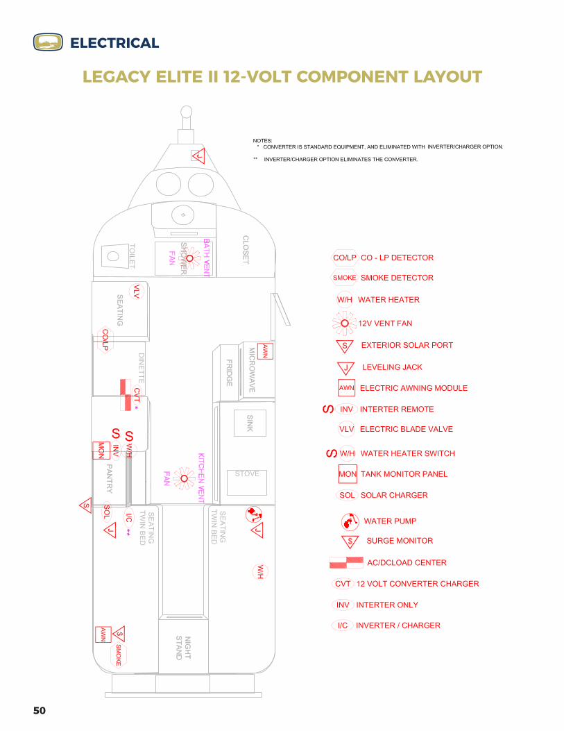
50
ELECTRICAL
LEGACY ELITE II 12-VOLT COMPONENT LAYOUT

51
ELECTRICAL
LEGACY ELITE II 12-VOLT ENTERTAINMENT LAYOUT

52
CLOSETLIGHTS
MAIN CABINLIGHTS
OUTSIDE COURTESYLIGHTS
PORCHLIGHTS
STREETAWNING
REAR CAMERA CELL/WIFIAMPLIFIER
CABINETLIGHTS
MASTERLIGHTS
CURBAWNING
AWNINGIN
LED LTS ON
OUT OFF
AWNINGIN
LED LTS ON
OUT OFF
* Switch will be plugged if not equipped with optional components.
MAIN ENTRY SWITCH PLATE (LEGACY ELITE II SHOWN - LEGACY ELITE DOES NOT HAVE STREET AWNING SWITCH)
ELECTRICAL
ENTRY SWITCH PANELS
* * *
AWNING REMOTE
Turns on/off led light strip on
Locks awning controls
Unlocks awning controls
Retracts awning in
Stops awning from being retracted or extended
Extends awning out
Toggles through channels(if equipped with dual awnings)
Ch. 0 - Controls both awningsCh. 1 - Controls curbside awningCh. 2 - Controls streetside awning
* Ensure the master awning switch(es) are turned on to operate the awning remote.

53
LIGHTING & SWITCHESThe main light switches are located on the switch panel just inside the door. MASTER LIGHTS switch allows you to turn on or off power to all light switches. PORCH LIGHTS switch will turn on and off the LED porch lights on the curbside and street side of your Ollie. Legacy Elite models feature one LED light on each side of the trailer. Legacy Elite II models feature two LED lights on each side.OUTSIDE COURTESY LIGHTS switch will turn on and off all of the outside courtesy lights located on both sides of your Ollie near the bottom of the shell. MAIN CABIN LIGHTS switch controls the main LED lights that are located on the interior roof of the trailer. CLOSET PORCH LIGHTS switch controls the LED light in the closet.CURB AWNING POWER switch is the master power button for the powered awning on the curbside of the trailer. STREET AWNING POWER switch is the master power button if the trailer is equipped with the optional powered awning on the street side of the trailer. Only available on Legacy Elite II models.REAR CAMERA switch provides power to the optional rear backup camera.CELL/WIFI AMPLIFIER switch is the master switch to provide power to the optional cell phone booster and WIFI booster.CABINET LIGHTS switch controls the LED lights in the upper cabinets.DINETTE LIGHTS are touch enabled LED lights. Touch the center of each light to turn on or off as desired. The MASTER LIGHTS switch will turn these lights off but not on.REAR LEFT LIGHTS are touch enabled LED lights. Touch the center of each light to turn on or off as desired. The MASTER LIGHTS switch will turn these lights off but not on.REAR RIGHT LIGHTS are touch enabled LED lights. Touch the center of each light to turn on or off as desired. The MASTER LIGHTS switch will turn these lights off but not on.BATHROOM LIGHTS switch is located above the dinette on Legacy Elite models and on the bottom of the upper cabinet above the toilet on Legacy Elite II models. WATER PUMP switch is the master switch to provide power to the water pump. There is one in the main cabin on the SEE LEVEL monitor and one in the bathroom.INSIDE COURTESY LIGHTS switch is located above the streetside bed on Elite model and under the pantry on Elite II model. The switch controls the LED lights near the floor throughout the interior of the trailer.WATER HEATER switch is the master switch to provide power to light the burner on the water heater.If your exterior lights are not working but you have power to your trailer, check the fuses in the fuse panel located in the rear upper cabinet and replace if necessary.
ELECTRICAL

54
LEGACY ELITE 12-VOLT BATTERY CONFIGURATION
(TWO BATTERIES)
54
ELECTRICAL
LEGACY ELITE
(TWO BATTERIES)
ELITE 12 VOLT BATTERY CONFIGURATION
Note:Battery Jumpers are 2/0
Rev. 11/06/2020
Inverter Ground (2/0 Black Cable)
Solar Ground (6ga Black Wire)
Chassis Ground (4ga Yellow Wire)Solar Hot (6ga Red w/ Black Stripe)
Inverter Hot (2/0 Red Cable)
Compliancy Note: No more than four terminals allowed per stud. (ANSI/RVIA LV 6-1.14)
Main 12V Hot (4ga Red Wire)
A B
JUMPER PART # LEGEND
A - Part# 1511B - Part# 1512
ELECTRICAL

55
LEGACY ELITE 6-VOLT AGM BATTERY CONFIGURATION
(TWO BATTERIES)
55
ELECTRICAL
LEGACY ELITE
(TWO BATTERIES)
3/8” Marine Terminal (+)
Rev. 11/06/2020
ELITE 6 VOLT BATTERY CONFIGURATION
Inverter Ground (2/0 Black Cable)
Solar Ground (6ga Black Wire)
Chassis Ground (4ga Yellow Wire)Solar Hot (6ga Red w/ Black Stripe)
Inverter Hot (2/0 Red Cable)
Note:Battery Jumper is 2/0
Compliancy Note: No more than four terminals allowed per stud. (ANSI/RVIA LV 6-1.14)
Part# 1489
Main 12V Hot (4ga Red Wire)
ELECTRICAL

56
LEGACY ELITE12-VOLT LITHIUM BATTERY CONFIGURATION
(TWO BATTERIES)
LITHIUM BATTERY CONFIGURATION
Solar Ground (6ga Black Wire)
Chassis Ground (4ga Yellow Wire)
Solar Hot (6ga Red w/ Black Stripe) Inverter Ground
(4/0 Black Cable)
Inverter Hot(4/0 Red Cable)
Main 12V Hot (4ga Red Wire)
Note:Battery Jumpers are 4/0
LEGACY ELITE
ELECTRICAL
(TWO BATTERIES)
56
Battery Heater(14ga Black Wire)
Battery Heater(14ga Red Wire)
ELECTRICAL

57
LEGACY ELITE II 12-VOLT BATTERY CONFIGURATION
(FOUR BATTERIES)
57
ELECTRICAL
LEGACY ELITE II
(FOUR BATTERIES)
Solar Ground (6ga Black Wire)
Battery Temp Sensor (Black Wire)
Chassis Ground (4ga Yellow Wire)
Solar Hot (6ga Red w/ Black Stripe)
Main 12V Hot (4ga Red Wire)
Inverter Ground (2/0 Black Cable)
Inverter Hot(2/0 Red Cable)
Note:Battery Jumpers are 2/0
3/8” Marine Terminal (+)
A
B C
A
C
D
57
ELECTRICAL

58
LEGACY ELITE II 6-VOLT AGM BATTERY CONFIGURATION
(FOUR BATTERIES)
58
ELECTRICAL
LEGACY ELITE II
(FOUR BATTERIES)
Solar Ground (6ga Black Wire)
Battery Temp Sensor (Black Wire)
Chassis Ground (4ga Yellow Wire)
Solar Hot(6ga Red w/ Black Stripe)
Main 12V Hot (4ga Red Wire)
Inverter Ground (2/0 Black Cable)
Inverter Hot(2/0 Red Cable)
Note:Battery Jumpers are 2/0
3/8” Marine Terminal (+)
5/16” Marine Terminal (-)
ELECTRICAL

59
LEGACY ELITE II 12-VOLT LITHIUM BATTERY CONFIGURATION
(TWO BATTERIES)
59
ELECTRICAL
LEGACY ELITE II
(TWO BATTERIES)
LITHIUM BATTERY CONFIGURATION
Solar Ground (6ga Black Wire)
Chassis Ground (4ga Yellow Wire)
Solar Hot (6ga Red w/ Black Stripe) Inverter Ground
(4/0 Black Cable)
Inverter Hot(4/0 Red Cable)
Note:Battery Jumpers are 4/0
Rev. 11/06/2020Compliancy Note: No more than four terminals allowed per stud. (ANSI/RVIA LV 6-1.14)
Main 12V Hot (4ga Red Wire)
ELECTRICAL

60
ELECTRICAL
LEGACY ELITE II 12-VOLT LITHIUM BATTERY CONFIGURATION
(THREE BATTERIES)
LEGACY ELITE II
(Three BATTERIES)
ELECTRICAL
Inverter Hot(4/0 Red Cable)
Solar Hot (6ga Red w/ Black Stripe)
Main 12V Hot (4ga Red Wire)
Note:Battery Jumpers are 4/0
Solar Ground (6ga Black Wire)
Chassis Ground (4ga Yellow Wire)
Inverter Ground (4/0 Black Cable)
60
Battery Heater(14ga Red Wire)
Battery Heater(14ga Black Wire)

61
ELECTRICAL
THIS PAGE WAS LEFT BLANK INTENTIONALLY

62
PLUMBINGOVERVIEWOliver’s plumbing can be divided into two separate systems. The fresh water system consists of those items which are used to deliver water for your use. The wastewater system includes the drains and tanks that store and remove water that has been used.
The plumbing system has the dual ability to be self-contained with onboard storage, complimented by a digital holding tank monitoring system, or to use facilities provided by an external pressurized source. In either case, the components of the system operate like those in your home. Components of the plumbing system consist of strong, lightweight, corrosion resistant materials. By following the instructions outlined here, you can expect efficient operation with minimum maintenance. Fresh water is provided from an external pressurized source or from the fresh water storage tank. These connection on the Oliver are located at the rear, bottom driver side corner of the trailer.
INLETSCITY WATER INLET: The city water connection is located on the lower rear street side of the trailer. Water provided from outside the Oliver is pressurized by the system from which it is delivered. When you connect your Oliver to an outside source, the fresh water tank and the water pump are kept separate from the remainder of the system by an in-line check valve.
TO ATTACH THE OLIVER TO A CITY WATER CONNECTION:1. Remove the cap from the city water inlet on the side of the Oliver.2. Attach a potable water hose to the outside source of water.3. Connect the other end of the hose to the Oliver city water inlet. Be sure to use a
pressure regulator (included at delivery).
WARNING: FAILURE TO USE A PRESSURE REGULATOR MAY DAMAGE THE INTERNAL WATER SYSTEM
4. Turn on the outside source of water. Open the various faucets gradually to clear the air from the lines. Close the faucets when the water flows freely. (May need to bleed air from the pressure relief valve.)
5. Be sure water heater is full of water before turning on the hot water heater.
NOTE: DO NOT turn the water pump on when using water from an external pressurized supply. This could result in damage to the water pump.
FRESH WATER INLET: The fresh water connection is located on the lower rear street side of the trailer. When an outside source of water is unavailable, water can

63
PLUMBINGbe drawn from the fresh water storage tank through the use of the 12-volt pump system. The tank is filled through a standard pressurized water hose connection located at the rear area next to the city water inlet. Standard capacity of the fresh water tank is 30 gallons.
TO FILL THE FRESH WATER TANK FROM PRESSURIZED WATER:1. Remove the cap from the fresh water inlet.2. Attach a fresh water hose to an outside water source.3. Attach the other end to the Oliver fresh water inlet.4. Turn on water source; fill until water starts to run from the fresh water overflow,
which is located on the opposite side, between the aluminum steps and the refrigerator vent.
5. When the tank is filled, turn off and disconnect the outside water hose and re-install the water cap.
BOONDOCKING INLET: The boondocking inlet is located on the lower right of the rear of the trailer. This inlet allows you to fill the fresh water tank from a potable water container using the onboard water pump. The boondocking inlet is also used to pull non-toxic RV anti-freeze into the water lines when winterizing. See the winterization details in the maintenance section for more details. TO FILL THE FRESH WATER TANK FROM A PORTABLE WATER CONTAINER (NON-PRESSURIZED):
1. Remove the cap from the boondocking inlet at the rear of the travel trailer/
2. Attach a cut off potable hose to the boondocking inlet.
3. Insert the other end into the potable water container.
4. Go inside and change the water pump valve configuration to the boondocking mode under the curb side access panel. (See valve confgurations on next pages).
5. Turn the main water pump switch on until all water is pumped from the portable water container into the fresh water tank.
6. When the tank is filled, turn off the water pump, turn the water pump valves back to the normal configuration, disconnect the outside water hose and re-install the inlet cap.
PLUMBING
Boondocking Valve Configuration on next page

64
NOTE: Always fill the tank with clean water from a known safe source. Make sure to cap the water inlet when the tank is filled. Also, always fill system with a hose that you know is clean and is used only for this purpose. Water from tanks are not intended for consumption.
When traveling, you may want to drain the tank, or keep the quantity of water in it to a minimum. This reduces the total weight of the Oliver for travel. When draining the tank make sure that the water pump has been turned off. The fresh water tank drain valve is concealed beneath the rear passenger compartment. Turning the water valve ¼ turn can drain water in the tank. The water will be released below the trailer near the rear bumper. Do not forget to close the valve after emptying the fresh water tank.
See diagram of the fresh water tank drain valve on next page
ELITE VALVE CONFIGURATION
PLUMBING
ELITE II VALVE CONFIGURATION
Water Pump
Accumulator
Filter
Normal Valve Con�guration
Water Pump
Filter
Boondocking Valve Con�gurationDrawing water from rear inlet to �ll fresh tank.
Accumulator
Boondocking Valve Con�gurationDrawing water from rear inlet to �ll fresh tank.
Water Pump
Filter
Accumulator
Normal Valve Con�guration
Water Pump
Filter
Accumulator
1
2 3
4
1
2 34
12 3 4
12 3 4

65
WATER PUMPWhen using water from the fresh water tank, the system must be pressurized. A self-priming 12-Volt DC pump, is provided to handle this function. A pump on/off switch is located on the See Level 2 monitor located in the main cabin and in the bathroom under the vanity.
When initially starting up the self contained water system:
1. Make sure the tank is filled with water.
2. Place the pump control switch in the ON position
3. Allow time for the pump to fill the hot water tank and fully pressurize the system.
4. The system is now ready for use.
NOTE: When the faucets are turned on the water pump should engage to deliver water and keep the system pressurized.
FAUCETS AND SHOWER
FAUCET/SHOWER CONTROLS BATHROOM FAUCET: The bathroom faucet is installed with a 4-foot flexible hose for showering and for cleaning the shower. To turn on the bathroom faucet, lift the handle up to open the flow of water. Turn the lever counter-clockwise to adjust the water to the desired temperature. To use the bathroom faucet as a shower, pull the head from the faucet to extend the flexible hose and place into the shower mount on the upper right wall.
PLUMBING
FRESH WATER DRAIN VALVE

66
KITCHEN FAUCET: The kitchen faucet features a pull down spout and two-way spray head. To turn on the kitchen faucet, pull the handle on the left out to open the flow of water. Push the handle counter-clockwise to adjust the water to the desired temperature. You can change the water flow from spray to stream by toggling the switch on the back of the faucet head.
OUTSIDE WASH STATION: The outside wash station is located in the basement storage compartment on Legacy Elite II models and battery compartment on Legacy Elite models, both on the rear street side of the trailer. Pull the white cover down to access the faucet and controls. Turn the hot (red) and cold (blue) knobs as need to the desired temperature. The faucet is connected to a flexible hose that stores inside the casing. Push the lever on the back of the shower head to open the flow of water. The flow of water can be locked open or closed by pushing or pulling the lever as needed.
CARE OF SHOWER: From time to time you will want to remove soap film from the shower wall. Use any mild household foam cleaner. Never use harsh chemicals or abrasives on the shower walls or shower base. After taking your shower, leave the bath door open to allow the humidity and moist air to escape. Also leave the bath door open when the unit is not in use. This allows circulation of air and prevents mildew.
WATER PRESSURE
NOTE: When trying to drain entire on-board fresh water system, make sure to open faucets and remove water heater drain plug. This will equalize the air pressure and allow free water flow.
The self-contained water system is a demand system. This means that the water pump will run whenever there is a need for water.
TOILETThe marine style toilet installed in your Oliver is connected to the pressurized fresh water system. The toilet is equipped with a foot pedal located at the bottom front side of the toilet when facing it. To flush, step on the pedal and depress fully. To add water step on the pedal and hold it down half way until the desired level is reached.
Unnecessary frequent flushing of the toilet will quickly deplete your fresh water supply and fill your holding tank. If the black water tank becomes full, you will no longer be able to flush the stool until the tank can be drained.
Always use deodorizing agents specifically designed for use in holding tank systems and biodegradable toilet paper. Never use chlorine or caustic chemicals, such as drain cleaners or laundry bleach, in your system. They will damage your toilet seals. Never allow foreign objects (non-dissolving items) to be flushed down the toilet.
PLUMBING

67
Follow the toilet manufacturer’s recommendations supplied with the toilet for cleaning and maintenance.
If you have a composting toilet, see the manufacturer’s component manual for operating instructions. TANK MONITORINGThe monitor panel allows you to check the approximate liquid levels in the fresh water, gray and black holding tanks, along with the charge on the batteries. Refer to manufactures manual for further assistance.
DUMPING WASTEWASTEWATER SYSTEM: The wastewater system in your Oliver can be described as two separate systems; a gray water system that consists of the drain lines and a holding tank for wastewater from the sinks and shower and a black water system, which includes the holding tank and drain for toilet wastes. Each system is self-contained and allows disposal of the wastewater at designated dump stations.
The gray water system has drain traps. Both tanks are vented to equalize air pressure and disperse odors caused by drain water and waste. Sometimes stop and go while driving may empty the drain traps of water and allow the odors of the gray water tank to come into the coach. Residue in the drain water lines also can produce odors. To combat gray water holding tank odor, an approved deodorizing agent should be used. An agent that dissolves grease and fats and contains a detergent will help keep tank and drain lines clean and free-flowing.
HOLDING TANKS: The Oliver Travel Trailers holding tanks hold 30 gallons in the grey tank and 15 gallons in the black tank. The fresh water tank has a dump valve, which permits dumping it independent from the black and grey tank. Each tank should be emptied often at a dump station designated for this purpose. Most national, state and private campgrounds have dumping facilities. Many service stations, particularly along interstate highways, also have these facilities and are listed dumping station locations across the nation.
DUMP OUTLETS
TO EMPTY THE HOLDING TANKS:1. Remove the two pins from sides of aluminum bumper, and pull the flexible
sewer hose out.2. Remove the end cover from the drain line and install the flexible drain hose.
Position the flexible drain hose over the dump station inlet. Make sure drain line is securely attached. Both drain termination handles are located below the courtesy wash station on the street side rear of the trailer, in the compartment (above the water inlets).
PLUMBING

68
3. Drain the black water tank first, by pulling the termination valve handle toward you. Make sure to allow sufficient time for the tank to completely drain and then rinse the tank with several gallons of water by depressing the toilet’s flush pedal. Close the toilet’s flush lever and fill the toilet with water, then flush. This creates an additional force to clean the tank more completely.
4. Drain the gray water tank by pulling the termination valve handle toward you. Draining the gray water tank last, with its soapy water, helps to further rinse the drain and flexible drain hose.
5. When tanks are emptied, close termination valves by pushing handles back to closed positions.
6. Remove flexible drain hose from the dump station inlet, using the shower hose, rinse off the flexible drain line if needed, cap it and replace it in the storage behind the rear bumper. Secure the bumper and cap the dump station inlet.
WASTE HANDLING
The following guidelines will help to ensure trouble free operation:
• Never put anything in the black water tank other than toilet paper, especially for RV systems.
• Do not put automotive antifreeze, household toilet cleaners or drain cleaners or any solid material into the wastewater system.
• Always use chemicals in the black water system, using cleaners made for the RV systems.
• Always keep the drain cap in place and termination valves closed when not dumping your tanks
• After every third time the holding tanks are emptied, fill and flush both tanks with clean, fresh water a couple of times to keep them clean and clear.
If connecting to a campsite sewer inlet, DO NOT open termination valves until tanks are ¾ full. DO NOT keep black water valve open when parked. Solid wastes are not flushed directly into sewer system. Only liquid waste is drained. Water must accumulate and chemicals in tank need time to break down solids before they can be released. If draining gray water tank directly into sewer inlet while
PLUMBING

69
parked, make sure to close termination valve for a period of time before leaving, allowing some water to accumulate in tank to use for flushing drain line and flexible hose.
BLACK TANK FLUSH PORT: Your Oliver comes standard with a black tank flush port on the street side near the bottom of the unit. This allows you to connect an outside water supply and rinse out your black tank.
• Hook up the appropriate hose to the black tank flush inlet.
• Make sure the black tank handle is closed and turn on the water.
• Watch the tank gauge on the See Level monitor and turn off the water before full.
• Drain the tank into an approved dumping location.
WARNING: DO NOT OVERFILL THE BLACK TANK (18.5 GALLONS)!!!
DO NOT OPEN BLACK TANK DUMP VALVE UNTIL YOU ARE READY TO DUMP!!!
NOTE: Always remember to clean up the dumping site before leaving. Never empty your holding tanks directly on the ground, a roadway, river or stream
DO NOT POLLUTE!!!
WATER SYSTEM TROUBLESHOOTINGYour plumbing may develop problems. Most of these problems can be greatly reduced, if not altogether eliminated, by following a schedule of planned inspections and maintenance. Neglect of proper maintenance procedures is the usual cause of most water system problems.
Road vibrations and excessive pressure from some city water sources are the main physical causes of water system damage. It is important to inspect all plumbing joints and fittings often for cracks and leaks. Water leaking from a plumbing joint can cause considerable damage if left unchecked.
There probably is a leak somewhere in the fresh water system if the pump is running and all the faucets and valves are closed. When the leaking fitting has been identified, turn off any external water source and turn off the water pump before attempting to stop the leak by tightening.
DO NOT over tighten! Plastic fittings rarely need to be tightened with a wrench. If these fittings leak after tightening, disconnect the fitting and check for dirt, scale or other foreign substances that may be causing the leak. Clean the fitting thoroughly and reinstall. If leaking persists, shut off the water supply until the fitting can be properly replaced. Check with Oliver Travel Trailers for correct method of replacement and replacement parts.
PLUMBING

70
TERMINATION VALVE MAINTENANCE: During the camping season, use a slide valve lubricant. Two to four ounces of this water-soluble additive is poured down the drain into the gray tank and flushed down the toilet into the black tank to lubricate the inside of the dump valve blades and to coat the inside of the drains and tanks to aid in complete draining and trouble-free valve operation. One of the most disagreeable RV repairs is replacing a stuck or broken dump valve with a full holding tank. RV technicians hate it, and they get paid to do it. It is certainly no fun when it happens to you, miles from nowhere, in the middle of a vacation getaway. A little attention to the waste systems can avoid such scenarios.
Proper winterization procedures of plumbing systems will typically be all that is necessary to prevent the damage caused by freezing. Freezing damage can harm any component of the system, including the water tanks, toilet, pump, and all piping. Be sure to follow the winterization process outlined in the Maintenance section of this manual. Also, be sure to discuss any additional precautions that should be taken to winterize your trailer’s plumbing system with your dealer. Local climates vary, and winter maintenance needs may be affected.
Be sure to read the literature supplied with plumbing components, such as the pump for troubleshooting tips. Also, remember that an electrical problem can cause water system problems. A variety of reasons can cause a lack of power to the pump. If you are unsure of how to locate and/or repair a plumbing problem, it is best to have your dealer or a qualified plumber handle the job.
WINTERIZATIONIf the Oliver is used in cold weather and left unheated for an extended period, the water in a tank or drain line may freeze. If this occurs you should take immediate steps to thaw it before damage to the system occurs. DO NOT continue to use water system components if such a condition exists. If damage has occurred, make sure to have it repaired before using again.
Before using the system again in warmer weather completely flush the system with water, flush the toilet and sanitize the entire fresh water system.
To see the full Winterization Process see the maintenance section of this manual and check out our Winterization video tutorial at:
https://olivertraveltrailers.com/oliver-university/videos/
PLUMBING

71
PLUMBINGLEGACY ELITE PLUMBING DIAGRAM
LEGACY ELITE II PLUMBING DIAGRAM
Fresh Water TankBottom Drain
Top Fill
Tank Drain
Outside Faucet
FreshTank Fill
Inlet
City Water Inlet
Water Accumulator
Suction Side
Pressure Side
Water Heater Rear Inlet
Trai
ler F
ront
Grey Water Tank
Black Water Tank
A. 130", B. 95", C. 15", D. 16", E. 33", F. 3", G. 13",H. 86", I. 70.75", J. 107.5", K. 33.75", L. 115",M. 13.25", N. 20.75", O. 21.25", P. 17', Q. 17'
A.
B.
C.
D.
2"E.
F.
H.
I.
K.
M.N.O.
Q.
P. L.
J.
G.
Truma AquaGo Water Heater
Hot
Cold
Standard Water HeaterHot
Cold
Extension
Check valve
Ball valve
BendInlet representation
Push-Fit 90
Push-Fit Connection
Elbow
Elbow with female �tting
Female �tting
Push-Fit tee
Plastic tee
Diverter valve
Fitting extension
Sharkbite Valve
Rev. 06/01/2021
Elite II – Pex Layout
City Water Inlet
Fresh Water Inlet
Rear Inlet
Outside Faucet
Water Pump
Accumulator
Tank DrainFresh Water Tank
Fill
Suction
Water Heater
Extension
Brass 90
Rev. 06/01/2021
Check valve
Ball valve
BendInlet representation
Push-Fit 90
Push-Fit Connection
Elbow
Elbow with female �tting
Brass tee
Female �tting
Push-Fit tee
Plastic tee
Diverter valve
Fitting extension
Sharkbite Valve
B B
B
B
B
B
A. 15', B. 15', C. 54.25", D. 54", E. 4", F. 5.5", G. 25.5",H. 16.5", I. 19", J. 16", K. 19.5", L. 29", M. 3", N. 24.5",O. 2.125", P. 106.5", Q. 64", R. 57.5", S. 10.5"
C.
A.
D.
B.E.
K.
J.
F.
G. H.
I.
L.
M.
N.O.
Q.
R.
S.
P.
Trai
ler F
ront
Black Water Tank
Black Tank Flush Inlet
Elite I – Pex Layout
VALVE ONLY USED IN FACTORY TESTING

72
PROPANEOVERVIEW The propane tanks are stored in the fiberglass propane tank housing located at the front of your travel trailer. Your Oliver comes standard with two 20 pound propane tanks or if you purchased the Legacy Elite II, you may have upgraded to two 30 pound propane tanks.
The propane system helps operate several components on your travel trailer. The water heater, furnace, stove, refrigerator and optional propane quick connects all work using propane as fuel. Read all manufacturer appliance literature, including the information on the LP bottles and regulator, provided in the unit packet and follow any instructions. Refer to manufacturers manual.
PURGING THE SYSTEMIf you happen to run your propane tanks completely out or if your trailer has been in storage, you will likely need to purge the propane lines to ensure a flow of propane is supplied to the components that use the gas.
Since several components have built-in safety functions that require a reset if the burners do not ignite, we suggest turning on the flow of propane to the stove and attempt to light the burner. Once your stove is lit, you should then be able to turn on your other components that use propane.
PROPANE TANK HOUSINGYour Oliver is equipped with a removable lid that allows you full access to the tanks.
1. The housing lid is held in place by two easy to use hood latches. To release the latch, simply pull the latch back from the top.
2. Once both hood latches have been released, carefully lift the fiberglass lid up and over the propane cylinders inside.
3. The two propane cylinders are each tightly secured in the propane tray mounted to the frame. The securing mechanism also holds the propane regulator in place.
4. If you are simply needing to open or close the tank or access the regulator controls, you can also simply open the round propane deck port located on the front of the housing lid for quick access.
USING THE REGULATORTo supply gas to the components that use propane, you will need to open the valves on the propane tanks. The regulator controls the flow of propane throughout the LP lines. The two-stage automatic changeover regulator controls the flow of propane throughout the LP lines.

73
PROPANE5. Point the changeover lever to the left or right to indicate your primary propane
tank. When gas is present in your primary tank, the indicator on the front of the regulator will be green.
6. Once your primary tank is depleted, the automatic changeover function of the regulator will automatically switch to the reserve tank and the indicator will be red, letting you know the primary tank is depleted and the reserve tank is now being used.
7. If needed, you can point the changeover lever toward your reserve tank and view the indicator to let you know how much gas remains in the reserve tank.
USING THE QUICK CONNECTS OPTIONMost propane grills or campfires come with a hose that connects directly to a propane bottle. In order to use the propane quick connects on your trailer, you will need a hose that uses a 1/4 inch male NPT quick connect fitting. A propane hose is not supplied with your Ollie, but you will receive two quick connect fittings.
1. Once you have the proper fitting installed on your grill or campfire, first turn the lever on the quick connect to the OFF position.
2. Next, pull the blue dust cap off, push the sleeve back on the connection and insert the male fitting into the female quick connect socket.
3. Push the fitting in until you feel it lock.
4. Turn the lever on the quick connection back to the on position to open the flow of propane to your grill, campfire or other propane component.
REPLACING OR REMOVING THE TANKS
1. To remove your propane tanks for refilling, first ensure the tank is turned off and unscrew the hose connection by turning the connector counter-clockwise.
2. Between the tanks, remove the large wing-nut by turning it counter-clockwise until it comes off the threaded rod and then lift the regulator up and set it to the side.
3. Now, lift the bar that secures the two tanks and remove or allow it to drop between the tanks.
4. Carefully lift the tank from the propane housing.
5. Once the propane tank is refilled, reverse the steps to secure the tanks inside the propane housing.
For additional safety, it is recommended to turn off your propane tanks while traveling.
PROPANE

74
EXTERIORENTRY STEPSA two step entry system is provided as standard equipment on all Oliver Travel Trailers. Lift up on the steps and pull forward, then fold out the bottom step. The steps are held in place by a detent on each side. To retract the steps, fold the bottom step and lift the steps out of the detent and push them back to the original stored position. Make sure that the steps are secure in the retracted position before moving the Oliver Travel Trailer. Make sure to keep fingers away from the sliding mechanism when extending or retracting the steps. Use extra caution if exiting or entering the Oliver without the use of the step.
ENTRY DOORThe entry doors consist of both the exterior door and the screen door. The screen door is used for ventilation when the Oliver is parked. Always use the door retainer latch if you want to leave the door open. Failure to do so may result in damage to door.
DO NOT attempt to drive or pull the Oliver with the doors open.
DO NOT use the exterior door retainer during windy conditions
DO NOT drive or pull the Oliver with the outer door open and the screen door closed. The doors may be damaged and it is a safety hazard.
EXTERIOR STORAGEIf you purchased a Oliver Legacy Elite II, it will come equipped with a dry basement storage compartment. The dry basement storage can be accessed from the inside or the outside of the trailer. From the outside, the basement storage is located on the rear street side of the trailer. It is secured by a marine style latch that can also be locked using the small key found on the supplied key ring. You will find an LED light mounted inside that conveniently illuminates the entire storage area. To turn the light on or off, reach inside and simply toggle the switch built in to the light as needed. Inside the basement storage you will find a number of items that come standard with your travel trailer, including one 20 foot sewage kit, one 25 foot water hose, one 25 foot 30-AMP shore power cord, a water inlet quick connect kit, one male to female water inlet adapter, one 120-Volt receptacle adapter, one lug wrench and two male NPT propane quick connect fittings if you purchase the propane quick connects option.
AWNINGAll Oliver Travel Trailers comes standard with a powered curb side awning. On Legacy Elite II models, we also offer an optional awning available on the street side

75
of the trailer. Before you open your awning, be sure that you have enough open space next to the side of the trailer to fully extend the awning open.
You will find the remote stored in a kitchen galley drawer. Ensure it is secured in a safe place while in transit as it could fall and be damaged.
Before using the remote, ensure the master power switch on the main switch panel is turned on, and always turn off the master power switch to the awning before traveling.
On your remote, you will find controls for opening and closing the awning along with buttons to turn the integrated LED lights on or off. The powered awning also features a motion sensor. In the case the sensor detects strong winds, the awning will automatically close. The sensitivity of the sensor can be adjusted if necessary. See your awning manual for more details.
See Awning Remote on page 52 for operating the powered awning.
STORAGE BASKETA popular add on, your storage basket will be secured on the front of your travel trailer, It is useful for transporting *generators or other camping accessories.
*Never operate a portable generator in this basket. Check with your generator’s manufacturer to determine a safe operating distance from the LP gas system.
ACCESSORY RECEIVERUseful for a bike rack or other compatible camping accessories. An RV approved bike rack or other accessory that fits a 1.25” receiver is recommended.
EXTERIOR
wNEVER remove this label NE JAMAIS N’enlevezr JAMAIS cette étiquette
Pour éviter les accidents entraînant des
BLESSURES GRAVES, des DÉCÈS Ou ou des DOMMAGES MATÉRIELS :
To prevent SERIOUS
INJURY, DEATH, or PROPERTY DAMAGE:
• Il faut s’S’assurer que le contenu de panier de rangement est correctement sécurisé.• NE PAS dépasser le POIDS MAXIMAL de 55 lb (équivalant de 25 Kg) pour le panier de rangement.• NE JAMAIS Ne faites re JAMAIS fonctionner un générateur portable dans le panier de rangement.• VÉERIFIER avec votre fabricant du générateur pour déterminer une distance de fonctionnement en toute sécurité.• TOUJOURS VEÉRIFIER que le poids de la remorque est correctement réparti.• Pour plus d’informations, visitez nous à olivertraveltrailers.com
• Ensure that the contents of the storage basket are properly secured.
• DO NOT exceed the storage basket’s MAXIMUM WEIGHT CAPACITY of 55 LBS.
• NEVER operate a portable generator in the storage basket.
• CHECK with your generator’s manufacturer to determine a safe operating distance.
• ALWAYS CHECK whether your trailer’s weight is properly distributed.
• For additional information visit us at olivertraveltrailers.com
WARNING ATTENTION AVERTISSEMENT
wNEVER remove this label NE JAMAIS N’enlevezr JAMAIS cette étiquette
Pour éviter les accidents entraînant des
BLESSURES GRAVES, des DÉCÈS Ou ou des DOMMAGES MATÉRIELS :
To prevent SERIOUS
INJURY, DEATH, or PROPERTY DAMAGE:
• Il faut s’S’assurer que le contenu de panier de rangement est correctement sécurisé.• NE PAS dépasser le POIDS MAXIMAL de 150 lb (équivalant de 68 Kg) pour le panier de rangement.• NE JAMAIS Ne faites re JAMAIS fonctionner un générateur portable dans le panier de rangement.• VÉERIFIER avec votre fabricant du générateur pour déterminer une distance de fonctionnement en toute sécurité.• TOUJOURS VEÉRIFIER que le poids de la remorque est correctement réparti.• Pour plus d’informations, visitez nous à olivertraveltrailers.com
• Ensure that the contents of the storage basket are properly secured.
• DO NOT exceed the storage basket’s MAXIMUM WEIGHT CAPACITY of 150 LBS.
• NEVER operate a portable generator in the storage basket.
• CHECK with your generator’s manufacturer to determine a safe operating distance.
• ALWAYS CHECK whether your trailer’s weight is properly distributed.
• For additional information visit us at olivertraveltrailers.com
WARNING ATTENTION AVERTISSEMENT
WARNING To prevent SERIOUS
NEVER remove this label
INJURY, DEATH, or PROPERTY DAMAGE:• DO NOT exceed this receiver’s MAXIMUM WEIGHT CAPACITY of 150 LBS. (This includes both racks and baskets, as well as their contents)• ALWAYS CHECK whether your trailer’s weight is properly distributed.• DO NOT modify this receiver. • DO NOT use an adapter on this receiver.• DO NOT exceed a total length of 24” from the end of the receiver to the outside of the attached accessory.• For additional information, visit us at olivertraveltrailers.com.
ATTENTIONNe retirez JAMAIS cette étiquette olivertraveltrailers.com
GRAVES, LE DÉCÈS ou LES DOMMAGES MATÉRIELS:Pour prévenir les BLESSURES
• NE PAS dépasser la CAPACITÉ MAXIMALE DE POIDS de cet attelage de 68 kg. (Y compris les supports et les paniers et leurs contenus)
• NE PAS utiliser un adaptateur pour cet attelage• NE PAS dépasser une longueur totale de 61 cm (24’’) du bout de l’attelage à l’extérieur
de l’accessoire attaché.• Pour plus d’informations, visitez olivertraveltrailers.com
LEGACY ELITE STORAGE BASKET LIMIT - 55 LBS LEGACY ELITE II STORAGE BASKET LIMIT - 150 LBS
ACCESSORY RECEIVER WEIGHT LIMIT - 150 LBS

76
EXTERIOR
WHEELS AND TIRES Tires play an important role in the load carrying capacity of the vehicle. To ensure good tire life, check them often. Inspect the general condition of the tires, as well as the air pressure.
Always check the air pressure when the tire is cold. Tires that are hot from traveling will show high pressures. The maximum tire pressure and the load carrying capacity of the tire are imprinted on each tire sidewall. Always inflate your tires to their correct pressure. Don’t over or under inflate. Under inflated tires will run hot, shorten the tire’s life and decrease the Oliver safe load limit. Over inflated tires will cause a rough and bouncing ride that can damage RV components or cargo. It is a good idea to always carry an accurate tire pressure gauge in the RV to make these checks. If pressure checks indicate a tire is losing air, check for signs of valve leakage, penetration or wheel and rim damage. Under or over inflating tires can cause tires to fail.
The way you drive can have a significant effect on the wear and life of tires. High speeds, unusual use of the brakes, taking corners too quickly and bad roads all can contribute to the early wear and failure of your tires. When you drive on surfaces with holes or rocks and other loose objects that can damage tires and cause misalignment, make sure to reduce speed and drive carefully. If you notice damage to a tire such as a bulge, uneven wear or damage by a foreign object or the road, have it inspected and repaired or replaced as needed at a reputable repair facility.
NOTE: Cold tire inflation pressure is defined as a tire that has not been used for three or more hours, or has been driven less than one mile. Tire inflation pressure of a hot tire may show an increase of as much as 6 psi over a cold tire. Measure and adjust tire pressure when the tires are cold.
WARNING: WHEN REPLACING A TIRE, MAKE SURE TO REPLACE IT WITH A TIRE OF THE SAME SIZE AND SPECIFICATIONS. NEVER USE DIFFERENT TYPES OF TIRES TOGETHER ON THE RV (I.E. RADIAL AND BIAS-BELTED). MIXING OF TIRES CAN CAUSE HANDLING PROBLEMS, AS WELL AS UNUSUAL TIRE WEAR, BOTH OF WHICH CAN CREATE UNSAFE OR EVEN DANGEROUS DRIVING CONDITIONS. IF YOUR SPARE IS OF A DIFFERENT SIZE BE ESPECIALLY CAREFUL AND USE ONLY TO GET TO THE NEAREST REPAIR FACILITY.
TIRE SAFETY INFORMATIONThis portion of the User’s Manual contains tire safety information as required by 49 CFR 575.6.
1.1. STEPS FOR DETERMINING CORRECT LOAD LIMIT – TRAILER: Determining the

77
EXTERIOR
load limits of a trailer includes more than understanding the load limits of the tires alone. On all trailers there is a Federal certification/VIN label that is located on the forward half of the left (road) side of the unit. This certification/VIN label will indicate the trailer’s Gross Vehicle Weight Rating (GVWR). This is the most weight the fully loaded trailer can weigh. It will also provide the Gross Axle Weight Rating (GAWR). This is the most a particular axle can weigh. If there are multiple axles, the GAWR of each axle will be provided. If your trailer has a GVWR of 10,000 pounds or less, there is a vehicle placard located in the same location as the certification label described above. This placard provides tire and loading information. In addition, this placard will show a statement regarding maximum cargo capacity. Cargo can be added to the trailer, up to the maximum weight specified on the placard. The combined weight of the cargo is provided as a single number. In any case, remember: the total weight of a fully loaded trailer cannot exceed the stated GVWR.
For trailers with living quarters installed, the weight of water and propane also need to be considered. The weight of fully filled propane containers is considered part of the weight of the trailer before it is loaded with cargo, and is not considered part of the disposable cargo load. Water however, is a disposable cargo weight and is treated as such. If there were a fresh water storage tank of 100 gallons, this tank when filled would weigh about 800 pounds. If more cargo is being transported, water can be off-loaded to keep the total amount of cargo added to the vehicle within the limits of the GVWR so as not to overload the vehicle. Understanding this flexibility will allow you, the owner, to make choices that fit your travel needs.
When loading your cargo, be sure it is distributed evenly to prevent overloading front to back and side to side. Heavy items should be placed low and as close to the axle positions as reasonable. Too many items on one side may overload a tire. The best way to know the actual weight of the vehicle is to weigh it at a public scale. Talk to your dealer to discuss the weighing methods needed to capture the various weights related to the trailer. This would include the weight empty or unloaded, weights per axle, wheel, hitch or king-pin, and total weight.
Excessive loads and/or under inflation cause tire overloading and, as a result, abnormal tire flexing occurs. This situation can generate an excessive amount of heat within the tire. Excessive heat may lead to tire failure. It is the air pressure that enables a tire to support the load, so proper inflation is critical. The proper air pressure may be found on the certification/VIN label and/or on the Tire Placard. This value should never exceed the maximum cold inflation pressure stamped on the tire.
1.1.1. TRAILERS 10,000 POUNDS GVWR OR LESS: Tire and Loading Information Placard – Figure 1-1
1. Locate the statement, “The weight of cargo should never exceed XXX kg or XXX

78
EXTERIOR
lbs.,” on your vehicle’s placard. See figure 1-1.
2. This figure equals the available amount of cargo and luggage load capacity.
3. Determine the combined weight of luggage and cargo being loaded on the vehicle. That weight may not safely exceed the available cargo and luggage load capacity.
The trailer’s placard refers to the Tire Information Placard attached adjacent to or near the trailer’s VIN (Certification) label at the left front of the trailer.
1.1.2. TRAILERS OVER 10,000 POUNDS GVWR (NOTE: THESE TRAILERS ARE NOT REQUIRED TO HAVE A TIRE INFORMATION PLACARD ON THE VEHICLE):
1. Determine the empty weight of your trailer by weighing the trailer using a public scale or other means. This step does not have to be repeated.
2. Locate the GVWR (Gross Vehicle Weight Rating) of the trailer on your trailer’s VIN (Certification) label.
3. Subtract the empty weight of your trailer from the GVWR stated on the VIN label. That weight is the maximum available cargo capacity of the trailer and may not be safely exceeded.
1.2. STEPS FOR DETERMINING CORRECT LOAD LIMIT – TOW VEHICLE:
1. Locate the statement, “The combined weight of occupants and cargo should never exceed XXX lbs.,” on your vehicle’s placard.
2. Determine the combined weight of the driver and passengers who will be riding in your vehicle.
3. Subtract the combined weight of the driver and passengers from XXX kilograms or XXX pounds.
4. The resulting figure equals the available amount of cargo and luggage capacity. For example, if the “XXX” amount equals 1400 lbs. and there will be five 150 lb. passengers in your vehicle, the amount of available cargo and luggage capacity is 650 lbs. (1400-750 (5 x 150) = 650 lbs.).

79
EXTERIOR
5. Determine the combined weight of luggage and cargo being loaded on the vehicle. That weight may not safely exceed the available cargo and luggage capacity calculated in Step # 4. 6. If your vehicle will be towing a trailer, load from your trailer will be transferred to your vehicle. Consult the tow vehicle’s manual to determine how this weight transfer reduces the available cargo and luggage capacity of your vehicle.
1.4. TIRE SAFETY - EVERYTHING RIDES ON IT: The National Traffic Safety Administration (NHTSA) has published a brochure (DOT HS 809 361) that discusses all aspects of Tire Safety, as required by CFR 575.6. This brochure is reproduced in part below. It can be obtained and downloaded from NHTSA, free of charge, from the following web site:http://www.nhtsa.dot.gov/cars/rules/TireSafety/ridesonit/tires_index.html
1.5. SAFETY FIRST–BASIC TIRE MAINTENANCE: Properly maintained tires improve the steering, stopping, traction, and load carrying capability of your vehicle. Under-inflated tires and overloaded vehicles are a major cause of tire failure. Therefore, as mentioned above, to avoid flat tires and other types of tire failure, you should maintain proper tire pressure, observe tire and vehicle load limits, avoid road hazards, and regularly inspect your tires.
1.5.1. FINDING YOUR VEHICLE’S RECOMMENDED TIRE PRESSURE AND LOAD LIMITS: Tire information placards and vehicle certification labels contain information on tires and load limits. These labels indicate the vehicle manufacturer’s information including:• Recommended tire size• Recommended tire inflation pressure• Vehicle capacity weight (VCW– the maximum occupant and cargo weight a
vehicle is designed to carry)• Front and rear gross axle weight ratings (GAWR– the maximum weight the axle
systems are designed to carry)
Both placards and certification labels are permanently attached to the trailer near the left front.
1.5.2. UNDERSTANDING TIRE PRESSURE AND LOAD LIMITS: Tire inflation pressure is the level of air in the tire that provides it with load carrying capacity and affects the overall performance of the vehicle. The tire inflation pressure is a number that indicates the amount of air pressure measured in pounds per square inch (psi)–a tire requires to be properly inflated. (You will also find this number on the vehicle information placard expressed in kilo-pascals (kpa), which is the metric measure used internationally.)
Manufacturers of passenger vehicles and light trucks determine this number

80
EXTERIOR
based on the vehicle’s design load limit, that is, the greatest amount of weight a vehicle can safely carry and the vehicle’s tire size. The proper tire pressure for your vehicle is referred to as the “recommended cold inflation pressure.” (As you will read below, it is difficult to obtain the recommended tire pressure if your tires are not cold.) Because by design tires can be used on more than one type of vehicle, tire manufacturers list the “maximum permissible inflation pressure” on the tire sidewall. This number is the greatest amount of air pressure that should ever be put in the tire under normal driving conditions.
1.5.3. CHECKING TIRE PRESSURE: It is important to check your vehicle’s tire pressure at least once a month for the following reasons:• Most tires may naturally lose air over time.• Tires can lose air suddenly if you drive over a pot hole or other object or if you
strike the curb when parking.• With radial tires, it is usually not possible to determine under inflation by visual
inspection.
For convenience, purchase a tire pressure gauge to keep in your vehicle. Gauges can be purchased at tire dealerships, auto supply stores, and other retail outlets. The recommended tire inflation pressure that vehicle manufacturers provide reflects the proper psi when a tire is cold. The term cold does not relate to the outside temperature. Rather, a cold tire is one that has not been driven on for at least three hours. When you drive, your tires get warmer, causing the air pressure within them to increase. Therefore, to get an accurate tire pressure reading, you must measure tire pressure when the tires are cold or compensate for the extra pressure in warm tires.
1.5.3.1 STEPS FOR MAINTAINING PROPER TIRE PRESSURE:
1. Locate the recommended tire pressure on the vehicle’s tire information placard, certification label, or in the owner’s manual.
2. Record the tire pressure of all tires.
3. If the tire pressure is too high in any of the tires, slowly release air by gently pressing on the tire valve stem with the edge of your tire gauge until you get to the correct pressure.
4. If the tire pressure is too low, note the difference between the measured tire pressure and the correct tire pressure. These “missing” pounds of pressure are what you will need to add.
5. At a service station, add the missing pounds of air pressure to each tire that is under-inflated.

81
EXTERIOR
6. Check all the tires to make sure they have the same air pressure (except in cases in which the front and rear tires are supposed to have different amounts of pressure). If you have been driving your vehicle and think that a tire is under-inflated, fill it to the recommended cold inflation pressure indicated on your vehicle’s tire information placard or certification label. While your tire may still be slightly under-inflated due to the extra pounds of pressure in the warm tire, it is safer to drive with air pressure that is slightly lower than the vehicle manufacturer’s recommended cold inflation pressure than to drive with a significantly under-inflated tire. Since this is a temporary fix, don’t forget to recheck and adjust the tire’s pressure when you can obtain a cold reading.
1.5.4. TIRE SIZE: To maintain tire safety, purchase new tires that are the same size as the vehicle’s original tires or another size recommended by the manufacturer. Look at the tire information placard, the owner’s manual, or the sidewall of the tire you are replacing to find this information. If you have any doubt about the correct size to choose, consult with the tire dealer.
1.5.5. TIRE TREAD: The tire tread provides the gripping action and traction that prevent your vehicle from slipping or sliding, especially when the road is wet or icy. In general, tires are not safe and should be replaced when the tread is worn down to 1/16 of an inch. Tires have built-in tread wear indicators that let you know when it is time to replace your tires. These indicators are raised sections spaced intermittently in the bottom of the tread grooves. When they appear “even” with the outside of the tread, it is time to replace your tires. Another method for checking tread depth is to place a penny in the tread with Lincoln’s head upside down and facing you. If you can see the top of Lincoln’s head, you are ready for new tires.
1.5.6. TIRE BALANCE AND WHEEL ALIGNMENT: To avoid vibration or shaking of the vehicle when a tire rotates, the tire must be properly balanced. This balance is achieved by positioning weights on the wheel to counterbalance heavy spots on the wheel-and-tire assembly. A wheel alignment adjusts the angles of the wheels so that they are positioned correctly relative to the vehicle’s frame. This adjustment maximizes the life of your tires. These adjustments require special equipment and should be performed by a qualified technician.
1.5.7. TIRE REPAIR: The proper repair of a punctured tire requires a plug for the hole and a patch for the area inside the tire that surrounds the puncture hole. Punctures through the tread can be repaired if they are not too large, but punctures to the sidewall should not be repaired. Tires must be removed from the rim to be properly inspected before being plugged and patched.
1.5.8. TIRE FUNDAMENTALS: Federal law requires tire manufacturers to place standardized information on the sidewall of all tires. This information identifies

82
EXTERIOR
and describes the fundamental characteristics of the tire and also provides a tire identification number for safety standard certification and in case of a recall.1.5.9.1. INFORMATION ON PASSENGER VEHICLE TIRES:
Please refer to the diagram below
P: The “P” indicates the tire is for passenger vehicles.
NEXT NUMBER: This three-digit number gives the width in millimeters of the tire from sidewall edge to sidewall edge. In general, the larger this number is, the wider the tire.
NEXT NUMBER: This two-digit number, known as the aspect ratio, gives the tire’s ratio of height to width. Numbers of 70 or lower indicate a short sidewall for improved steering response and better overall handling on dry pavement.
R: The “R” stands for radial. Radial ply construction of tires has been the industry standard for the past 20 years.
NEXT NUMBER: This two-digit number is the wheel or rim diameter in inches. If you change your wheel size, you will have to purchase new tires to match the new wheel diameter.
NEXT NUMBER: This two- or three-digit number is the tire’s load index. It is a measurement of how much weight each tire can support. You may find this information in your owner’s manual. If not, contact a local tire dealer.
Note: You may not find this information on all tires because law does not require it.
M+S: The “M+S” or “M/S” indicates that the tire has some mud and snow capability. Most radial tires have these markings; hence, they have some mud and snow capability.

83
EXTERIORSPEED RATING: The speed rating denotes the intended speed at which a tire is designed for extended periods of driving. The ratings range from 99 miles per hour (mph) to 186 mph. These ratings are listed on the next page. Note: You may not find this information on all tires because law does not require it.
TIRE SAFETY INFORMATION
LETTER RATING SPEED RATING
Q 99 MPH
R 106 MPH
S 112 MPH
T 118 MPH
U 124 MPH
H 130 MPH
V 149 MPH
W 168* MPH
Y 186* MPH * For tires with a maximum speed capability over 149 mph, tire manufacturers sometimes use the letters ZR.
For those with a maximum speed capability over 186 mph, tire manufacturers always use the letters ZR.
U.S. DOT TIRE IDENTIFICATION NUMBER: This begins with the letters “DOT” and indicates that the tire meets all federal standards. The next two numbers or letters are the plant code where it was manufactured, and the last four numbers represent the week and year the tire was built. For example, the numbers 3197 means the 31st week of 1997. The other numbers are marketing codes used at the manufacturer’s discretion. This information is used to contact consumers if a tire defect requires a recall.
TIRE PLY COMPOSITION AND MATERIALS USED: The number of plies indicates the number of layers of rubber-coated fabric in the tire. In general, the greater the number of plies, the more weight a tire can support. Tire manufacturers also must indicate the materials in the tire, which include steel, nylon, polyester, and others.

84
EXTERIOR
Studies of tire safety show that maintaining proper tire pressure, observing tire and vehicle load limits (not carrying more weight in your vehicle than your tires or vehicle can safely handle), avoiding road hazards, and inspecting tires for cuts, slashes, and other irregularities are the most important things you can do to avoid tire failure, such as tread separation or blowout and flat tires. These actions, along with other care and maintenance activities, can also:Improve vehicle handling, help protect you and others from avoidable breakdowns and accidents, improve fuel economy, and increase the life of your tires.
This booklet presents a comprehensive overview of tire safety, including information on the following topics:• Basic tire maintenance• Uniform Tire Quality Grading System • Fundamental characteristics of tires• Tire safety tips.
Use this information to make tire safety a regular part of your vehicle maintenance routine. Recognize that the time you spend is minimal compared with the inconvenience and safety consequences of a flat tire or other tire failure.
MAXIMUM LOAD RATING: This number indicates the maximum load in kilograms and pounds that can be carried by the tire.
MAXIMUM PERMISSIBLE INFLATION PRESSURE: This number is the greatest amount of air pressure that should ever be put in the tire under normal driving conditions.
1.5.9.2. UTQGS INFORMATION:
TREAD WEAR NUMBER: This number indicates the tire’s wear rate. The higher the tread wear number is, the longer it should take for the tread to wear down. For example, a tire graded 400 should last twice as long as a tire graded 200.
TRACTION LETTER: This letter indicates a tire’s ability to stop on wet pavement. A higher graded tire should allow you to stop your car on wet roads in a shorter distance than a tire with a lower grade. Traction is graded from highest to lowest as “AA”,”A”, “B”, and “C”.
TEMPERATURE LETTER: This letter indicates a tire’s resistance to heat. The temperature grade is for a tire that is inflated properly and not overloaded. Excessive speed, under inflation or excessive loading, either separately or in combination, can cause heat build-up and possible tire failure. From highest to lowest, a tire’s resistance to heat is graded as “A”, “B”, or “C”.

85
EXTERIOR
1.5.9.3. ADDITIONAL INFORMATION ON LIGHT TRUCK TIRES:
Please refer to the diagram on the next page
Tires for light trucks have other markings besides those found on the sidewalls of passenger tires.
LT: The “LT” indicates the tire is for light trucks or trailers.
ST: An “ST” is an indication the tire is for trailer use only.
MAX. LOAD DUAL KG (LBS.) AT KPA (PSI) COLD: This information indicates the maximum load and tire pressure when the tire is used as a dual, that is, when four tires are put on each rear axle (a total of six or more tires on the vehicle).
MAX. LOAD SINGLE KG (LBS.) AT KPA (PSI) COLD: This information indicates the maximum load and tire pressure when the tire is used as a single.
LOAD RANGE: This information identifies the tire’s load-carrying capabilities and its inflation limits.
1.6. TIRE SAFETY TIPS PREVENTING TIRE DAMAGE:
• Slow down if you have to go over a pothole or other object in the road.
• Do not run over curbs or other foreign objects in the roadway, and try not to strike the curb when parking.
TIRE SAFETY CHECKLIST:
86
EXTERIOR
• Check your tire pressure regularly (at least once a month), including the spare.
• Inspect tires for uneven wear patterns on the tread, cracks, foreign objects, or other signs of wear or trauma.
• Remove bits of glass and foreign objects wedged in the tread.
• Make sure your tire valves have valve caps.
• Check your tire pressure before going on a long trip.
• Do not overload your vehicle. Check the Tire Information and Loading Placard or User’s Manual for the maximum recommended load for the vehicle.
LUG NUT TORQUE SPECS: It is also important to have the wheel nuts checked regularly to make sure they have not loosened during travel. Follow the schedule for regular wheel nut torque checks. If you suspect that wheel nuts have loosened at any time, have them checked and torqued to proper limits immediately (120 Ft.Lbs.).
OWNER AWARENESS: If you suspect or notice cracked or broken wheel stud bolts, they must be replaced, along with adjacent bolts. Adjacent bolts probably also have been weakened due to additional stress placed on them.
Make frequent inspections of wheels and tires, looking for signs of wear or damage. Avoid abusive driving habits, such as hitting curbs, or chug holes at high speed, which can damage tires and wheel components.
NOTE: The proper method of tightening wheel nuts is with a torque wrench, not with an impact wrench or by hand. Because of the importance of having proper torque on wheel nuts, you should have wheels mounted and properly torqued by qualified personnel with the proper tools.
CHANGING A TIRE WARNING: NEVER CHANGE ANY TIRE WITHOUT SECURELY CHOCKING THE
REMAINING WHEELS. NEVER POSITION YOURSELF UNDER A RAISED TRAILER THAT COULD FALL ON YOU AND CAUSE SERIOUS INJURY OR EVEN DEATH!
Turn on tow vehicle hazard warning flashers. Set emergency brake. If close to moving vehicles, set up flares or warning lights. Chock opposite tire and leave trailer hitched to tow vehicle. Set main tongue jack to stabilize front end.
REMOVE SPARE TIRE: The spare tire is located behind the custom formed fiberglass spare tire shell. Be sure to visually inspect the spare tire for any deterioration or damage.

87
EXTERIOR
Removing it takes a couple of steps:1. Flip down license plate holder to access wing nut.2. Remove wing nut and washer.3. Now pull tire cover off and rest it on the ground.4. Disconnect wiring for license plate light.5. Remove the retainer ring holding spare tire6. Remove tire.
Slightly loosen the lug nuts on the tire you want to remove. Locate the approved jack points on the steel sub frame. Using a bottle or scissor jack, raise the trailer until the tire clears the ground, then finish loosening and removing them. Pull off the old tire, slide the hubcap out backwards and insert it on spare. Set spare tire evenly on the lug nuts and hand tighten lug nuts. Retract front jack back to travel position and remove all external jacks. Now tighten lug nuts completely. Lug nuts should be torqued to 120 ft. lbs. Place the flat tire in the spare location. Have the damaged tire checked and repaired or replaced. Be sure to have lug nuts re-torqued within 50 miles since they may loosen and every 200 miles thereafter.
WARNING: FAILURE TO RE-TIGHTEN WHEEL NUTS AS REQUIRED COULD ALLOW WHEELS TO COME OFF WHILE THE VEHICLE IS IN MOTION, CAUSING LOSS OF CONTROL, POSSIBLE COLLISION, SERIOUS INJURY OR EVEN DEATH!

88
INTERIORFANSOVERHEAD VENTS: The vents circulate fresh air and exhaust odor.
BATHROOM VENT: The bathroom vent has a switch to operate the exhaust fan. Push out or pull in on the grab handle to open and close the vent cover. Make sure to turn off the fan before closing the vent. Also be sure to remove any debris that falls into the vent that restricts its operation.
ROOF VENT: A main cabin vent is standard with your Oliver and can be controlled using the provided remote control or control panel on the fan itself. To operate this, refer to the vent manufacturer’s owner’s manual.
HEATING AND COOLING
THERMOSTAT & VENTS: Your air conditioner and furnace are controlled by the thermostat mounted on the side of the pantry cabinet. Touch the mode icon to wake up the thermostat and cycle through different modes. The first option is the fan mode. You can select high, low, or auto. The second option is the A/C mode. There is a slight delay before the A/C kicks on. This will give you time to set your desired temperature using the arrow keys. The third option is the furnace mode. The fourth and final option is the heat strip mode.
NOTE: When running your furnace, the fan setting on the thermostat needs to be set in Auto Mode to prevent the A/C fan from turning on.
For more information on operating the A/C, view your thermostat manual in the supplemental component manual supplied to you at delivery or view them in Oliver University.
KITCHENGALLEY: The Kitchen Galley cabinet is one of only a few wood components you will find in the Oliver. Your travel Trailer will have one half drawer directly below the sink and five other full drawers.
These handcrafted dovetail drawers feature soft close slides and a snap close feature to provide an additional 10 pound capacity, helping to prevent them from opening in transit. Before traveling, always ensure you fully push the drawers in to activate the snap close feature.
SINK & FAUCET: The kitchen countertop is fitted with a wide basin stainless steel sink and a high arching faucet. The faucet head is retractable for more precise rinsing. There is also a button on the back of the faucet head that will toggle between a spray and regular flow.

89
INTERIOR
STOVE: The two burner cooktop is turned sideways on the counter. This provides more counter space and allows the lid to act as a back-splash between the kitchen and the rear bed. To light the stove, set the dial to light, press and hold the dial while striking the igniter. You can now adjust the height of the flame using the dial. Please allow time for the burners to cool before closing the lid. Never set any hot pots or pans on the counter-tops as they will burn the gel coat. Allow them to cool on the stove or run cool water on them before setting them on your counter. It is important to follow all warnings and use caution when cooking inside the Oliver.
For more information on your stove, see the supplemental component manual supplied to you at delivery or view them in Oliver University.
REFRIGERATOR & VENTS: The refrigerator-freezer combo in your Oliver can be operated three ways; AC or shore power, DC or battery power, and LP Gas. When the refrigerator is in auto mode it will automatically switch between AC and LP Gas. There is a cold setting button to cycle cold levels from 1 to 5. To open the refrigerator door, press the latch on the top right and pull open.
There are two vents directly to the left of the entry door. These vents are to ensure ample airflow to the refrigerator. Upon inspection of the upper vent you will notice that the entire compartment is sealed off. This is to prevent harmful gas from entering the cabin. Behind the lower vent you will see the power wires and the LP Gas line that feeds the pilot. Regular cleaning of these areas is advised. It is important that you secure the vents properly to prevent them from coming off during transit. Please ensure that the four tabs are in the matching slots. Then ensure that the black knobs are fastened securely. Directly below the refrigerator vents, you will notice a small drain. This drain is for the condensation coming from the refrigerator.
For more information on your refrigerator, see the supplemental component manual supplied to you at delivery or view them in Oliver University.
MICROWAVE: The microwave is located above the refrigerator in a vented box. It is important to stow away the microwave plate to prevent it from breaking during transit.
You may have selected the convection microwave option. For questions on how to operate the standard microwave or convection microwave, see the operating manual provided to you at delivery or view them in Oliver University.
For more information on your microwave, see the supplemental component manual supplied to you at delivery or view them in Oliver University.
COUNTERTOPS: The standard countertops on both models is our luxury Fiber-Granite countertops packages. See our maintenance section for care instructions.

90
INTERIOR
BATHThe full length mirrored door at the front of the Oliver is the access to the bathroom. Turn the knob vertically to unlock the door and pull toward you to open.
BATH FAUCET/SHOWER: Inside, you will see that the sink faucet doubles as your shower wand, by extending the metal hose and attaching the wand to the holder on the wall.
SHOWER TRACK PACKAGE: If you ordered the optional Shower Curtain Package, this will transform your Wet bath to a hybrid dry/wet bath.
The shower curtain package allows you to cover your shower door, as well as separating your toilet from the shower, giving you a hybrid bathing area.
For added convenience, we have installed an additional water pump switch in the bathroom on the front of the vanity. You will need to turn this switch on when using the water in the bathroom from your fresh water tank.
TOILET: Your Oliver comes standard with a porcelain toilet and has a foot pedal on the side for flushing. If you ordered the optional Composting Toilet, see our video on “How to Use the Composting Toilet” and refer to the Optional Comonents manual for more information.
VANITY: The vanity is integrated with a water proof toilet paper dispenser on the side and flush mounted hand towel bar in the front. You will also find a towel bar mounted on the wall above the toilet.
BATH FAN: The bathroom exhaust fan is located in the ceiling and is easy to operate. Simply push up on the handle and press the red button.
BATH LIGHT & STORAGE: The bathroom light switch is located outside the bathroom, above the right dinette seat on the upper cabinet on Legacy Elite models and inside the bathroom on the bottom of the overhead storage on Legacy Elite II models. The overhead storage in the bathroom gives you a storage space for extra toiletries.
BACK-FLOW PREVENTER: One of the most important things in the bathroom is the back-flow preventer. The black T-handle near the bottom of the wall is connected to a blade valve that controls the flow of used water from your shower pan and sink to the grey tank. It is important to open this valve during camping and close the valve before traveling. This will prevent any water left in the grey tank from back-flowing into the shower pan while driving. If you ordered the optional electric blade valve on the Legacy Elite II, you will find the switch in the main closet of your Ollie. The black T-handle will not be present if you selected the optional electric Auto Drain option.

91
INTERIORENTERTAINMENT SYSTEMIf your Oliver is equipped with the full entertainment system it consists of a stereo/DVD head unit, a TV, and four speakers located throughout the main cabin.
STEREO: The stereo offers many functions, such as FM radio, CD and DVD capabilities, an auxiliary port, a USB port, Bluetooth, a headphone jack and dual output capabilities.
For more information on your stereo, see the supplemental component manual supplied to you at delivery or view them in Oliver University.
TELEVISION: You will find remotes for both the TV and stereo located in the kitchen galley drawer at delivery. The TV operates on 120-Volt power. If you are camping off-grid and your trailer is equipped with an inverter, you will need to turn the inverter on to operate the TV. If your trailer is not equipped with an inverter and not hooked up to 120-Volt power, you will need to install a small inverter in the attic to utilize the TV.
For more information on your TV, see the supplemental component manual supplied to you at delivery or view them in Oliver University.
CONNECTIVITY: If you would like to listen to music located on your mobile device or take phone calls through the stereo, you can pair your mobile phone or tablet to the stereo via bluetooth.
To pair your mobile phone or tablet, follow the instructions in the Standard Components manual for the stereo equipped on your travel trailer.
ANTENNAS: If you have added the Omni-directional antenna to your Ollie, it will allow you to watch over the air TV through your entertainment system. To perform a channel scan on your TV, press menu on the remote. Scroll over to channel, go down and make sure Air is selected. Go down one more time to start the channel scan. The TV will now search for channels in your area.
If you have ordered the Winegard Carryout G2+ Satellite Antenna, the portable satelitte antenna comes with a tripod stand. The portable option allows you to manually move your antenna to gain the best satellite reception. This is ideal when camping in areas that have overhanging trees. While this option gives you some flexibility, it does require it to be stored in your closet or tow vehicle when in transit. You will need a satellite receiver to gain access to the satellite TV signals. The Winegard satellite antenna is compatible with Direct TV, Dish Network and Bell TV. See our Winegard Carryout G2+ Satellite Antenna video for instruction on how to setup and use the antenna.
If you did not purchase an Omni-Directional or Satelitte antenna, a standard antenna will be installed on your travel trailer to capture AM/FM signals for your stereo.

92
INTERIOR
INTERIOR STORAGEOn the inside of your Ollie, you will find plenty of storage for all your personal items. The oversized closet in your Oliver provides Ample storage with its two shelves and clothes hanging rod. If you have opted for the standard floor plan you will notice a filler panel on the wall in the closet. The filler panel is used when you are converting the seating area to a sleeping area. Also in the closet, you will notice that the bathroom vent pipe runs through the closet wall and out through the roof.
OVERHEAD CABINETS: The lighted overhead cabinets are great for storing all of your lightweight items. The doors come standard in a translucent frosted acrylic or all black. Each door is operated with the marine style latches that you have seen throughout the trailer. All of the overhead cabinets are dressed with a rubber mat to reduce contents from sliding around during transit. The lights in the upper cabinets are controlled from the upper switch panel just to the right of the kitchen galley.
The Legacy Elite II will also have a pantry with two shelves next to the dinette that can be used for storing dry foods or other personal items. There are also a couple hidden compartments that your delivery specialist will have shown you during your orientation. You can also access the basement storage from the access panel below the bedding on the street side of the trailer or from the optional basement access door installed on the bottom of the rear seating area or night stand.
SEATING AND SLEEPINGIf you have purchased the Standard Floor Plan, you will find a rear dining table with seating that can be converted to a bed.
STANDARD FLOOR PLAN REAR SEATING/SLEEPING CONVERSION 1. To convert the rear seating area into a bed, you will need to retrieve the filler
panel from the closet. You will find it velcroed to the left wall. 2. Lift the table top off of the legs and set it aside. 3. Turn the collar on the table legs clockwise to loosen. 4. Next, turn the leg counter clockwise to remove it. 5. Take the table top and slide it along the edges of the curb side and street-side
seating areas. 6. Use the filler panel to fill in the extra space in the front. 7. Now simply move the back cushions to fill in the space. 8. Reverse the steps when you want to use the rear dining table again.
If you purchased the Twin Bed floor plan, you will find a rear nightstand that allows you to store personal items inside it. The two twin beds are 75 inches long by 30 inches wide.

93
INTERIOR
You may have purchased the upgraded mattress option. These mattresses are super comfortable and are custom made to fit the curvature of the Ollie’s corners. While custom sheets are not currently available, you can use standard bed sheets for these mattress and use straps or pins to keep them in place.
DINETTE: The dinette area of your Oliver is furnished with a table and two seats that easily transform into a sleeping area. It is easy to convert the dinette into a single bed.
DINETTE SEATING/SLEEPING CONVERSION1. Loosen the two threaded fasteners on the bottom of the table that connect to
the wall. Now, you can lift the dinette table out of the brackets and off the table leg.
2. Set the table to the side. Turn the collar on the table leg clockwise to loosen. Then turn the leg a quarter turn counter clockwise and remove. Take the table top and place it between the base of the two dinette seats.
3. Now, simply use your back cushions to fill in the space.4. Reverse the steps when you want to use the dinette as a table with seating for
two.For more information about converting the seating areas to sleeping, see our videos on Oliver University - https://olivertraveltrailers.com/oliver-university/

94
INTERIOR

95
INTERIOR

96
INTERIOR
97
MAINTENANCEOVERVIEWThe limited warranty and the limited warranties issued by component manufacturers require periodic service and maintenance and the owner’s failure to provide this service and/or maintenance may result in loss of warranty coverage for that item. The owner should review Oliver Travel Trailers (OTT) limited warranty and the limited warranty of all manufacturers of component parts of your Oliver.
Care and maintenance of the recreational vehicle is an important step in maintaining the safety, dependability and appearance of the unit. Keep good records of all maintenance performed since these may be necessary for warranty information or may assist in possible repairs needed.
Operational usage and climate may affect the frequency of necessary maintenance. Preventative maintenance is important to the life and enjoyment of any recreational vehicle. Many problems can be caught before they occur. Please do not hesitate to call your dealer with a question on maintenance or care of any items.
Always refer to the manufacturers recommendations located within the literature contained within the unit packet.
FIBERGLASSYour Oliver Travel Trailer is composed of finished fiberglass in both inner and outer shells. It requires the same care as a fine automobiles’ finish. Wash your Oliver at least once a month. Use warm water and a mild detergent to clean the finish. Take care to avoid spraying water directly into refrigerator, water heater and furnace vents when washing the Oliver. Remove bird and tree sap droppings, insects and tar as soon as possible to avoid staining of the finish.
Any finish will deteriorate with time. Dulling and fading can be increased by exposure to extreme sunlight, air pollutants, and excessive moisture. Surface weathering of fiberglass does not change the strength of the fiberglass.
Regular washing and waxing of exterior surfaces is the best insurance against surface deterioration such as fading, yellowing or chalking.
Wax fiberglass surfaces at least once a year with standard liquid or paste wax. (In some areas it is best to wax twice a year). Make sure to follow the directions for use as outlined by the product manufacturer. Make sure to wash and wax your unit out of the hot sun and when exterior surfaces are cool.
Storage of the Oliver out of direct sun also helps preserve its fiberglass finishes.Physical damage to fiberglass should be taken care of immediately to avoid

98
MAINTENANCEmoisture from entering through breaks, reducing its exceptional insulative properties and possibly causing problems with interior walls and components. Cover breaks in the fiberglass with plastic, sealing the edges with tape until proper repairs can be made.
NOTE: Do not use rubbing compound or any abrasive cleaner or abrasive cloth on the Oliver. If using a tar and insect remover, make sure it is safe for use on painted surfaces.
FRAMESWe use a 2 inch by 5 inch 6061 boxed aluminum that is ¼ inch thick for most of the frame along with cross sections for added strength. The tongue section of the frame is a heavy-duty 5/8 inch thick aluminum.
The galvanized-dipped steel sub-assembly is attached to the aluminum frame and allows us to attach the Dexter axles, gas shocks and leaf springs.
The axles feature Dexter’s Never Adjust electric brakes that will give you exceptional control when braking. The axles are also equipped with bronze bushings and grease zerks rather than brass, giving them a longer lifespan and is more resistant to corrosion.
Legacy Elite II models are also equipped with the Dexter EZ-Flex Suspension that helps reduce downward force by up to 80 percent, giving you a smoother ride.
To help reduce corrosion to the frame, we also install sacrificial zinc-anodes in several locations on the bottom of the frame. When two different metals are in contact and subject to corrosion, the current flow between the two metals will cause the least corrosion-resistant Zinc to corrode more and the more corrosion-resistant steel to corrode less. This will add years of life to your chassis.
You will need to check these every few years and replace as needed. You should wash the frame regularly, especially when towing the Oliver in the winter, in areas where road salts are used.
SEALS AND ADHESIVESIt is important to maintain the seals and adhesives of your Oliver to prevent moisture from entering and destroying your Oliver. When washing your Oliver inspect the seals for signs of drying out and wear. You should also inspect the exterior caulk and reseal as necessary. Weather, sun, and road vibration will have an effect on seals and silicone/caulk causing them to dry, crack or separate. Oliver recommends resealing the exterior shell of your camper at least once every year. It may be necessary to reseal more often in some environments.

99
MAINTENANCE
WINDOWS AND DOORSCheck the seals around the windows and doors at regular intervals. Follow previous instructions for checking the condition of seals and repairing as necessary.
• Make sure that windows remain operative by adjusting and lubricating latches and moving parts annually.
• Check the condition and operation of the door locks, lubricating as necessary.
• Use powdered graphite or light oil to lubricate moving parts on doors and windows.
• Keep screens and window slides clean and free of debris to maintain proper operation.
• Be sure to check the weep holes in the slides and remove any obstructions. T
• Test the operation of all windows occasionally to make sure they are working properly, closing flush and that the locks are holding tight.
TIRES AND WHEEL BEARINGSYour tires and wheels will require general maintenance and regular inspections. Check for tread wear, tire pressure, and sidewall cracking.
WARNING: SOME MAINTENANCE MAY REQUIRE THE USE OF SPECIAL TOOLS. DO NOT ATTEMPT TO SERVICE, REPAIR OR WORK ON ANY AXLE, BRAKE OR WHEEL SYSTEM UNLESS YOU HAVE APPROPRIATE SKILLS, KNOWLEDGE AND THE PROPER TOOLS. LACK OF PROPER TRAINING, FAILURE TO FOLLOW PROCEDURES OR USE SPECIAL TOOLS AND SAFETY EQUIPMENT COULD RESULT IN PROPERTY DAMAGE, SERIOUS INJURY OR LOSS OF LIFE.
Wheel bearings should be hand repacked every 12,000 miles or every 12 months. Every time the wheel hub is removed, the wheel bearings must be adjusted. Turn the hub slowly to seat the bearings while tightening the spindle nut until the hub no longer turns. Loosen the spindle nut so it may be turned by hand. Tighten nut finger tight then loosen to first hub slot allowing alignment. Install cotter pin.
Prepare bearings by cleaning with solvent to remove the old grease. Repack by pressing fresh grease into bearing roller area. Repack bearings more often if subject to extremely wet conditions. If trailer has not been used for more than 2 months, the wheel bearings should be inspected and repacked if necessary.
DRAINAGE SYSTEMThe drainage system, including the tanks and associated drain piping, should be periodically inspected for road damage. Any deterioration of the sealant around joints and fittings should be repaired immediately.

100
MAINTENANCE
UPHOLSTERYRegular vacuuming will help keep colors fresh and prolong wear. Apply a quality upholstery shampoo [mixed to the manufacturer’s instructions], to a small inconspicuous area of the fabric. If there are no adverse effects, clean the remaining area. Use suds (not water) and apply with a soft brush in a light, circular motion. When dry, vacuum. If the shampoo does not clean the test area properly, contact a professional cleaner.
Note: Cushion seats are subject to normal deterioration and to wear and exposure. Normal protective measures can help ensure longer fabric life.
ELECTRICALThe electrical system requires minimal maintenance under normal circumstances. Most electrical maintenance in the recreational vehicle involves the battery. Keeping the battery properly maintained will help to eliminate many frustrating electrical problems. If you experience electrical problems with your recreational vehicle, make sure to have it checked by a qualified electrician. For more information regarding the maintenance of flooded, AGM, and Lithium batteries, see the manufactuer’s component manual or contact the Oliver Travel Trailers service department.
TV ANTENNA: Keep the antenna clean of bugs or dust. Wash it with a mild soap detergent. Never use an abrasive type cleaner on the finish. While traveling in heavily wooded areas watch for trees, limbs, etc., to be sure the antenna clears.
PROPANE WARNING: FAILURE TO COMPLY COULD RESULT IN SERIOUS INJURY OR DEATH.
The hoses, pipes, tubes and fittings used in your LP system are designed to withstand pressures far exceeding those of the LP system. However, because environment and time can contribute to the deterioration of these components, they must be inspected for wear at regular intervals. Be sure to inspect the hose before each Season, and when having the tank refilled. Look for signs of deterioration such as cracks or loss of flexibility. When replacing the hose or other LP components, make sure to always replace them with components of the same type and rating.
Road vibration can loosen LP gas fittings. It is important to check your LP system for leaks at least every 5000 miles and whenever the tank is filled. It is also a good idea to have your entire LP gas system checked annually by a qualified LP gas service representative.
CABINETS, COUNTERTOPS AND APPLIANCES• Clean with hot soapy water or a good liquid cleaner. Avoid using abrasive
cleaners or ammonia-based cleaners.

101
MAINTENANCE• When cleaning stainless steel with a mild cleanser, rub gently with the grain
and rinse well. Rinse after each use and wipe down.
• Be sure to remove all food and ice from the refrigerator at the end of each trip.
• Prop the door open slightly to keep the interior dry and free of mold, mildew and odors.
• Make sure to read all literature provided with each of the appliances and follow the maintenance instructions included.
• Pay particular attention to any cautions or warnings included. Also read the rest of this manual and follow the instructions for the care and use of appliances.
• Do not place hot pans directly on counter tops because they can damage or scorch the surface.
PRE-FINISHED PANELS AND WOOD SURFACES: Treat cabinetry surfaces as you would any fine furniture product in your home. Proper care and maintenance of wood products will help extend their life.
• Clean pre-finished panels with a spray-type furniture polish.
• Avoid getting wood surfaces wet.
• Wipe off and dry immediately if you do get wet.
• Do not use abrasive cleansers around wood finishes.
• Clean regularly with a soft cloth and cleaner designed for wood products such as lemon oil or any oil based wood cleaning product.
• Avoid constant exposure to direct sunlight, which can cause fading and drying of wood surfaces.
CARE OF TABLE: Your table will warp if left in the wrong position for any length of time. During storage or non-use, the table should be left in the bed position, with the cushions left in the dining position. Never leave heavy items sitting on the table.
ABS PLASTIC: Some components of the recreational vehicle are constructed of strong, lightweight ABS plastic. Sometimes, it may be necessary to remove stains or generally clean. A mild solution of soap and water will clean many stains and should be used initially. Tougher stains may require stronger cleaners. Be sure to read the label to determine if the product is safe for use on ABS.
Avoid abrasive cleansers (even the liquid and cream types), alcohol based products and solvents such as acetone and MEK (methyl ethyl ketone). Gasoline and kerosene should not be used because of the damaging effect they have on the plastic surface, as well as the fire hazard they present. Often the damage caused by solvents, alcohol and oil based products may not be immediately noticeable, but the plastic is made weaker and prone to stress cracking.

102
MAINTENANCE
FOOD STORAGE: In the event the recreational vehicle is left for a period of time without the furnace in operation, canned goods and other foods packed in water should be stored as high as possible, since heat rises. They also might be stored in the refrigerator as insulation against the cold. Store dry foods and other items that are not damaged by freezing in the lower storage areas.
ROOF VENTSCheck roof vents regularly for debris that may block air flow or jam the cranking mechanism and clean as necessary. Lubricate the cranking mechanism with light oil. LIGHTINGMake sure to check the operation of all exterior lights often. Even though many of the exterior lights are closed LED systems you can never account for external road hazards. Check all lights, including turn signals, headlights, running lights, brake and back up lights, etc. to make sure they are working correctly. Replace burnt out bulbs or cracked reflectors immediately.
CONDENSATIONEvery Oliver camper is designed for 4-Season camping however cold weather can bring along with it unwanted moisture. This natural phenomenon brings positive and negative effects for your camper. The increase of moisture in the air can actually make the air feel warmer but it also brings the possibility of condensation inside your camper. Eventually this condensation as it builds up can become a problem as the water may start to fog up your windows, run down the side of your camper or even drip onto your mattresses. In a typical RV you might not even notice this issue as it may hide in your wood walls and floors or carpeted walls, eventually turning into mold and rot. In the Oliver there is nothing to hide this natural phenomenon which definitely puts a spot light on the problem at hand but also keeps you safe from future major repairs. The main question is how to we deal with this so it doesn’t cause us any problem at all.
1. USE A DEHUMIDIFIER: Just like you might have a dehumidifier at home in your basement, you should have one in your camper during the cold season. If you choose to use one with a holding tank be sure to empty it out frequently. You can also use a dehumidifier that has special beads that absorb moisture in the air and then they can be replenished. Be sure to replenish these units outside the camper so you aren’t just putting the moisture right back inside the camper.
2. USE YOUR EXHAUST FANS WHEN COOKING OR SHOWERING: Water vapor is being put into the air inside your camper every time you cook or shower. To help rid your camper of this unwanted water vapor that will turn into condensation, turn on your exhaust fans and exhaust it outside the camper.

103
MAINTENANCE
3. OPEN A WINDOW: Just by opening a window when it’s chilly outside it can help reduce the inside humidity. This may make your heat source work a bit harder and it isn’t recommended when it’s raining outside but the payoff on reducing the inside moisture may be worth it.
4. INCREASE THE TEMPERATURE: Condensation is created because water vapor in the air is cooled and turned back to liquid form. By increasing the inside temperature it may help reduce the amount of condensation.
5. MONITOR THE HUMIDITY: Some moisture in the air is actually good for you so monitoring the inside humidity and keeping it somewhere between 30 – 50% is okay. You can buy a hygrometer that displays what the humidity level inside your camper is.
6. USE A MOISTURE ABSORBER: You can get different products that absorb moisture in the air and helps prevent excessive humidity. This type of product works well in closed areas of your camper like a closet or other closed storage area that may not be heated.
7. USE AN ANTI-MOISTURE MATTRESS UNDERLAY: You can purchase a special underlay material that provides air flow under your mattress. This will help to prevent moisture buildup, mold and mildew.
STORING YOUR OLIVERIf storing the travel trailer (or other extreme conditions), certain precautions need to be taken to protect it until you open it again for use. Make sure to talk with Oliver concerning any special requirements for storage in your particular geographic area. The following steps are general and Oliver can help you choose those that are most appropriate for your needs.
1. Make sure to park the recreational vehicle on a level surface.
2. Make sure to winterize the Oliver as outlined in the next few pages.
3. Clean the recreational vehicle thoroughly, both inside and out, as previously outlined, including the refrigerator.
4. Make sure all electrical switches and appliances are turned off.
5. Close all mini-blinds for protection of the trailer interior from UV sunlight.
6. Make sure all windows, doors, and vents are closed securely. Cover exterior vents on appliances to prevent moisture and insects from entering during storage.
7. Make sure the tires are inflated to correct pressures.
8. Check the interior of the recreational vehicle periodically while in storage to make sure leaks have not developed or condensation formed that can damage interior components. Condensation can most readily be observed as moisture accumulation on windows and mirrors. To reduce condensation, make sure to occasionally air out the recreational vehicle during storage.

104
MAINTENANCE
9. If snow accumulates on the Travel Trailer, try to remove it as often as you can.
10. Leave the refrigerator door open.
11. If your trailer is equipped with Lithium batteries and your trailer will be stored for 30 days or more, disconnect the battery terminal from the batteries. When removing your trailer out of storage, ensure the battery terminals are correctly tightened to 80 Inch Pounds. Refer to the battery owners manual or website for proper storage and maintenance.
WINTERIZATION WARNING: DO NOT USE AUTOMOTIVE ANTIFREEZE. AUTOMOTIVE ANTIFREEZE IS
POISONOUS AND NOT FOR USE IN POTABLE WATER SYSTEMS. ONLY USE ANTIFREEZE SUITABLE FOR DRINKING WATER SYSTEMS. FAILURE TO DO SO COULD RESULT IN SERIOUS INJURY OR DEATH!!!
WINTERIZING PROCESS
OBJECTIVE SUMMARY: Prepare the unit for winterization when will not be in use to protect from freezing
TOOLS/ITEMS REQUIRED:• 1 and 1/16th socket, wrench and extension (for Suburban Water Heaters)• 3 gallon or larger bucket for draining water heater (if indoors)• 1 to 2 gallons of non-toxic, concentrated RV antifreeze• One 36-inch hose with male threaded end• Antifreeze Hand Pump Kit
WINTERIZATION PROTOCOL:
Before we begin, please ensure your Black, Grey and Fresh Water tanks are empty. Also, we do not recommend using blown air to winterize your Oliver Travel Trailer. Doing so may damage your plumbing system.
1. The first step in the winterization process is to turn off the gas on all propane gas tanks connected to your travel trailer.
2. Next, turn off your water heater at the power switch. If your travel trailer is equipped with a Truma tankless water heater, you will also have to turn off the switch outside on the water heater itself. Next, turn off the water pump and then turn on the hot and cold water at any faucet to depressurize the water system. Once water ceases to flow from the faucet, turn the faucet handles to the off position.
3. Next, you will need to close the by-pass valve on your Suburban or Truma water heater.
4. You can access the water heater by-pass valve through the deck port on the lower curbside seating or through the curbside access panel below the bedding.

105
Normal Valve Con�gurationWater Pump
Filter
Accumulator
Winterization Valve Con�gurationDrawing non-toxic RV anti-freeze from rear inlet directly to faucets and toilet.
Water Pump
Filter
Accumulator
Water Pump
Accumulator
Filter
Normal Valve Con�guration
Water Pump
Filter
Winterization Valve Con�gurationDrawing non-toxic RV anti-freeze from rear inlet directly to faucets and toilet.
Accumulator
MAINTENANCE
5. The bypass valve will be located near the back of the water heater. You may have to lift or move the furnace duct to locate the valve.
6. Turn the bypass valve so the handle points toward the rear of the travel trailer.
7. Next, you will need to configure the water pump valves which will allow you to pump RV antifreeze into the plumbing system from the inlet at the rear of the travel trailer.
8. You will find the pump and valves inside the camper under the curbside bed or seating area.
9. Configure the valves for winterization.
Figure 1 Water Heater Bypass Assembly
Figure 2 Water Heater Valvein Bypass Position
LEGACY ELITE VALVE CONFIGURATIONS
LEGACY ELITE II VALVE CONFIGURATIONS
1
2 3
4
1
2 3
4
12 3
41
2 34

106
MAINTENANCE
10. Next, attach a hose approximately 3 feet in length to the winterization inlet located at the curbside rear of the travel trailer.
11. Place the end of the hose into a gallon jug of non-toxic RV antifreeze. DO NOT dilute the antifreeze before pumping it into your plumbing system. It is important that you use only concentrated RV antifreeze for winterization.
12. Now, go inside the travel trailer and turn on the water pump.13. Turn on the cold water at the kitchen faucet and let it run until the flow turns
from water to antifreeze and turn it off. Repeat this step for the hot water as well.
14. In the bathroom, turn on the cold water at the vanity sink until the flow turns from water to antifreeze and turn it off. Repeat this step for the hot water as well.
15. Next, open the lid on the toilet and press the flush lever until the flow turns from water to antifreeze.
16. Ensure some antifreeze remains in the bowl to keep the seal lubricated.17. Next, at the outside wash station located at the rear street side of the trailer,
turn on the cold water and let it run until the flow turns from water to antifreeze.
18. Turn off the cold water and repeat the same steps with the hot water as well.19. Then, go inside the travel trailer and turn off the water pump.20. Next, connect an antifreeze hand pump to the city water inlet on the street
side, rear of the travel trailer and insert the other end into a gallon of RV antifreeze.
21. Open the outside wash station above the inlets and pull out the faucet from its holder and depress the button on the faucet head to lock the button in place. Then, turn on the cold water.
22. Prime the hand pump until antifreeze fills both hoses and pump antifreeze into the line until the flow from the faucet turns from water to antifreeze. This should take roughly 2 pumps. You do not have to repeat this process for the hot water.
23. Disconnect the hose from the city water and connect it to the Fresh Water inlet.
24. Prime the hand pump and pump 4 times to fill the line that runs to the fresh water tank. Disconnect the hose.
25. Locate the black tank flush inlet on the street side of the travel trailer and connect the hand pump hose to the inlet.
26. Prime the hand pump and pump 5 times to fill the line that runs to the black tank.
27. Remove the hose from the inlet.28. Finally, go inside the travel trailer and pour around two cups of antifreeze into
the kitchen sink drain, the bathroom vanity sink drain and the shower pan to keep the P-traps from freezing.
29. Next, you will need to drain your water heater.

107
MAINTENANCE
30. If you are indoors, place a large bucket below the water heater door before beginning the next step so you can catch the water as it drains.
31. If your unit is equipped with a suburban water heater, use a 1 and 1/16th socket to remove the anode from the bottom of the water heater and leave it uninstalled while the water system is winterized. Please be extremely cautious during this process as some residual hot water may still be in the water heater tank. Failure to do so may result in a scalding injury.
32. If your unit is equipped with a Truma AquaGo, drain the water heater by lifting up the black tab while pulling down the yellow Easy-Drain Lever. Do so, will eject the unit’s inlet filter which should not be reinstalled while the travel trailer winterized.
33. If you have the AquaGo Electric Antifreeze Kit installed, you will need to unplug it before draining your Truma water heater.
34. Once the water has been drained, lift up on the Easy-Drain lever and lock it in place.
SANITIZATION/DE-WINTERIZATION WARNING: DO NOT MIX BLEACH AND VINEGAR OR OTHER ACIDS. MIXING BLEACH
WITH ANY ACID CAUSES CHLORINE GAS. CHLORINE GAS EXPOSURE, EVEN AT LOW LEVELS AND SHORT PERIODS WILL IRRITATION TO MUCOUS MEMBRANES (EYES, THROAT, AND NOSE), AND CAUSES COUGHING AND BREATHING PROBLEMS, BURNING AND WATERY EYES, AND A RUNNY NOSE. HIGHER LEVELS OF EXPOSURE CAN CAUSE CHEST PAIN, MORE SEVERE BREATHING DIFFICULTIES, VOMITTING, PNEUMONIA, AND FLUID IN THE LUNGS. VERY HIGH LEVELS CAN CAUSE DEATH.
Sanitize the system before initial use; after extended periods of non-use; at least once a year during continuous use; and whenever there is suspicion that the system has been contaminated. 1. Prepare a chlorine solution using a gallon of water and 1⁄4 cup of liquid
household bleach (5% sodium hypo chlorinate solution). Use one gallon of solution for each 15 gallons of tank capacity.
2. You will need to turn the bypass valve on the back of the water heater to halt the flow of water into the water heater. The water heater can be accessed through either of the curbside service access compartments inside the unit.
3. Connect known good water source to City Water Inlet and allow water to flow out all faucets.
Figure 6 Inlet Located to the right of the bumper
Figure 5 Good and Bad Anodes

108
MAINTENANCE
1. Heavy usage such as using the recreational vehicle as a residential vehicle will require more frequent maintenance even if the camper is stationary.
2. Dusty environments will require more frequent maintenance.
3. Heavy use in Coastal and/or Snowy area with road salts will require more frequent maintenance.
4. Heavy use of Hard water will require more frequent maintenance.
Mileage recommendation based on mileage or interval, whichever occurs first.
4. Open fresh water tank drain valve to drain any antifreeze that may be in the tank.
5. Connect known good water source to Fresh Water Inlet and open water source running for a few minutes to flush fresh water fill line and tank.
6. Configure for water valves for boondocking so solution goes into tank.7. Place the end of the hose into a a container of the bleach solution and into your
plumbing system using winterization inlet. 8. Turn on the water pump from inside.9. Let it run until the entire bleach solution has been pulled out of the container
and into the camper.10. Continue filling the fresh water tank, until it overflows on the curbside of the
camper, using the known good water source still connected to the fresh water inlet.
11. Allow the water and bleach solution to sit inside the water lines and water tank for about 3 hours.
12. Turn the fresh water tank drain valve to allow the water and bleach mixture to drain.
13. Once drained, close the valve and repeat steps 9 & 11 with fresh water only14. Connect known good water source to City Water Inlet and allow water to flow
out all faucets flushing out bleach solution in plumbing lines.15. Once again drain the fresh water tank and it is ready for use. Be sure to reset
the water pump valves back into normal mode when you are ready to use the camper.
MAINTENANCE SCHEDULE

109
MAINTENANCE
BEFORE EACH TRIP
INSPECT TIRES & TIRE PRESSURE
INSPECT 7-PIN
INSPECT BRAKE LIGHTS & TURN SIGNALS
MONTHLY
INSPECT & CLEAN WATER PUMP FILTER - 1
LUBRICATE WASTE BLADE VALVES - 1
INSPECT LP SYSTEM - 1
INSPECT WINDOW TRACKS/WEEP HOLES - 1 & 2
INSPECT SAFETY BREAKAWAY
WASH THE EXTERIOR - 1 & 2
INSPECT SEALS/SILICONE FOR DETERIORATION - 1
EVERY 3 MONTHS
FLUSH FRESH WATER SYSTEM - 1 & 4
EVERY 3 MONTHS OR 3,000 MILES
FLUSH FRESH WATER SYSTEM - 1 & 4
LUBRICATE DEXTER EZ FLEX - 2
INSPECT SUSPENSION COMPONENTS
EVERY 12 MONTHS
INSPECT & RESEAL EXTERIOR - 1 & 2
WASH & WAX EXTERIOR - 1 & 2
INSPECT WATER HEATER ANODE - 1
INSPECT FRAME ANODES - 3
INSPECT & GREASE JACKS
INSPECT A/C & CLEAN FILTER - 1 & 2
INSPECT FURNACE & CLEAN - 1 & 2
SANITIZE FRESH WATER SYSTEM - 1
EVERY 12 MONTHS OR 12,000 MILES
REPACK WHEEL BEARINGS - 2
INSPECT BRAKE LININGS/MAGNETS

110
MAINTENANCE NOTES

111
MAINTENANCE NOTES

112
MAINTENANCE NOTES


SEE OUR VIDEOS AT OLIVERTRAVELTRAILERS.COM
OLIVER TRAVEL TRAILERS SERVICE DEPT.228 INDUSTRIAL AVE
HOHENWALD, TENNESSEE 38462TOLL FREE: 888-526-3978
EMAIL: [email protected]