Embed Size (px)
Citation preview
City of Dallas, Department of Transportation, Traffic Signals Page 1 of 234 Rev. 1 - 03/25/10 Doc#BDPS-FRM-118 2020 General Traffic Signal Construction Specifications
2020 General Traffic Signal Construction Specifications General Notes
1. All work performed shall be performed in accordance with:
a. The Plans, b. All specifications included and/or referenced herein, c. The City of Dallas’ Department of Public Works Paving Design Manual, d. The City of Dallas’ Department of Public Works Standard Construction Details (File 251-D), e. the latest edition of the North Central Texas Council of Governments’ Standard Specifications for Public Works Construction, including the
latest edition of the City of Dallas Department of Public Works and Transportation’s Addendum to such, f. Applicable sections of the National Electrical Code (NEC) and/or National Electrical Safety Code (NESC), g. any and all federal, state, and local ordinances, regulations, and/or requirements
2. When referenced, “TxDOT Standard Specifications” shall refer to the 2014 or later edition of the Texas Department of Transportation Standard Specifications for Construction and Maintenance of Highways, Streets, and Bridges.
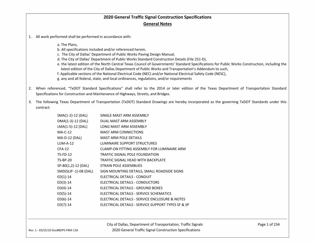
3. The following Texas Department of Transportation (TxDOT) Standard Drawings are hereby incorporated as the governing TxDOT Standards under this contract:
SMA(1-2)-12 (DAL) SINGLE MAST ARM ASSEMBLY DMA(1-3)-12 (DAL) DUAL MAST ARM ASSEMBLY LMA(1-5)-12 (DAL) LONG MAST ARM ASSEMBLY MA-C-12 MAST ARM CONNECTIONS MA-D-12 (DAL) MAST ARM POLE DETAILS LUM-A-12 LUMINAIRE SUPPORT STRUCTURES CFA-12 CLAMP-ON FITTING ASSEMBLY FOR LUMINAIRE ARM TS-FD-12 TRAFFIC SIGNAL POLE FOUNDATION TS-BP-20 TRAFFIC SIGNAL HEAD WITH BACKPLATE SP-80(1,2)-12 (DAL) STRAIN POLE ASSEMBLIES SMD(SLIP -1)-08 (DAL) SIGN MOUNTING DETAILS, SMALL ROADSIDE SIGNS ED(1)-14 ELECTRICAL DETAILS - CONDUIT ED(3)-14 ELECTRICAL DETAILS - CONDUCTORS ED(4)-14 ELECTRICAL DETAILS - GROUND BOXES ED(5)-14 ELECTRICAL DETAILS - SERVICE SCHEMATICS ED(6)-14 ELECTRICAL DETAILS - SERVICE ENCLOSURE & NOTES ED(7)-14 ELECTRICAL DETAILS - SERVICE SUPPORT TYPES SF & SP
City of Dallas, Department of Transportation, Traffic Signals Page 2 of 234 Rev. 1 - 03/25/10 Doc#BDPS-FRM-118 2020 General Traffic Signal Construction Specifications
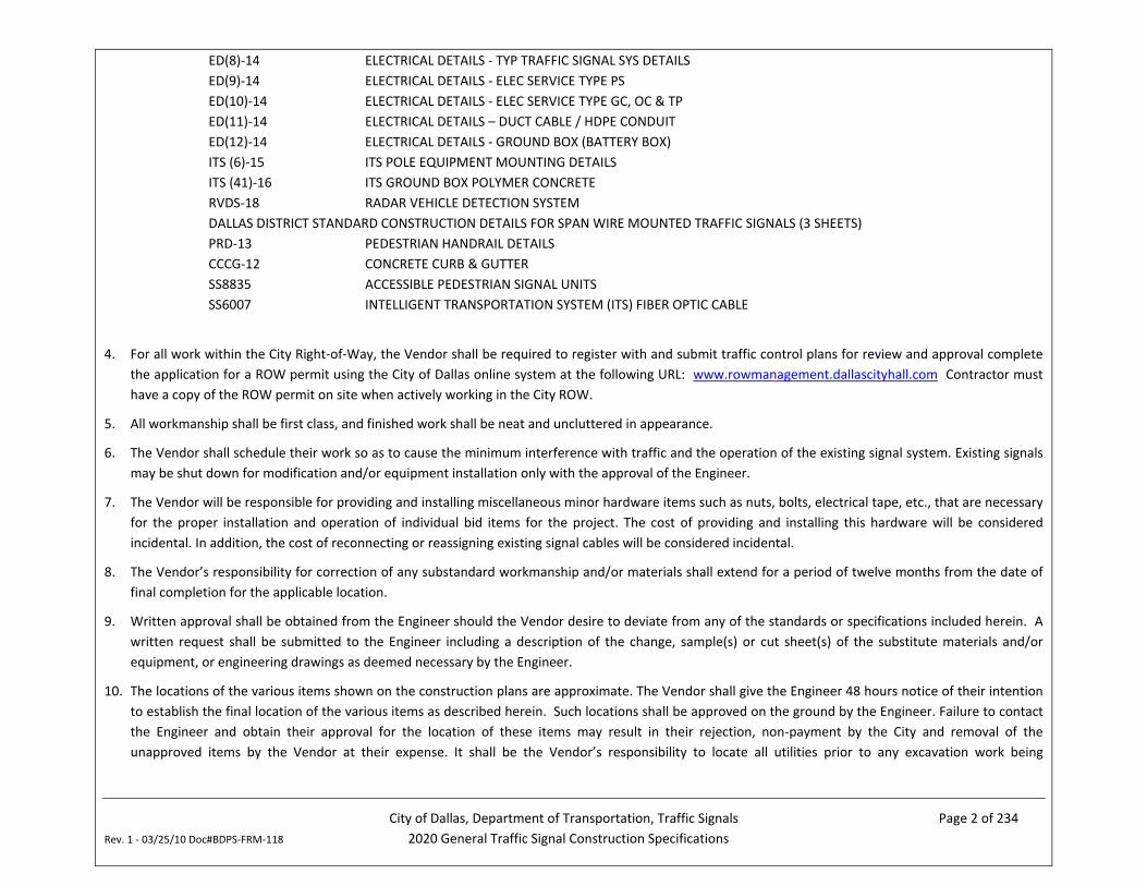
ED(8)-14 ELECTRICAL DETAILS - TYP TRAFFIC SIGNAL SYS DETAILS ED(9)-14 ELECTRICAL DETAILS - ELEC SERVICE TYPE PS ED(10)-14 ELECTRICAL DETAILS - ELEC SERVICE TYPE GC, OC & TP ED(11)-14 ELECTRICAL DETAILS – DUCT CABLE / HDPE CONDUIT ED(12)-14 ELECTRICAL DETAILS - GROUND BOX (BATTERY BOX) ITS (6)-15 ITS POLE EQUIPMENT MOUNTING DETAILS ITS (41)-16 ITS GROUND BOX POLYMER CONCRETE RVDS-18 RADAR VEHICLE DETECTION SYSTEM DALLAS DISTRICT STANDARD CONSTRUCTION DETAILS FOR SPAN WIRE MOUNTED TRAFFIC SIGNALS (3 SHEETS) PRD-13 PEDESTRIAN HANDRAIL DETAILS CCCG-12 CONCRETE CURB & GUTTER SS8835 ACCESSIBLE PEDESTRIAN SIGNAL UNITS SS6007 INTELLIGENT TRANSPORTATION SYSTEM (ITS) FIBER OPTIC CABLE
4. For all work within the City Right-of-Way, the Vendor shall be required to register with and submit traffic control plans for review and approval complete the application for a ROW permit using the City of Dallas online system at the following URL: www.rowmanagement.dallascityhall.com Contractor must have a copy of the ROW permit on site when actively working in the City ROW.
5. All workmanship shall be first class, and finished work shall be neat and uncluttered in appearance.
6. The Vendor shall schedule their work so as to cause the minimum interference with traffic and the operation of the existing signal system. Existing signals may be shut down for modification and/or equipment installation only with the approval of the Engineer.
7. The Vendor will be responsible for providing and installing miscellaneous minor hardware items such as nuts, bolts, electrical tape, etc., that are necessary for the proper installation and operation of individual bid items for the project. The cost of providing and installing this hardware will be considered incidental. In addition, the cost of reconnecting or reassigning existing signal cables will be considered incidental.
8. The Vendor’s responsibility for correction of any substandard workmanship and/or materials shall extend for a period of twelve months from the date of final completion for the applicable location.
9. Written approval shall be obtained from the Engineer should the Vendor desire to deviate from any of the standards or specifications included herein. A written request shall be submitted to the Engineer including a description of the change, sample(s) or cut sheet(s) of the substitute materials and/or equipment, or engineering drawings as deemed necessary by the Engineer.
10. The locations of the various items shown on the construction plans are approximate. The Vendor shall give the Engineer 48 hours notice of their intention to establish the final location of the various items as described herein. Such locations shall be approved on the ground by the Engineer. Failure to contact the Engineer and obtain their approval for the location of these items may result in their rejection, non-payment by the City and removal of the unapproved items by the Vendor at their expense. It shall be the Vendor’s responsibility to locate all utilities prior to any excavation work being
City of Dallas, Department of Transportation, Traffic Signals Page 3 of 234 Rev. 1 - 03/25/10 Doc#BDPS-FRM-118 2020 General Traffic Signal Construction Specifications
performed. If utilities shall be relocated in order for construction to proceed, then it will be the Vendor’s responsibility to coordinate this work. If damage to utilities occurs as a result of any construction performed by the Vendor, it shall be the Vendor’s responsibility to effect and pay for the repairs.
11. If more than one unit of a given bid item is required, then the Vendor shall ensure that all units of the product are from one manufacturer, unless otherwise approved by the Engineer.
12. All materials furnished by the Vendor shall become the property of the City effective from the date of final acceptance of the applicable work order. The Vendor shall have full responsibility for all materials with respect to damage, theft, or loss until the date of final acceptance of the work for the applicable work order.
13. The Vendor is responsible for the safe transport and storing of materials furnished by the City. Such materials become the responsibility of the contractor until the date of final acceptance of the work for each applicable work order. The Vendor bears the risk of loss or damage to such materials while in their possession prior to completion of the work for the applicable work order.
14. The Vendor agrees to reimburse the City for replacement of any materials furnished by the City that are lost, damaged or destroyed at their sole cost. The Vendor agrees to defend, indemnify, and hold harmless the City, its officers, agents, and employees, from any and all claims, judgments, lawsuits, fines, penalties, liens, costs, and other damages, whether suffered by third persons or by the Vendor, arising out of the transportation, storage, installation, or use of the City’s material during performance of the work. The City will not be responsible for storage rental charges of any kind, and no lien shall be attached to the materials as a result of Vendor’s failure to pay rental charges or other charges. The Vendor agrees to prevent liens and encumbrances of any nature from attaching to the material while it is in their possession.
15. Materials furnished by the City are, and remain at all times, the property of the City. The Vendor shall ensure that such materials are kept and stored separately from the Vendor’s property or other property, and shall advise others by labeling or other measures that the materials are the City’s property solely for use in the performance of the particular work. The City may require return of any materials hereunder, or refuse to furnish further materials in the event of failure to abide by these provisions.
16. While performing work under the project, the Vendor bears the sole risk of loss for damages to or destruction of any traffic signal equipment or appurtenances, on equipment that was not to be replaced or installed under project, but which was damaged or destroyed through the fault or negligent act of the Vendor. The Vendor shall replace such damaged or destroyed equipment, etc., at no cost to the City.
17. The Vendor shall assume full responsibility for the preservation of existing landscaping (e.g. sod, shrubbery, trees, etc.), sprinkler systems, and any other private property either on or off the ROW at the job site during the installation of items included in the project. Damaged landscaping, sprinkler systems, and other private property shall be replaced within a reasonable time by the Vendor at their own expense to the satisfaction of the Engineer.
18. No trees or shrubbery shall be cut except upon the specific authority of the Engineer.
19. Removal of mail boxes in the way of construction requires 48 hours advance notice to the Engineer. A temporary mailbox shall be provided at a location determined by the Engineer. The cost of removal of mailboxes and installation of temporary mailboxes shall be incidental to the items provided.
20. The Vendor shall secure permission from the proper authority and the approval of the Engineer before cutting into or removing any pavement, walks, curbs, or ramps which might be required during construction.
City of Dallas, Department of Transportation, Traffic Signals Page 4 of 234 Rev. 1 - 03/25/10 Doc#BDPS-FRM-118 2020 General Traffic Signal Construction Specifications
21. After work is completed, the Vendor shall restore any curbs or walks which have been damaged or removed to a condition equal to or better than the original condition and to the satisfaction of the Engineer.
22. Initial testing of all materials, construction items, or products incorporated in the work will be performed at the direction of the City and at the expense of the Vendor.
23. In the event that a material, construction item, product incorporated in the work fails to satisfy the minimum requirements of the initial test(s) described, appropriate prove-out tests shall be made as directed by the Engineer to determine the extent of the failure and to verify that corrective measures have been made to bring the item up to specification requirements. The cost of all testing necessary to determine the extent of the failure and the adequacy of the corrective measures shall be the responsibility of the Vendor.
24. The Vendor shall comply with all the requirements of the latest editions of the Texas Manual on Uniform Traffic Control Devices, the Texas Department of Transportation Temporary Traffic Control Design Standards, the City of Dallas’ Traffic Barricade Manual, and Exhibit “A” referenced in this document, respectively.
25. The Vendor shall provide and maintain all warning devices and take all precautionary measures required by law to protect persons and property while said persons or property are approaching, leaving, or within the work site or any area adjacent to said work site. No separate compensation will be paid to the Vendor for the installation or maintenance of any warning devices, barricades, lights, signs, or any other precautionary measures required by law for the protection of persons or property, including off duty police officers.
26. The Vendor shall be held responsible for all damages to work items and other public or private property due to the failure of warning devices, barricades, signs, lights, or other precautionary measures in protecting said property. Whenever evidence is found of such damage, the Engineer may order the damaged portion immediately removed and replaced by the Vendor at their expense.
27. For all work within the City Right-of-Way, the Vendor shall be required to register with and submit traffic control plans for review and approval complete the application for a ROW cut permit using the City of Dallas online system at the following URL: www.rowmanagement.dallascityhall.com Contractor must have a copy of the ROW permit on site when actively working in the City ROW.
28. When the Vendor is required to remove signal cable from existing conduit at an active traffic signal, he shall keep the signals in operation to the greatest extent possible. Electrical power disconnections shall be limited to off-peak traffic periods and shall be approved by the Engineer no less than 2 hours in advance. If the Vendor elects to install temporary overhead signal cable in order to avoid disconnecting power, the cost of installing the cable is considered incidental. No additional compensation will be granted for this work. If the Vendor is unable to remove cable from existing conduits due to swelling of the cable insulation or collapse of the conduit, he may be required to install temporary overhead cable to keep the signals in operation. The Engineer will determine when this is necessary and the Vendor will be compensated for this work through pay items listed in this agreement.
29. The Vendor may elect to provide an off-duty police officer for traffic control assistance during the performance of the work. Such police assistance shall be arranged by the Vendor directly and shall be paid for by the Vendor at their own expense, with no additional compensation by the City.
30. The City will provide the Vendor with a copy of the plans for the work to be performed at the time of issuance of each work order. These plans shall be marked-up by the Vendor, indicating all revisions and additions to the work, including field relocations of work. Lengths of all conduit runs view and
City of Dallas, Department of Transportation, Traffic Signals Page 5 of 234 Rev. 1 - 03/25/10 Doc#BDPS-FRM-118 2020 General Traffic Signal Construction Specifications
conductor routing shall be clearly illustrated on the As-Built drawings. The Vendor shall deliver these As-Built” drawings to the Engineer within ten (10) working days after the work has been completed on each work order.
31. All bidders who have not performed work for the City of Dallas within the last three (3) years shall submit a written statement of their previous experience in installing traffic signals with their bid. The statement shall include the name of the city or area served, the contract name and/or number, the date of contract award, the number and type of traffic signals installed, the date of contract completion, a discussion of any contract delays, discrepancies, and/or liquidated damages, and the name, address, and phone number of an individual representing the client who is in a position to verify such experience.
32. CONSTRUCTION time limit for individual work orders will be calculated using the procurement and installation times as included herein. For work orders involving multiple items, material procurement time will be based on the maximum procurement time for all items included in the particular work order. The maximum installation time will be calculated from the sum of the respective items for the particular work order. Upon receipt of a given work order, the Vendor shall prepare a CPM schedule and submit this schedule to the Engineer. Cost of preparation of this schedule shall be incidental to the applicable work order.
33. The Vendor shall submit a written request for suspension of time to the City via e-mail, fax or letter in the event that the Vendor encounters circumstances outside their control during material procurement or installation which will delay the project schedule. When making a suspension of time request, the Vendor shall clearly state the reason(s) for the request, the effective date the time suspension should begin and the estimated date that work can resume. The City will make the final decision as to whether to grant the suspension and when to lift the suspension.
34. A 10% retainage fee will be withheld from each invoice. If the work order is completed within the allotted number of working days (excluding times suspensions and weather delays), 100% of the retainage amount will be released. However, if the work is not completed within the allotted number of working days, liquidated damages will be withheld from the retainage fee in the amounts described in Section 1.36.1 of the latest edition of the North Central Texas Council of Government’s Standard Specifications for Public Works Construction, where the contract amount will be equal to the amount of the work order. Retainage fees will not be withheld from supplemental work orders.
35. Vendors are advised that the quantities shown on the bid forms are estimates. During the course of project, the City reserves the right to increase or decrease quantities of individual line items. Unit costs will not be adjusted to reflect changes in quantities.
36. Some of the work that will be performed under this agreement will be paid for with federal funds transferred through the Texas Department of Transportation. On those projects, the Vendor will be required to follow the Special Provisions outlined in Section A “Proposed Requirements and General Conditions” and Section C “Special Provisions—State/Federal Requirements” attached to this document.
37. If any of the requirements listed for the items are in conflict, the Vendor shall notify the Engineer in writing prior to ordering equipment and starting work. The Engineer will direct the Vendor on how to proceed. The Vendor is responsible for any additional costs incurred if the Engineer is not notified.
38. For bidding purposes, Vendors should assume that all work performed under this agreement will be subject to these Special Provisions.
NOTE: The Vendor will not receive any extra compensation for complying with any of the requirements described in the above General Notes or the Special Provisions for the project.
City of Dallas, Department of Transportation, Traffic Signals Page 6 of 234 Rev. 1 - 03/25/10 Doc#BDPS-FRM-118 2020 General Traffic Signal Construction Specifications
ITEM 1 MOBILIZATION FEES
1.1 METHOD OF PAYMENT
Payment for this item will cover the cost of moving personnel, construction equipment and supplies to the job site, as well as for providing individual public notices, obtaining approval for traffic control plans (TCPs) and Right of Way (ROW) cut permits with the City of Dallas online system: www.rowmanagement.dallascityhall.com. Please refer to Chapter 43 and Chapter 43 Revisions, Approved Ordinance 19-0758 for requirements related to TCPs, ROW permits and public notices.
UNIT OF PAYMENT: LUMP SUM
1.2 CONSTRUCTION TIME LIMIT
Once a work order has been issued, the Vendor will have a time limit of 7 working days to perform mobilization. This excludes the process for submittal and approval of TCPs and ROW cut permits. Please allow 10-15 working days for City approval before starting any work within the ROW and for any lane closures.
City of Dallas, Department of Transportation, Traffic Signals Page 7 of 234 Rev. 1 - 03/25/10 Doc#BDPS-FRM-118 2020 General Traffic Signal Construction Specifications
ITEM 2 INSTALLATION OF BASE-MOUNTED CONTROLLER CABINET
2.1 INSTALLATION SPECIFICATIONS
a. The Vendor will be responsible for installing the controller cabinet on the controller cabinet foundation in the field. This work shall include transporting the cabinet from the Department of Transportation Field Operations facility at 3204 Canton Street to the job site. The City reserves the right to change the pick-up address for the controller cabinet within City of Dallas city limits.
b. The Vendor shall mount the cabinet on the foundation, install a cabinet base extension (if provided by the City), connect all field wiring and install a ground rod in the foundation (if one does not already exist). In addition, if the cabinet foundation anchor bolts need repair in order to mount the controller cabinet, the Vendor will be required, at the direction of the Engineer, to either make repairs or replace the anchor bolts with Vendor-supplied stainless steel wedge anchor bolts matching the diameter of the damaged anchor bolts. Repairs to existing anchor bolts or replacement of anchor bolts, as necessary, shall be at the Vendor’s expense.
c. Immediately before mounting the controller assembly on the foundation, apply a bead of silicone caulk to seal the cabinet base.
d. Wiring of the controller cabinet shall consist of connecting (1) signal wires, (2) detector wires, (3) power wires, (4) ground wires, (5) communication cabling, and (6) pedestrian pushbutton wires to their respective terminals in the cabinet. The wiring for the controller cabinet shall be connected to the terminals based on the color of the insulation on the wire in accordance with the city’s standard termination tables. In the event of a conflict between the city’s standard termination tables and the traffic signal plans, the City’s standard shall prevail.
e. For CALTRANS cabinets, Signal conductors from the field shall be stripped back and a solderless terminal connector shall be attached by means of a ratchet-type compression crimping tool properly sized to the wire. These terminal connectors shall be inserted under the binder head screw and tightened securely. For ATC cabinets, signal conductors from the field shall be stripped back and attached to the Phoenix connectors as per manufacturer requirements.
f. The Vendor shall connect the wiring for the controller cabinet in accordance with the City of Dallas prep note for the traffic signal. The prep note will be provided at the time of cabinet pick-up for the Transportation Operations Field Operations facility. The Vendor shall not connect the wiring for the controller cabinet as shown on the traffic signal plans unless directed by the Engineer. The Vendor is responsible for any additional costs if the wiring is not connected as shown on the City of Dallas prep note for the traffic signal.
g. All field wiring in cabinets shall be neatly installed. Incoming cables shall be trained to their destination and neatly laced together. All spare wires shall be trimmed and neatly coiled with the ends taped. Detector lead-in cables shall have their insulation jackets removed from their terminal strip connection to the bottom of the cabinet, and have their ground wires tied together in the bottom of the cabinet. All signal wires, detector wires and pedestrian pushbutton wires in the cabinet shall be clearly marked with a permanent label indicating the signal phase to which each is connected. Conduits in the base of the cabinets shall be sealed with duct seal or other approved sealant after all cables and conductors are installed and the traffic signal has been activated.
h. The field wiring for new traffic signal installations and traffic signal modifications shall be tested prior to initial activation of the signal. The Vendor shall test the field wiring by applying power to each of the field wires and confirming that the appropriate signal indication(s) is energized before contacting the Engineer. In no event shall AC current be applied directly (“backfed”) to the terminals on the backplane.
City of Dallas, Department of Transportation, Traffic Signals Page 8 of 234 Rev. 1 - 03/25/10 Doc#BDPS-FRM-118 2020 General Traffic Signal Construction Specifications
Each individual field wire shall be tested by contacting the field conductor to either cabinet AC or to a flashing red output. The Vendor shall test the pedestrian push-button field wiring by depressing each pedestrian push button and verifying the appropriate indication light is energized on the card in the detector rack. The Vendor shall repeat these tests in the presence of the Engineer.
i. If a malfunction occurs during signal activation, the Vendor will be required to keep a qualified technician on site until the malfunction is repaired or until the Engineer has given their permission for the technician to leave. If the technician leaves the site before the malfunction is repaired, and it is determined that the malfunction is attributable to the Vendor’s workmanship, then the Vendor’s technician shall return and repair the problem.
2.2 MATERIAL SPECIFICATIONS
a. Refer to Exhibit B for further installation details.
2.3 METHOD OF PAYMENT
Payment for this item will include the cost of:
a. providing and installing a ground rod in the cabinet foundation (if required),
b. repairing or replacing the foundation anchor bolts (if required),
c. transporting the cabinet to the field,
d. mounting the cabinet on the cabinet foundation,
e. providing and installing a watertight seal around the base of the cabinet,
f. labeling and terminating all field wiring in the cabinet,
g. installing a cabinet base extension (if required),
h. testing the field wiring prior to activation of the signal and
i. maintaining a qualified technician on-site during activation of the signal.
UNIT OF PAYMENT: EACH
2.4 CONSTRUCTION TIME LIMIT
a. Once a work order has been issued, the Vendor will have a time limit of ½ working day to procure materials (if required) and 1 working day per cabinet for its installation.
City of Dallas, Department of Transportation, Traffic Signals Page 9 of 234 Rev. 1 - 03/25/10 Doc#BDPS-FRM-118 2020 General Traffic Signal Construction Specifications
ITEM 3 INSTALLATION OF POLE-MOUNTED CONTROLLER CABINET
3.1 INSTALLATION SPECIFICATIONS
a. The Vendor will be responsible for installing the controller cabinet on the designated signal or guy pole in the field. This work shall include transporting the cabinet from the Department of Transportation Field Operations facility at 3204 Canton Street to the job site. The City reserves the right to change the pick-up address for the controller cabinet within City of Dallas city limits.
b. The Vendor shall mount the cabinet on the signal or guy pole, connect all field wiring, and ground the cabinet at the signal pole base.
c. Wiring of the controller cabinet shall consist of connecting (1) signal wires, (2) detector wires, (3) power wires, (4) ground wires, (5) communication cabling, and (6) pedestrian pushbutton wires to their respective terminals in the cabinet. The wiring for the controller cabinet shall be connected to the terminals based on the color of the insulation on the wire in accordance with the city’s standard termination tables. In the event of a conflict between the city’s standard termination tables and the traffic signal plans, the City’s standard shall prevail.
d. Signal conductors from the field shall be stripped back and a solderless terminal connector shall be attached by means of a ratchet-type compression crimping tool properly sized to the wire. These terminal connectors shall be inserted under the binder head screw and tightened securely.
e. The Vendor shall connect the wiring for the controller cabinet in accordance with the City of Dallas prep note for the traffic signal. The prep note will be provided at the time of cabinet pick-up for the Transportation Operations Field Operations facility. The Vendor shall not connect the wiring for the controller cabinet as shown on the traffic signal plans unless directed by the Engineer. The Vendor is responsible for any additional costs if the wiring is not connected as shown on the City of Dallas prep note for the traffic signal.
f. All field wiring in cabinets shall be neatly installed. Incoming cables shall be trained to their destination and neatly laced together. All spare wires shall be trimmed and neatly coiled with the ends taped. Detector lead-in cables shall have their insulation jackets removed from their terminal strip connection to the bottom of the cabinet, and have their ground wires tied together in the bottom of the cabinet. All signal wires, detector wires and pedestrian pushbutton wires in the cabinet shall be clearly marked with a permanent label indicating the signal phase to which each is connected. Conduits in the base of the cabinets shall be sealed with duct seal or other approved sealant after all cables and conductors are installed and the traffic signal has been activated.
g. The field wiring for new traffic signal installations and traffic signal modifications shall be tested prior to initial activation of the signal. The Vendor shall test the field wiring by applying power to each of the field wires and confirming that the appropriate signal indication(s) is energized before contacting the Engineer. In no event shall AC current be applied directly (“backfed”) to the terminals on the backplane. Each individual field wire shall be tested by contacting the field conductor to either cabinet AC or to a flashing red output. The Vendor shall test the pedestrian push-button field wiring by depressing each pedestrian push button and verifying the appropriate indication light is energized on the card in the detector rack. The Vendor shall repeat these tests in the presence of the Engineer.
h. If a malfunction occurs during signal activation, the Vendor will be required to keep a qualified technician on site until the malfunction is repaired or until the Engineer has given their permission for the technician to leave. If the technician leaves the site before the malfunction is
City of Dallas, Department of Transportation, Traffic Signals Page 10 of 234 Rev. 1 - 03/25/10 Doc#BDPS-FRM-118 2020 General Traffic Signal Construction Specifications
repaired, and it is determined that the malfunction is attributable to the Vendor’s workmanship, then the Vendor’s technician shall return and repair the problem.
i. Refer to Exhibit C for further installation details.
3.2 MATERIAL SPECIFICATIONS
a. Refer to Exhibit C for details on the ground rods and L.B.’s to be used in the installation of pole-mounted controller cabinets.
3.3 METHOD OF PAYMENT
Payment for this item will include the cost of:
a. transporting the cabinet to the field,
b. mounting the cabinet on the signal or guy pole with City-supplied mounting brackets and band straps,
c. providing and installing a 3-inch L.B. and associated hardware,
d. providing and installing a watertight seal between the signal pole and L.B.,
e. labeling and terminating all field wiring,
f. grounding the cabinet,
g. testing the field wiring prior to activation of the signal and
h. maintaining a qualified technician on-site during activation of the signal.
UNIT OF PAYMENT: EACH
3.4 CONSTRUCTION TIME LIMIT
Once a work order has been issued, the Vendor will have a time limit of ½ working day to procure materials and 1 working day per cabinet for its installation.
City of Dallas, Department of Transportation, Traffic Signals Page 11 of 234 Rev. 1 - 03/25/10 Doc#BDPS-FRM-118 2020 General Traffic Signal Construction Specifications
ITEM 4 INSTALLATION OF TRAFFIC SIGNAL HEAD
4.1 INSTALLATION SPECIFICATIONS
a. The Vendor will be responsible for installing signal heads provided by the City in the field. This work shall include transporting the signal heads, louvers, back plates and mounting hardware from the Department of Transportation warehouse at 9500 Denton Drive to the job site. The City reserves the right to change the pick-up address within the City Limits.
b. This item includes drilling wire feed holes, mounting the signal heads on signal poles, mast arms and/or strain wires per the plans and details shown in Exhibit “E”, and final alignment and leveling of heads at the direction of the Engineer. This item additionally includes the procurement, installation, and connection of all wiring from the nearest pole base to the signal head.
c. The Vendor shall wire all signal heads with adequate wire to tie each signal section into the signal head and with adequate wire to tie each signal head into the signal cable for the system. Wiring for the signal head shall consist of connecting the common terminal block in each signal section to the common terminal block in each signal face, and where applicable, connecting the common terminal block in each signal face to the terminal block in the signal head terminal compartment. All wire feeding through the mast arm pole structure shall be wrapped once with plastic electrical tape and wrapped again with electrical friction tape extending 12 inches on each side of the pole opening for a total of 24 inches. No splicing shall occur in the mast arm pole structure or traffic signal pole; each traffic signal head shall have a unique run of multiconductor signal cable from the terminal block in the traffic signal head to the terminal block (or equivalent) near the base of the traffic signal pole.
d. The Vendor shall use multiconductor signal cable with either 5 or 7 conductors. Cable with a different number of conductors shall not be used unless approved by the Engineer. There shall be a sufficient number of conductors so as to safely operate the traffic signal head. The wiring for the traffic signal head shall be connected to the terminal block in the traffic signal head and the terminal block (or equivalent) near the base of the traffic signal pole based on the color of the insulation on the wire in accordance with the city’s wiring standard.
e. The Vendor will be required to adjust all signal heads with louvers so that they provide visibility to the intended lane(s) of traffic.
f. Per the TMUTCD, all signal heads or parts of heads not in operation shall be covered with burlap or turned down from traffic until placed into service.
g. Refer to Exhibits D, E, F, H and I for further details on the types of signal heads to be installed and how to place signal heads on signal poles, mast arms and strain wires.
4.2 MATERIAL SPECIFICATIONS
a. All wire running from mast arm/pedestal pole bases to the signal head terminal shall be #14 AWG stranded multi-conductor jacketed cable.
b. A screen composed of ¼-inch hardware cloth shall be securely fastened to the front face of each louver as directed by the Engineer.
City of Dallas, Department of Transportation, Traffic Signals Page 12 of 234 Rev. 1 - 03/25/10 Doc#BDPS-FRM-118 2020 General Traffic Signal Construction Specifications
4.3 METHOD OF PAYMENT
Payment for this item will include the cost of:
a. assembling the signal heads, back plates and mounting hardware,
b. transporting the signal heads and associated hardware to the field,
c. drilling wire feed holes and installing nylon bushings,
d. mounting the back plated signal heads on the mast arms, signal poles and/or strain wires with the appropriate hardware,
e. procuring, installing and connecting wiring from the signal heads to the terminal block at the base of the pole,
f. installing louvers,
g. procuring and installing hardware cloth for louvers,
h. covering the signal heads with Vendor supplied burlap (if required),
i. removing visibility obstructions such as tree limbs (if required), and
j. leveling and adjusting the signal heads for proper visibility.
NOTE: The Vendor will receive the same payment for the installation of a City supplied signal head regardless of the number of individual signal head sections. Payment for signal cable installed from a mast arm-mounted or pedestal pole-mounted signal head to the terminal block in the base of the pole shall be considered incidental to this item. Payment for signal cable installed on a span wire-mounted/strain pole-mounted/guy or wood pole-mounted signal head to the controller cabinet will be covered under ITEM 44, Procurement and Installation of Multiconductor Signal Cable and is not considered incidental to this item.
UNIT OF PAYMENT: EACH
4.4 CONSTRUCTION TIME LIMIT
Once a work order has been issued, the Vendor will have a time limit of ½ working day to procure materials and ½ working day per signal head for its installation.
City of Dallas, Department of Transportation, Traffic Signals Page 13 of 234 Rev. 1 - 03/25/10 Doc#BDPS-FRM-118 2020 General Traffic Signal Construction Specifications
ITEM 5 PROCUREMENT AND INSTALLATION OF TRAFFIC SIGNAL HEAD
5.1 INSTALLATION SPECIFICIATIONS
a. See section 4.1 for installation specification. Requirements regarding the transport of the pedestrian signal head do not apply to ITEM 5.
5.2 MATERIAL SPECIFICATIONS
a. Each signal head shall be a weather tight assembly of one or more signal faces of the expansible, adjustable, LED type, together with all brackets and fittings necessary for proper mounting with the type of signal support designated on Exhibits D, E, F, and H or as otherwise shown on the plans. Each signal face shall consist of one or more signal sections, rigidly and securely fastened together, capable of being positively positioned to control the movement of one direction of traffic. Each signal section shall consist of an optical unit, housing, housing door, and visor. Tie rods shall not be used to fasten signal sections together to form a signal face. All signal heads on a project shall be the product of one manufacturer.
b. The housing for each signal section shall be made of durable polycarbonate and shall be black in color unless otherwise specified in the Plans. It shall be clean, smooth and free from flaws, cracks, blowholes, and other imperfections. It shall be designed as a self contained unit capable of separate mounting or inclusion in a signal face containing two or more signal sections rigidly and securely fastened and perfectly aligned together. It shall be equipped with round openings in the top and bottom so that it may be rotated between water-proof supporting brackets and thus be capable of being directed at any angle in the horizontal plane. It shall be equipped with positive locking devices to maintain a specific angle of direction when in place. The doors shall be black in color and suitably hinged and held securely to the body of the housing by simple stainless steel locking devices. All other door parts, such as hinge pins, lens clips, screw, etc., shall also be of stainless steel material. A Neoprene gasket shall be used between the lenses and the signal door to exclude dust and moisture. The depth of each housing section shall not be greater than 7-1/8” for 12 inch signal heads. Each signal housing shall accept either plastic or aluminum backplates.
c. All visors shall be made of aluminum and shall be formed such that approximately 2 inches of the visor’s depth from the face of the housing forms a full circle and the remainder of the depth forms a tunnel visor. All visors shall be black in color unless otherwise specified in the Plans, not less than 0.050 inches in thickness if aluminum. Each visor shall be designed to fit tightly against the housing door, by the means of four standard twist-on type lugs secured with four stainless steel bolts for easy mounting and rotation. Visors shall be at least 9-1/2 inches deep for 12” signal sections, encompass 300 degrees of the lens, and have flat black finish on the inside surface.
d. The LED traffic signal lamp unit shall meet the requirements of the Texas Department of Transportation (TXDOT) Departmental Materials Specification DMS 11121 TWELVE-INCH LED TRAFFIC SIGNAL LAMP UNIT (12/2011 or latest revision).
e. The backplate shall also meet the
Back plates for all signal heads shall be made of aluminum. All back plates shall be capable of withstanding constant exposure to sunlight and corrosive atmospheres; shall maintain their flexibility under freezing temperatures; and shall withstand wind loads of 100 MPH after installation. All back plates shall be one piece with a non-reflective front surface but, will include a 2” retroreflective border affixed to them. All back plates shall have a 5” border width, shall have a minimum corner radius of 1.5 inches and shall have a nominal thickness of 0.050 inch. The finished back plate shall be pre-drilled to fit the signal for which it is designed or shall contain drill starts for field drilling. All back
City of Dallas, Department of Transportation, Traffic Signals Page 14 of 234 Rev. 1 - 03/25/10 Doc#BDPS-FRM-118 2020 General Traffic Signal Construction Specifications
plates shall be provided with all necessary bolts, nuts and washers for attaching to the signal head; this hardware shall be stainless steel. It shall be the Vendor’s responsibility to obtain back plates compatible with the signal head he intends to furnish on each project. All back plates on a project shall be identical and the product of one manufacturer. The backplate used shall have a 2-inch wide fluorescent yellow AASHTO Type B or C retroreflective border conforming to TxDOT DMS-8300 is required. Refer to Texas Department of Transportation (TXDOT) Traffic Signal Head with Backplate standard TS-BP-20.
Exterior finish
i. Aluminum. All exposed metal surfaces except for the inside of the visors of the assembled traffic signal head shall be electrostatically applied powder-coat paint. The inside of the visors shall be provided with two coats of high-grade flat black finish paint.
ii. Polycarbonate. The black colorant shall be completely impregnated in the polycarbonate material.
Unless otherwise noted on the Plans, vehicle signal heads shall be mounted with a universally adjustable signal bracket, meeting the following requirements:
i. The bracket shall allow for signal head rotation about the bracket axis, rotation about the supporting member axis, rotation on the vertical plane, and sliding of the support tube against the bracket connection point on the supporting member.
ii. The bracket shall be attached to the supporting member with a stainless steel band capable of withstanding 100 KSI tensile stress.
iii. The bracket attachment to the signal head shall assume rigid connection through the top and bottom of the signal head and fit the brand of signal head supplied by the Vendor on this project.
iv. The bracket shall be of the type to accept the number of signal sections specified in the Plans for each signal head.
v. Both arms of the bracket shall be cast from aluminum alloy and be secured about their rotational axis by set screws. The arm on one side of the tube shall be internally threaded to accommodate the threaded support tube.
vi. The entire assembly shall be capable of securely supporting a signal head under 100 mph wind loading conditions on the attached member.
vii. All parts used in this assembly shall be made of corrosion resistant material or be coated with a corrosion resistant finish.
viii. All wiring from the supporting member (signal arm or pole) to the signal head shall be completely concealed within the mounting assembly.
ix. Each bracket shall be furnished complete with the necessary hardware for installation on the signal supporting member.
x. The nominal arm length shall be nine (9) inches. Longer arms shall be substituted by the Vendor when maneuverability or visibility of the signal head is restricted.
When a mast arm or pole-mount installation is indicated on the Plans, vehicle signal heads should be mounted with the hardware shown in Exhibit E.
When a span wire installation is indicated on the Plans, vehicle signal heads should be mounted with the hardware shown in Exhibits H and I.
City of Dallas, Department of Transportation, Traffic Signals Page 15 of 234 Rev. 1 - 03/25/10 Doc#BDPS-FRM-118 2020 General Traffic Signal Construction Specifications
All louvers shall be of such design as to provide visibility of the signal lens to the intended lane(s) of traffic and shall meet the following requirements:
i. The internal arrangement of each louver shall consist of 5 vanes with 5 degree cut-offs right of center.
ii. All louvers shall have a flat black finish on the external services and a dull black finish on the inside surfaces.
iii. A screen composed of ¼-inch hardware cloth shall be securely fastened to the front face of each louver to prevent entry by birds.
iv. When indicated on the Plans, a Pelco Model SP-1010-TX geometrically programmed louver with visor and universal clips will be used to shield the signal displays. All other louvered signal displays shall be shielded with the louver specified in sections i., ii., and iii. above.
Refer to Exhibit D for details on the type and configuration of signal head lenses required.
f. All wire running from mast arm/pedestal pole bases to the signal head terminal shall be #14 AWG stranded multi-conductor jacketed cable.
5.3 METHOD OF PAYMENT
This ITEM is for procurement and installation of a 3-section display (or less). ITEM 6 is for procurement and installation of additional sections required for 4-section and 5-section traffic signal heads.
Payment for this item will include the cost of:
a. procuring and assembling the signal heads, back plates and mounting hardware,
b. drilling wire feed holes and installing nylon bushings,
c. mounting the back plated signal heads on the mast arms, signal poles, and/or strain wires with the appropriate hardware,
d. procuring, installing, and connecting wiring from the signal heads to the nearest pole base (for mast arm assemblies only),
e. procuring and installing louvers and hardware cloth,
f. covering the signal heads with Vendor supplied burlap (if required),
g. removing visibility obstructions such as tree limbs (if required), and
h. leveling and adjusting existing signal heads for proper visibility.
NOTE: Payment for signal cable installed from a mast arm-mounted or pedestal pole-mounted signal head to the terminal block in the base of the pole shall be considered incidental to this item. Payment for signal cable installed on a span wire-mounted/strain pole-mounted/guy or wood pole-mounted signal head to the controller cabinet will be covered under ITEM 44, Procurement and Installation of Multiconductor Signal Cable and is not considered incidental to this item.
UNIT OF PAYMENT: EACH
5.4 CONSTRUCTION TIME LIMIT
City of Dallas, Department of Transportation, Traffic Signals Page 16 of 234 Rev. 1 - 03/25/10 Doc#BDPS-FRM-118 2020 General Traffic Signal Construction Specifications
Once a work order has been issued, the Vendor will have a time limit of 20 working days to procure the signal head and associated materials and ½ working day per signal head for its installation.
City of Dallas, Department of Transportation, Traffic Signals Page 17 of 234 Rev. 1 - 03/25/10 Doc#BDPS-FRM-118 2020 General Traffic Signal Construction Specifications
ITEM 6 PROCUREMENT AND INSTALLATION OF SINGLE SECTION TRAFFIC SIGNAL HEAD
6.1 INSTALLATION SPECIFICIATIONS
See section 5.1 for installation specification.
6.2 MATERIAL SPECIFICATIONS
See section a for material specification.
6.3 METHOD OF PAYMENT
This item is for the procurement and installation of additional single traffic signal sections that are added to the 3-section head in ITEM 5; in other words, the items provides additional compensation for the procurement and installation of 4-section and 5-section traffic signal heads. For example, payment for a 5-section left turn signal head would be made using 1 EA of ITEM 5 plus 2 EA of ITEM 6.
Payment for this item will include the cost of:
a. procuring and assembling the signal heads, back plates and mounting hardware,
b. procuring and installing louvers and hardware cloth (if required),
c. covering the signal heads with Vendor supplied burlap (if required),
UNIT OF PAYMENT: EACH
6.4 CONSTRUCTION TIME LIMIT
No additional construction time will be given for this item. Construction time for procurement and installation of signal heads will be determined by ITEM 5.
City of Dallas, Department of Transportation, Traffic Signals Page 18 of 234 Rev. 1 - 03/25/10 Doc#BDPS-FRM-118 2020 General Traffic Signal Construction Specifications
ITEM 7 INSTALLATION OF LOUVER IN EXISTING TRAFFIC SIGNAL HEAD
7.1 INSTALLATION SPECIFICATIONS
a. The Vendor will be responsible for installing the louvers in signal heads already installed in the field. This work shall include transporting the louvers from the Department of Transportation warehouse at 9500 Denton Drive to the job site. The City reserves the right to change the pick-up address within the City Limits.
b. The Vendor will be required to adjust all signal heads with louvers so that they provide visibility to the specified lanes(s) of traffic
c. Refer to Exhibit D for details on placement of louvers in different signal head configurations.
7.2 MATERIAL SPECIFICATIONS
A screen composed of ¼ inch hardware cloth shall be securely fastened to the front of each louver as directed by the Engineer.
7.3 METHOD OF PAYMENT
Payment for this item will include the cost of:
a. transporting the louvers to the field,
b. installing the louvers,
c. installing a visor (if required),
d. procuring and installing the hardware cloth and
e. leveling and adjusting the signal heads for proper visibility.
NOTE: Payment for louvers which are installed as part of a new traffic signal head installation is covered under either ITEM 4, ITEM 5, or ITEM 6 and not under this item. This item applies only to installing louvers in existing signal heads already installed in the field. If the visor on the existing signal head will not support the louver provided by the City, then the City will be responsible for providing a visor that will accommodate the louver. The Vendor will install the louver.
UNIT OF PAYMENT: EACH
7.4 CONSTRUCTION TIME LIMIT
Once a work order has been issued, the Vendor will have a time limit of ½ working day to procure materials and ½ working day per signal head for installation of the louvers.
City of Dallas, Department of Transportation, Traffic Signals Page 19 of 234 Rev. 1 - 03/25/10 Doc#BDPS-FRM-118 2020 General Traffic Signal Construction Specifications
ITEM 8 PROCUREMENT AND INSTALLATION OF LOUVER IN EXISTING TRAFFIC SIGNAL HEAD
8.1 INSTALLATION SPECIFICATIONS
a. The Vendor will be responsible for installing the louvers in signal heads already installed in the field.
b. The Vendor will be required to adjust all signal heads with louvers so that they provide visibility to the specified lanes(s) of traffic.
c. Refer to Exhibit D for details on placement of louvers in different signal head configurations.
8.2 MATERIAL SPECIFICATIONS
a. All louvers shall be of such design as to provide visibility of the signal lens to the intended lane(s) of traffic and shall meet the following requirements:
i. The internal arrangement of each louver shall consist of 5 vanes with 5 degree cut-offs right of center.
ii. All louvers shall have a flat black finish on the external services and a dull black finish on the inside surfaces.
iii. A screen composed of ¼-inch hardware cloth shall be securely fastened to the front face of each louver to prevent entry by birds.
iv. When indicated on the Plans, a Pelco Model SP-1010-TX geometrically programmed louver with visor and universal clips will be used to shield the signal displays. All other louvered signal displays shall be shielded with the louver specified in sections i., ii., and iii. above.
8.3 METHOD OF PAYMENT
Payment for this item will include the cost of:
a. procuring and installing the louvers and hardware cloth.
b. procuring and installing a visor (if required) and
c. adjusting the signal heads for proper visibility.
NOTE: Payment for louvers which are installed as part of a new traffic signal head installation is covered under either ITEM 4, ITEM 5, or ITEM 6 and not under this item. This item applies only to installing louvers in existing signal heads already installed in the field. If the visor on the existing signal head will not support the louver provided by the City, then the City will be responsible for providing a visor that will accommodate the louver. The Vendor will install the louver.
UNIT OF PAYMENT: EACH
8.4 CONSTRUCTION TIME LIMIT
Once a work ordered has been issued, the Vendor will have a time limit of 20 working days to procure the louvers and associated materials and ½ working day per signal head for installation of the louvers.
City of Dallas, Department of Transportation, Traffic Signals Page 20 of 234 Rev. 1 - 03/25/10 Doc#BDPS-FRM-118 2020 General Traffic Signal Construction Specifications
ITEM 9 INSTALLATION OF PEDESTRIAN SIGNAL HEAD
9.1 INSTALLATION SPECIFICATIONS
a. The Vendor will be responsible for installing the pedestrian signal heads in the field. This work shall include transporting the pedestrian signal heads and clamshell mounting hardware from the Department of Transportation warehouse at 9500 Denton Drive to the job site. The City may change this location as long as it remains within City of Dallas city limits.
b. Drilling wire feed holes and mounting the pedestrian signal heads on signal poles will be the Vendor’s responsibility. Procuring, installing and connecting all wiring from the nearest terminal block (or equivalent) near the pole base to the pedestrian signal head will also be the Vendor’s responsibility.
c. All wire feeding through the mast arm pole structure shall be wrapped once with plastic electrical tape and wrapped again with electrical friction tape extending 12 inches on each side of the pole opening for a total of 24 inches. No splicing shall occur in traffic signal pole; each pedestrian signal head shall have a unique run of multiconductor signal cable from the terminal block in the pedestrian signal head to the terminal block (or equivalent) near the base of the traffic signal pole.
d. All pedestrian signal heads not in operation shall be covered with burlap until placed into service.
e. Refer to Exhibit F for further details on installing pedestrian signal heads on signal poles. Refer to Exhibit H for further details on installing pedestrian signal heads on steel guy or wood poles.
9.2 MATERIAL SPECIFICATIONS
a. All wire running from the pole base to the pedestrian signal head shall be #14 AWG stranded multiconductor jacketed cable.
b. Refer to Exhibit H, Detail B for further details on the 1-1/2 inch liquid-tight flexible metal conduit used in conjunction with mounting pedestrian signal heads on steel guy/wood poles.
9.3 METHOD OF PAYMENT
Payment for this item will include the cost of:
a. assembling the pedestrian signal heads and clamshell hardware,
b. transporting the pedestrian signal heads and associated hardware to the field,
c. drilling wire feed holes and installing nylon bushings,
d. mounting the pedestrian signal heads on the signal poles with clamshell hardware,
e. procuring and installing the liquid-tight flexible metal conduit from the pedestrian signal head to the splice can on steel guy/wood poles,
f. procuring, installing and connecting wiring from the pedestrian signal heads to the nearest signal pole base,
g. covering the pedestrian signal heads with Vendor supplied burlap (if required) and
City of Dallas, Department of Transportation, Traffic Signals Page 21 of 234 Rev. 1 - 03/25/10 Doc#BDPS-FRM-118 2020 General Traffic Signal Construction Specifications
h. adjusting the pedestrian signal heads for proper visibility.
NOTE: Payment for signal cable installed from a mast arm-mounted or pedestal pole-mounted pedestrian signal head to the terminal block in the base of the pole shall be considered incidental to this item. Payment for signal cable installed on a span wire-mounted/strain pole-mounted/guy or wood pole-mounted pedestrian signal head to the controller cabinet will be covered under ITEM 44, Procurement and Installation of Multiconductor Signal Cable and is not considered incidental to this item.
UNIT OF PAYMENT: EACH
9.4 CONSTRUCTION TIME LIMIT
Once a work order has been issued, the Vendor will have a time limit of ½ working days to procure materials and ½ working day per pedestrian signal head for its installation.
City of Dallas, Department of Transportation, Traffic Signals Page 22 of 234 Rev. 1 - 03/25/10 Doc#BDPS-FRM-118 2020 General Traffic Signal Construction Specifications
ITEM 10 PROCUREMENT AND INSTALLATION OF PEDESTRIAN SIGNAL HEAD
10.1 INSTALLATION SPECIFICATION
See section 9.1 for installation specification. Requirements regarding the transport of the pedestrian signal head do not apply to ITEM 10.
10.2 MATERIAL SPECIFICATIONS
a. The maximum dimensions of the signal head shall be:
i. 18 ½ inches wide
ii. 18 ¾ inches high
iii. 9 inches deep
The casing of the signal heads shall be a one piece polycarbonate or corrosion resistant aluminum alloy with four (4) integrally cast hinges to provide for operation of a swing down door. The casing shall be black in color (unless otherwise specified in the Plans).
Exterior finish
i. Aluminum. All exposed metal surfaces except for the inside of the visors of the assembled traffic signal head shall be electrostatically applied powder-coat paint or given two separately baked-on coats of high-grade enamel. The inside of the visors shall be provided with two coats of high-grade flat black finish paint.
ii. Polycarbonate. The black colorant shall be completely impregnated in the polycarbonate material.
All pedestrian signal heads not in operation shall be covered with burlap until placed into operation.
Each signal head shall be compatible with the mounting hardware described in these Specifications.
The optical unit shall include a transparent polycarbonate lens designed to display a full, uniform, bright alternating symbol message of “HAND” in Portland orange and “WALKING PERSON” in lunar white in the left portion of the signal head unit along with a double digit countdown timer in Portland orange in the right portion of the signal head unit. The “HAND” and “WALKING PERSON” messages shall each be a minimum of 12 inches in height and 7 inches in width. Numbers in the countdown timer display shall incorporate a dual stroke font and be a minimum of 9 inches in height and 7 inches in width.
The LED pedestrian signal head unit shall meet the applicable requirements of the Texas Department of Transportation (TXDOT) Departmental Material Specifications (DMS) 11130 Pedestrian Signal Heads (8/2004 or latest revision) and DMS 11131 Pedestrian LED Countdown Signal Modules (7/2012 or latest version). The pedestrian countdown timer shall automatically adjust to the programmed intervals of the signal controller. The timer shall count down the “DON’T WALK” interval only. During the countdown interval, the digits shall flash in tandem with the “DON’T WALK” display. If the “DON’T WALK” interval is interrupted or shortened as part of a transition into a pre-emption sequence, the countdown display shall go dark immediately upon activation of the pre-emption transition.
City of Dallas, Department of Transportation, Traffic Signals Page 23 of 234 Rev. 1 - 03/25/10 Doc#BDPS-FRM-118 2020 General Traffic Signal Construction Specifications
Each pedestrian head shall include a 1-1/2” deep polycarbonate egg crate visor with impregnated flat black color, designed to eliminate the interference of sunlight and to allow clear visibility of the symbols. The egg crate visor shall be easily detachable so that the signal head unit can be used with or without a visor.
Each pedestrian signal door shall be designed with adequate hinges and latch slots to provide swing down door operation and thumb screw locking devices.
All associated pins, screws, bolts, and nuts shall be made of stainless steel material.
All pedestrian signals shall be furnished with the specified mounting hardware installed and completely wired to the signal head. The casing shall include top and bottom openings that are sealed with removable plugs and that are intended for use with 1-1/2 inch pip bracket mounting hardware.
Each pedestrian signal mounting hardware assembly shall meet the following requirements:
i. Each unit shall consist of a two piece, cast aluminum alloy assembly, and be joined in the final assembly by the use of factory installed stainless pins. After mating, the two pieces shall have the following dimensions:
• Maximum height: 11-1/4 inches
• Maximum width: 5-1/2 inches (including hinge ears)
• Maximum depth: 2-3/4 inches
ii. Pole connection surface shall be configured to accept connections to poles of 4 to 13 inches in diameter. The hardware shall allow pole mounting by means of a band strap.
iii. The head half of the assembly shall be secured to the pedestrian signal with four 5/16 inch bolts.
iv. Three sets of screw terminal pairs shall be located on a terminal block in the head half of the assembly.
v. The terminal block compartment shall be watertight to prevent moisture from reaching the terminals.
vi. Indicator Controls Corporation Part Number 4805 “Clamshell Mounting Hardware” will be considered acceptable. Other brands of pedestrian signal mounting hardware meeting the above requirements may be substituted provided they are approved by the Engineer.
All wire running from the pole base to the pedestrian signal head shall be #14 AWG stranded multiconductor jacketed cable.
Refer to Exhibit H, Detail B for further details on the 1-1/2 inch liquid-tight flexible metal conduit used in conjunction with mounting pedestrian signal heads on steel guy/wood poles.
10.3 METHOD OF PAYMENT
Payment for this item will include the cost of:
a. Procurement of the pedestrian signal heads and associated hardware,
b. assembling the pedestrian signal heads and clamshell hardware,
City of Dallas, Department of Transportation, Traffic Signals Page 24 of 234 Rev. 1 - 03/25/10 Doc#BDPS-FRM-118 2020 General Traffic Signal Construction Specifications
c. transporting the pedestrian signal heads and associated hardware to the field,
d. drilling wire feed holes,
e. mounting the pedestrian signal heads on the signal poles with clamshell hardware,
f. procuring and installing the liquid-tight flexible metal conduit from the pedestrian signal head to the splice can on steel guy/wood poles,
g. procuring, installing and connecting wiring from the pedestrian signal heads to the nearest signal pole base,
h. covering the pedestrian signal heads with Vendor supplied burlap (if required) and
i. adjusting the pedestrian signal heads for proper visibility.
NOTE: Payment for multiconductor signal cable installed from a span wire-mounted; strain pole-mounted; or guy or wood pole-mounted pedestrian signal head to the controller cabinet will be covered under Item 44 Procurement and Installation of Multiconductor Signal Cable and not considered incidental to this item. Payment for multiconductor cable installed from pedestal pole-mounted pedestrian signal heads to the nearest signal pole base will be covered under Item 44 Procurement and Installation of Multiconductor Signal Cable and not considered incidental to this item.
UNIT OF PAYMENT: EACH
10.4 CONSTRUCTION TIME LIMIT
Once a work order has been issued, the Vendor will have a time limit of 20 working days to procure the pedestrian signal head and associated materials and ½ working day per pedestrian signal head for its installation
City of Dallas, Department of Transportation, Traffic Signals Page 25 of 234 Rev. 1 - 03/25/10 Doc#BDPS-FRM-118 2020 General Traffic Signal Construction Specifications
ITEM 11 INSTALLATION OF PEDESTRIAN PUSH BUTTON
11.1 INSTALLATION SPECIFICATIONS
a. The Vendor will be responsible for installing the pedestrian push buttons in the field. This work shall include transporting the pedestrian push button and supplemental sign from the Street Services Field Operations facility at 3204 Canton Street to the job site. The City reserves the right to change the pick-up address within the City Limits.
b. Drilling wire feed holes, installing nylon bushings, and mounting the pedestrian push button and sign on signal poles will be the Vendor’s responsibility. Procuring, installing and connecting all wiring from the nearest pole base to the new pedestrian push button will be the Vendor’s responsibility. If the pedestrian push buttons are installed at an operational traffic signal and there are spare wires in the existing multiconductor signal cable running from that signal pole to the traffic signal cabinet, splicing the multiconductor cable, if necessary, and connecting the wiring to their respective terminals in the traffic signal cabinet will be the Vendor’s responsibility.
c. All wire feeding through the mast arm pole structure shall be wrapped once with plastic electrical tape and wrapped again with electrical friction tape extending 12 inches on each side of the pole opening for a total of 24 inches. Pedestrian push buttons shall have a common ground wire that is completely isolated and independent from all other ground wires. No splicing shall occur in traffic signal pole; each pedestrian push button shall have a unique run of multiconductor signal cable from the terminal block in the pedestrian push button to the terminal block (or equivalent) near the base of the traffic signal pole.
d. Refer to Exhibit F for further details on installing pedestrian push buttons and signs on signal poles. Refer to Exhibit H for further details on installing pedestrian push buttons on steel guy or wood poles.
11.2 MATERIAL SPECIFICATIONS
a. All wire running from the pole base to the push button shall be #14 AWG stranded 2-conductor jacketed cable.
11.3 METHOD OF PAYMENT
Payment for this item will include the cost of:
a. assembling the pedestrian push button unit and sign,
b. transporting the pedestrian push button assembly to the field,
c. drilling wire feed holes and installing nylon bushings,
d. mounting the pedestrian push button and sign on the signal pole,
e. procuring and installing the liquid-tight flexible metal conduit from the pedestrian push button to the splice can on steel guy/wood poles,
f. procuring and installing a splice can on steel guy/wood poles and
g. procuring, installing and connecting wiring from the pedestrian push button to the nearest signal pole base.
UNIT OF PAYMENT: EACH
City of Dallas, Department of Transportation, Traffic Signals Page 26 of 234 Rev. 1 - 03/25/10 Doc#BDPS-FRM-118 2020 General Traffic Signal Construction Specifications
11.4 CONSTRUCTION TIME LIMIT
Once a work order has been issued, the Vendor will have a time limit of ½ working day to procure materials and ½ working day per pedestrian push button for its installation.
City of Dallas, Department of Transportation, Traffic Signals Page 27 of 234 Rev. 1 - 03/25/10 Doc#BDPS-FRM-118 2020 General Traffic Signal Construction Specifications
ITEM 12 PROCUREMENT AND INSTALLATION OF PEDESTRIAN PUSH BUTTON
12.1 INSTALLATION SPECIFICATIONS
See section 11.1 for installation specifications. Requirements regarding the transport of the pedestrian push button do not apply to this item.
12.2 MATERIAL SPECIFICATIONS
a. The assembly shall be of one piece cast aluminum construction which includes a push button switch, sign frame, and sign.
b. The housing of the push button switch shall be completely dust and moisture resistant.
c. The design of the push button switch shall conform to the latest requirements of the Americans with Disabilities Act (ADA).
d. The pedestrian push button shall emit a momentary, audible tone and visual indication when depressed. The visual indication shall be an LED light. The pedestrian push button will operate in momentary mode; additional equipment required for latching mode operation is not required.
e. Operating temperature shall range from -34°C to 74°C.
f. The sign frame for each assembly shall accept a 9” x 15” sign.
g. The sign shall have a white reflective background with black lettering and border with the message shown in Exhibit E.
h. Curve back assemblies shall be provided for mounting on round poles of 4 to 15 inches in diameter.
i. The push button housing and sign frame shall have a black, corrosion resistant finish (unless otherwise specified in the Plans).
i. Exterior finish
a. Aluminum. All exposed metal surfaces shall be electrostatically applied powder-coat paint or given two separately baked-on coats of high-grade enamel.
j. All wire running from the pole base to the push button shall be #14 AWG stranded 2-conductor jacketed cable.
k. Refer to Exhibit H, Detail B for further details on the ½ inch liquid-tight flexible metal conduit and splice can used in conjunction with mounting pedestrian push buttons on steel guy/wood poles.
12.3 METHOD OF PAYMENT
Payment for this item will include the cost of:
a. procuring and assembling the pedestrian push button unit and sign,
b. drilling wire feed holes and installing nylon bushings,
c. mounting the pedestrian push button and sign on the signal pole,
d. procuring and installing the liquid-tight flexible metal conduit from the push button to the splice can on steel guy/wood poles,
e. procuring and installing a splice can on steel guy/wood poles and
City of Dallas, Department of Transportation, Traffic Signals Page 28 of 234 Rev. 1 - 03/25/10 Doc#BDPS-FRM-118 2020 General Traffic Signal Construction Specifications
f. procuring, installing and connecting wiring from the pedestrian push button to the nearest signal pole base.
UNIT OF PAYMENT: EACH
12.4 CONSTRUCTION TIME LIMIT
The Vendor will have a time limit of 10 working days to procure the pedestrian push buttons and associated materials and ½ working day per pedestrian push button for its installation.
City of Dallas, Department of Transportation, Traffic Signals Page 29 of 234 Rev. 1 - 03/25/10 Doc#BDPS-FRM-118 2020 General Traffic Signal Construction Specifications
ITEM 13 INSTALLATION OF ACCESSIBLE PEDESTRIAN SIGNAL UNIT
13.1 INSTALLATION SPECIFICATION
a. The Vendor will be responsible for installing the Accessible Pedestrian Signal Unit(s) in the field, including pushbuttons and any ancillary equipment necessary for a fully functional installation. This work shall include transporting the pedestrian APS equipment from the Street Services Field Operations facility at 3204 Canton Street to the job site. The City reserves the right to change the pick-up address within the City Limits. The Vendor shall be responsible for the installation of the Accessible Pedestrian Signal Unit (APS) and supplemental signs in the field.
b. See section 11.1 for additional installation specifications.
13.2 MATERIAL SPECIFICATIONS
a. All materials used in the installation of the APS system shall be in accordance with TXDOT Special Specification 8835 and Section 11.3.
b. Refer to Exhibit F for further details on installing accessible pedestrian signal units and signs on signal poles. Refer to Exhibit H for further details on installing accessible pedestrian signal units on steel guy or wood poles.
13.3 METHOD OF PAYMENT
a. Payment for this item shall include the cost of all components required for the complete installation of a fully functional APS Unit as described in the latest TXDOT Special Specification 8835 and Section 11.3.
13.4 CONSTRUCTION TIME LIMIT
a. The Vendor will have a time limit of ½ working day to procure materials and ½ working day per APS Unit for its installation.
City of Dallas, Department of Transportation, Traffic Signals Page 30 of 234 Rev. 1 - 03/25/10 Doc#BDPS-FRM-118 2020 General Traffic Signal Construction Specifications
ITEM 14 PROCUREMENT AND INSTALLATION OF ACCESSIBLE PEDESTRIAN SIGNAL UNIT
14.1 INSTALLATION SPECIFICATION
a. The Vendor will be responsible for procuring and installing the Accessible Pedestrian Signal Unit(s) in the field, including pushbuttons and any ancillary equipment necessary for a fully functional installation.
b. The Vendor shall provide a copy of the custom voice message files and serial numbers of the installed equipment.
c. See section 11.1 for additional installation specifications.
14.2 MATERIAL SPECIFICATIONS
a. The Vendor shall provide a copy of the custom voice message files and serial numbers of the installed equipment along with warranty information.
b. See section 11.1 for additional installation specifications.
14.3 MATERIAL SPECIFICATIONS
c. The APS Unit components shall be furnished by the Vendor. APS Unit components shall meet the latest TxDOT APS Unit Special Specification 8835.
d. All materials used in the installation of the APS system shall be in accordance with TXDOT Special Specification 8835 and Section 11.3.
e. The APS Unit shall be operationally compatible with 170 and ATC controllers and Caltrans and ATC style cabinet assemblies currently used by the City of Dallas. The APS Units shall also be operationally compatible with ATC style cabinets. The APS Unit components shall also meet the material specification in section 12.2.
f. Configurable touchless actuation option shall be included and shall be capable of detecting movement when enabled within 1-4 inches to actuate/place ped call via the push button. The touchless actuation system shall be inconspicuous and vandal resistant.
g. Configurable option to interact with an external device and/or support for C-V2X pedestrian applications shall be available. The options available at a minimum should allow visually impaired and all pedestrians to remotely actuate ped call into the push button.
h. Each pushbutton shall be capable of interacting with an app on an external device, via Bluetooth Low Energy or other approved technology to help provide pedestrians location/directionality information and receive ped interval information via the external device.
i. The APS system to be provided under items 14 and 14A shall consist of the following basic components:
a. A central cabinet interface module with SDLC, Ethernet and Wi-Fi capability
b. The APS System shall be configurable from any APS Unit over Bluetooth Low Energy.
c. The APS System shall be configurable from the cabinet interface module over Wi-Fi or Ethernet.
d. Subsidiary serial communication and power cabling
City of Dallas, Department of Transportation, Traffic Signals Page 31 of 234 Rev. 1 - 03/25/10 Doc#BDPS-FRM-118 2020 General Traffic Signal Construction Specifications
e. Hinged bracket hardware for mounting in the traffic signal controller cabinet
f. 25-pin to 15-pin SDLC cable for interface with traffic signal controller
g. 15-pin to 15-pin SDLC cable for interface with the SDLC hub
h. 4-port 15-pin SDLC hub
j. Refer to Exhibit F for further details on installing accessible pedestrian signal units and signs on signal poles. Refer to Exhibit H for further details on installing accessible pedestrian signal units on steel guy or wood poles.
If the requirements of the TxDOT APS Unit Special Specification 8835 and requirements in section 12.2 are in conflict, the Vendor shall notify the Engineer in writing prior to ordering equipment. The Engineer will direct the Vendor how to proceed. The Vendor is responsible for any additional costs incurred if the Engineer is not notified.
14.4 METHOD OF PAYMENT
Payment for this item shall include the cost of all components required for the complete installation of a fully functional APS Unit as described in the latest TXDOT Special Specification 8835 and section 12.3. Individual pushbutton stations will be paid fo under Item 14. The cabinet console shall be paid for under Item 14A.
Item 14 - PROCUREMENT AND INSTALLATION OF ACCESSIBLE PEDESTRIAN SIGNAL UNIT (PUSHBUTTON STATION), EA
Item 14A - PROCUREMENT AND INSTALLATION OF ACCESSIBLE PEDESTRIAN SIGNAL UNIT (CABINET CONSOLE), EA
14.5 CONSTRUCTION TIME LIMIT
The Vendor will have a time limit of 20 working days to procure the APS Units and associated materials and ½ working day per APS Unit for its installation.
City of Dallas, Department of Transportation, Traffic Signals Page 32 of 234 Rev. 1 - 03/25/10 Doc#BDPS-FRM-118 2020 General Traffic Signal Construction Specifications
ITEM 15 INSTALLATION OF MAST ARM TRAFFIC SIGNAL POLE ASSEMBLY (0’ TO 48’)
15.1 INSTALLATION SPECIFICATION
a. The Vendor will be responsible for installing the mast arm traffic signal pole assembly in the field. This work shall include transporting the signal pole, mast arm(s), anchor bolts, and transformer base (as applicable) from the Department of Transportation signal pole yard at Good-Latimer Expressway and Logan Street to the job site. The City may change this location as long as it remains within City of Dallas city limits. Mounting the mast arm signal pole assembly on the foundation, installing a roadway luminaire (if required), installing wire from the roadway luminaire to the signal pole base and connecting and terminating the wire (if required) and installing a Vendor supplied ground rod in the foundation (if one does not already exist) will also be the Vendor’s responsibility. In addition, if the pole foundation anchor bolts need repair in order to install the signal pole, the Vendor will be required, at the direction of the Engineer, to either make repairs or replace the anchor bolts with Vendor supplied wedge anchor bolts. The vendor may optionally replace anchor bolts by drilling and epoxying new anchor bolts of the appropriate size at no additional cost to the City. Mechanical coupling to damaged anchor bolts will not be allowed.
b. Mast arm signal pole assemblies and hardware to be installed under this item may vary in finish from galvanized steel, painted, or colored (powdercoated).
c. For City-supplied Mast Arm pole assemblies where new foundations are to be placed, the City will provide the anchor bolts at the time of pole pick-up. Installation of anchor bolts will be paid for under ITEM 34.
d. Nuts on anchor bolts shall be tightened by the “turn-of-nut” method described in Item 447 “Structural Bolting” of the Texas Department of Transportation’s Standard Specifications.
e. Refer to the applicable TxDOT Standards for further details on installing mast arm signal pole assemblies.
15.2 MATERIAL SPECIFICATIONS
a. Grounding rod shall be at least 5/8 inch in diameter and 10 feet long. Grounding rod shall be a minimum depth of 3 feet into the soil. The grounding rod shall be copper clad. Refer to Exhibit J for details on ground rods for mast arm pole assemblies.
i. Wiring for grounding that runs from the grounding rod to the anchor bolts shall consist of #6 AWG
ii. Wiring for grounding that runs from the grounding rod to the grounding lug on the terminal block in the mast arm pole shall consist of #6 AWG stranded jacketed cable.
15.3 METHOD OF PAYMENT
Payment for this item will include the cost of:
a. procuring a and installing a ground rod in the signal pole foundation (if required),
b. repairing of replacing the signal pole foundation anchor bolts (if required),
c. removing protective grout caps from tops of existing mast arm pole foundations,
City of Dallas, Department of Transportation, Traffic Signals Page 33 of 234 Rev. 1 - 03/25/10 Doc#BDPS-FRM-118 2020 General Traffic Signal Construction Specifications
d. transporting the signal pole, mast arm, luminaire arm and transformer base to the job site (as applicable),
e. assembling the signal pole, mast arm, luminaire arm and transformer base (if applicable) into a complete structure,
f. adjusting the mast arm length to fit field conditions (if required),
g. removing obstructions such as tree limbs (if required),
h. mounting the signal pole assembly on the signal pole foundation and adjusting it so that it sits level,
i. grounding the signal pole.
j. The luminaire, if required, shall be paid for under ITEM 73 as shown on the plans. Installation of the luminaire and any necessary support hardware will be incidental to ITEM 15.
NOTE: The Vendor will receive the same payment for the installation only of City supplied mast arm signal pole assemblies regardless of the length of the mast arm not to exceed 48 feet and regardless of whether the signal pole includes a luminaire extension.
UNIT OF PAYMENT: EACH
15.4 CONSTRUCTION TIME LIMIT
Once a work order has been issued, the Vendor will have a time limit of 1 working day to procure materials and 1 working day per mast arm assembly for its installation.
City of Dallas, Department of Transportation, Traffic Signals Page 34 of 234 Rev. 1 - 03/25/10 Doc#BDPS-FRM-118 2020 General Traffic Signal Construction Specifications
ITEM 16 INSTALLATION OF MAST ARM SIGNAL POLE ASSEMBLY (50’ TO 65’)
16.1 INSTALLATION SPECIFICATION
a. The Vendor will be responsible for installing the mast arm traffic signal pole assembly in the field. This work shall include transporting the signal pole, mast arm(s) and transformer base (as applicable) from the Department of Transportation signal pole yard at Good-Latimer Expressway and Logan Street to the job site. The City may change this location as long as it remains within City of Dallas city limits. Mounting the mast arm signal pole assembly on the foundation, installing a roadway luminaire (if required), installing wire from the roadway luminaire to the signal pole base and connecting and terminating the wire (if required) and installing a Vendor supplied ground rod in the foundation (if one does not already exist) will also be the Vendor’s responsibility. In addition, if the pole foundation anchor bolts need repair in order to install the signal pole, the Vendor shall inform the Engineer immediately. Mounting LMA mast arm assemblies to foundations with damaged anchor bolts will not be allowed.
b. Mast arm signal pole assemblies and hardware to be installed under this item may vary in finish from galvanized steel, painted, or colored (powdercoated).
c. For City-supplied Mast Arm pole assemblies where new foundations are to be placed, the City will provide the anchor bolts at the time of pole pick-up. Installation of anchor bolts will be paid for under ITEM 34.
d. Nuts on anchor bolts shall be tightened by the “turn-of-nut” method described in Item 447 “Structural Bolting” of the Texas Department of Transportation’s Standard Specifications.
e. Refer to the applicable TxDOT Standards for further details on installing mast arm signal pole assemblies.
16.2 MATERIAL SPECIFICATIONS
a. Grounding rod shall be at least 5/8 inch in diameter and 10 feet long. Grounding rod shall be a minimum depth of 3 feet into the soil. The grounding rod shall be copper clad. Refer to Exhibit J for details on ground rods for mast arm pole assemblies.
i. Wiring for grounding that runs from the grounding rod to the anchor bolts shall consist of #6 AWG
ii. Wiring for grounding that runs from the grounding rod to the grounding lug on the terminal block in the mast arm pole shall consist of #6 AWG stranded jacketed cable.
16.3 METHOD OF PAYMENT
Payment for this item will include the cost of:
a. procuring a and installing a ground rod in the signal pole foundation (if required),
b. repairing of replacing the signal pole foundation anchor bolts (if required),
c. removing protective grout caps from tops of existing mast arm pole foundations,
d. transporting the signal pole, mast arm, luminaire arm and transformer base to the job site (as applicable),
City of Dallas, Department of Transportation, Traffic Signals Page 35 of 234 Rev. 1 - 03/25/10 Doc#BDPS-FRM-118 2020 General Traffic Signal Construction Specifications
e. assembling the signal pole, mast arm, luminaire arm and transformer base (if applicable) into a complete structure,
f. adjusting the mast arm length to fit field conditions (if required),
g. removing obstructions such as tree limbs (if required),
h. mounting the signal pole assembly on the signal pole foundation and adjusting it so that it sits level,
i. grounding the signal pole.
j. The luminaire, if required, shall be paid for under ITEM 73 as shown on the plans. Installation of the luminaire and any necessary support hardware will be incidental to ITEM 15.
NOTE: The Vendor will receive the same payment for the installation only of City supplied mast arm signal pole assemblies regardless of the length of the mast arm between 50’ and 65’, and regardless of whether the signal pole includes a luminaire extension.
UNIT OF PAYMENT: EACH
16.4 CONSTRUCTION TIME LIMIT
Once a work order has been issued, the Vendor will have a time limit of 1 working day to procure materials and 1 working day per mast arm assembly for its installation.
City of Dallas, Department of Transportation, Traffic Signals Page 36 of 234 Rev. 1 - 03/25/10 Doc#BDPS-FRM-118 2020 General Traffic Signal Construction Specifications
ITEM 17 INSTALLATION OF CLAMP ARM FOR DUAL MAST ARM SIGNAL POLE ASSEMBLY (20’ TO 44’)
(CITY-PROVIDED POLES ONLY)
17.1 INSTALLATION SPECIFICATION
a. The Vendor will be responsible for installing a clamp arm on the designated single-arm assembly to create a dual-arm traffic signal pole assembly in the field. This work shall include transporting the clamp arm and associated hardware from the Department of Transportation signal pole yard at Good-Latimer Expressway and Logan Street to the job site. The City may change this location as long as it remains within City of Dallas city limits. Note: This item is for use only with City-supplied poles and hardware. For Vendor-supplied poles and hardware, see ITEM 22 and ITEM 23.
b. Clamp arms and hardware to be installed under this item may vary in finish from galvanized steel, painted, or colored (powdercoated).
c. Refer to the applicable TxDOT Standards for further details on installing clamp arms on mast arm signal pole assemblies.
17.2 MATERIAL SPECIFICATIONS
i. All materials are to be provided by the City for this item. Any materials provided by the Vendor, if required, shall be in accordance with the applicable TxDOT Standards and specifications.
17.3 METHOD OF PAYMENT
Payment for this item will include the cost of:
a. transporting the clamp arm to the job site,
b. mounting the clamp arm to the designated mast arm signal pole to form a complete structure,
c. removing obstructions such as tree limbs (if required),
d. adjusting the clamp arm as directed by the engineer.
17.4 CONSTRUCTION TIME LIMIT
Once a work order has been issued, the Vendor will have a time limit of 1 working day to procure materials and 1 working day per clamp arm for its installation.
City of Dallas, Department of Transportation, Traffic Signals Page 37 of 234 Rev. 1 - 03/25/10 Doc#BDPS-FRM-118 2020 General Traffic Signal Construction Specifications
ITEM 18 INSTALLATION OF PEDESTAL SIGNAL POLE
18.1 INSTALLATION SPECIFICATION
a. The Vendor will be responsible for installing the pedestal signal pole assembly in the field. This work shall include transporting the pedestal signal pole and pole base from the Department of Transportation signal pole yard at Good-Latimer Expressway and Logan Street to the job site. The City may change this location as long as it remains within City of Dallas city limits. Mounting the pedestal signal pole assembly on the foundation and installing a Vendor supplied ground rod in the foundation (if one does not already exist) will also be the Vendor’s responsibility. In addition, if the pole foundation anchor bolts need repair in order to install the signal pole, the Vendor will be required, at the direction of the Engineer, to either make repairs or replace the anchor bolts with Vendor supplied wedge anchor bolts. The vendor may optionally replace anchor bolts by drilling and epoxying new anchor bolts of the appropriate size at no additional cost to the City. Mechanical coupling to damaged anchor bolts will not be allowed.
b. Pedestal signal poles and hardware to be installed under this item may vary in finish from galvanized steel, aluminum, painted, or colored (powdercoated).
c. For City-supplied Pedestal pole assemblies where new foundations are to be placed, the City will provide the anchor bolts at the time of pole pick-up. Installation of anchor bolts will be paid for under ITEM 34.
d. Nuts on anchor bolts shall be tightened by the “turn-of-nut” method described in Item 447 “Structural Bolting” of the Texas Department of Transportation’s Standard Specifications.
e. Pedestal signal pole assemblies shall be installed in accordance with manufacturer recommendations.
f. Pedestal signal poles shall be grounded as detailed in Exhibit I.
18.2 MATERIAL SPECIFICATIONS
a. Grounding rod shall be at least 5/8 inch in diameter and 10 feet long. Grounding rod shall be a minimum depth of 3 feet into the soil. The grounding rod shall be copper clad. Refer to Exhibit J for details on ground rods for signal pole assemblies.
b. Wiring for grounding that runs from the grounding rod to the anchor bolts shall consist of #6 AWG
c. Wiring for grounding that runs from the grounding rod to the grounding lug on the terminal block in the mast arm pole shall consist of #6 AWG stranded jacketed cable.
18.3 METHOD OF PAYMENT
Payment for this item will include the cost of:
a. procuring a ground rod and installing it in the signal pole foundation (if required),
b. repairing of replacing the signal pole foundation anchor bolts (if required),
c. removing protective grout caps from tops of existing mast arm pole foundations,
City of Dallas, Department of Transportation, Traffic Signals Page 38 of 234 Rev. 1 - 03/25/10 Doc#BDPS-FRM-118 2020 General Traffic Signal Construction Specifications
d. transporting the signal pole and transformer base to the job site,
e. assembling the pedestal signal pole into a complete structure,
f. removing obstructions such as tree limbs (if required),
g. mounting the signal pole assembly on the signal pole foundation and adjusting it so that it sits level
UNIT OF PAYMENT: EACH
18.4 CONSTRUCTION TIME LIMIT
Once a work order has been issued, the Vendor will have a time limit of 1 working day to procure materials and 1 working day per pedestal pole assembly for its installation.
City of Dallas, Department of Transportation, Traffic Signals Page 39 of 234 Rev. 1 - 03/25/10 Doc#BDPS-FRM-118 2020 General Traffic Signal Construction Specifications
ITEM 19 PROCUREMENT AND INSTALLATION OF TXDOT DALLAS STYLE MAST ARM SIGNAL POLE ASSEMBLY (SMA, 20' TO 32')
19.1 INSTALLATION SPECIFICATIONS
a. The Vendor will be responsible for procuring and installing the mast arm pole assembly in the field, mounting the mast arm signal pole assembly on the foundation, installing a roadway luminaire (if required), installing wire from the roadway luminaire to the signal pole base, connecting and terminating the wire (if required), and installing a Vendor supplied ground rod in the foundation (if one does not already exist).
b. If the proposed installation of the mast arm pole assembly will re-use an existing In addition, if the pole foundation anchor bolts need repair in order to install the signal pole, the Vendor will be required, at the direction of the Engineer, to either make repairs or replace the anchor bolts with Vendor supplied wedge anchor bolts. The vendor may optionally replace anchor bolts by drilling and epoxying new anchor bolts of the appropriate size. Mechanical coupling to damaged anchor bolts will not be allowed.
c. Nuts on anchor bolts shall be tightened by the “turn-of-nut” method described in Item 447 “Structural Bolting” of the Texas Department of Transportation’s Standard Specifications.
d. Refer to the applicable TxDOT Standards for further details on installing mast arm signal pole assemblies.
19.2 MATERIAL SPECIFICATIONS
a. All traffic signal structure components shall be furnished by the Vendor. All traffic signal structure components shall be hot dipped galvanized and/or powdercoated to resist corrosion. All structural components shall meet the latest TXDOT Dallas District traffic signal pole and mast arm specifications.
b. The following pole configurations and finish(es) are to be included under this item:
a. Galvanized finish, with luminaire extension
b. Galvanized finish, no luminaire extension
c. Powdercoated color finish, with luminaire extension
d. Powdercoated color finish, no luminaire extension
e. Galvanized finish, Special “Trinity” style luminaire extension (See Exhibit T)
Payment for each of the above configurations shall be bid separately, as Item 19a, 19b, etc.
c. The Vendor shall submit to the Engineer, for review and approval, two sets of shop drawings for the signal structures they will provide on this project. The drawings shall include information concerning structure dimensions, loading and all other data necessary for verifying structural adequacy. Shop drawings shall be 24” x 36” in size and shall have a title block in the lower right hand corner showing the name of the Vendor, fabricator, project name, and sheet number. These drawings shall bear the seal of a Professional Engineer registered in the State of Texas, assuming responsibility for the structural integrity of the design. These drawings shall be submitted to the Engineer ten days after the bid

City of Dallas, Department of Transportation, Traffic Signals Page 40 of 234 Rev. 1 - 03/25/10 Doc#BDPS-FRM-118 2020 General Traffic Signal Construction Specifications
opening date. If the Vendor changes signal pole suppliers during the course of this contract, then a new set of shop drawings from the new supplier shall be submitted and approved in accordance with the above provisions before any hardware is delivered.
d. Grounding rod shall be at least 5/8 inch in diameter and 10 feet long. Grounding rod shall be a minimum depth of 3 feet into the soil. The grounding rod shall be copper clad. Refer to Exhibit J for details on ground rods for mast arm pole assemblies.
i. Wiring for grounding that runs from the grounding rod to the anchor bolts shall consist of #6 AWG
e. Wiring for grounding that runs from the grounding rod to the grounding lug on the terminal block in the mast arm pole shall consist of #6 AWG stranded jacketed cable.
19.3 METHOD OF PAYMENT
Payment for this item will include the cost of:
a. procuring a ground rod and installing it in the signal pole foundation (if required),
b. repairing and replacing the signal pole foundation anchor bolts (if required),
c. removing protective grout caps from tops of existing mast arm pole foundations (if required),
d. procuring the signal pole, mast arm, and luminaire support hardware (if required),
e. assembling the signal pole, mast arm, and luminaire support hardware (if required) into a complete structure,
f. mounting the assembly on a signal pole foundation,
g. adjusting the mast arm length to fit field conditions (if required),
h. removing obstructions such as tree limbs (if required),
i. adjusting the signal pole assembly so that it sits level on its foundation and,
j. grounding the signal pole.
UNIT OF PAYMENT: EACH
19.4 CONSTRUCTION TIME LIMIT
Once a work order has been issued, the Vendor will have a time limit of 120 working days to procure the mast arm assembly and associated materials and 1 working day per mast arm assembly for its installation.
City of Dallas, Department of Transportation, Traffic Signals Page 41 of 234 Rev. 1 - 03/25/10 Doc#BDPS-FRM-118 2020 General Traffic Signal Construction Specifications
ITEM 20 PROCUREMENT AND INSTALLATION OF TXDOT DALLAS STYLE MAST ARM SIGNAL POLE ASSEMBLY (SMA, 36' TO 48')
20.1 INSTALLATION SPECIFICATIONS
a. The Vendor will be responsible for procuring and installing the mast arm pole assembly in the field, mounting the mast arm signal pole assembly on the foundation, installing a roadway luminaire (if required), installing wire from the roadway luminaire to the signal pole base and connecting and terminating the wire (if required) and installing a Vendor supplied ground rod in the foundation (if one does not already exist).
b. In addition, if the pole foundation anchor bolts need repair in order to install the signal pole, the Vendor will be required, at the direction of the Engineer, to either make repairs or replace the anchor bolts with Vendor supplied wedge anchor bolts. The vendor may optionally replace anchor bolts by drilling and epoxying new anchor bolts of the appropriate size. Mechanical coupling to damaged anchor bolts will not be allowed.
c. Nuts on anchor bolts shall be tightened by the “turn-of-nut” method described in Item 447 “Structural Bolting” of the Texas Department of Transportation’s Standard Specifications.
d. Refer to the applicable TxDOT Standards for further details on installing mast arm signal pole assemblies.
20.2 MATERIAL SPECIFICATIONS
a. All traffic signal structure components shall be furnished by the Vendor. All traffic signal structure components shall be hot dipped galvanized and/or powdercoated to resist corrosion. All structural components shall meet the latest TXDOT Dallas District traffic signal pole and mast arm specifications.
b. The following pole configurations and finish(es) are to be included under this item:
a. Galvanized finish, with luminaire extension
b. Galvanized finish, no luminaire extension
c. Powdercoated color finish, with luminaire extension
d. Powdercoated color finish, no luminaire extension
e. Galvanized finish, Special “Trinity” style luminaire extension (See Exhibit T)
Payment for each of the above configurations shall be bid separately, as Item 20a, 20b, etc.
c. The Vendor shall submit to the Engineer, for review and approval, two sets of shop drawings for the signal structures they will provide on this project. The drawings shall include information concerning structure dimensions, loading and all other data necessary for verifying structural adequacy. Shop drawings shall be 24” x 36” in size and shall have a title block in the lower right hand corner showing the name of the Vendor, fabricator, project name, and sheet number. These drawings shall bear the seal of a Professional Engineer registered in the State of Texas, assuming responsibility for the structural integrity of the design. These drawings shall be submitted to the Engineer ten days after the bid
City of Dallas, Department of Transportation, Traffic Signals Page 42 of 234 Rev. 1 - 03/25/10 Doc#BDPS-FRM-118 2020 General Traffic Signal Construction Specifications
opening date. If the Vendor changes signal pole suppliers during the course of this contract, then a new set of shop drawings from the new supplier shall be submitted and approved in accordance with the above provisions before any hardware is delivered.
d. Grounding rod shall be at least 5/8 inch in diameter and 10 feet long. Grounding rod shall be a minimum depth of 3 feet into the soil. The grounding rod shall be copper clad. Refer to Exhibit J for details on ground rods for mast arm pole assemblies.
ii. Wiring for grounding that runs from the grounding rod to the anchor bolts shall consist of #6 AWG
e. Wiring for grounding that runs from the grounding rod to the grounding lug on the terminal block in the mast arm pole shall consist of #6 AWG stranded jacketed cable.
20.3 METHOD OF PAYMENT
Payment for this item will include the cost of:
a. procuring a ground rod and installing it in the signal pole foundation (if required),
b. repairing and replacing the signal pole foundation anchor bolts (if required),
c. removing protective grout caps from tops of existing mast arm pole foundations (if required),
d. procuring the signal pole, mast arm, and luminaire support hardware (if required),
e. assembling the signal pole, mast arm, and luminaire support hardware (if required) into a complete structure,
f. mounting the assembly on a signal pole foundation,
g. adjusting the mast arm length to fit field conditions (if required),
h. removing obstructions such as tree limbs (if required),
i. adjusting the signal pole assembly so that it sits level on its foundation and,
j. grounding the signal pole.
UNIT OF PAYMENT: EACH
20.4 CONSTRUCTION TIME LIMIT
Once a work order has been issued, the Vendor will have a time limit of 120 working days to procure the mast arm assembly and associated materials and 1 working day per mast arm assembly for its installation.
City of Dallas, Department of Transportation, Traffic Signals Page 43 of 234 Rev. 1 - 03/25/10 Doc#BDPS-FRM-118 2020 General Traffic Signal Construction Specifications
ITEM 21 PROCUREMENT AND INSTALLATION OF TXDOT DALLAS STYLE MAST ARM SIGNAL POLE ASSEMBLY (LMA, 50' TO 65')
21.1 INSTALLATION SPECIFICATIONS
a. The Vendor will be responsible for procuring and installing the mast arm pole assembly in the field. Mounting the mast arm signal pole assembly on the foundation, installing a roadway luminaire (if required), installing wire from the roadway luminaire to the signal pole base and connecting and terminating the wire (if required) and installing a Vendor supplied ground rod in the foundation (if one does not already exist) will also be the Vendor’s responsibility. In addition, if the pole foundation anchor bolts need repair in order to install the signal pole, the Vendor shall inform the Engineer immediately. Mounting LMA mast arm assemblies to foundations with damaged anchor bolts will not be allowed.
b. Nuts on anchor bolts shall be tightened by the “turn-of-nut” method described in Item 447 “Structural Bolting” of the Texas Department of Transportation’s Standard Specifications.
c. Refer to the applicable TxDOT Standards for further details on installing mast arm signal pole assemblies.
21.2 MATERIAL SPECIFICATIONS
a. All traffic signal structure components shall be furnished by the Vendor. All traffic signal structure components shall be hot dipped galvanized and/or powdercoated to resist corrosion. All structural components shall meet the latest TXDOT Dallas District traffic signal pole and mast arm specifications.
b. The following pole configurations and finish(es) are to be included under this item:
a. Galvanized finish, with luminaire extension
b. Galvanized finish, no luminaire extension
c. Powdercoated color finish, with luminaire extension
d. Powdercoated color finish, no luminaire extension
e. Galvanized finish, Special “Trinity” style luminaire extension (See Exhibit T)
Payment for each of the above configurations shall be bid separately, as Item 21a, 21b, etc.
c. The Vendor shall submit to the Engineer, for review and approval, two sets of shop drawings for the signal structures they will provide on this project. The drawings shall include information concerning structure dimensions, loading and all other data necessary for verifying structural adequacy. Shop drawings shall be 24” x 36” in size and shall have a title block in the lower right hand corner showing the name of the Vendor, fabricator, project name, and sheet number. These drawings shall bear the seal of a Professional Engineer registered in the State of Texas, assuming responsibility for the structural integrity of the design. These drawings shall be submitted to the Engineer ten days after the bid opening date. If the Vendor changes signal pole suppliers during the course of this contract, then a new set of shop drawings from the new supplier shall be submitted and approved in accordance with the above provisions before any hardware is delivered.
City of Dallas, Department of Transportation, Traffic Signals Page 44 of 234 Rev. 1 - 03/25/10 Doc#BDPS-FRM-118 2020 General Traffic Signal Construction Specifications
d. Grounding rod shall be at least 5/8 inch in diameter and 10 feet long. Grounding rod shall be a minimum depth of 3 feet into the soil. The grounding rod shall be copper clad. Refer to Exhibit J for details on ground rods for mast arm pole assemblies.
iii. Wiring for grounding that runs from the grounding rod to the anchor bolts shall consist of #6 AWG
e. Wiring for grounding that runs from the grounding rod to the grounding lug on the terminal block in the mast arm pole shall consist of #6 AWG stranded jacketed cable.
21.3 METHOD OF PAYMENT
Payment for this item will include the cost of:
a. procuring a ground rod and installing it in the signal pole foundation (if required),
b. removing protective grout caps from tops of existing mast arm pole foundations (if required),
c. procuring the signal pole, mast arm, and luminaire support hardware (if required),
d. assembling the signal pole, mast arm, and luminaire support hardware (if required) into a complete structure,
e. mounting the assembly on a signal pole foundation,
f. adjusting the mast arm length to fit field conditions (if required),
g. removing obstructions such as tree limbs (if required),
h. adjusting the signal pole assembly so that it sits level on its foundation and,
i. grounding the signal pole.
UNIT OF PAYMENT: EACH
21.4 CONSTRUCTION TIME LIMIT
Once a work order has been issued, the Vendor will have a time limit of 120 working days to procure the mast arm assembly and associated materials and 1 working day per mast arm assembly for its installation.
City of Dallas, Department of Transportation, Traffic Signals Page 45 of 234 Rev. 1 - 03/25/10 Doc#BDPS-FRM-118 2020 General Traffic Signal Construction Specifications
ITEM 22 PROCUREMENT AND INSTALLATION OF TXDOT DALLAS STYLE CLAMP ARM FOR DMA SIGNAL POLE ASSEMBLY
(DMA, 20’ TO 36’)
22.1 INSTALLATION SPECIFICATIONS
a. The Vendor will be responsible for procuring and installing the DMA clamp arm for the appropriate DMA mast arm pole assembly in the field.
b. Refer to the applicable TxDOT Standards for further details on installation requirements for mounting clamp arms on mast arm signal pole assemblies.
22.2 MATERIAL SPECIFICATIONS
a. Refer to the applicable TxDOT Standards for further details on material requirements.
b. The following finish(es) are to be included under this item:
a. Galvanized finish
b. Powdercoated color finish
Payment for either of the above finishes shall be bid separately, as Items 22a and 22b.
22.3 METHOD OF PAYMENT
Payment for this item will include the cost of:
a. procuring the DMA clamp arm,
b. installing the DMA clamp arm on the applicable DMA mast arm assembly in the field, and
c. adjusting the DMA clamp arm as directed by the Engineer.
UNIT OF PAYMENT: EACH
22.4 CONSTRUCTION TIME LIMIT
Once a work order has been issued, the Vendor will have a time limit of 120 working days to procure the DMA clamp arm assembly and associated materials and 1 working day per clamp arm assembly for its installation.
City of Dallas, Department of Transportation, Traffic Signals Page 46 of 234 Rev. 1 - 03/25/10 Doc#BDPS-FRM-118 2020 General Traffic Signal Construction Specifications
ITEM 23 PROCUREMENT AND INSTALLATION OF TXDOT DALLAS STYLE CLAMP ARM FOR LMA SIGNAL POLE ASSEMBLY
(20’ TO 44’)
23.1 INSTALLATION SPECIFICATIONS
a. The Vendor will be responsible for procuring and installing the LMA clamp arm for the appropriate LMA mast arm pole assembly in the field.
b. Refer to the applicable TxDOT Standards for further details on installation requirements for mounting clamp arms on mast arm signal pole assemblies.
23.2 MATERIAL SPECIFICATIONS
a. Refer to the applicable TxDOT Standards for further details on material requirements.
b. The following finish(es) are to be included under this item:
a. Galvanized finish
b. Powdercoated color finish
Payment for either of the above finishes shall be bid separately, as Items 23a and 23b.
23.3 METHOD OF PAYMENT
Payment for this item will include the cost of:
a. procuring the LMA clamp arm,
b. installing the LMA clamp arm on the applicable mast arm assembly in the field, and
c. adjusting the LMA clamp arm as directed by the Engineer.
UNIT OF PAYMENT: EACH
23.4 CONSTRUCTION TIME LIMIT
Once a work order has been issued, the Vendor will have a time limit of 120 working days to procure the LMA clamp arm assembly and associated materials and 1 working day per clamp arm assembly for its installation.
City of Dallas, Department of Transportation, Traffic Signals Page 47 of 234 Rev. 1 - 03/25/10 Doc#BDPS-FRM-118 2020 General Traffic Signal Construction Specifications
ITEM 24 PROCUREMENT AND INSTALLATION OF PEDESTAL SIGNAL POLE
24.1 INSTALLATION SPECIFICATIONS
a. The Vendor will be responsible for procuring and installing the pedestal pole assembly in the field, mounting the pedestal signal pole assembly on the foundation, and installing a Vendor supplied ground rod in the foundation (if one does not already exist).
b. In addition, if the pole foundation anchor bolts need repair in order to install the signal pole, the Vendor will be required, at the direction of the Engineer, to either make repairs or replace the anchor bolts with Vendor supplied wedge anchor bolts. The vendor may optionally replace anchor bolts by drilling and epoxying new anchor bolts of the appropriate size. Mechanical coupling to damaged anchor bolts will not be allowed.
c. Nuts on anchor bolts shall be tightened by the “turn-of-nut” method described in Item 447 “Structural Bolting” of the Texas Department of Transportation’s Standard Specifications.
d. Refer to the applicable TxDOT Standards and Exhibit F for further details on installing pedestal signal pole assemblies.
24.2 MATERIAL SPECIFICATIONS
a. All traffic signal structure components shall be furnished by the Vendor. All traffic signal structure components shall be aluminum or powdercoated steel or aluminum to resist corrosion.
b. The following pole configurations and finish(es) are to be included under this item:
a. Brushed Aluminum Finish (Type I, 15’ Pedestal Pole)
b. Powdercoated Color Finish (Type I, 15’ Pedestal Pole)
c. Brushed Aluminum Finish (Type II, 10’ Pedestal Pole)
d. Powdercoated Color Finish (Type II, 10’ Pedestal Pole)
e. Brushed Aluminum Finish (Type III, 5’ Pedestal Pole)
f. Powdercoated Color Finish (Type III, 5’ Pedestal Pole)
g. Brushed Aluminum Finish (Type IV, 20’ Pedestal Pole)
h. Powdercoated Color Finish (Type IV, 20’ Pedestal Pole)
Payment for each of the above configurations shall be bid separately, as Item 24a, 24b, etc.
c. The Vendor shall submit to the Engineer, for review and approval, two sets of shop drawings for the signal structures they will provide on this project. The drawings shall include information concerning structure dimensions, loading and all other data necessary for verifying structural adequacy. Shop drawings shall be 24” x 36” in size and shall have a title block in the lower right hand corner showing the name of the Vendor, fabricator, project name, and sheet number. These drawings shall bear the seal of a Professional Engineer registered in the State of Texas, assuming responsibility for the structural integrity of the design. These drawings shall be submitted to the Engineer ten days after the bid
City of Dallas, Department of Transportation, Traffic Signals Page 48 of 234 Rev. 1 - 03/25/10 Doc#BDPS-FRM-118 2020 General Traffic Signal Construction Specifications
opening date. If the Vendor changes signal pole suppliers during the course of this contract, then a new set of shop drawings from the new supplier shall be submitted and approved in accordance with the above provisions before any hardware is delivered.
d. Grounding rod shall be at least 5/8 inch in diameter and 10 feet long. Grounding rod shall be a minimum depth of 3 feet into the soil. The grounding rod shall be copper clad. Refer to Exhibit J for details on ground rods for pedestal pole assemblies.
iv. Wiring for grounding that runs from the grounding rod to the anchor bolts shall consist of #6 AWG
e. Wiring for grounding that runs from the grounding rod to the grounding lug on the terminal block in the mast arm pole shall consist of #6 AWG stranded jacketed cable.
24.3 METHOD OF PAYMENT
Payment for this item will include the cost of:
a. procuring a ground rod and installing it in the signal pole foundation (if required),
b. repairing and replacing the signal pole foundation anchor bolts (if required),
c. removing protective grout caps from tops of existing mast arm pole foundations (if required),
d. procuring the pedestal signal pole and transformer base,
e. assembling the pedestal pole components into a complete structure,
f. mounting the assembly on a signal pole foundation,
g. removing obstructions such as tree limbs (if required),
h. adjusting the signal pole assembly so that it sits level on its foundation and,
i. grounding the signal pole.
UNIT OF PAYMENT: EACH
24.4 CONSTRUCTION TIME LIMIT
Once a work order has been issued, the Vendor will have a time limit of 90 working days to procure the pedestal pole assembly and associated materials and 1 working day per pedestal signal pole assembly for its installation.
City of Dallas, Department of Transportation, Traffic Signals Page 49 of 234 Rev. 1 - 03/25/10 Doc#BDPS-FRM-118 2020 General Traffic Signal Construction Specifications
ITEM 25 PROCUREMENT AND INSTALLATION OF DAMPENING PLATE ON MAST ARM
25.1 INSTALLATION SPECIFICATIONS
a. The Vendor will be responsible for installing the dampening plates and their associated mounting hardware in the field. Individual project plans will indicate which mast arms will receive dampening plates.
b. Refer to Exhibit E for further details on installing dampening plates.
25.2 MATERIAL SPECIFICATIONS
a. Dampening plates for mast arms up to 48 ft. in length shall be 18 inches wide by 48 inches in length and be constructed of 0.10 gauge aluminum panels.
b. Dampening plates for mast arms 50 ft. or longer shall be 18 inches wide by 66 inches in length and be constructed of 0.10 gauge aluminum panels.
c. The dampening plates shall be attached to the mast arm by means of an astro-bracket (Pelco “Astro-Brac” AB-0105 or pre-bid approved equal).
25.3 METHOD OF PAYMENT
Payment for this item will include the cost of:
a. procuring and installing the dampening plate and associated hardware
Payment for this item shall be the same regardless of the length of the damping plate.
UNIT OF PAYMENT: EACH
25.4 CONSTRUCTION TIME LIMIT
Once a work order has been issued, the Vendor will have a time limit of 5 working days to procure the dampening plate and associated materials and ½ working day per dampening plate for its installation.
City of Dallas, Department of Transportation, Traffic Signals Page 50 of 234 Rev. 1 - 03/25/10 Doc#BDPS-FRM-118 2020 General Traffic Signal Construction Specifications
ITEM 26 INSTALLATION OF A TIMBER POLE
26.1 INSTALLATION SPECIFICATIONS
a. The Vendor will be responsible for installing timber poles in the field. This work shall include transporting the timber pole from the Department of Transportation signal pole yard at Good-Latimer Expressway and Logan Street to the job site. The City may change the location of the signal pole yard as long as it remains within City of Dallas city limits.
b. The location of timber poles shown on the construction plans is approximate. The Vendor shall give the Engineer a minimum of 48 hours advance notice of their intention to establish the final timber pole location. Timber pole locations shall be approved by the Engineer at the site prior to installation.
c. Timber poles shall be set directly in the ground at a minimum depth of 6 feet.
d. Refer to Exhibit H for further details on installing timber poles.
26.2 MATERIAL SPECIFICATIONS
a. The backfill for timber poles shall consist of material excavated from the pole site.
26.3 METHOD OF PAYMENT
Payment for this item will include the cost of:
a. probing for utilities,
b. site excavation work,
c. properly disposing of excavated material (if necessary),
d. transporting the timber pole to the field,
e. setting the timber pole in the ground,
f. removing obstructions such as tree limbs (if required) and
g. installing backfill.
NOTE: Down guy assemblies (if required) will be paid separately under ITEM 29.
UNIT OF PAYMENT: EACH
26.4 CONSTRUCTION TIME LIMIT
Once a work order has been issued, the Vendor will have a time limit of 1 working day to procure materials and ½ working day per timber pole for its installation.
City of Dallas, Department of Transportation, Traffic Signals Page 51 of 234 Rev. 1 - 03/25/10 Doc#BDPS-FRM-118 2020 General Traffic Signal Construction Specifications
ITEM 27 PROCUREMENT AND INSTALLATION OF A TIMBER POLE
27.1 INSTALLATION SPECIFICATIONS
a. The Vendor will be responsible for procuring and installing timber poles in the field.
b. The location of timber poles shown on the construction plans is approximate. The Vendor shall give the Engineer a minimum of 48 hours advance notice of their intention to establish the final timber pole location. Timber pole locations shall be approved by the Engineer at the site prior to installation.
c. Timber poles shall be set directly in the ground at a minimum depth of 6 feet.
d. Refer to Exhibit H for further details on installing timber poles.
27.2 MATERIAL SPECIFICATIONS
a. The backfill for timber poles shall consist of material excavated from the pole site.
27.3 METHOD OF PAYMENT
Payment for this item will include the cost of:
a. Procuring the timber pole,
b. probing for utilities,
c. site excavation work,
d. properly disposing of excavated material (if necessary),
e. transporting the timber pole to the job site,
f. setting the timber pole in the ground,
g. removing obstructions such as tree limbs (if required) and
h. installing backfill.
NOTE: Down guy assemblies (if required) will be paid separately under ITEM 29.
UNIT OF PAYMENT: EACH
27.4 CONSTRUCTION TIME LIMIT
Once a work order has been issued, the Vendor will have a time limit of 10 working days to procure materials and ½ working day per timber pole for its installation.
City of Dallas, Department of Transportation, Traffic Signals Page 52 of 234 Rev. 1 - 03/25/10 Doc#BDPS-FRM-118 2020 General Traffic Signal Construction Specifications
ITEM 28 INSTALLATION OF STEEL GUY POLE
28.1 INSTALLATION SPECIFICATIONS
a. The Vendor will be responsible for installing steel guy poles in the field. This work shall include transporting the steel guy pole from the Department of Transportation signal pole yard at Good-Latimer Expressway and Logan Street to the job site. The City may change the location of the signal pole yard as long as it remains within City of Dallas city limits.
b. The location of steel guy poles shown on the construction plans is approximate. The Vendor shall give the Engineer a minimum of 48 hours advance notice of their intention to establish the final steel guy pole location. The steel guy pole location shall be approved by the Engineer at the site prior to installation. Refer to Exhibit H for further details on installing steel guy poles.
28.2 MATERIAL SPECIFICATIONS
a. Paint for steel guy poles shall be a platinum gray alkyd enamel with high gloss finish (Impervo High Gloss Enamel Platinum Gray no. 133 70 color by Benjamin Moore paints or equivalent).
b. The concrete backfill for steel guy poles shall consist of either Class A or Class C non-reinforced concrete as defined in the North Central Texas Council of Governments’ Standard Specifications for Public Works Construction Item 7.4.5.
28.3 METHOD OF PAYMENT
Payment for this item will include the cost of:
a. probing for utilities,
b. site excavation work,
c. properly disposing of excavated material,
d. transporting the steel guy pole to the field,
e. setting the steel guy pole in the ground,
f. removing obstructions such as tree limbs (if required),
g. procuring and installing backfill and,
h. procuring paint and painting the steel pole.
UNIT OF PAYMENT: EACH
28.4 CONSTRUCTION TIME LIMIT
Once a work order has been issued, the Vendor will have a time limit of 1 working day to procure materials and ½ working day per steel guy pole for its installation.
City of Dallas, Department of Transportation, Traffic Signals Page 53 of 234 Rev. 1 - 03/25/10 Doc#BDPS-FRM-118 2020 General Traffic Signal Construction Specifications
ITEM 29 PROCUREMENT AND INSTALLATION OF STEEL GUY POLE
29.1 INSTALLATION SPECIFICATIONS
a. The Vendor will be responsible for procuring and installing steel guy poles in the field. The location of steel guy poles shown on the construction plans is approximate. The Vendor shall give the Engineer a minimum of 48 hours advance notice of their intention to establish the final steel guy pole location. The steel guy pole location shall be approved by the Engineer at the site prior to installation. Refer to Exhibit H for further details on installing steel guy poles.
29.2 MATERIAL SPECIFICATIONS
a. Steel Guy Poles shall be galvanized steel, suitable for direct-burial, 35’ in height, with a base diameter of 8”, tapering to a 6” diameter at the top of pole.
b. Paint for steel guy poles shall be a platinum gray alkyd enamel with high gloss finish (Impervo High Gloss Enamel Platinum Gray no. 133 70 color by Benjamin Moore paints or equivalent).
c. The concrete backfill for steel guy poles shall consist of either Class A or Class C non-reinforced concrete as defined in the North Central Texas Council of Governments’ Standard Specifications for Public Works Construction Item 7.4.5.
29.3 METHOD OF PAYMENT
Payment for this item will include the cost of:
d. Procuring the steel guy pole,
e. probing for utilities,
f. site excavation work,
g. properly disposing of excavated material,
h. transporting the steel guy pole to the field,
i. setting the steel guy pole in the ground,
j. removing obstructions such as tree limbs (if required),
k. procuring and installing backfill and,
l. procuring paint and painting the steel pole.
UNIT OF PAYMENT: EACH
City of Dallas, Department of Transportation, Traffic Signals Page 54 of 234 Rev. 1 - 03/25/10 Doc#BDPS-FRM-118 2020 General Traffic Signal Construction Specifications
29.4 CONSTRUCTION TIME LIMIT
Once a work order has been issued, the Vendor will have a time limit of 10 working days to procure materials and ½ working day per steel guy pole for its installation.
City of Dallas, Department of Transportation, Traffic Signals Page 55 of 234 Rev. 1 - 03/25/10 Doc#BDPS-FRM-118 2020 General Traffic Signal Construction Specifications
ITEM 30 PROCUREMENT AND INSTALLATION OF DOWN GUY ASSEMBLY
30.1 INSTALLATION SPECIFICATIONS
a. The Vendor will be responsible for procuring and installing the down guy hardware in the field.
b. Refer to Exhibit H for further details on installing down guy assemblies.
30.2 MATERIAL SPECIFICATIONS
a. The concrete backfill for down guy assemblies shall consist of Class A non-reinforced concrete as defined in the North Central Texas Council of Governments’ Standard Specifications for Public Works Construction Item 7.4.5.
b. Refer to Exhibit H1 for further details on the guy spreader pipes, guy guards, anchor rods and anchors used in down guy assemblies.
30.3 METHOD OF PAYMENT
Payment for this item will include the cost of:
a. site excavation work,
b. properly disposing of excavated material,
c. procuring and installing guy spreader pipes (if required), guy guards, anchor rods and anchors,
d. removing obstructions such as tree limbs (if required),
e. adjusting the down guy assembly and
f. procuring and installing the concrete backfill.
NOTE: Payment for the procurement and installation of 3/8 inch guy (strain) wire that is installed as part of the down guy assembly will be covered separately under ITEM 31.
UNIT OF PAYMENT: EACH
30.4 CONSTRUCTION TIME LIMIT
Once a work order has been issued, the Vendor will have a time limit of 10 working days to procure materials and ½ working day per down guy assembly for its installation.
City of Dallas, Department of Transportation, Traffic Signals Page 56 of 234 Rev. 1 - 03/25/10 Doc#BDPS-FRM-118 2020 General Traffic Signal Construction Specifications
ITEM 31 PROCUREMENT AND INSTALLATION OF STEEL STRAIN WIRE
31.1 INSTALLATION SPECIFICATIONS
a. The Vendor will be responsible for procuring and installing the strain wire in the field.
b. Refer to Exhibit H1, H2 and M for further details on installing strain wire.
31.2 MATERIAL SPECIFICATIONS
a. The strain wire shall be composed of 3/8 inch diameter stranded utility grade galvanized steel messenger cable.
b. Refer to the applicable TxDOT Standards and Exhibit H further details on type of eye bolts, clamps and associated hardware used to fasten and tighten the strain wire.
31.3 METHOD OF PAYMENT
Payment for this item will include the cost of:
a. procuring and installing the strain wire,
b. procuring and installing the eye bolts, 3-bolt clamps and their associated hardware,
c. tightening and adjusting the bolts and clamps once signal heads, cable and signs are attached to the strain wire and
d. removing obstructions such as tree limbs (if required).
NOTE: Payment for the procurement and installation of 3/8 inch guy (strain) wire that is installed as part of the down guy assembly will be paid for under this item.
UNIT OF PAYMENT: LF
31.4 CONSTRUCTION TIME LIMIT
Once a work order has been issued, the Vendor will have a time limit of 10 working days to procure materials and 1 working day per 1000 linear feet of strain wire for its installation.
City of Dallas, Department of Transportation, Traffic Signals Page 57 of 234 Rev. 1 - 03/25/10 Doc#BDPS-FRM-118 2020 General Traffic Signal Construction Specifications
ITEM 32 PROCUREMENT AND INSTALLATION OF GALVANIZED PERMANENT STRAIN POLE AND FOUNDATION
32.1 INSTALLATION SPECIFICATIONS
a. The Vendor will be responsible for procuring and installing the strain pole and foundation in the field. The Vendor will also be required to install a luminaire arm, roadway luminaire and wiring from the luminaire to the signal pole base, if shown on the Plans.
b. The Vendor will be responsible for locating all utilities prior to any excavation work being performed. If utilities shall be relocated in order for construction of the foundation to proceed, then it will be the Vendor’s responsibility to coordinate this work. The Vendor shall probe before excavating foundations to determine the location of utilities and structures. If damage to utilities occurs as a result of any construction performed by the Vendor, it shall be the Vendor’s responsibility to effect and pay for the repairs. Foundations shall be paid for once, regardless of extra work caused by obstructions.
c. The location of strain pole foundations shown on the construction plans is approximate. The Vendor shall give the Engineer a minimum of 48 hours advance notice of their intention to establish the final foundation location. The foundation location shall be approved by the Engineer at the site prior to drilling.
d. The Engineer shall approve the depth and structural steel placement in all drilled shafts for foundations prior to the pouring of any concrete. If concrete is poured without the Engineer’s approval, the City may withhold payment and may require the Vendor remove the foundation at their expense.
e. All loose material shall be removed from the foundation excavation before concrete is placed. Any water shall be removed by pumping or bailing the use of explosives will not be permitted.
f. No concrete shall be placed when the atmospheric temperature drops below 40°F (temperature reading taken in the shade away from artificial heat), unless permission is given by the Engineer.
g. A mechanical vibrator shall be used for compacting and working the concrete for the foundation.
h. After the concrete finishing operation is completed and after free water has disappeared, the concrete surface of the foundation shall be sprayed with membrane curing compound. The surface of the concrete shall be kept damp between the completion of the finishing operation and application of the curing compound. The curing compound shall be applied under pressure by means of a nozzle, at a rate not to exceed 200 sq. ft. per gallon. A minimum of 96 hours curing time shall be required.
i. All bracing and templates for anchor bolts shall remain in place for at least 96 hours after the concrete is poured. During that time, the anchor bolts and conduit shall not be subjected to any applied strain.
j. Foundation anchor bolts shall extend a minimum of three (3) threads through each nut in the base.
k. Anchor bolts should be oriented such that two bolts are in tension and two bolts are in compression when span wire loads are applied.
l. Nuts on anchor bolts shall be tightened by the “turn-of-nut” method described in Item 447 “Structural Bolting” of the Texas Department of Transportation’s Standard Specifications.
City of Dallas, Department of Transportation, Traffic Signals Page 58 of 234 Rev. 1 - 03/25/10 Doc#BDPS-FRM-118 2020 General Traffic Signal Construction Specifications
m. Anchor bolt threads shall be coated with pipe joint compound prior to installation of upper nuts when erecting the strain pole. After the pole is plumbed and in permanent alignment, the exposed threads shall be cleaned and an additional coating of zinc rich paint applied to seal the bolt thread nut joint.
n. Backfill shall be tamped with mechanical tamps in 6 inch layers to the density of the surrounding ground. Where excavation is made in the roadway shoulder, the shoulder shall be replaced with material equal to the original composition.
o. All excavated material not required for backfill shall be promptly removed and disposed of by the Vendor, outside the limits of the project.
Refer to Exhibit H for further details on the installation of strain poles and their foundations.
32.2 MATERIAL SPECIFICATIONS
a. All traffic signal structure components shall be furnished by the Vendor.
b. The following pole configurations and finish(es) are to be included under this item:
a. Galvanized finish, with luminaire extension
b. Galvanized finish, no luminaire extension
c. Powdercoated color finish, with luminaire extension
d. Powdercoated color finish, no luminaire extension
e. Galvanized finish, Special “Trinity” style luminaire extension (See Exhibit T)
Payment for each of the above configurations shall be bid separately, as Item 32a, 32b, etc.
c. All traffic signal structure components described in section d and e below and the anchor bolts shall be hot dipped galvanized to resist corrosion.
d. Each strain pole shall be fabricated from a one piece high strength steel sheet, and shaped to form a monotube pole and shall have no more than one longitudinal full length high frequency resistance welded joint and no horizontal welded joints. All welds shall have a smooth and consistent external surface appearance. All poles shall be provided with reinforced hand holes as shown in Exhibit H.
e. Luminaire arms attached to stain poles shall be fabricated in accordance with the applicable TxDOT Standards.
f. The Vendor shall submit to the Engineer, for review and approval, two sets of shop drawings for the signal structures they will provide on this project. The drawings shall include information concerning structure dimensions, loading and all other data necessary for verifying structural adequacy. Shop drawings shall be 24” x 36” in size and shall have a title block in the lower right hand corner showing the name of the Vendor, fabricator, project name, and sheet number. These drawings shall bear the seal of a Professional Engineer registered in the State of Texas, assuming responsibility for the structural integrity of the design. These drawings shall be submitted to the Engineer ten days after the bid opening date. If the Vendor changes signal pole suppliers during the course of this contract, then a new set of shop drawings from the new supplier shall be submitted and approved in accordance with the above provisions before any hardware is delivered.
g. The roadway luminaire, if required, will be paid for separately under ITEM 74.
City of Dallas, Department of Transportation, Traffic Signals Page 59 of 234 Rev. 1 - 03/25/10 Doc#BDPS-FRM-118 2020 General Traffic Signal Construction Specifications
h. Wiring for the luminaire shall consist of #6 AWG XHHW wire and shall be suitable for AC service. The cable shall be capable of operating at 600 volts maximum and suitable for use at conductor temperatures not exceeding 75°C. Material and construction shall be in accordance with the applicable requirements of the I.P.C.E.A. conductors shall be stranded, annealed coated copper. Copper wire, before insulating or stranding, shall meet the requirements of the latest edition of A.S.T.M. B-033 (for coated wire). Stranding shall be class B, in accordance with the latest edition of A.S.T.M. B-8. Insulation shall consist of cross linked thermosetting polyethylene, meeting the requirements of column B of I.P.C.E.A., and listed by Underwriter’s Laboratories as type U.S.E. RHW-75 C.
i. Reinforcing steel shall conform to all provisions of the Texas Department of Transportation’s Standard Specifications for Construction and Maintenance of Highways, Streets, and Bridges Item 440 “Reinforcing Steel”.
j. Anchor bolts and associated nuts and washers shall conform to all provisions of the Texas Department of Transportation’s Standard Specifications
k. The curing compound applied to the surface of the foundation shall be of the membrane type with ASTM designation C 309 Type 2.
Refer to Exhibit H2 for further details on the structural requirements of strain poles and for details on the type of concrete, rebar, conduits, ground rods and anchor bolts required for the construction of strain pole foundations.
32.3 METHOD OF PAYMENT
Payment for this item will include the cost of:
a. probing for utilities,
b. site excavation work,
c. properly disposing of excavated material,
d. procuring and installing the concrete, curing compound, rebar, conduits, ground rods, and anchor bolts for the foundation,
e. procuring and installing concrete for small retainage structures around the foundation (if required),
f. procuring and installing the strain poles,
g. procuring and installing weatherheads,
h. procuring and installing span wire clamps,
i. procuring and installing luminaire arms (if required),
j. installing roadway luminaires (if required),
k. procuring and installing wiring from the luminaire head to the pole base (if required),
l. connecting and terminating the luminaire wiring (if required),
m. mounting the strain pole on the foundation,
n. adjusting the strain pole so that it rests level on the foundation,
o. removing obstructions such as tree limbs (if required) and
City of Dallas, Department of Transportation, Traffic Signals Page 60 of 234 Rev. 1 - 03/25/10 Doc#BDPS-FRM-118 2020 General Traffic Signal Construction Specifications
p. grounding the strain pole.
UNIT OF PAYMENT: Each
32.4 CONSTRUCTION TIME LIMIT
Once a work order has been issued, the Vendor will have a time limit of 120 working days to procure materials and 7 working days per pole and foundation for their installation.
City of Dallas, Department of Transportation, Traffic Signals Page 61 of 234 Rev. 1 - 03/25/10 Doc#BDPS-FRM-118 2020 General Traffic Signal Construction Specifications
ITEM 33 PROCUREMENT AND INSTALLATION OF TRAFFIC MONITORING CAMERA POLE & FOUNDATION
33.1 INSTALLATION SPECIFICATIONS
a. The Vendor will be responsible for installing the camera pole and foundation in the field.
b. The Vendor will be responsible for locating all utilities prior to any excavation work being performed. If utilities shall be located in order for construction of the foundation to proceed, then it will be the Vendor’s responsibility to coordinate this work. The Vendor shall probe before excavating foundations to determine the location of utilities and structures. If damage to utilities occurs as a result of any construction performed by the Vendor, it shall be the Vendor’s responsibility to effect and pay for the repairs. Foundations shall be paid for once, regardless of extra work caused by obstructions.
c. The location of camera pole foundations shown on the Plans is approximate. The Vendor shall give the Engineer a minimum of 48 hours advance notice of their intention to establish the final foundation location. The foundation location shall be approved by the Engineer at the site prior to drilling.
d. The Engineer shall approve the depth and structural steel placement in all drilled shafts for foundations prior to the pouring of any concrete. If concrete is poured without the Engineer’s approval, the City may withhold payment and may require the Vendor remove the foundation at their expense.
e. All loose material shall be removed from the foundation excavation before concrete is placed. Any water shall be removed by pumping or bailing.
f. A mechanical vibrator shall be used for compacting and working the concrete for the foundation.
g. After the concrete finishing operation is completed and after free water has disappeared, the concrete surface of the foundation shall be sprayed with membrane curing compound. The surface of the concrete shall be kept damp between the completion of the finishing operation and application of the curing compound. The surface of the concrete shall be kept damp between the completion of the finishing operation and application of the curing compound. The curing compound shall be applied under pressure by means of a nozzle, at a rate not to exceed 200 sq. ft. per gallon. A minimum of 96 hours curing time shall be required.
h. All bracing and templates for anchor bolts shall remain in place for 96 hours after the concrete is poured. During that time, the anchor bolts and conduit shall not be subjected to any applied strain.
i. Foundation anchor bolts shall extend a minimum of three (3) threads through each nut in the base.
j. Backfill shall be tamped with mechanical tamps in 6 inch layers to the density of the surrounding ground. Where excavation is made in the roadway shoulder, the shoulder shall be replaced with material equal to the original composition.
k. All excavated material, not required for backfill, shall be promptly removed and disposed of by the Vendor, outside the limits of the project.
l. No concrete shall be placed when the atmospheric temperature is below 40°F (temperature reading taken in the shade away from artificial heat), unless permission is given by the Engineer.
City of Dallas, Department of Transportation, Traffic Signals Page 62 of 234 Rev. 1 - 03/25/10 Doc#BDPS-FRM-118 2020 General Traffic Signal Construction Specifications
m. After the camera pole is set on the foundation, the Vendor shall adjust the leveling bolts at the base of the pole to insure that the pole is level and plumb.
n. Nuts on anchor bolts shall be tightened by the “turn-of-nut” method described in Item 447 “Structural Bolting” of the Texas Department of Transportation’s Standard Specifications for Construction and Maintenance of Highways, Streets, and Bridges.
o. Refer to Exhibit J for further details on the installation of camera poles and their foundations.
33.2 MATERIAL SPECIFICATIONS
a. Concrete for the camera pole foundation shall be Class C as specified in Section 7.4.5 of the North Central Texas Council of Governments’ Standard Specifications for Public Works Construction.
b. The curing compound applied to the surface of the foundation shall be of the membrane type with ASTM designation C 309 Type 2.
c. All reinforcing steel in the foundation shall be ASTM Grade 60.
d. All foundation parts, with the exception of the lower portion of the anchor bolts, nut anchorages and the top and bottom templates, shall be hot dip galvanized.
e. Foundation anchor bolts shall conform to ASTM A-193 B7. threads for foundation anchor bolts shall be eight pitch thread series. Nuts for anchor bolts shall be heavy hex and conform to ASTM A-194 GR 2H. Nuts shall be tapped after galvanizing.
f. Foundation anchor bolt washers shall conform to the requirements of the Texas Department of Transportation’s Standard Specifications for Construction and Maintenance of Highways, Streets and Bridges Item 447 “Structural Bolting”.
g. Welding of the camera pole structure shall be in accordance with ANSI/AWS/D1.1 Structural Welding Codes.
h. The pole shaft may be round or octagonal and shall have a uniform taper.
i. Circumferential welds, other than at the ends of the shafts, are not permitted. All welds shall have a smooth and consistent surface appearance. Longitudinal seam welds within 6 inches of the base welds shall have complete penetration while the remaining seam welds shall have a minimum of 60 percent penetration. A maximum of two longitudinal seam welds may be made in shaft sections.
j. The camera pole shall have a galvanized finish.
k. The Vendor shall submit to the Engineer, for review and approval, two sets of shop drawings for the camera pole structures they will provide on this project. The drawings shall include information concerning structure dimensions, loading and all other data necessary for verifying structural adequacy. Shop drawings shall be 24” x 36” in size and shall have a title block in the lower right hand corner showing the name of the Vendor, fabricator, project name, and sheet number. These drawings shall bear the seal of a Professional Engineer registered in the State of Texas, assuming responsibility for the structural integrity of the design. These drawings shall be submitted to the Engineer ten days after the bid opening date. If the Vendor changes camera pole suppliers during the course of this contract, then a new set of shop drawings from the new supplier shall be submitted and approved in accordance with the above provisions before any hardware is delivered.
l. Refer to Exhibit J for further details regarding grounding of poles. Refer to Exhibit K for details regarding camera poles and their foundations.
33.3 METHOD OF PAYMENT
City of Dallas, Department of Transportation, Traffic Signals Page 63 of 234 Rev. 1 - 03/25/10 Doc#BDPS-FRM-118 2020 General Traffic Signal Construction Specifications
Payment for this item will include the cost of:
a. probing for utilities,
b. site excavation work,
c. properly disposing of excavated material,
d. procuring the concrete, curing compound, rebar, ground rods, and anchor bolts for the foundation,
e. installing the concrete, curing compound, rebar, ground rods, and anchor bolts at the job site,
f. procuring and installing concrete for shoring around the foundation (if required),
g. procuring the surveillance camera poles,
h. mounting the camera pole on its foundation,
i. adjusting the pole so that it is level and plumb,
j. removing obstructions such as tree limbs (if required) and
k. grounding the camera pole.
UNIT OF PAYMENT: EACH
33.4 CONSTRUCTION TIME LIMIT
Once a work order has been issued, the Vendor will have a time limit of 120 working days to procure materials and 7 working days per pole and foundation for their installation.
City of Dallas, Department of Transportation, Traffic Signals Page 64 of 234 Rev. 1 - 03/25/10 Doc#BDPS-FRM-118 2020 General Traffic Signal Construction Specifications
ITEM 34 INSTALLATION OF TXDOT STANDARD TRAFFIC SIGNAL FOUNDATION
34.1 INSTALLATION SPECIFICATIONS
a. The Vendor will be responsible for locating all utilities prior to any excavation work being performed. If utilities shall be located in order for construction of the foundation to proceed, then it will be the Vendor’s responsibility to coordinate this work. The Vendor shall probe before excavating foundations to determine the location of utilities and structures. If damage to utilities occurs as a result of any construction performed by the Vendor, it shall be the Vendor’s responsibility to effect and pay for the repairs. Foundations shall be paid for once, regardless of extra work caused by obstructions.
b. The location of foundations shown on the Plans is approximate. The Vendor shall give the Engineer a minimum of 48 hours advance notice of their intention to establish the final foundation location. The foundation location shall be approved by the Engineer at the site prior to drilling.
c. The Engineer shall approve the depth and structural steel placement in all drilled shafts for foundations prior to the pouring of any concrete. If concrete is poured without the Engineer’s approval, the City may withhold payment and may require the Vendor remove the foundation at their expense.
d. Refer to applicable TxDOT Standards and Standard Specifications for further details on the installation of traffic signal foundations.
34.2 MATERIAL SPECIFICATIONS
a. Refer to the TxDOT Standards and Standard Specifications for material requirements for traffic signal foundations.
34.3 METHOD OF PAYMENT
Quantities for this item will be based on linear feet of foundation shaft placed for the following foundation types as detailed in the TxDOT Standards TS-FD-12 and LMA(3)-12 (DAL)::
Item 34a: Type 24-A
Item 34b: Type 30-A
Item 34c: Type 36-A
Item 34d: Type 36-B
Item 34e: Type 42-A
Item 34f: Type 48-A
Payment under this item will include the cost of:
a. probing for utilities,
b. site excavation work, including drilling and/or vacuum excavating to the proper depth,
City of Dallas, Department of Transportation, Traffic Signals Page 65 of 234 Rev. 1 - 03/25/10 Doc#BDPS-FRM-118 2020 General Traffic Signal Construction Specifications
c. properly disposing of excavated material,
d. procuring the concrete, curing compound, rebar, ground rods, and anchor bolts for the foundations,
e. installing the concrete, curing compound, rebar, ground rods, and anchor bolts at the job site,
f. procuring the materials for and covering the foundation with a grout cap (if required) and
g. procuring and installing concrete for shoring around the foundation (if required)
h. cleaning up and/or restoring any surrounding landscaping, vegetation, irrigation systems, or other items damaged by the placement of the traffic signal foundation. No additional compensation will be allowed for repairs or restoration of surrounding items damaged as part of the work performed under this Item.
UNIT OF PAYMENT: LINEAR FEET
34.4 CONSTRUCTION TIME LIMIT
Once a work order has been issued, the Vendor will have a time limit of 1 working day to procure materials and 1 working day per foundation for its installation.
City of Dallas, Department of Transportation, Traffic Signals Page 66 of 234 Rev. 1 - 03/25/10 Doc#BDPS-FRM-118 2020 General Traffic Signal Construction Specifications
ITEM 35 INSTALLATION OF NON-STANDARD TRAFFIC SIGNAL FOUNDATION
35.1 INSTALLATION SPECIFICATIONS
a. The Vendor will be responsible for locating all utilities prior to any excavation work being performed. If utilities shall be located in order for construction of the foundation to proceed, then it will be the Vendor’s responsibility to coordinate this work. The Vendor shall probe before excavating foundations to determine the location of utilities and structures. If damage to utilities occurs as a result of any construction performed by the Vendor, it shall be the Vendor’s responsibility to effect and pay for the repairs. Foundations shall be paid for once, regardless of extra work caused by obstructions.
b. The location of foundations shown on the Plans is approximate. The Vendor shall give the Engineer a minimum of 48 hours advance notice of their intention to establish the final foundation location. The foundation location shall be approved by the Engineer at the site prior to drilling.
d. The Engineer shall approve the depth and structural steel placement in all drilled shafts for foundations prior to the pouring of any concrete. If concrete is poured without the Engineer’s approval, the City may withhold payment and may require the Vendor remove the foundation at their expense.
e. Refer to the Plans for details regarding the design, material requirements, and other information regarding the construction of non-standard traffic signal foundation.
35.2 MATERIAL SPECIFICATIONS
a. Refer to the Plans for details regarding the design, material requirements, and other information regarding the construction of non-standard traffic signal foundation foundations.
35.3 METHOD OF PAYMENT
Payment under this item will include the cost of:
a. probing for utilities,
b. site excavation work, including drilling and/or vacuum excavating to the proper depth,
c. properly disposing of excavated material,
d. procuring the concrete, curing compound, rebar, ground rods, and anchor bolts for the foundations,
e. installing the concrete, curing compound, rebar, ground rods, and anchor bolts at the job site,
f. procuring the materials for and covering the foundation with a grout cap (if required) and
g. procuring and installing concrete for shoring around the foundation (if required)
City of Dallas, Department of Transportation, Traffic Signals Page 67 of 234 Rev. 1 - 03/25/10 Doc#BDPS-FRM-118 2020 General Traffic Signal Construction Specifications
h. cleaning up and/or restoring any surrounding landscaping, vegetation, irrigation systems, or other items damaged by the placement of the traffic signal foundation. No additional compensation will be allowed for repairs or restoration of surrounding items damaged as part of the work performed under this Item.
UNIT OF PAYMENT: CUBIC YARDS
35.4 CONSTRUCTION TIME LIMIT
Once a work order has been issued, the Vendor will have a time limit of 10 working days to procure materials and 1 working day per foundation for its installation.
City of Dallas, Department of Transportation, Traffic Signals Page 68 of 234 Rev. 1 - 03/25/10 Doc#BDPS-FRM-118 2020 General Traffic Signal Construction Specifications
ITEM 36 INSTALLATION OF BASE MOUNTED TRAFFIC SIGNAL CONTROLLER CABINET FOUNDATION
36.1 INSTALLATION SPECIFICATIONS
a. The Vendor will be responsible for locating all utilities prior to any excavation work being performed. If utilities shall be located in order for construction of the foundation to proceed, then it will be the Vendor’s responsibility to coordinate this work. The Vendor shall probe before excavating foundations to determine the location of utilities and structures. If damage to utilities occurs as a result of any construction performed by the Vendor, it shall be the Vendor’s responsibility to effect and pay for the repairs. Foundations shall be paid for once, regardless of extra work caused by obstructions.
b. The location of cabinet foundations shown on the Plans is approximate. The Vendor shall give the Engineer a minimum of 48 hours advance notice of their intention to establish the final foundation location. The foundation location shall be approved by the Engineer at the site prior to drilling.
c. All loose material shall be removed from the foundation excavation before concrete is placed. Any water shall be removed by pumping or bailing. The use of explosives will not be permitted.
d. A mechanical vibrator shall be used for compacting and working the concrete.
e. After the concrete finishing operation is completed and after free water has disappeared, the concrete surface of the foundation shall be sprayed with membrane curing compound. The surface of the concrete shall be kept damp between the completion of the finishing operation and application of the curing compound. The surface of the concrete shall be kept damp between the completion of the finishing operation and application of the curing compound. The curing compound shall be applied under pressure by means of a nozzle, at a rate not to exceed 200 sq. ft. per gallon. A minimum of 96 hours curing time shall be required.
f. All bracing and templates for anchor bolts shall remain in place for 96 hours after the concrete is poured. During that time, the anchor bolts and conduit shall not be subjected to any applied strain.
g. Backfill shall be tamped with mechanical tamps in 6 inch layers to the density of the surrounding ground. Where excavation is made in the roadway shoulder, the shoulder shall be replaced with material equal to the original composition.
h. All excavated material, not required for backfill, shall be promptly removed and disposed of by the Vendor, outside the limits of the project.
i. No concrete shall be placed when the atmospheric temperature drops below 40°F (temperature reading taken in the shade away from artificial heat), unless permission is given by the Engineer.
Refer to Exhibit B for further details on the installation of controller cabinet foundations.
36.2 MATERIAL SPECIFICATIONS
a. The curing compound applied to the surface of the foundation shall be of the membrane type with ASTM designation C 309 Type 2.
b. Refer to Exhibit B for details on the type of concrete, conduits, ground rods and anchor bolts to use in the construction of the controller cabinet foundations.
City of Dallas, Department of Transportation, Traffic Signals Page 69 of 234 Rev. 1 - 03/25/10 Doc#BDPS-FRM-118 2020 General Traffic Signal Construction Specifications
36.3 METHOD OF PAYMENT
Payment for this item will include the cost of:
a. probing for utilities,
b. site excavation work,
c. properly disposing of excavated material,
d. procuring the concrete, curing compound, rebar, ground rods, and anchor bolts for the foundations,
e. installing the concrete, curing compound, rebar, ground rods, and anchor bolts at the job site and
f. procuring and installing concrete for small retainage structures around the foundation (if required),
g. cleaning up and/or restoring any surrounding landscaping, vegetation, irrigation systems, or other items damaged by the placement of the traffic signal foundation. No additional compensation will be allowed for repairs or restoration of surrounding items damaged as part of the work performed under this Item.
Payment for Installation of Base Mounted Traffic Signal Controller Cabinet Foundations will be the same for either a Type 332 or Type 336 foundation.
UNIT OF PAYMENT: EACH
36.4 CONSTRUCTION TIME LIMIT
Once a work order has been issued, the Vendor will have a time limit of 5 working days to procure materials and 1 working day per foundation for its installation.
City of Dallas, Department of Transportation, Traffic Signals Page 70 of 234 Rev. 1 - 03/25/10 Doc#BDPS-FRM-118 2020 General Traffic Signal Construction Specifications
ITEM 37 PROCUREMENT AND INSTALLATION OF RIGID METAL CONDUIT
37.1 INSTALLATION SPECIFICATIONS
a. The location of conduit shown on the Plans is approximate. The Vendor shall give the Engineer a minimum of 48 hours advance notice of their intention to establish the final conduit location. The location shall be approved by the Engineer at the site prior to excavation or boring.
b. The Vendor shall comply with the latest edition of the city of Dallas’ Street Cut and Excavation Repair Standards when installing conduit.
c. Field bends in rigid metal conduit shall be as per the NEC.
d. Each length of galvanized rigid metal conduit, where used, shall be reamed and threaded on each end and couplings shall be made tight. White-lead paint or equal shall be used on threads of all joints. No reducer couplings shall be used unless specifically indicated on the Plans.
e. All conduit and fittings shall have burrs and rough places smoothed and shall be clean and free of obstructions before the cable is installed. Field cuts shall be made with a hacksaw only, and shall be square and true so that the ends will butt or come together for the full diameter thereof. In no case shall a cutting torch be used to cut or join conduit. Slip joints or running threads will not be permitted for coupling conduit unless approved by the Engineer. When a standard coupling cannot be used, an approved union coupling shall be used and shall provide a watertight coupling between the conduits. All couplings shall be properly installed to bring their ends of connected conduit together to produce a good rigid connection throughout the entire length of the conduit run. Where the coating on a conduit run has been damaged in handling or installation, such damaged parts shall be thoroughly painted with rust preventive paint. Ends of conduits shall be capped or plugged until installation of the wire is complete. Upon request by the Engineer, the Vendor shall draw a full size metal wire brush, attached by swivel joint to a pull tape, through the metal conduit to insure that the conduit is clean and free from obstructions. Conduit shall be placed at a minimum depth of 24 inches below finished street grade in street areas.
f. Metal conduit which is to be placed under existing pavement, sidewalks, and driveways, shall be installed by jacking or boring. Pits for jacking or boring shall not be closer than 2 feet to the back of the curb or the outside edge of the shoulder, unless otherwise directed by the Engineer. The jacking and boring method used shall not interfere with the operation of streets, highways, or other facilities, and shall not weaken or damage any embankment structure, or pavement. Heavy jacks are to be used for jacking. Boring is to be done by mechanical means providing a maximum one inch overcut for the conduit to be placed. Use of water or other fluids in connection with the boring operation will be permitted only to lubricate cuttings. Water jetting will not be permitted. Where conduit is to be placed under existing asphaltic pavement, the jacking method is to be used.
g. Backfill for all excavations shall be tamped with mechanical tamps in six inch (6”) layers to the density of the surrounding ground.
h. The Vendor shall provide adequately bent conduit and shall properly excavate so as to prevent damage to the conduit or conductor by a bend radius which is too short.
i. The Vendor shall procure and install an aluminum conduit marker (counter sunk) on the top of the curb directly where the conduit is installed. The aluminum marker shall be flush with the surface of the curb and shall be labelled “City of Dallas – Traffic Signal Conduit”. Preferred dimensions of the conduit markers are shown below.
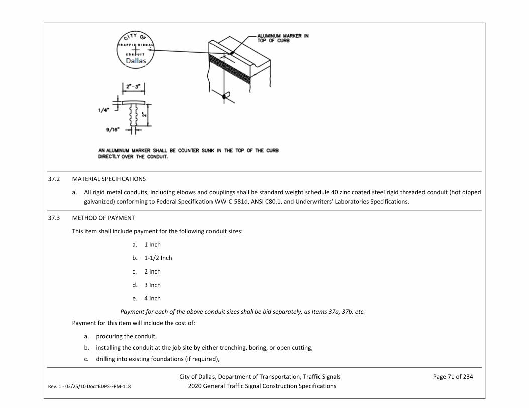
City of Dallas, Department of Transportation, Traffic Signals Page 71 of 234 Rev. 1 - 03/25/10 Doc#BDPS-FRM-118 2020 General Traffic Signal Construction Specifications
37.2 MATERIAL SPECIFICATIONS
a. All rigid metal conduits, including elbows and couplings shall be standard weight schedule 40 zinc coated steel rigid threaded conduit (hot dipped galvanized) conforming to Federal Specification WW-C-581d, ANSI C80.1, and Underwriters’ Laboratories Specifications.
37.3 METHOD OF PAYMENT
This item shall include payment for the following conduit sizes:
a. 1 Inch
b. 1-1/2 Inch
c. 2 Inch
d. 3 Inch
e. 4 Inch
Payment for each of the above conduit sizes shall be bid separately, as Items 37a, 37b, etc.
Payment for this item will include the cost of:
a. procuring the conduit,
b. installing the conduit at the job site by either trenching, boring, or open cutting,
c. drilling into existing foundations (if required),
City of Dallas, Department of Transportation, Traffic Signals Page 72 of 234 Rev. 1 - 03/25/10 Doc#BDPS-FRM-118 2020 General Traffic Signal Construction Specifications
d. mounting the conduit to service poles, signal poles, etc (as required),
NOTES:
i. The cost of procuring and installing conduit placed in a strain pole, surveillance camera pole, mast arm pole, streetscape pole, pedestal pole, or any foundation will not be paid under this item, but will be paid under the respective ITEMS.
ii. If an open street cut is required to install rigid metal conduit, payment for excavation and repair of the cut will be covered under ITEM 39. Installation of conduit under a sidewalk does not constitute an open street cut. Payment for removal and restoration of concrete sidewalks will be paid for under the respective sidewalk items.
UNIT OF PAYMENT: LINEAR FOOT
37.4 CONSTRUCTION TIME LIMIT
Once a work order has been issued, the Vendor will have a time limit of 10 working days to procure the conduit and 1 working day per 100 linear feet for its installation.
City of Dallas, Department of Transportation, Traffic Signals Page 73 of 234 Rev. 1 - 03/25/10 Doc#BDPS-FRM-118 2020 General Traffic Signal Construction Specifications
ITEM 38 PROCUREMENT AND INSTALLATION OF PVC CONDUIT
38.1 INSTALLATION SPECIFICATIONS
a. The location of conduit shown on the Plans is approximate. The Vendor shall give the Engineer a minimum of 48 hours advance notice of their intention to establish the final conduit location. The location shall be approved by the Engineer at the site prior to excavation or boring.
b. The Vendor shall comply with the latest edition of the city of Dallas’ Street Cut and Excavation Repair Standards when installing conduit.
c. PVC conduit shall be joined by the solvent-weld method in accordance with the conduit manufacturer’s recommendations. No reducer couplings shall be used unless specifically indicated on the Plans or approved by the Engineer.
d. Any bends or sweeps installed in conduit runs shall meet the minimum radius requirements of the NEC.
e. All conduit and fittings shall have burrs and rough places smoothed and shall be clean and free of obstructions before the cable is installed. Field cuts shall be made with a hacksaw only, and shall be square and true so that the ends will butt or come together for the full diameter thereof. In no case shall a cutting torch be used to cut or join conduit. Slip joints or running threads will not be permitted for coupling conduit unless approved by the Engineer. When a standard coupling cannot be used, an approved union coupling shall be used and shall provide a watertight coupling between the conduits. All couplings shall be properly installed to bring their ends of connected conduit together to produce a good rigid connection throughout the entire length of the conduit run. Ends of conduits shall be capped or plugged until installation of the wire is complete. Conduit shall be placed at a minimum depth of 36 inches below finished grade or top of pavement.
f. All conduit ends in ground boxes, foundations, controller cabinets, etc. shall be fitted with nylon bushings.
g. All conduits shall have nonmetallic pull strings installed, and ends shall be capped or sealed with an appropriate duct sealant. Foaming of conduit ends will not be allowed.
h. PVC conduit, which is to be placed under existing pavement, sidewalks, and driveways, shall be installed by first providing a void through which the PVC conduit can be inserted. The void may be made either by boring or jacking a mandrel. Pits for jacking or boring shall not be closer than 2 feet to the back of the curb or the outside edge of the shoulder, unless otherwise directed by the Engineer. The jacking and boring method used shall not interfere with the operation of streets, highways, or other facilities, and shall not weaken or damage any embankment structure, or pavement. Heavy jacks are to be used for jacking. Boring is to be done by mechanical means providing a maximum one inch overcut for the conduit to be placed. Use of water or other fluids in connection with the boring operation will be permitted only to lubricate cuttings. Water jetting will not be permitted. Where conduit is to be placed under existing asphaltic pavement, the jacking method is to be used.
i. Backfill for all excavations shall be tamped with mechanical tamps in six inch (6”) layers to the density of the surrounding ground.
j. The Vendor shall provide adequately bent conduit and shall properly excavate so as to prevent damage to the conduit or conductor by a bend radius which is too short.
k. All conduit runs shall be continuous and of the same material. Where tying into existing conduit, the Vendor shall continue with the same material or provide the appropriate dielectric union.
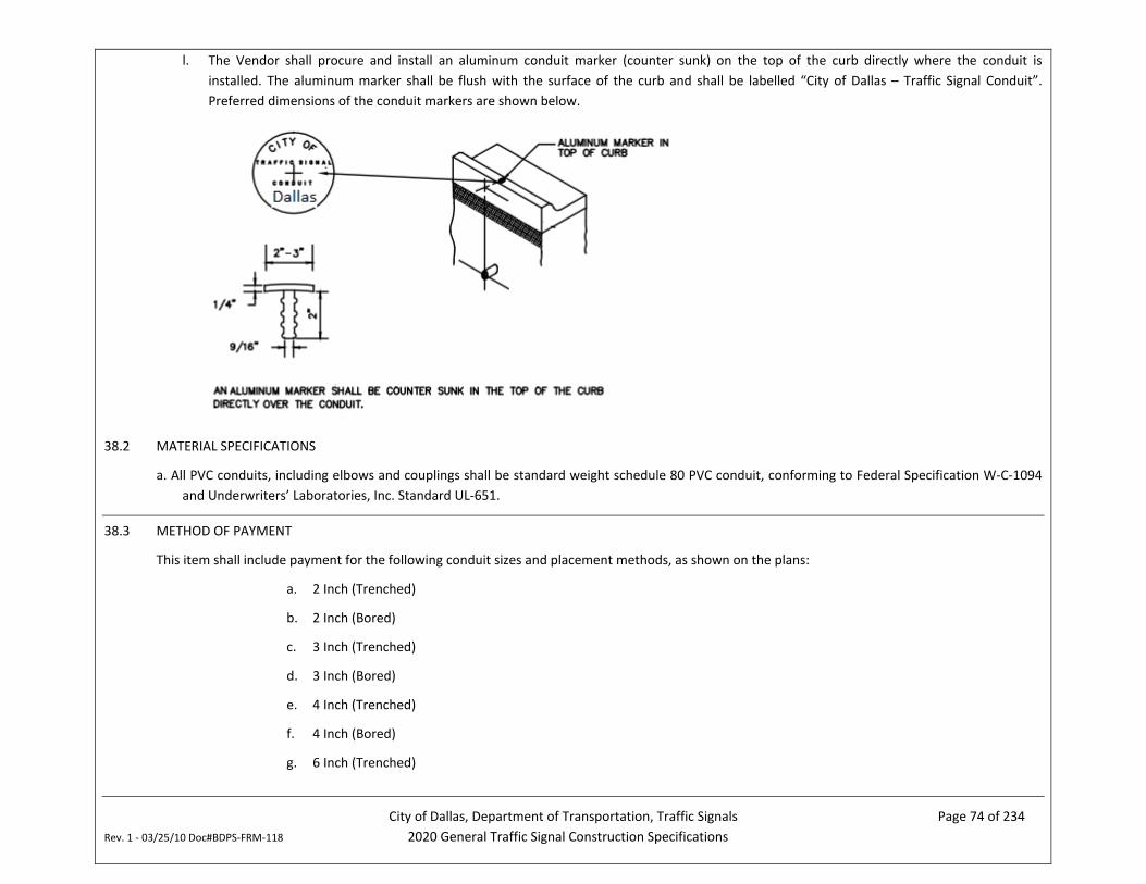
City of Dallas, Department of Transportation, Traffic Signals Page 74 of 234 Rev. 1 - 03/25/10 Doc#BDPS-FRM-118 2020 General Traffic Signal Construction Specifications
l. The Vendor shall procure and install an aluminum conduit marker (counter sunk) on the top of the curb directly where the conduit is installed. The aluminum marker shall be flush with the surface of the curb and shall be labelled “City of Dallas – Traffic Signal Conduit”. Preferred dimensions of the conduit markers are shown below.
38.2 MATERIAL SPECIFICATIONS
a. All PVC conduits, including elbows and couplings shall be standard weight schedule 80 PVC conduit, conforming to Federal Specification W-C-1094 and Underwriters’ Laboratories, Inc. Standard UL-651.
38.3 METHOD OF PAYMENT
This item shall include payment for the following conduit sizes and placement methods, as shown on the plans:
a. 2 Inch (Trenched)
b. 2 Inch (Bored)
c. 3 Inch (Trenched)
d. 3 Inch (Bored)
e. 4 Inch (Trenched)
f. 4 Inch (Bored)
g. 6 Inch (Trenched)
City of Dallas, Department of Transportation, Traffic Signals Page 75 of 234 Rev. 1 - 03/25/10 Doc#BDPS-FRM-118 2020 General Traffic Signal Construction Specifications
h. 6 Inch (Bored)
Payment for each of the above conduit sizes shall be bid separately, as Items 38a, 38b, etc.
Payment for this item will include the cost of:
a. procuring the conduit and all associated fittings, solvents, and sealants,
b. installing the conduit at the job site by either trenching or boring, as shown on the plans,
c. drilling into existing foundations (if required),
d. mounting the conduit to service poles, signal poles, etc (as required),
NOTES:
i. The cost of procuring and installing conduit placed in a strain pole, surveillance camera pole, mast arm pole, streetscape pole, pedestal pole, or any foundation will not be paid under this item, but will be paid under the respective ITEMS.
ii. If an open street cut is required to install conduit, payment for excavation and repair of the cut will be covered under ITEM 39. In the event that the open-cut method is used, payment for conduit under this item will be for the trenched method. Installation of conduit under a sidewalk does not constitute an open street cut. Payment for removal and restoration of concrete sidewalks will be paid for under the respective sidewalk items.
UNIT OF PAYMENT: LINEAR FOOT
38.4 CONSTRUCTION TIME LIMIT
Once a work order has been issued, the Vendor will have a time limit of 10 working days to procure the conduit and 1 working day per 100 linear feet for its installation.
City of Dallas, Department of Transportation, Traffic Signals Page 76 of 234 Rev. 1 - 03/25/10 Doc#BDPS-FRM-118 2020 General Traffic Signal Construction Specifications
ITEM 39 EXCAVATION AND REPAIR OF AN OPEN STREET CUT FOR INSTALLATION OF CONDUIT
39.1 INSTALLATION SPECIFICATIONS
a. When indicated on the Plans, the Vendor will be required to perform an open street cut in order to install conduit of various sizes.
b. Open cuts and their repair shall conform to the City of Dallas Department of Public Works Pavement Cut and Repair Standards Manual.
c. Open cuts shall be nominally 2’ wide and 18” deep as measured from the top of existing pavement.
39.2 MATERIAL SPECIFICATIONS
a. Refer to City of Dallas Department of Public Works Pavement Cut and Repair Standards Manual for details on materials required to perform street cut repairs.
39.3 METHOD OF PAYMENT
Two separate bid items will be included for work under this item:
a. Work outside the CBD
b. Work within the CBD
For the purposes of this contract, the CBD is defined as the area of the City of Dallas bounded by the following roadways:
IH 35E, IH 30, IH 345, Woodall Rodgers Freeway
Payment for this item will include the cost of:
a. Development of a Temporary Traffic Control Plan for approval by the City,
b. installation and maintenance of the temporary traffic control devices,
c. site excavation work, including sawcutting and removal of pavement, subgrade, and any encountered materials such as brick, rock, rails, rail ties, abandoned utilities, etc.,
d. properly disposal of excavated material,
e. providing steel plates to temporarily cover the excavation (if required),
f. procuring and installing backfill, asphalt, concrete, curing compound, rebar and sub-base material for the street cut repair, as detailed in the of Dallas Department of Public Works Pavement Cut and Repair Standards Manual.
g. Final surface paving.
h. Restoration of any disturbed vegetation, irrigation systems, etc.
City of Dallas, Department of Transportation, Traffic Signals Page 77 of 234 Rev. 1 - 03/25/10 Doc#BDPS-FRM-118 2020 General Traffic Signal Construction Specifications
NOTES:
i. Payment for the procurement and installation of conduit installed in the open cut will be covered under the applicable item for trenched conduit.
ii. This item shall include the cost of all paving necessary to restore the open cut trench. Payment for paving repairs associated with this item will not be paid separately under the other items included in this contract.
iii. Any waivers or permits required will be obtained by the City, including noise ordinance waivers, pavement cut permits, etc.
iv. Installation of conduit under a sidewalk does not constitute an open street cut and will be paid as described in the applicable conduit items.
UNIT OF PAYMENT: LINEAR FOOT
39.4 CONSTRUCTION TIME LIMIT
Once a work order has been issued, the Vendor will have a time limit of 20 working days to procure materials. One working day per 20 LF of open cut will be allowed for work outside the CBD under this item. One working day per 10 LF will be allowed for work performed within the CBD under this item.
City of Dallas, Department of Transportation, Traffic Signals Page 78 of 234 Rev. 1 - 03/25/10 Doc#BDPS-FRM-118 2020 General Traffic Signal Construction Specifications
ITEM 40 PROCUREMENT AND INSTALLATION OF ELECTRICAL POWER SERVICE WITH INSPECTION PERMIT OBTAINED BY CITY
40.1 INSTALLATION SPECIFICATIONS
a. The Vendor shall procure and install either a pedestal-style or pole-mounted meter base for electrical power service to the signal controller cabinet.
b. Refer to Exhibit L for details on the installation of overhead electrical power service.
c. Refer to TxDOT Standards for details on the installation of pedestal-type electrical services.
40.2 MATERIAL SPECIFICATIONS
For Overhead Services, the following specifications apply:
a. Weatherheads shall be made of cast aluminum or galvanized steel.
b. All 1-inch conduit shall be standard weight schedule 40 zinc coated steel rigid threaded conduit (hot dipped galvanized) conforming to Federal Specification WW-C-581d, ANSI C80.1, and Underwriters’ Laboratories Specifications.
c. Circuit breaker boxes shall be weatherproof galvanized steel enclosures with latches that are secured with Vendor supplied padlocks equipped with Corbin #2 locks. The breaker box shall contain a 20 amp circuit breaker for the luminaires and either a 50 or 60 amp breaker for the signal system (see Exhibit J for details). A Square D Model #Q024L7ORB circuit breaker box will be considered acceptable. Other brands can be substituted provided they are approved by the Engineer.
d. Power cable shall be #6 AWG XHHW wire and be suitable for AC service (see Exhibit J for details). The wire shall be capable of operating at 600 volts maximum and suitable for use at conductor temperatures not exceeding 75°C. material and construction shall be in accordance with the applicable requirements of the I.P.C.E.A. Conductors shall be stranded, annealed coated copper. Copper wire before insulating or stranding shall meet the requirements of the latest edition of A.S.T.M. B-033 (for coated wire). Stranding shall be class B, in accordance with the latest edition of A.S.T.M. B-8. Insulation shall consist of cross linked thermosetting polyethylene, meeting the requirements of column B of I.P.C.E.A., and listed by Underwriters’ Laboratories as type U.S.E. RHW-75C.
e. The meter base shall be rated for 100 amps. A Milbank Model #AT2300-03 meter base will be considered acceptable. Other brands can be substituted provided they are approved by the Engineer.
For pedestal services, the following specifications apply:
a. Materials for pedestal-type electrical service shall adhere to the applicable TxDOT standards
40.3 METHOD OF PAYMENT
Two separate bid items will be included for work under this item:
a. Overhead electrical service
City of Dallas, Department of Transportation, Traffic Signals Page 79 of 234 Rev. 1 - 03/25/10 Doc#BDPS-FRM-118 2020 General Traffic Signal Construction Specifications
b. Pedestal-style electrical service
Payment for this item will include the cost of:
a. procuring and installing all materials related to the power service connection including the pedestal, weatherhead, ½-inch PVC conduit, 1-inch rigid metal conduit, conduit mounting brackets, the power service meter base, the circuit breaker box (equipped with the appropriate circuit breakers), electrical power wires and ground wires, as applicable.
NOTES:
i. Payment for this item includes the cost of procuring and installing rigid metal conduit from the weatherhead to the electric service meter. Procurement and installation of all other conduit related to the electrical power service will be covered under ITEM 37. Payment for this item also includes the cost of procuring and installing power wire from the Electric Utility’s transformer to the electric meter base. Procurement and installation of all other power wire will be covered under Item 24. Payment for the procurement and installation of timber support poles or other type electric service supports for the power service is covered under other items.
ii. The City will be responsible for all permitting fees related to the establishment of electric service under this item.
UNIT OF PAYMENT: EACH
40.4 CONSTRUCTION TIME LIMIT
Once a work order has been issued, the Vendor will have a time limit of 90 working days to procure materials and ½ working day per intersection to complete the power service hardware installation.
City of Dallas, Department of Transportation, Traffic Signals Page 80 of 234 Rev. 1 - 03/25/10 Doc#BDPS-FRM-118 2020 General Traffic Signal Construction Specifications
ITEM 41 PROCUREMENT AND INSTALLATION OF ELECTRICAL POWER SERVICE WITH INSPECTION PERMIT OBTAINED BY VENDOR
41.1 INSTALLATION SPECIFICATION
a. The Vendor will be responsible for obtaining an electrical inspection permit from the City’s Building Inspection Division located at the Oak Cliff Municipal Center, 320 E. Jefferson, Room 118 (all permit fees will be paid by the Vendor, including any re-inspection fees). Prior to obtaining the permit, the Vendor will need to establish a 911 address for the electrical service pole (contact the City’s Address Coordinator).
b. The Vendor shall procure and install a meter base for electrical power service to the signal controller cabinet.
c. Refer to Exhibit L for details on the installation of electrical power service.
d. Refer to TxDOT Standards for details on the installation of pedestal-type electrical services.
41.2 MATERIAL SPECIFICATIONS
For Overhead Services, the following specifications apply:
a. Weatherheads shall be made of cast aluminum or galvanized steel.
b. All 1-inch conduit shall be standard weight schedule 40 zinc coated steel rigid threaded conduit (hot dipped galvanized) conforming to Federal Specification WW-C-581d, ANSI C80.1, and Underwriters’ Laboratories Specifications.
c. Circuit breaker boxes shall be weatherproof galvanized steel enclosures with latches that are secured with Vendor supplied padlocks equipped with Corbin #2 locks. The breaker box shall contain a 20 amp circuit breaker for the luminaires and either a 50 or 60 amp breaker for the signal system (see Exhibit J for details). A Square D Model #Q024L7ORB circuit breaker box will be considered acceptable. Other brands can be substituted provided they are approved by the Engineer.
d. Power cable shall be #6 AWG XHHW wire and be suitable for AC service (see Exhibit J for details). The wire shall be capable of operating at 600 volts maximum and suitable for use at conductor temperatures not exceeding 75°C. material and construction shall be in accordance with the applicable requirements of the I.P.C.E.A. Conductors shall be stranded, annealed coated copper. Copper wire before insulating or stranding shall meet the requirements of the latest edition of A.S.T.M. B-033 (for coated wire). Stranding shall be class B, in accordance with the latest edition of A.S.T.M. B-8. Insulation shall consist of cross linked thermosetting polyethylene, meeting the requirements of column B of I.P.C.E.A., and listed by Underwriters’ Laboratories as type U.S.E. RHW-75C.
e. The meter base shall be rated for 100 amps. A Milbank Model #AT2300-03 meter base will be considered acceptable. Other brands can be substituted provided they are approved by the Engineer.
For pedestal services, the following specifications apply:
a. Materials for pedestal-type electrical service shall adhere to the applicable TxDOT standards
City of Dallas, Department of Transportation, Traffic Signals Page 81 of 234 Rev. 1 - 03/25/10 Doc#BDPS-FRM-118 2020 General Traffic Signal Construction Specifications
41.3 METHOD OF PAYMENT
Two separate bid items will be included for work under this item:
b. Overhead electrical service
c. Pedestal-style electrical service
Payment for this item will include the cost of:
a. procuring and installing all materials related to the power service connection including the pedestal, weatherhead, ½-inch PVC conduit, 1-inch rigid metal conduit, conduit mounting brackets, the power service meter base, the circuit breaker box (equipped with the appropriate circuit breakers), electrical power wires and ground wires, as applicable.
NOTES:
i. Payment for this item includes the cost of procuring and installing rigid metal conduit from the weatherhead to the electric service meter. Procurement and installation of all other conduit related to the electrical power service will be covered under ITEM 37. Payment for this item also includes the cost of procuring and installing power wire from the Electric Utility’s transformer to the electric meter base. Procurement and installation of all other power wire will be covered under Item 24. Payment for the procurement and installation of timber support poles or other type electric service supports for the power service is covered under other items.
ii. The City will be responsible for all permitting fees related to the establishment of electric service under this item.
UNIT OF PAYMENT: EACH
41.4 CONSTRUCTION TIME LIMIT
Once a work order has been issued, the Vendor will have a time limit of 90 working days to obtain electric service and ½ working day per intersection to complete the power service hardware installation.
City of Dallas, Department of Transportation, Traffic Signals Page 82 of 234 Rev. 1 - 03/25/10 Doc#BDPS-FRM-118 2020 General Traffic Signal Construction Specifications
ITEM 42 INSTALLATION OF GROUND BOX
42.1 INSTALLATION SPECIFICATIONS
a. The Vendor will be responsible for installing the ground boxes in the field. This work shall include transporting the ground boxes from the Department of Transportation warehouse at 9500 Denton Drive to the job site. The City may change this location as long as it remains within City of Dallas city limits.
b. The location of ground boxes shown on the Plans is approximate. The Vendor shall give the Engineer a minimum 48 hours advance notice of their intention to establish the final ground box location. The location shall be approved by the Engineer at the site prior to excavation.
c. The concrete surface of the ground box apron shall be sprayed with membrane cutting compound after the concrete finishing operation is completed and after free water has disappeared. The surface of the concrete shall be kept damp between the completion of the finishing operation and application of the curing compound. The curing compound shall be applied under pressure by means of a nozzle at a rate not to exceed 200 sq. ft. per gallon. A minimum of 96 hours curing time shall be required.
Refer to Exhibit M for further details on the installation of ground boxes.
42.2 MATERIAL SPECIFICATIONS
a. The curing compound for the concrete apron shall be of the membrane type with ASTM designation C 309 Type 2.
Refer to Exhibit M for details on the type of concrete and rebar to be used in the construction of ground box aprons.
42.3 METHOD OF PAYMENT
Payment for this item will include the cost of:
a. site excavation work,
b. properly disposing of excavated material,
c. transporting the ground box to the job site and installing the ground box at the job site
d. providing the concrete, curing compound and rebar for the apron around the ground box,
e. constructing the apron around the ground box.
NOTE: Payment under this item shall be the same regardless of the size of the Ground Box.
UNIT OF PAYMENT: EACH
42.4 CONSTRUCTION TIME LIMIT
Once a work order has been issued, the Vendor will have a time limit of 1 working day to procure materials and 1 working day per ground box for its installation.
City of Dallas, Department of Transportation, Traffic Signals Page 83 of 234 Rev. 1 - 03/25/10 Doc#BDPS-FRM-118 2020 General Traffic Signal Construction Specifications
ITEM 43 PROCUREMENT AND INSTALLATION OF GROUND BOX
43.1 INSTALLATION SPECIFICATIONS
a. The Vendor will be responsible for installing the ground boxes in the field.
b. The location of ground boxes shown on the Plans is approximate. The Vendor shall give the Engineer a minimum 48 hours advance notice of their intention to establish the final ground box location. The location shall be approved by the Engineer at the site prior to excavation.
c. The concrete surface of the ground box apron shall be sprayed with membrane cutting compound after the concrete finishing operation is completed and after free water has disappeared. The surface of the concrete shall be kept damp between the completion of the finishing operation and application of the curing compound. The curing compound shall be applied under pressure by means of a nozzle at a rate not to exceed 200 sq. ft. per gallon. A minimum of 96 hours curing time shall be required.
d. Refer to Exhibit M for further details on the installation of ground boxes.
43.2 MATERIAL SPECIFICATIONS
a. Ground box covers shall be constructed of 2-inch thick (nominal) concrete or polymer concrete. Their top surface shall have a minimum coefficient of friction of 0.5. The logo “COD TRAFFIC SIGNAL/DANGER HIGH VOLTAGE” in minimum 1-inch letters shall be imprinted as an integral part of all ground box covers.
b. Ground box covers shall be secured with at least two ½-inch stainless steel bolts. Bolts shall be captive and withstand a minimum of 70 ft.-lbs. of torque and shall have a minimum 750 lbs. straight pull out strength. Nuts shall be floating.
c. Ground box enclosures shall be constructed of concrete or polymer concrete. When covered, ground boxes shall be able to withstand a test loading of 20,000 lbs. over a 10”x10” area centered on the cover and 600 lbs. per sq. ft. applied over the entire side well.
d. Ground boxes shall be stackable for extra height. The bottom edge of all ground boxes shall be footed with a minimum 1 ¼ -inch flange.
e. Bolt holes in the ground box shall be arranged to drain dirt.
f. All components shall be designed and tested to withstand temperatures as low as -20°F.
g. Ground boxes to be paid under this item shall be bid separately and sized nominally sized as follows:
a. Small Ground Box (TXDOT Type A): 12” wide by 23” long by 11” deep
b. Medium Ground Box (TXDOT Type B): 12” wide by 23” long by 22” deep
c. Large Ground Box (TXDOT Type D): 16” wide by 29” long by 22” deep
h. The curing compound for the concrete apron shall be of the membrane type with ASTM designation C 309 Type 2.
i. Refer to Texas Department of Transportation (TxDOT) Standard Drawings and Exhibit M for details on the type of concrete and rebar to be used in the construction of ground box aprons.
City of Dallas, Department of Transportation, Traffic Signals Page 84 of 234 Rev. 1 - 03/25/10 Doc#BDPS-FRM-118 2020 General Traffic Signal Construction Specifications
43.3 METHOD OF PAYMENT
Payment for this item will include the cost of:
a. site excavation work,
b. properly disposing of excavated material,
c. providing the concrete, curing compound and rebar for the apron around the ground box,
d. constructing the apron around the ground box and
e. Procuring the ground box installing it at the job site.
UNIT OF PAYMENT: EACH
43.4 CONSTRUCTION TIME LIMIT
Once a work order has been issued, the Vendor will have a time limit of 10 working days to procure materials and 1 working day per ground box for its installation.
City of Dallas, Department of Transportation, Traffic Signals Page 85 of 234 Rev. 1 - 03/25/10 Doc#BDPS-FRM-118 2020 General Traffic Signal Construction Specifications
ITEM 44 PROCUREMENT AND INSTALLATION OF MULTICONDUCTOR SIGNAL CABLE
44.1 INSTALLATION SPECIFICATIONS
a. Prior to pulling cable in existing underground conduit, the conduit shall be cleaned with a mandrel or cylindrical wire brush and blown out with compressed air. If conduit appears to be blocked, the Vendor shall make an attempt to clear the conduit by rodding.
b. The conductors shall be installed in a manner so as to insure against harmful stretching of the conductors or damage to the insulation. Installation methods shall conform to the recommendations of the cable manufacturer.
c. All cables in a given conduit run shall be pulled at the same time and the conductors shall be assembled to form one loop in such a manner that the pulling tension is equally distributed to all the cables. Long, hard pulls will necessitate the use of pulling eyes. For short runs, the cables may be gripped directly by the conductors by forming them into a loop to which the pull wire or rope can be attached. The insulation on each conductor shall be removed before the loop is formed. The method used will depend on the anticipated maximum pulling tension in each case.
d. In many instances, existing conduits which contain signal cable are to be used for the installation of new cables. In locations where new cables are to replace existing cables, the existing cables may be used to pull in the new cables. At locations where new cables are to be added to existing cable runs, the existing cables shall first be pulled out, then replaced, adding the new cables to the existing cables to form one cable pull. Installation and removal shall be done in such a way as to prevent damage to the existing and/or new cables. This requirement may be waived by the Engineer. In the event of damage, the Vendor shall bear the responsibility of providing the material and labor for replacement of damaged cables at no extra cost to the City.
e. The cable shall be fed freely off the reel into the conduit without making a reverse curve. At the pulling end, the pull wire and cables shall be drawn from the conduit in direct line with the conduit. Sheaves or other suitable devices shall be used as required to reduce any hazards to the cable during installation. The cables shall be adequately lubricated to reduce friction and further minimize possible damage. Such lubricants shall not be the grease or oil type used on lead sheathed cables, but shall be one of several commercially available wire pulling compounds that are suitable for P.V.C. sheathed cables. They shall consist of soap, talc, mica, or similar materials and shall be designed to have no deleterious effect on the cables being used.
f. Cables shall be neatly trained to their destinations in manholes, cabinets, pole bases, ground boxes, and all other termination. The Vendor shall adhere to the cable manufacturer’s recommended values for the minimum bending radii to which cables may be bent for permanent training during installation. These limits do not apply to conduit bends, sheaves, or other curved surfaces around which these cables may be pulled under tension while being installed. Larger radius bends are required for such conditions.
g. Plumbers putty or duct sealant shall be packed around cables at the end of each conduit run to seal the conduit openings and prevent moisture and debris from entering. Foaming of conduit ends is not permitted.
h. Splices are strictly prohibited inside conduit runs. Splicing signal cable in ground boxes is prohibited.
i. Splicing methods shall follow standard electrical practices and the cable manufacturer’s recommendations. All materials used shall be of high quality and specifically intended for this purpose. Cables shall be trained to their final position and cut to proper lengths. The cable’s jacket
City of Dallas, Department of Transportation, Traffic Signals Page 86 of 234 Rev. 1 - 03/25/10 Doc#BDPS-FRM-118 2020 General Traffic Signal Construction Specifications
and insulation shall be removed as required. Proper care should be exercised to insure against nicking the conductors. The connection shall be installed tightly and all burrs, rough edges, etc. shall be removed.
j. If wire nuts are used to secure splices, then only “Scotchlock” brand connectors shall be utilized. No more than three (3) wires shall be spliced together using “Scotchlock” connectors. If more than three (3) wires are connected, then a Kearney connector or mechanical clamp shall be used.
k. If the Engineer directs that connections shall be soldered, then heat shall be applied by using a hot soldering iron. Heating the connection with a direct flame is strictly prohibited. Care shall be used to protect the insulation when soldering. The entire surface shall be cleaned taking special care in cleaning the outside jacket in order to remove the wax finish. Before the first layer of tape is wrapped, the entire area shall be coated with an electric grade rubber cement. After this solvent has dried, the connection shall be insulated to the proper thickness with electrical grade rubber splicing compound tape. This tape requires a pressure and temperature in service to complete its vulcanizing process and shall be stretched to 2/3 its normal width when applied. The completed splice shall be covered with a half-lap layer of vinyl plastic electrical tape. This wrapping shall be smooth, but the tape shall not be stretched more than necessary.
44.2 MATERIAL SPECIFICATIONS
a. Multiconductor cable shall be supplied with a sufficient number of conductors so as to safely operate the traffic signal. The required number of conductors will be either indicated on the individual project traffic signal plans or will be determined by the Vendor. In either case, the Engineer will have final authority and approval over the number of conductors used.
b. All multiconductor cable shall be capable of operation at 600 volts maximum and suitable for use at conductor temperatures not exceeding 75°C (167°F). All such cable shall meet the requirements of the National Electrical Code.
c. Conductors shall be stranded #14 AWG annealed uncoated copper. The copper wire (before insulating) shall meet the requirements of the latest American Society for Testing and Materials’ (ASTM) standards for uncoated wire.
d. The overall cable jacket shall consist of a polyvinyl chloride compound which provides a tough, heat, moisture, and flame resistant covering meeting the requirements of the Insulated Power Cable Engineer’s Association (I.P.C.E.A.).
e. The color of the cable jackets in the multiconductor signal cable shall conform to the City’s cable termination standard. The Vendor shall submit the cable jacket colors in each proposed multiconductor cable (e.g. 5 conductor, 16 conductor, 20 conductor, 25 conductor) for the Engineer’s approval. Any changes in the cable jacket colors during the contract term shall be submitted to the city for approval.
44.3 METHOD OF PAYMENT
This item shall include payment for the following multiconductor cables:
City of Dallas, Department of Transportation, Traffic Signals Page 87 of 234 Rev. 1 - 03/25/10 Doc#BDPS-FRM-118 2020 General Traffic Signal Construction Specifications
a. 2 Conductor (#14 AWG) b. 5 Conductor (#14 AWG) c. 7 Conductor (#14 AWG) d. 12 Conductor (#14 AWG)
e. 16 Conductor (#14 AWG) f. 20 Conductor (#14 AWG) g. 25 Conductor (#14 AWG) h. 12 Conductor (#12 AWG)
Payment for each of the above multiconductor cables shall be bid separately, as Items 44a, 44b, etc.
Payment for this item will include the cost of:
a. providing the multiconductor signal cable and
b. installing and connecting the multiconductor signal cable at the job site.
NOTE: Payment for multiconductor cable will be made per linear foot of cable and not per linear foot of conductor. Payment for multiconductor cable installed inside a school flasher assembly will be covered under ITEM 59, Installation of a School Flasher. Payment for signal cable installed from a span wire-mounted signal head to the controller cabinet will be covered under this item and not considered incidental to ITEM 4, ITEM 5, and ITEM 6 as is the cable installed from mast arm-mounted signal heads to the nearest signal pole base.
UNIT OF PAYMENT: LINEAR FOOT
44.4 CONSTRUCTION TIME LIMIT
Once a work order has been issued, the Vendor will have a time limit of 10 working days to procure the multiconductor signal cable and 1 working day per 1000 linear feet for its installation.
City of Dallas, Department of Transportation, Traffic Signals Page 88 of 234 Rev. 1 - 03/25/10 Doc#BDPS-FRM-118 2020 General Traffic Signal Construction Specification
ITEM 45 PROCUREMENT AND INSTALLATION OF ELECTRICAL POWER WIRE
45.1 INSTALLATION SPECIFICATIONS
a. Prior to pulling cable in existing underground conduit, the conduit shall be cleaned with a mandrel or cylindrical wire brush and blown out with compressed air. If conduit appears to be blocked, the Vendor shall make an attempt to clear the conduit by rodding.
b. The conductors shall be installed in a manner so as to insure against harmful stretching of the conductors or damage to the insulation. Installation methods shall conform to the recommendations of the cable manufacturer.
c. All cables in a given conduit run shall be pulled at the same time and the conductors shall be assembled to form one loop in such a manner that the pulling tension is equally distributed to all the cables. Long, hard pulls will necessitate the use of pulling eyes. For short runs, the cables may be gripped directly by the conductors by forming them into a loop to which the pull wire or rope can be attached. The insulation on each conductor shall be removed before the loop is formed. The method used will depend on the anticipated maximum pulling tension in each case.
d. In many instances, existing conduits which contain signal cable are to be used for the installation of new cables. In locations where new cables are to replace existing cables, the existing cables may be used to pull in the new cables. At locations where new cables are to be added to existing cable runs, the existing cables shall first be pulled out, then replaced, adding the new cables to the existing cables to form one cable pull. Installation and removal shall be done in such a way as to prevent damage to the existing and/or new cables. This requirement may be waived by the Engineer. In the event of damage, the Vendor shall bear the responsibility of providing the material and labor for replacement of defective cables at no extra cost to the City.
e. The cable shall be fed freely off the reel into the conduit without making a reverse curve. At the pulling end, the pull wire and cables shall be drawn from the conduit in direct line with the conduit. Sheaves or other suitable devices shall be used as required to reduce any hazards to the cable during installation. The cables shall be adequately lubricated to reduce friction and further minimize possible damage. Such lubricants shall not be the grease or oil type used on lead sheathed cables, but shall be one of several commercially available wire pulling compounds that are suitable for P.V.C. sheathed cables. They shall consist of soap, talc, mica, or similar materials and shall be designed to have no deleterious effect on the cables being used.
f. Cables shall be neatly trained to their destinations in manholes, cabinets, pole bases, ground boxes, and all other termination. The Vendor shall adhere to the cable manufacturer’s recommended values for the minimum bending radii to which cables may be bent for permanent training during installation. These limits do not apply to conduit bends, sheaves, or other curved surfaces around which these cables may be pulled under tension while being installed. Larger radius bends are required for such conditions.
g. Plumbers putty or duct sealant shall be packed around cables at the end of each conduit run to seal the conduit openings and prevent moisture and debris from entering. Foaming of conduit ends is not permitted.
h. Splices are strictly prohibited inside conduit runs. Splicing of line or neutral electrical power wires in ground boxes is prohibited. Splicing of ground conductors is permitted with the use of copper-clad split bolts or similar corrosion resistant mechanical couplings.
City of Dallas, Department of Transportation, Traffic Signals Page 89 of 234 Rev. 1 - 03/25/10 Doc#BDPS-FRM-118 2020 General Traffic Signal Construction Specification
i. Splicing methods shall follow standard electrical practices and the cable manufacturer’s recommendations. All materials used shall be of high quality and specifically intended for this purpose. Cables shall be trained to their final position and cut to proper lengths. The cable’s jacket and insulation shall be removed as required. Proper care should be exercised to insure against nicking the conductors. The connection shall be installed tightly and all burrs, rough edges, etc. shall be removed.
j. If wire nuts are used to secure splices, then only “Scotchlock” brand connectors shall be utilized. No more than three (3) wires shall be spliced together using “Scotchlock” connectors. If more than three (3) wires are connected, then a Kearney connector or mechanical clamp shall be used.
k. If the Engineer directs that connections shall be soldered, then heat shall be applied by using a hot soldering iron. Heating the connection with a direct flame is strictly prohibited. Care shall be used to protect the insulation when soldering. The entire surface shall be cleaned taking special care in cleaning the outside jacket in order to remove the wax finish. Before the first layer of tape is wrapped, the entire area shall be coated with an electric grade rubber cement. After this solvent has dried, the connection shall be insulated to the proper thickness with electrical grade rubber splicing compound tape. This tape requires a pressure and temperature in service to complete its vulcanizing process and shall be stretched to 2/3 its normal width when applied. The completed splice shall be covered with a half-lap layer of vinyl plastic electrical tape. This wrapping shall be smooth, but the tape shall not be stretched more than necessary.
45.2 MATERIAL SPECIFICATIONS
a. Power cables shall be #6 AWG XHHW wire and shall be suitable for AC service.
b. The cable shall be capable of operating at 600 volts maximum and suitable for use at conductor temperatures not exceeding 75°C. Material and construction shall be in accordance with the applicable requirements of the I.P.C.E.A.
c. Conductors shall be stranded, annealed coated copper. Copper wire, before insulating or stranding, shall meet the requirements of the latest edition of A.T.S.M. B-033 (for coated wire). Stranding shall be class B, in accordance with the latest edition of A.S.T.M. B-8.
45.3 METHOD OF PAYMENT
Payment for this item will include the cost of:
a. procuring the power wire and
b. installing and connecting the power wire at the job site.
NOTE: Power wire installed from the TXU Electric Delivery power line to the electrical meter base will be considered part of the electrical power connection and consequently covered under ITEM 40 or ITEM 41, respectively. All other power wire will be paid for under this item.
UNIT OF PAYMENT: LINEAR FOOT
45.4 CONSTRUCTION TIME LIMIT
Once a work order has been issued, the Vendor will have a time limit of 10 working days to procure the power wire and 1 working day per 1000 linear feet for its installation.
City of Dallas, Department of Transportation, Traffic Signals Page 90 of 234 Rev. 1 - 03/25/10 Doc#BDPS-FRM-118 2020 General Traffic Signal Construction Specification
ITEM 46 PROCUREMENT AND INSTALLATION OF MULTICONDUCTOR VEHICLE DETECTOR OR COMMUNICATION CABLE
46.1 INSTALLATION SPECIFICATIONS
a. Prior to pulling cable in existing underground conduit, the conduit shall be cleaned with a mandrel or cylindrical wire brush and blown out with compressed air. If conduit appears to be blocked, the Vendor shall make an attempt to clear the conduit by rodding.
b. The conductors shall be installed in a manner so as to insure against harmful stretching of the conductors or damage to the insulation. Installation methods shall conform to the recommendations of the cable manufacturer.
c. All cables in a given conduit run shall be pulled at the same time and the conductors shall be assembled to form one loop in such a manner that the pulling tension is equally distributed to all the cables. Long, hard pulls will necessitate the use of pulling eyes. For short runs, the cables may be gripped directly by the conductors by forming them into a loop to which the pull wire or rope can be attached. The insulation on each conductor shall be removed before the loop is formed. The method used will depend on the anticipated maximum pulling tension in each case.
d. In many instances, existing conduits which contain signal cable are to be used for the installation of new cables. In locations where new cables are to replace existing cables, the existing cables may be used to pull in the new cables. At locations where new cables are to be added to existing cable runs, the existing cables shall first be pulled out, then replaced, adding the new cables to the existing cables to form one cable pull. Installation and removal shall be done in such a way as to prevent damage to the existing and/or new cables. This requirement may be waived by the Engineer. In the event of damage, the Vendor shall bear the responsibility of providing the material and labor for replacement of defective cables at no extra cost to the City.
e. The cable shall be fed freely off the reel into the conduit without making a reverse curve. At the pulling end, the pull wire and cables shall be drawn from the conduit in direct line with the conduit. Sheaves or other suitable devices shall be used as required to reduce any hazards to the cable during installation. The cables shall be adequately lubricated to reduce friction and further minimize possible damage. Such lubricants shall not be the grease or oil type used on lead sheathed cables, but shall be one of several commercially available wire pulling compounds that are suitable for P.V.C. sheathed cables. They shall consist of soap, talc, mica, or similar materials and shall be designed to have no deleterious effect on the cables being used.
f. Cables shall be neatly trained to their destinations in manholes, cabinets, pole bases, ground boxes, and all other termination. The Vendor shall adhere to the cable manufacturer’s recommended values for the minimum bending radii to which cables may be bent for permanent training during installation. These limits do not apply to conduit bends, sheaves, or other curved surfaces around which these cables may be pulled under tension while being installed. Larger radius bends are required for such conditions.
g. Plumbers putty or duct sealant shall be packed around cables at the end of each conduit run to seal the conduit openings and prevent moisture and debris from entering. Foaming of conduit ends is not permitted.
h. Splices are strictly prohibited in vehicle detector cables. All runs of vehicle detector cables shall be continuous from the detector or detector(s) junction box and the termination in the controller cabinet.
City of Dallas, Department of Transportation, Traffic Signals Page 91 of 234 Rev. 1 - 03/25/10 Doc#BDPS-FRM-118 2020 General Traffic Signal Construction Specification
46.2 MATERIAL SPECIFICATIONS
a. Radar Detector cable to be covered under this item shall be 9-conductor multiconductor cable as specified by the radar detector manufacturer. Refer to ITEM 49 and ITEM 50 for additional requirements regarding installation of radar detection systems.
b. VIVDS Video Cable shall consist of a single multiconductor cable containing a shielded coaxial cable and power conductors as specified by the detector manufacturer. The cable insulation shall be UV resistant and black in color.
c. Ethernet Cable shall be Cat5e, meeting the requirements specified in EIA/TIA-568-C, and shall be suitable for outdoor or direct burial use. The cable insulation shall be UV resistant and black in color.
46.3 METHOD OF PAYMENT
This item shall include payment for the following multiconductor cables:
a. Radar Detector Cable
b. VIVDS Video Detector Cable
c. Cat5e Ethernet Cable
Payment for this item will include the cost of:
a. providing the multiconductor cable and
b. installing and connecting the multiconductor cable at the job site.
UNIT OF PAYMENT: LINEAR FOOT
46.4 CONSTRUCTION TIME LIMIT
Once a work order has been issued, the Vendor will have a time limit of 10 working days to procure the multiconductor signal cable and 1 working day per 1000 linear feet for its installation.
City of Dallas, Department of Transportation, Traffic Signals Page 92 of 234 Rev. 1 - 03/25/10 Doc#BDPS-FRM-118 2020 General Traffic Signal Construction Specifications
ITEM 47 INSTALLATION OF SINGLE CABLE IN EXISTING CONDUIT
47.1 INSTALLATION SPECIFICATIONS
a. The Vendor will be responsible for picking up and transporting the cable from the Department of Transportation Field Operations facility at 3204 Canton Street to the job site. The City reserves the right to change the pick-up address for the controller cabinet within City of Dallas city limits.
b. Prior to pulling cable in existing underground conduit, the conduit shall be cleaned with a mandrel or cylindrical wire brush and blown out with compressed air. If conduit appears to be blocked, the Vendor shall make an attempt to clear the conduit by rodding.
c. The conductors shall be installed in a manner so as to insure against harmful stretching of the conductors or damage to the insulation. Installation methods shall conform to the recommendations of the cable manufacturer.
d. All cables in a given conduit run shall be pulled at the same time and the conductors shall be assembled to form one loop in such a manner that the pulling tension is equally distributed to all the cables. Long, hard pulls will necessitate the use of pulling eyes. For short runs, the cables may be gripped directly by the conductors by forming them into a loop to which the pull wire or rope can be attached. The insulation on each conductor shall be removed before the loop is formed. The method used will depend on the anticipated maximum pulling tension in each case.
e. In many instances, existing conduits which contain signal cable are to be used for the installation of new cables. In locations where new cables are to replace existing cables, the existing cables may be used to pull in the new cables. At locations where new cables are to be added to existing cable runs, the use of a mule tape or similar pulling method may be used to pull the new conductor into the conduit without removal of the other existing conductors. In the event of damage, the Vendor shall bear the responsibility of providing the material and labor for replacement of defective cables at no extra cost to the City.
f. The cable shall be fed freely off the reel into the conduit without making a reverse curve. At the pulling end, the pull wire and cables shall be drawn from the conduit in direct line with the conduit. Sheaves or other suitable devices shall be used as required to reduce any hazards to the cable during installation. The cables shall be adequately lubricated to reduce friction and further minimize possible damage. Such lubricants shall not be the grease or oil type used on lead sheathed cables, but shall be one of several commercially available wire pulling compounds that are suitable for P.V.C. sheathed cables. They shall consist of soap, talc, mica, or similar materials and shall be designed to have no deleterious effect on the cables being used.
g. Cables shall be neatly trained to their destinations in manholes, cabinets, pole bases, ground boxes, and all other termination. The Vendor shall adhere to the cable manufacturer’s recommended values for the minimum bending radii to which cables may be bent for permanent training during installation. These limits do not apply to conduit bends, sheaves, or other curved surfaces around which these cables may be pulled under tension while being installed. Larger radius bends are required for such conditions.
h. Plumbers putty or duct sealant shall be packed around cables at the end of each conduit run to seal the conduit openings and prevent moisture and debris from entering. Foaming of conduit ends is not permitted.
i. Splices are strictly prohibited inside conduit runs. Splicing signal cable in ground boxes is prohibited.
City of Dallas, Department of Transportation, Traffic Signals Page 93 of 234 Rev. 1 - 03/25/10 Doc#BDPS-FRM-118 2020 General Traffic Signal Construction Specifications
j. Splicing methods shall follow standard electrical practices and the cable manufacturer’s recommendations. All materials used shall be of high quality and specifically intended for this purpose. Cables shall be trained to their final position and cut to proper lengths. The cable’s jacket and insulation shall be removed as required. Proper care should be exercised to insure against nicking the conductors. The connection shall be installed tightly and all burrs, rough edges, etc. shall be removed.
k. If wire nuts are used to secure splices, then only “Scotchlock” brand connectors shall be utilized. No more than three (3) wires shall be spliced together using “Scotchlock” connectors. If more than three (3) wires are connected, then a Kearney connector or mechanical clamp shall be used.
l. If the Engineer directs that connections shall be soldered, then heat shall be applied by using a hot soldering iron. Heating the connection with a direct flame is strictly prohibited. Care shall be used to protect the insulation when soldering. The entire surface shall be cleaned taking special care in cleaning the outside jacket in order to remove the wax finish. Before the first layer of tape is wrapped, the entire area shall be coated with an electric grade rubber cement. After this solvent has dried, the connection shall be insulated to the proper thickness with electrical grade rubber splicing compound tape. This tape requires a pressure and temperature in service to complete its vulcanizing process and shall be stretched to 2/3 its normal width when applied. The completed splice shall be covered with a half-lap layer of vinyl plastic electrical tape. This wrapping shall be smooth, but the tape shall not be stretched more than necessary.
47.2 MATERIAL SPECIFICATIONS
a. All materials to be installed under this item are to be provided by the City. Any pulling compounds or other hardware used shall be in accordance with the cable manufacturer’s recommendations and the installation specifications above.
47.3 METHOD OF PAYMENT
Payment for this item will include the cost of:
a. Transporting the cable to the jobsite, and
b. installing and connecting the multiconductor cable at the job site.
NOTE: This item is provided only for use when installing City-supplied cable(s) in existing conduits. This item does not apply to installation of cable(s) associated with any other item in this contract.
UNIT OF PAYMENT: LINEAR FOOT
47.4 CONSTRUCTION TIME LIMIT
Once a work order has been issued, the Vendor will have a time limit of 1 working day to procure the cable and 1 working day per 1000 linear feet for its installation.
City of Dallas, Department of Transportation, Traffic Signals Page 94 of 234 Rev. 1 - 03/25/10 Doc#BDPS-FRM-118 2020 General Traffic Signal Construction Specifications
ITEM 48 INSTALLATION OF MICROWAVE, INFRARED, RADAR OR VIDEO DETECTOR
48.1 INSTALLATION SPECIFICATION
a. The Vendor will be responsible for installing the microwave, infrared, radar or video detector and its mounting hardware on a signal pole or mast arm in the field. This work shall include transporting the microwave, infrared, radar or video detector and its mounting hardware from the Department of Transportation Field Operations facility at 3204 Canton Street to the job site. The City may change the location of the signal pole yard as long as it remains within City of Dallas city limits.
b. The Vendor will be responsible for connecting and activating the microwave, infrared, radar or video detector and making any adjustments required to maximize the efficiency of the device.
c. Refer to Texas Department of Transportation (TxDOT) Standard Drawings and Exhibit N for additional details regarding mounting of detector devices.
48.2 MATERIAL SPECIFICATIONS
a. All materials to be installed under this item are to be provided by the City. Any incidental hardware used shall be in accordance with the detector manufacturer’s recommendations.
48.3 METHOD OF PAYMENT
Payment for this item will include the cost of:
a. transporting the microwave, infrared, radar or video detector and its mounting hardware to the job site, b. drilling wire feed holes, c. installing the microwave, infrared, radar or video detector and any required mounting hardware on a signal pole or mast arm at the job site, d. connecting and activating the microwave, infrared, radar or video detector e. installation the detection computer in the cabinet (if necessary), and f. adjusting the aim of the microwave, infrared, radar or video detector so as to maximize the efficiency of the device.
NOTES:
i. The cost of procuring and installing the multiconductor cable used to connect the microwave, infrared, radar or video detector with the signal controller will be paid for separately under ITEM 46. If the multiconductor detector cable is supplied by the City, installation of the detector cable will be paid for under ITEM 47.
ii. This item is only for use when installing detectors supplied by the City. Refer to ITEMS 49 – 54 for additional information regarding installation of detector equipment provided by the Vendor.
UNIT OF PAYMENT: EACH
48.4 CONSTRUCTION TIME LIMIT
City of Dallas, Department of Transportation, Traffic Signals Page 95 of 234 Rev. 1 - 03/25/10 Doc#BDPS-FRM-118 2020 General Traffic Signal Construction Specifications
Once a work order has been issued, the Vendor will have a time limit of ½ working day to procure the microwave, infrared, radar or video detector from the City and 1 working day per microwave, infrared, radar or video detector for its installation.
City of Dallas, Department of Transportation, Traffic Signals Page 96 of 234 Rev. 1 - 03/25/10 Doc#BDPS-FRM-118 2020 General Traffic Signal Construction Specifications
ITEM 49 PROCUREMENT AND INSTALLATION OF RADAR VEHICLE DETECTION SIGNAL CABINET CONTROL UNIT
(4 SENSORS OR LESS)
49.1 INSTALLATION SPECIFICATION
a. The Vendor will be responsible for procuring the radar vehicle detection system cabinet interface equipment in the traffic signal controller cabinet.
b. All equipment included in this item is to be installed as per the manufacturer’s recommendations.
c. The Vendor will be responsible for connecting and activating the radar detection system and making any adjustments required to maximize the efficiency of the system.
49.2 MATERIAL SPECIFICATIONS
a. All materials to be installed under this item are to be procured by the Vendor from a qualified manufacturer’s representative for the detection equipment to be provided.
b. The radar vehicle detection system to be provided under this item shall consist of the following basic components:
a. A central cabinet interface module and subsidiary serial communication and power cabling
b. Hinged bracket hardware for mounting in the traffic signal controller cabinet
c. 25-pin to 15-pin SDLC cable for interface with traffic signal controller
d. 4-port 15-pin SDLC hub
c. The following technical specifications are provided for the cabinet interface system included under this item. Note that the City of Dallas utilizes a proprietary vendor for Radar Detection Equipment, and that no equipment substitutions are allowed without approval of the City Traffic Engineer or their designee.
A. CABINET INTERFACE MODULE
Wavetronix Click 650 (or pre-bid approved equal)
Features:
Power Input: 120 VAC
Sensor Ports: 4
Sensor Power Output: 24 VDC
Sensor Communication: RS-485
Rack Communications: 4 x RJ-11
City of Dallas, Department of Transportation, Traffic Signals Page 97 of 234 Rev. 1 - 03/25/10 Doc#BDPS-FRM-118 2020 General Traffic Signal Construction Specifications
Dimensions: 7.8” x 10.3” x 3.9”
Operating Temperature Range: -29 deg F to 165 deg F
Control Interface Ports: DB-9, USB, RS-485, T-Bus
49.3 METHOD OF PAYMENT
Payment under this item will include the cost of:
a. Procuring the Radar Vehicle Detection System equipment,
b. Installing the equipment in the traffic signal controller cabinet,
c. Activating the system in the presence of the Engineer and/or manufacturer’s representative, and
d. Making any required field adjustments to sensors to optimize performance.
NOTES:
i. This item is used only for locations where a new radar detection system is to be installed. This item does not apply to locations with existing radar detection systems.
ii. Radar detector sensors and detector rack contact closure cards are not included in this item, but are paid for separately under ITEM 53 and ITEM 54.
iii. The cost of procuring and installing the multiconductor cable used to connect the radar detector sensors in the field with the cabinet interface will be paid for separately under ITEM 46. If the multiconductor detector cable is supplied by the City, installation of the detector cable will be paid for under ITEM 47.
iv. The Vendor shall bear all costs associated with relocating or repositioning radar sensors in the field which were not installed under the supervision of the Engineer or manufacturer’s representative, including re-pulling and/or replacement of any cable. ADDITIONAL COMPENSATION WILL NOT BE GRANTED IF EQUIPMENT IS INSTALLED WITHOUT PROPER SUPERVISION.
v. This item shall include minor “fine-tuning” adjustments to radar detector sensor aiming in the field. If a sensor is installed under proper supervision and it is determined by the Engineer that the sensor requires relocation, additional compensation will be given under ITEMS 47 and 48, as applicable.
UNIT OF PAYMENT: EACH
49.4 CONSTRUCTION TIME LIMIT

City of Dallas, Department of Transportation, Traffic Signals Page 98 of 234 Rev. 1 - 03/25/10 Doc#BDPS-FRM-118 2020 General Traffic Signal Construction Specifications
Once a work order has been issued, the Vendor will have a time limit of 30 working days to procure the Radar Vehicle Detection System and 2 working days for its installation.

City of Dallas, Department of Transportation, Traffic Signals Page 99 of 234 Rev. 1 - 03/25/10 Doc#BDPS-FRM-118 2020 General Traffic Signal Construction Specifications
ITEM 50 PROCUREMENT AND INSTALLATION OF RADAR VEHICLE DETECTION SIGNAL CABINET CONTROL UNIT
(5 OR 6 SENSORS)
50.1 INSTALLATION SPECIFICATION
e. The Vendor will be responsible for procuring the radar vehicle detection system cabinet interface equipment in the traffic signal controller cabinet.
f. All equipment included in this item is to be installed as per the manufacturer’s recommendations.
g. The Vendor will be responsible for connecting and activating the radar detection system and making any adjustments required to maximize the efficiency of the system.
50.2 MATERIAL SPECIFICATIONS
h. All materials to be installed under this item are to be procured by the Vendor from a qualified manufacturer’s representative for the detection equipment to be provided.
i. The radar vehicle detection system to be provided under this item shall consist of the following basic components:
a. A central cabinet interface module and subsidiary serial communication and power cabling
b. Hinged bracket hardware for mounting in the traffic signal controller cabinet
c. 25-pin to 15-pin SDLC cable for interface with traffic signal controller
d. 4-port 15-pin SDLC hub
j. The following technical specifications are provided for the cabinet interface system included under this item. Note that the City of Dallas utilizes a proprietary vendor for Radar Detection Equipment, and that no equipment substitutions are allowed without approval of the City Traffic Engineer or their designee.
B. CABINET INTERFACE MODULE
Wavetronix Click 656 (or pre-bid approved equal)
Features:
Power Input: 120 VAC
Sensor Ports: 4
Sensor Power Output: 24 VDC
Sensor Communication: RS-485
Rack Communications: 4 x RJ-11
City of Dallas, Department of Transportation, Traffic Signals Page 100 of 234 Rev. 1 - 03/25/10 Doc#BDPS-FRM-118 2020 General Traffic Signal Construction Specifications
Dimensions: 7.8” x 6.6” x 5.13”
Operating Temperature Range: -29 deg F to 165 deg F
Control Interface Ports: DB-9, USB, RS-485, T-Bus
50.3 METHOD OF PAYMENT
Payment under this item will include the cost of:
k. Procuring the Radar Vehicle Detection System equipment,
l. Installing the equipment in the traffic signal controller cabinet,
m. Activating the system in the presence of the Engineer and/or manufacturer’s representative, and
n. Making any required field adjustments to sensors to optimize performance.
NOTES:
i. This item is used only for locations where a new radar detection system is to be installed. This item does not apply to locations with existing radar detection systems.
ii. Radar detector sensors and detector rack contact closure cards are not included in this item, but are paid for separately under ITEM 53 and ITEM 54.
iii. The cost of procuring and installing the multiconductor cable used to connect the radar detector sensors in the field with the cabinet interface will be paid for separately under ITEM 46. If the multiconductor detector cable is supplied by the City, installation of the detector cable will be paid for under ITEM 47.
iv. The Vendor shall bear all costs associated with relocating or repositioning radar sensors in the field which were not installed under the supervision of the Engineer or manufacturer’s representative, including re-pulling and/or replacement of any cable. ADDITIONAL COMPENSATION WILL NOT BE GRANTED IF EQUIPMENT IS INSTALLED WITHOUT PROPER SUPERVISION.
v. This item shall include minor “fine-tuning” adjustments to radar detector sensor aiming in the field. If a sensor is installed under proper supervision and it is determined by the Engineer that the sensor requires relocation, additional compensation will be given under ITEMS 47 and 48, as applicable.
UNIT OF PAYMENT: EACH
50.4 CONSTRUCTION TIME LIMIT
Once a work order has been issued, the Vendor will have a time limit of 30 working days to procure the Radar Vehicle Detection System and 2 working days for its installation.
City of Dallas, Department of Transportation, Traffic Signals Page 101 of 234 Rev. 1 - 03/25/10 Doc#BDPS-FRM-118 2020 General Traffic Signal Construction Specifications
ITEM 51 INSTALLATION OF RADAR DETECTION CABINET CONTROL UNIT
51.1 INSTALLATION SPECIFICATION
a. The Vendor will be responsible for installing the radar detection cabinet control unit (CCU) and its mounting hardware in the traffic signal cabinet. This work shall include transporting the CCU and its mounting hardware from the Department of Transportation Field Operations facility at 3204 Canton Street to the job site. The City may change the pickup location as long as it remains within City of Dallas city limits.
b. The Vendor will be responsible for connecting radar detection field cables and making any adjustments required to maximize the efficiency of the device.
51.2 MATERIAL SPECIFICATIONS
c. All materials to be installed under this item are to be provided by the City. Any incidental hardware used shall be in accordance with the detector manufacturer’s recommendations.
51.3 METHOD OF PAYMENT
Payment for this item will include the cost of:
a. transporting the radar detection cabinet control unit (CCU) and its mounting hardware to the job site, b. connecting the connecting radar detection field cables to the CCU.
NOTES:
i. The cost of procuring and installing the multiconductor cable used to connect the radar detector with the signal controller will be paid for separately under ITEM 46. If the multiconductor detector cable is supplied by the City, installation of the detector cable will be paid for under ITEM 47.
ii. This item is only for use when installing detectors supplied by the City. Refer to ITEMS 49 – 54 for additional information regarding installation of detector equipment provided by the Vendor.
UNIT OF PAYMENT: EACH
51.4 CONSTRUCTION TIME LIMIT
Once a work order has been issued, the Vendor will have a time limit of 1/3 working days per CCU for its installation.
City of Dallas, Department of Transportation, Traffic Signals Page 102 of 234 Rev. 1 - 03/25/10 Doc#BDPS-FRM-118 2020 General Traffic Signal Construction Specifications
ITEM 52 PROCUREMENT AND INSTALLATION OF RADAR VEHICLE DETECTION SYSTEM
(MIDBLOCK LOCATION)
52.1 INSTALLATION SPECIFICATION
a. The Vendor will be responsible for procuring the midblock radar vehicle detection system including cabinet and installing these items in the field as directed by the Engineer.
b. All equipment included in this item is to be installed as per the manufacturer’s recommendations.
c. The Vendor will be responsible for connecting and activating the radar detection system and making any adjustments required to maximize the efficiency of the system.
d. Refer to Texas Department of Transportation (TxDOT) Standard Drawings and Exhibit N for additional details regarding mounting of Radar Vehicle Detectors.
52.2 MATERIAL SPECIFICATIONS
a. All materials to be installed under this item are to be procured by the Vendor from a qualified manufacturer’s representative for the detection equipment to be provided.
b. The radar vehicle detection system to be provided under this item shall consist of the following basic components:
a. A central cabinet interface module including hardware for mounting in the Vendor-supplied cabinet.
b. Necessary cabling to power and connect the sensor to the cabinet interface
c. The following technical specifications are provided for the midblock side-fire system to be included under this item. Note that the City of Dallas utilizes a proprietary vendor for Radar Detection Equipment, and that no equipment substitutions are allowed without approval of the City Traffic Engineer or their designee.
SIDE-FIRE RADAR DETECTOR PANEL
Wavetronix SmartSensor HD (or pre-bid approved equal)
Features:
Power Input: 9-28 VDC
Operating Frequency: 24.0–24.25 GHz (K-band)
Detection Range: 6 feet – 250 feet
Per Vehicle Data: speed, length, class, lane assignment, range
Presence Data in # Lanes: Up to 22
City of Dallas, Department of Transportation, Traffic Signals Page 103 of 234 Rev. 1 - 03/25/10 Doc#BDPS-FRM-118 2020 General Traffic Signal Construction Specifications
Sensor Communication: RS-232 / RS-485
Operating Temperature: -40°F to 165°F (-40°C to 74°C)
52.3 METHOD OF PAYMENT
Payment under this item will include the cost of:
a. Procuring the Radar Vehicle Detection System equipment, a solar power supply including battery(ies) and panel, and a suitable cabinet per the manufacturer’s recommendations,
b. Installing the cabinet and the sensor on a pole in the field,
c. Installing the detection equipment interface in the cabinet,
d. Activating the system in the presence of the Engineer and/or manufacturer’s representative, and
e. Making any required field adjustments to sensors to optimize performance.
NOTES:
i. The cost of procuring and installing the multiconductor cable used to connect the radar detector sensors in the field with the cabinet interface will be included in this item. ITEM 46 will not be used for payment for wiring between the side-fire radar sensor and the cabinet.
ii. The Vendor shall bear all costs associated with relocating or repositioning radar sensors in the field which were not installed under the supervision of the Engineer or manufacturer’s representative, including re-pulling and/or replacement of any cable. ADDITIONAL COMPENSATION WILL NOT BE GRANTED IF EQUIPMENT IS INSTALLED WITHOUT PROPER SUPERVISION.
iii. This item shall include minor “fine-tuning” adjustments to radar detector sensor aiming in the field. If a sensor is installed under proper supervision and it is determined by the Engineer that the sensor requires relocation, additional compensation may be provided under other items, as applicable.
iv. Communication equipment for midblock radar vehicle detection locations will be provided by the City, if required. Any conduit, cable, or other work items associated with communication to midblock locations will be paid for under other items.
v. The City may elect to power midblock radar vehicle detection locations with utility-provided electric service. Cost of obtaining and installing the electric service will be paid for under the applicable items. Any conduit or electrical conductors required for the installation will also be paid for under other items.
UNIT OF PAYMENT: EACH
52.4 CONSTRUCTION TIME LIMIT
City of Dallas, Department of Transportation, Traffic Signals Page 104 of 234 Rev. 1 - 03/25/10 Doc#BDPS-FRM-118 2020 General Traffic Signal Construction Specifications
Once a work order has been issued, the Vendor will have a time limit of 20 working days to procure the Radar Vehicle Detection System and 5 working days for its installation.
City of Dallas, Department of Transportation, Traffic Signals Page 105 of 234 Rev. 1 - 03/25/10 Doc#BDPS-FRM-118 2020 General Traffic Signal Construction Specifications
ITEM 53 PROCUREMENT AND INSTALLATION OF RADAR VEHICLE PRESENCE DETECTOR
53.1 INSTALLATION SPECIFICATION
a. The Vendor will be responsible for procuring the radar vehicle detection panel and mounting the panel at the direction of the Engineer, and per the manufacturers recommendations. Locations of radar detector panels shown on the Plans are informational only. Panels shall not be mounted without approval of locations by the Engineer.
b. The Vendor shall supply the detector rack card(s) to the Engineer at the time of installation of the panel.
c. The Vendor will be responsible for connecting and activating the radar detector panel and making any adjustments required to maximize the efficiency of the system
d. Refer to Texas Department of Transportation (TxDOT) Standard Drawings and Exhibit N for additional details regarding mounting of Radar Vehicle Detectors.
53.2 MATERIAL SPECIFICATIONS
a. All materials to be installed under this item are to be procured by the Vendor from a qualified manufacturer’s representative for the detection equipment to be provided.
b. The following technical specifications are provided for the radar vehicle detector to be included under this item. Note that the City of Dallas utilizes a proprietary vendor for Radar Detection Equipment, and that no equipment substitutions are allowed without approval of the City Traffic Engineer or their designee.
PRESENCE DETECTORS:
Wavetronix SmartSensor Matrix (or pre-bid approved equal) Features: Power Input: 9-28 VDC Operating Frequency: 24.0–24.25 GHz (K-band) Detection Range: 6 feet – 140 feet Sensor Communication: RS-485
Operating Temperature: -40°F to 165°F (-40°C to 74°C)
53.3 METHOD OF PAYMENT
Payment under this item will include the cost of:
a. Procuring the Radar Vehicle Detection System panel,
b. Procuring one (1) 2-channel detector rack contact closure card per panel,
c. Installing the detector panel in the field,
City of Dallas, Department of Transportation, Traffic Signals Page 106 of 234 Rev. 1 - 03/25/10 Doc#BDPS-FRM-118 2020 General Traffic Signal Construction Specifications
d. Activating the panel in the presence of the Engineer and/or manufacturer’s representative, and
e. Making any required field adjustments to sensors to optimize performance.
NOTES:
i. The cost of procuring and installing the multiconductor cable used to connect the radar detector sensors in the field with the cabinet interface will be paid for separately under ITEM 46. If the multiconductor detector cable is supplied by the City, installation of the detector cable will be paid for under ITEM 47.
ii. The Vendor shall bear all costs associated with relocating or repositioning radar sensors in the field which were not installed under the supervision of the Engineer or manufacturer’s representative, including re-pulling and/or replacement of any cable. ADDITIONAL COMPENSATION WILL NOT BE GRANTED IF EQUIPMENT IS INSTALLED WITHOUT PROPER SUPERVISION.
iii. This item shall include minor “fine-tuning” adjustments to radar detector sensor aiming in the field. If a sensor is installed under proper supervision and it is determined by the Engineer that the sensor requires relocation, additional compensation will be given under ITEMS 47 and 48, as applicable.
UNIT OF PAYMENT: EACH
53.4 CONSTRUCTION TIME LIMIT
Once a work order has been issued, the Vendor will have a time limit of 20 working days to procure the Radar Vehicle Detection System and 1/2 working day per sensor panel for its installation.
City of Dallas, Department of Transportation, Traffic Signals Page 107 of 234 Rev. 1 - 03/25/10 Doc#BDPS-FRM-118 2020 General Traffic Signal Construction Specifications
ITEM 54 PROCUREMENT AND INSTALLATION OF RADAR VEHICLE ADVANCE DETECTOR
54.1 INSTALLATION SPECIFICATION
f. The Vendor will be responsible for procuring the radar vehicle detection panel and mounting the panel at the direction of the Engineer, and per the manufacturers recommendations. Locations of radar detector panels shown on the Plans are informational only. Panels shall not be mounted without approval of locations by the Engineer.
g. The Vendor shall supply the detector rack card(s) to the Engineer at the time of installation of the panel.
h. The Vendor will be responsible for connecting and activating the radar detector panel and making any adjustments required to maximize the efficiency of the system
i. Refer to Texas Department of Transportation (TxDOT) Standard Drawings and Exhibit N for additional details regarding mounting of Radar Vehicle Detectors.
54.2 MATERIAL SPECIFICATIONS
j. All materials to be installed under this item are to be procured by the Vendor from a qualified manufacturer’s representative for the detection equipment to be provided.
k. The following technical specifications are provided for the radar vehicle detector to be included under this item. Note that the City of Dallas utilizes a proprietary vendor for Radar Detection Equipment, and that no equipment substitutions are allowed without approval of the City Traffic Engineer or their designee.
ADVANCE DETECTORS:
Wavetronix SmartSensor Advance (or pre-bid approved equal) Features: Power Input: 9-28 VDC Operating Frequency: 10.5–10.55 GHz (X-band) Detection Range: 50 feet – 600 feet Sensor Communication: RS-485
Operating Temperature: -40°F to 165°F (-40°C to 74°C)
54.3 METHOD OF PAYMENT
Payment under this item will include the cost of:
l. Procuring the Radar Vehicle Detection System panel,
m. Procuring one (1) 2-channel detector rack contact closure card per panel,
n. Installing the detector panel in the field,

City of Dallas, Department of Transportation, Traffic Signals Page 108 of 234 Rev. 1 - 03/25/10 Doc#BDPS-FRM-118 2020 General Traffic Signal Construction Specifications
o. Activating the panel in the presence of the Engineer and/or manufacturer’s representative, and
p. Making any required field adjustments to sensors to optimize performance.
NOTES:
i. The cost of procuring and installing the multiconductor cable used to connect the radar detector sensors in the field with the cabinet interface will be paid for separately under ITEM 46. If the multiconductor detector cable is supplied by the City, installation of the detector cable will be paid for under ITEM 47.
ii. The Vendor shall bear all costs associated with relocating or repositioning radar sensors in the field which were not installed under the supervision of the Engineer or manufacturer’s representative, including re-pulling and/or replacement of any cable. ADDITIONAL COMPENSATION WILL NOT BE GRANTED IF EQUIPMENT IS INSTALLED WITHOUT PROPER SUPERVISION.
iii. This item shall include minor “fine-tuning” adjustments to radar detector sensor aiming in the field. If a sensor is installed under proper supervision and it is determined by the Engineer that the sensor requires relocation, additional compensation will be given under ITEMS 47 and 48, as applicable.
UNIT OF PAYMENT: EACH
54.4 CONSTRUCTION TIME LIMIT
Once a work order has been issued, the Vendor will have a time limit of 20 working days to procure the Radar Vehicle Detection System and 1/2 working day per sensor panel for its installation.
City of Dallas, Department of Transportation, Traffic Signals Page 109 of 234 Rev. 1 - 03/25/10 Doc#BDPS-FRM-118 2020 General Traffic Signal Construction Specifications
ITEM 55 ITEM DELETED
City of Dallas, Department of Transportation, Traffic Signals Page 110 of 234 Rev. 1 - 03/25/10 Doc#BDPS-FRM-118 2020 General Traffic Signal Construction Specifications
ITEM 56 ITEM DELETED

City of Dallas, Department of Transportation, Traffic Signals Page 111 of 234 Rev. 1 - 03/25/10 Doc#BDPS-FRM-118 2020 General Traffic Signal Construction Specifications
ITEM 57 ITEM DELETED

City of Dallas, Department of Transportation, Traffic Signals Page 112 of 234 Rev. 1 - 03/25/10 Doc#BDPS-FRM-118 2020 General Traffic Signal Construction Specifications
ITEM 58 ITEM DELETED
.
City of Dallas, Department of Transportation, Traffic Signals Page 113 of 234 Rev. 1 - 03/25/10 Doc#BDPS-FRM-118 2020 General Traffic Signal Construction Specifications
ITEM 59 INSTALLATION OF SCHOOL/WARNING FLASHER ASSEMBLY
59.1 INSTALLATION SPECIFICATIONS
a. The Vendor will be responsible for installing the school/warning flasher assemblies and associated hardware in the field. This work shall include transporting the school/warning flasher signal head, solar panel, signs, pedestal pole, pole base and controller cabinet from the Department of Transportation’ Field Operations facility at 3204 Canton Street to the job site. The City may change the location of the signal pole yard as long as it remains within City of Dallas city limits.
b. The location of school/warning flashers shown on the Plans is approximate. The Vendor shall give the Engineer a minimum of 48 hours advance notice of their intention to establish the final school/warning flasher location. The location shall be approved by the Engineer at the site prior to installation.
c. Multiconductor signal cable shall be installed from the school/warning flasher controller cabinet to the flasher signal head.
d. The concrete surface of the school/warning flasher assembly foundation shall be sprayed with membrane curing compound after the concrete finishing operation is completed and after free water has disappeared. The surface of the concrete shall be kept damp between the completion of the finishing operation and application of the curing compound. The cuing compound shall be applied under pressure by means of a nozzle, at a rate not to exceed 200 sq. ft. per gallon. A minimum of 96 hours curing time shall be required.
e. All school/warning flashers not in operation shall be covered with burlap until placed into service.
f. Refer to Exhibits R and S for further details regarding installation of school/warning flasher assemblies.
59.2 MATERIAL SPECIFICATIONS
a. Multiconductor signal cable from the controller cabinet to the school/warning flasher signal head shall have conductors composed of stranded #14 AWG annealed uncoated copper wire. Multiconductor signal cable to be provided for this item shall be subject to the material requirements identified in ITEM 47. Electrical power wire to be provided for this item shall be subject to the material requirements identified in ITEM 45.
b. The curing compound applied to the surface of the foundation shall be of the membrane type with ASTM designation C 309 Type 2.
c. Refer to Exhibits R and S for further details on materials to be used in installing school/warning flasher assemblies.
59.3 METHOD OF PAYMENT
Payment for this item will include the cost of:
a. removing the existing school zone/warning sign and post assembly and transporting it to the Department of Transportation’ Canton Street facility (if required),
b. transporting the school/warning flasher assembly and associated hardware to the job site,
City of Dallas, Department of Transportation, Traffic Signals Page 114 of 234 Rev. 1 - 03/25/10 Doc#BDPS-FRM-118 2020 General Traffic Signal Construction Specifications
c. assembling the school/warning flasher signal head, solar panel, signs, pedestal pole, pedestal base and controller cabinet into a single structural unit (if required),
d. site excavation work,
e. properly disposing of excavated material,
f. procuring the concrete, curing compound, anchor bolts, rebar, ground rods, ground rod clamps, grounding conductors for the school flasher/warning flasher assembly foundation,
g. constructing the school/warning flasher assembly on its foundation,
h. mounting the school/warning flasher assembly on its foundation,
i. procuring, installing and connecting all wiring from the flasher head to the controller cabinet and from the controller cabinet to the ground rod and
j. covering the flasher head with Vendor-supplied burlap (if required).
NOTE: Multiconductor and/or electric power wire for this item is to be included in the bid price for this item, and will not be paid for under other items.
UNIT OF PAYMENT: EACH FLASHER ASSEMBLY
59.4 CONSTRUCTION TIME LIMIT
Once a work order has been issued, the Vendor will have a time limit of 10 working days to procure materials 10 working day per school/warning flasher assembly for its installation.
City of Dallas, Department of Transportation, Traffic Signals Page 115 of 234 Rev. 1 - 03/25/10 Doc#BDPS-FRM-118 2020 General Traffic Signal Construction Specifications
ITEM 60 INSTALLATION OF TRAFFIC SIGN
60.1 INSTALLATION SPECIFICATIONS
a. The Vendor will be responsible for installing traffic signs on signal hardware, street light poles and sign posts. This work shall include transporting the signs, sign posts and their associated mounting hardware from the Department of Transportation’ Field Operations facility at 3204 Canton Street and assembling and installing them at the job site. The City may change the location as long as it remains within City of Dallas city limits.
b. The location of sign posts shown on the Plans is approximate. The Vendor shall give the Engineer a minimum of 48 hours advance notice of their intention to establish sign post locations. Locations shall be approved by the Engineer at the site prior to installation.
c. Traffic signs shall be installed on signal poles, street light poles and sign posts at a 90° angle to the curb or as otherwise directed by the engineer.
a. Sign posts shall be plumb on their vertical axis.
b. Sign posts installed in concrete sidewalks or concrete medians shall be completely encased in concrete up to the surface. Sidewalks and medians shall be repaired to their original condition if they are damaged during the installation of the sign post.
c. All signs that will not be immediately placed into service shall be covered with burlap until notified by the Engineer.
d. All traffic signs shall be installed in conformance with mounting height and lateral clearance guidelines stated in the Texas Department of Transportation’s Texas Manual on Uniform Traffic Control Devices. Refer to Exhibits E, F, G, H, and I for further details on installing traffic signs.
60.2 MATERIAL SPECIFICATIONS
TRAFFIC SIGNAL MOUNTED SIGNS (ITEM 60a) a. All signs and mounting hardware will be furnished by the City for installation by the Vendor. NOTE: Signs to be mounted to existing poles such as light poles will be paid for as ITEM 60a SPANWIRE MOUNTED SIGNS (ITEM 60b) a. All signs will be provided by the City. b. The Vendor shall provide all necessary mounting hardware as shown in Exhibits H & I, and the applicable TxDOT Standards. GROUND MOUNTED SIGNS ON CITY-SUPPLIED POSTS (ITEM 60c) a. All signs and hardware will be furnished by the City for installation by the Vendor. b. Sign post bases shall be composed of Class A non-reinforced concrete, to be furnished and installed by the Vendor.
City of Dallas, Department of Transportation, Traffic Signals Page 116 of 234 Rev. 1 - 03/25/10 Doc#BDPS-FRM-118 2020 General Traffic Signal Construction Specifications
GROUND MOUNTED SIGNS ON TXDOT BREAKAWAY SIGN POSTS (ITEM 60d) a. All signs will be provided by the City for installation by the Vendor. b. All sign support hardware shall be procured and installed by the Vendor per the applicable TxDOT Standards. c. Sign foundations shall be in accordance with the TxDOT Standards and Specifications.
60.3 METHOD OF PAYMENT
Four types of sign installations are to be included under this item: a. Traffic Signal Mounted Signs (Pedestal pole or Mast-Arm) b. Spanwire Mounted Signs c. Ground Mounted on City-supplied Sign Posts d. Ground Mounted on TxDOT Breakaway Sign Posts
These four sign mounting configurations shall be bid separately as ITEM 60a, 58b, etc.
Payment for this item will include the cost of:
a. transporting the signs, sign posts and associated mounting hardware to the field,
b. procuring sign mounting hardware (if required) as described in Section 58.2,
c. assembling the signs and mounting hardware,
d. mounting the signs on the sign post, street light pole or signal hardware,
e. procuring and installing the concrete for sign post bases,
f. drilling holes for sign posts through concrete sidewalks or medians,
g. repairing concrete sidewalks or medians (if required) and
h. covering the signs with Vendor-supplied burlap (if required).+
UNIT OF PAYMENT: EACH
60.4 CONSTRUCTION TIME LIMIT
Once a work order has been issued, the Vendor will have a time limit of ½ working day to procure the materials ½ working day per sign for its installation.
City of Dallas, Department of Transportation, Traffic Signals Page 117 of 234 Rev. 1 - 03/25/10 Doc#BDPS-FRM-118 2020 General Traffic Signal Construction Specifications
ITEM 61 INSTALLATION OF CONCRETE SIDEWALK
61.1 INSTALLATION SPECIFICATIONS
a. The Vendor will be responsible for installing sidewalks as indicated on the Plans.
b. Sidewalk constructed under this contract shall have a nominal depth of 4 inches unless otherwise shown in the Plans or directed by the engineer. Refer to the City of Dallas 251-D for additional details on sidewalk thickness requirements.
c. The vendor will be responsible for locating all utilities prior to any excavation work being performed. If utilities shall be relocated in order for construction of concrete sidewalk to proceed, then it will be the Vendor’s responsibility to coordinate this work. The Vendor shall probe before excavating to determine the location of utilities and structures. If damage to utilities occurs as a result of any construction performed by the Vendor, it shall be the Vendor’s responsibility to effect and pay for the repairs.
d. The location of sidewalks shown on the construction plans is approximate. The Vendor shall give the Engineer a minimum of 48 hours advance notice of their intention to establish the final location. The sidewalk location shall be approved by the Engineer at the site prior to excavation.
e. Excavation required for sidewalk construction shall be to the lines and grades as shown in The Plans. All sidewalk construction shall be in conformance with the ADA, the City of Dallas 251-D, or the applicable TxDOT Standards. The Vendor shall perform all necessary filling, leveling, and fine grading to bring the subgrade to the exact grades specified. The Vendor is required to accomplish compaction by any mechanical means. Any over-excavation may be repaired with compacted sand or gravel thoroughly wetted in place as required by the Engineer.
f. Forms shall be composed of wood or metal and be straight, free from warp and of a depth equal to the thickness of the finished work. They shall be securely staked to the line and grade and maintained in a true position during the placement of concrete. Forms shall remain in place at least 24 hours after completion of concrete placement.
g. Expansion joints shall be placed between the new concrete sidewalk and adjoining existing sidewalks. The joints shall be formed using expansion joint material and shaped to the section all expansion joints shall be a minimum of ½” in thickness.
h. After the concrete finishing operation is completed and after free water has disappeared, the concrete surface shall be sprayed with membrane curing compound. The surface of the concrete shall be kept damp between the completion of the finishing operation and application of the curing compound. The curing compound shall be applied under pressure by means of a nozzle, at a rate not to exceed 200 sq. ft. per gallon. A minimum of 96 hours curing time shall be required.
61.2 MATERIAL SPECIFICATIONS
a. Refer to Section 7.4.5 of the North Central Texas Council of Governments Standard Specifications for Public Works Construction for details on the type of concrete (3000 psi) to be used in concrete sidewalks.
b. The curing compound shall be of the membrane type with ASTM designation C 309 Type 2.
City of Dallas, Department of Transportation, Traffic Signals Page 118 of 234 Rev. 1 - 03/25/10 Doc#BDPS-FRM-118 2020 General Traffic Signal Construction Specifications
c. Expansion joints shall be composed of pre-molded asphaltic material.
d. The reinforcing steel bars used in concrete sidewalks shall be grade 40 and all reinforcement shall be deformed, conforming to ASTM A 615, 40 KSI.
e. Refer to the City of Dallas 251-D for additional information regarding sidewalk construction.
61.3 METHOD OF PAYMENT
Payment for this item will include the cost of:
a. probing for utilities,
b. site excavation work,
c. properly disposing of excavated material,
d. subgrade stabilization,
e. procuring the concrete, curing compound, expansion joint material and reinforcing steel.
f. installing the concrete, curing compound, expansion joint material and reinforcing steel at the job site,
g. finishing the concrete,
h. applying curing compound,
i. removing and resetting signposts that are located within the sidewalk (if required), and
j. restoring any surrounding vegetation, landscaping, irrigation systems, etc. damaged or disturbed in the construction of the sidewalk.
NOTES:
i. This item will cover the installation of concrete sidewalk outside the limits of payment shown in the City of Dallas 251-D for ITEM 62, Installation of Barrier Free Sidewalk Ramp.
ii. This item may be used to pay for placement of concrete “riprap” in areas such as raised median islands, “pork chops”, etc. Payment will be calculated based on the SF measurement of concrete placed.
UNIT OF PAYMENT: SQUARE YARD
61.4 CONSTRUCTION TIME LIMIT
Once a work order has been issued, the Vendor will have a time limit of 1 working day to procure materials and 1 working day per 30 SY of sidewalk for its installation.
City of Dallas, Department of Transportation, Traffic Signals Page 119 of 234 Rev. 1 - 03/25/10 Doc#BDPS-FRM-118 2020 General Traffic Signal Construction Specifications
ITEM 62 INSTALLATION OF BARRIER FREE SIDEWALK RAMP
62.1 INSTALLATION SPECIFICATIONS
a. The Vendor will be responsible for installing barrier free sidewalk ramps of the type(s) indicated on the Plans.
b. The vendor will be responsible for locating all utilities prior to any excavation work being performed. If utilities shall be relocated in order for construction of the barrier free ramp to proceed, then it will be the Vendor’s responsibility to coordinate this work. The Vendor shall probe before excavating to determine the location of utilities and structures. If damage to utilities occurs as a result of any construction performed by the Vendor, it shall be the Vendor’s responsibility to effect and pay for the repairs. Ramps shall be paid for once, regardless of extra work caused by obstructions.
c. The location of barrier free ramps shown on the construction plans is approximate. The Vendor shall give the Engineer a minimum of 48 hours advance notice of their intention to establish the final location. The ramp location shall be approved by the Engineer at the site prior to excavation.
d. Excavation required for ramp construction shall be to the lines and grades as shown in the Plans. The Vendor shall perform all necessary filling, leveling, and fine grading to bring the subgrade to the exact grades specified. The Vendor is required to accomplish compaction by any mechanical means. Any over-excavation may be repaired with compacted sand or gravel thoroughly wetted in place as required by the Engineer.
e. Forms shall be composed of wood or metal and be straight, free from warp and of a depth equal to the thickness of the finished work. They shall be securely staked to the line and grade and maintained in a true position during the placement of concrete. Forms shall remain in place at least 24 hours after completion of concrete placement.
f. Expansion joints shall be placed between the barrier free ramp and adjoining existing sidewalks. The joints shall be formed using expansion joint material and shaped to the section all expansion joints shall be a minimum of ½” in thickness.
g. After the concrete finishing operation is completed and after free water has disappeared, the concrete surface shall be sprayed with membrane curing compound. The surface of the concrete shall be kept damp between the completion of the finishing operation and application of the curing compound. The curing compound shall be applied under pressure by means of a nozzle, at a rate not to exceed 200 sq. ft. per gallon. A minimum of 96 hours curing time shall be required.
h. Refer to the City of Dallas 251-D and the applicable TxDOT Standards for further details on the installation of barrier free sidewalk ramps.
62.2 MATERIAL SPECIFICATIONS
a. Refer to Section 7.4.5 of the North Central Texas Council of Governments Standard Specifications for Public Works Construction for details on the type of concrete (3000 psi) to be used in barrier free sidewalk ramps.
b. The curing compound shall be of the membrane type with ASTM designation C 309 Type 2.
c. Expansion joints shall be composed of pre-molded asphaltic material.
City of Dallas, Department of Transportation, Traffic Signals Page 120 of 234 Rev. 1 - 03/25/10 Doc#BDPS-FRM-118 2020 General Traffic Signal Construction Specifications
d. The reinforcing steel bars used in barrier free ramps shall be grade 40 and all reinforcement shall be deformed, conforming to ASTM A 615, 40 KSI.
62.3 METHOD OF PAYMENT
Payment for this item will include the cost of:
a. probing for utilities,
b. site excavation work,
c. properly disposing of excavated material,
d. subgrade stabilization,
e. procuring the concrete, curing compound, expansion joint material and reinforcing steel.
f. installing the concrete, curing compound, expansion joint material and reinforcing steel at the job site,
g. finishing the concrete,
h. applying curing compound,
i. removing and resetting signposts that are located within the sidewalk (if required), and
j. restoring any surrounding vegetation, landscaping, irrigation systems, etc. damaged or disturbed in the construction of the sidewalk.
NOTE: Payment quantities will be based on field-measured square footage values for areas shown within the pay limits for Barrier Free Ramps in the Plans or the standard details. Compensation for the installation of concrete that falls outside the limits of payment shown in the Plans or standard details will be covered under ITEM 61, Installation of Concrete Sidewalks.
UNIT OF PAYMENT: SQUARE YARD
62.4 CONSTRUCTION TIME LIMIT
Once a work order has been issued, the Vendor will have a time limit of 1 working day to procure materials and 1 working day per 15 SY of ramp constructed.
City of Dallas, Department of Transportation, Traffic Signals Page 121 of 234 Rev. 1 - 03/25/10 Doc#BDPS-FRM-118 2020 General Traffic Signal Construction Specifications
ITEM 63 PROCUREMENT AND INSTALLATION OF PEDESTRIAN HANDRAIL (GALVANIZED STEEL, 42” HEIGHT)
63.1 INSTALLATION SPECIFICIATIONS
a. Refer to the Plans for locations where pedestrian handrail is required.
b. Refer to applicable TxDOT Standards for installation details.
63.2 MATERIAL SPECIFICATIONS
a. Refer to the applicable TxDOT Standards and Specifications for material requirements, including handrail, anchor bolts, bolts, foundations, etc.
b. Submit shop drawings for Pedestrian Handrail to the Engineer as required by the applicable TxDOT Standards and Specifications. Shop drawings shall be signed and sealed by a structural engineer licensed to practice in the State of Texas.
63.3 METHOD OF PAYMENT
This item is for the procurement and installation of galvanized steel pedestrian handrail as shown on the Plans. Payment under this item shall include all hardware, materials, and labor necessary to construct a complete freestanding handrail structure.
UNIT OF PAYMENT: LINEAR FOOT
63.4 CONSTRUCTION TIME LIMIT
Once a work order has been issued, the Vendor will have a time limit of 45 working days to procure materials and 1 working day per 50 LF of handrail installed.
City of Dallas, Department of Transportation, Traffic Signals Page 122 of 234 Rev. 1 - 03/25/10 Doc#BDPS-FRM-118 2020 General Traffic Signal Construction Specifications
ITEM 64 INSTALLATION OF CONCRETE CURB (6 INCH)
64.1 INSTALLATION SPECIFICATION
a. The Vendor will be responsible for the installation of concrete curb as indicated on the plans.
b. The location of concrete curb shown on the construction plans is approximate. The Vendor shall give the Engineer a minimum of 48 hours advance notice of their intention to establish the final location. The concrete curb location shall be approved by the Engineer at the site prior to excavation.
c. For locations not on the TxDOT system, the installation of concrete curb shall meet the requirements of the Department of Public Works Paving Design Manual, the City of Dallas Department of Public Works Standard Construction Details, and the NCTCOG Standard Specifications for Public Works Construction (amended).
d. For locations on the TxDOT system, the installation of concrete curb shall meet the requirements of the applicable TxDOT Standards and Specifications.
e. Forms shall be composed of wood or metal and be straight, free from warp and of a depth equal to the thickness of the finished work. They shall be securely staked to the line and grade and maintained in a true position during the placement of concrete. Forms shall remain in place at least 24 hours after completion of concrete placement.
f. Lane closures and other traffic diversions shall be performed in accordance with the latest edition of the City of Dallas’ Traffic Barricade Manual.
64.2 MATERIAL SPECIFICATIONS
a. Refer to the City of Dallas Department of Public Works Paving Design Manual, the Department of Public Works Standard Construction Details, and the NCTCOG Standard Specifications for Public Works Construction (amended) for material requirements for off-system locations.
b. Refer to the applicable TxDOT Standards and Specifications for material requirements for material requirements at on-system locations.
NOTE: A site is considered an on-system location if any of the intersecting roadways are TxDOT facilities.
64.3 METHOD OF PAYMENT
This purpose of this item is to install concrete curb on rigid pavement.
Payment for this item will include the cost of:
a. traffic control and storm water pollution prevention,
b. drilling existing or installed pavement and installing dowel bars,
c. procuring the concrete, curing compound, expansion joint material, and reinforcing steel,
d. installing reinforcing steel bars,
City of Dallas, Department of Transportation, Traffic Signals Page 123 of 234 Rev. 1 - 03/25/10 Doc#BDPS-FRM-118 2020 General Traffic Signal Construction Specifications
e. installing the concrete, curing compound, expansion joint material,
f. finishing the curb,
g. removing and properly disposing of forms,
h. backfilling the pavement edges, and
i. concrete testing.
Note: this item is for installation of curb on top of rigid pavement or sidewalk. The curb shall be dowelled; however, the Engineer may permit monolithic casting (integral curb) with proposed pavement and/or sidewalk. This item only covers the concrete curb work above the thickness of the rigid pavement section. The rigid pavement below the curb will be paid under ITEM 66 or ITEM 67.
UNIT OF PAYMENT: LINEAR FOOT
64.4 CONSTRUCTION TIME LIMIT
Once a work order has been issued, the Vendor will have a time limit of 1 working day per 25 linear foot of concrete curb placed.
City of Dallas, Department of Transportation, Traffic Signals Page 124 of 234 Rev. 1 - 03/25/10 Doc#BDPS-FRM-118 2020 General Traffic Signal Construction Specifications
ITEM 65 INSTALLATION OF CONCRETE CURB AND GUTTER
65.1 INSTALLATION SPECIFICATION
a. The Vendor will be responsible for the installation of concrete curb and gutter as indicated on the plans.
b. The location of concrete curb and gutter shown on the construction plans is approximate. The Vendor shall give the Engineer a minimum of 48 hours advance notice of their intention to establish the final location. The concrete curb and gutter location shall be approved by the Engineer at the site prior to excavation.
c. For locations not on the TxDOT system, the installation of concrete curb and gutter shall meet the requirements of the Department of Public Works Paving Design Manual, the City of Dallas Department of Public Works Standard Construction Details, and the NCTCOG Standard Specifications for Public Works Construction (amended).
d. For locations on the TxDOT system, the installation of concrete curb and gutter shall meet the requirements of the applicable TxDOT Standards and Specifications.
e. Forms shall be composed of wood or metal and be straight, free from warp and of a depth equal to the thickness of the finished work. They shall be securely staked to the line and grade and maintained in a true position during the placement of concrete. Forms shall remain in place at least 24 hours after completion of concrete placement.
f. Lane closures and other traffic diversions shall be performed in accordance with the latest edition of the City of Dallas’ Traffic Barricade Manual.
65.2 MATERIAL SPECIFICATIONS
a. Refer to the City of Dallas Department of Public Works Paving Design Manual, the Department of Public Works Standard Construction Details, and the NCTCOG Standard Specifications for Public Works Construction (amended) for material requirements for off-system locations.
b. Refer to the applicable TxDOT Standards and Specifications for material requirements for material requirements at on-system locations.
NOTE: A site is considered an on-system location if any of the intersecting roadways are TxDOT facilities.
65.3 METHOD OF PAYMENT
This purpose of this item is to install concrete curb on rigid pavement.
Payment for this item will include the cost of:
a. traffic control and storm water pollution prevention,
b. drilling existing or installed pavement and installing dowel bars,
c. procuring the concrete, curing compound, expansion joint material, and reinforcing steel,
d. installing reinforcing steel bars,
City of Dallas, Department of Transportation, Traffic Signals Page 125 of 234 Rev. 1 - 03/25/10 Doc#BDPS-FRM-118 2020 General Traffic Signal Construction Specifications
e. installing the concrete, curing compound, expansion joint material,
f. finishing the curb,
g. removing and properly disposing of forms,
h. backfilling the pavement edges, and
i. concrete testing.
Note: this item is for installation of curb and gutter adjacent to either rigid or flexible pavement. The curb shall be cast monothlically with the gutter pan.
UNIT OF PAYMENT: LINEAR FOOT
65.4 CONSTRUCTION TIME LIMIT
Once a work order has been issued, the Vendor will have a time limit of 1 working day per 25 linear foot of concrete curb placed.
City of Dallas, Department of Transportation, Traffic Signals Page 126 of 234 Rev. 1 - 03/25/10 Doc#BDPS-FRM-118 2020 General Traffic Signal Construction Specifications
ITEM 66 INSTALLATION OF CONTINUOUSLY REINFORCED RIGID PAVEMENT NOT TO EXCEED 10 INCHES IN DEPTH
66.1 INSTALLATION SPECIFICATIONS
a. The Vendor will be responsible for the installation of rigid pavement not exceeding 10” in depth as indicated on the plans. Actual pavement to be constructed shall match the adjacent pavement section unless otherwise shown in the plans.
b. The vendor will be responsible for locating all utilities prior to any excavation work being performed. If utilities shall be relocated in order for construction of rigid pavement to proceed, then it will be the Vendor’s responsibility to coordinate this work. The Vendor shall probe before excavating to determine the location of utilities and structures. If damage to utilities occurs as a result of any construction performed by the Vendor, it shall be the Vendor’s responsibility to effect and pay for the repairs. Costs of any utility adjustments or relocations will be paid for by the City.
c. The location of rigid pavement shown on the construction plans is approximate. The Vendor shall give the Engineer a minimum of 48 hours advance notice of their intention to establish the final location. The rigid pavement location shall be approved by the Engineer at the site prior to excavation.
d. For locations not on the TxDOT system, the installation of rigid pavement not exceeding 10” in depth shall meet the requirements of the Department of Public Works Paving Design Manual, the City of Dallas Department of Public Works Standard Construction Details, and the NCTCOG Standard Specifications for Public Works Construction (amended).
e. For locations on the TxDOT system, the installation of rigid pavement not exceeding 10” in depth shall meet the requirements of the applicable TxDOT Standards and Specifications.
f. Forms shall be composed of wood or metal and be straight, free from warp and of a depth equal to the thickness of the finished work. They shall be securely staked to the line and grade and maintained in a true position during the placement of concrete. Forms shall remain in place at least 24 hours after completion of concrete placement.
g. Final pavement surface shall be subject to approval by the Engineer. The final surface shall be level with surrounding pavement, drainage structures, driveways, etc. The Vendor shall be responsible for repairs or replacement of pavement placed under this item if the final surface is deemed unacceptable.
h. Lane closures and other traffic diversions shall be performed in accordance with the latest edition of the City of Dallas’ Traffic Barricade Manual.
66.2 MATERIAL SPECIFICATIONS
a. Refer to the City of Dallas Department of Public Works Paving Design Manual, the Department of Public Works Standard Construction Details, and the NCTCOG Standard Specifications for Public Works Construction (amended) for material requirements for off-system locations.
b. Refer to the applicable TxDOT Standards and Specifications for material requirements for material requirements at on-system locations.
NOTE: A site is considered an on-system location if any of the intersecting roadways are TxDOT facilities.
City of Dallas, Department of Transportation, Traffic Signals Page 127 of 234 Rev. 1 - 03/25/10 Doc#BDPS-FRM-118 2020 General Traffic Signal Construction Specifications
66.3 METHOD OF PAYMENT
Payment for this item will include the cost of:
a. traffic control and storm water pollution prevention,
b. probing for utilities,
c. site excavation work,
d. properly disposing of excavated material,
e. widening/preparing and stabilizing the subgrade (up to 24” depth),
f. splicing with existing pavement reinforcing bars or drilling adjacent pavement and installing dowel bars,
g. procuring the concrete, curing compound, expansion joint material, and reinforcing steel,
h. installing reinforcing steel bars,
i. installing the concrete, curing compound, expansion joint material,
j. finishing the concrete,
k. removing and properly disposing of forms,
l. backfilling the pavement edges, and
m. concrete testing.
NOTE: Any asphalt overlay required to bring the final paving surface to grade shall be paid for under ITEM 69.
UNIT OF PAYMENT: SQUARE YARD
66.4 CONSTRUCTION TIME LIMIT
Once a work order has been issued, the Vendor will have a time limit of 1 working day per 10 SY of rigid pavement not to exceed 10” in depth.
City of Dallas, Department of Transportation, Traffic Signals Page 128 of 234 Rev. 1 - 03/25/10 Doc#BDPS-FRM-118 2020 General Traffic Signal Construction Specifications
ITEM 67 INSTALLATION OF CONTINUOUSLY REINFORCED RIGID PAVEMENT GREATER THAN 10 INCHES IN DEPTH
67.1 INSTALLATION SPECIFICATIONS
a. The Vendor will be responsible for the installation of rigid pavement greater than 10” in depth as indicated on the plans. Actual pavement to be constructed shall match the adjacent pavement section unless otherwise shown in the plans. Depth of rigid pavement installation shall not exceed 18 inches.
b. The vendor will be responsible for locating all utilities prior to any excavation work being performed. If utilities shall be relocated in order for construction of rigid pavement to proceed, then it will be the Vendor’s responsibility to coordinate this work. The Vendor shall probe before excavating to determine the location of utilities and structures. If damage to utilities occurs as a result of any construction performed by the Vendor, it shall be the Vendor’s responsibility to effect and pay for the repairs. Costs of any utility adjustments or relocations will be paid for by the City.
c. The location of rigid pavement shown on the construction plans is approximate. The Vendor shall give the Engineer a minimum of 48 hours advance notice of their intention to establish the final location. The rigid pavement location shall be approved by the Engineer at the site prior to excavation.
d. For locations not on the TxDOT system, the installation of rigid pavement greater than 10” in depth shall meet the requirements of the Department of Public Works Paving Design Manual, the City of Dallas Department of Public Works Standard Construction Details, and the NCTCOG Standard Specifications for Public Works Construction (amended).
e. For locations on the TxDOT system, the installation of rigid pavement greater than 10” in depth shall meet the requirements of the applicable TxDOT Standards and Specifications.
f. Forms shall be composed of wood or metal and be straight, free from warp and of a depth equal to the thickness of the finished work. They shall be securely staked to the line and grade and maintained in a true position during the placement of concrete. Forms shall remain in place at least 24 hours after completion of concrete placement.
g. Final pavement surface shall be subject to approval by the Engineer. The final surface shall be level with surrounding pavement, drainage structures, driveways, etc. The Vendor shall be responsible for repairs or replacement of pavement placed under this item if the final surface is deemed unacceptable.
h. Lane closures and other traffic diversions shall be performed in accordance with the latest edition of the City of Dallas’ Traffic Barricade Manual.
67.2 MATERIAL SPECIFICATIONS
a. Refer to the City of Dallas Department of Public Works Paving Design Manual, the Department of Public Works Standard Construction Details, and the NCTCOG Standard Specifications for Public Works Construction (amended) for material requirements for off-system locations.
b. Refer to the applicable TxDOT Standards and Specifications for material requirements for material requirements at on-system locations.
City of Dallas, Department of Transportation, Traffic Signals Page 129 of 234 Rev. 1 - 03/25/10 Doc#BDPS-FRM-118 2020 General Traffic Signal Construction Specifications
NOTE: A site is considered an on-system location if any of the intersecting roadways are TxDOT facilities.
67.3 METHOD OF PAYMENT
Payment for this item will include the cost of:
a. traffic control and storm water pollution prevention,
b. probing for utilities,
c. site excavation work,
d. properly disposing of excavated material,
e. widening/preparing and stabilizing the subgrade (up to 24” depth),
f. splicing with existing pavement reinforcing bars or drilling adjacent pavement and installing dowel bars,
g. procuring the concrete, curing compound, expansion joint material, and reinforcing steel,
h. installing reinforcing steel bars,
i. installing the concrete, curing compound, expansion joint material,
j. finishing the concrete,
k. removing and properly disposing of forms,
l. backfilling the pavement edges, and
m. concrete testing.
NOTE: Any asphalt overlay required to bring the final paving surface to grade shall be paid for under ITEM 69.
UNIT OF PAYMENT: SQUARE YARD
67.4 CONSTRUCTION TIME LIMIT
Once a work order has been issued, the Vendor will have a time limit of 1 working day per 10 SY of rigid pavement greater than 10” in depth.
City of Dallas, Department of Transportation, Traffic Signals Page 130 of 234 Rev. 1 - 03/25/10 Doc#BDPS-FRM-118 2020 General Traffic Signal Construction Specifications
ITEM 68 PROCUREMENT AND INSTALLATION OF SPECIALTY PAVEMENT AND/OR PAVERS
68.1 INSTALLATION SPECIFICATIONS
a. The Vendor will be responsible for the installation of specialty pavement and/or pavers as indicated on the Plans.
b. The vendor will be responsible for locating all utilities prior to any excavation work being performed. If utilities shall be relocated in order for construction of rigid pavement to proceed, then it will be the Vendor’s responsibility to coordinate this work. The Vendor shall probe before excavating to determine the location of utilities and structures. If damage to utilities occurs as a result of any construction performed by the Vendor, it shall be the Vendor’s responsibility to effect and pay for the repairs. Costs of any utility adjustments or relocations will be paid for by the City.
c. The location of proposed specialty pavement and/or pavers shown on the construction plans is approximate. The Vendor shall give the Engineer a minimum of 48 hours advance notice of their intention to establish the final location. The pavement location(s) shall be approved by the Engineer at the site prior to excavation.
d. For locations not on the TxDOT system, the installation of specialty pavement and/or pavers shall meet the requirements as shown in the plans, as well as the applicable requirements of the Department of Public Works Paving Design Manual, the City of Dallas Department of Public Works Standard Construction Details, and the NCTCOG Standard Specifications for Public Works Construction (amended).
e. Specialty pavement and/or pavers shall not be installed at on-system locations.
f. Forms shall be composed of wood or metal and be straight, free from warp and of a depth equal to the thickness of the finished work. They shall be securely staked to the line and grade and maintained in a true position during the placement of concrete. Forms shall remain in place at least 24 hours after completion of concrete placement.
g. Final pavement surface shall be subject to approval by the Engineer. The final surface shall be level with surrounding pavement, drainage structures, driveways, etc. The Vendor shall be responsible for repairs or replacement of pavement placed under this item if the final surface is deemed unacceptable.
h. Lane closures and other traffic diversions shall be performed in accordance with the latest edition of the City of Dallas’ Traffic Barricade Manual.
68.2 MATERIAL SPECIFICATIONS
a. Refer to the Plans, as well as the City of Dallas Department of Public Works Paving Design Manual, the Department of Public Works Standard Construction Details, and the NCTCOG Standard Specifications for Public Works Construction (amended) for material requirements for this item.
68.3 METHOD OF PAYMENT
Two types of specialty pavement are to be included under this item:
City of Dallas, Department of Transportation, Traffic Signals Page 131 of 234 Rev. 1 - 03/25/10 Doc#BDPS-FRM-118 2020 General Traffic Signal Construction Specifications
a. Stamped, colored concrete pavement (10” Maximum Depth)
b. Colored Concrete Pavers or Brick (To be placed over 8” Concrete Pavement)
Payment for this item will include the cost of:
b. traffic control and storm water pollution prevention,
c. probing for utilities,
d. site excavation work,
e. properly disposing of excavated material,
f. widening/preparing and stabilizing the subgrade (up to 24” depth),
g. splicing with existing pavement reinforcing bars or drilling adjacent pavement and installing dowel bars,
h. procuring the concrete, bricks, pavers, sand, curing compound, expansion joint material, and reinforcing steel,
i. installing reinforcing steel bars,
j. installing the concrete, curing compound, expansion joint material,
k. finishing the concrete,
l. placing pavers or bricks, including placement of a sand bed(as required),
m. tamping pavers or bricks and securing with sand,
n. removing and properly disposing of forms,
o. backfilling the pavement edges, and
p. concrete testing.
UNIT OF PAYMENT: SQUARE YARD
68.4 CONSTRUCTION TIME LIMIT
Once a work order has been issued, the Vendor will have a time limit of 1 working day per 5 SY of rigid pavement greater than 10” in depth.
City of Dallas, Department of Transportation, Traffic Signals Page 132 of 234 Rev. 1 - 03/25/10 Doc#BDPS-FRM-118 2020 General Traffic Signal Construction Specifications
ITEM 69 INSTALLATION OF FLEXIBLE PAVEMENT (SURFACE COURSE)
69.1 INSTALLATION SPECIFICATIONS
a. The Vendor will be responsible for the installation of the surface course of flexible pavement as indicated on the plans.
b. The vendor will be responsible for locating all utilities prior to any excavation work being performed. If utilities shall be relocated in order for construction of rigid pavement to proceed, then it will be the Vendor’s responsibility to coordinate this work. The Vendor shall probe before excavating to determine the location of utilities and structures. If damage to utilities occurs as a result of any construction performed by the Vendor, it shall be the Vendor’s responsibility to effect and pay for the repairs. Costs of any utility adjustments or relocations will be paid for by the City.
c. The location of flexible pavement (surface course) shown on the construction plans is approximate. The Vendor shall give the Engineer a minimum of 48 hours advance notice of their intention to establish the final location. The pavement location(s) shall be approved by the Engineer at the site prior to excavation.
d. For locations not on the TxDOT system, the installation of flexible pavement (surface course) shall meet the requirements of the Department of Public Works Paving Design Manual, the City of Dallas Department of Public Works Standard Construction Details, and the NCTCOG Standard Specifications for Public Works Construction (amended).
e. For locations on the TxDOT system, the installation of flexible pavement (surface course) shall meet the requirements of the applicable TxDOT Standards and Specifications.
f. Final pavement surface shall be subject to approval by the Engineer. The final surface shall be level with surrounding pavement, drainage structures, driveways, etc. The Vendor shall be responsible for repairs or replacement of pavement placed under this item if the final surface is deemed unacceptable.
g. Lane closures and other traffic diversions shall be performed in accordance with the latest edition of the City of Dallas’ Traffic Barricade Manual.
69.2 MATERIAL SPECIFICATIONS
a. Refer to the City of Dallas Department of Public Works Paving Design Manual, the Department of Public Works Standard Construction Details, and the NCTCOG Standard Specifications for Public Works Construction (amended) for material requirements for off-system locations.
b. Refer to the applicable TxDOT Standards and Specifications for material requirements for material requirements at on-system locations.
NOTE: A site is considered an on-system location if any of the intersecting roadways are TxDOT facilities.
69.3 METHOD OF PAYMENT
Payment for this item will include the cost of:
a. traffic control and storm water pollution prevention,
City of Dallas, Department of Transportation, Traffic Signals Page 133 of 234 Rev. 1 - 03/25/10 Doc#BDPS-FRM-118 2020 General Traffic Signal Construction Specifications
b. grinding or milling the top surface of the underlying pavement,
c. procuring and placing the asphalt,
d. compaction,
e. backfilling the pavement edges, and
f. material testing.
NOTE: This item may be used as payment for installation of an asphalt pavement overlay on new concrete pavement placed under ITEM 69 or ITEM 70.
UNIT OF PAYMENT: SQUARE YARD PER INCH THICKNESS
69.4 CONSTRUCTION TIME LIMIT
Once a work order has been issued, the Vendor will have a time limit of 1 working day per 20 square yards per inch thickness of flexible pavement surface course.
City of Dallas, Department of Transportation, Traffic Signals Page 134 of 234 Rev. 1 - 03/25/10 Doc#BDPS-FRM-118 2020 General Traffic Signal Construction Specifications
ITEM 70 INSTALLATION OF FLEXIBLE PAVEMENT (STRUCTURAL COURSE)
70.1 INSTALLATION SPECIFICATIONS
a. The Vendor will be responsible for the installation of the structural course of flexible pavement, including any necessary subgrade preparation as indicated on the plans.
b. The vendor will be responsible for locating all utilities prior to any excavation work being performed. If utilities shall be relocated in order for construction of rigid pavement to proceed, then it will be the Vendor’s responsibility to coordinate this work. The Vendor shall probe before excavating to determine the location of utilities and structures. If damage to utilities occurs as a result of any construction performed by the Vendor, it shall be the Vendor’s responsibility to effect and pay for the repairs. Costs of any utility adjustments or relocations will be paid for by the City.
c. The location of flexible pavement (structural course) shown on the construction plans is approximate. The Vendor shall give the Engineer a minimum of 48 hours advance notice of their intention to establish the final location. The rigid pavement location shall be approved by the Engineer at the site prior to excavation.
d. For locations not on the TxDOT system, the installation of flexible pavement (structural course) shall meet the requirements of the Department of Public Works Paving Design Manual, the City of Dallas Department of Public Works Standard Construction Details, and the NCTCOG Standard Specifications for Public Works Construction (amended).
e. For locations on the TxDOT system, the installation of flexible pavement (structural course) shall meet the requirements of the applicable TxDOT Standards and Specifications.
f. Lane closures and other traffic diversions shall be performed in accordance with the latest edition of the City of Dallas’ Traffic Barricade Manual.
70.2 MATERIAL SPECIFICATIONS
a. Refer to the City of Dallas Department of Public Works Paving Design Manual, the Department of Public Works Standard Construction Details, and the NCTCOG Standard Specifications for Public Works Construction (amended) for material requirements for off-system locations.
b. Refer to the applicable TxDOT Standards and Specifications for material requirements for material requirements at on-system locations.
NOTE: A site is considered an on-system location if any of the intersecting roadways are TxDOT facilities.
70.3 METHOD OF PAYMENT
Payment for this item will include the cost of:
a. traffic control and storm water pollution prevention,
b. probing for utilities,
c. site excavation work,
City of Dallas, Department of Transportation, Traffic Signals Page 135 of 234 Rev. 1 - 03/25/10 Doc#BDPS-FRM-118 2020 General Traffic Signal Construction Specifications
d. properly disposing of excavated material,
e. widening/preparing and stabilizing the subgrade (up to 24” depth),
f. procuring and placing the asphalt,
g. compaction,
h. backfilling the pavement edges, and
i. material testing.
UNIT OF PAYMENT: SQUARE YARD PER INCH THICKNESS
70.4 CONSTRUCTION TIME LIMIT
Once a work order has been issued, the Vendor will have a time limit of 1 working day per 10 square yards per inch thickness of flexible pavement structural course.
City of Dallas, Department of Transportation, Traffic Signals Page 136 of 234 Rev. 1 - 03/25/10 Doc#BDPS-FRM-118 2020 General Traffic Signal Construction Specifications
ITEM 71 INSTALLATION OF ROAD HUMP
71.1 INSTALLATION SPECIFICATIONS
a. The Vendor will be responsible for the installation of the road hump, including any necessary subgrade preparation as indicated on the plans.
b. The vendor will be responsible for locating all utilities prior to any excavation work being performed. Costs of any utility adjustments or relocations will be paid for by the City.
c. The location of road hump shown on the construction plans is approximate. The Vendor shall give the Engineer a minimum of 48 hours advance notice of their intention to establish the final location. The road hump location shall be approved by the Engineer at the site prior to excavation.
d. The installation of road hump shall meet the requirements of the City of Dallas Department of Transportation Road Humps For Local Streets, the City of Dallas Department of Public Works Standard Construction Details, and the NCTCOG Standard Specifications for Public Works Construction (amended).
e. Lane closures and other traffic diversions shall be performed in accordance with the latest edition of the City of Dallas’ Traffic Barricade Manual.
71.2 MATERIAL SPECIFICATIONS
a. Refer to the City of Dallas Department of Transportation Road Humps For Local Streets, the Department of Public Works Standard Construction Details, and the NCTCOG Standard Specifications for Public Works Construction (amended) for material requirements for off-system locations.
71.3 METHOD OF PAYMENT
Payment for this item will include the cost of:
a. traffic control and storm water pollution prevention, site excavation work,
b. properly disposing of excavated material,
c. procuring and placing the asphalt,
d. compaction, and
e. material testing.
UNIT OF PAYMENT: SQUARE YARD PER INCH THICKNESS
71.4 CONSTRUCTION TIME LIMIT
Once a work order has been issued, the Vendor will have a time limit of 10 working days per road hump.
City of Dallas, Department of Transportation, Traffic Signals Page 137 of 234 Rev. 1 - 03/25/10 Doc#BDPS-FRM-118 2020 General Traffic Signal Construction Specifications
ITEM 72 ADJUSTING MANHOLES OR INLETS
72.1 INSTALLATION SPECIFICATIONS
a. The Vendor will be responsible for adjusting the tops of manholes or inlets as indicated on the plans.
b. The vendor will be responsible for locating all utilities prior to any excavation work being performed. If utilities shall be relocated in order for construction of rigid pavement to proceed, then it will be the Vendor’s responsibility to coordinate this work. The Vendor shall probe before excavating to determine the location of utilities and structures. If damage to utilities occurs as a result of any construction performed by the Vendor, it shall be the Vendor’s responsibility to effect and pay for the repairs. Costs of any utility adjustments or relocations will be paid for by the City.
c. The adjustment of manholes or inlets shall meet the requirements of the Department of Public Works Standard Construction Details and the NCTCOG Standard Specifications for Public Works Construction (amended).
d. Lane closures and other traffic diversions shall be performed in accordance with the latest edition of the City of Dallas’ Traffic Barricade Manual.
72.2 MATERIAL SPECIFICATIONS
a. Refer to the City of Dallas Department of Public Works Paving Design Manual, the Department of Public Works Standard Construction Details, and the NCTCOG Standard Specifications for Public Works Construction (amended) for material requirements for off-system locations.
NOTE: This item shall not be used for locations on the TxDOT system.
72.3 METHOD OF PAYMENT
This item will be used to adjust or cap existing manholes or inlets.
Payment for this item will include the cost of:
a. traffic control and storm water pollution prevention,
b. probing for utilities,
c. site excavation work,
d. properly disposing of excavated material,
e. splicing with existing concrete reinforcing bars or drilling adjacent concrete and installing dowel bars,
f. procuring the concrete, curing compound, expansion joint material, and reinforcing steel,
City of Dallas, Department of Transportation, Traffic Signals Page 138 of 234 Rev. 1 - 03/25/10 Doc#BDPS-FRM-118 2020 General Traffic Signal Construction Specifications
g. installing reinforcing steel bars,
h. installing the concrete, curing compound, expansion joint material,
i. finishing the concrete,
j. removing and properly disposing of forms,
k. backfilling, and
l. concrete testing.
NOTE: Any pavement removal or replacement necessary to allow for adjustment of manholes or inlets will be paid for separately under the applicable Items.
UNIT OF PAYMENT: EACH
72.4 CONSTRUCTION TIME LIMIT
Once a work order has been issued, the Vendor will have a time limit of 10 working days to procure materials and 10 working days for each inlet or manhole adjustment.
City of Dallas, Department of Transportation, Traffic Signals Page 139 of 234 Rev. 1 - 03/25/10 Doc#BDPS-FRM-118 2020 General Traffic Signal Construction Specifications
ITEM 73 INSTALLATION OF INLET (COMPLETE)
73.1 INSTALLATION SPECIFICATIONS
a. The Vendor will be responsible for the construction of a storm drain inlet as indicated on the plans, including installation of an RCP lateral pipe to connect the inlet to the existing storm drain system.
b. The vendor will be responsible for locating all utilities prior to any excavation work being performed. If utilities shall be relocated in order for construction of rigid pavement to proceed, then it will be the Vendor’s responsibility to coordinate this work. The Vendor shall probe before excavating to determine the location of utilities and structures. If damage to utilities occurs as a result of any construction performed by the Vendor, it shall be the Vendor’s responsibility to effect and pay for the repairs. Costs of any utility adjustments or relocations will be paid for by the City.
c. The construction of the inlet shall meet the requirements of the Department of Public Works Standard Construction Details and the NCTCOG Standard Specifications for Public Works Construction (amended).
d. The Vendor will be responsible for procurement and installation of up to 30 linear feet of reinforced concrete pipe not to exceed 30 inches in diameter. The proposed pipe shall be installed at a grade matching that of the existing lateral to the existing structure.
e. Lane closures and other traffic diversions shall be performed in accordance with the latest edition of the City of Dallas’ Traffic Barricade Manual.
73.2 MATERIAL SPECIFICATIONS
a. Refer to the City of Dallas Department of Public Works Paving Design Manual, the Department of Public Works Standard Construction Details, and the NCTCOG Standard Specifications for Public Works Construction (amended) for material requirements for off-system locations.
NOTE: This item shall not be used for locations on the TxDOT system.
73.3 METHOD OF PAYMENT
This item will be used to install and connect an inlet to an existing storm drain system.
Payment for this item will include the cost of:
a. traffic control and storm water pollution prevention,
b. probing for utilities,
c. site excavation work,
City of Dallas, Department of Transportation, Traffic Signals Page 140 of 234 Rev. 1 - 03/25/10 Doc#BDPS-FRM-118 2020 General Traffic Signal Construction Specifications
d. properly disposing of excavated material,
e. procurement and installation of concrete pipe, including bedding (as required)
f. splicing with existing concrete reinforcing bars or drilling adjacent concrete and installing dowel bars,
g. procuring the concrete, curing compound, expansion joint material, and reinforcing steel,
h. installing reinforcing steel bars,
i. installing the concrete, curing compound, expansion joint material,
j. finishing the concrete,
k. removing and properly disposing of forms,
l. backfilling, and
m. concrete testing.
UNIT OF PAYMENT: EACH
73.4 CONSTRUCTION TIME LIMIT
Once a work order has been issued, the Vendor will have a time limit of 10 working days to procure materials and 20 working days for the installation of each inlet.
City of Dallas, Department of Transportation, Traffic Signals Page 141 of 234 Rev. 1 - 03/25/10 Doc#BDPS-FRM-118 2020 General Traffic Signal Construction Specifications
ITEM 74 PROCUREMENT AND INSTALLATION OF ROADWAY LUMINAIRE (LED)
74.1 INSTALLATION SPECIFICATION
a. The Vendor will be responsible for installing the roadway luminaire on the signal pole as shown on the Plans.
b. The luminaire shall be mounted level on both horizontal axes.
c. A shorting cap shall be installed on the luminaire for the duration of the burn-on period. Upon completion of burn-in, the shorting cap shall be replaced with a manufacturer-approved photocell.
d. The Vendor will be responsible for any adjustments to fixture mounting at the direction of the Engineer.
74.2 MATERIAL SPECIFICATIONS
a. Standard Roadway luminaires shall be LED, Duralight JXM-ST DURA- ST40S (230W with Lumen Output of 26,000 Lumens) Cobra Head or pre-bid approved equal. Luminaires shall have a powder coated exterior finish as required for the project. City can opt to request for “Shoe Box” type fixtures of similar wattage level and lumen output, when needed.
b. Decorative “Trinity” Style luminaires shall be LED (130W), KIM Lighting WP9L-LED (Catalog No. HSF/WP9LE3/120L4K120/WH/LS/A-32/DF/TL) or pre-bid approved equal. An additional decorative “LED Beacon” light is required with this item. LED Beacon shall be 3.9W, 120V, Blue in color, KIM Lighting 11A-1086-1, or pre-bid approved equal.
74.3 METHOD OF PAYMENT
Two types of roadway luminaires are to be included under this Item:
a. Standard “Cobra Head” Style LED Luminaire
b. Decorative “Trinity” Style LED Luminiare
Payment for either of the above shall be bid separately, as Item 68a and 68b, respectively.
Payment for this item shall include:
a. the cost of procuring and installing the roadway luminaire on the structure as shown on the Plans.
b. Installation of a shorting cap for performance of the burn-in test,
c. Installation of the photocell following the burn-in test,
d. Any adjustments to fixture orientation as directed by the Engineer.
74.4 CONSTRUCTION TIME LIMIT
City of Dallas, Department of Transportation, Traffic Signals Page 142 of 234 Rev. 1 - 03/25/10 Doc#BDPS-FRM-118 2020 General Traffic Signal Construction Specifications
c. The Vendor will have a time limit of 30 working days to procure the luminaire and ½ working day per Luminaire for its installation.
City of Dallas, Department of Transportation, Traffic Signals Page 143 of 234 Rev. 1 - 03/25/10 Doc#BDPS-FRM-118 2020 General Traffic Signal Construction Specifications
ITEM 75 PROCUREMENT AND INSTALLATION OF 4-INCH REFLECTORIZED PAVEMENT MARKER
75.1 INSTALLATION SPECIFICATIONS
a. The Vendor will be responsible for installing 4-inch reflectorized pavement lane markers of the type(s) indicated on the Plans.
b. The location of pavement markers shown on the Plans is approximate. The Vendor shall give the Engineer a minimum of 48 hours advance notice of their intention to establish the final location of markers. The location shall be approved by the Engineer at the site prior to installation.
c. The pavement surface upon which the markers will be placed shall be dry and free of dirt, cuing compound, grease, oil, moisture, paint and any other material that would adversely affect interaction with the adhesive. The Vendor shall perform a light surface grinding at the location of each proposed pavement marker. Each location shall be blown clean with an air compressor prior to application of adhesive.
d. Unless otherwise approved by the Engineer, reflectorized pavement markers shall not be installed if the pavement temperature is below 50° F.
e. The adhesive shall be placed uniformly on the pavement surface or on the bottom of the marker. The quantity of adhesive should be sufficient to completely cover the area of contact between the marker and the pavement. Once the adhesive is applied, immediately position the marker. Then apply pressure until firm contact is made with the pavement. Adequate time shall be given for the adhesive to set up before traffic is allowed to travel over the markers. Consult the adhesive manufacturer’s specifications for proper set up times.
f. Refer to the Plans and the City of Dallas Department of Public Works Standard Construction Details for additional details on the installation of 4-inch reflectorized pavement markers.
75.2 MATERIAL SPECIFICATIONS
a. All 4-inch reflectorized pavement lane markers shall meet the material requirements of the latest edition of the Texas Department of Transportation’s Departmental Materials Specification D-4200.
b. Unless otherwise directed by the Engineer, a bituminous pavement marker adhesive conforming to the material requirements of the latest edition of the Texas Department of Transportation’s Departmental Materials Specification D-6130 shall be used to secure markers to asphalt pavements. Unless otherwise directed by the Engineer, a two-part high-strength epoxy pavement marker adhesive conforming to the material requirements of the latest edition of the Texas Department of Transportation’s Departmental Materials Specification D-6100 shall be used to secure markers to concrete pavements.
City of Dallas, Department of Transportation, Traffic Signals Page 144 of 234 Rev. 1 - 03/25/10 Doc#BDPS-FRM-118 2020 General Traffic Signal Construction Specifications
NOTE: No separate items will be provided for varying colors of Reflective Pavement Markers. All Reflective Pavement Markers shall be paid for under this Item.
75.3 METHOD OF PAYMENT
Payment for this item will include the cost of:
a. pavement surface preparation,
b. laying out the markers,
c. procuring and installing the adhesive and
d. procuring and installing the pavement markers.
UNIT OF PAYMENT: EACH
75.4 CONSTRUCTION TIME LIMIT
Once a work order has been issued, the Vendor will have a time limit of 10 working days to procure materials and 1 working day per 150 markers for their installation.

City of Dallas, Department of Transportation, Traffic Signals Page 145 of 234 Rev. 1 - 03/25/10 Doc#BDPS-FRM-118 2020 General Traffic Signal Construction Specifications
ITEM 76 PROCUREMENT AND INSTALLATION OF 4-INCH THERMOPLASTIC PAVEMENT MARKING
76.1 INSTALLATION SPECIFICATION
a. The Vendor will be responsible for installing 4-inch thermoplastic pavement markings as indicated on the Plans.
b. The location of thermoplastic pavement markings shown on the Plans is approximate. The Vendor shall give the Engineer a minimum of 48 hours advance notice of their intention to establish the final location of markers. The location shall be approved by the Engineer at the site prior to installation.
c. Prior to the application, the pavement surface shall be free of dirt, curing compound, grease, oil, moisture, paint and any other material that would adversely affect interaction with the thermoplastic. The Vendor shall perform a light surface grinding along the length of the proposed pavement marking. The surface shall be blown clean with an air compressor prior to application of adhesive.
d. Immediately prior to installation of the thermoplastic, the pavement surface shall be sprayed with binder sealer at a rate of one gallon of sealer for every 800 to 1000 linear feet of markings. The binder sealer shall be mixed fresh each day and shall not be pre-mixed.
e. The thermoplastic material shall be applied to the pavement surface in a molten state by extrusion method with a surface application of glass beads. The thermoplastic shall be heated to a temperature between 400°F and 440°F during installation. The pavement surface shall have a temperature of at least 55° during application of the thermoplastic.
f. The thermoplastic material shall be installed at a nominal cross-sectional thickness of 0.125”.
g. Glass beads shall be applied immediately to the molten thermoplastic by the extrusion method with a machine-mounted drop-on applicator at a rate of ¼ pound of beads per linear foot of marking.
h. Refer to the City of Dallas Department of Public Works Standard Construction Details for additional information.
76.2 MATERIAL SPECIFICATIONS
a. All thermoplastic markings and the binder sealer shall meet the material requirements of the latest edition of the Texas Department of Transportation’s Departmental Materials Specification D-8220.
b. All glass beads shall meet the material requirements of the latest edition of the Texas Department of Transportation’s Departmental Materials Specification D-8290.
76.3 METHOD OF PAYMENT
Payment under this Item shall include 4-inch wide markings of the following colors:
a. White

City of Dallas, Department of Transportation, Traffic Signals Page 146 of 234 Rev. 1 - 03/25/10 Doc#BDPS-FRM-118 2020 General Traffic Signal Construction Specifications
b. Yellow
Payment for either of the above colors shall be bid separately, as Item 70a and 70b, respectively.
Payment for this item will include the cost of:
a. pavement surface preparation,
b. laying out the pavement markings,
c. procuring and installing the thermoplastic,
d. procuring and installing the binder sealer and
e. procuring and installing glass beads.
UNIT OF PAYMENT: LINEAR FOOT
76.4 CONSTRUCTION TIME LIMIT
Once a work order has been issued, the Vendor will have a time limit of 10 working days to procure materials and 1 working day per 1200 linear feet for their installation.

City of Dallas, Department of Transportation, Traffic Signals Page 147 of 234 Rev. 1 - 03/25/10 Doc#BDPS-FRM-118 2020 General Traffic Signal Construction Specifications
ITEM 77 PROCUREMENT AND INSTALLATION OF 6-INCH THERMOPLASTIC PAVEMENT MARKING
77.1 INSTALLATION SPECIFICATION
a. The Vendor will be responsible for installing 6-inch thermoplastic pavement markings as indicated on the Plans.
b. The location of thermoplastic pavement markings shown on the Plans is approximate. The Vendor shall give the Engineer a minimum of 48 hours advance notice of their intention to establish the final location of markers. The location shall be approved by the Engineer at the site prior to installation.
c. Prior to the application, the pavement surface shall be free of dirt, curing compound, grease, oil, moisture, paint and any other material that would adversely affect interaction with the thermoplastic. The Vendor shall perform a light surface grinding along the length of the proposed pavement marking. The surface shall be blown clean with an air compressor prior to application of adhesive.
d. Immediately prior to installation of the thermoplastic, the pavement surface shall be sprayed with binder sealer at a rate of one gallon of sealer for every 800 to 1000 linear feet of markings. The binder sealer shall be mixed fresh each day and shall not be pre-mixed.
e. The thermoplastic material shall be applied to the pavement surface in a molten state by extrusion method with a surface application of glass beads. The thermoplastic shall be heated to a temperature between 400°F and 440°F during installation. The pavement surface shall have a temperature of at least 55° during application of the thermoplastic.
f. The thermoplastic material shall be installed at a nominal cross-sectional thickness of 0.125”.
g. Glass beads shall be applied immediately to the molten thermoplastic by the extrusion method with a machine-mounted drop-on applicator at a rate of ¼ pound of beads per linear foot of marking.
h. Refer to the City of Dallas Department of Public Works Standard Construction Details for additional information.
77.2 MATERIAL SPECIFICATIONS
a. All thermoplastic markings and the binder sealer shall meet the material requirements of the latest edition of the Texas Department of Transportation’s Departmental Materials Specification D-8220.
b. All glass beads shall meet the material requirements of the latest edition of the Texas Department of Transportation’s Departmental Materials Specification D-8290.
77.3 METHOD OF PAYMENT
Payment under this Item shall include 6-inch wide markings of the following colors:
a. White
City of Dallas, Department of Transportation, Traffic Signals Page 148 of 234 Rev. 1 - 03/25/10 Doc#BDPS-FRM-118 2020 General Traffic Signal Construction Specifications
b. Yellow
Payment for either of the above colors shall be bid separately, as Item 71a and 71b, respectively.
Payment for this item will include the cost of:
a. pavement surface preparation,
b. laying out the pavement markings,
c. procuring and installing the thermoplastic,
d. procuring and installing the binder sealer and
e. procuring and installing glass beads.
UNIT OF PAYMENT: LINEAR FOOT
77.4 CONSTRUCTION TIME LIMIT
Once a work order has been issued, the Vendor will have a time limit of 10 working days to procure materials and 1 working day per 1200 linear feet for their installation.

City of Dallas, Department of Transportation, Traffic Signals Page 149 of 234 Rev. 1 - 03/25/10 Doc#BDPS-FRM-118 2020 General Traffic Signal Construction Specifications
ITEM 78 PROCUREMENT AND INSTALLATION OF 8-INCH THERMOPLASTIC PAVEMENT MARKING
78.1 INSTALLATION SPECIFICATION
a. The Vendor will be responsible for installing 8-inch thermoplastic pavement markings as indicated on the Plans.
b. The location of thermoplastic pavement markings shown on the Plans is approximate. The Vendor shall give the Engineer a minimum of 48 hours advance notice of their intention to establish the final location of markers. The location shall be approved by the Engineer at the site prior to installation.
c. Prior to the application, the pavement surface shall be free of dirt, curing compound, grease, oil, moisture, paint and any other material that would adversely affect interaction with the thermoplastic. The Vendor shall perform a light surface grinding along the length of the proposed pavement marking. The surface shall be blown clean with an air compressor prior to application of adhesive.
d. Immediately prior to installation of the thermoplastic, the pavement surface shall be sprayed with binder sealer at a rate of one gallon of sealer for every 800 to 1000 linear feet of markings. The binder sealer shall be mixed fresh each day and shall not be pre-mixed.
e. The thermoplastic material shall be applied to the pavement surface in a molten state by extrusion method with a surface application of glass beads. The thermoplastic shall be heated to a temperature between 400°F and 440°F during installation. The pavement surface shall have a temperature of at least 55° during application of the thermoplastic.
f. The thermoplastic material shall be installed at a nominal cross-sectional thickness of 0.125”.
g. Glass beads shall be applied immediately to the molten thermoplastic by the extrusion method with a machine-mounted drop-on applicator at a rate of ¼ pound of beads per linear foot of marking.
h. Refer to the City of Dallas Department of Public Works Standard Construction Details for additional information.
78.2 MATERIAL SPECIFICATIONS
a. All thermoplastic markings and the binder sealer shall meet the material requirements of the latest edition of the Texas Department of Transportation’s Departmental Materials Specification D-8220.
b. All glass beads shall meet the material requirements of the latest edition of the Texas Department of Transportation’s Departmental Materials Specification D-8290.
78.3 METHOD OF PAYMENT
Payment under this Item shall include 8-inch wide markings of the following colors:
a. White

City of Dallas, Department of Transportation, Traffic Signals Page 150 of 234 Rev. 1 - 03/25/10 Doc#BDPS-FRM-118 2020 General Traffic Signal Construction Specifications
b. Yellow
Payment for either of the above colors shall be bid separately, as Item 72a and 72b, respectively.
Payment for this item will include the cost of:
a. pavement surface preparation,
b. laying out the pavement markings,
c. procuring and installing the thermoplastic,
d. procuring and installing the binder sealer and
e. procuring and installing glass beads.
UNIT OF PAYMENT: LINEAR FOOT
78.4 CONSTRUCTION TIME LIMIT
Once a work order has been issued, the Vendor will have a time limit of 10 working days to procure materials and 1 working day per 1200 linear feet for their installation.
City of Dallas, Department of Transportation, Traffic Signals Page 151 of 234 Rev. 1 - 03/25/10 Doc#BDPS-FRM-118 2020 General Traffic Signal Construction Specifications
ITEM 79 PROCUREMENT AND INSTALLATION OF 12-INCH THERMOPLASTIC PAVEMENT MARKING
79.1 INSTALLATION SPECIFICATION
a. The Vendor will be responsible for installing 12-inch thermoplastic pavement markings as indicated on the Plans.
b. The location of thermoplastic pavement markings shown on the Plans is approximate. The Vendor shall give the Engineer a minimum of 48 hours advance notice of their intention to establish the final location of markers. The location shall be approved by the Engineer at the site prior to installation.
c. Prior to the application, the pavement surface shall be free of dirt, curing compound, grease, oil, moisture, paint and any other material that would adversely affect interaction with the thermoplastic. The Vendor shall perform a light surface grinding along the length of the proposed pavement marking. The surface shall be blown clean with an air compressor prior to application of adhesive.
d. Immediately prior to installation of the thermoplastic, the pavement surface shall be sprayed with binder sealer at a rate of one gallon of sealer for every 800 to 1000 linear feet of markings. The binder sealer shall be mixed fresh each day and shall not be pre-mixed.
e. The thermoplastic material shall be applied to the pavement surface in a molten state by extrusion method with a surface application of glass beads. The thermoplastic shall be heated to a temperature between 400°F and 440°F during installation. The pavement surface shall have a temperature of at least 55° during application of the thermoplastic.
f. The thermoplastic material shall be installed at a nominal cross-sectional thickness of 0.125”.
g. Glass beads shall be applied immediately to the molten thermoplastic by the extrusion method with a machine-mounted drop-on applicator at a rate of ¼ pound of beads per linear foot of marking.
h. Refer to the City of Dallas Department of Public Works Standard Construction Details for additional information.
79.2 MATERIAL SPECIFICATIONS
a. All thermoplastic markings and the binder sealer shall meet the material requirements of the latest edition of the Texas Department of Transportation’s Departmental Materials Specification D-8220.
b. All glass beads shall meet the material requirements of the latest edition of the Texas Department of Transportation’s Departmental Materials Specification D-8290.
79.3 METHOD OF PAYMENT
Payment under this Item shall include 12-inch wide markings of the following colors:
a. White

City of Dallas, Department of Transportation, Traffic Signals Page 152 of 234 Rev. 1 - 03/25/10 Doc#BDPS-FRM-118 2020 General Traffic Signal Construction Specifications
b. Yellow
Payment for either of the above colors shall be bid separately, as Item 73a and 73b, respectively.
Payment for this item will include the cost of:
a. pavement surface preparation,
b. laying out the pavement markings,
c. procuring and installing the thermoplastic,
d. procuring and installing the binder sealer and
e. procuring and installing glass beads.
UNIT OF PAYMENT: LINEAR FOOT
79.4 CONSTRUCTION TIME LIMIT
Once a work order has been issued, the Vendor will have a time limit of 10 working days to procure materials and 1 working day per 1200 linear feet for their installation.

City of Dallas, Department of Transportation, Traffic Signals Page 153 of 234 Rev. 1 - 03/25/10 Doc#BDPS-FRM-118 2020 General Traffic Signal Construction Specifications
ITEM 80 PROCUREMENT AND INSTALLATION OF 18-INCH THERMOPLASTIC PAVEMENT MARKING
80.1 INSTALLATION SPECIFICATION
a. The Vendor will be responsible for installing 18-inch thermoplastic pavement markings as indicated on the Plans.
b. The location of thermoplastic pavement markings shown on the Plans is approximate. The Vendor shall give the Engineer a minimum of 48 hours advance notice of their intention to establish the final location of markers. The location shall be approved by the Engineer at the site prior to installation.
c. Prior to the application, the pavement surface shall be free of dirt, curing compound, grease, oil, moisture, paint and any other material that would adversely affect interaction with the thermoplastic. The Vendor shall perform a light surface grinding along the length of the proposed pavement marking. The surface shall be blown clean with an air compressor prior to application of adhesive.
d. Immediately prior to installation of the thermoplastic, the pavement surface shall be sprayed with binder sealer at a rate of one gallon of sealer for every 800 to 1000 linear feet of markings. The binder sealer shall be mixed fresh each day and shall not be pre-mixed.
e. The thermoplastic material shall be applied to the pavement surface in a molten state by extrusion method with a surface application of glass beads. The thermoplastic shall be heated to a temperature between 400°F and 440°F during installation. The pavement surface shall have a temperature of at least 55° during application of the thermoplastic.
f. The thermoplastic material shall be installed at a nominal cross-sectional thickness of 0.125”.
g. Glass beads shall be applied immediately to the molten thermoplastic by the extrusion method with a machine-mounted drop-on applicator at a rate of ¼ pound of beads per linear foot of marking.
h. Refer to the City of Dallas Department of Public Works Standard Construction Details for additional information.
80.2 MATERIAL SPECIFICATIONS
a. All thermoplastic markings and the binder sealer shall meet the material requirements of the latest edition of the Texas Department of Transportation’s Departmental Materials Specification D-8220.
b. All glass beads shall meet the material requirements of the latest edition of the Texas Department of Transportation’s Departmental Materials Specification D-8290.
80.3 METHOD OF PAYMENT
Payment under this Item shall include 18-inch wide markings of the following colors:
a. White

City of Dallas, Department of Transportation, Traffic Signals Page 154 of 234 Rev. 1 - 03/25/10 Doc#BDPS-FRM-118 2020 General Traffic Signal Construction Specifications
b. Yellow
Payment for either of the above colors shall be bid separately, as Item 74a and 74b, respectively.
Payment for this item will include the cost of:
a. pavement surface preparation,
b. laying out the pavement markings,
c. procuring and installing the thermoplastic,
d. procuring and installing the binder sealer and
e. procuring and installing glass beads.
UNIT OF PAYMENT: LINEAR FOOT
80.4 CONSTRUCTION TIME LIMIT
Once a work order has been issued, the Vendor will have a time limit of 10 working days to procure materials and 1 working day per 800 linear feet for their installation.

City of Dallas, Department of Transportation, Traffic Signals Page 155 of 234 Rev. 1 - 03/25/10 Doc#BDPS-FRM-118 2020 General Traffic Signal Construction Specifications
ITEM 81 PROCUREMENT AND INSTALLATION OF 24-INCH THERMOPLASTIC PAVEMENT MARKING
81.1 INSTALLATION SPECIFICATION
a. The Vendor will be responsible for installing 24-inch thermoplastic pavement markings as indicated on the Plans.
b. The location of thermoplastic pavement markings shown on the Plans is approximate. The Vendor shall give the Engineer a minimum of 48 hours advance notice of their intention to establish the final location of markers. The location shall be approved by the Engineer at the site prior to installation.
c. Prior to the application, the pavement surface shall be free of dirt, curing compound, grease, oil, moisture, paint and any other material that would adversely affect interaction with the thermoplastic. The Vendor shall perform a light surface grinding along the length of the proposed pavement marking. The surface shall be blown clean with an air compressor prior to application of adhesive.
d. Immediately prior to installation of the thermoplastic, the pavement surface shall be sprayed with binder sealer at a rate of one gallon of sealer for every 800 to 1000 linear feet of markings. The binder sealer shall be mixed fresh each day and shall not be pre-mixed.
e. The thermoplastic material shall be applied to the pavement surface in a molten state by extrusion method with a surface application of glass beads. The thermoplastic shall be heated to a temperature between 400°F and 440°F during installation. The pavement surface shall have a temperature of at least 55° during application of the thermoplastic.
f. The thermoplastic material shall be installed at a nominal cross-sectional thickness of 0.125”.
g. Glass beads shall be applied immediately to the molten thermoplastic by the extrusion method with a machine-mounted drop-on applicator at a rate of ¼ pound of beads per linear foot of marking.
h. Refer to the City of Dallas Department of Public Works Standard Construction Details for additional information.
81.2 MATERIAL SPECIFICATIONS
a. All thermoplastic markings and the binder sealer shall meet the material requirements of the latest edition of the Texas Department of Transportation’s Departmental Materials Specification D-8220.
b. All glass beads shall meet the material requirements of the latest edition of the Texas Department of Transportation’s Departmental Materials Specification D-8290.
81.3 METHOD OF PAYMENT
Payment under this Item shall include 24-inch wide markings of the following colors:
a. White
City of Dallas, Department of Transportation, Traffic Signals Page 156 of 234 Rev. 1 - 03/25/10 Doc#BDPS-FRM-118 2020 General Traffic Signal Construction Specifications
b. Yellow
Payment for either of the above colors shall be bid separately, as Item 75a and 75b, respectively.
Payment for this item will include the cost of:
a. pavement surface preparation,
b. laying out the pavement markings,
c. procuring and installing the thermoplastic,
d. procuring and installing the binder sealer and
e. procuring and installing glass beads.
UNIT OF PAYMENT: LINEAR FOOT
81.4 CONSTRUCTION TIME LIMIT
Once a work order has been issued, the Vendor will have a time limit of 10 working days to procure materials and 1 working day per 800 linear feet for their installation.
City of Dallas, Department of Transportation, Traffic Signals Page 157 of 234 Rev. 1 - 03/25/10 Doc#BDPS-FRM-118 2020 General Traffic Signal Construction Specifications
ITEM 82 PROCUREMENT AND INSTALLATION OF WHITE THERMOPLASTIC FOR PAVEMENT LEGEND MARKING
82.1 INSTALLATION SPECIFICATIONS
a. The Vendor will be responsible for installing thermoplastic pavement legend markings such as pavement marking arrows, “ONLY” legends and railroad crossing markings as indicated on the Plans.
b. The location of thermoplastic pavement markings shown on the Plans is approximate. The Vendor shall give the Engineer a minimum of 48 hours advance notice of their intention to establish the final location of markers. The location shall be approved by the Engineer at the site prior to installation.
c. Prior to the application, the pavement surface shall be free of dirt, curing compound, grease, oil, moisture, paint and any other material that would adversely affect interaction with the thermoplastic. The Vendor shall perform a light surface grinding along the length of the proposed pavement marking. The surface shall be blown clean with an air compressor prior to application of adhesive.
d. Immediately prior to installation of the thermoplastic, the pavement surface shall be sprayed with binder sealer at a rate of one gallon of sealer for every 250 to 300 square feet of markings. The binder sealer shall be mixed fresh each day and shall not be pre-mixed.
e. The thermoplastic material shall be applied to the pavement surface in a molten state by extrusion method with a surface application of glass beads. The thermoplastic shall be heated to a temperature between 400°F and 440°F during installation. The pavement surface shall have a temperature of at least 55° during application of the thermoplastic.
f. The thermoplastic material shall be installed at a nominal cross-sectional thickness of 0.125”.
g. Glass beads shall be applied immediately to the molten thermoplastic by the extrusion method with a machine-mounted drop-on applicator at a rate of ¾ pound of beads per square foot of marking.
h. Refer to the City of Dallas Department of Public Works Standard Construction Details for additional information.
82.2 MATERIAL SPECIFICATIONS
a. All thermoplastic markings and the binder sealer shall meet the material requirements of the latest edition of the Texas Department of Transportation’s Departmental Materials Specification D-8220.
b. All glass beads shall meet the material requirements of the latest edition of the Texas Department of Transportation’s Departmental Materials Specification D-8290.
82.3 METHOD OF PAYMENT
Payment for this item will include the cost of:
City of Dallas, Department of Transportation, Traffic Signals Page 158 of 234 Rev. 1 - 03/25/10 Doc#BDPS-FRM-118 2020 General Traffic Signal Construction Specifications
a. pavement surface preparation,
b. laying out the pavement markings,
c. procuring and installing the thermoplastic,
d. procuring and installing the binder sealer and
e. procuring and installing glass beads.
NOTE: Payment quantities will be based on actual square footage placed.
UNIT OF PAYMENT: SQUARE FOOT
82.4 CONSTRUCTION TIME LIMIT
Once a work order has been issued, the Vendor will have a time limit of 10 working days to procure materials and 1 working day per 400 square feet for their installation.
City of Dallas, Department of Transportation, Traffic Signals Page 159 of 234 Rev. 1 - 03/25/10 Doc#BDPS-FRM-118 2020 General Traffic Signal Construction Specifications
ITEM 83 PROCUREMENT AND INSTALLATION OF GREEN THERMOPLASTIC FOR BIKE LANE MARKINGS
83.1 INSTALLATION SPECIFICATIONS
a. The Vendor will be responsible for installing thermoplastic pavement legend markings along bike lanes as indicated on the Plans.
b. The location of thermoplastic pavement markings shown on the Plans is approximate. The Vendor shall give the Engineer a minimum of 48 hours advance notice of their intention to establish the final location of markers. The location shall be approved by the Engineer at the site prior to installation.
c. Prior to the application, the pavement surface shall be free of dirt, curing compound, grease, oil, moisture, paint and any other material that would adversely affect interaction with the thermoplastic. The Vendor shall perform a light surface grinding along the length of the proposed pavement marking. The surface shall be blown clean with an air compressor prior to application of adhesive.
d. Immediately prior to installation of the thermoplastic, the pavement surface shall be sprayed with binder sealer at a rate of one gallon of sealer for every 250 to 300 square feet of markings. The binder sealer shall be mixed fresh each day and shall not be pre-mixed.
e. The thermoplastic material shall be applied to the pavement surface in a molten state by extrusion method with a surface application of glass beads. The thermoplastic shall be heated to a temperature between 400°F and 440°F during installation. The pavement surface shall have a temperature of at least 55° during application of the thermoplastic.
f. The thermoplastic material shall be installed at a nominal cross-sectional thickness of 0.125”.
g. Glass beads shall be applied immediately to the molten thermoplastic by the extrusion method with a machine-mounted drop-on applicator at a rate of ¾ pound of beads per square foot of marking.
h. Refer to the City of Dallas Department of Public Works Standard Construction Details for additional information.
83.2 MATERIAL SPECIFICATIONS
a. All thermoplastic markings and the binder sealer shall meet the material requirements of the latest edition of the Texas Department of Transportation’s Departmental Materials Specification D-8220.
b. All glass beads shall meet the material requirements of the latest edition of the Texas Department of Transportation’s Departmental Materials Specification D-8290.
83.3 METHOD OF PAYMENT
Payment for this item will include the cost of:
c. pavement surface preparation,
City of Dallas, Department of Transportation, Traffic Signals Page 160 of 234 Rev. 1 - 03/25/10 Doc#BDPS-FRM-118 2020 General Traffic Signal Construction Specifications
d. laying out the pavement markings,
e. procuring and installing the thermoplastic,
f. procuring and installing the binder sealer and
g. procuring and installing glass beads.
NOTE: Payment quantities will be based on actual square footage placed.
UNIT OF PAYMENT: SQUARE FOOT
83.4 CONSTRUCTION TIME LIMIT
Once a work order has been issued, the Vendor will have a time limit of 10 working days to procure materials and 1 working day per 400 square feet for their installation.
City of Dallas, Department of Transportation, Traffic Signals Page 161 of 234 Rev. 1 - 03/25/10 Doc#BDPS-FRM-118 2020 General Traffic Signal Construction Specifications
ITEM 84 REMOVAL OF CONTROLLER CABINET
84.1 REMOVAL SPECIFICATIONS
a. The Vendor is responsible for removing the controller cabinets from the signal pole or foundation and transporting them to the Department of Transportation’ salvage yard located at Good-Latimer Expressway and Logan Street. The City may change this location as long as it remains within City of Dallas city limits.
b. The Vendor will handle and ship all salvaged controller cabinets in a manner as to prevent damage to them. All cables shall be secured in the cabinets to prevent damage to these items. All screws will be tightened in their respective slots to prevent loss during shipping. The controller and all supplemental control equipment (conflict monitors, detector amplifiers, load switches, etc.) will be removed from the cabinet prior to its removal and given to an authorized City representative.
c. The Engineer will identify existing damage to salvaged material and mark damaged items in the field. The Vendor will not be held responsible for damage he does not cause. If damage to material is the fault of the Vendor, he will have three working days to make repairs or supply equal items at their expense. If the Vendor fails to repair or replace damaged items in said time, the City will charge the Vendor for the assessed value as determined by the Engineer.
d. The Vendor will deliver salvaged materials on weekdays between 8:30 am and 2:30 pm. The Vendor shall notify the Engineer 24 hours in advance of delivering salvaged material to confirm an arrival time.
84.2 METHOD OF PAYMENT
Payment for this item will include the cost of:
a. removing the controller cabinet from the signal pole or foundation,
b. removing wiring associated with pole mounted cabinets from the signal pole and properly disposing of it and
c. transporting the controller cabinet to the Department of Transportation’ salvage yard.
UNIT OF PAYMENT: EACH
84.3 CONSTRUCTION TIME LIMIT
Once a work order has been issued, the Vendor will have a time limit of ½ working day per cabinet for its removal.
City of Dallas, Department of Transportation, Traffic Signals Page 162 of 234 Rev. 1 - 03/25/10 Doc#BDPS-FRM-118 2020 General Traffic Signal Construction Specifications
ITEM 85 REMOVAL OF CONTROLLER CABINET FOUNDATION
85.1 REMOVAL SPECIFICATIONS
a. All foundations subject to removal shall be razed to a level at least 8 inches below the ground surface. Once the foundation is removed, the ground surface shall be restored to surrounding conditions.
85.2 METHOD OF PAYMENT
Payment for this item will include the cost of:
a. removing the foundation,
b. properly disposing of excavated material and
c. restoring the ground surface to surrounding conditions.
UNIT OF PAYMENT: EACH
85.3 CONSTRUCTION TIME LIMIT
Once a work order has been issued, the Vendor will have a time limit of 2 working days per foundation for its removal.
City of Dallas, Department of Transportation, Traffic Signals Page 163 of 234 Rev. 1 - 03/25/10 Doc#BDPS-FRM-118 2020 General Traffic Signal Construction Specifications
ITEM 86 REMOVAL OF GROUND BOX
86.1 REMOVAL INSTRUCTIONS
All ground boxes shown for removal shall be removed from the ground and disposed of properly. Once the ground box is removed, the ground surface shall be restored to surrounding conditions. Any damage to conduits or signal cables shall be repaired by the Vendor at their cost.
86.2 METHOD OF PAYMENT
Payment for this item will include the cost of:
a. removing the ground box,
b. properly disposing of the ground box,
c. restoring the ground surface to surrounding conditions and
d. repairing any damage to conduits or signal cables.
NOTE: Splicing of signal cables is not permitted between the signal pole(s) and the signal controller cabinet.
UNIT OF PAYMENT: EACH
86.3 CONSTRUCTION TIME LIMIT
Once a work order has been issued, the Vendor will have a time limit of ½ working day per ground box for its removal.
City of Dallas, Department of Transportation, Traffic Signals Page 164 of 234 Rev. 1 - 03/25/10 Doc#BDPS-FRM-118 2020 General Traffic Signal Construction Specifications
ITEM 87 REMOVAL OF CONDUIT
87.1 REMOVAL INSTRUCTIONS
All conduit shown for removal shall be removed from the ground and disposed of properly. Conduit which cannot be removed without undue effort or risk of damage to surroundings may be alternatively backfilled and abandoned. Abandoned conduit shall be cut back to no less than 3 feet away from the nearest foundation, ground box, or other signal-related underground item. Once the conduit is removed, the ground surface shall be restored to match its original condition. Any damage to surrounding vegetation, landscaping, irrigation systems, etc. shall be repaired at the expense of the Vendor.
87.2 METHOD OF PAYMENT
Payment for this item will include the cost of:
e. removing the ground box,
f. properly disposing of the ground box,
g. restoring the ground surface to surrounding conditions and
h. repairing any damage to conduits or signal cables, and
i. restoration of disturbed area
UNIT OF PAYMENT: EACH
87.3 CONSTRUCTION TIME LIMIT
Once a work order has been issued, the Vendor will have a time limit of 1 working day per 100 LF of conduit removal.
City of Dallas, Department of Transportation, Traffic Signals Page 165 of 234 Rev. 1 - 03/25/10 Doc#BDPS-FRM-118 2020 General Traffic Signal Construction Specifications
ITEM 88 REMOVAL OF WIRES IN CONDUIT
88.1 REMOVAL SPECIFICATIONS
a. All signal wiring shown for removal on the Plans shall be disconnected and completely removed from the conduit.
88.2 METHOD OF PAYMENT
Payment for this item will include the cost of:
a. disconnecting and removing the signal cables and
b. properly disposing of the removed signal cable.
NOTE: This item will be measured by linear foot of conduit and not per cable.
UNIT OF PAYMENT: LINEAR FOOT
88.3 CONSTRUCTION TIME LIMIT
Once a work order has been issued, the Vendor will have a time limit of 1 working day per 1000 linear feet of wire for its removal.
City of Dallas, Department of Transportation, Traffic Signals Page 166 of 234 Rev. 1 - 03/25/10 Doc#BDPS-FRM-118 2020 General Traffic Signal Construction Specifications
ITEM 89 REMOVAL OF TRAFFIC SIGNAL POLE FOUNDATION (PARTIAL)
89.1 REMOVAL SPECIFICATIONS
a. All foundations shown for partial removal on the Plans shall be razed to a level at least 8 inches below the ground surface. Once the foundation is removed, the ground surface shall be restored to surrounding conditions.
89.2 METHOD OF PAYMENT
Payment for this item will include the cost of:
a. removing the upper portions of the foundation,
b. properly disposing of excavated material and
c. restoring the ground surface to surrounding conditions.
UNIT OF PAYMENT: EACH
89.3 CONSTRUCTION TIME LIMIT
Once a work order has been issued, the Vendor will have a time limit of 1 working day per foundation for its partial removal.
City of Dallas, Department of Transportation, Traffic Signals Page 167 of 234 Rev. 1 - 03/25/10 Doc#BDPS-FRM-118 2020 General Traffic Signal Construction Specifications
ITEM 90 REMOVAL OF TRAFFIC SIGNAL POLE FOUNDATION (COMPLETE)
90.1 REMOVAL SPECIFICATIONS
a. All foundations shown for complete removal on the Plans shall be removed to a depth not to exceed 4 feet for mast-arm signal foundations. Pedestal signal pole foundations shall be removed to full depth. Once the foundation is removed, the excavated area shall be backfilled with a flowable backfill material and the ground surface shall be restored and graded to match surrounding conditions.
b. At locations where a new traffic signal foundation is to be installed in the same location as the old foundation, the Engineer may waive the requirement for backfilling.
c. The Vendor shall take appropriate actions to keep the excavated area properly shored and safed-up at all times.
90.2 METHOD OF PAYMENT
Removal of the following types of foundations are to be included under this item:
a. Mast Arm Foundation, 36" Diameter Or Less
b. Mast Arm Foundation, Greater Than 36" Diameter
c. Pedestal Pole Foundation
Payment for this item will include the cost of:
d. removing the foundation,
e. properly disposing of excavated material,
f. backfilling the excavated area, and
g. restoring the ground surface to surrounding conditions.
UNIT OF PAYMENT: EACH
90.3 CONSTRUCTION TIME LIMIT
Once a work order has been issued, the Vendor will have a time limit of 2 working days per foundation for its complete removal.
City of Dallas, Department of Transportation, Traffic Signals Page 168 of 234 Rev. 1 - 03/25/10 Doc#BDPS-FRM-118 2020 General Traffic Signal Construction Specifications
ITEM 91 REMOVAL OF MAST ARM POLE ASSEMBLY
91.1 REMOVAL SPECIFICATIONS
a. The Vendor is responsible for removing the mast arm pole assemblies from their foundations and transporting them to the Department of Transportation’ salvage yard located at Good-Latimer Expressway and Logan Street. The City may change this location as long as it remains within City of Dallas city limits.
b. The Vendor will handle and ship all salvaged mast arm pole assemblies in a manner so as to prevent damage to them.
c. The Engineer will identify existing damage to salvaged material and mark damaged items in the field. The Vendor will not be held responsible for damage he does not cause. If damage to material is the fault of the Vendor, he will have three working days to make repairs or supply equal items at their expense. If the Vendor fails to repair or replace damaged items in said time, the City will charge the Vendor for the assessed value as determined by the Engineer.
d. The Vendor will deliver salvaged materials on weekdays between 8:30 am and 2:30 pm. The Vendor shall notify the Engineer 24 hours in advance of delivering salvaged material to confirm an arrival time.
91.2 METHOD OF PAYMENT
Payment for this item will include the cost of:
a. removing the mast arm pole assemblies and transformer bases from their foundations,
b. detaching the transformer bases, luminaire arms and mast arms from the signal poles,
c. removing all attached pedestrian pushbuttons,
d. removing signal cable associated with the pedestrian pushbuttons and properly disposing of it,
e. removing all attached luminaires,
f. removing electrical power wire associated with the luminaires and properly disposing of it and
g. transporting the mast arm pole assemblies and their associated mounting hardware to the Department of Transportation’ salvage yard at the intersection of Good-Latimer and Logan St.
NOTE: Any vehicular or pedestrian signal heads and their associated mounting hardware and signal cable that are removed in conjunction with the removal of the mast arm pole assembly will be paid for separately under ITEM 93. Any signs and their associated mounting hardware that are removed as part of the mast arm pole assembly removal will be paid for separately under ITEM 96.
UNIT OF PAYMENT: EACH
City of Dallas, Department of Transportation, Traffic Signals Page 169 of 234 Rev. 1 - 03/25/10 Doc#BDPS-FRM-118 2020 General Traffic Signal Construction Specifications
91.3 CONSTRUCTION TIME LIMIT
Once a work order has been issued, the Vendor will have a time limit of ½ working day per mast arm pole assembly for its removal.
City of Dallas, Department of Transportation, Traffic Signals Page 170 of 234 Rev. 1 - 03/25/10 Doc#BDPS-FRM-118 2020 General Traffic Signal Construction Specifications
ITEM 92 REMOVAL OF MAST ARM FROM EXISTING SIGNAL POLE
92.1 REMOVAL SPECIFICATIONS
a. The Vendor is responsible for removing the mast arms from the signal poles and transporting them to the Department of Transportation’ salvage yard located at Good-Latimer Expressway and Logan Street. The City may change this location as long as it remains within City of Dallas city limits.
b. The Vendor will handle and ship all salvaged mast arms in a manner so as to prevent damage to them.
c. The Engineer will identify existing damage to salvaged material and mark damaged items in the field. The Vendor will not be held responsible for damage he does not cause. If damage to material is the fault of the Vendor, he will have three working days to make repairs or supply equal items at their expense. If the Vendor fails to repair or replace damaged items in said time, the City will charge the Vendor for the assessed value as determined by the Engineer.
d. The Vendor will deliver salvaged materials on weekdays between 8:30 am and 2:30 pm. The Vendor shall notify the Engineer 24 hours in advance of delivering salvaged material to confirm an arrival time.
92.2 METHOD OF PAYMENT
Payment for this item will include the cost of:
a. removing the mast arm from the signal pole and
b. transporting the mast arm to the Department of Transportation’ salvage yard.
NOTE: Any mast arm-mounted signal heads and their associated wiring that are removed in conjunction with the removal of the mast arm will be paid for separately under ITEM 93. Any signs and their associated mounting hardware that are removed as part of the mast arm removal will be paid for separately under ITEM 96.
UNIT OF PAYMENT: EACH
92.3 CONSTRUCTION TIME LIMIT
Once a work order has been issued, the Vendor will have a time limit of ½ working day per mast arm for its removal.
City of Dallas, Department of Transportation, Traffic Signals Page 171 of 234 Rev. 1 - 03/25/10 Doc#BDPS-FRM-118 2020 General Traffic Signal Construction Specifications
ITEM 93 REMOVAL OF PEDESTAL TRAFFIC SIGNAL POLE
93.1 REMOVAL SPECIFICATIONS
a. The Vendor is responsible for removing the pedestal signal poles and transporting them to the Department of Transportation’ salvage yard located at Good-Latimer Expressway and Logan Street. The City may change this location as long as it remains within City of Dallas city limits.
b. The Vendor will handle and ship all salvaged pedestal signal poles in a manner so as to prevent damage to them.
c. The Engineer will identify existing damage to salvaged material and mark damaged items in the field. The Vendor will not be held responsible for damage he does not cause. If damage to material is the fault of the Vendor, he will have three working days to make repairs or supply equal items at their expense. If the Vendor fails to repair or replace damaged items in said time, the City will charge the Vendor for the assessed value as determined by the Engineer.
d. The Vendor will deliver salvaged materials on weekdays between 8:30 am and 2:30 pm. The Vendor shall notify the Engineer 24 hours in advance of delivering salvaged material to confirm an arrival time.
93.2 METHOD OF PAYMENT
Payment for this item will include the cost of:
a. removing the pedestal signal poles and transformer bases from their foundations,
b. detaching the transformer bases from the pedestal poles,
c. removing all attached pedestrian pushbuttons,
d. removing signal cable associated with the pedestrian pushbuttons and properly disposing of it and
e. transporting the pedestal poles and associated hardware to the Department of Transportation’ salvage yard at the intersection of Good-Latimer and Logan St.
NOTE: Any vehicular or pedestrian signal heads and their associated mounting hardware and signal cable that are removed as part of the pedestal pole removal will be paid for separately under ITEM 93. Any signs and their associated mounting hardware that are removed as part of the pedestal pole removal will be paid for separately under ITEM 96.
UNIT OF PAYMENT: EACH
93.3 CONSTRUCTION TIME LIMIT
Once a work order has been issued, the Vendor will have a time limit of ½ working day per pole for its removal.

City of Dallas, Department of Transportation, Traffic Signals Page 172 of 234 Rev. 1 - 03/25/10 Doc#BDPS-FRM-118 2020 General Traffic Signal Construction Specifications
ITEM 94 REMOVAL OF VEHICULAR OR PEDESTRIAN TRAFFIC SIGNAL HEAD
94.1 REMOVAL INSTRUCTIONS
a. The Vendor is responsible for removing the signal heads from the signal poles, mast arms or strain wire and transporting them to the Department of Transportation’ salvage yard located at Good-Latimer Expressway and Logan Street. The City may change this location as long as it remains within City of Dallas city limits.
b. The Vendor will handle and ship all salvaged signal heads in a manner so as to prevent damage to them.
c. The Engineer will identify existing damage to salvaged material and mark damaged items in the field. The Vendor will not be held responsible for damage he does not cause. If damage to material is the fault of the Vendor, he will have three working days to make repairs or supply equal items at their expense. If the Vendor fails to repair or replace damaged items in said time, the City will charge the Vendor for the assessed value as determined by the Engineer.
d. The Vendor will deliver salvaged materials on weekdays between 8:30 am and 2:30 pm. The Vendor shall notify the Engineer 24 hours in advance of delivering salvaged material to confirm an arrival time.
94.2 METHOD OF PAYMENT
Payment for this item will include the cost of:
a. removing the signal heads and their associated mounting hardware from signal poles, mast arms or strain wire,
b. removing signal cable associated with the signal heads from signal poles, mast arms or strain wire and properly disposing of it and
c. transporting the signal heads and associated mounting hardware to the Department of Transportation’ salvage yard.
NOTE: Any louvers installed in the signal faces of heads removed under this Item will not be paid for separately under ITEM 94.
UNIT OF PAYMENT: EACH
94.3 CONSTRUCTION TIME LIMIT
Once a work order has been issued, the Vendor will have a time limit of ½ working day per signal head for its removal.
City of Dallas, Department of Transportation, Traffic Signals Page 173 of 234 Rev. 1 - 03/25/10 Doc#BDPS-FRM-118 2020 General Traffic Signal Construction Specifications
ITEM 95 REMOVAL OF LOUVERS FROM EXISTING TRAFFIC SIGNAL HEAD
95.1 REMOVAL SPECIFICATIONS
a. The Vendor is responsible for removing the louvers from the existing signal heads and transporting them to the Department of Transportation’ salvage yard located at Good-Latimer Expressway and Logan Street. The City may change this location as long as it remains within City of Dallas city limits.
b. The Vendor will handle and ship all salvaged louvers in a manner so as to prevent damage to them.
c. The Engineer will identify existing damage to salvaged material and mark damaged items in the field. The Vendor will not be held responsible for damage he does not cause. If damage to material is the fault of the Vendor, he will have three working days to make repairs or supply equal items at their expense. If the Vendor fails to repair or replace damaged items in said time, the City will charge the Vendor for the assessed value as determined by the Engineer.
d. The Vendor will deliver salvaged materials on weekdays between 8:30 am and 2:30 pm. The Vendor shall notify the Engineer 24 hours in advance of delivering salvaged material to confirm an arrival time.
95.2 METHOD OF PAYMENT
Payment for this item will include the cost of:
a. removing the louvers from the existing signal heads and
b. transporting the louvers to the Department of Transportation’ facilities at 3204 Canton Street.
NOTE: This item is for use only for removal of louvers from signal faces which are to remain in service in the field.
UNIT OF PAYMENT: EACH
95.3 CONSTRUCTION TIME LIMIT
Once a work order has been issued, the Vendor will have a time limit of ½ working day per signal head for removal of louvers.
City of Dallas, Department of Transportation, Traffic Signals Page 174 of 234 Rev. 1 - 03/25/10 Doc#BDPS-FRM-118 2020 General Traffic Signal Construction Specifications
ITEM 96 REMOVAL OF PEDESTRIAN PUSH BUTTON
96.1 REMOVAL SPECIFICATIONS
a. The Vendor is responsible for removing the pedestrian pushbuttons and transporting them to the Department of Public Works and Transportation’s salvage yard located at Good-Latimer Expressway and Logan Street. The City may change this location as long as it remains within City of Dallas city limits.
b. The Vendor will handle and ship all salvaged pedestrian pushbuttons in a manner so as to prevent damage to them.
c. The Engineer will identify existing damage to salvaged material and mark damaged items in the field. The Vendor will not be held responsible for damage he does not cause. If damage to material is the fault of the Vendor, he will have three working days to make repairs or supply equal items at their expense. If the Vendor fails to repair or replace damaged items in said time, the City will charge the Vendor for the assessed value as determined by the Engineer.
d. The Vendor will deliver salvaged materials on weekdays between 8:30 am and 2:30 pm. The Vendor shall notify the Engineer 24 hours in advance of delivering salvaged material to confirm an arrival time.
96.2 METHOD OF PAYMENT
Payment for this item will include the cost of:
a. Removing the pedestrian pushbutton from the signal pole and
b. transporting the pedestrian pushbutton to the Department of Transportation’ salvage yard.
NOTE: Payment under this item applies to those situations where only the pedestrian pushbutton is being removed. Pedestrian pushbuttons that are removed in conjunction with the removal of a mast arm pole assembly, a pedestal signal pole, or steel guy pole will be paid for under those respective Items.
UNIT OF PAYMENT: EACH
96.3 CONSTRUCTION TIME LMIT
Once a work order has been issued, the Vendor will have a time limit of ½ working day per pushbutton for its removal.
City of Dallas, Department of Transportation, Traffic Signals Page 175 of 234 Rev. 1 - 03/25/10 Doc#BDPS-FRM-118 2020 General Traffic Signal Construction Specifications
ITEM 97 REMOVAL OF TRAFFIC SIGN
97.1 REMOVALS SPECIFICATIONS
a. The Vendor will be responsible for removing the signs and their associated mounting hardware from the signal hardware, street light poles or sign posts and transporting them to the Department of Transportation’ Field Operations facility at 3204 Canton Street. Sign posts shall also be removed and transported to the Canton St. facility, unless otherwise indicated on the Plans. The City may change this location as long as it remains within City of Dallas city limits.
b. The Vendor will handle and ship all salvaged materials in a manner so as to prevent them from being damaged.
c. The Engineer will identify existing damage to salvaged materials and mark damaged items in the field. The Vendor will not be held responsible for damage he does not cause. If damage to material is the fault of the Vendor, he will have three working days to make repairs or supply equal items at their expense. If the Vendor fails to repair or replace damaged items in said time, the City will charge the Vendor for the assessed value as determined by the Engineer.
d. Signs, mounting hardware and sign posts shall be delivered to the salvage yard separated. Any concrete adhered to the sign post shall be removed prior to delivery.
e. The Vendor will deliver salvaged materials on weekdays between 8:30 am and 2:30 pm. The Vendor shall notify the Engineer 24 hours in advance of delivering salvaged material to confirm an arrival time.
97.2 METHOD OF PAYMENT
Payment for this item will include the cost of:
a. removing the sign and its associated mounting hardware from the signal hardware, street light pole, or sign post,
b. removing the sign post (if required),
c. separating the sign from its mounting hardware and sign post,
d. transporting the sign, its associated mounting hardware and sign posit (if required) to the Department of Transportation’ Canton Street facility.
UNIT OF PAYMENT: EACH
97.3 CONSTRUCTION TIME LIMIT
Once a work order has been issued, the Vendor will have a time limit of ½ working day per sign for its removal.
City of Dallas, Department of Transportation, Traffic Signals Page 176 of 234 Rev. 1 - 03/25/10 Doc#BDPS-FRM-118 2020 General Traffic Signal Construction Specifications
ITEM 98 REMOVAL OF STRAIN WIRE
98.1 REMOVAL SPECIFICATIONS
a. The Vendor will be responsible for removing the strain wire from the intersection and ensuring it is disposed of properly.
98.2 METHOD OF PAYMENT
Payment for this item will include the cost of:
a. removing the strain wire and
b. properly disposing of the removed wire.
UNIT OF PAYMENT: LINEAR FOOT
98.3 CONSTRUCTION TIME LIMIT
Once a work order has been issued, the Vendor will have a time limit of 1 working day per 1000 linear feet of wire for its removal.
.
City of Dallas, Department of Transportation, Traffic Signals Page 177 of 234 Rev. 1 - 03/25/10 Doc#BDPS-FRM-118 2020 General Traffic Signal Construction Specifications
ITEM 99 REMOVAL OF STEEL GUY POLE
99.1 REMOVAL SPECIFICATIONS
a. The Vendor will be responsible for removing the steel guy pole from the intersection and transporting them to the Department of Transportation salvage yard located at Good-Latimer Expressway and Logan Street. The City may change this location as long as it remains within City of Dallas city limits.
b. Salvageable material shall be handled and shipped in a manner so as to prevent damage.
c. The Engineer will identify existing damage to salvaged material and mark damaged items in the field. The Vendor will not be held responsible for damage he does not cause. If damage to material is the fault of the Vendor, he will have three working days to make repairs or supply equal items at their expense. If the Vendor fails to repair or replace damaged items in said time, the City will charge the Vendor for the assessed value as determined by the Engineer.
d. The Vendor will deliver salvaged materials on weekdays between 8:30 am and 2:30 pm. The Vendor shall notify the Engineer 24 hours in advance of delivering salvaged material to confirm an arrival time.
99.2 METHOD OF PAYMENT
Payment for this item will include the cost of:
a. removing the steel guy pole,
b. removing any attached conduit and associated wiring and properly disposing of such,
c. removing all pedestrian pushbuttons and associated wiring and properly disposing of the wiring,
d. removing and separating any concrete that was used to encase the steel guy pole,
e. backfilling the space left after the steel guy pole removal and
f. transporting the steel guy pole and pedestrian pushbuttons to the Department of Public Works and Transportation’s salvage yard.
NOTE: Any pole-mounted controller cabinets that are removed in conjunction with the removal of the steel guy pole will be paid for separately under ITEM 83. Any pedestrian signal heads and their associated mounting hardware and signal cable that are removed in conjunction with the steel guy pole will be paid for under ITEM 93. The removal of any strain wire or down guy assembly will be covered separately under ITEM 97 and ITEM 99 respectively. Any signs and their associated mounting hardware that are removed as part of the steel guy pole removal will be paid for separately under ITEM 96.
UNIT OF PAYMENT: EACH
City of Dallas, Department of Transportation, Traffic Signals Page 178 of 234 Rev. 1 - 03/25/10 Doc#BDPS-FRM-118 2020 General Traffic Signal Construction Specifications
99.3 CONSTRUCTION TIME LIMIT
Once a work order has been issued, the Vendor will have a time limit of ½ working day per steel guy pole for its removal.
ITEM 100 REMOVAL OF DOWN GUY ASSEMBLY
100.1 REMOVAL SPECIFICATIONS
a. The Vendor will be responsible for removing the down guy assembly (which includes the guy wire, guy spreader, guy guard, guy clamp and anchor rod) at the intersection and insuring that these materials are disposed of properly.
100.2 METHOD OF PAYMENT
Payment for this item will include the cost of:
a. removing the down guy assembly,
b. removing the concrete encasement around the anchor rod,
c. backfilling the space left after the removal of the anchor rod and
d. properly disposing of the removed materials.
UNIT OF PAYMENT: EACH
100.3 CONSTRUCTION TIME LIMIT
Once a work order has been issued, the Vendor will have a time limit of ½ working day per down guy assembly for its removal.
City of Dallas, Department of Transportation, Traffic Signals Page 179 of 234 Rev. 1 - 03/25/10 Doc#BDPS-FRM-118 2020 General Traffic Signal Construction Specifications
ITEM 101 REMOVAL OF PRESSURE PAD DETECTOR
101.1 REMOVAL SPECIFICATIONS
a. The Vendor will be responsible for removing the pressure pad detector unit from the pavement and then restoring the pavement to its surrounding conditions in accordance with the latest edition of the City of Dallas’ Street Cut and Excavation Repair Standards.
b. Lane closures and other traffic diversions during removal of the pressure pad detectors shall be performed in accordance with the latest edition of the City of Dallas’ Traffic Barricade Manual.
101.2 METHOD OF PAYMENT
Payment for this item will include the cost of:
a. Sawcutting and removing pavement surrounding the pressure pad detector housing,
b. removing the pressure pad detector,
c. repairing the pavement to match surrounding conditions, and
d. proper disposal of the pressure pad unit.
NOTE: This item shall be a standalone Item for the complete removal of the pressure pad detector and reconstruction of the surrounding pavement after removal. No separate payment for pavement removal or construction will be made in connection with this Item.
UNIT OF PAYMENT: EACH
101.3 CONSTRUCTION TIME LIMIT
Once a work order has been issued, the Vendor will have a time limit of 5 working days per pressure pad for its removal.
City of Dallas, Department of Transportation, Traffic Signals Page 180 of 234 Rev. 1 - 03/25/10 Doc#BDPS-FRM-118 2020 General Traffic Signal Construction Specifications
ITEM 102 REMOVAL OF RIGID PAVEMENT
102.1 REMOVAL SPECIFICATIONS
a. The Vendor will be responsible for the removal of rigid pavement as indicated on the plans.
b. The removal of rigid pavement shall meet the requirements of Item 104 6001 - Removing Concrete in the latest edition of the Texas Department of Transportation’s Departmental Standard Specifications for Construction and Maintenance of Highways, Streets and Bridges.
102.2 METHOD OF PAYMENT
Payment for this item will include the cost of:
a. Sawcutting and removing the concrete pavement
b. Backfilling the area from which the rigid pavement was removed (if required)
c. Proper disposal of removed materials
This item is intended for the removal of rigid pavement. If flexible pavement is encountered under the rigid pavement, this item will include the removal of the flexible pavement. This item will not be used for pavement removal required for foundations, conduit, open cut, barrier free sidewalk, and sidewalk; pavement removal is subsidiary to those items.
UNIT OF PAYMENT: SQUARE YARD
102.3 CONSTRUCTION TIME LIMIT
Once a work order has been issued, the Vendor will have a time limit of 1 working day per 50 square yards of rigid pavement.
City of Dallas, Department of Transportation, Traffic Signals Page 181 of 234 Rev. 1 - 03/25/10 Doc#BDPS-FRM-118 2020 General Traffic Signal Construction Specifications
ITEM 103 REMOVAL OF SIDEWALK
103.1 REMOVAL SPECIFICATIONS
a. The Vendor will be responsible for the removal of sidewalk as indicated on the plans.
b. The removal of sidewalk shall meet the requirements of Item 104 6015 - Removing Concrete in the latest edition of the Texas Department of Transportation’s Departmental Standard Specifications for Construction and Maintenance of Highways, Streets and Bridges.
103.2 METHOD OF PAYMENT
Payment for this item will include the cost of:
c. Sawcutting and removing the concrete pavement
d. Backfilling the area from which the sidewalk was removed (if required)
e. Proper disposal of removed materials
This item is intended for the removal of sidewalk. If flexible pavement is encountered under the sidewalk, this item will include the removal of the flexible pavement. This item will not be used for pavement removal required for foundations, conduit, open cut, barrier free sidewalk, and sidewalk; pavement removal is subsidiary to those items.
UNIT OF PAYMENT: SQUARE YARD
103.3 CONSTRUCTION TIME LIMIT
Once a work order has been issued, the Vendor will have a time limit of 1 working day per 50 SY of sidewalk.
City of Dallas, Department of Transportation, Traffic Signals Page 182 of 234 Rev. 1 - 03/25/10 Doc#BDPS-FRM-118 2020 General Traffic Signal Construction Specifications
ITEM 104 REMOVAL OF CONRETE CURB (6”)
104.1 REMOVAL SPECIFICATIONS
a. The Vendor will be responsible for the removal of curb as indicated on the plans.
b. The removal of sidewalk shall meet the requirements of Item 104 6021 - Removing Concrete Curb in the latest edition of the Texas Department of Transportation’s Departmental Standard Specifications for Construction and Maintenance of Highways, Streets and Bridges.
104.2 METHOD OF PAYMENT
Payment for this item will include the cost of:
c. Sawcutting and removing the concrete curb
d. Backfilling the area from which the curb was removed (if required)
e. Proper disposal of removed materials
UNIT OF PAYMENT: LINEAR FOOT
104.3 CONSTRUCTION TIME LIMIT
Once a work order has been issued, the Vendor will have a time limit of 1 working day per 50 LF of curb.
City of Dallas, Department of Transportation, Traffic Signals Page 183 of 234 Rev. 1 - 03/25/10 Doc#BDPS-FRM-118 2020 General Traffic Signal Construction Specifications
ITEM 105 REMOVAL OF CONCRETE CURB AND CUTTER (6”)
105.1 REMOVAL SPECIFICATIONS
f. The Vendor will be responsible for the removal of curb and gutter as indicated on the plans.
g. The removal of sidewalk shall meet the requirements of Item 104 6022 - Removing Concrete Curb and Gutter in the latest edition of the Texas Department of Transportation’s Departmental Standard Specifications for Construction and Maintenance of Highways, Streets and Bridges.
105.2 METHOD OF PAYMENT
Payment for this item will include the cost of:
h. Sawcutting and removing the concrete curb and gutter
i. Backfilling the area from which the curb and gutter was removed (if required)
j. Proper disposal of removed materials
UNIT OF PAYMENT: LINEAR FOOT
105.3 CONSTRUCTION TIME LIMIT
Once a work order has been issued, the Vendor will have a time limit of 1 working day per 50 LF of curb and gutter.
City of Dallas, Department of Transportation, Traffic Signals Page 184 of 234 Rev. 1 - 03/25/10 Doc#BDPS-FRM-118 2020 General Traffic Signal Construction Specifications
ITEM 106 REMOVAL OF CONCRETE RETAINING WALL
106.1 REMOVAL SPECIFICATIONS
k. The Vendor will be responsible for the removal of curb as indicated on the plans.
l. The removal of sidewalk shall meet the requirements of Item 104 6024 - Removing Concrete Retaining Walls in the latest edition of the Texas Department of Transportation’s Departmental Standard Specifications for Construction and Maintenance of Highways, Streets and Bridges.
106.2 METHOD OF PAYMENT
Payment for this item will include the cost of:
m. Sawcutting and removing the concrete retaining wall
n. Backfilling the area from which the retaining wall was removed (if required)
o. Proper disposal of removed materials
UNIT OF PAYMENT: LINEAR FOOT
106.3 CONSTRUCTION TIME LIMIT
Once a work order has been issued, the Vendor will have a time limit of 1 working day per 50 LF of retaining wall.
City of Dallas, Department of Transportation, Traffic Signals Page 185 of 234 Rev. 1 - 03/25/10 Doc#BDPS-FRM-118 2020 General Traffic Signal Construction Specifications
ITEM 107 REMOVAL OF FLEXIBLE PAVEMENT
107.1 REMOVAL SPECIFICATIONS
a. The Vendor will be responsible for the removal of flexible pavement as indicated on the plans.
b. The removal of flexible pavement shall meet the requirements of item 105 6011 Removing Stabilized Base and Asphalt Paving (2”-6”) in the latest edition of the Texas Department of Transportation’s Departmental Standard Specifications for Construction and Maintenance of Highways, Streets and Bridges.
107.2 METHOD OF PAYMENT
Payment for this item will include the cost of:
a. Sawcutting and removing the flexible pavement and subgrade materials,
b. Backfilling the area from which the flexible pavement was removed (if required)
c. Proper disposal of removed materials
This item is intended for the removal of flexible pavement. If rigid pavement is encountered under the flexible pavement, this item will not be used. The removal will be paid for under ITEM 106. This item will not be used for pavement removal required for foundations, conduit, open cut, barrier free sidewalk, and sidewalk; pavement removal is subsidiary to those items.
UNIT OF PAYMENT: SQUARE YARD
107.3 CONSTRUCTION TIME LIMIT
Once a work order has been issued, the Vendor will have a time limit of 1 working day per 50 SY of flexible pavement.
City of Dallas, Department of Transportation, Traffic Signals Page 186 of 234 Rev. 1 - 03/25/10 Doc#BDPS-FRM-118 2020 General Traffic Signal Construction Specifications
ITEM 108 REMOVAL OF SPECIALTY PAVING MATERIALS (BRICK, STONE, OR PAVERS)
108.1 REMOVAL SPECIFICATIONS
a. The Vendor will be responsible for the removal of special pavement including concrete, brick, stone, and/or pavers as determined by the “City”. Limits of removal shown on plans will serve as the basis for removal quantities, however actual limits of removal will be determined in the field.
b. The Vendor shall schedule a site investigation meeting with a City representative to determine the specific limits of removal of specialty pavement prior to the commencement of the work.
c. The Vendor shall carefully remove and stockpile the specialty paving materials, if necessary, while other work is completed. The Vendor will be responsible replacing any special paving materials such as bricks or pavers that are damaged or stolen. The Engineer shall approve the replacement special pavement materials prior to installation.
108.2 METHOD OF PAYMENT
This item is intended for the removal of stone, brick, or concrete pavers that will be replaced once other signal construction activities are completed.
Payment for this item will include the cost of:
a. removing the special pavement,
b. proper disposal of removed materials (if required), and
c. stockpiling or storing of the specialty paving materials (if required)
NOTES:
i. This item will be used only when specialty paving materials are present at a location and those specialty materials are to be removed and replaced at the same work location.
ii. This item does not include the cost of constructing new pavement structure or placement of the specialty materials in new paving. ITEM 66 shall be used for the construction of new pavement where the specialty paving materials are to be placed.
UNIT OF PAYMENT: SQUARE YARD
108.3 CONSTRUCTION TIME LIMIT
Once a work order has been issued, the Vendor will have a time limit of 1 working day per 50 square yards of specialty paving materials.
City of Dallas, Department of Transportation, Traffic Signals Page 187 of 234 Rev. 1 - 03/25/10 Doc#BDPS-FRM-118 2020 General Traffic Signal Construction Specifications
ITEM 109 REMOVAL OF RAISED REFLECTORIZED MARKER AND CERAMIC BUTTON
109.1 REMOVAL SPECIFICATIONS
a. The Vendor is responsible for removing the raised reflectorized markers and ceramic buttons along with any adhesive from the pavement. Markers and buttons shall be removed in such a manner so as to minimize damage to the pavement surface.
b. Removal of the markers and buttons may be accomplished by any mechanical method provided it is approved by the Engineer.
c. All removed markers shall be disposed of properly.
d. Lane closures and other traffic diversions during removal of the raised markers and buttons shall be performed in accordance with the latest edition of the City of Dallas’ Traffic Barricade Manual.
109.2 METHOD OF PAYMENT
Payment for this item will include the cost of:
a. removing the raised reflectorized markers and ceramic buttons,
b. restoring the pavement surface to a smooth and acceptable condition and
c. proper disposal of the markers and buttons.
UNIT OF PAYMENT: EACH
109.3 CONSTRUCTION TIME LIMIT
Once a work order has been issued, the Vendor will have a time limit of ½ working day per 100 markers or buttons for their removal.
City of Dallas, Department of Transportation, Traffic Signals Page 188 of 234 Rev. 1 - 03/25/10 Doc#BDPS-FRM-118 2020 General Traffic Signal Construction Specifications
ITEM 110 REMOVAL OF CAST IRON TRAFFIC BUTTON
110.1 REMOVAL SPECIFICATIONS
a. The Vendor will be responsible for removing the cast iron traffic buttons from the pavement. The Vendor will be responsible for cutting the bolts used to secure the traffic button to the pavement down to a level flush with the surface of the pavement.
b. All removed markers shall be disposed of properly.
c. Lane closures and other traffic diversions during removal of the raised cast iron traffic buttons shall be performed in accordance with the latest edition of the City of Dallas’ Traffic Barricade Manual.
110.2 METHOD OF PAYMENT
Payment for this item will include the cost of:
a. removing the raised cast iron traffic button,
b. cutting the button bolts flush with the surface of the pavement and
c. proper disposal of the button and its bolts.
UNIT OF PAYMENT: EACH
110.3 CONSTRUCTION TIME LIMIT
Once a work order has been issued, the Vendor will have a time limit of ½ working day per 20 buttons for their removal.
City of Dallas, Department of Transportation, Traffic Signals Page 189 of 234 Rev. 1 - 03/25/10 Doc#BDPS-FRM-118 2020 General Traffic Signal Construction Specifications
ITEM 111 REMOVAL OF PAVEMENT MARKING LINE
111.1 REMOVAL SPECIFICATIONS
a. The Vendor will be responsible for completely removing lane lines, channelization lines, edge lines, puppy tracks, crosswalk lines, stop bars, and cross-hatching lines from the pavement. Pavement marking lines shall be removed in such a manner so as to minimize the color and/or texture contrast of the pavement.
b. Removal of pavement marking lines shall be performed by one or more of the following methods:
i. sand blasting,
ii. water blasting or
iii. surface grinding.
c. The Vendor shall repeat the removal procedure(s) as needed to completely eliminate old marking materials from the pavement surface as directed by the Engineer.
d. The pavement surface shall be cleaned and left smooth and level after the markings are removed. Any excess shall be removed and disposed of properly.
e. Damage to the pavement surface greater than ¼-inch in depth shall be repaired at the direction of the engineer.
f. Lane closures and other traffic diversions during removal of pavement marking lines shall be performed in accordance with the latest edition of the City of Dallas’ Traffic Barricade Manual.
111.2 METHOD OF PAYMENT
Payment for this item will include the cost of:
a. removing the pavement marking lines,
b. restoring the pavement surface to an acceptable condition and
c. proper disposal of the removed marking material.
UNIT OF PAYMENT: LINEAR FOOT
111.3 CONSTRUCTION TIME LIMIT
Once a work order has been issued, the Vendor will have a time limit of 1 working day per 500 linear feet of pavement marking lane lines for their removal.
City of Dallas, Department of Transportation, Traffic Signals Page 190 of 234 Rev. 1 - 03/25/10 Doc#BDPS-FRM-118 2020 General Traffic Signal Construction Specifications
ITEM 112 REMOVAL OF PAVEMENT MARKING ARROW AND LEGEND
112.1 REMOVAL SPECIFICATIONS
a. The Vendor will be responsible for completely removing lane lines, channelization lines, edge lines, puppy tracks, crosswalk lines, stop bars, and cross-hatching lines from the pavement. Pavement marking lines shall be removed in such a manner so as to minimize the color and/or texture contrast of the pavement.
b. Removal of pavement marking lines shall be performed by one or more of the following methods:
iv. sand blasting,
v. water blasting or
vi. surface grinding.
c. The Vendor shall repeat the removal procedure(s) as needed to completely eliminate old marking materials from the pavement surface as directed by the Engineer.
d. The pavement surface shall be cleaned and left smooth and level after the markings are removed. Any excess shall be removed and disposed of properly.
e. Damage to the pavement surface greater than ¼-inch in depth shall be repaired at the direction of the engineer.
f. Lane closures and other traffic diversions during removal of pavement marking lines shall be performed in accordance with the latest edition of the City of Dallas’ Traffic Barricade Manual.
112.2 METHOD OF PAYMENT
Payment for this item will include the cost of:
a. removing the pavement marking arrows and legends,
b. restoring the pavement surface to an acceptable condition and
c. proper disposal of the removed marking material.
UNIT OF PAYMENT: SQUARE FOOT
112.3 CONSTRUCTION TIME LIMIT
Once a work order has been issued, the Vendor will have a time limit of 1 working day per 150 square feet of pavement marking arrow or legend for its removal.
City of Dallas, Department of Transportation, Traffic Signals Page 191 of 234 Rev. 1 - 03/25/10 Doc#BDPS-FRM-118 2020 General Traffic Signal Construction Specifications
ITEM 113 INSTALLATION OF BLANK-OUT SIGN
113.1 INSTALLATION SPECIFICATION
a. The Vendor will be responsible for installing the blank-out sign in the field.
a. Drilling wire feed holes, installing nylon bushings, and mounting the blank-out sign will be the Vendor’s responsibility. connecting all wiring from the signal cabinet to the blank-out sign will be the Vendor’s responsibility.
b. All wire feeding through the mast arm pole structure shall be wrapped once with plastic electrical tape and wrapped again with electrical friction tape extending 12 inches on each side of the pole opening for a total of 24 inches.
c. Blank-out signs shall be installed according to the manufacturer’s recommendations and the cabinet configuration notes supplied by the City.
113.2 METHOD OF PAYMENT
Payment for this item will include the cost of:
d. assembling the blank-out sign assembly, including necessary mounting hardware,
e. transporting the blank-out sign and associated hardware to the field,
f. drilling wire feed holes,
g. mounting the blank-out sign on the signal pole with necessary hardware hardware,
h. connecting wiring from the blank-out sign to the nearest signal pole base, terminal block, or splice can,
i. adjusting the blank-out sign for proper visibility.
NOTE: Payment for multiconductor signal cable installed from a span wire-mounted; strain pole-mounted; or guy or wood pole-mounted blank-out sign to the controller cabinet will be covered under Item 44 Procurement and Installation of Multiconductor Signal Cable and not considered incidental to this item. Payment for multiconductor cable installed from mast arm-mounted or pedestal pole-mounted blank-out signs to the nearest signal pole base or terminal block will be considered incidental to this item.
UNIT OF PAYMENT: EACH
113.3 CONSTRUCTION TIME LIMIT
Once a work order has been issued, the Vendor will have a time limit of 1 working days to obtain the blank-out sign and associated materials from the City facility and ½ working day per blank-out sign for its installation
City of Dallas, Department of Transportation, Traffic Signals Page 192 of 234 Rev. 1 - 03/25/10 Doc#BDPS-FRM-118 2020 General Traffic Signal Construction Specifications
ITEM 114 PROCUREMENT & INSTALLATION OF BLANK-OUT SIGN
114.1 INSTALLATION SPECIFICATION
a. The Vendor will be responsible for procuring and installing the blank-out sign in the field.
b. Drilling wire feed holes, installing nylon bushings, and mounting the blank-out sign will be the Vendor’s responsibility. Procuring, installing and connecting all wiring from the signal cabinet to the blank-out sign will be the Vendor’s responsibility.
c. All wire feeding through the mast arm pole structure shall be wrapped once with plastic electrical tape and wrapped again with electrical friction tape extending 12 inches on each side of the pole opening for a total of 24 inches.
d. Blank-out signs shall be installed according to the manufacturer’s recommendations and the cabinet configuration notes supplied by the City.
114.2 MATERIAL SPECIFICATIONS
a. The maximum dimensions of the blank out sign shall be:
i. 36 inches wide (Dimension “X”)
ii. 36 inches high (Dimension “Y”)
The blank-out sign shall be of the LED type, similar to Duralight JXM-BLK(X,Y), with lane designations as shown on the plans. The sign shall have a black powder-coated aluminum body with black powdercoated aluminum sun shields. Blank-out signs shall be provided with all necessary mounting hardware. Blank-out signs shall be capable of displaying up to 2 lighted states, not including the all-black state.
114.3 METHOD OF PAYMENT
Payment for this item will include the cost of:
a. Procurement of the blank-out sign and associated hardware,
b. assembling the blank-out sign assembly, including necessary mounting hardware,
c. transporting the blank-out sign and associated hardware to the field,
d. drilling wire feed holes,
e. mounting the blank-out sign on the signal pole with necessary hardware hardware,
f. procuring and installing any liquid-tight flexible metal conduit from the blank-out sign to the splice can on steel guy/wood poles,
g. procuring, installing and connecting wiring from the blank-out sign to the nearest signal pole base, terminal block, or splice can,
h. adjusting the blank-out sign for proper visibility.
NOTE: Payment for multiconductor signal cable installed from a span wire-mounted; strain pole-mounted; or guy or wood pole-mounted blank-out sign to the controller cabinet will be covered under Item 44 Procurement and Installation of Multiconductor Signal Cable and not considered
City of Dallas, Department of Transportation, Traffic Signals Page 193 of 234 Rev. 1 - 03/25/10 Doc#BDPS-FRM-118 2020 General Traffic Signal Construction Specifications
incidental to this item. Payment for multiconductor cable installed from mast arm-mounted or pedestal pole-mounted blank-out signs to the nearest signal pole base or terminal block will be considered incidental to this item.
UNIT OF PAYMENT: EACH
114.4 CONSTRUCTION TIME LIMIT
Once a work order has been issued, the Vendor will have a time limit of 60 working days to procure the blank-out sign and associated materials and ½ working day per blank-out sign for its installation
City of Dallas, Department of Transportation, Traffic Signals Page 194 of 234 Rev. 1 - 03/25/10 Doc#BDPS-FRM-118 2020 General Traffic Signal Construction Specifications
ITEM 115 INSTALLATION OF TRAFFIC MONITORING CAMERA
115.1 INSTALLATION SPECIFICATION
a. The Vendor will be responsible for installing the traffic monitoring camera in the field.
b. Drilling wire feed holes, installing nylon bushings, and mounting the camera will be the Vendor’s responsibility. connecting all wiring from the signal cabinet to the camera will be the Vendor’s responsibility.
c. All wire feeding through the mast arm pole structure shall be wrapped once with plastic electrical tape and wrapped again with electrical friction tape extending 12 inches on each side of the pole opening for a total of 24 inches.
d. Cameras shall be installed according to the manufacturer’s recommendations and the cabinet configuration notes supplied by the City.
115.2 METHOD OF PAYMENT
Payment for this item will include the cost of:
a. assembling the camera assembly, including necessary mounting hardware,
b. transporting the camera and associated hardware to the field,
c. drilling wire feed holes,
d. mounting the camera on the signal pole with necessary hardware,
e. connecting wiring from the camera to the nearest signal pole base, terminal block, or splice can,
f. Installing connectors specified by the manufacturer,
g. adjusting the camera for proper visibility.
NOTE: Payment for multiconductor signal cable installed from a span wire-mounted; strain pole-mounted; or guy or wood pole-mounted camera to the controller cabinet will be covered under Item 44 Procurement and Installation of Multiconductor Signal Cable and not considered incidental to this item. Payment for multiconductor cable installed from mast arm-mounted or pedestal pole-mounted cameras to the nearest signal pole base or terminal block will be considered incidental to this item.
UNIT OF PAYMENT: EACH
115.3 INSTALLATION TIME LIMIT
Once a work order has been issued, the Vendor will have a time limit of 1 working days to obtain the camera and associated materials from the City facility and ½ working day per camera for its installation
City of Dallas, Department of Transportation, Traffic Signals Page 195 of 234 Rev. 1 - 03/25/10 Doc#BDPS-FRM-118 2020 General Traffic Signal Construction Specifications
ITEM 116 PROCUREMENT OF FIBER OPTIC CABLE
116.1 MATERIAL SPECIFICATION
a. The fiber optic cable shall be furnished by the Vendor. Fiber optic cable shall meet the latest TxDOT Intelligent Transportation System (ITS) Fiber Optic Cable Special Specification 6007. Fiber optic cable shall also be imprinted with “City of Dallas, Traffic Signals, 214-670-4812” or as required by the City at the time of the work order.
116.2 PACKAGING AND SHIPPING REQUIRMENTS
a. Documentation of compliance to the required specifications shall be provided to the Engineer prior to ordering the material. The completed cable shall be packaged for shipment on reels. The cable shall be wrapped in weather and temperature resistant covering. Both ends of the cable shall be sealed to prevent the ingress of moisture.
b. Each end of the cable shall be securely fastened to the reel to prevent the cable from coming loose during transit. Six feet of cable length on each end of the cable shall be accessible for testing. The complete outer jacket marking shall be visible on the six feet of cable length that is accessible.
c. The minimum hub diameter of the reel shall be at least thirty times the diameter of the cable. The F/O cable shall be in one continuous length per reel with no factory splices in the fiber. Each reel shall be marked to indicate the direction the reel should be rolled to prevent loosening of the cable. Each cable reel shall have a durable weatherproof label or tag showing the manufacturer's name, the cable type, the actual length of cable on the reel, the Vendor's name, the project/work order number, and the reel number. A shipping record shall also be included in a weatherproof envelope showing the above information and also include the date of manufacture, cable characteristics (size, attenuation, bandwidth, etc.), factory test results, cable identification number and any other pertinent documentation showing conformance to all the requirements listed in the latest TxDOT Intelligent Transportation System (ITS) Fiber Optic Cable Special Specification 6007.
d. The Vendor shall deliver materials on weekdays between 8:30 am and 2:30 pm. The Vendor shall notify the Engineer 48 hours in advance of delivering the material to confirm an arrival time. Any damage to the material will result in furnishing a replacement at no additional cost to the City within 10 working days.
e. If the requirements of the TxDOT Intelligent Transportation System (ITS) Fiber Optic Cable Special Specification 6007 and requirements in this section are in conflict, the Vendor shall notify the Engineer in writing prior to ordering equipment. The Engineer will direct the Vendor how to proceed. The Vendor is responsible for any additional costs incurred if the Engineer is not notified.
City of Dallas, Department of Transportation, Traffic Signals Page 196 of 234 Rev. 1 - 03/25/10 Doc#BDPS-FRM-118 2020 General Traffic Signal Construction Specifications
116.3 METHOD OF PAYMENT
Procurement of the following items are to be included under this item:
a. 12-count fiber optic cable b. 24-count fiber optic cable c. 36-count fiber optic cable d. 72-count fiber optic cable
Installation for these items will be paid using ITEM 117.
Payment for this item shall include the cost of the material, packaging, shipping, testing and incidentals:
UNIT OF PAYMENT: LINEAR FOOT
116.4 PROCUREMENT TIME LIMIT a. Once a work order has been issued, the Vendor will have a time limit of 40 working days to procure materials
City of Dallas, Department of Transportation, Traffic Signals Page 197 of 234 Rev. 1 - 03/25/10 Doc#BDPS-FRM-118 2020 General Traffic Signal Construction Specifications
ITEM 117 INSTALLATION OF FIBER OPTIC CABLE
117.1 INSTALLATION SPECIFICATION
a. The Vendor shall be responsible for installing the fiber optic cable in the field, for a fully functional installation. This work shall include transporting the fiber optic cable from the Traffic Signal Field Operations facility at 3204 Canton Street to the job site. The City reserves the right to change the pick-up address within the City Limits. Installer shall meet minimum experience requirements in the latest TxDOT Intelligent Transportation System (ITS) Fiber Optic Cable Special Specification 6007.
b. Installation of fiber optic cable shall meet the latest TxDOT Intelligent Transportation System (ITS) Fiber Optic Cable Special Specification 6007.
c. Lane closures and other traffic diversions during installation of fiber optic cable shall be performed in accordance with the latest edition of the City of Dallas’ Traffic Barricade Manual.
117.2 METHOD OF PAYMENT
Installation of the following items are to be included under this item:
a. 12-count fiber optic cable – 1000 foot length b. 24-count fiber optic cable – 1000 foot length c. 36-count fiber optic cable – 1000 foot length d. 72-count fiber optic cable – 1000 foot length
Procurement of these items will be paid for using ITEM 116.
Payment for this item shall include full compensation for installing fiber optic cable furnished by the City; for pulling through conduit or duct; aerial installation; terminating; testing; and for materials, equipment, labor, tools, documentation, warranty, and incidentals. Training is not included in this item:
UNIT OF PAYMENT: EACH (1000 FOOT LENGTH)
117.3 INSTALLATION TIME LIMIT a. The Vendor will have a time limit of 10 working days for installation of 1000’ of fiber optic cable.
City of Dallas, Department of Transportation, Traffic Signals Page 198 of 234 Rev. 1 - 03/25/10 Doc#BDPS-FRM-118 2020 General Traffic Signal Construction Specifications
ITEM 118 RELOCATION OF FIBER OPTIC CABLE
118.1 RELOCATION SPECIFICATION
a. The Vendor will be responsible for completely relocating fiber optic cable identified in the work order. Installer shall meet minimum experience requirements in the latest TxDOT Intelligent Transportation System (ITS) Fiber Optic Cable Special Specification 6007.
b. Relocation of fiber optic cable shall meet the latest TxDOT Intelligent Transportation System (ITS) Fiber Optic Cable Special Specification 6007.
c. Lane closures and other traffic diversions during removal of fiber optic cable shall be performed in accordance with the latest edition of the City of Dallas’ Traffic Barricade Manual.
118.2 METHOD OF PAYMENT
Payment for this item shall include full compensation for relocating all cable, regardless of cable size; for pulling through conduit or duct; aerial installation; terminating; testing; and for materials, equipment, labor, tools, documentation, and incidentals.
UNIT OF PAYMENT: EACH (1000 FOOT LENGTH)
118.3 RELOCATION TIME LIMIT a. The Vendor will have a time limit of 7 working day for relocation of 500’ of fiber optic cable.
City of Dallas, Department of Transportation, Traffic Signals Page 199 of 234 Rev. 1 - 03/25/10 Doc#BDPS-FRM-118 2020 General Traffic Signal Construction Specifications
ITEM 119 REMOVAL OF FIBER OPTIC CABLE
119.1 REMOVAL SPECIFICATION
a. The Vendor will be responsible for completely removing fiber optic cable identified in the work order.
b. Removal of fiber optic cable shall meet the latest TxDOT Intelligent Transportation System (ITS) Fiber Optic Cable Special Specification 6007.
c. Removed fiber optic cable, if specified in the work order, will need to be salvaged and delivered to the Traffic Signal Field Operations facility at 3204 Canton Street. The City reserves the right to change the drop-off address within the City Limits. The Vendor shall deliver salvaged fiber optic cable on weekdays between 8:30 am and 2:30 pm. The Vendor shall notify the Engineer 48 hours in advance to confirm an arrival time.
d. Lane closures and other traffic diversions during removal of fiber optic cable shall be performed in accordance with the latest edition of the City of Dallas’ Traffic Barricade Manual.
119.2 METHOD OF PAYMENT
Payment for this item shall include full compensation for removing all cable for salvage, regardless of cable size; returning to the City; and for materials, equipment, labor, tools, documentation, and incidentals
UNIT OF PAYMENT: EACH (1000 FOOT LENGTH)
119.3 REMOVAL TIME LIMIT a. The Vendor will have a time limit of 1 working day for removal of 500’ of fiber optic cable.
City of Dallas, Department of Transportation, Traffic Signals Page 200 of 234 Rev. 1 - 03/25/10 Doc#BDPS-FRM-118 2020 General Traffic Signal Construction Specifications
ITEM 120 INSTALLATION OF FIBER OPTIC FUSION SPLICE (12 SPLICES)
120.1 INSTALLATION SPECIFICATION
a. The Vendor will be responsible for fusion splicing the fibers in the field, as identified in the work order. Installer shall meet minimum experience requirements in the latest TxDOT Intelligent Transportation System (ITS) Fiber Optic Cable Special Specification 6007.
b. Fusion splicing of fiber optic cable shall meet the latest TxDOT Intelligent Transportation System (ITS) Fiber Optic Cable Special Specification 6007.
120.2 TESTING
a. The Vendor will be responsible for testing the fusion splices and associated fibers.
b. Testing shall meet the latest TxDOT Intelligent Transportation System (ITS) Fiber Optic Cable Special Specification 6007
120.3 METHOD OF PAYMENT
Payment for this item, for 6 fusion splices shown on the work order and performed, is full compensation for splicing; testing; and for materials, equipment, labor, tools, documentation, warranty, training and incidentals:
UNIT OF PAYMENT: EACH (PER 6 SPLICES)
120.4 INSTALLATION TIME LIMIT a. The Vendor will have a time limit of 5 working days to complete 6 fusion splices.
City of Dallas, Department of Transportation, Traffic Signals Page 201 of 234 Rev. 1 - 03/25/10 Doc#BDPS-FRM-118 2020 General Traffic Signal Construction Specifications
ITEM 121 PROCUREMENT OF UNDERGROUND FIBER OPTIC SPLICE ENCLOSURE – TXDOT TYPE 1
121.1 MATERIAL SPECIFICATION
a. The fiber optic splice enclosure shall be furnished by the Vendor. Fiber optic splice enclosure shall meet the latest TxDOT Intelligent Transportation System (ITS) Fiber Optic Cable Special Specification 6007.
121.2 PACKAGING AND SHIPPING REQUIREMENTS
a. The Vendor shall deliver materials on weekdays between 8:30 am and 2:30 pm. The Vendor shall notify the Engineer 48 hours in advance of delivering the material to confirm an arrival time. Any damage to the material will result in furnishing a replacement at no additional cost to the City within 10 working days.
121.3 METHOD OF PAYMENT
a. Payment for this item is full compensation for procuring underground fiber optic splice enclosure – TxDOT Type 1; and for materials, documentation, warranty, and incidentals.
b. Installation for this item will be paid under ITEM 122.
UNIT OF PAYMENT: EACH
121.4 PROCUREMENT TIME LIMIT a. The Vendor will have a time limit of 15 working days to procure materials.
City of Dallas, Department of Transportation, Traffic Signals Page 202 of 234 Rev. 1 - 03/25/10 Doc#BDPS-FRM-118 2020 General Traffic Signal Construction Specifications
ITEM 122 INSTALLATION OF UNDERGROUND FIBER OPTIC SPLICE ENCLOSURE – TXDOT TYPE 1
122.1 INSTALLATION SPECIFICATION
a. The underground fiber optic splice enclosure shall be installed by the Vendor as identified in the work order. Installer shall meet minimum experience requirements in the latest TxDOT Intelligent Transportation System (ITS) Fiber Optic Cable Special Specification 6007.
b. Underground fiber optic splice enclosure installation shall meet the latest TxDOT Intelligent Transportation System (ITS) Fiber Optic Cable Special Specification 6007.
c. This work may include transporting any City supplied material from the Department of Transportation Field Operations facility at 3204 Canton Street to the job site. The City may change the pickup location as long as it remains within City of Dallas city limits.
122.2 METHOD OF PAYMENT
a. Payment for this item is full compensation for transporting, installing underground fiber optic splice enclosure; and for materials, equipment, labor, tools, documentation, testing, training and incidentals.
b. Procurement for this item will be paid under ITEM 121.
UNIT OF PAYMENT: EACH
122.3 INSTALLATION TIME LIMIT a. The Vendor will have a time limit of 5 working days to install 1 underground fiber optic splice enclosure.
City of Dallas, Department of Transportation, Traffic Signals Page 203 of 234 Rev. 1 - 03/25/10 Doc#BDPS-FRM-118 2020 General Traffic Signal Construction Specifications
ITEM 123 PROCUREMENT OF RACK MOUNTED FIBER OPTIC SPLICE ENCLOSURE
123.1 MATERIAL SPECIFICATION
a. The rack mounted fiber optic splice enclosure shall be furnished by the Vendor. Rack mounted fiber optic splice enclosure shall provide for connecter housing and splice housing, and shall include all material to house fiber splice count equal to or greater than the number of fiber ports specified. Coil and protect a maintenance loop of at least 5 ft. of buffer tube inside the splice tray and provide mounting brackets with a minimum of 4 cable clamps. Allow for future splices in the event of a damaged splice or pigtail. Rack mounted fiber optic splice enclosures shall also allow for expansion at a minimum to 4 cables, 24 fibers and 24 ports. Fiber optic splice enclosure shall also meet the requirements for field rack mount splice enclosures in the latest TxDOT Intelligent Transportation System (ITS) Fiber Optic Cable Special Specification 6007. All material supplied as a part of this item shall meet or exceed requirements in the latest TxDOT Intelligent Transportation System (ITS) Fiber Optic Cable Special Specification 6007
123.2 PACKAGING AND SHIPPING REQUIREMENTS
a. The Vendor shall deliver materials on weekdays between 8:30 am and 2:30 pm. The Vendor shall notify the Engineer 48 hours in advance of delivering the material to confirm an arrival time. Any damage to the material will result in furnishing a replacement at no additional cost to the City within 10 working days.
123.3 METHOD OF PAYMENT
a. Procurement of the following items are to be included under this item:
a. 6 port b. 12 port
b. Payment for this item is full compensation for procuring rack mounted fiber optic mounted splice enclosure; and for materials, documentation, warranty, and incidentals.
c. Installation for this item will be paid under ITEM 124.
UNIT OF PAYMENT: EACH
123.4 PROCUREMENT TIME LIMIT a. The Vendor will have a time limit of 15 working days to procure materials.
City of Dallas, Department of Transportation, Traffic Signals Page 204 of 234 Rev. 1 - 03/25/10 Doc#BDPS-FRM-118 2020 General Traffic Signal Construction Specifications
ITEM 124 INSTALLATION OF RACK MOUNTED FIBER OPTIC SPLICE ENCLOSURE
124.1 INSTALLATION SPECIFICATION
a. The rack mounted fiber optic splice enclosure shall be installed by the Vendor as identified in the work order. Installer shall meet minimum experience requirements in the latest TxDOT Intelligent Transportation System (ITS) Fiber Optic Cable Special Specification 6007.
b. Rack mounted fiber optic splice enclosure installation shall meet the latest TxDOT Intelligent Transportation System (ITS) Fiber Optic Cable Special Specification 6007.
c. This work may include transporting any City supplied material from the Department of Transportation Field Operations facility at 3204 Canton Street to the job site. The City may change the pickup location as long as it remains within City of Dallas city limits.
124.2 METHOD OF PAYMENT
a. Installation of the following items are to be included under this item:
a. 6 port b. 12 port
b. Payment for this item is full compensation for transporting, installing rack fiber optic mounted splice enclosure; and for materials, equipment, labor, tools, documentation, testing, training and incidentals.
c. Procurement for this item will be paid under ITEM 123.
UNIT OF PAYMENT: EACH
124.3 INSTALLATION TIME LIMIT a. The Vendor will have a time limit of 2 working days to install 1 rack mounted fiber optic splice enclosure.
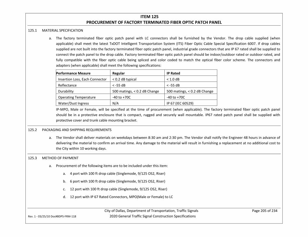
City of Dallas, Department of Transportation, Traffic Signals Page 205 of 234 Rev. 1 - 03/25/10 Doc#BDPS-FRM-118 2020 General Traffic Signal Construction Specifications
ITEM 125 PROCUREMENT OF FACTORY TERMINATED FIBER OPTIC PATCH PANEL
125.1 MATERIAL SPECIFICATION
a. The factory terminated fiber optic patch panel with LC connectors shall be furnished by the Vendor. The drop cable supplied (when applicable) shall meet the latest TxDOT Intelligent Transportation System (ITS) Fiber Optic Cable Special Specification 6007. If drop cables supplied are not built into the factory terminated fiber optic patch panel, industrial grade connectors that are IP 67 rated shall be supplied to connect the patch panel to the drop cable. Factory terminated fiber optic patch panel should be indoor/outdoor rated or outdoor rated, and fully compatible with the fiber optic cable being spliced and color coded to match the optical fiber color scheme. The connectors and adapters (when applicable) shall meet the following specifications:
Performance Meaure Regular IP Rated Insertion Loss, Each Connector < 0.2 dB typical < 1.0 dB Reflectance < -55 dB < -55 dB Durability 500 matings, < 0.2 dB Change 500 matings, < 0.2 dB Change Operating Temperature -40 to +70C -40 to +70C Water/Dust Ingress N/A IP 67 (IEC 60529)
IP-MPO, Male or Female, will be specified at the time of procurement (when applicable). The factory terminated fiber optic patch panel should be in a protective enclosure that is compact, rugged and securely wall mountable. IP67 rated patch panel shall be supplied with protective cover and trunk cable mounting bracket.
125.2 PACKAGING AND SHIPPING REQUIREMENTS
a. The Vendor shall deliver materials on weekdays between 8:30 am and 2:30 pm. The Vendor shall notify the Engineer 48 hours in advance of delivering the material to confirm an arrival time. Any damage to the material will result in furnishing a replacement at no additional cost to the City within 10 working days.
125.3 METHOD OF PAYMENT
a. Procurement of the following items are to be included under this item:
a. 4 port with 100 ft drop cable (Singlemode, 9/125 OS2, Riser)
b. 6 port with 100 ft drop cable (Singlemode, 9/125 OS2, Riser)
c. 12 port with 100 ft drop cable (Singlemode, 9/125 OS2, Riser)
d. 12 port with IP 67 Rated Connectors, MPO(Male or Female) to LC
City of Dallas, Department of Transportation, Traffic Signals Page 206 of 234 Rev. 1 - 03/25/10 Doc#BDPS-FRM-118 2020 General Traffic Signal Construction Specifications
b. Payment for this item is full compensation for procuring factory terminated fiber optic patch panel with protective cover and trunk cable mounting bracket; and for materials, documentation, warranty, and incidentals.
c. Installation for this item will be paid under ITEM 126.
UNIT OF PAYMENT: EACH
125.4 PROCUREMENT TIME LIMIT a. The Vendor will have a time limit of 25 working days to procure materials.
City of Dallas, Department of Transportation, Traffic Signals Page 207 of 234 Rev. 1 - 03/25/10 Doc#BDPS-FRM-118 2020 General Traffic Signal Construction Specifications
ITEM 126 INSTALLATION OF FACTORY TERMINATED FIBER OPTIC PATCH PANEL
126.1 INSTALLATION SPECIFICATION
a. The factory terminated fiber optic patch panel shall be installed by the Vendor as identified in the work order. Install fiber optic patch panel and drop cable (when applicable) according to manufacturer recommendations. Installer shall meet minimum experience requirements in the latest TxDOT Intelligent Transportation System (ITS) Fiber Optic Cable Special Specification 6007.
b. This work may include transporting any City supplied material from the Department of Transportation Field Operations facility at 3204 Canton Street to the job site. The City may change the pickup location as long as it remains within City of Dallas city limits.
126.2 METHOD OF PAYMENT
a. Installation of the following items are to be included under this item:
a. 4 port with 100 ft drop cable
b. 6 port with 100 ft drop cable
c. 12 port with 100 ft drop cable
b. Payment for this item is full compensation for transporting, installing factory terminated fiber optic patch panel and associated drop cable (when applicable); and for materials, equipment, labor, tools, documentation, testing, training and incidentals.
c. Procurement for this item will be paid under ITEM 125.
UNIT OF PAYMENT: EACH
126.3 INSTALLATION TIME LIMIT a. The Vendor will have a time limit of 1 working day to install 1 factory terminated fiber optic patch panel.
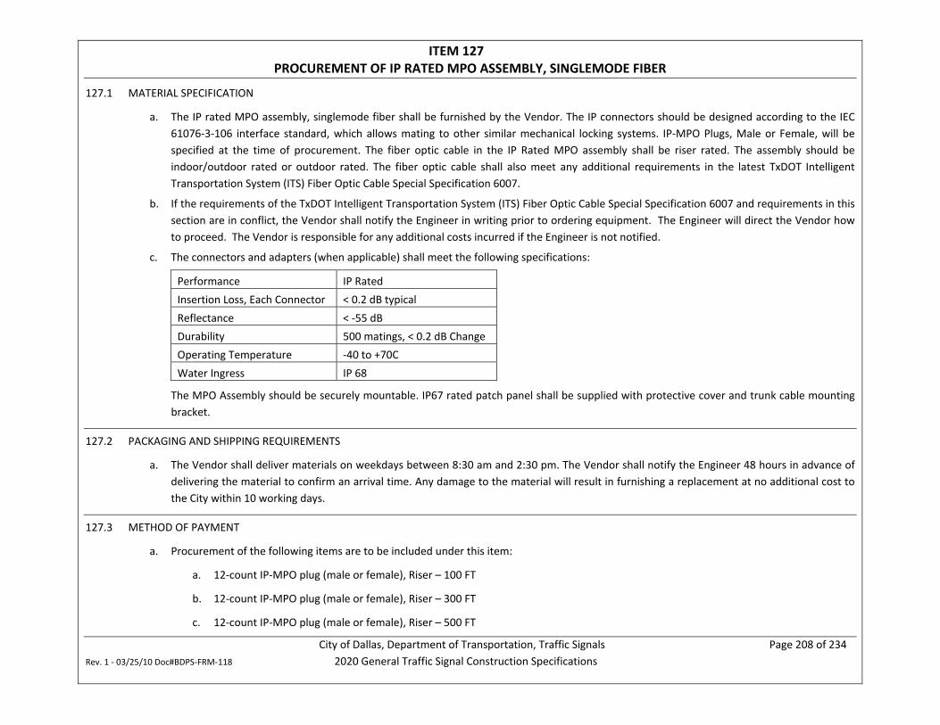
City of Dallas, Department of Transportation, Traffic Signals Page 208 of 234 Rev. 1 - 03/25/10 Doc#BDPS-FRM-118 2020 General Traffic Signal Construction Specifications
ITEM 127 PROCUREMENT OF IP RATED MPO ASSEMBLY, SINGLEMODE FIBER
127.1 MATERIAL SPECIFICATION
a. The IP rated MPO assembly, singlemode fiber shall be furnished by the Vendor. The IP connectors should be designed according to the IEC 61076-3-106 interface standard, which allows mating to other similar mechanical locking systems. IP-MPO Plugs, Male or Female, will be specified at the time of procurement. The fiber optic cable in the IP Rated MPO assembly shall be riser rated. The assembly should be indoor/outdoor rated or outdoor rated. The fiber optic cable shall also meet any additional requirements in the latest TxDOT Intelligent Transportation System (ITS) Fiber Optic Cable Special Specification 6007.
b. If the requirements of the TxDOT Intelligent Transportation System (ITS) Fiber Optic Cable Special Specification 6007 and requirements in this section are in conflict, the Vendor shall notify the Engineer in writing prior to ordering equipment. The Engineer will direct the Vendor how to proceed. The Vendor is responsible for any additional costs incurred if the Engineer is not notified.
c. The connectors and adapters (when applicable) shall meet the following specifications:
Performance IP Rated Insertion Loss, Each Connector < 0.2 dB typical Reflectance < -55 dB Durability 500 matings, < 0.2 dB Change Operating Temperature -40 to +70C Water Ingress IP 68
The MPO Assembly should be securely mountable. IP67 rated patch panel shall be supplied with protective cover and trunk cable mounting bracket.
127.2 PACKAGING AND SHIPPING REQUIREMENTS
a. The Vendor shall deliver materials on weekdays between 8:30 am and 2:30 pm. The Vendor shall notify the Engineer 48 hours in advance of delivering the material to confirm an arrival time. Any damage to the material will result in furnishing a replacement at no additional cost to the City within 10 working days.
127.3 METHOD OF PAYMENT
a. Procurement of the following items are to be included under this item:
a. 12-count IP-MPO plug (male or female), Riser – 100 FT
b. 12-count IP-MPO plug (male or female), Riser – 300 FT
c. 12-count IP-MPO plug (male or female), Riser – 500 FT
City of Dallas, Department of Transportation, Traffic Signals Page 209 of 234 Rev. 1 - 03/25/10 Doc#BDPS-FRM-118 2020 General Traffic Signal Construction Specifications
b. Payment for this item is full compensation for procuring IP rated MPO assembly, singlemode fiber; and for materials, documentation, warranty, and incidentals.
c. Installation for this item will be paid under ITEM 128.
UNIT OF PAYMENT: EACH
127.4 PROCUREMENT TIME LIMIT a. The Vendor will have a time limit of 15 working days to procure materials.
City of Dallas, Department of Transportation, Traffic Signals Page 210 of 234 Rev. 1 - 03/25/10 Doc#BDPS-FRM-118 2020 General Traffic Signal Construction Specifications
ITEM 128 INSTALLATION OF IP RATED MPO ASSEMBLY
128.1 INSTALLATION SPECIFICATION
a. The IP rated MPO assembly shall be installed by the Vendor as identified in the work order. Installation shall meet or exceed manufacturer recommendations. Installer shall meet minimum experience requirements in the latest TxDOT Intelligent Transportation System (ITS) Fiber Optic Cable Special Specification 6007.
b. This work may include transporting any City supplied material from the Department of Transportation Field Operations facility at 3204 Canton Street to the job site. The City may change the pickup location as long as it remains within City of Dallas city limits.
128.2 METHOD OF PAYMENT
a. Payment for this item is full compensation for transporting, installing IP rated MPO assembly; and for materials, equipment, labor, tools, documentation, testing, training and incidentals.
b. Procurement for this item will be paid under ITEM 127.
UNIT OF PAYMENT: EACH
128.3 INSTALLATION TIME LIMIT a. The Vendor will have a time limit of 1 working day to install one 100’ IP Rated MPO Assembly.
City of Dallas, Department of Transportation, Traffic Signals Page 211 of 234 Rev. 1 - 03/25/10 Doc#BDPS-FRM-118 2020 General Traffic Signal Construction Specifications
ITEM 129 TESTING OF 12 COUNT IP RATED PATCH PANELS AND MPO ASSEMBLY
129.1 TESTING SPECIFICATION
a. The IP rated patch panels and MPO assembly shall be tested by the Vendor as identified in the work order. Testing shall be performed by personnel that meet the minimum experience requirements in the latest TxDOT Intelligent Transportation System (ITS) Fiber Optic Cable Special Specification 6007.
b. Testing shall meet the latest TxDOT Intelligent Transportation System (ITS) Fiber Optic Cable Special Specification 6007.
129.2 METHOD OF PAYMENT
a. Payment for this item is full compensation for testing a pair of 12 count IP rated patch panels and associated MPO assembly; and for materials, equipment, labor, tools, documentation, warranty, training and incidentals.
UNIT OF PAYMENT: EACH
129.3 TESTING TIME LIMIT a. The Vendor will have a time limit of 5 working days to test a pair of 12 Count IP Rated Patch Panels and connecting MPO assembly.
City of Dallas, Department of Transportation, Traffic Signals Page 212 of 234 Rev. 1 - 03/25/10 Doc#BDPS-FRM-118 2020 General Traffic Signal Construction Specifications
ITEM 130 PROCUREMENT OF JUMPER CABLE – SINGLEMODE FIBER
130.1 MATERIAL SPECIFICATION
a. The fiber optic jumper cable(s), to cross connect the fiber patch panel to the fiber optic transmission equipment as shown on the work order or a directed, shall be furnished by the Vendor. Match the core size, type, and attenuation from the fiber optic cable to the simplex jumper. Use yellow jumpers and provide strain relief on the connectors. Provide fiber with a 900 micron polymer buffer, Kevlar strength member, and a PVC jacket with a maximum outer jacket of 2.4 mm in diameter.
b. Jumper cables shall be provided with LC connectors except when providing jumpers for existing equipment. For existing equipment provide connectors suitable to be connected to patch panels and fiber optic transmission equipment in use. All jumpers must have factory terminated connectors. Field terminations of connectors is prohibited.
130.2 METHOD OF PAYMENT
a. Installation of the following items are to be included under this item:
a. 3 ft, UPC Simplex
b. 7 ft, UPC Simplex
c. 10 ft, UPC Simplex
d. 16 ft, UPC Simplex
b. Payment for this item is full compensation for procuring jumper cables; and for documentation, warranty, and incidentals.
UNIT OF PAYMENT: EACH
130.3 PROCUREMENT TIME LIMIT a. The Vendor will have a time limit of 5 working days to procure materials.
City of Dallas, Department of Transportation, Traffic Signals Page 213 of 234 Rev. 1 - 03/25/10 Doc#BDPS-FRM-118 2020 General Traffic Signal Construction Specifications
ITEM 131 PROCUREMENT OF INDUSTRIAL GRADE PATCH CABLE – SINGLEMODE FIBER
131.1 MATERIAL SPECIFICATION
a. The industrial grade patch cable(s) shall be furnished by the Vendor. Match the core size, type, and attenuation from the fiber optic cable to the patch cable or as approved. Provide strain relief on the connectors. Provide fiber with a (minimum) 900 micron polymer buffer, Kevlar strength member, and a rugged polyurethane jacket to protect against cuts, abrasions and chemicals.
b. Maximum Connector Insertion Loss: 0.2dB
c. Cable Attenuation: 0.78dB/km at 1310nm
d. Impact Resistance: Meet or exceed EIA/TIA-455-25
e. Industrial grade patch cables shall be provided with factory terminated IP67 Industrial Duplex LC connector on one end and a duplex LC connector plug on the other end. Field terminations of connectors is prohibited.
131.2 METHOD OF PAYMENT
a. Installation of the following items are to be included under this item:
a. 10 ft, IP67 Industrial Duplex LC (ODVA) to LC plug b. 20 ft, IP67 Industrial Duplex LC (ODVA) to LC plug c. 40 ft, IP67 Industrial Duplex LC (ODVA) to LC plug
b. Payment for this item is full compensation for procuring industrial grade patch cable(s); and for documentation, warranty, and incidentals.
UNIT OF PAYMENT: EACH
131.3 PROCUREMENT TIME LIMIT a. The Vendor will have a time limit of 15 working days to procure materials.
City of Dallas, Department of Transportation, Traffic Signals Page 214 of 234 Rev. 1 - 03/25/10 Doc#BDPS-FRM-118 2020 General Traffic Signal Construction Specifications
ITEM 132 PROCUREMENT OF TRACER WIRE
132.1 MATERIAL SPECIFICATION
a. The tracer wire shall be furnished by the Vendor. Tracer wire shall meet the latest TxDOT Intelligent Transportation System (ITS) Fiber Optic Cable Special Specification 6007.
132.2 METHOD OF PAYMENT
a. Payment for this item is full compensation for procuring tracer wire; and for documentation, warranty, and incidentals.
UNIT OF PAYMENT: LINEAR FOOT
132.3 PROCUREMENT TIME LIMIT a. The Vendor will have a time limit of 2 working days to procure materials.
City of Dallas, Department of Transportation, Traffic Signals Page 215 of 234 Rev. 1 - 03/25/10 Doc#BDPS-FRM-118 2020 General Traffic Signal Construction Specifications
ITEM 133 PROCUREMENT OF PULL ROPE
133.1 MATERIAL SPECIFICATION
a. The pull rope shall be furnished by the Vendor. Tracer wire shall meet the latest TxDOT Intelligent Transportation System (ITS) Fiber Optic Cable Special Specification 6007.
133.2 METHOD OF PAYMENT
a. Payment for this item is full compensation for procuring pull rope; and for documentation, warranty, and incidentals.
UNIT OF PAYMENT: LINEAR FOOT
133.3 PROCUREMENT TIME LIMIT a. The Vendor will have a time limit of 2 working days to procure materials.
City of Dallas, Department of Transportation, Traffic Signals Page 216 of 234 Rev. 1 - 03/25/10 Doc#BDPS-FRM-118 2020 General Traffic Signal Construction Specifications
ITEM 134 INSTALLATION OF TRACER WIRE
134.1 INSTALLATION SPECIFICATION
a. The tracer wire shall be installed by the Vendor as identified in the work order.
b. This work may include transporting any City supplied material from the Department of Transportation Field Operations facility at 3204 Canton Street to the job site. The City may change the pickup location as long as it remains within City of Dallas city limits.
134.2 METHOD OF PAYMENT
a. Payment for this item is full compensation for transporting, installing tracer wire; and for documentation, warranty, and incidentals.
UNIT OF PAYMENT: LINEAR FOOT
134.3 INSTALLATION TIME LIMIT a. The Vendor will have a time limit of 3 working days to install each 500 feet of tracer wire.
City of Dallas, Department of Transportation, Traffic Signals Page 217 of 234 Rev. 1 - 03/25/10 Doc#BDPS-FRM-118 2020 General Traffic Signal Construction Specifications
ITEM 135 INSTALLATION OF PULL ROPE
135.1 INSTALLATION SPECIFICATION
a. The pull rope shall be installed by the Vendor as identified in the work order.
b. This work may include transporting any City supplied material from the Department of Transportation Field Operations facility at 3204 Canton Street to the job site. The City may change the pickup location as long as it remains within City of Dallas city limits.
135.2 METHOD OF PAYMENT
a. Payment for this item is full compensation for transporting, installing pull rope; and for documentation, warranty, and incidentals.
UNIT OF PAYMENT: LINEAR FOOT
135.3 INSTALLATION TIME LIMIT a. The Vendor will have a time limit of 3 working days to install each 500 feet of pull rope.
City of Dallas, Department of Transportation, Traffic Signals Page 218 of 234 Rev. 1 - 03/25/10 Doc#BDPS-FRM-118 2020 General Traffic Signal Construction Specifications
ITEM 136 TESTING - OTDR
136.1 TESTING SPECIFICATION
a. The Vendor shall utilize an Optical Time Domain Reflectometer (OTDR) to measure fiber optic cable for overall attenuation (signal loss dB/km), fiber cable length, and identify fiber optic cable anomalies such as breaks. The test procedures shall meet the latest TxDOT Intelligent Transportation System (ITS) Fiber Optic Cable Special Specification 6007, USDA RUS CFR 1755.900, and TIA/EIA-455-61 test specifications. For all tests, provide test forms to be used that compare measured results with threshold values. Vendor shall complete post-installation tests, post termination tests, subsystem tests, final end-to-end test, loss budget calculations and documentation. Testing shall be performed by personnel that meet the minimum experience requirements in the latest TxDOT Intelligent Transportation System (ITS) Fiber Optic Cable Special Specification 6007.
136.2 METHOD OF PAYMENT
a. Payment for this item is full compensation to complete all tests for 6 fibers, loss budget calculations and documentation, and incidentals.
UNIT OF PAYMENT: EACH (PER 6 FIBERS)
136.3 TESTING TIME LIMIT a. The Vendor will have a time limit of 5 working days to test 6 fibers.
City of Dallas, Department of Transportation, Traffic Signals Page 219 of 234 Rev. 1 - 03/25/10 Doc#BDPS-FRM-118 2020 General Traffic Signal Construction Specifications
ITEM 137 TESTING – OPTICAL POWER METER & LIGHT SOURCE
137.1 TESTING SPECIFICATION
a. The Vendor shall utilize optical Power Meter and Light Source to measure the di-directional insertion loss, absolute power of the fiber optic signal across links at 1310 nm and 1550 nm, and to check for anomalies. Vendor shall document and submit results after test acceptance. For the devices used, the Vendor shall provide the current calibration certificate and verification of conformance with the manufacturer’s specification, showing the devices have been calibrated within the last year. Testing shall be performed by personnel that meet the minimum experience requirements in the latest TxDOT Intelligent Transportation System (ITS) Fiber Optic Cable Special Specification 6007.
b. The vendor shall also calculate the total loss budget according to the following calculations and compare the actual loss in each segment of the system to the calculated budget. Submit the results for each section of fiber optic cable in tabular format reporting if the total loss is within the limits of these Specifications by noting “pass” or “fail” for each segment of fiber. A segment of fiber is defined as one that terminates at each end. Use the following calculations to determine the loss budget for each segment:
a. Splice loss budget = number of splices x 0.1 dB/splice,
b. Connector loss budget = number of connectors x 0.75 dB/connector,
c. Length loss budget = length of fiber optic cable (measured by OTDR) x 0.35 dB/km for 1310 nm wavelength or 0.25 dB/km for 1550 nm wavelength, and
d. Total Loss Budget = splice loss budget + connector loss budget + length loss budget.
Provide loss budget calculation equations on test form to be submitted as part of the documentation requirements. Provide threshold calculations described above along with measured results.
137.2 METHOD OF PAYMENT
a. Payment for this item is full compensation to complete testing of 6 fibers utilizing optical Power Meter and Light Source, loss budget calculations, documentation; and incidentals.
UNIT OF PAYMENT: EACH (PER 6 FIBERS)
137.3 TESTING TIME LIMIT a. The Vendor will have a time limit of 5 working days to test 6 fibers.

City of Dallas, Department of Transportation, Traffic Signals Page 220 of 234 Rev. 1 - 03/25/10 Doc#BDPS-FRM-118 2020 General Traffic Signal Construction Specifications
ITEM 138 PROCUREMENT OF RUGGED OPTICAL LOSS TEST KIT
138.1 SPECIFICATION
a. The Vendor shall furnish a rugged optical loss test kit that includes optical Power Meter with data storage, Light Source and ancillary tools needed to measure the insertion loss, absolute power of the fiber optic signal across links per TIA/EIA standards. The furnished equipment shall meet (when applicable) the following specifications:
OPTICAL SPECIFICATIONS: POWER METER Calibrated Wavelengths 850, 980, 1300, 1310, 1490, 1550, 1625 nm Detector Type Filtered InGaAs Measurement Range +26 to -50 dBm
Tone Detect Range +6 to -30 dBm +6 to -25 dBm for 850 nm
Wavelength ID Range +6 to -30 dBm +6 to -25 dBm for 850 nm
Accuracy ±0.25 dB Resolution 0.01 dB Measurement Units dB, dBm, μW OPTICAL SPECIFICATIONS: LIGHT SOURCE Wavelength (±20 nm) 1310 nm 1550 nm 1625 nm Spectral Width 5 nm 5 nm 2 nm Emitter Type Laser
Safety Class bClass I FDA 21 CFR 1040.10 and 1040.11, IEC 60825-1: 2007-03
Output Power -5 dBm (typical), 9/125 fiber
Output Stability ±0.05 dB over 1 hour (after 15 minutes warm-up) ±0.1 dB over 8 hours (after 15 minutes warm-up)
Tone Output 270 Hz, 330 Hz, 1 kHz, 2 kHz GENERAL SPECIFICATIONS Connectors/Adapters 1.25 mm Universal, 2.5 mm Universal, LC
Power 2 AA batteries, USB Power Source Operating Temperature -10 °C to 50 °C, 90 % RH (non-condensing) Storage Temperature -30 °C to 60 °C, 90 % RH (non-condensing) Stored Data Access USB Port
City of Dallas, Department of Transportation, Traffic Signals Page 221 of 234 Rev. 1 - 03/25/10 Doc#BDPS-FRM-118 2020 General Traffic Signal Construction Specifications
PC Reporting Tool Windows 10 compatible software
b. The ancillary tools furnished by the vendor shall at a minimum include cables required to connect to a PC, Windows compatible software and license for creating reports, 1.25 mm Universal connector/adapter, 2.5 mm Universal connector/adapter, LC Simplex/Duplex connector/adapter for Power Meter and Light Source, LC/LC test cable and manufacturer recommended cleaning supplies
c. The Power Meter and Light Source shall have field swappable connector adapters and shall allow for identification and simultaneous testing of up to three wavelengths. The Power Meter shall have a large display and should be visible in direct sunlight and backlight for low light conditions
138.2 METHOD OF PAYMENT
a. Payment for this item is full compensation for procuring rugged optical loss test kit; and for materials, documentation, manufacturer’s warranty, and incidentals.
UNIT OF PAYMENT: EACH
138.3 PROCUREMENT TIME LIMIT a. The Vendor will have a time limit of 30 working days to furnish the equipment.
City of Dallas, Department of Transportation, Traffic Signals Page 222 of 234 Rev. 1 - 03/25/10 Doc#BDPS-FRM-118 2020 General Traffic Signal Construction Specifications
ITEM 139 PROCUREMENT OF FIBER PORT CLEANER, 1.25 MM KEYED LC
139.1 MATERIAL SPECIFICATION
a. The fiber port cleaner shall be furnished by the Vendor for 1.25 mm LC. An integrated dust cap shall allow for cleaning unmated connector end faces. The cleaner will be used for removing oil, dirt, salt, isopropyl alcohol residue and distilled water residue from connector end faces.
b. The cleaner should have an extendable tip, rotate 180 degrees and provide a minimum of 525 cleanings
139.2 METHOD OF PAYMENT
a. Payment for this item is full compensation for procuring fiber port cleaner, 1.25 MM keyed LC; and for documentation, warranty, and incidentals.
UNIT OF PAYMENT: EACH
139.3 PROCUREMENT TIME LIMIT a. The Vendor will have a time limit of 7 working days to procure materials.
City of Dallas, Department of Transportation, Traffic Signals Page 223 of 234 Rev. 1 - 03/25/10 Doc#BDPS-FRM-118 2020 General Traffic Signal Construction Specifications
ITEM 140 PROCUREMENT OF FIBER OPTIC CONNECTOR CLEANER, CASSETTE
140.1 MATERIAL SPECIFICATION
a. The fiber optic connector cleaner cassette shall be furnished by the Vendor. The cleaner will be used for removing oil, dirt, salt, isopropyl alcohol residue and distilled water residue from connector end faces.
b. The cleaner should have a simple push button shutter, clean without the need for isopropyl alcohol and should have refillable cleaning tapes with a minimum of 400 cleanings
140.2 METHOD OF PAYMENT
a. Payment for this item is full compensation for procuring fiber optic connector cleaner, cassette; and for documentation, warranty, and incidentals.
UNIT OF PAYMENT: EACH
140.3 PROCUREMENT TIME LIMIT a. The Vendor will have a time limit of 7 working days to procure materials.
City of Dallas, Department of Transportation, Traffic Signals Page 224 of 234 Rev. 1 - 03/25/10 Doc#BDPS-FRM-118 2020 General Traffic Signal Construction Specifications
ITEM 141 TRAINING
141.1 SPECIFICATION
a. Conduct a BISCI or IMSA certified training class (minimum of 16 hr.) for up to 10 representatives designated by the Department on procedures of installation, operations, testing, maintenance and repair of all fiber optic equipment specified within this specification (Items 115 thru 139). Submit to the Engineer for approval, a copy of the training material at least 30 days before the training begins. Conduct training within the local area unless otherwise authorized by the Engineer. Include at a minimum the following training material:
a. NESC, NEC, and ANSI/TIA 590 code compliance, b. Fiber optic cable pulling and installation techniques, c. Use of installation tools, d. Splicing and terminating equipment and test instruments, e. Trouble shooting procedures, f. Methods of recording installation and test data, g. OTDR setup and interpreting test results, h. Power Meter setup and interpreting test results, and i. Industry best practices for deployment of fiber optic infrastructure.
b. Provide 10 hard copies of the training material. Also, provide electronic copy of the training material..
141.2 METHOD OF PAYMENT
a. Payment for this item is full compensation for training; and for documentation, training material, training equipment, and incidentals.
UNIT OF PAYMENT: EACH
141.3 TIME LIMIT a. The Vendor will have a time limit of 45 working days to arrange for training.
City of Dallas, Department of Transportation, Traffic Signals Page 225 of 234 Rev. 1 - 03/25/10 Doc#BDPS-FRM-118 2020 General Traffic Signal Construction Specifications
ITEM 142 PROCUREMENT & INSTALLATION OF TRAFFIC MONITORING CAMERA SYSTEM
142.1 INSTALLATION SPECIFICATION
c. The Vendor will be responsible for procuring and installing the traffic monitoring camera system in the field.
d. The traffic monitoring camera system shall be mounted at the direction of the Engineer, and per the manufacturer’s recommendations. Locations of camera and associated equipment shown on the Plans are informational only. Traffic monitoring camera system shall not be mounted without approval of locations by the Engineer.
e. Drilling wire feed holes, installing nylon bushings, and mounting the camera will be the Vendor’s responsibility. connecting all wiring from the signal cabinet to the camera will be the Vendor’s responsibility.
f. All wire feeding through the mast arm pole structure shall be wrapped once with plastic electrical tape and wrapped again with electrical friction tape extending 12 inches on each side of the pole opening for a total of 24 inches.
g. Camera(s) and associated equipment shall be installed according to the manufacturer’s recommendations and the cabinet configuration notes supplied by the City. Locations of camera and associated equipment shown on the Plans are informational only.
142.2 MATERIAL SPECIFICATIONS
h. All materials to be installed under this item are to be procured by the Vendor from a qualified manufacturer’s representative for the traffic monitoring camera system to be provided.
i. The following limited technical specifications are provided for the traffic monitoring camera system to be included under this item. Note that that no equipment substitutions are allowed without approval of the City Traffic Engineer or their designee.
CAMERA: COHU RISE 4262-1120HD Series with Command Core+TM H.264/H.265 High-Definition, IP68 Camera specifications or Bosch MIC-7522-Z30GR PTZ 2MP HDR 30x IP68 Camera specifications, shall apply
Sensor: 1/2.8” Exmor R CMOS
Scanning: Progressive
Resolution: 1,920 x 1,080 (1080p) or higher
Digital Formats: YUV 4:2:2 SMPTE 274M, BT.709, BT.1120
Capture Rate: 60 fps
Camera Format: Day/Night (IR Cut Filter)
S/N Ratio >50 db
Faceplate Wiper: On/Off, Dwell, Time Out Settings
City of Dallas, Department of Transportation, Traffic Signals Page 226 of 234 Rev. 1 - 03/25/10 Doc#BDPS-FRM-118 2020 General Traffic Signal Construction Specifications
Video Analytics (VA): ITS Advanced License for Vehicle Detection, Count and Speed, % Change of Speed, Multiple View Analytics/PTZ Presets, Vehicle Classification, Traffic Incident Detection, Stopped Vehicle, Wrong Way Direction; or Intelligent Video Analytics with combinable alarm rules and object filters.
Digital Circuit: Four digital I/O circuits, user defined as either input or output
Protection Rating: Camera - IP68, Pressurized with Dry Nitrogen, 3.5 psi. Positioner Body - IP66
Operating Temp: -40°F to 167°F (-40°C to 75°C) Per NEMA TS2 2.2.7
Heaters: Software controlled for managing proper internal temperature of camera system. The faceplate heater shall be ITO coated glass designed to maintain outer faceplate surface temperature above 32° (0°C) down to - 4° (- 20C)
Humidity: 0 to 100%, condensing
Vibration: Per NEMA TS2 para. 2.2.8. 5-30Hz sweep @ 0.5g applied in each of 3 mutually perpendicular planes.
Shock: Per NEMA TS2 para. 2.2.9. 10g applied in each of 3 mutually perpendicular planes
Corrosion: MIL-STD-810G, Method 509.5, Paragraph 4.5.2, ANSI NCSL Z540-1, ISO 17025:2005
Impact Rating: IK10
MTBF: 251,000 hours, based on HALT Steady State Field MTBF calculations
Input Voltage: PoE++
Power: Typical 30w, up to 60w with heaters ON
Voltage Range: NEMA standard TS 2-2003 section 2.2.7 tests C thru H
Transient/Surge: Certified to CISPR 24 levels
Emmissions Certified: to CISPR 22 levels Pigtail Cable(s) Approx. 24”
Compliance: ONVIF Profile S and T, NTCIP 1205
j. Manufacturer specified pole or pedestal mount to meet the mounting location with inverted mounting capability.
k. RJ45 connectors specified by the manufacturer to terminate the Ethernet field cables.
l. Manufacturer specified power supply. Shall either be (7412007-003) PoE++, 60W, 110/220vac IP50, -34 to 74C or (PD-9501GO-ET) Outdoor IP67 Rated PoE++ Power Supply, Surface Mount, -40C to 65C or 60 W High PoE Midspan (NPD-6001B) or 95 W High PoE Midspan (NPD-9501A or NPD-9501-E).
m. Standalone Outdoor IP67 rated ethernet/PoE++ surge protection device will be required. (7412009-001) or as specified by the manufacturer
n. CAT5/6 RJ45 IP67 rated Coupler
o. Manufacturer specified burial grade ethernet field cables with RJ45 connectors.
142.3 METHOD OF PAYMENT
City of Dallas, Department of Transportation, Traffic Signals Page 227 of 234 Rev. 1 - 03/25/10 Doc#BDPS-FRM-118 2020 General Traffic Signal Construction Specifications
Payment for this item will include the cost of:
p. Procuring the traffic monitoring camera system that includes listed IP68 cameras, mounting hardware, burial grade ethernet field cables with RJ45 connectors (100’ minimum or more as specified in the plans), power supply, Ethernet surge protection and RJ45 coupler,
q. assembling the camera assembly, including necessary mounting hardware,
r. transporting the camera and associated hardware to the field,
s. drilling wire feed holes,
t. mounting the camera on the signal pole with necessary hardware,
u. connecting wiring from the camera to the traffic signal cabinet,
v. Installing connectors specified by the manufacturer,
w. Installing RJ45 coupler,
x. Installing power supply inside the traffic signal cabinet,
y. Installing Ethernet surge protection inside the traffic signal cabinet,
z. adjusting the camera for proper visibility.
UNIT OF PAYMENT: EACH
142.4 INSTALLATION TIME LIMIT
Once a work order has been issued, the Vendor will have a time limit of 5 working days to obtain the camera and associated materials from the manufacturer and ½ working day per camera for its installation.
City of Dallas, Department of Transportation, Traffic Signals Page 228 of 234 Rev. 1 - 03/25/10 Doc#BDPS-FRM-118 2020 General Traffic Signal Construction Specifications
ITEM 200 PROCURE AN INSTALL TXDOT ITS GROUND BOX (TYPE 1) (24X36X48)
200.1 INSTALLATION SPECIFICATION
Install bollards to the depth as shown on the plans or as directed. Clean bollard holes free of loose dirt and debris, and thoroughly compact bottom of hole to the correct elevation for placement of the bollards. Place bollards to the correct alignment, elevation, and plumb. Backfill around fixed and timber bollards with minimum 3000 PSI concrete. Remove and replace existing bollards of the type shown on the plans or as directed. Remove and dispose of existing bollards as shown on the plans or as directed. Install bollard foundation of the size and depth as shown on the plans.
200.2 MATERIAL SPECIFICATIONS
Provide fixed bollards consisting of 10 in. diameter galvanized standard weight steel pipe filled with concrete and with form domed cap. Provide steel such as pipe, plates, and other required parts in accordance with TxDOT Item 442, “Metal for Structures.” Paint or galvanize pipe, plates, and other required steel parts in accordance with the plans and meeting the requirements of TxDOT Item 441, “Steel Structures” and TxDOT Item 445, “Galvanizing.” Provide foundation concrete meeting the requirements of TxDOT Item 421, “Hydraulic Cement Concrete.” Perform welding in accordance with TxDOT Item 448, “Structural Field Welding.” All materials to be installed under this item are to be procured by the Vendor from a qualified manufacturer’s representative for the traffic monitoring camera system to be provided.
200.3 METHOD OF PAYMENT
This Item will be measured by each bollard installed, removed and replaced, or removed as shown on the plans and will be paid for at the unit price bid for the various types of Bollards. This price is full compensation for furnishing, preparing, hauling and installing materials; for excavation and backfill, and for labor, tools, equipment and incidentals.
UNIT OF PAYMENT: EACH
200.4 INSTALLATION TIME LIMIT
Once a work order has been issued, the Vendor will have a time limit of 10 working days to obtain the bollard and associated materials from the manufacturer and 1 working day per 3 bollards for its installation.
City of Dallas, Department of Transportation, Traffic Signals Page 229 of 234 Rev. 1 - 03/25/10 Doc#BDPS-FRM-118 2020 General Traffic Signal Construction Specifications
ITEM 201 INSTALLATION OF BOLLARD
201.1 INSTALLATION SPECIFICATION
Install bollards to the depth as shown on the plans or as directed. Clean bollard holes free of loose dirt and debris, and thoroughly compact bottom of hole to the correct elevation for placement of the bollards. Place bollards to the correct alignment, elevation, and plumb. Backfill around fixed and timber bollards with minimum 3000 PSI concrete. Remove and replace existing bollards of the type shown on the plans or as directed. Remove and dispose of existing bollards as shown on the plans or as directed. Install bollard foundation of the size and depth as shown on the plans.
201.2 MATERIAL SPECIFICATIONS
Provide fixed bollards consisting of 10 in. diameter galvanized standard weight steel pipe filled with concrete and with form domed cap. Provide steel such as pipe, plates, and other required parts in accordance with TxDOT Item 442, “Metal for Structures.” Paint or galvanize pipe, plates, and other required steel parts in accordance with the plans and meeting the requirements of TxDOT Item 441, “Steel Structures” and TxDOT Item 445, “Galvanizing.” Provide foundation concrete meeting the requirements of TxDOT Item 421, “Hydraulic Cement Concrete.” Perform welding in accordance with TxDOT Item 448, “Structural Field Welding.” All materials to be installed under this item are to be procured by the Vendor from a qualified manufacturer’s representative for the traffic monitoring camera system to be provided.
201.3 METHOD OF PAYMENT
This Item will be measured by each bollard installed, removed and replaced, or removed as shown on the plans and will be paid for at the unit price bid for the various types of Bollards. This price is full compensation for furnishing, preparing, hauling and installing materials; for excavation and backfill, and for labor, tools, equipment and incidentals.
UNIT OF PAYMENT: EACH
201.4 INSTALLATION TIME LIMIT
Once a work order has been issued, the Vendor will have a time limit of 10 working days to obtain the bollard and associated materials from the manufacturer and 1 working day per 3 bollards for its installation.
City of Dallas, Department of Transportation, Traffic Signals Page 230 of 234 Rev. 1 - 03/25/10 Doc#BDPS-FRM-118 2020 General Traffic Signal Construction Specifications
ITEM 202 INSTALLATION OF OBJECT MARKER
202.1 INSTALLATION SPECIFICATION
Locate delineators and object markers as shown on the plans or as directed.
Locate barrier reflectors as shown on the plans or as directed, and install in accordance with manufacturers recommendations.
Install winged channel post and flexible delineator posts to allow the reflector units and reflectorized panels to be installed at the specified height and orientation. Align post as shown or as directed.
Drive post plumb using a driving cap to prevent visible cross-section dimension distortion. Drill or drive a pilot hole when post cannot be driven without visibly distorting the cross-section dimension. Backfill pilot holes thoroughly by tamping in 6-in. lifts to grade.
Install surface-mount and other types of delineators and object markers in accordance with details shown on the plans.
202.2 MATERIAL SPECIFICATIONS
Furnish only new materials in accordance with details shown on the plans unless otherwise directed. The Engineer will sample in accordance with Tex-725-I or Tex-737-I.
202.2.1. Delineator and Object Marker Assemblies. Fabricate in accordance with the following:
202.2.1.1. DMS-8600, “Delineators, Object Markers, and Barrier Reflectors.”
202.2.1.2. DMS-4400, “Flexible Delineator and Object Marker Posts (Embedded and Surface-Mount Types).”
202.3 METHOD OF PAYMENT
Installation will be measured by each delineator or object marker assembly installed. This is a plans quantity measurement Item. The quantity to be paid for is shown in the proposal unless modified by Article 9.2., “Plans Quantity Measurement.” Additional measurements or calculations will be made if adjustments of quantities are required.
This price is full compensation for furnishing and fabricating when required, and installing and mounting the delineator or object marker assemblies including posts, adhesive or pads for surface mount assemblies, back plates, reflector units, fastening plates, brackets, bolts, nuts, and washers; and materials, equipment, labor, tools, and incidentals.
UNIT OF PAYMENT: EACH
City of Dallas, Department of Transportation, Traffic Signals Page 231 of 234 Rev. 1 - 03/25/10 Doc#BDPS-FRM-118 2020 General Traffic Signal Construction Specifications
202.4 INSTALLATION TIME LIMIT
Once a work order has been issued, the Vendor will have a time limit of 10 working days to obtain the object marker and associated materials from the manufacturer and 1 working day per 10 markers for its installation.
City of Dallas, Department of Transportation, Traffic Signals Page 232 of 234 Rev. 1 - 03/25/10 Doc#BDPS-FRM-118 2020 General Traffic Signal Construction Specifications
ITEM 203 INSTALLATION OF SOD
203.1 INSTALLATION SPECIFICATION
Cultivate the area to a depth of 4 in. before placing the sod. Plant the sod specified and mulch, if required, after the area has been completed to lines and grades as shown on the plans. Apply fertilizer uniformly over the entire area in accordance with Article 166.3., “Construction,” and water in accordance with Article 168.3., “Construction.” Plant between the average date of the last freeze in the Spring and 6 weeks before the average date for the first freeze in the Fall according to the Texas Almanac for the project area.
Place sod over the prepared area. Roll or tamp the sodded area to form a thoroughly compacted, solid mat filling all voids in the sodded area with additional sod. Trim and remove all visible netting and backing materials. Keep sod along edges of curbs, driveways, walkways, etc., trimmed until acceptance.
203.2 MATERIAL SPECIFICATIONS
Use live, growing grass sod of the type specified on the plans. Use grass sod with a healthy root system and dense matted roots throughout the soil of the sod for a minimum thickness of 1 in. Do not use sod from areas where the grass is thinned out. Keep sod material moist from the time it is dug until it is planted. Grass sod with dried roots is unacceptable. Use block, rolled, or solid sod free from noxious weeds, Johnson grass, other grasses, or any matter deleterious to the growth and subsistence of the sod.
203.3 METHOD OF PAYMENT
Block Sodding will be measured by the square yard in its final position. This price is full compensation for securing a source, excavation, loading, hauling, placing, rolling, finishing, furnishing materials, equipment, labor, tools, supplies, and incidentals. Fertilizer will not be paid for directly but will be subsidiary to this Item.
UNIT OF PAYMENT: SY
203.4 INSTALLATION TIME LIMIT
Once a work order has been issued, the Vendor will have a time limit of 10 working days to obtain the sod and associated materials from the manufacturer and 1 working day per 100 sy for its installation.
City of Dallas, Department of Transportation, Traffic Signals Page 233 of 234 Rev. 1 - 03/25/10 Doc#BDPS-FRM-118 2020 General Traffic Signal Construction Specifications
ITEM 204 EXCAVATION OF EXISTING GRADE
204.1 INSTALLATION SPECIFICATION
Locate delineators and object markers as shown on the plans or as directed.
Locate barrier reflectors as shown on the plans or as directed, and install in accordance with manufacturers recommendations.
Install winged channel post and flexible delineator posts to allow the reflector units and reflectorized panels to be installed at the specified height and orientation. Align post as shown or as directed.
Drive post plumb using a driving cap to prevent visible cross-section dimension distortion. Drill or drive a pilot hole when post cannot be driven without visibly distorting the cross-section dimension. Backfill pilot holes thoroughly by tamping in 6-in. lifts to grade.
Install surface-mount and other types of delineators and object markers in accordance with details shown on the plans.
204.2 MATERIAL SPECIFICATIONS
Furnish only new materials in accordance with details shown on the plans unless otherwise directed. The Engineer will sample in accordance with Tex-725-I or Tex-737-I.
204.2.1. Delineator and Object Marker Assemblies. Fabricate in accordance with the following:
204.2.1.1. DMS-8600, “Delineators, Object Markers, and Barrier Reflectors.”
204.2.1.2. DMS-4400, “Flexible Delineator and Object Marker Posts (Embedded and Surface-Mount Types).”
204.3 METHOD OF PAYMENT
This Item will be measured by the cubic yard in its original position as computed by the method of average end areas. This is a plans quantity measurement Item. The quantity to be paid is the quantity shown in the proposal unless modified by Article 9.2., “Plans Quantity Measurement.” Additional measurements or calculations will be made if adjustments of quantities are required. Limits of measurement for excavation in retaining wall areas will be as shown on the plans. Shrinkage or swelling factors will not be considered in determining the calculated quantities.
The work performed and materials furnished in accordance with this Item and measured as provided under “Measurement” will be paid for at the unit price bid for “Excavation (Roadway),” “Excavation (Channel),” “Excavation (Special),” or “Excavation (Roadway and Channel).” This price is full compensation for 110 authorized excavation; drying; undercutting subgrade and reworking or replacing the undercut material in rock cuts; hauling; disposal of material not used elsewhere on the project; scarification and compaction; and equipment, labor, materials, tools, and incidentals.
City of Dallas, Department of Transportation, Traffic Signals Page 234 of 234 Rev. 1 - 03/25/10 Doc#BDPS-FRM-118 2020 General Traffic Signal Construction Specifications
Drying required deeper than 6 in. below subgrade elevation will be paid for in accordance with Article 9.7., “Payment for Extra Work and Force Account Method.” Excavation and replacement of unsuitable material below subgrade elevations will be performed and paid for in accordance with the applicable bid items. However, if TxDOT Item 132, “Embankment,” is not included in the Contract, payment for replacement of unsuitable material will be paid for in accordance with Article 9.7., “Payment for Extra Work and Force Account Method.”
When a slide not due to the Contractor’s negligence or operation occurs, payments for removal and disposal of the slide material will be in accordance with Article 9.7., “Payment for Extra Work and Force Account Method.” Excavation in backfill areas of retaining walls will not be measured or paid for directly but will be subsidiary to pertinent Items.
UNIT OF PAYMENT: CY
204.4 INSTALLATION TIME LIMIT
Once a work order has been issued, the Vendor will have a time limit of 0 working days to obtain the bollard and associated materials from the manufacturer and 1 working day per 25 CY for its installation.