Embed Size (px)
Citation preview

DESIGN AND INSTALLATION GUIDE
P A R T Y W A L L S Y S T E M - 5 0 m m
EDITION: March 2019

D E S I G N A N D I N S T A L L A T I O N G U I D E
CO
NT
EN
TS
3
ABOUT NASAHI ............................................................................ 5
NASAHI PANELS ............................................................................ 6
ADVANTAGES OF NASAHI .......................................................... 7
SYSTEM OVERVIEW ...................................................................... 10
STRUCTURAL ................................................................................. 12
SYSTEM PERFORMANCE ............................................................. 12
INSTALLATION PROCESS ............................................................ 14
INSTALLATION SEQUENCE ......................................................... 16
WORKING WITH NASAHI PANELS ............................................. 18
DELIVERY AND HANDLING ......................................................... 19
HEALTH AND SAFETY .................................................................. 20
NCC COMPLIANCE ...................................................................... 21
MATERIAL PROPERTIES ............................................................... 23
PANEL REINFORCING LAYOUT .................................................. 23
DETAILED DRAWINGS ................................................................. 24
WARRANTY & GUARANTEE ........................................................ 35
3
HEAD OFFICENasahi Building Materials Australia Pty Ltd1331 Stud Rd, Rowville, Victoria, 3181P: 1300 2 NASAHI (1300 2 627244)E: [email protected]
CMA-CM40172

5
www.nasahi.net.au
D E S I G N A N D I N S T A L L A T I O N G U I D E5
ABOUT NASAHI®
For the past 20 years Nasahi have been one
of the world’s largest producers of innovative,
high–quality AAC materials. We have become a
world leader in the production of revolutionary
building materials by investing over AUD$60
million in the most technologically advanced
processes in the industry. Our production
facility has the capacity of 700,000 m3 of AAC
products per year, selling within China and
exporting to Japan, Singapore, Malaysia,
Vietnam, Philippines, UAE, Maldives, Russia,
Angola, Australia, New Zealand etc. Our
reputation for consistently producing high
-quality products is exceptional.
The Nasahi range of building systems are
regularly tested in Australia by NATA accredited
laboratories. They are carefully engineered to
comply with the requirements of the Building
Code of Australia, and to remain at the cutting
edge of product innovation.
Nasahi’s in-house engineers provide project
specific guidance, assisting with custom
projects and bringing your ideas to life.
With warehouses located in every state of
Australia, Nasahi can easily meet demands and
quickly deliver to site.
Our ISO 9001 and JIS A 5416 manufacturing
processes are audited annually by
independent authorities. This ensures that we
meet the needs of our customers and other
stakeholders while complying with statutory
and regulatory requirements.
Nasahi’s “building smarter” philosophy has
integrated the highest quality manufacturing
processes with systems in place to meet the
demands of the local market. By focusing on
service, product quality and technical support
we provide a guarantee you can trust.

D E S I G N A N D I N S T A L L A T I O N G U I D E7
P A R T Y W A L L S Y S T E M6
AUTOCLAVED AERATED CONCRETE (AAC)
Autoclaved Aerated Concrete is a lightweight
precast concrete building material that provides
excellent structural, thermal, fire, termite and
mould-resistance. AAC is manufactured from
cement, sand, lime and water; it is aerated by
adding an expanding agent to the mix. The
mix is poured into a large mould and allowed
to rise. These large soft blocks are sliced into
the required panel sizes, and are then cured in
a steam pressure autoclave for up to 12 hours.
The result is a concrete panel filled with small,
finely dispersed air bubbles, which is both
strong and lightweight.
Nasahi Panels are designed to provide a superior
wall and floor solution. It’s excellent airborne
noise transmission properties result in a quieter,
more comfortable home at a significantly
reduced cost compared with concrete or brick.
Manufactured from lightweight steel-reinforced
autoclaved aerated concrete, Nasahi Panels
have a working density of 650kg/m3 making
them highly resistant to chipping and damage
during delivery and handling. Nasahi Panels
are also thermally stable, providing long-term
durability.
An embedded corrosion protected steel mesh
inside the panels gives them excellent strength
when installed as internal walls or over a load-
bearing timber or steel frame. Panels are
supplied in a standard width of 600mm and up
to 3300mm length, and can easily be cut to size
allowing fast and strong installation.
Table 1: Weight of 2200mm Long Panel
Thickness 50mm
Working Panel Weight (650kg/m3) 43kg
ADVANTAGES OF NASAHI®
Quick Installation3 qualified tradespeople can easily
install 50m2 of Nasahi® Panel per
day, making it significantly faster and
less labour intensive than traditional
masonry.
Lightweight and StrongNasahi Panels weigh less than
standard concrete masonry, making
it convenient, lightweight, and easy
to work with. Strength is provided
by corrosion protected internal steel
reinforcing mesh.
Fire ResistantNasahi Panels are deemed non-
combustible and are compliant as
party walls. Nasahi Panels have been
rigorously tested and will provide a FRL
of up to 120 minutes.
QuietThe Nasahi Panel’s unique aerated
construction provides the thermal
performance of a lightweight system
while delivering excellent acoustic
performance like a dense masonry
product.
TransportablePanels are flat-packed in packs of up
to 20 improving transportability to and
around site.
Nasahi Panels can also be used for:
• External Walls
• Flooring
• Fences
NASAHI® PANELS

D E S I G N A N D I N S T A L L A T I O N G U I D E9
P A R T Y W A L L S Y S T E M8
DEsIgN PROCEss
This installation guide specifies design
principles for the Nasahi Party Wall
System that comply with the Performance
Requirements of the NCC at the time
of writing. The designer must check the
adequacy of the building solution for
compliance with the appropriate authority.
Internal wind loads experienced by the
panels, fasteners and supporting frame must
be designed in accordance with the relevant
Australian standards for the site specific loads.
Stage 1: Determine the site wind load
requirements including wind category, terrain
category, topography and other factors that are
required to calculate the wind pressures acting
on the internal walls.
Stage 2: Identify whether other NCC
performance requirements apply to your
project. These typically include fire resistance
levels and acoustic performance.
Stage 3: select the appropriate configuration
in this guide to meet the requirements outlined
in stages 1 and 2.
Stage 4: Complete the detailed design, and
determine the number of panels and accessories
required for the project.
DEsIgN DETAIL CONsIDERATIONs
PenetrationsA service supply pipe must only be installed in
the cavity of a discontinuous construction; and
in the case of a pipe that serves only one sole-
occupancy unit, not be fixed to the wall leaf on
the side adjoining any other sole-occupancy
unit and have a clearance of not less than 10mm
to the other wall leaf.
Electrical outlets and taps may penetrate
through plasterboard internal linings but must
be offset from each other by a minimum of
300mm.
Penetrations through the fire rated Nasahi Party
Wall system wall are outside the scope of this
guide. A fire engineer must be consulted to
approve any changes, and the use of proprietary
fire rated collars are recommended.
fRAMINg DEsIgN
The load-bearing stud frame must be
designed in accordance with the specific
framing codes for timber or steel frames.
Timber framesTimber framing must be designed in accordance
with the relevant parts of As1684. stud spacing
and height should be sized to suit wind loads
in accordance with local codes. Noggins must
be flush fitted at a maximum of 1350mm centre
spacing.
steel framessteel framing must comply with NAsh standard
2005. for steel framing the minimum framing
specification is ‘C’ section studs and noggins of
overall section size 51mm web and 32mm flange.
Minimum steel thickness must be 0.75mm in
accordance with As3623 and As/NZ4600.

Plasterboard Wall Lining (Min 10mm)
R2.0 Insulation
Wall 1 Frame
Nasahi Panel
Optional C-Channel onUnsupported End
Aluminium AngleBracket
Wall 2 Frame
Steel I-Section
Nasahi Panels
Nasahi® Panels are manufactured from Autoclaved
Aerated Concrete (AAC), embedded with coated steel
reinforcing mesh, in a standard width of 600mm and
up to 3300mm length.
Thickness 50mm
36kgDry Panel Weight (495kg/m3) Working Panel Weight (650kg/m3) 43kg
Nasahi I-Section
Galvanised steel I-section
51mm x 35mm
BMT = 0.55mm
Used to join horizontal walls longer than 2200mm.
Nasahi C-Channel
Galvanised steel C-Channel
51mm x 35mm
BMT = 0.55mm
Used as Party Wall base as shown in Detail 3.1 on Page 26
and/or to align Nasahi Panels at wall ends.
Fire Resistant Mineral Wool
A non-combustible, moisture-resistant, non-corrosive,
non-deteriorating, mildew-proof and vermin-proof mineral
wool must be used to provide fire protection in party wall
constructions as shown in the drawings.
SYSTEM OVERVIEWAluminium Angle BracketFasteners
Angle Bracket to Nasahi Panels Angle Bracket to Timber Frames
Adhesive
Nasahi® Adhesive comes in 20kg
bags and is used to glue, seal and
patch panel joints.
Touch-up Paint
If Nasahi® Panels are cut to size, all
exposed reinforcing steel must be
treated with Nasahi® Corrosion
Protection Touch Up Paint in
accordance with the instructions
on the container.
12G x 25mm Hex Head
Type 17 Class 3 Screws
Angle Bracket into Steel Frames
12G x 20mm Hex Head Self-
Drilling Class 3 Screws
12G x 45mm Hex Head
SDS Type 17, Class 3 Screws
The Nasahi aluminium angle bracket is used to attach Nasahi Panels to the periphery of the timber or steel frame.75mm x 45mm x 50mmBMT = 1.5 mm
Each angle bracket requires2 Fixings in panel and 2 Fixingsinto Frame.
Fire Rated Plasterboard 300mm Strip
For residential applications in floor joist zone and roof space as shown in Details 2.2 on Page 25.
NOTE: Minimum embedment of 40mm into Nasahi Panels.

D E S I G N A N D I N S T A L L A T I O N G U I D E13
P A R T Y W A L L S Y S T E M12
SYSTEM PERFORMANCE
STRUCTURAL
The Nasahi Party Wall System is a non load-
bearing system that is designed to act as a fire
rated acoustic intertenancy wall installed onto a
load-bearing timber or steel frame.
Panel WeightPanels must be base supported and installed
onto a thin bed of adhesive or into a C-track.
Under no circumstances are panels to be
suspended from the frame.
Internal Wind PressureInternal pressure is a function of the relative
permeability of the external building surfaces
including windows and doors, and should
be calculated in accordance with AS/NZS
1170.2. The Nasahi Party Wall System has been
designed to withstand typical internal pressures
up to 0.5kPa. For greater pressures please
contact Nasahi engineering support.
FIRE RESISTANCE
When tested to AS/NZS1530.4 the systems
outlined in this guide meet the performance
requirements of the NCC and provide a Fire
Resistance Level (FRL) of:
-/120/90 – When installed from concrete floors
to ceilings up to 3m height.
90/90/90 – Up to 10m wall height.
60/60/60 – Up to 15m wall height.
Nasahi Panels have been tested to AS/
NZS1530.1 to show non-combustibility, and
when exposed to fire Nasahi Panels do not emit
any toxic gases or vapours.
If higher levels of fire resistance are required
please contact Nasahi for project specific
engineering support.
ACOUSTIC PERFORMANCE
The Nasahi Party Wall System has been designed and verified by qualified acoustic engineers to provide
excellent acoustic performance in low-rise multi-residential installations.
Walls in a Class 2 or 3 building separating sole occupancy units must have airborne sound insulation of
Rw + Ctr greater than 50db, or a DnT,w of greater than 45dB. The Nasahi Party Wall System exceeds this
requirement, and by incorporating a 20mm discontinuity it complies with all relevant NCC requirements.
Table 2: Nasahi® Party Wall System Acoustic Performance
Nasahi System **Variation** Rw (Ctr) System Details
P50-T70-01
P50-T90-02
P50-S76-03
P50-S92-04
70mm Timber
90mm Timber
76mm Steel
92mm Steel
61 (-14)*
60 (-8)
65 (-15)
66 (-13)
10mm Standard PB
**Wall Frame**
R2.0 Insulation
20mm cavity
50mm Nasahi Panel
20mm cavity
R2.0 Insulation
**Wall Frame**
10mm Standard PB
P50-T90-05
P50-T90-06
P50-T90-07
P50-T90-08
P50-T90-09
13mm Standard PB
13mm Acoustic PB
-/120/90 Fire Rated PB
10mm Water Resistant PB
6mm FC Sheet
69 (-4)
58 (-3)
59 (-4)
59 (-6)
64 (-8)
**Wall Lining**
90mm Timber Frame
R2.0 Insulation
20mm cavity
50mm Nasahi Panel
20mm cavity
R2.0 Insulation
**Wall Lining**
Note: 76mm and 92mm Steel Frames have better acoustic ratings than values shown.* DnT,w (Ctr) values reported for 70mm Timber Frames

Nasahi FlooringSystem
Angle Brackets Fixed To Wall Perimeter as per Details 1.1 and 1.2
I-Section as per Detail 1.2
Steel C-Channel to Align Panel Ends (Optional)
Fire Resistant MineralWool Around Perimeter
This drawing shows 60 min FRL,
for 90 min FRL see Detail 2.2 on Page 25.
P A R T Y W A L L S Y S T E M D E S I G N A N D I N S T A L L A T I O N G U I D E15
P A R T Y W A L L S Y S T E M14
INsTALLATION PROCEss
Stage 1: Preparation
1. One wall frame must be completed prior
to installation of the Nasahi Party Wall system.
A pre-installation check list is available on our
website.
Stage 2: Base Panel Installation
2. starting at an end, fix aluminium angle
brackets:
(a) At wall studs 2 brackets per panel; and
(b) At the bottom plate at the spacings
specified in Table 3 on Page 17.
3. Ensure a minimum 20mm cavity is
maintained between the frame and the Nasahi
Panel. Apply either a thin bed of Nasahi Panel
Adhesive on the slab, or fix C-Channel track
to slab using appropriate anchors as shown in
Detail 3.1 on Page 26.
4. Lay the base panel horizontally with the
long edge on the slab and fix the panel to the
installed angle brackets.
5. Check that the Nasahi Panel is plumb and
a minimum 20mm cavity is maintained between
the panel and wall frame.
Stage 3: Upper Panels
6. Apply Nasahi Panel Adhesive to the base
panel edge.
7. Install the next panel on top of the base
panel in a stacked-bond configuration,
temporarily fixing it to the frame using an Angle
bracket. Ensure panels are joined as close as
possible, and are fully sealed with Nasahi Panel
Adhesive.
Stage 4: Walls Longer Than 2200mm
8. Install an I-section to the unsupported panel
ends as shown in Details 1.1 and 1.2 on Page 24.
9. Use a spirit level to ensure that the Nasahi
Panel is plumb and minimum 20mm cavity is
maintained between panel and frame. fix the
I-section to the frame by installing aluminium
Angle brackets at the top plate and bottom
plate of the wall.
10. Repeat steps 6 to 11 until the wall run is
complete.
11. An optional ‘C’-channel may be installed at
the wall run ends for additional panel alignment.
12. seal any gaps around the Nasahi Panel
perimeter and the supporting building structure
with fire-resistant mineral wool, as shown in the
details provided on Pages 27 to 30.
13. In floor joist zones and roof spaces, 16mm
fire rated plasterboard must be installed as
shown in Details 2.1 and 2.2 on Page 25.
Stage 5: Wall Frame Completion
14. stand the next wall frame up to the Nasahi
Party Wall ensuring a minimum 20mm cavity is
maintained.
15. fix aluminium angles to the periphery of the
wall frame. These serve to support the wall in
the event of fire on the other side of the wall.
16. Remove temporary brackets and fixings
from all locations except the periphery of
the wall.
17. services must not be fixed to or chased
into Nasahi Panels. Pipes serving only one sole
occupancy unit must not be fixed to the wall leaf
on the side adjoining any other sole occupancy
unit and must have at least 10mm clearance to
the other wall leaf.
NOTE: Install min. R2.0 insulation and min.
10mm plasterboard wall linings as per
manufacturers specifications. Wall lining
joints must be staggered on opposite sides
of the wall.
Upon project completion, the installer must
complete a Nasahi Installation Compliance
Certificate and submit to both Nasahi and the
builder for the system to be warranted.

P A R T Y W A L L S Y S T E M D E S I G N A N D I N S T A L L A T I O N G U I D E16 17
1. Preparation
a Check that wall frame is complete.
b Cut panels to suit required wall dimensions. Coat
all exposed reinforcing mesh with Nasahi Corrosion
Protection Touch-Up Paint.
2. Base Panel
a fix angle brackets to periphery of wall using
two 12g x 25mm hex head Type 17 screws:
• bottom plate at the spacings specified
in Table 3 on Page 17.
• On end studs two per panel.
• TEMPORARY brackets are shown in RED and
may be installed one stud back from end of
panel, at panel centre height.
b Prepare base by either applying a bed of
Nasahi Adhesive on the slab or fix C-Channel
track using appropriate anchors.
c Lay panel onto slab ensuring it is level and fix
to angle brackets using two 12g x 45mm hex
head screws.
3. Upper Panels
a Apply 2–3mm thick panel adhesive to long
edge.
b Lay next panel on top and fix to angle bracket.
c for walls longer than 2200mm install
I-channel.
d fix the I-channel to the wall frame using angle
brackets.
e Ensure Nasahi Panels are plumb and have
minimum cavity of 20mm from frame.
f Repeat steps (a) to (e) until the wall is complete.
g Where necessary fill any gaps around Nasahi
Panel and structure with fire Resistant Mineral
Wool.
h Install fire-rated plasterboard in floor joist
zones and roof space as shown in Detail 2.2 on
Page 25 if required for fRL 90/90/90.
INsTALLATION sEqUENCE
4. Complete Frame
a stand up second frame ensuring a
minimum 20mm cavity between panels is
maintained.
b fix panels to wall frame periphery using
angled brackets.
c Remove temporary panel brackets.
Finishing
a Install insulation and plasterboard as per
manufacturers instructions.
Table 3: Angle Bracket Spacing and Max
Wall Height Requirement for FRL
Typical Floor Joists
Bottom PlateTop Plate
Nasahi Panel
Vertical Steel I-Section
Typical Floor Joists
Bottom PlateTop Plate
Vertical Steel I-Section
Nasahi Panel
16mm Fire Rated PlasterboardMin. 150mm Above and Below Joist Over I-Section Only
12G x 45mm Type 17 Hex HeadScrews @ max. 400mm grid
Figure 2: 90 Minute FRL Solution - Fire Rated Plasterboard Installation (Floor Joist Zone)
Figure 1: 60 Minute FRL Solution
Wall framingMax. Wall
height (h)
Max. vertical space of
Aluminium bracket
Max. horizontal space of
Aluminium bracket (X)fRL
15m 3m 1100mm 60/60/60
6.6m 3m 400mm 90/90/90
10m 3m 250mm 90/90/90
Min. 70mm deep timber
or min. 51mm deep steel
framing
3m 3m 1100mm -/120/90
Min. 70mm deep timber
or steel framing

D E S I G N A N D I N S T A L L A T I O N G U I D E19
P A R T Y W A L L S Y S T E M18
CUTTING PANELS
Nasahi® Panels can easily be cut to the required
length, using power or hand tools.
Nasahi® Panels are delivered to site flat packed.
The flat packs can be used as a cutting bench
for other panels as required. Any reinforcement
exposed during cutting must be coated with
Nasahi® Corrosion Protection Touch Up Paint.
WORKING WITH NASAHI® PANELSDELIVERY AND HANDLING
BASIC TOOLS REQUIRED TO INSTALL NASAHI® PANELS
• Saw with diamond blade
• Drill for screwing fasteners
• Mixing drill and buckets for panel adhesive
• Steel trowel
• Vacuum
DELIVERY
Nasahi Panels are delivered to site in flat packs
of up to 20.
Each pack has a wet mass of approximately
900kg, including packaging.
Panel packs must only be stacked one pack
high and must be properly supported on
level ground.
If packs are to be placed on any type of structure,
always consult the project engineer to verify the
structural adequacy of the structure.
HANDLING
To reduce the likelihood of damage, handling
of Nasahi Panels around site should be kept
to a minimum. When lifting a panel, turn onto
its long edge and support the weight by lifting
with two people as shown below. Before lifting
panels, a manual handling risk assessment must
be performed to ensure personal injury risk is
minimised.
Packs should be unloaded as close as possible
to the installation area; however, where this is
not possible Nasahi recommends the use of
trolleys and/or other mechanical devices.

D E S I G N A N D I N S T A L L A T I O N G U I D E21
P A R T Y W A L L S Y S T E M20
Personal Protective Equipment (PPE)
When working with Nasahi® Panels, it is
recommended that the following Australian
compliant PPE is worn as a minimum:
• P1 or P2 Dust masks
• Protective glasses / goggles
• Ear Plugs / Ear Muffs – Class 5
• gloves, long sleeve shirt and long pants
• Protective footwear.
Hazardous Materials
for MsDs of all components sold by Nasahi®,
please visit our website.
hEALTh AND sAfETY
All quarry products,
including bricks,
concrete and
Nasahi® Panels
contain Crystalline
silica, or silica Dust.
NCC COMPLIANCE
NCC Volume One – Covers commercial, residential and public buildings defined as Class 2 to 9. Typical
examples include multi-family dwellings, commercial, health buildings and anything not covered under
volume Two.
NCC Volume Two – Covers domestic constructions defined as Class 1 and 10. Typical examples include
single-family dwellings, houses and garages.
It is the responsibility of the builder to ensure the system is designed in accordance with this installation
manual and that all site-specific performance provisions outlined in the relevant sections of the NCC
are met.
The Nasahi Party Wall system has been certified to meet the following provisions of the National
Construction Code for volume One and volume Two as listed below:
volume One volume Two
structural bP1.1 & bP1.2 P2.1.1
fire CP1 & CP2 P2.3.1
Acoustic fP5.2 & fP5.5 P2.4.6
The Nasahi® CodeMark Certificate can be downloaded from our website.
sAfETYProlonged exposure to
silica Dust without the
correct PPE can be harmful
and potentially cause
skin irritation and life-
threatening health hazards
such as bronchitis, silicosis
and lung cancer.
silica dust is generated when cutting,
drilling or moving the panels.
The site should be cleaned of dust regularly
and when using power tools these should be
fitted with an efficient, well-maintained dust
extraction system.
Nasahi® Panels do not contain any additives that
are known to cause health problems; however,
because of the risk of exposure to silica Dust it
is recommended that the correct PPE is worn.
The Nasahi® Party Wall system Installer is
responsible for informing all employees of
these health and safety requirements under
the Occupational health and safety Act.
CMA-CM401723

D E S I G N A N D I N S T A L L A T I O N G U I D E
AP
PE
ND
IX
23
MATERIAL PROPERTIEs
Property standard value Units
Ambient Density, ambAs/NZs
4456.8650 kg/m3
Dry1 Density, dry As 5146.2 495 kg/m3
Mean Compressive strength As 5146.2 4.3 MPa
Characteristic Unconfined Compressive
strength, f’ucAs 5146.2 2.8 MPa
Mean flexural strength As 5146.2 1.07 MPa
Characteristic flexural strength, f’ut As 5146.2 0.50 MPa
Mean Cold Water AbsorptionAs/NZs
4456.1469.0 %
Design serviceability Limit state
Deflection Limit, maxAs 1170 sPAN/240
Notes: 1. Dry density is achieved by oven drying specimens so that the moisture content
is close to 0%.
PANEL REINfORCINg LAYOUT
50MM THICK PANEL (50 X 600 X 2200)
50
55
160
170
160
55
2520200
200200
200200
160200
200200
200200 20
600
2200
15
35
CORROSION PROTECTEDSTEEL MESH Ø3.2

P A R T Y W A L L S Y S T E M D E S I G N A N D I N S T A L L A T I O N G U I D E24 25
DETAILED DRAWINgs
DETAILED DRAWINGS
www.nasahi.net.au 1300 2 NASAHI
Detail 1.2 Angle Bracket Positioning
Angle Bracket
Wall FramingMax. Vertical
Space of Aluminium Bracket
Max. Wall Height
‘H’
Min. 70mm deeptimber or steel framing
Min 70mm deeptimber or min. 51mm
deep steel framing
250mm
900mm
600mm
15m
6.6m
10m
3m
3m
3m
3m3m
Max. HorizontalSpace of Aluminium
Bracket ‘X’
400mm
FRL
60/60/60
90/90/90
90/90/90
-/120/90
x
H
Each angle bracket requires 2 Fixings into Panels and 2 Fixings into Frame
==
DETAIL 1.1: PARTY WALL LAYOUT
DETAIL 1.2: ANgLE bRACkET POsITIONINg
DETAILED DRAWINGS
www.nasahi.net.au 1300 2 NASAHI
Concrete Slab
Concrete Slab Concrete Slab
Concrete Slab
Concrete Slab
Concrete Slab
H
X
Detail 2.3 Concrete Floor to Concrete Soffit(120 Minute FRL)
Angle Brackets 100mm Below And Above The Horizontal Panel Joint
20
mm
Min
.2
0m
m M
in.
Nasahi Panel
Internal Wall Lining
Angle Bracket
Nasahi Adhesive
Min. Timber Depth 70mm
Nasahi Panel
Internal Wall Lining
Angle Bracket
Nasahi Adhesive
Min. Steel Depth 51mm
20
mm
Min
.2
0m
m M
in.
T imber Frame Steel Frame
3m Max.
3m Max.
3m Max.
H
X
Y
Fire Rated PlasterboardMin. 150mm Above Bottom Plate and Below Top Plate
Roof Space
First Floor Space
Second Floor Space
Floor Joist Zone
Ground Floor Space
Floor Joist Zone
Detail 2.2 Party Wall Multi-Storey Fire Board InstallationFor 90 Minutes Solution
100mm Below And AboveThe Horizontal Panel Joint
3m Max
3m Max
3m Max
H
X
Y Roof Space
First Floor Space
Second Floor Space
Floor Joist Zone
Ground Floor Space
Floor Joist Zone
Detail 2.1 Party Wall Multi-Storey Installation For 60 Minutes Solution
100mm Below And Above The Horizontal Panel Joint
DETAIL 2.1: MULTI-sTOREY INsTALLATION
(60 MINUTE fRL)
DETAIL 2.3: CONCRETE fLOOR TO CONCRETE sOffIT
(120 MINUTE fRL)
DETAIL 2.2: MULTI-sTOREY fIRE bOARD INsTALLATION
(90 MINUTE fRL)
Wall framingMax. Wall
height (h)
Max. vertical space of
Aluminium bracket
Max. horizontal space of
Aluminium bracket (X)fRL
15m 3m 1100mm 60/60/60
6.6m 3m 400mm 90/90/90
10m 3m 250mm 90/90/90
Min. 70mm deep timber
or min. 51mm deep steel
framing
3m 3m 1100mm -/120/90
Min. 70mm deep timber
or steel framing
Each angle bracket requires 2 Fixings into Panels and 2 Fixings into Frame
• Angle brackets must be spaced in accordance with wind loads andFRL requirements as specified in this installation guide.
End Detail (Optional C-Channel)
Angle Bracket
Nasahi Panel
Panel Joint Option 1 (Fix through I-Section)
Panel Joint Option 2 (Fix Both Sides of I-Section)
Table A: Angle bracket spacing and Max. Wall height Requirement for fRL
Note: 'Y' - All panels not restrained by a ‘H’ section and are less than 1100mm must be restrained by having two (2) brackets per panel piece.
NOTE: Angle Fixings MUST BE ONE (1) at the TOP plate and ONE (1) at Bottom Plate at spacings as per table below.
When restraining panels with a 'C' channel or 'H' section a minimum dimension of 75mm must be used. To achieve this, the panel below may need to be cut accordingly.
See page 34 for Optional C-Chanel fixing
• A cavity

P A R T Y W A L L S Y S T E M D E S I G N A N D I N S T A L L A T I O N G U I D E26 27
Nasahi Panel
Internal Wall Lining
Concrete Slab
Fire Rated Sealantfor C-Channel Base
Refer Base Detail
Angle Bracket
Detail 3.3 - Step In Slab (Option 1) Detail 3.3 - Step In Slab (Option 2)
20
mm
Min
.
20
mm
Min
.
20
mm
Min
.
20
mm
Min
.
10mm Min.
Detail 3.1 - Party Wall Base - Option 2 (Nasahi Adhesive Bed)
Nasahi Panel
Angle Bracket
Nasahi Adhesive Bed
20
mm
Min
.
20
mm
Min
.
Detail 3.1 - Party Wall Base - Option 1 (C-Channel)
Detail 3.1 - Party Wall Base - Option 2 (Nasahi Adhesive Bed)
Nasahi Panel
C-Channel Base
Fire Related Sealant
Concrete Nail3.8 x 50mm(1200mm Max. Crs.)
Nasahi Panel
Angle Bracket
Nasahi Adhesive Bed
20
mm
Min
.
20
mm
Min
.
20
mm
Min
.
20
mm
Min
.
DETAIL 3.1: PARTY WALL bAsE -
OPTION 1 (C-ChANNEL)
DETAIL 3.3: sTEP IN sLAb (OPTION 1) DETAIL 3.3: sTEP IN sLAb (OPTION 2)
DETAIL 3.1: PARTY WALL bAsE -
OPTION 2 (NAsAhI ADhEsIvE bAg)
20
mm
Min
.
20
mm
Min
.
FRL of Brick Work To MatchNasahi Party Wall System
Floor Joist
Flooring
Bearer
Angle Bracket
Termite & Moisture BarrierRequired as
Detail 3.2A - Masonry/Strip Footing Base (60 Minute FRL)
Nasahi Panel
16mm Fire Rated PlasterboardMin. 150mm Above Floor Base Plate Widthas per FRL Required
FRL of Brick Work To MatchNasahi Party Wall System
Floor Joist
Flooring
Bearer
16mm Fire Rated PlasterboardMin 150mm Above Floor Base Plate
Width as per FRL Required
Nasahi Panel
Angle Bracket
Termite & Moisture BarrierAs Required
Detail 3.2B - Masonry/Strip Footing Base (90 minute FRL)
20m
m M
in.
20m
m M
in.
150mm Min.
20m
m M
in.
20m
m M
in.
10 mm Min. Gap
FRL of Brick Work To MatchNasahi Party Wall System
Floor Joist
Flooring
Bearer
Angle Bracket
Termite & Moisture BarrierAs Required
Detail 3.4A - Masonry/Strip Footing Base (90 Minute FRL)
Detail 3.4 - Cantilever Beam Panel Support (60 min)
Nasahi Panel
Beam & Support Angle as Specified by EngineerNon-Combustible Lining
20m
m M
in.
20m
m M
in.
10 mm Min.
Beam & Support Angle as Specified by Engineer
Gap
Non-Combustible Lining
16mm Fire Rated PlasterboardMin 150mm Above and Below Top Plate Width as per FRL Requirement
150mm Min.
DETAIL 3.4A: CANTILEvER bEAM
PANEL sUPPORT (60Min)
DETAIL 3.4b: CANTILEvER bEAM
PANEL sUPPORT (90Min)
DETAIL 3.2A: MAsONRY/sTRIP fOOTINg bAsE
(60Min fRL)
DETAIL 3.2b: MAsONRY/sTRIP fOOTINg bAsE
(90Min fRL)

P A R T Y W A L L S Y S T E M D E S I G N A N D I N S T A L L A T I O N G U I D E28 29
Nasahi Panel External Wall System
Fire Resistant Mineral Wool
Angle Bracket
Nasahi Panel Party Wall
Internal Wall Lining
Detail 4.1 - Party Wall To External Wall Junction
20mm Min.
20mm Min.
20mm Min.20mm Min.
Fire Resistant Mineral Wool
Nasahi Adhesive
Nasahi Panel Party Wall
Nasahi Panel External Wall System
Nasahi Panel External Wall System
Nasahi Panel External Wall System
12G X 100mm Panel Fixing
Expansion Joint
Nasahi Adhesive
20mm Min.
20mm Min.
20
mm
Min
.
20
mm
Min
.
Internal Wall Lining
Nasahi Panel
Internal Wall Lining
Angle Bracket
12G X 75mm Panel Fixing
Detail 4.3 - Typical Party Wall Corner
Non Combustible External Wall Cladding by others.
Angle Bracket
Nasahi Panel Party Wall
Internal Wall Lining
Cavity as per system requirements no greater than 50mm.
Pack Fire Resistant Mineral Wool
DETAIL 4.1: PARTY WALL TO EXTERNAL WALL JUNCTION DETAIL 4.1A: PARTY WALL TO OThER EXTERNAL
WALL JUNCTION CLADDINg
DETAIL 4.2: PARTY WALL TO EXTERNAL WALL JUNCTION
DETAIL 4.3: TYPICAL PARTY WALL CORNER
The NCC (volume 2, Class 1 and 10a buildings) relating to
separating walls, clause 3.7.1.8(e) notes;
(e) Where a building has a masonry veneer external wall,
any gaps between the separating walls and the
external non-combustible veneer wall must be:
(i) Not more than 50mm; and
(ii) packed with a mineral fibre or other
suitable fire-resistant material with the packing
arrangement to maintain any weather
proofing requirement of part 3.3.4
Detail 5.1A - Typical Wall / Floor Junction (60 minute FRL)
Nasahi Panel
Nasahi Adhesive
Angle Bracket
Floor Joist
Internal Wall Lining
20m
m M
in.
20m
m M
in.
5.1A PARTY WALL TYPICAL WALL - 60 MIN fLOOR JUNCTION DETAIL - ELEvATION vIEW
Detail 5.1B - Typical Wall / Floor Junction (90 minute FRL)
Nasahi Panel
Nasahi Adhesive
Angle Bracket
Floor Joist
16mm Fire Grade PlasterboardMin 150mm Above and Below Joist Width as per FRL Requirement
Internal Wall Lining
20m
m M
in.
20m
m M
in.
150mm Min.
150mm Min.
5.1b PARTY WALL TYPICAL WALL - 90 MIN fLOOR JUNCTION DETAIL - ELEvATION vIEW
P A R T Y W A L L S Y S T E M D E S I G N A N D I N S T A L L A T I O N G U I D E30 31
20m
m M
in.
20m
m M
in.
Nasahi External Wall System
Cavity Closer
Nasahi Panel
Angle Bracket
Floor Joist
Internal Wall Lining
Box Gutter
Roof Framing
Internal Wall Lining
FlashingFire Rated Mineral Fibre
16mm Fire Grade PlasterboardMin 150mm Above and Below Joist Width as per FRL Requirement
150mm Min.
5.2b PARTY WALL (90MIN) TO EXTERNAL WALL TRANsITION
Nasahi Panel
Roof Framing
Internal Wall Lining
Nasahi Adhesive
Angle Bracket
Continuous Capping
20m
m M
in.
20m
m M
in.
Fire Rated Mineral Fibre
6.1A PARTY WALL - 60 MIN PITChED ROOf JUNCTION DET
20m
m M
in.
20m
m M
in.
Nasahi External Wall System
Cavity Closer
Nasahi Panel
Angle Bracket
Floor Joist
Internal Wall Lining
Box Gutter
Roof Framing
Internal Wall Lining
FlashingFire Rated Mineral Fibre
5.2A PARTY WALL (60MIN) TO EXTERNAL WALL TRANsITION
Note: for 60 minute fire Resistance Level (fRL), plasterboard installation in floor joist areas is not required.
Detail 6.1B - Party Wall / Pitched Roof Junction (90 MINUTE FRL
Nasahi Panel
16mm Fire Grade PlasterboardMin 150mm Below Top PlateWidth as per Required FRL
Roof Framing
Internal Wall Lining
Nasahi Adhesive
Angle Bracket Fixed OverPlasterboard Strip
Continuous Capping
20m
m M
in.
20m
m M
in.
Fire Rated Mineral Fibre
150mm Min.
6.1b PARTY WALL - 90 MIN PITChED ROOf JUNCTION DETAIL

P A R T Y W A L L S Y S T E M D E S I G N A N D I N S T A L L A T I O N G U I D E32
Nasahi Panel
Roofing
16mm Fire Rated PlasterboardMin 150mm Above and Below Top Plate
Width as per FRL Requirement
Roof Batten
Box Gutter
Roof Framing
Parapet Capping
Internal Wall Lining
Nasahi Adhesive
Angle Bracket
Angle Bracket
Detail - 6.2B - Party Wall / Roof Parapet Junction (90 MINUTE FRL)
20m
m M
in.
20m
m M
in.
Fire Rated Mineral Fibre
150mm Min.
6.2b PARTY WALL - 90 MIN ROOf PARAPET JUNCTION DETAIL
DETAILED DRAWINGS
www.nasahi.net.au 1300 2 NASAHI
Nasahi Panel Party Wall(C-Channel at End
Under I-Section)
I-Section Fixedto End of Panels
Detail 7.1 - Eave Closure (60 MINUTE FRL)
Nasahi External Wall System
Steel Angle BracketFixed to RoofStructure & Nasahi Panel
Fire Rated Mineral Fibre
Roof Battens
Roofing
Nasahi External Wall System
Nasahi Panel Party Wall(C-Channel At End
Under I-Section)
I-Section FixedTo End of Panels
16mm Fire Rated PlasterboardFull Coverage in Roof Space
Steel Angle BracketFixed To RoofStructure & Nasahi Panel
Fire Rated Mineral Fibre
Roof Battens
Roofing
Detail 7.2 - Eave Closure 90 Minute FRL
DETAIL 7.1: EAvE CLOsURE 60 MINUTE fRL
DETAIL 7.2: EAvE CLOsURE 90 MINUTE fRL
Note: Panels require end restraint of 150mm minimum. This may be an issue when roof space is
limited. To meet the requirement the panel below may need to be cut.
Additional details and special cases can be found in the Technical Notes section on our website.
Nasahi Panel
Roofing
Roof Batten
Box Gutter
Roof Framing
Parapet Capping
Internal Wall Lining
Nasahi Adhesive
Angle Bracket
Angle Bracket
Detail - 6.2A - Party Wall / Roof Parapet Junction (60 Minute FRL)
20m
m M
in.
20m
m M
in.
Fire Rated Mineral Fibre
6.2A PARTY WALL - 60 MIN ROOf PARAPET JUNCTION DETAIL
Note: for 60 minute fire Resistance Level (fRL), plasterboard installation in top plate joint areas is not required.

P A R T Y W A L L S Y S T E M D E S I G N A N D I N S T A L L A T I O N G U I D E34 35
WARRANTY & gUARANTEE
Guarantee
Nasahi guarantee the systems described
in its literature for 7 years, subject to the
terms and conditions of the Nasahi Warranty
document on our website. Nasahi does not
guarantee components, products or services,
such as installation supplied by others. Nasahi
recommends that only products, components
and systems recommended by it be used.
Nasahi Approved Coating systems used with
the Nasahi External Wall system must be
guaranteed by the coating manufacturer, and
meet the minimum performance requirements
specified by Nasahi. It must have been
prepared and installed in accordance with
the manufacturers written instructions and
technical specifications. Only projects for which
a completed Nasahi Installation Compliance
Certificate has been received will be eligible
for the Nasahi guarantee. blank certificates
are available from our website. This guarantee
applies to the performance of the system for
the uses outlined in this Installation guide and
excludes liability for consequential damage or
losses in connection with defective cladding,
other than those imposed by legislation.
Warranty
The Nasahi Panels, when installed in accordance
with this guide, are warranted for a period of 15
years (from date of purchase) to be free from any
defects subject to the conditions and exclusions
set out in the Nasahi Warranty document
available on our website. Nasahi Products are
warranted to not materially degrade, corrode
or breakdown during the Term of this warranty
(Nasahi Warranty document).
Disclaimer
The information presented within this
Installation guide is provided in good faith and,
to the best of our knowledge, is accurate at
the time of preparation. The provision of this
information should not be interpreted as a
recommendation to use any of our products in
violation of patent rights or in breach of statutes
or regulations. Users are advised to make their
own determination as to the suitability of
this information in relation to their particular
project and circumstances. As the information
contained within this Installation guide may be
applied under conditions beyond our control,
no responsibility can be accepted by Nasahi,
or its staff for any losses or damage caused by
any person acting or refraining from action as a
result of misuse of this information.
Nasahi Panel
Angle Bracket
H
Fix Angle Bracket to top plate 200mm from end wall
At Ends, Screw Fix 'C' - Channel to Nasahi panels max 900cts using 12G x 45 Hex Head screws
Fix Angle Bracket to bottom plate 200mm from end wall
End Detail (Optional C-Channel) from page 24
Nasahi Panel
20
50
Timber or Steel frame
Solid Continuous adhesive joint
Note: It is not a requirement to flush joint adhesive to panel face. A continuous adhesive joint with a minimum 30mm must be provided for fire & acoustic requirements.
Expanded View Detail A
200
Timber or Steel frame
Detail A
notes:
20
Panel Joint Detail
Nasahi Panel
Angle Bracket
Nasahi Adhesive Bed
20-45mm. 20-45mm.
Cavity distance between panels & frame
Timber or steel frame 3015
3015
5.0mm o holes staggered 15mm (min) from ends.
Aluminium angle. 50mm wide x (45mm x 75mm long) x 1.5BMT
If required, it is permitted to site drill another 5mm diam hole (hole shown in red) so as to achieve a maximum 45mm gap between the frame and panel. The hole to be no less than 15mm from the edge of the angle in line with the existing hole closest to the edge.
oo
oo
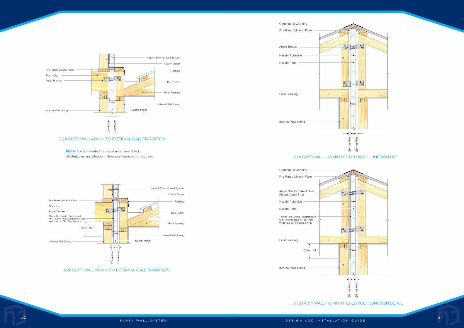
w w w . n a s a h i . n e t . a u - 1 3 0 0 2 N A S A H I