Embed Size (px)
Citation preview
2019 Type RS (RS+) series
Service Manual
Version: V1.1, 11/12/2019

TT-XX19RS Service Manual
1
Contents:
Safety Nnotice .......................................................................................................................................... 2
Part A. System Diagram ......................................................................................................................... 3
Part B. Recommended Spare Parts List .............................................................................................. 4
Part C. Structure Exploded Diagram .................................................................................................... 7
Part D. OC module & IR touch PCBA Disassembly & Reassembly ................................................ 7
Part E. PCBA Overviews ........................................................................................................................ 8
Part F. IR Touch Panel Signal Test .............................................................................................. 12
Part G. Replace OC module (OC panel & backlight) ............................................................ 13
Part H. Clean dirt or condensation behind the tempered glass ....................................... 13
Part I. Replace Outer Frame (Front frame) ............................................................................. 13
Part J. Replace IR Touch Panel Sensor PCBAs ....................................................................... 14
Part K. Firmware Upgrade .............................................................................................................. 21
Part L. Trouble shooting ....................................................................................................................... 28
TT-XX19RS Service Manual
2
Safety Nnotice
1. There are many electrical and mechanical parts in the RS series touchscreen, which the
technician need pay attention to the safety precaution before repairing.
2. It is essential that all the components should be replaced with the same or authorized
components as recommended in this manual to prevent Shock, Fire, or any other Hazards.
3. Please do not modify the original mechanical or electrical design without previous verification
from the manufacturer or authorized agent.
4. Before start repairing or disassembling the machine, please make sure unplug the machine
from any power source and properly grounded.

TT-XX19RS Service Manual
3
Part A. System Diagram
AC switch board
OPS
docking
board
Power board MSD848.15 (MSD8386.15)
Android Mainboard
T-CON
AC In
5VSB, 5V, 12V, 18V
Backlight PWR
OPS PC
SPK L Front port (IR&keypad) board
Touch signal
HDMI out
OC Module IR Touch Panel
SPK R
LVDS cable
18V
LVDS
FRT
HDMI
Power
12V
230V
Backlight
Touch USB
Public USB
MIC
Key, IR,
Light sensor,
LED_R/G

TT-XX19RS Service Manual
4
Part B. Recommended Spare Parts List
TT-6519RS RSPL:
Part No. Part Description Usage
Initial Parts set
10503T7AP000006 Power board, MP600T-65P 1
10503T7AC000011 Mainboard TVE.MSD8386.15 V1.2 UHD DDR3GB eMMC1 1
30100T8C9004010 OPS docking board, HHT-OPS_PI3HDX1204B1-4K60HZ FFC-51 1
30100T7AP001010 AC switch board, HHT_AC_SWITCHBOARD_AP6 1
10503T9JM000002 Front port (IR&Keypad) board, RS_19 HDMI1.4 1204B IC 1
10503T7AC000005 65” IR PCB SET, X65H02 (10pcs PCBA) 1
Part list for reference
10503T5A5000046 T-CON board, 60Hz for AUO T650QVN06.3 1
10403ZZZZ001683 Inner cable, between Power board and Mainboard, 14pin, 500mm 1
10403ZZZZ002225 Inner cable, LVDS cable, between Mainboard to T-CON board, 51pin, 801MM
X6+ 1
10403ZZZZ001384 Inner cable, between Mainboard and speaker, 2 ports cable, longer side
1290mm shorter side 950mm 1
10403ZZZZ001140 Inner cable, between Power board and OPS docking board, with
Magnetic ring, 6pin to 4pin, 330mm 1
10403ZZZZ001487 Inner HDMI cable, HDMI2.0, between Mainboard and Front port (IR&Keypad)
board, 900mm 1
10403ZZZZ000905 Inner cable, between AC switch board and Power board, 3pin, 560mm 1
10403ZZZZ001990 Inner cable, between Mainboard and IR Touch mainboard, 2 ports cable,
10pin to 6pin & 8pin, 1190mm 1
10403ZZZZ002179 Inner cable, between Mainboard and Front port (IR&Keypad) board, 920mm 1
10403ZZZZ002180 Inner cable, between Mainboard and 4K OPS board, 51P, FFC cable, 506
MM RS65-848.15 1
10403ZZZZ001875 RS DC power supply cable, 100mm 1
10500T6C6004011 Speaker, 8Ω15W, UY40223B8-10F-B 2
10505T7JC001010 2018 remote controller 1
10500T8I5009020 Double head Magnetic pen, Newline Logo 2
10403ZZZZ000807 USB A-A cable, 3m 1
10403ZZZZ001451 HDMI Cable, 3M 1
10500T6J8007010 WIFI dongle, EDUP AC1602, USB3.0, Dual-band 1
TT-XX19RS Service Manual
5
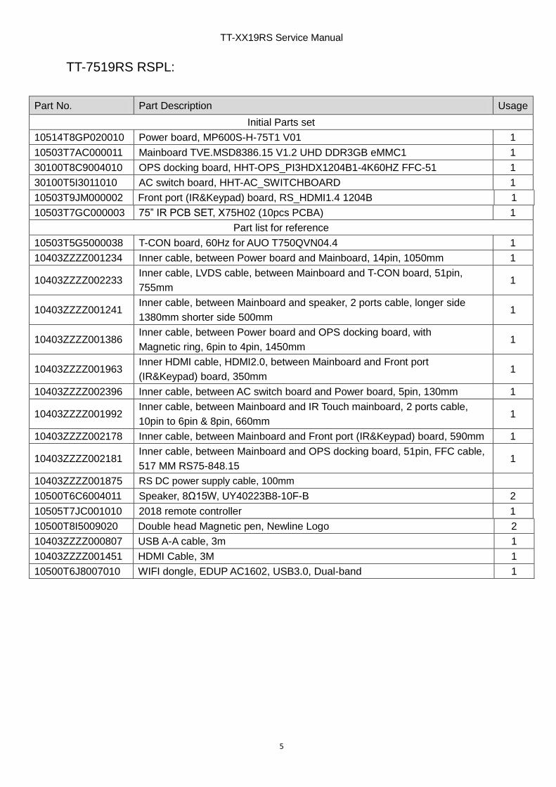
TT-7519RS RSPL:
Part No. Part Description Usage
Initial Parts set
10514T8GP020010 Power board, MP600S-H-75T1 V01 1
10503T7AC000011 Mainboard TVE.MSD8386.15 V1.2 UHD DDR3GB eMMC1 1
30100T8C9004010 OPS docking board, HHT-OPS_PI3HDX1204B1-4K60HZ FFC-51 1
30100T5I3011010 AC switch board, HHT-AC_SWITCHBOARD 1
10503T9JM000002 Front port (IR&Keypad) board, RS_HDMI1.4 1204B 1
10503T7GC000003 75” IR PCB SET, X75H02 (10pcs PCBA) 1
Part list for reference
10503T5G5000038 T-CON board, 60Hz for AUO T750QVN04.4 1
10403ZZZZ001234 Inner cable, between Power board and Mainboard, 14pin, 1050mm 1
10403ZZZZ002233 Inner cable, LVDS cable, between Mainboard and T-CON board, 51pin,
755mm 1
10403ZZZZ001241 Inner cable, between Mainboard and speaker, 2 ports cable, longer side
1380mm shorter side 500mm 1
10403ZZZZ001386 Inner cable, between Power board and OPS docking board, with
Magnetic ring, 6pin to 4pin, 1450mm 1
10403ZZZZ001963 Inner HDMI cable, HDMI2.0, between Mainboard and Front port
(IR&Keypad) board, 350mm 1
10403ZZZZ002396 Inner cable, between AC switch board and Power board, 5pin, 130mm 1
10403ZZZZ001992 Inner cable, between Mainboard and IR Touch mainboard, 2 ports cable,
10pin to 6pin & 8pin, 660mm 1
10403ZZZZ002178 Inner cable, between Mainboard and Front port (IR&Keypad) board, 590mm 1
10403ZZZZ002181 Inner cable, between Mainboard and OPS docking board, 51pin, FFC cable,
517 MM RS75-848.15 1
10403ZZZZ001875 RS DC power supply cable, 100mm
10500T6C6004011 Speaker, 8Ω15W, UY40223B8-10F-B 2
10505T7JC001010 2018 remote controller 1
10500T8I5009020 Double head Magnetic pen, Newline Logo 2
10403ZZZZ000807 USB A-A cable, 3m 1
10403ZZZZ001451 HDMI Cable, 3M 1
10500T6J8007010 WIFI dongle, EDUP AC1602, USB3.0, Dual-band 1

TT-XX19RS Service Manual
6
TT-8619RS RSPL:
Part No. Part Description Usage
Initial Parts set
10514T8JP020010 Power board, MP600S-H-86T1 V01 1
10503T7AC000011 Mainboard TVE.MSD8386.15 V1.2 UHD DDR3GB eMMC1 1
30100T8C9004010 OPS docking board, HHT-OPS_PI3HDX1204B1-4K60HZ FFC-51 1
30100T5I3011010 AC switch board, HHT-AC Switch 1
10503T9JM000002 Front port (IR&Keypad) board, RS_HDMI1.4 1204B 1
10503T7JC000004 86” IR PCB SET, X86H02 (12pcs PCBA) 1
Part list for reference
10503T5J5000014 T-CON board, 60Hz for LC860EQY-FJA4 1
10403ZZZZ001234 Inner cable, between Power board and Mainboard, 14pin, 1050mm 1
10403ZZZZ001504 Inner cable, LVDS cable, between Mainboard and T-CON board, 51pin,
880mm 1
10403ZZZZ001235 Inner cable, between Mainboard and T-CON board, for power supply, 5pin,
900mm 1
10403ZZZZ001241 Inner cable, between Mainboard and speaker, 2 ports cable, longer side
1380mm shorter side 500mm 1
10403ZZZZ001386 Inner cable, between Power board and OPS docking board, with
Magnetic ring, 6pin to 4pin, 1450mm 1
10403ZZZZ001963 Inner HDMI cable, HDMI2.0, between Mainboard and Front port (IR&Keypad)
board, 350mm 1
10403ZZZZ002396 Inner cable, between AC switch board and Power board, 5pin, 130mm 1
10403ZZZZ001992 Inner cable, between Mainboard and IR Touch mainboard, 2 ports cable,
10pin to 6pin & 8pin, 660mm 1
10403ZZZZ002178 Inner cable, between Mainboard and Front port (IR&Keypad) board, 590mm 1
10403ZZZZ002181 Inner cable, between Mainboard and OPS docking board, 51pin, FFC cable,
517 MM RS75-848.15 1
10403ZZZZ001875 RS DC power supply cable, 100mm 1
10500T6C6004011 Speaker, 8Ω15W, UY40223B8-10F-B 2
10505T7JC001010 2018 remote controller 1
10500T8I5009020 Double head Magnetic pen, Newline Logo 2
10403ZZZZ000807 USB A-A cable, 3m 1
10403ZZZZ001451 HDMI Cable, 3M 1
10500T6J8007010 WIFI dongle, EDUP AC1602, USB3.0, Dual-band 1

TT-XX19RS Service Manual
7
Part C. Structure Exploded Diagram
Basically there are 4 layers for RS series structure, they are Outer frame (IR touch panel inside),
Tempered glass, OC module (OC panel & Backlight) and PCBAs.
Structure exploded diagram (Zoom in to see details):
RS65:
https://www.dropbox.com/s/2fj2bp8n9hcj44f/18%E6%AC%BE%E6%B5%B7%E5%A4%96RSx65
%E7%88%86%E7%82%B8%E5%9B%BE.pdf?dl=0
RS75
https://www.dropbox.com/s/kadzcl3y1vshgz1/18%E6%AC%BE%E6%B5%B7%E5%A4%96RSx75
%E7%88%86%E7%82%B8%E5%9B%BE.pdf?dl=0
RS86:
https://www.dropbox.com/s/n9cvebi2vqlgynv/18%E6%AC%BE%E6%B5%B7%E5%A4%96RSx86
%E7%88%86%E7%82%B8%E5%9B%BE.pdf?dl=0
Part D. OC module & IR touch PCBA Disassembly & Reassembly
A. Operation video of replacing OC module:
https://www.dropbox.com/s/oglbsha5d6j2s3k/2018%20OEM_OC%20module_Disassembly%2
0%26%20Reassembly.mp4?dl=0
Operations involved in the above video:
1. Take off rear covers, remove all PCBAs and cables on the OC back cover.
2. Take off defect OC module from the defect screen.
3. Take new OC module (no outer frame) from new OC module (with outer frame) and put it on
the defect screen.
4. Put back all PCBAs and cables on the new OC module, fix all of them and install the rear
covers, power on to test it.
5. Throw away the defect OC module and the outer frame of new OC module.
Note:
1. The above step 2-3 had better be done in a dust-free plant to avoid the dust stick onto the
tempered glass or OC module surface.
TT-XX19RS Service Manual
8
B. Operation video of disassembling and reassembling IR touch PCBAs:
https://www.dropbox.com/s/vwmeazi4wgpcswk/2018%20OEM_IR%20PCB%20SET_Disasse
mbly%20%26%20Reassembly.mp4?dl=0
Operations involved in the above video:
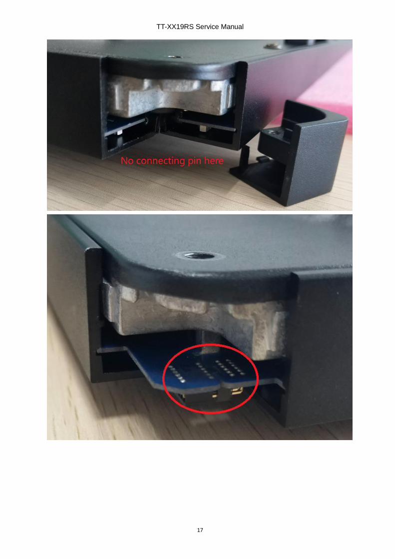
1. Take off 4 corner covers, there is no connection in the upper-right corner in front view, from
right to left to remove upper IR PCBAs, from bottom to up to remove the left and right side
IR PCBAs, from right to left to remove the bottom side IR PCBAs.
2. According to IR PCBA layout and refer to above opposite order to insert the 4 frames IR
PCBAs.
3. Connect the bottom-left, bottom-right and upper-left corner PCBA, pay attention not to
bend the contact pins, assemble the 4 corner covers.
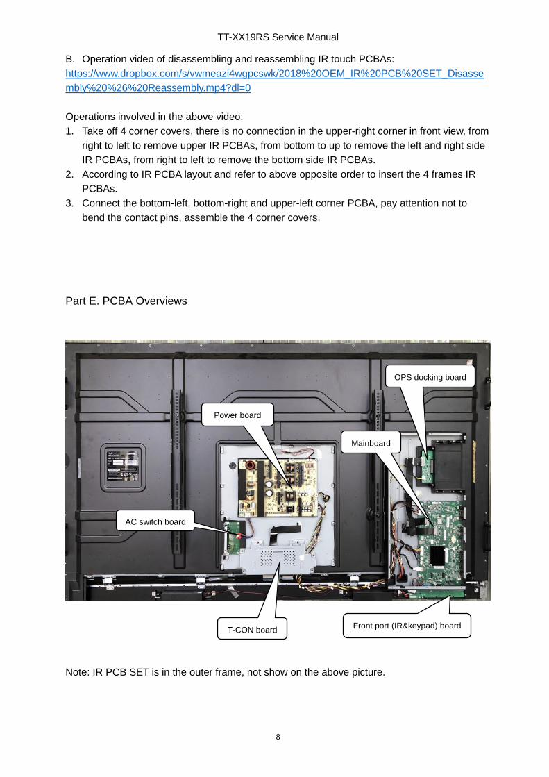
Part E. PCBA Overviews
Note: IR PCB SET is in the outer frame, not show on the above picture.
Power board
OPS docking board
AC switch board
Front port (IR&keypad) board T-CON board
Mainboard
TT-XX19RS Service Manual
9
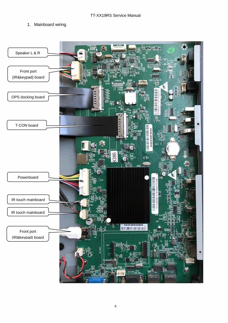
1. Mainboard wiring
Speaker L & R
T-CON board
OPS docking board
Powerboard
IR touch mainboard
Front port
(IR&keypad) board
Front port
(IR&keypad) board
IR touch mainboard

TT-XX19RS Service Manual
10
2. Power board wiring
3. OPS docking board wiring
OPS docking
board
Mainboard
AC switch board
OC backlight
Mainboard
Powerboard
TT-XX19RS Service Manual
11
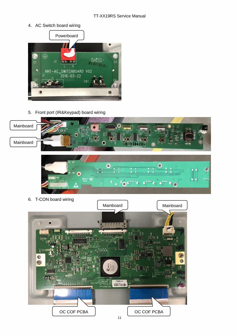
4. AC Switch board wiring
5. Front port (IR&Keypad) board wiring
6. T-CON board wiring
Powerboard
Mainboard Mainboard
OC COF PCBAOC COF PCBA
Mainboard
Mainboard
TT-XX19RS Service Manual
12
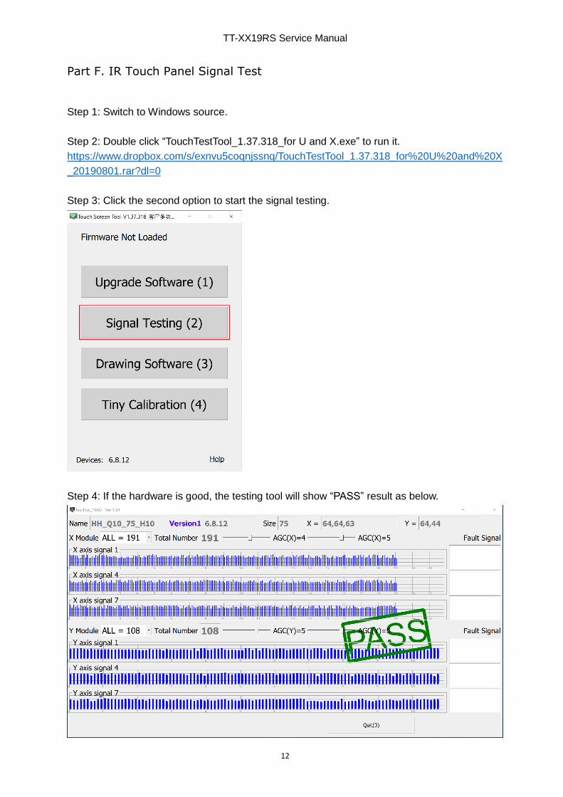
Part F. IR Touch Panel Signal Test
Step 1: Switch to Windows source.
Step 2: Double click “TouchTestTool_1.37.318_for U and X.exe” to run it.
https://www.dropbox.com/s/exnvu5coqnjssnq/TouchTestTool_1.37.318_for%20U%20and%20X
_20190801.rar?dl=0
Step 3: Click the second option to start the signal testing.
Step 4: If the hardware is good, the testing tool will show “PASS” result as below.

TT-XX19RS Service Manual
13
If the hardware has some problem, you may will get error report such as below:
*It may will not affect the writing performance, if yes, don’t need to repair it.
Note: If problem still present, please take picture or screen shoot the testing result to us for
analysis.
Part G. Replace OC module (OC panel & backlight)
Refer to chapter A of Part D.
Part H. Clean dirt or condensation behind the tempered glass
Step 1. Refer to chapter A of Part D to remove the OC module.
Step 2. Check panel and glass surface to find where the dirt or condensation is.
Step 3. Use a dustless cloth under a strong light source to wipe it.
Note: If possible, these operation had better be done in a dust-free plant, if there is no dust-free
plant available, a clean meeting room is recommended.
Part I. Replace Outer Frame (Front frame)
Refer to chapter A of Part D, remove the OC module, remove the tempered glass, then you can
disassemble the outer frame and replace anyone of the outer frame.
Note: Pay attention to take out the IR PCB from original outer frame to new frame.
TT-XX19RS Service Manual
14
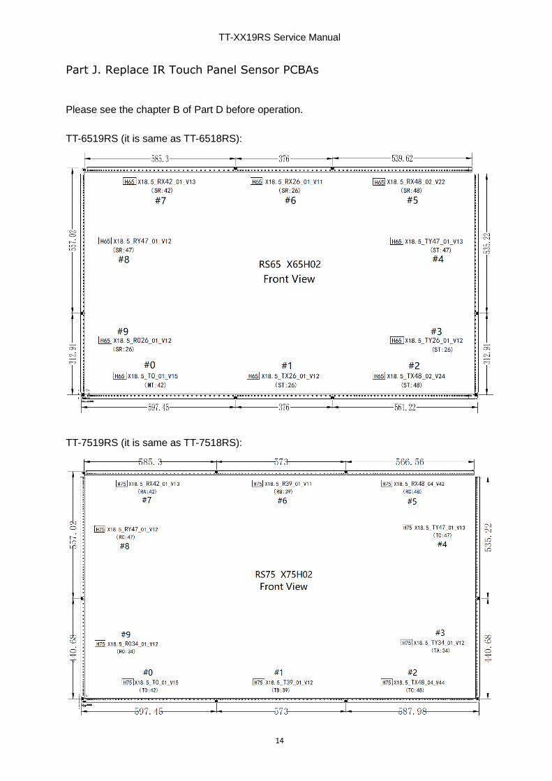
Part J. Replace IR Touch Panel Sensor PCBAs
Please see the chapter B of Part D before operation.
TT-6519RS (it is same as TT-6518RS):
TT-7519RS (it is same as TT-7518RS):

TT-XX19RS Service Manual
15
TT-8619RS (it is same as TT-8618RS):
Step 1: Place it on a flat table, remove 4 corner covers.

TT-XX19RS Service Manual
16
TT-XX19RS Service Manual
17
TT-XX19RS Service Manual
18
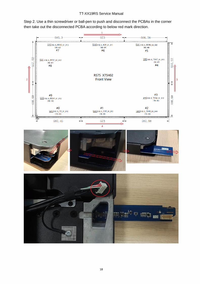
Step 2. Use a thin screwdriver or ball-pen to push and disconnect the PCBAs in the corner
then take out the disconnected PCBA according to below red mark direction.
TT-XX19RS Service Manual
19
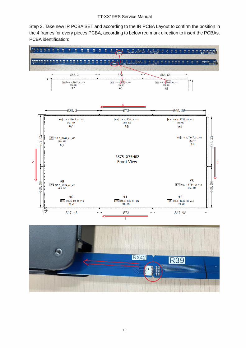
Step 3. Take new IR PCBA SET and according to the IR PCBA Layout to confirm the position in
the 4 frames for every pieces PCBA, according to below red mark direction to insert the PCBAs.
PCBA identification:

TT-XX19RS Service Manual
20
Note: Make sure every piece PCBA have been connected solidly, no loose connection.
Usually need 2 person co-work to connect it, one person aim at the contact pins and pin slot,
and one person push the PCBA in another side to make the contact pins get in pin slot.
Step 4. Install back 4 corner covers with screws.
TT-XX19RS Service Manual
21
Part K. Firmware Upgrade
How to upgrade FW and Config file from factory menu.
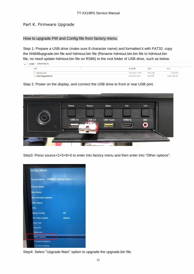
Step 1: Prepare a USB drive (make sure 8 character name) and formatted it with FAT32, copy
the hht848upgrade.bin file and hdmiout.bin file (Rename hdmiout.bin.bin file to hdmiout.bin
file, no need update hdmiout.bin file on RS86) to the root folder of USB drive, such as below.
Step 2: Power on the display, and connect the USB drive to front or rear USB port.
Step3: Press source+2+5+8+0 to enter into factory menu and then enter into “Other options”.
Step4: Select “Upgrade Main” option to upgrade the upgrade.bin file.
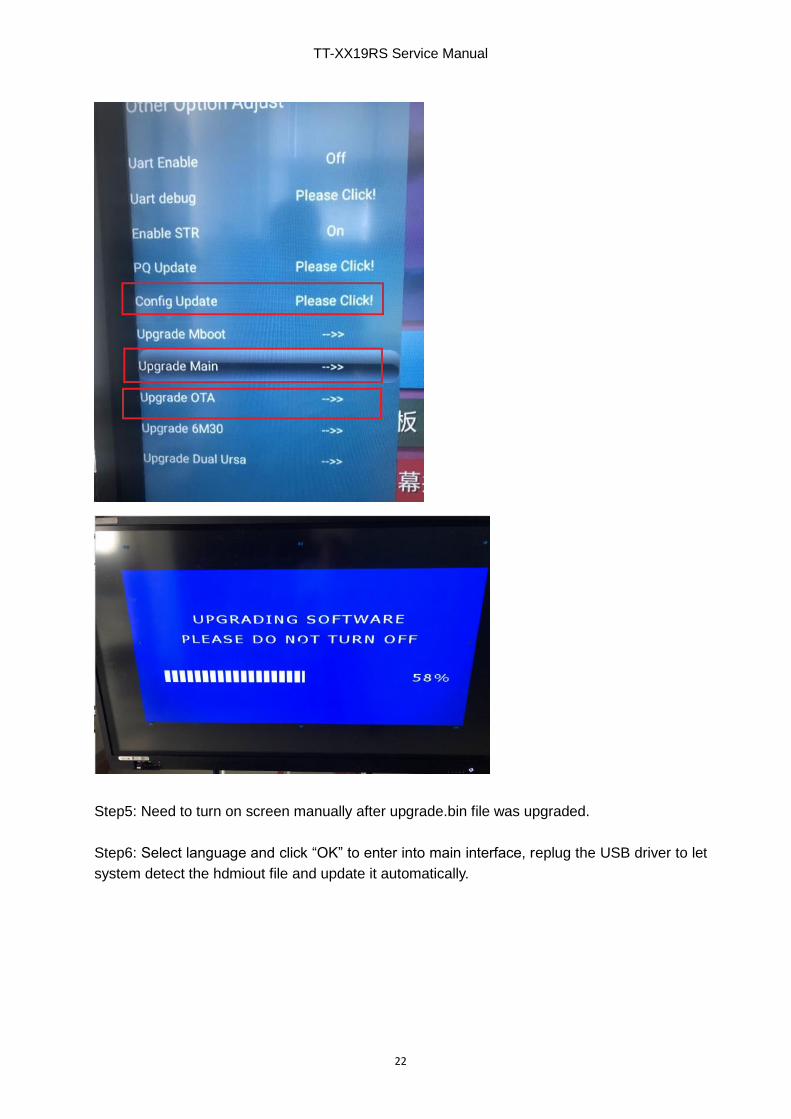
TT-XX19RS Service Manual
22
Step5: Need to turn on screen manually after upgrade.bin file was upgraded.
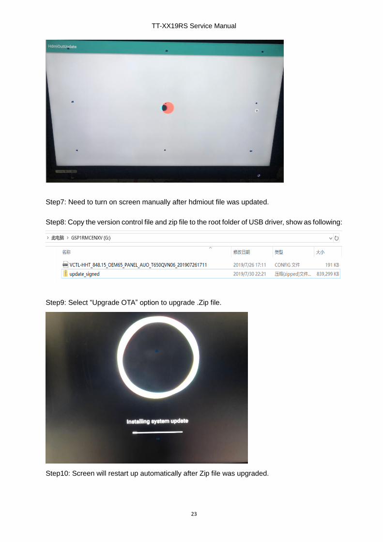
Step6: Select language and click “OK” to enter into main interface, replug the USB driver to let
system detect the hdmiout file and update it automatically.
TT-XX19RS Service Manual
23
Step7: Need to turn on screen manually after hdmiout file was updated.
Step8: Copy the version control file and zip file to the root folder of USB driver, show as following:
Step9: Select “Upgrade OTA” option to upgrade .Zip file.
Step10: Screen will restart up automatically after Zip file was upgraded.
TT-XX19RS Service Manual
24
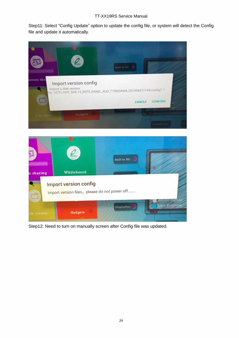
Step11: Select “Config Update” option to update the config file, or system will detect the Config
file and update it automatically.
Step12: Need to turn on manually screen after Config file was updated.
TT-XX19RS Service Manual
25
How to upgrade FW and Config file for a blank mainboard.
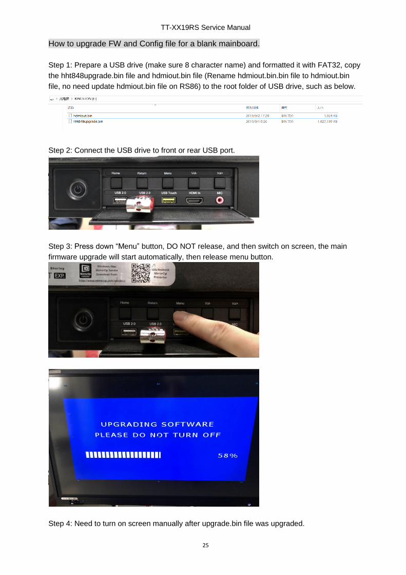
Step 1: Prepare a USB drive (make sure 8 character name) and formatted it with FAT32, copy
the hht848upgrade.bin file and hdmiout.bin file (Rename hdmiout.bin.bin file to hdmiout.bin
file, no need update hdmiout.bin file on RS86) to the root folder of USB drive, such as below.
Step 2: Connect the USB drive to front or rear USB port.
Step 3: Press down “Menu” button, DO NOT release, and then switch on screen, the main
firmware upgrade will start automatically, then release menu button.
Step 4: Need to turn on screen manually after upgrade.bin file was upgraded.

TT-XX19RS Service Manual
26
Step5: Select language and click “OK” to enter into main interface, replug the USB driver to let
system detect the hdmiout file and update it automatically.
Step6: Need to turn on screen manually after hdmiout file was updated.
Step7: Copy the version file and zip file to the root folder of USB driver, show as following:
Step8: Switch on screen and press down power button, DO NOT release, the zip file will upgrade
automatically.
TT-XX19RS Service Manual
27
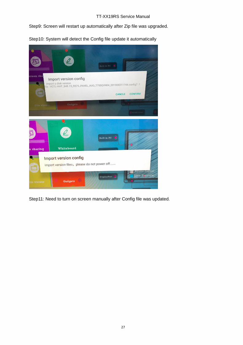
Step9: Screen will restart up automatically after Zip file was upgraded.
Step10: System will detect the Config file update it automatically
Step11: Need to turn on screen manually after Config file was updated.

TT-XX19RS Service Manual
28
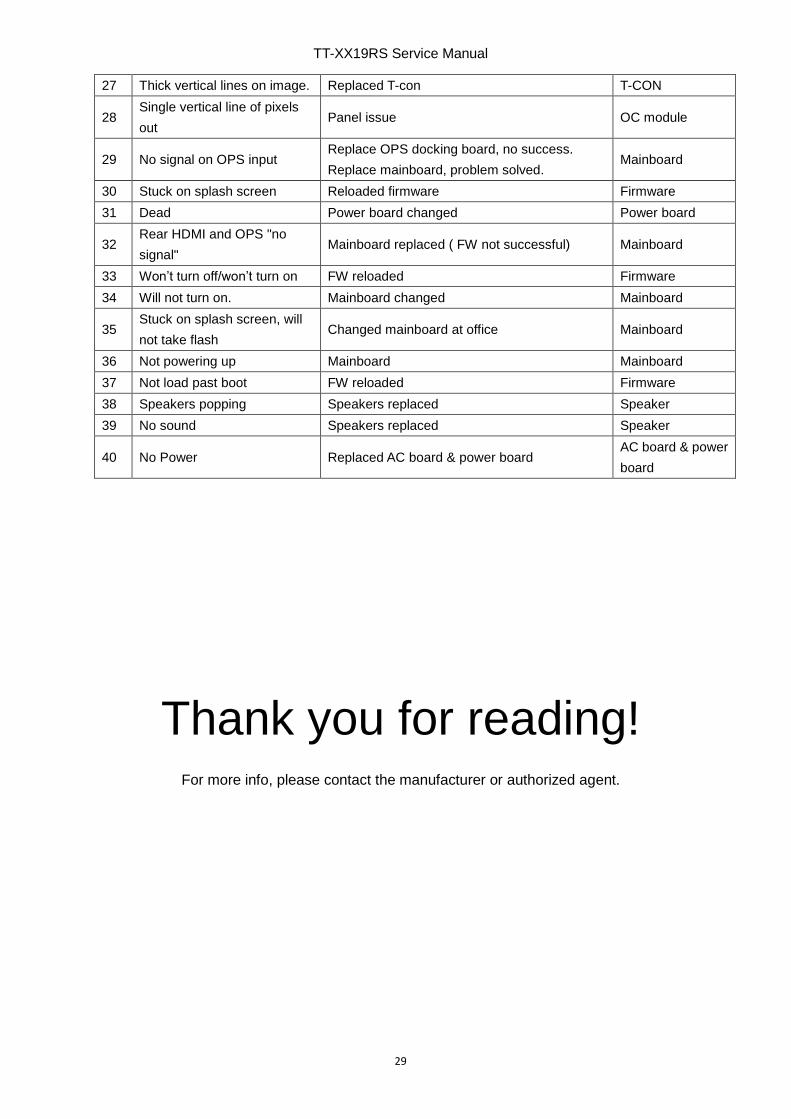
Part L. Trouble shooting
Below are some true RMA cases from similar model for reference.
Defect symptom Repair procedure Defect component
1 No image Replace mainboard, no success. Replace
power board, problem solved Power board
2 No image Replace all PCB modules, no success.
Replace OC, problem solved OC module
3 No image, backlight OK Replace T-con T-CON
4 No image, no backlight, long
turn on Mainboard Mainboard
5 No image Replace mainboard, solved Mainboard
6 No touch Fitted 2 sets new sensors IR PCB SET
7 No touch Main IR PCB changed IR mainboard
8 No touch Ribbon cables reconnected correctly around
corners Cable
9 No proper touch Reconnect IR PCB's and replace FFC's with
new ones Cable
10 Gaps in touch Fitted new set of IR ( twice) IR PCB SET
11 No touch IR FW upgrade IR firmware
12 No touch Mainboard Mainboard
13 Dead areas interactivity Full set of IR sensors IR PCB SET
14 No touch externally, android
OK Mainboard changed Mainboard
15 Poor touch response Reconnected IR array ribbon cable (bottom
right) Ribbon cable
16 No touch on all sources Swapped mainboard Mainboard
17 No touch on all sources Reseated IR array IR PCB SET
18 Large dead areas for touch
and sluggish Full set of IR PCBs changed IR PCB SET
19 Vertical/Horizontal stripe/line
in the image Replace OC module OC module
20 Vertical stripes in the image.
Reconnect T-con to OC panel connections and
cleaned LVDS FFC. LVDS cable was sticked to
tighten onto LED panel which causes an
improper connection to T-con.
Clean cable &
reconnect cable
21 Scrambled image T-con changed T-CON
22 3 vertical lines of pixels T-con board T-CON
23 Picture colors
wrong/pixellated T-con board T-CON
24 Bleached image, contrast
functions not responding Firmware flashed Firmware
25 Picture lines T-con board replaced T-CON
26 Picture breakup T-con board replaced T-CON
TT-XX19RS Service Manual
29
27 Thick vertical lines on image. Replaced T-con T-CON
28 Single vertical line of pixels
out Panel issue OC module
29 No signal on OPS input Replace OPS docking board, no success.
Replace mainboard, problem solved. Mainboard
30 Stuck on splash screen Reloaded firmware Firmware
31 Dead Power board changed Power board
32 Rear HDMI and OPS "no
signal" Mainboard replaced ( FW not successful) Mainboard
33 Won’t turn off/won’t turn on FW reloaded Firmware
34 Will not turn on. Mainboard changed Mainboard
35 Stuck on splash screen, will
not take flash Changed mainboard at office Mainboard
36 Not powering up Mainboard Mainboard
37 Not load past boot FW reloaded Firmware
38 Speakers popping Speakers replaced Speaker
39 No sound Speakers replaced Speaker
40 No Power Replaced AC board & power board AC board & power
board
Thank you for reading!
For more info, please contact the manufacturer or authorized agent.