Embed Size (px)
Citation preview
www.rohm.com
ResistorsPassive Devices
CONTENTS
Quick Reference of Resistance Range ・・・・・・・・・・・・・ P. D2
Class-leading Compact Size Chip Resistors (RASMID series)Ultra-Compact Chip Resistors (SMR003 <009005>) ・・・・・・・ P. D3
Thick Film Chip Resistors (Standard series)Compact Chip Resistors (MCR series <01005 to 0805>) ・・・・・・・ P. D4
Chip Resistors (MCR series <1206 to 2512>) ・・・・・・・・・ P. D5
Compact Chip Resistor Networks (MNR series <0402×2 to 1206×4>) ・・・・・・ P. D6
8-element Chip Resistor Networks (MNR series <0603×5 to 1206×5>) ・・・・・・・ P. D7
Thick Film Chip Resistors (High Reliability series)High Anti-surge Chip Resistors (SDR series) ・・・・・・・・ P. D8
Anti-surge Chip Resistors (ESR series) ・・・・・・・・・・・・・・・・・・・ P. D8
High Power Chip Resistors <Wide Terminal type> (LTR series) ・・・・・・ P. D9
High Voltage Resistance Chip Resistors (KTR series) ・・・・・ P. D10
Tolerance for Sulfurization Chip Resistor (SFR series) ・・・・・ P. D11
Chip Resistors for Current Detection (Thick Film type)Chip Resistors (Low Ohmic MCR series) ・・・・・・・・・・・・・・・ P. D12
Low Ohmic Chip Resistors <Face Down type> (UCR series) ・・・・・・ P. D13
High Power Chip Resistors <Wide Terminal type> <Low TCR> (LHR series) ・・・・・ P. D14
High Power Chip Resistors <Wide Terminal type> (Low Ohmic LTR series) ・・・・・ P. D14
Chip Resistors for Current Detection (Metal Plate type)Ultra Low Ohmic Chip Shunt Resistors (PMR series) ・・・・・ P. D15
Ultra Low Ohmic Chip Shunt Resistors <Wide Terminal type> (PML series) ・・・・・ P. D16
High Power Ultra Low Ohmic Chip Shunt Resistors (PSR series) ・・・・・ P. D17
High Power Low Ohmic Chip Shunt Resistors (GMR series) ・・・・・ P. D18
Standard Nominal Resistance Values ・・・・・・・・・・・ P. D19
ISO 9001-/IATF 16949-approved
D1
D
Resisto
rs
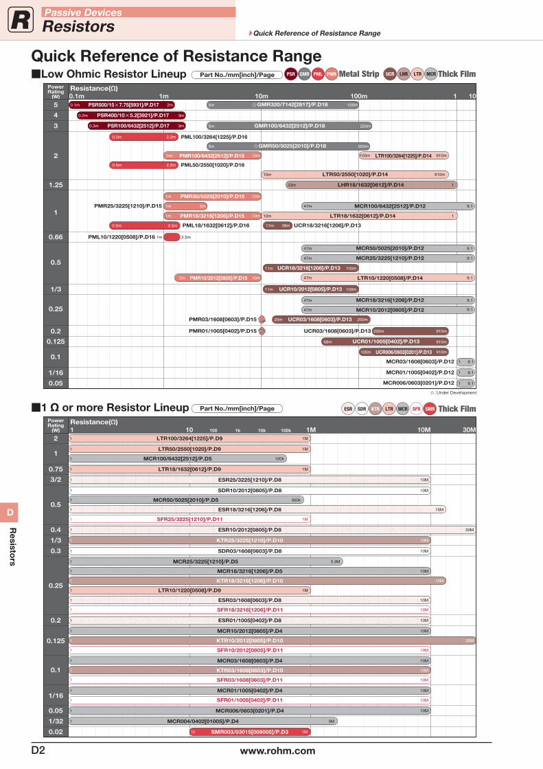
PSR GMR PML PMR Metal Strip UCR LTR MCR Thick FilmPart No./mm[inch]/Page
:Under Development
5
4
3
2
1
1.25
0.5
1/3
0.66
0.25
0.125
0.2
1/16
0.1
0.05
PowerRating
(W)
5m 220mGMR100/6432[2512]/P.D18
5m 200mGMR50/5025[2010]/P.D18
5m 100mGMR320/7142[2817]/P.D18
100m 910m10m1m
0.5m 2.2m
3m0.2m
2m0.1m PSR500/15×7.75[5931]/P.D17
PSR400/10×5.2[3921]/P.D17
3m0.3m PSR100/6432[2512]/P.D17
PML100/3264[1225]/P.D16
PMR100/6432[2512]/P.D15 LTR100/3264[1225]/P.D14
0.5m 2.2m PML50/2550[1020]/P.D16
10m1m
0.5m 2.5m
5m1mPMR25/3225[1210]/P.D15
PML18/1632[0612]/P.D16 11m 39m UCR18/3216[1206]/P.D13UCR18/3216[1206]/P.D13
PMR18/3216[1206]/P.D15
10m1m
9.147m MCR100/6432[2512]/P.D12
PMR50/5025[2010]/P.D15
10m 1LTR18/1632[0612]/P.D14
10m 910mLTR50/2550[1020]/P.D14
33m 1LHR18/1632[0612]/P.D14
1m 2.5mPML10/1220[0508]/P.D16
9.147m MCR50/5025[2010]/P.D12
11m 100mUCR18/3216[1206]/P.D13
9.147m10m2m PMR10/2012[0805]/P.D15 LTR10/1220[0508]/P.D14
11m 100mUCR10/2012[0805]/P.D13
9.147m MCR25/3225[1210]/P.D12
9.147m MCR18/3216[1206]/P.D12
9.147m MCR10/2012[0805]/P.D12
10m10m 20m 200mPMR03/1608[0603]/P.D15 UCR03/1608[0603]/P.D13
10m10mPMR01/1005[0402]/P.D15 220m 910mUCR03/1608[0603]/P.D13
68m 910mUCR01/1005[0402]/P.D13
910m100m UCR006/0603[0201]/P.D13
1m 10m 100m 1 100.1mResistance(Ω)
1 9.1MCR03/1608[0603]/P.D12
1 9.1MCR01/1005[0402]/P.D12
1 9.1MCR006/0603[0201]/P.D12
LHR
Thick FilmSMRSFRKTRSDRESR LTR MCRPart No./mm[inch]/Page
10M1
UCR03/1608[0603]
3M1 MCR004/0402[01005]/P.D4
1M10 SMR003/03015[009005]/P.D3
10M1 MCR006/0603[0201]/P.D4
10M1 SFR01/1005[0402]/P.D11
10M1 MCR01/1005[0402]/P.D4
10M1 MCR03/1608[0603]/P.D4
10M1 KTR03/1608[0603]/P.D10
10M1 SFR03/1608[0603]/P.D11
10M1 SFR10/2012[0805]/P.D11
10M1 SFR18/3216[1206]/P.D11
1M1 SFR25/3225[1210]/P.D11
10M1 MCR18/3216[1206]/P.D5
3.3M1 MCR25/3225[1210]/P.D5
560k1 MCR50/5025[2010]/P.D5
100k1 MCR100/6432[2512]/P.D5
15M1 KTR18/3216[1206]/P.D10
10M1 SDR10/2012[0805]/P.D8
10M1 KTR25/3225[1210]/P.D10
10M1 MCR10/2012[0805]/P.D4
10M1 ESR03/1608[0603]/P.D8
10M1 ESR25/3225[1210]/P.D8
1M1 LTR10/1220[0508]/P.D9
1M1 LTR18/1632[0612]/P.D9
1M1 LTR50/2550[1020]/P.D9
1M1 LTR100/3264[1225]/P.D9
ESR01/1005[0402]/P.D8
30M1 KTR10/2012[0805]/P.D10
2
1
0.75
3/2
0.5
0.4
1/3
0.3
0.2
0.125
0.25
0.1
0.05
1/16
1/32
0.02
PowerRating
(W) 10 100 1k 10k 100k 1M 10M 30M1Resistance(Ω)
15M1 ESR18/3216[1206]/P.D8
30M1 ESR10/2012[0805]/P.D8
10M1 SDR03/1608[0603]/P.D8
Quick Reference of Resistance RangeLow Ohmic Resistor Lineup
1 Ω or more Resistor Lineup
D2 www.rohm.com
Passive Devices
Resistors Quick Reference of Resistance Range
D
Resisto
rs
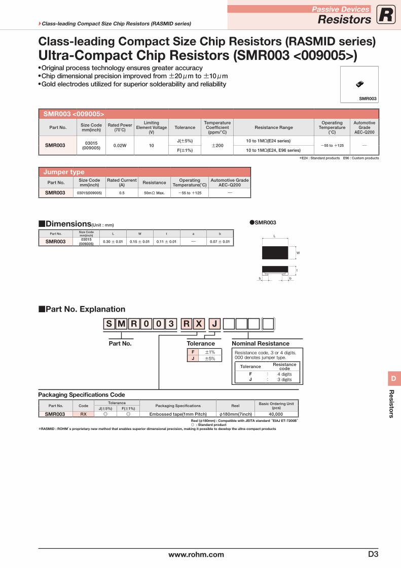
Original process technology ensures greater accuracy Chip dimensional precision improved from ±20μm to ±10μm Gold electrodes utilized for superior solderability and reliability
SMR003 <009005>
Part No. Size Codemm(inch)
Rated Power(70°C)
LimitingElement Voltage
(V)Tolerance
Temperature Coefficient(ppm/°C)
Resistance RangeOperating
Temperature(°C)
AutomotiveGrade
AEC-Q200
SMR003 03015(009005) 0.02W 10
J(±5%)±200
10 to 1MΩ(E24 series)-55 to +125 ―
F(±1%) 10 to 1MΩ(E24, E96 series)
*E24 : Standard products E96 : Custom products
Jumper typePart No. Size Code
mm(inch)Rated Current
(A) Resistance Operating Temperature(°C)
Automotive GradeAEC-Q200
SMR003 03015(009005) 0.5 50mΩ Max. -55 to +125 ―
Part No. Explanation
Packaging Specifications Code
Part No. CodeTolerance
Packaging Specifications Reel Basic Ordering Unit (pcs)J(±5%) F(±1%)
SMR003 RX Embossed tape(1mm Pitch) φ180mm(7inch) 40,000Reel (φ180mm) : Compatible with JEITA standard “EIAJ ET-7200B” : Standard product
* RASMID : ROHM’s proprietary new method that enables superior dimensional precision, making it possible to develop the ultra-compact products
SMR003
S M R 0 0 3 R X J
Part No. ToleranceF ±1%J ±5%
Nominal ResistanceResistance code, 3 or 4 digits.000 denotes jumper type.
Tolerance Resistancecode
FJ
::
4 digits3 digits
Dimensions(Unit : mm)
Part No. Size Codemm(inch) L W t a b
SMR003 03015(009005)
0.30 ± 0.01 0.15 ± 0.01 0.11 ± 0.01 ― 0.07 ± 0.01
Ultra-Compact Chip Resistors (SMR003 <009005>)Class-leading Compact Size Chip Resistors (RASMID series)
SMR003
L
W
t
bb
D3www.rohm.com
Passive Devices
ResistorsClass-leading Compact Size Chip Resistors (RASMID series)
D
Resisto
rs
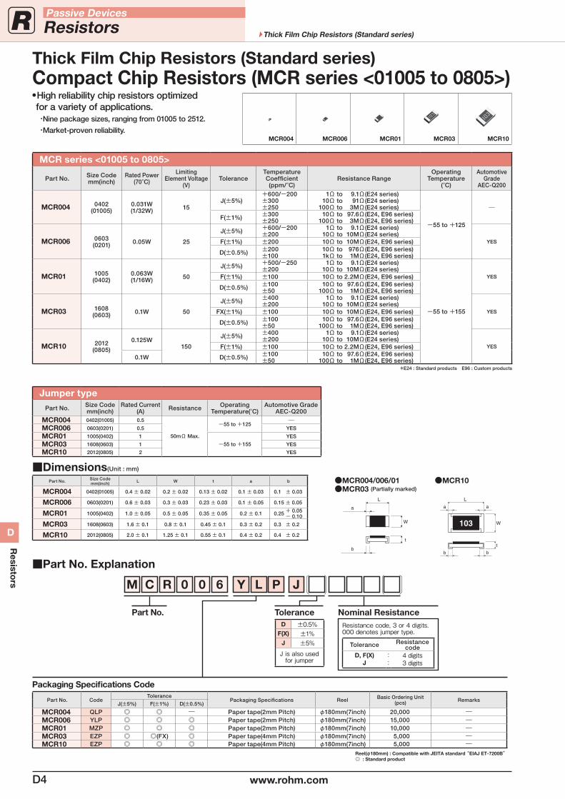
High reliability chip resistors optimized for a variety of applications.
・Nine package sizes, ranging from 01005 to 2512.
・Market-proven reliability.
MCR series <01005 to 0805>
Part No. Size Codemm(inch)
Rated Power(70°C)
LimitingElement Voltage
(V)Tolerance
Temperature Coefficient(ppm/°C)
Resistance RangeOperating
Temperature(°C)
AutomotiveGrade
AEC-Q200
MCR004 0402(01005)
0.031W(1/32W) 15
J(±5%)+600/-200±300±250
1Ω to 9.1Ω(E24 series) 10Ω to 91Ω(E24 series) 100Ω to 3MΩ(E24 series)
-55 to +125
―F(±1%) ±300
±250 10Ω to 97.6Ω(E24, E96 series) 100Ω to 3MΩ(E24, E96 series)
MCR006 0603(0201) 0.05W 25
J(±5%) +600/-200±200
1Ω to 9.1Ω(E24 series) 10Ω to 10MΩ(E24 series)
YESF(±1%) ±200 10Ω to 10MΩ(E24, E96 series)
D(±0.5%) ±200±100
10Ω to 976Ω(E24, E96 series) 1kΩ to 1MΩ(E24, E96 series)
MCR01 1005(0402)
0.063W(1/16W) 50
J(±5%) +500/-250±200
1Ω to 9.1Ω(E24 series) 10Ω to 10MΩ(E24 series)
-55 to +155
YESF(±1%) ±100 10Ω to 2.2MΩ(E24, E96 series)
D(±0.5%) ±100±50
10Ω to 97.6Ω(E24, E96 series) 100Ω to 1MΩ(E24, E96 series)
MCR03 1608(0603) 0.1W 50
J(±5%) ±400±200
1Ω to 9.1Ω(E24 series) 10Ω to 10MΩ(E24 series)
YESFX(±1%) ±100 10Ω to 10MΩ(E24, E96 series)
D(±0.5%) ±100±50
10Ω to 97.6Ω(E24, E96 series) 100Ω to 1MΩ(E24, E96 series)
MCR10 2012(0805)
0.125W150
J(±5%) ±400±200
1Ω to 9.1Ω(E24 series) 10Ω to 10MΩ(E24 series)
YESF(±1%) ±100 10Ω to 2.2MΩ(E24, E96 series)
0.1W D(±0.5%) ±100±50
10Ω to 97.6Ω(E24, E96 series) 100Ω to 1MΩ(E24, E96 series)
*E24 : Standard products E96 : Custom products
Jumper typePart No. Size Code
mm(inch)Rated Current
(A) Resistance Operating Temperature(°C)
Automotive GradeAEC-Q200
MCR004 0402(01005) 0.5
50mΩ Max.
-55 to +125―
MCR006 0603(0201) 0.5 YES
MCR01 1005(0402) 1
-55 to +155
YES
MCR03 1608(0603) 1 YES
MCR10 2012(0805) 2 YES
Part No. Explanation
Packaging Specifications Code
Part No. CodeTolerance
Packaging Specifications Reel Basic Ordering Unit (pcs) Remarks
J(±5%) F(±1%) D(±0.5%)
MCR004 QLP ― Paper tape(2mm Pitch) φ180mm(7inch) 20,000 ―MCR006 YLP Paper tape(2mm Pitch) φ180mm(7inch) 15,000 ―MCR01 MZP Paper tape(2mm Pitch) φ180mm(7inch) 10,000 ―MCR03 EZP (FX) Paper tape(4mm Pitch) φ180mm(7inch) 5,000 ―MCR10 EZP Paper tape(4mm Pitch) φ180mm(7inch) 5,000 ―
Reel(φ180mm) : Compatible with JEITA standard “EIAJ ET-7200B” : Standard product
MCR004 MCR006 MCR01 MCR03 MCR10
M C R 0 0 6 Y L P J
Part No. ToleranceD ±0.5%
F(X) ±1%J ±5%
J is also usedfor jumper
Nominal ResistanceResistance code, 3 or 4 digits.000 denotes jumper type.
Tolerance Resistancecode
D, F(X)J
::
4 digits3 digits
Dimensions(Unit : mm)
Part No. Size Codemm(inch) L W t a b
MCR004 0402(01005) 0.4 ± 0.02 0.2 ± 0.02 0.13 ± 0.02 0.1 ± 0.03 0.1 ± 0.03
MCR006 0603(0201) 0.6 ± 0.03 0.3 ± 0.03 0.23 ± 0.03 0.1 ± 0.05 0.15 ± 0.05
MCR01 1005(0402) 1.0 ± 0.05 0.5 ± 0.05 0.35 ± 0.05 0.2 ± 0.1 0.25 + 0.05 - 0.10
MCR03 1608(0603) 1.6 ± 0.1 0.8 ± 0.1 0.45 ± 0.1 0.3 ± 0.2 0.3 ± 0.2
MCR10 2012(0805) 2.0 ± 0.1 1.25 ± 0.1 0.55 ± 0.1 0.4 ± 0.2 0.4 ± 0.2
MCR004/006/01 MCR10 MCR03 (Partially marked)
a
W
L
b
t
b
a
L
a
b
W
t
103
Compact Chip Resistors (MCR series <01005 to 0805>)Thick Film Chip Resistors (Standard series)
D4 www.rohm.com
Passive Devices
Resistors Thick Film Chip Resistors (Standard series)
D
Resisto
rs
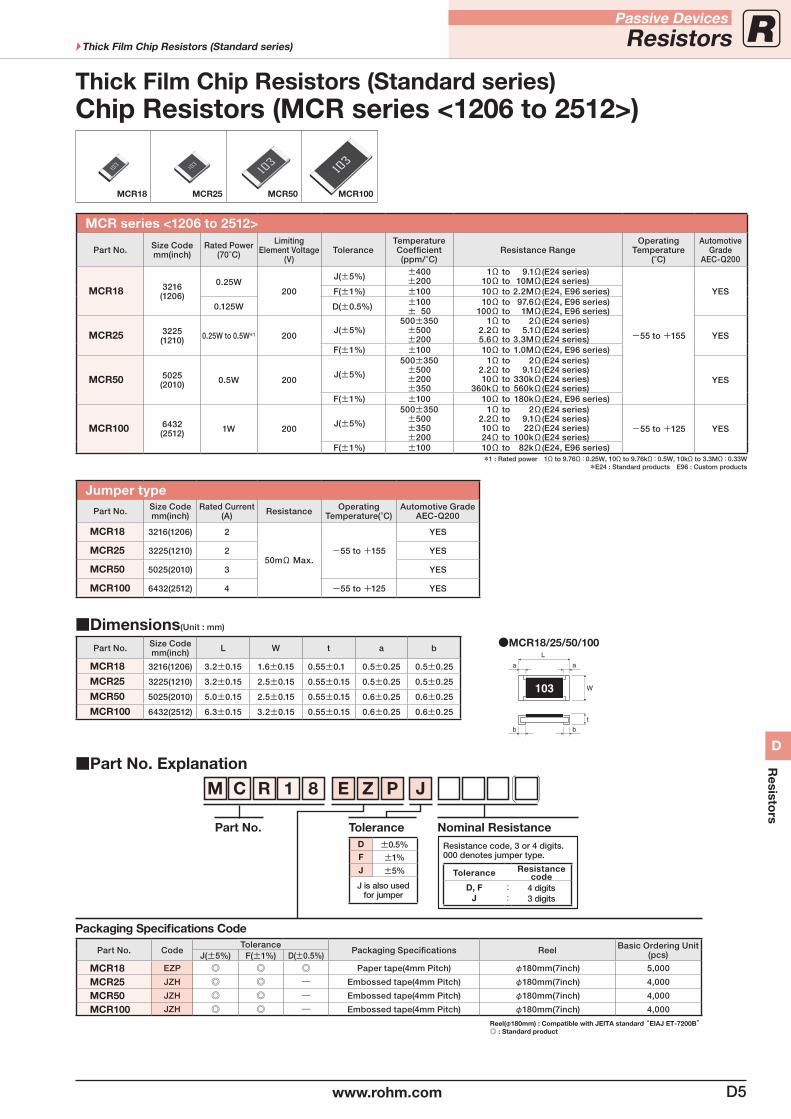
Thick Film Chip Resistors (Standard series)
MCR18 MCR25 MCR50 MCR100
MCR series <1206 to 2512>
Part No. Size Codemm(inch)
Rated Power(70°C)
LimitingElement Voltage
(V)Tolerance
Temperature Coefficient(ppm/°C)
Resistance RangeOperating
Temperature(°C)
AutomotiveGrade
AEC-Q200
MCR18 3216(1206)
0.25W200
J(±5%) ±400±200
1Ω to 9.1Ω(E24 series) 10Ω to 10MΩ(E24 series)
-55 to +155
YESF(±1%) ±100 10Ω to 2.2MΩ(E24, E96 series)
0.125W D(±0.5%) ±100± 50
10Ω to 97.6Ω(E24, E96 series) 100Ω to 1MΩ(E24, E96 series)
MCR25 3225(1210) 0.25W to 0.5W*1 200
J(±5%)500±350
±500±200
1Ω to 2Ω(E24 series) 2.2Ω to 5.1Ω(E24 series) 5.6Ω to 3.3MΩ(E24 series) YES
F(±1%) ±100 10Ω to 1.0MΩ(E24, E96 series)
MCR50 5025(2010) 0.5W 200
J(±5%)
500±350±500±200±350
1Ω to 2Ω(E24 series) 2.2Ω to 9.1Ω(E24 series) 10Ω to 330kΩ(E24 series) 360kΩ to 560kΩ(E24 series)
YES
F(±1%) ±100 10Ω to 180kΩ(E24, E96 series)
MCR100 6432(2512) 1W 200
J(±5%)
500±350±500±350±200
1Ω to 2Ω(E24 series) 2.2Ω to 9.1Ω(E24 series) 10Ω to 22Ω(E24 series) 24Ω to 100kΩ(E24 series)
-55 to +125 YES
F(±1%) ±100 10Ω to 82kΩ(E24, E96 series)*1 : Rated power 1Ω to 9.76Ω:0.25W, 10Ω to 9.76kΩ:0.5W, 10kΩ to 3.3MΩ:0.33W
*E24 : Standard products E96 : Custom products
Jumper typePart No. Size Code
mm(inch)Rated Current
(A) Resistance Operating Temperature(°C)
Automotive GradeAEC-Q200
MCR18 3216(1206) 2
50mΩ Max.-55 to +155
YES
MCR25 3225(1210) 2 YES
MCR50 5025(2010) 3 YES
MCR100 6432(2512) 4 -55 to +125 YES
Part No. Explanation
Packaging Specifications Code
Part No. CodeTolerance
Packaging Specifications Reel Basic Ordering Unit (pcs)J(±5%) F(±1%) D(±0.5%)
MCR18 EZP Paper tape(4mm Pitch) φ180mm(7inch) 5,000
MCR25 JZH ― Embossed tape(4mm Pitch) φ180mm(7inch) 4,000
MCR50 JZH ― Embossed tape(4mm Pitch) φ180mm(7inch) 4,000
MCR100 JZH ― Embossed tape(4mm Pitch) φ180mm(7inch) 4,000
Reel(φ180mm) : Compatible with JEITA standard “EIAJ ET-7200B” : Standard product
M C R 1 8 E Z P J
Part No. ToleranceD ±0.5%F ±1%
J ±5%
J is also usedfor jumper
Nominal ResistanceResistance code, 3 or 4 digits.000 denotes jumper type.
Tolerance Resistancecode
D, FJ
::
4 digits3 digits
Dimensions(Unit : mm)
Part No. Size Codemm(inch) L W t a b
MCR18 3216(1206) 3.2±0.15 1.6±0.15 0.55±0.1 0.5±0.25 0.5±0.25
MCR25 3225(1210) 3.2±0.15 2.5±0.15 0.55±0.15 0.5±0.25 0.5±0.25
MCR50 5025(2010) 5.0±0.15 2.5±0.15 0.55±0.15 0.6±0.25 0.6±0.25
MCR100 6432(2512) 6.3±0.15 3.2±0.15 0.55±0.15 0.6±0.25 0.6±0.25
b
a
L
a
b
W
t
103
MCR18/25/50/100
Chip Resistors (MCR series <1206 to 2512>)
D5www.rohm.com
Passive Devices
ResistorsThick Film Chip Resistors (Standard series)
D
Resisto
rs
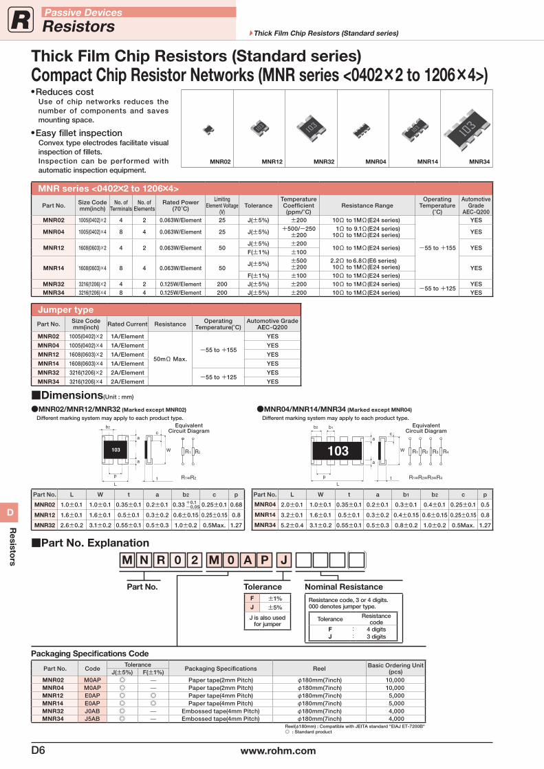
MNR series <0402×2 to 1206×4>
Part No. Size Codemm(inch)
No. ofTerminals
No. ofElements
Rated Power(70°C)
LimitingElement Voltage
(V)Tolerance
Temperature Coefficient(ppm/°C)
Resistance RangeOperating
Temperature(°C)
AutomotiveGrade
AEC-Q200MNR02 1005(0402)×2 4 2 0.063W/Element 25 J(±5%) ±200 10Ω to 1MΩ(E24 series)
-55 to +155
YES
MNR04 1005(0402)×4 8 4 0.063W/Element 25 J(±5%) +500/-250±200
1Ω to 9.1Ω(E24 series) 10Ω to 1MΩ(E24 series) YES
MNR12 1608(0603)×2 4 2 0.063W/Element 50J(±5%) ±200
10Ω to 1MΩ(E24 series) YESF(±1%) ±100
MNR14 1608(0603)×4 8 4 0.063W/Element 50J(±5%) ±500
±200 2.2Ω to 6.8Ω(E6 series) 10Ω to 1MΩ(E24 series) YES
F(±1%) ±100 10Ω to 1MΩ(E24 series)MNR32 3216(1206)×2 4 2 0.125W/Element 200 J(±5%) ±200 10Ω to 1MΩ(E24 series)
-55 to +125YES
MNR34 3216(1206)×4 8 4 0.125W/Element 200 J(±5%) ±200 10Ω to 1MΩ(E24 series) YES
Jumper typePart No. Size Code
mm(inch) Rated Current Resistance Operating Temperature(°C)
Automotive GradeAEC-Q200
MNR02 1005(0402)×2 1A/Element
50mΩ Max.
-55 to +155
YES
MNR04 1005(0402)×4 1A/Element YES
MNR12 1608(0603)×2 1A/Element YES
MNR14 1608(0603)×4 1A/Element YES
MNR32 3216(1206)×2 2A/Element-55 to +125
YES
MNR34 3216(1206)×4 2A/Element YES
Part No. Explanation
Packaging Specifications Code
Part No. CodeTolerance
Packaging Specifications Reel Basic Ordering Unit (pcs)J(±5%) F(±1%)
MNR02 M0AP — Paper tape(2mm Pitch) φ180mm(7inch) 10,000MNR04 M0AP — Paper tape(2mm Pitch) φ180mm(7inch) 10,000MNR12 E0AP Paper tape(4mm Pitch) φ180mm(7inch) 5,000MNR14 E0AP Paper tape(4mm Pitch) φ180mm(7inch) 5,000MNR32 J0AB — Embossed tape(4mm Pitch) φ180mm(7inch) 4,000MNR34 J5AB — Embossed tape(4mm Pitch) φ180mm(7inch) 4,000
Reel(φ180mm) : Compatible with JEITA standard "EIAJ ET-7200B" : Standard product
M N R 0 2 M 0 A P J
Part No. ToleranceF ±1%J ±5%
J is also usedfor jumper
Nominal Resistance
Resistance code, 3 or 4 digits.000 denotes jumper type.
Tolerance Resistancecode
FJ
::
4 digits3 digits
Dimensions(Unit : mm)
MNR02/MNR12/MNR32 (Marked except MNR02)
Different marking system may apply to each product type.
MNR04/MNR14/MNR34 (Marked except MNR04)
Different marking system may apply to each product type.
Part No. L W t a b2 c p
MNR02 1.0±0.1 1.0±0.1 0.35±0.1 0.2±0.1 0.33 +0.1-0.05 0.25±0.1 0.68
MNR12 1.6±0.1 1.6±0.1 0.5±0.1 0.3±0.2 0.6±0.15 0.25±0.15 0.8
MNR32 2.6±0.2 3.1±0.2 0.55±0.1 0.5±0.3 1.0±0.2 0.5Max. 1.27
Part No. L W t a b1 b2 c p
MNR04 2.0±0.1 1.0±0.1 0.35±0.1 0.2±0.1 0.3±0.1 0.4±0.1 0.25±0.1 0.5
MNR14 3.2±0.1 1.6±0.1 0.5±0.1 0.3±0.2 0.4±0.15 0.6±0.15 0.25±0.15 0.8
MNR34 5.2±0.4 3.1±0.2 0.55±0.1 0.5±0.3 0.8±0.2 1.0±0.2 0.5Max. 1.27
MNR02 MNR12 MNR32 MNR04 MNR14 MNR34
Reduces cost Use of chip networks reduces the
number of components and saves mounting space.
Easy fillet inspection Convex type electrodes facilitate visual
inspection of fillets. Inspection can be performed with
automatic inspection equipment.
Compact Chip Resistor Networks (MNR series <0402×2 to 1206×4>)Thick Film Chip Resistors (Standard series)
EquivalentCircuit Diagram
EquivalentCircuit Diagram
D6 www.rohm.com
Passive Devices
Resistors Thick Film Chip Resistors (Standard series)
D
Resisto
rs
Thick Film Chip Resistors (Standard series)
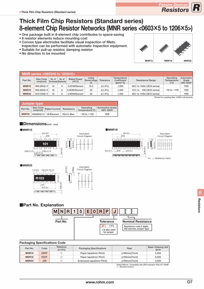
MNR series <0603×5 to 1206×5>
Part No. Size Codemm(inch)
No. ofTerminals
No. ofElements
Rated Power(70°C)
LimitingElement Voltage
(V)Tolerance
Temperature Coefficient(ppm/°C)
Resistance RangeOperating
Temperature(°C)
AutomotiveGrade
AEC-Q200
MNR15 1608 (0603)×5 10 8 0.031W/Element 12.5 J(±5%) ±200 56Ω to 100kΩ(E24 series)
-55 to +125
YES
MNR18 1605 (0602)×8 16 8 0.063W/Element* 25 J(±5%) ±200 10Ω to 1MΩ(E24 series) YES
MNR35 3216 (1206)×5 10 8 0.063W/Element 50 J(±5%) ±200 56Ω to 100kΩ(E12 series) YES
*Power for a packing Max. 0.25W in all elements
Jumper typePart No. Size Code
mm(inch) Rated Current Resistance Operating Temperature(°C)
Automotive GradeAEC-Q200
MNR18 1605(0602)×8 1A/Element 50mΩ Max. -55 to +125 YES
Part No. Explanation
Packaging Specifications Code
Part No. CodeTolerance
Packaging Specifications Reel Basic Ordering Unit (pcs)J(±5%)
MNR15 E0RP Paper tape(4mm Pitch) φ180mm(7inch) 5,000
MNR18 E0AP Paper tape(4mm Pitch) φ180mm(7inch) 5,000
MNR35 J5R Embossed tape(4mm Pitch) φ180mm(7inch) 4,000
Reel(φ180mm) : Compatible with JEITA standard "EIAJ ET-7200B" : Standard product
M N R 1 5 E 0 R P J
Part No. ToleranceJ ±5%
J is also usedfor jumper
Nominal ResistanceResistance code,3 digits,000 denotes Jumper type.
One package built in 8-element chip contributes to space-saving 8 resistor elements reduce mounting cost Convex type electrodes facilitate visual inspection of fillets. Inspection can be performed with automatic inspection equipment.
Suitable for pull-up resistor, damping resistor No direction to be mounted
MNR15 MNR18 MNR35
Dimensions(Unit : mm)
MNR15 MNR183.2±0.1
0.32±0.150.48±0.150.32±0.15
0.64
1.6±
0.1
0.5±
0.1 0.
3±0.
1
0.3±
0.1
EquivalentCircuit Diagram
EquivalentCircuit Diagram
EquivalentCircuit Diagram
101
0.3±0.1
0.3±
0.2
3.8±0.1
(0.5)
(0.2)0.3±0.1
1.6±
0.1
0.45±
0.1
0.3±
0.2
*( ) : Reference Value
MNR35
6.4±0.41 5
0.8±0.2 0.5±0.21.0±0.2
0.5±
0.3
0.5M
ax.
3.1±
0.2
10 6
1.27
R103
0.55±
0.1
8-element Chip Resistor Networks (MNR series <0603×5 to 1206×5>)
D7www.rohm.com
Passive Devices
ResistorsThick Film Chip Resistors (Standard series)
D
Resisto
rs
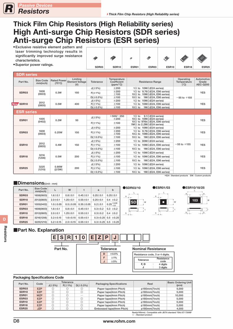
SDR series
Part No. Size Codemm(inch)
Rated Power(70°C)
LimitingElement Voltage
(V)Tolerance
Temperature Coefficient(ppm/°C)
Resistance RangeOperating
Temperature(°C)
AutomotiveGrade
AEC-Q200
SDR03 1608(0603) 0.3W 150
J(±5%) ±200 1Ω to 10MΩ(E24 series)
-55 to +155
YESF(±1%) ±200±100
1Ω to 9.76Ω(E24, E96 series) 10Ω to 10MΩ(E24, E96 series)
D(±0.5%) ±100 10Ω to 1MΩ(E24, E96 series)
SDR10 2012(0805) 0.5W 400
J(±5%) ±200 1Ω to 10MΩ(E24 series)YESF(±1%) ±100 1Ω to 10MΩ(E24, E96 series)
D(±0.5%) ±100 10Ω to 1MΩ(E24, E96 series)
ESR series
ESR01 1005(0402) 0.2W 50
J(±5%) +500/-250±200
1Ω to 9.1Ω(E24 series) 10Ω to 10MΩ(E24 series)
-55 to +155
YESF(±1%) ±100 10Ω to 976kΩ(E24, E96 series)
1MΩ to 2.2MΩ(E24 series)
ESR03 1608(0603) 0.25W 150
J(±5%) ±200 1Ω to 10MΩ(E24 series)
YESF(±1%) ±200±100
1Ω to 9.76Ω(E24, E96 series) 10Ω to 10MΩ(E24, E96 series)
D(±0.5%) ±100 10Ω to 1MΩ(E24, E96 series)
ESR10 2012(0805) 0.4W 150
J(±5%) ±200 1Ω to 30MΩ(E24 series)
YESF(±1%) ±100 1Ω to 10MΩ(E24, E96 series)
D(±0.5%) ±100 10Ω to 1MΩ(E24, E96 series)
ESR18 3216(1206) 0.5W 200
J(±5%) ±200 1Ω to 15MΩ(E24 series)
YESF(±1%) ±100 1Ω to 10MΩ(E24, E96 series)
D(±0.5%) ±100 10Ω to 1MΩ(E24, E96 series)
ESR25 3225(1210)
0.66W(2/3W) 200
J(±5%) ±200 1Ω to 10MΩ(E24 series)
YESF(±1%) ±100 1Ω to 10MΩ(E24, E96 series)
D(±0.5%) ±100 10Ω to 1MΩ(E24, E96 series)*E24 : Standard products E96 : Custom products
Part No. Explanation
Packaging Specifications Code
Part No. CodeTolerance
Packaging Specifications Reel Basic Ordering Unit (pcs)J(±5%) F(±1%) D(±0.5%)
SDR03 EZP Paper tape(4mm Pitch) φ180mm(7inch) 5,000SDR10 EZP Paper tape(4mm Pitch) φ180mm(7inch) 5,000ESR01 MZP Paper tape(4mm Pitch) φ180mm(7inch) 10,000ESR03 EZP Paper tape(4mm Pitch) φ180mm(7inch) 5,000ESR10 EZP Paper tape(4mm Pitch) φ180mm(7inch) 5,000ESR18 EZP Paper tape(4mm Pitch) φ180mm(7inch) 5,000ESR25 JZP Embossed tape(4mm Pitch) φ180mm(7inch) 4,000
Reel(φ180mm) : Compatible with JEITA standard "EIAJ ET-7200B" : Standard product
E S R 1 0 E Z P J
Part No. ToleranceD ±0.5%
F ±1%
J ±5%
Nominal Resistance
Resistance code, 3 or 4 digits.
Tolerance Resistancecode
F, DJ
::
4 digits3 digits
Exclusive resistive element pattern and laser trimming technology results in significantly improved surge resistance characteristics.
Superior power ratings.
High Anti-surge Chip Resistors (SDR series)Anti-surge Chip Resistors (ESR series)
Thick Film Chip Resistors (High Reliability series)
Dimensions(Unit : mm)
Part No. Size Codemm(inch) L W t a b
SDR03 1608(0603) 1.6±0.1 0.8±0.1 0.45±0.1 0.25±0.1 0.25±0.1
SDR10 2012(0805) 2.0±0.1 1.25±0.1 0.55±0.1 0.25±0.1 0.4 ±0.2
ESR01 1005(0402) 1.0±0.05 0.5±0.05 0.35±0.05 0.2±0.1 0.25+0.05 -0.1
ESR03 1608(0603) 1.6±0.1 0.8±0.1 0.45±0.1 0.3±0.2 0.3 ±0.2
ESR10 2012(0805) 2.0±0.1 1.25±0.1 0.55±0.1 0.3±0.2 0.4 ±0.2
ESR18 3216(1206) 3.2±0.15 1.6±0.15 0.55±0.1 0.3±0.25 0.5 ±0.25
ESR25 3225(1210) 3.2±0.15 2.5±0.15 0.55±0.1 0.3±0.25 0.5 ±0.25
b
a
L
a
b
W
t
103
ESR10/18/25ESR01/03
a
W
L
b
t
SDR03/10
a
W
L
b
t
SD
SDR03 SDR10 ESR01 ESR03 ESR10 ESR18 ESR25
D8 www.rohm.com
Passive Devices
Resistors Thick Film Chip Resistors (High Reliability series)
D
Resisto
rs
Part No. Explanation
Packaging Specifications Code
Part No. CodeTolerance
Packaging Specifications Reel Basic Ordering Unit (pcs)J(±5%) F(±1%) D(±0.5%)
LTR10 EZP Paper tape(4mm Pitch) φ180mm(7inch) 5,000
LTR18 EZP Paper tape(4mm Pitch) φ180mm(7inch) 5,000
LTR50 UZP Embossed tape(4mm Pitch) φ180mm(7inch) 5,000
LTR100 JZP Embossed tape(4mm Pitch) φ180mm(7inch) 4,000
Reel(φ180mm) : Compatible with JEITA standard "EIAJ ET-7200B" : Standard product
L T R 1 8 E Z P J
Part No. ToleranceD ±0.5%F ±1%J ±5%
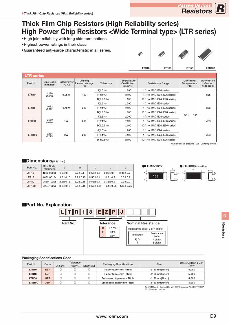
LTR series
Part No. Size Codemm(inch)
Rated Power(70°C)
LimitingElement Voltage
(V)Tolerance
Temperature Coefficient(ppm/°C)
Resistance RangeOperating
Temperature(°C)
AutomotiveGrade
AEC-Q200
LTR10 1220(0508) 0.25W 150
J(±5%) ±200 1Ω to 1MΩ(E24 series)
-55 to +155
YESF(±1%) ±100 1Ω to 1MΩ(E24, E96 series)
D(±0.5%) ±100 10Ω to 1MΩ(E24, E96 series)
LTR18 1632(0612) 0.75W 200
J(±5%) ±200 1Ω to 1MΩ(E24 series)
YESF(±1%) ±100 1Ω to 1MΩ(E24, E96 series)
D(±0.5%) ±100 10Ω to 1MΩ(E24, E96 series)
LTR50 2550(1020) 1W 200
J(±5%) ±200 1Ω to 1MΩ(E24 series)
YESF(±1%) ±100 1Ω to 1MΩ(E24, E96 series)
D(±0.5%) ±100 10Ω to 1MΩ(E24, E96 series)
LTR100 3264(1225) 2W 200
J(±5%) ±200 1Ω to 1MΩ(E24 series)
YESF(±1%) ±100 1Ω to 1MΩ(E24, E96 series)
D(±0.5%) ±100 10Ω to 1MΩ(E24, E96 series)
*E24 : Standard products E96 : Custom products
Nominal Resistance
Resistance code, 3 or 4 digits.
Tolerance Resistancecode
F, DJ
::
4 digits3 digits
Dimensions(Unit : mm)
Part No. Size Codemm(inch) L W t a b
LTR10 1220(0508) 1.2±0.1 2.0±0.1 0.55±0.1 0.25±0.1 0.35±0.2
LTR18 1632(0612) 1.6±0.15 3.2±0.15 0.55±0.1 0.3±0.2 0.5±0.2
LTR50 2550(1020) 2.5±0.15 5.0±0.15 0.55±0.1 0.38±0.2 0.9±0.2
LTR100 3264(1225) 3.2±0.15 6.4±0.15 0.55±0.15 0.4±0.25 1.13±0.25
b
a
L
a
b
W t
b
a
L
a
b
W tLTR10/18/50 LTR100(No marking)
High joint reliability with long side terminations. Highest power ratings in their class. Guaranteed anti-surge characteristic in all series.
LTR10 LTR18 LTR50 LTR100
High Power Chip Resistors <Wide Terminal type> (LTR series)Thick Film Chip Resistors (High Reliability series)
D9www.rohm.com
Passive Devices
ResistorsThick Film Chip Resistors (High Reliability series)
D
Resisto
rs
Part No. Explanation
Packaging Specifications Code
Part No. CodeTolerance
Packaging Specifications Reel Basic Ordering Unit (pcs)J(±5%) F(±1%)
KTR03 EZP Paper tape(4mm Pitch) φ180mm(7inch) 5,000KTR10 EZP Paper tape(4mm Pitch) φ180mm(7inch) 5,000KTR18 EZP Paper tape(4mm Pitch) φ180mm(7inch) 5,000KTR25 JZP Embossed tape(4mm Pitch) φ180mm(7inch) 4,000
Reel(φ180mm) : Compatible with JEITA standard "EIAJ ET-7200B" : Standard product
K T R 1 0 E Z P J
Part No. ToleranceF ±1%
J ±5%
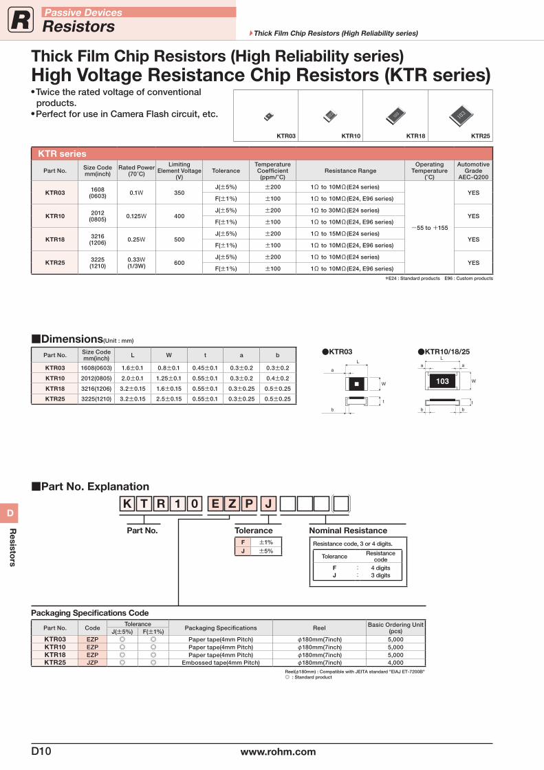
KTR series
Part No. Size Codemm(inch)
Rated Power(70°C)
LimitingElement Voltage
(V)Tolerance
Temperature Coefficient(ppm/°C)
Resistance RangeOperating
Temperature(°C)
AutomotiveGrade
AEC-Q200
KTR03 1608(0603) 0.1W 350
J(±5%) ±200 1Ω to 10MΩ(E24 series)
-55 to +155
YESF(±1%) ±100 1Ω to 10MΩ(E24, E96 series)
KTR10 2012(0805) 0.125W 400
J(±5%) ±200 1Ω to 30MΩ(E24 series)YES
F(±1%) ±100 1Ω to 10MΩ(E24, E96 series)
KTR18 3216(1206) 0.25W 500
J(±5%) ±200 1Ω to 15MΩ(E24 series)YES
F(±1%) ±100 1Ω to 10MΩ(E24, E96 series)
KTR25 3225(1210)
0.33W(1/3W) 600
J(±5%) ±200 1Ω to 10MΩ(E24 series)YES
F(±1%) ±100 1Ω to 10MΩ(E24, E96 series)
*E24 : Standard products E96 : Custom products
Nominal Resistance
Resistance code, 3 or 4 digits.
Tolerance Resistancecode
FJ
::
4 digits3 digits
Twice the rated voltage of conventional products.
Perfect for use in Camera Flash circuit, etc.
KTR03 KTR10 KTR18 KTR25
Dimensions(Unit : mm)
Part No. Size Codemm(inch) L W t a b
KTR03 1608(0603) 1.6±0.1 0.8±0.1 0.45±0.1 0.3±0.2 0.3±0.2
KTR10 2012(0805) 2.0±0.1 1.25±0.1 0.55±0.1 0.3±0.2 0.4±0.2
KTR18 3216(1206) 3.2±0.15 1.6±0.15 0.55±0.1 0.3±0.25 0.5±0.25
KTR25 3225(1210) 3.2±0.15 2.5±0.15 0.55±0.1 0.3±0.25 0.5±0.25
b
a
L
a
b
W
t
103
KTR03 KTR10/18/25
a
W
L
b
t
High Voltage Resistance Chip Resistors (KTR series)Thick Film Chip Resistors (High Reliability series)
D10 www.rohm.com
Passive Devices
Resistors Thick Film Chip Resistors (High Reliability series)
D
Resisto
rs
Part No. Explanation
Packaging Specifications Code
Part No. CodeTolerance
Packaging Specifications Reel Basic Ordering Unit (pcs)J(±5%) F(±1%)
SFR01 MZP Paper tape(2mm Pitch) φ180mm(7inch) 10,000
SFR03 EZP Paper tape(4mm Pitch) φ180mm(7inch) 5,000
SFR10 EZP Paper tape(4mm Pitch) φ180mm(7inch) 5,000
SFR18 EZP Paper tape(4mm Pitch) φ180mm(7inch) 5,000
SFR25 JZP Embossed tape(4mm Pitch) φ180mm(8inch) 4,000
Reel(φ180mm) : Compatible with JEITA standard "EIAJ ET-7200B" : Standard product
S F R 0 3 E Z P J
Part No. ToleranceF ±1%J ±5%
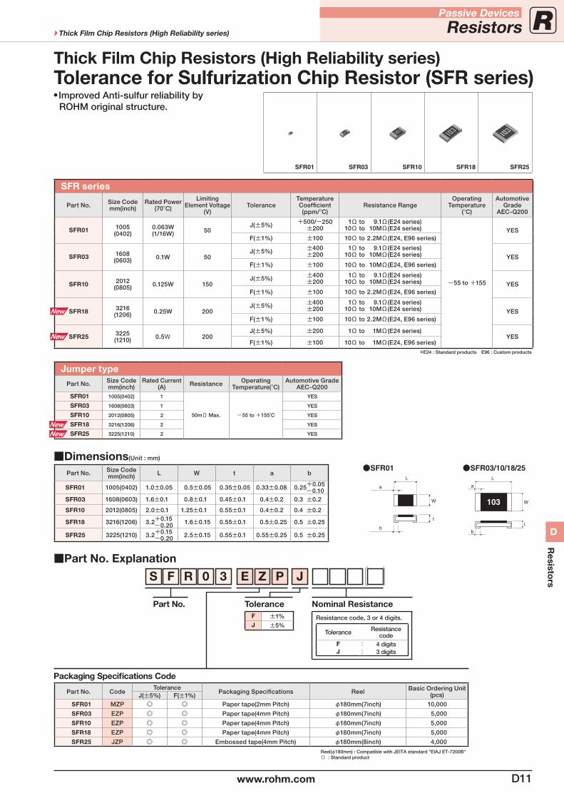
SFR series
Part No. Size Codemm(inch)
Rated Power(70°C)
LimitingElement Voltage
(V)Tolerance
Temperature Coefficient(ppm/°C)
Resistance RangeOperating
Temperature(°C)
AutomotiveGrade
AEC-Q200
SFR01 1005(0402)
0.063W(1/16W) 50
J(±5%) +500/-250±200
1Ω to 9.1Ω(E24 series) 10Ω to 10MΩ(E24 series)
-55 to +155
YESF(±1%) ±100 10Ω to 2.2MΩ(E24, E96 series)
SFR03 1608(0603) 0.1W 50
J(±5%) ±400±200
1Ω to 9.1Ω(E24 series) 10Ω to 10MΩ(E24 series) YES
F(±1%) ±100 10Ω to 10MΩ(E24, E96 series)
SFR10 2012(0805) 0.125W 150
J(±5%) ±400±200
1Ω to 9.1Ω(E24 series) 10Ω to 10MΩ(E24 series) YES
F(±1%) ±100 10Ω to 2.2MΩ(E24, E96 series)
SFR18 3216(1206) 0.25W 200
J(±5%) ±400±200
1Ω to 9.1Ω(E24 series) 10Ω to 10MΩ(E24 series) YES
F(±1%) ±100 10Ω to 2.2MΩ(E24, E96 series)
SFR25 3225(1210) 0.5W 200
J(±5%) ±200 1Ω to 1MΩ(E24 series)YES
F(±1%) ±100 10Ω to 1MΩ(E24, E96 series)
*E24 : Standard products E96 : Custom products
Jumper typePart No. Size Code
mm(inch)Rated Current
(A) Resistance Operating Temperature(°C)
Automotive GradeAEC-Q200
SFR01 1005(0402) 1
50mΩ Max. -55 to +155˚C
YES
SFR03 1608(0603) 1 YES
SFR10 2012(0805) 2 YES
SFR18 3216(1206) 2 YES
SFR25 3225(1210) 2 YES
Nominal Resistance
Resistance code, 3 or 4 digits.
Tolerance Resistancecode
FJ
::
4 digits3 digits
Improved Anti-sulfur reliability by ROHM original structure.
Tolerance for Sulfurization Chip Resistor (SFR series)Thick Film Chip Resistors (High Reliability series)
Dimensions(Unit : mm)
Part No. Size Codemm(inch) L W t a b
SFR01 1005(0402) 1.0±0.05 0.5±0.05 0.35±0.05 0.33±0.08 0.25+0.05 -0.10
SFR03 1608(0603) 1.6±0.1 0.8±0.1 0.45±0.1 0.4±0.2 0.3 ±0.2
SFR10 2012(0805) 2.0±0.1 1.25±0.1 0.55±0.1 0.4±0.2 0.4 ±0.2
SFR18 3216(1206) 3.2+0.15 -0.20 1.6±0.15 0.55±0.1 0.5±0.25 0.5 ±0.25
SFR25 3225(1210) 3.2+0.15 -0.20 2.5±0.15 0.55±0.1 0.55±0.25 0.5 ±0.25
SFR01 SFR03/10/18/25
a
W
L
b
t
b
a
L
W
t
103
SFR01 SFR03 SFR10 SFR18 SFR25
D11www.rohm.com
Passive Devices
ResistorsThick Film Chip Resistors (High Reliability series)
D
Resisto
rs
Chip Resistors for Current Detection (Thick Film type)
Part No. Explanation
Packaging Specifications Code
Part No. CodeTolerance
Packaging Specifications Reel Basic Ordering Unit (pcs)J(±5%) F(±1%)
MCR006 YLP — Paper tape(2mm Pitch) φ180mm(7inch) 15,000MCR01 MZP — Paper tape(2mm Pitch) φ180mm(7inch) 10,000MCR03 EZP — Paper tape(4mm Pitch) φ180mm(7inch) 5,000MCR10 EZH Paper tape(4mm Pitch) φ180mm(7inch) 5,000MCR18 EZH Paper tape(4mm Pitch) φ180mm(7inch) 5,000MCR25 JZH Embossed tape(4mm Pitch) φ180mm(7inch) 4,000MCR50 JZH Embossed tape(4mm Pitch) φ180mm(7inch) 4,000MCR100 JZH Embossed tape(4mm Pitch) φ180mm(7inch) 4,000
Reel(φ180mm) : Compatible with JEITA standard "EIAJ ET-7200B" : Standard product
M C R 1 0 E Z H J L
Part No. ToleranceF ±1%
J ±5%
Special Part Code
L0.1 to 9.1Ω(F)0.1 to 0.91Ω(J)
S 0.047 to 0.091Ω
Nominal Resistance
Resistance code, 3 or 4 digits.
Tolerance+Special P/N
Resistancecode
FL, FS, JSJL
::
4 digits3 digits
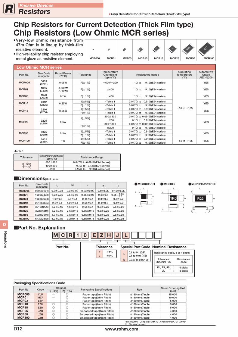
Low Ohmic MCR series
Part No. Size Codemm(inch)
Rated Power(70°C) Tolerance
Temperature Coefficient(ppm/°C)
Resistance RangeOperating
Temperature(°C)
AutomotiveGrade
AEC-Q200
MCR006 0603(0201) 0.05W F(±1%) +600/-200 1Ω to 9.1Ω(E24 series)
-55 to +155
YES
MCR01 1005(0402)
0.063W(1/16W) F(±1%) ±400 1Ω to 9.1Ω(E24 series) YES
MCR03 1608(0603) 0.1W F(±1%) ±400 1Ω to 9.1Ω(E24 series) YES
MCR10 2012(0805) 0.25W
J(±5%) *Table 1 0.047Ω to 0.91Ω(E24 series)YES
F(±1%) *Table 1 0.047Ω to 9.1Ω(E24 series)
MCR18 3216(1206) 0.25W
J(±5%) *Table 1 0.047Ω to 0.91Ω(E24 series)YES
F(±1%) *Table 1 0.047Ω to 9.1Ω(E24 series)
MCR25 3225(1210) 0.5W
J(±5%)300±300 0.047Ω to 0.091Ω(E24 series)
YES±200 0.1Ω to 0.91Ω(E24 series)
F(±1%)300±300 0.047Ω to 0.091Ω(E24 series)
±200 0.1Ω to 9.1Ω(E24 series)
MCR50 5025(2010) 0.5W
J(±5%) *Table 1 0.047Ω to 0.91Ω(E24 series)YES
F(±1%) *Table 1 0.047Ω to 9.1Ω(E24 series)
MCR100 6432(2512) 1W
J(±5%) *Table 1 0.047Ω to 0.91Ω(E24 series)-55 to +125 YES
F(±1%) *Table 1 0.047Ω to 9.1Ω(E24 series)
*Table 1
Tolerance Temperature Coefficient(ppm/°C) Resistance Range
J(±5%)F(±1%)
500±300 0.047Ω to 0.091Ω(E24 Series)400±200 0.1Ω to 0.13Ω(E24 Series)
±250 0.15Ω to 9.1Ω(E24 Series)
MCR006/01 MCR03 MCR10/18/25/50/100
b
a
L
a
b
W
t
R22
a
W
L
b
t
1R0
Dimensions(Unit : mm)
Part No. Size Codemm(inch) L W t a b
MCR006 0603(0201) 0.6±0.03 0.3±0.03 0.23±0.03 0.1±0.05 0.15±0.05
MCR01 1005(0402) 1.0±0.05 0.5±0.05 0.35±0.05 0.2±0.1 0.25 +0.05-0.1
MCR03 1608(0603) 1.6±0.1 0.8±0.1 0.45±0.1 0.3±0.2 0.3±0.2
MCR10 2012(0805) 2.0±0.1 1.25±0.1 0.55±0.1 0.4±0.2 0.4±0.2
MCR18 3216(1206) 3.2±0.15 1.6±0.15 0.55±0.1 0.5±0.25 0.5±0.25
MCR25 3225(1210) 3.2±0.15 2.5±0.15 0.55±0.15 0.5±0.25 0.5±0.25
MCR50 5025(2010) 5.0±0.15 2.5±0.15 0.55±0.15 0.6±0.25 0.6±0.25
MCR100 6432(2512) 6.3±0.15 3.2±0.15 0.55±0.15 0.6±0.25 0.6±0.25
L
a
W
b
t
Very-low ohmic resistance from 47m Ohm is in lineup by thick-film resistive element.
High-reliability chip resistor employing metal glaze as resistive element. MCR006 MCR01 MCR03 MCR10 MCR18 MCR25 MCR50 MCR100
Chip Resistors (Low Ohmic MCR series)
D12 www.rohm.com
Passive Devices
Resistors Chip Resistors for Current Detection (Thick Film type)
D
Resisto
rs
Part No. Explanation
Packaging Specifications Code
Part No. CodeTolerance
Packaging Specifications Reel Basic Ordering Unit(pcs) Remarks
J(±5%) F(±1%)UCR006 YVP Paper tape(2mm Pitch) φ180mm(7inch) 15,000 UCR01 MVP Paper tape(2mm Pitch) φ180mm(7inch) 10,000
UCR03EWP Paper tape(4mm Pitch) φ180mm(7inch) 5,000 20mΩ to 47mΩEVP Paper tape(4mm Pitch) φ180mm(7inch) 5,000 51mΩ to 910mΩ
UCR10 EVH Paper tape(4mm Pitch) φ180mm(7inch) 5,000 UCR18 EVH Paper tape(4mm Pitch) φ180mm(7inch) 5,000
Reel(φ180mm) : Compatible with JEITA standard "EIAJ ET-7200B" : Standard product
U C R 1 0 E V H F S
Part No. ToleranceF ±1%
J ±5%
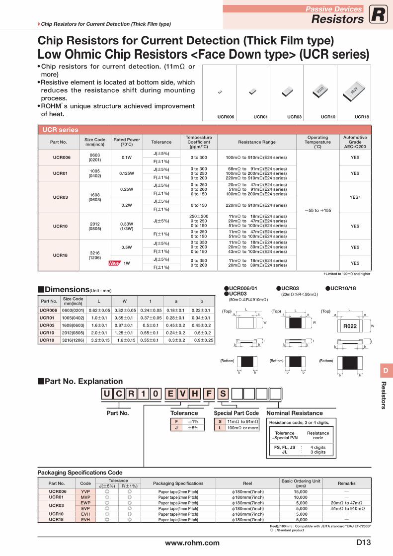
UCR series
Part No. Size Codemm(inch)
Rated Power(70°C) Tolerance
Temperature Coefficient(ppm/°C)
Resistance RangeOperating
Temperature(°C)
AutomotiveGrade
AEC-Q200
UCR006 0603(0201) 0.1W
J(±5%)0 to 300 100mΩ to 910mΩ(E24 series)
-55 to +155
YESF(±1%)
UCR01 1005(0402) 0.125W
J(±5%) 0 to 3000 to 2500 to 200
68mΩ to 91mΩ(E24 series) 100mΩ to 200mΩ(E24 series) 220mΩ to 910mΩ(E24 series)
YESF(±1%)
UCR03 1608(0603)
0.25WJ(±5%) 0 to 250
0 to 2000 to 150
20mΩ to 47mΩ(E24 series) 51mΩ to 91mΩ(E24 series) 100mΩ to 200mΩ(E24 series)
YES*F(±1%)
0.2WJ(±5%)
0 to 150 220mΩ to 910mΩ(E24 series)F(±1%)
UCR10 2012(0805)
0.33W(1/3W)
J(±5%)250±2000 to 2500 to 150
11mΩ to 18mΩ(E24 series) 20mΩ to 47mΩ(E24 series) 51mΩ to 100mΩ(E24 series) YES
F(±1%) 0 to 2500 to 150
11mΩ to 47mΩ(E24 series) 51mΩ to 100mΩ(E24 series)
UCR18 3216(1206)
0.5WJ(±5%) 0 to 350
0 to 2000 to 150
11mΩ to 18mΩ(E24 series) 20mΩ to 39mΩ(E24 series) 43mΩ to 100mΩ(E24 series)
YESF(±1%)
1WJ(±5%) 0 to 350
0 to 200 11mΩ to 18mΩ(E24 series) 20mΩ to 39mΩ(E24 series) YES
F(±1%)*Limited to 100mΩ and higher
Special Part CodeS 11mΩ to 91mΩL 100mΩ or more
Nominal Resistance
Resistance code, 3 or 4 digits.
Tolerance+Special P/N
Resistancecode
FS, FL, JSJL
::
4 digits3 digits
Chip resistors for current detection. (11mΩ or more)
Resistive element is located at bottom side, which reduces the resistance shift during mounting process.
ROHM’s unique structure achieved improvement of heat. UCR006 UCR01 UCR03 UCR10 UCR18
Dimensions(Unit : mm)
Part No. Size Codemm(inch) L W t a b
UCR006 0603(0201) 0.62±0.05 0.32±0.05 0.24±0.05 0.18±0.1 0.22±0.1
UCR01 1005(0402) 1.0±0.1 0.55±0.1 0.37±0.05 0.28±0.1 0.34±0.1
UCR03 1608(0603) 1.6±0.1 0.87±0.1 0.5±0.1 0.45±0.2 0.45±0.2
UCR10 2012(0805) 2.0±0.1 1.25±0.1 0.55±0.1 0.24±0.2 0.5±0.2
UCR18 3216(1206) 3.2±0.15 1.6±0.15 0.55±0.1 0.3±0.2 0.9±0.25
UCR006/01UCR03
(50mΩ≦R≦910mΩ)
UCR10/18UCR03(20mΩ≦R<50mΩ)
b
b b
b
a aL
W
t
(Top)
(Bottom)
(Top)
(Bottom)
b
b b
a
L
a
b
W
t
R022
(Top)
(Bottom)
tb b
b b
a aL
W
Low Ohmic Chip Resistors <Face Down type> (UCR series)Chip Resistors for Current Detection (Thick Film type)
D13www.rohm.com
Passive Devices
ResistorsChip Resistors for Current Detection (Thick Film type)
D
Resisto
rs
Chip Resistors for Current Detection (Thick Film type)
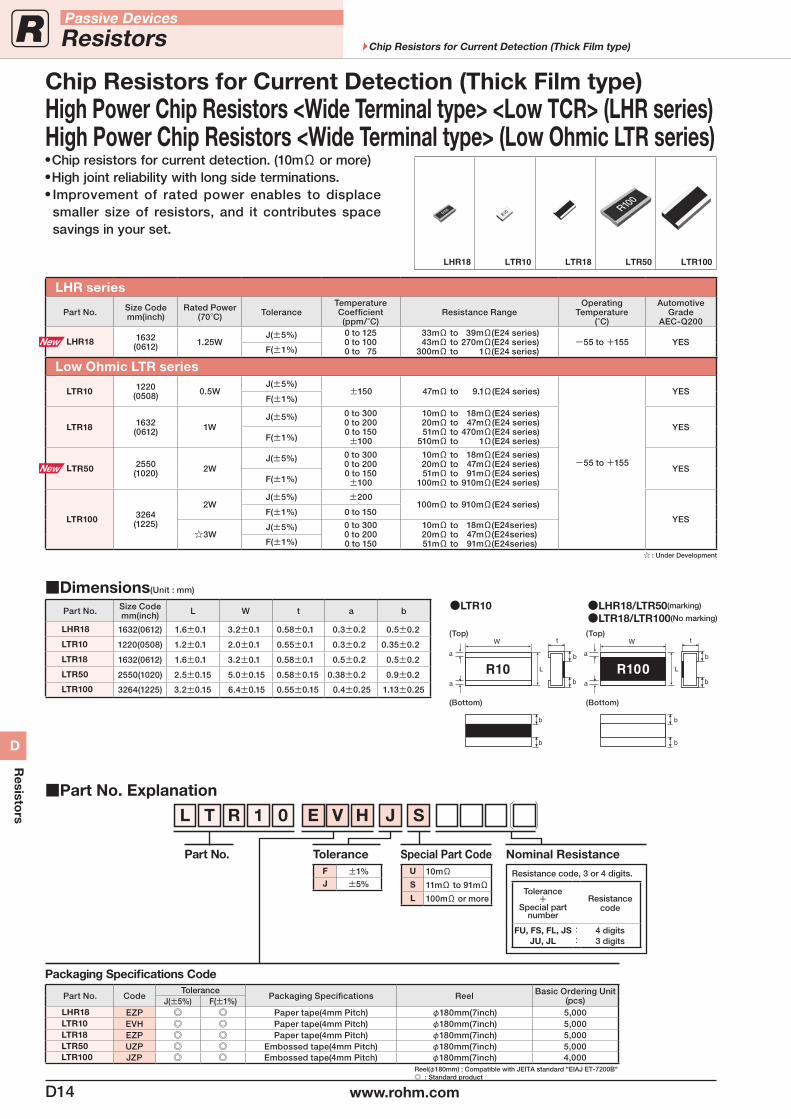
Chip resistors for current detection. (10mΩ or more) High joint reliability with long side terminations. Improvement of rated power enables to displace
smaller size of resistors, and it contributes space savings in your set.
Part No. Explanation
Packaging Specifications Code
Part No. CodeTolerance
Packaging Specifications Reel Basic Ordering Unit (pcs)J(±5%) F(±1%)
LHR18 EZP Paper tape(4mm Pitch) φ180mm(7inch) 5,000LTR10 EVH Paper tape(4mm Pitch) φ180mm(7inch) 5,000LTR18 EZP Paper tape(4mm Pitch) φ180mm(7inch) 5,000LTR50 UZP Embossed tape(4mm Pitch) φ180mm(7inch) 5,000LTR100 JZP Embossed tape(4mm Pitch) φ180mm(7inch) 4,000
Reel(φ180mm) : Compatible with JEITA standard "EIAJ ET-7200B" : Standard product
L T R 1 0 E V H J S
Part No. ToleranceF ±1%J ±5%
LHR series
Part No. Size Codemm(inch)
Rated Power(70°C) Tolerance
Temperature Coefficient(ppm/°C)
Resistance RangeOperating
Temperature(°C)
AutomotiveGrade
AEC-Q200
LHR18 1632(0612) 1.25W
J(±5%) 0 to 1250 to 1000 to 75
33mΩ to 39mΩ(E24 series) 43mΩ to 270mΩ(E24 series) 300mΩ to 1Ω(E24 series)
-55 to +155 YESF(±1%)
Low Ohmic LTR series
LTR10 1220(0508) 0.5W
J(±5%)±150 47mΩ to 9.1Ω(E24 series)
-55 to +155
YESF(±1%)
LTR18 1632(0612) 1W
J(±5%) 0 to 3000 to 2000 to 150±100
10mΩ to 18mΩ(E24 series) 20mΩ to 47mΩ(E24 series) 51mΩ to 470mΩ(E24 series) 510mΩ to 1Ω(E24 series)
YESF(±1%)
LTR50 2550(1020) 2W
J(±5%) 0 to 3000 to 2000 to 150±100
10mΩ to 18mΩ(E24 series) 20mΩ to 47mΩ(E24 series) 51mΩ to 91mΩ(E24 series) 100mΩ to 910mΩ(E24 series)
YESF(±1%)
LTR100 3264(1225)
2WJ(±5%) ±200
100mΩ to 910mΩ(E24 series)
YESF(±1%) 0 to 150
3W J(±5%) 0 to 300
0 to 2000 to 150
10mΩ to 18mΩ(E24series) 20mΩ to 47mΩ(E24series) 51mΩ to 91mΩ(E24series)F(±1%)
: Under Development
Special Part CodeU 10mΩS 11mΩ to 91mΩL 100mΩ or more
Nominal Resistance
Resistance code, 3 or 4 digits.
Tolerance+
Special partnumber
Resistancecode
FU, FS, FL, JSJU, JL
::
4 digits3 digits
Dimensions(Unit : mm)
Part No. Size Codemm(inch) L W t a b
LHR18 1632(0612) 1.6±0.1 3.2±0.1 0.58±0.1 0.3±0.2 0.5±0.2
LTR10 1220(0508) 1.2±0.1 2.0±0.1 0.55±0.1 0.3±0.2 0.35±0.2
LTR18 1632(0612) 1.6±0.1 3.2±0.1 0.58±0.1 0.5±0.2 0.5±0.2
LTR50 2550(1020) 2.5±0.15 5.0±0.15 0.58±0.15 0.38±0.2 0.9±0.2
LTR100 3264(1225) 3.2±0.15 6.4±0.15 0.55±0.15 0.4±0.25 1.13±0.25
LTR10 LHR18/LTR50(marking)
LTR18/LTR100(No marking)
(Top)
b
a
L
a
b
b
b
W t
(Bottom)
(Top)
(Bottom)
b
a
L
a
b
b
b
W t
High Power Chip Resistors <Wide Terminal type> <Low TCR> (LHR series)High Power Chip Resistors <Wide Terminal type> (Low Ohmic LTR series)
LHR18 LTR10 LTR18 LTR50 LTR100
D14 www.rohm.com
Passive Devices
Resistors Chip Resistors for Current Detection (Thick Film type)
D
Resisto
rs
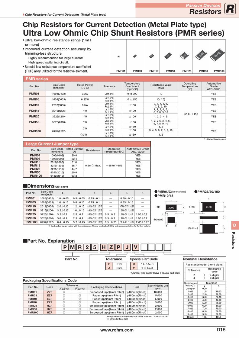
PMR series
Part No. Size Codemm(inch)
Rated Power(70°C) Tolerance
Temperature Coefficient(ppm/°C)
Resistance Value(mΩ)
OperatingTemperature
(°C)
AutomotiveGrade
AEC-Q200
PMR01 1005(0402) 0.2W J(±5%) 0 to 200 10
-55 to +155
YES
PMR03 1608(0603) 0.25W J(±5%)F(±1%) 0 to 150 10(5) YES
PMR10 2012(0805) 0.5W J(±5%)F(±1%) ±150 2, 3, 4, 5, 6,
7, 8, 9, 10 YES
PMR18 3216(1206) 1W J(±5%)F(±1%) ±100 1, 2, 3, 4, 5,
6, 7, 8, 9, 10 YES
PMR25 3225(1210) 1W J(±5%)F(±1%) ±100 1, 2, 3, 4, 5 YES
PMR50 5025(2010) 1W J(±5%)F(±1%) ±100 1, 2, 2.5, 3, 4, 5,
6, 7, 8, 9, 10 YES
PMR100 6432(2512)2W J(±5%)
F(±1%)±150 1, 2
YES±100 3, 4, 5, 6, 7, 8, 9, 10
3W J(±5%)F(±1%) ±150 1, 2
: Under Development
Large Current Jumper typePart No. Size Code
mm(inch)Rated Current
(A) Resistance OperatingTemperature(°C)
Automotive GradeAEC-Q200
PMR01 1005(0402) 20.0
0.5mΩ Max. -55 to +155
YESPMR03 1608(0603) 22.4 YESPMR10 2012(0805) 31.6 YESPMR18 3216(1206) 38.7 YESPMR25 3225(1210) 44.7 YESPMR50 5025(2010) 50.0 YESPMR100 6432(2512) 63.2 YES
Part No. Explanation
Packaging Specifications Code
Part No. CodeTolerance
Packaging Specifications Reel Basic Ordering Unit (pcs)J(±5%) F(±1%)
PMR01 ZZP — Embossed tape(2mm Pitch) φ180mm(7inch) 10,000PMR03 EZP Paper tape(4mm Pitch) φ180mm(7inch) 5,000PMR10 EZP Paper tape(4mm Pitch) φ180mm(7inch) 5,000PMR18 EZP Paper tape(4mm Pitch) φ180mm(7inch) 5,000PMR25 HZP Embossed tape(4mm Pitch) φ180mm(7inch) 2,000PMR50 HZP Embossed tape(4mm Pitch) φ180mm(7inch) 2,000PMR100 HZP Embossed tape(4mm Pitch) φ180mm(7inch) 2,000
Reel(φ180mm) : Compatible with JEITA standard "EIAJ ET-7200B" : Standard product
P M R 2 5 H Z P J V
Part No. ToleranceF ±1%J ±5%
Special Part CodeU 5 to 10mΩV 1 to 4mΩ
Nominal ResistanceResistance code, 3 or 4 digits.
Tolerance Resistancecode
FJ
::
4 digits3 digits
ResistanceValue(Ω)
ToleranceJ F
Jumper 000 —1mΩ 1L0 1L002mΩ 2L0 2L003mΩ 3L0 3L004mΩ 4L0 4L005mΩ 5L0 5L006mΩ 6L0 6L007mΩ 7L0 7L008mΩ 8L0 8L009mΩ 9L0 9L0010mΩ 10L 10L0
Ultra low-ohmic resistance range (1mΩ or more)
Improved current detection accuracy by trimming-less structure.
Highly recommended for large current/High speed switching circuit.
Special low resistance temperature coefficient (TCR) alloy utilized for the resistive element. PMR01 PMR03 PMR10 PMR18 PMR25 PMR50 PMR100
Dimensions(Unit : mm)
Part No. Size Codemm(inch) L W t a b c
PMR01 1005(0402) 1.0±0.05 0.5±0.05 0.25±0.1 — 0.30±0.10 —PMR03 1608(0603) 1.6±0.15 0.8±0.15 0.25±0.1 — 0.35±0.15 —PMR10 2012(0805) 2.0±0.15 1.2±0.15 0.42 to 0.28*±0.15 — 0.75 to 0.35*±0.25 —PMR18 3216(1206) 3.2±0.15 1.6±0.15 0.42 to 0.28*±0.15 — 1.20 to 0.5 *±0.25 —PMR25 3225(1210) 3.2±0.2 2.5±0.2 0.52 to 0.32*±0.15 0.5±0.2 1.00 to 0.8 *±0.2 1.95±0.2
PMR50 5025(2010) 5.0±0.2 2.5±0.2 0.52 to 0.32*±0.15 0.5±0.2 1.85 to 0.9 *±0.2 1.95±0.2
PMR100 6432(2512) 6.4±0.25 3.2±0.25 0.52 to 0.32*±0.15 0.5±0.25 2.3 to 1.1 *±0.25 2.65±0.25* Each value range varies with the resistance. Please contact a ROHM sales representative for further details.
PMR01/03(No marking) PMR25/50/100PMR10/18
b
a
t
w
L
c
2L00(Top)(Top)
(Bottom)
(Bottom)
*Jumper type doesn't have a special part code
Ultra Low Ohmic Chip Shunt Resistors (PMR series)Chip Resistors for Current Detection (Metal Plate type)
D15www.rohm.com
Passive Devices
ResistorsChip Resistors for Current Detection (Metal Plate type)
D
Resisto
rs
Chip Resistors for Current Detection (Metal Plate type)
Part No. Explanation
Packaging Specifications Code
Part No. CodeTolerance
Packaging Specifications Reel Basic Ordering Unit (pcs)J(±5%) G(±2%)
PML10 EZP Paper tape(4mm Pitch) φ180mm(7inch) 5,000
PML18 EZP Paper tape(4mm Pitch) φ180mm(7inch) 5,000
PML50 HZP — Embossed tape(4mm Pitch) φ180mm(7inch) 2,000
PML100 HZP — Embossed tape(4mm Pitch) φ180mm(7inch) 2,000Reel(φ180mm) : Compatible with JEITA standard "EIAJ ET-7200B" : Standard product
P M L 5 0 H Z P J V
Part No. ToleranceG ±2%J ±5%
Special Part Code
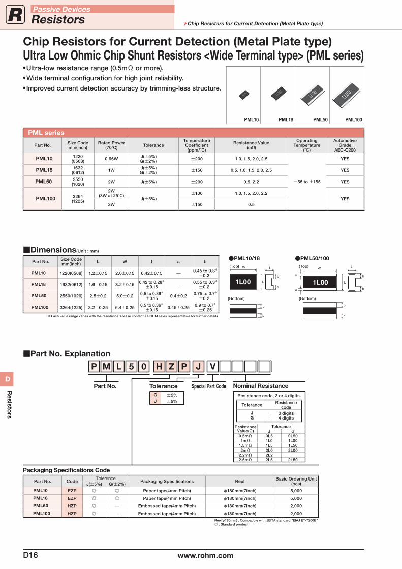
PML series
Part No. Size Codemm(inch)
Rated Power(70°C) Tolerance
Temperature Coefficient(ppm/°C)
Resistance Value(mΩ)
OperatingTemperature
(°C)
AutomotiveGrade
AEC-Q200
PML10 1220 (0508) 0.66W J(±5%)
G(±2%) ±200 1.0, 1.5, 2.0, 2.5
-55 to +155
YES
PML18 1632(0612) 1W J(±5%)
G(±2%) ±150 0.5, 1.0, 1.5, 2.0, 2.5 YES
PML50 2550(1020) 2W J(±5%) ±200 0.5, 2.2 YES
PML100 3264(1225)
2W(3W at 25°C)
J(±5%)±100 1.0, 1.5, 2.0, 2.2
YES2W ±150 0.5
Dimensions(Unit : mm)
Part No. Size Codemm(inch) L W t a b
PML10 1220(0508) 1.2±0.15 2.0±0.15 0.42±0.15 — 0.45 to 0.3*±0.2
PML18 1632(0612) 1.6±0.15 3.2±0.15 0.42 to 0.28*±0.15 — 0.55 to 0.3*
±0.2
PML50 2550(1020) 2.5±0.2 5.0±0.2 0.5 to 0.36*±0.15 0.4±0.2 0.75 to 0.7*
±0.2
PML100 3264(1225) 3.2±0.25 6.4±0.25 0.5 to 0.36*±0.15 0.45±0.25 0.9 to 0.7*
±0.25* Each value range varies with the resistance. Please contact a ROHM sales representative for further details.
PML50/100PML10/18
a
a b
b
b
b
t
L
W
1L00
(Top)
(Bottom)
(Top)
(Bottom)
Nominal Resistance
Resistance code, 3 or 4 digits.
Tolerance Resistancecode
JG
::
3 digits4 digits
ResistanceValue(Ω)
ToleranceJ G
0.5mΩ 0L5 0L501mΩ 1L0 1L00
1.5mΩ 1L5 1L502mΩ 2L0 2L00
2.2mΩ 2L2 2.5mΩ 2L5 2L50
Ultra-low resistance range (0.5mΩ or more). Wide terminal configuration for high joint reliability. Improved current detection accuracy by trimming-less structure.
PML10 PML18 PML50 PML100
Ultra Low Ohmic Chip Shunt Resistors <Wide Terminal type> (PML series)
D16 www.rohm.com
Passive Devices
Resistors Chip Resistors for Current Detection (Metal Plate type)
D
Resisto
rs
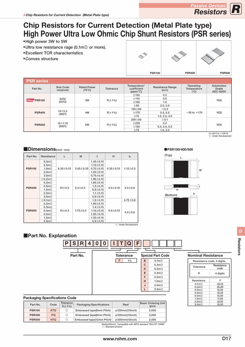
PSR series
Part No. Size Codemm(inch)
Rated Power(70°C) Tolerance
Temperature*
coefficient(ppm/°C)
Resistance Range(mΩ)
OperatingTemperature
(°C)
AutomotiveGrade
AEC-Q200
PSR100 6432(2512) 3W F(±1%)
±150 0.3
-55 to +170
YES±115 0.5±100 1.0±50 2.0, 3.0
PSR400 10×5.2(3921) 4W F(±1%)
125±50 0.2YES±175 0.3, 0.5
±75 1.0, 2.0, 3.0
PSR500 15×7.75(5931) 5W F(±1%)
200±50 0.1
YES±225 0.2±150 0.3, 0.4, 0.5±75 1.0, 2.0
*(+20°C to +125°C) : Under Development
Part No. Explanation
Packaging Specifications Code
Part No. CodeTolerance
Packaging Specifications Reel Basic Ordering Unit (pcs)F(±1%)
PSR100 KTQ Embossed tape(8mm Pitch) φ330mm(13inch) 5,000
PSR400 ITQ Embossed tape(8mm Pitch) φ330mm(13inch) 3,000
PSR500 HTQ Embossed tape(12mm Pitch) φ330mm(13inch) 2,000
Reel(φ330mm) : Compatible with JEITA standard "EIAJ ET-7200B" : Standard product
P S R 4 0 I T Q F
Part No. ToleranceF 1%
Special Part CodeB 0.1mΩC 0.2mΩD 0.3mΩE 0.4mΩF 0.5mΩH 1.0mΩJ 2.0mΩL 3.0mΩ
Nominal ResistanceResistance code, 4 digits.
Tolerance Resistancecode
F : 4 digits
Resistance F0.1mΩ 0L100.2mΩ 0L200.3mΩ 0L300.4mΩ 0L400.5mΩ 0L501.0mΩ 1L002.0mΩ 2L003.0mΩ 3L00
High power 3W to 5W Ultra low resistance rage (0.1mΩ or more). Excellent TCR characterristics Convex structure
0
Dimensions(Unit : mm)
Part No. Resistance L W t H b
PSR100
0.3mΩ
6.35±0.15 3.05±0.25
1.45±0.15
0.35±0.15 1.12±0.30.5mΩ 1.15±0.151.0mΩ 0.75±0.152.0mΩ 1.00±0.153.0mΩ 0.75±0.15
PSR400
0.2mΩ
10±0.3 5.2±0.3
1.96±0.15
0.5±0.15 2.0±0.6
0.3mΩ 1.85±0.150.5mΩ 1.3±0.151.0mΩ 0.9±0.152.0mΩ 1.1±0.153.0mΩ 0.9±0.15
PSR500
0.1mΩ
15±0.3 7.75±0.3
1.9±0.15
0.5±0.15
4.75±0.60.2mΩ 1.85±0.15
4.0±0.6
0.3mΩ 1.4±0.150.4mΩ 1.15±0.150.5mΩ 1.05±0.151.0mΩ 1.35±0.152.0mΩ 0.9±0.15
: Under Development
PSR100/400/500
(Top)
(Bottom)
W
L
b
tH
High Power Ultra Low Ohmic Chip Shunt Resistors (PSR series)Chip Resistors for Current Detection (Metal Plate type)
PSR100 PSR400 PSR500
D17www.rohm.com
Passive Devices
ResistorsChip Resistors for Current Detection (Metal Plate type)
D
Resisto
rs
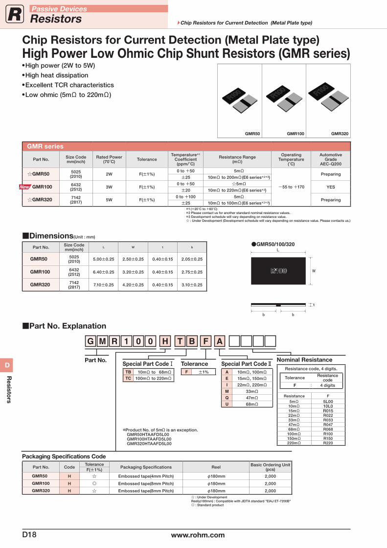
Chip Resistors for Current Detection (Metal Plate type)High Power Low Ohmic Chip Shunt Resistors (GMR series) High power (2W to 5W) High heat dissipation Excellent TCR characteristics Low ohmic (5mΩ to 220mΩ)
GMR series
Part No. Size Codemm(inch)
Rated Power(70°C) Tolerance
Temperature*1
Coefficient(ppm/°C)
Resistance Range(mΩ)
OperatingTemperature
(°C)
AutomotiveGrade
AEC-Q200
GMR50 5025(2010) 2W F(±1%)
0 to +50 5mΩ
-55 to +170
Preparing±25 10mΩ to 200mΩ(E6 series*2*3)
GMR100 6432(2512) 3W F(±1%)
0 to +50 5mΩYES
±20 10mΩ to 220mΩ(E6 series*2)
GMR320 7142(2817) 5W F(±1%)
0 to +100 5mΩPreparing
±25 10mΩ to 100mΩ(E6 series*2*3)*1 (+20°C to +60°C)*2 Please contact us for another standard nominal resistance values.*3 Development schedule will vary depending on resistance value. : Under Development (Development schedule will vary depending on resistance value. Please contacts us.)
Dimensions(Unit : mm)
Part No. Size Codemm(inch)
L W t b
GMR50 5025(2010) 5.00±0.25 2.50±0.25 0.40±0.15 2.05±0.25
GMR100 6432(2512) 6.40±0.25 3.20±0.25 0.40±0.15 2.75±0.25
GMR320 7142(2817) 7.10±0.25 4.20±0.25 0.40±0.15 3.10±0.25
GMR50/100/320
GMR50 GMR100 GMR320
Part No. Explanation
Packaging Specifications Code
Part No. CodeTolerance
Packaging Specifications Reel Basic Ordering Unit (pcs)F(±1%)
GMR50 H Embossed tape(4mm Pitch) φ180mm 2,000
GMR100 H Embossed tape(8mm Pitch) φ180mm 2,000
GMR320 H Embossed tape(8mm Pitch) φ180mm 2,000 : Under DevelopmentReel(φ180mm) : Compatible with JEITA standard "EIAJ ET-7200B" : Standard product
G M R 1 0 H T B F A
Part No.Special Part CodeⅠ
TB 10mΩ to 68mΩTC 100mΩ to 220mΩ
ToleranceF ±1%
Special Part CodeⅡA 10mΩ, 100mΩE 15mΩ, 150mΩI 22mΩ, 220mΩ
M 33mΩQ 47mΩU 68mΩ
0
Nominal ResistanceResistance code, 4 digits.
Tolerance Resistancecode
F : 4 digits
Resistance F5mΩ 5L0010mΩ 10L015mΩ R01522mΩ R02233mΩ R03347mΩ R04768mΩ R068100mΩ R100150mΩ R150220mΩ R220
*Product No. of 5mΩ is an exception. GMR50HTAAFD5L00 GMR100HTAAFD5L00 GMR320HTAAFD5L00
D18 www.rohm.com
Passive Devices
Resistors Chip Resistors for Current Detection (Metal Plate type)
D
Resisto
rs
Standard Nominal Resistance ValuesE3 10 22 47
E6 10 15 22 33 47 68
E12 10 12 15 18 22 27 33 39 47 56 68 82
E2410 11 12 13 15 16 18 20 22 24 27 30 33 36 39 43 47
51 56 62 68 75 82 91
E96
100 102 105 107 110 113 115 118 121 124 127 130 133 137 140 143 147
150 154 158 162 165 169 174 178 182 187 191 196 200 205 210 215 221
226 232 237 243 249 255 261 267 274 280 287 294 301 309 316 324 332
340 348 357 365 374 383 392 402 412 422 432 442 453 464 475 487 499
511 523 536 549 562 576 590 604 619 634 649 665 681 698 715 732 750
768 787 806 825 845 866 887 909 931 953 976
Nominal ResistanceResistors of a series fall into one of nominal resistance ranges shown in the table above. Nominal resistance is determined by the common ratio shown right.
Resistance CodingNominal resistance is expressed in 3 digits when the resistance tolerance is ±5% and in 4 digits when ±1%.The leading 2 or 3 digits indicate significant figure while the last digit indicates the number of zeros. The letter R or L denotes the decimal point if necessary.
Ex.1 22Ω→22×100Ω→220 (the last digit indicates the number "0" of a multiplier)Ex.2 47kΩ→47×103Ω→473 (the last digit indicates the number "3" of a multiplier)Ex.3 1.2MΩ→12×105Ω→125 (the last digit indicates the number "5" of a multiplier)Ex.4 2.7Ω→2R7 (the decimal point indicate the letter R/the letter R apply to the low Resistance less than 10Ω)Ex.5 1130Ω→113×101Ω→1131 (the last digit indicates the number "1" of a multiplier/Resistance Tolerance 1%(F) products)Ex.6 0.10Ω→R10Ex.7 1mΩ→1L0
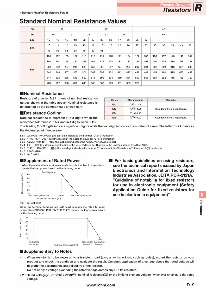
Supplement of Rated Power・When the ambient temperature exceeds the rated ambient temperature, derate the load power based on the derating curve.
For basic guidelines on using resistors, see the technical reports issued by Japan Electronics and Information Technology Industries Association. JEITA RCR-2121A. “Guideline of notabilia for fixed resistors
for use in electronic equipment (Safety Application Guide for fixed resistors for use in electronic equipment)”
(PSR100, GMR100)
When the terminal temperature with load exceeds the rated terminal temperature(PSR100:140°C, GMR100:110°C), derate the load power based on the derating curve.
Supplementary to Notes* 1 : When resistor is to be exposed to a transient load (excessive large load, such as pulse), mount the resistor on your
product and check the condition and evaluate the result. Constant application of a voltage above the rated voltage will degrade the performance and reliability of the resistor.
Do not apply a voltage exceeding the rated voltage across any ROHM resistors.
* 2 : Rated voltage(V) =√rated power(W)×nominal resistance(Ω) or the limiting element voltage, whichever smaller, is the rated voltage.
Series Common ratio Remarks
E6 6√‾10≒1.46
Rounded off to a 2-digit figure.E12 12√‾10≒1.21
E24 24√‾10≒1.10
E96 96√‾10≒1.02 Rounded off to a 3-digit figure.
Min. operatingtemperature
Max. operatingtemperature
Rated terminaltemperatureTerminal temperature(°C)
170
100
80
60
40
20
0
70°C(°C)
D19www.rohm.com
Passive Devices
ResistorsStandard Nominal Resistance Values
D
Resisto
rs

D20 www.rohm.com
Passive Devices
Resistors
D
Resisto
rs
MEMO