Embed Size (px)
Citation preview
8/13/2019 2018374 m Naf
http://slidepdf.com/reader/full/2018374-m-naf 1/174
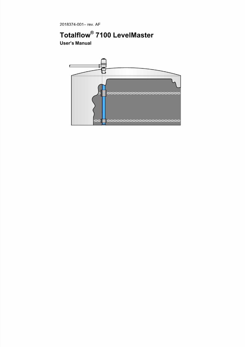
2018374-001– rev. AF
Totalflow ®
7100 LevelMaster
User’s Manual

8/13/2019 2018374 m Naf
http://slidepdf.com/reader/full/2018374-m-naf 2/174
Intellectual Property & Copyright Notice
©2002, 2003,2010 by ABB Inc., Totalflow (“Owner”), Bartlesville, Oklahoma 74006, U.S.A. All rights
reserved.
Any and all derivatives of, including translations thereof, shall remain the sole property of the Owner,
regardless of any circumstances.
The original US English version of this manual shall be deemed the only valid version. Translated
versions, in any other language, shall be maintained as accurately as possible. Should any
discrepancies exist, the US English version will be considered final.
Notice: This publication is for information only. The contents are subject to change without notice and
should not be construed as a commitment, representation, warranty, or guarantee of any method,
product, or device by Owner.
Inquiries regarding this manual should be addressed to ABB Inc., Totalflow Products, Technical
Communications, 7051 Industrial Blvd., Bartlesville, Oklahoma 74006, U.S.A.
8/13/2019 2018374 m Naf
http://slidepdf.com/reader/full/2018374-m-naf 3/174
i
TABLE OF CONTENTS
INTRODUCTION .....................................................................................................VII
Organization & Style...................................................................................................vii
Chapter Descriptions..................................................................................................vii
Getting Help ...............................................................................................................vii
Before Calling..............................................................................................................vii
Key Symbols .............................................................................................................viii
Safety Practices and Precautions .............................................................................viii
Safety Guidelines .......................................................................................................viii Safety First ...................................................................................................................ix Equipment Markings.....................................................................................................ix Grounding the Product .................................................................................................ix Operating Voltage.........................................................................................................ix Danger From Loss of Ground.......................................................................................ix Safe Equipment ............................................................................................................ x
1.0 SYSTEM DESCRIPTION............................................................................ 1–1 1.1 Overview......................................................................................................1–1
1.1.1 Floats........................................................................................................... 1–1 1.1.2 Sensor ......................................................................................................... 1–2 1.1.3 Temperature................................................................................................ 1–2 1.1.4 Data Gathering ............................................................................................1–2 1.1.5 RS-485 ........................................................................................................ 1–2 1.1.6 Optional High Level Auxiliary Switch........................................................... 1–2
1.2 Hazardous Location Installations.................................................................1–3
1.3 General Specifications.................................................................................1–4
1.4 Software Features .......................................................................................1–4
1.5 Host Controller Configurations ....................................................................1–5 1.6 Totalflow Host PROMs ................................................................................1–6
2.0 INSTALLATION.......................................................................................... 2–1
2.1 Unpacking and Inspection ...........................................................................2–1
2.1.1 Unpacking....................................................................................................2–1 2.1.2 Initial Inspection........................................................................................... 2–1 2.1.3 Damaged Components................................................................................2–1 2.1.4 Parts List......................................................................................................2–1 2.1.5 Optional Parts List ....................................................................................... 2–2 2.1.6 Typical Tank Installation..............................................................................2–2
2.2 Pre-Assembled Casing Installation Procedure ............................................ 2–3
2.2.1 Supplied Materials....................................................................................... 2–3 2.2.2 Component Assembly ................................................................................. 2–4 2.2.3 Tank Insertion of Pre-Assembled LevelMaster Unit.................................... 2–5
2.3 High Level Auxiliary Switch Installation ....................................................... 2–6
2.3.1 Overview......................................................................................................2–6 2.3.2 12” & 16” Installation Procedure..................................................................2–7 2.3.3 24” Installation Procedure ...........................................................................2–8
8/13/2019 2018374 m Naf
http://slidepdf.com/reader/full/2018374-m-naf 4/174
ii
2.4 General Wiring .......................................................................................... 2–10
2.4.1 Board Wiring ..............................................................................................2–10 2.4.2 Wiring Interconnect ....................................................................................2–11
2.5 Daisy Chained...........................................................................................2–12
2.5.1 Jumpers .....................................................................................................2–12
2.5.2 Wiring Limitations.......................................................................................2–13 2.6 General Purpose Location Wiring..............................................................2–13
2.6.1 No Host ......................................................................................................2–13 2.6.2 6400 FCU, XFC and XFCG4 Host .............................................................2–14 2.6.3 LMC7100, XRC, and XRCG4 Host............................................................2–14 2.6.4 6700 FCU Host ..........................................................................................2–14 2.6.5 6790 RTU Host ..........................................................................................2–14
2.7 Hazardous Location Wiring ....................................................................... 2–19
2.7.1 Limitations..................................................................................................2–19 2.7.2 Wiring Interconnect ....................................................................................2–21 2.7.3 No Host ......................................................................................................2–21
2.7.4 6400, XFC, or XFCG4 Host .......................................................................2–22 2.7.5 LMC7100, XRC, or XRCG4 Host...............................................................2–22 2.7.6 6700 FCU Host ..........................................................................................2–22 2.7.7 6790 RTU Host ..........................................................................................2–22
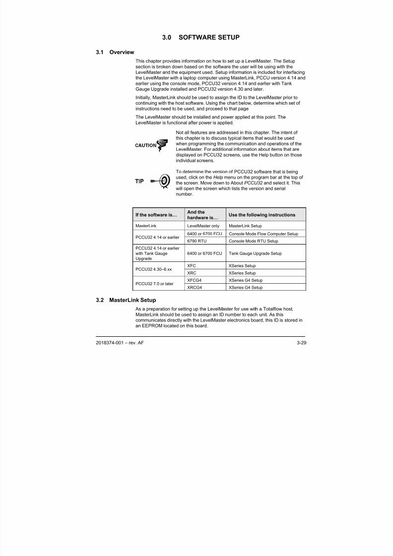
3.0 SOFTWARE SETUP ..................................................................................3-29
3.1 Overview ....................................................................................................3-29
3.2 MasterLink Setup .......................................................................................3-29
3.2.1 Tools Required........................................................................................... 3-30 3.2.2 Instructions................................................................................................. 3-30
3.3 Console Mode Flow Computer Setup.........................................................3-32
3.3.1 Tools Required........................................................................................... 3-33
3.3.2 Instructions................................................................................................. 3-33 3.4 Console Mode RTU Setup .........................................................................3-38
3.4.1 Tools Required........................................................................................... 3-39 3.4.2 Instructions................................................................................................. 3-39
3.5 Tank Gauge Upgrade Setup ......................................................................3-44
3.5.1 Tools Required........................................................................................... 3-44 3.5.2 Instructions................................................................................................. 3-44
3.6 XSeries Setup ............................................................................................3-49
3.6.1 Tools Required........................................................................................... 3-49 3.6.2 Instructions................................................................................................. 3-49
3.7 XSeries G4 Setup.......................................................................................3-54
3.7.1 Tools Required........................................................................................... 3-54 3.7.2 Instructions................................................................................................. 3-54
3.8 Volume Calculations Setup ........................................................................3-61
3.8.1 Strapping Tables........................................................................................ 3-61
3.9 Float Calibration .........................................................................................3-62
3.9.1 MasterLink.................................................................................................. 3-63 3.9.2 Console Mode............................................................................................ 3-63
8/13/2019 2018374 m Naf
http://slidepdf.com/reader/full/2018374-m-naf 5/174
iii
3.9.3 PCCU32 .....................................................................................................3-63
3.10 Data Collection ...........................................................................................3-63
3.10.1 Trending .....................................................................................................3-63
3.11 Duty Cycling Power ....................................................................................3-64
3.11.1 PCCU32 Ver. 4.14 or Earlier ......................................................................3-65
3.11.2 PCCU32 Ver 4.30 or Later .........................................................................3-65 3.11.3 Console Mode ............................................................................................3-65
3.12 Push-to-Read .............................................................................................3-66
3.12.1 Wiring Push to Read Input Button ..............................................................3-66 3.12.2 Console Mode ............................................................................................3-67 3.12.3 XSeries Equipment.....................................................................................3-68
3.13 Remote User Interface (Host Console) ......................................................3-70
3.13.1 Screens ......................................................................................................3-70 3.13.2 Polling.........................................................................................................3-70
3.14 Communications Protocol...........................................................................3-71
4.0 MAINTENANCE & TROUBLESHOOTING.................................................. 4-1
4.1 Replacing the Electronics Board ..................................................................4-1
4.2 Replacing Floats...........................................................................................4-3
4.3 Replacing the Sensor Assembly...................................................................4-4
4.4 Moving a LevelMaster from One Tank to Another........................................4-6
4.5 Troubleshooting a New Installation ..............................................................4-8
4.6 Troubleshooting Existing Installations ........................................................4-10
4.7 Additional Troubleshooting.........................................................................4-11
4.7.1 Tank Level Pass Through ..........................................................................4-13 4.7.2 Testing tv azhe Sensor...............................................................................4-15
APPENDIX A DEFINITIONS AND ACRONYMS........................................A–1 APPENDIX B DRAWINGS SECTION ........................................................B–1
8/13/2019 2018374 m Naf
http://slidepdf.com/reader/full/2018374-m-naf 6/174
iv
TABLE OF FIGURES
Figure 1–1 Typical LevelMaster Oil and Water Tank Installation .......................................................1–1
Figure 1–2 Typical LevelMaster Configuration ...................................................................................1–3
Figure 1–3 LevelMaster Group D Hazardous Location Installation ....................................................1–3
Figure 2–1 LevelMaster Components.................................................................................................2–3
Figure 2–2 Overview of 12” and 16” High Level Auxiliary Switch Installation.....................................2–7 Figure 2–3 Overview of 24” High Level Auxiliary Switch Installation..................................................2–9
Figure 2–4 LevelMaster Electronics Board.......................................................................................2–11
Figure 2–5 RS-485 General Purpose Wiring Interconnect ...............................................................2–12
Figure 2–6 Daisy Chaining General Purpose Wiring Schematic ......................................................2–12
Figure 2–7 RS-485 Termination J1 Wiring........................................................................................2–13
Figure 2–8 LevelMaster to Laptop Computer ...................................................................................2–15
Figure 2–9 LM to 6400, XFC or XFCG4 Comm 1 General Purpose Wiring.....................................2–16
Figure 2–10 LM to 6400, XFC or XFCG4 Comm 1 Comm 2 General Purpose Wiring ....................2–16
Figure 2–11 LM to LMC7100, XRC, or XRCG4 Comm 1 General Purpose Wiring..........................2–17
Figure 2–12 LM to LMC7100, XRC, or XRCG4 Comm 2 General Purpose Wiring..........................2–17
Figure 2–13 6700 FCU General Purpose Wiring..............................................................................2–18 Figure 2–14 6790 RTU General Purpose Wiring..............................................................................2–19
Figure 2–15 LevelMaster Wiring Schematic, Class 1 Division 1, Group D.......................................2–20
Figure 2–16 Totalflow CSA Certified Barrier Board..........................................................................2–20
Figure 2–17 LevelMaster to Barrier Diagram, Class 1, Division 1, Group D ....................................2–21
Figure 2–18 LevelMaster Wiring Schematic, Class 1 Division 1, Group C, D ..................................2–21
Figure 2–19 6400, XFC, or XFCG4 Comm 1 Hazardous Location Wiring .......................................2–23
Figure 2–20 6400, XFC, or XFCG4 Comm 2 Hazardous Location Wiring .......................................2–24
Figure 2–21 LMC, XRC, or XRCG4 COMM 1 Hazardous Location Wiring ......................................2–25
Figure 2–22 6700 FCU Hazardous Location Wiring.........................................................................2–27
Figure 2–23 RTU Hazardous Location Wiring..................................................................................2–28
Figure 3–1 Console Mode, Initial Screen.......................................................................................... 3-34 Figure 3–2 Console Mode, Tank 1 Setup ......................................................................................... 3-35
Figure 3–3 Console Mode, Initial Screen.......................................................................................... 3-40
Figure 3–4 Console Mode, Tank 1 Setup ......................................................................................... 3-41
Figure 3–5 Console Mode, Satellite Port Setup................................................................................ 3-43
Figure 3–6 PCCU32 Software without the Tank Gauge Software Upgrade..................................... 3-46
Figure 3–7 PCCU32 Software with the Tank Gauge Software Upgrade.......................................... 3-46
Figure 3–8 Communication Tab........................................................................................................ 3-51
Figure 3–9 G4 LevelMaster Setup Screen........................................................................................ 3-56
Figure 3–10 G4 LevelMaster Communication Tab ........................................................................... 3-57
Figure 3–11 G4 LevelMaster Request Block .................................................................................... 3-58
Figure 3–12 PCCU32 Save and Restore Screen, Save Station Files .............................................. 3-59 Figure 3–13 PCCU32 Save and Restore Screen, Restore Station Files.......................................... 3-59
Figure 3–14 Host Hardware Digital Outputs ..................................................................................... 3-65
Figure 3–15 Console Mode, Tank Duty Cycle Setup........................................................................ 3-66
Figure 3–16 Host Hardware Digital Inputs ........................................................................................ 3-67
Figure 3–17 Host Console Mode using a Device Template ............................................................. 3-71

8/13/2019 2018374 m Naf
http://slidepdf.com/reader/full/2018374-m-naf 7/174
v
LIST OF TABLES
Table 1—1 Totalflow PROM Configurations ...................................................................................... 1–6
Table 3—1 Console Mode, Local Commands...................................................................................3-34
Table 3—2 Console Mode Tank Setup Parameters..........................................................................3-36
Table 3—3 Communications Port Parameters..................................................................................3-37
Table 3—4 Console Mode, Tank Setup Parameters.........................................................................3-42 Table 3—5 RTU Communication Port Parameters ...........................................................................3-43
Table 3—6 Communication Port Parameters....................................................................................3-47
Table 3—7 Duty Cycle Parameters...................................................................................................3-64
Table 3—8 Push-To-Read Parameters.............................................................................................3-68
Table 3—9 Protocol Explanation (version 3.04 and forward)............................................................3-72
Table 4—1 Troubleshooting New Installations....................................................................................4-8
Table 4—2 Troubleshooting an Existing Installation .........................................................................4-10
Table 4—3 Error Messages (Ver. 5.015 – 5.018) .............................................................................4-12
Table 4—4 Query Commands for TLPT............................................................................................4-13

8/13/2019 2018374 m Naf
http://slidepdf.com/reader/full/2018374-m-naf 8/174
vi
BBBlllaaannnkkk PPPaaagggeee
8/13/2019 2018374 m Naf
http://slidepdf.com/reader/full/2018374-m-naf 9/174
vii
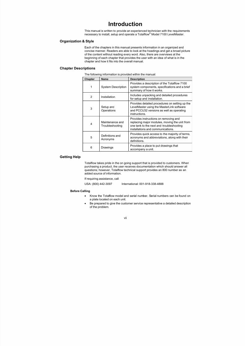
IntroductionThis manual is written to provide an experienced technician with the requirements
necessary to install, setup and operate a Totalflow® Model 7100 LevelMaster.
Organization & Style
Each of the chapters in this manual presents information in an organized and
concise manner. Readers are able to look at the headings and get a broad picture
of the content without reading every word. Also, there are overviews at the
beginning of each chapter that provides the user with an idea of what is in the
chapter and how it fits into the overall manual.
Chapter Descriptions
The following information is provided within the manual:
Chapter Name Description
1 System Description
Provides a description of the Totalflow 7100
system components, specifications and a brief
summary of how it works.
2 InstallationIncludes unpacking and detailed procedures
for setup and installation.
3Setup and
Operations
Provides detailed procedures on setting up the
LevelMaster using the MasterLink software
and PCCU32 versions as well as operating
instructions.
4Maintenance and
Troubleshooting
Provides instructions on removing and
replacing major modules, moving the unit from
one tank to the next and troubleshooting
installations and communications.
5Definitions and
Acronyms
Provides quick access to the majority of terms,acronyms and abbreviations, along with their
definitions.
6 DrawingsProvides a place to put drawings that
accompany a unit.
Getting Help
Totalflow takes pride in the on going support that is provided to customers. When
purchasing a product, the user receives documentation which should answer all
questions; however, Totalflow technical support provides an 800 number as an
added source of information.
If requiring assistance, call:
USA: (800) 442-3097 International: 001-918-338-4888
Before Calling
• Know the Totalflow model and serial number. Serial numbers can be found on
a plate located on each unit.
• Be prepared to give the customer service representative a detailed description
of the problem.
8/13/2019 2018374 m Naf
http://slidepdf.com/reader/full/2018374-m-naf 10/174
viii
• Note any alarms or messages as they appear.
• Prepare a written description of problem.
• Know the software version, board and optional part numbers.
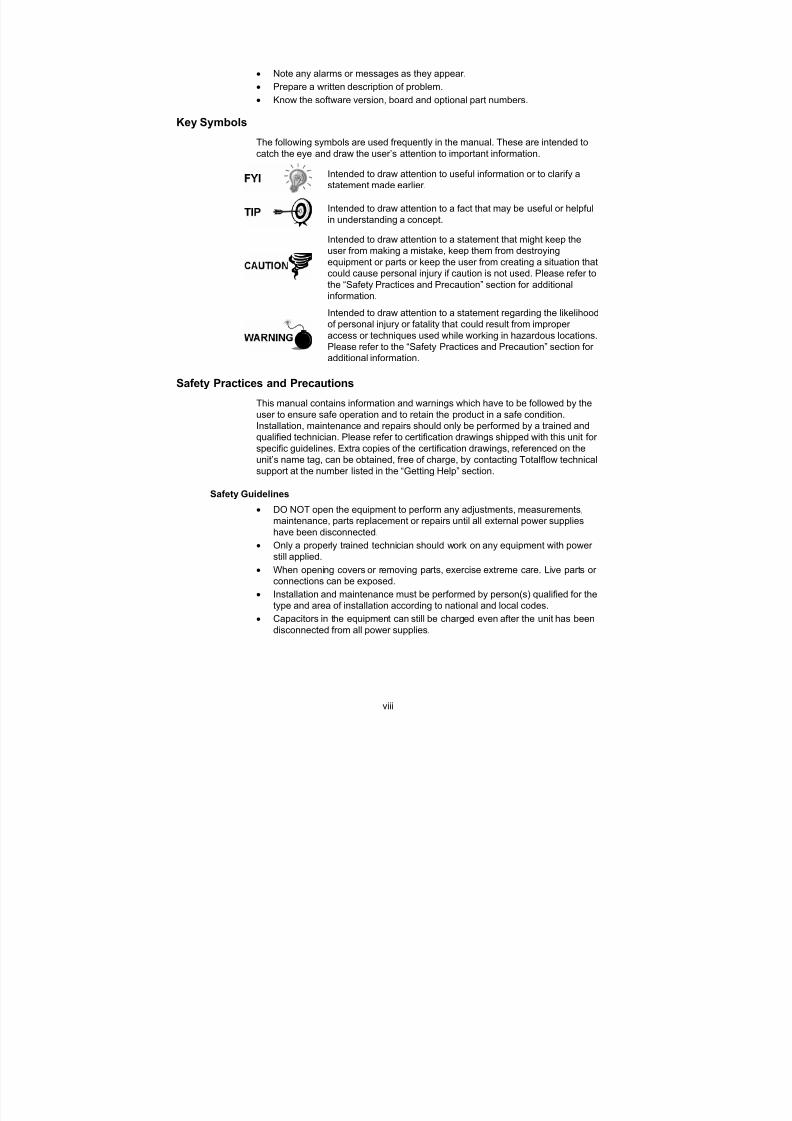
Key Symbols
The following symbols are used frequently in the manual. These are intended tocatch the eye and draw the user’s attention to important information.
Intended to draw attention to useful information or to clarify a
statement made earlier.
Intended to draw attention to a fact that may be useful or helpful
in understanding a concept.
Intended to draw attention to a statement that might keep the
user from making a mistake, keep them from destroying
equipment or parts or keep the user from creating a situation that
could cause personal injury if caution is not used. Please refer to
the “Safety Practices and Precaution” section for additionalinformation.
Intended to draw attention to a statement regarding the likelihood
of personal injury or fatality that could result from improper
access or techniques used while working in hazardous locations.
Please refer to the “Safety Practices and Precaution” section for
additional information.
Safety Practices and Precautions
This manual contains information and warnings which have to be followed by the
user to ensure safe operation and to retain the product in a safe condition.
Installation, maintenance and repairs should only be performed by a trained and
qualified technician. Please refer to certification drawings shipped with this unit for
specific guidelines. Extra copies of the certification drawings, referenced on the
unit’s name tag, can be obtained, free of charge, by contacting Totalflow technical
support at the number listed in the “Getting Help” section.
Safety Guidelines
• DO NOT open the equipment to perform any adjustments, measurements,
maintenance, parts replacement or repairs until all external power supplies
have been disconnected.
• Only a properly trained technician should work on any equipment with power
still applied.
• When opening covers or removing parts, exercise extreme care. Live parts or
connections can be exposed.
• Installation and maintenance must be performed by person(s) qualified for the
type and area of installation according to national and local codes.
• Capacitors in the equipment can still be charged even after the unit has been
disconnected from all power supplies.
8/13/2019 2018374 m Naf
http://slidepdf.com/reader/full/2018374-m-naf 11/174
ix
Safety First
Various statements in this manual identified as conditions or practices that could
result in equipment damage, personal injury or loss of life will be highlighted using
the following Icons.
Exercise caution while performing this task. Carelessness could
result in damage to the equipment, other property and personalinjury.
STOP. Do not proceed without first verifying that a hazardous
condition does not exist. This task may not be undertaken until
proper protection has been accomplished, or the hazardous
condition has been removed. Personal injury or fatality could
result. Examples of these warnings include:
• Removal of the enclosure cover(s) in a hazardous
location must follow guidelines stipulated in the
certification drawings shipped with this unit.
• If the unit is installed or to be installed in a hazardous
location, the technician must follow the guidelines
stipulated in the certification drawings shipped with thisunit.
• Access to unit via a PCCU cable in a hazardous location
must follow guidelines stipulated in the certification
drawings shipped with this unit.
• Connecting or disconnecting equipment in a hazardous
location for installation or maintenance of electric
components must follow guidelines stipulated in the
certification drawings shipped with this unit.
DANGER indicates a personal injury hazard immediately
accessible as one reads the markings.
CAUTION indicates a personal injury hazard not immediately
accessible as one reads the markings, or a hazard to property,including the equipment itself.
Equipment Markings
Protective ground (earth) terminal
Grounding the Product
If a grounding conductor is required, it should be connected to the grounding
terminal before any other connections are made.
Operating Voltage
Before switching on the power, check that the operating voltage listed on the
equipment agrees with the power being connected to the equipment.
Danger From Loss of Ground
A grounding conductor may or may not be required, depending on the hazardous
classification. If required, any interruption of the grounding conductor inside or
outside the equipment or loose connection of the grounding conductor can result

8/13/2019 2018374 m Naf
http://slidepdf.com/reader/full/2018374-m-naf 12/174
x
in a dangerous unit. Intentional interruption of the grounding conductor is not
permitted.
Safe Equipment
If it is determined that the equipment cannot be operated safety, it should be taken
out of operation and secured against unintentional usage.
8/13/2019 2018374 m Naf
http://slidepdf.com/reader/full/2018374-m-naf 13/174
2018374-001 – rev. AF 1–1
1.0 SYSTEM DESCRIPTION
1.1 Overview
The Totalflow® LevelMaster is an Intelligent Digital Level Sensor and is designed
for custody transfer accuracy in demanding level measurement applications,
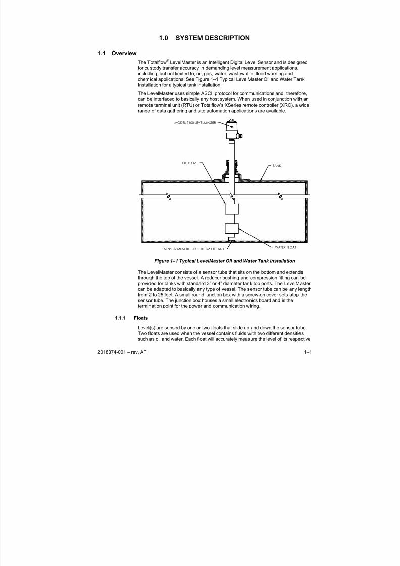
including, but not limited to, oil, gas, water, wastewater, flood warning andchemical applications. See Figure 1–1 Typical LevelMaster Oil and Water Tank
Installation for a typical tank installation.
The LevelMaster uses simple ASCII protocol for communications and, therefore,
can be interfaced to basically any host system. When used in conjunction with an
remote terminal unit (RTU) or Totalflow’s XSeries remote controller (XRC), a wide
range of data gathering and site automation applications are available.
MODEL 7100 LEVELMASTER
SENSOR MUST BE ON BOTTOM OF TANK
OIL FLOAT
WATER FLOAT
TANK
Figure 1–1 Typical LevelMaster Oil and Water Tank Installation
The LevelMaster consists of a sensor tube that sits on the bottom and extends
through the top of the vessel. A reducer bushing and compression fitting can be
provided for tanks with standard 3” or 4” diameter tank top ports. The LevelMaster
can be adapted to basically any type of vessel. The sensor tube can be any lengthfrom 2 to 25 feet. A small round junction box with a screw-on cover sets atop the
sensor tube. The junction box houses a small electronics board and is the
termination point for the power and communication wiring.
1.1.1 Floats
Level(s) are sensed by one or two floats that slide up and down the sensor tube.
Two floats are used when the vessel contains fluids with two different densities
such as oil and water. Each float will accurately measure the level of its respective
8/13/2019 2018374 m Naf
http://slidepdf.com/reader/full/2018374-m-naf 14/174
1–2 2018374-001 – rev. AF
fluid over the full vertical range of the sensor tube with a relative accuracy to the
nearest ± 0.1 inch (2.5 mm); optional ± 0.05 inch (1.27mm).
1.1.2 Sensor
The sensor casing is manufactured with different materials, based on the
corrosiveness of the fluid. These fluids include, but are not limited to, culinarywater, oils, solvents, acids and chemicals. Floats have an outer material that can
withstand most solvents and chemicals, plus other float materials are being
considered.
1.1.3 Temperature
Temperature is also provided along with the fluid level readings. A standard
configuration includes one temperature sensor located 12 inches (304.8 mm) from
the bottom of the sensor tube reading accurately to within 1°F(0.6°C).
1.1.4 Data Gathering
Retrieving the information from the LevelMaster can be accomplished in many
ways. Since the LevelMaster uses simple ASCII protocol, the user can use third
party RTUs, PLCs or a PC. When connected to Totalflow’s flow computer or RTU,
host applications such as WinCCU32, TDS32 and PCCU32 become viable data
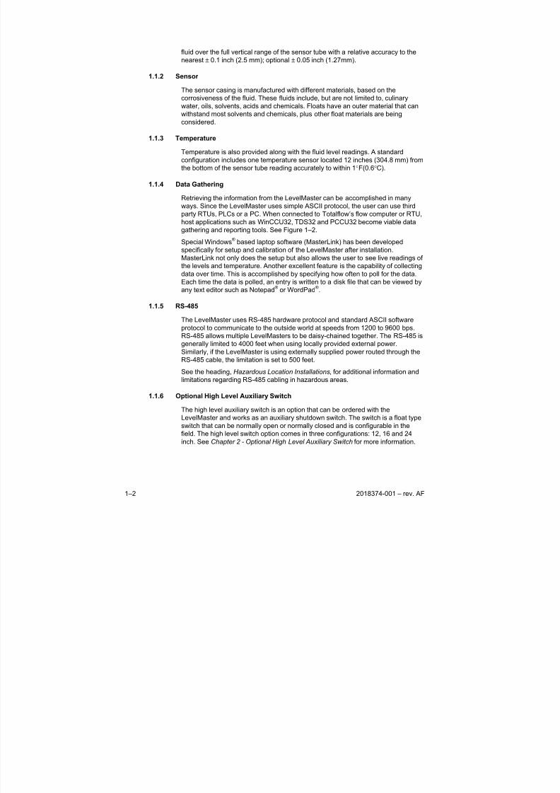
gathering and reporting tools. See Figure 1–2.
Special Windows® based laptop software (MasterLink) has been developed
specifically for setup and calibration of the LevelMaster after installation.
MasterLink not only does the setup but also allows the user to see live readings of
the levels and temperature. Another excellent feature is the capability of collecting
data over time. This is accomplished by specifying how often to poll for the data.
Each time the data is polled, an entry is written to a disk file that can be viewed by
any text editor such as Notepad® or WordPad
®.
1.1.5 RS-485
The LevelMaster uses RS-485 hardware protocol and standard ASCII software
protocol to communicate to the outside world at speeds from 1200 to 9600 bps.
RS-485 allows multiple LevelMasters to be daisy-chained together. The RS-485 is
generally limited to 4000 feet when using locally provided external power.
Similarly, if the LevelMaster is using externally supplied power routed through the
RS-485 cable, the limitation is set to 500 feet.
See the heading, Hazardous Location Installations, for additional information and
limitations regarding RS-485 cabling in hazardous areas.
1.1.6 Optional High Level Auxiliary Switch
The high level auxiliary switch is an option that can be ordered with the
LevelMaster and works as an auxiliary shutdown switch. The switch is a float type
switch that can be normally open or normally closed and is configurable in the
field. The high level switch option comes in three configurations: 12, 16 and 24
inch. See Chapter 2 - Optional High Level Auxiliary Switch for more information.
8/13/2019 2018374 m Naf
http://slidepdf.com/reader/full/2018374-m-naf 15/174
2018374-001 – rev. AF 1–3
HOST
Figure 1–2 Typical LevelMaster Configuration
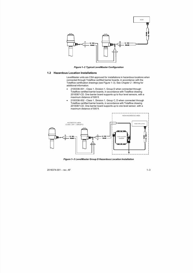
1.2 Hazardous Location Installations
LevelMaster units are CSA approved for installations in hazardous locations when
connected through Totalflow certified barrier boards, in accordance with the
Totalflow certification drawings (see Figure 1–3). See Chapter 2 - Wiring for
additional information.
• 2100336-001 - Class 1, Division 1, Group D when connected through
Totalflow certified barrier boards, in accordance with Totalflow drawing
2018387-CD. One barrier board supports up to four level sensors, with a
maximum distance of 500 ft.
• 2100336-002 - Class 1, Division 1, Group C, D when connected through
Totalflow certified barrier boards, in accordance with Totalflow drawing
2018387-CD. One barrier board supports up to one level sensor, with a
maximum distance of 500 ft.
HAZARDOUS AREA
CLASS I, DIV 1, GROUP D
NON-HAZARDOUS AREA
HOST, RTU or PLC
LEVELMASTER
BARRIER
Figure 1–3 LevelMaster Group D Hazardous Location Installation
8/13/2019 2018374 m Naf
http://slidepdf.com/reader/full/2018374-m-naf 16/174
1–4 2018374-001 – rev. AF
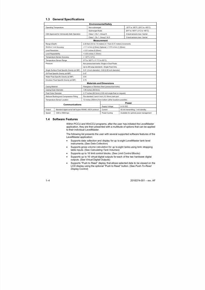
1.3 General Specifications
Environmental/Safety
Operating Temperature Non-submerged -20°F to 185°F (-29°C to +85°C)
Submerged floats 26°F to 185°F (-3°C to +85°C)
CSA Approved for Intrinsically Safe Operation Class 1, Div 1, Group D 4 level sensors max / barrier
Class 1, Div 1, Group C & D 3 level sensors max / barrier
Measurement
Range (Depth) 2-25 feet (0.6 to 7.6 meters) in 1 foot (0.31 meters) increments
Relative Level Accuracy + 0.1 inches (2.5mm) Optional: + 0.05 inches (1.25mm)
Level Resolution + 0.01 inches (0.25mm)
Level Repeatability + 0.05 inches (1.25mm)
Temperature Sensor Accuracy + 1.8°F (1.0°C)
Temperature Sensor Range 0°F to 185°F (-17.7°C to 85°C)
Non-pressurized tanks: Single or Dual FloatsPressure
Up to 200 psig (standard) : Single Float Only
Single Surface Float Specific Gravity (at 68F) 0.41 (3 inch diameter), 0.60 (2.85 inch diameter)
Oil Float Specific Gravity (at 68F) 0.47Water Float Specific Gravity (at 68F) 0.91
Emulsion Float Specific Gravity (at 68F) 0.75
Materials and Dimensions
Casing Material Fiberglass or Stainless Steel (pressurized tanks)
Casing Outer Diameter 1.95 inches (48.5mm)
Float Outer Diameter 3.17 inches (80.5mm) (2.85 inch single float on request)
Reducer Bushing and Compression Fitting Fits standard 3 and 4 inch (10.16mm) tank port
Temperature Sensor Location 12 inches (300mm) from bottom (other locations possible)
Power Communications
Supply Voltage 9-18 VDC
Output Standard digital serial half duplex RS485, ASCII protocol Current 40 mA transmitting; 1 mA standby
Speed 1200 or 9600 bps Power Cycling Available for optimal power management
1.4 Software Features
Within PCCU and WinCCU programs, after the user has initiated the LevelMaster
application, they are then presented with a multitude of options that can be applied
to their individual LevelMaster.
The following list presents the user with several supported software features of the
LevelMaster application:
• Supports data collection and display for up to eight LevelMaster tank level
instruments. (See Data Collection)
• Supports gross volume calculation for up to eight tanks using tank strapping
table inputs. (See Calculating Tank Volumes)
• Supports up to 16 limit control blocks. (See Limit Control Blocks)
• Supports up to 16 virtual digital outputs for each of the two hardware digital
outputs. (See Virtual Digital Outputs)
• Supports “Push to Read” display that allows selected data to be viewed on the
LCD display using the optional “Push to Read” button. (See Push-To-Read
Display Control )
8/13/2019 2018374 m Naf
http://slidepdf.com/reader/full/2018374-m-naf 17/174
2018374-001 – rev. AF 1–5
• Supports Totalflow proprietary local protocols – PCCU32 and Terminal. The
software supports PCCU32 and Terminal protocols over the local
communications port. PCCU32 Revisions 4.1 and higher are supported.
• Supports Totalflow proprietary remote protocol – WinCCU remote host
console. The software supports single host X-frame protocol. This protocol
allows the Totalflow application, array and register access from the remote
host console or TDS32, WinCCU applications.• Supports the Totalflow configurable trend system. The software supports
Totalflow trend configuration and collection. Trend files may be configured or
collected using the PCCU32 or WinCCU programs.
• The software supports RAMS configurable alarms, alarm by exception and
alarm cry-out. Alarms may be configured using PCCU32 or WinCCU
programs.
• Supports selectable tank data display and storage units. The software
supports selectable engineering units for collected levels, temperature and
volume data. Units may be selected using PCCU32, WinCCU or Modbus
protocol.
• Supports power duty cycling. This option is used for power conservation. It
allows the software to switch the power on and off to the LevelMasters via adigital output contained in the software. (See Tank System Setup)
1.5 Host Controller Configurations
The LevelMaster can be operated in a stand-alone configuration wherein it
attaches directly to the LevelMaster unit. Conversely, it can also be used as one of
the many host controller configurations. This manual will detail those operations
and provide basic information regarding these options.
8/13/2019 2018374 m Naf
http://slidepdf.com/reader/full/2018374-m-naf 18/174
1–6
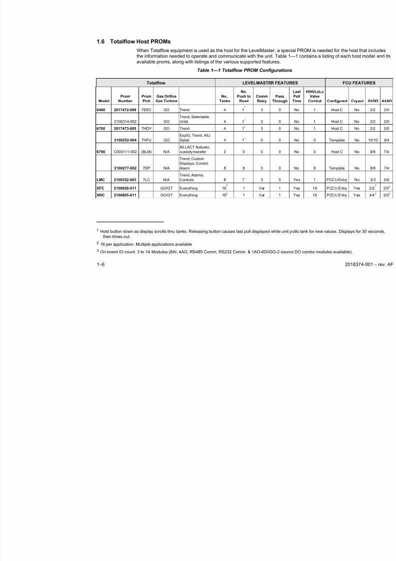
1.6 Totalflow Host PROMs
When Totalflow equipment is used as the host for the LevelMaster, a special PROM is nee
the information needed to operate and communicate with the unit. Table 1—1 contains a lis
available proms, along with listings of the various supported features.
Table 1—1 Totalflow PROM Configurations
Totalflow LEVELMASTER FEATURES
Model
Prom
Number
Prom
Pick
Gas Orifice
Gas Turbine
No..
Tanks
No.
Push to
Read
Comm
Retry
Pass
Through
Last
Poll
Time
HiHi/LoLo
Valve
Control
6400 2017472-009 7EEC GO Trend 4 11
3 0 No 1
2100314-002 GO
Trend, Selectable
Units 4 11 3 0 No 1
6700 2017473-005 7HDY GO Trend 4 11 3 0 No 1
2100252-004 7HFU GO
ExpIO, Trend, AIU
Detail 4 11 0 0 No 0
6790 C000111-002 (BLM) N/A
All LACT features,
custody transfer 2 0 0 0 No 0
2100277-002 7DP N/A
Trend, Custom
Displays, Control,
Alarm 8 8 3 0 No 8
LMC 2100352-003 7LC N/A
Trend, Alarms,
Controls 8 11 3 0 Yes 1
XFC 2100826-011 GO/GT Everything 162
1 Var 1 Yes 16
XRC 2100805-011 GO/GT Everything 162 1 Var 1 Yes 16
1 Hold button down as display scrolls thru tanks. Releasing button causes last poll displayed while unit polls tank for new v
then times out.
2 16 per application. Multiple applications available. 3 On board IO count. 3 to 14 Modules (8AI, 4AO, RS485 Comm, RS232 Comm. & 1AO-6DI/DO-2 source DO combo mod
8/13/2019 2018374 m Naf
http://slidepdf.com/reader/full/2018374-m-naf 19/174
2018374-001 – rev. AF 2–1
2.0 INSTALLATION
This chapter will lead the user through the unpacking, assembling, installing and
wiring of the LevelMaster. For safe and trouble free installation, follow all
instructions and advisories.
Although the LevelMaster is easy to install, there is no one procedure that will fit
all situations. For example, if the length ordered fits a standard size tank such as
11, 16 or 25 foot, most of the LevelMaster is pre-assembled at the factory. Use the
procedure entitled Installing a Pre-Assembled Unit .
Read through this chapter before installation and establish an
installation strategy. Also, before beginning the actual
installation, refer to any instructions, drawings or wiring
diagrams that are included with the LevelMaster. The detail part
of any assembly will typically use the documentation that
accompanies the unit. If a discrepancy exists between this
manual and documentation that accompanies the unit, the unit’s
documentation will take precedence.
2.1 Unpacking and Inspection
2.1.1 Unpacking
The model 7100 LevelMaster product is shipped in a specially designed shipping
carton which contains the sensor unit, electronics board with enclosure, mounting
components, parts list, wiring and interconnect diagrams. If an intrinsically safe
barrier is provided, it and its associated hardware are shipped in a separate
carton.
Carefully remove the items from each carton.
2.1.2 Initial Inspection
Inspect the shipping carton for damage. If the shipping carton is damaged, keep it
until the contents have been inspected for damage.
• Inspect the exterior of the individual components for dents, chipped paint, etc.
• Inspect the sensor wiring harness for damage or breakage.
• Open the electronics enclosure by removing its cap (see Figure 2–1).
• Visually inspect the Digital PC Board and cables for damage.
• Compare the contents to the parts list below.
2.1.3 Damaged Components
If any components have been damaged or if there are noticeable defects, notify aTotalflow representative. Keep all shipping materials for the carrier's inspection.
Totalflow will arrange for immediate repair or replacement; see Getting Help,
located in the introduction to this manual.
2.1.4 Parts List
The following parts list is for the convenience of those who receive their
LevelMaster in a kit form. Some parts may be connected to or installed in other
8/13/2019 2018374 m Naf
http://slidepdf.com/reader/full/2018374-m-naf 20/174
2–2 2018374-001 – rev. AF
parts but should be accounted for before starting the assembly process. Use
Figure 2-1 for assistance when verifying parts list.
• Sensor Assembly – Goes inside the casing and will be basically the same
length as the assembled casing. Has a ribbon cable coming out one end and
is terminated with a 16-pin connector.
• Electronics Enclosure – Approximately 3 ½” diameter x 6” long with a screw-
on cover. Houses the electronics board.
• Electronics Board – Approximately 2 ½” x 4”. May be shipped inside the
Electronics Enclosure.
• Float Kit – Composed of 1 or 2 floats. Floats are 3” diameter. Two floats are
required for an oil and water application.
• Plug – The plug is epoxied into the bottom of the bottom casing joint.
• Top Cap – The top cap is an aluminum bushing that screws on to the top of
the casing, leaving a 3/4” NPT threaded female opening.
• Nipple – ¾” pipe nipple. This goes between the top cap bushing and the
electronics enclosure.
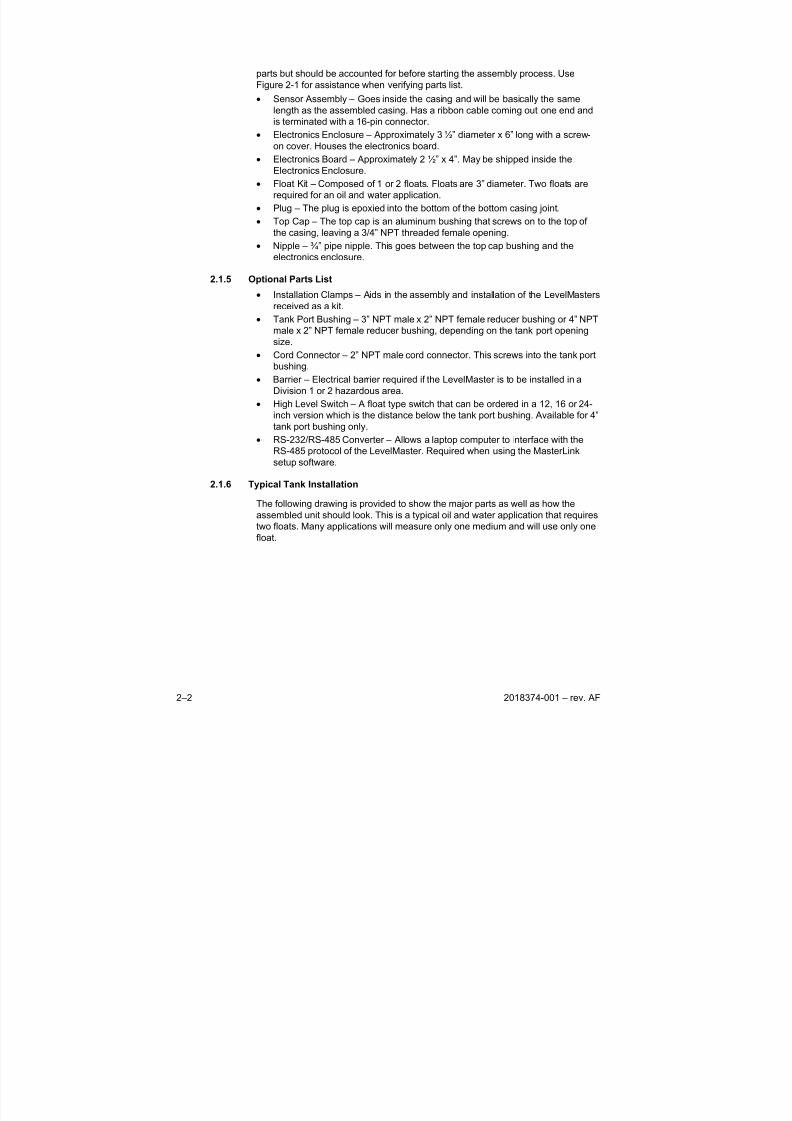
2.1.5 Optional Parts List
• Installation Clamps – Aids in the assembly and installation of the LevelMasters
received as a kit.
• Tank Port Bushing – 3” NPT male x 2” NPT female reducer bushing or 4” NPT
male x 2” NPT female reducer bushing, depending on the tank port opening
size.
• Cord Connector – 2” NPT male cord connector. This screws into the tank port
bushing.
• Barrier – Electrical barrier required if the LevelMaster is to be installed in a
Division 1 or 2 hazardous area.
• High Level Switch – A float type switch that can be ordered in a 12, 16 or 24-
inch version which is the distance below the tank port bushing. Available for 4”
tank port bushing only.• RS-232/RS-485 Converter – Allows a laptop computer to interface with the
RS-485 protocol of the LevelMaster. Required when using the MasterLink
setup software.
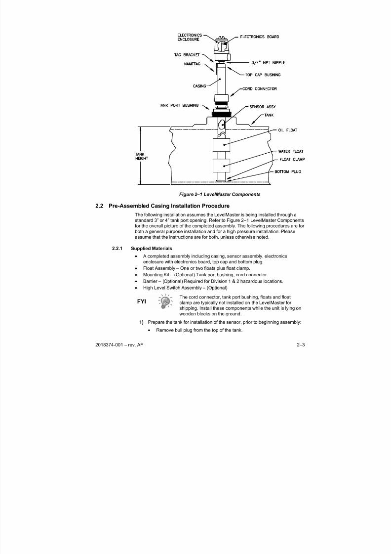
2.1.6 Typical Tank Installation
The following drawing is provided to show the major parts as well as how the
assembled unit should look. This is a typical oil and water application that requires
two floats. Many applications will measure only one medium and will use only one
float.
8/13/2019 2018374 m Naf
http://slidepdf.com/reader/full/2018374-m-naf 21/174
2018374-001 – rev. AF 2–3
Figure 2–1 LevelMaster Components
2.2 Pre-Assembled Casing Installation Procedure
The following installation assumes the LevelMaster is being installed through astandard 3” or 4” tank port opening. Refer to Figure 2–1 LevelMaster Components
for the overall picture of the completed assembly. The following procedures are for
both a general purpose installation and for a high pressure installation. Please
assume that the instructions are for both, unless otherwise noted.
2.2.1 Supplied Materials
• A completed assembly including casing, sensor assembly, electronics
enclosure with electronics board, top cap and bottom plug.
• Float Assembly – One or two floats plus float clamp.
• Mounting Kit – (Optional) Tank port bushing, cord connector.
• Barrier – (Optional) Required for Division 1 & 2 hazardous locations.
• High Level Switch Assembly – (Optional)
The cord connector, tank port bushing, floats and float
clamp are typically not installed on the LevelMaster for
shipping. Install these components while the unit is lying on
wooden blocks on the ground.
1) Prepare the tank for installation of the sensor, prior to beginning assembly:
• Remove bull plug from the top of the tank.
8/13/2019 2018374 m Naf
http://slidepdf.com/reader/full/2018374-m-naf 22/174
2–4 2018374-001 – rev. AF
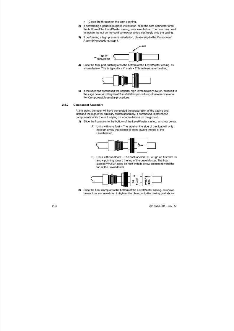
• Clean the threads on the tank opening.
2) If performing a general purpose installation, slide the cord connector onto
the bottom of the LevelMaster casing, as shown below. The user may need
to loosen the nut on the cord connector so it slides freely onto the casing.
3) If performing a high pressure installation, please skip to the Component
Assembly procedure, step 1.
4) Slide the tank port bushing onto the bottom of the LevelMaster casing, as
shown below. This is typically a 4” male x 2” female reducer bushing.
5) If the user has purchased the optional high level auxiliary switch, proceed to
the High Level Auxiliary Switch Installation procedure; otherwise, move to
the Component Assembly procedure.
2.2.2 Component Assembly
At this point, the user will have completed the preparation of the casing and
installed the high level auxiliary switch assembly, if purchased. Install these
components while the unit is lying on wooden blocks on the ground.
1) Slide the float(s) onto the bottom of the LevelMaster casing, as show below.
A) Units with one float – The label on the side of the float will onlyhave an arrow that needs to point toward the top of the
LevelMaster.
B) Units with two floats – The float labeled OIL will go on first with its
arrow pointing toward the top of the LevelMaster. The float
labeled WATER goes on next with its arrow pointing toward the
top of the LevelMaster.
2) Slide the float clamp onto the bottom of the LevelMaster casing, as shown
below. Use a screw driver to tighten the clamp onto the casing, just above
8/13/2019 2018374 m Naf
http://slidepdf.com/reader/full/2018374-m-naf 23/174
2018374-001 – rev. AF 2–5
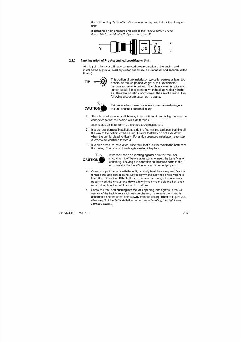
the bottom plug. Quite of bit of force may be required to lock the clamp on
tight.
If installing a high pressure unit, skip to the Tank Insertion of Pre-
Assembled LevelMaster Unit procedure, step 2.
2.2.3 Tank Insertion of Pre-Assembled LevelMaster Unit
At this point, the user will have completed the preparation of the casing and
installed the high level auxiliary switch assembly, if purchased, and assembled the
float(s).
This portion of the installation typically requires at least two
people, as the length and weight of the LevelMaster
become an issue. A unit with fiberglass casing is quite a bitlighter but will flex a lot more when held up vertically in the
air. The ideal situation incorporates the use of a crane. The
following procedure assumes no crane.
Failure to follow these procedures may cause damage to
the unit or cause personal injury.
1) Slide the cord connector all the way to the bottom of the casing. Loosen the
connector so that the casing will slide through.
Skip to step 2B if performing a high pressure installation.
2) In a general purpose installation, slide the float(s) and tank port bushing all
the way to the bottom of the casing. Ensure that they do not slide down
when the unit is raised vertically. For a high pressure installation, see step
3; otherwise, continue to step 4.
3) In a high pressure installation, slide the Float(s) all the way to the bottom of
the casing. The tank port bushing is welded into place.
If the tank has an operating agitator or mixer, the user
should turn it off before attempting to insert the LevelMaster
assembly. Leaving it in operation could cause harm to the
equipment, if the LevelMaster is not inserted properly.
4) Once on top of the tank with the unit, carefully feed the casing and float(s)
through the tank port opening. Lower slowly and allow the unit’s weight tokeep the unit vertical. If the bottom of the tank has sludge, the user may
need to work the unit up and down a few times once the sludge has been
reached to allow the unit to reach the bottom.
5) Screw the tank port bushing into the tank opening, and tighten. If the 24”
version of the high level switch was purchased, make sure the tubing is
assembled and the offset points away from the casing. Refer to Figure 2-2.
(See step 5 of the 24” installation procedure in Installing the High Level
Auxiliary Switch.)
8/13/2019 2018374 m Naf
http://slidepdf.com/reader/full/2018374-m-naf 24/174
2–6 2018374-001 – rev. AF
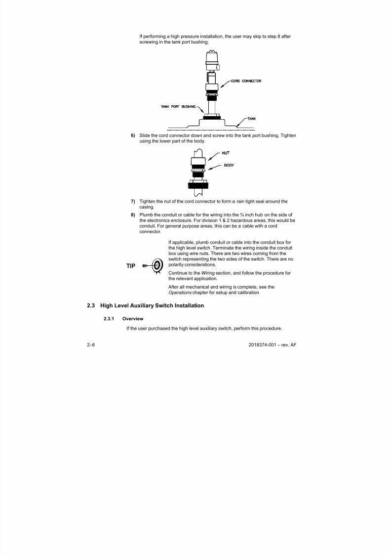
If performing a high pressure installation, the user may skip to step 8 after
screwing in the tank port bushing.
6) Slide the cord connector down and screw into the tank port bushing. Tighten
using the lower part of the body.
7) Tighten the nut of the cord connector to form a rain tight seal around the
casing.
8) Plumb the conduit or cable for the wiring into the ¾ inch hub on the side ofthe electronics enclosure. For division 1 & 2 hazardous areas, this would be
conduit. For general purpose areas, this can be a cable with a cord
connector.
If applicable, plumb conduit or cable into the conduit box for
the high level switch. Terminate the wiring inside the conduit
box using wire nuts. There are two wires coming from the
switch representing the two sides of the switch. There are no
polarity considerations.
Continue to the Wiring section, and follow the procedure for
the relevant application.
After all mechanical and wiring is complete, see the
Operations chapter for setup and calibration.
2.3 High Level Auxiliary Switch Installation
2.3.1 Overview
If the user purchased the high level auxiliary switch, perform this procedure.
8/13/2019 2018374 m Naf
http://slidepdf.com/reader/full/2018374-m-naf 25/174
2018374-001 – rev. AF 2–7
If the user was directed here from the Pre-Assembled Casing Installation –
Preparation section, this installation should be performed while the unit is lying on
wooden blocks on the ground.
If wanting to… Then use… See Page
Install a 12” assembly 12” & 16” Installation Procedure 2-7
Install a 16” assembly 12” & 16” Installation Procedure 2-7
Install a 24” assembly 24” Installation Procedure 2-8
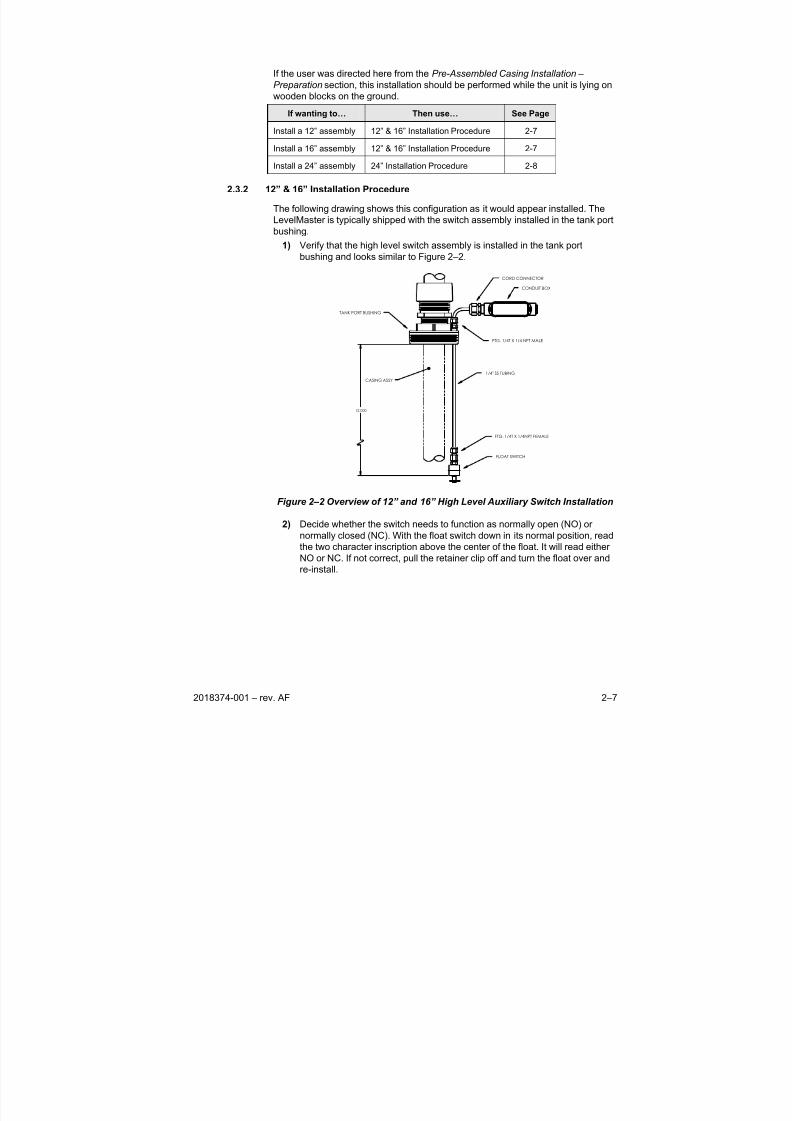
2.3.2 12” & 16” Installation Procedure
The following drawing shows this configuration as it would appear installed. The
LevelMaster is typically shipped with the switch assembly installed in the tank port
bushing.
1) Verify that the high level switch assembly is installed in the tank port
bushing and looks similar to Figure 2–2.
12.000
CASING ASSY
1/4" SS TUBING
FTG. 1/4T X 1/4 NPT MALE
FTG. 1/4T X 1/4NPT FEMALE
FLOAT SWITCH
CORD CONNECTOR
CONDUIT BOX
TANK PORT BUSHING
Figure 2–2 Overview of 12” and 16” High Level Auxiliary Switch Installation
2) Decide whether the switch needs to function as normally open (NO) or
normally closed (NC). With the float switch down in its normal position, read
the two character inscription above the center of the float. It will read either
NO or NC. If not correct, pull the retainer clip off and turn the float over and
re-install.
8/13/2019 2018374 m Naf
http://slidepdf.com/reader/full/2018374-m-naf 26/174
2–8 2018374-001 – rev. AF
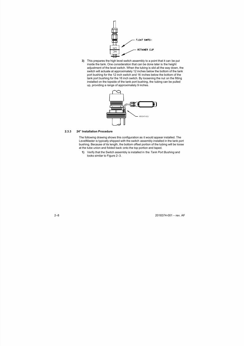
NO N C
3) This prepares the high level switch assembly to a point that it can be put
inside the tank. One consideration that can be done later is the height
adjustment of the level switch. When the tubing is slid all the way down, the
switch will actuate at approximately 12 inches below the bottom of the tank
port bushing for the 12 inch switch and 16 inches below the bottom of the
tank port bushing for the 16 inch switch. By loosening the nut on the fitting
installed on the topside of the tank port bushing, the tubing can be pulled
up, providing a range of approximately 9 inches.
HEIGHT ADJ
2.3.3 24” Installation Procedure
The following drawing shows this configuration as it would appear installed. The
LevelMaster is typically shipped with the switch assembly installed in the tank port
bushing. Because of its length, the bottom offset portion of the tubing will be loose
at the tube union and folded back onto the top portion and taped.
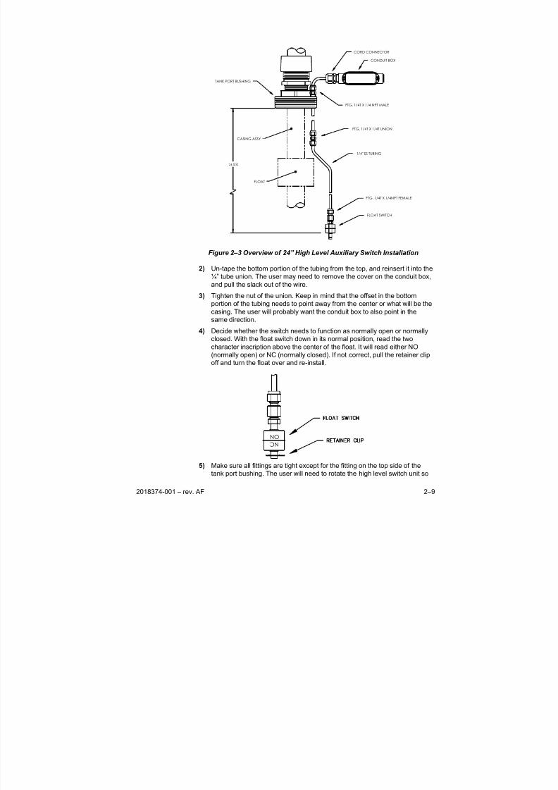
1) Verify that the Switch assembly is installed in the Tank Port Bushing and
looks similar to Figure 2–3.
8/13/2019 2018374 m Naf
http://slidepdf.com/reader/full/2018374-m-naf 27/174
2018374-001 – rev. AF 2–9
24.000
CASING ASSY
1/4" SS TUBING
FTG. 1/4T X 1/4 NPT MALE
FTG. 1/4T X 1/4NPT FEMALE
FLOAT SWITCH
CORD CONNECTOR
CONDUIT BOX
TANK PORT BUSHING
FTG. 1/4T X 1/4T UNION
FLOAT
Figure 2–3 Overview of 24” High Level Auxiliary Switch Installation
2) Un-tape the bottom portion of the tubing from the top, and reinsert it into the
¼” tube union. The user may need to remove the cover on the conduit box,
and pull the slack out of the wire.
3) Tighten the nut of the union. Keep in mind that the offset in the bottom
portion of the tubing needs to point away from the center or what will be thecasing. The user will probably want the conduit box to also point in the
same direction.
4) Decide whether the switch needs to function as normally open or normally
closed. With the float switch down in its normal position, read the two
character inscription above the center of the float. It will read either NO
(normally open) or NC (normally closed). If not correct, pull the retainer clip
off and turn the float over and re-install.
NO N C
5) Make sure all fittings are tight except for the fitting on the top side of the
tank port bushing. The user will need to rotate the high level switch unit so
8/13/2019 2018374 m Naf
http://slidepdf.com/reader/full/2018374-m-naf 28/174
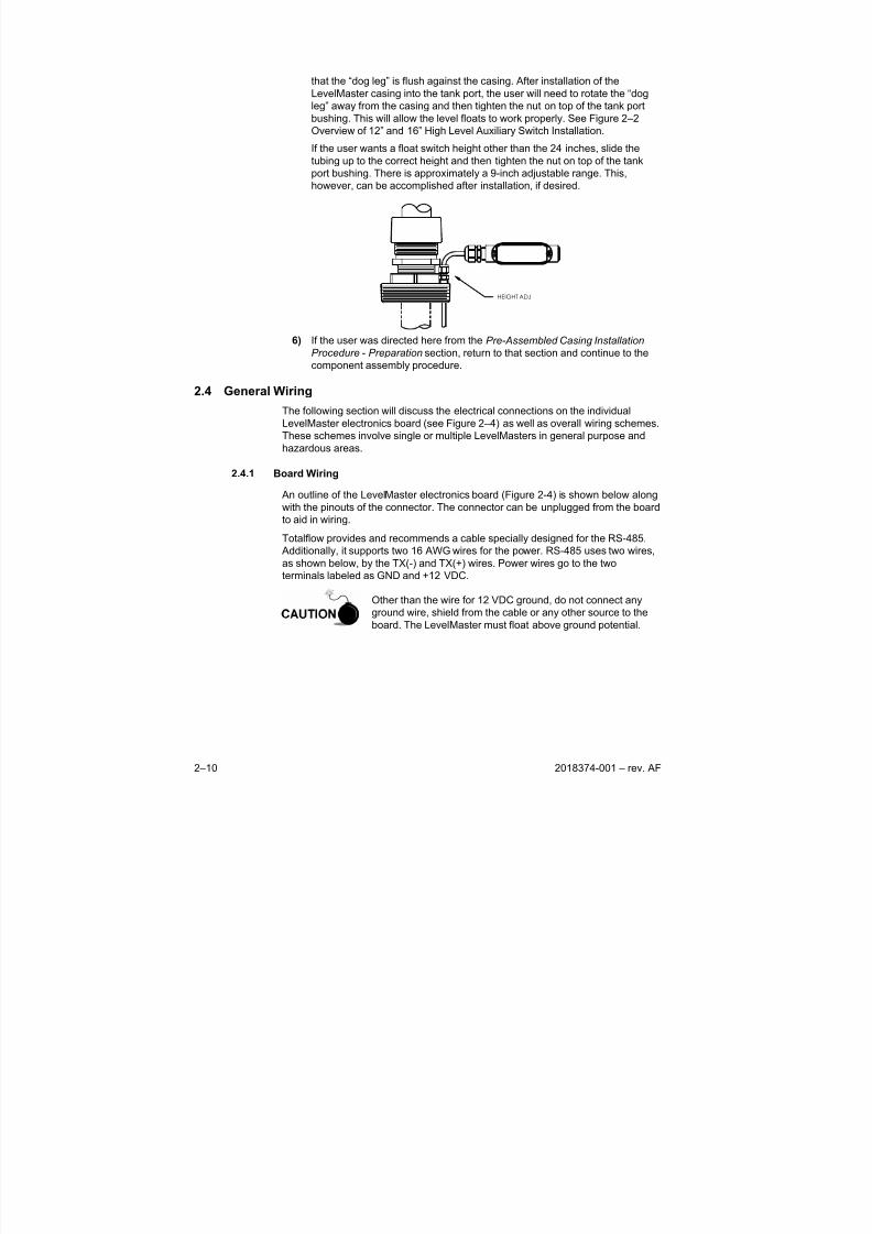
2–10 2018374-001 – rev. AF
that the “dog leg” is flush against the casing. After installation of the
LevelMaster casing into the tank port, the user will need to rotate the “dog
leg” away from the casing and then tighten the nut on top of the tank port
bushing. This will allow the level floats to work properly. See Figure 2–2
Overview of 12” and 16” High Level Auxiliary Switch Installation.
If the user wants a float switch height other than the 24 inches, slide the
tubing up to the correct height and then tighten the nut on top of the tankport bushing. There is approximately a 9-inch adjustable range. This,
however, can be accomplished after installation, if desired.
HEIGHT ADJ
6) If the user was directed here from the Pre-Assembled Casing Installation
Procedure - Preparation section, return to that section and continue to the
component assembly procedure.
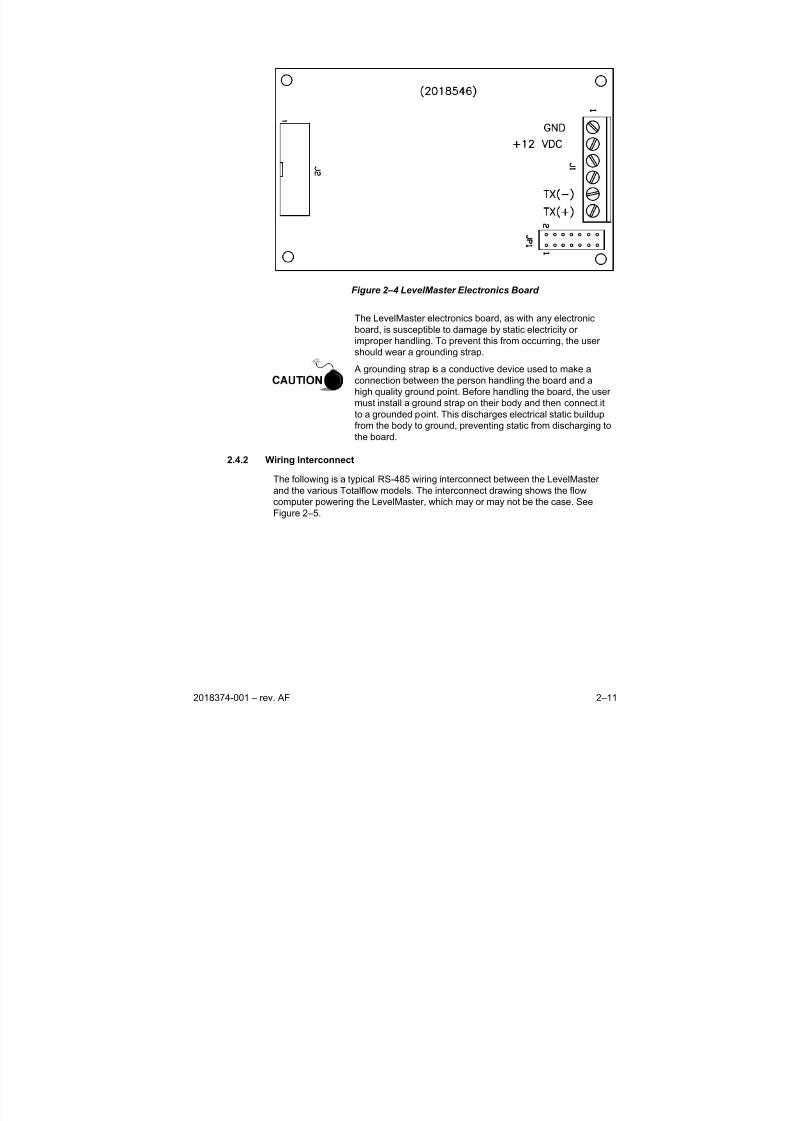
2.4 General Wiring
The following section will discuss the electrical connections on the individual
LevelMaster electronics board (see Figure 2–4) as well as overall wiring schemes.
These schemes involve single or multiple LevelMasters in general purpose and
hazardous areas.
2.4.1 Board Wiring
An outline of the LevelMaster electronics board (Figure 2-4) is shown below along
with the pinouts of the connector. The connector can be unplugged from the board
to aid in wiring.
Totalflow provides and recommends a cable specially designed for the RS-485.
Additionally, it supports two 16 AWG wires for the power. RS-485 uses two wires,
as shown below, by the TX(-) and TX(+) wires. Power wires go to the two
terminals labeled as GND and +12 VDC.
Other than the wire for 12 VDC ground, do not connect any
ground wire, shield from the cable or any other source to the
board. The LevelMaster must float above ground potential.
8/13/2019 2018374 m Naf
http://slidepdf.com/reader/full/2018374-m-naf 29/174
2018374-001 – rev. AF 2–11
Figure 2–4 LevelMaster Electronics Board
The LevelMaster electronics board, as with any electronic
board, is susceptible to damage by static electricity or
improper handling. To prevent this from occurring, the user
should wear a grounding strap.
A grounding strap is a conductive device used to make a
connection between the person handling the board and a
high quality ground point. Before handling the board, the user
must install a ground strap on their body and then connect it
to a grounded point. This discharges electrical static buildup
from the body to ground, preventing static from discharging to
the board.
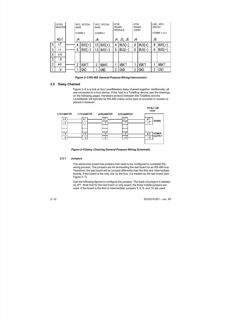
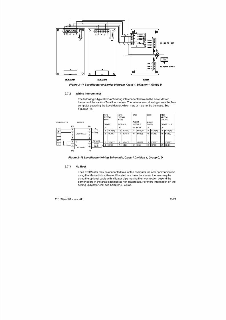
2.4.2 Wiring Interconnect
The following is a typical RS-485 wiring interconnect between the LevelMaster
and the various Totalflow models. The interconnect drawing shows the flow
computer powering the LevelMaster, which may or may not be the case. See
Figure 2–5.
8/13/2019 2018374 m Naf
http://slidepdf.com/reader/full/2018374-m-naf 30/174
2–12 2018374-001 – rev. AF
LEVEL
MASTERXFC, XFCG4,
6400
COMM 1
6700
RS485
MODULE
6700
RS485
CARD
LMC, XRC,
XRCG4
COMM 1 or 2
XFC, XFCG4,
6400
COMM 2
Figure 2–5 RS-485 General Purpose Wiring Interconnect
2.5 Daisy Chained
Figure 2–6 is a look at four LevelMasters daisy chained together. Additionally, all
are connected to a host device. If the host is a Totalflow device, see the drawings
on the following pages. Hardware protocol between the Totalflow and the
LevelMaster will typically be RS-485 unless some type of converter or modem is
placed in between.
Figure 2–6 Daisy Chaining General Purpose Wiring Schematic
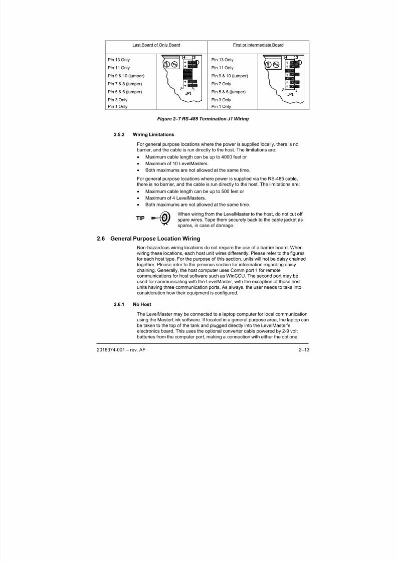
2.5.1 Jumpers
The electronics board has jumpers that need to be configured to complete thewiring process. The jumpers are for terminating the last board on an RS-485 bus.
Therefore, the last board will be jumped differently than the first and intermediate
boards. If the board is the only one on the bus, it is treated as the last board (see
Figure 2–7).
Use the following figures to configure the jumpers. The bank of jumpers is labeled
as JP1. Note that for the last board or only board, the three middle jumpers are
used. If the board is the first or intermediate, jumpers 5, 6, 9, and 10 are used.
8/13/2019 2018374 m Naf
http://slidepdf.com/reader/full/2018374-m-naf 31/174
2018374-001 – rev. AF 2–13
Last Board of Only Board First or Intermediate Board
Pin 13 Only
Pin 11 Only
Pin 9 & 10 (jumper)
Pin 7 & 8 (jumper)
Pin 5 & 6 (jumper)
Pin 3 Only
Pin 1 Only
Pin 13 Only
Pin 11 Only
Pin 9 & 10 (jumper)
Pin 7 Only
Pin 5 & 6 (jumper)
Pin 3 Only
Pin 1 Only
Figure 2–7 RS-485 Termination J1 Wiring
2.5.2 Wiring Limitations
For general purpose locations where the power is supplied locally, there is nobarrier, and the cable is run directly to the host. The limitations are:
• Maximum cable length can be up to 4000 feet or
• Maximum of 10 LevelMasters.
• Both maximums are not allowed at the same time.
For general purpose locations where power is supplied via the RS-485 cable,
there is no barrier, and the cable is run directly to the host. The limitations are:
• Maximum cable length can be up to 500 feet or
• Maximum of 4 LevelMasters.
• Both maximums are not allowed at the same time.
When wiring from the LevelMaster to the host, do not cut offspare wires. Tape them securely back to the cable jacket as
spares, in case of damage.
2.6 General Purpose Location Wiring
Non-hazardous wiring locations do not require the use of a barrier board. When
wiring these locations, each host unit wires differently. Please refer to the figures
for each host type. For the purpose of this section, units will not be daisy chained
together. Please refer to the previous section for information regarding daisy
chaining. Generally, the host computer uses Comm port 1 for remote
communications for host software such as WinCCU. The second port may be
used for communicating with the LevelMaster, with the exception of those host
units having three communication ports. As always, the user needs to take intoconsideration how their equipment is configured.
2.6.1 No Host
The LevelMaster may be connected to a laptop computer for local communication
using the MasterLink software. If located in a general purpose area, the laptop can
be taken to the top of the tank and plugged directly into the LevelMaster’s
electronics board. This uses the optional converter cable powered by 2-9 volt
batteries from the computer port, making a connection with either the optional
8/13/2019 2018374 m Naf
http://slidepdf.com/reader/full/2018374-m-naf 32/174
2–14 2018374-001 – rev. AF
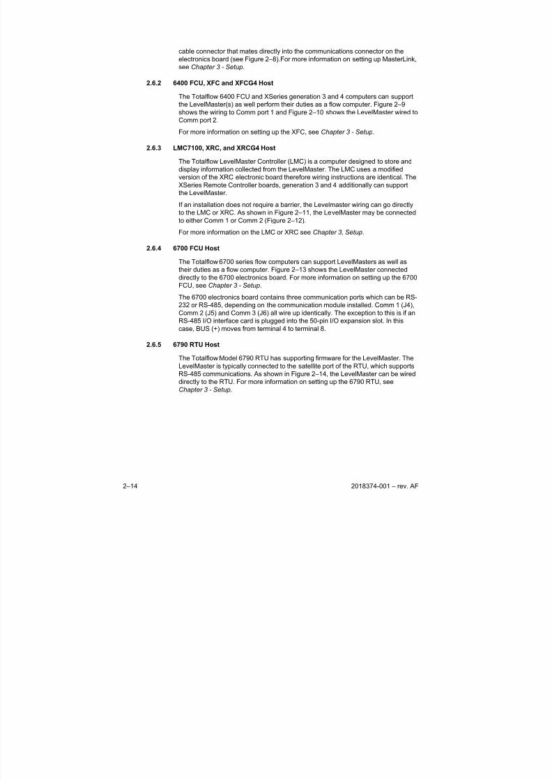
cable connector that mates directly into the communications connector on the
electronics board (see Figure 2–8).For more information on setting up MasterLink,
see Chapter 3 - Setup.
2.6.2 6400 FCU, XFC and XFCG4 Host
The Totalflow 6400 FCU and XSeries generation 3 and 4 computers can supportthe LevelMaster(s) as well perform their duties as a flow computer. Figure 2–9
shows the wiring to Comm port 1 and Figure 2–10 shows the LevelMaster wired to
Comm port 2.
For more information on setting up the XFC, see Chapter 3 - Setup.
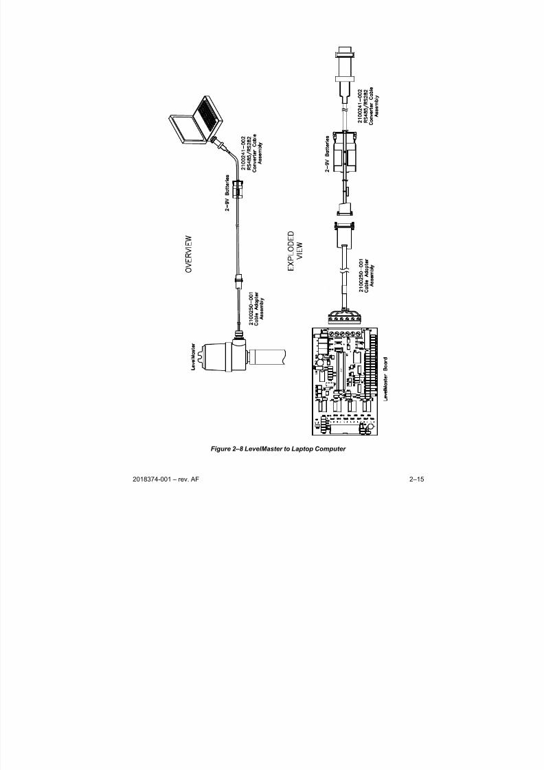
2.6.3 LMC7100, XRC, and XRCG4 Host
The Totalflow LevelMaster Controller (LMC) is a computer designed to store and
display information collected from the LevelMaster. The LMC uses a modified
version of the XRC electronic board therefore wiring instructions are identical. The
XSeries Remote Controller boards, generation 3 and 4 additionally can support
the LevelMaster.
If an installation does not require a barrier, the Levelmaster wiring can go directly
to the LMC or XRC. As shown in Figure 2–11, the LevelMaster may be connected
to either Comm 1 or Comm 2 (Figure 2–12).
For more information on the LMC or XRC see Chapter 3, Setup.
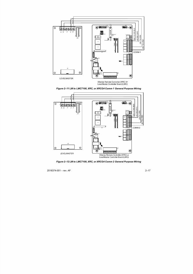
2.6.4 6700 FCU Host
The Totalflow 6700 series flow computers can support LevelMasters as well as
their duties as a flow computer. Figure 2–13 shows the LevelMaster connected
directly to the 6700 electronics board. For more information on setting up the 6700
FCU, see Chapter 3 - Setup.
The 6700 electronics board contains three communication ports which can be RS-232 or RS-485, depending on the communication module installed. Comm 1 (J4),
Comm 2 (J5) and Comm 3 (J6) all wire up identically. The exception to this is if an
RS-485 I/O interface card is plugged into the 50-pin I/O expansion slot. In this
case, BUS (+) moves from terminal 4 to terminal 8.
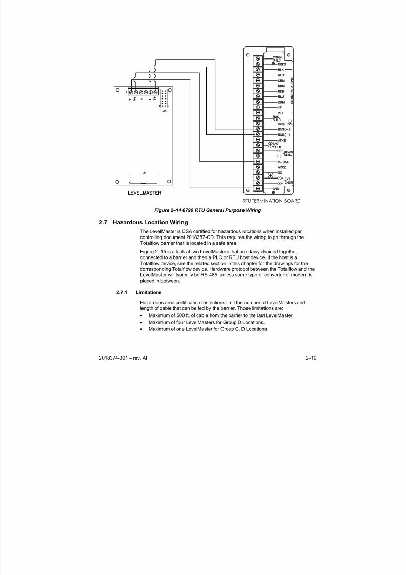
2.6.5 6790 RTU Host
The Totalflow Model 6790 RTU has supporting firmware for the LevelMaster. The
LevelMaster is typically connected to the satellite port of the RTU, which supports
RS-485 communications. As shown in Figure 2–14, the LevelMaster can be wired
directly to the RTU. For more information on setting up the 6790 RTU, see
Chapter 3 - Setup.
8/13/2019 2018374 m Naf
http://slidepdf.com/reader/full/2018374-m-naf 33/174
2018374-001 – rev. AF 2–15
U X 8
Figure 2–8 LevelMaster to Laptop Computer

8/13/2019 2018374 m Naf
http://slidepdf.com/reader/full/2018374-m-naf 34/174
2–16 2018374-001 – rev. AF
3
1
J 4 - 6 T X ( - )
J 4 - 4 T X ( + )
J 4 - 2 + 1 2
V D C
J 4 - 1 G N D
1
1 4
1
1 4
R 3 2
1 1
3
1 3
1 4
1 2
C OMM 2
C O M M
1
3
1
V -
V +
T -
T +
Figure 2–9 LM to 6400, XFC or XFCG4 Comm 1 General Purpose Wiring
Figure 2–10 LM to 6400, XFC or XFCG4 Comm 1 Comm 2 General Purpose Wiring
8/13/2019 2018374 m Naf
http://slidepdf.com/reader/full/2018374-m-naf 35/174
2018374-001 – rev. AF 2–17
Figure 2–11 LM to LMC7100, XRC, or XRCG4 Comm 1 General Purpose Wiring
Figure 2–12 LM to LMC7100, XRC, or XRCG4 Comm 2 General Purpose Wiring
8/13/2019 2018374 m Naf
http://slidepdf.com/reader/full/2018374-m-naf 36/174
2–18 2018374-001 – rev. AF
J 1 5
J 1 6
J 2 J
1 8
J 1 9
J 2 0
J 8
J 1 4
J 1
J 3 J
1 1 J
1 2
1 3
3
2
4
1
7
6
8
5
1 0
1 1
1 2
9
6 7 0 0 E L E C T R O N I C S B O A R D
C O M M 1
( J 4 ) , C O M M 2
( J 5 ) , C O M M 3
( J 6 )
J 1 3
J 4
J 5
J 6
J 2 1
J 1 0
O N
-
J 1 7
J 9
O F F
Figure 2–13 6700 FCU General Purpose Wiring
8/13/2019 2018374 m Naf
http://slidepdf.com/reader/full/2018374-m-naf 37/174
2018374-001 – rev. AF 2–19
RTU TERMINATION BOARD
Figure 2–14 6790 RTU General Purpose Wiring
2.7 Hazardous Location Wiring
The LevelMaster is CSA certified for hazardous locations when installed per
controlling document 2018387-CD. This requires the wiring to go through the
Totalflow barrier that is located in a safe area.
Figure 2–15 is a look at two LevelMasters that are daisy chained together,
connected to a barrier and then a PLC or RTU host device. If the host is a
Totalflow device, see the related section in this chapter for the drawings for the
corresponding Totalflow device. Hardware protocol between the Totalflow and the
LevelMaster will typically be RS-485, unless some type of converter or modem is
placed in between.
2.7.1 LimitationsHazardous area certification restrictions limit the number of LevelMasters and
length of cable that can be fed by the barrier. Those limitations are:
• Maximum of 500 ft. of cable from the barrier to the last LevelMaster.
• Maximum of four LevelMasters for Group D Locations.
• Maximum of one LevelMaster for Group C, D Locations.
8/13/2019 2018374 m Naf
http://slidepdf.com/reader/full/2018374-m-naf 38/174
2–20 2018374-001 – rev. AF
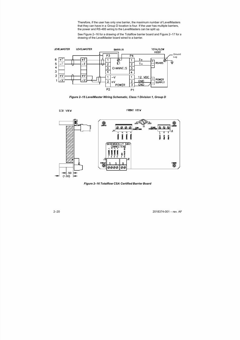
Therefore, if the user has only one barrier, the maximum number of LevelMasters
that they can have in a Group D location is four. If the user has multiple barriers,
the power and RS-485 wiring to the LevelMasters can be split up.
See Figure 2–16 for a drawing of the Totalflow barrier board and Figure 2–17 for a
drawing of the LevelMaster board wired to a barrier.
Ground
Lug
Figure 2–15 LevelMaster Wiring Schematic, Class 1 Division 1, Group D
Figure 2–16 Totalflow CSA Certified Barrier Board
8/13/2019 2018374 m Naf
http://slidepdf.com/reader/full/2018374-m-naf 39/174
8/13/2019 2018374 m Naf
http://slidepdf.com/reader/full/2018374-m-naf 40/174
2–22 2018374-001 – rev. AF
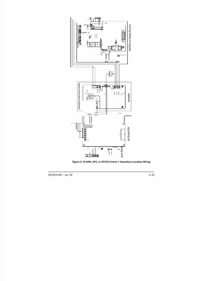
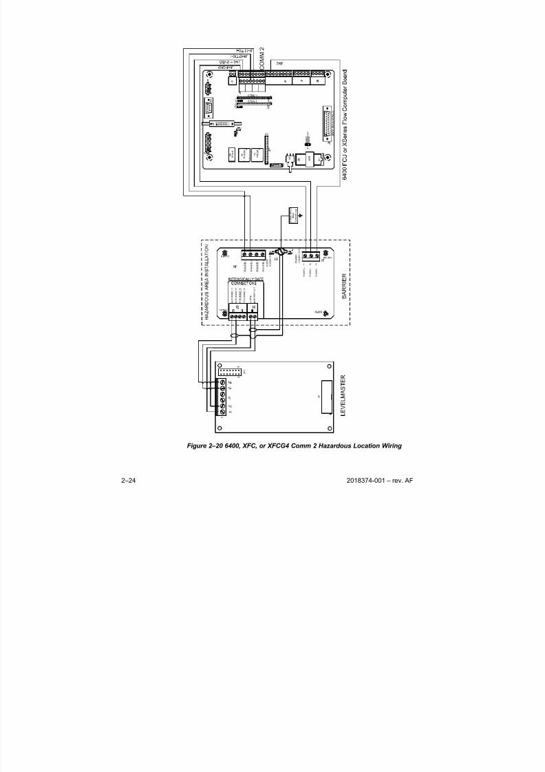
2.7.4 6400, XFC, or XFCG4 Host
The Totalflow 6400 FCU or XSeries flow computers, generation 3 and 4, can
support the LevelMaster(s) as well as perform their duties as a flow computer.
Figure 2–19 shows the wiring to the XFC Comm 1 port, and Figure 2–20 shows
the wiring to the XFC Comm 2 port. Both figures reflect the LevelMaster wired
through a barrier board for hazardous location installations.
For more information on setting up the XFC, see Chapter 3 - Setup.
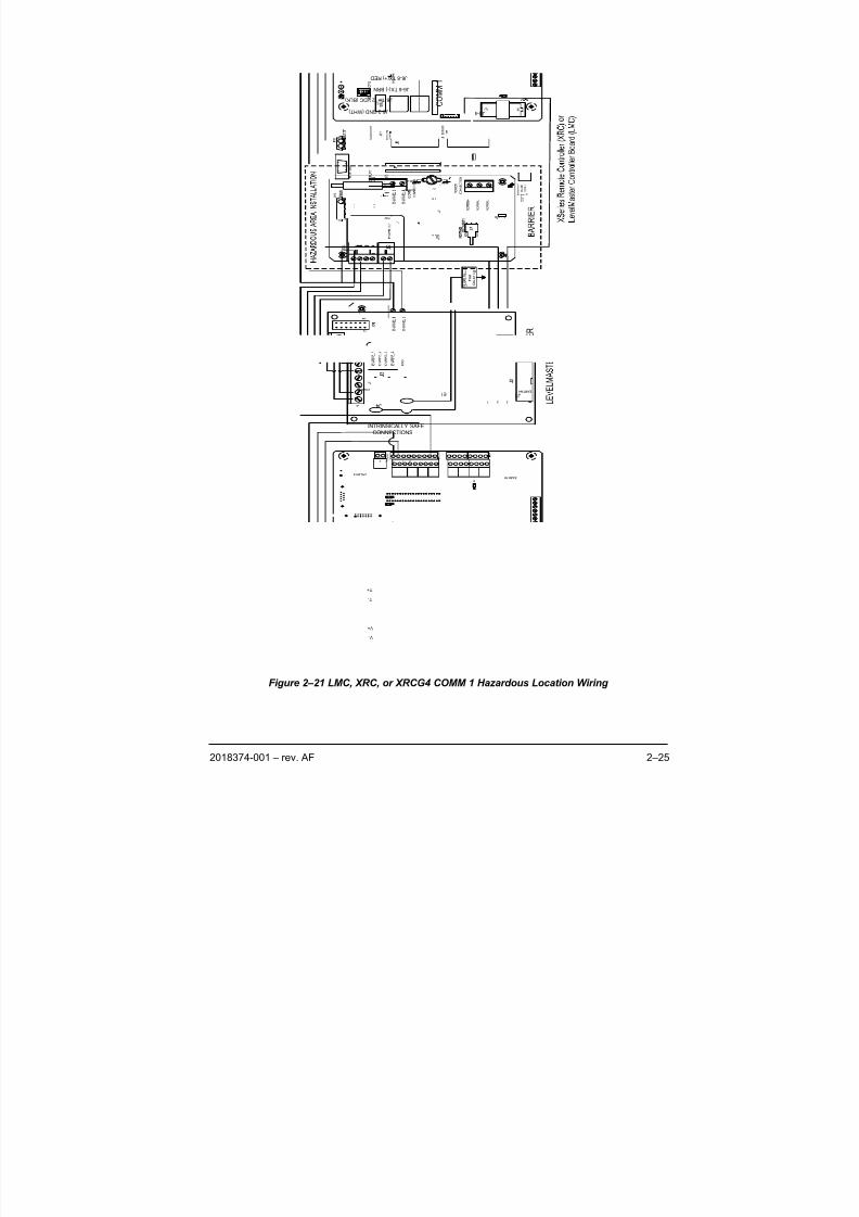
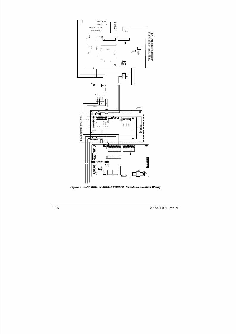
2.7.5 LMC7100, XRC, or XRCG4 Host
LevelMaster Controller (LMC) or XSeries Remote Controller (XRC) a Totalflow
computer designed to store and display information collected from the
LevelMaster. The LMC uses a modified version of the XRC electronic board
therefore wiring instructions are identical. The XSeries Remote Controller boards,
generation 3 and 4 additionally can support the LevelMaster.
As shown in, the LevelMaster may be connected to either Comm 1 (see Figure 2–
21) or Comm 2 (see Figure 2–). Both figures reflect the LevelMaster wired through
a barrier board for hazardous location installations. The wiring for both ports
supports RS-485 communications.
For more information on the LMC or XRC see Chapter 3, Setup.
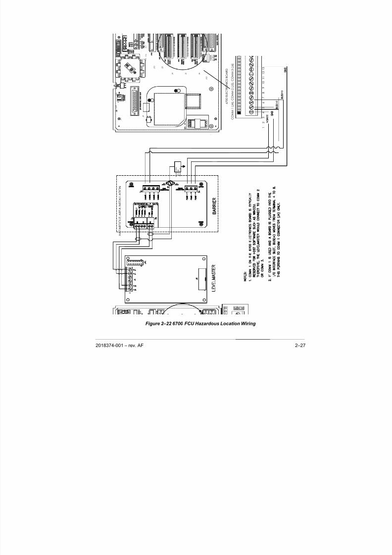
2.7.6 6700 FCU Host
The Totalflow 6700 series flow computers can support LevelMasters as well as
perform their duties as a flow computer. Figure 2–22 shows the LevelMaster
connected to the 6700 electronics board through the Totalflow barrier. For more
information on setting up the 6700, see Chapter 3 - Setup.
The 6700 electronics board contains three communication ports which can be RS-
232 or RS-485 depending on the communication’s module installed. Comm 1 (J4),
Comm 2 (J5) and Comm 3 (J6) all wire up identically except that if an RS-485 I/Ointerface card is plugged into the 50-pin I/O expansion slot, BUS (+) moves from
terminal 4 to terminal 8. The LevelMaster is typically connected to Comm 2 or
Comm 3, leaving Comm 1 for host software such as WinCCU.
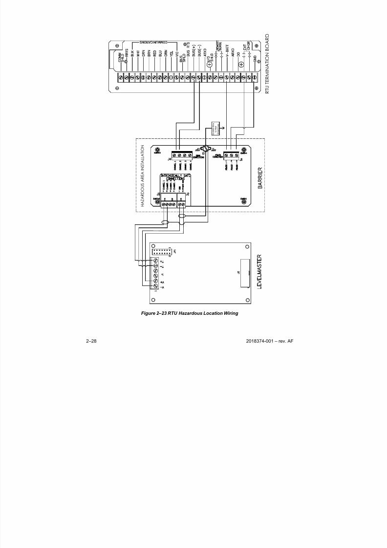
2.7.7 6790 RTU Host
The Totalflow Model 6790 RTU has supporting firmware for the LevelMaster. The
LevelMaster is typically connected to the satellite port of the RTU which supports
RS-485 communications. If the installation site does not require a barrier as
shown below (See Figure 2–23), the LevelMaster can be wired directly to the
RTU. For more information on setting up the 6790 RTU, see Chapter 3 - Setup.
8/13/2019 2018374 m Naf
http://slidepdf.com/reader/full/2018374-m-naf 41/174
2018374-001 – rev. AF 2–23
Figure 2–19 6400, XFC, or XFCG4 Comm 1 Hazardous Location Wiring
31
J 4 - 6 T X ( - )
J 4 - 4 T X ( + )
J 4 - 2 + 1 2 V D C
J 4 - 1 G N D
1
1 4
1
1 4
R 3 2 1
1 3
13
14
1
2
COMM 2
COMM 1
3 1
V -
V +
T -
T +
J 6 - 2
2
CONNECTIONS
INTRINSICALLY SAFE
E A R T H 1
J 1 E A R T H 4
3 2 1
E 1
EARTH2
EARTH3
1 4 3 2 1
J 4
8/13/2019 2018374 m Naf
http://slidepdf.com/reader/full/2018374-m-naf 42/174
2–24 2018374-001 – rev. AF
Figure 2–20 6400, XFC, or XFCG4 Comm 2 Hazardous Location Wiring
8/13/2019 2018374 m Naf
http://slidepdf.com/reader/full/2018374-m-naf 43/174
2018374-001 – rev. AF 2–25
Figure 2–21 LMC, XRC, or XRCG4 COMM 1 Hazardous Location Wiring
X A 2
1
1
R 3 2 1
14
13
2
1
2 1
1 3
1 3
2 1
C O M M : 2
C O M M : 1
J 6 - 1 + 1 2 V D C ( B L K )
J 6 - 2 G N D ( W H T )
J 6 - 6 T X ( - ) B R N
J 6 - 8 T X ( + ) R E D
2
CONNECTIONS
INTRINSICALLY SAFE
E A R T H 1
J 1 E A R T H 4
3 2 1
E 1
EARTH2
EARTH3
1 4 3 2 1
J 4
V -
V +
T -
T +
J 8 - 4
8/13/2019 2018374 m Naf
http://slidepdf.com/reader/full/2018374-m-naf 44/174
2–26 2018374-001 – rev. AF
Figure 2– LMC, XRC, or XRCG4 COMM 2 Hazardous Location Wiring
X A 2
1
1
R 3 2 1
14
13
2
1
2 1
1 3
1 3
2 1
C O M M : 2
C O M M : 1
J 6 - 1 + 1 2 V D C ( B L K )
J 6 - 2 G N D ( W H T )
J 6 - 6 T X ( - ) B R N
J 6 - 8 T X ( + ) R E D
2
CONNECTIONS
INTRINSICALLY SAFE
E A R T H 1
J 1 E A R T H 4
3 2 1
E 1
EARTH2
EARTH3
1 4 3 2 1
J 4
V -
V +
T -
T +
J 8 - 4
8/13/2019 2018374 m Naf
http://slidepdf.com/reader/full/2018374-m-naf 45/174
2018374-001 – rev. AF 2–27
J 1 3
J 4
J 5
J 6
J 2 1
J 1 0
J 1 7
J 9
O F F
O N
-
J 1 5
J 1 6
J 2 J
1 8
J 1 9
J 2 0
J 8
J 1 4
J 1
J 3 J
1 1 J
1 2
1 3
3
2
4
1
7
6
8
5
1 0
1 1
1 2
9
6 7 0 0 E L E C T R O N I C S B O A R D
C O M M 1
( J 4 ) , C O M M 2
( J 5 ) , C O M M 3 ( J 6 )
H A Z A R D O U S A R E A I N S T A L L A T I O N
1 2 A W G W i r e
t o H o s t
G r o u n d L u g
Figure 2–22 6700 FCU Hazardous Location Wiring
8/13/2019 2018374 m Naf
http://slidepdf.com/reader/full/2018374-m-naf 46/174
2–28 2018374-001 – rev. AF
H A Z A R D O U S A R E A I N S T A L L A T I O N
1 2 A W G W i r e
t o H o s t
G r o u n d L u g
R T U T E R M I N
A T I O N B O A R D
Figure 2–23 RTU Hazardous Location Wiring
8/13/2019 2018374 m Naf
http://slidepdf.com/reader/full/2018374-m-naf 47/174
2018374-001 – rev. AF 3-29
3.0 SOFTWARE SETUP
3.1 Overview
This chapter provides information on how to set up a LevelMaster. The Setup
section is broken down based on the software the user will be using with the
LevelMaster and the equipment used. Setup information is included for interfacingthe LevelMaster with a laptop computer using MasterLink, PCCU version 4.14 and
earlier using the console mode, PCCU32 version 4.14 and earlier with Tank
Gauge Upgrade installed and PCCU32 version 4.30 and later.
Initially, MasterLink should be used to assign the ID to the LevelMaster prior to
continuing with the host software. Using the chart below, determine which set of
instructions need to be used, and proceed to that page.
The LevelMaster should be installed and power applied at this point. The
LevelMaster is functional after power is applied.
Not all features are addressed in this chapter. The intent of
this chapter is to discuss typical items that would be used
when programming the communication and operations of theLevelMaster. For additional information about items that are
displayed on PCCU32 screens, use the Help button on those
individual screens.
To determine the version of PCCU32 software that is being
used, click on the Help menu on the program bar at the top of
the screen. Move down to About PCCU32 and select it. This
will open the screen which lists the version and serial
number.
If the software is… And thehardware is… Use the following instructions
MasterLink LevelMaster only MasterLink Setup
6400 or 6700 FCU Console Mode Flow Computer SetupPCCU32 4.14 or earlier
6790 RTU Console Mode RTU Setup
PCCU32 4.14 or earlier
with Tank Gauge
Upgrade
6400 or 6700 FCU Tank Gauge Upgrade Setup
XFC XSeries SetupPCCU32 4.30–6.xx
XRC XSeries Setup
XFCG4 XSeries G4 Setup
PCCU32 7.0 or later XRCG4 XSeries G4 Setup
3.2 MasterLink Setup
As a preparation for setting up the LevelMaster for use with a Totalflow host,
MasterLink should be used to assign an ID number to each unit. As this
communicates directly with the LevelMaster electronics board, this ID is stored in
an EEPROM located on this board.
8/13/2019 2018374 m Naf
http://slidepdf.com/reader/full/2018374-m-naf 48/174
3-30 2018374-001 – rev. AF
When the equipment configuration does not contain a host unit such as a
Totalflow XFC or flow computer, MasterLink is the primary tool used for setup and
calibration. MasterLink is a Windows-based program designed specifically for that
purpose.
The following procedure assumes the LevelMaster is installed and power is
applied. The procedure will describe how to use the MasterLink software package
to enter the required setup and calibration information. For additional informationwhen using MasterLink, click on the Help menu item on the main screen.
Additionally, most of the individual screens have a Help button providing
information for that screen
3.2.1 Tools Required
• Laptop computer
• MasterLink software package
• RS-485 to RS-232 converter. The LevelMaster is RS-485 only and will need to
be converted to RS-232 to communicate with the laptop computer. A
converter with cable and connectors is available from Totalflow:
• Cable with connector that mates to the communications connector on
the LevelMaster electronics board.
or
• Cable with alligator clips to connect to wires or screw terminals.
3.2.2 Instructions
1) Connect the RS-485/RS232 converter cable to the communication ports of
the laptop computer and to the LevelMaster communication connector.
2) Power up the laptop computer.
3) Start the MasterLink software program.
4) From the Comm. Port window, use the down arrow to select the
communications port of the laptop that is being used.
5) From the Baud Rate window, use the down arrow to select 1200 or 9600
baud. The LevelMaster should default to 9600 when first powered up. The
rate in the window tells the software what baud rate to use and must match
the LevelMaster’s baud rate.
6) If no names exist or a new location is to be used, right click inside the
screen (white area) and select Add New Location. Enter up to 25 characters
for a location.
7) To add a LevelMaster to an existing (or just created) location, click on the
appropriate location name on the screen and then right click, and select Add
New LevelMaster . After the user has added the new LevelMaster, make
sure the location is highlighted.8) Click on the Setup LevelMaster button.
9) One Unit: Check the selection that says, “I have only one LevelMaster
connected to communication port and I want to set it up” and then click the
Setup LevelMaster button.
10) Daisy Chain Multiple Units: If the user has more than one unit on the RS-
485 bus, existing units should have their own IDs already assigned. The
new unit will default to 1 for an ID. Therefore, check the selection that says,
8/13/2019 2018374 m Naf
http://slidepdf.com/reader/full/2018374-m-naf 49/174
2018374-001 – rev. AF 3-31
“I know the ID of the LevelMaster that I want to setup”, enter 1 for the ID
and select the Setup LevelMaster button.
11) The user will see a Monitor screen and a communication attempt will be
made with the LevelMaster.
12) If communications are not established, the Monitor screen will remain, and
the communications errors will appear at the bottom of the screen. If thishappens, close the screen, change to the other baud rate and start with
step 8 again. If still no success, verify the wiring per the wiring section in
Chapter 2.
When communication is established, the Monitor screen will
then appear and, after a short delay, temperature and tank
level readings should appear. This screen is for information
only and is an indication to the user that communications are
working. The only user entry here is a check box to cause the
screen to be continuously updated.
13) One Unit: A screen will appear asking if the user would like to add thisLevelMaster to their list. Click the Yes button. Another screen will appear
asking the user to enter a name for the LevelMaster. Enter up 15 characters
for a name and click OK . This name will only be used for the location file,
which the user can view later.
14) Multiple Units: Skip to step 11.
15) Click on the Setup tab and enter an ID from 1 to 99 for the LevelMaster.
Make sure each unit has its own individual ID, especially units on the same
RS-485 bus. Click Set New ID. The user will be notified when that is
complete; click OK . The user is the asked “Would you like to update the
new ID to your list?” Click Yes.
16) The user can change the baud rate if desired. The Set Baud Rate button will
indicate the opposite baud rate that is currently being used. The baud ratechange will only take affect after the LevelMaster has been powered off and
back on. A new unit defaults to 9600 baud and is recommended unless
communications is not reliable.
17) Click the Hardware Change button.
18) Select the option that says “I Just Moved the LevelMaster to a New Tank”.
This causes the LevelMaster to run a program which establishes new offset
voltages based on its new surroundings.
19) Click the Next button.
20) Read the message and then click the Next button. Follow the instructions.
21) Click OK when done
If unit will be operated by a Totalflow host, do not calibrate
the floats, also referred to as Level Bias, in MasterLink
during the initial setup. Performing the calibration through
the Totalflow host provides an audit trail.
22) Although the LevelMaster is a highly accurate device, there can be subtle
errors such as the fluids gravity being slightly different than what the float
was calibrated. This can cause the float to float either slightly higher or
8/13/2019 2018374 m Naf
http://slidepdf.com/reader/full/2018374-m-naf 50/174
3-32 2018374-001 – rev. AF
lower in the fluid. Therefore, if the user has been manually gauging the
levels and feels confident with the measurements, the user can enter those
values here on the Setup tab. Entering the tank levels generates a
calibration offset within the LevelMaster.
23) If the user will not be using a separate Totalflow host to operate with
the LevelMaster, continue with this step; otherwise, skip to Step 19.
24) To enter the levels, enter the measured value for the upper or only level in
the Tank Level 1 window, and click the Set Tank Level 1 button. The user
will need to acknowledge a screen that says when it is done.
25) If the LevelMaster has two floats, enter the value for the lower level in the
Tank Level 2 window, and click the Set Tank Level 2 button. The user will
again need to acknowledge a screen that says when it is done.
The user can now click on the Monitor tab, check the Continuous Monitor
box and wait for an update. The new reading(s) should agree with the
entered value(s).
26) If any changes have been made since the last setup file save, click on the
Upload/Download tab. This screen allows the user to save all the
parameters within the LevelMaster to a file. Either use the default path andname, or enter a new path and name. Upon completion, click the Read and
Save Data to File button. The default name is the base serial number of the
LevelMaster.
27) Click the Close button to return to the main MasterLink screen.
28) If the user has several locations, (e.g. large tank batteries or fields), they
may want to create different location files. This allows the user to group
certain tanks or locations in different files. To name the displayed location
file, select Location from the file menu along the top of the screen and then
select Save Location File. Enter a file name, and click the Save button. If
the user never names a location file, all information will always go into the
same default file named FirstSetup. The last location file viewed will, by
default, be displayed when the program is started again. To open a differentfile, click Location from the file menu and select Open Location File. Click
on the appropriate file name and then click open.
While the user can now read basic tank levels at this point,
they should proceed to the Calibration section of this chapter
to set up the tank for volume.
3.3 Console Mode Flow Computer Setup
Totalflow’s Model 6400 and 6700 flow computers can be set up to provide support
for the LevelMaster using PCCU32 version 4.14 or older. The flow computer
would be connected to the LevelMaster via RS-485 protocol. The FCU will poll theLevelMaster at user programmable intervals and store the current level(s) and
temperature data into registers known as Application, Array, Registers (App,
Array, Reg). This data is available to Totalflow software packages WinCCU32 and
PCCU32.
Set up for the LevelMaster data in the flow computer is done using the Console
mode found in PCCU32. An alternate method is to use a terminal emulator such
as HyperTerm found in Windows. When using HyperTerm in Windows, the user
8/13/2019 2018374 m Naf
http://slidepdf.com/reader/full/2018374-m-naf 51/174
2018374-001 – rev. AF 3-33
will need to enter the protocol information shown below and then type “CONS” to
get into the Console mode.
The following procedure assumes that the LevelMaster has been physically
installed and wired to the FCU board, per the instructions in Chapter 2 and that
the FCU is already installed and operating. For more information on the FCU,
please see the User Manual for the corresponding Totalflow model.
3.3.1 Tools Required
• Laptop computer
• PCCU32 version 4.14 or older
• 9 pin computer cable terminated with military connector, available in 8, 25 and
50 foot lengths
3.3.2 Instructions
1) Connect the computer to the local communications port on the side of the
FCU enclosure.
2) Open the PCCU32 software.
The icon or tool bar is located directly below the program bar
on the PCCU32 screen. By moving the mouse pointer over
each icon and pausing, a help label will identify the command
assigned to that icon. See the PCCU32 help files for more
information.
By viewing the status bar across the bottom of the PCCU32
screen, the user will see the status of their connection and
their login name.
3) Make the software connection to the FCU by clicking the Connect to
Totalflow icon and then the Entry button.
4) Locate Operate on the program bar. Open the pull-down menu and selectConsole Mode.
The first time the Console Mode screen appears, it may be
too small to show all of the information required. Hold the
mouse pointer over one of the corners until the diagonal
double ended arrow displays. Click and drag the window to
the desired height and width. The user may also accomplish
this by dragging the side and the bottom of the screen
separately until it is large enough. Microsoft Windows
remembers the screen size for the next time that the window
is opened. The user can change it at any time.
5) The initial screen may appear similar to the screen shown in Figure 3–1.
Differences may be in the version of the prom and may reflect other
capabilities than shown here. See Table 3—1 for Console Mode, Local
Commands to use in editing the setup screens.
For the purpose of this procedure, it is assumed that the user’s screen is
identical to this one. If it is not, the user will need to locate the proper group
number and enter it instead of the numbers used here.
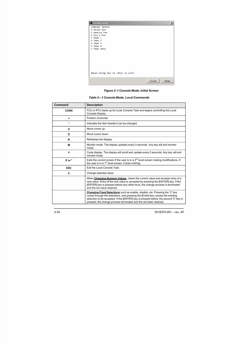
8/13/2019 2018374 m Naf
http://slidepdf.com/reader/full/2018374-m-naf 52/174
3-34 2018374-001 – rev. AF
Figure 3–1 Console Mode, Initial Screen
Table 3—1 Console Mode, Local Commands
Command Description
CONS FCU or RTU starts up its Local Console Task and begins controlling the Local
Console Display.
> Position of prompt.
* Indicates the item beside it can be changed.
U Move cursor up.
D Move cursor down.
R Refreshes the display.
M Monitor mode. The display updates every 5 seconds. Any key will exit monitor
mode.
Y Cycle display. The display will scroll and update every 5 seconds. Any key will exit
monitor mode.
E or * Exits the current screen if the user is in a 2nd
level screen making modifications. If
the user is in a 1st level screen, it does nothing.
ESC Exit the Local Console Task.
C Change selected value:
When Changing Numeric Values, clears the current value and accepts entry of a
new value. Entry of the new value is accepted by pressing the [ENTER] key. If the
[ENTER] key is pressed before any other keys, the change process is terminated
and the old value retained.
Changing Fixed Selections such as enable, disable, etc. Pressing the 'C' key
cycles through the selections, and pressing the [Enter] key causes the existing
selection to be accepted. If the [ENTER] key is pressed before the second 'C' key is
pressed, the change process terminates and the old state retained.
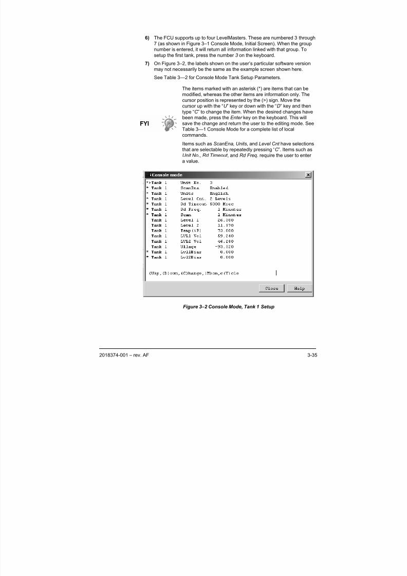
8/13/2019 2018374 m Naf
http://slidepdf.com/reader/full/2018374-m-naf 53/174
2018374-001 – rev. AF 3-35
6) The FCU supports up to four LevelMasters. These are numbered 3 through
7 (as shown in Figure 3–1 Console Mode, Initial Screen). When the group
number is entered, it will return all information linked with that group. To
setup the first tank, press the number 3 on the keyboard.
7) On Figure 3–2, the labels shown on the user’s particular software version
may not necessarily be the same as the example screen shown here.
See Table 3—2 for Console Mode Tank Setup Parameters.
The items marked with an asterisk (*) are items that can be
modified, whereas the other items are information only. The
cursor position is represented by the (>) sign. Move the
cursor up with the “U ” key or down with the “D” key and then
type “C ” to change the item. When the desired changes have
been made, press the Enter key on the keyboard. This will
save the change and return the user to the editing mode. See
Table 3—1 Console Mode for a complete list of local
commands.
Items such as ScanEna, Units, and Level Cnt have selections
that are selectable by repeatedly pressing “C ”. Items such asUnit No., Rd Timeout , and Rd Freq. require the user to enter
a value.
Figure 3–2 Console Mode, Tank 1 Setup
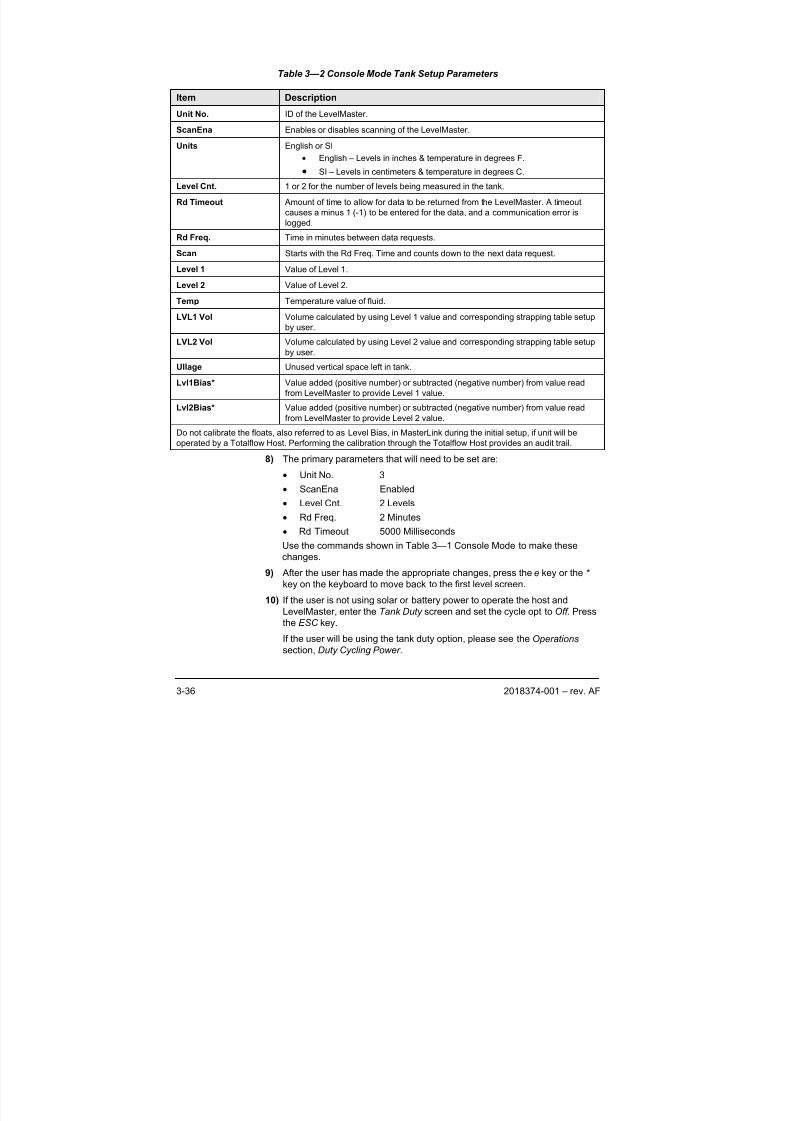
8/13/2019 2018374 m Naf
http://slidepdf.com/reader/full/2018374-m-naf 54/174
3-36 2018374-001 – rev. AF
Table 3—2 Console Mode Tank Setup Parameters
Item Description
Unit No. ID of the LevelMaster.
ScanEna Enables or disables scanning of the LevelMaster.
Units English or SI
• English – Levels in inches & temperature in degrees F.
• SI – Levels in centimeters & temperature in degrees C.
Level Cnt. 1 or 2 for the number of levels being measured in the tank.
Rd Timeout Amount of time to allow for data to be returned from the LevelMaster. A timeout
causes a minus 1 (-1) to be entered for the data, and a communication error is
logged.
Rd Freq. Time in minutes between data requests.
Scan Starts with the Rd Freq. Time and counts down to the next data request.
Level 1 Value of Level 1.
Level 2 Value of Level 2.
Temp Temperature value of fluid.
LVL1 Vol Volume calculated by using Level 1 value and corresponding strapping table setup
by user.
LVL2 Vol Volume calculated by using Level 2 value and corresponding strapping table setup
by user.
Ullage Unused vertical space left in tank.
Lvl1Bias* Value added (positive number) or subtracted (negative number) from value read
from LevelMaster to provide Level 1 value.
Lvl2Bias* Value added (positive number) or subtracted (negative number) from value read
from LevelMaster to provide Level 2 value.
Do not calibrate the floats, also referred to as Level Bias, in MasterLink during the initial setup, if unit will beoperated by a Totalflow Host. Performing the calibration through the Totalflow Host provides an audit trail.
8) The primary parameters that will need to be set are:
• Unit No. 3
• ScanEna Enabled
• Level Cnt. 2 Levels
• Rd Freq. 2 Minutes
• Rd Timeout 5000 Milliseconds
Use the commands shown in Table 3—1 Console Mode to make these
changes.
9) After the user has made the appropriate changes, press the e key or the * key on the keyboard to move back to the first level screen.
10) If the user is not using solar or battery power to operate the host and
LevelMaster, enter the Tank Duty screen and set the cycle opt to Off . Press
the ESC key.
If the user will be using the tank duty option, please see the Operations
section, Duty Cycling Power .
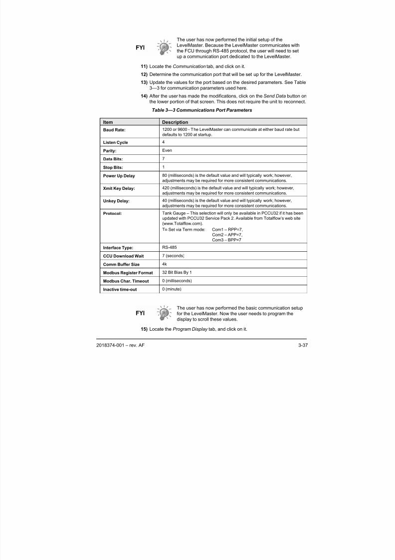
8/13/2019 2018374 m Naf
http://slidepdf.com/reader/full/2018374-m-naf 55/174
2018374-001 – rev. AF 3-37
The user has now performed the initial setup of the
LevelMaster. Because the LevelMaster communicates with
the FCU through RS-485 protocol, the user will need to set
up a communication port dedicated to the LevelMaster.
11) Locate the Communication tab, and click on it.
12) Determine the communication port that will be set up for the LevelMaster.
13) Update the values for the port based on the desired parameters. See Table
3—3 for communication parameters used here.
14) After the user has made the modifications, click on the Send Data button on
the lower portion of that screen. This does not require the unit to reconnect.
Table 3—3 Communications Port Parameters
Item Description
Baud Rate: 1200 or 9600 - The LevelMaster can communicate at either baud rate but
defaults to 1200 at startup.
Listen Cycle 4
Parity: Even
Data Bits: 7
Stop Bits: 1
Power Up Delay 80 (milliseconds) is the default value and will typically work; however,
adjustments may be required for more consistent communications.
Xmit Key Delay: 420 (milliseconds) is the default value and will typically work; however,
adjustments may be required for more consistent communications.
Unkey Delay: 40 (milliseconds) is the default value and will typically work; however,
adjustments may be required for more consistent communications.
Protocol: Tank Gauge – This selection will only be available in PCCU32 if it has beenupdated with PCCU32 Service Pack 2. Available from Totalflow’s web site
(www.Totalflow.com).
To Set via Term mode: Com1 – RPP=7,
Com2 – APP=7,
Com3 – BPP=7
Interface Type: RS-485
CCU Download Wait 7 (seconds)
Comm Buffer Size 4k
Modbus Register Format 32 Bit Bias By 1
Modbus Char. Timeout 0 (milliseconds)
Inactive time-out 0 (minute)
The user has now performed the basic communication setup
for the LevelMaster. Now the user needs to program the
display to scroll these values.
15) Locate the Program Display tab, and click on it.
8/13/2019 2018374 m Naf
http://slidepdf.com/reader/full/2018374-m-naf 56/174
3-38 2018374-001 – rev. AF
16) Click in the Value column next to the list of displays, and a drop-down menu
of the available displays will appear.
17) Click on the tank number and desired display item. It may appear similar to
this:
TNK1LVL1
This will set up Tank 1, Level 1 to display. Press the Tab key on thekeyboard. This will return all associated values for this display item.
18) Change the value for the display interval to at least five (seconds). The
default was set to zero which turns the display item off.
19) Click on the Send Data button on the lower portion of that screen. This does
not require the unit to reconnect.
20) Repeat steps 15 through 19 for each display item the user would like to
modify.
While the user can now read basic tank levels at this point,
they should proceed to the Calibration section of this chapter
to setup the bias, if needed.
The user has now performed the basic setup of the
LevelMaster. The final step is to save all the configuration
files to the hard drive.
21) Ensure that the device configuration files are backed up, and click on the
Save button. This procedure will take a few minutes. After the information
has been collected, the Device Configuration File Save screen will appear
and ask for the location to save the file. The destination directory may be
something like this:
C:/PCCU32/Devconfi/_FCU-6410.fcu
See the PCCU32 help files for more information.
When the FCU is warm booted, it will automatically load
these configuration files at startup.
3.4 Console Mode RTU Setup
Totalflow’s Model 6790 RTU provides support for the LevelMaster through
PCCU32 version 4.14 or older. The RTU will poll the LevelMaster via RS-485
protocol and, at programmable intervals, store the current level(s) and
temperature data into registers known as Application, Array, Registers (App,
Array, Reg). The data is then available to the RTU for processing. This data is
also available in Totalflow software packages WinCCU32, PCCU32 and TDS32.
Setup for the LevelMaster data in the RTU is done using the Console mode found
in PCCU32. An alternate method is to use a terminal emulator such as HyperTerm
found in Windows. When using HyperTerm in Windows, the user will need to enter
the protocol information shown below and then type “CONS” to get into the
Console mode.
8/13/2019 2018374 m Naf
http://slidepdf.com/reader/full/2018374-m-naf 57/174
2018374-001 – rev. AF 3-39
Most RTU systems are custom designed to fit specific user
needs; thus, the firmware deals with user applications. Each
RTU will be accompanied by its own custom documentation
detailing those applications and their setup; therefore, these
instructions are general in nature. Please refer to the user’s
guide provided with the RTU. If the user has a project with
specific requirements, get in touch with the local Totalflowsales person or call Totalflow at (800) 442-3097 and ask for a
Projects person.
3.4.1 Tools Required
• Laptop computer
• PCCU32 version 4.14 or older
• 9 pin Computer Cable terminated with military connector, available in 8, 25
and 50 foot lengths.
3.4.2 Instructions
1) Connect the computer to the local communications port on the side of theRTU enclosure.
2) Open the PCCU32 software.
The icon or tool bar is located directly below the program bar
on the PCCU32 screen. By moving the mouse pointer over
each icon and pausing, a help label will identify the command
assigned to that icon. See the PCCU32 help files for more
information.
By viewing the status bar across the bottom of the PCCU32
screen, the user will see the status of the connection and their
login name.
3) Make the software connection to the RTU by clicking the Connect to
Totalflow icon and then the Entry button.
4) Locate Operate on the program bar. Open the pull-down menu, and select
Console Mode.
The first time the Console Mode screen appears, it may be
too small to show all of the information required. Hold the
mouse pointer over one of the corners until the diagonal
double ended arrow appears. Click and drag the window until
it is the desired height and width. The user may also
accomplish this by dragging the side and the bottom of the
screen separately until it is large enough. Microsoft Windows
remembers the screen size for the next time that the windowis opened. The user may change it at any time.
5) The initial screen may appear similar to the screen shown in Figure 3–3
Console Mode, Initial Screen. Differences may be in the version of the prom
and may reflect other capabilities than what is shown here.
Information is divided into groups, and, since each RTU is typically
customized, the number of groups and their labels will vary from job to job.
For the purpose of this procedure, it is assumed that the user’s screen is
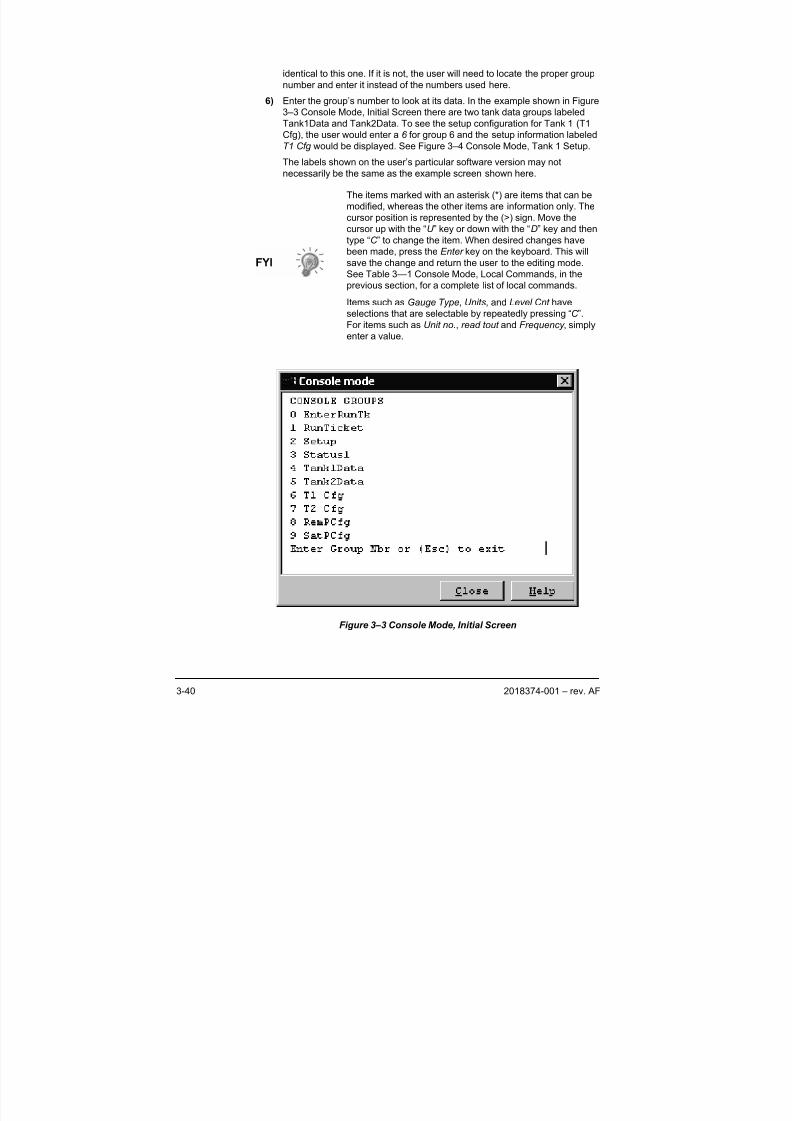
8/13/2019 2018374 m Naf
http://slidepdf.com/reader/full/2018374-m-naf 58/174
3-40 2018374-001 – rev. AF
identical to this one. If it is not, the user will need to locate the proper group
number and enter it instead of the numbers used here.
6) Enter the group’s number to look at its data. In the example shown in Figure
3–3 Console Mode, Initial Screen there are two tank data groups labeled
Tank1Data and Tank2Data. To see the setup configuration for Tank 1 (T1
Cfg), the user would enter a 6 for group 6 and the setup information labeled
T1 Cfg would be displayed. See Figure 3–4 Console Mode, Tank 1 Setup.
The labels shown on the user’s particular software version may not
necessarily be the same as the example screen shown here.
The items marked with an asterisk (*) are items that can be
modified, whereas the other items are information only. The
cursor position is represented by the (>) sign. Move the
cursor up with the “U ” key or down with the “D” key and then
type “C ” to change the item. When desired changes have
been made, press the Enter key on the keyboard. This will
save the change and return the user to the editing mode.
See Table 3—1 Console Mode, Local Commands, in the
previous section, for a complete list of local commands.Items such as Gauge Type, Units, and Level Cnt have
selections that are selectable by repeatedly pressing “C ”.
For items such as Unit no., read tout and Frequency , simply
enter a value.
Figure 3–3 Console Mode, Initial Screen
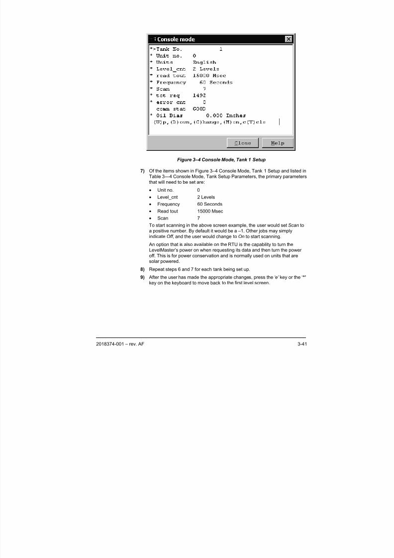
8/13/2019 2018374 m Naf
http://slidepdf.com/reader/full/2018374-m-naf 59/174
2018374-001 – rev. AF 3-41
Figure 3–4 Console Mode, Tank 1 Setup
7) Of the items shown in Figure 3–4 Console Mode, Tank 1 Setup and listed in
Table 3—4 Console Mode, Tank Setup Parameters, the primary parameters
that will need to be set are:
• Unit no. 0
• Level_cnt 2 Levels
• Frequency 60 Seconds
• Read tout 15000 Msec
• Scan 7
To start scanning in the above screen example, the user would set Scan to
a positive number. By default it would be a –1. Other jobs may simply
indicate Off , and the user would change to On to start scanning.
An option that is also available on the RTU is the capability to turn the
LevelMaster’s power on when requesting its data and then turn the power
off. This is for power conservation and is normally used on units that are
solar powered.
8) Repeat steps 6 and 7 for each tank being set up.
9) After the user has made the appropriate changes, press the ‘e’ key or the ‘*’
key on the keyboard to move back to the first level screen.
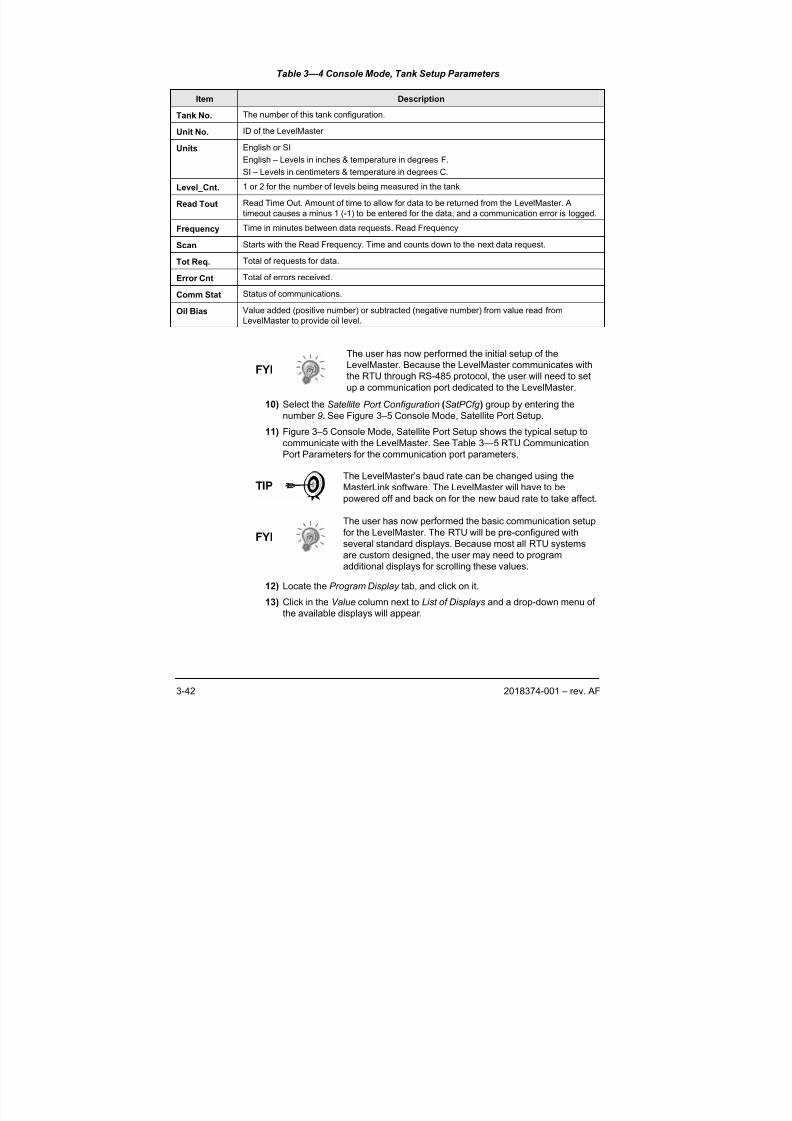
8/13/2019 2018374 m Naf
http://slidepdf.com/reader/full/2018374-m-naf 60/174
3-42 2018374-001 – rev. AF
Table 3—4 Console Mode, Tank Setup Parameters
Item Description
Tank No. The number of this tank configuration.
Unit No. ID of the LevelMaster
Units English or SI
English – Levels in inches & temperature in degrees F.
SI – Levels in centimeters & temperature in degrees C.
Level_Cnt. 1 or 2 for the number of levels being measured in the tank.
Read Tout Read Time Out. Amount of time to allow for data to be returned from the LevelMaster. A
timeout causes a minus 1 (-1) to be entered for the data, and a communication error is logged.
Frequency Time in minutes between data requests. Read Frequency
Scan Starts with the Read Frequency. Time and counts down to the next data request.
Tot Req. Total of requests for data.
Error Cnt Total of errors received.
Comm Stat Status of communications.
Oil Bias Value added (positive number) or subtracted (negative number) from value read from
LevelMaster to provide oil level.
The user has now performed the initial setup of the
LevelMaster. Because the LevelMaster communicates with
the RTU through RS-485 protocol, the user will need to set
up a communication port dedicated to the LevelMaster.
10) Select the Satellite Port Configuration (SatPCfg ) group by entering the
number 9. See Figure 3–5 Console Mode, Satellite Port Setup.
11) Figure 3–5 Console Mode, Satellite Port Setup shows the typical setup tocommunicate with the LevelMaster. See Table 3—5 RTU Communication
Port Parameters for the communication port parameters.
The LevelMaster’s baud rate can be changed using the
MasterLink software. The LevelMaster will have to be
powered off and back on for the new baud rate to take affect.
The user has now performed the basic communication setup
for the LevelMaster. The RTU will be pre-configured with
several standard displays. Because most all RTU systems
are custom designed, the user may need to program
additional displays for scrolling these values.
12) Locate the Program Display tab, and click on it.
13) Click in the Value column next to List of Displays and a drop-down menu of
the available displays will appear.
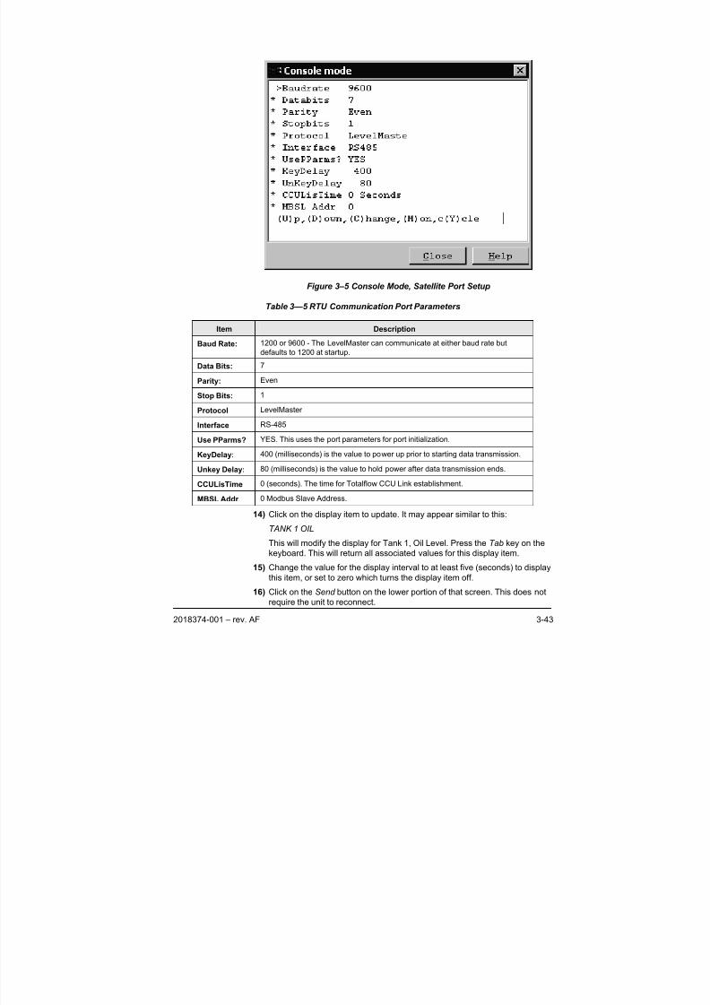
8/13/2019 2018374 m Naf
http://slidepdf.com/reader/full/2018374-m-naf 61/174
2018374-001 – rev. AF 3-43
Figure 3–5 Console Mode, Satellite Port Setup
Table 3—5 RTU Communication Port Parameters
Item Description
Baud Rate: 1200 or 9600 - The LevelMaster can communicate at either baud rate but
defaults to 1200 at startup.
Data Bits: 7
Parity: Even
Stop Bits: 1
Protocol LevelMaster
Interface RS-485
Use PParms? YES. This uses the port parameters for port initialization.
KeyDelay: 400 (milliseconds) is the value to power up prior to starting data transmission.
Unkey Delay: 80 (milliseconds) is the value to hold power after data transmission ends.
CCULisTime 0 (seconds). The time for Totalflow CCU Link establishment.
MBSL Addr 0 Modbus Slave Address.
14) Click on the display item to update. It may appear similar to this:TANK 1 OIL
This will modify the display for Tank 1, Oil Level. Press the Tab key on the
keyboard. This will return all associated values for this display item.
15) Change the value for the display interval to at least five (seconds) to display
this item, or set to zero which turns the display item off.
16) Click on the Send button on the lower portion of that screen. This does not
require the unit to reconnect.
8/13/2019 2018374 m Naf
http://slidepdf.com/reader/full/2018374-m-naf 62/174
3-44 2018374-001 – rev. AF
17) Repeat steps 14 through 16 for each display item needing to be modified.
While the user can now read and display tank level
information at this point, they should proceed to the
Calibration section of this chapter to set up the bias.
The user has now performed the basic setup of theLevelMaster. The final step is to save all the configuration files
to the hard drive.
18) Ensure that the device configuration files are backed up, and click on the
Save button. This procedure will take a few minutes. After the information
has been collected, the Device Configuration File save screen will appear
and ask for the location to save the file. The destination directory may be
something like this:
C:/PCCU32/Devconfi/_RTU-6790.rtu
See the PCCU32 help Files for more information.
The user has now performed the basic setup of the
LevelMaster. The final step is to save all the configuration files
to the hard drive.
3.5 Tank Gauge Upgrade Setup
Totalflow’s Tank Gauge Software Upgrade makes setup for the LevelMaster,
using PCCU32, more user friendly. This upgrade integrates the Console screens
directly into the PCCU32 Entry screen. This makes using the Console mode
obsolete. If the user owns a version of PCCU32 4.14 or a prior version, they may
request a free copy from Totalflow, or download a free copy of from Totalflow’s
web page.
The flow computer stores the current level(s) and temperature data into registers
known as Application, Array, Registers (App, Array, Reg).
The following procedure assumes that the LevelMaster has been physically
installed and wired to the FCU board, per the instructions in Chapter 2 and that
the FCU is already installed and operating. For more information on the FCU,
please see the user’s manual for the corresponding Totalflow model.
3.5.1 Tools Required
• Laptop computer.
• PCCU32 version 4.14 or earlier with Tank Gauge Software Upgrade installed.
• 9 pin computer cable terminated with military connector, available in 8, 25 and
50 foot lengths.
3.5.2 Instructions
1) Connect the computer to the local communications port on the side of the
FCU enclosure.
2) Open the PCCU32 software.
8/13/2019 2018374 m Naf
http://slidepdf.com/reader/full/2018374-m-naf 63/174
2018374-001 – rev. AF 3-45
The icon or tool bar is located directly below the program bar
on the PCCU32 screen. By moving the mouse pointer over
each icon and pausing, a help label will identify the command
assigned to that icon. See the PCCU32 help files for more
information.
By viewing the status bar across the bottom of the PCCU32screen, the user will see the status of their connection and
the login name.
3) Make the software connection to the FCU by clicking the Connect to
Totalflow icon and then the Entry button.
If wondering if the Tank Gauge Software Upgrade has been
installed, view Figure 3–6 PCCU32 Software without the
Tank Gauge Software Upgrade and Figure 3–7 PCCU32
Software with the Tank Gauge Software Upgrade. While the
screen may not be identical, the user will notice that the Entry
screen will now show tabs reflecting setup and output
information for up to four tanks.
Because the LevelMaster communicates with the FCU
through RS-485 protocol, the user will need to set up a
communication port dedicated to the LevelMaster. This
procedure assumes that the wiring has already been
completed.
4) Locate the Communication tab and click on it.
5) Determine the communication port that the user wired for the setup of the
LevelMaster.
6) Update the values for the port based on the desired parameters. See Table
3—6 Communication Port Parameters for communication parameters used
here.
7) After the user has made the necessary modifications, click on the Send
button on the lower portion of that screen. This does not require the unit to
reconnect.
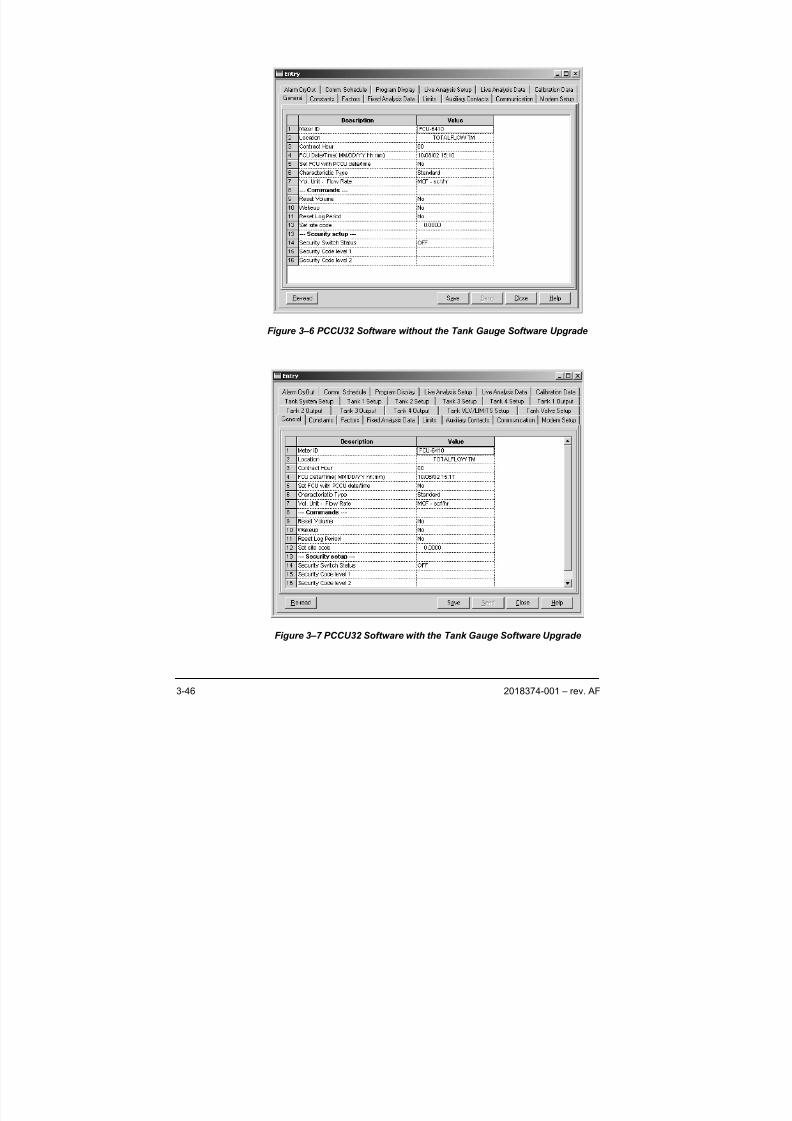
8/13/2019 2018374 m Naf
http://slidepdf.com/reader/full/2018374-m-naf 64/174
3-46 2018374-001 – rev. AF
Figure 3–6 PCCU32 Software without the Tank Gauge Software Upgrade
Figure 3–7 PCCU32 Software with the Tank Gauge Software Upgrade
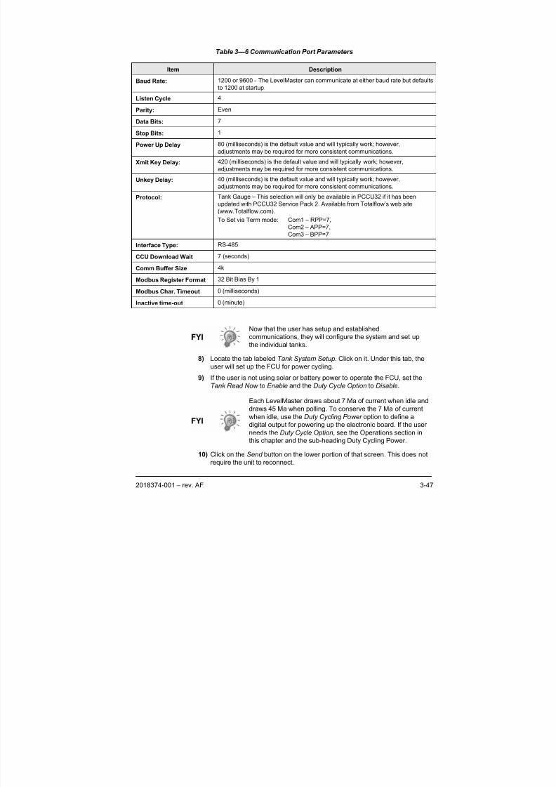
8/13/2019 2018374 m Naf
http://slidepdf.com/reader/full/2018374-m-naf 65/174
2018374-001 – rev. AF 3-47
Table 3—6 Communication Port Parameters
Item Description
Baud Rate: 1200 or 9600 - The LevelMaster can communicate at either baud rate but defaults
to 1200 at startup.
Listen Cycle 4Parity: Even
Data Bits: 7
Stop Bits: 1
Power Up Delay 80 (milliseconds) is the default value and will typically work; however,
adjustments may be required for more consistent communications.
Xmit Key Delay: 420 (milliseconds) is the default value and will typically work; however,
adjustments may be required for more consistent communications.
Unkey Delay: 40 (milliseconds) is the default value and will typically work; however,
adjustments may be required for more consistent communications.
Protocol: Tank Gauge – This selection will only be available in PCCU32 if it has been
updated with PCCU32 Service Pack 2. Available from Totalflow’s web site
(www.Totalflow.com).
To Set via Term mode: Com1 – RPP=7,
Com2 – APP=7,
Com3 – BPP=7
Interface Type: RS-485
CCU Download Wait 7 (seconds)
Comm Buffer Size 4k
Modbus Register Format 32 Bit Bias By 1
Modbus Char. Timeout 0 (milliseconds)
Inactive time-out 0 (minute)
Now that the user has setup and established
communications, they will configure the system and set up
the individual tanks.
8) Locate the tab labeled Tank System Setup. Click on it. Under this tab, the
user will set up the FCU for power cycling.
9) If the user is not using solar or battery power to operate the FCU, set the
Tank Read Now to Enable and the Duty Cycle Option to Disable.
Each LevelMaster draws about 7 Ma of current when idle anddraws 45 Ma when polling. To conserve the 7 Ma of current
when idle, use the Duty Cycling Power option to define a
digital output for powering up the electronic board. If the user
needs the Duty Cycle Option, see the Operations section in
this chapter and the sub-heading Duty Cycling Power.
10) Click on the Send button on the lower portion of that screen. This does not
require the unit to reconnect.
8/13/2019 2018374 m Naf
http://slidepdf.com/reader/full/2018374-m-naf 66/174
3-48 2018374-001 – rev. AF
11) Locate the tab labeled Tank 1 Setup. Click on it. Under this tab, the user will
setup their first tank unit.
12) Change the value on the line labeled Tank Unit Number to match the ID
number that was assigned to that particular tank.
13) Change the value on the line labeled Tank Units for metric or English
measurement.14) Change the value on the line labeled Number of Floats to match the number
of floats on this LevelMaster.
15) Change the value on the line labeled Tank Comm Timeout to the
milliseconds desired before a time out error is issued. Suggested value:
5000
16) Change the value on the line labeled Tank Scan Time to scan frequency
desired.
17) Change the value on the line labeled Tank Scan Enable to Enable.
18) After these basic values have been entered, the user may enter a bias level
for each float, if needed. This should be a positive or negative number in
inches based on the difference between the measurements and themeasurements reflected in PCCU32.
19) If desired, the user may enter strapping points, strap heights and a volume
factor for each point. This will ensure accurate quantities are measured.
20) Click on the Send button on the lower portion of that screen. This does not
require the unit to reconnect.
21) Repeat Steps 11 through 20 for each tank being set up.
22) Locate the tab labeled Tank 1 Output . Click on it. Under this tab, the user
will see the first tank unit information. Click on 2, 3 and 4 to view tank
information respectively.
The user has now performed the basic setup andcommunication setup for the LevelMaster. Now the user
needs to program the display to scroll these values.
23) Locate the Program Display tab, and click on it. The program will need to
read the list of displays. This may take a few minutes.
24) Click in the Value column next to List of Displays, and a drop-down menu of
the available displays will appear.
25) Click on the tank number and desired display item. It may appear similar to
this:
TNK1LVL1
This will set up Tank 1, Level 1 to display. Press the Tab key on the
keyboard. This will return all associated values for this display item.
26) Change the value for the Display Interval to at least five (seconds). The
default was set to zero which turns the display item off.
27) Click on the Send button on the lower portion of that screen. This does not
require the unit to reconnect.
28) Repeat steps 24 through 27 for each display item the user would like to
modify.
8/13/2019 2018374 m Naf
http://slidepdf.com/reader/full/2018374-m-naf 67/174
2018374-001 – rev. AF 3-49
The user has now performed the basic setup of the
LevelMaster. The final step is to save all the configuration
files to the hard drive.
29) Ensure that the device configuration files are backed up, and click on the
Save button. This procedure will take a few minutes. After the information
has been collected, the Device Configuration File save screen will appearand ask for the location to save the file. The destination directory may be
something like this:
C:/PCCU32/_FCU-6410_.fcu
See the PCCU32 help files for more information.
When the FCU is warm booted, it will automatically load
these configuration files at startup.
3.6 XSeries Setup
Totalflow’s XSeries System (XFC or XRC) can be setup to provide support for the
LevelMaster. Each will poll the LevelMaster at user programmable intervals and
store the current level(s) and temperature data into registers known as
Application, Array, Registers (App, Array, Reg). This data is available in Totalflow
software packages, WinCCU32 and PCCU32.
The XFC and XRC are connected to the LevelMaster via RS-485 protocol. Set up
for the LevelMaster data in the XFC or XRC is done using the following procedure.
This procedure assumes that there are no other LevelMaster applications already
instantiated.
To instantiate the LevelMaster application, the user needs to have administrative
access in the security system. See the online help files for PCCU32 for more
information.
3.6.1 Tools Required
• Laptop computer
• PCCU32 version 4.30 to 6.xx.
• 9 or 25 Pin PCCU cable terminated with military connector, available in 8, 25
and 50 foot lengths.
3.6.2 Instructions
3.6.2.1 Instantiating the LevelMaster Application
1) Connect the computer to the local communications port on the side of the
XFC or XRC enclosure.
2) Open the PCCU32 software.
By moving the mouse pointer over each icon and pausing, a
help label will identify the command assigned to that icon.
The icon or tool bar is located directly below the program bar
on the PCCU32 screen. As these icons are user-selectable,
the user may toggle off icons that they will not be using. See
the PCCU32 help files for more information.
8/13/2019 2018374 m Naf
http://slidepdf.com/reader/full/2018374-m-naf 68/174
3-50 2018374-001 – rev. AF
3) Locate Operate on the program bar. Open the pull down menu and move
down to Security . From the cascading menu, select Login.
4) Enter the user name and password for Administrative access. Click Enter .
By viewing the status bar across the bottom of the PCCU32
screen, the user will see the status of the connection and
their login name.
5) Make the software connection to the XFC or XRC by clicking the Connect to
Totalflow icon and then the Entry button, or go directly to the Entry screen
by clicking the Entry icon.
6) Click on the Station ID in the tree-view Entry screen. If the user has multiple
stations, select the location being set up in the tree-view so that it is
highlighted.
7) Click on the Applications tab next to the Station Setup tab.
This procedure assumes that the basic applications used by
the XFC or XRC are already instantiated. See the PCCU32
help files for more information on setting up the XFC or XRCand instantiating applications.
8) Move down to the first application that reads Spare. The Application number
is normally slot 51 through 55. Click on the word Spare. This will open a pull
down menu.
9) Locate the LevelMaster application, and select it. The user will need the
application number for a later step, so mark it down. As stated above, the
slot number is generally Application 51 through 55.
10) Click on the Send button on the lower portion of that screen. This will
download the new application information to the XFC. This requires the unit
to reconnect automatically. A screen will appear. Select OK .
3.6.2.2 LevelMaster Setup
1) Expand the Communications entry in the tree-view by clicking the + sign.
The user will be able to see that a LevelMaster entry is now displayed.
2) Click on the LevelMaster caption. By default, the user will move to the Setup
tab.
3) Within the Setup tab, the user may change the value of the Device/APP ID.
Any name change will be reflected in the tree-view.
4) Next, enter the number of tanks that will be effected. Upon completion, click
the Send button.
3.6.2.3 LevelMaster Communications Port Setup
The following information will detail the steps necessary to establish the
communications port for the LevelMaster
1) Towards the top of the tree-view, click on the Communications caption.
2) Click on the Communications Ports tab. The user will see all of the
communication ports and their designated assignments.
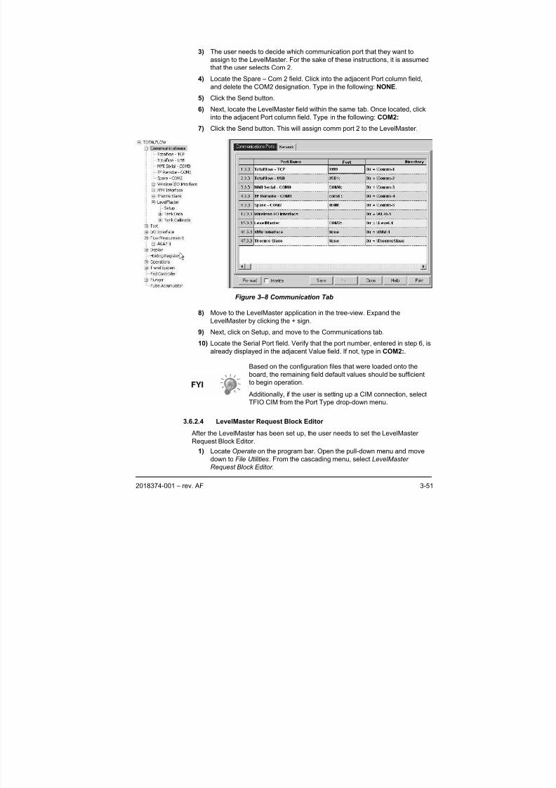
8/13/2019 2018374 m Naf
http://slidepdf.com/reader/full/2018374-m-naf 69/174
2018374-001 – rev. AF 3-51
3) The user needs to decide which communication port that they want to
assign to the LevelMaster. For the sake of these instructions, it is assumed
that the user selects Com 2.
4) Locate the Spare – Com 2 field. Click into the adjacent Port column field,
and delete the COM2 designation. Type in the following: NONE.
5) Click the Send button.6) Next, locate the LevelMaster field within the same tab. Once located, click
into the adjacent Port column field. Type in the following: COM2:
7) Click the Send button. This will assign comm port 2 to the LevelMaster.
Figure 3–8 Communication Tab
8) Move to the LevelMaster application in the tree-view. Expand the
LevelMaster by clicking the + sign.
9) Next, click on Setup, and move to the Communications tab.
10) Locate the Serial Port field. Verify that the port number, entered in step 6, is
already displayed in the adjacent Value field. If not, type in COM2:.
Based on the configuration files that were loaded onto the
board, the remaining field default values should be sufficient
to begin operation.
Additionally, if the user is setting up a CIM connection, select
TFIO CIM from the Port Type drop-down menu.
3.6.2.4 LevelMaster Request Block Editor
After the LevelMaster has been set up, the user needs to set the LevelMaster
Request Block Editor.
1) Locate Operate on the program bar. Open the pull-down menu and move
down to File Utilities. From the cascading menu, select LevelMaster
Request Block Editor .
8/13/2019 2018374 m Naf
http://slidepdf.com/reader/full/2018374-m-naf 70/174
3-52 2018374-001 – rev. AF
2) The LevelMaster Request Block Editor screen will appear.
• Modify Application. Enter the number of the application that was
instantiated in step 9.
• Select the tank number associated with the Tank Application
instantiated in step 14.
• Set the correct number of sensors for this tank.• Modify the ID to match the unit ID.
• Set the interval to the time desired between data requests.
3) Locate File on the program bar of the LevelMaster Request Block Editor
screen and select Save As.
4) The user will need to save this file to their computer files in PCCU32 on the
computer. The path may be something like this:
C:/PCCU32/LMBlockRequest/TankReq1.TRB
Please note the location, as the user will be uploading these files to the R
Drive later.
5) Repeat steps 21 through 23 for each tank installed. The user will need to
rename the file for each tank set up in step 23. When finished, close the
editor. It would be best to append the file name with the ID number of each
tank, i.e.,
C:/PCCU32/LMBlockRequest/TankReq2.TRB
6) Locate Operate on the program bar. Open the pull-down menu and move
down to File Utilities. From the cascading menu, select File Transfer .
7) Under the R : drive, open COM -1 by clicking on it. Open Level by clicking on
it. Click on the Download button on the bottom of the File Transfer screen.
Return to the location on the computer where the user stored the
LevelMaster Request Block files created in steps 23 and 24.
8) Click on the TankReq1.TRB file, and click on Open. Repeat this step for
each tank set up in steps 23 and 24. When finished downloading all files,
click Close.
9) In the tree-view Entry screen, open the LevelMaster applications by clicking
on the “+” next to the LevelMaster Device ID. To view each tank, select the
tank, and click the Re-read button on the bottom of the screen.
3.6.2.5 LevelMaster Display and Annuciator Setup
1) In the tree view Entry Screen, click on Display . Under the Setup tab, the
user may setup display groups, etc. Click on the Annunciators tab.
Determine which unassigned annunciator to reflect the status of the
communication port that the user has dedicated to the LevelMaster. By
setting this up, the user will be able to view the LevelMaster Protocol “R”
and Receive functions “ ” as the XFC or XRC polls the LevelMaster for
Information.
For more information on setting up displays, see the PCCU32 help files.
2) In the tree view Entry screen, open the LevelMaster applications by clicking
on the “+” next to the LevelMaster Device ID. To view each tank, select the
tank and click the Re-read button on the bottom of the screen.
8/13/2019 2018374 m Naf
http://slidepdf.com/reader/full/2018374-m-naf 71/174
2018374-001 – rev. AF 3-53
3) Record the register number in the left hand shaded column for each item
the user would like to build a display for. Do this for each tank that the user
wishes to display information on.
4) In the tree view Entry screen, open the Display application by clicking on the
“+” next to the Display . Click on the Display Group that the user would like
to add the information to, or create a New Display Group. To create a New
Display Group, see the PCCU32 help files.
5) In the Setup screen, the user may rename the Group Description and
modify the Number of Displays. Click on the Send button on the lower
portion of that screen. This will download the new application information to
the XFC. This requires the unit to reconnect automatically. A screen will
appear. Select OK .
6) Return to the Display Group. Click on the first Spare. This will open the Item
Setup screen for this item.
7) Modify the first display item by entering the Name of Display Item and
entering the Register number recorded in step 30. Change the Display
Interval to a minimum of five seconds. This may be changed to any length
from 0 to 255. Entering 0 turns the display off. To modify any other values,see the PCCU32 help files for more information.
8) Click on the Send button on the lower portion of that screen. This does not
require the unit to reconnect.
9) Once the user has moved to a level of the tree-view Entry Screen above the
Display Group level, the LCD screen located on the front of the unit should
begin scrolling.
While the user can now read basic tank levels at this point,
they should proceed to the Calibration section of this chapter
to setup the tank for volume.
The user has now performed the basic setup of theLevelMaster. The final step is to save all the configuration
files to the S Drive for memory backup on the XFC or XRC-
195 board static ram chip.
10) Ensure that the Enable Memory Backup pins located on the XFC or XRC-
195 board are set correctly. See the XFC or XRC user’s manual or the
PCCU32 help files for more information.
11) Locate Operate on the program bar. Open the pull-down menu, and move
down to File Utilities. From the cascading menu, select the Save and
Restore Utility .
12) Click on Save Station Files. On the new screen, the user will need toindicate the location where they wish to store this copy of the station
configuration files. The destination directory may be something like this:
C:/PCCU32/Station Files/Station Name/
Check mark the All Setup or Configuration Files box. Do not change either
the Extension List or the From location.
Click OK . This may take a few minutes to complete. If the user has
preformed this at a prior time, it may state that the files already exist and
8/13/2019 2018374 m Naf
http://slidepdf.com/reader/full/2018374-m-naf 72/174
3-54 2018374-001 – rev. AF
ask if the user would like to Overwrite /Merge or Rename the existing file to
a backup file.
13) When completed, the Upload Completed ! screen will appear. It will ask if
the user would also like to copy the files to the S Drive. The user should
answer Yes. The user will see the same screen displayed as in step 39. The
user will notice that the Destination Directory is now Source Directory and it
is the location where they saved the station f iles on their computers harddrive. The From location is now Download To, and the location is S:\. Do
not change this. Click OK . When the Download Completed screen appears,
click OK .
When the XFC or XRC is cold booted, it will automatically
load these configuration files at startup.
The user may desire to program the Push-to-Read feature.
This feature allows the user to receive immediate readings
from the LevelMaster. See the Operations section of this
chapter, Push-To-Read instructions.
3.7 XSeries G4 Setup
Totalflow’s XSeries System G4 (XFC or XRC) can be setup to provide support for
the LevelMaster. Each will poll the LevelMaster at user programmable intervals
and store the current level(s) and temperature data into registers known as
Application, Array, Registers (App, Array, Reg). This data is available in Totalflow
software packages, WinCCU32 and PCCU32.
The XFC and XRC are connected to the LevelMaster via RS-485 protocol. Set up
for the LevelMaster data in the XFC or XRC is done using the following procedure.
This procedure assumes that there are no other LevelMaster applications already
instantiated.
To instantiate the LevelMaster application, the user needs to have administrativeaccess in the security system. See the online help files for PCCU32 for more
information.
3.7.1 Tools Required
• Laptop computer
• PCCU32 version 7.0 or later.
• 9 or 25 Pin PCCU cable terminated with military connector, available in 8, 25
and 50 foot lengths.
3.7.2 Instructions
3.7.2.1 Instantiating the LevelMaster Application
1) Connect the computer to the local communications port on the side of the
XFCG4 or XRCG4 enclosure.
2) Open the PCCU32 software.
8/13/2019 2018374 m Naf
http://slidepdf.com/reader/full/2018374-m-naf 73/174
2018374-001 – rev. AF 3-55
By moving the mouse pointer over each icon and pausing, a
help label will identify the command assigned to that icon.
The icon or tool bar is located directly below the program bar
on the PCCU32 screen. As these icons are user-selectable,
the user may toggle off icons that they will not be using. See
the PCCU32 help files for more information.3) Locate Operate on the program bar. Open the pull down menu and move
down to Security . From the cascading menu, select Login.
4) Enter the user name and password for Administrative access. Click Enter .
By viewing the status bar across the bottom of the PCCU32
screen, the user will see the status of the connection and
their login name.
5) Make the software connection to the XFCG4 or XRCG4 by clicking the
Connect to Totalflow icon and then the Entry button, or go directly to the
Entry screen by clicking the Entry icon.
6) Click on the Station ID in the tree-view Entry screen. If the user has multiplestations, select the location being set up in the tree-view so that it is
highlighted.
7) Click on the Applications tab next to the Station Setup tab.
This procedure assumes that the basic applications used by
the XFC or XRC are already instantiated. See the PCCU32
help files for more information on setting up the XFC or XRC
and instantiating applications.
8) Move down to the first application that reads Spare. The Application number
is normally slot 51 through 55. Click on the word Spare. This will open a pull
down menu.
9) Locate the LevelMaster application, and select it. The user will need the
application number for a later step, so mark it down. As stated above, the
slot number is generally Application 51 through 55.
10) Click on the Send button on the lower portion of that screen. This will
download the new application information to the XFC. This requires the unit
to reconnect automatically. A screen will appear. Select OK .
3.7.2.2 LevelMaster Setup
The following information will detail the steps necessary to setup the number of
tanks and establish the communications port for the LevelMaster.
Installation and setup of the Xseries G4 units has been
simplified. In PCCU 32 7.xx, the LevelMaster Communicationsetup is now part of the LevelMaster application.
1) Expand the Communications entry in the tree-view by clicking the + sign.
The user will be able to see that a LevelMaster entry is now displayed.
2) Expand the LevelMaster entry in the tree-view by clicking the + sign. Click
Setup entry under LevelMaster.
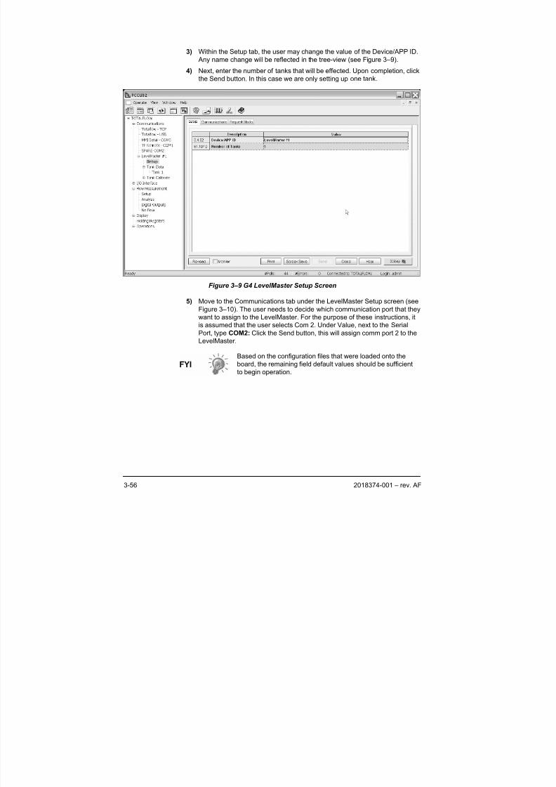
8/13/2019 2018374 m Naf
http://slidepdf.com/reader/full/2018374-m-naf 74/174
3-56 2018374-001 – rev. AF
3) Within the Setup tab, the user may change the value of the Device/APP ID.
Any name change will be reflected in the tree-view (see Figure 3–9).
4) Next, enter the number of tanks that will be effected. Upon completion, click
the Send button. In this case we are only setting up one tank.
Figure 3–9 G4 LevelMaster Setup Screen
5) Move to the Communications tab under the LevelMaster Setup screen (seeFigure 3–10). The user needs to decide which communication port that they
want to assign to the LevelMaster. For the purpose of these instructions, it
is assumed that the user selects Com 2. Under Value, next to the Serial
Port, type COM2: Click the Send button, this will assign comm port 2 to the
LevelMaster.
Based on the configuration files that were loaded onto the
board, the remaining field default values should be sufficient
to begin operation.

8/13/2019 2018374 m Naf
http://slidepdf.com/reader/full/2018374-m-naf 75/174
2018374-001 – rev. AF 3-57
Figure 3–10 G4 LevelMaster Communication Tab
3.7.2.3 LevelMaster Request Block Editor
After the LevelMaster has been set up, the user needs to set the LevelMaster
Request Block Editor.
1) Move to the Request Blocks tab under the LevelMaster Setup screen (see
Figure 3–11).
2) Select Add and enter a tank name. Repeating instances will require a new
individual name. Click OK .
3) Complete the following:
• Auto Configuration
o Modify Application if required to reflect the application slot
instanstantiated previously. In this instance, set Application
number to 51.
o Select the first tank number associated with the Tank
Application. In this instance, set Tank Number to 1. Additional
tanks will increment this number. In repeating instances for
multiple tanks, change the tank number and ID for each new
tank.
o Set the correct number of sensors for this tank. In this instance,
we are setting up a Dual Level sensor.
• Registers
o Modify the ID to match the unit ID. In this instance, set ID to 1.
Additional tanks will increment this ID number.
o Set the interval to the time desired between data requests.
Typically, this is set to poll every 15 minutes.
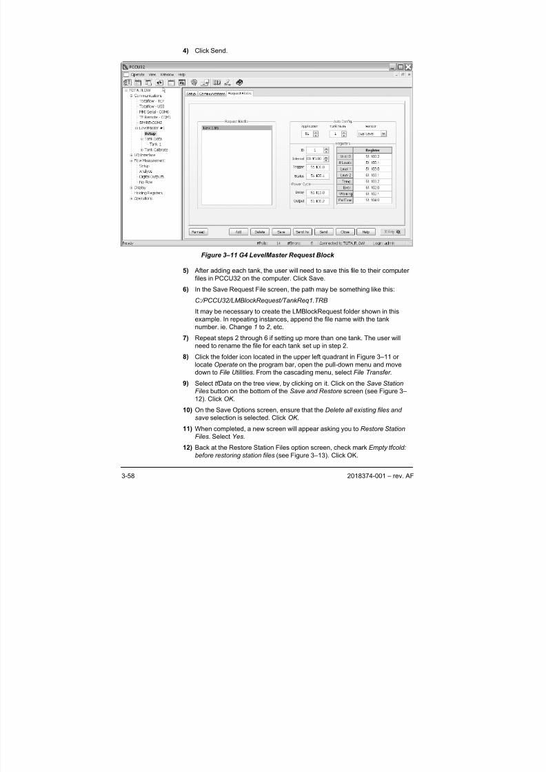
8/13/2019 2018374 m Naf
http://slidepdf.com/reader/full/2018374-m-naf 76/174
3-58 2018374-001 – rev. AF
4) Click Send.
Figure 3–11 G4 LevelMaster Request Block
5) After adding each tank, the user will need to save this file to their computer
files in PCCU32 on the computer. Click Save.
6) In the Save Request File screen, the path may be something like this:
C:/PCCU32/LMBlockRequest/TankReq1.TRB
It may be necessary to create the LMBlockRequest folder shown in this
example. In repeating instances, append the file name with the tank
number. ie. Change 1 to 2 , etc.
7) Repeat steps 2 through 6 if setting up more than one tank. The user will
need to rename the file for each tank set up in step 2.
8) Click the folder icon located in the upper left quadrant in Figure 3–11 or
locate Operate on the program bar, open the pull-down menu and move
down to File Utilities. From the cascading menu, select File Transfer .
9) Select tfData on the tree view, by clicking on it. Click on the Save Station
Files button on the bottom of the Save and Restore screen (see Figure 3–
12). Click OK .
10) On the Save Options screen, ensure that the Delete all existing files and
save selection is selected. Click OK .
11) When completed, a new screen will appear asking you to Restore Station
Files. Select Yes.
12) Back at the Restore Station Files option screen, check mark Empty tfcold:
before restoring station files (see Figure 3–13). Click OK.
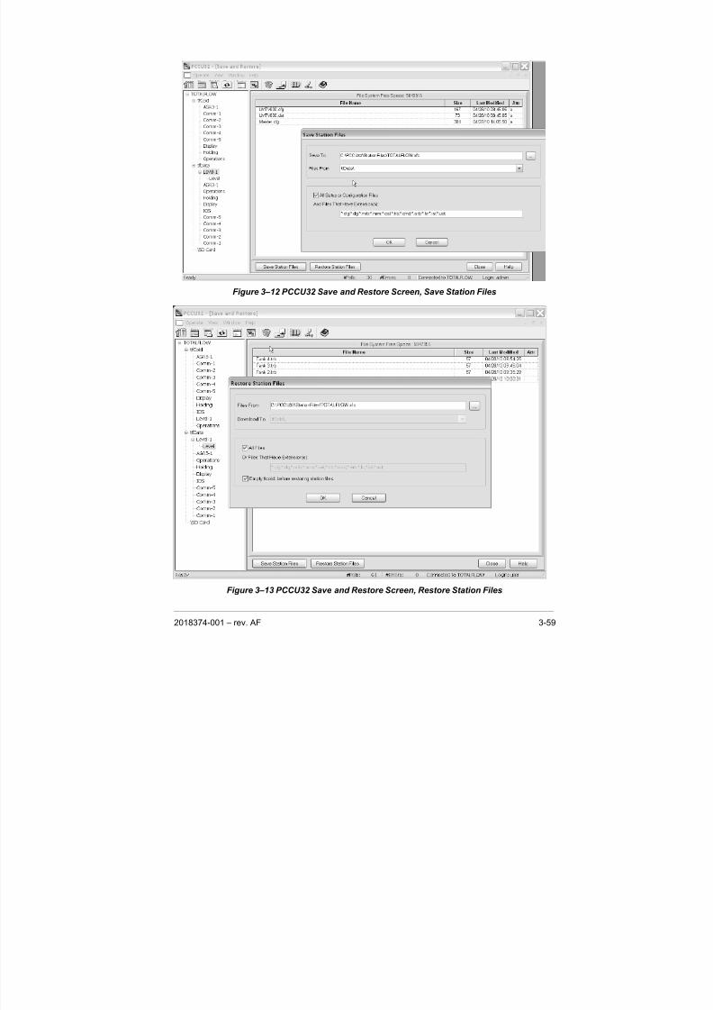
8/13/2019 2018374 m Naf
http://slidepdf.com/reader/full/2018374-m-naf 77/174
2018374-001 – rev. AF 3-59
Figure 3–12 PCCU32 Save and Restore Screen, Save Station Files
Figure 3–13 PCCU32 Save and Restore Screen, Restore Station Files
8/13/2019 2018374 m Naf
http://slidepdf.com/reader/full/2018374-m-naf 78/174
3-60 2018374-001 – rev. AF
3.7.2.4 LevelMaster Display and Annuciator Setup
1) In the tree view Entry Screen, click on Display . Under the Setup tab, the
user may setup display groups, etc. Click on the Annunciators tab.
Determine which unassigned annunciator to reflect the status of the
communication port that the user has dedicated to the LevelMaster. By
setting this up, the user will be able to view the LevelMaster Protocol “R”
and Receive functions “ ” as the XFC or XRC polls the LevelMaster forInformation.
For more information on setting up displays, see the PCCU32 help files.
2) In the tree view Entry screen, open the LevelMaster applications by clicking
on the “+” next to the LevelMaster Device ID. To view each tank, select the
tank and click the Re-read button on the bottom of the screen.
3) Record the register number in the left hand shaded column for each item
the user would like to build a display for. Do this for each tank that the user
wishes to display information on.
4) In the tree view Entry screen, open the Display application by clicking on the
“+” next to the Display . Click on the Display Group that the user would like
to add the information to, or create a New Display Group. To create a New Display Group, see the PCCU32 help files.
5) In the Setup screen, the user may rename the Group Description and
modify the Number of Displays. Click on the Send button on the lower
portion of that screen. This will download the new application information to
the XFC. This requires the unit to reconnect automatically. A screen will
appear. Select OK .
6) Return to the Display Group. Click on the first Spare. This will open the Item
Setup screen for this item.
7) Modify the first display item by entering the Name of Display Item and
entering the Register number recorded in step 30. Change the Display
Interval to a minimum of five seconds. This may be changed to any lengthfrom 0 to 255. Entering 0 turns the display off. To modify any other values,
see the PCCU32 help files for more information.
8) Click on the Send button on the lower portion of that screen. This does not
require the unit to reconnect.
9) Once the user has moved to a level of the tree-view Entry Screen above the
Display Group level, the LCD screen located on the front of the unit should
begin scrolling.
While the user can now read basic tank levels at this point,
they should proceed to the Calibration section of this chapter
to setup the tank for volume.
The user has now performed the basic setup of the
LevelMaster. The final step is to save all the configuration
files to the S Drive for memory backup on the XFC or XRC-
195 board static ram chip.
8/13/2019 2018374 m Naf
http://slidepdf.com/reader/full/2018374-m-naf 79/174
8/13/2019 2018374 m Naf
http://slidepdf.com/reader/full/2018374-m-naf 80/174
3-62 2018374-001 – rev. AF
When MasterLink software is used to communicate locally and no host hardware
unit is controlling the LevelMaster, there is no capability for developing a strapping
table. However, the user may enter a new figure for each level, thus allowing for
the adjustment of the density of the liquid which affects the float level. Details for
adjusting the float levels is located in the section entitled, Float Calibration.
Host hardware, PCCU32, WinCCU Remote Host Console or Modbus may be
used to configure strapping tables and view calculated gross values.
3.8.1.1 Table Factors
The following three items are used to create a strapping table and are used to
calculate tank volumes. Strapping table inputs include:
• No. of Tank Sections (10 max) – Horizontal sections that the user divides the
tank into, usually the actual straps around the tank, are used for section
dividers. Because tanks may not be uniform from bottom to top, dividing each
tank into sections allows the user to more accurately provide information for
each section. If the tank is uniform, the user may enter only one section.
• Section # Height – Each section (1-10) of the tank has an entry for its height
in inches from the bottom of the tank.
• Section # Vol. Factor – Each section (1-10) of the tank has an entry for its
own volume factor per ¼ inch of height. By default, this would be barrels per
¼ inch. However, because the tank is broken into sections, the user may
adjust individual volume factors based on the condition of each section.
Therefore, a section which has sustained damage, either concave or convex,
may be adjusted to allow for the missing or addition storage space.
For example, a twenty-foot tank may be divided into five, 48-inch calibration
sections. Using default English units, enter the height at the top of each of the five
sections and the barrels per quarter inch of tank volume within that section. The
host software then calculates the gross volume for each of the tank sections and
adds them together. Volume outputs may be viewed using any of the host
software packages discussed in this chapter.
3.8.1.2 PCCU32
Tank Setup Screen: As the user sets up each tank in the Tank Setup screen, the
lower portion of the screen allows the user to enter information to create a
strapping table. The user will need to enter the number of tank sections and then
complete the following information for each section (x being the section number):
• Section (X) height
• Section (X) volume per unit height
3.9 Float Calibration
While the LevelMaster is factory calibrated for the user’s particular tank,
occasionally there are extenuating circumstances that may require the floats to becalibrated. These circumstances may be as simple as a difference in the fluid
gravity.
Calibrating the float is actually based on determining a new level factor and
making a positive or negative adjustment to the level. This is called a bias. The
user may determine the need to set a bias if they have been comparing the
reading level of each float and comparing that to an actual measurement.
8/13/2019 2018374 m Naf
http://slidepdf.com/reader/full/2018374-m-naf 81/174
2018374-001 – rev. AF 3-63
To further adjust the volumes due to an outside influence, namely a damaged
section of the tank, a strapping table allows for a more accurate adjustment. This
allows the user to make a correction based only on the area damaged, rather than
an adjustment to the entire volume of the tank by setting a bias level.
3.9.1 MasterLink
When communicating directly with the LevelMaster from the user’s laptop using
MasterLink during the setup process, the user may enter a new value for each
float in the Setup screen. Under the Setup tab for this tank, the user will see the
section “Enter Gauging Tape Measurements Here:” For each tank level, the user
may set a new level based upon the actual gauge level. (See Tip below.)
3.9.2 Console Mode
When setting up each tank using the Console mode, the user may set a bias for
each level. This allows the user to adjust the reading of the float.
• Enter the Tank Setup screen. Here the user may enter only a positive or
negative bias level for each float.
3.9.3 PCCU32
Tank Setup Screen: As the user sets up each tank in the Tank Setup screen, in
the upper portion of the screen they may enter a positive or negative bias for each
level.
Do not calibrate the floats, also referred to as level bias, in
MasterLink during the initial setup if the unit will be operated
by a Totalflow host. Performing the calibration through the
Totalflow host provides an audit trail.
3.10 Data Collection
Data collection from the LevelMaster may be accomplished in several ways.
Because the LevelMaster communicates using RS-485, any host with RS-485 or
converting hardware may communicate. The most basic method for data
collection is communicating directly with the LevelMaster using MasterLink
software on a laptop computer and a RS-232 converter. Totalflow equipment is
specifically designed to communicate with the LevelMaster. They can also be
configured using Modbus RTU or ASCII protocol.
Currently, the most efficient way to collect data from the LevelMaster is to use a
Totalflow host device with trending capabilities.
3.10.1 Trending
PCCU32 versions 4.30 or later may be programmed to collect data by using theTrending application available with the Advanced version. Trending is a system
whereby values stored in an App/Array/Reg location can be written to a file, printer
or screen.
Advanced users may design their Trend function to use the Push to Read feature
to poll on demand. The basic steps required to setup the Trend function for data
collection may contain the following:
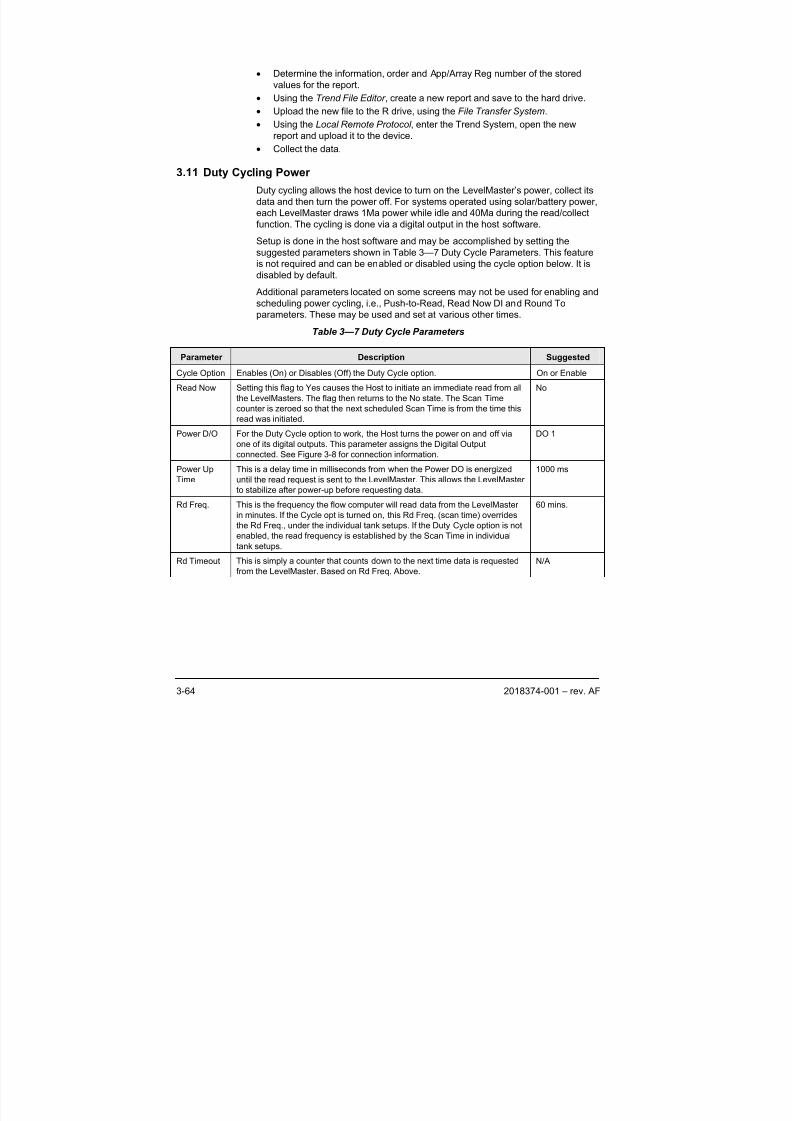
8/13/2019 2018374 m Naf
http://slidepdf.com/reader/full/2018374-m-naf 82/174
3-64 2018374-001 – rev. AF
• Determine the information, order and App/Array Reg number of the stored
values for the report.
• Using the Trend File Editor , create a new report and save to the hard drive.
• Upload the new file to the R drive, using the File Transfer System.
• Using the Local Remote Protocol , enter the Trend System, open the new
report and upload it to the device.
• Collect the data.
3.11 Duty Cycling Power
Duty cycling allows the host device to turn on the LevelMaster’s power, collect its
data and then turn the power off. For systems operated using solar/battery power,
each LevelMaster draws 1Ma power while idle and 40Ma during the read/collect
function. The cycling is done via a digital output in the host software.
Setup is done in the host software and may be accomplished by setting the
suggested parameters shown in Table 3—7 Duty Cycle Parameters. This feature
is not required and can be enabled or disabled using the cycle option below. It is
disabled by default.
Additional parameters located on some screens may not be used for enabling and
scheduling power cycling, i.e., Push-to-Read, Read Now DI and Round To
parameters. These may be used and set at various other times.
Table 3—7 Duty Cycle Parameters
Parameter Description Suggested
Cycle Option Enables (On) or Disables (Off) the Duty Cycle option. On or Enable
Read Now Setting this flag to Yes causes the Host to initiate an immediate read from all
the LevelMasters. The flag then returns to the No state. The Scan Time
counter is zeroed so that the next scheduled Scan Time is from the time this
read was initiated.
No
Power D/O For the Duty Cycle option to work, the Host turns the power on and off viaone of its digital outputs. This parameter assigns the Digital Output
connected. See Figure 3-8 for connection information.
DO 1
Power Up
Time
This is a delay time in milliseconds from when the Power DO is energized
until the read request is sent to the LevelMaster. This allows the LevelMaster
to stabilize after power-up before requesting data.
1000 ms
Rd Freq. This is the frequency the flow computer will read data from the LevelMaster
in minutes. If the Cycle opt is turned on, this Rd Freq. (scan time) overrides
the Rd Freq., under the individual tank setups. If the Duty Cycle option is not
enabled, the read frequency is established by the Scan Time in individual
tank setups.
60 mins.
Rd Timeout This is simply a counter that counts down to the next time data is requested
from the LevelMaster. Based on Rd Freq. Above.
N/A
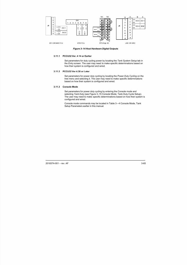
8/13/2019 2018374 m Naf
http://slidepdf.com/reader/full/2018374-m-naf 83/174
2018374-001 – rev. AF 3-65
D
O 2
D
O 1
( + )
( - )
( + )
( - )
Figure 3–14 Host Hardware Digital Outputs
3.11.1 PCCU32 Ver. 4.14 or Earlier
Set parameters for duty cycling power by locating the Tank System Setup tab in
the Entry screen. The user may need to make specific determinations based on
how their system is configured and wired.
3.11.2 PCCU32 Ver 4.30 or Later
Set parameters for power duty cycling by locating the Power Duty Cycling on the
tree menu and selecting it. The user may need to make specific determinations
based on how their system is configured and wired.
3.11.3 Console Mode
Set parameters for power duty cycling by entering the Console mode and
selecting Tank Duty (see Figure 3–15 Console Mode, Tank Duty Cycle Setup).
The user may need to make specific determinations based on how their system is
configured and wired.
Console mode commands may be located in Table 3—4 Console Mode, Tank
Setup Parameters earlier in this manual.
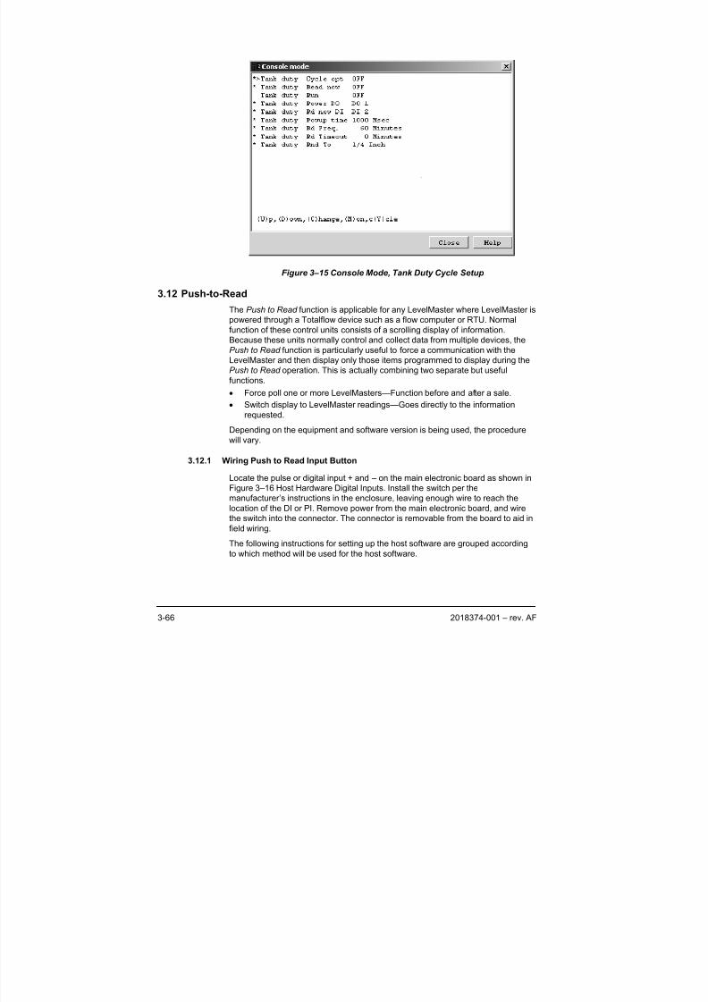
8/13/2019 2018374 m Naf
http://slidepdf.com/reader/full/2018374-m-naf 84/174
3-66 2018374-001 – rev. AF
Figure 3–15 Console Mode, Tank Duty Cycle Setup
3.12 Push-to-Read
The Push to Read function is applicable for any LevelMaster where LevelMaster is
powered through a Totalflow device such as a flow computer or RTU. Normal
function of these control units consists of a scrolling display of information.
Because these units normally control and collect data from multiple devices, the
Push to Read function is particularly useful to force a communication with the
LevelMaster and then display only those items programmed to display during the
Push to Read operation. This is actually combining two separate but useful
functions.
• Force poll one or more LevelMasters—Function before and after a sale.
• Switch display to LevelMaster readings—Goes directly to the information
requested.
Depending on the equipment and software version is being used, the procedure
will vary.
3.12.1 Wiring Push to Read Input Button
Locate the pulse or digital input + and – on the main electronic board as shown in
Figure 3–16 Host Hardware Digital Inputs. Install the switch per the
manufacturer’s instructions in the enclosure, leaving enough wire to reach the
location of the DI or PI. Remove power from the main electronic board, and wire
the switch into the connector. The connector is removable from the board to aid in
field wiring.
The following instructions for setting up the host software are grouped according
to which method will be used for the host software.
8/13/2019 2018374 m Naf
http://slidepdf.com/reader/full/2018374-m-naf 85/174
2018374-001 – rev. AF 3-67
If the software is… And the hardware is…Use the following
instructions:
6400 or 6700 FCUPCCU32 4.14 or Earlier
6790 RTUConsole Mode
PCCU32 4.14 or Earlier with
Tank Gauge Upgrade
6400 or 6700 FCU Tank Gauge Upgrade
XFCPCCU32 4.30 or Later
XRCX Series Setup
XFCG4 XSeries G4 SetupPCCU32 7.0 or later
XRCG4 XSeries G4 Setup
Figure 3–16 Host Hardware Digital Inputs
3.12.2 Console Mode
The following instructions are applicable for the 6400 and 6700 FCUs as well asthe 6790 RTU, using PCCU32 version 4.14 or earlier without the Tank Gauge
Upgrade installed. For the purpose of these instructions, it is assumed that the
basic wiring has been completed and that the user has basic knowledge of the
flow computer and PCCU32 software.
3.12.2.1 Instructions
1) Locate Operate on the program bar. Open the pull-down menu and select
Console Mode.
2) After the Console Mode screen appears, locate the Tank Duty menu item,
and enter the corresponding number to access the setup.
3) Move the > down to Tank Duty Rd now DI , by repeatedly pushing the D fordown.
4) Once there, push the C key for change, and enter the new value.
5) The change information will appear at the bottom of that window. Use the U
for up and D for down to display the different options available.
6) Once the user has found the correct option, press Enter to save the change.
7) Using Table 3—8 Push-To-Read Parameters, make sure all parameters are
set as needed.
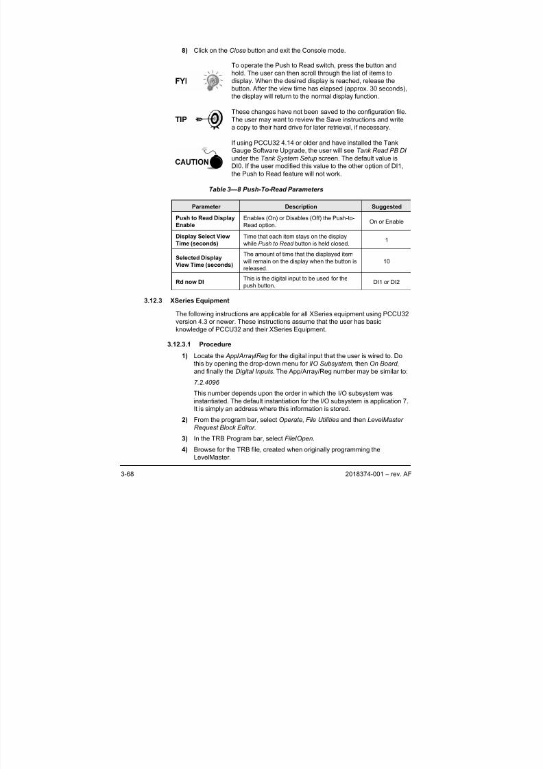
8/13/2019 2018374 m Naf
http://slidepdf.com/reader/full/2018374-m-naf 86/174
3-68 2018374-001 – rev. AF
8) Click on the Close button and exit the Console mode.
To operate the Push to Read switch, press the button and
hold. The user can then scroll through the list of items to
display. When the desired display is reached, release the
button. After the view time has elapsed (approx. 30 seconds),
the display will return to the normal display function.
These changes have not been saved to the configuration file.
The user may want to review the Save instructions and write
a copy to their hard drive for later retrieval, if necessary.
If using PCCU32 4.14 or older and have installed the Tank
Gauge Software Upgrade, the user will see Tank Read PB DI
under the Tank System Setup screen. The default value is
DI0. If the user modified this value to the other option of DI1,
the Push to Read feature will not work.
Table 3—8 Push-To-Read Parameters
Parameter Description Suggested
Push to Read Display
Enable
Enables (On) or Disables (Off) the Push-to-
Read option.On or Enable
Display Select View
Time (seconds)
Time that each item stays on the display
while Push to Read button is held closed.1
Selected Display
View Time (seconds)
The amount of time that the displayed item
will remain on the display when the button is
released.
10
Rd now DIThis is the digital input to be used for the
push button.DI1 or DI2
3.12.3 XSeries Equipment
The following instructions are applicable for all XSeries equipment using PCCU32
version 4.3 or newer. These instructions assume that the user has basic
knowledge of PCCU32 and their XSeries Equipment.
3.12.3.1 Procedure
1) Locate the App / Array /Reg for the digital input that the user is wired to. Do
this by opening the drop-down menu for I /O Subsystem, then On Board ,
and finally the Digital Inputs. The App/Array/Reg number may be similar to:
7.2.4096
This number depends upon the order in which the I/O subsystem wasinstantiated. The default instantiation for the I/O subsystem is application 7.
It is simply an address where this information is stored.
2) From the program bar, select Operate, File Utilities and then LevelMaster
Request Block Editor .
3) In the TRB Program bar, select File /Open.
4) Browse for the TRB file, created when originally programming the
LevelMaster.
8/13/2019 2018374 m Naf
http://slidepdf.com/reader/full/2018374-m-naf 87/174
2018374-001 – rev. AF 3-69
5) Modify the App/Array/Reg number listed in the Trigger window to the
number that was located in step 4.
6) Save the file to the previous location, and close the LevelMaster Request
Block Editor . Then closes the editor.
7) From the program bar, select Operate, File Utilities and then File Transfer .
8) Under the R drive, select the Comm port the LevelMaster is running on.
9) Select the Level folder directly beneath the Comm Port .
10) Select Download from the bottom of this window, and locate the TRB file
that was just recently modified from the hard drive. Select the file, and press
the Open button.
11) This will replace the file on the R drive and update the last modified date
and time for that file. Close the File Transfer screen.
The user has now completed the set up to force poll one or
more LevelMasters. The next step is to program the display
to scroll through the desired display items.
12) Click on Display in the tree menu.
13) On the Setup screen for display, change the value of the Group Scroll
Control to the App/Array/Reg number located in step 4.
14) Update the value of the Scroll Lock Timeout to a pre-determined figure.
The rule of thumb to follow when figuring the desired scroll
lock timeout is to allot enough time for each item to be
displayed for the allotted display interval (set up in the display
screen for each item) and to allow the group of items to be
displayed three times. Because the poll and the display are
started simultaneously the first time the list scrolls through, it
is the value already stored. The second time through should
be the updated (Polled) numbers. The third time through willallow the user to make notes of the numbers that they missed
the second time through. For example, the user may have ten
items to display for five seconds each, multiplied by three
times. The user would set the scroll lock timeout to 11/2
minutes.
15) Click Send .
To operate the Push to Read switch, press release the
button. The group display numbers will begin scrolling. Click
the button again when the correct display group is showing.
This group should begin to scroll through its list. If the user
followed the Tip above, the list should scroll through threetimes and then return to the normal display.
When the equipment is polling the LevelMaster, the user will
see an arrow→. When not communicating, the user will see
an R .
8/13/2019 2018374 m Naf
http://slidepdf.com/reader/full/2018374-m-naf 88/174
3-70 2018374-001 – rev. AF
3.13 Remote User Interface (Host Console)
When access to a host via remote communication is required, this is
accomplished by using a feature called Remote User Interface or Host Console.
This interface is handled by either WinCCU or PCCU32, the firmware device
template and a form of communication equipment, i.e., radio.
The process for using the device template with either WinCCU or PCCU32 is toimport the template into WinCCU and/or PCCU32. It is then available for attaching
to the device ID with the WinCCU ID Manager or, if using PCCU32, it is available
for use with the ExIO/RTU device type. WinCCU32 and PCCU32 software use a
mode called Host Console to interface with the register data in a format
determined by template. The template is designed or edited using the Device
Template Editor , which is a standard part of WinCCU32 and PCCU32.
3.13.1 Screens
The Host Console screens are used to view and change any necessary data.
When using WinCCU, the host console may be started by either using the Host
Console icon on the WinCCU task bar or by using the Device I/O pull-down menu
and then selecting Host Console. When using PCCU32, the connection to thedevice must be established first and then the Host Console icon on the PCCU32
task bar may be used to begin the host console operation.
3.13.2 Polling
Another feature available in WinCCU32 and PCCU32 is the ability to poll for the
App, Array, Reg data using the Remote Communications function. This requires
that the desired data be setup in a custom report area of the template. A Trending
function is also available with WinCCU32 and PCCU32 in which the user specifies
the register locations and intervals to trend.
When the host console is started, a screen similar to Figure 3–17 Host Console
Mode using a Device Template appears. The upper left box lists the areas that are
contained in the device template, and the upper right box lists the groups of data
that are contained in the highlighted area. The lower box lists the data items
contained in the highlighted group.
For more information regarding Host Console, please see the
help files provided with the software.
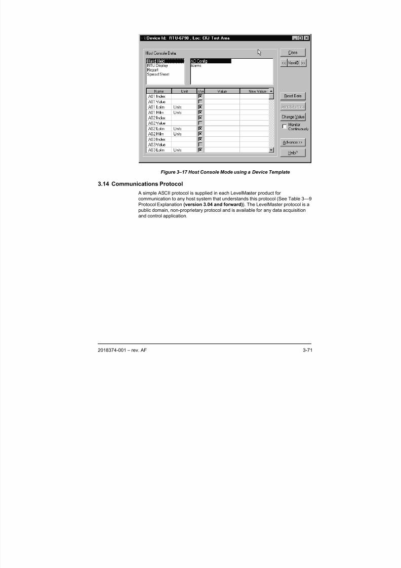
8/13/2019 2018374 m Naf
http://slidepdf.com/reader/full/2018374-m-naf 89/174
2018374-001 – rev. AF 3-71
Figure 3–17 Host Console Mode using a Device Template
3.14 Communications Protocol
A simple ASCII protocol is supplied in each LevelMaster product for
communication to any host system that understands this protocol (See Table 3—9
Protocol Explanation (version 3.04 and forward)). The LevelMaster protocol is a
public domain, non-proprietary protocol and is available for any data acquisition
and control application.
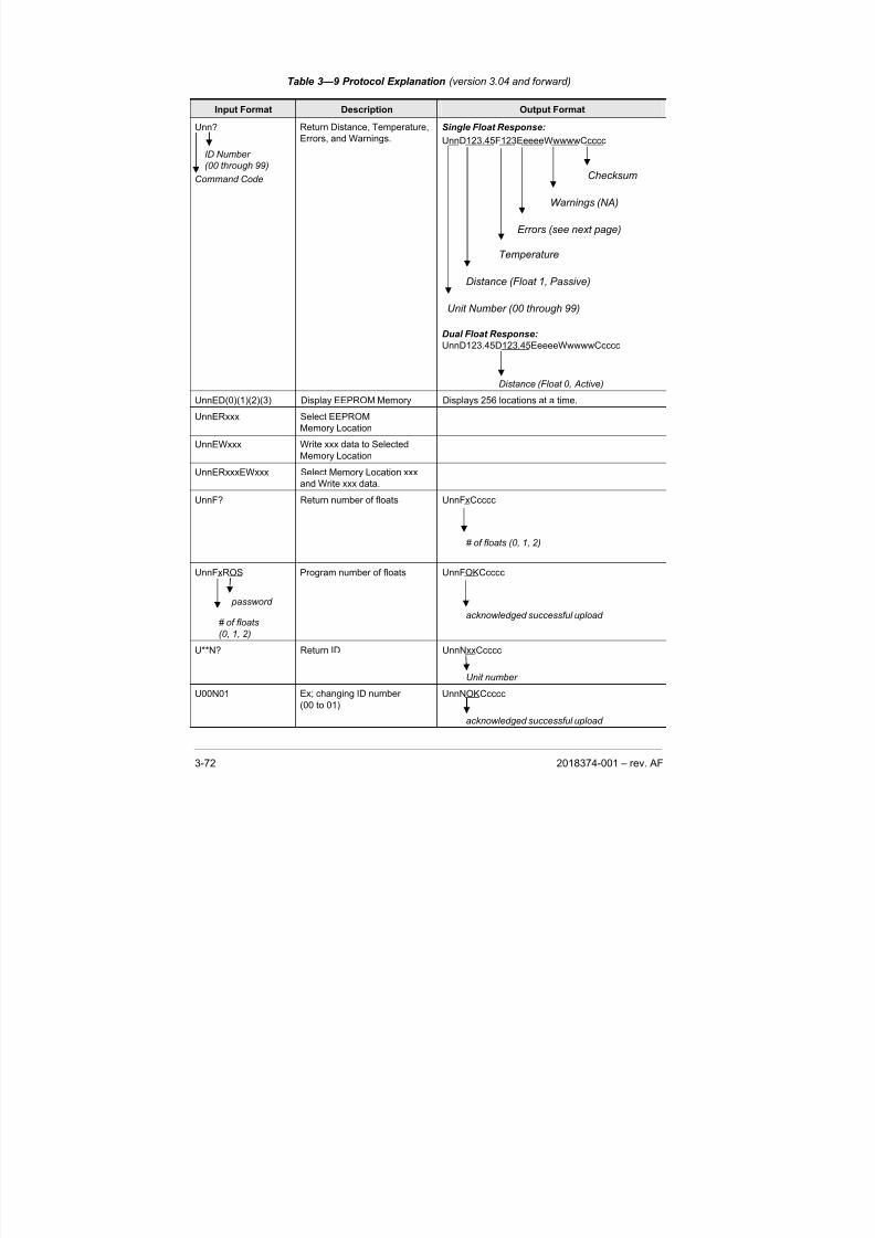
8/13/2019 2018374 m Naf
http://slidepdf.com/reader/full/2018374-m-naf 90/174
3-72 2018374-001 – rev. AF
Table 3—9 Protocol Explanation (version 3.04 and forward)
Input Format Description Output Format
Unn?
ID Number(00 through 99)
Command Code
Return Distance, Temperature,
Errors, and Warnings.
Single Float Response:
UnnD123.45F123EeeeeWwwwwCcccc
Checksum
Warnings (NA)
Errors (see next page)
Temperature
Distance (Float 1, Passive)
Unit Number (00 through 99)
Dual Float Response:
UnnD123.45D123.45EeeeeWwwwwCcccc
Distance (Float 0, Active)
UnnED(0)(1)(2)(3) Display EEPROM Memory Displays 256 locations at a time.
UnnERxxx Select EEPROM
Memory Location
UnnEWxxx Write xxx data to Selected
Memory Location
UnnERxxxEWxxx Select Memory Location xxxand Write xxx data.
UnnF? Return number of floats UnnFxCcccc
# of floats (0, 1, 2)
UnnFxROS
password
# of floats
(0, 1, 2)
Program number of floats UnnFOKCcccc
acknowledged successful upload
U**N? Return ID UnnNxxCcccc
Unit number
U00N01 Ex; changing ID number
(00 to 01)
UnnNOKCcccc
acknowledged successful upload
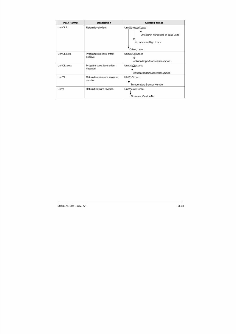
8/13/2019 2018374 m Naf
http://slidepdf.com/reader/full/2018374-m-naf 91/174
2018374-001 – rev. AF 3-73
Input Format Description Output Format
UnnOL? Return level offset UnnOL+xxxxCcccc
Offset # in hundreths of base units
(in, mm, cm) Sign + or -
Offset, Level
UnnOLxxxx Program xxxx level offset
positive
UnnOLOKCcccc
acknowledged successful upload
UnnOL-xxxx Program -xxxx level offset
negative
UnnOLOKCcccc
acknowledged successful upload
UnnT? Return temperature sense or
number
U01TxCcccc
Temperature Sensor NumberUnnV Return firmware revision UnnVx.xxxCcccc
Firmware Version No.

8/13/2019 2018374 m Naf
http://slidepdf.com/reader/full/2018374-m-naf 92/174
3-74 2018374-001 – rev. AF
BBBlllaaannnkkk PPPaaagggeee
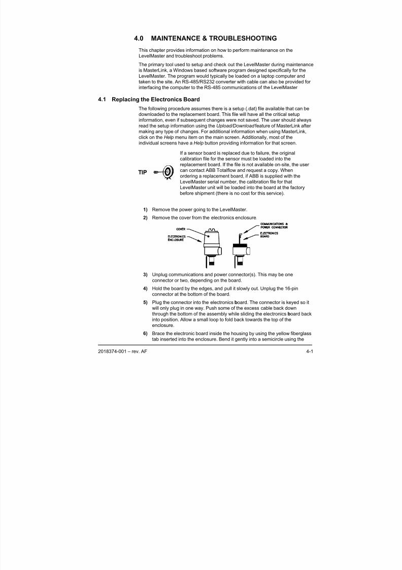
8/13/2019 2018374 m Naf
http://slidepdf.com/reader/full/2018374-m-naf 93/174
2018374-001 – rev. AF 4-1
4.0 MAINTENANCE & TROUBLESHOOTING
This chapter provides information on how to perform maintenance on the
LevelMaster and troubleshoot problems.
The primary tool used to setup and check out the LevelMaster during maintenance
is MasterLink, a Windows based software program designed specifically for the
LevelMaster. The program would typically be loaded on a laptop computer and
taken to the site. An RS-485/RS232 converter with cable can also be provided for
interfacing the computer to the RS-485 communications of the LevelMaster
4.1 Replacing the Electronics Board
The following procedure assumes there is a setup (.dat) file available that can be
downloaded to the replacement board. This file will have all the critical setup
information, even if subsequent changes were not saved. The user should always
read the setup information using the Upload/Download feature of MasterLink after
making any type of changes. For additional information when using MasterLink,
click on the Help menu item on the main screen. Additionally, most of the
individual screens have a Help button providing information for that screen.
If a sensor board is replaced due to failure, the original
calibration file for the sensor must be loaded into the
replacement board. If the file is not available on-site, the user
can contact ABB Totalflow and request a copy. When
ordering a replacement board, if ABB is supplied with the
LevelMaster serial number, the calibration file for that
LevelMaster unit will be loaded into the board at the factory
before shipment (there is no cost for this service).
1) Remove the power going to the LevelMaster.
2) Remove the cover from the electronics enclosure.
3) Unplug communications and power connector(s). This may be one
connector or two, depending on the board.
4) Hold the board by the edges, and pull it slowly out. Unplug the 16-pin
connector at the bottom of the board.
5) Plug the connector into the electronics board. The connector is keyed so it
will only plug in one way. Push some of the excess cable back down
through the bottom of the assembly while sliding the electronics board back
into position. Allow a small loop to fold back towards the top of the
enclosure.
6) Brace the electronic board inside the housing by using the yellow fiberglass
tab inserted into the enclosure. Bend it gently into a semicircle using the
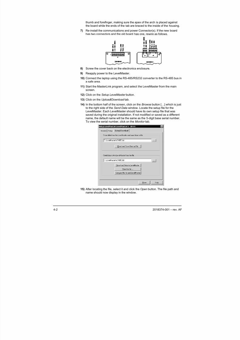
8/13/2019 2018374 m Naf
http://slidepdf.com/reader/full/2018374-m-naf 94/174
4-2 2018374-001 – rev. AF
thumb and forefinger, making sure the apex of the arch is placed against
the board while the ends of the tab are braced to the inside of the housing.
7) Re-install the communications and power Connector(s). If the new board
has two connectors and the old board has one, rewire as follows.
8) Screw the cover back on the electronics enclosure.
9) Reapply power to the LevelMaster.
10) Connect the laptop using the RS-485/RS232 converter to the RS-485 bus in
a safe area.
11) Start the MasterLink program, and select the LevelMaster from the mainscreen.
12) Click on the Setup LevelMaster button.
13) Click on the Upload /Download tab.
14) In the bottom half of the screen, click on the Browse button […] which is just
to the right side of the Send Data window. Locate the setup file for the
LevelMaster. Each LevelMaster should have its own setup file that was
saved during the original installation. If not modified or saved as a different
name, the default name will be the same as the 5-digit base serial number.
To view the serial number, click on the Monitor tab.
15) After locating the file, select it and click the Open button. The file path and
name should now display in the window.
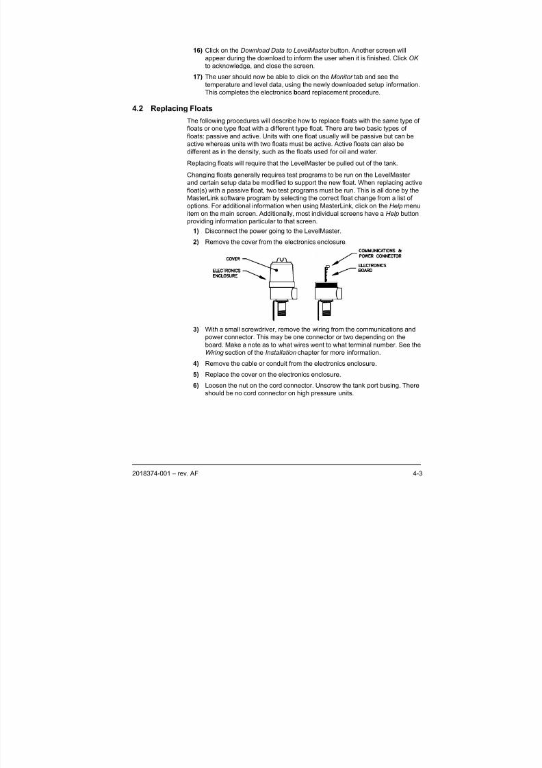
8/13/2019 2018374 m Naf
http://slidepdf.com/reader/full/2018374-m-naf 95/174
2018374-001 – rev. AF 4-3
16) Click on the Download Data to LevelMaster button. Another screen will
appear during the download to inform the user when it is finished. Click OK
to acknowledge, and close the screen.
17) The user should now be able to click on the Monitor tab and see the
temperature and level data, using the newly downloaded setup information.
This completes the electronics board replacement procedure.
4.2 Replacing Floats
The following procedures will describe how to replace floats with the same type of
floats or one type float with a different type float. There are two basic types of
floats: passive and active. Units with one float usually will be passive but can be
active whereas units with two floats must be active. Active floats can also be
different as in the density, such as the floats used for oil and water.
Replacing floats will require that the LevelMaster be pulled out of the tank.
Changing floats generally requires test programs to be run on the LevelMaster
and certain setup data be modified to support the new float. When replacing active
float(s) with a passive float, two test programs must be run. This is all done by the
MasterLink software program by selecting the correct float change from a list ofoptions. For additional information when using MasterLink, click on the Help menu
item on the main screen. Additionally, most individual screens have a Help button
providing information particular to that screen.
1) Disconnect the power going to the LevelMaster.
2) Remove the cover from the electronics enclosure.
3) With a small screwdriver, remove the wiring from the communications and
power connector. This may be one connector or two depending on the
board. Make a note as to what wires went to what terminal number. See the
Wiring section of the Installation chapter for more information.
4) Remove the cable or conduit from the electronics enclosure.
5) Replace the cover on the electronics enclosure.
6) Loosen the nut on the cord connector. Unscrew the tank port busing. There
should be no cord connector on high pressure units.
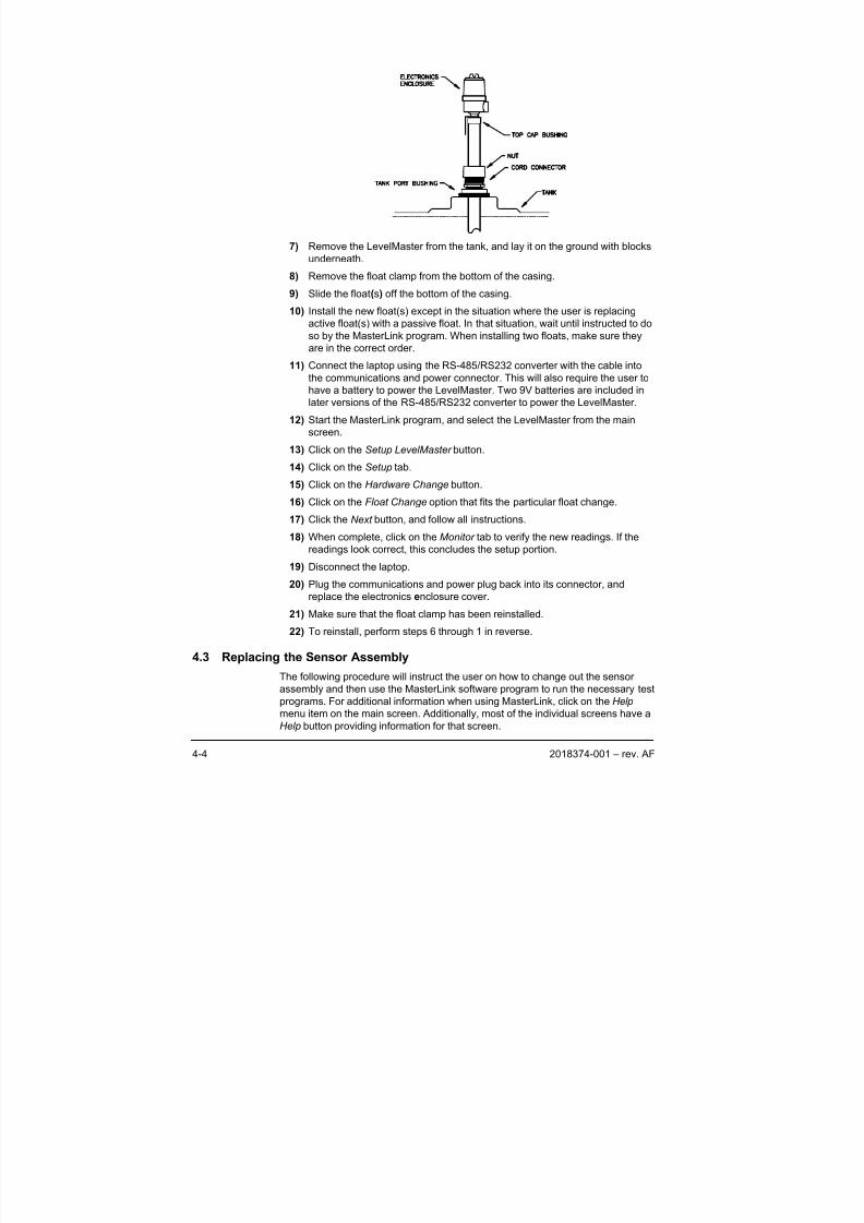
8/13/2019 2018374 m Naf
http://slidepdf.com/reader/full/2018374-m-naf 96/174
4-4 2018374-001 – rev. AF
7) Remove the LevelMaster from the tank, and lay it on the ground with blocks
underneath.
8) Remove the float clamp from the bottom of the casing.
9) Slide the float(s) off the bottom of the casing.
10) Install the new float(s) except in the situation where the user is replacingactive float(s) with a passive float. In that situation, wait until instructed to do
so by the MasterLink program. When installing two floats, make sure they
are in the correct order.
11) Connect the laptop using the RS-485/RS232 converter with the cable into
the communications and power connector. This will also require the user to
have a battery to power the LevelMaster. Two 9V batteries are included in
later versions of the RS-485/RS232 converter to power the LevelMaster.
12) Start the MasterLink program, and select the LevelMaster from the main
screen.
13) Click on the Setup LevelMaster button.
14) Click on the Setup tab.15) Click on the Hardware Change button.
16) Click on the Float Change option that fits the particular float change.
17) Click the Next button, and follow all instructions.
18) When complete, click on the Monitor tab to verify the new readings. If the
readings look correct, this concludes the setup portion.
19) Disconnect the laptop.
20) Plug the communications and power plug back into its connector, and
replace the electronics enclosure cover.
21) Make sure that the float clamp has been reinstalled.
22) To reinstall, perform steps 6 through 1 in reverse.
4.3 Replacing the Sensor Assembly
The following procedure will instruct the user on how to change out the sensor
assembly and then use the MasterLink software program to run the necessary test
programs. For additional information when using MasterLink, click on the Help
menu item on the main screen. Additionally, most of the individual screens have a
Help button providing information for that screen.
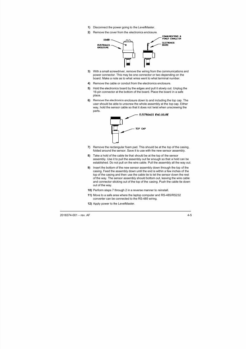
8/13/2019 2018374 m Naf
http://slidepdf.com/reader/full/2018374-m-naf 97/174
2018374-001 – rev. AF 4-5
1) Disconnect the power going to the LevelMaster.
2) Remove the cover from the electronics enclosure.
3) With a small screwdriver, remove the wiring from the communications and
power connector. This may be one connector or two depending on the
board. Make a note as to what wires went to what terminal number.
4) Remove the cable or conduit from the electronics enclosure.
5) Hold the electronics board by the edges and pull it slowly out. Unplug the16-pin connector at the bottom of the board. Place the board in a safe
place.
6) Remove the electronics enclosure down to and including the top cap. The
user should be able to unscrew the whole assembly at the top cap. Either
way, hold the sensor cable so that it does not twist when unscrewing the
parts.
7) Remove the rectangular foam pad. This should be at the top of the casing,
folded around the sensor. Save it to use with the new sensor assembly.
8) Take a hold of the cable tie that should be at the top of the sensor
assembly. Use it to pull the assembly out far enough so that a hold can be
established. Do not pull on the wire cable. Pull the assembly all the way out.
9) Insert the bottom of the new sensor assembly down through the top of the
casing. Feed the assembly down until the end is within a few inches of the
top of the casing and then use the cable tie to let the sensor down the rest
of the way. The sensor assembly should bottom out, leaving the wire cableand connector sticking out of the top of the casing. Push the cable tie down
out of the way.
10) Perform steps 7 through 2 in a reverse manner to reinstall.
11) Move to a safe area where the laptop computer and RS-485/RS232
converter can be connected to the RS-485 wiring.
12) Apply power to the LevelMaster.
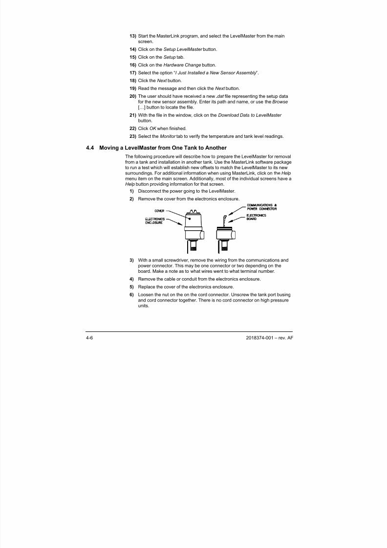
8/13/2019 2018374 m Naf
http://slidepdf.com/reader/full/2018374-m-naf 98/174
4-6 2018374-001 – rev. AF
13) Start the MasterLink program, and select the LevelMaster from the main
screen.
14) Click on the Setup LevelMaster button.
15) Click on the Setup tab.
16) Click on the Hardware Change button.
17) Select the option “I Just Installed a New Sensor Assembly ”.
18) Click the Next button.
19) Read the message and then click the Next button.
20) The user should have received a new .dat file representing the setup data
for the new sensor assembly. Enter its path and name, or use the Browse
[…] button to locate the file.
21) With the file in the window, click on the Download Data to LevelMaster
button.
22) Click OK when finished.
23) Select the Monitor tab to verify the temperature and tank level readings.
4.4 Moving a LevelMaster from One Tank to Another
The following procedure will describe how to prepare the LevelMaster for removal
from a tank and installation in another tank. Use the MasterLink software package
to run a test which will establish new offsets to match the LevelMaster to its new
surroundings. For additional information when using MasterLink, click on the Help
menu item on the main screen. Additionally, most of the individual screens have a
Help button providing information for that screen.
1) Disconnect the power going to the LevelMaster.
2) Remove the cover from the electronics enclosure.
3) With a small screwdriver, remove the wiring from the communications and
power connector. This may be one connector or two depending on the
board. Make a note as to what wires went to what terminal number.
4) Remove the cable or conduit from the electronics enclosure.5) Replace the cover of the electronics enclosure.
6) Loosen the nut on the on the cord connector. Unscrew the tank port busing
and cord connector together. There is no cord connector on high pressure
units.
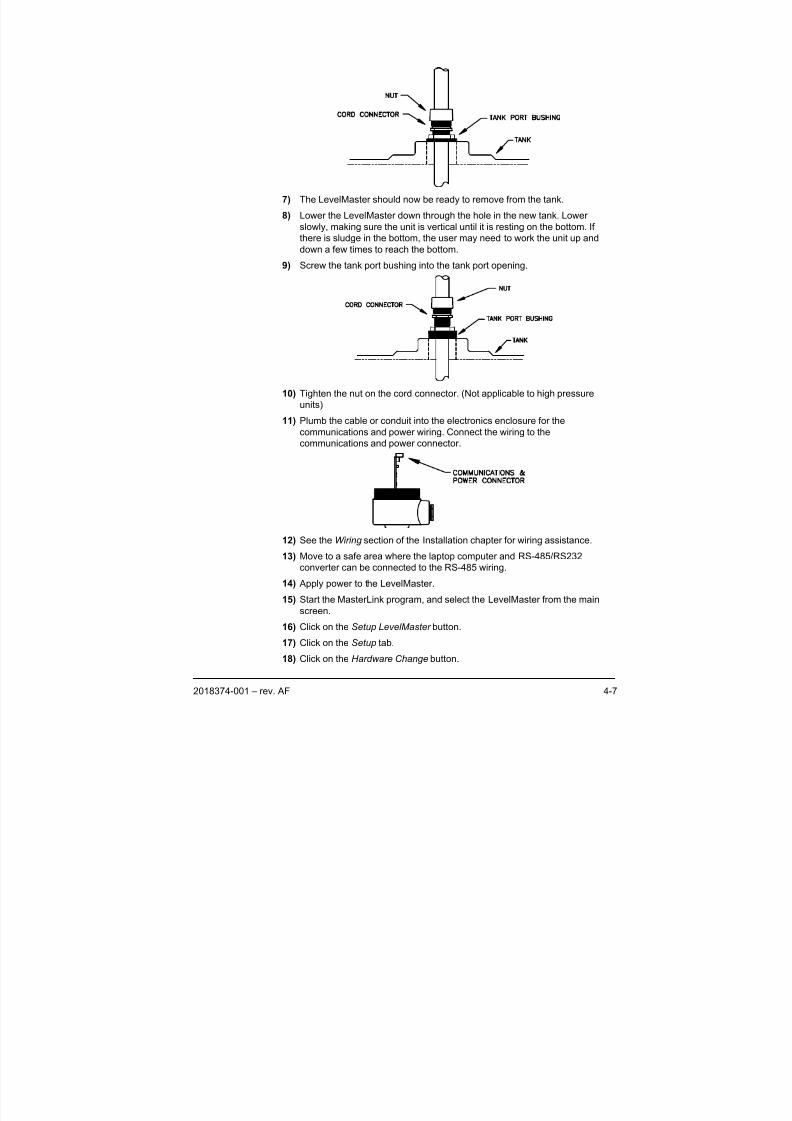
8/13/2019 2018374 m Naf
http://slidepdf.com/reader/full/2018374-m-naf 99/174
2018374-001 – rev. AF 4-7
7) The LevelMaster should now be ready to remove from the tank.
8) Lower the LevelMaster down through the hole in the new tank. Lower
slowly, making sure the unit is vertical until it is resting on the bottom. If
there is sludge in the bottom, the user may need to work the unit up and
down a few times to reach the bottom.
9) Screw the tank port bushing into the tank port opening.
10) Tighten the nut on the cord connector. (Not applicable to high pressure
units)
11) Plumb the cable or conduit into the electronics enclosure for the
communications and power wiring. Connect the wiring to thecommunications and power connector.
12) See the Wiring section of the Installation chapter for wiring assistance.
13) Move to a safe area where the laptop computer and RS-485/RS232
converter can be connected to the RS-485 wiring.
14) Apply power to the LevelMaster.
15) Start the MasterLink program, and select the LevelMaster from the main
screen.
16) Click on the Setup LevelMaster button.
17) Click on the Setup tab.
18) Click on the Hardware Change button.
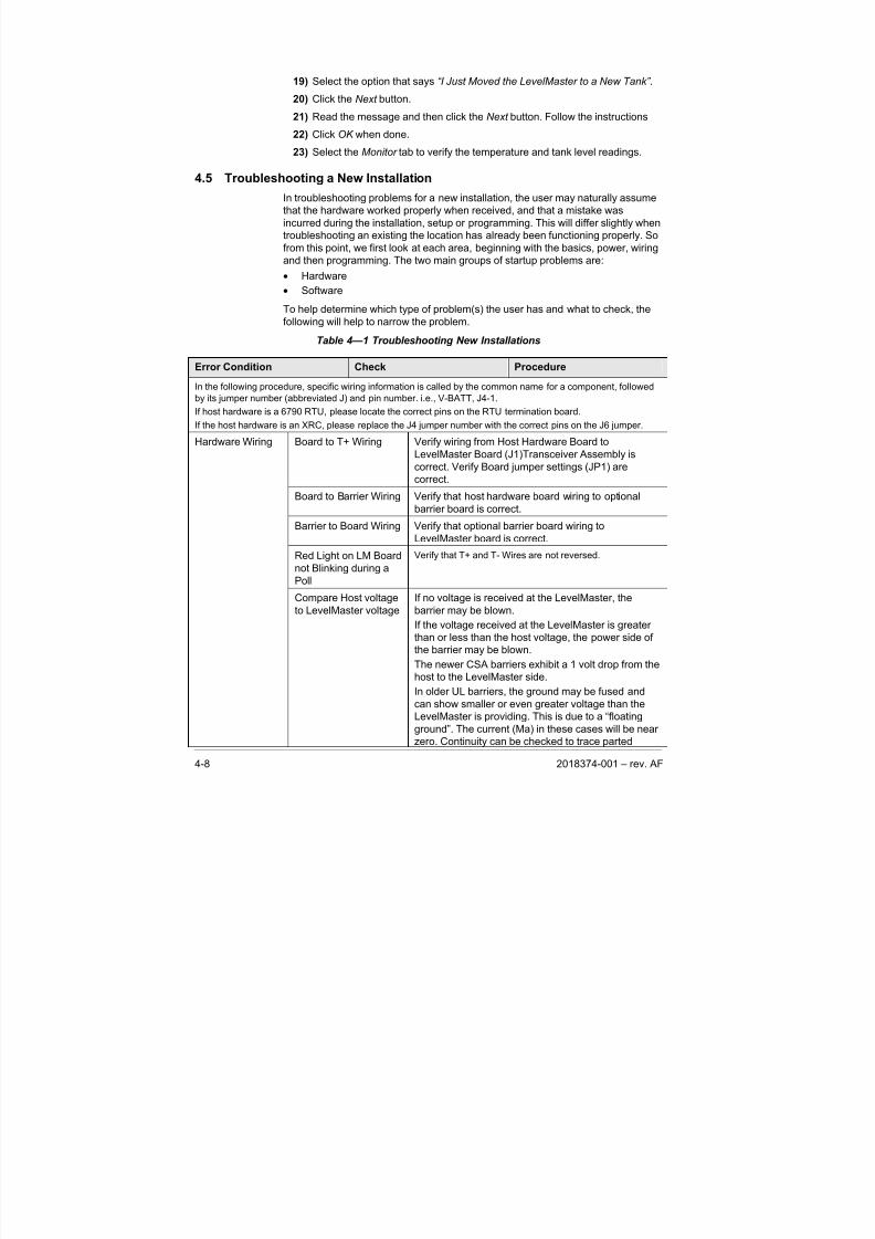
8/13/2019 2018374 m Naf
http://slidepdf.com/reader/full/2018374-m-naf 100/174
4-8 2018374-001 – rev. AF
19) Select the option that says “I Just Moved the LevelMaster to a New Tank” .
20) Click the Next button.
21) Read the message and then click the Next button. Follow the instructions
22) Click OK when done.
23) Select the Monitor tab to verify the temperature and tank level readings.
4.5 Troubleshooting a New Installation
In troubleshooting problems for a new installation, the user may naturally assume
that the hardware worked properly when received, and that a mistake was
incurred during the installation, setup or programming. This will differ slightly when
troubleshooting an existing the location has already been functioning properly. So
from this point, we first look at each area, beginning with the basics, power, wiring
and then programming. The two main groups of startup problems are:
• Hardware
• Software
To help determine which type of problem(s) the user has and what to check, the
following will help to narrow the problem.
Table 4—1 Troubleshooting New Installations
Error Condition Check Procedure
In the following procedure, specific wiring information is called by the common name for a component, followed
by its jumper number (abbreviated J) and pin number. i.e., V-BATT, J4-1.
If host hardware is a 6790 RTU, please locate the correct pins on the RTU termination board.
If the host hardware is an XRC, please replace the J4 jumper number with the correct pins on the J6 jumper.
Board to T+ Wiring Verify wiring from Host Hardware Board to
LevelMaster Board (J1)Transceiver Assembly is
correct. Verify Board jumper settings (JP1) are
correct.
Board to Barrier Wiring Verify that host hardware board wiring to optional
barrier board is correct.
Barrier to Board Wiring Verify that optional barrier board wiring to
LevelMaster board is correct.
Red Light on LM Board
not Blinking during a
Poll
Verify that T+ and T- Wires are not reversed.
Hardware Wiring
Compare Host voltage
to LevelMaster voltage
If no voltage is received at the LevelMaster, the
barrier may be blown.
If the voltage received at the LevelMaster is greater
than or less than the host voltage, the power side ofthe barrier may be blown.
The newer CSA barriers exhibit a 1 volt drop from the
host to the LevelMaster side.
In older UL barriers, the ground may be fused and
can show smaller or even greater voltage than the
LevelMaster is providing. This is due to a “floating
ground”. The current (Ma) in these cases will be near
zero. Continuity can be checked to trace parted
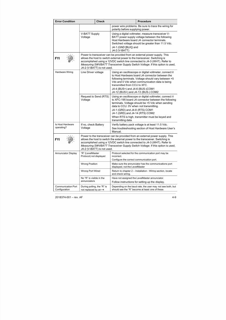
8/13/2019 2018374 m Naf
http://slidepdf.com/reader/full/2018374-m-naf 101/174
2018374-001 – rev. AF 4-9
Error Condition Check Procedure
power wire problems. Be sure to trace the wiring for
polarity before supplying power.
V-BATT Supply
Voltage
Using a digital voltmeter, measure transceiver V-
BATT power supply voltage between the following
Host Hardware board J4 connector terminals.Switched voltage should be greater than 11.5 Vdc.
J4-1 (GND [BLK]) and
J4-2 (V-BATT)
Power to transceiver can be provided from an external power supply. This
allows the host to switch external power to the transceiver. Switching is
accomplished using a 12VDC switch line connected to J4-3 (WHT). Refer to
Measuring SWVBATT Transceiver Supply Switch Voltage. If this option is used,
J4-2 (V-BATT) is not used.
Line Driver voltage Using an oscilloscope or digital voltmeter, connect it
to Host Hardware board J4 connector between the
following terminals. Voltage should vary between +5
Vdc and 0 Vdc when communication data is beingtransmitted from CCU to XFC.
J4-4 (BUS+) and J4-6 (BUS-)COM1
J4-12 (BUS+) and J4-13 (BUS-) COM2
Hardware Wiring
Request to Send (RTS)
Voltage
Using an oscilloscope or digital voltmeter, connect it
to XFC-195 board J4 connector between the following
terminals. Voltage should be +5 Vdc when sending
data to CCU. 0V when not transmitting.
J4-1 (GRD) and J4-8 (RTS) COM1
J4-1 (GRD) and J4-14 (RTS) COM2
When RTS is high, transmitter must be keyed and
transmitting data.
Is Host Hardware
operating?If no, check Battery
Voltage
Verify battery pack voltage is at least 11.5 Vdc.
See troubleshooting section of Host Hardware User’s
Manual.
Power to the transceiver can be provided from an external power supply. This
allows the host to switch the external power to the transceiver. Switching is
accomplished using a 12VDC switch line connected to J4-3 (WHT). Refer to
Measuring SWVBATT Transceiver Supply Switch Voltage. If this option is used,
J4-2 (V-BATT) is not used.
“R” (LevelMaster
Protocol) not displayed
Protocol selected for the communication port may be
incorrect.
Configure the correct communication port.
Wrong Position Make sure the annunciator has the communications portdisplayed, not the LevelMaster
Wrong Port Wired Return to chapter 2 – Installation - Wiring section, locate
and check wiring.
Annunciator Display
No “R” is visible in the
annunciators
Have not assigned the LevelMaster annunciator.
Follow instructions for setting up the display.
Communication Port
Configuration
During polling, the “R” is
not replaced by an
Depending on the baud rate, the user may not see both, but
should see the “R” become at least one of these.
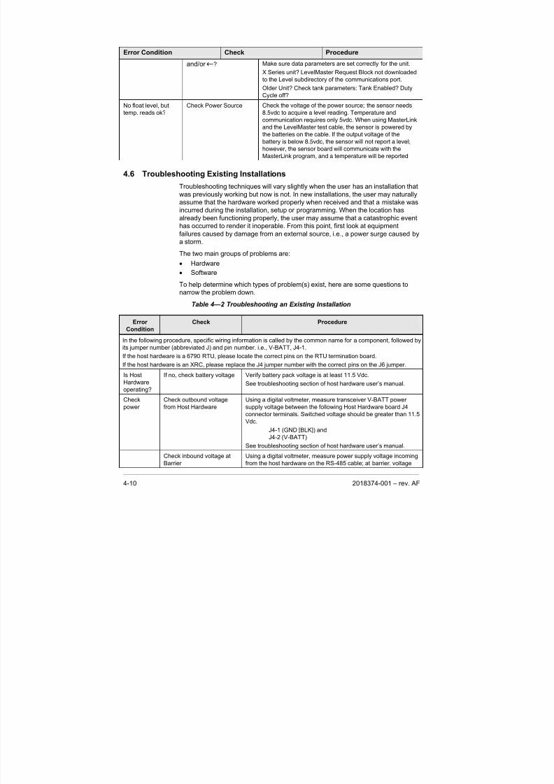
8/13/2019 2018374 m Naf
http://slidepdf.com/reader/full/2018374-m-naf 102/174
4-10 2018374-001 – rev. AF
Error Condition Check Procedure
and/or ? Make sure data parameters are set correctly for the unit.
X Series unit? LevelMaster Request Block not downloaded
to the Level subdirectory of the communications port.
Older Unit? Check tank parameters: Tank Enabled? Duty
Cycle off?
No float level, but
temp. reads ok?
Check Power Source Check the voltage of the power source; the sensor needs
8.5vdc to acquire a level reading. Temperature and
communication requires only 5vdc. When using MasterLink
and the LevelMaster test cable, the sensor is powered by
the batteries on the cable. If the output voltage of the
battery is below 8.5vdc, the sensor will not report a level;
however, the sensor board will communicate with the
MasterLink program, and a temperature will be reported
4.6 Troubleshooting Existing Installations
Troubleshooting techniques will vary slightly when the user has an installation that
was previously working but now is not. In new installations, the user may naturally
assume that the hardware worked properly when received and that a mistake wasincurred during the installation, setup or programming. When the location has
already been functioning properly, the user may assume that a catastrophic event
has occurred to render it inoperable. From this point, first look at equipment
failures caused by damage from an external source, i.e., a power surge caused by
a storm.
The two main groups of problems are:
• Hardware
• Software
To help determine which types of problem(s) exist, here are some questions to
narrow the problem down.
Table 4—2 Troubleshooting an Existing Installation
Error
Condition
Check Procedure
In the following procedure, specific wiring information is called by the common name for a component, followed by
its jumper number (abbreviated J) and pin number. i.e., V-BATT, J4-1.
If the host hardware is a 6790 RTU, please locate the correct pins on the RTU termination board.
If the host hardware is an XRC, please replace the J4 jumper number with the correct pins on the J6 jumper.
Is Host
Hardware
operating?
If no, check battery voltage Verify battery pack voltage is at least 11.5 Vdc.
See troubleshooting section of host hardware user’s manual.
Checkpower Check outbound voltagefrom Host Hardware Using a digital voltmeter, measure transceiver V-BATT powersupply voltage between the following Host Hardware board J4
connector terminals. Switched voltage should be greater than 11.5
Vdc.
J4-1 (GND [BLK]) and
J4-2 (V-BATT)
See troubleshooting section of host hardware user’s manual.
Check inbound voltage at
Barrier
Using a digital voltmeter, measure power supply voltage incoming
from the host hardware on the RS-485 cable; at barrier, voltage
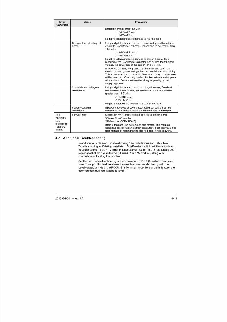
8/13/2019 2018374 m Naf
http://slidepdf.com/reader/full/2018374-m-naf 103/174
2018374-001 – rev. AF 4-11
Error
Condition
Check Procedure
should be greater than 11.5 Vdc.
J1-2 (POWER -) and
J1-1 (POWER +)
Negative voltage indicates damage to RS-485 cable.
Check outbound voltage at
Barrier
Using a digital voltmeter, measure power voltage outbound from
Barrier to LevelMaster; at barrier, voltage should be greater than
11.5 Vdc.
J1-2 (POWER -) and
J1-1 (POWER +)
Negative voltage indicates damage to barrier. If the voltage
received at the LevelMaster is greater than or less than the host
voltage, the power side of the barrier can be blown.
In older UL barriers, the ground may be fused and can show
smaller or even greater voltage than the LevelMaster is providing.
This is due to a “floating ground”. The current (Ma) in these cases
will be near zero. Continuity can be checked to trace parted power
wire problem. Be sure to trace the wiring for polarity before
supplying power.
Check inbound voltage at
LevelMaster
Using a digital voltmeter, measure voltage incoming from host
hardware on RS-485 cable; at LevelMaster, voltage should be
greater than 11.5 Vdc.
J1-1 (GND) and
J1-2 (+12 VDC)
Negative voltage indicates damage to RS-485 cable.
Power received at
LevelMaster
If power is received at LevelMaster board but board is still not
functioning, this indicates the LevelMaster board is damaged.
Host
Hardware
LCD
returned toTotalflow
display
Software files Most likely if the screen displays something similar to this:
XSeries Flow Computer
2100xxx-xxx (COPYRIGHT)
If this is the case, the system has cold started. This requires
uploading configuration files from computer to host hardware. See
user manual for host hardware and help files in host software.
4.7 Additional Troubleshooting
In addition to Table 4—1 Troubleshooting New Installations and Table 4—2
Troubleshooting an Existing Installation, Totalflow has built in additional tools for
troubleshooting. Table 4—3 Error Messages (Ver. 5.015 – 5.018) discusses error
messages that may be reflected in PCCU32 and MasterLink, along with
information on locating the problem.
Another tool for troubleshooting is a tool provided in PCCU32 called Tank Level
Pass Through. This feature allows the user to communicate directly with theLevelMaster, outside of the PCCU32 in Terminal mode. By using this feature, the
user can communicate at a base level.
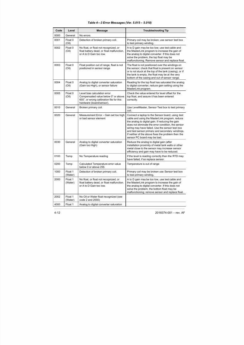
8/13/2019 2018374 m Naf
http://slidepdf.com/reader/full/2018374-m-naf 104/174
4-12 2018374-001 – rev. AF
Table 4—3 Error Messages (Ver. 5.015 – 5.018)
Code Level Message Troubleshooting Tip
0000 General No errors
0001 Float 0
(Oil)
Detection of broken primary coil. Primary coil may be broken; use sensor test box
to test primary winding.0002 Float 0
(Oil)
No float, or float not recognized, or
float battery dead, or float malfunction,
or A to D Gain too low.
A to D gain may be too low; use test cable and
the MasterLink program to increase the gain of
the analog to digital converter. If this does not
solve the problem, the top float may be
malfunctioning. Remove sensor and replace float.
0003 Float 0
(Oil)
Float position out of range, float is not
positioned in sensor range
The float is not positioned over the windings on
the sensor; check that float is present on sensor
or is not stuck at the top of the tank (casing), or if
the tank is empty, the float may be at the very
bottom of the casing and out of sensor range.
0004 Float 0
(Oil)
Analog to digital converter saturation
(Gain too High), or sensor failure
Reading for the top float has saturated the analog
to digital converter; reduce gain setting using the
MasterLink program.
0005 Float 0
(Oil)
Level bias calculation error.
Compensated value below 0” or above
655”, or wrong calibration file for this
hardware (board/sensor).
Check the value entered for level offset for the
top float, and assure it has been entered
correctly.
0010 General Broken primary coil. Use LevelMaster, Sensor Test box to test primary
coil.
0020 General Measurement Error – Gain set too high
or bad sensor element
Connect a laptop to the Sensor board, using test
cable and using the MasterLink program, reduce
the analog to digital gain. If reducing the gain
does not eliminate the error condition, the sensor
wiring may have failed. Use the sensor test box
and test sensor primary and secondary windings.
If neither of the above fixes the problem then the
sensor PC board may be bad.
0030 General Analog to digital converter saturation
(Gain too High)
Reduce the analog to digital gain (after
installation proximity of metal tank walls or other
metal close to the sensor may increase sensor
efficiency and gain may have to be reduced.
0100 Temp No Temperature reading If the level is reading correctly then the RTD may
have failed, if so replace sensor.
0200 Temp Calculated Temperature error value
below 0 or above 255
Temperature is out of range.
1000 Float 1
(Water)
Detection of broken primary coil. Primary coil may be broken use Sensor test box
to test primary winding.
2000 Float 1
(Water)
No float, or float not recognized, or
float battery dead, or float malfunction,
or A to D Gain too low.
A to D gain may be too low, use test cable and
the MasterLink program to increase the gain of
the analog to digital converter. If this does not
solve the problem, the bottom float may be
malfunctioning; remove sensor and replace float.
2002 Float 1
(Water)
No Oil or Water float recognized (see
code 2 and 2000)
4000 Float 1 Analog to digital converter saturation
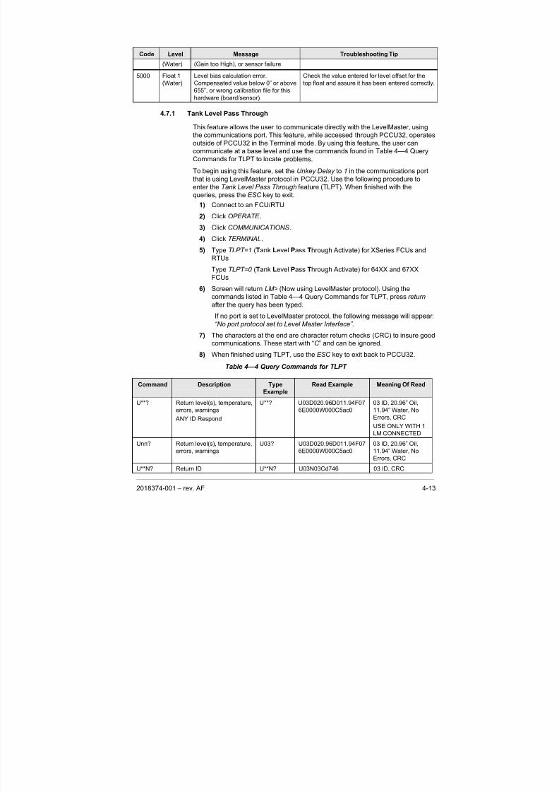
8/13/2019 2018374 m Naf
http://slidepdf.com/reader/full/2018374-m-naf 105/174
2018374-001 – rev. AF 4-13
Code Level Message Troubleshooting Tip
(Water) (Gain too High), or sensor failure
5000 Float 1
(Water)
Level bias calculation error.
Compensated value below 0” or above
655”, or wrong calibration file for this
hardware (board/sensor).
Check the value entered for level offset for the
top float and assure it has been entered correctly.
4.7.1 Tank Level Pass Through
This feature allows the user to communicate directly with the LevelMaster, using
the communications port. This feature, while accessed through PCCU32, operates
outside of PCCU32 in the Terminal mode. By using this feature, the user can
communicate at a base level and use the commands found in Table 4—4 Query
Commands for TLPT to locate problems.
To begin using this feature, set the Unkey Delay to 1 in the communications port
that is using LevelMaster protocol in PCCU32. Use the following procedure to
enter the Tank Level Pass Through feature (TLPT). When finished with the
queries, press the ESC key to exit.
1) Connect to an FCU/RTU
2) Click OPERATE .
3) Click COMMUNICATIONS.
4) Click TERMINAL.
5) Type TLPT=1 (Tank Level Pass Through Activate) for XSeries FCUs and
RTUs
Type TLPT=0 (Tank Level Pass Through Activate) for 64XX and 67XX
FCUs
6) Screen will return LM> (Now using LevelMaster protocol). Using the
commands listed in Table 4—4 Query Commands for TLPT, press return
after the query has been typed.
If no port is set to LevelMaster protocol, the following message will appear:
“No port protocol set to Level Master Interface” .
7) The characters at the end are character return checks (CRC) to insure good
communications. These start with “C ” and can be ignored.
8) When finished using TLPT, use the ESC key to exit back to PCCU32.
Table 4—4 Query Commands for TLPT
Command Description Type
Example
Read Example Meaning Of Read
U**? Return level(s), temperature,
errors, warnings
ANY ID Respond
U**? U03D020.96D011.94F07
6E0000W000C5ac0
03 ID, 20.96” Oil,
11.94” Water, No
Errors, CRC
USE ONLY WITH 1
LM CONNECTED
Unn? Return level(s), temperature,
errors, warnings
U03? U03D020.96D011.94F07
6E0000W000C5ac0
03 ID, 20.96” Oil,
11.94” Water, No
Errors, CRC
U**N? Return ID U**N? U03N03Cd746 03 ID, CRC
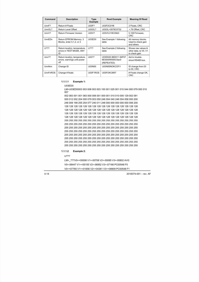
8/13/2019 2018374 m Naf
http://slidepdf.com/reader/full/2018374-m-naf 106/174
4-14 2018374-001 – rev. AF
Command Description Type
Example
Read Example Meaning Of Read
UnnF? Return # Floats U03F? U03F2C01f6 2 Floats, CRC
UnnOL? Return Level Offset U03OL? U03OL+0079C0732 +.79 Offset, CRC
UnnV? Return Firmware Version U03V? U03V5.018C09d3 5.108 Firmware,
CRCUnnEDn Return EPROM Memory. 3
Blocks, enter 0,1,2, or 3
U03ED0 See Example 1 following
table
All memory blocks.
Used to check gain
and others
U??? Return level(s), temperature,
errors in TEST MODE, ANY
ID
U??? See Example 2 following
table
Shows raw values &
other data, ie V0, V1
to check gain
Unn?? Return level(s), temperature,
errors, warnings until power
off
U03?? U03D020.96D011.94F07
6E0000W000C5ac0
(REPEATED)
Aid to trouble-
shoot RS485 bus.
UnnNnn Change ID U03N00 U03N00NOKCOf11 ID change from 03
to 00, CRC
UnnFnROS Change # floats U03F1ROS U03FOKC6f57 # Floats change OK,CRC
1.1.1.1 Example 1:
U03ED0
LM>U03ED0003 003 008 003 003 100 001 025 001 010 044 000 079 000 010
007
002 083 001 001 083 000 006 001 000 001 010 010 005 129 002 091
000 012 002 204 000 079 003 050 246 004 040 246 004 058 000 200
246 009 199 255 254 077 240 011 248 000 000 000 000 000 006 200
128 128 128 128 128 128 128 128 128 128 128 128 128 128 128 128
128 128 128 128 128 128 128 128 128 128 128 128 128 128 128 128
128 128 128 128 128 128 128 128 128 128 128 128 128 128 128 128
128 128 128 128 128 128 128 128 128 128 128 128 128 128 128 128
255 255 255 255 255 255 255 255 255 255 255 255 255 255 255 255
255 255 255 255 255 255 255 255 255 255 255 255 255 255 255 255
255 255 255 255 255 255 255 255 255 255 255 255 255 255 255 255
255 255 255 255 255 255 255 255 255 255 255 255 255 255 255 255
255 255 255 255 255 255 255 255 255 255 255 255 255 255 255 255
255 255 255 255 255 255 255 255 255 255 255 255 255 255 255 255
255 255 255 255 255 255 255 255 255 255 255 255 255 255 255 255
255 255 255 255 255 255 255 255 255 255 255 255 255 255 255 255
1.1.1.2 Example 2:
U???
LM>_???V0=+00006 V1=-00708 V2=-00085 V3=-00802 AVG
V0=-06447 V1=+05155 V2=-06952 V3=-07166 PC00548 F0
V0=+07765 V1=+01656 V2=+04361 V3=+08909 PC00548 F1
8/13/2019 2018374 m Naf
http://slidepdf.com/reader/full/2018374-m-naf 107/174
2018374-001 – rev. AF 4-15
V0=-06447 V1=+05155 V2=-06952 V3=-07166 5 7 S00557 L02285 021 F0
V0=+07765 V1=+01656 V2=+04361 V3=+08909 2 3 S00245 L01113 010 F1
R=10727 T1=10950 T2=10762 T3=10733 T4=10722 T5=10731
R=10728 T1=10955 T2=10760 T3=10733 T4=10722 T5=10731
R=10728 T1=10948 T2=10762 T3=10732 T4=10723 T5=10731R=10727 T1=10950 T2=10763 T3=10736 T4=10722 T5=10730
R=10729 T1=10953 T2=10761 T3=10734 T4=10724 T5=10730
R=10728 T1=10955 T2=10763 T3=10734 T4=10722 T5=10728
R=10728 T1=10950 T2=10761 T3=10733 T4=10723 T5=10730
R=10728 T1=10950 T2=10765 T3=10733 T4=10726 T5=10730
R=10728 T1=10953 T2=10761 T3=10735 T4=10721 T5=10730
R=10727 T1=10953 T2=10763 T3=10735 T4=10723 T5=10731
DIST=022.93 TC=+000.00 F0
DIST=011.13 TC=+000.00 F1
U03D023.72D012.11F076E0000W0000Ca982
4.7.2 Testing tv azhe Sensor
The following information will take the user through the process of testing the
LevelMaster sensor.
1) Remove the Killark conduit dome cover on the top of the LevelMaster
sensor, and disconnect the green phoenix connector.
2) Remove the yellow fiberglass tension support and then lift the interface
board out of the conduit housing.
3) Disconnect the ribbon cable.
4) Connect the sensor ribbon cable to the test box cable.
5) Set the ohmmeter to the 2K range and attach the leads to the test box.
6) Record the readings for future reference.
7) On the backside of the test box is a resistance table for different windings
for each sensor. If the winding readings are +/- 5.0% of the resistance table
on the backside of the test box, the sensor passes the test. If the test fails,
the reading will normally be open or shorted wires. If this is the case, the
sensor will need to be replaced.
8) Disconnect the ribbon cable from the test box cable, and reconnect the
ribbon cable to the interface board.
9) Set the board in the conduit housing, and replace the yellow fiberglass
tension support.
10) Reconnect the green phoenix connector.
11) Replace the Killark conduit dome cover.

8/13/2019 2018374 m Naf
http://slidepdf.com/reader/full/2018374-m-naf 108/174
4-16 2018374-001 – rev. AF
BBBlllaaannnkkk PPPaaagggeee
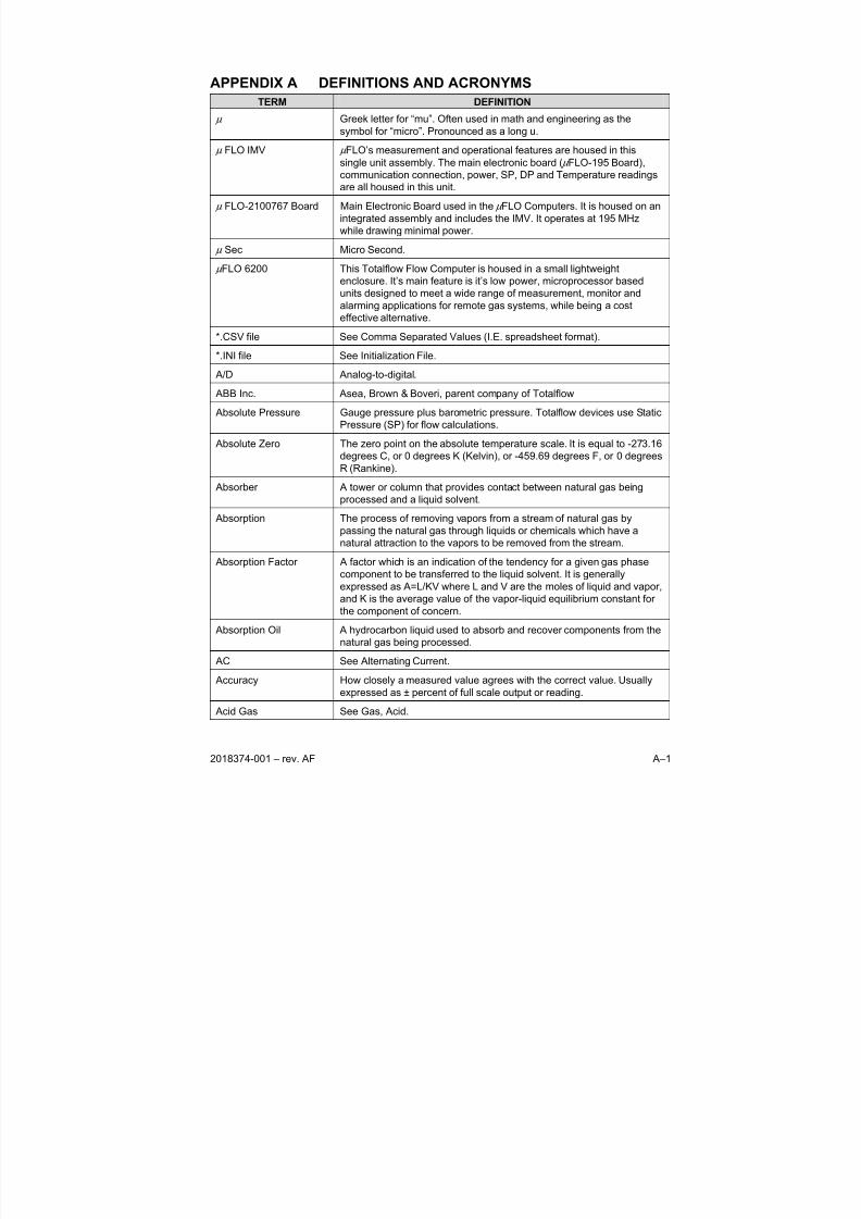
8/13/2019 2018374 m Naf
http://slidepdf.com/reader/full/2018374-m-naf 109/174
2018374-001 – rev. AF A–1
APPENDIX A DEFINITIONS AND ACRONYMS
TERM DEFINITION
μ Greek letter for “mu”. Often used in math and engineering as the
symbol for “micro”. Pronounced as a long u.
μ FLO IMV μ FLO’s measurement and operational features are housed in this
single unit assembly. The main electronic board ( μ FLO-195 Board),
communication connection, power, SP, DP and Temperature readings
are all housed in this unit.
μ FLO-2100767 Board Main Electronic Board used in the μ FLO Computers. It is housed on an
integrated assembly and includes the IMV. It operates at 195 MHz
while drawing minimal power.
μ Sec Micro Second.
μ FLO 6200 This Totalflow Flow Computer is housed in a small lightweight
enclosure. It’s main feature is it’s low power, microprocessor based
units designed to meet a wide range of measurement, monitor and
alarming applications for remote gas systems, while being a cost
effective alternative.
*.CSV file See Comma Separated Values (I.E. spreadsheet format).
*.INI file See Initialization File.
A/D Analog-to-digital.
ABB Inc. Asea, Brown & Boveri, parent company of Totalflow
Absolute Pressure Gauge pressure plus barometric pressure. Totalflow devices use Static
Pressure (SP) for flow calculations.
Absolute Zero The zero point on the absolute temperature scale. It is equal to -273.16
degrees C, or 0 degrees K (Kelvin), or -459.69 degrees F, or 0 degrees
R (Rankine).
Absorber A tower or column that provides contact between natural gas being
processed and a liquid solvent.
Absorption The process of removing vapors from a stream of natural gas by
passing the natural gas through liquids or chemicals which have a
natural attraction to the vapors to be removed from the stream.
Absorption Factor A factor which is an indication of the tendency for a given gas phase
component to be transferred to the liquid solvent. It is generally
expressed as A=L/KV where L and V are the moles of liquid and vapor,
and K is the average value of the vapor-liquid equilibrium constant for
the component of concern.
Absorption Oil A hydrocarbon liquid used to absorb and recover components from the
natural gas being processed.
AC See Alternating Current.
Accuracy How closely a measured value agrees with the correct value. Usually
expressed as ± percent of full scale output or reading.
Acid Gas See Gas, Acid.
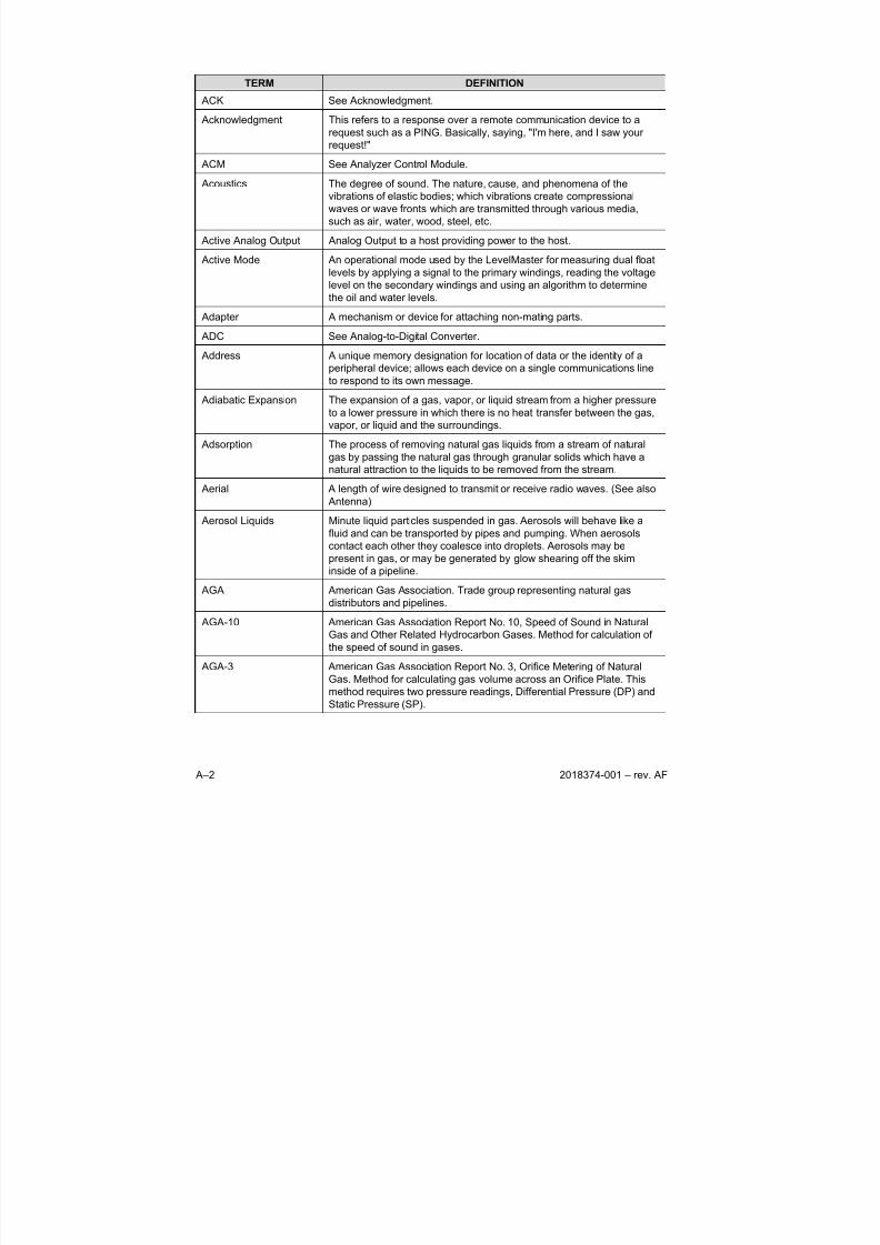
8/13/2019 2018374 m Naf
http://slidepdf.com/reader/full/2018374-m-naf 110/174
A–2 2018374-001 – rev. AF
TERM DEFINITION
ACK See Acknowledgment.
Acknowledgment This refers to a response over a remote communication device to a
request such as a PING. Basically, saying, "I'm here, and I saw your
request!"
ACM See Analyzer Control Module.
Acoustics The degree of sound. The nature, cause, and phenomena of the
vibrations of elastic bodies; which vibrations create compressional
waves or wave fronts which are transmitted through various media,
such as air, water, wood, steel, etc.
Active Analog Output Analog Output to a host providing power to the host.
Active Mode An operational mode used by the LevelMaster for measuring dual float
levels by applying a signal to the primary windings, reading the voltage
level on the secondary windings and using an algorithm to determine
the oil and water levels.
Adapter A mechanism or device for attaching non-mating parts.
ADC See Analog-to-Digital Converter.
Address A unique memory designation for location of data or the identity of a
peripheral device; allows each device on a single communications line
to respond to its own message.
Adiabatic Expansion The expansion of a gas, vapor, or liquid stream from a higher pressure
to a lower pressure in which there is no heat transfer between the gas,
vapor, or liquid and the surroundings.
Adsorption The process of removing natural gas liquids from a stream of natural
gas by passing the natural gas through granular solids which have a
natural attraction to the liquids to be removed from the stream.
Aerial A length of wire designed to transmit or receive radio waves. (See also
Antenna)
Aerosol Liquids Minute liquid particles suspended in gas. Aerosols will behave like a
fluid and can be transported by pipes and pumping. When aerosols
contact each other they coalesce into droplets. Aerosols may be
present in gas, or may be generated by glow shearing off the skim
inside of a pipeline.
AGA American Gas Association. Trade group representing natural gas
distributors and pipelines.
AGA-10 American Gas Association Report No. 10, Speed of Sound in Natural
Gas and Other Related Hydrocarbon Gases. Method for calculation ofthe speed of sound in gases.
AGA-3 American Gas Association Report No. 3, Orifice Metering of Natural
Gas. Method for calculating gas volume across an Orifice Plate. This
method requires two pressure readings, Differential Pressure (DP) and
Static Pressure (SP).
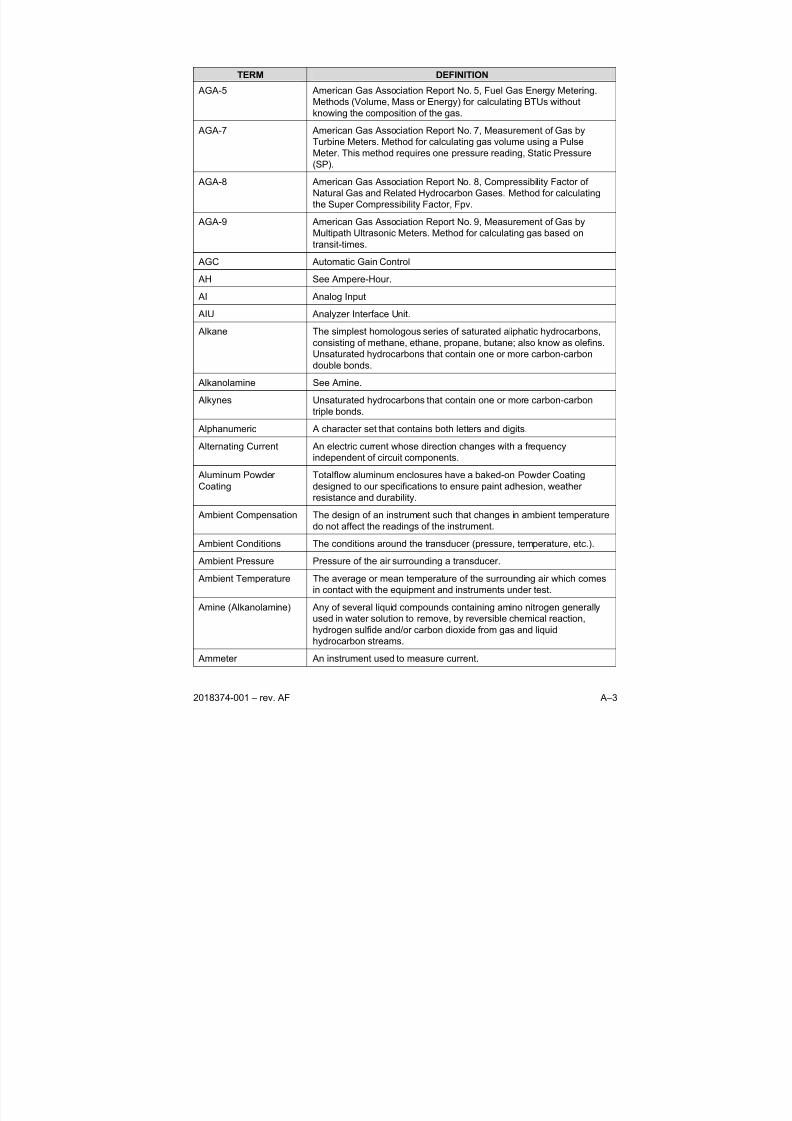
8/13/2019 2018374 m Naf
http://slidepdf.com/reader/full/2018374-m-naf 111/174
2018374-001 – rev. AF A–3
TERM DEFINITION
AGA-5 American Gas Association Report No. 5, Fuel Gas Energy Metering.
Methods (Volume, Mass or Energy) for calculating BTUs without
knowing the composition of the gas.
AGA-7 American Gas Association Report No. 7, Measurement of Gas by
Turbine Meters. Method for calculating gas volume using a PulseMeter. This method requires one pressure reading, Static Pressure
(SP).
AGA-8 American Gas Association Report No. 8, Compressibility Factor of
Natural Gas and Related Hydrocarbon Gases. Method for calculating
the Super Compressibility Factor, Fpv.
AGA-9 American Gas Association Report No. 9, Measurement of Gas by
Multipath Ultrasonic Meters. Method for calculating gas based on
transit-times.
AGC Automatic Gain Control
AH See Ampere-Hour.
AI Analog Input
AIU Analyzer Interface Unit.
Alkane The simplest homologous series of saturated aliphatic hydrocarbons,
consisting of methane, ethane, propane, butane; also know as olefins.
Unsaturated hydrocarbons that contain one or more carbon-carbon
double bonds.
Alkanolamine See Amine.
Alkynes Unsaturated hydrocarbons that contain one or more carbon-carbon
triple bonds.
Alphanumeric A character set that contains both letters and digits.
Alternating Current An electric current whose direction changes with a frequency
independent of circuit components.
Aluminum Powder
Coating
Totalflow aluminum enclosures have a baked-on Powder Coating
designed to our specifications to ensure paint adhesion, weather
resistance and durability.
Ambient Compensation The design of an instrument such that changes in ambient temperature
do not affect the readings of the instrument.
Ambient Conditions The conditions around the transducer (pressure, temperature, etc.).
Ambient Pressure Pressure of the air surrounding a transducer.
Ambient Temperature The average or mean temperature of the surrounding air which comesin contact with the equipment and instruments under test.
Amine (Alkanolamine) Any of several liquid compounds containing amino nitrogen generally
used in water solution to remove, by reversible chemical reaction,
hydrogen sulfide and/or carbon dioxide from gas and liquid
hydrocarbon streams.
Ammeter An instrument used to measure current.
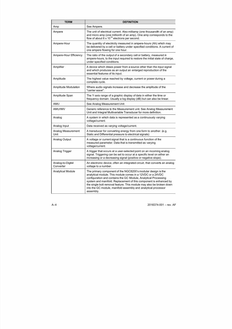
8/13/2019 2018374 m Naf
http://slidepdf.com/reader/full/2018374-m-naf 112/174
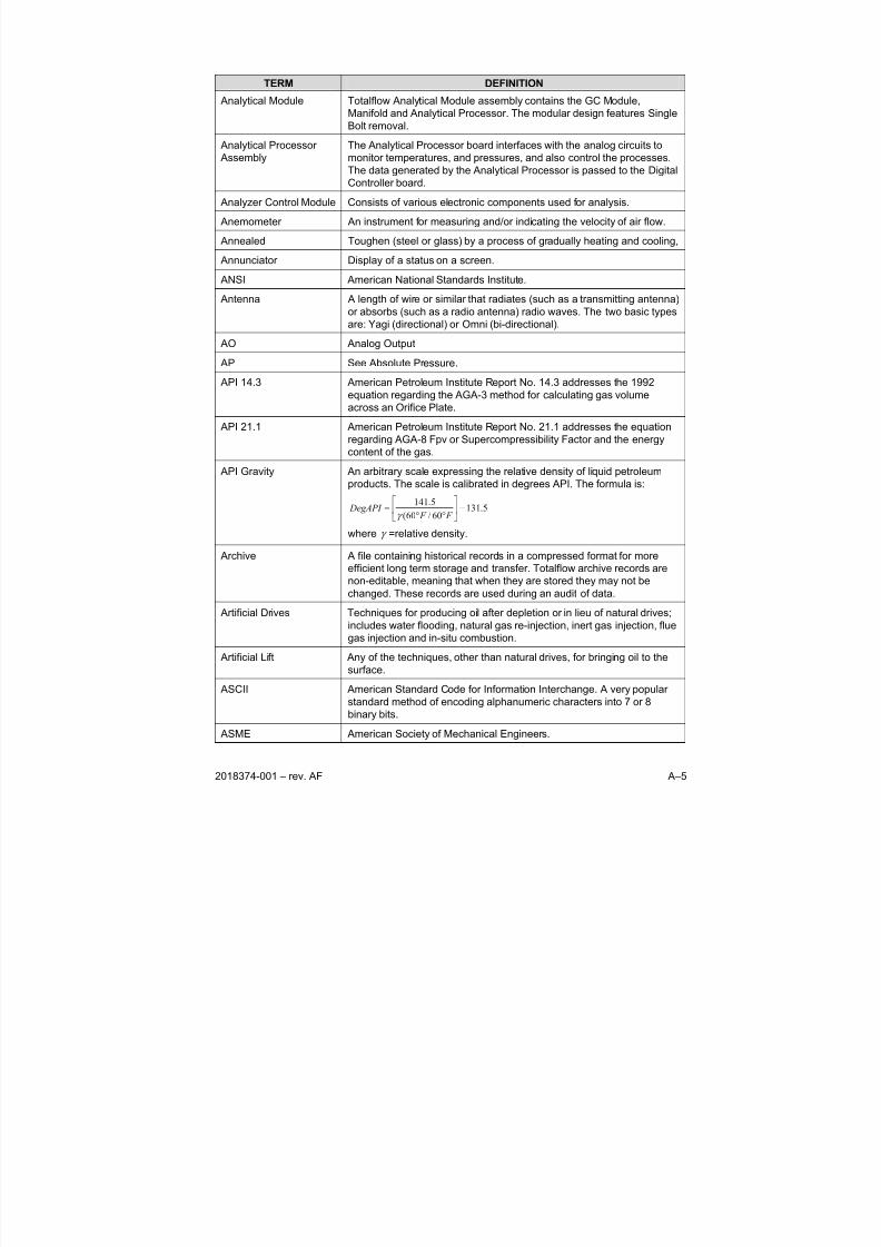
8/13/2019 2018374 m Naf
http://slidepdf.com/reader/full/2018374-m-naf 113/174
2018374-001 – rev. AF A–5
TERM DEFINITION
Analytical Module Totalflow Analytical Module assembly contains the GC Module,
Manifold and Analytical Processor. The modular design features Single
Bolt removal.
Analytical Processor
Assembly
The Analytical Processor board interfaces with the analog circuits to
monitor temperatures, and pressures, and also control the processes.The data generated by the Analytical Processor is passed to the Digital
Controller board.
Analyzer Control Module Consists of various electronic components used for analysis.
Anemometer An instrument for measuring and/or indicating the velocity of air flow.
Annealed Toughen (steel or glass) by a process of gradually heating and cooling,
Annunciator Display of a status on a screen.
ANSI American National Standards Institute.
Antenna A length of wire or similar that radiates (such as a transmitting antenna)
or absorbs (such as a radio antenna) radio waves. The two basic types
are: Yagi (directional) or Omni (bi-directional).
AO Analog Output
AP See Absolute Pressure.
API 14.3 American Petroleum Institute Report No. 14.3 addresses the 1992
equation regarding the AGA-3 method for calculating gas volume
across an Orifice Plate.
API 21.1 American Petroleum Institute Report No. 21.1 addresses the equation
regarding AGA-8 Fpv or Supercompressibility Factor and the energy
content of the gas.
API Gravity An arbitrary scale expressing the relative density of liquid petroleum
products. The scale is calibrated in degrees API. The formula is:
5.13160/60(
5.141−⎥
⎦
⎤⎢⎣
⎡
°°=
F F DegAPI
γ
where γ =relative density.
Archive A file containing historical records in a compressed format for more
efficient long term storage and transfer. Totalflow archive records are
non-editable, meaning that when they are stored they may not be
changed. These records are used during an audit of data.
Artificial Drives Techniques for producing oil after depletion or in lieu of natural drives;
includes water flooding, natural gas re-injection, inert gas injection, flue
gas injection and in-situ combustion.
Artificial Lift Any of the techniques, other than natural drives, for bringing oil to the
surface.
ASCII American Standard Code for Information Interchange. A very popular
standard method of encoding alphanumeric characters into 7 or 8
binary bits.
ASME American Society of Mechanical Engineers.
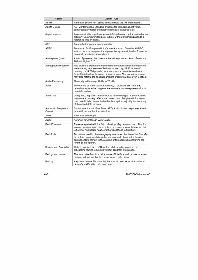
8/13/2019 2018374 m Naf
http://slidepdf.com/reader/full/2018374-m-naf 114/174
A–6 2018374-001 – rev. AF
TERM DEFINITION
ASTM American Society for Testing and Materials (ASTM International).
ASTM D 3588 ASTM International Standard Practice for calculating heat value,
compressibility factor and relative density of gaseous fuels.
Asynchronous A communications protocol where information can be transmitted at an
arbitrary, unsynchronized point in time, without synchronization to a
reference time or "clock".
ATC Automatic temperature compensation.
ATEX Term used for European Union’s New Approach Directive 94/9/EC
which concerns equipment and protective systems intended for use in
potentially explosive atmospheres.
Atmosphere (one) A unit of pressure; the pressure that will support a column of mercury
760 mm high at 0 °C.
Atmospheric Pressure The pressure exerted on the earth by the earth’s atmosphere (air and
water vapor). A pressure of 760 mm of mercury, 29.92 inches of
mercury, or 14.696 pounds per square inch absolute is used as a(scientific) standard for some measurements. Atmospheric pressure
may also refer to the absolute ambient pressure at any given location.
Audio Frequency Generally in the range 20 Hz to 20 KHz.
Audit To examine or verify data for accuracy. Totalflow’s DB1 and DB2
records may be edited to generate a more accurate representation of
data information.
Audit Trail Using the Long Term Archive files to justify changes made to records
that more accurately reflects the correct data. Peripheral information
used to edit data is recorded without exception, to justify the accuracy
of the edited data records.
Automatic FrequencyControl
Similar to Automatic Fine Tune (AFT). A circuit that keeps a receiver intune with the wanted transmission.
AWG American Wire Gage.
AWG Acronym for American Wire Gauge.
Back Pressure Pressure against which a fluid is flowing. May be composed of friction
in pipes, restrictions in pipes, valves, pressure in vessels to which fluid
is flowing, hydrostatic head, or other resistance to fluid flow.
Backflush Technique used in chromatography to reverse direction of the flow after
the lighter components have been measured, allowing the heavier
components to remain in the column until measured, shortening the
length of the column.Background Acquisition Data is acquired by a DAQ system while another program or
processing routine is running without apparent interruption.
Background Noise The total noise floor from all sources of interference in a measurement
system, independent of the presence of a data signal.
Backup A system, device, file or facility that can be used as an alternative in
case of a malfunction or loss of data.
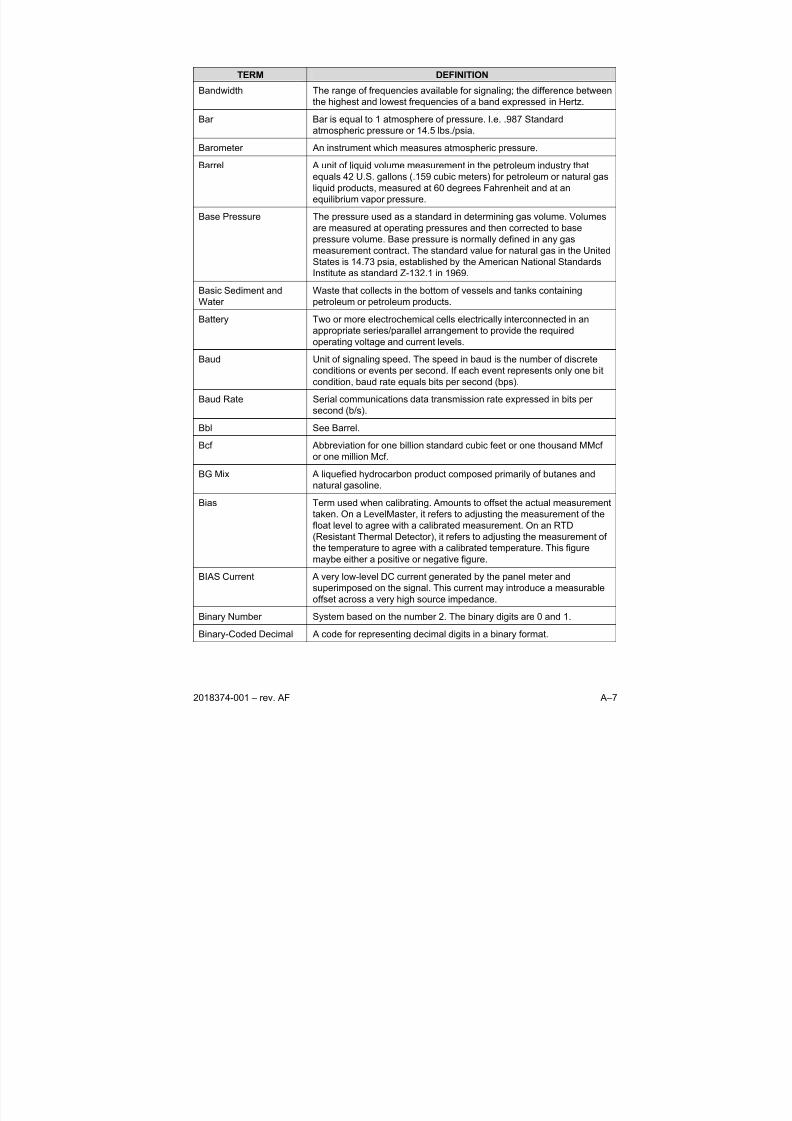
8/13/2019 2018374 m Naf
http://slidepdf.com/reader/full/2018374-m-naf 115/174
2018374-001 – rev. AF A–7
TERM DEFINITION
Bandwidth The range of frequencies available for signaling; the difference between
the highest and lowest frequencies of a band expressed in Hertz.
Bar Bar is equal to 1 atmosphere of pressure. I.e. .987 Standard
atmospheric pressure or 14.5 lbs./psia.
Barometer An instrument which measures atmospheric pressure.
Barrel A unit of liquid volume measurement in the petroleum industry that
equals 42 U.S. gallons (.159 cubic meters) for petroleum or natural gas
liquid products, measured at 60 degrees Fahrenheit and at an
equilibrium vapor pressure.
Base Pressure The pressure used as a standard in determining gas volume. Volumes
are measured at operating pressures and then corrected to base
pressure volume. Base pressure is normally defined in any gas
measurement contract. The standard value for natural gas in the United
States is 14.73 psia, established by the American National Standards
Institute as standard Z-132.1 in 1969.
Basic Sediment andWater
Waste that collects in the bottom of vessels and tanks containingpetroleum or petroleum products.
Battery Two or more electrochemical cells electrically interconnected in an
appropriate series/parallel arrangement to provide the required
operating voltage and current levels.
Baud Unit of signaling speed. The speed in baud is the number of discrete
conditions or events per second. If each event represents only one bit
condition, baud rate equals bits per second (bps).
Baud Rate Serial communications data transmission rate expressed in bits per
second (b/s).
Bbl See Barrel.Bcf Abbreviation for one billion standard cubic feet or one thousand MMcf
or one million Mcf.
BG Mix A liquefied hydrocarbon product composed primarily of butanes and
natural gasoline.
Bias Term used when calibrating. Amounts to offset the actual measurement
taken. On a LevelMaster, it refers to adjusting the measurement of the
float level to agree with a calibrated measurement. On an RTD
(Resistant Thermal Detector), it refers to adjusting the measurement of
the temperature to agree with a calibrated temperature. This figure
maybe either a positive or negative figure.
BIAS Current A very low-level DC current generated by the panel meter andsuperimposed on the signal. This current may introduce a measurable
offset across a very high source impedance.
Binary Number System based on the number 2. The binary digits are 0 and 1.
Binary-Coded Decimal A code for representing decimal digits in a binary format.
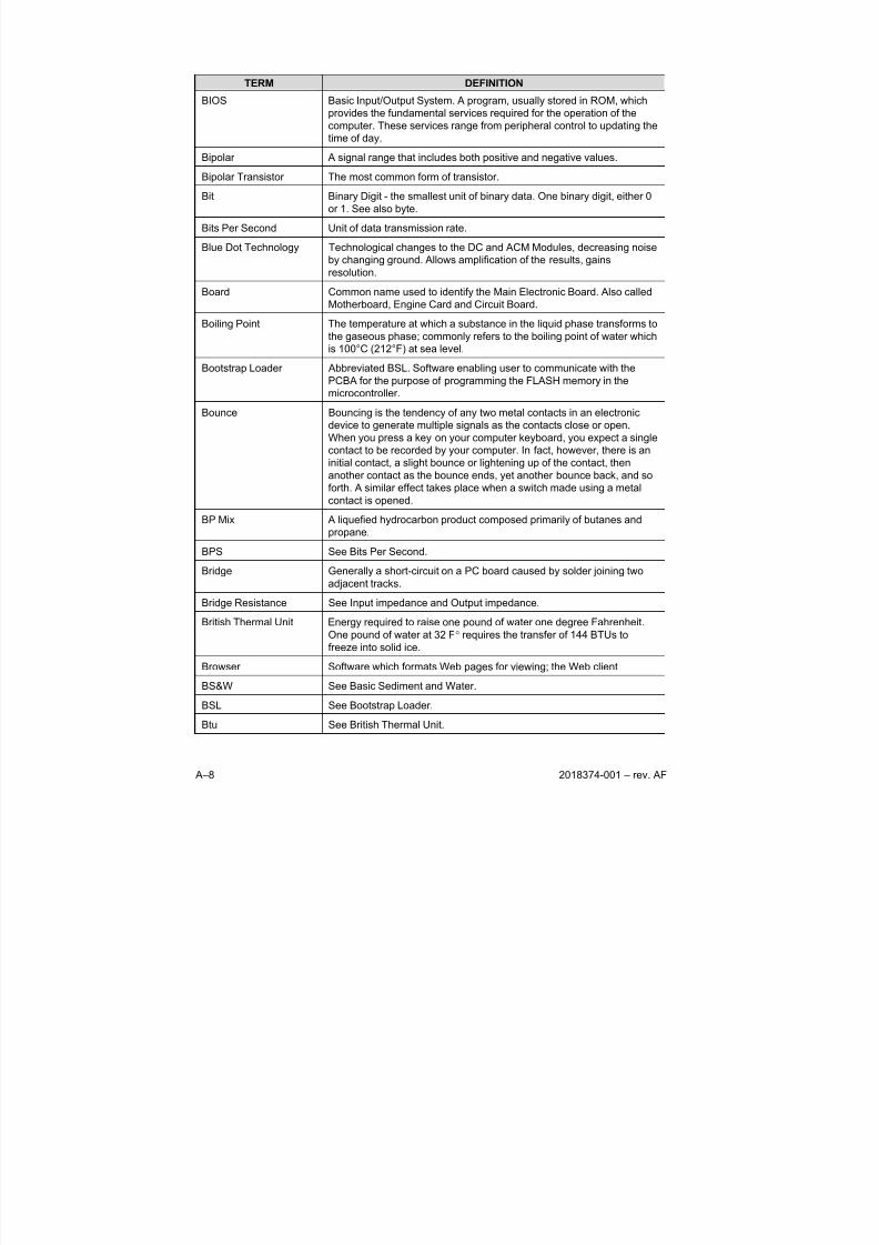
8/13/2019 2018374 m Naf
http://slidepdf.com/reader/full/2018374-m-naf 116/174
A–8 2018374-001 – rev. AF
TERM DEFINITION
BIOS Basic Input/Output System. A program, usually stored in ROM, which
provides the fundamental services required for the operation of the
computer. These services range from peripheral control to updating the
time of day.
Bipolar A signal range that includes both positive and negative values.
Bipolar Transistor The most common form of transistor.
Bit Binary Digit - the smallest unit of binary data. One binary digit, either 0
or 1. See also byte.
Bits Per Second Unit of data transmission rate.
Blue Dot Technology Technological changes to the DC and ACM Modules, decreasing noise
by changing ground. Allows amplification of the results, gains
resolution.
Board Common name used to identify the Main Electronic Board. Also called
Motherboard, Engine Card and Circuit Board.
Boiling Point The temperature at which a substance in the liquid phase transforms to
the gaseous phase; commonly refers to the boiling point of water which
is 100°C (212°F) at sea level.
Bootstrap Loader Abbreviated BSL. Software enabling user to communicate with the
PCBA for the purpose of programming the FLASH memory in the
microcontroller.
Bounce Bouncing is the tendency of any two metal contacts in an electronic
device to generate multiple signals as the contacts close or open.
When you press a key on your computer keyboard, you expect a single
contact to be recorded by your computer. In fact, however, there is an
initial contact, a slight bounce or lightening up of the contact, then
another contact as the bounce ends, yet another bounce back, and soforth. A similar effect takes place when a switch made using a metal
contact is opened.
BP Mix A liquefied hydrocarbon product composed primarily of butanes and
propane.
BPS See Bits Per Second.
Bridge Generally a short-circuit on a PC board caused by solder joining two
adjacent tracks.
Bridge Resistance See Input impedance and Output impedance.
British Thermal Unit Energy required to raise one pound of water one degree Fahrenheit.
One pound of water at 32 F° requires the transfer of 144 BTUs tofreeze into solid ice.
Browser Software which formats Web pages for viewing; the Web client
BS&W See Basic Sediment and Water.
BSL See Bootstrap Loader.
Btu See British Thermal Unit.
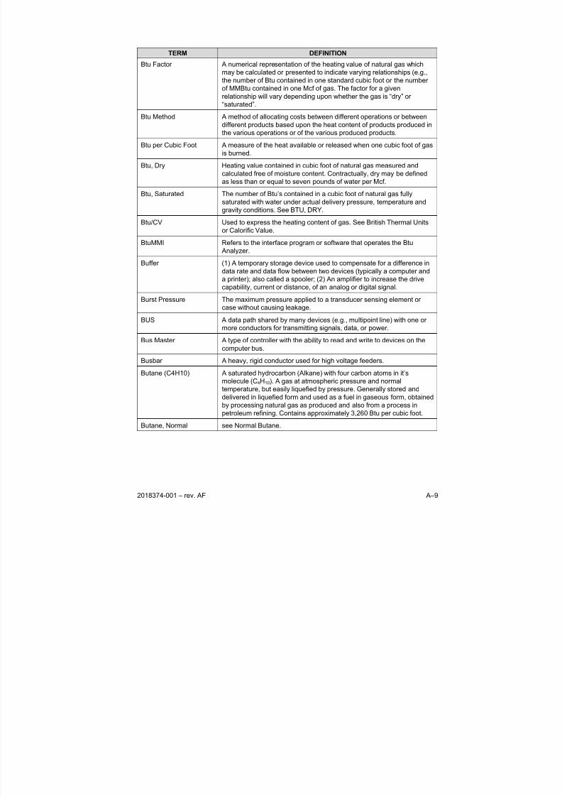
8/13/2019 2018374 m Naf
http://slidepdf.com/reader/full/2018374-m-naf 117/174
2018374-001 – rev. AF A–9
TERM DEFINITION
Btu Factor A numerical representation of the heating value of natural gas which
may be calculated or presented to indicate varying relationships (e.g.,
the number of Btu contained in one standard cubic foot or the number
of MMBtu contained in one Mcf of gas. The factor for a given
relationship will vary depending upon whether the gas is “dry” or
“saturated”.
Btu Method A method of allocating costs between different operations or between
different products based upon the heat content of products produced in
the various operations or of the various produced products.
Btu per Cubic Foot A measure of the heat available or released when one cubic foot of gas
is burned.
Btu, Dry Heating value contained in cubic foot of natural gas measured and
calculated free of moisture content. Contractually, dry may be defined
as less than or equal to seven pounds of water per Mcf.
Btu, Saturated The number of Btu’s contained in a cubic foot of natural gas fully
saturated with water under actual delivery pressure, temperature andgravity conditions. See BTU, DRY.
Btu/CV Used to express the heating content of gas. See British Thermal Units
or Calorific Value.
BtuMMI Refers to the interface program or software that operates the Btu
Analyzer.
Buffer (1) A temporary storage device used to compensate for a difference in
data rate and data flow between two devices (typically a computer and
a printer); also called a spooler; (2) An amplifier to increase the drive
capability, current or distance, of an analog or digital signal.
Burst Pressure The maximum pressure applied to a transducer sensing element or
case without causing leakage.
BUS A data path shared by many devices (e.g., multipoint line) with one or
more conductors for transmitting signals, data, or power.
Bus Master A type of controller with the ability to read and write to devices on the
computer bus.
Busbar A heavy, rigid conductor used for high voltage feeders.
Butane (C4H10) A saturated hydrocarbon (Alkane) with four carbon atoms in it’s
molecule (C4H10). A gas at atmospheric pressure and normal
temperature, but easily liquefied by pressure. Generally stored and
delivered in liquefied form and used as a fuel in gaseous form, obtained
by processing natural gas as produced and also from a process inpetroleum refining. Contains approximately 3,260 Btu per cubic foot.
Butane, Normal see Normal Butane.
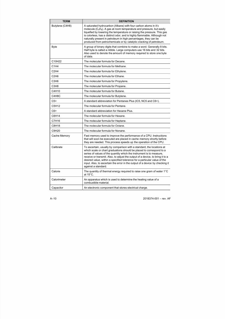
8/13/2019 2018374 m Naf
http://slidepdf.com/reader/full/2018374-m-naf 118/174
A–10 2018374-001 – rev. AF
TERM DEFINITION
Butylene (C4H8) A saturated hydrocarbon (Alkane) with four carbon atoms in it’s
molecule (C4H8). A gas at room temperature and pressure, but easily
liquefied by lowering the temperature or raising the pressure. This gas
is colorless, has a distinct odor, and is highly flammable. Although not
naturally present in petroleum in high percentages, they can be
produced from petrochemicals or by catalytic cracking of petroleum.
Byte A group of binary digits that combine to make a word. Generally 8 bits.
Half byte is called a nibble. Large computers use 16 bits and 32 bits.
Also used to denote the amount of memory required to store one byte
of data.
C10H22 The molecular formula for Decane.
C1H4 The molecular formula for Methane.
C2H4 The molecular formula for Ethylene.
C2H6 The molecular formula for Ethane.
C3H6 The molecular formula for Propylene.
C3H8 The molecular formula for Propane.
C4H10 The molecular formula for Butane.
C4H8C The molecular formula for Butylene.
C5+ A standard abbreviation for Pentanes Plus (IC5, NC5 and C6+).
C5H12 The molecular formula for Pentane.
C6+ A standard abbreviation for Hexane Plus.
C6H14 The molecular formula for Hexane.
C7H16 The molecular formula for Heptane.
C8H18 The molecular formula for Octane.
C9H20 The molecular formula for Nonane.
Cache Memory Fast memory used to improve the performance of a CPU. Instructions
that will soon be executed are placed in cache memory shortly before
they are needed. This process speeds up the operation of the CPU.
Calibrate To ascertain, usually by comparison with a standard, the locations at
which scale or chart graduations should be placed to correspond to a
series of values of the quantity which the instrument is to measure,
receive or transmit. Also, to adjust the output of a device, to bring it to a
desired value, within a specified tolerance for a particular value of the
input. Also, to ascertain the error in the output of a device by checking itagainst a standard.
Calorie The quantity of thermal energy required to raise one gram of water 1°C
at 15°C.
Calorimeter An apparatus which is used to determine the heating value of a
combustible material.
Capacitor An electronic component that stores electrical charge.
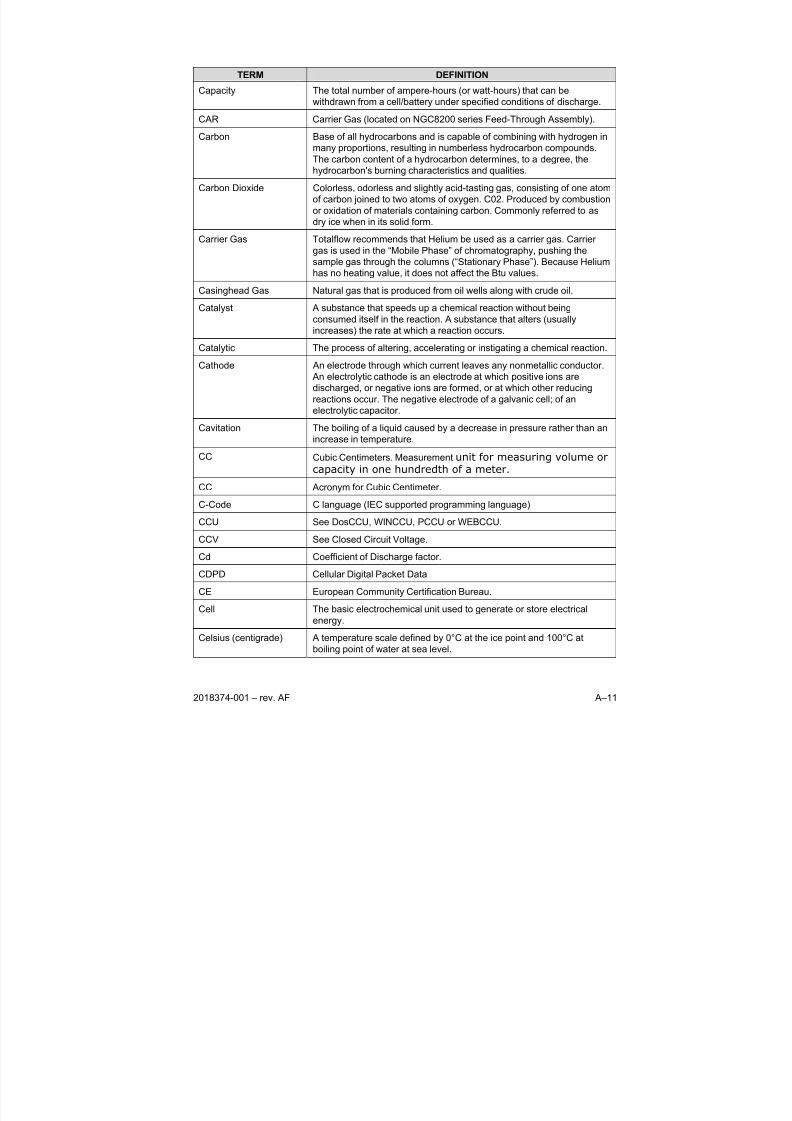
8/13/2019 2018374 m Naf
http://slidepdf.com/reader/full/2018374-m-naf 119/174
2018374-001 – rev. AF A–11
TERM DEFINITION
Capacity The total number of ampere-hours (or watt-hours) that can be
withdrawn from a cell/battery under specified conditions of discharge.
CAR Carrier Gas (located on NGC8200 series Feed-Through Assembly).
Carbon Base of all hydrocarbons and is capable of combining with hydrogen in
many proportions, resulting in numberless hydrocarbon compounds.
The carbon content of a hydrocarbon determines, to a degree, the
hydrocarbon's burning characteristics and qualities.
Carbon Dioxide Colorless, odorless and slightly acid-tasting gas, consisting of one atom
of carbon joined to two atoms of oxygen. C02. Produced by combustion
or oxidation of materials containing carbon. Commonly referred to as
dry ice when in its solid form.
Carrier Gas Totalflow recommends that Helium be used as a carrier gas. Carrier
gas is used in the “Mobile Phase” of chromatography, pushing the
sample gas through the columns (“Stationary Phase”). Because Helium
has no heating value, it does not affect the Btu values.
Casinghead Gas Natural gas that is produced from oil wells along with crude oil.
Catalyst A substance that speeds up a chemical reaction without being
consumed itself in the reaction. A substance that alters (usually
increases) the rate at which a reaction occurs.
Catalytic The process of altering, accelerating or instigating a chemical reaction.
Cathode An electrode through which current leaves any nonmetallic conductor.
An electrolytic cathode is an electrode at which positive ions are
discharged, or negative ions are formed, or at which other reducing
reactions occur. The negative electrode of a galvanic cell; of an
electrolytic capacitor.
Cavitation The boiling of a liquid caused by a decrease in pressure rather than anincrease in temperature.
CC Cubic Centimeters. Measurement unit for measuring volume orcapacity in one hundredth of a meter.
CC Acronym for Cubic Centimeter.
C-Code C language (IEC supported programming language)
CCU See DosCCU, WINCCU, PCCU or WEBCCU.
CCV See Closed Circuit Voltage.
Cd Coefficient of Discharge factor.
CDPD Cellular Digital Packet Data
CE European Community Certification Bureau.
Cell The basic electrochemical unit used to generate or store electrical
energy.
Celsius (centigrade) A temperature scale defined by 0°C at the ice point and 100°C at
boiling point of water at sea level.
8/13/2019 2018374 m Naf
http://slidepdf.com/reader/full/2018374-m-naf 120/174
A–12 2018374-001 – rev. AF
TERM DEFINITION
CENELEC European Committee for Electro-technical Standardization. Also known
as the European Standards Organization.
Centimeter Acronym c. Metric measurement equal to .3937 inch.
Central Processing Unit The central part of a computer system that performs operations on
data. In a personal computer the CPU is typically a single
microprocessor integrated circuit.
Ceramic Insulation High-temperature compositions of metal oxides used to insulate a pair
of thermocouple wires The most common are Alumina (Al2O3),
Beryllium (BeO), and Magnesia (MgO). Their application depends upon
temperature and type of thermocouple. High-purity alumina is required
for platinum alloy thermocouples. Ceramic insulators are available as
single and multihole tubes or as beads.
Certification The process of submitting equipment to specific tests to determine that
the equipment meets the specifications or safety standards.
Cf A standard abbreviation for Cubic foot.
CFG Configuration File. When saving new configuration files, the file is
saved as a *.cfg file.
CFM The volumetric flow rate of a liquid or gas in cubic feet per minute.
Character A letter, digit or other symbol that is used as the representation of data.
A connected sequence of characters is called a character string.
Characteristics Detailed information pertaining to it’s description. The XFC stores this
information in the PROM chip. A feature or quality that makes
somebody or something recognizable.
Charge The conversion of electrical energy, provided in the form of a current
from an external source, into chemical energy within a cell or battery.
Chip Another name for integrated circuit or the piece of silicon on which
semiconductors are created.
Chromatograph An instrument used in chemical analysis, to determine the make-up of
various substances, and often used to determine the Btu content of
natural gas. Chromatography- A method of separating gas compounds
by allowing it to seep through an adsorbent so that each compound is
adsorbed in a separate layer.
CIM Communication Interface Module. Totalflow’s version is called TFIO
Communication Interface Module.
Circuit 1. The complete path between two terminals over which one-way or
two-way communications may be provided. 2. An electronic pathbetween two or more points, capable of providing a number of
channels. 3. A number of conductors connected together for the
purpose of carrying an electrical current. 4. An electronic closed-loop
path among two or more points used for signal transfer. 5. A number of
electrical components, such as resistors, inductances, capacitors,
transistors, and power sources connected together in one or more
closed loops.
8/13/2019 2018374 m Naf
http://slidepdf.com/reader/full/2018374-m-naf 121/174
2018374-001 – rev. AF A–13
TERM DEFINITION
Circuit board Sometimes abbreviated PCB. Printed circuit boards are also called
cards. A thin plate on which chips and other electronic components are
placed. They fall into the following categories:
Motherboard: Typically, the mother board contains the CPU, memory
and basic controllers for the system. Sometimes call the system boardor main board.
Expansion board: Any board that plugs into one of the computer's
expansion slots, including controller boards, LAN cards, and video
adapters.
Daughter Card: Any board that attaches directly to another board.
Controller board: A special type of expansion board that contains a
controller for a peripheral device.
Network Interface Card (NIC): An expansion board that enables a PC to
be connected to a local-area network (LAN).
Video Adapter: An expansion board that contains a controller for a
graphics monitor.
Class 1, Division 1 Class 1 refers to the presence of flammable gases, vapors or liquids.
Division 1 indicates an area where ignitable concentrations of
flammable gases, vapors or liquids can exist all of the time or some of
the time under normal operating conditions.
Class 1, Division 2 Class 1 refers to the presence of flammable gases, vapors or liquids.
Division 2 indicates an area where ignitable concentrations of
flammable gases, vapors or liquids are not likely to exist under normal
operating conditions.
Class 1, Zone 0 Class 1 refers to the presence of flammable gases, vapors or liquids.
Zone 0 refers to a place in which an explosive atmosphere consisting of
a mixture with air of flammable substances in the form of gas, vapor or
mist is present continuously or for long periods or frequently.
Class 1, Zone 1 Class 1 refers to the presence of flammable gases, vapors or liquids.
Zone 1 refers to a place in which an explosive atmosphere consisting of
a mixture with air of flammable substances in the form of gas, vapor or
mist is likely to occur in normal operation occasionally.
Class 1, Zone 2 Class 1 refers to the presence of flammable gases, vapors or liquids.
Zone 2 refers to a place in which an explosive atmosphere consisting of
a mixture with air of flammable substances in the form of gas, vapor or
mist is not likely to occur in normal operation.
Clean Gas Gas that has no particles larger than one micron and no more than one
milligram of solids per cubic meter.
Clear To restore a device to a prescribed initial state, usually the zero state.
Clock The source(s) of timing signals for sequencing electronic events (e.g.
synchronous data transfer).
Closed Circuit Voltage The difference in potential between the terminals of a cell/battery when
it is discharging (on- load condition).
CM Acronym for Cubic Meter.
8/13/2019 2018374 m Naf
http://slidepdf.com/reader/full/2018374-m-naf 122/174
A–14 2018374-001 – rev. AF
TERM DEFINITION
Cm Acronym for Centimeter.
CMM Acronym for Cubic Meter per Minute.
CMOS See Complimentary Metal-Oxide-Semiconductor.
CNG See Compressed Natural Gas
CO2 A standard abbreviation for Carbon Dioxide.
Coalbed Methane A methane-rich, sulfur-free natural gas contained within underground
coal beds.
Coefficient of expansion The ratio of the change in length or volume of a body to the original
length or volume for a unit change in temperature.
Coil A conductor wound in a series of turns.
Cold Start A rebooting technique which will clear all operational errors, loose all
data files, but will not damage configuration files if stored on the
SDRIVE.
Cold Weather Enclosure Totalflow insulated and heated enclosure designed to house either the
NGC8200 or Btu 8000/8100 Chromatographs in inclement climates.
Collector The semiconductor region in a bipolar junction transistor through which
a flow of charge carriers leaves the base region.
Column Hardware component used in gas chromatography to separate
components into measurable units.
Combustible Classification of liquid substances that will burn on the basis of flash
points. A combustible liquid means any liquid having a flash point at or
above 37.8°C (100°F) but below 93.3°C (200°F), except any mixture
having components with flash points of 93.3°C (200°F) or higher, the
total of which makes up 99 percent or more of the total volume of the
mixture.
Comma Separated
Values
These file types are importable records used by spreadsheet programs
to display and manipulate data.
Communication Transmission and reception of data among data processing equipment
and related peripherals.
Communication Port Comm. Port (abbreviation) refers to the host computer's physical
communication's port being used to communicate with the equipment.
Used by Totalflow when discussing local or remote communication with
various equipment including the XFC, FCU, XRC, RTU and
LevelMaster etc.
Compensation An addition of specific materials or devices to counteract a known error.Complimentary Metal-
Oxide-Semiconductor
Family of logic devices that uses p-type and n-type channel devices on
the same integrated circuit. It has the advantage of offering medium
speed and very low power requirements.
Component (1) A small object or program that performs a specific function and is
designed in such a way to easily operate with other components and
applications. Increasingly, the term is being used interchangeably with
applet. (2) A part of a device.
8/13/2019 2018374 m Naf
http://slidepdf.com/reader/full/2018374-m-naf 123/174
2018374-001 – rev. AF A–15
TERM DEFINITION
Compressed Gas A gas or mixture of gases having, in a container an absolute pressure
exceeding 40 psi at 21.1°C (70°F). A gas or mixture having in a
container, an absolute pressure exceeding 104 psi at 54.4°C (130°F)
regardless of the pressure at (21.1°C (70°F). A liquid having a vapor
pressure exceeding 40 psi at 37.8°C (70°F) as determined by ASTM D-
323-72.
Compressed Natural
Gas
Natural gas in high-pressure surface containers that is highly
compressed (though not to the point of liquefaction). CNG is used
extensively as a transportation fuel for automobiles, trucks and buses in
some parts of the world. Small amounts of natural gas are also
transported overland in high-pressure containers.
Compressibility The property of a material which permits it to decrease in volume when
subjected to an increase in pressure. In gas-measurement usage, the
compressibility factor "Z" is the deviation from the ideal Boyle and
Charles' law behavior. See SUPERCOMPRESSIBILITY FACTOR.
Compressibility Factor See Supercompressibility Factor.
Compressibility Factor A factor usually expressed as “z” which gives the ratio of the actual
volume of gas at a given temperature and pressure to the volume of
gas when calculated by the ideal gas law without any consideration of
the compressibility factor.
Concentration Amount of solute per unit volume or mass of solvent or of solution.
Concurrent Performing more than one task at a time.
Condensate 1) The liquid formed by the condensation of a vapor or gas; specifically,
the hydrocarbon liquid separated from natural gas because of changes
in temperature and pressure when the gas from the reservoir was
delivered to the surface separators. 2) A term used to describe light
liquid hydrocarbons separated from crude oil after production and soldseparately.
Condensation Liquefaction of vapor.
Condensed Phases The liquid and solid phases; phases in which particles interact strongly.
Condensed States The solid and liquid states.
Conduction The conveying of electrical energy or heat through or by means of a
conductor.
Configuration No. The Configuration number is a suffix of the serial number which defines
the characteristics of the unit.
Console Mode A local user interface typically used with custom applications that are
not supported through any other mechanism. Also referred to as PrinterConsole Mode.
Contact Current carrying part of a switch, relay or connector.
Conversion Time The time required, in an analog input or output system, from the
moment a channel is interrogated (such as with a read instruction) to
the moment that accurate data is available. This could include switching
time, settling time, acquisition time, A/D conversion time, etc.
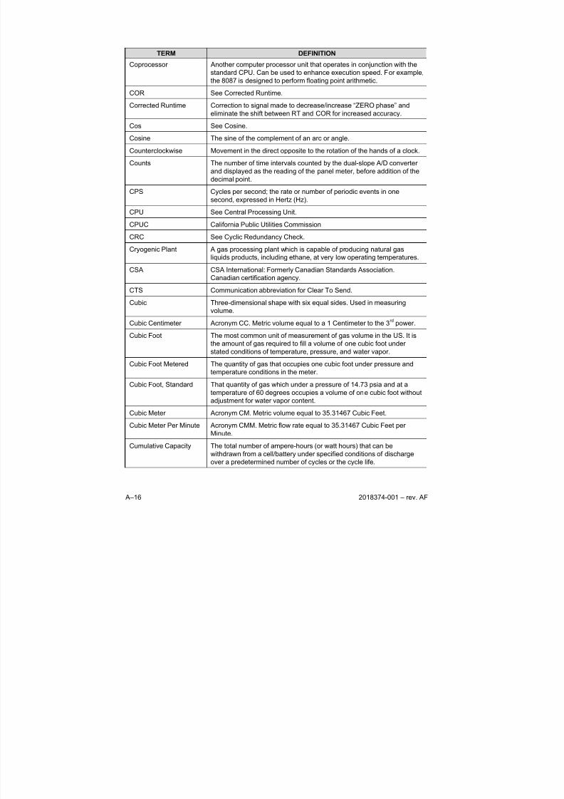
8/13/2019 2018374 m Naf
http://slidepdf.com/reader/full/2018374-m-naf 124/174
A–16 2018374-001 – rev. AF
TERM DEFINITION
Coprocessor Another computer processor unit that operates in conjunction with the
standard CPU. Can be used to enhance execution speed. For example,
the 8087 is designed to perform floating point arithmetic.
COR See Corrected Runtime.
Corrected Runtime Correction to signal made to decrease/increase “ZERO phase” and
eliminate the shift between RT and COR for increased accuracy.
Cos See Cosine.
Cosine The sine of the complement of an arc or angle.
Counterclockwise Movement in the direct opposite to the rotation of the hands of a clock.
Counts The number of time intervals counted by the dual-slope A/D converter
and displayed as the reading of the panel meter, before addition of the
decimal point.
CPS Cycles per second; the rate or number of periodic events in one
second, expressed in Hertz (Hz).
CPU See Central Processing Unit.
CPUC California Public Utilities Commission
CRC See Cyclic Redundancy Check.
Cryogenic Plant A gas processing plant which is capable of producing natural gas
liquids products, including ethane, at very low operating temperatures.
CSA CSA International: Formerly Canadian Standards Association.
Canadian certification agency.
CTS Communication abbreviation for Clear To Send.
Cubic Three-dimensional shape with six equal sides. Used in measuring
volume.
Cubic Centimeter Acronym CC. Metric volume equal to a 1 Centimeter to the 3rd
power.
Cubic Foot The most common unit of measurement of gas volume in the US. It is
the amount of gas required to fill a volume of one cubic foot under
stated conditions of temperature, pressure, and water vapor.
Cubic Foot Metered The quantity of gas that occupies one cubic foot under pressure and
temperature conditions in the meter.
Cubic Foot, Standard That quantity of gas which under a pressure of 14.73 psia and at a
temperature of 60 degrees occupies a volume of one cubic foot without
adjustment for water vapor content.
Cubic Meter Acronym CM. Metric volume equal to 35.31467 Cubic Feet.
Cubic Meter Per Minute Acronym CMM. Metric flow rate equal to 35.31467 Cubic Feet per
Minute.
Cumulative Capacity The total number of ampere-hours (or watt hours) that can be
withdrawn from a cell/battery under specified conditions of discharge
over a predetermined number of cycles or the cycle life.

8/13/2019 2018374 m Naf
http://slidepdf.com/reader/full/2018374-m-naf 125/174
2018374-001 – rev. AF A–17
TERM DEFINITION
Current Current is measured in amps (milliamps and micro amps). It is the
passage of electrons. Conventional current flows from positive to
negative. Electrons flow from negative to positive - called "electron
flow".
Cursor Dots used to indicate the location of the next character or symbol to beentered.
Custody Transfer The legal and commercial transfer of a commodity such as natural gas,
LNG, etc. from one party to another.
Custody Transfer
Transaction
The Custody Transfer Transaction is the hand-off of the physical
commodity from one operator to another.
Cut-Off Voltage The cell/battery voltage at which the discharge is terminated.
CV Calorific Value. European value of heating content.
CV1 Column 1 Vent (located on NGC8200 series Feed-Through Assembly).
CV2 Column 2 Vent (located on NGC8200 series Feed-Through Assembly).
CWE Cold Weather Enclosure.
Cycle One complete sequence of events. One complete alteration of an AC
current or Volt. The discharge and subsequent charge of a
rechargeable cell/battery is called a cycle.
Cycle Life The number of cycles under specified conditions which were available
from a rechargeable cell/battery before it fails to meet specified criteria
as to performance.
Cycle Time The time usually expressed in seconds for a controller to complete one
on/off cycle.
Cyclic Redundancy
Check
An ongoing verification of the validity of transmitted and received data
providing assurance that the message conforms to a pre-agreed upon
convention of communications.
D/A See Digital-to-analog.
D/I See Digital Input.
D/O See Digital Output.
DAC See Digital to Analog Converter.
DACU Data Acquisition Control Unit.
Data Acquisition Gathering information from sources such as sensors and AMUs in an
accurate, timely and organized manner. Modern systems convert this
information to digital data, which can be stored and processed by acomputer.
Data Collect Physically, locally or remotely, retrieving data stored with a Totalflow
unit. This data is typically stored in records located in a data base
format.
DB See Decibel.
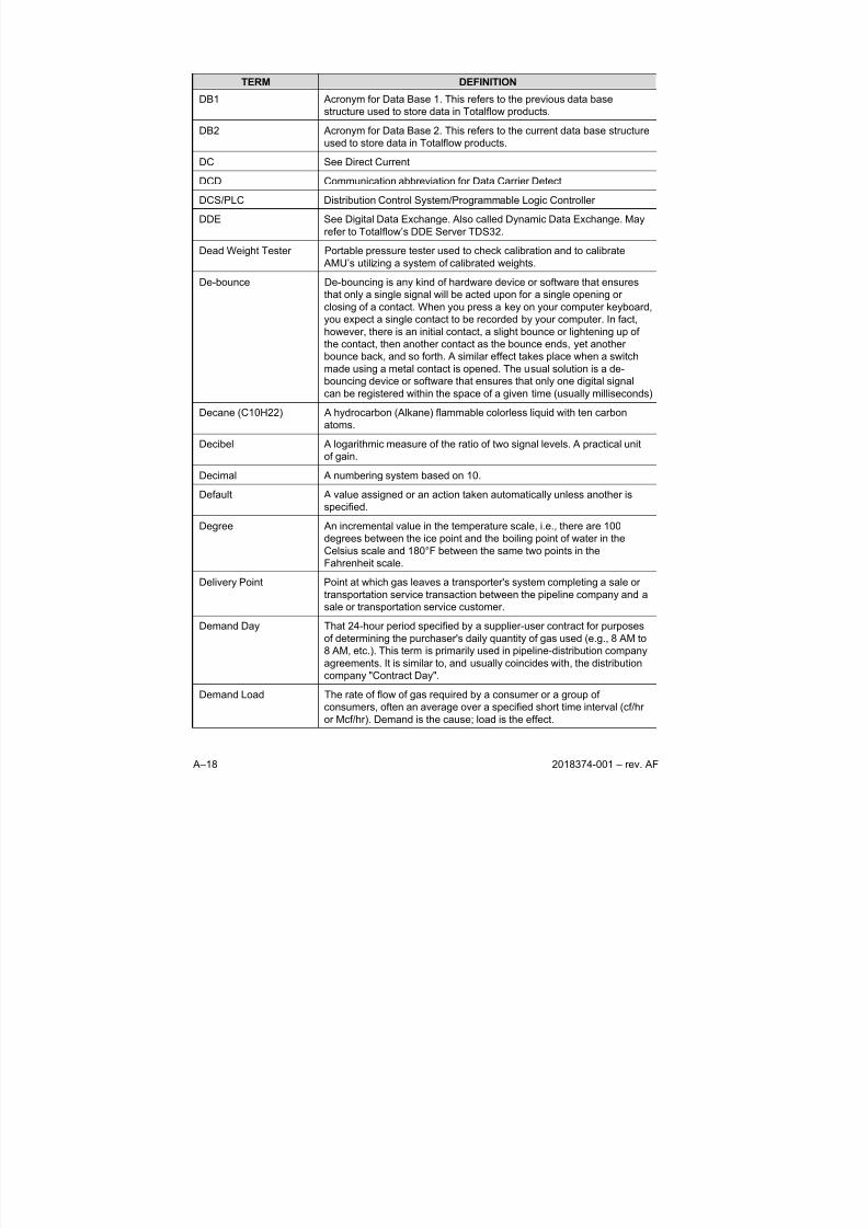
8/13/2019 2018374 m Naf
http://slidepdf.com/reader/full/2018374-m-naf 126/174
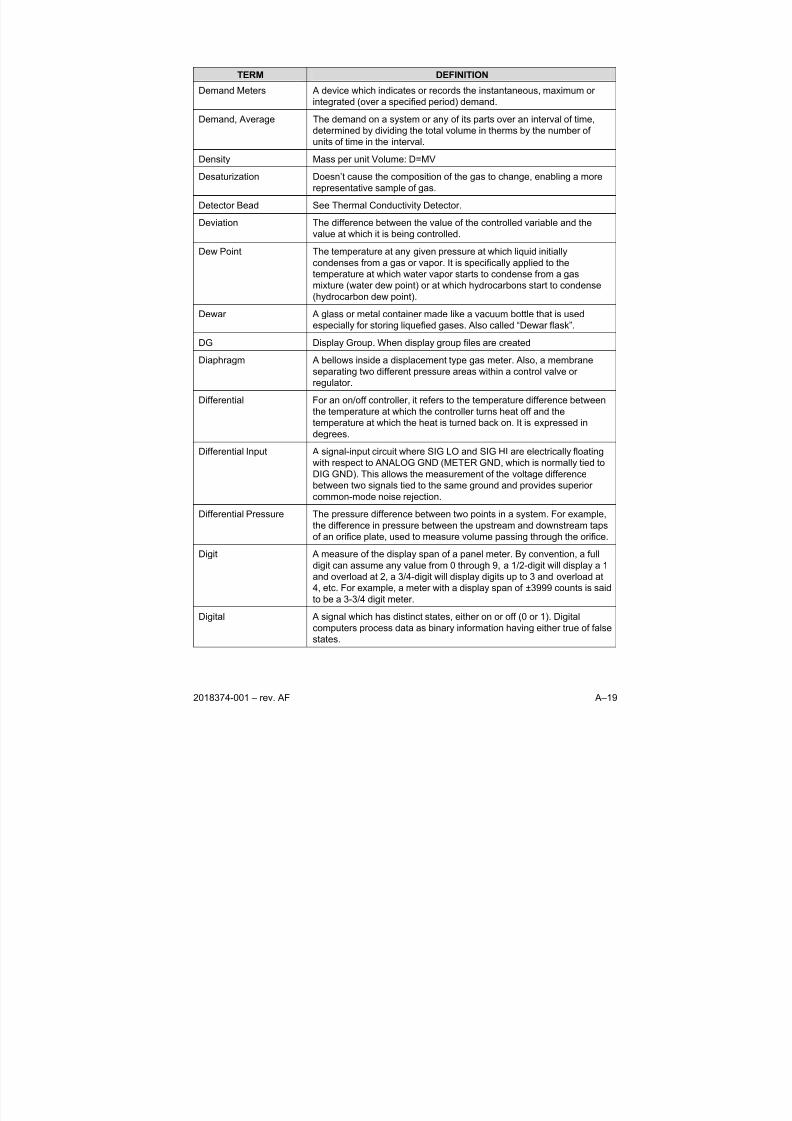
8/13/2019 2018374 m Naf
http://slidepdf.com/reader/full/2018374-m-naf 127/174
2018374-001 – rev. AF A–19
TERM DEFINITION
Demand Meters A device which indicates or records the instantaneous, maximum or
integrated (over a specified period) demand.
Demand, Average The demand on a system or any of its parts over an interval of time,
determined by dividing the total volume in therms by the number of
units of time in the interval.
Density Mass per unit Volume: D=MV
Desaturization Doesn’t cause the composition of the gas to change, enabling a more
representative sample of gas.
Detector Bead See Thermal Conductivity Detector.
Deviation The difference between the value of the controlled variable and the
value at which it is being controlled.
Dew Point The temperature at any given pressure at which liquid initially
condenses from a gas or vapor. It is specifically applied to the
temperature at which water vapor starts to condense from a gas
mixture (water dew point) or at which hydrocarbons start to condense(hydrocarbon dew point).
Dewar A glass or metal container made like a vacuum bottle that is used
especially for storing liquefied gases. Also called “Dewar flask”.
DG Display Group. When display group files are created
Diaphragm A bellows inside a displacement type gas meter. Also, a membrane
separating two different pressure areas within a control valve or
regulator.
Differential For an on/off controller, it refers to the temperature difference between
the temperature at which the controller turns heat off and the
temperature at which the heat is turned back on. It is expressed in
degrees.
Differential Input A signal-input circuit where SIG LO and SIG HI are electrically floating
with respect to ANALOG GND (METER GND, which is normally tied to
DIG GND). This allows the measurement of the voltage difference
between two signals tied to the same ground and provides superior
common-mode noise rejection.
Differential Pressure The pressure difference between two points in a system. For example,
the difference in pressure between the upstream and downstream taps
of an orifice plate, used to measure volume passing through the orifice.
Digit A measure of the display span of a panel meter. By convention, a full
digit can assume any value from 0 through 9, a 1/2-digit will display a 1
and overload at 2, a 3/4-digit will display digits up to 3 and overload at4, etc. For example, a meter with a display span of ±3999 counts is said
to be a 3-3/4 digit meter.
Digital A signal which has distinct states, either on or off (0 or 1). Digital
computers process data as binary information having either true of false
states.
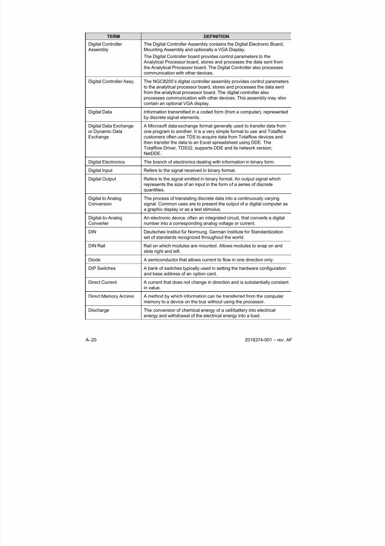
8/13/2019 2018374 m Naf
http://slidepdf.com/reader/full/2018374-m-naf 128/174
A–20 2018374-001 – rev. AF
TERM DEFINITION
Digital Controller
Assembly
The Digital Controller Assembly contains the Digital Electronic Board,
Mounting Assembly and optionally a VGA Display.
The Digital Controller board provides control parameters to the
Analytical Processor board, stores and processes the data sent from
the Analytical Processor board. The Digital Controller also processescommunication with other devices.
Digital Controller Assy. The NGC8200’s digital controller assembly provides control parameters
to the analytical processor board, stores and processes the data sent
from the analytical processor board. The digital controller also
processes communication with other devices. This assembly may also
contain an optional VGA display.
Digital Data Information transmitted in a coded form (from a computer), represented
by discrete signal elements.
Digital Data Exchange
or Dynamic Data
Exchange
A Microsoft data exchange format generally used to transfer data from
one program to another. It is a very simple format to use and Totalflow
customers often use TDS to acquire data from Totalflow devices and
then transfer the data to an Excel spreadsheet using DDE. The
Totalflow Driver, TDS32, supports DDE and its network version,
NetDDE.
Digital Electronics The branch of electronics dealing with information in binary form.
Digital Input Refers to the signal received in binary format.
Digital Output Refers to the signal emitted in binary format. An output signal which
represents the size of an input in the form of a series of discrete
quantities.
Digital to Analog
Conversion
The process of translating discrete data into a continuously varying
signal. Common uses are to present the output of a digital computer as
a graphic display or as a test stimulus.
Digital-to-Analog
Converter
An electronic device, often an integrated circuit, that converts a digital
number into a corresponding analog voltage or current.
DIN Deutsches Institut für Normung. German Institute for Standardization
set of standards recognized throughout the world.
DIN Rail Rail on which modules are mounted. Allows modules to snap on and
slide right and left.
Diode A semiconductor that allows current to flow in one direction only.
DIP Switches A bank of switches typically used in setting the hardware configuration
and base address of an option card.
Direct Current A current that does not change in direction and is substantially constant
in value.
Direct Memory Access A method by which information can be transferred from the computer
memory to a device on the bus without using the processor.
Discharge The conversion of chemical energy of a cell/battery into electrical
energy and withdrawal of the electrical energy into a load.
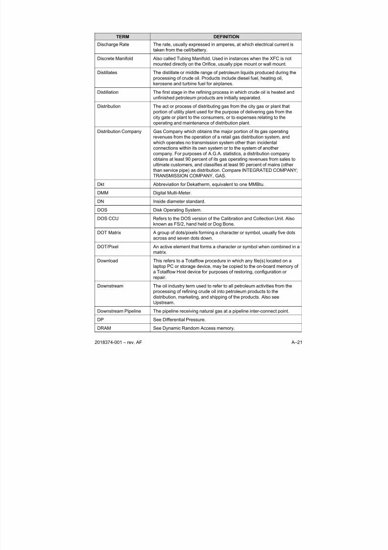
8/13/2019 2018374 m Naf
http://slidepdf.com/reader/full/2018374-m-naf 129/174
2018374-001 – rev. AF A–21
TERM DEFINITION
Discharge Rate The rate, usually expressed in amperes, at which electrical current is
taken from the cell/battery.
Discrete Manifold Also called Tubing Manifold. Used in instances when the XFC is not
mounted directly on the Orifice, usually pipe mount or wall mount.
Distillates The distillate or middle range of petroleum liquids produced during the
processing of crude oil. Products include diesel fuel, heating oil,
kerosene and turbine fuel for airplanes.
Distillation The first stage in the refining process in which crude oil is heated and
unfinished petroleum products are initially separated.
Distribution The act or process of distributing gas from the city gas or plant that
portion of utility plant used for the purpose of delivering gas from the
city gate or plant to the consumers, or to expenses relating to the
operating and maintenance of distribution plant.
Distribution Company Gas Company which obtains the major portion of its gas operating
revenues from the operation of a retail gas distribution system, and
which operates no transmission system other than incidentalconnections within its own system or to the system of another
company. For purposes of A.G.A. statistics, a distribution company
obtains at least 90 percent of its gas operating revenues from sales to
ultimate customers, and classifies at least 90 percent of mains (other
than service pipe) as distribution. Compare INTEGRATED COMPANY;
TRANSMISSION COMPANY, GAS.
Dkt Abbreviation for Dekatherm, equivalent to one MMBtu.
DMM Digital Multi-Meter.
DN Inside diameter standard.
DOS Disk Operating System.DOS CCU Refers to the DOS version of the Calibration and Collection Unit. Also
known as FS/2, hand held or Dog Bone.
DOT Matrix A group of dots/pixels forming a character or symbol, usually five dots
across and seven dots down.
DOT/Pixel An active element that forms a character or symbol when combined in a
matrix.
Download This refers to a Totalflow procedure in which any file(s) located on a
laptop PC or storage device, may be copied to the on-board memory of
a Totalflow Host device for purposes of restoring, configuration or
repair.
Downstream The oil industry term used to refer to all petroleum activities from the
processing of refining crude oil into petroleum products to the
distribution, marketing, and shipping of the products. Also see
Upstream.
Downstream Pipeline The pipeline receiving natural gas at a pipeline inter-connect point.
DP See Differential Pressure.
DRAM See Dynamic Random Access memory.
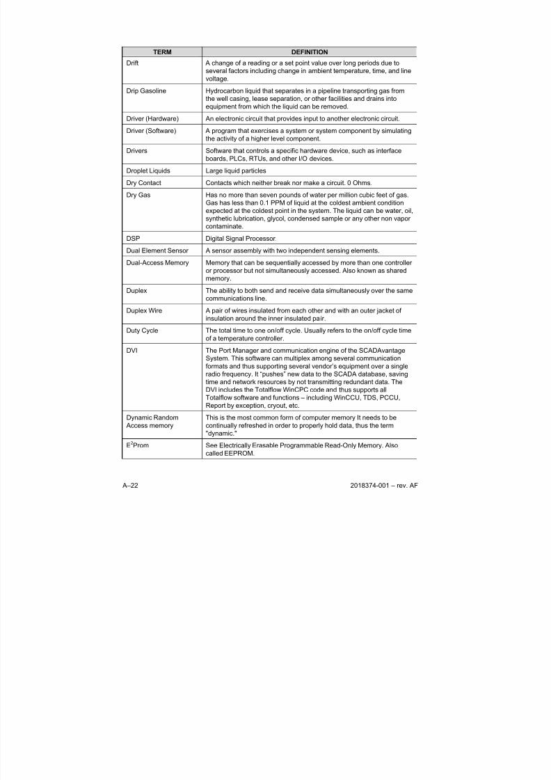
8/13/2019 2018374 m Naf
http://slidepdf.com/reader/full/2018374-m-naf 130/174
A–22 2018374-001 – rev. AF
TERM DEFINITION
Drift A change of a reading or a set point value over long periods due to
several factors including change in ambient temperature, time, and line
voltage.
Drip Gasoline Hydrocarbon liquid that separates in a pipeline transporting gas from
the well casing, lease separation, or other facilities and drains intoequipment from which the liquid can be removed.
Driver (Hardware) An electronic circuit that provides input to another electronic circuit.
Driver (Software) A program that exercises a system or system component by simulating
the activity of a higher level component.
Drivers Software that controls a specific hardware device, such as interface
boards, PLCs, RTUs, and other I/O devices.
Droplet Liquids Large liquid particles
Dry Contact Contacts which neither break nor make a circuit. 0 Ohms.
Dry Gas Has no more than seven pounds of water per million cubic feet of gas.
Gas has less than 0.1 PPM of liquid at the coldest ambient condition
expected at the coldest point in the system. The liquid can be water, oil,
synthetic lubrication, glycol, condensed sample or any other non vapor
contaminate.
DSP Digital Signal Processor.
Dual Element Sensor A sensor assembly with two independent sensing elements.
Dual-Access Memory Memory that can be sequentially accessed by more than one controller
or processor but not simultaneously accessed. Also known as shared
memory.
Duplex The ability to both send and receive data simultaneously over the same
communications line.
Duplex Wire A pair of wires insulated from each other and with an outer jacket of
insulation around the inner insulated pair.
Duty Cycle The total time to one on/off cycle. Usually refers to the on/off cycle time
of a temperature controller.
DVI The Port Manager and communication engine of the SCADAvantage
System. This software can multiplex among several communication
formats and thus supporting several vendor’s equipment over a single
radio frequency. It “pushes” new data to the SCADA database, saving
time and network resources by not transmitting redundant data. The
DVI includes the Totalflow WinCPC code and thus supports all
Totalflow software and functions – including WinCCU, TDS, PCCU,Report by exception, cryout, etc.
Dynamic Random
Access memory
This is the most common form of computer memory It needs to be
continually refreshed in order to properly hold data, thus the term
"dynamic."
E2Prom See Electrically Erasable Programmable Read-Only Memory. Also
called EEPROM.
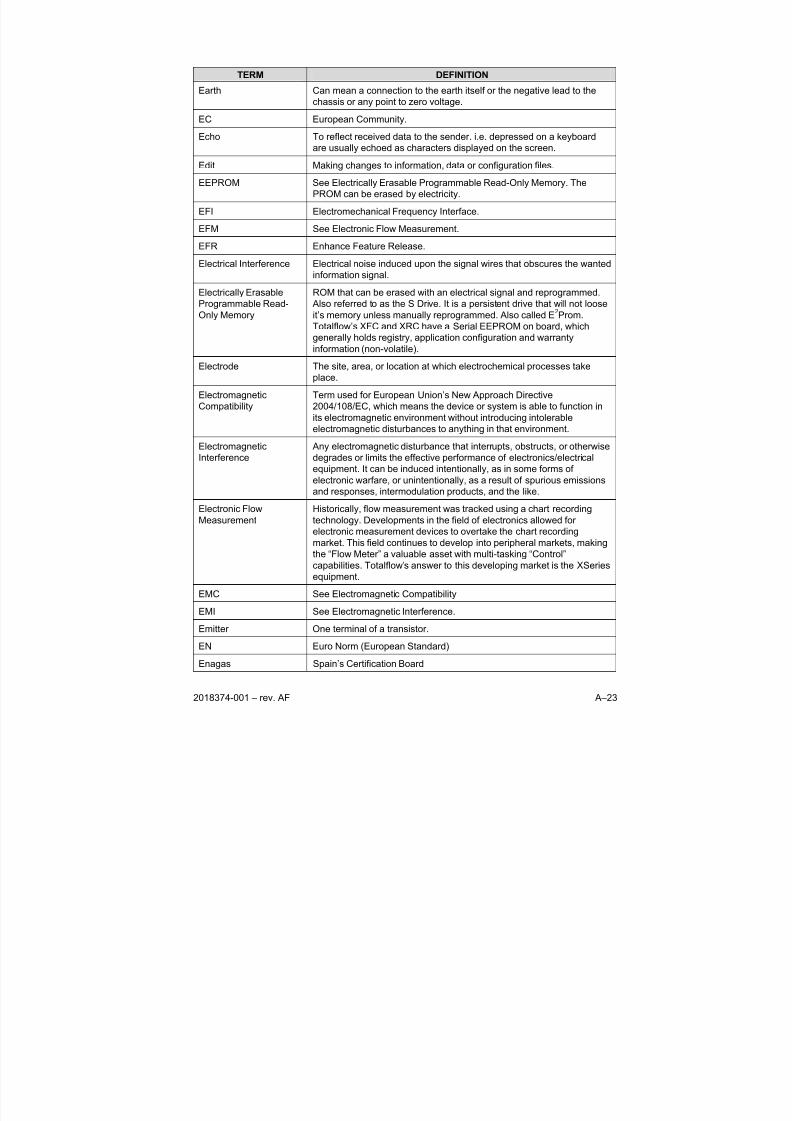
8/13/2019 2018374 m Naf
http://slidepdf.com/reader/full/2018374-m-naf 131/174
2018374-001 – rev. AF A–23
TERM DEFINITION
Earth Can mean a connection to the earth itself or the negative lead to the
chassis or any point to zero voltage.
EC European Community.
Echo To reflect received data to the sender. i.e. depressed on a keyboard
are usually echoed as characters displayed on the screen.
Edit Making changes to information, data or configuration files.
EEPROM See Electrically Erasable Programmable Read-Only Memory. The
PROM can be erased by electricity.
EFI Electromechanical Frequency Interface.
EFM See Electronic Flow Measurement.
EFR Enhance Feature Release.
Electrical Interference Electrical noise induced upon the signal wires that obscures the wanted
information signal.
Electrically Erasable
Programmable Read-
Only Memory
ROM that can be erased with an electrical signal and reprogrammed.
Also referred to as the S Drive. It is a persistent drive that will not loose
it’s memory unless manually reprogrammed. Also called E2Prom.
Totalflow’s XFC and XRC have a Serial EEPROM on board, which
generally holds registry, application configuration and warranty
information (non-volatile).
Electrode The site, area, or location at which electrochemical processes take
place.
Electromagnetic
Compatibility
Term used for European Union’s New Approach Directive
2004/108/EC, which means the device or system is able to function in
its electromagnetic environment without introducing intolerable
electromagnetic disturbances to anything in that environment.
Electromagnetic
Interference
Any electromagnetic disturbance that interrupts, obstructs, or otherwise
degrades or limits the effective performance of electronics/electrical
equipment. It can be induced intentionally, as in some forms of
electronic warfare, or unintentionally, as a result of spurious emissions
and responses, intermodulation products, and the like.
Electronic Flow
Measurement
Historically, flow measurement was tracked using a chart recording
technology. Developments in the field of electronics allowed for
electronic measurement devices to overtake the chart recording
market. This field continues to develop into peripheral markets, making
the “Flow Meter” a valuable asset with multi-tasking “Control”
capabilities. Totalflow’s answer to this developing market is the XSeries
equipment.
EMC See Electromagnetic Compatibility
EMI See Electromagnetic Interference.
Emitter One terminal of a transistor.
EN Euro Norm (European Standard)
Enagas Spain’s Certification Board
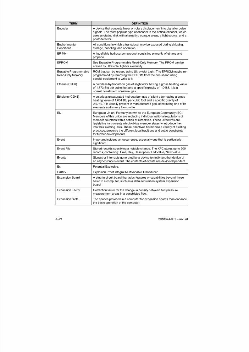
8/13/2019 2018374 m Naf
http://slidepdf.com/reader/full/2018374-m-naf 132/174
A–24 2018374-001 – rev. AF
TERM DEFINITION
Encoder A device that converts linear or rotary displacement into digital or pulse
signals. The most popular type of encoder is the optical encoder, which
uses a rotating disk with alternating opaque areas, a light source, and a
photodetector.
EnvironmentalConditions
All conditions in which a transducer may be exposed during shipping,storage, handling, and operation.
EP Mix A liquefiable hydrocarbon product consisting primarily of ethane and
propane.
EPROM See Erasable Programmable Read-Only Memory. The PROM can be
erased by ultraviolet light or electricity.
Erasable Programmable
Read-Only Memory
ROM that can be erased using Ultraviolet Light. The EPROM maybe re-
programmed by removing the EPROM from the circuit and using
special equipment to write to it.
Ethane (C2H6) A colorless hydrocarbon gas of slight odor having a gross heating value
of 1,773 Btu per cubic foot and a specific gravity of 1.0488. It is a
normal constituent of natural gas.
Ethylene (C2H4) A colorless unsaturated hydrocarbon gas of slight odor having a gross
heating value of 1,604 Btu per cubic foot and a specific gravity of
0.9740. It is usually present in manufactured gas, constituting one of its
elements and is very flammable.
EU European Union. Formerly known as the European Community (EC).
Members of this union are replacing individual national regulations of
member countries with a series of Directives. These Directives are
legislative instruments which oblige member states to introduce them
into their existing laws. These directives harmonize a variety of existing
practices, preserve the different legal traditions and settle constraints
for further developments.Event Important incident: an occurrence, especially one that is particularly
significant.
Event File Stored records specifying a notable change. The XFC stores up to 200
records, containing: Time, Day, Description, Old Value, New Value.
Events Signals or interrupts generated by a device to notify another device of
an asynchronous event. The contents of events are device-dependent.
Ex Potential Explosive.
EXIMV Explosion Proof Integral Multivariable Transducer.
Expansion Board A plug-in circuit board that adds features or capabilities beyond those
basic to a computer, such as a data acquisition system expansionboard.
Expansion Factor Correction factor for the change in density between two pressure
measurement areas in a constricted flow.
Expansion Slots The spaces provided in a computer for expansion boards than enhance
the basic operation of the computer.
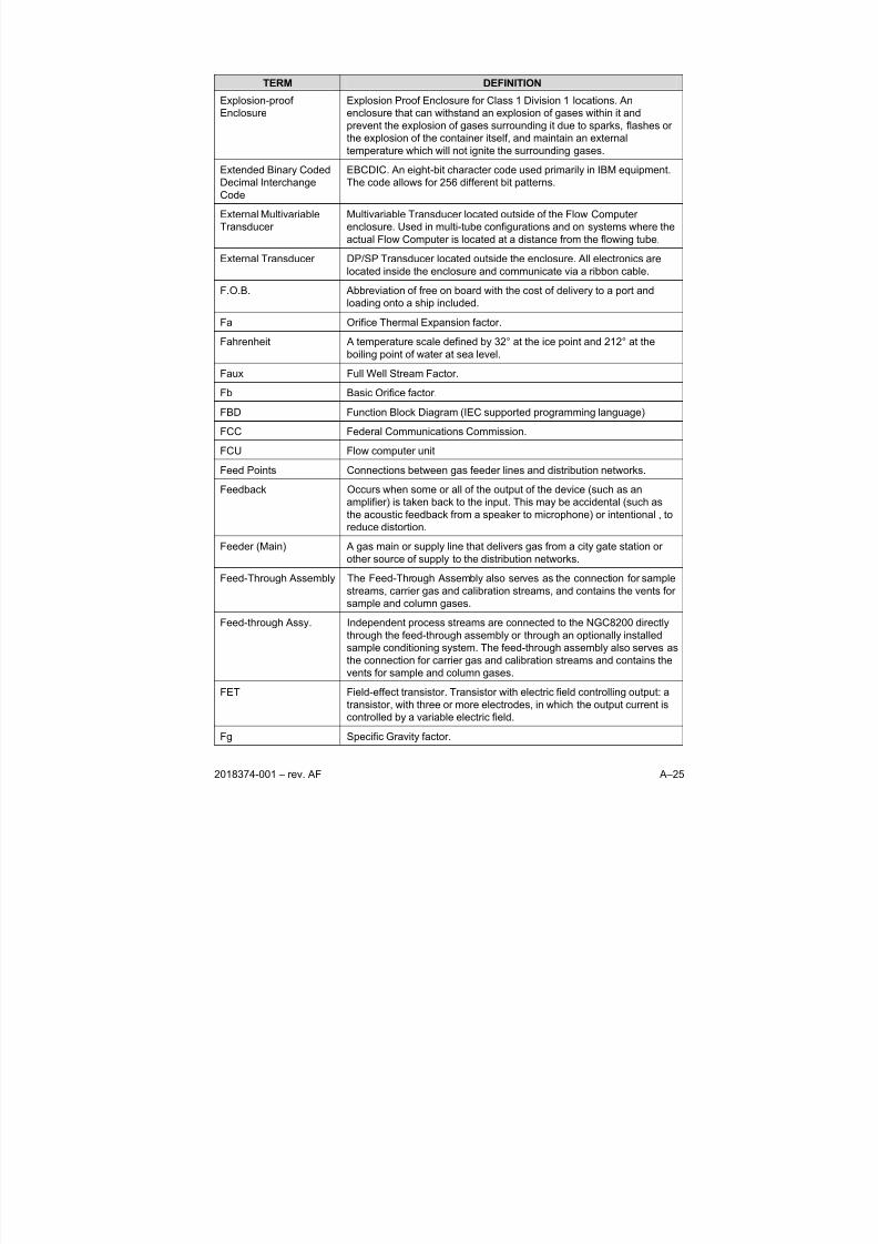
8/13/2019 2018374 m Naf
http://slidepdf.com/reader/full/2018374-m-naf 133/174
2018374-001 – rev. AF A–25
TERM DEFINITION
Explosion-proof
Enclosure
Explosion Proof Enclosure for Class 1 Division 1 locations. An
enclosure that can withstand an explosion of gases within it and
prevent the explosion of gases surrounding it due to sparks, flashes or
the explosion of the container itself, and maintain an external
temperature which will not ignite the surrounding gases.
Extended Binary Coded
Decimal Interchange
Code
EBCDIC. An eight-bit character code used primarily in IBM equipment.
The code allows for 256 different bit patterns.
External Multivariable
Transducer
Multivariable Transducer located outside of the Flow Computer
enclosure. Used in multi-tube configurations and on systems where the
actual Flow Computer is located at a distance from the flowing tube.
External Transducer DP/SP Transducer located outside the enclosure. All electronics are
located inside the enclosure and communicate via a ribbon cable.
F.O.B. Abbreviation of free on board with the cost of delivery to a port and
loading onto a ship included.
Fa Orifice Thermal Expansion factor.
Fahrenheit A temperature scale defined by 32° at the ice point and 212° at the
boiling point of water at sea level.
Faux Full Well Stream Factor.
Fb Basic Orifice factor.
FBD Function Block Diagram (IEC supported programming language)
FCC Federal Communications Commission.
FCU Flow computer unit
Feed Points Connections between gas feeder lines and distribution networks.
Feedback Occurs when some or all of the output of the device (such as an
amplifier) is taken back to the input. This may be accidental (such as
the acoustic feedback from a speaker to microphone) or intentional , to
reduce distortion.
Feeder (Main) A gas main or supply line that delivers gas from a city gate station or
other source of supply to the distribution networks.
Feed-Through Assembly The Feed-Through Assembly also serves as the connection for sample
streams, carrier gas and calibration streams, and contains the vents for
sample and column gases.
Feed-through Assy. Independent process streams are connected to the NGC8200 directly
through the feed-through assembly or through an optionally installedsample conditioning system. The feed-through assembly also serves as
the connection for carrier gas and calibration streams and contains the
vents for sample and column gases.
FET Field-effect transistor. Transistor with electric field controlling output: a
transistor, with three or more electrodes, in which the output current is
controlled by a variable electric field.
Fg Specific Gravity factor.
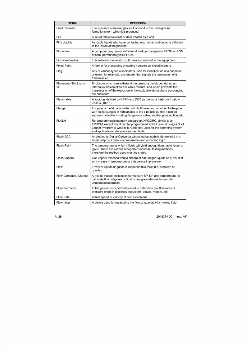
8/13/2019 2018374 m Naf
http://slidepdf.com/reader/full/2018374-m-naf 134/174
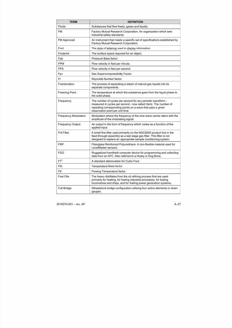
8/13/2019 2018374 m Naf
http://slidepdf.com/reader/full/2018374-m-naf 135/174
2018374-001 – rev. AF A–27
TERM DEFINITION
Fluids Substances that flow freely; gases and liquids.
FM Factory Mutual Research Corporation. An organization which sets
industrial safety standards.
FM Approved An instrument that meets a specific set of specifications established by
Factory Mutual Research Corporation.
Font The style of lettering used to display information.
Footprint The surface space required for an object.
Fpb Pressure Base factor.
FPM Flow velocity in feet per minute.
FPS Flow velocity in feet per second.
Fpv See Supercompressibility Factor.
Fr Reynolds Number factor.
Fractionation The process of separating a steam of natural gas liquids into itsseparate components.
Freezing Point The temperature at which the substance goes from the liquid phase to
the solid phase.
Frequency The number of cycles per second for any periodic waveform -
measured in cycles per second - now called Hertz. The number of
repeating corresponding points on a wave that pass a given
observation point per unit time.
Frequency Modulation Modulation where the frequency of the sine wave carrier alters with the
amplitude of the modulating signal.
Frequency Output An output in the form of frequency which varies as a function of the
applied input.
Frit Filter A small fine filter used primarily on the NGC8200 product line in the
feed-through assembly as a last stage gas filter. This filter is not
designed to replace an appropriate sample conditioning system.
FRP Fiberglass Reinforced Polyurethane. A non-flexible material used for
LevelMaster sensors.
FS/2 Ruggadized handheld computer device for programming and collecting
data from an XFC. Also referred to a Husky or Dog Bone.
FT3 A standard abbreviation for Cubic Foot.
Ftb Temperature Base factor.
Ftf Flowing Temperature factor.
Fuel Oils The heavy distillates from the oil refining process that are used
primarily for heating, for fueling industrial processes, for fueling
locomotives and ships, and for fueling power generation systems.
Full Bridge Wheatstone bridge configuration utilizing four active elements or strain
gauges.
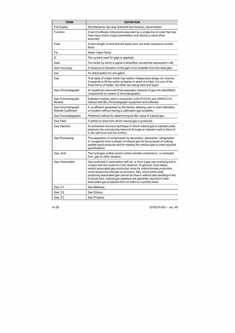
8/13/2019 2018374 m Naf
http://slidepdf.com/reader/full/2018374-m-naf 136/174
A–28 2018374-001 – rev. AF
TERM DEFINITION
Full Duplex Simultaneous, two-way (transmit and receive), transmission.
Function A set of software instructions executed by a single line of code that may
have input and/or output parameters and returns a value when
executed.
Fuse A short length of wire that will easily burn out when excessive current
flows.
Fw Water Vapor factor.
G The symbol used for giga or gigabyte.
Gain The factor by which a signal is amplified, sometimes expressed in dB.
Gain Accuracy A measure of deviation of the gain of an amplifier from the ideal gain.
Gal An abbreviation for one gallon.
Gas That state of matter which has neither independent shape nor volume.
It expands to fill the entire container in which it is held. It is one of the
three forms of matter, the other two being solid and liquid.
Gas Chromatograph An analytical instrument that separates mixtures of gas into identifiable
components by means of chromatography.
Gas Chromatograph
Module
Software module used in conjunction with PCCU32 and WINCCU to
interact with Btu Chromatograph equipment and software.
Gas Chromatograph
Module Coefficient
A co-efficient generated by the factory allowing user to start calibration
on location without having a calibration gas available.
Gas Chromatography Preferred method for determining the Btu value of natural gas.
Gas Field A district or area from which natural gas is produced.
Gas Injection An enhanced recovery technique in which natural gas is injected under
pressure into a producing reservoir through an injection well to drive oil
to the well bore and the surface.
Gas Processing The separation of components by absorption, adsorption, refrigeration
or cryogenics from a stream of natural gas for the purpose of making
salable liquid products and for treating the residue gas to meet required
specifications.
Gas, Acid The hydrogen sulfide and/or carbon dioxide contained in, or extracted
from, gas or other streams.
Gas, Associated Gas produced in association with oil, or from a gas cap overlying and in
contact with the crude oil in the reservoir. In general, most states
restrict associated gas production since its indiscriminate production
could reduce the ultimate oil recovery. Also, since some wellsproducing associated gas cannot be shut-in without also shutting-in the
oil production, natural gas pipelines are generally required to take
associated gas produced from oil wells on a priority basis.
Gas, C1 See Methane.
Gas, C2 See Ethane.
Gas, C3 See Propane.
8/13/2019 2018374 m Naf
http://slidepdf.com/reader/full/2018374-m-naf 137/174
2018374-001 – rev. AF A–29
TERM DEFINITION
Gas, C5+ Pentanes Plus (IC5, NeoC5, NC5 and C6+)
Gas, C6+ Hexanes Plus (C6, C7, C8, C9, C10, C11, etc.).
Gas, CO2 See Carbon Dioxide.
Gas, Dry Gas whose water content has been reduced by a dehydration process.Gas containing little or no hydrocarbons commercially recoverable as
liquid product. Specified small quantities of liquids are permitted by
varying statutory definitions in certain states.
Gas, IC4 See Iso-Butane.
Gas, IC5 See Iso-Pentane.
Gas, Liquefied
Petroleum (LPG)
A gas containing certain specific hydrocarbons which are gaseous
under normal atmospheric conditions but can be liquefied under
moderate pressure at normal temperatures. Propane and butane are
the principal examples.
Gas, Manufactured A gas obtained by destructive distillation of coal, or by the thermal
decomposition of oil, or by the reaction of steam passing through a bed
of heated coal or coke, or catalyst beds. Examples are coal gases,
coke oven gases, producer gas, blast furnace gas, blue (water) gas,
and carbureted water gas. Btu content varies widely.
Gas, Natural A naturally occurring mixture of hydrocarbon and non-hydrocarbon
gases found in porous geologic formations beneath the earth's surface,
often in association with petroleum. The principal constituent is
methane.
Gas, NC4 See Normal Butane.
Gas, NC5 See Normal Pentane.
Gas, NeoC5 See Neo-Pentane.
Gas, Non-associated Free natural gas not in contact with, nor dissolved in, crude oil in the
reservoir.
Gas, Oil A gas resulting from the thermal decomposition of petroleum oils,
composed mainly of volatile hydrocarbons and hydrogen. The true
heating value of oil gas may vary between 800 and 1600 Btu per cubic
foot depending on operating conditions and feedstock properties.
Gas, Sour Gas found in its natural state, containing such amounts of compounds
of sulfur as to make it impractical to use, without purifying, because of
its corrosive effect on piping and equipment.
Gas, Sweet Gas found in its natural state, containing such small amounts of
compounds of sulfur that it can be used without purifying, with nodeleterious effect on piping and equipment.
Gas, Unconventional Gas that can not be economically produced using current technology.
Gas, Wet Wet natural gas is unprocessed natural gas or partially processed
natural gas produced from strata containing condensable
hydrocarbons. The term is subject to varying legal definitions as
specified by certain state statutes.
8/13/2019 2018374 m Naf
http://slidepdf.com/reader/full/2018374-m-naf 138/174
A–30 2018374-001 – rev. AF
TERM DEFINITION
Gate Station Generally a location at which gas changes ownership, from one party to
another, neither of which is the ultimate consumer. It should be noted,
however, that the gas may change from one system to another at this
point without changing ownership. Also referred to as city gate station,
town border station, or delivery point.
Gathering The act of operating extensive low-pressure gas lines which aggregate
the production of several separate gas wells into one larger receipt
point into an interstate pipeline.
Gathering Agreement Agreement between a producer and a gathering system operator
specifying the terms and conditions for entry of the producer's gas into
the gathering system.
Gathering Line A pipeline, usually of small diameter, used in gathering gas from the
field to a central point.
Gathering Station A compressor station at which gas is gathered from wells by means of
suction because pressure is not sufficient to produce the desired rate of
flow into a transmission or distribution system.Gathering System The gathering pipelines plus any pumps, tanks, or additional equipment
used to move oil or gas from the wellhead to the main pipeline for
delivery to a processing facility or consumer.
Gauge Factor A measure of the ratio of the relative change of resistance to the
relative change in length of a piezoresistive strain gage.
Gauge Pressure Absolute pressure minus local atmospheric pressure.
Gauge, Pressure Instrument for measuring the relative pressure of a fluid. Types include
gauge, absolute, and differential.
Gauging Tape
Measurements
This refers to a manual method of measuring the level of a liquid in a
tank. These measurements may be used to calibrate float levels.GC See Gas Chromatograph.
GC Module The NGC8200’s GC module is comprised of three parts: columns,
chromatographic valve and GC module circuit board. The valve controls
the flow of gas within the system. The columns perform the separation
of the gas into component parts for analysis. The GC module circuit
board contains the sensors for the carrier pressure regulators, the
sample pressure sensor and the thermal conductivity detectors (TCD's)
which detect the different gas components as they leave the GC
columns. It also contains an EEPROM or FLASH memory for storage of
calibration and characterization information of the module and its
sensors.
GC Module Assembly The GC Module is comprised of 3 parts; Columns, Valves and
Electronic Interface. The Valves control flow of gas within the system.
The Columns perform the separation of the gas into component parts
for analysis. The Electronic Interface contains pressure and
temperature sensors to monitor and detect the different gas
components as they leave the GC Columns.
GCM See Gas Chromatograph Module
8/13/2019 2018374 m Naf
http://slidepdf.com/reader/full/2018374-m-naf 139/174
2018374-001 – rev. AF A–31
TERM DEFINITION
GCM See Gas Chromatograph Module Coefficient.
GCN Gravity, Carbon Dioxide and Nitrogen compounds. Used in NX-19 GCN
Supercompressibility Factor.
GCNM Gravity, Carbon Dioxide, Nitrogen and Methane compounds. Used in
NX-19 GCNM Supercompressibility Factor.
GDF Gasde of France
Gj An abbreviation for gigajoule, equivalent to one thousand mega joules
or one billion joules.
GND See Ground.
GOST Russian Government Standards for Importation.
GPA 2145-03 Gas Processors Association Physical Constants for Paraffin
Hydrocarbons and other Components of Natural Gas
GPA 2172-96 Gas Processors Association Calculation of Gross Heating Value,
Relative Density and Compressibility of Natural Gas Mixtures fromCompositional Analysis.
GPM Gallons of liquid per thousand cubic feet.
GPS 2261 See Gas Processors Standard 2261.
GPV Gauge Port Vent. Refers to the NGC8200 Port designed to equalize the
pressure inside of the explosion-proof enclosure.
GPV Gauge Port Valve (located on NGC8200 series Feed-Through
Assembly).
GRD See Ground.
Gross Heating Value The heating value measured in a calorimeter when the water produced
during the combustion process is condensed to a liquid state. The heat
of condensation of the water is included in the total measured heat.
Ground 1) An electronically neutral circuit having the same potential as the
surrounding earth. Normally, a non-current carrying circuit intended for
the safety purposes. A reference point for an electrical system. 2) A
large conducting body (as the earth) used as a common return for an
electric circuit and as an arbitrary zero of potential. 3) Reference point
for an electrical system.
Grounding Strap A grounding strap is a conductive device used to make connection
between the person handling the board, and a high quality ground
potential.
H2 The molecular formula for Hydrogen.
H2S The molecular formula for Hydrogen Sulfide.
Half Duplex Communication transmission in one direction at a time.
Handshake An interface procedure that is based on status/data signals that assure
orderly data transfer as opposed to asynchronous exchange.
8/13/2019 2018374 m Naf
http://slidepdf.com/reader/full/2018374-m-naf 140/174
A–32 2018374-001 – rev. AF
TERM DEFINITION
Handshaking Exchange of predetermined signals between two devices establishing a
connection. Usually part of a communications protocol.
Hardware The physical components of a computer system, such as the circuit
boards, plug-in boards, chassis, enclosures, peripherals, cables, and so
on. It does not include data or computer programs.
Harmonic A sinusoidal component of a waveform that is a whole multiple of the
fundamental frequency. An oscillation that is an integral sub-multiple of
the fundamental is called a sub-harmonic.
HART Communication Interface.
Hazardous Area Area in which an explosive gas atmosphere is present or may be
expected to be present.
Heat Thermal energy. Heat is expressed in units of calories or Btu's
Heat Capacity The amount of heat required to raise the temperature of a body (of any
mass) one degree Celsius.
Heat of Condensation The amount of heat that must be removed from one gram of a vapor at
it's condensation point to condense the vapor with no change in
temperature.
Heat of Vaporization The amount of heat required to vaporize one gram of a liquid at its
boiling point with no change in temperature. Usually expressed in J/g.
The molar heat of vaporization is the amount of heat required to
vaporize one mole of liquid at its boiling point with no change in
temperature and usually expressed ion kJ/mol.
Heat Transfer A form of energy that flows between two samples of matter because of
their differences in temperature.
Heating Value The amount of heat developed by the complete combustion of a unit
quantity of a material. Heating values for natural gas are usuallyexpressed as the Btu per Cf of gas at designated conditions
(temperature and pressure) and either on the dry or water saturated
basis.
Heavy Crude Crude oil of 20-degree API gravity or less; often very thick and viscous.
Heavy Ends The portion of a hydrocarbon mixture having the highest boiling point.
Hexanes or heptanes and all heavier hydrocarbons are usually the
heavy ends in a natural gas stream.
Heavy Hydrocarbons More susceptible to increases in temperature and decreases in
pressure, thus causing liquids to form.
Heptane (C7H16) A saturated hydrocarbon (Alkane) with 7 carbon atoms in it’s molecule(C7H16). A liquid under normal conditions.
Hertz Cycles per second. A measure of frequency or bandwidth.
Hexadecimal A numbering system to the base 16, 0 through F.
Hexane (C6H14) A saturated hydrocarbon (Alkane) with six carbon atoms in it’s molecule
(C6H14). A liquid under normal conditions.
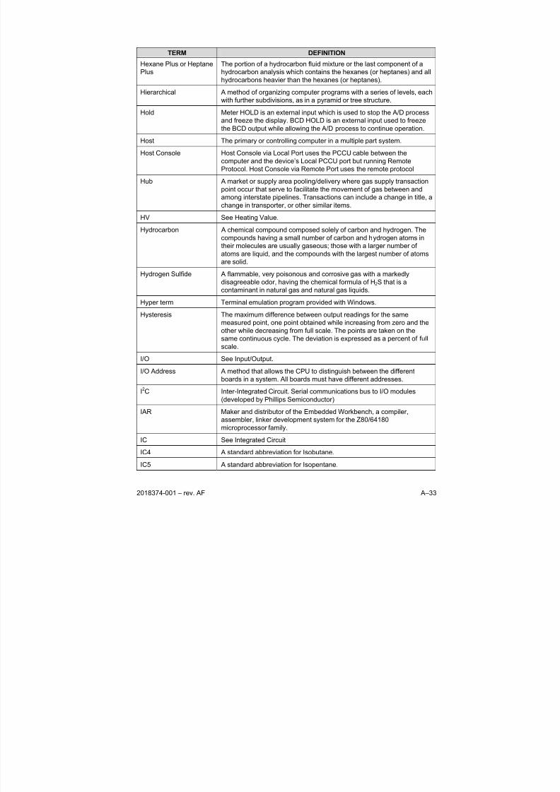
8/13/2019 2018374 m Naf
http://slidepdf.com/reader/full/2018374-m-naf 141/174
2018374-001 – rev. AF A–33
TERM DEFINITION
Hexane Plus or Heptane
Plus
The portion of a hydrocarbon fluid mixture or the last component of a
hydrocarbon analysis which contains the hexanes (or heptanes) and all
hydrocarbons heavier than the hexanes (or heptanes).
Hierarchical A method of organizing computer programs with a series of levels, each
with further subdivisions, as in a pyramid or tree structure.
Hold Meter HOLD is an external input which is used to stop the A/D process
and freeze the display. BCD HOLD is an external input used to freeze
the BCD output while allowing the A/D process to continue operation.
Host The primary or controlling computer in a multiple part system.
Host Console Host Console via Local Port uses the PCCU cable between the
computer and the device’s Local PCCU port but running Remote
Protocol. Host Console via Remote Port uses the remote protocol
Hub A market or supply area pooling/delivery where gas supply transaction
point occur that serve to facilitate the movement of gas between and
among interstate pipelines. Transactions can include a change in title, a
change in transporter, or other similar items.
HV See Heating Value.
Hydrocarbon A chemical compound composed solely of carbon and hydrogen. The
compounds having a small number of carbon and hydrogen atoms in
their molecules are usually gaseous; those with a larger number of
atoms are liquid, and the compounds with the largest number of atoms
are solid.
Hydrogen Sulfide A flammable, very poisonous and corrosive gas with a markedly
disagreeable odor, having the chemical formula of H2S that is a
contaminant in natural gas and natural gas liquids.
Hyper term Terminal emulation program provided with Windows.Hysteresis The maximum difference between output readings for the same
measured point, one point obtained while increasing from zero and the
other while decreasing from full scale. The points are taken on the
same continuous cycle. The deviation is expressed as a percent of full
scale.
I/O See Input/Output.
I/O Address A method that allows the CPU to distinguish between the different
boards in a system. All boards must have different addresses.
I2C Inter-Integrated Circuit. Serial communications bus to I/O modules
(developed by Phillips Semiconductor)
IAR Maker and distributor of the Embedded Workbench, a compiler,
assembler, linker development system for the Z80/64180
microprocessor family.
IC See Integrated Circuit
IC4 A standard abbreviation for Isobutane.
IC5 A standard abbreviation for Isopentane.
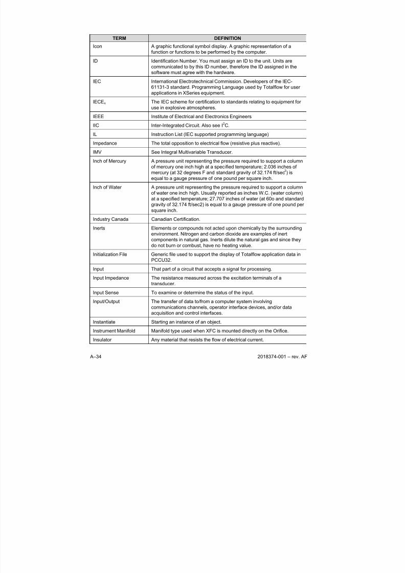
8/13/2019 2018374 m Naf
http://slidepdf.com/reader/full/2018374-m-naf 142/174
A–34 2018374-001 – rev. AF
TERM DEFINITION
Icon A graphic functional symbol display. A graphic representation of a
function or functions to be performed by the computer.
ID Identification Number. You must assign an ID to the unit. Units are
communicated to by this ID number, therefore the ID assigned in the
software must agree with the hardware.
IEC International Electrotechnical Commission. Developers of the IEC-
61131-3 standard. Programming Language used by Totalflow for user
applications in XSeries equipment.
IECEx The IEC scheme for certification to standards relating to equipment for
use in explosive atmospheres.
IEEE Institute of Electrical and Electronics Engineers
IIC Inter-Integrated Circuit. Also see I2C.
IL Instruction List (IEC supported programming language)
Impedance The total opposition to electrical flow (resistive plus reactive).
IMV See Integral Multivariable Transducer.
Inch of Mercury A pressure unit representing the pressure required to support a column
of mercury one inch high at a specified temperature; 2.036 inches of
mercury (at 32 degrees F and standard gravity of 32.174 ft/sec2) is
equal to a gauge pressure of one pound per square inch.
Inch of Water A pressure unit representing the pressure required to support a column
of water one inch high. Usually reported as inches W.C. (water column)
at a specified temperature; 27.707 inches of water (at 60o and standard
gravity of 32.174 ft/sec2) is equal to a gauge pressure of one pound per
square inch.
Industry Canada Canadian Certification.
Inerts Elements or compounds not acted upon chemically by the surrounding
environment. Nitrogen and carbon dioxide are examples of inert
components in natural gas. Inerts dilute the natural gas and since they
do not burn or combust, have no heating value.
Initialization File Generic file used to support the display of Totalflow application data in
PCCU32.
Input That part of a circuit that accepts a signal for processing.
Input Impedance The resistance measured across the excitation terminals of a
transducer.
Input Sense To examine or determine the status of the input.Input/Output The transfer of data to/from a computer system involving
communications channels, operator interface devices, and/or data
acquisition and control interfaces.
Instantiate Starting an instance of an object.
Instrument Manifold Manifold type used when XFC is mounted directly on the Orifice.
Insulator Any material that resists the flow of electrical current.
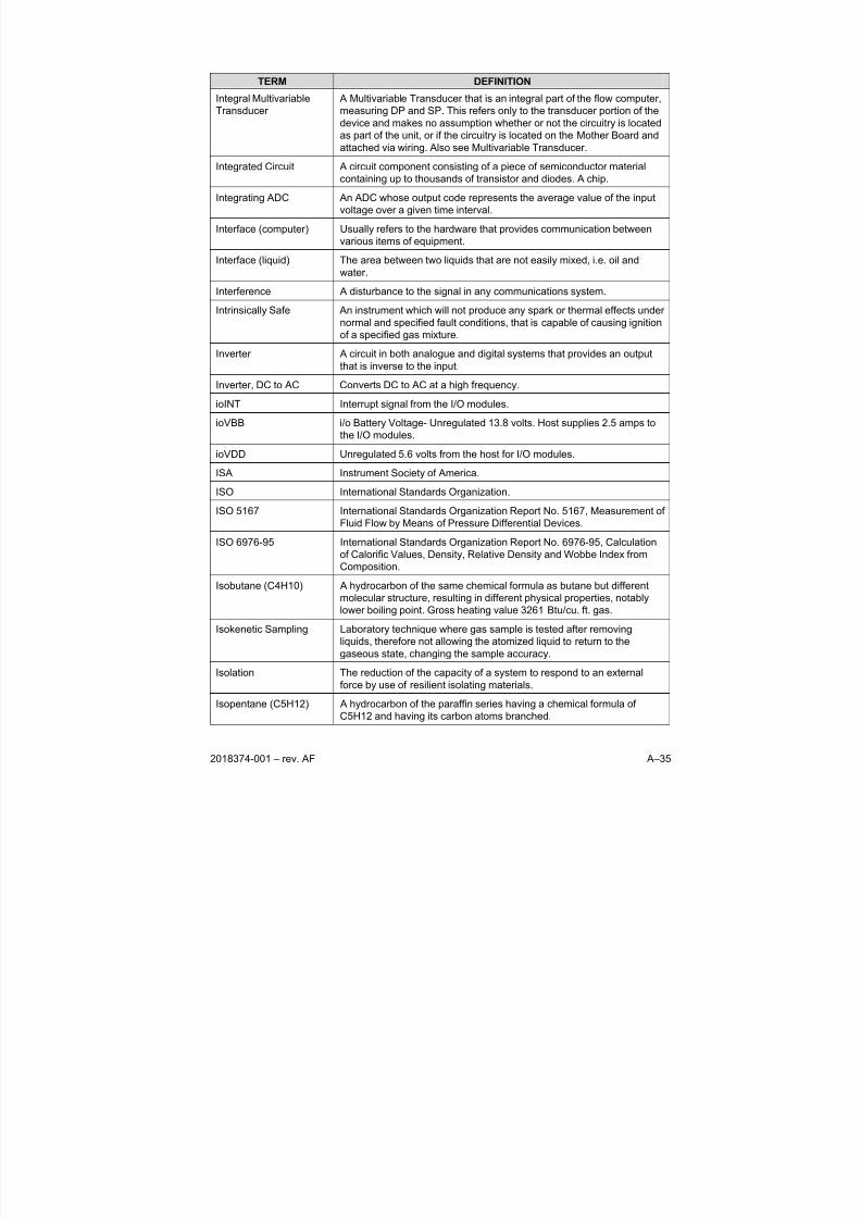
8/13/2019 2018374 m Naf
http://slidepdf.com/reader/full/2018374-m-naf 143/174
2018374-001 – rev. AF A–35
TERM DEFINITION
Integral Multivariable
Transducer
A Multivariable Transducer that is an integral part of the flow computer,
measuring DP and SP. This refers only to the transducer portion of the
device and makes no assumption whether or not the circuitry is located
as part of the unit, or if the circuitry is located on the Mother Board and
attached via wiring. Also see Multivariable Transducer.
Integrated Circuit A circuit component consisting of a piece of semiconductor material
containing up to thousands of transistor and diodes. A chip.
Integrating ADC An ADC whose output code represents the average value of the input
voltage over a given time interval.
Interface (computer) Usually refers to the hardware that provides communication between
various items of equipment.
Interface (liquid) The area between two liquids that are not easily mixed, i.e. oil and
water.
Interference A disturbance to the signal in any communications system.
Intrinsically Safe An instrument which will not produce any spark or thermal effects undernormal and specified fault conditions, that is capable of causing ignition
of a specified gas mixture.
Inverter A circuit in both analogue and digital systems that provides an output
that is inverse to the input.
Inverter, DC to AC Converts DC to AC at a high frequency.
ioINT Interrupt signal from the I/O modules.
ioVBB i/o Battery Voltage- Unregulated 13.8 volts. Host supplies 2.5 amps to
the I/O modules.
ioVDD Unregulated 5.6 volts from the host for I/O modules.
ISA Instrument Society of America.
ISO International Standards Organization.
ISO 5167 International Standards Organization Report No. 5167, Measurement of
Fluid Flow by Means of Pressure Differential Devices.
ISO 6976-95 International Standards Organization Report No. 6976-95, Calculation
of Calorific Values, Density, Relative Density and Wobbe Index from
Composition.
Isobutane (C4H10) A hydrocarbon of the same chemical formula as butane but different
molecular structure, resulting in different physical properties, notably
lower boiling point. Gross heating value 3261 Btu/cu. ft. gas.
Isokenetic Sampling Laboratory technique where gas sample is tested after removingliquids, therefore not allowing the atomized liquid to return to the
gaseous state, changing the sample accuracy.
Isolation The reduction of the capacity of a system to respond to an external
force by use of resilient isolating materials.
Isopentane (C5H12) A hydrocarbon of the paraffin series having a chemical formula of
C5H12 and having its carbon atoms branched.
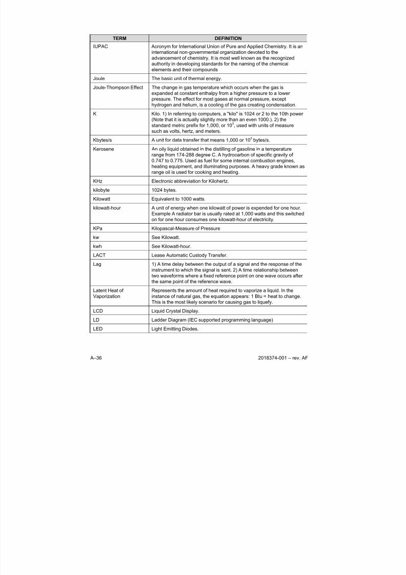
8/13/2019 2018374 m Naf
http://slidepdf.com/reader/full/2018374-m-naf 144/174
A–36 2018374-001 – rev. AF
TERM DEFINITION
IUPAC Acronym for International Union of Pure and Applied Chemistry. It is an
international non-governmental organization devoted to the
advancement of chemistry. It is most well known as the recognized
authority in developing standards for the naming of the chemical
elements and their compounds
Joule The basic unit of thermal energy.
Joule-Thompson Effect The change in gas temperature which occurs when the gas is
expanded at constant enthalpy from a higher pressure to a lower
pressure. The effect for most gases at normal pressure, except
hydrogen and helium, is a cooling of the gas creating condensation.
K Kilo. 1) In referring to computers, a "kilo" is 1024 or 2 to the 10th power
(Note that it is actually slightly more than an even 1000.). 2) the
standard metric prefix for 1,000, or 103, used with units of measure
such as volts, hertz, and meters.
Kbytes/s A unit for data transfer that means 1,000 or 103 bytes/s.
Kerosene An oily liquid obtained in the distilling of gasoline in a temperaturerange from 174-288 degree C. A hydrocarbon of specific gravity of
0.747 to 0.775. Used as fuel for some internal combustion engines,
heating equipment, and illuminating purposes. A heavy grade known as
range oil is used for cooking and heating.
KHz Electronic abbreviation for Kilohertz.
kilobyte 1024 bytes.
Kilowatt Equivalent to 1000 watts.
kilowatt-hour A unit of energy when one kilowatt of power is expended for one hour.
Example A radiator bar is usually rated at 1,000 watts and this switched
on for one hour consumes one kilowatt-hour of electricity.KPa Kilopascal-Measure of Pressure
kw See Kilowatt.
kwh See Kilowatt-hour.
LACT Lease Automatic Custody Transfer.
Lag 1) A time delay between the output of a signal and the response of the
instrument to which the signal is sent. 2) A time relationship between
two waveforms where a fixed reference point on one wave occurs after
the same point of the reference wave.
Latent Heat of
Vaporization
Represents the amount of heat required to vaporize a liquid. In the
instance of natural gas, the equation appears: 1 Btu = heat to change.This is the most likely scenario for causing gas to liquefy.
LCD Liquid Crystal Display.
LD Ladder Diagram (IEC supported programming language)
LED Light Emitting Diodes.
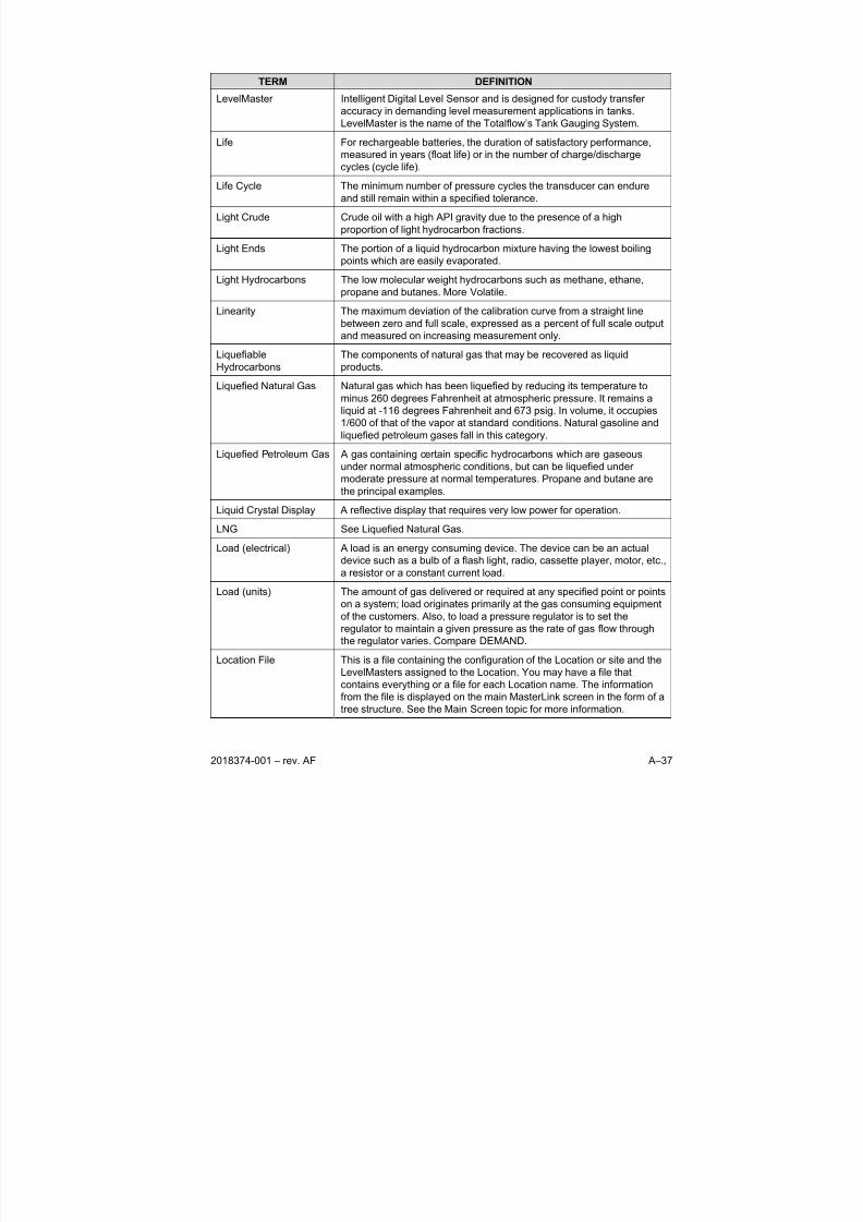
8/13/2019 2018374 m Naf
http://slidepdf.com/reader/full/2018374-m-naf 145/174
2018374-001 – rev. AF A–37
TERM DEFINITION
LevelMaster Intelligent Digital Level Sensor and is designed for custody transfer
accuracy in demanding level measurement applications in tanks.
LevelMaster is the name of the Totalflow’s Tank Gauging System.
Life For rechargeable batteries, the duration of satisfactory performance,
measured in years (float life) or in the number of charge/dischargecycles (cycle life).
Life Cycle The minimum number of pressure cycles the transducer can endure
and still remain within a specified tolerance.
Light Crude Crude oil with a high API gravity due to the presence of a high
proportion of light hydrocarbon fractions.
Light Ends The portion of a liquid hydrocarbon mixture having the lowest boiling
points which are easily evaporated.
Light Hydrocarbons The low molecular weight hydrocarbons such as methane, ethane,
propane and butanes. More Volatile.
Linearity The maximum deviation of the calibration curve from a straight linebetween zero and full scale, expressed as a percent of full scale output
and measured on increasing measurement only.
Liquefiable
Hydrocarbons
The components of natural gas that may be recovered as liquid
products.
Liquefied Natural Gas Natural gas which has been liquefied by reducing its temperature to
minus 260 degrees Fahrenheit at atmospheric pressure. It remains a
liquid at -116 degrees Fahrenheit and 673 psig. In volume, it occupies
1/600 of that of the vapor at standard conditions. Natural gasoline and
liquefied petroleum gases fall in this category.
Liquefied Petroleum Gas A gas containing certain specific hydrocarbons which are gaseous
under normal atmospheric conditions, but can be liquefied undermoderate pressure at normal temperatures. Propane and butane are
the principal examples.
Liquid Crystal Display A reflective display that requires very low power for operation.
LNG See Liquefied Natural Gas.
Load (electrical) A load is an energy consuming device. The device can be an actual
device such as a bulb of a flash light, radio, cassette player, motor, etc.,
a resistor or a constant current load.
Load (units) The amount of gas delivered or required at any specified point or points
on a system; load originates primarily at the gas consuming equipment
of the customers. Also, to load a pressure regulator is to set the
regulator to maintain a given pressure as the rate of gas flow throughthe regulator varies. Compare DEMAND.
Location File This is a file containing the configuration of the Location or site and the
LevelMasters assigned to the Location. You may have a file that
contains everything or a file for each Location name. The information
from the file is displayed on the main MasterLink screen in the form of a
tree structure. See the Main Screen topic for more information.
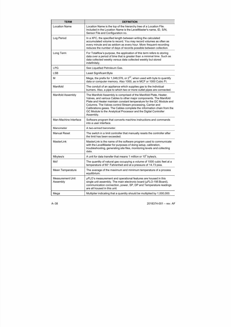
8/13/2019 2018374 m Naf
http://slidepdf.com/reader/full/2018374-m-naf 146/174
A–38 2018374-001 – rev. AF
TERM DEFINITION
Location Name Location Name is the top of the hierarchy tree of a Location File.
Included in the Location Name is the LevelMaster's name, ID, S/N,
Sensor File and Configuration no.
Log Period In a XFC, the specified length between writing the calculated
accumulated volume to record. You may record volumes as often asevery minute and as seldom as every hour. More frequent recording
reduces the number of days of records possible between collection.
Long Term For Totalflow’s purpose, the application of this term refers to storing
data over a period of time that is greater than a minimal time. Such as
data collected weekly versus data collected weekly but stored
indefinitely.
LPG See Liquefied Petroleum Gas.
LSB Least Significant Byte
M Mega, the prefix for 1,048,576, or 220
, when used with byte to quantify
data or computer memory. Also 1000, as in MCF or 1000 Cubic Ft.
Manifold The conduit of an appliance which supplies gas to the individual
burners. Also, a pipe to which two or more outlet pipes are connected.
Manifold Assembly The Manifold Assembly is comprised of the Manifold Plate, Heater,
Valves, and various Cables to other major components. The Manifold
Plate and Heater maintain constant temperature for the GC Module and
Columns. The Valves control Stream processing, Carrier and
Calibrations gases. The Cables complete the information chain from the
GC Module to the Analytical Processor and the Digital Controller
Assembly.
Man-Machine Interface Software program that converts machine instructions and commands
into a user interface.
Manometer A two-armed barometer.
Manual Reset The switch in a limit controller that manually resets the controller after
the limit has been exceeded.
MasterLink MasterLink is the name of the software program used to communicate
with the LevelMaster for purposes of doing setup, calibration,
troubleshooting, generating site files, monitoring levels and collecting
data.
Mbytes/s A unit for data transfer that means 1 million or 106 bytes/s.
Mcf The quantity of natural gas occupying a volume of 1000 cubic feet at a
temperature of 60° Fahrenheit and at a pressure of 14.73 psia.
Mean Temperature The average of the maximum and minimum temperature of a process
equilibrium.
Measurement Unit
Assembly
μFLO’s measurement and operational features are housed in this
single unit assembly. The main electronic board (μFLO-195 Board),
communication connection, power, SP, DP and Temperature readings
are all housed in this unit.
Mega Multiplier indicating that a quantity should be multiplied by 1,000,000.
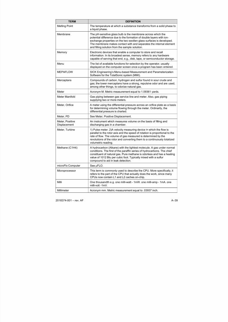
8/13/2019 2018374 m Naf
http://slidepdf.com/reader/full/2018374-m-naf 147/174
2018374-001 – rev. AF A–39
TERM DEFINITION
Melting Point The temperature at which a substance transforms from a solid phase to
a liquid phase.
Membrane The pH-sensitive glass bulb is the membrane across which the
potential difference due to the formation of double layers with ion-
exchange properties on the two swollen glass surfaces is developed.The membrane makes contact with and separates the internal element
and filling solution from the sample solution.
Memory Electronic devices that enable a computer to store and recall
information. In its broadest sense, memory refers to any hardware
capable of serving that end, e.g., disk, tape, or semiconductor storage.
Menu The list of available functions for selection by the operator, usually
displayed on the computer screen once a program has been entered.
MEPAFLOW SICK Engineering’s Menu-based Measurement and Parameterization
Software for the TotalSonic system (MMI).
Mercaptans Compounds of carbon, hydrogen and sulfur found in sour crude and
gas; the lower mercaptans have a strong, repulsive odor and are used,among other things, to odorize natural gas.
Meter Acronym M. Metric measurement equal to 1.09361 yards.
Meter Manifold Gas piping between gas service line and meter. Also, gas piping
supplying two or more meters.
Meter, Orifice A meter using the differential pressure across an orifice plate as a basis
for determining volume flowing through the meter. Ordinarily, the
differential pressure is charted.
Meter, PD See Meter, Positive Displacement.
Meter, Positive
Displacement
An instrument which measures volume on the basis of filling and
discharging gas in a chamber.
Meter, Turbine 1) Pulse meter. 2)A velocity measuring device in which the flow is
parallel to the rotor axis and the speed of rotation is proportional to the
rate of flow. The volume of gas measured is determined by the
revolutions of the rotor and converting them to a continuously totalized
volumetric reading.
Methane (C1H4) A hydrocarbon (Alkane) with the lightest molecule. A gas under normal
conditions. The first of the paraffin series of hydrocarbons. The chief
constituent of natural gas. Pure methane is odorless and has a heating
value of 1012 Btu per cubic foot. Typically mixed with a sulfur
compound to aid in leak detection.
microFlo Computer See μFLO.
Microprocessor This term is commonly used to describe the CPU. More specifically, it
refers to the part of the CPU that actually does the work, since many
CPUs now contain L1 and L2 caches on-chip.
Milli One thousandth e.g. one milli-watt - 1mW. one milli-amp - 1mA. one
milli-volt -1mV.
Millimeter Acronym mm. Metric measurement equal to .03937 inch.
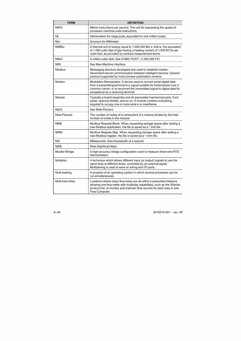
8/13/2019 2018374 m Naf
http://slidepdf.com/reader/full/2018374-m-naf 148/174
A–40 2018374-001 – rev. AF
TERM DEFINITION
MIPS Million instructions per second. The unit for expressing the speed of
processor machine code instructions.
Mj Abbreviation for mega joule, equivalent to one million joules.
Mm Acronym for Millimeter.
MMBtu A thermal unit of energy equal to 1,000,000 Btu’s, that is, the equivalent
of 1,000 cubic feet of gas having a heating content of 1,000 BTUs per
cubic foot, as provided by contract measurement terms.
MMcf A million cubic feet. See CUBIC FOOT. (1,000,000 CF)
MMI See Man-Machine Interface.
Modbus Messaging structure developed and used to establish master-
slave/client-server communication between intelligent devices. Generic
protocol supported by most process automation vendors.
Modem Modulator-Demodulator. A device used to convert serial digital data
from a transmitting terminal to a signal suitable for transmission over a
common carrier, or to reconvert the transmitted signal to digital data for
acceptance by a receiving terminal.
Module Typically a board assembly and its associated mechanical parts, front
panel, optional shields, and so on. A module contains everything
required to occupy one or more slots in a mainframe.
Mol% See Mole Percent.
Mole Percent The number of moles of a component of a mixture divided by the total
number of moles in the mixture.
MRB Modbus Request Block. When requesting storage space after adding a
new Modbus application, the file is saved as a *.mrb file.
MRM Modbus Register Map. When requesting storage space after adding a
new Modbus register, the file is saved as a *.mrm file.
MS Milliseconds. One-thousandth of a second.
MSB Most Significant Byte
Mueller Bridge A high-accuracy bridge configuration used to measure three-wire RTD
thermometers.
Multiplex A technique which allows different input (or output) signals to use the
same lines at different times, controlled by an external signal.
Multiplexing is used to save on wiring and I/O ports.
Multi-tasking A property of an operating system in which several processes can be
run simultaneously.
Multi-tube Sites Locations where many flow tubes are all within a prescribed distance
allowing one flow meter with multitube capabilities, such as the XSeries
product line, to monitor and maintain flow records for each tube in one
Flow Computer.
8/13/2019 2018374 m Naf
http://slidepdf.com/reader/full/2018374-m-naf 149/174
2018374-001 – rev. AF A–41
TERM DEFINITION
Multivariable Transducer Transducer supplying more than 1 variable. Totalflow uses this term to
encompass units that read Static Pressure, Differential Pressure.
Historically these units were coined AMU for Analog Measurement Unit.
As a result of advanced technology, the unit no longer functions as only
an analog measurement unit. Therefore the newer terminology,
Multivariable Transducer, more aptly describes the functionality of thisdesign. The abbreviation IMV refers to the Integral version of the
multivariable. The abbreviation XIMV, refers to the XSeries IMV version
of the multivariable, which contains the circuitry as part of the unit and
the abbreviation IMVX, refers to the Explosion Proof IMV, where the
required circuitry resides on the Main Processor Board. See each
instance for additional explanation.
MW Acronym for Molecular Weight.
N2 A standard abbreviation for Nitrogen.
NAK See Negative Acknowledgement
NAMUR Normenarbeitsgemeinschaft für Mess- und Regeltechnik in derchemischen Industrie (Standards study group for measurement and
process control technology in the chemical industry).
Natural Gas See Gas, Natural.
Natural Gas Distillate Material removed from natural gas at the "heavy end" portion; that is,
aliphatic compounds ranging from C4 to C8 (butanes and heavier).
Natural Gas Liquids The hydrocarbon components: propane, butanes, and pentanes (also
referred to as condensate), or a combination of them that are subject to
recovery from raw gas liquids by processing in field separators,
scrubbers, gas processing and reprocessing plants, or cycling plants.
The propane and butane components are often referred to as liquefied
petroleum gases or LPG.Natural Gasoline A mixture of hydrocarbons, mostly pentanes and heavier, extracted
from natural gas, which meets vapor pressure and other specifications.
NBS National Bureau of Standards.
NC See Normally Closed.
NC4 A standard abbreviation for Normal Butane.
NC5 A standard abbreviation for Normal Pentane.
NEC National Electrical Codes
Negative
Acknowledgment
This refers to a response over a remote communication device, such as
a PING. Basically, saying, "I don’t acknowledge your request!" This isthe opposite of ACK. NAK is a slang term that means that you disagree
or do not acknowledge something.
NEMA National Electrical Manufacturers Association.
NEMA, Type 3R A standard from the National Electrical Manufacturers Association.
Enclosure constructed for indoor/outdoor use to provide protection
against falling dirt, rain, sleet and snow and remain undamaged by
external formation of ice.
8/13/2019 2018374 m Naf
http://slidepdf.com/reader/full/2018374-m-naf 150/174
A–42 2018374-001 – rev. AF
TERM DEFINITION
NEMA, Type 4 A standard from the National Electrical Manufacturers Association.
Enclosure constructed for indoor/outdoor use to provide protection
against falling dirt, rain, sleet, snow, windblown dust, splashing water,
and hose-directed water and remain undamaged by external formation
of ice.
NEMA, Type 4X A standard from the National Electrical Manufacturers Association.
Enclosure constructed as for Type 4 with protection against corrosion.
NeoC4 A standard abbreviation for Neobutane.
NeoC5 A standard abbreviation for Neopentane.
Network A group of computers that are connected to each other by
communications lines to share information and resources.
Newton Meter Torque measurement unit equal to 8.84 Inch Pounds.
NGC Natural Gas Chromatograph
NGC Termination Panel The NGC8200 Termination Panel acts as a connection to the outside
world. It features Transient Protection, a built-in voltage regulator,
Positive Temperature Co-efficient Fuses (PTC) and many other
safeguards to protect the remainder of the system from electrical
damage. All outside communications and I/O are channeled through
this board. It is designed to be a low cost, field replaceable
maintenance solution and is designed to operate on either 12V or 24V.
NGC8201 Totalflow NGC8201 Gas Chromatograph for Process Gas
Chromatography. The NGC is designed to continually analyze process
gas streams, on-site, determine composition, calorific value, and store
the analysis information.
The unit can collect and retain analysis information for one to four
independent sample streams.
NGC8206 Totalflow NGC8200 Gas Chromatograph, with C6+. The NGC is
designed to continually analyze natural gas streams, on-site, determine
composition, calorific value, and store the analysis information. It is
designed for natural gas streams, 800 to 1500 Btu/scf (29.8 to 55.9
Mega joules/meter 3) with less than 100 PPM H2S.
The unit is a fully functional gas chromatograph for “Pipeline Quality”
natural gas, designed to analyze natural gas streams, dry of both
hydrocarbon liquids and water. The unit can collect and retain analysis
information for one to four independent sample streams. Applicable
installations include: Transmission, Distribution, Custody Transfer with
Metrology quality results, Production, Gas Gathering and End User Gas
Markets.
NGL See Natural Gas Liquids.
NGL A standard abbreviation for Natural Gas Liquids.
Nm Abbreviation for Newton Meter. Metric Torque measurement.
NO See Normally Open.
8/13/2019 2018374 m Naf
http://slidepdf.com/reader/full/2018374-m-naf 151/174
2018374-001 – rev. AF A–43
TERM DEFINITION
Noise An undesirable electrical signal. Noise comes from external sources
such as the AC power line, motors, generators, transformers,
fluorescent lights, soldering irons, CRT displays, computers, electrical
storms, welders, radio transmitters, and internal sources such as
semiconductors, resistors, and capacitors. Unwanted disturbances
superimposed upon a useful signal that tends to obscure its informationcontent.
Nonane (C9H20) A hydrocarbon (Alkane) flammable colorless liquid with nine carbon
atoms.
Non-hazardous area Area in which an explosive gas atmosphere is not expected to be
present in quantities such as to require special precautions.
Non-Persistent Refers to data that is no longer available after a Warm Start.
Normal Butane An aliphatic compound of the paraffin series having the chemical
formula of C4H10 and having all of its carbon atoms joined in a straight
chain.
Normal Pentane A hydrocarbon of the paraffin series having a chemical formula ofC5H12 and having all its carbon atoms joined in a straight chain.
Normalization of
Component Mole
Percentages
The exact amount of sample which is injected onto the columns of the
chromatograph must be a very reproducible volume in order to give
consistent values for the resulting calculated Btu. The calculation
controls the volume, temperature and pressure of the sample to be
injected by a very simple means. A few seconds before the sample is
actually injected, the flow of sample through the sample valve injection
loop is stopped by automatically shutting the sample shut-off valve.
This allows the pressure of the sample in the sample loop to bleed
down to atmospheric pressure. Since the temperature is controlled and
the size of sample loop does not vary then the only change possible in
sample size is related to variations in atmospheric pressure. Atmospheric pressure does vary with the weather and in order to
compensate for this or any other slight sample size change, the mole
percentages of each component are adjusted to equal a total of 100%
through a calculation called normalization.
The values in mole percents are determined by the chromatographic
analysis and then totaled to a value that is near 100%, which is called
the unnormalized total. The unnormalized total is divided by 100% and
the resulting factor is then multiplied by the mole% value for each
component. This calculation will adjust each component’s mole% in the
correct manner as to result in a new total of exactly 100%. The
calculation also checks to see if the unnormalized total is out of a
specified range for alarm purposes. This is an overall performancecheck to determine if the chromatograph has some problem or has
drifted out of calibration.
Normally Closed Designation which states that the contacts of a switch or relay are
closed or connected when at rest. When activated, the contacts open
or separated.
8/13/2019 2018374 m Naf
http://slidepdf.com/reader/full/2018374-m-naf 152/174
A–44 2018374-001 – rev. AF
TERM DEFINITION
Normally Open Designation which states that the contacts of a switch or relay are
normally open or not connected. When activated the contacts close or
become connected.
Norsok Norwegian Certification Bureau
NPN Negative-Positive-Negative (Transistor).
NPT National Pipe Thread.
NRTL Nationally Recognized Testing Laboratory.
Null A condition, such as balance, which results in a minimum absolute
value of output.
NX-19 American Gas Association Report referring to a specific method to
calculate the Supercompressibility factor.
O2 A standard abbreviation for oxygen.
Octane (C8H18) A hydrocarbon (Alkane) flammable colorless liquid with eight carbon
atoms. Is the 100 point on the Octane Rating Scale.
OCV See Open Circuit Voltage.
ODBC See Open Database Connectivity.
OEU Optional Equipment Unit.
Offset The difference in temperature between the set point and the actual
process temperature. Also, referred to as droop.
OHM The unit of resistance usually shown as the symbol "R". One thousand
ohms is written "k" and one million ohms is written "M". Resistance is
measured with a multimeter, set to the "ohms range".
Ohmmeter An instrument used to measure electrical resistance.
OLE Object Linking and Embedding. A set of system services that provides
a means for applications to interact and interoperate. Based on the
underlying Component Object Model, OLE is object-enabling system
software. Through OLE Automation, an application can dynamically
identify and use the services of other applications, to build powerful
solutions using packaged software. OLE also makes it possible to
create compound documents consisting of multiple sources of
information from different applications.
Ole for Process Control This is a data interchange format and supporting software. Typically,
vendors (such as ABB) write OPC server drivers which can talk to their
devices. SCADA system vendors (again like ABB) write OPC clients
that can gather data from OPC Servers. The idea is to provide auniversal way to collect data into a SCADA system regardless of the
equipment vendor. This standard was developed and is maintained by
the OPC Foundation. The Totalflow Driver, TDS32, supports OPC.
Ole for Process Control
Database
A programming interface to databases. Supports the OLEDB interface.
OLEDB See Ole for Process Control Database.
8/13/2019 2018374 m Naf
http://slidepdf.com/reader/full/2018374-m-naf 153/174
2018374-001 – rev. AF A–45
TERM DEFINITION
Olefins Basic chemicals made from oil or natural gas liquids feedstocks;
commonly used to manufacture plastics and gasoline. Examples are
ethylene and propylene.
OOP Object-Oriented Programming. The XFC/XRC architecture incorporates
an object-oriented approach.
OPC See Ole for Process Control.
Open Circuit A complete break in a metal conductor path.
Open Circuit Voltage The difference in potential between the terminals of a cell/battery when
the circuit is open (no-load condition).
Open Collector A single NPN transistor with the base connected to the logic driving
circuitry and with the emitter grounded. The collector is the output pin of
the gate.
Open Database
Connectivity
A widely accepted application-programming interface (API) for
database access. It is based on the Call-Level Interface (CLI)
specifications from X/Open and ISO/IEC for database APIs and usesStructured Query Language (SQL) as its database access language.
Using ODBC, you can create database applications with access to any
database for which your end-user has an ODBC driver. This allows
access for authorized users to databases over any network, including
the Internet. The SCADA system provides an ODBC driver, making the
database accessible to authorized users anywhere on a corporate
network, or even over the Internet if the network is properly configured.
Operating System Base-level software that controls a computer, runs programs, interacts
with users, and communicates with installed hardware or peripheral
devices.
Optional Equipment Unit Totalflow enclosure designed to house optional power and
communication devices.
Orifice Meter Device to record differential pressure measurement which uses a steel
plate with a calibrated hole or orifice to generate a drop in pressure
between the two sides of the plate. Also the primary element of the
meter run.
Orifice Plate A plate of non-corrosive material which can be fastened between
flanges or in a special fitting perpendicular to the axis of flow and
having a concentric circular hole. The primary use is for the
measurement of gas flow.
ORing Boolean algebra logical function. Described as the addition or summing
of switches or inputs, in the case of Boolean elements, the 0 and 1
represent two possible states of a premise or hypothesis: True or False,On or Off. When adding Boolean elements not real numbers, you will
find these results:
1 or 1 = 1
1 or 0 = 1
0 or 1 = 1
0 or 0 = 0
O-Ring A flat ring made of rubber or plastic, used as a gasket.
8/13/2019 2018374 m Naf
http://slidepdf.com/reader/full/2018374-m-naf 154/174
A–46 2018374-001 – rev. AF
TERM DEFINITION
Output That part of a circuit where the processed signal is available.
Output Impedance The resistance as measured on the output terminals of a pressure
transducer.
Output Noise The RMS, peak-to-peak (as specified) ac component of a transducer's
dc output in the absence of a measurand variation.
P/I See Pulse Input.
Parameter (1) Characteristic. For example, specifying parameters means defining
the characteristics of something. In general, parameters are used to
customize a program. For example, file names, page lengths, and font
specifications could all be considered parameters. (2) In programming,
the term parameter is synonymous with argument, a value that is
passed to a routine.
Parity A technique for testing transmitting data. Typically, a binary digit is
added to the data to make the sum of all the digits of the binary data
either always even (even parity) or always odd (odd parity).
Parts per Million Acronym PPM.
Passive Analog Output Analog Output to a host that is powered by an outside source.
PCCU Portable Collection and Calibration Unit.
PCCU32 Windows version of PCCU communications software to process,
archive and collect data from the Totalflow equipment. Generally run
from a laptop.
Peak Area The retention time the element takes to exit the column. This is used in
calculating the amount of each component in the sample or Mole %.
Pentane (C5H12) A saturated hydrocarbon (Alkane) with five carbon atoms in it’s
molecule (C5H12). A liquid under normal conditions.
Pentane, Normal See Normal Pentane.
Pentanes Plus A hydrocarbon mixture consisting mostly of normal pentane and
heavier components.
Peripheral The input/output and data storage devices attached to a computer such
as disk drives, printers, keyboards, displays, data acquisition systems,
etc.
Persistent Refers to data that remains available after a Warm Start.
PEX A flexible material used for LevelMaster sensors.
PGC Process Gas Chromatograph
Phase A time based relationship between a periodic function and a reference.
In electricity, it is expressed in angular degrees to describe the voltage
or current relationship of two alternating waveforms.
Phenol Hydrocarbon derivative containing an [OH] group bound to an aromatic
ring.
8/13/2019 2018374 m Naf
http://slidepdf.com/reader/full/2018374-m-naf 155/174
2018374-001 – rev. AF A–47
TERM DEFINITION
Physical Change A change in which a substance changes from one physical state to
another but no substances with different composition are formed.
Example Gas to Liquid - Solid.
PID Proportional, Integral, Derivative. A three mode control action where the
controller has time proportioning, integral (auto reset) and derivativerate action.
Piezoceramic A ceramic material that has piezoelectric properties similar to those of
some natural crystals.
Pipeline Condensate Liquid hydrocarbons that have condensed from gas to liquid as a result
of changes in pressure and temperature as gas flows in a pipeline.
Pipeline condensate only remains as a liquid under high-pressure
conditions and would vaporize at atmospheric pressure.
Plant Products All liquid hydrocarbons and other products (including sulfur and
excluding residue gas) recovered in a gas processing plant.
PLC See Programmable logic controller
Plunger Lift A technique used to optimize gas production. A Steel plunger is
inserted into the production tubing in the well. The flow is turned off and
this shut-in causes plunger to fall allowing fluid to collect above plunger.
Different techniques are used to decide how long to shut in and flow the
well.
Polarity In electricity, the quality of having two oppositely charged poles, one
positive one negative.
Polling A snapshot view of the readings taken by the Totalflow equipment.
Port A communications connection on a computer or a remote controller. A
place of access to a device or network, used for input/output of digital
and analog signals.Positive Temperature
Co-efficient
An increase in resistance due to an increase in temperature.
Positive Temperature
Co-efficient Fuse
Opens circuit when high current condition occurs. Closes when
condition no longer exists. Replaces typical fuses, which require
replacement when blown.
POU Program Organization Unit. This is Softing’s term for an ‘independent
programming unit’. Programs, functions, etc.
Power Supply A separate unit or part of a circuit that supplies power to the rest of the
circuit or to a system.
PPM Acronym for parts per million.Pressure Base The contractual, regulatory or standard ambient pressure at which
natural gas is measured or sampled expressed in psia (pounds per
square inch absolute).
Pressure Differential Difference in pressure between any two points in a continuous system.
Pressure Markers Pressure testing at different levels of pressure. Used for comparison
purposes.
8/13/2019 2018374 m Naf
http://slidepdf.com/reader/full/2018374-m-naf 156/174
A–48 2018374-001 – rev. AF
TERM DEFINITION
Pressure, Absolute See PSIA.
Pressure, Atmospheric See Atmospheric Pressure.
Pressure, Gas In the natural gas industry pressure is measured by the force applied to
a designated area. PSI and OSI refer to how much pressure (pound or
ounce) is applied to one square inch. Inches Water Column (In.W.C.) is
also used to express gas pressure and is measured using a manometer
for lower pressure readings. 1 PSIG=27.21 Inches Water Column.
Pressure, Gauge See PSIG.
Primary Cell (or Battery) A cell or battery which is not intended to be recharged and is discarded
when the cell or battery has delivered all its electrical energy.
PRM Acronym for Pressure Regulator Module.
Probe A generic term that is used to describe many types of temperature
sensors.
Process Gas Gas use for which alternate fuels are not technically feasible, such as in
applications requiring precise temperature controls and precise flame
characteristics.
Program A list of instructions that a computer follows to perform a task.
Programmable Logic
Controller
A highly reliable special-purpose computer used in industrial monitoring
and control applications. PLCs typically have proprietary programming
and networking protocols, and special-purpose digital and analog I/O
ports.
Programmable Read
Only Memory
Computer memory in which data can be written to. ROM is used for
storing programs (e.g. operating systems) and characteristic files on a
permanent basis. (non-volatile)
Programmed I/O The standard method a CPU uses to access an I/O device-- each byteof data is read or written by the CPU.
PROM See Programmable Read Only Memory
Propane (C3H8) A saturated hydrocarbon (Alkane) gas, the molecule of which is
composed of three carbon and eight hydrogen atoms. Propane is
present in most natural gas and is the first product refined from crude
petroleum. It has many industrial uses and may be used for heating
and lighting. Contains approximately 2,500 Btu per cubic foot.
Proportional, Integral,
Derivative
PID Controllers are designed to eliminate the need for continuous
operator attention. An example would be the cruise control in a car or a
house thermostat. These controllers are used to automatically adjust
some variable to hold the measurement (or process variable) at the set-point. The set-point is where you would like the measurement to be.
Error is defined as the difference between set-point and measurement.
Propylene (C3H6) A saturated hydrocarbon (Alkane) gas, the molecule of which is
composed of three carbon and six hydrogen atoms. At room
temperature and pressure, propylene is a gas. It is colorless, highly
flammable, and has a odor similar to garlic. It is found in coal gas and
can be synthesized by cracking petroleum. The main use of propylene
is as a monomer, mostly for the production of polypropylene.
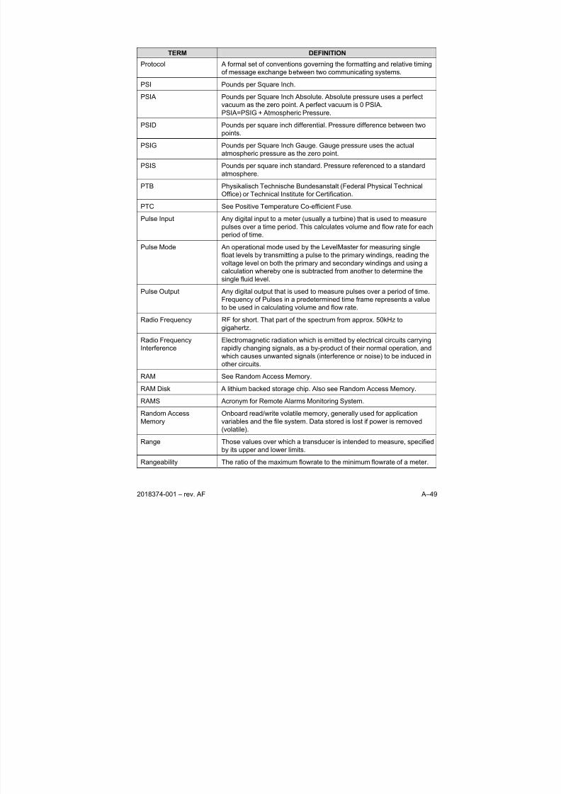
8/13/2019 2018374 m Naf
http://slidepdf.com/reader/full/2018374-m-naf 157/174
2018374-001 – rev. AF A–49
TERM DEFINITION
Protocol A formal set of conventions governing the formatting and relative timing
of message exchange between two communicating systems.
PSI Pounds per Square Inch.
PSIA Pounds per Square Inch Absolute. Absolute pressure uses a perfect
vacuum as the zero point. A perfect vacuum is 0 PSIA.
PSIA=PSIG + Atmospheric Pressure.
PSID Pounds per square inch differential. Pressure difference between two
points.
PSIG Pounds per Square Inch Gauge. Gauge pressure uses the actual
atmospheric pressure as the zero point.
PSIS Pounds per square inch standard. Pressure referenced to a standard
atmosphere.
PTB Physikalisch Technische Bundesanstalt (Federal Physical Technical
Office) or Technical Institute for Certification.
PTC See Positive Temperature Co-efficient Fuse.
Pulse Input Any digital input to a meter (usually a turbine) that is used to measure
pulses over a time period. This calculates volume and flow rate for each
period of time.
Pulse Mode An operational mode used by the LevelMaster for measuring single
float levels by transmitting a pulse to the primary windings, reading the
voltage level on both the primary and secondary windings and using a
calculation whereby one is subtracted from another to determine the
single fluid level.
Pulse Output Any digital output that is used to measure pulses over a period of time.
Frequency of Pulses in a predetermined time frame represents a value
to be used in calculating volume and flow rate.
Radio Frequency RF for short. That part of the spectrum from approx. 50kHz to
gigahertz.
Radio Frequency
Interference
Electromagnetic radiation which is emitted by electrical circuits carrying
rapidly changing signals, as a by-product of their normal operation, and
which causes unwanted signals (interference or noise) to be induced in
other circuits.
RAM See Random Access Memory.
RAM Disk A lithium backed storage chip. Also see Random Access Memory.
RAMS Acronym for Remote Alarms Monitoring System.
Random Access
Memory
Onboard read/write volatile memory, generally used for application
variables and the file system. Data stored is lost if power is removed
(volatile).
Range Those values over which a transducer is intended to measure, specified
by its upper and lower limits.
Rangeability The ratio of the maximum flowrate to the minimum flowrate of a meter.
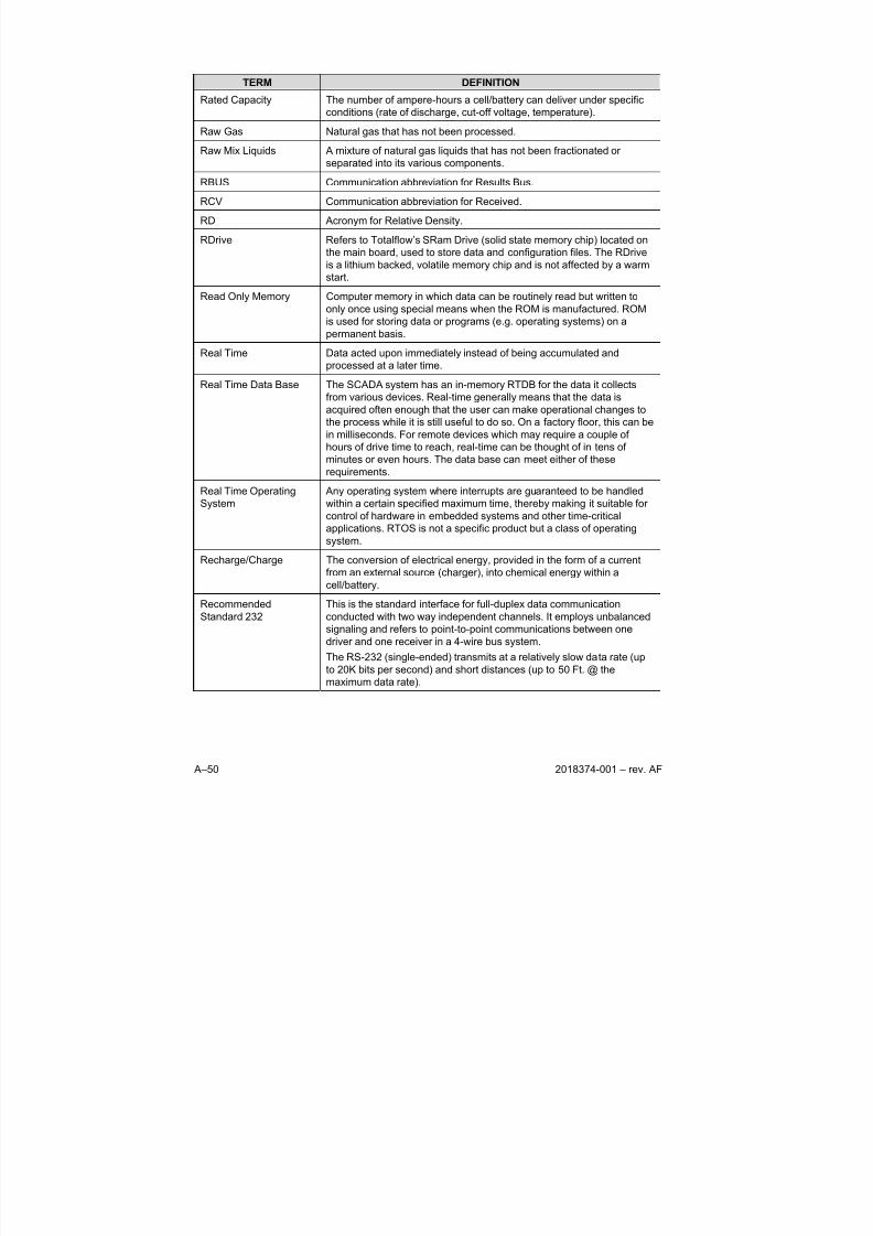
8/13/2019 2018374 m Naf
http://slidepdf.com/reader/full/2018374-m-naf 158/174
A–50 2018374-001 – rev. AF
TERM DEFINITION
Rated Capacity The number of ampere-hours a cell/battery can deliver under specific
conditions (rate of discharge, cut-off voltage, temperature).
Raw Gas Natural gas that has not been processed.
Raw Mix Liquids A mixture of natural gas liquids that has not been fractionated or
separated into its various components.
RBUS Communication abbreviation for Results Bus.
RCV Communication abbreviation for Received.
RD Acronym for Relative Density.
RDrive Refers to Totalflow’s SRam Drive (solid state memory chip) located on
the main board, used to store data and configuration files. The RDrive
is a lithium backed, volatile memory chip and is not affected by a warm
start.
Read Only Memory Computer memory in which data can be routinely read but written to
only once using special means when the ROM is manufactured. ROM
is used for storing data or programs (e.g. operating systems) on a
permanent basis.
Real Time Data acted upon immediately instead of being accumulated and
processed at a later time.
Real Time Data Base The SCADA system has an in-memory RTDB for the data it collects
from various devices. Real-time generally means that the data is
acquired often enough that the user can make operational changes to
the process while it is still useful to do so. On a factory floor, this can be
in milliseconds. For remote devices which may require a couple of
hours of drive time to reach, real-time can be thought of in tens of
minutes or even hours. The data base can meet either of these
requirements.Real Time Operating
System
Any operating system where interrupts are guaranteed to be handled
within a certain specified maximum time, thereby making it suitable for
control of hardware in embedded systems and other time-critical
applications. RTOS is not a specific product but a class of operating
system.
Recharge/Charge The conversion of electrical energy, provided in the form of a current
from an external source (charger), into chemical energy within a
cell/battery.
Recommended
Standard 232
This is the standard interface for full-duplex data communication
conducted with two way independent channels. It employs unbalanced
signaling and refers to point-to-point communications between onedriver and one receiver in a 4-wire bus system.
The RS-232 (single-ended) transmits at a relatively slow data rate (up
to 20K bits per second) and short distances (up to 50 Ft. @ the
maximum data rate).

8/13/2019 2018374 m Naf
http://slidepdf.com/reader/full/2018374-m-naf 159/174
2018374-001 – rev. AF A–51
TERM DEFINITION
Recommended
Standard 422
This is the standard interface for half-duplex communications
conducted with a dual-state driver. It employs balanced signaling and
refers to multi-drop communications between one driver and up to ten
receivers, known as “straight-through” cabling in a 4-wire bus system.
The RS-422 (Differential) transmits a much faster data rate (up to 100Kbits per second) and longer distances (up to 4000 Ft. @ the maximum
data rate).
Recommended
Standard 485
This is the standard interface for half-duplex communications
conducted in the tri-state or common mode. It employs balanced
signaling and refers to true multi-point communications between up to
32 drivers and 32 receivers, in 2-wire bus system.
The RS-485 (Differential) transmits a much faster data rate (up to 100K
bits per second) and longer distances (up to 4000 Ft. @ the maximum
data rate). It also supports more nodes per line because it uses lower
impedance drivers and receivers.
Record A collection of unrelated information that is treated as a single unit.
Register A storage device with a specific capacity, such as a bit, byte or word.
Relay Electromechanical device containing a coil and set of contacts. The
contacts close when the coil is activated.
Remote Not hard-wired; communicating via switched lines, such as telephone
lines. Usually refers to peripheral devices that are located a site away
from the CPU.
Remote Controller,
XSeries.
Totalflow’s XSeries Remote Controller is a low power, microprocessor
based unit designed to meet a wide range of automation, monitor,
control, alarming and measurement applications.
Remote Terminal Unit An industrial data collection device similar to a PLC, designed for
location at a remote site, that communicates data to a host system byusing telemetry (such as radio, dial-up telephone, or leased lines).
Repeatability The ability of a transducer to reproduce output readings when the same
measurement value is applied to it consecutively, under the same
conditions, and in the same direction. Repeatability is expressed as the
maximum difference between output readings.
Residue Gas The portion of natural gas remaining in a gaseous state after recovery
of certain components through gas processing.
Resistance The measure of the ability of a material to pass a current.
Resistance Temperature
Characteristic
A relationship between a thermistors resistance and the temperature.
Resistant Thermal
Detector
A metallic probe that measures temperature based upon its coefficient
of resistivity.
Resistor Passive component with a known resistance. The value of resistance is
usually shown by a set of colored bands on the body of the component.
Resolution The smallest significant number to which a measurement can be
determined. For example, a converter with 12-bit resolution can resolve
1 part in 4096.
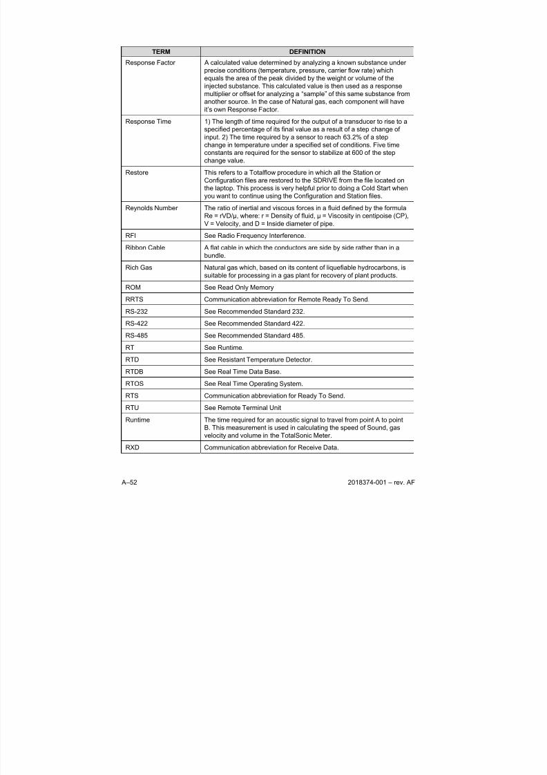
8/13/2019 2018374 m Naf
http://slidepdf.com/reader/full/2018374-m-naf 160/174
A–52 2018374-001 – rev. AF
TERM DEFINITION
Response Factor A calculated value determined by analyzing a known substance under
precise conditions (temperature, pressure, carrier flow rate) which
equals the area of the peak divided by the weight or volume of the
injected substance. This calculated value is then used as a response
multiplier or offset for analyzing a “sample” of this same substance from
another source. In the case of Natural gas, each component will haveit’s own Response Factor.
Response Time 1) The length of time required for the output of a transducer to rise to a
specified percentage of its final value as a result of a step change of
input. 2) The time required by a sensor to reach 63.2% of a step
change in temperature under a specified set of conditions. Five time
constants are required for the sensor to stabilize at 600 of the step
change value.
Restore This refers to a Totalflow procedure in which all the Station or
Configuration files are restored to the SDRIVE from the file located on
the laptop. This process is very helpful prior to doing a Cold Start when
you want to continue using the Configuration and Station files.Reynolds Number The ratio of inertial and viscous forces in a fluid defined by the formula
Re = rVD/µ, where: r = Density of fluid, µ = Viscosity in centipoise (CP),
V = Velocity, and D = Inside diameter of pipe.
RFI See Radio Frequency Interference.
Ribbon Cable A flat cable in which the conductors are side by side rather than in a
bundle.
Rich Gas Natural gas which, based on its content of liquefiable hydrocarbons, is
suitable for processing in a gas plant for recovery of plant products.
ROM See Read Only Memory
RRTS Communication abbreviation for Remote Ready To Send.
RS-232 See Recommended Standard 232.
RS-422 See Recommended Standard 422.
RS-485 See Recommended Standard 485.
RT See Runtime.
RTD See Resistant Temperature Detector.
RTDB See Real Time Data Base.
RTOS See Real Time Operating System.
RTS Communication abbreviation for Ready To Send.RTU See Remote Terminal Unit
Runtime The time required for an acoustic signal to travel from point A to point
B. This measurement is used in calculating the speed of Sound, gas
velocity and volume in the TotalSonic Meter.
RXD Communication abbreviation for Receive Data.
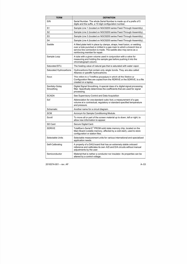
8/13/2019 2018374 m Naf
http://slidepdf.com/reader/full/2018374-m-naf 161/174
2018374-001 – rev. AF A–53
TERM DEFINITION
S/N Serial Number. The whole Serial Number is made up of a prefix of 5
digits and the suffix, a 10 digit configuration number.
S1 Sample Line 1 (located on NGC8200 series Feed-Through Assembly).
S2 Sample Line 2 (located on NGC8200 series Feed-Through Assembly).
S3 Sample Line 3 (located on NGC8200 series Feed-Through Assembly).
S4 Sample Line 4 (located on NGC8200 series Feed-Through Assembly).
Saddle A fitted plate held in place by clamps, straps, heat fusion, or welding
over a hole punched or drilled in a gas main to which a branch line or
service line connection is made. The saddle also may serve as a
reinforcing member for repair.
Sample Loop A tube with a given volume used in conjunction with a valve for
measuring and holding the sample gas before pushing it into the
chromatograph column.
Saturated BTU The heating value of natural gas that is saturated with water vapor.
Saturated Hydrocarbons Hydrocarbons that contain only single bonds. They are also called
Alkanes or paraffin hydrocarbons.
Save This refers to a Totalflow procedure in which all the Station or
Configuration files are copied from the RDRIVE or the SDRIVE, to a file
created on a laptop.
Savitsky-Golay
Smoothing
Digital Signal Smoothing. A special class of a digital signal processing
filter. Specifically determines the coefficients that are used for signal
processing.
SCADA See Supervisory Control and Data Acquisition
Scf Abbreviation for one standard cubic foot, a measurement of a gas
volume at a contractual, regulatory or standard specified temperature
and pressure.
Schematic Another name for a circuit diagram.
SCM Acronym for Sample Conditioning Module.
Scroll To move all or part of the screen material up to down, left or right, to
allow new information to appear.
SD Card Secure Digital Card.
SDRIVE Totalflow’s Serial E2 PROM solid state memory chip, located on the
Main Board (volatile memory, affected by a cold start), used to store
configuration or station files.
Selectable Units Selectable measurement units for various international and specialized
application needs.
Self-Calibrating A property of a DAQ board that has an extremely stable onboard
reference and calibrates its own A/D and D/A circuits without manual
adjustments by the user.
Semiconductor Material that is nether a conductor nor insulator. Its properties can be
altered by a control voltage.

8/13/2019 2018374 m Naf
http://slidepdf.com/reader/full/2018374-m-naf 162/174
A–54 2018374-001 – rev. AF
TERM DEFINITION
Sensing Element That part of the transducer which reacts directly in response to the
input.
Sensor A device that responds to a physical stimulus (heat, light, sound,
pressure, motion, flow, and so on), and produces a corresponding
electrical signal.
Sensor File The Sensor File contains all the setup/calibration information of the unit.
The Sensor File is a (.dat) file and by default is named after the base
serial number proceeded by an "s", such as s00108.dat. Although the
name can be overwritten, it is recommended that the default name be
kept.
Serial I/O A common form of data transmission, in which the bits of each
character are sent one at a time over the line.
Serial Port A communications interface that uses one data line to transfer data bits
sequentially. On the IBM PC the serial port refers to a standard
asynchronous serial interface which uses the 8250/16450/16550 family
of UARTs.Service Life The period of useful life (usually in hours or minutes) of a primary
cell/battery before a predetermined cut-off voltage is reached.
Set Point The temperature at which a controller is set to control a system.
Set-Point A "level" or control point in a feedback system.
SFC Sequential Function Chart (IEC supported programming language)
SG Acronym for Specific Gravity.
Short Circuit A connection of comparatively low resistance accidentally or
intentionally made between points on a circuit between which the
resistance is normally much greater. Also called a "bridge" or "short"
such as when solder from two tracks touch on a PC board.
Shrinkage The reduction in volume and/or heating value of a natural gas stream
due to extraction or removal of some of its components.
SIG See Signal.
Signal Any communication between message-based devices consisting of a
write to a signal register.
Signal Generator A circuit that produces a variable and controllable signal.
Signed Integer Can represent a number half the size of a “unsigned integer”, including
a negative number.
Sink Device such as a load that consumes power or conducts away heat.Skip Days Extra Daily records for recording events that require the start of a new
day. i.e. Volume Reset, Backward Time change over the hour, and
Contract Hour change.
SNAM Italy’s Certification Board
SNR Signal to Noise Ratio.
SoftCONTROL Softing’s IEC compiler environment
8/13/2019 2018374 m Naf
http://slidepdf.com/reader/full/2018374-m-naf 163/174
2018374-001 – rev. AF A–55
TERM DEFINITION
Softing Maker and distributor of the IEC compiler softCONTROL
Software The non-physical parts of a computer system that include computer
programs such as the operating system, high-level languages,
applications programs, etc.
Solar cell A cell that produces current under sunlight.
Solenoid A coil of wire that is long compared to its diameter, through which a
current will flow and produce a magnetic flux to push or pull a rod
(called an armature).
SOS See Speed of Sound.
Sour Gas Natural gas that has a high concentration of H2S.
Source Device that provides signal power or energy to a load.
SP See Static Pressure
Span The difference between the upper and lower limits of a range
expressed in the same units as the range.
Specific Gravity The ratio of the mass of a solid or liquid to the mass of an equal volume
of distilled water at 4°C (39°F) or of a gas to an equal volume of air or
hydrogen under prescribed conditions of temperature and pressure.
Also called relative density .
Speed of Gas Rate at which gas travels through the pipeline. Used in flow calculations
in the TotalSonic Meter. Calculations follow AGA 9 Report.
Speed of Sound Rate at which sound travels through the medium. Used in flow
calculations in the TotalSonic Meter. Calculations follow AGA 10
Report.
SPU Signal Processing Unit (measurement transducer).
SQL See Structured Query Language.
SRAM See Static Random Access Memory
SSM Acronym for Stream Selector Module.
ST Structured Text (IEC supported programming language)
Stability The quality of an instrument or sensor to maintain a consistent output
when a constant input is applied.
Stable Gas Is a vapor containing less than 0.1 PPM of liquid when vapor is cooled
to 18.3°F (10°C) below the coldest ambient temperature possible at any
point in the system.
Static Pressure Equals PSIA or PSIG. Referenced to atmospheric pressure versus
absolute pressure in a vacuum. It is defined as the pressure exerted by
a non-moving liquid or gas. In the case of a gas well this would be the
natural PSI of the gas inside of the well.
Static Random Access
Memory
The place in your computer that programs reside when running. You
can access any part of the memory, and it can easily be overwritten
with new values. SRAM is much more expensive and physically larger
than DRAM but much faster.
8/13/2019 2018374 m Naf
http://slidepdf.com/reader/full/2018374-m-naf 164/174
A–56 2018374-001 – rev. AF
TERM DEFINITION
Status Output Any digital output that uses “On” or “Off” conditions to determine the
status of the assigned description. Changing from one to the other
represents a change in the condition.
STP Standard Temperature and Pressure
Structured Query
Language
IBM developed this language in the 60’s as a way of accessing data
from a relational database. It has a very simple syntax for simple
functions but can become complex for sophisticated applications. This
language is standardized by international standards bodies, and is
almost universal in application. Almost all databases support SQL. The
RTDB supports SQL and this makes it extremely flexible within a
corporate network. Authorized users throughout the organization can
write SQL statements to acquire data from this database that they need
for Marketing, Accounting, Engineering, or other functions.
Sulfur A pale, yellow, non-metallic chemical element that may be found in a
gas stream and which needs to be removed or reduced from the gas
stream for corrosion control or health or safety reasons.
Supercompressibility
Factor
A factor used to account for the following effect: Boyle's law for gases
states that the specific weight of a gas is directly proportional to the
absolute pressure, the temperature remaining constant. All gases
deviate from this law by varying amounts, and within the range of
conditions ordinarily encountered in the natural gas industry, the actual
specific weight under the higher pressure is usually greater than the
theoretical. The factor used to reflect this deviation from the ideal gas
law in gas measurement with an orifice meter is called the
"Supercompressibility factor Fpv". The factor is used to calculate
corrected from volumes at standard temperatures and pressures. The
factor is of increasing importance at high pressures and low
temperatures.
Supervisory Control and
Data Acquisition
A common PC function in process control applications, where
programmable logic controllers (PLCs) perform control functions but are
monitored and supervised by a PC.
Surge A sudden change (usually an increase) in the voltage on a power line.
A surge is similar to a spike, but is of longer duration.
SV Sample Vent (located on NGC8200 series Feed-Through Assembly).
SW VBATT Switched Battery Voltage. Cycles power to equipment to save power.
Switch An electrical device for connecting and disconnecting power to a circuit,
having two states, on (closed) or off (open). Ideally having zero
impedance when closed and infinite impedance when open.
Synchronous (1) Hardware - A property of an event that is synchronized to a
reference clock. (2) Software - A property of a function that begins an
operation and returns only when the operation is complete.
Syntax Comparable to the grammar of a human language, syntax is the set of
rules used for forming statements in a particular programming
language.
8/13/2019 2018374 m Naf
http://slidepdf.com/reader/full/2018374-m-naf 165/174
2018374-001 – rev. AF A–57
TERM DEFINITION
System Noise A measure of the amount of noise seen by an analog circuit or an ADC
when the analog inputs are grounded.
TankMaster Totalflow Control System for LevelMaster Tank Units.
Tap To cut threads in a round hole so that other fittings or equipment can be
screwed into the hole. Also to make an opening in a vessel or pipe.
TBUS Communication abbreviation for Transmit Bus.
TCD See Thermal Conductivity Detector.
TCP/IP TCP/IP – This is the basic communication format for the Internet, and
for much of what happens on a corporate network. Virtually all
networked PCs and other computers have an “IP address” having the
format xxx.xxx.xxx.xxx (xxx can range from 0 to 255 in most cases).
You can see the IP address of your PC by going to the start menu,
selecting run, and entering cmd. A “DOS Box” will be displayed on your
screen. Type ipconfig to get the IP address. When you enter a URL
(e.g., www.totalflow.com) in a browser, a DNS server (on the network)
resolves this into an IP address and directs your request to the machinewith that address.
TCR Temperature Compensated Regulator.
TDS32 Totalflow DDE Server that allows Microsoft Windows applications with
DDE capabilities to communicate with Totalflow’s equipment. For
example data can be retrieved and placed in an Excel spreadsheet.
Temperature Coefficient An experimental number used to modify the calibration of a device
(Totalflow transducer) to account for changes in environmental
temperature.
Temperature Error The maximum change in output, at any measured value within the
specified range, when the transducer temperature is changed fromroom temperature to specified temperature extremes.
Temperature Range,
Compensated
The range of ambient temperatures within which all tolerances specified
for Thermal Zero Shift and Thermal Sensitivity Shift are applicable
(temperature error).
Temperature, Ambient The temperature of the air, atmosphere or other fluid that completely
surrounds the apparatus, equipment or the work piece under
consideration. For devices which do not generate heat, this
temperature is the same as the temperature of the medium at the point
of device location when the device is not present. For devices which do
generate heat, this temperature is the temperature of the medium
surrounding the device when the device is present and generating heat.
Allowable ambient-temperature limits are based on the assumption thatthe device in question is not exposed to significant radiant-energy
sources such as sunlight or heated surfaces.
Temperature, Flowing Temperature of the flowing fluid. Usually gas and measured by an RTD.
Terminal Mode Man-Machine interface tool used as and engineering interface with
equipment.
Termination Placement of a connector on a cable.
8/13/2019 2018374 m Naf
http://slidepdf.com/reader/full/2018374-m-naf 166/174
A–58 2018374-001 – rev. AF
TERM DEFINITION
Termination Panel The NGC8200’s termination panel acts as a connection to the outside
world. It features transient protection, a voltage regulator for the digital
controller, positive temperature co-efficient fuses (PTC) and many other
safeguards to protect the remainder of the system from electrical
damage. All outside communications and I/O are channeled through
this board. It is designed to be a low cost, field replaceablemaintenance solution and is designed to operate on either 12V or 24V.
Termination Panel A circuit board with screw terminals or other connector system that
allows convenient connection of field signals to a data acquisition or
communication system.
TF Loader Packages In PCCU32, the 32-Bit XSeries Loader is the program that allows for
the downloading of specific files to an NGC, XFC, XRC or µFLO
XSeries device. The 32-Bit XSeries Loader application allows packages
containing a combination of Flash, WinCE OS (nk.bin), ISaGraf
Runtime, Blackfin Firmware (NGC) and configuration files to be
downloaded to XFCs, XRCs, NGCs or µFLO machine types. These
same packages can be downloaded to other machines of the sametype to expedite configurations for machines having the same purpose.
With the creation of these packages, the user is then prevented from
accidentally loading incompatible packages to the wrong device.
TF.NET Totalflow network used to access web data.
TFIO Module Totalflow Input/Output module (i.e. quad AO)
Thermal Conductivity
Detector
Universal detector that shows a response to all compounds. An
electrical component that changes resistance based on the
components ability to conduct heat. In chromatography, two TCDs are
used, 1)as a reference detector and 2) as the sensor detector. The
reference detector is exposed to only the carrier gas and the Sensordetector is exposed to the sample.
Thermistor A temperature-sensing element composed of sintered semiconductor
material which exhibits a large change in resistance proportional to a
small change in temperature. Thermistors usually have negative
temperature coefficients.
Thermistor Bead See Thermal Conductivity Detector.
Thermocouple A temperature sensor created by joining two dissimilar metals. The
junction produces a small voltage as a function of the temperature.
Thermowell A closed-end tube designed to protect temperature sensors from harsh
environments, high pressure, and flows. They can be installed into a
system by pipe thread or welded flange and are usually made ofcorrosion-resistant metal or ceramic material depending upon the
application.
Therms Master Totalflow application for Gas Analyzer.
Tolerance The allowable percentage variation of any component from that stated
on its body.
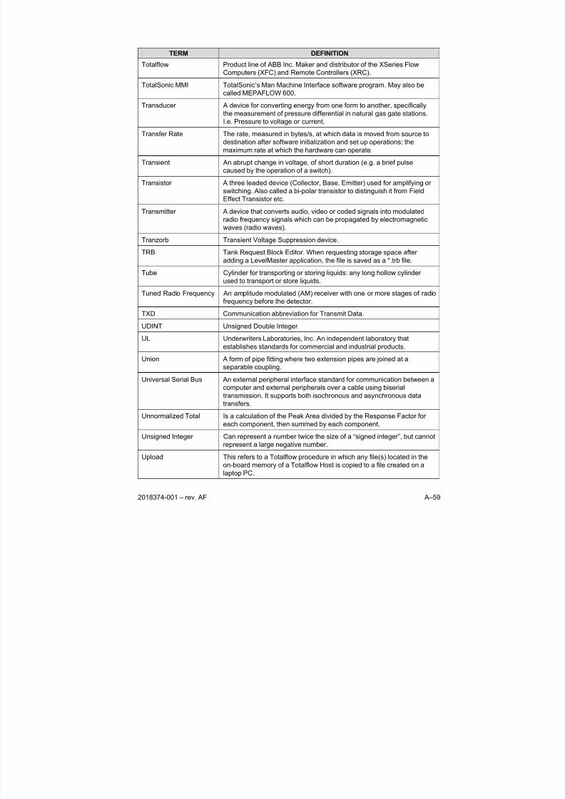
8/13/2019 2018374 m Naf
http://slidepdf.com/reader/full/2018374-m-naf 167/174
2018374-001 – rev. AF A–59
TERM DEFINITION
Totalflow Product line of ABB Inc. Maker and distributor of the XSeries Flow
Computers (XFC) and Remote Controllers (XRC).
TotalSonic MMI TotalSonic’s Man Machine Interface software program. May also be
called MEPAFLOW 600.
Transducer A device for converting energy from one form to another, specifically
the measurement of pressure differential in natural gas gate stations.
I.e. Pressure to voltage or current.
Transfer Rate The rate, measured in bytes/s, at which data is moved from source to
destination after software initialization and set up operations; the
maximum rate at which the hardware can operate.
Transient An abrupt change in voltage, of short duration (e.g. a brief pulse
caused by the operation of a switch).
Transistor A three leaded device (Collector, Base, Emitter) used for amplifying or
switching. Also called a bi-polar transistor to distinguish it from Field
Effect Transistor etc.
Transmitter A device that converts audio, video or coded signals into modulated
radio frequency signals which can be propagated by electromagnetic
waves (radio waves).
Tranzorb Transient Voltage Suppression device.
TRB Tank Request Block Editor. When requesting storage space after
adding a LevelMaster application, the file is saved as a *.trb file.
Tube Cylinder for transporting or storing liquids: any long hollow cylinder
used to transport or store liquids.
Tuned Radio Frequency An amplitude modulated (AM) receiver with one or more stages of radio
frequency before the detector.
TXD Communication abbreviation for Transmit Data.
UDINT Unsigned Double Integer
UL Underwriters Laboratories, Inc. An independent laboratory that
establishes standards for commercial and industrial products.
Union A form of pipe fitting where two extension pipes are joined at a
separable coupling.
Universal Serial Bus An external peripheral interface standard for communication between a
computer and external peripherals over a cable using biserial
transmission. It supports both isochronous and asynchronous data
transfers.
Unnormalized Total Is a calculation of the Peak Area divided by the Response Factor for
each component, then summed by each component.
Unsigned Integer Can represent a number twice the size of a “signed integer”, but cannot
represent a large negative number.
Upload This refers to a Totalflow procedure in which any file(s) located in the
on-board memory of a Totalflow Host is copied to a file created on a
laptop PC.
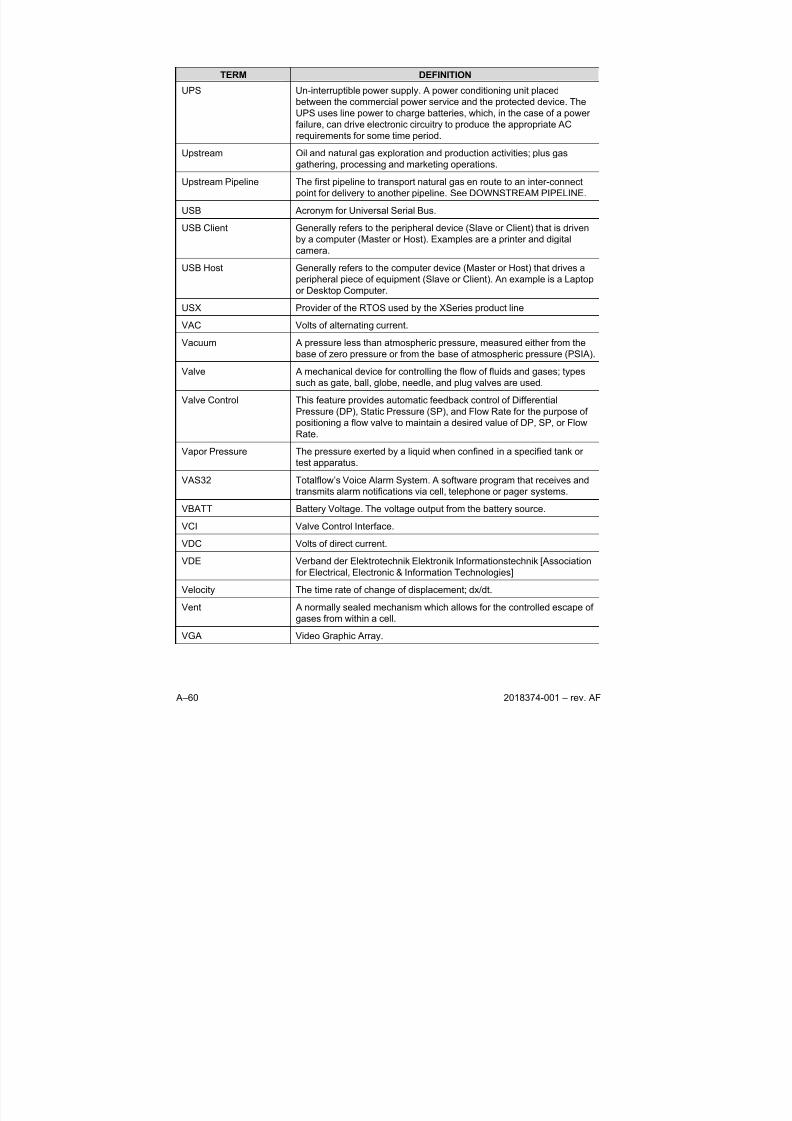
8/13/2019 2018374 m Naf
http://slidepdf.com/reader/full/2018374-m-naf 168/174
A–60 2018374-001 – rev. AF
TERM DEFINITION
UPS Un-interruptible power supply. A power conditioning unit placed
between the commercial power service and the protected device. The
UPS uses line power to charge batteries, which, in the case of a power
failure, can drive electronic circuitry to produce the appropriate AC
requirements for some time period.
Upstream Oil and natural gas exploration and production activities; plus gas
gathering, processing and marketing operations.
Upstream Pipeline The first pipeline to transport natural gas en route to an inter-connect
point for delivery to another pipeline. See DOWNSTREAM PIPELINE.
USB Acronym for Universal Serial Bus.
USB Client Generally refers to the peripheral device (Slave or Client) that is driven
by a computer (Master or Host). Examples are a printer and digital
camera.
USB Host Generally refers to the computer device (Master or Host) that drives a
peripheral piece of equipment (Slave or Client). An example is a Laptop
or Desktop Computer.
USX Provider of the RTOS used by the XSeries product line
VAC Volts of alternating current.
Vacuum A pressure less than atmospheric pressure, measured either from the
base of zero pressure or from the base of atmospheric pressure (PSIA).
Valve A mechanical device for controlling the flow of fluids and gases; types
such as gate, ball, globe, needle, and plug valves are used.
Valve Control This feature provides automatic feedback control of Differential
Pressure (DP), Static Pressure (SP), and Flow Rate for the purpose of
positioning a flow valve to maintain a desired value of DP, SP, or Flow
Rate.
Vapor Pressure The pressure exerted by a liquid when confined in a specified tank or
test apparatus.
VAS32 Totalflow’s Voice Alarm System. A software program that receives and
transmits alarm notifications via cell, telephone or pager systems.
VBATT Battery Voltage. The voltage output from the battery source.
VCI Valve Control Interface.
VDC Volts of direct current.
VDE Verband der Elektrotechnik Elektronik Informationstechnik [Association
for Electrical, Electronic & Information Technologies]Velocity The time rate of change of displacement; dx/dt.
Vent A normally sealed mechanism which allows for the controlled escape of
gases from within a cell.
VGA Video Graphic Array.

8/13/2019 2018374 m Naf
http://slidepdf.com/reader/full/2018374-m-naf 169/174
2018374-001 – rev. AF A–61
TERM DEFINITION
Virtual Memory A method of making disk storage appear like RAM memory to the CPU,
thus allowing programs that need more RAM memory than is installed
to run in the system. This technique is slow compared to "real" memory.
Viscosity The inherent resistance of a substance to flow.
VOG Velocity of Gas.
Volatile Memory A storage medium that loses all data when power is removed.
Volt The unit of voltage or potential difference.. One thousand volts = 1kV.
Voltage Electrical pressure, the force, which causes current to flow through a
conductor. Voltage must be expressed as a difference of potential
between two points since it is a relational term. Connecting both
voltmeter leads to the same point will show no voltage present although
the voltage between that point and ground may be hundred or
thousands of volts.
Voltmeter A meter for reading voltage. It is one of the ranges in a multimeter.
Volume Calculation
Period
The specified length between reading and calculating volume data.
Volume Flow Rate Calculated using the area of the full closed conduit and the average
fluid velocity in the form, Q = V x A, to arrive at the total volume quantity
of flow. Q = volumetric flowrate, V = average fluid velocity, and A =
cross sectional area of the pipe.
VOS Velocity of Sound.
Warm Start A rebooting technique which will clear most operational errors, without
damaging either the data or configuration files. This causes the
equipment to boot from the Rdrive, which is a solid state memory chip.
Watt Symbol W. The unit of power. One watt is the product of one volt andone amp. Power (W) = Current (I) X Energy (E). (E = Volts)
Wavelength The distance between two points of corresponding phase in
consecutive cycles
Web Page All the text, graphics, and sound visible with a single access to a Web
site; what you see when you request a particular URL.
Web Server The hardware and software required to make Web pages available for
delivery to others on networks connected with yours.
Web Site A collection of electronic "pages" of information on a Web server
Well, Development A well drilled in order to obtain production of gas or oil known to exist.
Well, Disposal A deep well in which to inject waste chemicals, etc., such as a well todispose of salt brine from the solution mining of salt dome gas storage
caverns.
Well, Exploratory A well drilled to a previously untested geologic structure to determine
the presence of oil or gas.
Well, Gas A well which produces at surface conditions the contents of a gas
reservoir; legal definitions vary among the states.
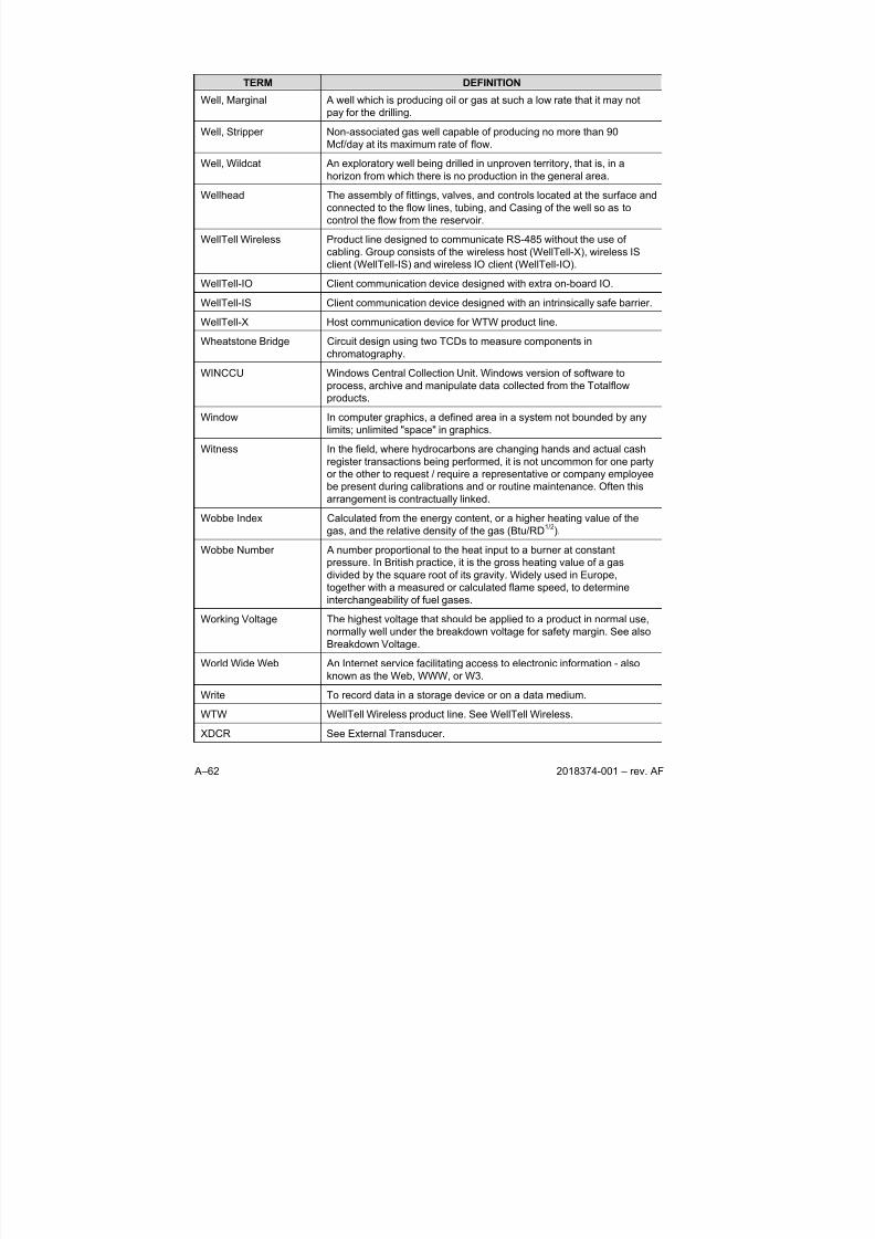
8/13/2019 2018374 m Naf
http://slidepdf.com/reader/full/2018374-m-naf 170/174
A–62 2018374-001 – rev. AF
TERM DEFINITION
Well, Marginal A well which is producing oil or gas at such a low rate that it may not
pay for the drilling.
Well, Stripper Non-associated gas well capable of producing no more than 90
Mcf/day at its maximum rate of flow.
Well, Wildcat An exploratory well being drilled in unproven territory, that is, in a
horizon from which there is no production in the general area.
Wellhead The assembly of fittings, valves, and controls located at the surface and
connected to the flow lines, tubing, and Casing of the well so as to
control the flow from the reservoir.
WellTell Wireless Product line designed to communicate RS-485 without the use of
cabling. Group consists of the wireless host (WellTell-X), wireless IS
client (WellTell-IS) and wireless IO client (WellTell-IO).
WellTell-IO Client communication device designed with extra on-board IO.
WellTell-IS Client communication device designed with an intrinsically safe barrier.
WellTell-X Host communication device for WTW product line.
Wheatstone Bridge Circuit design using two TCDs to measure components in
chromatography.
WINCCU Windows Central Collection Unit. Windows version of software to
process, archive and manipulate data collected from the Totalflow
products.
Window In computer graphics, a defined area in a system not bounded by any
limits; unlimited "space" in graphics.
Witness In the field, where hydrocarbons are changing hands and actual cash
register transactions being performed, it is not uncommon for one party
or the other to request / require a representative or company employeebe present during calibrations and or routine maintenance. Often this
arrangement is contractually linked.
Wobbe Index Calculated from the energy content, or a higher heating value of the
gas, and the relative density of the gas (Btu/RD1/2
).
Wobbe Number A number proportional to the heat input to a burner at constant
pressure. In British practice, it is the gross heating value of a gas
divided by the square root of its gravity. Widely used in Europe,
together with a measured or calculated flame speed, to determine
interchangeability of fuel gases.
Working Voltage The highest voltage that should be applied to a product in normal use,
normally well under the breakdown voltage for safety margin. See alsoBreakdown Voltage.
World Wide Web An Internet service facilitating access to electronic information - also
known as the Web, WWW, or W3.
Write To record data in a storage device or on a data medium.
WTW WellTell Wireless product line. See WellTell Wireless.
XDCR See External Transducer.
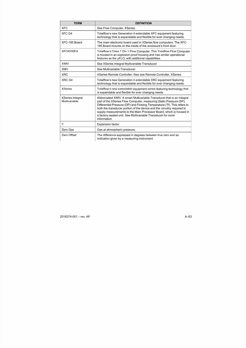
8/13/2019 2018374 m Naf
http://slidepdf.com/reader/full/2018374-m-naf 171/174
2018374-001 – rev. AF A–63
TERM DEFINITION
XFC See Flow Computer, XSeries.
XFC G4 Totalflow’s new Generation 4 extendable XFC equipment featuring
technology that is expandable and flexible for ever changing needs.
XFC-195 Board The main electronic board used in XSeries flow computers. The XFC-
195 Board mounts on the inside of the enclosure’s front door.
XFC6200EX Totalflow’s Class 1 Div 1 Flow Computer. This Totalflow Flow Computer
is housed in an explosion proof housing and has similar operational
features as the μ FLO, with additional capabilities.
XIMV See XSeries Integral Multivariable Transducer.
XMV See Multivariable Transducer.
XRC XSeries Remote Controller. Also see Remote Controller, XSeries.
XRC G4 Totalflow’s new Generation 4 extendable XRC equipment featuring
technology that is expandable and flexible for ever changing needs.
XSeries Totalflow’s new extendable equipment series featuring technology thatis expandable and flexible for ever changing needs.
XSeries Integral
Multivariable
Abbreviated XIMV. A smart Multivariable Transducer that is an integral
part of the XSeries Flow Computer, measuring Static Pressure (SP),
Differential Pressure (DP) and Flowing Temperature (Tf). This refers to
both the transducer portion of the device and the circuitry required to
supply measurements to the Main Processor Board, which is housed in
a factory sealed unit. See Multivariable Transducer for more
information.
Y Expansion factor.
Zero Gas Gas at atmospheric pressure.
Zero Offset The difference expressed in degrees between true zero and an
indication given by a measuring instrument.

8/13/2019 2018374 m Naf
http://slidepdf.com/reader/full/2018374-m-naf 172/174
A–64 2018374-001 – rev. AF
BBBlllaaannnkkk PPPaaagggeee

8/13/2019 2018374 m Naf
http://slidepdf.com/reader/full/2018374-m-naf 173/174
2018374-001 – rev. AF B–1
APPENDIX B DRAWINGS SECTION
This section of the manual has been provided as a location for the user to place
the drawings that accompanies the new Totalflow units.
Totalflow recommends that a complete set of all drawings that accompany a unit
be placed in this section. This would ensure that the user have only drawingsapplicable to their units and drawings that are at the latest revision level.

8/13/2019 2018374 m Naf
http://slidepdf.com/reader/full/2018374-m-naf 174/174