Embed Size (px)
Citation preview
National Standard Plumbing Code Committee __________________________________________________________
2018 PROPOSED
CHANGES National Standard
Plumbing Code (NSPC) Proposed Code Changes
_____________________________________ March 9, 2017
Tropicana Casino and Resort Brighton and the Boardwalk Atlantic City, New Jersey
_________________________________________________________________________________________________
180 S. Washington St. Ste 100 Falls Church, VA 22046
1-800-533-7694, Fax: 703-237-7442, e-mail: [email protected], URL: http://www.phccweb.org/nspc

National Standard Plumbing Code Committee
180 S. Washington St. Ste 100 Falls Church, VA 22046 1-800-533-7694, Fax: 703-237-7442, e-mail: [email protected], URL: http://www.phccweb.org/nspc
January 30, 2017 The National Standard Plumbing Code Committee will conduct a Public Hearing on Proposed Changes to the Code. This Hearing will be held March 9, 2017 at the Tropicana Casino and Resort in Atlantic City, New Jersey. The public is invited to attend and comment will be allowed on the Proposed Changes. Adopted changes shall be published in the 2018 National Standard Plumbing Code. There will be an 8:00 A.M. start of the Public Hearing in the Bongo Room. A lunch break will be called at noon and the meeting will reconvene at 1:00 P.M. or as directed by the Chairman. An afternoon break will be provided with the meeting scheduled to conclude at 5:00 P.M.
Hotel accommodations are available through the Tropicana Casino and Resort, mention the Plumbing-Heating-Cooling Contractors—National Association meeting for group rate availability. The hotel may be contacted by calling 800-247-8767.
The Proposed Changes are available to download from the PHCC—National Association website, phccweb.org, for review. Hard copy of the Proposed Changes book shall be available at the Hearing location.
For questions or further information, contact Charles White, Code Secretariat, at 800-533-7694 or by e-mail, [email protected].

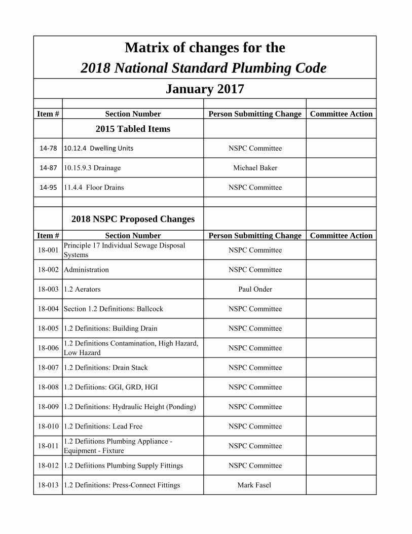
Item # Section Number Person Submitting Change Committee Action
2015 Tabled Items
14-78 10.12.4 Dwelling Units NSPC Committee
14-87 10.15.9.3 Drainage Michael Baker
14-95 11.4.4 Floor Drains NSPC Committee
2018 NSPC Proposed Changes
Item # Section Number Person Submitting Change Committee Action
18-001 Principle 17 Individual Sewage Disposal Systems NSPC Committee
18-002 Administration NSPC Committee
18-003 1.2 Aerators Paul Onder
18-004 Section 1.2 Definitions: Ballcock NSPC Committee
18-005 1.2 Definitions: Building Drain NSPC Committee
18-006 1.2 Definitions Contamination, High Hazard, Low Hazard NSPC Committee
18-007 1.2 Definitions: Drain Stack NSPC Committee
18-008 1.2 Defiitions: GGI, GRD, HGI NSPC Committee
18-009 1.2 Definitions: Hydraulic Height (Ponding) NSPC Committee
18-010 1.2 Definitions: Lead Free NSPC Committee
18-011 1.2 Defiitions Plumbing Appliance - Equipment - Fixture NSPC Committee
18-012 1.2 Defiitions Plumbing Supply Fittings NSPC Committee
18-013 1.2 Definitions: Press-Connect Fittings Mark Fasel
Matrix of changes for the2018 National Standard Plumbing Code
January 2017
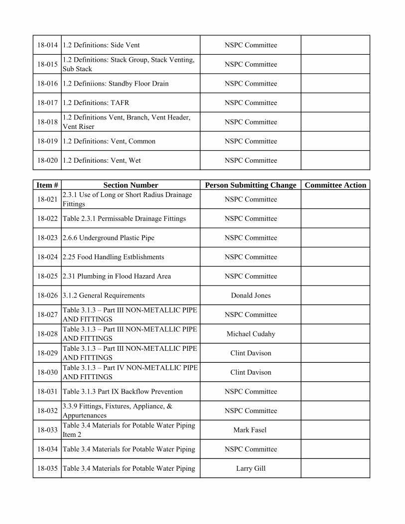
18-014 1.2 Definitions: Side Vent NSPC Committee
18-015 1.2 Definitions: Stack Group, Stack Venting, Sub Stack NSPC Committee
18-016 1.2 Definiions: Standby Floor Drain NSPC Committee
18-017 1.2 Definitions: TAFR NSPC Committee
18-018 1.2 Definitions Vent, Branch, Vent Header, Vent Riser NSPC Committee
18-019 1.2 Definitions: Vent, Common NSPC Committee
18-020 1.2 Definitions: Vent, Wet NSPC Committee
Item # Section Number Person Submitting Change Committee Action
18-021 2.3.1 Use of Long or Short Radius Drainage Fittings NSPC Committee
18-022 Table 2.3.1 Permissable Drainage Fittings NSPC Committee
18-023 2.6.6 Underground Plastic Pipe NSPC Committee
18-024 2.25 Food Handling Estblishments NSPC Committee
18-025 2.31 Plumbing in Flood Hazard Area NSPC Committee
18-026 3.1.2 General Requirements Donald Jones
18-027 Table 3.1.3 – Part III NON-METALLIC PIPE AND FITTINGS NSPC Committee
18-028 Table 3.1.3 – Part III NON-METALLIC PIPE AND FITTINGS Michael Cudahy
18-029 Table 3.1.3 – Part III NON-METALLIC PIPE AND FITTINGS Clint Davison
18-030 Table 3.1.3 – Part IV NON-METALLIC PIPE AND FITTINGS Clint Davison
18-031 Table 3.1.3 Part IX Backflow Prevention NSPC Committee
18-032 3.3.9 Fittings, Fixtures, Appliance, & Appurtenances NSPC Committee
18-033 Table 3.4 Materials for Potable Water Piping Item 2 Mark Fasel
18-034 Table 3.4 Materials for Potable Water Piping NSPC Committee
18-035 Table 3.4 Materials for Potable Water Piping Larry Gill
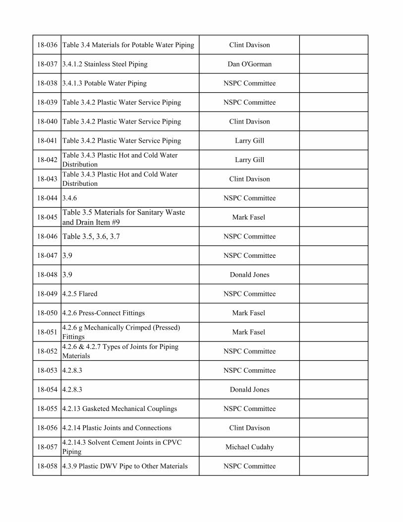
18-036 Table 3.4 Materials for Potable Water Piping Clint Davison
18-037 3.4.1.2 Stainless Steel Piping Dan O'Gorman
18-038 3.4.1.3 Potable Water Piping NSPC Committee
18-039 Table 3.4.2 Plastic Water Service Piping NSPC Committee
18-040 Table 3.4.2 Plastic Water Service Piping Clint Davison
18-041 Table 3.4.2 Plastic Water Service Piping Larry Gill
18-042 Table 3.4.3 Plastic Hot and Cold Water Distribution Larry Gill
18-043 Table 3.4.3 Plastic Hot and Cold Water Distribution Clint Davison
18-044 3.4.6 NSPC Committee
18-045 Table 3.5 Materials for Sanitary Waste and Drain Item #9
Mark Fasel
18-046 Table 3.5, 3.6, 3.7 NSPC Committee
18-047 3.9 NSPC Committee
18-048 3.9 Donald Jones
18-049 4.2.5 Flared NSPC Committee
18-050 4.2.6 Press-Connect Fittings Mark Fasel
18-051 4.2.6 g Mechanically Crimped (Pressed) Fittings Mark Fasel
18-052 4.2.6 & 4.2.7 Types of Joints for Piping Materials NSPC Committee
18-053 4.2.8.3 NSPC Committee
18-054 4.2.8.3 Donald Jones
18-055 4.2.13 Gasketed Mechanical Couplings NSPC Committee
18-056 4.2.14 Plastic Joints and Connections Clint Davison
18-057 4.2.14.3 Solvent Cement Joints in CPVC Piping Michael Cudahy
18-058 4.3.9 Plastic DWV Pipe to Other Materials NSPC Committee
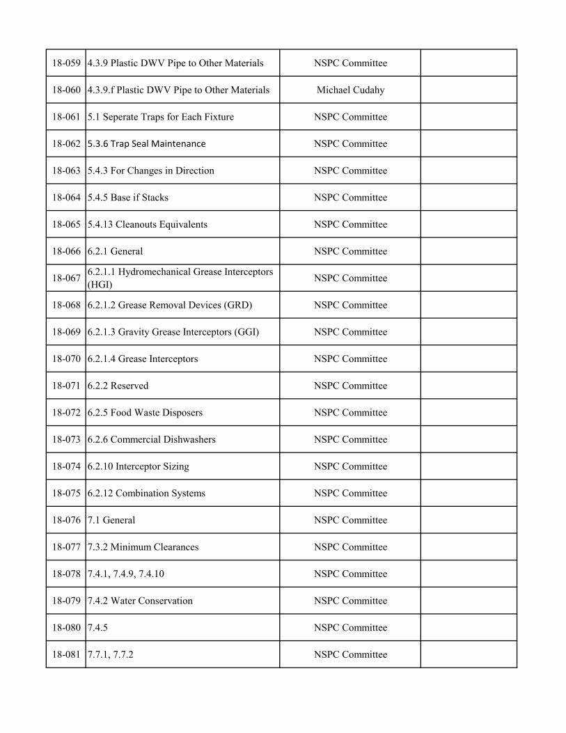
18-059 4.3.9 Plastic DWV Pipe to Other Materials NSPC Committee
18-060 4.3.9.f Plastic DWV Pipe to Other Materials Michael Cudahy
18-061 5.1 Seperate Traps for Each Fixture NSPC Committee
18-062 5.3.6 Trap Seal Maintenance NSPC Committee
18-063 5.4.3 For Changes in Direction NSPC Committee
18-064 5.4.5 Base if Stacks NSPC Committee
18-065 5.4.13 Cleanouts Equivalents NSPC Committee
18-066 6.2.1 General NSPC Committee
18-067 6.2.1.1 Hydromechanical Grease Interceptors (HGI) NSPC Committee
18-068 6.2.1.2 Grease Removal Devices (GRD) NSPC Committee
18-069 6.2.1.3 Gravity Grease Interceptors (GGI) NSPC Committee
18-070 6.2.1.4 Grease Interceptors NSPC Committee
18-071 6.2.2 Reserved NSPC Committee
18-072 6.2.5 Food Waste Disposers NSPC Committee
18-073 6.2.6 Commercial Dishwashers NSPC Committee
18-074 6.2.10 Interceptor Sizing NSPC Committee
18-075 6.2.12 Combination Systems NSPC Committee
18-076 7.1 General NSPC Committee
18-077 7.3.2 Minimum Clearances NSPC Committee
18-078 7.4.1, 7.4.9, 7.4.10 NSPC Committee
18-079 7.4.2 Water Conservation NSPC Committee
18-080 7.4.5 NSPC Committee
18-081 7.7.1, 7.7.2 NSPC Committee
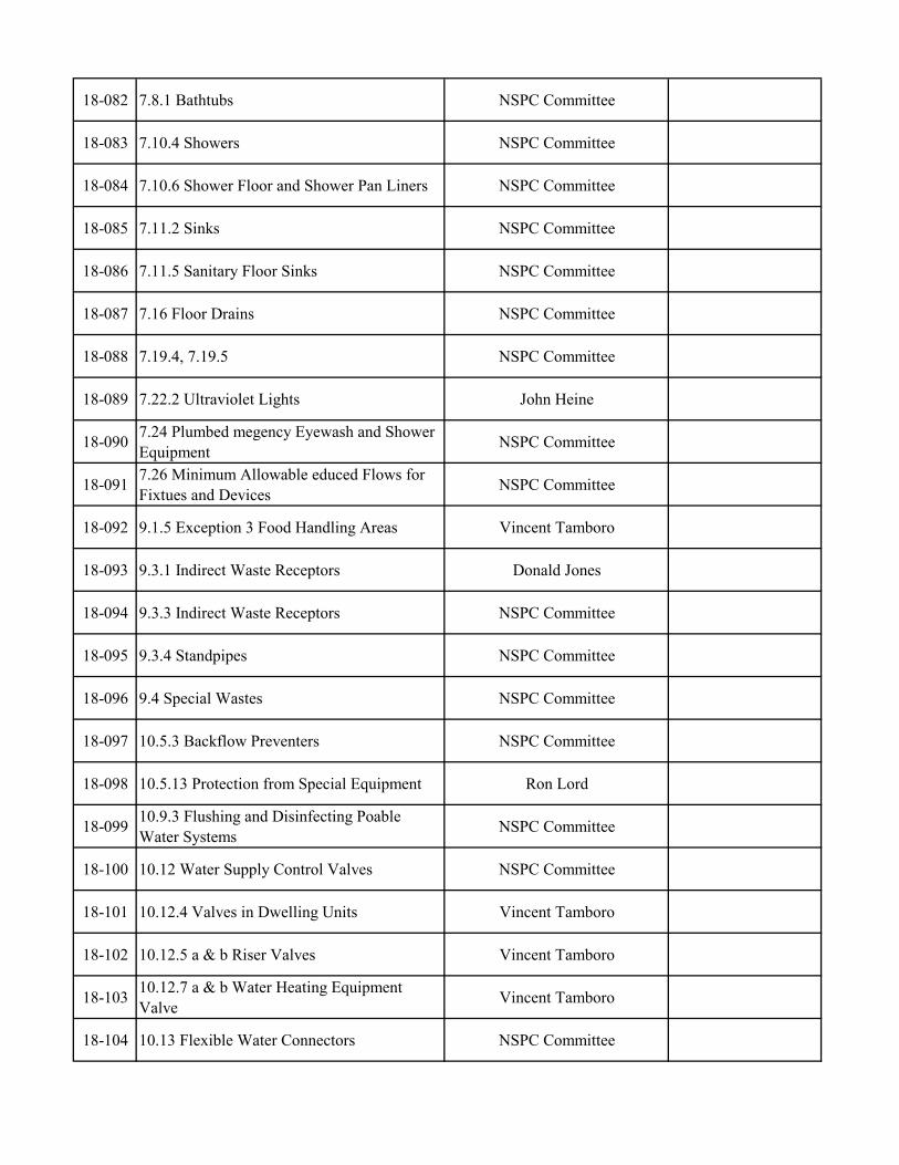
18-082 7.8.1 Bathtubs NSPC Committee
18-083 7.10.4 Showers NSPC Committee
18-084 7.10.6 Shower Floor and Shower Pan Liners NSPC Committee
18-085 7.11.2 Sinks NSPC Committee
18-086 7.11.5 Sanitary Floor Sinks NSPC Committee
18-087 7.16 Floor Drains NSPC Committee
18-088 7.19.4, 7.19.5 NSPC Committee
18-089 7.22.2 Ultraviolet Lights John Heine
18-090 7.24 Plumbed megency Eyewash and Shower Equipment NSPC Committee
18-091 7.26 Minimum Allowable educed Flows for Fixtues and Devices NSPC Committee
18-092 9.1.5 Exception 3 Food Handling Areas Vincent Tamboro
18-093 9.3.1 Indirect Waste Receptors Donald Jones
18-094 9.3.3 Indirect Waste Receptors NSPC Committee
18-095 9.3.4 Standpipes NSPC Committee
18-096 9.4 Special Wastes NSPC Committee
18-097 10.5.3 Backflow Preventers NSPC Committee
18-098 10.5.13 Protection from Special Equipment Ron Lord
18-099 10.9.3 Flushing and Disinfecting Poable Water Systems NSPC Committee
18-100 10.12 Water Supply Control Valves NSPC Committee
18-101 10.12.4 Valves in Dwelling Units Vincent Tamboro
18-102 10.12.5 a & b Riser Valves Vincent Tamboro
18-103 10.12.7 a & b Water Heating Equipment Valve Vincent Tamboro
18-104 10.13 Flexible Water Connectors NSPC Committee
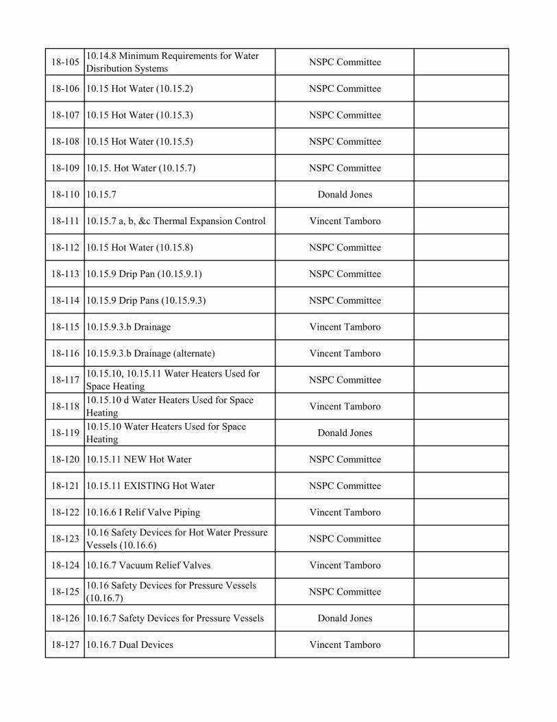
18-105 10.14.8 Minimum Requirements for Water Disribution Systems NSPC Committee
18-106 10.15 Hot Water (10.15.2) NSPC Committee
18-107 10.15 Hot Water (10.15.3) NSPC Committee
18-108 10.15 Hot Water (10.15.5) NSPC Committee
18-109 10.15. Hot Water (10.15.7) NSPC Committee
18-110 10.15.7 Donald Jones
18-111 10.15.7 a, b, &c Thermal Expansion Control Vincent Tamboro
18-112 10.15 Hot Water (10.15.8) NSPC Committee
18-113 10.15.9 Drip Pan (10.15.9.1) NSPC Committee
18-114 10.15.9 Drip Pans (10.15.9.3) NSPC Committee
18-115 10.15.9.3.b Drainage Vincent Tamboro
18-116 10.15.9.3.b Drainage (alternate) Vincent Tamboro
18-117 10.15.10, 10.15.11 Water Heaters Used for Space Heating NSPC Committee
18-118 10.15.10 d Water Heaters Used for Space Heating Vincent Tamboro
18-119 10.15.10 Water Heaters Used for Space Heating Donald Jones
18-120 10.15.11 NEW Hot Water NSPC Committee
18-121 10.15.11 EXISTING Hot Water NSPC Committee
18-122 10.16.6 I Relif Valve Piping Vincent Tamboro
18-123 10.16 Safety Devices for Hot Water Pressure Vessels (10.16.6) NSPC Committee
18-124 10.16.7 Vacuum Relief Valves Vincent Tamboro
18-125 10.16 Safety Devices for Pressure Vessels (10.16.7) NSPC Committee
18-126 10.16.7 Safety Devices for Pressure Vessels Donald Jones
18-127 10.16.7 Dual Devices Vincent Tamboro
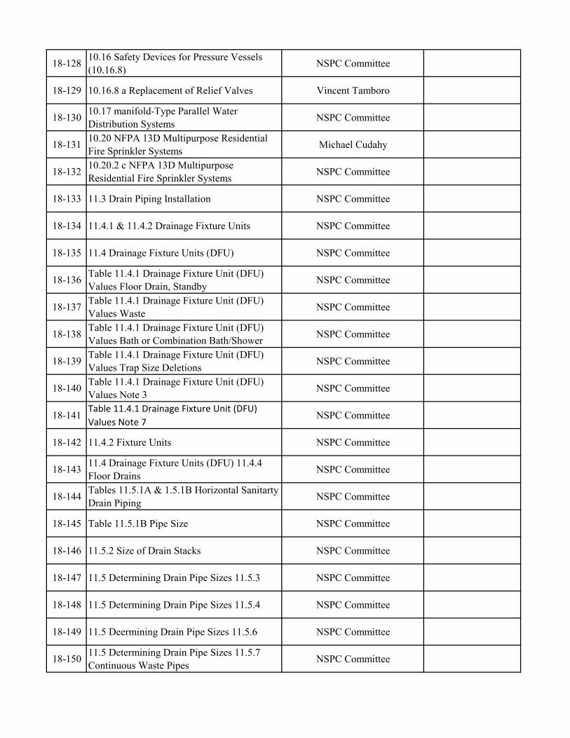
18-128 10.16 Safety Devices for Pressure Vessels (10.16.8) NSPC Committee
18-129 10.16.8 a Replacement of Relief Valves Vincent Tamboro
18-130 10.17 manifold-Type Parallel Water Distribution Systems NSPC Committee
18-131 10.20 NFPA 13D Multipurpose Residential Fire Sprinkler Systems Michael Cudahy
18-132 10.20.2 c NFPA 13D Multipurpose Residential Fire Sprinkler Systems NSPC Committee
18-133 11.3 Drain Piping Installation NSPC Committee
18-134 11.4.1 & 11.4.2 Drainage Fixture Units NSPC Committee
18-135 11.4 Drainage Fixture Units (DFU) NSPC Committee
18-136 Table 11.4.1 Drainage Fixture Unit (DFU) Values Floor Drain, Standby NSPC Committee
18-137 Table 11.4.1 Drainage Fixture Unit (DFU) Values Waste NSPC Committee
18-138 Table 11.4.1 Drainage Fixture Unit (DFU) Values Bath or Combination Bath/Shower NSPC Committee
18-139 Table 11.4.1 Drainage Fixture Unit (DFU) Values Trap Size Deletions NSPC Committee
18-140 Table 11.4.1 Drainage Fixture Unit (DFU) Values Note 3 NSPC Committee
18-141Table 11.4.1 Drainage Fixture Unit (DFU) Values Note 7
NSPC Committee
18-142 11.4.2 Fixture Units NSPC Committee
18-143 11.4 Drainage Fixture Units (DFU) 11.4.4 Floor Drains NSPC Committee
18-144 Tables 11.5.1A & 1.5.1B Horizontal Sanitarty Drain Piping NSPC Committee
18-145 Table 11.5.1B Pipe Size NSPC Committee
18-146 11.5.2 Size of Drain Stacks NSPC Committee
18-147 11.5 Determining Drain Pipe Sizes 11.5.3 NSPC Committee
18-148 11.5 Determining Drain Pipe Sizes 11.5.4 NSPC Committee
18-149 11.5 Deermining Drain Pipe Sizes 11.5.6 NSPC Committee
18-150 11.5 Determining Drain Pipe Sizes 11.5.7 Continuous Waste Pipes NSPC Committee
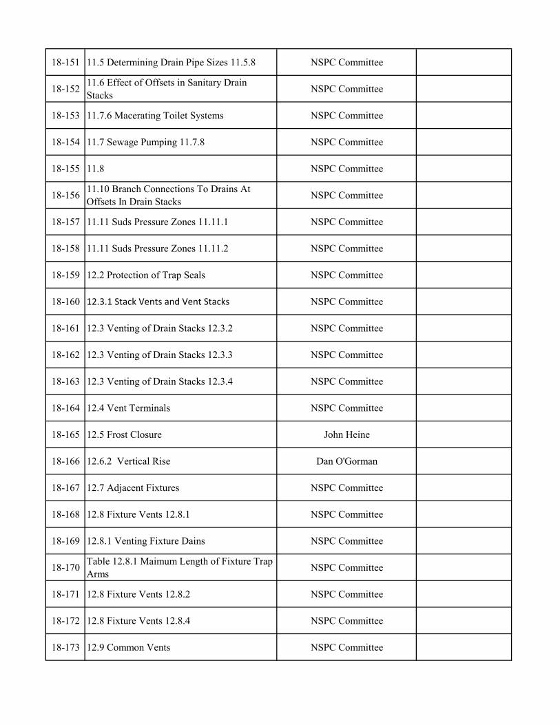
18-151 11.5 Determining Drain Pipe Sizes 11.5.8 NSPC Committee
18-152 11.6 Effect of Offsets in Sanitary Drain Stacks NSPC Committee
18-153 11.7.6 Macerating Toilet Systems NSPC Committee
18-154 11.7 Sewage Pumping 11.7.8 NSPC Committee
18-155 11.8 NSPC Committee
18-156 11.10 Branch Connections To Drains At Offsets In Drain Stacks NSPC Committee
18-157 11.11 Suds Pressure Zones 11.11.1 NSPC Committee
18-158 11.11 Suds Pressure Zones 11.11.2 NSPC Committee
18-159 12.2 Protection of Trap Seals NSPC Committee
18-160 12.3.1 Stack Vents and Vent Stacks NSPC Committee
18-161 12.3 Venting of Drain Stacks 12.3.2 NSPC Committee
18-162 12.3 Venting of Drain Stacks 12.3.3 NSPC Committee
18-163 12.3 Venting of Drain Stacks 12.3.4 NSPC Committee
18-164 12.4 Vent Terminals NSPC Committee
18-165 12.5 Frost Closure John Heine
18-166 12.6.2 Vertical Rise Dan O'Gorman
18-167 12.7 Adjacent Fixtures NSPC Committee
18-168 12.8 Fixture Vents 12.8.1 NSPC Committee
18-169 12.8.1 Venting Fixture Dains NSPC Committee
18-170 Table 12.8.1 Maimum Length of Fixture Trap Arms NSPC Committee
18-171 12.8 Fixture Vents 12.8.2 NSPC Committee
18-172 12.8 Fixture Vents 12.8.4 NSPC Committee
18-173 12.9 Common Vents NSPC Committee
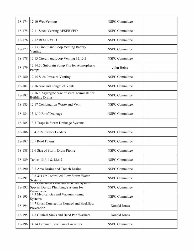
18-174 12.10 Wet Venting NSPC Committee
18-175 12.11 Stack Venting RESERVED NSPC Committee
18-176 12.12 RESERVED NSPC Committee
18-177 12.13 Circuit and Loop Venting Battery Venting NSPC Committee
18-178 12.13 Circuit and Loop Venting 12.13.2 NSPC Committee
18-179 12.14.2b Subdrain Sump Pits for Atmospheric Pumps John Heine
18-180 12.15 Suds Pressure Venting NSPC Committee
18-181 12.16 Size and Length of Vents NSPC Committee
18-182 12.16.8 Aggregate Size of Vent Terminals for Building Drains NSPC Committee
18-183 12.17 Combination Waste and Vent NSPC Committee
18-184 13.1.10 Roof Drainage NSPC Committee
18-185 13.3 Traps in Storm Drainage Systems
18-186 13.4.2 Rainwater Leaders NSPC Committee
18-187 13.5 Roof Drains NSPC Committee
18-188 13.6 Size of Storm Drain Piping NSPC Committee
18-189 Tables 13.6.1 & 13.6.2 NSPC Committee
18-190 13.7 Area Drains and Trench Drains NSPC Committee
18-191 13.8 & 13.9 Controlled Flow Storm Water Systems NSPC Committee
18-19213.9 Controlled Flow Storm Water System Special Design Plumbing Systems for Stormwater
NSPC Committee
18-193 14.3 Medical Gas and Vacuum Piping Systems NSPC Committee
18-194 14.7 Cross Connection Control and Backflow Prevention Donald Jones
18-195 14.8 Clinical Sinks and Bend Pan Washers Donald Jones
18-196 14.14 Laminar Flow Faucet Aerators NSPC Committee
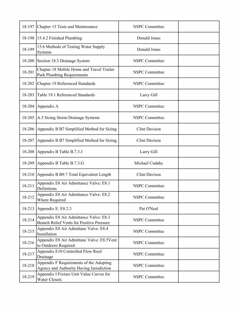
18-197 Chapter 15 Tests and Maintenance NSPC Committee
18-198 15.4.2 Finished Plumbing Donald Jones
18-199 15.6 Methods of Testing Water Supply Systems Donald Jones
18-200 Section 18.3 Drainage System NSPC Committee
18-201 Chapter 18 Mobile Home and Travel Trailer Park Plumbing Requirements NSPC Committee
18-202 Chapter 19 Referenced Standards NSPC Committee
18-203 Table 19.1 Referenced Standards Larry Gill
18-204 Appendix A NSPC Committee
18-205 A.5 Sizing Storm Drainage Systems NSPC Committee
18-206 Appendix B B7 Simplified Method for Sizing Clint Davison
18-207 Appendix B B7 Simplified Method for Sizing Clint Davison
18-208 Appendix B Table B.7.3.J Larry Gill
18-209 Appendix B Table B.7.3.G Michael Cudahy
18-210 Appendix B B9.7 Total Equivalent Length Clint Davison
18-211 Appendix E8 Air Admittance Valve: E8.1 Definitions NSPC Committee
18-212 Appendix E8 Air Admittance Valve: E8.2 Where Required NSPC Committee
18-213 Appendix E: E8.2.3 Pat O'Neal
18-214 Appendix E8 Air Admittance Valve: E8.3 Branch Relief Vents for Positive Pressure NSPC Committee
18-215 Appendix E8 Air Admittanc Valve: E8.4 Installation NSPC Committee
18-216 Appendix E8 Air Admittanc Valve: E8.5Vent to Outdoors Required NSPC Committee
18-217 Appendix E10 Controlled Flow Roof Drainage NSPC Committee
18-218 Appendix F Requirements of the Adopting Agency and Authority Having Jurisdiction NSPC Committee
18-219 Appendix I Fixture Unit Value Curves for Water Closets NSPC Committee
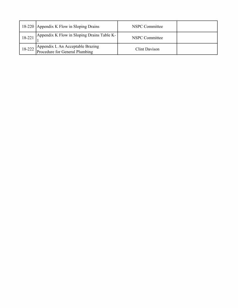
18-220 Appendix K Flow in Sloping Drains NSPC Committee
18-221 Appendix K Flow in Sloping Drains Table K-1 NSPC Committee
18-222 Appendix L An Acceptable Brazing Procedure for General Plumbing Clint Davison

National Standard Plumbing Code Committee __________________________________________________________
2014 TABLED ITEMS
National Standard Plumbing Code (NSPC)
Proposed Code Changes
_________________________________________________________________________________________________
180 S. Washington St. Ste. 100 Falls Church, VA 22046 1-800-533-7694, Fax: 703-237-7442, e-mail: [email protected], URL: http://www.phccweb.org/nspc

14-78
National Standard Plumbing Code 2015 Proposed Code Change Form
14 - 78
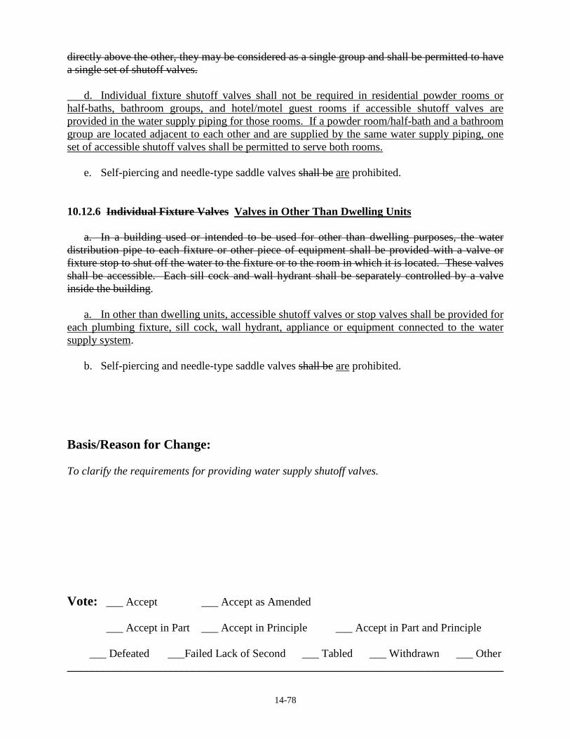
Contact Information: Person Submitting Change NSPC Committee Date 04-05-2014 . Mailing Address 180 S. Washington Street, P.O. Box 6808 . City/State/Zip Falls Church, VA 22046 . Phone 1-800-533-7694 Fax 1-703-237-7442 E-mail [email protected] Check All That Apply: ___ Amend section with this editorial change __X_ Change subsection to read as follows ____ Delete subsection and substitute as follows ____ Add new subsection to read as follows ____ Delete subsection without substitution Code Section: 10.12 WATER SUPPLY CONTROL SHUTOFF VALVES 10.12.4 Valves in Dwelling Units a. In single dwelling units, the building valve required by Section 10.12.2 shall shutoff the water supply to all fixtures and outlets. b. In multiple dwelling units, one or more shutoff valves shall be provided in the main water supply piping or main branches in each dwelling unit so that the water supply to any plumbing fixture or group of fixtures in for that dwelling unit can be shutoff without stopping the water supply to fixtures in other dwelling units. These valves shall be accessible in the dwelling unit that they control. c. Except as permitted in Section 10.12.4.d in residential powder rooms or half-baths, bathroom groups, and hotel/motel guest rooms, individual fixture shutoff or stop valves shall be provided for water closets, lavatories, kitchen sinks, laundry trays tubs and sinks, bar sinks, bidets, clothes washing machines, sill cocks, wall hydrants, appliances, and equipment connected to the water supply system. Valves for fixtures, appliances, and equipment shall be accessible without having to move the appliance or equipment, except for ice makers. EXCEPTION: Appliances shall be permitted to be moved for access to shutoff valves for ice
makers. d. Unless individual fixture shutoff valves are provided for fixtures in powder rooms or bathroom groups in accordance with Section 10.12.4.c, shutoff valves may be provided for the each powder room or bathroom group in lieu of individual fixture shutoff valves. In individual dwelling units where powder rooms or bathroom groups are located adjacent to each other or one
14-78
directly above the other, they may be considered as a single group and shall be permitted to have a single set of shutoff valves. d. Individual fixture shutoff valves shall not be required in residential powder rooms or half-baths, bathroom groups, and hotel/motel guest rooms if accessible shutoff valves are provided in the water supply piping for those rooms. If a powder room/half-bath and a bathroom group are located adjacent to each other and are supplied by the same water supply piping, one set of accessible shutoff valves shall be permitted to serve both rooms. e. Self-piercing and needle-type saddle valves shall be are prohibited. 10.12.6 Individual Fixture Valves Valves in Other Than Dwelling Units a. In a building used or intended to be used for other than dwelling purposes, the water distribution pipe to each fixture or other piece of equipment shall be provided with a valve or fixture stop to shut off the water to the fixture or to the room in which it is located. These valves shall be accessible. Each sill cock and wall hydrant shall be separately controlled by a valve inside the building. a. In other than dwelling units, accessible shutoff valves or stop valves shall be provided for each plumbing fixture, sill cock, wall hydrant, appliance or equipment connected to the water supply system. b. Self-piercing and needle-type saddle valves shall be are prohibited. Basis/Reason for Change: To clarify the requirements for providing water supply shutoff valves. Vote: ___ Accept ___ Accept as Amended
___ Accept in Part ___ Accept in Principle ___ Accept in Part and Principle
___ Defeated ___Failed Lack of Second ___ Tabled ___ Withdrawn ___ Other ______________________________________________________________________________
National Standard Plumbing Code 2015 Proposed Code Change Form Deadline April 30, 2014
14 - 87
14-87
Contact Information: Person Submitting Change 2 _____ Michael G. Baker____________ Date 3 ___March 12, 2014___ Jurisdiction/Company/ Mailing Address __President, New Jersey Plumbing Inspectors Association _______________ City/State/Zip __475 Valley Rd. Wayne, NJ 07470______________________________ Phone __973.694.1800x3287 Fax __973.709.0209 E-mail ____ [email protected] IMPORTANT: Please review the attached instruction sheet regarding proposed code changes. Check All That Apply: _____ Amend section with this editorial change _____ Change subsection to read as follows _____ Delete subsection and substitute as follows _XX Add new subsection to read as follows _____ Delete subsection without substitution Code Section: 10.15.9.3 Drainage c. Water Heaters without legs shall be required to be raised as to not diminish the capacity of the pan Basis/Reason for Change: The placement of water heaters directly in a pan severely limits its capacity Vote: ___ Accept ___ Accept as Amended
___ Accept in Part ___ Accept in Principle ___ Accept in Part and Principle
___ Defeated ___Failed Lack of Second ___ Tabled ___ Withdrawn ___ Other ____________________________________________________________________________________
14-95
National Standard Plumbing Code 2015 Proposed Code Change Form
14 - 95
Contact Information: Person Submitting Change NSPC Committee Date 04-29-2014 . Mailing Address 180 S. Washington Street, P.O. Box 6808 . City/State/Zip Falls Church, VA 22046 . Phone 1-800-533-7694 Fax 1-703-237-7442 E-mail [email protected] Check All That Apply: ___ Amend section with this editorial change __X_ Change subsection to read as follows ____ Delete subsection and substitute as follows ____ Add new subsection to read as follows ____ Delete subsection without substitution Code Section: 11.4 FIXTURE UNITS 11.4.4 Floor Drains a. Floor drains shall be sized in accordance with this Section. The minimum size for floor drains is 2” pipe size. b. Floor drains that handle indirect waste shall be sized based on the total drainage fixture units (DFU) that they receive. c. Where floor drains receive a predicable flow in gallons per minute (GPM), they shall be sized according to Table 11.4.1 as an unlisted drain with extended discharge. Their drainage fixture unit (DFU) load shall be based on Table 11.4.2. d. Where floor drains are general purpose, their drainage fixture unit (DFU) load shall be based on their installed drain pipe size as indicated for an unlisted fixture in Table 11.4.1. e. Floor drains associated with emergency fixtures in Section 7.24 shall be sized for the GPM discharge capacity of the emergency fixtures, but the drainage fixture unit (DFU) load on the sanitary drainage system shall be zero (0.0 DFU). The discharge pipe size for such floor drains shall be the minimum size for all downstream drain piping.
14-95
Table 5.2 MINIMUM SIZE OF NON-INTEGRAL TRAPS
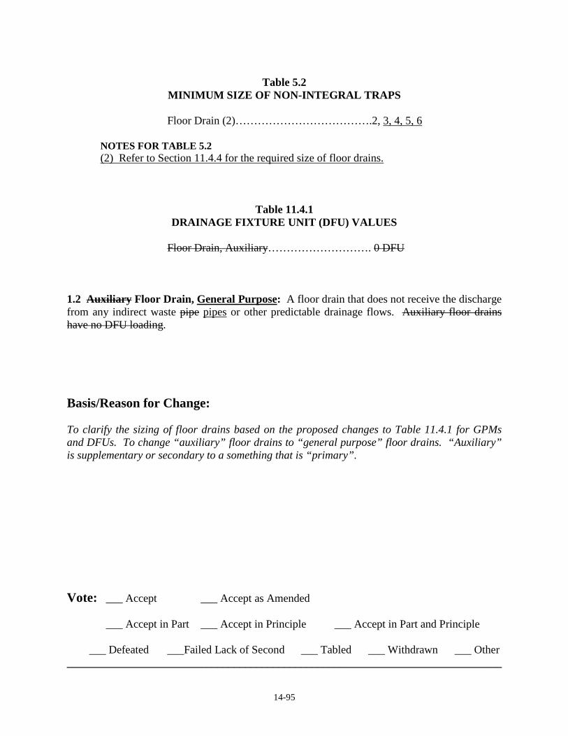
Floor Drain (2)……………………………….2, 3, 4, 5, 6 NOTES FOR TABLE 5.2 (2) Refer to Section 11.4.4 for the required size of floor drains.
Table 11.4.1 DRAINAGE FIXTURE UNIT (DFU) VALUES
Floor Drain, Auxiliary………………………. 0 DFU 1.2 Auxiliary Floor Drain, General Purpose: A floor drain that does not receive the discharge from any indirect waste pipe pipes or other predictable drainage flows. Auxiliary floor drains have no DFU loading. Basis/Reason for Change: To clarify the sizing of floor drains based on the proposed changes to Table 11.4.1 for GPMs and DFUs. To change “auxiliary” floor drains to “general purpose” floor drains. “Auxiliary” is supplementary or secondary to a something that is “primary”. Vote: ___ Accept ___ Accept as Amended
___ Accept in Part ___ Accept in Principle ___ Accept in Part and Principle
___ Defeated ___Failed Lack of Second ___ Tabled ___ Withdrawn ___ Other ______________________________________________________________________________

National Standard Plumbing Code Committee __________________________________________________________
2018 PROPOSED
CHANGES
_________________________________________________________________________________________________
180 S. Washington St. Ste 100 Falls Church, VA 22046 1-800-533-7694, Fax: 703-237-7442, e-mail: [email protected], URL: http://www.phccweb.org/nspc

National Standard Plumbing Code 2018 Proposed Code Change Form
-
Principle No.17 page 1 of 1 6-28-2015
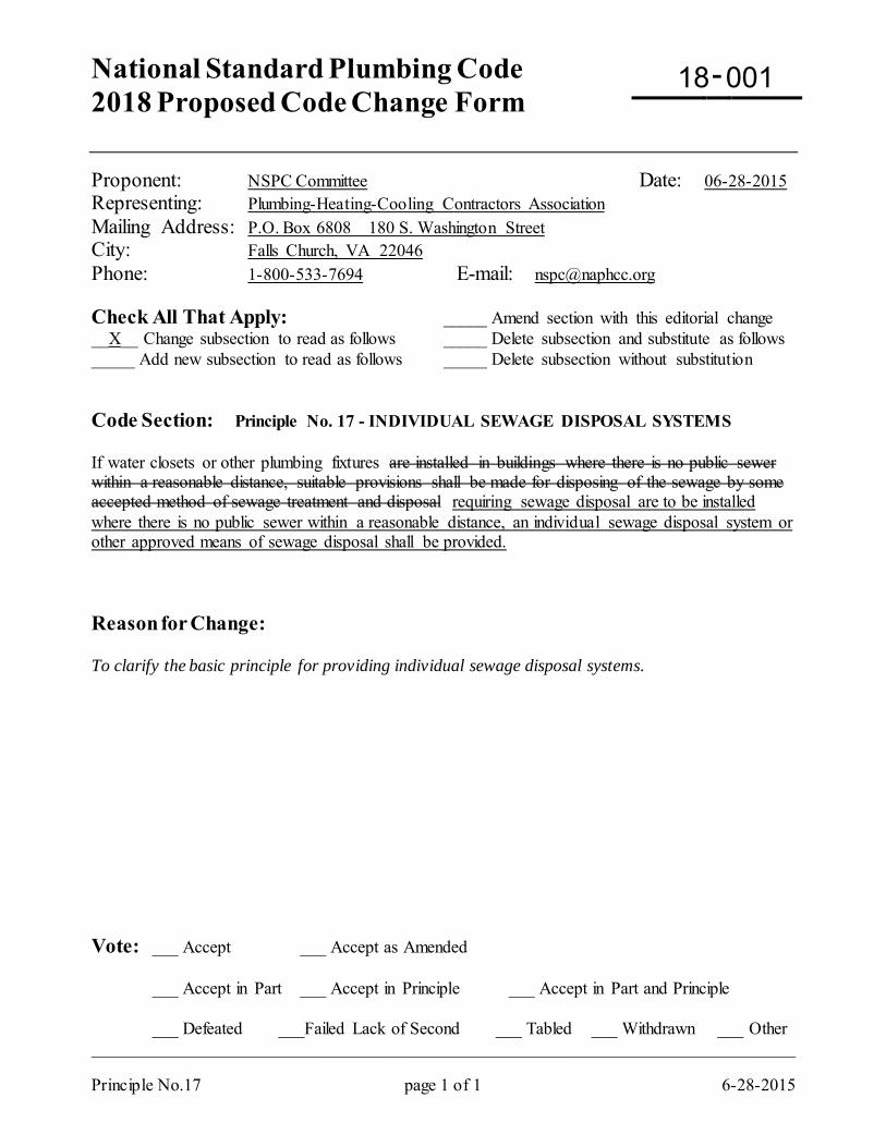
Proponent: NSPC Committee Date: 06-28-2015 Representing: Plumbing-Heating-Cooling Contractors Association Mailing Address: P.O. Box 6808 180 S. Washington Street City: Falls Church, VA 22046 Phone: 1-800-533-7694 E-mail: [email protected] Check All That Apply: _____ Amend section with this editorial change __X__ Change subsection to read as follows _____ Delete subsection and substitute as follows _____ Add new subsection to read as follows _____ Delete subsection without substitution Code Section: Principle No. 17 - INDIVIDUAL SEWAGE DISPOSAL SYSTEMS If water closets or other plumbing fixtures are installed in buildings where there is no public sewer within a reasonable distance, suitable provisions shall be made for disposing of the sewage by some accepted method of sewage treatment and disposal requiring sewage disposal are to be installed where there is no public sewer within a reasonable distance, an individual sewage disposal system or other approved means of sewage disposal shall be provided. Reason for Change: To clarify the basic principle for providing individual sewage disposal systems. Vote: ___ Accept ___ Accept as Amended
___ Accept in Part ___ Accept in Principle ___ Accept in Part and Principle
___ Defeated ___Failed Lack of Second ___ Tabled ___ Withdrawn ___ Other _________________________________________________________________________________
18 001
National Standard Plumbing Code 2018 Proposed Code Change Form
-
ADM Chapter page 1 of 10 6-22-2016
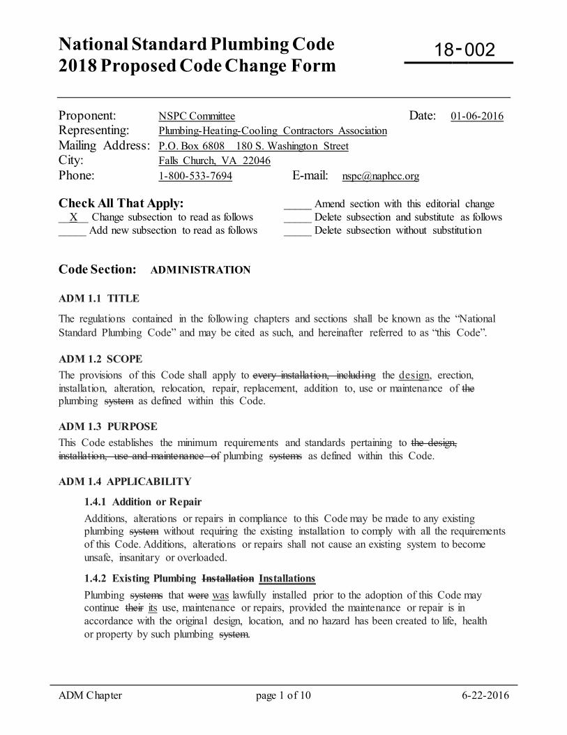
Proponent: NSPC Committee Date: 01-06-2016 Representing: Plumbing-Heating-Cooling Contractors Association Mailing Address: P.O. Box 6808 180 S. Washington Street City: Falls Church, VA 22046 Phone: 1-800-533-7694 E-mail: [email protected] Check All That Apply: _____ Amend section with this editorial change __X__ Change subsection to read as follows _____ Delete subsection and substitute as follows _____ Add new subsection to read as follows _____ Delete subsection without substitution Code Section: ADMINISTRATION
ADM 1.1 TITLE
The regulations contained in the following chapters and sections shall be known as the “National Standard Plumbing Code” and may be cited as such, and hereinafter referred to as “this Code”. ADM 1.2 SCOPE The provisions of this Code shall apply to every installation, including the design, erection, installation, alteration, relocation, repair, replacement, addition to, use or maintenance of the plumbing system as defined within this Code. ADM 1.3 PURPOSE This Code establishes the minimum requirements and standards pertaining to the design, installation, use and maintenance of plumbing systems as defined within this Code. ADM 1.4 APPLICABILITY
1.4.1 Addition or Repair Additions, alterations or repairs in compliance to this Code may be made to any existing plumbing system without requiring the existing installation to comply with all the requirements of this Code. Additions, alterations or repairs shall not cause an existing system to become unsafe, insanitary or overloaded.
1.4.2 Existing Plumbing Installation Installations Plumbing systems that were was lawfully installed prior to the adoption of this Code may continue their its use, maintenance or repairs, provided the maintenance or repair is in accordance with the original design, location, and no hazard has been created to life, health or property by such plumbing system.
18 002
ADM Chapter page 2 of 10 6-22-2016
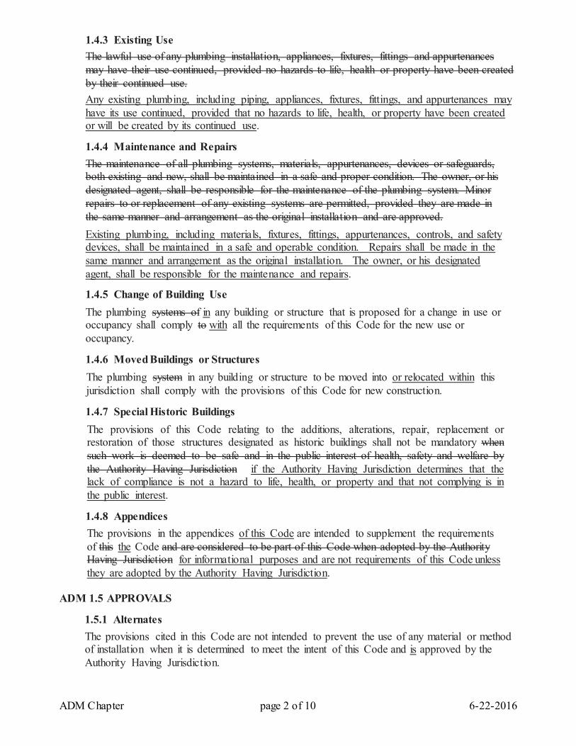
1.4.3 Existing Use The lawful use of any plumbing installation, appliances, fixtures, fittings and appurtenances may have their use continued, provided no hazards to life, health or property have been created by their continued use. Any existing plumbing, including piping, appliances, fixtures, fittings, and appurtenances may have its use continued, provided that no hazards to life, health, or property have been created or will be created by its continued use.
1.4.4 Maintenance and Repairs The maintenance of all plumbing systems, materials, appurtenances, devices or safeguards, both existing and new, shall be maintained in a safe and proper condition. The owner, or his designated agent, shall be responsible for the maintenance of the plumbing system. Minor repairs to or replacement of any existing systems are permitted, provided they are made in the same manner and arrangement as the original installation and are approved. Existing plumbing, including materials, fixtures, fittings, appurtenances, controls, and safety devices, shall be maintained in a safe and operable condition. Repairs shall be made in the same manner and arrangement as the original installation. The owner, or his designated agent, shall be responsible for the maintenance and repairs.
1.4.5 Change of Building Use The plumbing systems of in any building or structure that is proposed for a change in use or occupancy shall comply to with all the requirements of this Code for the new use or occupancy.
1.4.6 Moved Buildings or Structures The plumbing system in any building or structure to be moved into or relocated within this jurisdiction shall comply with the provisions of this Code for new construction.
1.4.7 Special Historic Buildings The provisions of this Code relating to the additions, alterations, repair, replacement or restoration of those structures designated as historic buildings shall not be mandatory when such work is deemed to be safe and in the public interest of health, safety and welfare by the Authority Having Jurisdiction if the Authority Having Jurisdiction determines that the lack of compliance is not a hazard to life, health, or property and that not complying is in the public interest.
1.4.8 Appendices The provisions in the appendices of this Code are intended to supplement the requirements of this the Code and are considered to be part of this Code when adopted by the Authority Having Jurisdiction for informational purposes and are not requirements of this Code unless they are adopted by the Authority Having Jurisdiction.
ADM 1.5 APPROVALS
1.5.1 Alternates The provisions cited in this Code are not intended to prevent the use of any material or method of installation when it is determined to meet the intent of this Code and is approved by the Authority Having Jurisdiction.
ADM Chapter page 3 of 10 6-22-2016
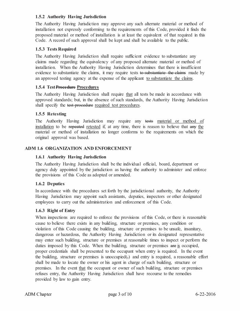
1.5.2 Authority Having Jurisdiction The Authority Having Jurisdiction may approve any such alternate material or method of installation not expressly conforming to the requirements of this Code, provided it finds the proposed material or method of installation is at least the equivalent of that required in this Code. A record of such approval shall be kept and shall be available to the public.
1.5.3 Tests Required The Authority Having Jurisdiction shall require sufficient evidence to substantiate any claims made regarding the equivalency of any proposed alternate material or method of installation. When the Authority Having Jurisdiction determines that there is insufficient evidence to substantiate the claims, it may require tests to substantiate the claims made by an approved testing agency at the expense of the applicant to substantiate the claims.
1.5.4 Test Procedure Procedures The Authority Having Jurisdiction shall require that all tests be made in accordance with approved standards; but, in the absence of such standards, the Authority Having Jurisdiction shall specify the test procedure required test procedures.
1.5.5 Retesting The Authority Having Jurisdiction may require any tests material or method of installation to be repeated retested if, at any time, there is reason to believe that any the material or method of installation no longer conforms to the requirements on which the original approval was based.
ADM 1.6 ORGANIZATION AND ENFORCEMENT
1.6.1 Authority Having Jurisdiction The Authority Having Jurisdiction shall be the individual official, board, department or agency duly appointed by the jurisdiction as having the authority to administer and enforce the provisions of this Code as adopted or amended.
1.6.2 Deputies In accordance with the procedures set forth by the jurisdictional authority, the Authority Having Jurisdiction may appoint such assistants, deputies, inspectors or other designated employees to carry out the administration and enforcement of this Code.
1.6.3 Right of Entry When inspections are required to enforce the provisions of this Code, or there is reasonable cause to believe there exists in any building, structure or premises, any condition or violation of this Code causing the building, structure or premises to be unsafe, insanitary, dangerous or hazardous, the Authority Having Jurisdiction or its designated representative may enter such building, structure or premises at reasonable times to inspect or perform the duties imposed by this Code. When the building, structure or premises are is occupied, proper credentials shall be presented to the occupant when entry is required. In the event the building, structure or premises is unoccupied(,) and entry is required, a reasonable effort shall be made to locate the owner or his agent in charge of such building, structure or premises. In the event that the occupant or owner of such building, structure or premises refuses entry, the Authority Having Jurisdiction shall have recourse to the remedies provided by law to gain entry.
ADM Chapter page 4 of 10 6-22-2016
1.6.4 Stop Work Order Upon notice from the Authority Having Jurisdiction, work being done on any building, structure or premises contrary to the provisions of this Code, or in an unsafe and dangerous manner, shall be stopped immediately . The stop work notice shall be in writing, served on the owner of the property, or his agent, or to the person doing such work. It shall state the conditions under which the Authority Having Jurisdiction may grant authorization to proceed with the work.
1.6.5 Authority to Condemn When the Authority Having Jurisdiction determines that any plumbing system or portion thereof that is regulated by this Code has become insanitary or hazardous to life, health or property, it shall order in writing that such plumbing system or portion thereof be repaired, replaced or removed so as to be in code compliance. The written order shall fix a reasonable time limit for the work to be brought into code compliance, and no person shall use the condemned plumbing system until such work is complete and approved by the Authority Having Jurisdiction.
1.6.6 Authority to Abate Any plumbing system, or portion thereof that is found to be insanitary or constitute a hazard to life, health or property is hereby declared to be a nuisance. Where a nuisance exists, the Authority Having Jurisdiction shall require the nuisance to be abated and shall seek such abatement in the manner prescribed by law.
1.6.7 1.6.6 Liability The Authority Having Jurisdiction, or any individual duly appointed or authorized by the Authority Having Jurisdiction to enforce this Code, acting in good faith and without malice, shall not thereby be rendered personally liable for any damage that may occur to persons or property as a result of any act, or by reason of any act or omission in the lawful discharge of his duties. Should a suit be brought against the Authority Having Jurisdiction or duly appointed representative because of such act or omission, it shall be defended by legal counsel provided by this jurisdiction until final termination of the proceedings.
1.6.8 1.6.7 Work Prior to Permit Where work for which a permit is required by this Code is started prior to obtaining the prescribed permit, the applicant shall pay a double fee an additional fee in accordance with Section 1.10.1. In the event of an emergency where it is absolutely necessary to perform the plumbing work immediately, such as nights, weekends or holidays, said additional fee shall not be doubled charged if a permit is secured at the earliest possible time after the emergency plumbing work has been performed.
ADM 1.7 VIOLATIONS AND PENALTIES
1.7.1 Violations It shall be unlawful for any individual, partnership, firm or corporation to, or cause to, install, construct, erect, alter, repair, improve, convert, move, use or maintain any plumbing system in violation of this Code.
ADM Chapter page 5 of 10 6-22-2016
1.7.2 Penalties Any individual, partnership, firm or corporation who shall violate or fail to comply with any of the requirements of this Code shall be deemed guilty of a , and if convicted, shall be punishable by a fine or imprisonment or both as established by this jurisdiction. Each day during which a violation occurs or continues, shall constitute a separate offense.
ADM 1.8 PERMITS
1.8.1 Permits Required It shall be unlawful for any individual, partnership, firm or corporation to commence, or cause to commence, any installation, alteration, repair, replacement, conversion or addition to any plumbing system, or part thereof, regulated by this Code, except as permitted in Section 1.8.2, without first obtaining a plumbing permit for each separate building or structure, on forms prepared and provided by the Authority Having Jurisdiction.
1.8.2 Permits Not Required for the Following a. Permits shall not be required for the following work:
1. The stoppage of leaks in drains or vent pipes water, drain, or vent piping. However, should the defect necessitate removal and replacement with new material, it shall constitute new work and a permit shall be obtained and inspection made as required in this Code.
2. The clearing of stoppages or obstructions to flow. 3. The repairing of leaks in valves or fixtures. 4. The removing and reinstallation of a water closet for a cleanout opening provided the reinstallation does not require replacement or rearrangement of valves, pipes or new fixtures. 5. The repair of faucets and adjustment or replacement of water closet parts.
b. Exemptions from obtaining a permit required by this Code shall not be construed as to authorize any work to be performed in violation of this Code.
ADM 1.9 PROCESS FOR OBTAINING PERMITS
1.9.1 Application a. Applications for a permit shall be made in writing by the person, or his agent, proposing to do such work covered by the permit. The applicant shall file such application in writing on a form prepared and provided by the Authority Having Jurisdiction. Every such permit shall:
1. Describe in detail the work to be done for which the permit was obtained. 2. Describe in detail the parcel of land on which the proposed work is to be done by legal description, street address or other means to definitely locate the site or building where the work is to be performed. 3. List the type of occupancy or use. 4. Provide plans, drawings, diagrams, calculations, specifications, or other data as required by Section 1.9.2 Sections 1.9.2 and 1.9.3. 5. Be signed by the person or agent making application. 6. Provide any other information the Authority Having Jurisdiction may require.
ADM Chapter page 6 of 10 6-22-2016
1.9.2 Plans Two or more sets of plans shall be submitted with each permit application if required by the Authority Having Jurisdiction. The plans shall contain all the engineering calculations, drawings, diagrams and other data as required for approval. The Authority Having Jurisdiction may also require that the plans, drawings, diagrams and calculations be designed by an engineer and/or architect licensed by the state in which the work is to be performed. Except that the The Authority Having Jurisdiction may waive the submission of plans and other data, provided it is determined that the nature of the work covered by the permit does not require plan review to obtain code compliance.
1.9.3 Specifications All specifications required to be on the plans shall be drawn to scale and sufficiently clear to indicate the nature, location and extent of the proposed work so as to show how it will conform to that are required to be submitted for a permit shall be coordinated with the proposed work and shall confirm that the work will comply with the requirements of this Code..
1.9.4 Permit Issuance If, after reviewing the plans and specifications, the Authority Having Jurisdiction finds that they are complete and conform to the requirements of this Code, it shall authorize a permit to be issued upon payment of all the fees specified in Section 1.10.1.
1.9.5 Approved Plans When the Authority Having Jurisdiction issues a permit and plans were required, it shall endorse, either in writing or stamp the plans "APPROVED", and all work shall be done in accordance with the those plans without deviation.
1.9.6 Plans Retention The Authority Having Jurisdiction shall retain one set of approved plans until final approval of the work contained therein. One set of approved plans shall be returned to the applicant and this set of approved plans shall be kept on the job site at all times until final approval of the work contained therein. One set of the approved plans shall be returned to the applicant and that set of the approved plans, or a copy of that approved set, shall be kept on the job site at all times until final approval of the installed work contained therein. The Authority Having Jurisdiction shall retain one set of the approved plans until final approval of the installed work contained therein.
1.9.7 Permit Validity The issuance of a permit by the Authority Having Jurisdiction is not and shall not be construed to be authorization or approval of any violation of the requirements of this Code. Any presumption of a permit to be that a permit is authorization to violate or cancel any provisions of this Code shall be invalid. The issuance of a permit based on submitted plans and specifications submitted shall not prevent the Authority Having Jurisdiction from requiring the correction of any errors in the plans and specifications or from preventing the progress of the construction when it is in violation of any provision of this Code.
1.9.8 Permit Expiration Every permit issued by the Authority Having Jurisdiction, in accordance with the provisions of this Code, shall expire by limitation and become null and void when such work authorized by the permit has not commenced within days from the date of issuance
ADM Chapter page 7 of 10 6-22-2016
or if such work is suspended or abandoned for a period of days after commencement of such work. In order for such work to recommence, a new permit shall be obtained and a fee of _____ percent of the original permit fee shall be charged, provided no changes have been made or will be made to the original plans as submitted. The Authority Having Jurisdiction may grant an extension to any permit provided the request is in writing by the permittee stating the reason or circumstances that prevented him from completing such work as required by this Code.
1.9.9 Revocation or Suspension
At any time, the Authority Having Jurisdiction may suspend or revoke a permit issued in error or on the basis of incorrect information submitted or in violation of any section of this Code. The suspension or revocation of such permit shall be in written form by the Authority Having Jurisdiction stating the reason or purpose of such suspension or revocation.
ADM 1.10 PERMITS
1.10.1 Fees Schedule The permit fees for all plumbing work shall be as set forth by the Authority Having Jurisdiction of the jurisdiction having authority.
1.10.2 Plan Review Fees When plans are reviewed as a requirement prior to issuance of a permit, the fee shall be equal to __ percent of the total permit fee as set forth in Section 1.10.1.
1.10.3 Plan Review Expiration Permit application and plan review for which no permit is issued shall expire by limitation within ____ days following the date of application. All plan review fees shall be forfeited by the applicant and the plans may be destroyed by the Authority Having Jurisdiction or returned to the applicant.
1.10.4 Work Without a Permit When any plumbing work is commenced without first obtaining a permit from the Authority Having Jurisdiction, an investigation of such work shall be made before a permit may be issued. The investigation fee shall be collected whether or not a permit is then or subsequently issued. Any investigation fee shall equal the amount of the permit fee, if a permit were to be issued in accordance with this Code. If the investigation fee is collected, it shall not exempt any person from compliance or penalties set forth in this Code.
1.10.5 Refunding of Fees Any fee collected by the Authority Having Jurisdiction that was erroneously paid or collected may be refunded, provided not more than _____ percent of the fee payment shall be refunded when no work has been done. Any request for the refunding of any fee shall be in writing by the applicant no later than _______ days after the date of fee payment.
ADM 1.11 INSPECTIONS
1.11.1 Required Inspections a. All new plumbing systems, The rough plumbing in new plumbing systems and parts of existing systems that require a permit shall be tested to disclose any leaks or defects prior to being covered or concealed and inspected by the Authority Having Jurisdiction prior to being covered or concealed. Where any such work has been covered or concealed before
ADM Chapter page 8 of 10 6-22-2016
testing and inspection, the Authority Having Jurisdiction shall require that such work be exposed for testing and inspection and testing. b. After completion of the plumbing installation and the plumbing fixtures are set and their traps filled with water, a final inspection shall be conducted as required by this Code. Additional inspections may be required when alternate materials or methods of installation are approved by the Authority Having Jurisdiction. c. All equipment, material and labor required for testing the plumbing system work shall be furnished by the permittee. The Authority Having Jurisdiction shall not be liable for any expense incurred by the removal or replacement of materials required to permit testing and inspection or testing. Such expense is the responsibility of the permittee. Upon completion of the rough plumbing installation, prior to covering or concealing any such work, the Authority Having Jurisdiction shall inspect the work and any such test, as prescribed hereinafter, to disclose any leaks or defects. After completion of the plumbing system and the plumbing fixtures are set and their traps filled with water, a final inspection shall be conducted as required by this Code. Additional inspections may be required when alternate materials or methods of installation are approved by the Authority Having Jurisdiction.
1.11.2 Exception: For moved-in or relocated structures, minor installations and repairs in existing facilities, the Authority Having Jurisdiction may make require other such tests or inspections or tests as necessary to assure that the work has been performed and is safe for use in accordance with the intent of this Code.
1.11.3 Use of Existing Plumbing The operation of any plumbing installation to replace existing systems or fixtures serving an occupied portion of any building or structure shall not be considered by the requirements of this Code to prohibit such operation, provided a request for inspection has been made to the Authority Having Jurisdiction within 48 hours of such work and before any such work is covered or concealed. Where new plumbing work affects existing plumbing that serves an occupied portion of a building or structure, the existing plumbing may be used by the occupants if the associated new work has been inspected and is considered to be safe for use by the Authority Having Jurisdiction. The use may be interrupted by additional required new work.
1.11.4 System Testing All new plumbing systems and work, including modified parts of existing systems, shall be tested and approved as required elsewhere in this Code.
1.11.5 Requests for Inspection The Authority Having Jurisdiction shall be notified by the person doing the work(,) authorized by the permit(,) that such work has been subjected to the required tests and is ready for inspection. The method of request, whether in writing or by telephone, shall be established by the Authority Having Jurisdiction. It shall be the duty of the permittee doing the work authorized by a permit to provide reasonable access and means for accomplishing proper inspections.
ADM Chapter page 9 of 10 6-22-2016
1.11.6 Other Inspections The Authority Having Jurisdiction may require other inspections, in addition to those required by this Code, of any plumbing work in order if necessary to ascertain compliance with the requirements of this Code.
1.11.7 Reinspection Fees a. The assessment of a reinspection fee may be required for any of the following:
1. For any portion of work not completed for which when inspection was requested. 2. For any required corrections that have not been completed and for which when reinspection was requested. 3. For not having the approved plans on site on-site and readily available to the inspector. 4. Failure to provide access for inspection on the date inspection was requested. 5. Deviation from the approved plans that would require requires reapproval of by the Authority Having Jurisdiction. 6. Failure to provide a correct address for an inspection.
b. This provision is Reinspection fees are intended to control the practice of calling for inspections prior to having work ready for inspection(,) and not for the first time job rejection for not complying with the installation requirements first-time rejection of work. c. Upon the assessment of a reinspection fee, the applicant shall pay the reinspection fee in accordance with Section 1.10.1 and no additional inspections shall be performed until all reinspection fees have been paid.
ADM 1.12 FINAL CONNECTIONS
1.12.1 Energy or Fuel It shall be unlawful for any person to make, or cause to make, any connection to any source of energy or fuel to any plumbing system or equipment regulated by this Code prior to the approval of the Authority Having Jurisdiction.
1.12.2 Water and Sewer It shall be unlawful for any person to make, or cause to make, any connection to any water supply or sewer system to any plumbing system or equipment regulated by this Code prior to the approval of the Authority Having Jurisdiction.
1.12.3 Temporary Connection By authorization of the Authority Having Jurisdiction, a temporary connection may be made to any plumbing equipment to a source of energy or fuel for testing purposes only.
ADM 1.132 UNCONSTITUTIONALITY Should any chapter, section, subsection, sentence, clause or phrase of this Code be held for any reason as unconstitutional, such decision shall not affect the validity of the remaining chapters, sections, subsections, sentences, clause or phrases of this Code.
ADM Chapter page 10 of 10 6-22-2016
Reason for Change: To clarify the Administration requirements of the Code. Vote: ___ Accept ___ Accept as Amended
___ Accept in Part ___ Accept in Principle ___ Accept in Part and Principle
___ Defeated ___Failed Lack of Second ___ Tabled ___ Withdrawn ___ Other _________________________________________________________________________________
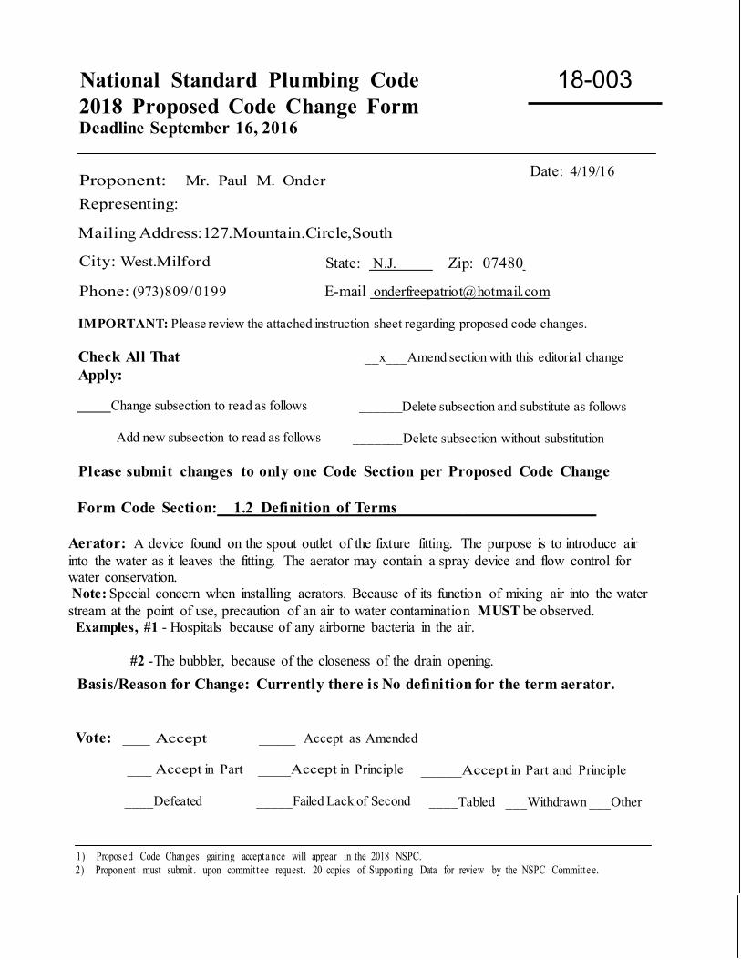
National Standard Plumbing Code 2018 Proposed Code Change Form Deadline September 16, 2016
Proponent: Mr. Paul M. Onder
Representing:
Mailing Address:127.Mountain.Circle,South
Date: 4/19/16
City: West.Milford State: N.J. Zip: 07480
Phone: (973)809/0199 E-mail [email protected]
IMPORTANT: Please review the attached instruction sheet regarding proposed code changes.
Check All That Apply:
__x___Amend section with this editorial change
Change subsection to read as follows ______Delete subsection and substitute as follows
Add new subsection to read as follows _______ Delete subsection without substitution
Please submit changes to only one Code Section per Proposed Code Change
Form Code Section:__1.2 Definition of Terms________________________
Aerator: A device found on the spout outlet of the fixture fitting. The purpose is to introduce air into the water as it leaves the fitting. The aerator may contain a spray device and flow control for water conservation. Note: Special concern when installing aerators. Because of its function of mixing air into the water stream at the point of use, precaution of an air to water contamination MUST be observed. Examples, #1 - Hospitals because of any airborne bacteria in the air. #2 -The bubbler, because of the closeness of the drain opening.
Basis/Reason for Change: Currently there is No definition for the term aerator. Vote: ___ Accept ____ Accept as Amended
___ Accept in Part ____Accept in Principle _____Accept in Part and Principle
____Defeated _____Failed Lack of Second ____Tabled ___Withdrawn ___Other
1) Propose d Code Changes gaining accepta nce will appear in the 2018 NSPC. 2) Proponent must submit . upon commit tee request . 20 copies of Supporting Data for review by the NSPC Committe e.
18-003
National Standard Plumbing Code 2018 Proposed Code Change Form
-
1.2 Ballcock page 1 of 1 10-22-2015
Proponent: NSPC Committee Date: 10-22-2015 Representing: Plumbing-Heating-Cooling Contractors Association Mailing Address: P.O. Box 6808 180 S. Washington Street City: Falls Church, VA 22046 Phone: 1-800-533-7694 E-mail: [email protected] Check All That Apply: _____ Amend section with this editorial change _____ Change subsection to read as follows _____ Delete subsection and substitute as follows __X__ Add new subsection to read as follows _____ Delete subsection without substitution Code Section: 1.2 DEFINITION OF TERMS Ballcock: A manually operated mechanism for filling water tanks, including those for flush tank water closets, while avoiding overflow and backflow. Reason for Change: To define "ballcock" as used in Section 7.19.3 and illustrated in Figure 7.19.3. Vote: ___ Accept ___ Accept as Amended
___ Accept in Part ___ Accept in Principle ___ Accept in Part and Principle
___ Defeated ___Failed Lack of Second ___ Tabled ___ Withdrawn ___ Other _________________________________________________________________________________
18 004
National Standard Plumbing Code 2018 Proposed Code Change Form
-
1.2 Branch Drains page 1 of 2 1-29-2016
Proponent: NSPC Committee Date: 1-29-2016
Check All That Apply: _____ Amend section with this editorial change __X__ Change subsection to read as follows _____ Delete subsection and substitute as follows _____ Add new subsection to read as follows __X__ Delete subsection without substitution
Code Section: 1.2 DEFINITION OF TERMS Branch Drain: A branch of drain piping, including horizontal fixture branches, horizontal branch drains, horizontal battery-vented drains, and branches of the building drain. Building Drain, Sanitary: The lowest piping in the building sanitary drainage system that receives the discharge from drain stacks, horizontal branch drains, and fixture all drains within the building and conveys the sewage drainage to the building sewer which begins three (3) feet beyond the outside face of the building. See Figure 1.2.16 Fixture Branch Drain: A branch drain that receives the discharge from two or more fixture drains.
Comment: See Table 11.5.1B for the maximum number of drainage fixture units (DFU) permitted on each size of horizontal fixture branch.
Grade: The fall (slope) of a line of pipe in reference to a horizontal plane. See Figure 1.2.36.
Comment: See Table 11.5.1A for sizing sloping building drains, branches of the building drain, and building sewers sanitary drains. See Table 13.6.2 for sizing sloping stormwater drains.
Horizontal Branch Drain: Horizontal drain piping, with or without offsets, that receives the discharge from two or more fixture drains and conveys the drainage to the building drain or a branch of the building drain. Horizontal branch drains do not connect to drain stacks. Horizontal Fixture Branch: Horizontal drain piping, with or without offsets, that receives the discharge from two or more fixture drains and conveys the drainage to a vertical drain stack with a reduced allowable DFU loading for the branch as indicated in Table 11.5.1B.
Comment: The reduced DFU loading for the branch is to prevent the branch flow from impacting the flow in the stack, causing turbulence in the stack and restricting flow in the branch.
Reason for Change: For coordination with the proposed changes to Table 11.5.1A, Table 11.5.1B, Section 11.5.3, and Section 11.5.6 regarding horizontal drain piping and branch connections to drain stacks.
Vote: ___ Accept ___ Accept as Amended
___ Accept in Part ___ Accept in Principle ___ Accept in Part and Principle
___ Defeated ___Failed Lack of Second ___ Tabled ___ Withdrawn ___ Other _________________________________________________________________________________
18 005
National Standard Plumbing Code 2018 Proposed Code Change Form
-
1.2 High & Low Hazard page 1 of 1 4-14-2016
Proponent: NSPC Committee Date: 04-14-2016 Representing: Plumbing-Heating-Cooling Contractors Association Mailing Address: P.O. Box 6808 180 S. Washington Street City: Falls Church, VA 22046 Phone: 1-800-533-7694 E-mail: [email protected] Check All That Apply: _____ Amend section with this editorial change __X__ Change subsection to read as follows _____ Delete subsection and substitute as follows _____ Add new subsection to read as follows _____ Delete subsection without substitution
Code Section: 1.2 DEFINITION OF TERMS Contamination (of Potable Water): The impairment of the quality of the potable water that creates an actual a high hazard to the public health through poisoning or through the spread of disease by sewage, industrial fluids, or waste. (See Refer to the definition of "pollution high hazard"). Health Hazard: In backflow prevention, an actual or potential threat of contamination of the potable water supply to the plumbing system of a physical or toxic nature that would be a danger to health. Health hazards include any contamination that could cause death, illness, or spread of disease.
High Hazard: A condition in the plumbing system that could contaminate the supply and distribution of potable water if not protected by the necessary backflow prevention. Low Hazard: A condition in the plumbing system that could pollute the supply and distribution of potable water if not protected by the necessary backflow prevention. Non-Health Hazard: In backflow prevention, an actual or potential threat to the physical properties or potability of the potable water supply to the plumbing system, but would not constitute a health or system hazard. Pollution (of Potable Water): An impairment of the quality of the potable water to a degree that does not create a high hazard to the public health but that does adversely and unreasonably affect the aesthetic qualities of such the potable water for domestic use. (See Refer to the definition of "contamination low hazard"). Reason for Change: To coordinate the definitions with the proposed changes in Section 10.5.3 changing health and non-health hazards to high and low hazards. Vote: ___ Accept ___ Accept as Amended
___ Accept in Part ___ Accept in Principle ___ Accept in Part and Principle
___ Defeated ___Failed Lack of Second ___ Tabled ___ Withdrawn ___ Other _________________________________________________________________________________
18 006
National Standard Plumbing Code 2018 Proposed Code Change Form
-
1.2 Drain Stack page 1 of 1 4-22-2016
Proponent: NSPC Committee Date: 04-22-2016 Representing: Plumbing-Heating-Cooling Contractors Association Mailing Address: P.O. Box 6808 180 S. Washington Street City: Falls Church, VA 22046 Phone: 1-800-533-7694 E-mail: [email protected] Check All That Apply: _____ Amend section with this editorial change __X__ Change subsection to read as follows _____ Delete subsection and substitute as follows _____ Add new subsection to read as follows _____ Delete subsection without substitution Code Section: 1.2 DEFINITION OF TERMS Drain Stack: A vertical drain, with or without offsets, that conveys drainage from fixture drains and horizontal fixture branch drains to the building drain or a branch of the building drain. Vertical drain piping, with or without offsets, that conveys drainage from horizontal drain piping to a lower floor elevation. Drain stacks do not include vertical drain piping from an individual fixture, a wet vented water closet, or a bathroom group that is not more than one story height. Drain stacks require a stack vent. Reason for Change: To clarify the definition of "drain stack", based on the proposed changes to the terminology used in the requirements for horizontal drain piping in Chapter 11. To exclude vertical drain piping from an individual fixture, a wet vented water closet, or an individual bathroom group that is not more than one story in height. Vote: ___ Accept ___ Accept as Amended
___ Accept in Part ___ Accept in Principle ___ Accept in Part and Principle
___ Defeated ___Failed Lack of Second ___ Tabled ___ Withdrawn ___ Other _________________________________________________________________________________
18 007
National Standard Plumbing Code 2018 Proposed Code Change Form
-
1.2 Grease Interceptor Abbreviations page 1 of 1 10-20-2015
Proponent: NSPC Committee Date: 10-20-2015 Representing: Plumbing-Heating-Cooling Contractors Association Mailing Address: P.O. Box 6808 180 S. Washington Street City: Falls Church, VA 22046 Phone: 1-800-533-7694 E-mail: [email protected] Check All That Apply: _____ Amend section with this editorial change _____ Change subsection to read as follows _____ Delete subsection and substitute as follows __X__ Add new subsection to read as follows _____ Delete subsection without substitution Code Section: 1.2 DEFINITION OF TERMS GGI: The abbreviation for "gravity grease interceptor". GRD: The abbreviation for "grease removal device", a type of grease interceptor. HGI: The abbreviation for "hydromechanical grease interceptor". Reason for Change: To define terms used in Section 6.2, Grease Interceptors. Vote: ___ Accept ___ Accept as Amended
___ Accept in Part ___ Accept in Principle ___ Accept in Part and Principle
___ Defeated ___Failed Lack of Second ___ Tabled ___ Withdrawn ___ Other _________________________________________________________________________________
18 008
National Standard Plumbing Code 2018 Proposed Code Change Form
-
1.2 Hydraulic Height (ponding) page 1 of 1 9-15-2016
Proponent: NSPC Committee Date: 09-15-2016 Representing: Plumbing-Heating-Cooling Contractors Association Mailing Address: P.O. Box 6808 180 S. Washington Street City: Falls Church, VA 22046 Phone: 1-800-533-7694 E-mail: [email protected] Check All That Apply: _____ Amend section with this editorial change _____ Change subsection to read as follows _____ Delete subsection and substitute as follows __X__ Add new subsection to read as follows _____ Delete subsection without substitution Code Section: 1.2 DEFINITION OF TERMS Hydraulic Height (ponding): The depth or head of rainwater for a particular roof drain at a required water flow rate in its installed condition with vertical drain piping and with offset drain piping. Reason for Change: To define the term “hydraulic height” with regard to the depth of ponding caused by a particular roof drain at a required project design water flow rate (GPM) for coordination with the structural design of the roof. Vote: ___ Accept ___ Accept as Amended
___ Accept in Part ___ Accept in Principle ___ Accept in Part and Principle
___ Defeated ___Failed Lack of Second ___ Tabled ___ Withdrawn ___ Other _________________________________________________________________________________
18 009
National Standard Plumbing Code 2018 Proposed Code Change Form
-
1.2 Lead-Free Items page 1 of 1 7-14-2015
Proponent: NSPC Committee Date: 7-14-2015 Representing: Plumbing-Heating-Cooling Contractors Association Mailing Address: P.O. Box 6808 180 S. Washington Street City: Falls Church, VA 22046 Phone: 1-800-533-7694 E-mail: [email protected] Check All That Apply: _____ Amend section with this editorial change __X__ Change subsection to read as follows _____ Delete subsection and substitute as follows _____ Add new subsection to read as follows _____ Delete subsection without substitution Code Section: 1.2 DEFINITION OF TERMS Lead Content:
a. Materials used in potable water supply systems, including piping faucets, and valves, shall be “lead-free” as defined by current Federal Law. b. Drinking water system components shall comply with the lead leachate requirements of NSF 61. Refer to Section 3.1.5 for components that are within the scope of NSF 61. Lead-Free: Containing not more than a weighted average of 0.25% lead for the wetted surfaces of pipes, tubes, fittings for pipes and tubes, plumbing supply fittings, and fixtures. Lead-free solder and flux contains no more than 0.2% lead. Weighted Average Lead Content: The weighted average lead content of a pipe, pipe fitting, plumbing fitting, or fixture shall be calculated by using the following formula: For each wetted component, the percentage of lead in the component shall be multiplied by the ratio of the wetted surface area of that component to the total wetted surface area of the entire product to arrive at the weighted percentage of lead of the component. The weighted percentage of lead of each wetted component shall be added together, and the sum of these weighted percentages shall constitute the weighted average lead content of the product. The lead content of the material used to produce wetted components shall be used to determine compliance with "lead-free". For lead content of materials that are provided as a range, the maximum content of the range shall be used. Reason for Change: To add terms associated with lead-free plumbing. Vote: ___ Accept ___ Accept as Amended
___ Accept in Part ___ Accept in Principle ___ Accept in Part and Principle
___ Defeated ___Failed Lack of Second ___ Tabled ___ Withdrawn ___ Other _________________________________________________________________________________
18 010
National Standard Plumbing Code 2018 Proposed Code Change Form
-
1.2 Plumbing Devices page 1 of 2 11-22-2015
Proponent: NSPC Committee Date: 11-22-2015 Representing: Plumbing-Heating-Cooling Contractors Association Mailing Address: P.O. Box 6808 180 S. Washington Street City: Falls Church, VA 22046 Phone: 1-800-533-7694 E-mail: [email protected] Check All That Apply: _____ Amend section with this editorial change __X__ Change subsection to read as follows _____ Delete subsection and substitute as follows _____ Add new subsection to read as follows _____ Delete subsection without substitution Code Section: 1.2 DEFINITION OF TERMS Plumbing Appliance: Any one of a special class of plumbing fixture that is intended to perform a special plumbing function. Its operation and/or control may be dependent upon one or more energized components, such as motors, controls, heating elements, or pressure or temperature-sensing elements. Such fixtures may operate automatically through one or more of the following actions: a time cycle, a temperature range, a pressure range, a measured volume or weight; or the fixture may be manually adjusted or controlled by the user or operator. Plumbing Appliance: A removable device that; (1) performs a specific domestic function in a facility, (2) is provided for use by the occupants, and (3) requires a water supply and/or drainage connection to the plumbing system.
Comment: Plumbing appliances include clothes washers, dishwashers, food-waste-disposal and grinder units, water heaters, water softeners, and similar devices. ice makers, and coffee machines. Refer to Table 3.1.3 - Part VII for listed plumbing appliances.
Plumbing Equipment: A fixed, pipe-connected plumbing device that performs a specific operational function in the performance of a plumbing system.
Comment: Plumbing equipment includes food waste disposers, commercial warewashers, water softeners, and water heaters. Refer to Table 3.1.3 - Part VII for listed plumbing equipment.
Plumbing Fixture: A receptacle or device connected to the water distribution system of the premises, and demands a supply of water there from; or discharges used water, liquid-borne waste materials, or sewage either directly or indirectly to the drainage system of the premises; or which requires both a water supply connection and a discharge to the drainage system of the premises. Plumbing appliances as a special class of fixture are further defined. Plumbing Fixture: A plumbing device or combination of devices in a facility that; (1) is installed for personal use by the occupants, (2) requires water supply and/or drainage, (3) is pipe-connected to the plumbing system, and (4) is a fixed, functional part of the facility.
18 011
1.2 Plumbing Devices page 2 of 2 11-22-2015
Comment: Plumbing fixtures include water closets, toilets, urinals, bidets, lavatories, bathtubs, whirlpool baths, showers, sinks, floor drains, and receptors bath/shower combinations, wash fountains, kitchen sinks, laundry sinks, service sinks, specialty sinks, emergency showers, hose bibbs, sill cocks, yard hydrants, and drinking fountains. Refer to Table 3.1.3 - Part V for listed plumbing fixtures.
Table 3.1.3 APPROVED MATERIALS Table 3.1.3 - Part VII PLUMBING APPLIANCES AND EQUIPMENT Reason for Change: To clarify the definitions of plumbing appliance, plumbing equipment, and plumbing fixture. To modify the Title of Table 3.1.3 - Part VII by adding plumbing equipment, which it includes. Vote: ___ Accept ___ Accept as Amended
___ Accept in Part ___ Accept in Principle ___ Accept in Part and Principle
___ Defeated ___Failed Lack of Second ___ Tabled ___ Withdrawn ___ Other _________________________________________________________________________________
National Standard Plumbing Code 2018 Proposed Code Change Form
-
1.2 Plumbing Supply Fittings page 1 of 1 5-27-2016
Proponent: NSPC Committee Date: 05-27-2016 Representing: Plumbing-Heating-Cooling Contractors Association Mailing Address: P.O. Box 6808 180 S. Washington Street City: Falls Church, VA 22046 Phone: 1-800-533-7694 E-mail: [email protected] Check All That Apply: _____ Amend section with this editorial change _____ Change subsection to read as follows _____ Delete subsection and substitute as follows __X__ Add new subsection to read as follows _____ Delete subsection without substitution Code Section: 1.2 DEFINITION OF TERMS Plumbing Supply Fittings: Supply stop valves, water supply outlets for bathtubs, showers, bidets, clothes washers, drinking fountains, sinks, lavatories, and laundry tubs, metering fittings, self-closing valves, and automatic compensating valves, which are regulated by ASME A112.18.1/CSA B125.1. Reason for Change: To define “plumbing supply fittings”, in Section 3.3.6. Vote: ___ Accept ___ Accept as Amended
___ Accept in Part ___ Accept in Principle ___ Accept in Part and Principle
___ Defeated ___Failed Lack of Second ___ Tabled ___ Withdrawn ___ Other _________________________________________________________________________________
18 012
National Standard Plumbing Code 2018 Proposed Code Change Form Deadline September 16, 2016
-
1) Proposed Code Changes gaining acceptance will appear in the 2018 NSPC. 2) Proponent must submit, upon committee request, 20 copies of Supporting Data for review by the NSPC Committee.
Proponent: Mark Fasel Date: 9/7/2016
Representing: Viega LLC.
Mailing Address: 100 North Broadway 6th floor
City: Wichita State: Kansas Zip: 67202
Phone: 317 447-2956 E-mail: [email protected] IMPORTANT: Please review the attached instruction sheet regarding proposed code changes. Check All That Apply: _____ Amend section with this editorial change X Change subsection to read as follows _____ Delete subsection and substitute as follows _____ Add new subsection to read as follows _____ Delete subsection without substitution Please submit changes to only one Code Section per Proposed Code Change Form
Code Section: Definition Press-Connect Fitting: A permanent mechanical connection for joining copper tubing utilizing an elastomeric seal or elastomeric seal with corrosion-resistant grip ring or rings. Fitting connections are made by mechanically compressing the wall of the fitting end over the tube utilizing a pressing tool and jaws or press rings approved by the fitting manufacturer. Basis/Reason for Change: The term Press-Connect aligns with language used in the actual product standard ASME B16.51 and is needed to harmonize definitions and prevent confusion within the industry. The current code does not include a definition of Press-Connect Fitting. The term elastomeric seal is also the terminology used in lieu of O-ring in standard B16.51 and will be harmonized with this revision. There are no costs for inclusion of this proposal to the code. Vote: ___ Accept ___ Accept as Amended
___ Accept in Part ___ Accept in Principle ___ Accept in Part and Principle
___ Defeated ___Failed Lack of Second ___ Tabled ___ Withdrawn ___ Other ____________________________________________________________________________________
18 013
National Standard Plumbing Code 2018 Proposed Code Change Form
-
1.2 Side Vent page 1 of 1 8-31-2016
Proponent: NSPC Committee Date: 08-31-2016 Representing: Plumbing-Heating-Cooling Contractors Association Mailing Address: P.O. Box 6808 180 S. Washington Street City: Falls Church, VA 22046 Phone: 1-800-533-7694 E-mail: [email protected] Check All That Apply: _____ Amend section with this editorial change _____ Change subsection to read as follows _____ Delete subsection and substitute as follows _____ Add new subsection to read as follows __X_ Delete subsection without substitution Code Section: 1.2 DEFINITIONS Side Vent: See “Vent, Side” Vent, Side: A vent connecting to a horizontal or vertical drain pipe at an angle not less than 45º from vertical. See Figure 1.2.76 Delete Figure 1.2.76 Reason for Change: The term “side vent” is not used in the text of the NSPC. Vote: ___ Accept ___ Accept as Amended
___ Accept in Part ___ Accept in Principle ___ Accept in Part and Principle
___ Defeated ___Failed Lack of Second ___ Tabled ___ Withdrawn ___ Other _________________________________________________________________________________
18 014
National Standard Plumbing Code 2018 Proposed Code Change Form
-
1.2 Stack Group, Stack Venting, Sub-Stack page 1 of 1 2-13-2016
Proponent: NSPC Committee Date: 2-13-2016 Representing: Plumbing-Heating-Cooling Contractors Association Mailing Address: P.O. Box 6808 180 S. Washington Street City: Falls Church, VA 22046 Phone: 1-800-533-7694 E-mail: [email protected] Check All That Apply: __X__ Amend section with this editorial change _____ Change subsection to read as follows _____ Delete subsection and substitute as follows _____ Add new subsection to read as follows _____ Delete subsection without substitution Code Section: 1.2 DEFINITION OF TERMS 1.2 Stack Group: A group of fixtures located adjacent to the stack so that by means of proper fittings. vents may be reduced to a minimum. See Section 12.11 for stack venting groups of fixtures. 1.2 Stack Venting: A method of venting a fixture or bathroom group through a stack vent or the vent for a sub-stack. See Figures 1.2.57, 12.11.1-A&B, 12.11.2-A&B, and Section 12.11 1.2 Sub-Stack: A vertical branch drain from a drain stack that serves a stack group of fixtures on the same floor level. See Figure 12.11.2-A Reason for Change: Proposed deletion of Section 12.11 Stack Venting. If approved, delete the referenced Figures. Vote: ___ Accept ___ Accept as Amended
___ Accept in Part ___ Accept in Principle ___ Accept in Part and Principle
___ Defeated ___Failed Lack of Second ___ Tabled ___ Withdrawn ___ Other _________________________________________________________________________________
18 015
National Standard Plumbing Code 2018 Proposed Code Change Form
-
1.2 Standby Floor Drain page 1 of 1 12-01-2015
Proponent: NSPC Committee Date: 12-01-2015 Representing: Plumbing-Heating-Cooling Contractors Association Mailing Address: P.O. Box 6808 180 S. Washington Street City: Falls Church, VA 22046 Phone: 1-800-533-7694 E-mail: [email protected] Check All That Apply: _____ Amend section with this editorial change __X__ Change subsection to read as follows _____ Delete subsection and substitute as follows _____ Add new subsection to read as follows _____ Delete subsection without substitution Code Section: 1.2 DEFINITION OF TERMS Auxiliary Standby Floor Drain: A floor drain that does not receive the discharge from any indirect waste pipe pipes or other predictable drainage flows. Auxiliary Standby floor drains have no DFU loading. Reason for Change: To change "auxiliary" to "standby". "Auxiliary" is supplementary or secondary to something that is "primary". Vote: ___ Accept ___ Accept as Amended
___ Accept in Part ___ Accept in Principle ___ Accept in Part and Principle
___ Defeated ___Failed Lack of Second ___ Tabled ___ Withdrawn ___ Other _________________________________________________________________________________
18 016
National Standard Plumbing Code 2018 Proposed Code Change Form
-
1.2 TAFR Valve Abbreviation page 1 of 1 7-14-2015
Proponent: NSPC Committee Date: 07-14-2015 Representing: Plumbing-Heating-Cooling Contractors Association Mailing Address: P.O. Box 6808 180 S. Washington Street City: Falls Church, VA 22046 Phone: 1-800-533-7694 E-mail: [email protected] Check All That Apply: _____ Amend section with this editorial change _____ Change subsection to read as follows _____ Delete subsection and substitute as follows __X__ Add new subsection to read as follows _____ Delete subsection without substitution Code Section: 1.2 DEFINITION OF TERMS TAFR: The abbreviation for ASSE 1062 temperature actuated flow reduction valves, which provide protection from scalding for individual plumbing supply fittings. Reason for Change: To define TAFR. Vote: ___ Accept ___ Accept as Amended
___ Accept in Part ___ Accept in Principle ___ Accept in Part and Principle
___ Defeated ___Failed Lack of Second ___ Tabled ___ Withdrawn ___ Other _________________________________________________________________________________
18 017
National Standard Plumbing Code 2018 Proposed Code Change Form
-
1.2 Vent, Branch, Header, Riser page 1 of 1 1-13-2016
Proponent: NSPC Committee Date: 1-13-2016 Representing: Plumbing-Heating-Cooling Contractors Association Mailing Address: P.O. Box 6808 180 S. Washington Street City: Falls Church, VA 22046 Phone: 1-800-533-7694 E-mail: [email protected] Check All That Apply: _____ Amend section with this editorial change __X__ Change subsection to read as follows _____ Delete subsection and substitute as follows _____ Add new subsection to read as follows _____ Delete subsection without substitution Code Section: 1.2 DEFINITIONS Vent, Branch: A vent connecting two or more individual fixture vents to a vent riser, vent stack, stack vent, or outdoor vent terminal. Horizontal vent piping connecting fixture vents and other vent piping to other branch vents, vent risers, vent stacks (where permitted), stack vents, or outdoor vent terminals. See Figure 1.2.70 Vent Header: Vent piping that connects two or more stack vents, or vent stacks vent stacks, or vent risers to an outdoor vent terminal. Vent Riser: A vertical vent pipe with connections from fixture vents, branch vents, and circuit vents on different floor levels that connects to a stack vent, vent stack, or outdoor vent terminal. Not a vent stack. Vertical vent piping connecting fixture vents, branch vents, circuit and loop vents, and other plumbing vents on different floor levels to vent piping on an upper floor or to an outdoor vent terminal. Reason for Change: To coordinate the definitions with proposed changes in Chapter 12. Vote: ___ Accept ___ Accept as Amended
___ Accept in Part ___ Accept in Principle ___ Accept in Part and Principle
___ Defeated ___Failed Lack of Second ___ Tabled ___ Withdrawn ___ Other _________________________________________________________________________________
18 018
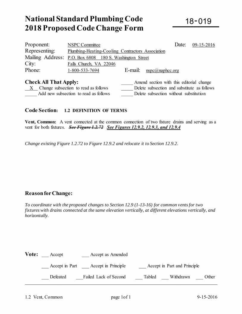
National Standard Plumbing Code 2018 Proposed Code Change Form
-
1.2 Vent, Common page 1of 1 9-15-2016
Proponent: NSPC Committee Date: 09-15-2016 Representing: Plumbing-Heating-Cooling Contractors Association Mailing Address: P.O. Box 6808 180 S. Washington Street City: Falls Church, VA 22046 Phone: 1-800-533-7694 E-mail: [email protected] Check All That Apply: _____ Amend section with this editorial change __X__ Change subsection to read as follows _____ Delete subsection and substitute as follows _____ Add new subsection to read as follows _____ Delete subsection without substitution Code Section: 1.2 DEFINITION OF TERMS Vent, Common: A vent connected at the common connection of two fixture drains and serving as a vent for both fixtures. See Figure 1.2.72 See Figures 12.9.2, 12.9.3, and 12.9.4 Change existing Figure 1.2.72 to Figure 12.9.2 and relocate it to Section 12.9.2. Reason for Change: To coordinate with the proposed changes to Section 12.9 (1-13-16) for common vents for two fixtures with drains connected at the same elevation vertically, at different elevations vertically, and horizontally. Vote: ___ Accept ___ Accept as Amended
___ Accept in Part ___ Accept in Principle ___ Accept in Part and Principle
___ Defeated ___Failed Lack of Second ___ Tabled ___ Withdrawn ___ Other _________________________________________________________________________________
18 019
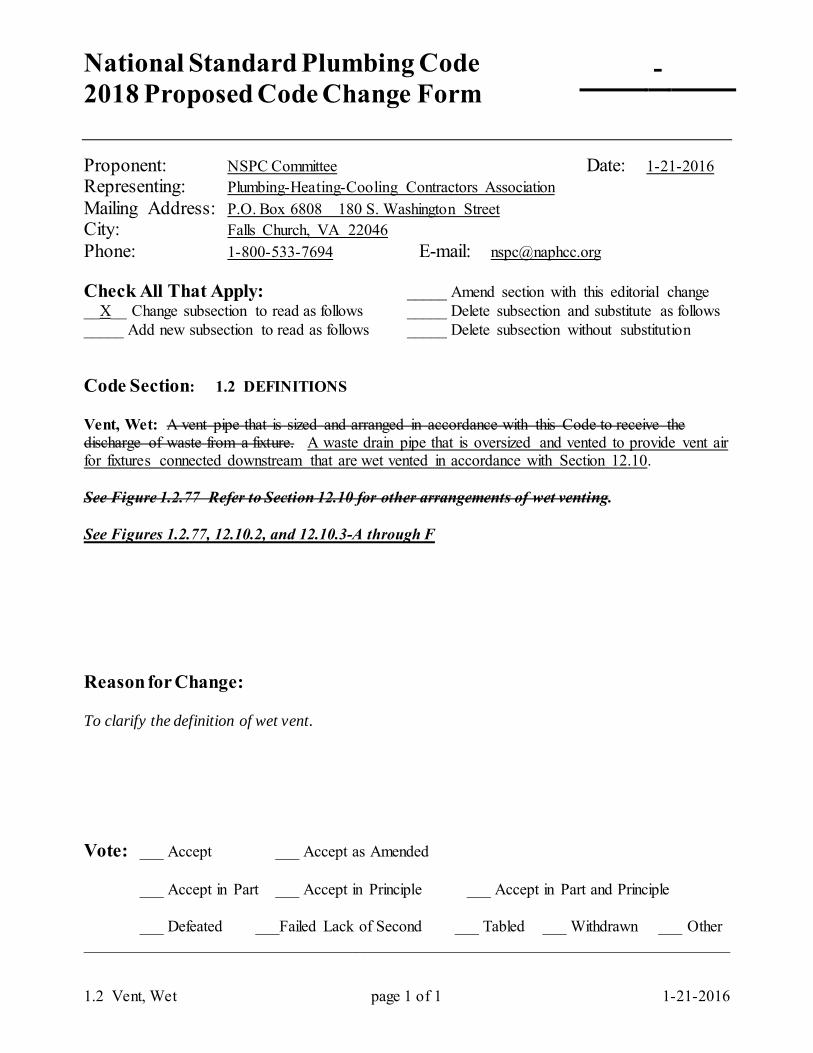
National Standard Plumbing Code 2018 Proposed Code Change Form
-
1.2 Vent, Wet page 1 of 1 1-21-2016
Proponent: NSPC Committee Date: 1-21-2016 Representing: Plumbing-Heating-Cooling Contractors Association Mailing Address: P.O. Box 6808 180 S. Washington Street City: Falls Church, VA 22046 Phone: 1-800-533-7694 E-mail: [email protected] Check All That Apply: _____ Amend section with this editorial change __X__ Change subsection to read as follows _____ Delete subsection and substitute as follows _____ Add new subsection to read as follows _____ Delete subsection without substitution Code Section: 1.2 DEFINITIONS Vent, Wet: A vent pipe that is sized and arranged in accordance with this Code to receive the discharge of waste from a fixture. A waste drain pipe that is oversized and vented to provide vent air for fixtures connected downstream that are wet vented in accordance with Section 12.10. See Figure 1.2.77 Refer to Section 12.10 for other arrangements of wet venting. See Figures 1.2.77, 12.10.2, and 12.10.3-A through F Reason for Change: To clarify the definition of wet vent. Vote: ___ Accept ___ Accept as Amended
___ Accept in Part ___ Accept in Principle ___ Accept in Part and Principle
___ Defeated ___Failed Lack of Second ___ Tabled ___ Withdrawn ___ Other _________________________________________________________________________________
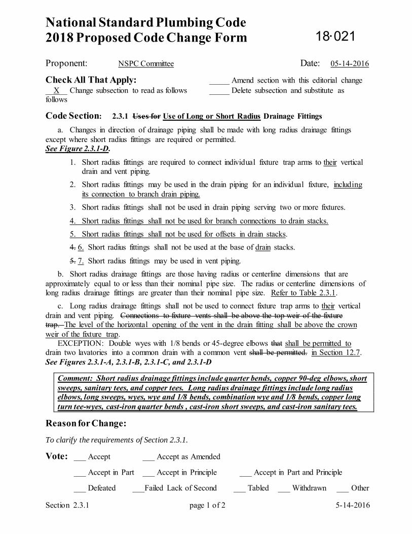
National Standard Plumbing Code 2018 Proposed Code Change Form
Section 2.3.1 page 1 of 2 5-14-2016
Proponent: NSPC Committee Date: 05-14-2016
Check All That Apply: _____ Amend section with this editorial change __X__ Change subsection to read as follows _____ Delete subsection and substitute as follows
Code Section: 2.3.1 Uses for Use of Long or Short Radius Drainage Fittings
a. Changes in direction of drainage piping shall be made with long radius drainage fittings except where short radius fittings are required or permitted. See Figure 2.3.1-D.
1. Short radius fittings are required to connect individual fixture trap arms to their vertical drain and vent piping.
2. Short radius fittings may be used in the drain piping for an individual fixture, including its connection to branch drain piping.
3. Short radius fittings shall not be used in drain piping serving two or more fixtures.
4. Short radius fittings shall not be used for branch connections to drain stacks. 5. Short radius fittings shall not be used for offsets in drain stacks. 4. 6. Short radius fittings shall not be used at the base of drain stacks.
5. 7. Short radius fittings may be used in vent piping. b. Short radius drainage fittings are those having radius or centerline dimensions that are approximately equal to or less than their nominal pipe size. The radius or centerline dimensions of long radius drainage fittings are greater than their nominal pipe size. Refer to Table 2.3.1. c. Long radius drainage fittings shall not be used to connect fixture trap arms to their vertical drain and vent piping. Connections to fixture vents shall be above the top weir of the fixture trap. The level of the horizontal opening of the vent in the drain fitting shall be above the crown weir of the fixture trap. EXCEPTION: Double wyes with 1/8 bends or 45-degree elbows that shall be permitted to drain two lavatories into a common drain with a common vent shall be permitted. in Section 12.7. See Figures 2.3.1-A, 2.3.1-B, 2.3.1-C, and 2.3.1-D
Comment: Short radius drainage fittings include quarter bends, copper 90-deg elbows, short sweeps, sanitary tees, and copper tees. Long radius drainage fittings include long radius elbows, long sweeps, wyes, wye and 1/8 bends, combination wye and 1/8 bends, copper long turn tee-wyes, cast-iron quarter bends , cast-iron short sweeps, and cast-iron sanitary tees.
Reason for Change: To clarify the requirements of Section 2.3.1.
Vote: ___ Accept ___ Accept as Amended
___ Accept in Part ___ Accept in Principle ___ Accept in Part and Principle
___ Defeated ___Failed Lack of Second ___ Tabled ___ Withdrawn ___ Other
18 021
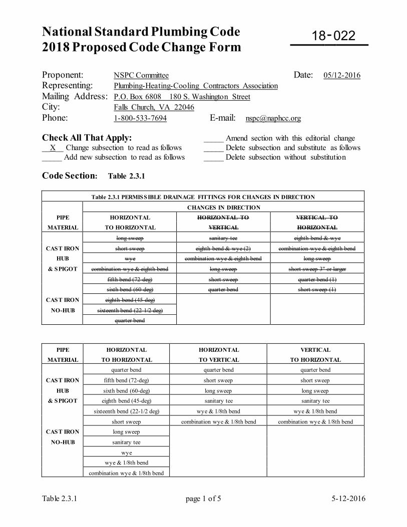
National Standard Plumbing Code 2018 Proposed Code Change Form
-
Table 2.3.1 page 1 of 5 5-12-2016
Proponent: NSPC Committee Date: 05/12-2016 Representing: Plumbing-Heating-Cooling Contractors Association Mailing Address: P.O. Box 6808 180 S. Washington Street City: Falls Church, VA 22046 Phone: 1-800-533-7694 E-mail: [email protected] Check All That Apply: _____ Amend section with this editorial change __X__ Change subsection to read as follows _____ Delete subsection and substitute as follows _____ Add new subsection to read as follows _____ Delete subsection without substitution Code Section: Table 2.3.1
Table 2.3.1 PERMISSIBLE DRAINAGE FITTINGS FOR CHANGES IN DIRECTION
CHANGES IN DIRECTION
PIPE HORIZONTAL HORIZONTAL TO VERTICAL TO
MATERIAL TO HORIZONTAL VERTICAL HORIZONTAL
long sweep sanitary tee eighth bend & wye
CAST IRON short sweep eighth bend & wye (2) combination wye & eighth bend
HUB wye combination wye & eighth bend long sweep
& SPIGOT combination wye & eighth bend long sweep short sweep 3" or larger
fifth bend (72-deg) short sweep quarter bend (1)
sixth bend (60-deg) quarter bend short sweep (1)
CAST IRON eighth bend (45-deg)
NO-HUB sixteenth bend (22-1/2 deg)
quarter bend
PIPE HORIZONTAL HORIZONTAL VERTICAL
MATERIAL TO HORIZONTAL TO VERTICAL TO HORIZONTAL
quarter bend quarter bend quarter bend
CAST IRON fifth bend (72-deg) short sweep short sweep
HUB sixth bend (60-deg) long sweep long sweep
& SPIGOT eighth bend (45-deg) sanitary tee sanitary tee
sixteenth bend (22-1/2 deg) wye & 1/8th bend wye & 1/8th bend
short sweep combination wye & 1/8th bend combination wye & 1/8th bend
CAST IRON long sweep
NO-HUB sanitary tee
wye
wye & 1/8th bend
combination wye & 1/8th bend
18 022
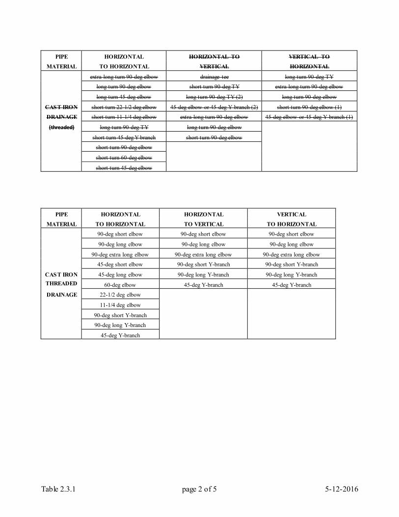
Table 2.3.1 page 2 of 5 5-12-2016
PIPE HORIZONTAL HORIZONTAL TO VERTICAL TO
MATERIAL TO HORIZONTAL VERTICAL HORIZONTAL
extra long turn 90-deg elbow drainage tee long turn 90-deg TY
long turn 90-deg elbow short turn 90-deg TY extra long turn 90-deg elbow
long turn 45-deg elbow long turn 90-deg TY (2) long turn 90-deg elbow
CAST IRON short turn 22-1/2 deg elbow 45-deg elbow or 45-deg Y branch (2) short turn 90-deg elbow (1)
DRAINAGE short turn 11-1/4 deg elbow extra long turn 90-deg elbow 45-deg elbow or 45-deg Y branch (1)
(threaded) long turn 90-deg TY long turn 90-deg elbow
short turn 45-deg Y branch short turn 90-deg elbow
short turn 90-deg elbow
short turn 60-deg elbow
short turn 45-deg elbow
PIPE HORIZONTAL HORIZONTAL VERTICAL
MATERIAL TO HORIZONTAL TO VERTICAL TO HORIZONTAL
90-deg short elbow 90-deg short elbow 90-deg short elbow
90-deg long elbow 90-deg long elbow 90-deg long elbow
90-deg extra long elbow 90-deg extra long elbow 90-deg extra long elbow
45-deg short elbow 90-deg short Y-branch 90-deg short Y-branch
CAST IRON 45-deg long elbow 90-deg long Y-branch 90-deg long Y-branch THREADED 60-deg elbow 45-deg Y-branch 45-deg Y-branch
DRAINAGE 22-1/2 deg elbow
11-1/4 deg elbow
90-deg short Y-branch
90-deg long Y-branch
45-deg Y-branch
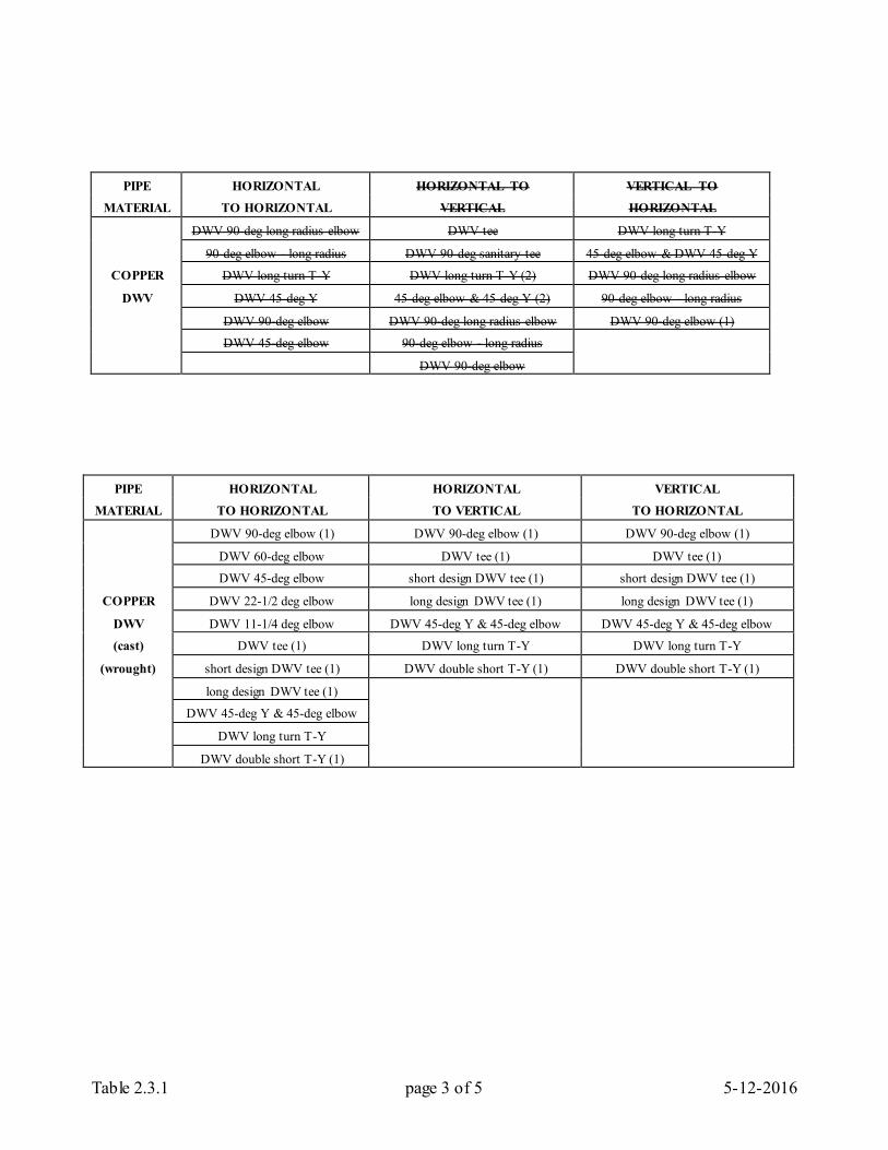
Table 2.3.1 page 3 of 5 5-12-2016
PIPE HORIZONTAL HORIZONTAL TO VERTICAL TO
MATERIAL TO HORIZONTAL VERTICAL HORIZONTAL
DWV 90-deg long radius elbow DWV tee DWV long turn T-Y
90-deg elbow - long radius DWV 90-deg sanitary tee 45-deg elbow & DWV 45-deg Y
COPPER DWV long turn T-Y DWV long turn T-Y (2) DWV 90-deg long radius elbow
DWV DWV 45-deg Y 45-deg elbow & 45-deg Y (2) 90-deg elbow - long radius
DWV 90-deg elbow DWV 90-deg long radius elbow DWV 90-deg elbow (1)
DWV 45-deg elbow 90-deg elbow - long radius
DWV 90-deg elbow
PIPE HORIZONTAL HORIZONTAL VERTICAL
MATERIAL TO HORIZONTAL TO VERTICAL TO HORIZONTAL
DWV 90-deg elbow (1) DWV 90-deg elbow (1) DWV 90-deg elbow (1)
DWV 60-deg elbow DWV tee (1) DWV tee (1) DWV 45-deg elbow short design DWV tee (1) short design DWV tee (1)
COPPER DWV 22-1/2 deg elbow long design DWV tee (1) long design DWV tee (1)
DWV DWV 11-1/4 deg elbow DWV 45-deg Y & 45-deg elbow DWV 45-deg Y & 45-deg elbow
(cast) DWV tee (1) DWV long turn T-Y DWV long turn T-Y
(wrought) short design DWV tee (1) DWV double short T-Y (1) DWV double short T-Y (1)
long design DWV tee (1)
DWV 45-deg Y & 45-deg elbow
DWV long turn T-Y
DWV double short T-Y (1)
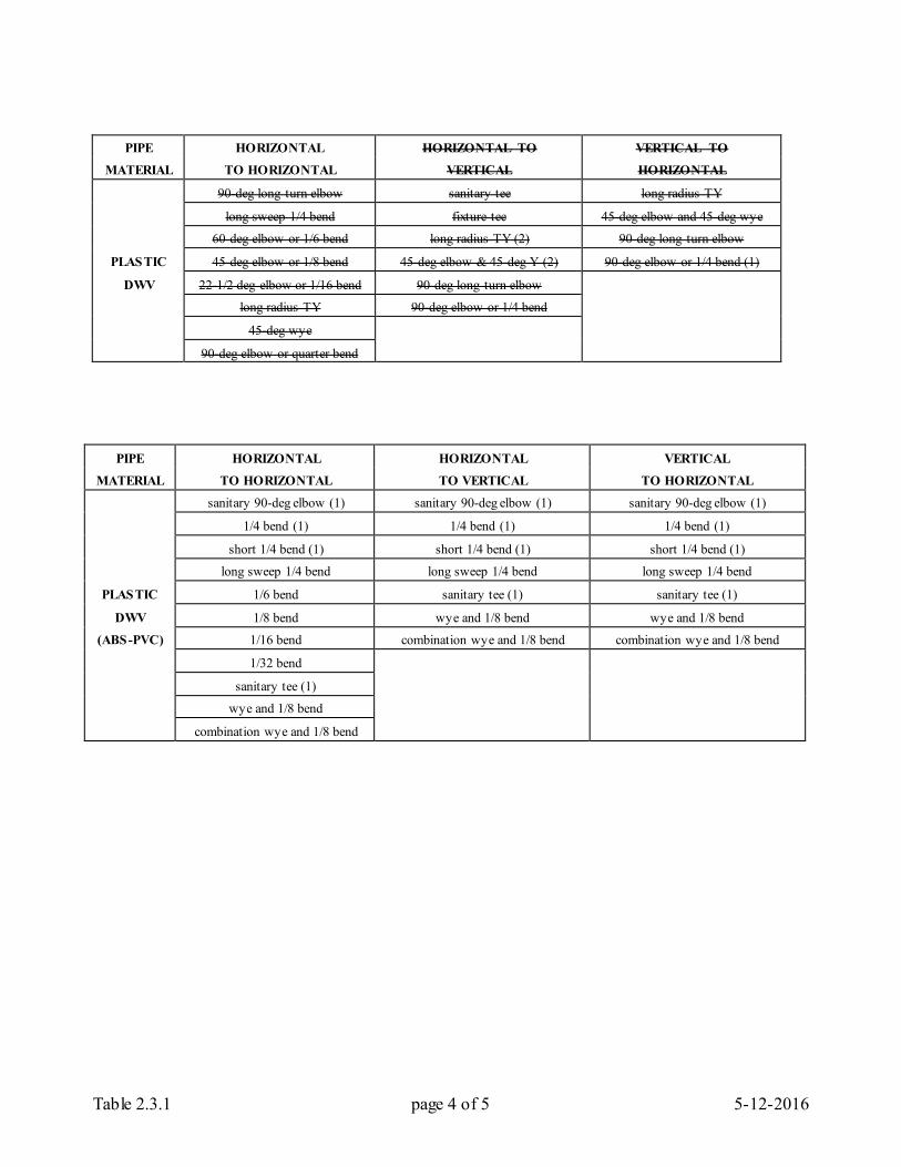
Table 2.3.1 page 4 of 5 5-12-2016
PIPE HORIZONTAL HORIZONTAL TO VERTICAL TO
MATERIAL TO HORIZONTAL VERTICAL HORIZONTAL
90-deg long turn elbow sanitary tee long radius TY
long sweep 1/4 bend fixture tee 45-deg elbow and 45-deg wye
60-deg elbow or 1/6 bend long radius TY (2) 90-deg long turn elbow
PLASTIC 45-deg elbow or 1/8 bend 45-deg elbow & 45-deg Y (2) 90-deg elbow or 1/4 bend (1)
DWV 22-1/2 deg elbow or 1/16 bend 90-deg long turn elbow
long radius TY 90-deg elbow or 1/4 bend
45-deg wye
90-deg elbow or quarter bend
PIPE HORIZONTAL HORIZONTAL VERTICAL
MATERIAL TO HORIZONTAL TO VERTICAL TO HORIZONTAL
sanitary 90-deg elbow (1) sanitary 90-deg elbow (1) sanitary 90-deg elbow (1)
1/4 bend (1) 1/4 bend (1) 1/4 bend (1)
short 1/4 bend (1) short 1/4 bend (1) short 1/4 bend (1)
long sweep 1/4 bend long sweep 1/4 bend long sweep 1/4 bend
PLASTIC 1/6 bend sanitary tee (1) sanitary tee (1)
DWV 1/8 bend wye and 1/8 bend wye and 1/8 bend
(ABS-PVC) 1/16 bend combination wye and 1/8 bend combination wye and 1/8 bend
1/32 bend
sanitary tee (1)
wye and 1/8 bend
combination wye and 1/8 bend
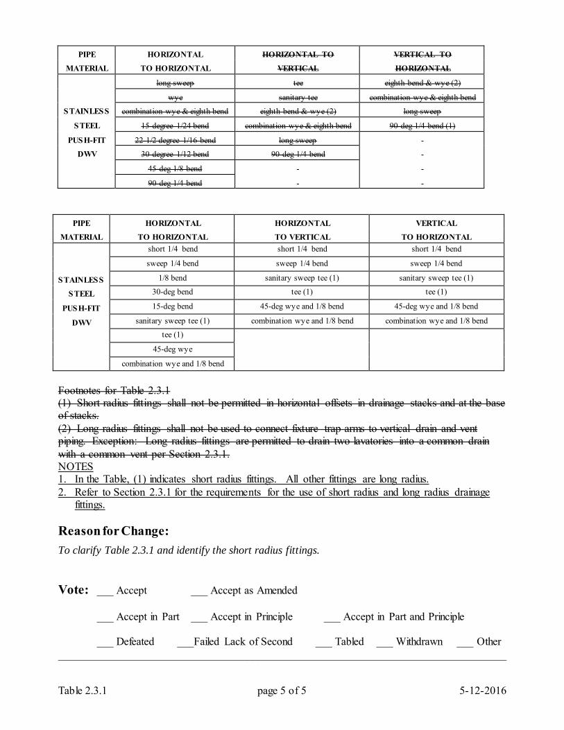
Table 2.3.1 page 5 of 5 5-12-2016
PIPE HORIZONTAL HORIZONTAL TO VERTICAL TO
MATERIAL TO HORIZONTAL VERTICAL HORIZONTAL
long sweep tee eighth bend & wye (2)
wye sanitary tee combination wye & eighth bend
STAINLESS combination wye & eighth bend eighth bend & wye (2) long sweep
STEEL 15-degree 1/24 bend combination wye & eighth bend 90-deg 1/4 bend (1)
PUSH-FIT 22-1/2 degree 1/16 bend long sweep
DWV 30-degree 1/12 bend 90-deg 1/4 bend
45-deg 1/8 bend
90-deg 1/4 bend
PIPE HORIZONTAL HORIZONTAL VERTICAL
MATERIAL TO HORIZONTAL TO VERTICAL TO HORIZONTAL
short 1/4 bend short 1/4 bend short 1/4 bend
sweep 1/4 bend sweep 1/4 bend sweep 1/4 bend
STAINLESS 1/8 bend sanitary sweep tee (1) sanitary sweep tee (1)
STEEL 30-deg bend tee (1) tee (1)
PUSH-FIT 15-deg bend 45-deg wye and 1/8 bend 45-deg wye and 1/8 bend
DWV sanitary sweep tee (1) combination wye and 1/8 bend combination wye and 1/8 bend
tee (1) 45-deg wye combination wye and 1/8 bend Footnotes for Table 2.3.1 (1) Short radius fittings shall not be permitted in horizontal offsets in drainage stacks and at the base of stacks. (2) Long radius fittings shall not be used to connect fixture trap arms to vertical drain and vent piping. Exception: Long radius fittings are permitted to drain two lavatories into a common drain with a common vent per Section 2.3.1. NOTES 1. In the Table, (1) indicates short radius fittings. All other fittings are long radius. 2. Refer to Section 2.3.1 for the requirements for the use of short radius and long radius drainage
fittings. Reason for Change: To clarify Table 2.3.1 and identify the short radius fittings. Vote: ___ Accept ___ Accept as Amended
___ Accept in Part ___ Accept in Principle ___ Accept in Part and Principle
___ Defeated ___Failed Lack of Second ___ Tabled ___ Withdrawn ___ Other _________________________________________________________________________________
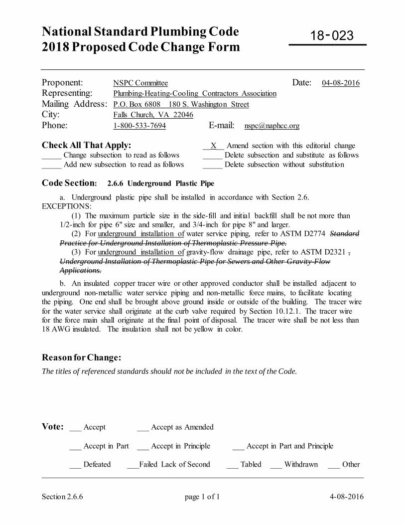
National Standard Plumbing Code 2018 Proposed Code Change Form
-
Section 2.6.6 page 1 of 1 4-08-2016
Proponent: NSPC Committee Date: 04-08-2016 Representing: Plumbing-Heating-Cooling Contractors Association Mailing Address: P.O. Box 6808 180 S. Washington Street City: Falls Church, VA 22046 Phone: 1-800-533-7694 E-mail: [email protected] Check All That Apply: __X__ Amend section with this editorial change _____ Change subsection to read as follows _____ Delete subsection and substitute as follows _____ Add new subsection to read as follows _____ Delete subsection without substitution Code Section: 2.6.6 Underground Plastic Pipe
a. Underground plastic pipe shall be installed in accordance with Section 2.6. EXCEPTIONS: (1) The maximum particle size in the side-fill and initial backfill shall be not more than
1/2-inch for pipe 6" size and smaller, and 3/4-inch for pipe 8" and larger. (2) For underground installation of water service piping, refer to ASTM D2774 Standard
Practice for Underground Installation of Thermoplastic Pressure Pipe. (3) For underground installation of gravity-flow drainage pipe, refer to ASTM D2321 ,
Underground Installation of Thermoplastic Pipe for Sewers and Other Gravity-Flow Applications.
b. An insulated copper tracer wire or other approved conductor shall be installed adjacent to underground non-metallic water service piping and non-metallic force mains, to facilitate locating the piping. One end shall be brought above ground inside or outside of the building. The tracer wire for the water service shall originate at the curb valve required by Section 10.12.1. The tracer wire for the force main shall originate at the final point of disposal. The tracer wire shall be not less than 18 AWG insulated. The insulation shall not be yellow in color. Reason for Change: The titles of referenced standards should not be included in the text of the Code. Vote: ___ Accept ___ Accept as Amended
___ Accept in Part ___ Accept in Principle ___ Accept in Part and Principle
___ Defeated ___Failed Lack of Second ___ Tabled ___ Withdrawn ___ Other _________________________________________________________________________________
18 023
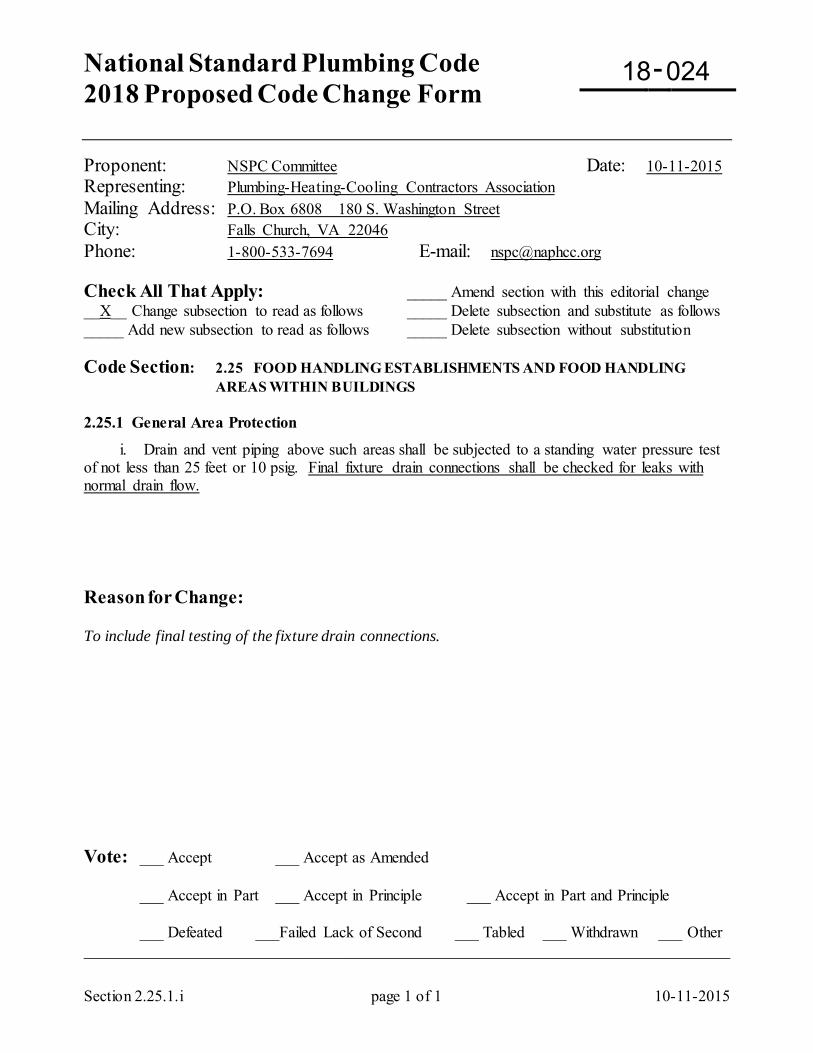
National Standard Plumbing Code 2018 Proposed Code Change Form
-
Section 2.25.1.i page 1 of 1 10-11-2015
Proponent: NSPC Committee Date: 10-11-2015 Representing: Plumbing-Heating-Cooling Contractors Association Mailing Address: P.O. Box 6808 180 S. Washington Street City: Falls Church, VA 22046 Phone: 1-800-533-7694 E-mail: [email protected] Check All That Apply: _____ Amend section with this editorial change __X__ Change subsection to read as follows _____ Delete subsection and substitute as follows _____ Add new subsection to read as follows _____ Delete subsection without substitution Code Section: 2.25 FOOD HANDLING ESTABLISHMENTS AND FOOD HANDLING
AREAS WITHIN BUILDINGS 2.25.1 General Area Protection
i. Drain and vent piping above such areas shall be subjected to a standing water pressure test of not less than 25 feet or 10 psig. Final fixture drain connections shall be checked for leaks with normal drain flow. Reason for Change: To include final testing of the fixture drain connections. Vote: ___ Accept ___ Accept as Amended
___ Accept in Part ___ Accept in Principle ___ Accept in Part and Principle
___ Defeated ___Failed Lack of Second ___ Tabled ___ Withdrawn ___ Other _________________________________________________________________________________
18 024
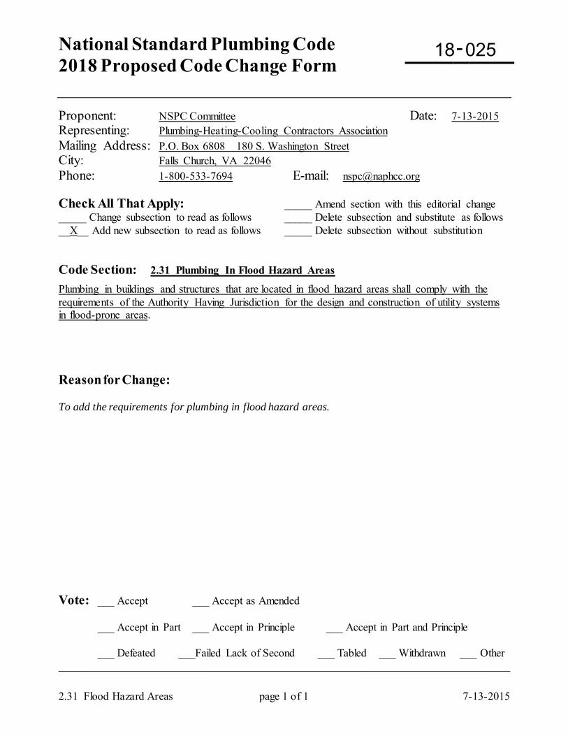
National Standard Plumbing Code 2018 Proposed Code Change Form
-
2.31 Flood Hazard Areas page 1 of 1 7-13-2015
Proponent: NSPC Committee Date: 7-13-2015 Representing: Plumbing-Heating-Cooling Contractors Association Mailing Address: P.O. Box 6808 180 S. Washington Street City: Falls Church, VA 22046 Phone: 1-800-533-7694 E-mail: [email protected] Check All That Apply: _____ Amend section with this editorial change _____ Change subsection to read as follows _____ Delete subsection and substitute as follows __X__ Add new subsection to read as follows _____ Delete subsection without substitution Code Section: 2.31 Plumbing In Flood Hazard Areas
Plumbing in buildings and structures that are located in flood hazard areas shall comply with the requirements of the Authority Having Jurisdiction for the design and construction of utility systems in flood-prone areas. Reason for Change: To add the requirements for plumbing in flood hazard areas. Vote: ___ Accept ___ Accept as Amended
___ Accept in Part ___ Accept in Principle ___ Accept in Part and Principle
___ Defeated ___Failed Lack of Second ___ Tabled ___ Withdrawn ___ Other _________________________________________________________________________________
18 025
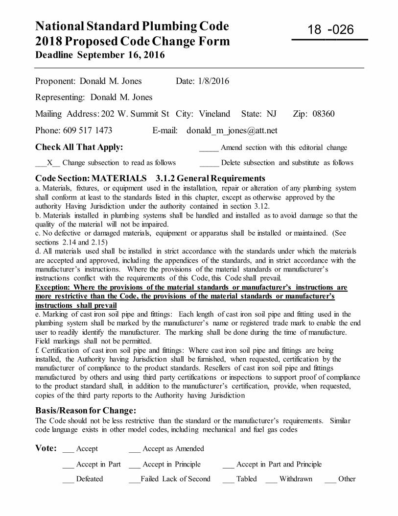
National Standard Plumbing Code 2018 Proposed Code Change Form Deadline September 16, 2016
-
Proponent: Donald M. Jones Date: 1/8/2016
Representing: Donald M. Jones
Mailing Address: 202 W. Summit St City: Vineland State: NJ Zip: 08360
Phone: 609 517 1473 E-mail: [email protected]
Check All That Apply: _____ Amend section with this editorial change ___X__ Change subsection to read as follows _____ Delete subsection and substitute as follows
Code Section: MATERIALS 3.1.2 General Requirements a. Materials, fixtures, or equipment used in the installation, repair or alteration of any plumbing system shall conform at least to the standards listed in this chapter, except as otherwise approved by the authority Having Jurisdiction under the authority contained in section 3.12. b. Materials installed in plumbing systems shall be handled and installed as to avoid damage so that the quality of the material will not be impaired. c. No defective or damaged materials, equipment or apparatus shall be installed or maintained. (See sections 2.14 and 2.15) d. All materials used shall be installed in strict accordance with the standards under which the materials are accepted and approved, including the appendices of the standards, and in strict accordance with the manufacturer’s instructions. Where the provisions of the material standards or manufacturer’s instructions conflict with the requirements of this Code, this Code shall prevail. Exception: Where the provisions of the material standards or manufacturer’s instructions are more restrictive than the Code, the provisions of the material standards or manufacturer’s instructions shall prevail e. Marking of cast iron soil pipe and fittings: Each length of cast iron soil pipe and fitting used in the plumbing system shall be marked by the manufacturer’s name or registered trade mark to enable the end user to readily identify the manufacturer. The marking shall be done during the time of manufacture. Field markings shall not be permitted. f. Certification of cast iron soil pipe and fittings: Where cast iron soil pipe and fittings are being installed, the Authority having Jurisdiction shall be furnished, when requested, certification by the manufacturer of compliance to the product standards. Resellers of cast iron soil pipe and fittings manufactured by others and using third party certifications or inspections to support proof of compliance to the product standard shall, in addition to the manufacturer’s certification, provide, when requested, copies of the third party reports to the Authority having Jurisdiction Basis/Reason for Change: The Code should not be less restrictive than the standard or the manufacturer’s requirements. Similar code language exists in other model codes, including mechanical and fuel gas codes Vote: ___ Accept ___ Accept as Amended
___ Accept in Part ___ Accept in Principle ___ Accept in Part and Principle
___ Defeated ___Failed Lack of Second ___ Tabled ___ Withdrawn ___ Other
18 026
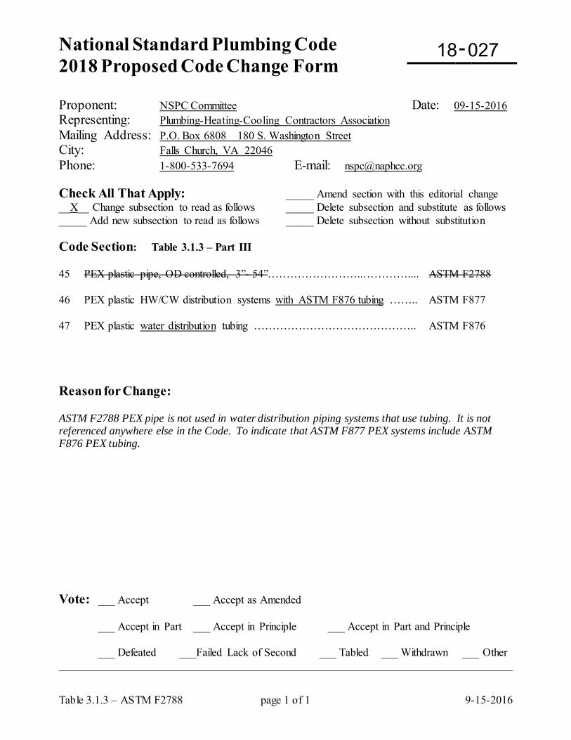
National Standard Plumbing Code 2018 Proposed Code Change Form
-
Table 3.1.3 – ASTM F2788 page 1 of 1 9-15-2016
Proponent: NSPC Committee Date: 09-15-2016 Representing: Plumbing-Heating-Cooling Contractors Association Mailing Address: P.O. Box 6808 180 S. Washington Street City: Falls Church, VA 22046 Phone: 1-800-533-7694 E-mail: [email protected] Check All That Apply: _____ Amend section with this editorial change __X__ Change subsection to read as follows _____ Delete subsection and substitute as follows _____ Add new subsection to read as follows _____ Delete subsection without substitution Code Section: Table 3.1.3 – Part III 45 PEX plastic pipe, OD controlled, 3”- 54”……………………..………….... ASTM F2788 46 PEX plastic HW/CW distribution systems with ASTM F876 tubing …….. ASTM F877 47 PEX plastic water distribution tubing …………………………………….. ASTM F876 Reason for Change: ASTM F2788 PEX pipe is not used in water distribution piping systems that use tubing. It is not referenced anywhere else in the Code. To indicate that ASTM F877 PEX systems include ASTM F876 PEX tubing. Vote: ___ Accept ___ Accept as Amended
___ Accept in Part ___ Accept in Principle ___ Accept in Part and Principle
___ Defeated ___Failed Lack of Second ___ Tabled ___ Withdrawn ___ Other _________________________________________________________________________________
18 027
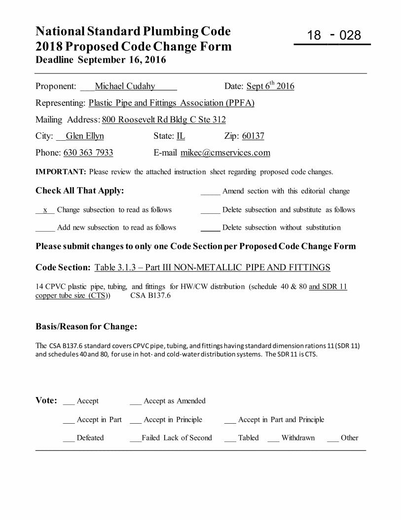
National Standard Plumbing Code 2018 Proposed Code Change Form Deadline September 16, 2016
-
Proponent: ___Michael Cudahy Date: Sept 6th 2016
Representing: Plastic Pipe and Fittings Association (PPFA)
Mailing Address: 800 Roosevelt Rd Bldg C Ste 312
City: __Glen Ellyn State: IL Zip: 60137
Phone: 630 363 7933 E-mail [email protected] IMPORTANT: Please review the attached instruction sheet regarding proposed code changes. Check All That Apply: _____ Amend section with this editorial change __x__ Change subsection to read as follows _____ Delete subsection and substitute as follows _____ Add new subsection to read as follows _____ Delete subsection without substitution Please submit changes to only one Code Section per Proposed Code Change Form Code Section: Table 3.1.3 – Part III NON-METALLIC PIPE AND FITTINGS 14 CPVC plastic pipe, tubing, and fittings for HW/CW distribution (schedule 40 & 80 and SDR 11 copper tube size (CTS)) CSA B137.6 Basis/Reason for Change: The CSA B137.6 standard covers CPVC pipe, tubing, and fittings having standard dimension rations 11 (SDR 11) and schedules 40 and 80, for use in hot- and cold-water distribution systems. The SDR 11 is CTS. Vote: ___ Accept ___ Accept as Amended
___ Accept in Part ___ Accept in Principle ___ Accept in Part and Principle
___ Defeated ___Failed Lack of Second ___ Tabled ___ Withdrawn ___ Other ____________________________________________________________________________________
18 028
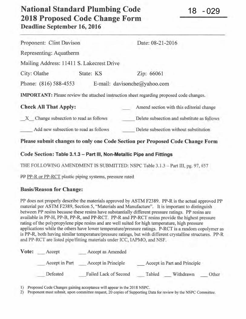
18 029
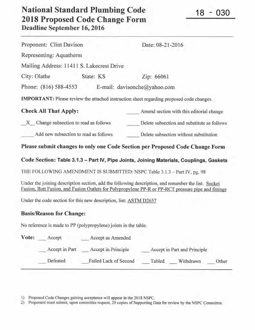
18 030
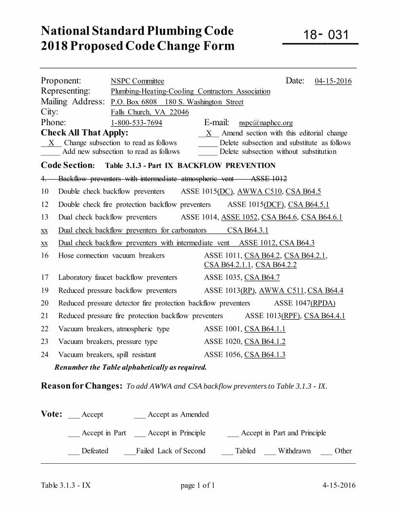
National Standard Plumbing Code 2018 Proposed Code Change Form
-
Table 3.1.3 - IX page 1 of 1 4-15-2016
Proponent: NSPC Committee Date: 04-15-2016 Representing: Plumbing-Heating-Cooling Contractors Association Mailing Address: P.O. Box 6808 180 S. Washington Street City: Falls Church, VA 22046 Phone: 1-800-533-7694 E-mail: [email protected] Check All That Apply: __X__ Amend section with this editorial change __X__ Change subsection to read as follows _____ Delete subsection and substitute as follows _____ Add new subsection to read as follows _____ Delete subsection without substitution
Code Section: Table 3.1.3 - Part IX BACKFLOW PREVENTION
4. Backflow preventers with intermediate atmospheric vent ASSE 1012 10 Double check backflow preventers ASSE 1015(DC), AWWA C510, CSA B64.5
12 Double check fire protection backflow preventers ASSE 1015(DCF), CSA B64.5.1 13 Dual check backflow preventers ASSE 1014, ASSE 1052, CSA B64.6, CSA B64.6.1
xx Dual check backflow preventers for carbonators CSA B64.3.1 xx Dual check backflow preventers with intermediate vent ASSE 1012, CSA B64.3 16 Hose connection vacuum breakers ASSE 1011, CSA B64.2, CSA B64.2.1, CSA B64.2.1.1, CSA B64.2.2 17 Laboratory faucet backflow preventers ASSE 1035, CSA B64.7
19 Reduced pressure backflow preventers ASSE 1013(RP), AWWA C511, CSA B64.4 20 Reduced pressure detector fire protection backflow preventers ASSE 1047(RPDA) 21 Reduced pressure fire protection backflow preventers ASSE 1013(RPF), CSA B64.4.1
22 Vacuum breakers, atmospheric type ASSE 1001, CSA B64.1.1 23 Vacuum breakers, pressure type ASSE 1020, CSA B64.1.2
24 Vacuum breakers, spill resistant ASSE 1056, CSA B64.1.3 Renumber the Table alphabetically as required. Reason for Changes: To add AWWA and CSA backflow preventers to Table 3.1.3 - IX. Vote: ___ Accept ___ Accept as Amended
___ Accept in Part ___ Accept in Principle ___ Accept in Part and Principle
___ Defeated ___Failed Lack of Second ___ Tabled ___ Withdrawn ___ Other _________________________________________________________________________________
18 031
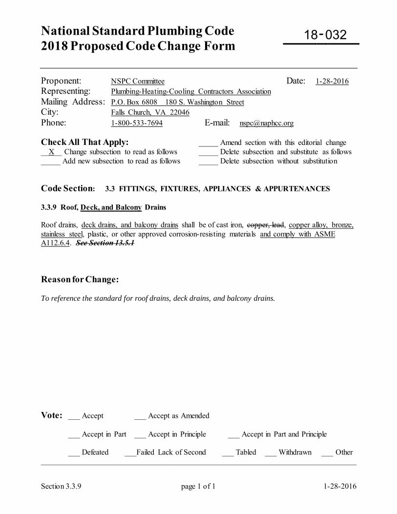
National Standard Plumbing Code 2018 Proposed Code Change Form
-
Section 3.3.9 page 1 of 1 1-28-2016
Proponent: NSPC Committee Date: 1-28-2016 Representing: Plumbing-Heating-Cooling Contractors Association Mailing Address: P.O. Box 6808 180 S. Washington Street City: Falls Church, VA 22046 Phone: 1-800-533-7694 E-mail: [email protected] Check All That Apply: _____ Amend section with this editorial change __X__ Change subsection to read as follows _____ Delete subsection and substitute as follows _____ Add new subsection to read as follows _____ Delete subsection without substitution Code Section: 3.3 FITTINGS, FIXTURES, APPLIANCES & APPURTENANCES 3.3.9 Roof, Deck, and Balcony Drains Roof drains, deck drains, and balcony drains shall be of cast iron, copper, lead, copper alloy, bronze, stainless steel, plastic, or other approved corrosion-resisting materials and comply with ASME A112.6.4. See Section 13.5.1 Reason for Change: To reference the standard for roof drains, deck drains, and balcony drains. Vote: ___ Accept ___ Accept as Amended
___ Accept in Part ___ Accept in Principle ___ Accept in Part and Principle
___ Defeated ___Failed Lack of Second ___ Tabled ___ Withdrawn ___ Other _________________________________________________________________________________
18 032
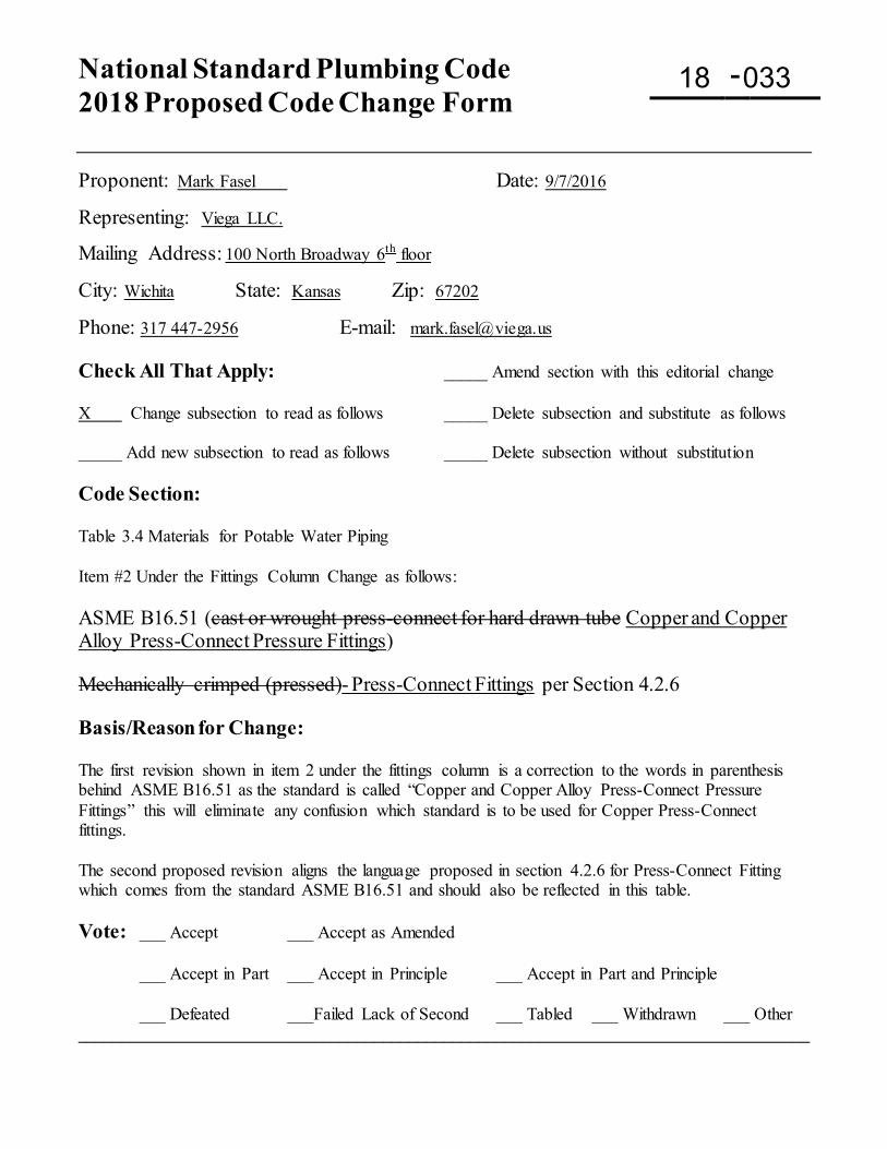
National Standard Plumbing Code 2018 Proposed Code Change Form
-
Proponent: Mark Fasel Date: 9/7/2016
Representing: Viega LLC.
Mailing Address: 100 North Broadway 6th floor
City: Wichita State: Kansas Zip: 67202
Phone: 317 447-2956 E-mail: [email protected] Check All That Apply: _____ Amend section with this editorial change X Change subsection to read as follows _____ Delete subsection and substitute as follows _____ Add new subsection to read as follows _____ Delete subsection without substitution Code Section: Table 3.4 Materials for Potable Water Piping Item #2 Under the Fittings Column Change as follows: ASME B16.51 (cast or wrought press-connect for hard drawn tube Copper and Copper Alloy Press-Connect Pressure Fittings) Mechanically crimped (pressed)- Press-Connect Fittings per Section 4.2.6 Basis/Reason for Change: The first revision shown in item 2 under the fittings column is a correction to the words in parenthesis behind ASME B16.51 as the standard is called “Copper and Copper Alloy Press-Connect Pressure Fittings” this will eliminate any confusion which standard is to be used for Copper Press-Connect fittings. The second proposed revision aligns the language proposed in section 4.2.6 for Press-Connect Fitting which comes from the standard ASME B16.51 and should also be reflected in this table. Vote: ___ Accept ___ Accept as Amended
___ Accept in Part ___ Accept in Principle ___ Accept in Part and Principle
___ Defeated ___Failed Lack of Second ___ Tabled ___ Withdrawn ___ Other ____________________________________________________________________________________
18 033
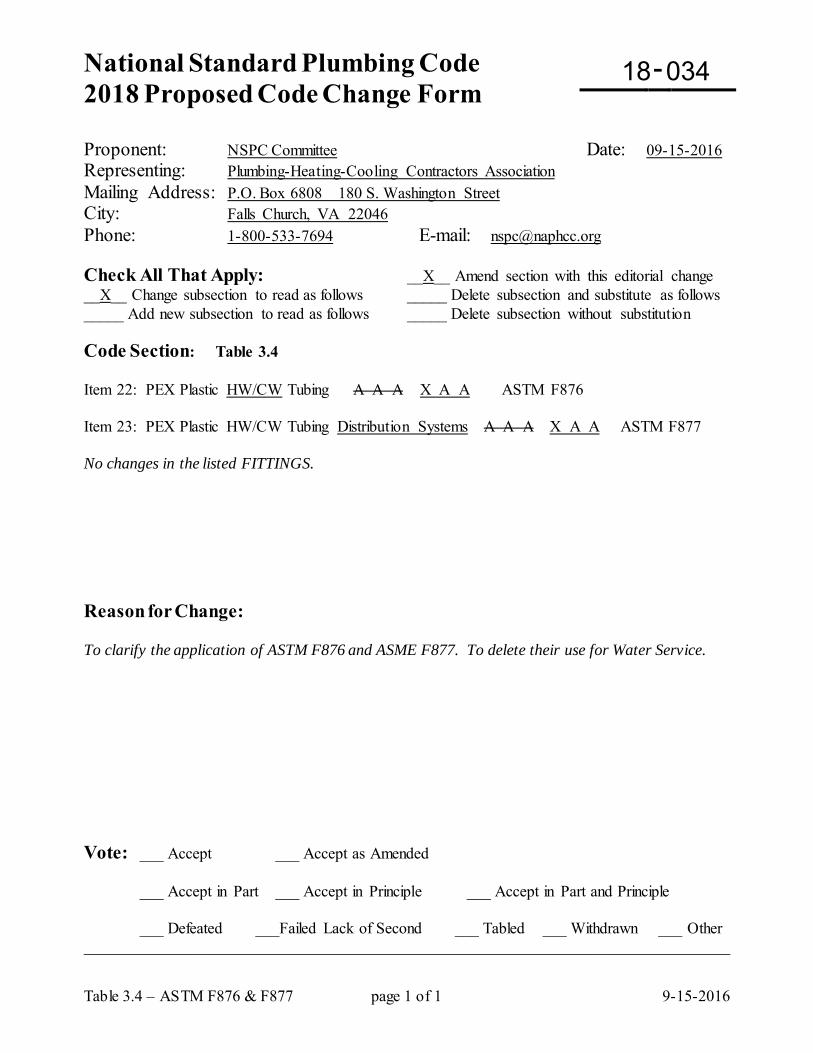
National Standard Plumbing Code 2018 Proposed Code Change Form
-
Table 3.4 – ASTM F876 & F877 page 1 of 1 9-15-2016
Proponent: NSPC Committee Date: 09-15-2016 Representing: Plumbing-Heating-Cooling Contractors Association Mailing Address: P.O. Box 6808 180 S. Washington Street City: Falls Church, VA 22046 Phone: 1-800-533-7694 E-mail: [email protected] Check All That Apply: __X__ Amend section with this editorial change __X__ Change subsection to read as follows _____ Delete subsection and substitute as follows _____ Add new subsection to read as follows _____ Delete subsection without substitution Code Section: Table 3.4 Item 22: PEX Plastic HW/CW Tubing A A A X A A ASTM F876 Item 23: PEX Plastic HW/CW Tubing Distribution Systems A A A X A A ASTM F877 No changes in the listed FITTINGS. Reason for Change: To clarify the application of ASTM F876 and ASME F877. To delete their use for Water Service. Vote: ___ Accept ___ Accept as Amended
___ Accept in Part ___ Accept in Principle ___ Accept in Part and Principle
___ Defeated ___Failed Lack of Second ___ Tabled ___ Withdrawn ___ Other _________________________________________________________________________________
18 034
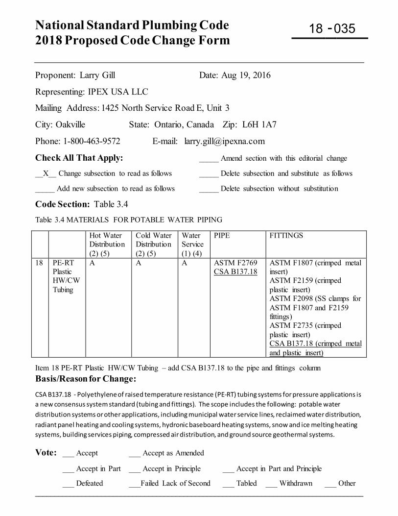
National Standard Plumbing Code 2018 Proposed Code Change Form
-
Proponent: Larry Gill Date: Aug 19, 2016
Representing: IPEX USA LLC
Mailing Address: 1425 North Service Road E, Unit 3
City: Oakville State: Ontario, Canada Zip: L6H 1A7
Phone: 1-800-463-9572 E-mail: [email protected]
Check All That Apply: _____ Amend section with this editorial change __X__ Change subsection to read as follows _____ Delete subsection and substitute as follows _____ Add new subsection to read as follows _____ Delete subsection without substitution
Code Section: Table 3.4 Table 3.4 MATERIALS FOR POTABLE WATER PIPING Hot Water
Distribution (2) (5)
Cold Water Distribution (2) (5)
Water Service (1) (4)
PIPE FITTINGS
18 PE-RT Plastic HW/CW Tubing
A A A ASTM F2769 CSA B137.18
ASTM F1807 (crimped metal insert) ASTM F2159 (crimped plastic insert) ASTM F2098 (SS clamps for ASTM F1807 and F2159 fittings) ASTM F2735 (crimped plastic insert) CSA B137.18 (crimped metal and plastic insert)
Item 18 PE-RT Plastic HW/CW Tubing – add CSA B137.18 to the pipe and fittings column Basis/Reason for Change: CSA B137.18 - Polyethylene of raised temperature resistance (PE-RT) tubing systems for pressure applications is a new consensus system standard (tubing and fittings). The scope includes the following: potable water distribution systems or other applications, including municipal water service lines, reclaimed water distribution, radiant panel heating and cooling systems, hydronic baseboard heating systems, snow and ice melting heating systems, building services piping, compressed air distribution, and ground source geothermal systems.
Vote: ___ Accept ___ Accept as Amended
___ Accept in Part ___ Accept in Principle ___ Accept in Part and Principle
___ Defeated ___Failed Lack of Second ___ Tabled ___ Withdrawn ___ Other ____________________________________________________________________________________
18 035
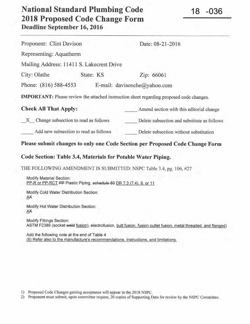
18 036
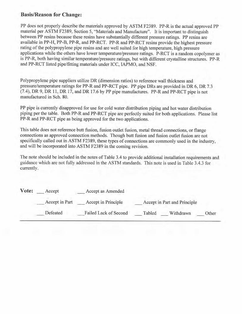
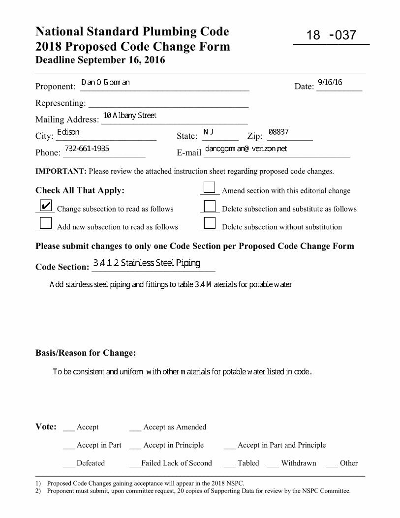
National Standard Plumbing Code 2018 Proposed Code Change Form Deadline September 16, 2016
-
1) Proposed Code Changes gaining acceptance will appear in the 2018 NSPC. 2) Proponent must submit, upon committee request, 20 copies of Supporting Data for review by the NSPC Committee.
Proponent: _____________________________________ Date: __________
Representing: ___________________________________
Mailing Address: ________________________________
City: ______________________ State: ________ Zip: __________
Phone: __________________ E-mail ________________________________ IMPORTANT: Please review the attached instruction sheet regarding proposed code changes. Check All That Apply: _____ Amend section with this editorial change _____ Change subsection to read as follows _____ Delete subsection and substitute as follows _____ Add new subsection to read as follows _____ Delete subsection without substitution Please submit changes to only one Code Section per Proposed Code Change Form Code Section: ___________________________ Basis/Reason for Change: Vote: ___ Accept ___ Accept as Amended
___ Accept in Part ___ Accept in Principle ___ Accept in Part and Principle
___ Defeated ___Failed Lack of Second ___ Tabled ___ Withdrawn ___ Other ____________________________________________________________________________________
18 037
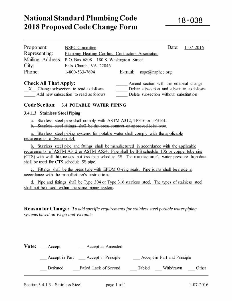
National Standard Plumbing Code 2018 Proposed Code Change Form
-
Section 3.4.1.3 - Stainless Steel page 1 of 1 1-07-2016
Proponent: NSPC Committee Date: 1-07-2016 Representing: Plumbing-Heating-Cooling Contractors Association Mailing Address: P.O. Box 6808 180 S. Washington Street City: Falls Church, VA 22046 Phone: 1-800-533-7694 E-mail: [email protected] Check All That Apply: _____ Amend section with this editorial change __X__ Change subsection to read as follows _____ Delete subsection and substitute as follows _____ Add new subsection to read as follows _____ Delete subsection without substitution Code Section: 3.4 POTABLE WATER PIPING
3.4.1.3 Stainless Steel Piping a. Stainless steel pipe shall comply with ASTM A312, TP316 or TP316L. b. Stainless steel fittings shall be the press connect or approved joint type. a. Stainless steel piping systems for potable water shall comply with the applicable requirements of Section 3.4.
b. Stainless steel pipe and fittings shall be manufactured in accordance with the applicable requirements of ASTM A312 or ASTM A554. Pipe shall be IPS schedule 10S or copper tube size (CTS) with wall thicknesses not less than schedule 5S. The manufacturer's water pressure drop data shall be used for CTS schedule 5S pipe. c. Fittings shall be the press type with EPDM O-ring seals. Pipe joints shall be made in accordance with the manufacturer's instructions. d. Pipe and fittings shall be Type 304 or Type 316 stainless steel. The types of stainless steel shall not be mixed within the same piping system. Reason for Change: To add specific requirements for stainless steel potable water piping systems based on Viega and Victaulic. Vote: ___ Accept ___ Accept as Amended
___ Accept in Part ___ Accept in Principle ___ Accept in Part and Principle
___ Defeated ___Failed Lack of Second ___ Tabled ___ Withdrawn ___ Other _________________________________________________________________________________
18 038
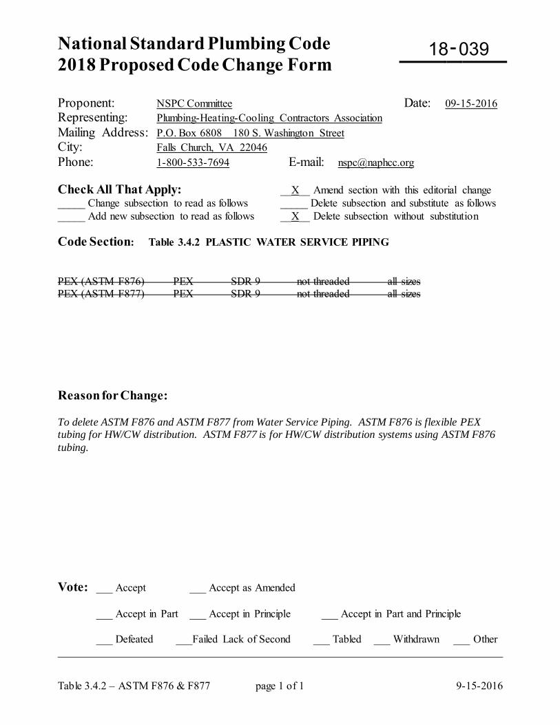
National Standard Plumbing Code 2018 Proposed Code Change Form
-
Table 3.4.2 – ASTM F876 & F877 page 1 of 1 9-15-2016
Proponent: NSPC Committee Date: 09-15-2016 Representing: Plumbing-Heating-Cooling Contractors Association Mailing Address: P.O. Box 6808 180 S. Washington Street City: Falls Church, VA 22046 Phone: 1-800-533-7694 E-mail: [email protected] Check All That Apply: __X__ Amend section with this editorial change _____ Change subsection to read as follows _____ Delete subsection and substitute as follows _____ Add new subsection to read as follows __X__ Delete subsection without substitution Code Section: Table 3.4.2 PLASTIC WATER SERVICE PIPING PEX (ASTM F876) PEX SDR 9 not threaded all sizes PEX (ASTM F877) PEX SDR 9 not threaded all sizes Reason for Change: To delete ASTM F876 and ASTM F877 from Water Service Piping. ASTM F876 is flexible PEX tubing for HW/CW distribution. ASTM F877 is for HW/CW distribution systems using ASTM F876 tubing. Vote: ___ Accept ___ Accept as Amended
___ Accept in Part ___ Accept in Principle ___ Accept in Part and Principle
___ Defeated ___Failed Lack of Second ___ Tabled ___ Withdrawn ___ Other _________________________________________________________________________________
18 039
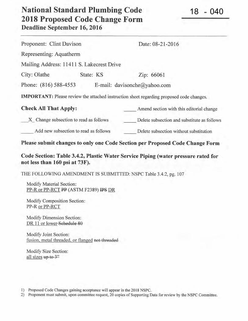
18 040
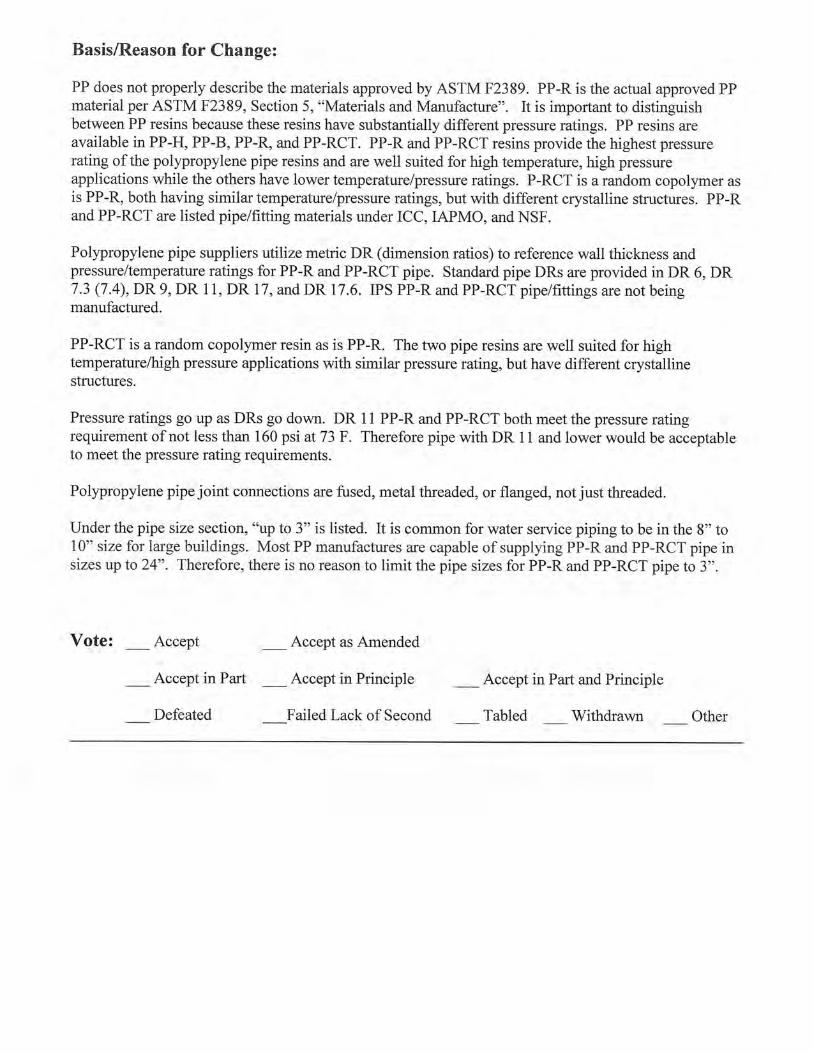
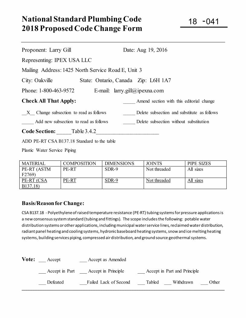
National Standard Plumbing Code 2018 Proposed Code Change Form
-
Proponent: Larry Gill Date: Aug 19, 2016
Representing: IPEX USA LLC
Mailing Address: 1425 North Service Road E, Unit 3
City: Oakville State: Ontario, Canada Zip: L6H 1A7
Phone: 1-800-463-9572 E-mail: [email protected]
Check All That Apply: _____ Amend section with this editorial change __X__ Change subsection to read as follows _____ Delete subsection and substitute as follows _____ Add new subsection to read as follows _____ Delete subsection without substitution
Code Section: _____Table 3.4.2______________________ ADD PE-RT CSA B137.18 Standard to the table Plastic Water Service Piping MATERIAL COMPOSITION DIMENSIONS JOINTS PIPE SIZES PE-RT (ASTM F2769)
PE-RT SDR-9 Not threaded All sizes
PE-RT (CSA B137.18)
PE-RT SDR-9 Not threaded All sizes
Basis/Reason for Change: CSA B137.18 - Polyethylene of raised temperature resistance (PE-RT) tubing systems for pressure applications is a new consensus system standard (tubing and fittings). The scope includes the following: potable water distribution systems or other applications, including municipal water service lines, reclaimed water distribution, radiant panel heating and cooling systems, hydronic baseboard heating systems, snow and ice melting heating systems, building services piping, compressed air distribution, and ground source geothermal systems.
Vote: ___ Accept ___ Accept as Amended
___ Accept in Part ___ Accept in Principle ___ Accept in Part and Principle
___ Defeated ___Failed Lack of Second ___ Tabled ___ Withdrawn ___ Other ____________________________________________________________________________________
18 041
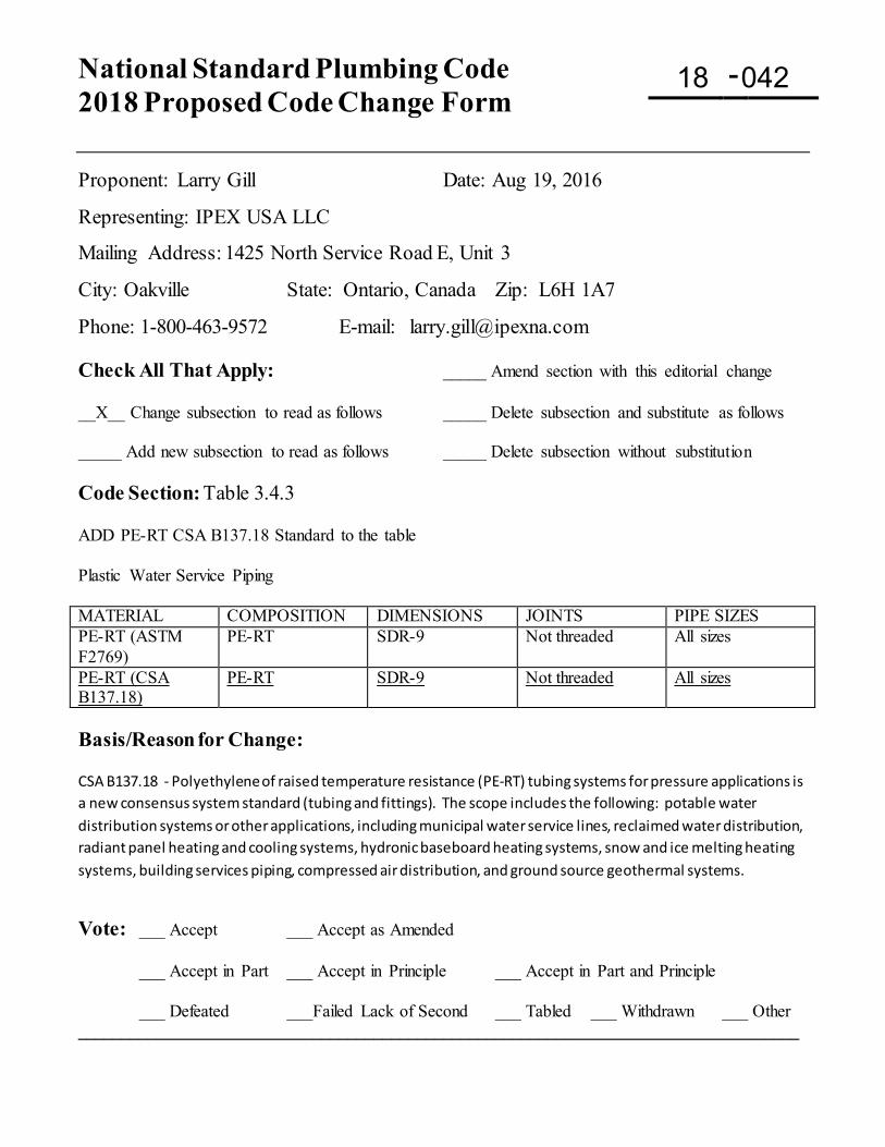
National Standard Plumbing Code 2018 Proposed Code Change Form
-
Proponent: Larry Gill Date: Aug 19, 2016
Representing: IPEX USA LLC
Mailing Address: 1425 North Service Road E, Unit 3
City: Oakville State: Ontario, Canada Zip: L6H 1A7
Phone: 1-800-463-9572 E-mail: [email protected] Check All That Apply: _____ Amend section with this editorial change __X__ Change subsection to read as follows _____ Delete subsection and substitute as follows _____ Add new subsection to read as follows _____ Delete subsection without substitution Code Section: Table 3.4.3 ADD PE-RT CSA B137.18 Standard to the table Plastic Water Service Piping MATERIAL COMPOSITION DIMENSIONS JOINTS PIPE SIZES PE-RT (ASTM F2769)
PE-RT SDR-9 Not threaded All sizes
PE-RT (CSA B137.18)
PE-RT SDR-9 Not threaded All sizes
Basis/Reason for Change: CSA B137.18 - Polyethylene of raised temperature resistance (PE-RT) tubing systems for pressure applications is a new consensus system standard (tubing and fittings). The scope includes the following: potable water distribution systems or other applications, including municipal water service lines, reclaimed water distribution, radiant panel heating and cooling systems, hydronic baseboard heating systems, snow and ice melting heating systems, building services piping, compressed air distribution, and ground source geothermal systems.
Vote: ___ Accept ___ Accept as Amended
___ Accept in Part ___ Accept in Principle ___ Accept in Part and Principle
___ Defeated ___Failed Lack of Second ___ Tabled ___ Withdrawn ___ Other ___________________________________________________________________________________
18 042
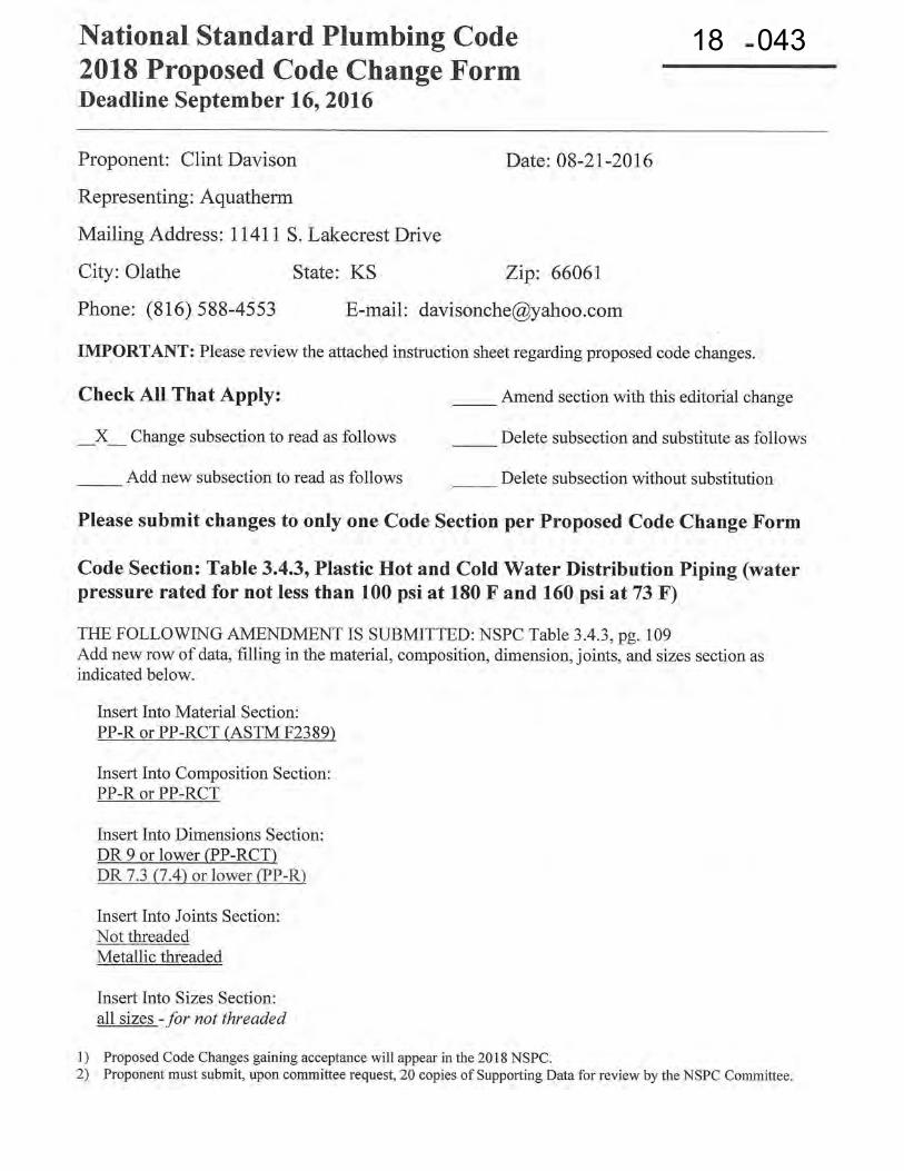
18 043
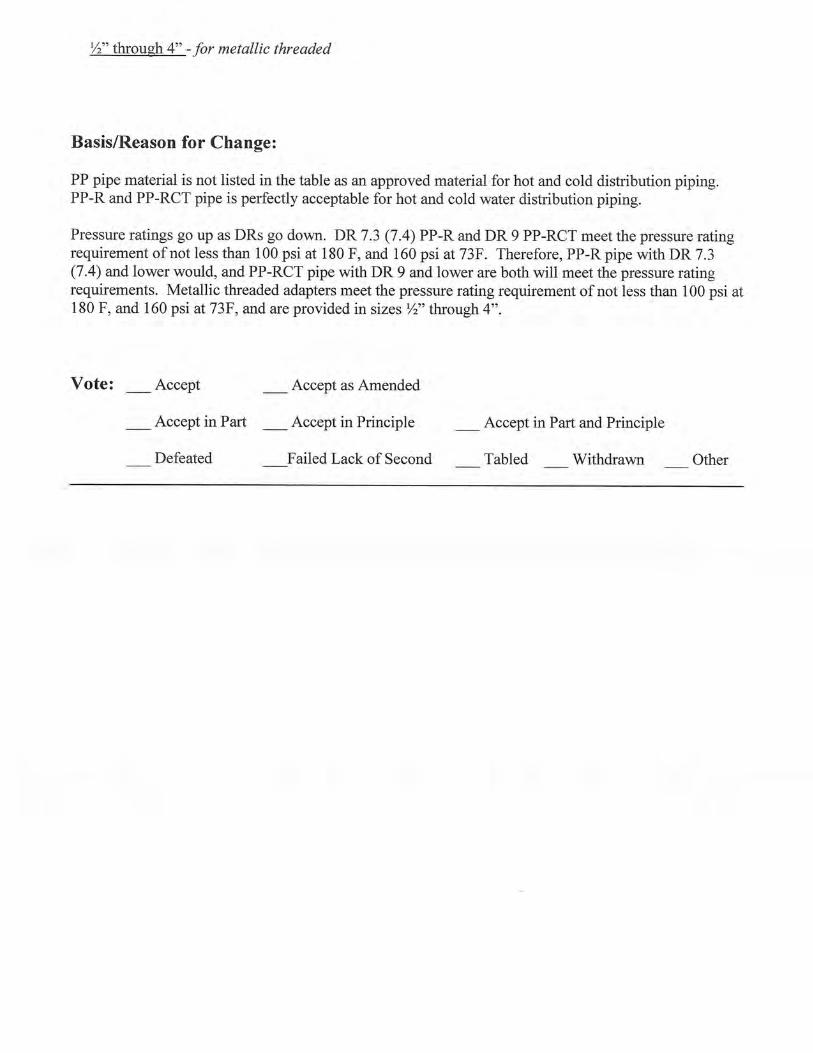
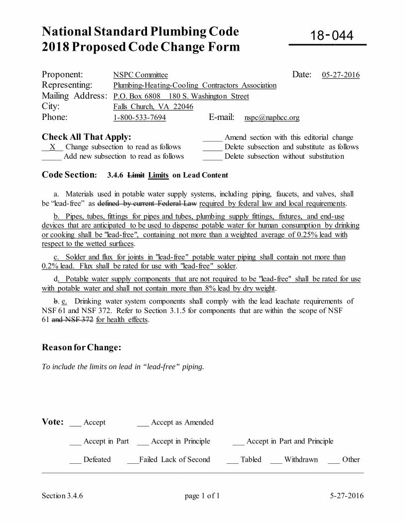
National Standard Plumbing Code 2018 Proposed Code Change Form
-
Section 3.4.6 page 1 of 1 5-27-2016
Proponent: NSPC Committee Date: 05-27-2016 Representing: Plumbing-Heating-Cooling Contractors Association Mailing Address: P.O. Box 6808 180 S. Washington Street City: Falls Church, VA 22046 Phone: 1-800-533-7694 E-mail: [email protected] Check All That Apply: _____ Amend section with this editorial change __X__ Change subsection to read as follows _____ Delete subsection and substitute as follows _____ Add new subsection to read as follows _____ Delete subsection without substitution Code Section: 3.4.6 Limit Limits on Lead Content a. Materials used in potable water supply systems, including piping, faucets, and valves, shall be “lead-free” as defined by current Federal Law required by federal law and local requirements. b. Pipes, tubes, fittings for pipes and tubes, plumbing supply fittings, fixtures, and end-use devices that are anticipated to be used to dispense potable water for human consumption by drinking or cooking shall be "lead-free", containing not more than a weighted average of 0.25% lead with respect to the wetted surfaces.
c. Solder and flux for joints in "lead-free" potable water piping shall contain not more than 0.2% lead. Flux shall be rated for use with "lead-free" solder. d. Potable water supply components that are not required to be "lead-free" shall be rated for use with potable water and shall not contain more than 8% lead by dry weight. b. e. Drinking water system components shall comply with the lead leachate requirements of NSF 61 and NSF 372. Refer to Section 3.1.5 for components that are within the scope of NSF 61 and NSF 372 for health effects. Reason for Change: To include the limits on lead in “lead-free” piping. Vote: ___ Accept ___ Accept as Amended
___ Accept in Part ___ Accept in Principle ___ Accept in Part and Principle
___ Defeated ___Failed Lack of Second ___ Tabled ___ Withdrawn ___ Other _________________________________________________________________________________
18 044
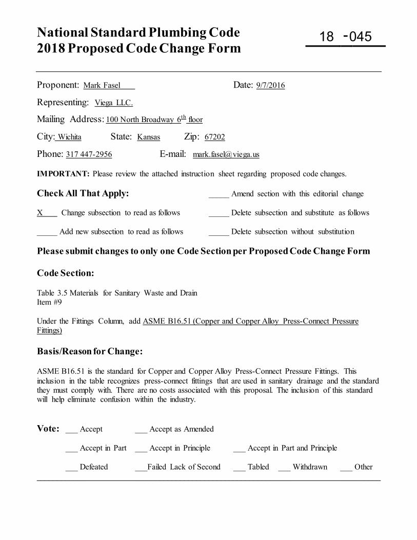
National Standard Plumbing Code 2018 Proposed Code Change Form
-
Proponent: Mark Fasel Date: 9/7/2016
Representing: Viega LLC.
Mailing Address: 100 North Broadway 6th floor
City: Wichita State: Kansas Zip: 67202
Phone: 317 447-2956 E-mail: [email protected] IMPORTANT: Please review the attached instruction sheet regarding proposed code changes. Check All That Apply: _____ Amend section with this editorial change X Change subsection to read as follows _____ Delete subsection and substitute as follows _____ Add new subsection to read as follows _____ Delete subsection without substitution Please submit changes to only one Code Section per Proposed Code Change Form Code Section: Table 3.5 Materials for Sanitary Waste and Drain Item #9 Under the Fittings Column, add ASME B16.51 (Copper and Copper Alloy Press-Connect Pressure Fittings) Basis/Reason for Change: ASME B16.51 is the standard for Copper and Copper Alloy Press-Connect Pressure Fittings. This inclusion in the table recognizes press-connect fittings that are used in sanitary drainage and the standard they must comply with. There are no costs associated with this proposal. The inclusion of this standard will help eliminate confusion within the industry. Vote: ___ Accept ___ Accept as Amended
___ Accept in Part ___ Accept in Principle ___ Accept in Part and Principle
___ Defeated ___Failed Lack of Second ___ Tabled ___ Withdrawn ___ Other ____________________________________________________________________________________
18 045
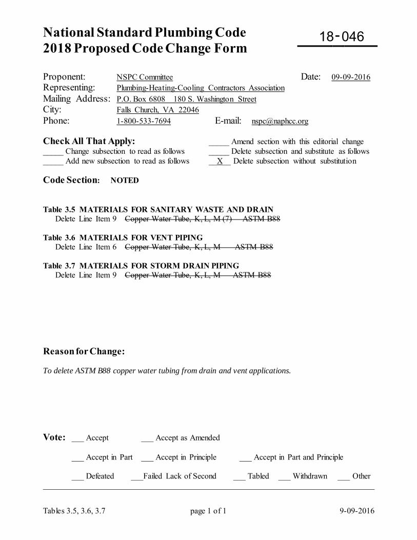
National Standard Plumbing Code 2018 Proposed Code Change Form
-
Tables 3.5, 3.6, 3.7 page 1 of 1 9-09-2016
Proponent: NSPC Committee Date: 09-09-2016 Representing: Plumbing-Heating-Cooling Contractors Association Mailing Address: P.O. Box 6808 180 S. Washington Street City: Falls Church, VA 22046 Phone: 1-800-533-7694 E-mail: [email protected] Check All That Apply: _____ Amend section with this editorial change _____ Change subsection to read as follows _____ Delete subsection and substitute as follows _____ Add new subsection to read as follows __X__ Delete subsection without substitution Code Section: NOTED Table 3.5 MATERIALS FOR SANITARY WASTE AND DRAIN Delete Line Item 9 Copper Water Tube, K, L, M (7) ASTM B88 Table 3.6 MATERIALS FOR VENT PIPING Delete Line Item 6 Copper Water Tube, K, L, M ASTM B88 Table 3.7 MATERIALS FOR STORM DRAIN PIPING Delete Line Item 9 Copper Water Tube, K, L, M ASTM B88 Reason for Change: To delete ASTM B88 copper water tubing from drain and vent applications. Vote: ___ Accept ___ Accept as Amended
___ Accept in Part ___ Accept in Principle ___ Accept in Part and Principle
___ Defeated ___Failed Lack of Second ___ Tabled ___ Withdrawn ___ Other _________________________________________________________________________________
18 046
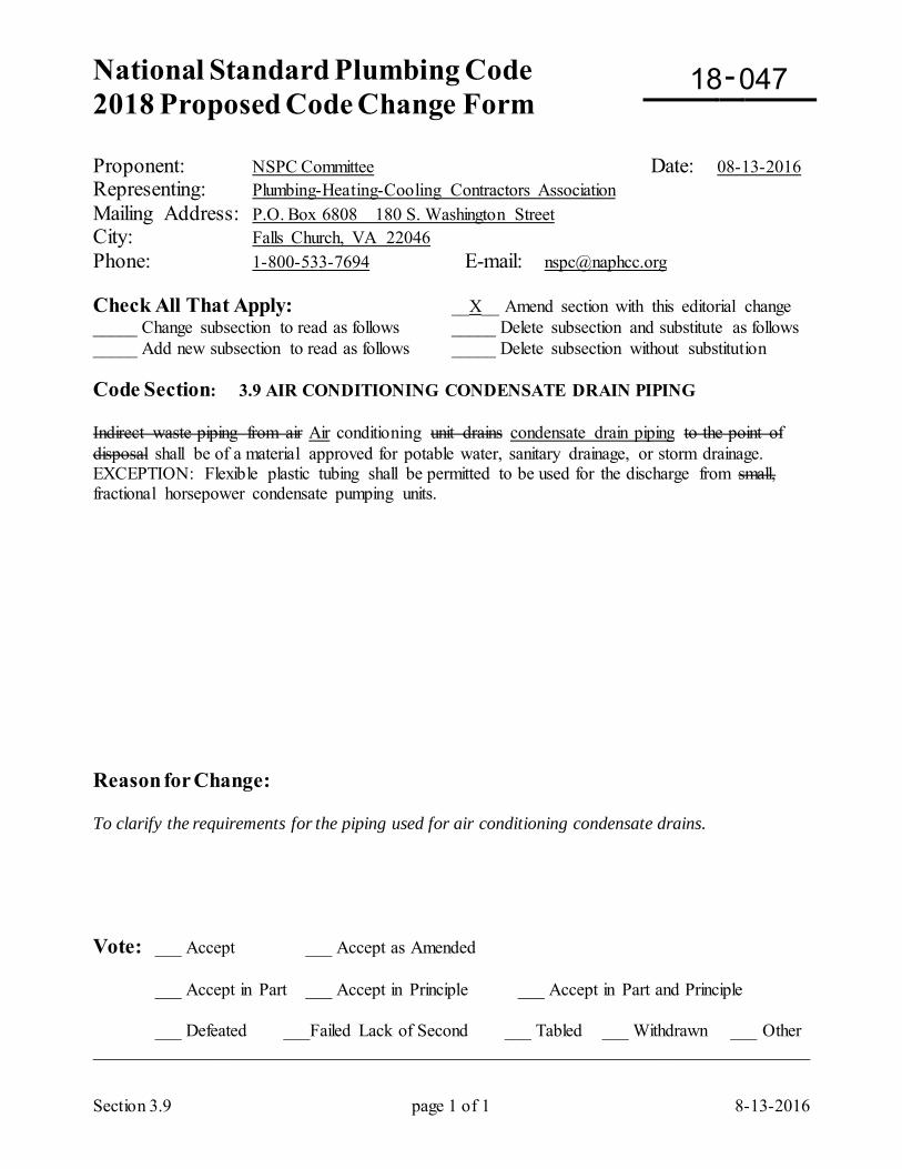
National Standard Plumbing Code 2018 Proposed Code Change Form
-
Section 3.9 page 1 of 1 8-13-2016
Proponent: NSPC Committee Date: 08-13-2016 Representing: Plumbing-Heating-Cooling Contractors Association Mailing Address: P.O. Box 6808 180 S. Washington Street City: Falls Church, VA 22046 Phone: 1-800-533-7694 E-mail: [email protected] Check All That Apply: __X__ Amend section with this editorial change _____ Change subsection to read as follows _____ Delete subsection and substitute as follows _____ Add new subsection to read as follows _____ Delete subsection without substitution Code Section: 3.9 AIR CONDITIONING CONDENSATE DRAIN PIPING Indirect waste piping from air Air conditioning unit drains condensate drain piping to the point of disposal shall be of a material approved for potable water, sanitary drainage, or storm drainage. EXCEPTION: Flexible plastic tubing shall be permitted to be used for the discharge from small, fractional horsepower condensate pumping units. Reason for Change: To clarify the requirements for the piping used for air conditioning condensate drains. Vote: ___ Accept ___ Accept as Amended
___ Accept in Part ___ Accept in Principle ___ Accept in Part and Principle
___ Defeated ___Failed Lack of Second ___ Tabled ___ Withdrawn ___ Other _________________________________________________________________________________
18 047
National Standard Plumbing Code 2018 Proposed Code Change Form Deadline September 16, 2016
-
1) Proposed Code Changes gaining acceptance will appear in the 2018 NSPC. 2) Proponent must submit, upon committee request, 20 copies of Supporting Data for review by the NSPC Committee.
Proponent: Donald M. Jones Date: 1/9/2016
Representing: Donald M. Jones
Mailing Address: 202 W. Summit St
City: Vineland State: NJ Zip: 08360
Phone: 609 517 1473 E-mail: [email protected] IMPORTANT: Please review the attached instruction sheet regarding proposed code changes. Check All That Apply: _____ Amend section with this editorial change __X__ Change subsection to read as follows _____ Delete subsection and substitute as follows _____ Add new subsection to read as follows _____ Delete subsection without substitution Please submit changes to only one Code Section per Proposed Code Change Form Code Section: 3.9 Air Conditioning Condensate Drain Piping Indirect waste piping from air conditioning unit drains to the point of disposal shall be of a material approved for potable water, sanitary drainage, or storm drainage. Drainage fittings shall be used for systems larger than 20-ton cooling capacity in accordance with Section 9.4.3 Air Conditioning Condensate EXCEPTION: Flexible plastic tubing shall be permitted to be used for the discharge from small, fractional horsepower condensate pumping units. Basis/Reason for Change: This is a clarification of the intent of the code, which presently conflicts with 9.4.3. Section 3.9 implies that potable pipe and fitting can be used for all installations, but potable/pressure fittings are restricted to systems of 20-tons and less (in accordance with 9.4.3). Vote: ___ Accept ___ Accept as Amended
___ Accept in Part ___ Accept in Principle ___ Accept in Part and Principle
___ Defeated ___Failed Lack of Second ___ Tabled ___ Withdrawn ___ Other ____________________________________________________________________________________
18 048
National Standard Plumbing Code 2018 Proposed Code Change Form
-
Section 4.2.5 page 1 of 1 4-12-2016
Proponent: NSPC Committee Date: 04-12-2016 Representing: Plumbing-Heating-Cooling Contractors Association Mailing Address: P.O. Box 6808 180 S. Washington Street City: Falls Church, VA 22046 Phone: 1-800-533-7694 E-mail: [email protected] Check All That Apply: _____ Amend section with this editorial change __X__ Change subsection to read as follows _____ Delete subsection and substitute as follows _____ Add new subsection to read as follows _____ Delete subsection without substitution Code Section: 4.2.5 Flared Flared joints for copper water tube shall be made with fittings complying with ASME B16.26. Annealed Type K or L copper tube may be flared. If flared joints are used in hard drawn Types K or L copper tube, the tube end to be flared shall be annealed prior to being flared. The tube Tube ends shall be reamed and then expanded with an approved flaring tool. See Figure 4.2.5 Reason for Change: To include the requirements for flared joints in copper water tube. Vote: ___ Accept ___ Accept as Amended
___ Accept in Part ___ Accept in Principle ___ Accept in Part and Principle
___ Defeated ___Failed Lack of Second ___ Tabled ___ Withdrawn ___ Other _________________________________________________________________________________
18 049
National Standard Plumbing Code 2018 Proposed Code Change Form Deadline September 16, 2016
-
Proponent: Mark Fasel Date: 9/7/2016
Representing: Viega LLC.
Mailing Address: 100 North Broadway 6th floor City: Wichita State: Kansas Zip: 67202
Phone: 317 447-2956 E-mail: [email protected]
Check All That Apply: _____ Amend section with this editorial change X Change subsection to read as follows _____ Delete subsection and substitute as follows
Code Section: 4.2.6 Mechanically Crimped (Pressed) Joints Press-Connect Fittings a. Copper fittings for water supply and distribution, designed for mechanically crimped (pressed) pressed connections to ASTM B88 hard drawn copper water tube, shall include an a-ring gasket elastomeric sealing element complying with NSF 61 for potable water. EXCEPTION: Mechanically crimped (pressed) Press-connect fitting joints shall be permitted with annealed copper water tube when such use is included in the fitting manufacturer's technical data and installation instructions. b. The fittings shall comply with the material and sizing requirements of ASME B16.22 (wrought copper or copper alloy fittings) or ASME B 16.18 (cast copper alloy fittings). be in full compliance with ASME B16.51. c. During installation, the tube end shall be deburred de-burred and depth-marked to permit visual verification of full insertion of the tube into the fitting socket. d. The joint shall be crimped (pressed) pressed using a tool approved by the manufacturer of the fitting. e. The joints fittings shall be rated by the manufacturer for not less than 200 psig at 180 -200 deg F. f. The fittings shall be permitted to be installed in concealed locations. Basis/Reason for Change: ASME B16.51 is the standard for Press-connect fittings that uses the terminology “Press-Connect Fittings” This addition will help to harmonize the terminology used between the model code and the standard specification to which the fittings must comply. In section 4.2.6 subpart “a” the term elastomeric sealing element is used in ASME B16.51 as well and the term O-ring is not used due to the variety of sealing elements used in press-connect fittings. In section 4.2.5 subpart “e”, the minimum pressure and temperature the fittings must be in compliance per standard B16.51 200 psig and 200 deg. F. Replacing the 180 deg F. with 200 deg. F aligns the code with the standards requirements. There is no cost associated with this code proposal.
Vote: ___ Accept ___ Accept as Amended
___ Accept in Part ___ Accept in Principle ___ Accept in Part and Principle
___ Defeated ___Failed Lack of Second ___ Tabled ___ Withdrawn ___ Other ____________________________________________________________________________________
18 050
National Standard Plumbing Code 2018 Proposed Code Change Form Deadline September 16, 2016
-
Proponent: Mark Fasel Date: 9/7/2016
Representing: Viega LLC.
Mailing Address: 100 North Broadway 6th floor City: Wichita State: Kansas Zip: 67202
Phone: 317 447-2956 E-mail: [email protected] Check All That Apply: _____ Amend section with this editorial change X Change subsection to read as follows _____ Delete subsection and substitute as follows _____ Add new subsection to read as follows _____ Delete subsection without substitution
Code Section: 4.2.6 Mechanically Crimped (Pressed) Joints a. Copper fittings for water supply and distribution, designed for mechanically crimped (pressed) connections to ASTM B88 hard drawn copper water tube, shall include an o-ring gasket complying with NSF 61 for potable water. EXCEPTION: Mechanically crimped (pressed) shall be permitted with annealed copper water tube when such use is included in the fitting manufacturer's technical data and installation instructions. b. The fittings shall comply with the material and sizing requirements of ASME B16.22 (wrought copper or copper alloy fittings) or ASME B 16.18 (cast copper alloy fittings). c. During installation, the tube end shall be de-burred and depth-marked to permit visual verification of full insertion of the tube into the fitting socket. d. The joint shall be crimped (pressed) using a tool approved by the manufacturer of the fitting. e. The joints shall be rated by the manufacturer for not less than 200 psig at 180 deg F. f. The fittings shall be permitted to be installed in concealed locations. g. The fittings shall be permitted to be installed underground when such use is included in the fitting manufacturer's technical data and installation instructions. Basis/Reason for Change: Several manufacturers of copper and copper alloy press-connect fittings already allow direct burial of these fittings. We have had multiple requests from Code Officials in New Jersey to include this language into the body of the code to clarify burial of press-connect fittings. Section 4.2.6 subpart “g” clearly requires that the manufacturer’s technical data and instruction manual validate the burial of the fittings. This additional language will reduce confusion in the industry. There is no cost associated with this proposal. Vote: ___ Accept ___ Accept as Amended
___ Accept in Part ___ Accept in Principle ___ Accept in Part and Principle
___ Defeated ___Failed Lack of Second ___ Tabled ___ Withdrawn ___ Other ____________________________________________________________________________________
18 051
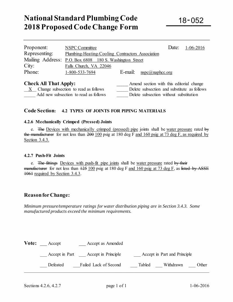
National Standard Plumbing Code 2018 Proposed Code Change Form
-
Sections 4.2.6, 4.2.7 page 1 of 1 1-06-2016
Proponent: NSPC Committee Date: 1-06-2016 Representing: Plumbing-Heating-Cooling Contractors Association Mailing Address: P.O. Box 6808 180 S. Washington Street City: Falls Church, VA 22046 Phone: 1-800-533-7694 E-mail: [email protected] Check All That Apply: _____ Amend section with this editorial change __X__ Change subsection to read as follows _____ Delete subsection and substitute as follows _____ Add new subsection to read as follows _____ Delete subsection without substitution Code Section: 4.2 TYPES OF JOINTS FOR PIPING MATERIALS 4.2.6 Mechanically Crimped (Pressed) Joints e. The Devices with mechanically crimped (pressed) pipe joints shall be water pressure rated by the manufacturer for not less than 200 100 psig at 180 deg F and 160 psig at 73 deg F, as required by Section 3.4.3. 4.2.7 Push-Fit Joints e. The fittings Devices with push-fit pipe joints shall be water pressure rated by their manufacturer for not less than 125 100 psig at 180 deg F and 160 psig at 73 deg F, as listed by ASSE 1061 required by Section 3.4.3. Reason for Change: Minimum pressure/temperature ratings for water distribution piping are in Section 3.4.3. Some manufactured products exceed the minimum requirements. Vote: ___ Accept ___ Accept as Amended
___ Accept in Part ___ Accept in Principle ___ Accept in Part and Principle
___ Defeated ___Failed Lack of Second ___ Tabled ___ Withdrawn ___ Other _________________________________________________________________________________
18 052
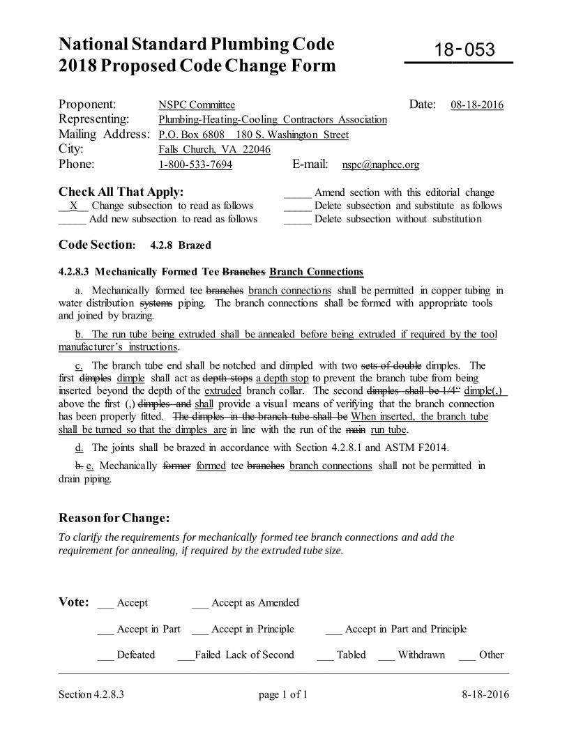
National Standard Plumbing Code 2018 Proposed Code Change Form
-
Section 4.2.8.3 page 1 of 1 8-18-2016
Proponent: NSPC Committee Date: 08-18-2016 Representing: Plumbing-Heating-Cooling Contractors Association Mailing Address: P.O. Box 6808 180 S. Washington Street City: Falls Church, VA 22046 Phone: 1-800-533-7694 E-mail: [email protected] Check All That Apply: _____ Amend section with this editorial change __X__ Change subsection to read as follows _____ Delete subsection and substitute as follows _____ Add new subsection to read as follows _____ Delete subsection without substitution Code Section: 4.2.8 Brazed 4.2.8.3 Mechanically Formed Tee Branches Branch Connections
a. Mechanically formed tee branches branch connections shall be permitted in copper tubing in water distribution systems piping. The branch connections shall be formed with appropriate tools and joined by brazing.
b. The run tube being extruded shall be annealed before being extruded if required by the tool manufacturer’s instructions.
c. The branch tube end shall be notched and dimpled with two sets of double dimples. The first dimples dimple shall act as depth stops a depth stop to prevent the branch tube from being inserted beyond the depth of the extruded branch collar. The second dimples shall be 1/4“ dimple(,) above the first (,) dimples and shall provide a visual means of verifying that the branch connection has been properly fitted. The dimples in the branch tube shall be When inserted, the branch tube shall be turned so that the dimples are in line with the run of the main run tube. d. The joints shall be brazed in accordance with Section 4.2.8.1 and ASTM F2014. b. e. Mechanically former formed tee branches branch connections shall not be permitted in drain piping. Reason for Change: To clarify the requirements for mechanically formed tee branch connections and add the requirement for annealing, if required by the extruded tube size. Vote: ___ Accept ___ Accept as Amended
___ Accept in Part ___ Accept in Principle ___ Accept in Part and Principle
___ Defeated ___Failed Lack of Second ___ Tabled ___ Withdrawn ___ Other _________________________________________________________________________________
18 053
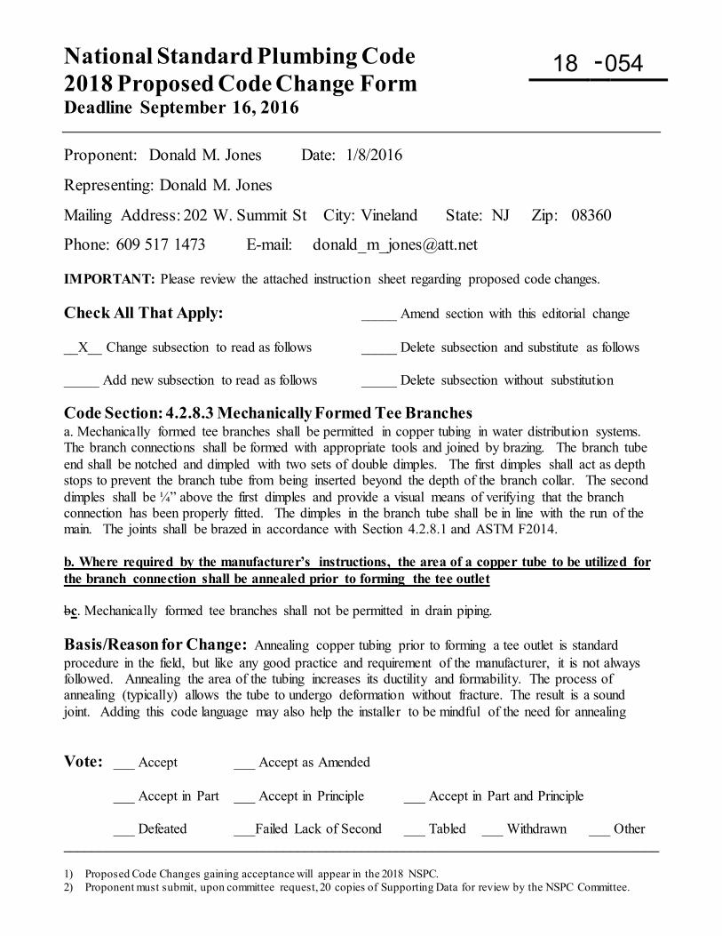
National Standard Plumbing Code 2018 Proposed Code Change Form Deadline September 16, 2016
-
1) Proposed Code Changes gaining acceptance will appear in the 2018 NSPC. 2) Proponent must submit, upon committee request, 20 copies of Supporting Data for review by the NSPC Committee.
Proponent: Donald M. Jones Date: 1/8/2016
Representing: Donald M. Jones
Mailing Address: 202 W. Summit St City: Vineland State: NJ Zip: 08360
Phone: 609 517 1473 E-mail: [email protected] IMPORTANT: Please review the attached instruction sheet regarding proposed code changes. Check All That Apply: _____ Amend section with this editorial change __X__ Change subsection to read as follows _____ Delete subsection and substitute as follows _____ Add new subsection to read as follows _____ Delete subsection without substitution Code Section: 4.2.8.3 Mechanically Formed Tee Branches a. Mechanically formed tee branches shall be permitted in copper tubing in water distribution systems. The branch connections shall be formed with appropriate tools and joined by brazing. The branch tube end shall be notched and dimpled with two sets of double dimples. The first dimples shall act as depth stops to prevent the branch tube from being inserted beyond the depth of the branch collar. The second dimples shall be ¼” above the first dimples and provide a visual means of verifying that the branch connection has been properly fitted. The dimples in the branch tube shall be in line with the run of the main. The joints shall be brazed in accordance with Section 4.2.8.1 and ASTM F2014. b. Where required by the manufacturer’s instructions, the area of a copper tube to be utilized for the branch connection shall be annealed prior to forming the tee outlet bc. Mechanically formed tee branches shall not be permitted in drain piping. Basis/Reason for Change: Annealing copper tubing prior to forming a tee outlet is standard procedure in the field, but like any good practice and requirement of the manufacturer, it is not always followed. Annealing the area of the tubing increases its ductility and formability. The process of annealing (typically) allows the tube to undergo deformation without fracture. The result is a sound joint. Adding this code language may also help the installer to be mindful of the need for annealing Vote: ___ Accept ___ Accept as Amended
___ Accept in Part ___ Accept in Principle ___ Accept in Part and Principle
___ Defeated ___Failed Lack of Second ___ Tabled ___ Withdrawn ___ Other ____________________________________________________________________________________
18 054
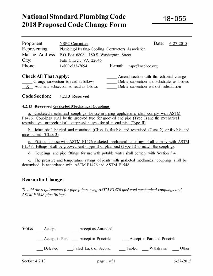
National Standard Plumbing Code 2018 Proposed Code Change Form
-
Section 4.2.13 page 1 of 1 6-27-2015
Proponent: NSPC Committee Date: 6-27-2015 Representing: Plumbing-Heating-Cooling Contractors Association Mailing Address: P.O. Box 6808 180 S. Washington Street City: Falls Church, VA 22046 Phone: 1-800-533-7694 E-mail: [email protected] Check All That Apply: _____ Amend section with this editorial change _____ Change subsection to read as follows _____ Delete subsection and substitute as follows __X__ Add new subsection to read as follows _____ Delete subsection without substitution Code Section: 4.2.13 Reserved 4.2.13 Reserved Gasketed Mechanical Couplings
a. Gasketed mechanical couplings for use in piping applications shall comply with ASTM F1476. Couplings shall be the grooved type for grooved end pipe (Type I) and the mechanical restraint type or mechanical compression type for plain end pipe (Type II).
b. Joints shall be rigid and restrained (Class 1), flexible and restrained (Class 2), or flexible and unrestrained (Class 3).
c. Fittings for use with ASTM F1476 gasketed mechanical couplings shall comply with ASTM F1548. Fittings shall be grooved end (Type I) or plain end (Type II) to match the couplings. d. Couplings and pipe fittings for use with potable water shall comply with Section 3.4.
e. The pressure and temperature ratings of joints with gasketed mechanical couplings shall be determined in accordance with ASTM F1476 and ASTM F1548. Reason for Change: To add the requirements for pipe joints using ASTM F1476 gasketed mechanical couplings and ASTM F1548 pipe fittings. Vote: ___ Accept ___ Accept as Amended
___ Accept in Part ___ Accept in Principle ___ Accept in Part and Principle
___ Defeated ___Failed Lack of Second ___ Tabled ___ Withdrawn ___ Other _________________________________________________________________________________
18 055
18 056
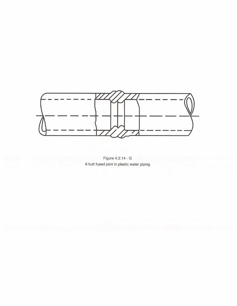
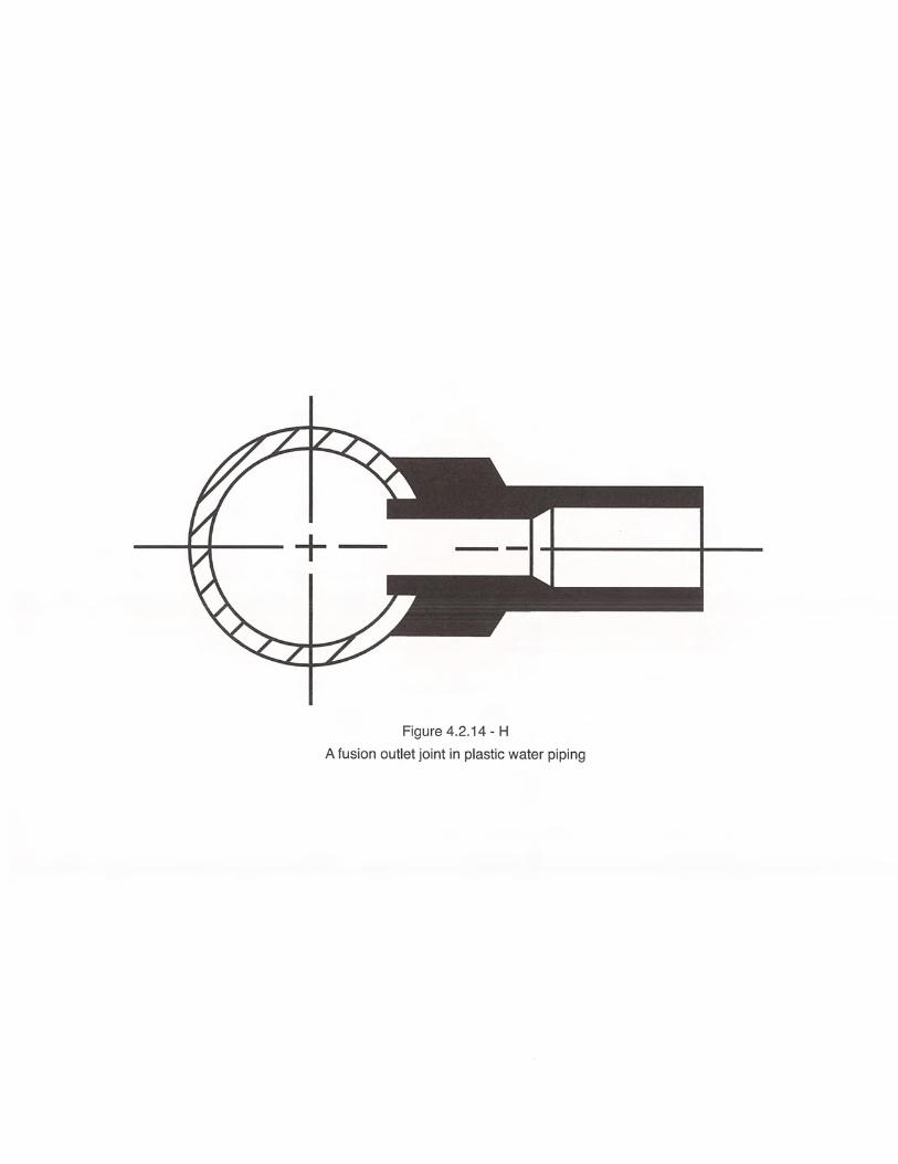
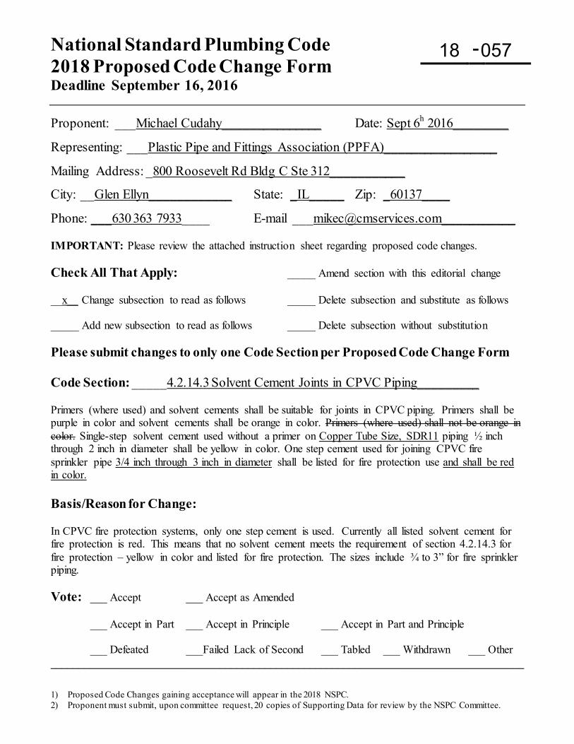
National Standard Plumbing Code 2018 Proposed Code Change Form Deadline September 16, 2016
-
1) Proposed Code Changes gaining acceptance will appear in the 2018 NSPC. 2) Proponent must submit, upon committee request, 20 copies of Supporting Data for review by the NSPC Committee.
Proponent: ___Michael Cudahy_______________ Date: Sept 6h 2016________
Representing: ___Plastic Pipe and Fittings Association (PPFA)_________________
Mailing Address: _800 Roosevelt Rd Bldg C Ste 312___________
City: __Glen Ellyn____________ State: _IL_____ Zip: _60137____
Phone: ___630 363 7933____ E-mail [email protected]___________ IMPORTANT: Please review the attached instruction sheet regarding proposed code changes. Check All That Apply: _____ Amend section with this editorial change __x__ Change subsection to read as follows _____ Delete subsection and substitute as follows _____ Add new subsection to read as follows _____ Delete subsection without substitution Please submit changes to only one Code Section per Proposed Code Change Form Code Section: _____4.2.14.3 Solvent Cement Joints in CPVC Piping_________ Primers (where used) and solvent cements shall be suitable for joints in CPVC piping. Primers shall be purple in color and solvent cements shall be orange in color. Primers (where used) shall not be orange in color. Single-step solvent cement used without a primer on Copper Tube Size, SDR11 piping ½ inch through 2 inch in diameter shall be yellow in color. One step cement used for joining CPVC fire sprinkler pipe 3/4 inch through 3 inch in diameter shall be listed for fire protection use and shall be red in color. Basis/Reason for Change: In CPVC fire protection systems, only one step cement is used. Currently all listed solvent cement for fire protection is red. This means that no solvent cement meets the requirement of section 4.2.14.3 for fire protection – yellow in color and listed for fire protection. The sizes include ¾ to 3” for fire sprinkler piping. Vote: ___ Accept ___ Accept as Amended
___ Accept in Part ___ Accept in Principle ___ Accept in Part and Principle
___ Defeated ___Failed Lack of Second ___ Tabled ___ Withdrawn ___ Other ____________________________________________________________________________________
18 057
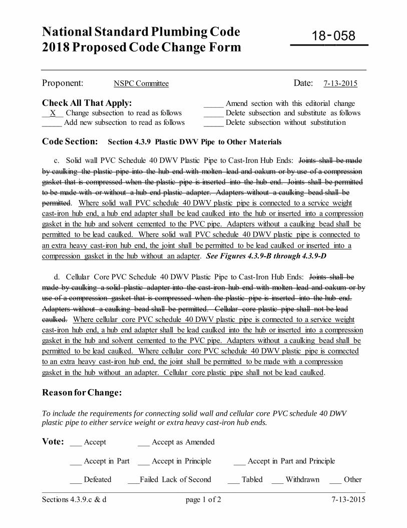
National Standard Plumbing Code 2018 Proposed Code Change Form
-
Sections 4.3.9.c & d page 1 of 2 7-13-2015
Proponent: NSPC Committee Date: 7-13-2015 Check All That Apply: _____ Amend section with this editorial change __X__ Change subsection to read as follows _____ Delete subsection and substitute as follows _____ Add new subsection to read as follows _____ Delete subsection without substitution Code Section: Section 4.3.9 Plastic DWV Pipe to Other Materials c. Solid wall PVC Schedule 40 DWV Plastic Pipe to Cast-Iron Hub Ends: Joints shall be made by caulking the plastic pipe into the hub end with molten lead and oakum or by use of a compression gasket that is compressed when the plastic pipe is inserted into the hub end. Joints shall be permitted to be made with or without a hub end plastic adapter. Adapters without a caulking bead shall be permitted. Where solid wall PVC schedule 40 DWV plastic pipe is connected to a service weight cast-iron hub end, a hub end adapter shall be lead caulked into the hub or inserted into a compression gasket in the hub and solvent cemented to the PVC pipe. Adapters without a caulking bead shall be permitted to be lead caulked. Where solid wall PVC schedule 40 DWV plastic pipe is connected to an extra heavy cast-iron hub end, the joint shall be permitted to be lead caulked or inserted into a compression gasket in the hub without an adapter. See Figures 4.3.9-B through 4.3.9-D d. Cellular Core PVC Schedule 40 DWV Plastic Pipe to Cast-Iron Hub Ends: Joints shall be made by caulking a solid plastic adapter into the cast-iron hub end with molten lead and oakum or by use of a compression gasket that is compressed when the plastic pipe is inserted into the hub end. Adapters without a caulking bead shall be permitted. Cellular core plastic pipe shall not be lead caulked. Where cellular core PVC schedule 40 DWV plastic pipe is connected to a service weight cast-iron hub end, a hub end adapter shall be lead caulked into the hub or inserted into a compression gasket in the hub and solvent cemented to the PVC pipe. Adapters without a caulking bead shall be permitted to be lead caulked. Where cellular core PVC schedule 40 DWV plastic pipe is connected to an extra heavy cast-iron hub end, the joint shall be permitted to be made with a compression gasket in the hub without an adapter. Cellular core plastic pipe shall not be lead caulked. Reason for Change: To include the requirements for connecting solid wall and cellular core PVC schedule 40 DWV plastic pipe to either service weight or extra heavy cast-iron hub ends. Vote: ___ Accept ___ Accept as Amended
___ Accept in Part ___ Accept in Principle ___ Accept in Part and Principle
___ Defeated ___Failed Lack of Second ___ Tabled ___ Withdrawn ___ Other _________________________________________________________________________________
18 058
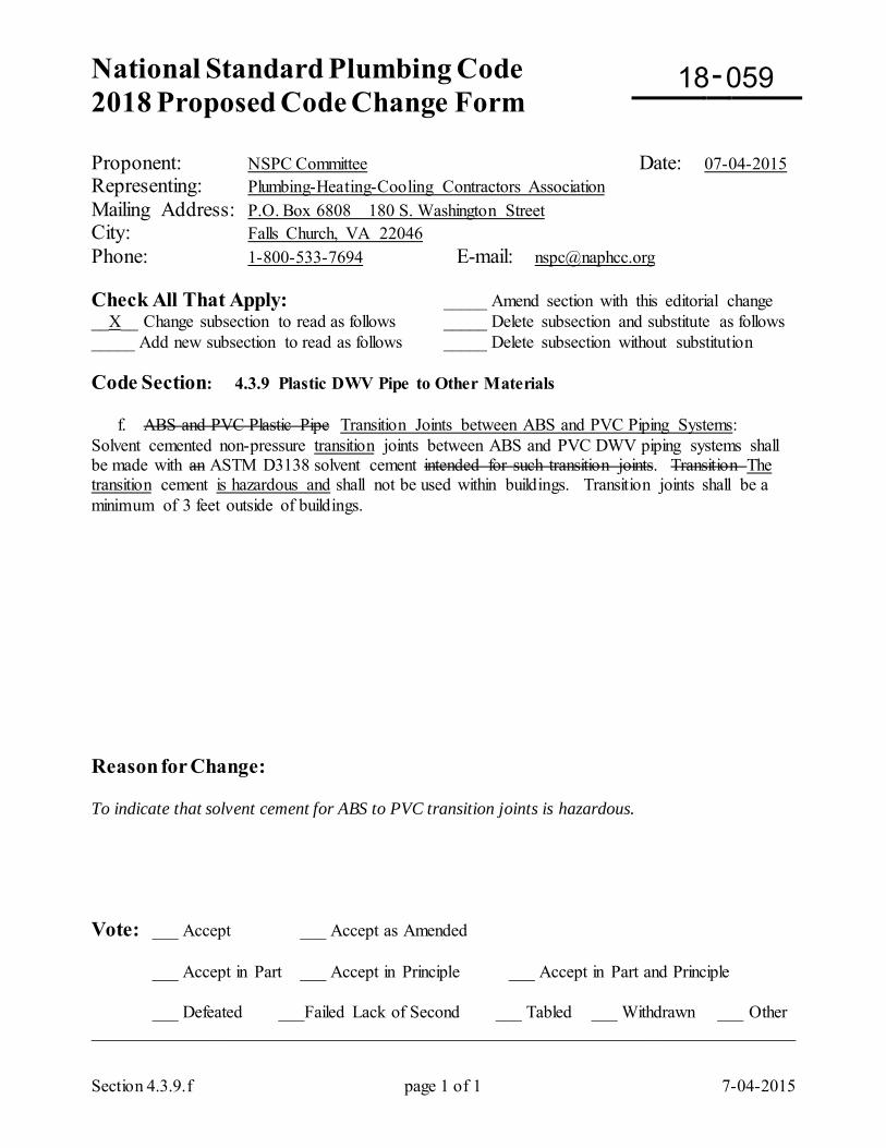
National Standard Plumbing Code 2018 Proposed Code Change Form
-
Section 4.3.9.f page 1 of 1 7-04-2015
Proponent: NSPC Committee Date: 07-04-2015 Representing: Plumbing-Heating-Cooling Contractors Association Mailing Address: P.O. Box 6808 180 S. Washington Street City: Falls Church, VA 22046 Phone: 1-800-533-7694 E-mail: [email protected] Check All That Apply: _____ Amend section with this editorial change __X__ Change subsection to read as follows _____ Delete subsection and substitute as follows _____ Add new subsection to read as follows _____ Delete subsection without substitution Code Section: 4.3.9 Plastic DWV Pipe to Other Materials f. ABS and PVC Plastic Pipe Transition Joints between ABS and PVC Piping Systems: Solvent cemented non-pressure transition joints between ABS and PVC DWV piping systems shall be made with an ASTM D3138 solvent cement intended for such transition joints. Transition The transition cement is hazardous and shall not be used within buildings. Transition joints shall be a minimum of 3 feet outside of buildings. Reason for Change: To indicate that solvent cement for ABS to PVC transition joints is hazardous. Vote: ___ Accept ___ Accept as Amended
___ Accept in Part ___ Accept in Principle ___ Accept in Part and Principle
___ Defeated ___Failed Lack of Second ___ Tabled ___ Withdrawn ___ Other _________________________________________________________________________________
18 059
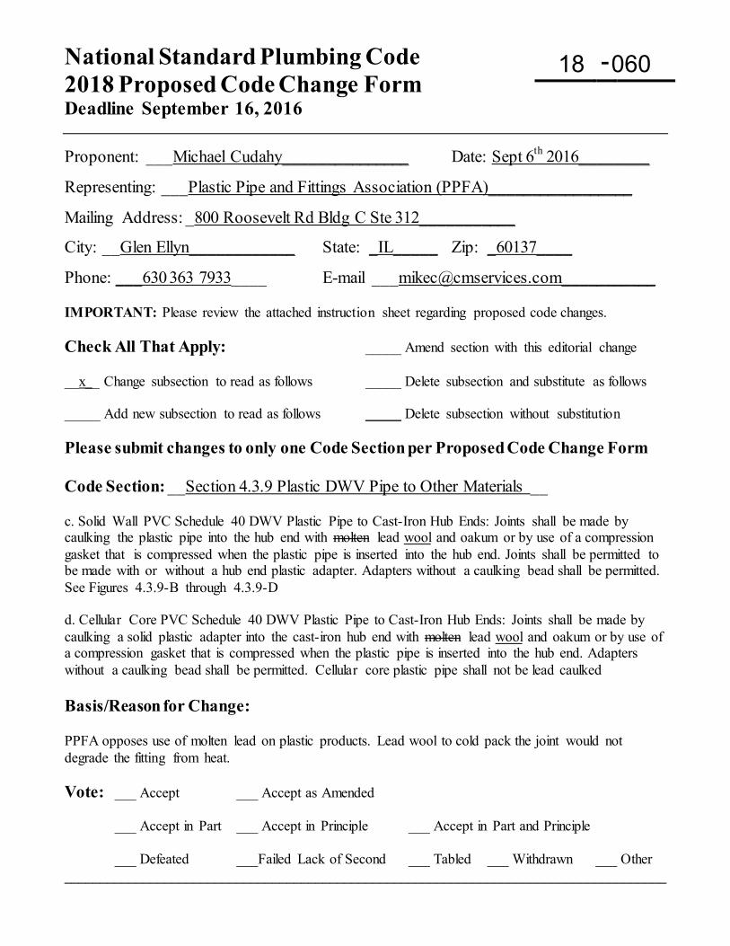
National Standard Plumbing Code 2018 Proposed Code Change Form Deadline September 16, 2016
-
Proponent: ___Michael Cudahy_______________ Date: Sept 6th 2016________
Representing: ___Plastic Pipe and Fittings Association (PPFA)_________________
Mailing Address: _800 Roosevelt Rd Bldg C Ste 312___________
City: __Glen Ellyn____________ State: _IL_____ Zip: _60137____
Phone: ___630 363 7933____ E-mail [email protected]___________ IMPORTANT: Please review the attached instruction sheet regarding proposed code changes. Check All That Apply: _____ Amend section with this editorial change __x__ Change subsection to read as follows _____ Delete subsection and substitute as follows _____ Add new subsection to read as follows _____ Delete subsection without substitution Please submit changes to only one Code Section per Proposed Code Change Form Code Section: __Section 4.3.9 Plastic DWV Pipe to Other Materials __ c. Solid Wall PVC Schedule 40 DWV Plastic Pipe to Cast-Iron Hub Ends: Joints shall be made by caulking the plastic pipe into the hub end with molten lead wool and oakum or by use of a compression gasket that is compressed when the plastic pipe is inserted into the hub end. Joints shall be permitted to be made with or without a hub end plastic adapter. Adapters without a caulking bead shall be permitted. See Figures 4.3.9-B through 4.3.9-D d. Cellular Core PVC Schedule 40 DWV Plastic Pipe to Cast-Iron Hub Ends: Joints shall be made by caulking a solid plastic adapter into the cast-iron hub end with molten lead wool and oakum or by use of a compression gasket that is compressed when the plastic pipe is inserted into the hub end. Adapters without a caulking bead shall be permitted. Cellular core plastic pipe shall not be lead caulked Basis/Reason for Change: PPFA opposes use of molten lead on plastic products. Lead wool to cold pack the joint would not degrade the fitting from heat. Vote: ___ Accept ___ Accept as Amended
___ Accept in Part ___ Accept in Principle ___ Accept in Part and Principle
___ Defeated ___Failed Lack of Second ___ Tabled ___ Withdrawn ___ Other ____________________________________________________________________________________
18 060
National Standard Plumbing Code 2018 Proposed Code Change Form
-
5.1 Exception (3) page 1 of 1 7-01-2015
Proponent: NSPC Committee Date: 7-01-2015 Representing: Plumbing-Heating-Cooling Contractors Association Mailing Address: P.O. Box 6808 180 S. Washington Street City: Falls Church, VA 22046 Phone: 1-800-533-7694 E-mail: [email protected] Check All That Apply: _____ Amend section with this editorial change __X__ Change subsection to read as follows _____ Delete subsection and substitute as follows _____ Add new subsection to read as follows _____ Delete subsection without substitution Code Section: 5.1 SEPARATE TRAPS FOR EACH FIXTURE EXCEPTIONS: (3) A combination plumbing fixture multi-compartment sink with up to 3 compartments may be installed on one trap provided that no compartment is more than 6 inches deeper than another and the waste outlets are not more than 30 inches from the trap inlet. Reason for Change: Combination plumbing fixtures include more than multi-compartment sinks. To add the limit on the difference in depth of sink compartments to avoid drain backup into deeper sink compartments. Vote: ___ Accept ___ Accept as Amended
___ Accept in Part ___ Accept in Principle ___ Accept in Part and Principle
___ Defeated ___Failed Lack of Second ___ Tabled ___ Withdrawn ___ Other _________________________________________________________________________________
18 061
National Standard Plumbing Code 2018 Proposed Code Change Form
-
Section 5.3.6 page 1 of 1 1-08-2016
Proponent: NSPC Committee Date: 1-08-2016 Representing: Plumbing-Heating-Cooling Contractors Association Mailing Address: P.O. Box 6808 180 S. Washington Street City: Falls Church, VA 22046 Phone: 1-800-533-7694 E-mail: [email protected] Check All That Apply: _____ Amend section with this editorial change __X__ Change subsection to read as follows _____ Delete subsection and substitute as follows _____ Add new subsection to read as follows _____ Delete subsection without substitution Code Section: 5.3.6 Trap Seal Maintenance
a. Traps that could lose their seal due to evaporation because of infrequent use shall have an accessible means to manually replenish the trap seal or be connected to (a) an automatic trap seal primer conforming to ASSE 1018 or ASSE 1044. b. Floor drains that comply with ASME A112.6.3 shall be permitted to be fitted with a barrier type floor drain trap seal protection device complying with ASSE 1072 to minimize the rate of evaporation of their trap seal. The device shall have an application designation marking for the type of floor and environment it has been designed and tested for (AF, AF-GW, SF, CF, CT, WF). Reason for Change: To clarify the function of ASSE 1072 trap seal protection devices. The primary function of ASSE 1072 devices is to reduce the rate of evaporation of trap seals, not to prevent the backflow of sewer gas after a trap seal has evaporated. Vote: ___ Accept ___ Accept as Amended
___ Accept in Part ___ Accept in Principle ___ Accept in Part and Principle
___ Defeated ___Failed Lack of Second ___ Tabled ___ Withdrawn ___ Other _________________________________________________________________________________
18 062
National Standard Plumbing Code 2018 Proposed Code Change Form
-
Section 5.4.3 page 1 of 1 2-16-2016
Proponent: NSPC Committee Date: 2-16-2016 Representing: Plumbing-Heating-Cooling Contractors Association Mailing Address: P.O. Box 6808 180 S. Washington Street City: Falls Church, VA 22046 Phone: 1-800-533-7694 E-mail: [email protected] Check All That Apply: _____ Amend section with this editorial change __X__ Change subsection to read as follows _____ Delete subsection and substitute as follows _____ Add new subsection to read as follows _____ Delete subsection without substitution Code Section: 5.4 DRAIN PIPE CLEANOUTS FOR DRAIN PIPING 5.4.3 Change of Direction For Changes in Direction
a. Cleanouts shall be installed at changes of direction in drain piping made with drain piping made with 60°, 72°, and 90° fittings. EXCEPTION: Where there are multiple changes of direction in a run of piping, one cleanout shall be permitted for up to forty total feet of offset piping. See Figure 5.4.3 b. Cleanouts shall not be required where changes of direction are made with one or more 22-1/2° or 45° fittings. a. Cleanouts shall be provided in horizontal drain piping for changes in direction greater than 45 degrees.
b. One cleanout may be provided for up to four (4) long radius changes in direction. Each change in direction shall be considered as ten (10) feet of straight pipe and deducted from the maximum allowable spacing between cleanouts in Section 5.4.1. See Figure 5.4.3 Reason for Change: To clarify the requirements for cleanouts with changes in direction and limit one cleanout to no more than four changes in direction. To apply an equivalent length to 90 deg elbows for their effect on the maximum spacing of cleanouts. Vote: ___ Accept ___ Accept as Amended
___ Accept in Part ___ Accept in Principle ___ Accept in Part and Principle
___ Defeated ___Failed Lack of Second ___ Tabled ___ Withdrawn ___ Other _________________________________________________________________________________
18 063
National Standard Plumbing Code 2018 Proposed Code Change Form
-
Section 5.4.5 page 1 of 1 2-17-2016
Proponent: NSPC Committee Date: 2-17-2016 Representing: Plumbing-Heating-Cooling Contractors Association Mailing Address: P.O. Box 6808 180 S. Washington Street City: Falls Church, VA 22046 Phone: 1-800-533-7694 E-mail: [email protected] Check All That Apply: _____ Amend section with this editorial change __X__ Change subsection to read as follows _____ Delete subsection and substitute as follows _____ Add new subsection to read as follows _____ Delete subsection without substitution Code Section: 5.4 DRAIN PIPE CLEANOUTS FOR DRAIN PIPING 5.4.5 Base of Stacks
a. A cleanout shall be provided near the base of each vertical sanitary drain stack and located not less than six (6) inches above the lowest flood level rim of the lowest fixture on the lowest floor fixtures served on that level. If there are no fixtures installed on the lowest floor served on that level, the cleanout shall be installed at above the base of the stack. b. For buildings with a floor slab, a crawl space of less than 18 inches clear height, or where a stack cleanout is would not be accessible from within the building, the cleanout shall may be installed not more than five (5) feet outside the building wall. c. Where cleanout connections are below grade, the cleanout opening shall be installed in an accessible location flush with the finished floor or terminated above the floor,. c. d. Rain leaders and conductors connected to a building storm drain or storm sewer shall have a cleanout installed at or above the base of the outside leader or inside conductor before it connects to the building drain or sewer. See Figures 5.4.5-A through 5.4.5-C Reason for Change: To clarify the requirements for cleanouts for the base of drain stacks. Vote: ___ Accept ___ Accept as Amended
___ Accept in Part ___ Accept in Principle ___ Accept in Part and Principle
___ Defeated ___Failed Lack of Second ___ Tabled ___ Withdrawn ___ Other _________________________________________________________________________________
18 064
National Standard Plumbing Code 2018 Proposed Code Change Form
-
Section 5.4.13 page 1 and 1 1-07-2016
Proponent: NSPC Committee Date: 1-07-2016 Representing: Plumbing-Heating-Cooling Contractors Association Mailing Address: P.O. Box 6808 180 S. Washington Street City: Falls Church, VA 22046 Phone: 1-800-533-7694 E-mail: [email protected] Check All That Apply: _____ Amend section with this editorial change __X__ Change subsection to read as follows _____ Delete subsection and substitute as follows _____ Add new subsection to read as follows _____ Delete subsection without substitution Code Section: 5.4 DRAIN PIPE CLEANOUTS FOR DRAIN PIPING 5.4.13 Cleanout Equivalent Where the drain piping is concealed, a fixture trap or a fixture with integral trap, removable without disturbing the concealed roughing work piping, shall be accepted as a cleanout equivalent, provided the opening to be used as a cleanout opening is the size required by Table 5.4.9. See Figure 5.4.13 EXCEPTIONS: (1) The trap arm of a floor drain with a removable strainer. (2) Fixtures with removable traps not more than one pipe size smaller than the drain served shall be permitted. (1) A removable fixture trap may be used as a cleanout equivalent for drain piping that is no more than one size larger than the drain pipe for the removed trap. (2) A floor drain with a removable strainer or grate may be used as a cleanout equivalent based on the pipe size of its outlet and trap. Reason for Change: To clarify the requirements for cleanout equivalents. Vote: ___ Accept ___ Accept as Amended
___ Accept in Part ___ Accept in Principle ___ Accept in Part and Principle
___ Defeated ___Failed Lack of Second ___ Tabled ___ Withdrawn ___ Other _________________________________________________________________________________
18 065
National Standard Plumbing Code 2018 Proposed Code Change Form
-
Section 6.2.1 page 1 of 1 10-18-2015
Proponent: NSPC Committee Date: 10-18-2015 Representing: Plumbing-Heating-Cooling Contractors Association Mailing Address: P.O. Box 6808 180 S. Washington Street City: Falls Church, VA 22046 Phone: 1-800-533-7694 E-mail: [email protected] Check All That Apply: _____ Amend section with this editorial change __X__ Change subsection to read as follows _____ Delete subsection and substitute as follows _____ Add new subsection to read as follows _____ Delete subsection without substitution Code Section: 6.2 GREASE INTERCEPTORS 6.2.1 General a. Grease interceptors shall comply with the requirements of the Adopting Agency Section 6.1.4.
b. Grease interceptors include the following types: 1. Hydro-mechanical Hydromechanical grease interceptors (HGI) 2. Grease removal (or recovery) devices (GRD) 3. Gravity grease interceptors 4. FOG (fats, oils, and greases) disposal systems
c. (no changes) d. (no changes)
e. (no changes) f. (no changes) Reason for Change: To clarify the listing of grease interceptors. Vote: ___ Accept ___ Accept as Amended
___ Accept in Part ___ Accept in Principle ___ Accept in Part and Principle
___ Defeated ___Failed Lack of Second ___ Tabled ___ Withdrawn ___ Other _________________________________________________________________________________
18 066
National Standard Plumbing Code 2018 Proposed Code Change Form
-
Section 6.2.1.1 page 1 of 1 10-20-2016
Proponent: NSPC Committee Date: 10-20-2016 Representing: Plumbing-Heating-Cooling Contractors Association Mailing Address: P.O. Box 6808 180 S. Washington Street City: Falls Church, VA 22046 Phone: 1-800-533-7694 E-mail: [email protected] Check All That Apply: _____ Amend section with this editorial change __X__ Change subsection to read as follows _____ Delete subsection and substitute as follows _____ Add new subsection to read as follows _____ Delete subsection without substitution Code Section: 6.2 GREASE INTERCEPTORS 6.2.1.1 Hydro-Mechanical Hydromechanical Grease Interceptors (HGI) a. Hydro-mechanical Hydromechanical grease interceptors (HGI) shall comply with the performance, testing, and installation requirements of ASME A112.14.3(,) or PDI Standard G101(,) and Section 6.2., or CSA B481. b. These HGI interceptors shall be sized according to Section 6.2.10 and retain not less than two pounds of grease for each gpm of rated flow. c. A calibrated, non-adjustable flow control device shall be provided on the inlet side of each HGI interceptor to prevent the waste flow (gpm) from exceeding the rated flow capacity of the interceptor. The flow control device shall be vented in accordance with Section 6.2.4. d. Where optional FOG level sensing and alarm devices are provided for PDI G101 HGI interceptors, they shall comply with PDI G102. Reason for Change: To clarify the requirements for hydromechanical grease interceptors (HGI). FOG level sensing and alarm devices should be designed and rated to work with specific HGI interceptors. Vote: ___ Accept ___ Accept as Amended
___ Accept in Part ___ Accept in Principle ___ Accept in Part and Principle
___ Defeated ___Failed Lack of Second ___ Tabled ___ Withdrawn ___ Other _________________________________________________________________________________
18 067
National Standard Plumbing Code 2018 Proposed Code Change Form
-
Section 6.2.1.2 page 1 of 1 10-20-2015
Proponent: NSPC Committee Date: 10-20-2015 Representing: Plumbing-Heating-Cooling Contractors Association Mailing Address: P.O. Box 6808 180 S. Washington Street City: Falls Church, VA 22046 Phone: 1-800-533-7694 E-mail: [email protected] Check All That Apply: _____ Amend section with this editorial change __X__ Change subsection to read as follows _____ Delete subsection and substitute as follows _____ Add new subsection to read as follows _____ Delete subsection without substitution Code Section: 6.2 GREASE INTERCEPTORS 6.2.1.2 Grease Removal (or Recovery) Devices (GRD) a. Grease removal devices (GRD), which are Hydro-mechanical interceptors hydromechanical grease interceptors that are capable of automatically removing free-floating grease, fats, and oils from their waste discharge without intervention of the user except for maintenance, shall comply with ASME A112.14.4 and Section 6.2 or CSA B481.
b. These GRD interceptors shall be sized according to Section 6.2.10. c. A calibrated, non-adjustable flow control device shall be provided on the inlet side of or within each GRD interceptor to prevent the waste flow (gpm) from exceeding the rated flow capacity of the interceptor. The flow control device shall be vented in accordance with Section 6.2.4. Reason for Change: To clarify the requirements for grease removal devices (GRD). Vote: ___ Accept ___ Accept as Amended
___ Accept in Part ___ Accept in Principle ___ Accept in Part and Principle
___ Defeated ___Failed Lack of Second ___ Tabled ___ Withdrawn ___ Other _________________________________________________________________________________
18 068
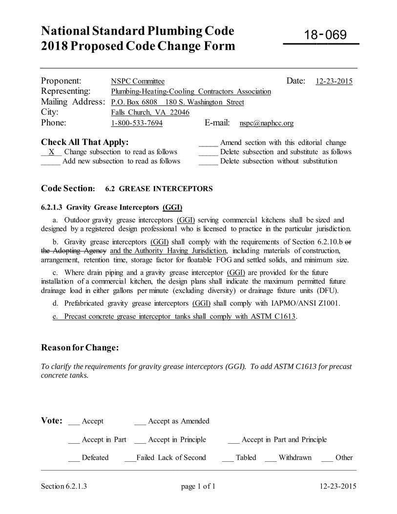
National Standard Plumbing Code 2018 Proposed Code Change Form
-
Section 6.2.1.3 page 1 of 1 12-23-2015
Proponent: NSPC Committee Date: 12-23-2015 Representing: Plumbing-Heating-Cooling Contractors Association Mailing Address: P.O. Box 6808 180 S. Washington Street City: Falls Church, VA 22046 Phone: 1-800-533-7694 E-mail: [email protected] Check All That Apply: _____ Amend section with this editorial change __X__ Change subsection to read as follows _____ Delete subsection and substitute as follows _____ Add new subsection to read as follows _____ Delete subsection without substitution Code Section: 6.2 GREASE INTERCEPTORS 6.2.1.3 Gravity Grease Interceptors (GGI) a. Outdoor gravity grease interceptors (GGI) serving commercial kitchens shall be sized and designed by a registered design professional who is licensed to practice in the particular jurisdiction.
b. Gravity grease interceptors (GGI) shall comply with the requirements of Section 6.2.10.b or the Adopting Agency and the Authority Having Jurisdiction, including materials of construction, arrangement, retention time, storage factor for floatable FOG and settled solids, and minimum size. c. Where drain piping and a gravity grease interceptor (GGI) are provided for the future installation of a commercial kitchen, the design plans shall indicate the maximum permitted future drainage load in either gallons per minute (excluding diversity) or drainage fixture units (DFU). d. Prefabricated gravity grease interceptors (GGI) shall comply with IAPMO/ANSI Z1001.
e. Precast concrete grease interceptor tanks shall comply with ASTM C1613. Reason for Change: To clarify the requirements for gravity grease interceptors (GGI). To add ASTM C1613 for precast concrete tanks. Vote: ___ Accept ___ Accept as Amended
___ Accept in Part ___ Accept in Principle ___ Accept in Part and Principle
___ Defeated ___Failed Lack of Second ___ Tabled ___ Withdrawn ___ Other _________________________________________________________________________________
18 069
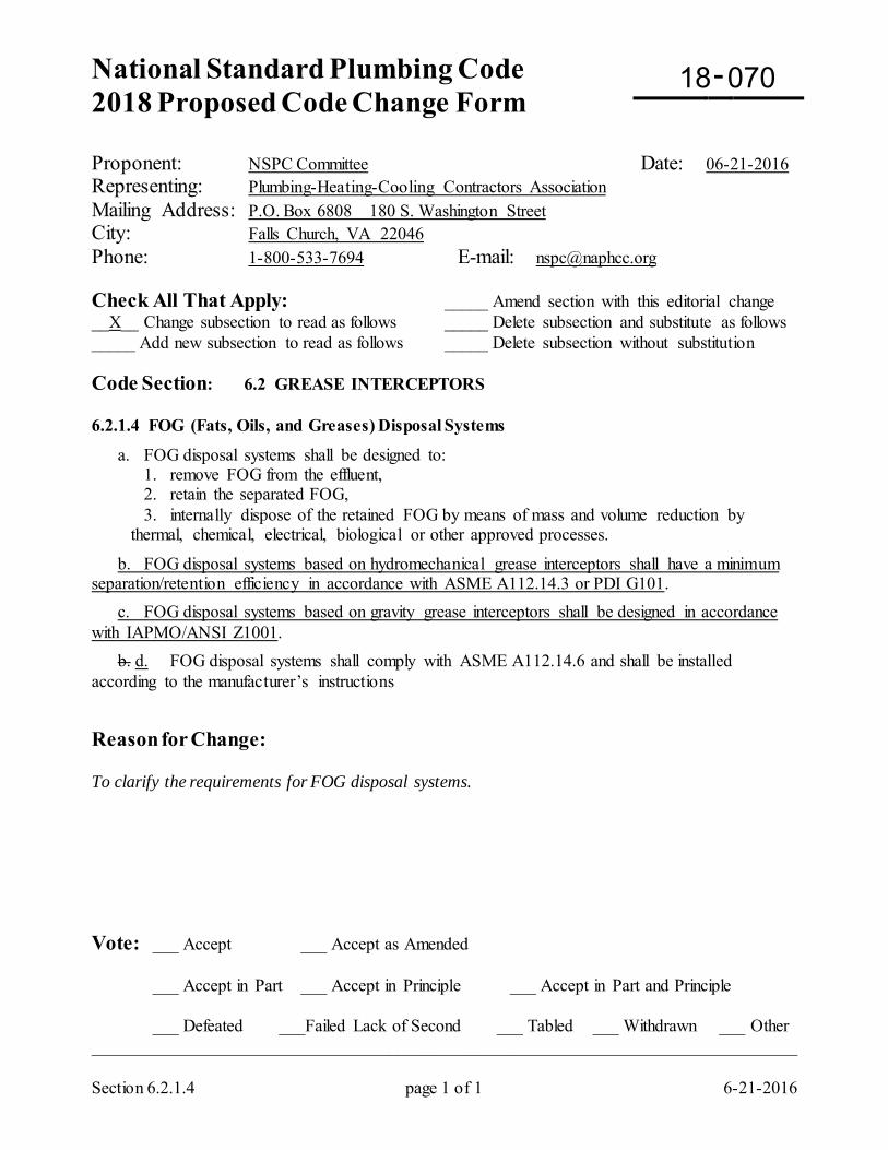
National Standard Plumbing Code 2018 Proposed Code Change Form
-
Section 6.2.1.4 page 1 of 1 6-21-2016
Proponent: NSPC Committee Date: 06-21-2016 Representing: Plumbing-Heating-Cooling Contractors Association Mailing Address: P.O. Box 6808 180 S. Washington Street City: Falls Church, VA 22046 Phone: 1-800-533-7694 E-mail: [email protected] Check All That Apply: _____ Amend section with this editorial change __X__ Change subsection to read as follows _____ Delete subsection and substitute as follows _____ Add new subsection to read as follows _____ Delete subsection without substitution Code Section: 6.2 GREASE INTERCEPTORS 6.2.1.4 FOG (Fats, Oils, and Greases) Disposal Systems
a. FOG disposal systems shall be designed to: 1. remove FOG from the effluent, 2. retain the separated FOG, 3. internally dispose of the retained FOG by means of mass and volume reduction by
thermal, chemical, electrical, biological or other approved processes.
b. FOG disposal systems based on hydromechanical grease interceptors shall have a minimum separation/retention efficiency in accordance with ASME A112.14.3 or PDI G101. c. FOG disposal systems based on gravity grease interceptors shall be designed in accordance with IAPMO/ANSI Z1001. b. d. FOG disposal systems shall comply with ASME A112.14.6 and shall be installed according to the manufacturer’s instructions
Reason for Change: To clarify the requirements for FOG disposal systems. Vote: ___ Accept ___ Accept as Amended
___ Accept in Part ___ Accept in Principle ___ Accept in Part and Principle
___ Defeated ___Failed Lack of Second ___ Tabled ___ Withdrawn ___ Other _________________________________________________________________________________
18 070
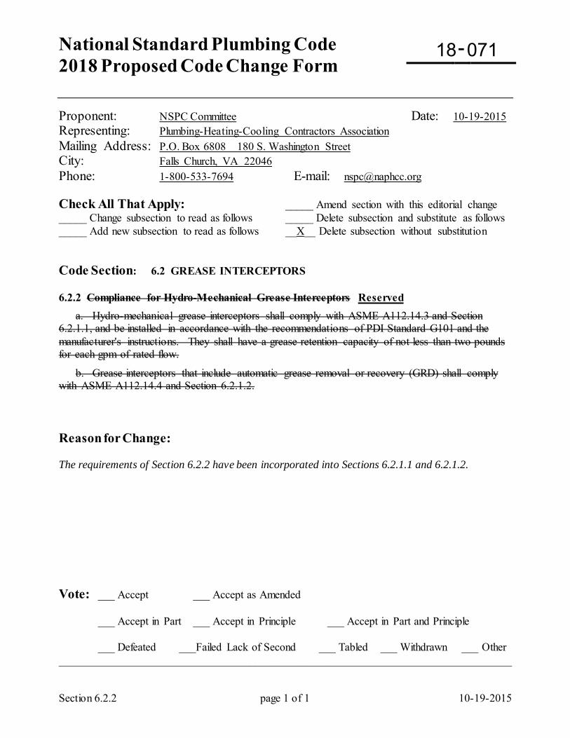
National Standard Plumbing Code 2018 Proposed Code Change Form
-
Section 6.2.2 page 1 of 1 10-19-2015
Proponent: NSPC Committee Date: 10-19-2015 Representing: Plumbing-Heating-Cooling Contractors Association Mailing Address: P.O. Box 6808 180 S. Washington Street City: Falls Church, VA 22046 Phone: 1-800-533-7694 E-mail: [email protected] Check All That Apply: _____ Amend section with this editorial change _____ Change subsection to read as follows _____ Delete subsection and substitute as follows _____ Add new subsection to read as follows __X__ Delete subsection without substitution Code Section: 6.2 GREASE INTERCEPTORS 6.2.2 Compliance for Hydro-Mechanical Grease Interceptors Reserved a. Hydro-mechanical grease interceptors shall comply with ASME A112.14.3 and Section 6.2.1.1, and be installed in accordance with the recommendations of PDI Standard G101 and the manufacturer's instructions. They shall have a grease retention capacity of not less than two pounds for each gpm of rated flow.
b. Grease interceptors that include automatic grease removal or recovery (GRD) shall comply with ASME A112.14.4 and Section 6.2.1.2. Reason for Change: The requirements of Section 6.2.2 have been incorporated into Sections 6.2.1.1 and 6.2.1.2. Vote: ___ Accept ___ Accept as Amended
___ Accept in Part ___ Accept in Principle ___ Accept in Part and Principle
___ Defeated ___Failed Lack of Second ___ Tabled ___ Withdrawn ___ Other _________________________________________________________________________________
18 071
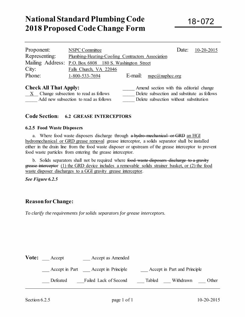
National Standard Plumbing Code 2018 Proposed Code Change Form
-
Section 6.2.5 page 1 of 1 10-20-2015
Proponent: NSPC Committee Date: 10-20-2015 Representing: Plumbing-Heating-Cooling Contractors Association Mailing Address: P.O. Box 6808 180 S. Washington Street City: Falls Church, VA 22046 Phone: 1-800-533-7694 E-mail: [email protected] Check All That Apply: _____ Amend section with this editorial change __X__ Change subsection to read as follows _____ Delete subsection and substitute as follows _____ Add new subsection to read as follows _____ Delete subsection without substitution Code Section: 6.2 GREASE INTERCEPTORS 6.2.5 Food Waste Disposers a. Where food waste disposers discharge through a hydro-mechanical or GRD an HGI hydromechanical or GRD grease removal grease interceptor, a solids separator shall be installed either in the drain line from the food waste disposer or upstream of the grease interceptor to prevent food waste particles from entering the grease interceptor.
b. Solids separators shall not be required where food waste disposers discharge to a gravity grease interceptor (1) the GRD device includes a removable solids strainer basket, or (2) the food waste disposer discharges to a GGI gravity grease interceptor.
See Figure 6.2.5 Reason for Change: To clarify the requirements for solids separators for grease interceptors. Vote: ___ Accept ___ Accept as Amended
___ Accept in Part ___ Accept in Principle ___ Accept in Part and Principle
___ Defeated ___Failed Lack of Second ___ Tabled ___ Withdrawn ___ Other _________________________________________________________________________________
18 072
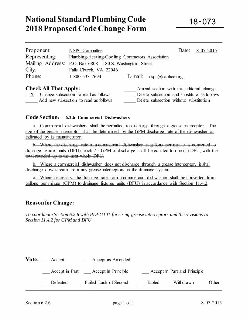
National Standard Plumbing Code 2018 Proposed Code Change Form
-
Section 6.2.6 page 1 of 1 8-07-2015
Proponent: NSPC Committee Date: 8-07-2015 Representing: Plumbing-Heating-Cooling Contractors Association Mailing Address: P.O. Box 6808 180 S. Washington Street City: Falls Church, VA 22046 Phone: 1-800-533-7694 E-mail: [email protected] Check All That Apply: _____ Amend section with this editorial change __X__ Change subsection to read as follows _____ Delete subsection and substitute as follows _____ Add new subsection to read as follows _____ Delete subsection without substitution Code Section: 6.2.6 Commercial Dishwashers
a. Commercial dishwashers shall be permitted to discharge through a grease interceptor. The size of the grease interceptor shall be determined by the GPM discharge rate of the dishwasher as indicated by its manufacturer. b. Where the discharge rate of a commercial dishwasher in gallons per minute is converted to drainage fixture units (DFU), each 7.5 GPM of discharge shall be equated to one (1) DFU, with the total rounded up to the next whole DFU.
b. Where a commercial dishwasher does not discharge through a grease interceptor, it shall discharge downstream from any grease interceptors in the drainage system. c. Where necessary, the drainage rate from a commercial dishwasher shall be converted from gallons per minute (GPM) to drainage fixtures units (DFU) in accordance with Section 11.4.2. Reason for Change: To coordinate Section 6.2.6 with PDI-G101 for sizing grease interceptors and the revisions to Section 11.4.2 for GPM and DFU. Vote: ___ Accept ___ Accept as Amended
___ Accept in Part ___ Accept in Principle ___ Accept in Part and Principle
___ Defeated ___Failed Lack of Second ___ Tabled ___ Withdrawn ___ Other _________________________________________________________________________________
18 073
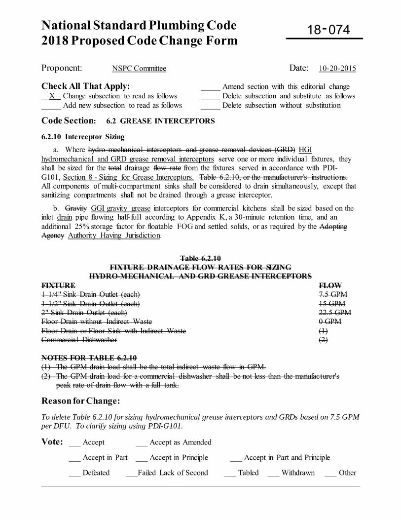
National Standard Plumbing Code 2018 Proposed Code Change Form
-
Proponent: NSPC Committee Date: 10-20-2015 Check All That Apply: _____ Amend section with this editorial change __X _ Change subsection to read as follows _____ Delete subsection and substitute as follows _____ Add new subsection to read as follows _____ Delete subsection without substitution
Code Section: 6.2 GREASE INTERCEPTORS 6.2.10 Interceptor Sizing a. Where hydro-mechanical interceptors and grease removal devices (GRD) HGI hydromechanical and GRD grease removal interceptors serve one or more individual fixtures, they shall be sized for the total drainage flow rate from the fixtures served in accordance with PDI-G101, Section 8 - Sizing for Grease Interceptors. Table 6.2.10, or the manufacturer's instructions. All components of multi-compartment sinks shall be considered to drain simultaneously, except that sanitizing compartments shall not be drained through a grease interceptor.
b. Gravity GGI gravity grease interceptors for commercial kitchens shall be sized based on the inlet drain pipe flowing half-full according to Appendix K, a 30-minute retention time, and an additional 25% storage factor for floatable FOG and settled solids, or as required by the Adopting Agency Authority Having Jurisdiction.
Table 6.2.10 FIXTURE DRAINAGE FLOW RATES FOR SIZING
HYDRO-MECHANICAL AND GRD GREASE INTERCEPTORS FIXTURE FLOW 1-1/4" Sink Drain Outlet (each) 7.5 GPM 1-1/2" Sink Drain Outlet (each) 15 GPM 2" Sink Drain Outlet (each) 22.5 GPM Floor Drain without Indirect Waste 0 GPM Floor Drain or Floor Sink with Indirect Waste (1) Commercial Dishwasher (2) NOTES FOR TABLE 6.2.10 (1) The GPM drain load shall be the total indirect waste flow in GPM. (2) The GPM drain load for a commercial dishwasher shall be not less than the manufacturer's
peak rate of drain flow with a full tank.
Reason for Change: To delete Table 6.2.10 for sizing hydromechanical grease interceptors and GRDs based on 7.5 GPM per DFU. To clarify sizing using PDI-G101.
Vote: ___ Accept ___ Accept as Amended
___ Accept in Part ___ Accept in Principle ___ Accept in Part and Principle
___ Defeated ___Failed Lack of Second ___ Tabled ___ Withdrawn ___ Other _________________________________________________________________________________
18 074
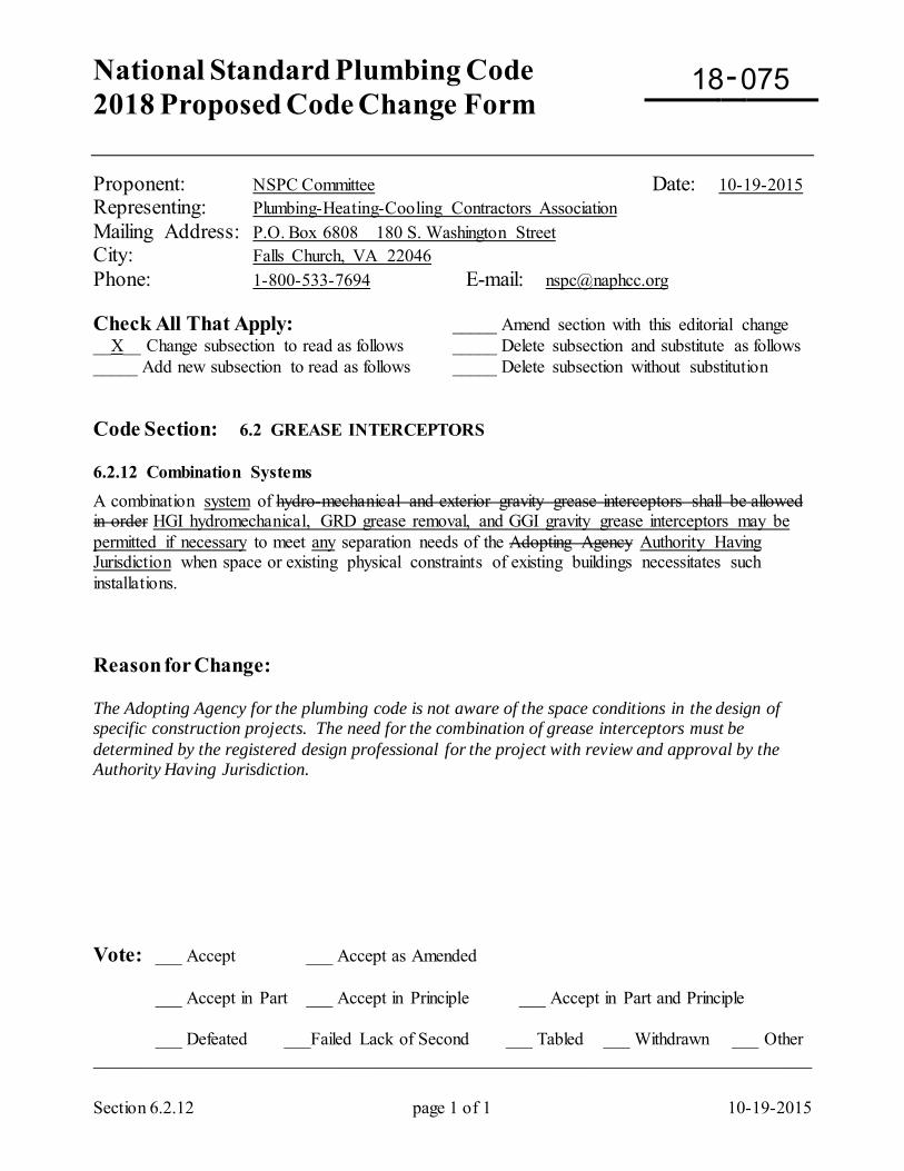
National Standard Plumbing Code 2018 Proposed Code Change Form
-
Section 6.2.12 page 1 of 1 10-19-2015
Proponent: NSPC Committee Date: 10-19-2015 Representing: Plumbing-Heating-Cooling Contractors Association Mailing Address: P.O. Box 6808 180 S. Washington Street City: Falls Church, VA 22046 Phone: 1-800-533-7694 E-mail: [email protected] Check All That Apply: _____ Amend section with this editorial change __X__ Change subsection to read as follows _____ Delete subsection and substitute as follows _____ Add new subsection to read as follows _____ Delete subsection without substitution Code Section: 6.2 GREASE INTERCEPTORS 6.2.12 Combination Systems A combination system of hydro-mechanical and exterior gravity grease interceptors shall be allowed in order HGI hydromechanical, GRD grease removal, and GGI gravity grease interceptors may be permitted if necessary to meet any separation needs of the Adopting Agency Authority Having Jurisdiction when space or existing physical constraints of existing buildings necessitates such installations. Reason for Change: The Adopting Agency for the plumbing code is not aware of the space conditions in the design of specific construction projects. The need for the combination of grease interceptors must be determined by the registered design professional for the project with review and approval by the Authority Having Jurisdiction. Vote: ___ Accept ___ Accept as Amended
___ Accept in Part ___ Accept in Principle ___ Accept in Part and Principle
___ Defeated ___Failed Lack of Second ___ Tabled ___ Withdrawn ___ Other _________________________________________________________________________________
18 075
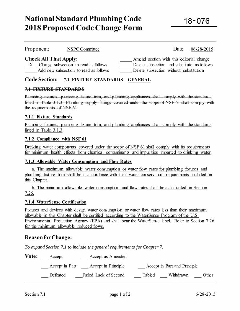
National Standard Plumbing Code 2018 Proposed Code Change Form
-
Section 7.1 page 1 of 2 6-28-2015
Proponent: NSPC Committee Date: 06-28-2015
Check All That Apply: _____ Amend section with this editorial change __X__ Change subsection to read as follows _____ Delete subsection and substitute as follows _____ Add new subsection to read as follows _____ Delete subsection without substitution
Code Section: 7.1 FIXTURE STANDARDS GENERAL 7.1 FIXTURE STANDARDS Plumbing fixtures, plumbing fixture trim, and plumbing appliances shall comply with the standards listed in Table 3.1.3. Plumbing supply fittings covered under the scope of NSF 61 shall comply with the requirements of NSF 61. 7.1.1 Fixture Standards Plumbing fixtures, plumbing fixture trim, and plumbing appliances shall comply with the standards listed in Table 3.1.3. 7.1.2 Compliance with NSF 61
Drinking water components covered under the scope of NSF 61 shall comply with its requirements for minimum health effects from chemical contaminants and impurities imparted to drinking water. 7.1.3 Allowable Water Consumption and Flow Rates a. The maximum allowable water consumption or water flow rates for plumbing fixtures and plumbing fixture trim shall be in accordance with their water conservation requirements included in this Chapter. b. The minimum allowable water consumption and flow rates shall be as indicated in Section 7.26. 7.1.4 WaterSense Certification
Fixtures and devices with design water consumption or water flow rates less than their maximum allowable in this Chapter shall be certified according to the WaterSense Program of the U.S. Environmental Protection Agency (EPA) and shall bear the WaterSense label. Refer to Section 7.26 for the minimum allowable reduced flows. Reason for Change: To expand Section 7.1 to include the general requirements for Chapter 7.
Vote: ___ Accept ___ Accept as Amended
___ Accept in Part ___ Accept in Principle ___ Accept in Part and Principle
___ Defeated ___Failed Lack of Second ___ Tabled ___ Withdrawn ___ Other _________________________________________________________________________________
18 076
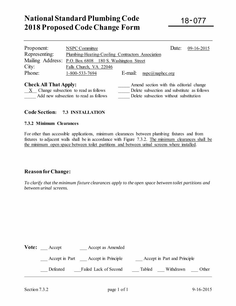
National Standard Plumbing Code 2018 Proposed Code Change Form
-
Section 7.3.2 page 1 of 1 9-16-2015
Proponent: NSPC Committee Date: 09-16-2015 Representing: Plumbing-Heating-Cooling Contractors Association Mailing Address: P.O. Box 6808 180 S. Washington Street City: Falls Church, VA 22046 Phone: 1-800-533-7694 E-mail: [email protected] Check All That Apply: _____ Amend section with this editorial change __X__ Change subsection to read as follows _____ Delete subsection and substitute as follows _____ Add new subsection to read as follows _____ Delete subsection without substitution Code Section: 7.3 INSTALLATION 7.3.2 Minimum Clearances For other than accessible applications, minimum clearances between plumbing fixtures and from fixtures to adjacent walls shall be in accordance with Figure 7.3.2. The minimum clearances shall be the minimum open space between toilet partitions and between urinal screens where installed. Reason for Change: To clarify that the minimum fixture clearances apply to the open space between toilet partitions and between urinal screens. Vote: ___ Accept ___ Accept as Amended
___ Accept in Part ___ Accept in Principle ___ Accept in Part and Principle
___ Defeated ___Failed Lack of Second ___ Tabled ___ Withdrawn ___ Other _________________________________________________________________________________
18 077
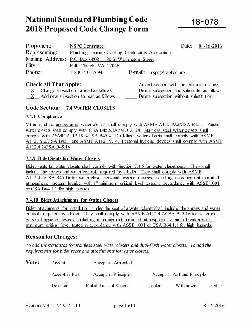
National Standard Plumbing Code 2018 Proposed Code Change Form
-
Sections 7.4.1, 7.4.9, 7.4.10 page 1 of 1 8-16-2016
Proponent: NSPC Committee Date: 08-16-2016 Representing: Plumbing-Heating-Cooling Contractors Association Mailing Address: P.O. Box 6808 180 S. Washington Street City: Falls Church, VA 22046 Phone: 1-800-533-7694 E-mail: [email protected] Check All That Apply: _____ Amend section with this editorial change __X__ Change subsection to read as follows _____ Delete subsection and substitute as follows __X__ Add new subsection to read as follows _____ Delete subsection without substitution Code Section: 7.4 WATER CLOSETS
7.4.1 Compliance Vitreous china and ceramic water closets shall comply with ASME A112.19.2/CSA B45.1. Plastic water closets shall comply with CSA B45.5/IAPMO Z124. Stainless steel water closets shall comply with ASME A112.19.3/CSA B45.4. Dual-flush water closets shall comply with ASME A112.19.2/CSA B45.1 and ASME A112.19.14. Personal hygiene devices shall comply with ASME A112.4.2/CSA B45.16. 7.4.9 Bidet Seats for Water Closets Bidet seats for water closets shall comply with Section 7.4.5 for water closet seats. They shall include the sprays and water controls required by a bidet. They shall comply with ASME A112.4.2/CSA B45.16 for water closet personal hygiene devices, including an equipment-mounted atmospheric vacuum breaker with 1” minimum critical level tested in accordance with ASSE 1001 or CSA B64.1.1 for high hazards. 7.4.10 Bidet Attachments for Water Closets
Bidet attachments for installation under the seat of a water closet shall include the sprays and water controls required by a bidet. They shall comply with ASME A112.4.2/CSA B45.16 for water closet personal hygiene devices, including an equipment-mounted atmospheric vacuum breaker with 1” minimum critical level tested in accordance with ASSE 1001 or CSA B64.1.1 for high hazards. Reason for Changes: To add the standards for stainless steel water closets and dual-flush water closets. To add the requirements for bidet seats and attachments for water closets. Vote: ___ Accept ___ Accept as Amended
___ Accept in Part ___ Accept in Principle ___ Accept in Part and Principle
___ Defeated ___Failed Lack of Second ___ Tabled ___ Withdrawn ___ Other _________________________________________________________________________________
18 078
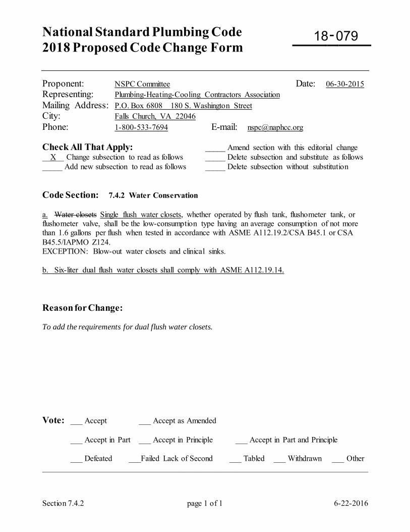
National Standard Plumbing Code 2018 Proposed Code Change Form
-
Section 7.4.2 page 1 of 1 6-22-2016
Proponent: NSPC Committee Date: 06-30-2015 Representing: Plumbing-Heating-Cooling Contractors Association Mailing Address: P.O. Box 6808 180 S. Washington Street City: Falls Church, VA 22046 Phone: 1-800-533-7694 E-mail: [email protected] Check All That Apply: _____ Amend section with this editorial change __X__ Change subsection to read as follows _____ Delete subsection and substitute as follows _____ Add new subsection to read as follows _____ Delete subsection without substitution Code Section: 7.4.2 Water Conservation a. Water closets Single flush water closets, whether operated by flush tank, flushometer tank, or flushometer valve, shall be the low-consumption type having an average consumption of not more than 1.6 gallons per flush when tested in accordance with ASME A112.19.2/CSA B45.1 or CSA B45.5/IAPMO Z124. EXCEPTION: Blow-out water closets and clinical sinks. b. Six-liter dual flush water closets shall comply with ASME A112.19.14. Reason for Change: To add the requirements for dual flush water closets. Vote: ___ Accept ___ Accept as Amended
___ Accept in Part ___ Accept in Principle ___ Accept in Part and Principle
___ Defeated ___Failed Lack of Second ___ Tabled ___ Withdrawn ___ Other _________________________________________________________________________________
18 079
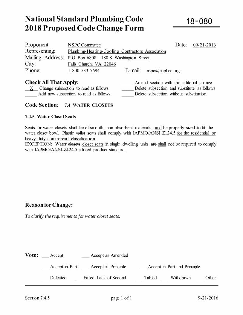
National Standard Plumbing Code 2018 Proposed Code Change Form
-
Section 7.4.5 page 1 of 1 9-21-2016
Proponent: NSPC Committee Date: 09-21-2016 Representing: Plumbing-Heating-Cooling Contractors Association Mailing Address: P.O. Box 6808 180 S. Washington Street City: Falls Church, VA 22046 Phone: 1-800-533-7694 E-mail: [email protected] Check All That Apply: _____ Amend section with this editorial change __X__ Change subsection to read as follows _____ Delete subsection and substitute as follows _____ Add new subsection to read as follows _____ Delete subsection without substitution Code Section: 7.4 WATER CLOSETS 7.4.5 Water Closet Seats Seats for water closets shall be of smooth, non-absorbent materials, and be properly sized to fit the water closet bowl. Plastic toilet seats shall comply with IAPMO/ANSI Z124.5 for the residential or heavy duty commercial classification. EXCEPTION: Water closets closet seats in single dwelling units are shall not be required to comply with IAPMO/ANSI Z124.5 a listed product standard. Reason for Change: To clarify the requirements for water closet seats. Vote: ___ Accept ___ Accept as Amended
___ Accept in Part ___ Accept in Principle ___ Accept in Part and Principle
___ Defeated ___Failed Lack of Second ___ Tabled ___ Withdrawn ___ Other _________________________________________________________________________________
18 080
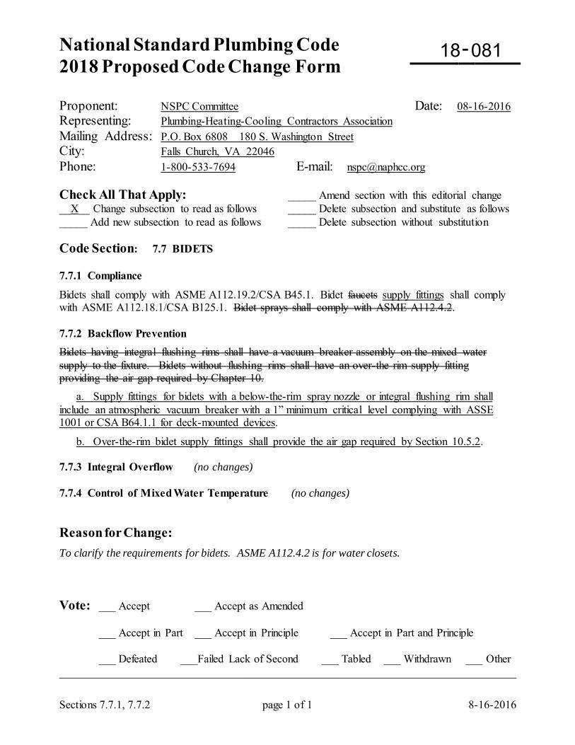
National Standard Plumbing Code 2018 Proposed Code Change Form
-
Sections 7.7.1, 7.7.2 page 1 of 1 8-16-2016
Proponent: NSPC Committee Date: 08-16-2016 Representing: Plumbing-Heating-Cooling Contractors Association Mailing Address: P.O. Box 6808 180 S. Washington Street City: Falls Church, VA 22046 Phone: 1-800-533-7694 E-mail: [email protected] Check All That Apply: _____ Amend section with this editorial change __X__ Change subsection to read as follows _____ Delete subsection and substitute as follows _____ Add new subsection to read as follows _____ Delete subsection without substitution Code Section: 7.7 BIDETS 7.7.1 Compliance
Bidets shall comply with ASME A112.19.2/CSA B45.1. Bidet faucets supply fittings shall comply with ASME A112.18.1/CSA B125.1. Bidet sprays shall comply with ASME A112.4.2. 7.7.2 Backflow Prevention Bidets having integral flushing rims shall have a vacuum breaker assembly on the mixed water supply to the fixture. Bidets without flushing rims shall have an over-the rim supply fitting providing the air gap required by Chapter 10. a. Supply fittings for bidets with a below-the-rim spray nozzle or integral flushing rim shall include an atmospheric vacuum breaker with a 1” minimum critical level complying with ASSE 1001 or CSA B64.1.1 for deck-mounted devices.
b. Over-the-rim bidet supply fittings shall provide the air gap required by Section 10.5.2. 7.7.3 Integral Overflow (no changes) 7.7.4 Control of Mixed Water Temperature (no changes) Reason for Change: To clarify the requirements for bidets. ASME A112.4.2 is for water closets. Vote: ___ Accept ___ Accept as Amended
___ Accept in Part ___ Accept in Principle ___ Accept in Part and Principle
___ Defeated ___Failed Lack of Second ___ Tabled ___ Withdrawn ___ Other _________________________________________________________________________________
18 081
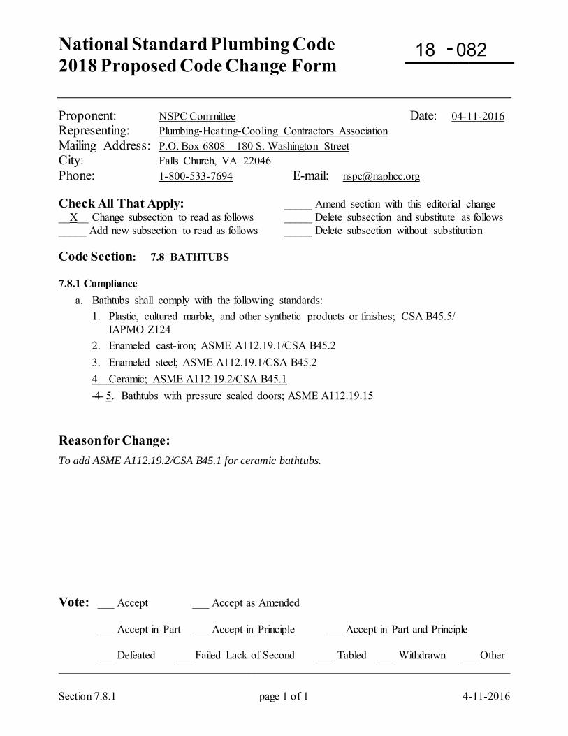
National Standard Plumbing Code 2018 Proposed Code Change Form
-
Section 7.8.1 page 1 of 1 4-11-2016
Proponent: NSPC Committee Date: 04-11-2016 Representing: Plumbing-Heating-Cooling Contractors Association Mailing Address: P.O. Box 6808 180 S. Washington Street City: Falls Church, VA 22046 Phone: 1-800-533-7694 E-mail: [email protected] Check All That Apply: _____ Amend section with this editorial change __X__ Change subsection to read as follows _____ Delete subsection and substitute as follows _____ Add new subsection to read as follows _____ Delete subsection without substitution Code Section: 7.8 BATHTUBS 7.8.1 Compliance a. Bathtubs shall comply with the following standards: 1. Plastic, cultured marble, and other synthetic products or finishes; CSA B45.5/ IAPMO Z124 2. Enameled cast-iron; ASME A112.19.1/CSA B45.2 3. Enameled steel; ASME A112.19.1/CSA B45.2 4. Ceramic; ASME A112.19.2/CSA B45.1 4 5. Bathtubs with pressure sealed doors; ASME A112.19.15 Reason for Change: To add ASME A112.19.2/CSA B45.1 for ceramic bathtubs. Vote: ___ Accept ___ Accept as Amended
___ Accept in Part ___ Accept in Principle ___ Accept in Part and Principle
___ Defeated ___Failed Lack of Second ___ Tabled ___ Withdrawn ___ Other _________________________________________________________________________________
18 082
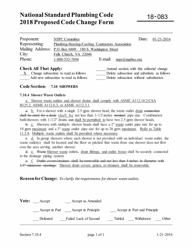
National Standard Plumbing Code 2018 Proposed Code Change Form
-
Section 7.10.4 page 1 of 1 1-21-2016
Proponent: NSPC Committee Date: 01-21-2016 Representing: Plumbing-Heating-Cooling Contractors Association Mailing Address: P.O. Box 6808 180 S. Washington Street City: Falls Church, VA 22046 Phone: 1-800-533-7694 E-mail: [email protected] Check All That Apply: _____ Amend section with this editorial change __X__ Change subsection to read as follows _____ Delete subsection and substitute as follows _____ Add new subsection to read as follows _____ Delete subsection without substitution Code Section: 7.10 SHOWERS
7.10.4 Shower Waste Outlets a. Shower waste outlets and shower drains shall comply with ASME A112.18.2/CSA B125.2, ASME A112.6.3, or ASME A112.3.1. a. b. For a shower with a single 2.5 gpm shower head, the waste outlet drain connection shall be sized for a drain sha ll be not less than 1-1/2 inches nominal pipe size. Combination bath/showers with 1-1/2" drains can shall be permitted to have two 2.5 gpm shower heads. b. c. Showers with multiple shower heads shall have a 2" waste outlet pipe size for up to 10 gpm maximum and a 3" waste outlet pipe size for up to 20 gpm maximum. Refer to Table 11.5.8. Multiple waste outlets shall be provided where necessary. c. d. In group showers where each shower is not provided with an individual waste outlet, the waste outlet(s) shall be located and the floor so pitched that waste from one shower does not flow over the area serving another shower. d. e. Waste Shower waste outlets, drain fittings, and outlet boxes shall be securely connected to the drainage piping system. e. f. Outlet covers/strainers shall be removable and not less than 4 inches in diameter with 1/4" minimum openings. Shower drain covers, grates, or strainers shall be removable. Reason for Change: To clarify the requirements for shower waste outlets. Vote: ___ Accept ___ Accept as Amended
___ Accept in Part ___ Accept in Principle ___ Accept in Part and Principle
___ Defeated ___Failed Lack of Second ___ Tabled ___ Withdrawn ___ Other _________________________________________________________________________________
18 083
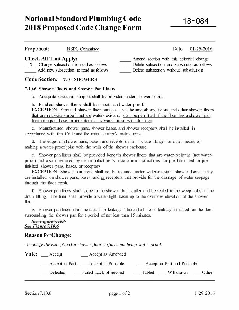
National Standard Plumbing Code 2018 Proposed Code Change Form
-
Section 7.10.6 page 1 of 2 1-29-2016
Proponent: NSPC Committee Date: 01-29-2016
Check All That Apply: _____ Amend section with this editorial change __X__ Change subsection to read as follows _____ Delete subsection and substitute as follows _____ Add new subsection to read as follows _____ Delete subsection without substitution
Code Section: 7.10 SHOWERS 7.10.6 Shower Floors and Shower Pan Liners a. Adequate structural support shall be provided under shower floors.
b. Finished shower floors shall be smooth and water-proof. EXCEPTION: Grouted shower floor surfaces shall be smooth and floors and other shower floors that are not water-proof, but are water-resistant, shall be permitted if the floor has a shower pan liner or a pan, base, or receptor that is water-proof with drainage.
c. Manufactured shower pans, shower bases, and shower receptors shall be installed in accordance with this Code and the manufacturer’s instructions. d. The edges of shower pans, bases, and receptors shall include flanges or other means of making a water-proof joint with the walls of the shower enclosure.
e. Shower pan liners shall be provided beneath shower floors that are water-resistant (not water-proof) and also if required by the manufacturer’s installation instructions for pre-fabricated or pre-finished shower pans, bases, or receptors. EXCEPTION: Shower pan liners shall not be required under water-resistant shower floors if they are installed on shower pans, bases, and or receptors that provide for the drainage of water seepage through the floor finish.
f. Shower pan liners shall slope to the shower drain outlet and be sealed to the weep holes in the drain fitting. The liner shall provide a water-tight basin up to the overflow elevation of the shower floor.
g. Shower pan liners shall be tested for leakage. There shall be no leakage indicated on the floor surrounding the shower pan for a period of not less than 15 minutes. See Figure 7.10.6 See Figure 7.10.6 Reason for Change: To clarify the Exception for shower floor surfaces not being water-proof.
Vote: ___ Accept ___ Accept as Amended
___ Accept in Part ___ Accept in Principle ___ Accept in Part and Principle
___ Defeated ___Failed Lack of Second ___ Tabled ___ Withdrawn ___ Other _________________________________________________________________________________
18 084
National Standard Plumbing Code 2018 Proposed Code Change Form
-
Section 7.11.2 page 1 of 1 9-15-2016
Proponent: NSPC Committee Date: 09-15-2016 Representing: Plumbing-Heating-Cooling Contractors Association Mailing Address: P.O. Box 6808 180 S. Washington Street City: Falls Church, VA 22046 Phone: 1-800-533-7694 E-mail: [email protected] Check All That Apply: __X _ Amend section with this editorial change __X _ Change subsection to read as follows _____ Delete subsection and substitute as follows _____ Add new subsection to read as follows _____ Delete subsection without substitution Code Section: 7.11 SINKS 7.11.2 Domestic Kitchen Sinks and Bar Sinks a. Domestic kitchen sinks and bar sinks shall have one or two compartments with one faucet or water supply fitting. Each compartment of a kitchen sink or bar sink shall have an outlet suitable for either a domestic food waste disposer or a basket strainer. The waste outlet pipe for each compartment shall be 1-1/2” nominal size. Outlet Drain outlet fittings shall have crossbars a basket strainer or other provisions for protecting the drain outlet and shall include a means of closing the drain outlet. A two-compartment sink may be connected to one drain trap. b. Faucets for kitchen sinks and bar sinks shall be designed and manufactured so that they will not exceed a water flow rate of 2.2 gallons per minute when tested in accordance with ASME A112.18.1/CSA B125.1. See Figure 11.7.2 Delete Figure 11.7.2. It is not necessary. The drain outlets of two-compartment domestic kitchen sinks do not have a maximum spacing associated with one trap. They do not require a continuous waste pipe for the drain piping between two compartments. Two compartments can be piped separately for one trap. Two-compartment sinks can have separate traps to avoid backflow between compartments. Reason for Change: To clarify the requirements for draining domestic kitchen sinks and bar sinks. Vote: ___ Accept ___ Accept as Amended
___ Accept in Part ___ Accept in Principle ___ Accept in Part and Principle
___ Defeated ___Failed Lack of Second ___ Tabled ___ Withdrawn ___ Other _________________________________________________________________________________
18 085
National Standard Plumbing Code 2018 Proposed Code Change Form
-
Section 7.11.5 page 1 of 1 1-29-2016
Proponent: NSPC Committee Date: 01-29-2016 Representing: Plumbing-Heating-Cooling Contractors Association Mailing Address: P.O. Box 6808 180 S. Washington Street City: Falls Church, VA 22046 Phone: 1-800-533-7694 E-mail: [email protected] Check All That Apply: _____ Amend section with this editorial change __X__ Change subsection to read as follows _____ Delete subsection and substitute as follows _____ Add new subsection to read as follows _____ Delete subsection without substitution Code Section: 7.11 SINKS 7.11.5 Sanitary Floor Sinks Sanitary floor sinks shall comply with ASME A112.6.7. a. Sanitary floor sinks shall be used as indirect waste receptors in Section 9.3. Their required drain outlet size shall be determined in accordance with Section 9.3.6. b. Sanitary floor sinks shall be enameled epoxy-coated cast iron, stainless steel, or PVC plastic construction, and shall comply with ASME A112.6.7. c. Top loading classification shall be light duty, medium duty, heavy duty, extra heavy duty, or special duty in accordance with ASME A112.6.3, based on their required safe live load. d. Floor sinks shall include anchor flanges, weepholes, flashing clamps, sediment buckets, and secondary strainers where required by their installation and application. e. Sink size and grate configuration shall be coordinated with the indirect waste piping being drained. Reason for Change: To include additional requirements for sanitary floor sinks. Vote: ___ Accept ___ Accept as Amended
___ Accept in Part ___ Accept in Principle ___ Accept in Part and Principle
___ Defeated ___Failed Lack of Second ___ Tabled ___ Withdrawn ___ Other _________________________________________________________________________________
National Standard Plumbing Code 2018 Proposed Code Change Form
-
Section 7.16 page 1 of 2 8-13-2016
Proponent: NSPC Committee Date: 08-13-2016 Representing: Plumbing-Heating-Cooling Contractors Association Mailing Address: P.O. Box 6808 180 S. Washington Street City: Falls Church, VA 22046 Phone: 1-800-533-7694 E-mail: [email protected] Check All That Apply: _____ Amend section with this editorial change __X__ Change subsection to read as follows _____ Delete subsection and substitute as follows _____ Add new subsection to read as follows _____ Delete subsection without substitution Code Sections: Noted 7.16 FLOOR DRAINS, AREA DRAINS, AND TRENCH DRAINS 7.16.1 Compliance a. Floor drains , area drains, and trench drains shall comply with ASME A112.6.3 or, if stainless steel, ASME A112.3.1. b. Top loading classifications shall be light duty, medium duty, heavy duty, extra heavy duty, or special duty, based on their required safe live load. 7.16.2 Grate Free Area and Strainer or Sediment Basket
a. The free area of the top grate for floor drains , area drains, and trench drains shall comply with ASME A112.6.3 based on their outlet connection size.
b. Where floor drains and area drains receive other than clear-water waste, they shall include an internal outlet strainer or removable metal sediment basket to retain solids. b. The trap seal for floor drains shall be not less than 2 inches deep.
c. Where infrequently used floor drains are subject to evaporation of their trap seals, they shall either 1) be provided with a 4-inch deep trap seal and have an accessible means to replenish, or 2) be fed from an automatic trap seal priming device complying with ASSE 1018 or ASSE 1044, or 3) be fitted with a barrier type floor drain trap seal protection device complying with ASSE 1072. d. Where traps are automatically primed, the priming connection shall be above the weir of the trap. See Figures 7.16.2-A through -C Figure 7.16.2 (change ex. Figure 7.16.2-A to Figure 7.16.2)
7.16.3 Size of Floor Drains a. Floor drains and their discharge piping shall be sized in accordance with Section 11.4.4. Floor drains shall be not less than 2” pipe size.
18 087
Section 7.16 page 2 of 2 8-13-2016
7.16.3 Trap Seals
a. Trap seals shall be not less than 2 inches deep or more than 4 inches deep. b. Where infrequently used floor drains are subject to evaporation of their trap seals, they shall either 1) be provided with a 4-inch deep trap seal and have an accessible means to replenish, or 2) be fed from an automatic trap seal priming device complying with ASSE 1018 or ASSE 1044, or 3) be fitted with a barrier type floor drain trap seal protection device complying with ASSE 1072.
c. Where traps are automatically primed, the priming connection shall be above the trap seal. See Figures 7.16.3-A and -B (change ex. Figures 7.16.2-B & C to Figures 7.16.3-A & B)
7.16.4 Required Locations of Floor Drains (no changes)
7.16.5 Walk-in Coolers and Freezers
(no changes) 7.16.6 Floor Slope
(no changes) Reason for Changes: To move area drains and trench drains to Chapter 13 for storm water drainage. In existing Section 7.16.3, there is no Section 11.4.4 and all of the drains in ASME A112.6.3 have a 2” minimum pipe size. To move the trap seal requirements to new Section 7.16.3. Vote: ___ Accept ___ Accept as Amended
___ Accept in Part ___ Accept in Principle ___ Accept in Part and Principle
___ Defeated ___Failed Lack of Second ___ Tabled ___ Withdrawn ___ Other _________________________________________________________________________________
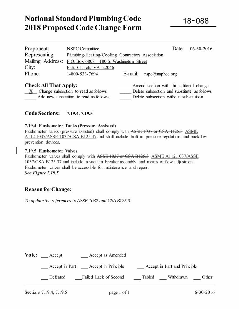
National Standard Plumbing Code 2018 Proposed Code Change Form
-
Sections 7.19.4, 7.19.5 page 1 of 1 6-30-2016
Proponent: NSPC Committee Date: 06-30-2016 Representing: Plumbing-Heating-Cooling Contractors Association Mailing Address: P.O. Box 6808 180 S. Washington Street City: Falls Church, VA 22046 Phone: 1-800-533-7694 E-mail: [email protected] Check All That Apply: _____ Amend section with this editorial change __X__ Change subsection to read as follows _____ Delete subsection and substitute as follows _____ Add new subsection to read as follows _____ Delete subsection without substitution Code Sections: 7.19.4, 7.19.5 7.19.4 Flushometer Tanks (Pressure Assisted) Flushometer tanks (pressure assisted) shall comply with ASSE 1037 or CSA B125.3 ASME A112.1037/ASSE 1037/CSA B125.37 and shall include built-in pressure regulation and backflow prevention devices.
7.19.5 Flushometer Valves Flushometer valves shall comply with ASSE 1037 or CSA B125.3 ASME A112.1037/ASSE 1037/CSA B125.37 and include a vacuum breaker assembly and means of flow adjustment. Flushometer valves shall be accessible for maintenance and repair. See Figure 7.19.5 Reason for Change: To update the references to ASSE 1037 and CSA B125.3. Vote: ___ Accept ___ Accept as Amended
___ Accept in Part ___ Accept in Principle ___ Accept in Part and Principle
___ Defeated ___Failed Lack of Second ___ Tabled ___ Withdrawn ___ Other _________________________________________________________________________________
18 088
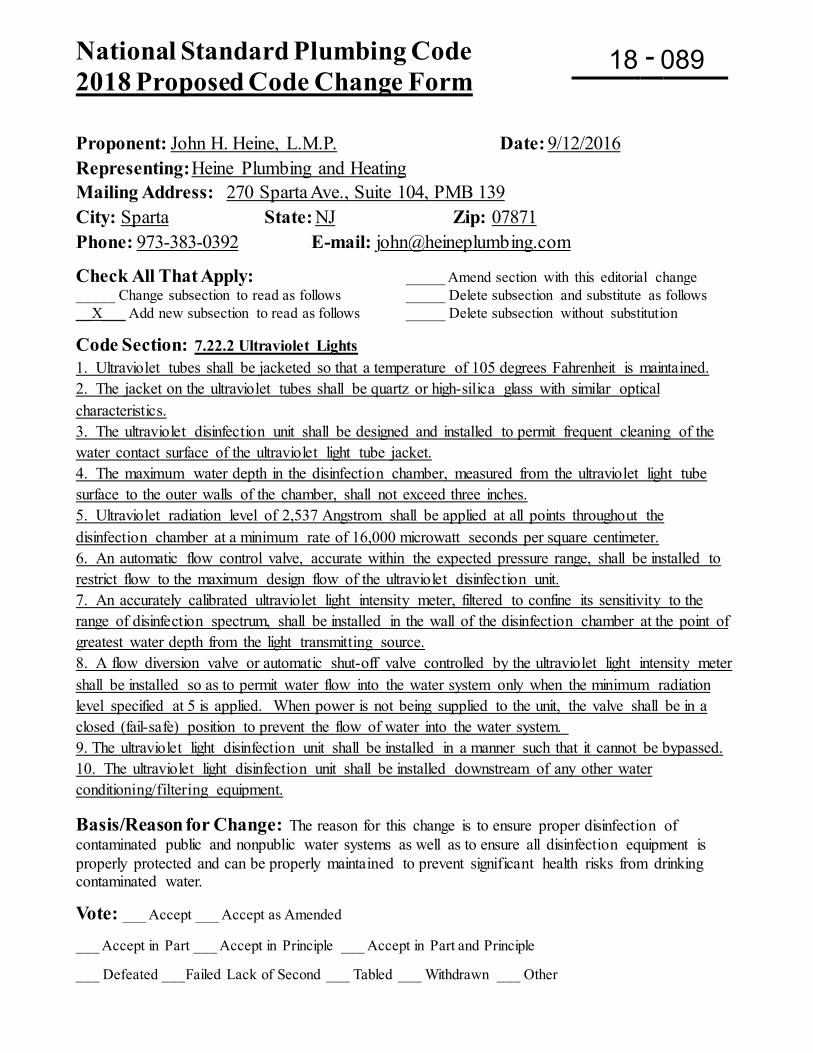
National Standard Plumbing Code 2018 Proposed Code Change Form
-
Proponent: John H. Heine, L.M.P. Date: 9/12/2016 Representing: Heine Plumbing and Heating Mailing Address: 270 Sparta Ave., Suite 104, PMB 139 City: Sparta State: NJ Zip: 07871 Phone: 973-383-0392 E-mail: [email protected]
Check All That Apply: _____ Amend section with this editorial change _____ Change subsection to read as follows _____ Delete subsection and substitute as follows __X___ Add new subsection to read as follows _____ Delete subsection without substitution
Code Section: 7.22.2 Ultraviolet Lights 1. Ultraviolet tubes shall be jacketed so that a temperature of 105 degrees Fahrenheit is maintained. 2. The jacket on the ultraviolet tubes shall be quartz or high-silica glass with similar optical characteristics. 3. The ultraviolet disinfection unit shall be designed and installed to permit frequent cleaning of the water contact surface of the ultraviolet light tube jacket. 4. The maximum water depth in the disinfection chamber, measured from the ultraviolet light tube surface to the outer walls of the chamber, shall not exceed three inches. 5. Ultraviolet radiation level of 2,537 Angstrom shall be applied at all points throughout the disinfection chamber at a minimum rate of 16,000 microwatt seconds per square centimeter. 6. An automatic flow control valve, accurate within the expected pressure range, shall be installed to restrict flow to the maximum design flow of the ultraviolet disinfection unit. 7. An accurately calibrated ultraviolet light intensity meter, filtered to confine its sensitivity to the range of disinfection spectrum, shall be installed in the wall of the disinfection chamber at the point of greatest water depth from the light transmitting source. 8. A flow diversion valve or automatic shut-off valve controlled by the ultraviolet light intensity meter shall be installed so as to permit water flow into the water system only when the minimum radiation level specified at 5 is applied. When power is not being supplied to the unit, the valve shall be in a closed (fail-safe) position to prevent the flow of water into the water system. 9. The ultraviolet light disinfection unit shall be installed in a manner such that it cannot be bypassed. 10. The ultraviolet light disinfection unit shall be installed downstream of any other water conditioning/filtering equipment. Basis/Reason for Change: The reason for this change is to ensure proper disinfection of contaminated public and nonpublic water systems as well as to ensure all disinfection equipment is properly protected and can be properly maintained to prevent significant health risks from drinking contaminated water.
Vote: ___ Accept ___ Accept as Amended ___ Accept in Part ___ Accept in Principle ___ Accept in Part and Principle ___ Defeated ___Failed Lack of Second ___ Tabled ___ Withdrawn ___ Other
18 089
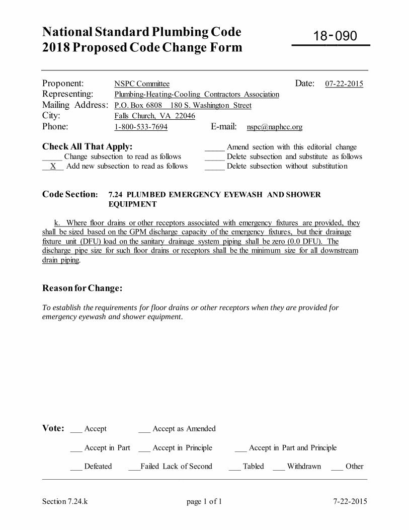
National Standard Plumbing Code 2018 Proposed Code Change Form
-
Section 7.24.k page 1 of 1 7-22-2015
Proponent: NSPC Committee Date: 07-22-2015 Representing: Plumbing-Heating-Cooling Contractors Association Mailing Address: P.O. Box 6808 180 S. Washington Street City: Falls Church, VA 22046 Phone: 1-800-533-7694 E-mail: [email protected] Check All That Apply: _____ Amend section with this editorial change _____ Change subsection to read as follows _____ Delete subsection and substitute as follows __X__ Add new subsection to read as follows _____ Delete subsection without substitution Code Section: 7.24 PLUMBED EMERGENCY EYEWASH AND SHOWER
EQUIPMENT k. Where floor drains or other receptors associated with emergency fixtures are provided, they shall be sized based on the GPM discharge capacity of the emergency fixtures, but their drainage fixture unit (DFU) load on the sanitary drainage system piping shall be zero (0.0 DFU). The discharge pipe size for such floor drains or receptors shall be the minimum size for all downstream drain piping. Reason for Change: To establish the requirements for floor drains or other receptors when they are provided for emergency eyewash and shower equipment. Vote: ___ Accept ___ Accept as Amended
___ Accept in Part ___ Accept in Principle ___ Accept in Part and Principle
___ Defeated ___Failed Lack of Second ___ Tabled ___ Withdrawn ___ Other _________________________________________________________________________________
18 090
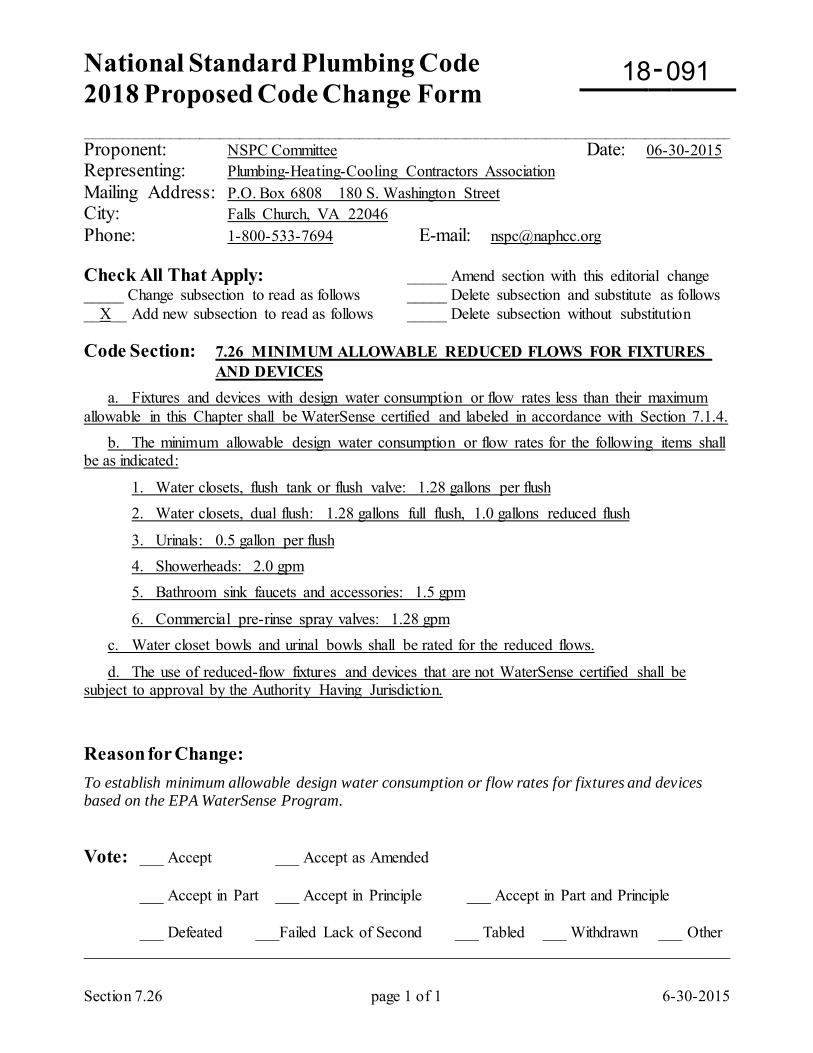
National Standard Plumbing Code 2018 Proposed Code Change Form
-
_________________________________________________________________________________________________
Section 7.26 page 1 of 1 6-30-2015
Proponent: NSPC Committee Date: 06-30-2015 Representing: Plumbing-Heating-Cooling Contractors Association Mailing Address: P.O. Box 6808 180 S. Washington Street City: Falls Church, VA 22046 Phone: 1-800-533-7694 E-mail: [email protected] Check All That Apply: _____ Amend section with this editorial change _____ Change subsection to read as follows _____ Delete subsection and substitute as follows __X__ Add new subsection to read as follows _____ Delete subsection without substitution Code Section: 7.26 MINIMUM ALLOWABLE REDUCED FLOWS FOR FIXTURES AND DEVICES a. Fixtures and devices with design water consumption or flow rates less than their maximum allowable in this Chapter shall be WaterSense certified and labeled in accordance with Section 7.1.4. b. The minimum allowable design water consumption or flow rates for the following items shall be as indicated:
1. Water closets, flush tank or flush valve: 1.28 gallons per flush 2. Water closets, dual flush: 1.28 gallons full flush, 1.0 gallons reduced flush
3. Urinals: 0.5 gallon per flush 4. Showerheads: 2.0 gpm 5. Bathroom sink faucets and accessories: 1.5 gpm
6. Commercial pre-rinse spray valves: 1.28 gpm c. Water closet bowls and urinal bowls shall be rated for the reduced flows.
d. The use of reduced-flow fixtures and devices that are not WaterSense certified shall be subject to approval by the Authority Having Jurisdiction. Reason for Change: To establish minimum allowable design water consumption or flow rates for fixtures and devices based on the EPA WaterSense Program. Vote: ___ Accept ___ Accept as Amended
___ Accept in Part ___ Accept in Principle ___ Accept in Part and Principle
___ Defeated ___Failed Lack of Second ___ Tabled ___ Withdrawn ___ Other _________________________________________________________________________________
18 091
National Standard Plumbing Code 2018 Proposed Code Change Form Deadline September 16, 2016
-
Proponent: Vincent Tamburro Date: 09/13/16
Representing: Vincent Tamburro
Mailing Address: 6105 Warrens Way
City: Wanaque State: NJ Zip: 07465
Phone: 862-377-0560 E-mail [email protected] IMPORTANT: Please review the attached instruction sheet regarding proposed code changes. Check All That Apply: _____ Amend section with this editorial change __X__ Change subsection to read as follows _____ Delete subsection and substitute as follows _____ Add new subsection to read as follows _____ Delete subsection without substitution Please submit changes to only one Code Section per Proposed Code Change Form Code Section: 9.1.5 Food Handling Areas a. (unchanged) b. (unchanged) EXCEPTIONS: (1) (unchanged) (2) (unchanged) (3) If a properly vented floor drain is installed immediately adjacent to a sink used for dishwashing or food prep, a properly trapped and vented single compartment sink or sink compartment shall be permitted to connect directly to the drainage system, on the sewer side of the floor drain trap. (4) (unchanged) Basis/Reason for Change: To be clear that only a single sink compartment and not a multiple compartment sink with a continuous waste is permitted to be connected in this manner. Vote: ___ Accept ___ Accept as Amended
___ Accept in Part ___ Accept in Principle ___ Accept in Part and Principle
___ Defeated ___Failed Lack of Second ___ Tabled ___ Withdrawn ___ Other ____________________________________________________________________________________
18 092
National Standard Plumbing Code 2018 Proposed Code Change Form
-
Proponent: Donald M. Jones Date: 1/8/2016
Representing: Donald M. Jones
Mailing Address: 202 W. Summit St
City: Vineland State: NJ Zip: 08360
Phone: 609 517 1473 E-mail: [email protected] Check All That Apply: _____ Amend section with this editorial change __X__ Change subsection to read as follows _____ Delete subsection and substitute as follows _____ Add new subsection to read as follows _____ Delete subsection without substitution
Code Section: INDIRECT WASTE RECEPTORS 9.3.1 General a. Receptors for indirect wastes shall be properly trapped and vented floor drains, floor sinks, standpipes, open-hub drains, air gaps fittings, or other approved fixtures. b. Receptors shall be of such size, shape, and capacity as required to prevent splashing or flooding by the discharge from any and all indirect waste pipes served by the receptor. c. Plumbing fixtures that are used for domestic or culinary purposes shall not be used as receptors for indirect wastes, except as follows: 1. In a dwelling unit, a kitchen sink trap or food waste disposer shall be permitted to receive the discharge from a dishwasher. 2. In a dwelling unit, a laundry sink, provided that an air gap is maintained for any potable clear-water waste, shall be an acceptable receptor for: a) Air conditioning equipment b) Automatic clothes washer c) Water treatment unit d) Water heater relief valve discharge e) Condensing furnace, boiler, and water heater condensate 3. A service sink or mop basin shall be an acceptable receptor for air conditioning and condensing furnace, boiler, and water heater condensate and any infrequent potable clear-water waste if the required air gap is provided for potable clear-water wastes. Basis/Reason for Change: Appliances are “going green.” Condensing boilers and water heaters are commonplace, so they should be include along with furnaces. Vote: ___ Accept ___ Accept as Amended
___ Accept in Part ___ Accept in Principle ___ Accept in Part and Principle
___ Defeated ___Failed Lack of Second ___ Tabled ___ Withdrawn ___ Other ____________________________________________________________________________________
18 093

National Standard Plumbing Code 2018 Proposed Code Change Form
-
Section 9.3.3 page 1 of 1 7-16-2015
Proponent: NSPC Committee Date: 07-16-2015 Representing: Plumbing-Heating-Cooling Contractors Association Mailing Address: P.O. Box 6808 180 S. Washington Street City: Falls Church, VA 22046 Phone: 1-800-533-7694 E-mail: [email protected] Check All That Apply: _____ Amend section with this editorial change __X__ Change subsection to read as follows _____ Delete subsection and substitute as follows _____ Add new subsection to read as follows _____ Delete subsection without substitution Code Section: 9.3 INDIRECT WASTE RECEPTORS 9.3.3 Prohibited Locations Receptors for indirect wastes shall not be located in a toilet room or in any confined, concealed. inaccessible, or unventilated space. EXCEPTION: Air conditioning condensate in dwellings shall be permitted to drain to a tub waste and overflow or lavatory tailpiece in accordance with Section 9.4.3.c.5. Reason for Change: To coordinate Section 9.3.3 with proposed changes to Section 9.4.3. Vote: ___ Accept ___ Accept as Amended
___ Accept in Part ___ Accept in Principle ___ Accept in Part and Principle
___ Defeated ___Failed Lack of Second ___ Tabled ___ Withdrawn ___ Other _________________________________________________________________________________
18 094
National Standard Plumbing Code 2018 Proposed Code Change Form
-
Section 9.3.4 page 1 of 1 8-07-2015
Proponent: NSPC Committee Date: 08-07-2015 Representing: Plumbing-Heating-Cooling Contractors Association Mailing Address: P.O. Box 6808 180 S. Washington Street City: Falls Church, VA 22046 Phone: 1-800-533-7694 E-mail: [email protected] Check All That Apply: _____ Amend section with this editorial change __X__ Change subsection to read as follows _____ Delete subsection and substitute as follows _____ Add new subsection to read as follows _____ Delete subsection without substitution Code Section: 9.3 INDIRECT WASTE RECEPTORS 9.3.4 Standpipes for Domestic Clothes Washers A standpipe, 2-inch minimum pipe size and extending not more than 48 inches nor less than 18 inches above its trap, shall be permitted to serve as a receptor for a domestic clothes washer. In a dwelling, a laundry sink shall be permitted to drain into the standpipe. See Figure 9.3.4 (In Figure 9.3.4, delete the detail with the laundry sink.) Reason for Change: The connection of the laundry sink to the standpipe in Figure 9.3.4 is not a proper indirect waste connection to the standpipe. Connections must be indirect at the top of the standpipe. Vote: ___ Accept ___ Accept as Amended
___ Accept in Part ___ Accept in Principle ___ Accept in Part and Principle
___ Defeated ___Failed Lack of Second ___ Tabled ___ Withdrawn ___ Other _________________________________________________________________________________
18 095
National Standard Plumbing Code 2018 Proposed Code Change Form
-
Section 9.4.3 page 1 of 2 2-02-2016
Proponent: NSPC Committee Date: 02-02-2016 Representing: Plumbing-Heating-Cooling Contractors Association Mailing Address: P.O. Box 6808 180 S. Washington Street City: Falls Church, VA 22046 Phone: 1-800-533-7694 E-mail: [email protected] Check All That Apply: _____ Amend section with this editorial change __X__ Change subsection to read as follows _____ Delete subsection and substitute as follows _____ Add new subsection to read as follows _____ Delete subsection without substitution Code Section: Chapter 9 - Indirect Waste Piping and Special Wastes 9.4.3 Air Conditioning Condensate a. Indirect waste piping from air conditioning units shall be sized according to the condensate-generating capacity of the units served. Branches from individual units shall be no smaller than the drain opening or drain connection on the unit. Traps shall be provided at each air conditioning unit or cooling coil to maintain atmospheric pressure in the waste piping.
b. Gravity condensate waste piping shall be sloped not less than 1/8" per foot. Drainage fittings shall be used for sizes 1-1/4" and larger. Minimum pipe sizes for gravity flow shall be as follows: 3/4" pipe size through 3-ton cooling capacity 1" pipe size through 20-ton cooling capacity 1-1/4" pipe size through 100-ton cooling capacity 1-1/2" pipe size through 300-ton cooling capacity 2" size pipe through 600-ton cooling capacity c. Discharge of air conditioning condensate shall not be permitted to create a nuisance such as by flowing across the ground or paved surfaces. Unless expressly prohibited by the Authority Having Jurisdiction, the point of indirect discharge for air conditioning condensate shall be one of the following: 1. The building sanitary drainage system. 2. The building storm drainage system. 3. A sump pump pit. 4. A subsurface absorption pit or trench. 5. Within dwellings, a tub waste and overflow, lavatory tailpiece, or laundry sink within the
same dwelling. See Figures 9.4.3-A and 9.4.3-B
18 096
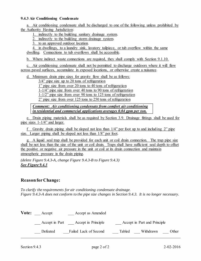
Section 9.4.3 page 2 of 2 2-02-2016
9.4.3 Air Conditioning Condensate
a. Air conditioning condensate shall be discharged to one of the following unless prohibited by the Authority Having Jurisdiction: 1. indirectly to the building sanitary drainage system. 2. indirectly to the building storm drainage system. 3. to an approved outdoor location. 4. in dwellings, to a laundry sink, lavatory tailpiece, or tub overflow within the same
dwelling. Connections to tub overflows shall be accessible.
b. Where indirect waste connections are required, they shall comply with Section 9.1.10. c. Air conditioning condensate shall not be permitted to discharge outdoors where it will flow across paved surfaces, accumulate in exposed locations, or otherwise create a nuisance.
d. Minimum drain pipe sizes for gravity flow shall be as follows: 3/4” pipe size up to 20 tons of refrigeration 1” pipe size from over 20 tons to 40 tons of refrigeration 1-1/4” pipe size from over 40 tons to 90 tons of refrigeration 1-1/2” pipe size from over 90 tons to 125 tons of refrigeration 2” pipe size from over 125 tons to 250 tons of refrigeration
Comment: Air conditioning condensate from comfort air conditioning in residential and commercial applications averages 0.04 gpm per ton.
e. Drain piping materials shall be as required by Section 3.9. Drainage fittings shall be used for pipe sizes 1-1/4” and larger.
f Gravity drain piping shall be sloped not less than 1/4” per foot up to and including 2” pipe size. Larger piping shall be sloped not less than 1/8” per foot.
g. A liquid seal trap shall be provided for each unit or coil drain connection. The trap pipe size shall be not less than the size of the unit or coil drain. Traps shall have sufficient seal depth to offset the positive or negative air pressure in the unit or coil at its drain connection and maintain atmospheric pressure in the drain piping. (delete Figure 9.4.3-A, change Figure 9.4.3-B to Figure 9.4.3) See Figure 9.4.3 Reason for Change: To clarify the requirements for air conditioning condensate drainage. Figure 9.4.3-A does not conform to the pipe size changes in Section 9.4.3. It is no longer necessary. Vote: ___ Accept ___ Accept as Amended
___ Accept in Part ___ Accept in Principle ___ Accept in Part and Principle
___ Defeated ___Failed Lack of Second ___ Tabled ___ Withdrawn ___ Other _________________________________________________________________________________
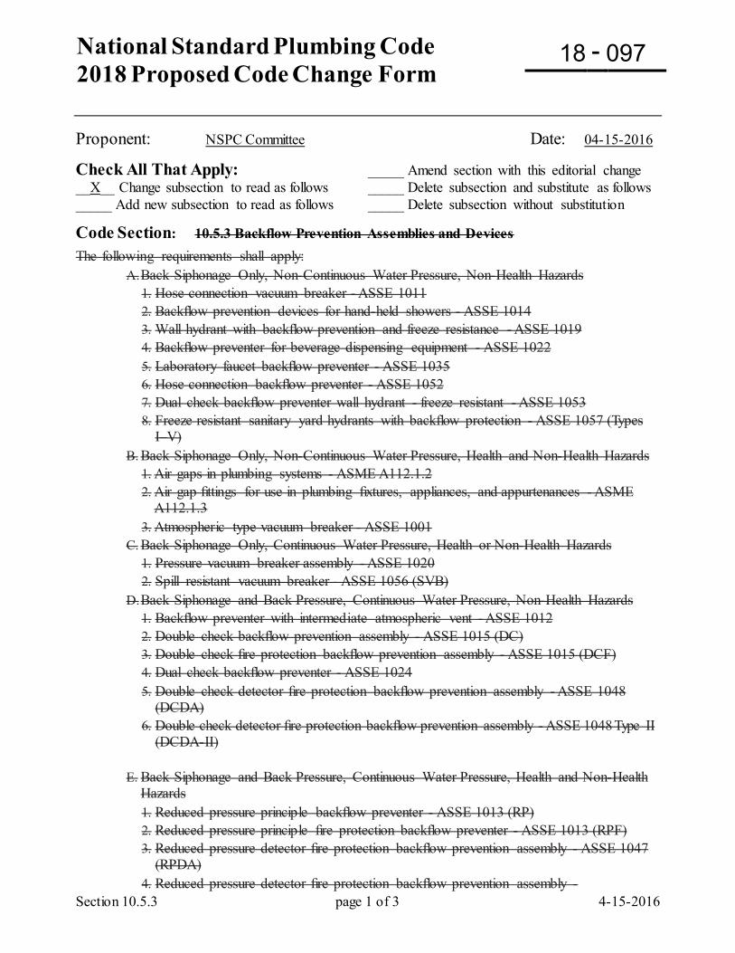
National Standard Plumbing Code 2018 Proposed Code Change Form
-
Section 10.5.3 page 1 of 3 4-15-2016
Proponent: NSPC Committee Date: 04-15-2016
Check All That Apply: _____ Amend section with this editorial change __X__ Change subsection to read as follows _____ Delete subsection and substitute as follows _____ Add new subsection to read as follows _____ Delete subsection without substitution
Code Section: 10.5.3 Backflow Prevention Assemblies and Devices The following requirements shall apply:
A. Back Siphonage Only, Non-Continuous Water Pressure, Non-Health Hazards 1. Hose connection vacuum breaker - ASSE 1011 2. Backflow prevention devices for hand-held showers - ASSE 1014 3. Wall hydrant with backflow prevention and freeze resistance - ASSE 1019 4. Backflow preventer for beverage dispensing equipment - ASSE 1022 5. Laboratory faucet backflow preventer - ASSE 1035 6. Hose connection backflow preventer - ASSE 1052 7. Dual check backflow preventer wall hydrant - freeze resistant - ASSE 1053 8. Freeze resistant sanitary yard hydrants with backflow protection - ASSE 1057 (Types
I–V) B. Back Siphonage Only, Non-Continuous Water Pressure, Health and Non-Health Hazards
1. Air gaps in plumbing systems - ASME A112.1.2 2. Air gap fittings for use in plumbing fixtures, appliances, and appurtenances - ASME
A112.1.3 3. Atmospheric type vacuum breaker - ASSE 1001
C. Back Siphonage Only, Continuous Water Pressure, Health or Non-Health Hazards 1. Pressure vacuum breaker assembly - ASSE 1020 2. Spill resistant vacuum breaker - ASSE 1056 (SVB)
D. Back Siphonage and Back Pressure, Continuous Water Pressure, Non-Health Hazards 1. Backflow preventer with intermediate atmospheric vent - ASSE 1012 2. Double check backflow prevention assembly - ASSE 1015 (DC) 3. Double check fire protection backflow prevention assembly - ASSE 1015 (DCF) 4. Dual check backflow preventer - ASSE 1024 5. Double check detector fire protection backflow prevention assembly - ASSE 1048
(DCDA) 6. Double check detector fire protection backflow prevention assembly - ASSE 1048 Type II
(DCDA-II)
E. Back Siphonage and Back Pressure, Continuous Water Pressure, Health and Non-Health Hazards 1. Reduced pressure principle backflow preventer - ASSE 1013 (RP) 2. Reduced pressure principle fire protection backflow preventer - ASSE 1013 (RPF) 3. Reduced pressure detector fire protection backflow prevention assembly - ASSE 1047
(RPDA) 4. Reduced pressure detector fire protection backflow prevention assembly -
18 097
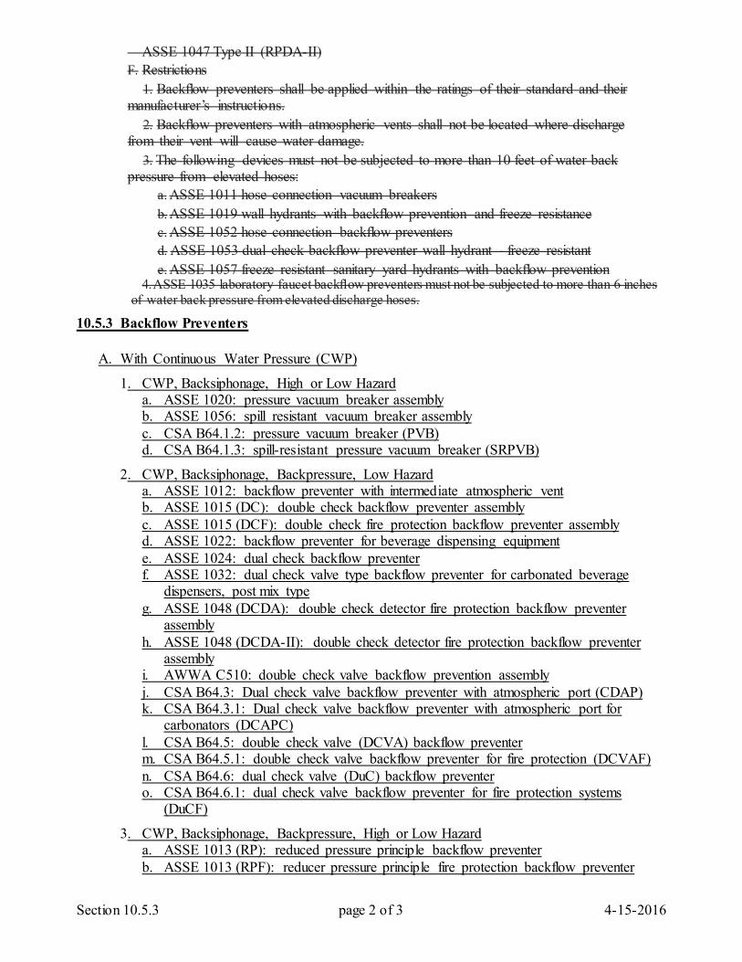
Section 10.5.3 page 2 of 3 4-15-2016
ASSE 1047 Type II (RPDA-II) F. Restrictions
1. Backflow preventers shall be applied within the ratings of their standard and their manufacturer’s instructions.
2. Backflow preventers with atmospheric vents shall not be located where discharge from their vent will cause water damage.
3. The following devices must not be subjected to more than 10 feet of water back pressure from elevated hoses:
a. ASSE 1011 hose connection vacuum breakers b. ASSE 1019 wall hydrants with backflow prevention and freeze resistance c. ASSE 1052 hose connection backflow preventers d. ASSE 1053 dual check backflow preventer wall hydrant - freeze resistant e. ASSE 1057 freeze resistant sanitary yard hydrants with backflow prevention
4. ASSE 1035 laboratory faucet backflow preventers must not be subjected to more than 6 inches of water back pressure from elevated discharge hoses.
10.5.3 Backflow Preventers A. With Continuous Water Pressure (CWP)
1. CWP, Backsiphonage, High or Low Hazard a. ASSE 1020: pressure vacuum breaker assembly b. ASSE 1056: spill resistant vacuum breaker assembly c. CSA B64.1.2: pressure vacuum breaker (PVB) d. CSA B64.1.3: spill-resistant pressure vacuum breaker (SRPVB)
2. CWP, Backsiphonage, Backpressure, Low Hazard a. ASSE 1012: backflow preventer with intermediate atmospheric vent b. ASSE 1015 (DC): double check backflow preventer assembly c. ASSE 1015 (DCF): double check fire protection backflow preventer assembly d. ASSE 1022: backflow preventer for beverage dispensing equipment e. ASSE 1024: dual check backflow preventer f. ASSE 1032: dual check valve type backflow preventer for carbonated beverage
dispensers, post mix type g. ASSE 1048 (DCDA): double check detector fire protection backflow preventer
assembly h. ASSE 1048 (DCDA-II): double check detector fire protection backflow preventer
assembly i. AWWA C510: double check valve backflow prevention assembly j. CSA B64.3: Dual check valve backflow preventer with atmospheric port (CDAP) k. CSA B64.3.1: Dual check valve backflow preventer with atmospheric port for
carbonators (DCAPC) l. CSA B64.5: double check valve (DCVA) backflow preventer m. CSA B64.5.1: double check valve backflow preventer for fire protection (DCVAF) n. CSA B64.6: dual check valve (DuC) backflow preventer o. CSA B64.6.1: dual check valve backflow preventer for fire protection systems
(DuCF)
3. CWP, Backsiphonage, Backpressure, High or Low Hazard a. ASSE 1013 (RP): reduced pressure principle backflow preventer b. ASSE 1013 (RPF): reducer pressure principle fire protection backflow preventer
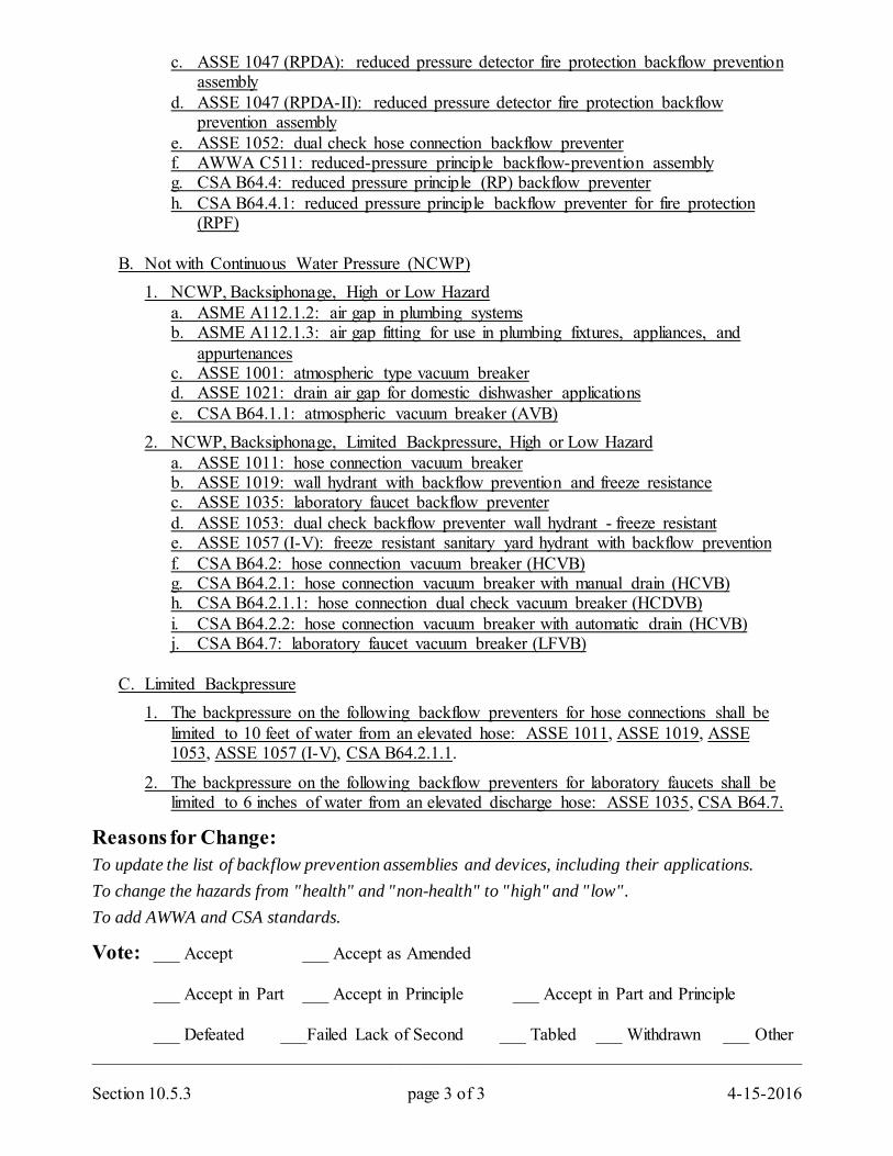
Section 10.5.3 page 3 of 3 4-15-2016
c. ASSE 1047 (RPDA): reduced pressure detector fire protection backflow prevention assembly
d. ASSE 1047 (RPDA-II): reduced pressure detector fire protection backflow prevention assembly
e. ASSE 1052: dual check hose connection backflow preventer f. AWWA C511: reduced-pressure principle backflow-prevention assembly g. CSA B64.4: reduced pressure principle (RP) backflow preventer h. CSA B64.4.1: reduced pressure principle backflow preventer for fire protection
(RPF) B. Not with Continuous Water Pressure (NCWP) 1. NCWP, Backsiphonage, High or Low Hazard a. ASME A112.1.2: air gap in plumbing systems b. ASME A112.1.3: air gap fitting for use in plumbing fixtures, appliances, and
appurtenances c. ASSE 1001: atmospheric type vacuum breaker d. ASSE 1021: drain air gap for domestic dishwasher applications e. CSA B64.1.1: atmospheric vacuum breaker (AVB) 2. NCWP, Backsiphonage, Limited Backpressure, High or Low Hazard a. ASSE 1011: hose connection vacuum breaker b. ASSE 1019: wall hydrant with backflow prevention and freeze resistance c. ASSE 1035: laboratory faucet backflow preventer d. ASSE 1053: dual check backflow preventer wall hydrant - freeze resistant e. ASSE 1057 (I-V): freeze resistant sanitary yard hydrant with backflow prevention f. CSA B64.2: hose connection vacuum breaker (HCVB) g. CSA B64.2.1: hose connection vacuum breaker with manual drain (HCVB) h. CSA B64.2.1.1: hose connection dual check vacuum breaker (HCDVB) i. CSA B64.2.2: hose connection vacuum breaker with automatic drain (HCVB) j. CSA B64.7: laboratory faucet vacuum breaker (LFVB) C. Limited Backpressure 1. The backpressure on the following backflow preventers for hose connections shall be
limited to 10 feet of water from an elevated hose: ASSE 1011, ASSE 1019, ASSE 1053, ASSE 1057 (I-V), CSA B64.2.1.1.
2. The backpressure on the following backflow preventers for laboratory faucets shall be limited to 6 inches of water from an elevated discharge hose: ASSE 1035, CSA B64.7.
Reasons for Change: To update the list of backflow prevention assemblies and devices, including their applications. To change the hazards from "health" and "non-health" to "high" and "low". To add AWWA and CSA standards.
Vote: ___ Accept ___ Accept as Amended
___ Accept in Part ___ Accept in Principle ___ Accept in Part and Principle
___ Defeated ___Failed Lack of Second ___ Tabled ___ Withdrawn ___ Other _________________________________________________________________________________
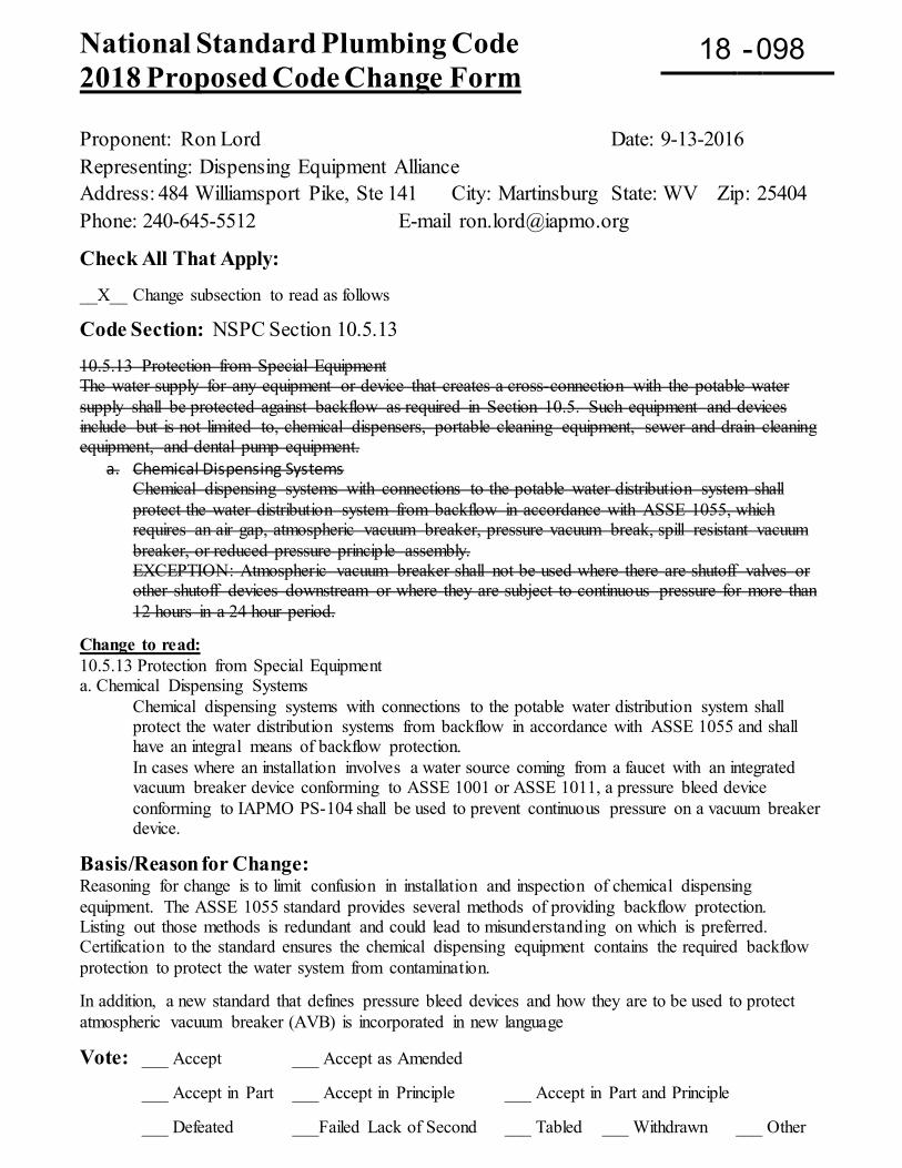
National Standard Plumbing Code 2018 Proposed Code Change Form
-
Proponent: Ron Lord Date: 9-13-2016 Representing: Dispensing Equipment Alliance Address: 484 Williamsport Pike, Ste 141 City: Martinsburg State: WV Zip: 25404 Phone: 240-645-5512 E-mail [email protected]
Check All That Apply: __X__ Change subsection to read as follows
Code Section: NSPC Section 10.5.13 10.5.13 Protection from Special Equipment The water supply for any equipment or device that creates a cross-connection with the potable water supply shall be protected against backflow as required in Section 10.5. Such equipment and devices include but is not limited to, chemical dispensers, portable cleaning equipment, sewer and drain cleaning equipment, and dental pump equipment.
a. Chemical Dispensing Systems Chemical dispensing systems with connections to the potable water distribution system shall protect the water distribution system from backflow in accordance with ASSE 1055, which requires an air gap, atmospheric vacuum breaker, pressure vacuum break, spill resistant vacuum breaker, or reduced pressure principle assembly. EXCEPTION: Atmospheric vacuum breaker shall not be used where there are shutoff valves or other shutoff devices downstream or where they are subject to continuous pressure for more than 12 hours in a 24 hour period.
Change to read: 10.5.13 Protection from Special Equipment a. Chemical Dispensing Systems
Chemical dispensing systems with connections to the potable water distribution system shall protect the water distribution systems from backflow in accordance with ASSE 1055 and shall have an integral means of backflow protection. In cases where an installation involves a water source coming from a faucet with an integrated vacuum breaker device conforming to ASSE 1001 or ASSE 1011, a pressure bleed device conforming to IAPMO PS-104 shall be used to prevent continuous pressure on a vacuum breaker device.
Basis/Reason for Change: Reasoning for change is to limit confusion in installation and inspection of chemical dispensing equipment. The ASSE 1055 standard provides several methods of providing backflow protection. Listing out those methods is redundant and could lead to misunderstanding on which is preferred. Certification to the standard ensures the chemical dispensing equipment contains the required backflow protection to protect the water system from contamination. In addition, a new standard that defines pressure bleed devices and how they are to be used to protect atmospheric vacuum breaker (AVB) is incorporated in new language
Vote: ___ Accept ___ Accept as Amended
___ Accept in Part ___ Accept in Principle ___ Accept in Part and Principle
___ Defeated ___Failed Lack of Second ___ Tabled ___ Withdrawn ___ Other
18 098
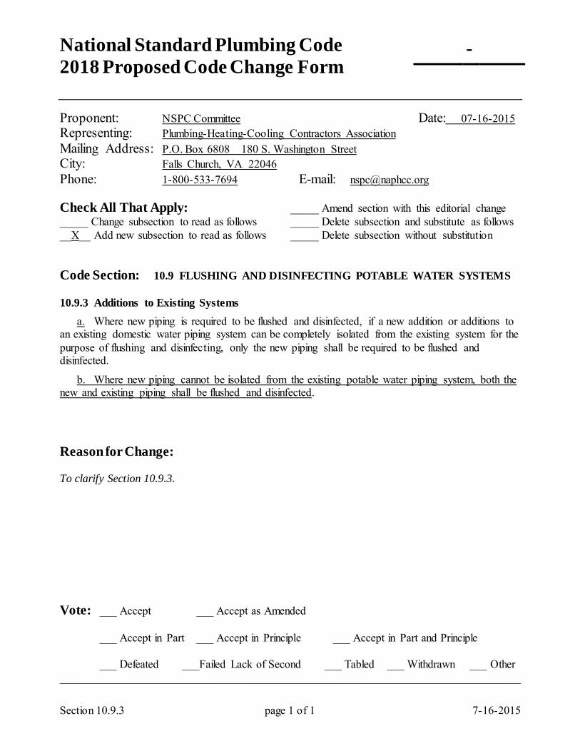
National Standard Plumbing Code 2018 Proposed Code Change Form
-
Section 10.9.3 page 1 of 1 7-16-2015
Proponent: NSPC Committee Date: 07-16-2015 Representing: Plumbing-Heating-Cooling Contractors Association Mailing Address: P.O. Box 6808 180 S. Washington Street City: Falls Church, VA 22046 Phone: 1-800-533-7694 E-mail: [email protected] Check All That Apply: _____ Amend section with this editorial change _____ Change subsection to read as follows _____ Delete subsection and substitute as follows __X__ Add new subsection to read as follows _____ Delete subsection without substitution Code Section: 10.9 FLUSHING AND DISINFECTING POTABLE WATER SYSTEMS 10.9.3 Additions to Existing Systems a. Where new piping is required to be flushed and disinfected, if a new addition or additions to an existing domestic water piping system can be completely isolated from the existing system for the purpose of flushing and disinfecting, only the new piping shall be required to be flushed and disinfected.
b. Where new piping cannot be isolated from the existing potable water piping system, both the new and existing piping shall be flushed and disinfected. Reason for Change: To clarify Section 10.9.3. Vote: ___ Accept ___ Accept as Amended
___ Accept in Part ___ Accept in Principle ___ Accept in Part and Principle
___ Defeated ___Failed Lack of Second ___ Tabled ___ Withdrawn ___ Other _________________________________________________________________________________
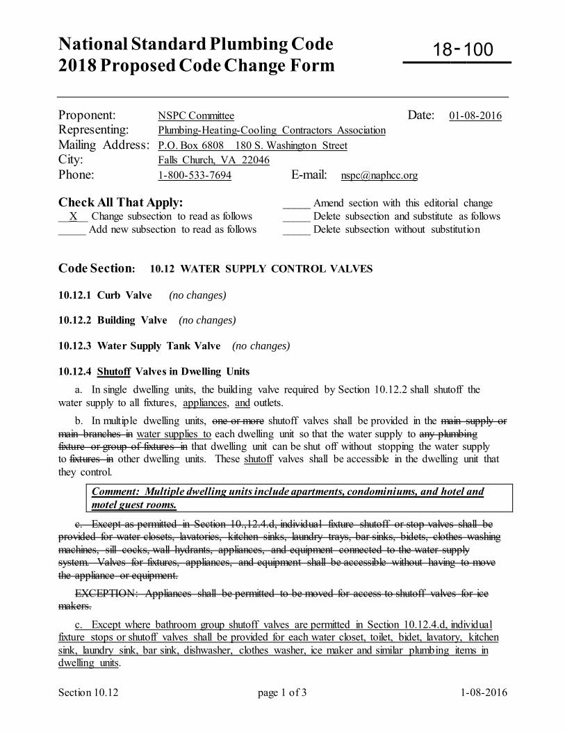
National Standard Plumbing Code 2018 Proposed Code Change Form
-
Section 10.12 page 1 of 3 1-08-2016
Proponent: NSPC Committee Date: 01-08-2016 Representing: Plumbing-Heating-Cooling Contractors Association Mailing Address: P.O. Box 6808 180 S. Washington Street City: Falls Church, VA 22046 Phone: 1-800-533-7694 E-mail: [email protected] Check All That Apply: _____ Amend section with this editorial change __X__ Change subsection to read as follows _____ Delete subsection and substitute as follows _____ Add new subsection to read as follows _____ Delete subsection without substitution Code Section: 10.12 WATER SUPPLY CONTROL VALVES 10.12.1 Curb Valve (no changes) 10.12.2 Building Valve (no changes) 10.12.3 Water Supply Tank Valve (no changes) 10.12.4 Shutoff Valves in Dwelling Units a. In single dwelling units, the building valve required by Section 10.12.2 shall shutoff the water supply to all fixtures, appliances, and outlets. b. In multiple dwelling units, one or more shutoff valves shall be provided in the main supply or main branches in water supplies to each dwelling unit so that the water supply to any plumbing fixture or group of fixtures in that dwelling unit can be shut off without stopping the water supply to fixtures in other dwelling units. These shutoff valves shall be accessible in the dwelling unit that they control.
Comment: Multiple dwelling units include apartments, condominiums, and hotel and motel guest rooms.
c. Except as permitted in Section 10.,12.4.d, individual fixture shutoff or stop valves shall be provided for water closets, lavatories, kitchen sinks, laundry trays, bar sinks, bidets, clothes washing machines, sill cocks, wall hydrants, appliances, and equipment connected to the water supply system. Valves for fixtures, appliances, and equipment shall be accessible without having to move the appliance or equipment. EXCEPTION: Appliances shall be permitted to be moved for access to shutoff valves for ice makers.
c. Except where bathroom group shutoff valves are permitted in Section 10.12.4.d, individual fixture stops or shutoff valves shall be provided for each water closet, toilet, bidet, lavatory, kitchen sink, laundry sink, bar sink, dishwasher, clothes washer, ice maker and similar plumbing items in dwelling units.
18 100
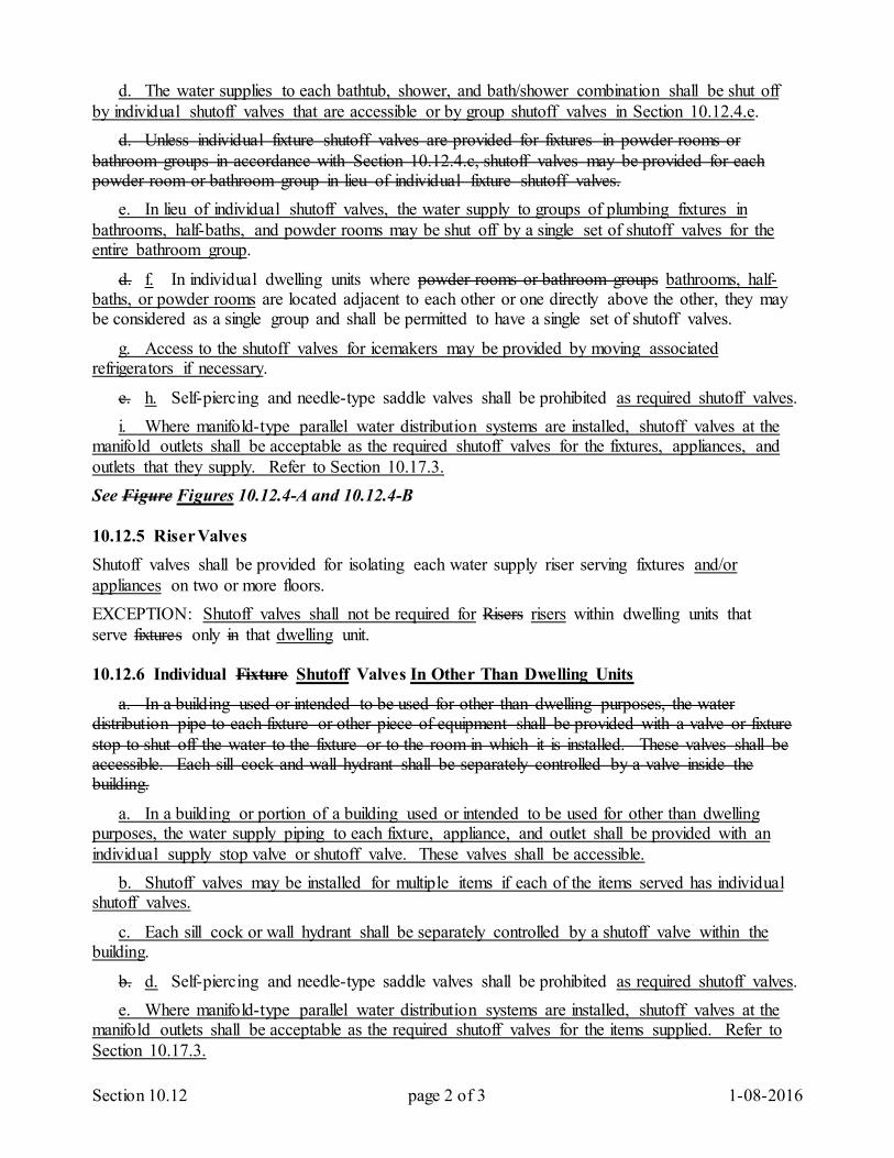
Section 10.12 page 2 of 3 1-08-2016
d. The water supplies to each bathtub, shower, and bath/shower combination shall be shut off by individual shutoff valves that are accessible or by group shutoff valves in Section 10.12.4.e. d. Unless individual fixture shutoff valves are provided for fixtures in powder rooms or bathroom groups in accordance with Section 10.12.4.c, shutoff valves may be provided for each powder room or bathroom group in lieu of individual fixture shutoff valves. e. In lieu of individual shutoff valves, the water supply to groups of plumbing fixtures in bathrooms, half-baths, and powder rooms may be shut off by a single set of shutoff valves for the entire bathroom group.
d. f. In individual dwelling units where powder rooms or bathroom groups bathrooms, half-baths, or powder rooms are located adjacent to each other or one directly above the other, they may be considered as a single group and shall be permitted to have a single set of shutoff valves.
g. Access to the shutoff valves for icemakers may be provided by moving associated refrigerators if necessary.
e. h. Self-piercing and needle-type saddle valves shall be prohibited as required shutoff valves. i. Where manifold-type parallel water distribution systems are installed, shutoff valves at the manifold outlets shall be acceptable as the required shutoff valves for the fixtures, appliances, and outlets that they supply. Refer to Section 10.17.3. See Figure Figures 10.12.4-A and 10.12.4-B 10.12.5 Riser Valves Shutoff valves shall be provided for isolating each water supply riser serving fixtures and/or appliances on two or more floors. EXCEPTION: Shutoff valves shall not be required for Risers risers within dwelling units that serve fixtures only in that dwelling unit. 10.12.6 Individual Fixture Shutoff Valves In Other Than Dwelling Units
a. In a building used or intended to be used for other than dwelling purposes, the water distribution pipe to each fixture or other piece of equipment shall be provided with a valve or fixture stop to shut off the water to the fixture or to the room in which it is installed. These valves shall be accessible. Each sill cock and wall hydrant shall be separately controlled by a valve inside the building.
a. In a building or portion of a building used or intended to be used for other than dwelling purposes, the water supply piping to each fixture, appliance, and outlet shall be provided with an individual supply stop valve or shutoff valve. These valves shall be accessible. b. Shutoff valves may be installed for multiple items if each of the items served has individual shutoff valves.
c. Each sill cock or wall hydrant shall be separately controlled by a shutoff valve within the building.
b. d. Self-piercing and needle-type saddle valves shall be prohibited as required shutoff valves. e. Where manifold-type parallel water distribution systems are installed, shutoff valves at the manifold outlets shall be acceptable as the required shutoff valves for the items supplied. Refer to Section 10.17.3.
Section 10.12 page 3 of 3 1-08-2016
Comment: In buildings or portions thereof that are used for other than dwelling purposes, each fixture or equipment connection must have an individual shutoff means. Shutoff means in such systems cannot shutoff a group of fixtures that do not have individual shutoff means. The guest rooms in hotels and motels are considered to be dwelling units.
10.12.7 Water Heating Equipment Valve (no changes) 10.12.8 Meter Valve (no changes) 10.12.9 Valve Accessibility Water supply shutoff valves shall be placed so as to be accessible for use, service and maintenance.
Comment: Access to water supply shutoff valves can require the use of tools to remove access panels or doors.
Reason for Changes: To clarify the requirements for water supply control valves. Vote: ___ Accept ___ Accept as Amended
___ Accept in Part ___ Accept in Principle ___ Accept in Part and Principle
___ Defeated ___Failed Lack of Second ___ Tabled ___ Withdrawn ___ Other _________________________________________________________________________________
National Standard Plumbing Code 2018 Proposed Code Change Form Deadline September 16, 2016
-
Proponent: Vincent Tamburro Date: 09/13/16
Representing: Vincent Tamburro
Mailing Address: 6105 Warrens Way
City: Wanaque State: NJ Zip: 07465
Phone: 862-377-0560 E-mail [email protected] IMPORTANT: Please review the attached instruction sheet regarding proposed code changes. Check All That Apply: _____ Amend section with this editorial change __X__ Change subsection to read as follows _____ Delete subsection and substitute as follows _____ Add new subsection to read as follows _____ Delete subsection without substitution Please submit changes to only one Code Section per Proposed Code Change Form Code Section: 10.12.4 Valves in Dwelling Units a. (unchanged) b. In multiple dwelling units, one or more shutoff valves shall be provided in the main supply or main branches in each dwelling unit so that the water supply to any plumbing fixture or group of fixtures in that dwelling unit can be shut off without stopping the water supply to fixtures in other dwelling units. These valves shall be readily accessible, unobstructed, and no more than five feet above the floor in the dwelling unit that they control. c. (unchanged) d. (unchanged) e. (unchanged) See Figure 10.12.4-A and 10.12.4-B Basis/Reason for Change: In my 55 and older condominium complex, most main valves are seven feet or more above the floor and many are behind the water heater piping and exhaust. The heater, washing machine and laundry tub impede ladder access. Main valves should be located where the resident can turn it off in an emergency. Vote: ___ Accept ___ Accept as Amended
___ Accept in Part ___ Accept in Principle ___ Accept in Part and Principle
___ Defeated ___Failed Lack of Second ___ Tabled ___ Withdrawn ___ Other ___________________________________________________________________________________
18 101
National Standard Plumbing Code 2018 Proposed Code Change Form Deadline September 16, 2016
-
Proponent: Vincent Tamburro Date: 09/15/16
Representing: Vincent Tamburro
Mailing Address: 6105 Warrens Way
City: Wanaque State: NJ Zip: 07465
Phone: 862-377-0560 E-mail [email protected] IMPORTANT: Please review the attached instruction sheet regarding proposed code changes. Check All That Apply: _____ Amend section with this editorial change __X__ Change subsection to read as follows _____ Delete subsection and substitute as follows __X__ Add new subsection to read as follows _____ Delete subsection without substitution Please submit changes to only one Code Section per Proposed Code Change Form Code Section: 10.12.5 Riser Valves
a. Accessible shutoff valves shall be provided for isolating each water supply riser or drop serving fixtures on two or more floors. EXCEPTION: Risers or drops within individual dwelling units that serve fixtures only in that unit. See Figure 1.2.49
b. Risers or drops supplying more than eight dwelling units shall have accessible shutoff valves installed on each branch.
Basis/Reason for Change: The buildings where I reside have seventy-five dwelling units supplied by a short 4” main on the lower level that connects to two side-by-side 3” risers with valves. Any repair to a dwelling unit main valve or any portion of the common distribution system requires shutting and draining over thirty dwelling units. This section as written seems to assume that a main will be run on the lowest level with several risers. If the main is vertical, no valves are required on the branches because they are horizontal instead of vertical. If a single 4” riser had been installed, then no valves would have been required, as there would be no other riser to isolate it from. The proposal allows for back-to-back units on four floors to be served by a single valved riser. “Drops” are to include supplies feeding down from an overhead main. “Accessible” is to be clear that the valves are accessible. Vote: ___ Accept ___ Accept as Amended
___ Accept in Part ___ Accept in Principle ___ Accept in Part and Principle
___ Defeated ___Failed Lack of Second ___ Tabled ___ Withdrawn ___ Other
18 102
National Standard Plumbing Code 2018 Proposed Code Change Form Deadline September 16, 2016
-
Proponent: Vincent Tamburro Date: 09/13/16
Representing: Vincent Tamburro
Mailing Address: 6105 Warrens Way
City: Wanaque State: NJ Zip: 07465
Phone: 862-377-0560 E-mail [email protected] IMPORTANT: Please review the attached instruction sheet regarding proposed code changes. Check All That Apply: _____ Amend section with this editorial change __X___ Change subsection to read as follows _____ Delete subsection and substitute as follows __X___ Add new subsection to read as follows _____ Delete subsection without substitution Please submit changes to only one Code Section per Proposed Code Change Form Code Section: 10.12.7 Water Heating Equipment Valve
a. A manual shutoff valve shall be provided in the cold water supply to each water heater. If a shutoff valve is also provided in the hot water supply from the heater, it shall not isolate any safety devices from the heater or storage tank. Shutoff valves for water heaters shall be the gate, ball, plug, or butterfly type. See Figure 10.12.7
b. Leak sensing shutoff valves installed on gas fired water heaters shall interlock with the burner controls to prevent dry-firing.
Basis/Reason for Change:
a. To be clear that a leak sensing valve cannot take the place of the regular valve. b. Water heater controls do not sense if there is water in the tank. Even with a small leak, an absent
owner would not be aware of the situation, as the water is not used for an extended period. The tank could eventually empty. If the appliance is used for space heating, this may exacerbate the problem.
Vote: ___ Accept ___ Accept as Amended
___ Accept in Part ___ Accept in Principle ___ Accept in Part and Principle
___ Defeated ___Failed Lack of Second ___ Tabled ___ Withdrawn ___ Other ____________________________________________________________________________________
18 103
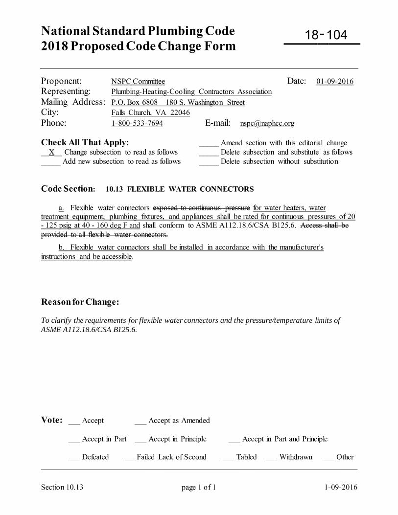
National Standard Plumbing Code 2018 Proposed Code Change Form
-
Section 10.13 page 1 of 1 1-09-2016
Proponent: NSPC Committee Date: 01-09-2016 Representing: Plumbing-Heating-Cooling Contractors Association Mailing Address: P.O. Box 6808 180 S. Washington Street City: Falls Church, VA 22046 Phone: 1-800-533-7694 E-mail: [email protected] Check All That Apply: _____ Amend section with this editorial change __X__ Change subsection to read as follows _____ Delete subsection and substitute as follows _____ Add new subsection to read as follows _____ Delete subsection without substitution Code Section: 10.13 FLEXIBLE WATER CONNECTORS a. Flexible water connectors exposed to continuous pressure for water heaters, water treatment equipment, plumbing fixtures, and appliances shall be rated for continuous pressures of 20 - 125 psig at 40 - 160 deg F and shall conform to ASME A112.18.6/CSA B125.6. Access shall be provided to all flexible water connectors. b. Flexible water connectors shall be installed in accordance with the manufacturer's instructions and be accessible. Reason for Change: To clarify the requirements for flexible water connectors and the pressure/temperature limits of ASME A112.18.6/CSA B125.6. Vote: ___ Accept ___ Accept as Amended
___ Accept in Part ___ Accept in Principle ___ Accept in Part and Principle
___ Defeated ___Failed Lack of Second ___ Tabled ___ Withdrawn ___ Other _________________________________________________________________________________
18 104
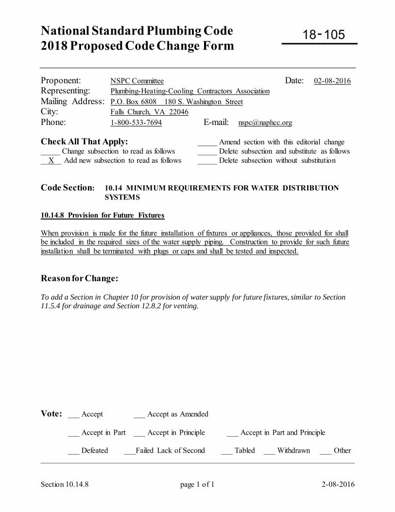
National Standard Plumbing Code 2018 Proposed Code Change Form
-
Section 10.14.8 page 1 of 1 2-08-2016
Proponent: NSPC Committee Date: 02-08-2016 Representing: Plumbing-Heating-Cooling Contractors Association Mailing Address: P.O. Box 6808 180 S. Washington Street City: Falls Church, VA 22046 Phone: 1-800-533-7694 E-mail: [email protected] Check All That Apply: _____ Amend section with this editorial change _____ Change subsection to read as follows _____ Delete subsection and substitute as follows __X__ Add new subsection to read as follows _____ Delete subsection without substitution Code Section: 10.14 MINIMUM REQUIREMENTS FOR WATER DISTRIBUTION
SYSTEMS 10.14.8 Provision for Future Fixtures When provision is made for the future installation of fixtures or appliances, those provided for shall be included in the required sizes of the water supply piping. Construction to provide for such future installation shall be terminated with plugs or caps and shall be tested and inspected. Reason for Change: To add a Section in Chapter 10 for provision of water supply for future fixtures, similar to Section 11.5.4 for drainage and Section 12.8.2 for venting. Vote: ___ Accept ___ Accept as Amended
___ Accept in Part ___ Accept in Principle ___ Accept in Part and Principle
___ Defeated ___Failed Lack of Second ___ Tabled ___ Withdrawn ___ Other _________________________________________________________________________________
18 105
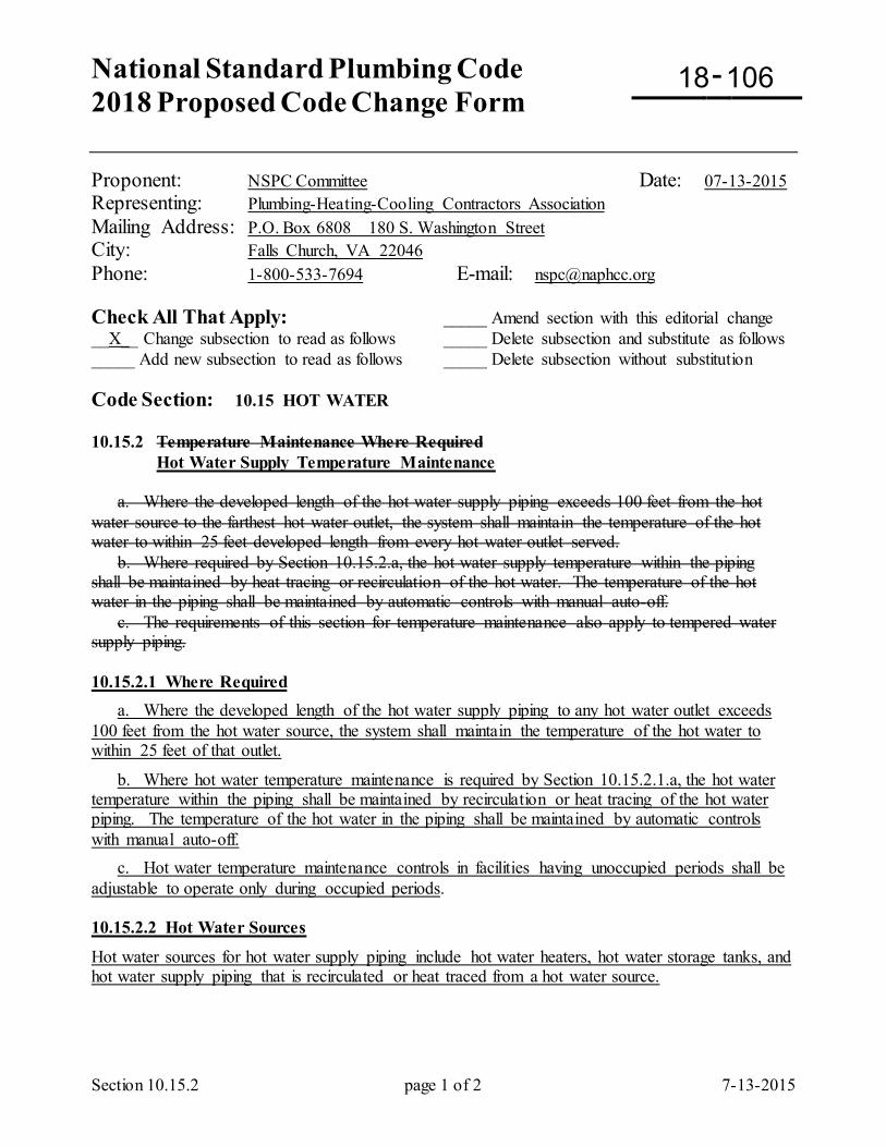
National Standard Plumbing Code 2018 Proposed Code Change Form
-
Section 10.15.2 page 1 of 2 7-13-2015
Proponent: NSPC Committee Date: 07-13-2015 Representing: Plumbing-Heating-Cooling Contractors Association Mailing Address: P.O. Box 6808 180 S. Washington Street City: Falls Church, VA 22046 Phone: 1-800-533-7694 E-mail: [email protected] Check All That Apply: _____ Amend section with this editorial change __X__ Change subsection to read as follows _____ Delete subsection and substitute as follows _____ Add new subsection to read as follows _____ Delete subsection without substitution Code Section: 10.15 HOT WATER 10.15.2 Temperature Maintenance Where Required Hot Water Supply Temperature Maintenance a. Where the developed length of the hot water supply piping exceeds 100 feet from the hot water source to the farthest hot water outlet, the system shall maintain the temperature of the hot water to within 25 feet developed length from every hot water outlet served. b. Where required by Section 10.15.2.a, the hot water supply temperature within the piping shall be maintained by heat tracing or recirculation of the hot water. The temperature of the hot water in the piping shall be maintained by automatic controls with manual auto-off. c. The requirements of this section for temperature maintenance also apply to tempered water supply piping. 10.15.2.1 Where Required a. Where the developed length of the hot water supply piping to any hot water outlet exceeds 100 feet from the hot water source, the system shall maintain the temperature of the hot water to within 25 feet of that outlet.
b. Where hot water temperature maintenance is required by Section 10.15.2.1.a, the hot water temperature within the piping shall be maintained by recirculation or heat tracing of the hot water piping. The temperature of the hot water in the piping shall be maintained by automatic controls with manual auto-off. c. Hot water temperature maintenance controls in facilities having unoccupied periods shall be adjustable to operate only during occupied periods. 10.15.2.2 Hot Water Sources
Hot water sources for hot water supply piping include hot water heaters, hot water storage tanks, and hot water supply piping that is recirculated or heat traced from a hot water source.
18 106
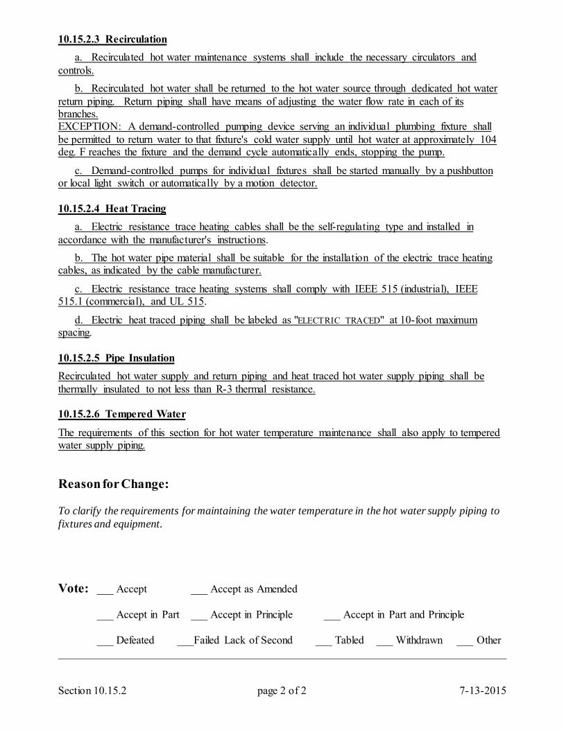
Section 10.15.2 page 2 of 2 7-13-2015
10.15.2.3 Recirculation a. Recirculated hot water maintenance systems shall include the necessary circulators and controls. b. Recirculated hot water shall be returned to the hot water source through dedicated hot water return piping. Return piping shall have means of adjusting the water flow rate in each of its branches. EXCEPTION: A demand-controlled pumping device serving an individual plumbing fixture shall be permitted to return water to that fixture's cold water supply until hot water at approximately 104 deg. F reaches the fixture and the demand cycle automatically ends, stopping the pump.
c. Demand-controlled pumps for individual fixtures shall be started manually by a pushbutton or local light switch or automatically by a motion detector. 10.15.2.4 Heat Tracing a. Electric resistance trace heating cables shall be the self-regulating type and installed in accordance with the manufacturer's instructions. b. The hot water pipe material shall be suitable for the installation of the electric trace heating cables, as indicated by the cable manufacturer.
c. Electric resistance trace heating systems shall comply with IEEE 515 (industrial), IEEE 515.1 (commercial), and UL 515.
d. Electric heat traced piping shall be labeled as "ELECTRIC TRACED" at 10-foot maximum spacing. 10.15.2.5 Pipe Insulation Recirculated hot water supply and return piping and heat traced hot water supply piping shall be thermally insulated to not less than R-3 thermal resistance. 10.15.2.6 Tempered Water
The requirements of this section for hot water temperature maintenance shall also apply to tempered water supply piping. Reason for Change: To clarify the requirements for maintaining the water temperature in the hot water supply piping to fixtures and equipment. Vote: ___ Accept ___ Accept as Amended
___ Accept in Part ___ Accept in Principle ___ Accept in Part and Principle
___ Defeated ___Failed Lack of Second ___ Tabled ___ Withdrawn ___ Other _________________________________________________________________________________
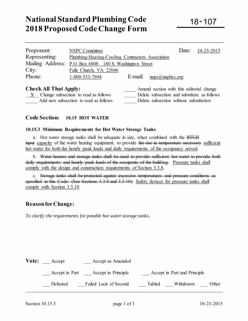
National Standard Plumbing Code 2018 Proposed Code Change Form
-
Section 10.15.3 page 1 of 1 10-23-2015
Proponent: NSPC Committee Date: 10-23-2015 Representing: Plumbing-Heating-Cooling Contractors Association Mailing Address: P.O. Box 6808 180 S. Washington Street City: Falls Church, VA 22046 Phone: 1-800-533-7694 E-mail: [email protected] Check All That Apply: _____ Amend section with this editorial change __X__ Change subsection to read as follows _____ Delete subsection and substitute as follows _____ Add new subsection to read as follows _____ Delete subsection without substitution Code Section: 10.15 HOT WATER 10.15.3 Minimum Requirements for Hot Water Storage Tanks a. Hot water storage tanks shall be adequate in size, when combined with the BTUH input capacity of the water heating equipment, to provide the rise in temperature necessary sufficient hot water for both the hourly peak loads and daily requirements of the occupancy served. b. Water heaters and storage tanks shall be sized to provide sufficient hot water to provide both daily requirements and hourly peak loads of the occupants of the building. Pressure tanks shall comply with the design and construction requirements of Section 3.3.8. c. Storage tanks shall be protected against excessive temperatures and pressure conditions as specified in this Code. (See Sections 3.3.8 and 3.3.10). Safety devices for pressure tanks shall comply with Section 3.3.10. Reason for Change: To clarify the requirements for potable hot water storage tanks. Vote: ___ Accept ___ Accept as Amended
___ Accept in Part ___ Accept in Principle ___ Accept in Part and Principle
___ Defeated ___Failed Lack of Second ___ Tabled ___ Withdrawn ___ Other _________________________________________________________________________________
18 107
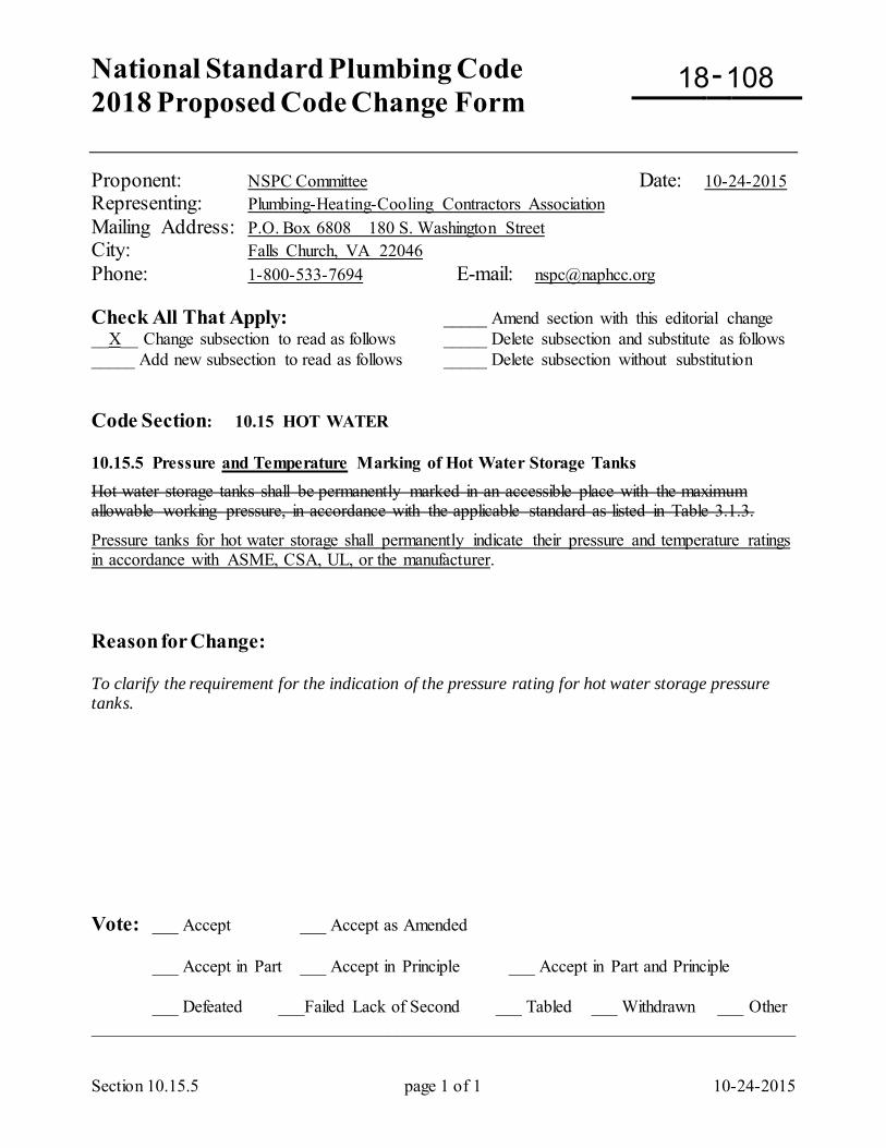
National Standard Plumbing Code 2018 Proposed Code Change Form
-
Section 10.15.5 page 1 of 1 10-24-2015
Proponent: NSPC Committee Date: 10-24-2015 Representing: Plumbing-Heating-Cooling Contractors Association Mailing Address: P.O. Box 6808 180 S. Washington Street City: Falls Church, VA 22046 Phone: 1-800-533-7694 E-mail: [email protected] Check All That Apply: _____ Amend section with this editorial change __X__ Change subsection to read as follows _____ Delete subsection and substitute as follows _____ Add new subsection to read as follows _____ Delete subsection without substitution Code Section: 10.15 HOT WATER 10.15.5 Pressure and Temperature Marking of Hot Water Storage Tanks Hot water storage tanks shall be permanently marked in an accessible place with the maximum allowable working pressure, in accordance with the applicable standard as listed in Table 3.1.3.
Pressure tanks for hot water storage shall permanently indicate their pressure and temperature ratings in accordance with ASME, CSA, UL, or the manufacturer. Reason for Change: To clarify the requirement for the indication of the pressure rating for hot water storage pressure tanks. Vote: ___ Accept ___ Accept as Amended
___ Accept in Part ___ Accept in Principle ___ Accept in Part and Principle
___ Defeated ___Failed Lack of Second ___ Tabled ___ Withdrawn ___ Other _________________________________________________________________________________
18 108
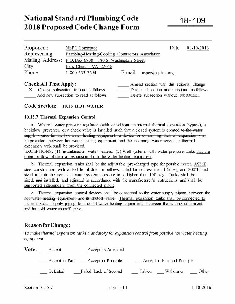
National Standard Plumbing Code 2018 Proposed Code Change Form
-
Section 10.15.7 page 1 of 1 1-10-2016
Proponent: NSPC Committee Date: 01-10-2016 Representing: Plumbing-Heating-Cooling Contractors Association Mailing Address: P.O. Box 6808 180 S. Washington Street City: Falls Church, VA 22046 Phone: 1-800-533-7694 E-mail: [email protected] Check All That Apply: _____ Amend section with this editorial change __X__ Change subsection to read as follows _____ Delete subsection and substitute as follows _____ Add new subsection to read as follows _____ Delete subsection without substitution Code Section: 10.15 HOT WATER 10.15.7 Thermal Expansion Control
a. Where a water pressure regulator (with or without an internal thermal expansion bypass), a backflow preventer, or a check valve is installed such that a closed system is created to the water supply source for the hot water heating equipment, a device for controlling thermal expansion shall be provided. between hot water heating equipment and the incoming water service, a thermal expansion tank shall be provided. EXCEPTIONS: (1) Instantaneous water heaters. (2) Well systems with water pressure tanks that are open for flow of thermal expansion from the water heating equipment. b. Thermal expansion tanks shall be the adjustable pre-charged type for potable water, ASME steel construction with a flexible bladder or bellows, rated for not less than 125 psig and 200°F, and sized to limit the increased water system pressure to no higher than 100 psig. Tanks shall be sized, and installed, and adjusted in accordance with the manufacturer's instructions and shall be supported independent from the connected piping. c. Thermal expansion control devices shall be connected to the water supply piping between the hot water heating equipment and its shutoff valve. Thermal expansion tanks shall be connected to the cold water supply piping for the hot water heating equipment, between the heating equipment and its cold water shutoff valve. Reason for Change: To make thermal expansion tanks mandatory for expansion control from potable hot water heating equipment. Vote: ___ Accept ___ Accept as Amended
___ Accept in Part ___ Accept in Principle ___ Accept in Part and Principle
___ Defeated ___Failed Lack of Second ___ Tabled ___ Withdrawn ___ Other _________________________________________________________________________________
18 109
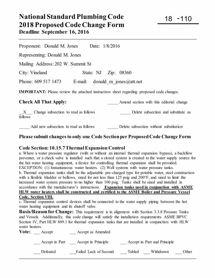
National Standard Plumbing Code 2018 Proposed Code Change Form Deadline September 16, 2016
-
Proponent: Donald M. Jones Date: 1/8/2016
Representing: Donald M. Jones
Mailing Address: 202 W. Summit St
City: Vineland State: NJ Zip: 08360
Phone: 609 517 1473 E-mail: [email protected] IMPORTANT: Please review the attached instruction sheet regarding proposed code changes. Check All That Apply: _____ Amend section with this editorial change __X___ Change subsection to read as follows _____ Delete subsection and substitute as follows _____ Add new subsection to read as follows _____ Delete subsection without substitution Please submit changes to only one Code Section per Proposed Code Change Form Code Section: 10.15.7 Thermal Expansion Control a. Where a water pressure regulator (with or without an internal thermal expansion bypass), a backflow preventer, or a check valve is installed such that a closed system is created to the water supply source for the hot water heating equipment, a device for controlling thermal expansion shall be provided. EXCEPTION: (1) Instantaneous water heaters. (2) Well systems with water pressure tanks. b. Thermal expansion tanks shall be the adjustable pre-charged type for potable water, steel construction with a flexible bladder or bellows, rated for not less than 125 psig and 200°F, and sized to limit the increased water system pressure to no higher than 100 psig. Tanks shall be sized and installed in accordance with the manufacturer’s instructions. Expansion tanks used in conjunction with ASME HLW water heaters shall be constructed and certified to the ASME Boiler and Pressure Vessel Code, Section VIII. c. Thermal expansion control devices shall be connected to the water supply piping between the hot water heating equipment and its shutoff valve. Basis/Reason for Change: This requirement is in alignment with Section 3.3.8 Pressure Tanks and Vessels. Additionally, this code change will satisfy the installation requirements ASME BPVC Section IV, Part HLW 809.1 for thermal expansion tanks that are installed in conjunction with HLW water heaters. Vote: ___ Accept ___ Accept as Amended
___ Accept in Part ___ Accept in Principle ___ Accept in Part and Principle
___ Defeated ___Failed Lack of Second ___ Tabled ___ Withdrawn ___ Other ____________________________________________________________________________________
18 110
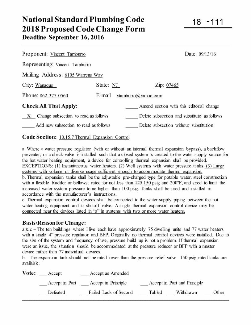
National Standard Plumbing Code 2018 Proposed Code Change Form Deadline September 16, 2016
-
Proponent: Vincent Tamburro Date: 09/13/16
Representing: Vincent Tamburro
Mailing Address: 6105 Warrens Way
City: Wanaque State: NJ Zip: 07465
Phone: 862-377-0560 E-mail [email protected]
Check All That Apply: _____ Amend section with this editorial change __X__ Change subsection to read as follows _____ Delete subsection and substitute as follows _____ Add new subsection to read as follows _____ Delete subsection without substitution Code Section: 10.15.7 Thermal Expansion Control a. Where a water pressure regulator (with or without an internal thermal expansion bypass), a backflow preventer, or a check valve is installed such that a closed system is created to the water supply source for the hot water heating equipment, a device for controlling thermal expansion shall be provided. EXCEPTIONS: (1) Instantaneous water heaters. (2) Well systems with water pressure tanks. (3) Large systems with volume or diverse usage sufficient enough to accommodate thermo expansion. b. Thermal expansion tanks shall be the adjustable pre-charged type for potable water, steel construction with a flexible bladder or bellows, rated for not less than 125 150 psig and 200ºF, and sized to limit the increased water system pressure to no higher than 100 psig. Tanks shall be sized and installed in accordance with the manufacturer’s instructions. c. Thermal expansion control devices shall be connected to the water supply piping between the hot water heating equipment and its shutoff valve. A single thermal expansion control device may be connected near the devices listed in “a” in systems with two or more water heaters. Basis/Reason for Change: a & c – The ten buildings where I live each have approximately 75 dwelling units and 77 water heaters with a single 4” pressure regulator and BFP. Originally no thermal control devices were installed. Due to the size of the system and frequency of use, pressure build up is not a problem. If thermal expansion were an issue, the situation should be accommodated at the pressure reducer or BFP with a master device rather than 77 individual devices. b – The expansion tank should not be rated lower than the pressure relief valve. 150 psig rated tanks are available.
Vote: ___ Accept ___ Accept as Amended
___ Accept in Part ___ Accept in Principle ___ Accept in Part and Principle
___ Defeated ___Failed Lack of Second ___ Tabled ___ Withdrawn ___ Other ____________________________________________________________________________________
18 111
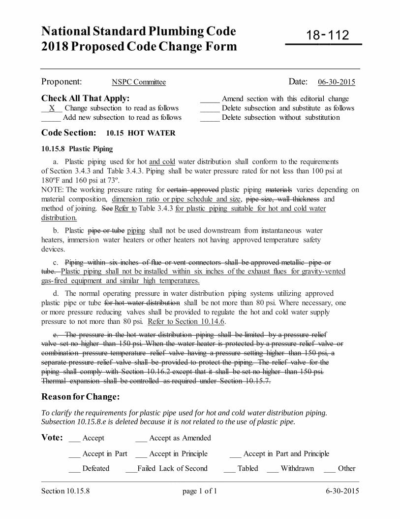
National Standard Plumbing Code 2018 Proposed Code Change Form
-
Section 10.15.8 page 1 of 1 6-30-2015
Proponent: NSPC Committee Date: 06-30-2015
Check All That Apply: _____ Amend section with this editorial change __X__ Change subsection to read as follows _____ Delete subsection and substitute as follows _____ Add new subsection to read as follows _____ Delete subsection without substitution
Code Section: 10.15 HOT WATER 10.15.8 Plastic Piping a. Plastic piping used for hot and cold water distribution shall conform to the requirements of Section 3.4.3 and Table 3.4.3. Piping shall be water pressure rated for not less than 100 psi at 180ºF and 160 psi at 73º. NOTE: The working pressure rating for certain approved plastic piping materials varies depending on material composition, dimension ratio or pipe schedule and size, pipe size, wall thickness and method of joining. See Refer to Table 3.4.3 for plastic piping suitable for hot and cold water distribution. b. Plastic pipe or tube piping shall not be used downstream from instantaneous water heaters, immersion water heaters or other heaters not having approved temperature safety devices.
c. Piping within six inches of flue or vent connectors shall be approved metallic pipe or tube. Plastic piping shall not be installed within six inches of the exhaust flues for gravity-vented gas-fired equipment and similar high temperatures. d. The normal operating pressure in water distribution piping systems utilizing approved plastic pipe or tube for hot water distribution shall be not more than 80 psi. Where necessary, one or more pressure reducing valves shall be provided to regulate the hot and cold water supply pressure to not more than 80 psi. Refer to Section 10.14.6.
e. The pressure in the hot water distribution piping shall be limited by a pressure relief valve set no higher than 150 psi. When the water heater is protected by a pressure relief valve or combination pressure temperature relief valve having a pressure setting higher than 150 psi, a separate pressure relief valve shall be provided to protect the piping. The relief valve for the piping shall comply with Section 10.16.2 except that it shall be set no higher than 150 psi. Thermal expansion shall be controlled as required under Section 10.15.7.
Reason for Change: To clarify the requirements for plastic pipe used for hot and cold water distribution piping. Subsection 10.15.8.e is deleted because it is not related to the use of plastic pipe.
Vote: ___ Accept ___ Accept as Amended
___ Accept in Part ___ Accept in Principle ___ Accept in Part and Principle
___ Defeated ___Failed Lack of Second ___ Tabled ___ Withdrawn ___ Other _________________________________________________________________________________
18 112
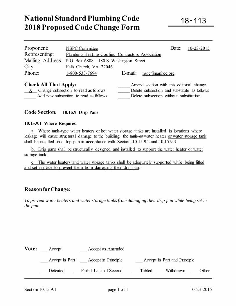
National Standard Plumbing Code 2018 Proposed Code Change Form
-
Section 10.15.9.1 page 1 of 1 10-23-2015
Proponent: NSPC Committee Date: 10-23-2015 Representing: Plumbing-Heating-Cooling Contractors Association Mailing Address: P.O. Box 6808 180 S. Washington Street City: Falls Church, VA 22046 Phone: 1-800-533-7694 E-mail: [email protected] Check All That Apply: _____ Amend section with this editorial change __X__ Change subsection to read as follows _____ Delete subsection and substitute as follows _____ Add new subsection to read as follows _____ Delete subsection without substitution Code Section: 10.15.9 Drip Pans 10.15.9.1 Where Required a. Where tank-type water heaters or hot water storage tanks are installed in locations where leakage will cause structural damage to the building, the tank or water heater or water storage tank shall be installed in a drip pan in accordance with Section 10.15.9.2 and 10.15.9.3 b. Drip pans shall be structurally designed and installed to support the water heater or water storage tank. c. The water heaters and water storage tanks shall be adequately supported while being lifted and set in place to prevent them from damaging their drip pan. Reason for Change: To prevent water heaters and water storage tanks from damaging their drip pan while being set in the pan. Vote: ___ Accept ___ Accept as Amended
___ Accept in Part ___ Accept in Principle ___ Accept in Part and Principle
___ Defeated ___Failed Lack of Second ___ Tabled ___ Withdrawn ___ Other _________________________________________________________________________________
18 113
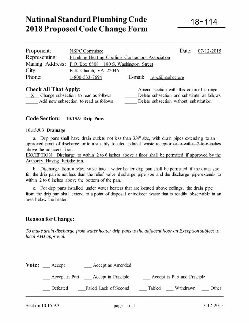
National Standard Plumbing Code 2018 Proposed Code Change Form
-
Section 10.15.9.3 page 1 of 1 7-12-2015
Proponent: NSPC Committee Date: 07-12-2015 Representing: Plumbing-Heating-Cooling Contractors Association Mailing Address: P.O. Box 6808 180 S. Washington Street City: Falls Church, VA 22046 Phone: 1-800-533-7694 E-mail: [email protected] Check All That Apply: _____ Amend section with this editorial change __X__ Change subsection to read as follows _____ Delete subsection and substitute as follows _____ Add new subsection to read as follows _____ Delete subsection without substitution Code Section: 10.15.9 Drip Pans 10.15.9.3 Drainage
a. Drip pans shall have drain outlets not less than 3/4" size, with drain pipes extending to an approved point of discharge or to a suitably located indirect waste receptor or to within 2 to 6 inches above the adjacent floor. EXCEPTION: Discharge to within 2 to 6 inches above a floor shall be permitted if approved by the Authority Having Jurisdiction. b. Discharge from a relief valve into a water heater drip pan shall be permitted if the drain size for the drip pan is not less than the relief valve discharge pipe size and the discharge pipe extends to within 2 to 6 inches above the bottom of the pan. c. For drip pans installed under water heaters that are located above ceilings, the drain pipe from the drip pan shall extend to a point of disposal or indirect waste that is readily observable in an area below the heater. Reason for Change: To make drain discharge from water heater drip pans to the adjacent floor an Exception subject to local AHJ approval. Vote: ___ Accept ___ Accept as Amended
___ Accept in Part ___ Accept in Principle ___ Accept in Part and Principle
___ Defeated ___Failed Lack of Second ___ Tabled ___ Withdrawn ___ Other _________________________________________________________________________________
18 114
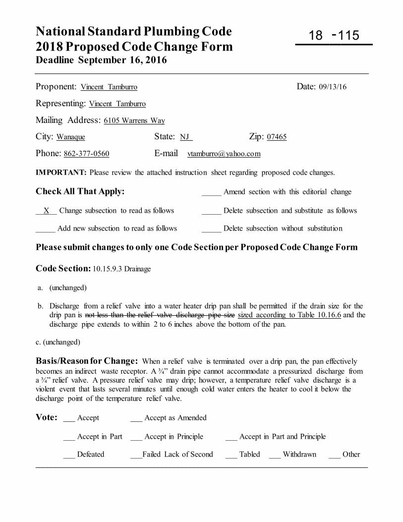
National Standard Plumbing Code 2018 Proposed Code Change Form Deadline September 16, 2016
-
Proponent: Vincent Tamburro Date: 09/13/16
Representing: Vincent Tamburro
Mailing Address: 6105 Warrens Way
City: Wanaque State: NJ Zip: 07465
Phone: 862-377-0560 E-mail [email protected] IMPORTANT: Please review the attached instruction sheet regarding proposed code changes. Check All That Apply: _____ Amend section with this editorial change __X__ Change subsection to read as follows _____ Delete subsection and substitute as follows _____ Add new subsection to read as follows _____ Delete subsection without substitution Please submit changes to only one Code Section per Proposed Code Change Form Code Section: 10.15.9.3 Drainage a. (unchanged) b. Discharge from a relief valve into a water heater drip pan shall be permitted if the drain size for the
drip pan is not less than the relief valve discharge pipe size sized according to Table 10.16.6 and the discharge pipe extends to within 2 to 6 inches above the bottom of the pan.
c. (unchanged) Basis/Reason for Change: When a relief valve is terminated over a drip pan, the pan effectively becomes an indirect waste receptor. A ¾” drain pipe cannot accommodate a pressurized discharge from a ¾” relief valve. A pressure relief valve may drip; however, a temperature relief valve discharge is a violent event that lasts several minutes until enough cold water enters the heater to cool it below the discharge point of the temperature relief valve. Vote: ___ Accept ___ Accept as Amended
___ Accept in Part ___ Accept in Principle ___ Accept in Part and Principle
___ Defeated ___Failed Lack of Second ___ Tabled ___ Withdrawn ___ Other ____________________________________________________________________________________
18 115
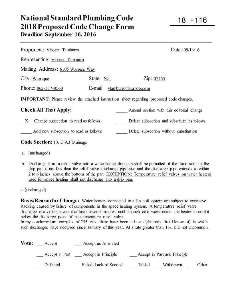
National Standard Plumbing Code 2018 Proposed Code Change Form Deadline September 16, 2016
-
Proponent: Vincent Tamburro Date: 09/16/16
Representing: Vincent Tamburro
Mailing Address: 6105 Warrens Way
City: Wanaque State: NJ Zip: 07465
Phone: 862-377-0560 E-mail [email protected] IMPORTANT: Please review the attached instruction sheet regarding proposed code changes. Check All That Apply: _____ Amend section with this editorial change __X__ Change subsection to read as follows _____ Delete subsection and substitute as follows _____ Add new subsection to read as follows _____ Delete subsection without substitution Code Section: 10.15.9.3 Drainage a. (unchanged) b. Discharge from a relief valve into a water heater drip pan shall be permitted if the drain size for the
drip pan is not less than the relief valve discharge pipe size and the discharge pipe extends to within 2 to 6 inches above the bottom of the pan. EXCEPTION: Temperature relief valves on water heaters used for space heating shall not discharge into a drip pan.
c. (unchanged) Basis/Reason for Change: Water heaters connected to a fan coil system are subject to excessive stacking caused by failure of components in the space heating system. A temperature relief valve discharge is a violent event that lasts several minutes until enough cold water enters the heater to cool it below the discharge point of the temperature relief valve. In my condominium complex of 755 units, there have been at least eight units that I know of, in which such discharges have occurred since January of this year. At a rate greater than 1%, it is not uncommon. Vote: ___ Accept ___ Accept as Amended
___ Accept in Part ___ Accept in Principle ___ Accept in Part and Principle
___ Defeated ___Failed Lack of Second ___ Tabled ___ Withdrawn ___ Other
18 116
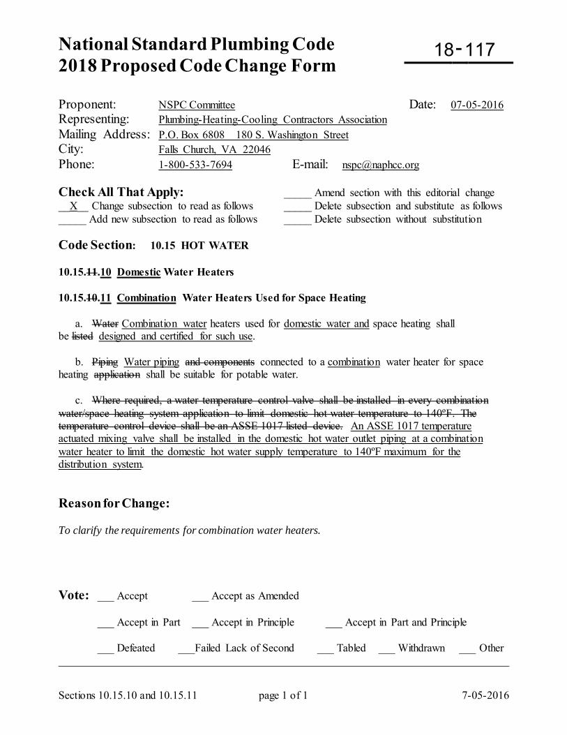
National Standard Plumbing Code 2018 Proposed Code Change Form
-
Sections 10.15.10 and 10.15.11 page 1 of 1 7-05-2016
Proponent: NSPC Committee Date: 07-05-2016 Representing: Plumbing-Heating-Cooling Contractors Association Mailing Address: P.O. Box 6808 180 S. Washington Street City: Falls Church, VA 22046 Phone: 1-800-533-7694 E-mail: [email protected] Check All That Apply: _____ Amend section with this editorial change __X__ Change subsection to read as follows _____ Delete subsection and substitute as follows _____ Add new subsection to read as follows _____ Delete subsection without substitution Code Section: 10.15 HOT WATER 10.15.11.10 Domestic Water Heaters 10.15.10.11 Combination Water Heaters Used for Space Heating a. Water Combination water heaters used for domestic water and space heating shall be listed designed and certified for such use. b. Piping Water piping and components connected to a combination water heater for space heating application shall be suitable for potable water. c. Where required, a water temperature control valve shall be installed in every combination water/space heating system application to limit domestic hot water temperature to 140ºF. The temperature control device shall be an ASSE 1017 listed device. An ASSE 1017 temperature actuated mixing valve shall be installed in the domestic hot water outlet piping at a combination water heater to limit the domestic hot water supply temperature to 140ºF maximum for the distribution system. Reason for Change: To clarify the requirements for combination water heaters. Vote: ___ Accept ___ Accept as Amended
___ Accept in Part ___ Accept in Principle ___ Accept in Part and Principle
___ Defeated ___Failed Lack of Second ___ Tabled ___ Withdrawn ___ Other _________________________________________________________________________________
18 117
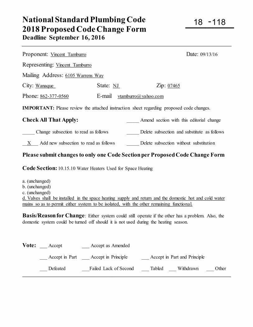
National Standard Plumbing Code 2018 Proposed Code Change Form Deadline September 16, 2016
-
Proponent: Vincent Tamburro Date: 09/13/16
Representing: Vincent Tamburro
Mailing Address: 6105 Warrens Way
City: Wanaque State: NJ Zip: 07465
Phone: 862-377-0560 E-mail [email protected] IMPORTANT: Please review the attached instruction sheet regarding proposed code changes. Check All That Apply: _____ Amend section with this editorial change _____ Change subsection to read as follows _____ Delete subsection and substitute as follows __X___ Add new subsection to read as follows _____ Delete subsection without substitution Please submit changes to only one Code Section per Proposed Code Change Form Code Section: 10.15.10 Water Heaters Used for Space Heating a. (unchanged) b. (unchanged) c. (unchanged) d. Valves shall be installed in the space heating supply and return and the domestic hot and cold water mains so as to permit either system to be isolated, with the other remaining functional. Basis/Reason for Change: Either system could still operate if the other has a problem. Also, the domestic system could be turned off should it is not used during the heating season. Vote: ___ Accept ___ Accept as Amended
___ Accept in Part ___ Accept in Principle ___ Accept in Part and Principle
___ Defeated ___Failed Lack of Second ___ Tabled ___ Withdrawn ___ Other ____________________________________________________________________________________
18 118
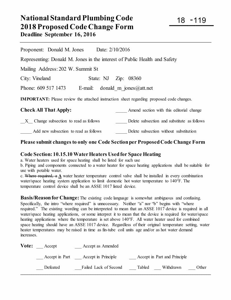
National Standard Plumbing Code 2018 Proposed Code Change Form Deadline September 16, 2016
-
Proponent: Donald M. Jones Date: 2/10/2016
Representing: Donald M. Jones in the interest of Public Health and Safety
Mailing Address: 202 W. Summit St
City: Vineland State: NJ Zip: 08360
Phone: 609 517 1473 E-mail: [email protected] IMPORTANT: Please review the attached instruction sheet regarding proposed code changes. Check All That Apply: _____ Amend section with this editorial change __X__ Change subsection to read as follows _____ Delete subsection and substitute as follows _____ Add new subsection to read as follows _____ Delete subsection without substitution Please submit changes to only one Code Section per Proposed Code Change Form Code Section: 10.15.10 Water Heaters Used for Space Heating a. Water heaters used for space heating shall be listed for such use b. Piping and components connected to a water heater for space heating applications shall be suitable for use with potable water. c. Where required, a A water heater temperature control valve shall be installed in every combination water/space heating system application to limit domestic hot water temperature to 140°F. The temperature control device shall be an ASSE 1017 listed device. Basis/Reason for Change: The existing code language is somewhat ambiguous and confusing. Specifically, the intro “where required” is unnecessary. Neither “a” nor “b” begins with “where required.” The existing wording can be interpreted to mean that an ASSE 1017 device is required in all water/space heating applications, or some interpret it to mean that the device is required for water/space heating applications where the temperature is set above 140°F. All water heater used for combined space heating should have an ASSE 1017 device. Regardless of their original temperature setting, water heater temperatures may be raised in time as fin-tube coil units age and/or as hot water demand increases. Vote: ___ Accept ___ Accept as Amended
___ Accept in Part ___ Accept in Principle ___ Accept in Part and Principle
___ Defeated ___Failed Lack of Second ___ Tabled ___ Withdrawn ___ Other ____________________________________________________________________________________
18 119
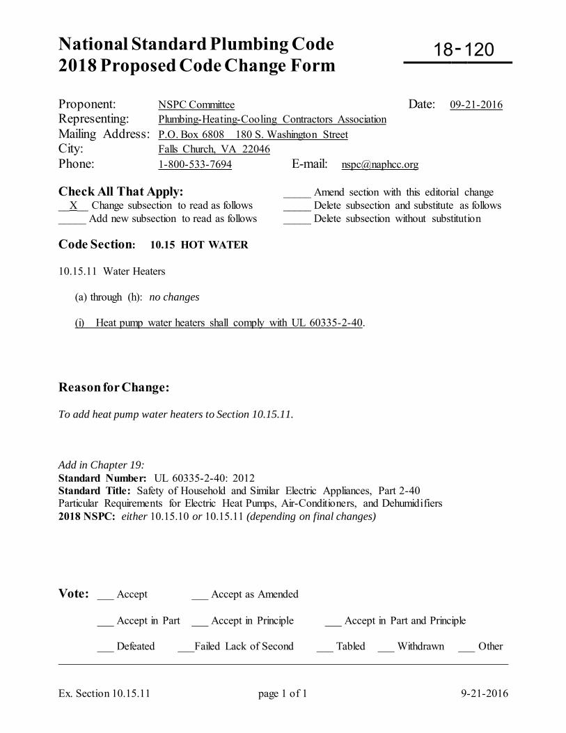
National Standard Plumbing Code 2018 Proposed Code Change Form
-
Ex. Section 10.15.11 page 1 of 1 9-21-2016
Proponent: NSPC Committee Date: 09-21-2016 Representing: Plumbing-Heating-Cooling Contractors Association Mailing Address: P.O. Box 6808 180 S. Washington Street City: Falls Church, VA 22046 Phone: 1-800-533-7694 E-mail: [email protected] Check All That Apply: _____ Amend section with this editorial change __X__ Change subsection to read as follows _____ Delete subsection and substitute as follows _____ Add new subsection to read as follows _____ Delete subsection without substitution Code Section: 10.15 HOT WATER 10.15.11 Water Heaters (a) through (h): no changes (i) Heat pump water heaters shall comply with UL 60335-2-40. Reason for Change: To add heat pump water heaters to Section 10.15.11. Add in Chapter 19: Standard Number: UL 60335-2-40: 2012 Standard Title: Safety of Household and Similar Electric Appliances, Part 2-40 Particular Requirements for Electric Heat Pumps, Air-Conditioners, and Dehumidifiers 2018 NSPC: either 10.15.10 or 10.15.11 (depending on final changes) Vote: ___ Accept ___ Accept as Amended
___ Accept in Part ___ Accept in Principle ___ Accept in Part and Principle
___ Defeated ___Failed Lack of Second ___ Tabled ___ Withdrawn ___ Other _________________________________________________________________________________
18 120
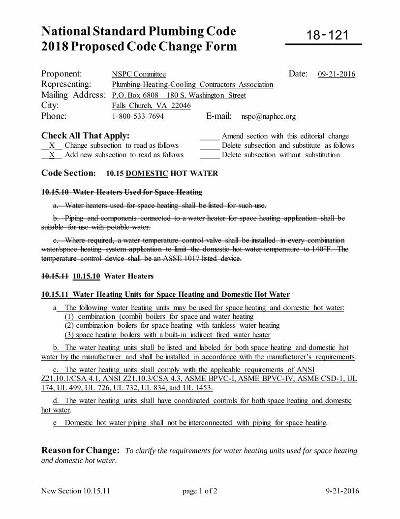
National Standard Plumbing Code 2018 Proposed Code Change Form
-
New Section 10.15.11 page 1 of 2 9-21-2016
Proponent: NSPC Committee Date: 09-21-2016 Representing: Plumbing-Heating-Cooling Contractors Association Mailing Address: P.O. Box 6808 180 S. Washington Street City: Falls Church, VA 22046 Phone: 1-800-533-7694 E-mail: [email protected] Check All That Apply: _____ Amend section with this editorial change __X__ Change subsection to read as follows _____ Delete subsection and substitute as follows __X__ Add new subsection to read as follows _____ Delete subsection without substitution Code Section: 10.15 DOMESTIC HOT WATER 10.15.10 Water Heaters Used for Space Heating
a. Water heaters used for space heating shall be listed for such use. b. Piping and components connected to a water heater for space heating application shall be suitable for use with potable water.
c. Where required, a water temperature control valve shall be installed in every combination water/space heating system application to limit the domestic hot water temperature to 140°F. The temperature control device shall be an ASSE 1017 listed device. 10.15.11 10.15.10 Water Heaters 10.15.11 Water Heating Units for Space Heating and Domestic Hot Water
a The following water heating units may be used for space heating and domestic hot water: (1) combination (combi) boilers for space and water heating (2) combination boilers for space heating with tankless water heating (3) space heating boilers with a built- in indirect fired water heater b. The water heating units shall be listed and labeled for both space heating and domestic hot water by the manufacturer and shall be installed in accordance with the manufacturer’s requirements. c. The water heating units shall comply with the applicable requirements of ANSI Z21.10.1/CSA 4.1, ANSI Z21.10.3/CSA 4.3, ASME BPVC-I, ASME BPVC-IV, ASME CSD-1, UL 174, UL 499, UL 726, UL 732, UL 834, and UL 1453. d. The water heating units shall have coordinated controls for both space heating and domestic hot water. e Domestic hot water piping shall not be interconnected with piping for space heating. Reason for Change: To clarify the requirements for water heating units used for space heating and domestic hot water.
18 121
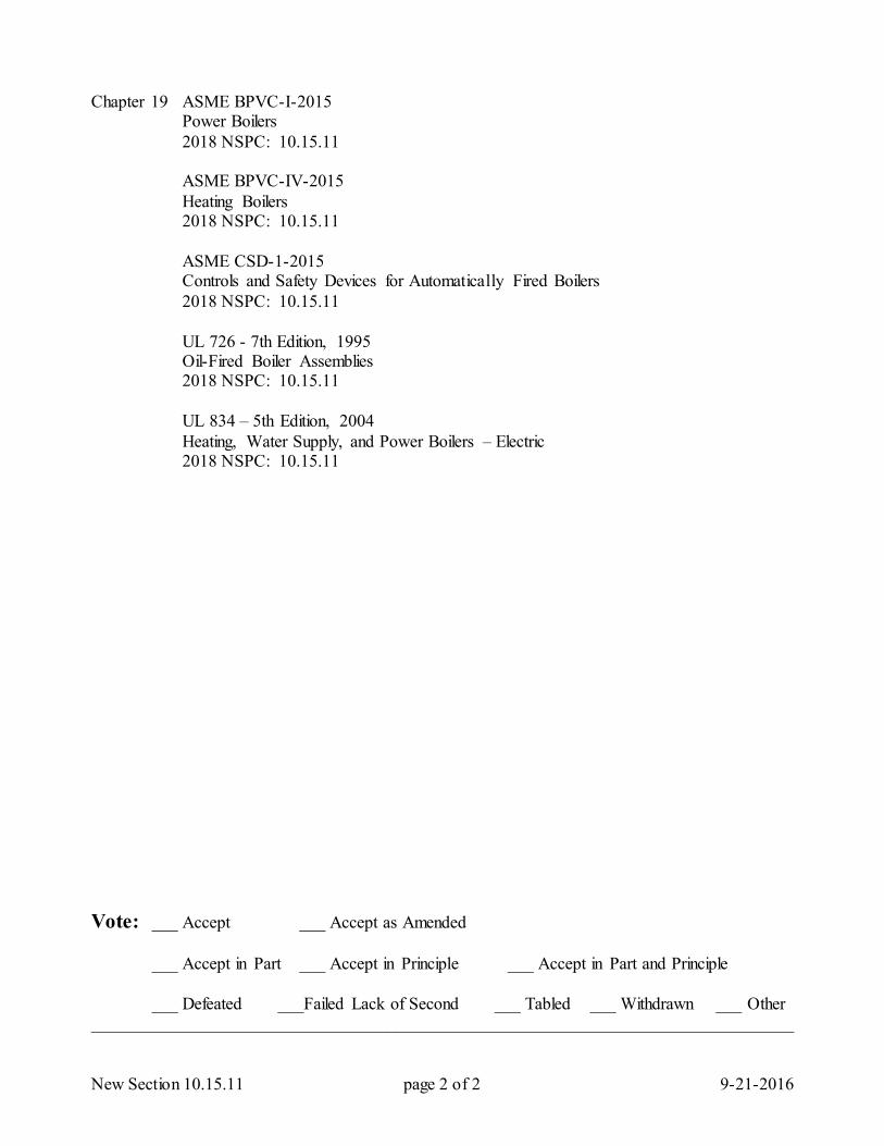
New Section 10.15.11 page 2 of 2 9-21-2016
Chapter 19 ASME BPVC-I-2015 Power Boilers 2018 NSPC: 10.15.11 ASME BPVC-IV-2015 Heating Boilers 2018 NSPC: 10.15.11 ASME CSD-1-2015 Controls and Safety Devices for Automatically Fired Boilers 2018 NSPC: 10.15.11 UL 726 - 7th Edition, 1995 Oil-Fired Boiler Assemblies 2018 NSPC: 10.15.11 UL 834 – 5th Edition, 2004 Heating, Water Supply, and Power Boilers – Electric 2018 NSPC: 10.15.11 Vote: ___ Accept ___ Accept as Amended
___ Accept in Part ___ Accept in Principle ___ Accept in Part and Principle
___ Defeated ___Failed Lack of Second ___ Tabled ___ Withdrawn ___ Other _________________________________________________________________________________
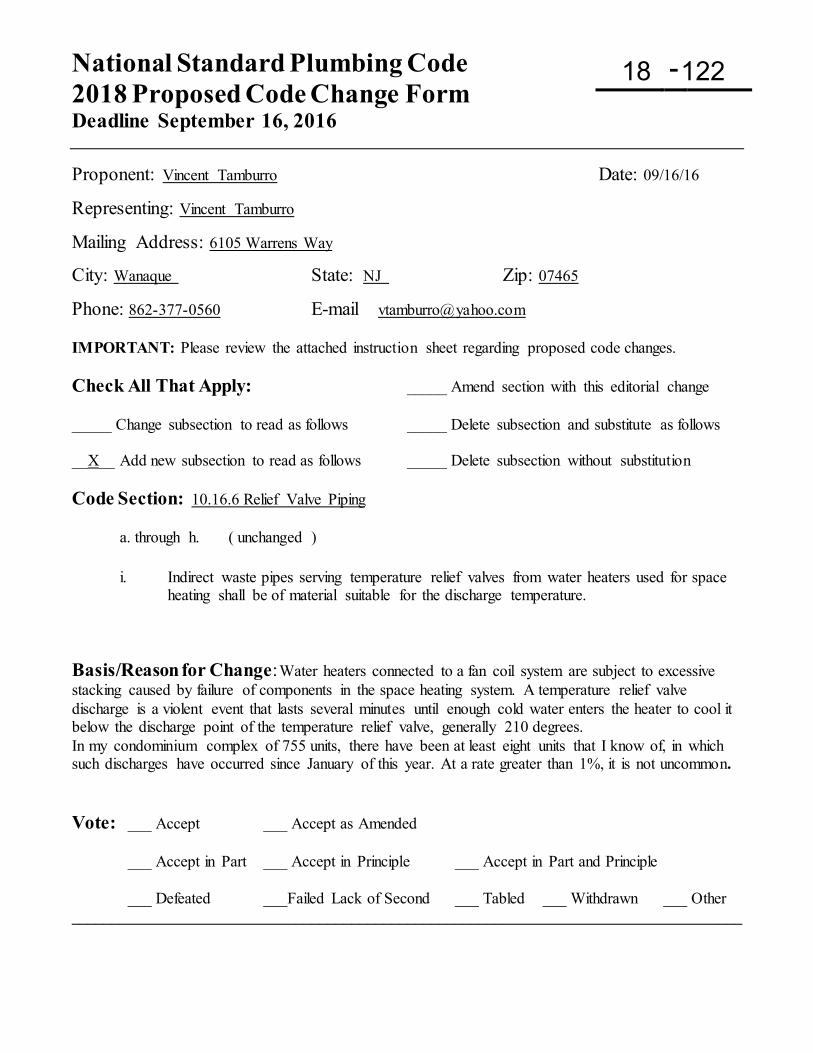
National Standard Plumbing Code 2018 Proposed Code Change Form Deadline September 16, 2016
-
Proponent: Vincent Tamburro Date: 09/16/16
Representing: Vincent Tamburro
Mailing Address: 6105 Warrens Way
City: Wanaque State: NJ Zip: 07465
Phone: 862-377-0560 E-mail [email protected] IMPORTANT: Please review the attached instruction sheet regarding proposed code changes. Check All That Apply: _____ Amend section with this editorial change _____ Change subsection to read as follows _____ Delete subsection and substitute as follows __X__ Add new subsection to read as follows _____ Delete subsection without substitution Code Section: 10.16.6 Relief Valve Piping
a. through h. ( unchanged ) i. Indirect waste pipes serving temperature relief valves from water heaters used for space
heating shall be of material suitable for the discharge temperature.
Basis/Reason for Change: Water heaters connected to a fan coil system are subject to excessive stacking caused by failure of components in the space heating system. A temperature relief valve discharge is a violent event that lasts several minutes until enough cold water enters the heater to cool it below the discharge point of the temperature relief valve, generally 210 degrees. In my condominium complex of 755 units, there have been at least eight units that I know of, in which such discharges have occurred since January of this year. At a rate greater than 1%, it is not uncommon. Vote: ___ Accept ___ Accept as Amended
___ Accept in Part ___ Accept in Principle ___ Accept in Part and Principle
___ Defeated ___Failed Lack of Second ___ Tabled ___ Withdrawn ___ Other ____________________________________________________________________________________
18 122
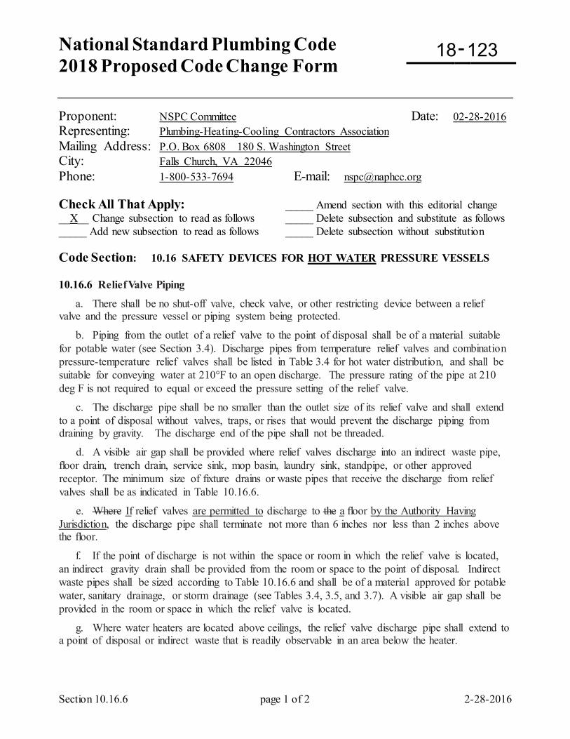
National Standard Plumbing Code 2018 Proposed Code Change Form
-
Section 10.16.6 page 1 of 2 2-28-2016
Proponent: NSPC Committee Date: 02-28-2016 Representing: Plumbing-Heating-Cooling Contractors Association Mailing Address: P.O. Box 6808 180 S. Washington Street City: Falls Church, VA 22046 Phone: 1-800-533-7694 E-mail: [email protected] Check All That Apply: _____ Amend section with this editorial change __X__ Change subsection to read as follows _____ Delete subsection and substitute as follows _____ Add new subsection to read as follows _____ Delete subsection without substitution Code Section: 10.16 SAFETY DEVICES FOR HOT WATER PRESSURE VESSELS 10.16.6 Relief Valve Piping
a. There shall be no shut-off valve, check valve, or other restricting device between a relief valve and the pressure vessel or piping system being protected.
b. Piping from the outlet of a relief valve to the point of disposal shall be of a material suitable for potable water (see Section 3.4). Discharge pipes from temperature relief valves and combination pressure-temperature relief valves shall be listed in Table 3.4 for hot water distribution, and shall be suitable for conveying water at 210°F to an open discharge. The pressure rating of the pipe at 210 deg F is not required to equal or exceed the pressure setting of the relief valve.
c. The discharge pipe shall be no smaller than the outlet size of its relief valve and shall extend to a point of disposal without valves, traps, or rises that would prevent the discharge piping from draining by gravity. The discharge end of the pipe shall not be threaded.
d. A visible air gap shall be provided where relief valves discharge into an indirect waste pipe, floor drain, trench drain, service sink, mop basin, laundry sink, standpipe, or other approved receptor. The minimum size of fixture drains or waste pipes that receive the discharge from relief valves shall be as indicated in Table 10.16.6.
e. Where If relief valves are permitted to discharge to the a floor by the Authority Having Jurisdiction, the discharge pipe shall terminate not more than 6 inches nor less than 2 inches above the floor.
f. If the point of discharge is not within the space or room in which the relief valve is located, an indirect gravity drain shall be provided from the room or space to the point of disposal. Indirect waste pipes shall be sized according to Table 10.16.6 and shall be of a material approved for potable water, sanitary drainage, or storm drainage (see Tables 3.4, 3.5, and 3.7). A visible air gap shall be provided in the room or space in which the relief valve is located.
g. Where water heaters are located above ceilings, the relief valve discharge pipe shall extend to a point of disposal or indirect waste that is readily observable in an area below the heater.
18 123
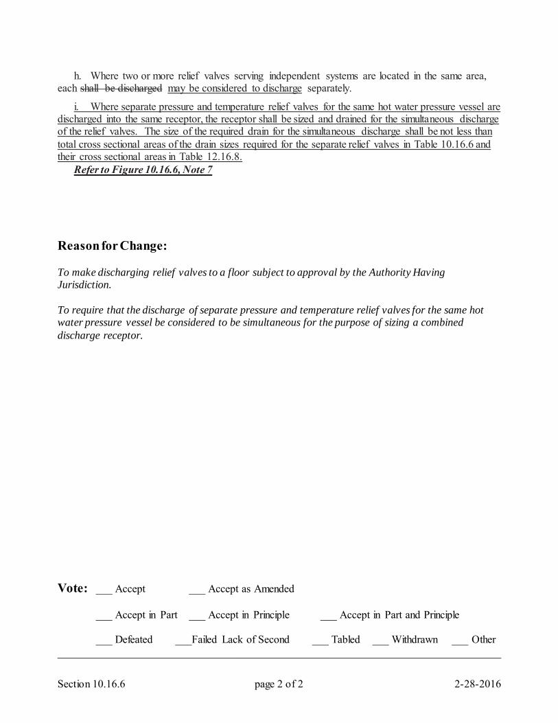
Section 10.16.6 page 2 of 2 2-28-2016
h. Where two or more relief valves serving independent systems are located in the same area, each shall be discharged may be considered to discharge separately.
i. Where separate pressure and temperature relief valves for the same hot water pressure vessel are discharged into the same receptor, the receptor shall be sized and drained for the simultaneous discharge of the relief valves. The size of the required drain for the simultaneous discharge shall be not less than total cross sectional areas of the drain sizes required for the separate relief valves in Table 10.16.6 and their cross sectional areas in Table 12.16.8. Refer to Figure 10.16.6, Note 7 Reason for Change: To make discharging relief valves to a floor subject to approval by the Authority Having Jurisdiction. To require that the discharge of separate pressure and temperature relief valves for the same hot water pressure vessel be considered to be simultaneous for the purpose of sizing a combined discharge receptor. Vote: ___ Accept ___ Accept as Amended
___ Accept in Part ___ Accept in Principle ___ Accept in Part and Principle
___ Defeated ___Failed Lack of Second ___ Tabled ___ Withdrawn ___ Other _________________________________________________________________________________
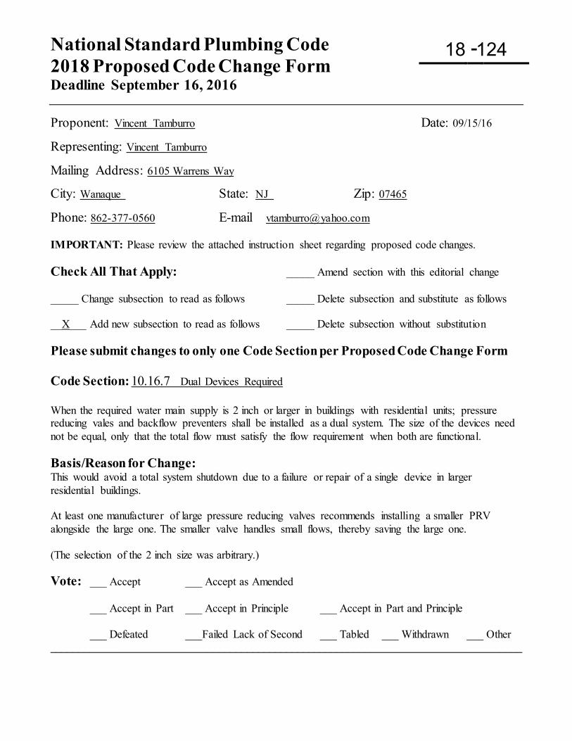
National Standard Plumbing Code 2018 Proposed Code Change Form Deadline September 16, 2016
-
Proponent: Vincent Tamburro Date: 09/15/16
Representing: Vincent Tamburro
Mailing Address: 6105 Warrens Way
City: Wanaque State: NJ Zip: 07465
Phone: 862-377-0560 E-mail [email protected] IMPORTANT: Please review the attached instruction sheet regarding proposed code changes. Check All That Apply: _____ Amend section with this editorial change _____ Change subsection to read as follows _____ Delete subsection and substitute as follows __X___ Add new subsection to read as follows _____ Delete subsection without substitution Please submit changes to only one Code Section per Proposed Code Change Form Code Section: 10.16.7 Dual Devices Required When the required water main supply is 2 inch or larger in buildings with residential units; pressure reducing vales and backflow preventers shall be installed as a dual system. The size of the devices need not be equal, only that the total flow must satisfy the flow requirement when both are functional. Basis/Reason for Change: This would avoid a total system shutdown due to a failure or repair of a single device in larger residential buildings. At least one manufacturer of large pressure reducing valves recommends installing a smaller PRV alongside the large one. The smaller valve handles small flows, thereby saving the large one. (The selection of the 2 inch size was arbitrary.) Vote: ___ Accept ___ Accept as Amended
___ Accept in Part ___ Accept in Principle ___ Accept in Part and Principle
___ Defeated ___Failed Lack of Second ___ Tabled ___ Withdrawn ___ Other ____________________________________________________________________________________
18 124
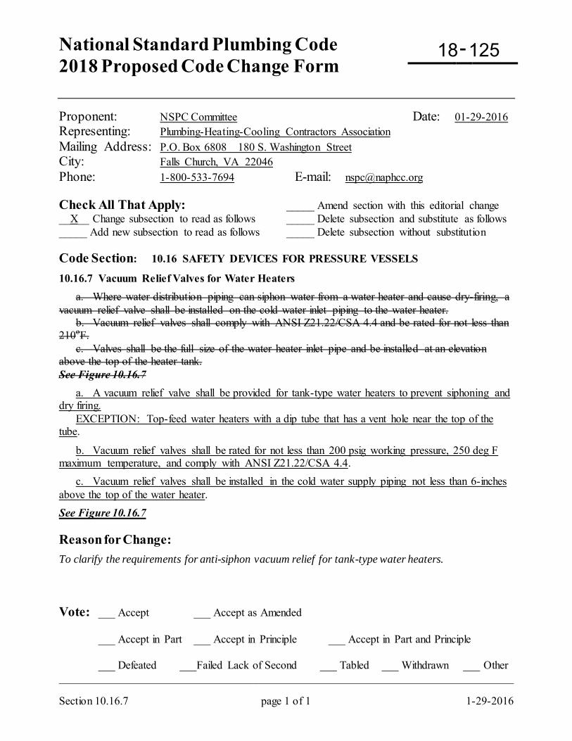
National Standard Plumbing Code 2018 Proposed Code Change Form
-
Section 10.16.7 page 1 of 1 1-29-2016
Proponent: NSPC Committee Date: 01-29-2016 Representing: Plumbing-Heating-Cooling Contractors Association Mailing Address: P.O. Box 6808 180 S. Washington Street City: Falls Church, VA 22046 Phone: 1-800-533-7694 E-mail: [email protected] Check All That Apply: _____ Amend section with this editorial change __X__ Change subsection to read as follows _____ Delete subsection and substitute as follows _____ Add new subsection to read as follows _____ Delete subsection without substitution Code Section: 10.16 SAFETY DEVICES FOR PRESSURE VESSELS
10.16.7 Vacuum Relief Valves for Water Heaters a. Where water distribution piping can siphon water from a water heater and cause dry-firing, a vacuum relief valve shall be installed on the cold water inlet piping to the water heater. b. Vacuum relief valves shall comply with ANSI Z21.22/CSA 4.4 and be rated for not less than 210oF. c. Valves shall be the full size of the water heater inlet pipe and be installed at an elevation above the top of the heater tank. See Figure 10.16.7 a. A vacuum relief valve shall be provided for tank-type water heaters to prevent siphoning and dry firing. EXCEPTION: Top-feed water heaters with a dip tube that has a vent hole near the top of the tube.
b. Vacuum relief valves shall be rated for not less than 200 psig working pressure, 250 deg F maximum temperature, and comply with ANSI Z21.22/CSA 4.4. c. Vacuum relief valves shall be installed in the cold water supply piping not less than 6-inches above the top of the water heater. See Figure 10.16.7 Reason for Change: To clarify the requirements for anti-siphon vacuum relief for tank-type water heaters. Vote: ___ Accept ___ Accept as Amended
___ Accept in Part ___ Accept in Principle ___ Accept in Part and Principle
___ Defeated ___Failed Lack of Second ___ Tabled ___ Withdrawn ___ Other _________________________________________________________________________________
18 125
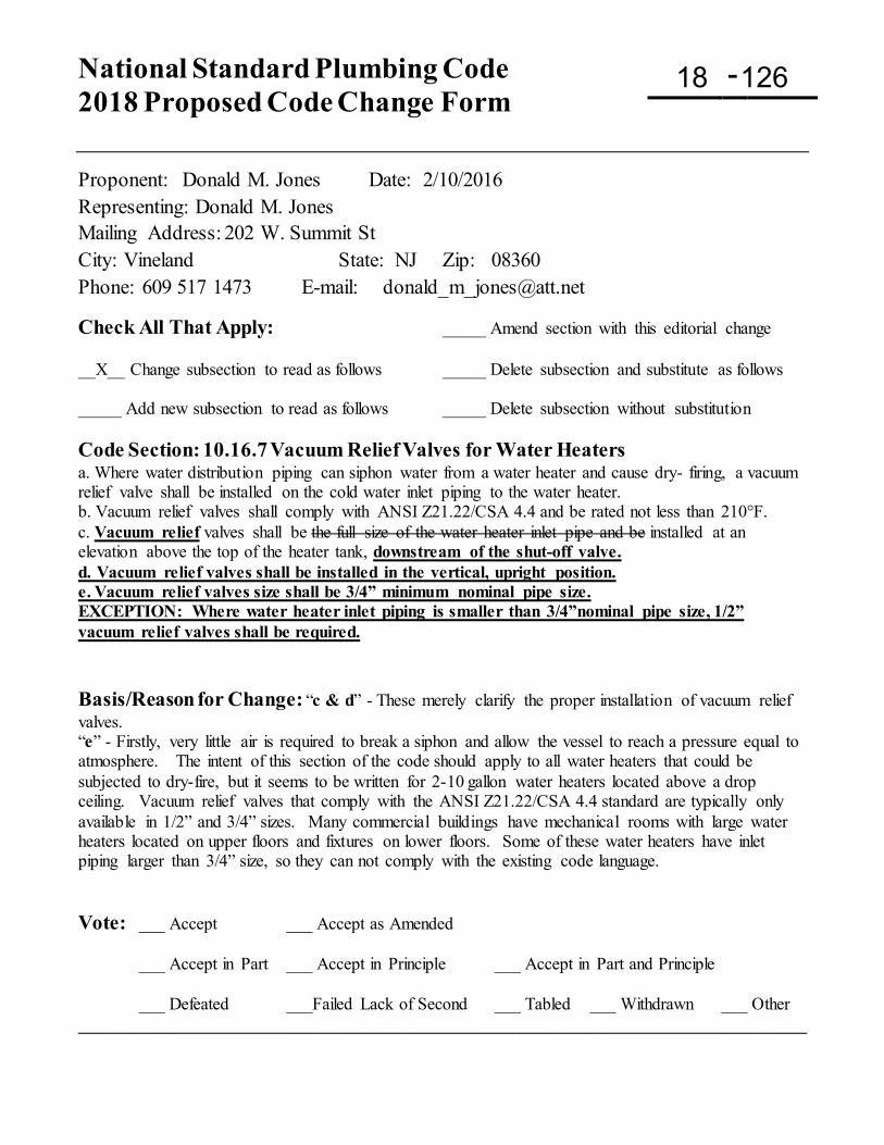
National Standard Plumbing Code 2018 Proposed Code Change Form
-
Proponent: Donald M. Jones Date: 2/10/2016 Representing: Donald M. Jones Mailing Address: 202 W. Summit St City: Vineland State: NJ Zip: 08360 Phone: 609 517 1473 E-mail: [email protected]
Check All That Apply: _____ Amend section with this editorial change __X__ Change subsection to read as follows _____ Delete subsection and substitute as follows _____ Add new subsection to read as follows _____ Delete subsection without substitution Code Section: 10.16.7 Vacuum Relief Valves for Water Heaters a. Where water distribution piping can siphon water from a water heater and cause dry- firing, a vacuum relief valve shall be installed on the cold water inlet piping to the water heater. b. Vacuum relief valves shall comply with ANSI Z21.22/CSA 4.4 and be rated not less than 210°F. c. Vacuum relief valves shall be the full size of the water heater inlet pipe and be installed at an elevation above the top of the heater tank, downstream of the shut-off valve. d. Vacuum relief valves shall be installed in the vertical, upright position. e. Vacuum relief valves size shall be 3/4” minimum nominal pipe size. EXCEPTION: Where water heater inlet piping is smaller than 3/4”nominal pipe size, 1/2” vacuum relief valves shall be required. Basis/Reason for Change: “c & d” - These merely clarify the proper installation of vacuum relief valves. “e” - Firstly, very little air is required to break a siphon and allow the vessel to reach a pressure equal to atmosphere. The intent of this section of the code should apply to all water heaters that could be subjected to dry-fire, but it seems to be written for 2-10 gallon water heaters located above a drop ceiling. Vacuum relief valves that comply with the ANSI Z21.22/CSA 4.4 standard are typically only available in 1/2” and 3/4” sizes. Many commercial buildings have mechanical rooms with large water heaters located on upper floors and fixtures on lower floors. Some of these water heaters have inlet piping larger than 3/4” size, so they can not comply with the existing code language. Vote: ___ Accept ___ Accept as Amended
___ Accept in Part ___ Accept in Principle ___ Accept in Part and Principle
___ Defeated ___Failed Lack of Second ___ Tabled ___ Withdrawn ___ Other ____________________________________________________________________________________
18 126
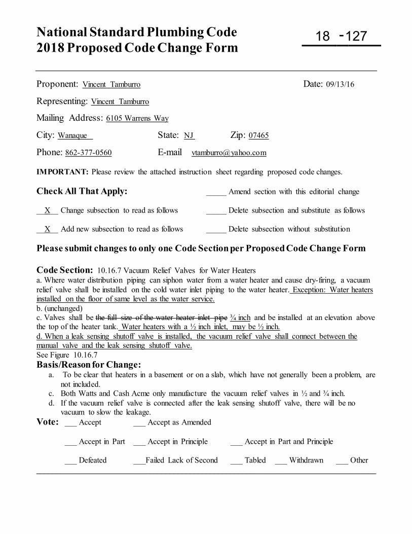
National Standard Plumbing Code 2018 Proposed Code Change Form
-
Proponent: Vincent Tamburro Date: 09/13/16
Representing: Vincent Tamburro
Mailing Address: 6105 Warrens Way
City: Wanaque State: NJ Zip: 07465
Phone: 862-377-0560 E-mail [email protected] IMPORTANT: Please review the attached instruction sheet regarding proposed code changes. Check All That Apply: _____ Amend section with this editorial change __X__ Change subsection to read as follows _____ Delete subsection and substitute as follows __X__ Add new subsection to read as follows _____ Delete subsection without substitution Please submit changes to only one Code Section per Proposed Code Change Form Code Section: 10.16.7 Vacuum Relief Valves for Water Heaters a. Where water distribution piping can siphon water from a water heater and cause dry-firing, a vacuum relief valve shall be installed on the cold water inlet piping to the water heater. Exception: Water heaters installed on the floor of same level as the water service. b. (unchanged) c. Valves shall be the full size of the water heater inlet pipe ¾ inch and be installed at an elevation above the top of the heater tank. Water heaters with a ½ inch inlet, may be ½ inch. d. When a leak sensing shutoff valve is installed, the vacuum relief valve shall connect between the manual valve and the leak sensing shutoff valve. See Figure 10.16.7 Basis/Reason for Change:
a. To be clear that heaters in a basement or on a slab, which have not generally been a problem, are not included.
c. Both Watts and Cash Acme only manufacture the vacuum relief valves in ½ and ¾ inch. d. If the vacuum relief valve is connected after the leak sensing shutoff valve, there will be no
vacuum to slow the leakage. Vote: ___ Accept ___ Accept as Amended
___ Accept in Part ___ Accept in Principle ___ Accept in Part and Principle
___ Defeated ___Failed Lack of Second ___ Tabled ___ Withdrawn ___ Other ____________________________________________________________________________________
18 127
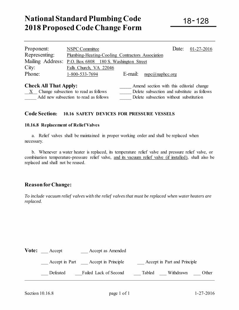
National Standard Plumbing Code 2018 Proposed Code Change Form
-
Section 10.16.8 page 1 of 1 1-27-2016
Proponent: NSPC Committee Date: 01-27-2016 Representing: Plumbing-Heating-Cooling Contractors Association Mailing Address: P.O. Box 6808 180 S. Washington Street City: Falls Church, VA 22046 Phone: 1-800-533-7694 E-mail: [email protected] Check All That Apply: _____ Amend section with this editorial change __X__ Change subsection to read as follows _____ Delete subsection and substitute as follows _____ Add new subsection to read as follows _____ Delete subsection without substitution Code Section: 10.16 SAFETY DEVICES FOR PRESSURE VESSELS 10.16.8 Replacement of Relief Valves a. Relief valves shall be maintained in proper working order and shall be replaced when necessary. b. Whenever a water heater is replaced, its temperature relief valve and pressure relief valve, or combination temperature-pressure relief valve, and its vacuum relief valve (if installed), shall also be replaced and shall not be reused. Reason for Change: To include vacuum relief valves with the relief valves that must be replaced when water heaters are replaced. Vote: ___ Accept ___ Accept as Amended
___ Accept in Part ___ Accept in Principle ___ Accept in Part and Principle
___ Defeated ___Failed Lack of Second ___ Tabled ___ Withdrawn ___ Other _________________________________________________________________________________
18 128
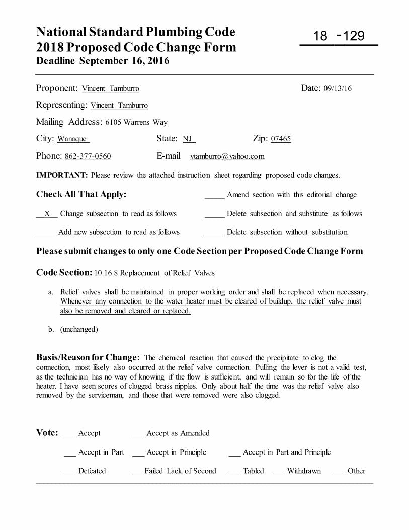
National Standard Plumbing Code 2018 Proposed Code Change Form Deadline September 16, 2016
-
Proponent: Vincent Tamburro Date: 09/13/16
Representing: Vincent Tamburro
Mailing Address: 6105 Warrens Way
City: Wanaque State: NJ Zip: 07465
Phone: 862-377-0560 E-mail [email protected] IMPORTANT: Please review the attached instruction sheet regarding proposed code changes. Check All That Apply: _____ Amend section with this editorial change __X__ Change subsection to read as follows _____ Delete subsection and substitute as follows _____ Add new subsection to read as follows _____ Delete subsection without substitution Please submit changes to only one Code Section per Proposed Code Change Form Code Section: 10.16.8 Replacement of Relief Valves
a. Relief valves shall be maintained in proper working order and shall be replaced when necessary. Whenever any connection to the water heater must be cleared of buildup, the relief valve must also be removed and cleared or replaced.
b. (unchanged)
Basis/Reason for Change: The chemical reaction that caused the precipitate to clog the connection, most likely also occurred at the relief valve connection. Pulling the lever is not a valid test, as the technician has no way of knowing if the flow is sufficient, and will remain so for the life of the heater. I have seen scores of clogged brass nipples. Only about half the time was the relief valve also removed by the serviceman, and those that were removed were also clogged. Vote: ___ Accept ___ Accept as Amended
___ Accept in Part ___ Accept in Principle ___ Accept in Part and Principle
___ Defeated ___Failed Lack of Second ___ Tabled ___ Withdrawn ___ Other ____________________________________________________________________________________
18 129
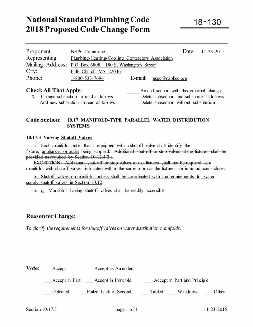
National Standard Plumbing Code 2018 Proposed Code Change Form
-
Section 10.17.3 page 1 of 1 11-23-2015
Proponent: NSPC Committee Date: 11-23-2015 Representing: Plumbing-Heating-Cooling Contractors Association Mailing Address: P.O. Box 6808 180 S. Washington Street City: Falls Church, VA 22046 Phone: 1-800-533-7694 E-mail: [email protected] Check All That Apply: _____ Amend section with this editorial change __X__ Change subsection to read as follows _____ Delete subsection and substitute as follows _____ Add new subsection to read as follows _____ Delete subsection without substitution Code Section: 10.17 MANIFOLD-TYPE PARALLEL WATER DISTRIBUTION
SYSTEMS 10.17.3 Valving Shutoff Valves a. Each manifold outlet that is equipped with a shutoff valve shall identify the fixture, appliance, or outlet being supplied. Additional shut-off or stop valves at the fixtures shall be provided as required by Section 10.12.4.2.a. EXCEPTION: Additional shut-off or stop valves at the fixtures shall not be required if a manifold with shutoff valves is located within the same room as the fixtures, or in an adjacent closet. b. Shutoff valves on manifold outlets shall be coordinated with the requirements for water supply shutoff valves in Section 10.12. b. c. Manifolds having shutoff valves shall be readily accessible.
Reason for Change: To clarify the requirements for shutoff valves on water distribution manifolds. Vote: ___ Accept ___ Accept as Amended
___ Accept in Part ___ Accept in Principle ___ Accept in Part and Principle
___ Defeated ___Failed Lack of Second ___ Tabled ___ Withdrawn ___ Other _________________________________________________________________________________
18 130
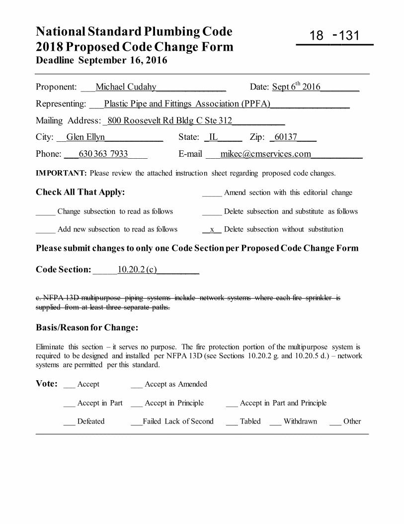
National Standard Plumbing Code 2018 Proposed Code Change Form Deadline September 16, 2016
-
Proponent: ___Michael Cudahy_______________ Date: Sept 6th 2016________
Representing: ___Plastic Pipe and Fittings Association (PPFA)_________________
Mailing Address: _800 Roosevelt Rd Bldg C Ste 312___________
City: __Glen Ellyn____________ State: _IL_____ Zip: _60137____
Phone: ___630 363 7933____ E-mail [email protected]___________ IMPORTANT: Please review the attached instruction sheet regarding proposed code changes. Check All That Apply: _____ Amend section with this editorial change _____ Change subsection to read as follows _____ Delete subsection and substitute as follows _____ Add new subsection to read as follows __x__ Delete subsection without substitution Please submit changes to only one Code Section per Proposed Code Change Form Code Section: _____10.20.2 (c)_________ c. NFPA 13D multipurpose piping systems include network systems where each fire sprinkler is supplied from at least three separate paths. Basis/Reason for Change: Eliminate this section – it serves no purpose. The fire protection portion of the multipurpose system is required to be designed and installed per NFPA 13D (see Sections 10.20.2 g. and 10.20.5 d.) – network systems are permitted per this standard. Vote: ___ Accept ___ Accept as Amended
___ Accept in Part ___ Accept in Principle ___ Accept in Part and Principle
___ Defeated ___Failed Lack of Second ___ Tabled ___ Withdrawn ___ Other ____________________________________________________________________________________
18 131
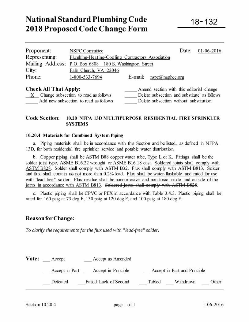
National Standard Plumbing Code 2018 Proposed Code Change Form
-
Section 10.20.4 page 1 of 1 1-06-2016
Proponent: NSPC Committee Date: 01-06-2016 Representing: Plumbing-Heating-Cooling Contractors Association Mailing Address: P.O. Box 6808 180 S. Washington Street City: Falls Church, VA 22046 Phone: 1-800-533-7694 E-mail: [email protected] Check All That Apply: _____ Amend section with this editorial change __X__ Change subsection to read as follows _____ Delete subsection and substitute as follows _____ Add new subsection to read as follows _____ Delete subsection without substitution Code Section: 10.20 NFPA 13D MULTIPURPOSE RESIDENTIAL FIRE SPRINKLER
SYSTEMS 10.20.4 Materials for Combined System Piping a. Piping materials shall be in accordance with this Section and be listed, as defined in NFPA 13D, for both residential fire sprinkler service and potable water distribution. b. Copper piping shall be ASTM B88 copper water tube, Type L or K. Fittings shall be the solder joint type, ASME B16.22 wrought or ASME B16.18 cast. Soldered joints shall comply with ASTM B828. Solder shall comply with ASTM B32. Flux shall comply with ASTM B813. Solder and flux shall contain no not more than 0.2% lead. Flux shall be water-flushable and rated for use with "lead-free" solder. Flux residue shall be noncorrosive and non-toxic inside and outside of the joints in accordance with ASTM B813. Soldered joints shall comply with ASTM B828.
c. Plastic piping shall be CPVC or PEX in accordance with Table 3.4.3. Plastic piping shall be rated for 160 psig at 73 deg F, 130 psig at 120 deg F, and 100 psig at 180 deg F. Reason for Change: To clarify the requirements for the flux used with "lead-free" solder. Vote: ___ Accept ___ Accept as Amended
___ Accept in Part ___ Accept in Principle ___ Accept in Part and Principle
___ Defeated ___Failed Lack of Second ___ Tabled ___ Withdrawn ___ Other _________________________________________________________________________________
18 132
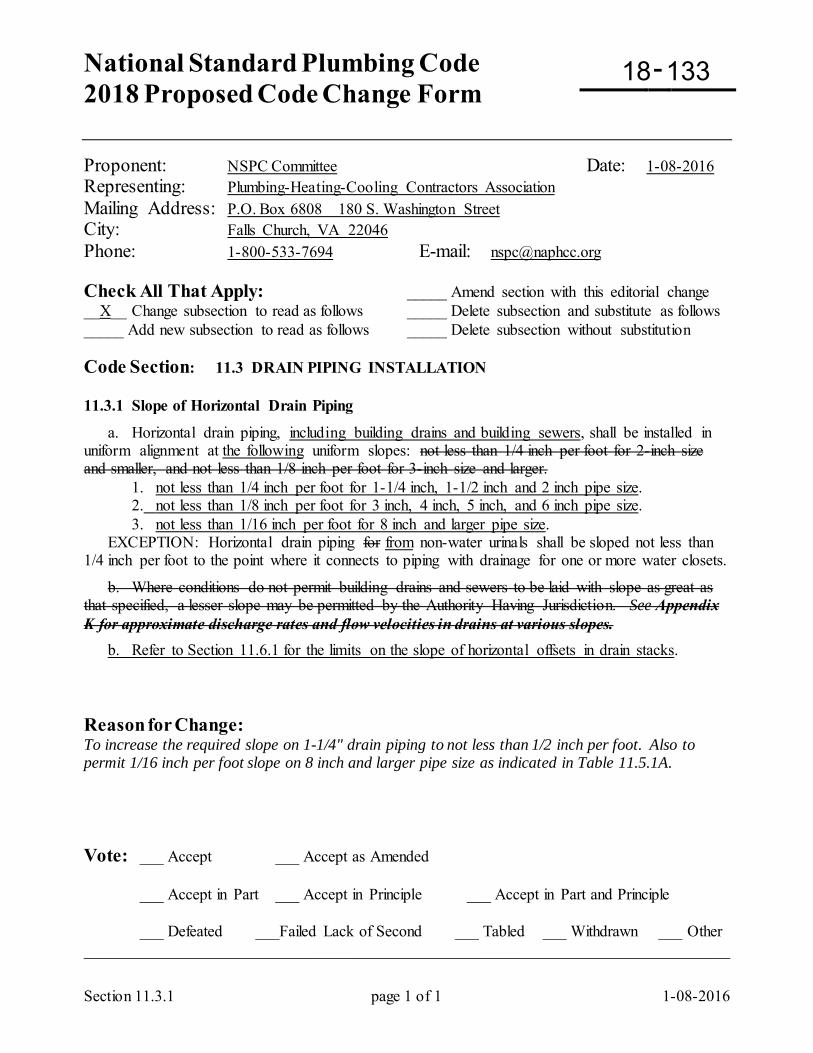
National Standard Plumbing Code 2018 Proposed Code Change Form
-
Section 11.3.1 page 1 of 1 1-08-2016
Proponent: NSPC Committee Date: 1-08-2016 Representing: Plumbing-Heating-Cooling Contractors Association Mailing Address: P.O. Box 6808 180 S. Washington Street City: Falls Church, VA 22046 Phone: 1-800-533-7694 E-mail: [email protected] Check All That Apply: _____ Amend section with this editorial change __X__ Change subsection to read as follows _____ Delete subsection and substitute as follows _____ Add new subsection to read as follows _____ Delete subsection without substitution Code Section: 11.3 DRAIN PIPING INSTALLATION 11.3.1 Slope of Horizontal Drain Piping
a. Horizontal drain piping, including building drains and building sewers, shall be installed in uniform alignment at the following uniform slopes: not less than 1/4 inch per foot for 2-inch size and smaller, and not less than 1/8 inch per foot for 3-inch size and larger. 1. not less than 1/4 inch per foot for 1-1/4 inch, 1-1/2 inch and 2 inch pipe size. 2. not less than 1/8 inch per foot for 3 inch, 4 inch, 5 inch, and 6 inch pipe size. 3. not less than 1/16 inch per foot for 8 inch and larger pipe size. EXCEPTION: Horizontal drain piping for from non-water urinals shall be sloped not less than 1/4 inch per foot to the point where it connects to piping with drainage for one or more water closets.
b. Where conditions do not permit building drains and sewers to be laid with slope as great as that specified, a lesser slope may be permitted by the Authority Having Jurisdiction. See Appendix K for approximate discharge rates and flow velocities in drains at various slopes. b. Refer to Section 11.6.1 for the limits on the slope of horizontal offsets in drain stacks. Reason for Change: To increase the required slope on 1-1/4" drain piping to not less than 1/2 inch per foot. Also to permit 1/16 inch per foot slope on 8 inch and larger pipe size as indicated in Table 11.5.1A. Vote: ___ Accept ___ Accept as Amended
___ Accept in Part ___ Accept in Principle ___ Accept in Part and Principle
___ Defeated ___Failed Lack of Second ___ Tabled ___ Withdrawn ___ Other _________________________________________________________________________________
18 133
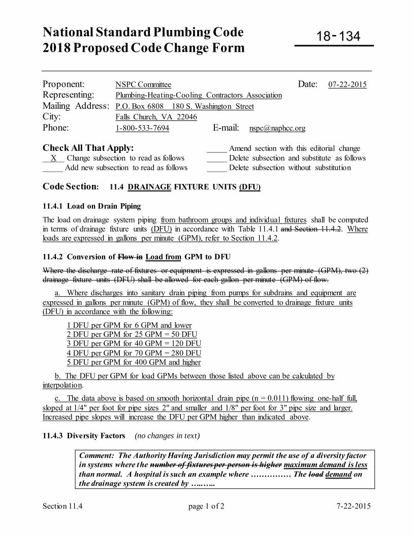
National Standard Plumbing Code 2018 Proposed Code Change Form
-
Section 11.4 page 1 of 2 7-22-2015
Proponent: NSPC Committee Date: 07-22-2015 Representing: Plumbing-Heating-Cooling Contractors Association Mailing Address: P.O. Box 6808 180 S. Washington Street City: Falls Church, VA 22046 Phone: 1-800-533-7694 E-mail: [email protected] Check All That Apply: _____ Amend section with this editorial change __X__ Change subsection to read as follows _____ Delete subsection and substitute as follows _____ Add new subsection to read as follows _____ Delete subsection without substitution Code Section: 11.4 DRAINAGE FIXTURE UNITS (DFU) 11.4.1 Load on Drain Piping
The load on drainage system piping from bathroom groups and individual fixtures shall be computed in terms of drainage fixture units (DFU) in accordance with Table 11.4.1 and Section 11.4.2. Where loads are expressed in gallons per minute (GPM), refer to Section 11.4.2. 11.4.2 Conversion of Flow in Load from GPM to DFU
Where the discharge rate of fixtures or equipment is expressed in gallons per minute (GPM), two (2) drainage fixture units (DFU) shall be allowed for each gallon per minute (GPM) of flow. a. Where discharges into sanitary drain piping from pumps for subdrains and equipment are expressed in gallons per minute (GPM) of flow, they shall be converted to drainage fixture units (DFU) in accordance with the following:
1 DFU per GPM for 6 GPM and lower 2 DFU per GPM for 25 GPM = 50 DFU 3 DFU per GPM for 40 GPM = 120 DFU 4 DFU per GPM for 70 GPM = 280 DFU 5 DFU per GPM for 400 GPM and higher
b. The DFU per GPM for load GPMs between those listed above can be calculated by interpolation. c. The data above is based on smooth horizontal drain pipe (n = 0.011) flowing one-half full, sloped at 1/4" per foot for pipe sizes 2" and smaller and 1/8" per foot for 3" pipe size and larger. Increased pipe slopes will increase the DFU per GPM higher than indicated above. 11.4.3 Diversity Factors (no changes in text)
Comment: The Authority Having Jurisdiction may permit the use of a diversity factor in systems where the number of fixtures per person is higher maximum demand is less than normal. A hospital is such an example where …………… The load demand on the drainage system is created by …..…..
18 134
Section 11.4 page 2 of 2 7-22-2015
Reason for Change: To clarify the conversion of GPM of drainage to DFUs, based on the DFUs in Table 11.5.1A and the GPMs in Table K-2. The existing ratio of 2 DFU per GPM does not apply to all GPMs. The ratio of 5 DFU per GPM applies to all GPMs above 400. Vote: ___ Accept ___ Accept as Amended
___ Accept in Part ___ Accept in Principle ___ Accept in Part and Principle
___ Defeated ___Failed Lack of Second ___ Tabled ___ Withdrawn ___ Other _________________________________________________________________________________
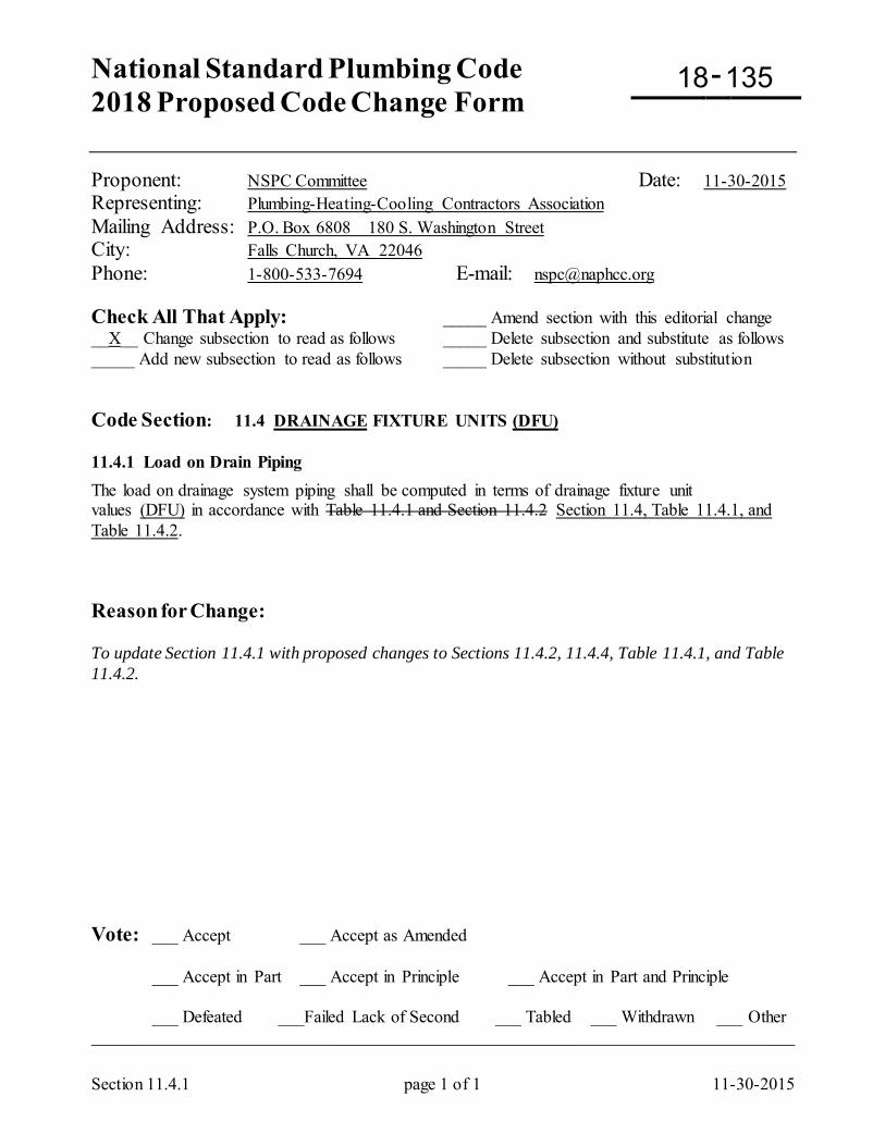
National Standard Plumbing Code 2018 Proposed Code Change Form
-
Section 11.4.1 page 1 of 1 11-30-2015
Proponent: NSPC Committee Date: 11-30-2015 Representing: Plumbing-Heating-Cooling Contractors Association Mailing Address: P.O. Box 6808 180 S. Washington Street City: Falls Church, VA 22046 Phone: 1-800-533-7694 E-mail: [email protected] Check All That Apply: _____ Amend section with this editorial change __X__ Change subsection to read as follows _____ Delete subsection and substitute as follows _____ Add new subsection to read as follows _____ Delete subsection without substitution Code Section: 11.4 DRAINAGE FIXTURE UNITS (DFU) 11.4.1 Load on Drain Piping The load on drainage system piping shall be computed in terms of drainage fixture unit values (DFU) in accordance with Table 11.4.1 and Section 11.4.2 Section 11.4, Table 11.4.1, and Table 11.4.2. Reason for Change: To update Section 11.4.1 with proposed changes to Sections 11.4.2, 11.4.4, Table 11.4.1, and Table 11.4.2. Vote: ___ Accept ___ Accept as Amended
___ Accept in Part ___ Accept in Principle ___ Accept in Part and Principle
___ Defeated ___Failed Lack of Second ___ Tabled ___ Withdrawn ___ Other _________________________________________________________________________________
18 135
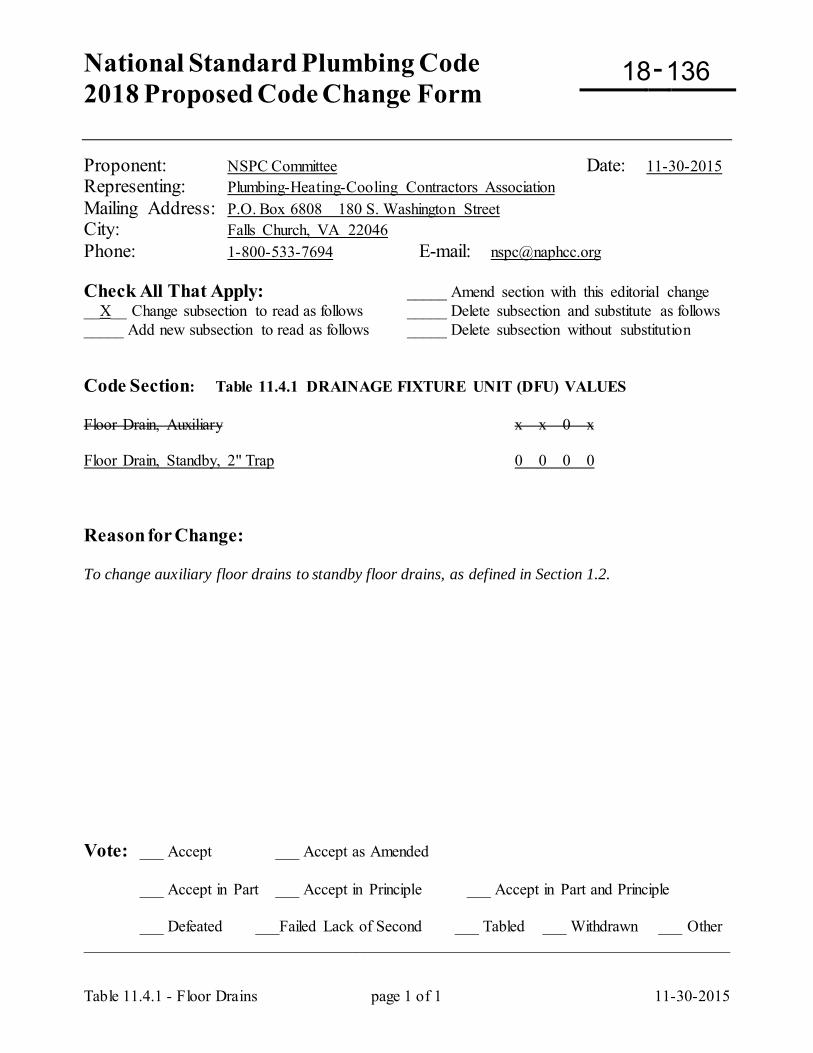
National Standard Plumbing Code 2018 Proposed Code Change Form
-
Table 11.4.1 - Floor Drains page 1 of 1 11-30-2015
Proponent: NSPC Committee Date: 11-30-2015 Representing: Plumbing-Heating-Cooling Contractors Association Mailing Address: P.O. Box 6808 180 S. Washington Street City: Falls Church, VA 22046 Phone: 1-800-533-7694 E-mail: [email protected] Check All That Apply: _____ Amend section with this editorial change __X__ Change subsection to read as follows _____ Delete subsection and substitute as follows _____ Add new subsection to read as follows _____ Delete subsection without substitution Code Section: Table 11.4.1 DRAINAGE FIXTURE UNIT (DFU) VALUES Floor Drain, Auxiliary x x 0 x Floor Drain, Standby, 2" Trap 0 0 0 0 Reason for Change: To change auxiliary floor drains to standby floor drains, as defined in Section 1.2. Vote: ___ Accept ___ Accept as Amended
___ Accept in Part ___ Accept in Principle ___ Accept in Part and Principle
___ Defeated ___Failed Lack of Second ___ Tabled ___ Withdrawn ___ Other _________________________________________________________________________________
18 136
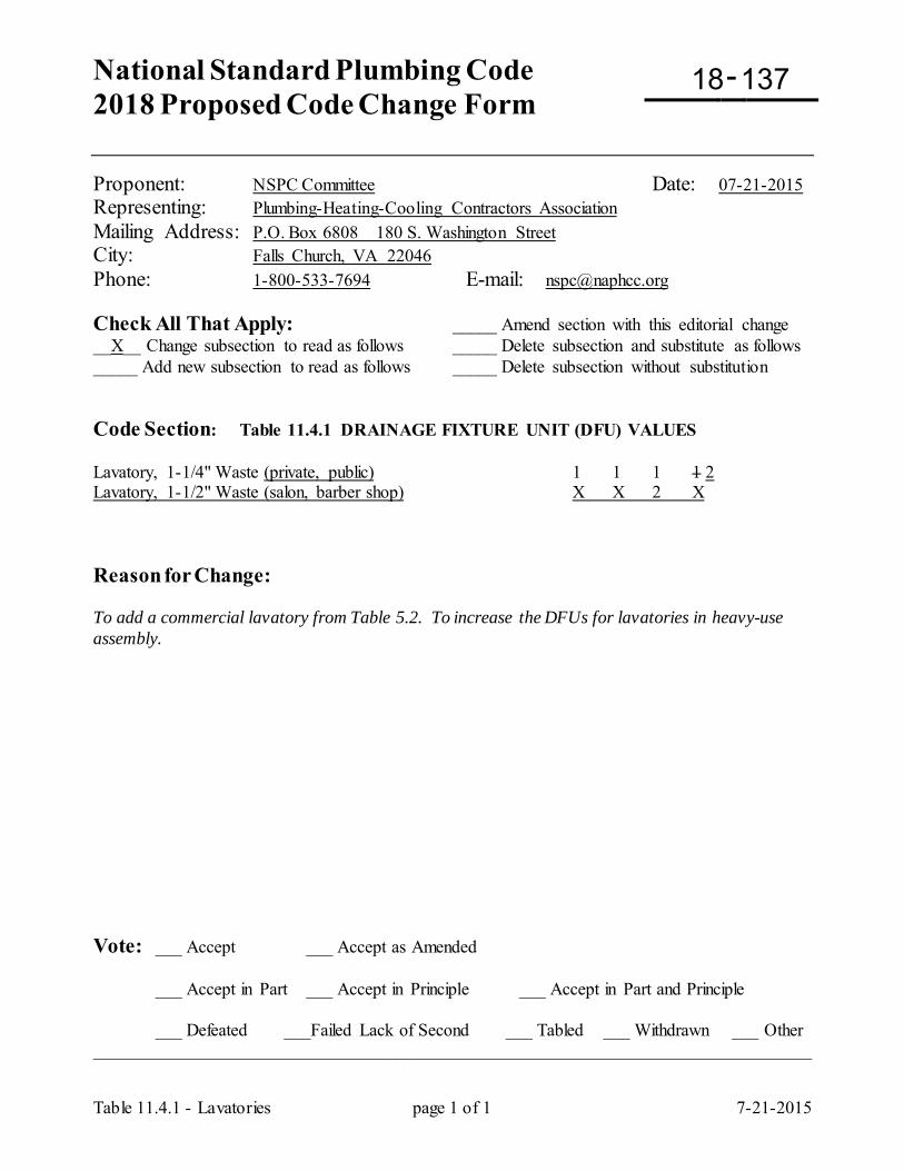
National Standard Plumbing Code 2018 Proposed Code Change Form
-
Table 11.4.1 - Lavatories page 1 of 1 7-21-2015
Proponent: NSPC Committee Date: 07-21-2015 Representing: Plumbing-Heating-Cooling Contractors Association Mailing Address: P.O. Box 6808 180 S. Washington Street City: Falls Church, VA 22046 Phone: 1-800-533-7694 E-mail: [email protected] Check All That Apply: _____ Amend section with this editorial change __X__ Change subsection to read as follows _____ Delete subsection and substitute as follows _____ Add new subsection to read as follows _____ Delete subsection without substitution Code Section: Table 11.4.1 DRAINAGE FIXTURE UNIT (DFU) VALUES Lavatory, 1-1/4" Waste (private, public) 1 1 1 1 2 Lavatory, 1-1/2" Waste (salon, barber shop) X X 2 X Reason for Change: To add a commercial lavatory from Table 5.2. To increase the DFUs for lavatories in heavy-use assembly. Vote: ___ Accept ___ Accept as Amended
___ Accept in Part ___ Accept in Principle ___ Accept in Part and Principle
___ Defeated ___Failed Lack of Second ___ Tabled ___ Withdrawn ___ Other _________________________________________________________________________________
18 137
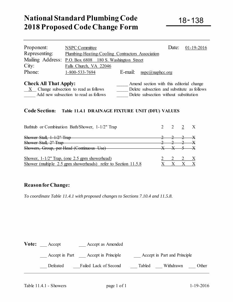
National Standard Plumbing Code 2018 Proposed Code Change Form
-
Table 11.4.1 - Showers page 1 of 1 1-19-2016
Proponent: NSPC Committee Date: 01-19-2016 Representing: Plumbing-Heating-Cooling Contractors Association Mailing Address: P.O. Box 6808 180 S. Washington Street City: Falls Church, VA 22046 Phone: 1-800-533-7694 E-mail: [email protected] Check All That Apply: _____ Amend section with this editorial change __X__ Change subsection to read as follows _____ Delete subsection and substitute as follows _____ Add new subsection to read as follows _____ Delete subsection without substitution Code Section: Table 11.4.1 DRAINAGE FIXTURE UNIT (DFU) VALUES Bathtub or Combination Bath/Shower, 1-1/2" Trap 2 2 2 X Shower Stall, 1-1/2" Trap 2 2 2 X Shower Stall, 2" Trap 2 2 2 X Showers, Group, per Head (Continuous Use) X X 5 X Shower, 1-1/2" Trap, (one 2.5 gpm showerhead) 2 2 2 X Shower (multiple 2.5 gpm showerheads) refer to Section 11.5.8 X X X X Reason for Change: To coordinate Table 11.4.1 with proposed changes to Sections 7.10.4 and 11.5.8. Vote: ___ Accept ___ Accept as Amended
___ Accept in Part ___ Accept in Principle ___ Accept in Part and Principle
___ Defeated ___Failed Lack of Second ___ Tabled ___ Withdrawn ___ Other _________________________________________________________________________________
18 138
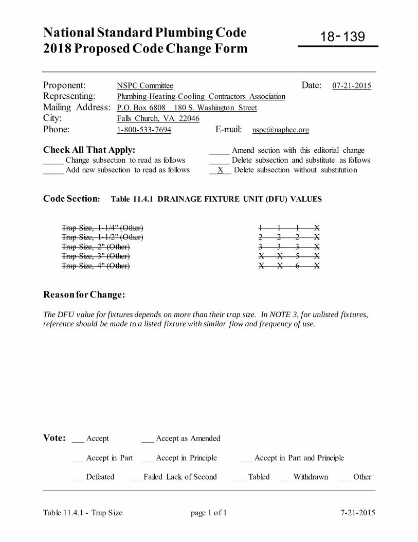
National Standard Plumbing Code 2018 Proposed Code Change Form
-
Table 11.4.1 - Trap Size page 1 of 1 7-21-2015
Proponent: NSPC Committee Date: 07-21-2015 Representing: Plumbing-Heating-Cooling Contractors Association Mailing Address: P.O. Box 6808 180 S. Washington Street City: Falls Church, VA 22046 Phone: 1-800-533-7694 E-mail: [email protected] Check All That Apply: _____ Amend section with this editorial change _____ Change subsection to read as follows _____ Delete subsection and substitute as follows _____ Add new subsection to read as follows __X__ Delete subsection without substitution Code Section: Table 11.4.1 DRAINAGE FIXTURE UNIT (DFU) VALUES Trap Size, 1-1/4" (Other) 1 1 1 X Trap Size, 1-1/2" (Other) 2 2 2 X Trap Size, 2" (Other) 3 3 3 X Trap Size, 3" (Other) X X 5 X Trap Size, 4" (Other) X X 6 X Reason for Change: The DFU value for fixtures depends on more than their trap size. In NOTE 3, for unlisted fixtures, reference should be made to a listed fixture with similar flow and frequency of use. Vote: ___ Accept ___ Accept as Amended
___ Accept in Part ___ Accept in Principle ___ Accept in Part and Principle
___ Defeated ___Failed Lack of Second ___ Tabled ___ Withdrawn ___ Other _________________________________________________________________________________
18 139
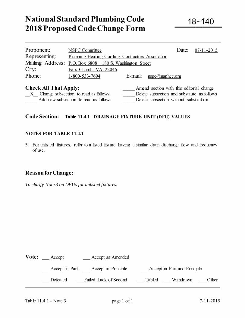
National Standard Plumbing Code 2018 Proposed Code Change Form
-
Table 11.4.1 - Note 3 page 1 of 1 7-11-2015
Proponent: NSPC Committee Date: 07-11-2015 Representing: Plumbing-Heating-Cooling Contractors Association Mailing Address: P.O. Box 6808 180 S. Washington Street City: Falls Church, VA 22046 Phone: 1-800-533-7694 E-mail: [email protected] Check All That Apply: _____ Amend section with this editorial change __X__ Change subsection to read as follows _____ Delete subsection and substitute as follows _____ Add new subsection to read as follows _____ Delete subsection without substitution Code Section: Table 11.4.1 DRAINAGE FIXTURE UNIT (DFU) VALUES NOTES FOR TABLE 11.4.1 3. For unlisted fixtures, refer to a listed fixture having a similar drain discharge flow and frequency
of use. Reason for Change: To clarify Note 3 on DFUs for unlisted fixtures. Vote: ___ Accept ___ Accept as Amended
___ Accept in Part ___ Accept in Principle ___ Accept in Part and Principle
___ Defeated ___Failed Lack of Second ___ Tabled ___ Withdrawn ___ Other _________________________________________________________________________________
18 140
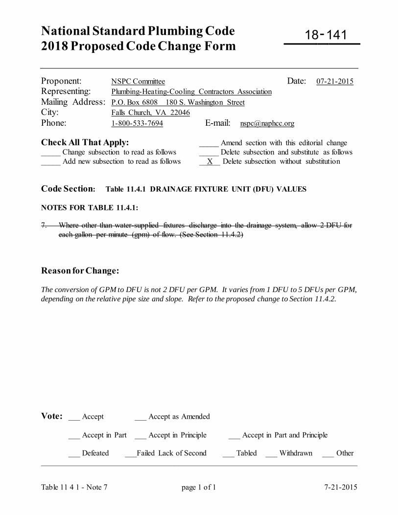
National Standard Plumbing Code 2018 Proposed Code Change Form
-
Table 11 4 1 - Note 7 page 1 of 1 7-21-2015
Proponent: NSPC Committee Date: 07-21-2015 Representing: Plumbing-Heating-Cooling Contractors Association Mailing Address: P.O. Box 6808 180 S. Washington Street City: Falls Church, VA 22046 Phone: 1-800-533-7694 E-mail: [email protected] Check All That Apply: _____ Amend section with this editorial change _____ Change subsection to read as follows _____ Delete subsection and substitute as follows _____ Add new subsection to read as follows __X__ Delete subsection without substitution Code Section: Table 11.4.1 DRAINAGE FIXTURE UNIT (DFU) VALUES NOTES FOR TABLE 11.4.1: 7. Where other than water-supplied fixtures discharge into the drainage system, allow 2 DFU for
each gallon per minute (gpm) of flow. (See Section 11.4.2) Reason for Change: The conversion of GPM to DFU is not 2 DFU per GPM. It varies from 1 DFU to 5 DFUs per GPM, depending on the relative pipe size and slope. Refer to the proposed change to Section 11.4.2. Vote: ___ Accept ___ Accept as Amended
___ Accept in Part ___ Accept in Principle ___ Accept in Part and Principle
___ Defeated ___Failed Lack of Second ___ Tabled ___ Withdrawn ___ Other _________________________________________________________________________________
18 141

National Standard Plumbing Code 2018 Proposed Code Change Form
-
Section 11.4.2, Table 11.4.2 page 1 of 1 7-21-2015
Proponent: NSPC Committee Date: 07-21-2015
Check All That Apply: _____ Amend section with this editorial change __X__ Change subsection to read as follows _____ Delete subsection and substitute as follows _____ Add new subsection to read as follows _____ Delete subsection without substitution
Code Section: 11.4 FIXTURE UNITS 11.4.2 Conversion of Flow in GPM to DFU Where the discharge rate of fixtures or equipment is expressed in gallons per minute (GPM), two (2) drainage fixture units (DFU) shall be allowed for each gallon per minute (GPM) of flow. a. Where discharges into sanitary drain piping are expressed in gallons per minute (GPM) of flow, they may be converted to drainage fixture units (DFU) according to this Section. Refer to Table 11.4.2.
b. The data in Table 11.4.2 is based on smooth horizontal drain pipe (n = 0.011) flowing one-half full, sloped at 1/4" per foot for pipe sizes 2" and smaller and 1/8" per foot for 3" pipe size and larger. Increased pipe slopes will increase the DFU per GPM higher than indicated in Table 11.4.2.
c. Drain flow rates higher than 300 gallons per minute (GPM) shall be converted to drainage fixture units (DFU) at a rate of five (5) DFU per GPM.
TABLE 11.4.2 GALLONS PER MINUTE (GPM) FLOW TO DRAINAGE FIXTURE UNITS (DFU) GPM DFU GPM DFU GPM DFU GPM DFU
1 1 9 15 45 150 150 690 2 2 10 18 50 180 175 820 3 3 15 25 60 225 200 950 4 4 20 35 70 275 250 1200 5 5 25 45 80 325 300 1450 6 6 30 65 90 375 350 1750 7 9 35 90 100 425 400 2000 8 12 40 120 125 560 450 2250
Reason for Change: To clarify the conversion of GPM to DFUs based on the GPMs in Table K-2 and the DFUs in Table 11.5.1A. Vote: ___ Accept ___ Accept as Amended
___ Accept in Part ___ Accept in Principle ___ Accept in Part and Principle
___ Defeated ___Failed Lack of Second ___ Tabled ___ Withdrawn ___ Other _________________________________________________________________________________
18 142
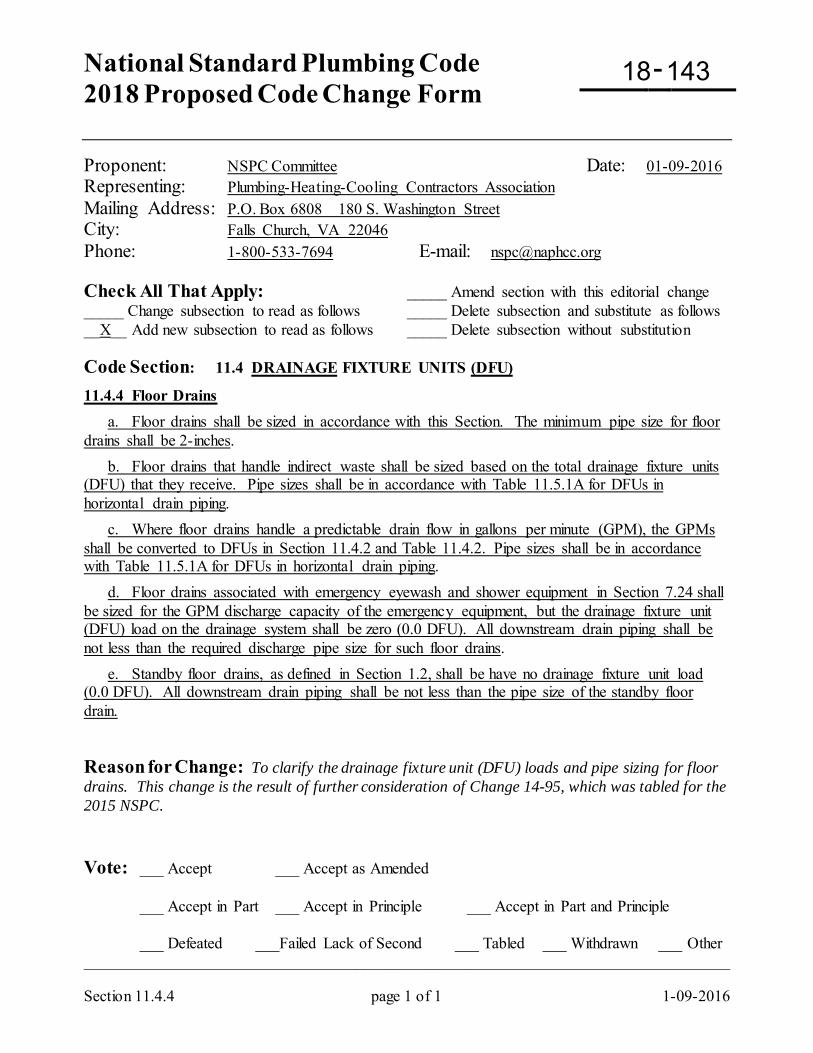
National Standard Plumbing Code 2018 Proposed Code Change Form
-
Section 11.4.4 page 1 of 1 1-09-2016
Proponent: NSPC Committee Date: 01-09-2016 Representing: Plumbing-Heating-Cooling Contractors Association Mailing Address: P.O. Box 6808 180 S. Washington Street City: Falls Church, VA 22046 Phone: 1-800-533-7694 E-mail: [email protected] Check All That Apply: _____ Amend section with this editorial change _____ Change subsection to read as follows _____ Delete subsection and substitute as follows __X__ Add new subsection to read as follows _____ Delete subsection without substitution Code Section: 11.4 DRAINAGE FIXTURE UNITS (DFU)
11.4.4 Floor Drains a. Floor drains shall be sized in accordance with this Section. The minimum pipe size for floor drains shall be 2-inches. b. Floor drains that handle indirect waste shall be sized based on the total drainage fixture units (DFU) that they receive. Pipe sizes shall be in accordance with Table 11.5.1A for DFUs in horizontal drain piping. c. Where floor drains handle a predictable drain flow in gallons per minute (GPM), the GPMs shall be converted to DFUs in Section 11.4.2 and Table 11.4.2. Pipe sizes shall be in accordance with Table 11.5.1A for DFUs in horizontal drain piping. d. Floor drains associated with emergency eyewash and shower equipment in Section 7.24 shall be sized for the GPM discharge capacity of the emergency equipment, but the drainage fixture unit (DFU) load on the drainage system shall be zero (0.0 DFU). All downstream drain piping shall be not less than the required discharge pipe size for such floor drains. e. Standby floor drains, as defined in Section 1.2, shall be have no drainage fixture unit load (0.0 DFU). All downstream drain piping shall be not less than the pipe size of the standby floor drain. Reason for Change: To clarify the drainage fixture unit (DFU) loads and pipe sizing for floor drains. This change is the result of further consideration of Change 14-95, which was tabled for the 2015 NSPC. Vote: ___ Accept ___ Accept as Amended
___ Accept in Part ___ Accept in Principle ___ Accept in Part and Principle
___ Defeated ___Failed Lack of Second ___ Tabled ___ Withdrawn ___ Other _________________________________________________________________________________
18 143
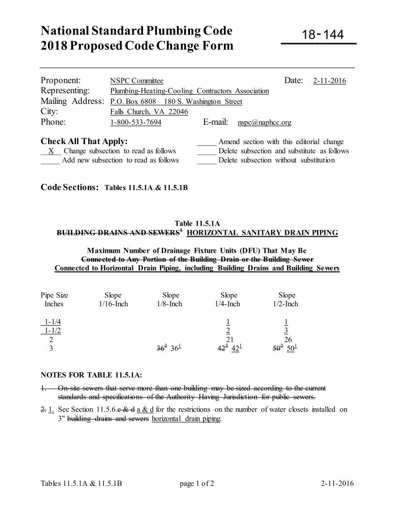
National Standard Plumbing Code 2018 Proposed Code Change Form
-
Tables 11.5.1A & 11.5.1B page 1 of 2 2-11-2016
Proponent: NSPC Committee Date: 2-11-2016 Representing: Plumbing-Heating-Cooling Contractors Association Mailing Address: P.O. Box 6808 180 S. Washington Street City: Falls Church, VA 22046 Phone: 1-800-533-7694 E-mail: [email protected] Check All That Apply: _____ Amend section with this editorial change __X__ Change subsection to read as follows _____ Delete subsection and substitute as follows _____ Add new subsection to read as follows _____ Delete subsection without substitution Code Sections: Tables 11.5.1A & 11.5.1B
Table 11.5.1A BUILDING DRAINS AND SEWERS1 HORIZONTAL SANITARY DRAIN PIPING
Maximum Number of Drainage Fixture Units (DFU) That May Be
Connected to Any Portion of the Building Drain or the Building Sewer Connected to Horizontal Drain Piping, including Building Drains and Building Sewers
Pipe Size Slope Slope Slope Slope Inches 1/16-Inch 1/8-Inch 1/4-Inch 1/2-Inch 1-1/4 1 1 1-1/2 2 3 2 21 26 3 362 361 422 421 502 501
NOTES FOR TABLE 11.5.1A:
1. On-site sewers that serve more than one building may be sized according to the current standards and specifications of the Authority Having Jurisdiction for public sewers.
2. 1. See Section 11.5.6.c & d a & d for the restrictions on the number of water closets installed on 3" building drains and sewers horizontal drain piping.
18 144
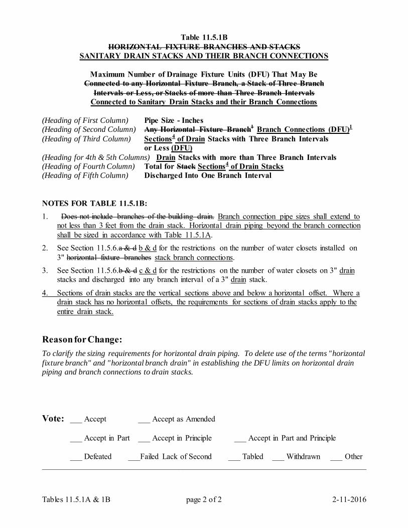
Tables 11.5.1A & 1B page 2 of 2 2-11-2016
Table 11.5.1B
HORIZONTAL FIXTURE BRANCHES AND STACKS SANITARY DRAIN STACKS AND THEIR BRANCH CONNECTIONS
Maximum Number of Drainage Fixture Units (DFU) That May Be
Connected to any Horizontal Fixture Branch, a Stack of Three Branch Intervals or Less, or Stacks of more than Three Branch Intervals
Connected to Sanitary Drain Stacks and their Branch Connections (Heading of First Column) Pipe Size - Inches (Heading of Second Column) Any Horizontal Fixture Branch1 Branch Connections (DFU)1 (Heading of Third Column) Sections4 of Drain Stacks with Three Branch Intervals or Less (DFU) (Heading for 4th & 5th Columns) Drain Stacks with more than Three Branch Intervals (Heading of Fourth Column) Total for Stack Sections4 of Drain Stacks (Heading of Fifth Column) Discharged Into One Branch Interval NOTES FOR TABLE 11.5.1B: 1. Does not include branches of the building drain. Branch connection pipe sizes shall extend to
not less than 3 feet from the drain stack. Horizontal drain piping beyond the branch connection shall be sized in accordance with Table 11.5.1A.
2. See Section 11.5.6.a & d b & d for the restrictions on the number of water closets installed on 3" horizontal fixture branches stack branch connections.
3. See Section 11.5.6.b & d c & d for the restrictions on the number of water closets on 3" drain stacks and discharged into any branch interval of a 3" drain stack.
4. Sections of drain stacks are the vertical sections above and below a horizontal offset. Where a drain stack has no horizontal offsets, the requirements for sections of drain stacks apply to the entire drain stack.
Reason for Change: To clarify the sizing requirements for horizontal drain piping. To delete use of the terms "horizontal fixture branch" and "horizontal branch drain" in establishing the DFU limits on horizontal drain piping and branch connections to drain stacks. Vote: ___ Accept ___ Accept as Amended
___ Accept in Part ___ Accept in Principle ___ Accept in Part and Principle
___ Defeated ___Failed Lack of Second ___ Tabled ___ Withdrawn ___ Other _________________________________________________________________________________
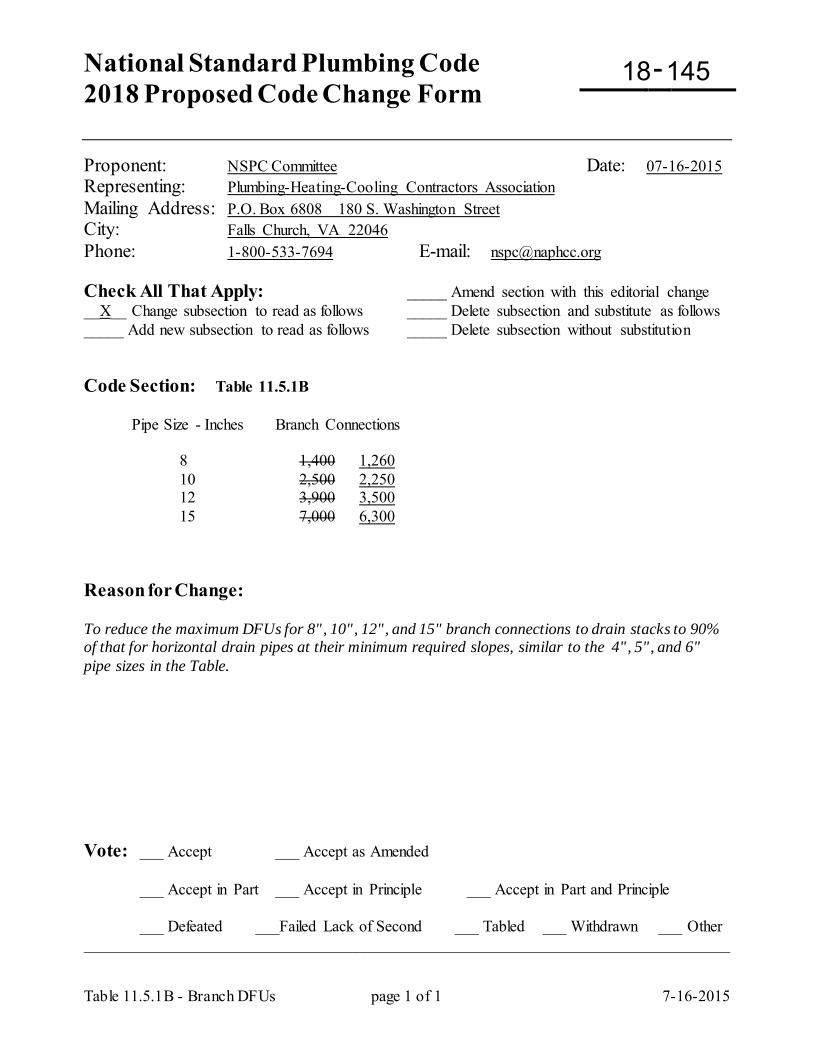
National Standard Plumbing Code 2018 Proposed Code Change Form
-
Table 11.5.1B - Branch DFUs page 1 of 1 7-16-2015
Proponent: NSPC Committee Date: 07-16-2015 Representing: Plumbing-Heating-Cooling Contractors Association Mailing Address: P.O. Box 6808 180 S. Washington Street City: Falls Church, VA 22046 Phone: 1-800-533-7694 E-mail: [email protected] Check All That Apply: _____ Amend section with this editorial change __X__ Change subsection to read as follows _____ Delete subsection and substitute as follows _____ Add new subsection to read as follows _____ Delete subsection without substitution Code Section: Table 11.5.1B Pipe Size - Inches Branch Connections 8 1,400 1,260 10 2,500 2,250 12 3,900 3,500 15 7,000 6,300 Reason for Change: To reduce the maximum DFUs for 8", 10", 12", and 15" branch connections to drain stacks to 90% of that for horizontal drain pipes at their minimum required slopes, similar to the 4", 5", and 6" pipe sizes in the Table. Vote: ___ Accept ___ Accept as Amended
___ Accept in Part ___ Accept in Principle ___ Accept in Part and Principle
___ Defeated ___Failed Lack of Second ___ Tabled ___ Withdrawn ___ Other _________________________________________________________________________________
18 145
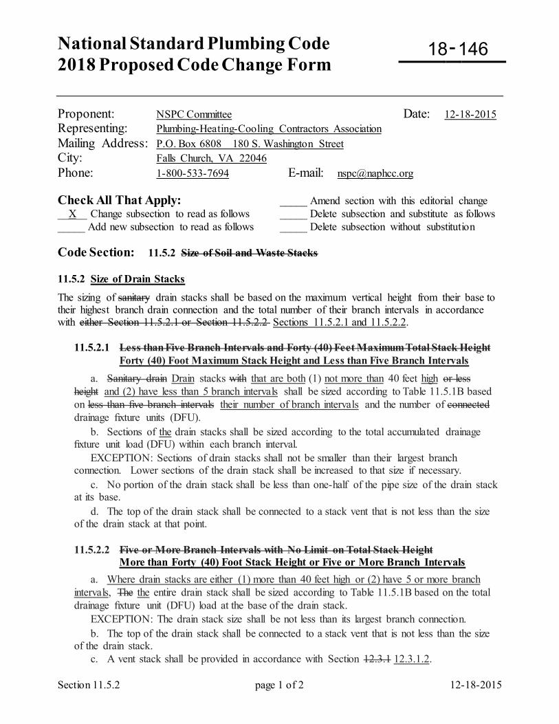
National Standard Plumbing Code 2018 Proposed Code Change Form
-
Section 11.5.2 page 1 of 2 12-18-2015
Proponent: NSPC Committee Date: 12-18-2015 Representing: Plumbing-Heating-Cooling Contractors Association Mailing Address: P.O. Box 6808 180 S. Washington Street City: Falls Church, VA 22046 Phone: 1-800-533-7694 E-mail: [email protected] Check All That Apply: _____ Amend section with this editorial change __X__ Change subsection to read as follows _____ Delete subsection and substitute as follows _____ Add new subsection to read as follows _____ Delete subsection without substitution Code Section: 11.5.2 Size of Soil and Waste Stacks 11.5.2 Size of Drain Stacks
The sizing of sanitary drain stacks shall be based on the maximum vertical height from their base to their highest branch drain connection and the total number of their branch intervals in accordance with either Section 11.5.2.1 or Section 11.5.2.2 Sections 11.5.2.1 and 11.5.2.2.
11.5.2.1 Less than Five Branch Intervals and Forty (40) Feet Maximum Total Stack Height Forty (40) Foot Maximum Stack Height and Less than Five Branch Intervals a. Sanitary drain Drain stacks with that are both (1) not more than 40 feet high or less height and (2) have less than 5 branch intervals shall be sized according to Table 11.5.1B based on less than five branch intervals their number of branch intervals and the number of connected drainage fixture units (DFU). b. Sections of the drain stacks shall be sized according to the total accumulated drainage fixture unit load (DFU) within each branch interval. EXCEPTION: Sections of drain stacks shall not be smaller than their largest branch connection. Lower sections of the drain stack shall be increased to that size if necessary. c. No portion of the drain stack shall be less than one-half of the pipe size of the drain stack at its base. d. The top of the drain stack shall be connected to a stack vent that is not less than the size of the drain stack at that point. 11.5.2.2 Five or More Branch Intervals with No Limit on Total Stack Height
More than Forty (40) Foot Stack Height or Five or More Branch Intervals a. Where drain stacks are either (1) more than 40 feet high or (2) have 5 or more branch intervals, The the entire drain stack shall be sized according to Table 11.5.1B based on the total drainage fixture unit (DFU) load at the base of the drain stack. EXCEPTION: The drain stack size shall be not less than its largest branch connection. b. The top of the drain stack shall be connected to a stack vent that is not less than the size of the drain stack. c. A vent stack shall be provided in accordance with Section 12.3.1 12.3.1.2.
18 146
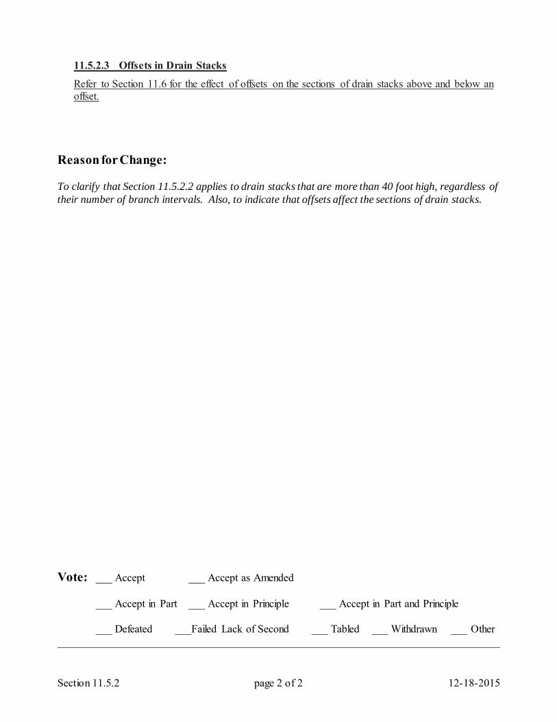
Section 11.5.2 page 2 of 2 12-18-2015
11.5.2.3 Offsets in Drain Stacks
Refer to Section 11.6 for the effect of offsets on the sections of drain stacks above and below an offset.
Reason for Change: To clarify that Section 11.5.2.2 applies to drain stacks that are more than 40 foot high, regardless of their number of branch intervals. Also, to indicate that offsets affect the sections of drain stacks. Vote: ___ Accept ___ Accept as Amended
___ Accept in Part ___ Accept in Principle ___ Accept in Part and Principle
___ Defeated ___Failed Lack of Second ___ Tabled ___ Withdrawn ___ Other _________________________________________________________________________________
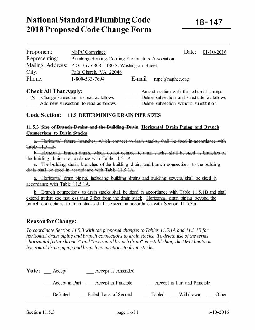
National Standard Plumbing Code 2018 Proposed Code Change Form
-
Section 11.5.3 page 1 of 1 1-10-2016
Proponent: NSPC Committee Date: 01-10-2016 Representing: Plumbing-Heating-Cooling Contractors Association Mailing Address: P.O. Box 6808 180 S. Washington Street City: Falls Church, VA 22046 Phone: 1-800-533-7694 E-mail: [email protected] Check All That Apply: _____ Amend section with this editorial change __X__ Change subsection to read as follows _____ Delete subsection and substitute as follows _____ Add new subsection to read as follows _____ Delete subsection without substitution Code Section: 11.5 DETERMINING DRAIN PIPE SIZES 11.5.3 Size of Branch Drains and the Building Drain Horizontal Drain Piping and Branch Connections to Drain Stacks a. Horizontal fixture branches, which connect to drain stacks, shall be sized in accordance with Table 11.5.1B. b. Horizontal branch drains, which do not connect to drain stacks, shall be sized as branches of the building drain in accordance with Table 11.5.1A. c. The building drain, branches of the building drain, and branch connections to the building drain shall be sized in accordance with Table 11.5.1A. a. Horizontal drain piping, including building drains and building sewers, shall be sized in accordance with Table 11.5.1A. b. Branch connections to drain stacks shall be sized in accordance with Table 11.5.1B and shall extend at that size not less than 3 feet from the drain stack. Horizontal drain piping beyond the branch connections to drain stacks shall be sized in accordance with Section 11.5.3.a. Reason for Change: To coordinate Section 11.5.3 with the proposed changes to Tables 11.5.1A and 11.5.1B for horizontal drain piping and branch connections to drain stacks. To delete use of the terms "horizontal fixture branch" and "horizontal branch drain" in establishing the DFU limits on horizontal drain piping and branch connections to drain stacks. Vote: ___ Accept ___ Accept as Amended
___ Accept in Part ___ Accept in Principle ___ Accept in Part and Principle
___ Defeated ___Failed Lack of Second ___ Tabled ___ Withdrawn ___ Other _________________________________________________________________________________
18 147
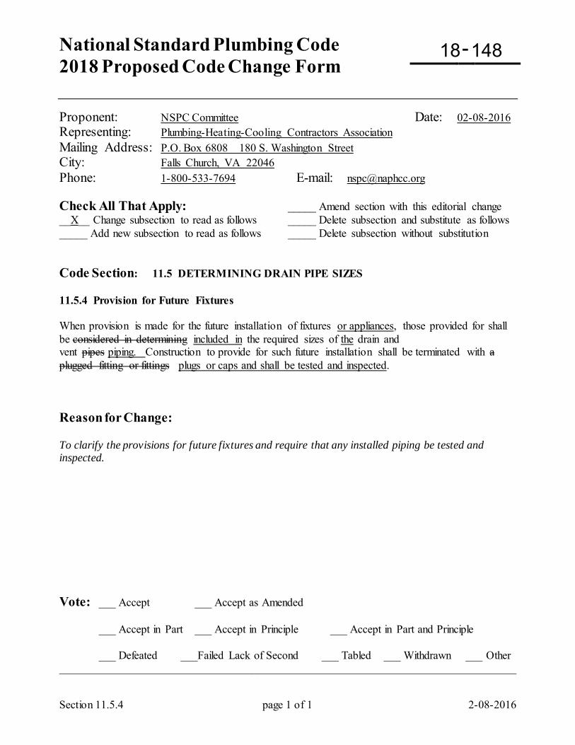
National Standard Plumbing Code 2018 Proposed Code Change Form
-
Section 11.5.4 page 1 of 1 2-08-2016
Proponent: NSPC Committee Date: 02-08-2016 Representing: Plumbing-Heating-Cooling Contractors Association Mailing Address: P.O. Box 6808 180 S. Washington Street City: Falls Church, VA 22046 Phone: 1-800-533-7694 E-mail: [email protected] Check All That Apply: _____ Amend section with this editorial change __X__ Change subsection to read as follows _____ Delete subsection and substitute as follows _____ Add new subsection to read as follows _____ Delete subsection without substitution Code Section: 11.5 DETERMINING DRAIN PIPE SIZES 11.5.4 Provision for Future Fixtures When provision is made for the future installation of fixtures or appliances, those provided for shall be considered in determining included in the required sizes of the drain and vent pipes piping. Construction to provide for such future installation shall be terminated with a plugged fitting or fittings plugs or caps and shall be tested and inspected. Reason for Change: To clarify the provisions for future fixtures and require that any installed piping be tested and inspected. Vote: ___ Accept ___ Accept as Amended
___ Accept in Part ___ Accept in Principle ___ Accept in Part and Principle
___ Defeated ___Failed Lack of Second ___ Tabled ___ Withdrawn ___ Other _________________________________________________________________________________
18 148
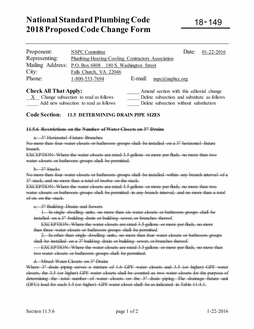
National Standard Plumbing Code 2018 Proposed Code Change Form
-
Section 11.5.6 page 1 of 2 1-22-2016
Proponent: NSPC Committee Date: 01-22-2016 Representing: Plumbing-Heating-Cooling Contractors Association Mailing Address: P.O. Box 6808 180 S. Washington Street City: Falls Church, VA 22046 Phone: 1-800-533-7694 E-mail: [email protected] Check All That Apply: _____ Amend section with this editorial change __X__ Change subsection to read as follows _____ Delete subsection and substitute as follows _____ Add new subsection to read as follows _____ Delete subsection without substitution Code Section: 11.5 DETERMINING DRAIN PIPE SIZES
11.5.6 Restrictions on the Number of Water Closets on 3" Drains
a. 3" Horizontal Fixture Branches No more than four water closets or bathroom groups shall be installed on a 3" horizontal fixture branch. EXCEPTION: Where the water closets are rated 3.5 gallons or more per flush, no more than two water closets or bathroom groups shall be permitted.
b. 3" Stacks No more than four water closets or bathroom groups shall be installed within any branch interval of a 3" stack, and no more than a total of twelve on the stack. EXCEPTION: Where the water closets are rated 3.5 gallons or more per flush, no more than two water closets or bathroom groups shall be permitted in any branch interval, and no more than a total of six on the stack.
c. 3" Building Drains and Sewers 1. In single dwelling units, no more than six water closets or bathroom groups shall be installed on a 3" building drain or building sewer, or branches thereof. EXCEPTION: Where the water closets are rated 3.5 gallons or more per flush, no more than three water closets or bathroom groups shall be permitted. 2. In other than single dwelling units, no more than four water closets or bathroom groups shall be installed on a 3'' building drain or building sewer, or branches thereof. EXCEPTION: Where the water closets are rated 3.5 gallons or more per flush, no more than two water closets or bathroom groups shall be permitted.
d. Mixed Water Closets on 3" Drains Where 3" drain piping serves a mixture of 1.6 GPF water closets and 3.5 (or higher) GPF water closets, the 3.5 (or higher) GPF water closets shall be counted as two water closets for the purpose of determining the total number of water closets on the 3" drain piping. The drainage fixture unit (DFU) load for each 3.5 (or higher) GPF water closet shall be as indicated in Table 11.4.1.
18 149
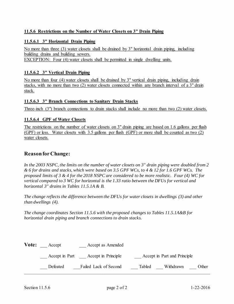
Section 11.5.6 page 2 of 2 1-22-2016
11.5.6 Restrictions on the Number of Water Closets on 3" Drain Piping 11.5.6.1 3" Horizontal Drain Piping No more than three (3) water closets shall be drained by 3" horizontal drain piping, including building drains and building sewers. EXCEPTION: Four (4) water closets shall be permitted in single dwelling units. 11.5.6.2 3" Vertical Drain Piping No more than four (4) water closets shall be drained by 3" vertical drain piping, including drain stacks, with no more than two (2) water closets connected within any branch interval of a 3" drain stack. 11.5.6.3 3" Branch Connections to Sanitary Drain Stacks Three-inch (3") branch connections to drain stacks shall include no more than two (2) water closets. 11.5.6.4 GPF of Water Closets The restrictions on the number of water closets on 3" drain piping are based on 1.6 gallons per flush (GPF) or less. Water closets with 3.5 gallons per flush (GPF) or more shall be counted as two (2) water closets. Reason for Change: In the 2003 NSPC, the limits on the number of water closets on 3" drain piping were doubled from 2 & 6 for drains and stacks, which were based on 3.5 GPF WCs, to 4 & 12 for 1.6 GPF WCs. The proposed limits of 3 & 4 for the 2018 NSPC are considered to be more realistic. Four (4) WC for vertical compared to 3 WC for horizontal is the 1.33 ratio between the DFUs for vertical and horizontal 3" drains in Tables 11.5.1A & B. The change reflects the difference between the DFUs for water closets in dwellings (3) and other than dwellings (4). The change coordinates Section 11.5.6 with the proposed changes to Tables 11.5.1A&B for horizontal drain piping and branch connections to drain stacks. Vote: ___ Accept ___ Accept as Amended
___ Accept in Part ___ Accept in Principle ___ Accept in Part and Principle
___ Defeated ___Failed Lack of Second ___ Tabled ___ Withdrawn ___ Other _________________________________________________________________________________
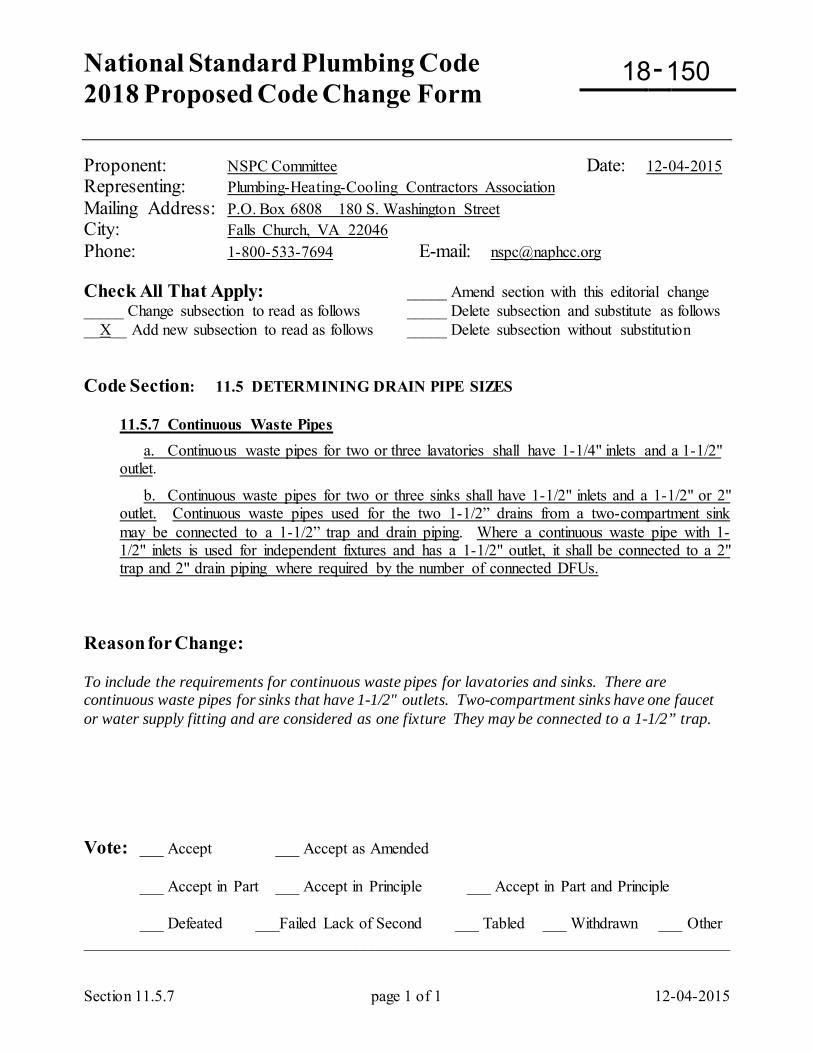
National Standard Plumbing Code 2018 Proposed Code Change Form
-
Section 11.5.7 page 1 of 1 12-04-2015
Proponent: NSPC Committee Date: 12-04-2015 Representing: Plumbing-Heating-Cooling Contractors Association Mailing Address: P.O. Box 6808 180 S. Washington Street City: Falls Church, VA 22046 Phone: 1-800-533-7694 E-mail: [email protected] Check All That Apply: _____ Amend section with this editorial change _____ Change subsection to read as follows _____ Delete subsection and substitute as follows __X__ Add new subsection to read as follows _____ Delete subsection without substitution Code Section: 11.5 DETERMINING DRAIN PIPE SIZES
11.5.7 Continuous Waste Pipes a. Continuous waste pipes for two or three lavatories shall have 1-1/4" inlets and a 1-1/2" outlet.
b. Continuous waste pipes for two or three sinks shall have 1-1/2" inlets and a 1-1/2" or 2" outlet. Continuous waste pipes used for the two 1-1/2” drains from a two-compartment sink may be connected to a 1-1/2” trap and drain piping. Where a continuous waste pipe with 1-1/2" inlets is used for independent fixtures and has a 1-1/2" outlet, it shall be connected to a 2" trap and 2" drain piping where required by the number of connected DFUs.
Reason for Change: To include the requirements for continuous waste pipes for lavatories and sinks. There are continuous waste pipes for sinks that have 1-1/2" outlets. Two-compartment sinks have one faucet or water supply fitting and are considered as one fixture They may be connected to a 1-1/2” trap. Vote: ___ Accept ___ Accept as Amended
___ Accept in Part ___ Accept in Principle ___ Accept in Part and Principle
___ Defeated ___Failed Lack of Second ___ Tabled ___ Withdrawn ___ Other _________________________________________________________________________________
18 150
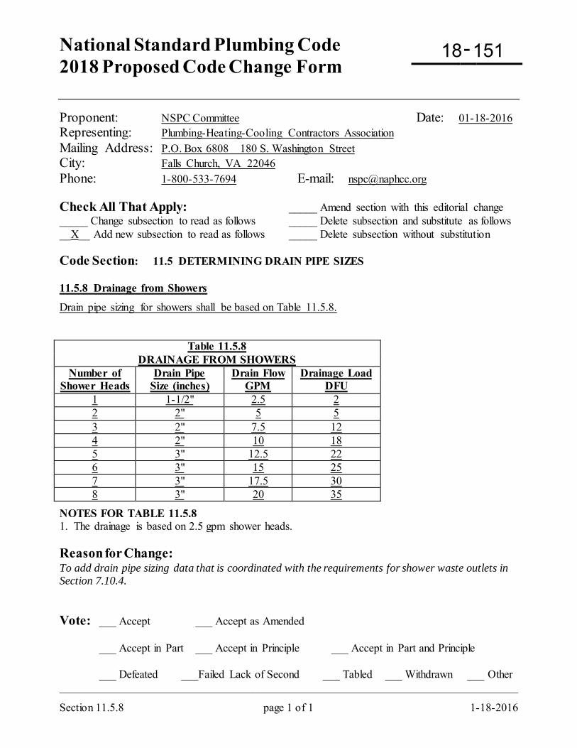
National Standard Plumbing Code 2018 Proposed Code Change Form
-
Section 11.5.8 page 1 of 1 1-18-2016
Proponent: NSPC Committee Date: 01-18-2016 Representing: Plumbing-Heating-Cooling Contractors Association Mailing Address: P.O. Box 6808 180 S. Washington Street City: Falls Church, VA 22046 Phone: 1-800-533-7694 E-mail: [email protected] Check All That Apply: _____ Amend section with this editorial change _____ Change subsection to read as follows _____ Delete subsection and substitute as follows __X__ Add new subsection to read as follows _____ Delete subsection without substitution Code Section: 11.5 DETERMINING DRAIN PIPE SIZES 11.5.8 Drainage from Showers
Drain pipe sizing for showers shall be based on Table 11.5.8.
Table 11.5.8 DRAINAGE FROM SHOWERS
Number of Drain Pipe Drain Flow Drainage Load Shower Heads Size (inches) GPM DFU
1 1-1/2" 2.5 2 2 2" 5 5 3 2" 7.5 12 4 2" 10 18 5 3" 12.5 22 6 3" 15 25 7 3" 17.5 30 8 3" 20 35
NOTES FOR TABLE 11.5.8 1. The drainage is based on 2.5 gpm shower heads. Reason for Change: To add drain pipe sizing data that is coordinated with the requirements for shower waste outlets in Section 7.10.4. Vote: ___ Accept ___ Accept as Amended
___ Accept in Part ___ Accept in Principle ___ Accept in Part and Principle
___ Defeated ___Failed Lack of Second ___ Tabled ___ Withdrawn ___ Other _________________________________________________________________________________
18 151
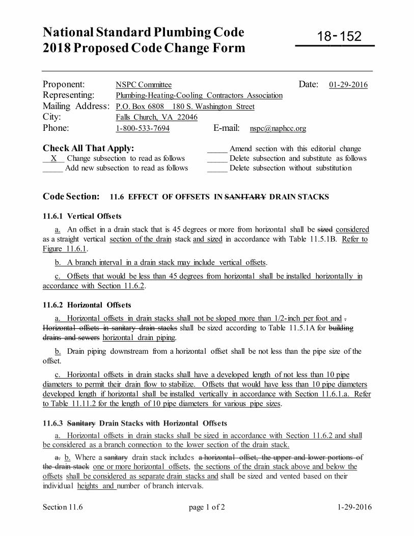
National Standard Plumbing Code 2018 Proposed Code Change Form
-
Section 11.6 page 1 of 2 1-29-2016
Proponent: NSPC Committee Date: 01-29-2016 Representing: Plumbing-Heating-Cooling Contractors Association Mailing Address: P.O. Box 6808 180 S. Washington Street City: Falls Church, VA 22046 Phone: 1-800-533-7694 E-mail: [email protected] Check All That Apply: _____ Amend section with this editorial change __X__ Change subsection to read as follows _____ Delete subsection and substitute as follows _____ Add new subsection to read as follows _____ Delete subsection without substitution Code Section: 11.6 EFFECT OF OFFSETS IN SANITARY DRAIN STACKS 11.6.1 Vertical Offsets a. An offset in a drain stack that is 45 degrees or more from horizontal shall be sized considered as a straight vertical section of the drain stack and sized in accordance with Table 11.5.1B. Refer to Figure 11.6.1.
b. A branch interval in a drain stack may include vertical offsets.
c. Offsets that would be less than 45 degrees from horizontal shall be installed horizontally in accordance with Section 11.6.2. 11.6.2 Horizontal Offsets a. Horizontal offsets in drain stacks shall not be sloped more than 1/2-inch per foot and . Horizontal offsets in sanitary drain stacks shall be sized according to Table 11.5.1A for building drains and sewers horizontal drain piping.
b. Drain piping downstream from a horizontal offset shall be not less than the pipe size of the offset.
c. Horizontal offsets in drain stacks shall have a developed length of not less than 10 pipe diameters to permit their drain flow to stabilize. Offsets that would have less than 10 pipe diameters developed length if horizontal shall be installed vertically in accordance with Section 11.6.1.a. Refer to Table 11.11.2 for the length of 10 pipe diameters for various pipe sizes. 11.6.3 Sanitary Drain Stacks with Horizontal Offsets a. Horizontal offsets in drain stacks shall be sized in accordance with Section 11.6.2 and shall be considered as a branch connection to the lower section of the drain stack. a. b. Where a sanitary drain stack includes a horizontal offset, the upper and lower portions of the drain stack one or more horizontal offsets, the sections of the drain stack above and below the offsets shall be considered as separate drain stacks and shall be sized and vented based on their individual heights and number of branch intervals.
18 152
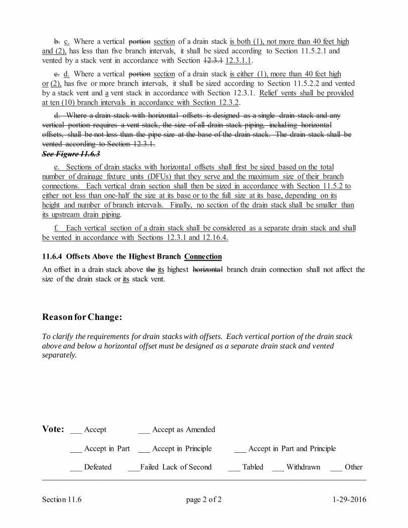
Section 11.6 page 2 of 2 1-29-2016
b. c. Where a vertical portion section of a drain stack is both (1), not more than 40 feet high and (2), has less than five branch intervals, it shall be sized according to Section 11.5.2.1 and vented by a stack vent in accordance with Section 12.3.1 12.3.1.1.
c. d. Where a vertical portion section of a drain stack is either (1), more than 40 feet high or (2), has five or more branch intervals, it shall be sized according to Section 11.5.2.2 and vented by a stack vent and a vent stack in accordance with Section 12.3.1. Relief vents shall be provided at ten (10) branch intervals in accordance with Section 12.3.2. d. Where a drain stack with horizontal offsets is designed as a single drain stack and any vertical portion requires a vent stack, the size of all drain stack piping, including horizontal offsets, shall be not less than the pipe size at the base of the drain stack. The drain stack shall be vented according to Section 12.3.1. See Figure 11.6.3 e. Sections of drain stacks with horizontal offsets shall first be sized based on the total number of drainage fixture units (DFUs) that they serve and the maximum size of their branch connections. Each vertical drain section shall then be sized in accordance with Section 11.5.2 to either not less than one-half the size at its base or to the full size at its base, depending on its height and number of branch intervals. Finally, no section of the drain stack shall be smaller than its upstream drain piping.
f. Each vertical section of a drain stack shall be considered as a separate drain stack and shall be vented in accordance with Sections 12.3.1 and 12.16.4. 11.6.4 Offsets Above the Highest Branch Connection An offset in a drain stack above the its highest horizontal branch drain connection shall not affect the size of the drain stack or its stack vent. Reason for Change: To clarify the requirements for drain stacks with offsets. Each vertical portion of the drain stack above and below a horizontal offset must be designed as a separate drain stack and vented separately. Vote: ___ Accept ___ Accept as Amended
___ Accept in Part ___ Accept in Principle ___ Accept in Part and Principle
___ Defeated ___Failed Lack of Second ___ Tabled ___ Withdrawn ___ Other _________________________________________________________________________________
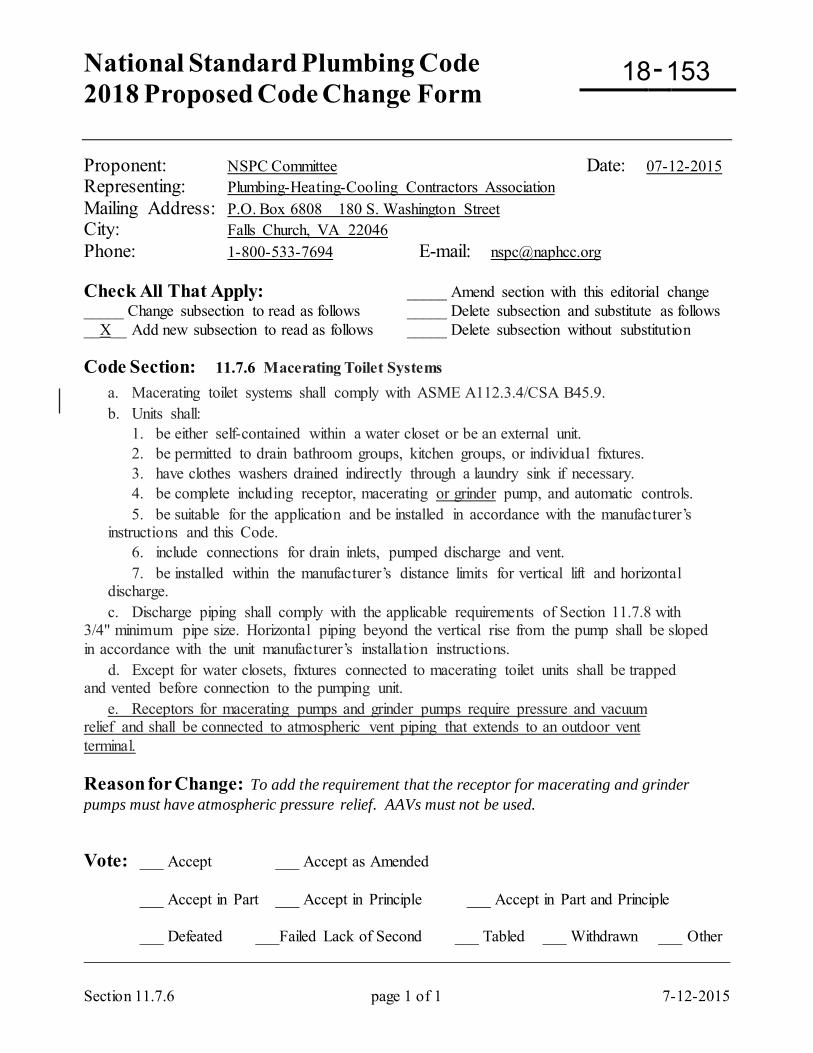
National Standard Plumbing Code 2018 Proposed Code Change Form
-
Section 11.7.6 page 1 of 1 7-12-2015
Proponent: NSPC Committee Date: 07-12-2015 Representing: Plumbing-Heating-Cooling Contractors Association Mailing Address: P.O. Box 6808 180 S. Washington Street City: Falls Church, VA 22046 Phone: 1-800-533-7694 E-mail: [email protected] Check All That Apply: _____ Amend section with this editorial change _____ Change subsection to read as follows _____ Delete subsection and substitute as follows __X__ Add new subsection to read as follows _____ Delete subsection without substitution Code Section: 11.7.6 Macerating Toilet Systems
a. Macerating toilet systems shall comply with ASME A112.3.4/CSA B45.9. b. Units shall:
1. be either self-contained within a water closet or be an external unit. 2. be permitted to drain bathroom groups, kitchen groups, or individual fixtures. 3. have clothes washers drained indirectly through a laundry sink if necessary. 4. be complete including receptor, macerating or grinder pump, and automatic controls. 5. be suitable for the application and be installed in accordance with the manufacturer’s instructions and this Code. 6. include connections for drain inlets, pumped discharge and vent. 7. be installed within the manufacturer’s distance limits for vertical lift and horizontal discharge.
c. Discharge piping shall comply with the applicable requirements of Section 11.7.8 with 3/4" minimum pipe size. Horizontal piping beyond the vertical rise from the pump shall be sloped in accordance with the unit manufacturer’s installation instructions. d. Except for water closets, fixtures connected to macerating toilet units shall be trapped and vented before connection to the pumping unit. e. Receptors for macerating pumps and grinder pumps require pressure and vacuum relief and shall be connected to atmospheric vent piping that extends to an outdoor vent terminal. Reason for Change: To add the requirement that the receptor for macerating and grinder pumps must have atmospheric pressure relief. AAVs must not be used. Vote: ___ Accept ___ Accept as Amended
___ Accept in Part ___ Accept in Principle ___ Accept in Part and Principle
___ Defeated ___Failed Lack of Second ___ Tabled ___ Withdrawn ___ Other _________________________________________________________________________________
18 153
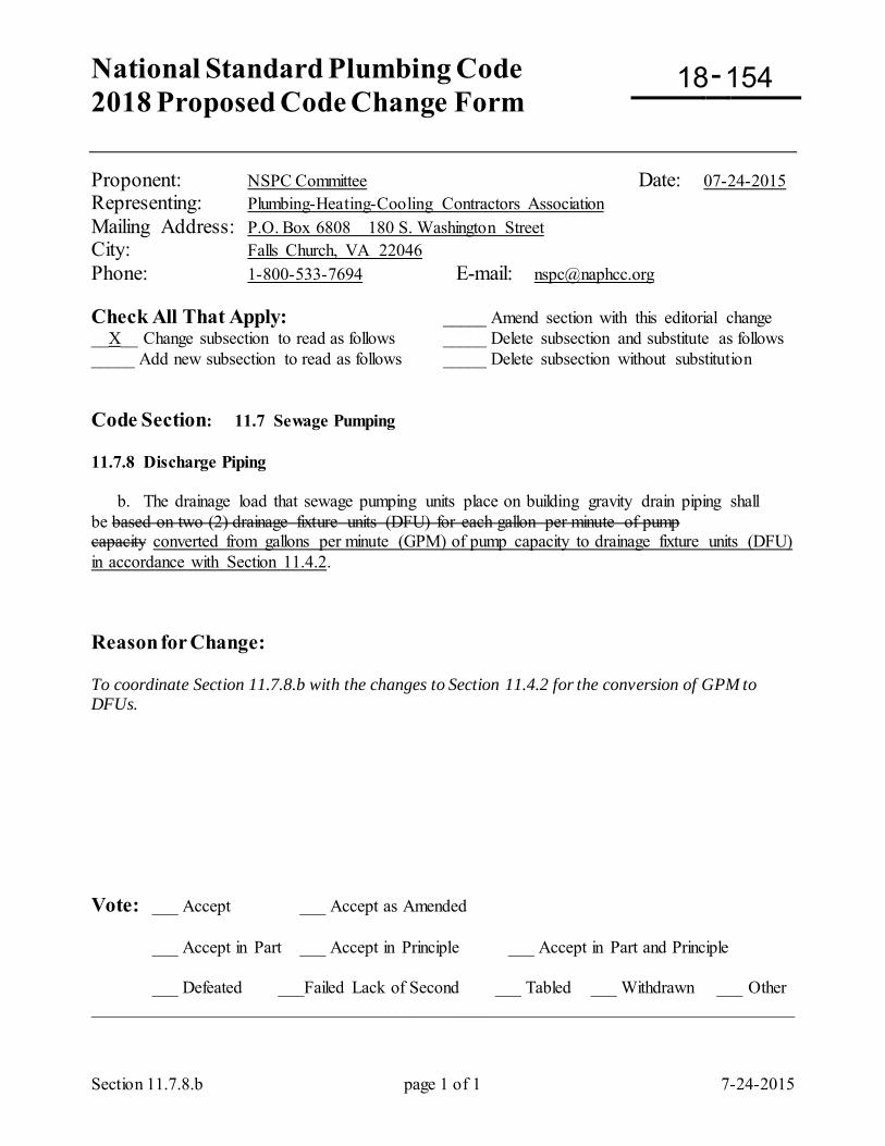
National Standard Plumbing Code 2018 Proposed Code Change Form
-
Section 11.7.8.b page 1 of 1 7-24-2015
Proponent: NSPC Committee Date: 07-24-2015 Representing: Plumbing-Heating-Cooling Contractors Association Mailing Address: P.O. Box 6808 180 S. Washington Street City: Falls Church, VA 22046 Phone: 1-800-533-7694 E-mail: [email protected] Check All That Apply: _____ Amend section with this editorial change __X__ Change subsection to read as follows _____ Delete subsection and substitute as follows _____ Add new subsection to read as follows _____ Delete subsection without substitution Code Section: 11.7 Sewage Pumping 11.7.8 Discharge Piping b. The drainage load that sewage pumping units place on building gravity drain piping shall be based on two (2) drainage fixture units (DFU) for each gallon per minute of pump capacity converted from gallons per minute (GPM) of pump capacity to drainage fixture units (DFU) in accordance with Section 11.4.2. Reason for Change: To coordinate Section 11.7.8.b with the changes to Section 11.4.2 for the conversion of GPM to DFUs. Vote: ___ Accept ___ Accept as Amended
___ Accept in Part ___ Accept in Principle ___ Accept in Part and Principle
___ Defeated ___Failed Lack of Second ___ Tabled ___ Withdrawn ___ Other _________________________________________________________________________________
18 154
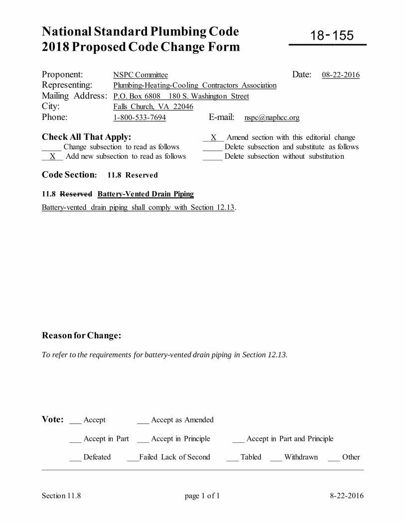
National Standard Plumbing Code 2018 Proposed Code Change Form
-
Section 11.8 page 1 of 1 8-22-2016
Proponent: NSPC Committee Date: 08-22-2016 Representing: Plumbing-Heating-Cooling Contractors Association Mailing Address: P.O. Box 6808 180 S. Washington Street City: Falls Church, VA 22046 Phone: 1-800-533-7694 E-mail: [email protected] Check All That Apply: __X__ Amend section with this editorial change _____ Change subsection to read as follows _____ Delete subsection and substitute as follows __X__ Add new subsection to read as follows _____ Delete subsection without substitution Code Section: 11.8 Reserved 11.8 Reserved Battery-Vented Drain Piping
Battery-vented drain piping shall comply with Section 12.13. Reason for Change: To refer to the requirements for battery-vented drain piping in Section 12.13. Vote: ___ Accept ___ Accept as Amended
___ Accept in Part ___ Accept in Principle ___ Accept in Part and Principle
___ Defeated ___Failed Lack of Second ___ Tabled ___ Withdrawn ___ Other _________________________________________________________________________________
18 155
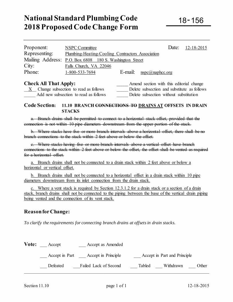
National Standard Plumbing Code 2018 Proposed Code Change Form
-
Section 11.10 page 1 of 1 12-18-2015
Proponent: NSPC Committee Date: 12-18-2015 Representing: Plumbing-Heating-Cooling Contractors Association Mailing Address: P.O. Box 6808 180 S. Washington Street City: Falls Church, VA 22046 Phone: 1-800-533-7694 E-mail: [email protected] Check All That Apply: _____ Amend section with this editorial change __X__ Change subsection to read as follows _____ Delete subsection and substitute as follows _____ Add new subsection to read as follows _____ Delete subsection without substitution Code Section: 11.10 BRANCH CONNECTIONS TO DRAINS AT OFFSETS IN DRAIN
STACKS a. Branch drains shall be permitted to connect to a horizontal stack offset, provided that the connection is not within 10 pipe diameters downstream from the upper portion of the stack. b. Where stacks have five or more branch intervals above a horizontal offset, there shall be no branch connections to the stack within 2 feet above or below the offset.
c. Where stacks having five or more branch intervals above a vertical offset have branch connections to the stack within 2 feet above or below the offset, the offset shall be vented as required for a horizontal offset. a. Branch drains shall not be connected to a drain stack within 2 feet above or below a horizontal or vertical offset.
b. Branch drains shall not be connected to a horizontal offset in a drain stack within 10 pipe diameters downstream from its inlet connection from the drain stack.
c. Where a vent stack is required by Section 12.3.1.2 for a drain stack or a section of a drain stack, branch drains shall not be connected to the piping between the base of the vertical drain piping being vented and the connection of its vent stack.
Reason for Change: To clarify the requirements for connecting branch drains at offsets in drain stacks. Vote: ___ Accept ___ Accept as Amended
___ Accept in Part ___ Accept in Principle ___ Accept in Part and Principle
___ Defeated ___Failed Lack of Second ___ Tabled ___ Withdrawn ___ Other _________________________________________________________________________________
18 156
National Standard Plumbing Code 2018 Proposed Code Change Form
-
11.11 Suds Pressure Zones page 1 of 3 5-03-2016
Proponent: NSPC Committee Date: 05-03-2016 Representing: Plumbing-Heating-Cooling Contractors Association Mailing Address: P.O. Box 6808 180 S. Washington Street City: Falls Church, VA 22046 Phone: 1-800-533-7694 E-mail: [email protected] Check All That Apply: _____ Amend section with this editorial change __X__ Change subsection to read as follows _____ Delete subsection and substitute as follows _____ Add new subsection to read as follows _____ Delete subsection without substitution Code Section: 11.11 SUDS PRESSURE ZONES 11.11.1 General a. Where suds-producing fixtures on upper floors discharge into a sanitary drain stack more than 25 feet above its base or a horizontal offset, suds pressure zones shall exist as described in Section 11.11.2. b. Fixture or branch drain connections shall not be made to such drain stacks in the suds pressure zones except where suds pressure relief vents complying with Section 12.15 are provided. c. Suds-producing fixtures include kitchen sinks, laundry sinks, automatic clothes washers, dishwashers, commercial laundry equipment, and other fixtures, appliances, and equipment that could discharge sudsy detergents. Comment #1: The most likely fixtures to create suds pressure problems in drain stacks are clothes washers, dishwashers, kitchen sinks, and laundry sinks. Where liquid wastes in tall buildings include high-sudsing detergents, the detergent is vigorously mixed with the liquid waste and air in the stack. The liquid waste is heavier than the suds and does not carry them along with the flow. The suds will settle in the lower portions of the drainage system, including any horizontal offsets. The air that is flowing with the liquid waste compresses the suds and builds up pressure in the stack that can blow traps seals if not relieved. Zones of the drainage and vent piping where suds pressure can exist are described in Section 11.11.2 and illustrated in Figure 11.11.2. Comment #2: Suds pressure relief vents in Section 12.15 are larger than ordinary vents for drainage systems because the suds are heavier than air. Suds can weight from 2 to as much as 19 pounds per cubic foot.
18 157
11.11 Suds Pressure Zones page 3 of 3 5-03-2016
11.11.2 Locations of Suds Pressure Zones in Stacks Serving Suds-Producing Fixtures a. Zone 1 - at drain stack offsets greater than 45 degrees from vertical and less than 50 feet in length. A suds pressure zone shall extend 40 pipe diameters up the drain stack above the offset, 10 pipe diameters downstream from the base of the upper portion of the drain stack, and in the horizontal offset, 40 pipe diameters upstream from the top of the lower portion of the drain stack. b. Zone 2 - at the base of a sanitary drain stack. A suds pressure zone shall extend 40 pipe diameters up the drain stack above its base. c. Zone 3 - in the horizontal drain beyond the base of a sanitary drain stack. A suds pressure zone shall extend 10 pipe diameters from the base of the drain stack. Also in Zone 3, if a turn greater than 45 degrees occurs in the horizontal drain less than 50 feet from the base of the drain stack, suds pressure zones shall exist 40 pipe diameters upstream and 10 diameters downstream from the horizontal turn. d. Zone 4 - in a vent stack at the base of a sanitary drain stack or at a horizontal offset. Where a vent stack connects above or beyond the base of a sanitary drain stack or at a horizontal offset, a suds pressure zone shall extend up the vent stack to a level equal to the level of the suds pressure zone in the sanitary drain stack.
11.11.3 Separate Stacks Where sanitary drain stacks serving suds-producing fixtures extend six or more floor above the base of the stack or above a horizontal offset in the stack, the lowest four floors above the base or horizontal offset shall be drained by a separate stack. In the case of a horizontal offset, the separate stack for the four floors above the offset may be reconnected to the main stack below the offset, provided that the point of connection is not a suds pressure zone in either stack. See Figure 11.11.3 11.11.3 Branch Drain Connections Within Suds Pressure Zones a. Where branch drain connections are required for drain piping within suds pressure zones, they shall be 2-inch minimum pipe size to provide adequate venting. The branch drain shall be not less than 2-inch pipe size from its connection to the suds pressure zone to the connection of its pressure relief vent. The minimum length of branch connections to drain stacks is 3 feet in Table 11.5.1B, Note 1. There shall be no fixture drain connections between the pressure relief vent and the suds pressure zone. b. Branch drain connections to horizontal drain piping within a suds pressure zone shall be vertical, 45 degrees or more from horizontal. 11.11.4 Vent Stack Connections Within Suds Pressure Zones Where vent stack connections to drain stacks or horizontal offsets are within suds pressure zones for the drain piping, no vent system piping shall be connected to the vent stack within its suds pressure zone (Zone 4).
11.11 Suds Pressure Zones page 3 of 3 5-03-2016
11.11.5 Separate Drain Stacks Where branch drain connections are required within a suds pressure zone for the lower floor connections to a multi-story drain stack, a separate drain stack may be provided for the lower floors to avoid pressure relief venting within the suds pressure zone for the taller drain stack. 11.11.6 Exceptions to Suds Pressure Control
a. The requirements for suds pressure control in Sections 11.11 and 12.15 shall not apply to the following:
(1) detached one- and two-family dwellings (2) multiple single-family dwellings (townhouses)
(3) facilities where suds pressure is not considered to be a problem by the Authority Having Jurisdiction
Reason for Change: To clarify the requirements for suds pressure control. Vote: ___ Accept ___ Accept as Amended
___ Accept in Part ___ Accept in Principle ___ Accept in Part and Principle
___ Defeated ___Failed Lack of Second ___ Tabled ___ Withdrawn ___ Other _________________________________________________________________________________
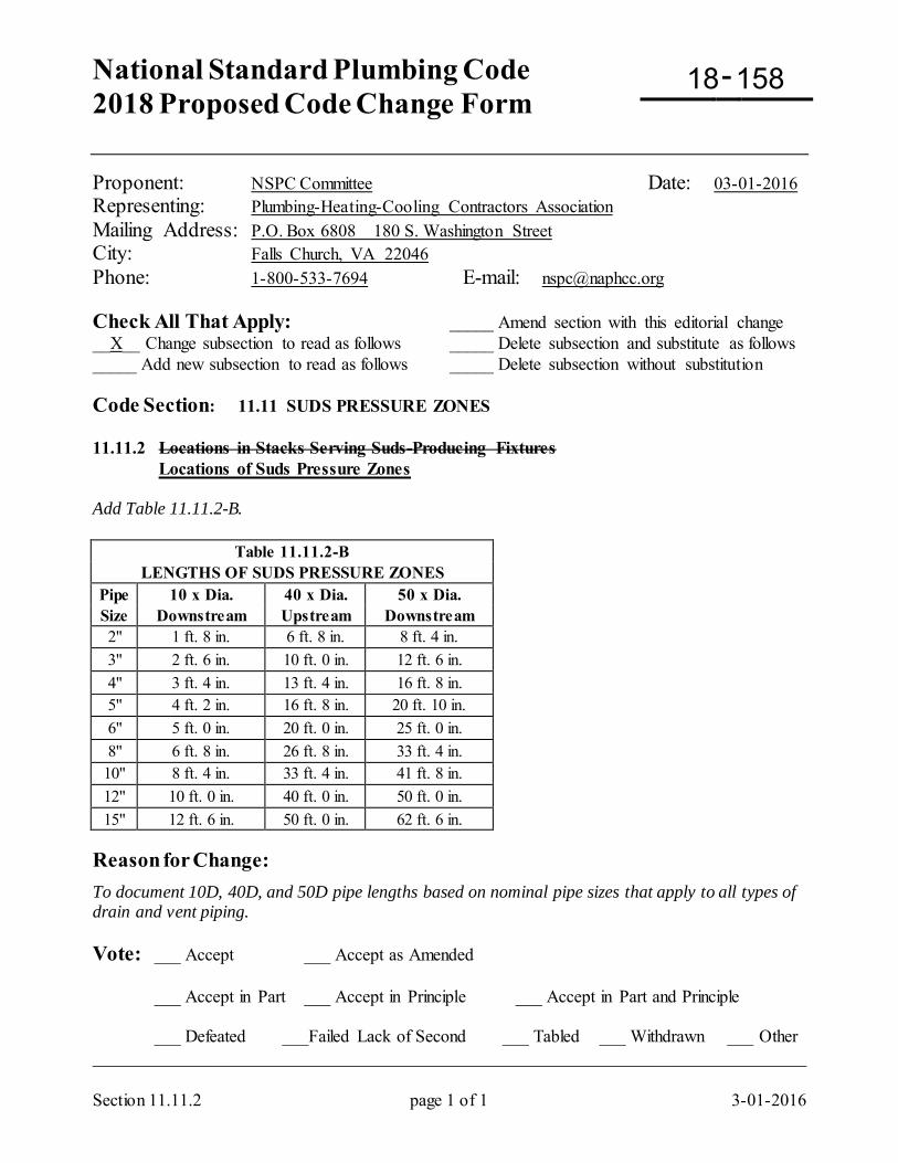
National Standard Plumbing Code 2018 Proposed Code Change Form
-
Section 11.11.2 page 1 of 1 3-01-2016
Proponent: NSPC Committee Date: 03-01-2016 Representing: Plumbing-Heating-Cooling Contractors Association Mailing Address: P.O. Box 6808 180 S. Washington Street City: Falls Church, VA 22046 Phone: 1-800-533-7694 E-mail: [email protected] Check All That Apply: _____ Amend section with this editorial change __X__ Change subsection to read as follows _____ Delete subsection and substitute as follows _____ Add new subsection to read as follows _____ Delete subsection without substitution Code Section: 11.11 SUDS PRESSURE ZONES 11.11.2 Locations in Stacks Serving Suds-Producing Fixtures Locations of Suds Pressure Zones Add Table 11.11.2-B.
Table 11.11.2-B LENGTHS OF SUDS PRESSURE ZONES
Pipe 10 x Dia. 40 x Dia. 50 x Dia. Size Downstream Upstream Downstream 2" 1 ft. 8 in. 6 ft. 8 in. 8 ft. 4 in. 3" 2 ft. 6 in. 10 ft. 0 in. 12 ft. 6 in. 4" 3 ft. 4 in. 13 ft. 4 in. 16 ft. 8 in. 5" 4 ft. 2 in. 16 ft. 8 in. 20 ft. 10 in. 6" 5 ft. 0 in. 20 ft. 0 in. 25 ft. 0 in. 8" 6 ft. 8 in. 26 ft. 8 in. 33 ft. 4 in.
10" 8 ft. 4 in. 33 ft. 4 in. 41 ft. 8 in. 12" 10 ft. 0 in. 40 ft. 0 in. 50 ft. 0 in. 15" 12 ft. 6 in. 50 ft. 0 in. 62 ft. 6 in.
Reason for Change: To document 10D, 40D, and 50D pipe lengths based on nominal pipe sizes that apply to all types of drain and vent piping. Vote: ___ Accept ___ Accept as Amended
___ Accept in Part ___ Accept in Principle ___ Accept in Part and Principle
___ Defeated ___Failed Lack of Second ___ Tabled ___ Withdrawn ___ Other _________________________________________________________________________________
18 158
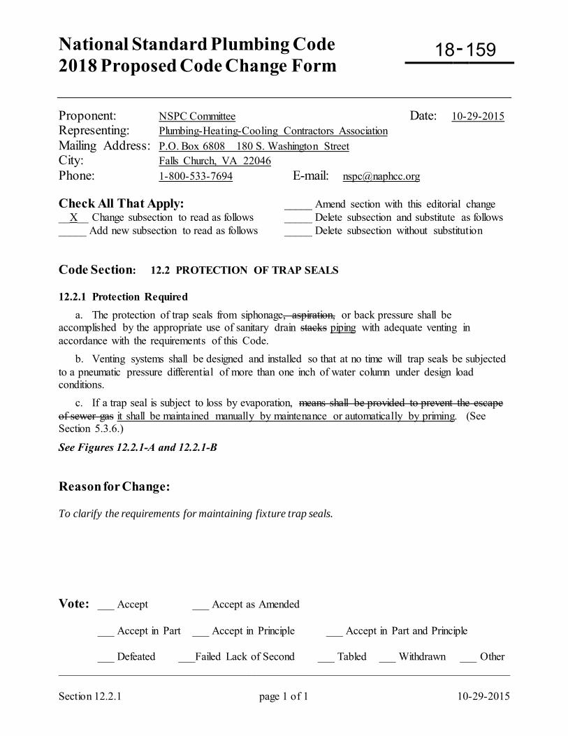
National Standard Plumbing Code 2018 Proposed Code Change Form
-
Section 12.2.1 page 1 of 1 10-29-2015
Proponent: NSPC Committee Date: 10-29-2015 Representing: Plumbing-Heating-Cooling Contractors Association Mailing Address: P.O. Box 6808 180 S. Washington Street City: Falls Church, VA 22046 Phone: 1-800-533-7694 E-mail: [email protected] Check All That Apply: _____ Amend section with this editorial change __X__ Change subsection to read as follows _____ Delete subsection and substitute as follows _____ Add new subsection to read as follows _____ Delete subsection without substitution Code Section: 12.2 PROTECTION OF TRAP SEALS 12.2.1 Protection Required a. The protection of trap seals from siphonage, aspiration, or back pressure shall be accomplished by the appropriate use of sanitary drain stacks piping with adequate venting in accordance with the requirements of this Code. b. Venting systems shall be designed and installed so that at no time will trap seals be subjected to a pneumatic pressure differential of more than one inch of water column under design load conditions. c. If a trap seal is subject to loss by evaporation, means shall be provided to prevent the escape of sewer gas it shall be maintained manually by maintenance or automatically by priming. (See Section 5.3.6.)
See Figures 12.2.1-A and 12.2.1-B Reason for Change: To clarify the requirements for maintaining fixture trap seals. Vote: ___ Accept ___ Accept as Amended
___ Accept in Part ___ Accept in Principle ___ Accept in Part and Principle
___ Defeated ___Failed Lack of Second ___ Tabled ___ Withdrawn ___ Other _________________________________________________________________________________
18 159
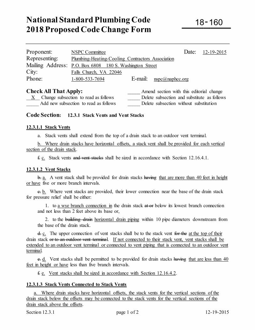
National Standard Plumbing Code 2018 Proposed Code Change Form
-
Section 12.3.1 page 1 of 2 12-19-2015
Proponent: NSPC Committee Date: 12-19-2015 Representing: Plumbing-Heating-Cooling Contractors Association Mailing Address: P.O. Box 6808 180 S. Washington Street City: Falls Church, VA 22046 Phone: 1-800-533-7694 E-mail: [email protected] Check All That Apply: _____ Amend section with this editorial change __X__ Change subsection to read as follows _____ Delete subsection and substitute as follows _____ Add new subsection to read as follows _____ Delete subsection without substitution Code Section: 12.3.1 Stack Vents and Vent Stacks 12.3.1.1 Stack Vents
a. Stack vents shall extend from the top of a drain stack to an outdoor vent terminal. b. Where drain stacks have horizontal offsets, a stack vent shall be provided for each vertical section of the drain stack.
f. c. Stack vents and vent stacks shall be sized in accordance with Section 12.16.4.1. 12.3.1.2 Vent Stacks b. a. A vent stack shall be provided for drain stacks having that are more than 40 feet in height or have five or more branch intervals.
c. b. Where vent stacks are provided, their lower connection near the base of the drain stack for pressure relief shall be either:
1. to a wye branch connection in the drain stack at or below its lowest branch connection and not less than 2 feet above its base or,
2. to the building drain horizontal drain piping within 10 pipe diameters downstream from the base of the drain stack.
d. c. The upper connection of vent stacks shall be to the stack vent for the at the top of their drain stack or to an outdoor vent terminal. If not connected to their stack vent, vent stacks shall be extended to an outdoor vent terminal or connected to vent piping that is connected to an outdoor vent terminal.
e. d. Vent stacks shall be permitted to be provided for drain stacks having that are less than 40 feet in height or have less than five branch intervals.
f. e. Vent stacks shall be sized in accordance with Section 12.16.4.2. 12.3.1.3 Stack Vents Connected to Stack Vents
a. Where drain stacks have horizontal offsets, the stack vents for the vertical sections of the drain stack below the offsets may be connected to the stack vents for the vertical sections of the drain stack above the offsets.
18 160
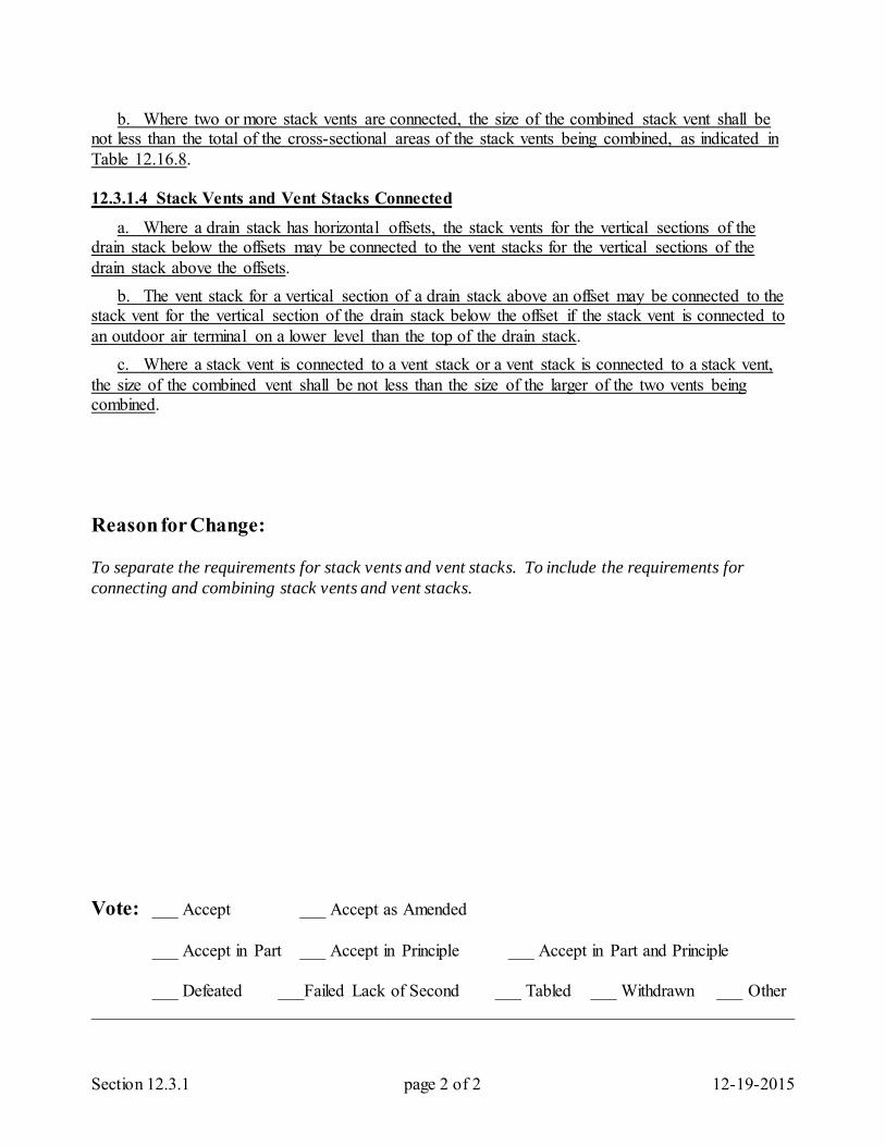
Section 12.3.1 page 2 of 2 12-19-2015
b. Where two or more stack vents are connected, the size of the combined stack vent shall be not less than the total of the cross-sectional areas of the stack vents being combined, as indicated in Table 12.16.8. 12.3.1.4 Stack Vents and Vent Stacks Connected
a. Where a drain stack has horizontal offsets, the stack vents for the vertical sections of the drain stack below the offsets may be connected to the vent stacks for the vertical sections of the drain stack above the offsets. b. The vent stack for a vertical section of a drain stack above an offset may be connected to the stack vent for the vertical section of the drain stack below the offset if the stack vent is connected to an outdoor air terminal on a lower level than the top of the drain stack. c. Where a stack vent is connected to a vent stack or a vent stack is connected to a stack vent, the size of the combined vent shall be not less than the size of the larger of the two vents being combined. Reason for Change: To separate the requirements for stack vents and vent stacks. To include the requirements for connecting and combining stack vents and vent stacks. Vote: ___ Accept ___ Accept as Amended
___ Accept in Part ___ Accept in Principle ___ Accept in Part and Principle
___ Defeated ___Failed Lack of Second ___ Tabled ___ Withdrawn ___ Other _________________________________________________________________________________
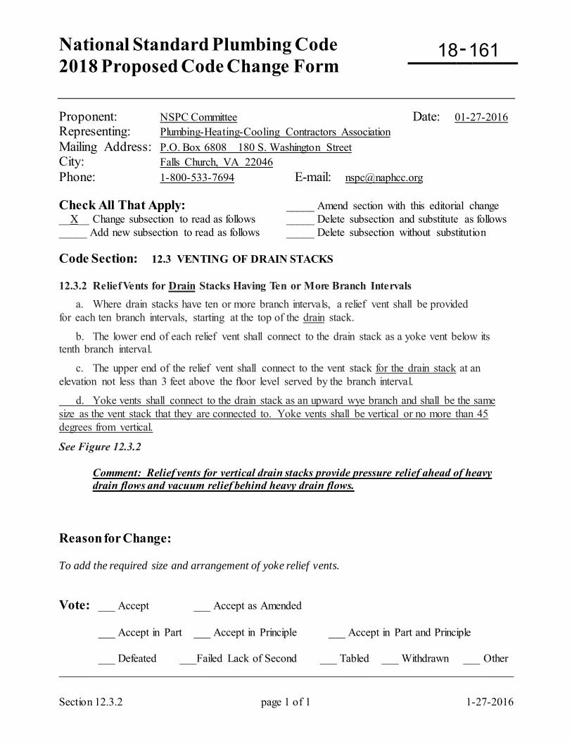
National Standard Plumbing Code 2018 Proposed Code Change Form
-
Section 12.3.2 page 1 of 1 1-27-2016
Proponent: NSPC Committee Date: 01-27-2016 Representing: Plumbing-Heating-Cooling Contractors Association Mailing Address: P.O. Box 6808 180 S. Washington Street City: Falls Church, VA 22046 Phone: 1-800-533-7694 E-mail: [email protected] Check All That Apply: _____ Amend section with this editorial change __X__ Change subsection to read as follows _____ Delete subsection and substitute as follows _____ Add new subsection to read as follows _____ Delete subsection without substitution Code Section: 12.3 VENTING OF DRAIN STACKS 12.3.2 Relief Vents for Drain Stacks Having Ten or More Branch Intervals a. Where drain stacks have ten or more branch intervals, a relief vent shall be provided for each ten branch intervals, starting at the top of the drain stack.
b. The lower end of each relief vent shall connect to the drain stack as a yoke vent below its tenth branch interval.
c. The upper end of the relief vent shall connect to the vent stack for the drain stack at an elevation not less than 3 feet above the floor level served by the branch interval.
d. Yoke vents shall connect to the drain stack as an upward wye branch and shall be the same size as the vent stack that they are connected to. Yoke vents shall be vertical or no more than 45 degrees from vertical.
See Figure 12.3.2
Comment: Relief vents for vertical drain stacks provide pressure relief ahead of heavy drain flows and vacuum relief behind heavy drain flows.
Reason for Change: To add the required size and arrangement of yoke relief vents. Vote: ___ Accept ___ Accept as Amended
___ Accept in Part ___ Accept in Principle ___ Accept in Part and Principle
___ Defeated ___Failed Lack of Second ___ Tabled ___ Withdrawn ___ Other _________________________________________________________________________________
18 161
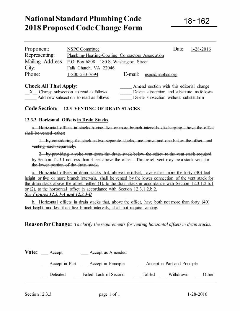
National Standard Plumbing Code 2018 Proposed Code Change Form
-
Section 12.3.3 page 1 of 1 1-28-2016
Proponent: NSPC Committee Date: 1-28-2016 Representing: Plumbing-Heating-Cooling Contractors Association Mailing Address: P.O. Box 6808 180 S. Washington Street City: Falls Church, VA 22046 Phone: 1-800-533-7694 E-mail: [email protected] Check All That Apply: _____ Amend section with this editorial change __X__ Change subsection to read as follows _____ Delete subsection and substitute as follows _____ Add new subsection to read as follows _____ Delete subsection without substitution Code Section: 12.3 VENTING OF DRAIN STACKS 12.3.3 Horizontal Offsets in Drain Stacks
a. Horizontal offsets in stacks having five or more branch intervals discharging above the offset shall be vented either: 1. by considering the stack as two separate stacks, one above and one below the offset, and
venting each separately. 2. by providing a yoke vent from the drain stack below the offset to the vent stack required
by Section 12.3.1 not less than 3 feet above the offset. This relief vent may be a stack vent for the lower portion of the drain stack.
a. Horizontal offsets in drain stacks that, above the offset, have either more the forty (40) feet height or five or more branch intervals, shall be vented by the lower connection of the vent stack for the drain stack above the offset, either (1), to the drain stack in accordance with Section 12.3.1.2,b.1 or (2), to the horizontal offset in accordance with Section 12.3.1.2.b.2. See Figures 12.3.3-A and 12.3.3-B b. Horizontal offsets in drain stacks that, above the offset, have both not more than forty (40) feet height and less than five branch intervals, shall not require venting. Reason for Change: To clarify the requirements for venting horizontal offsets in drain stacks. Vote: ___ Accept ___ Accept as Amended
___ Accept in Part ___ Accept in Principle ___ Accept in Part and Principle
___ Defeated ___Failed Lack of Second ___ Tabled ___ Withdrawn ___ Other _________________________________________________________________________________
18 162
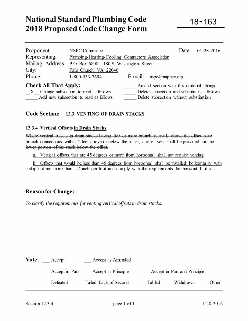
National Standard Plumbing Code 2018 Proposed Code Change Form
-
Section 12.3.4 page 1 of 1 1-28-2016
Proponent: NSPC Committee Date: 01-28-2016 Representing: Plumbing-Heating-Cooling Contractors Association Mailing Address: P.O. Box 6808 180 S. Washington Street City: Falls Church, VA 22046 Phone: 1-800-533-7694 E-mail: [email protected] Check All That Apply: _____ Amend section with this editorial change __X__ Change subsection to read as follows _____ Delete subsection and substitute as follows _____ Add new subsection to read as follows _____ Delete subsection without substitution
Code Section: 12.3 VENTING OF DRAIN STACKS
12.3.4 Vertical Offsets in Drain Stacks Where vertical offsets in drain stacks having five or more branch intervals above the offset have branch connections within 2 feet above or below the offset, a relief vent shall be provided for the lower portion of the stack below the offset. a. Vertical offsets that are 45 degrees or more from horizontal shall not require venting.
b. Offsets that would be less than 45 degrees from horizontal shall be installed horizontally with a slope of not more than 1/2-inch per foot and comply with the requirements for horizontal offsets. Reason for Change: To clarify the requirements for venting vertical offsets in drain stacks. Vote: ___ Accept ___ Accept as Amended
___ Accept in Part ___ Accept in Principle ___ Accept in Part and Principle
___ Defeated ___Failed Lack of Second ___ Tabled ___ Withdrawn ___ Other _________________________________________________________________________________
18 163
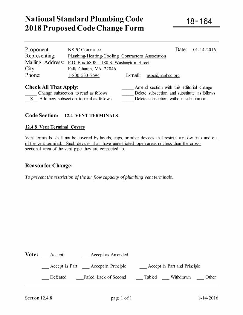
National Standard Plumbing Code 2018 Proposed Code Change Form
-
Section 12.4.8 page 1 of 1 1-14-2016
Proponent: NSPC Committee Date: 01-14-2016 Representing: Plumbing-Heating-Cooling Contractors Association Mailing Address: P.O. Box 6808 180 S. Washington Street City: Falls Church, VA 22046 Phone: 1-800-533-7694 E-mail: [email protected] Check All That Apply: _____ Amend section with this editorial change _____ Change subsection to read as follows _____ Delete subsection and substitute as follows __X__ Add new subsection to read as follows _____ Delete subsection without substitution Code Section: 12.4 VENT TERMINALS 12.4.8 Vent Terminal Covers Vent terminals shall not be covered by hoods, caps, or other devices that restrict air flow into and out of the vent terminal. Such devices shall have unrestricted open areas not less than the cross-sectional area of the vent pipe they are connected to. Reason for Change: To prevent the restriction of the air flow capacity of plumbing vent terminals. Vote: ___ Accept ___ Accept as Amended
___ Accept in Part ___ Accept in Principle ___ Accept in Part and Principle
___ Defeated ___Failed Lack of Second ___ Tabled ___ Withdrawn ___ Other _________________________________________________________________________________
18 164
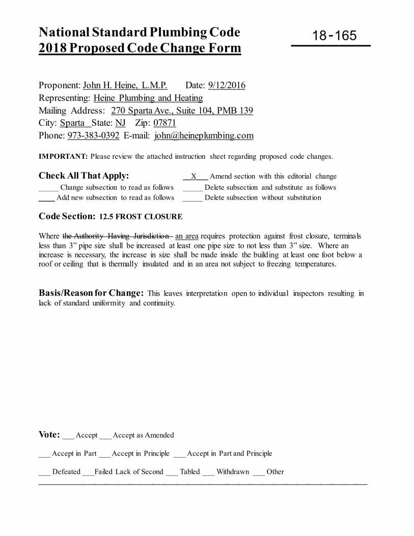
National Standard Plumbing Code 2018 Proposed Code Change Form
-
Proponent: John H. Heine, L.M.P. Date: 9/12/2016 Representing: Heine Plumbing and Heating Mailing Address: 270 Sparta Ave., Suite 104, PMB 139 City: Sparta State: NJ Zip: 07871 Phone: 973-383-0392 E-mail: [email protected] IMPORTANT: Please review the attached instruction sheet regarding proposed code changes. Check All That Apply: __X___ Amend section with this editorial change _____ Change subsection to read as follows _____ Delete subsection and substitute as follows ____ Add new subsection to read as follows _____ Delete subsection without substitution Code Section: 12.5 FROST CLOSURE Where the Authority Having Jurisdiction an area requires protection against frost closure, terminals less than 3” pipe size shall be increased at least one pipe size to not less than 3” size. Where an increase is necessary, the increase in size shall be made inside the building at least one foot below a roof or ceiling that is thermally insulated and in an area not subject to freezing temperatures. Basis/Reason for Change: This leaves interpretation open to individual inspectors resulting in lack of standard uniformity and continuity. Vote: ___ Accept ___ Accept as Amended ___ Accept in Part ___ Accept in Principle ___ Accept in Part and Principle ___ Defeated ___Failed Lack of Second ___ Tabled ___ Withdrawn ___ Other ____________________________________________________________________________________
18 165
National Standard Plumbing Code 2018 Proposed Code Change Form Deadline September 16, 2016
-
Proponent: _____________________________________ Date: __________
Representing: ___________________________________
Mailing Address: ________________________________
City: ______________________ State: ________ Zip: __________
Phone: __________________ E-mail ________________________________ IMPORTANT: Please review the attached instruction sheet regarding proposed code changes. Check All That Apply: _____ Amend section with this editorial change _____ Change subsection to read as follows _____ Delete subsection and substitute as follows _____ Add new subsection to read as follows _____ Delete subsection without substitution Please submit changes to only one Code Section per Proposed Code Change Form Code Section: ___________________________ Basis/Reason for Change: Vote: ___ Accept ___ Accept as Amended
___ Accept in Part ___ Accept in Principle ___ Accept in Part and Principle
___ Defeated ___Failed Lack of Second ___ Tabled ___ Withdrawn ___ Other ____________________________________________________________________________________
18 166
National Standard Plumbing Code 2018 Proposed Code Change Form
-
Section 12.7 page 1 of 1 1-12-2016
Proponent: NSPC Committee Date: 01-12-2016 Representing: Plumbing-Heating-Cooling Contractors Association Mailing Address: P.O. Box 6808 180 S. Washington Street City: Falls Church, VA 22046 Phone: 1-800-533-7694 E-mail: [email protected] Check All That Apply: _____ Amend section with this editorial change __X__ Change subsection to read as follows _____ Delete subsection and substitute as follows _____ Add new subsection to read as follows _____ Delete subsection without substitution Code Section: 12.7 COMMON VENTS FOR ADJACENT FIXTURES
a. Two fixtures set adjacent within the distance allowed between a trap and its vent (,) may be served with one common vent, provided that each fixture connects separately into an approved double fitting having drain inlet openings at the same level. (See Section 12.9.2 for inlet openings at different levels.) Refer to Section 12.9.2 for venting fixtures with drains at different elevations. b. Approved double fixture drain fittings shall have high branch inlet connections that are open to the level of the vent opening within the fitting. They shall include double sanitary tees, double fixture fittings (plastic), and sanitary crosses.
See Figure 12.7
Comment: Suitable double fittings for connecting adjacent fixtures such as lavatories, sinks, tubs, showers, urinals, or floor-outlet water closets to a stack are double sanitary tees, double fixture fittings (plastic), and sanitary crosses. These fittings have high branch openings into the stack that keep the top of the vent opening above the weir of the traps to prevent self-siphonage. Reason for Change: To clarify Section 12.7. It is for venting adjacent fixtures with a common vent. It does not apply to connections to drain stacks. Vote: ___ Accept ___ Accept as Amended
___ Accept in Part ___ Accept in Principle ___ Accept in Part and Principle
___ Defeated ___Failed Lack of Second ___ Tabled ___ Withdrawn ___ Other _________________________________________________________________________________
18 167
National Standard Plumbing Code 2018 Proposed Code Change Form
-
Section 12.8.1 page 1 of 1 1-21-2016
Proponent: NSPC Committee Date: 01-21-2016 Representing: Plumbing-Heating-Cooling Contractors Association Mailing Address: P.O. Box 6808 180 S. Washington Street City: Falls Church, VA 22046 Phone: 1-800-533-7694 E-mail: [email protected] Check All That Apply: _____ Amend section with this editorial change __X__ Change subsection to read as follows _____ Delete subsection and substitute as follows _____ Add new subsection to read as follows _____ Delete subsection without substitution Code Section: 12.8 FIXTURE VENTS
12.8.1 Venting Fixture Drains Fixture drains shall have a vent an atmospheric vent connection so located that the vent connects horizontal vent opening within the drain pipe fitting is above the top crown weir of the fixture trap and the developed length of the trap arm is within the limits set forth in Table 12.8.1. See Figure 12.8.1 EXCEPTIONS: (1) Water closets and similar siphonic fixtures, clinical sinks, and flushing-rim service sinks
with integral traps. See Section 12.8.4 (2) Combination waste and vent systems. See Section 12.17 (3) Vents may be connected below the top weir of the fixture trap if the following conditions
are met: a) The vertical section of the drain pipe shall be at least one pipe size larger than the trap
inlet size. b) The horizontal pipe connected to the trap outlet shall be at least two pipe diameters long. c) The developed length of the trap arm shall not exceed the values in Table 12.8.1. Delete Figure 12.8.1-B Reason for Change: To clarify the requirements for fixture vent connections. In Exception (1), siphon-jet urinals should not be an exception to Section 12.8.1. Exception (3) should be deleted. Refer to Figure 12.8.1-B. The increased size of the vertical drain "C" at the end of a trap arm does not prevent self-siphonage. In Note 4, no requirements are indicated for the vent on the "vented drain line" that "D" is connected to. Similar text was in the 1987 NSPC and the 1988 MD State Plumbing Code (COMAR 09.20). Figure 12.8.1-B is to be deleted. Vote: ___ Accept ___ Accept as Amended
___ Accept in Part ___ Accept in Principle ___ Accept in Part and Principle
___ Defeated ___Failed Lack of Second ___ Tabled ___ Withdrawn ___ Other _________________________________________________________________________________
18 168
National Standard Plumbing Code 2018 Proposed Code Change Form
-
Section 12.8.1 page 1 of 1 1-23-2016
Proponent: NSPC Committee Date: 01-23-2016
Check All That Apply: _____ Amend section with this editorial change __X__ Change subsection to read as follows _____ Delete subsection and substitute as follows _____ Add new subsection to read as follows _____ Delete subsection without substitution
Code Section: 12.8 FIXTURE VENTS
12.8.1 Venting Fixture Drains Fixture drains shall have a vent an atmospheric vent connection so located that the vent connects horizontal vent opening within the drain pipe fitting is above the top crown weir of the fixture trap and the developed length of the trap arm is within the limits set forth in Table 12.8.1. See Figure 12.8.1 EXCEPTIONS: (1) Water closets and similar siphonic fixtures, clinical sinks, and flushing-rim service sinks
with integral traps. See Section 12.8.4 (2) Combination waste and vent systems. (3) Vents may be connected below the top weir of the fixture trap if the following conditions
are met: a) The vertical section of the drain pipe shall be at least one pipe size larger than the trap
inlet size. b) The horizontal pipe connected to the trap outlet shall be at least two pipe diameters long. c) The developed length of the trap arm shall not exceed the values in Table 12.8.1. (2) Wet vented fixtures. See Section 12.10 (3) Battery vented fixtures. See Section 12.13 (4) Combination waste and vent fixtures. See Section 12.17 (5) Waste stack vented fixtures. See Section 12.19 Delete Figure 12.8.1-B
Reasons for Change: To clarify the requirements for fixture vent connections. In Exception (1), siphon-jet urinals should not be an exception to Section 12.8.1. Existing Exception (3) should be deleted. Refer to Figure 12.8.1-B. The increased size of the vertical drain "C" at the end of a trap arm does not prevent self-siphonage. In Note 4, no requirements are indicated for the vent on the "vented drain line" that "D" is connected to. Similar text was in the 1987 NSPC and the 1988 MD State Plumbing Code (COMAR 09.20). Figure 12.8.1-B is to be deleted. To add wet vented fixtures, battery-vented fixtures and waste stack vented fixtures to the Exceptions to Section 12.8.1.
Vote: ___ Accept ___ Accept as Amended
___ Accept in Part ___ Accept in Principle ___ Accept in Part and Principle
___ Defeated ___Failed Lack of Second ___ Tabled ___ Withdrawn ___ Other _________________________________________________________________________________
18 169
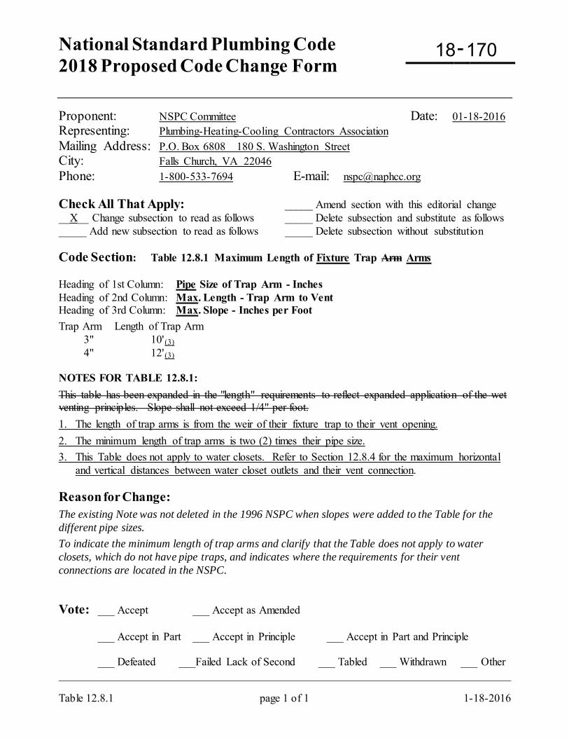
National Standard Plumbing Code 2018 Proposed Code Change Form
-
Table 12.8.1 page 1 of 1 1-18-2016
Proponent: NSPC Committee Date: 01-18-2016 Representing: Plumbing-Heating-Cooling Contractors Association Mailing Address: P.O. Box 6808 180 S. Washington Street City: Falls Church, VA 22046 Phone: 1-800-533-7694 E-mail: [email protected] Check All That Apply: _____ Amend section with this editorial change __X__ Change subsection to read as follows _____ Delete subsection and substitute as follows _____ Add new subsection to read as follows _____ Delete subsection without substitution Code Section: Table 12.8.1 Maximum Length of Fixture Trap Arm Arms Heading of 1st Column: Pipe Size of Trap Arm - Inches Heading of 2nd Column: Max. Length - Trap Arm to Vent Heading of 3rd Column: Max. Slope - Inches per Foot Trap Arm Length of Trap Arm 3" 10'(3) 4" 12'(3) NOTES FOR TABLE 12.8.1: This table has been expanded in the "length" requirements to reflect expanded application of the wet venting principles. Slope shall not exceed 1/4" per foot. 1. The length of trap arms is from the weir of their fixture trap to their vent opening. 2. The minimum length of trap arms is two (2) times their pipe size. 3. This Table does not apply to water closets. Refer to Section 12.8.4 for the maximum horizontal
and vertical distances between water closet outlets and their vent connection. Reason for Change: The existing Note was not deleted in the 1996 NSPC when slopes were added to the Table for the different pipe sizes. To indicate the minimum length of trap arms and clarify that the Table does not apply to water closets, which do not have pipe traps, and indicates where the requirements for their vent connections are located in the NSPC. Vote: ___ Accept ___ Accept as Amended
___ Accept in Part ___ Accept in Principle ___ Accept in Part and Principle
___ Defeated ___Failed Lack of Second ___ Tabled ___ Withdrawn ___ Other _________________________________________________________________________________
18 170
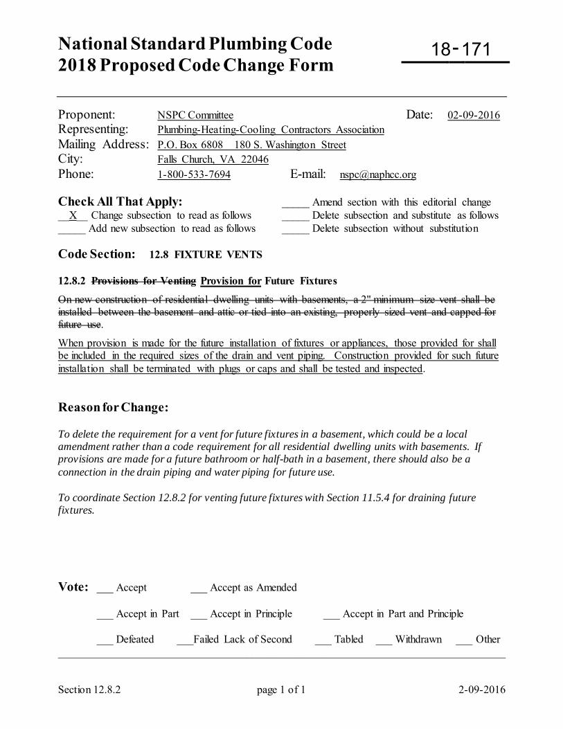
National Standard Plumbing Code 2018 Proposed Code Change Form
-
Section 12.8.2 page 1 of 1 2-09-2016
Proponent: NSPC Committee Date: 02-09-2016 Representing: Plumbing-Heating-Cooling Contractors Association Mailing Address: P.O. Box 6808 180 S. Washington Street City: Falls Church, VA 22046 Phone: 1-800-533-7694 E-mail: [email protected] Check All That Apply: _____ Amend section with this editorial change __X__ Change subsection to read as follows _____ Delete subsection and substitute as follows _____ Add new subsection to read as follows _____ Delete subsection without substitution Code Section: 12.8 FIXTURE VENTS 12.8.2 Provisions for Venting Provision for Future Fixtures
On new construction of residential dwelling units with basements, a 2" minimum size vent shall be installed between the basement and attic or tied into an existing, properly sized vent and capped for future use.
When provision is made for the future installation of fixtures or appliances, those provided for shall be included in the required sizes of the drain and vent piping. Construction provided for such future installation shall be terminated with plugs or caps and shall be tested and inspected. Reason for Change: To delete the requirement for a vent for future fixtures in a basement, which could be a local amendment rather than a code requirement for all residential dwelling units with basements. If provisions are made for a future bathroom or half-bath in a basement, there should also be a connection in the drain piping and water piping for future use. To coordinate Section 12.8.2 for venting future fixtures with Section 11.5.4 for draining future fixtures. Vote: ___ Accept ___ Accept as Amended
___ Accept in Part ___ Accept in Principle ___ Accept in Part and Principle
___ Defeated ___Failed Lack of Second ___ Tabled ___ Withdrawn ___ Other _________________________________________________________________________________
18 171
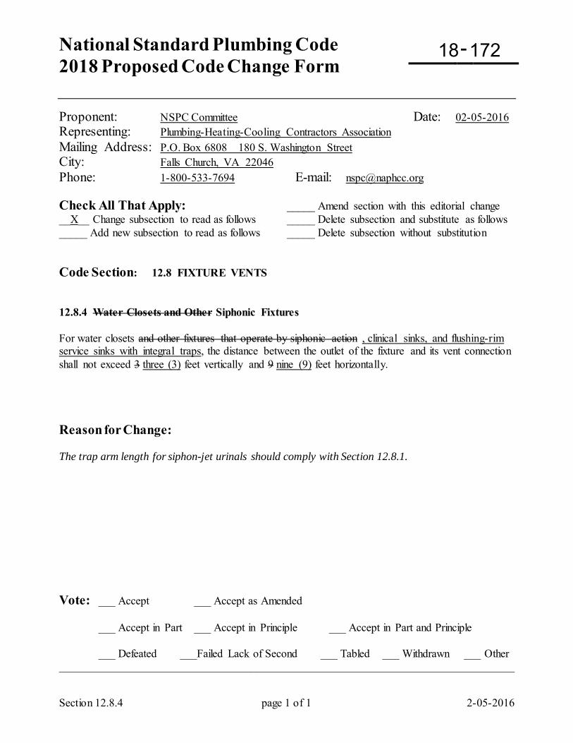
National Standard Plumbing Code 2018 Proposed Code Change Form
-
Section 12.8.4 page 1 of 1 2-05-2016
Proponent: NSPC Committee Date: 02-05-2016 Representing: Plumbing-Heating-Cooling Contractors Association Mailing Address: P.O. Box 6808 180 S. Washington Street City: Falls Church, VA 22046 Phone: 1-800-533-7694 E-mail: [email protected] Check All That Apply: _____ Amend section with this editorial change __X__ Change subsection to read as follows _____ Delete subsection and substitute as follows _____ Add new subsection to read as follows _____ Delete subsection without substitution Code Section: 12.8 FIXTURE VENTS 12.8.4 Water Closets and Other Siphonic Fixtures For water closets and other fixtures that operate by siphonic action , clinical sinks, and flushing-rim service sinks with integral traps, the distance between the outlet of the fixture and its vent connection shall not exceed 3 three (3) feet vertically and 9 nine (9) feet horizontally. Reason for Change: The trap arm length for siphon-jet urinals should comply with Section 12.8.1. Vote: ___ Accept ___ Accept as Amended
___ Accept in Part ___ Accept in Principle ___ Accept in Part and Principle
___ Defeated ___Failed Lack of Second ___ Tabled ___ Withdrawn ___ Other _________________________________________________________________________________
18 172
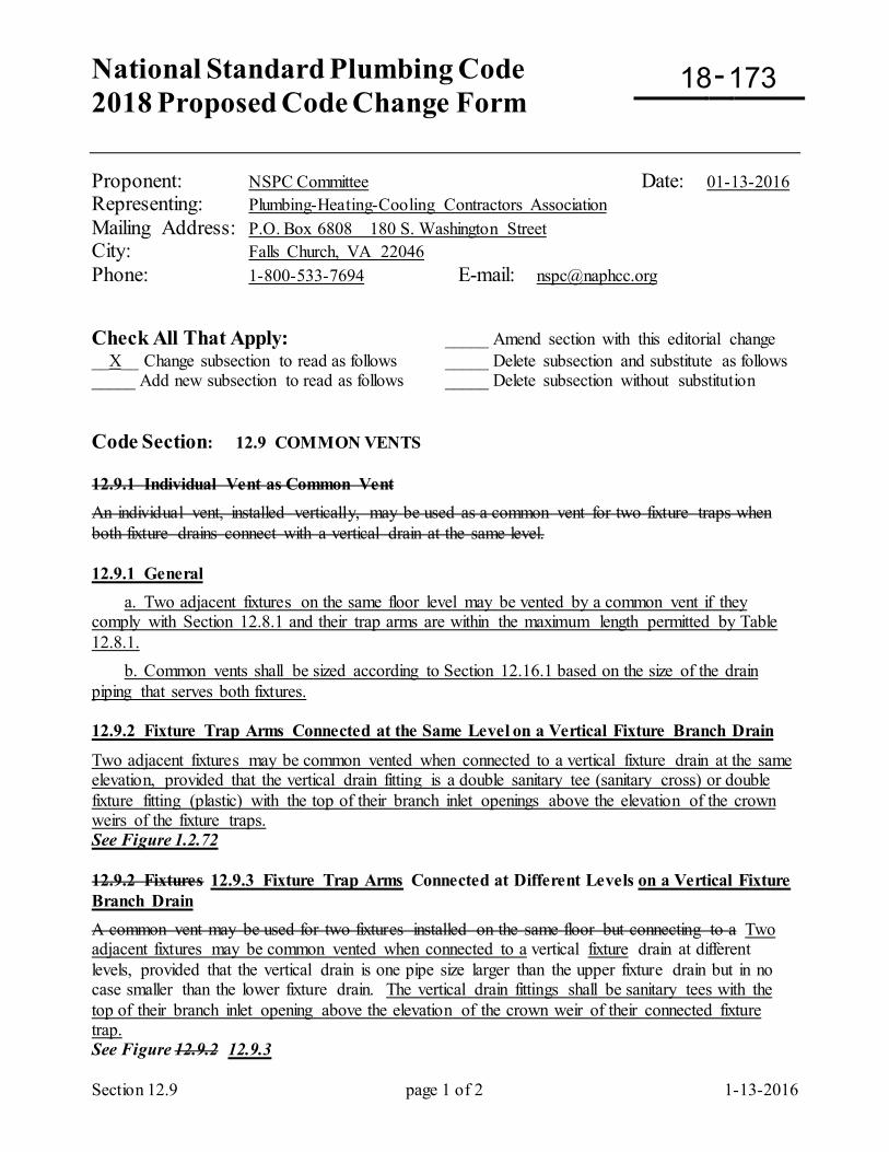
National Standard Plumbing Code 2018 Proposed Code Change Form
-
Section 12.9 page 1 of 2 1-13-2016
Proponent: NSPC Committee Date: 01-13-2016 Representing: Plumbing-Heating-Cooling Contractors Association Mailing Address: P.O. Box 6808 180 S. Washington Street City: Falls Church, VA 22046 Phone: 1-800-533-7694 E-mail: [email protected] Check All That Apply: _____ Amend section with this editorial change __X__ Change subsection to read as follows _____ Delete subsection and substitute as follows _____ Add new subsection to read as follows _____ Delete subsection without substitution Code Section: 12.9 COMMON VENTS 12.9.1 Individual Vent as Common Vent An individual vent, installed vertically, may be used as a common vent for two fixture traps when both fixture drains connect with a vertical drain at the same level. 12.9.1 General a. Two adjacent fixtures on the same floor level may be vented by a common vent if they comply with Section 12.8.1 and their trap arms are within the maximum length permitted by Table 12.8.1. b. Common vents shall be sized according to Section 12.16.1 based on the size of the drain piping that serves both fixtures. 12.9.2 Fixture Trap Arms Connected at the Same Level on a Vertical Fixture Branch Drain
Two adjacent fixtures may be common vented when connected to a vertical fixture drain at the same elevation, provided that the vertical drain fitting is a double sanitary tee (sanitary cross) or double fixture fitting (plastic) with the top of their branch inlet openings above the elevation of the crown weirs of the fixture traps. See Figure 1.2.72 12.9.2 Fixtures 12.9.3 Fixture Trap Arms Connected at Different Levels on a Vertical Fixture Branch Drain A common vent may be used for two fixtures installed on the same floor but connecting to a Two adjacent fixtures may be common vented when connected to a vertical fixture drain at different levels, provided that the vertical drain is one pipe size larger than the upper fixture drain but in no case smaller than the lower fixture drain. The vertical drain fittings shall be sanitary tees with the top of their branch inlet opening above the elevation of the crown weir of their connected fixture trap. See Figure 12.9.2 12.9.3
18 173
Section 12.9 page 2 of 2 1-13-2016
12.9.4 Fixture Trap Arms Connected to a Horizontal Fixture Branch Drain Two adjacent fixtures may be common vented when connected to a horizontal fixture branch drain, provided that the horizontal drain fitting is a 90-deg double elbow or double quarter bend and the common vent is connected directly downstream from the double fitting within the maximum permitted length from the fixture traps. Reducers, if required for the fixture drain connections to the double fitting, shall be eccentric and installed flat-on-top for the vent air. The top of the inlet openings on the double fitting shall be above the elevation of the crown weirs of the fixture traps. See Figure 12.9.4 Reason for Change: To clarify the requirements for common venting adjacent fixtures. Vote: ___ Accept ___ Accept as Amended
___ Accept in Part ___ Accept in Principle ___ Accept in Part and Principle
___ Defeated ___Failed Lack of Second ___ Tabled ___ Withdrawn ___ Other _________________________________________________________________________________
National Standard Plumbing Code 2018 Proposed Code Change Form
-
Section 12.10 page 1 of 3 2-13-2016
Proponent: NSPC Committee Date: 02-13-2016 Check All That Apply: _____ Amend section with this editorial change __X__ Change subsection to read as follows _____ Delete subsection and substitute as follows _____ Add new subsection to read as follows _____ Delete subsection without substitution Code Section: 12.10 WET VENTING 12.10.1 Single Bathroom Groups
a. An individually vented lavatory in a single bathroom group shall be permitted to serve as a wet vent for the water closet, the bathtub or shower stall, or the water closet and bathtub/shower if all of the following conditions are met.
1. The wet vent is 1-1/2" minimum pipe size if the water closet bend is 3" size or it shall be 2" minimum pipe size if the water closet bend is 4" pipe size. 2. A horizontal branch drain serving both the lavatory and the bathtub or shower stall is 2" minimum pipe size. 3. The length of the trap arm for the bathtub or shower stall is within the limits of Table 12.8.1. If not, the bathtub or shower stall shall be individually vented. 4. The distance from the outlet of the water closet to the connection of the wet vent is within the limits established by Section 12.8.4. Otherwise, the water closet shall be individually vented. 5. A horizontal branch serving the lavatory and the bathtub or shower stall shall connect to the stack at the same level as the water closet, or it may connect to the water closet bend, or the lavatory and bathtub or shower stall may individually connect to the water closet bend. 6. When the bathroom group is the topmost load on a stack, a horizontal branch serving the lavatory and the bathtub or shower stall may connect to the stack below the water closet bend, or the lavatory and the bathtub or shower stall may individually connect to the stack below the water closet bend.
See Figures 12.10.1-A through -C 12.10.2 Double Bathtubs and Lavatories Two lavatories and two bathtubs or showers back-to-back may be installed on the same horizontal branch with a common vent for the lavatories and with no back vent for the bathtubs or shower stalls provided the wet vent is 2" in size and the lengths of the tub/shower drains conform to Table 12.8.1. See Figure 12.10.2 12.10.3 Multi-Story Bathroom Groups a. On the lower floors of a stack, the waste pipe from one or two lavatories may be used as a wet vent for one or two bathtubs or showers as provided in Section 12.10.2. b. Each water closet below the top floor shall be individually back vented. EXCEPTION: The water closets in bathroom groups shall not be required to be back vented if the following conditions are met: (1) The 2" waste serving the tubs/showers and lavatories connect directly into the water closet bend with a 45° wye tap in the direction of flow or, (2) A special stack fitting is used that consists of a 3" or 4" closet opening and two side inlets each 2" in size and the inverts of which are above the center, and below the top of the water closet opening;
18 174
Section 12.10 page 2 of 3 2-13-2016
and one of the 2" inlets is connected to the tub/shower drains, and the other is connected to the waste pipe from a maximum of two lavatories that are vented to a vent stack or stack vent; or, (3) In lieu of the special stack fitting of Section 12.10.3b(2) above, 4" closet bends with two 2" wye taps may be used. See Figures 12.10.3-A through -E
12.10.4 Bathtubs and Water Closets a. An individually-vented bathtub in a single bathroom group shall be permitted to serve as a wet vent for the water closet if all of the following conditions are met:
1. The wet vent is 2" minimum size. 2. The distance from the outlet of the water closet to the connection of the wet vent is within the limits established by Section 12.8.4. Otherwise, the water closet shall be individually vented.
See Figure 12.10.4
12.10.5 Reserved 12.10.6 Floor Drains and Floor Sinks a. A lavatory or sink shall be permitted to serve as a wet vent for a floor drain or floor sink if all of the following conditions are met:
1. The wet vent shall be not less than 1-1/2" size for a 1 DFU lavatory or 2" for a 2 DFU sink. 2. The wet vent shall be larger than 1/2 the size of the drain for the floor drain or floor sink. 3. The distance from the outlet of the floor drain or floor sink to the connection of the wet vent shall be within the limits established by Table 12.8.1.
12.10.1 General
a. Wet vent piping shall be sized to drain the fixtures upstream and vent the fixtures downstream.
b. Each section of wet vent piping shall be: (1) not less than one pipe size larger than the minimum required drain pipe for the upstream fixtures that they drain, and (2) not less than one pipe size larger than the minimum required vent pipe for the downstream fixtures being wet vented by that section, whichever is larger. c. Dry vents shall be not less than one-half the minimum required pipe size for the drain piping that serves all of the fixtures being wet vented and dry vented.
Comment: Wet vents must be not less than one pipe-size oversize for draining the upstream fixtures and not less than one pipe-size oversize for venting the downstream fixtures.
12.10.2 Individual Water Closets a. An individual water closet may be wet vented by an adjacent lavatory.
b. The wet vent from the lavatory drain shall be not less than one pipe size larger than one-half the size of the drain from the water closet. c. The maximum length of the water closet trap arm to its wet vent connection shall comply with Section 12.8.4, horizontally and vertically. d. The dry vent from the wet vent at the lavatory connection shall be not less than one-half the size of the drain from the two fixtures. See Figures 12.10.2 and 1.2.77
Section 12.10 page 3 of 3 2-13-2016
12.10.3 Bathroom Groups
a. Water closets and bathtubs or shower stalls in bathroom groups may be wet vented by the lavatories. b. The dry vent pipe from the lavatories shall be not less than one-half the size of the drain pipe for the group. c. The size of wet vent piping shall comply with the following:
(1) be not less than one pipe-size larger than the required drain pipe size for its upstream fixtures, and
(2) be not less than one pipe size larger than one-half the size of the largest connected drain piping being wet vented downstream.
d. The connection of fixture drains to horizontal wet vents shall be horizontal. Except for water closets, the upper portion of the wet vent opening shall not be below the weir of the fixture trap. e. The bathtubs or shower stalls may be connected to their water closet drain upstream from its wet vent connection.
f. The maximum length of the fixture trap arms for lavatories, bathtubs, and shower stalls shall comply with Section 12.8.1.
g. The maximum length of the water closet trap arms to their wet vent connection shall comply with Section 12.8.4, horizontally and vertically. h. Where fixtures are wet vented vertically, water closets shall connect to the wet vent at the same lowest elevation. Bathtubs or shower stalls shall connect to the wet vent at the same elevation as the water closets or higher.
Refer to Figures 12.10.3-A through F 12.10.4 Floor Drains and Floor Sinks
a. A floor drain or floor sink may be wet vented by an adjacent lavatory or sink. b. The size of the drain for the fixtures shall be based on the total drainage fixture units (DFU) connected c. The size of the dry vent for the fixtures shall be not less than one-half the pipe size of the drain for both fixtures.
d. The size of the wet vent between the lavatory or sinks and the floor drain or floor sink shall be: (1) not less than one pipe-size larger than the required drain pipe size for the lavatory or sink, and (2) not less than one pipe-size larger than one-half of the drain pipe for both fixtures, whichever is larger.
e. The maximum lengths of the fixture trap arms shall comply with Section 12.8.1.
Reason for Change: To clarify the requirements for wet venting fixtures. Vote: ___ Accept ___ Accept as Amended
___ Accept in Part ___ Accept in Principle ___ Accept in Part and Principle
___ Defeated ___Failed Lack of Second ___ Tabled ___ Withdrawn ___ Other _________________________________________________________________________________
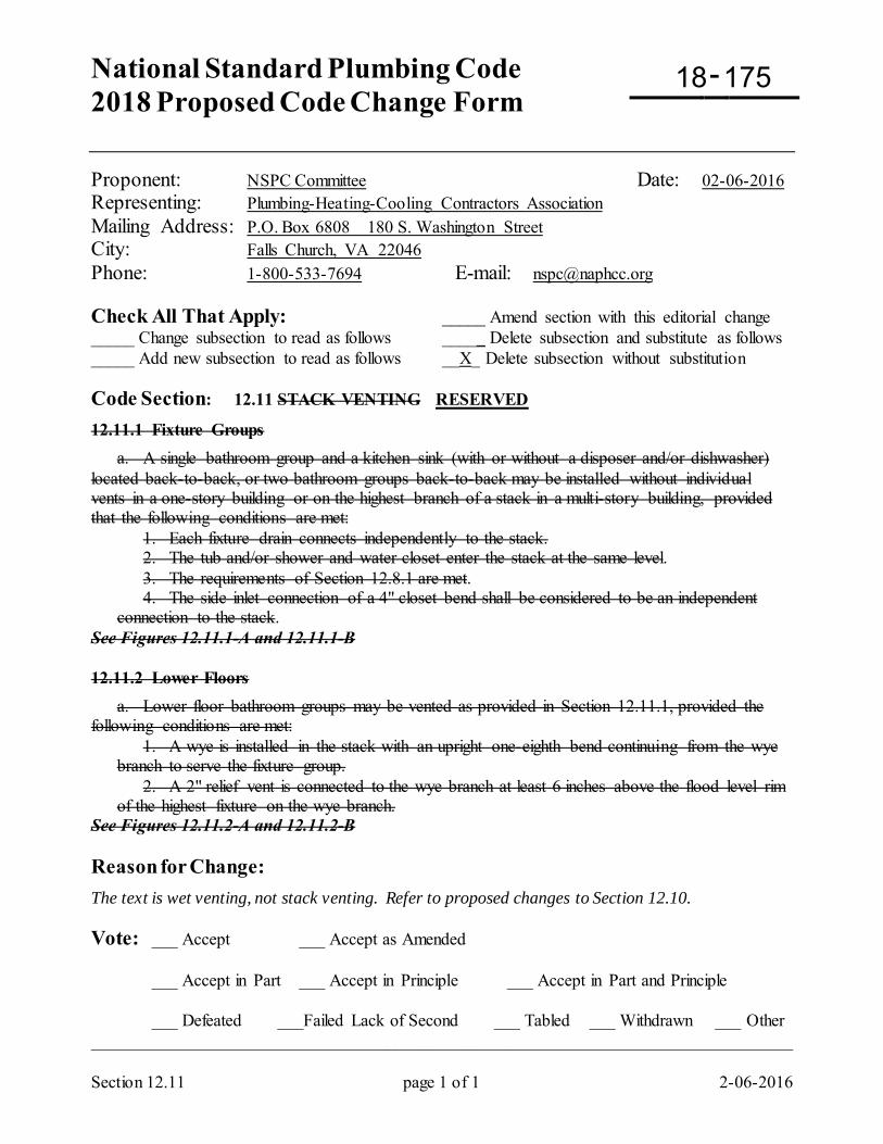
National Standard Plumbing Code 2018 Proposed Code Change Form
-
Section 12.11 page 1 of 1 2-06-2016
Proponent: NSPC Committee Date: 02-06-2016 Representing: Plumbing-Heating-Cooling Contractors Association Mailing Address: P.O. Box 6808 180 S. Washington Street City: Falls Church, VA 22046 Phone: 1-800-533-7694 E-mail: [email protected] Check All That Apply: _____ Amend section with this editorial change _____ Change subsection to read as follows _____ Delete subsection and substitute as follows _____ Add new subsection to read as follows __X_ Delete subsection without substitution Code Section: 12.11 STACK VENTING RESERVED
12.11.1 Fixture Groups a. A single bathroom group and a kitchen sink (with or without a disposer and/or dishwasher) located back-to-back, or two bathroom groups back-to-back may be installed without individual vents in a one-story building or on the highest branch of a stack in a multi-story building, provided that the following conditions are met:
1. Each fixture drain connects independently to the stack. 2. The tub and/or shower and water closet enter the stack at the same level. 3. The requirements of Section 12.8.1 are met. 4. The side inlet connection of a 4" closet bend shall be considered to be an independent connection to the stack.
See Figures 12.11.1-A and 12.11.1-B 12.11.2 Lower Floors a. Lower floor bathroom groups may be vented as provided in Section 12.11.1, provided the following conditions are met:
1. A wye is installed in the stack with an upright one-eighth bend continuing from the wye branch to serve the fixture group. 2. A 2" relief vent is connected to the wye branch at least 6 inches above the flood level rim of the highest fixture on the wye branch.
See Figures 12.11.2-A and 12.11.2-B Reason for Change: The text is wet venting, not stack venting. Refer to proposed changes to Section 12.10. Vote: ___ Accept ___ Accept as Amended
___ Accept in Part ___ Accept in Principle ___ Accept in Part and Principle
___ Defeated ___Failed Lack of Second ___ Tabled ___ Withdrawn ___ Other _________________________________________________________________________________
18 175
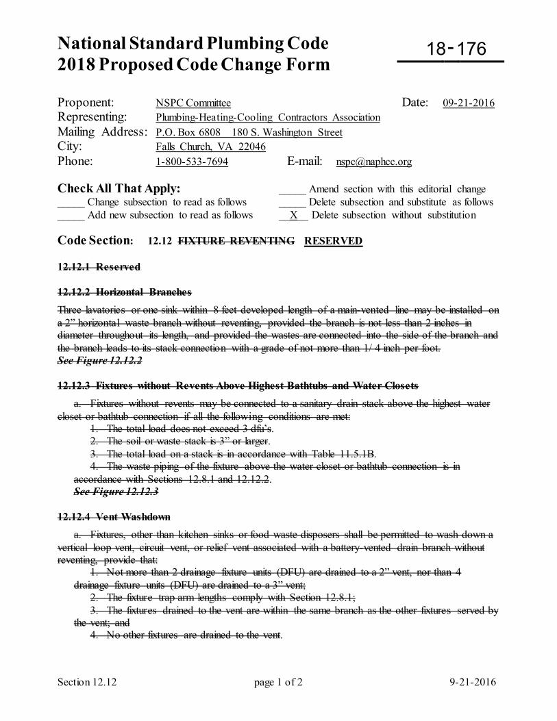
National Standard Plumbing Code 2018 Proposed Code Change Form
-
Section 12.12 page 1 of 2 9-21-2016
Proponent: NSPC Committee Date: 09-21-2016 Representing: Plumbing-Heating-Cooling Contractors Association Mailing Address: P.O. Box 6808 180 S. Washington Street City: Falls Church, VA 22046 Phone: 1-800-533-7694 E-mail: [email protected] Check All That Apply: _____ Amend section with this editorial change _____ Change subsection to read as follows _____ Delete subsection and substitute as follows _____ Add new subsection to read as follows __X__ Delete subsection without substitution Code Section: 12.12 FIXTURE REVENTING RESERVED 12.12.1 Reserved 12.12.2 Horizontal Branches Three lavatories or one sink within 8 feet developed length of a main-vented line may be installed on a 2” horizontal waste branch without reventing, provided the branch is not less than 2 inches in diameter throughout its length, and provided the wastes are connected into the side of the branch and the branch leads to its stack connection with a grade of not more than 1/ 4 inch per foot. See Figure 12.12.2 12.12.3 Fixtures without Revents Above Highest Bathtubs and Water Closets a. Fixtures without revents may be connected to a sanitary drain stack above the highest water closet or bathtub connection if all the following conditions are met: 1. The total load does not exceed 3 dfu’s. 2. The soil or waste stack is 3” or larger. 3. The total load on a stack is in accordance with Table 11.5.1B. 4. The waste piping of the fixture above the water closet or bathtub connection is in
accordance with Sections 12.8.1 and 12.12.2. See Figure 12.12.3 12.12.4 Vent Washdown a. Fixtures, other than kitchen sinks or food waste disposers shall be permitted to wash down a vertical loop vent, circuit vent, or relief vent associated with a battery-vented drain branch without reventing, provide that: 1. Not more than 2 drainage fixture units (DFU) are drained to a 2” vent, nor than 4
drainage fixture units (DFU) are drained to a 3” vent; 2. The fixture trap arm lengths comply with Section 12.8.1; 3. The fixtures drained to the vent are within the same branch as the other fixtures served by
the vent; and 4. No other fixtures are drained to the vent.
18 176
Section 12.12 page 2 of 2 9-21-2016
Delete Figure 12.12.2 and Figure 12.12.3 Delete the definitions of Revent and Reventing in Chapter 1 Reason for Change: Reventing is providing individual vents on fixtures that are vented by other means that are permitted by the Code. Other approved means are wet venting, battery venting, waste stack venting, and combination waste and venting. There are no code requirements that fixtures be revented. Vote: ___ Accept ___ Accept as Amended
___ Accept in Part ___ Accept in Principle ___ Accept in Part and Principle
___ Defeated ___Failed Lack of Second ___ Tabled ___ Withdrawn ___ Other _________________________________________________________________________________
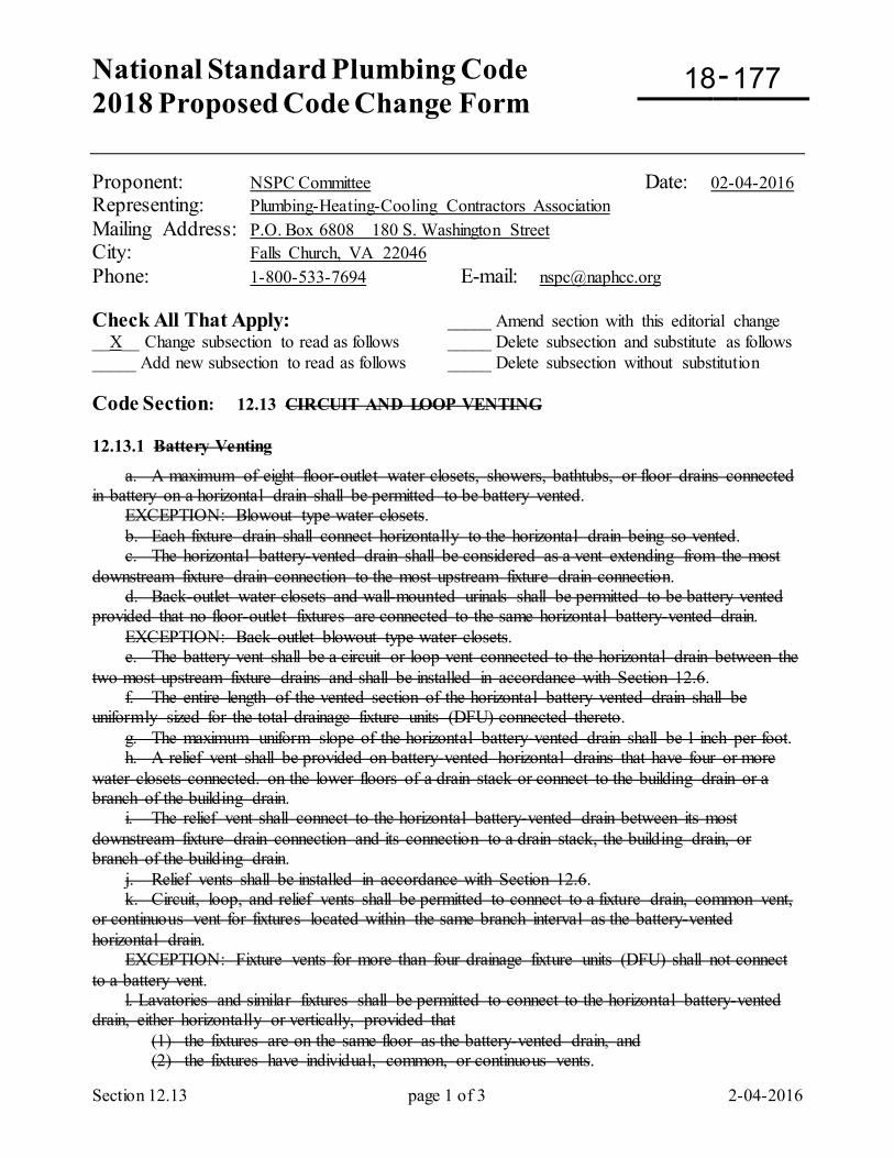
National Standard Plumbing Code 2018 Proposed Code Change Form
-
Section 12.13 page 1 of 3 2-04-2016
Proponent: NSPC Committee Date: 02-04-2016 Representing: Plumbing-Heating-Cooling Contractors Association Mailing Address: P.O. Box 6808 180 S. Washington Street City: Falls Church, VA 22046 Phone: 1-800-533-7694 E-mail: [email protected] Check All That Apply: _____ Amend section with this editorial change __X__ Change subsection to read as follows _____ Delete subsection and substitute as follows _____ Add new subsection to read as follows _____ Delete subsection without substitution Code Section: 12.13 CIRCUIT AND LOOP VENTING 12.13.1 Battery Venting
a. A maximum of eight floor-outlet water closets, showers, bathtubs, or floor drains connected in battery on a horizontal drain shall be permitted to be battery vented. EXCEPTION: Blowout type water closets. b. Each fixture drain shall connect horizontally to the horizontal drain being so vented. c. The horizontal battery-vented drain shall be considered as a vent extending from the most downstream fixture drain connection to the most upstream fixture drain connection. d. Back-outlet water closets and wall-mounted urinals shall be permitted to be battery vented provided that no floor-outlet fixtures are connected to the same horizontal battery-vented drain. EXCEPTION: Back-outlet blowout type water closets. e. The battery vent shall be a circuit or loop vent connected to the horizontal drain between the two most upstream fixture drains and shall be installed in accordance with Section 12.6. f. The entire length of the vented section of the horizontal battery-vented drain shall be uniformly sized for the total drainage fixture units (DFU) connected thereto. g. The maximum uniform slope of the horizontal battery-vented drain shall be 1 inch per foot. h. A relief vent shall be provided on battery-vented horizontal drains that have four or more water closets connected. on the lower floors of a drain stack or connect to the building drain or a branch of the building drain. i. The relief vent shall connect to the horizontal battery-vented drain between its most downstream fixture drain connection and its connection to a drain stack, the building drain, or branch of the building drain. j. Relief vents shall be installed in accordance with Section 12.6. k. Circuit, loop, and relief vents shall be permitted to connect to a fixture drain, common vent, or continuous vent for fixtures located within the same branch interval as the battery-vented horizontal drain. EXCEPTION: Fixture vents for more than four drainage fixture units (DFU) shall not connect to a battery vent. l. Lavatories and similar fixtures shall be permitted to connect to the horizontal battery-vented drain, either horizontally or vertically, provided that (1) the fixtures are on the same floor as the battery-vented drain, and (2) the fixtures have individual, common, or continuous vents.
18 177
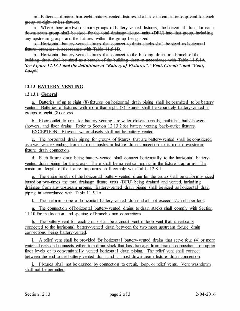
Section 12.13 page 2 of 3 2-04-2016
m. Batteries of more than eight battery-vented fixtures shall have a circuit or loop vent for each group of eight or less fixtures. n. Where there are two or more groups of battery-vented fixtures, the horizontal drain for each downstream group shall be sized for the total drainage fixture units (DFU) into that group, including any upstream groups and the fixtures within the group being sized. o. Horizontal battery-vented drains that connect to drain stacks shall be sized as horizontal fixture branches in accordance with Table 11.5.1B. p. Horizontal battery-vented drains that connect to the building drain or a branch of the building drain shall be sized as a branch of the building drain in accordance with Table 11.5.1A. See Figure 12.13.1 and the definitions of "Battery of Fixtures", "Vent, Circuit", and "Vent, Loop".
12.13 BATTERY VENTING 12.13.1 General
a. Batteries of up to eight (8) fixtures on horizontal drain piping shall be permitted to be battery vented. Batteries of fixtures with more than eight (8) fixtures shall be separately battery-vented in groups of eight (8) or less.
b. Floor-outlet fixtures for battery venting are water closets, urinals, bathtubs, bath/showers, showers, and floor drains. Refer to Section 12.13.2 for battery venting back-outlet fixtures. EXCEPTION: Blowout water closets shall not be battery-vented. c. The horizontal drain piping for groups of fixtures that are battery-vented shall be considered as a wet vent extending from its most upstream fixture drain connection to its most downstream fixture drain connection. d. Each fixture drain being battery-vented shall connect horizontally to the horizontal battery-vented drain piping for the group. There shall be no vertical piping in the fixture trap arms. The maximum length of the fixture trap arms shall comply with Table 12.8.1. e. The entire length of the horizontal battery-vented drain for the group shall be uniformly sized based on two-times the total drainage fixture units (DFU) being drained and vented, including drainage from any upstream groups. Battery-vented drain piping shall be sized as horizontal drain piping in accordance with Table 11.5.1A. f. The uniform slope of horizontal battery-vented drains shall not exceed 1/2 inch per foot. g. The connection of horizontal battery-vented drains to drain stacks shall comply with Section 11.10 for the location and spacing of branch drain connections. h. The battery vent for each group shall be a circuit vent or loop vent that is vertically connected to the horizontal battery-vented drain between the two most upstream fixture drain connections being battery-vented. i. A relief vent shall be provided for horizontal battery-vented drains that serve four (4) or more water closets and connects either to a drain stack that has drainage from branch connections on upper floor levels or to conventionally vented horizontal drain piping. The relief vent shall connect between the end to the battery-vented drain and its most downstream fixture drain connection. j. Fixtures shall not be drained by connection to circuit, loop, or relief vents. Vent washdown shall not be permitted.
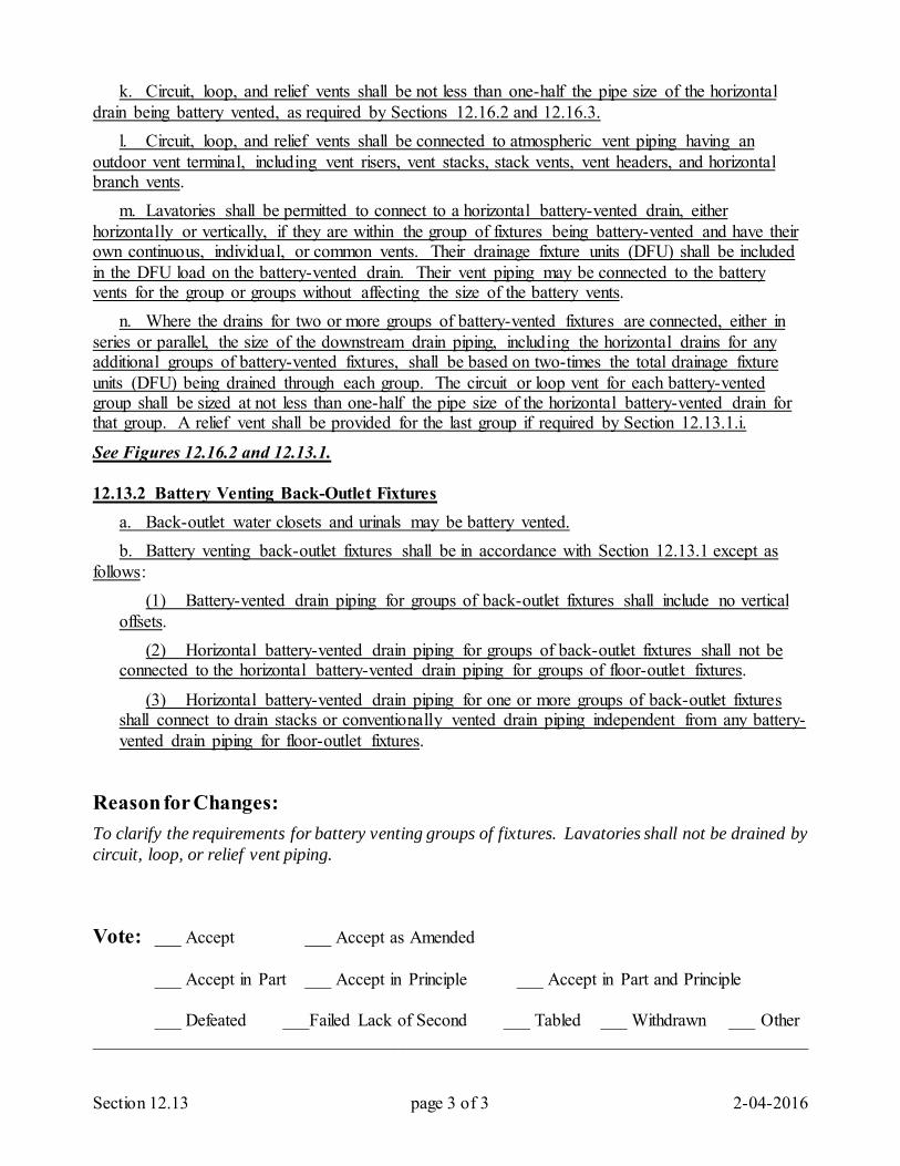
Section 12.13 page 3 of 3 2-04-2016
k. Circuit, loop, and relief vents shall be not less than one-half the pipe size of the horizontal drain being battery vented, as required by Sections 12.16.2 and 12.16.3. l. Circuit, loop, and relief vents shall be connected to atmospheric vent piping having an outdoor vent terminal, including vent risers, vent stacks, stack vents, vent headers, and horizontal branch vents. m. Lavatories shall be permitted to connect to a horizontal battery-vented drain, either horizontally or vertically, if they are within the group of fixtures being battery-vented and have their own continuous, individual, or common vents. Their drainage fixture units (DFU) shall be included in the DFU load on the battery-vented drain. Their vent piping may be connected to the battery vents for the group or groups without affecting the size of the battery vents. n. Where the drains for two or more groups of battery-vented fixtures are connected, either in series or parallel, the size of the downstream drain piping, including the horizontal drains for any additional groups of battery-vented fixtures, shall be based on two-times the total drainage fixture units (DFU) being drained through each group. The circuit or loop vent for each battery-vented group shall be sized at not less than one-half the pipe size of the horizontal battery-vented drain for that group. A relief vent shall be provided for the last group if required by Section 12.13.1.i.
See Figures 12.16.2 and 12.13.1. 12.13.2 Battery Venting Back-Outlet Fixtures a. Back-outlet water closets and urinals may be battery vented. b. Battery venting back-outlet fixtures shall be in accordance with Section 12.13.1 except as follows: (1) Battery-vented drain piping for groups of back-outlet fixtures shall include no vertical
offsets. (2) Horizontal battery-vented drain piping for groups of back-outlet fixtures shall not be
connected to the horizontal battery-vented drain piping for groups of floor-outlet fixtures.
(3) Horizontal battery-vented drain piping for one or more groups of back-outlet fixtures shall connect to drain stacks or conventionally vented drain piping independent from any battery-vented drain piping for floor-outlet fixtures.
Reason for Changes: To clarify the requirements for battery venting groups of fixtures. Lavatories shall not be drained by circuit, loop, or relief vent piping. Vote: ___ Accept ___ Accept as Amended
___ Accept in Part ___ Accept in Principle ___ Accept in Part and Principle
___ Defeated ___Failed Lack of Second ___ Tabled ___ Withdrawn ___ Other _________________________________________________________________________________
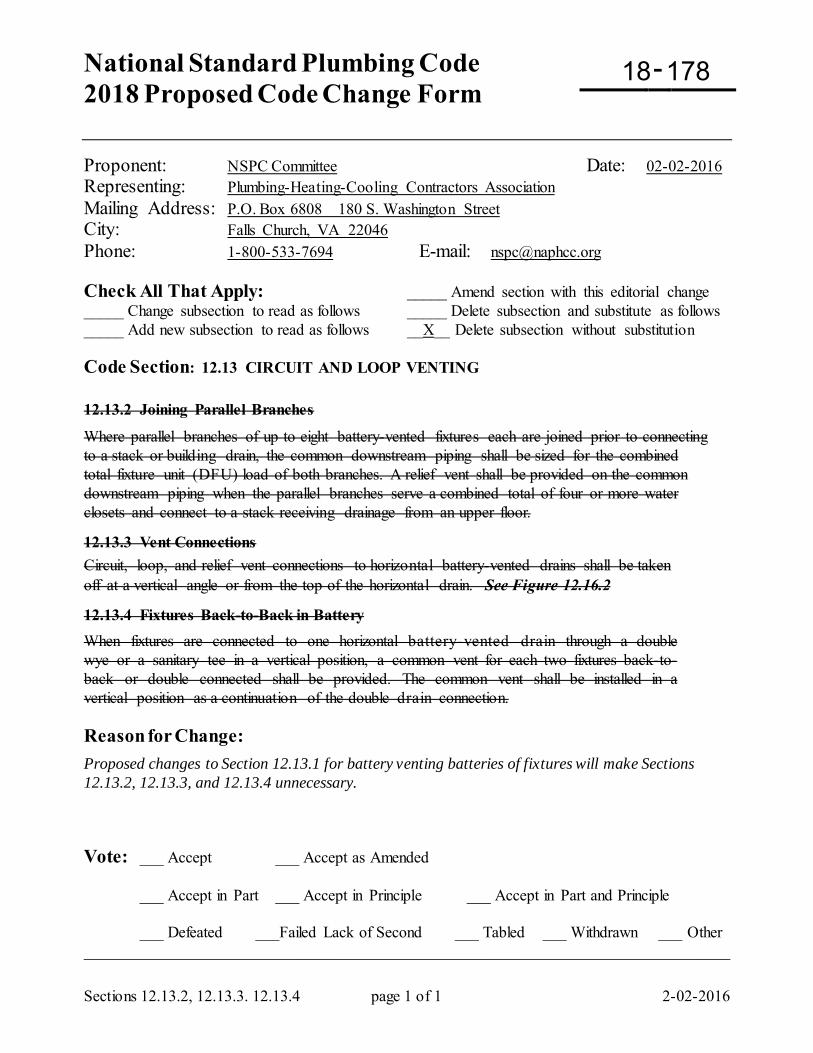
National Standard Plumbing Code 2018 Proposed Code Change Form
-
Sections 12.13.2, 12.13.3. 12.13.4 page 1 of 1 2-02-2016
Proponent: NSPC Committee Date: 02-02-2016 Representing: Plumbing-Heating-Cooling Contractors Association Mailing Address: P.O. Box 6808 180 S. Washington Street City: Falls Church, VA 22046 Phone: 1-800-533-7694 E-mail: [email protected] Check All That Apply: _____ Amend section with this editorial change _____ Change subsection to read as follows _____ Delete subsection and substitute as follows _____ Add new subsection to read as follows __X__ Delete subsection without substitution Code Section: 12.13 CIRCUIT AND LOOP VENTING 12.13.2 Joining Parallel Branches Where parallel branches of up to eight battery-vented fixtures each are joined prior to connecting to a stack or building drain, the common downstream piping shall be sized for the combined total fixture unit (DFU) load of both branches. A relief vent shall be provided on the common downstream piping when the parallel branches serve a combined total of four or more water closets and connect to a stack receiving drainage from an upper floor. 12.13.3 Vent Connections Circuit, loop, and relief vent connections to horizontal battery-vented drains shall be taken off at a vertical angle or from the top of the horizontal drain. See Figure 12.16.2 12.13.4 Fixtures Back-to-Back in Battery When fixtures are connected to one horizontal battery-vented drain through a double wye or a sanitary tee in a vertical position, a common vent for each two fixtures back-to-back or double connected shall be provided. The common vent shall be installed in a vertical position as a continuation of the double drain connection. Reason for Change: Proposed changes to Section 12.13.1 for battery venting batteries of fixtures will make Sections 12.13.2, 12.13.3, and 12.13.4 unnecessary. Vote: ___ Accept ___ Accept as Amended
___ Accept in Part ___ Accept in Principle ___ Accept in Part and Principle
___ Defeated ___Failed Lack of Second ___ Tabled ___ Withdrawn ___ Other _________________________________________________________________________________
18 178
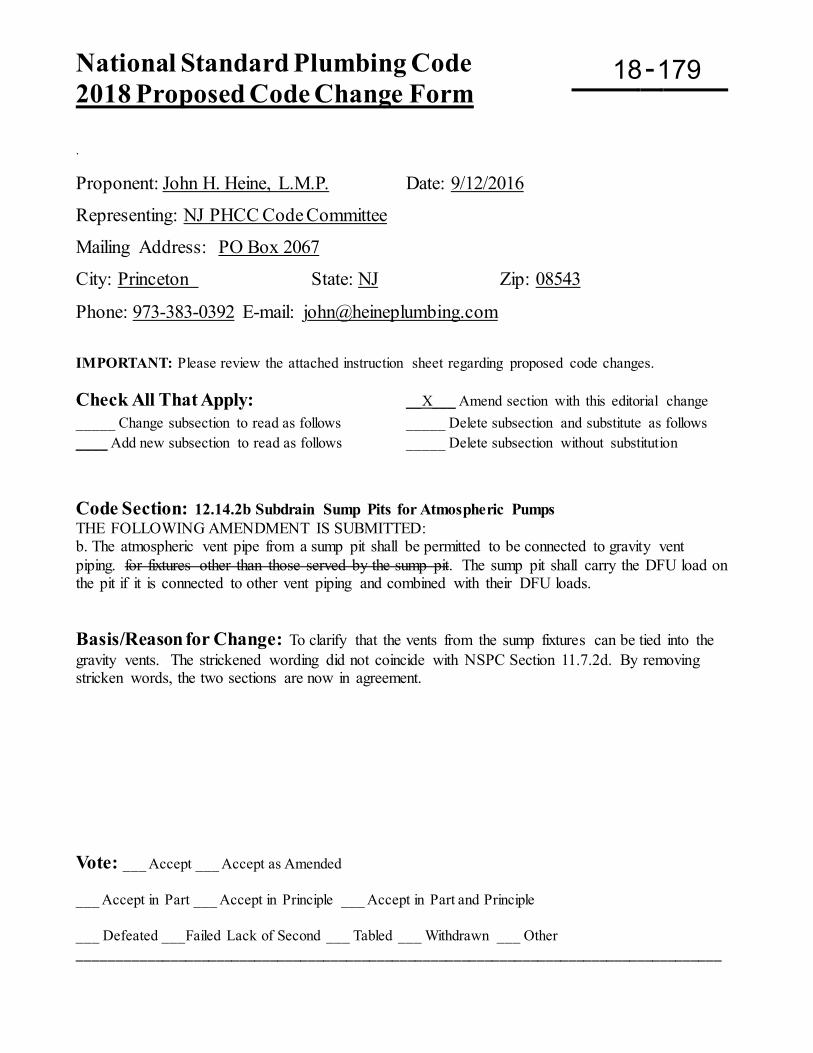
National Standard Plumbing Code 2018 Proposed Code Change Form
-
. Proponent: John H. Heine, L.M.P. Date: 9/12/2016
Representing: NJ PHCC Code Committee
Mailing Address: PO Box 2067
City: Princeton State: NJ Zip: 08543
Phone: 973-383-0392 E-mail: [email protected]
IMPORTANT: Please review the attached instruction sheet regarding proposed code changes. Check All That Apply: __X___ Amend section with this editorial change _____ Change subsection to read as follows _____ Delete subsection and substitute as follows ____ Add new subsection to read as follows _____ Delete subsection without substitution Code Section: 12.14.2b Subdrain Sump Pits for Atmospheric Pumps THE FOLLOWING AMENDMENT IS SUBMITTED: b. The atmospheric vent pipe from a sump pit shall be permitted to be connected to gravity vent piping. for fixtures other than those served by the sump pit. The sump pit shall carry the DFU load on the pit if it is connected to other vent piping and combined with their DFU loads. Basis/Reason for Change: To clarify that the vents from the sump fixtures can be tied into the gravity vents. The strickened wording did not coincide with NSPC Section 11.7.2d. By removing stricken words, the two sections are now in agreement. Vote: ___ Accept ___ Accept as Amended ___ Accept in Part ___ Accept in Principle ___ Accept in Part and Principle ___ Defeated ___Failed Lack of Second ___ Tabled ___ Withdrawn ___ Other ____________________________________________________________________________________
18 179
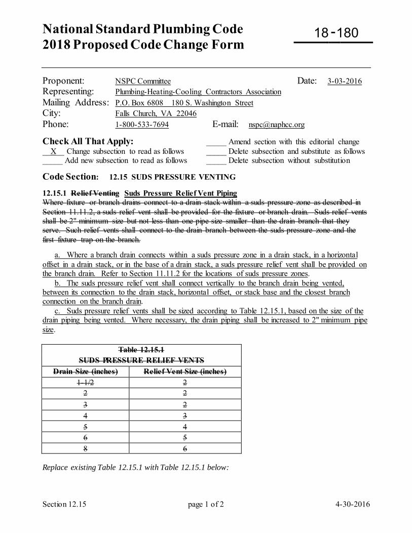
National Standard Plumbing Code 2018 Proposed Code Change Form
-
Section 12.15 page 1 of 2 4-30-2016
Proponent: NSPC Committee Date: 3-03-2016 Representing: Plumbing-Heating-Cooling Contractors Association Mailing Address: P.O. Box 6808 180 S. Washington Street City: Falls Church, VA 22046 Phone: 1-800-533-7694 E-mail: [email protected]
Check All That Apply: _____ Amend section with this editorial change __X__ Change subsection to read as follows _____ Delete subsection and substitute as follows _____ Add new subsection to read as follows _____ Delete subsection without substitution
Code Section: 12.15 SUDS PRESSURE VENTING 12.15.1 Relief Venting Suds Pressure Relief Vent Piping Where fixture or branch drains connect to a drain stack within a suds pressure zone as described in Section 11.11.2, a suds relief vent shall be provided for the fixture or branch drain. Suds relief vents shall be 2" minimum size but not less than one pipe size smaller than the drain branch that they serve. Such relief vents shall connect to the drain branch between the suds pressure zone and the first fixture trap on the branch. a. Where a branch drain connects within a suds pressure zone in a drain stack, in a horizontal offset in a drain stack, or in the base of a drain stack, a suds pressure relief vent shall be provided on the branch drain. Refer to Section 11.11.2 for the locations of suds pressure zones. b. The suds pressure relief vent shall connect vertically to the branch drain being vented, between its connection to the drain stack, horizontal offset, or stack base and the closest branch connection on the branch drain. c. Suds pressure relief vents shall be sized according to Table 12.15.1, based on the size of the drain piping being vented. Where necessary, the drain piping shall be increased to 2" minimum pipe size.
Replace existing Table 12.15.1 with Table 12.15.1 below:
Table 12.15.1 SUDS PRESSURE RELIEF VENTS
Drain Size (inches) Relief Vent Size (inches) 1-1/2 2
2 2 3 2 4 3 5 4 6 5 8 6
18 180
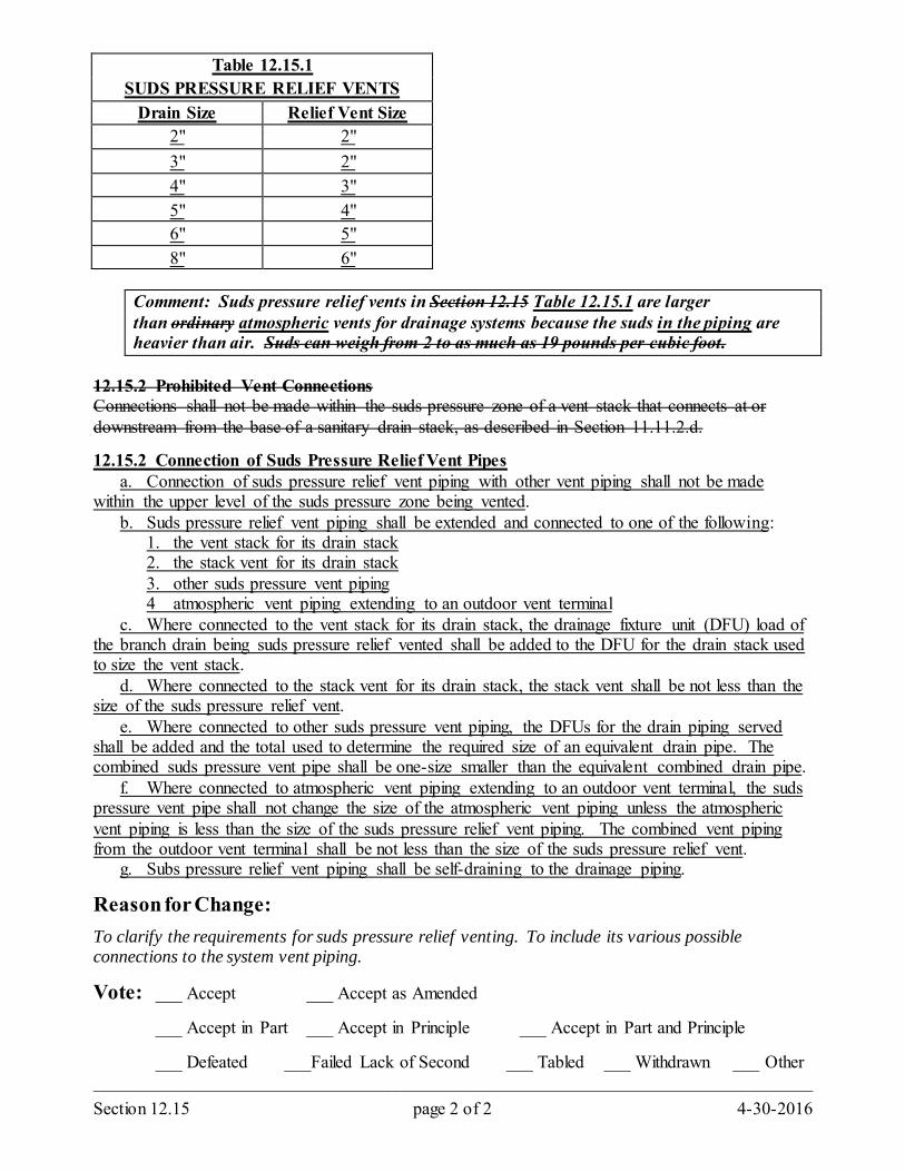
Section 12.15 page 2 of 2 4-30-2016
Table 12.15.1 SUDS PRESSURE RELIEF VENTS
Drain Size Relief Vent Size 2" 2" 3" 2" 4" 3" 5" 4" 6" 5" 8" 6"
Comment: Suds pressure relief vents in Section 12.15 Table 12.15.1 are larger than ordinary atmospheric vents for drainage systems because the suds in the piping are heavier than air. Suds can weigh from 2 to as much as 19 pounds per cubic foot.
12.15.2 Prohibited Vent Connections Connections shall not be made within the suds pressure zone of a vent stack that connects at or downstream from the base of a sanitary drain stack, as described in Section 11.11.2.d. 12.15.2 Connection of Suds Pressure Relief Vent Pipes a. Connection of suds pressure relief vent piping with other vent piping shall not be made within the upper level of the suds pressure zone being vented. b. Suds pressure relief vent piping shall be extended and connected to one of the following: 1. the vent stack for its drain stack 2. the stack vent for its drain stack 3. other suds pressure vent piping 4 atmospheric vent piping extending to an outdoor vent terminal c. Where connected to the vent stack for its drain stack, the drainage fixture unit (DFU) load of the branch drain being suds pressure relief vented shall be added to the DFU for the drain stack used to size the vent stack. d. Where connected to the stack vent for its drain stack, the stack vent shall be not less than the size of the suds pressure relief vent. e. Where connected to other suds pressure vent piping, the DFUs for the drain piping served shall be added and the total used to determine the required size of an equivalent drain pipe. The combined suds pressure vent pipe shall be one-size smaller than the equivalent combined drain pipe. f. Where connected to atmospheric vent piping extending to an outdoor vent terminal, the suds pressure vent pipe shall not change the size of the atmospheric vent piping unless the atmospheric vent piping is less than the size of the suds pressure relief vent piping. The combined vent piping from the outdoor vent terminal shall be not less than the size of the suds pressure relief vent. g. Subs pressure relief vent piping shall be self-draining to the drainage piping.
Reason for Change: To clarify the requirements for suds pressure relief venting. To include its various possible connections to the system vent piping.
Vote: ___ Accept ___ Accept as Amended
___ Accept in Part ___ Accept in Principle ___ Accept in Part and Principle
___ Defeated ___Failed Lack of Second ___ Tabled ___ Withdrawn ___ Other _________________________________________________________________________________
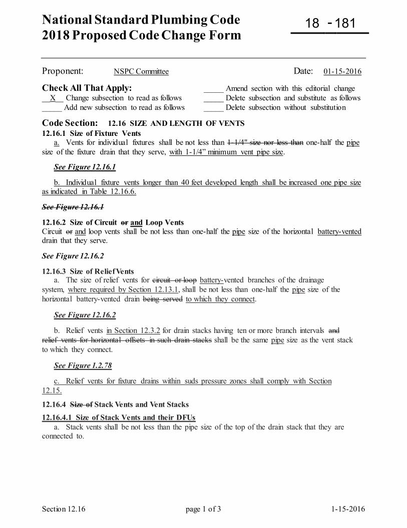
National Standard Plumbing Code 2018 Proposed Code Change Form
-
Section 12.16 page 1 of 3 1-15-2016
Proponent: NSPC Committee Date: 01-15-2016
Check All That Apply: _____ Amend section with this editorial change __X__ Change subsection to read as follows _____ Delete subsection and substitute as follows _____ Add new subsection to read as follows _____ Delete subsection without substitution
Code Section: 12.16 SIZE AND LENGTH OF VENTS 12.16.1 Size of Fixture Vents a. Vents for individual fixtures shall be not less than 1-1/4" size nor less than one-half the pipe size of the fixture drain that they serve, with 1-1/4” minimum vent pipe size.
See Figure 12.16.1
b. Individual fixture vents longer than 40 feet developed length shall be increased one pipe size as indicated in Table 12.16.6. See Figure 12.16.1 12.16.2 Size of Circuit or and Loop Vents Circuit or and loop vents shall be not less than one-half the pipe size of the horizontal battery-vented drain that they serve. See Figure 12.16.2 12.16.3 Size of Relief Vents a. The size of relief vents for circuit or loop battery-vented branches of the drainage system, where required by Section 12.13.1, shall be not less than one-half the pipe size of the horizontal battery-vented drain being served to which they connect.
See Figure 12.16.2
b. Relief vents in Section 12.3.2 for drain stacks having ten or more branch intervals and relief vents for horizontal offsets in such drain stacks shall be the same pipe size as the vent stack to which they connect.
See Figure 1.2.78
c. Relief vents for fixture drains within suds pressure zones shall comply with Section 12.15.
12.16.4 Size of Stack Vents and Vent Stacks 12.16.4.1 Size of Stack Vents and their DFUs a. Stack vents shall be not less than the pipe size of the top of the drain stack that they are connected to.
18 181
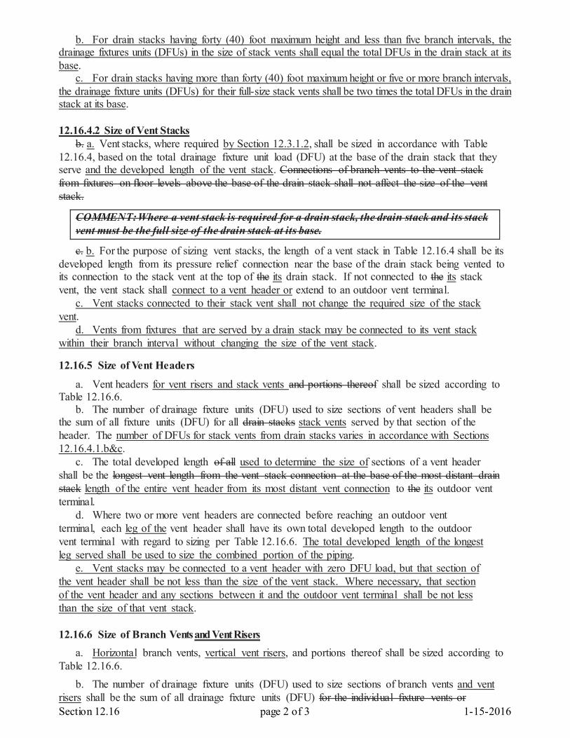
Section 12.16 page 2 of 3 1-15-2016
b. For drain stacks having forty (40) foot maximum height and less than five branch intervals, the drainage fixtures units (DFUs) in the size of stack vents shall equal the total DFUs in the drain stack at its base. c. For drain stacks having more than forty (40) foot maximum height or five or more branch intervals, the drainage fixture units (DFUs) for their full-size stack vents shall be two times the total DFUs in the drain stack at its base.
12.16.4.2 Size of Vent Stacks b. a. Vent stacks, where required by Section 12.3.1.2, shall be sized in accordance with Table 12.16.4, based on the total drainage fixture unit load (DFU) at the base of the drain stack that they serve and the developed length of the vent stack. Connections of branch vents to the vent stack from fixtures on floor levels above the base of the drain stack shall not affect the size of the vent stack.
COMMENT: Where a vent stack is required for a drain stack, the drain stack and its stack vent must be the full size of the drain stack at its base.
c. b. For the purpose of sizing vent stacks, the length of a vent stack in Table 12.16.4 shall be its developed length from its pressure relief connection near the base of the drain stack being vented to its connection to the stack vent at the top of the its drain stack. If not connected to the its stack vent, the vent stack shall connect to a vent header or extend to an outdoor vent terminal. c. Vent stacks connected to their stack vent shall not change the required size of the stack vent. d. Vents from fixtures that are served by a drain stack may be connected to its vent stack within their branch interval without changing the size of the vent stack. 12.16.5 Size of Vent Headers
a. Vent headers for vent risers and stack vents and portions thereof shall be sized according to Table 12.16.6. b. The number of drainage fixture units (DFU) used to size sections of vent headers shall be the sum of all fixture units (DFU) for all drain stacks stack vents served by that section of the header. The number of DFUs for stack vents from drain stacks varies in accordance with Sections 12.16.4.1.b&c. c. The total developed length of all used to determine the size of sections of a vent header shall be the longest vent length from the vent stack connection at the base of the most distant drain stack length of the entire vent header from its most distant vent connection to the its outdoor vent terminal. d. Where two or more vent headers are connected before reaching an outdoor vent terminal, each leg of the vent header shall have its own total developed length to the outdoor vent terminal with regard to sizing per Table 12.16.6. The total developed length of the longest leg served shall be used to size the combined portion of the piping. e. Vent stacks may be connected to a vent header with zero DFU load, but that section of the vent header shall be not less than the size of the vent stack. Where necessary, that section of the vent header and any sections between it and the outdoor vent terminal shall be not less than the size of that vent stack. 12.16.6 Size of Branch Vents and Vent Risers a. Horizontal branch vents, vertical vent risers, and portions thereof shall be sized according to Table 12.16.6. b. The number of drainage fixture units (DFU) used to size sections of branch vents and vent risers shall be the sum of all drainage fixture units (DFU) for the individual fixture vents or
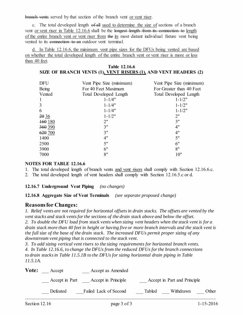
Section 12.16 page 3 of 3 1-15-2016
branch vents served by that section of the branch vent or vent riser.
c. The total developed length of all used to determine the size of sections of a branch vent or vent riser in Table 12.16.6 shall be the longest length from its connection to length of the entire branch vent or vent riser from the its most distant individual fixture vent being vented to its connection to an outdoor vent terminal. d. In Table 12.16.6, the minimum vent pipe sizes for the DFUs being vented are based on whether the total developed length of the entire branch vent or vent riser is more or less than 40 feet.
Table 12.16.6 SIZE OF BRANCH VENTS (1), VENT RISERS (1), AND VENT HEADERS (2)
DFU Vent Pipe Size (minimum) Vent Pipe Size (minimum) Being For 40 Feet Maximum For Greater than 40 Feet Vented Total Developed Length Total Developed Length 1 1-1/4" 1-1/2" 3 1-1/4" 1-1/2" 6 1-1/4" 1-1/2" 20 36 1-1/2" 2" 160 180 2" 3" 360 390 3" 4" 620 700 3" 4" 1400 4" 5" 2500 5" 6" 3900 6" 8" 7000 8" 10" NOTES FOR TABLE 12.16.6 1. The total developed length of branch vents and vent risers shall comply with Section 12.16.6.c. 2. The total developed length of vent headers shall comply with Section 12.16.5.c or d. 12.16.7 Underground Vent Piping (no changes) 12.16.8 Aggregate Size of Vent Terminals (see separate proposed change)
Reasons for Changes: 1. Relief vents are not required for horizontal offsets in drain stacks. The offsets are vented by the vent stacks and stack vents for the sections of the drain stack above and below the offset. 2. To double the DFU load from stack vents when sizing vent headers when the stack vent is for a drain stack more than 40 feet in height or having five or more branch intervals and the stack vent is the full size of the base of the drain stack. The increased DFUs permit proper sizing of any downstream vent piping that is connected to the stack vent. 3. To add sizing vertical vent risers to the sizing requirements for horizontal branch vents. 4. In Table 12.16.6, to change the DFUs from the reduced DFUs for the branch connections to drain stacks in Table 11.5.1B to the DFUs for sizing horizontal drain piping in Table 11.5.1A. Vote: ___ Accept ___ Accept as Amended
___ Accept in Part ___ Accept in Principle ___ Accept in Part and Principle
___ Defeated ___Failed Lack of Second ___ Tabled ___ Withdrawn ___ Other ________________________________________________________________________________
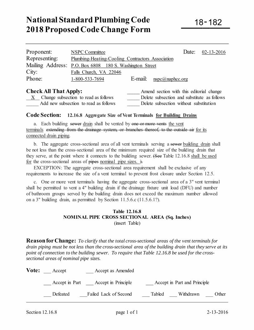
National Standard Plumbing Code 2018 Proposed Code Change Form
-
Section 12.16.8 page 1 of 1 2-13-2016
Proponent: NSPC Committee Date: 02-13-2016 Representing: Plumbing-Heating-Cooling Contractors Association Mailing Address: P.O. Box 6808 180 S. Washington Street City: Falls Church, VA 22046 Phone: 1-800-533-7694 E-mail: [email protected] Check All That Apply: _____ Amend section with this editorial change __X__ Change subsection to read as follows _____ Delete subsection and substitute as follows _____ Add new subsection to read as follows _____ Delete subsection without substitution Code Section: 12.16.8 Aggregate Size of Vent Terminals for Building Drains
a. Each building sewer drain shall be vented by one or more vents the vent terminals extending from the drainage system, or branches thereof, to the outside air for its connected drain piping.
b. The aggregate cross-sectional area of all vent terminals serving a sewer building drain shall be not less than the cross-sectional area of the minimum required size of the building drain that they serve, at the point where it connects to the building sewer. (See Table 12.16.8 shall be used for the cross-sectional areas of pipes nominal pipe sizes. ). EXCEPTION: The aggregate cross-sectional area requirement shall be exclusive of any requirements to increase the size of a vent terminal to prevent frost closure under Section 12.5.
c. One or more vent terminals having the aggregate cross-sectional area of a 3" vent terminal shall be permitted to vent a 4" building drain if the drainage fixture unit load (DFU) and number of bathroom groups served by the building drain does not exceed the maximum number allowed on a 3" building drain, as permitted by Section 11.5.6.c (11.5.6.1?).
Table 12.16.8 NOMINAL PIPE CROSS SECTIONAL AREA (Sq. Inches)
(insert Table) Reason for Change: To clarify that the total cross-sectional areas of the vent terminals for drain piping must be not less than the cross-sectional area of the building drain that they serve at its point of connection to the building sewer. To require that Table 12.16.8 be used for the cross-sectional areas of nominal pipe sizes. Vote: ___ Accept ___ Accept as Amended
___ Accept in Part ___ Accept in Principle ___ Accept in Part and Principle
___ Defeated ___Failed Lack of Second ___ Tabled ___ Withdrawn ___ Other _________________________________________________________________________________
18 182
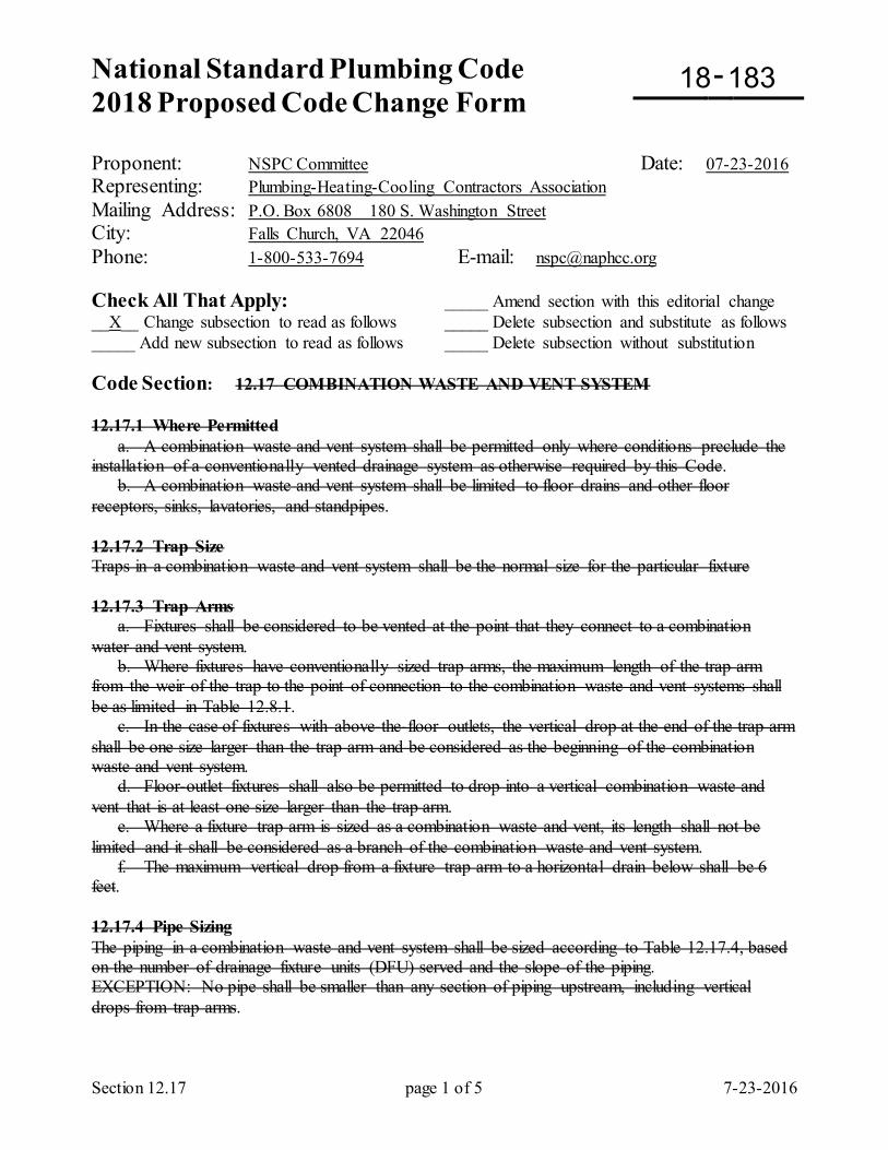
National Standard Plumbing Code 2018 Proposed Code Change Form
-
Section 12.17 page 1 of 5 7-23-2016
Proponent: NSPC Committee Date: 07-23-2016 Representing: Plumbing-Heating-Cooling Contractors Association Mailing Address: P.O. Box 6808 180 S. Washington Street City: Falls Church, VA 22046 Phone: 1-800-533-7694 E-mail: [email protected] Check All That Apply: _____ Amend section with this editorial change __X__ Change subsection to read as follows _____ Delete subsection and substitute as follows _____ Add new subsection to read as follows _____ Delete subsection without substitution Code Section: 12.17 COMBINATION WASTE AND VENT SYSTEM 12.17.1 Where Permitted a. A combination waste and vent system shall be permitted only where conditions preclude the installation of a conventionally vented drainage system as otherwise required by this Code. b. A combination waste and vent system shall be limited to floor drains and other floor receptors, sinks, lavatories, and standpipes. 12.17.2 Trap Size Traps in a combination waste and vent system shall be the normal size for the particular fixture 12.17.3 Trap Arms a. Fixtures shall be considered to be vented at the point that they connect to a combination water and vent system. b. Where fixtures have conventionally sized trap arms, the maximum length of the trap arm from the weir of the trap to the point of connection to the combination waste and vent systems shall be as limited in Table 12.8.1. c. In the case of fixtures with above-the-floor outlets, the vertical drop at the end of the trap arm shall be one size larger than the trap arm and be considered as the beginning of the combination waste and vent system. d. Floor-outlet fixtures shall also be permitted to drop into a vertical combination waste and vent that is at least one size larger than the trap arm. e. Where a fixture trap arm is sized as a combination waste and vent, its length shall not be limited and it shall be considered as a branch of the combination waste and vent system. f. The maximum vertical drop from a fixture trap arm to a horizontal drain below shall be 6 feet. 12.17.4 Pipe Sizing The piping in a combination waste and vent system shall be sized according to Table 12.17.4, based on the number of drainage fixture units (DFU) served and the slope of the piping. EXCEPTION: No pipe shall be smaller than any section of piping upstream, including vertical drops from trap arms.
18 183
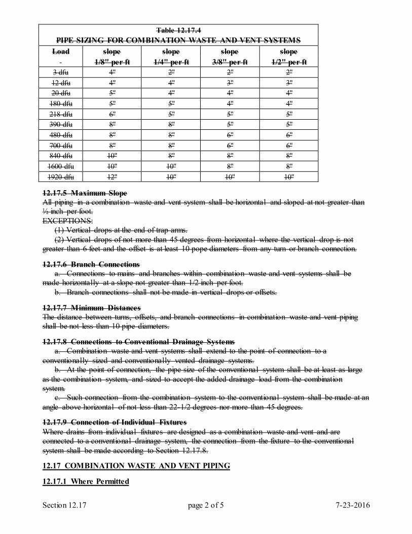
Section 12.17 page 2 of 5 7-23-2016
Table 12.17.4 PIPE SIZING FOR COMBINATION WASTE AND VENT SYSTEMS
Load slope slope slope slope 1/8" per ft 1/4" per ft 3/8" per ft 1/2" per ft
3 dfu 4" 2" 2" 2" 12 dfu 4" 4" 3" 3" 20 dfu 5" 4" 4" 4"
180 dfu 5" 5" 4" 4" 218 dfu 6" 5" 5" 5" 390 dfu 8" 8" 5" 5" 480 dfu 8" 8" 6" 6" 700 dfu 8" 8" 6" 6" 840 dfu 10" 8" 8" 8"
1600 dfu 10" 10" 8" 8" 1920 dfu 12" 10" 10" 10"
12.17.5 Maximum Slope All piping in a combination waste and vent system shall be horizontal and sloped at not greater than ½ inch per foot. EXCEPTIONS: (1) Vertical drops at the end of trap arms. (2) Vertical drops of not more than 45 degrees from horizontal where the vertical drop is not greater than 6 feet and the offset is at least 10 pope diameters from any turn or branch connection. 12.17.6 Branch Connections a. Connections to mains and branches within combination waste and vent systems shall be made horizontally at a slope not greater than 1/2 inch per foot. b. Branch connections shall not be made in vertical drops or offsets. 12.17.7 Minimum Distances The distance between turns, offsets, and branch connections in combination waste and vent piping shall be not less than 10 pipe diameters. 12.17.8 Connections to Conventional Drainage Systems a. Combination waste and vent systems shall extend to the point of connection to a conventionally sized and conventionally vented drainage systems. b. At the point of connection, the pipe size of the conventional system shall be at least as large as the combination system, and sized to accept the added drainage load from the combination system. c. Such connection from the combination system to the conventional system shall be made at an angle above horizontal of not less than 22-1/2 degrees nor more than 45 degrees. 12.17.9 Connection of Individual Fixtures Where drains from individual fixtures are designed as a combination waste and vent and are connected to a conventional drainage system, the connection from the fixture to the conventional system shall be made according to Section 12.17.8. 12.17 COMBINATION WASTE AND VENT PIPING 12.17.1 Where Permitted
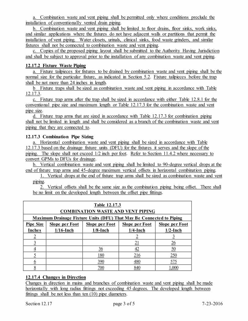
Section 12.17 page 3 of 5 7-23-2016
a. Combination waste and vent piping shall be permitted only where conditions preclude the installation of conventionally vented drain piping. b. Combination waste and vent piping shall be limited to floor drains, floor sinks, work sinks, and similar applications where the fixtures do not have adjacent walls or partitions that permit the installation of vent piping. Water closets, urinals, clinical sinks, food waste grinders, and similar fixtures shall not be connected to combination waste and vent piping. c. Copies of the proposed piping layout shall be submitted to the Authority Having Jurisdiction and shall be subject to approval prior to the installation of any combination waste and vent piping. 12.17.2 Fixture Waste Piping a. Fixture tailpieces for fixtures to be drained by combination waste and vent piping shall be the normal size for the particular fixture, as indicated in Section 5.2. Fixture tailpieces before the trap shall be not more than 24 inches in length. b Fixture traps shall be sized as combination waste and vent piping in accordance with Table 12.17.3. c. Fixture trap arms after the trap shall be sized in accordance with either Table 12.8.1 for the conventional pipe size and maximum length or Table 12.17.3 for the combination waste and vent pipe size. d. Fixture trap arms that are sized in accordance with Table 12.17.3 for combination piping shall not be limited in length and shall be considered as a branch of the combination waste and vent piping that they are connected to. 12.17.3 Combination Pipe Sizing a. Horizontal combination waste and vent piping shall be sized in accordance with Table 12.17.3 based on the drainage fixture units (DFU) for the fixtures it serves and the slope of the piping. The slope shall not exceed 1/2 inch per foot. Refer to Section 11.4.2 where necessary to convert GPMs to DFUs for drainage. b. Vertical combination waste and vent piping shall be limited to 90-degree vertical drops at the end of fixture trap arms and 45-degree maximum vertical offsets in horizontal combination piping. 1. Vertical drops at the end of fixture trap arms shall be sized as combination waste and vent
piping. 2. Vertical offsets shall be the same size as the combination piping being offset. There shall
be no limit on the developed length between the offset pipe fittings.
Table 12.17.3 COMBINATION WASTE AND VENT PIPING
Maximum Drainage Fixture Units (DFU) That May Be Connected to Piping Pipe Size Slope per Foot Slope per Foot Slope per Foot Slope per Foot Inches 1/16-Inch 1/8-Inch 1/4-Inch 1/2-Inch
2 2 3 3 21 26 4 36 42 50 5 180 216 250 6 390 480 575 8 700 840 1,000
12.17.4 Changes in Direction Changes in direction in mains and branches of combination waste and vent piping shall be made horizontally with long radius fittings not exceeding 45 degrees. The developed length between fittings shall be not less than ten (10) pipe diameters.
Section 12.17 page 4 of 5 7-23-2016
12.17.5 Branch Pipe Connections a. Branch pipe connections within horizontal combination waste and vent piping shall be made horizontally at slopes not greater than 1/2 inch per foot. b. Branch fittings shall be the long radius type. The developed length between branch fitting connections shall be not less than ten (10) pipe diameters. c. Branch pipe connections shall not be made in vertical drops from fixture trap arms and in the 45-degree vertical offsets in the combination piping. 12.17.6 Relief Vents a. Atmospheric relief vents shall be provided immediately downstream from the first fixture drain connection and immediately upstream from the connection of the combination piping to conventionally vented drain piping. Vents shall also be provided at intervals not exceeding 100 feet from each fixture drain connection and from other relief vents. b. Each relief vent shall be not less than one-half the pipe size of the combination pipe being vented, with 1-1/4” minimum vent pipe size. c. Relief vents for combination piping shall connect vertically to the combination piping being vented. Relief vents shall be connected to other relief vents for combination drains, atmospheric vent piping for conventional drains, or extended to an outdoor vent terminal. The DFU drainage load associated with each relief vent shall be the DFU at its point of connection to the combination piping. d. Where two or more relief vents are connected, the size of the combined relief vent shall be not less than the size of the largest relief vent being connected. e. Where relief vents are connected to atmospheric vent piping for conventional drains, the size of the atmospheric vent piping shall be based on the additional DFU load of the relief vents. 12.17.7 Connections to Conventional Drainage Piping a. Combination waste and vent piping shall extend to a point of non-turbulent flow in horizontal conventionally drained and vented piping. At the point of connection, the pipe size of the conventional drain piping shall be not less than the pipe size of the combination piping being connected and shall be adequate to accept the added DFU drainage load from the combination piping. b. The connection of the combination piping to the conventional piping shall be made at an angle of 45 degrees down from horizontal. Reason for Change: To clarify the requirements for combination waste and vent piping. The pipe sizes for combination waste and vent piping are two sizes larger than normal when considering 2-1/2”, 3-1/2”, 4-1/2”, and 5-1/2” as pipe sizes. Vote: ___ Accept ___ Accept as Amended
___ Accept in Part ___ Accept in Principle ___ Accept in Part and Principle
___ Defeated ___Failed Lack of Second ___ Tabled ___ Withdrawn ___ Other _________________________________________________________________________________
National Standard Plumbing Code 2018 Proposed Code Change Form
-
Section 13.1.10 page 1 of 3 8-08-2016
Proponent: NSPC Committee Date: 08-08-2016 Representing: Plumbing-Heating-Cooling Contractors Association Mailing Address: P.O. Box 6808 180 S. Washington Street City: Falls Church, VA 22046 Phone: 1-800-533-7694 E-mail: [email protected] Check All That Apply: _____ Amend section with this editorial change __X__ Change subsection to read as follows _____ Delete subsection and substitute as follows _____ Add new subsection to read as follows _____ Delete subsection without substitution Code Section: 13.1.10 Roof Drainage 13.1.10.1 Primary Roof Drainage
Roof areas of buildings shall be drained by roof drains or scuppers unless gutters and downspouts or other non-plumbing drainage is provided. The locations and sizing of roof drains and scuppers shall be coordinated with the structural design and slope of the roof. Roof drains, scuppers, vertical conductors or leaders, and horizontal storm drainage piping for primary drainage shall be sized based on a storm of 60 minutes duration and a 100-year return period. (See Appendix A).
13.1.10.2 Secondary Roof Drainage a. Where parapet walls or other construction extend above the roof and create areas where storm water would become trapped if the primary roof drainage system failed to provide sufficient drainage, an independent secondary roof drainage system consisting of scuppers, standpipes, or roof drains shall be provided. Secondary roof drainage shall be sized for a 100-year, 15-minute storm (see Appendix A). The capacity of the primary system shall not be considered in the sizing of the secondary system. b. Where secondary drainage is provided by means of roof drains or standpipes, the secondary system shall be separate from the primary system and shall discharge independently at grade or other approved point of discharge.
c. Where secondary roof drainage is provided, the overflow level(s) into the secondary system shall be established by the amount of ponding that is allowed in the structural design of the roof, including roof deflection. An allowance shall be made to account for the required overflow head of water above the secondary inlets. The elevation of the secondary inlet plus the required overflow head shall not exceed the maximum allowable water level on the roof.
d. Scuppers shall be sized as rectangular weir, using hydraulic principles to determine the required length and resulting overflow head (see Appendix A). Secondary roof drains and standpipes shall be sized according Table 13.6.1. Where standpipes are used, the head allowance required under Section 13.1.10.2.c shall be not less than 1-1/2 inches. e. Strainers shall not be required on open standpipes when used for secondary inlets.
f. Where secondary roof drainage is provided by roof drains or standpipes, they shall be permitted to discharge horizontally, similar to scuppers, but below the roof level.
18 184
Section 13.1.10 page 2 of 3 8-08-2016
13.1.10.3 13.1.10.4 Addition of Vertical Walls
Where vertical walls drain onto roofs, an allowance based on 50% of the maximum projected wall area shall be added to the roof area onto which each wall drains.
13.1.10.4 Equivalent Systems When approved by the Authority Having Jurisdiction, the requirements of Sections 13.1.10.1 and 13.1.10.2 shall not preclude the installation of an engineered roof drainage system that has sufficient capacity to prevent water from ponding on the roof in excess of that allowed in the roof structural design during a 100-year, 15-minute storm.
13.1.10.5 Scuppers a. Parapet/scupper roof drains with piped discharge shall comply with the requirements for roof drains.
b. Through-the-wall scuppers at raised roof curbs, gutters, conductor heads, downspouts, and roof overflows that are not connected to discharge piping are not within the scope of this Code.
13.1.10.1 General a. Roof drains with roof drain piping shall be provided where the design of a roof is based on roof drains for primary and/or secondary roof drainage. Where the roof includes through-the-wall scuppers for either primary or secondary drainage, the roof drains shall be coordinated with the scuppers for inlet elevations and hydraulic heights (ponding) based on the structural design of the roof for its maximum rain load (R). b. Roof drains shall comply with Section 13.5.
c. Primary roof drain piping shall be connected to a storm sewer where available, a combined sewer where necessary, or to a point of discharge satisfactory to the Authority Having Jurisdiction.
d. Secondary roof drain piping shall be independent from primary drain piping and shall discharge at grade at an observable location. 13.1.10.2 Primary Roof Drains
a. Primary roof drains and their drain piping shall be sized based on a 60-minute storm with a 100-year return for the geographic location, based on Appendix A.
b. The maximum allowable hydraulic head (ponding) for primary roof drains at the design rainwater flow (GPM) for the section of roof being drained shall be coordinated with the limit of the rain load (R) used in the structural design of the roof. The maximum allowable hydraulic head (ponding) of primary roof drains shall be not less than one (1) inch below the inlet elevation of the secondary roof drainage.
c. On design plans, primary roof drains shall indicate their required flow (GPM) and their maximum allowable hydraulic head (ponding). Submittal data for approval shall include this data and the pipe size for the proposed primary roof drain.
13.1.10.3 Secondary Roof Drains a. Secondary roof drains and their drain piping shall be sized based on a 15-minute storm with a 100-year return for the geographic location, based on Appendix A. The capacity of the primary roof drainage system shall not considered in sizing the secondary system.
Section 13.1.10 page 3 of 3 8-08-2016
b. The maximum allowable hydraulic head (ponding) for secondary roof drains at the design rainwater flow (GPM) for the section of roof being drained shall be coordinated with the limit of the inches of rain load (R) used in structural design of the roof. The maximum allowable hydraulic head (ponding) of the primary roof drains, plus a clear space of not less than one (1) inch to the inlet elevation of the secondary roof drain, plus the maximum allowable hydraulic head (ponding) of the secondary roof drain shall not exceed the inches of rain load (R) used in the structural design of the roof. c. On design plans, secondary roof drains shall indicate their required flow (GPM), their minimum inlet elevation above the hydraulic head (ponding) of the primary drain, and their maximum allowable hydraulic head (ponding). Submittal data for approval shall include this data and the pipe size for the proposed secondary roof drain. Reason for Change: To coordinate the selection and approval of roof drains with their hydraulic height (ponding) for their required flow rate and the maximum inches of rainwater in the rain load (R) of the structural design of the roof. To delete through-the-wall scuppers without discharge piping from the scope of the NSPC. They are building construction, not plumbing. Vote: ___ Accept ___ Accept as Amended
___ Accept in Part ___ Accept in Principle ___ Accept in Part and Principle
___ Defeated ___Failed Lack of Second ___ Tabled ___ Withdrawn ___ Other _________________________________________________________________________________
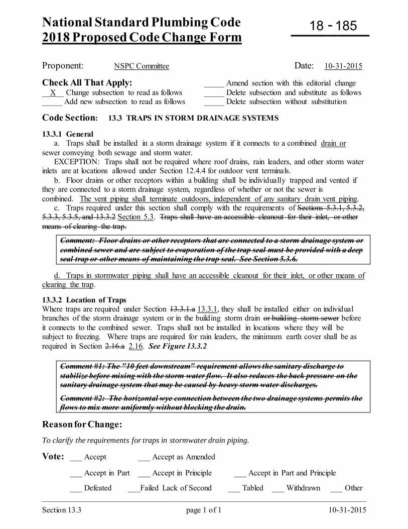
National Standard Plumbing Code 2018 Proposed Code Change Form
-
Section 13.3 page 1 of 1 10-31-2015
Proponent: NSPC Committee Date: 10-31-2015
Check All That Apply: _____ Amend section with this editorial change __X__ Change subsection to read as follows _____ Delete subsection and substitute as follows _____ Add new subsection to read as follows _____ Delete subsection without substitution
Code Section: 13.3 TRAPS IN STORM DRAINAGE SYSTEMS 13.3.1 General a. Traps shall be installed in a storm drainage system if it connects to a combined drain or sewer conveying both sewage and storm water. EXCEPTION: Traps shall not be required where roof drains, rain leaders, and other storm water inlets are at locations allowed under Section 12.4.4 for outdoor vent terminals. b. Floor drains or other receptors within a building shall be individually trapped and vented if they are connected to a storm drainage system, regardless of whether or not the sewer is combined. The vent piping shall terminate outdoors, independent of any sanitary drain vent piping. c. Traps required under this section shall comply with the requirements of Sections 5.3.1, 5.3.2, 5.3.3, 5.3.5, and 13.3.2 Section 5.3. Traps shall have an accessible cleanout for their inlet, or other means of clearing the trap.
Comment: Floor drains or other receptors that are connected to a storm drainage system or combined sewer and are subject to evaporation of the trap seal must be provided with a deep seal trap or other means of maintaining the trap seal. See Section 5.3.6.
d. Traps in stormwater piping shall have an accessible cleanout for their inlet, or other means of clearing the trap. 13.3.2 Location of Traps Where traps are required under Section 13.3.1.a 13.3.1, they shall be installed either on individual branches of the storm drainage system or in the building storm drain or building storm sewer before it connects to the combined sewer. Traps shall not be installed in locations where they will be subject to freezing. Where traps are required for rain leaders, the minimum earth cover shall be as required in Section 2.16.a 2.16. See Figure 13.3.2
Comment #1: The "10 feet downstream" requirement allows the sanitary discharge to stabilize before mixing with the storm water flow. It also reduces the back pressure on the sanitary drainage system that may be caused by heavy storm water discharges.
Comment #2: The horizontal wye connection between the two drainage systems permits the flows to mix more uniformly without blocking the drain.
Reason for Change: To clarify the requirements for traps in stormwater drain piping.
Vote: ___ Accept ___ Accept as Amended
___ Accept in Part ___ Accept in Principle ___ Accept in Part and Principle
___ Defeated ___Failed Lack of Second ___ Tabled ___ Withdrawn ___ Other _________________________________________________________________________________
18 185
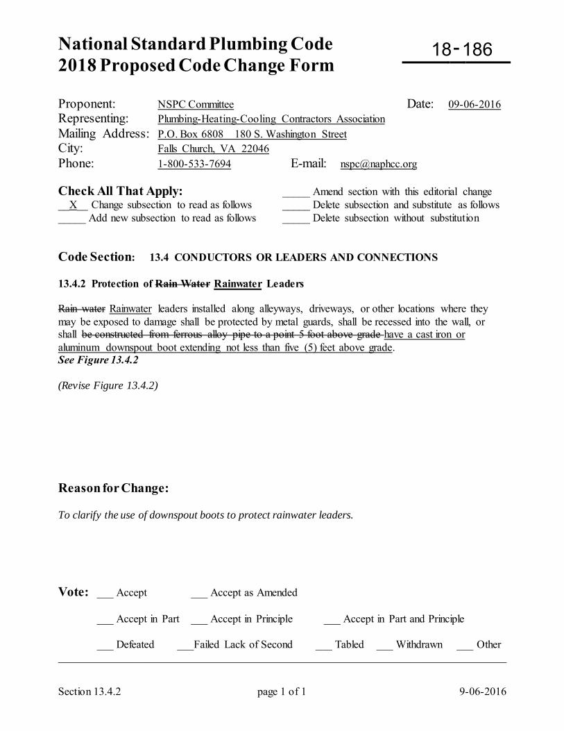
National Standard Plumbing Code 2018 Proposed Code Change Form
-
Section 13.4.2 page 1 of 1 9-06-2016
Proponent: NSPC Committee Date: 09-06-2016 Representing: Plumbing-Heating-Cooling Contractors Association Mailing Address: P.O. Box 6808 180 S. Washington Street City: Falls Church, VA 22046 Phone: 1-800-533-7694 E-mail: [email protected] Check All That Apply: _____ Amend section with this editorial change __X__ Change subsection to read as follows _____ Delete subsection and substitute as follows _____ Add new subsection to read as follows _____ Delete subsection without substitution Code Section: 13.4 CONDUCTORS OR LEADERS AND CONNECTIONS 13.4.2 Protection of Rain Water Rainwater Leaders Rain water Rainwater leaders installed along alleyways, driveways, or other locations where they may be exposed to damage shall be protected by metal guards, shall be recessed into the wall, or shall be constructed from ferrous alloy pipe to a point 5 foot above grade have a cast iron or aluminum downspout boot extending not less than five (5) feet above grade. See Figure 13.4.2 (Revise Figure 13.4.2) Reason for Change: To clarify the use of downspout boots to protect rainwater leaders. Vote: ___ Accept ___ Accept as Amended
___ Accept in Part ___ Accept in Principle ___ Accept in Part and Principle
___ Defeated ___Failed Lack of Second ___ Tabled ___ Withdrawn ___ Other _________________________________________________________________________________
18 186
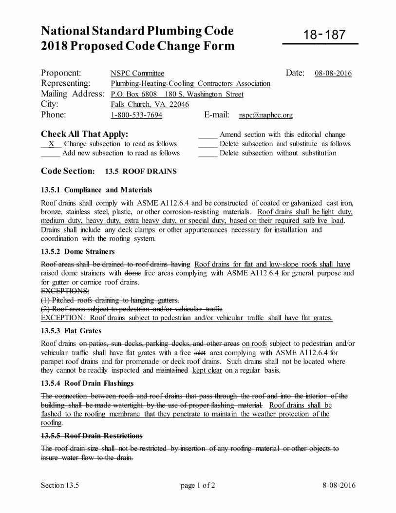
National Standard Plumbing Code 2018 Proposed Code Change Form
-
Section 13.5 page 1 of 2 8-08-2016
Proponent: NSPC Committee Date: 08-08-2016 Representing: Plumbing-Heating-Cooling Contractors Association Mailing Address: P.O. Box 6808 180 S. Washington Street City: Falls Church, VA 22046 Phone: 1-800-533-7694 E-mail: [email protected] Check All That Apply: _____ Amend section with this editorial change __X__ Change subsection to read as follows _____ Delete subsection and substitute as follows _____ Add new subsection to read as follows _____ Delete subsection without substitution Code Section: 13.5 ROOF DRAINS 13.5.1 Compliance and Materials
Roof drains shall comply with ASME A112.6.4 and be constructed of coated or galvanized cast iron, bronze, stainless steel, plastic, or other corrosion-resisting materials. Roof drains shall be light duty, medium duty, heavy duty, extra heavy duty, or special duty, based on their required safe live load. Drains shall include any deck clamps or other appurtenances necessary for installation and coordination with the roofing system.
13.5.2 Dome Strainers Roof areas shall be drained to roof drains having Roof drains for flat and low-slope roofs shall have raised dome strainers with dome free areas complying with ASME A112.6.4 for general purpose and for gutter or cornice roof drains. EXCEPTIONS: (1) Pitched roofs draining to hanging gutters. (2) Roof areas subject to pedestrian and/or vehicular traffic EXCEPTION: Roof drains subject to pedestrian and/or vehicular traffic shall have flat grates.
13.5.3 Flat Grates Roof drains on patios, sun decks, parking decks, and other areas on roofs subject to pedestrian and/or vehicular traffic shall have flat grates with a free inlet area complying with ASME A112.6.4 for parapet roof drains and for promenade or deck roof drains. Such drains shall not be located where they cannot be readily inspected and maintained kept clear on a regular basis.
13.5.4 Roof Drain Flashings The connection between roofs and roof drains that pass through the roof and into the interior of the building shall be made watertight by the use of proper flashing material. Roof drains shall be flashed to the roofing membrane that they penetrate to maintain the weather protection of the roofing.
13.5.5 Roof Drain Restrictions The roof drain size shall not be restricted by insertion of any roofing material or other objects to insure water flow to the drain.
18 187
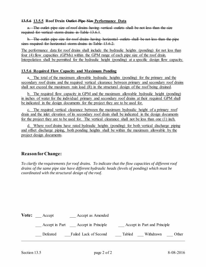
Section 13.5 page 2 of 2 8-08-2016
13.5.6 13.5.5 Roof Drain Outlet Pipe Size Performance Data
a. The outlet pipe size of roof drains having vertical outlets shall be not less than the size required for vertical storm drains in Table 13.6.1.
b. The outlet pipe size for roof drains having horizontal outlets shall be not less than the pipe sizes required for horizontal storm drains in Table 13.6.2. The performance data for roof drains shall include the hydraulic heights (ponding) for not less than four (4) flow capacities (GPMs) within the GPM range of each pipe size of the roof drain. Interpolation shall be permitted for the hydraulic height (ponding) at a specific design flow capacity.
13.5.6 Required Flow Capacity and Maximum Ponding a. The total of the maximum allowable hydraulic heights (ponding) for the primary and the secondary roof drains and the required vertical clearance between primary and secondary roof drains shall not exceed the maximum rain load (R) in the structural design of the roof being drained.
b. The required flow capacity in GPM and the maximum allowable hydraulic height (ponding) in inches of water for the individual primary and secondary roof drains at their required GPM shall be indicated in the design documents for the project they are to be used for.
c. The required vertical clearance between the maximum hydraulic height of a primary roof drain and the inlet elevation of its secondary roof drain shall be indicated in the design documents for the project they are to be used for. The vertical clearance shall not be less than one (1) inch. d. Where roof drains have rated hydraulic heights (ponding) for both vertical discharge piping and offset discharge piping, both ponding heights shall be within the maximum allowable by the project design documents. Reason for Change: To clarify the requirements for roof drains. To indicate that the flow capacities of different roof drains of the same pipe size have different hydraulic heads (levels of ponding) which must be coordinated with the structural design of the roof. Vote: ___ Accept ___ Accept as Amended
___ Accept in Part ___ Accept in Principle ___ Accept in Part and Principle
___ Defeated ___Failed Lack of Second ___ Tabled ___ Withdrawn ___ Other _________________________________________________________________________________
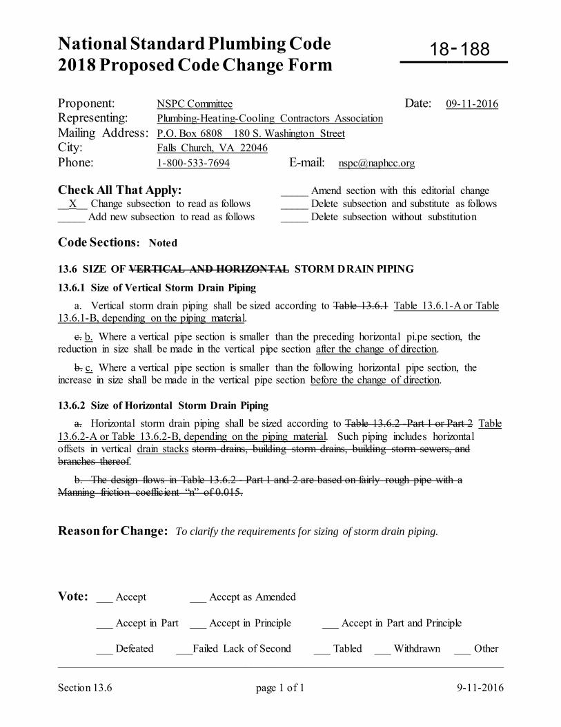
National Standard Plumbing Code 2018 Proposed Code Change Form
-
Section 13.6 page 1 of 1 9-11-2016
Proponent: NSPC Committee Date: 09-11-2016 Representing: Plumbing-Heating-Cooling Contractors Association Mailing Address: P.O. Box 6808 180 S. Washington Street City: Falls Church, VA 22046 Phone: 1-800-533-7694 E-mail: [email protected] Check All That Apply: _____ Amend section with this editorial change __X__ Change subsection to read as follows _____ Delete subsection and substitute as follows _____ Add new subsection to read as follows _____ Delete subsection without substitution Code Sections: Noted 13.6 SIZE OF VERTICAL AND HORIZONTAL STORM DRAIN PIPING
13.6.1 Size of Vertical Storm Drain Piping a. Vertical storm drain piping shall be sized according to Table 13.6.1 Table 13.6.1-A or Table 13.6.1-B, depending on the piping material.
c. b. Where a vertical pipe section is smaller than the preceding horizontal pi.pe section, the reduction in size shall be made in the vertical pipe section after the change of direction.
b. c. Where a vertical pipe section is smaller than the following horizontal pipe section, the increase in size shall be made in the vertical pipe section before the change of direction. 13.6.2 Size of Horizontal Storm Drain Piping a. Horizontal storm drain piping shall be sized according to Table 13.6.2 -Part 1 or Part 2 Table 13.6.2-A or Table 13.6.2-B, depending on the piping material. Such piping includes horizontal offsets in vertical drain stacks storm drains, building storm drains, building storm sewers, and branches thereof.
b. The design flows in Table 13.6.2 - Part 1 and 2 are based on fairly rough pipe with a Manning friction coefficient “n” of 0.015. Reason for Change: To clarify the requirements for sizing of storm drain piping. Vote: ___ Accept ___ Accept as Amended
___ Accept in Part ___ Accept in Principle ___ Accept in Part and Principle
___ Defeated ___Failed Lack of Second ___ Tabled ___ Withdrawn ___ Other _________________________________________________________________________________
18 188
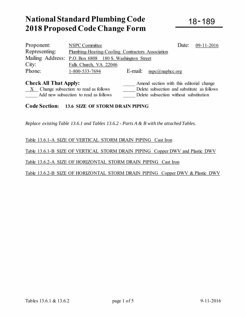
National Standard Plumbing Code 2018 Proposed Code Change Form
-
Tables 13.6.1 & 13.6.2 page 1 of 5 9-11-2016
Proponent: NSPC Committee Date: 09-11-2016 Representing: Plumbing-Heating-Cooling Contractors Association Mailing Address: P.O. Box 6808 180 S. Washington Street City: Falls Church, VA 22046 Phone: 1-800-533-7694 E-mail: [email protected] Check All That Apply: _____ Amend section with this editorial change __X__ Change subsection to read as follows _____ Delete subsection and substitute as follows _____ Add new subsection to read as follows _____ Delete subsection without substitution Code Section: 13.6 SIZE OF STORM DRAIN PIPING Replace existing Table 13.6.1 and Tables 13.6.2 - Parts A & B with the attached Tables. Table 13.6.1-A SIZE OF VERTICAL STORM DRAIN PIPING Cast Iron Table 13.6.1-B SIZE OF VERTICAL STORM DRAIN PIPING Copper DWV and Plastic DWV Table 13.6.2-A SIZE OF HORIZONTAL STORM DRAIN PIPING Cast Iron Table 13.6.2-B SIZE OF HORIZONTAL STORM DRAIN PIPING Copper DWV & Plastic DWV
18 189
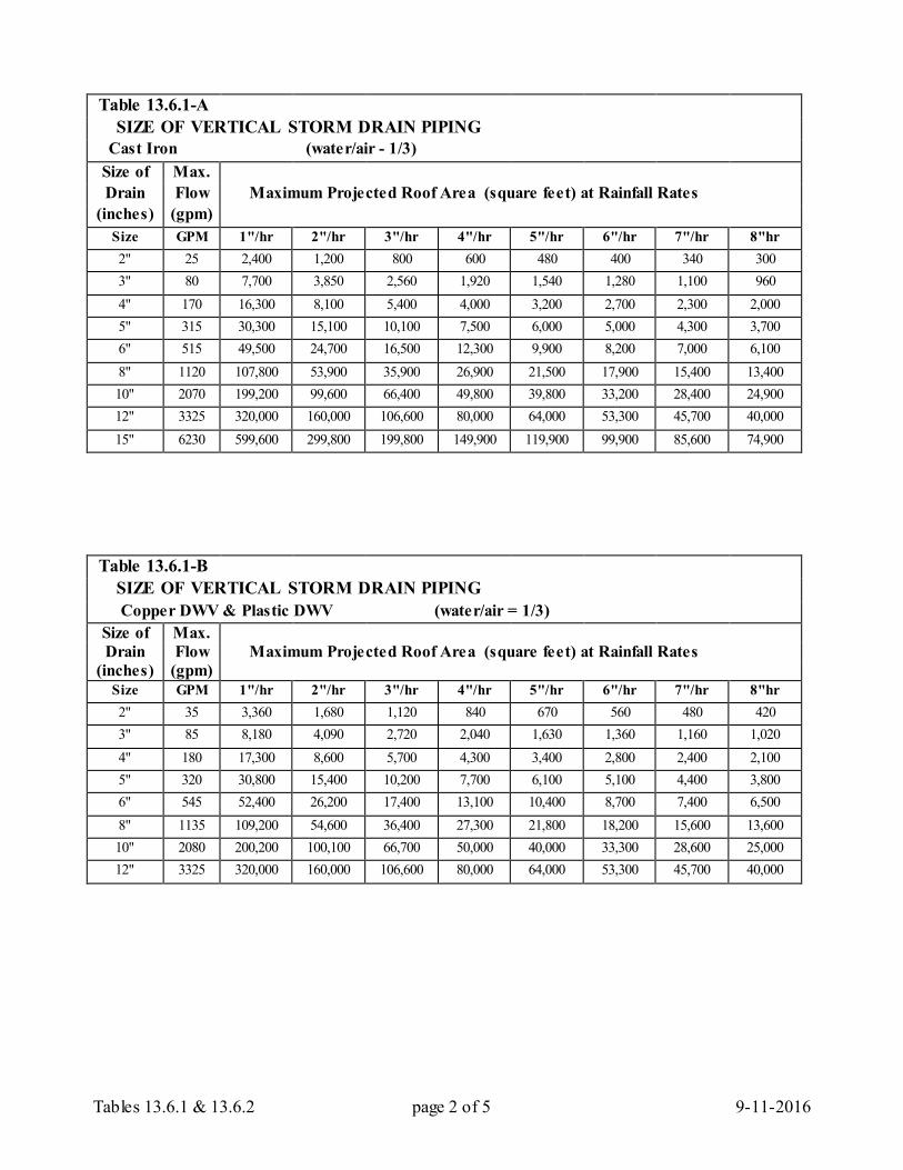
Tables 13.6.1 & 13.6.2 page 2 of 5 9-11-2016
Table 13.6.1-A
SIZE OF VERTICAL STORM DRAIN PIPING Cast Iron (water/air - 1/3)
Size of Max. Drain Flow Maximum Projected Roof Area (square feet) at Rainfall Rates
(inches) (gpm) Size GPM 1"/hr 2"/hr 3"/hr 4"/hr 5"/hr 6"/hr 7"/hr 8"hr 2" 25 2,400 1,200 800 600 480 400 340 300 3" 80 7,700 3,850 2,560 1,920 1,540 1,280 1,100 960 4" 170 16,300 8,100 5,400 4,000 3,200 2,700 2,300 2,000 5" 315 30,300 15,100 10,100 7,500 6,000 5,000 4,300 3,700 6" 515 49,500 24,700 16,500 12,300 9,900 8,200 7,000 6,100 8" 1120 107,800 53,900 35,900 26,900 21,500 17,900 15,400 13,400 10" 2070 199,200 99,600 66,400 49,800 39,800 33,200 28,400 24,900 12" 3325 320,000 160,000 106,600 80,000 64,000 53,300 45,700 40,000 15" 6230 599,600 299,800 199,800 149,900 119,900 99,900 85,600 74,900
Table 13.6.1-B
SIZE OF VERTICAL STORM DRAIN PIPING Copper DWV & Plastic DWV (water/air = 1/3)
Size of Max. Drain Flow Maximum Projected Roof Area (square feet) at Rainfall Rates
(inches) (gpm) Size GPM 1"/hr 2"/hr 3"/hr 4"/hr 5"/hr 6"/hr 7"/hr 8"hr 2" 35 3,360 1,680 1,120 840 670 560 480 420 3" 85 8,180 4,090 2,720 2,040 1,630 1,360 1,160 1,020 4" 180 17,300 8,600 5,700 4,300 3,400 2,800 2,400 2,100 5" 320 30,800 15,400 10,200 7,700 6,100 5,100 4,400 3,800 6" 545 52,400 26,200 17,400 13,100 10,400 8,700 7,400 6,500 8" 1135 109,200 54,600 36,400 27,300 21,800 18,200 15,600 13,600 10" 2080 200,200 100,100 66,700 50,000 40,000 33,300 28,600 25,000 12" 3325 320,000 160,000 106,600 80,000 64,000 53,300 45,700 40,000
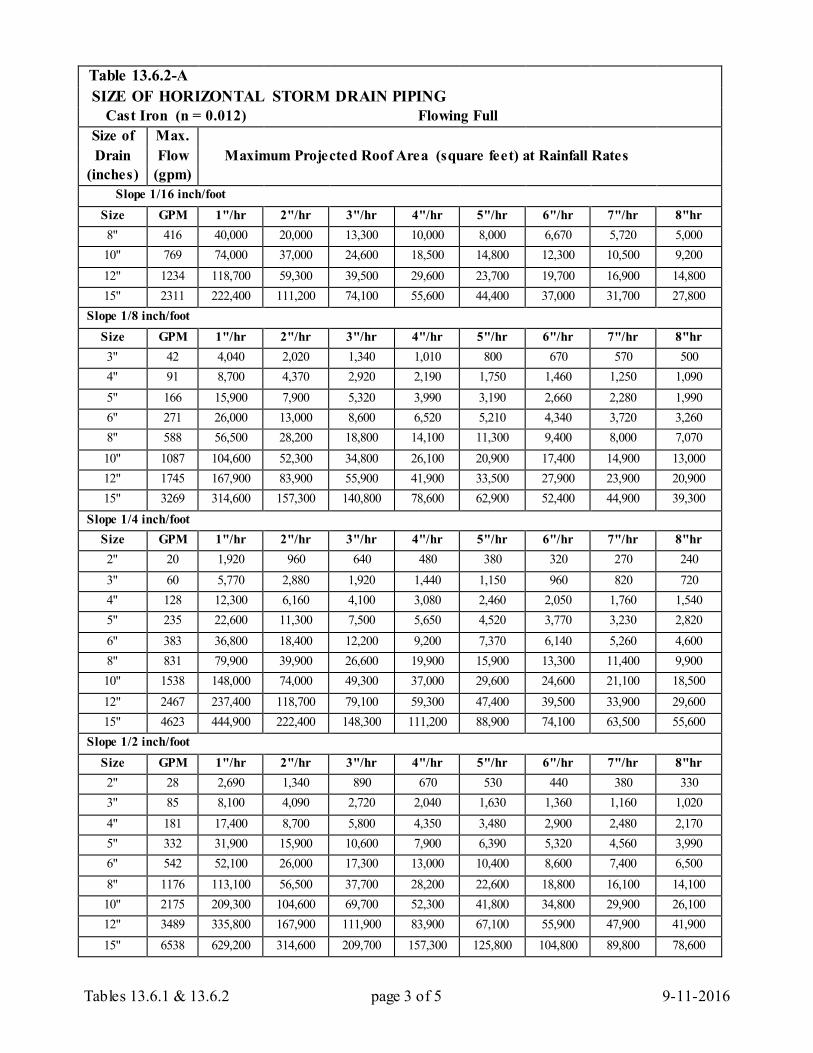
Tables 13.6.1 & 13.6.2 page 3 of 5 9-11-2016
Table 13.6.2-A SIZE OF HORIZONTAL STORM DRAIN PIPING
Cast Iron (n = 0.012) Flowing Full Size of Max. Drain Flow Maximum Projected Roof Area (square feet) at Rainfall Rates
(inches) (gpm) Slope 1/16 inch/foot
Size GPM 1"/hr 2"/hr 3"/hr 4"/hr 5"/hr 6"/hr 7"/hr 8"hr 8" 416 40,000 20,000 13,300 10,000 8,000 6,670 5,720 5,000 10" 769 74,000 37,000 24,600 18,500 14,800 12,300 10,500 9,200 12" 1234 118,700 59,300 39,500 29,600 23,700 19,700 16,900 14,800 15" 2311 222,400 111,200 74,100 55,600 44,400 37,000 31,700 27,800
Slope 1/8 inch/foot Size GPM 1"/hr 2"/hr 3"/hr 4"/hr 5"/hr 6"/hr 7"/hr 8"hr 3" 42 4,040 2,020 1,340 1,010 800 670 570 500 4" 91 8,700 4,370 2,920 2,190 1,750 1,460 1,250 1,090 5" 166 15,900 7,900 5,320 3,990 3,190 2,660 2,280 1,990 6" 271 26,000 13,000 8,600 6,520 5,210 4,340 3,720 3,260 8" 588 56,500 28,200 18,800 14,100 11,300 9,400 8,000 7,070 10" 1087 104,600 52,300 34,800 26,100 20,900 17,400 14,900 13,000 12" 1745 167,900 83,900 55,900 41,900 33,500 27,900 23,900 20,900 15" 3269 314,600 157,300 140,800 78,600 62,900 52,400 44,900 39,300
Slope 1/4 inch/foot Size GPM 1"/hr 2"/hr 3"/hr 4"/hr 5"/hr 6"/hr 7"/hr 8"hr 2" 20 1,920 960 640 480 380 320 270 240 3" 60 5,770 2,880 1,920 1,440 1,150 960 820 720 4" 128 12,300 6,160 4,100 3,080 2,460 2,050 1,760 1,540 5" 235 22,600 11,300 7,500 5,650 4,520 3,770 3,230 2,820 6" 383 36,800 18,400 12,200 9,200 7,370 6,140 5,260 4,600 8" 831 79,900 39,900 26,600 19,900 15,900 13,300 11,400 9,900 10" 1538 148,000 74,000 49,300 37,000 29,600 24,600 21,100 18,500 12" 2467 237,400 118,700 79,100 59,300 47,400 39,500 33,900 29,600 15" 4623 444,900 222,400 148,300 111,200 88,900 74,100 63,500 55,600
Slope 1/2 inch/foot Size GPM 1"/hr 2"/hr 3"/hr 4"/hr 5"/hr 6"/hr 7"/hr 8"hr 2" 28 2,690 1,340 890 670 530 440 380 330 3" 85 8,100 4,090 2,720 2,040 1,630 1,360 1,160 1,020 4" 181 17,400 8,700 5,800 4,350 3,480 2,900 2,480 2,170 5" 332 31,900 15,900 10,600 7,900 6,390 5,320 4,560 3,990 6" 542 52,100 26,000 17,300 13,000 10,400 8,600 7,400 6,500 8" 1176 113,100 56,500 37,700 28,200 22,600 18,800 16,100 14,100 10" 2175 209,300 104,600 69,700 52,300 41,800 34,800 29,900 26,100 12" 3489 335,800 167,900 111,900 83,900 67,100 55,900 47,900 41,900 15" 6538 629,200 314,600 209,700 157,300 125,800 104,800 89,800 78,600
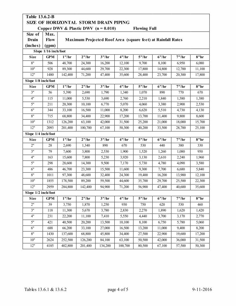
Tables 13.6.1 & 13.6.2 page 4 of 5 9-11-2016
Table 13.6.2-B SIZE OF HORIZONTAL STORM DRAIN PIPING
Copper DWV & Plastic DWV (n = 0.010) Flowing Full Size of Max. Drain Flow Maximum Projected Roof Area (square feet) at Rainfall Rates
(inches) (gpm) Slope 1/16 inch/foot
Size GPM 1"/hr 2"/hr 3"/hr 4"/hr 5"/hr 6"/hr 7"/hr 8"hr 8" 506 48,700 24,300 16,200 12,100 9,700 8,100 6,950 6,080 10" 928 89,300 44,600 29,700 22,300 17,800 14,800 12,700 11,100 12" 1480 142,400 71,200 47,400 35,600 28,400 23,700 20,300 17,800
Slope 1/8 inch/foot Size GPM 1"/hr 2"/hr 3"/hr 4"/hr 5"/hr 6"/hr 7"/hr 8"hr 3" 56 5,390 2,690 1,790 1,340 1,070 890 770 670 4" 115 11,000 5,530 3,690 2,760 2,210 1,840 1,580 1,380 5" 211 20,300 10,100 6,770 5,070 4,060 3,380 2,900 2,530 6" 344 33,100 16,500 11,000 8,200 6,620 5,510 4,730 4,130 8" 715 68,800 34,400 22,900 17,200 13,700 11,400 9,800 8,600 10" 1312 126,200 63,100 42,000 31,500 25,200 21,000 18,000 15,700 12" 2093 201,400 100,700 67,100 50,300 40,200 33,500 28,700 25,100
Slope 1/4 inch/foot Size GPM 1"/hr 2"/hr 3"/hr 4"/hr 5"/hr 6"/hr 7"/hr 8"hr 2" 28 2,690 1,340 890 670 530 440 380 330 3" 79 7,600 3,800 2,530 1,900 1,520 1,260 1,080 950 4" 163 15,600 7,800 5,230 3,920 3,130 2,610 2,240 1,960 5" 298 28,600 14,300 9,500 7,170 5,730 4,780 4,090 3,580 6" 486 46,700 23,300 15,500 11,600 9,300 7,700 6,680 5,840 8" 1011 97,300 48,600 32,400 24,300 19,400 16,200 13,900 12,100 10" 1855 178,500 89,200 59,500 44,600 35,700 29,700 25,500 22,300 12" 2959 284,800 142,400 94,900 71,200 56,900 47,400 40,600 35,600
Slope 1/2 inch/foot Size GPM 1"/hr 2"/hr 3"/hr 4"/hr 5"/hr 6"/hr 7"/hr 8"hr 2" 39 3,750 1,870 1,250 930 750 620 530 460 3" 118 11,300 5,670 3,780 2,830 2,270 1,890 1,620 1,420 4" 231 22,200 11,100 7,410 5,550 4,440 3,700 3,170 2,770 5" 421 40,500 20,200 13,500 10,100 8,100 6,750 5,780 5,060 6" 688 66,200 33,100 27,000 16,500 13,200 11,000 9,400 8,200 8" 1430 137,600 68,800 45,800 34,400 27,500 22,900 19,600 17,200 10" 2624 252,500 126,200 84,100 63,100 50,500 42,000 36,000 31,500 12" 4185 402,800 201,400 134,200 100,700 80,500 67,100 57,500 50,300
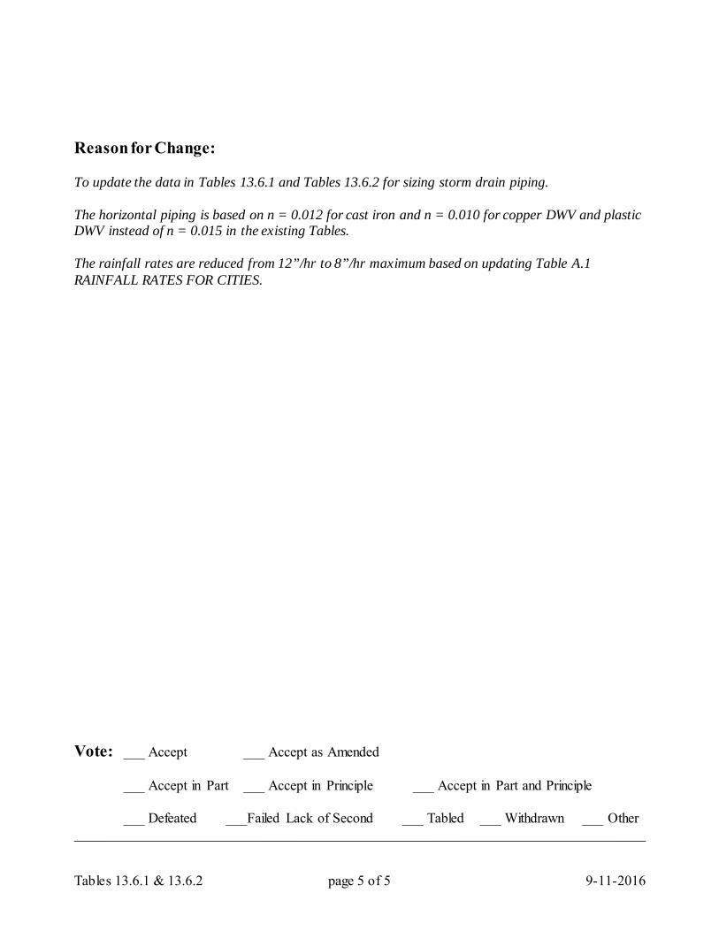
Tables 13.6.1 & 13.6.2 page 5 of 5 9-11-2016
Reason for Change: To update the data in Tables 13.6.1 and Tables 13.6.2 for sizing storm drain piping. The horizontal piping is based on n = 0.012 for cast iron and n = 0.010 for copper DWV and plastic DWV instead of n = 0.015 in the existing Tables. The rainfall rates are reduced from 12”/hr to 8”/hr maximum based on updating Table A.1 RAINFALL RATES FOR CITIES. Vote: ___ Accept ___ Accept as Amended
___ Accept in Part ___ Accept in Principle ___ Accept in Part and Principle
___ Defeated ___Failed Lack of Second ___ Tabled ___ Withdrawn ___ Other _________________________________________________________________________________
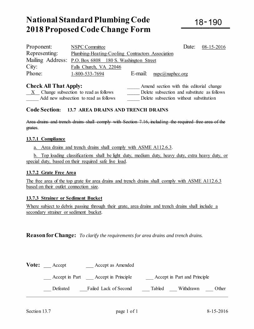
National Standard Plumbing Code 2018 Proposed Code Change Form
-
Section 13.7 page 1 of 1 8-15-2016
Proponent: NSPC Committee Date: 08-15-2016 Representing: Plumbing-Heating-Cooling Contractors Association Mailing Address: P.O. Box 6808 180 S. Washington Street City: Falls Church, VA 22046 Phone: 1-800-533-7694 E-mail: [email protected] Check All That Apply: _____ Amend section with this editorial change __X__ Change subsection to read as follows _____ Delete subsection and substitute as follows _____ Add new subsection to read as follows _____ Delete subsection without substitution Code Section: 13.7 AREA DRAINS AND TRENCH DRAINS Area drains and trench drains shall comply with Section 7.16, including the required free area of the grates. 13.7.1 Compliance
a. Area drains and trench drains shall comply with ASME A112.6.3. b. Top loading classifications shall be light duty, medium duty, heavy duty, extra heavy duty, or special duty, based on their required safe live load. 13.7.2 Grate Free Area
The free area of the top grate for area drains and trench drains shall comply with ASME A112.6.3 based on their outlet connection size. 13.7.3 Strainer or Sediment Bucket Where subject to debris passing through their grate, area drains and trench drains shall include a secondary strainer or sediment bucket. Reason for Change: To clarify the requirements for area drains and trench drains. Vote: ___ Accept ___ Accept as Amended
___ Accept in Part ___ Accept in Principle ___ Accept in Part and Principle
___ Defeated ___Failed Lack of Second ___ Tabled ___ Withdrawn ___ Other _________________________________________________________________________________
18 190
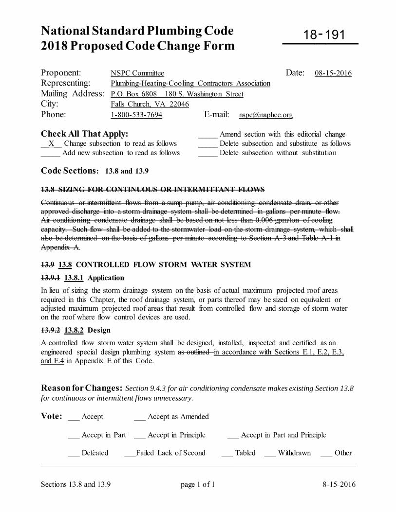
National Standard Plumbing Code 2018 Proposed Code Change Form
-
Sections 13.8 and 13.9 page 1 of 1 8-15-2016
Proponent: NSPC Committee Date: 08-15-2016 Representing: Plumbing-Heating-Cooling Contractors Association Mailing Address: P.O. Box 6808 180 S. Washington Street City: Falls Church, VA 22046 Phone: 1-800-533-7694 E-mail: [email protected] Check All That Apply: _____ Amend section with this editorial change __X__ Change subsection to read as follows _____ Delete subsection and substitute as follows _____ Add new subsection to read as follows _____ Delete subsection without substitution Code Sections: 13.8 and 13.9 13.8 SIZING FOR CONTINUOUS OR INTERMITTANT FLOWS
Continuous or intermittent flows from a sump pump, air conditioning condensate drain, or other approved discharge into a storm drainage system shall be determined in gallons per minute flow. Air conditioning condensate drainage shall be based on not less than 0.006 gpm/ton of cooling capacity. Such flow shall be added to the stormwater load on the storm drainage system, which shall also be determined on the basis of gallons per minute according to Section A-3 and Table A-1 in Appendix A. 13.9 13.8 CONTROLLED FLOW STORM WATER SYSTEM
13.9.1 13.8.1 Application In lieu of sizing the storm drainage system on the basis of actual maximum projected roof areas required in this Chapter, the roof drainage system, or parts thereof may be sized on equivalent or adjusted maximum projected roof areas that result from controlled flow and storage of storm water on the roof where flow control devices are used.
13.9.2 13.8.2 Design A controlled flow storm water system shall be designed, installed, inspected and certified as an engineered special design plumbing system as outlined in accordance with Sections E.1, E.2, E.3, and E.4 in Appendix E of this Code. Reason for Changes: Section 9.4.3 for air conditioning condensate makes existing Section 13.8 for continuous or intermittent flows unnecessary. Vote: ___ Accept ___ Accept as Amended
___ Accept in Part ___ Accept in Principle ___ Accept in Part and Principle
___ Defeated ___Failed Lack of Second ___ Tabled ___ Withdrawn ___ Other _________________________________________________________________________________
18 191
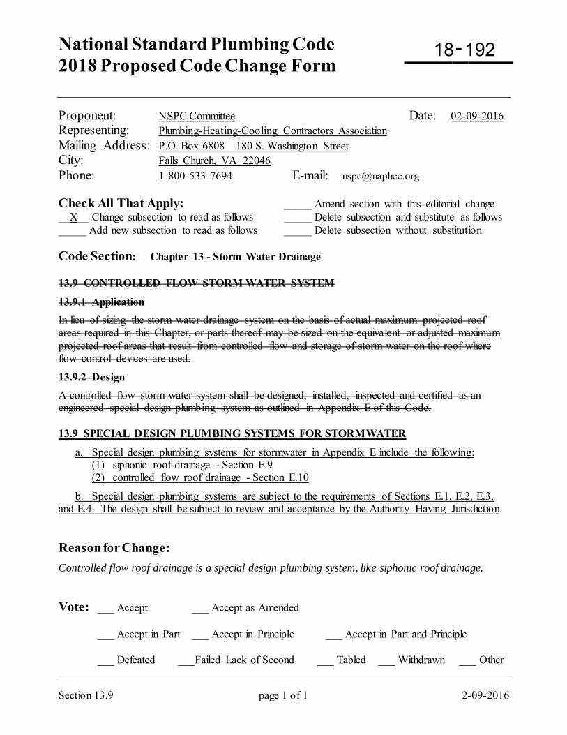
National Standard Plumbing Code 2018 Proposed Code Change Form
-
Section 13.9 page 1 of 1 2-09-2016
Proponent: NSPC Committee Date: 02-09-2016 Representing: Plumbing-Heating-Cooling Contractors Association Mailing Address: P.O. Box 6808 180 S. Washington Street City: Falls Church, VA 22046 Phone: 1-800-533-7694 E-mail: [email protected] Check All That Apply: _____ Amend section with this editorial change __X__ Change subsection to read as follows _____ Delete subsection and substitute as follows _____ Add new subsection to read as follows _____ Delete subsection without substitution Code Section: Chapter 13 - Storm Water Drainage 13.9 CONTROLLED FLOW STORM WATER SYSTEM
13.9.1 Application In lieu of sizing the storm water drainage system on the basis of actual maximum projected roof areas required in this Chapter, or parts thereof may be sized on the equivalent or adjusted maximum projected roof areas that result from controlled flow and storage of storm water on the roof where flow control devices are used.
13.9.2 Design A controlled flow storm water system shall be designed, installed, inspected and certified as an engineered special design plumbing system as outlined in Appendix E of this Code. 13.9 SPECIAL DESIGN PLUMBING SYSTEMS FOR STORMWATER
a. Special design plumbing systems for stormwater in Appendix E include the following: (1) siphonic roof drainage - Section E.9 (2) controlled flow roof drainage - Section E.10
b. Special design plumbing systems are subject to the requirements of Sections E.1, E.2, E.3, and E.4. The design shall be subject to review and acceptance by the Authority Having Jurisdiction. Reason for Change: Controlled flow roof drainage is a special design plumbing system, like siphonic roof drainage. Vote: ___ Accept ___ Accept as Amended
___ Accept in Part ___ Accept in Principle ___ Accept in Part and Principle
___ Defeated ___Failed Lack of Second ___ Tabled ___ Withdrawn ___ Other _________________________________________________________________________________
18 192
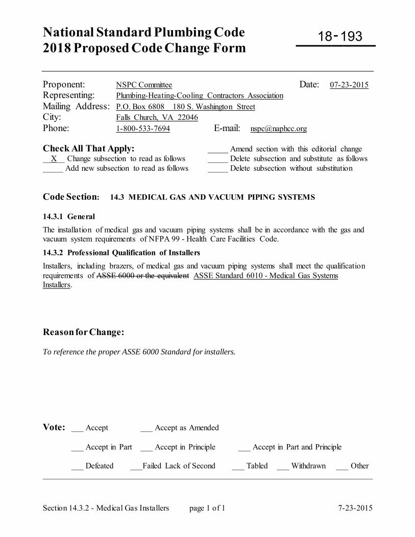
National Standard Plumbing Code 2018 Proposed Code Change Form
-
Section 14.3.2 - Medical Gas Installers page 1 of 1 7-23-2015
Proponent: NSPC Committee Date: 07-23-2015 Representing: Plumbing-Heating-Cooling Contractors Association Mailing Address: P.O. Box 6808 180 S. Washington Street City: Falls Church, VA 22046 Phone: 1-800-533-7694 E-mail: [email protected] Check All That Apply: _____ Amend section with this editorial change __X__ Change subsection to read as follows _____ Delete subsection and substitute as follows _____ Add new subsection to read as follows _____ Delete subsection without substitution Code Section: 14.3 MEDICAL GAS AND VACUUM PIPING SYSTEMS 14.3.1 General The installation of medical gas and vacuum piping systems shall be in accordance with the gas and vacuum system requirements of NFPA 99 - Health Care Facilities Code.
14.3.2 Professional Qualification of Installers Installers, including brazers, of medical gas and vacuum piping systems shall meet the qualification requirements of ASSE 6000 or the equivalent ASSE Standard 6010 - Medical Gas Systems Installers. Reason for Change: To reference the proper ASSE 6000 Standard for installers. Vote: ___ Accept ___ Accept as Amended
___ Accept in Part ___ Accept in Principle ___ Accept in Part and Principle
___ Defeated ___Failed Lack of Second ___ Tabled ___ Withdrawn ___ Other _________________________________________________________________________________
18 193
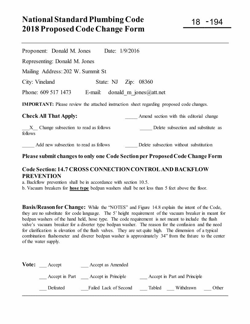
National Standard Plumbing Code 2018 Proposed Code Change Form
-
Proponent: Donald M. Jones Date: 1/9/2016
Representing: Donald M. Jones
Mailing Address: 202 W. Summit St
City: Vineland State: NJ Zip: 08360
Phone: 609 517 1473 E-mail: [email protected] IMPORTANT: Please review the attached instruction sheet regarding proposed code changes. Check All That Apply: _____ Amend section with this editorial change ___X__ Change subsection to read as follows _____ Delete subsection and substitute as follows _____ Add new subsection to read as follows _____ Delete subsection without substitution Please submit changes to only one Code Section per Proposed Code Change Form Code Section: 14.7 CROSS CONNECTION CONTROL AND BACKFLOW PREVENTION a. Backflow prevention shall be in accordance with section 10.5. b. Vacuum breakers for hose type bedpan washers shall be not less than 5 feet above the floor. Basis/Reason for Change: While the “NOTES” and Figure 14.8 explain the intent of the Code, they are no substitute for code language. The 5’ height requirement of the vacuum breaker in meant for bedpan washers of the hand held, hose type. The code requirement is not meant to include the flush valve’s vacuum breaker for a diverter type bedpan washer. The reason for the confusion and the need for clarification is elevation of the flush valves. They are set quite high. The dimension of a typical combination flushometer and diverer bedpan washer is approximately 34” from the fixture to the center of the water supply. Vote: ___ Accept ___ Accept as Amended
___ Accept in Part ___ Accept in Principle ___ Accept in Part and Principle
___ Defeated ___Failed Lack of Second ___ Tabled ___ Withdrawn ___ Other ____________________________________________________________________________________
18 194
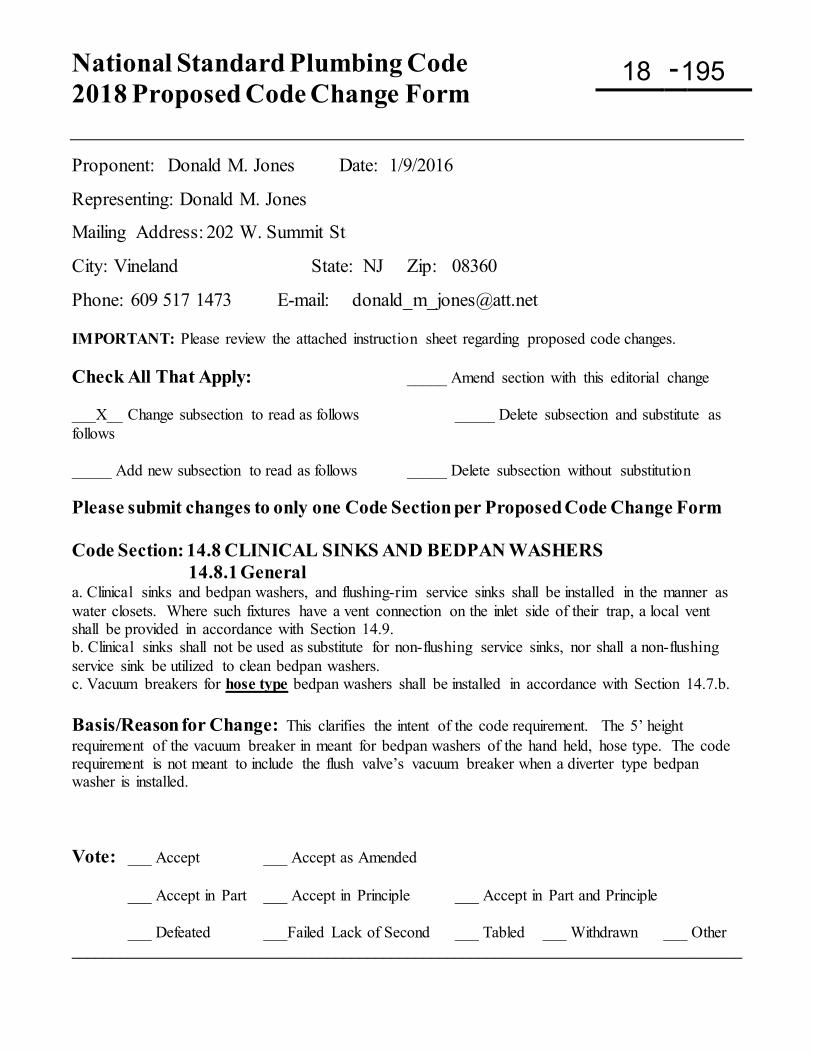
National Standard Plumbing Code 2018 Proposed Code Change Form
-
Proponent: Donald M. Jones Date: 1/9/2016
Representing: Donald M. Jones
Mailing Address: 202 W. Summit St
City: Vineland State: NJ Zip: 08360
Phone: 609 517 1473 E-mail: [email protected] IMPORTANT: Please review the attached instruction sheet regarding proposed code changes. Check All That Apply: _____ Amend section with this editorial change ___X__ Change subsection to read as follows _____ Delete subsection and substitute as follows _____ Add new subsection to read as follows _____ Delete subsection without substitution Please submit changes to only one Code Section per Proposed Code Change Form Code Section: 14.8 CLINICAL SINKS AND BEDPAN WASHERS 14.8.1 General a. Clinical sinks and bedpan washers, and flushing-rim service sinks shall be installed in the manner as water closets. Where such fixtures have a vent connection on the inlet side of their trap, a local vent shall be provided in accordance with Section 14.9. b. Clinical sinks shall not be used as substitute for non-flushing service sinks, nor shall a non-flushing service sink be utilized to clean bedpan washers. c. Vacuum breakers for hose type bedpan washers shall be installed in accordance with Section 14.7.b. Basis/Reason for Change: This clarifies the intent of the code requirement. The 5’ height requirement of the vacuum breaker in meant for bedpan washers of the hand held, hose type. The code requirement is not meant to include the flush valve’s vacuum breaker when a diverter type bedpan washer is installed. Vote: ___ Accept ___ Accept as Amended
___ Accept in Part ___ Accept in Principle ___ Accept in Part and Principle
___ Defeated ___Failed Lack of Second ___ Tabled ___ Withdrawn ___ Other ____________________________________________________________________________________
18 195
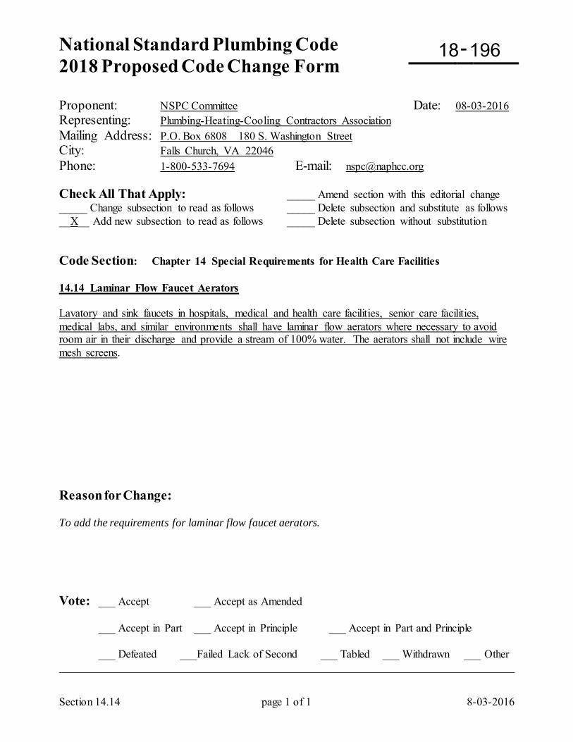
National Standard Plumbing Code 2018 Proposed Code Change Form
-
Section 14.14 page 1 of 1 8-03-2016
Proponent: NSPC Committee Date: 08-03-2016 Representing: Plumbing-Heating-Cooling Contractors Association Mailing Address: P.O. Box 6808 180 S. Washington Street City: Falls Church, VA 22046 Phone: 1-800-533-7694 E-mail: [email protected] Check All That Apply: _____ Amend section with this editorial change _____ Change subsection to read as follows _____ Delete subsection and substitute as follows __X__ Add new subsection to read as follows _____ Delete subsection without substitution Code Section: Chapter 14 Special Requirements for Health Care Facilities 14.14 Laminar Flow Faucet Aerators Lavatory and sink faucets in hospitals, medical and health care facilities, senior care facilities, medical labs, and similar environments shall have laminar flow aerators where necessary to avoid room air in their discharge and provide a stream of 100% water. The aerators shall not include wire mesh screens. Reason for Change: To add the requirements for laminar flow faucet aerators. Vote: ___ Accept ___ Accept as Amended
___ Accept in Part ___ Accept in Principle ___ Accept in Part and Principle
___ Defeated ___Failed Lack of Second ___ Tabled ___ Withdrawn ___ Other _________________________________________________________________________________
18 196
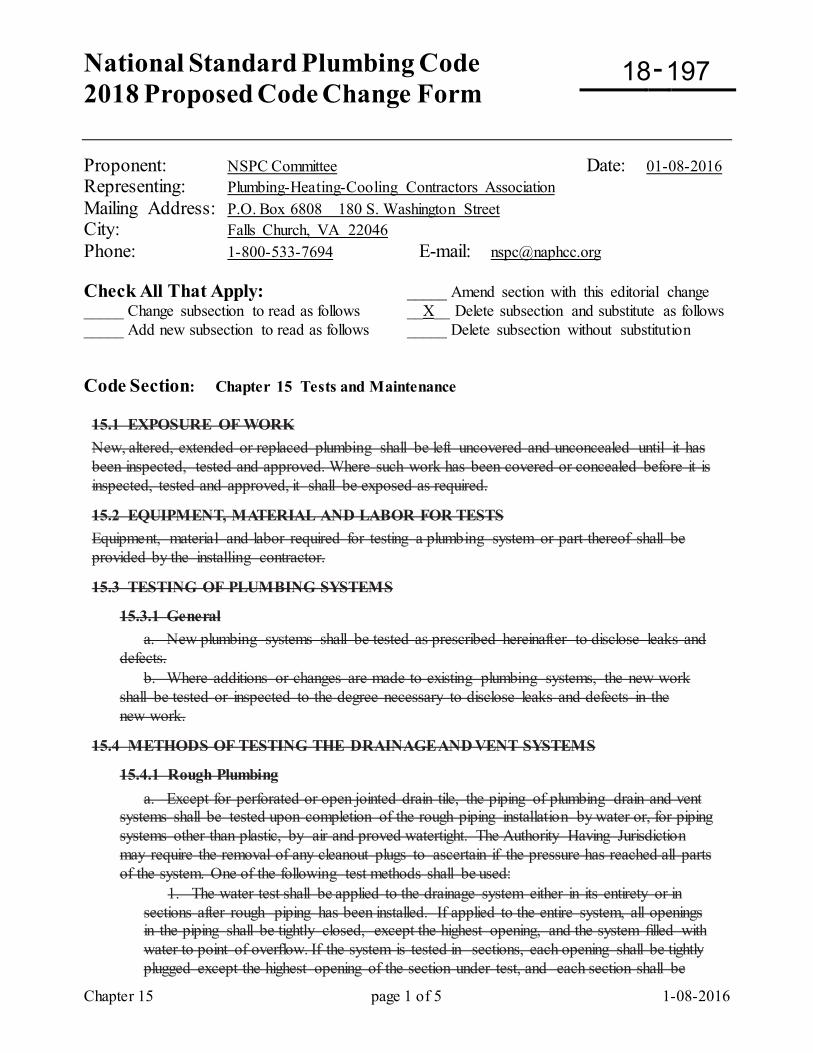
National Standard Plumbing Code 2018 Proposed Code Change Form
-
Chapter 15 page 1 of 5 1-08-2016
Proponent: NSPC Committee Date: 01-08-2016 Representing: Plumbing-Heating-Cooling Contractors Association Mailing Address: P.O. Box 6808 180 S. Washington Street City: Falls Church, VA 22046 Phone: 1-800-533-7694 E-mail: [email protected] Check All That Apply: _____ Amend section with this editorial change _____ Change subsection to read as follows __X__ Delete subsection and substitute as follows _____ Add new subsection to read as follows _____ Delete subsection without substitution Code Section: Chapter 15 Tests and Maintenance 15.1 EXPOSURE OF WORK New, altered, extended or replaced plumbing shall be left uncovered and unconcealed until it has been inspected, tested and approved. Where such work has been covered or concealed before it is inspected, tested and approved, it shall be exposed as required.
15.2 EQUIPMENT, MATERIAL AND LABOR FOR TESTS Equipment, material and labor required for testing a plumbing system or part thereof shall be provided by the installing contractor.
15.3 TESTING OF PLUMBING SYSTEMS
15.3.1 General a. New plumbing systems shall be tested as prescribed hereinafter to disclose leaks and defects. b. Where additions or changes are made to existing plumbing systems, the new work shall be tested or inspected to the degree necessary to disclose leaks and defects in the new work.
15.4 METHODS OF TESTING THE DRAINAGE AND VENT SYSTEMS
15.4.1 Rough Plumbing a. Except for perforated or open jointed drain tile, the piping of plumbing drain and vent systems shall be tested upon completion of the rough piping installation by water or, for piping systems other than plastic, by air and proved watertight. The Authority Having Jurisdiction may require the removal of any cleanout plugs to ascertain if the pressure has reached all parts of the system. One of the following test methods shall be used:
1. The water test shall be applied to the drainage system either in its entirety or in sections after rough piping has been installed. If applied to the entire system, all openings in the piping shall be tightly closed, except the highest opening, and the system filled with water to point of overflow. If the system is tested in sections, each opening shall be tightly plugged except the highest opening of the section under test, and each section shall be
18 197
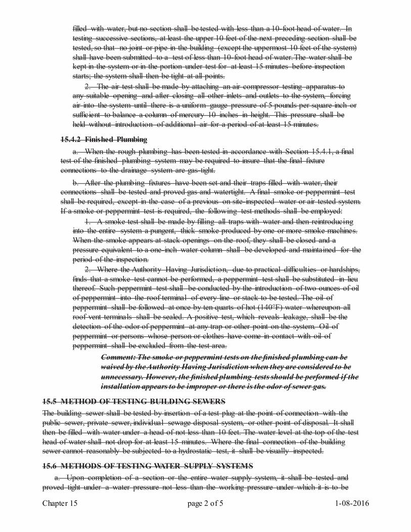
Chapter 15 page 2 of 5 1-08-2016
filled with water, but no section shall be tested with less than a 10-foot head of water. In testing successive sections, at least the upper 10 feet of the next preceding section shall be tested, so that no joint or pipe in the building (except the uppermost 10 feet of the system) shall have been submitted to a test of less than 10-foot head of water. The water shall be kept in the system or in the portion under test for at least 15 minutes before inspection starts; the system shall then be tight at all points. 2. The air test shall be made by attaching an air compressor testing apparatus to any suitable opening and after closing all other inlets and outlets to the system, forcing air into the system until there is a uniform gauge pressure of 5 pounds per square inch or sufficient to balance a column of mercury 10 inches in height. This pressure shall be held without introduction of additional air for a period of at least 15 minutes.
15.4.2 Finished Plumbing a. When the rough plumbing has been tested in accordance with Section 15.4.1, a final test of the finished plumbing system may be required to insure that the final fixture connections to the drainage system are gas-tight. b. After the plumbing fixtures have been set and their traps filled with water, their connections shall be tested and proved gas and watertight. A final smoke or peppermint test shall be required, except in the case of a previous on site-inspected water or air tested system. If a smoke or peppermint test is required, the following test methods shall be employed:
1. A smoke test shall be made by filling all traps with water and then reintroducing into the entire system a pungent, thick smoke produced by one or more smoke machines. When the smoke appears at stack openings on the roof, they shall be closed and a pressure equivalent to a one-inch water column shall be developed and maintained for the period of the inspection. 2. Where the Authority Having Jurisdiction, due to practical difficulties or hardships, finds that a smoke test cannot be performed, a peppermint test shall be substituted in lieu thereof. Such peppermint test shall be conducted by the introduction of two ounces of oil of peppermint into the roof terminal of every line or stack to be tested. The oil of peppermint shall be followed at once by ten quarts of hot (140°F) water whereupon all roof vent terminals shall be sealed. A positive test, which reveals leakage, shall be the detection of the odor of peppermint at any trap or other point on the system. Oil of peppermint or persons whose person or clothes have come in contact with oil of peppermint shall be excluded from the test area.
Comment: The smoke or peppermint tests on the finished plumbing can be waived by the Authority Having Jurisdiction when they are considered to be unnecessary. However, the finished plumbing tests should be performed if the installation appears to be improper or there is the odor of sewer gas.
15.5 METHOD OF TESTING BUILDING SEWERS The building sewer shall be tested by insertion of a test plug at the point of connection with the public sewer, private sewer, individual sewage disposal system, or other point of disposal. It shall then be filled with water under a head of not less than 10 feet. The water level at the top of the test head of water shall not drop for at least 15 minutes. Where the final connection of the building sewer cannot reasonably be subjected to a hydrostatic test, it shall be visually inspected.
15.6 METHODS OF TESTING WATER SUPPLY SYSTEMS a. Upon completion of a section or the entire water supply system, it shall be tested and proved tight under a water pressure not less than the working pressure under which it is to be
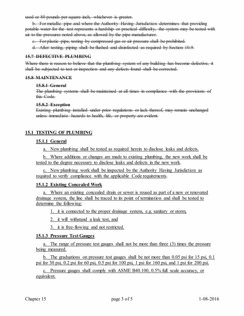
Chapter 15 page 3 of 5 1-08-2016
used or 80 pounds per square inch, whichever is greater. b. For metallic pipe and where the Authority Having Jurisdiction determines that providing potable water for the test represents a hardship or practical difficulty, the system may be tested with air to the pressures noted above, as allowed by the pipe manufacturer. c. For plastic pipe, testing by compressed gas or air pressure shall be prohibited. d. After testing, piping shall be flushed and disinfected as required by Section 10.9.
15.7 DEFECTIVE PLUMBING Where there is reason to believe that the plumbing system of any building has become defective, it shall be subjected to test or inspection and any defects found shall be corrected.
15.8 MAINTENANCE 15.8.1 General The plumbing systems shall be maintained at all times in compliance with the provisions of this Code.
15.8.2 Exception Existing plumbing installed under prior regulations or lack thereof, may remain unchanged unless immediate hazards to health, life, or property are evident.
15.1 TESTING OF PLUMBING
15.1.1 General a. New plumbing shall be tested as required herein to disclose leaks and defects. b. Where additions or changes are made to existing plumbing, the new work shall be tested to the degree necessary to disclose leaks and defects in the new work. c. New plumbing work shall be inspected by the Authority Having Jurisdiction as required to verify compliance with the applicable Code requirements.
15.1.2 Existing Concealed Work a. Where an existing concealed drain or sewer is reused as part of a new or renovated drainage system, the line shall be traced to its point of termination and shall be tested to determine the following:
1. it is connected to the proper drainage system, e.g. sanitary or storm,
2. it will withstand a leak test, and 3. it is free-flowing and not restricted.
15.1.3 Pressure Test Gauges
a. The range of pressure test gauges shall not be more than three (3) times the pressure being measured. b. The graduations on pressure test gauges shall be not more than 0.05 psi for 15 psi, 0.1 psi for 30 psi, 0.2 psi for 60 psi, 0.5 psi for 100 psi, 1 psi for 160 psi, and 1 psi for 200 psi. c. Pressure gauges shall comply with ASME B40.100, 0.5% full scale accuracy, or equivalent.
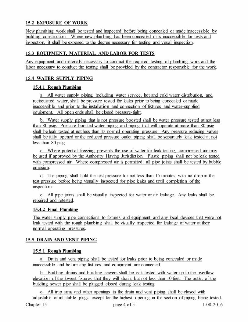
Chapter 15 page 4 of 5 1-08-2016
15.2 EXPOSURE OF WORK
New plumbing work shall be tested and inspected before being concealed or made inaccessible by building construction. Where new plumbing has been concealed or is inaccessible for tests and inspection, it shall be exposed to the degree necessary for testing and visual inspection. 15.3 EQUIPMENT, MATERIAL, AND LABOR FOR TESTS
Any equipment and materials necessary to conduct the required testing of plumbing work and the labor necessary to conduct the testing shall be provided by the contractor responsible for the work. 15.4 WATER SUPPLY PIPING
15.4.1 Rough Plumbing a. All water supply piping, including water service, hot and cold water distribution, and recirculated water, shall be pressure tested for leaks prior to being concealed or made inaccessible and prior to the installation and connection of fixtures and water-supplied equipment. All open ends shall be closed pressure-tight. b. Water supply piping that is not pressure boosted shall be water pressure tested at not less than 80 psig. Pressure boosted water piping and piping that will operate at more than 80 psig shall be leak tested at not less than its normal operating pressure. Any pressure reducing valves shall be fully opened or the reduced pressure outlet piping shall be separately leak tested at not less than 80 psig. c. Where potential freezing prevents the use of water for leak testing, compressed air may be used if approved by the Authority Having Jurisdiction. Plastic piping shall not be leak tested with compressed air. Where compressed air is permitted, all pipe joints shall be tested by bubble emission.
d. The piping shall hold the test pressure for not less than 15 minutes with no drop in the test pressure before being visually inspected for pipe leaks and until completion of the inspection.
e. All pipe joints shall be visually inspected for water or air leakage. Any leaks shall be repaired and retested.
15.4.2 Final Plumbing The water supply pipe connections to fixtures and equipment and any local devices that were not leak tested with the rough plumbing shall be visually inspected for leakage of water at their normal operating pressures.
15.5 DRAIN AND VENT PIPING
15.5.1 Rough Plumbing a. Drain and vent piping shall be tested for leaks prior to being concealed or made inaccessible and before any fixtures and equipment are connected. b. Building drains and building sewers shall be leak tested with water up to the overflow elevation of the lowest fixtures that they will drain, but not less than 10 feet. The outlet of the building sewer pipe shall be plugged closed during leak testing. c. All trap arms and other openings in the drain and vent piping shall be closed with adjustable or inflatable plugs, except for the highest opening in the section of piping being tested.
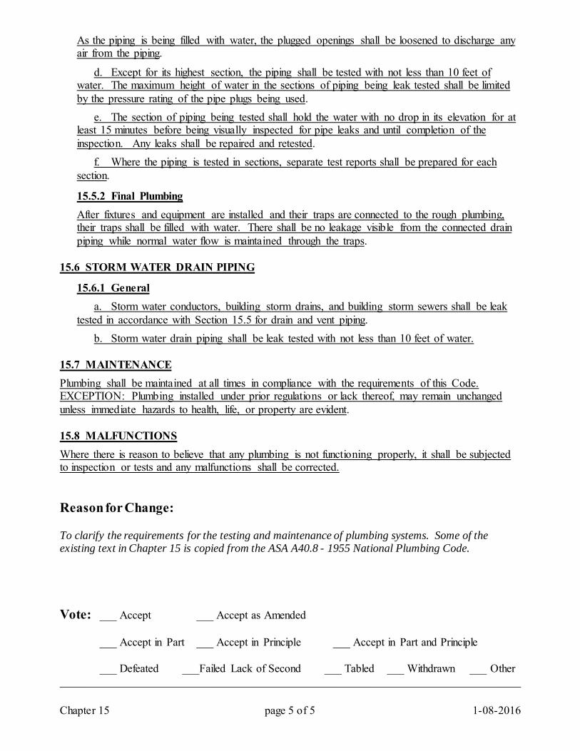
Chapter 15 page 5 of 5 1-08-2016
As the piping is being filled with water, the plugged openings shall be loosened to discharge any air from the piping.
d. Except for its highest section, the piping shall be tested with not less than 10 feet of water. The maximum height of water in the sections of piping being leak tested shall be limited by the pressure rating of the pipe plugs being used. e. The section of piping being tested shall hold the water with no drop in its elevation for at least 15 minutes before being visually inspected for pipe leaks and until completion of the inspection. Any leaks shall be repaired and retested. f. Where the piping is tested in sections, separate test reports shall be prepared for each section.
15.5.2 Final Plumbing After fixtures and equipment are installed and their traps are connected to the rough plumbing, their traps shall be filled with water. There shall be no leakage visible from the connected drain piping while normal water flow is maintained through the traps.
15.6 STORM WATER DRAIN PIPING
15.6.1 General a. Storm water conductors, building storm drains, and building storm sewers shall be leak tested in accordance with Section 15.5 for drain and vent piping. b. Storm water drain piping shall be leak tested with not less than 10 feet of water.
15.7 MAINTENANCE Plumbing shall be maintained at all times in compliance with the requirements of this Code. EXCEPTION: Plumbing installed under prior regulations or lack thereof, may remain unchanged unless immediate hazards to health, life, or property are evident. 15.8 MALFUNCTIONS Where there is reason to believe that any plumbing is not functioning properly, it shall be subjected to inspection or tests and any malfunctions shall be corrected. Reason for Change: To clarify the requirements for the testing and maintenance of plumbing systems. Some of the existing text in Chapter 15 is copied from the ASA A40.8 - 1955 National Plumbing Code. Vote: ___ Accept ___ Accept as Amended
___ Accept in Part ___ Accept in Principle ___ Accept in Part and Principle
___ Defeated ___Failed Lack of Second ___ Tabled ___ Withdrawn ___ Other _________________________________________________________________________________
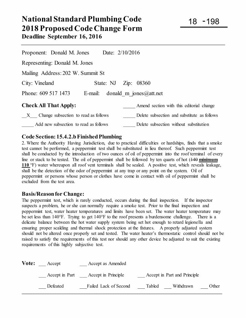
National Standard Plumbing Code 2018 Proposed Code Change Form Deadline September 16, 2016
-
Proponent: Donald M. Jones Date: 2/10/2016
Representing: Donald M. Jones
Mailing Address: 202 W. Summit St
City: Vineland State: NJ Zip: 08360
Phone: 609 517 1473 E-mail: [email protected] Check All That Apply: _____ Amend section with this editorial change __X___ Change subsection to read as follows _____ Delete subsection and substitute as follows _____ Add new subsection to read as follows _____ Delete subsection without substitution Code Section: 15.4.2.b Finished Plumbing 2. Where the Authority Having Jurisdiction, due to practical difficulties or hardships, finds that a smoke test cannot be performed, a peppermint test shall be substituted in lieu thereof. Such peppermint test shall be conducted by the introduction of two ounces of oil of peppermint into the roof terminal of every line or stack to be tested. The oil of peppermint shall be followed by ten quarts of hot (140 minimum 110 °F) water whereupon all roof vent terminals shall be sealed. A positive test, which reveals leakage, shall be the detection of the odor of peppermint at any trap or any point on the system. Oil of peppermint or persons whose person or clothes have come in contact with oil of peppermint shall be excluded from the test area. Basis/Reason for Change: The peppermint test, which is rarely conducted, occurs during the final inspection. If the inspector suspects a problem, he or she can normally require a smoke test. Prior to the final inspection and peppermint test, water heater temperatures and limits have been set. The water heater temperature may be set less than 140°F. Trying to get 140°F to the roof presents a burdensome challenge. There is a delicate balance between the hot water supply system being set hot enough to retard legionella and ensuring proper scalding and thermal shock protection at the fixtures. A properly adjusted system should not be altered once properly set and tested. The water heater’s thermostatic control should not be raised to satisfy the requirements of this test nor should any other device be adjusted to suit the existing requirements of this highly subjective test. Vote: ___ Accept ___ Accept as Amended
___ Accept in Part ___ Accept in Principle ___ Accept in Part and Principle
___ Defeated ___Failed Lack of Second ___ Tabled ___ Withdrawn ___ Other ___________________________________________________________________________________
18 198
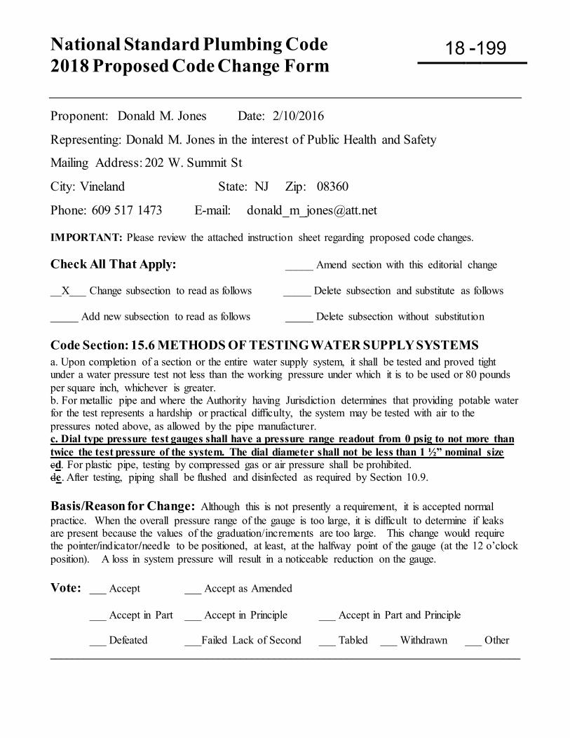
National Standard Plumbing Code 2018 Proposed Code Change Form
-
Proponent: Donald M. Jones Date: 2/10/2016
Representing: Donald M. Jones in the interest of Public Health and Safety
Mailing Address: 202 W. Summit St
City: Vineland State: NJ Zip: 08360
Phone: 609 517 1473 E-mail: [email protected] IMPORTANT: Please review the attached instruction sheet regarding proposed code changes. Check All That Apply: _____ Amend section with this editorial change __X___ Change subsection to read as follows _____ Delete subsection and substitute as follows _____ Add new subsection to read as follows _____ Delete subsection without substitution Code Section: 15.6 METHODS OF TESTING WATER SUPPLY SYSTEMS a. Upon completion of a section or the entire water supply system, it shall be tested and proved tight under a water pressure test not less than the working pressure under which it is to be used or 80 pounds per square inch, whichever is greater. b. For metallic pipe and where the Authority having Jurisdiction determines that providing potable water for the test represents a hardship or practical difficulty, the system may be tested with air to the pressures noted above, as allowed by the pipe manufacturer. c. Dial type pressure test gauges shall have a pressure range readout from 0 psig to not more than twice the test pressure of the system. The dial diameter shall not be less than 1 ½” nominal size cd. For plastic pipe, testing by compressed gas or air pressure shall be prohibited. de. After testing, piping shall be flushed and disinfected as required by Section 10.9. Basis/Reason for Change: Although this is not presently a requirement, it is accepted normal practice. When the overall pressure range of the gauge is too large, it is difficult to determine if leaks are present because the values of the graduation/increments are too large. This change would require the pointer/indicator/needle to be positioned, at least, at the halfway point of the gauge (at the 12 o’clock position). A loss in system pressure will result in a noticeable reduction on the gauge. Vote: ___ Accept ___ Accept as Amended
___ Accept in Part ___ Accept in Principle ___ Accept in Part and Principle
___ Defeated ___Failed Lack of Second ___ Tabled ___ Withdrawn ___ Other ____________________________________________________________________________________
18 199
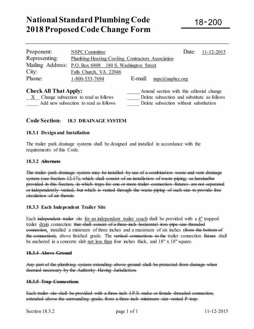
National Standard Plumbing Code 2018 Proposed Code Change Form
-
Section 18.3.2 page 1 of 1 11-12-2015
Proponent: NSPC Committee Date: 11-12-2015 Representing: Plumbing-Heating-Cooling Contractors Association Mailing Address: P.O. Box 6808 180 S. Washington Street City: Falls Church, VA 22046 Phone: 1-800-533-7694 E-mail: [email protected] Check All That Apply: _____ Amend section with this editorial change __X__ Change subsection to read as follows _____ Delete subsection and substitute as follows _____ Add new subsection to read as follows _____ Delete subsection without substitution Code Section: 18.3 DRAINAGE SYSTEM 18.3.1 Design and Installation The trailer park drainage systems shall be designed and installed in accordance with the requirements of this Code. 18.3.2 Alternate The trailer park drainage system may be installed by use of a combination waste and vent drainage system (see Section 12.17), which shall consist of an installation of waste piping, as hereinafter provided in this Section, in which traps for one or more trailer connection fixtures are not separated or independently vented, but which is vented through the waste piping of such size to provide free circulation of air therein. 18.3.3 Each Independent Trailer Site Each independent trailer site for an independent trailer coach shall be provided with a 4" trapped trailer drain connection that shall consist of a three-inch horizontal iron pipe size threaded connection, installed a minimum of three inches and a maximum of six inches (from the bottom of the connection), above finished grade. The vertical connections to the trailer connection fixture shall be anchored in a concrete slab not less than four inches thick, and 18" x 18" square. 18.3.4 Above Ground Any part of the plumbing system extending above ground shall be protected from damage when deemed necessary by the Authority Having Jurisdiction. 18.3.5 Trap Connections Each trailer site shall be provided with a three-inch I.P.S. make or female threaded connection, extended above the surrounding grade, from a three-inch minimum size vented P-trap.
18 200
18.3.5.1 Location Traps shall be located with reference to the immediate boundary lines of the designated space or area within each trailer site that will actually be occupied by the trailer. Each such trap shall be located in the rear third-quarter section along the left boundary line of the trailer parking area not less than one foot or more than three feet from the road side of the trailer and shall be a minimum of five feet from the rear boundary of the trailer site. This location may be varied by permission of the Authority Having Jurisdiction when unusual conditions are encountered. 18.3.5.2 Material All traps, tail pipes, vertical vents, the upper five feet of any horizontal vent, and the first feet of any trap branch shall be fabricated from materials approved for use within a building. 18.3.6 Reserved 18.3.7 Drain Connections Mobile home and travel trailer drain connections shall be of approved semi-rigid or flexible reinforced hose having smooth interior surfaces and not less than 3-inch inside diameter. Main connections shall be equipped with a standard quick-disconnect screw or clamp type fitting, not smaller than the outlet. Main connections shall be gas-tight and no longer than necessary to make the connection between the trailer coach drain connection and the trailer connection fixture on the site. 18.3.8 Cleanouts Cleanouts shall be provided as required by Chapter 5 of this Code, except cleanouts shall be provided in vent terminals one foot above grade. 18.3.9 Drainage Fixture Unit (DFU) Loading For the purpose of determining pipe sizes, each trailer site connection shall be assigned a drainage loading value of six drainage fixture units (DFU) and each trailer park drainage system shall be sized in accordance with Table 18.3.12. 18.3.10 Slope of Sewers The grade of sewers shall provide a minimum velocity of two feet per second when the pipe is flowing half full. 18.3.11 Drainage System Discharge The discharge of the park drainage system shall be connected to a public sewer. Where a public sewer is not available within 300 feet for use, and individual sewage disposal system of a type that is acceptable and approved by the Authority Having Jurisdiction shall be installed.
Comment: It is preferred that trailer parks be connected to public sewers, even if more than 300 feet away. Trailer sites are typically densely spaced to maximize the use of the property, which leaves little space for an adequate on-site sewage disposal system.
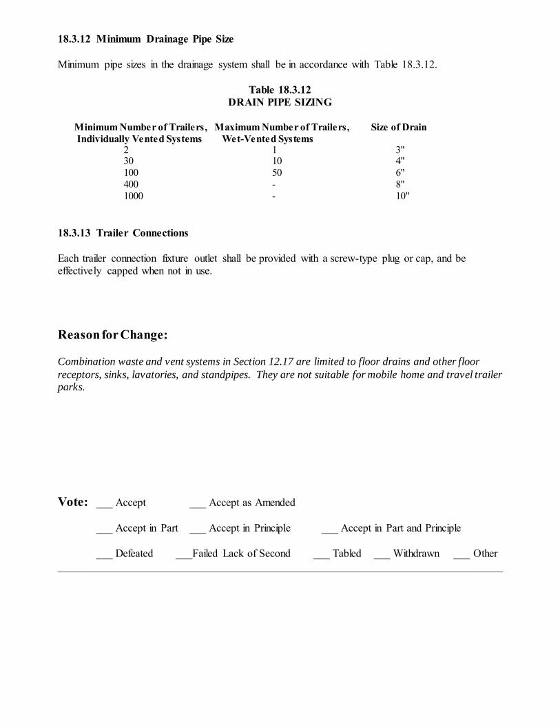
18.3.12 Minimum Drainage Pipe Size Minimum pipe sizes in the drainage system shall be in accordance with Table 18.3.12.
Table 18.3.12 DRAIN PIPE SIZING
Minimum Number of Trailers, Maximum Number of Trailers, Size of Drain Individually Vented Systems Wet-Vented Systems
2 1 3" 30 10 4" 100 50 6" 400 - 8" 1000 - 10" 18.3.13 Trailer Connections Each trailer connection fixture outlet shall be provided with a screw-type plug or cap, and be effectively capped when not in use. Reason for Change: Combination waste and vent systems in Section 12.17 are limited to floor drains and other floor receptors, sinks, lavatories, and standpipes. They are not suitable for mobile home and travel trailer parks. Vote: ___ Accept ___ Accept as Amended
___ Accept in Part ___ Accept in Principle ___ Accept in Part and Principle
___ Defeated ___Failed Lack of Second ___ Tabled ___ Withdrawn ___ Other _________________________________________________________________________________
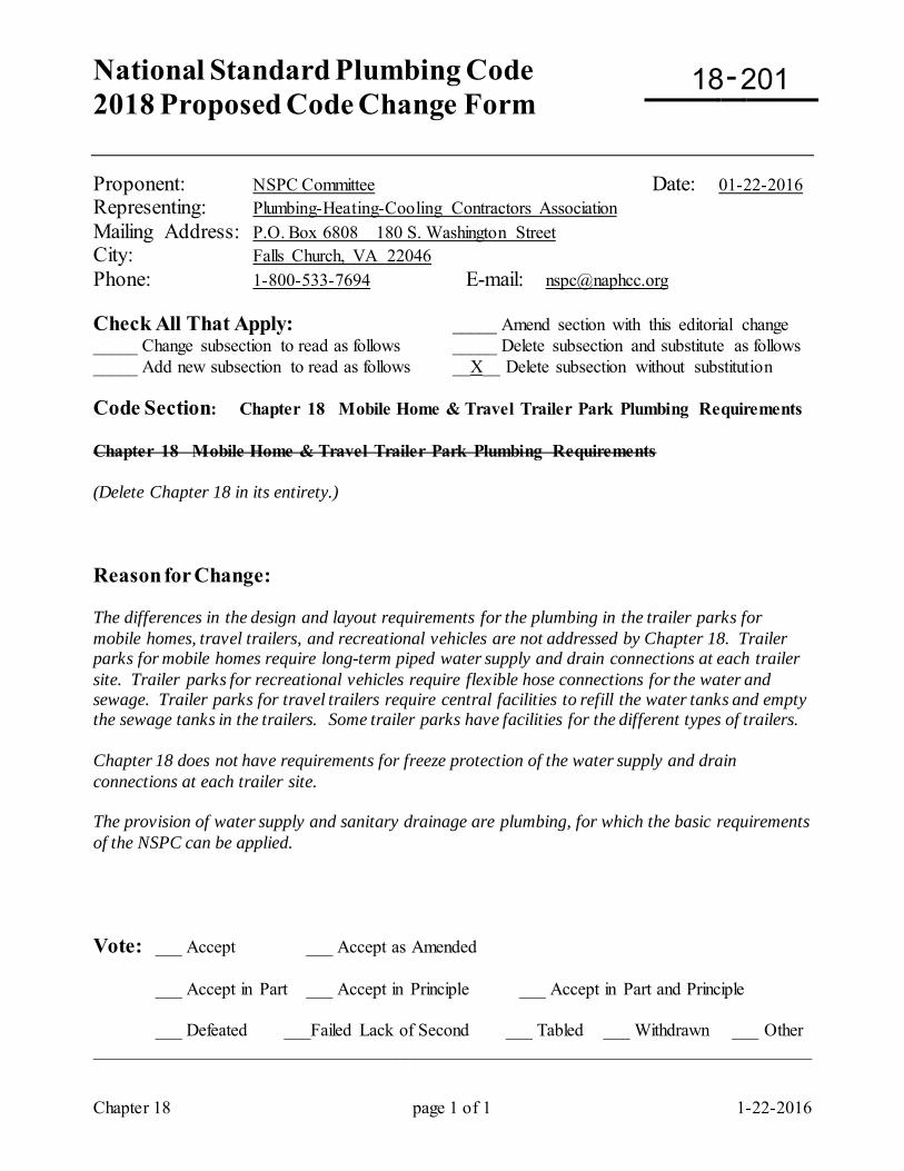
National Standard Plumbing Code 2018 Proposed Code Change Form
-
Chapter 18 page 1 of 1 1-22-2016
Proponent: NSPC Committee Date: 01-22-2016 Representing: Plumbing-Heating-Cooling Contractors Association Mailing Address: P.O. Box 6808 180 S. Washington Street City: Falls Church, VA 22046 Phone: 1-800-533-7694 E-mail: [email protected] Check All That Apply: _____ Amend section with this editorial change _____ Change subsection to read as follows _____ Delete subsection and substitute as follows _____ Add new subsection to read as follows __X__ Delete subsection without substitution Code Section: Chapter 18 Mobile Home & Travel Trailer Park Plumbing Requirements Chapter 18 Mobile Home & Travel Trailer Park Plumbing Requirements (Delete Chapter 18 in its entirety.) Reason for Change: The differences in the design and layout requirements for the plumbing in the trailer parks for mobile homes, travel trailers, and recreational vehicles are not addressed by Chapter 18. Trailer parks for mobile homes require long-term piped water supply and drain connections at each trailer site. Trailer parks for recreational vehicles require flexible hose connections for the water and sewage. Trailer parks for travel trailers require central facilities to refill the water tanks and empty the sewage tanks in the trailers. Some trailer parks have facilities for the different types of trailers. Chapter 18 does not have requirements for freeze protection of the water supply and drain connections at each trailer site. The provision of water supply and sanitary drainage are plumbing, for which the basic requirements of the NSPC can be applied. Vote: ___ Accept ___ Accept as Amended
___ Accept in Part ___ Accept in Principle ___ Accept in Part and Principle
___ Defeated ___Failed Lack of Second ___ Tabled ___ Withdrawn ___ Other _________________________________________________________________________________
18 201
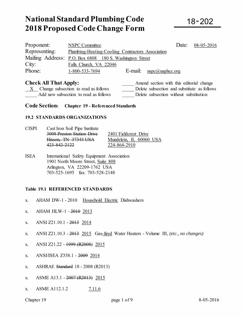
National Standard Plumbing Code 2018 Proposed Code Change Form
-
Chapter 19 page 1 of 9 8-05-2016
Proponent: NSPC Committee Date: 08-05-2016 Representing: Plumbing-Heating-Cooling Contractors Association Mailing Address: P.O. Box 6808 180 S. Washington Street City: Falls Church, VA 22046 Phone: 1-800-533-7694 E-mail: [email protected] Check All That Apply: _____ Amend section with this editorial change __X__ Change subsection to read as follows _____ Delete subsection and substitute as follows _____ Add new subsection to read as follows _____ Delete subsection without substitution Code Section: Chapter 19 - Referenced Standards 19.2 STANDARDS ORGANIZATIONS CISPI Cast Iron Soil Pipe Institute 3008 Preston Station Drive 2401 Fieldcrest Drive Hixson, TN 37343 USA Mundelein, IL 60060 USA 423-842-2122 224-864-2910 ISEA International Safety Equipment Association 1901 North Moore Street, Suite 808 Arlington, VA 22209-1762 USA 703-525-1695 fax: 703-528-2148 Table 19.1 REFERENCED STANDARDS x. AHAM DW-1 - 2010 Household Electric Dishwashers x. AHAM HLW-1 - 2010 2013 x. ANSI Z21.10.1 - 2013 2014 x. ANSI Z21.10.3 - 2013 2015 Gas-fired Water Heaters - Volume III, (etc., no changes) x. ANSI Z21.22 - 1999 (R2008) 2015 x. ANSI/ISEA Z358.1 - 2009 2014 x. ASHRAE Standard 18 - 2008 (R2013) x. ASME A13.1 - 2007 (R2013) 2015 x. ASME A112.1.2 7.11.6
18 202
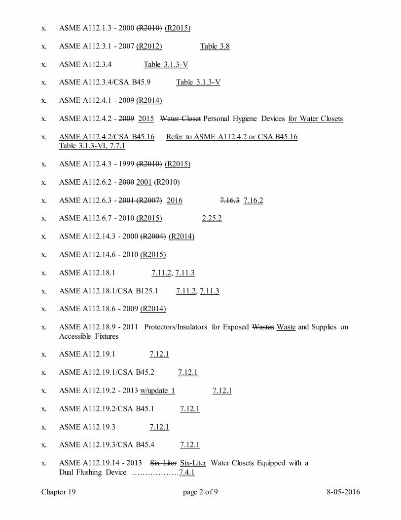
Chapter 19 page 2 of 9 8-05-2016
x. ASME A112.1.3 - 2000 (R2010) (R2015) x. ASME A112.3.1 - 2007 (R2012) Table 3.8 x. ASME A112.3.4 Table 3.1.3-V x. ASME A112.3.4/CSA B45.9 Table 3.1.3-V x. ASME A112.4.1 - 2009 (R2014) x. ASME A112.4.2 - 2009 2015 Water Closet Personal Hygiene Devices for Water Closets x. ASME A112.4.2/CSA B45.16 Refer to ASME A112.4.2 or CSA B45.16 Table 3.1.3-VI, 7.7.1 x. ASME A112.4.3 - 1999 (R2010) (R2015) x. ASME A112.6.2 - 2000 2001 (R2010) x. ASME A112.6.3 - 2001 (R2007) 2016 7.16.3 7.16.2 x. ASME A112.6.7 - 2010 (R2015) 2.25.2 x. ASME A112.14.3 - 2000 (R2004) (R2014) x. ASME A112.14.6 - 2010 (R2015) x. ASME A112.18.1 7.11.2, 7.11.3 x. ASME A112.18.1/CSA B125.1 7.11.2, 7.11.3 x. ASME A112.18.6 - 2009 (R2014) x. ASME A112.18.9 - 2011 Protectors/Insulators for Exposed Wastes Waste and Supplies on
Accessible Fixtures x. ASME A112.19.1 7.12.1 x. ASME A112.19.1/CSA B45.2 7.12.1 x. ASME A112.19.2 - 2013 w/update 1 7.12.1 x. ASME A112.19.2/CSA B45.1 7.12.1 x. ASME A112.19.3 7.12.1 x. ASME A112.19.3/CSA B45.4 7.12.1 x. ASME A112.19.14 - 2013 Six Liter Six-Liter Water Closets Equipped with a Dual Flushing Device ………………7.4.1
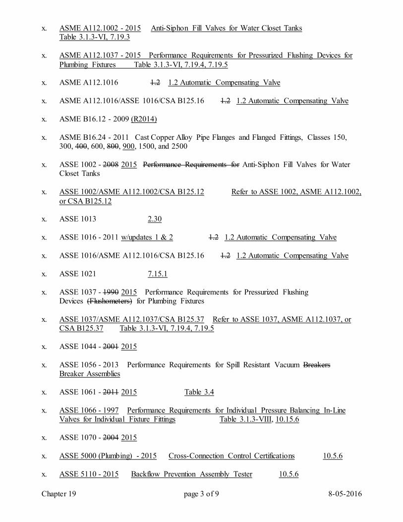
Chapter 19 page 3 of 9 8-05-2016
x. ASME A112.1002 - 2015 Anti-Siphon Fill Valves for Water Closet Tanks Table 3.1.3-VI, 7.19.3 x. ASME A112.1037 - 2015 Performance Requirements for Pressurized Flushing Devices for
Plumbing Fixtures Table 3.1.3-VI, 7.19.4, 7.19.5 x. ASME A112.1016 1.2 1.2 Automatic Compensating Valve x. ASME A112.1016/ASSE 1016/CSA B125.16 1.2 1.2 Automatic Compensating Valve x. ASME B16.12 - 2009 (R2014) x. ASME B16.24 - 2011 Cast Copper Alloy Pipe Flanges and Flanged Fittings, Classes 150,
300, 400, 600, 800, 900, 1500, and 2500 x. ASSE 1002 - 2008 2015 Performance Requirements for Anti-Siphon Fill Valves for Water
Closet Tanks x. ASSE 1002/ASME A112.1002/CSA B125.12 Refer to ASSE 1002, ASME A112.1002,
or CSA B125.12 x. ASSE 1013 2.30 x. ASSE 1016 - 2011 w/updates 1 & 2 1.2 1.2 Automatic Compensating Valve x. ASSE 1016/ASME A112.1016/CSA B125.16 1.2 1.2 Automatic Compensating Valve x. ASSE 1021 7.15.1 x. ASSE 1037 - 1990 2015 Performance Requirements for Pressurized Flushing
Devices (Flushometers) for Plumbing Fixtures x. ASSE 1037/ASME A112.1037/CSA B125.37 Refer to ASSE 1037, ASME A112.1037, or
CSA B125.37 Table 3.1.3-VI, 7.19.4, 7.19.5 x. ASSE 1044 - 2001 2015 x. ASSE 1056 - 2013 Performance Requirements for Spill Resistant Vacuum Breakers Breaker Assemblies x. ASSE 1061 - 2011 2015 Table 3.4 x. ASSE 1066 - 1997 Performance Requirements for Individual Pressure Balancing In-Line
Valves for Individual Fixture Fittings Table 3.1.3-VIII, 10.15.6 x. ASSE 1070 - 2004 2015 x. ASSE 5000 (Plumbing) - 2015 Cross-Connection Control Certifications 10.5.6 x. ASSE 5110 - 2015 Backflow Prevention Assembly Tester 10.5.6
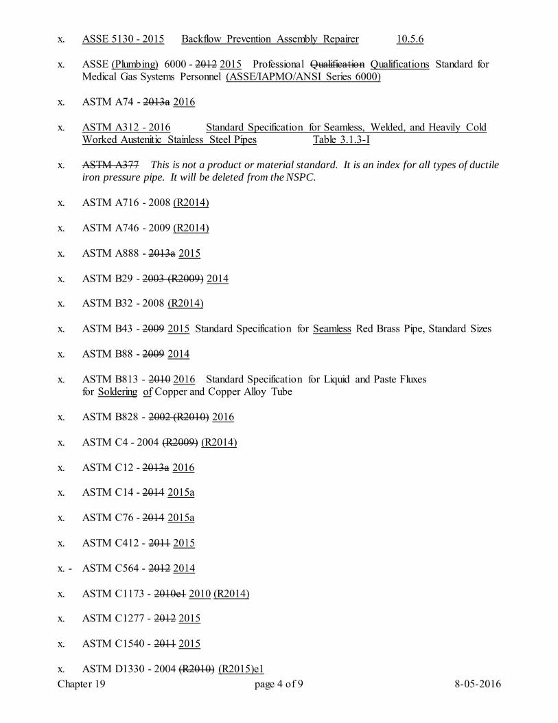
Chapter 19 page 4 of 9 8-05-2016
x. ASSE 5130 - 2015 Backflow Prevention Assembly Repairer 10.5.6 x. ASSE (Plumbing) 6000 - 2012 2015 Professional Qualification Qualifications Standard for
Medical Gas Systems Personnel (ASSE/IAPMO/ANSI Series 6000) x. ASTM A74 - 2013a 2016 x. ASTM A312 - 2016 Standard Specification for Seamless, Welded, and Heavily Cold
Worked Austenitic Stainless Steel Pipes Table 3.1.3-I x. ASTM A377 This is not a product or material standard. It is an index for all types of ductile
iron pressure pipe. It will be deleted from the NSPC. x. ASTM A716 - 2008 (R2014) x. ASTM A746 - 2009 (R2014) x. ASTM A888 - 2013a 2015 x. ASTM B29 - 2003 (R2009) 2014 x. ASTM B32 - 2008 (R2014) x. ASTM B43 - 2009 2015 Standard Specification for Seamless Red Brass Pipe, Standard Sizes x. ASTM B88 - 2009 2014 x. ASTM B813 - 2010 2016 Standard Specification for Liquid and Paste Fluxes
for Soldering of Copper and Copper Alloy Tube x. ASTM B828 - 2002 (R2010) 2016 x. ASTM C4 - 2004 (R2009) (R2014) x. ASTM C12 - 2013a 2016 x. ASTM C14 - 2014 2015a x. ASTM C76 - 2014 2015a x. ASTM C412 - 2011 2015 x. - ASTM C564 - 2012 2014 x. ASTM C1173 - 2010e1 2010 (R2014) x. ASTM C1277 - 2012 2015 x. ASTM C1540 - 2011 2015 x. ASTM D1330 - 2004 (R2010) (R2015)e1
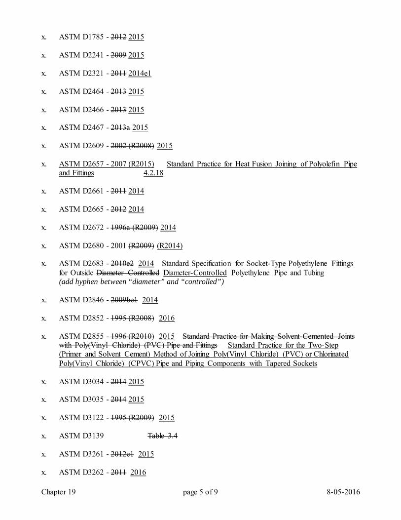
Chapter 19 page 5 of 9 8-05-2016
x. ASTM D1785 - 2012 2015 x. ASTM D2241 - 2009 2015 x. ASTM D2321 - 2011 2014e1 x. ASTM D2464 - 2013 2015 x. ASTM D2466 - 2013 2015 x. ASTM D2467 - 2013a 2015 x. ASTM D2609 - 2002 (R2008) 2015 x. ASTM D2657 - 2007 (R2015) Standard Practice for Heat Fusion Joining of Polyolefin Pipe
and Fittings 4.2.18 x. ASTM D2661 - 2011 2014 x. ASTM D2665 - 2012 2014 x. ASTM D2672 - 1996a (R2009) 2014 x. ASTM D2680 - 2001 (R2009) (R2014) x. ASTM D2683 - 2010e2 2014 Standard Specification for Socket-Type Polyethylene Fittings
for Outside Diameter Controlled Diameter-Controlled Polyethylene Pipe and Tubing (add hyphen between “diameter” and “controlled”) x. ASTM D2846 - 2009be1 2014 x. ASTM D2852 - 1995 (R2008) 2016 x. ASTM D2855 - 1996 (R2010) 2015 Standard Practice for Making Solvent-Cemented Joints
with Poly(Vinyl Chloride) (PVC) Pipe and Fittings Standard Practice for the Two-Step (Primer and Solvent Cement) Method of Joining Poly(Vinyl Chloride) (PVC) or Chlorinated Poly(Vinyl Chloride) (CPVC) Pipe and Piping Components with Tapered Sockets
x. ASTM D3034 - 2014 2015 x. ASTM D3035 - 2014 2015 x. ASTM D3122 - 1995 (R2009) 2015 x. ASTM D3139 Table 3.4 x. ASTM D3261 - 2012e1 2015 x. ASTM D3262 - 2011 2016
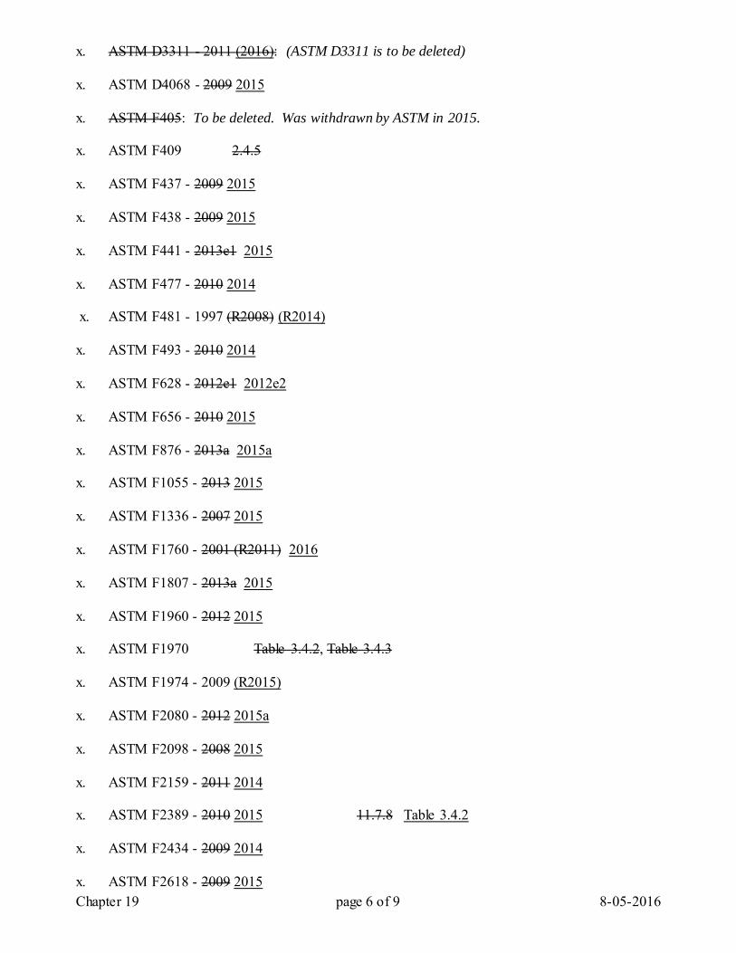
Chapter 19 page 6 of 9 8-05-2016
x. ASTM D3311 - 2011 (2016): (ASTM D3311 is to be deleted) x. ASTM D4068 - 2009 2015 x. ASTM F405: To be deleted. Was withdrawn by ASTM in 2015. x. ASTM F409 2.4.5 x. ASTM F437 - 2009 2015 x. ASTM F438 - 2009 2015 x. ASTM F441 - 2013e1 2015 x. ASTM F477 - 2010 2014 x. ASTM F481 - 1997 (R2008) (R2014) x. ASTM F493 - 2010 2014 x. ASTM F628 - 2012e1 2012e2 x. ASTM F656 - 2010 2015 x. ASTM F876 - 2013a 2015a x. ASTM F1055 - 2013 2015 x. ASTM F1336 - 2007 2015 x. ASTM F1760 - 2001 (R2011) 2016 x. ASTM F1807 - 2013a 2015 x. ASTM F1960 - 2012 2015 x. ASTM F1970 Table 3.4.2, Table 3.4.3 x. ASTM F1974 - 2009 (R2015) x. ASTM F2080 - 2012 2015a x. ASTM F2098 - 2008 2015 x. ASTM F2159 - 2011 2014 x. ASTM F2389 - 2010 2015 11.7.8 Table 3.4.2 x. ASTM F2434 - 2009 2014 x. ASTM F2618 - 2009 2015
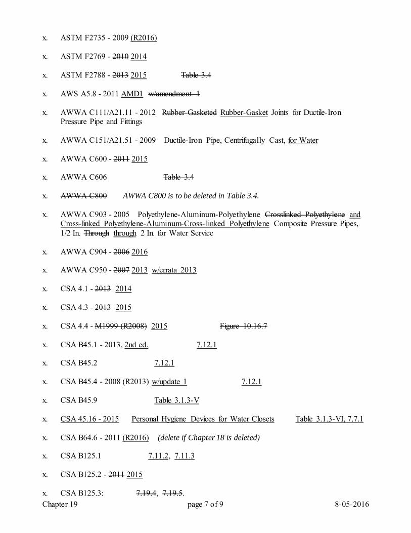
Chapter 19 page 7 of 9 8-05-2016
x. ASTM F2735 - 2009 (R2016) x. ASTM F2769 - 2010 2014 x. ASTM F2788 - 2013 2015 Table 3.4 x. AWS A5.8 - 2011 AMD1 w/amendment 1 x. AWWA C111/A21.11 - 2012 Rubber-Gasketed Rubber-Gasket Joints for Ductile-Iron
Pressure Pipe and Fittings x. AWWA C151/A21.51 - 2009 Ductile-Iron Pipe, Centrifugally Cast, for Water x. AWWA C600 - 2011 2015 x. AWWA C606 Table 3.4 x. AWWA C800 AWWA C800 is to be deleted in Table 3.4. x. AWWA C903 - 2005 Polyethylene-Aluminum-Polyethylene Crosslinked Polyethylene and
Cross-linked Polyethylene-Aluminum-Cross- linked Polyethylene Composite Pressure Pipes, 1/2 In. Through through 2 In. for Water Service
x. AWWA C904 - 2006 2016 x. AWWA C950 - 2007 2013 w/errata 2013 x. CSA 4.1 - 2013 2014 x. CSA 4.3 - 2013 2015 x. CSA 4.4 - M1999 (R2008) 2015 Figure 10.16.7 x. CSA B45.1 - 2013, 2nd ed. 7.12.1 x. CSA B45.2 7.12.1 x. CSA B45.4 - 2008 (R2013) w/update 1 7.12.1 x. CSA B45.9 Table 3.1.3-V x. CSA 45.16 - 2015 Personal Hygiene Devices for Water Closets Table 3.1.3-VI, 7.7.1 x. CSA B64.6 - 2011 (R2016) (delete if Chapter 18 is deleted) x. CSA B125.1 7.11.2, 7.11.3 x. CSA B125.2 - 2011 2015 x. CSA B125.3: 7.19.4, 7.19.5.
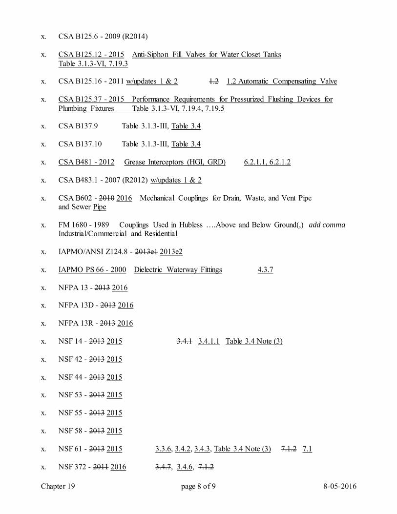
Chapter 19 page 8 of 9 8-05-2016
x. CSA B125.6 - 2009 (R2014) x. CSA B125.12 - 2015 Anti-Siphon Fill Valves for Water Closet Tanks Table 3.1.3-VI, 7.19.3 x. CSA B125.16 - 2011 w/updates 1 & 2 1.2 1.2 Automatic Compensating Valve x. CSA B125.37 - 2015 Performance Requirements for Pressurized Flushing Devices for
Plumbing Fixtures Table 3.1.3-VI, 7.19.4, 7.19.5 x. CSA B137.9 Table 3.1.3-III, Table 3.4 x. CSA B137.10 Table 3.1.3-III, Table 3.4 x. CSA B481 - 2012 Grease Interceptors (HGI, GRD) 6.2.1.1, 6.2.1.2 x. CSA B483.1 - 2007 (R2012) w/updates 1 & 2 x. CSA B602 - 2010 2016 Mechanical Couplings for Drain, Waste, and Vent Pipe and Sewer Pipe x. FM 1680 - 1989 Couplings Used in Hubless ….Above and Below Ground(,) add comma Industrial/Commercial and Residential x. IAPMO/ANSI Z124.8 - 2013e1 2013e2 x. IAPMO PS 66 - 2000 Dielectric Waterway Fittings 4.3.7 x. NFPA 13 - 2013 2016 x. NFPA 13D - 2013 2016 x. NFPA 13R - 2013 2016 x. NSF 14 - 2013 2015 3.4.1 3.4.1.1 Table 3.4 Note (3) x. NSF 42 - 2013 2015 x. NSF 44 - 2013 2015 x. NSF 53 - 2013 2015 x. NSF 55 - 2013 2015 x. NSF 58 - 2013 2015 x. NSF 61 - 2013 2015 3.3.6, 3.4.2, 3.4.3, Table 3.4 Note (3) 7.1.2 7.1 x. NSF 372 - 2011 2016 3.4.7, 3.4.6, 7.1.2
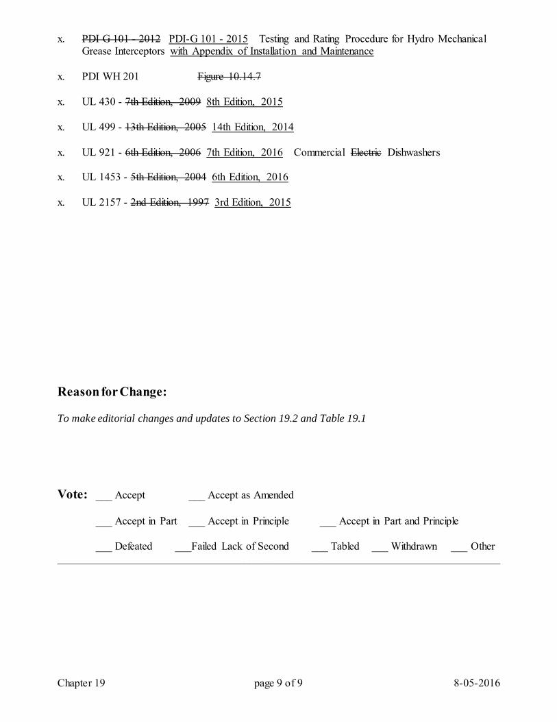
Chapter 19 page 9 of 9 8-05-2016
x. PDI G 101 - 2012 PDI-G 101 - 2015 Testing and Rating Procedure for Hydro Mechanical Grease Interceptors with Appendix of Installation and Maintenance
x. PDI WH 201 Figure 10.14.7 x. UL 430 - 7th Edition, 2009 8th Edition, 2015 x. UL 499 - 13th Edition, 2005 14th Edition, 2014 x. UL 921 - 6th Edition, 2006 7th Edition, 2016 Commercial Electric Dishwashers x. UL 1453 - 5th Edition, 2004 6th Edition, 2016 x. UL 2157 - 2nd Edition, 1997 3rd Edition, 2015 Reason for Change: To make editorial changes and updates to Section 19.2 and Table 19.1 Vote: ___ Accept ___ Accept as Amended
___ Accept in Part ___ Accept in Principle ___ Accept in Part and Principle
___ Defeated ___Failed Lack of Second ___ Tabled ___ Withdrawn ___ Other _________________________________________________________________________________
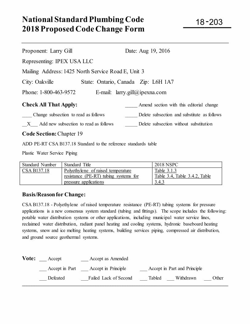
National Standard Plumbing Code 2018 Proposed Code Change Form
-
Proponent: Larry Gill Date: Aug 19, 2016
Representing: IPEX USA LLC
Mailing Address: 1425 North Service Road E, Unit 3
City: Oakville State: Ontario, Canada Zip: L6H 1A7
Phone: 1-800-463-9572 E-mail: [email protected] Check All That Apply: _____ Amend section with this editorial change ____ Change subsection to read as follows _____ Delete subsection and substitute as follows __X___ Add new subsection to read as follows _____ Delete subsection without substitution
Code Section: Chapter 19 ADD PE-RT CSA B137.18 Standard to the reference standards table Plastic Water Service Piping Standard Number Standard Title 2018 NSPC CSA B137.18 Polyethylene of raised temperature
resistance (PE-RT) tubing systems for pressure applications
Table 3.1.3 Table 3.4, Table 3.4.2, Table 3.4.3
Basis/Reason for Change: CSA B137.18 - Polyethylene of raised temperature resistance (PE-RT) tubing systems for pressure applications is a new consensus system standard (tubing and fittings). The scope includes the following: potable water distribution systems or other applications, including municipal water service lines, reclaimed water distribution, radiant panel heating and cooling systems, hydronic baseboard heating systems, snow and ice melting heating systems, building services piping, compressed air distribution, and ground source geothermal systems.
Vote: ___ Accept ___ Accept as Amended
___ Accept in Part ___ Accept in Principle ___ Accept in Part and Principle
___ Defeated ___Failed Lack of Second ___ Tabled ___ Withdrawn ___ Other ____________________________________________________________________________________
18 203
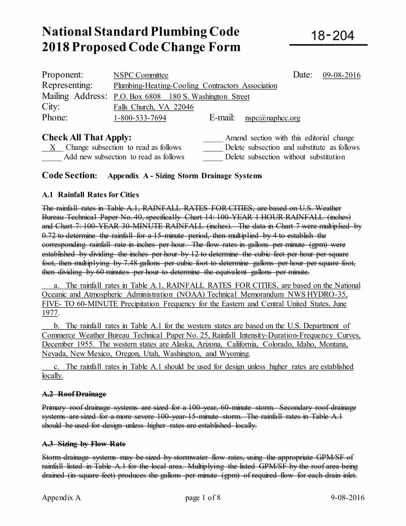
National Standard Plumbing Code 2018 Proposed Code Change Form
-
Appendix A page 1 of 8 9-08-2016
Proponent: NSPC Committee Date: 09-08-2016 Representing: Plumbing-Heating-Cooling Contractors Association Mailing Address: P.O. Box 6808 180 S. Washington Street City: Falls Church, VA 22046 Phone: 1-800-533-7694 E-mail: [email protected] Check All That Apply: _____ Amend section with this editorial change __X__ Change subsection to read as follows _____ Delete subsection and substitute as follows _____ Add new subsection to read as follows _____ Delete subsection without substitution Code Section: Appendix A - Sizing Storm Drainage Systems A.1 Rainfall Rates for Cities
The rainfall rates in Table A.1, RAINFALL RATES FOR CITIES, are based on U.S. Weather Bureau Technical Paper No. 40, specifically Chart 14: 100-YEAR 1 HOUR RAINFALL (inches) and Chart 7: 100-YEAR 30-MINUTE RAINFALL (inches). The data in Chart 7 were multiplied by 0.72 to determine the rainfall for a 15-minute period, then multiplied by 4 to establish the corresponding rainfall rate in inches per hour. The flow rates in gallons per minute (gpm) were established by dividing the inches per hour by 12 to determine the cubic feet per hour per square foot, then multiplying by 7.48 gallons per cubic foot to determine gallons per hour per square foot, then dividing by 60 minutes per hour to determine the equivalent gallons per minute.
a. The rainfall rates in Table A.1, RAINFALL RATES FOR CITIES, are based on the National Oceanic and Atmospheric Administration (NOAA) Technical Memorandum NWS HYDRO-35, FIVE- TO 60-MINUTE Precipitation Frequency for the Eastern and Central United States, June 1977. b. The rainfall rates in Table A.1 for the western states are based on the U.S. Department of Commerce Weather Bureau Technical Paper No. 25, Rainfall Intensity-Duration-Frequency Curves, December 1955. The western states are Alaska, Arizona, California, Colorado, Idaho, Montana, Nevada, New Mexico, Oregon, Utah, Washington, and Wyoming. c. The rainfall rates in Table A.1 should be used for design unless higher rates are established locally. A.2 Roof Drainage
Primary roof drainage systems are sized for a 100-year, 60-minute storm. Secondary roof drainage systems are sized for a more severe 100-year-15-minute storm. The rainfall rates in Table A.1 should be used for design unless higher rates are established locally. A.3 Sizing by Flow Rate
Storm drainage systems may be sized by stormwater flow rates, using the appropriate GPM/SF of rainfall listed in Table A.1 for the local area. Multiplying the listed GPM/SF by the roof area being drained (in square feet) produces the gallons per minute (gpm) of required flow for each drain inlet.
18 204
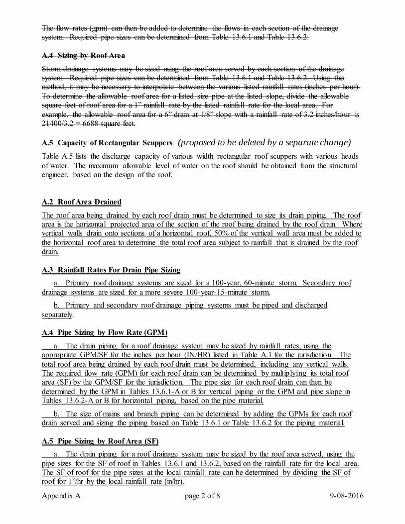
Appendix A page 2 of 8 9-08-2016
The flow rates (gpm) can then be added to determine the flows in each section of the drainage system. Required pipe sizes can be determined from Table 13.6.1 and Table 13.6.2. A.4 Sizing by Roof Area
Storm drainage systems may be sized using the roof area served by each section of the drainage system. Required pipe sizes can be determined from Table 13.6.1 and Table 13.6.2. Using this method, it may be necessary to interpolate between the various listed rainfall rates (inches per hour). To determine the allowable roof area for a listed size pipe at the listed slope, divide the allowable square feet of roof area for a 1” rainfall rate by the listed rainfall rate for the local area. For example, the allowable roof area for a 6” drain at 1/8” slope with a rainfall rate of 3.2 inches/hour is 21400/3.2 = 6688 square feet. A.5 Capacity of Rectangular Scuppers (proposed to be deleted by a separate change)
Table A.5 lists the discharge capacity of various width rectangular roof scuppers with various heads of water. The maximum allowable level of water on the roof should be obtained from the structural engineer, based on the design of the roof. A.2 Roof Area Drained
The roof area being drained by each roof drain must be determined to size its drain piping. The roof area is the horizontal projected area of the section of the roof being drained by the roof drain. Where vertical walls drain onto sections of a horizontal roof, 50% of the vertical wall area must be added to the horizontal roof area to determine the total roof area subject to rainfall that is drained by the roof drain. A.3 Rainfall Rates For Drain Pipe Sizing a. Primary roof drainage systems are sized for a 100-year, 60-minute storm. Secondary roof drainage systems are sized for a more severe 100-year-15-minute storm. b. Primary and secondary roof drainage piping systems must be piped and discharged separately. A.4 Pipe Sizing by Flow Rate (GPM)
a. The drain piping for a roof drainage system may be sized by rainfall rates, using the appropriate GPM/SF for the inches per hour (IN/HR) listed in Table A.1 for the jurisdiction. The total roof area being drained by each roof drain must be determined, including any vertical walls. The required flow rate (GPM) for each roof drain can be determined by multiplying its total roof area (SF) by the GPM/SF for the jurisdiction. The pipe size for each roof drain can then be determined by the GPM in Tables 13.6.1-A or B for vertical piping or the GPM and pipe slope in Tables 13.6.2-A or B for horizontal piping, based on the pipe material.
b. The size of mains and branch piping can be determined by adding the GPMs for each roof drain served and sizing the piping based on Table 13.6.1 or Table 13.6.2 for the piping material. A.5 Pipe Sizing by Roof Area (SF) a. The drain piping for a roof drainage system may be sized by the roof area served, using the pipe sizes for the SF of roof in Tables 13.6.1 and 13.6.2, based on the rainfall rate for the local area. The SF of roof for the pipe sizes at the local rainfall rate can be determined by dividing the SF of roof for 1”/hr by the local rainfall rate (in/hr).
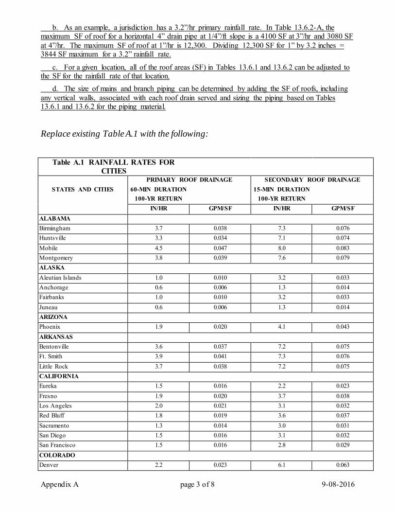
Appendix A page 3 of 8 9-08-2016
b. As an example, a jurisdiction has a 3.2”/hr primary rainfall rate. In Table 13.6.2-A, the maximum SF of roof for a horizontal 4” drain pipe at 1/4”/ft slope is a 4100 SF at 3”/hr and 3080 SF at 4”/hr. The maximum SF of roof at 1”/hr is 12,300. Dividing 12,300 SF for 1” by 3.2 inches = 3844 SF maximum for a 3.2” rainfall rate.
c. For a given location, all of the roof areas (SF) in Tables 13.6.1 and 13.6.2 can be adjusted to the SF for the rainfall rate of that location. d. The size of mains and branch piping can be determined by adding the SF of roofs, including any vertical walls, associated with each roof drain served and sizing the piping based on Tables 13.6.1 and 13.6.2 for the piping material. Replace existing Table A.1 with the following:
Table A.1 RAINFALL RATES FOR CITIES
PRIMARY ROOF DRAINAGE SECONDARY ROOF DRAINAGE STATES AND CITIES 60-MIN DURATION 15-MIN DURATION
100-YR RETURN 100-YR RETURN IN/HR GPM/SF IN/HR GPM/SF
ALABAMA Birmingham 3.7 0.038 7.3 0.076 Huntsville 3.3 0.034 7.1 0.074 Mobile 4.5 0.047 8.0 0.083 Montgomery 3.8 0.039 7.6 0.079 ALASKA Aleutian Islands 1.0 0.010 3.2 0.033 Anchorage 0.6 0.006 1.3 0.014 Fairbanks 1.0 0.010 3.2 0.033 Juneau 0.6 0.006 1.3 0.014 ARIZONA Phoenix 1.9 0.020 4.1 0.043 ARKANSAS Bentonville 3.6 0.037 7.2 0.075 Ft. Smith 3.9 0.041 7.3 0.076 Little Rock 3.7 0.038 7.2 0.075 CALIFORNIA Eureka 1.5 0.016 2.2 0.023 Fresno 1.9 0.020 3.7 0.038 Los Angeles 2.0 0.021 3.1 0.032 Red Bluff 1.8 0.019 3.6 0.037 Sacramento 1.3 0.014 3.0 0.031 San Diego 1.5 0.016 3.1 0.032 San Francisco 1.5 0.016 2.8 0.029 COLORADO Denver 2.2 0.023 6.1 0.063
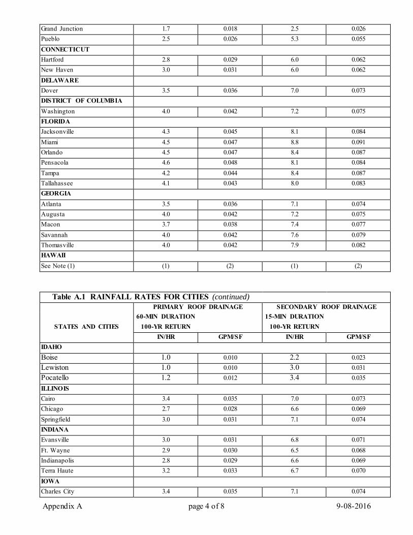
Appendix A page 4 of 8 9-08-2016
Grand Junction 1.7 0.018 2.5 0.026 Pueblo 2.5 0.026 5.3 0.055 CONNECTICUT Hartford 2.8 0.029 6.0 0.062 New Haven 3.0 0.031 6.0 0.062 DELAWARE Dover 3.5 0.036 7.0 0.073 DISTRICT OF COLUMBIA Washington 4.0 0.042 7.2 0.075 FLORIDA Jacksonville 4.3 0.045 8.1 0.084 Miami 4.5 0.047 8.8 0.091 Orlando 4.5 0.047 8.4 0.087 Pensacola 4.6 0.048 8.1 0.084 Tampa 4.2 0.044 8.4 0.087 Tallahassee 4.1 0.043 8.0 0.083 GEORGIA Atlanta 3.5 0.036 7.1 0.074 Augusta 4.0 0.042 7.2 0.075 Macon 3.7 0.038 7.4 0.077 Savannah 4.0 0.042 7.6 0.079 Thomasville 4.0 0.042 7.9 0.082 HAWAII See Note (1) (1) (2) (1) (2)
Table A.1 RAINFALL RATES FOR CITIES (continued) PRIMARY ROOF DRAINAGE SECONDARY ROOF DRAINAGE 60-MIN DURATION 15-MIN DURATION
STATES AND CITIES 100-YR RETURN 100-YR RETURN IN/HR GPM/SF IN/HR GPM/SF
IDAHO Boise 1.0 0.010 2.2 0.023 Lewiston 1.0 0.010 3.0 0.031 Pocatello 1.2 0.012 3.4 0.035 ILLINOIS Cairo 3.4 0.035 7.0 0.073 Chicago 2.7 0.028 6.6 0.069 Springfield 3.0 0.031 7.1 0.074 INDIANA Evansville 3.0 0.031 6.8 0.071 Ft. Wayne 2.9 0.030 6.5 0.068 Indianapolis 2.8 0.029 6.6 0.069 Terra Haute 3.2 0.033 6.7 0.070 IOWA Charles City 3.4 0.035 7.1 0.074
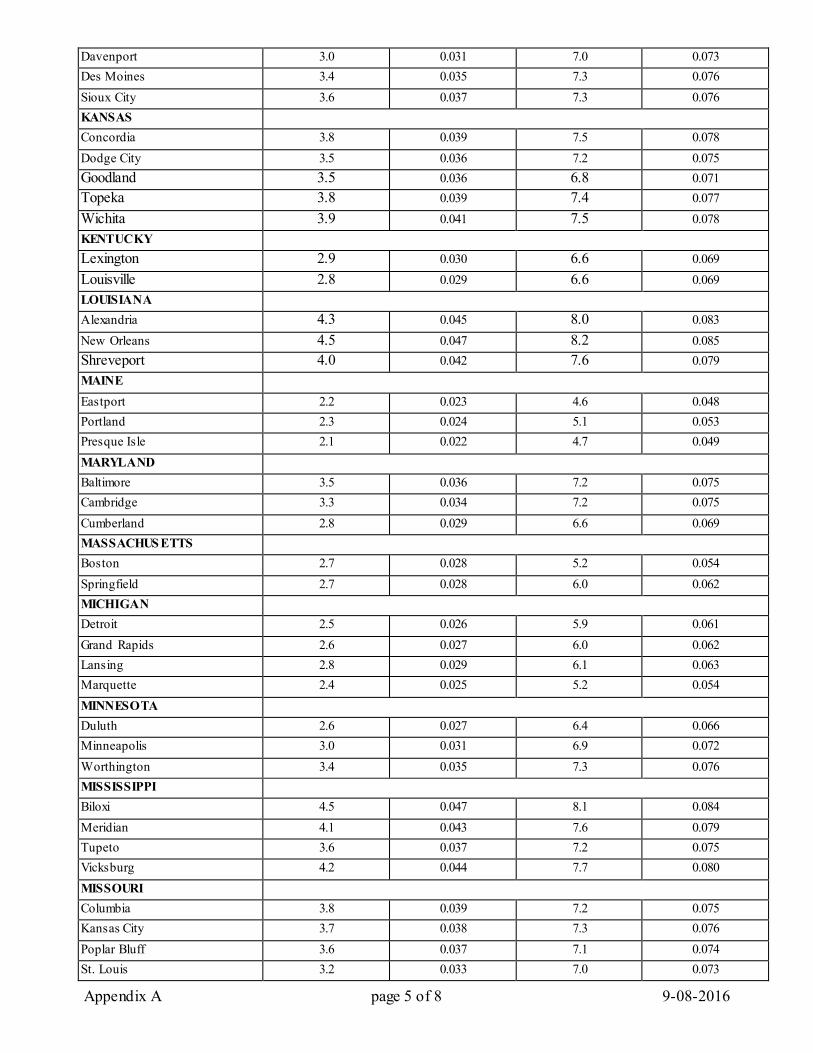
Appendix A page 5 of 8 9-08-2016
Davenport 3.0 0.031 7.0 0.073 Des Moines 3.4 0.035 7.3 0.076 Sioux City 3.6 0.037 7.3 0.076 KANSAS Concordia 3.8 0.039 7.5 0.078 Dodge City 3.5 0.036 7.2 0.075 Goodland 3.5 0.036 6.8 0.071 Topeka 3.8 0.039 7.4 0.077 Wichita 3.9 0.041 7.5 0.078 KENTUCKY Lexington 2.9 0.030 6.6 0.069 Louisville 2.8 0.029 6.6 0.069 LOUISIANA Alexandria 4.3 0.045 8.0 0.083 New Orleans 4.5 0.047 8.2 0.085 Shreveport 4.0 0.042 7.6 0.079 MAINE Eastport 2.2 0.023 4.6 0.048 Portland 2.3 0.024 5.1 0.053 Presque Isle 2.1 0.022 4.7 0.049 MARYLAND Baltimore 3.5 0.036 7.2 0.075 Cambridge 3.3 0.034 7.2 0.075 Cumberland 2.8 0.029 6.6 0.069 MASSACHUS ETTS Boston 2.7 0.028 5.2 0.054 Springfield 2.7 0.028 6.0 0.062 MICHIGAN Detroit 2.5 0.026 5.9 0.061 Grand Rapids 2.6 0.027 6.0 0.062 Lansing 2.8 0.029 6.1 0.063 Marquette 2.4 0.025 5.2 0.054 MINNESOTA Duluth 2.6 0.027 6.4 0.066 Minneapolis 3.0 0.031 6.9 0.072 Worthington 3.4 0.035 7.3 0.076 MISSISSIPPI Biloxi 4.5 0.047 8.1 0.084 Meridian 4.1 0.043 7.6 0.079 Tupeto 3.6 0.037 7.2 0.075 Vicksburg 4.2 0.044 7.7 0.080 MISSOURI Columbia 3.8 0.039 7.2 0.075 Kansas City 3.7 0.038 7.3 0.076 Poplar Bluff 3.6 0.037 7.1 0.074 St. Louis 3.2 0.033 7.0 0.073
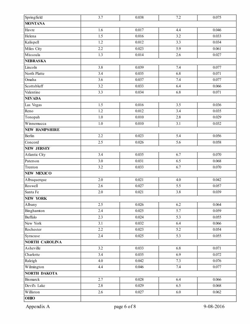
Appendix A page 6 of 8 9-08-2016
Springfield 3.7 0.038 7.2 0.075 MONTANA Havre 1.6 0.017 4.4 0.046 Helena 1.5 0.016 3.2 0.033 Kalispell 1.2 0.012 3.3 0.034 Miles City 2.2 0.023 5.9 0.061 Missoula 1.3 0.014 2.6 0.027 NEBRASKA Lincoln 3.8 0.039 7.4 0.077 North Platte 3.4 0.035 6.8 0.071 Omaha 3.6 0.037 7.4 0.077 Scottsbluff 3.2 0.033 6.4 0.066 Valentine 3.3 0.034 6.8 0.071 NEVADA Las Vegas 1.5 0.016 3.5 0.036 Reno 1.2 0.012 3.4 0.035 Tonopah 1.0 0.010 2.8 0.029 Winnemucca 1.0 0.010 3.1 0.032 NEW HAMPSHIRE Berlin 2.2 0.023 5.4 0.056 Concord 2.5 0.026 5.6 0.058 NEW JERSEY Atlantic City 3.4 0.035 6.7 0.070 Paterson 3.0 0.031 6.5 0.068 Trenton 3.2 0.033 6.7 0.070 NEW MEXICO Albuquerque 2.0 0.021 4.0 0.042 Roswell 2.6 0.027 5.5 0.057 Santa Fe 2.0 0.021 3.8 0.039 NEW YORK Albany 2.5 0.026 6.2 0.064 Binghamton 2.4 0.025 5.7 0.059 Buffalo 2.3 0.024 5.3 0.055 New York 3.1 0.032 6.4 0.066 Rochester 2.2 0.023 5.2 0.054 Syracuse 2.4 0.025 5.3 0.055 NORTH CAROLINA Asheville 3.2 0.033 6.8 0.071 Charlotte 3.4 0.035 6.9 0.072 Raleigh 4.0 0.042 7.3 0.076 Wilmington 4.4 0.046 7.4 0.077 NORTH DAKOTA Bismarck 2.7 0.028 6.4 0.066 Devil's Lake 2.8 0.029 6.5 0.068 Williston 2.6 0.027 6.0 0.062 OHIO
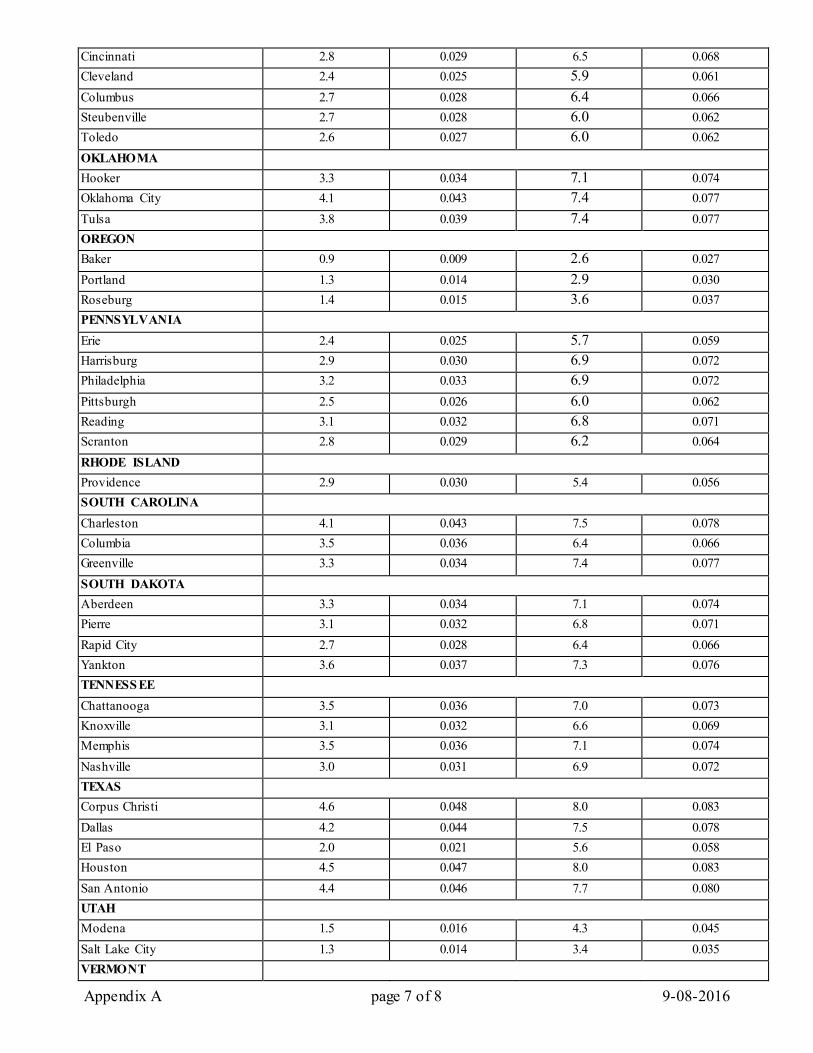
Appendix A page 7 of 8 9-08-2016
Cincinnati 2.8 0.029 6.5 0.068 Cleveland 2.4 0.025 5.9 0.061 Columbus 2.7 0.028 6.4 0.066 Steubenville 2.7 0.028 6.0 0.062 Toledo 2.6 0.027 6.0 0.062 OKLAHOMA Hooker 3.3 0.034 7.1 0.074 Oklahoma City 4.1 0.043 7.4 0.077 Tulsa 3.8 0.039 7.4 0.077 OREGON Baker 0.9 0.009 2.6 0.027 Portland 1.3 0.014 2.9 0.030 Roseburg 1.4 0.015 3.6 0.037 PENNSYLVANIA Erie 2.4 0.025 5.7 0.059 Harrisburg 2.9 0.030 6.9 0.072 Philadelphia 3.2 0.033 6.9 0.072 Pittsburgh 2.5 0.026 6.0 0.062 Reading 3.1 0.032 6.8 0.071 Scranton 2.8 0.029 6.2 0.064 RHODE ISLAND Providence 2.9 0.030 5.4 0.056 SOUTH CAROLINA Charleston 4.1 0.043 7.5 0.078 Columbia 3.5 0.036 6.4 0.066 Greenville 3.3 0.034 7.4 0.077 SOUTH DAKOTA Aberdeen 3.3 0.034 7.1 0.074 Pierre 3.1 0.032 6.8 0.071 Rapid City 2.7 0.028 6.4 0.066 Yankton 3.6 0.037 7.3 0.076 TENNESS EE Chattanooga 3.5 0.036 7.0 0.073 Knoxville 3.1 0.032 6.6 0.069 Memphis 3.5 0.036 7.1 0.074 Nashville 3.0 0.031 6.9 0.072 TEXAS Corpus Christi 4.6 0.048 8.0 0.083 Dallas 4.2 0.044 7.5 0.078 El Paso 2.0 0.021 5.6 0.058 Houston 4.5 0.047 8.0 0.083 San Antonio 4.4 0.046 7.7 0.080 UTAH Modena 1.5 0.016 4.3 0.045 Salt Lake City 1.3 0.014 3.4 0.035 VERMONT
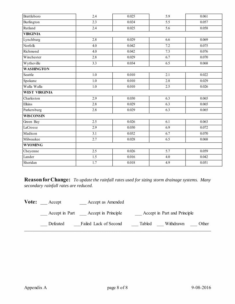
Appendix A page 8 of 8 9-08-2016
Brattleboro 2.4 0.025 5.9 0.061 Burlington 2.3 0.024 5.5 0.057 Rutland 2.4 0.025 5.6 0.058 VIRGINIA Lynchburg 2.8 0.029 6.6 0.069 Norfolk 4.0 0.042 7.2 0.075 Richmond 4.0 0.042 7.3 0.076 Winchester 2.8 0.029 6.7 0.070 Wytheville 3.3 0.034 6.5 0.068 WASHINGTON Seattle 1.0 0.010 2.1 0.022 Spokane 1.0 0.010 2.8 0.029 Walla Walla 1.0 0.010 2.5 0.026 WEST VIRGINIA Charleston 2.9 0.030 6.3 0.065 Elkins 2.8 0.029 6.3 0.065 Parkersburg 2.8 0.029 6.3 0.065 WISCONSIN Green Bay 2.5 0.026 6.1 0.063 LaCrosse 2.9 0.030 6.9 0.072 Madison 3.1 0.032 6.7 0.070 Milwaukee 2.7 0.028 6.5 0.068 WYOMING Cheyenne 2.5 0.026 5.7 0.059 Lander 1.5 0.016 4.0 0.042 Sheridan 1.7 0.018 4.9 0.051
Reason for Change: To update the rainfall rates used for sizing storm drainage systems. Many secondary rainfall rates are reduced. Vote: ___ Accept ___ Accept as Amended
___ Accept in Part ___ Accept in Principle ___ Accept in Part and Principle
___ Defeated ___Failed Lack of Second ___ Tabled ___ Withdrawn ___ Other _________________________________________________________________________________
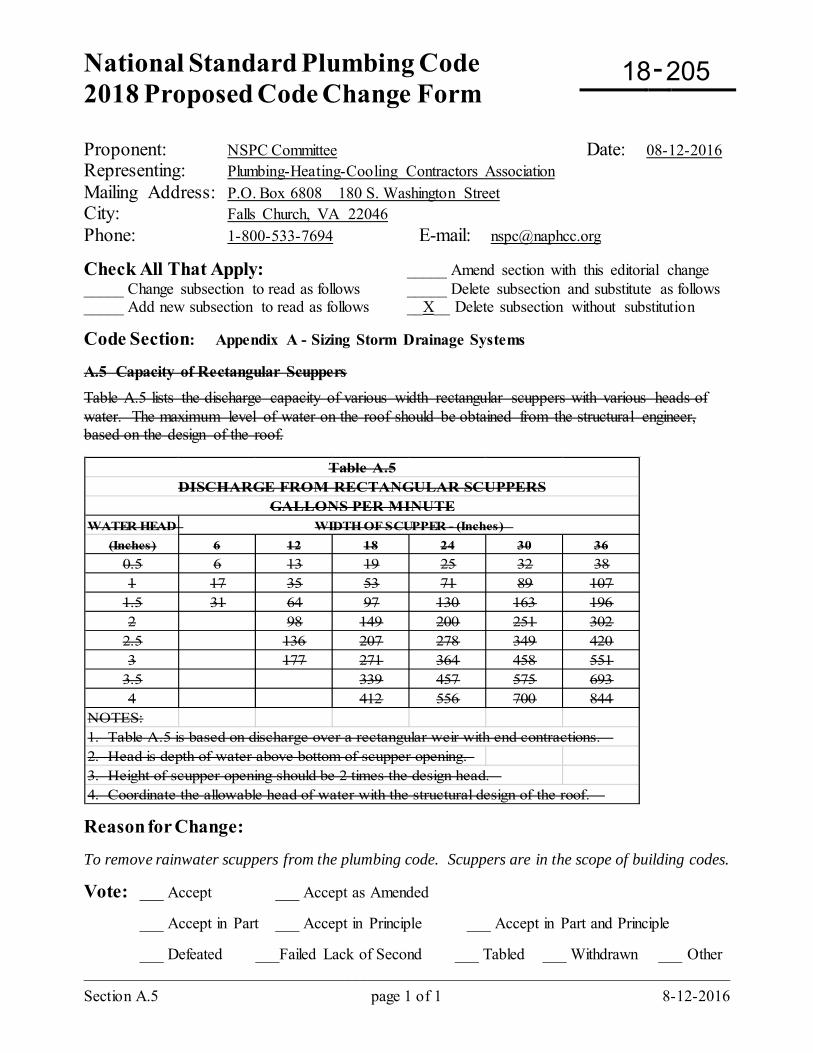
National Standard Plumbing Code 2018 Proposed Code Change Form
-
Section A.5 page 1 of 1 8-12-2016
Proponent: NSPC Committee Date: 08-12-2016 Representing: Plumbing-Heating-Cooling Contractors Association Mailing Address: P.O. Box 6808 180 S. Washington Street City: Falls Church, VA 22046 Phone: 1-800-533-7694 E-mail: [email protected]
Check All That Apply: _____ Amend section with this editorial change _____ Change subsection to read as follows _____ Delete subsection and substitute as follows _____ Add new subsection to read as follows __X__ Delete subsection without substitution
Code Section: Appendix A - Sizing Storm Drainage Systems A.5 Capacity of Rectangular Scuppers Table A.5 lists the discharge capacity of various width rectangular scuppers with various heads of water. The maximum level of water on the roof should be obtained from the structural engineer, based on the design of the roof.
WATER HEAD(Inches) 6 12 18 24 30 36
0.5 6 13 19 25 32 381 17 35 53 71 89 107
1.5 31 64 97 130 163 1962 98 149 200 251 302
2.5 136 207 278 349 4203 177 271 364 458 551
3.5 339 457 575 6934 412 556 700 844
NOTES:1. Table A.5 is based on discharge over a rectangular weir with end contractions. 2. Head is depth of water above bottom of scupper opening.3. Height of scupper opening should be 2 times the design head.4. Coordinate the allowable head of water with the structural design of the roof.
WIDTH OF SCUPPER - (Inches)
Table A.5DISCHARGE FROM RECTANGULAR SCUPPERS
GALLONS PER MINUTE
Reason for Change: To remove rainwater scuppers from the plumbing code. Scuppers are in the scope of building codes.
Vote: ___ Accept ___ Accept as Amended
___ Accept in Part ___ Accept in Principle ___ Accept in Part and Principle
___ Defeated ___Failed Lack of Second ___ Tabled ___ Withdrawn ___ Other _________________________________________________________________________________
18 205
18 206
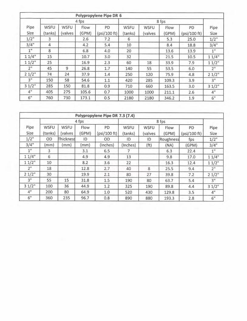
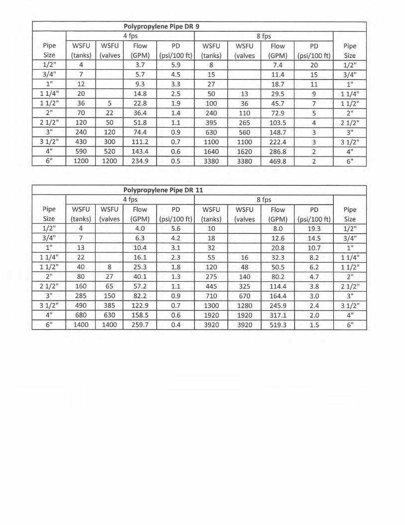
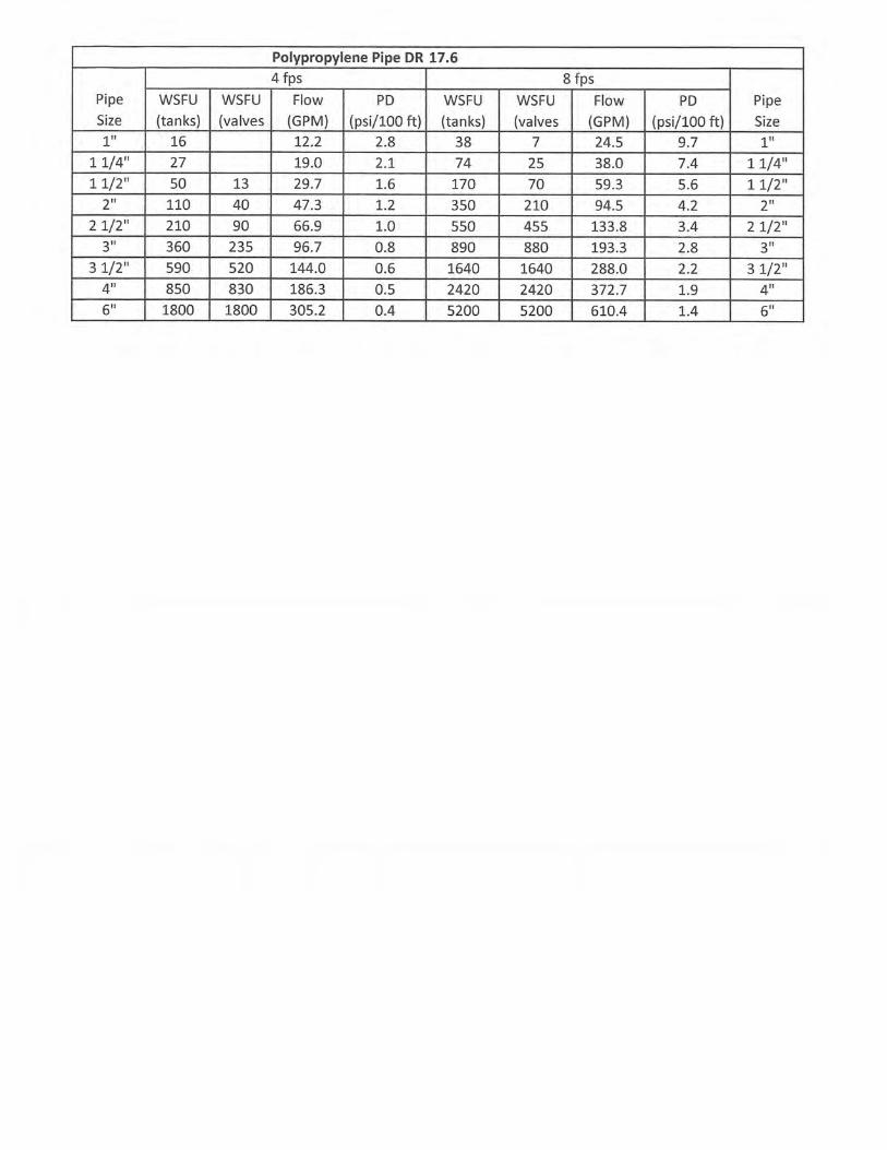

18 207
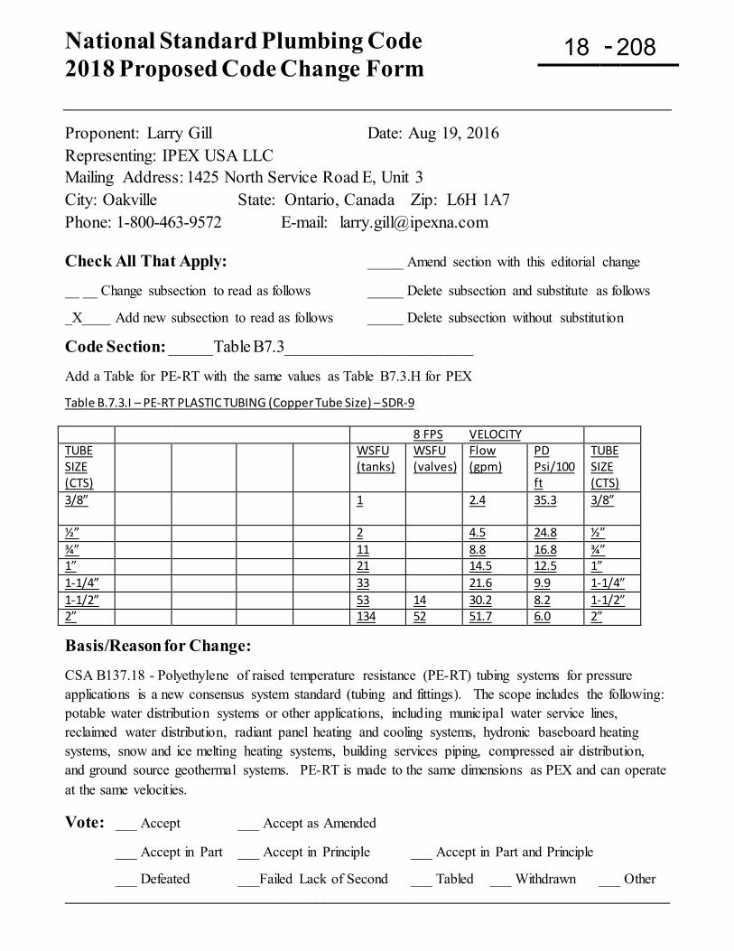
National Standard Plumbing Code 2018 Proposed Code Change Form
-
Proponent: Larry Gill Date: Aug 19, 2016 Representing: IPEX USA LLC Mailing Address: 1425 North Service Road E, Unit 3 City: Oakville State: Ontario, Canada Zip: L6H 1A7 Phone: 1-800-463-9572 E-mail: [email protected] Check All That Apply: _____ Amend section with this editorial change __ __ Change subsection to read as follows _____ Delete subsection and substitute as follows _X____ Add new subsection to read as follows _____ Delete subsection without substitution
Code Section: _____Table B7.3______________________ Add a Table for PE-RT with the same values as Table B7.3.H for PEX Table B.7.3.I – PE-RT PLASTIC TUBING (Copper Tube Size) – SDR-9
8 FPS VELOCITY TUBE SIZE (CTS)
WSFU (tanks)
WSFU (valves)
Flow (gpm)
PD Psi/100 ft
TUBE SIZE (CTS)
3/8”
1 2.4 35.3 3/8”
½” 2 4.5 24.8 ½” ¾” 11 8.8 16.8 ¾” 1” 21 14.5 12.5 1” 1-1/4” 33 21.6 9.9 1-1/4” 1-1/2” 53 14 30.2 8.2 1-1/2” 2” 134 52 51.7 6.0 2” Basis/Reason for Change: CSA B137.18 - Polyethylene of raised temperature resistance (PE-RT) tubing systems for pressure applications is a new consensus system standard (tubing and fittings). The scope includes the following: potable water distribution systems or other applications, including municipal water service lines, reclaimed water distribution, radiant panel heating and cooling systems, hydronic baseboard heating systems, snow and ice melting heating systems, building services piping, compressed air distribution, and ground source geothermal systems. PE-RT is made to the same dimensions as PEX and can operate at the same velocities.
Vote: ___ Accept ___ Accept as Amended
___ Accept in Part ___ Accept in Principle ___ Accept in Part and Principle
___ Defeated ___Failed Lack of Second ___ Tabled ___ Withdrawn ___ Other ____________________________________________________________________________________
18 208
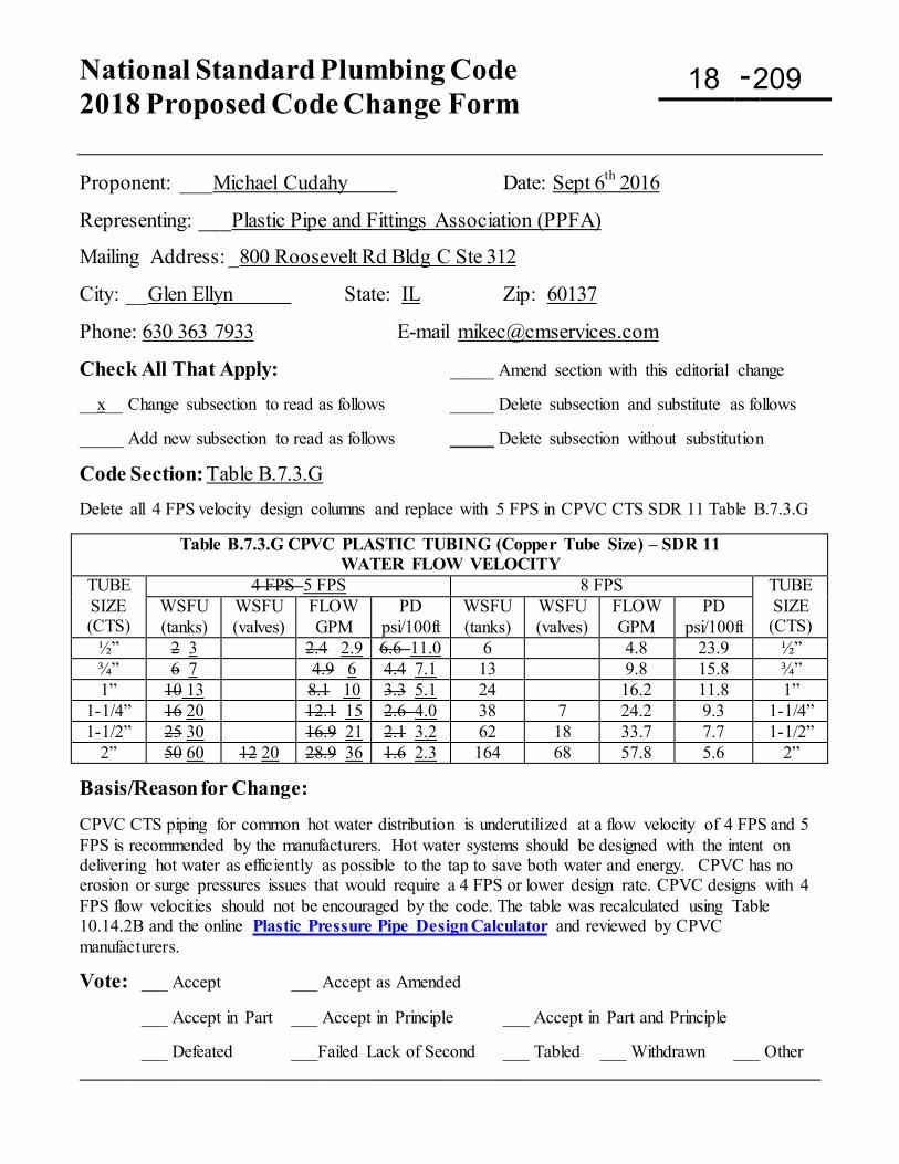
National Standard Plumbing Code 2018 Proposed Code Change Form
-
Proponent: ___Michael Cudahy Date: Sept 6th 2016
Representing: ___Plastic Pipe and Fittings Association (PPFA)
Mailing Address: _800 Roosevelt Rd Bldg C Ste 312
City: __Glen Ellyn State: IL Zip: 60137
Phone: 630 363 7933 E-mail [email protected]
Check All That Apply: _____ Amend section with this editorial change __x__ Change subsection to read as follows _____ Delete subsection and substitute as follows _____ Add new subsection to read as follows _____ Delete subsection without substitution
Code Section: Table B.7.3.G Delete all 4 FPS velocity design columns and replace with 5 FPS in CPVC CTS SDR 11 Table B.7.3.G
Table B.7.3.G CPVC PLASTIC TUBING (Copper Tube Size) – SDR 11 WATER FLOW VELOCITY
TUBE SIZE (CTS)
4 FPS 5 FPS 8 FPS TUBE SIZE (CTS)
WSFU (tanks)
WSFU (valves)
FLOW GPM
PD psi/100ft
WSFU (tanks)
WSFU (valves)
FLOW GPM
PD psi/100ft
½” 2 3 2.4 2.9 6.6 11.0 6 4.8 23.9 ½” ¾” 6 7 4.9 6 4.4 7.1 13 9.8 15.8 ¾” 1” 10 13 8.1 10 3.3 5.1 24 16.2 11.8 1”
1-1/4” 16 20 12.1 15 2.6 4.0 38 7 24.2 9.3 1-1/4” 1-1/2” 25 30 16.9 21 2.1 3.2 62 18 33.7 7.7 1-1/2”
2” 50 60 12 20 28.9 36 1.6 2.3 164 68 57.8 5.6 2”
Basis/Reason for Change: CPVC CTS piping for common hot water distribution is underutilized at a flow velocity of 4 FPS and 5 FPS is recommended by the manufacturers. Hot water systems should be designed with the intent on delivering hot water as efficiently as possible to the tap to save both water and energy. CPVC has no erosion or surge pressures issues that would require a 4 FPS or lower design rate. CPVC designs with 4 FPS flow velocities should not be encouraged by the code. The table was recalculated using Table 10.14.2B and the online Plastic Pressure Pipe Design Calculator and reviewed by CPVC manufacturers.
Vote: ___ Accept ___ Accept as Amended
___ Accept in Part ___ Accept in Principle ___ Accept in Part and Principle
___ Defeated ___Failed Lack of Second ___ Tabled ___ Withdrawn ___ Other ____________________________________________________________________________________
18 209
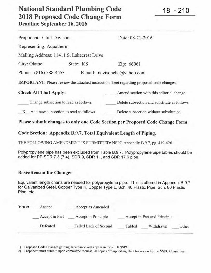
18 210
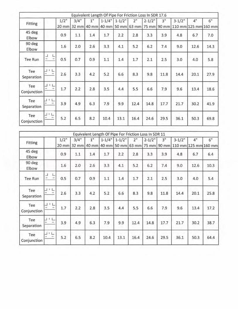
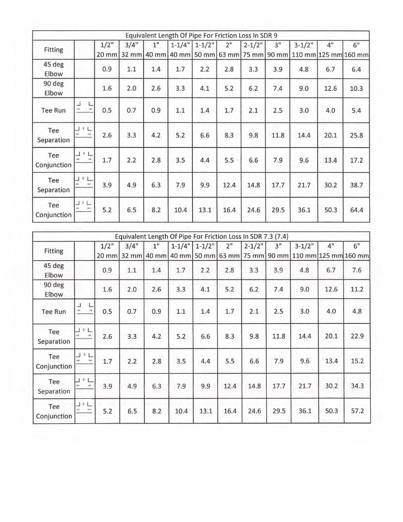
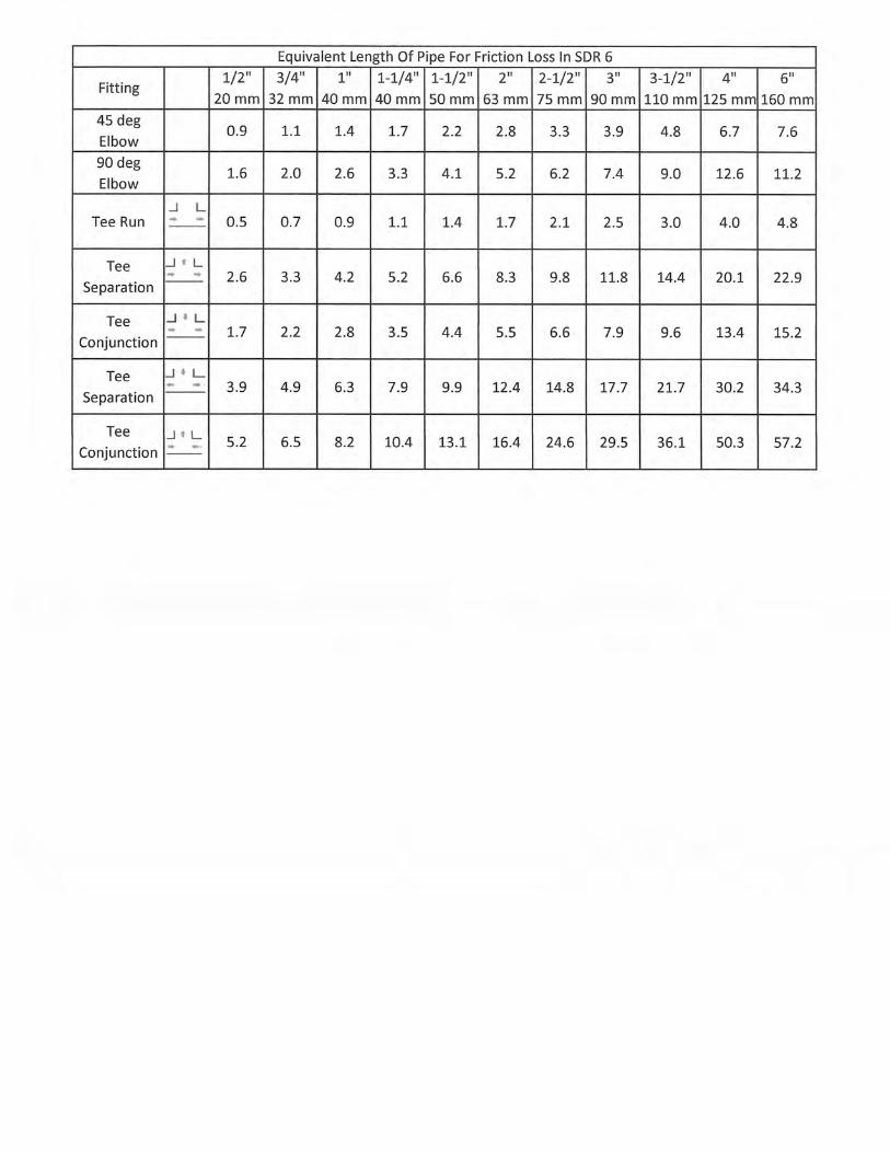
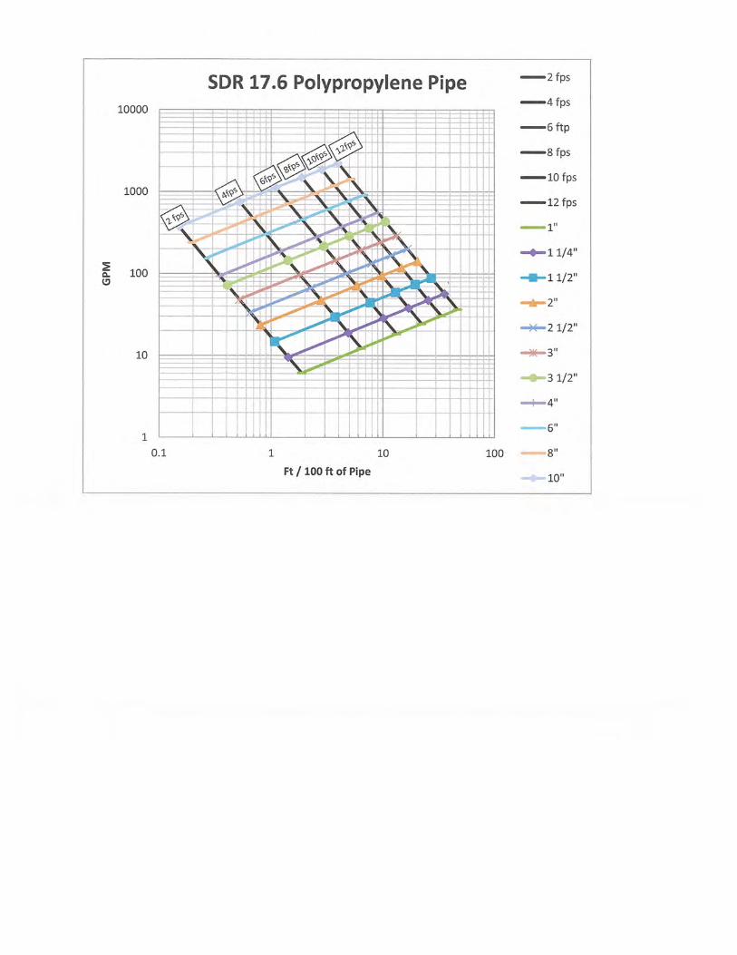
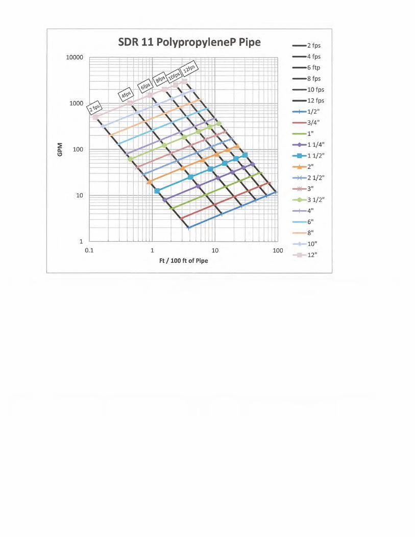
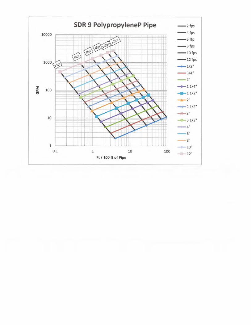
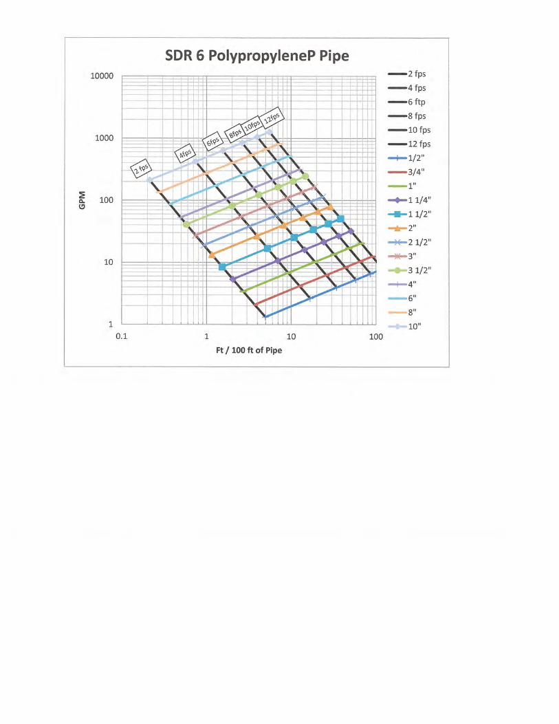
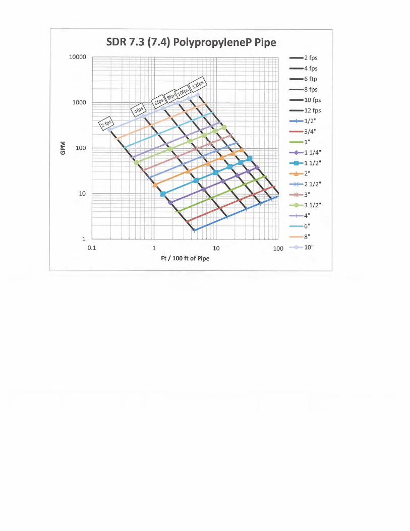
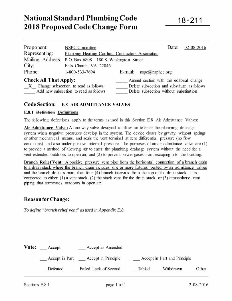
National Standard Plumbing Code 2018 Proposed Code Change Form
-
Sections E.8.1 page 1 of 1 2-08-2016
Proponent: NSPC Committee Date: 02-08-2016 Representing: Plumbing-Heating-Cooling Contractors Association Mailing Address: P.O. Box 6808 180 S. Washington Street City: Falls Church, VA 22046 Phone: 1-800-533-7694 E-mail: [email protected] Check All That Apply: _____ Amend section with this editorial change __X__ Change subsection to read as follows _____ Delete subsection and substitute as follows _____ Add new subsection to read as follows _____ Delete subsection without substitution
Code Section: E.8 AIR ADMITTANCE VALVES
E.8.1 Definition Definitions
The following definitions apply to the terms as used in this Section E.8 Air Admittance Valves:
Air Admittance Valve: A one-way valve designed to allow air to enter the plumbing drainage system when negative pressures develop in the system. The device closes by gravity, without springs or other mechanical means, and seals the vent terminal at zero differential pressure (no flow conditions) and also under positive internal pressure. The purposes of an air admittance valve are (1) to provide a method of allowing air to enter the plumbing drainage system without the need for a vent extended outdoors to open air, and (2) to prevent sewer gases from escaping into the building.
Branch Relief Vent: A positive pressure vent pipe from the horizontal connection of a branch drain to a drain stack where the branch drain includes one or more fixtures vented by air admittance valves and the branch drain is more than four (4) branch intervals from the top of the drain stack. It is connected to either (1) a vent stack, (2) the stack vent for the drain stack, or (3) atmospheric vent piping that terminates outdoors in open air. Reason for Change: To define "branch relief vent" as used in Appendix E.8. Vote: ___ Accept ___ Accept as Amended
___ Accept in Part ___ Accept in Principle ___ Accept in Part and Principle
___ Defeated ___Failed Lack of Second ___ Tabled ___ Withdrawn ___ Other _________________________________________________________________________________
18 211
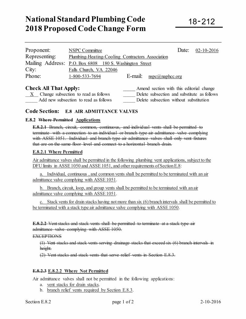
National Standard Plumbing Code 2018 Proposed Code Change Form
-
Section E.8.2 page 1 of 2 2-10-2016
Proponent: NSPC Committee Date: 02-10-2016 Representing: Plumbing-Heating-Cooling Contractors Association Mailing Address: P.O. Box 6808 180 S. Washington Street City: Falls Church, VA 22046 Phone: 1-800-533-7694 E-mail: [email protected] Check All That Apply: _____ Amend section with this editorial change __X__ Change subsection to read as follows _____ Delete subsection and substitute as follows _____ Add new subsection to read as follows _____ Delete subsection without substitution Code Section: E.8 AIR ADMITTANCE VALVES
E.8.2 Where Permitted Applications E.8.2.1 Branch, circuit, common, continuous, and individual vents shall be permitted to terminate with a connection to an individual or branch type air admittance valve complying with ASSE 1051. Individual and branch type air admittance valves shall only vent fixtures that are on the same floor level and connect to a horizontal branch drain. E.8.2.1 Where Permitted
Air admittance valves shall be permitted in the following plumbing vent applications, subject to the DFU limits in ASSE 1050 and ASSE 1051, and other requirements of Section E.8:
a. Individual, continuous , and common vents shall be permitted to be terminated with an air admittance valve complying with ASSE 1051.
b. Branch, circuit, loop, and group vents shall be permitted to be terminated with an air admittance valve complying with ASSE 1051.
c. Stack vents for drain stacks having not more than six (6) branch intervals shall be permitted to be terminated with a stack type air admittance valve complying with ASSE 1050.
E.8.2.2 Vent stacks and stack vents shall be permitted to terminate at a stack type air admittance valve complying with ASSE 1050. EXCEPTIONS
(1) Vent stacks and stack vents serving drainage stacks that exceed six (6) branch intervals in height. (2) Vent stacks and stack vents that serve relief vents in Section E.8.3.
E.8.2.3 E.8.2.2 Where Not Permitted Air admittance valves shall not be permitted in the following applications: a. vent stacks for drain stacks. b. branch relief vents required by Section E.8.3.
18 212
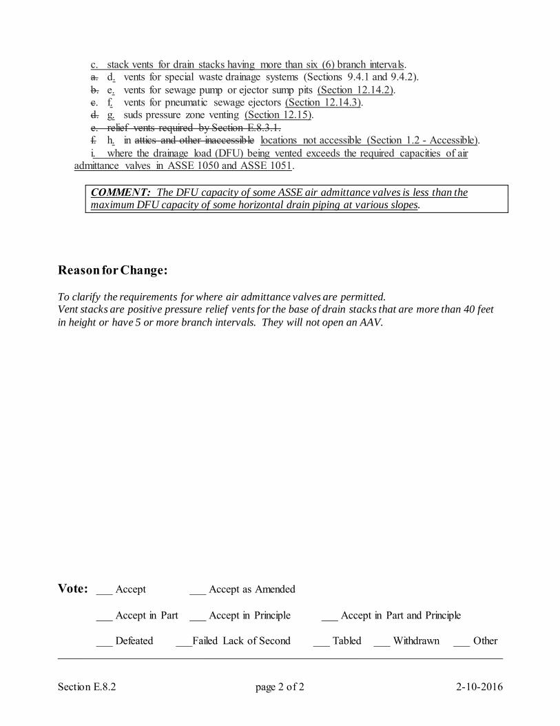
Section E.8.2 page 2 of 2 2-10-2016
c. stack vents for drain stacks having more than six (6) branch intervals. a. d. vents for special waste drainage systems (Sections 9.4.1 and 9.4.2). b. e. vents for sewage pump or ejector sump pits (Section 12.14.2). c. f. vents for pneumatic sewage ejectors (Section 12.14.3). d. g. suds pressure zone venting (Section 12.15). e. relief vents required by Section E.8.3.1. f. h. in attics and other inaccessible locations not accessible (Section 1.2 - Accessible). i. where the drainage load (DFU) being vented exceeds the required capacities of air admittance valves in ASSE 1050 and ASSE 1051.
COMMENT: The DFU capacity of some ASSE air admittance valves is less than the maximum DFU capacity of some horizontal drain piping at various slopes.
Reason for Change: To clarify the requirements for where air admittance valves are permitted. Vent stacks are positive pressure relief vents for the base of drain stacks that are more than 40 feet in height or have 5 or more branch intervals. They will not open an AAV. Vote: ___ Accept ___ Accept as Amended
___ Accept in Part ___ Accept in Principle ___ Accept in Part and Principle
___ Defeated ___Failed Lack of Second ___ Tabled ___ Withdrawn ___ Other _________________________________________________________________________________
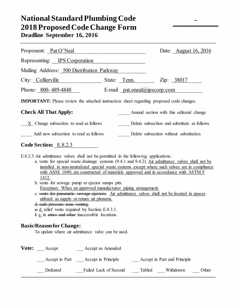
National Standard Plumbing Code 2018 Proposed Code Change Form Deadline September 16, 2016
-
Proponent: _Pat O’Neal__________________________ Date: _August 16, 2016
Representing: __IPS Corporation___________________
Mailing Address: _500 Distribution Parkway__________
City: _Collierville_______________ State: _Tenn._______ Zip: _38017_____
Phone: _800- 489-4848___ E-mail [email protected]__________ IMPORTANT: Please review the attached instruction sheet regarding proposed code changes. Check All That Apply: _____ Amend section with this editorial change ___X_ Change subsection to read as follows _____ Delete subsection and substitute as follows _____ Add new subsection to read as follows _____ Delete subsection without substitution Code Section: _E.8.2.3_________ E.8.2.3 Air admittance valves shall not be permitted in the following applications:
a. vents for special waste drainage systems (9.4.1 and 9.4.2). Air admittance valves shall not be installed in non-neutralized special waste systems except where such valves are in compliance with ASSE 1049, are constructed of materials approved and in accordance with ASTM F 1412.
b. vents for sewage pump or ejector sumps pits. Exception: When an approved manufacturer piping arrangement. c. vents for pneumatic sewage ejectors. Air admittance valves shall not be located in spaces
utilized as supply or return air plenums. d. suds pressure zone venting. e. d. relief vents required by Section E.8.3.1. f. e. in attics and other inaccessible locations. Basis/Reason for Change:
To update where air admittance valve can be used.
Vote: ___ Accept ___ Accept as Amended
___ Accept in Part ___ Accept in Principle ___ Accept in Part and Principle
___ Defeated ___Failed Lack of Second ___ Tabled ___ Withdrawn ___ Other ____________________________________________________________________________________
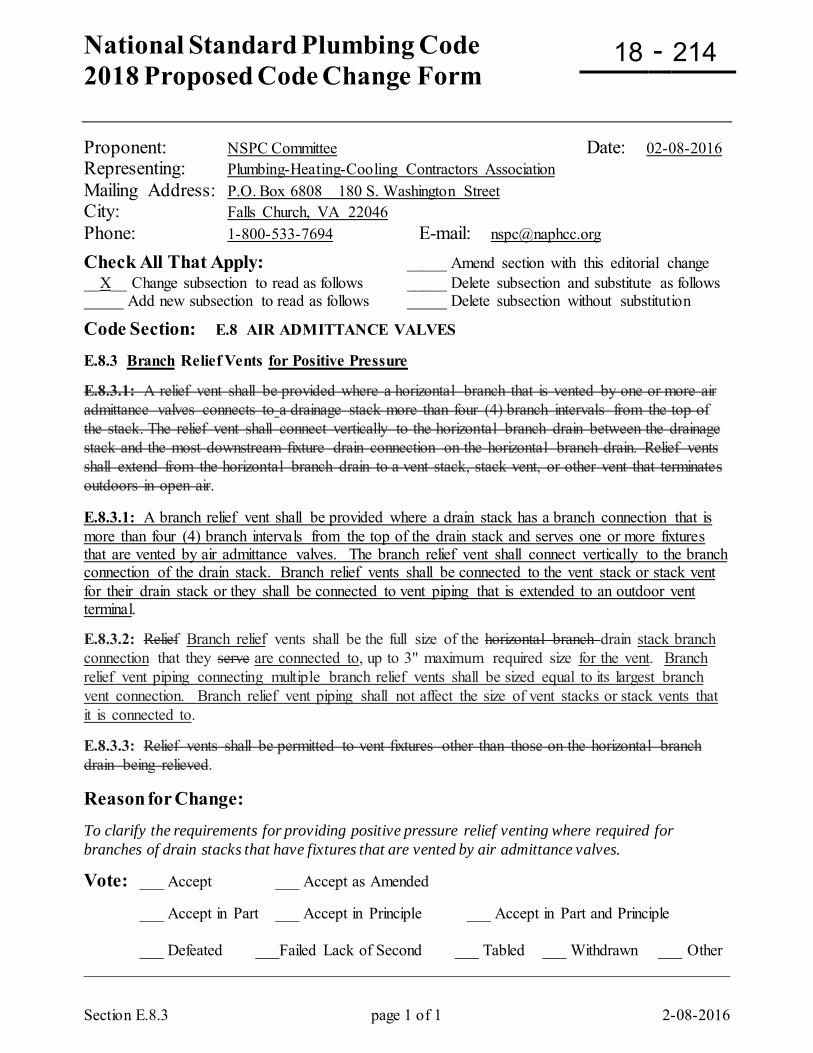
National Standard Plumbing Code 2018 Proposed Code Change Form
-
Section E.8.3 page 1 of 1 2-08-2016
Proponent: NSPC Committee Date: 02-08-2016 Representing: Plumbing-Heating-Cooling Contractors Association Mailing Address: P.O. Box 6808 180 S. Washington Street City: Falls Church, VA 22046 Phone: 1-800-533-7694 E-mail: [email protected] Check All That Apply: _____ Amend section with this editorial change __X__ Change subsection to read as follows _____ Delete subsection and substitute as follows _____ Add new subsection to read as follows _____ Delete subsection without substitution
Code Section: E.8 AIR ADMITTANCE VALVES E.8.3 Branch Relief Vents for Positive Pressure E.8.3.1: A relief vent shall be provided where a horizontal branch that is vented by one or more air admittance valves connects to a drainage stack more than four (4) branch intervals from the top of the stack. The relief vent shall connect vertically to the horizontal branch drain between the drainage stack and the most downstream fixture drain connection on the horizontal branch drain. Relief vents shall extend from the horizontal branch drain to a vent stack, stack vent, or other vent that terminates outdoors in open air. E.8.3.1: A branch relief vent shall be provided where a drain stack has a branch connection that is more than four (4) branch intervals from the top of the drain stack and serves one or more fixtures that are vented by air admittance valves. The branch relief vent shall connect vertically to the branch connection of the drain stack. Branch relief vents shall be connected to the vent stack or stack vent for their drain stack or they shall be connected to vent piping that is extended to an outdoor vent terminal. E.8.3.2: Relief Branch relief vents shall be the full size of the horizontal branch drain stack branch connection that they serve are connected to, up to 3" maximum required size for the vent. Branch relief vent piping connecting multiple branch relief vents shall be sized equal to its largest branch vent connection. Branch relief vent piping shall not affect the size of vent stacks or stack vents that it is connected to. E.8.3.3: Relief vents shall be permitted to vent fixtures other than those on the horizontal branch drain being relieved.
Reason for Change: To clarify the requirements for providing positive pressure relief venting where required for branches of drain stacks that have fixtures that are vented by air admittance valves. Vote: ___ Accept ___ Accept as Amended
___ Accept in Part ___ Accept in Principle ___ Accept in Part and Principle
___ Defeated ___Failed Lack of Second ___ Tabled ___ Withdrawn ___ Other _________________________________________________________________________________
18 214
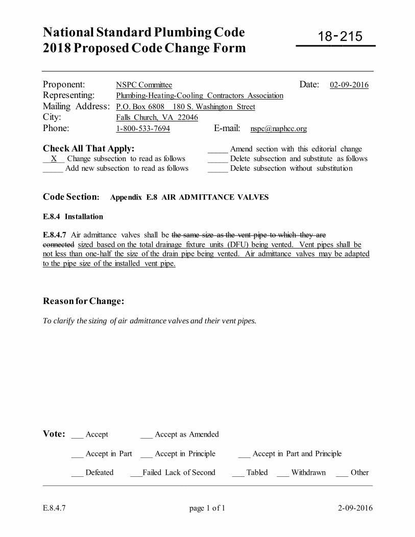
National Standard Plumbing Code 2018 Proposed Code Change Form
-
E.8.4.7 page 1 of 1 2-09-2016
Proponent: NSPC Committee Date: 02-09-2016 Representing: Plumbing-Heating-Cooling Contractors Association Mailing Address: P.O. Box 6808 180 S. Washington Street City: Falls Church, VA 22046 Phone: 1-800-533-7694 E-mail: [email protected] Check All That Apply: _____ Amend section with this editorial change __X__ Change subsection to read as follows _____ Delete subsection and substitute as follows _____ Add new subsection to read as follows _____ Delete subsection without substitution Code Section: Appendix E.8 AIR ADMITTANCE VALVES E.8.4 Installation E.8.4.7 Air admittance valves shall be the same size as the vent pipe to which they are connected sized based on the total drainage fixture units (DFU) being vented. Vent pipes shall be not less than one-half the size of the drain pipe being vented. Air admittance valves may be adapted to the pipe size of the installed vent pipe. Reason for Change: To clarify the sizing of air admittance valves and their vent pipes. Vote: ___ Accept ___ Accept as Amended
___ Accept in Part ___ Accept in Principle ___ Accept in Part and Principle
___ Defeated ___Failed Lack of Second ___ Tabled ___ Withdrawn ___ Other _________________________________________________________________________________
18 215
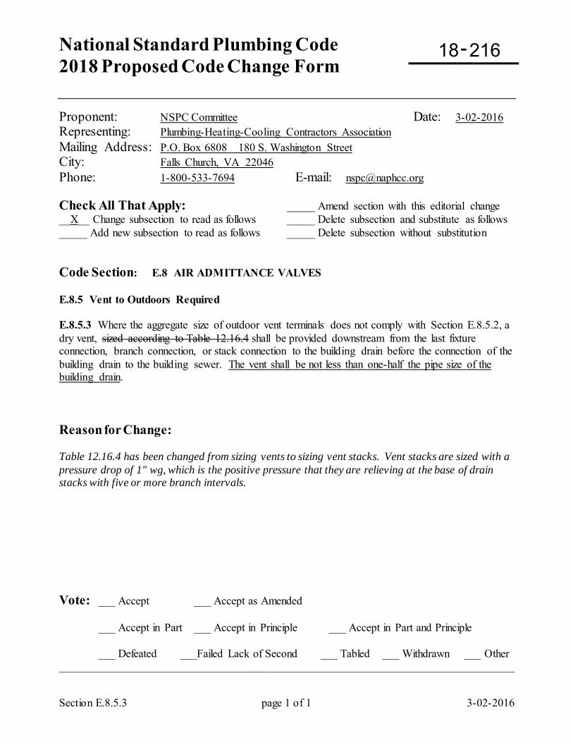
National Standard Plumbing Code 2018 Proposed Code Change Form
-
Section E.8.5.3 page 1 of 1 3-02-2016
Proponent: NSPC Committee Date: 3-02-2016 Representing: Plumbing-Heating-Cooling Contractors Association Mailing Address: P.O. Box 6808 180 S. Washington Street City: Falls Church, VA 22046 Phone: 1-800-533-7694 E-mail: [email protected] Check All That Apply: _____ Amend section with this editorial change __X__ Change subsection to read as follows _____ Delete subsection and substitute as follows _____ Add new subsection to read as follows _____ Delete subsection without substitution Code Section: E.8 AIR ADMITTANCE VALVES E.8.5 Vent to Outdoors Required E.8.5.3 Where the aggregate size of outdoor vent terminals does not comply with Section E.8.5.2, a dry vent, sized according to Table 12.16.4 shall be provided downstream from the last fixture connection, branch connection, or stack connection to the building drain before the connection of the building drain to the building sewer. The vent shall be not less than one-half the pipe size of the building drain. Reason for Change: Table 12.16.4 has been changed from sizing vents to sizing vent stacks. Vent stacks are sized with a pressure drop of 1" wg, which is the positive pressure that they are relieving at the base of drain stacks with five or more branch intervals. Vote: ___ Accept ___ Accept as Amended
___ Accept in Part ___ Accept in Principle ___ Accept in Part and Principle
___ Defeated ___Failed Lack of Second ___ Tabled ___ Withdrawn ___ Other _________________________________________________________________________________
18 216
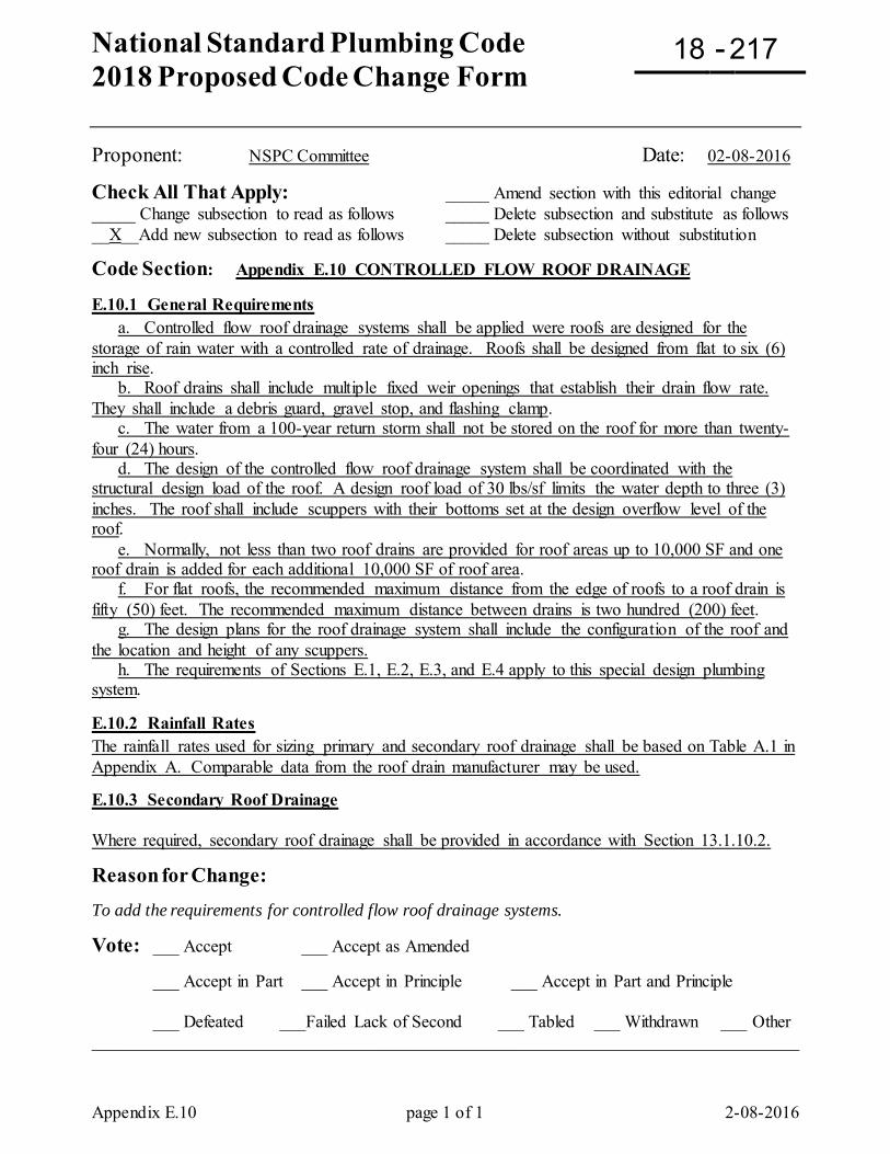
National Standard Plumbing Code 2018 Proposed Code Change Form
-
Appendix E.10 page 1 of 1 2-08-2016
Proponent: NSPC Committee Date: 02-08-2016
Check All That Apply: _____ Amend section with this editorial change _____ Change subsection to read as follows _____ Delete subsection and substitute as follows __X__Add new subsection to read as follows _____ Delete subsection without substitution
Code Section: Appendix E.10 CONTROLLED FLOW ROOF DRAINAGE E.10.1 General Requirements a. Controlled flow roof drainage systems shall be applied were roofs are designed for the storage of rain water with a controlled rate of drainage. Roofs shall be designed from flat to six (6) inch rise. b. Roof drains shall include multiple fixed weir openings that establish their drain flow rate. They shall include a debris guard, gravel stop, and flashing clamp. c. The water from a 100-year return storm shall not be stored on the roof for more than twenty-four (24) hours. d. The design of the controlled flow roof drainage system shall be coordinated with the structural design load of the roof. A design roof load of 30 lbs/sf limits the water depth to three (3) inches. The roof shall include scuppers with their bottoms set at the design overflow level of the roof. e. Normally, not less than two roof drains are provided for roof areas up to 10,000 SF and one roof drain is added for each additional 10,000 SF of roof area. f. For flat roofs, the recommended maximum distance from the edge of roofs to a roof drain is fifty (50) feet. The recommended maximum distance between drains is two hundred (200) feet. g. The design plans for the roof drainage system shall include the configuration of the roof and the location and height of any scuppers. h. The requirements of Sections E.1, E.2, E.3, and E.4 apply to this special design plumbing system. E.10.2 Rainfall Rates The rainfall rates used for sizing primary and secondary roof drainage shall be based on Table A.1 in Appendix A. Comparable data from the roof drain manufacturer may be used. E.10.3 Secondary Roof Drainage Where required, secondary roof drainage shall be provided in accordance with Section 13.1.10.2.
Reason for Change: To add the requirements for controlled flow roof drainage systems. Vote: ___ Accept ___ Accept as Amended
___ Accept in Part ___ Accept in Principle ___ Accept in Part and Principle
___ Defeated ___Failed Lack of Second ___ Tabled ___ Withdrawn ___ Other _________________________________________________________________________________
18 217
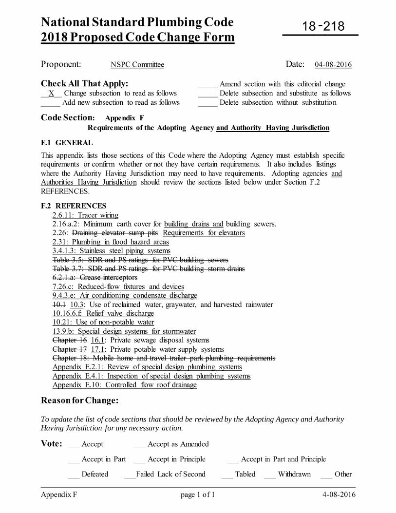
National Standard Plumbing Code 2018 Proposed Code Change Form
-
Appendix F page 1 of 1 4-08-2016
Proponent: NSPC Committee Date: 04-08-2016 Check All That Apply: _____ Amend section with this editorial change __X__ Change subsection to read as follows _____ Delete subsection and substitute as follows _____ Add new subsection to read as follows _____ Delete subsection without substitution
Code Section: Appendix F Requirements of the Adopting Agency and Authority Having Jurisdiction F.1 GENERAL This appendix lists those sections of this Code where the Adopting Agency must establish specific requirements or confirm whether or not they have certain requirements. It also includes listings where the Authority Having Jurisdiction may need to have requirements. Adopting agencies and Authorities Having Jurisdiction should review the sections listed below under Section F.2 REFERENCES. F.2 REFERENCES
2.6.11: Tracer wiring 2.16.a.2: Minimum earth cover for building drains and building sewers. 2.26: Draining elevator sump pits Requirements for elevators 2.31: Plumbing in flood hazard areas 3.4.1.3: Stainless steel piping systems Table 3.5: SDR and PS ratings for PVC building sewers Table 3.7: SDR and PS ratings for PVC building storm drains 6.2.1.a: Grease interceptors 7.26.c: Reduced-flow fixtures and devices 9.4.3.e: Air conditioning condensate discharge 10.1 10.3: Use of reclaimed water, graywater, and harvested rainwater 10.16.6.f: Relief valve discharge 10.21: Use of non-potable water 13.9.b: Special design systems for stormwater Chapter 16 16.1: Private sewage disposal systems Chapter 17 17.1: Private potable water supply systems Chapter 18: Mobile home and travel trailer park plumbing requirements Appendix E.2.1: Review of special design plumbing systems Appendix E.4.1: Inspection of special design plumbing systems Appendix E.10: Controlled flow roof drainage
Reason for Change: To update the list of code sections that should be reviewed by the Adopting Agency and Authority Having Jurisdiction for any necessary action.
Vote: ___ Accept ___ Accept as Amended
___ Accept in Part ___ Accept in Principle ___ Accept in Part and Principle
___ Defeated ___Failed Lack of Second ___ Tabled ___ Withdrawn ___ Other _________________________________________________________________________________
18 218
National Standard Plumbing Code 2018 Proposed Code Change Form
-
Appendix I page 1 of 1 8-03-2015
Proponent: NSPC Committee Date: 08-03-2015 Representing: Plumbing-Heating-Cooling Contractors Association Mailing Address: P.O. Box 6808 180 S. Washington Street City: Falls Church, VA 22046 Phone: 1-800-533-7694 E-mail: [email protected] Check All That Apply: _____ Amend section with this editorial change _____ Change subsection to read as follows _____ Delete subsection and substitute as follows _____ Add new subsection to read as follows __X__ Delete subsection without substitution Code Section: Appendix I Fixture Unit Value Curves for Water Closets Delete Appendix I. Reason for Change: The data in Appendix I is from 1994 and was used to update the 1996 issue of the NSPC. The ASME standard for the hydraulic performance requirements for water closets and urinals (ASME A112.19.6) was published in 1995 and consolidated into ASME A112.19.2 in 2003. The DFUs and WSFUs for water closets have been updated. Appendix I is no longer necessary. Vote: ___ Accept ___ Accept as Amended
___ Accept in Part ___ Accept in Principle ___ Accept in Part and Principle
___ Defeated ___Failed Lack of Second ___ Tabled ___ Withdrawn ___ Other _________________________________________________________________________________
18 219
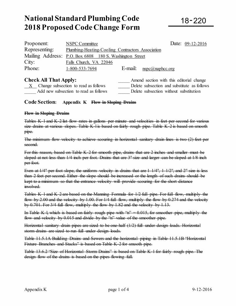
National Standard Plumbing Code 2018 Proposed Code Change Form
-
Appendix K page 1 of 4 9-12-2016
Proponent: NSPC Committee Date: 09-12-2016 Representing: Plumbing-Heating-Cooling Contractors Association Mailing Address: P.O. Box 6808 180 S. Washington Street City: Falls Church, VA 22046 Phone: 1-800-533-7694 E-mail: [email protected] Check All That Apply: _____ Amend section with this editorial change __X__ Change subsection to read as follows _____ Delete subsection and substitute as follows _____ Add new subsection to read as follows _____ Delete subsection without substitution Code Section: Appendix K Flow in Sloping Drains Flow in Sloping Drains
Tables K-1 and K-2 list flow rates in gallons per minute and velocities in feet per second for various size drains at various slopes. Table K-l is based on fairly rough pipe. Table K-2 is based on smooth pipe.
The minimum flow velocity to achieve scouring in horizontal sanitary drain lines is two (2) feet per second.
For this reason, based on Table K-2 for smooth pipe, drains that are 2 inches and smaller must be sloped at not less than 1/4 inch per foot. Drains that are 3" size and larger can be sloped at 1/8 inch per foot.
Even at 1/4" per foot slope, the uniform velocity in drains that are 1-1/4", 1-1/2", and 2" size is less than 2 feet per second. Either the slope should be increased or the length of such drains should be kept to a minimum so that the entrance velocity will provide scouring for the short distance involved. Tables K-1 and K-2 are based on the Manning Formula for 1/2 full pipe. For full flow, multiply the flow by 2.00 and the velocity by 1.00. For 1/4 full flow, multiply the flow by 0.274 and the velocity by 0.701. For 3/4 full flow, multiply the flow by 1.82 and the velocity by 1.13.
In Table K-l, which is based on fairly rough pipe with “n” = 0.015, for smoother pipe, multiply the flow and velocity by 0.015 and divide by the “n” value of the smoother pipe. Horizontal sanitary drain pipes are sized to be one-half (1/2) full under design loads. Horizontal storm drains are sized to run full under design loads. Table 11.5.1A Building Drains and Sewers and the horizontal piping in Table 11.5.1B “Horizontal Fixture Branches and Stacks” is based on Table K-2 for smooth pipe. Table 13.6.2 “Size of Horizontal Storm Drains” is based on Table K-1 for fairly rough pipe. The design flow of the drains is based on the pipes flowing full.
18 220
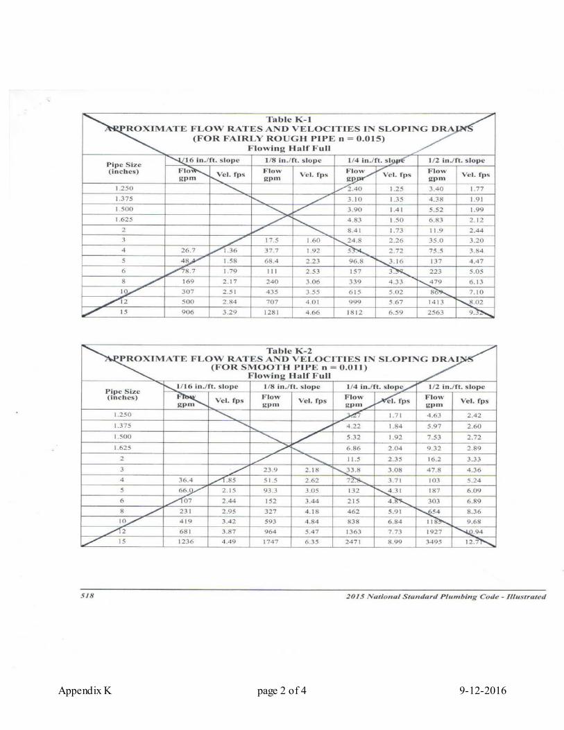
Appendix K page 2 of 4 9-12-2016
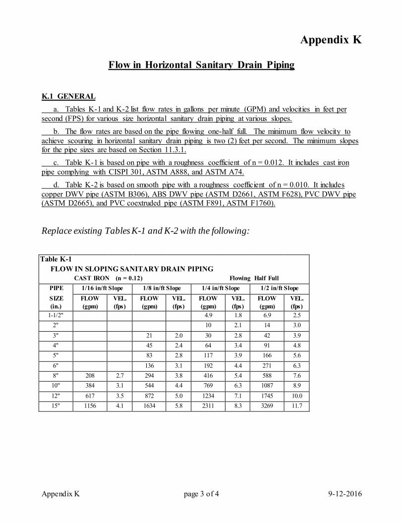
Appendix K page 3 of 4 9-12-2016
Appendix K
Flow in Horizontal Sanitary Drain Piping
K.1 GENERAL a. Tables K-1 and K-2 list flow rates in gallons per minute (GPM) and velocities in feet per second (FPS) for various size horizontal sanitary drain piping at various slopes. b. The flow rates are based on the pipe flowing one-half full. The minimum flow velocity to achieve scouring in horizontal sanitary drain piping is two (2) feet per second. The minimum slopes for the pipe sizes are based on Section 11.3.1. c. Table K-1 is based on pipe with a roughness coefficient of n = 0.012. It includes cast iron pipe complying with CISPI 301, ASTM A888, and ASTM A74. d. Table K-2 is based on smooth pipe with a roughness coefficient of n = 0.010. It includes copper DWV pipe (ASTM B306), ABS DWV pipe (ASTM D2661, ASTM F628), PVC DWV pipe (ASTM D2665), and PVC coextruded pipe (ASTM F891, ASTM F1760). Replace existing Tables K-1 and K-2 with the following: Table K-1
FLOW IN SLOPING SANITARY DRAIN PIPING CAST IRON (n = 0.12) Flowing Half Full
PIPE 1/16 in/ft Slope 1/8 in/ft Slope 1/4 in/ft Slope 1/2 in/ft Slope SIZE FLOW VEL. FLOW VEL. FLOW VEL. FLOW VEL. (in.) (gpm) (fps) (gpm) (fps) (gpm) (fps) (gpm) (fps)
1-1/2" 4.9 1.8 6.9 2.5 2" 10 2.1 14 3.0 3" 21 2.0 30 2.8 42 3.9 4" 45 2.4 64 3.4 91 4.8 5" 83 2.8 117 3.9 166 5.6 6" 136 3.1 192 4.4 271 6.3 8" 208 2.7 294 3.8 416 5.4 588 7.6 10" 384 3.1 544 4.4 769 6.3 1087 8.9 12" 617 3.5 872 5.0 1234 7.1 1745 10.0 15" 1156 4.1 1634 5.8 2311 8.3 3269 11.7
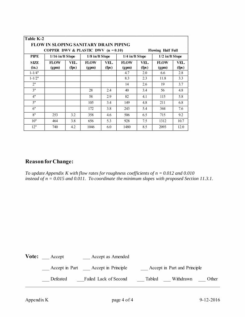
Appendix K page 4 of 4 9-12-2016
Table K-2 FLOW IN SLOPING SANITARY DRAIN PIPING
COPPER DWV & PLASTIC DWV (n = 0.10) Flowing Half Full PIPE 1/16 in/ft Slope 1/8 in/ft Slope 1/4 in/ft Slope 1/2 in/ft Slope SIZE FLOW VEL. FLOW VEL. FLOW VEL. FLOW VEL. (in.) (gpm) (fps) (gpm) (fps) (gpm) (fps) (gpm) (fps)
1-1/4" 4.7 2.0 6.6 2.8 1-1/2" 8.3 2.3 11.8 3.3
2" 14 2.6 19 3.7 3" 28 2.4 40 3.4 56 4.8 4" 58 2.9 82 4.1 115 5.8 5" 105 3.4 149 4.8 211 6.8 6" 172 3.8 243 5.4 344 7.6 8" 253 3.2 358 4.6 506 6.5 715 9.2 10" 464 3.8 656 5.3 928 7.5 1312 10.7 12" 740 4.2 1046 6.0 1480 8.5 2093 12.0
Reason for Change: To update Appendix K with flow rates for roughness coefficients of n = 0.012 and 0.010 instead of n = 0.015 and 0.011. To coordinate the minimum slopes with proposed Section 11.3.1. Vote: ___ Accept ___ Accept as Amended
___ Accept in Part ___ Accept in Principle ___ Accept in Part and Principle
___ Defeated ___Failed Lack of Second ___ Tabled ___ Withdrawn ___ Other _________________________________________________________________________________
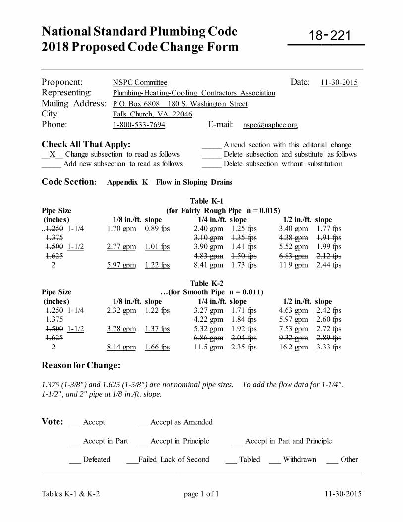
National Standard Plumbing Code 2018 Proposed Code Change Form
-
Tables K-1 & K-2 page 1 of 1 11-30-2015
Proponent: NSPC Committee Date: 11-30-2015 Representing: Plumbing-Heating-Cooling Contractors Association Mailing Address: P.O. Box 6808 180 S. Washington Street City: Falls Church, VA 22046 Phone: 1-800-533-7694 E-mail: [email protected] Check All That Apply: _____ Amend section with this editorial change __X__ Change subsection to read as follows _____ Delete subsection and substitute as follows _____ Add new subsection to read as follows _____ Delete subsection without substitution Code Section: Appendix K Flow in Sloping Drains Table K-1 Pipe Size (for Fairly Rough Pipe n = 0.015) (inches) 1/8 in./ft. slope 1/4 in./ft. slope 1/2 in./ft. slope ..1.250 1-1/4 1.70 gpm 0.89 fps 2.40 gpm 1.25 fps 3.40 gpm 1.77 fps 1.375 3.10 gpm 1.35 fps 4.38 gpm 1.91 fps 1.500 1-1/2 2.77 gpm 1.01 fps 3.90 gpm 1.41 fps 5.52 gpm 1.99 fps 1.625 4.83 gpm 1.50 fps 6.83 gpm 2.12 fps 2 5.97 gpm 1.22 fps 8.41 gpm 1.73 fps 11.9 gpm 2.44 fps Table K-2 Pipe Size …(for Smooth Pipe n = 0.011) (inches) 1/8 in./ft. slope 1/4 in./ft. slope 1/2 in./ft. slope 1.250 1-1/4 2.32 gpm 1.22 fps 3.27 gpm 1.71 fps 4.63 gpm 2.42 fps 1.375 4.22 gpm 1.84 fps 5.97 gpm 2.60 fps 1.500 1-1/2 3.78 gpm 1.37 fps 5.32 gpm 1.92 fps 7.53 gpm 2.72 fps 1.625 6.86 gpm 2.04 fps 9.32 gpm 2.89 fps 2 8.14 gpm 1.66 fps 11.5 gpm 2.35 fps 16.2 gpm 3.33 fps Reason for Change: 1.375 (1-3/8") and 1.625 (1-5/8") are not nominal pipe sizes. To add the flow data for 1-1/4", 1-1/2", and 2" pipe at 1/8 in./ft. slope. Vote: ___ Accept ___ Accept as Amended
___ Accept in Part ___ Accept in Principle ___ Accept in Part and Principle
___ Defeated ___Failed Lack of Second ___ Tabled ___ Withdrawn ___ Other _________________________________________________________________________________
18 221
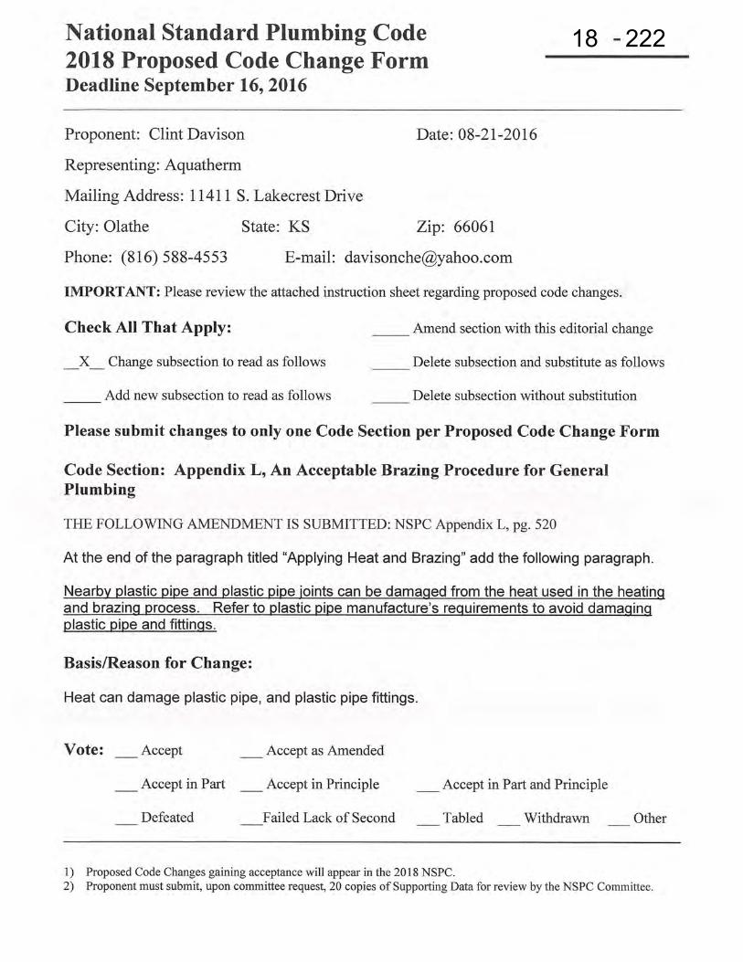
18 222