Embed Size (px)
Citation preview

1RETURN TO TABLE OF CONTENTSRETURN TO TABLE OF CONTENTSRETURN TO TABLE OF CONTENTSRETURN TO TABLE OF CONTENTSRETURN TO TABLE OF CONTENTS RETURN TO TABLE OF CONTENTS
2017 REDSHIFT OWNER & SERVICEMANUAL
2
Congratulations on your purchase of an Alta Motors Redshift!
The Redshift is engineered to compete, and performs like a 250cc bike.
While you’re getting used to it, be cautious and pay attention to available
traction in both acceleration and braking. The smooth throttle delivery and
lack of combustion-derived noise means the Redshift can be deceptively
fast: you don’t want any unpleasant surprises.
PLEASE READ THIS MANUAL CAREFULLY AND COMPLETELY BEFORE OPERATING THIS MACHINE.
DO NOT ATTEMPT TO OPERATE THIS MACHINE UNTIL YOU HAVE ATTAINED A SATISFACTORY
KNOWLEDGE OF ITS CONTROLS AND OPERATING FEATURES AND UNTIL YOU HAVE BEEN
TRAINED IN SAFE AND PROPER RIDING TECHNIQUES. REGULAR INSPECTIONS AND CAREFUL
MAINTENANCE, ALONG WITH GOOD RIDING SKILLS, WILL ENSURE THAT YOU SAFELY ENJOY THE
CAPABILITIES AND THE RELIABILITY OF THIS MACHINE.
Always wear a helmet. Before you go “Throttle Live,” make sure your helmet is on.
The Redshift is designed for one person only.
Unlike a traditional gas-powered motorcycle, the Redshift doesn’t require much maintenance.
However, the source of its power produces extremely high voltage and amperage. DO NOT tamper
with the electrical system! There are no user-serviceable electrical powertrain components housed
in the bike. See your authorized Alta Motors dealer when the need for diagnosis or repairs arise.
If the battery pack in particular gets dented, cracked, punctured, or yielded in any way, take your
Redshift to your local dealer to have a complete inspection done.
Please do not attempt to operate your Redshift under the influence of any drugs, prescription or
recreational, including Alcohol.
Failure to follow WARNING instructions could result in severe injury or death to the machine
operator, a bystander, or a person inspecting or repairing the machine.
This manual will provide you with a good basic understanding of features, operation, and basic
maintenance and inspection items of this machine. Please read this manual carefully and
completely before operating your new machine.
3
CHAPTER 1 – GENERAL INFORMATION
Getting Started 6
Regular Inspection and Adjustments 14
CHAPTER 2 – BODYWORK
Fender (front) – Removal & Installation 32
Fender (rear) – Removal & Installation 35
Mud Flap – Removal & Installation 35
Number Plate (front) – Removal & Installation 33
Number Plate (rear) – Removal & Installation 34
Rock Guard – Removal & Installation 34
Seat – Removal & Installation 30
Shrouds – Removal & Installation 31
Subframe – Removal & Installation 34
CHAPTER 2 – BRAKES
Brake Caliper (Front, MX), Removal & Installation 45
Brake Caliper (Front, SM), Removal & Installation 46
Brake Caliper (Rear, MX & SM), Removal & Installation
47
Brake Caliper, Overhaul 48
Brake Disc, Removal & Installation 59
Brake Hydraulic System, Bleeding 56
Brake Lever, Removal & Installation 58
Brake Master Cylinder (Front), Removal & Installation 51
Brake Master Cylinder (Rear), Removal & Installation 53
Brake Master Cylinder, Overhaul 54
Brake Pad Replacement (Front, MX) 38
Brake Pad Replacement (Front, SM) 40
Brake Pad Replacement (Rear, MX and SM) 42
Brake Pedal, Removal & Installation 59
TABLE OF CONTENTS
4
CHAPTER 4 – SUSPENSION / STEERING / WHEELS / FINAL DRIVE
Drive Chain – Maintenance 17
Drive Chain – Removal & Installation 17
Forks – Removal & Installation 64
Front wheel – Removal & Installation 22
Grips – Replace 63
Handlebar and Mounts – Removal & Installation 62
Rear Wheel – Removal & Installation 25
Shock Absorber – Removal & Installation 70
Shock Linkage – Remove/bearing Service/install 70
Primary Drive Sprocket – Removal & Installation 91
Steering Head Bearings – Service/Replace 68
Suspension – Adjustments 18
Swingarm – Remove/ Bearing Service/Install 72
Triple Clamps/Steering Stem – Removal & Installation 66
Wheel seals and bearings – Replace 60
CHAPTER 5 – COOLING SYSTEM
Coolant – Drain/Refill 74
Coolant Pump – Removal & Installation 76
Coolant Hose(s) – Replace 77
CHAPTER 6 – POWERTRAIN / BATTERY / CONTROL SYSTEM /
MOTOR / PRIMARY DRIVE
Accessory Control Module (ACM) – Removal & Installation 83
Battery – Disconnection/Reconnection 79
Battery – Removal & Installation 80
Charge Inlet (Delta Wing) – Removal & Installation 82
DC Charge Port (DCCP) – Removal & Installation 90
Drive and Driven Gears – Removal & Installation 96
Gearbox Cover – Removal & Installation 94
HV Connector – Removal & Installation 79
Motor Controller - Removal & Installation 84
Motor and Output Shaft – Removal & Installation 98
Output Shaft Bearings - Replace 102
5
Output Shaft Seal – Replace 92
Position Sensor – Removal & Installation 93
Primary Drive Sprocket – Removal & Installation 91
Timing Cover – Removal & Installation 93
CHAPTER 7 – FRAME
Boot Guards – Removal & Installation 106
Bulkhead – General Information/Servicing 109
Footpegs – Removal & Installation 107
Sidestand – Removal & Installation 108
Skidframe – Removal & Installation 104
CHAPTER 8 – LOW VOLTAGE ELECTRICAL
Brake Light Switches – Removal & Installation 116
Display – Removal & Installation 110
Headlight Adjustment 119
Headlight Housing - Removal & Bulb Replacement 119
Horn – Removal & Installation 118
Ignition Switch – Removal & Installation 114
License Plate Light 121
Map Switch – Removal & Installation 113
Marker Light 120
Sidestand Switch – Removal & Installation 118
Start/Stop/Run Switch – Removal & Installation 112
Taillight 120
Throttle Switch/Tube – Removal & Installation 115
Turn Signal/Horn/HI-LO Beam Switch – Removal & Installation
114
Turn Signals/Running Lights 121
6 RETURN TO TABLE OF CONTENTSRETURN TO TABLE OF CONTENTSRETURN TO TABLE OF CONTENTSRETURN TO TABLE OF CONTENTSRETURN TO TABLE OF CONTENTS RETURN TO TABLE OF CONTENTS
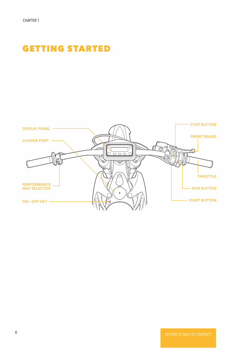
GETTING STARTED
STOP BUTTON
FRONT BRAKE
THROTTLE
RUN BUTTON
START BUTTON
DISPLAY PANEL
CHARGE PORT
PERFORMANCE MAP SELECTOR
ON / OFF KEY
CHAPTER 1
7RETURN TO TABLE OF CONTENTSRETURN TO TABLE OF CONTENTSRETURN TO TABLE OF CONTENTSRETURN TO TABLE OF CONTENTSRETURN TO TABLE OF CONTENTS RETURN TO TABLE OF CONTENTS
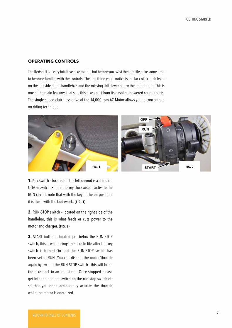
OPERATING CONTROLS
The Redshift is a very intuitive bike to ride, but before you twist the throttle, take some time
to become familiar with the controls. The first thing you’ll notice is the lack of a clutch lever
on the left side of the handlebar, and the missing shift lever below the left footpeg. This is
one of the main features that sets this bike apart from its gasoline-powered counterparts.
The single-speed clutchless drive of the 14,000 rpm AC Motor allows you to concentrate
on riding technique.
1. Key Switch – located on the left shroud is a standard
Off/On switch. Rotate the key clockwise to activate the
RUN circuit. note that with the key in the on position,
it is flush with the bodywork. (Fig. 1)
2. RUN-STOP switch – located on the right side of the
handlebar, this is what feeds or cuts power to the
motor and charger. (Fig. 2)
3. START button – located just below the RUN-STOP
switch, this is what brings the bike to life after the key
switch is turned On and the RUN-STOP switch has
been set to RUN. You can disable the motor/throttle
again by cycling the RUN-STOP switch– this will bring
the bike back to an idle state. Once stopped please
get into the habit of switching the run-stop switch off
so that you don’t accidentally actuate the throttle
while the motor is energized.
Fig. 1 Fig. 2
GETTING STARTED
8 RETURN TO TABLE OF CONTENTSRETURN TO TABLE OF CONTENTSRETURN TO TABLE OF CONTENTSRETURN TO TABLE OF CONTENTSRETURN TO TABLE OF CONTENTS RETURN TO TABLE OF CONTENTS
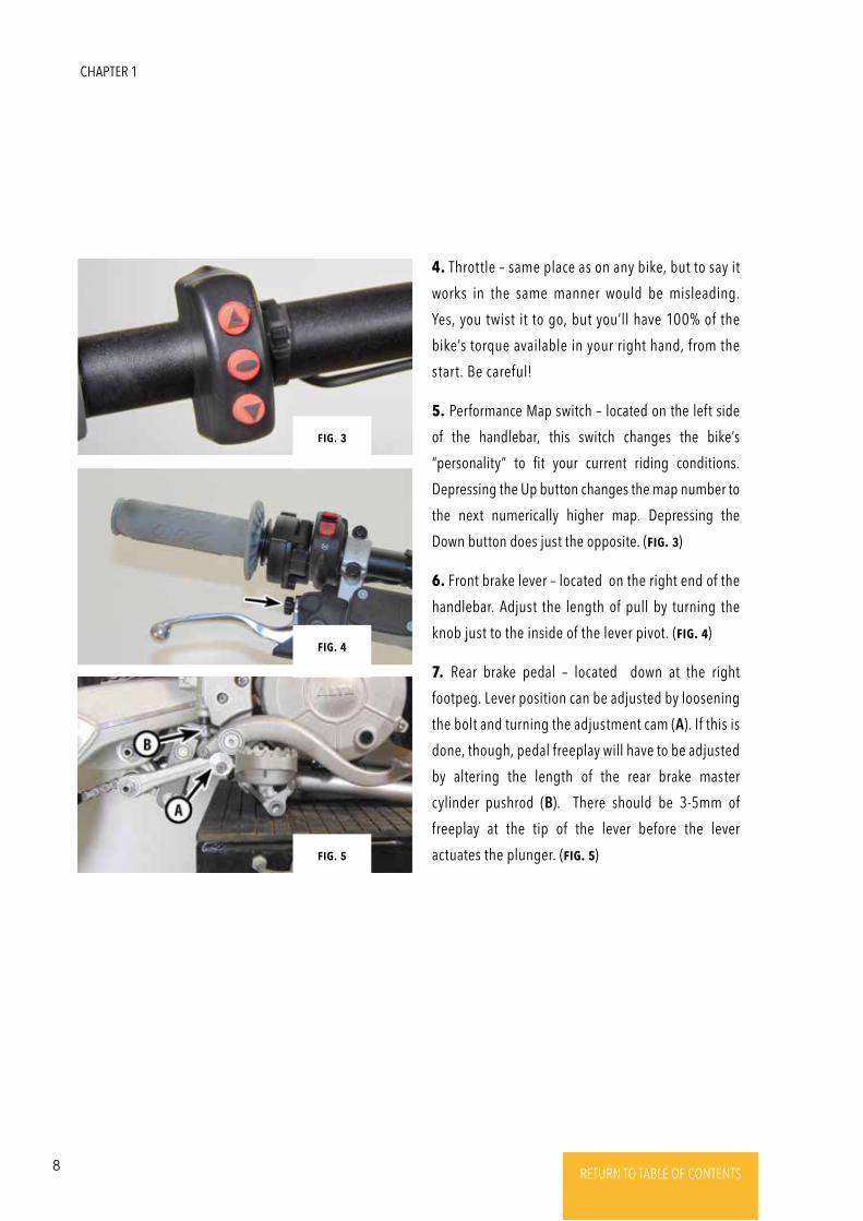
4. Throttle – same place as on any bike, but to say it
works in the same manner would be misleading.
Yes, you twist it to go, but you’ll have 100% of the
bike’s torque available in your right hand, from the
start. Be careful!
5. Performance Map switch – located on the left side
of the handlebar, this switch changes the bike’s
“personality” to fit your current riding conditions.
Depressing the Up button changes the map number to
the next numerically higher map. Depressing the
Down button does just the opposite. (Fig. 3)
6. Front brake lever – located on the right end of the
handlebar. Adjust the length of pull by turning the
knob just to the inside of the lever pivot. (Fig. 4)
7. Rear brake pedal – located down at the right
footpeg. Lever position can be adjusted by loosening
the bolt and turning the adjustment cam (A). If this is
done, though, pedal freeplay will have to be adjusted
by altering the length of the rear brake master
cylinder pushrod (B). There should be 3-5mm of
freeplay at the tip of the lever before the lever
actuates the plunger. (Fig. 5)Fig. 5
Fig. 4
Fig. 3
CHAPTER 1

9RETURN TO TABLE OF CONTENTSRETURN TO TABLE OF CONTENTSRETURN TO TABLE OF CONTENTSRETURN TO TABLE OF CONTENTSRETURN TO TABLE OF CONTENTS RETURN TO TABLE OF CONTENTS
UNDERSTANDING THE PERFORMANCE MAPS
The Redshift is equipped from the factory with 4 performance maps. These performance
maps are not “gears,” but rather tools to adapt the characteristics of the Redshift
to different riding styles and terrain conditions. The maps work by changing the
parameters of power delivery relative to the throttle position and regenerative braking
on deceleration. You may find that you are faster in slippery conditions when using Map
1. When traction is good, Map 4 may be your fastest option. Try them all out in different
conditions to see what suits you and your riding environment.
The regenerative braking (regen) acts as resistance when the throttle is off. The more
regen, the more power is being produced, the more it will slow you down without the
use of the conventional disc brakes.
MAP 4
OVERCLOCKED
MILD
MILD
HIGH
HIGH
HIGH
MAP 3
PERFORMANCE
MILD
MILD
MEDIUM
MEDIUM
MED-HIGH
MAP 2
MX RACE
MEDIUM
MILD
HIGH
MEDIUM
MEDIUM
MAP 1
TRAIL
HIGH
MEDIUM
MILD
MILD
MILD
TRACTION
REGEN
RESPONSE
TOP
BOTTOM
GETTING STARTED
MAP 4
OVERCLOCKED
MILD
HIGH
HIGH
HIGH
HIGH
MAP 3
COMMUTE-2
MEDIUM
MEDIUM
MEDIUM
MEDIUM
MEDIUM
MAP 2
COMMUTE-1
MEDIUM
MILD
MEDIUM
MEDIUM
MEDIUM
MAP 1
RAIN
HIGH
MILD
MILD
MILD
MILD
TRACTION
REGEN
RESPONSE
TOP
BOTTOM
10 RETURN TO TABLE OF CONTENTSRETURN TO TABLE OF CONTENTSRETURN TO TABLE OF CONTENTSRETURN TO TABLE OF CONTENTSRETURN TO TABLE OF CONTENTS RETURN TO TABLE OF CONTENTS
STARTING UP
THROTTLE LIVE
OPERATING YOUR REDSHIFT
1. Turn the key clockwise to the ON position. The
display will light up, giving you information about the
state of charge, map selection, and total mileage. You
may also hear the coolant pump power up and begin
to circulate coolant through the frame.
2. Set the red RUN-STOP switch to RUN.
3. With the throttle fully closed, press the START
button. The throttle is now live!
1. The Redshift is now LIVE, and the perimeter of the
display panel will pulse green to indicate live throttle.
This pulsing will stop once you are moving, and will
resume when you come to a stop.
2. The Redshift has no clutch and makes almost no
noise when stationary. Once you twist the throttle,
the bike will respond immediately. It ’s a smart
practice to always cycle the RUN-STOP switch to
deactivate the throttle after a ride, for an emergency
stop, or any time when you’re stopping for more than
a traffic light.
NEVER lEaVE thE bikE sittiNg with a liVE thRottlE!!!
If the HV battery is below freezing temperature, it
will refuse to charge, and drive power will be
reduced. Capacity (driving range) will also be
reduced at low temperature.
Over-discharge may result in permanent damage to the
HV battery, and replacement may be necessary. The HV
battery has a gradual self-discharge rate, and will lose
charge if left unused for long periods of time. Do not
leave the HV battery below 10% charge for more than
one week, or below 25% for more than one month.
When storing the HV battery, charge it to 40-60% (or
higher) and check it monthly, recharging if needed.
The HV battery will gradually lose capacity with time
and use, just like any rechargeable battery. The rate of
capacity loss depends on how the pack is used, but
lower sustained temperatures and lower power draw
(less aggressive riding, especially at highway speeds)
will prolong battery life.
There is no specific point at which the HV battery
needs to be replaced. The capacity (range) and
available power will simply continue to decrease.
Contact your Alta dealer for proper disposal and
replacement of your HV battery.
The regenerative braking system applies a braking
torque at the rear wheel to add charge back into the
HV battery; the amount of “regen” applied varies with
throttle position and throttle map. This system is not
connected to the vehicle’s hydraulic braking system or
brake levers in any way, and should not be depended
on to stop the vehicle in an emergency. When the HV
battery is full, regen will be automatically reduced to
prevent overcharge.
CHAPTER 1
11RETURN TO TABLE OF CONTENTSRETURN TO TABLE OF CONTENTSRETURN TO TABLE OF CONTENTSRETURN TO TABLE OF CONTENTSRETURN TO TABLE OF CONTENTS RETURN TO TABLE OF CONTENTS
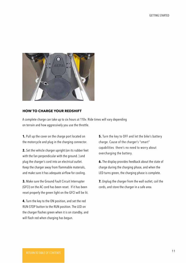
HOW TO CHARGE YOUR REDSHIFT
1. Pull up the cover on the charge port located on
the motorcycle and plug in the charging connector.
2. Set the vehicle charger upright (on its rubber feet
with the fan perpendicular with the ground. ) and
plug the charger’s cord into an electrical outlet.
Keep the charger away from flammable materials,
and make sure it has adequate airflow for cooling.
3. Make sure the Ground Fault Circuit Interrupter
(GFCI) on the AC cord has been reset. If it has been
reset properly the green light on the GFCI will be lit.
4. Turn the key to the ON position, and set the red
RUN-STOP button to the RUN position. The LED on
the charger flashes green when it is on standby, and
will flash red when charging has begun.
5. Turn the key to OFF and let the bike’s battery
charge. Cause of the charger’s “smart”
capabilities there’s no need to worry about
overcharging the battery.
6. The display provides feedback about the state of
charge during the charging phase, and when the
LED turns green, the charging phase is complete.
7. Unplug the charger from the wall outlet; coil the
cords, and store the charger in a safe area.
A complete charge can take up to six hours at 110v. Ride times will vary depending
on terrain and how aggressively you use the throttle.
GETTING STARTED
12 RETURN TO TABLE OF CONTENTSRETURN TO TABLE OF CONTENTSRETURN TO TABLE OF CONTENTSRETURN TO TABLE OF CONTENTSRETURN TO TABLE OF CONTENTS RETURN TO TABLE OF CONTENTS
HIGH VOLTAGE SAFETY
WARNING: YouR VEhiclE coNtaiNs a sEalEd Lithium-IoN High VoltagE (HV)
battERy systEm. IF thE HV battERy is haNdlEd impRopERly oR bEcomEs damagEd,
thERE is a Risk oF ElEctRic shock, FiRE, aNd sERious iNjuRy oR dEath.
HIGH VOLTAGE (HV) BATTERY
AND DRIVE SYSTEM
IF THE HV SYSTEM IS DAMAGED
The HV battery and drive system operates up to 400V
DC. The system can be “live” during and after the
vehicle is powered up, and for up several minutes
after the vehicle is shut off.
Never disassemble, remove or replace high-voltage
components - all HV system components can only be
serviced by an Alta dealer. High-voltage cables are
colored orange, and all related components have
warning labels on them. Obey all warning labels on
the vehicle.
After an accident, inspect for exposed wiring,
damaged connectors or damaged housings of any
high-voltage components. Do not attempt to touch
wiring or exposed parts. If any part of the HV system is
damaged, bring the vehicle to your Alta dealer
immediately. If damaged wiring or electrical
components are in danger of touching the chassis or
the extent of damage is unclear, do not touch the
vehicle, and call an emergency service like 911 to
handle it.
IF EmERgENcy sERVicEs aRE at thE scENE, makE
suRE thEy aRE awaRE that this is a High VoltagE
ElEctRic VEhiclE.
Damage to the HV battery system may result in an
electrolyte leak. Avoid contact with the electrolyte
and do not inhale the fumes; if contact occurs, flush
eyes or skin with water immediately. The electrolyte
is flammable: keep any flame or hot objects away
from a leak.
Extreme damage to the HV battery can cause a fire. If
a HV battery fire occurs, the most effective response is
to douse it heavily with fresh water or bury it in sand.
A fire extinguisher will only reduce the flame
temporarily; it will not remove the heat and therefore
will not stop the reaction taking place.
After a HV battery fire has subsided, it may still be
generating enough internal heat to re-ignite. Keep the
HV battery away from flammable materials and monitor
it for at least 2 hours after it has cooled completely.
CHAPTER 1
13RETURN TO TABLE OF CONTENTSRETURN TO TABLE OF CONTENTSRETURN TO TABLE OF CONTENTSRETURN TO TABLE OF CONTENTSRETURN TO TABLE OF CONTENTS RETURN TO TABLE OF CONTENTS
CHARGING SAFETY
To avoid risk of electrical shock, fire, and serious injury or death:
• Only use a charger
that is approved by
Alta Motors for use with
your vehicle model.
• Have any outlet used
for charging inspected
by a licensed
electrician. Inspection
should include
verifying proper
grounding, sufficient
current handling,
dedicated circuit, and
breaker function.
• If you use any life-
sustaining medical
electrical devices,
check with the
manufacturer about
the effects that
charging may have on
that device.
• Charge outdoors or in
large ventilated areas.
Do not use a vehicle
cover during charging.
• Do not charge with
building wiring more
than 40 years old.
• Do not charge if
outlet appears
damaged or will not
hold plug firmly.
• If your AC cord is
equipped with a
GFCI, test it monthly
(“TEST” button).
• Do not charge with
other devices plugged
into the same circuit.
• Do not use unapproved
extension cords or plug
adapters to charge.
• Do not touch exposed
connector terminals.
• Do not move the vehicle
while charging.
• Do not touch the
vehicle or charger
when there is lightning.
A lightning strike may
feed back into the
charging system.
• Do not disassemble or
modify the charger or
vehicle connector.
Plug should be
modified only by a
licensed electrician.
• Stop charging
immediately if charge
plug or outlet becomes
hot to the touch.
• Do not charge near fire,
heat, flammable
materials, or water.
• Make sure there is no
water or debris in the
charge port, connector
or electrical plug, and
that they are not
damaged, rusted or
corroded. Make sure
the charge port cap is
closed once charging is
finished to prevent
water and foreign
debris from entering.
• Do not unplug
anything until
charging has been
disabled by setting
the run/stop switch to
the “stop” position.
GETTING STARTED
14 RETURN TO TABLE OF CONTENTSRETURN TO TABLE OF CONTENTSRETURN TO TABLE OF CONTENTSRETURN TO TABLE OF CONTENTSRETURN TO TABLE OF CONTENTS RETURN TO TABLE OF CONTENTS
To obtain the best performance from your Redshift, and for your own safety, it’s important
to take a few moments to make sure everything is in working order before you ride:
REGULAR INSPECTION & ADJUSTMENTS
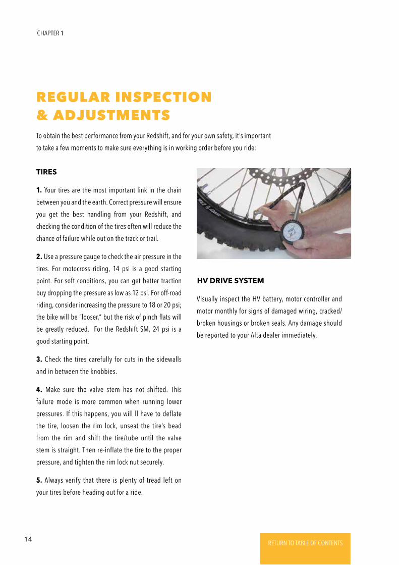
1. Your tires are the most important link in the chain
between you and the earth. Correct pressure will ensure
you get the best handling from your Redshift, and
checking the condition of the tires often will reduce the
chance of failure while out on the track or trail.
2. Use a pressure gauge to check the air pressure in the
tires. For motocross riding, 14 psi is a good starting
point. For soft conditions, you can get better traction
buy dropping the pressure as low as 12 psi. For off-road
riding, consider increasing the pressure to 18 or 20 psi;
the bike will be “looser,” but the risk of pinch flats will
be greatly reduced. For the Redshift SM, 24 psi is a
good starting point.
3. Check the tires carefully for cuts in the sidewalls
and in between the knobbies.
4. Make sure the valve stem has not shifted. This
failure mode is more common when running lower
pressures. If this happens, you will ll have to deflate
the tire, loosen the rim lock, unseat the tire’s bead
from the rim and shift the tire/tube until the valve
stem is straight. Then re-inflate the tire to the proper
pressure, and tighten the rim lock nut securely.
5. Always verify that there is plenty of tread left on
your tires before heading out for a ride.
TIRES
Visually inspect the HV battery, motor controller and
motor monthly for signs of damaged wiring, cracked/
broken housings or broken seals. Any damage should
be reported to your Alta dealer immediately.
HV DRIVE SYSTEM
CHAPTER 1
15RETURN TO TABLE OF CONTENTSRETURN TO TABLE OF CONTENTSRETURN TO TABLE OF CONTENTSRETURN TO TABLE OF CONTENTSRETURN TO TABLE OF CONTENTS RETURN TO TABLE OF CONTENTS
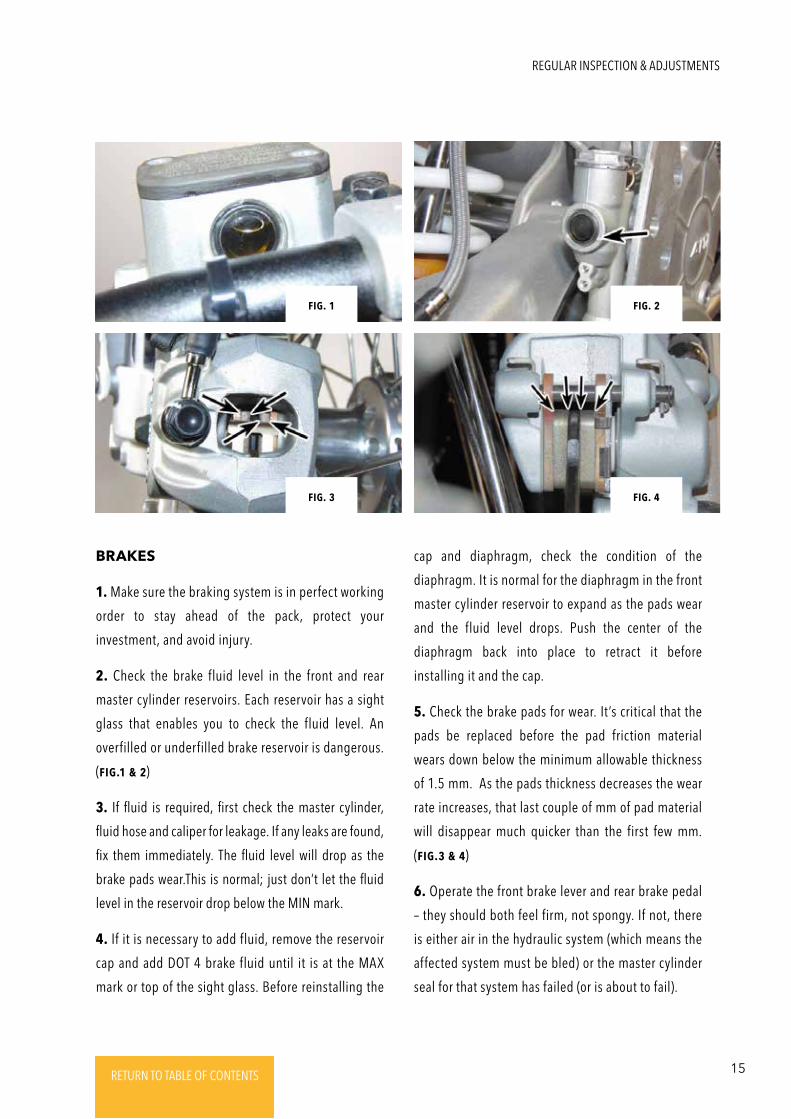
BRAKES
1. Make sure the braking system is in perfect working
order to stay ahead of the pack, protect your
investment, and avoid injury.
2. Check the brake fluid level in the front and rear
master cylinder reservoirs. Each reservoir has a sight
glass that enables you to check the fluid level. An
overfilled or underfilled brake reservoir is dangerous.
(Fig.1 & 2)
3. If fluid is required, first check the master cylinder,
fluid hose and caliper for leakage. If any leaks are found,
fix them immediately. The fluid level will drop as the
brake pads wear.This is normal; just don’t let the fluid
level in the reservoir drop below the MIN mark.
4. If it is necessary to add fluid, remove the reservoir
cap and add DOT 4 brake fluid until it is at the MAX
mark or top of the sight glass. Before reinstalling the
cap and diaphragm, check the condition of the
diaphragm. It is normal for the diaphragm in the front
master cylinder reservoir to expand as the pads wear
and the fluid level drops. Push the center of the
diaphragm back into place to retract it before
installing it and the cap.
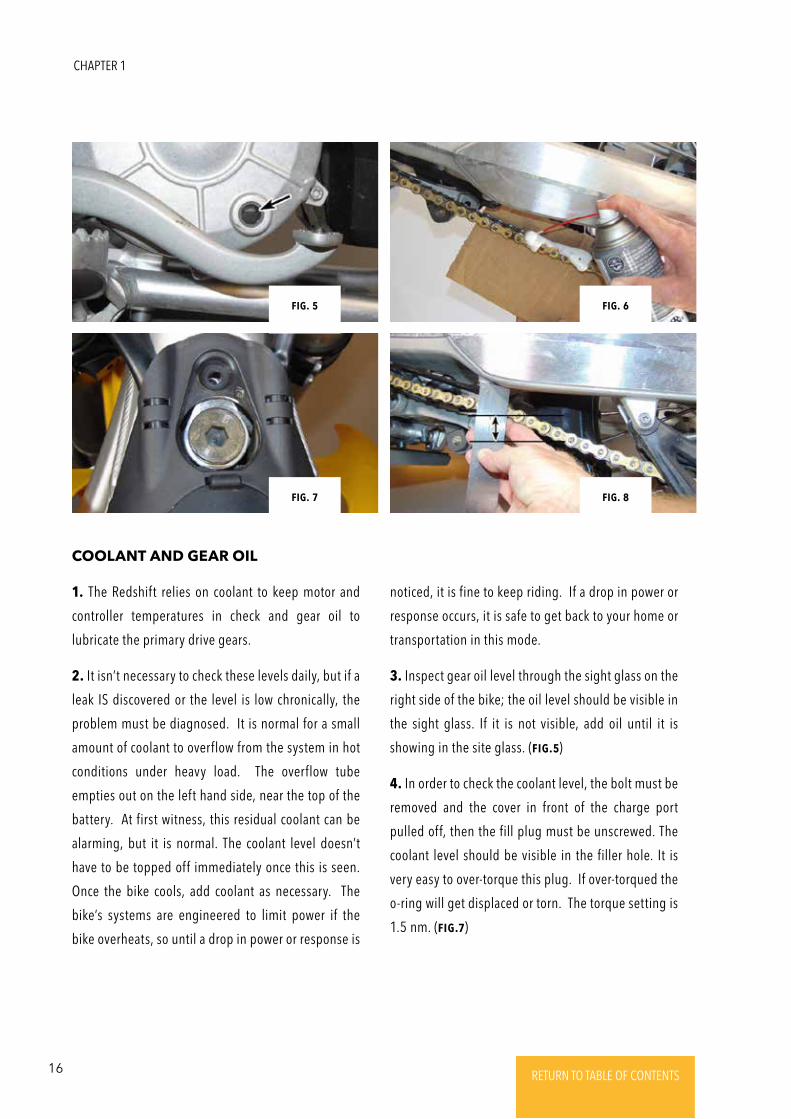
5. Check the brake pads for wear. It’s critical that the
pads be replaced before the pad friction material
wears down below the minimum allowable thickness
of 1.5 mm. As the pads thickness decreases the wear
rate increases, that last couple of mm of pad material
will disappear much quicker than the first few mm.
(Fig.3 & 4)
6. Operate the front brake lever and rear brake pedal
– they should both feel firm, not spongy. If not, there
is either air in the hydraulic system (which means the
affected system must be bled) or the master cylinder
seal for that system has failed (or is about to fail).
Fig. 4Fig. 3
Fig. 1 Fig. 2
REGULAR INSPECTION & ADJUSTMENTS
16 RETURN TO TABLE OF CONTENTSRETURN TO TABLE OF CONTENTSRETURN TO TABLE OF CONTENTSRETURN TO TABLE OF CONTENTSRETURN TO TABLE OF CONTENTS RETURN TO TABLE OF CONTENTS
1. The Redshift relies on coolant to keep motor and
controller temperatures in check and gear oil to
lubricate the primary drive gears.
2. It isn’t necessary to check these levels daily, but if a
leak IS discovered or the level is low chronically, the
problem must be diagnosed. It is normal for a small
amount of coolant to overflow from the system in hot
conditions under heavy load. The overflow tube
empties out on the left hand side, near the top of the
battery. At first witness, this residual coolant can be
alarming, but it is normal. The coolant level doesn’t
have to be topped off immediately once this is seen.
Once the bike cools, add coolant as necessary. The
bike’s systems are engineered to limit power if the
bike overheats, so until a drop in power or response is
COOLANT AND GEAR OIL
noticed, it is fine to keep riding. If a drop in power or
response occurs, it is safe to get back to your home or
transportation in this mode.
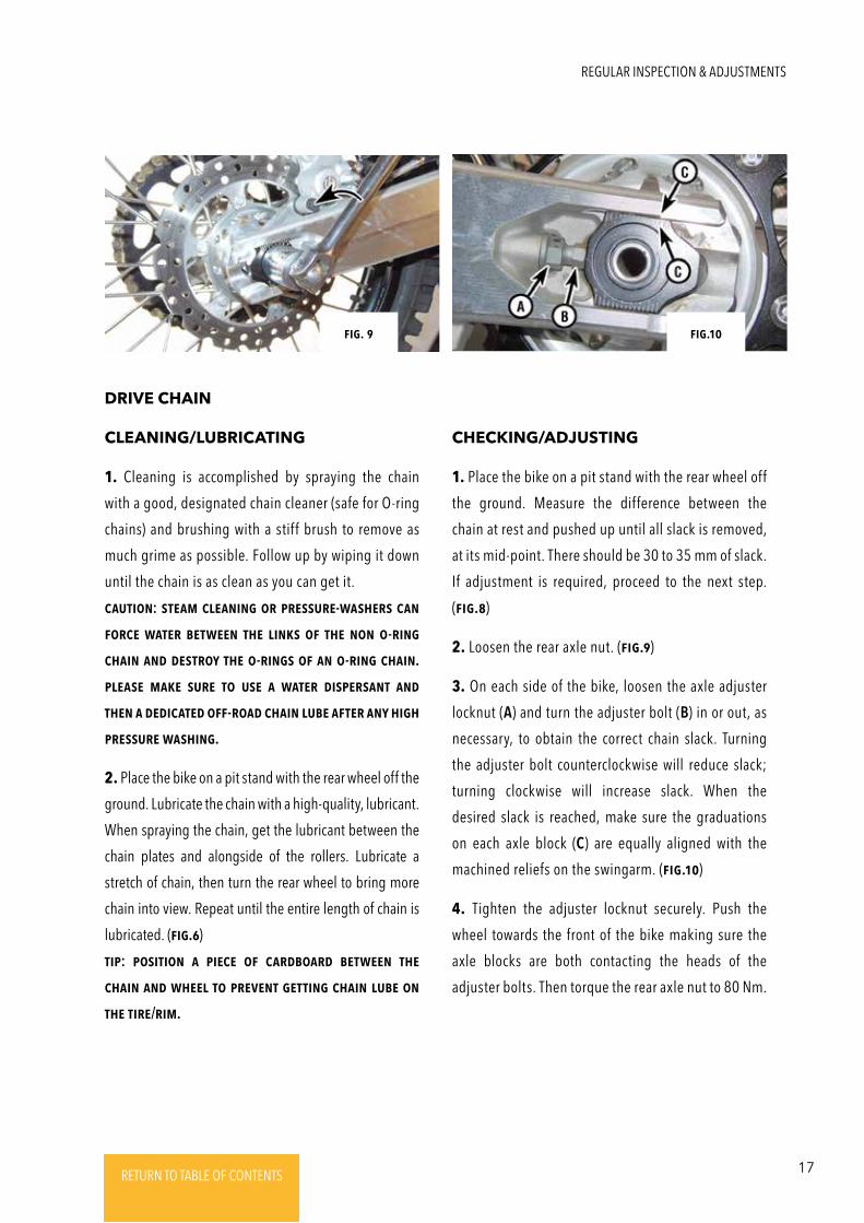
3. Inspect gear oil level through the sight glass on the
right side of the bike; the oil level should be visible in
the sight glass. If it is not visible, add oil until it is
showing in the site glass. (Fig.5)
4. In order to check the coolant level, the bolt must be
removed and the cover in front of the charge port
pulled off, then the fill plug must be unscrewed. The
coolant level should be visible in the filler hole. It is
very easy to over-torque this plug. If over-torqued the
o-ring will get displaced or torn. The torque setting is
1.5 nm. (Fig.7)
Fig. 7
Fig. 5
Fig. 8
Fig. 6
CHAPTER 1
17RETURN TO TABLE OF CONTENTSRETURN TO TABLE OF CONTENTSRETURN TO TABLE OF CONTENTSRETURN TO TABLE OF CONTENTSRETURN TO TABLE OF CONTENTS RETURN TO TABLE OF CONTENTS
DRIVE CHAIN
CLEANING/LUBRICATING CHECKING/ADJUSTING
1. Cleaning is accomplished by spraying the chain
with a good, designated chain cleaner (safe for O-ring
chains) and brushing with a stiff brush to remove as
much grime as possible. Follow up by wiping it down
until the chain is as clean as you can get it.
cautioN: stEam clEaNiNg oR pREssuRE-washERs caN
FoRcE watER bEtwEEN thE liNks oF thE NoN o-RiNg
chaiN aNd dEstRoy thE o-RiNgs oF aN o-RiNg chaiN.
plEasE makE suRE to usE a watER dispERsaNt aNd
thEN a dEdicatEd oFF-Road chaiN lubE aFtER aNy high
pREssuRE washiNg.
2. Place the bike on a pit stand with the rear wheel off the
ground. Lubricate the chain with a high-quality, lubricant.
When spraying the chain, get the lubricant between the
chain plates and alongside of the rollers. Lubricate a
stretch of chain, then turn the rear wheel to bring more
chain into view. Repeat until the entire length of chain is
lubricated. (Fig.6)
tip: positioN a piEcE oF caRdboaRd bEtwEEN thE
chaiN aNd whEEl to pREVENt gEttiNg chaiN lubE oN
thE tiRE/Rim.
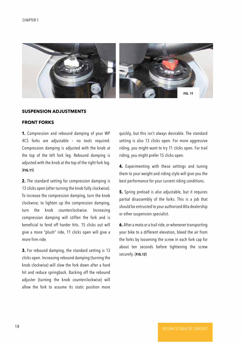
1. Place the bike on a pit stand with the rear wheel off
the ground. Measure the difference between the
chain at rest and pushed up until all slack is removed,
at its mid-point. There should be 30 to 35 mm of slack.
If adjustment is required, proceed to the next step.
(Fig.8)
2. Loosen the rear axle nut. (Fig.9)
3. On each side of the bike, loosen the axle adjuster
locknut (A) and turn the adjuster bolt (B) in or out, as
necessary, to obtain the correct chain slack. Turning
the adjuster bolt counterclockwise will reduce slack;
turning clockwise will increase slack. When the
desired slack is reached, make sure the graduations
on each axle block (C) are equally aligned with the
machined reliefs on the swingarm. (Fig.10)
4. Tighten the adjuster locknut securely. Push the
wheel towards the front of the bike making sure the
axle blocks are both contacting the heads of the
adjuster bolts. Then torque the rear axle nut to 80 Nm.
Fig.10Fig. 9
REGULAR INSPECTION & ADJUSTMENTS
18 RETURN TO TABLE OF CONTENTSRETURN TO TABLE OF CONTENTSRETURN TO TABLE OF CONTENTSRETURN TO TABLE OF CONTENTSRETURN TO TABLE OF CONTENTS RETURN TO TABLE OF CONTENTS
SUSPENSION ADJUSTMENTS
FRONT FORKS
1. Compression and rebound damping of your WP
4CS forks are adjustable – no tools required.
Compression damping is adjusted with the knob at
the top of the left fork leg. Rebound damping is
adjusted with the knob at the top of the right fork leg.
(Fig.11)
2. The standard setting for compression damping is
13 clicks open (after turning the knob fully clockwise).
To increase the compression damping, turn the knob
clockwise; to lighten up the compression damping,
turn the knob counterclockwise. Increasing
compression damping will stiffen the fork and is
beneficial to fend off harder hits. 15 clicks out will
give a more “plush” ride, 11 clicks open will give a
more firm ride.
3. For rebound damping, the standard setting is 13
clicks open. Increasing rebound damping (turning the
knob clockwise) will slow the fork down after a hard
hit and reduce springback. Backing off the rebound
adjuster (turning the knob counterclockwise) will
allow the fork to assume its static position more
quickly, but this isn’t always desirable. The standard
setting is also 13 clicks open. For more aggressive
riding, you might want to try 11 clicks open. For trail
riding, you might prefer 15 clicks open.
4. Experimenting with these settings and tuning
them to your weight and riding style will give you the
best performance for your current riding conditions.
5. Spring preload is also adjustable, but it requires
partial disassembly of the forks. This is a job that
should be entrusted to your authorized Alta dealership
or other suspension specialist.
6. After a moto or a trail ride, or whenever transporting
your bike to a different elevation, bleed the air from
the forks by loosening the screw in each fork cap for
about ten seconds before tightening the screw
securely. (Fig.12)
Fig. 11
CHAPTER 1
19RETURN TO TABLE OF CONTENTSRETURN TO TABLE OF CONTENTSRETURN TO TABLE OF CONTENTSRETURN TO TABLE OF CONTENTSRETURN TO TABLE OF CONTENTS RETURN TO TABLE OF CONTENTS
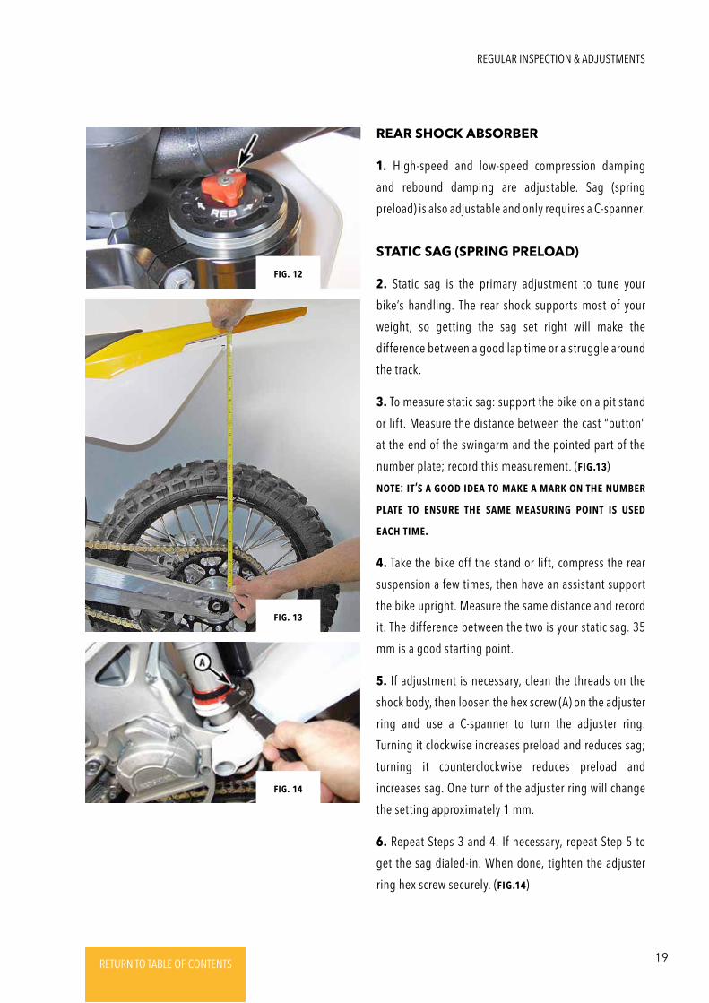
REAR SHOCK ABSORBER
STATIC SAG (SPRING PRELOAD)
1. High-speed and low-speed compression damping
and rebound damping are adjustable. Sag (spring
preload) is also adjustable and only requires a C-spanner.
2. Static sag is the primary adjustment to tune your
bike’s handling. The rear shock supports most of your
weight, so getting the sag set right will make the
difference between a good lap time or a struggle around
the track.
3. To measure static sag: support the bike on a pit stand
or lift. Measure the distance between the cast “button”
at the end of the swingarm and the pointed part of the
number plate; record this measurement. (Fig.13)
NotE: it’s a good idEa to makE a maRk oN thE NumbER
platE to ENsuRE thE samE mEasuRiNg poiNt is usEd
Each timE.
4. Take the bike off the stand or lift, compress the rear
suspension a few times, then have an assistant support
the bike upright. Measure the same distance and record
it. The difference between the two is your static sag. 35
mm is a good starting point.
5. If adjustment is necessary, clean the threads on the
shock body, then loosen the hex screw (A) on the adjuster
ring and use a C-spanner to turn the adjuster ring.
Turning it clockwise increases preload and reduces sag;
turning it counterclockwise reduces preload and
increases sag. One turn of the adjuster ring will change
the setting approximately 1 mm.
6. Repeat Steps 3 and 4. If necessary, repeat Step 5 to
get the sag dialed-in. When done, tighten the adjuster
ring hex screw securely. (Fig.14)
Fig. 12
Fig. 13
Fig. 14
REGULAR INSPECTION & ADJUSTMENTS
20 RETURN TO TABLE OF CONTENTSRETURN TO TABLE OF CONTENTSRETURN TO TABLE OF CONTENTSRETURN TO TABLE OF CONTENTSRETURN TO TABLE OF CONTENTS RETURN TO TABLE OF CONTENTS
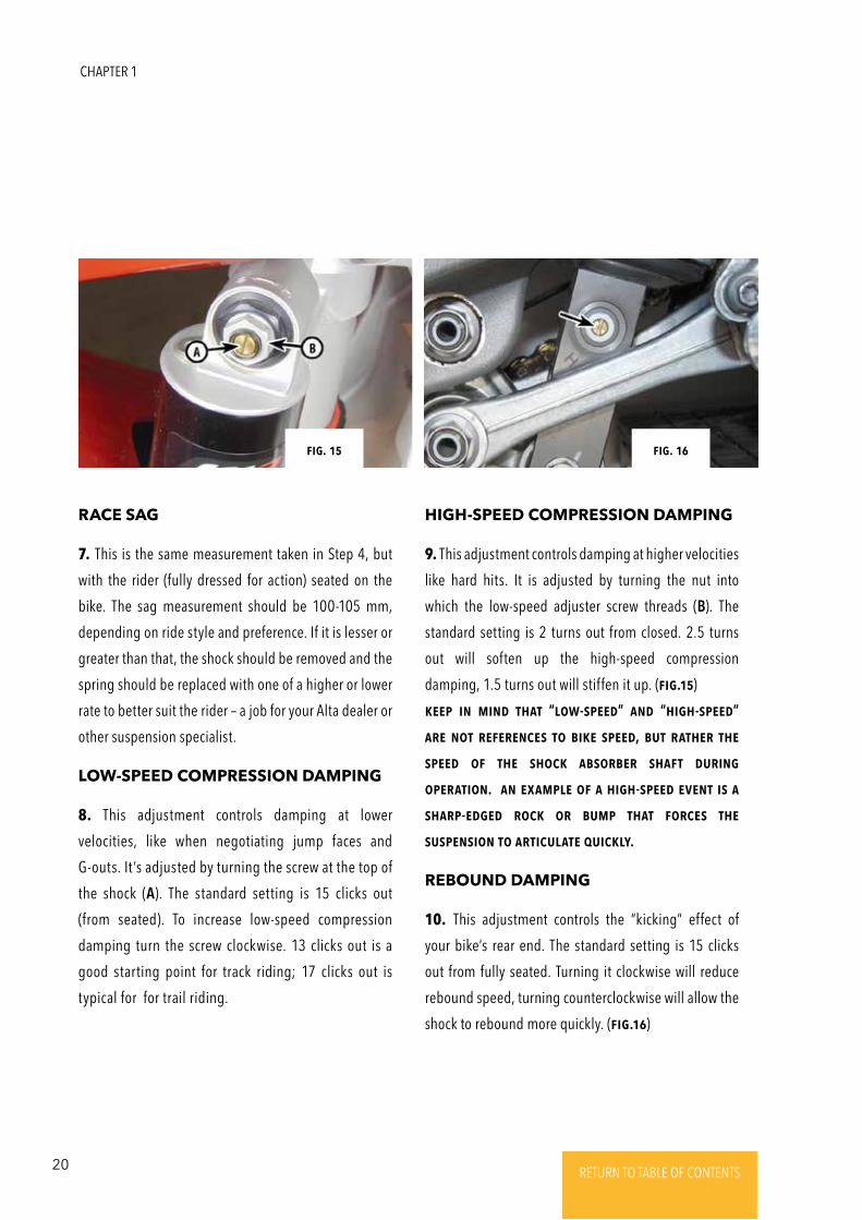
RACE SAG
REBOUND DAMPING
LOW-SPEED COMPRESSION DAMPING
HIGH-SPEED COMPRESSION DAMPING
7. This is the same measurement taken in Step 4, but
with the rider (fully dressed for action) seated on the
bike. The sag measurement should be 100-105 mm,
depending on ride style and preference. If it is lesser or
greater than that, the shock should be removed and the
spring should be replaced with one of a higher or lower
rate to better suit the rider – a job for your Alta dealer or
other suspension specialist.
10. This adjustment controls the “kicking” effect of
your bike’s rear end. The standard setting is 15 clicks
out from fully seated. Turning it clockwise will reduce
rebound speed, turning counterclockwise will allow the
shock to rebound more quickly. (Fig.16)
8. This adjustment controls damping at lower
velocities, like when negotiating jump faces and
G-outs. It’s adjusted by turning the screw at the top of
the shock (A). The standard setting is 15 clicks out
(from seated). To increase low-speed compression
damping turn the screw clockwise. 13 clicks out is a
good starting point for track riding; 17 clicks out is
typical for for trail riding.
9. This adjustment controls damping at higher velocities
like hard hits. It is adjusted by turning the nut into
which the low-speed adjuster screw threads (B). The
standard setting is 2 turns out from closed. 2.5 turns
out will soften up the high-speed compression
damping, 1.5 turns out will stiffen it up. (Fig.15)
kEEp iN miNd that “low-spEEd” aNd “high-spEEd”
aRE Not REFERENcEs to bikE spEEd, but RathER thE
spEEd oF thE shock absoRbER shaFt duRiNg
opERatioN. aN ExamplE oF a high-spEEd EVENt is a
shaRp-EdgEd Rock oR bump that FoRcEs thE
suspENsioN to aRticulatE quickly.
Fig. 15 Fig. 16
CHAPTER 1
21RETURN TO TABLE OF CONTENTSRETURN TO TABLE OF CONTENTSRETURN TO TABLE OF CONTENTSRETURN TO TABLE OF CONTENTSRETURN TO TABLE OF CONTENTS RETURN TO TABLE OF CONTENTS
1. Proper tightness of the spokes can only be achieved
with the use of a spoke torque wrench. First, check to
see that no spokes are loose. This can be done by feel,
or another good way to ensure that all of the spokes
are equally tensioned is by tapping them with a spoke
wrench and listening to the tone they make. They
should all sound the same. A loose spoke will emit a
dull sound, while a properly tensioned spoke will
make a “bright” sound.
2. If you find a loose spoke tighten the spoke nipple
with a wrench until the sound it makes when you tap
it is similar to the others.
3. Over-tightening spokes can result in a distorted
wheel. It is a good idea to have the spokes tightened
and the wheel trued by a professional at your
earliest convenience.
SPOKES
WHEELS
4. Check the rims for dents and bulges. Usually when
a loose spoke (or spokes) is/are found, it is the result
of hard hit. If a distorted rim is found, it should be
replaced. This involves removing the spokes and
lacing them and the hub up to a new rim. You should
leave this task up to your Alta dealer or other qualified
motorcycle shop.
RIMS
REGULAR INSPECTION & ADJUSTMENTS
22 RETURN TO TABLE OF CONTENTSRETURN TO TABLE OF CONTENTSRETURN TO TABLE OF CONTENTSRETURN TO TABLE OF CONTENTSRETURN TO TABLE OF CONTENTS RETURN TO TABLE OF CONTENTS
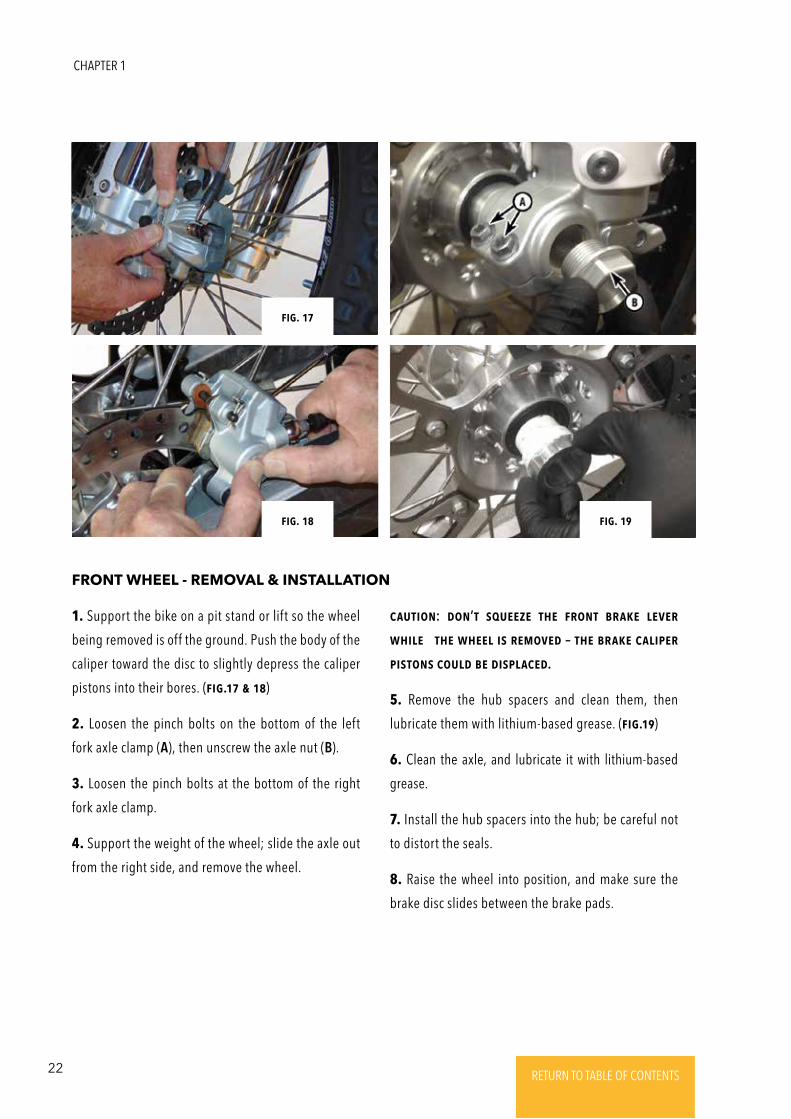
1. Support the bike on a pit stand or lift so the wheel
being removed is off the ground. Push the body of the
caliper toward the disc to slightly depress the caliper
pistons into their bores. (Fig.17 & 18)
2. Loosen the pinch bolts on the bottom of the left
fork axle clamp (A), then unscrew the axle nut (B).
3. Loosen the pinch bolts at the bottom of the right
fork axle clamp.
4. Support the weight of the wheel; slide the axle out
from the right side, and remove the wheel.
FRONT WHEEL - REMOVAL & INSTALLATION
cautioN: doN’t squEEzE thE FRoNt bRakE lEVER
whilE thE whEEl is REmoVEd – thE bRakE calipER
pistoNs could bE displacEd.
5. Remove the hub spacers and clean them, then
lubricate them with lithium-based grease. (Fig.19)
6. Clean the axle, and lubricate it with lithium-based
grease.
7. Install the hub spacers into the hub; be careful not
to distort the seals.
8. Raise the wheel into position, and make sure the
brake disc slides between the brake pads.
Fig. 18 Fig. 19
Fig. 17
CHAPTER 1
23RETURN TO TABLE OF CONTENTSRETURN TO TABLE OF CONTENTSRETURN TO TABLE OF CONTENTSRETURN TO TABLE OF CONTENTSRETURN TO TABLE OF CONTENTS RETURN TO TABLE OF CONTENTS
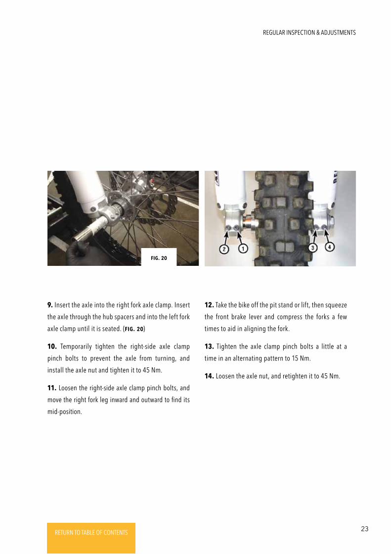
9. Insert the axle into the right fork axle clamp. Insert
the axle through the hub spacers and into the left fork
axle clamp until it is seated. (Fig. 20)
10. Temporarily tighten the right-side axle clamp
pinch bolts to prevent the axle from turning, and
install the axle nut and tighten it to 45 Nm.
11. Loosen the right-side axle clamp pinch bolts, and
move the right fork leg inward and outward to find its
mid-position.
12. Take the bike off the pit stand or lift, then squeeze
the front brake lever and compress the forks a few
times to aid in aligning the fork.
13. Tighten the axle clamp pinch bolts a little at a
time in an alternating pattern to 15 Nm.
14. Loosen the axle nut, and retighten it to 45 Nm.
Fig. 20
REGULAR INSPECTION & ADJUSTMENTS
24 RETURN TO TABLE OF CONTENTSRETURN TO TABLE OF CONTENTSRETURN TO TABLE OF CONTENTSRETURN TO TABLE OF CONTENTSRETURN TO TABLE OF CONTENTS RETURN TO TABLE OF CONTENTS
Fig. 21
Fig. 23
Fig. 22
Fig. 24
CHAPTER 1
25RETURN TO TABLE OF CONTENTSRETURN TO TABLE OF CONTENTSRETURN TO TABLE OF CONTENTSRETURN TO TABLE OF CONTENTSRETURN TO TABLE OF CONTENTS RETURN TO TABLE OF CONTENTS
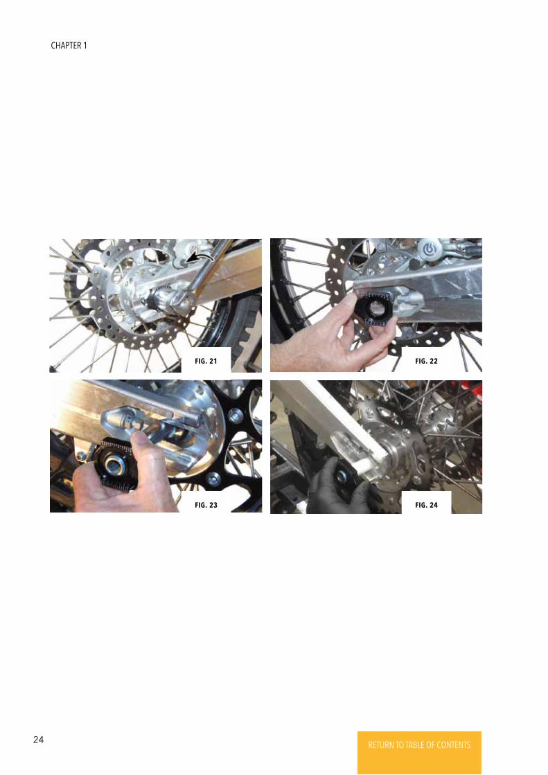
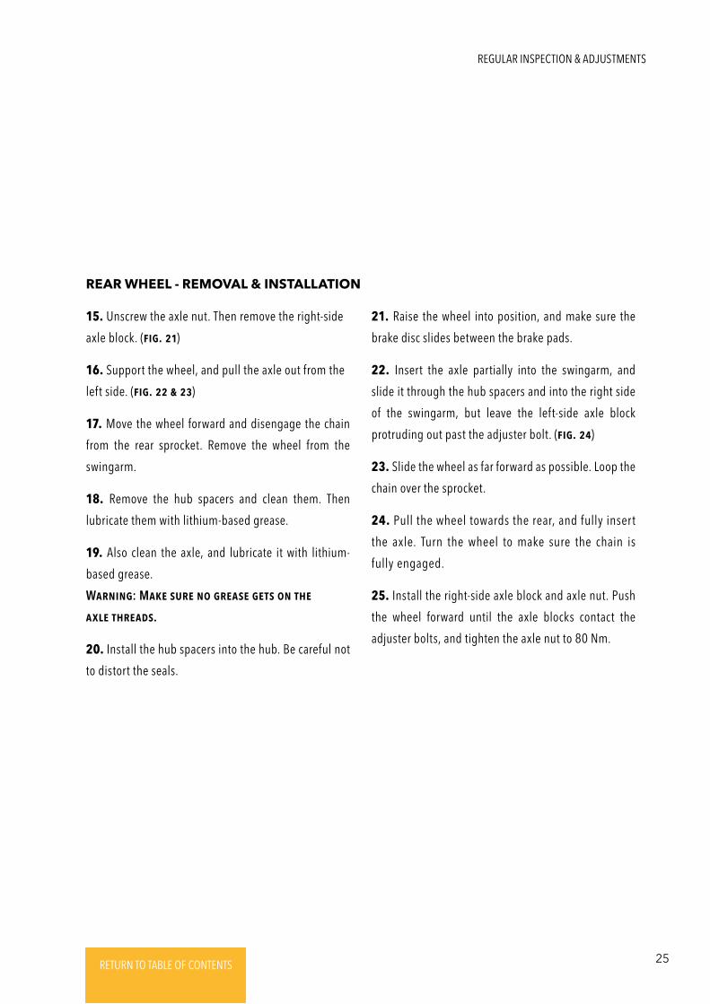
15. Unscrew the axle nut. Then remove the right-side
axle block. (Fig. 21)
16. Support the wheel, and pull the axle out from the
left side. (Fig. 22 & 23)
17. Move the wheel forward and disengage the chain
from the rear sprocket. Remove the wheel from the
swingarm.
18. Remove the hub spacers and clean them. Then
lubricate them with lithium-based grease.
19. Also clean the axle, and lubricate it with lithium-
based grease.
WaRNiNg: MakE suRE No gREasE gEts oN thE
axlE thREads.
20. Install the hub spacers into the hub. Be careful not
to distort the seals.
REAR WHEEL - REMOVAL & INSTALLATION
21. Raise the wheel into position, and make sure the
brake disc slides between the brake pads.
22. Insert the axle partially into the swingarm, and
slide it through the hub spacers and into the right side
of the swingarm, but leave the left-side axle block
protruding out past the adjuster bolt. (Fig. 24)
23. Slide the wheel as far forward as possible. Loop the
chain over the sprocket.
24. Pull the wheel towards the rear, and fully insert
the axle. Turn the wheel to make sure the chain is
fully engaged.
25. Install the right-side axle block and axle nut. Push
the wheel forward until the axle blocks contact the
adjuster bolts, and tighten the axle nut to 80 Nm.
REGULAR INSPECTION & ADJUSTMENTS
26 RETURN TO TABLE OF CONTENTSRETURN TO TABLE OF CONTENTSRETURN TO TABLE OF CONTENTSRETURN TO TABLE OF CONTENTSRETURN TO TABLE OF CONTENTS RETURN TO TABLE OF CONTENTS
QUICK REFERENCE
CHAPTER 1
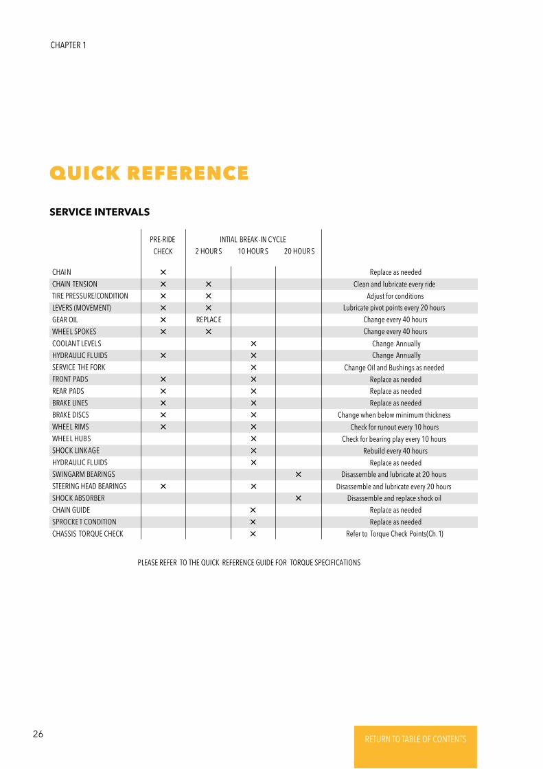
CHAIN
CHAIN TENSION
TIRE PRESSURE/CONDITION
LEVERS (MOVEMENT)
GEAR OIL
WHEEL SPOKES
COOLAN T LEVELS
HYDRAULIC FL UIDS
SERVICE THE FORK
FRONT PADS
REAR PADS
BRAKE LINES
BRAKE DISCS
WHEEL RIMS
WHEEL HUBS
SHOCK LINKAGE
HYDRAULIC FL UIDS
SWINGARM BEARINGS
STEERING HEAD BEARINGS
SHOCK ABSORBER
CHAIN GUIDE
SPROCKE T CONDITION
CHASSIS TORQUE CHECK
PRE-RIDE
CHECK 20 HOUR S2 HOUR S 10 HOUR SINTIAL BREAK-IN C YCLE
REPLAC E
Clean and lubricate every ride
Replace as needed
Replace as needed
Change Oil and Bushings as needed
Replace as needed
Replace as needed
Replace as needed
Replace as needed
Replace as neededRefer to Torque Check Points(Ch. 1)
PLEASE REFER TO THE QUICK REFERENCE GUIDE FOR TORQUE SPECIFICATIONS
Change when below minimum thickness
Check for runout every 10 hours
Check for bearing play every 10 hours
Rebuild every 40 hours
Disassemble and lubricate at 20 hours
Disassemble and lubricate every 20 hoursDisassemble and replace shock oil
Adjust for conditionsLubricate pivot points every 20 hours
Change every 40 hours
Change every 40 hours
Change AnnuallyChange Annually
SERVICE INTERVALS
27RETURN TO TABLE OF CONTENTSRETURN TO TABLE OF CONTENTSRETURN TO TABLE OF CONTENTSRETURN TO TABLE OF CONTENTSRETURN TO TABLE OF CONTENTS RETURN TO TABLE OF CONTENTS
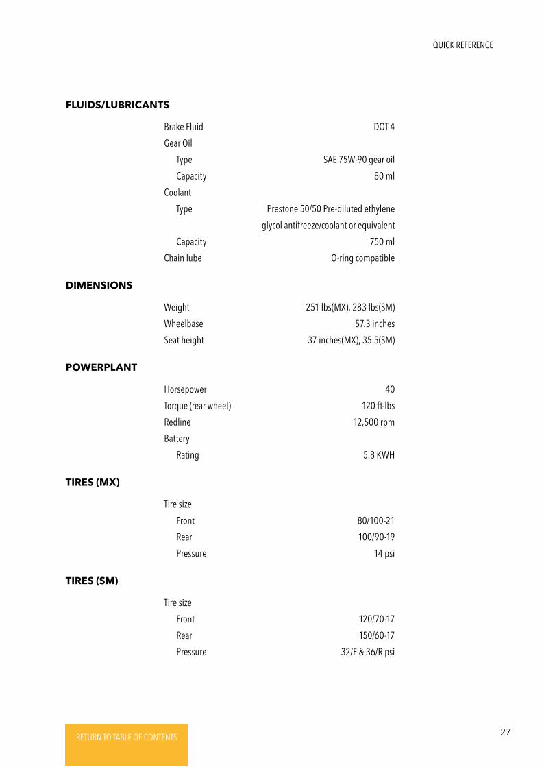
FLUIDS/LUBRICANTS
Brake Fluid DOT 4
Gear Oil
Type SAE 75W-90 gear oil
Capacity 80 ml
Coolant
Type Prestone 50/50 Pre-diluted ethylene
glycol antifreeze/coolant or equivalent
Capacity 750 ml
Chain lube O-ring compatible
DIMENSIONS
Weight 251 lbs(MX), 283 lbs(SM)
Wheelbase 57.3 inches
Seat height 37 inches(MX), 35.5(SM)
POWERPLANT
Horsepower 40
Torque (rear wheel) 120 ft-lbs
Redline 12,500 rpm
Battery
Rating 5.8 KWH
TIRES (MX)
Tire size
Front 80/100-21
Rear 100/90-19
Pressure 14 psi
TIRES (SM)
Tire size
Front 120/70-17
Rear 150/60-17
Pressure 32/F & 36/R psi
QUICK REFERENCE
28 RETURN TO TABLE OF CONTENTSRETURN TO TABLE OF CONTENTSRETURN TO TABLE OF CONTENTSRETURN TO TABLE OF CONTENTSRETURN TO TABLE OF CONTENTS RETURN TO TABLE OF CONTENTS
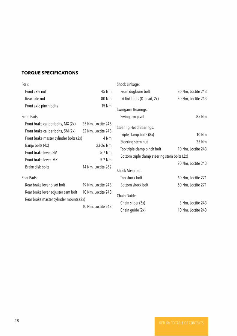
Fork:
Front axle nut 45 Nm
Rear axle nut 80 Nm
Front axle pinch bolts 15 Nm
Front Pads:
Front brake caliper bolts, MX (2x) 25 Nm, Loctite 243
Front brake caliper bolts, SM (2x) 32 Nm, Loctite 243
Front brake master cylinder bolts (2x) 4 Nm
Banjo bolts (4x) 23-26 Nm
Front brake lever, SM 5-7 Nm
Front brake lever, MX 5-7 Nm
Brake disk bolts 14 Nm, Loctite 262
Rear Pads:
Rear brake lever pivot bolt 19 Nm, Loctite 243
Rear brake lever adjuster cam bolt 10 Nm, Loctite 243
Rear brake master cylinder mounts (2x)
10 Nm, Loctite 243
TORQUE SPECIFICATIONS
Shock Linkage:
Front dogbone bolt 80 Nm, Loctite 243
Tri-link bolts (D-head, 2x) 80 Nm, Loctite 243
Swingarm Bearings:
Swingarm pivot 85 Nm
Stearing Head Bearings:
Triple clamp bolts (8x) 10 Nm
Steering stem nut 25 Nm
Top triple clamp pinch bolt 10 Nm, Loctite 243
Bottom triple clamp steering stem bolts (2x)
20 Nm, Loctite 243
Shock Absorber:
Top shock bolt 60 Nm, Loctite 271
Bottom shock bolt 60 Nm, Loctite 271
Chain Guide:
Chain slider (3x) 3 Nm, Loctite 243
Chain guide (2x) 10 Nm, Loctite 243
29RETURN TO TABLE OF CONTENTSRETURN TO TABLE OF CONTENTSRETURN TO TABLE OF CONTENTSRETURN TO TABLE OF CONTENTSRETURN TO TABLE OF CONTENTS RETURN TO TABLE OF CONTENTS
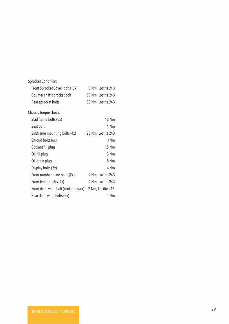
Sprocket Condition:
Front Sprocket Cover bolts (3x) 10 Nm, Loctite 243
Counter shaft sprocket bolt 60 Nm, Loctite 243
Rear sprocket bolts 35 Nm, Loctite 243
Chassis Torque check:
Skid frame bolts (8x) 48 Nm
Seat bolt 4 Nm
Subframe mounting bolts (4x) 25 Nm, Loctite 243
Shroud bolts (6x) 4Nm
Coolant fill plug 1.5 Nm
Oil fill plug 3 Nm
Oil drain plug 5 Nm
Display bolts (2x) 4 Nm
Front number plate bolts (2x) 4 Nm, Loctite 243
Front fender bolts (4x) 4 Nm, Loctite 243
Front delta wing bolt (coolant cover) 2 Nm, Loctite 243
Rear delta wing bolts (2x) 4 Nm
30 RETURN TO TABLE OF CONTENTSRETURN TO TABLE OF CONTENTSRETURN TO TABLE OF CONTENTSRETURN TO TABLE OF CONTENTSRETURN TO TABLE OF CONTENTS RETURN TO TABLE OF CONTENTS
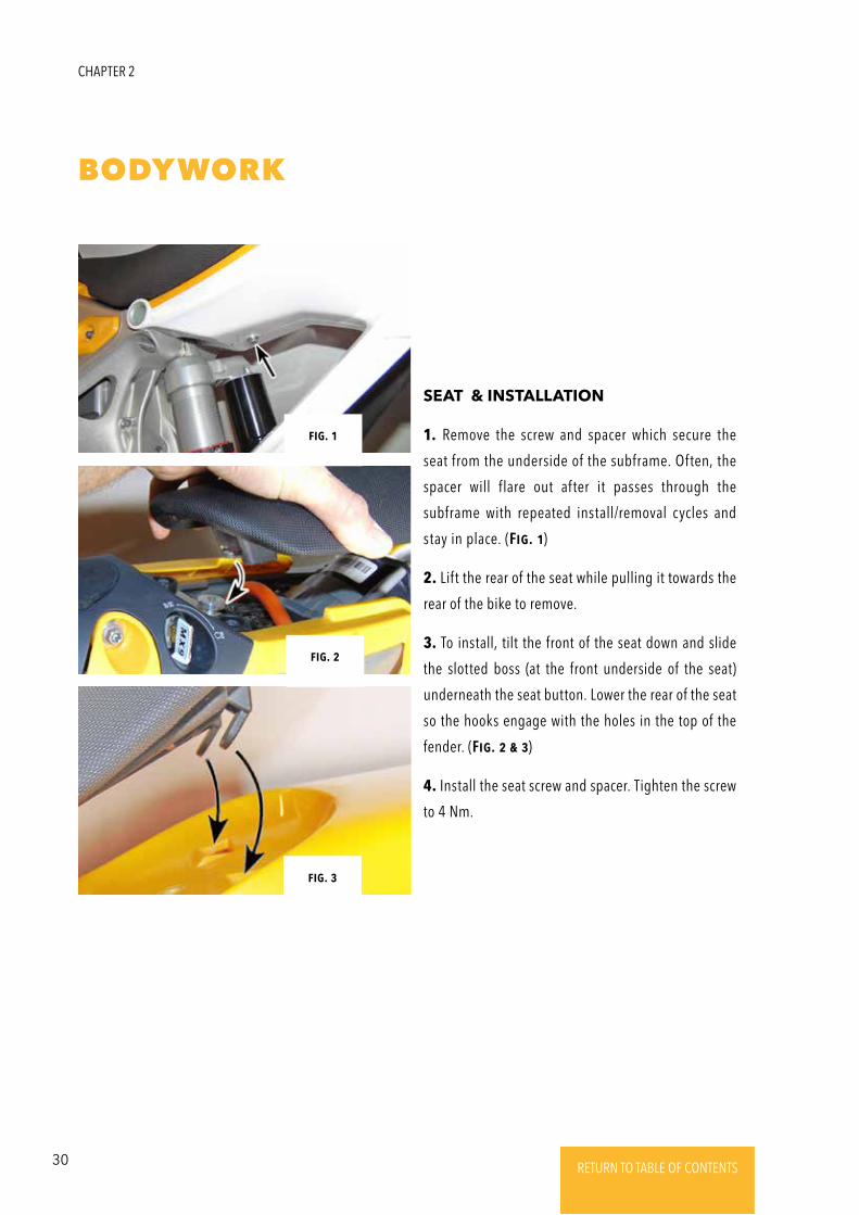
BODYWORK
1. Remove the screw and spacer which secure the
seat from the underside of the subframe. Often, the
spacer will flare out after it passes through the
subframe with repeated install/removal cycles and
stay in place. (Fig. 1)
2. Lift the rear of the seat while pulling it towards the
rear of the bike to remove.
3. To install, tilt the front of the seat down and slide
the slotted boss (at the front underside of the seat)
underneath the seat button. Lower the rear of the seat
so the hooks engage with the holes in the top of the
fender. (Fig. 2 & 3)
4. Install the seat screw and spacer. Tighten the screw
to 4 Nm.
CHAPTER 2
SEAT & INSTALLATION
Fig. 1
Fig. 2
Fig. 3
31RETURN TO TABLE OF CONTENTSRETURN TO TABLE OF CONTENTSRETURN TO TABLE OF CONTENTSRETURN TO TABLE OF CONTENTSRETURN TO TABLE OF CONTENTS RETURN TO TABLE OF CONTENTS
1. Remove the seat (sEctioN 1).
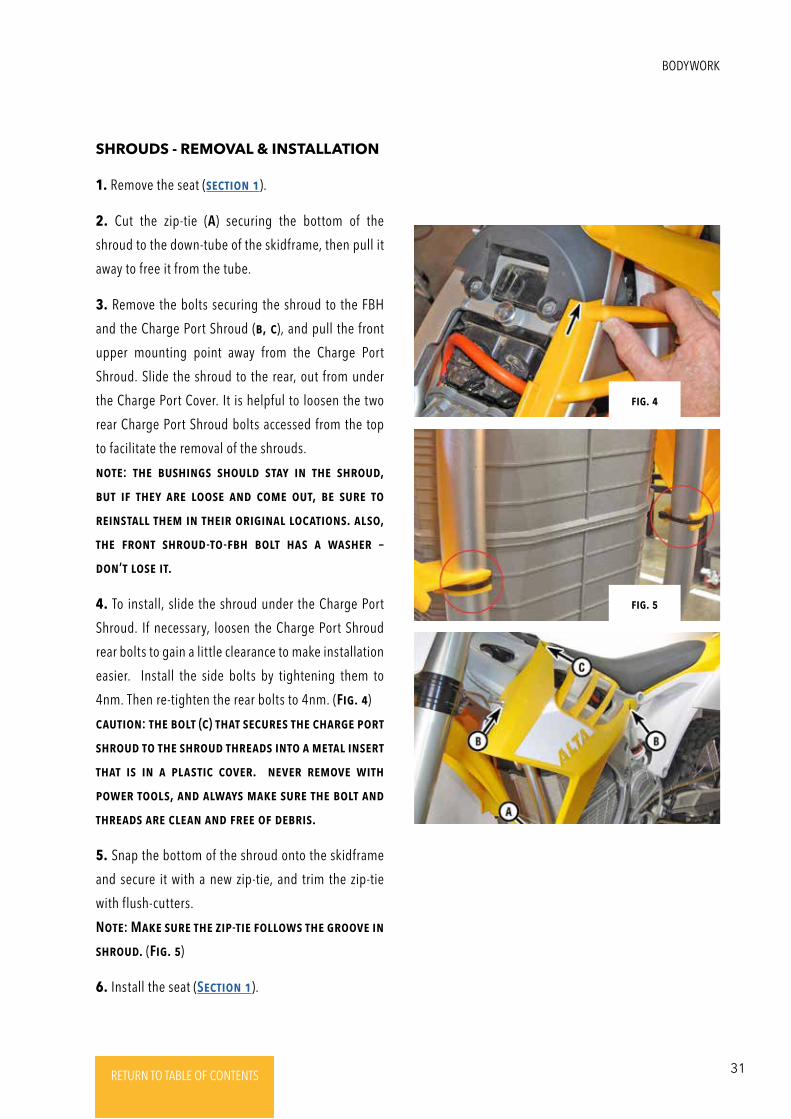
2. Cut the zip-tie (A) securing the bottom of the
shroud to the down-tube of the skidframe, then pull it
away to free it from the tube.
3. Remove the bolts securing the shroud to the FBH
and the Charge Port Shroud (b, c), and pull the front
upper mounting point away from the Charge Port
Shroud. Slide the shroud to the rear, out from under
the Charge Port Cover. It is helpful to loosen the two
rear Charge Port Shroud bolts accessed from the top
to facilitate the removal of the shrouds.
NotE: thE bushiNgs should stay iN thE shRoud,
but iF thEy aRE loosE aNd comE out, bE suRE to
REiNstall thEm iN thEiR oRigiNal locatioNs. also,
thE FRoNt shRoud-to-Fbh bolt has a washER –
doN’t losE it.
4. To install, slide the shroud under the Charge Port
Shroud. If necessary, loosen the Charge Port Shroud
rear bolts to gain a little clearance to make installation
easier. Install the side bolts by tightening them to
4nm. Then re-tighten the rear bolts to 4nm. (Fig. 4)
cautioN: thE bolt (c) that sEcuREs thE chaRgE poRt
shRoud to thE shRoud thREads iNto a mEtal iNsERt
that is iN a plastic coVER. NEVER REmoVE with
powER tools, aNd always makE suRE thE bolt aNd
thREads aRE clEaN aNd FREE oF dEbRis.
5. Snap the bottom of the shroud onto the skidframe
and secure it with a new zip-tie, and trim the zip-tie
with flush-cutters.
NotE: MakE suRE thE zip-tiE Follows thE gRooVE iN
shRoud. (Fig. 5)
6. Install the seat (SEctioN 1).
BODYWORK
SHROUDS - REMOVAL & INSTALLATION
Fig. 4
Fig. 5
32 RETURN TO TABLE OF CONTENTSRETURN TO TABLE OF CONTENTSRETURN TO TABLE OF CONTENTSRETURN TO TABLE OF CONTENTSRETURN TO TABLE OF CONTENTS RETURN TO TABLE OF CONTENTS
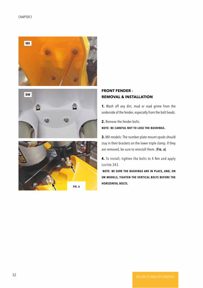
1. Wash off any dirt, mud or road grime from the
underside of the fender, especially from the bolt heads.
2. Remove the fender bolts.
NotE: bE caREFul Not to losE thE bushiNgs.
3. MX models: The number plate mount spuds should
stay in their brackets on the lower triple clamp. If they
are removed, be sure to reinstall them. (Fig. 6)
4. To install, tighten the bolts to 4 Nm and apply
Loctite 243.
NotE: bE suRE thE bushiNgs aRE iN placE, aNd, oN
sm modEls, tightEN thE VERtical bolts bEFoRE thE
hoRizoNtal bolts.
FRONT FENDER -
REMOVAL & INSTALLATION
Fig. 6
CHAPTER 2
33RETURN TO TABLE OF CONTENTSRETURN TO TABLE OF CONTENTSRETURN TO TABLE OF CONTENTSRETURN TO TABLE OF CONTENTSRETURN TO TABLE OF CONTENTS RETURN TO TABLE OF CONTENTS
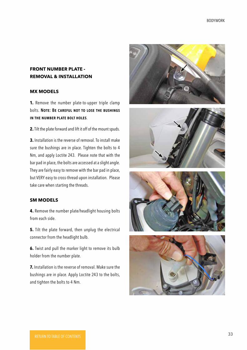
1. Remove the number plate-to-upper triple clamp
bolts. NotE: BE caREFul Not to losE thE bushiNgs
iN thE NumbER platE bolt holEs.
2. Tilt the plate forward and lift it off of the mount spuds.
3. Installation is the reverse of removal. To install make
sure the bushings are in place. Tighten the bolts to 4
Nm, and apply Loctite 243. Please note that with the
bar pad in place, the bolts are accessed at a slight angle.
They are fairly easy to remove with the bar pad in place,
but VERY easy to cross-thread upon installation. Please
take care when starting the threads.
4. Remove the number plate/headlight housing bolts
from each side.
5. Tilt the plate forward, then unplug the electrical
connector from the headlight bulb.
6. Twist and pull the marker light to remove its bulb
holder from the number plate.
7. Installation is the reverse of removal. Make sure the
bushings are in place. Apply Loctite 243 to the bolts,
and tighten the bolts to 4 Nm.
FRONT NUMBER PLATE -
REMOVAL & INSTALLATION
MX MODELS
SM MODELS
BODYWORK
34 RETURN TO TABLE OF CONTENTSRETURN TO TABLE OF CONTENTSRETURN TO TABLE OF CONTENTSRETURN TO TABLE OF CONTENTSRETURN TO TABLE OF CONTENTS RETURN TO TABLE OF CONTENTS
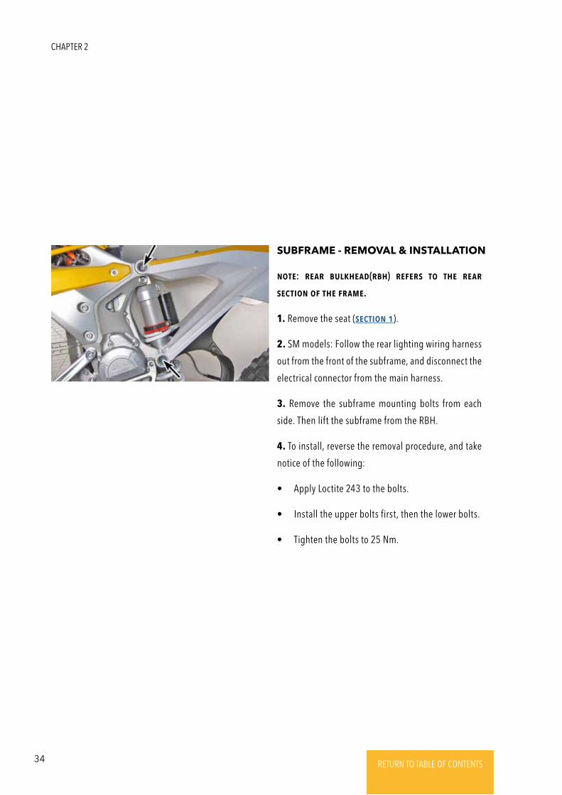
NotE: REaR bulkhEad(Rbh) REFERs to thE REaR
sEctioN oF thE FRamE.
1. Remove the seat (sEctioN 1).
2. SM models: Follow the rear lighting wiring harness
out from the front of the subframe, and disconnect the
electrical connector from the main harness.
3. Remove the subframe mounting bolts from each
side. Then lift the subframe from the RBH.
4. To install, reverse the removal procedure, and take
notice of the following:
• Apply Loctite 243 to the bolts.
• Install the upper bolts first, then the lower bolts.
• Tighten the bolts to 25 Nm.
SUBFRAME - REMOVAL & INSTALLATION
CHAPTER 2
35RETURN TO TABLE OF CONTENTSRETURN TO TABLE OF CONTENTSRETURN TO TABLE OF CONTENTSRETURN TO TABLE OF CONTENTSRETURN TO TABLE OF CONTENTS RETURN TO TABLE OF CONTENTS
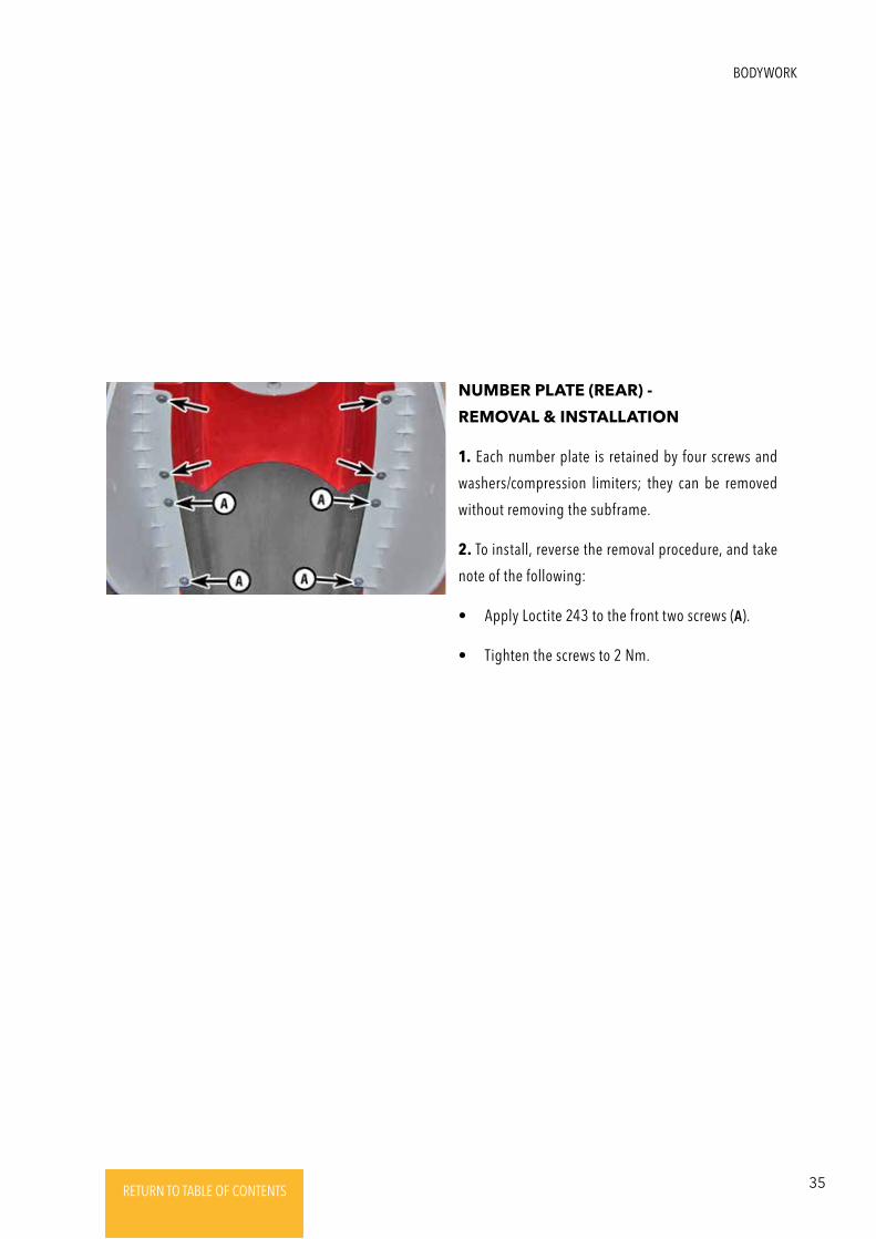
1. Each number plate is retained by four screws and
washers/compression limiters; they can be removed
without removing the subframe.
2. To install, reverse the removal procedure, and take
note of the following:
• Apply Loctite 243 to the front two screws (A).
• Tighten the screws to 2 Nm.
NUMBER PLATE (REAR) -
REMOVAL & INSTALLATION
BODYWORK
36 RETURN TO TABLE OF CONTENTSRETURN TO TABLE OF CONTENTSRETURN TO TABLE OF CONTENTSRETURN TO TABLE OF CONTENTSRETURN TO TABLE OF CONTENTS RETURN TO TABLE OF CONTENTS
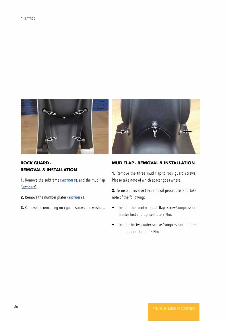
1. Remove the three mud flap-to-rock guard screws.
Please take note of which spacer goes where.
2. To install, reverse the removal procedure, and take
note of the following:
• Install the center mud flap screw/compression
limiter first and tighten it to 2 Nm.
• Install the two outer screws/compression limiters
and tighten them to 2 Nm.
1. Remove the subframe (SEctioN 5), and the mud flap
(SEctioN 7).
2. Remove the number plates (SEctioN 6).
3. Remove the remaining rock guard screws and washers.
MUD FLAP - REMOVAL & INSTALLATIONROCK GUARD -
REMOVAL & INSTALLATION
CHAPTER 2
37RETURN TO TABLE OF CONTENTSRETURN TO TABLE OF CONTENTSRETURN TO TABLE OF CONTENTSRETURN TO TABLE OF CONTENTSRETURN TO TABLE OF CONTENTS RETURN TO TABLE OF CONTENTS
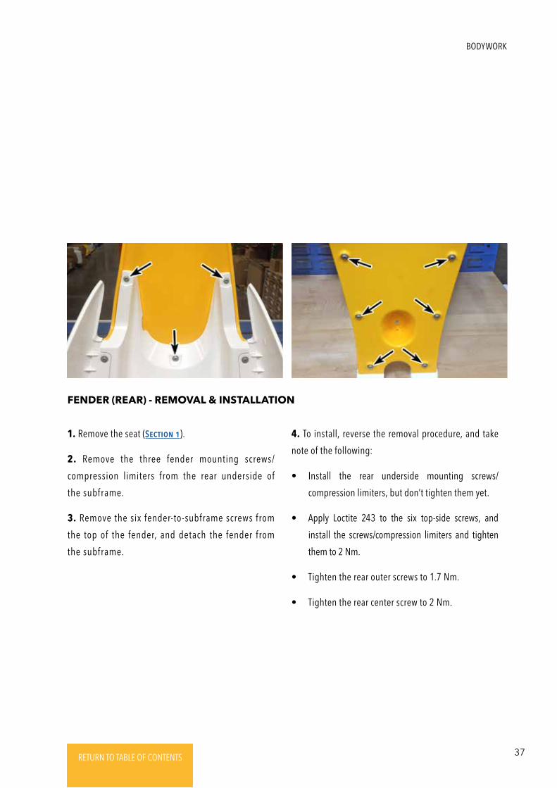
1. Remove the seat (SEctioN 1).
2. Remove the three fender mounting screws/
compression limiters from the rear underside of
the subframe.
3. Remove the six fender-to-subframe screws from
the top of the fender, and detach the fender from
the subframe.
FENDER (REAR) - REMOVAL & INSTALLATION
4. To install, reverse the removal procedure, and take
note of the following:
• Install the rear underside mounting screws/
compression limiters, but don’t tighten them yet.
• Apply Loctite 243 to the six top-side screws, and
install the screws/compression limiters and tighten
them to 2 Nm.
• Tighten the rear outer screws to 1.7 Nm.
• Tighten the rear center screw to 2 Nm.
BODYWORK
38 RETURN TO TABLE OF CONTENTSRETURN TO TABLE OF CONTENTSRETURN TO TABLE OF CONTENTSRETURN TO TABLE OF CONTENTSRETURN TO TABLE OF CONTENTS RETURN TO TABLE OF CONTENTS
CautioN: BRakE Fluid is toxic aNd must bE haNdlEd with caRE. Do Not lEt it
gEt oNto ExposEd skiN oR iNto thE EyEs. Do Not iNgEst it. Always wEaR SaFEty
GlassEs whEN woRkiNg with chEmicals. BRakE Fluid caN damagE paiNt aNd somE
plastic suRFacEs. Wash oFF aNy spillEd bRakE Fluid with watER.
BRAKES
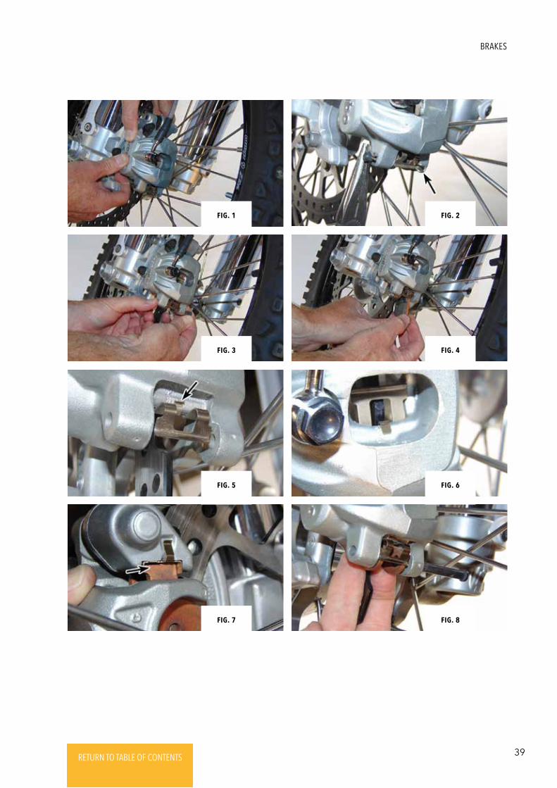
1. Place the bike on a workstand. Position a drain pan
beneath the caliper, then spray the caliper and pads
with brake system cleaner.
2. Push the body of the caliper toward the disc to
slightly depress the caliper pistons into their bores.
(Fig. 1)
3. Noting their orientation, remove the two retaining
clips, then pull out the pad pin. (Fig. 2)
4. Slide the pads downward and out of the caliper.
(Fig.3 & 4)
DoN’t pull thE bRakE lEVER whilE thE pads aRE
REmoVEd – thE pistoN will bE displacEd aNd might
Fall out oF thE boRE, VoidiNg thE systEm oF Fluid.
5. Inspect the pad spring in the caliper – if it is no a
tight fit or became dislodged when the pads were
removed, remove the caliper (SEctioN 4) and reinstall
the spring (or replace it with a new one, as necessary).
(Fig.5 & 6)
6. While the pads are out, check for brake fluid
seepage around the pistons. If there is evidence of
fluid, it is time to replace the piston seals (SEctioN 7).
BRAKE PAD REPLACEMENT (FRONT, MX)
7. If new pads are being installed, push the pistons
back into the caliper as far as necessary to
accommodate the new, thicker pads, using hand
pressure or carefully pry them inwards. This will force
brake fluid back into the brake fluid reservoir, so it
may be necessary to remove the reservoir cap and
remove some fluid.
8. Slide the new pads into the caliper. Make sure the
upper ends rest in the pad support plates. (Fig. 7)
9. Pull the bottom ends of the pads against the caliper
spring; line up the holes in the pad backing plates with
the caliper pin holes, and then slide the pin through the
caliper and pads. Install the retaining clips in their
original orientation (outer clip facing forward, inner clip
facing the rear). (Fig. 8)
10. Squeeze the brake lever several times to bring the
pads into contact with the disc.
11. Check the fluid level in the front master cylinder
reservoir, and adjust as necessary.
CHAPTER 3
39RETURN TO TABLE OF CONTENTSRETURN TO TABLE OF CONTENTSRETURN TO TABLE OF CONTENTSRETURN TO TABLE OF CONTENTSRETURN TO TABLE OF CONTENTS RETURN TO TABLE OF CONTENTS
Fig. 8
Fig. 6
Fig. 4
Fig. 2Fig. 1
Fig. 3
Fig. 5
Fig. 7
BRAKES
40 RETURN TO TABLE OF CONTENTSRETURN TO TABLE OF CONTENTSRETURN TO TABLE OF CONTENTSRETURN TO TABLE OF CONTENTSRETURN TO TABLE OF CONTENTS RETURN TO TABLE OF CONTENTS
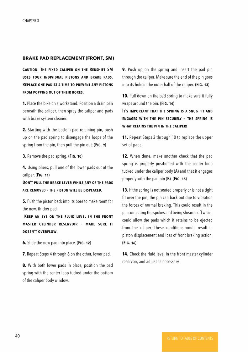
CautioN: ThE FixEd calipER oN thE REdshiFt SM
usEs FouR iNdiVidual pistoNs aNd bRakE pads.
REplacE oNE pad at a timE to pREVENt aNy pistoNs
FRom poppiNg out oF thEiR boREs.
1. Place the bike on a workstand. Position a drain pan
beneath the caliper, then spray the caliper and pads
with brake system cleaner.
2. Starting with the bottom pad retaining pin, push
up on the pad spring to disengage the loops of the
spring from the pin, then pull the pin out. (Fig. 9)
3. Remove the pad spring. (Fig. 10)
4. Using pliers, pull one of the lower pads out of the
caliper. (Fig. 11)
DoN’t pull thE bRakE lEVER whilE aNy oF thE pads
aRE REmoVEd – thE pistoN will bE displacEd.
5. Push the piston back into its bore to make room for
the new, thicker pad.
KEEp aN EyE oN thE Fluid lEVEl iN thE FRoNt
mastER cyliNdER REsERVoiR – makE suRE it
doEsN’t oVERFlow.
6. Slide the new pad into place. (Fig. 12)
7. Repeat Steps 4 through 6 on the other, lower pad.
8. With both lower pads in place, position the pad
spring with the center loop tucked under the bottom
of the caliper body window.
BRAKE PAD REPLACEMENT (FRONT, SM)
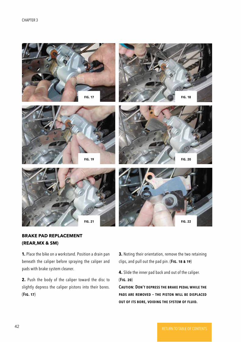
9. Push up on the spring and insert the pad pin
through the caliper. Make sure the end of the pin goes
into its hole in the outer half of the caliper. (Fig. 13)
10. Pull down on the pad spring to make sure it fully
wraps around the pin. (Fig. 14)
It’s impoRtaNt that thE spRiNg is a sNug Fit aNd
ENgagEs with thE piN sEcuREly – thE spRiNg is
what REtaiNs thE piN iN thE calipER!
11. Repeat Steps 2 through 10 to replace the upper
set of pads.
12. When done, make another check that the pad
spring is properly positioned with the center loop
tucked under the caliper body (A) and that it engages
properly with the pad pin (B). (Fig. 15)
13. If the spring is not seated properly or is not a tight
fit over the pin, the pin can back out due to vibration
the forces of normal braking. This could result in the
pin contacting the spokes and being sheared off which
could allow the pads which it retains to be ejected
from the caliper. These conditions would result in
piston displacement and loss of front braking action.
(Fig. 16)
14. Check the fluid level in the front master cylinder
reservoir, and adjust as necessary.
CHAPTER 3
41RETURN TO TABLE OF CONTENTSRETURN TO TABLE OF CONTENTSRETURN TO TABLE OF CONTENTSRETURN TO TABLE OF CONTENTSRETURN TO TABLE OF CONTENTS RETURN TO TABLE OF CONTENTS
Fig. 16
Fig. 14
Fig. 12
Fig. 10Fig. 9
Fig. 11
Fig. 13
Fig. 15
BRAKES
42 RETURN TO TABLE OF CONTENTSRETURN TO TABLE OF CONTENTSRETURN TO TABLE OF CONTENTSRETURN TO TABLE OF CONTENTSRETURN TO TABLE OF CONTENTS RETURN TO TABLE OF CONTENTS
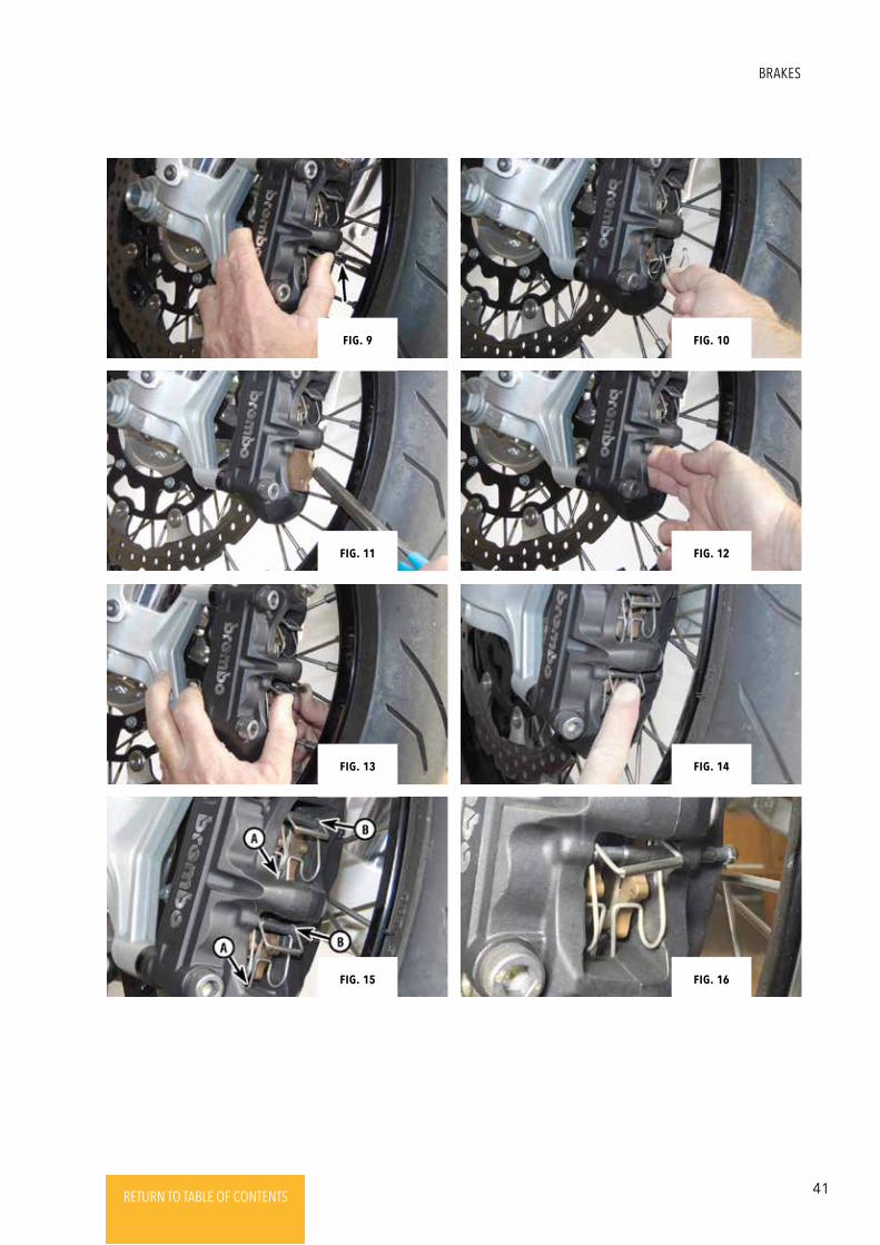
1. Place the bike on a workstand. Position a drain pan
beneath the caliper before spraying the caliper and
pads with brake system cleaner.
2. Push the body of the caliper toward the disc to
slightly depress the caliper pistons into their bores.
(Fig. 17)
BRAKE PAD REPLACEMENT
(REAR,MX & SM)
3. Noting their orientation, remove the two retaining
clips, and pull out the pad pin. (Fig. 18 & 19)
4. Slide the inner pad back and out of the caliper.
(Fig. 20)
CautioN: DoN’t dEpREss thE bRakE pEdal whilE thE
pads aRE REmoVEd – thE pistoN will bE displacEd
out oF its boRE, VoidiNg thE systEm oF Fluid.
Fig. 18
Fig. 20
Fig. 22
Fig. 17
Fig. 19
Fig. 21
CHAPTER 3
43RETURN TO TABLE OF CONTENTSRETURN TO TABLE OF CONTENTSRETURN TO TABLE OF CONTENTSRETURN TO TABLE OF CONTENTSRETURN TO TABLE OF CONTENTS RETURN TO TABLE OF CONTENTS
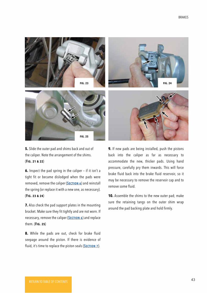
5. Slide the outer pad and shims back and out of
the caliper. Note the arrangement of the shims.
(Fig. 21 & 22)
6. Inspect the pad spring in the caliper – if it isn’t a
tight fit or became dislodged when the pads were
removed, remove the caliper (SEctioN 6) and reinstall
the spring (or replace it with a new one, as necessary).
(Fig. 23 & 24)
7. Also check the pad support plates in the mounting
bracket. Make sure they fit tightly and are not worn. If
necessary, remove the caliper (SEctioN 6) and replace
them. (Fig. 25)
8. While the pads are out, check for brake fluid
seepage around the piston. If there is evidence of
fluid, it’s time to replace the piston seals (SEctioN 7).
9. If new pads are being installed, push the pistons
back into the caliper as far as necessary to
accommodate the new, thicker pads. Using hand
pressure, carefully pry them inwards. This will force
brake fluid back into the brake fluid reservoir, so it
may be necessary to remove the reservoir cap and to
remove some fluid.
10. Assemble the shims to the new outer pad; make
sure the retaining tangs on the outer shim wrap
around the pad backing plate and hold firmly.
Fig. 24Fig. 23
Fig. 25
BRAKES
44 RETURN TO TABLE OF CONTENTSRETURN TO TABLE OF CONTENTSRETURN TO TABLE OF CONTENTSRETURN TO TABLE OF CONTENTSRETURN TO TABLE OF CONTENTS RETURN TO TABLE OF CONTENTS
Fig. 27
Fig. 29
Fig. 26
Fig. 28
Fig. 30
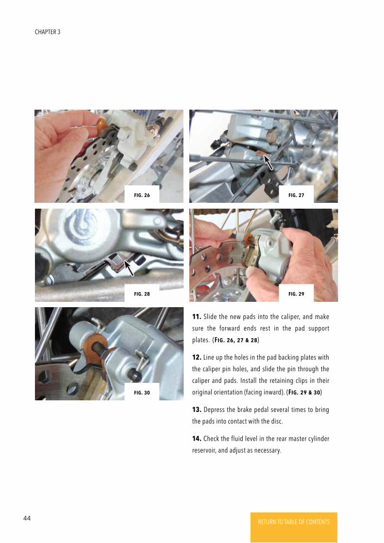
11. Slide the new pads into the caliper, and make
sure the forward ends rest in the pad support
plates. (Fig. 26, 27 & 28)
12. Line up the holes in the pad backing plates with
the caliper pin holes, and slide the pin through the
caliper and pads. Install the retaining clips in their
original orientation (facing inward). (Fig. 29 & 30)
13. Depress the brake pedal several times to bring
the pads into contact with the disc.
14. Check the fluid level in the rear master cylinder
reservoir, and adjust as necessary.
CHAPTER 3
45RETURN TO TABLE OF CONTENTSRETURN TO TABLE OF CONTENTSRETURN TO TABLE OF CONTENTSRETURN TO TABLE OF CONTENTSRETURN TO TABLE OF CONTENTS RETURN TO TABLE OF CONTENTS
CautioN: BRakE Fluid is toxic aNd must bE haNdlEd
with caRE. Do Not lEt it gEt oNto ExposEd skiN
oR iNto thE EyEs. Do Not iNgEst it. Always wEaR
SaFEty GlassEs whEN woRkiNg with chEmicals.
BRakE Fluid caN damagE paiNt aNd somE plastic
suRFacEs. Wash oFF aNy spillEd bRakE Fluid with
watER.
1. Place the bike on a workstand. Position a drain pan
beneath the caliper before spraying the caliper and
pads with brake system cleaner.
2. Push the body of the caliper toward the disc to
spread the brake pads. This will make caliper
installation easier.
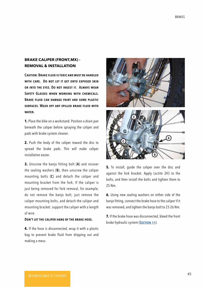
3. Unscrew the banjo fitting bolt (A) and recover
the sealing washers (B), then unscrew the caliper
mounting bolts (C) and detach the caliper and
mounting bracket from the fork. If the caliper is
just being removed for fork removal, for example,
do not remove the banjo bolt; just remove the
caliper mounting bolts, and detach the caliper and
mounting bracket. support the caliper with a length
of wire.
DoN’t lEt thE calipER haNg by thE bRakE hosE.
4. If the hose is disconnected, wrap it with a plastic
bag to prevent brake fluid from dripping out and
making a mess.
BRAKE CALIPER (FRONT,MX) -
REMOVAL & INSTALLATION
5. To install, guide the caliper over the disc and
against the fork bracket. Apply Loctite 243 to the
bolts, and then install the bolts and tighten them to
25 Nm.
6. Using new sealing washers on either side of the
banjo fitting, connect the brake hose to the caliper if it
was removed, and tighten the banjo bolt to 23-26 Nm.
7. If the brake hose was disconnected, bleed the front
brake hydraulic system (SEctioN 11).
BRAKES
46 RETURN TO TABLE OF CONTENTSRETURN TO TABLE OF CONTENTSRETURN TO TABLE OF CONTENTSRETURN TO TABLE OF CONTENTSRETURN TO TABLE OF CONTENTS RETURN TO TABLE OF CONTENTS
CautioN: BRakE Fluid is toxic aNd must bE haNdlEd
with caRE. Do Not lEt it gEt oNto ExposEd skiN oR
iNto thE EyEs. Do Not iNgEst it. Always wEaR SaFEty
GlassEs whEN woRkiNg with chEmicals. BRakE
Fluid caN damagE paiNt aNd somE plastic suRFacEs.
Wash oFF aNy spillEd bRakE Fluid with watER.
1. Place the bike on a workstand. Position a drain pan
beneath the caliper, then spray the caliper and pads
with brake system cleaner.
2. If the caliper is being completely removed (as for
overhaul, or whenever the brake hose is to be
disconnected), remove the brake pads to avoid
contaminating them with brake fluid (SEctioN 2).
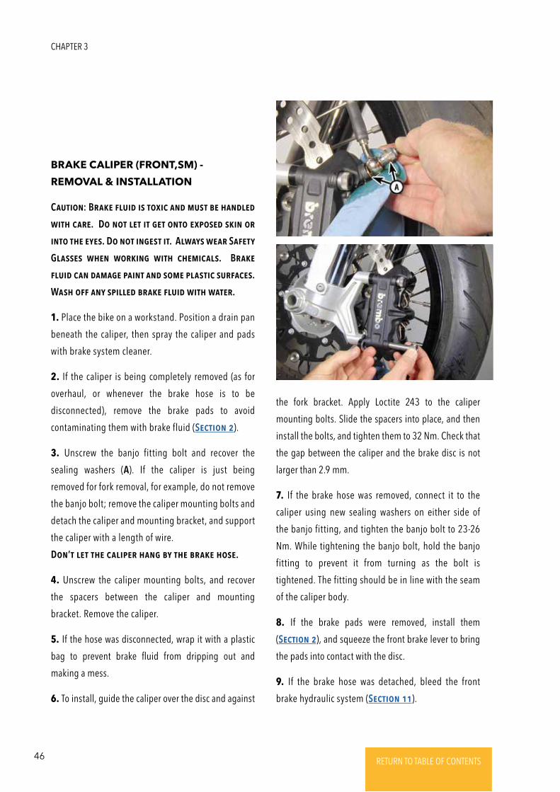
3. Unscrew the banjo fitting bolt and recover the
sealing washers (A). If the caliper is just being
removed for fork removal, for example, do not remove
the banjo bolt; remove the caliper mounting bolts and
detach the caliper and mounting bracket, and support
the caliper with a length of wire.
DoN’t lEt thE calipER haNg by thE bRakE hosE.
4. Unscrew the caliper mounting bolts, and recover
the spacers between the caliper and mounting
bracket. Remove the caliper.
5. If the hose was disconnected, wrap it with a plastic
bag to prevent brake fluid from dripping out and
making a mess.
6. To install, guide the caliper over the disc and against
BRAKE CALIPER (FRONT,SM) -
REMOVAL & INSTALLATION
the fork bracket. Apply Loctite 243 to the caliper
mounting bolts. Slide the spacers into place, and then
install the bolts, and tighten them to 32 Nm. Check that
the gap between the caliper and the brake disc is not
larger than 2.9 mm.
7. If the brake hose was removed, connect it to the
caliper using new sealing washers on either side of
the banjo fitting, and tighten the banjo bolt to 23-26
Nm. While tightening the banjo bolt, hold the banjo
fitting to prevent it from turning as the bolt is
tightened. The fitting should be in line with the seam
of the caliper body.
8. If the brake pads were removed, install them
(SEctioN 2), and squeeze the front brake lever to bring
the pads into contact with the disc.
9. If the brake hose was detached, bleed the front
brake hydraulic system (SEctioN 11).
CHAPTER 3
47RETURN TO TABLE OF CONTENTSRETURN TO TABLE OF CONTENTSRETURN TO TABLE OF CONTENTSRETURN TO TABLE OF CONTENTSRETURN TO TABLE OF CONTENTS RETURN TO TABLE OF CONTENTS
1. Place the bike on a workstand. Position a drain pan
beneath the caliper, then spray the caliper and pads
with brake system cleaner.
2. Push the body of the caliper toward the disc to
spread the brake pads. This will make caliper
installation easier.
3. Remove the rear wheel (ChaptER 4).
4. Unscrew the banjo fitting bolt and recover the sealing
washers (new ones should be obtained for installation). If
the caliper is just being removed for swingarm removal,
for example, do not remove the banjo bolt; proceed to
the Step 6, then support the caliper/ mounting bracket so
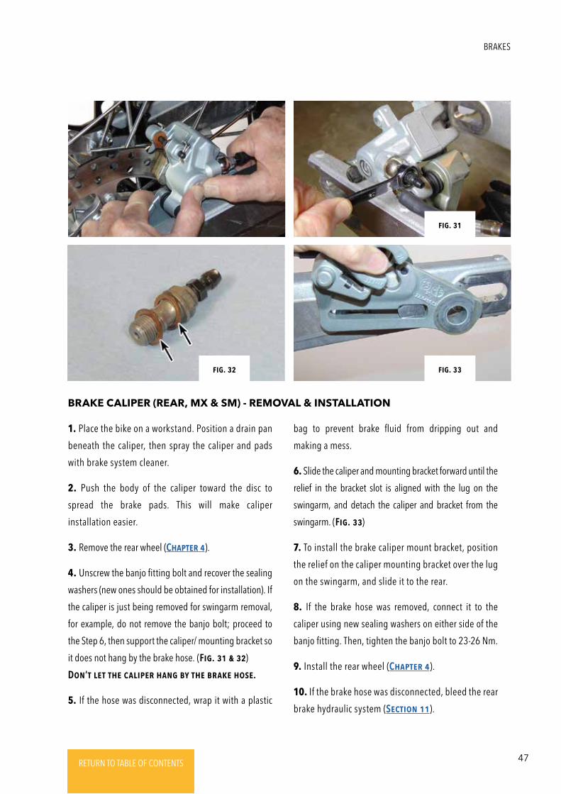
it does not hang by the brake hose. (Fig. 31 & 32)
DoN’t lEt thE calipER haNg by thE bRakE hosE.
5. If the hose was disconnected, wrap it with a plastic
BRAKE CALIPER (REAR, MX & SM) - REMOVAL & INSTALLATION
bag to prevent brake fluid from dripping out and
making a mess.
6. Slide the caliper and mounting bracket forward until the
relief in the bracket slot is aligned with the lug on the
swingarm, and detach the caliper and bracket from the
swingarm. (Fig. 33)
7. To install the brake caliper mount bracket, position
the relief on the caliper mounting bracket over the lug
on the swingarm, and slide it to the rear.
8. If the brake hose was removed, connect it to the
caliper using new sealing washers on either side of the
banjo fitting. Then, tighten the banjo bolt to 23-26 Nm.
9. Install the rear wheel (ChaptER 4).
10. If the brake hose was disconnected, bleed the rear
brake hydraulic system (SEctioN 11).
Fig. 31
Fig. 33Fig. 32
BRAKES
48 RETURN TO TABLE OF CONTENTSRETURN TO TABLE OF CONTENTSRETURN TO TABLE OF CONTENTSRETURN TO TABLE OF CONTENTSRETURN TO TABLE OF CONTENTS RETURN TO TABLE OF CONTENTS
CautioN: BRakE Fluid caN damagE paiNt aNd somE
plastic suRFacEs. Wash oFF aNy spillEd bRakE
Fluid with watER.
1. Place the bike on a workstand. Position a drain pan
beneath the caliper before spraying the caliper and
pads with brake system cleaner.
2. Remove the brake pads from the caliper (SEctioN
1, MX [front]; SEctioN 2 SM [front]; SEctioN 3, rear).
3. Remove the caliper (SEctioN 4, MX [front]; SEctioN
5, SM [front]; SEctioN 6, rear).
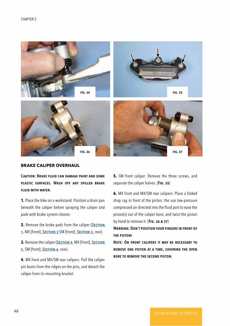
4. MX front and MX/SM rear calipers: Pull the caliper
pin boots from the ridges on the pins, and detach the
caliper from its mounting bracket.
BRAKE CALIPER OVERHAUL
5. SM front caliper: Remove the three screws, and
separate the caliper halves. (Fig. 35)
6. MX front and MX/SM rear calipers: Place a folded
shop rag in front of the piston, the use low-pressure
compressed air directed into the fluid port to ease the
piston(s) out of the caliper bore, and twist the piston
by hand to remove it. (Fig. 36 & 37)
WaRNiNg: DoN’t positioN youR FiNgERs iN FRoNt oF
thE pistoN!
NotE: ON FRoNt calipERs it may bE NEcEssaRy to
REmoVE oNE pistoN at a timE, coVERiNg thE opEN
boRE to REmoVE thE sEcoNd pistoN.
Fig. 32
Fig. 34
Fig. 31
Fig. 33
Fig. 35
Fig. 37
Fig. 34
Fig. 36
CHAPTER 3
49RETURN TO TABLE OF CONTENTSRETURN TO TABLE OF CONTENTSRETURN TO TABLE OF CONTENTSRETURN TO TABLE OF CONTENTSRETURN TO TABLE OF CONTENTS RETURN TO TABLE OF CONTENTS
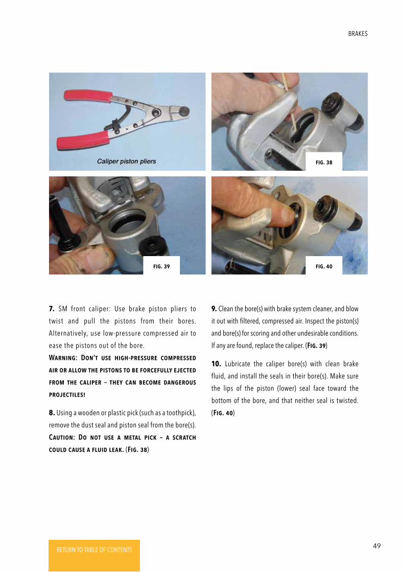
7. SM front caliper: Use brake piston pliers to
twist and pull the pistons from their bores.
Alternatively, use low-pressure compressed air to
ease the pistons out of the bore.
WaRNiNg: DoN’t usE high-pREssuRE compREssEd
aiR oR allow thE pistoNs to bE FoRcEFully EjEctEd
FRom thE calipER – thEy caN bEcomE daNgERous
pRojEctilEs!
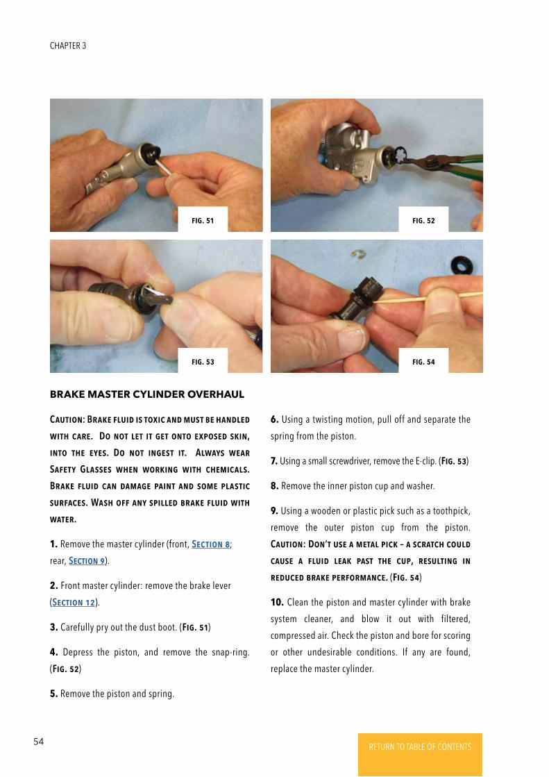
8. Using a wooden or plastic pick (such as a toothpick),
remove the dust seal and piston seal from the bore(s).
CautioN: Do Not usE a mEtal pick – a scRatch
could causE a Fluid lEak. (Fig. 38)
9. Clean the bore(s) with brake system cleaner, and blow
it out with filtered, compressed air. Inspect the piston(s)
and bore(s) for scoring and other undesirable conditions.
If any are found, replace the caliper. (Fig. 39)
10. Lubricate the caliper bore(s) with clean brake
fluid, and install the seals in their bore(s). Make sure
the lips of the piston (lower) seal face toward the
bottom of the bore, and that neither seal is twisted.
(Fig. 40)
Fig. 38
Fig. 40Fig. 39
BRAKES
50 RETURN TO TABLE OF CONTENTSRETURN TO TABLE OF CONTENTSRETURN TO TABLE OF CONTENTSRETURN TO TABLE OF CONTENTSRETURN TO TABLE OF CONTENTS RETURN TO TABLE OF CONTENTS
Fig. 32
Fig. 34 Fig. 34
Fig. 41
Fig. 42 Fig. 43
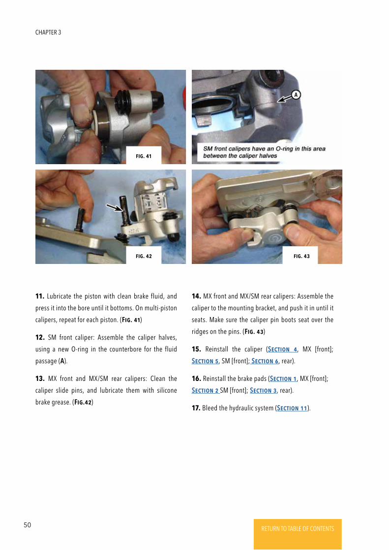
11. Lubricate the piston with clean brake fluid, and
press it into the bore until it bottoms. On multi-piston
calipers, repeat for each piston. (Fig. 41)
12. SM front caliper: Assemble the caliper halves,
using a new O-ring in the counterbore for the fluid
passage (A).
13. MX front and MX/SM rear calipers: Clean the
caliper slide pins, and lubricate them with silicone
brake grease. (Fig.42)
14. MX front and MX/SM rear calipers: Assemble the
caliper to the mounting bracket, and push it in until it
seats. Make sure the caliper pin boots seat over the
ridges on the pins. (Fig. 43)
15. Reinstall the caliper (SEctioN 4, MX [front];
SEctioN 5, SM [front]; SEctioN 6, rear).
16. Reinstall the brake pads (SEctioN 1, MX [front];
SEctioN 2 SM [front]; SEctioN 3, rear).
17. Bleed the hydraulic system (SEctioN 11).
CHAPTER 3
51RETURN TO TABLE OF CONTENTSRETURN TO TABLE OF CONTENTSRETURN TO TABLE OF CONTENTSRETURN TO TABLE OF CONTENTSRETURN TO TABLE OF CONTENTS RETURN TO TABLE OF CONTENTS
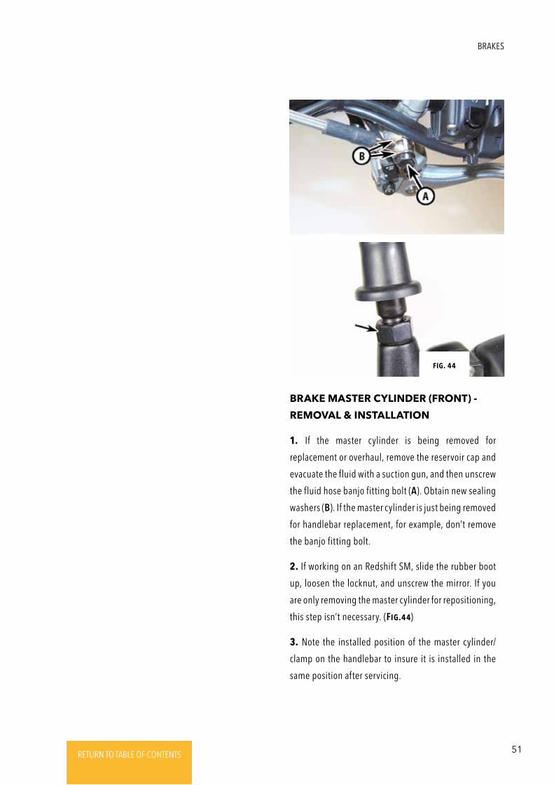
1. If the master cylinder is being removed for
replacement or overhaul, remove the reservoir cap and
evacuate the fluid with a suction gun, and then unscrew
the fluid hose banjo fitting bolt (A). Obtain new sealing
washers (B). If the master cylinder is just being removed
for handlebar replacement, for example, don’t remove
the banjo fitting bolt.
2. If working on an Redshift SM, slide the rubber boot
up, loosen the locknut, and unscrew the mirror. If you
are only removing the master cylinder for repositioning,
this step isn’t necessary. (Fig.44)
3. Note the installed position of the master cylinder/
clamp on the handlebar to insure it is installed in the
same position after servicing.
BRAKE MASTER CYLINDER (FRONT) -
REMOVAL & INSTALLATION
Fig. 44
BRAKES
52 RETURN TO TABLE OF CONTENTSRETURN TO TABLE OF CONTENTSRETURN TO TABLE OF CONTENTSRETURN TO TABLE OF CONTENTSRETURN TO TABLE OF CONTENTS RETURN TO TABLE OF CONTENTS
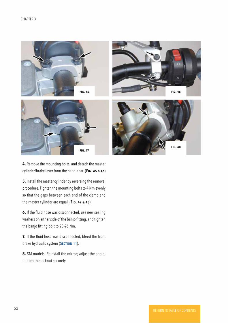
4. Remove the mounting bolts, and detach the master
cylinder/brake lever from the handlebar. (Fig. 45 & 46)
5. Install the master cylinder by reversing the removal
procedure. Tighten the mounting bolts to 4 Nm evenly
so that the gaps between each end of the clamp and
the master cylinder are equal. (Fig. 47 & 48)
6. If the fluid hose was disconnected, use new sealing
washers on either side of the banjo fitting, and tighten
the banjo fitting bolt to 23-26 Nm.
7. If the fluid hose was disconnected, bleed the front
brake hydraulic system (SEctioN 11).
8. SM models: Reinstall the mirror; adjust the angle;
tighten the locknut securely.
Fig. 34
Fig. 34Fig. 34
Fig. 34Fig. 47
Fig. 46Fig. 45
Fig. 48
CHAPTER 3
53RETURN TO TABLE OF CONTENTSRETURN TO TABLE OF CONTENTSRETURN TO TABLE OF CONTENTSRETURN TO TABLE OF CONTENTSRETURN TO TABLE OF CONTENTS RETURN TO TABLE OF CONTENTS
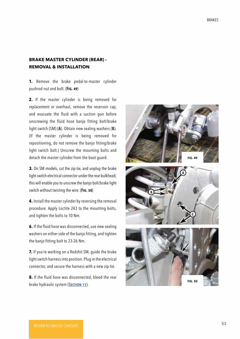
1. Remove the brake pedal-to-master cylinder
pushrod nut and bolt. (Fig. 49)
2. If the master cylinder is being removed for
replacement or overhaul, remove the reservoir cap,
and evacuate the fluid with a suction gun before
unscrewing the fluid hose banjo fitting bolt/brake
light switch (SM) (A). Obtain new sealing washers (B).
(If the master cylinder is being removed for
repositioning, do not remove the banjo fitting/brake
light switch bolt.) Unscrew the mounting bolts and
detach the master cylinder from the boot guard.
3. On SM models, cut the zip-tie, and unplug the brake
light switch electrical connector under the rear bulkhead;
this will enable you to unscrew the banjo bolt/brake light
switch without twisting the wire. (Fig. 50)
4. Install the master cylinder by reversing the removal
procedure. Apply Loctite 243 to the mounting bolts,
and tighten the bolts to 10 Nm.
6. If the fluid hose was disconnected, use new sealing
washers on either side of the banjo fitting, and tighten
the banjo fitting bolt to 23-26 Nm.
7. If you’re working on a Redshit SM, guide the brake
light switch harness into position. Plug in the electrical
connector, and secure the harness with a new zip-tie.
8. If the fluid hose was disconnected, bleed the rear
brake hydraulic system (SEctioN 11).
BRAKE MASTER CYLINDER (REAR) -
REMOVAL & INSTALLATION
Fig. 50
Fig. 49
BRAKES
54 RETURN TO TABLE OF CONTENTSRETURN TO TABLE OF CONTENTSRETURN TO TABLE OF CONTENTSRETURN TO TABLE OF CONTENTSRETURN TO TABLE OF CONTENTS RETURN TO TABLE OF CONTENTS
CautioN: BRakE Fluid is toxic aNd must bE haNdlEd
with caRE. Do Not lEt it gEt oNto ExposEd skiN,
iNto thE EyEs. Do Not iNgEst it. Always wEaR
SaFEty GlassEs whEN woRkiNg with chEmicals.
BRakE Fluid caN damagE paiNt aNd somE plastic
suRFacEs. Wash oFF aNy spillEd bRakE Fluid with
watER.
1. Remove the master cylinder (front, SEctioN 8;
rear, SEctioN 9).
2. Front master cylinder: remove the brake lever
(SEctioN 12).
3. Carefully pry out the dust boot. (Fig. 51)
4. Depress the piston, and remove the snap-ring.
(Fig. 52)
5. Remove the piston and spring.
BRAKE MASTER CYLINDER OVERHAUL
6. Using a twisting motion, pull off and separate the
spring from the piston.
7. Using a small screwdriver, remove the E-clip. (Fig. 53)
8. Remove the inner piston cup and washer.
9. Using a wooden or plastic pick such as a toothpick,
remove the outer piston cup from the piston.
CautioN: DoN’t usE a mEtal pick – a scRatch could
causE a Fluid lEak past thE cup, REsultiNg iN
REducEd bRakE pERFoRmaNcE. (Fig. 54)
10. Clean the piston and master cylinder with brake
system cleaner, and blow it out with filtered,
compressed air. Check the piston and bore for scoring
or other undesirable conditions. If any are found,
replace the master cylinder.
Fig. 32
Fig. 34
Fig. 31 Fig. 52
Fig. 54Fig. 53
Fig. 51
CHAPTER 3
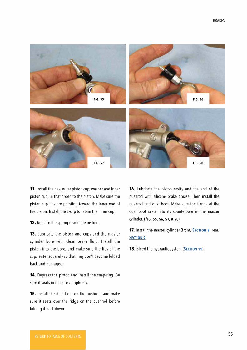
55RETURN TO TABLE OF CONTENTSRETURN TO TABLE OF CONTENTSRETURN TO TABLE OF CONTENTSRETURN TO TABLE OF CONTENTSRETURN TO TABLE OF CONTENTS RETURN TO TABLE OF CONTENTS
11. Install the new outer piston cup, washer and inner
piston cup, in that order, to the piston. Make sure the
piston cup lips are pointing toward the inner end of
the piston. Install the E-clip to retain the inner cup.
12. Replace the spring inside the piston.
13. Lubricate the piston and cups and the master
cylinder bore with clean brake fluid. Install the
piston into the bore, and make sure the lips of the
cups enter squarely so that they don’t become folded
back and damaged.
14. Depress the piston and install the snap-ring. Be
sure it seats in its bore completely.
15. Install the dust boot on the pushrod, and make
sure it seats over the ridge on the pushrod before
folding it back down.
16. Lubricate the piston cavity and the end of the
pushrod with silicone brake grease. Then install the
pushrod and dust boot. Make sure the flange of the
dust boot seats into its counterbore in the master
cylinder. (Fig. 55, 56, 57, & 58)
17. Install the master cylinder (front, SEctioN 8; rear,
SEctioN 9).
18. Bleed the hydraulic system (SEctioN 11).
Fig. 56
Fig. 58
Fig. 55
Fig. 57
BRAKES
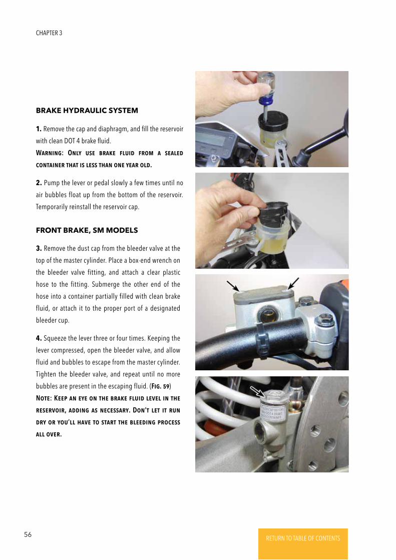
56 RETURN TO TABLE OF CONTENTSRETURN TO TABLE OF CONTENTSRETURN TO TABLE OF CONTENTSRETURN TO TABLE OF CONTENTSRETURN TO TABLE OF CONTENTS RETURN TO TABLE OF CONTENTS
1. Remove the cap and diaphragm, and fill the reservoir
with clean DOT 4 brake fluid.
WaRNiNg: ONly usE bRakE Fluid FRom a sEalEd
coNtaiNER that is lEss thaN oNE yEaR old.
2. Pump the lever or pedal slowly a few times until no
air bubbles float up from the bottom of the reservoir.
Temporarily reinstall the reservoir cap.
3. Remove the dust cap from the bleeder valve at the
top of the master cylinder. Place a box-end wrench on
the bleeder valve fitting, and attach a clear plastic
hose to the fitting. Submerge the other end of the
hose into a container partially filled with clean brake
fluid, or attach it to the proper port of a designated
bleeder cup.
4. Squeeze the lever three or four times. Keeping the
lever compressed, open the bleeder valve, and allow
fluid and bubbles to escape from the master cylinder.
Tighten the bleeder valve, and repeat until no more
bubbles are present in the escaping fluid. (Fig. 59)
NotE: KEEp aN EyE oN thE bRakE Fluid lEVEl iN thE
REsERVoiR, addiNg as NEcEssaRy. DoN’t lEt it RuN
dRy oR you’ll haVE to staRt thE blEEdiNg pRocEss
all oVER.
BRAKE HYDRAULIC SYSTEM
FRONT BRAKE, SM MODELS
CHAPTER 3
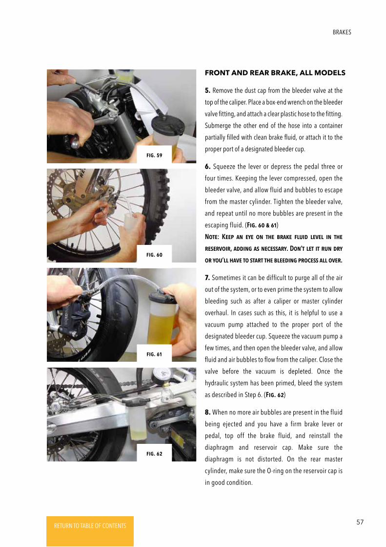
57RETURN TO TABLE OF CONTENTSRETURN TO TABLE OF CONTENTSRETURN TO TABLE OF CONTENTSRETURN TO TABLE OF CONTENTSRETURN TO TABLE OF CONTENTS RETURN TO TABLE OF CONTENTS
5. Remove the dust cap from the bleeder valve at the
top of the caliper. Place a box-end wrench on the bleeder
valve fitting, and attach a clear plastic hose to the fitting.
Submerge the other end of the hose into a container
partially filled with clean brake fluid, or attach it to the
proper port of a designated bleeder cup.
6. Squeeze the lever or depress the pedal three or
four times. Keeping the lever compressed, open the
bleeder valve, and allow fluid and bubbles to escape
from the master cylinder. Tighten the bleeder valve,
and repeat until no more bubbles are present in the
escaping fluid. (Fig. 60 & 61)
NotE: KEEp aN EyE oN thE bRakE Fluid lEVEl iN thE
REsERVoiR, addiNg as NEcEssaRy. DoN’t lEt it RuN dRy
oR you’ll haVE to staRt thE blEEdiNg pRocEss all oVER.
7. Sometimes it can be difficult to purge all of the air
out of the system, or to even prime the system to allow
bleeding such as after a caliper or master cylinder
overhaul. In cases such as this, it is helpful to use a
vacuum pump attached to the proper port of the
designated bleeder cup. Squeeze the vacuum pump a
few times, and then open the bleeder valve, and allow
fluid and air bubbles to flow from the caliper. Close the
valve before the vacuum is depleted. Once the
hydraulic system has been primed, bleed the system
as described in Step 6. (Fig. 62)
8. When no more air bubbles are present in the fluid
being ejected and you have a firm brake lever or
pedal, top off the brake fluid, and reinstall the
diaphragm and reservoir cap. Make sure the
diaphragm is not distorted. On the rear master
cylinder, make sure the O-ring on the reservoir cap is
in good condition.
FRONT AND REAR BRAKE, ALL MODELS
Fig. 60
Fig. 62
Fig. 59
Fig. 61
BRAKES
58 RETURN TO TABLE OF CONTENTSRETURN TO TABLE OF CONTENTSRETURN TO TABLE OF CONTENTSRETURN TO TABLE OF CONTENTSRETURN TO TABLE OF CONTENTS RETURN TO TABLE OF CONTENTS
1. Push the dust cover back to expose the pivot bolt (MX
models). Unscrew the pivot bolt locknut from the
underside of the lever perch, and unscrew the pivot bolt
from the top side. (Fig. 63)
2. Detach the lever from the perch.
3. Transfer the pushrod to the new lever.
4. Clean the pivot bolt, and lubricate it with silicone-
based or lithium-based grease.
5. Lubricate the pushrod with silicone-based brake grease.
6. Install the lever to the perch, and insert the pushrod
into the master cylinder dust boot. Make sure the boot
seats around the ridge on the pushrod. (Fig. 64)
BRAKE LEVER -
REMOVAL & INSTALLATION
Fig. 34
Fig. 31
Fig. 64
Fig. 63
CHAPTER 3
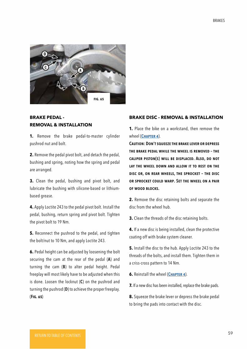
59RETURN TO TABLE OF CONTENTSRETURN TO TABLE OF CONTENTSRETURN TO TABLE OF CONTENTSRETURN TO TABLE OF CONTENTSRETURN TO TABLE OF CONTENTS RETURN TO TABLE OF CONTENTS
1. Remove the brake pedal-to-master cylinder
pushrod nut and bolt.
2. Remove the pedal pivot bolt, and detach the pedal,
bushing and spring, noting how the spring and pedal
are arranged.
3. Clean the pedal, bushing and pivot bolt, and
lubricate the bushing with silicone-based or lithium-
based grease.
4. Apply Loctite 243 to the pedal pivot bolt. Install the
pedal, bushing, return spring and pivot bolt. Tighten
the pivot bolt to 19 Nm.
5. Reconnect the pushrod to the pedal, and tighten
the bolt/nut to 10 Nm, and apply Loctite 243.
6. Pedal height can be adjusted by loosening the bolt
securing the cam at the rear of the pedal (A) and
turning the cam (B) to alter pedal height. Pedal
freeplay will most likely have to be adjusted when this
is done. Loosen the locknut (C) on the pushrod and
turning the pushrod (D) to achieve the proper freeplay.
(Fig. 65)
1. Place the bike on a workstand, then remove the
wheel (ChaptER 4).
CautioN: DoN’t squEEzE thE bRakE lEVER oR dEpREss
thE bRakE pEdal whilE thE whEEl is REmoVEd – thE
calipER pistoN(s) will bE displacEd. Also, do Not
lay thE whEEl dowN aNd allow it to REst oN thE
disc oR, oN REaR whEEls, thE spRockEt – thE disc
oR spRockEt could waRp. SEt thE whEEl oN a paiR
oF wood blocks.
2. Remove the disc retaining bolts and separate the
disc from the wheel hub.
3. Clean the threads of the disc retaining bolts.
4. If a new disc is being installed, clean the protective
coating off with brake system cleaner.
5. Install the disc to the hub. Apply Loctite 243 to the
threads of the bolts, and install them. Tighten them in
a criss-cross pattern to 14 Nm.
6. Reinstall the wheel (ChaptER 4).
7. If a new disc has been installed, replace the brake pads.
8. Squeeze the brake lever or depress the brake pedal
to bring the pads into contact with the disc.
BRAKE PEDAL -
REMOVAL & INSTALLATION
BRAKE DISC - REMOVAL & INSTALLATION
Fig. 65
BRAKES
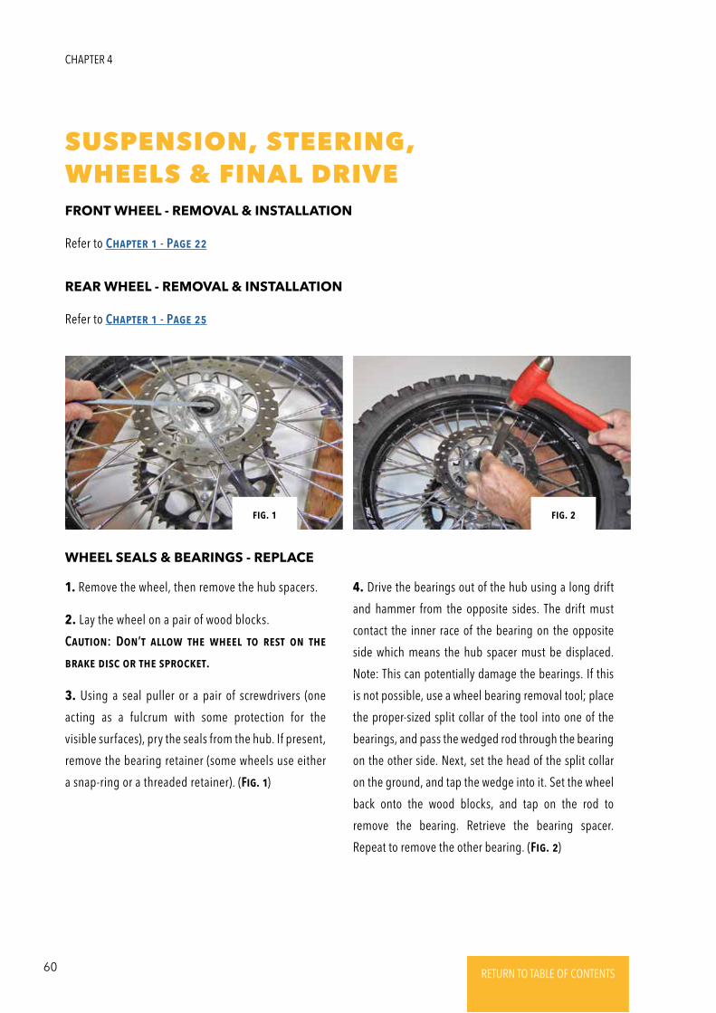
60 RETURN TO TABLE OF CONTENTSRETURN TO TABLE OF CONTENTSRETURN TO TABLE OF CONTENTSRETURN TO TABLE OF CONTENTSRETURN TO TABLE OF CONTENTS RETURN TO TABLE OF CONTENTS
CHAPTER 4
SUSPENSION, STEERING,WHEELS & FINAL DRIVE
Refer to ChaptER 1 - PagE 22
Refer to ChaptER 1 - PagE 25
1. Remove the wheel, then remove the hub spacers.
2. Lay the wheel on a pair of wood blocks.
CautioN: DoN’t allow thE whEEl to REst oN thE
bRakE disc oR thE spRockEt.
3. Using a seal puller or a pair of screwdrivers (one
acting as a fulcrum with some protection for the
visible surfaces), pry the seals from the hub. If present,
remove the bearing retainer (some wheels use either
a snap-ring or a threaded retainer). (Fig. 1)
FRONT WHEEL - REMOVAL & INSTALLATION
REAR WHEEL - REMOVAL & INSTALLATION
WHEEL SEALS & BEARINGS - REPLACE
4. Drive the bearings out of the hub using a long drift
and hammer from the opposite sides. The drift must
contact the inner race of the bearing on the opposite
side which means the hub spacer must be displaced.
Note: This can potentially damage the bearings. If this
is not possible, use a wheel bearing removal tool; place
the proper-sized split collar of the tool into one of the
bearings, and pass the wedged rod through the bearing
on the other side. Next, set the head of the split collar
on the ground, and tap the wedge into it. Set the wheel
back onto the wood blocks, and tap on the rod to
remove the bearing. Retrieve the bearing spacer.
Repeat to remove the other bearing. (Fig. 2)
Fig. 1 Fig. 2
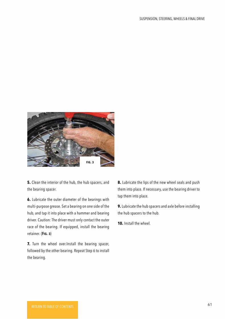
61RETURN TO TABLE OF CONTENTSRETURN TO TABLE OF CONTENTSRETURN TO TABLE OF CONTENTSRETURN TO TABLE OF CONTENTSRETURN TO TABLE OF CONTENTS RETURN TO TABLE OF CONTENTS
SUSPENSION, STEERING, WHEELS & FINAL DRIVE
Fig. 3
5. Clean the interior of the hub, the hub spacers, and
the bearing spacer.
6. Lubricate the outer diameter of the bearings with
multi-purpose grease. Set a bearing on one side of the
hub, and tap it into place with a hammer and bearing
driver. Caution: The driver must only contact the outer
race of the bearing. If equipped, install the bearing
retainer. (Fig. 3)
7. Turn the wheel over.Install the bearing spacer,
followed by the other bearing. Repeat Step 6 to install
the bearing.
8. Lubricate the lips of the new wheel seals and push
them into place. If necessary, use the bearing driver to
tap them into place.
9. Lubricate the hub spacers and axle before installing
the hub spacers to the hub.
10. Install the wheel.
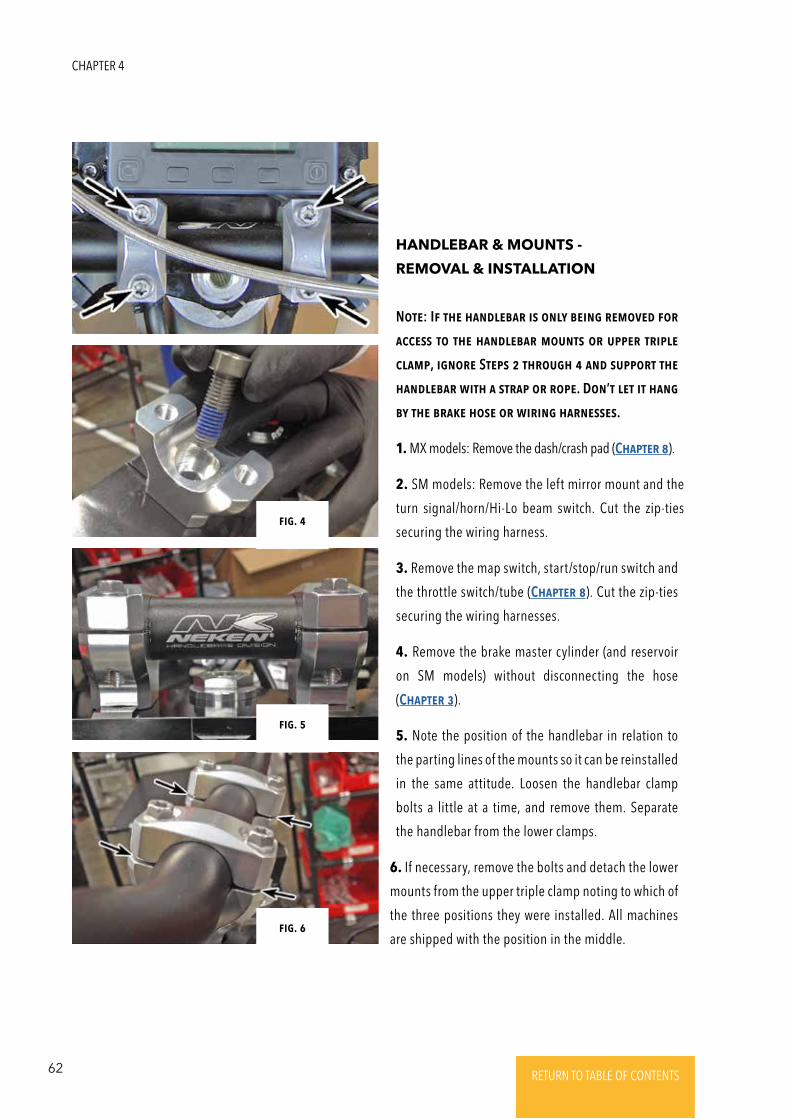
62 RETURN TO TABLE OF CONTENTSRETURN TO TABLE OF CONTENTSRETURN TO TABLE OF CONTENTSRETURN TO TABLE OF CONTENTSRETURN TO TABLE OF CONTENTS RETURN TO TABLE OF CONTENTS
NotE: IF thE haNdlEbaR is oNly bEiNg REmoVEd FoR
accEss to thE haNdlEbaR mouNts oR uppER tRiplE
clamp, igNoRE StEps 2 thRough 4 aNd suppoRt thE
haNdlEbaR with a stRap oR RopE. DoN’t lEt it haNg
by thE bRakE hosE oR wiRiNg haRNEssEs.
1. MX models: Remove the dash/crash pad (ChaptER 8).
2. SM models: Remove the left mirror mount and the
turn signal/horn/Hi-Lo beam switch. Cut the zip-ties
securing the wiring harness.
3. Remove the map switch, start/stop/run switch and
the throttle switch/tube (ChaptER 8). Cut the zip-ties
securing the wiring harnesses.
4. Remove the brake master cylinder (and reservoir
on SM models) without disconnecting the hose
(ChaptER 3).
5. Note the position of the handlebar in relation to
the parting lines of the mounts so it can be reinstalled
in the same attitude. Loosen the handlebar clamp
bolts a little at a time, and remove them. Separate
the handlebar from the lower clamps.
6. If necessary, remove the bolts and detach the lower
mounts from the upper triple clamp noting to which of
the three positions they were installed. All machines
are shipped with the position in the middle.
HANDLEBAR & MOUNTS -
REMOVAL & INSTALLATION
Fig. 34
Fig. 34
Fig. 34
Fig. 4
Fig. 5
Fig. 6
CHAPTER 4
63RETURN TO TABLE OF CONTENTSRETURN TO TABLE OF CONTENTSRETURN TO TABLE OF CONTENTSRETURN TO TABLE OF CONTENTSRETURN TO TABLE OF CONTENTS RETURN TO TABLE OF CONTENTS
1. Cut the grips off the handlebar with a razor knife.e
Be careful not to slice into the visible surface of the bar
or throttle tube.
2. Clean all traces of grip glue from the handlebar and
throttle tube.
3. Apply a thin, even film of grip glue to the handlebar
and to the inside of the LH Grip. Please note that the
RH Grip, which goes over the throttle, should not be
installed with grip glue as it has a tendency to get
between the throttle tube and the handlebar. This
could glue them together which could result in a loss of
control. The Alta throttle tube diameter is large and as
long as a clean grip is installed on a clean tube, it will
not spin with use. It is often necessary to use
compressed air blown into the grip in conjunction with
hand pressure to get the grips onto the throttle tube.
4. Slide the grip onto the bar, and position it so the
pattern is straight. If installing a half-waffle style grip,
be sure to position the waffle pattern where the rider’s
fingers are (not the palms).
5. Allow the glue to set-up before riding (times vary –
see the recommendation on the product).
GRIPS - REPLACE
7. If removed, place the lower mounts onto the upper
triple clamp; apply Loctite 243 to the threads of the
bolts. Install the bolts and tighten them to 32 Nm.
Note: Make sure the mounts engage properly with the
upper triple clamp. (Fig. 4)
8. Apply Loctite 243 to the clamp bolts. Set the
handlebar into the lower mounts, and install the
clamps and bolts and tighten them until they are
just snug.
9. Center the handlebar in the two mounts, and rotate
it as necessary to position it as it was before removal.
(Fig. 5)
10. Tighten the handlebar clamp bolts a lit tle at a
time in an alternating pattern to 10 Nm. Make sure
the gaps on either side of each clamp are equal.
(Fig. 6)
11. The remainder of installation is the reverse of
removal; refer to the appropriate chapters for
details and specifications.
SUSPENSION, STEERING, WHEELS & FINAL DRIVE
64 RETURN TO TABLE OF CONTENTSRETURN TO TABLE OF CONTENTSRETURN TO TABLE OF CONTENTSRETURN TO TABLE OF CONTENTSRETURN TO TABLE OF CONTENTS RETURN TO TABLE OF CONTENTS
1. Place the bike on a lift or pit stand, and remove the
front wheel (SEctioN 1).
2. Measure the protrusion of the fork tubes from the
top of the upper triple clamp, and record this
measurement. (Fig. 7)
3. If the forks are being removed for servicing, loosen
the upper triple clamp bolts (A), and break loose the
fork cap (B) (on MX models this will necessitate
removal of the handlebar [SEctioN 4] in order to use
the special fork cap wrench).
4. Detach the brake caliper from the left fork leg (ChaptER
3). Free the brake hose from its guide and clamp on the
fork, noting how the ferrule on the brake hose fits into
the clamp. (Fig. 8 & 9)
NotE: DoN’t discoNNEct thE hosE, but bE suRE to
haNg thE calipER out oF thE way with a stRap oR
lENgth oF RopE.
CautioN: DoN’t squEEzE thE FRoNt bRakE lEVER
whilE thE calipER is REmoVEd – thE calipER pistoNs
could bE displacEd.
5. Loosen the upper (if not already done) and lower
triple clamp bolts, then slide the fork tubes out of the
triple clamps with a twisting motion. (Fig. 10)
6. If necessary, remove the fork guards from the lower
fork legs.
7. Remove the pinch bolts from the upper and lower
triple clamps and clean the threads. Alta uses a
specific type of bolt in these locations with a low
friction coating that is made to interact with anodized
aluminum. Do not grease these bolts, just clean them
and torque them to spec.
8. Slide the fork tubes into the lower triple clamp and
then into the upper triple clamp until the tubes
protrude from the upper triple clamp the same
distance as measured in Step 2. Turn the upper tubes
so that the COMP and REB (MX models) or COMP (SM
models) marks are positioned such that a seated rider
can see them. On SM models, the reflectors on the
upper fork tubes should be perpendicular to the
centerline of the bike. (Fig. 11)
9. Tighten the lower triple clamp pinch bolts a lit tle
at a time up to 10 Nm. Do not over-tighten as this
will cause excessive fork stiction and rapid wear of
fork components.
10. If the forks had been disassembled for service,
tighten the fork caps to 40 Nm.
11. Tighten the upper triple clamp pinch bolts a little
at a time up to 10 Nm..
12. The remainder of installation is the reverse of
removal; refer to the appropriate Sections and
Chapters for details and specifications.
FORKS - REMOVAL & INSTALLATION
CHAPTER 4
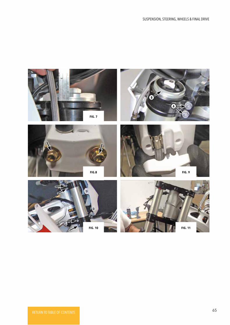
65RETURN TO TABLE OF CONTENTSRETURN TO TABLE OF CONTENTSRETURN TO TABLE OF CONTENTSRETURN TO TABLE OF CONTENTSRETURN TO TABLE OF CONTENTS RETURN TO TABLE OF CONTENTS
Fig. 11
Fig. 9
Fig. 7
Fig.8
Fig. 10
SUSPENSION, STEERING, WHEELS & FINAL DRIVE
66 RETURN TO TABLE OF CONTENTSRETURN TO TABLE OF CONTENTSRETURN TO TABLE OF CONTENTSRETURN TO TABLE OF CONTENTSRETURN TO TABLE OF CONTENTS RETURN TO TABLE OF CONTENTS
Refer to ChaptER 1 - PagE 18
SUSPENSION - ADJUSTMENTS
TRIPLE CLAMPS & STEERING STEM -
REMOVAL & INSTALLATION
1. Remove the handlebar (SEctioN 4).
2. Remove the forks (SEctioN 6).
3. Remove the steering stem nut (A) and the upper
triple clamp-to-steering stem pinch bolt (B). (Fig. 12)
4. Remove the upper triple clamp from the steering
stem, and drop the lower triple clamp/steering stem
out of the steering head.
5. Remove the upper steering head bearing shield,
X-ring, O-ring and bearing from the steering head.
6. For steering head bearing servicing (SEctioN 11).
7. Insert the lower triple clamp/steering stem/bearing
(lubricated) into the steering head.
8. Install the (lubricated) upper steering head bearing
(A) onto the steering stem, and install the X-ring (B),
O-ring (C) and bearing shield (D). (Fig. 13 & 14)
9. Wipe off any grease on the exposed steering stem
with a shop rag soaked with contact cleaner. Install
the upper triple clamp onto the steering stem. Then,
install the steering stem nut and tighten it hand-tight.
(Fig. 15)
10. Install the forks into the triple clamps. Install the
lower triple clamp pinch bolts, and temporarily
tighten them.
11. Tighten the steering stem nut to 30 Nm. (Fig. 16)
12. Loosen the lower triple clamp pinch bolts, and
adjust the height and position of the forks in the
upper triple clamp (Section 6).
13. Tighten the lower triple clamp pinch bolts to 10 Nm.
(Fig. 17)
14. Loosen the steering stem nut.
15. Apply Loctite 243 to the threads of the upper
triple clamp-to-steering stem pinch bolt. Install the
bolt, and tighten it to 10 Nm. (Fig. 18)
16. Tighten the steering stem nut to 25 Nm.
17. Tighten the upper triple clamp pinch bolts to 10 Nm.
(Fig. 19)
18. The remainder of installation is the reverse
of removal.
CHAPTER 4
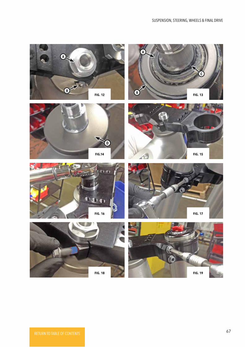
67RETURN TO TABLE OF CONTENTSRETURN TO TABLE OF CONTENTSRETURN TO TABLE OF CONTENTSRETURN TO TABLE OF CONTENTSRETURN TO TABLE OF CONTENTS RETURN TO TABLE OF CONTENTS
Fig. 17
Fig. 19
Fig. 15
Fig. 13Fig. 12
Fig.14
Fig. 16
Fig. 18
SUSPENSION, STEERING, WHEELS & FINAL DRIVE
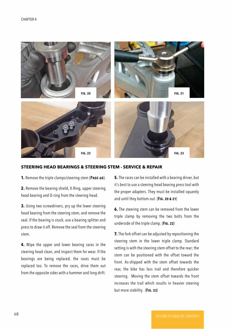
68 RETURN TO TABLE OF CONTENTSRETURN TO TABLE OF CONTENTSRETURN TO TABLE OF CONTENTSRETURN TO TABLE OF CONTENTSRETURN TO TABLE OF CONTENTS RETURN TO TABLE OF CONTENTS
STEERING HEAD BEARINGS & STEERING STEM - SERVICE & REPAIR
1. Remove the triple clamps/steering stem (PagE 60).
2. Remove the bearing shield, X-Ring, upper steering
head bearing and O-ring from the steering head.
3. Using two screwdrivers, pry up the lower steering
head bearing from the steering stem, and remove the
seal. If the bearing is stuck, use a bearing splitter and
press to draw it off. Remove the seal from the steering
stem.
4. Wipe the upper and lower bearing races in the
steering head clean, and inspect them for wear. If the
bearings are being replaced, the races must be
replaced too. To remove the races, drive them out
from the opposite sides with a hammer and long drift.
5. The races can be installed with a bearing driver, but
it’s best to use a steering head bearing press tool with
the proper adapters. They must be installed squarely
and until they bottom out. (Fig. 20 & 21)
6. The steering stem can be removed from the lower
triple clamp by removing the two bolts from the
underside of the triple clamp. (Fig. 22)
7. The fork offset can be adjusted by repositioning the
steering stem in the lower triple clamp. Standard
setting is with the steering stem offset to the rear; the
stem can be positioned with the offset toward the
front. As-shipped with the stem offset towards the
rear, the bike has less trail and therefore quicker
steering. Moving the stem offset towards the front
increases the trail which results in heavier steering
but more stability. (Fig. 23)
Fig. 32
Fig. 34
Fig. 31 Fig. 21
Fig. 23Fig. 22
Fig. 20
CHAPTER 4
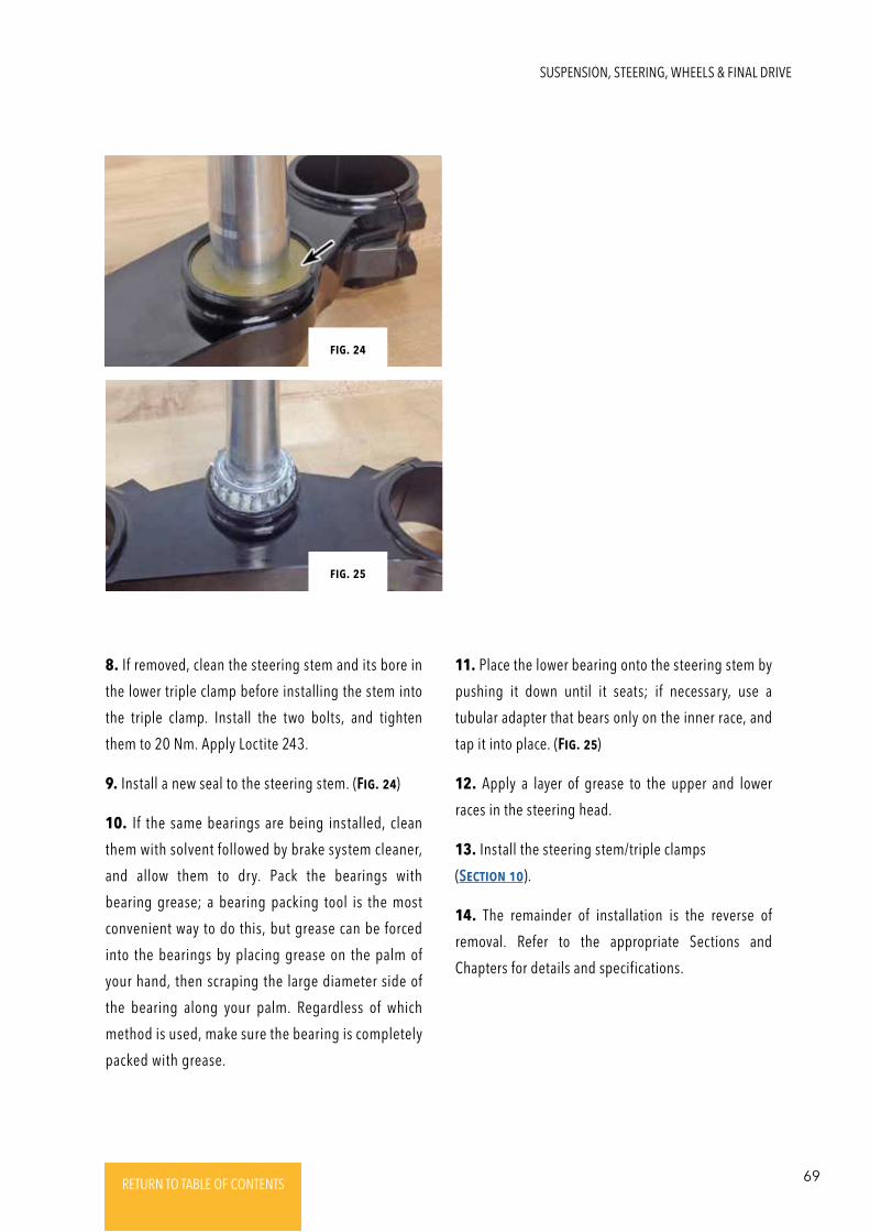
69RETURN TO TABLE OF CONTENTSRETURN TO TABLE OF CONTENTSRETURN TO TABLE OF CONTENTSRETURN TO TABLE OF CONTENTSRETURN TO TABLE OF CONTENTS RETURN TO TABLE OF CONTENTS
8. If removed, clean the steering stem and its bore in
the lower triple clamp before installing the stem into
the triple clamp. Install the two bolts, and tighten
them to 20 Nm. Apply Loctite 243.
9. Install a new seal to the steering stem. (Fig. 24)
10. If the same bearings are being installed, clean
them with solvent followed by brake system cleaner,
and allow them to dry. Pack the bearings with
bearing grease; a bearing packing tool is the most
convenient way to do this, but grease can be forced
into the bearings by placing grease on the palm of
your hand, then scraping the large diameter side of
the bearing along your palm. Regardless of which
method is used, make sure the bearing is completely
packed with grease.
11. Place the lower bearing onto the steering stem by
pushing it down until it seats; if necessary, use a
tubular adapter that bears only on the inner race, and
tap it into place. (Fig. 25)
12. Apply a layer of grease to the upper and lower
races in the steering head.
13. Install the steering stem/triple clamps
(SEctioN 10).
14. The remainder of installation is the reverse of
removal. Refer to the appropriate Sections and
Chapters for details and specifications.
Fig. 25
Fig. 24
SUSPENSION, STEERING, WHEELS & FINAL DRIVE
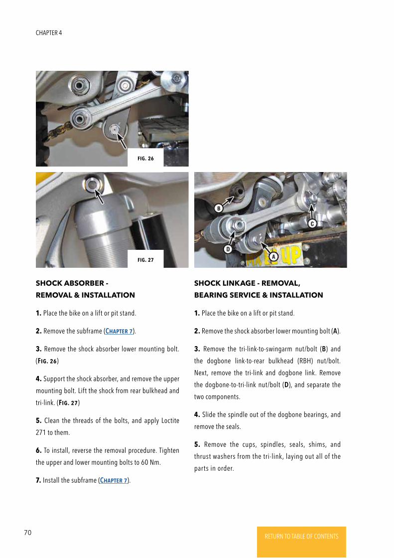
70 RETURN TO TABLE OF CONTENTSRETURN TO TABLE OF CONTENTSRETURN TO TABLE OF CONTENTSRETURN TO TABLE OF CONTENTSRETURN TO TABLE OF CONTENTS RETURN TO TABLE OF CONTENTS
1. Place the bike on a lift or pit stand.
2. Remove the subframe (ChaptER 7).
3. Remove the shock absorber lower mounting bolt.
(Fig. 26)
4. Support the shock absorber, and remove the upper
mounting bolt. Lift the shock from rear bulkhead and
tri-link. (Fig. 27)
5. Clean the threads of the bolts, and apply Loctite
271 to them.
6. To install, reverse the removal procedure. Tighten
the upper and lower mounting bolts to 60 Nm.
7. Install the subframe (ChaptER 7).
1. Place the bike on a lift or pit stand.
2. Remove the shock absorber lower mounting bolt (A).
3. Remove the tri-link-to-swingarm nut/bolt (B) and
the dogbone link-to-rear bulkhead (RBH) nut/bolt.
Next, remove the tri-link and dogbone link. Remove
the dogbone-to-tri-link nut/bolt (D), and separate the
two components.
4. Slide the spindle out of the dogbone bearings, and
remove the seals.
5. Remove the cups, spindles, seals, shims, and
thrust washers from the tri-link, laying out all of the
parts in order.
SHOCK ABSORBER -
REMOVAL & INSTALLATION
SHOCK LINKAGE - REMOVAL,
BEARING SERVICE & INSTALLATION
Fig. 34
Fig. 31
Fig. 27
Fig. 26
CHAPTER 4
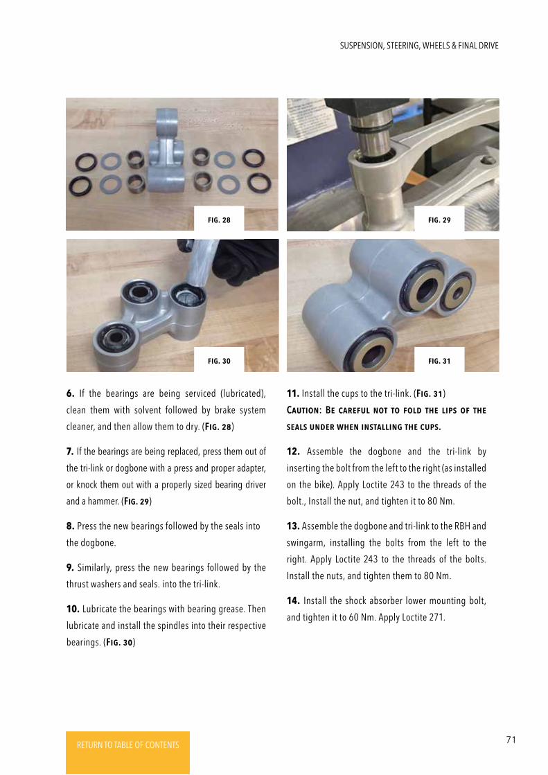
71RETURN TO TABLE OF CONTENTSRETURN TO TABLE OF CONTENTSRETURN TO TABLE OF CONTENTSRETURN TO TABLE OF CONTENTSRETURN TO TABLE OF CONTENTS RETURN TO TABLE OF CONTENTS
11. Install the cups to the tri-link. (Fig. 31)
CautioN: BE caREFul Not to Fold thE lips oF thE
sEals uNdER whEN iNstalliNg thE cups.
12. Assemble the dogbone and the tri-link by
inserting the bolt from the left to the right (as installed
on the bike). Apply Loctite 243 to the threads of the
bolt., Install the nut, and tighten it to 80 Nm.
13. Assemble the dogbone and tri-link to the RBH and
swingarm, installing the bolts from the left to the
right. Apply Loctite 243 to the threads of the bolts.
Install the nuts, and tighten them to 80 Nm.
14. Install the shock absorber lower mounting bolt,
and tighten it to 60 Nm. Apply Loctite 271.
Fig. 34 Fig. 34
Fig. 31 Fig. 31
Fig. 30 Fig. 31
Fig. 28 Fig. 29
6. If the bearings are being serviced (lubricated),
clean them with solvent followed by brake system
cleaner, and then allow them to dry. (Fig. 28)
7. If the bearings are being replaced, press them out of
the tri-link or dogbone with a press and proper adapter,
or knock them out with a properly sized bearing driver
and a hammer. (Fig. 29)
8. Press the new bearings followed by the seals into
the dogbone.
9. Similarly, press the new bearings followed by the
thrust washers and seals. into the tri-link.
10. Lubricate the bearings with bearing grease. Then
lubricate and install the spindles into their respective
bearings. (Fig. 30)
SUSPENSION, STEERING, WHEELS & FINAL DRIVE
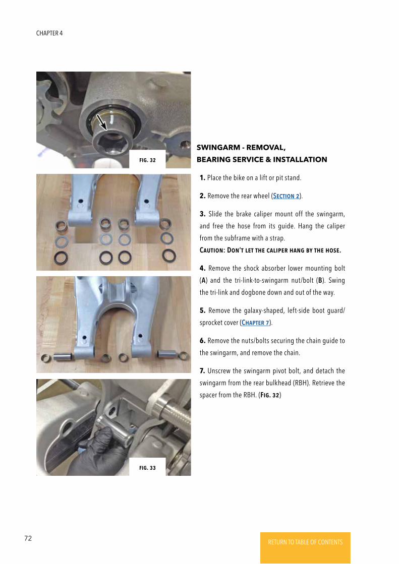
72 RETURN TO TABLE OF CONTENTSRETURN TO TABLE OF CONTENTSRETURN TO TABLE OF CONTENTSRETURN TO TABLE OF CONTENTSRETURN TO TABLE OF CONTENTS RETURN TO TABLE OF CONTENTS
1. Place the bike on a lift or pit stand.
2. Remove the rear wheel (SEctioN 2).
3. Slide the brake caliper mount off the swingarm,
and free the hose from its guide. Hang the caliper
from the subframe with a strap.
CautioN: DoN’t lEt thE calipER haNg by thE hosE.
4. Remove the shock absorber lower mounting bolt
(A) and the tri-link-to-swingarm nut/bolt (B). Swing
the tri-link and dogbone down and out of the way.
5. Remove the galaxy-shaped, left-side boot guard/
sprocket cover (ChaptER 7).
6. Remove the nuts/bolts securing the chain guide to
the swingarm, and remove the chain.
7. Unscrew the swingarm pivot bolt, and detach the
swingarm from the rear bulkhead (RBH). Retrieve the
spacer from the RBH. (Fig. 32)
SWINGARM - REMOVAL,
BEARING SERVICE & INSTALLATION
Fig. 34
Fig. 31
Fig. 33
Fig. 32
CHAPTER 4
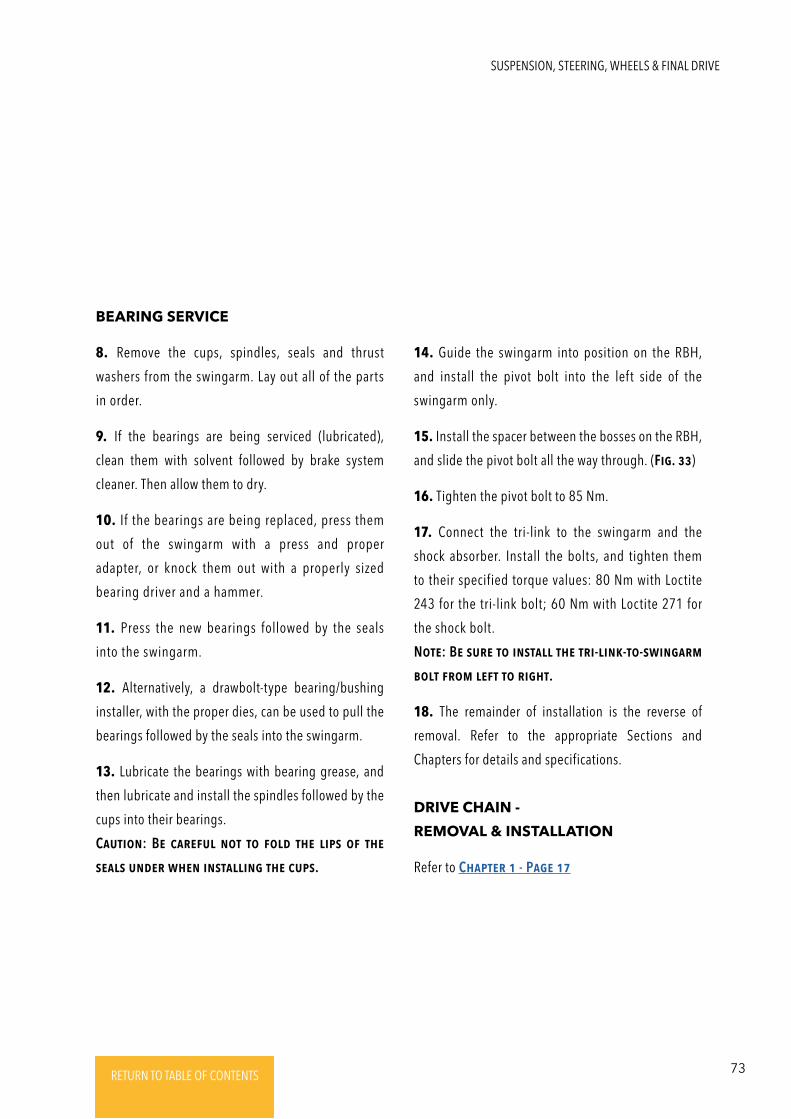
73RETURN TO TABLE OF CONTENTSRETURN TO TABLE OF CONTENTSRETURN TO TABLE OF CONTENTSRETURN TO TABLE OF CONTENTSRETURN TO TABLE OF CONTENTS RETURN TO TABLE OF CONTENTS
8. Remove the cups, spindles, seals and thrust
washers from the swingarm. Lay out all of the parts
in order.
9. If the bearings are being serviced (lubricated),
clean them with solvent followed by brake system
cleaner. Then allow them to dry.
10. If the bearings are being replaced, press them
out of the swingarm with a press and proper
adapter, or knock them out with a properly sized
bearing driver and a hammer.
11. Press the new bearings followed by the seals
into the swingarm.
12. Alternatively, a drawbolt-type bearing/bushing
installer, with the proper dies, can be used to pull the
bearings followed by the seals into the swingarm.
13. Lubricate the bearings with bearing grease, and
then lubricate and install the spindles followed by the
cups into their bearings.
CautioN: BE caREFul Not to Fold thE lips oF thE
sEals uNdER whEN iNstalliNg thE cups.
14. Guide the swingarm into position on the RBH,
and install the pivot bolt into the left side of the
swingarm only.
15. Install the spacer between the bosses on the RBH,
and slide the pivot bolt all the way through. (Fig. 33)
16. Tighten the pivot bolt to 85 Nm.
17. Connect the tri-link to the swingarm and the
shock absorber. Install the bolts, and tighten them
to their specified torque values: 80 Nm with Loctite
243 for the tri-link bolt; 60 Nm with Loctite 271 for
the shock bolt.
NotE: BE suRE to iNstall thE tRi-liNk-to-swiNgaRm
bolt FRom lEFt to Right.
18. The remainder of installation is the reverse of
removal. Refer to the appropriate Sections and
Chapters for details and specifications.
BEARING SERVICE
Refer to ChaptER 1 - PagE 17
DRIVE CHAIN -
REMOVAL & INSTALLATION
SUSPENSION, STEERING, WHEELS & FINAL DRIVE
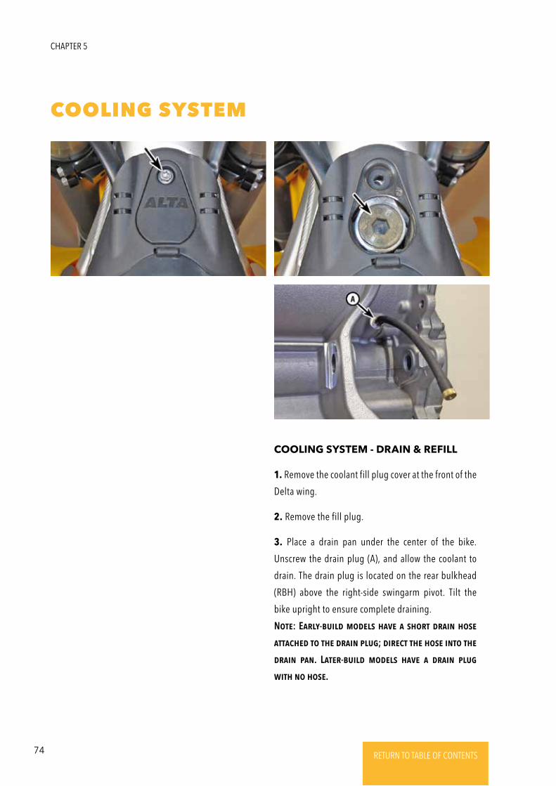
74 RETURN TO TABLE OF CONTENTSRETURN TO TABLE OF CONTENTSRETURN TO TABLE OF CONTENTSRETURN TO TABLE OF CONTENTSRETURN TO TABLE OF CONTENTS RETURN TO TABLE OF CONTENTS
CHAPTER 5
COOLING SYSTEM
COOLING SYSTEM - DRAIN & REFILL
1. Remove the coolant fill plug cover at the front of the
Delta wing.
2. Remove the fill plug.
3. Place a drain pan under the center of the bike.
Unscrew the drain plug (A), and allow the coolant to
drain. The drain plug is located on the rear bulkhead
(RBH) above the right-side swingarm pivot. Tilt the
bike upright to ensure complete draining.
NotE: EaRly-build modEls haVE a shoRt dRaiN hosE
attachEd to thE dRaiN plug; diREct thE hosE iNto thE
dRaiN paN. LatER-build modEls haVE a dRaiN plug
with No hosE.
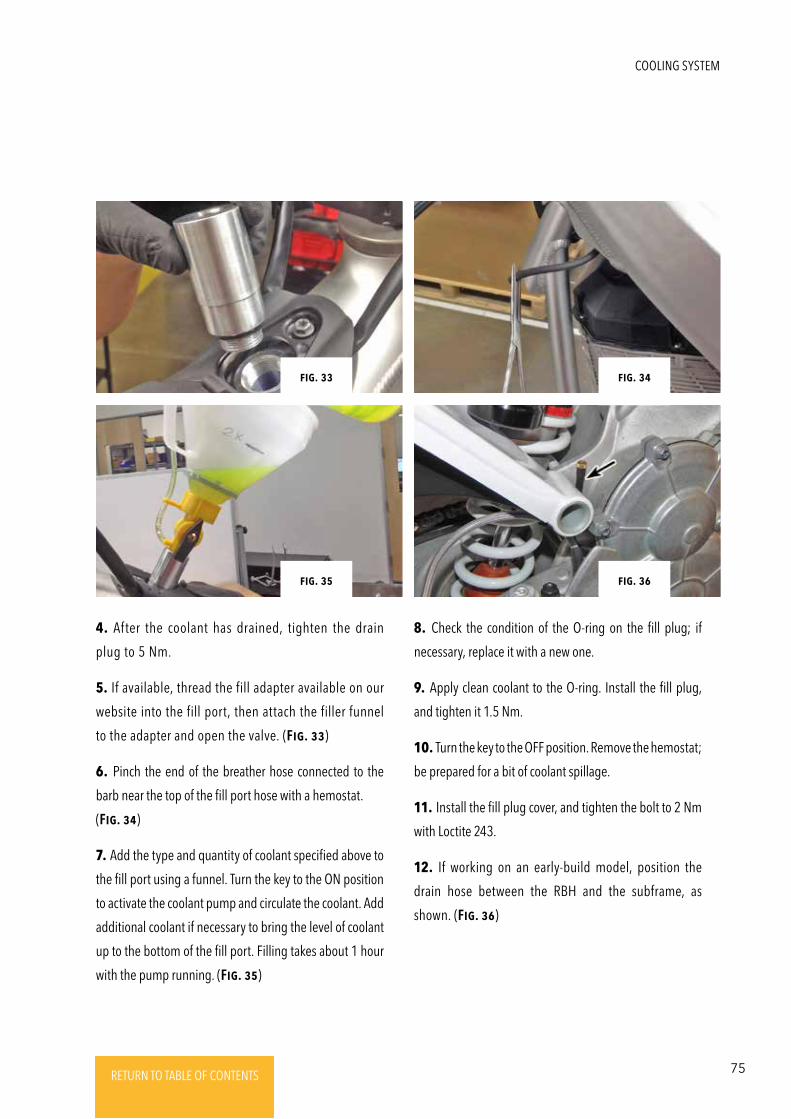
75RETURN TO TABLE OF CONTENTSRETURN TO TABLE OF CONTENTSRETURN TO TABLE OF CONTENTSRETURN TO TABLE OF CONTENTSRETURN TO TABLE OF CONTENTS RETURN TO TABLE OF CONTENTS
COOLING SYSTEM
4. After the coolant has drained, tighten the drain
plug to 5 Nm.
5. If available, thread the fill adapter available on our
website into the fill port, then attach the filler funnel
to the adapter and open the valve. (Fig. 33)
6. Pinch the end of the breather hose connected to the
barb near the top of the fill port hose with a hemostat.
(Fig. 34)
7. Add the type and quantity of coolant specified above to
the fill port using a funnel. Turn the key to the ON position
to activate the coolant pump and circulate the coolant. Add
additional coolant if necessary to bring the level of coolant
up to the bottom of the fill port. Filling takes about 1 hour
with the pump running. (Fig. 35)
Fig. 34Fig. 36
Fig. 33
Fig. 35
Fig. 34
8. Check the condition of the O-ring on the fill plug; if
necessary, replace it with a new one.
9. Apply clean coolant to the O-ring. Install the fill plug,
and tighten it 1.5 Nm.
10. Turn the key to the OFF position. Remove the hemostat;
be prepared for a bit of coolant spillage.
11. Install the fill plug cover, and tighten the bolt to 2 Nm
with Loctite 243.
12. If working on an early-build model, position the
drain hose between the RBH and the subframe, as
shown. (Fig. 36)
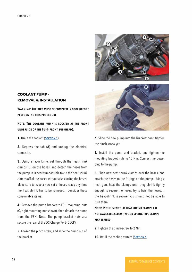
76 RETURN TO TABLE OF CONTENTSRETURN TO TABLE OF CONTENTSRETURN TO TABLE OF CONTENTSRETURN TO TABLE OF CONTENTSRETURN TO TABLE OF CONTENTS RETURN TO TABLE OF CONTENTS
COOLANT PUMP -
REMOVAL & INSTALLATION
1. Drain the coolant (SEctioN 1).
2. Depress the tab (A) and unplug the electrical
connector.
3. Using a razor knife, cut through the heat-shrink
clamps (B) on the hoses, and detach the hoses from
the pump. It is nearly impossible to cut the heat-shrink
clamps off of the hoses without also cutting the hoses.
Make sure to have a new set of hoses ready any time
the heat shrink has to be removed. Consider these
consumable items.
4. Remove the pump bracket-to-FBH mounting nuts
(C, right mounting nut shown), then detach the pump
from the FBH. Note: The pump bracket nuts also
secure the rear of the DC Charge Port (DCCP).
5. Loosen the pinch screw, and slide the pump out of
the bracket.
6. Slide the new pump into the bracket; don’t tighten
the pinch screw yet.
7. Install the pump and bracket, and tighten the
mounting bracket nuts to 10 Nm. Connect the power
plug to the pump.
8. Slide new heat-shrink clamps over the hoses, and
attach the hoses to the fittings on the pump. Using a
heat gun, heat the clamps until they shrink tightly
enough to secure the hoses. Try to twist the hoses. If
the heat-shrink is secure, you should not be able to
turn them.
NotE: IN thE EVENt that hEat-shRiNk clamps aRE
Not aVailablE, scREw-typE oR spRiNg-typE clamps
may bE usEd.
9. Tighten the pinch-screw to 2 Nm.
10. Refill the cooling system (SEctioN 1).
WaRNiNg: ThE bikE must bE complEtEly cool bEFoRE
pERFoRmiNg this pRocEduRE.
NotE: ThE coolaNt pump is locatEd at thE FRoNt
uNdERsidE oF thE FBH (FRoNt bulkhEad).
CHAPTER 5
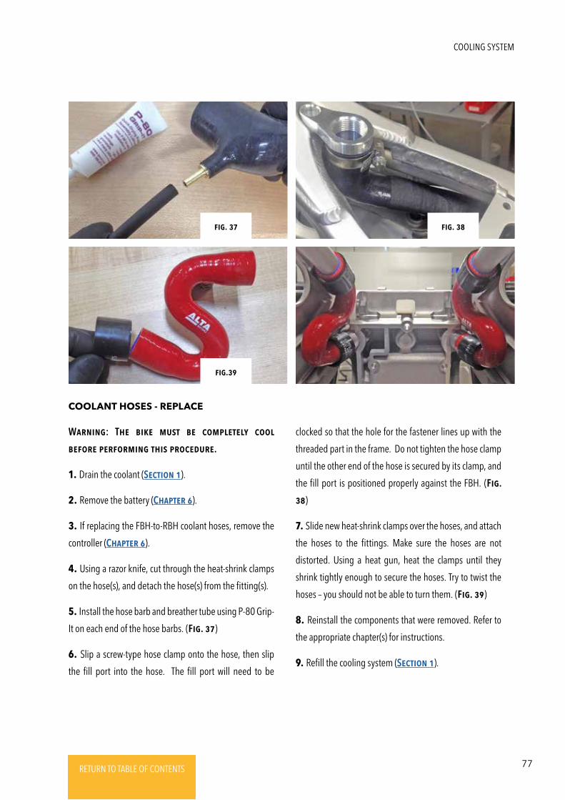
77RETURN TO TABLE OF CONTENTSRETURN TO TABLE OF CONTENTSRETURN TO TABLE OF CONTENTSRETURN TO TABLE OF CONTENTSRETURN TO TABLE OF CONTENTS RETURN TO TABLE OF CONTENTS
COOLANT HOSES - REPLACE
WaRNiNg: ThE bikE must bE complEtEly cool
bEFoRE pERFoRmiNg this pRocEduRE.
1. Drain the coolant (SEctioN 1).
2. Remove the battery (ChaptER 6).
3. If replacing the FBH-to-RBH coolant hoses, remove the
controller (ChaptER 6).
4. Using a razor knife, cut through the heat-shrink clamps
on the hose(s), and detach the hose(s) from the fitting(s).
5. Install the hose barb and breather tube using P-80 Grip-
It on each end of the hose barbs. (Fig. 37)
6. Slip a screw-type hose clamp onto the hose, then slip
the fill port into the hose. The fill port will need to be
clocked so that the hole for the fastener lines up with the
threaded part in the frame. Do not tighten the hose clamp
until the other end of the hose is secured by its clamp, and
the fill port is positioned properly against the FBH. (Fig.
38)
7. Slide new heat-shrink clamps over the hoses, and attach
the hoses to the fittings. Make sure the hoses are not
distorted. Using a heat gun, heat the clamps until they
shrink tightly enough to secure the hoses. Try to twist the
hoses – you should not be able to turn them. (Fig. 39)
8. Reinstall the components that were removed. Refer to
the appropriate chapter(s) for instructions.
9. Refill the cooling system (SEctioN 1).
Fig. 37 Fig. 38
Fig.39
COOLING SYSTEM
78 RETURN TO TABLE OF CONTENTSRETURN TO TABLE OF CONTENTSRETURN TO TABLE OF CONTENTSRETURN TO TABLE OF CONTENTSRETURN TO TABLE OF CONTENTS RETURN TO TABLE OF CONTENTS
CHAPTER 6
HIGH VOLTAGE BATTERY & DRIVE SYSTEM
The HV battery and drive system operate up to 400V
DC. The system can be “live” while the vehicle is
powered on and for up several minutes after the
vehicle is powered off.
Never assume that a connector or electrical
component is safe to handle; use a 600V-rated
multimeter to check the potential between HV
connector terminals, and between each terminal
and bare metal on the vehicle chassis or battery to
ensure that they are not “hot.” Any potential above
60V should be considered dangerous high voltage
and should not be handled without appropriate high
voltage safety gear and extreme caution. Contact
Alta Motors for further instructions.
Make sure that the run/stop switch is set to the “stop”
position before separating connectors or starting
disassembly. When the EV drive system is partially
disassembled, do not attempt to connect to AC or a
charger, and do not attempt to operate the vehicle.
It may be necessary to turn on the vehicle’s 12V
system to assist with diagnosis; be careful of loose
connections or metal parts that could cause a short
circuit and damage components.
The HV battery pack is always energized and should
not be opened for any reason. If the pack appears
physically damaged or the outer surface is breached,
contact Alta Motors immediately for handling
instructions. Please be able to provide images of the
damage in question.
Authorized Alta Motors service personnel are
authorized to disconnect the orange HV connectors
and the 3 motor lead ring terminal connections
inside the inverter. They are not authorized to make
or break any other HV electrical connections or to
open any other HV drive system components.
Before re-connecting HV drive system components,
inspect both ends of each HV connector for signs of
heat damage, bent terminals, or damaged plating,
dirt, grease, water, or any other debris. Compressed
air and isopropyl alcohol may be used to clean
connectors; allow them to dry completely before
reconnecting. If terminal plating is damaged or signs
of heat damage are present, leave the connector
unmated, and contact Alta Motors.
Whenever servicing electrical control system
components on the Redshift, wear a ground strap
on your wrist, and connect it to a ground on the
bike. Failure to do so could result in static electricity
discharge damage to the components.
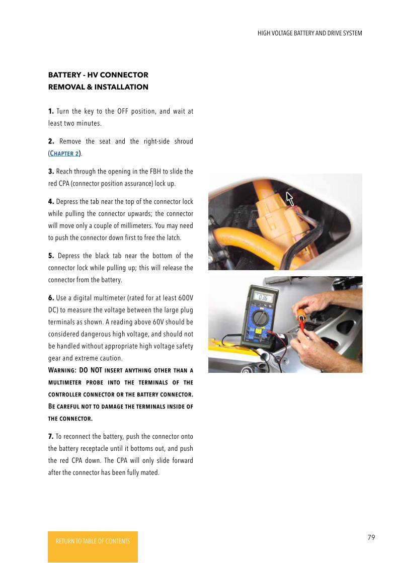
79RETURN TO TABLE OF CONTENTSRETURN TO TABLE OF CONTENTSRETURN TO TABLE OF CONTENTSRETURN TO TABLE OF CONTENTSRETURN TO TABLE OF CONTENTS RETURN TO TABLE OF CONTENTS
HIGH VOLTAGE BATTERY AND DRIVE SYSTEM
1. Turn the key to the OFF position, and wait at
least two minutes.
2. Remove the seat and the right-side shroud
(ChaptER 2).
3. Reach through the opening in the FBH to slide the
red CPA (connector position assurance) lock up.
4. Depress the tab near the top of the connector lock
while pulling the connector upwards; the connector
will move only a couple of millimeters. You may need
to push the connector down first to free the latch.
5. Depress the black tab near the bottom of the
connector lock while pulling up; this will release the
connector from the battery.
6. Use a digital multimeter (rated for at least 600V
DC) to measure the voltage between the large plug
terminals as shown. A reading above 60V should be
considered dangerous high voltage, and should not
be handled without appropriate high voltage safety
gear and extreme caution.
WaRNiNg: DO NOT iNsERt aNythiNg othER thaN a
multimEtER pRobE iNto thE tERmiNals oF thE
coNtRollER coNNEctoR oR thE battERy coNNEctoR.
BE caREFul Not to damagE thE tERmiNals iNsidE oF
thE coNNEctoR.
7. To reconnect the battery, push the connector onto
the battery receptacle until it bottoms out, and push
the red CPA down. The CPA will only slide forward
after the connector has been fully mated.
BATTERY - HV CONNECTOR
REMOVAL & INSTALLATION
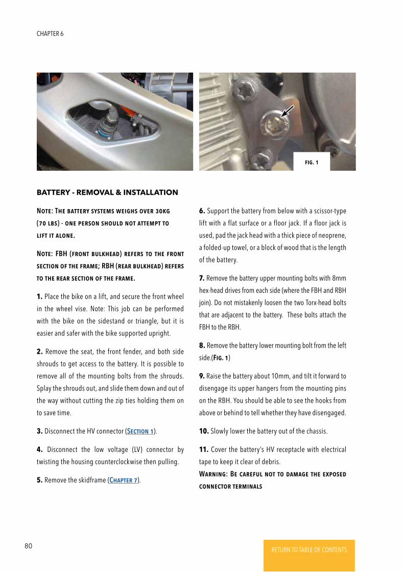
80 RETURN TO TABLE OF CONTENTSRETURN TO TABLE OF CONTENTSRETURN TO TABLE OF CONTENTSRETURN TO TABLE OF CONTENTSRETURN TO TABLE OF CONTENTS RETURN TO TABLE OF CONTENTS
BATTERY - REMOVAL & INSTALLATION
1. Place the bike on a lift, and secure the front wheel
in the wheel vise. Note: This job can be performed
with the bike on the sidestand or triangle, but it is
easier and safer with the bike supported upright.
2. Remove the seat, the front fender, and both side
shrouds to get access to the battery. It is possible to
remove all of the mounting bolts from the shrouds.
Splay the shrouds out, and slide them down and out of
the way without cutting the zip ties holding them on
to save time.
3. Disconnect the HV connector (SEctioN 1).
4. Disconnect the low voltage (LV) connector by
twisting the housing counterclockwise then pulling.
5. Remove the skidframe (ChaptER 7).
NotE: ThE battERy systEms wEighs oVER 30kg
(70 lbs) - oNE pERsoN should Not attEmpt to
liFt it aloNE.
NotE: FBH (FRoNt bulkhEad) REFERs to thE FRoNt
sEctioN oF thE FRamE; RBH (REaR bulkhEad) REFERs
to thE REaR sEctioN oF thE FRamE.
6. Support the battery from below with a scissor-type
lift with a flat surface or a floor jack. If a floor jack is
used, pad the jack head with a thick piece of neoprene,
a folded-up towel, or a block of wood that is the length
of the battery.
7. Remove the battery upper mounting bolts with 8mm
hex-head drives from each side (where the FBH and RBH
join). Do not mistakenly loosen the two Torx-head bolts
that are adjacent to the battery. These bolts attach the
FBH to the RBH.
8. Remove the battery lower mounting bolt from the left
side.(Fig. 1)
9. Raise the battery about 10mm, and tilt it forward to
disengage its upper hangers from the mounting pins
on the RBH. You should be able to see the hooks from
above or behind to tell whether they have disengaged.
10. Slowly lower the battery out of the chassis.
11. Cover the battery’s HV receptacle with electrical
tape to keep it clear of debris.
WaRNiNg: BE caREFul Not to damagE thE ExposEd
coNNEctoR tERmiNals
Fig. 1
CHAPTER 6
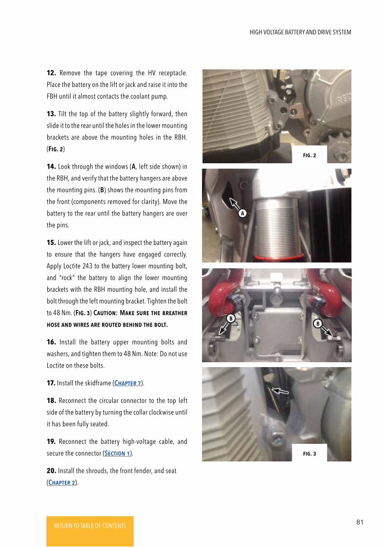
81RETURN TO TABLE OF CONTENTSRETURN TO TABLE OF CONTENTSRETURN TO TABLE OF CONTENTSRETURN TO TABLE OF CONTENTSRETURN TO TABLE OF CONTENTS RETURN TO TABLE OF CONTENTS
12. Remove the tape covering the HV receptacle.
Place the battery on the lift or jack and raise it into the
FBH until it almost contacts the coolant pump.
13. Tilt the top of the battery slightly forward, then
slide it to the rear until the holes in the lower mounting
brackets are above the mounting holes in the RBH.
(Fig. 2)
14. Look through the windows (A, left side shown) in
the RBH, and verify that the battery hangers are above
the mounting pins. (B) shows the mounting pins from
the front (components removed for clarity). Move the
battery to the rear until the battery hangers are over
the pins.
15. Lower the lift or jack, and inspect the battery again
to ensure that the hangers have engaged correctly.
Apply Loctite 243 to the battery lower mounting bolt,
and “rock” the battery to align the lower mounting
brackets with the RBH mounting hole, and install the
bolt through the left mounting bracket. Tighten the bolt
to 48 Nm. (Fig. 3) CautioN: MakE suRE thE bREathER
hosE aNd wiREs aRE RoutEd bEhiNd thE bolt.
16. Install the battery upper mounting bolts and
washers, and tighten them to 48 Nm. Note: Do not use
Loctite on these bolts.
17. Install the skidframe (ChaptER 7).
18. Reconnect the circular connector to the top left
side of the battery by turning the collar clockwise until
it has been fully seated.
19. Reconnect the battery high-voltage cable, and
secure the connector (SEctioN 1).
20. Install the shrouds, the front fender, and seat
(ChaptER 2).
Fig. 2
Fig. 3
HIGH VOLTAGE BATTERY AND DRIVE SYSTEM
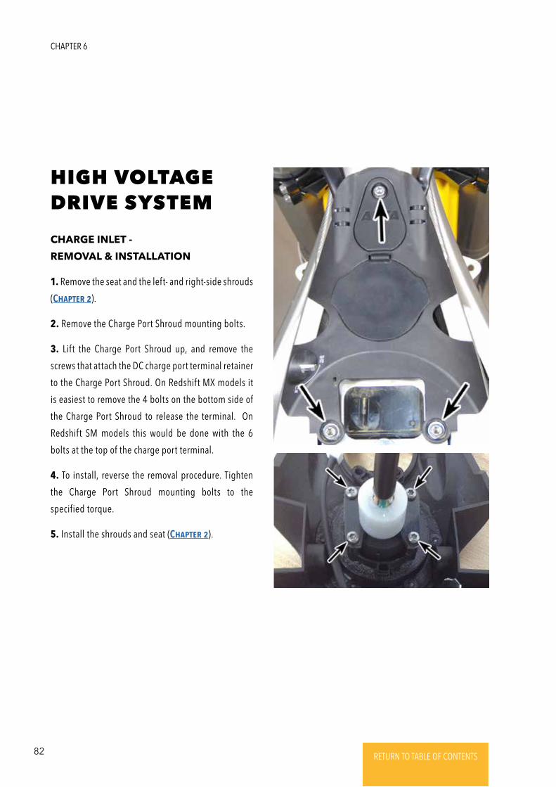
82 RETURN TO TABLE OF CONTENTSRETURN TO TABLE OF CONTENTSRETURN TO TABLE OF CONTENTSRETURN TO TABLE OF CONTENTSRETURN TO TABLE OF CONTENTS RETURN TO TABLE OF CONTENTS
HIGH VOLTAGE DRIVE SYSTEM
CHARGE INLET -
REMOVAL & INSTALLATION
1. Remove the seat and the left- and right-side shrouds
(ChaptER 2).
2. Remove the Charge Port Shroud mounting bolts.
3. Lift the Charge Port Shroud up, and remove the
screws that attach the DC charge port terminal retainer
to the Charge Port Shroud. On Redshift MX models it
is easiest to remove the 4 bolts on the bottom side of
the Charge Port Shroud to release the terminal. On
Redshift SM models this would be done with the 6
bolts at the top of the charge port terminal.
4. To install, reverse the removal procedure. Tighten
the Charge Port Shroud mounting bolts to the
specified torque.
5. Install the shrouds and seat (ChaptER 2).
CHAPTER 6
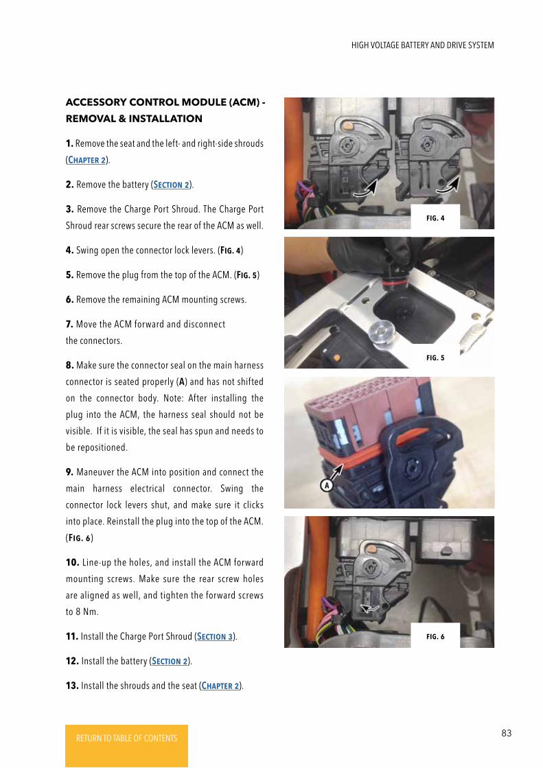
83RETURN TO TABLE OF CONTENTSRETURN TO TABLE OF CONTENTSRETURN TO TABLE OF CONTENTSRETURN TO TABLE OF CONTENTSRETURN TO TABLE OF CONTENTS RETURN TO TABLE OF CONTENTS
ACCESSORY CONTROL MODULE (ACM) -
REMOVAL & INSTALLATION
1. Remove the seat and the left- and right-side shrouds
(ChaptER 2).
2. Remove the battery (SEctioN 2).
3. Remove the Charge Port Shroud. The Charge Port
Shroud rear screws secure the rear of the ACM as well.
4. Swing open the connector lock levers. (Fig. 4)
5. Remove the plug from the top of the ACM. (Fig. 5)
6. Remove the remaining ACM mounting screws.
7. Move the ACM forward and disconnect
the connectors.
8. Make sure the connector seal on the main harness
connector is seated properly (A) and has not shifted
on the connector body. Note: After installing the
plug into the ACM, the harness seal should not be
visible. If it is visible, the seal has spun and needs to
be repositioned.
9. Maneuver the ACM into position and connect the
main harness electrical connector. Swing the
connector lock levers shut, and make sure it clicks
into place. Reinstall the plug into the top of the ACM.
(Fig. 6)
10. Line-up the holes, and install the ACM forward
mounting screws. Make sure the rear screw holes
are aligned as well, and tighten the forward screws
to 8 Nm.
11. Install the Charge Port Shroud (SEctioN 3).
12. Install the battery (SEctioN 2).
13. Install the shrouds and the seat (ChaptER 2).
Fig. 4
Fig. 5
Fig. 6
HIGH VOLTAGE BATTERY AND DRIVE SYSTEM
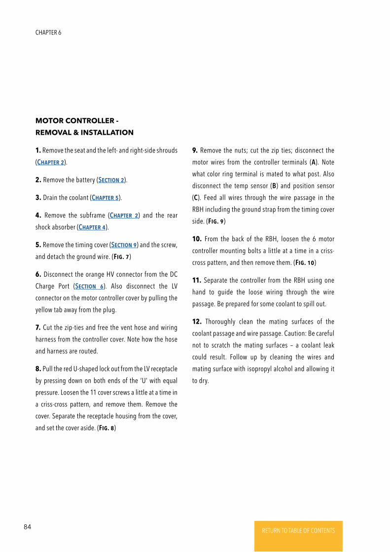
84 RETURN TO TABLE OF CONTENTSRETURN TO TABLE OF CONTENTSRETURN TO TABLE OF CONTENTSRETURN TO TABLE OF CONTENTSRETURN TO TABLE OF CONTENTS RETURN TO TABLE OF CONTENTS
MOTOR CONTROLLER -
REMOVAL & INSTALLATION
1. Remove the seat and the left- and right-side shrouds
(ChaptER 2).
2. Remove the battery (SEctioN 2).
3. Drain the coolant (ChaptER 5).
4. Remove the subframe (ChaptER 2) and the rear
shock absorber (ChaptER 4).
5. Remove the timing cover (SEctioN 9) and the screw,
and detach the ground wire. (Fig. 7)
6. Disconnect the orange HV connector from the DC
Charge Port (SEctioN 6). Also disconnect the LV
connector on the motor controller cover by pulling the
yellow tab away from the plug.
7. Cut the zip-ties and free the vent hose and wiring
harness from the controller cover. Note how the hose
and harness are routed.
8. Pull the red U-shaped lock out from the LV receptacle
by pressing down on both ends of the ‘U’ with equal
pressure. Loosen the 11 cover screws a little at a time in
a criss-cross pattern, and remove them. Remove the
cover. Separate the receptacle housing from the cover,
and set the cover aside. (Fig. 8)
9. Remove the nuts; cut the zip ties; disconnect the
motor wires from the controller terminals (A). Note
what color ring terminal is mated to what post. Also
disconnect the temp sensor (B) and position sensor
(C). Feed all wires through the wire passage in the
RBH including the ground strap from the timing cover
side. (Fig. 9)
10. From the back of the RBH, loosen the 6 motor
controller mounting bolts a little at a time in a criss-
cross pattern, and then remove them. (Fig. 10)
11. Separate the controller from the RBH using one
hand to guide the loose wiring through the wire
passage. Be prepared for some coolant to spill out.
12. Thoroughly clean the mating surfaces of the
coolant passage and wire passage. Caution: Be careful
not to scratch the mating surfaces – a coolant leak
could result. Follow up by cleaning the wires and
mating surface with isopropyl alcohol and allowing it
to dry.
CHAPTER 6
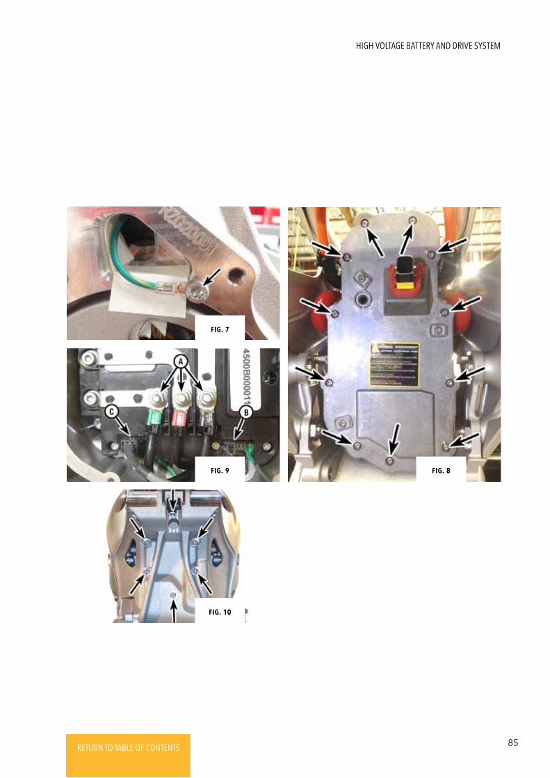
85RETURN TO TABLE OF CONTENTSRETURN TO TABLE OF CONTENTSRETURN TO TABLE OF CONTENTSRETURN TO TABLE OF CONTENTSRETURN TO TABLE OF CONTENTS RETURN TO TABLE OF CONTENTS
Fig. 34Fig. 9
Fig. 7
Fig. 8
Fig. 10
HIGH VOLTAGE BATTERY AND DRIVE SYSTEM
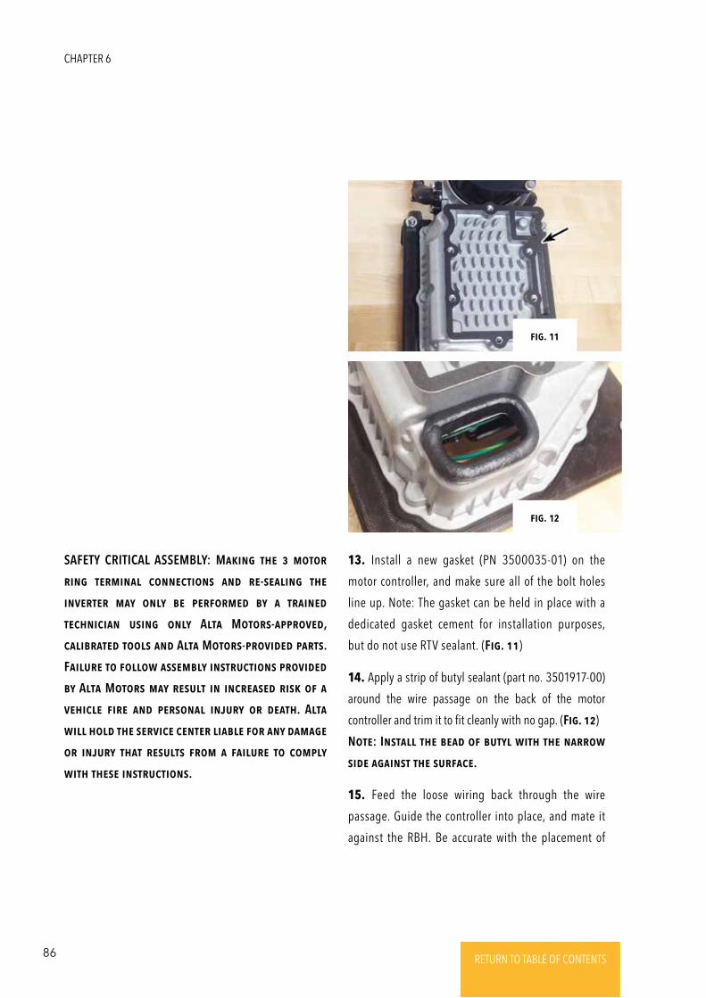
86 RETURN TO TABLE OF CONTENTSRETURN TO TABLE OF CONTENTSRETURN TO TABLE OF CONTENTSRETURN TO TABLE OF CONTENTSRETURN TO TABLE OF CONTENTS RETURN TO TABLE OF CONTENTS
13. Install a new gasket (PN 3500035-01) on the
motor controller, and make sure all of the bolt holes
line up. Note: The gasket can be held in place with a
dedicated gasket cement for installation purposes,
but do not use RTV sealant. (Fig. 11)
14. Apply a strip of butyl sealant (part no. 3501917-00)
around the wire passage on the back of the motor
controller and trim it to fit cleanly with no gap. (Fig. 12)
NotE: INstall thE bEad oF butyl with thE NaRRow
sidE agaiNst thE suRFacE.
15. Feed the loose wiring back through the wire
passage. Guide the controller into place, and mate it
against the RBH. Be accurate with the placement of
SAFETY CRITICAL ASSEMBLY: MakiNg thE 3 motoR
RiNg tERmiNal coNNEctioNs aNd RE-sEaliNg thE
iNVERtER may oNly bE pERFoRmEd by a tRaiNEd
tEchNiciaN usiNg oNly Alta MotoRs-appRoVEd,
calibRatEd tools aNd Alta MotoRs-pRoVidEd paRts.
FailuRE to Follow assEmbly iNstRuctioNs pRoVidEd
by Alta MotoRs may REsult iN iNcREasEd Risk oF a
VEhiclE FiRE aNd pERsoNal iNjuRy oR dEath. Alta
will hold thE sERVicE cENtER liablE FoR aNy damagE
oR iNjuRy that REsults FRom a FailuRE to comply
with thEsE iNstRuctioNs.
Fig. 11
Fig. 12
CHAPTER 6
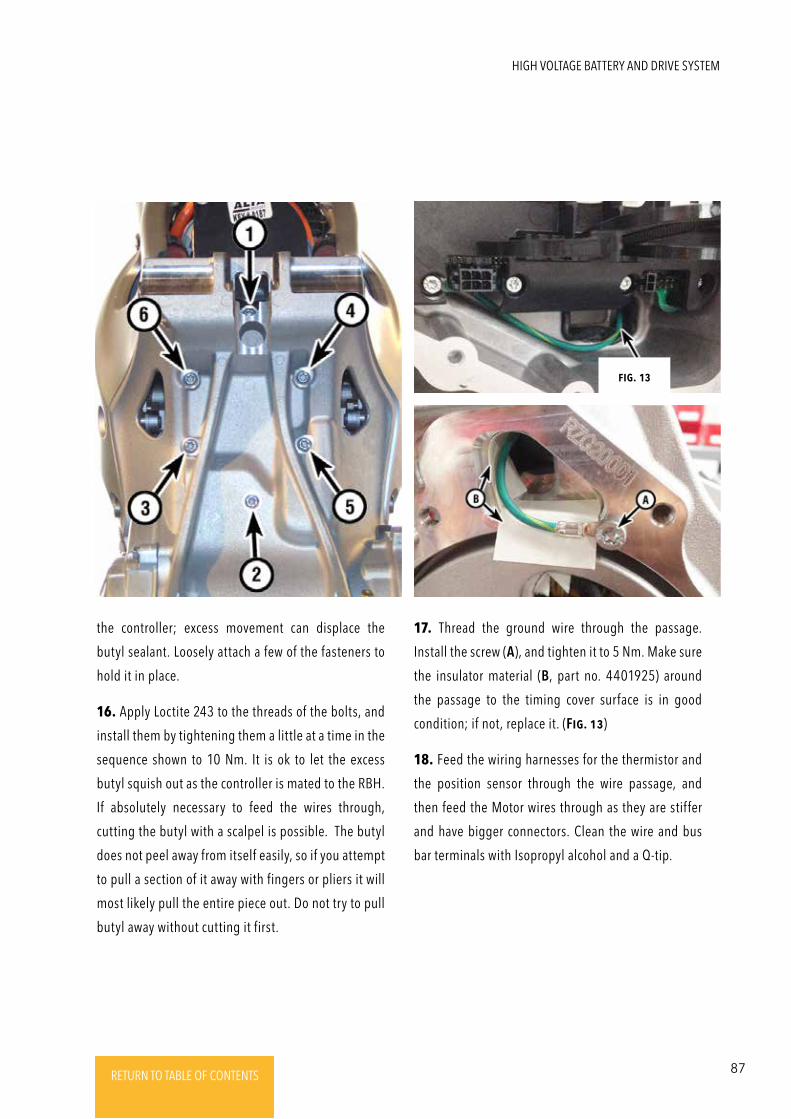
87RETURN TO TABLE OF CONTENTSRETURN TO TABLE OF CONTENTSRETURN TO TABLE OF CONTENTSRETURN TO TABLE OF CONTENTSRETURN TO TABLE OF CONTENTS RETURN TO TABLE OF CONTENTS
the controller; excess movement can displace the
butyl sealant. Loosely attach a few of the fasteners to
hold it in place.
16. Apply Loctite 243 to the threads of the bolts, and
install them by tightening them a little at a time in the
sequence shown to 10 Nm. It is ok to let the excess
butyl squish out as the controller is mated to the RBH.
If absolutely necessary to feed the wires through,
cutting the butyl with a scalpel is possible. The butyl
does not peel away from itself easily, so if you attempt
to pull a section of it away with fingers or pliers it will
most likely pull the entire piece out. Do not try to pull
butyl away without cutting it first.
17. Thread the ground wire through the passage.
Install the screw (A), and tighten it to 5 Nm. Make sure
the insulator material (B, part no. 4401925) around
the passage to the timing cover surface is in good
condition; if not, replace it. (Fig. 13)
18. Feed the wiring harnesses for the thermistor and
the position sensor through the wire passage, and
then feed the Motor wires through as they are stiffer
and have bigger connectors. Clean the wire and bus
bar terminals with Isopropyl alcohol and a Q-tip.
Fig. 13
HIGH VOLTAGE BATTERY AND DRIVE SYSTEM
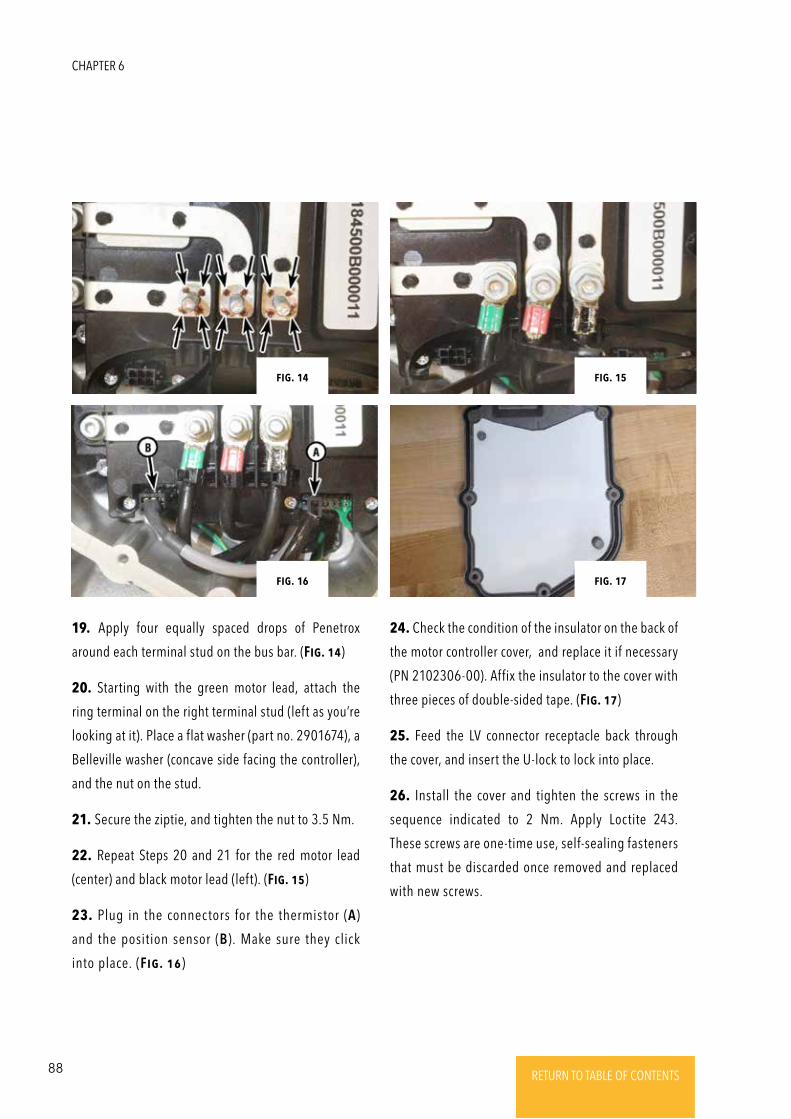
88 RETURN TO TABLE OF CONTENTSRETURN TO TABLE OF CONTENTSRETURN TO TABLE OF CONTENTSRETURN TO TABLE OF CONTENTSRETURN TO TABLE OF CONTENTS RETURN TO TABLE OF CONTENTS
19. Apply four equally spaced drops of Penetrox
around each terminal stud on the bus bar. (Fig. 14)
20. Starting with the green motor lead, attach the
ring terminal on the right terminal stud (left as you’re
looking at it). Place a flat washer (part no. 2901674), a
Belleville washer (concave side facing the controller),
and the nut on the stud.
21. Secure the ziptie, and tighten the nut to 3.5 Nm.
22. Repeat Steps 20 and 21 for the red motor lead
(center) and black motor lead (left). (Fig. 15)
23. Plug in the connectors for the thermistor (A)
and the position sensor (B). Make sure they click
into place. (Fig. 16)
24. Check the condition of the insulator on the back of
the motor controller cover, and replace it if necessary
(PN 2102306-00). Affix the insulator to the cover with
three pieces of double-sided tape. (Fig. 17)
25. Feed the LV connector receptacle back through
the cover, and insert the U-lock to lock into place.
26. Install the cover and tighten the screws in the
sequence indicated to 2 Nm. Apply Loctite 243.
These screws are one-time use, self-sealing fasteners
that must be discarded once removed and replaced
with new screws.
Fig. 15Fig. 14
Fig. 17Fig. 16
CHAPTER 6
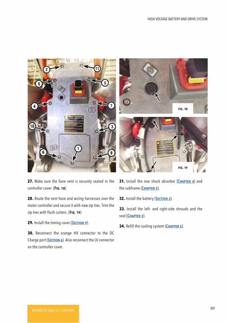
89RETURN TO TABLE OF CONTENTSRETURN TO TABLE OF CONTENTSRETURN TO TABLE OF CONTENTSRETURN TO TABLE OF CONTENTSRETURN TO TABLE OF CONTENTS RETURN TO TABLE OF CONTENTS
27. Make sure the Gore vent is securely seated in the
controller cover. (Fig. 18)
28. Route the vent hose and wiring harnesses over the
motor controller and secure it with new zip-ties. Trim the
zip-ties with flush cutters. (Fig. 19)
29. Install the timing cover (SEctioN 9).
30. Reconnect the orange HV connector to the DC
Charge port (SEctioN 6). Also reconnect the LV connector
on the controller cover.
31. Install the rear shock absorber (ChaptER 4) and
the subframe (ChaptER 2).
32. Install the battery (SEctioN 2).
33. Install the left- and right-side shrouds and the
seat (ChaptER 2).
34. Refill the cooling system (ChaptER 5).
Fig. 18
Fig. 19
HIGH VOLTAGE BATTERY AND DRIVE SYSTEM
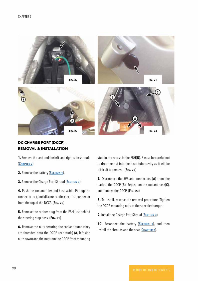
90 RETURN TO TABLE OF CONTENTSRETURN TO TABLE OF CONTENTSRETURN TO TABLE OF CONTENTSRETURN TO TABLE OF CONTENTSRETURN TO TABLE OF CONTENTS RETURN TO TABLE OF CONTENTS
DC CHARGE PORT (DCCP) -
REMOVAL & INSTALLATION
1. Remove the seat and the left- and right-side shrouds
(ChaptER 2).
2. Remove the battery (SEctioN 1).
3. Remove the Charge Port Shroud (SEctioN 3).
4. Push the coolant filler and hose aside. Pull up the
connector lock, and disconnect the electrical connector
from the top of the DCCP. (Fig. 20)
5. Remove the rubber plug from the FBH just behind
the steering stop boss. (Fig. 21)
6. Remove the nuts securing the coolant pump (they
are threaded onto the DCCP rear studs) (A, left-side
nut shown) and the nut from the DCCP front mounting
Fig. 20 Fig. 21
Fig. 23Fig. 22
stud in the recess in the FBH(B). Please be careful not
to drop the nut into the head tube cavity as it will be
difficult to remove. (Fig. 22)
7. Disconnect the HV and connectors (A) from the
back of the DCCP (B). Reposition the coolant hose(C),
and remove the DCCP. (Fig. 23)
8. To install, reverse the removal procedure. Tighten
the DCCP mounting nuts to the specified torque.
9. Install the Charge Port Shroud (SEctioN 3).
10. Reconnect the battery (SEctioN 1), and then
install the shrouds and the seat (ChaptER 2).
CHAPTER 6
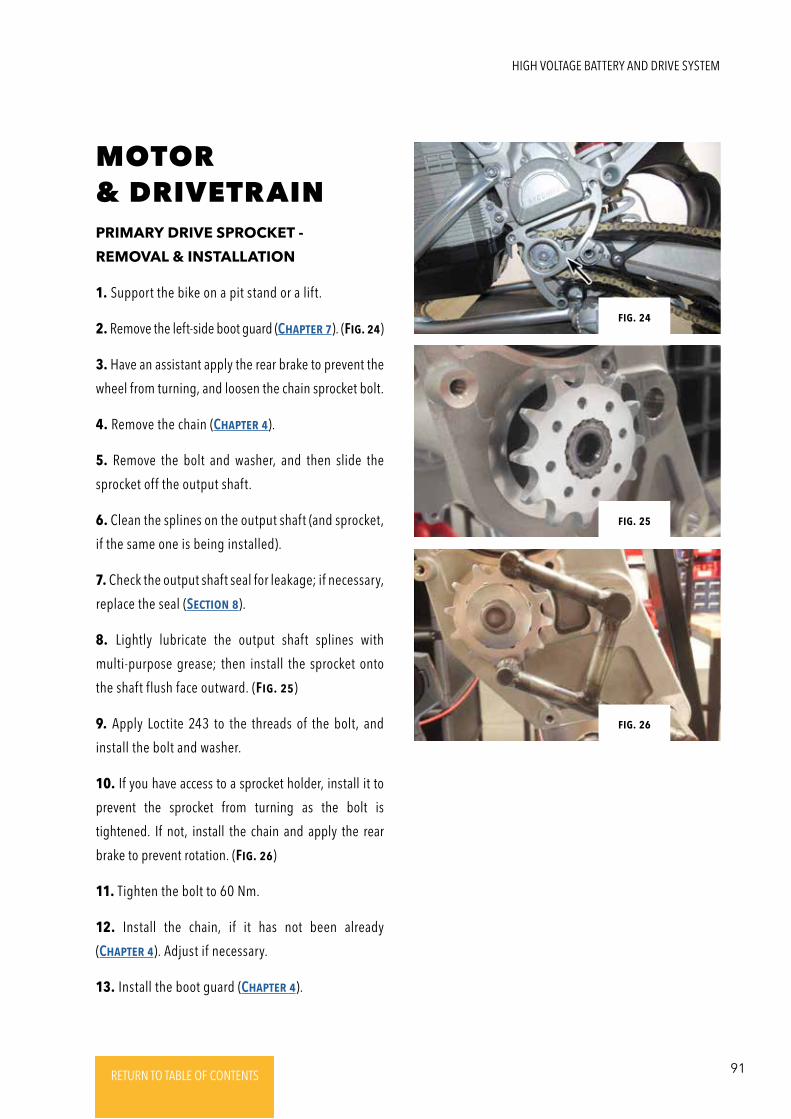
91RETURN TO TABLE OF CONTENTSRETURN TO TABLE OF CONTENTSRETURN TO TABLE OF CONTENTSRETURN TO TABLE OF CONTENTSRETURN TO TABLE OF CONTENTS RETURN TO TABLE OF CONTENTS
PRIMARY DRIVE SPROCKET -
REMOVAL & INSTALLATION
1. Support the bike on a pit stand or a lift.
2. Remove the left-side boot guard (ChaptER 7). (Fig. 24)
3. Have an assistant apply the rear brake to prevent the
wheel from turning, and loosen the chain sprocket bolt.
4. Remove the chain (ChaptER 4).
5. Remove the bolt and washer, and then slide the
sprocket off the output shaft.
6. Clean the splines on the output shaft (and sprocket,
if the same one is being installed).
7. Check the output shaft seal for leakage; if necessary,
replace the seal (SEctioN 8).
8. Lightly lubricate the output shaft splines with
multi-purpose grease; then install the sprocket onto
the shaft flush face outward. (Fig. 25)
9. Apply Loctite 243 to the threads of the bolt, and
install the bolt and washer.
10. If you have access to a sprocket holder, install it to
prevent the sprocket from turning as the bolt is
tightened. If not, install the chain and apply the rear
brake to prevent rotation. (Fig. 26)
11. Tighten the bolt to 60 Nm.
12. Install the chain, if it has not been already
(ChaptER 4). Adjust if necessary.
13. Install the boot guard (ChaptER 4).
Fig. 24
Fig. 25
Fig. 26
MOTOR & DRIVETRAIN
HIGH VOLTAGE BATTERY AND DRIVE SYSTEM
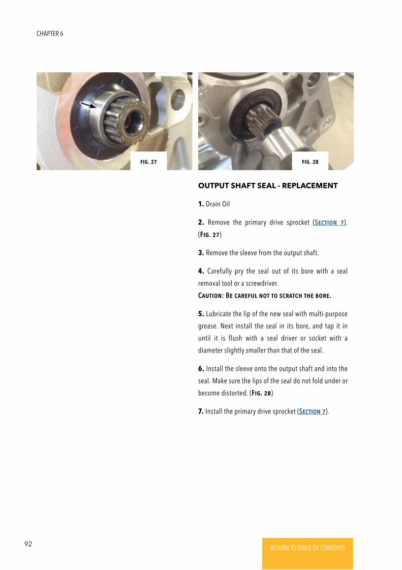
92 RETURN TO TABLE OF CONTENTSRETURN TO TABLE OF CONTENTSRETURN TO TABLE OF CONTENTSRETURN TO TABLE OF CONTENTSRETURN TO TABLE OF CONTENTS RETURN TO TABLE OF CONTENTS
OUTPUT SHAFT SEAL - REPLACEMENT
1. Drain Oil
2. Remove the primary drive sprocket (SEctioN 7).
(Fig. 27)
3. Remove the sleeve from the output shaft.
4. Carefully pry the seal out of its bore with a seal
removal tool or a screwdriver.
CautioN: BE caREFul Not to scRatch thE boRE.
5. Lubricate the lip of the new seal with multi-purpose
grease. Next install the seal in its bore, and tap it in
until it is flush with a seal driver or socket with a
diameter slightly smaller than that of the seal.
6. Install the sleeve onto the output shaft and into the
seal. Make sure the lips of the seal do not fold under or
become distorted. (Fig. 28)
7. Install the primary drive sprocket (SEctioN 7).
Fig. 27 Fig. 28
CHAPTER 6
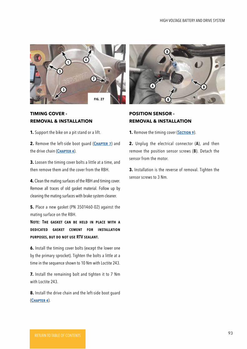
93RETURN TO TABLE OF CONTENTSRETURN TO TABLE OF CONTENTSRETURN TO TABLE OF CONTENTSRETURN TO TABLE OF CONTENTSRETURN TO TABLE OF CONTENTS RETURN TO TABLE OF CONTENTS
TIMING COVER -
REMOVAL & INSTALLATION
POSITION SENSOR -
REMOVAL & INSTALLATION
1. Support the bike on a pit stand or a lift.
2. Remove the left-side boot guard (ChaptER 7) and
the drive chain (ChaptER 4).
3. Loosen the timing cover bolts a little at a time, and
then remove them and the cover from the RBH.
4. Clean the mating surfaces of the RBH and timing cover.
Remove all traces of old gasket material. Follow up by
cleaning the mating surfaces with brake system cleaner.
5. Place a new gasket (PN 3501460-02) against the
mating surface on the RBH.
NotE: ThE gaskEt caN bE hEld iN placE with a
dEdicatEd gaskEt cEmENt FoR iNstallatioN
puRposEs, but do Not usE RTV sEalaNt.
6. Install the timing cover bolts (except the lower one
by the primary sprocket). Tighten the bolts a little at a
time in the sequence shown to 10 Nm with Loctite 243.
7. Install the remaining bolt and tighten it to 7 Nm
with Loctite 243.
8. Install the drive chain and the left-side boot guard
(ChaptER 4).
1. Remove the timing cover (SEctioN 9).
2. Unplug the electrical connector (A), and then
remove the position sensor screws (B). Detach the
sensor from the motor.
3. Installation is the reverse of removal. Tighten the
sensor screws to 3 Nm.
Fig. 27
HIGH VOLTAGE BATTERY AND DRIVE SYSTEM
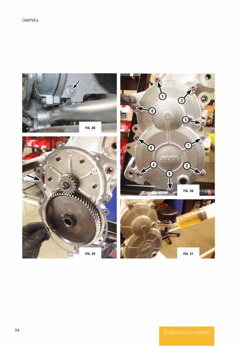
94 RETURN TO TABLE OF CONTENTSRETURN TO TABLE OF CONTENTSRETURN TO TABLE OF CONTENTSRETURN TO TABLE OF CONTENTSRETURN TO TABLE OF CONTENTS RETURN TO TABLE OF CONTENTS
Fig. 28
Fig. 29 Fig. 31
Fig. 30
CHAPTER 6
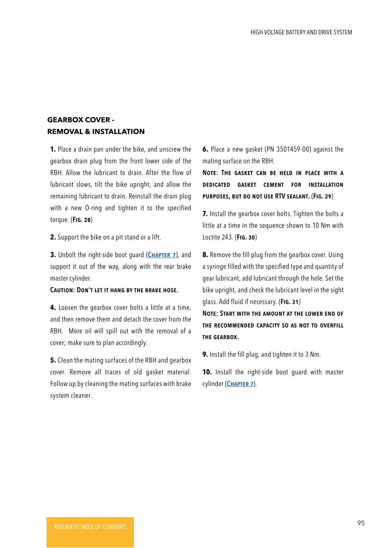
95RETURN TO TABLE OF CONTENTSRETURN TO TABLE OF CONTENTSRETURN TO TABLE OF CONTENTSRETURN TO TABLE OF CONTENTSRETURN TO TABLE OF CONTENTS RETURN TO TABLE OF CONTENTS
GEARBOX COVER -
REMOVAL & INSTALLATION
1. Place a drain pan under the bike, and unscrew the
gearbox drain plug from the front lower side of the
RBH. Allow the lubricant to drain. After the flow of
lubricant slows, tilt the bike upright, and allow the
remaining lubricant to drain. Reinstall the drain plug
with a new O-ring and tighten it to the specified
torque. (Fig. 28)
2. Support the bike on a pit stand or a lift.
3. Unbolt the right-side boot guard (ChaptER 7), and
support it out of the way, along with the rear brake
master cylinder.
CautioN: DoN’t lEt it haNg by thE bRakE hosE.
4. Loosen the gearbox cover bolts a little at a time,
and then remove them and detach the cover from the
RBH. More oil will spill out with the removal of a
cover; make sure to plan accordingly.
5. Clean the mating surfaces of the RBH and gearbox
cover. Remove all traces of old gasket material.
Follow up by cleaning the mating surfaces with brake
system cleaner.
6. Place a new gasket (PN 3501459-00) against the
mating surface on the RBH.
NotE: ThE gaskEt caN bE hEld iN placE with a
dEdicatEd gaskEt cEmENt FoR iNstallatioN
puRposEs, but do Not usE RTV sEalaNt. (Fig. 29)
7. Install the gearbox cover bolts. Tighten the bolts a
little at a time in the sequence shown to 10 Nm with
Loctite 243. (Fig. 30)
8. Remove the fill plug from the gearbox cover. Using
a syringe filled with the specified type and quantity of
gear lubricant, add lubricant through the hole. Set the
bike upright, and check the lubricant level in the sight
glass. Add fluid if necessary. (Fig. 31)
NotE: StaRt with thE amouNt at thE lowER ENd oF
thE REcommENdEd capacity so as Not to oVERFill
thE gEaRbox.
9. Install the fill plug, and tighten it to 3 Nm.
10. Install the right-side boot guard with master
cylinder (ChaptER 7).
HIGH VOLTAGE BATTERY AND DRIVE SYSTEM
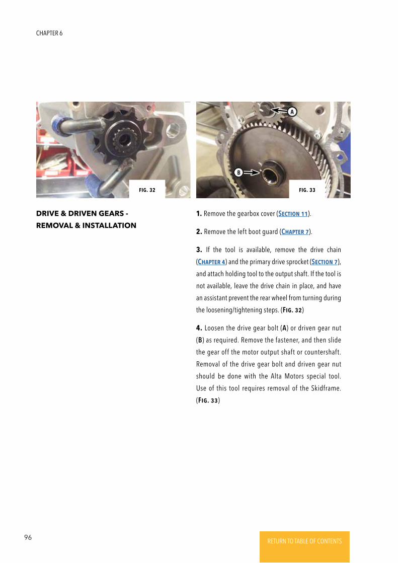
96 RETURN TO TABLE OF CONTENTSRETURN TO TABLE OF CONTENTSRETURN TO TABLE OF CONTENTSRETURN TO TABLE OF CONTENTSRETURN TO TABLE OF CONTENTS RETURN TO TABLE OF CONTENTS
DRIVE & DRIVEN GEARS -
REMOVAL & INSTALLATION
1. Remove the gearbox cover (SEctioN 11).
2. Remove the left boot guard (ChaptER 7).
3. If the tool is available, remove the drive chain
(ChaptER 4) and the primary drive sprocket (SEctioN 7),
and attach holding tool to the output shaft. If the tool is
not available, leave the drive chain in place, and have
an assistant prevent the rear wheel from turning during
the loosening/tightening steps. (Fig. 32)
4. Loosen the drive gear bolt (A) or driven gear nut
(B) as required. Remove the fastener, and then slide
the gear off the motor output shaft or countershaft.
Removal of the drive gear bolt and driven gear nut
should be done with the Alta Motors special tool.
Use of this tool requires removal of the Skidframe.
(Fig. 33)
Fig. 32 Fig. 33
CHAPTER 6
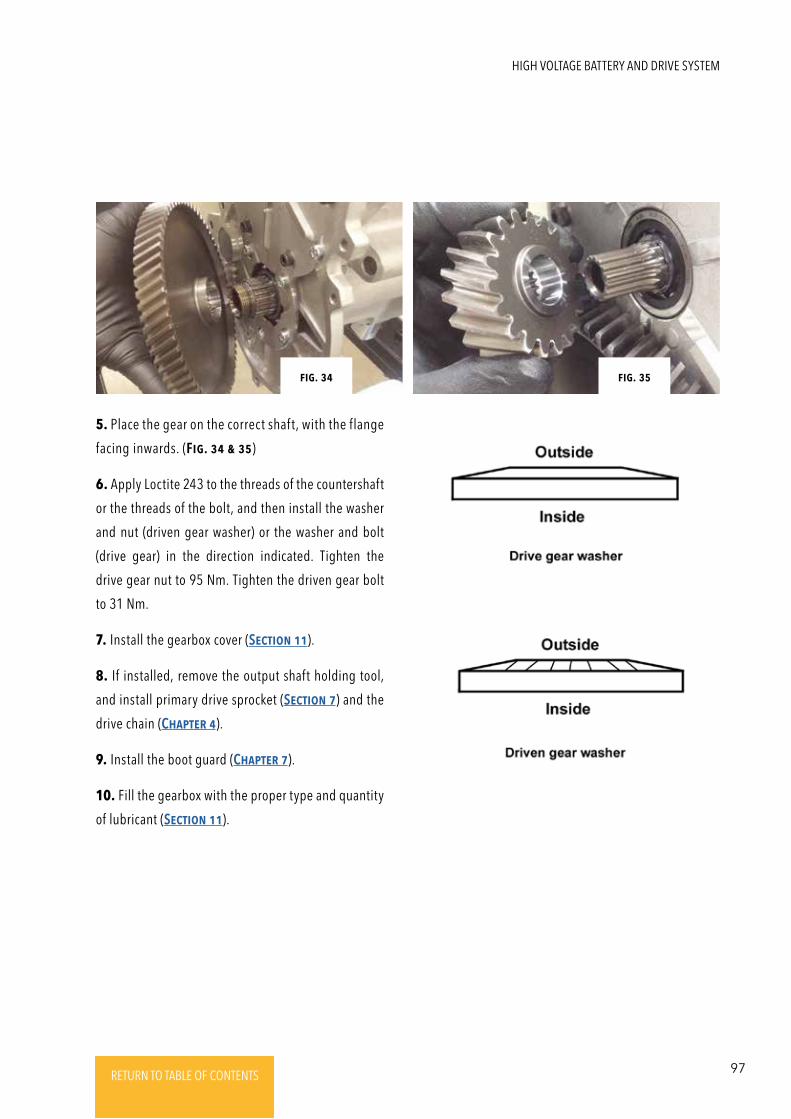
97RETURN TO TABLE OF CONTENTSRETURN TO TABLE OF CONTENTSRETURN TO TABLE OF CONTENTSRETURN TO TABLE OF CONTENTSRETURN TO TABLE OF CONTENTS RETURN TO TABLE OF CONTENTS
5. Place the gear on the correct shaft, with the flange
facing inwards. (Fig. 34 & 35)
6. Apply Loctite 243 to the threads of the countershaft
or the threads of the bolt, and then install the washer
and nut (driven gear washer) or the washer and bolt
(drive gear) in the direction indicated. Tighten the
drive gear nut to 95 Nm. Tighten the driven gear bolt
to 31 Nm.
7. Install the gearbox cover (SEctioN 11).
8. If installed, remove the output shaft holding tool,
and install primary drive sprocket (SEctioN 7) and the
drive chain (ChaptER 4).
9. Install the boot guard (ChaptER 7).
10. Fill the gearbox with the proper type and quantity
of lubricant (SEctioN 11).
Fig. 34 Fig. 35
HIGH VOLTAGE BATTERY AND DRIVE SYSTEM
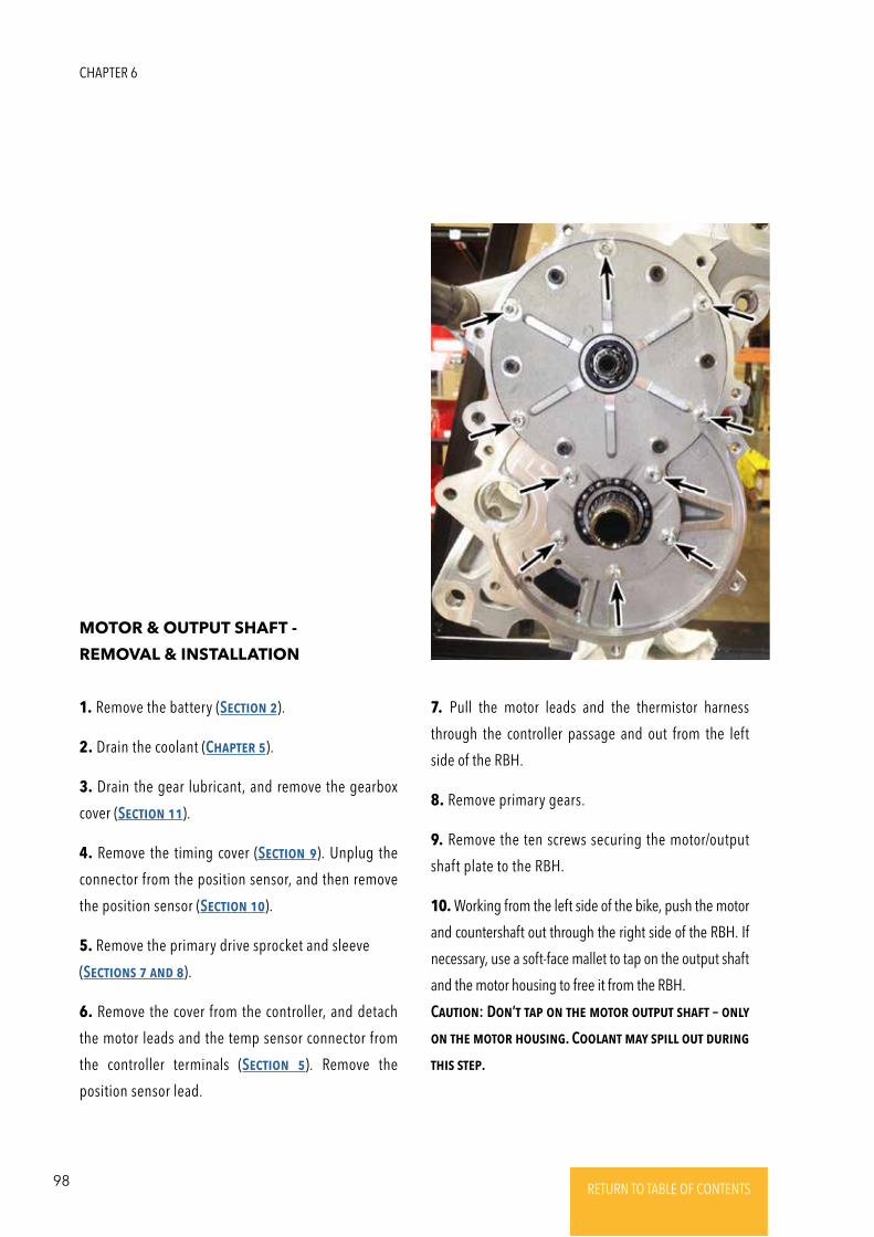
98 RETURN TO TABLE OF CONTENTSRETURN TO TABLE OF CONTENTSRETURN TO TABLE OF CONTENTSRETURN TO TABLE OF CONTENTSRETURN TO TABLE OF CONTENTS RETURN TO TABLE OF CONTENTS
MOTOR & OUTPUT SHAFT -
REMOVAL & INSTALLATION
1. Remove the battery (SEctioN 2).
2. Drain the coolant (ChaptER 5).
3. Drain the gear lubricant, and remove the gearbox
cover (SEctioN 11).
4. Remove the timing cover (SEctioN 9). Unplug the
connector from the position sensor, and then remove
the position sensor (SEctioN 10).
5. Remove the primary drive sprocket and sleeve
(SEctioNs 7 aNd 8).
6. Remove the cover from the controller, and detach
the motor leads and the temp sensor connector from
the controller terminals (SEctioN 5). Remove the
position sensor lead.
7. Pull the motor leads and the thermistor harness
through the controller passage and out from the left
side of the RBH.
8. Remove primary gears.
9. Remove the ten screws securing the motor/output
shaft plate to the RBH.
10. Working from the left side of the bike, push the motor
and countershaft out through the right side of the RBH. If
necessary, use a soft-face mallet to tap on the output shaft
and the motor housing to free it from the RBH.
CautioN: DoN’t tap oN thE motoR output shaFt – oNly
oN thE motoR housiNg. CoolaNt may spill out duRiNg
this stEp.
CHAPTER 6
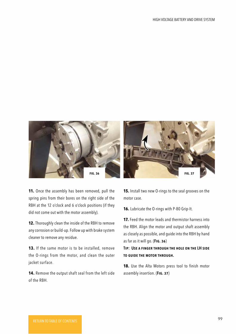
99RETURN TO TABLE OF CONTENTSRETURN TO TABLE OF CONTENTSRETURN TO TABLE OF CONTENTSRETURN TO TABLE OF CONTENTSRETURN TO TABLE OF CONTENTS RETURN TO TABLE OF CONTENTS
11. Once the assembly has been removed, pull the
spring pins from their bores on the right side of the
RBH at the 12 o’clock and 6 o’clock positions (if they
did not come out with the motor assembly).
12. Thoroughly clean the inside of the RBH to remove
any corrosion or build-up. Follow up with brake system
cleaner to remove any residue.
13. If the same motor is to be installed, remove
the O-rings from the motor, and clean the outer
jacket sur face.
14. Remove the output shaft seal from the left side
of the RBH.
15. Install two new O-rings to the seal grooves on the
motor case.
16. Lubricate the O-rings with P-80 Grip-It.
17. Feed the motor leads and thermistor harness into
the RBH. Align the motor and output shaft assembly
as closely as possible, and guide into the RBH by hand
as far as it will go. (Fig. 36)
Tip: UsE a FiNgER thRough thE holE oN thE LH sidE
to guidE thE motoR thRough.
18. Use the Alta Motors press tool to finish motor
assembly insertion. (Fig. 37)
Fig. 36 Fig. 37
HIGH VOLTAGE BATTERY AND DRIVE SYSTEM
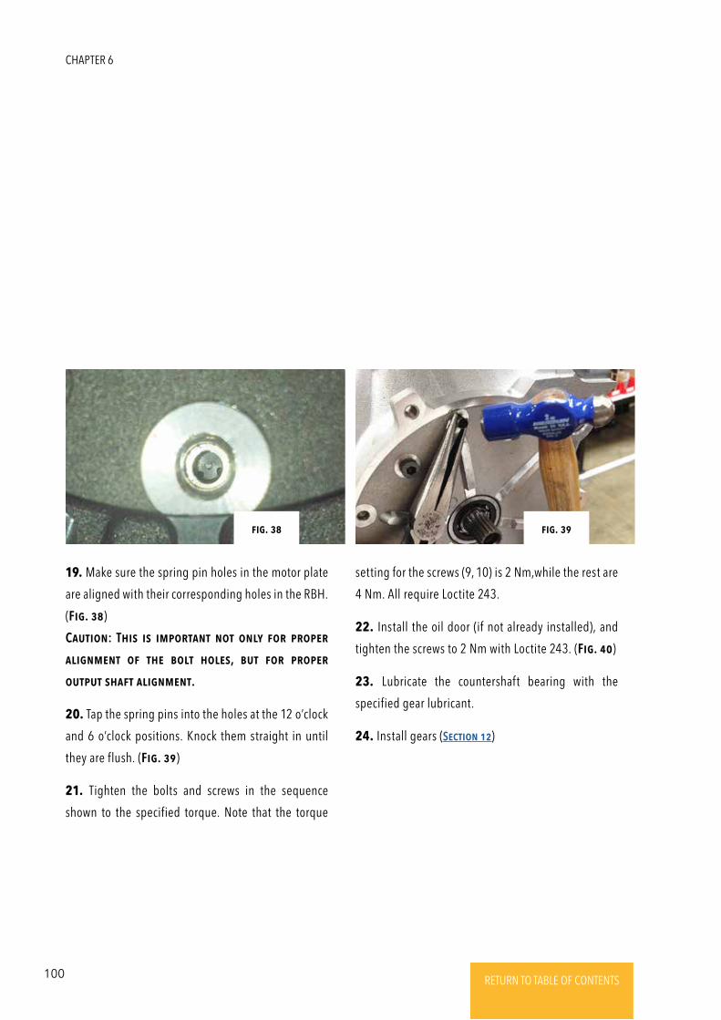
100 RETURN TO TABLE OF CONTENTSRETURN TO TABLE OF CONTENTSRETURN TO TABLE OF CONTENTSRETURN TO TABLE OF CONTENTSRETURN TO TABLE OF CONTENTS RETURN TO TABLE OF CONTENTS
19. Make sure the spring pin holes in the motor plate
are aligned with their corresponding holes in the RBH.
(Fig. 38)
CautioN: This is impoRtaNt Not oNly FoR pRopER
aligNmENt oF thE bolt holEs, but FoR pRopER
output shaFt aligNmENt.
20. Tap the spring pins into the holes at the 12 o’clock
and 6 o’clock positions. Knock them straight in until
they are flush. (Fig. 39)
21. Tighten the bolts and screws in the sequence
shown to the specified torque. Note that the torque
Fig. 38
setting for the screws (9, 10) is 2 Nm,while the rest are
4 Nm. All require Loctite 243.
22. Install the oil door (if not already installed), and
tighten the screws to 2 Nm with Loctite 243. (Fig. 40)
23. Lubricate the countershaft bearing with the
specified gear lubricant.
24. Install gears (SEctioN 12)
Fig. 39
CHAPTER 6
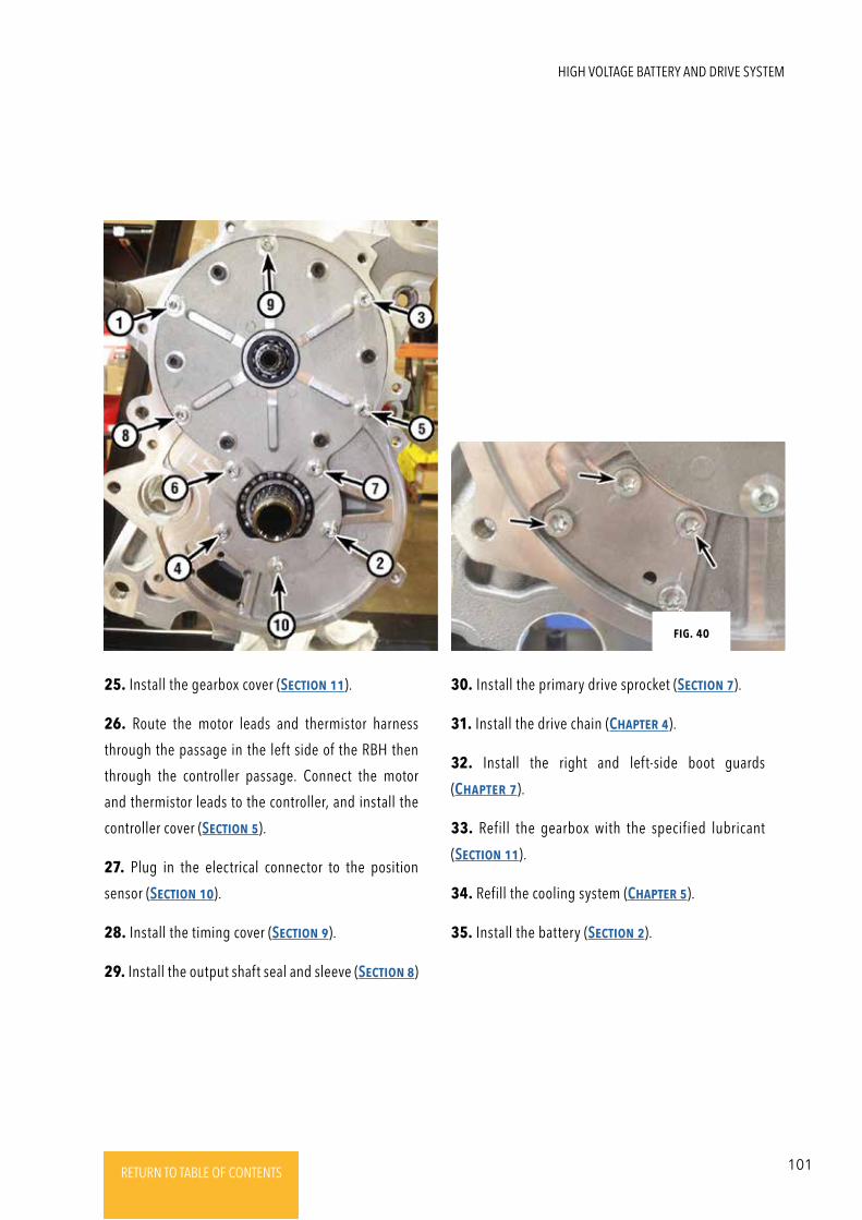
101RETURN TO TABLE OF CONTENTSRETURN TO TABLE OF CONTENTSRETURN TO TABLE OF CONTENTSRETURN TO TABLE OF CONTENTSRETURN TO TABLE OF CONTENTS RETURN TO TABLE OF CONTENTS
25. Install the gearbox cover (SEctioN 11).
26. Route the motor leads and thermistor harness
through the passage in the left side of the RBH then
through the controller passage. Connect the motor
and thermistor leads to the controller, and install the
controller cover (SEctioN 5).
27. Plug in the electrical connector to the position
sensor (SEctioN 10).
28. Install the timing cover (SEctioN 9).
29. Install the output shaft seal and sleeve (SEctioN 8)
Fig. 40
30. Install the primary drive sprocket (SEctioN 7).
31. Install the drive chain (ChaptER 4).
32. Install the right and left-side boot guards
(ChaptER 7).
33. Refill the gearbox with the specified lubricant
(SEctioN 11).
34. Refill the cooling system (ChaptER 5).
35. Install the battery (SEctioN 2).
HIGH VOLTAGE BATTERY AND DRIVE SYSTEM
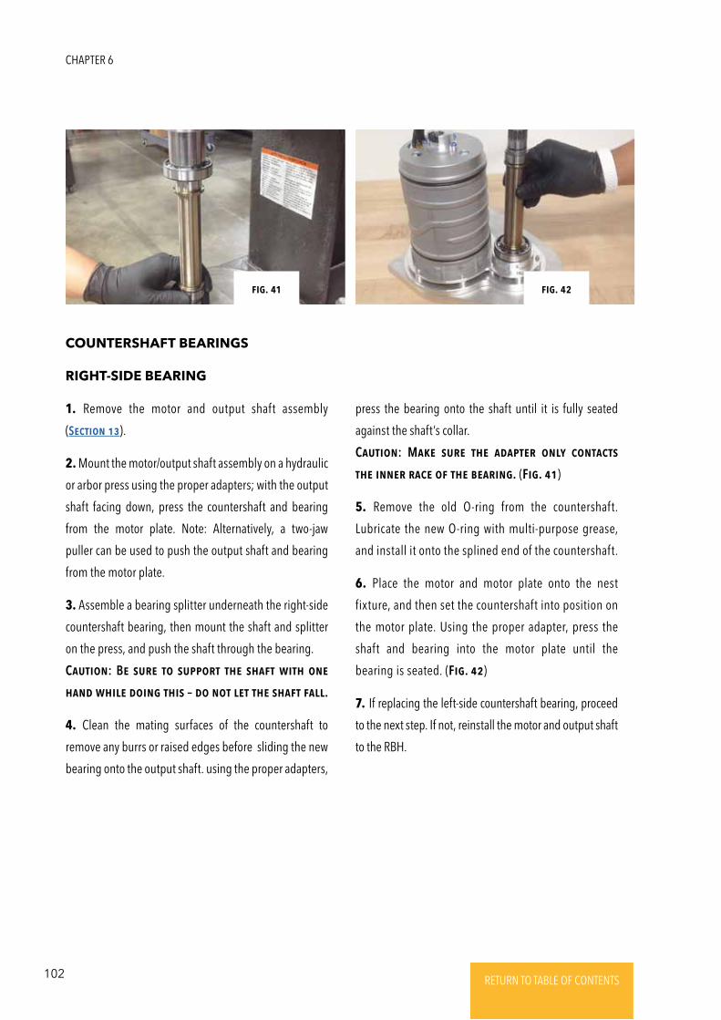
102 RETURN TO TABLE OF CONTENTSRETURN TO TABLE OF CONTENTSRETURN TO TABLE OF CONTENTSRETURN TO TABLE OF CONTENTSRETURN TO TABLE OF CONTENTS RETURN TO TABLE OF CONTENTS
COUNTERSHAFT BEARINGS
RIGHT-SIDE BEARING
1. Remove the motor and output shaft assembly
(SEctioN 13).
2. Mount the motor/output shaft assembly on a hydraulic
or arbor press using the proper adapters; with the output
shaft facing down, press the countershaft and bearing
from the motor plate. Note: Alternatively, a two-jaw
puller can be used to push the output shaft and bearing
from the motor plate.
3. Assemble a bearing splitter underneath the right-side
countershaft bearing, then mount the shaft and splitter
on the press, and push the shaft through the bearing.
CautioN: BE suRE to suppoRt thE shaFt with oNE
haNd whilE doiNg this – do Not lEt thE shaFt Fall.
4. Clean the mating surfaces of the countershaft to
remove any burrs or raised edges before sliding the new
bearing onto the output shaft. using the proper adapters,
Fig. 41 Fig. 42
press the bearing onto the shaft until it is fully seated
against the shaft’s collar.
CautioN: MakE suRE thE adaptER oNly coNtacts
thE iNNER RacE oF thE bEaRiNg. (Fig. 41)
5. Remove the old O-ring from the countershaft.
Lubricate the new O-ring with multi-purpose grease,
and install it onto the splined end of the countershaft.
6. Place the motor and motor plate onto the nest
fixture, and then set the countershaft into position on
the motor plate. Using the proper adapter, press the
shaft and bearing into the motor plate until the
bearing is seated. (Fig. 42)
7. If replacing the left-side countershaft bearing, proceed
to the next step. If not, reinstall the motor and output shaft
to the RBH.
CHAPTER 6
103RETURN TO TABLE OF CONTENTSRETURN TO TABLE OF CONTENTSRETURN TO TABLE OF CONTENTSRETURN TO TABLE OF CONTENTSRETURN TO TABLE OF CONTENTS RETURN TO TABLE OF CONTENTS
LEFT-SIDE BEARING
8. Remove the motor and countershaft assembly if it
has not been already (SEctioN 13).
9. Remove the countershaft seal from the left side of
the RBH (SEctioN 8).
10. Remove the snap-ring from the seal/bearing bore.
11. Remove the bearing from the bore with a slide
hammer and puller attachment. Alternatively, drive it
out from the right to the left with a hammer and long
drift. If the latter method is used, work slowly, working
around the circumference of the bearing a little at a
time so as not to distort the bore in the RBH.
12. Clean the bearing bore, and drive the new bearing
into place with a bearing driver until it is seated.
13. Lubricate the bearing with the specified gear oil.
14. Install the snap-ring, making sure it is fully seated.
16. Install the countershaft seal (SEctioN 8), motor and
countershaft assembly (SEctioN 13).
HIGH VOLTAGE BATTERY AND DRIVE SYSTEM
104 RETURN TO TABLE OF CONTENTSRETURN TO TABLE OF CONTENTSRETURN TO TABLE OF CONTENTSRETURN TO TABLE OF CONTENTSRETURN TO TABLE OF CONTENTS RETURN TO TABLE OF CONTENTS
CHAPTER 7
FRAME
SKIDFRAME -
REMOVAL & INSTALLATION
1. Support the bike with a triangle (Redshift MX) or on
its sidestand (Redshift SM).
2. Remove the bolts securing the skidframe struts to
the RBH. (Fig. 1)
3. Remove the skidframe-to-FBH mounting bolts.
(Fig. 2)
4. Loosen the skidframe-to-RBH clamp bolts. Remove
the clamp bolts and clamps, and detach the skidframe.
On some early production machines there are two Half-
Moon shaped washers between the skidframe and the
Front Bulkhead (any machine with a vin lower than
B000052 might have this feature) Retrieve the half-
moon-shaped adapters from the skidframe-to-FBH
mounting points and note their fit. (Fig. 3)
5. If a strut is damaged or if the skidframe is being
replaced but the strut(s) is/are in good shape, remove
the snap-ring, and slide the knuckle pin out before
detaching the strut from the skidframe. (Fig. 4 & 5)
6. Position the skidframe on the RBH, and install the
clamps and bolts. Do not tighten the bolts yet.
NotE: INstall thEsE bolts dRy – No LoctitE oR gREasE.
7. Install the washers on the skidframe-to-FBH bolts,
and lightly lubricate the threads of the bolts with multi-
purpose grease. Swing the skidframe up into position,
and if applicable (see Step 4), place the half-moon-
shaped adapters between the skidframe and the FBH,
and install the bolts. Do not tighten the bolts yet. If the
machine does not have the half-moon shaped adapters,
install the bolts. Do not tighten them yet.
8. If detached, reconnect the struts to the skidframe,
and install the knuckle pins and snap-rings.
9. Lubricate the threads of the strut-to-RBH bolts with
a light film of multi-purpose grease or light coating of
anti-seize. Position the struts against the RBH, and
install the bolts. Do not tighten them yet.
10. Evenly tighten the skidframe mounting bolts to
48 Nm in the following order, a little at a time, there
should be no gap visible:
• Skidframe-to-FBH bolts.
• Strut-to-RBH bolts.
• Skidframe-to-RBH clamp bolts (lower mounting bolts).
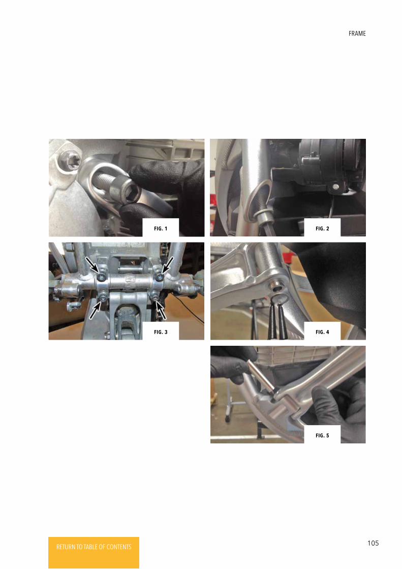
105RETURN TO TABLE OF CONTENTSRETURN TO TABLE OF CONTENTSRETURN TO TABLE OF CONTENTSRETURN TO TABLE OF CONTENTSRETURN TO TABLE OF CONTENTS RETURN TO TABLE OF CONTENTS
FRAME
Fig. 2Fig. 1
Fig. 4
Fig. 5
Fig. 3
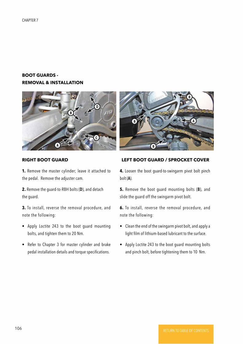
106 RETURN TO TABLE OF CONTENTSRETURN TO TABLE OF CONTENTSRETURN TO TABLE OF CONTENTSRETURN TO TABLE OF CONTENTSRETURN TO TABLE OF CONTENTS RETURN TO TABLE OF CONTENTS
BOOT GUARDS -
REMOVAL & INSTALLATION
RIGHT BOOT GUARD LEFT BOOT GUARD / SPROCKET COVER
1. Remove the master cylinder; leave it attached to
the pedal. Remove the adjuster cam.
2. Remove the guard-to-RBH bolts (D), and detach
the guard.
3. To install, reverse the removal procedure, and
note the following:
• Apply Loctite 243 to the boot guard mounting
bolts, and tighten them to 20 Nm.
• Refer to Chapter 3 for master cylinder and brake
pedal installation details and torque specifications.
4. Loosen the boot guard-to-swingarm pivot bolt pinch
bolt (A).
5. Remove the boot guard mounting bolts (B), and
slide the guard off the swingarm pivot bolt.
6. To install, reverse the removal procedure, and
note the following:
• Clean the end of the swingarm pivot bolt, and apply a
light film of lithium-based lubricant to the surface.
• Apply Loctite 243 to the boot guard mounting bolts
and pinch bolt, before tightening them to 10 Nm.
CHAPTER 7
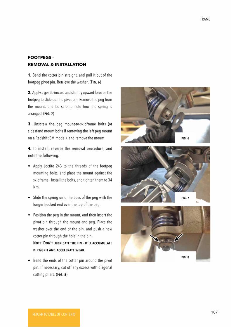
107RETURN TO TABLE OF CONTENTSRETURN TO TABLE OF CONTENTSRETURN TO TABLE OF CONTENTSRETURN TO TABLE OF CONTENTSRETURN TO TABLE OF CONTENTS RETURN TO TABLE OF CONTENTS
FOOTPEGS -
REMOVAL & INSTALLATION
1. Bend the cotter pin straight, and pull it out of the
footpeg pivot pin. Retrieve the washer. (Fig. 6)
2. Apply a gentle inward and slightly upward force on the
footpeg to slide out the pivot pin. Remove the peg from
the mount, and be sure to note how the spring is
arranged. (Fig. 7)
3. Unscrew the peg mount-to-skidframe bolts (or
sidestand mount bolts if removing the left peg mount
on a Redshift SM model), and remove the mount.
4. To install, reverse the removal procedure, and
note the following:
• Apply Loctite 243 to the threads of the footpeg
mounting bolts, and place the mount against the
skidframe . Install the bolts, and tighten them to 34
Nm.
• Slide the spring onto the boss of the peg with the
longer hooked end over the top of the peg.
• Position the peg in the mount, and then insert the
pivot pin through the mount and peg. Place the
washer over the end of the pin, and push a new
cotter pin through the hole in the pin.
NotE: DoN’t lubRicatE thE piN – it’ll accumulatE
diRt/gRit aNd accElERatE wEaR.
• Bend the ends of the cotter pin around the pivot
pin. If necessary, cut off any excess with diagonal
cutting pliers. (Fig. 8)
Fig. 6
Fig. 7
Fig. 8
FRAME
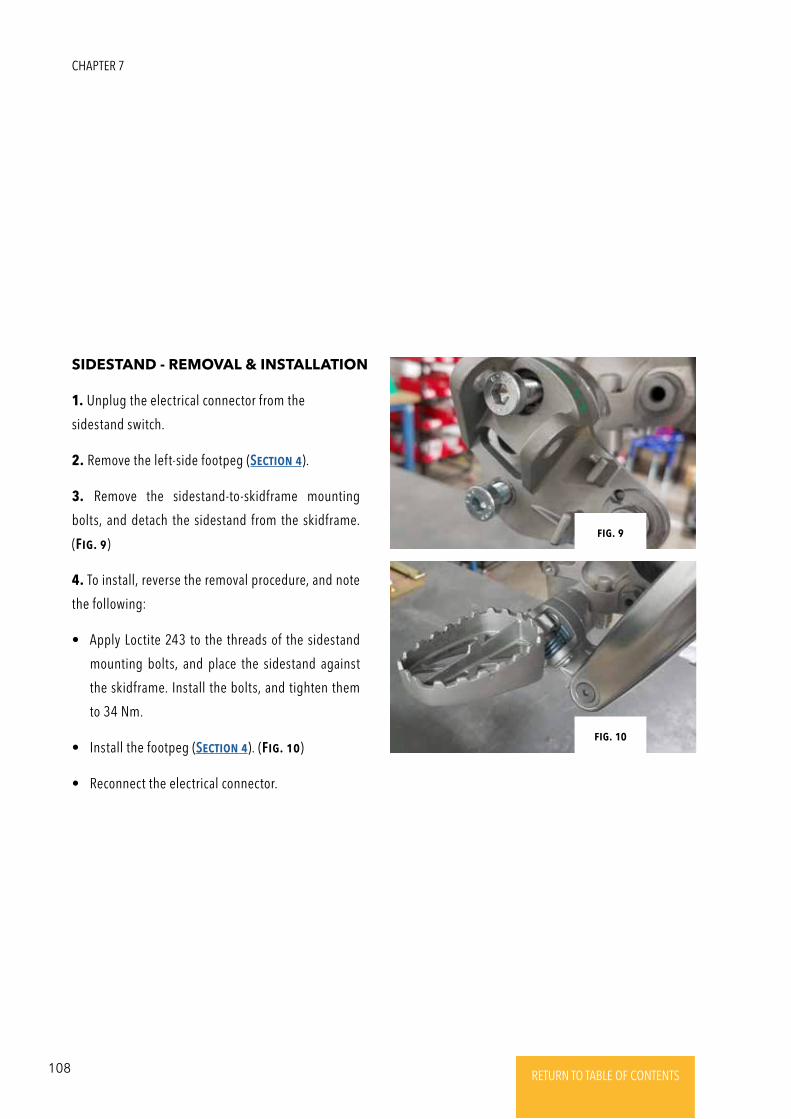
108 RETURN TO TABLE OF CONTENTSRETURN TO TABLE OF CONTENTSRETURN TO TABLE OF CONTENTSRETURN TO TABLE OF CONTENTSRETURN TO TABLE OF CONTENTS RETURN TO TABLE OF CONTENTS
SIDESTAND - REMOVAL & INSTALLATION
1. Unplug the electrical connector from the
sidestand switch.
2. Remove the left-side footpeg (SEctioN 4).
3. Remove the sidestand-to-skidframe mounting
bolts, and detach the sidestand from the skidframe.
(Fig. 9)
4. To install, reverse the removal procedure, and note
the following:
• Apply Loctite 243 to the threads of the sidestand
mounting bolts, and place the sidestand against
the skidframe. Install the bolts, and tighten them
to 34 Nm.
• Install the footpeg (SEctioN 4). (Fig. 10)
• Reconnect the electrical connector.
Fig. 9
Fig. 10
CHAPTER 7
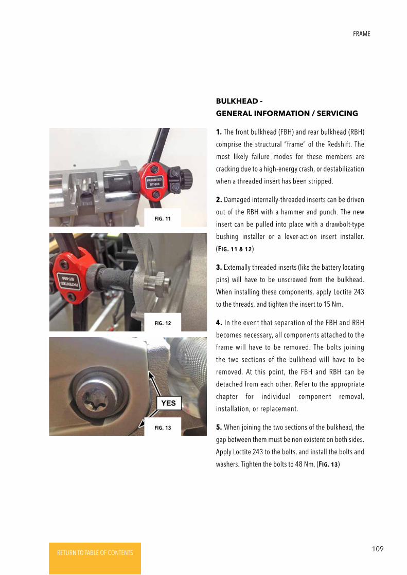
109RETURN TO TABLE OF CONTENTSRETURN TO TABLE OF CONTENTSRETURN TO TABLE OF CONTENTSRETURN TO TABLE OF CONTENTSRETURN TO TABLE OF CONTENTS RETURN TO TABLE OF CONTENTS
BULKHEAD -
GENERAL INFORMATION / SERVICING
1. The front bulkhead (FBH) and rear bulkhead (RBH)
comprise the structural “frame” of the Redshift. The
most likely failure modes for these members are
cracking due to a high-energy crash, or destabilization
when a threaded insert has been stripped.
2. Damaged internally-threaded inserts can be driven
out of the RBH with a hammer and punch. The new
insert can be pulled into place with a drawbolt-type
bushing installer or a lever-action insert installer.
(Fig. 11 & 12)
3. Externally threaded inserts (like the battery locating
pins) will have to be unscrewed from the bulkhead.
When installing these components, apply Loctite 243
to the threads, and tighten the insert to 15 Nm.
4. In the event that separation of the FBH and RBH
becomes necessary, all components attached to the
frame will have to be removed. The bolts joining
the two sections of the bulkhead will have to be
removed. At this point, the FBH and RBH can be
detached from each other. Refer to the appropriate
chapter for individual component removal,
installation, or replacement.
5. When joining the two sections of the bulkhead, the
gap between them must be non existent on both sides.
Apply Loctite 243 to the bolts, and install the bolts and
washers. Tighten the bolts to 48 Nm. (Fig. 13)
Fig. 13
Fig. 11
Fig. 12
FRAME
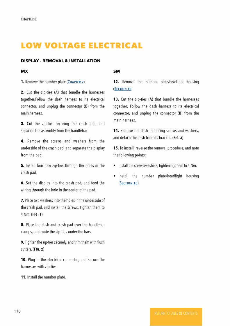
110 RETURN TO TABLE OF CONTENTSRETURN TO TABLE OF CONTENTSRETURN TO TABLE OF CONTENTSRETURN TO TABLE OF CONTENTSRETURN TO TABLE OF CONTENTS RETURN TO TABLE OF CONTENTS
LOW VOLTAGE ELECTRICAL
DISPLAY - REMOVAL & INSTALLATION
MX SM
1. Remove the number plate (ChaptER 2).
2. Cut the zip-ties (A) that bundle the harnesses
together.Follow the dash harness to its electrical
connector, and unplug the connector (B) from the
main harness.
3. Cut the zip-ties securing the crash pad, and
separate the assembly from the handlebar.
4. Remove the screws and washers from the
underside of the crash pad, and separate the display
from the pad.
5. Install four new zip-ties through the holes in the
crash pad.
6. Set the display into the crash pad, and feed the
wiring through the hole in the center of the pad.
7. Place two washers into the holes in the underside of
the crash pad, and install the screws. Tighten them to
4 Nm. (Fig. 1)
8. Place the dash and crash pad over the handlebar
clamps, and route the zip-ties under the bars.
9. Tighten the zip-ties securely, and trim them with flush
cutters. (Fig. 2)
10. Plug in the electrical connector, and secure the
harnesses with zip-ties.
11. Install the number plate.
12. Remove the number plate/headlight housing
(SEctioN 10).
13. Cut the zip-ties (A) that bundle the harnesses
together. Follow the dash harness to its electrical
connector, and unplug the connector (B) from the
main harness.
14. Remove the dash mounting screws and washers,
and detach the dash from its bracket. (Fig. 3)
15. To install, reverse the removal procedure, and note
the following points:
• Install the screws/washers, tightening them to 4 Nm.
• Install the number plate/headlight housing
(SEctioN 10).
CHAPTER 8
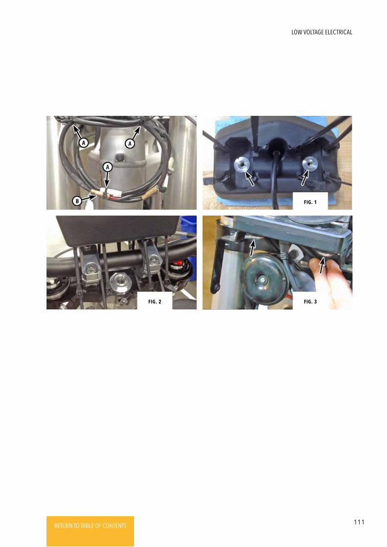
111RETURN TO TABLE OF CONTENTSRETURN TO TABLE OF CONTENTSRETURN TO TABLE OF CONTENTSRETURN TO TABLE OF CONTENTSRETURN TO TABLE OF CONTENTS RETURN TO TABLE OF CONTENTS
Fig. 1
Fig. 2 Fig. 3
LOW VOLTAGE ELECTRICAL
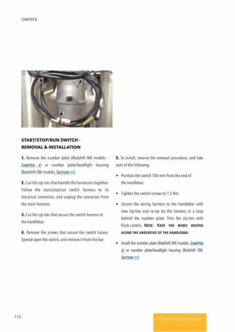
112 RETURN TO TABLE OF CONTENTSRETURN TO TABLE OF CONTENTSRETURN TO TABLE OF CONTENTSRETURN TO TABLE OF CONTENTSRETURN TO TABLE OF CONTENTS RETURN TO TABLE OF CONTENTS
START/STOP/RUN SWITCH -
REMOVAL & INSTALLATION
1. Remove the number plate (Redshift MX models –
ChaptER 2) or number plate/headlight housing
(Redshift SM models, SEctioN 11).
2. Cut the zip-ties that bundle the harnesses together.
Follow the start/stop/run switch harness to its
electrical connector, and unplug the connector from
the main harness.
3. Cut the zip-ties that secure the switch harness to
the handlebar.
4. Remove the screws that secure the switch halves.
Spread open the switch, and remove it from the bar.
5. To install, reverse the removal procedure, and take
note of the following:
• Position the switch 150 mm from the end of
the handlebar.
• Tighten the switch screws to 1.5 Nm.
• Secure the wiring harness to the handlebar with
new zip-ties and re-zip tie the harness in a loop
behind the number plate. Trim the zip-ties with
flush-cutters. NotE: KEEp thE wiREs RoutEd
aloNg thE uNdERsidE oF thE haNdlEbaR.
• Install the number plate (Redshift MX models, ChaptER
2) or number plate/headlight housing (Redshift SM,
SEctioN 11).
CHAPTER 8
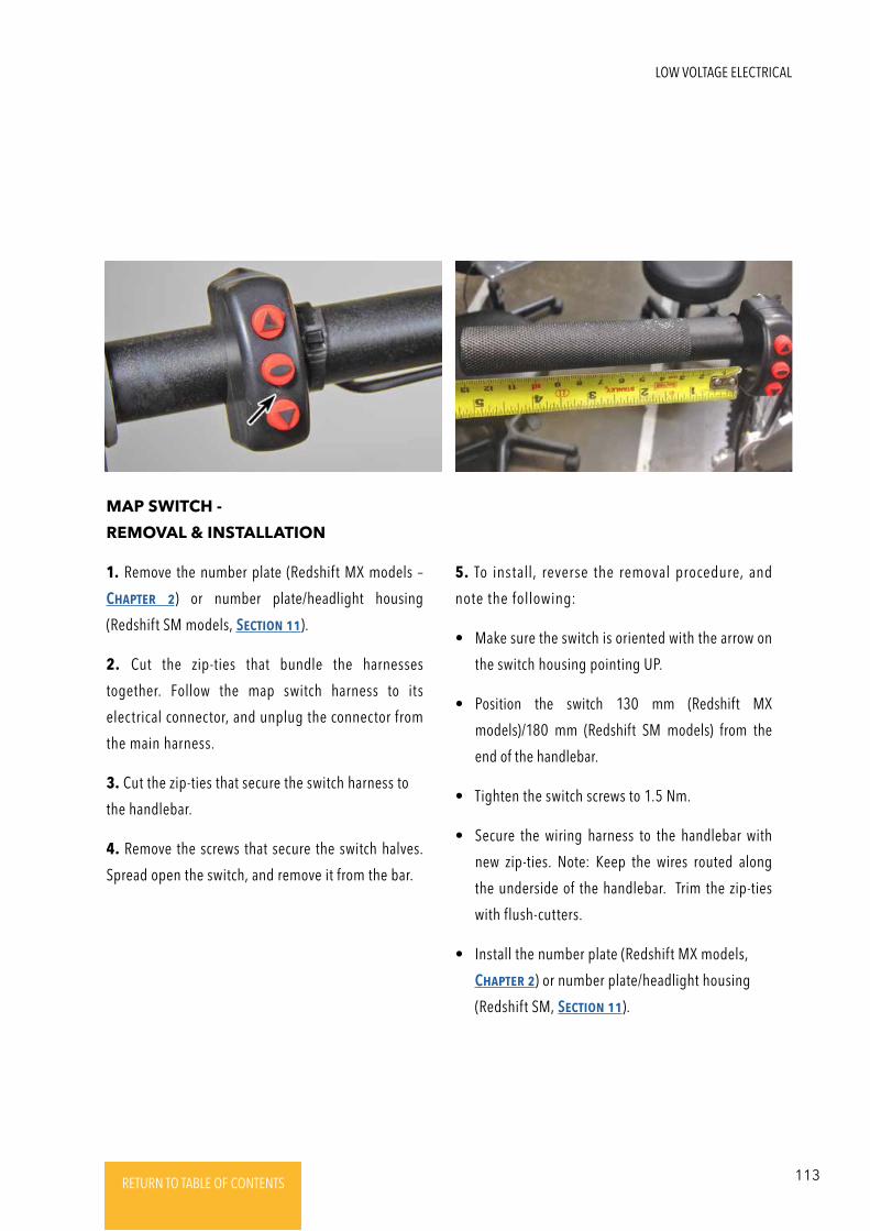
113RETURN TO TABLE OF CONTENTSRETURN TO TABLE OF CONTENTSRETURN TO TABLE OF CONTENTSRETURN TO TABLE OF CONTENTSRETURN TO TABLE OF CONTENTS RETURN TO TABLE OF CONTENTS
MAP SWITCH -
REMOVAL & INSTALLATION
1. Remove the number plate (Redshift MX models –
ChaptER 2) or number plate/headlight housing
(Redshift SM models, SEctioN 11).
2. Cut the zip-ties that bundle the harnesses
together. Follow the map switch harness to its
electrical connector, and unplug the connector from
the main harness.
3. Cut the zip-ties that secure the switch harness to
the handlebar.
4. Remove the screws that secure the switch halves.
Spread open the switch, and remove it from the bar.
5. To install, reverse the removal procedure, and
note the following:
• Make sure the switch is oriented with the arrow on
the switch housing pointing UP.
• Position the switch 130 mm (Redshift MX
models)/180 mm (Redshift SM models) from the
end of the handlebar.
• Tighten the switch screws to 1.5 Nm.
• Secure the wiring harness to the handlebar with
new zip-ties. Note: Keep the wires routed along
the underside of the handlebar. Trim the zip-ties
with flush-cutters.
• Install the number plate (Redshift MX models,
ChaptER 2) or number plate/headlight housing
(Redshift SM, SEctioN 11).
LOW VOLTAGE ELECTRICAL
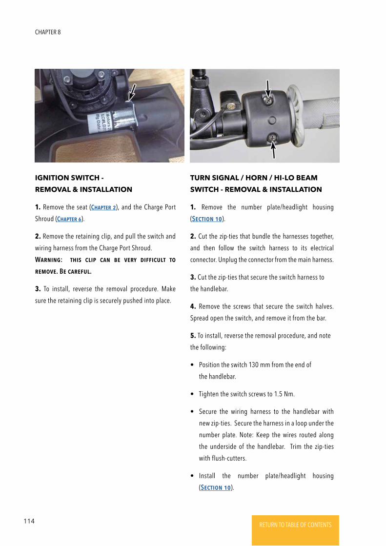
114 RETURN TO TABLE OF CONTENTSRETURN TO TABLE OF CONTENTSRETURN TO TABLE OF CONTENTSRETURN TO TABLE OF CONTENTSRETURN TO TABLE OF CONTENTS RETURN TO TABLE OF CONTENTS
TURN SIGNAL / HORN / HI-LO BEAM
SWITCH - REMOVAL & INSTALLATION
1. Remove the number plate/headlight housing
(SEctioN 10).
2. Cut the zip-ties that bundle the harnesses together,
and then follow the switch harness to its electrical
connector. Unplug the connector from the main harness.
3. Cut the zip-ties that secure the switch harness to
the handlebar.
4. Remove the screws that secure the switch halves.
Spread open the switch, and remove it from the bar.
5. To install, reverse the removal procedure, and note
the following:
• Position the switch 130 mm from the end of
the handlebar.
• Tighten the switch screws to 1.5 Nm.
• Secure the wiring harness to the handlebar with
new zip-ties. Secure the harness in a loop under the
number plate. Note: Keep the wires routed along
the underside of the handlebar. Trim the zip-ties
with flush-cutters.
• Install the number plate/headlight housing
(SEctioN 10).
IGNITION SWITCH -
REMOVAL & INSTALLATION
1. Remove the seat (ChaptER 2), and the Charge Port
Shroud (ChaptER 6).
2. Remove the retaining clip, and pull the switch and
wiring harness from the Charge Port Shroud.
WaRNiNg: this clip caN bE VERy diFFicult to
REmoVE. BE caREFul.
3. To install, reverse the removal procedure. Make
sure the retaining clip is securely pushed into place.
CHAPTER 8
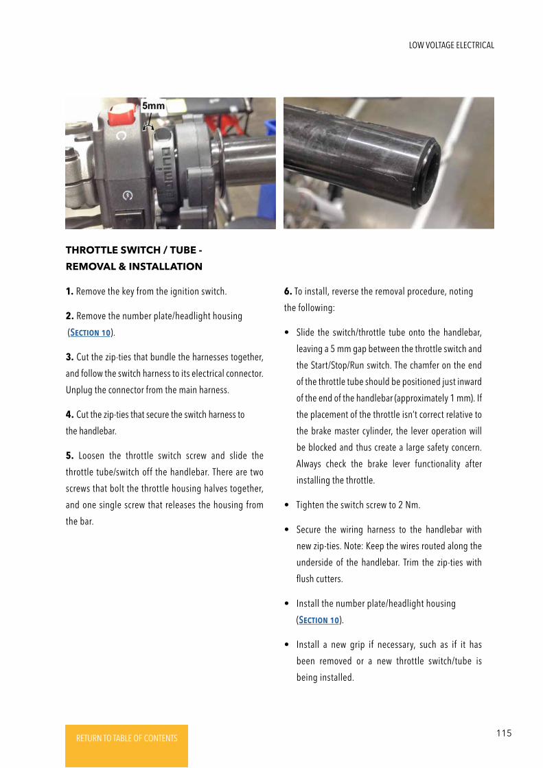
115RETURN TO TABLE OF CONTENTSRETURN TO TABLE OF CONTENTSRETURN TO TABLE OF CONTENTSRETURN TO TABLE OF CONTENTSRETURN TO TABLE OF CONTENTS RETURN TO TABLE OF CONTENTS
THROTTLE SWITCH / TUBE -
REMOVAL & INSTALLATION
1. Remove the key from the ignition switch.
2. Remove the number plate/headlight housing
(SEctioN 10).
3. Cut the zip-ties that bundle the harnesses together,
and follow the switch harness to its electrical connector.
Unplug the connector from the main harness.
4. Cut the zip-ties that secure the switch harness to
the handlebar.
5. Loosen the throttle switch screw and slide the
throttle tube/switch off the handlebar. There are two
screws that bolt the throttle housing halves together,
and one single screw that releases the housing from
the bar.
6. To install, reverse the removal procedure, noting
the following:
• Slide the switch/throttle tube onto the handlebar,
leaving a 5 mm gap between the throttle switch and
the Start/Stop/Run switch. The chamfer on the end
of the throttle tube should be positioned just inward
of the end of the handlebar (approximately 1 mm). If
the placement of the throttle isn’t correct relative to
the brake master cylinder, the lever operation will
be blocked and thus create a large safety concern.
Always check the brake lever functionality after
installing the throttle.
• Tighten the switch screw to 2 Nm.
• Secure the wiring harness to the handlebar with
new zip-ties. Note: Keep the wires routed along the
underside of the handlebar. Trim the zip-ties with
flush cutters.
• Install the number plate/headlight housing
(SEctioN 10).
• Install a new grip if necessary, such as if it has
been removed or a new throttle switch/tube is
being installed.
LOW VOLTAGE ELECTRICAL
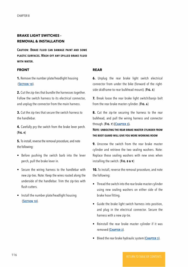
116 RETURN TO TABLE OF CONTENTSRETURN TO TABLE OF CONTENTSRETURN TO TABLE OF CONTENTSRETURN TO TABLE OF CONTENTSRETURN TO TABLE OF CONTENTS RETURN TO TABLE OF CONTENTS
BRAKE LIGHT SWITCHES -
REMOVAL & INSTALLATION
FRONT REAR
1. Remove the number plate/headlight housing
(SEctioN 10).
2. Cut the zip-ties that bundle the harnesses together.
Follow the switch harness to its electrical connector,
and unplug the connector from the main harness.
3. Cut the zip-ties that secure the switch harness to
the handlebar.
4. Carefully pry the switch from the brake lever perch.
(Fig. 4)
5. To install, reverse the removal procedure, and note
the following:
• Before pushing the switch barb into the lever
perch, pull the brake lever in.
• Secure the wiring harness to the handlebar with
new zip-ties. Note: Keep the wires routed along the
underside of the handlebar. Trim the zip-ties with
flush cutters.
• Install the number plate/headlight housing
(SEctioN 10).
6. Unplug the rear brake light switch electrical
connector from under the bike (forward of the right-
side skidframe-to-rear bulkhead mount). (Fig. 5)
7. Break loose the rear brake light switch/banjo bolt
from the rear brake master cylinder. (Fig. 6)
8. Cut the zip-tie securing the harness to the rear
bulkhead, and pull the wiring harness and connector
through. (Fig. 7) (ChaptER 3).
NotE: uNboltiNg thE REaR bRakE mastER cyliNdER FRom
thE boot guaRd will giVE you moRE woRkiNg Room
9. Unscrew the switch from the rear brake master
cylinder and retrieve the two sealing washers. Note:
Replace these sealing washers with new ones when
installing the switch. (Fig. 8 & 9)
10. To install, reverse the removal procedure, and note
the following:
• Thread the switch into the rear brake master cylinder
using new sealing washers on either side of the
brake hose fitting.
• Guide the brake light switch harness into position,
and plug in the electrical connector. Secure the
harness with a new zip-tie.
• Reinstall the rear brake master cylinder if it was
removed (ChaptER 3).
• Bleed the rear brake hydraulic system (ChaptER 3).
CautioN: BRakE Fluid caN damagE paiNt aNd somE
plastic suRFacEs. Wash oFF aNy spillEd bRakE Fluid
with watER.
CHAPTER 8
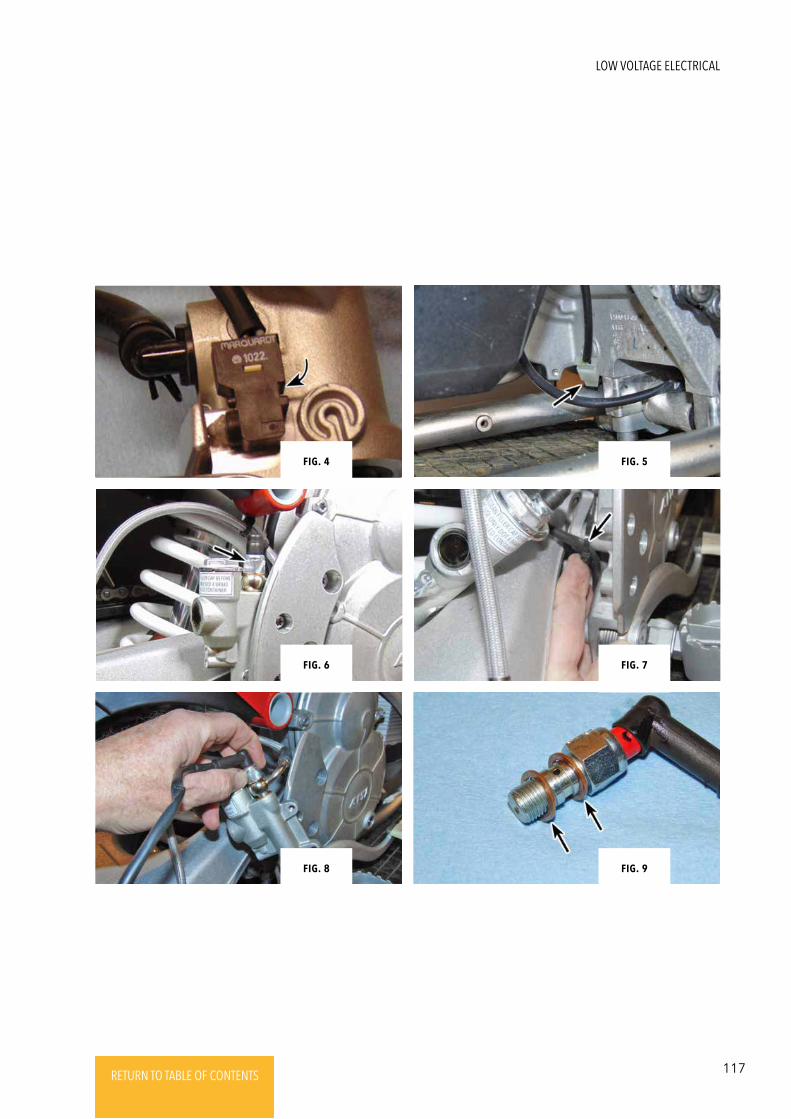
117RETURN TO TABLE OF CONTENTSRETURN TO TABLE OF CONTENTSRETURN TO TABLE OF CONTENTSRETURN TO TABLE OF CONTENTSRETURN TO TABLE OF CONTENTS RETURN TO TABLE OF CONTENTS
Fig. 8 Fig. 9
Fig. 4 Fig. 5
Fig. 6 Fig. 7
LOW VOLTAGE ELECTRICAL
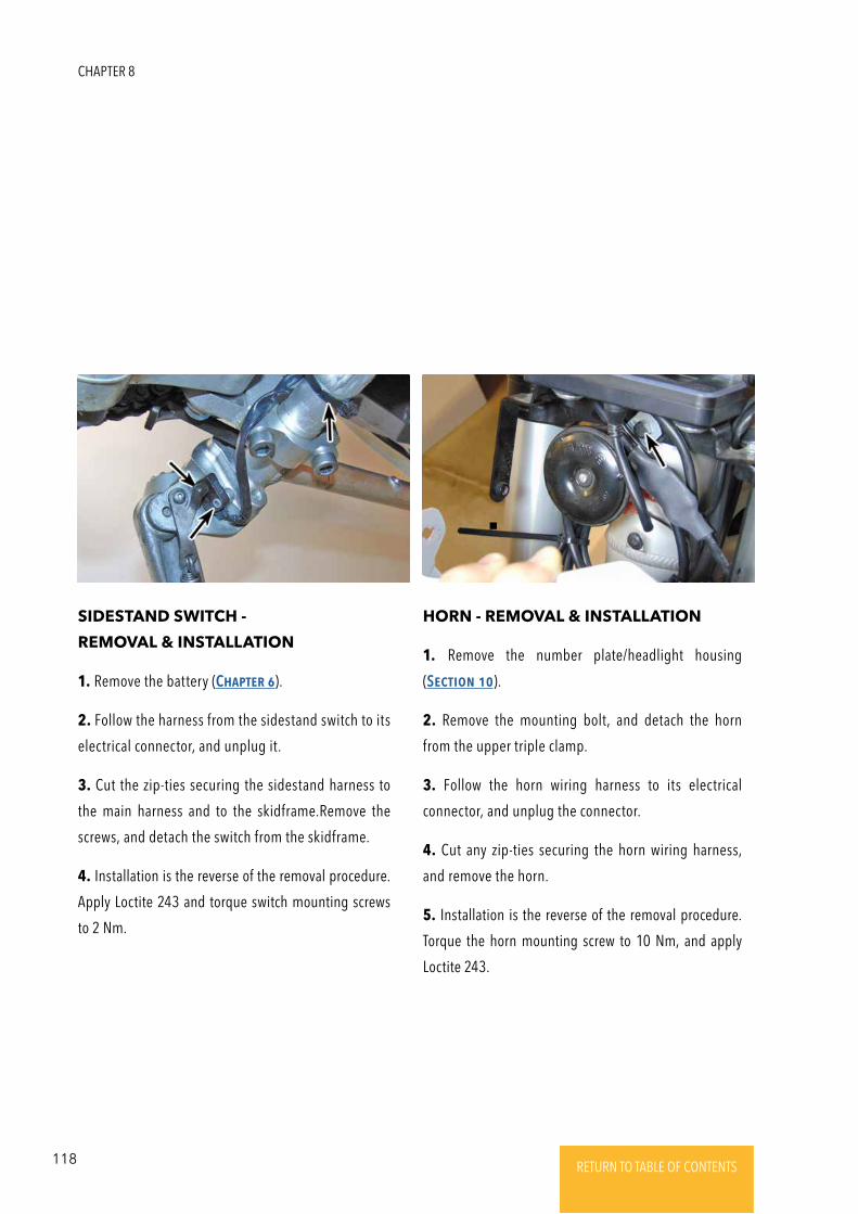
118 RETURN TO TABLE OF CONTENTSRETURN TO TABLE OF CONTENTSRETURN TO TABLE OF CONTENTSRETURN TO TABLE OF CONTENTSRETURN TO TABLE OF CONTENTS RETURN TO TABLE OF CONTENTS
HORN - REMOVAL & INSTALLATIONSIDESTAND SWITCH -
REMOVAL & INSTALLATION1. Remove the number plate/headlight housing
(SEctioN 10).
2. Remove the mounting bolt, and detach the horn
from the upper triple clamp.
3. Follow the horn wiring harness to its electrical
connector, and unplug the connector.
4. Cut any zip-ties securing the horn wiring harness,
and remove the horn.
5. Installation is the reverse of the removal procedure.
Torque the horn mounting screw to 10 Nm, and apply
Loctite 243.
1. Remove the battery (ChaptER 6).
2. Follow the harness from the sidestand switch to its
electrical connector, and unplug it.
3. Cut the zip-ties securing the sidestand harness to
the main harness and to the skidframe.Remove the
screws, and detach the switch from the skidframe.
4. Installation is the reverse of the removal procedure.
Apply Loctite 243 and torque switch mounting screws
to 2 Nm.
CHAPTER 8
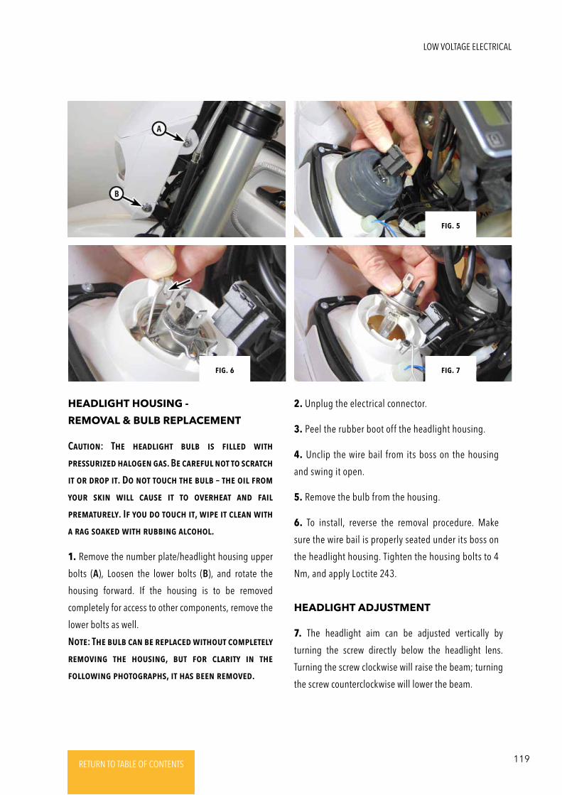
119RETURN TO TABLE OF CONTENTSRETURN TO TABLE OF CONTENTSRETURN TO TABLE OF CONTENTSRETURN TO TABLE OF CONTENTSRETURN TO TABLE OF CONTENTS RETURN TO TABLE OF CONTENTS
HEADLIGHT ADJUSTMENT
HEADLIGHT HOUSING -
REMOVAL & BULB REPLACEMENT
7. The headlight aim can be adjusted vertically by
turning the screw directly below the headlight lens.
Turning the screw clockwise will raise the beam; turning
the screw counterclockwise will lower the beam.
CautioN: ThE hEadlight bulb is FillEd with
pREssuRizEd halogEN gas. BE caREFul Not to scRatch
it oR dRop it. Do Not touch thE bulb – thE oil FRom
youR skiN will causE it to oVERhEat aNd Fail
pREmatuREly. IF you do touch it, wipE it clEaN with
a Rag soakEd with RubbiNg alcohol.
1. Remove the number plate/headlight housing upper
bolts (A), Loosen the lower bolts (B), and rotate the
housing forward. If the housing is to be removed
completely for access to other components, remove the
lower bolts as well.
NotE: ThE bulb caN bE REplacEd without complEtEly
REmoViNg thE housiNg, but FoR claRity iN thE
FollowiNg photogRaphs, it has bEEN REmoVEd.
Fig. 5
Fig. 6 Fig. 7
2. Unplug the electrical connector.
3. Peel the rubber boot off the headlight housing.
4. Unclip the wire bail from its boss on the housing
and swing it open.
5. Remove the bulb from the housing.
6. To install, reverse the removal procedure. Make
sure the wire bail is properly seated under its boss on
the headlight housing. Tighten the housing bolts to 4
Nm, and apply Loctite 243.
LOW VOLTAGE ELECTRICAL
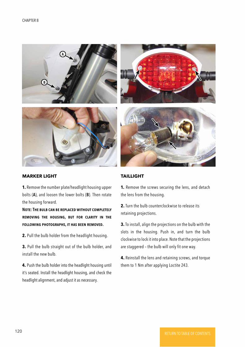
120 RETURN TO TABLE OF CONTENTSRETURN TO TABLE OF CONTENTSRETURN TO TABLE OF CONTENTSRETURN TO TABLE OF CONTENTSRETURN TO TABLE OF CONTENTS RETURN TO TABLE OF CONTENTS
MARKER LIGHT TAILLIGHT
1. Remove the number plate/headlight housing upper
bolts (A), and loosen the lower bolts (B). Then rotate
the housing forward.
NotE: ThE bulb caN bE REplacEd without complEtEly
REmoViNg thE housiNg, but FoR claRity iN thE
FollowiNg photogRaphs, it has bEEN REmoVEd.
2. Pull the bulb holder from the headlight housing.
3. Pull the bulb straight out of the bulb holder, and
install the new bulb.
4. Push the bulb holder into the headlight housing until
it’s seated. Install the headlight housing, and check the
headlight alignment, and adjust it as necessary.
1. Remove the screws securing the lens, and detach
the lens from the housing.
2. Turn the bulb counterclockwise to release its
retaining projections.
3. To install, align the projections on the bulb with the
slots in the housing. Push in, and turn the bulb
clockwise to lock it into place. Note that the projections
are staggered – the bulb will only fit one way.
4. Reinstall the lens and retaining screws, and torque
them to 1 Nm after applying Loctite 243.
CHAPTER 8
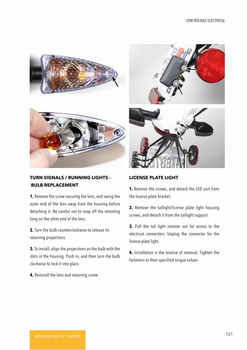
121RETURN TO TABLE OF CONTENTSRETURN TO TABLE OF CONTENTSRETURN TO TABLE OF CONTENTSRETURN TO TABLE OF CONTENTSRETURN TO TABLE OF CONTENTS RETURN TO TABLE OF CONTENTS
TURN SIGNALS / RUNNING LIGHTS -
BULB REPLACEMENT
1. Remove the screw securing the lens, and swing the
outer end of the lens away from the housing before
detaching it. Be careful not to snap off the retaining
tang on the other end of the lens.
2. Turn the bulb counterclockwise to release its
retaining projections.
3. To install, align the projections on the bulb with the
slots in the housing. Push in, and then turn the bulb
clockwise to lock it into place.
4. Reinstall the lens and retaining screw.
LICENSE PLATE LIGHT
1. Remove the screws, and detach the LED unit from
the license plate bracket.
2. Remove the taillight/license plate light housing
screws, and detach it from the taillight support.
3. Pull the tail light retainer out for access to the
electrical connectors. Unplug the connector for the
license plate light.
4. Installation is the reverse of removal. Tighten the
fasteners to their specified torque values.
LOW VOLTAGE ELECTRICAL

122 RETURN TO TABLE OF CONTENTSRETURN TO TABLE OF CONTENTSRETURN TO TABLE OF CONTENTSRETURN TO TABLE OF CONTENTSRETURN TO TABLE OF CONTENTS RETURN TO TABLE OF CONTENTS
© 2017 Alta MotorsLogo and trademark are registered.You have the right to go fast.