Embed Size (px)
Citation preview
O W N E R ’ S M A N U A L
2 0 1 7D I E S E L S U P P L E M E N T
R A M T R U C K
VEHICLES SOLD IN CANADAWith respect to any Vehicles Sold in Canada, the name FCAUS LLC shall be deemed to be deleted and the name FCACanada Inc. used in substitution therefore.
DRIVING AND ALCOHOLDrunken driving is one of the most frequent causes ofaccidents.Your driving ability can be seriously impaired with bloodalcohol levels far below the legal minimum. If you aredrinking, don’t drive. Ride with a designated non-drinking driver, call a cab, a friend, or use public trans-portation.
WARNING!
Driving after drinking can lead to an accident.Your perceptions are less sharp, your reflexes areslower, and your judgment is impaired when youhave been drinking. Never drink and then drive.
This manual illustrates and describes the operation offeatures and equipment that are either standard or op-tional on this vehicle. This manual may also include adescription of features and equipment that are no longeravailable or were not ordered on this vehicle. Pleasedisregard any features and equipment described in thismanual that are not on this vehicle.
FCA US LLC reserves the right to make changes in designand specifications, and/or make additions to or improve-ments to its products without imposing any obligationupon itself to install them on products previously manu-factured.
Copyright © 2016 FCA US LLC
RAM DIESEL SUPPLEMENT
RAM 1500 . . . . . . . . . . . . . . . . . . . . . . . . . . . . . . . . . . . . . . . . . . . . . . . . . . . . . . . . . . . . . . . . . . . . . . . 3
RAM 2500 / 3500 / 4500 / 5500 . . . . . . . . . . . . . . . . . . . . . . . . . . . . . . . . . . . . . . . . . . . . 85
INDEX . . . . . . . . . . . . . . . . . . . . . . . . . . . . . . . . . . . . . . . . . . . . . . . . . . . . . . . . . . . . . . . . . . . . . . . . . 217


RAM 1500

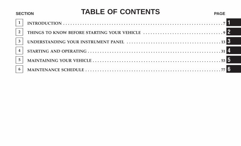
TABLE OF CONTENTSSECTION PAGE
1 INTRODUCTION . . . . . . . . . . . . . . . . . . . . . . . . . . . . . . . . . . . . . . . . . . . . . . . . . . . . . . . . . . . . . . . . . . 7
2 THINGS TO KNOW BEFORE STARTING YOUR VEHICLE . . . . . . . . . . . . . . . . . . . . . . . . . . . . . . . . . 9
3 UNDERSTANDING YOUR INSTRUMENT PANEL . . . . . . . . . . . . . . . . . . . . . . . . . . . . . . . . . . . . . . . 13
4 STARTING AND OPERATING . . . . . . . . . . . . . . . . . . . . . . . . . . . . . . . . . . . . . . . . . . . . . . . . . . . . . . . 31
5 MAINTAINING YOUR VEHICLE . . . . . . . . . . . . . . . . . . . . . . . . . . . . . . . . . . . . . . . . . . . . . . . . . . . . . 53
6 MAINTENANCE SCHEDULE . . . . . . . . . . . . . . . . . . . . . . . . . . . . . . . . . . . . . . . . . . . . . . . . . . . . . . . . 77
1
2
3
4
5
6

INTRODUCTION
CONTENTS� A MESSAGE FROM FCA US LLC . . . . . . . . . . . . . .8
1
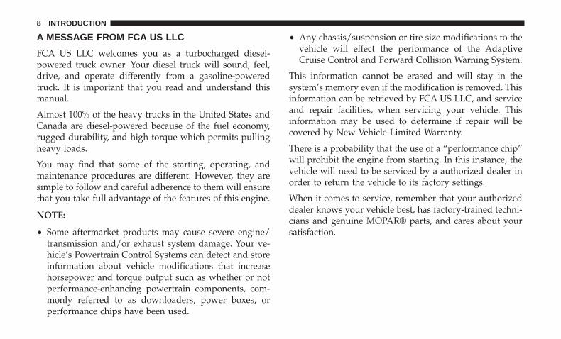
A MESSAGE FROM FCA US LLC
FCA US LLC welcomes you as a turbocharged diesel-powered truck owner. Your diesel truck will sound, feel,drive, and operate differently from a gasoline-poweredtruck. It is important that you read and understand thismanual.
Almost 100% of the heavy trucks in the United States andCanada are diesel-powered because of the fuel economy,rugged durability, and high torque which permits pullingheavy loads.
You may find that some of the starting, operating, andmaintenance procedures are different. However, they aresimple to follow and careful adherence to them will ensurethat you take full advantage of the features of this engine.
NOTE:
• Some aftermarket products may cause severe engine/transmission and/or exhaust system damage. Your ve-hicle’s Powertrain Control Systems can detect and storeinformation about vehicle modifications that increasehorsepower and torque output such as whether or notperformance-enhancing powertrain components, com-monly referred to as downloaders, power boxes, orperformance chips have been used.
• Any chassis/suspension or tire size modifications to thevehicle will effect the performance of the AdaptiveCruise Control and Forward Collision Warning System.
This information cannot be erased and will stay in thesystem’s memory even if the modification is removed. Thisinformation can be retrieved by FCA US LLC, and serviceand repair facilities, when servicing your vehicle. Thisinformation may be used to determine if repair will becovered by New Vehicle Limited Warranty.
There is a probability that the use of a “performance chip”will prohibit the engine from starting. In this instance, thevehicle will need to be serviced by a authorized dealer inorder to return the vehicle to its factory settings.
When it comes to service, remember that your authorizeddealer knows your vehicle best, has factory-trained techni-cians and genuine MOPAR® parts, and cares about yoursatisfaction.
8 INTRODUCTION
THINGS TO KNOW BEFORE STARTING YOUR VEHICLE
CONTENTS� REMOTE STARTING SYSTEM . . . . . . . . . . . . . . .10
▫ How To Use Remote Start. . . . . . . . . . . . . . . . . .10
� ENGINE BREAK-IN RECOMMENDATIONS . . . . .11
2
REMOTE STARTING SYSTEM
This system uses the key fob to start the engineconveniently from outside the vehicle while stillmaintaining security. The system has a range ofapproximately 300 ft (91 m).
NOTE:
• The vehicle must be equipped with an automatic trans-mission to be equipped with Remote Start.
• Obstructions between the vehicle and the key fob mayreduce this range.
• The Remote Start system will wait for the “Wait To Start”amber telltale to extinguish before cranking the engine.This allows time for the engine pre-heat cycle to pre-heatthe cylinder air, and is normal in cold weather. Refer to“Instrument Cluster Display” in “Understanding YourInstrument Panel” for further information on the “WaitTo Start” amber telltale and the pre-heat cycle.
How To Use Remote Start
All of the following conditions must be met before theengine will remote start:
• Gear selector in PARK
• Doors closed
• Hood closed
• HAZARD switch off
• BRAKE switch inactive (brake pedal not pressed)
• Battery at an acceptable charge level
• PANIC button not pushed
• Fuel meets minimum requirement
• System not disabled from previous remote start event
• Vehicle security alarm not active
• Water In Fuel Indicator Light is not illuminated
• “Wait To Start” telltale is not illuminated
10 THINGS TO KNOW BEFORE STARTING YOUR VEHICLE
WARNING!
• Do not start or run an engine in a closed garage orconfined area. Exhaust gas contains Carbon Monox-ide (CO) which is odorless and colorless. CarbonMonoxide is poisonous and can cause serious injuryor death when inhaled.
• Keep Remote Keyless Entry key fobs away fromchildren. Operation of the Remote Start System,windows, door locks or other controls could causeserious injury or death.
ENGINE BREAK-IN RECOMMENDATIONS
The diesel engine does not require a break-in period due toits construction. Normal operation is allowed, providingthe following recommendations are followed:
• Warm up the engine before placing it under load.
• Do not operate the engine at idle for prolonged periods.
• Use the appropriate transmission gear to prevent enginelugging.
• Observe vehicle oil pressure and temperature indicators.
• Check the coolant and oil levels frequently.
• Vary throttle position at highway speeds when carryingor towing significant weight.
NOTE: Light duty operation such as light trailer towing orno load operation will extend the time before the engine isat full efficiency. Reduced fuel economy and power may beseen at this time.
The engine oil installed in the engine at the factory is ahigh-quality energy conserving type lubricant. Oil changesshould be consistent with anticipated climate conditionsunder which vehicle operations will occur. The recom-mended viscosity and quality grades are shown under“Fluids, Lubricants and Genuine Parts”, under “Maintain-ing Your Vehicle” in this manual. NON-DETERGENT ORSTRAIGHT MINERAL OILS MUST NEVER BE USED.
2
THINGS TO KNOW BEFORE STARTING YOUR VEHICLE 11

UNDERSTANDING YOUR INSTRUMENT PANEL
CONTENTS� INSTRUMENT CLUSTER . . . . . . . . . . . . . . . . . . .14
� WARNING AND INDICATOR LIGHTS . . . . . . . . .19
▫ Yellow Telltale Indicator Lights . . . . . . . . . . . . . .19
� INSTRUMENT CLUSTER DISPLAY . . . . . . . . . . . .21
▫ Oil Life Reset . . . . . . . . . . . . . . . . . . . . . . . . . .23
▫ Fuel Filter Life Reset . . . . . . . . . . . . . . . . . . . . .24
▫ Diesel Particulate Filter (DPF) Messages . . . . . . .25
▫ Displays . . . . . . . . . . . . . . . . . . . . . . . . . . . . . .26
▫ Vehicle Information (Customer InformationFeatures). . . . . . . . . . . . . . . . . . . . . . . . . . . . . .27
▫ Diesel Exhaust Fluid (DEF) Warning Messages . . .28
▫ Diesel Exhaust Fluid (DEF) Fault WarningMessages . . . . . . . . . . . . . . . . . . . . . . . . . . . . .29
3
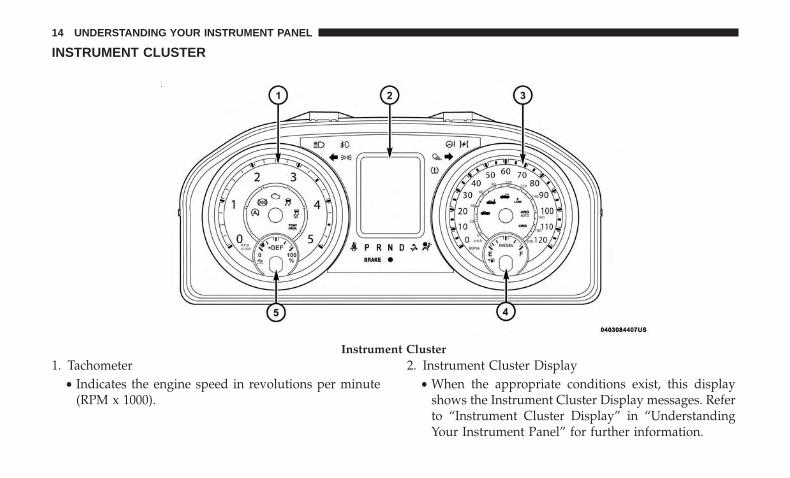
INSTRUMENT CLUSTER
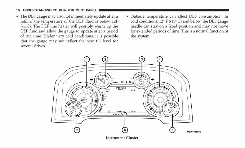
1. Tachometer• Indicates the engine speed in revolutions per minute
(RPM x 1000).
2. Instrument Cluster Display• When the appropriate conditions exist, this display
shows the Instrument Cluster Display messages. Referto “Instrument Cluster Display” in “UnderstandingYour Instrument Panel” for further information.
Instrument Cluster
14 UNDERSTANDING YOUR INSTRUMENT PANEL
3. Speedometer• Indicates vehicle speed.
4. Fuel Gauge• The pointer shows the level of fuel in the fuel tank
when the ignition switch is in the ON/RUN position.• The fuel pump symbol points to the side of the
vehicle where the fuel filler door is located.
5. DEF Gauge• The DEF Gauge displays the actual level of Diesel
Exhaust Fluid in the DEF tank. Diesel Exhaust Fluid(DEF) is required to maintain normal vehicle operationand emissions compliance. If something is wrong withthe gauge, a DEF Warning Message or MalfunctionIndicator Light (MIL) will be displayed. More infor-mation is available in the Instrument Cluster Displaysection under the heading of Diesel Exhaust Fluid(DEF) Warning Messages.
WARNING!
A hot engine cooling system is dangerous. You orothers could be badly burned by steam or boilingcoolant. You may want to call an authorized dealer for
(Continued)
WARNING! (Continued)service if your vehicle overheats. If you decide to lookunder the hood yourself, see “Maintaining Your Ve-hicle.” Follow the warnings under the “Cooling Sys-tem Pressure Cap” paragraph.
CAUTION!
Driving with a hot engine cooling system could dam-age your vehicle. If the temperature gauge reads “H”pull over and stop the vehicle. Idle the vehicle with theair conditioner turned off until the pointer drops backinto the normal range. If the pointer remains on the“H”, turn the engine off immediately and call anauthorized dealer for service.
NOTE:
• The gauge may take up to five seconds to update afteradding a gallon or more of Diesel Exhaust Fluid (DEF) tothe DEF tank. If you have a fault related to the DEFsystem, the gauge may not update to the new level. Seeyour authorized dealer for service.
3
UNDERSTANDING YOUR INSTRUMENT PANEL 15
• The DEF gauge may also not immediately update after arefill if the temperature of the DEF fluid is below 12F(-11C). The DEF line heater will possibly warm up theDEF fluid and allow the gauge to update after a periodof run time. Under very cold conditions, it is possiblethat the gauge may not reflect the new fill level forseveral drives.
• Outside temperature can affect DEF consumption. Incold conditions, 12° F (-11° C) and below, the DEF gaugeneedle can stay on a fixed position and may not movefor extended periods of time. This is a normal function ofthe system.
Instrument Cluster
16 UNDERSTANDING YOUR INSTRUMENT PANEL
1. Tachometer• Indicates the engine speed in revolutions per minute
(RPM x 1000).
2. Engine Coolant Temperature• This gauge shows the engine coolant temperature. The
gauge pointer will likely show higher temperatureswhen driving in hot weather, up mountain grades, orin heavy stop and go traffic. If the red Warning Lightturns on while driving, safely bring the vehicle to astop, and turn off the engine. DO NOT operate thevehicle until the cause is corrected.
WARNING!
A hot engine cooling system is dangerous. You orothers could be badly burned by steam or boilingcoolant. You may want to call an authorized dealer forservice if your vehicle overheats. If you decide to lookunder the hood yourself, see “Maintaining Your Ve-hicle.” Follow the warnings under the “Cooling Sys-tem Pressure Cap” paragraph.
CAUTION!
Driving with a hot engine cooling system could dam-age your vehicle. If the temperature gauge reads “H”pull over and stop the vehicle. Idle the vehicle with theair conditioner turned off until the pointer drops backinto the normal range. If the pointer remains on the“H”, turn the engine off immediately and call anauthorized dealer for service.
3. Oil Pressure Gauge• The pointer should always indicate some oil pressure
when the engine is running. A continuous high or lowreading under normal driving conditions may indicatea lubrication system malfunction. Immediate serviceshould be obtained from an authorized dealer.
4. Speedometer• Indicates vehicle speed.
5. Fuel Gauge• The pointer shows the level of fuel in the fuel tank
when the ignition switch is in the ON/RUN position.• The fuel pump symbol points to the side of the
vehicle where the fuel filler door is located.
3
UNDERSTANDING YOUR INSTRUMENT PANEL 17
6. Instrument Cluster Display• When the appropriate conditions exist, this display
shows the Instrument Cluster Display messages. Referto “Instrument Cluster Display” in “UnderstandingYour Instrument Panel” for further information.
7. DEF Gauge• The DEF Gauge displays the actual level of Diesel
Exhaust Fluid in the DEF tank. Diesel Exhaust Fluid(DEF) is required to maintain normal vehicle operationand emissions compliance. If something is wrong withthe gauge, a DEF Warning Message or MalfunctionIndicator Light (MIL) will be displayed. More infor-mation is available in the Instrument Cluster Displaysection under the heading of Diesel Exhaust Fluid(DEF) Warning Messages.
NOTE:
• The DEF tank on these vehicles is designed with a largeamount of full reserve. So the level sensor will indicate afull reading even before the tank is completely full. Toput it another way, there’s additional storage capacity inthe tank above the Full mark that’s not represented inthe gauge. You may not see any movement in thereading – even after driving up to 2,000 miles in somecases.
• The gauge may take up to five seconds to update afteradding a gallon or more of Diesel Exhaust Fluid (DEF) tothe DEF tank. If you have a fault related to the DEFsystem, the gauge may not update to the new level. Seeyour authorized dealer for service.
• The DEF gauge may also not immediately update after arefill if the temperature of the DEF fluid is below 12F(-11C). The DEF line heater will possibly warm up theDEF fluid and allow the gauge to update after a periodof run time. Under very cold conditions, it is possiblethat the gauge may not reflect the new fill level forseveral drives.
• Outside temperature can affect DEF consumption. Incold conditions, 12° F (-11° C) and below, the DEF gaugeneedle can stay on a fixed position and may not movefor extended periods of time. This is a normal function ofthe system.
CAUTION!
Driving with a hot engine cooling system could dam-age your vehicle. If the temperature gauge reads “H”pull over and stop the vehicle. Idle the vehicle with the
(Continued)
18 UNDERSTANDING YOUR INSTRUMENT PANEL
CAUTION! (Continued)air conditioner turned off until the pointer drops backinto the normal range. If the pointer remains on the“H”, turn the engine off immediately and call anauthorized dealer for service.
WARNING AND INDICATOR LIGHTS
IMPORTANT: The warning / indicator lights switch on inthe instrument panel together with a dedicated messageand/or acoustic signal when applicable. These indications
are indicative and precautionary and as such must not beconsidered as exhaustive and/or alternative to the informa-tion contained in the Owner’s Manual, which you areadvised to read carefully in all cases. Always refer to theinformation in this chapter in the event of a failure indica-tion.
All active telltales will display first if applicable. Thesystem check menu may appear different based uponequipment options and current vehicle status. Some tell-tales are optional and may not appear.
Yellow Telltale Indicator Lights
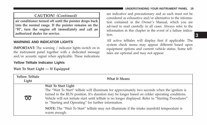
Wait To Start Light — If Equipped
Yellow TelltaleLight
What It Means
Wait To Start LightThe “Wait To Start” telltale will illuminate for approximately two seconds when the ignition isturned to the RUN position. It’s duration may be longer based on colder operating conditions.Vehicle will not initiate start until telltale is no longer displayed. Refer to “Starting Procedures”in “Starting and Operating” for further information.
NOTE: The “Wait To Start” telltale may not illuminate if the intake manifold temperature iswarm enough.
3
UNDERSTANDING YOUR INSTRUMENT PANEL 19
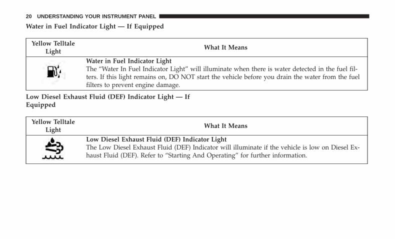
Water in Fuel Indicator Light — If Equipped
Yellow TelltaleLight
What It Means
Water in Fuel Indicator LightThe “Water In Fuel Indicator Light” will illuminate when there is water detected in the fuel fil-ters. If this light remains on, DO NOT start the vehicle before you drain the water from the fuelfilters to prevent engine damage.
Low Diesel Exhaust Fluid (DEF) Indicator Light — IfEquipped
Yellow TelltaleLight
What It Means
Low Diesel Exhaust Fluid (DEF) Indicator LightThe Low Diesel Exhaust Fluid (DEF) Indicator will illuminate if the vehicle is low on Diesel Ex-haust Fluid (DEF). Refer to “Starting And Operating” for further information.
20 UNDERSTANDING YOUR INSTRUMENT PANEL
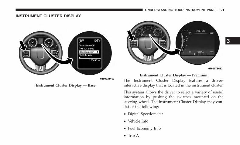
INSTRUMENT CLUSTER DISPLAY
The Instrument Cluster Display features a driver-interactive display that is located in the instrument cluster.
This system allows the driver to select a variety of usefulinformation by pushing the switches mounted on thesteering wheel. The Instrument Cluster Display may con-sist of the following:
• Digital Speedometer
• Vehicle Info
• Fuel Economy Info
• Trip A
Instrument Cluster Display — Base
Instrument Cluster Display — Premium
3
UNDERSTANDING YOUR INSTRUMENT PANEL 21

• Trip B
• Stop/Start Info (If Equipped)
• Trailer Tow
• Audio
• Stored Messages
• Screen Setup
• Vehicle Settings (Not Equipped with a Uconnect 5.0 &8.4 radio)
• Settings
• Turn Menu Off
The system allows the driver to select information bypushing the following buttons mounted on the steeringwheel:
• UP Arrow Button
Push and release the UP arrow button to scrollupward through the main menu and submenus(Fuel Economy, Trip A, Trip B, Audio, StoredMessages, Screen Set Up).
• DOWN Arrow Button
Push and release the DOWN arrow button toscroll downward through the main menu andsubmenus (Fuel Economy, Trip A, Trip B, Audio,Stored Messages, Screen Set Up).
Steering Wheel Buttons
22 UNDERSTANDING YOUR INSTRUMENT PANEL
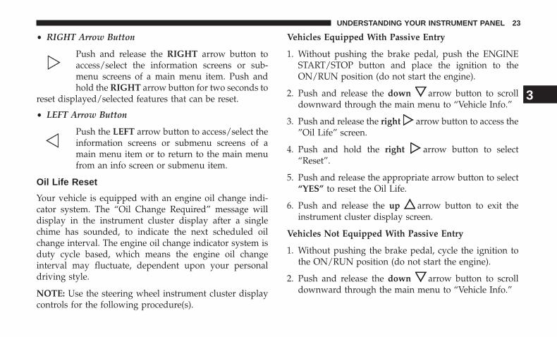
• RIGHT Arrow Button
Push and release the RIGHT arrow button toaccess/select the information screens or sub-menu screens of a main menu item. Push andhold the RIGHT arrow button for two seconds to
reset displayed/selected features that can be reset.
• LEFT Arrow Button
Push the LEFT arrow button to access/select theinformation screens or submenu screens of amain menu item or to return to the main menufrom an info screen or submenu item.
Oil Life Reset
Your vehicle is equipped with an engine oil change indi-cator system. The “Oil Change Required” message willdisplay in the instrument cluster display after a singlechime has sounded, to indicate the next scheduled oilchange interval. The engine oil change indicator system isduty cycle based, which means the engine oil changeinterval may fluctuate, dependent upon your personaldriving style.
NOTE: Use the steering wheel instrument cluster displaycontrols for the following procedure(s).
Vehicles Equipped With Passive Entry
1. Without pushing the brake pedal, push the ENGINESTART/STOP button and place the ignition to theON/RUN position (do not start the engine).
2. Push and release the down arrow button to scrolldownward through the main menu to “Vehicle Info.”
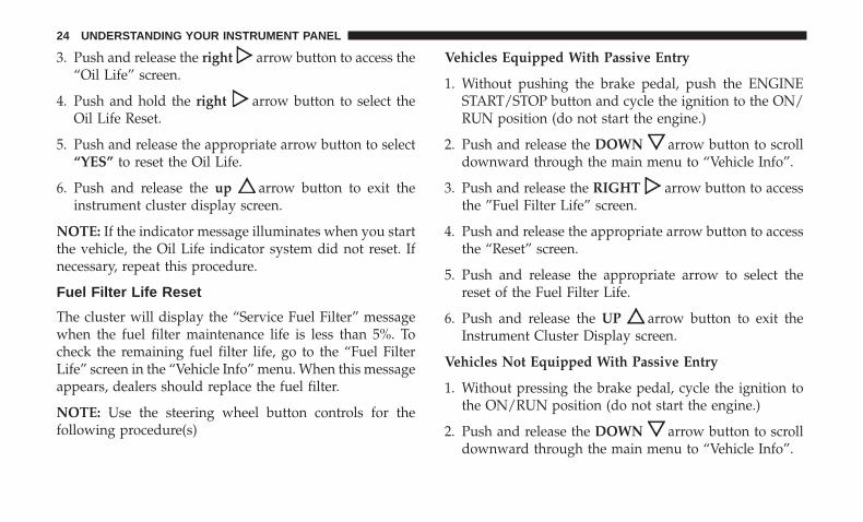
3. Push and release the right arrow button to access the”Oil Life” screen.
4. Push and hold the right arrow button to select“Reset”.
5. Push and release the appropriate arrow button to select“YES” to reset the Oil Life.
6. Push and release the up arrow button to exit theinstrument cluster display screen.
Vehicles Not Equipped With Passive Entry
1. Without pushing the brake pedal, cycle the ignition tothe ON/RUN position (do not start the engine).
2. Push and release the down arrow button to scrolldownward through the main menu to “Vehicle Info.”
3
UNDERSTANDING YOUR INSTRUMENT PANEL 23
3. Push and release the right arrow button to access the“Oil Life” screen.
4. Push and hold the right arrow button to select theOil Life Reset.
5. Push and release the appropriate arrow button to select“YES” to reset the Oil Life.
6. Push and release the up arrow button to exit theinstrument cluster display screen.
NOTE: If the indicator message illuminates when you startthe vehicle, the Oil Life indicator system did not reset. Ifnecessary, repeat this procedure.
Fuel Filter Life Reset
The cluster will display the “Service Fuel Filter” messagewhen the fuel filter maintenance life is less than 5%. Tocheck the remaining fuel filter life, go to the “Fuel FilterLife” screen in the “Vehicle Info” menu. When this messageappears, dealers should replace the fuel filter.
NOTE: Use the steering wheel button controls for thefollowing procedure(s)
Vehicles Equipped With Passive Entry
1. Without pushing the brake pedal, push the ENGINESTART/STOP button and cycle the ignition to the ON/RUN position (do not start the engine.)
2. Push and release the DOWN arrow button to scrolldownward through the main menu to “Vehicle Info”.
3. Push and release the RIGHT arrow button to accessthe ”Fuel Filter Life” screen.
4. Push and release the appropriate arrow button to accessthe “Reset” screen.
5. Push and release the appropriate arrow to select thereset of the Fuel Filter Life.
6. Push and release the UP arrow button to exit theInstrument Cluster Display screen.
Vehicles Not Equipped With Passive Entry
1. Without pressing the brake pedal, cycle the ignition tothe ON/RUN position (do not start the engine.)
2. Push and release the DOWN arrow button to scrolldownward through the main menu to “Vehicle Info”.
24 UNDERSTANDING YOUR INSTRUMENT PANEL
3. Push and release the RIGHT arrow button to accessthe ”Fuel Filter Life” screen.
4. Push and release the appropriate arrow button to accessthe “Reset” screen.
5. Push and release the appropriate arrow to select thereset of the Fuel Filter Life.
6. Push and release the UP arrow button to exit theInstrument Cluster Display screen.
NOTE: If the indicator message illuminates when you startthe vehicle, the Fuel Filter indicator system did not reset. Ifnecessary, repeat this procedure.
Diesel Particulate Filter (DPF) Messages
This engine meets all required diesel engine emissionsstandards. To achieve these emissions standards, yourvehicle is equipped with a state-of-the-art engine andexhaust system. These systems are seamlessly integratedinto your vehicle and managed by the Powertrain ControlModule (PCM). The PCM manages engine combustion toallow the exhaust system’s catalyst to trap and burnParticulate Matter (PM) pollutants, with no input or inter-action on your part.
WARNING!
A hot exhaust system can start a fire if you park overmaterials that can burn. Such materials might be grassor leaves coming into contact with your exhaust sys-tem. Do not park or operate your vehicle in areas whereyour exhaust system can contact anything that canburn.
Your vehicle has the ability to alert you to additionalmaintenance required on your vehicle or engine. Refer tothe following messages that may be displayed on yourinstrument cluster:
• Exhaust Filter XX% Full Safely Drive at HighwaySpeeds to Remedy — This message will be displayed inthe instrument cluster if the exhaust particulate filterreaches 80% of its maximum storage capacity. Underconditions of exclusive short duration and low speeddriving cycles, your diesel engine and exhaust after-treatment system may never reach the conditions re-quired to cleanse the filter to remove the trapped PM. Ifthis occurs, the “Exhaust Filter XX% Full Safely Drive atHighway Speeds to Remedy” message will be displayedin the Instrument Cluster Display. If this message isdisplayed, you will hear one chime to assist in alerting
3
UNDERSTANDING YOUR INSTRUMENT PANEL 25
you of this condition. By simply driving your vehicle athighway speeds for up to 20 minutes, you can remedythe condition in the particulate filter system and allowyour diesel engine and exhaust after-treatment system tocleanse the filter to remove the trapped PM and restorethe system to normal operating condition.
• Exhaust System — Regeneration In Process ExhaustFilter XX% Full — This message indicates that theDiesel Particulate Filter (DPF) is self-cleaning. Maintainyour current driving condition until regeneration iscompleted.
• Exhaust System — Regeneration Completed — Thismessage indicates that the Diesel Particulate Filter (DPF)self-cleaning is completed. If this message is displayed,you will hear one chime to assist in alerting you of thiscondition.
• Exhaust Service Required — See Dealer Now — Thismessages indicates regeneration has been disabled dueto a system malfunction. At this point the engine Pow-ertrain Control Module (PCM) will register a fault code,the instrument panel will display a MIL light.
CAUTION!
See your authorized dealer, as damage to the exhaustsystem could occur soon with continued operation.
• Exhaust Filter Full — Power Reduced See Dealer —This message indicates the PCM has derated the engineto limit the likelihood of permanent damage to theafter-treatment system. If this condition is not correctedand a dealer service is not performed, extensive exhaustafter-treatment damage can occur. To correct this condi-tion it will be necessary to have your vehicle serviced byyour local authorized dealer.
CAUTION!
See your authorized dealer, as damage to the exhaustsystem could occur soon with continued operation.
Displays
When the appropriate conditions exist, the InstrumentCluster Display displays the following messages:
• System Setup Unavailable – Vehicle Not in Park
• System Setup Unavailable – Vehicle in Motion
26 UNDERSTANDING YOUR INSTRUMENT PANEL
• Exhaust Filter Full Safely Drive at Highway Speeds ToRemedy
• Exhaust Filter XX% Full – Power Reduced See Dealer
• Exhaust Service Required – See Dealer Now
• Exhaust System – Filter XX% Full Service Required SeeDealer
• Exhaust System – Regeneration In Process Exhaust FilterXX% Full
• Exhaust System – Regeneration Completed
• Engine Will Not Restart in XXXX mi DEF Low RefillSoon
• Engine Will Not Restart in XXXX mi Refill DEF
• Engine Will Not Restart Refill DEF
• Service DEF System See Dealer
• Incorrect DEF Detected See Dealer
• Engine Will Not Restart in XXX mi Service DEF SeeDealer
• Engine Will Not Restart Service DEF System See Dealer
Vehicle Information (Customer InformationFeatures)
Vehicle Information Submenus
• Battery Voltage
Displays the actual battery voltage.
• Fuel Filter Life
Displays the life of the fuel filter.
• Oil Pressure
Displays the actual oil pressure.
• Oil Temperature
Displays the actual oil temperature.
• Trans Temperature
Displays the actual transmission sump temperature.
• Coolant Temp
Displays the actual coolant temperature.
• Tire Pressure Monitor System
Displays the actual tire pressure.
3
UNDERSTANDING YOUR INSTRUMENT PANEL 27
• Engine Hours
Displays the actual engine hours.
Gauge Summary (Coolant Temp, Trans Temp, Oil Temp,Oil Pressure)
Diesel Exhaust Fluid (DEF) Warning Messages
Your vehicle will begin displaying warning messages whenthe DEF level reaches a driving range of approximately 500miles (800 km). If the following warning message sequenceis ignored, your vehicle may not restart unless DEF isadded with in the displayed mileage shown in the clustermessage.
• Engine Will Not Restart in XXXX mi DEF Low RefillSoon — This message will display when DEF drivingrange is less than 500 miles, DEF fluid top off is requiredwith in the displayed mileage. The message will bedisplayed in the cluster during vehicle start up with thecurrent allowed mileage and accompanied by a singlechime. The remaining mileage can be pulled up anytimeby way of the “Messages” list within the InstrumentCluster Display
• Engine Will Not Restart in XXXX mi Refill DEF — Thismessage will display when DEF driving range is lessthan 200 miles. It is also displayed at 150 miles and100 miles. DEF fluid top off is required with in thedisplayed mileage. The message will be displayed in theInstrument Cluster Display during vehicle start up withan updated distance mileage, and it will be accompaniedby a single chime. Starting at 100 miles, remaining rangewill be continuously displayed while operating thevehicle. Chimes will also accompany the 75, 50 and 25mile remaining distances. The DEF Low telltale will beon continuously until DEF fluid is topped off.
• Engine Will Not Restart Refill DEF — This messagewill display when the DEF driving range is less than 1mile, DEF fluid top off is required or the engine will notrestart. The message will be displayed in the InstrumentCluster Display during vehicle start up, and it will beaccompanied by a single chime. The DEF Low telltalewill be illuminated continuously until DEF fluid tank isfilled with a minimum of two gallons of DEF.
28 UNDERSTANDING YOUR INSTRUMENT PANEL
Diesel Exhaust Fluid (DEF) Fault WarningMessages
There are different messages which are displayed if thevehicle detects that the DEF system has been filled with afluid other than DEF, has experienced component failures,or when tampering has been detected.
When the DEF system needs to be serviced the followingwarnings will display:
• Service DEF System See Dealer — This message willdisplay when the fault is initially detected and each timethe vehicle is started. The message will be accompaniedby a single chime and the Malfunction Indicator Light.We recommend you drive to your nearest authorizeddealer and have your vehicle serviced immediately. Ifnot corrected in 50 miles, vehicle will enter the “EngineWill not restart in XXXmi Service DEF See dealer”warning stage and message.
• Incorrect DEF Detected See Dealer — This message willdisplay if the DEF system has detected the incorrectfluid has been introduced to the DEF tank. The messagewill be accompanied by a single chime. We recommendyou drive to your nearest authorized dealer and haveyour vehicle serviced immediately. If not corrected in
30 miles, vehicle will enter the “Engine Will not restart inXXX mi Service DEF See dealer” warning stage andmessage.
• Engine Will Not Restart in XXX mi Service DEF SeeDealer — This message is first displayed if the faultdetected is not serviced after 50 miles of operation. It isalso displayed at 150 miles 125 miles and 100 miles.System service is required within the displayed mileage.The message will be displayed during vehicle start upwith an updated distance mileage, and it will be accom-panied by a single chime. Starting at 100 miles, remain-ing range will be continuously displayed while operat-ing the vehicle. Chimes will also accompany the 75, 50and 25 mile remaining distances. We recommend youdrive to your nearest authorized dealer and have yourvehicle serviced immediately.
• Engine Will Not Restart Service DEF System SeeDealer — This message will display if DEF system issuedetected is not serviced during the allowed period. Yourengine will not restart unless your vehicle is serviced byyour authorized dealer. This message will be displayedwhen under 1 mile until engine will not start and eachtime the vehicle is started, and will be continuouslydisplayed. The message will be accompanied by a single
3
UNDERSTANDING YOUR INSTRUMENT PANEL 29
chime. Your Malfunction Indicator Light will be continu-ously illumined. We highly recommend you drive toyour nearest authorized dealer if the message appearswhile engine is running.
• Engine Will Not Start Service DEF System See Dealer— This message will display when the fault detected isnot serviced after the Engine will not restart Service DEFSystem See Dealer message is displayed on the nextsubsequent restart. Your engine will not start unlessyour vehicle is serviced by your authorized dealer. Themessage will be accompanied by a single chime. YourMalfunction Indicator Light will be continuously illumi-nated. If the message appears and you can not start theengine, we recommend you have your vehicle towed toyour nearest authorized dealer immediately.
30 UNDERSTANDING YOUR INSTRUMENT PANEL
STARTING AND OPERATING
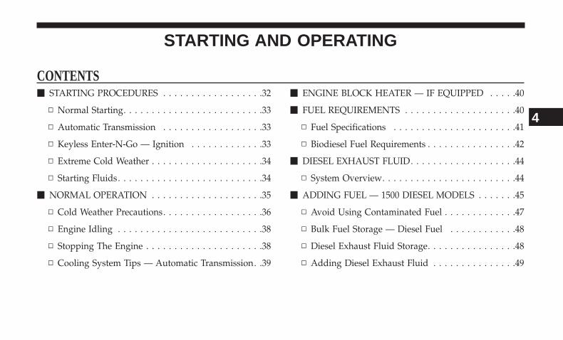
CONTENTS� STARTING PROCEDURES . . . . . . . . . . . . . . . . . .32
▫ Normal Starting. . . . . . . . . . . . . . . . . . . . . . . . .33
▫ Automatic Transmission . . . . . . . . . . . . . . . . . .33
▫ Keyless Enter-N-Go — Ignition . . . . . . . . . . . . .33
▫ Extreme Cold Weather . . . . . . . . . . . . . . . . . . . .34
▫ Starting Fluids. . . . . . . . . . . . . . . . . . . . . . . . . .34
� NORMAL OPERATION . . . . . . . . . . . . . . . . . . . .35
▫ Cold Weather Precautions. . . . . . . . . . . . . . . . . .36
▫ Engine Idling . . . . . . . . . . . . . . . . . . . . . . . . . .38
▫ Stopping The Engine . . . . . . . . . . . . . . . . . . . . .38
▫ Cooling System Tips — Automatic Transmission. .39
� ENGINE BLOCK HEATER — IF EQUIPPED . . . . .40
� FUEL REQUIREMENTS . . . . . . . . . . . . . . . . . . . .40
▫ Fuel Specifications . . . . . . . . . . . . . . . . . . . . . .41
▫ Biodiesel Fuel Requirements . . . . . . . . . . . . . . . .42
� DIESEL EXHAUST FLUID. . . . . . . . . . . . . . . . . . .44
▫ System Overview. . . . . . . . . . . . . . . . . . . . . . . .44
� ADDING FUEL — 1500 DIESEL MODELS . . . . . . .45
▫ Avoid Using Contaminated Fuel . . . . . . . . . . . . .47
▫ Bulk Fuel Storage — Diesel Fuel . . . . . . . . . . . .48
▫ Diesel Exhaust Fluid Storage. . . . . . . . . . . . . . . .48
▫ Adding Diesel Exhaust Fluid . . . . . . . . . . . . . . .49
4
STARTING PROCEDURES
Before starting your vehicle, adjust your seat, both insideand outside mirrors, and fasten your seat belts.
The starter is allowed to crank for up to 30-second inter-vals. Waiting a few minutes between such intervals willprotect the starter from overheating.
WARNING!
• Before exiting a vehicle, always shift the automatictransmission into PARK and apply the parkingbrake. Always make sure the keyless ignition node isin the “OFF” mode, remove the key fob from thevehicle and lock the vehicle.
• Never leave children alone in a vehicle, or withaccess to an unlocked vehicle. Leaving children in avehicle unattended is dangerous for a number ofreasons. A child or others could be seriously orfatally injured. Children should be warned not totouch the parking brake, brake pedal or the gearselector.
(Continued)
WARNING! (Continued)• Do not leave the key fob in or near the vehicle, or in
a location accessible to children, and do not leave theignition of a vehicle equipped with Keyless Enter-N-Go in the ACC or ON/RUN mode. A child couldoperate power windows, other controls, or move thevehicle.
• Do not leave children or animals inside parkedvehicles in hot weather. Interior heat build-up maycause serious injury or death.
NOTE: Engine start up in very low ambient temperaturecould result in evident white smoke. This condition willdisappear as the engine warms up.
CAUTION!
• The engine is allowed to crank as long as 30 seconds.If the engine fails to start during this period, pleasewait at least two minutes for the starter to cool beforerepeating start procedure.
(Continued)
32 STARTING AND OPERATING
CAUTION! (Continued)• If the “Water in Fuel Indicator Light” remains on,
DO NOT START engine before you drain the waterfrom the fuel filters to avoid engine damage. Refer to“Maintenance Procedures/Draining Fuel/Water Sepa-rator Filter” in “Maintaining Your Vehicle” for fur-ther information.
Normal Starting
Normal starting of either a warm or cold engine is obtainedwithout pumping or pressing the accelerator pedal. Turnthe key fob to the START position and release when theengine starts. If the engine fails to start, turn the key fob tothe OFF position, wait five seconds, then repeat the “Nor-mal Starting” procedure.
Automatic Transmission
Start the engine with the transmission gear selector in thePARK position. Apply the brake before shifting to anydriving range.
Tip Start Feature
Do not press the accelerator. Cycle the ignition switchbriefly to the START position and release it. The startermotor will continue to run but will automatically disen-gage when the engine is running.
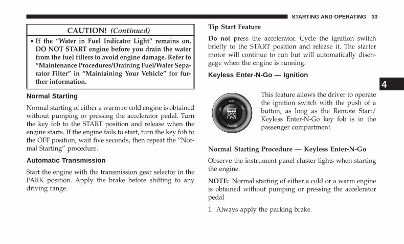
Keyless Enter-N-Go — Ignition
This feature allows the driver to operatethe ignition switch with the push of abutton, as long as the Remote Start/Keyless Enter-N-Go key fob is in thepassenger compartment.
Normal Starting Procedure — Keyless Enter-N-Go
Observe the instrument panel cluster lights when startingthe engine.
NOTE: Normal starting of either a cold or a warm engineis obtained without pumping or pressing the acceleratorpedal
1. Always apply the parking brake.
4
STARTING AND OPERATING 33
2. Press and hold the brake pedal while pushing theENGINE START/STOP button once.
NOTE: A delay of the start of up to five seconds is possibleunder very cold conditions. The �Wait to Start� telltale willbe illuminated during the pre-heat process, When theengine Wait To Start light goes off the engine will auto-matically crank.
CAUTION!
If the “Water in Fuel Indicator Light” remains on, DONOT START the engine before you drain the waterfrom the fuel filters to avoid engine damage. Refer to“Maintenance Procedures/Draining Fuel/Water Sepa-rator Filter” in “Maintaining Your Vehicle” for furtherinformation.
3. The system will automatically engage the starter tocrank the engine. If the vehicle fails to start, the starterwill disengage automatically after 25 seconds.
4. If you wish to stop the cranking of the engine prior tothe engine starting, push the button again.
5. Check that the oil pressure warning light has turned off.
6. Release the parking brake.
Extreme Cold Weather
The engine block heater is a resistance heater installed in thewater jacket of the engine. It requires a 110–115 Volt ACelectrical outlet with a grounded, three-wire extension cord.Its use is recommended for environments that routinely fallbelow -10°F (-23°C). It should be used when the vehicle hasnot been running overnight or longer periods and should beplugged in two hours prior to start. Its use is required forcold starts with temperatures under -20°F (-28°C).
NOTE: The engine block heater cord is a factory installedoption. If your vehicle is not equipped, heater cords areavailable from your authorized MOPAR dealer.
• A 12 Volt heater built into the fuel filter housing aids inpreventing fuel gelling. It is controlled by a built-inthermostat.
• A Diesel Pre-Heat system both improves engine startingand reduces the amount of white smoke generated by awarming engine.
Starting Fluids
The engine is equipped with a glow plug preheatingsystem. If the instructions in this manual are followed, theengine should start in all conditions and no type of startingfluid should be used.
34 STARTING AND OPERATING
WARNING!
• Do not leave children or animals inside parkedvehicles in hot weather. Interior heat build up maycause serious injury or death.
• When leaving the vehicle, always make sure thekeyless ignition node is in the “OFF” mode, removethe key fob from the vehicle and lock the vehicle.
• Never leave children alone in a vehicle, or withaccess to an unlocked vehicle. Allowing children tobe in a vehicle unattended is dangerous for a numberof reasons. A child or others could be seriously orfatally injured. Children should be warned not totouch the parking brake, brake pedal or the gearselector.
• Do not leave the key fob in or near the vehicle, or ina location accessible to children, and do not leave theignition of a vehicle equipped with Keyless Enter-N-Go in the ACC or ON/RUN mode. A child couldoperate power windows, other controls, or move thevehicle.
NORMAL OPERATION
Observe the following when the diesel engine is operating.
• All message center lights are off.
• Malfunction Indicator Light (MIL) is off.
• Engine Oil Pressure telltale is not illuminated.
• Voltmeter operation:
The voltmeter may show a gauge fluctuation at variousengine temperatures. This is caused by the glow plugheating system. The number of cycles and the length of thecycling operation is controlled by the engine control mod-ule. Glow plug heater operation can run for several min-utes, once the heater operation is complete the voltmeterneedle will stabilize.
4
STARTING AND OPERATING 35
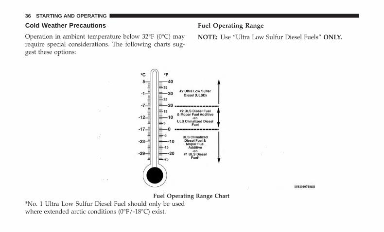
Cold Weather Precautions
Operation in ambient temperature below 32°F (0°C) mayrequire special considerations. The following charts sug-gest these options:
Fuel Operating Range
NOTE: Use “Ultra Low Sulfur Diesel Fuels” ONLY.
*No. 1 Ultra Low Sulfur Diesel Fuel should only be usedwhere extended arctic conditions (0°F/-18°C) exist.
Fuel Operating Range Chart
36 STARTING AND OPERATING
NOTE:
• Use of Climatized Ultra Low Sulfur Diesel Fuel orNumber 1 Ultra Low Sulfur Diesel Fuel results in anoticeable decrease in fuel economy.
• Climatized Ultra Low Sulfur Diesel Fuel is a blend ofNumber 2 Ultra Low Sulfur and Number 1 Ultra LowSulfur Diesel Fuels which reduces the temperature atwhich wax crystals form in fuel.
• The fuel grade should be clearly marked on the pump atthe fuel station.
• The engine requires the use of “Ultra Low Sulfur DieselFuel”. Use of incorrect fuel could result in engine andexhaust system damage. Refer to “Fuel Requirements”in “Starting And Operating” for further information.
• If climatized or diesel Number 1 ULSD fuel is notavailable, and you are operating below (20°F/-6°C), insustained arctic conditions, Mopar Premium Diesel FuelTreatment (or equivalent) is recommended to avoidgelling (see Fuel Operating Range Chart).
Engine Oil Usage
Refer to “Maintenance Procedures” in “Maintaining YourVehicle” for the correct engine oil viscosity.
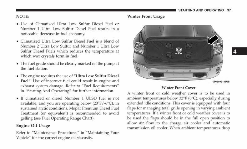
Winter Front Usage
A winter front or cold weather cover is to be used inambient temperatures below 32°F (0°C), especially duringextended idle conditions. This cover is equipped with fourflaps for managing total grille opening in varying ambienttemperatures. If a winter front or cold weather cover is tobe used the flaps should be in the full open position toallow air flow to the charge air cooler and automatictransmission oil cooler. When ambient temperatures drop
Winter Front Cover
4
STARTING AND OPERATING 37
below 0°F (-17°C) the four flaps need to be closed. Asuitable cold weather cover is available from your MOPARdealer.
Engine Warm-Up
Avoid full throttle operation when the engine is cold. Whenstarting a cold engine, bring the engine up to operatingspeed slowly to allow the oil pressure to stabilize as theengine warms up.
If temperatures are below 32°F (0°C), operate the engine atmoderate speeds for five minutes before full loads areapplied.
Engine Idling
Avoid prolonged idling, long periods of idling may beharmful to your engine because combustion chamber tem-peratures can drop so low that the fuel may not burn
completely. Incomplete combustion allows carbon andvarnish to form on piston rings, cylinder head valves, andinjector nozzles. Also, the unburned fuel can enter thecrankcase, diluting the oil and causing rapid wear to theengine.
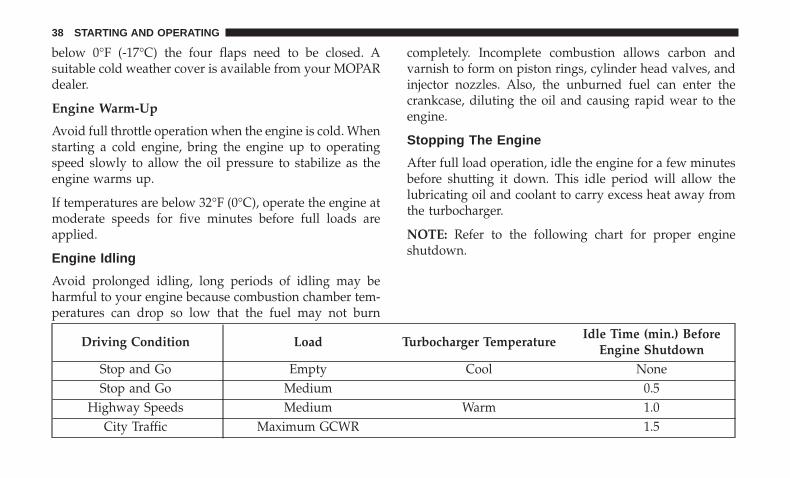
Stopping The Engine
After full load operation, idle the engine for a few minutesbefore shutting it down. This idle period will allow thelubricating oil and coolant to carry excess heat away fromthe turbocharger.
NOTE: Refer to the following chart for proper engineshutdown.
Driving Condition Load Turbocharger TemperatureIdle Time (min.) Before
Engine ShutdownStop and Go Empty Cool NoneStop and Go Medium 0.5
Highway Speeds Medium Warm 1.0City Traffic Maximum GCWR 1.5
38 STARTING AND OPERATING
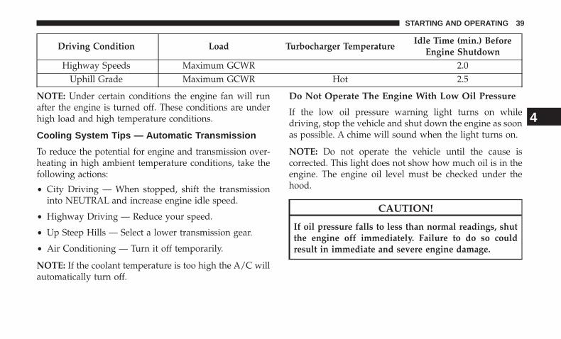
Driving Condition Load Turbocharger TemperatureIdle Time (min.) Before
Engine ShutdownHighway Speeds Maximum GCWR 2.0
Uphill Grade Maximum GCWR Hot 2.5
NOTE: Under certain conditions the engine fan will runafter the engine is turned off. These conditions are underhigh load and high temperature conditions.
Cooling System Tips — Automatic Transmission
To reduce the potential for engine and transmission over-heating in high ambient temperature conditions, take thefollowing actions:
• City Driving — When stopped, shift the transmissioninto NEUTRAL and increase engine idle speed.
• Highway Driving — Reduce your speed.
• Up Steep Hills — Select a lower transmission gear.
• Air Conditioning — Turn it off temporarily.
NOTE: If the coolant temperature is too high the A/C willautomatically turn off.
Do Not Operate The Engine With Low Oil Pressure
If the low oil pressure warning light turns on whiledriving, stop the vehicle and shut down the engine as soonas possible. A chime will sound when the light turns on.
NOTE: Do not operate the vehicle until the cause iscorrected. This light does not show how much oil is in theengine. The engine oil level must be checked under thehood.
CAUTION!
If oil pressure falls to less than normal readings, shutthe engine off immediately. Failure to do so couldresult in immediate and severe engine damage.
4
STARTING AND OPERATING 39
Do Not Operate The Engine With Failed Parts
All engine failures give some warning before the parts fail.Be on the alert for changes in performance, sounds, andvisual evidence that the engine requires service. Someimportant clues are:
• Engine misfiring or vibrating severely.
• Sudden loss of power.
• Unusual engine noises.
• Fuel, oil or coolant leaks.
• Sudden change, outside the normal operating range, inthe engine operating temperature.
• Excessive smoke.
• Oil pressure drop.
ENGINE BLOCK HEATER — IF EQUIPPED
The engine block heater warms engine coolant and permitsquicker starts in cold weather. Connect the heater cord to aground-fault interrupter protected 110–115 Volt AC electri-cal outlet with a grounded, three-wire extension cord.
Its use is recommended for environments that routinely fallbelow -10°F (-23°C). It should be used when the vehicle hasnot been running for long periods of time and should be
plugged in two hours prior to start. Its use is required forcold starts with temperatures under -20°F (-28°C).
To ensure reliable starting at these temperatures, use of anexternally powered electric engine block heater (availablefrom your authorized dealer) is recommended.
WARNING!
Remember to disconnect the cord before driving. Dam-age to the 110–115 Volt electrical cord could causeelectrocution.
NOTE: The block heater will require 110 Volts AC and6.5 Amps to activate the heater element.
FUEL REQUIREMENTS
Use good quality diesel fuel from a reputable supplier inyour vehicle. Federal law requires that you must fuel thisvehicle with Ultra Low Sulfur Highway Diesel fuel(15 ppm Sulfur maximum) and prohibits the use of LowSulfur Highway Diesel fuel (500 ppm Sulfur maximum) toavoid damage to the emissions control system.
For most year-round service, No. 2 diesel fuel meetingASTM (formerly known as the American Society for Test-ing and Materials) specification D-975 Grade S15 will
40 STARTING AND OPERATING
provide good performance. If the vehicle is exposed toextreme cold (below 20°F or -7°C), or is required to operateat colder-than-normal conditions for prolonged periods,use climatized No. 2 diesel fuel or dilute the No. 2 dieselfuel with 50% No. 1 diesel fuel. This will provide betterprotection from fuel gelling or wax-plugging of the fuelfilter.
WARNING!
Do not use alcohol or gasoline as a fuel blending agent.They can be unstable under certain conditions andhazardous or explosive when mixed with diesel fuel.
Diesel fuel is seldom completely free of water. To preventfuel system trouble, drain the accumulated water from thefuel/water separator using the fuel/water separator drainprovided on the fuel filter housing. If you buy good qualityfuel and follow the cold weather advice above, fuel condi-tioners should not be required in your vehicle. If availablein your area, a high cetane “premium” diesel fuel may offerimproved cold-starting and warm-up performance.
CAUTION!
If the “Water in Fuel Indicator Light” remains on, DONOT START engine before you drain the water fromthe fuel filter(s) to avoid engine damage. Refer to“Maintenance Procedures/Draining Fuel/Water Sepa-rator Filter” in “Maintaining Your Vehicle” for furtherinformation.
Fuel Specifications
This diesel engine has been developed to take advantage ofthe high energy content and generally lower cost No. 2Ultra Low Sulfur diesel fuel or No. 2 Ultra Low Sulfurclimatized diesel fuels.
NOTE:
• If you accidentally fill the fuel tank with gasoline onyour diesel vehicle, do not start the engine. Damage tothe engine and fuel system could occur. Please call yourauthorized dealer for service.
• A maximum blend of 5% biodiesel meeting ASTMspecification D-975 may be used with your diesel enginewithout any adjustments to regular service schedules.
4
STARTING AND OPERATING 41
• Commercially available fuel additives are not necessaryfor the proper operation of your diesel engine.
• No. 1 Ultra Low Sulfur diesel fuel should only be usedwhere extended arctic conditions (-10°F or -23°C) exist.
Biodiesel Fuel Requirements
A maximum blend of 5% biodiesel meeting ASTM specifi-cation D975 is recommended for use with your dieselengine. If frequent operation with biodiesel blends that arebetween 6% and 20% (B6–B20) is desired, the maintenanceschedule is subject to shorter intervals.
The oil and filter change along with fuel filter replacementis subject to shorter intervals when operating your engineon biodiesel greater than 5%. Do not use biodiesel greaterthan 20%.
For regular use of biodiesel blends between 6% and 20%(B6–B20) it is important that you understand and complywith these requirements. Refer to the “Maintenance Chart”in the “Maintenance Schedules” section for further direc-tion.
CAUTION!
Failure to comply with Oil Change requirements forvehicles operating on biodiesel blends between 6%and 20% (B6–B20) will result in premature engine wear.Such wear is not covered by the New Vehicle LimitedWarranty.
Biodiesel is a fuel produced from renewable resourcestypically derived from animal fat, rapeseed oil (RapeseedMethyl Ester (RME) base), or soybean oil (Soy Methyl Ester(SME or SOME) base).
Biodiesel fuel has inherent limitations which require thatyou understand and adhere to the following requirementsif you use blends of biodiesel between 6% and 20%(B6–B20). There are no unique restrictions for the use of B5.
CAUTION!
Use of blends greater than 20% is not approved. Use ofblends greater than 20% can result in engine damage.Such damage is not covered by the New VehicleLimited Warranty.
42 STARTING AND OPERATING
Biodiesel Fuel Properties — Low AmbientTemperatures
Biodiesel fuel may gel or solidify at low ambient tempera-tures, which may pose problems for both storage andoperation. Precautions can be necessary at low ambienttemperatures, such as storing the fuel in a heated buildingor a heated storage tank, or using cold temperature addi-tives.
Fuel Quality — Must Comply With ASTMStandards
The quality of biodiesel fuel may vary widely. Only fuelproduced by a BQ9000 supplier to the following specifica-tions may be blended to meet biodiesel blend B6 – B20 fuelmeeting ASTM specification D-7467:
• Petrodiesel fuel meeting ASTM specification D-975 andbiodiesel fuel (B100) meeting ASTM specification D-6751
Fuel Oxidation Stability — Must Use Fuel WithinSix Months Of Manufacture
Biodiesel fuel has poor oxidation stability which can resultin long term storage problems. Fuel produced to approvedASTM standards, if stored properly, provides for protec-tion against fuel oxidation for up to six months.
Fuel Water Separation — Must Use MOPARApproved Fuel Filter Elements
Biodiesel fuel has a natural affinity to water and wateraccelerates microbial growth. Your MOPAR filtration sys-tem is designed to provide adequate fuel water separationcapabilities.
Fuel In Oil Dilution — Must Adhere To RequiredOil Change Interval
Fuel dilution of lubricating oil has been observed with theuse of biodiesel fuel. Fuel in oil must not exceed 5%. Toensure this limit is met your oil change interval must bemaintained with in the suggested schedule. The regularuse of biodiesel between 6% and 20% requires intervalsshorter than the outlined 10,000 miles and must not exceedthe suggested schedule. When routinely operating onbiodiesel between 6% and 20%, oil and filter replacementintervals must not exceed 8,000 Miles or 6 months, whichever comes first.
Biodiesel Fuel Filter Change Intervals
The use of biodiesel requires intervals shorter than theoutlined 30,000 miles (48,280 km) and must not exceed the
4
STARTING AND OPERATING 43
suggested schedule. When operating on biodiesel between6% and 20%, fuel filter replacement intervals must notexceed 20,000 Miles (40,233 km).
NOTE: Under no circumstances should oil change inter-vals exceed 8,000 miles (12,875 km) or 6 months, if regularoperation occurs with 6% - 20% biodiesel blends. Under nocircumstances should fuel filter intervals exceed 20,000miles (40,233 km), if regular operation occurs with 6% -20% biodiesel blends. Failure to comply with these OilChange and fuel filter requirements for vehicles operatingon biodiesel blends up to B20 may result in prematureengine wear. Such wear is not covered by the New VehicleLimited Warranty. The engine may suffer severe damage ifoperated with concentrations of biodiesel higher than 20%.
DIESEL EXHAUST FLUID
Your vehicle is equipped with a Selective Catalytic Reduc-tion system to meet the very stringent diesel emissionsstandards required by the Environmental ProtectionAgency.
The purpose of the SCR system is to reduce levels of NOx(oxides of nitrogen emitted from engines) that are harmfulto our health and the environment to a near-zero level.Small quantities of Diesel Exhaust Fluid (DEF) is injected
into the exhaust upstream of a catalyst where, whenvaporized, it converts smog-forming nitrogen oxides(NOx) into harmless nitrogen (N2) and water vapor (H2O),two natural components of the air we breathe. You canoperate with the comfort that your vehicle is contributingto a cleaner, healthier world environment for this andgenerations to come.
System Overview
This vehicle is equipped with a Diesel Exhaust Fluid (DEF)injection system and a Selective Catalytic Reduction (SCR)catalyst to meet the emission requirements.
The DEF injection system consists of the following compo-nents:
• DEF tank
• DEF pump
• DEF injector
• Electronically-heated DEF lines
• NOx sensors
• Temperature sensors
• SCR catalyst
44 STARTING AND OPERATING
The DEF injection system and SCR catalyst enable theachievement of diesel emissions requirements; while main-taining outstanding fuel economy, drivability, torque andpower ratings.
Refer to “Instrument Cluster Display” in “UnderstandingYour Instrument Panel” for system messages and warn-ings.
NOTE:
• Your vehicle is equipped with a DEF injection system.You may occasionally hear an audible clicking noisefrom under the vehicle at a stop. This is normal opera-tion.
• The DEF pump will run for a period of time after engineshutdown to purge the DEF system. This is normaloperation and may be audible from the rear of thevehicle.
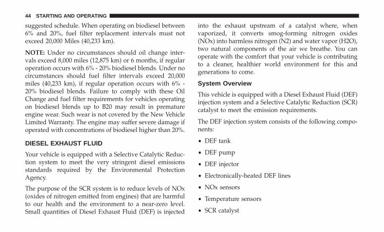
ADDING FUEL — 1500 DIESEL MODELS
1. Open the fuel filler door.
NOTE: There is no fuel filler cap. A flapper door inside thefiller pipe seals the system.
2. Insert the fuel nozzle fully into the filler pipe – thenozzle opens and holds the flapper door while refuel-ing.
Diesel Fuel And Diesel Exhaust Fluid Fill Location
1 — Diesel Exhaust Fluid Fill Location2 — Diesel Fuel Fill Location
4
STARTING AND OPERATING 45
3. Fill the vehicle with fuel – when the fuel nozzle “clicks”or shuts off the fuel tank is full.
4. Remove the fuel nozzle and close the fuel door.
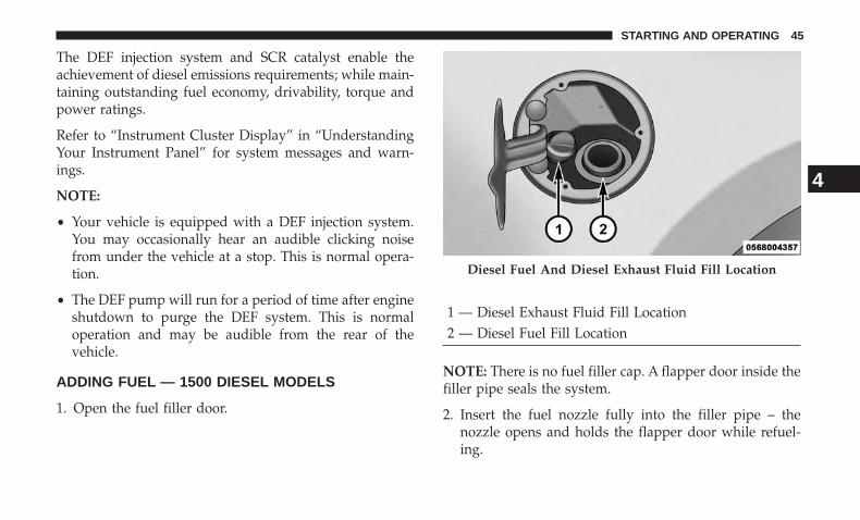
Emergency Fuel Can Refueling
Most fuel cans will not open the flapper door.
A funnel is provided to open the flapper door to allowemergency refueling with a fuel can.
1. Retrieve fuel funnel from the jack kit located under thefront passenger seat.
2. Insert funnel into same filler pipe opening as the fuelnozzle.
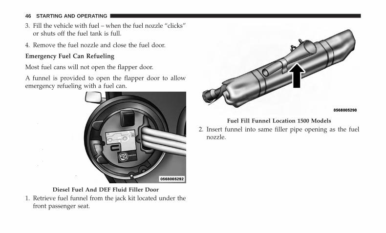
Diesel Fuel And DEF Fluid Filler Door
Fuel Fill Funnel Location 1500 Models
46 STARTING AND OPERATING
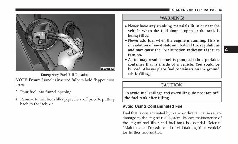
NOTE: Ensure funnel is inserted fully to hold flapper dooropen.
3. Pour fuel into funnel opening.
4. Remove funnel from filler pipe, clean off prior to puttingback in the jack kit.
WARNING!
• Never have any smoking materials lit in or near thevehicle when the fuel door is open or the tank isbeing filled.
• Never add fuel when the engine is running. This isin violation of most state and federal fire regulationsand may cause the “Malfunction Indicator Light” toturn on.
• A fire may result if fuel is pumped into a portablecontainer that is inside of a vehicle. You could beburned. Always place fuel containers on the groundwhile filling.
CAUTION!
To avoid fuel spillage and overfilling, do not “top off”the fuel tank after filling.
Avoid Using Contaminated Fuel
Fuel that is contaminated by water or dirt can cause severedamage to the engine fuel system. Proper maintenance ofthe engine fuel filter and fuel tank is essential. Refer to“Maintenance Procedures” in “Maintaining Your Vehicle”for further information.
Emergency Fuel Fill Location
4
STARTING AND OPERATING 47
Bulk Fuel Storage — Diesel Fuel
If you store quantities of fuel, good maintenance of thestored fuel is also essential. Fuel contaminated with waterwill promote the growth of “microbes.” These microbesform “slime” that will clog the fuel filtration system andlines. Drain condensation from the supply tank and changethe line filter on a regular basis.
NOTE: When a diesel engine is allowed to run out of fuel,air is pulled into the fuel system.
If the vehicle will not start, refer to “MaintenanceProcedures/Priming If The Engine Has Run Out Of Fuel”in “Maintaining Your Vehicle” for further information.
WARNING!
Do not open the high pressure fuel system with theengine running. Engine operation causes high fuelpressure. High pressure fuel spray can cause seriousinjury or death.
Diesel Exhaust Fluid Storage
Diesel Exhaust Fluid (DEF) is considered a very stableproduct with a long shelf life. If DEF is kept in tempera-tures between 10° and 90°F (-12° and 32°C), it will last aminimum of one year.
DEF is subject to freezing at the lowest temperatures. Forexample, DEF may freeze at temperatures at or below12° F (-11° C). The system has been designed to operate inthis environment.
NOTE: When working with DEF, it is important to knowthat:
• Any containers or parts that come into contact with DEFmust be DEF compatible (plastic or stainless steel).Copper, brass, aluminum, iron or non-stainless steelshould be avoided as they are subject to corrosionby DEF.
• If DEF is spilled, it should be wiped up completely.
48 STARTING AND OPERATING
Adding Diesel Exhaust Fluid
The DEF gauge (located on the instrument cluster) willdisplay the level of DEF remaining in the tank. Refer to“Instrument Cluster” and “Instrument Cluster Descrip-tions” in “Understanding Your Instrument Panel” for fur-ther information.
NOTE:
• Driving conditions (altitude, vehicle speed, load, etc.)will effect the amount of DEF that is used in yourvehicle.
• Another factor is that outside temperature can affectDEF consumption. In cold conditions, 12° F (-11° C) andbelow, the DEF gauge needle can stay on a fixed positionand may not move for extended periods of time. This isa normal function of the system.
• There is an electric heater inside the DEF tank thatautomatically works when necessary. And if the DEFsupply does freeze, the truck will operate normally untilit thaws.
DEF Fill Procedure
NOTE: Refer to “Fluids, Lubricants, and Genuine Parts” in“Maintaining Your Vehicle” for the correct fluid type.
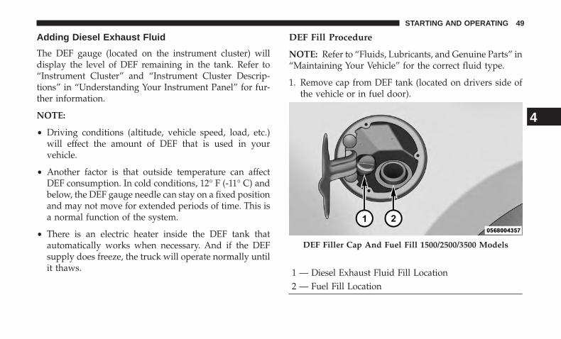
1. Remove cap from DEF tank (located on drivers side ofthe vehicle or in fuel door).
DEF Filler Cap And Fuel Fill 1500/2500/3500 Models
1 — Diesel Exhaust Fluid Fill Location2 — Fuel Fill Location
4
STARTING AND OPERATING 49
2. Insert DEF fill adapter/nozzle into DEF tank filler neck.
NOTE:
• The DEF gauge may take up to five seconds to updateafter adding a gallon or more of Diesel Exhaust Fluid(DEF) to the DEF tank. If you have a fault related to theDEF system, the gauge may not update to the new level.See your authorized dealer for service.
• The DEF gauge may also not immediately update after arefill if the temperature of the DEF fluid is below 12F(-11C). The DEF line heater will possibly warm up theDEF fluid and allow the gauge to update after a periodof run time. Under very cold conditions, it is possiblethat the gauge may not reflect the new fill level forseveral drives.
CAUTION!
• To avoid DEF spillage, and possible damage to theDEF tank from overfilling, do not “top off” the DEFtank after filling.
• DO NOT OVERFILL. DEF will freeze below 12ºF(-11ºC). The DEF system is designed to work intemperatures below the DEF freezing point, how-ever, if the tank is overfilled and freezes, the systemcould be damaged.
• When DEF is spilled, clean the area immediatelywith water and use an absorbent material to soak upthe spills on the ground.
• Do not attempt to start your engine if DEF is acci-dentally added to the diesel fuel tank as it can resultin severe damage to your engine, including but notlimited to failure of the fuel pump and injectors.
(Continued)
50 STARTING AND OPERATING
CAUTION! (Continued)• Never add anything other than DEF to the tank –
especially any form of hydrocarbon such as dieselfuel, fuel system additives, gasoline, or any otherpetroleum-based product. Even a very small amountof these, less than 100 parts per million or less than1 oz. per 78 gallons (295 liters) will contaminate theentire DEF system and will require replacement. Ifowners use a container, funnel or nozzle when refill-ing the tank, it should either be new or one that ishas only been used for adding DEF. MOPAR pro-vides an attachable nozzle with its DEF for thispurpose.
3. Stop filling the DEF tank immediately when any of thefollowing happen: DEF stops flowing from the fill bottleinto the DEF tank, DEF splashes out the filler neck, or aDEF pump nozzle automatically shuts off.
4. Reinstall cap onto DEF tank.
Filling The Def Tank In Cold Climates
Since DEF will begin to freeze at 12°F (-11°C), your vehicleis equipped with an automatic DEF heating system. Thisallows the DEF injection system to operate properly attemperatures below 12°F (-11°C). If your vehicle is not inoperation for an extended period of time with tempera-tures below 12°F (-11°C), the DEF in the tank may freeze. Ifthe tank is overfilled and freezes, it could be damaged.Therefore, do not overfill the DEF tank.
Extra care should be taken when filling with portablecontainers to avoid overfilling. Note the level of the DEFgauge in your instrument cluster. You may safely add amaximum of 2 gallons (7.5 Liters) of DEF from portablecontainers when your DEF gauge is reading ½ full.
4
STARTING AND OPERATING 51

MAINTAINING YOUR VEHICLE
CONTENTS� ENGINE COMPARTMENT — 3.0L DIESEL . . . . . .54
� MAINTENANCE PROCEDURES . . . . . . . . . . . . .55
▫ Engine Oil . . . . . . . . . . . . . . . . . . . . . . . . . . . .55
▫ Engine Air Cleaner Filter . . . . . . . . . . . . . . . . . .57
▫ Draining Fuel/Water Separator Filter . . . . . . . . .60
▫ Underbody Mounted Fuel Filter Replacement. . . .61
▫ Priming If The Engine Has Run Out Of Fuel . . . .62
▫ Intervention Regeneration Strategy — MessageProcess Flow . . . . . . . . . . . . . . . . . . . . . . . . . .64
▫ Maintenance-Free Batteries . . . . . . . . . . . . . . . .64
▫ Cooling System . . . . . . . . . . . . . . . . . . . . . . . .65
▫ Charge Air Cooler — Inter-Cooler . . . . . . . . . . .69
▫ Brake System . . . . . . . . . . . . . . . . . . . . . . . . . .69
� FLUID CAPACITIES . . . . . . . . . . . . . . . . . . . . . .71
� FLUIDS, LUBRICANTS AND GENUINE PARTS . . .72
▫ Engine . . . . . . . . . . . . . . . . . . . . . . . . . . . . . . .72
▫ Chassis . . . . . . . . . . . . . . . . . . . . . . . . . . . . . .75
5
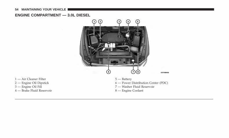
ENGINE COMPARTMENT — 3.0L DIESEL
1 — Air Cleaner Filter 5 — Battery2 — Engine Oil Dipstick 6 — Power Distribution Center (PDC)3 — Engine Oil Fill 7 — Washer Fluid Reservoir4 — Brake Fluid Reservoir 8 — Engine Coolant
54 MAINTAINING YOUR VEHICLE
MAINTENANCE PROCEDURES
The pages that follow contain the required maintenanceservices determined by the engineers who designed yourvehicle.
Besides those maintenance items specified in the fixedmaintenance schedule, there are other components whichmay require servicing or replacement in the future.
CAUTION!
• Failure to properly maintain your vehicle or performrepairs and service when necessary could result inmore costly repairs, damage to other components ornegatively impact vehicle performance. Immediatelyhave potential malfunctions examined by an autho-rized dealership or qualified repair center.
• Your vehicle has been built with improved fluidsthat protect the performance and durability of yourvehicle and also allow extended maintenance inter-vals. Do not use chemical flushes in these compo-nents as the chemicals can damage your engine,transmission, power steering or air conditioning.Such damage is not covered by the New Vehicle
(Continued)
CAUTION! (Continued)Limited Warranty. If a flush is needed because ofcomponent malfunction, use only the specified fluidfor the flushing procedure.
Engine Oil
Engine Oil Selection
For best performance and maximum protection under alltypes of operating conditions, the manufacturer recom-mends engine oils that meet the requirements of FCAMaterial Standard MS-10902, and that are API CJ-4 certifiedand meet the requirements of FCA LLC.
Checking Oil Level
To assure proper lubrication of your vehicle’s engine, theengine oil must be maintained at the correct level. Checkthe oil level at regular intervals. The best time to check theoil level is before starting the engine after it has beenparked overnight. When checking oil after operating theengine, first ensure the engine is at full operating tempera-ture, then wait for five minutes after engine shutdown tocheck the oil.
5
MAINTAINING YOUR VEHICLE 55
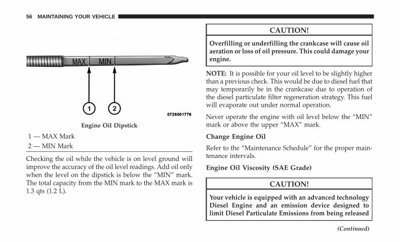
1 — MAX Mark2 — MIN Mark
Checking the oil while the vehicle is on level ground willimprove the accuracy of the oil level readings. Add oil onlywhen the level on the dipstick is below the “MIN” mark.The total capacity from the MIN mark to the MAX mark is1.3 qts (1.2 L).
CAUTION!
Overfilling or underfilling the crankcase will cause oilaeration or loss of oil pressure. This could damage yourengine.
NOTE: It is possible for your oil level to be slightly higherthan a previous check. This would be due to diesel fuel thatmay temporarily be in the crankcase due to operation ofthe diesel particulate filter regeneration strategy. This fuelwill evaporate out under normal operation.
Never operate the engine with oil level below the “MIN”mark or above the upper “MAX” mark.
Change Engine Oil
Refer to the “Maintenance Schedule” for the proper main-tenance intervals.
Engine Oil Viscosity (SAE Grade)
CAUTION!
Your vehicle is equipped with an advanced technologyDiesel Engine and an emission device designed tolimit Diesel Particulate Emissions from being released
(Continued)
Engine Oil Dipstick
56 MAINTAINING YOUR VEHICLE
CAUTION! (Continued)into the atmosphere. The durability of your engine andlife expectancy of this diesel particulate filter emissiondevice is highly dependent on the use of the correctengine oil.
We recommend you use 5W-40 synthetic engine oil such asMOPAR or Shell Rotella that meets FCA Material StandardMS-10902 and the API CJ-4 engine oil category is required.
Materials Added To Engine Oil
The manufacturer strongly recommends against the addi-tion of any additives (other than leak detection dyes) to theengine oil. Engine oil is an engineered product and itsperformance may be impaired by supplemental additives.
Engine Oil Filter
Refer to “Fluids, Lubricants, And Genuine Parts” in “Main-taining Your Vehicle” for further information. The engineoil filter should be changed at every engine oil change.
Disposing Of Used Engine Oil And Oil Filters
Care should be taken in disposing of used engine oil andoil filters from your vehicle. Used oil and oil filters,indiscriminately discarded, can present a problem to the
environment. Contact your authorized dealer, service sta-tion or governmental agency for advice on how and whereused oil and oil filters can be safely discarded in your area.
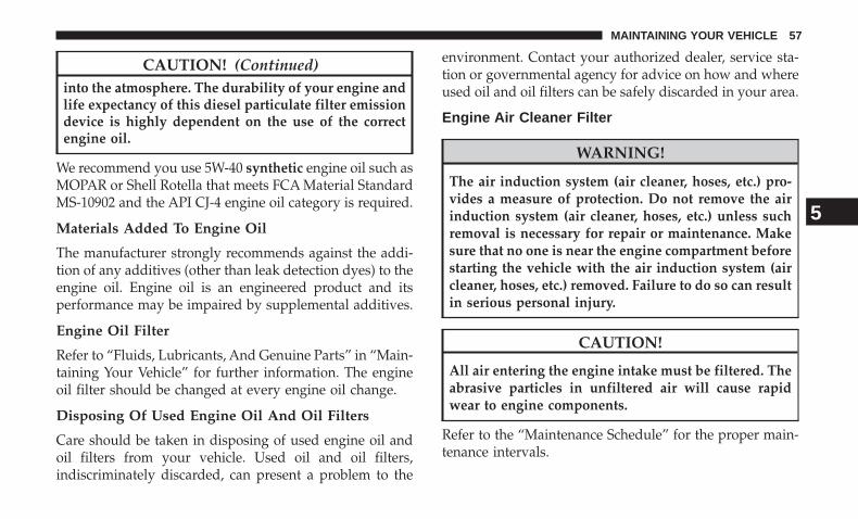
Engine Air Cleaner Filter
WARNING!
The air induction system (air cleaner, hoses, etc.) pro-vides a measure of protection. Do not remove the airinduction system (air cleaner, hoses, etc.) unless suchremoval is necessary for repair or maintenance. Makesure that no one is near the engine compartment beforestarting the vehicle with the air induction system (aircleaner, hoses, etc.) removed. Failure to do so can resultin serious personal injury.
CAUTION!
All air entering the engine intake must be filtered. Theabrasive particles in unfiltered air will cause rapidwear to engine components.
Refer to the “Maintenance Schedule” for the proper main-tenance intervals.
5
MAINTAINING YOUR VEHICLE 57
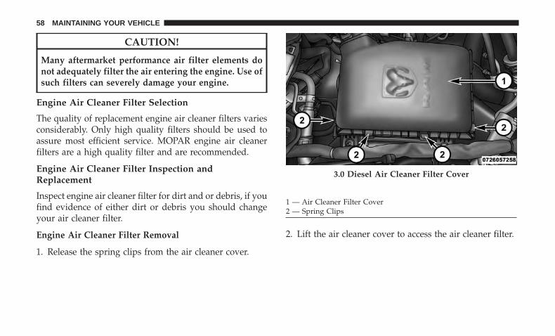
CAUTION!
Many aftermarket performance air filter elements donot adequately filter the air entering the engine. Use ofsuch filters can severely damage your engine.
Engine Air Cleaner Filter Selection
The quality of replacement engine air cleaner filters variesconsiderably. Only high quality filters should be used toassure most efficient service. MOPAR engine air cleanerfilters are a high quality filter and are recommended.
Engine Air Cleaner Filter Inspection andReplacement
Inspect engine air cleaner filter for dirt and or debris, if youfind evidence of either dirt or debris you should changeyour air cleaner filter.
Engine Air Cleaner Filter Removal
1. Release the spring clips from the air cleaner cover.
2. Lift the air cleaner cover to access the air cleaner filter.
3.0 Diesel Air Cleaner Filter Cover
1 — Air Cleaner Filter Cover2 — Spring Clips
58 MAINTAINING YOUR VEHICLE
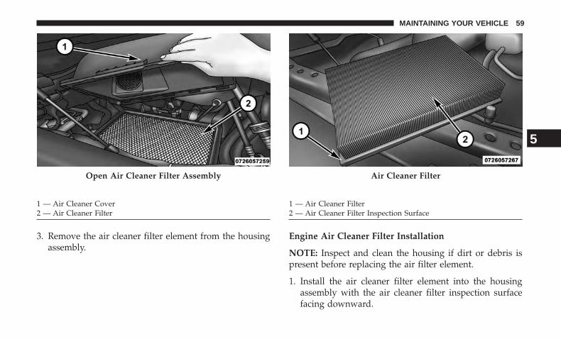
3. Remove the air cleaner filter element from the housingassembly.
Engine Air Cleaner Filter Installation
NOTE: Inspect and clean the housing if dirt or debris ispresent before replacing the air filter element.
1. Install the air cleaner filter element into the housingassembly with the air cleaner filter inspection surfacefacing downward.
Open Air Cleaner Filter Assembly
1 — Air Cleaner Cover2 — Air Cleaner Filter
Air Cleaner Filter
1 — Air Cleaner Filter2 — Air Cleaner Filter Inspection Surface
5
MAINTAINING YOUR VEHICLE 59
2. Install the air cleaner cover onto the housing assemblylocating tabs.
3. Latch the spring clips and lock the air cleaner cover tothe housing assembly.
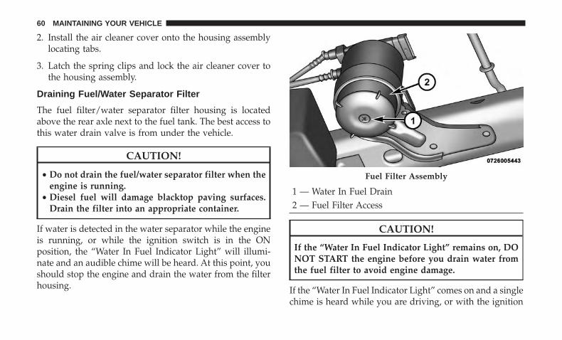
Draining Fuel/Water Separator Filter
The fuel filter/water separator filter housing is locatedabove the rear axle next to the fuel tank. The best access tothis water drain valve is from under the vehicle.
CAUTION!
• Do not drain the fuel/water separator filter when theengine is running.
• Diesel fuel will damage blacktop paving surfaces.Drain the filter into an appropriate container.
If water is detected in the water separator while the engineis running, or while the ignition switch is in the ONposition, the “Water In Fuel Indicator Light” will illumi-nate and an audible chime will be heard. At this point, youshould stop the engine and drain the water from the filterhousing.
1 — Water In Fuel Drain2 — Fuel Filter Access
CAUTION!
If the “Water In Fuel Indicator Light” remains on, DONOT START the engine before you drain water fromthe fuel filter to avoid engine damage.
If the “Water In Fuel Indicator Light” comes on and a singlechime is heard while you are driving, or with the ignition
Fuel Filter Assembly
60 MAINTAINING YOUR VEHICLE
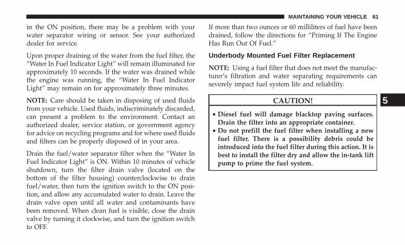
in the ON position, there may be a problem with yourwater separator wiring or sensor. See your authorizeddealer for service.
Upon proper draining of the water from the fuel filter, the“Water In Fuel Indicator Light” will remain illuminated forapproximately 10 seconds. If the water was drained whilethe engine was running, the “Water In Fuel IndicatorLight” may remain on for approximately three minutes.
NOTE: Care should be taken in disposing of used fluidsfrom your vehicle. Used fluids, indiscriminately discarded,can present a problem to the environment. Contact anauthorized dealer, service station, or government agencyfor advice on recycling programs and for where used fluidsand filters can be properly disposed of in your area.
Drain the fuel/water separator filter when the “Water InFuel Indicator Light” is ON. Within 10 minutes of vehicleshutdown, turn the filter drain valve (located on thebottom of the filter housing) counterclockwise to drainfuel/water, then turn the ignition switch to the ON posi-tion, and allow any accumulated water to drain. Leave thedrain valve open until all water and contaminants havebeen removed. When clean fuel is visible, close the drainvalve by turning it clockwise, and turn the ignition switchto OFF.
If more than two ounces or 60 milliliters of fuel have beendrained, follow the directions for “Priming If The EngineHas Run Out Of Fuel.”
Underbody Mounted Fuel Filter Replacement
NOTE: Using a fuel filter that does not meet the manufac-turer’s filtration and water separating requirements canseverely impact fuel system life and reliability.
CAUTION!
• Diesel fuel will damage blacktop paving surfaces.Drain the filter into an appropriate container.
• Do not prefill the fuel filter when installing a newfuel filter. There is a possibility debris could beintroduced into the fuel filter during this action. It isbest to install the filter dry and allow the in-tank liftpump to prime the fuel system.
5
MAINTAINING YOUR VEHICLE 61
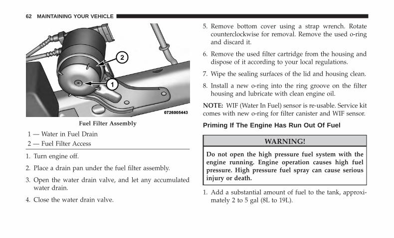
1 — Water in Fuel Drain2 — Fuel Filter Access
1. Turn engine off.
2. Place a drain pan under the fuel filter assembly.
3. Open the water drain valve, and let any accumulatedwater drain.
4. Close the water drain valve.
5. Remove bottom cover using a strap wrench. Rotatecounterclockwise for removal. Remove the used o-ringand discard it.
6. Remove the used filter cartridge from the housing anddispose of it according to your local regulations.
7. Wipe the sealing surfaces of the lid and housing clean.
8. Install a new o-ring into the ring groove on the filterhousing and lubricate with clean engine oil.
NOTE: WIF (Water In Fuel) sensor is re-usable. Service kitcomes with new o-ring for filter canister and WIF sensor.
Priming If The Engine Has Run Out Of Fuel
WARNING!
Do not open the high pressure fuel system with theengine running. Engine operation causes high fuelpressure. High pressure fuel spray can cause seriousinjury or death.
1. Add a substantial amount of fuel to the tank, approxi-mately 2 to 5 gal (8L to 19L).
Fuel Filter Assembly
62 MAINTAINING YOUR VEHICLE
2. Press ignition switch twice without your foot on braketo put vehicle in Run position. This will activate the intank fuel pump for approximately 30 seconds. Repeatthis process twice.
3. Start the engine using the “Normal Starting” procedure.Refer to “Starting Procedures” in “Starting and Operat-ing” for further information.
CAUTION!
The starter motor will engage for approximately 30seconds at a time. Allow two minutes between crank-ing intervals.
NOTE: The engine may run rough until the air is forcedfrom all the fuel lines.
WARNING!
Do not use alcohol or gasoline as a fuel blending agent.They can be unstable under certain conditions and behazardous or explosive when mixed with diesel fuel.
CAUTION!
Due to lack of lubricants in alcohol or gasoline, the useof these fuels can cause damage to the fuel system.
NOTE:
• Use of biodiesel mixture in excess of 20% can negativelyimpact the fuel filter’s ability to separate water from thefuel, resulting in high pressure fuel system corrosion ordamage.
• In addition, commercially available fuel additives arenot necessary for the proper operation of your dieselengine.
• For extreme cold conditions, �Mopar Premium DieselFuel Treatment� is recommended to assist with coldstarting.
5
MAINTAINING YOUR VEHICLE 63
Intervention Regeneration Strategy — MessageProcess Flow
This engine meets all required diesel engine emissionsstandards. To achieve these emissions standards, yourvehicle is equipped with a state-of-the-art engine andexhaust system. These systems are seamlessly integratedinto your vehicle and managed by the Powertrain ControlModule (PCM). The PCM manages engine combustion toallow the exhaust system’s catalyst to trap and burnParticulate Matter (PM) pollutants, with no input or inter-action on your part.
Additionally, your vehicle has the ability to alert you toadditional maintenance required on your vehicle or engine.
Refer to “Instrument Cluster Display” in “UnderstandingYour Instrument Panel” for further information.
WARNING!
A hot exhaust system can start a fire if you park overmaterials that can burn. Such materials might be grassor leaves coming into contact with your exhaust sys-tem. Do not park or operate your vehicle in areas whereyour exhaust system can contact anything that canburn.
Maintenance-Free Batteries
Your vehicle is equipped with a maintenance-free battery.The top of the maintenance-free battery is permanentlysealed. You will never have to add water, nor is periodicmaintenance required.
WARNING!
Battery posts, terminals, and related accessories con-tain lead and lead compounds. Always wash handsafter handling the battery.
CAUTION!
It is essential when replacing the cables on the batterythat the positive cable is attached to the positive postand the negative cable is attached to the negative post.Battery posts are marked (+) positive and negative (-)and are identified on the battery case. Also, if a “fastcharger” is used while the battery is in vehicle, discon-nect both vehicle battery cables before connecting thecharger to the battery. Do not use a “fast charger” toprovide starting voltage.
64 MAINTAINING YOUR VEHICLE
Cooling System
WARNING!
You or others can be badly burned by hot enginecoolant (antifreeze) or steam from your radiator. If yousee or hear steam coming from under the hood, do notopen the hood until the radiator has had time to cool.Never try to open a cooling system pressure cap whenthe radiator is hot.
Engine Coolant Checks
Check the engine coolant (antifreeze) protection every12 months (before the onset of freezing weather, whereapplicable). If the engine coolant (antifreeze) is dirty orrusty in appearance, the system should be drained, flushedand refilled with fresh coolant. Check the front of the A/Ccondenser (if equipped) or radiator for any accumulationof bugs, leaves, etc. If dirty, clean by gently spraying waterfrom a garden hose vertically down the face of the A/Ccondenser (if equipped) or the back of the radiator core.
Check the engine cooling system hoses for brittle rubber,cracking, tears, cuts and tightness of the connection at thecoolant recovery bottle and radiator. Inspect the entiresystem for leaks.
With the engine at normal operating temperature (but notrunning), check the cooling system pressure cap for propervacuum sealing by draining a small amount of enginecoolant (antifreeze) from the radiator drain cock. Theradiator drain cock is located in the lower radiator tank. Ifthe cap is sealing properly, the engine coolant (antifreeze)will begin to drain from the coolant expansion bottle. DONOT REMOVE THE COOLANT PRESSURE CAP WHENTHE COOLING SYSTEM IS HOT.
Cooling System — Drain Flush And Refill
If the engine coolant (antifreeze) is dirty or contains aconsiderable amount of sediment, clean and flush with areliable cooling system cleaner. Follow with a thoroughrinsing to remove all deposits and chemicals. Properlydispose of old engine coolant (antifreeze).
Refer to the “Maintenance Schedule” for the proper main-tenance intervals.
Selection Of Coolant
Refer to “Fluids, Lubricants, And Genuine Parts” in “Main-taining Your Vehicle” for further information.
5
MAINTAINING YOUR VEHICLE 65
CAUTION!
• Mixing of engine coolant (antifreeze) other thanspecified Organic Additive Technology (OAT) en-gine coolant (antifreeze), may result in engine dam-age and may decrease corrosion protection. OrganicAdditive Technology (OAT) engine coolant is differ-ent and should not be mixed with Hybrid OrganicAdditive Technology (HOAT) engine coolant (anti-freeze) or any “globally compatible” coolant (anti-freeze). If a non-OAT engine coolant (antifreeze) isintroduced into the cooling system in an emergency,the cooling system will need to be drained, flushed,and refilled with fresh OAT coolant (conforming toMS.90032), by an authorized dealer as soon as pos-sible.
• Do not use water alone or alcohol-based enginecoolant (antifreeze) products. Do not use additionalrust inhibitors or antirust products, as they may notbe compatible with the engine coolant and may plugthe radiator.
• This vehicle has not been designed for use withpropylene glycol-based engine coolant (antifreeze).Use of propylene glycol-based engine coolant (anti-freeze) is not recommended.
Adding Coolant
Your vehicle has been built with an improved enginecoolant (OAT coolant conforming to MS.90032) that allowsextended maintenance intervals. This engine coolant (anti-freeze) can be used up to ten years or 150,000 miles(240,000 km) before replacement. To prevent reducing thisextended maintenance period, it is important that you usethe same engine coolant (OAT coolant conforming toMS.90032) throughout the life of your vehicle.
Please review these recommendations for using OrganicAdditive Technology (OAT) engine coolant (antifreeze)that meets the requirements of FCA Material StandardMS.90032. When adding engine coolant (antifreeze):
• We recommend using MOPAR Antifreeze/Coolant 10Year/150,000 Mile Formula OAT (Organic AdditiveTechnology) that meets the requirements of FCA Mate-rial Standard MS.90032.
• Mix a minimum solution of 50% OAT engine coolantthat meets the requirements of FCA Material StandardMS.90032 and distilled water. Use higher concentrations(not to exceed 70%) if temperatures below −34°F (−37°C)are anticipated. Please contact your authorized dealerfor assistance.
66 MAINTAINING YOUR VEHICLE
• Use only high purity water such as distilled or deionizedwater when mixing the water/engine coolant (anti-freeze) solution. The use of lower quality water willreduce the amount of corrosion protection in the enginecooling system.
NOTE:
• It is the owner’s responsibility to maintain the properlevel of protection against freezing according to thetemperatures occurring in the area where the vehicle isoperated.
• Some vehicles require special tools to add coolant prop-erly. Failure to fill these systems properly could lead tosevere internal engine damage. If any coolant is neededto be added to the system, please contact your localauthorized dealer.
• Mixing engine coolant (antifreeze) types is not recom-mended and can result in cooling system damage. IfHOAT and OAT coolant are mixed in an emergency,have a authorized dealer drain, flush, and refill withOAT coolant (conforming to MS.90032) as soon as pos-sible.
Cooling System Pressure Cap
The cap must be fully tightened to prevent loss of enginecoolant (antifreeze), and to ensure that the engine coolant(antifreeze) will return to the radiator from the coolantexpansion bottle.
The cap should be inspected and cleaned if there is anyaccumulation of foreign material on the sealing surfaces.
WARNING!
• Do not open hot engine cooling system. Never addengine coolant (antifreeze) when the engine is over-heated. Do not loosen or remove the cap to cool anoverheated engine. Heat causes pressure to build upin the cooling system. To prevent scalding or injury,do not remove the pressure cap while the system ishot or under pressure.
• Do not use a pressure cap other than the one speci-fied for your vehicle. Personal injury or enginedamage may result.
5
MAINTAINING YOUR VEHICLE 67
Disposal Of Used Engine Coolant
Used ethylene glycol-based engine coolant (antifreeze) is aregulated substance requiring proper disposal. Check withyour local authorities to determine the disposal rules foryour community. To prevent ingestion by animals orchildren, do not store ethylene glycol-based engine coolant(antifreeze) in open containers or allow it to remain inpuddles on the ground. If ingested by a child or pet, seekemergency assistance immediately. Clean up any groundspills immediately.
Points To Remember
NOTE: When the vehicle is stopped after a few miles/kilometers of operation, you may observe vapor comingfrom the front of the engine compartment. This is normallya result of moisture from rain, snow, or high humidityaccumulating on the radiator and being vaporized whenthe thermostat opens, allowing hot engine coolant (anti-freeze) to enter the radiator.
If an examination of your engine compartment shows noevidence of radiator or hose leaks, the vehicle may besafely driven. The vapor will soon dissipate.
• Do not overfill the coolant expansion bottle.
• Check the coolant freeze point in the radiator and in thecoolant expansion bottle. If engine coolant (antifreeze)needs to be added, the contents of the coolant expansionbottle must also be protected against freezing.
• If frequent engine coolant (antifreeze) additions arerequired, the cooling system should be pressure testedfor leaks.
• Maintain engine coolant (antifreeze) concentration at aminimum of 50% OAT coolant (conforming toMS.90032) and distilled water for proper corrosion pro-tection of your engine which contains aluminum com-ponents.
• Make sure that the coolant expansion bottle overflowhoses are not kinked or obstructed.
• Keep the front of the radiator clean. If your vehicle isequipped with air conditioning, keep the front of thecondenser clean.
• Do not change the thermostat for Summer or Winteroperation. If replacement is ever necessary, install ONLYthe correct type thermostat. Other designs may result inunsatisfactory engine coolant (antifreeze) performance,poor gas mileage, and increased emissions.
68 MAINTAINING YOUR VEHICLE
Charge Air Cooler — Inter-Cooler
The charge air cooler is positioned in front of the radiatorand the air conditioner condenser. Air enters the enginethrough the air cleaner and passes through the turbo-charger, where it is pressurized. This pressurized air rap-idly reaches high temperature. The air is then directedthrough a hose to the charge air cooler and through anotherhose to the intake manifold of the engine. This coolingprocess enables more efficient burning of fuel resulting infewer emissions.
To guarantee optimum performance of the system, keepthe surfaces of the charge air cooler, condenser and radiatorclean and free of debris. Periodically check the hosesleading to and from the charge air cooler for cracks or looseclamps resulting in loss of pressure and reduced engineperformance.
Brake System
Brake Master Cylinder — Brake Fluid Level Check
The fluid level of the master cylinder should be checkedwhen performing under the hood service, or immediatelyif the “Brake System Warning Light” indicates systemfailure.
The brake master cylinder has a translucent plastic reser-voir. On the outboard side of the reservoir, there is a“MAX” mark and a “MIN” mark. The fluid level must bekept within these two marks. Do not add fluid above thefull mark because leakage may occur at the cap.
With disc brakes, the fluid level can be expected to fall asthe brake linings wear. However, an unexpected drop influid level may be caused by a leak and a system checkshould be conducted.
Refer to “Fluids, Lubricants, And Genuine Parts” in “Main-taining Your Vehicle” for further information.
WARNING!
• Use only manufacturer’s recommended brake fluid.Refer to “Fluids, Lubricants, and Genuine Parts” in“Maintaining Your Vehicle” for further information.Using the wrong type of brake fluid can severelydamage your brake system and/or impair its perfor-mance. The proper type of brake fluid for yourvehicle is also identified on the original factoryinstalled hydraulic master cylinder reservoir.
(Continued)
5
MAINTAINING YOUR VEHICLE 69
WARNING! (Continued)• To avoid contamination from foreign matter or mois-
ture, use only new brake fluid or fluid that has beenin a tightly closed container. Keep the master cylin-der reservoir cap secured at all times. Brake fluid ina open container absorbs moisture from the airresulting in a lower boiling point. This may cause itto boil unexpectedly during hard or prolonged brak-ing, resulting in sudden brake failure. This couldresult in a accident.
(Continued)
WARNING! (Continued)• Overfilling the brake fluid reservoir can result in
spilling brake fluid on hot engine parts, causing thebrake fluid to catch fire. Brake fluid can also damagepainted and vinyl surfaces, care should be taken toavoid its contact with these surfaces.
• Do not allow petroleum based fluid to contaminatethe brake fluid. Brake seal components could bedamaged, causing partial or complete brake failure.This could result in an accident.
70 MAINTAINING YOUR VEHICLE
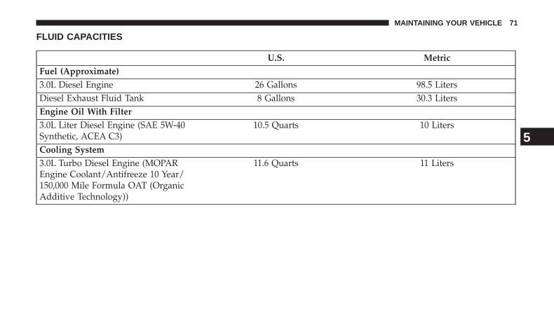
FLUID CAPACITIES
U.S. MetricFuel (Approximate)3.0L Diesel Engine 26 Gallons 98.5 LitersDiesel Exhaust Fluid Tank 8 Gallons 30.3 LitersEngine Oil With Filter3.0L Liter Diesel Engine (SAE 5W-40Synthetic, ACEA C3)
10.5 Quarts 10 Liters
Cooling System3.0L Turbo Diesel Engine (MOPAREngine Coolant/Antifreeze 10 Year/150,000 Mile Formula OAT (OrganicAdditive Technology))
11.6 Quarts 11 Liters
5
MAINTAINING YOUR VEHICLE 71
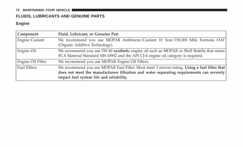
FLUIDS, LUBRICANTS AND GENUINE PARTS
Engine
Component Fluid, Lubricant, or Genuine PartEngine Coolant We recommend you use MOPAR Antifreeze/Coolant 10 Year/150,000 Mile Formula OAT
(Organic Additive Technology).Engine Oil We recommend you use 5W-40 synthetic engine oil such as MOPAR or Shell Rotella that meets
FCA Material Standard MS-10902 and the API CJ-4 engine oil category is required.Engine Oil Filter We recommend you use MOPAR Engine Oil Filters.Fuel Filters We recommend you use MOPAR Fuel Filter. Must meet 3 micron rating. Using a fuel filter that
does not meet the manufacturers filtration and water separating requirements can severelyimpact fuel system life and reliability.
72 MAINTAINING YOUR VEHICLE
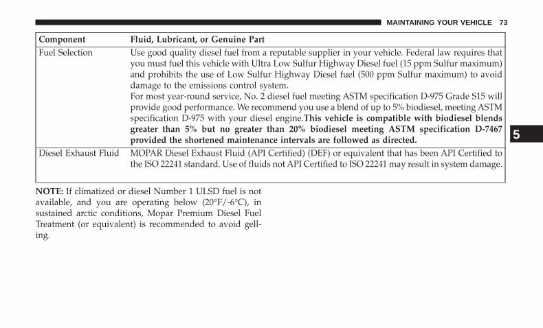
Component Fluid, Lubricant, or Genuine PartFuel Selection Use good quality diesel fuel from a reputable supplier in your vehicle. Federal law requires that
you must fuel this vehicle with Ultra Low Sulfur Highway Diesel fuel (15 ppm Sulfur maximum)and prohibits the use of Low Sulfur Highway Diesel fuel (500 ppm Sulfur maximum) to avoiddamage to the emissions control system.For most year-round service, No. 2 diesel fuel meeting ASTM specification D-975 Grade S15 willprovide good performance. We recommend you use a blend of up to 5% biodiesel, meeting ASTMspecification D-975 with your diesel engine.This vehicle is compatible with biodiesel blendsgreater than 5% but no greater than 20% biodiesel meeting ASTM specification D-7467provided the shortened maintenance intervals are followed as directed.
Diesel Exhaust Fluid MOPAR Diesel Exhaust Fluid (API Certified) (DEF) or equivalent that has been API Certified tothe ISO 22241 standard. Use of fluids not API Certified to ISO 22241 may result in system damage.
NOTE: If climatized or diesel Number 1 ULSD fuel is notavailable, and you are operating below (20°F/-6°C), insustained arctic conditions, Mopar Premium Diesel FuelTreatment (or equivalent) is recommended to avoid gell-ing.
5
MAINTAINING YOUR VEHICLE 73
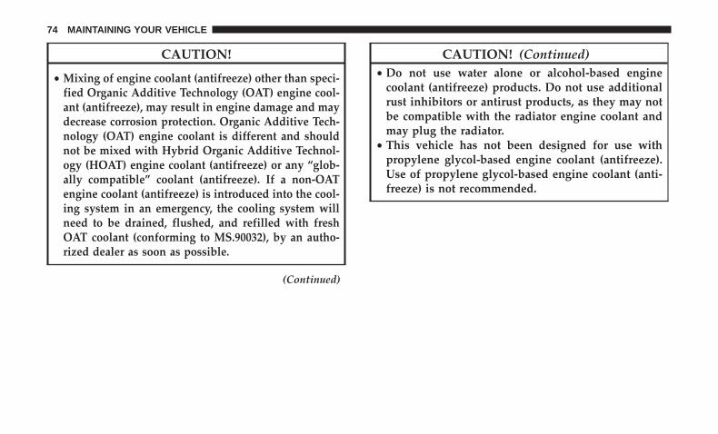
CAUTION!
• Mixing of engine coolant (antifreeze) other than speci-fied Organic Additive Technology (OAT) engine cool-ant (antifreeze), may result in engine damage and maydecrease corrosion protection. Organic Additive Tech-nology (OAT) engine coolant is different and shouldnot be mixed with Hybrid Organic Additive Technol-ogy (HOAT) engine coolant (antifreeze) or any “glob-ally compatible” coolant (antifreeze). If a non-OATengine coolant (antifreeze) is introduced into the cool-ing system in an emergency, the cooling system willneed to be drained, flushed, and refilled with freshOAT coolant (conforming to MS.90032), by an autho-rized dealer as soon as possible.
(Continued)
CAUTION! (Continued)• Do not use water alone or alcohol-based engine
coolant (antifreeze) products. Do not use additionalrust inhibitors or antirust products, as they may notbe compatible with the radiator engine coolant andmay plug the radiator.
• This vehicle has not been designed for use withpropylene glycol-based engine coolant (antifreeze).Use of propylene glycol-based engine coolant (anti-freeze) is not recommended.
74 MAINTAINING YOUR VEHICLE
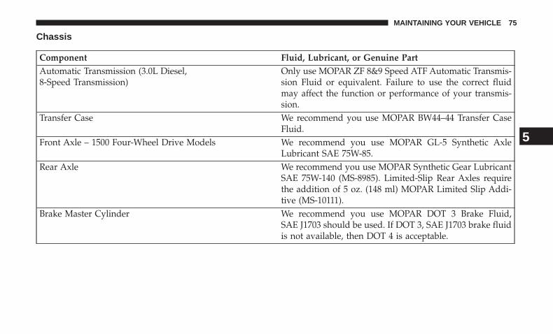
Chassis
Component Fluid, Lubricant, or Genuine PartAutomatic Transmission (3.0L Diesel,8-Speed Transmission)
Only use MOPAR ZF 8&9 Speed ATF Automatic Transmis-sion Fluid or equivalent. Failure to use the correct fluidmay affect the function or performance of your transmis-sion.
Transfer Case We recommend you use MOPAR BW44–44 Transfer CaseFluid.
Front Axle – 1500 Four-Wheel Drive Models We recommend you use MOPAR GL-5 Synthetic AxleLubricant SAE 75W-85.
Rear Axle We recommend you use MOPAR Synthetic Gear LubricantSAE 75W-140 (MS-8985). Limited-Slip Rear Axles requirethe addition of 5 oz. (148 ml) MOPAR Limited Slip Addi-tive (MS-10111).
Brake Master Cylinder We recommend you use MOPAR DOT 3 Brake Fluid,SAE J1703 should be used. If DOT 3, SAE J1703 brake fluidis not available, then DOT 4 is acceptable.
5
MAINTAINING YOUR VEHICLE 75

MAINTENANCE SCHEDULE
CONTENTS� MAINTENANCE SCHEDULE . . . . . . . . . . . . . . .78
▫ Maintenance Chart — Diesel Fuel Up To B5Biodiesel . . . . . . . . . . . . . . . . . . . . . . . . . . . . .79
▫ Additional Maintenance — B6 To B20 Biodiesel . .82
6
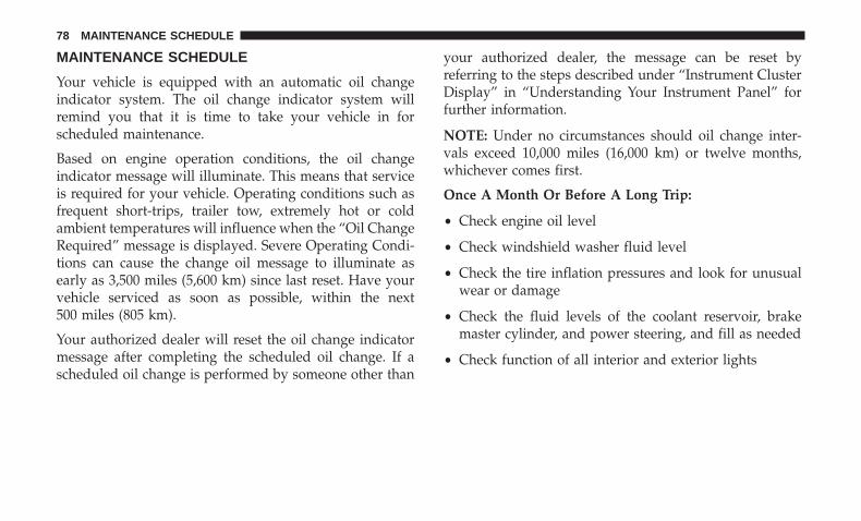
MAINTENANCE SCHEDULE
Your vehicle is equipped with an automatic oil changeindicator system. The oil change indicator system willremind you that it is time to take your vehicle in forscheduled maintenance.
Based on engine operation conditions, the oil changeindicator message will illuminate. This means that serviceis required for your vehicle. Operating conditions such asfrequent short-trips, trailer tow, extremely hot or coldambient temperatures will influence when the “Oil ChangeRequired” message is displayed. Severe Operating Condi-tions can cause the change oil message to illuminate asearly as 3,500 miles (5,600 km) since last reset. Have yourvehicle serviced as soon as possible, within the next500 miles (805 km).
Your authorized dealer will reset the oil change indicatormessage after completing the scheduled oil change. If ascheduled oil change is performed by someone other than
your authorized dealer, the message can be reset byreferring to the steps described under “Instrument ClusterDisplay” in “Understanding Your Instrument Panel” forfurther information.
NOTE: Under no circumstances should oil change inter-vals exceed 10,000 miles (16,000 km) or twelve months,whichever comes first.
Once A Month Or Before A Long Trip:
• Check engine oil level
• Check windshield washer fluid level
• Check the tire inflation pressures and look for unusualwear or damage
• Check the fluid levels of the coolant reservoir, brakemaster cylinder, and power steering, and fill as needed
• Check function of all interior and exterior lights
78 MAINTENANCE SCHEDULE
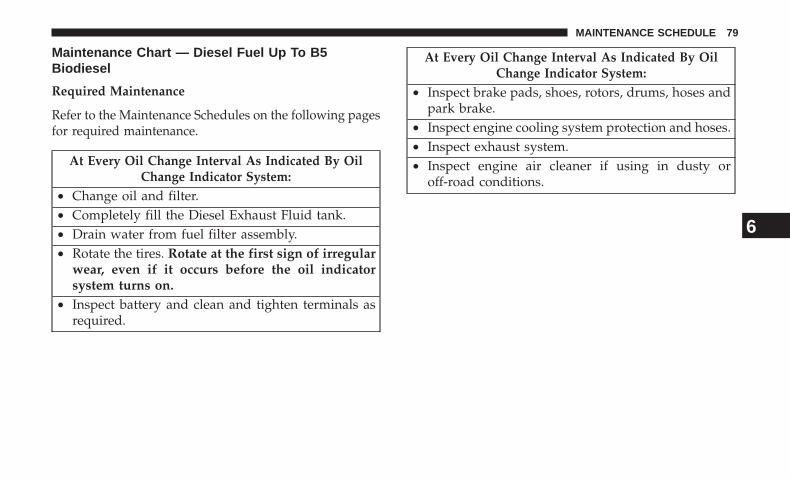
Maintenance Chart — Diesel Fuel Up To B5Biodiesel
Required Maintenance
Refer to the Maintenance Schedules on the following pagesfor required maintenance.
At Every Oil Change Interval As Indicated By OilChange Indicator System:
• Change oil and filter.• Completely fill the Diesel Exhaust Fluid tank.• Drain water from fuel filter assembly.• Rotate the tires. Rotate at the first sign of irregular
wear, even if it occurs before the oil indicatorsystem turns on.
• Inspect battery and clean and tighten terminals asrequired.
At Every Oil Change Interval As Indicated By OilChange Indicator System:
• Inspect brake pads, shoes, rotors, drums, hoses andpark brake.
• Inspect engine cooling system protection and hoses.• Inspect exhaust system.• Inspect engine air cleaner if using in dusty or
off-road conditions.
6
MAINTENANCE SCHEDULE 79
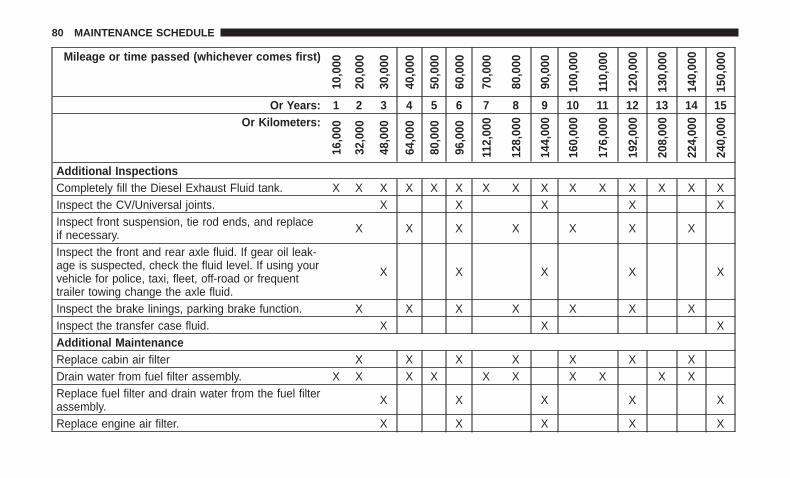
Mileage or time passed (whichever comes first)
10,0
00
20,0
00
30,0
00
40,0
00
50,0
00
60,0
00
70,0
00
80,0
00
90,0
00
100,
000
110,
000
120,
000
130,
000
140,
000
150,
000
Or Years: 1 2 3 4 5 6 7 8 9 10 11 12 13 14 15Or Kilometers:
16,0
00
32,0
00
48,0
00
64,0
00
80,0
00
96,0
00
112,
000
128,
000
144,
000
160,
000
176,
000
192,
000
208,
000
224,
000
240,
000
Additional InspectionsCompletely fill the Diesel Exhaust Fluid tank. X X X X X X X X X X X X X X XInspect the CV/Universal joints. X X X X XInspect front suspension, tie rod ends, and replaceif necessary. X X X X X X X
Inspect the front and rear axle fluid. If gear oil leak-age is suspected, check the fluid level. If using yourvehicle for police, taxi, fleet, off-road or frequenttrailer towing change the axle fluid.
X X X X X
Inspect the brake linings, parking brake function. X X X X X X XInspect the transfer case fluid. X X XAdditional MaintenanceReplace cabin air filter X X X X X X XDrain water from fuel filter assembly. X X X X X X X X X XReplace fuel filter and drain water from the fuel filterassembly. X X X X X
Replace engine air filter. X X X X X
80 MAINTENANCE SCHEDULE
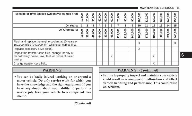
Mileage or time passed (whichever comes first)
10,0
00
20,0
00
30,0
00
40,0
00
50,0
00
60,0
00
70,0
00
80,0
00
90,0
00
100,
000
110,
000
120,
000
130,
000
140,
000
150,
000
Or Years: 1 2 3 4 5 6 7 8 9 10 11 12 13 14 15Or Kilometers:
16,0
00
32,0
00
48,0
00
64,0
00
80,0
00
96,0
00
112,
000
128,
000
144,
000
160,
000
176,
000
192,
000
208,
000
224,
000
240,
000
Flush and replace the engine coolant at 10 years or150,000 miles (240,000 km) whichever comes first. X X
Replace accessory drive belt(s). XInspect the transfer case fluid, change for any ofthe following: police, taxi, fleet, or frequent trailertowing.
X X
Change transfer case fluid. X
WARNING!
• You can be badly injured working on or around amotor vehicle. Do only service work for which youhave the knowledge and the right equipment. If youhave any doubt about your ability to perform aservice job, take your vehicle to a competent me-chanic.
(Continued)
WARNING! (Continued)• Failure to properly inspect and maintain your vehicle
could result in a component malfunction and effectvehicle handling and performance. This could causean accident.
6
MAINTENANCE SCHEDULE 81
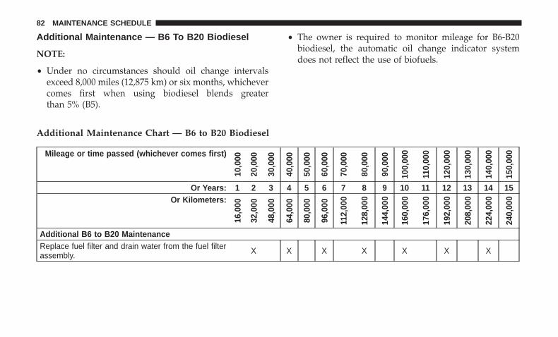
Additional Maintenance — B6 To B20 Biodiesel
NOTE:
• Under no circumstances should oil change intervalsexceed 8,000 miles (12,875 km) or six months, whichevercomes first when using biodiesel blends greaterthan 5% (B5).
• The owner is required to monitor mileage for B6-B20biodiesel, the automatic oil change indicator systemdoes not reflect the use of biofuels.
Additional Maintenance Chart — B6 to B20 Biodiesel
Mileage or time passed (whichever comes first)
10,0
00
20,0
00
30,0
00
40,0
00
50,0
00
60,0
00
70,0
00
80,0
00
90,0
00
100,
000
110,
000
120,
000
130,
000
140,
000
150,
000
Or Years: 1 2 3 4 5 6 7 8 9 10 11 12 13 14 15Or Kilometers:
16,0
00
32,0
00
48,0
00
64,0
00
80,0
00
96,0
00
112,
000
128,
000
144,
000
160,
000
176,
000
192,
000
208,
000
224,
000
240,
000
Additional B6 to B20 MaintenanceReplace fuel filter and drain water from the fuel filterassembly. X X X X X X X
82 MAINTENANCE SCHEDULE
WARNING!
• You can be badly injured working on or around amotor vehicle. Do only service work for which youhave the knowledge and the right equipment. If youhave any doubt about your ability to perform aservice job, take your vehicle to a competent me-chanic.
• Failure to properly inspect and maintain your vehiclecould result in a component malfunction and effectvehicle handling and performance. This could causean accident. 6
MAINTENANCE SCHEDULE 83

84 MAINTENANCE SCHEDULE

RAM 2500 / 3500 / 4500 / 5500

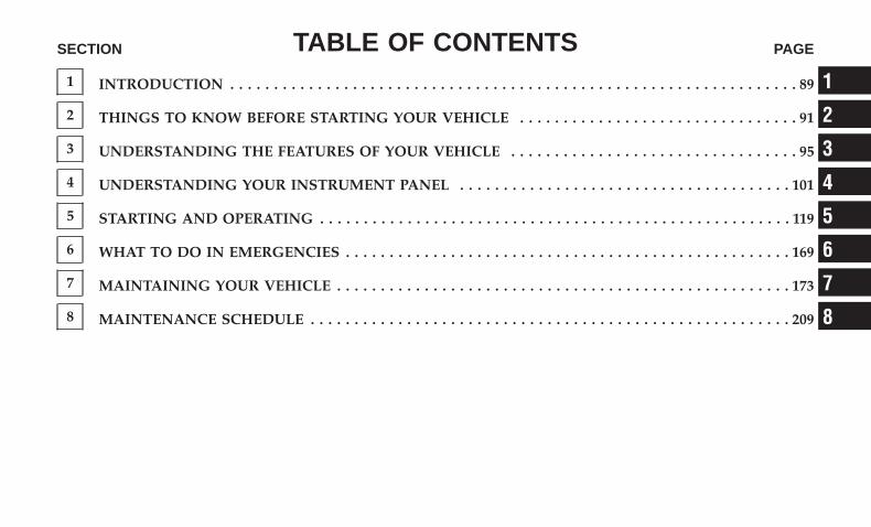
TABLE OF CONTENTSSECTION PAGE
1 INTRODUCTION . . . . . . . . . . . . . . . . . . . . . . . . . . . . . . . . . . . . . . . . . . . . . . . . . . . . . . . . . . . . . . . . . 89
2 THINGS TO KNOW BEFORE STARTING YOUR VEHICLE . . . . . . . . . . . . . . . . . . . . . . . . . . . . . . . . 91
3 UNDERSTANDING THE FEATURES OF YOUR VEHICLE . . . . . . . . . . . . . . . . . . . . . . . . . . . . . . . . . 95
4 UNDERSTANDING YOUR INSTRUMENT PANEL . . . . . . . . . . . . . . . . . . . . . . . . . . . . . . . . . . . . . . 101
5 STARTING AND OPERATING . . . . . . . . . . . . . . . . . . . . . . . . . . . . . . . . . . . . . . . . . . . . . . . . . . . . . . 119
6 WHAT TO DO IN EMERGENCIES . . . . . . . . . . . . . . . . . . . . . . . . . . . . . . . . . . . . . . . . . . . . . . . . . . . 169
7 MAINTAINING YOUR VEHICLE . . . . . . . . . . . . . . . . . . . . . . . . . . . . . . . . . . . . . . . . . . . . . . . . . . . . 173
8 MAINTENANCE SCHEDULE . . . . . . . . . . . . . . . . . . . . . . . . . . . . . . . . . . . . . . . . . . . . . . . . . . . . . . . 209
1
2
3
4
5
6
7
8


INTRODUCTION
CONTENTS� A MESSAGE FROM FCA US LLC . . . . . . . . . . . . .90
1
A MESSAGE FROM FCA US LLC
FCA US LLC and Cummins welcome you as a Cumminsturbocharged diesel-powered truck owner. Your dieseltruck will sound, feel, drive, and operate differently from agasoline-powered truck. It is important that you read andunderstand this manual.
Almost 100% of the heavy duty trucks in the United Statesand Canada are diesel-powered because of the fueleconomy, rugged durability, and high torque which per-mits pulling heavy loads. Cummins engines power wellover half of these trucks. Now this same technology andproven performance is yours in your truck equipped withthe Cummins turbocharged diesel engine.
You may find that some of the starting, operating, andmaintenance procedures are different. However, they aresimple to follow and careful adherence to them will ensurethat you take full advantage of the features of this engine.
NOTE: Some aftermarket products may cause severeengine/transmission and/or exhaust system damage. Yourvehicle’s Powertrain Control Systems can detect and storeinformation about vehicle modifications that increasehorsepower and torque output such as whether or notperformance-enhancing powertrain components, com-monly referred to as downloaders, power boxes, or perfor-mance chips have been used.
This information cannot be erased and will stay in thesystem’s memory even if the modification is removed. Thisinformation can be retrieved by FCA US LLC, and serviceand repair facilities, when servicing your vehicle. Thisinformation may be used to determine if repair will becovered by the New Vehicle Limited Warranty.
There is a probability that the use of a “performance chip”will prohibit the engine from starting. In this instance, thevehicle will need to be serviced by a authorized dealer inorder to return the vehicle to its factory settings.
When it comes to service, remember that your authorizeddealer knows your vehicle best, has factory-trained techni-cians and genuine MOPAR® parts, and cares about yoursatisfaction.
90 INTRODUCTION
THINGS TO KNOW BEFORE STARTING YOUR VEHICLE
CONTENTS� REMOTE STARTING SYSTEM — IF EQUIPPED . . .92
▫ How To Use Remote Start. . . . . . . . . . . . . . . . . .92
▫ Remote Start Abort Message . . . . . . . . . . . . . . . .93
▫ To Enter Remote Start Mode . . . . . . . . . . . . . . . .93
▫ To Exit Remote Start Mode Without Driving TheVehicle . . . . . . . . . . . . . . . . . . . . . . . . . . . . . . .93
▫ To Exit Remote Start Mode And Drive TheVehicle . . . . . . . . . . . . . . . . . . . . . . . . . . . . . . .93
▫ Remote Start Comfort Systems — If Equipped . . .94
� ENGINE BREAK-IN RECOMMENDATIONS . . . . .94
2
REMOTE STARTING SYSTEM — IF EQUIPPED
This system uses the key fob to start the engineconveniently from outside the vehicle while stillmaintaining security. The system has a range ofapproximately 300 ft (91 m).
NOTE:
• The vehicle must be equipped with an automatic trans-mission to be equipped with Remote Start.
• The Remote Start system will wait for the “Wait To Start”telltale to extinguish before cranking the engine. Thisallows time for the intake heater to pre-heat the incom-ing air, and is normal operation in cold weather. Refer to“Wait To Start” located in “Warning and IndicatorLights” within “Understanding Your Instrument Panel”.
How To Use Remote Start
All of the following conditions must be met before theengine will remote start:
• Transmission in PARK
• Doors closed
• Hood closed
• HAZARD switch off
• BRAKE switch inactive (brake pedal not pushed)
• Ignition key removed from ignition switch
• Battery at an acceptable charge level
• PANIC button not pushed
• Fuel meets minimum requirement
• Water In Fuel Indicator Light is not illuminated
• Wait To Start Light is not illuminated
WARNING!
• Do not start or run an engine in a closed garage orconfined area. Exhaust gas contains Carbon Monox-ide (CO) which is odorless and colorless. CarbonMonoxide is poisonous and can cause serious injuryor death when inhaled.
• Keep Remote Keyless Entry key fobs away fromchildren. Operation of the Remote Start System,windows, door locks or other controls could causeserious injury or death.
92 THINGS TO KNOW BEFORE STARTING YOUR VEHICLE
Remote Start Abort Message
The following messages will display in the InstrumentCluster Display if the vehicle fails to remote start or exitsremote start prematurely:
• Remote Start Aborted - Door Open
• Remote Start Aborted - Hood Open
• Remote Start Aborted - Fuel Low
• Remote Start Aborted - System Fault
The Instrument Cluster Display message stays active untilthe ignition is placed in the ON/RUN position.
To Enter Remote Start Mode
Push and release the REMOTE START button onthe key fob twice, within five seconds. Theparking lights will flash and the horn will chirptwice (if programmed). In cold ambient tempera-
ture conditions, the diesel vehicle may delay crank up to 30seconds for the fuel and grid heater. Once the vehicle hasstarted, the engine will run for 15 minutes or 75 seconds inextreme cold and high elevation.
NOTE:
• The park lamps will turn on and remain on duringRemote Start mode.
• For security, power window and power sunroof opera-tion (if equipped) are disabled when the vehicle is in theRemote Start mode.
• The engine can be started two consecutive times (two15-minute cycles) with the key fob. However, the igni-tion switch must be cycled to the ON position before youcan repeat the start sequence for a third cycle.
To Exit Remote Start Mode Without Driving TheVehicle
Push and release the REMOTE START button one time orallow the engine to run for the entire fifteen minute cycle.
NOTE: To avoid unintentional shut downs, the systemwill disable the one time push of the REMOTE STARTbutton for two seconds after receiving a valid Remote Startrequest.
To Exit Remote Start Mode And Drive The Vehicle
To exit Remote Start Mode and drive the vehicle before theend of the 15-minute cycle, push and release the unlockbutton on the key fob to unlock the door and disarm the
2
THINGS TO KNOW BEFORE STARTING YOUR VEHICLE 93
Vehicle Security Alarm System (if equipped). Then, prior tothe end of the 15-minute cycle, place the ignition to theON/RUN position.
NOTE: The ignition switch must be in the ON/RUNposition in order to drive the vehicle.
Remote Start Comfort Systems — If Equipped
When remote start is activated, the heated steering wheel,and driver heated seat features will automatically turn onin cold weather. In warm weather, the driver vented seatfeature will automatically turn on when the remote start isactivated. These features will stay on through the durationof remote start or until the ignition switch is turned to theON/RUN position.
The Remote Start Comfort System can be activated anddeactivated through the Instrument Cluster Display. Formore information on Remote Start Comfort System opera-tion refer to your Owners Manual.
ENGINE BREAK-IN RECOMMENDATIONS
The Cummins turbocharged diesel engine does not requirea break-in period due to its construction. Normal operationis allowed, providing the following recommendations arefollowed:
• Warm up the engine before placing it under load.
• Do not operate the engine at idle for prolonged periods.
• Use the appropriate transmission gear to prevent enginelugging.
• Observe vehicle oil pressure and temperature indicators.
• Check the coolant and oil levels frequently.
• Vary throttle position at highway speeds when carryingor towing significant weight.
NOTE: Light duty operation such as light trailer towing orno load operation will extend the time before the engine isat full efficiency. Reduced fuel economy and power may beseen at this time.
For additional vehicle break-in requirements, refer to“Trailer Towing” in “Starting And Operating” of the Own-ers Manual.
Because of the construction of the Cummins turbochargeddiesel engine, engine run-in is enhanced by loaded oper-ating conditions which allow the engine parts to achievefinal finish and fit during the first 6,000 miles (10 000 km).
94 THINGS TO KNOW BEFORE STARTING YOUR VEHICLE
UNDERSTANDING THE FEATURES OF YOUR VEHICLE
CONTENTS� ELECTRONIC SPEED CONTROL . . . . . . . . . . . . .96
▫ To Activate . . . . . . . . . . . . . . . . . . . . . . . . . . . .96
▫ To Set A Desired Speed . . . . . . . . . . . . . . . . . . .97
▫ To Deactivate . . . . . . . . . . . . . . . . . . . . . . . . . .97
▫ To Resume Speed . . . . . . . . . . . . . . . . . . . . . . .97
▫ To Vary The Speed Setting . . . . . . . . . . . . . . . . .97
▫ To Accelerate For Passing . . . . . . . . . . . . . . . . .99
3
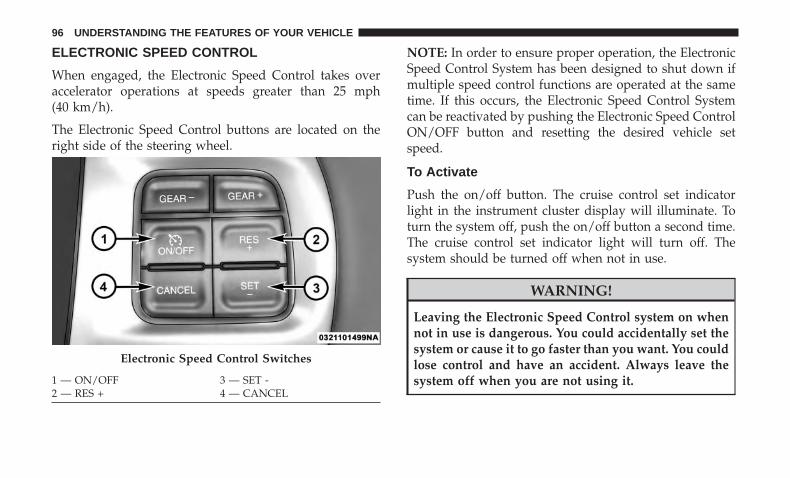
ELECTRONIC SPEED CONTROL
When engaged, the Electronic Speed Control takes overaccelerator operations at speeds greater than 25 mph(40 km/h).
The Electronic Speed Control buttons are located on theright side of the steering wheel.
NOTE: In order to ensure proper operation, the ElectronicSpeed Control System has been designed to shut down ifmultiple speed control functions are operated at the sametime. If this occurs, the Electronic Speed Control Systemcan be reactivated by pushing the Electronic Speed ControlON/OFF button and resetting the desired vehicle setspeed.
To Activate
Push the on/off button. The cruise control set indicatorlight in the instrument cluster display will illuminate. Toturn the system off, push the on/off button a second time.The cruise control set indicator light will turn off. Thesystem should be turned off when not in use.
WARNING!
Leaving the Electronic Speed Control system on whennot in use is dangerous. You could accidentally set thesystem or cause it to go faster than you want. You couldlose control and have an accident. Always leave thesystem off when you are not using it.
Electronic Speed Control Switches
1 — ON/OFF 3 — SET -2 — RES + 4 — CANCEL
96 UNDERSTANDING THE FEATURES OF YOUR VEHICLE
To Set A Desired Speed
Turn the Electronic Speed Control on. When the vehicle hasreached the desired speed, push the SET (-) button andrelease. Release the accelerator and the vehicle will operateat the selected speed.
NOTE: The vehicle should be traveling at a steady speedand on level ground before pushing the SET (-) button.
To Deactivate
A soft tap on the brake pedal, pushing the CANC button ornormal brake pressure while slowing the vehicle willdeactivate the Electronic Speed Control without erasing theset speed from memory.
Pushing the on/off button or turning the ignition to theOFF position erases the set speed from memory.
To Resume Speed
To resume a previously set speed, push the RES (+) buttonand release. Resume can be used at any speed above25 mph (40 km/h).
To Vary The Speed Setting
To Increase Speed
When the Electronic Speed Control is set, you can increasespeed by pushing the RES (+) button.
The driver’s preferred units can be selected through theinstrument panel settings if equipped. Refer to “Under-standing Your Instrument Panel” for more information.The speed decrement shown is dependant on the chosenspeed unit of U.S. (mph) or Metric (km/h):
U.S. Speed (mph)
• Pushing the RES (+) button once will result in a 1 mphincrease in set speed. Each subsequent tap of the buttonresults in an increase of 1 mph.
• If the button is continually pushed, the set speed willcontinue to increase until the button is released, then thenew set speed will be established.
3
UNDERSTANDING THE FEATURES OF YOUR VEHICLE 97
Metric Speed (km/h)
• Pushing the RES (+) button once will result in a 1 km/hincrease in set speed. Each subsequent tap of the buttonresults in an increase of 1 km/h.
• If the button is continually pushed, the set speed willcontinue to increase until the button is released, then thenew set speed will be established.
To Decrease Speed
When the Electronic Speed Control is set, you can decreasespeed by pushing the SET (-) button.
The driver’s preferred units can be selected through theinstrument panel settings if equipped. Refer to “Under-standing Your Instrument Panel” for more information.The speed decrement shown is dependant on the chosenspeed unit of U.S. (mph) or Metric (km/h):
U.S. Speed (mph)
• Pushing the SET (-) button once will result in a 1 mphdecrease in set speed. Each subsequent tap of the buttonresults in a decrease of 1 mph.
• If the button is continually pushed, the set speed willcontinue to decrease until the button is released, then thenew set speed will be established.
Metric Speed (km/h)
• Pushing the SET (-) button once will result in a 1 km/hdecrease in set speed. Each subsequent tap of the buttonresults in a decrease of 1 km/h.
• If the button is continually pushed, the set speed willcontinue to decrease until the button is released, then thenew set speed will be established.
98 UNDERSTANDING THE FEATURES OF YOUR VEHICLE
To Accelerate For Passing
Press the accelerator as you would normally. When thepedal is released, the vehicle will return to the set speed.
Using Electronic Speed Control On Hills
The transmission may downshift on hills to maintain thevehicle set speed.
NOTE: The Electronic Speed Control system maintainsspeed up and down hills. A slight speed change onmoderate hills is normal.
On steep hills, a greater speed loss or gain may occur so itmay be preferable to drive without Electronic Speed Con-trol.
WARNING!
Electronic Speed Control can be dangerous where thesystem cannot maintain a constant speed. Your vehiclecould go too fast for the conditions, and you could losecontrol and have an accident. Do not use ElectronicSpeed Control in heavy traffic or on roads that arewinding, icy, snow-covered or slippery.
3
UNDERSTANDING THE FEATURES OF YOUR VEHICLE 99

UNDERSTANDING YOUR INSTRUMENT PANEL
CONTENTS� INSTRUMENT CLUSTER . . . . . . . . . . . . . . . . . .102
� WARNING AND INDICATOR LIGHTS . . . . . . . .107
▫ Yellow Telltale Indicator Lights . . . . . . . . . . . . .107
� INSTRUMENT CLUSTER DISPLAY . . . . . . . . . . .109
▫ Oil Life Reset . . . . . . . . . . . . . . . . . . . . . . . . . .111
▫ Fuel Filter Life Reset. . . . . . . . . . . . . . . . . . . . .112
▫ Diesel Particulate Filter (DPF) Messages . . . . . .113
▫ Instrument Cluster Display Messages . . . . . . . .115
▫ Cold Ambient Derate Mode Messages . . . . . . . .116
▫ Diesel Exhaust Fluid (DEF) Warning Messages . .116
▫ Diesel Exhaust Fluid (DEF) Fault WarningMessages . . . . . . . . . . . . . . . . . . . . . . . . . . . . .117
▫ RAM Active Air System . . . . . . . . . . . . . . . . . .118
4
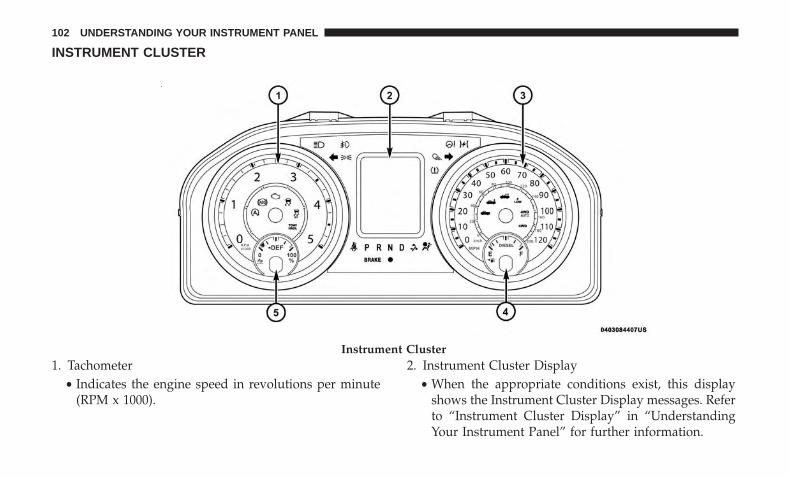
INSTRUMENT CLUSTER
1. Tachometer• Indicates the engine speed in revolutions per minute
(RPM x 1000).
2. Instrument Cluster Display• When the appropriate conditions exist, this display
shows the Instrument Cluster Display messages. Referto “Instrument Cluster Display” in “UnderstandingYour Instrument Panel” for further information.
Instrument Cluster
102 UNDERSTANDING YOUR INSTRUMENT PANEL
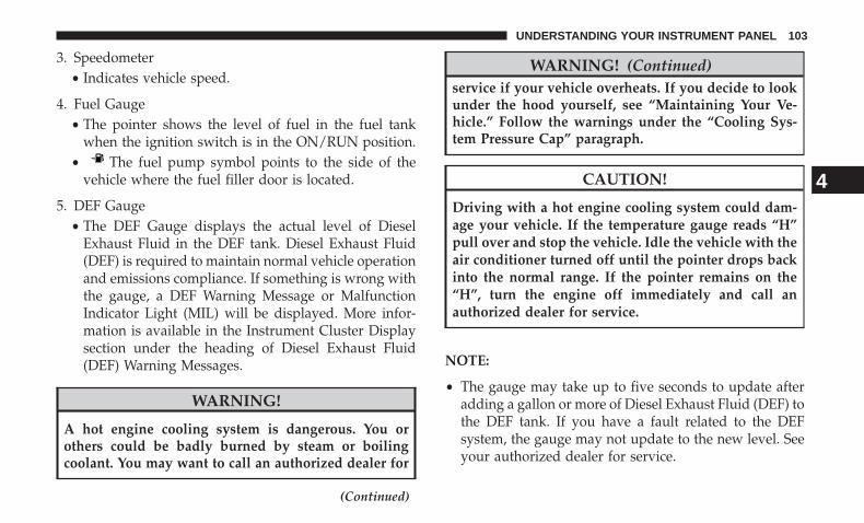
3. Speedometer• Indicates vehicle speed.
4. Fuel Gauge• The pointer shows the level of fuel in the fuel tank
when the ignition switch is in the ON/RUN position.• The fuel pump symbol points to the side of the
vehicle where the fuel filler door is located.
5. DEF Gauge• The DEF Gauge displays the actual level of Diesel
Exhaust Fluid in the DEF tank. Diesel Exhaust Fluid(DEF) is required to maintain normal vehicle operationand emissions compliance. If something is wrong withthe gauge, a DEF Warning Message or MalfunctionIndicator Light (MIL) will be displayed. More infor-mation is available in the Instrument Cluster Displaysection under the heading of Diesel Exhaust Fluid(DEF) Warning Messages.
WARNING!
A hot engine cooling system is dangerous. You orothers could be badly burned by steam or boilingcoolant. You may want to call an authorized dealer for
(Continued)
WARNING! (Continued)service if your vehicle overheats. If you decide to lookunder the hood yourself, see “Maintaining Your Ve-hicle.” Follow the warnings under the “Cooling Sys-tem Pressure Cap” paragraph.
CAUTION!
Driving with a hot engine cooling system could dam-age your vehicle. If the temperature gauge reads “H”pull over and stop the vehicle. Idle the vehicle with theair conditioner turned off until the pointer drops backinto the normal range. If the pointer remains on the“H”, turn the engine off immediately and call anauthorized dealer for service.
NOTE:
• The gauge may take up to five seconds to update afteradding a gallon or more of Diesel Exhaust Fluid (DEF) tothe DEF tank. If you have a fault related to the DEFsystem, the gauge may not update to the new level. Seeyour authorized dealer for service.
4
UNDERSTANDING YOUR INSTRUMENT PANEL 103

• The DEF gauge may also not immediately update after arefill if the temperature of the DEF fluid is below 12F(-11C). The DEF line heater will possibly warm up theDEF fluid and allow the gauge to update after a periodof run time. Under very cold conditions, it is possiblethat the gauge may not reflect the new fill level forseveral drives.
• Outside temperature can affect DEF consumption. Incold conditions, 12° F (-11° C) and below, the DEF gaugeneedle can stay on a fixed position and may not movefor extended periods of time. This is a normal function ofthe system.
Instrument Cluster
104 UNDERSTANDING YOUR INSTRUMENT PANEL
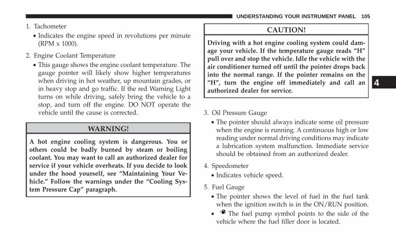
1. Tachometer• Indicates the engine speed in revolutions per minute
(RPM x 1000).
2. Engine Coolant Temperature• This gauge shows the engine coolant temperature. The
gauge pointer will likely show higher temperatureswhen driving in hot weather, up mountain grades, orin heavy stop and go traffic. If the red Warning Lightturns on while driving, safely bring the vehicle to astop, and turn off the engine. DO NOT operate thevehicle until the cause is corrected.
WARNING!
A hot engine cooling system is dangerous. You orothers could be badly burned by steam or boilingcoolant. You may want to call an authorized dealer forservice if your vehicle overheats. If you decide to lookunder the hood yourself, see “Maintaining Your Ve-hicle.” Follow the warnings under the “Cooling Sys-tem Pressure Cap” paragraph.
CAUTION!
Driving with a hot engine cooling system could dam-age your vehicle. If the temperature gauge reads “H”pull over and stop the vehicle. Idle the vehicle with theair conditioner turned off until the pointer drops backinto the normal range. If the pointer remains on the“H”, turn the engine off immediately and call anauthorized dealer for service.
3. Oil Pressure Gauge• The pointer should always indicate some oil pressure
when the engine is running. A continuous high or lowreading under normal driving conditions may indicatea lubrication system malfunction. Immediate serviceshould be obtained from an authorized dealer.
4. Speedometer• Indicates vehicle speed.
5. Fuel Gauge• The pointer shows the level of fuel in the fuel tank
when the ignition switch is in the ON/RUN position.• The fuel pump symbol points to the side of the
vehicle where the fuel filler door is located.
4
UNDERSTANDING YOUR INSTRUMENT PANEL 105
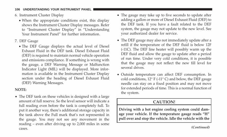
6. Instrument Cluster Display• When the appropriate conditions exist, this display
shows the Instrument Cluster Display messages. Referto “Instrument Cluster Display” in “UnderstandingYour Instrument Panel” for further information.
7. DEF Gauge• The DEF Gauge displays the actual level of Diesel
Exhaust Fluid in the DEF tank. Diesel Exhaust Fluid(DEF) is required to maintain normal vehicle operationand emissions compliance. If something is wrong withthe gauge, a DEF Warning Message or MalfunctionIndicator Light (MIL) will be displayed. More infor-mation is available in the Instrument Cluster Displaysection under the heading of Diesel Exhaust Fluid(DEF) Warning Messages.
NOTE:
• The DEF tank on these vehicles is designed with a largeamount of full reserve. So the level sensor will indicate afull reading even before the tank is completely full. Toput it another way, there’s additional storage capacity inthe tank above the Full mark that’s not represented inthe gauge. You may not see any movement in thereading – even after driving up to 2,000 miles in somecases.
• The gauge may take up to five seconds to update afteradding a gallon or more of Diesel Exhaust Fluid (DEF) tothe DEF tank. If you have a fault related to the DEFsystem, the gauge may not update to the new level. Seeyour authorized dealer for service.
• The DEF gauge may also not immediately update after arefill if the temperature of the DEF fluid is below 12F(-11C). The DEF line heater will possibly warm up theDEF fluid and allow the gauge to update after a periodof run time. Under very cold conditions, it is possiblethat the gauge may not reflect the new fill level forseveral drives.
• Outside temperature can affect DEF consumption. Incold conditions, 12° F (-11° C) and below, the DEF gaugeneedle can stay on a fixed position and may not movefor extended periods of time. This is a normal function ofthe system.
CAUTION!
Driving with a hot engine cooling system could dam-age your vehicle. If the temperature gauge reads “H”pull over and stop the vehicle. Idle the vehicle with the
(Continued)
106 UNDERSTANDING YOUR INSTRUMENT PANEL
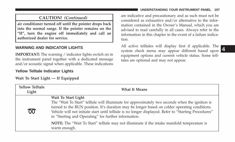
CAUTION! (Continued)air conditioner turned off until the pointer drops backinto the normal range. If the pointer remains on the“H”, turn the engine off immediately and call anauthorized dealer for service.
WARNING AND INDICATOR LIGHTS
IMPORTANT: The warning / indicator lights switch on inthe instrument panel together with a dedicated messageand/or acoustic signal when applicable. These indications
are indicative and precautionary and as such must not beconsidered as exhaustive and/or alternative to the infor-mation contained in the Owner’s Manual, which you areadvised to read carefully in all cases. Always refer to theinformation in this chapter in the event of a failure indica-tion.
All active telltales will display first if applicable. Thesystem check menu may appear different based uponequipment options and current vehicle status. Some tell-tales are optional and may not appear.
Yellow Telltale Indicator Lights
Wait To Start Light — If Equipped
Yellow TelltaleLight
What It Means
Wait To Start LightThe “Wait To Start” telltale will illuminate for approximately two seconds when the ignition isturned to the RUN position. It’s duration may be longer based on colder operating conditions.Vehicle will not initiate start until telltale is no longer displayed. Refer to “Starting Procedures”in “Starting and Operating” for further information.
NOTE: The “Wait To Start” telltale may not illuminate if the intake manifold temperature iswarm enough.
4
UNDERSTANDING YOUR INSTRUMENT PANEL 107
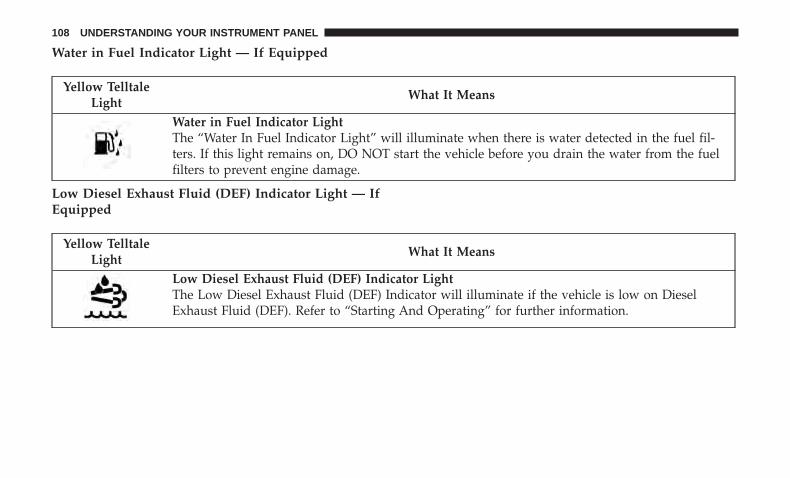
Water in Fuel Indicator Light — If Equipped
Yellow TelltaleLight
What It Means
Water in Fuel Indicator LightThe “Water In Fuel Indicator Light” will illuminate when there is water detected in the fuel fil-ters. If this light remains on, DO NOT start the vehicle before you drain the water from the fuelfilters to prevent engine damage.
Low Diesel Exhaust Fluid (DEF) Indicator Light — IfEquipped
Yellow TelltaleLight
What It Means
Low Diesel Exhaust Fluid (DEF) Indicator LightThe Low Diesel Exhaust Fluid (DEF) Indicator will illuminate if the vehicle is low on DieselExhaust Fluid (DEF). Refer to “Starting And Operating” for further information.
108 UNDERSTANDING YOUR INSTRUMENT PANEL
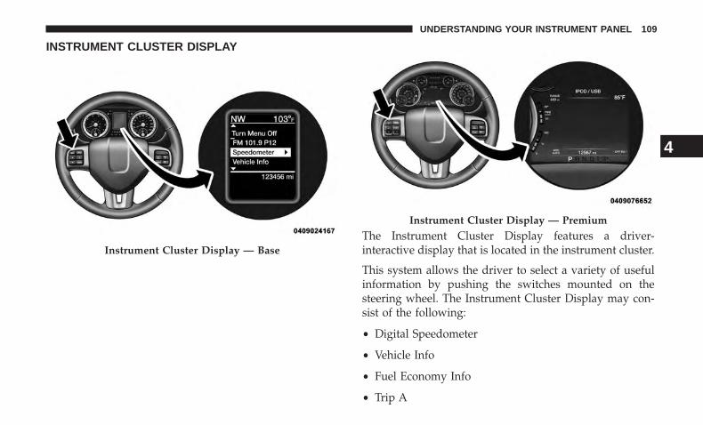
INSTRUMENT CLUSTER DISPLAY
The Instrument Cluster Display features a driver-interactive display that is located in the instrument cluster.
This system allows the driver to select a variety of usefulinformation by pushing the switches mounted on thesteering wheel. The Instrument Cluster Display may con-sist of the following:
• Digital Speedometer
• Vehicle Info
• Fuel Economy Info
• Trip A
Instrument Cluster Display — Base
Instrument Cluster Display — Premium
4
UNDERSTANDING YOUR INSTRUMENT PANEL 109
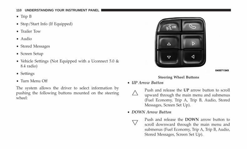
• Trip B
• Stop/Start Info (If Equipped)
• Trailer Tow
• Audio
• Stored Messages
• Screen Setup
• Vehicle Settings (Not Equipped with a Uconnect 5.0 &8.4 radio)
• Settings
• Turn Menu Off
The system allows the driver to select information bypushing the following buttons mounted on the steeringwheel:
• UP Arrow Button
Push and release the UP arrow button to scrollupward through the main menu and submenus(Fuel Economy, Trip A, Trip B, Audio, StoredMessages, Screen Set Up).
• DOWN Arrow Button
Push and release the DOWN arrow button toscroll downward through the main menu andsubmenus (Fuel Economy, Trip A, Trip B, Audio,Stored Messages, Screen Set Up).
Steering Wheel Buttons
110 UNDERSTANDING YOUR INSTRUMENT PANEL
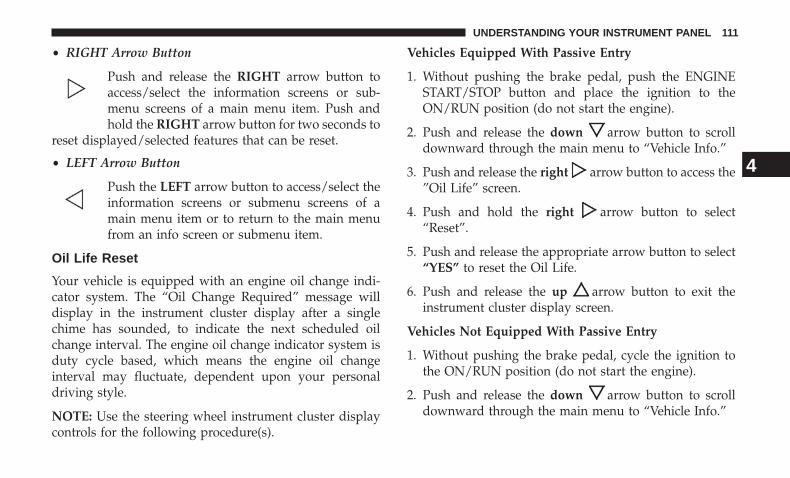
• RIGHT Arrow Button
Push and release the RIGHT arrow button toaccess/select the information screens or sub-menu screens of a main menu item. Push andhold the RIGHT arrow button for two seconds to
reset displayed/selected features that can be reset.
• LEFT Arrow Button
Push the LEFT arrow button to access/select theinformation screens or submenu screens of amain menu item or to return to the main menufrom an info screen or submenu item.
Oil Life Reset
Your vehicle is equipped with an engine oil change indi-cator system. The “Oil Change Required” message willdisplay in the instrument cluster display after a singlechime has sounded, to indicate the next scheduled oilchange interval. The engine oil change indicator system isduty cycle based, which means the engine oil changeinterval may fluctuate, dependent upon your personaldriving style.
NOTE: Use the steering wheel instrument cluster displaycontrols for the following procedure(s).
Vehicles Equipped With Passive Entry
1. Without pushing the brake pedal, push the ENGINESTART/STOP button and place the ignition to theON/RUN position (do not start the engine).
2. Push and release the down arrow button to scrolldownward through the main menu to “Vehicle Info.”
3. Push and release the right arrow button to access the”Oil Life” screen.
4. Push and hold the right arrow button to select“Reset”.
5. Push and release the appropriate arrow button to select“YES” to reset the Oil Life.
6. Push and release the up arrow button to exit theinstrument cluster display screen.
Vehicles Not Equipped With Passive Entry
1. Without pushing the brake pedal, cycle the ignition tothe ON/RUN position (do not start the engine).
2. Push and release the down arrow button to scrolldownward through the main menu to “Vehicle Info.”
4
UNDERSTANDING YOUR INSTRUMENT PANEL 111

3. Push and release the right arrow button to access the“Oil Life” screen.
4. Push and hold the right arrow button to select theOil Life Reset.
5. Push and release the appropriate arrow button to select“YES” to reset the Oil Life.
6. Push and release the up arrow button to exit theinstrument cluster display screen.
NOTE: If the indicator message illuminates when you startthe vehicle, the Oil Life indicator system did not reset. Ifnecessary, repeat this procedure.
Fuel Filter Life Reset
The cluster will display the “Service Fuel Filter” messagewhen the fuel filter maintenance life is less than 5%. Tocheck the remaining fuel filter life, go to the “Fuel FilterLife” screen in the “Vehicle Info” menu. When this messageappears, dealers should replace the fuel filter.
NOTE: Use the steering wheel button controls for thefollowing procedure(s)
Vehicles Equipped With Passive Entry
1. Without pushing the brake pedal, push the ENGINESTART/STOP button and cycle the ignition to the ON/RUN position (do not start the engine.)
2. Push and release the DOWN arrow button to scrolldownward through the main menu to “Vehicle Info”.
3. Push and release the RIGHT arrow button to accessthe ”Fuel Filter Life” screen.
4. Push and release the appropriate arrow button to accessthe “Reset” screen.
5. Push and release the appropriate arrow to select thereset of the Fuel Filter Life.
6. Push and release the UP arrow button to exit theInstrument Cluster Display screen.
Vehicles Not Equipped With Passive Entry
1. Without pressing the brake pedal, cycle the ignition tothe ON/RUN position (do not start the engine.)
2. Push and release the DOWN arrow button to scrolldownward through the main menu to “Vehicle Info”.
112 UNDERSTANDING YOUR INSTRUMENT PANEL
3. Push and release the RIGHT arrow button to accessthe ”Fuel Filter Life” screen.
4. Push and release the appropriate arrow button to accessthe “Reset” screen.
5. Push and release the appropriate arrow to select thereset of the Fuel Filter Life.
6. Push and release the UP arrow button to exit theInstrument Cluster Display screen.
NOTE: If the indicator message illuminates when you startthe vehicle, the Fuel Filter indicator system did not reset. Ifnecessary, repeat this procedure.
Diesel Particulate Filter (DPF) Messages
The Cummins diesel engine meets all diesel emissionsstandards, resulting in one of the lowest emitting dieselengines ever produced. To achieve these emissions stan-dards, your vehicle is equipped with a state-of-the-artengine and exhaust system. These systems are seamlesslyintegrated into your vehicle and managed by the Pow-ertrain Control Module (PCM). The PCM manages enginecombustion to allow the exhaust system’s catalyst to trapand burn Particulate Matter (PM) pollutants, with no inputor interaction on your part.
WARNING!
A hot exhaust system can start a fire if you park overmaterials that can burn. Such materials might be grassor leaves coming into contact with your exhaust sys-tem. Do not park or operate your vehicle in areas whereyour exhaust system can contact anything that canburn.
Your vehicle has the ability to alert you to additionalmaintenance required on your vehicle or engine. Thefollowing messages may display in your Instrument Clus-ter Display:
• Perform Service — Your vehicle will require emissionsmaintenance at a set interval. To help remind you whenthis maintenance is due, the Instrument Cluster Displaywill display “Perform Service”. When the “PerformService” message is displayed in the Instrument ClusterDisplay it is necessary to have the emissions mainte-nance performed. Emissions maintenance may includereplacing the Closed Crankcase Ventilation (CCV) filterelement. The procedure for clearing and resetting the�Perform Service� indicator message is located in theappropriate Service Information.
4
UNDERSTANDING YOUR INSTRUMENT PANEL 113
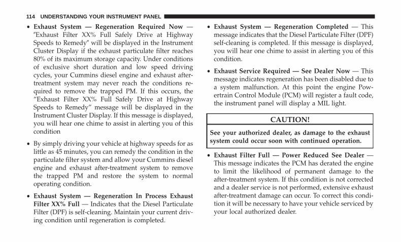
• Exhaust System — Regeneration Required Now —�Exhaust Filter XX% Full Safely Drive at HighwaySpeeds to Remedy� will be displayed in the InstrumentCluster Display if the exhaust particulate filter reaches80% of its maximum storage capacity. Under conditionsof exclusive short duration and low speed drivingcycles, your Cummins diesel engine and exhaust after-treatment system may never reach the conditions re-quired to remove the trapped PM. If this occurs, the“Exhaust Filter XX% Full Safely Drive at HighwaySpeeds to Remedy” message will be displayed in theInstrument Cluster Display. If this message is displayed,you will hear one chime to assist in alerting you of thiscondition
• By simply driving your vehicle at highway speeds for aslittle as 45 minutes, you can remedy the condition in theparticulate filter system and allow your Cummins dieselengine and exhaust after-treatment system to removethe trapped PM and restore the system to normaloperating condition.
• Exhaust System — Regeneration In Process ExhaustFilter XX% Full — Indicates that the Diesel ParticulateFilter (DPF) is self-cleaning. Maintain your current driv-ing condition until regeneration is completed.
• Exhaust System — Regeneration Completed — Thismessage indicates that the Diesel Particulate Filter (DPF)self-cleaning is completed. If this message is displayed,you will hear one chime to assist in alerting you of thiscondition.
• Exhaust Service Required — See Dealer Now — Thismessage indicates regeneration has been disabled due toa system malfunction. At this point the engine Pow-ertrain Control Module (PCM) will register a fault code,the instrument panel will display a MIL light.
CAUTION!
See your authorized dealer, as damage to the exhaustsystem could occur soon with continued operation.
• Exhaust Filter Full — Power Reduced See Dealer —This message indicates the PCM has derated the engineto limit the likelihood of permanent damage to theafter-treatment system. If this condition is not correctedand a dealer service is not performed, extensive exhaustafter-treatment damage can occur. To correct this condi-tion it will be necessary to have your vehicle serviced byyour local authorized dealer.
114 UNDERSTANDING YOUR INSTRUMENT PANEL
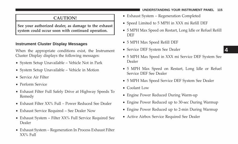
CAUTION!
See your authorized dealer, as damage to the exhaustsystem could occur soon with continued operation.
Instrument Cluster Display Messages
When the appropriate conditions exist, the InstrumentCluster Display displays the following messages:
• System Setup Unavailable – Vehicle Not in Park
• System Setup Unavailable – Vehicle in Motion
• Service Air Filter
• Perform Service
• Exhaust Filter Full Safely Drive at Highway Speeds ToRemedy
• Exhaust Filter XX% Full – Power Reduced See Dealer
• Exhaust Service Required – See Dealer Now
• Exhaust System – Filter XX% Full Service Required SeeDealer
• Exhaust System – Regeneration In Process Exhaust FilterXX% Full
• Exhaust System – Regeneration Completed
• Speed Limited to 5 MPH in XXX mi Refill DEF
• 5 MPH Max Speed on Restart, Long Idle or Refuel RefillDEF
• 5 MPH Max Speed Refill DEF
• Service DEF System See Dealer
• 5 MPH Max Speed in XXX mi Service DEF System SeeDealer
• 5 MPH Max Speed on Restart, Long Idle or RefuelService DEF See Dealer
• 5 MPH Max Speed Service DEF System See Dealer
• Coolant Low
• Engine Power Reduced During Warm-up
• Engine Power Reduced up to 30-sec During Warmup
• Engine Power Reduced up to 2-min During Warmup
• Active Airbox Service Required See Dealer
4
UNDERSTANDING YOUR INSTRUMENT PANEL 115
Cold Ambient Derate Mode Messages
The vehicle will display messages when a derate (enginepower reduction) is activated to protect the turbochargerduring engine start up in cold ambient temperatures.
• Engine Power Reduced During Warmup — This mes-sage will display during start up when the ambienttemperature is between 10° F (-12° C) and -10° F (-23° C).
• Engine Power Reduced Up To 30 Sec (Seconds) DuringWarmup — This message will display during start upwhen the ambient temperature is between -10° F (-23° C)and -25 F (-32° C).
• Engine Power Reduced Up To 2 Min (Minutes) DuringWarmup — This message will display during start upwhen the ambient temperature is -25° F (-32° C) andbelow.
• Coolant Low — This telltale will turn on to indicate thevehicle coolant level is low. See “Adding Coolant” underthe section “Maintaining Your Vehicle” for more infor-mation.
Diesel Exhaust Fluid (DEF) Warning Messages
Your vehicle will begin displaying warning messages whenthe DEF level reaches a driving range of approximately
350 miles (560 km). If the following warning messagesequence is ignored, your vehicle may be limited to amaximum speed of 5 MPH (8 km/H) unless DEF is added.
• DEF Low Refill Soon — This message will displaywhen the low level is reached, during vehicle start up,and with increased frequency during vehicle operation.It will be accompanied by a single chime. Approximately5 gallons (19 Liters) of DEF is required to refill the tankwhen this message is initially displayed. on pickupapplications, and approximately 7 gallons (28 Liters) arerequired on chassis-cab applications.
• Speed Limited to 5 MPH in XXX mi Refill DEF — Thismessage will continuously display if the “DEF LowRefill Soon” message is ignored, and the frequency ofoccurance of the chime will increase unless up to2 gallons (7.5 Liters) of DEF is added to the tank.
• 5 MPH Max Speed on Restart, Long Idle or RefuelRefill DEF — This message will continuously displaywhen the counter reaches zero, and will be accompaniedby a periodic chime.
• The vehicle will only be capable of a maximum speed of5 MPH upon the first of the following conditions tooccur:
116 UNDERSTANDING YOUR INSTRUMENT PANEL
• If the vehicle is shutoff and restarted.• If the vehicle is idled for an extended period of time,
approximately one hour or greater.• If the system detects that the level of fuel in the tank
has increased.
• Add a minimum of 2 gallons (9.5 Liters) of DEF to thetank in order to avoid vehicle operation at a maximumspeed of 5 MPH (8 km/H).
NOTE: A minimum of 2 gallons (9.5 Liters) may berequired to restore normal vehicle operation. Although thevehicle will start normally and can be placed in gear afterthis message has been initially displayed, extreme cautionshould be utilized since the vehicle will only be capable ofmaneuvering at a maximum speed of 5 MPH (8 km/H).
Diesel Exhaust Fluid (DEF) Fault WarningMessages
There are five different messages which are displayed if thevehicle detects that the DEF system has been filled with afluid other than DEF, has experienced component failures,or when tampering has been detected. The vehicle may belimited to a maximum speed of 5 MPH (8 km/H) if theDEF system is not serviced within less than 200 miles(322 km) of the fault being detected.
When the DEF system needs to be serviced the followingwarnings will display:
• Service DEF System See Dealer — This message willdisplay when the fault is initially detected, each time thevehicle is started, and periodically during driving. Themessage will be accompanied by a single chime. Werecommend you drive to your nearest authorized dealerand have your vehicle serviced as soon as possible.
• 5 MPH Max Speed in 150 mi Service DEF System SeeDealer — This message will display if the DEF systemhas not been serviced after the “Service DEF System –See Dealer” message is displayed. This message willcontinuously display until the mileage counter reacheszero, and will be accompanied by a periodic chime. Themessage will continue to countdown until it reaches zerounless the vehicle is serviced. We recommend you driveto your nearest authorized dealer and have your vehicleserviced immediately.
NOTE: Under some circumstances this mileage countermay start with a value of less than 150 miles (241 km). Forexample, if recurring faults are detected in a time intervalof less than 40 hours, the counter may restart at the valuewhere it stopped when a previous fault was temporarilyremedied, or at a minimum of 50 miles (80 km).
4
UNDERSTANDING YOUR INSTRUMENT PANEL 117
• 5 MPH Max Speed on Restart, Long Idle or RefuelService DEF See Dealer — This message will continu-ously display when the mileage counter reaches zero,and will be accompanied by a periodic chime.
• The vehicle will only be capable of a maximum speed of5 MPH upon the first of the following conditions tooccur:• If the vehicle is shutoff and restarted.• If the vehicle is idled for an extended period of time,
approximately one hour or greater.• If the system detects that the level of fuel in the tank
has increased.
• 5 MPH Max Speed Service DEF System See Dealer —This message will continuously display, and will beaccompanied by a periodic chime. Although the vehiclecan be started and placed in gear, the vehicle will onlyoperate at a maximum speed of 5 MPH. Your vehiclewill require towing, see your authorized dealer forservice.
NOTE: When this message is displayed, the engine canstill be started. However, the vehicle will only operate at amaximum speed of 5 MPH.
• Incorrect DEF Detected See Dealer — This message willdisplay when the fault is initially detected, each time thevehicle is started, and periodically during driving. Themessage will be accompanied by a single chime. Werecommend you drive to your nearest authorized dealerand have your vehicle serviced as soon as possible.
RAM Active Air System
Your vehicle is equipped with an advanced Ram Active Airsystem that provides enhanced performance, especiallywhen towing under demanding hot or high altitude con-ditions. If the Instrument Cluster Display displays themessage “Active Airbox Service Required See Dealer”,vehicle performance may be reduced until service is per-formed by an authorized RAM dealer.
118 UNDERSTANDING YOUR INSTRUMENT PANEL
STARTING AND OPERATING
CONTENTS� STARTING PROCEDURES . . . . . . . . . . . . . . . . .121
▫ Manual Transmission — If Equipped . . . . . . . .121
▫ Automatic Transmission — If Equipped . . . . . .121
▫ Keyless Enter-N-Go — If Equipped . . . . . . . . . .122
▫ Extreme Cold Weather . . . . . . . . . . . . . . . . . . .125
▫ Normal Starting Procedure — Engine ManifoldAir Temperature Above 66° F (19° C) . . . . . . . . .126
▫ Starting Procedure — Engine Manifold AirTemperature 0°F To 66°F (–18°C to 19°C) . . . . . .126
▫ Starting Procedure — Engine Manifold AirTemperature Below 0°F (-18°C) . . . . . . . . . . . . .128
▫ Starting Fluids . . . . . . . . . . . . . . . . . . . . . . . . .129
� NORMAL OPERATION — DIESEL ENGINE. . . . .130
▫ Cold Weather Precautions . . . . . . . . . . . . . . . . .131
▫ Engine Idling . . . . . . . . . . . . . . . . . . . . . . . . .133
▫ Stopping The Engine . . . . . . . . . . . . . . . . . . . .134
▫ Idle Shutdown . . . . . . . . . . . . . . . . . . . . . . . . .135
▫ Programmable Maximum Vehicle Speed(Chassis Cab Only). . . . . . . . . . . . . . . . . . . . . .136
▫ Operating Precautions . . . . . . . . . . . . . . . . . . .136
▫ Cooling System Tips — Automatic Transmission . .136
� ENGINE BLOCK HEATER — IF EQUIPPED . . . .137
▫ Block Heater Usage . . . . . . . . . . . . . . . . . . . . .138
� DIESEL EXHAUST BRAKE (ENGINE BRAKING) .138
5
� AUTOMATIC TRANSMISSION — IF EQUIPPED .140
▫ Key Ignition Park Interlock . . . . . . . . . . . . . . . .141
▫ Brake/Transmission Shift Interlock System . . . .141
▫ Six-Speed Automatic Transmission — IfEquipped . . . . . . . . . . . . . . . . . . . . . . . . . . . .141
� MANUAL TRANSMISSION — IF EQUIPPED . . .150
▫ Shifting . . . . . . . . . . . . . . . . . . . . . . . . . . . . . .151
▫ Downshifting. . . . . . . . . . . . . . . . . . . . . . . . . .152
▫ Reverse Shifting . . . . . . . . . . . . . . . . . . . . . . . .153
� AUXILIARY SWITCHES — IF EQUIPPED . . . . . .153
� POWER TAKE OFF OPERATION — IF EQUIPPED(CHASSIS CAB ONLY) . . . . . . . . . . . . . . . . . . . .154
▫ Stationary Mode . . . . . . . . . . . . . . . . . . . . . . .154
▫ Mobile Mode . . . . . . . . . . . . . . . . . . . . . . . . . .155
� ENGINE RUNAWAY . . . . . . . . . . . . . . . . . . . . .156
� FUEL REQUIREMENTS . . . . . . . . . . . . . . . . . . .157
▫ Fuel Specifications . . . . . . . . . . . . . . . . . . . . . .157
▫ Bio-Diesel Fuel Requirements . . . . . . . . . . . . . .158
� ADDING FUEL — 2500/3500 DIESEL MODELS . .160
� ADDING FUEL — CHASSIS CAB MODELS . . . . .162
▫ Fuel Filler Cap. . . . . . . . . . . . . . . . . . . . . . . . .163
▫ Avoid Using Contaminated Fuel . . . . . . . . . . . .163
▫ Bulk Fuel Storage — Diesel Fuel . . . . . . . . . . . .163
▫ Diesel Exhaust Fluid Storage . . . . . . . . . . . . . . .164
▫ Adding Diesel Exhaust Fluid. . . . . . . . . . . . . . .164
� DIESEL EXHAUST FLUID . . . . . . . . . . . . . . . . . .167
▫ System Overview . . . . . . . . . . . . . . . . . . . . . . .168
120 STARTING AND OPERATING
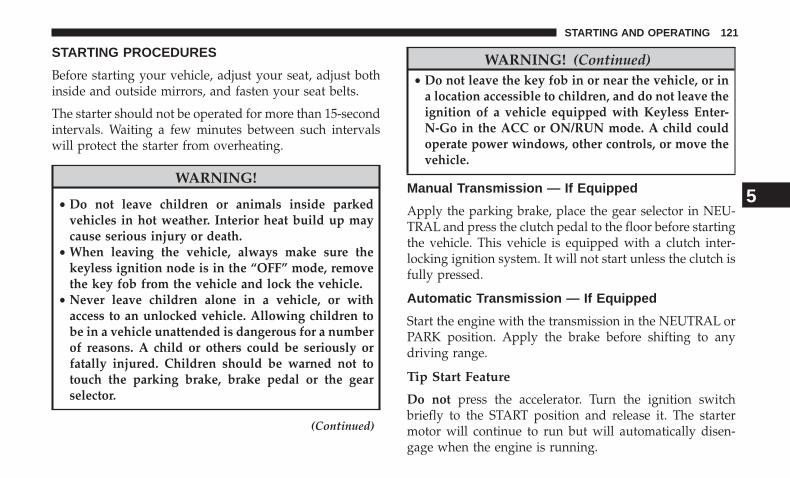
STARTING PROCEDURES
Before starting your vehicle, adjust your seat, adjust bothinside and outside mirrors, and fasten your seat belts.
The starter should not be operated for more than 15-secondintervals. Waiting a few minutes between such intervalswill protect the starter from overheating.
WARNING!
• Do not leave children or animals inside parkedvehicles in hot weather. Interior heat build up maycause serious injury or death.
• When leaving the vehicle, always make sure thekeyless ignition node is in the “OFF” mode, removethe key fob from the vehicle and lock the vehicle.
• Never leave children alone in a vehicle, or withaccess to an unlocked vehicle. Allowing children tobe in a vehicle unattended is dangerous for a numberof reasons. A child or others could be seriously orfatally injured. Children should be warned not totouch the parking brake, brake pedal or the gearselector.
(Continued)
WARNING! (Continued)• Do not leave the key fob in or near the vehicle, or in
a location accessible to children, and do not leave theignition of a vehicle equipped with Keyless Enter-N-Go in the ACC or ON/RUN mode. A child couldoperate power windows, other controls, or move thevehicle.
Manual Transmission — If Equipped
Apply the parking brake, place the gear selector in NEU-TRAL and press the clutch pedal to the floor before startingthe vehicle. This vehicle is equipped with a clutch inter-locking ignition system. It will not start unless the clutch isfully pressed.
Automatic Transmission — If Equipped
Start the engine with the transmission in the NEUTRAL orPARK position. Apply the brake before shifting to anydriving range.
Tip Start Feature
Do not press the accelerator. Turn the ignition switchbriefly to the START position and release it. The startermotor will continue to run but will automatically disen-gage when the engine is running.
5
STARTING AND OPERATING 121
Keyless Enter-N-Go — If Equipped
This feature allows the driver to operatethe ignition switch with the push of abutton, as long as the Remote Start/Keyless Enter-N-Go key fob is in thepassenger compartment.
Normal Starting
Using The ENGINE START/STOP Button
1. The transmission must be in PARK or NEUTRAL.
2. Press and hold the brake pedal while pushing theENGINE START/STOP button once.
3. The system takes over and attempts to start the vehicle.If the vehicle fails to start, the starter will disengageautomatically after 25 seconds.
4. If you wish to stop the cranking of the engine prior tothe engine starting, remove your foot from the brakepedal and push the button again.
NOTE:
• Normal starting of either a cold or a warm engine isobtained without pumping or pressing the acceleratorpedal.
• Under cold weather conditions, the engine may notimmediately crank if the �Wait To Start� telltale isilluminated. This is normal operation. For vehiclesequipped with Keyless Enter-N-Go, the vehicle willautomatically crank when the �Wait To Start� time haselapsed. See the section �Starting Procedure EngineManifold Air Temperature 0°F to 66°F (18° C to 19°C)�for more information.
To Turn Off The Engine Using ENGINE START/STOPButton
1. Place the gear selector in PARK, then push and releasethe ENGINE START/STOP button.
2. The ignition will return to the OFF position.
122 STARTING AND OPERATING
3. If the gear selector is not in PARK, the ENGINE START/STOP button must be held for two seconds or three shortpushes in a row with the vehicle speed above 5 mph(8 km/h) before the engine will shut off. The ignitionswitch position will remain in the ACC position until thegear selector is in PARK and the button is pushed twiceto the OFF position. If the gear selector is not in PARKand the ENGINE START/STOP button is pushed once,the instrument cluster display will display a “VehicleNot In Park” message and the engine will remainrunning. Never leave a vehicle out of the PARK position,or it could roll.
4. If the gear selector is in NEUTRAL, push and release theENGINE START/STOP button with the vehicle speedbelow 5 mph (8 km/h) before the engine will shut off.The ignition will remain in the ACC position.
NOTE: If the ignition is left in the ACC or RUN (engine notrunning) position and the transmission is in PARK, thesystem will automatically time out after 30 minutes ofinactivity and the ignition will switch to the OFF position.
ENGINE START/STOP Button Functions — WithDriver’s Foot OFF The Brake Pedal (In PARK OrNEUTRAL Position)
The ENGINE START/STOP button operates similar to anignition switch. It has three positions, OFF, ACC, RUN. Tochange the ignition switch positions without starting thevehicle and use the accessories follow these steps:
1. Starting with the ignition in the OFF position:
2. Push the ENGINE START/STOP button once to changethe ignition to the ACC position.
3. Push the ENGINE START/STOP button a second timeto change the ignition to the RUN position.
4. Push the ENGINE START/STOP button a third time toreturn the ignition to the OFF position.
5
STARTING AND OPERATING 123
Keyless Enter-N-Go Starting Procedure — EngineManifold Air Temperature 0° F To 66° F (–18° C to19° C)
NOTE: The temperature displayed in the instrument clus-ter does not necessarily reflect the engine manifold airtemperature. Refer to “Instrument Cluster Display” in“Understanding Your Instrument Panel” for further infor-mation. When engine temperatures fall below 66°F (19°C)the “Wait To Start Light” will remain on indicating theintake manifold heater system is active.
Follow the steps in the “Normal Starting” procedureexcept:
1. Pushing the engine start button with the driver’s foot onthe brake will move the ignition from OFF or ACC toRUN, and will illuminate the �Wait To Start� telltale. Theengine will not immediately crank, this is normal op-eration.
2. The “Wait To Start� telltale will remain on for a period oftime that varies depending on the engine temperature.
3. While the �Wait to Start� telltale is on, the instrumentcluster will additionally display a gauge or bar whoseinitial length represents the full �Wait to Start� timeperiod. Its length will decrease until it disappears whenthe �Wait to Start� time has elapsed.
CAUTION!
If the “Water in Fuel Indicator Light” remains on, DONOT START engine before you drain the water fromthe fuel filters to avoid engine damage. Refer to“Maintenance Procedures/Draining Fuel/Water Sepa-rator Filter” in “Maintaining Your Vehicle” for furtherinformation.
4. After the engine “Wait To Start” telltale goes off, theengine will automatically crank.
CAUTION!
The engine may automatically crank when the “WaitTo Start” time has elapsed. To abort the automaticstarting process, ensure the driver’s foot is fully re-moved from the brake pedal prior to pushing theSTART/STOP button to cycle the ignition off.
124 STARTING AND OPERATING
5. After engine start-up, check to see that there is oilpressure.
6. Allow the engine to idle about three minutes until themanifold heaters have completed the post-heat cycle.
7. Release the parking brake and drive.
NOTE:
• Engine idle speed will automatically increase to 1,000RPM and engage the Variable Geometry Turbocharger atlow coolant temperatures to improve engine warm-up.
• The engine may not automatically crank after the engine�Wait To Start� telltale goes off if a door or the hood isajar.
• If the engine stalls, or if the ignition switch is left ON formore than two minutes after the “Wait To Start Light”goes out, reset the grid heaters by turning the ignitionswitch to the OFF position for at least five seconds andthen back ON. Repeat steps 1 through 7 of “KeylessEnter-N-Go Starting Procedure – Engine Manifold AirTemperature Below 66° F (19° C).”
Extreme Cold Weather
The Cummins diesel engine is equipped with severalfeatures designed to assist cold weather starting and op-eration:
• The engine block heater is a resistance heater installed inthe water jacket of the engine just above and behind theoil filter. It requires a 110–115 Volt AC electrical outletwith a grounded, three-wire extension cord.
NOTE: The engine block heater cord is a factory installedoption. If your vehicle is not equipped, heater cords areavailable from your authorized MOPAR dealer.
• A 12 Volt heater built into the fuel filter housings aid inpreventing fuel gelling. It is controlled by a built-inthermostat.
• A heated intake air system both improves engine start-ing and reduces the amount of white smoke generatedby a warming engine.
5
STARTING AND OPERATING 125
Normal Starting Procedure — Engine Manifold AirTemperature Above 66° F (19° C)
Observe the instrument panel cluster lights when startingthe engine.
1. Always apply the parking brake.
2. Shift into PARK for an automatic transmission.For vehicles equipped with a manual transmission, fullypress and hold the clutch pedal and shift into NEU-TRAL.
3. Turn the ignition switch to the ON position and watchthe instrument panel cluster lights.
CAUTION!
If the “Water in Fuel Indicator Light” remains on, DONOT START the engine before you drain the waterfrom the fuel filters to avoid engine damage. Refer to“Maintenance Procedures/Draining Fuel/Water Sepa-rator Filter” in “Maintaining Your Vehicle” for furtherinformation.
4. Turn the ignition switch to the START position andcrank the engine. Do not press the accelerator duringstarting.
CAUTION!
Do not crank engine for more than 15 seconds at a timeor starter motor damage may result. Turn the ignitionswitch to the OFF position and wait at least twominutes for the starter to cool before repeating startprocedure.
5. When the engine starts, release the key fob.
6. Check that the oil pressure warning light has turned off.
7. Release the parking brake.
Starting Procedure — Engine Manifold AirTemperature 0°F To 66°F (–18°C to 19°C)
NOTE: The temperature displayed in the instrument clus-ter does not necessarily reflect the engine manifold airtemperature. Refer to “Instrument Cluster Display” in“Understanding Your Instrument Panel” for further infor-mation. When engine temperatures fall below 66°F (19°C)the “Wait To Start Light” will remain on indicating theintake manifold heater system is active.
126 STARTING AND OPERATING
Follow the steps in the “Normal Starting” procedureexcept:
1. The “Wait To Start” telltale will remain on for a period oftime that varies depending on the engine temperature.
2. While the �Wait To Start” telltale is on, the instrumentcluster will additionally display a gauge or bar whoseinitial length represents the full �Wait To Start� timeperiod. Its length will decrease until it disappears whenthe �Wait To Start� time has elapsed.
CAUTION!
If the “Water in Fuel Indicator Light” remains on, DONOT START engine before you drain the water fromthe fuel filters to avoid engine damage. Refer to“Maintenance Procedures/Draining Fuel/Water Sepa-rator Filter” in “Maintaining Your Vehicle” for furtherinformation.
3. After the “Wait To Start” telltale goes off, turn theignition switch to the START position. Do not press theaccelerator during starting.
CAUTION!
Do not crank engine for more than 15 seconds at a timeor starter motor damage may result. Turn the ignitionswitch to the OFF position and wait at least twominutes for the starter to cool before repeating startprocedure.
4. After engine start-up, check that the oil pressure warn-ing light has turned off.
5. Allow the engine to idle about three minutes until themanifold heaters have completed the post-heat cycle.
6. Release the parking brake and drive.
NOTE:
• Engine idle speed will automatically increase to1,000 RPM and engage the Variable Geometry Turbo-charger at low coolant temperatures to improve enginewarm-up.
• Automatic equipped vehicles with optional KeylessEnter-N-Go – If the start button is pushed once while inpark with the ignition off and driver’s foot on the brakepedal, the vehicle will automatically crank and startafter the Wait to Start time has elapsed. If it is desired to
5
STARTING AND OPERATING 127
abort the start process before it completes, the driver’sfoot should be fully removed from the brake pedal priorto pushing the start button again in order for the ignitionto move directly to off.
• If the engine stalls, or if the ignition switch is left ON formore than two minutes after the “Wait To Start” telltalegoes out, reset the grid heaters by turning the ignitionswitch to the OFF position for at least five seconds andthen back ON. Repeat steps 1 through 5 of “StartingProcedure – Engine Manifold Air Temperature Below66°F (19°C).”
Starting Procedure — Engine Manifold AirTemperature Below 0°F (-18°C)
In extremely cold weather below 0°F (-18°C) it may bebeneficial to cycle the manifold heaters twice before at-tempting to start the engine. This can be accomplished byturning the ignition OFF for at least five seconds and thenback ON after the “Wait To Start” telltale has turned off,but before the engine is started. However, excessive cyclingof the manifold heaters will result in damage to the heaterelements or reduced battery voltage.
NOTE:If multiple pre-heat cycles are used before start-ing, additional engine run time may be required tomaintain battery state of charge at a satisfactory level.
1. If the engine stalls after the initial start, the ignition mustbe turned to the OFF position for at least five secondsand then to the ON position to recycle the manifoldheaters.
NOTE: Excessive white smoke and poor engine perfor-mance will result if manifold heaters are not recycled.
2. Heat generated by the manifold heaters dissipates rap-idly in a cold engine. If more than two minutes passbetween the time the “Wait To Start” telltale turns offand the engine is started, recycle the manifold heatersby turning the ignition switch to the OFF position for atleast five seconds and then back ON.
3. If the vehicle is driven and vehicle speed exceeds19 mph (31 km/h) before the manifold heater post-heat(after start) cycle is complete, the manifold heaters willshut off.
4. If the engine is started before the “Wait To Start” telltaleturns off, the preheat cycle will turn off.
5. If the engine is cranked for more than 10 seconds, thepost-heat cycle will turn off.
128 STARTING AND OPERATING
NOTE:
• Engine idle speed will automatically increase to1,000 RPM and engage the Variable Geometry Turbo-charger at low coolant temperatures to improve enginewarm-up.
• When a diesel engine is allowed to run out of fuel or thefuel gels at low temperatures, air is pulled into the fuelsystem. If your engine has run out of fuel, refer to“Maintenance Procedures/Priming If The Engine HasRun Out Of Fuel” in “Maintaining Your Vehicle” forfurther information.
• If the engine stalls, or if the ignition switch is left ON formore than two minutes after the “Wait To Start” telltalegoes out, reset the grid heaters by turning the ignitionswitch to the OFF position for at least five seconds andthen back ON. Repeat steps 1 through 5 of “StartingProcedure – Engine Manifold Air Temperature Below66°F (19°C).”
Starting Fluids
WARNING!
Starting fluids or flammable liquids must never beused in the Cummins diesel engine (see Warninglabel). Never pour diesel fuel, flammable liquid, start-ing fluids (ether) into the air cleaner canister, air intakepiping, or turbocharger inlet in an attempt to start thevehicle. This could result in a flash fire and explosioncausing serious personal injury and engine damage.
The engine is equipped with an automatic electric airpreheating system. If the instructions in this manual arefollowed, the engine should start in all conditions.
WARNING!
• Do not leave children or animals inside parkedvehicles in hot weather. Interior heat build up maycause serious injury or death.
• When leaving the vehicle, always make sure thekeyless ignition node is in the “OFF” mode, removethe key fob from the vehicle and lock the vehicle.
(Continued)
5
STARTING AND OPERATING 129
WARNING! (Continued)• Never leave children alone in a vehicle, or with
access to an unlocked vehicle. Allowing children tobe in a vehicle unattended is dangerous for a numberof reasons. A child or others could be seriously orfatally injured. Children should be warned not totouch the parking brake, brake pedal or the gearselector.
• Do not leave the key fob in or near the vehicle, or ina location accessible to children, and do not leave theignition of a vehicle equipped with Keyless Enter-N-Go in the ACC or ON/RUN mode. A child couldoperate power windows, other controls, or move thevehicle.
NORMAL OPERATION — DIESEL ENGINE
Observe the following when the engine is operating.
• All message center lights are off.
• Malfunction Indicator Light (MIL) is off.
• Engine oil pressure is above 10 psi (69 kPa) at idle.
• Voltmeter operation:
The voltmeter may show a gauge fluctuation at variousengine temperatures. This cycling operation is caused bythe post-heat cycle of the intake manifold heater system.The number of cycles and the length of the cycling opera-tion is controlled by the engine control module. Post-heatoperation can run for several minutes, and then the elec-trical system and voltmeter needle will stabilize.
The cycling action will cause temporary dimming of theheadlamps, interior lamps, and also a noticeable reductionin blower motor speed.
130 STARTING AND OPERATING
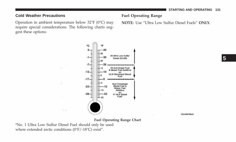
Cold Weather Precautions
Operation in ambient temperature below 32°F (0°C) mayrequire special considerations. The following charts sug-gest these options:
Fuel Operating Range
NOTE: Use “Ultra Low Sulfur Diesel Fuels” ONLY.
*No. 1 Ultra Low Sulfur Diesel Fuel should only be usedwhere extended arctic conditions (0°F/-18°C) exist”.
Fuel Operating Range Chart
5
STARTING AND OPERATING 131
NOTE:
• Use of Climatized Ultra Low Sulfur Diesel Fuel orNumber 1 Ultra Low Sulfur Diesel Fuel results in anoticeable decrease in fuel economy.
• Climatized Ultra Low Sulfur Diesel Fuel is a blend ofNumber 2 Ultra Low Sulfur and Number 1 Ultra LowSulfur Diesel Fuels which reduces the temperature atwhich wax crystals form in fuel.
• The fuel grade should be clearly marked on the pump atthe fuel station.
• The engine requires the use of “Ultra Low Sulfur DieselFuel”. Use of incorrect fuel could result in engine andexhaust system damage. Refer to “Fuel Requirements”in “Starting And Operating” for further information.
• If climatized or diesel Number 1 ULSD fuel is notavailable, and you are operating below (20°F/-6°C), insustained arctic conditions, Mopar Premium Diesel FuelTreatment (or equivalent) is recommended to avoidgelling (see Fuel Operating Range Chart).
Engine Oil Usage
Refer to “Maintenance Procedures” in “Maintaining YourVehicle” for the correct engine oil viscosity.
Winter Front Cover Usage
A winter front or cold weather cover is to be used inambient temperatures below 32°F (0°C), especially duringextended idle conditions. This cover is equipped with fourflaps for managing total grille opening in varying ambienttemperatures. If a winter front or cold weather cover is tobe used the flaps should be left in the full open position toallow air flow to the charge air cooler and automatictransmission oil cooler. When ambient temperatures dropbelow 0°F (-17°C) the four flaps need to be closed. Asuitable cold weather cover is available from your MOPARdealer.
Battery Blanket Usage
A battery loses 60% of its cranking power as the batterytemperature decreases to 0°F (-18°C). For the same de-crease in temperature, the engine requires twice as muchpower to crank at the same RPM. The use of 120 VACpowered battery blankets will greatly increase startingcapability at low temperatures. Suitable battery blanketsare available from your authorized MOPAR dealer.
132 STARTING AND OPERATING
Engine Warm-Up
Avoid full throttle operation when the engine is cold. Whenstarting a cold engine, bring the engine up to operatingspeed slowly to allow the oil pressure to stabilize as theengine warms up.
NOTE: High-speed, no-load running of a cold engine canresult in excessive white smoke and poor engine perfor-mance. No-load engine speeds should be kept under 1,200RPM during the warm-up period, especially in cold ambi-ent temperature conditions.
Your vehicle is equipped with a turbo speed limiter, thisfeature limits the engine speed to 1,200 RPM when enginecoolant temperatures are below 70°F (21°C). This feature isdesigned to protect the turbocharger from damage and willonly operate in PARK or NEUTRAL.
If temperatures are below 32°F (0°C), operate the engine atmoderate speeds for five minutes before full loads areapplied.
NOTE: If ambient temperatures are low and the coolanttemperature is below 180°F (82°C), the engine idle speedwill slowly increase to 1,000 RPM after two minutes of idle,if the following conditions are met:
• Foot is off brake pedal and throttle pedal.
• Automatic transmission is in PARK.
• Vehicle speed is 0 mph (0 km/h).
• Applying the throttle will cancel fast idle.
• Operating the exhaust brake at idle will greatly improvewarm up rate and will help keep the engine close tooperating temperature during extended idle.
Engine Idling
Avoid prolonged idling, long periods of idling may beharmful to your engine because combustion chamber tem-peratures can drop so low that the fuel may not burncompletely. Incomplete combustion allows carbon andvarnish to form on piston rings, engine valves, and injectornozzles. Also, the unburned fuel can enter the crankcase,diluting the oil and causing rapid wear to the engine.
If the engine is allowed to idle or the truck is driven on lowengine speed drive cycles for more than 2 hours, thesystem will automatically enter an emissions operatingmode that will increase the engine idle speed to 900 RPM(1050 RPM for Chassis Cab). While in this mode, which isdesigned to help maintain the diesel particulate filter, theengine idle speed will return to normal when the brakepedal is applied. A small change in engine tone or a slightchange in engine performance while accelerating may also
5
STARTING AND OPERATING 133
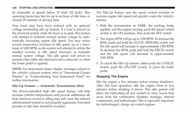
be noticeable at speeds below 20 mph (32 kmh). Thisoperating mode may last for up to an hour of idle time, oraround 20 minutes of driving time.
Your truck may have been ordered with an optionalvoltage monitoring idle up feature. If a load is placed onthe electrical system while the truck is in park, this featurewill attempt to maintain normal system voltage by auto-matically increasing engine idle speed. You may noticeseveral consecutive increases in idle speed, up to a maxi-mum of 1450 RPM, as the system will attempt to utilize thesmallest increase in idle speed necessary to maintainnormal system voltage. The idle speed will return tonormal when either the electrical load is removed, or whenthe brake pedal is applied.
NOTE: For instrument cluster display messages related tothe vehicle’s exhaust system, refer to “Instrument ClusterDisplay” in “Understanding Your Instrument Panel” forfurther information.
Idle-Up Feature — Automatic Transmission Only
The driver-controlled high idle speed feature will helpincrease cylinder temperatures and provide additional cabheat, however, excessive idling may still cause the exhaustaftertreatment system to not properly regenerate. Extendedperiods of idle time should be avoided.
The Idle-Up feature uses the speed control switches toincrease engine idle speed and quickly warm the vehicle’sinterior.
1. With the transmission in PARK, the parking brakeapplied, and the engine running, push the speed controlswitch to the ON position, then push the SET switch.
2. The engine RPM will go up to 1100 RPM. To increase theRPM, push and hold the ACCEL/RESUME switch andthe idle speed will increase to approximately 1500 RPM.To decrease the RPM, push and hold the DECEL switchand the idle speed will decrease to approximately1100 RPM.
3. To cancel the Idle–Up feature, either push the CANCELswitch, push the ON/OFF switch, or press the brakepedal.
Stopping The Engine
Idle the engine a few minutes before routine shutdown.After full load operation, idle the engine three to fiveminutes before shutting it down. This idle period willallow the lubricating oil and coolant to carry excess heataway from the combustion chamber, bearings, internalcomponents, and turbocharger. This is especially importantfor turbocharged, charge air-cooled engines.
134 STARTING AND OPERATING
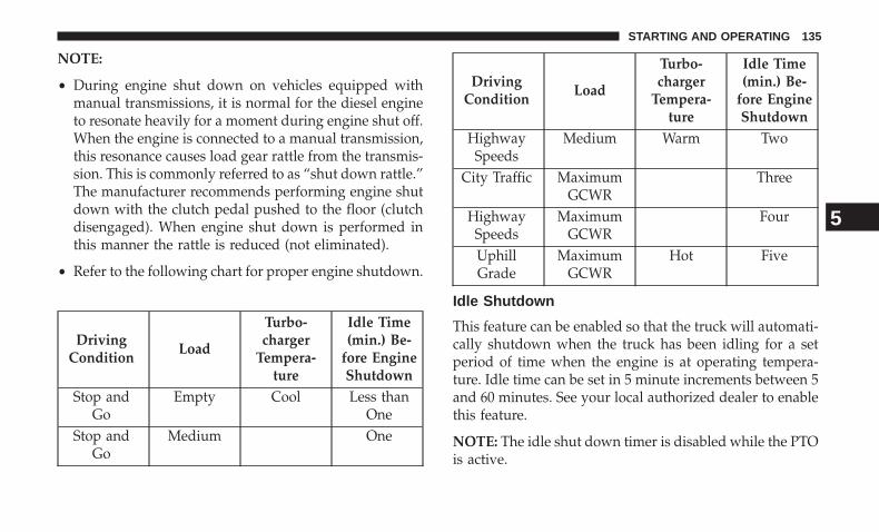
NOTE:
• During engine shut down on vehicles equipped withmanual transmissions, it is normal for the diesel engineto resonate heavily for a moment during engine shut off.When the engine is connected to a manual transmission,this resonance causes load gear rattle from the transmis-sion. This is commonly referred to as “shut down rattle.”The manufacturer recommends performing engine shutdown with the clutch pedal pushed to the floor (clutchdisengaged). When engine shut down is performed inthis manner the rattle is reduced (not eliminated).
• Refer to the following chart for proper engine shutdown.
DrivingCondition
Load
Turbo-charger
Tempera-ture
Idle Time(min.) Be-
fore EngineShutdown
Stop andGo
Empty Cool Less thanOne
Stop andGo
Medium One
DrivingCondition
Load
Turbo-charger
Tempera-ture
Idle Time(min.) Be-
fore EngineShutdown
HighwaySpeeds
Medium Warm Two
City Traffic MaximumGCWR
Three
HighwaySpeeds
MaximumGCWR
Four
UphillGrade
MaximumGCWR
Hot Five
Idle Shutdown
This feature can be enabled so that the truck will automati-cally shutdown when the truck has been idling for a setperiod of time when the engine is at operating tempera-ture. Idle time can be set in 5 minute increments between 5and 60 minutes. See your local authorized dealer to enablethis feature.
NOTE: The idle shut down timer is disabled while the PTOis active.
5
STARTING AND OPERATING 135
Programmable Maximum Vehicle Speed (ChassisCab Only)
This feature allows the owner to set a maximum vehiclespeed for the vehicle. The 3500 Series maximum vehiclespeed can be set between 40 mph (64 km/h) and 87 mph(140 km/h). The 4500/5500 Series maximum vehicle speedcan be set between 40 mph (64 km/h) and 85 mph(136 km/h). See your local authorized dealer to enable thisfeature.
NOTE: DO NOT set the maximum vehicle speed to a valuegreater than what the vehicle tires are rated for.
Operating Precautions
Avoid Overheating The Engine
The temperature of the engine coolant (antifreeze) (amixture of 50% ethylene-glycol and 50% water) must notexceed the normal range of the temperature gauge 240°F(116°C) with a 21 psi (145 kPa) coolant pressure cap.
Usually the engine coolant (antifreeze) temperature indi-cated during operation will be to the left of center in thenormal range of the gauge.
Avoid Low Coolant Temperature Operation
Continual operation at low engine coolant (antifreeze)temperature below the normal range on the gauge 140°F(60°C) can be harmful to the engine. Low engine coolant(antifreeze) temperature can cause incomplete combustionwhich allows carbon and varnish to form on piston ringsand injector nozzles. Also, the unburned fuel can enter thecrankcase, diluting the lubricating oil and causing rapidwear to the engine.
Cooling System Tips — Automatic Transmission
To reduce potential for engine and transmission overheat-ing in high ambient temperature conditions, take thefollowing actions:
• City Driving —When stopped, shift the transmission into NEUTRAL andincrease engine idle speed.
• Highway Driving —Reduce your speed.
• Up Steep Hills —Select a lower transmission gear.
• Air Conditioning —Turn it off temporarily.
136 STARTING AND OPERATING
Do Not Operate The Engine With Low Oil Pressure
When the engine is at normal operating temperature, theminimum oil pressures required are:
Idle 700 to 800 RPM 10 psi (69 kPa)Full speed and load 30 psi (207 kPa)
CAUTION!
If oil pressure falls to less than normal readings, shutthe engine off immediately. Failure to do so couldresult in immediate and severe engine damage.
Do Not Operate The Engine With Failed Parts
All engine failures give some warning before the parts fail.Be on the alert for changes in performance, sounds, andvisual evidence that the engine requires service. Someimportant clues are:
• Engine misfiring or vibrating severely.
• Sudden loss of power.
• Unusual engine noises.
• Fuel, oil or coolant leaks.
• Sudden change, outside the normal operating range, inthe engine operating temperature.
• Excessive smoke.
• Oil pressure drop.
ENGINE BLOCK HEATER — IF EQUIPPED
The engine block heater warms engine coolant and permitsquicker starts in cold weather. Connect the heater cord to aground-fault interrupter protected 110–115 Volt AC electri-cal outlet with a grounded, three-wire extension cord.
The engine block heater cord is routed under the hood tothe right side and can be located just behind the grille nearthe headlamp.
NOTE: The engine block heater cord is a factory installedoption. If your vehicle is not equipped, heater cords areavailable from your authorized MOPAR dealer.
The block heater must be plugged in at least one hour tohave an adequate warming effect on the coolant.
5
STARTING AND OPERATING 137
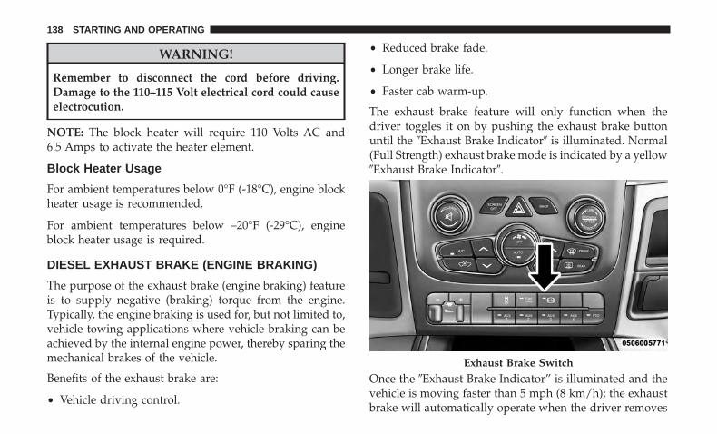
WARNING!
Remember to disconnect the cord before driving.Damage to the 110–115 Volt electrical cord could causeelectrocution.
NOTE: The block heater will require 110 Volts AC and6.5 Amps to activate the heater element.
Block Heater Usage
For ambient temperatures below 0°F (-18°C), engine blockheater usage is recommended.
For ambient temperatures below –20°F (-29°C), engineblock heater usage is required.
DIESEL EXHAUST BRAKE (ENGINE BRAKING)
The purpose of the exhaust brake (engine braking) featureis to supply negative (braking) torque from the engine.Typically, the engine braking is used for, but not limited to,vehicle towing applications where vehicle braking can beachieved by the internal engine power, thereby sparing themechanical brakes of the vehicle.
Benefits of the exhaust brake are:
• Vehicle driving control.
• Reduced brake fade.
• Longer brake life.
• Faster cab warm-up.
The exhaust brake feature will only function when thedriver toggles it on by pushing the exhaust brake buttonuntil the �Exhaust Brake Indicator� is illuminated. Normal(Full Strength) exhaust brake mode is indicated by a yellow�Exhaust Brake Indicator�.
Once the �Exhaust Brake Indicator” is illuminated and thevehicle is moving faster than 5 mph (8 km/h); the exhaustbrake will automatically operate when the driver removes
Exhaust Brake Switch
138 STARTING AND OPERATING
pressure from the accelerator pedal. Exhaust braking ismost effective when the engine RPM is higher. The auto-matic transmission will downshift more aggressively inTOW/HAUL mode when the exhaust brake is enabled toincrease brake performance.
CAUTION!
Use of aftermarket exhaust brakes is not recommendedand could lead to engine damage
WARNING!
Do not use the exhaust brake feature when driving inicy or slippery conditions as the increased enginebraking can cause the rear wheels to slide and thevehicle to swing around with the possible loss ofvehicle control, which may cause an accident possiblyresulting in personal injury or death.
NOTE: For optimum braking power it is recommended touse the exhaust brake while in TOW/HAUL mode.
The exhaust brake feature can also be used to reduce theengine warm up time. To use the exhaust brake as awarm-up device, the vehicle must be stopped or movingless than 5 mph (8 km/h), the �Exhaust Brake Indicator�must be on, and the coolant temperature must be below180°F (82°C) and ambient temperature below 60°F (16°C).
Automatic Smart Exhaust Brake (Auto)
Automatic Exhaust Brake technology delivers smoother,less aggressive exhaust braking characteristics duringdownhill descents. Although it can apply full exhaustbraking force if needed, Automatic Exhaust Brake may notapply obvious braking if the vehicle speed is not increas-ing. Automatic Exhaust Brake is intended to maintainvehicle speed, while Full Exhaust Brake is intended toreduce vehicle speed.
Automatic Exhaust Brake can be enabled by pushing theexhaust brake button again anytime after the normal FullExhaust Brake has been turned on. The “Exhaust BrakeIndicator” in the instrument cluster display will changefrom Yellow to Green when Automatic Exhaust Brake isenabled. Pushing the exhaust brake button again willtoggle the exhaust brake mode to off.
5
STARTING AND OPERATING 139
AUTOMATIC TRANSMISSION — IF EQUIPPED
WARNING!
• It is dangerous to shift out of PARK or NEUTRAL ifthe engine speed is higher than idle speed. If yourfoot is not firmly pressing the brake pedal, thevehicle could accelerate quickly forward or in re-verse. You could lose control of the vehicle and hitsomeone or something. Only shift into gear when theengine is idling normally and your foot is firmlypressing the brake pedal.
• Unintended movement of a vehicle could injurethose in or near the vehicle. As with all vehicles, youshould never exit a vehicle while the engine isrunning. Before exiting a vehicle, always apply theparking brake, shift the transmission into PARK,turn the engine OFF, and remove the key fob. Whenthe ignition is in the LOCK/OFF (key removal)position, (or, with Keyless Enter-N-Go, when theignition is in the OFF mode) the transmission islocked in PARK, securing the vehicle against un-wanted movement.
(Continued)
WARNING! (Continued)• When leaving the vehicle, always make sure the
ignition is in the OFF mode, remove the key fob fromthe vehicle, and lock the vehicle.
• Never use the PARK position as a substitute for theparking brake. Always apply the parking brake fullywhen parked to guard against vehicle movement andpossible injury or damage.
• Your vehicle could move and injure you and others ifit is not in PARK. Check by trying to move the gearselector out of PARK with the brake pedal released.Make sure the transmission is in PARK before leav-ing the vehicle.
• Never leave children alone in a vehicle, or withaccess to an unlocked vehicle. Allowing children tobe in a vehicle unattended is dangerous for a numberof reasons. A child or others could be seriously orfatally injured. Children should be warned not totouch the parking brake, brake pedal or the trans-mission gear selector.
(Continued)
140 STARTING AND OPERATING
WARNING! (Continued)• Do not leave the key fob in or near the vehicle (or in
a location accessible to children), and do not leavethe ignition (in a vehicle equipped with KeylessEnter-N-Go) in the ACC or ON/RUN mode. A childcould operate power windows, other controls, ormove the vehicle.
CAUTION!
Damage to the transmission may occur if the followingprecautions are not observed:• Shift into or out of PARK or REVERSE only after the
vehicle has come to a complete stop.• Do not shift between PARK, REVERSE, NEUTRAL,
or DRIVE when the engine is above idle speed.• Before shifting into any gear, make sure your foot is
firmly pressing the brake pedal.
NOTE: You must press and hold the brake pedal whileshifting out of PARK.
Key Ignition Park Interlock
This vehicle is equipped with a Key Ignition Park Interlockwhich requires the transmission to be in PARK before the
ignition can be turned to the LOCK/OFF (key removal)position. The key fob can only be removed from theignition when the ignition is in the LOCK/OFF position,and the transmission is locked in PARK whenever theignition is in the LOCK/OFF position.
Brake/Transmission Shift Interlock System
This vehicle is equipped with a Brake Transmission ShiftInterlock System (BTSI) that holds the transmission gearselector in PARK unless the brakes are applied. To shift thetransmission out of PARK, the ignition must be turned tothe ON/RUN mode (engine running or not) and the brakepedal must be pressed.
Six-Speed Automatic Transmission — If Equipped
Chassis Cab models (with automatic transmission) use theAS69RC transmission (which is equipped with a PowerTake-Off [PTO] access cover on the side of the transmissioncase). Pickup models may use either the AS69RC transmis-sion, or the 68RFE transmission (which has no PTO accesscover).
The transmission gear position display (located in theinstrument cluster) indicates the transmission gear range.The gear selector is mounted on the right side of thesteering column. You must press the brake pedal to move
5
STARTING AND OPERATING 141
the gear selector out of PARK (refer to “Brake/Transmission Shift Interlock System” in this section). Todrive, move the gear selector from PARK or NEUTRAL tothe DRIVE position. Pull the gear selector toward youwhen shifting into REVERSE or PARK, or when shiftingout of PARK.
The electronically-controlled transmission provides a pre-cise shift schedule. The transmission electronics are self-calibrating; therefore, the first few shifts on a new vehiclemay be somewhat abrupt. This is a normal condition, andprecision shifts will develop within a few hundred miles(kilometers).
Only shift from DRIVE to PARK or REVERSE when theaccelerator pedal is released and the vehicle is stopped. Besure to keep your foot on the brake pedal when shiftingbetween these gears.
The transmission gear selector has only PARK, REVERSE,NEUTRAL, and DRIVE shift positions. Manual downshiftscan be made using the Electronic Range Select (ERS) shiftcontrol (refer to �Electronic Range Select (ERS) Operation�in this section for further information). Pressing the ERS(-/+) switches (on the gear selector) while in the DRIVEposition will select the highest available transmission gear,and will display that gear limit in the instrument cluster as
1, 2, 3, etc. Some models will display both the selected gearlimit, and the actual current gear, while in ERS mode.
Gear Ranges
DO NOT race the engine when shifting from PARK orNEUTRAL into another gear range.
NOTE: After selecting any gear range, wait a moment toallow the selected gear to engage before accelerating. Thisis especially important when the engine is cold.
PARK (P)
This range supplements the parking brake by locking thetransmission. The engine can be started in this range.Never attempt to use PARK while the vehicle is in motion.Apply the parking brake when leaving the vehicle in thisrange.
When parking on a level surface, you may shift thetransmission into PARK first, and then apply the parkingbrake.
When parking on a hill, apply the parking brake beforeshifting the transmission to PARK, otherwise the load onthe transmission locking mechanism may make it difficultto move the gear selector out of PARK. As an added
142 STARTING AND OPERATING
precaution, turn the front wheels toward the curb on adownhill grade and away from the curb on an uphill grade.
When exiting the vehicle, always:
• Apply the parking brake.
• Shift the transmission into PARK.
• Turn the engine OFF.
• Remove the key fob.
NOTE: On four-wheel drive vehicles be sure that thetransfer case is in a drive position.
WARNING!
• Never use the PARK position as a substitute for theparking brake. Always apply the parking brake fullywhen parked to guard against vehicle movement andpossible injury or damage.
• Your vehicle could move and injure you and others ifit is not in PARK. Check by trying to move the gearselector out of PARK with the brake pedal released.Make sure the transmission is in PARK before leav-ing the vehicle.
(Continued)
WARNING! (Continued)• It is dangerous to shift out of PARK or NEUTRAL if
the engine speed is higher than idle speed. If yourfoot is not firmly pressing the brake pedal, thevehicle could accelerate quickly forward or in re-verse. You could lose control of the vehicle and hitsomeone or something. Only shift into gear when theengine is idling normally and your foot is firmlypressing the brake pedal.
• Unintended movement of a vehicle could injurethose in or near the vehicle. As with all vehicles, youshould never exit a vehicle while the engine isrunning. Before exiting a vehicle, always apply theparking brake, shift the transmission into PARK,turn the engine OFF, and remove the key fob. Whenthe ignition is in the LOCK/OFF (key removal)position (or, with Keyless Enter-N-Go, when theignition is in the OFF mode), the transmission islocked in PARK, securing the vehicle against un-wanted movement.
• When leaving the vehicle, always make sure theignition is in the OFF mode, remove the key fob fromthe vehicle, and lock the vehicle.
(Continued)
5
STARTING AND OPERATING 143
WARNING! (Continued)• Never leave children alone in a vehicle, or with
access to an unlocked vehicle. Allowing children tobe in a vehicle unattended is dangerous for a numberof reasons. A child or others could be seriously orfatally injured. Children should be warned not totouch the parking brake, brake pedal or the trans-mission gear selector.
• Do not leave the key fob in or near the vehicle (or ina location accessible to children), and do not leavethe ignition (in a vehicle equipped with KeylessEnter-N-Go) in the ACC or ON/RUN mode. A childcould operate power windows, other controls, ormove the vehicle.
CAUTION!
• Before moving the transmission gear selector out ofPARK, you must turn the ignition to the ON/RUNmode, and also press the brake pedal. Otherwise,damage to the gear selector could result.
• DO NOT race the engine when shifting from PARKor NEUTRAL into another gear range, as this candamage the drivetrain.
The following indicators should be used to ensure that youhave engaged the transmission into the PARK position:
• When shifting into PARK, pull the gear selector towardyou and move it all the way counterclockwise until itstops.
• Release the gear selector and make sure it is fully seatedin the PARK gate.
• Look at the transmission gear position display andverify that it indicates the PARK position (P).
• With brake pedal released, verify that the gear selectorwill not move out of PARK.
REVERSE (R)
This range is for moving the vehicle backward. Shift intoREVERSE only after the vehicle has come to a completestop.
NEUTRAL (N)
Use this range when the vehicle is standing for prolongedperiods with the engine running. The engine may bestarted in this range. Apply the parking brake and shift thetransmission into PARK if you must leave the vehicle.
144 STARTING AND OPERATING
WARNING!
Do not coast in NEUTRAL and never turn off theignition to coast down a hill. These are unsafe practicesthat limit your response to changing traffic or roadconditions. You might lose control of the vehicle andhave a collision.
CAUTION!
Towing the vehicle, coasting, or driving for any otherreason with the transmission in NEUTRAL can causesevere transmission damage. Refer to “RecreationalTowing” in “Starting And Operating” and “Towing ADisabled Vehicle” in “What To Do In Emergencies” forfurther information.
DRIVE (D)
This range should be used for most city and highwaydriving. It provides the smoothest upshifts and downshifts,and the best fuel economy. The transmission automaticallyupshifts through underdrive first, second, and third gears,direct fourth gear and overdrive fifth and sixth gears. TheDRIVE position provides optimum driving characteristicsunder all normal operating conditions.
When frequent transmission shifting occurs (such as whenoperating the vehicle under heavy loading conditions, inhilly terrain, traveling into strong head winds, or whiletowing a heavy trailer), use the Electronic Range Select(ERS) shift control (refer to “Electronic Range Select (ERS)Operation” in this section for further information) to selecta lower gear range. Under these conditions, using a lowergear range will improve performance and extend transmis-sion life by reducing excessive shifting and heat buildup.
If the transmission temperature exceeds normal operatinglimits, the powertrain controller will modify the transmis-sion shift schedule and expand the range of torque con-verter clutch engagement. This is done to prevent trans-mission damage due to overheating.
If the transmission becomes extremely hot or is in dangerof overheating, the “Transmission Temperature WarningLight” may illuminate and the transmission may operatedifferently until the transmission cools down.
5
STARTING AND OPERATING 145
NOTE: Use caution when operating a heavily loadedvehicle at low speeds (such as towing a trailer up a steepgrade, or in stop-and-go traffic) during hot weather. Inthese conditions, torque converter slip can impose a sig-nificant additional heat load on the cooling system. Down-shifting the transmission to the lowest possible gear (whenclimbing a grade), or shifting to NEUTRAL (when stoppedin heavy traffic) can help to reduce this excess heatgeneration.
During cold temperatures, transmission operation may bemodified depending on engine and transmission tempera-ture as well as vehicle speed. This feature improves warmup time of the engine and transmission to achieve maxi-mum efficiency. Engagement of the torque converter clutchis inhibited until the transmission fluid is warm (refer tothe “Note” under “Torque Converter Clutch” in this sec-tion). On Pickup models with 68RFE transmission, topoverdrive gear is also inhibited until the transmission fluidis warm, and during extremely cold temperatures (-16°F[-27°C] or below), operation may briefly be limited to firstand direct gears only. On trucks with AS69RC transmis-sion, fifth and sixth gears may be inhibited briefly on coldstarts below 41°F (5°C), and during very cold temperatures(-4°F [-20°C] or below), operation may briefly be limited tothird gear only. During this condition, the ability of the
vehicle to accelerate under heavily loaded conditions maybe reduced. In all cases, normal operation will resume oncethe transmission temperature has risen to a suitable level.
Transmission Limp Home Mode
Transmission function is monitored electronically for ab-normal conditions. If a condition is detected that couldresult in transmission damage, Transmission Limp HomeMode is activated. In this mode, the transmission remainsin fourth gear (for 68RFE transmission) or third gear (forAS69RC transmission) regardless of which forward gear isselected. If an AS69RC-equipped truck enters Limp HomeMode at highway speeds, it will initially engage fifth gear,until the vehicle slows to a speed where third gear can beengaged. PARK, REVERSE, and NEUTRAL will continueto operate. The Malfunction Indicator Light (MIL) may beilluminated. Limp Home Mode allows the vehicle to bedriven to an authorized dealer for service without damag-ing the transmission.
In the event of a momentary problem, the transmission canbe reset to regain all forward gears by performing thefollowing steps:
1. Stop the vehicle.
2. Shift the transmission into PARK.
146 STARTING AND OPERATING
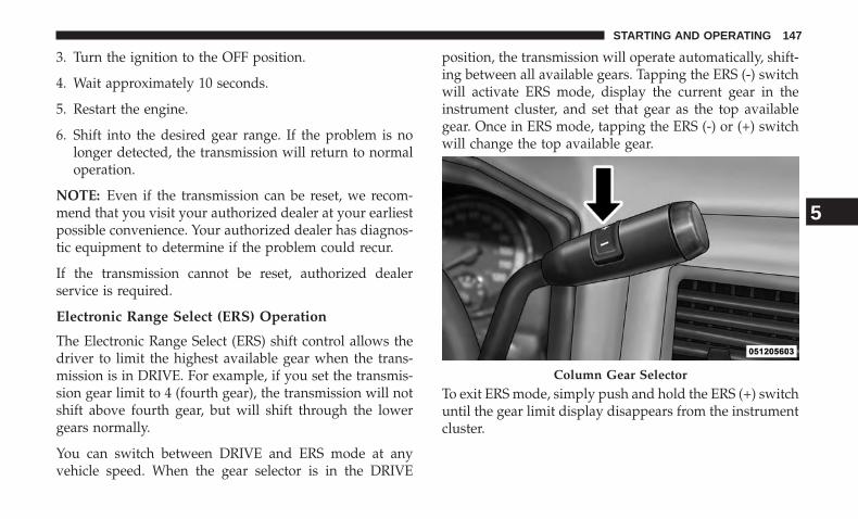
3. Turn the ignition to the OFF position.
4. Wait approximately 10 seconds.
5. Restart the engine.
6. Shift into the desired gear range. If the problem is nolonger detected, the transmission will return to normaloperation.
NOTE: Even if the transmission can be reset, we recom-mend that you visit your authorized dealer at your earliestpossible convenience. Your authorized dealer has diagnos-tic equipment to determine if the problem could recur.
If the transmission cannot be reset, authorized dealerservice is required.
Electronic Range Select (ERS) Operation
The Electronic Range Select (ERS) shift control allows thedriver to limit the highest available gear when the trans-mission is in DRIVE. For example, if you set the transmis-sion gear limit to 4 (fourth gear), the transmission will notshift above fourth gear, but will shift through the lowergears normally.
You can switch between DRIVE and ERS mode at anyvehicle speed. When the gear selector is in the DRIVE
position, the transmission will operate automatically, shift-ing between all available gears. Tapping the ERS (-) switchwill activate ERS mode, display the current gear in theinstrument cluster, and set that gear as the top availablegear. Once in ERS mode, tapping the ERS (-) or (+) switchwill change the top available gear.
To exit ERS mode, simply push and hold the ERS (+) switchuntil the gear limit display disappears from the instrumentcluster.
Column Gear Selector
5
STARTING AND OPERATING 147
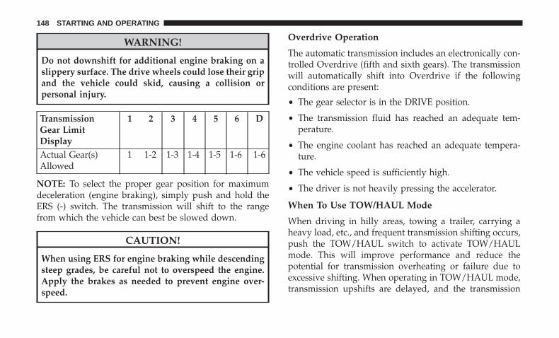
WARNING!
Do not downshift for additional engine braking on aslippery surface. The drive wheels could lose their gripand the vehicle could skid, causing a collision orpersonal injury.
TransmissionGear LimitDisplay
1 2 3 4 5 6 D
Actual Gear(s)Allowed
1 1-2 1-3 1-4 1-5 1-6 1-6
NOTE: To select the proper gear position for maximumdeceleration (engine braking), simply push and hold theERS (-) switch. The transmission will shift to the rangefrom which the vehicle can best be slowed down.
CAUTION!
When using ERS for engine braking while descendingsteep grades, be careful not to overspeed the engine.Apply the brakes as needed to prevent engine over-speed.
Overdrive Operation
The automatic transmission includes an electronically con-trolled Overdrive (fifth and sixth gears). The transmissionwill automatically shift into Overdrive if the followingconditions are present:
• The gear selector is in the DRIVE position.
• The transmission fluid has reached an adequate tem-perature.
• The engine coolant has reached an adequate tempera-ture.
• The vehicle speed is sufficiently high.
• The driver is not heavily pressing the accelerator.
When To Use TOW/HAUL Mode
When driving in hilly areas, towing a trailer, carrying aheavy load, etc., and frequent transmission shifting occurs,push the TOW/HAUL switch to activate TOW/HAULmode. This will improve performance and reduce thepotential for transmission overheating or failure due toexcessive shifting. When operating in TOW/HAUL mode,transmission upshifts are delayed, and the transmission
148 STARTING AND OPERATING
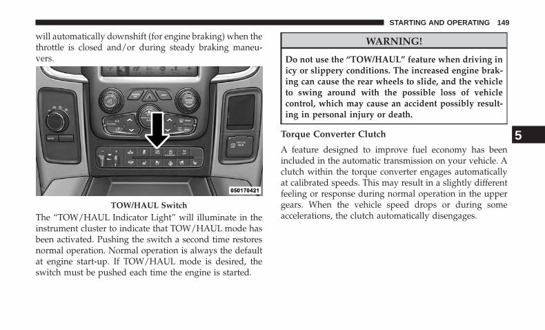
will automatically downshift (for engine braking) when thethrottle is closed and/or during steady braking maneu-vers.
The “TOW/HAUL Indicator Light” will illuminate in theinstrument cluster to indicate that TOW/HAUL mode hasbeen activated. Pushing the switch a second time restoresnormal operation. Normal operation is always the defaultat engine start-up. If TOW/HAUL mode is desired, theswitch must be pushed each time the engine is started.
WARNING!
Do not use the “TOW/HAUL” feature when driving inicy or slippery conditions. The increased engine brak-ing can cause the rear wheels to slide, and the vehicleto swing around with the possible loss of vehiclecontrol, which may cause an accident possibly result-ing in personal injury or death.
Torque Converter Clutch
A feature designed to improve fuel economy has beenincluded in the automatic transmission on your vehicle. Aclutch within the torque converter engages automaticallyat calibrated speeds. This may result in a slightly differentfeeling or response during normal operation in the uppergears. When the vehicle speed drops or during someaccelerations, the clutch automatically disengages.
TOW/HAUL Switch
5
STARTING AND OPERATING 149
NOTE:
• The torque converter clutch will not engage (and 68RFE-equipped trucks will not shift to sixth gear), until thetransmission fluid and engine coolant are warm [usuallyafter 1 to 3 miles (2 to 5 km) of driving]. Because theengine speed is higher when the torque converter clutchis not engaged, it may seem as if the transmission is notshifting properly when cold. This is normal. Using theElectronic Range Select (ERS) shift control, when thetransmission is sufficiently warm, will demonstrate thatthe transmission is able to shift into and out of Over-drive.
• If the vehicle has not been driven for several days, thefirst few seconds of operation after shifting the transmis-sion into gear may seem sluggish. This is due to the fluidpartially draining from the torque converter into thetransmission. This condition is normal and will notcause damage to the transmission. The torque converterwill refill within five seconds after starting the engine.
MANUAL TRANSMISSION — IF EQUIPPED
WARNING!
You or others could be injured if you leave the vehicleunattended without having the parking brake fullyapplied. The parking brake should always be appliedwhen the driver is not in the vehicle, especially on anincline.
CAUTION!
Never drive with your foot resting on the clutch pedal,or attempt to hold the vehicle on a hill with the clutchpedal partially engaged, as this will cause abnormalwear on the clutch.
NOTE: During cold weather, you may experience in-creased effort in shifting until the transmission fluid warmsup. This is normal.
150 STARTING AND OPERATING
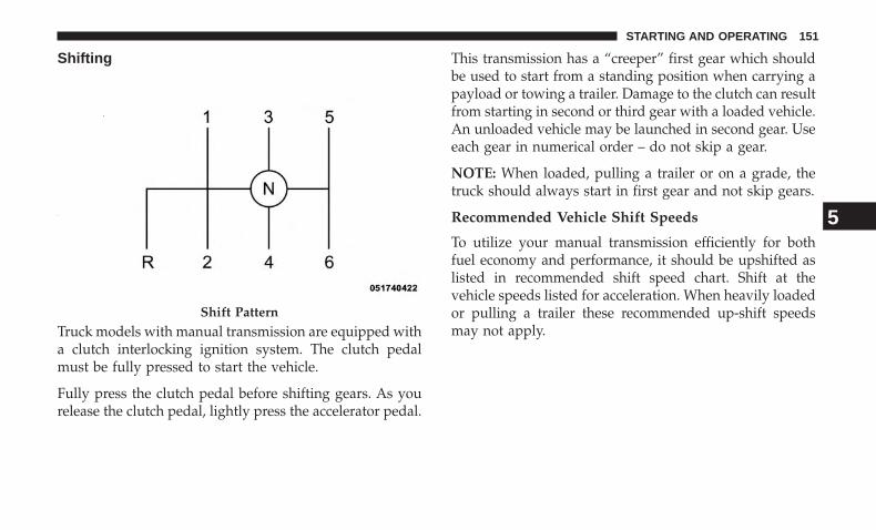
Shifting
Truck models with manual transmission are equipped witha clutch interlocking ignition system. The clutch pedalmust be fully pressed to start the vehicle.
Fully press the clutch pedal before shifting gears. As yourelease the clutch pedal, lightly press the accelerator pedal.
This transmission has a “creeper” first gear which shouldbe used to start from a standing position when carrying apayload or towing a trailer. Damage to the clutch can resultfrom starting in second or third gear with a loaded vehicle.An unloaded vehicle may be launched in second gear. Useeach gear in numerical order – do not skip a gear.
NOTE: When loaded, pulling a trailer or on a grade, thetruck should always start in first gear and not skip gears.
Recommended Vehicle Shift Speeds
To utilize your manual transmission efficiently for bothfuel economy and performance, it should be upshifted aslisted in recommended shift speed chart. Shift at thevehicle speeds listed for acceleration. When heavily loadedor pulling a trailer these recommended up-shift speedsmay not apply.
Shift Pattern
5
STARTING AND OPERATING 151
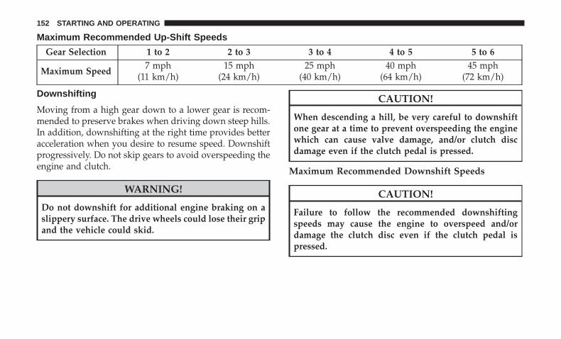
Maximum Recommended Up-Shift Speeds
Gear Selection 1 to 2 2 to 3 3 to 4 4 to 5 5 to 6
Maximum Speed7 mph
(11 km/h)15 mph
(24 km/h)25 mph
(40 km/h)40 mph
(64 km/h)45 mph
(72 km/h)
Downshifting
Moving from a high gear down to a lower gear is recom-mended to preserve brakes when driving down steep hills.In addition, downshifting at the right time provides betteracceleration when you desire to resume speed. Downshiftprogressively. Do not skip gears to avoid overspeeding theengine and clutch.
WARNING!
Do not downshift for additional engine braking on aslippery surface. The drive wheels could lose their gripand the vehicle could skid.
CAUTION!
When descending a hill, be very careful to downshiftone gear at a time to prevent overspeeding the enginewhich can cause valve damage, and/or clutch discdamage even if the clutch pedal is pressed.
Maximum Recommended Downshift Speeds
CAUTION!
Failure to follow the recommended downshiftingspeeds may cause the engine to overspeed and/ordamage the clutch disc even if the clutch pedal ispressed.
152 STARTING AND OPERATING
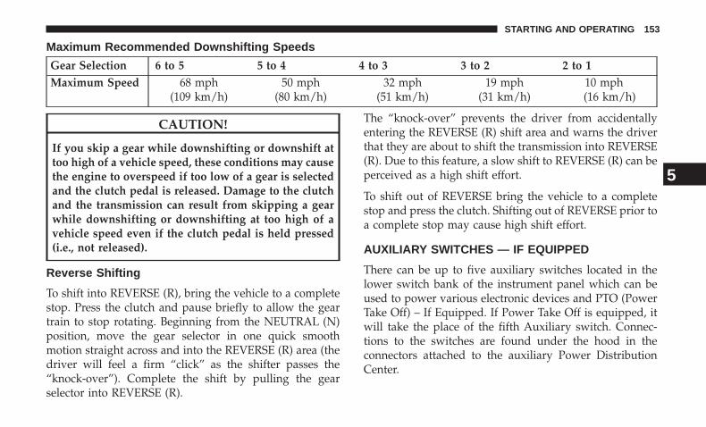
Maximum Recommended Downshifting Speeds
Gear Selection 6 to 5 5 to 4 4 to 3 3 to 2 2 to 1Maximum Speed 68 mph
(109 km/h)50 mph
(80 km/h)32 mph
(51 km/h)19 mph
(31 km/h)10 mph(16 km/h)
CAUTION!
If you skip a gear while downshifting or downshift attoo high of a vehicle speed, these conditions may causethe engine to overspeed if too low of a gear is selectedand the clutch pedal is released. Damage to the clutchand the transmission can result from skipping a gearwhile downshifting or downshifting at too high of avehicle speed even if the clutch pedal is held pressed(i.e., not released).
Reverse Shifting
To shift into REVERSE (R), bring the vehicle to a completestop. Press the clutch and pause briefly to allow the geartrain to stop rotating. Beginning from the NEUTRAL (N)position, move the gear selector in one quick smoothmotion straight across and into the REVERSE (R) area (thedriver will feel a firm “click” as the shifter passes the“knock-over”). Complete the shift by pulling the gearselector into REVERSE (R).
The “knock-over” prevents the driver from accidentallyentering the REVERSE (R) shift area and warns the driverthat they are about to shift the transmission into REVERSE(R). Due to this feature, a slow shift to REVERSE (R) can beperceived as a high shift effort.
To shift out of REVERSE bring the vehicle to a completestop and press the clutch. Shifting out of REVERSE prior toa complete stop may cause high shift effort.
AUXILIARY SWITCHES — IF EQUIPPED
There can be up to five auxiliary switches located in thelower switch bank of the instrument panel which can beused to power various electronic devices and PTO (PowerTake Off) – If Equipped. If Power Take Off is equipped, itwill take the place of the fifth Auxiliary switch. Connec-tions to the switches are found under the hood in theconnectors attached to the auxiliary Power DistributionCenter.
5
STARTING AND OPERATING 153
You have the ability to configure the functionality of theauxiliary switches via the instrument cluster display. Allswitches can now be configured for setting the switch typeoperation to latching or momentary, power source of eitherbattery or ignition, and ability to hold last state across keycycles.
NOTE: Holding last state conditions are met when switchtype is set to latching and power source is set to ignition.
For further information on using the auxiliary switches,please refer to the Ram Body Builders Guide by accessingwww.rambodybuilder.com and choosing the appropriatelinks.
POWER TAKE OFF OPERATION — IF EQUIPPED(CHASSIS CAB ONLY)
This vehicle when equipped with PTO Prep and either theAS69RC automatic six-speed or G-56 manual six-speedtransmissions, will allow for an aftermarket upfit with atransmission driven PTO (power take off). The customerwill have the ability to operate the PTO in either a“stationary” or “mobile” mode. The vehicles will be factoryset to the “stationary” mode. To select ’mobile mode’ Youwill need to enter the commercial vehicle menu on theinstrument cluster display and select mobile PTO mode.
Details of the PTO selection modes and further PTOinformation is available at the Ram Truck Bodybuildersweb site. rambodybuilder.com
AS69RC Six-Speed Automatic Transmission Only
The PTO drive gear (part of the AS69RC) operates at torqueconverter turbine speed. The turbine speed will be lessthan engine speed when the torque converter clutch is notengaged and will be same as engine speed when the torqueconverter clutch is engaged.
Stationary Mode
To operate the PTO in this mode the vehicle must meet thefollowing conditions:
• Transmission in PARK position (vehicles equipped withautomatic transmission.)
• PTO switch has been activated.
• Parking brake applied (vehicles equipped with manualtransmission).
• Brake pedal must not be applied.
• Vehicle engine must be running.
• No vehicle, brake or clutch switch faults present.
154 STARTING AND OPERATING
• PTO must be correctly installed using the vehicle pro-vided circuits.
The instrument cluster will display a �PTO On� message forfive seconds if the above conditions are met. Otherwise, theinstrument cluster will display a message �To Operate PTOShift To Park� indicating what operator action should betaken to engage the PTO mode.
The customer has the choice to operate the PTO by utilizingthe cruise control switches or by utilizing a remote control(provided by the PTO supplier). To operate the featureusing the cruise control switches, the customer must firstactivate the PTO switch which will turn on the PTO. Inorder to increase or decrease the engine idle speed, tooptimize the PTO function, the “RESUME/ACCEL” and“DECEL” cruise switches can be used respectively. Todisengage PTO operation and return to “standard vehicleoperation” simply toggle the PTO switch to the OFFposition.
The torque converter clutch (TCC) will automatically en-gage at engine speeds above 1,200 RPM (engine speed) inPTO stationary mode. Once engaged, the TCC will remainapplied and will not disengage until the engine speed fallsbelow 1,000 RPM. TCC engagement is desirable for certaintypes of PTO applications (Automatic Transmission Only).
To operate the PTO via a remote switch, the customer mustmake sure the above conditions are met. It is vital forproper operation that the PTO and remote have beeninstalled correctly, paying special attention to ensure thevehicle provided wiring has been connected properly. Thisis the responsibility of the installer of the PTO andswitches/remote system. It is the responsibility of the PTOmanufacturer to ensure that their electrical (switches andremote) system is compatible with the vehicle’s electricalarchitecture and software functionality.
NOTE: Single set speed can be programmed via the PTOmenu on the instrument cluster display. Further details areavailable at the Ram Truck Bodybuilders web site locatedat rambodybuilder.com
Mobile Mode
To operate the PTO in this mode the vehicle must meet thefollowing conditions:
• Mobile mode is activated via the menu on the instru-ment cluster display.
• (ON/OFF) switch has been activated.
• Vehicles with automatic transmission must be in PARKor DRIVE.
5
STARTING AND OPERATING 155
• Parking brake must not be applied.
• Brake pedal must not be applied.
• No vehicle, brake or clutch switch faults present.
• Vehicle engine must be running.
• PTO must be correctly installed using the vehicle pro-vided circuits.
The customer may choose to use the PTO while the vehicleis moving. To do so, the PTO function must be activatedprior to taking the vehicle out of PARK. This is accom-plished by activating the upfitter-provided PTO on/offswitch. At this point, the customer may place the vehicle ina forward or reverse gear and have PTO operation once thevehicle begins to move. To disengage PTO operation andreturn to “standard vehicle operation” simply toggle theon/off switch to the OFF position.
NOTE: For application specific information with respectto PTO and pump requirements and additional vehicleinformation (wiring schematics, preset idle values, enginespeed limits, and vehicle hardware and software require-ments) please refer to the Body Builders Guide by access-ing rambodybuilder.com and choosing the appropriatelinks.
ENGINE RUNAWAY
Diesel engine runaway is a rare condition affecting dieselengines, where the engine consumes its own lubrication oiland runs at higher and higher RPM until it overspeeds toa point where it destroys itself due to either mechanicalfailure or engine seizure through lack of lubrication.
WARNING!
In case of engine runaway due to flammable fumesfrom fuel spills or turbocharger oil leaks being suckedinto the engine, do the following to help avoid per-sonal injury and/or vehicle damage:1. Turn the ignition switch to the OFF position.2. Using a CO2 or dry chemical type fire extinguisher,direct the spray from the fire extinguisher into thegrille on the passenger side so that the spray enters theengine air intake.The inlet for the engine air intake is located behind thepassenger side headlamp and receives air through thegrille.
156 STARTING AND OPERATING
FUEL REQUIREMENTS
Use good quality diesel fuel from a reputable supplier inyour vehicle. Federal law requires that you must fuel thisvehicle with Ultra Low Sulfur Highway Diesel fuel (15ppm Sulfur maximum) and prohibits the use of Low SulfurHighway Diesel fuel (500 ppm Sulfur maximum) to avoiddamage to the emissions control system.
For most year-round service, No. 2 diesel fuel meetingASTM (formerly known as the American Society for Test-ing and Materials) specification D-975 Grade S15 willprovide good performance. If the vehicle is exposed toextreme cold (below 20°F or -7°C), or is required to operateat colder-than-normal conditions for prolonged periods,use climatized No. 2 diesel fuel or dilute the No. 2 dieselfuel with 50% No. 1 diesel fuel. This will provide betterprotection from fuel gelling or wax-plugging of the fuelfilters.
WARNING!
Do not use alcohol or gasoline as a fuel blending agent.They can be unstable under certain conditions andhazardous or explosive when mixed with diesel fuel.
Diesel fuel is seldom completely free of water. To preventfuel system trouble, drain the accumulated water from thefuel/water separator using the fuel/water separator drainprovided on both fuel filters. If you buy good quality fueland follow the cold weather advice above, fuel condition-ers should not be required in your vehicle. If available inyour area, a high cetane “premium” diesel fuel may offerimproved cold-starting and warm-up performance.
CAUTION!
If the “Water in Fuel Indicator Light” remains on, DONOT START engine before you drain the water fromthe fuel filter(s) to avoid engine damage. Refer to“Maintenance Procedures/Draining Fuel/Water Sepa-rator Filter” in “Maintaining Your Vehicle” for furtherinformation.
Fuel Specifications
The Cummins diesel engine has been developed to takeadvantage of the high energy content and generally lowercost No. 2 Ultra Low Sulfur diesel fuel or No. 2 Ultra LowSulfur climatized diesel fuels. Experience has shown that italso operates on No. 1 Ultra Low Sulfur diesel fuels orother fuels within specification.
5
STARTING AND OPERATING 157
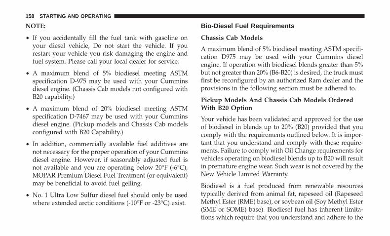
NOTE:
• If you accidentally fill the fuel tank with gasoline onyour diesel vehicle, Do not start the vehicle. If yourestart your vehicle you risk damaging the engine andfuel system. Please call your local dealer for service.
• A maximum blend of 5% biodiesel meeting ASTMspecification D-975 may be used with your Cumminsdiesel engine. (Chassis Cab models not configured withB20 capability.)
• A maximum blend of 20% biodiesel meeting ASTMspecification D-7467 may be used with your Cumminsdiesel engine. (Pickup models and Chassis Cab modelsconfigured with B20 Capability.)
• In addition, commercially available fuel additives arenot necessary for the proper operation of your Cumminsdiesel engine. However, if seasonably adjusted fuel isnot available and you are operating below 20°F (-6°C),MOPAR Premium Diesel Fuel Treatment (or equivalent)may be beneficial to avoid fuel gelling.
• No. 1 Ultra Low Sulfur diesel fuel should only be usedwhere extended arctic conditions (-10°F or -23°C) exist.
Bio-Diesel Fuel Requirements
Chassis Cab Models
A maximum blend of 5% biodiesel meeting ASTM specifi-cation D975 may be used with your Cummins dieselengine. If operation with biodiesel blends greater than 5%but not greater than 20% (B6-B20) is desired, the truck mustfirst be reconfigured by an authorized Ram dealer and theprovisions in the following section must be adhered to.
Pickup Models And Chassis Cab Models OrderedWith B20 Option
Your vehicle has been validated and approved for the useof biodiesel in blends up to 20% (B20) provided that youcomply with the requirements outlined below. It is impor-tant that you understand and comply with these require-ments. Failure to comply with Oil Change requirements forvehicles operating on biodiesel blends up to B20 will resultin premature engine wear. Such wear is not covered by theNew Vehicle Limited Warranty.
Biodiesel is a fuel produced from renewable resourcestypically derived from animal fat, rapeseed oil (RapeseedMethyl Ester (RME) base), or soybean oil (Soy Methyl Ester(SME or SOME) base). Biodiesel fuel has inherent limita-tions which require that you understand and adhere to the
158 STARTING AND OPERATING
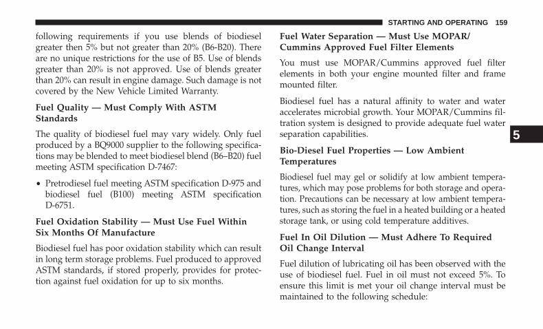
following requirements if you use blends of biodieselgreater then 5% but not greater than 20% (B6-B20). Thereare no unique restrictions for the use of B5. Use of blendsgreater than 20% is not approved. Use of blends greaterthan 20% can result in engine damage. Such damage is notcovered by the New Vehicle Limited Warranty.
Fuel Quality — Must Comply With ASTMStandards
The quality of biodiesel fuel may vary widely. Only fuelproduced by a BQ9000 supplier to the following specifica-tions may be blended to meet biodiesel blend (B6–B20) fuelmeeting ASTM specification D-7467:
• Pretrodiesel fuel meeting ASTM specification D-975 andbiodiesel fuel (B100) meeting ASTM specificationD-6751.
Fuel Oxidation Stability — Must Use Fuel WithinSix Months Of Manufacture
Biodiesel fuel has poor oxidation stability which can resultin long term storage problems. Fuel produced to approvedASTM standards, if stored properly, provides for protec-tion against fuel oxidation for up to six months.
Fuel Water Separation — Must Use MOPAR/Cummins Approved Fuel Filter Elements
You must use MOPAR/Cummins approved fuel filterelements in both your engine mounted filter and framemounted filter.
Biodiesel fuel has a natural affinity to water and wateraccelerates microbial growth. Your MOPAR/Cummins fil-tration system is designed to provide adequate fuel waterseparation capabilities.
Bio-Diesel Fuel Properties — Low AmbientTemperatures
Biodiesel fuel may gel or solidify at low ambient tempera-tures, which may pose problems for both storage and opera-tion. Precautions can be necessary at low ambient tempera-tures, such as storing the fuel in a heated building or a heatedstorage tank, or using cold temperature additives.
Fuel In Oil Dilution — Must Adhere To RequiredOil Change Interval
Fuel dilution of lubricating oil has been observed with theuse of biodiesel fuel. Fuel in oil must not exceed 5%. Toensure this limit is met your oil change interval must bemaintained to the following schedule:
5
STARTING AND OPERATING 159
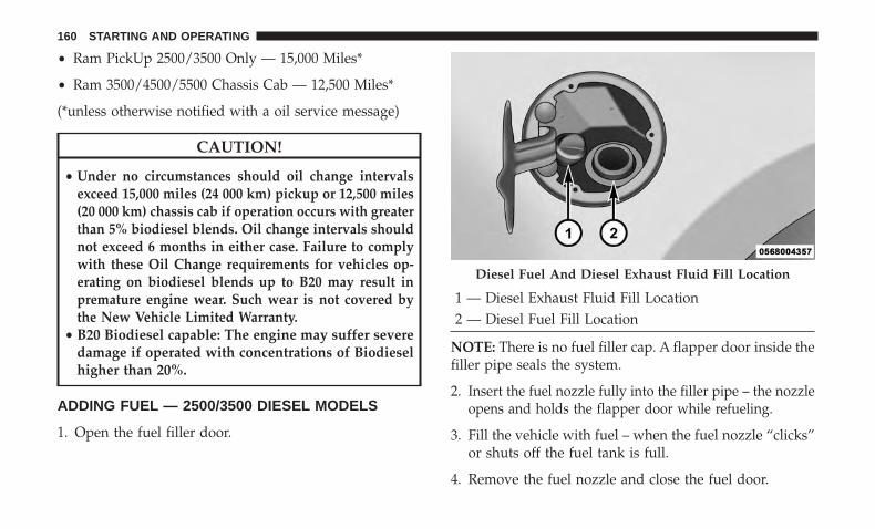
• Ram PickUp 2500/3500 Only — 15,000 Miles*
• Ram 3500/4500/5500 Chassis Cab — 12,500 Miles*
(*unless otherwise notified with a oil service message)
CAUTION!
• Under no circumstances should oil change intervalsexceed 15,000 miles (24 000 km) pickup or 12,500 miles(20 000 km) chassis cab if operation occurs with greaterthan 5% biodiesel blends. Oil change intervals shouldnot exceed 6 months in either case. Failure to complywith these Oil Change requirements for vehicles op-erating on biodiesel blends up to B20 may result inpremature engine wear. Such wear is not covered bythe New Vehicle Limited Warranty.
• B20 Biodiesel capable: The engine may suffer severedamage if operated with concentrations of Biodieselhigher than 20%.
ADDING FUEL — 2500/3500 DIESEL MODELS
1. Open the fuel filler door.
1 — Diesel Exhaust Fluid Fill Location2 — Diesel Fuel Fill Location
NOTE: There is no fuel filler cap. A flapper door inside thefiller pipe seals the system.
2. Insert the fuel nozzle fully into the filler pipe – the nozzleopens and holds the flapper door while refueling.
3. Fill the vehicle with fuel – when the fuel nozzle “clicks”or shuts off the fuel tank is full.
4. Remove the fuel nozzle and close the fuel door.
Diesel Fuel And Diesel Exhaust Fluid Fill Location
160 STARTING AND OPERATING
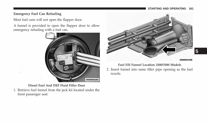
Emergency Fuel Can Refueling
Most fuel cans will not open the flapper door.
A funnel is provided to open the flapper door to allowemergency refueling with a fuel can.
1. Retrieve fuel funnel from the jack kit located under thefront passenger seat.
2. Insert funnel into same filler pipe opening as the fuelnozzle.
Diesel Fuel And DEF Fluid Filler Door
Fuel Fill Funnel Location 2500/3500 Models
5
STARTING AND OPERATING 161
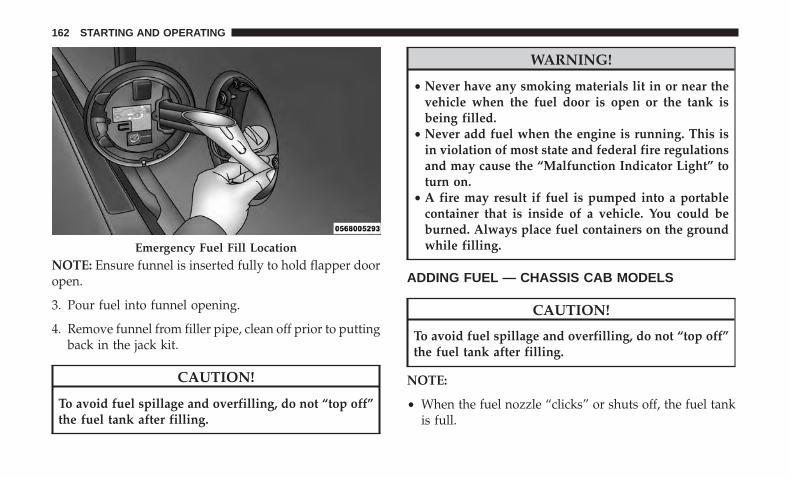
NOTE: Ensure funnel is inserted fully to hold flapper dooropen.
3. Pour fuel into funnel opening.
4. Remove funnel from filler pipe, clean off prior to puttingback in the jack kit.
CAUTION!
To avoid fuel spillage and overfilling, do not “top off”the fuel tank after filling.
WARNING!
• Never have any smoking materials lit in or near thevehicle when the fuel door is open or the tank isbeing filled.
• Never add fuel when the engine is running. This isin violation of most state and federal fire regulationsand may cause the “Malfunction Indicator Light” toturn on.
• A fire may result if fuel is pumped into a portablecontainer that is inside of a vehicle. You could beburned. Always place fuel containers on the groundwhile filling.
ADDING FUEL — CHASSIS CAB MODELS
CAUTION!
To avoid fuel spillage and overfilling, do not “top off”the fuel tank after filling.
NOTE:
• When the fuel nozzle “clicks” or shuts off, the fuel tankis full.
Emergency Fuel Fill Location
162 STARTING AND OPERATING
• Tighten the fuel filler cap until you hear a “clicking”sound. This is an indication that the fuel filler cap isproperly tightened.
• Make sure that the fuel filler cap is tightened each timethe vehicle is refueled.
WARNING!
A fire may result if fuel is pumped into a portablecontainer that is on a truck bed. You could be burned.Always place fuel containers on the ground whilefilling.
Fuel Filler Cap
If the fuel filler cap is lost or damaged, be sure thereplacement cap is for use with this vehicle.
CAUTION!
Damage to the fuel system or emission control systemcould result from using an improper fuel tank fillertube cap. A poorly fitting cap could let impurities intothe fuel system.
WARNING!
• Never have any smoking materials lit in or near thevehicle when the fuel filler cap is removed or thetank filled.
• Never add fuel to the vehicle when the engine isrunning.
Avoid Using Contaminated Fuel
Fuel that is contaminated by water or dirt can cause severedamage to the engine fuel system. Proper maintenance ofthe engine fuel filter and fuel tank is essential. Refer to“Maintenance Procedures” in “Maintaining Your Vehicle”for further information.
Bulk Fuel Storage — Diesel Fuel
If you store quantities of fuel, good maintenance of thestored fuel is also essential. Fuel contaminated with waterwill promote the growth of “microbes.” These microbesform “slime” that will clog the fuel filtration system andlines. Drain condensation from the supply tank and changethe line filter on a regular basis.
NOTE: When a diesel engine is allowed to run out of fuel,air is pulled into the fuel system.
5
STARTING AND OPERATING 163
If the vehicle will not start, refer to “MaintenanceProcedures/Priming If The Engine Has Run Out Of Fuel”in “Maintaining Your Vehicle” for further information.
WARNING!
Do not open the high pressure fuel system with theengine running. Engine operation causes high fuelpressure. High pressure fuel spray can cause seriousinjury or death.
Diesel Exhaust Fluid Storage
Diesel Exhaust Fluid (DEF) is considered a very stableproduct with a long shelf life. If DEF is kept in tempera-tures between 10° and 90°F (-12° and 32°C), it will last aminimum of one year.
DEF is subject to freezing at the lowest temperatures.For example, DEF may freeze at temperatures at or below12° F (-11° C). The system has been designed to operate inthis environment.
NOTE: When working with DEF, it is important to knowthat:
• Any containers or parts that come into contact with DEFmust be DEF compatible (plastic or stainless steel).
Copper, brass, aluminum, iron or non-stainless steelshould be avoided as they are subject to corrosion byDEF.
• If DEF is spilled, it should be wiped up completely.
Adding Diesel Exhaust Fluid
The DEF gauge (located on the instrument cluster) willdisplay the level of DEF remaining in the tank. Refer to“Instrument Cluster” and “Instrument Cluster Descrip-tions” in “Understanding Your Instrument Panel” for fur-ther information.
NOTE:
• Driving conditions (altitude, vehicle speed, load, etc.)will effect the amount of DEF that is used in yourvehicle.
• Another factor is that outside temperature can affectDEF consumption. In cold conditions, 12° F (-11° C) andbelow, the DEF gauge needle can stay on a fixed positionand may not move for extended periods of time. This isa normal function of the system.
164 STARTING AND OPERATING
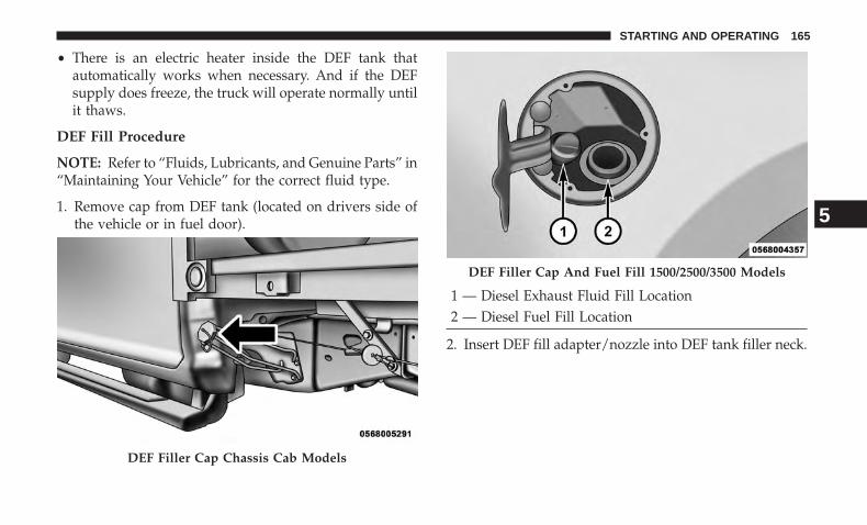
• There is an electric heater inside the DEF tank thatautomatically works when necessary. And if the DEFsupply does freeze, the truck will operate normally untilit thaws.
DEF Fill Procedure
NOTE: Refer to “Fluids, Lubricants, and Genuine Parts” in“Maintaining Your Vehicle” for the correct fluid type.
1. Remove cap from DEF tank (located on drivers side ofthe vehicle or in fuel door).
1 — Diesel Exhaust Fluid Fill Location2 — Diesel Fuel Fill Location
2. Insert DEF fill adapter/nozzle into DEF tank filler neck.
DEF Filler Cap Chassis Cab Models
DEF Filler Cap And Fuel Fill 1500/2500/3500 Models
5
STARTING AND OPERATING 165
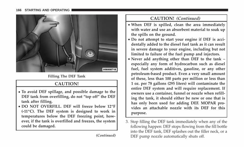
CAUTION!
• To avoid DEF spillage, and possible damage to theDEF tank from overfilling, do not “top off” the DEFtank after filling.
• DO NOT OVERFILL. DEF will freeze below 12ºF(-11ºC). The DEF system is designed to work intemperatures below the DEF freezing point, how-ever, if the tank is overfilled and freezes, the systemcould be damaged.
(Continued)
CAUTION! (Continued)• When DEF is spilled, clean the area immediately
with water and use an absorbent material to soak upthe spills on the ground.
• Do not attempt to start your engine if DEF is acci-dentally added to the diesel fuel tank as it can resultin severe damage to your engine, including but notlimited to failure of the fuel pump and injectors.
• Never add anything other than DEF to the tank –especially any form of hydrocarbon such as dieselfuel, fuel system additives, gasoline, or any otherpetroleum-based product. Even a very small amountof these, less than 100 parts per million or less than1 oz. per 78 gallons (295 liters) will contaminate theentire DEF system and will require replacement. Ifowners use a container, funnel or nozzle when refill-ing the tank, it should either be new or one that ishas only been used for adding DEF. MOPAR pro-vides an attachable nozzle with its DEF for thispurpose.
3. Stop filling the DEF tank immediately when any of thefollowing happen: DEF stops flowing from the fill bottleinto the DEF tank, DEF splashes out the filler neck, or aDEF pump nozzle automatically shuts off.
Filling The DEF Tank
166 STARTING AND OPERATING
4. Reinstall cap onto DEF tank.
Filling The Def Tank In Cold Climates
Since DEF will begin to freeze at 12°F (-11°C), your vehicleis equipped with an automatic DEF heating system. Thisallows the DEF injection system to operate properly attemperatures below 12°F (-11°C). If your vehicle is not inoperation for an extended period of time with tempera-tures below 12°F (-11°C), the DEF in the tank may freeze. Ifthe tank is overfilled and freezes, it could be damaged.Therefore, do not overfill the DEF tank.
The DEF tank on these vehicles is designed with a largeamount of full reserve. So the level sensor will indicate aFull reading even before the tank is completely full. To putit another way, there’s additional storage capacity in thetank above the Full mark that’s not represented in thegauge. You may not see any movement in the reading –even after driving up to 2,000 miles in some cases.
The difference this makes varies by vehicle. Heavy-dutypickup trucks have a 5.7-gallon (21.5 liter) tank that willdisplay a Full reading when about 90 percent full. Thismeans that drivers can consume at least 10 percent of atruly full DEF tank without seeing any visible change in thegauge reading. Chassis cabs have a larger 9-gallon (34 liter)tank, and will display a Full reading when about 75 percent
full. So drivers can consume 25 percent of a truly full DEFtank without seeing any visible change in the gaugereading.
Extra care should be taken when filling with portablecontainers to avoid overfilling. Note the level of the DEFgauge in your instrument cluster. On pickup applications,you may safely add a maximum of 2 gallons (7.5 liters) ofDEF from portable containers when your DEF gauge isreading ½ full. On Chassis Cab applications a maximum of2 gallons (7.5 liters) may be added when the DEF gauge isreading ¾ full.
DIESEL EXHAUST FLUID
Your vehicle is equipped with a Selective Catalytic Reduc-tion system to meet the very stringent diesel emissionsstandards required by the Environmental ProtectionAgency.
The purpose of the SCR system is to reduce levels of NOx(oxides of nitrogen emitted from engines) that are harmfulto our health and the environment to a near-zero level.Small quantities of Diesel Exhaust Fluid (DEF) is injectedinto the exhaust upstream of a catalyst where, whenvaporized, it converts smog-forming nitrogen oxides(NOx) into harmless nitrogen (N2) and water vapor (H2O),
5
STARTING AND OPERATING 167
two natural components of the air we breathe. You canoperate with the comfort that your vehicle is contributingto a cleaner, healthier world environment for this andgenerations to come.
System Overview
This vehicle is equipped with a Diesel Exhaust Fluid (DEF)injection system and a Selective Catalytic Reduction (SCR)catalyst to meet the emission requirements.
The DEF injection system consists of the following compo-nents:
• DEF tank
• DEF pump
• DEF injector
• Electronically-heated DEF lines
• DEF control module
• NOx sensors
• Temperature sensors
• SCR catalyst
• UQS Sensor
The DEF injection system and SCR catalyst enable theachievement of diesel emissions requirements; while main-taining outstanding fuel economy, drivability, torque andpower ratings.
Refer to �Instrument Cluster Display” in “UnderstandingYour Instrument Panel” for system messages and warn-ings.
NOTE:
• Your vehicle is equipped with a DEF injection system.You may occasionally hear an audible clicking noise.This is normal operation.
• The DEF pump will run for a period of time after engineshutdown to purge the DEF system. This is normaloperation.
168 STARTING AND OPERATING
WHAT TO DO IN EMERGENCIES
CONTENTS� JUMP STARTING . . . . . . . . . . . . . . . . . . . . . . . .170 ▫ With Portable Starting Unit . . . . . . . . . . . . . . . .172
6
JUMP STARTING
WARNING!
• To prevent personal injury or damage to clothing, donot allow battery fluid to contact eyes, skin orfabrics. Do not lean over a battery when connectingjumper cables or allow cable clamps to touch eachother. Keep open flames or sparks away from batteryvent holes. Always wear eye protection when work-ing with batteries.
• Do not use a booster battery or any other boostersource that has a greater than 12 Volt system, i.e., donot use a 24 Volt power source.
NOTE: Replacement batteries should both be of equal sizeto prevent damage to the vehicle’s charging system.
Your vehicle is equipped with two 12 Volt batteries. If itbecomes necessary to use a booster battery with jumpercables to start a vehicle’s engine because its batteries aredischarged, the following procedure should be used:
Set the parking brake and place an automatic transmissionin PARK (or NEUTRAL for a manual transmission).Turn off lights, heater and other electrical loads. Observecharge indicator (if equipped) in both batteries. If the
indicator (if equipped) is light or yellow on either battery,replace that battery.
CAUTION!
Use the jump start procedure only when the chargeindicator (if equipped) in both batteries is dark in thecenter. Do not attempt jump starting when eitherbattery charge indicator (if equipped) is light or yel-low. If the charge indicator (if equipped) has a greendot in the center, failure to start is not due to adischarged battery and cranking system should bechecked.
1. Attach one jumper cable to the positive terminal ofbooster battery and the other end of the same cable tothe positive terminal of the discharged battery.
NOTE: Do not connect jumper cables to the fuses. Onlyuse the jump post when connecting jumper cables.
WARNING!
Do not permit vehicles to touch each other as this couldestablish a ground connection and personal injurycould result.
170 WHAT TO DO IN EMERGENCIES
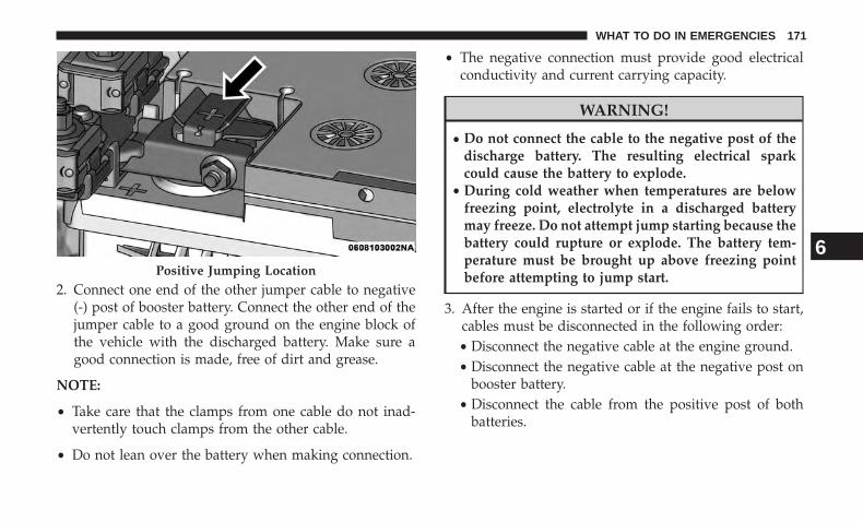
2. Connect one end of the other jumper cable to negative(-) post of booster battery. Connect the other end of thejumper cable to a good ground on the engine block ofthe vehicle with the discharged battery. Make sure agood connection is made, free of dirt and grease.
NOTE:
• Take care that the clamps from one cable do not inad-vertently touch clamps from the other cable.
• Do not lean over the battery when making connection.
• The negative connection must provide good electricalconductivity and current carrying capacity.
WARNING!
• Do not connect the cable to the negative post of thedischarge battery. The resulting electrical sparkcould cause the battery to explode.
• During cold weather when temperatures are belowfreezing point, electrolyte in a discharged batterymay freeze. Do not attempt jump starting because thebattery could rupture or explode. The battery tem-perature must be brought up above freezing pointbefore attempting to jump start.
3. After the engine is started or if the engine fails to start,cables must be disconnected in the following order:• Disconnect the negative cable at the engine ground.• Disconnect the negative cable at the negative post on
booster battery.• Disconnect the cable from the positive post of both
batteries.
Positive Jumping Location
6
WHAT TO DO IN EMERGENCIES 171
WARNING!
Any procedure other than above could result in:• Personal injury caused by electrolyte squirting out
the battery vent.• Personal injury or property damage due to battery
explosion.• Damage to charging system of booster vehicle or of
immobilized vehicle.
With Portable Starting Unit
There are many types of these units available. Follow themanufacturer’s instructions for necessary precautions andoperation.
CAUTION!
It is very important that the starting unit operatingvoltage does not exceed 12 Volts DC or damage tobattery, starter motor, alternator, or electrical systemmay occur.
172 WHAT TO DO IN EMERGENCIES
MAINTAINING YOUR VEHICLE
CONTENTS� ENGINE COMPARTMENT — 6.7L DIESEL —
SIX-SPEED 68RFE (2500/3500 Models) . . . . . . . . .174
� ENGINE COMPARTMENT — 6.7L DIESEL —SIX-SPEED AS69RC HD (3500/CHASSIS CABMODELS) . . . . . . . . . . . . . . . . . . . . . . . . . . . . .175
� MAINTENANCE PROCEDURES . . . . . . . . . . . . .176
▫ Engine Oil . . . . . . . . . . . . . . . . . . . . . . . . . . .176
▫ Engine Air Cleaner Filter . . . . . . . . . . . . . . . . .180
▫ Draining Fuel/Water Separator Filter . . . . . . . .184
▫ Engine Mounted Fuel Filter Replacement . . . . . .185
▫ Underbody Mounted Fuel Filter Replacement . . .186
▫ Priming If The Engine Has Run Out Of Fuel . . .188
▫ Intervention Regeneration Strategy — MessageProcess Flow . . . . . . . . . . . . . . . . . . . . . . . . . .189
▫ Diesel Exhaust Fluid. . . . . . . . . . . . . . . . . . . . .190
▫ Maintenance-Free Batteries . . . . . . . . . . . . . . . .190
▫ Cooling System . . . . . . . . . . . . . . . . . . . . . . . .191
▫ Charge Air Cooler — Inter-Cooler . . . . . . . . . . .195
▫ Brake System . . . . . . . . . . . . . . . . . . . . . . . . .195
▫ Clutch Hydraulic System . . . . . . . . . . . . . . . . .196
▫ Transfer Case — If Equipped . . . . . . . . . . . . . .197
▫ Manual Transmission — If Equipped . . . . . . . . .197
▫ Automatic Transmission — If Equipped . . . . . . .197
▫ Noise Control System Required Maintenance &Warranty . . . . . . . . . . . . . . . . . . . . . . . . . . . .200
� FLUID CAPACITIES . . . . . . . . . . . . . . . . . . . . . .204
� FLUIDS, LUBRICANTS AND GENUINE PARTS . .205
▫ Engine . . . . . . . . . . . . . . . . . . . . . . . . . . . . . .205
▫ Chassis . . . . . . . . . . . . . . . . . . . . . . . . . . . . .207
7
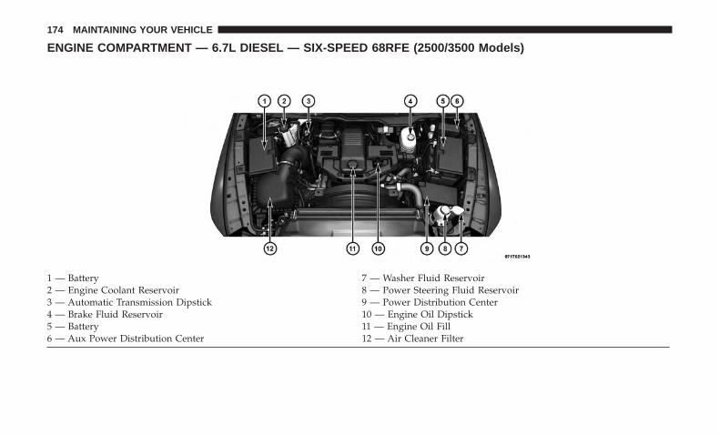
ENGINE COMPARTMENT — 6.7L DIESEL — SIX-SPEED 68RFE (2500/3500 Models)
1 — Battery 7 — Washer Fluid Reservoir2 — Engine Coolant Reservoir 8 — Power Steering Fluid Reservoir3 — Automatic Transmission Dipstick 9 — Power Distribution Center4 — Brake Fluid Reservoir 10 — Engine Oil Dipstick5 — Battery 11 — Engine Oil Fill6 — Aux Power Distribution Center 12 — Air Cleaner Filter
174 MAINTAINING YOUR VEHICLE
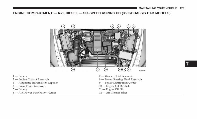
ENGINE COMPARTMENT — 6.7L DIESEL — SIX-SPEED AS69RC HD (3500/CHASSIS CAB MODELS)
1 — Battery 7 — Washer Fluid Reservoir2 — Engine Coolant Reservoir 8 — Power Steering Fluid Reservoir3 — Automatic Transmission Dipstick 9 — Power Distribution Center4 — Brake Fluid Reservoir 10 — Engine Oil Dipstick5 — Battery 11 — Engine Oil Fill6 — Aux Power Distribution Center 12 — Air Cleaner Filter
7
MAINTAINING YOUR VEHICLE 175
MAINTENANCE PROCEDURES
The pages that follow contain the required maintenanceservices determined by the engineers who designed yourvehicle.
Besides those maintenance items specified in the fixedmaintenance schedule, there are other components whichmay require servicing or replacement in the future.
CAUTION!
• Failure to properly maintain your vehicle or performrepairs and service when necessary could result inmore costly repairs, damage to other components ornegatively impact vehicle performance. Immediatelyhave potential malfunctions examined by an autho-rized dealership or qualified repair center.
(Continued)
CAUTION! (Continued)• Your vehicle has been built with improved fluids
that protect the performance and durability of yourvehicle and also allow extended maintenance inter-vals. Do not use chemical flushes in these compo-nents as the chemicals can damage your engine,transmission, power steering or air conditioning.Such damage is not covered by the New VehicleLimited Warranty. If a flush is needed because ofcomponent malfunction, use only the specified fluidfor the flushing procedure.
Engine Oil
Checking Oil Level
To assure proper lubrication of your vehicle’s engine, theengine oil must be maintained at the correct level. Checkthe oil level at regular intervals. The best time to check theoil level is before starting the engine after it has beenparked overnight. When checking oil after operating theengine, first ensure the engine is at full operating tempera-ture, then wait for 30 minutes after engine shutdown tocheck the oil.
176 MAINTAINING YOUR VEHICLE
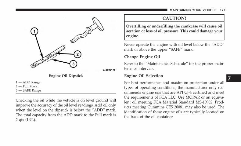
Checking the oil while the vehicle is on level ground willimprove the accuracy of the oil level readings. Add oil onlywhen the level on the dipstick is below the “ADD” mark.The total capacity from the ADD mark to the Full mark is2 qts (1.9L).
CAUTION!
Overfilling or underfilling the crankcase will cause oilaeration or loss of oil pressure. This could damage yourengine.
Never operate the engine with oil level below the “ADD”mark or above the upper “SAFE” mark.
Change Engine Oil
Refer to the “Maintenance Schedule” for the proper main-tenance intervals.
Engine Oil Selection
For best performance and maximum protection under alltypes of operating conditions, the manufacturer only rec-ommends engine oils that are API CJ-4 certified and meetthe requirements of FCA LLC. Use MOPAR or an equiva-lent oil meeting FCA Material Standard MS-10902. Prod-ucts meeting Cummins CES 20081 may also be used. Theidentification of these engine oils are typically located onthe back of the oil container.
Engine Oil Dipstick
1 — ADD Range2 — Full Mark3 — SAFE Range
7
MAINTAINING YOUR VEHICLE 177
American Petroleum Institute (API) Engine OilIdentification Symbol
This symbol means that the oil has beencertified by the American Petroleum In-stitute (API). The manufacturer only rec-ommends API Certified engine oils.
Oils with a high ash content may produce damagingdeposits on cylinder head valves and/or aftertreatmentsystem damage. A maximum sulfated ash content of 1.00mass % is recommended for all oil used in the engine.
The same oil change interval is to be followed for syntheticoil as for petroleum based oil. Also, synthetic oil must meetthe same performance specifications as petroleum oil.
CAUTION!
Do not use chemical flushes in your engine oil as thechemicals can damage your engine. Such damage is notcovered by the New Vehicle Limited Warranty.
Engine Oil Viscosity (SAE Grade)
In ambient temperatures above 0°F (-18°C), we recommendyou use SAE 15W-40 engine oil such as MOPAR, ShellRotella and Shell Rimula that meets FCA Material StandardMS-10902 and the API CJ-4 engine oil category is required.Products meeting Cummins CES 20081 may also be used.The identification of these engine oils is typically locatedon the back of the oil container.
In ambient temperatures below 0°F (-18°C), SAE 5W-40 werecommend you use synthetic engine oil such as MOPAR,Shell Rotella and Shell Rimula that meets FCA MaterialStandard MS-10902 and the API CJ-4 engine oil category isrequired.
CAUTION!
Failure to use SAE 5W-40 synthetic engine oil inambient temperatures below 0°F (-18°C) could result insevere engine damage.
178 MAINTAINING YOUR VEHICLE
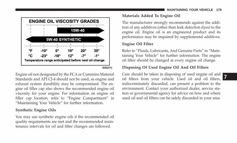
Engine oil not designated by the FCA or Cummins MaterialStandards and API CJ-4 should not be used, as engine andexhaust system durability may be compromised. The en-gine oil filler cap also shows the recommended engine oilviscosity for your engine. For information on engine oilfiller cap location, refer to “Engine Compartment” in“Maintaining Your Vehicle” for further information.
Synthetic Engine Oils
You may use synthetic engine oils if the recommended oilquality requirements are met and the recommended main-tenance intervals for oil and filter changes are followed.
Materials Added To Engine Oil
The manufacturer strongly recommends against the addi-tion of any additives (other than leak detection dyes) to theengine oil. Engine oil is an engineered product and itsperformance may be impaired by supplemental additives.
Engine Oil Filter
Refer to “Fluids, Lubricants, And Genuine Parts” in “Main-taining Your Vehicle” for further information. The engineoil filter should be changed at every engine oil change.
Disposing Of Used Engine Oil And Oil Filters
Care should be taken in disposing of used engine oil andoil filters from your vehicle. Used oil and oil filters,indiscriminately discarded, can present a problem to theenvironment. Contact your authorized dealer, service sta-tion or governmental agency for advice on how and whereused oil and oil filters can be safely discarded in your area.
7
MAINTAINING YOUR VEHICLE 179
Engine Air Cleaner Filter
CAUTION!
All air entering the engine intake must be filtered. Theabrasive particles in unfiltered air will cause rapidwear to engine components.
WARNING!
The air induction system (air cleaner, hoses, etc.) pro-vides a measure of protection. Do not remove the airinduction system (air cleaner, hoses, etc.) unless suchremoval is necessary for repair or maintenance. Makesure that no one is near the engine compartment beforestarting the vehicle with the air induction system (aircleaner, hoses, etc.) removed. Failure to do so can resultin serious personal injury.
The condition of the air cleaner filter is monitored by theEngine Control Module. The “SERVICE AIR FILTER”message will display in the instrument cluster when ser-vice is required. Refer to “Instrument Cluster Display” in“Understanding Your Instrument Panel” for further infor-mation.
The “SERVICE AIR FILTER” message could be displayedperiodically. This is because engine air flow requirementschange based on driving conditions. As the filter becomesmore restrictive and air flow requirements increase the“SERVICE AIR FILTER” message will be displayed. Themessage may not be displayed in subsequent drive cyclesif the same conditions are not met. The air filter elementshould be replaced within 250 miles (402 km) from the firsttime this message is displayed to ensure proper engineoperation during all driving conditions.
CAUTION!
Driving with a restricted air filter can cause enginedamage. Driving in dusty environments for extendedperiods will lead to rapid air filter plugging. Actionshould be taken as soon as the “SERVICE AIR FIL-TER” message is displayed.
180 MAINTAINING YOUR VEHICLE
If the vehicle experiences a sudden loss of engine powerwhile being driven in heavy snow or rain, or whenplowing snow, and/or the “SERVICE AIR FILTER” mes-sage is displayed on the instrument cluster along with achime that repeats every 60 seconds, visually inspect the airfilter for snow/ice build up or extreme water saturation. Ifthe air filter is not damaged, remove all snow/ice andreinstall air filter. If the air filter is damaged, replace filterelement.
NOTE: The air filter housing contains a Mass Air Flowsensor. This sensor is critical to proper engine operationand component longevity. Any damage or modification tothis sensor could result in major engine and/or exhaustaftertreatment damage. We recommend you use MOPARbrand parts.
Even though your vehicle is equipped with an Air FilterMonitor, a visual inspection of the air cleaner filter element is
recommended every 15,000 miles (24,000km) or 12 months –whichever occurs first. Under no circumstances should theair cleaner filter element exceed 30,000 miles (48,000 km) or24 months, whichever comes first.
CAUTION!
Many aftermarket performance air filter elements donot adequately filter the air entering the engine. Use ofsuch filters can severely damage your engine.
Engine Air Cleaner Filter Selection
The quality of replacement engine air cleaner filters variesconsiderably. Only high quality filters should be used toassure most efficient service. MOPAR engine air cleanerfilters are a high quality filter and are recommended.
7
MAINTAINING YOUR VEHICLE 181
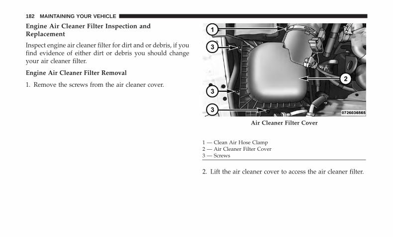
Engine Air Cleaner Filter Inspection andReplacement
Inspect engine air cleaner filter for dirt and or debris, if youfind evidence of either dirt or debris you should changeyour air cleaner filter.
Engine Air Cleaner Filter Removal
1. Remove the screws from the air cleaner cover.
2. Lift the air cleaner cover to access the air cleaner filter.
Air Cleaner Filter Cover
1 — Clean Air Hose Clamp2 — Air Cleaner Filter Cover3 — Screws
182 MAINTAINING YOUR VEHICLE
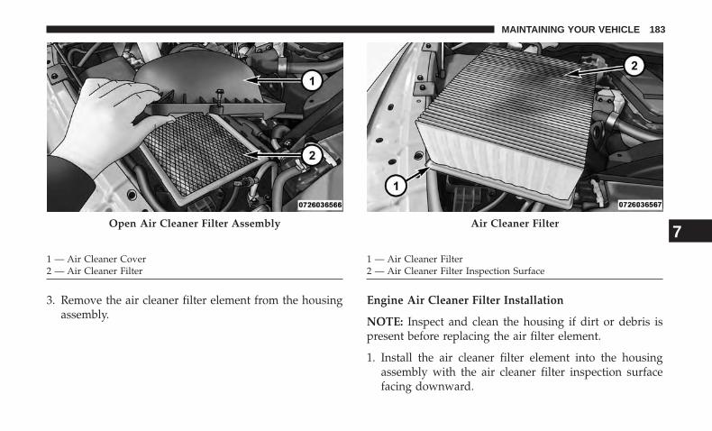
3. Remove the air cleaner filter element from the housingassembly.
Engine Air Cleaner Filter Installation
NOTE: Inspect and clean the housing if dirt or debris ispresent before replacing the air filter element.
1. Install the air cleaner filter element into the housingassembly with the air cleaner filter inspection surfacefacing downward.
Open Air Cleaner Filter Assembly
1 — Air Cleaner Cover2 — Air Cleaner Filter
Air Cleaner Filter
1 — Air Cleaner Filter2 — Air Cleaner Filter Inspection Surface
7
MAINTAINING YOUR VEHICLE 183
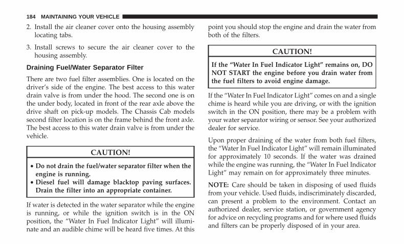
2. Install the air cleaner cover onto the housing assemblylocating tabs.
3. Install screws to secure the air cleaner cover to thehousing assembly.
Draining Fuel/Water Separator Filter
There are two fuel filter assemblies. One is located on thedriver’s side of the engine. The best access to this waterdrain valve is from under the hood. The second one is onthe under body, located in front of the rear axle above thedrive shaft on pick-up models. The Chassis Cab modelssecond filter location is on the frame behind the front axle.The best access to this water drain valve is from under thevehicle.
CAUTION!
• Do not drain the fuel/water separator filter when theengine is running.
• Diesel fuel will damage blacktop paving surfaces.Drain the filter into an appropriate container.
If water is detected in the water separator while the engineis running, or while the ignition switch is in the ONposition, the “Water In Fuel Indicator Light” will illumi-nate and an audible chime will be heard five times. At this
point you should stop the engine and drain the water fromboth of the filters.
CAUTION!
If the “Water In Fuel Indicator Light” remains on, DONOT START the engine before you drain water fromthe fuel filters to avoid engine damage.
If the “Water In Fuel Indicator Light” comes on and a singlechime is heard while you are driving, or with the ignitionswitch in the ON position, there may be a problem withyour water separator wiring or sensor. See your authorizeddealer for service.
Upon proper draining of the water from both fuel filters,the “Water In Fuel Indicator Light” will remain illuminatedfor approximately 10 seconds. If the water was drainedwhile the engine was running, the “Water In Fuel IndicatorLight” may remain on for approximately three minutes.
NOTE: Care should be taken in disposing of used fluidsfrom your vehicle. Used fluids, indiscriminately discarded,can present a problem to the environment. Contact anauthorized dealer, service station, or government agencyfor advice on recycling programs and for where used fluidsand filters can be properly disposed of in your area.
184 MAINTAINING YOUR VEHICLE
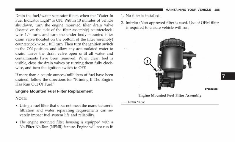
Drain the fuel/water separator filters when the “Water InFuel Indicator Light” is ON. Within 10 minutes of vehicleshutdown, turn the engine mounted filter drain valve(located on the side of the filter assembly) counterclock-wise 1/4 turn, and turn the under body mounted filterdrain valve (located on the bottom of the filter assembly)counterclock wise 1 full turn. Then turn the ignition switchto the ON position, and allow any accumulated water todrain. Leave the drain valve open until all water andcontaminants have been removed. When clean fuel isvisible, close the drain valves by turning them fully clock-wise, and turn the ignition switch to OFF.
If more than a couple ounces/milliliters of fuel have beendrained, follow the directions for “Priming If The EngineHas Run Out Of Fuel.”
Engine Mounted Fuel Filter Replacement
NOTE:
• Using a fuel filter that does not meet the manufacturer’sfiltration and water separating requirements can se-verely impact fuel system life and reliability.
• The engine mounted filter housing is equipped with aNo-Filter-No-Run (NFNR) feature. Engine will not run if:
1. No filter is installed.
2. Inferior/Non-approved filter is used. Use of OEM filteris required to ensure vehicle will run.
Engine Mounted Fuel Filter Assembly
1 — Drain Valve
7
MAINTAINING YOUR VEHICLE 185
CAUTION!
• Diesel fuel will damage blacktop paving surfaces.Drain the filter into an appropriate container.
• Do not prefill the fuel filter when installing a newfuel filter. There is a possibility debris could beintroduced into the fuel filter during this action. It isbest to install the filter dry and allow the in-tank liftpump to prime the fuel system.
1. Ensure engine is turned off.
2. Place drain pan under the fuel filter drain hose.
3. Open the water drain valve 1/4 turn counterclockwiseand completely drain fuel and water into the approvedcontainer.
4. Close the water drain valve.
5. Remove lid using a socket or strap wrench. Rotatecounterclockwise for removal. Remove used o-ring anddiscard it.
6. Remove the used filter cartridge from the housing anddispose of according to your local regulations.
7. Wipe clean the sealing surfaces of the lid and housing.
8. Install new o-ring back into ring groove on the filterhousing and lubricate with clean engine oil.
9. Remove new filter cartridge from plastic bag and installinto housing.
NOTE: Do not remove cartridge from bag until you reachthis step in order to keep cartridge clean.
10. Push down on the cartridge to ensure it is properlyseated. Do not pre-fill the filter housing with fuel.
11. Install lid onto housing and tighten to 22.5 ft lbs(30.5 N.m). Do not overtighten the lid.
12. Prime the engine using the procedure in “Priming IfThe Engine Has Run Out Of Fuel.” Then start theengine and confirm there are no leaks.
Underbody Mounted Fuel Filter Replacement
NOTE:
• Using a fuel filter that does not meet the manufacturer’sfiltration and water separating requirements can se-verely impact fuel system life and reliability.
• The underbody mounted filter housing will cause theengine not to run if:
186 MAINTAINING YOUR VEHICLE
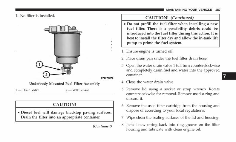
1. No filter is installed.
CAUTION!
• Diesel fuel will damage blacktop paving surfaces.Drain the filter into an appropriate container.
(Continued)
CAUTION! (Continued)• Do not prefill the fuel filter when installing a new
fuel filter. There is a possibility debris could beintroduced into the fuel filter during this action. It isbest to install the filter dry and allow the in-tank liftpump to prime the fuel system.
1. Ensure engine is turned off.
2. Place drain pan under the fuel filter drain hose.
3. Open the water drain valve 1 full turn counterclockwiseand completely drain fuel and water into the approvedcontainer.
4. Close the water drain valve.
5. Remove lid using a socket or strap wrench. Rotatecounterclockwise for removal. Remove used o-ring anddiscard it.
6. Remove the used filter cartridge from the housing anddispose of according to your local regulations.
7. Wipe clean the sealing surfaces of the lid and housing.
8. Install new o-ring back into ring groove on the filterhousing and lubricate with clean engine oil.
Underbody Mounted Fuel Filter Assembly
1 — Drain Valve 2 — WIF Sensor
7
MAINTAINING YOUR VEHICLE 187
NOTE: WIF sensor is re-usable. Service kit comes with newo-ring for filter canister and WIF sensor.
Priming If The Engine Has Run Out Of Fuel
WARNING!
Do not open the high pressure fuel system with theengine running. Engine operation causes high fuelpressure. High pressure fuel spray can cause seriousinjury or death.
1. Add a substantial amount of fuel to the tank, approxi-mately 2 to 5 gal (8L to 19L).
2. Turn ignition switch to the start position to engagestarter for one second, return ignition switch to runposition. This will activate in tank fuel pump for ap-proximately 15 seconds. Repeat this process twice.
3. Start the engine using the “Normal Starting” procedure.Refer to “Starting Procedures” in “Starting and Operat-ing” for further information.
CAUTION!
Do not engage the starter motor for more than 15seconds at a time. Allow two minutes between thecranking intervals.
NOTE: The engine may run rough until the air is forcedfrom all the fuel lines.
WARNING!
Do not use alcohol or gasoline as a fuel blending agent.They can be unstable under certain conditions and behazardous or explosive when mixed with diesel fuel.
CAUTION!
Due to lack of lubricants in alcohol or gasoline, the useof these fuels can cause damage to the fuel system.
NOTE:
• A maximum blend of 5% biodiesel, meeting ASTMspecification D-975 may be used with your Cumminsdiesel engine. (Chassis Cab models not configured withB20 capability.)
188 MAINTAINING YOUR VEHICLE
• A maximum blend of 20% biodiesel, meeting ASTMspecification D-7467 may be used with your Cumminsdiesel engine. (Pickup models and Chassis Cab modelsconfigured with B20 capability.)
• Use of biodiesel mixture in excess of 20% can negativelyimpact the fuel filter’s ability to separate water from thefuel, resulting in high pressure fuel system corrosion ordamage.
• Ethanol blends are not recommended or approved foruse with your Cummins diesel engine.
• In addition, commercially available fuel additives arenot necessary for the proper operation of your Cumminsdiesel engine.
Intervention Regeneration Strategy — MessageProcess Flow
The Cummins diesel engine meets all EPA Heavy DutyDiesel Engine Emissions Standards, resulting in one of thelowest emitting diesel engines ever produced.
To achieve these emissions standards, your vehicle isequipped with a state-of-the-art engine and exhaust sys-tem. The engine and exhaust after-treatment system worktogether to achieve the EPA Heavy Duty Diesel Engine
Emissions Standards. These systems are seamlessly inte-grated into your vehicle and managed by the CumminsPowertrain Control Module (PCM). The PCM managesengine combustion to allow the exhaust system’s catalystto trap and burn Particulate Matter (PM) pollutants, withno input or interaction on your part.
If the engine is allowed to idle or the truck is driven on lowengine speed drive cycles for more than 2 hours, thesystem will automatically enter an emissions operatingmode that will increase the engine idle speed to 900 RPM(1050 RPM for Chassis Cab). While in this mode, which isdesigned to help maintain the diesel particulate filter, theengine idle speed will return to normal when the brakepedal is applied. A small change in engine tone or a slightchange in engine performance while accelerating may alsobe noticeable at speeds below 20 mph (32 kmh). Thisoperating mode may last for up to an hour of idle time, oraround 20 minutes of driving time.
Additionally, your vehicle has the ability to alert you toadditional maintenance required on your truck or engine.
Refer to “Instrument Cluster Display” in “UnderstandingYour Instrument Panel” for further information.
7
MAINTAINING YOUR VEHICLE 189
WARNING!
A hot exhaust system can start a fire if you park overmaterials that can burn. Such materials might be grassor leaves coming into contact with your exhaust sys-tem. Do not park or operate your vehicle in areas whereyour exhaust system can contact anything that canburn.
Diesel Exhaust Fluid
Diesel Exhaust Fluid (DEF) sometimes known simply bythe name of its active component, UREA—is a key compo-nent of selective catalytic reduction (SCR) systems, whichhelp diesel vehicles meet stringent emission regulations.DEF is a liquid reducing agent that reacts with engineexhaust in the presence of a catalyst to convert smog-forming nitrogen oxides (NOx) into harmless nitrogen andwater vapor.
Refer to “Fluids, Lubricants, and Genuine Parts” in “Main-taining Your Vehicle” for further information.
You can receive assistance in locating DEF in the UnitedStates by calling 866-RAM-INFO (866-726-4636). In Canadacall 1–800–465–2001 (English) or 1–800–387–9983 (French)
Maintenance-Free Batteries
The top of the maintenance-free batteries are permanentlysealed. You will never have to add water, nor is periodicmaintenance required.
NOTE: Replacement batteries should both be of equalcapacity to prevent damage to the vehicle’s chargingsystem.
CAUTION!
It is essential when replacing the cables on the batterythat the positive cable is attached to the positive postand the negative cable is attached to the negative post.Battery posts are marked (+) positive and negative (-)and are identified on the battery case. Also, if a “fastcharger” is used while the battery is in vehicle, discon-nect both vehicle battery cables before connecting thecharger to the battery. Do not use a “fast charger” toprovide starting voltage.
190 MAINTAINING YOUR VEHICLE
WARNING!
Battery posts, terminals, and related accessories con-tain lead and lead compounds. Always wash handsafter handling the battery.
Battery Blanket Usage
A battery loses 60% of its cranking power as the batterytemperature decreases to 0°F (-18°). For the same decreasein temperature, the engine requires twice as much power tocrank at the same RPM. The use of 120 Volt AC poweredbattery blankets will greatly increase starting capability atlow temperatures. Suitable battery blankets are availablefrom your authorized MOPAR dealer.
Cooling System
WARNING!
You or others can be badly burned by hot enginecoolant (antifreeze) or steam from your radiator. If yousee or hear steam coming from under the hood, do notopen the hood until the radiator has had time to cool.Never try to open a cooling system pressure cap whenthe radiator is hot.
Engine Coolant Checks
Check the engine coolant (antifreeze) protection every12 months (before the onset of freezing weather, whereapplicable). If the engine coolant (antifreeze) is dirty orrusty in appearance, the system should be drained, flushedand refilled with fresh coolant. Check the front of the A/Ccondenser (if equipped) or radiator for any accumulationof bugs, leaves, etc. If dirty, clean by gently spraying waterfrom a garden hose vertically down the face of the A/Ccondenser (if equipped) or the back of the radiator core.
Check the engine cooling system hoses for brittle rubber,cracking, tears, cuts and tightness of the connection at thecoolant recovery bottle and radiator. Inspect the entiresystem for leaks.
With the engine at normal operating temperature (but notrunning), check the cooling system pressure cap for propervacuum sealing by draining a small amount of enginecoolant (antifreeze) from the radiator drain cock. Theradiator drain cock is located in the lower radiator tank. Ifthe cap is sealing properly, the engine coolant (antifreeze)will begin to drain from the coolant expansion bottle. DONOT REMOVE THE COOLANT PRESSURE CAP WHENTHE COOLING SYSTEM IS HOT.
7
MAINTAINING YOUR VEHICLE 191
Cooling System — Drain Flush And Refill
If the engine coolant (antifreeze) is dirty or contains aconsiderable amount of sediment, clean and flush with areliable cooling system cleaner. Follow with a thoroughrinsing to remove all deposits and chemicals. Properlydispose of old engine coolant (antifreeze).
Refer to the “Maintenance Schedule” for the proper main-tenance intervals.
Selection Of Coolant
Refer to “Fluids, Lubricants, And Genuine Parts” in “Main-taining Your Vehicle” for further information.
CAUTION!
• Mixing of engine coolant (antifreeze) other than speci-fied Organic Additive Technology (OAT) engine cool-ant (antifreeze), may result in engine damage and maydecrease corrosion protection. Organic Additive Tech-nology (OAT) engine coolant is different and shouldnot be mixed with Hybrid Organic Additive Technol-ogy (HOAT) engine coolant (antifreeze) or any “glob-ally compatible” coolant (antifreeze). If a non-OAT
(Continued)
CAUTION! (Continued)engine coolant (antifreeze) is introduced into the cool-ing system in an emergency, the cooling system willneed to be drained, flushed, and refilled with freshOAT coolant (conforming to MS.90032), by an autho-rized dealer as soon as possible.
• Do not use water alone or alcohol-based enginecoolant (antifreeze) products. Do not use additionalrust inhibitors or antirust products, as they may notbe compatible with the engine coolant and may plugthe radiator.
• This vehicle has not been designed for use withpropylene glycol-based engine coolant (antifreeze).Use of propylene glycol-based engine coolant (anti-freeze) is not recommended.
Adding Coolant
Your vehicle has been built with an improved enginecoolant (OAT coolant conforming to MS.90032) that allowsextended maintenance intervals. This engine coolant (anti-freeze) can be used up to ten years or 150,000 miles(240,000 km) before replacement. To prevent reducing thisextended maintenance period, it is important that you use
192 MAINTAINING YOUR VEHICLE
the same engine coolant (OAT coolant conforming toMS.90032) throughout the life of your vehicle.
Please review these recommendations for using OrganicAdditive Technology (OAT) engine coolant (antifreeze)that meets the requirements of FCA Material StandardMS.90032. When adding engine coolant (antifreeze):
• We recommend using MOPAR Antifreeze/Coolant10 Year/150,000 Mile Formula OAT (Organic AdditiveTechnology) that meets the requirements of FCA Mate-rial Standard MS.90032.
• Mix a minimum solution of 50% OAT engine coolantthat meets the requirements of FCA Material StandardMS.90032 and distilled water. Use higher concentrations(not to exceed 70%) if temperatures below −34°F (−37°C)are anticipated. Please contact your authorized dealerfor assistance.
• Use only high purity water such as distilled or deionizedwater when mixing the water/engine coolant (anti-freeze) solution. The use of lower quality water willreduce the amount of corrosion protection in the enginecooling system.
NOTE:
• It is the owner’s responsibility to maintain the properlevel of protection against freezing according to thetemperatures occurring in the area where the vehicle isoperated.
• Some vehicles require special tools to add coolant prop-erly. Failure to fill these systems properly could lead tosevere internal engine damage. If any coolant is neededto be added to the system, please contact your localauthorized dealer.
• Mixing engine coolant (antifreeze) types is not recom-mended and can result in cooling system damage.If HOAT and OAT coolant are mixed in an emergency,have a authorized dealer drain, flush, and refill withOAT coolant (conforming to MS.90032) as soon as pos-sible.
Cooling System Pressure Cap
The cap must be fully tightened to prevent loss of enginecoolant (antifreeze), and to ensure that the engine coolant(antifreeze) will return to the radiator from the coolantexpansion bottle.
7
MAINTAINING YOUR VEHICLE 193
The cap should be inspected and cleaned if there is anyaccumulation of foreign material on the sealing surfaces.
WARNING!
• Do not open hot engine cooling system. Never addengine coolant (antifreeze) when the engine is over-heated. Do not loosen or remove the cap to cool anoverheated engine. Heat causes pressure to build upin the cooling system. To prevent scalding or injury,do not remove the pressure cap while the system ishot or under pressure.
• Do not use a pressure cap other than the one speci-fied for your vehicle. Personal injury or enginedamage may result.
Disposal Of Used Engine Coolant
Used ethylene glycol-based engine coolant (antifreeze) is aregulated substance requiring proper disposal. Check withyour local authorities to determine the disposal rules foryour community. To prevent ingestion by animals orchildren, do not store ethylene glycol-based engine coolant(antifreeze) in open containers or allow it to remain inpuddles on the ground. If ingested by a child or pet, seekemergency assistance immediately. Clean up any groundspills immediately.
Points To Remember
NOTE: When the vehicle is stopped after a few miles/kilometers of operation, you may observe vapor comingfrom the front of the engine compartment. This is normallya result of moisture from rain, snow, or high humidityaccumulating on the radiator and being vaporized whenthe thermostat opens, allowing hot engine coolant (anti-freeze) to enter the radiator.
If an examination of your engine compartment shows noevidence of radiator or hose leaks, the vehicle may besafely driven. The vapor will soon dissipate.
• Do not overfill the coolant expansion bottle.
• Check the coolant freeze point in the radiator and in thecoolant expansion bottle. If engine coolant (antifreeze)needs to be added, the contents of the coolant expansionbottle must also be protected against freezing.
• If frequent engine coolant (antifreeze) additions arerequired, the cooling system should be pressure testedfor leaks.
• Maintain engine coolant (antifreeze) concentration at aminimum of 50% OAT coolant (conforming to
194 MAINTAINING YOUR VEHICLE
MS.90032) and distilled water for proper corrosion pro-tection of your engine which contains aluminum com-ponents.
• Make sure that the coolant expansion bottle overflowhoses are not kinked or obstructed.
• Keep the front of the radiator clean. If your vehicle isequipped with air conditioning, keep the front of thecondenser clean.
• Do not change the thermostat for Summer or Winteroperation. If replacement is ever necessary, install ONLYthe correct type thermostat. Other designs may result inunsatisfactory engine coolant (antifreeze) performance,poor gas mileage, and increased emissions.
Charge Air Cooler — Inter-Cooler
The charge air cooler is positioned below the radiator andthe air conditioner condenser. Air enters the enginethrough the air cleaner and passes through the turbo-charger, where it is pressurized. This pressurized air rap-idly reaches high temperature. The air is then directedthrough a hose to the charge air cooler and through anotherhose to the intake manifold of the engine. The air entering
the engine has been cooled by about 50° to 100°F (10° to38°C). This cooling process enables more efficient burningof fuel resulting in fewer emissions.
To guarantee optimum performance of the system, keepthe surfaces of the charge air cooler, condenser and radiatorclean and free of debris. Periodically check the hosesleading to and from the charge air cooler for cracks or looseclamps resulting in loss of pressure and reduced engineperformance.
Brake System
Brake Master Cylinder — Brake Fluid Level Check
The fluid level of the master cylinder should be checkedwhen performing under the hood service, or immediatelyif the “Brake System Warning Light” indicates systemfailure.
The brake master cylinder has a translucent plastic reser-voir. On the outboard side of the reservoir, there is a“MAX” mark and a “MIN” mark. The fluid level must bekept within these two marks. Do not add fluid above thefull mark because leakage may occur at the cap.
7
MAINTAINING YOUR VEHICLE 195
With disc brakes, the fluid level can be expected to fall asthe brake linings wear. However, an unexpected drop influid level may be caused by a leak and a system checkshould be conducted.
Refer to “Fluids, Lubricants, And Genuine Parts” in “Main-taining Your Vehicle” for further information.
WARNING!
• Use only manufacturer’s recommended brake fluid.Refer to “Fluids, Lubricants, and Genuine Parts” in“Maintaining Your Vehicle” for further information.Using the wrong type of brake fluid can severelydamage your brake system and/or impair its perfor-mance. The proper type of brake fluid for yourvehicle is also identified on the original factoryinstalled hydraulic master cylinder reservoir.
(Continued)
WARNING! (Continued)• To avoid contamination from foreign matter or mois-
ture, use only new brake fluid or fluid that has beenin a tightly closed container. Keep the master cylin-der reservoir cap secured at all times. Brake fluid ina open container absorbs moisture from the airresulting in a lower boiling point. This may cause itto boil unexpectedly during hard or prolonged brak-ing, resulting in sudden brake failure. This couldresult in a accident.
• Overfilling the brake fluid reservoir can result inspilling brake fluid on hot engine parts, causing thebrake fluid to catch fire. Brake fluid can also damagepainted and vinyl surfaces, care should be taken toavoid its contact with these surfaces.
• Do not allow petroleum based fluid to contaminatethe brake fluid. Brake seal components could bedamaged, causing partial or complete brake failure.This could result in an accident.
Clutch Hydraulic System
The clutch hydraulic system is a sealed maintenance-freesystem. In the event of leakage or other malfunction, thesystem must be replaced.
196 MAINTAINING YOUR VEHICLE
Transfer Case — If Equipped
Drain And Refill
Refer to the “Maintenance Schedule” for the proper main-tenance intervals.
Selection of Lubricant
Refer to “Fluids, Lubricants, and Genuine Parts” in “Main-taining Your Vehicle” for fluid specifications.
Fluid Level Check
This fluid level can be checked by removing the filler plug.The fluid level should be to the bottom edge of the fillerplug hole with the vehicle in a level position.
Manual Transmission — If Equipped
Selection of Lubricant
Refer to “Fluids, Lubricants, and Genuine Parts” in “Main-taining Your Vehicle” for fluid specifications.
Fluid Level Check
The fluid level can be checked by removing the filler plug.If the level of the lubricant is more than 1/2 in (12 mm)below the bottom of the filler hole while the vehicle is on
level ground, enough lubricant should be added to bringthe level to 1/4 in (6 mm) below the bottom of the fillerhole.
Automatic Transmission — If Equipped
Selection of Lubricant
It is important to use the proper transmission fluid toensure optimum transmission performance and life. Useonly the manufacturer’s specified transmission fluid. Referto “Fluids, Lubricants, and Genuine Parts” in this sectionfor fluid specifications. It is important to maintain thetransmission fluid at the correct level using the recom-mended fluid.
No chemical flushes should be used in any transmission;only the approved lubricant should be used.
CAUTION!
Using a transmission fluid other than the manufactur-er’s recommended fluid may cause deterioration intransmission shift quality and/or torque convertershudder, and will require more frequent fluid andfilter changes. Refer to “Fluids, Lubricants, and Genu-ine Parts” in this section for fluid specifications.
7
MAINTAINING YOUR VEHICLE 197
Special Additives
The manufacturer strongly recommends against using anyspecial additives in the transmission. Automatic Transmis-sion Fluid (ATF) is an engineered product and its perfor-mance may be impaired by supplemental additives. There-fore, do not add any fluid additives to the transmission.The only exception to this policy is the use of special dyesfor diagnosing fluid leaks. Avoid using transmission seal-ers as they may adversely affect seals.
CAUTION!
Do not use chemical flushes in your transmission asthe chemicals can damage your transmission compo-nents. Such damage is not covered by the New VehicleLimited Warranty.
Fluid Level Check
It is best to check the fluid level when the transmission isat normal operating temperature (170-180°F / 77-82°C for68RFE transmission, or 158-176°F / 70-80°C for AS69RCtransmission). This normally occurs after at least 15 miles(25 km) of driving. At normal operating temperature thefluid cannot be held comfortably between the fingertips.You can read the transmission sump temperature in the
instrument cluster display (refer to “Instrument ClusterDisplay” in “Understanding Your Instrument Panel” forfurther information).
Use the following procedure to check the transmissionfluid level properly:
1. Monitor the transmission temperature using the instru-ment cluster display, and operate the vehicle as requiredto reach the normal operating temperature. If the trans-mission is not functioning properly, or the vehiclecannot be driven, see the NOTE and CAUTION belowabout checking the fluid level at colder temperatures.
2. Park the vehicle on level ground.
3. Run the engine at normal idle speed for at least 60seconds, and leave the engine running for the rest of thisprocedure.
4. Fully apply the parking brake and press the brake pedal.
5. Place the gear selector momentarily into each gearposition (allowing time for the transmission to fullyengage in each position), ending with the transmissionin PARK.
6. Remove the dipstick, wipe it clean and reinsert it untilseated.
198 MAINTAINING YOUR VEHICLE
7. Remove the dipstick again and note the fluid level onboth sides. The fluid level reading is only valid if thereis a solid coating of oil on both sides of the dipstick.Note that the holes in the dipstick will be full of fluid ifthe actual level is at or above the hole. The fluid levelshould be between the “HOT” (upper) reference holeson the dipstick at normal operating temperature. If thefluid level is low, add fluid through the dipstick tube tobring it to the proper level. Do not overfill. Use ONLYthe specified fluid (see �Fluids, Lubricants, and GenuineParts� for fluid specifications). After adding any quan-tity of oil through the dipstick tube, wait a minimum oftwo minutes for the oil to fully drain into the transmis-sion before rechecking the fluid level.
NOTE: If it is necessary to check the transmission belowthe operating temperature, the fluid level should be be-tween the two “COLD” (lower) holes on the dipstick withthe fluid at 60-70°F / 16-21°C for 68RFE transmission, or68-86°F / 20-30°C for AS69RC transmission. Only use theCOLD region of the dipstick as a rough reference whensetting the fluid level after a transmission service or fluidchange. Re-check the fluid level, and adjust as required,once the transmission reaches normal operating tempera-ture.
CAUTION!
If the fluid temperature is below 50°F (10°C) it may notregister on the dipstick. Do not add fluid until thetemperature is elevated enough to produce an accuratereading. Run the engine at idle, in PARK, to warm thefluid.
8. Reinsert the dipstick. Check for leaks. Release the park-ing brake.
NOTE: To prevent dirt and water from entering thetransmission after checking or replenishing fluid, makesure that the dipstick cap is properly reseated. It is normalfor the dipstick cap to spring back slightly from its fullyseated position, as long as its seal remains engaged in thedipstick tube.
Fluid And Filter Changes
Refer to the “Maintenance Schedule” for the proper main-tenance intervals.
In addition, change the fluid and filter(s) if the fluidbecomes contaminated (with water, etc.), or if the transmis-sion is disassembled for any reason.
7
MAINTAINING YOUR VEHICLE 199
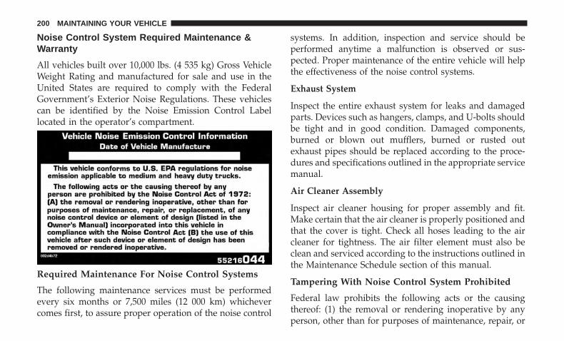
Noise Control System Required Maintenance &Warranty
All vehicles built over 10,000 lbs. (4 535 kg) Gross VehicleWeight Rating and manufactured for sale and use in theUnited States are required to comply with the FederalGovernment’s Exterior Noise Regulations. These vehiclescan be identified by the Noise Emission Control Labellocated in the operator’s compartment.
Required Maintenance For Noise Control Systems
The following maintenance services must be performedevery six months or 7,500 miles (12 000 km) whichevercomes first, to assure proper operation of the noise control
systems. In addition, inspection and service should beperformed anytime a malfunction is observed or sus-pected. Proper maintenance of the entire vehicle will helpthe effectiveness of the noise control systems.
Exhaust System
Inspect the entire exhaust system for leaks and damagedparts. Devices such as hangers, clamps, and U-bolts shouldbe tight and in good condition. Damaged components,burned or blown out mufflers, burned or rusted outexhaust pipes should be replaced according to the proce-dures and specifications outlined in the appropriate servicemanual.
Air Cleaner Assembly
Inspect air cleaner housing for proper assembly and fit.Make certain that the air cleaner is properly positioned andthat the cover is tight. Check all hoses leading to the aircleaner for tightness. The air filter element must also beclean and serviced according to the instructions outlined inthe Maintenance Schedule section of this manual.
Tampering With Noise Control System Prohibited
Federal law prohibits the following acts or the causingthereof: (1) the removal or rendering inoperative by anyperson, other than for purposes of maintenance, repair, or
200 MAINTAINING YOUR VEHICLE
replacement, of any device or element of design incorpo-rated into any new vehicle for the purpose of noise controlprior to its sale or delivery to the ultimate purchaser orwhile it is in use, or (2) the use of the vehicle after suchdevice or element of design has been removed or renderedinoperative by any person.
Among those acts presumed to constitute tampering arethe acts listed below.
AIR CLEANER
• Removal of the air cleaner.
• Removal of the air cleaner filter element from the aircleaner housing.
• Removal of the air ducting.
EXHAUST SYSTEM
• Removal or rendering inoperative exhaust system com-ponents including the muffler or tailpipe.
ENGINE COOLING SYSTEM
• Removal or rendering inoperative the fan clutch.
• Removal of the fan shroud.
Noise Emission Warranty
The manufacturer warrants that this vehicle as manufac-tured by the manufacturer, was designed, built andequipped to conform at the time it left the manufacturer’scontrol with all applicable U.S. EPA Noise Control Regu-lations.
This warranty covers this vehicle as designed, built andequipped by the manufacturer, and is not limited to anyparticular part, component or system of the vehicle manu-factured by the manufacturer. Defects in design, assemblyor in any part, component or system of the vehicle asmanufactured by the manufacturer, which, at the time itleft the manufacturer’s control, caused noise emissions toexceed Federal standards, are covered by this warranty forthe life of the vehicle.
7
MAINTAINING YOUR VEHICLE 201
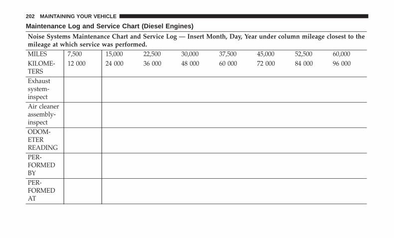
Maintenance Log and Service Chart (Diesel Engines)
Noise Systems Maintenance Chart and Service Log — Insert Month, Day, Year under column mileage closest to themileage at which service was performed.MILES 7,500 15,000 22,500 30,000 37,500 45,000 52,500 60,000KILOME-TERS
12 000 24 000 36 000 48 000 60 000 72 000 84 000 96 000
Exhaustsystem-inspectAir cleanerassembly-inspectODOM-ETERREADINGPER-FORMEDBYPER-FORMEDAT
202 MAINTAINING YOUR VEHICLE
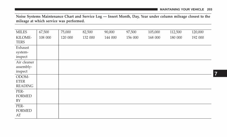
Noise Systems Maintenance Chart and Service Log — Insert Month, Day, Year under column mileage closest to themileage at which service was performed.
MILES 67,500 75,000 82,500 90,000 97,500 105,000 112,500 120,000KILOME-TERS
108 000 120 000 132 000 144 000 156 000 168 000 180 000 192 000
Exhaustsystem-inspectAir cleanerassembly-inspectODOM-ETERREADINGPER-FORMEDBYPER-FORMEDAT
7
MAINTAINING YOUR VEHICLE 203
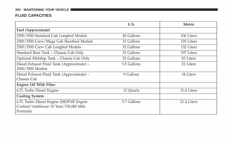
FLUID CAPACITIES
U.S. MetricFuel (Approximate)2500/3500 Standard Cab Longbed Models 28 Gallons 106 Liters2500/3500 Crew/Mega Cab Shortbed Models 31 Gallons 129 Liters2500/3500 Crew Cab Longbed Models 32 Gallons 132 LitersStandard Rear Tank – Chassis Cab Only 52 Gallons 197 LitersOptional Midship Tank – Chassis Cab Only 22 Gallons 83 LitersDiesel Exhaust Fluid Tank (Approximate) –2500/3500 Models
5.5 Gallons 21 Liters
Diesel Exhaust Fluid Tank (Approximate) –Chassis Cab
9 Gallons 34 Liters
Engine Oil With Filter6.7L Turbo Diesel Engine 12 Quarts 11.4 LitersCooling System6.7L Turbo Diesel Engine (MOPAR EngineCoolant/Antifreeze 10 Year/150,000 MileFormula)
5.7 Gallons 21.4 Liters
204 MAINTAINING YOUR VEHICLE
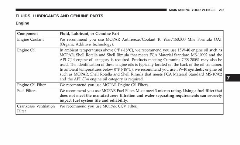
FLUIDS, LUBRICANTS AND GENUINE PARTS
Engine
Component Fluid, Lubricant, or Genuine PartEngine Coolant We recommend you use MOPAR Antifreeze/Coolant 10 Year/150,000 Mile Formula OAT
(Organic Additive Technology).Engine Oil In ambient temperatures above 0°F (-18°C), we recommend you use 15W-40 engine oil such as
MOPAR, Shell Rotella and Shell Rimula that meets FCA Material Standard MS-10902 and theAPI CJ-4 engine oil category is required. Products meeting Cummins CES 20081 may also beused. The identification of these engine oils is typically located on the back of the oil container.In ambient temperatures below 0°F (-18°C), we recommend you use 5W-40 synthetic engine oilsuch as MOPAR, Shell Rotella and Shell Rimula that meets FCA Material Standard MS-10902and the API CJ-4 engine oil category is required.
Engine Oil Filter We recommend you use MOPAR Engine Oil Filters.Fuel Filters We recommend you use MOPAR Fuel Filter. Must meet 3 micron rating. Using a fuel filter that
does not meet the manufacturers filtration and water separating requirements can severelyimpact fuel system life and reliability.
Crankcase VentilationFilter
We recommend you use MOPAR CCV Filter.
7
MAINTAINING YOUR VEHICLE 205
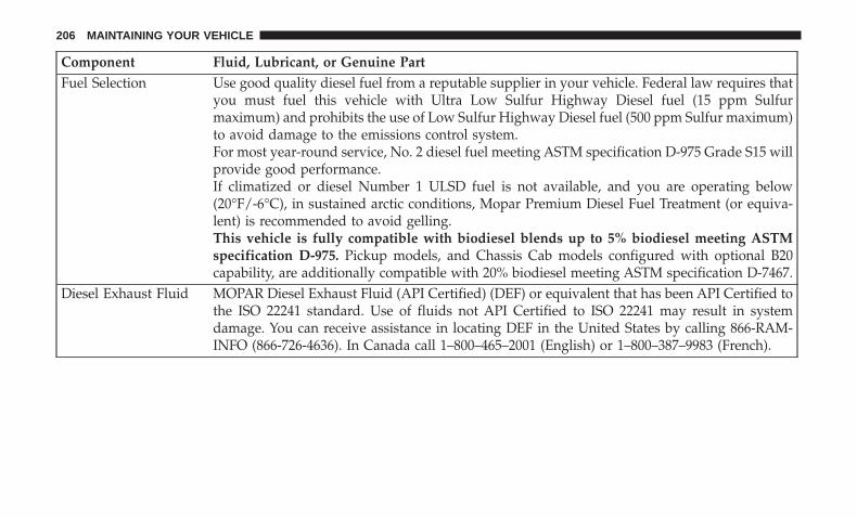
Component Fluid, Lubricant, or Genuine PartFuel Selection Use good quality diesel fuel from a reputable supplier in your vehicle. Federal law requires that
you must fuel this vehicle with Ultra Low Sulfur Highway Diesel fuel (15 ppm Sulfurmaximum) and prohibits the use of Low Sulfur Highway Diesel fuel (500 ppm Sulfur maximum)to avoid damage to the emissions control system.For most year-round service, No. 2 diesel fuel meeting ASTM specification D-975 Grade S15 willprovide good performance.If climatized or diesel Number 1 ULSD fuel is not available, and you are operating below(20°F/-6°C), in sustained arctic conditions, Mopar Premium Diesel Fuel Treatment (or equiva-lent) is recommended to avoid gelling.This vehicle is fully compatible with biodiesel blends up to 5% biodiesel meeting ASTMspecification D-975. Pickup models, and Chassis Cab models configured with optional B20capability, are additionally compatible with 20% biodiesel meeting ASTM specification D-7467.
Diesel Exhaust Fluid MOPAR Diesel Exhaust Fluid (API Certified) (DEF) or equivalent that has been API Certified tothe ISO 22241 standard. Use of fluids not API Certified to ISO 22241 may result in systemdamage. You can receive assistance in locating DEF in the United States by calling 866-RAM-INFO (866-726-4636). In Canada call 1–800–465–2001 (English) or 1–800–387–9983 (French).
206 MAINTAINING YOUR VEHICLE
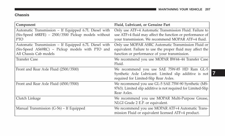
Chassis
Component Fluid, Lubricant, or Genuine PartAutomatic Transmission – If Equipped 6.7L Diesel with(Six-Speed 68RFE) – 2500/3500 Pickup models withoutPTO
Only use ATF+4 Automatic Transmission Fluid. Failure touse ATF+4 fluid may affect the function or performance ofyour transmission. We recommend MOPAR ATF+4 fluid.
Automatic Transmission – If Equipped 6.7L Diesel with(Six-Speed AS69RC) – Pickup models with PTO andAll Chassis Cab models
Only use MOPAR ASRC Automatic Transmission Fluid orequivalent. Failure to use the proper fluid may affect thefunction or performance of your transmission.
Transfer Case We recommend you use MOPAR BW44–44 Transfer CaseFluid.
Front and Rear Axle Fluid (2500/3500) We recommend you use SAE 75W-85 HD Ram GL-5Synthetic Axle Lubricant. Limited slip additive is notrequired for Limited-Slip Rear Axles.
Front and Rear Axle Fluid (4500/5500) We recommend you use GL-5 SAE 75W-90 Synthetic (MS-9763). Limited slip additive is not required for Limited-SlipRear Axles.
Clutch Linkage We recommend you use MOPAR Multi-Purpose Grease,NLGI Grade 2 E.P. or equivalent.
Manual Transmission (G-56) – If Equipped We recommend you use MOPAR ATF+4 Automatic Trans-mission Fluid or equivalent licensed ATF+4 product.
7
MAINTAINING YOUR VEHICLE 207

MAINTENANCE SCHEDULE
CONTENTS� MAINTENANCE SCHEDULE — DIESEL
ENGINE . . . . . . . . . . . . . . . . . . . . . . . . . . . . . .210
▫ Oil Change Indicator System — CumminsDiesel . . . . . . . . . . . . . . . . . . . . . . . . . . . . . .210
▫ Perform Service Indicator — CumminsDiesel . . . . . . . . . . . . . . . . . . . . . . . . . . . . . . .211
▫ Maintenance Chart — Cummins DieselEngine . . . . . . . . . . . . . . . . . . . . . . . . . . . . . .212
8
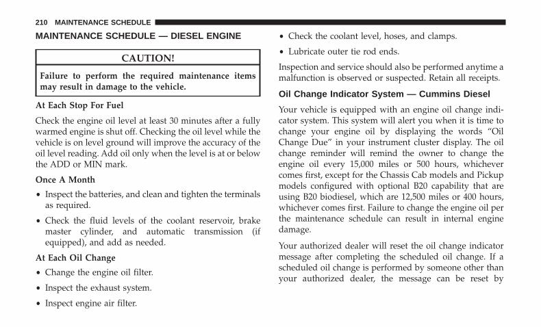
MAINTENANCE SCHEDULE — DIESEL ENGINE
CAUTION!
Failure to perform the required maintenance itemsmay result in damage to the vehicle.
At Each Stop For Fuel
Check the engine oil level at least 30 minutes after a fullywarmed engine is shut off. Checking the oil level while thevehicle is on level ground will improve the accuracy of theoil level reading. Add oil only when the level is at or belowthe ADD or MIN mark.
Once A Month
• Inspect the batteries, and clean and tighten the terminalsas required.
• Check the fluid levels of the coolant reservoir, brakemaster cylinder, and automatic transmission (ifequipped), and add as needed.
At Each Oil Change
• Change the engine oil filter.
• Inspect the exhaust system.
• Inspect engine air filter.
• Check the coolant level, hoses, and clamps.
• Lubricate outer tie rod ends.
Inspection and service should also be performed anytime amalfunction is observed or suspected. Retain all receipts.
Oil Change Indicator System — Cummins Diesel
Your vehicle is equipped with an engine oil change indi-cator system. This system will alert you when it is time tochange your engine oil by displaying the words “OilChange Due” in your instrument cluster display. The oilchange reminder will remind the owner to change theengine oil every 15,000 miles or 500 hours, whichevercomes first, except for the Chassis Cab models and Pickupmodels configured with optional B20 capability that areusing B20 biodiesel, which are 12,500 miles or 400 hours,whichever comes first. Failure to change the engine oil perthe maintenance schedule can result in internal enginedamage.
Your authorized dealer will reset the oil change indicatormessage after completing the scheduled oil change. If ascheduled oil change is performed by someone other thanyour authorized dealer, the message can be reset by
210 MAINTENANCE SCHEDULE
referring to the steps described under “Instrument ClusterDisplay” in “Understanding Your Instrument Panel” forfurther information.
Replace the engine oil and oil filter every 15,000 miles (24000 km) or six months, or sooner if prompted by the oilchange indicator system. Under no circumstances shouldoil change intervals exceed 15,000 miles (24 000 km) or sixmonths, whichever comes first.
NOTE:
• Under no circumstances should oil change intervalsexceed 15,000 miles (24,000 km) or six months or500 Hours, whichever comes first.
• Replace the engine oil and oil filter every 12,500 miles(20 000 km) when running B20 fuel (Chassis Cab Only).
If Chassis Cab models and Pickup models configured withoptional B20 capability are operated with greater than 5%levels of biodiesel, the oil change interval must not exceed12,500 miles (20 000 km) under any circumstances. See theFuel Requirements section for more information regardingoperation of Chassis Cab models and Pickup modelsconfigured for use with biodiesel blend (B6-B20) fuelmeeting ASTM specification D-7467.
Perform Service Indicator — Cummins Diesel
Your vehicle will require emissions maintenance at a setinterval. To help remind you when this maintenance is due,the instrument cluster will display “Perform Service”.When the “Perform Service” message is displayed on theinstrument cluster it is necessary to have the emissionsmaintenance performed. Emissions maintenance may in-clude replacing the Closed Crankcase Ventilation (CCV)filter element. The procedure for clearing and resetting the“Perform Service” indicator message is located in theappropriate Service Information.
8
MAINTENANCE SCHEDULE 211
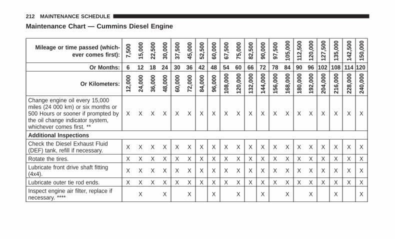
Maintenance Chart — Cummins Diesel Engine
Mileage or time passed (which-ever comes first): 7,
500
15,0
00
22,5
00
30,0
00
37,5
00
45,0
00
52,5
00
60,0
00
67,5
00
75,0
00
82,5
00
90,0
00
97,5
00
105,
000
112,
500
120,
000
127,
500
135,
000
142,
500
150,
000
Or Months: 6 12 18 24 30 36 42 48 54 60 66 72 78 84 90 96 102 108 114 120
Or Kilometers:
12,0
00
24,0
00
36,0
00
48,0
00
60,0
00
72,0
00
84,0
00
96,0
00
108,
000
120,
000
132,
000
144,
000
156,
000
168,
000
180,
000
192,
000
204,
000
216,
000
228,
000
240,
000
Change engine oil every 15,000miles (24 000 km) or six months or500 Hours or sooner if prompted bythe oil change indicator system,whichever comes first. **
X X X X X X X X X X X X X X X X X X X X
Additional InspectionsCheck the Diesel Exhaust Fluid(DEF) tank, refill if necessary. X X X X X X X X X X X X X X X X X X X X
Rotate the tires. X X X X X X X X X X X X X X X X X X X XLubricate front drive shaft fitting(4x4). X X X X X X X X X X X X X X X X X X X X
Lubricate outer tie rod ends. X X X X X X X X X X X X X X X X X X X XInspect engine air filter, replace ifnecessary. **** X X X X X X X X X X
212 MAINTENANCE SCHEDULE
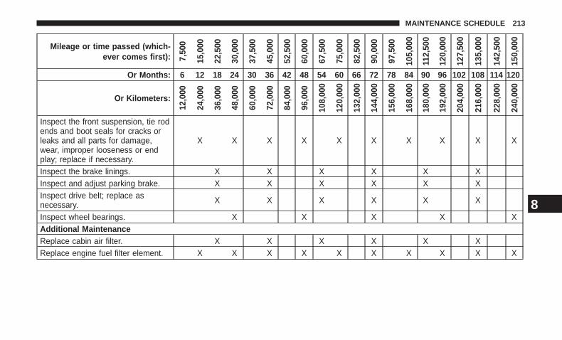
Mileage or time passed (which-ever comes first): 7,
500
15,0
00
22,5
00
30,0
00
37,5
00
45,0
00
52,5
00
60,0
00
67,5
00
75,0
00
82,5
00
90,0
00
97,5
00
105,
000
112,
500
120,
000
127,
500
135,
000
142,
500
150,
000
Or Months: 6 12 18 24 30 36 42 48 54 60 66 72 78 84 90 96 102 108 114 120
Or Kilometers:
12,0
00
24,0
00
36,0
00
48,0
00
60,0
00
72,0
00
84,0
00
96,0
00
108,
000
120,
000
132,
000
144,
000
156,
000
168,
000
180,
000
192,
000
204,
000
216,
000
228,
000
240,
000
Inspect the front suspension, tie rodends and boot seals for cracks orleaks and all parts for damage,wear, improper looseness or endplay; replace if necessary.
X X X X X X X X X X
Inspect the brake linings. X X X X X XInspect and adjust parking brake. X X X X X XInspect drive belt; replace asnecessary. X X X X X X
Inspect wheel bearings. X X X X XAdditional MaintenanceReplace cabin air filter. X X X X X XReplace engine fuel filter element. X X X X X X X X X X
8
MAINTENANCE SCHEDULE 213
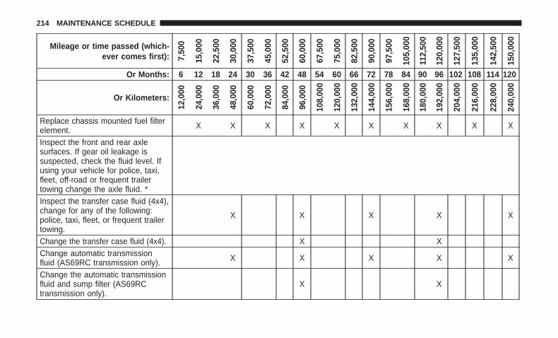
Mileage or time passed (which-ever comes first): 7,
500
15,0
00
22,5
00
30,0
00
37,5
00
45,0
00
52,5
00
60,0
00
67,5
00
75,0
00
82,5
00
90,0
00
97,5
00
105,
000
112,
500
120,
000
127,
500
135,
000
142,
500
150,
000
Or Months: 6 12 18 24 30 36 42 48 54 60 66 72 78 84 90 96 102 108 114 120
Or Kilometers:
12,0
00
24,0
00
36,0
00
48,0
00
60,0
00
72,0
00
84,0
00
96,0
00
108,
000
120,
000
132,
000
144,
000
156,
000
168,
000
180,
000
192,
000
204,
000
216,
000
228,
000
240,
000
Replace chassis mounted fuel filterelement. X X X X X X X X X X
Inspect the front and rear axlesurfaces. If gear oil leakage issuspected, check the fluid level. Ifusing your vehicle for police, taxi,fleet, off-road or frequent trailertowing change the axle fluid. *Inspect the transfer case fluid (4x4),change for any of the following:police, taxi, fleet, or frequent trailertowing.
X X X X X
Change the transfer case fluid (4x4). X XChange automatic transmissionfluid (AS69RC transmission only). X X X X X
Change the automatic transmissionfluid and sump filter (AS69RCtransmission only).
X X
214 MAINTENANCE SCHEDULE
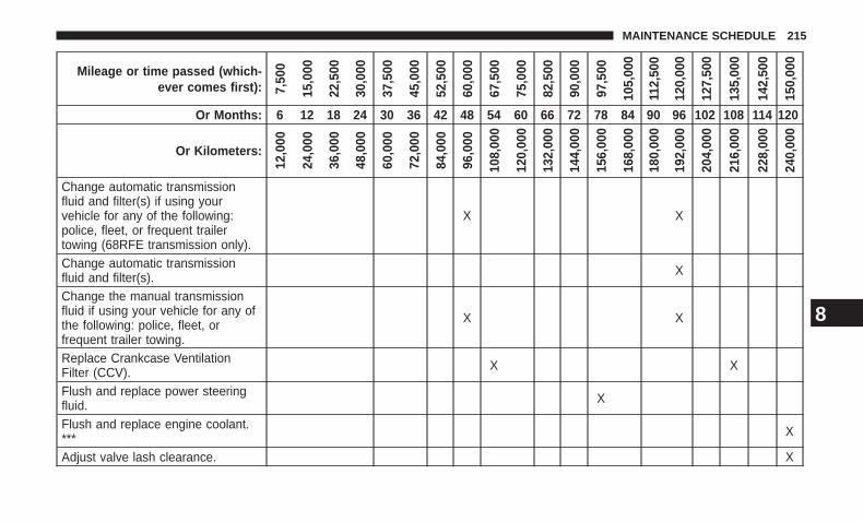
Mileage or time passed (which-ever comes first): 7,
500
15,0
00
22,5
00
30,0
00
37,5
00
45,0
00
52,5
00
60,0
00
67,5
00
75,0
00
82,5
00
90,0
00
97,5
00
105,
000
112,
500
120,
000
127,
500
135,
000
142,
500
150,
000
Or Months: 6 12 18 24 30 36 42 48 54 60 66 72 78 84 90 96 102 108 114 120
Or Kilometers:
12,0
00
24,0
00
36,0
00
48,0
00
60,0
00
72,0
00
84,0
00
96,0
00
108,
000
120,
000
132,
000
144,
000
156,
000
168,
000
180,
000
192,
000
204,
000
216,
000
228,
000
240,
000
Change automatic transmissionfluid and filter(s) if using yourvehicle for any of the following:police, fleet, or frequent trailertowing (68RFE transmission only).
X X
Change automatic transmissionfluid and filter(s). X
Change the manual transmissionfluid if using your vehicle for any ofthe following: police, fleet, orfrequent trailer towing.
X X
Replace Crankcase VentilationFilter (CCV). X X
Flush and replace power steeringfluid. X
Flush and replace engine coolant.*** X
Adjust valve lash clearance. X
8
MAINTENANCE SCHEDULE 215
Inspection and service should also be performed anytime amalfunction is observed or suspected. Retain all receipts.
* Inspect the front and rear axle surfaces every 20,000 miles(32,000 km). If gear oil leakage is suspected, check the fluidlevel. If using your vehicle for police, taxi, fleet, off-road orfrequent trailer towing change the axle fluid every20,000 miles (32,000 km).
** Under no circumstances should oil change intervalsexceed 15,000 miles (24 000 km) or six months or500 Hours, whichever comes first.
*** The manufacturer highly recommends that all coolingsystem service, maintenance, and repairs be performed byyour local authorized dealer.
**** Under no circumstances should the air cleaner filterelement exceed 30,000 miles (48,000 km) or 24 months,whichever comes first.
WARNING!
• You can be badly injured working on or around amotor vehicle. Do only service work for which youhave the knowledge and the right equipment. If youhave any doubt about your ability to perform aservice job, take your vehicle to a competentmechanic.
• Failure to properly inspect and maintain your vehiclecould result in a component malfunction and effectvehicle handling and performance. This could causean accident.
CAUTION!
***The manufacturer highly recommends that allcooling system service, maintenance, and repairs beperformed by your local authorized dealer.
216 MAINTENANCE SCHEDULE
INDEX
8
INDEX 217
Adding Engine Coolant (Antifreeze) . . . . . . . . . . . . . .66Adding Fuel . . . . . . . . . . . . . . . . . . . . . . . . . . . . . . .45Air Cleaner, Engine (Engine Air Cleaner Filter) . . . . . .57Antifreeze (Engine Coolant) . . . . . . . . . . . . . . . . . . . .65
Capacities . . . . . . . . . . . . . . . . . . . . . . . . . . . . . .71Disposal . . . . . . . . . . . . . . . . . . . . . . . . . . . . . . . .68
Automatic TransmissionFluid Type . . . . . . . . . . . . . . . . . . . . . . . . . . . . . .75
Axle Fluid . . . . . . . . . . . . . . . . . . . . . . . . . . . . . . . .75
Battery . . . . . . . . . . . . . . . . . . . . . . . . . . . . . . . . . . .64Brake Fluid. . . . . . . . . . . . . . . . . . . . . . . . . . . . . . . .75Brake System . . . . . . . . . . . . . . . . . . . . . . . . . . . . . .69
Fluid Check . . . . . . . . . . . . . . . . . . . . . . . . . . . . .69Master Cylinder . . . . . . . . . . . . . . . . . . . . . . . . . .69
Capacities, Antifreeze (Engine Coolant) . . . . . . . . . . . .71Capacities, Fluid . . . . . . . . . . . . . . . . . . . . . . . . . . . .71Caps, Filler
Oil (Engine) . . . . . . . . . . . . . . . . . . . . . . . . . . . . .56Radiator (Coolant Pressure) . . . . . . . . . . . . . . . . . .67
Charge Air Cooler . . . . . . . . . . . . . . . . . . . . . . . . . . .69Coolant Pressure Cap (Radiator Cap) . . . . . . . . . . . . .67Cooling System. . . . . . . . . . . . . . . . . . . . . . . . . . . . .65
Adding Coolant (Antifreeze) . . . . . . . . . . . . . . . . .66
Coolant Capacity . . . . . . . . . . . . . . . . . . . . . . . . .71Coolant Level . . . . . . . . . . . . . . . . . . . . . . . . . . . .65Disposal Of Used Coolant . . . . . . . . . . . . . . . . . . .68Drain, Flush, And Refill . . . . . . . . . . . . . . . . . . . . .65Points To Remember . . . . . . . . . . . . . . . . . . . . . . .68Pressure Cap . . . . . . . . . . . . . . . . . . . . . . . . . . . .67Radiator Cap . . . . . . . . . . . . . . . . . . . . . . . . . . . .67Selection Of Coolant (Antifreeze) . . . . . . . . . . .65 , 72
Diesel Fuel . . . . . . . . . . . . . . . . . . . . . . . . . . . . . . . .40Diesel Fuel Requirements. . . . . . . . . . . . . . . . . . . . . .40
Bulk Storage Of . . . . . . . . . . . . . . . . . . . . . . . . . .48Diesel Fuel System, Re-Priming . . . . . . . . . . . . . . . . .62Disposal
Antifreeze (Engine Coolant) . . . . . . . . . . . . . . . . . .68Draining Fuel/Water Separator Filter . . . . . . . . . . . . .60
Engine . . . . . . . . . . . . . . . . . . . . . . . . . . . . . . . . . . .54Air Cleaner . . . . . . . . . . . . . . . . . . . . . . . . . . . . .57Block Heater . . . . . . . . . . . . . . . . . . . . . . . . . .34 , 40Break-In Recommendations . . . . . . . . . . . . . . . . . .11Compartment . . . . . . . . . . . . . . . . . . . . . . . . . . . .54Coolant (Antifreeze) . . . . . . . . . . . . . . . . . . . . . . .72Identification . . . . . . . . . . . . . . . . . . . . . . . . . . . .54Idling . . . . . . . . . . . . . . . . . . . . . . . . . . . . . . . . .38
218 INDEX - RAM 1500
Oil . . . . . . . . . . . . . . . . . . . . . . . . . . . . . . . . .55 , 72Oil Filler Cap . . . . . . . . . . . . . . . . . . . . . . . . . . . .56
FiltersAir Cleaner . . . . . . . . . . . . . . . . . . . . . . . . . . . . .57Engine Fuel . . . . . . . . . . . . . . . . . . . . . . . . . . . . .60Engine Oil . . . . . . . . . . . . . . . . . . . . . . . . . . .57 , 72Engine Oil Disposal . . . . . . . . . . . . . . . . . . . . . . .57
Fluid Capacities . . . . . . . . . . . . . . . . . . . . . . . . . . . .71Fluid Level Checks
Brake . . . . . . . . . . . . . . . . . . . . . . . . . . . . . . . . . .69Fluid, Brake . . . . . . . . . . . . . . . . . . . . . . . . . . . . . . .75Fluids, Lubricants And Genuine Parts . . . . . . . . . . . . .72Fuel . . . . . . . . . . . . . . . . . . . . . . . . . . . . . . . . . . . . .40
Adding . . . . . . . . . . . . . . . . . . . . . . . . . . . . . . . .45Diesel . . . . . . . . . . . . . . . . . . . . . . . . . . . . . .40 , 72Filter . . . . . . . . . . . . . . . . . . . . . . . . . . . . . . . . . .60Requirements . . . . . . . . . . . . . . . . . . . . . . . . . . . .40Specifications . . . . . . . . . . . . . . . . . . . . . . . . . . . .41Tank Capacity . . . . . . . . . . . . . . . . . . . . . . . . . . . .71
Fueling . . . . . . . . . . . . . . . . . . . . . . . . . . . . . . . . . .45Gauges
Voltmeter . . . . . . . . . . . . . . . . . . . . . . . . . . . . . . .35
Instrument Cluster . . . . . . . . . . . . . . . . . . . . . . . . . .14
Intervention Regeneration Strategy . . . . . . . . . . . . . . .25
Keyless Enter-N-Go. . . . . . . . . . . . . . . . . . . . . . . . . .33
Maintenance Procedures . . . . . . . . . . . . . . . . . . . . . .55Maintenance Schedule . . . . . . . . . . . . . . . . . . . . . . . .78
New Vehicle Break-In Period . . . . . . . . . . . . . . . . . . .11
Oil, Engine . . . . . . . . . . . . . . . . . . . . . . . . . . . . . . . .55Capacity . . . . . . . . . . . . . . . . . . . . . . . . . . . . . . .71Change Interval . . . . . . . . . . . . . . . . . . . . . . . . . .56Dipstick . . . . . . . . . . . . . . . . . . . . . . . . . . . . . . . .55Disposal . . . . . . . . . . . . . . . . . . . . . . . . . . . . . . . .57Filter . . . . . . . . . . . . . . . . . . . . . . . . . . . . . . .57 , 72Filter Disposal . . . . . . . . . . . . . . . . . . . . . . . . . . .57Materials Added To . . . . . . . . . . . . . . . . . . . . . . . .57Recommendation . . . . . . . . . . . . . . . . . . . . . . . . .55Viscosity . . . . . . . . . . . . . . . . . . . . . . . . . . . . . . .56
Radiator Cap (Coolant Pressure Cap) . . . . . . . . . . . . .65Remote Starting System . . . . . . . . . . . . . . . . . . . . . . .10
Schedule, Maintenance . . . . . . . . . . . . . . . . . . . . . . .78Selection Of Coolant (Antifreeze) . . . . . . . . . . . . . . . .72
8
INDEX - RAM 1500 219
Starting . . . . . . . . . . . . . . . . . . . . . . . . . . . . . . . . . .32Automatic Transmission . . . . . . . . . . . . . . . . . . . .33Engine Block Heater . . . . . . . . . . . . . . . . . . . .34 , 40Remote . . . . . . . . . . . . . . . . . . . . . . . . . . . . . . . .10
Starting Procedures . . . . . . . . . . . . . . . . . . . . . . . . . .32Starting Procedures (Diesel Engines) . . . . . . . . . . . . . .32
Tip Start . . . . . . . . . . . . . . . . . . . . . . . . . . . . . . . . . .33Transfer Case
Fluid . . . . . . . . . . . . . . . . . . . . . . . . . . . . . . . . . .75TransmissionViscosity, Engine Oil . . . . . . . . . . . . . . . . . . . . . . . . .56
Voltmeter . . . . . . . . . . . . . . . . . . . . . . . . . . . . . . . . .35
Water Separator, Diesel Fuel. . . . . . . . . . . . . . . . . . . .60
220 INDEX - RAM 1500
Adding Engine Coolant (Antifreeze) . . . . . . . . . . . . .192
Adding Fuel . . . . . . . . . . . . . . . . . . . . . . . . . . . . . .160Air Cleaner, Engine (Engine Air Cleaner Filter). . . . . .180Air Filter . . . . . . . . . . . . . . . . . . . . . . . . . . . . . . . .180Antifreeze (Engine Coolant) . . . . . . . . . . . . . . . . . . .192
Capacities . . . . . . . . . . . . . . . . . . . . . . . . . . . . . .204Disposal . . . . . . . . . . . . . . . . . . . . . . . . . . . . . . .194
Automatic TransmissionAdding Fluid . . . . . . . . . . . . . . . . . . . . . . . . . . .199Fluid Level Check . . . . . . . . . . . . . . . . . . . . . . . .198Fluid Type . . . . . . . . . . . . . . . . . . . . . . . . . . . . .207Shifting . . . . . . . . . . . . . . . . . . . . . . . . . . . . . . .141
Axle Fluid . . . . . . . . . . . . . . . . . . . . . . . . . . . . . . .207
Battery . . . . . . . . . . . . . . . . . . . . . . . . . . . . . . . . . .190Blanket . . . . . . . . . . . . . . . . . . . . . . . . . . . .132 , 191Emergency Starting . . . . . . . . . . . . . . . . . . . . . . .170
Brake System . . . . . . . . . . . . . . . . . . . . . . . . . . . . .195Fluid Check . . . . . . . . . . . . . . . . . . . . . . . . . . . .195Master Cylinder . . . . . . . . . . . . . . . . . . . . . . . . .195
Brake/Transmission Interlock . . . . . . . . . . . . . . . . . .141
Capacities, Antifreeze (Engine Coolant) . . . . . . . . . . .204Capacities, Fluid . . . . . . . . . . . . . . . . . . . . . . . . . . .204
Caps, FillerOil (Engine) . . . . . . . . . . . . . . . . . . . . . . . . . . . .178Radiator (Coolant Pressure) . . . . . . . . . . . . . . . . .193
Charge Air Cooler . . . . . . . . . . . . . . . . . . . . . . . . . .195Coolant Pressure Cap (Radiator Cap). . . . . . . . . . . . .193Cooling System . . . . . . . . . . . . . . . . . . . . . . . . . . . .191
Adding Coolant (Antifreeze) . . . . . . . . . . . . . . . . .192Coolant Capacity . . . . . . . . . . . . . . . . . . . . . . . . .204Coolant Level . . . . . . . . . . . . . . . . . . . . . . . . . . .191Disposal Of Used Coolant . . . . . . . . . . . . . . . . . .194Drain, Flush, And Refill . . . . . . . . . . . . . . . . . . . .192Points To Remember . . . . . . . . . . . . . . . . . . . . . .194Pressure Cap . . . . . . . . . . . . . . . . . . . . . . . . . . . .193Radiator Cap . . . . . . . . . . . . . . . . . . . . . . . . . . .193Selection Of Coolant (Antifreeze) . . . . . . . . . .192 , 205
Diesel Exhaust Brake . . . . . . . . . . . . . . . . . . . . . . . .138Diesel Fuel . . . . . . . . . . . . . . . . . . . . . . . . . . . . . . .157Diesel Fuel Requirements . . . . . . . . . . . . . . . . . . . . .157
Bulk Storage Of . . . . . . . . . . . . . . . . . . . . . . . . . .163Diesel Fuel System, Re-Priming. . . . . . . . . . . . . . . . .188Disposal
Antifreeze (Engine Coolant) . . . . . . . . . . . . . . . . .194Draining Fuel/Water Separator Filter. . . . . . . . . . . . .184
8
INDEX - RAM 2500 / 3500 / 4500 / 5500 221
Electronic Range Select (ERS) . . . . . . . . . . . . . . . . . .147Electronic Speed Control (Cruise Control) . . . . . . . . . .96Emergency, In Case Of
Jump Starting . . . . . . . . . . . . . . . . . . . . . . . . . . .170Engine . . . . . . . . . . . . . . . . . . . . . . . . . . . . . . . . . .174
Air Cleaner . . . . . . . . . . . . . . . . . . . . . . . . . . . . .180Block Heater . . . . . . . . . . . . . . . . . . . . . . . .125 , 137Break-In Recommendations . . . . . . . . . . . . . . . . . .94Compartment . . . . . . . . . . . . . . . . . . . . . . .174 , 175Coolant (Antifreeze) . . . . . . . . . . . . . . . . . . . . . .205Identification . . . . . . . . . . . . . . . . . . . . . . . .174 , 175Idling . . . . . . . . . . . . . . . . . . . . . . . . . . . . . . . . .133Jump Starting . . . . . . . . . . . . . . . . . . . . . . . . . . .170Oil . . . . . . . . . . . . . . . . . . . . . . . . . . . . . . .176 , 205Oil Filler Cap . . . . . . . . . . . . . . . . . . . . . . . . . . .178Oil Synthetic . . . . . . . . . . . . . . . . . . . . . . . . . . . .179Runaway . . . . . . . . . . . . . . . . . . . . . . . . . . . . . .156
Exhaust Brake . . . . . . . . . . . . . . . . . . . . . . . . . . . . .138Exhaust System . . . . . . . . . . . . . . . . . . . . . . . . . . . .200Filters
Engine Fuel . . . . . . . . . . . . . . . . . . . . . . . . . . . .184Engine Oil . . . . . . . . . . . . . . . . . . . . . . . . .179 , 205Engine Oil Disposal . . . . . . . . . . . . . . . . . . . . . . .179
Fluid Capacities. . . . . . . . . . . . . . . . . . . . . . . . . . . .204
Fluid Level ChecksBrake . . . . . . . . . . . . . . . . . . . . . . . . . . . . . . . . .195Manual Transmission . . . . . . . . . . . . . . . . . . . . . .197Transfer Case . . . . . . . . . . . . . . . . . . . . . . . . . . .197
Fluids, Lubricants And Genuine Parts . . . . . . . . . . . .205Fuel . . . . . . . . . . . . . . . . . . . . . . . . . . . . . . . . . . . .157
Adding . . . . . . . . . . . . . . . . . . . . . . . . . . . .160 , 162Diesel . . . . . . . . . . . . . . . . . . . . . . . . .157 , 162 , 205Filter . . . . . . . . . . . . . . . . . . . . . . . . . . . . . . . . .184Requirements . . . . . . . . . . . . . . . . . . . . . . . . . . .157Specifications . . . . . . . . . . . . . . . . . . . . . . . . . . .157Tank Capacity . . . . . . . . . . . . . . . . . . . . . . . . . . .204
Fueling. . . . . . . . . . . . . . . . . . . . . . . . . . . . . . . . . .160Gauges
Voltmeter . . . . . . . . . . . . . . . . . . . . . . . . . . . . . .130
Gear Ranges . . . . . . . . . . . . . . . . . . . . . . . . . . . . . .142
Idle Up Feature . . . . . . . . . . . . . . . . . . . . . . . . . . . .134Instrument Cluster. . . . . . . . . . . . . . . . . . . . . . . . . .102Intervention Regeneration Strategy . . . . . . . . . . . . . .113
Jump Starting . . . . . . . . . . . . . . . . . . . . . . . . . . . . .170
222 INDEX - RAM 2500 / 3500 / 4500 / 5500
Keyless Enter-N-Go . . . . . . . . . . . . . . . . . . . . . . . . .122
Maintenance Procedures. . . . . . . . . . . . . . . . . . . . . .176Maintenance Schedule . . . . . . . . . . . . . . . . . . . . . . .210Manual Transmission . . . . . . . . . . . . . . . . . . . . . . . .150
Fluid Level Check . . . . . . . . . . . . . . . . . . . . . . . .197Shift Speeds . . . . . . . . . . . . . . . . . . . . . . . . . . . .151
New Vehicle Break-In Period . . . . . . . . . . . . . . . . . . .94Noise Control
Maintenance . . . . . . . . . . . . . . . . . . . . . . . . . . . .200Tampering Prohibited . . . . . . . . . . . . . . . . . . . . .200
Noise Emission Warranty . . . . . . . . . . . . . . . . . . . . .200
Oil Change Indicator . . . . . . . . . . . . . . . . . . . . . . . .210Oil, Engine . . . . . . . . . . . . . . . . . . . . . . . . . . . . . . .176
Capacity . . . . . . . . . . . . . . . . . . . . . . . . . . . . . . .204Change Interval . . . . . . . . . . . . . . . . . . . . . . . . .177Dipstick . . . . . . . . . . . . . . . . . . . . . . . . . . . . . . .176Disposal . . . . . . . . . . . . . . . . . . . . . . . . . . . . . . .179Filter . . . . . . . . . . . . . . . . . . . . . . . . . . . . .179 , 205Filter Disposal . . . . . . . . . . . . . . . . . . . . . . . . . . .179Identification Logo . . . . . . . . . . . . . . . . . . . . . . .178Materials Added To . . . . . . . . . . . . . . . . . . . . . . .179Recommendation . . . . . . . . . . . . . . . . . . . . . . . . .177
Synthetic . . . . . . . . . . . . . . . . . . . . . . . . . . . . . .179Viscosity . . . . . . . . . . . . . . . . . . . . . . . . . . . . . . .178
Overdrive . . . . . . . . . . . . . . . . . . . . . . . . . . . . . . . .148Overdrive OFF Switch . . . . . . . . . . . . . . . . . . . . . . .148
Perform Service Indicator, Reset . . . . . . . . . . . . . . . .211Power
Take-Off Adapter . . . . . . . . . . . . . . . . . . . . . . . . .154Take-Off Operation . . . . . . . . . . . . . . . . . . . . . . .154
PTO (Power Take-Off) . . . . . . . . . . . . . . . . . . . . . . .154
Radiator Cap (Coolant Pressure Cap). . . . . . . . . . . . .191Remote Starting System . . . . . . . . . . . . . . . . . . . . . . .92Resetting Perform Service Indicator . . . . . . . . . . . . . .211
Selection Of Coolant (Antifreeze) . . . . . . . . . . . . . . .205Shifting . . . . . . . . . . . . . . . . . . . . . . . . . . . . . . . . .140
Automatic Transmission . . . . . . . . . . . . . . . . . . . .141Manual Transmission . . . . . . . . . . . . . . . . . . . . . .150
Speed ControlAccel/Decel . . . . . . . . . . . . . . . . . . . . . . . . . . . . .99Cancel . . . . . . . . . . . . . . . . . . . . . . . . . . . . . . . . .97
Speed Control (Cruise Control). . . . . . . . . . . . . . . . . .96Starting . . . . . . . . . . . . . . . . . . . . . . . . . . . . . . . . .121
Automatic Transmission . . . . . . . . . . . . . . . . . . . .121
8
INDEX - RAM 2500 / 3500 / 4500 / 5500 223
Engine Block Heater . . . . . . . . . . . . . . . . . .125 , 137Manual Transmission . . . . . . . . . . . . . . . . . . . . . .121Remote . . . . . . . . . . . . . . . . . . . . . . . . . . . . . . . .92
Starting Procedures . . . . . . . . . . . . . . . . . . . . . . . . .121Starting Procedures (Diesel Engines) . . . . . . . . . . . . .121Synthetic Engine Oil . . . . . . . . . . . . . . . . . . . . . . . .179
Tip Start . . . . . . . . . . . . . . . . . . . . . . . . . . . . . . . . .121Torque Converter Clutch . . . . . . . . . . . . . . . . . . . . .149Traction Control . . . . . . . . . . . . . . . . . . . . . . . . . . .197Transfer Case
Fluid . . . . . . . . . . . . . . . . . . . . . . . . . . . . . . . . .207Transmission
Automatic . . . . . . . . . . . . . . . . . . . . . . . . . . . . .141Fluid . . . . . . . . . . . . . . . . . . . . . . . . . . . . . . . . .207Manual . . . . . . . . . . . . . . . . . . . . . . . . . . . .121 , 150Shifting . . . . . . . . . . . . . . . . . . . . . . . . . . . . . . .140
Viscosity, Engine Oil . . . . . . . . . . . . . . . . . . . . . . . .178Voltmeter . . . . . . . . . . . . . . . . . . . . . . . . . . . . . . . .130
Water Separator, Diesel Fuel . . . . . . . . . . . . . . . . . . .184
224 INDEX - RAM 2500 / 3500 / 4500 / 5500
INSTALLATION OF RADIO TRANSMITTINGEQUIPMENTSpecial design considerations are incorporated into thisvehicle’s electronic system to provide immunity to radiofrequency signals. Mobile two-way radios and telephoneequipment must be installed properly by trained person-nel. The following must be observed during installation.
The positive power connection should be made directlyto the battery and fused as close to the battery as possible.The negative power connection should be made to bodysheet metal adjacent to the negative battery connection.This connection should not be fused.
Antennas for two-way radios should be mounted on theroof or the rear area of the vehicle. Care should be usedin mounting antennas with magnet bases. Magnets mayaffect the accuracy or operation of the compass onvehicles so equipped.
The antenna cable should be as short as practical androuted away from the vehicle wiring when possible. Useonly fully shielded coaxial cable.
Carefully match the antenna and cable to the radio toensure a low Standing Wave Ratio (SWR).
Mobile radio equipment with output power greater thannormal may require special precautions.
All installations should be checked for possible interfer-ence between the communications equipment and thevehicle’s electronic systems.
First Edition
Printed in U.S.A.
©2016 FCA US LLC. All Rights Reserved.
Ram is a registered trademark of FCA US LLC.
17D241-226-AA
STICK WITH THE SPECIALISTS®


![[XLS]comptroller.defense.govcomptroller.defense.gov/Portals/45/Documents/defbudget/... · Web view22069572 25884975 25806130 25804188 4500 4500 4500 4500 23000 23000 23000 23000 4500](https://img.pdfslide.us/doc/110x75/5ab602207f8b9a7c5b8d4b5a/xls-view22069572-25884975-25806130-25804188-4500-4500-4500-4500-23000-23000-23000.jpg)