Embed Size (px)
Citation preview
2017 Network Innovation Competition Proposal
Page 1 of 100
Project Code/Version Number:
SPMEN02/V01
Section 1 Project Summary
1.1 Project Title
LV Engine
1.2 Project
Explanation
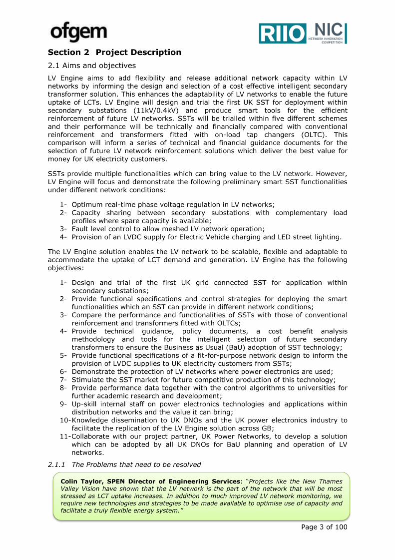
LV Engine will carry out a globally innovative trial of Solid State
Transformers (SSTs) within the distribution network at secondary
substations (11kV/0.4kV) for the purpose of enhancing network
flexibility and releasing additional capacity within our existing low
voltage (LV) infrastructure and facilitating the increasing uptake of Low
Carbon Technologies (LCTs).
1.3 Funding licensee
SP Manweb plc. supported by SP Distribution plc.
1.4 Project
description
Problem: The UK electricity network is experiencing a significant
change in the way electricity is generated and consumed due to the
growing uptake of LCTs and the electrification of heat and transport
resulting in:
A strain on the LV network leading to network operation out with
voltage statutory limits and thermal capacity of network assets;
Inability to ensure cost effective network design due to
uncertainty in uptake of LCTs;
An increasing demand for LVDC and the associated benefits.
These developments mean that a conventional ‘fit-and-forget’ approach
no longer represents value for money for UK electricity consumers.
Method: LV Engine intends to carry out a network trial of SSTs within
secondary substations and compare their effectiveness in supporting
the LV network with conventional 11kV/0.4kV transformers. The
outcomes of this trial will lead to technical guidance documents and
methodologies to inform the optimal selection of secondary
transformers and the functionality required at secondary substations
given the local LV network characteristics and requirements.
Solution: LV Engine will significantly enhance the flexibility and
adaptability of LV networks to facilitate the uptake of LCTs whilst
avoiding costly network reinforcement. LV Engine will enable the
following:
Active operation of LV networks;
Better utilisation of existing network infrastructure;
Facilitate the integration of LCTs at LVAC & LVDC;
Support the DSO transition.
Benefits: LV Engine will deliver savings to customers by enabling the
uptake of LCTs within the 11kV & LV networks. The project will
demonstrate how SSTs can be a more competitive alternative to
conventional reinforcement, whilst stimulating a competitive market
place for power electronics & SSTs within UK distribution networks.
If successful, the roll out of the LV Engine solution at GB level could
represent a saving of £62m by 2030 & £528m by 2050. Valuable
learning will also be generated for future SST and LVDC projects.

Page 2 of 100
1.5 Funding
1.5.1 NIC
Funding Request
(£k) 7,290.06
1.5.2 Network
Licensee
Compulsory
Contribution (£k)
824.16
1.5.3 Network
Licensee Extra
Contribution (£k)
0.0
1.5.4 External
Funding –
excluding from
NICs (£k):
53.69
1.5.5 Total
Project Costs
(£k)
8,295.28
1.6 List of
Project Partners, External
Funders and Project
Supporters (and value of
contribution)
Project Partners: UK Power Networks will be project partner and
member of our design authority board. Manufacturing partner(s) and
a lead consultancy will be identified upon funding award through a
competitive tendering process to ensure the project delivers value
for money to UK electricity customers.
Academic Partners: Extensive engagement has taken place with
academic institutes to identify potential project partners. Academic
partners who represent value for money will be selected during
project set up.
Project Supporters: Power Electronics UK, Glasgow City Council,
ETH Zurich, Kiel University, Heriot Watt University, University of
Strathclyde, WSP, BRE, PNDC, BSI, IEC, IET, Direct Current BV,
Franklin Energy, Chargemaster.
1.7 Timescale
1.7.1 Project
Start Date January 2018 1.7.2 Project End
Date December 2022
1.8 Project Manager Contact Details
1.8.1 Contact
Name & Job
Title
Anthony
Donoghue,
Innovation
Engineer
1.8.2 Email
& Telephone
Number
+441416146904
1.8.3 Contact
Address Ochil House, Technology Ave, Blantyre, Glasgow G72 0HT
1.9 Cross Sector Projects – N/A
1.9.1 Funding requested the from the [Gas/Electricity]
NIC (£k, please state which other competition) N/A
1.9.2 Please confirm whether or not this
[Gas/Electricity] NIC Project could proceed in the
absence of funding being awarded for the other Project.
N/A
1.10 Technology Readiness Level (TRL)
1.10.1 TRL at
Project Start Date 5 1.10.2 TRL at
Project End Date 8
Page 3 of 100
Section 2 Project Description
2.1 Aims and objectives
LV Engine aims to add flexibility and release additional network capacity within LV
networks by informing the design and selection of a cost effective intelligent secondary
transformer solution. This enhances the adaptability of LV networks to enable the future
uptake of LCTs. LV Engine will design and trial the first UK SST for deployment within
secondary substations (11kV/0.4kV) and produce smart tools for the efficient
reinforcement of future LV networks. SSTs will be trialled within five different schemes
and their performance will be technically and financially compared with conventional
reinforcement and transformers fitted with on-load tap changers (OLTC). This
comparison will inform a series of technical and financial guidance documents for the
selection of future LV network reinforcement solutions which deliver the best value for
money for UK electricity customers.
SSTs provide multiple functionalities which can bring value to the LV network. However,
LV Engine will focus and demonstrate the following preliminary smart SST functionalities
under different network conditions:
1- Optimum real-time phase voltage regulation in LV networks;
2- Capacity sharing between secondary substations with complementary load
profiles where spare capacity is available;
3- Fault level control to allow meshed LV network operation;
4- Provision of an LVDC supply for Electric Vehicle charging and LED street lighting.
The LV Engine solution enables the LV network to be scalable, flexible and adaptable to
accommodate the uptake of LCT demand and generation. LV Engine has the following
objectives:
1- Design and trial of the first UK grid connected SST for application within
secondary substations;
2- Provide functional specifications and control strategies for deploying the smart
functionalities which an SST can provide in different network conditions;
3- Compare the performance and functionalities of SSTs with those of conventional
reinforcement and transformers fitted with OLTCs;
4- Provide technical guidance, policy documents, a cost benefit analysis
methodology and tools for the intelligent selection of future secondary
transformers to ensure the Business as Usual (BaU) adoption of SST technology;
5- Provide functional specifications of a fit-for-purpose network design to inform the
provision of LVDC supplies to UK electricity customers from SSTs;
6- Demonstrate the protection of LV networks where power electronics are used;
7- Stimulate the SST market for future competitive production of this technology;
8- Provide performance data together with the control algorithms to universities for
further academic research and development;
9- Up-skill internal staff on power electronics technologies and applications within
distribution networks and the value it can bring;
10- Knowledge dissemination to UK DNOs and the UK power electronics industry to
facilitate the replication of the LV Engine solution across GB;
11- Collaborate with our project partner, UK Power Networks, to develop a solution
which can be adopted by all UK DNOs for BaU planning and operation of LV
networks.
2.1.1 The Problems that need to be resolved
Colin Taylor, SPEN Director of Engineering Services: “Projects like the New Thames Valley Vision have shown that the LV network is the part of the network that will be most stressed as LCT uptake increases. In addition to much improved LV network monitoring, we require new technologies and strategies to be made available to optimise use of capacity and facilitate a truly flexible energy system.”
Page 4 of 100
The electricity network in the UK is experiencing significant changes in the way energy is
generated and consumed due to the growing integration of LCTs. The UK government’s
intention to electrify the transportation and heating sectors will result in an increase in
network demand despite improvements in energy efficiency. The growing connection of
distributed generation (DG) is also causing an additional strain on the LV network. The
conventional “fit-and-forget” approach to the design of our LV networks is no longer a
cost effective solution to accommodate an increasing uptake in LCTs. Conventional
network reinforcement does not represent value for money for our electricity customers
for the following reasons:
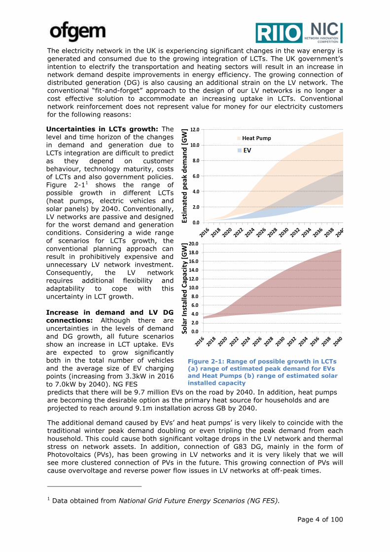
Uncertainties in LCTs growth: The
level and time horizon of the changes
in demand and generation due to
LCTs integration are difficult to predict
as they depend on customer
behaviour, technology maturity, costs
of LCTs and also government policies.
Figure 2-11 shows the range of
possible growth in different LCTs
(heat pumps, electric vehicles and
solar panels) by 2040. Conventionally,
LV networks are passive and designed
for the worst demand and generation
conditions. Considering a wide range
of scenarios for LCTs growth, the
conventional planning approach can
result in prohibitively expensive and
unnecessary LV network investment.
Consequently, the LV network
requires additional flexibility and
adaptability to cope with this
uncertainty in LCT growth.
Increase in demand and LV DG
connections: Although there are
uncertainties in the levels of demand
and DG growth, all future scenarios
show an increase in LCT uptake. EVs
are expected to grow significantly
both in the total number of vehicles
and the average size of EV charging
points (increasing from 3.3kW in 2016
to 7.0kW by 2040). NG FES
Figure 2-1: Range of possible growth in LCTs (a) range of estimated peak demand for EVs and Heat Pumps (b) range of estimated solar
installed capacity
predicts that there will be 9.7 million EVs on the road by 2040. In addition, heat pumps
are becoming the desirable option as the primary heat source for households and are
projected to reach around 9.1m installation across GB by 2040.
The additional demand caused by EVs’ and heat pumps’ is very likely to coincide with the
traditional winter peak demand doubling or even tripling the peak demand from each
household. This could cause both significant voltage drops in the LV network and thermal
stress on network assets. In addition, connection of G83 DG, mainly in the form of
Photovoltaics (PVs), has been growing in LV networks and it is very likely that we will
see more clustered connection of PVs in the future. This growing connection of PVs will
cause overvoltage and reverse power flow issues in LV networks at off-peak times.
1 Data obtained from National Grid Future Energy Scenarios (NG FES).
0.0
2.0
4.0
6.0
8.0
10.0
12.0
2015 2017 2019 2021 2023 2025 2027 2029 2031 2033 2035 2037 2039
Axi
s T
itle
Chart Title
0
2
4
6
8
10
12
2015 2017 2019 2021 2023 2025 2027 2029 2031 2033 2035 2037 2039
0.0
2.0
4.0
6.0
8.0
10.0
12.0
2016 2018 2020 2022 2024 2026 2028 2030 2032 2034 2036 2038 2040
Peak Demand [GW]
Esti
mat
ed
pea
k d
eman
d [
GW
]
0.0
2.0
4.0
6.0
8.0
10.0
12.0
Heat Pump
Peak Demand [GW]
0.0
2.0
4.0
6.0
8.0
10.0
12.0
Heat Pump
Peak Demand [GW]
Sola
r In
stal
led
Cap
acit
y [G
W]
0.0
2.0
4.0
6.0
8.0
10.0
12.0
14.0
16.0
18.0
20.0
Page 5 of 100
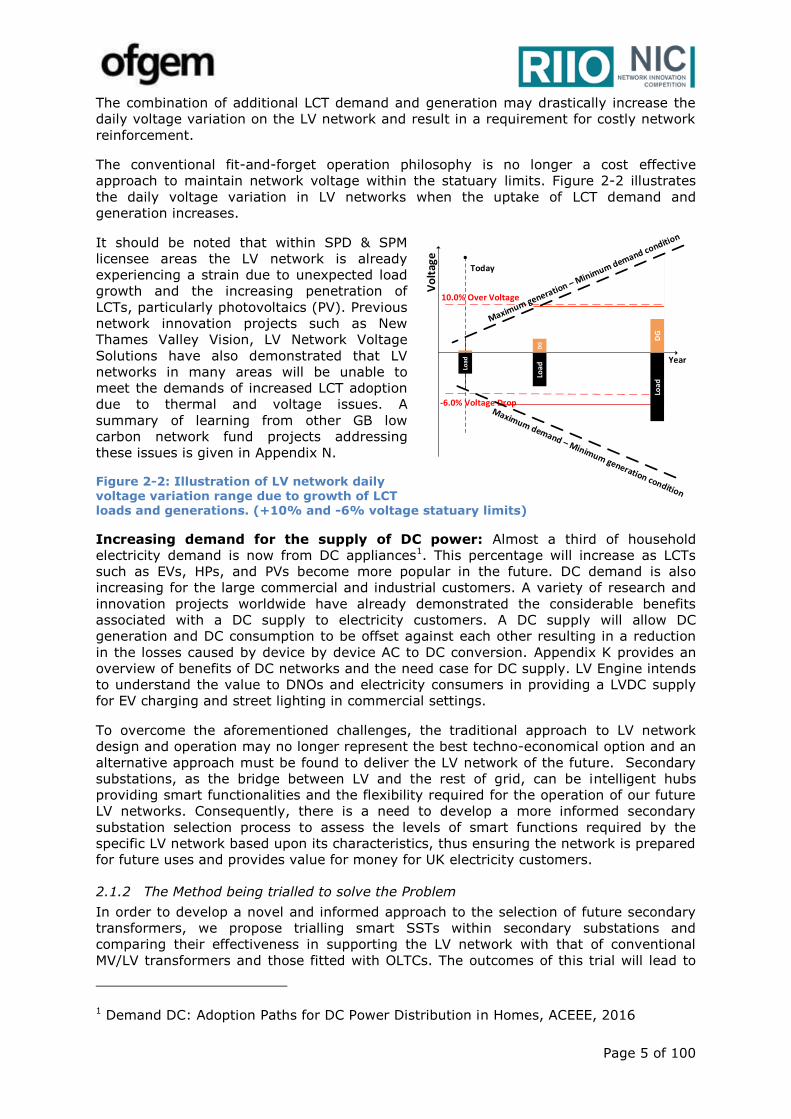
The combination of additional LCT demand and generation may drastically increase the
daily voltage variation on the LV network and result in a requirement for costly network
reinforcement.
The conventional fit-and-forget operation philosophy is no longer a cost effective
approach to maintain network voltage within the statuary limits. Figure 2-2 illustrates
the daily voltage variation in LV networks when the uptake of LCT demand and
generation increases.
It should be noted that within SPD & SPM
licensee areas the LV network is already
experiencing a strain due to unexpected load
growth and the increasing penetration of
LCTs, particularly photovoltaics (PV). Previous
network innovation projects such as New
Thames Valley Vision, LV Network Voltage
Solutions have also demonstrated that LV
networks in many areas will be unable to
meet the demands of increased LCT adoption
due to thermal and voltage issues. A
summary of learning from other GB low
carbon network fund projects addressing
these issues is given in Appendix N.
Figure 2-2: Illustration of LV network daily
voltage variation range due to growth of LCT loads and generations. (+10% and -6% voltage statuary limits)
Increasing demand for the supply of DC power: Almost a third of household
electricity demand is now from DC appliances1. This percentage will increase as LCTs
such as EVs, HPs, and PVs become more popular in the future. DC demand is also
increasing for the large commercial and industrial customers. A variety of research and
innovation projects worldwide have already demonstrated the considerable benefits
associated with a DC supply to electricity customers. A DC supply will allow DC
generation and DC consumption to be offset against each other resulting in a reduction
in the losses caused by device by device AC to DC conversion. Appendix K provides an
overview of benefits of DC networks and the need case for DC supply. LV Engine intends
to understand the value to DNOs and electricity consumers in providing a LVDC supply
for EV charging and street lighting in commercial settings.
To overcome the aforementioned challenges, the traditional approach to LV network
design and operation may no longer represent the best techno-economical option and an
alternative approach must be found to deliver the LV network of the future. Secondary
substations, as the bridge between LV and the rest of grid, can be intelligent hubs
providing smart functionalities and the flexibility required for the operation of our future
LV networks. Consequently, there is a need to develop a more informed secondary
substation selection process to assess the levels of smart functions required by the
specific LV network based upon its characteristics, thus ensuring the network is prepared
for future uses and provides value for money for UK electricity customers.
2.1.2 The Method being trialled to solve the Problem
In order to develop a novel and informed approach to the selection of future secondary
transformers, we propose trialling smart SSTs within secondary substations and
comparing their effectiveness in supporting the LV network with that of conventional
MV/LV transformers and those fitted with OLTCs. The outcomes of this trial will lead to
1 Demand DC: Adoption Paths for DC Power Distribution in Homes, ACEEE, 2016
Loa
d
Loa
d
DG
DG
Year
Vo
ltag
e
Load
-6.0% Voltage Drop
10.0% Over Voltage
Today
Page 6 of 100
technical guidance documents, policy documents and methodologies which will inform
the optimal selection of the controllability required at secondary substations given the
local and neighbouring LV networks requirements.
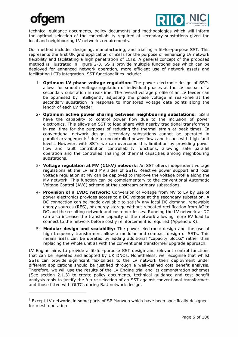
Our method includes designing, manufacturing, and trialling a fit-for-purpose SST. This
represents the first UK grid application of SSTs for the purpose of enhancing LV network
flexibility and facilitating a high penetration of LCTs. A general concept of the proposed
method is illustrated in Figure 2-3. SSTs provide multiple functionalities which can be
deployed for enhanced network operation, more efficient use of network assets and
facilitating LCTs integration. SST functionalities include:
1- Optimum LV phase voltage regulation: The power electronic design of SSTs
allows for smooth voltage regulation of individual phases at the LV busbar of a
secondary substation in real-time. The overall voltage profile of an LV feeder can
be optimised by intelligently adjusting the phase voltage in real-time at the
secondary substation in response to monitored voltage data points along the
length of each LV feeder.
2- Optimum active power sharing between neighbouring substations: SSTs
have the capability to control power flow due to the inclusion of power
electronics. This allows an SST to load share with nearby traditional transformers
in real time for the purposes of reducing the thermal strain at peak times. In
conventional network design, secondary substations cannot be operated in
parallel arrangements1 due to uncontrolled power flows and issues with high fault
levels. However, with SSTs we can overcome this limitation by providing power
flow and fault contribution controllability functions, allowing safe parallel
operation and the controlled sharing of thermal capacities among neighbouring
substations.
3- Voltage regulation at MV (11kV) network: An SST offers independent voltage
regulations at the LV and MV sides of SSTs. Reactive power support and local
voltage regulation at MV can be deployed to improve the voltage profile along the
MV network. This function can be complementary to the conventional Automatic
Voltage Control (AVC) scheme at the upstream primary substations.
4- Provision of a LVDC network: Conversion of voltage from MV to LV by use of
power electronics provides access to a DC voltage at the secondary substation. A
DC connection can be made available to satisfy any local DC demand, renewable
energy sources (RES), or energy storage without repeated rectification from AC to
DC and the resulting network and customer losses. Running the LV network at DC
can also increase the transfer capacity of the network allowing more EV load to
connect to the network before costly reinforcement is required (Appendix K).
5- Modular design and scalability: The power electronic design and the use of
high frequency transformers allow a modular and compact design of SSTs. This
means SSTs can be uprated by adding additional “capacity blocks” rather than
replacing the whole unit as with the conventional transformer upgrade approach.
LV Engine aims to provide a fit-for-purpose SST design and relevant control functions
that can be repeated and adopted by UK DNOs. Nonetheless, we recognise that whilst
SSTs can provide significant flexibilities to the LV network their deployment under
different applications should be justified through a well-defined cost benefit analysis.
Therefore, we will use the results of the LV Engine trial and its demonstration schemes
(See section 2.1.3) to create policy documents, technical guidance and cost benefit
analysis tools to justify the future selection of an SST against conventional transformers
and those fitted with OLTCs during BaU network design.
1 Except LV networks in some parts of SP Manweb which have been specifically designed
for mesh operation
Page 7 of 100
Figure 2-3: The high level functionalities of a SST considered in LV Engine’s method
2.1.3 The Development or Demonstration being undertaken
We plan to demonstrate the SST performance in different schemes where different
network issues or customer requirements need to be addressed. In order to provide an
adequate level of technical and financial knowledge for applications of SSTs, five
different schemes will be implemented within LV Engine.
These demonstration schemes are designed to provide distinctive learning which can
inform the adoption of SSTs as one of the BaU reinforcement options. Each scheme
requires its own technical specification, control algorithms, communication techniques,
and monitoring methodology. We will collate the learning from the five schemes to form
a policy document and best operational practice guidance which also includes cost
benefit analysis tools. This will inform a cost-effective and technically-sound selection of
the intelligence required at a secondary substation given the characteristics of the
specific LV network. One trial of each scheme will be considered and each scheme will be
trialled in different parts of SPD and SPM where we can adequately demonstrate the
functionalities of SSTs without risking supply to our network customers. An overview of
each trial scheme is as follows:
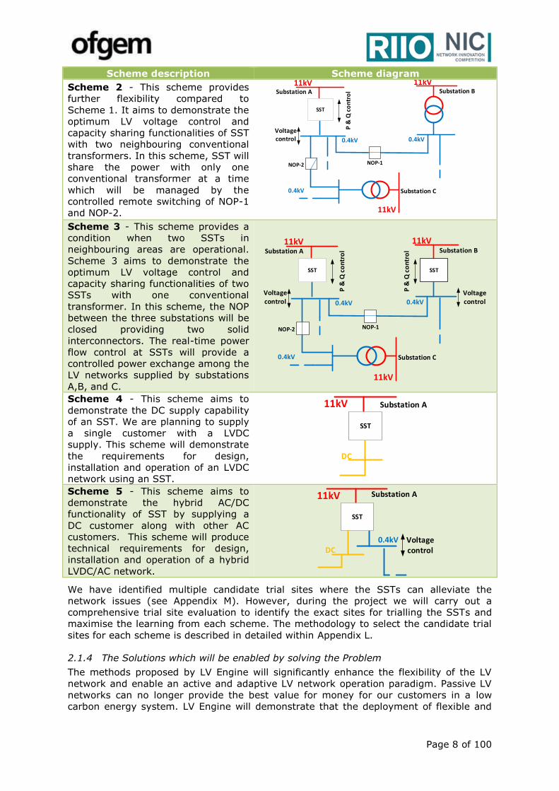
Scheme description Scheme diagram
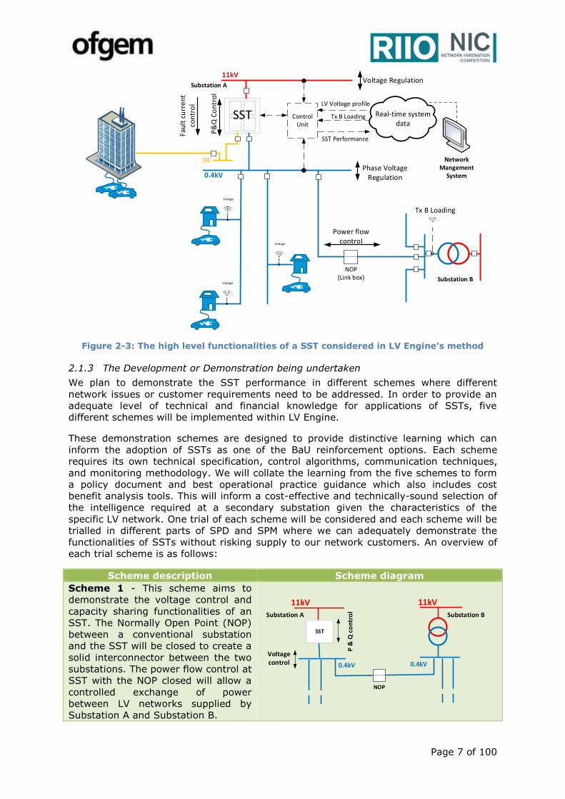
Scheme 1 - This scheme aims to
demonstrate the voltage control and
capacity sharing functionalities of an
SST. The Normally Open Point (NOP)
between a conventional substation
and the SST will be closed to create a
solid interconnector between the two
substations. The power flow control at
SST with the NOP closed will allow a
controlled exchange of power
between LV networks supplied by
Substation A and Substation B.
Control Unit
P&
Q C
on
tro
l
Real-time system data
Phase Voltage Regulation
Voltage Regulation
LV Voltage profile
Power flow control
Voltage
Voltage
Voltage
Tx B Loading
Tx B Loading
Substation A
NOP(Link box) Substation B
11kV
DC
0.4kV
Network Mangement
SystemFa
ult
cu
rre
nt
con
tro
l
SST
SST Performance
SST
Substation A
11kV
Substation B
11kV
NOP
0.4kV0.4kV
P &
Q c
on
tro
l
Voltage control
Page 8 of 100
Scheme description Scheme diagram
Scheme 2 - This scheme provides
further flexibility compared to
Scheme 1. It aims to demonstrate the
optimum LV voltage control and
capacity sharing functionalities of SST
with two neighbouring conventional
transformers. In this scheme, SST will
share the power with only one
conventional transformer at a time
which will be managed by the
controlled remote switching of NOP-1
and NOP-2. Scheme 3 - This scheme provides a
condition when two SSTs in
neighbouring areas are operational.
Scheme 3 aims to demonstrate the
optimum LV voltage control and
capacity sharing functionalities of two
SSTs with one conventional
transformer. In this scheme, the NOP
between the three substations will be
closed providing two solid
interconnectors. The real-time power
flow control at SSTs will provide a
controlled power exchange among the
LV networks supplied by substations
A,B, and C.
Scheme 4 - This scheme aims to
demonstrate the DC supply capability
of an SST. We are planning to supply
a single customer with a LVDC
supply. This scheme will demonstrate
the requirements for design,
installation and operation of an LVDC
network using an SST.
Scheme 5 - This scheme aims to
demonstrate the hybrid AC/DC
functionality of SST by supplying a
DC customer along with other AC
customers. This scheme will produce
technical requirements for design,
installation and operation of a hybrid
LVDC/AC network.
We have identified multiple candidate trial sites where the SSTs can alleviate the
network issues (see Appendix M). However, during the project we will carry out a
comprehensive trial site evaluation to identify the exact sites for trialling the SSTs and
maximise the learning from each scheme. The methodology to select the candidate trial
sites for each scheme is described in detailed within Appendix L.
2.1.4 The Solutions which will be enabled by solving the Problem
The methods proposed by LV Engine will significantly enhance the flexibility of the LV
network and enable an active and adaptive LV network operation paradigm. Passive LV
networks can no longer provide the best value for money for our customers in a low
carbon energy system. LV Engine will demonstrate that the deployment of flexible and
SST
Substation A 11kV
Substation B 11kV
NOP-1
Substation C
11kV
NOP-2
0.4kV 0.4kV
0.4kV
P &
Q c
on
tro
l
Voltage control
SST
Substation A 11kV
Substation B 11kV
NOP-1
Substation C
11kV
NOP-2
SST
0.4kV 0.4kV
0.4kV
P &
Q c
on
tro
l
Voltage control
P &
Q c
on
tro
l
Voltage control
SST
Substation A 11kV
DC
SST
Substation A 11kV
DC0.4kV Voltage
control

Page 9 of 100
smart secondary substations can be a superior alternative to conventional reinforcement.
The design, manufacturing and proof of technology of a SST will also create a
competitive market reducing the SST cost while improving quality.
The LV Engine will enable the following solutions:
Active operation of LV networks - An active and adaptive LV network
operation scheme is required to accommodate the long-term and short-term
uncertainties in LV customers’ demand and generation; otherwise significant
network reinforcement will be required to keep the network operational. LV
Engine methodologies offer active real-time phase voltage regulation and capacity
sharing capabilities which can be flexibly deployed to meet the customers’ needs
and grid requirements. LV Engine will also enable an adaptable network by
providing a scalable secondary substation design.
Better utilisation of network assets – The LV Engine method enables an
alternative solution to conventional reinforcements, the cost of which may
increase significantly during RIIO-ED2 due to growing LCTs integration. LV Engine
will demonstrate how the use of SSTs can release network capacity within our
existing infrastructure to reduce the requirement for this investment.
Facilitate integration of LCTs – The UKs low carbon emission targets depend
on the successful integration of LCTs within the LV network. However, the
clustered integration of LCT demand and generation may be delayed due to
network voltage and thermal issues. The LV Engine solution will facilitate the
connections of LCTs by avoiding the lead time required for network upgrade
through conventional reinforcements. Furthermore, an LVDC supply could act as
an enabler for the faster and more cost effective integration of Electric Vehicle
charging points into the LV network.
Support DSO operation transition – LV Engine will provide the future
Distribution System Operator (DSO) with tools and methodologies for real-time
management of network constraints. That can delay the point at which a DSO will
intervene or make requests customers to adjust their behaviour. In addition,
managing network constraints can facilitate the access to market for energy
aggregators and allow them to offer various services to our LV customers.
2.2 Technical description of Project
2.2.1 Solid State Transformer topology
There is considerable interest in the development of SSTs within academia and by
manufacturers, who both see the potential for such devices within the power distribution
networks of the future. Many topologies have been proposed for SSTs1 and our initial
engagement with manufacturers has also confirmed that there are a number of viable
topologies which could be used to implement a SST. Appendix G provides some technical
details of SST design. The key features of a SST can comprise of the following blocks:
A converter from AC to DC which will be connected to the SP Energy Networks
11kV three-phase distribution supply;
A DC stage, which can supply multiple output stages at both AC and DC voltages;
A DC to DC converter, which can provide a desirable DC supply;
A DC to AC converter, which can provide an AC (0.4kV) three-phase supply;
1 Solid-State-Transformers: Key Components of Future Traction and Smart Grid Systems, IPEC 2014.
Concepts, modelling, applications, advantages and challenges, Power Electronics for Grid Connected Renewable Energy Systems, 2015.

Page 10 of 100
A high/medium frequency transformer, which provides the required step-down in
voltage of the SST and also ensures galvanic isolation between the Medium
Voltage (11kV) and Low Voltage (0.4kV AC and DC) systems.
2.2.2 LV ENGINE is an innovation project
LV Engine is highly innovative and we are expecting significant learning to be generated
in this project for a flexible and controllable LV network. The innovation aspects of LV
Engine are fourfold:
SST manufacturing and design - LV Engine will design, manufacture and trial
the world’s first grid connected SST (to our best knowledge). The TRL of SSTs for
grid applications is considered to be 5, as numerous prototype devices have been
through laboratory trials. There are still several technical and operational
challenges for a SST grid application which require to be addressed before BaU
adoption. LV Engine aims to enhance the SST TRL to 8.
Controllability in LV network - The control algorithms and functionalities of the
schemes considered within LV Engine including phase voltage control and capacity
sharing are unique and innovative.
Trial of LVDC network - LV Engine will trial an LVDC network for the purpose of
supplying street lighting and EV charging points. This has not been trialled by any
UK DNOs before. However, LVDC is a promising solution for connection of many
LCTs. LV Engine will provide valuable learning and technical requirements for the
future deployment of LVDC networks and allow DNOs to understand when and
how it can reduce network reinforcement.
Methodology of future transformer selection - A methodology for selecting
the optimal transformer which considers the outcomes of the LV Engine schemes,
conventional transformers and also transformers fitted with OLTC will provide the
most technically capable and cost effective reinforcement solution.
2.3 LV ENGINE Work Packages
LV Engine is planned to be managed within seven work packages (WP). The separate
work packages are designed to give focus to the major activities and developments
required for the successful delivery of LV Engine.
Table 2-1: LV Engine work package description
WP 1 – Technical design Duration: Mar 2018- Nov 2018
Objectives: Develop the detailed technical specifications which will be required for
manufacturing and implementation of the LV Engine solution and identify trial sites.
Description: The site selection methodology described in Appendix L will be modified
where required and a fresh site selection will be carried out to identify the trial sites for
each LV Engine scheme. The technical specifications of SSTs including control
algorithms, operation ranges, component ratings, size and enclosure, and maintenance
requirements will be developed in this WP. The technical specifications of SSTs will be
developed based on each LV Engine’s scheme operational requirements. The
performance of SST in different network conditions and the specification of the control
algorithms will be assessed through desktop simulation of the identified trial sites. We
will engage with experts, academics, manufacturers and UK Power Networks prior to
procurement to ensure that the developed technical specifications are fit-for-purpose and
manufacturing risks and mitigation plans have been identified. Apart from SST, each trial
scheme has its own requirements in terms of system architecture, monitoring
equipment, protection schemes, communication technologies and detailed site
preparation. We will develop the technical specification of each scheme and its
components in this WP. The reliability of the scheme as a whole will be evaluated to
ensure there is no impact on customers’ security of supply. In addition, we will ensure
that the operational performance of each scheme can be monitored remotely and all the

Page 11 of 100
field data is collected in a SP Energy Networks historian database for further
performance analysis. WP 2 – Partner selection and procurement Duration: Sep 2018- Feb 2020
Objectives: Select the manufacturing partner through a competitive tendering process
and also procure the equipment required for LV Engine schemes.
Description: This work package includes all the activities to procure LV Engine scheme
equipment and conduct a competitive tendering for selecting partners for the SST design
and manufacturing. We will build upon the manufacturing engagement conducted during
proposal preparation and carry out further market research to identify leading
manufacturers. We will develop detailed evaluation criteria specifically for LV Engine
project based on its requirements and our experience from previous innovation projects
to ensure we identify partners who maximise value for money. WP 3 – Design & Manufacturing of SSTs Duration: Feb 2019 - Dec 2020
Objectives: Design and manufacture a fit-for-purpose SST based on the technical
requirements and functionalities developed in WP 1.
Description: This WP includes collaboration between SP Energy Networks and the
manufacturing partner(s) to design and manufacture the SSTs required for each LV
Engine scheme according to the technical specifications created within WP 1. The various
design options and parameters will be optimised to deliver an SST which is fit-for-
purpose for deployment within a distribution network and represents a balance between
performance, reliability and cost. These design parameters include material choice,
topology, number of redundant modules, control algorithms etc. This work package also
includes various factory acceptance tests on the manufactured SSTs. The tests required
will be determined within WP 1 and during the design stage in WP 3 to ensure a quality
assured product is delivered for network trial. Furthermore, a detailed life cycle analysis
will be carried out to assess the SST environmental impact. WP 4 – Network Integration Testing Duration: Oct 2019 - Aug 2020
Objectives: Test the functionalities and reliability of the manufactured SST in a network
integration facility and obtain network integration certificate.
Description: In addition to the factory acceptance tests scheduled in WP 3 and in order
to boost confidence in SST operation and reduce the risk of SST failure we will carry out
network integration testing of the manufactured SST. This will be undertaken prior to the
live trial within the real network. The purpose of this testing is to demonstrate the SST
performance within a replica 11kV and LV network with mock customers’ demand and
generation behaviour. The detailed of test schedules and the test network conditions will
be developed in WP 1 and WP 3. If we identify any issue in SST performance, the
manufacturer will fix the issue on site or the SST will be shipped back to the factory for
troubleshooting, diagnostics and any design refinement where required. As two distinct
SST designs will be trialled within LV Engine, the tests will be carried out on both SST
prototypes (hybrid AC/DC output and one with DC output only). WP 5 – Live Network Trial Duration: Nov 2019 - Oct 2022
Objectives: Install and commission the LV Engine schemes and monitor their
performance.
Description: This WP includes all the activities required for the site preparation,
installation, commissioning and performance monitoring of the SST schemes. The
system architecture and communication solutions designed in WP 1 will be installed at
the designated trial sites. Following the successful network integration testing within WP
4, Scheme 1 will be installed and commissioned after satisfying the required site
acceptance tests. A staggered installation of each scheme will be implemented with one
month between each installation. This will provide us with an opportunity to implement
any refinements and lessons learnt from previous installations before the installation and
commissioning of the remaining schemes.
It should be noted that in order to eliminate any adverse impact on the customers, the
existing conventional transformers will be maintained in the secondary substations. The
Page 12 of 100
necessary switch over arrangement will be implemented to bring the conventional
transformers back to service in case SSTs fail to operate. This work package will also
include the installation of the voltage monitoring equipment within customer premises if
required by each trial scheme.
After commissioning, we will collect the performance data under each scheme to
evaluate the impact on the network and demonstrate the unlocked network capacity.
Additional live tests such as forced power flow variation and voltage adjustments at LV
and MV will be also carried to evaluate the performance of each scheme. These tests will
aim to provide adequate evidence and data to inform WP 6 for developing a novel
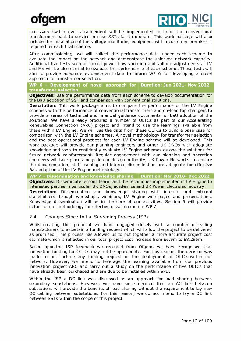
approach for transformer selection. WP 6 - Development of novel approach for
transformer selection
Duration: Jun 2021- Nov 2022
Objectives: Use the performance data from each scheme to develop documentation for
the BaU adoption of SST and comparison with conventional solutions.
Description: This work package aims to compare the performance of the LV Engine
schemes with the performance of conventional transformers and on-load tap changers to
provide a series of technical and financial guidance documents for BaU adoption of the
solutions. We have already procured a number of OLTCs as part of our Accelerating
Renewables Connection (ARC) project and intend to use the learnings available from
these within LV Engine. We will use the data from these OLTCs to build a base case for
comparison with the LV Engine schemes. A novel methodology for transformer selection
and the best operational practices for each LV Engine scheme will be developed. This
work package will provide our planning engineers and other UK DNOs with adequate
knowledge and tools to confidently evaluate LV Engine schemes as one the solutions for
future network reinforcement. Regular engagement with our planning and operation
engineers will take place alongside our design authority, UK Power Networks, to ensure
the documentation, staff training and internal dissemination are adequate for effective
BaU adoption of the LV Engine methodology. WP 7 – Dissemination and knowledge sharing Duration: Mar 2018- Dec 2022
Objectives: Disseminate lessons learnt and the techniques implemented in LV Engine to
interested parties in particular UK DNOs, academics and UK Power Electronic industry.
Description: Dissemination and knowledge sharing with internal and external
stakeholders through workshops, webinars, LV Engine web pages and presentations.
Knowledge dissemination will be in the core of our activities. Section 5 will provide
details of our methodology for effective dissemination in WP 7.
2.4 Changes Since Initial Screening Process (ISP)
Whilst creating this proposal we have engaged closely with a number of leading
manufacturers to ascertain a funding request which will allow the project to be delivered
as promised. This process has allowed us to put together a more accurate project cost
estimate which is reflected in our total project cost increase from £6.9m to £8.295m.
Based upon the ISP feedback we received from Ofgem, we have recognised that
innovation funding for OLTCs may not be appropriate. For this reason, the decision was
made to not include any funding request for the deployment of OLTCs within our
network. However, we intend to leverage the learning available from our previous
innovation project ARC and carry out a study on the performance of five OLTCs that
have already been purchased and are due to be installed within SPD.
Within the ISP a DC link was discussed as an approach for load sharing between
secondary substations. However, we have since decided that an AC link between
substations will provide the benefits of load sharing without the requirement to lay new
DC cabling between substations. For this reason, we do not intend to lay a DC link
between SSTs within the scope of this project.
Page 13 of 100
Section 3 Project business case
3.1 Overview
The increasing uptake of LCTs is causing a strain on LV networks and driving the need
for costly network reinforcement. However, these technologies are critical to achieve the
UK Governments targets to reduce carbon emissions by 80% by 2050 whilst
decarbonising the heat and transport sectors. Multiple studies, for example SSEPD’s New
Thames Valley Vision project, have indicated that a significant percentage of the LV
network will require reinforcement due to the uptake of LCTs.
In addition, there is much uncertainty surrounding the scale, timing and locality of LCT
uptake across the UK. For this reason, DNOs must be prepared for a variety of future
scenarios and be equipped with the flexibility required to overcome the challenges they
will present. Traditional LV reinforcement methodologies often include laying new cable
and constructing new secondary substations to overcome voltage and thermal
constraints associated with new LCT connections. This costly and lengthy approach to
reinforcement may no longer represent value to UK electricity customers. It also causes
significant disruption to the public when excavating and reinstating roads and pavements
in active urban areas. A more innovative and cost effective approach is required.
LV Engine will uncover new and innovative approaches to unlock the capacity available
within our existing LV infrastructure and facilitate the uptake of LCTs on the scale
demanded by society, whilst providing the flexibility required due to the uncertainty
surrounding the nature and timing of their uptake. If rolled out across GB, LV Engine has
the potential to deliver capacity for the connection of low carbon technologies, provide
environmental benefits and net financial benefits to customers as follows:
The total financial benefit of £62m by 2030 and £528m by 2050;
Reduce CO2 emissions by 418,307 tonnes by 2030 and 1,314,050 tonnes by
2050;
Reduce system losses and network reinforcement by facilitating a future LVDC
supply for our LV customers.
Value for money for electricity customers is demonstrated by the pay back of the full
funding requested for LV Engine within 7 years from the start of the project.
3.2 LV ENGINE is in line with SP Energy Networks’ Innovation Strategy
SP Energy Networks believe innovation1 is critical to deliver the energy networks of the
future which can facilitate the changes in how the network is being used whilst providing
value for money to our customers. The LV Engine proposal addresses one of the specific
priorities of the SP Energy Networks’ Innovation Strategy which is preparing the network
for low carbon technologies. The trialling of cutting-edge technologies to bring a fresh
approach to selecting fit-for-purpose secondary transformers is in accordance to the
company’s ethos of: “think big, start small, scale fast.”
LV Engine matches one of SP Energy Network’s three innovation areas, specifically
Technology Innovation. The use of the SST is in accordance with the intention within this
area to use new assets, whilst the development of the capability to share power flows
between LV substations will make progress towards the objective to operate the network
more dynamically.
LV Engine builds on the findings of previous network automation innovation projects
whilst also exploring opportunities to reduce system losses with the provision of a LVDC
supply.
1 https://www.SPEnergyNetworksergynetworks.co.uk/userfiles/file/201403SPEnergy
NetworksInnovationStrategyMH.pdf
Page 14 of 100
3.3 The LV Engine benefits
LV Engine proposes a new and innovative approach to LV network reinforcement that will
provide additional network capacity at less cost and more quickly. The project will
demonstrate how SSTs can release network capacity within our existing network
infrastructure and lay the ground works for an adaptable and flexible LV network which
includes a ground breaking low voltage DC supply to our customers.
Optimised & independent voltage control – LV Engine will provide automated and
optimised voltage control of each phase thus overcoming constraints due to the limited
voltage control in existing LV networks. Monitoring of voltage at strategic points along LV
feeders will allow an SST to intelligently adjust voltage at the LV busbar to best support
the voltage profile along the length of the feeders. Thus more LCT connections could be
accommodated on existing LV circuits whilst maintaining voltages within statutory
limits.
Automated load sharing between transformers – LV Engine will provide additional
network capacity in existing networks by controlling power flow between transformers.
Building upon the learning of UK Power Network’s project “FUN LV”, LV Engine will use
an SST to allow multiple transformers to load share across LV feeders to defer or discard
the requirement for reinforcement due to load growth.
DC Supplies – LV Engine inherently facilitates DC supplies which could be used to
satisfy the increasing demand from DC devices. A significant increase in efficiency is
realised by directly supplying these loads with DC and eliminating the repeated
rectification between AC and DC. Strategically providing DC supplies will provide
increasing benefits as DC demand is expected to grow; specifically electronic DC devices,
lighting technologies which convert AC to DC and the demand from DC EV charging
points are all forecasted to increase.
Phase Balancing – LV Engine offers increased capacity and reduction in losses by
providing the ability to balance loading on the phases on the HV side of the SST,
correcting any LV unbalance that would otherwise be transferred upstream.
3.4 LV Engine Business Case
3.4.1 Business Case methodology
A case study exploring the reinforcement necessary to accommodate LCT uptake has
been used to quantify the LV Engine business case. Using this case study we have
compared the Base Case reinforcement approach to that proposed by LV Engine as
detailed in Appendix C.
For the financial analysis, Base Case and LV Engine method lifetime costs, comprising
both Capex and Opex, were attained based upon the requirements of the case study. LV
Engine cost estimates were based upon detailed guidance from manufacturers which
allow for a reduction in unit price as production volumes and TRL continue to increase.
Specifically, the method capex cost is £115.0k in 2023 falling to £62.0k by 2045 at
which we assumed the capex cost remains unchanged in the following years. The Base
Case capex cost of £149.0k is based upon SP Energy Network’s unit cost manual and
consultation with our design engineers drawing on extensive experience of implementing
traditional reinforcement schemes.
Benefits corresponding to the roll out of LV Engine to SP Energy Network and GB were
evaluated based on an estimate of the number of GMTs where LV Engine could be used
to resolve voltage issues. In addition, we have factored in a generous market share to
account for the uptake of other emerging smart solutions which may compete with the
LV Engine methods.
To ensure that our financial analysis is both credible and transparent we have quantified
the key functionalities and benefits associated with SSTs, specifically additional capacity
due to voltage regulation and sharing between substations, because they can be reliably
Page 15 of 100
estimated based upon our current knowledge and understanding. Financial benefits
associated with the provision of DC supplies are not included in the present business
case due to a greater uncertainty regarding the number of applications and their timing.
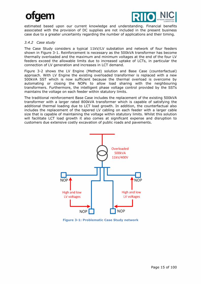
3.4.2 Case study
The Case Study considers a typical 11kV/LV substation and network of four feeders
shown in Figure 3-1. Reinforcement is necessary as the 500kVA transformer has become
thermally overloaded and the maximum and minimum voltages at the end of the four LV
feeders exceed the allowable limits due to increased uptake of LCTs, in particular the
connection of LV generation and increases in LCT demand.
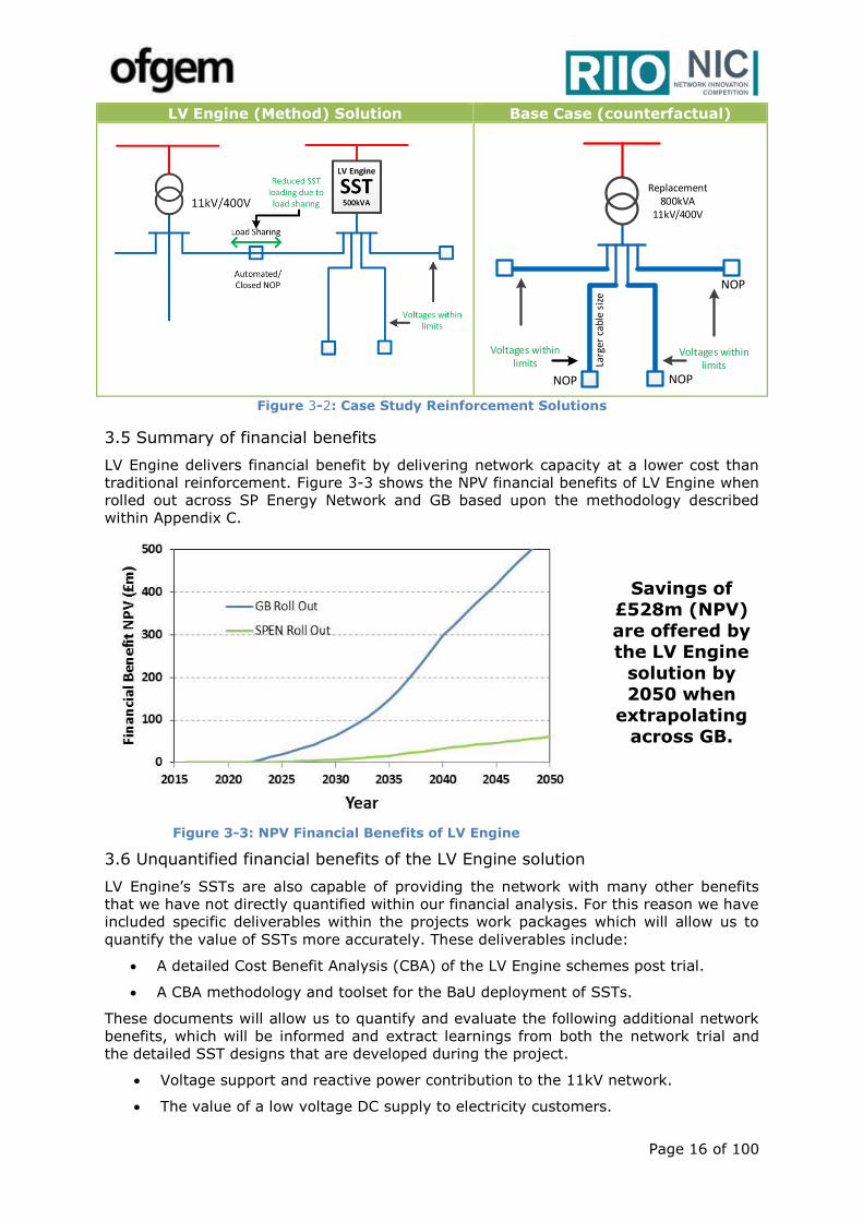
Figure 3-2 shows the LV Engine (Method) solution and Base Case (counterfactual)
approach. With LV Engine the existing overloaded transformer is replaced with a new
500kVA SST which is now sufficient because the thermal overload is overcome by
automating or closing the NOPs to allow load sharing with the neighbouring
transformers. Furthermore, the intelligent phase voltage control provided by the SSTs
maintains the voltage on each feeder within statutory limits.
The traditional reinforcement Base Case includes the replacement of the existing 500kVA
transformer with a larger rated 800kVA transformer which is capable of satisfying the
additional thermal loading due to LCT load growth. In addition, the counterfactual also
includes the replacement of the tapered LV cabling on each feeder with a larger cable
size that is capable of maintaining the voltage within statutory limits. Whilst this solution
will facilitate LCT load growth it also comes at significant expense and disruption to
customers due extensive costly excavation of public roads and pavements.
Figure 3-1: Problematic Case Study network
Page 16 of 100
LV Engine (Method) Solution Base Case (counterfactual)
Figure 3-2: Case Study Reinforcement Solutions
3.5 Summary of financial benefits
LV Engine delivers financial benefit by delivering network capacity at a lower cost than
traditional reinforcement. Figure 3-3 shows the NPV financial benefits of LV Engine when
rolled out across SP Energy Network and GB based upon the methodology described
within Appendix C.
Figure 3-3: NPV Financial Benefits of LV Engine
Savings of £528m (NPV)
are offered by the LV Engine
solution by 2050 when
extrapolating across GB.
3.6 Unquantified financial benefits of the LV Engine solution
LV Engine’s SSTs are also capable of providing the network with many other benefits
that we have not directly quantified within our financial analysis. For this reason we have
included specific deliverables within the projects work packages which will allow us to
quantify the value of SSTs more accurately. These deliverables include:
A detailed Cost Benefit Analysis (CBA) of the LV Engine schemes post trial.
A CBA methodology and toolset for the BaU deployment of SSTs.
These documents will allow us to quantify and evaluate the following additional network
benefits, which will be informed and extract learnings from both the network trial and
the detailed SST designs that are developed during the project.
Voltage support and reactive power contribution to the 11kV network.
The value of a low voltage DC supply to electricity customers.
NOP
Replacement 800kVA
11kV/400V
NOPNOP
Voltages within limits
Voltages within limits La
rger
cab
le s
ize

Page 17 of 100
Capacity increase of SST with modular “capacity banks”
Power quality improvement by operating SST as an active harmonic filter.
Value of any reduction in substation footprint.
Peak shaving by exercising conservation voltage reduction.
3.7 Carbon benefits
Figure 3-4 shows the embedded carbon of the LV Engine solution alongside the
alternative traditional reinforcement approach. The LV Engine method incurs significantly
less embedded carbon than the traditional approach which requires the installation of
more new assets. It also enables the earlier connection of LCTs by 15-18 weeks due to a
quicker reinforcement time when compared to the counterfactual. The benefit of this has
been quantified within the carbon benefit calculation as shown in Figure 3-5.
A contrary impact on carbon arises due to the increased network losses associated with
the LV Engine solution relative to the counterfactual. In addition, SST losses are
expected to be initially greater than the equivalent traditional transformer. A
consequence of the increase in losses due to LV Engine is that operational carbon will be
greater.
Figure 3-5 shows the overall (embedded and operational) carbon impact of LV Engine
compared to the counterfactual evaluated using the methodology in Appendix C. It
should be noted that the financial value of the additional losses is still much less than the
cost of the avoided traditional reinforcement and that it has been reflected in the
aforementioned financial analysis.
Figure 3-4: Embedded carbon comparison
Figure 3-5: Cumulative carbon benefits
3.5 Project risks
A detailed risk register can be seen in Appendix E. The register is based upon the risks
we have identified through discussion with a number of manufacturers, academics and
internal stakeholders and our previous experience of delivering NIA and NIC projects.
Page 18 of 100
Section 4 Benefits, Timeliness, and Partners
4.1 Accelerates the development of a low carbon energy sector and/or delivers environmental benefits whilst having the potential to deliver net financial benefits to future and existing customers
LV Engine aims to facilitate the adoption of LCTs by providing flexibility and
controllability in the LV & MV networks. Passive distribution networks are no longer
always cost effective solutions to accommodate the uncertainty in the generation and
the demand profiles of our customers. LV Engine will trial cutting-edge technologies to
provide a novel approach for selecting fit-for-purpose secondary transformers. The
outcomes of this project can be a model for operation and planning of our future
distribution networks.
Impact on low carbon energy sector and environmental benefits:
As described in Section 3, the LV Engine solution and the counterfactual reinforcement
approach both release adequate additional network capacity to facilitate the future
uptake of LCTs. We have assigned a carbon reduction value to the LV Engine solution in
the form of avoided civil works associated with cable installation and a faster connection
of LCTs. Table 4-1 shows the carbon reduction we expect between 2030-2050
based upon the number of deployment opportunities we have projected.
Table 4-1: LV Engine carbon savings due to avoided civil works
Scale 2030 2040 2050
SPEN Rollout (kt.CO2) 46.99 129.88 147.61
GB Rollout (kt.CO2) 418.31 1,156.21 1,314.05
The outcomes of LV Engine can also contribute to our low carbon energy sector by:
1. Expediting the connection of renewables e.g. PV uptake is often limited due to
voltage issues without costly LV network reinforcement;
2. Reducing the curtailment of the renewables connected to the MV and LV network
due to temporary voltage issues;
3. Providing voltage support to the 11kV network to improve the point of connection
of 11kV LCT developments. Improving the voltage profile along the length of an
11kV feeder may reduce the need for costly overhead lines if a connection at the
primary substation is required, thus improving the financial feasibility of 11kV LCT
projects;
4. Providing local reactive power compensation and reducing the overall network
losses which will ultimately reduce carbon emissions;
5. Expediting the connection of electric vehicles and other LCTs which may benefit
from a LVDC connection;
6. Reducing network losses by providing an LVDC supply to allow DC distributed
generation and consumption to be coordinated without the need for repeated
conversion between AC & DC. A reduction in losses will increase the kWh
exported by LCT generation and directly improve the financial feasibility of LCT
projects particularly as feed in tariffs are reduced;
7. Reduced fire risk due to possible use of dry type transformers providing additional
flexibility in site location particularly within environmentally sensitive areas.
Financial benefits to customers:
Conventionally, distribution networks are passive and they are designed for the worst
demand and generation conditions. This approach is becoming a prohibitively expensive
approach to network design and reinforcement and may limit the future uptake of LCTs.
Page 19 of 100
LV Engine will deliver a fit-for-purpose SST and an improved methodology for the
economic design and planning of our LV network to facilitate the uptake of LCTs whilst
significantly reducing the costly reinforcement it causes. LV Engine will deliver £528m
in avoided network reinforcement across GB by 2050 as per Table 4-2.
Table 4-2: Summary of the financial benefits of LV Engine between 2030 and 2050
Scale 2030 2040 2050
SPEN Rollout (NPV) £6.98m £32.63m £59.27m
GB Rollout (NPV) £62.11m £290.48m £527.61m
In addition, we expect LV Engine will provide the following additional financial benefits
that have not been quantified at this stage:
1. Reduction in network charging costs - LV Engine will reduce the network
charging costs imposed on our customers by avoiding and deferring the costly
network reinforcement required in both the LV and MV networks due to the
uptake of LCTs.
2. Facilitate access to low cost energy - LV Engine will act as an enabler of PV
connections for the purposes of addressing fuel poverty and facilitating access to
cheaper energy. There are multiple examples within SP Energy Networks where
local housing associations and councils have been limited in their ability to install
rooftop PV due to the inability of the network to regulate voltage effectively. LV
Engine will remove this constraint and allow a much higher penetration of PV
within the LV network to allow organisations to combat fuel poverty and reduce
customer bills.
3. Providing scalability to secondary substations - The modular nature of SST
technology will allow the capacity of an SST to be increased at limited cost and
disruption to customers by adding additional “capacity blocks” when demand
increases. This will allow capacity upgrades close to the actual requirement rather
than replacing an overloaded transformer with a higher rated and under-utilised
unit.
4. Enabling the transition to DSO by removing LV network constraints and
increasing the flexibility and adaptability of the LV network. This will provide a
future DSO with the tools it requires to intelligently operate the distribution
network efficiently and delay the point at which the DSO is required to interact
with customers to remove local constraints. A flexible distribution network will
also provide aggregators with access to the LV network and enable them to offer
services to LV customers. This will increase competition in the energy supply
industry and allow customers to choose low carbon energy sources if desired.
Furthermore, if rolled out SSTs have the potential to offer voltage control to the
11kV network as a service to the future DSO. For these reasons we believe LV
Engine is complementary to SP Energy Networks NIC proposal “Fusion” and both
are in line with SP Energy Networks’ innovation strategy.
5. Delivering a fit-for-purpose SST design - LV Engine will produce a cost
competitive SST design for deployment within distribution networks which can be
adopted by other UK DNOs quickly to facilitate the uptake of the technology into
BaU practices.
Page 20 of 100
4.2 LV Engine provides value for money to electricity distribution and transmission customers
A breakdown of the project costs against each participant and work package can be seen
in Figure 4-1 & Figure 4-2. The total project cost summates to £8,295.28k. This has
been created based upon detailed conversation with a number of manufacturers,
potential project partners and experience working on other successful SP Energy
Networks innovation projects.
Figure 4-1: A breakdown of project costs by work package
Figure 4-2: A breakdown of project costs by participant
Page 21 of 100
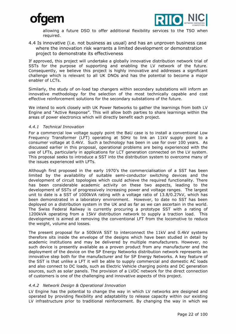
In addition, Table 4-3 shows a detailed breakdown labour cost of project.
Table 4-3: LV Engine detailed labour cost breakdown
Work Package Project Participant Rate
(£)
FTE
(days)
Man-
hours
cost (£k)
Total*
(£k)
Project Set Up SP Energy Networks XXX XXX XXX XXX
WP 1
SP Energy Networks XXX XXX XXX XXX
UK Power Networks XXX XXX XXX XXX
Technical Consultant XXX XXX XXX XXX
Academic Advisor XXX XXX XXX XXX
WP 2
SP Energy Networks XXX XXX XXX XXX
UK Power Networks XXX XXX XXX XXX
Technical Consultant XXX XXX XXX XXX
Academic Advisor XXX XXX XXX XXX
WP 3
SP Energy Networks XXX XXX XXX XXX
UK Power Networks XXX XXX XXX XXX
Technical Consultant XXX XXX XXX XXX
Academic Advisor XXX XXX XXX XXX
WP 4
SP Energy Networks XXX XXX XXX XXX
UK Power Networks XXX XXX XXX XXX
Technical Consultant XXX XXX XXX XXX
Academic Advisor XXX XXX XXX XXX
WP 5
SP Energy Networks XXX XXX XXX XXX
UK Power Networks XXX XXX XXX XXX
Technical Consultant XXX XXX XXX XXX
WP 6
SP Energy Networks XXX XXX XXX XXX
UK Power Networks XXX XXX XXX XXX
Technical Consultant XXX XXX XXX XXX
WP 7 SP Energy Networks XXX XXX XXX XXX
Technical Consultant XXX XXX XXX XXX
*Note: Travel costs, expenses and contingencies have been included in addition to the day rate per FTE.
Based upon the financial benefits calculated within our baseline and in combination with
our projected deployment opportunities across GB the full funding requested for LV
Engine will be repaid to electricity customers within 7 years of the project funding award.
4.3 LV Engine will also deliver value to electricity customers for the following reasons:
A competitive procurement and tendering process will be carried out to identify
manufacturing partners who will deliver value for money by delivering a fit-for-
purpose SST at the lowest possible cost, whilst also providing resource and
monetary contributions towards the project.
LV Engine will also look to collaborate with other parties with relevant experience
within the power electronics industry to build upon the learnings available from
relevant projects and ensure LV Engine considers the latest developments within
the area and does not repeat work carried out by others.
The outcomes of this project will largely enhance the operation and planning of
distribution networks. However, the project will also benefit the transmission
network by enabling more embedded generation connections to reduce
transmission network losses and constraints. Furthermore, a more flexible and
adaptable distribution network will directly benefit the transmission network by
Page 22 of 100
allowing a future DSO to offer additional flexibility services to the TSO when
required.
4.4 Is innovative (i.e. not business as usual) and has an unproven business case where the innovation risk warrants a limited development or demonstration project to demonstrate its effectiveness
If approved, this project will undertake a globally innovative distribution network trial of
SSTs for the purpose of supporting and enabling the LV network of the future.
Consequently, we believe this project is highly innovative and addresses a significant
challenge which is relevant to all UK DNOs and has the potential to become a major
enabler of LCTs.
Similarly, the study of on-load tap changers within secondary substations will inform an
innovative methodology for the selection of the most technically capable and cost
effective reinforcement solutions for the secondary substations of the future.
We intend to work closely with UK Power Networks to gather the learnings from both LV
Engine and “Active Response”. This will allow both parties to share learnings within the
areas of power electronics which will directly benefit each project.
4.4.1 Technical Innovation
For a commercial low voltage supply point the BaU case is to install a conventional Low
Frequency Transformer (LFT) operating at 50Hz to link an 11kV supply point to a
consumer voltage at 0.4kV. Such a technology has been in use for over 100 years. As
discussed earlier in this proposal, operational problems are being experienced with the
use of LFTs, particularly in applications for LCT generation connected on the LV system.
This proposal seeks to introduce a SST into the distribution system to overcome many of
the issues experienced with LFTs.
Although first proposed in the early 1970’s the commercialisation of a SST has been
limited by the availability of suitable semi-conductor switching devices and the
development of circuit topologies which could achieve the required functionality. There
has been considerable academic activity on these two aspects, leading to the
development of SSTs of progressively increasing power and voltage ranges. The largest
unit to date is a SST of 1000kVA rating with a voltage ratio of 13.8/0.27kV, which has
been demonstrated in a laboratory environment. However, to date no SST has been
deployed on a distribution system in the UK and as far as we can ascertain in the world.
The Swiss Federal Railway is currently procuring a prototype SST with a rating of
1200kVA operating from a 15kV distribution network to supply a traction load. This
development is aimed at removing the conventional LFT from the locomotive to reduce
the weight, volume and losses.
The present proposal for a 500kVA SST to interconnect the 11kV and 0.4kV systems
therefore sits inside the envelope of the designs which have been studied in detail by
academic institutions and may be delivered by multiple manufacturers. However, no
such device is presently available as a proven product from any manufacturer and the
deployment of the device on the SP Energy Networks distribution network represents an
innovative step both for the manufacturer and for SP Energy Networks. A key feature of
the SST is that unlike a LFT it will be able to supply commercial and domestic AC loads
and also connect to DC loads, such as Electric Vehicle charging points and DC generation
sources, such as solar panels. The provision of a LVDC network for the direct connection
of customers is one of the challenging and innovative aspects of this project.
4.4.2 Network Design & Operational Innovation
LV Engine has the potential to change the way in which LV networks are designed and
operated by providing flexibility and adaptability to release capacity within our existing
LV infrastructure prior to traditional reinforcement. By changing the way in which we

Page 23 of 100
plan and design our LV networks we can ensure that the cost to reinforce the network to
facilitate LCTs is minimised as much as possible. The project will produce design tools
and policy documents to ensure the value of the project is adopted and implemented
into our BaU toolbox.
To this end LV Engine will develop a power electronics design guidance document in
partnership with UK Power Networks for the purpose of creating a new and innovative
approach to network reinforcement which considers the value that can be provided by
power electronic technologies as cost effective alternative to traditional reinforcement.
SP Energy Networks & UK Power Networks are committed to implementing the learnings
from our NIC projects into BaU and this document will help to ensure the learnings
associated with our complementary NIC projects are adopted by the business, other
DNOs, and our customers see a return on their investment as soon as possible.
4.4.3 SST Technology Readiness Level (TRL)
A trial of SST technology requires Ofgem NIC funding as the TRL of this device is not
currently high enough for grid application. The technology has reached a level of
maturity in railway traction applications, which use similar voltage levels to distribution
networks. The TRL of SSTs for traction applications is considered to be 8, as prototype
units have been deployed and tested in field trials. The TRL of SSTs for grid applications
is considered to be 5-6, as prototype devices have been through laboratory trials.
LV Engine intends to elevate the TRL of SSTs to an 8 and provide DNOs with the toolset
required to design and operate a smart and efficient distribution network of the future.
However, there are yet challenges to demonstrate the performance and reliability of the
technology, and an efficient fit-for-purpose design for grid applications is required.
There are still several technical and operational challenges for a SST grid application
which require to be addressed before BaU adoption. Some of these challenges are a
modular based design, the SST network protection design, improving efficiency and
reducing losses, a compact design and developing sophisticated control algorithms to
enable smart functionalities and control.
In preparation for LV Engine and to reduce the risk associated with the project we have
discussed these challenges at length with multiple experts, manufacturers and
academics in the area. These discussions have given us confidence that the
developments required to elevate the TRL of the technology from a 5-6 to an 8 is
achievable within the timescales of the project and that the learnings from the project
can be implemented into BaU as soon as possible. A more detailed view on the TRL
progression of SSTs is shown within Appendix H along with a projection in the TRL and
SST performance we hope to achieve during LV Engine.
4.4.4 LV Engine has an unproven business case which requires a demonstration project
to manage risk
To achieve the same functionality as a SST using conventional (BaU) equipment would
require a combination of a LFT plus a voltage control device, such as a Static
Synchronous Compensator (STATCOM), plus a separate inverter/rectifier unit to supply
DC loads and DC generation sources. SP Energy Networks believes that the SST will
demonstrate superior performance, in terms of cost, losses, weight and volume, to the
BaU solution, but recognises the risks inherent in such a project. Without the support
provided by the NIC process, the deployment of the LV Engine project would not be a
viable solution and would not be within SP Energy Networks’ normal mandate to use only
proven equipment on their network.
By deploying a SST on the 11kV/0.4kV distribution network, which can provide supplies
to both AC and DC LV systems, SP Energy Networks will be using equipment, which
although tested in the factory, will not have been used operationally on any system
Page 24 of 100
connected to consumer supplies. Consequently, as the first project into the field, there
are risks that the SST will not achieve its designed operational reliability and availability.
There will be risks that the technology does not perform as expected, the manufacturer
does not support the technology long term, the project costs exceed the budget, and the
project timescales extend beyond those planned. However, the learning opportunities
gained from the deployment of an SST and its long term operation will be invaluable for
both SP Energy Networks and other UK DNOs wishing to consider similar installations.
4.5 Involvement of other parties and external funding
Key to the delivery of LV Engine is identifying project partners who can take the lead on
the design and manufacture of the fit-for-purpose SSTs described within this proposal. It
is important to SP Energy Networks that we identify responsible and competent partners
who represent value for money for our electricity customers. Details on our existing
partners and future partner selection methodology are described below:
UK Power Networks will act as a project partner and member of our design authority
board during LV Engine. Collaboration between DNOs is critical to ensure our respective
innovation projects are adopted into BaU practices and value is delivered to our
customers. For this reason UK Power Networks will ensure LV Engine considers the
requirements of DNOs across the UK and shares learnings from its complementary NIC
proposal “Active Response”. A list of well-defined actions have been mapped against
each work package and agreed between SP Energy Networks & UK Power Networks.
Manufacturing Partner(s) - A thorough tendering process will be carried out to
identify a partner(s) who represent the most value for money whilst ensuring successful
delivery of the project. We will seek manufacturing partners who can contribute at least
10% of their associated project costs up front. Since no manufacturing partner will be in
place prior to the start of the project SP Energy Networks will contribute 10% of the total
project funding request up front and recover a proportion of this cost once a partner(s)
has been identified. Manufacturers will also be examined against detailed criteria which
include cost, timescales, performance, reliability, resources, and financial stability
amongst others.
Academic Partner(s) - We have identified specific areas of research that an academic
partner(s) will carry out during the delivery of LV Engine. These activities have been
mapped against each work package within the project delivery plan. To date we have
held discussions with multiple universities to identify which parties are in a position to
contribute. For the purposes of maximising value to the project we intend to formalise
this activity during project set up should funding be awarded. We intend to work with
those who can demonstrate knowledge and experience in the subject area to allow us to
build upon learnings that have been established during previous external projects.
Current LV Engine Partner Engagement
In addition to the above, SP Energy Networks have actively engaged in detailed
conversation with multiple potential partners during the creation of this proposal to gain
confidence in the feasibility of LV Engine:
1. Multiple suppliers, universities and research centres have been identified who are
capable and willing to support the project as partners. An “Expression of Interest
(EOI)” document has been distributed to allow these potential partners to
formally log their interest in the project and set out how they can contribute in
detail.
2. The project concept was discussed with potential partners through teleconference
or face-to-face meetings. Challenges and risks were identified, and areas which
potential partners can provide contributions were discussed.
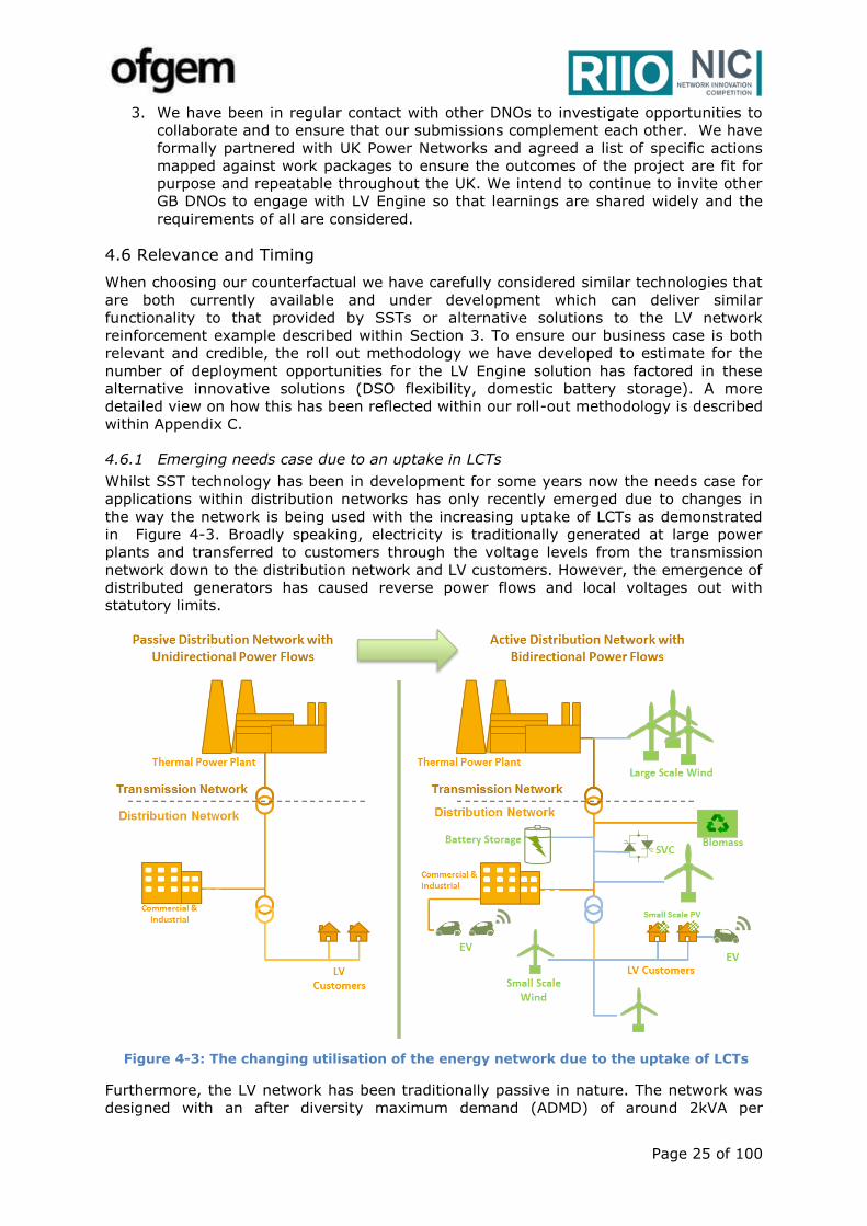
Page 25 of 100
3. We have been in regular contact with other DNOs to investigate opportunities to
collaborate and to ensure that our submissions complement each other. We have
formally partnered with UK Power Networks and agreed a list of specific actions
mapped against work packages to ensure the outcomes of the project are fit for
purpose and repeatable throughout the UK. We intend to continue to invite other
GB DNOs to engage with LV Engine so that learnings are shared widely and the
requirements of all are considered.
4.6 Relevance and Timing
When choosing our counterfactual we have carefully considered similar technologies that
are both currently available and under development which can deliver similar
functionality to that provided by SSTs or alternative solutions to the LV network
reinforcement example described within Section 3. To ensure our business case is both
relevant and credible, the roll out methodology we have developed to estimate for the
number of deployment opportunities for the LV Engine solution has factored in these
alternative innovative solutions (DSO flexibility, domestic battery storage). A more
detailed view on how this has been reflected within our roll-out methodology is described
within Appendix C.
4.6.1 Emerging needs case due to an uptake in LCTs
Whilst SST technology has been in development for some years now the needs case for
applications within distribution networks has only recently emerged due to changes in
the way the network is being used with the increasing uptake of LCTs as demonstrated
in Figure 4-3. Broadly speaking, electricity is traditionally generated at large power
plants and transferred to customers through the voltage levels from the transmission
network down to the distribution network and LV customers. However, the emergence of
distributed generators has caused reverse power flows and local voltages out with
statutory limits.
Figure 4-3: The changing utilisation of the energy network due to the uptake of LCTs
Furthermore, the LV network has been traditionally passive in nature. The network was
designed with an after diversity maximum demand (ADMD) of around 2kVA per
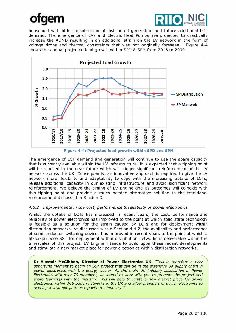
Page 26 of 100
household with little consideration of distributed generation and future additional LCT
demand. The emergence of EVs and Electric Heat Pumps are projected to drastically
increase the ADMD resulting in an additional strain on the LV network in the form of
voltage drops and thermal constraints that was not originally foreseen. Figure 4-4
shows the annual projected load growth within SPD & SPM from 2016 to 2030.
Figure 4-4: Projected load growth within SPD and SPM
The emergence of LCT demand and generation will continue to use the spare capacity
that is currently available within the LV infrastructure. It is expected that a tipping point
will be reached in the near future which will trigger significant reinforcement of the LV
network across the UK. Consequently, an innovative approach is required to give the LV
network more flexibility and adaptability to cope with the increasing uptake of LCTs,
release additional capacity in our existing infrastructure and avoid significant network
reinforcement. We believe the timing of LV Engine and its outcomes will coincide with
this tipping point and provide a much needed alternative solution to the traditional
reinforcement discussed in Section 3.
4.6.2 Improvements in the cost, performance & reliability of power electronics
Whilst the uptake of LCTs has increased in recent years, the cost, performance and
reliability of power electronics has improved to the point at which solid state technology
is feasible as a solution for the strain caused by LCTs and for deployment within
distribution networks. As discussed within Section 4.4.2, the availability and performance
of semiconductor switching devices has improved in recent years to the point at which a
fit-for-purpose SST for deployment within distribution networks is deliverable within the
timescales of this project. LV Engine intends to build upon these recent developments
and stimulate a new market place for power electronics within distribution networks.
Dr Alastair McGibbon, Director of Power Electronics UK: “This is therefore a very opportune moment to begin an SST project that can tie in the extensive UK supply chain in
power electronics with the energy sector. As the main UK industry association in Power Electronics with over 70 members, we intend to work with you to promote the project and share learnings with the industry. This will help to ignite a new market place for power electronics within distribution networks in the UK and allow providers of power electronics to develop a strategic partnership with the industry.”
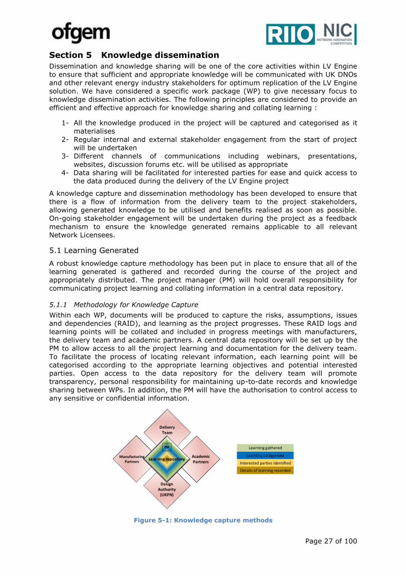
Page 27 of 100
Section 5 Knowledge dissemination
Dissemination and knowledge sharing will be one of the core activities within LV Engine
to ensure that sufficient and appropriate knowledge will be communicated with UK DNOs
and other relevant energy industry stakeholders for optimum replication of the LV Engine
solution. We have considered a specific work package (WP) to give necessary focus to
knowledge dissemination activities. The following principles are considered to provide an
efficient and effective approach for knowledge sharing and collating learning :
1- All the knowledge produced in the project will be captured and categorised as it
materialises
2- Regular internal and external stakeholder engagement from the start of project
will be undertaken
3- Different channels of communications including webinars, presentations,
websites, discussion forums etc. will be utilised as appropriate
4- Data sharing will be facilitated for interested parties for ease and quick access to
the data produced during the delivery of the LV Engine project
A knowledge capture and dissemination methodology has been developed to ensure that
there is a flow of information from the delivery team to the project stakeholders,
allowing generated knowledge to be utilised and benefits realised as soon as possible.
On-going stakeholder engagement will be undertaken during the project as a feedback
mechanism to ensure the knowledge generated remains applicable to all relevant
Network Licensees.
5.1 Learning Generated
A robust knowledge capture methodology has been put in place to ensure that all of the
learning generated is gathered and recorded during the course of the project and
appropriately distributed. The project manager (PM) will hold overall responsibility for
communicating project learning and collating information in a central data repository.
5.1.1 Methodology for Knowledge Capture
Within each WP, documents will be produced to capture the risks, assumptions, issues
and dependencies (RAID), and learning as the project progresses. These RAID logs and
learning points will be collated and included in progress meetings with manufacturers,
the delivery team and academic partners. A central data repository will be set up by the
PM to allow access to all the project learning and documentation for the delivery team.
To facilitate the process of locating relevant information, each learning point will be
categorised according to the appropriate learning objectives and potential interested
parties. Open access to the data repository for the delivery team will promote
transparency, personal responsibility for maintaining up-to-date records and knowledge
sharing between WPs. In addition, the PM will have the authorisation to control access to
any sensitive or confidential information.
Figure 5-1: Knowledge capture methods
Delivery Team
Design Authority
(UKPN)
AcademicPartners
Manufacturing Partners
Learning repository
PM Learning gathered
Learning categorised
Interested parties identified
Details of learning recorded
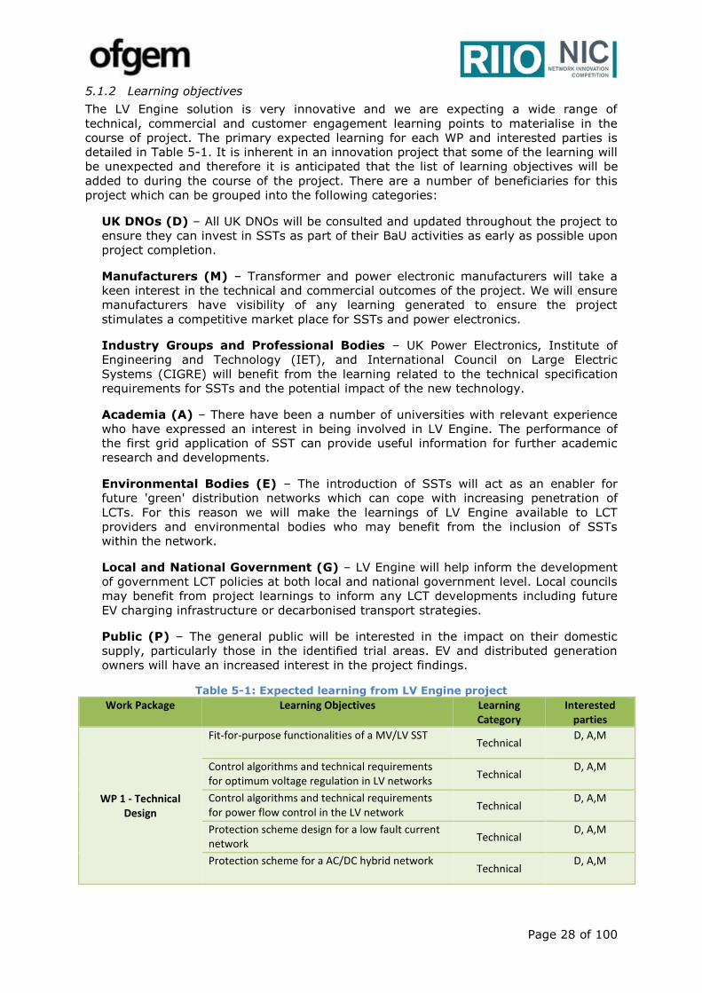
Page 28 of 100
5.1.2 Learning objectives
The LV Engine solution is very innovative and we are expecting a wide range of
technical, commercial and customer engagement learning points to materialise in the
course of project. The primary expected learning for each WP and interested parties is
detailed in Table 5-1. It is inherent in an innovation project that some of the learning will
be unexpected and therefore it is anticipated that the list of learning objectives will be
added to during the course of the project. There are a number of beneficiaries for this
project which can be grouped into the following categories:
UK DNOs (D) – All UK DNOs will be consulted and updated throughout the project to
ensure they can invest in SSTs as part of their BaU activities as early as possible upon
project completion.
Manufacturers (M) – Transformer and power electronic manufacturers will take a
keen interest in the technical and commercial outcomes of the project. We will ensure
manufacturers have visibility of any learning generated to ensure the project
stimulates a competitive market place for SSTs and power electronics.
Industry Groups and Professional Bodies – UK Power Electronics, Institute of
Engineering and Technology (IET), and International Council on Large Electric
Systems (CIGRE) will benefit from the learning related to the technical specification
requirements for SSTs and the potential impact of the new technology.
Academia (A) – There have been a number of universities with relevant experience
who have expressed an interest in being involved in LV Engine. The performance of
the first grid application of SST can provide useful information for further academic
research and developments.
Environmental Bodies (E) – The introduction of SSTs will act as an enabler for
future 'green' distribution networks which can cope with increasing penetration of
LCTs. For this reason we will make the learnings of LV Engine available to LCT
providers and environmental bodies who may benefit from the inclusion of SSTs
within the network.
Local and National Government (G) – LV Engine will help inform the development
of government LCT policies at both local and national government level. Local councils
may benefit from project learnings to inform any LCT developments including future
EV charging infrastructure or decarbonised transport strategies.
Public (P) – The general public will be interested in the impact on their domestic
supply, particularly those in the identified trial areas. EV and distributed generation
owners will have an increased interest in the project findings.
Table 5-1: Expected learning from LV Engine project
Work Package Learning Objectives Learning Category
Interested parties
WP 1 - Technical Design
Fit-for-purpose functionalities of a MV/LV SST Technical
D, A,M
Control algorithms and technical requirements for optimum voltage regulation in LV networks
Technical D, A,M
Control algorithms and technical requirements for power flow control in the LV network
Technical D, A,M
Protection scheme design for a low fault current network
Technical D, A,M
Protection scheme for a AC/DC hybrid network Technical
D, A,M
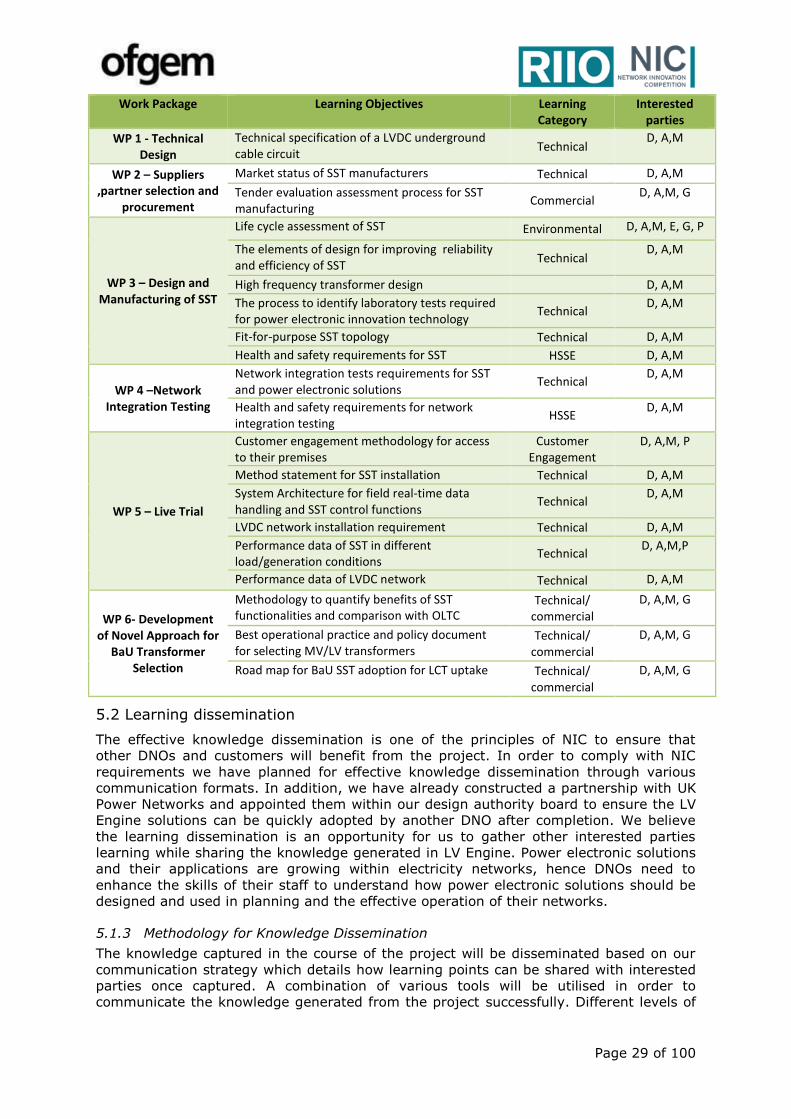
Page 29 of 100
Work Package Learning Objectives Learning Category
Interested parties
WP 1 - Technical Design
Technical specification of a LVDC underground cable circuit
Technical D, A,M
WP 2 – Suppliers ,partner selection and
procurement
Market status of SST manufacturers Technical D, A,M
Tender evaluation assessment process for SST manufacturing
Commercial D, A,M, G
WP 3 – Design and Manufacturing of SST
Life cycle assessment of SST Environmental D, A,M, E, G, P
The elements of design for improving reliability and efficiency of SST
Technical D, A,M
High frequency transformer design D, A,M
The process to identify laboratory tests required for power electronic innovation technology
Technical D, A,M
Fit-for-purpose SST topology Technical D, A,M
Health and safety requirements for SST HSSE D, A,M
WP 4 –Network Integration Testing
Network integration tests requirements for SST and power electronic solutions
Technical D, A,M
Health and safety requirements for network integration testing
HSSE D, A,M
WP 5 – Live Trial
Customer engagement methodology for access to their premises
Customer Engagement
D, A,M, P
Method statement for SST installation Technical D, A,M
System Architecture for field real-time data handling and SST control functions
Technical D, A,M
LVDC network installation requirement Technical D, A,M
Performance data of SST in different load/generation conditions
Technical D, A,M,P
Performance data of LVDC network Technical D, A,M
WP 6- Development of Novel Approach for
BaU Transformer Selection
Methodology to quantify benefits of SST functionalities and comparison with OLTC
Technical/ commercial
D, A,M, G
Best operational practice and policy document for selecting MV/LV transformers
Technical/ commercial
D, A,M, G
Road map for BaU SST adoption for LCT uptake Technical/ commercial
D, A,M, G
5.2 Learning dissemination
The effective knowledge dissemination is one of the principles of NIC to ensure that
other DNOs and customers will benefit from the project. In order to comply with NIC
requirements we have planned for effective knowledge dissemination through various
communication formats. In addition, we have already constructed a partnership with UK
Power Networks and appointed them within our design authority board to ensure the LV
Engine solutions can be quickly adopted by another DNO after completion. We believe
the learning dissemination is an opportunity for us to gather other interested parties
learning while sharing the knowledge generated in LV Engine. Power electronic solutions
and their applications are growing within electricity networks, hence DNOs need to
enhance the skills of their staff to understand how power electronic solutions should be
designed and used in planning and the effective operation of their networks.
5.1.3 Methodology for Knowledge Dissemination
The knowledge captured in the course of the project will be disseminated based on our
communication strategy which details how learning points can be shared with interested
parties once captured. A combination of various tools will be utilised in order to
communicate the knowledge generated from the project successfully. Different levels of
Page 30 of 100
detail, including the frequency and method of communication, will be appropriate for
each type of stakeholder.
LV Engine will comply with SP Energy Networks’ publicly available data sharing policy
that will be available by the 30th September 2017. However, our communication strategy
will include the following:
SP Energy Networks website – A dedicated ares within the SP Energy Networks
website will be set up for LV Engine as one of our communication strategies. The
webpages will raise awareness of the aims and objectives of the project, trial areas
and provide all the relevant documentation produced during the project. Data sharing
about the performance of the LV Engine solutions will be available through this
website. The interested parties will be encouraged to register through the website to
be informed about any recent updates and the progress of LV Engine.
UK DNOs workshops – We recognise that UK DNOs are a key stakeholder and
effective communication with UK DNOs will help facilitate the successful roll-out of the
LV Engine solution. We have included regular face-to-face workshops with other
DNOs at major project milestones to discuss learning and capture any feedback. This
immediate form of communication will help to share crucial information and receive
feedback based on exiting learning and experience from other parties.
Webinars – In order to reach a wider audience and provide an opportunity for
external stakeholders with different backgrounds to learn about the project, we plan
to share the project learning and methodologies through regular webinars.
Joint presentations with UK Power Networks – Power electronics solutions and
their applications within distribution networks are growing. In order to stimulate a
competitive market for power electronic solution within distribution networks, we plan
to arrange joint dissemination events with UK Power Networks and members of the
power electronics industry within the UK. This will provide us with an opportunity to
discuss how industry can support the challenges faced by DNOs by providing power
electronic products and technologies that are tailored to our business needs.
LCNI conferences - We aim to present the learning of LV Engine during the LCNI
conferences that will take place during the course of project. This has been included
within our project plan.
Written reports – Regular progress reports and project documentations will be
published on the LV Engine webpages and ENA knowledge sharing portal. This
includes the project close-down report which will include all findings, methodologies
and lessons learnt and will be published in accordance with NIC requirements.
International technical papers – In addition to above, we propose that we reach
other stakeholders around the world and exchange LV Engine learning with other non-
UK experts. That will raise the awareness within the electricity industry around the
world about the innovation work in the UK and facilitate the future competitive market
for SST manufacturing. Therefore, we will identify relevant international conferences
and submit technical papers including the methodologies used and the learning
gathered within the project.
5.3 IPR
The work undertaken as part of this NIC project will adhere to the default IPR
arrangements set out within the NIC governance. Project partners and suppliers will be
required to comply with the default IPR arrangements as part of the selection criteria of
the competitive tendering.
Page 31 of 100
Section 6 Project Readiness
6.1 Evidence of why the Project can start in a timely manner
We are confident that the LV Engine project can start in a timely manner based on the
detailed ground work undertaken in the preparation of this FSP. Based on the following
evidence we consider that the project is ready to start after the necessary funding is provided:
Commitment from SP Energy Networks Management team to deliver this
innovation project;
Receipt of Expressions of Interest from a number of interested parties (ranging
from SMEs to major equipment suppliers and academics) in support of the design,
development and delivery of an approved SST;
Availability of UK Power Networks for peer review as a design authority;
Identified site trial areas for deploying different scheme designs;
Established site trial selection criteria, and will re-evaluate identified sites to
determine their suitability at the proposed time of SST deployment with respect
to their low carbon technology uptake in order to ensure maximum trial benefits;
Knowledge and learning gained from relevant NIA and NIC projects;
Knowledge gained through supplier and academic engagement both in the UK and
overseas;
Successful track record of delivering large-scale innovation projects;
Established Project Plan, work scope, and risk register;
Identified project delivery structure with defined roles and responsibilities.
6.1.1 Commitment from SP Energy Networks Management team
The concept and benefits of LV Engine have been discussed extensively at different
stages of the proposal preparation, with different (and relevant) managerial levels within
SP Energy Networks. There has been strong support within the senior management team
including the Director of Engineering Services and Director of Network Planning and
Regulation to fully provide the required resources for starting the LV Engine project in a
timely manner. We have also identified potential resources including planning engineers,
transformer experts, operation engineers, and district design engineers within who can
support delivery of LV Engine.
6.1.2 Expressions of interest from a range of interested parties
We have actively engaged with a range of interested parties (both here in the UK and
overseas) and stakeholders whose knowledge and expertise have helped shape this
proposal. We have requested that the interested parties fill an expression of interest
form detailing their relevant experience and technical capabilities, available resources,
and potential financial contribution. The responses we have received from stakeholders
have been very encouraging and provided us with a confidence that it is timely to start
LV Engine project. A summary of interested parties whom we have spoken with, during
proposal preparation, are as follows:
Manufacturers - We have been speaking to a number of manufacturers both
large and small with SST experience. Based on the information gathered on
research and development in the manufacturing side and also the prototypes
have been developed so far, we have confidence that it is the right time to trial
SST in a grid application and there are a number of manufacturers who can
potentially join as a partner in the LV Engine project.
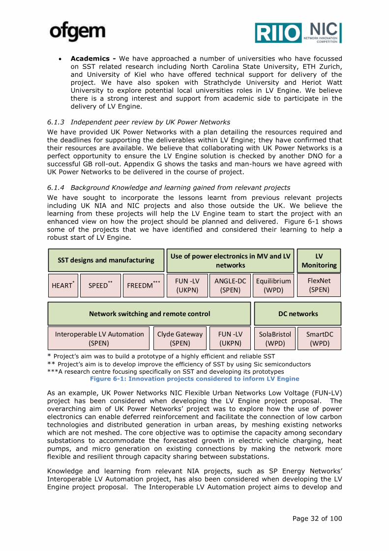
Page 32 of 100
Academics - We have approached a number of universities who have focussed
on SST related research including North Carolina State University, ETH Zurich,
and University of Kiel who have offered technical support for delivery of the
project. We have also spoken with Strathclyde University and Heriot Watt
University to explore potential local universities roles in LV Engine. We believe
there is a strong interest and support from academic side to participate in the
delivery of LV Engine.
6.1.3 Independent peer review by UK Power Networks
We have provided UK Power Networks with a plan detailing the resources required and
the deadlines for supporting the deliverables within LV Engine; they have confirmed that
their resources are available. We believe that collaborating with UK Power Networks is a
perfect opportunity to ensure the LV Engine solution is checked by another DNO for a
successful GB roll-out. Appendix G shows the tasks and man-hours we have agreed with
UK Power Networks to be delivered in the course of project.
6.1.4 Background Knowledge and learning gained from relevant projects
We have sought to incorporate the lessons learnt from previous relevant projects
including UK NIA and NIC projects and also those outside the UK. We believe the
learning from these projects will help the LV Engine team to start the project with an
enhanced view on how the project should be planned and delivered. Figure 6-1 shows
some of the projects that we have identified and considered their learning to help a
robust start of LV Engine.
* Project’s aim was to build a prototype of a highly efficient and reliable SST
** Project’s aim is to develop improve the efficiency of SST by using Sic semiconductors
***A research centre focusing specifically on SST and developing its prototypes Figure 6-1: Innovation projects considered to inform LV Engine
As an example, UK Power Networks NIC Flexible Urban Networks Low Voltage (FUN-LV)
project has been considered when developing the LV Engine project proposal. The
overarching aim of UK Power Networks’ project was to explore how the use of power
electronics can enable deferred reinforcement and facilitate the connection of low carbon
technologies and distributed generation in urban areas, by meshing existing networks
which are not meshed. The core objective was to optimise the capacity among secondary
substations to accommodate the forecasted growth in electric vehicle charging, heat
pumps, and micro generation on existing connections by making the network more
flexible and resilient through capacity sharing between substations.
Knowledge and learning from relevant NIA projects, such as SP Energy Networks’
Interoperable LV Automation project, has also been considered when developing the LV
Engine project proposal. The Interoperable LV Automation project aims to develop and
SST designs and manufacturing
HEART* SPEED** FREEDM***
Use of power electronics in MV and LV networks
FUN -LV (UKPN)
ANGLE-DC (SPEN)
Equilibrium (WPD)
DC networks
SolaBristol (WPD)
SmartDC (WPD)
LV Monitoring
FlexNet (SPEN)
Network switching and remote control
Interoperable LV Automation (SPEN)
Clyde Gateway (SPEN)
FUN -LV (UKPN)
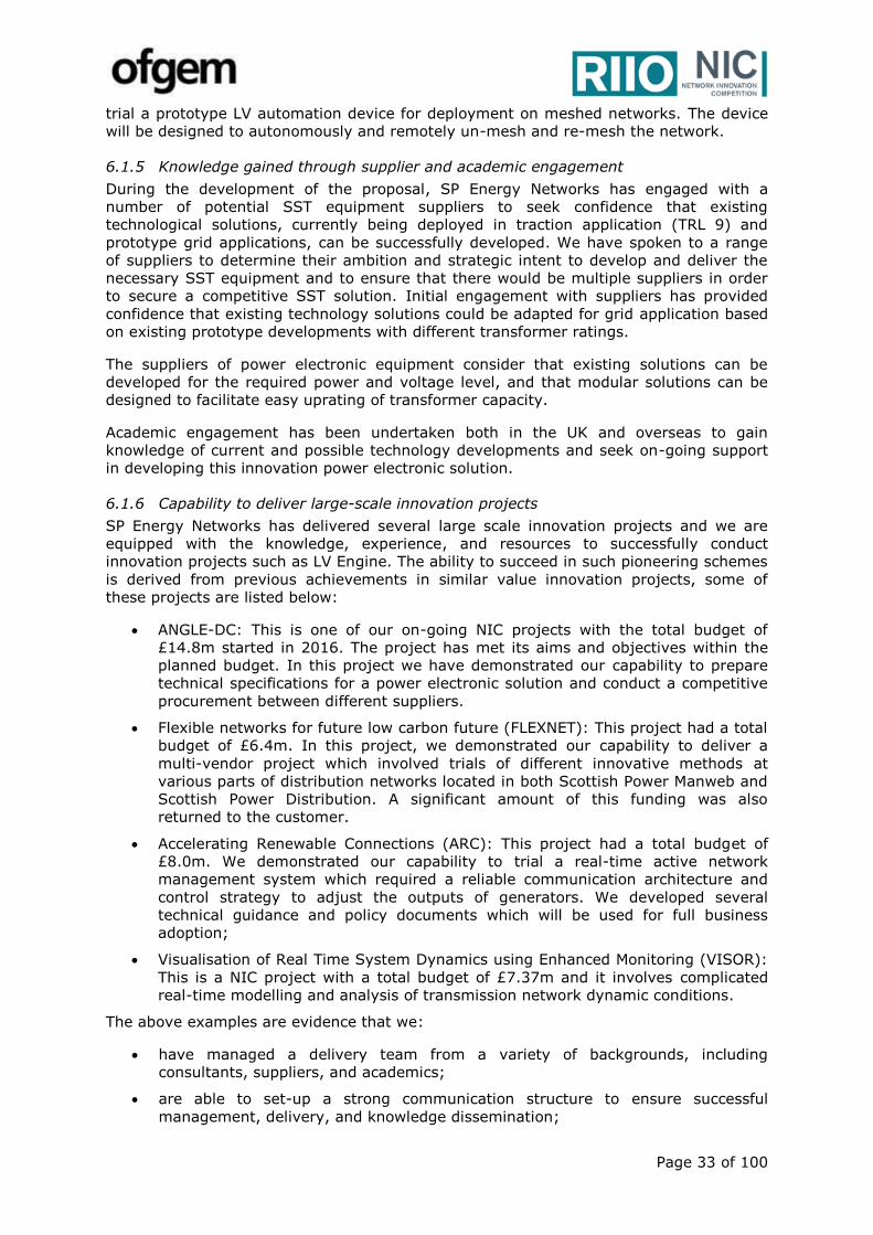
Page 33 of 100
trial a prototype LV automation device for deployment on meshed networks. The device
will be designed to autonomously and remotely un-mesh and re-mesh the network.
6.1.5 Knowledge gained through supplier and academic engagement
During the development of the proposal, SP Energy Networks has engaged with a
number of potential SST equipment suppliers to seek confidence that existing
technological solutions, currently being deployed in traction application (TRL 9) and
prototype grid applications, can be successfully developed. We have spoken to a range
of suppliers to determine their ambition and strategic intent to develop and deliver the
necessary SST equipment and to ensure that there would be multiple suppliers in order
to secure a competitive SST solution. Initial engagement with suppliers has provided
confidence that existing technology solutions could be adapted for grid application based
on existing prototype developments with different transformer ratings.
The suppliers of power electronic equipment consider that existing solutions can be
developed for the required power and voltage level, and that modular solutions can be
designed to facilitate easy uprating of transformer capacity.
Academic engagement has been undertaken both in the UK and overseas to gain
knowledge of current and possible technology developments and seek on-going support
in developing this innovation power electronic solution.
6.1.6 Capability to deliver large-scale innovation projects
SP Energy Networks has delivered several large scale innovation projects and we are
equipped with the knowledge, experience, and resources to successfully conduct
innovation projects such as LV Engine. The ability to succeed in such pioneering schemes
is derived from previous achievements in similar value innovation projects, some of
these projects are listed below:
ANGLE-DC: This is one of our on-going NIC projects with the total budget of
£14.8m started in 2016. The project has met its aims and objectives within the
planned budget. In this project we have demonstrated our capability to prepare
technical specifications for a power electronic solution and conduct a competitive
procurement between different suppliers.
Flexible networks for future low carbon future (FLEXNET): This project had a total
budget of £6.4m. In this project, we demonstrated our capability to deliver a
multi-vendor project which involved trials of different innovative methods at
various parts of distribution networks located in both Scottish Power Manweb and
Scottish Power Distribution. A significant amount of this funding was also
returned to the customer.
Accelerating Renewable Connections (ARC): This project had a total budget of
£8.0m. We demonstrated our capability to trial a real-time active network
management system which required a reliable communication architecture and
control strategy to adjust the outputs of generators. We developed several
technical guidance and policy documents which will be used for full business
adoption;
Visualisation of Real Time System Dynamics using Enhanced Monitoring (VISOR):
This is a NIC project with a total budget of £7.37m and it involves complicated
real-time modelling and analysis of transmission network dynamic conditions.
The above examples are evidence that we:
have managed a delivery team from a variety of backgrounds, including
consultants, suppliers, and academics;
are able to set-up a strong communication structure to ensure successful
management, delivery, and knowledge dissemination;
Page 34 of 100
have been capable of delivering the innovation projects with different technical
requirements.
This experience will ensure that SP Energy Networks can deliver the LV Engine project
successfully, generate and capture all learning outcomes within the estimated time and
budget, and ensure that the opportunity to realise business as usual benefits are realised
by UK DNOs.
6.1.7 Established Project Plan, Work Scope and Risk Register
We have developed a robust and appropriately detailed project plan and scope of work
to ensure the successful delivery of the LV Engine project. The plan takes account of the
project aims and objectives; it will consist of seven work packages. The activities, time
lines, and dependencies between activities in our project plan are constructed based on
information we gathered from different parties during proposal preparation and also our
experience for delivery of similar innovation projects. The details of our project plan are
given in Appendix D.
We have also identified risks, quantified their impact, and developed mitigation plans
based on the information gathered by engaging with a number of potential SST suppliers
and experience gained from delivering other innovation projects. Risks were categorised
based on the relevance to different aspects of the project (Technical risks, procurement
and manufacturing, Health and safety and operation, Project management). Appendix E
shows the risk register developed during the proposal preparation phase. We will be
updating the risk register during the delivery phase as part of our project management
governance. The project manager will inform the steering board in case any risk has
major impact on overall delivery of the project which may trigger the suspending the
project process.
6.1.8 Identified Project management structure
We have planned a project management structure based on WPs within LV Engine and
the expertise required for delivery of each WP. In order to optimise the level of
interfaces and communication between delivery team and project manager, we have
divided the delivery team to four distinctive teams, namely i) SST Design and
manufacturing, ii) Installation and commissioning, iii) BaU integration, and iv)
Knowledge dissemination. The adequate resources and expertise will be provided
through internal resources, different partners, and contractors to each team. Figure 6-2
shows the LV Engine project management structure. The project manager will be one of
our senior project managers within our future networks team with experience of
delivering large scale and complex projects.
The Project Manager will be responsible for overall delivery of the project and also
engaging with the Project Steering Board to communicate the project progress,
exception reports, or any issue raised. The Steering Board includes representatives of SP
Energy Networks, manufacturing partners, and academics. As part of our collaboration
with UK Power Networks, their Head of Innovation will be also part of our Steering
Board.
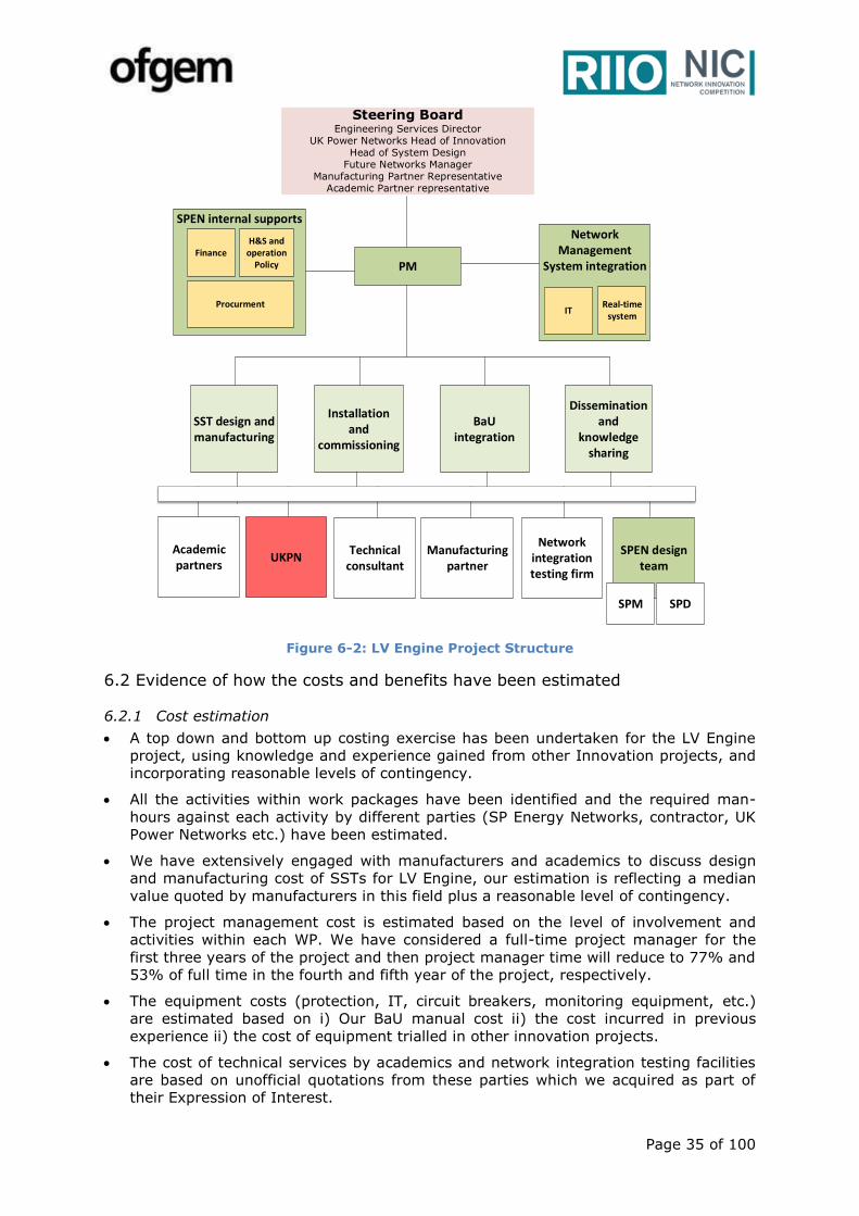
Page 35 of 100
Figure 6-2: LV Engine Project Structure
6.2 Evidence of how the costs and benefits have been estimated
6.2.1 Cost estimation
A top down and bottom up costing exercise has been undertaken for the LV Engine
project, using knowledge and experience gained from other Innovation projects, and
incorporating reasonable levels of contingency.
All the activities within work packages have been identified and the required man-
hours against each activity by different parties (SP Energy Networks, contractor, UK
Power Networks etc.) have been estimated.
We have extensively engaged with manufacturers and academics to discuss design
and manufacturing cost of SSTs for LV Engine, our estimation is reflecting a median
value quoted by manufacturers in this field plus a reasonable level of contingency.
The project management cost is estimated based on the level of involvement and
activities within each WP. We have considered a full-time project manager for the
first three years of the project and then project manager time will reduce to 77% and
53% of full time in the fourth and fifth year of the project, respectively.
The equipment costs (protection, IT, circuit breakers, monitoring equipment, etc.)
are estimated based on i) Our BaU manual cost ii) the cost incurred in previous
experience ii) the cost of equipment trialled in other innovation projects.
The cost of technical services by academics and network integration testing facilities
are based on unofficial quotations from these parties which we acquired as part of
their Expression of Interest.
SPEN internal supports
PM
Academic partners
Technical consultant
Manufacturing partner
Network integration testing firm
SPEN design team
Finance
Procurment
H&S and operation
Policy
UKPN
SST design and manufacturing
Installation and
commissioning
BaU integration
Dissemination and
knowledge sharing
Steering BoardEngineering Services Director
UK Power Networks Head of InnovationHead of System Design
Future Networks ManagerManufacturing Partner Representative
Academic Partner representative
SPDSPM
Network Management
System integration
ITReal-time
system
Page 36 of 100
6.2.2 Benefit estimation
The financial benefit of LV Engine is calculated based on the comparison between
the reinforcement method proposed by LV Engine and a Base Case which
represents the conventional reinforcement approach.
The Base Case cost is based on SP Energy Networks’ unit manual cost and in
consultation with our design engineers and planning managers. The LV Engine
method cost is based upon our extensive engagement with manufacturers and
experience gathered during previous NIC projects.
The unit cost for an SST has been estimated for 2023 based upon manufacturer
engagement and a cost reduction curve has been applied between 2023 and
2050.
The number of deployment opportunities for roll out across SP Energy Networks
and GB is based upon the uptake of LCTs projected by National Grid annual report
Future Energy Scenarios (FES) and the resulting reinforcement required as
estimated by Electricity North Wests’ within its project LV Network Solutions.
The roll out methodology includes a reduction in possible deployment
opportunities due to a generous market share percentage for other innovative
reinforcement approaches that may be available between now and 2050 i.e. DSO
flexibility, battery storage, SOPs, OLTC etc. In total the number of deployment
opportunities for LV Engine between 2023 and 2050 represents 16% of
the ground mounted secondary transformers within GB.
The benefit estimation includes the impact of LV Engine on network losses and
carbon emissions. This is based upon a losses and carbon calculation for an
individual deployment and extrapolated across SP Energy Networks and GB using
our roll out methodology.
6.3 Evidence of the measures the Network Licensee will employ to minimise the possibility of cost overruns or shortfalls in Direct Benefits
We will use established robust methodologies throughout the lifetime of the LV Engine
project to minimise the risk of cost overruns. The methodologies we use are outlined as
follows:
Ensure a competitive tendering for selecting manufacturing partner: The
greatest potential uncertainty lies around the budget for the SST, consequently to
reduce the risk of cost overruns we have actively engaged with a number of
potential SST suppliers during the proposal preparation phase to make a practical
estimation of the equipment cost based on their responses to our Expression of
Interest and follow up supplier meetings. We will prepare a more detailed
equipment specification based on our project learning to ensure the most
competitive costs via a competitive tender exercise. We will also closely monitor
the progress in the SST design and manufacturing to ensure the cost incurred is
proportional to the expected progress.
Breaking down the project into WPs: The LV Engine project has been split
into separate WPs with allocated budget and tolerances to minimise the possibility
of cost overruns or shortfalls in direct benefits. A stage control strategy will be
used to define the activities in each WP. Monthly project cost reviews and cost at
completion forecasts will be also conducted for each WP to provide an accurate
picture of total project cost.
Maintaining Project Delivery Focus and Realising Learning Objectives:
Due to the innovative nature of the LV Engine project, there is always a
temptation to trial new ideas and new methods which are not in the main project
objectives while the project is progressing. We acknowledge that we need to stay
Page 37 of 100
focused on our project learning objectives as defined at the project outset to
avoid unplanned expenditures.
Risk Management Process and Mitigation Plans: We recognise that
identifying risks and putting appropriate mitigation plans in place is an effective
methodology to avoid possible cost overrun on the LV Engine project. We have
already identified risks in LV Engine especially those which will have a financial
impact on the project. We will continue to actively update the risk register and
mitigation plans during the course of project.
6.4 A verification of all information included in the proposal (the processes a Network Licensee has in place to ensure the accuracy of information can be
detailed in the appendices)
SP Energy Networks has endeavoured to ensure the accuracy of the information included
in this proposal. The following process was undertaken to ensure that the information
included in this proposal and associated appendices, prepared by an experienced
technical team led by a full-time dedicated proposal manager, is up-to-date, and reflects
the best knowledge available at the time:
Independent review by UK Power Networks: An independent peer review
has been undertaken by UK Power Networks to ensure that the delivered solution
will be fit-for-purpose with suitable functionality for adoption by other DNOs into
Business as Usual.
Academic and supplier engagement: We have engaged with a range of
potential suppliers to ensure the SST cost estimated for the financial analysis and
the lead time considered in the project plan are realistic. We have discussed the
LV Engine project concept with some of the experts in the field including
academics (Kiel University, ETH Zurich etc.) to ensure the feasibility and
applicability of the project.
External consultants: WSP, experts in the various associated technical fields
(including transformers, LVDC and power electronics) were engaged during the
development of this proposal to verify the proposed design concept, the technical
assumptions, the project risks, the project delivery programme and the costs,
both CAPEX and OPEX, used in the cost benefit analysis.
A thorough quality control: An independent peer-review and challenge session
of the proposal was carried out by different internal and external technical
experts outside of the proposal preparation team. Various cross checked between
this proposal and other data sources such as full submission spreadsheet and cost
benefit analysis spreadsheets have been carried out to ensure the data presented
in this proposal are correct.
Data Assurance Governance (DAG) Review: The proposal has been through
SP Energy Networks full DAG process prior to senior management sign-off.
6.5 How the Project plan would still deliver learning in the event that the take up
of low carbon technologies and renewable energy in the trial area is lower than anticipated in the Full Submission
LV Engine will still deliver its learning objectives in the unlikely event of a lower uptake
of renewables and LCTs across SP Energy Networks’ licence areas. LV Engine solution
provides a toolbox for flexible operation of the LV networks. The demonstration of LV
Engine includes three principle functionalities: i) LV voltage control ii) Capacity sharing
between secondary substations and iii) provision of DC network. We will focus on
demonstration of these principle functionalities and we will deliver our leaning objectives
summered in Table 5-1 even in the event of low LCT uptake. We will also be able to
compare SSTs performance with conventional transformers equipped with OLTC for the
same level of LCT uptake.

Page 38 of 100
The LV Engine project will provide valuable learning in LVDC deployment and application,
it will also help upskill staff in power electronics which, in the future will be more
prevalent in electricity distribution networks. The project will also develop a
comprehensive SST specification and deployment policy guide which can be used by
other DNOs. This learning will not depend on the rate of uptake of low carbon
technologies on the LV network.
6.6 The processes in place to identify circumstances where the most appropriate course of action will be to suspend the Project, pending permission from
Ofgem that it can be halted
The project manager will be responsible for monitoring the project progress and
evaluating the project performance at the end of each stage of the project. Project
manager consider the key performance indicators (KPI) that represent the followings:
1- Project deliverables can be delivered within the planned time and quality
2- Project learning objectives can be generated as planned
3- Project cost is within the planned budget
If any of the above KPIs indicates the project is not performing as planned, depending
on the impact on the project, the project manager may escalate the issues to the
Steering Board by submitting an exception report. The exception report will contain the
information for the project board to decide if the project should be stopped or remedial
actions are required. If the Steering Board recognises that project must be halted, they
will issue a formal report to Ofgem to request permission to discontinue or delay the
project, detailing the issues, meeting minutes and recommendations. Figure 6-3 shows
the process to identify situations where the most appropriate course of action is to halt
the project. This process will comply with NIC governance and will be delivered in the
best interests of our customers.
Figure 6-3: Process in place to identify if project should be halted
Steering Board
deadlinesCost Quality
Ofgem
Stage 1 Stage 2 Stage 3
Stage Control Risk Assesment
Project Manager
Exception Report
Permission to halt the project
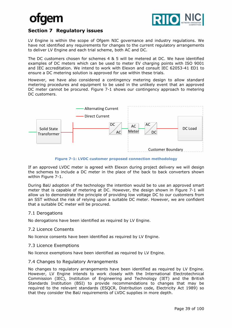
Page 39 of 100
Section 7 Regulatory issues
LV Engine is within the scope of Ofgem NIC governance and industry regulations. We
have not identified any requirements for changes to the current regulatory arrangements
to deliver LV Engine and each trial scheme, both AC and DC.
The DC customers chosen for schemes 4 & 5 will be metered at DC. We have identified
examples of DC meters which can be used to meter EV charging points with ISO 9001
and IEC accreditation. We intend to work with Elexon and consult IEC 62053-41 ED1 to
ensure a DC metering solution is approved for use within these trials.
However, we have also considered a contingency metering design to allow standard
metering procedures and equipment to be used in the unlikely event that an approved
DC meter cannot be procured. Figure 7-1 shows our contingency approach to metering
DC customers.
Solid State Transformer
DC AC
DCACDC Load
AC Meter
Customer Boundary
Alternating Current
Direct Current
Figure 7-1: LVDC customer proposed connection methodology
If an approved LVDC meter is agreed with Elexon during project delivery we will design
the schemes to include a DC meter in the place of the back to back converters shown
within Figure 7-1.
During BaU adoption of the technology the intention would be to use an approved smart
meter that is capable of metering at DC. However, the design shown in Figure 7-1 will
allow us to demonstrate the principle of providing low voltage DC to our customers from
an SST without the risk of relying upon a suitable DC meter. However, we are confident
that a suitable DC meter will be procured.
7.1 Derogations
No derogations have been identified as required by LV Engine.
7.2 Licence Consents
No licence consents have been identified as required by LV Engine.
7.3 Licence Exemptions
No licence exemptions have been identified as required by LV Engine.
7.4 Changes to Regulatory Arrangements
No changes to regulatory arrangements have been identified as required by LV Engine.
However, LV Engine intends to work closely with the International Electrotechnical
Commission (IEC), Institution of Engineering and Technology (IET) and the British
Standards Institution (BSI) to provide recommendations to changes that may be
required to the relevant standards (ESQCR, Distribution code, Electricity Act 1989) so
that they consider the BaU requirements of LVDC supplies in more depth.
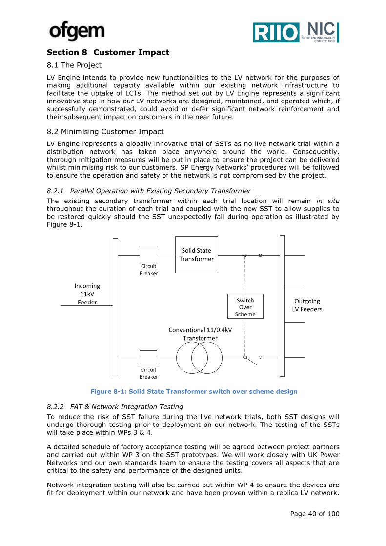
Page 40 of 100
Section 8 Customer Impact
8.1 The Project
LV Engine intends to provide new functionalities to the LV network for the purposes of
making additional capacity available within our existing network infrastructure to
facilitate the uptake of LCTs. The method set out by LV Engine represents a significant
innovative step in how our LV networks are designed, maintained, and operated which, if
successfully demonstrated, could avoid or defer significant network reinforcement and
their subsequent impact on customers in the near future.
8.2 Minimising Customer Impact
LV Engine represents a globally innovative trial of SSTs as no live network trial within a
distribution network has taken place anywhere around the world. Consequently,
thorough mitigation measures will be put in place to ensure the project can be delivered
whilst minimising risk to our customers. SP Energy Networks’ procedures will be followed
to ensure the operation and safety of the network is not compromised by the project.
8.2.1 Parallel Operation with Existing Secondary Transformer
The existing secondary transformer within each trial location will remain in situ
throughout the duration of each trial and coupled with the new SST to allow supplies to
be restored quickly should the SST unexpectedly fail during operation as illustrated by
Figure 8-1.
Switch Over
Scheme
Conventional 11/0.4kV Transformer
Incoming 11kV
Feeder
Circuit Breaker
Outgoing LV Feeders
Circuit Breaker
Solid State Transformer
Figure 8-1: Solid State Transformer switch over scheme design
8.2.2 FAT & Network Integration Testing
To reduce the risk of SST failure during the live network trials, both SST designs will
undergo thorough testing prior to deployment on our network. The testing of the SSTs
will take place within WPs 3 & 4.
A detailed schedule of factory acceptance testing will be agreed between project partners
and carried out within WP 3 on the SST prototypes. We will work closely with UK Power
Networks and our own standards team to ensure the testing covers all aspects that are
critical to the safety and performance of the designed units.
Network integration testing will also be carried out within WP 4 to ensure the devices are
fit for deployment within our network and have been proven within a replica LV network.
Page 41 of 100
This testing includes proving the protection design, earthing arrangements and the
performance of critical SST functionalities.
8.2.3 Staggered Network Trials
Each trial scheme will be staggered within WP 5 to allow us gather learnings as the
project progresses and provide us with an opportunity to alter our installation plans
should any unexpected challenges occur during each trial installation. This approach will
help to minimise the risk to our customers.
8.2.4 Single LVDC Customers
One of the most innovative elements of LV Engine is the provision of a low voltage DC
supply to our customers. To minimise the risk of negatively impacting our customers we
intend to provide DC to one customer only within trial schemes 4 & 5. This will allow us
to engineer a manageable metering design and minimise the risks associated with
provided DC to multiple customers for the first time.
8.3 Planned Interruptions
Switching over from the existing transformers to the new SSTs within the schemes will
require planned interruptions to the LV customers. To minimise these interruptions we
will look for opportunities to switch LV feeder onto adjacent transformers using the pre-
existing NOPs. If this is not possible SP Energy Networks’ standard procedure will be
followed for scheduling outages to ensure the risk to customers is minimised.
8.4 Unplanned Interruptions
No unplanned interruptions are anticipated, however a switch over scheme will be
included alongside each trial scheme to allow supply to be returned via the existing
transformers should an SST fail unexpectedly.
8.5 Engagement with Customers
Customer engagement during the delivery of LV Engine will focus on the recruitment of
suitable trial sites for a low voltage DC supply and access to a small number of customer
premises for the purpose of installing voltage meters at strategic points along each LV
feeder. The voltage meters will be used to allow the SSTs to regulate voltage at the LV
busbar in real time whilst having view of the voltage profile along the length of each
feeder.
We expect minimal disruption to the chosen customers during installation of these
voltage monitors and no action will be required by the customers once the meters are
installed. Adequate time has been set aside within the project delivery plan to gain this
support and promotional material will be created to promote the project and encourage
customer participation prior to installation of the SSTs on site.
8.5.1 LV Engine Customer Engagement Channels
LV Engine will be publicised to our customers using a variety of multi-media
communication channels. A dedicated SPEN LV Engine website will be the main source of
information for the customers within our trial areas. The SPEN website will be updated
regularly with details of the chosen trial locations and how customers can participate.
Local newspaper and promotional pamphlets will also be used to raise awareness of the
project in these areas.
8.5.2 Customer Recruitment Process
Recruitment of suitable site to trial LVDC supply – During the process of putting
together this proposal we have identified several potential sites that would benefit from a
low voltage DC supply. We intend to maintain this engagement during the delivery of the
project to secure these sites as trial locations for schemes 4 & 5. Our engagement
methodology for these customers includes:

Page 42 of 100
Identify potential third parties through search of public domain and using existing
connections and partners;
Distribute promotional information on the benefits of DC and the LV Engine
solution to identified potential third party sites;
Face to face meetings with shortlisted sites to discuss project in detail;
Put agreements in place with chosen sites for duration of project;
Appoint a point of contact for chosen customers to maintain strong
communication links; and
And provide regular updates on progress of project prior to trial through face to
face engagement and teleconferences.
Voltage meter installations - An external consultancy will be used to recruit
customers face to face within the chosen trial sites. A promotional pamphlet will be
created and distributed to each customer that will be supplied by the SSTs. The
pamphlets will advertise a small financial incentive to each customer who takes part in
the project and is willing to allow access to their premises for the purpose of installing a
voltage metering device. Once the pamphlets have been distributed and reviewed by our
customers, we intend to follow this up with face-to-face recruitment to secure their
participation.
8.5.3 Managing Customer Enquiries
LV Engine will use a number of communication channels to ensure that customer
questions and queries are handled in an efficient and confidential manner. The dedicated
LV Engine area within the SPEN website will include a contact form to allow customers to
raise any concerns they may have regarding the metering equipment that has been
installed within their premises. We will also operate an SMS service to allow customers
to request a call back if desired.
8.5.4 Managing Customer LVDC Safety Concerns
LV Engine will work closely with the customers chosen to trial the LVDC supply to
alleviate any safety concerns that arise from the use of a DC voltage. We will build upon
the learnings that are available within current safety standards to ensure all safety
requirements are addressed. This will be communicated both directly with customers and
via the SP Energy Networks website. These standards include:
IEC/TS 60479-1 Effects of current on human beings and livestock
IEC TS 63053:2017 General requirements for residual current operated protective
devices for DC system
IEC 60898-3 Circuit-breakers for overcurrent protection for household and similar
installations - Part 3: Circuit-breakers for d.c. operation
IET Code of Practice for Low and Extra Low Voltage Direct Current Power
Distribution in Buildings
Electricity Act 1989
8.6 Protection from Incentive Penalties
LV Engine will require no protection from incentive penalties.
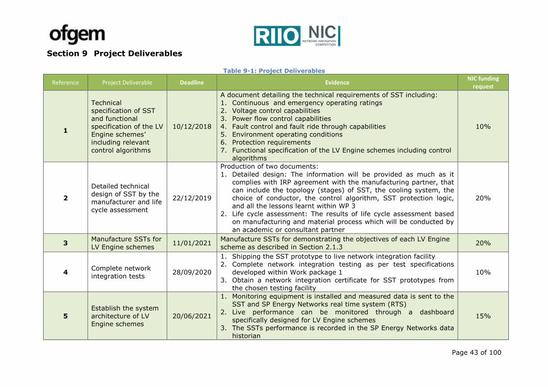
Page 43 of 100
Section 9 Project Deliverables
Table 9-1: Project Deliverables
Reference Project Deliverable Deadline Evidence NIC funding
request
1
Technical
specification of SST
and functional
specification of the LV
Engine schemes’
including relevant
control algorithms
10/12/2018
A document detailing the technical requirements of SST including:
1. Continuous and emergency operating ratings
2. Voltage control capabilities
3. Power flow control capabilities
4. Fault control and fault ride through capabilities
5. Environment operating conditions
6. Protection requirements
7. Functional specification of the LV Engine schemes including control
algorithms
10%
2
Detailed technical
design of SST by the
manufacturer and life
cycle assessment
22/12/2019
Production of two documents:
1. Detailed design: The information will be provided as much as it
complies with IRP agreement with the manufacturing partner, that
can include the topology (stages) of SST, the cooling system, the
choice of conductor, the control algorithm, SST protection logic,
and all the lessons learnt within WP 3
2. Life cycle assessment: The results of life cycle assessment based
on manufacturing and material process which will be conducted by
an academic or consultant partner
20%
3 Manufacture SSTs for
LV Engine schemes 11/01/2021
Manufacture SSTs for demonstrating the objectives of each LV Engine
scheme as described in Section 2.1.3 20%
4 Complete network
integration tests 28/09/2020
1. Shipping the SST prototype to live network integration facility
2. Complete network integration testing as per test specifications
developed within Work package 1
3. Obtain a network integration certificate for SST prototypes from
the chosen testing facility
10%
5
Establish the system
architecture of LV
Engine schemes
20/06/2021
1. Monitoring equipment is installed and measured data is sent to the
SST and SP Energy Networks real time system (RTS)
2. Live performance can be monitored through a dashboard
specifically designed for LV Engine schemes
3. The SSTs performance is recorded in the SP Energy Networks data
historian
15%
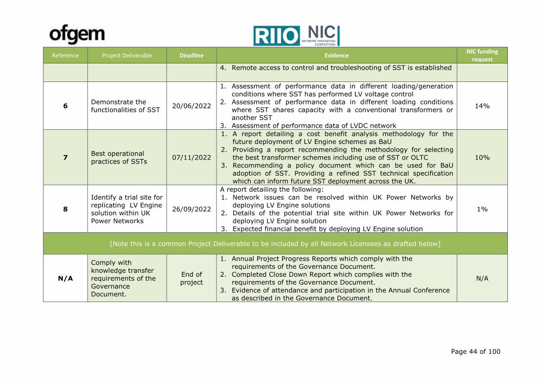
Page 44 of 100
Reference Project Deliverable Deadline Evidence NIC funding
request
4. Remote access to control and troubleshooting of SST is established
6 Demonstrate the
functionalities of SST 20/06/2022
1. Assessment of performance data in different loading/generation
conditions where SST has performed LV voltage control
2. Assessment of performance data in different loading conditions
where SST shares capacity with a conventional transformers or
another SST
3. Assessment of performance data of LVDC network
14%
7 Best operational
practices of SSTs 07/11/2022
1. A report detailing a cost benefit analysis methodology for the
future deployment of LV Engine schemes as BaU
2. Providing a report recommending the methodology for selecting
the best transformer schemes including use of SST or OLTC
3. Recommending a policy document which can be used for BaU
adoption of SST. Providing a refined SST technical specification
which can inform future SST deployment across the UK.
10%
8
Identify a trial site for
replicating LV Engine
solution within UK
Power Networks
26/09/2022
A report detailing the following:
1. Network issues can be resolved within UK Power Networks by
deploying LV Engine solutions
2. Details of the potential trial site within UK Power Networks for
deploying LV Engine solution
3. Expected financial benefit by deploying LV Engine solution
1%
[Note this is a common Project Deliverable to be included by all Network Licensees as drafted below]
N/A
Comply with
knowledge transfer
requirements of the
Governance
Document.
End of
project
1. Annual Project Progress Reports which comply with the
requirements of the Governance Document.
2. Completed Close Down Report which complies with the
requirements of the Governance Document.
3. Evidence of attendance and participation in the Annual Conference
as described in the Governance Document.
N/A
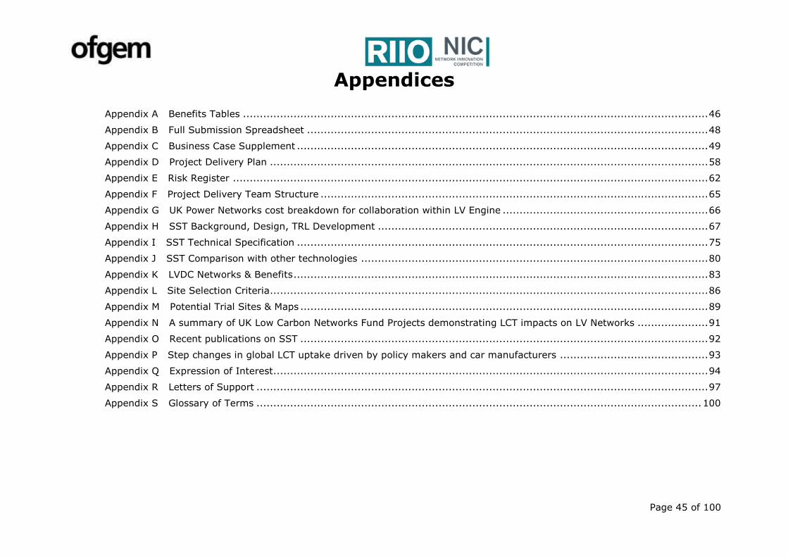
Page 45 of 100
Appendices
Appendix A Benefits Tables .......................................................................................................................................... 46
Appendix B Full Submission Spreadsheet ....................................................................................................................... 48
Appendix C Business Case Supplement .......................................................................................................................... 49
Appendix D Project Delivery Plan .................................................................................................................................. 58
Appendix E Risk Register ............................................................................................................................................. 62
Appendix F Project Delivery Team Structure ................................................................................................................... 65
Appendix G UK Power Networks cost breakdown for collaboration within LV Engine ............................................................. 66
Appendix H SST Background, Design, TRL Development .................................................................................................. 67
Appendix I SST Technical Specification .......................................................................................................................... 75
Appendix J SST Comparison with other technologies ....................................................................................................... 80
Appendix K LVDC Networks & Benefits ........................................................................................................................... 83
Appendix L Site Selection Criteria .................................................................................................................................. 86
Appendix M Potential Trial Sites & Maps ......................................................................................................................... 89
Appendix N A summary of UK Low Carbon Networks Fund Projects demonstrating LCT impacts on LV Networks ..................... 91
Appendix O Recent publications on SST ......................................................................................................................... 92
Appendix P Step changes in global LCT uptake driven by policy makers and car manufacturers ............................................ 93
Appendix Q Expression of Interest ................................................................................................................................. 94
Appendix R Letters of Support ...................................................................................................................................... 97
Appendix S Glossary of Terms .................................................................................................................................... 100
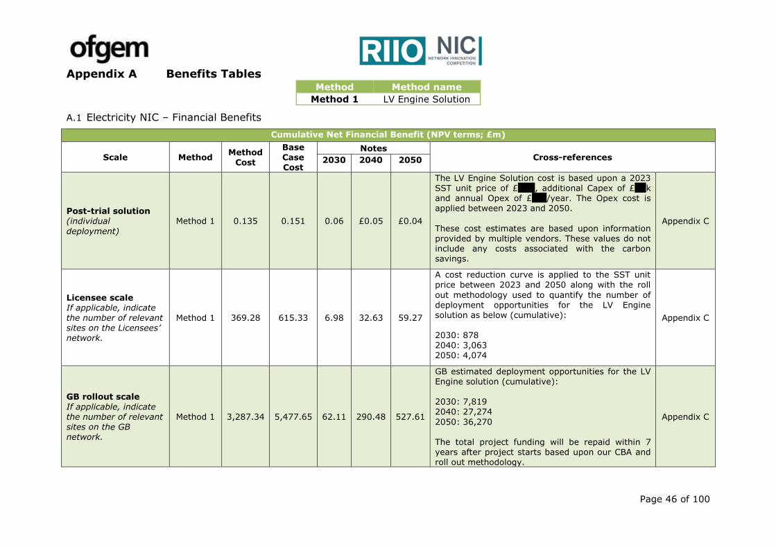
Page 46 of 100
Appendix A Benefits Tables Method Method name
Method 1 LV Engine Solution
A.1 Electricity NIC – Financial Benefits
Cumulative Net Financial Benefit (NPV terms; £m)
Scale Method Method
Cost
Base Case Cost
Notes Cross-references 2030 2040 2050
Post-trial solution (individual
deployment)
Method 1 0.135 0.151 0.06 £0.05 £0.04
The LV Engine Solution cost is based upon a 2023 SST unit price of £XXX, additional Capex of £XXk and annual Opex of £xxx/year. The Opex cost is applied between 2023 and 2050.
These cost estimates are based upon information provided by multiple vendors. These values do not include any costs associated with the carbon savings.
Appendix C
Licensee scale If applicable, indicate the number of relevant sites on the Licensees’ network.
Method 1 369.28 615.33 6.98 32.63 59.27
A cost reduction curve is applied to the SST unit price between 2023 and 2050 along with the roll
out methodology used to quantify the number of deployment opportunities for the LV Engine solution as below (cumulative): 2030: 878 2040: 3,063 2050: 4,074
Appendix C
GB rollout scale
If applicable, indicate the number of relevant sites on the GB network.
Method 1 3,287.34 5,477.65 62.11 290.48 527.61
GB estimated deployment opportunities for the LV Engine solution (cumulative): 2030: 7,819
2040: 27,274
2050: 36,270 The total project funding will be repaid within 7 years after project starts based upon our CBA and roll out methodology.
Appendix C

Page 47 of 100
A.2 Electricity NIC – Carbon and/or Environmental Benefits
Cumulative Carbon Benefit (tCO2e)
Scale Method Method
Cost
Base
Case Cost
Notes Cross-references
2030 2040 2050
Post-trial solution (individual deployment)
Method 1 0.135 0.151 27 -25 -47
Carbon benefits include CO2 emissions associated with the civil works and timing of the LV
Engine solution and the
counterfactual. Also includes CO2 emission associated with the losses of both options.
Our calculations do not include the CO2 benefits associated with the potential loss savings of a future LVDC network.
Appendix C
Licensee scale
If applicable, indicate the number of relevant sites on the Licensees’ network.
Method 1 369.28 615.33 46,991 129,883 147,614
Cumulative number of
deployments across SP Energy
Networks: 2030: 878 2040: 3,064 2050: 4,074
Appendix C
GB rollout scale If applicable, indicate the number of relevant sites on the GB network.
Method 1 3,287.34 5,477.65 418,307 1,156,207 1,314,050
Cumulative number of deployments across GB: 2030:7,819 2040:27,274 2050:36,270
Appendix C
If applicable, indicate any environmental benefits which cannot be expressed as tCO2e.
The carbon benefits listed above do not consider the savings that could be realised by enabling a future LVDC network. A LVDC network can significantly reduce network and customer losses by removing the need to continuous rectification between AC and DC. This reduction in losses could significantly reduce the energy consumed on the LV network and bring considerable carbon savings alongside the financial benefits. Increased transfer capacity at LVDC could also further reduce the need for LV cabling and the associated carbon impact by converting AC circuits to DC in the future. This has also not been included within the carbon benefits calculation.
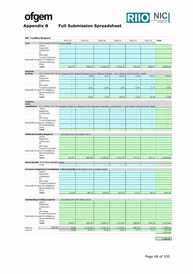
Page 48 of 100
Appendix B Full Submission Spreadsheet
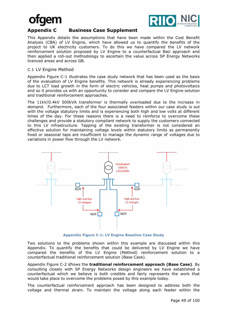
Page 49 of 100
Appendix C Business Case Supplement
This Appendix details the assumptions that have been made within the Cost Benefit
Analysis (CBA) of LV Engine, which have allowed us to quantify the benefits of the
project to UK electricity customers. To do this we have compared the LV network
reinforcement solution proposed by LV Engine to a counterfactual BaU approach and
then applied a roll-out methodology to ascertain the value across SP Energy Networks
licenced areas and across GB.
C.1 LV Engine Method
Appendix Figure C-1 illustrates the case study network that has been used as the basis
of the evaluation of LV Engine benefits. This network is already experiencing problems
due to LCT load growth in the form of electric vehicles, heat pumps and photovoltaics
and so it provides us with an opportunity to consider and compare the LV Engine solution
and traditional reinforcement approaches.
The 11kV/0.4kV 500kVA transformer is thermally overloaded due to the increase in
demand. Furthermore, each of the four associated feeders within our case study is out
with the voltage statutory limits and is experiencing both high and low volts at different
times of the day. For these reasons there is a need to reinforce to overcome these
challenges and provide a statutory compliant network to supply the customers connected
to this LV infrastructure. Tapping of the existing transformer is not considered an
effective solution for maintaining voltage levels within statutory limits as permanently
fixed or seasonal taps are insufficient to manage the dynamic range of voltages due to
variations in power flow through the LV network.
Appendix Figure C-1: LV Engine Baseline Case Study
Two solutions to the problems shown within this example are discussed within this
Appendix. To quantify the benefits that could be delivered by LV Engine we have
compared the benefits of the LV Engine (Method) reinforcement solution to a
counterfactual traditional reinforcement solution (Base Case).
Appendix Figure C-2 shows the traditional reinforcement approach (Base Case). By
consulting closely with SP Energy Networks design engineers we have established a
counterfactual which we believe is both credible and fairly represents the work that
would take place to overcome the problems posed by this example today.
The counterfactual reinforcement approach has been designed to address both the
voltage and thermal strain. To maintain the voltage along each feeder within the
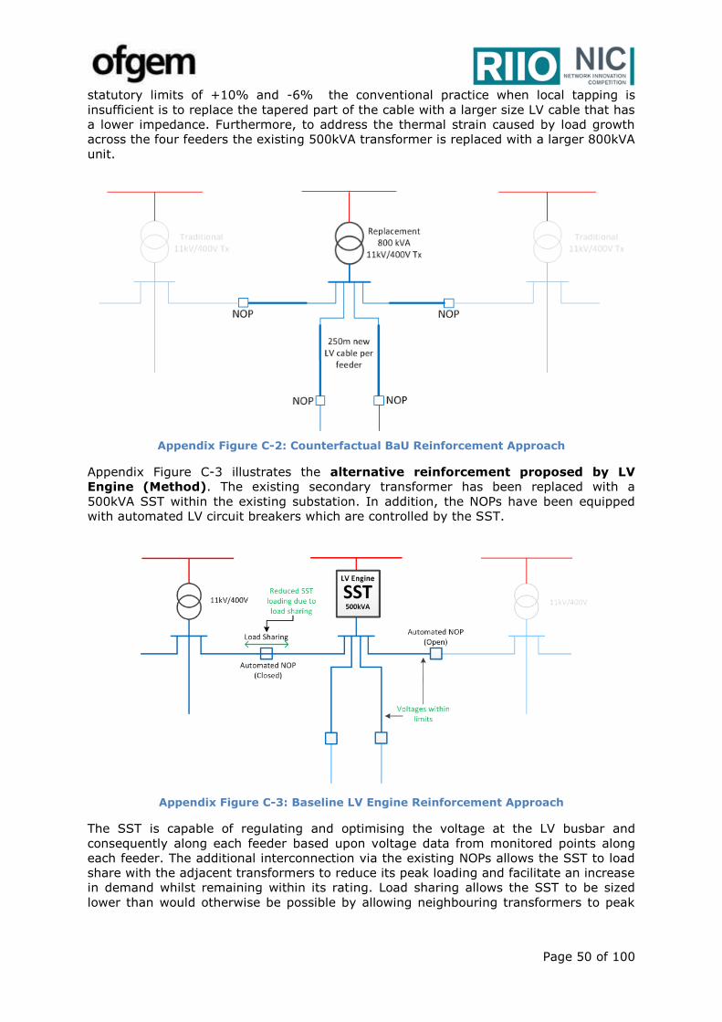
Page 50 of 100
statutory limits of +10% and -6% the conventional practice when local tapping is
insufficient is to replace the tapered part of the cable with a larger size LV cable that has
a lower impedance. Furthermore, to address the thermal strain caused by load growth
across the four feeders the existing 500kVA transformer is replaced with a larger 800kVA
unit.
Appendix Figure C-2: Counterfactual BaU Reinforcement Approach
Appendix Figure C-3 illustrates the alternative reinforcement proposed by LV
Engine (Method). The existing secondary transformer has been replaced with a
500kVA SST within the existing substation. In addition, the NOPs have been equipped
with automated LV circuit breakers which are controlled by the SST.
Appendix Figure C-3: Baseline LV Engine Reinforcement Approach
The SST is capable of regulating and optimising the voltage at the LV busbar and
consequently along each feeder based upon voltage data from monitored points along
each feeder. The additional interconnection via the existing NOPs allows the SST to load
share with the adjacent transformers to reduce its peak loading and facilitate an increase
in demand whilst remaining within its rating. Load sharing allows the SST to be sized
lower than would otherwise be possible by allowing neighbouring transformers to peak

Page 51 of 100
shave the maximum loading. This additional LV network flexibility will also benefit the
neighbouring transformers with complementary load profiles if SST capacity is available.
C.2 Roll Out Methodology
Opportunities for LV Engine have been identified when the majority of feeder circuits
associated with a Ground Mounted Transformer have voltage issues. These could be
voltages outside of permitted limits due to the uptake of generation, additional demand
or both. Gone Green projections from National Grid’s 2016 Future Energy Scenarios for
future LV generation, EVs and domestic demand including heat pumps have been
considered. These have been used in conjunction with the average penetration levels
leading to voltage issues reported as part of Electricity North West’s LV Network
Solutions project. This extensive study of real LV networks showed that customers
experience voltage problems when more than 30% of customers install PV generation
and when more than 50% of customers install heat pumps. LV Engine is assumed to be
applied based upon satisfying a proportion of the total requirements, specifically as
shown in Appendix Figure C-4, a market share which reduces to 37% in 2050, when
alternative techniques or products may be available for accommodating LV LCT
connections economically. Appendix Figure C-5 shows the uptake of LV Engine
culminating at approximately 16% of today’s traditional GMTs being replaced by LV
Engine SSTs by 2050.
Appendix Figure C-4: Cumulative GB
Opportunities for LV Engine
Appendix Figure C-5: Assumed market share serviced by LV Engine
C.3 Financial Benefits
Financial benefits have been evaluated by comparing the total costs for the Base Case
and LV Engine method which have been built up by considering the individual
components.
Appendix Table C-1 summarises the Capex and Opex costs for the Base Case
(counterfactual) . Capex costs include allowances for the substation items and the
additional cable required along each feeder to address the voltage issues. Opex costs
include allowances for inspection and oil replacement. Costs are based on the values
given in SP Energy Networks’ unit cost manual and or established through discussions
with SP Energy Networks’ Design Engineers and Asset Management teams.
Appendix Table C-1: Base Case (Counterfactual) Capex and Opex
Capex Cost
Substation Items £ 17,145
Cable Circuit Items £ 132,259
Total £ 149,404
Opex Cost
Annual £ 74

Page 52 of 100
Appendix Table C-2 details the Capex and Opex associated with the LV Engine method
should the solution be rolled out on mass as BaU at the end of the project. LV Engine
Capex costs include allowances for the SST, control, protection modifications and NOP
automation. Opex costs include allowances for inspection and replacement of the filters
and fans. We have established these cost estimates based upon our engagement with
multiple vendors and in reference to SP Energy Networks’ unit cost manual and
experience with other NIA & NIC innovation projects. We expect the unit cost of the SST
to fall as the TRL level of the technology continues to increase. A SST unit cost of £XXX
in 2023, falling to £XXk in 2050 has been reflected within the analysis of the LV Engine
financial benefits. We have included a specific deliverable within the scope of LV Engine
to better understand the O&M requirements of SSTs to inform how the technology could
be effectively adopted by BaU practices.
Appendix Table C-2: LV Engine Capex and Opex by 2050
Capex Cost
LV Engine £ xx,xxx
Opex Cost
Annual £ xxx
C.4 LV Engine impact on losses
The cost of losses has been included in the CBA on the basis of the value of losses, the
estimated percentage change in losses and the energy supplied via the number of
applications of LV Engine in GB and SP Energy Networks as determined by our roll out
methodology.
LV Engine has the potential to deliver significant savings by reducing network
losses if SSTs are rolled out across the UK. Voltage control of each phase at both LV and
11kV and the capability to provide a LVDC supply to customers can both contribute
significantly to this saving. However, this is not reflected in the benefits analysis at
this stage as the uptake rate of DC and the impact of voltage control on losses is difficult
to forecast. Consequently, a conservative approach has been taken when
calculating the benefits an SST can bring to network losses. Specific deliverables
within LV Engine will allow these factors to be quantified reliably as an output of the
project.
The following factors have been quantified and included in our CBA as
additional losses:
SST efficiency: LV Engine will initially increase losses as the efficiency of an SST (98%)
is lower than that of a traditional 11kV/LV transformer (99.4%). However, it is expected
that technological advancements in semi-conductors will allow the losses experienced
through an SST to match that of a traditional transformer by 2050. Consequently, these
additional losses have been reflected in our CBA but reduce each year as efficiency
increases towards 2050.
Base Case reduced network impedance: The counterfactual base case includes the
replacement of a large proportion of each LV feeder with a larger size cable with a lower
impedance. Consequently, network losses are reduced relative to the method employed
by LV Engine. This has been quantified and included within our benefits analysis based
upon the number of deployment opportunities calculated by our roll out methodology.
Higher utilisation of LV network: Within the benefits analysis we have included an
increase in the LV network utilisation factor for both the Base Case and LV Engine
methods. Therefore, the additional network losses described above are calculated based
upon a higher utilisation of the network post reinforcement.
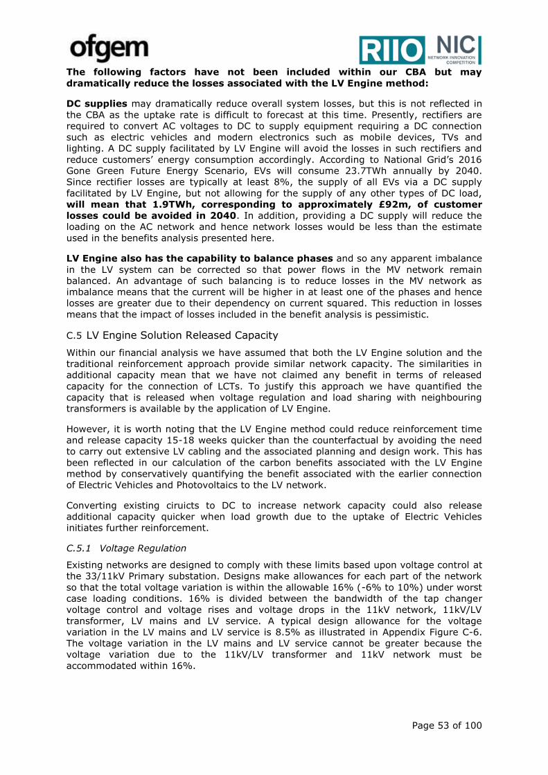
Page 53 of 100
The following factors have not been included within our CBA but may
dramatically reduce the losses associated with the LV Engine method:
DC supplies may dramatically reduce overall system losses, but this is not reflected in
the CBA as the uptake rate is difficult to forecast at this time. Presently, rectifiers are
required to convert AC voltages to DC to supply equipment requiring a DC connection
such as electric vehicles and modern electronics such as mobile devices, TVs and
lighting. A DC supply facilitated by LV Engine will avoid the losses in such rectifiers and
reduce customers’ energy consumption accordingly. According to National Grid’s 2016
Gone Green Future Energy Scenario, EVs will consume 23.7TWh annually by 2040.
Since rectifier losses are typically at least 8%, the supply of all EVs via a DC supply
facilitated by LV Engine, but not allowing for the supply of any other types of DC load,
will mean that 1.9TWh, corresponding to approximately £92m, of customer
losses could be avoided in 2040. In addition, providing a DC supply will reduce the
loading on the AC network and hence network losses would be less than the estimate
used in the benefits analysis presented here.
LV Engine also has the capability to balance phases and so any apparent imbalance
in the LV system can be corrected so that power flows in the MV network remain
balanced. An advantage of such balancing is to reduce losses in the MV network as
imbalance means that the current will be higher in at least one of the phases and hence
losses are greater due to their dependency on current squared. This reduction in losses
means that the impact of losses included in the benefit analysis is pessimistic.
C.5 LV Engine Solution Released Capacity
Within our financial analysis we have assumed that both the LV Engine solution and the
traditional reinforcement approach provide similar network capacity. The similarities in
additional capacity mean that we have not claimed any benefit in terms of released
capacity for the connection of LCTs. To justify this approach we have quantified the
capacity that is released when voltage regulation and load sharing with neighbouring
transformers is available by the application of LV Engine.
However, it is worth noting that the LV Engine method could reduce reinforcement time
and release capacity 15-18 weeks quicker than the counterfactual by avoiding the need
to carry out extensive LV cabling and the associated planning and design work. This has
been reflected in our calculation of the carbon benefits associated with the LV Engine
method by conservatively quantifying the benefit associated with the earlier connection
of Electric Vehicles and Photovoltaics to the LV network.
Converting existing ciruicts to DC to increase network capacity could also release
additional capacity quicker when load growth due to the uptake of Electric Vehicles
initiates further reinforcement.
C.5.1 Voltage Regulation
Existing networks are designed to comply with these limits based upon voltage control at
the 33/11kV Primary substation. Designs make allowances for each part of the network
so that the total voltage variation is within the allowable 16% (-6% to 10%) under worst
case loading conditions. 16% is divided between the bandwidth of the tap changer
voltage control and voltage rises and voltage drops in the 11kV network, 11kV/LV
transformer, LV mains and LV service. A typical design allowance for the voltage
variation in the LV mains and LV service is 8.5% as illustrated in Appendix Figure C-6.
The voltage variation in the LV mains and LV service cannot be greater because the
voltage variation due to the 11kV/LV transformer and 11kV network must be
accommodated within 16%.
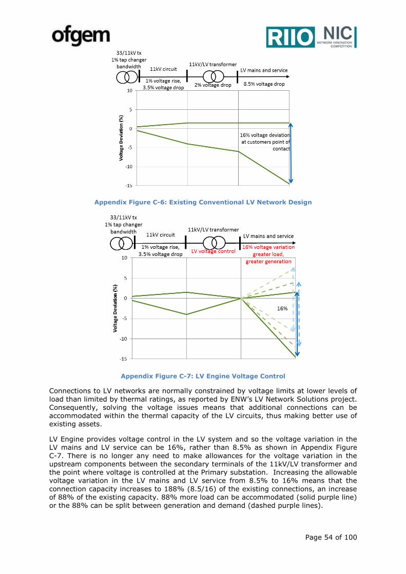
Page 54 of 100
Appendix Figure C-6: Existing Conventional LV Network Design
Appendix Figure C-7: LV Engine Voltage Control
Connections to LV networks are normally constrained by voltage limits at lower levels of
load than limited by thermal ratings, as reported by ENW’s LV Network Solutions project.
Consequently, solving the voltage issues means that additional connections can be
accommodated within the thermal capacity of the LV circuits, thus making better use of
existing assets.
LV Engine provides voltage control in the LV system and so the voltage variation in the
LV mains and LV service can be 16%, rather than 8.5% as shown in Appendix Figure
C-7. There is no longer any need to make allowances for the voltage variation in the
upstream components between the secondary terminals of the 11kV/LV transformer and
the point where voltage is controlled at the Primary substation. Increasing the allowable
voltage variation in the LV mains and LV service from 8.5% to 16% means that the
connection capacity increases to 188% (8.5/16) of the existing connections, an increase
of 88% of the existing capacity. 88% more load can be accommodated (solid purple line)
or the 88% can be split between generation and demand (dashed purple lines).
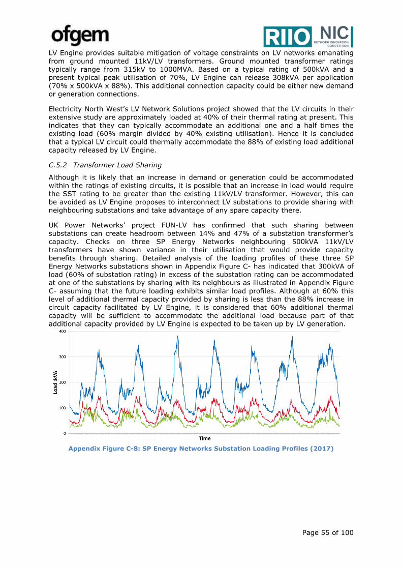
Page 55 of 100
LV Engine provides suitable mitigation of voltage constraints on LV networks emanating
from ground mounted 11kV/LV transformers. Ground mounted transformer ratings
typically range from 315kV to 1000MVA. Based on a typical rating of 500kVA and a
present typical peak utilisation of 70%, LV Engine can release 308kVA per application
(70% x 500kVA x 88%). This additional connection capacity could be either new demand
or generation connections.
Electricity North West’s LV Network Solutions project showed that the LV circuits in their
extensive study are approximately loaded at 40% of their thermal rating at present. This
indicates that they can typically accommodate an additional one and a half times the
existing load (60% margin divided by 40% existing utilisation). Hence it is concluded
that a typical LV circuit could thermally accommodate the 88% of existing load additional
capacity released by LV Engine.
C.5.2 Transformer Load Sharing
Although it is likely that an increase in demand or generation could be accommodated
within the ratings of existing circuits, it is possible that an increase in load would require
the SST rating to be greater than the existing 11kV/LV transformer. However, this can
be avoided as LV Engine proposes to interconnect LV substations to provide sharing with
neighbouring substations and take advantage of any spare capacity there.
UK Power Networks’ project FUN-LV has confirmed that such sharing between
substations can create headroom between 14% and 47% of a substation transformer’s
capacity. Checks on three SP Energy Networks neighbouring 500kVA 11kV/LV
transformers have shown variance in their utilisation that would provide capacity
benefits through sharing. Detailed analysis of the loading profiles of these three SP
Energy Networks substations shown in Appendix Figure C- has indicated that 300kVA of
load (60% of substation rating) in excess of the substation rating can be accommodated
at one of the substations by sharing with its neighbours as illustrated in Appendix Figure
C- assuming that the future loading exhibits similar load profiles. Although at 60% this
level of additional thermal capacity provided by sharing is less than the 88% increase in
circuit capacity facilitated by LV Engine, it is considered that 60% additional thermal
capacity will be sufficient to accommodate the additional load because part of that
additional capacity provided by LV Engine is expected to be taken up by LV generation.
Appendix Figure C-8: SP Energy Networks Substation Loading Profiles (2017)
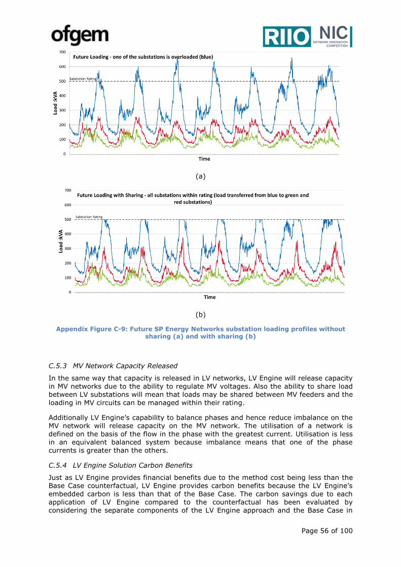
Page 56 of 100
(a)
(b)
Appendix Figure C-9: Future SP Energy Networks substation loading profiles without sharing (a) and with sharing (b)
C.5.3 MV Network Capacity Released
In the same way that capacity is released in LV networks, LV Engine will release capacity
in MV networks due to the ability to regulate MV voltages. Also the ability to share load
between LV substations will mean that loads may be shared between MV feeders and the
loading in MV circuits can be managed within their rating.
Additionally LV Engine’s capability to balance phases and hence reduce imbalance on the
MV network will release capacity on the MV network. The utilisation of a network is
defined on the basis of the flow in the phase with the greatest current. Utilisation is less
in an equivalent balanced system because imbalance means that one of the phase
currents is greater than the others.
C.5.4 LV Engine Solution Carbon Benefits
Just as LV Engine provides financial benefits due to the method cost being less than the
Base Case counterfactual, LV Engine provides carbon benefits because the LV Engine’s
embedded carbon is less than that of the Base Case. The carbon savings due to each
application of LV Engine compared to the counterfactual has been evaluated by
considering the separate components of the LV Engine approach and the Base Case in

Page 57 of 100
the same way that the financial benefit per application was determined. Manufacture and
installation of equipment has embedded carbon which is determined through
consideration of the material and lifecycle assessment. Values for the embedded carbon
in cables and 11kV/LV transformers arising from previous innovation projects have been
adopted in our evaluation. Where values were not available, then the embedded carbon
has been estimated based upon the carbon value for the material type and the
equipment weight. In the case of LV Engine’s SST, the embedded carbon has
pessimistically been assumed to be the same as an equivalent traditional transformer,
on the basis that an SST comprises small transformers alongside the power electronics.
Carbon benefits due to the application of LV Engine in GB and the SP Energy Networks
region have been determined by considering the number of applications resulting from
the aforementioned roll out methodology.
Operational carbon impacts arise due to losses and the associated use of electrical
energy. Carbon impacts due to LV Engine’s effect on losses have been evaluated using
electricity conversion factors (tonnes per MWh) published by the UK government. The
increase in the utilisation of existing circuits and associated increase in losses means
that carbon is expected to increase also.
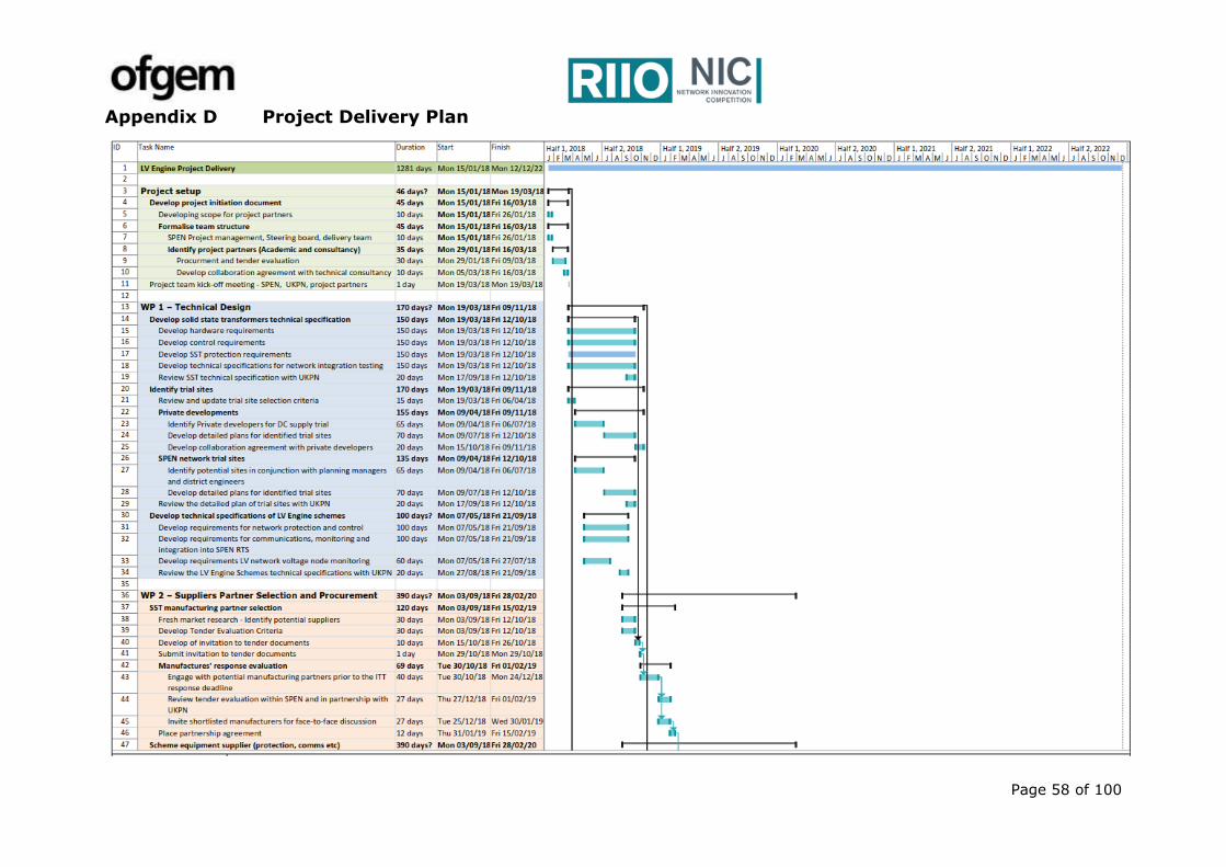
Page 58 of 100
Appendix D Project Delivery Plan
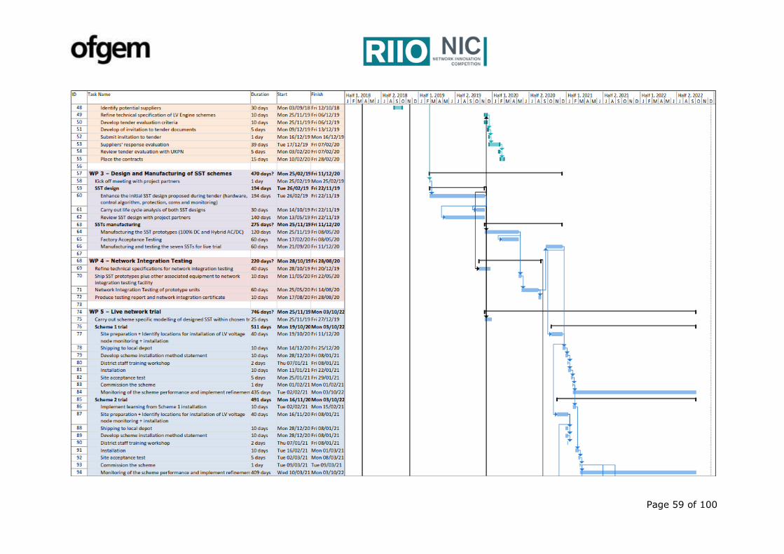
Page 59 of 100
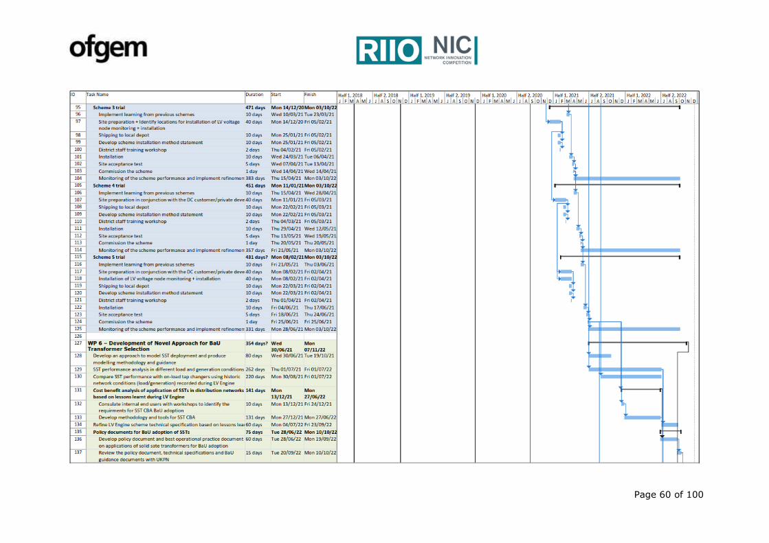
Page 60 of 100

Page 61 of 100
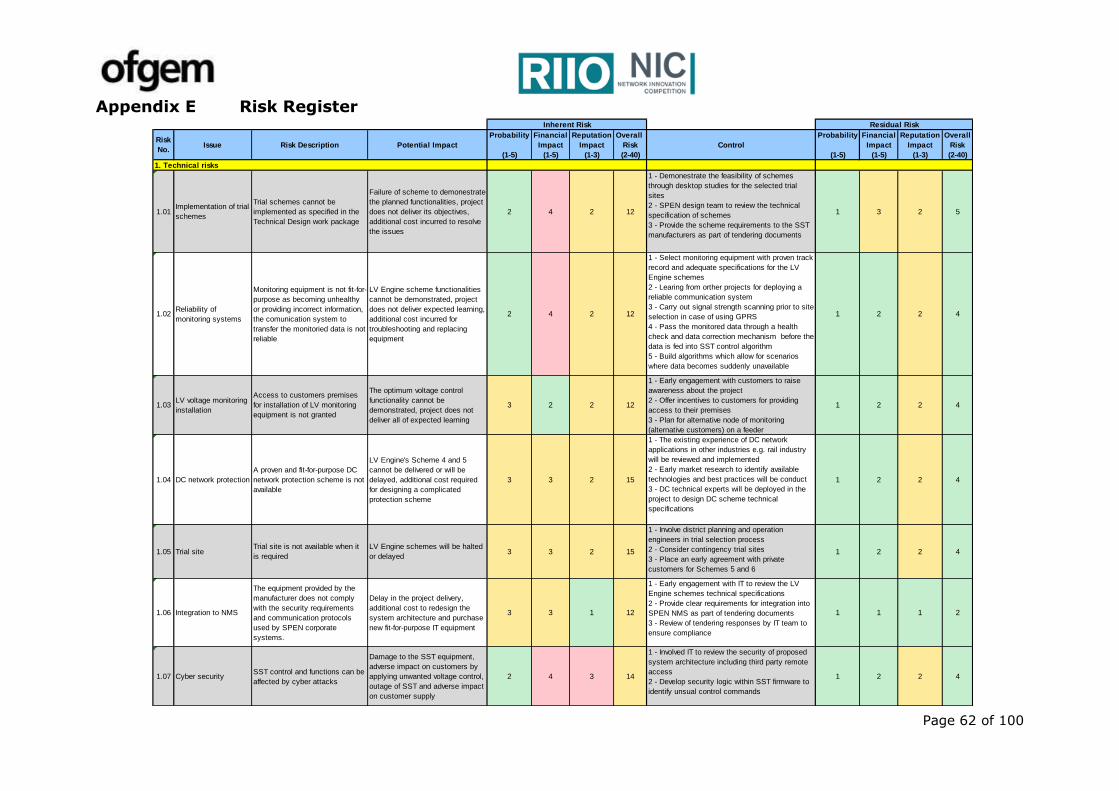
Page 62 of 100
Probability Financial Reputation Overall Probability Financial Reputation Overall
Impact Impact Risk Impact Impact Risk
(1-5) (1-5) (1-3) (2-40) (1-5) (1-5) (1-3) (2-40)
1. Technical risks
1.01Implementation of trial
schemes
Trial schemes cannot be
implemented as specified in the
Technical Design work package
Failure of scheme to demonestrate
the planned functionalities, project
does not deliver its objectives,
additional cost incurred to resolve
the issues
2 4 2 12
1 - Demonestrate the feasibility of schemes
through desktop studies for the selected trial
sites
2 - SPEN design team to review the technical
specification of schemes
3 - Provide the scheme requirements to the SST
manufacturers as part of tendering documents
1 3 2 5
1.02Reliability of
monitoring systems
Monitoring equipment is not fit-for-
purpose as becoming unhealthy
or providing incorrect information,
the comunication system to
transfer the monitoried data is not
reliable
LV Engine scheme functionalities
cannot be demonstrated, project
does not deliver expected learning,
additional cost incurred for
troubleshooting and replacing
equipment
2 4 2 12
1 - Select monitoring equipment with proven track
record and adequate specifications for the LV
Engine schemes
2 - Learing from orther projects for deploying a
reliable communication system
3 - Carry out signal strength scanning prior to site
selection in case of using GPRS
4 - Pass the monitored data through a health
check and data correction mechanism before the
data is fed into SST control algorithm
5 - Build algorithms which allow for scenarios
where data becomes suddenly unavailable
1 2 2 4
1.03LV voltage monitoring
installation
Access to customers premises
for installation of LV monitoring
equipment is not granted
The optimum voltage control
functionality cannot be
demonstrated, project does not
deliver all of expected learning
3 2 2 12
1 - Early engagement with customers to raise
awareness about the project
2 - Offer incentives to customers for providing
access to their premises
3 - Plan for alternative node of monitoring
(alternative customers) on a feeder
1 2 2 4
1.04 DC network protection
A proven and fit-for-purpose DC
network protection scheme is not
available
LV Engine's Scheme 4 and 5
cannot be delivered or will be
delayed, additional cost required
for designing a complicated
protection scheme
3 3 2 15
1 - The existing experience of DC network
applications in other industries e.g. rail industry
will be reviewed and implemented
2 - Early market research to identify available
technologies and best practices will be conduct
3 - DC technical experts will be deployed in the
project to design DC scheme technical
specifications
1 2 2 4
1.05 Trial siteTrial site is not available when it
is required
LV Engine schemes will be halted
or delayed3 3 2 15
1 - Involve district planning and operation
engineers in trial selection process
2 - Consider contingency trial sites
3 - Place an early agreement with private
customers for Schemes 5 and 6
1 2 2 4
1.06 Integration to NMS
The equipment provided by the
manufacturer does not comply
with the security requirements
and communication protocols
used by SPEN corporate
systems.
Delay in the project delivery,
additional cost to redesign the
system architecture and purchase
new fit-for-purpose IT equipment
3 3 1 12
1 - Early engagement with IT to review the LV
Engine schemes technical specifications
2 - Provide clear requirements for integration into
SPEN NMS as part of tendering documents
3 - Review of tendering responses by IT team to
ensure compliance
1 1 1 2
1.07 Cyber securitySST control and functions can be
affected by cyber attacks
Damage to the SST equipment,
adverse impact on customers by
applying unwanted voltage control,
outage of SST and adverse impact
on customer supply
2 4 3 14
1 - Involved IT to review the security of proposed
system architecture including third party remote
access
2 - Develop security logic within SST firmware to
identify unsual control commands
1 2 2 4
Risk
No.
Inherent Risk Residual Risk
Potential ImpactRisk DescriptionIssue Control
Appendix E Risk Register
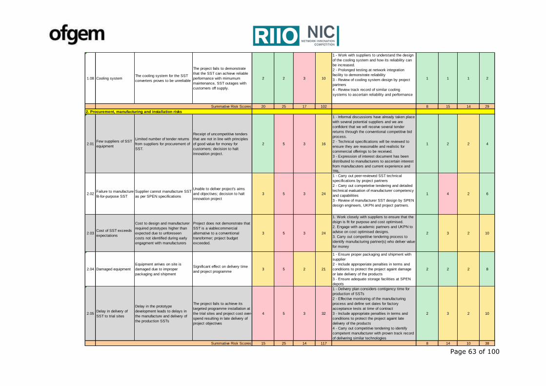
Page 63 of 100
1.08 Cooling systemThe cooling system for the SST
converters proves to be unreliable
The project fails to demonstrate
that the SST can achieve reliable
performance with mimumum
maintenance, SST outages with
customers off supply.
2 2 3 10
1 - Work with suppliers to understand the design
of the cooling system and how its reliability can
be increased.
2 - Prolonged testing at network integration
facility to demonstrate reliability
3 - Review of cooling system design by project
partners
4 - Review track record of similar cooling
systems to ascertain reliability and performance
1 1 1 2
20 25 17 102 8 15 14 29
2. Procurement, manufacturing and installation risks
2.01Few suppliers of SST
equipment
Limited number of tender returns
from suppliers for procurement of
SST.
Receipt of uncompetitive tenders
that are not in line with principles
of good value for money for
customers; decision to halt
innovation project.
2 5 3 16
1 - Informal discussions have already taken place
with several potential suppliers and we are
confident that we will receive several tender
returns through the conventional competitive bid
process.
2 - Technical specifications will be reviewed to
ensure they are reasonable and realistic for
commercial offerings to be received.
3 - Expression of interest document has been
distributed to manufacturers to ascertain interest
from manufacuters and current experience and
TRL.
1 2 2 4
2.02Failure to manufacture
fit-for-purpose SST
Supplier cannot manufacture SST
as per SPEN specifications
Unable to deliver project's aims
and objectives; decision to halt
innovation project
3 5 3 24
1 - Carry out peer-reviewed SST technical
specifications by project partners
2 - Carry out competetive tendering and detailed
technical evaluation of manufacturer competency
and capabilities
3 - Review of manufacturer SST design by SPEN
design engineers, UKPN and project partners.
1 4 2 6
2.03Cost of SST exceeds
expectations
Cost to design and manufacturer
required prototypes higher than
expected due to unforeseen
costs not identified during early
engagment with manufacturers
Project does not demonstrate that
SST is a viablecommercial
alternative to a conventional
transformer; project budget
exceeded.
3 5 3 24
1. Work closely with suppliers to ensure that the
dsign is fit for purpose and cost optimised.
2. Engage with academic partners and UKPN to
advise on cost optimised designs.
3. Carry out competitive tendering process to
identify manufacturing partner(s) who deliver value
for money
2 3 2 10
2.04 Damaged equipment
Equipment arrives on site is
damaged due to improper
packaging and shipment
Significant effect on delivery time
and project programme3 5 2 21
1 - Ensure proper packaging and shipment with
supplier
2 - Include approperiate penalties in terms and
conditions to protect the project againt damage
or late delivery of the products
3 - Ensure adequate storage facilities at SPEN
depots
2 2 2 8
2.05Delay in delivery of
SST to trial sites
Delay in the prototype
development leads to delays in
the manufacture and delivery of
the production SSTs
The project fails to achieve its
targeted programme installation at
the trial sites and project cost over-
spend resulting in late delivery of
project objectives
4 5 3 32
1 - Delivery plan considers contigency time for
production of SSTs
2 - Effective monitoring of the manufacturing
process and define set dates for factory
acceptance tests at time of contract
3 - Include appropriate penalties in terms and
conditions to protect the project againt late
delivery of the products
4 - Carry out competitive tendering to identify
competent manufacturer with proven track record
of delivering similar technologies
2 3 2 10
15 25 14 117 8 14 10 38
Summative Risk Scores
Summative Risk Scores
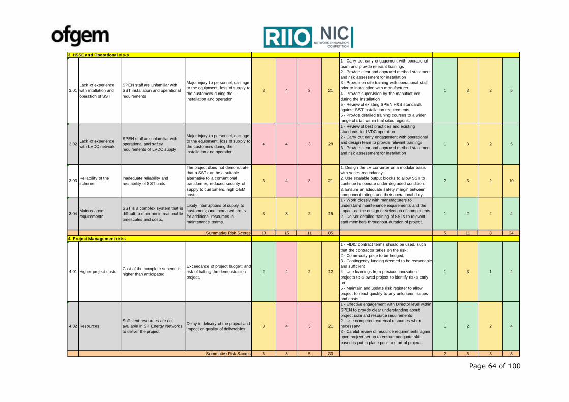
Page 64 of 100
3. HSSE and Operational risks
3.01
Lack of experience
with intallation and
operation of SST
SPEN staff are unfamiliar with
SST installation and operational
requirements
Major injury to personnel, damage
to the equipment, loss of supply to
the customers during the
installation and operation
3 4 3 21
1 - Carry out early engagement with operational
team and provide relevant trainings
2 - Provide clear and approved method statement
and risk assessment for installation
3 - Provide on site training with operational staff
prior to installation with manufacturer
4 - Provide supervision by the manufacturer
during the installation
5 - Review of existing SPEN H&S standards
against SST installation requirements
6 - Provide detailed training courses to a wider
range of staff within trial sites regions.
1 3 2 5
3.02Lack of experience
with LVDC network
SPEN staff are unfamiliar with
operational and saftey
requirements of LVDC supply
Major injury to personnel, damage
to the equipment, loss of supply to
the customers during the
installation and operation
4 4 3 28
1 - Review of best practices and existing
standards for LVDC operation
2 - Carry out early engagement with operational
and design team to provide relevant trainings
3 - Provide clear and approved method statement
and risk assessment for installation
1 3 2 5
3.03Reliability of the
scheme
Inadequate reliability and
availability of SST units
The project does not demonstrate
that a SST can be a suitable
alternative to a conventional
transformer, reduced security of
supply to customers, high O&M
costs.
3 4 3 21
1. Design the LV converter on a modular basis
with series redundancy.
2. Use scalable output blocks to allow SST to
continue to operate under degraded condition.
3. Ensure an adequate safety margin between
component ratings and their operational duty.
2 3 2 10
3.04Maintenance
requirements
SST is a complex system that is
difficult to maintain in reasonable
timescales and costs,
Likely interruptions of supply to
customers; and increased costs
for additional resources in
maintenance teams.
3 3 2 15
1 - Work closely with manufacturers to
understand maintenance requirements and the
impact on the design or selection of components
2 - Deliver detailed training of SSTs to relevant
staff members throughout duration of project.
1 2 2 4
13 15 11 85 5 11 8 24
4. Project Management risks
4.01 Higher project costsCost of the complete scheme is
higher than anticipated
Exceedance of project budget; and
risk of halting the demonstration
project.
2 4 2 12
1 - FIDIC contract terms should be used, such
that the contractor takes on the risk;
2 - Commodity price to be hedged.
3 - Contingency funding deemed to be reasonable
and sufficient
4 - Use learnings from previous innovation
projects to allowed project to identify risks early
on
5 - Maintain and update risk register to allow
project to react quickly to any unforseen issues
and costs.
1 3 1 4
4.02 Resources
Sufficient resources are not
available in SP Energy Networks
to deliver the project
Delay in delivery of the project and
impact on quality of deliverables3 4 3 21
1 - Effective engagement with Director level within
SPEN to provide clear understanding about
project size and resource requirements
2 - Use competent external resources where
necessary
3 - Careful review of resource requirements again
upon project set up to ensure adequate skill
based is put in place prior to start of project
1 2 2 4
5 8 5 33 2 5 3 8Summative Risk Scores
Summative Risk Scores
Page 65 of 100
Appendix F Project Delivery Team Structure
Specific roles and responsibilities have been defined for each project tasks and
deliverable. These roles are relevant to the activities identified within each project work
package and the project structure shown in Figure 6-2.
Project Manager (PM) - The LV Engine Project Manager (PM) will be responsible for
the successful day-to-day delivery of the LV Engine project against key performance
indicators, the project programme and budget. The PM will liaise with various parties
including the Project Steering Board, SP Energy Networks H&S, Operational, Legal and
Commercial Departments, Policy, Standards, Design Departments, Project delivery team
and internal and external stakeholders.
Project Delivery Team – The project delivery team will consist of internal SP Energy
Networks staff, technical consultant, academics and manufacturing partner. They will
support the PM throughout the duration of the project and carry out the tasks allocated
to the team. The final delivery team members will be identified during project set up to
ensure that all project deliverables are completed within time and budget.
Manufacturing Partner(s) – This party is responsible for the design, manufacturing
and testing of SSTs for the LV Engine schemes and support the team during installation, commissioning and troubleshooting required in the course of project.
Design Authority Board - UK Power Networks will carry out an independent review of
the different design and deliverables of LV Engine. This will ensure that the delivered
solutions are fit for purpose with suitable functionalities for adoption by other UK DNOs
into their BaU practices. UK Power Networks will also identify a potential trial site for replication of LV Engine solution within their Licensees.
Consultancy Support - Technical consultancy will work with internal SP Energy
Networks staff and provide support in the following areas where required: SST
specification, design of LV Engine schemes, development and deployment, system
modelling and trial site selection, algorithm development for power control, harmonic
and fault level studies, protection and earthing studies, LVDC distribution network
specification, policy and technical guidelines documentation and training.
Network Integration Testing Facility - The testing facility will provide technical
support during WP 2 & 3 and carry out suitable network integration testing of the SST
prototypes during WP 4. They will be responsible for de-risking the SST solution prior to deployment within SP Manweb (SPM) and SP Distribution (SPD) networks.
SPM & SPD District Support – The districts will be responsible for providing support
during trial site selection and SST deployment during the live network trials. They will carry out the installation of each SST scheme as detailed within WP 5.
SP Energy Networks Real Time Systems Team and IT – Responsible for the
effective integration of each trial scheme's monitoring into SP Energy Networks’ Network
Management System. IT team will also support the preparation of LV Engine IT system
architecture and compliance with IT security requirement.
Academic Partners - Input of specialist knowledge in order to optimise the SST
technology solution. Detailed studies on the reliability, O&M requirement and operational
performance of the SSTs will be delivered by the academic partner. In addition, our
academic partner support with the delivery of a detailed life cycle analysis of the chosen
SST designs.
Stakeholder Engagement Team – Responsible for delivering the LV Engine
stakeholder engagement methodology and providing assistance and guidance during project dissemination events and interaction with customers.
Knowledge Manager - The knowledge manager will be internally resourced within SP
Energy Networks, and will be responsible for the on-going capture and dissemination of
appropriate project learning through all relevant communication channels.
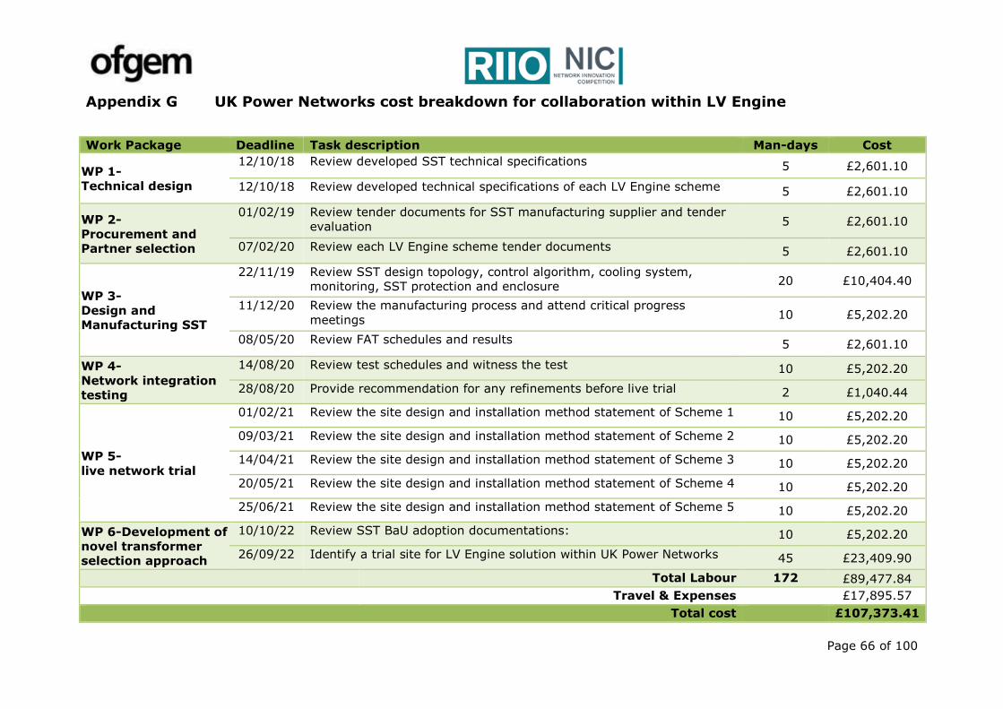
Page 66 of 100
Appendix G UK Power Networks cost breakdown for collaboration within LV Engine
Work Package Deadline Task description Man-days Cost
WP 1-
Technical design
12/10/18 Review developed SST technical specifications 5 £2,601.10
12/10/18 Review developed technical specifications of each LV Engine scheme 5 £2,601.10
WP 2-
Procurement and
Partner selection
01/02/19 Review tender documents for SST manufacturing supplier and tender
evaluation 5 £2,601.10
07/02/20 Review each LV Engine scheme tender documents 5 £2,601.10
WP 3-
Design and
Manufacturing SST
22/11/19 Review SST design topology, control algorithm, cooling system,
monitoring, SST protection and enclosure 20 £10,404.40
11/12/20 Review the manufacturing process and attend critical progress
meetings 10 £5,202.20
08/05/20 Review FAT schedules and results 5 £2,601.10
WP 4-
Network integration
testing
14/08/20 Review test schedules and witness the test 10 £5,202.20
28/08/20 Provide recommendation for any refinements before live trial 2 £1,040.44
WP 5-
live network trial
01/02/21 Review the site design and installation method statement of Scheme 1 10 £5,202.20
09/03/21 Review the site design and installation method statement of Scheme 2 10 £5,202.20
14/04/21 Review the site design and installation method statement of Scheme 3 10 £5,202.20
20/05/21 Review the site design and installation method statement of Scheme 4 10 £5,202.20
25/06/21 Review the site design and installation method statement of Scheme 5 10 £5,202.20
WP 6-Development of
novel transformer
selection approach
10/10/22 Review SST BaU adoption documentations: 10 £5,202.20
26/09/22 Identify a trial site for LV Engine solution within UK Power Networks 45 £23,409.90
Total Labour 172 £89,477.84
Travel & Expenses £17,895.57
Total cost £107,373.41
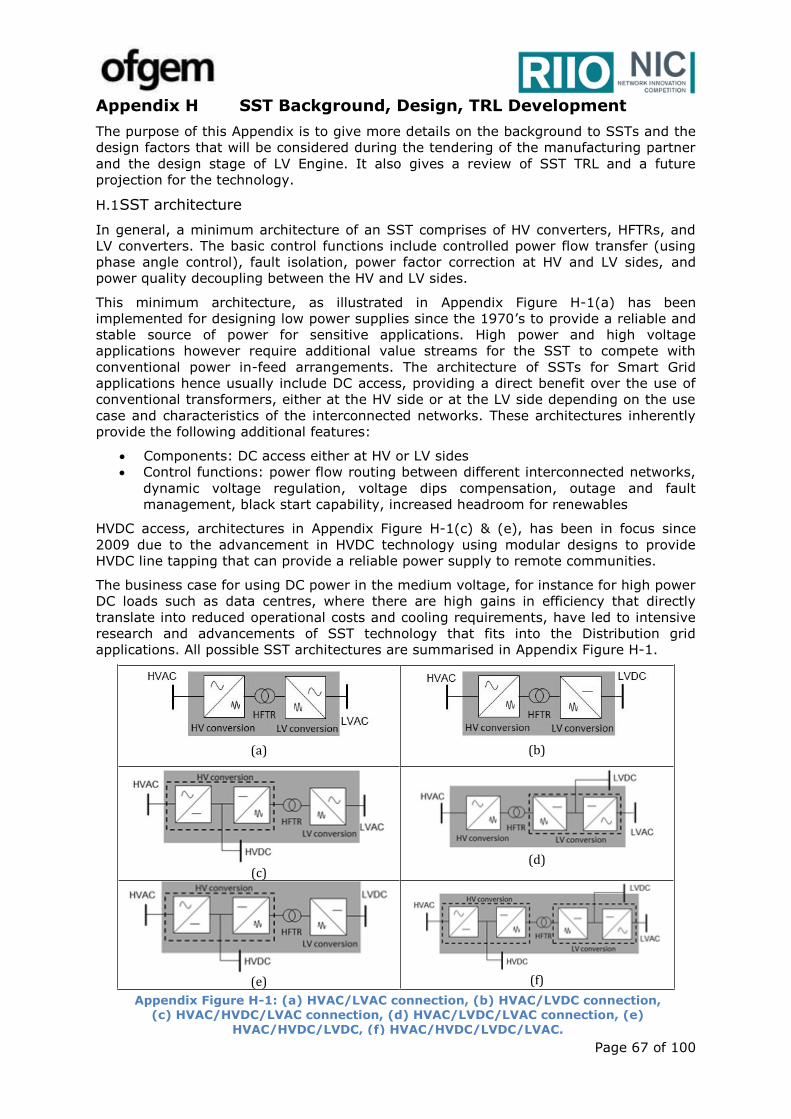
Page 67 of 100
Appendix H SST Background, Design, TRL Development
The purpose of this Appendix is to give more details on the background to SSTs and the
design factors that will be considered during the tendering of the manufacturing partner
and the design stage of LV Engine. It also gives a review of SST TRL and a future
projection for the technology.
H.1 SST architecture
In general, a minimum architecture of an SST comprises of HV converters, HFTRs, and
LV converters. The basic control functions include controlled power flow transfer (using
phase angle control), fault isolation, power factor correction at HV and LV sides, and
power quality decoupling between the HV and LV sides.
This minimum architecture, as illustrated in Appendix Figure H-1(a) has been
implemented for designing low power supplies since the 1970’s to provide a reliable and
stable source of power for sensitive applications. High power and high voltage
applications however require additional value streams for the SST to compete with
conventional power in-feed arrangements. The architecture of SSTs for Smart Grid
applications hence usually include DC access, providing a direct benefit over the use of
conventional transformers, either at the HV side or at the LV side depending on the use
case and characteristics of the interconnected networks. These architectures inherently
provide the following additional features:
Components: DC access either at HV or LV sides
Control functions: power flow routing between different interconnected networks,
dynamic voltage regulation, voltage dips compensation, outage and fault
management, black start capability, increased headroom for renewables
HVDC access, architectures in Appendix Figure H-1(c) & (e), has been in focus since
2009 due to the advancement in HVDC technology using modular designs to provide
HVDC line tapping that can provide a reliable power supply to remote communities.
The business case for using DC power in the medium voltage, for instance for high power
DC loads such as data centres, where there are high gains in efficiency that directly
translate into reduced operational costs and cooling requirements, have led to intensive
research and advancements of SST technology that fits into the Distribution grid
applications. All possible SST architectures are summarised in Appendix Figure H-1.
(a)
(b)
(c)
(d)
(e)
(f)
Appendix Figure H-1: (a) HVAC/LVAC connection, (b) HVAC/LVDC connection, (c) HVAC/HVDC/LVAC connection, (d) HVAC/LVDC/LVAC connection, (e)
HVAC/HVDC/LVDC, (f) HVAC/HVDC/LVDC/LVAC.
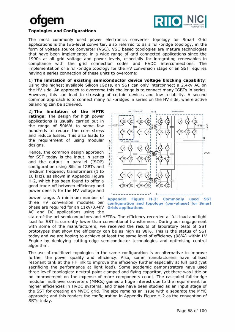
Page 68 of 100
Topologies and Configurations
The most commonly used power electronics converter topology for Smart Grid
applications is the two-level converter, also referred to as a full-bridge topology, in the
form of voltage source converter (VSC). VSC based topologies are mature technologies
that have been implemented in a wide range of grid connected applications since the
1990s at all grid voltage and power levels, especially for integrating renewables in
compliance with the grid connection codes and HVDC interconnections. The
implementation of a full-bridge topology for the HV conversion stage of an SST requires
having a series connection of these units to overcome:
1) The limitation of existing semiconductor device voltage blocking capability:
Using the highest available Silicon IGBTs, an SST can only interconnect a 2.4kV AC on
the HV side. An approach to overcome this challenge is to connect many IGBTs in series.
However, this can lead to stressing of certain devices and low reliability. A second
common approach is to connect many full-bridges in series on the HV side, where active
balancing can be achieved.
2) The limitation of the HFTR
ratings: The design for high power
applications is usually carried out in
the range of 50kVA to some few
hundreds to reduce the core stress
and reduce losses. This also leads to
the requirement of using modular
designs.
Hence, the common design approach
for SST today is the input in series
and the output in parallel (ISOP)
configuration using Silicon IGBTs and
medium frequency transformers (1 to
10 kHz), as shown in Appendix Figure
H-2, which has been found to offer a
good trade-off between efficiency and
power density for the MV voltage and
power range. A minimum number of
three HV conversion modules per
phase are required for an 11kV/0.4kV
AC and DC applications using the
state-of-the art semiconductors and HFTRs. The efficiency recorded at full load and light
load for SST is currently lower than conventional transformers. During our engagement
with some of the manufacturers, we received the results of laboratory tests of SST
prototypes that show the efficiency can be as high as 98%. This is the status of SST
today and we are hoping to achieve at least the same level of efficiency (98%) within LV
Engine by deploying cutting-edge semiconductor technologies and optimising control
algorithm.
The use of multilevel topologies in the same configuration is an alternative to improve
further the power quality and efficiency. Also, some manufacturers have utilised
resonant tank at the HF link to improve the efficiency further especially at full load (yet
sacrificing the performance at light load). Some academic demonstrators have used
three-level’ topologies: neutral-point clamped and flying capacitor, yet there was little or
no improvement on the expense of more components count. The cascaded full-bridge
modular multilevel converters (MMCs) gained a huge interest due to the requirement for
higher efficiencies in HVDC systems, and these have been studied as an input stage of
the SST for creating an MVDC grid. The size remains an issue with a separate the MMC
approach; and this renders the configuration in Appendix Figure H-2 as the convention of
SSTs today.
Appendix Figure H-2: Commonly used SST configuration and topology (per-phase) for Smart Grids applications
Page 69 of 100
H.2 SST origin, advancements
The concept of the SST dates back to the 1968 with the introduction of the “Electronic
Transformer” for fault current limiting and interruption and voltage regulation in low
power applications. It has since found different applications in different markets, where
its maturity and introduction to each market has different TRLs due to different
limitations, requirements and challenges of each market. Advancements in HVDC MFTR
and HFTRs for low power supplies are the main enablers for the Smart Grid applications
of SSTs, where there are some common requirements and similar benefits.
Academia and industry R&D has increased since 2015 for the application of SSTs within
Smart Grids. This is mainly due to advancements in two main technologies: the power
semiconductor devices and the HFTRs. It is important to note that, in 2015 SiC high
power modules were mass produced, allowing high frequency switching for high power
applications and consequently resulting in a decrease in magnetic components’ sizes and
comparable technology costs as for to the Silicon based designs.
H.3 Maturity, limitations and future outlook till 2050
There are two main elements that have a high impact on the design optimisation and
technology advancement of SSTs. These are;
High Frequency Transformers (HFTR)
Conventional 50Hz transformers are mature technology. Using these mature designs for
MF and HF applications provides a reduction in core material quantity as a function of
transformer frequency, and hence the losses globally decrease. This however introduces
a technology limitation as the core losses intensity increases, leading to high
temperature gradient and requirement for higher cooling requirements. In conventionally
wound transformers, a considerable amount of leakage flux enters the core, resulting in
localized core saturation and hotspots. This becomes a very critical issue especially for
high-power high-frequency transformers. Coaxially wound transformers are seen to be a
viable alternative in that the leakage flux is contained within the inter-winding space,
with very little or none of it permeating the core. Such transformers can also realize
multiple benefits of a low distributed and controllable leakage inductance, robust
construction, low electromechanical forces, and low core and copper losses.
At the lower end of the power scale there have been advancements driven by the
requirement for high efficiency inductive charging where there is a significant air gap
between the primary and secondary coils of the transformer. Although the application is
different from the Smart Grid’s, the technology can be conveniently introduced into an
ISOP SST due to its modularity.
To optimise the design of a HFTR to decrease its losses and size, an optimised selection
of core material, wire material and construction type for a specific range of operating
frequency is required. It was found that nanocrystalline core material and Litz wire
windings for the transformer design have the potential of optimising the HFTR for the
SST application in distribution grids. However, the R&D of magnetic materials for
transformers, filters and other passive components is not currently carried out on a
large. These components remain bespoke at a premium cost, and their introduction as
off-the-shelf will have a high impact on the cost of the SST.
Semiconductor Devices
Appendix Figure H-3 illustrates the evolution and TRL of high power semiconductors for
utilisation in Smart Grid products as observed in 2017, and Appendix Figure H-4
illustrates the impact of the introduction of these devices on the SST rating. There is
currently huge activities and R&D investment dedicated to developing HV (>10kV) and
high power (>1MVA) semiconductor packages for the smart grid towards 2050. In an
optimistic view, a single optimised SST will be rated for more than 5MVA with and
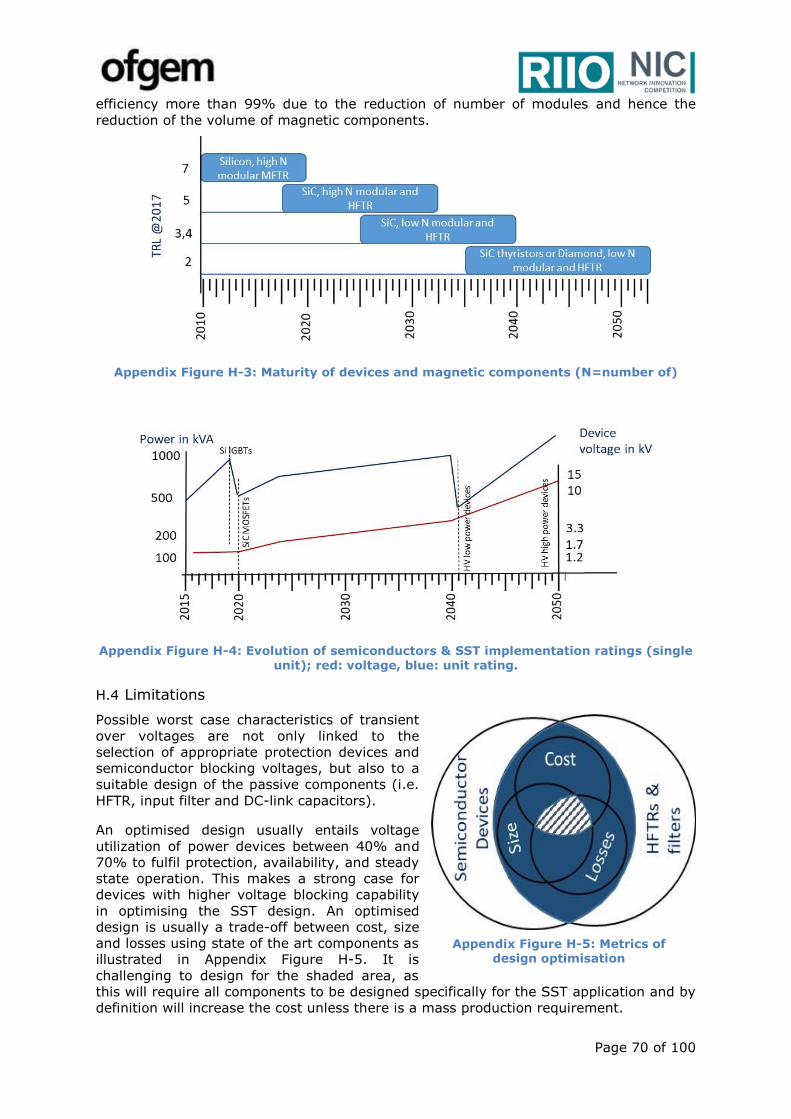
Page 70 of 100
efficiency more than 99% due to the reduction of number of modules and hence the
reduction of the volume of magnetic components.
Appendix Figure H-3: Maturity of devices and magnetic components (N=number of)
Appendix Figure H-4: Evolution of semiconductors & SST implementation ratings (single unit); red: voltage, blue: unit rating.
H.4 Limitations
Possible worst case characteristics of transient
over voltages are not only linked to the
selection of appropriate protection devices and
semiconductor blocking voltages, but also to a
suitable design of the passive components (i.e.
HFTR, input filter and DC-link capacitors).
An optimised design usually entails voltage
utilization of power devices between 40% and
70% to fulfil protection, availability, and steady
state operation. This makes a strong case for
devices with higher voltage blocking capability
in optimising the SST design. An optimised
design is usually a trade-off between cost, size
and losses using state of the art components as
illustrated in Appendix Figure H-5. It is
challenging to design for the shaded area, as
this will require all components to be designed specifically for the SST application and by
definition will increase the cost unless there is a mass production requirement.
Appendix Figure H-5: Metrics of design optimisation
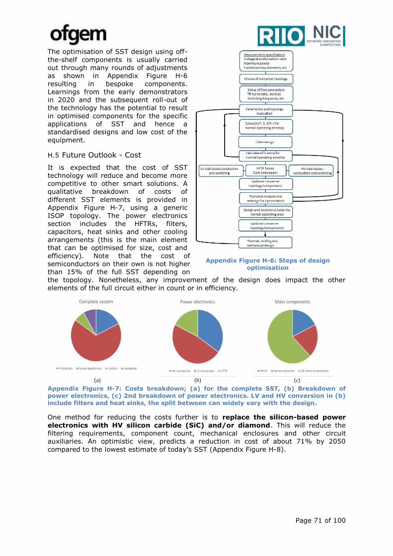
Page 71 of 100
The optimisation of SST design using off-
the-shelf components is usually carried
out through many rounds of adjustments
as shown in Appendix Figure H-6
resulting in bespoke components.
Learnings from the early demonstrators
in 2020 and the subsequent roll-out of
the technology has the potential to result
in optimised components for the specific
applications of SST and hence a
standardised designs and low cost of the
equipment.
H.5 Future Outlook - Cost
It is expected that the cost of SST
technology will reduce and become more
competitive to other smart solutions. A
qualitative breakdown of costs of
different SST elements is provided in
Appendix Figure H-7, using a generic
ISOP topology. The power electronics
section includes the HFTRs, filters,
capacitors, heat sinks and other cooling
arrangements (this is the main element
that can be optimised for size, cost and
efficiency). Note that the cost of
semiconductors on their own is not higher
than 15% of the full SST depending on
the topology. Nonetheless, any improvement of the design does impact the other
elements of the full circuit either in count or in efficiency.
(a) (b) (c)
Appendix Figure H-7: Costs breakdown; (a) for the complete SST, (b) Breakdown of power electronics, (c) 2nd breakdown of power electronics. LV and HV conversion in (b) include filters and heat sinks, the split between can widely vary with the design.
One method for reducing the costs further is to replace the silicon-based power
electronics with HV silicon carbide (SiC) and/or diamond. This will reduce the
filtering requirements, component count, mechanical enclosures and other circuit
auxiliaries. An optimistic view, predicts a reduction in cost of about 71% by 2050
compared to the lowest estimate of today’s SST (Appendix Figure H-8).
Appendix Figure H-6: Steps of design optimisation
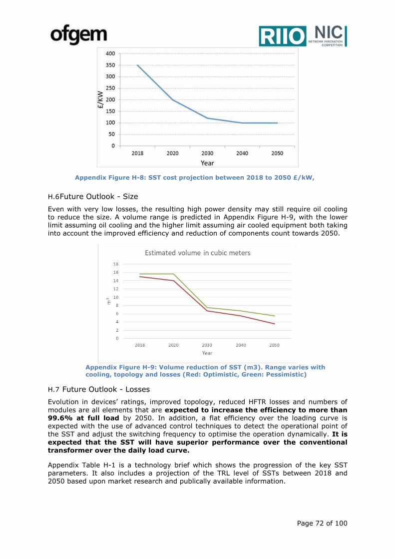
Page 72 of 100
H.6 Future Outlook - Size
Even with very low losses, the resulting high power density may still require oil cooling
to reduce the size. A volume range is predicted in Appendix Figure H-9, with the lower
limit assuming oil cooling and the higher limit assuming air cooled equipment both taking
into account the improved efficiency and reduction of components count towards 2050.
H.7 Future Outlook - Losses
Evolution in devices’ ratings, improved topology, reduced HFTR losses and numbers of
modules are all elements that are expected to increase the efficiency to more than
99.6% at full load by 2050. In addition, a flat efficiency over the loading curve is
expected with the use of advanced control techniques to detect the operational point of
the SST and adjust the switching frequency to optimise the operation dynamically. It is
expected that the SST will have superior performance over the conventional
transformer over the daily load curve.
Appendix Table H-1 is a technology brief which shows the progression of the key SST
parameters. It also includes a projection of the TRL level of SSTs between 2018 and
2050 based upon market research and publically available information.
Appendix Figure H-8: SST cost projection between 2018 to 2050 £/kW,
Appendix Figure H-9: Volume reduction of SST (m3). Range varies with cooling, topology and losses (Red: Optimistic, Green: Pessimistic)
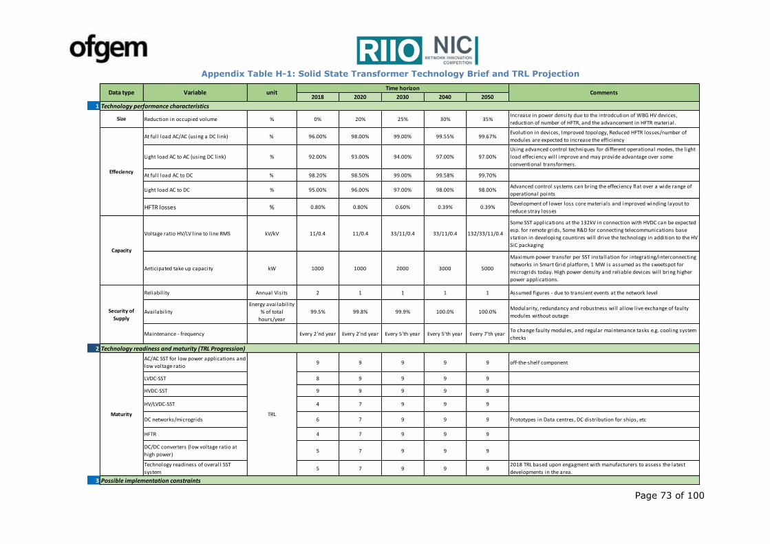
Page 73 of 100
2018 2020 2030 2040 2050
1
Reduction in occupied volume % 0% 20% 25% 30% 35%Increase in power density due to the introdcution of WBG HV devices,
reduction of number of HFTR, and the advancement in HFTR material.
At full load AC/AC (using a DC link) % 96.00% 98.00% 99.00% 99.55% 99.67%Evolution in devices, Improved topology, Reduced HFTR losses/number of
modules are expected to increase the efficiency
Light load AC to AC (using DC link) % 92.00% 93.00% 94.00% 97.00% 97.00%
Using advanced control techniques for different operational modes, the light
load effeciency will improve and may provide advantage over some
conventional transformers.
At full load AC to DC % 98.20% 98.50% 99.00% 99.58% 99.70%
Light load AC to DC % 95.00% 96.00% 97.00% 98.00% 98.00%Advanced control systems can bring the effeciency flat over a wide range of
operational points
HFTR losses % 0.80% 0.80% 0.60% 0.39% 0.39%Development of lower loss core materials and improved winding layout to
reduce stray losses
Voltage ratio HV/LV line to l ine RMS kV/kV 11/0.4 11/0.4 33/11/0.4 33/11/0.4 132/33/11/0.4
Some SST applications at the 132kV in connection with HVDC can be expected
esp. for remote grids, Some R&D for connecting telecommunications base
station in developing countires will drive the technology in addition to the HV
SiC packaging
Anticipated take up capacity kW 1000 1000 2000 3000 5000
Maximum power transfer per SST installation for integrating/interconnecting
networks in Smart Grid platform, 1 MW is assumed as the sweetspot for
microgrids today. High power density and reliable devices will bring higher
power applications.
Reliability Annual Visits 2 1 1 1 1 Assumed figures - due to transient events at the network level
Availability
Energy availability
% of total
hours/year
99.5% 99.8% 99.9% 100.0% 100.0%Modularity, redundancy and robustness will allow live exchange of faulty
modules without outage
Maintenance - frequency Every 2'nd year Every 2'nd year Every 5'th year Every 5'th year Every 7'th yearTo change faulty modules, and regular maintenance tasks e.g. cooling system
checks
2
AC/AC SST for low power applications and
low voltage ratio9 9 9 9 9 off-the-shelf component
LVDC-SST 8 9 9 9 9
HVDC-SST 9 9 9 9 9
HV/LVDC-SST 4 7 9 9 9
DC networks/microgrids 6 7 9 9 9 Prototypes in Data centres, DC distribution for ships, etc
HFTR 4 7 9 9 9
DC/DC converters (low voltage ratio at
high power)5 7 9 9 9
Technology readiness of overall SST
system5 7 9 9 9
2018 TRL based upon engagment with manufacturers to assess the latest
developments in the area.
3
TRL
Technology readiness and maturity (TRL Progression)
Maturity
Possible implementation constraints
Technology performance characteristics
Size
Capacity
Security of
Supply
Effeciency
Variable unitTime horizon
CommentsData type
Appendix Table H-1: Solid State Transformer Technology Brief and TRL Projection

Page 74 of 100
Magnetics volume in % of 2018 volume % 100% 90% 90% 85% 85%
This is a relevant mature technology with very l ittle activities in R&D. There's
however R&D into superconducting materials which may have a long term
effect on the physical size. The view however reflects the status of the
technology today, and how the converter can be optimised to make full use of
the existing technologies.
HV isolation volume in % of 2018 % 100% 100% 100% 100% 100% This is a relevant mature technology with very l ittle activities in R&D.
Tappings N/A 12:01 12:01 12:01 12:01 12:01 With the advances in semiconductors, mutliple tappings are not required.
Voltage transformation ratio N/A 13:1 13:1 20:1 30:1 30:1
If a single level SST were to be used, an HFTR of high voltage ratio is needed,
which can lead to significant design problems due losses gradient and
voltage stresses. However, some R&D exists which will lead to higher voltage
ratio and higher effeciency
Maximum frequency kHz 350 350 350 350 350 There is no obvious need for increased frequency
Maximum rating kW 20 100 200 300 500 Higher figures are achieved for MFTRs
4
Full SST (AC/DC/AC) equipment cost per
unit - optimistic£/kW 340 204 136 112.2 100.0
Taking into account mass production cost reduction towards 2020, in
addition to trends in cost reduction of semiconductors and magnetics. With
increased effeciency, cooling requirements will decrease and more compact
designs will result. 2040-2050 new semiconductors will be introduced
keeping the costs flat but improving performance.
Cost reduction from 1 unit in 2018 as
base - optimistic% 0 40% 60% 67% 71%
A huge reduction in material count and cooling requirements due to the
advances in HV semiconductors
O&M costs% of investment
costs per year1% 1% 1% 1% 1% Assumed flat - monitoring, DSO services, remote control, …
For full SST Year 30 40 50 70 >70Increase in economic l ife due to robustness in components, operational
experience, application targetted designs. It is expected that the SST will be fit
and forget by 2050
5
Height for ground-level street installation m 2.5 2.5 1.2 1.2 1.2
Footprint m2 6.0 - 6.25 5.6 - 6.25 5.6 - 6.25 4.6 - 5.6 3.0 - 4.6 Assumed reductions based in reductions in componets esp magnetics
Noise generation (comment : no building
for noise purpose)dB 55 45 40 30 30
The noise level is affected by the switching frequency and cooling
requirements, using SiC devices 2020 allows for high frequency switching
and hence low acoustic noise. Also, the expected effeciency improvements
will lower the cooling requirements and hence provide even more reduction
towards 2050. Advanced noise cancellation techniques from 2030 onwards.
EMC No issue No issue No issue No issue No issue
6
commercial availabilityYes/No/Not
ApplicableNo Yes Yes Yes Yes
Adaptive/advanced control implemented to improve effeciency and dynamic
performance.
commercial availabilityYes/No/Not
ApplicableNo Yes Yes Yes Yes
Online gain adjstment to cope with highly dynamic power flow through many
interconnected networks.
Ability to comply with existing grid codesYes/No/Not
ApplicableYes Yes Yes Yes Yes
commercial availabilityYes/No/Not
ApplicableYes Yes Yes Yes Yes Increased transient power rating in converters, energy storage - black start
necessity of network /model simulations Detailed/Generic Detailed Detailed Generic Generic GenericWith advanced controls, SST will test the grid upon installation and adjust its
gains. High modularity would facil itate switching in only required modules
Virtual rotating
mass
Network
models/simulati
on
Size
Dynamic performance of the technology
Adaptive control
Self tuning
control
Grid code
compliance
Environmental
impact and
public
acceptance
Costs
Investment costs
of system
components
O&M costs
Economic
lifetime
Environmental impact and public acceptance
HFTR

Page 75 of 100
Appendix I SST Technical Specification
I.1 Introduction
This specification defines the functional requirements for a SST for use of the SP Energy
Networks’ distribution network to interconnect MV and LV systems. The electrical and
physical environment where the device will be installed is also defined. In their
responses suppliers should confirm that their equipment is able to operate under these
environments. The functional requirements of the SST are defined in this document and
suppliers shall confirm that their proposal is able to match the requirements. The
contract stage specification will include an Appendix containing schedules to be
completed by the supplier confirming their compliance with this specification. The
specification is intentionally functional, the technology and the topology of the
convertors is at preference of the suppliers. SP Energy Networks intend to procure two
designs of SST for operation in field trials, which can assess the merits and demerits of
different solutions. It should be noted that this technical specification document will be
modified and developed further as part of WP1-Technical Design of LV Engine.
I.2 Evaluation Criteria
Each proposal received will be considered on its merits in terms of its ability to meet the
following criteria, which will be used to evaluate the competing submissions. The
following list is not in a priority order.
2.1 Compliance with the functional requirements as defined in this specification
2.2 Volume occupied by the SST
2.3 Operating losses, i.e. from input MV terminals to output LV terminals, including
any auxiliary power demand
2.4 Capital cost (CAPEX) of the SST
2.5 Operating cost (OPEX) of the SST, including capitalisation of operating losses (as
2.4), maintenance costs, spares utilisation, etc.
I.3 SST Requirements
The SST shall have a nominal power rating of 500kVA. The manufacturer shall advise if
this rating can be achieved with air or liquid cooling and whether forced or natural
cooling is required. To minimise maintenance requirements, Scottish Power Energy
Networks have a preference for an Air Natural (AN) design. The SST primary terminals
will be connected to an 11kV Medium Voltage (MV) distribution system. The SST
secondary terminals will be connected to a Low Voltage (LV) distribution system, with
the capability to supply AC and/or as shown in Appendix Figure I-1.
The ratings (in kVA) of the individual output stages of the SST will be specified at a later
stage of the project, based on customer and trial site requirements. The choice of DC
output stage voltage may change depending on customer and trial site requirements. SP
Energy Networks intend to procure both designs for SST for the trial installations.
Manufacturers may propose to supply either Design 1 or 2 or both, as suits their
Design 1 Design 2
Appendix Figure I-1: Design1 and Design 2 schematic diagram
SST
Substation A
11kV
DC
SST
Substation A
11kV
DC
0.4kV
0.4kV, 3 – phase AC output, with a neutral connection
0.4kV, 2 – pole DC output,
with a ground connection
0.4kV, 2 – pole DC outputs, with a ground connection
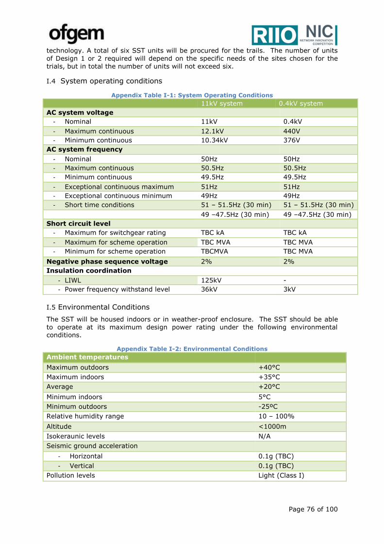
Page 76 of 100
technology. A total of six SST units will be procured for the trails. The number of units
of Design 1 or 2 required will depend on the specific needs of the sites chosen for the
trials, but in total the number of units will not exceed six.
I.4 System operating conditions
Appendix Table I-1: System Operating Conditions
11kV system 0.4kV system
AC system voltage
- Nominal 11kV 0.4kV
- Maximum continuous 12.1kV 440V
- Minimum continuous 10.34kV 376V
AC system frequency
- Nominal 50Hz 50Hz
- Maximum continuous 50.5Hz 50.5Hz
- Minimum continuous 49.5Hz 49.5Hz
- Exceptional continuous maximum 51Hz 51Hz
- Exceptional continuous minimum 49Hz 49Hz
- Short time conditions 51 – 51.5Hz (30 min) 51 – 51.5Hz (30 min)
49 –47.5Hz (30 min) 49 –47.5Hz (30 min)
Short circuit level
- Maximum for switchgear rating TBC kA TBC kA
- Maximum for scheme operation TBC MVA TBC MVA
- Minimum for scheme operation TBCMVA TBC MVA
Negative phase sequence voltage 2% 2%
Insulation coordination
- LIWL 125kV -
- Power frequency withstand level 36kV 3kV
I.5 Environmental Conditions
The SST will be housed indoors or in weather-proof enclosure. The SST should be able
to operate at its maximum design power rating under the following environmental
conditions.
Appendix Table I-2: Environmental Conditions
Ambient temperatures
Maximum outdoors +40°C
Maximum indoors +35°C
Average +20°C
Minimum indoors 5°C
Minimum outdoors -25ºC
Relative humidity range 10 – 100%
Altitude <1000m
Isokeraunic levels N/A
Seismic ground acceleration
- Horizontal 0.1g (TBC)
- Vertical 0.1g (TBC)
Pollution levels Light (Class I)
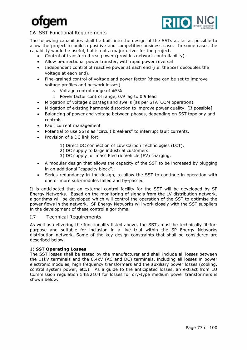
Page 77 of 100
I.6 SST Functional Requirements
The following capabilities shall be built into the design of the SSTs as far as possible to
allow the project to build a positive and competitive business case. In some cases the
capability would be useful, but is not a major driver for the project.
Control of transferred real power (provides network controllability).
Allow bi-directional power transfer, with rapid power reversal
Independent control of reactive power at each end (i.e. the SST decouples the
voltage at each end).
Fine-grained control of voltage and power factor (these can be set to improve
voltage profiles and network losses).
o Voltage control range of ±5%
o Power factor control range, 0.9 lag to 0.9 lead
Mitigation of voltage dips/sags and swells (as per STATCOM operation).
Mitigation of existing harmonic distortion to improve power quality. [If possible]
Balancing of power and voltage between phases, depending on SST topology and
controls.
Fault current management
Potential to use SSTs as “circuit breakers” to interrupt fault currents.
Provision of a DC link for:
1) Direct DC connection of Low Carbon Technologies (LCT).
2) DC supply to large industrial customers.
3) DC supply for mass Electric Vehicle (EV) charging.
A modular design that allows the capacity of the SST to be increased by plugging
in an additional “capacity block”.
Series redundancy in the design, to allow the SST to continue in operation with
one or more sub-modules failed and by-passed
It is anticipated that an external control facility for the SST will be developed by SP
Energy Networks. Based on the monitoring of signals from the LV distribution network,
algorithms will be developed which will control the operation of the SST to optimise the
power flows in the network. SP Energy Networks will work closely with the SST suppliers
in the development of these control algorithms.
I.7 Technical Requirements
As well as delivering the functionality listed above, the SSTs must be technically fit-for-
purpose and suitable for inclusion in a live trial within the SP Energy Networks
distribution network. Some of the key design constraints that shall be considered are
described below.
1) SST Operating Losses
The SST losses shall be stated by the manufacturer and shall include all losses between
the 11kV terminals and the 0.4kV (AC and DC) terminals, including all losses in power
electronic modules, high frequency transformers and the auxiliary power losses (cooling,
control system power, etc.). As a guide to the anticipated losses, an extract from EU
Commission regulation 548/2104 for losses for dry-type medium power transformers is
shown below.
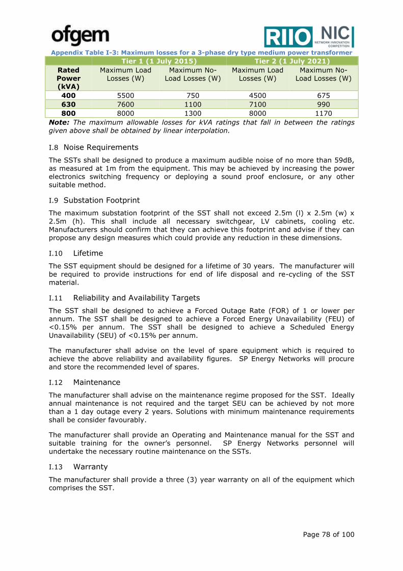
Page 78 of 100
Appendix Table I-3: Maximum losses for a 3-phase dry type medium power transformer
Tier 1 (1 July 2015) Tier 2 (1 July 2021)
Rated
Power
(kVA)
Maximum Load
Losses (W)
Maximum No-
Load Losses (W)
Maximum Load
Losses (W)
Maximum No-
Load Losses (W)
400 5500 750 4500 675
630 7600 1100 7100 990
800 8000 1300 8000 1170
Note: The maximum allowable losses for kVA ratings that fall in between the ratings
given above shall be obtained by linear interpolation.
I.8 Noise Requirements
The SSTs shall be designed to produce a maximum audible noise of no more than 59dB,
as measured at 1m from the equipment. This may be achieved by increasing the power
electronics switching frequency or deploying a sound proof enclosure, or any other
suitable method.
I.9 Substation Footprint
The maximum substation footprint of the SST shall not exceed 2.5m (l) x 2.5m (w) x
2.5m (h). This shall include all necessary switchgear, LV cabinets, cooling etc.
Manufacturers should confirm that they can achieve this footprint and advise if they can
propose any design measures which could provide any reduction in these dimensions.
I.10 Lifetime
The SST equipment should be designed for a lifetime of 30 years. The manufacturer will
be required to provide instructions for end of life disposal and re-cycling of the SST
material.
I.11 Reliability and Availability Targets
The SST shall be designed to achieve a Forced Outage Rate (FOR) of 1 or lower per
annum. The SST shall be designed to achieve a Forced Energy Unavailability (FEU) of
<0.15% per annum. The SST shall be designed to achieve a Scheduled Energy
Unavailability (SEU) of <0.15% per annum.
The manufacturer shall advise on the level of spare equipment which is required to
achieve the above reliability and availability figures. SP Energy Networks will procure
and store the recommended level of spares.
I.12 Maintenance
The manufacturer shall advise on the maintenance regime proposed for the SST. Ideally
annual maintenance is not required and the target SEU can be achieved by not more
than a 1 day outage every 2 years. Solutions with minimum maintenance requirements
shall be consider favourably.
The manufacturer shall provide an Operating and Maintenance manual for the SST and
suitable training for the owner’s personnel. SP Energy Networks personnel will
undertake the necessary routine maintenance on the SSTs.
I.13 Warranty
The manufacturer shall provide a three (3) year warranty on all of the equipment which
comprises the SST.
Page 79 of 100
I.14 Additional Project Design Considerations
I.15 SST Protection
The SST shall be capable of detection and self-protection in the event of internal faults.
The initial response should be to isolate or by-pass any faulty sub-modules, allowing the
device to remain in operation. If this is not possible, or redundancy levels have been
exceeded, the SST should initiate a trip from the MV and LV supply systems.
The units shall include a suitable protection arrangement that is capable of clearing LV
faults within an acceptable timeframe. SP Energy Networks will consider any innovative
solutions to this challenge.
I.16 DC Earthing
A suitable DC earthing arrangement shall be designed for both Design 1 and Design 2 to
enable a DC supply to be provided to customers safely.
I.17 SST Monitoring
The SST(s) shall incorporate adequate monitoring which captures the key performance
indicators, i.e. temperature, three phase current and voltage, harmonic distortion etc.
and presents the data in such a way that it can be communicated using conventional
protocols and media.
SP Energy Networks are considering developing a Real Time System for monitoring and
controlling multiple SST devices to optimise system-wide performance. SST suppliers
should comment on the ability of their technology to communicate with a remote Real
Time System, to both send and receive data and which communication protocols are
supported by their control system.
I.18 SST Generated Harmonic Distortion
The manufacturer shall provide information on the level of harmonic distortion generated
by the SST at the MV and LV terminals. Any such distortion will be assessed following
the guide lines in Engineering Recommendation G5/4 – 1.
I.19 Overload capability
The manufacturer shall indicate what overload (in kVA) capability (in time) is available
when the SST is operating at full load (500kVA), at maximum operating temperature
(35ºC) and minimum operating temperature (5ºC).
Page 80 of 100
Appendix J SST Comparison with other technologies
For SP Energy Networks the “Business as Usual” approach would involve the
procurement and installation of conventional LFT units, operating at 50Hz, for the
connection of Low Voltage power supplies. In this Appendix we provide a comparison of
the functionality which can be achieved by the development and trial installation of a
SST with the conventional LFT solution. However, in order to achieve a “like for like”
comparison of functionalities which the SST can provide, the LFT needs to be augmented
in some cases by additional technologies, such as OLTC, DC Inverter (DCI) and
STATCOM.
J.1 Power flow control
An SST can provide precise (fine) control of power in either direction, by adjustment of
the operating conditions of the power electronic converters. An LFT may allow power
flow in either direction without any control. On-load tap-changers are typically not
widely used on distribution LFT units, due to reliability and maintenance issues
associated with the moving parts of the operating mechanism.
J.2 Voltage control
The SST can provide precise (fine) phase voltage control for the LV system, by
adjustment of the operating conditions of the power electronic converters. A LFT
incorporating an OLTC can provide a stepped (coarse) voltage control of the LV system
which may not suitable for LV network experiencing imbalance voltage profile and
requires a dynamic fine voltage regulation. In summary, the following limitations have
been the main barriers to rolling out of OLTCs:
• Frequent tapping: There are some evidences around the mechanical stress on
OLTCs as a result of frequent tapping in response to daily voltage variations. That has
adverse impact on OLTC life time and O&M. This problem will become worse in an
area with high uptake of LCTs.
• Step voltage control: OLTC essentially relies on the tap steps (2.5%) of the existing
transformers. With this tapping granularity, the voltage control of LV feeders with
different length and different LCT uptake can be challenging if even possible.
• Impact on MV voltage: Tapping to adjust secondary voltage can impact the MV
voltage. With the deployment of multiple OLTCs, the MV voltage control may become
more challenging and add complexity to the AVC operation at the primary substation.
J.3 Reactive power control
The SST contains independent converters on the MV and LV sides of the unit and can
provide independent control of reactive power absorption and generation on the MV and
LV systems. In this way it can influence the voltage profile on the distribution systems,
reducing operating losses in the wider network. To achieve the same functionality a LFT
would require an additional STATCOM unit on the LV system to provide the equivalent
absorption or generation of reactive power, LFT fitted with OLTC would not be able to
provide reactive power compensation.
J.4 Dynamic reactive power response
In addition to its steady state reactive power control capability the SST will be able to
respond to dynamic events, providing rapid absorption of generation of reactive power
as required to respond to system perturbations. A similar capability can be achieved by
a LFT plus STATCOM combination.
J.5 Load balancing
As the SST de-couples the MV converter from the LV converter via a DC link, any
unbalance in the LV loads is not transferred to the MV system, i.e. the SST has an
inherent load balancing facility. An LFT would simply pass the load imbalance through to

Page 81 of 100
the MV system. The provision of a STATCOM could provide load balancing for the LV
system, however, the algorithm for load balancing is incompatible with normal reactive
power or voltage control. A sophisticated control system would need to be developed to
automatically change between normal operating states and unbalanced load state, e.g.
when a load imbalance beyond a certain threshold was detected.
J.6 AC and DC output stages
It is a prime requirement of the SST that it can provide AC (0.4kV) and DC (0.4kV or
800V) output stages for both the trial sites and for future commercial operation. A LFT
can inherently achieve an AC output stage, but to create a DC output would require the
addition of separate DCI unit.
J.7 Harmonic generation and filtering
As a power electronic converter a SST will generate low levels of harmonic distortion and
the design of the unit will need to comply with the requirements of Engineering
Recommendation G5/4-1. By control action it may also be able to act as an active filter,
reducing distortion created by other non-linear loads on the network. A LFT is a passive
device with respect to harmonic distortion, neither generating nor actively attenuating
harmonic distortion.
J.8 Fault current capability
Depending on the design of the converters the SST may have the capability to limit or
block the flow of high current levels arising from faults on the LV system. In fault
conditions a SST only delivers its load current, i.e. it cannot pass high levels of fault
current. However, this may be an issue for LV protection systems, which may rely on
such fault currents to blow fuses, which isolate the faulted parts of the system. A LFT
will allow the passage of fault currents limited only by the impedance of the transformer,
but such currents are coordinated to blow protective fuses.
J.9 Operating losses
Discussions with equipment suppliers indicate that a SST could have operating losses,
i.e. from MV to LV connections of between 2% to 4%. This compares unfavourably with
a LFT with losses less than 1.0%. However this disadvantage reduces when the losses
of a DCI and STATCOM are included assessed as 0.5% each, bringing the comparable
operating loss to less than 2.0%. As SST component technology advances, principally
due to the use of more advanced semiconductor materials, such as Silicon Carbide and
Diamond, the losses of a SST will decrease to match those of a LFT.
J.10 Audible noise
The design target for the SST will be to achieve a noise emission level which is
comparable with existing LFT installations. A figure of 59dBA has been issued to
potential suppliers as a design target and indications are that this should be achievable.
J.11 Volume
As the SST is an indoor installation, requiring a cooling system, it is unlikely to achieve
the compact design of a LFT. A target volume of 2.5 x 2.5 x 2.5m has been advised to
potential suppliers, who have indicated that this is achievable. As discussed above, for a
“like for like” comparison a compact LFT solution needs to be augmented by additional
equipment, such as DCI and STATCOM units, which need to be included in any
comparison of volume.
J.12 Technology Readiness Level (TRL)
Based on discussions with multiple suppliers and academics and reviewing the available
literature, we consider that the SST presently has a TRL of 5 to 6. Thus all of the
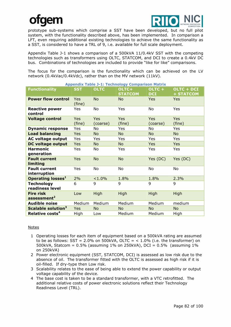
Page 82 of 100
prototype sub-systems which comprise a SST have been developed, but no full pilot
system, with the functionality described above, has been implemented. In comparison a
LFT, even requiring additional existing technologies to achieve the same functionality as
a SST, is considered to have a TRL of 9, i.e. available for full scale deployment.
Appendix Table J-1 shows a comparison of a 500kVA 11/0.4kV SST with the competing
technologies such as transformers using OLTC, STATCOM, and DCI to create a 0.4kV DC
bus. Combinations of technologies are included to provide “like for like” comparisons.
The focus for the comparison is the functionality which can be achieved on the LV
network (0.4kVac/0.4kVdc), rather than on the MV network (11kV).
Appendix Table J-1: Technology Comparison Matrix
Functionality SST OLTC OLTC+
STATCOM
OLTC +
DCI
OLTC + DCI
+ STATCOM
Power flow control Yes
(fine)
No No Yes Yes
Reactive power
control
Yes No Yes No Yes
Voltage control Yes
(fine)
Yes
(coarse)
Yes
(fine)
Yes
(coarse)
Yes
(fine)
Dynamic response Yes No Yes No Yes
Load balancing Yes No No No No
AC voltage output Yes Yes Yes Yes Yes
DC voltage output Yes No No Yes Yes
Harmonic
generation
Yes No Yes Yes Yes
Fault current
limiting
Yes No No Yes (DC) Yes (DC)
Fault current
interruption
Yes No No No No
Operating losses1 2% <1.0% 1.8% 1.8% 2.3%
Technology
readiness level
6 9 9 9 9
Fire risk
assessment2 Low High High High High
Audible noise Medium Medium Medium Medium medium
Scalable solution3 Yes No No No No
Relative costs4 High Low Medium Medium High
Notes
1 Operating losses for each item of equipment based on a 500kVA rating are assumed
to be as follows: SST = 2.0% on 500kVA, OLTC = < 1.0% (i.e. the transformer) on
500kVA, Statcom = 0.5% (assuming 1% on 250kVA), DCI = 0.5% (assuming 1%
on 250kVA)
2 Power electronic equipment (SST, STATCOM, DCI) is assessed as low risk due to the
absence of oil. The transformer fitted with the OLTC is assessed as high risk if it is
oil-filled. If dry-type then Low risk.
3 Scalability relates to the ease of being able to extend the power capability or output
voltage capability of the device.
4 The base cost is taken to be a standard transformer, with a VTC retrofitted. The
additional relative costs of power electronic solutions reflect their Technology
Readiness Level (TRL).
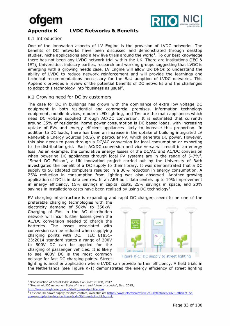
Page 83 of 100
Appendix K LVDC Networks & Benefits
K.1 Introduction
One of the innovation aspects of LV Engine is the provision of LVDC networks. The
benefits of DC networks have been discussed and demonstrated through desktop
studies, niche applications and a few live trials around the world1. To our best knowledge
there has not been any LVDC network trial within the UK. There are institutions (IEC &
IET), Universities, industry parties, research and working groups suggesting that LVDC is
emerging with a growing needs case. LV Engine will allow UK DNOs to understand the
ability of LVDC to reduce network reinforcement and will provide the learnings and
technical recommendations neccessary for the BaU adoption of LVDC networks. This
Appendix provides a review of the potential benefits of DC networks and the challenges
to adopt this technology into “business as usual”.
K.2 Growing need for DC by customers
The case for DC in buildings has grown with the dominance of extra low voltage DC
equipment in both residential and commercial premises. Information technology
equipment, mobile devices, modern LED lighting, and TVs are the main appliances which
need DC voltage supplied through AC/DC conversion. It is estimated that currently
around 35% of residential home power consumption is DC based loads, with increasing
uptake of EVs and energy efficient appliances likely to increase this proportion. In
addition to DC loads, there has been an increase in the uptake of building integrated LV
Renewable Energy Sources (RES), in particular PV, which generate DC power. However,
this also needs to pass through a DC/AC conversion for local consumption or exporting
to the distribution grid. Each AC/DC conversion and vice versa will result in an energy
loss. As an example, the cumulative energy losses of the DC/AC and AC/DC conversion
when powering DC appliances through local PV systems are in the range of 5-7%2.
“Smart DC Edison”, a UK innovation project carried out by the University of Bath
investigated the benefit of a DC supply to their library. It was demonstrated that a DC
supply to 50 adapted computers resulted in a 30% reduction in energy consumption. A
25% reduction in consumption from lighting was also observed. Another growing
application of DC is in data centres. In an ABB built data centre, up to 10% improvement
in energy efficiency, 15% savings in capital costs, 25% savings in space, and 20%
savings in installations costs have been realised by using DC technology3.
EV charging infrastructure is expanding and rapid DC chargers seem to be one of the
preferable charging technologies with the
electricity demand of 50kW to 350kW.
Charging of EVs in the AC distribution
network will incur further losses given the
AC/DC conversion needed to charge the
batteries. The losses associated with
conversion can be reduced when supplying
charging points with DC. IEC 61851-
23:2014 standard states a range of 200V
to 500V DC can be applied for the
charging of passenger vehicles. It is likely
to see 400V DC is the most common
voltage for fast DC charging points. Street
lighting is another application where LVDC can provide further efficiency. A field trials in
the Netherlands (see Figure K-1) demonstrated the energy efficiency of street lighting
1 “Construction of actual LVDC distribution line”, CIRED, 2017 2 “Household DC networks: State of the art and future prospects”, Sep. 2015,
http://www.insightenergy.org/static_pages/publications 3 Efficient DC power supply for data centres, available at: https://www.electricalreview.co.uk/features/9475-efficient-dc-
power-supply-for-data-centres+&cd=3&hl=en&ct=clnk&gl=uk
Figure K-1: DC supply to street lighting

Page 84 of 100
networks when supplying new LED lighting modules with DC1. To the best of our
knowledge the performance benefits (installation costs and energy savings) of integrated
EV charging and LED street lighting on a LVDC network have yet to be fully quantified.
Most of the AC/DC conversation devices require a three stage conversion process
AC/DC/device DC. A DC supply would enable a reduction in the number of conversion
stages to a two stage DC/device DC only. This can reduce losses due to this conversion
by 2.5-10%2. Also, the introduction of the new USB Type-C standard (provides data and
power up to 100W) will eliminate the need for many adapters to convert 230V AC to
lower voltages and then into DC to connect electronic devices. Such new generation of
technology inherently requires a LVDC supply.
K.3 LVDC Networks
With the growing need for DC demand, there is an opportunity for the DNOs to provide
LVDC to customers. DC supply can result in further efficiencies if the AC/DC conversion
is undertaken at the network level. In this case, control of the network would be even
stronger as the procurement, operation and maintenance of the AC/DC converters are in
the care of DNOs and highly efficient devices can be utilised. In addition to improving the
overall efficiency of energy consumption and generation at LV networks, there are
further network benefits by enabling LVDC distribution networks:
Increased transfer capacity within thermal constraints
An LVDC distribution system can offer a higher power carrying capacity than the
traditional 400V AC systems. This higher power transfer capacity can be achieved by
using DC voltages that are within the insulation withstand capability of the
conventional LV cable circuits. LVD 2006/95/EC allows the use of LVDC voltages up to
1500V. This voltage level (±750V) has been successfully trialled in Finland for LV
underground cable circuits3. There is even an opportunity to convert the existing AC
cables for DC operation to increase the power transfer capacity. In this way, the
costly and lengthy network reinforcement projects can be avoided. Table K-1 shows
the additional capacity released by converting a 3-phase 400V AC network to different
DC voltage levels. University of Manchester has conducted a similar capacity released
calculation considering typical UK LV underground cables4.
Table K-1: Capacity can be released by operating at DC compared to 3-phase AC network*
Core 1 Core2 Core 3 Core 4
Additional
capacity
Unipolar
+400 0 0 -39%
+500 0 0 -24%
+750 0 0 14%
Bipolar
+400 -400 0 22%
+500 -500 0 52%
+750 -750 0 128%
Unipolar
+400 0 +400 0 22%
+500 0 +500 0 52%
+750 0 +750 0 128%
Bipolar
+400 -400 +400 -400 143%
+500 -500 +500 -500 204%
+750 -750 +750 -750 356%
* The power factor in the AC system has been assumed to be 0.95
1 Direct Current B.V, “The First DC Smart Grid for Public Lighting,” 2014. [Online]. Available:
http://www.directcurrent.eu/en/news/news-archive/112-first-dc-smart-grid-for-public-lighting 2 Hammerstrom, D.J.: ‘AC versus DC distribution systems, did we get it right?’ IEEE Power Engineering Society General Meeting, 2007 3 Feasibility of Low Voltage Cables for Use at 1500V DC Distribution Networks. Tampere University, Finland. 4 “Transition from alternating current to direct Current low voltage distribution networks”, IET Generation Transmission &
Distribution September, 2015
Core 3
Core 1 Core 2
Core 1 Core 2
Core 3 Core 4
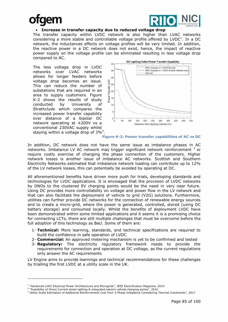
Page 85 of 100
Increase in transfer capacity due to reduced voltage drop
The transfer capacity within LVDC network is also higher than LVAC networks
considering a more stable and controllable voltage profile offered by LVDC1. In a DC
network, the inductances effects on voltage profiles will be very limited. In addition,
the reactive power in a DC network does not exist, hence, the impact of reactive
power supply on the voltage profile can be eliminated resulting in less voltage drop
compared to AC.
The less voltage drop in LVDC
networks over LVAC networks
allows for longer feeders before
voltage drop becomes an issue.
This can reduce the number of
substations that are required in an
area to supply customers. Figure
K-2 shows the results of study
conducted by University of
Strathclyde which compares the
increased power transfer capability
over distance of a bipolar DC
network operating at ±200V vs a
conventional 230VAC supply whilst
staying within a voltage drop of 3%2. Figure K-2: Power transfer capabilities of AC vs DC
In addition, DC network does not have the same issue as imbalance phases in AC
networks. Imbalance LV AC network may trigger significant network reinforcement 3 or
require costly exercise of changing the phase connection of the customers. Higher
network losses is another issue of imbalance AC networks. Scottish and Southern
Electricity Networks estimated that imbalance network loading can contribute up to 12%
of the LV network losses, this can potentially be avoided by operating at DC.
All aforementioned benefits have driven more push for trials, developing standards and
technologies for LVDC applications. It is envisaged that the provision of LVDC networks
by DNOs to the clustered EV charging points would be the need in very near future.
Using DC provides more controllability on voltage and power flow in the LV network and
that can also facilitate the deployment of vehicle to grid (V2G) solutions. Furthermore,
utilities can further provide DC networks for the connection of renewable energy sources
and to create a micro-grid, where the power is generated, controlled, stored (using DC
battery storage) and consumed locally. Whilst the benefits of deployment LVDC have
been demonstrated within some limited applications and it seems it is a promising choice
for connecting LCTs, there are still multiple challenges that must be overcome before the
full adoption of this technology as BaU. Some of them are:
1- Technical: More learning, standards, and technical specifications are required to
build the confidence in safe operation of LVDC
2- Commercial: An approved metering mechanism is yet to be confirmed and tested
3- Regulatory: The electricity regulatory framework needs to provide the
requirements for connection and operation at DC voltage, as the current regulations
only answer the AC requirements
LV Engine aims to provide learnings and technical recommendations for these challenges
by trialling the first LVDC at a utility scale in the UK.
1 “Advanced LVDC Electrical Power Architectures and Microgrids”, IEEE Electrification Magazine, 2014 2 “Feasibility of Direct Current street lighting & integrated electric vehicle charging points”, 2016 3 Utility-Scale Estimation of Additional Reinforcement Cost from 3-Phase Imbalance Considering Thermal Constraints”, 2017
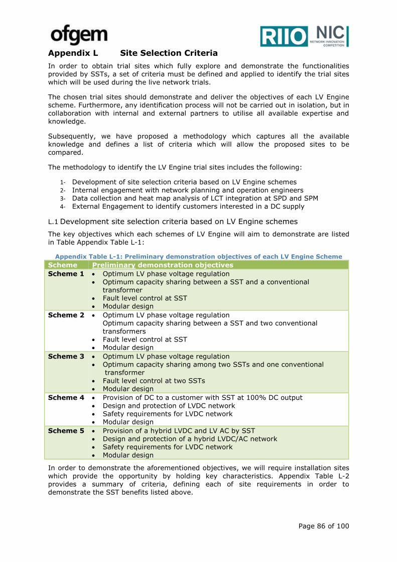
Page 86 of 100
Appendix L Site Selection Criteria
In order to obtain trial sites which fully explore and demonstrate the functionalities
provided by SSTs, a set of criteria must be defined and applied to identify the trial sites
which will be used during the live network trials.
The chosen trial sites should demonstrate and deliver the objectives of each LV Engine
scheme. Furthermore, any identification process will not be carried out in isolation, but in
collaboration with internal and external partners to utilise all available expertise and
knowledge.
Subsequently, we have proposed a methodology which captures all the available
knowledge and defines a list of criteria which will allow the proposed sites to be
compared.
The methodology to identify the LV Engine trial sites includes the following:
1- Development of site selection criteria based on LV Engine schemes
2- Internal engagement with network planning and operation engineers
3- Data collection and heat map analysis of LCT integration at SPD and SPM
4- External Engagement to identify customers interested in a DC supply
L.1 Development site selection criteria based on LV Engine schemes
The key objectives which each schemes of LV Engine will aim to demonstrate are listed
in Table Appendix Table L-1:
Appendix Table L-1: Preliminary demonstration objectives of each LV Engine Scheme
Scheme Preliminary demonstration objectives
Scheme 1 Optimum LV phase voltage regulation
Optimum capacity sharing between a SST and a conventional
transformer
Fault level control at SST
Modular design
Scheme 2 Optimum LV phase voltage regulation
Optimum capacity sharing between a SST and two conventional
transformers
Fault level control at SST
Modular design
Scheme 3 Optimum LV phase voltage regulation
Optimum capacity sharing among two SSTs and one conventional
transformer
Fault level control at two SSTs
Modular design
Scheme 4 Provision of DC to a customer with SST at 100% DC output
Design and protection of LVDC network
Safety requirements for LVDC network
Modular design
Scheme 5 Provision of a hybrid LVDC and LV AC by SST
Design and protection of a hybrid LVDC/AC network
Safety requirements for LVDC network
Modular design
In order to demonstrate the aforementioned objectives, we will require installation sites
which provide the opportunity by holding key characteristics. Appendix Table L-2
provides a summary of criteria, defining each of site requirements in order to
demonstrate the SST benefits listed above.
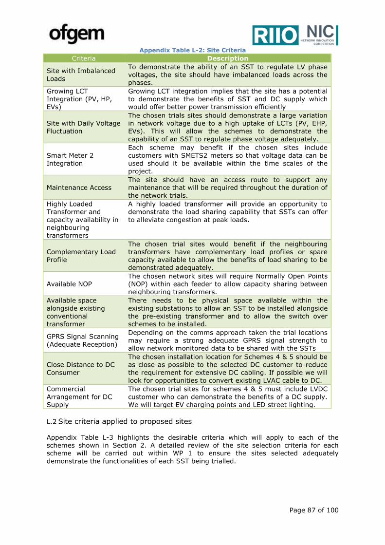
Page 87 of 100
Appendix Table L-2: Site Criteria
Criteria Description
Site with Imbalanced
Loads
To demonstrate the ability of an SST to regulate LV phase
voltages, the site should have imbalanced loads across the
phases.
Growing LCT
Integration (PV, HP,
EVs)
Growing LCT integration implies that the site has a potential
to demonstrate the benefits of SST and DC supply which
would offer better power transmission efficiently
Site with Daily Voltage
Fluctuation
The chosen trials sites should demonstrate a large variation
in network voltage due to a high uptake of LCTs (PV, EHP,
EVs). This will allow the schemes to demonstrate the
capability of an SST to regulate phase voltage adequately.
Smart Meter 2
Integration
Each scheme may benefit if the chosen sites include
customers with SMETS2 meters so that voltage data can be
used should it be available within the time scales of the
project.
Maintenance Access
The site should have an access route to support any
maintenance that will be required throughout the duration of
the network trials.
Highly Loaded
Transformer and
capacity availability in
neighbouring
transformers
A highly loaded transformer will provide an opportunity to
demonstrate the load sharing capability that SSTs can offer
to alleviate congestion at peak loads.
Complementary Load
Profile
The chosen trial sites would benefit if the neighbouring
transformers have complementary load profiles or spare
capacity available to allow the benefits of load sharing to be
demonstrated adequately.
Available NOP
The chosen network sites will require Normally Open Points
(NOP) within each feeder to allow capacity sharing between
neighbouring transformers.
Available space
alongside existing
conventional
transformer
There needs to be physical space available within the
existing substations to allow an SST to be installed alongside
the pre-existing transformer and to allow the switch over
schemes to be installed.
GPRS Signal Scanning
(Adequate Reception)
Depending on the comms approach taken the trial locations
may require a strong adequate GPRS signal strength to
allow network monitored data to be shared with the SSTs
Close Distance to DC
Consumer
The chosen installation location for Schemes 4 & 5 should be
as close as possible to the selected DC customer to reduce
the requirement for extensive DC cabling. If possible we will
look for opportunities to convert existing LVAC cable to DC.
Commercial
Arrangement for DC
Supply
The chosen trial sites for schemes 4 & 5 must include LVDC
customer who can demonstrate the benefits of a DC supply.
We will target EV charging points and LED street lighting.
L.2 Site criteria applied to proposed sites
Appendix Table L-3 highlights the desirable criteria which will apply to each of the
schemes shown in Section 2. A detailed review of the site selection criteria for each
scheme will be carried out within WP 1 to ensure the sites selected adequately
demonstrate the functionalities of each SST being trialled.

Page 88 of 100
Appendix Table L-4: SST Criteria Applied to Schemes
Criteria Scheme
1 Scheme
2 Scheme
3 Scheme
4 Scheme
5
Phase Imbalanced Loading
Growing LCT Integration
Daily voltage fluctuation
Smart Meter 2 Integration
Access for Maintenance
Highly Loaded Transformer
Complementary Load Profile available
NOP available between neighbouring substations
Space available for parallel operation with existing transformer
GPRS signal scanning - adequate reception
L.3 Internal engagement with network planning and operation engineers
As a DNO, we would seek to engage with multiple teams and disciplines from across our
business. There would be two key outcomes to this engagement;
Identifying sites that can demonstrate the full functionalities of an SST.
Explaining the benefits that SSTs can offer to resolving system issues
In order to achieve these outcomes, we intend to distribute a questionnaire which will
set out a series of questions to help identify any sites where the full functionalities of an
SST can be demonstrated. In addition, internal presentations will be held to raise
awareness of the SST technology and its applications throughout the business.
Finally, we will use SP Energy Networks’ geographical assets and customer database to
identify substations which have a significant amount of LV LCT penetration (as this is
where SSTs can raise efficiency).
L.4 External engagement to identify customers interested in DC supply
Through SP Energy Networks previous innovation work and business as usual practices,
we have built up a significant network of external contacts. As we are embarking into a
new area of innovation, we would seek to utilize these contacts to identify customers
who would be interested in converting their current AC supply to a DC based system or a
hybrid of the two. This process will reveal sites available to us for consideration. We will
focus on LED street lighting and rapid Electric Vehicle charging as a preference,
which could provide the biggest direct benefits to both consumers and DNO, by allowing
the project to investigate the ability of LVDC to reduce consumer losses whilst also
reducing network reinforcement by increasing cable transfer capacity. We have already
identified some potential external stakeholders who have large DC consumption and are
interested in developing smart energy solutions. These include:
EV charging point suppliers and manufacturers
Local councils with on-going EV charging point and street lighting developments
Large car parks
Shopping centres
Data Centres

Page 89 of 100
Appendix M Potential Trial Sites & Maps
Through investigation and discussion with our colleagues, we have identified several
sites where SSTs could be applied with anticipated benefit. The site and potential
benefits of introducing a SST into the area have been noted in each case.
M.1 Proposed Sites – Private Developments
During the duration of the development of this proposal we have been in close
conversation with multiple private developments who are interested in a potential AC
and/or DC supply from an SST during this innovation project. These conversations are
ongoing and are dependent on the outcome of the funding request. Should LV Engine be
awarded funding we will continue to engage with these third parties to select a trial site
that can demonstrate the benefits of LVDC using an SST.
M.2 Proposed Sites – SP Energy Networks Network Trail Sites:
The following sites have been identified internally at SP Energy Networks which could be
used to demonstrate the functionalities and benefits of each trial scheme. During work
package 1 we will carry out a fresh review of potential trial sites to ensure sites are
selected which maximise the learnings that come out of each trial scheme.
M.2.1 Wrexham – Heol Glyndwr Secondary (SPM)
This is a residential area which is saturated with PV. The site was investigated as part of
the project Flexnets. The substation was deliberately overloaded with PV to demonstrate
the ability of an on-load tap changer to regulate the voltage. However, the study did not
go ahead and a tap changer was never installed. Consequently, the LV network is
experiencing voltage spikes that are above the tolerance (260V+). Wrexham city council
had originally approach SP Energy Networks and asked to install 3000 PV arrays in the
area and have an ambitious sustainability / low carbon strategy for the area.
M.2.2 Milton Rd /Terrace, fed from Johnston Street S/S
The voltage profile in the existing LV Network at Milton Rd /Terrace, fed from Johnston
Street S/S, has existing issues, with voltage rises at the feeder exceeding the statutory
limits. Due to the fact that the existing LV cables are through privately owned gardens
and no way leaves are currently in place, the proposed solution is to install a new
substation and overlay the LV cables.
M.2.3 Cowie Housing
An area of social housing with a large uptake of PV which is experiencing voltage
regulation issues and may require significant network reinforcement. It is likely that an
intermediary solution will be required while infrastructure is being deployed to avoid
equipment damage.
M.2.4 Southport Uprating / differential protection scheme (SPM)
At Southport there is a project to uprate the network from 6.6kV to 11kV. There is
currently a fault level issue that could be improved if SSTs were installed in the area.
The network in the area is being converted from X-type to Y–type network with a
differential protection scheme to combat issues with high fault level in the area. This
could potentially be a site to demonstrate load sharing between multiple substations
whilst allowing the network area to be converted to y-type but maintaining network
interconnection and flexibility.
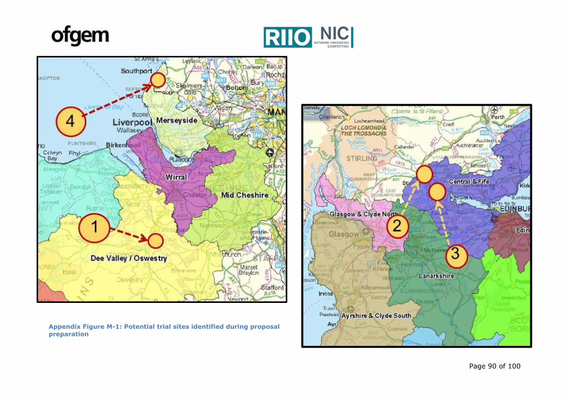
Page 90 of 100
Appendix Figure M-1: Potential trial sites identified during proposal
preparation

Page 91 of 100
Appendix N A summary of UK Low Carbon Networks Fund Projects demonstrating LCT impacts on
LV Networks
Desktop study on existing feeders showed that over 60% of feeders with more than 25 customers experienced voltage issue due to PV uptake
Customers may experience voltage outside statutory limit with 30% PV penetration
The first occurrence of problems as penetration increases is driven by voltage issues in all the feeders examined. For the EHP and EV case, the first occurrence of problems is driven by voltage and also by thermal issues
LV Network Voltage Solutions
(ENW)
The measured peak value of PVs is often greater
than the rated peak value
Suggesting that a network designer may consider
0.25kW greater than its rated value
Reasonable to assume that there will be at least
one time during the year when the peak power generation for a group of PV panels is reached
simultaneously
Customer-Led network revolution
(NPG)
Probabilistic assessment carried out in I2EV
highlights that technical problems in the LV networks may occur for EV penetrations larger than 30%.
Reverse power flows are found in PV scenarios
with a percentage penetration greater than a 25% uptake. As anticipated Summer has the worst impact on the network. On average over- voltages occur in scenarios with a PV uptake of 15% and above.
Potential concentration of EVs and HPs closer to
the end of the LV feeders could create significant
voltage drop issues.
New Thames valley Vision(SSE)
The peak demand for residential EV charging was
found to coincide with the traditional evening peak, the After Diversity Maximum Demand (ADMD) observed in the Project for non-electrically heated households with a 3.5kW EV charger is approximately 2kW, double the conventional demand observed in the Project.
Project demonstrates that 32% of UK LV feeders
will require intervention to protect against thermal or voltage problems at EV penetration levels exceeding 40%.
My Electric Avenue(SSE)
In the Urban based LV network the The 500kVA 6.1/0.433kV feeding transformer was found to be overloaded in 2034 by approximately 30% and for this reason the studies were repeated with a replacement 800kVA transformer to eliminate the overload
DS2030

Page 92 of 100
Appendix O Recent publications on SST
L. Ferreira Costa, G. De Carne, G. Buticchi and M. Liserre, "The Smart Transformer: A solid-state transformer tailored to provide
ancillary services to the distribution grid," in IEEE Power Electronics Magazine, vol. 4, no. 2, pp. 56-67, June 2017.
G. De Carne, G. Buticchi, M. Liserre and C. Vournas, "Load control using sensitivity identification by means of smart transformer,"
2017 IEEE Manchester PowerTech, Manchester, United Kingdom, 2017.
S. Bhattacharya, "Transforming the transformer," in IEEE Spectrum, vol. 54, no. 7,
pp. 38-43, July 2017.
Liang Wang, Donglai Zhang, Yi Wang and Huan Liu, "High-frequency solid-state
transformer power conversion technologies for energy internet," 2017 IEEE 3rd
International Future Energy Electronics Conference and ECCE Asia (IFEEC 2017 - ECCE
Asia), Kaohsiung, Taiwan, 2017, pp. 1397-1401.
A. Q. Huang, "Medium-Voltage Solid-State Transformer: Technology for a Smarter and Resilient Grid," in IEEE Industrial
Electronics Magazine, vol. 10, no. 3, pp. 29-42, Sept. 2016.
J. S. Lai, W. H. Lai, S. R. Moon, L. Zhang and A. Maitra, "A 15-kV class intelligent universal
transformer for utility applications," 2016 IEEE Applied Power Electronics Conference and
Exposition (APEC), Long Beach, CA, 2016, pp. 1974-1981.
A. Afiat Milani; M. T. A. Khan; A. Chakrabortty; I. Husain, "Equilibrium Point Analysis and
Power Sharing Methods for Distribution Systems Driven by Solid-State Transformers," in IEEE
Transactions on Power Systems , 2017.
J. E. Huber and J. W. Kolar, "Solid-State Transformers: On the Origins and Evolution of Key Concepts," in IEEE Industrial
Electronics Magazine, vol. 10, no. 3, pp. 19-28, Sept. 2016.
J. Ramos-Ruiz, H. Krishnamoorthy and P. Enjeti, "Adding capacity to an
existing electric power distribution network using a solid state
transformer system," 2015 IEEE Energy Conversion Congress and
Exposition (ECCE), Montreal, QC, 2015, pp. 6059-6066. Dr. Iqbal Husain, ABB Distinguished Professor of Electrical and Computer Engineering at NC State and director of the FREEDM Center
Page 93 of 100
Appendix P Step changes in global LCT uptake driven by policy makers and car manufacturers
SSTs will act as an enabler of DC technologies including household battery storage

Page 94 of 100
Appendix Q Expression of Interest
Page 95 of 100
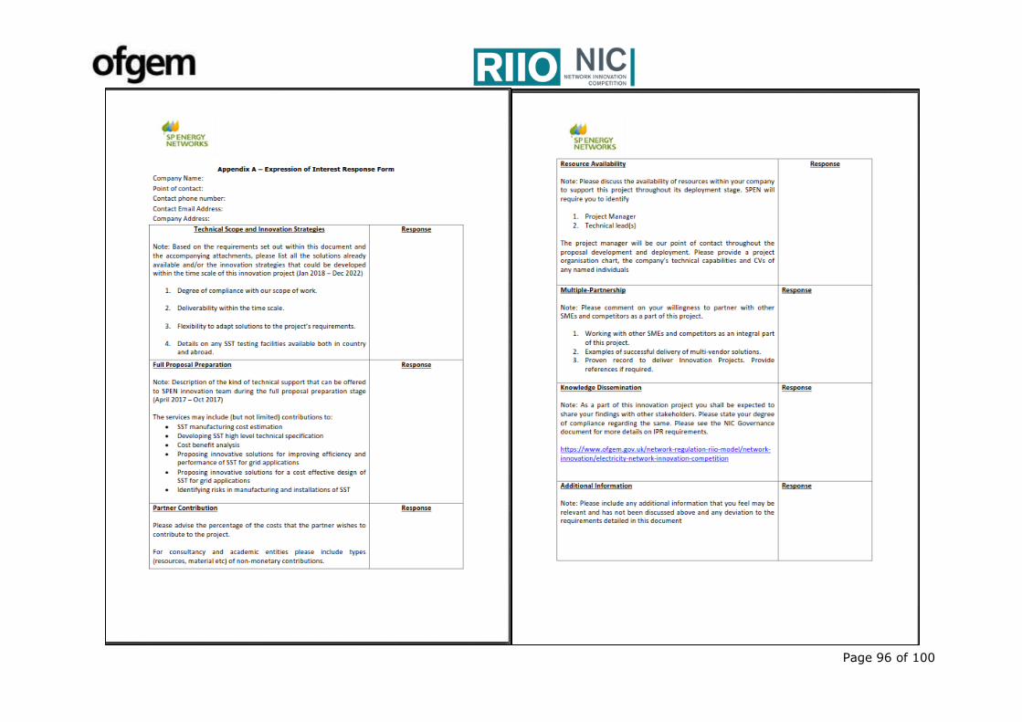
Page 96 of 100
Page 97 of 100
Appendix R Letters of Support
LV Engine is supported by and will work closely with a range of industry bodies and organisations across multiple industries to ensure the
project considers the requirements of all stakeholders and builds upon the latest learnings available. Below is an extract of a selection of
the letters of support we have received during the course of preparing this proposal:
UK Power Networks: “This letter sets out UK Power Networks commitment to support SP Energy Networks 2017 NIC project LV Engine
… We support the objectives of LV Engine and believe the project complements our 2017 NIC proposal Active Response…We believe that
deployment Solid State Transformer within secondary substations can deliver much needed functionalities to 11kV and LV networks…”
Glasgow City Council: “…We are in support of LV Engine’s objectives of enabling a higher penetration of LCTs…To this end we are
supportive of a potential trial of a Solid State Transformer at Duke Street Car Park alongside our pre-exiting plans to install 200kW PV
and fast Electric Vehicle charging points…”
International Electrotehnical Commission (IEC): “...LV Engine with the trial of LVDC as shown in your "Scheme 4 & 5" in real fields
aligns perfectly with the IEC LVDC SyC focus, and the learning and outcomes of the LVDC deployment will definitely provide an important
source to inform LVDC standards development. We will work closely with the IEC UK National Committee LVDC members to ensure the
best use of your experience from the [V Engine for future LVDC standards development...”
Institution of Engineering and Technology (IET): “...LVDC distribution systems are considered a key option for better use of energy
and management, and improved exploitation of renewable and distributed energy resources. IET has already recognised the potential
LVDC benefits and has prepared and published a new Code of Practice on LVDC power distribution. We strongly believe this effort will be
complemented by “LV Engine objectives which provides a LVDC supply...”
British Standards Institution (BSI): “...BSI is interested in this project which present the first DNO-led project on LVDC as the
findings therein would support the development of a new standard for supporting LVDC in public networks. We would expect the LVDC
field trials to provide a firm understanding for a UK position in IEC SyC LVDC. This can be both valuable in terms of maintaining fit-for-
purpose standards, but also for ensuring the UK maintain a position of strategic importance within the international community, i.e. the
UK is leading research into new areas for the benefit of the LVDC industry. We are pleased to be partners on this project and commend it
for consideration...”
PowerelectronicsUK: “As the main industry association in Power Electronics with over 70 members we intend to work with you to
promote the project and share learnings with the industry on the outcome. This will help to ignite a new market place for power
electronics within distribution networks...”

Page 98 of 100
University of Kiel: “…The Chair of Power Electronics finds the LV Engine project interesting and well focused. It is particularly relevant
the design of Smart Transformer with stages of different power to supply both DC and AC grids and different trial schemes showing the
different possible system level optimization of the Smart Transformer…The Chair has already collected 8 million Euros for many projects
focused on smart transformer…”
ETH Zurich: “…having discussed the proposal with you in detail we see the value that the project could bring by elevating the TRL of
SSTs for deployment within distribution networks…ETH Zurich is conducting research on SSTs for more than 8 years…it is the right time
to carry out a trial of SSTs for grid applications…We believe the functionality that will be demonstrated by LV Engine to be both
technically feasible and deliverable within the timescale of the project…”
University of Strathclyde: “We support the objectives of the project and see particular value in the learnings and innovations which will
arise from the LVDC network trial using Solid State Transformers...From our research and active international engagement in this topic
we believe it is very timely to carry out an innovation project to trial an LVDC supply from a Distribution Network Operator in order to see
the considerable benefits afforded to network licensees and electricity consumers...” Power Networks Demonstration Centre (PNDC): “…the PNDC is in support of the objectives set out within the proposal for LV
Engine…PNDC will help shape the test environment… experience and test network capability will de-risk the LV Engine project and ensure
the outcomes are positioned for success…”
Building Research Establishment (BRE): “...BRE are particularly interested in the principle of enabling greater penetration of Low
Carbon Technologies (LCTs) into the existing LV network as well as the potential provision of low voltage DC supply to electricity
customers. To this end BRE is delighted to support the proposal and our potential future involvement...”
Direct Current BV: “...We see a great future for DC, and strongly believe projects such as “LV Engine” with field trials of LVDC will
accelerate the wider adoption of LVDC, particularly in street lighting and EV charging. Therefore, we look forward to working with you on
this innovative project...”
Franklin Energy: “...Franklin Energy is excited to support the LV Engine and SP Energy Networks to help identify trial sites for LVDC
supply for EV charging, battery storage and PV optimisation. We believe that a DC supply could help by reducing the costs of DC rapid
chargers (£15,000 each), help with the uptake of V2G and help with domestic battery and PV installations...”
Chargemaster: “...We have long-term relationships in place with all the major EV manufacturers and operate the largest EV charging
network in the UK, with over 4000 charge points and over 8000 paying subscribers. As such we have first-hand experience of network
constraints in terms of capacity. Innovative potential solutions such as LVDC are of interest ... We are in an ideal position to help SP
Energy Networks identify and manage appropriate trial sites for this project...”
Page 99 of 100
WSP: “…WSP has noted the considerable level of interest in SST technologies from both large and small to medium sized enterprises
(SME) who are working in this area…WSP strongly supports the proposal from SP Energy Networks to develop and deploy SST units on its
distribution network. If successful, this initiative will pave the way for further up-take of power electronic solutions to support the
changing nature of the loads and generators…”

Page 100 of 100
Appendix S Glossary of Terms
Acronym Definition
ADMD After Diversity Maximum Demand
AC Alternate Current
BaU Business as Usual
DC Direct Current
DG Distributed Generation
DNO Distribution Network Operator
DSO Distribution System Operator
EVs Electric Vehicles
EOI Expressions of Interest
GB Great Britain
IET Institute of Engineering
IGBT Insulated Gate Bipolar Transistor
CIGRE International Council on Large Electric Systems
KPIs Key Performance Indicators
LCTs Low Carbon Technologies
LFT Low Frequency Transformer
LV Low Voltage
MV Medium Voltage
MMC Modular Multilevel Convertors
NOP Normally Open Point
OLTC On Load Tap Changers
PM Project Manager
RAG Red, Amber, Green
RES Renewable Energy Sources
RAID Risks, Assumptions, Issues, and Dependencies
SPD ScottishPower Distribution
SPEN ScottishPower Energy Networks
SPM ScottishPower ManWeb
SST Solid State Transformer
STATCOM Static Synchronous Compensator
TRL Technology Readiness Level
UKPN UK Power Networks
VSC Voltage Source Convertor
WP Work Package