Embed Size (px)
Citation preview
2017INTERNATIONAL OPTIMIST
CLASS RULES
Authority*: World Sailing * World Sailing is not a National Authority as described in these rules
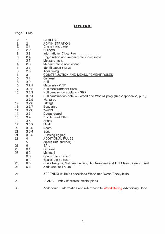
CONTENTS
Page Rule
2 1 GENERAL2 2. ADMINISTRATION2 2.12 2.23 2.33 2.44 2.54 2.65 2.76 2.86 36 3.16 3.26 3.2.17 3.2.2
10 3.2.33.2.43.2.5
12 3.2.613 3.2.714 3.2.814 3.316 3.419 3.519 3.5.220 3.5.321 3.5.421 3.5.522 4
523 623 6.123 6.2
6.36.4
25 6.526 6.6
27
29
30
English languageBuildersInternational Class FeeRegistration and measurement certificateMeasurementMeasurement instructionsIdentification marksAdvertisingCONSTRUCTION AND MEASUREMENT RULESGeneralHullMaterials - GRPHull measurement rules Hull construction details - GRPHull construction details - Wood and Wood/Epoxy (See Appendix A, p 25) Not used FittingsBuoyancyWeightDaggerboardRudder and TillerSparsMastBoomSpritRunning riggingADDITIONAL RULES(spare rule number)SAILGeneralMainsailSpare rule numberSpare rule numberClass Insignia, National Letters, Sail Numbers and Luff Measurement Band Additional sail rules
APPENDIX A: Rules specific to Wood and Wood/Epoxy hulls.
PLANS. Index of current official plans.
Addendum - information and references to World Sailing Advertising Code
1

1 GENERAL
1.1 The object of the class is to provide racing for young people at low cost.
1.2 The Optimist is a One-Design Class Dinghy. Except where these rules specifically per-
mit variations, boats of this class shall be alike in hull form, construction, weight and
weight distribution, rigging spars and sail plan.
Note: In deciding whether an item is permitted it should be noted that, in a One-Design
Class, unless the rules specifically state that something is permitted it shall be
assumed to be prohibited.
1.3
1.4
These rules are complementary to the plans, measurement forms and measurement diagrams. Any request for interpretation and resolution thereof shall be made in accor-
dance with current World Sailing regulations.
In the event of discrepancy between these rules, the measurement form and/or the plans the matter shall be referred to World Sailing.
2 ADMINISTRATION
2.1 English Language
2.1.1
2.1.2
2.1.3
2.1.4
2.2
2.2.1
2.2.2
2.2.3
2.2.4
The official language of the class is English, and in the event of a dispute over interpre-
tation the English text shall prevail.
The word “shall” is mandatory and the word “may” is permissive.
Wherever in these rules the words “Class Rules” are used they shall be taken as includ-
ing the plans, diagrams and the measurement forms.
The “National Class Association” is the International Optimist Class Association in the country concerned.
Builders
The Optimist may be built by any professional or amateur builder.
Professional builders shall be responsible for supplying boats complying with the Class Rules. The builder shall at his own expense correct or replace any boat which fails
to pass measurement, due to an omission or error by the builder, provided that the boat
is submitted for measurement within twelve months of purchase.
Manufacturers of kits or parts shall be responsible for supplying parts, which, when assembled in accordance with the manufacturer’s instructions (if any), will produce boats complying with the Class Rules. The manufacturer of the kit or parts which is shown not to do this shall, at his own expense, replace the parts of the kit which are incorrect provided that the error is made known to the manufacturer not more than twelve months from the date of purchase.
A builder shall issue with each hull a written builder’s declaration, stating that the hull complies with the relevant Class Rules.
2

2.32.3.1
2.3.2
2.3.3
World Sailing Class FeeThe amount of the World Sailing Class Fee is determined by World Sailing in consultation
with IODA. The Executive Committee may alter this amount following such consultation.
The World Sailing Class Fee shall be paid by the builder on each hull as soon as
building or moulding commences. For wood and wood/epoxy hulls the plaque shall be
supplied at the time of measurement.
The builder shall buy the building plaque and Registration Book:(a) for GRP hulls, from IODA
(b) for wood and wood/epoxy hulls, from IODA or the National Optimist Association
2.3.4 (a) IODA is responsible for collecting the World Sailing Class Fee on behalf of World Sailing.(b) IODA will buy building plaques from World Sailing unless otherwise agreed with World Sailing. (c) IODA or the National Association shall sell the plaques to the builder.
Each plaque shall, at every stage, be sold with the official World Sailing Class Fee receipt
and the builders declaration form. The World Sailing Class Fee receipt shall be sent to
the appropriate National Authority when the boat’s sail number is applied for.
2.3.5
2.4
2.4.1
2.4.2
2.4.3
For each World Sailing Class Fee paid, IODA or the National Optimist Association shall
issue a builder’s declaration, World Sailing Class Fee receipt and a World Sailing
Plaque, which the builder shall deliver with the hull to the owner. Builder’s
declarations and World Sailing Class Fee receipts are only valid if they are made out on the official forms issued by IODA. The building fee receipt and builder’s declaration is
incorporated in the Registration Book.
Registration and Measurement Certificate
No boat is permitted to race in the class unless it has a valid measurement certificate. This rule may be suspended in the case of charter boats at any event with the
permission of the IODA Executive Committee.
Each National Authority shall issue sail numbers which shall be consecutive and the number shall be preceded by the national letters. Numbering may restart at 1 on reach-
ing number 9999. A National Authority shall issue a sail number only on receipt of
evidence that the building fee has been paid.
The certificate is obtained as follows:
(a) The builder shall have the hull measured by a measurer officially recognised by his National Authority. The Registration Book with the World Sailing Class Fee receipt, builder’s declaration and hull measurement form section completed shall be supplied to the owner of the boat.
(b) The owner shall apply to the appropriate National Authority for a sail number enclos-
ing their Registration Book with builder’s declaration and building fee receipt. The National Authority shall enter the sail number in the Registration Book.
(c) The owner is responsible for sending the Registration Book with the builder’s
decla-ration and all measurement form sections completed to his National Authority,
togeth-er with any registration fee that may be required. On receipt of this the
National Authority shall complete the measurement certificate section of the
Registration Book and return it to the owner. Note that where a National Authority
prefers to issue its own certificate this shall be firmly fixed to, and mentioned in the
Registration Book.
2.4.4 Change of ownership invalidates the measurement certificate but shall not necessitate remeasurement. The new owner shall apply to his National Authority for endorsement of the certificate/Registration Book returning it with any re-registration fee required and stating the necessary particulars.The measurement certificate/Registration Book shall then be
3

4
2.4.5
2.4.6
2.4.7
2.5
2.5.1
2.5.2
2.5.3
2.5.4
2.5.5
2.5.6
2.6
returned to the owner.
If a replacement Registration book is required, it may be obtained from IODA. The new Registration book shall be printed with the same plaque number as the old Registration book. In the case of hulls produced before Registration Books were introduced, where the Measurement Certificate has been lost a National Authority may, after consultation with IODA, issue a replacement Measurement Certificate, valid for all events other than IODA championships, without evidence of measurement provided that the World Sai l ing/ ISAF/IYRU/ plaque remains affixed to the hull. (Note that such plaques have
numbers lower than 92000)
Notwithstanding anything contained in these rules, World Sai l ing or the National
Authority shall have the power to refuse to grant a certificate, or withdraw
a measurement certificate from any boat, giving written reasons for taking such action.
In countries where there is no National Authority or in which the National Authority does not wish to administer the class, its functions as stated in these rules shall be carried
out by IODA or its delegated representatives (i.e. National Class Associations).
Measurement
Only a measurer officially recognised by a National Authority shall measure a hull,
spars, sails and equipment, and sign the declaration on the measurement form that they
com-ply with the Class Rules. Hulls shall be measured in accordance with the
appropriate hull measurement instructions. For wood and wood/epoxy hulls see
Appendix A.
The measurer shall report on the measurement form anything which he considers to be a departure from the intended nature or design of the boat or to be against the general interest of the class. A measurement certificate may be refused, even if the specific requirements of the rules are satisfied.
A measurer shall not measure a hull, spars, sails, or equipment owned or built by him-
self, or in which he is an interested party or has a vested interest.
For wood and wood/epoxy hulls, see Appendix A.
All GRP hulls shall comply with the current rules or the rules current at the time the boat was first measured and registered with the National Authority as the bona fide property of a current Optimist sailor or his family, (with no family being permitted to register more than two Optimists per sailor) or a sailing club/school recognised by the national author-
ity or national Optimist association .
GRP hulls first so measured and registered between 1 March 1995 and 1 March
1996 shall conform either to the class rules in force from 1 March 1994 or to the class
rules in force from 1 March 1995. Hulls first so measured and registered after 1 March
1996 shall conform to the class rules then current.
Fittings, spars, sails and other equipment shall comply with the current rules, unless oth-
erwise stated in the specific class rule referring to such equipment.
It is the owner’s responsibility to ensure that his hull, spars, sails and equipment are maintained in accordance with the Class Rules so that the measurement certificate is not invalidated. Alterations or replacements to the hull, sails, spars and equipment shall comply with the current rules.
New or altered sails shall be measured by a measurer who shall stamp or sign and date the sails near the tack. The details shall be recorded on the certificate and the entry signed by the measurer or the secretary of the National Authority.
Measurement InstructionsExcept where varied by these rules the World Sailing Measurement Instructions shall
apply.

2.7 Identification Marks
2.7.1 The Class Emblem shall be the letter I and O and shall conform in shape and size to the pattern held by World Sailing. Copies may be obtained from the National Class
Associations, IODA or National Authority.
2.7.2 The building fee plaque shall be legible, clearly shown and permanently glued on the
starboard side of the aft face of the mast thwart bulkhead.
2.7.3 All hulls, shall have the sail number and National Letters clearly shown on a plate firm-
ly fixed to the starboard side of the aft face of the mast thwart bulkhead in figures not
less than 10 mm high.
2.7.3.1 GRP hulls shall have an identification number, in figures not less than 10 mm high,
moulded in each hull component:
Component 1: Hull shell: the forward face of the forward transom (within 60 mm of the centre of this transom).
Component 2: Gunwale - Mast Thwart assembly: the starboard bottom flange of the mast thwart bulkhead.
Component 3: Daggerboard Case - Midship Frame assembly: the forward bottom
flange of the daggerboard case.
This identification number shall consist of : code number of builder and code number of mould, both allocated by IODA to each mould and builder following approval of each pro-
totype. This number may be invalidated if it is established that hulls have deviated from Class Rules after prototype measurement.
Example of a possible hull identification no.: ( this example no. is not valid)
004N9022804 H2.7.3.2 On GRP hulls the builder shall engrave on the forward transom, 15 mm below the iden-
tification number a registration mark, in figures not less than 6 mm high. This registra-
tion mark shall consist of:
2.7.3.3 Manufacturers shall allot a serial number to the mast, boom, sprit, daggerboard and rud-
der. These serial numbers shall be reported on the appropriate Measurement Form by
the measurer and shall be clearly and indelibly marked by the builder on the rudder,
daggerboard and spars.
2.7.4 The sail number and National Letters shall be clearly marked on the rudder, dagger-
board and spars.
5
Year ISAF plaque fee number
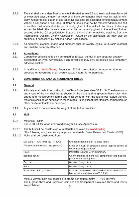
Mat 300 ( +/- 10% ) Mat 450 (+/- 10%) Chopped strand mat of E glass fibres
Polyester resin for GRP lamination.
Of any material to bond hull components and backing
plates where appropriate.
Woven Cloth or Biaxial 280 (+/-10%)
Resin
Bonding agent
Gel coat May be of any colour
May be of any colourPaint
Durable, non-absorbent closed cell PVC foam which shall be
bonded to the walls (see also CR 3.2.3.2)
Foam core 13/60 ( +/-10% )
6
2.7.5
2.7.6
2.82.8.1
2.8.2
3
The sail shall carry identification marks indicated in rule 6.5 and each sail manufactured or measured after January 1st 1990 shall have permanently fixed near its tack an offi-
cially numbered sail button or sail label. No sail shall be accepted for first measurement without a sail button or sail label. Buttons or labels shall not be transferred from one sail to another. Sail labels shall be permanently glued to the sail with two lines of stitching across the label. Alternatively labels shall be permanently glued to the sail and further secured with the ICA supplied rivet. Buttons / Labels shall normally be obtained from the International Optimist Dinghy Association (IODA) by the sailmakers but may also be obtained, if necessary, by National Class Associations.
All emblems, plaques, marks and numbers shall be clearly legible, of durable material and shall be securely attached.
AdvertisingCompetitor advertising is only permitted as follows: the hull in any area not already
designated for Event Advertising. Such advertising may only be applied as a temporary adhesive sticker.
In addition to World Sailing Regulation 20.2.4, promotion of tobacco or alcohol
products or advertising of an overtly sexual nature, is not permitted.
CONSTRUCTION AND MEASUREMENT RULES
3.1 General
3.1.1 All boats shall be built according to the Class Rules (see also CR 2.1.3). The dimensions
and shape of the hull shall be as shown on the plans and as given in these rules, dia-
grams and measurement forms and shall conform with the tolerances stated therein.
Materials shall be as specified in these Class Rules except that titanium, carbon fibre or
other exotic materials are prohibited.
3.1.2 Any attempt to concentrate the weight of the hull is prohibited.
3.2 Hull
3.2.1 Materials - GRP.
For CR 3.2.1 for wood and wood/epoxy hulls, see Appendix A.
3.2.1.1 The hull shall be constructed of materials approved by World Sailing. The following are the currently approved materials: Glass Reinforced Plastic (GRP).
3.2.1.2 Hulls shall be constructed from:
Mats & woven cloth are specified in grams per square metre +/- 10% (gr./m2)
The E glass fibres and Polyester resin shall be transparent. Coloured fibres and resins
are prohibited.
Cloth of woven or otherwise biaxial applied skeins of
continuous E glass fibres

3.2.2
Foam core is specified in thickness and weight per cubic metre +/- 10% (mm; kg/m3)
No material other than those prescribed above shall be used to build hulls. In case of doubt the IODA and World Sailing may prescribe any tests and investigations at
builder’s expense. (see also CR 3.2.3.2)
Hull Measurement Rules (see also CR 3.1)
For GRP hulls, World Sailing or IODA will require samples of the hull laminates to check
compliance with the Class Rules. A builder shall permit an approved measurer or class
representative to inspect work at any time during production of hulls.
3.2.2.1 GRP Hulls. For wood and wood/epoxy hulls, see Appendix A.
Unless otherwise prescribed in these Class Rules, plans and measurement forms, toler-
ances shall be +/- 2 mm. Measurements prescribed as max. (=not more than) or min.
(=not less than) shall have no further tolerances.
Some tolerance examples (all measurements in mm):
XYZ co-ordinate: 1037/008/35.3 i.e. all standard tolerances +/-2. (1035-1039/006-010/33.3-37.3)
Dimension: 40. i.e. standard tolerance +/-2. (38-42)
XYZ co-ordinate: 2158 +/- 4/000/172 i.e. X co-ordinate 2158 +/- 4 (2154-2162), Y co-ordinate
000 and Z co-ordinate 172 have standard tolerance +/- 2.
XYZ co-ordinate (1037/008/35.3) +/- 4 i.e. all co-ordinates +/- 4
Dimension: 40 +/- 3 i.e. 37-43.
Dimension: 40 +4/-0 i.e. 40-44.
The tolerances on hull measurements are intended to allow for genuine building errors
and for subsequent distortion only and shall not be used to deliberately alter the design
shape.
3.2.2.2 GRP Hull Prototype Measurement: It is obligatory for all builders of GRP hulls to ensurethat any prototype hull measures correctly before series production commences. Non-professional builders shall ensure that the first hull built in any mould shall be measured as a prototype. Only measurers approved by World Sailing and the IODA shall measure prototypes. (see also CR 2.7.3.1)
3.2.2.3 The Base-line shall be a horizontal line passing through points which are 110 mm and162 mm below the outer surface of the hull on its centreline at 28 mm and 2121 mmrespectively from a vertical plane through the lower corner of the aft transom. The upper-base-line shall be a horizontal centreline passing through points which are 63 mm abovethe highest point of the aft transom and 23 mm above the highest point of the forwardtransom.
3.2.2.4 The aft transom shall be at right angles to the base line but a maximum deviation of 5
mm, measured at the upper edge of the transom is permitted.
7
-+

3.2.2.5 GRP Hulls. For wood and wood/epoxy hulls see Appendix A.
The overall length excluding rudder fittings shall be 2300 mm +/- 7 mm, measured at
point 4. For length and beam measurements points 4 (sheerline) shall be defined by
using the ‘Standardized Sheerline Finder’.
3.2.2.6 A straight edge long enough to span the bottom panel from chine to chine placed at any
point on the panel at right angles to the fore and aft centreline shall nowhere be more
than 5 mm from the surface of the panel. No hollows are allowed.
3.2.2.7 A straight edge placed anywhere in contact with the side panel and spanning the panel
and so angled that it lies as close as possible to the panel shall nowhere be more than
5mm from the surface of the panel.
3.2.2.8 A straight edge 300 mm long placed anywhere on the bottom panel parallel to the fore
and aft centreline of the boat shall nowhere be more than 4 mm from the surface of the
bottom panel. No hollows are allowed. A straight edge 150 mm long, placed in the same
way, shall nowhere be more than 2 mm from the bottom panel.
On GRP hulls only, for the purpose of this and other ‘panel flatness measurements’ the
extent of the panels will be limited by an edge zone, defined by the ‘Standardized Edge-
Edge-Zone Finder’.
8
CR 3.2.2.6, 3.2.2.7, 3.2.2.8
Standardized Edge-Zone and Sheerline Finder (CR 3.2.2.8)

3.2.2.9 GRP Hulls. For wood and wood/epoxy hulls, see Appendix A.
The forward and aft transoms, mast thwart bulkhead, midship frame aft face and dag-
gerboard case (vertical) sides shall be flat with not more than 5 mm tolerance. The top
sides of the mast thwart, daggerboard case and midship frame shall be flat +2-0 mm (i.e
no hollows allowed).
3.2.2.10 GRP Hulls. For wood and wood/epoxy hulls, see Appendix A.
The inside length of the daggerboard slot and of the slot in the bottom panel shall be 330
mm +/-4 mm. The vertical ends in the daggerboard slot shall be square to the base line.
At each end a rake to taper not exceeding 4 mm is permitted. The daggerboard case top
side, measured at the top edges of the ends of the daggerboard slot, shall be parallel to
the upper base line, within a tolerance of 5 mm maximum.
3.2.2.11 GRP Hulls. For wood and wood/epoxy hulls, see Appendix A.
The inside width of the daggerboard case slot shall be 17 mm +/- 1 mm. The fore and
aft ends of the slot shall be semi-circular in cross section. (See also CR 3.2.6.1)
3.2.2.12 GRP Hulls. For wood and wood/epoxy hulls, see Appendix A.
The outside edges of the hull between the bottom and side panels, between the bottom
and forward transom, and between the side panels and forward transom shall be round-
ed to a radius of 10 mm +0/-1 mm. At the aft transom side and bottom outside edges no
radius is permitted.
3.2.2.13 The mast hole in the thwart shall be approximately circular. The diameter is optional but
shall not vary by more than 3mm in any direction. A sleeve of any material may be fitted
in the hole to limit abrasion. The sleeve shall not extend more than 3 mm above the mast
thwart. The total height of the sleeve shall not exceed 30 mm and its hole shall comply
with the requirements of this rule
3.2.2.14 Except as specified in these Class Rules or plans, holes or cut outs in the gunwale,
daggerboard case, midship frame, mast thwart and bulkhead are prohibited. (see also
CR 1.2)
3.2.2.15 GRP Hulls.
To avoid sharp projections and injuries, the exposed edges of: the gunwale and rubbing
strake, midship frame top flange, daggerboard case opening, mast thwart and mast
thwart bulkhead opening; shall be rounded to the maximum possible radius.
9
CR 3.2.2.13
CR 3.2.2.15

3.2.2.16 GRP Hulls. For wood and wood/epoxy hulls, see plans
The Gunwale-Rubbing strake section is defined perpendicular* to the sheerline. its posi-
tioning angle is fixed and related to the base line reference surface only. The Gunwale
section shall be constant throughout its entire length, including the Forward and Aft tran-
som, except within 180 mm of the intersection between Transom and Side sheerlines.
The Rubbing strake section shall be constant throughout its entire length, including the
Forward and Aft transom, except within 10 mm of the intersection between Transom and
Side sheerlines. (*If sheerline is curved, perpendicular = along the radius of the sheer-
line curve)
3.2.3 GRP Hull Construction Details See also CR 3.2.2
For wood and wood/epoxy hull construction details, see Appendix A
3.2.3.1 GRP Moulds.
Hulls shall be constructed of only three moulded components as described in CR
2.7.3.1. Each of these three components shall be constructed using only one mould.
Builders shall apply for a mould identification number allocated by the IODA for each
mould. (see also CR 2.7.3.1 & 2.7.3.2)
3.2.3.2 Laminate specifications. (see also CR 3.2.1.2)
- Laminate specification and lay up order shall be as defined in these Class Rules,
details and plans.
- Distribution of glass content and weight of each laminate shall be uniform throughout
within +/- 5%.
- Thickness of laminate shall be uniform throughout within +/- 5% or 1mm whichever is greater.
- Thickness and density of foam core in the bottom and the mast thwart laminate
shall be uniform throughout within +/- 3%.
- For the purpose of building efficiency, overlapping of 1 mat, woven cloth or biaxial
is permitted within 50 mm. from any corner. Overlapping, if any, shall be applied
over the full length along each corner.
- Any laminate shall only have one mould side, which shall be smooth.
- Moulded patterns are not permitted except for an optional anti-slip pattern not
exceeding 1mm thickness at the gunwale aft of the midship frame.
- The upper 300 mat of the bottom laminate shall overlap the 300 mat used in the
mast step base to ensure a strong bond between hull and mast step.
Laminate specifications and lay-up
order details:
10
(a) Bottom laminate Thickness : max 19 mm
Mould side gel coat
300 mat
300 mat
450 mat
Foam core 13/60
450 mat
300 mat
Painted coat on the entire surface of the exposed
inner bottom
A patch or patches of anti-slip paint (total surface
not less than 0.50 m2) on the exposed inner bot-
tom aft of the midship frame, but not closer than
250 mm to the aft transom.

11
A patch or patches of non-slip paint are permitted
forward of the mid-ship frame but not in front of
the aft side of the mast or bulkhead and not clos-
er than 250mm to the sides.
(c) Daggerboard slot laminate Thickness : min 4 mm / max 8 mm
Mould side gel coat
300 mat
min 2 x 450 mat / max 5 x 450 mat
300 mat
Painted coat optional
(d) Daggerboard case-midship
frame assembly, except flanges
and top of daggerboard case lami-
nate
Thickness : min 4 mm / max 8 mm
Mould side gel coat
300 mat
min 3 x 450 mat / max 6 x 450 mat
Painted coat optional
(e) Mast thwart laminate Thickness : max 17 mm
Mould side gel coat
300 mat
300 mat
300 mat
Foam core 13/60
450 mat
Painted coat optional.
Within 50 mm of the mast hole min 3 / max 5 addi-tional layers of 450 mat may be used as local rein-forcement.
(f) Mast thwart bulkhead laminate
except flanges
Thickness : max 4 mm
Mould side gel coat
300 mat
(b) Sides and transoms laminates,
incl. rubbing strakes.
One piece of 450 mat not exceed-
ing 300 mm x 200 mm centred on
the vertical centreline of the aft
transom may be used for gudgeon
reinforcement. The max, thickness
specified in CR 3.2.3.2 (b) may be
exceeded in this area.
Thickness : max 4 mm
Mould side gel coat
300 mat
450 mat
450 mat
280 woven cloth or biaxial
Painted coat optional
450 mat
450 mat
Painted coat optional.

For the purpose of positioning and fixing, the top of the daggerboard case, the flanges
of the midship frame-daggerboard case assembly and the flanges of the mast thwart
bulkhead shall consist of min 3 x 450 / max 5 x 450 mat (min 3 mm / max 8 mm thick-
ness). At this top and these flanges, the distribution of glass content and the thickness
of the laminate need not be uniform throughout..
3.2.4 Construction Details - Wood: See Appendix A3.2.5 Rule no. not used.3.2.6 Fittings
3.2.6.1 The following fittings are permitted:(a) 2 Mainsheet blocks (excluding those on the boom) shall be attached to the hull
inner bottom. The centre of their fixing points shall be at 786 mm +/- 5 mm and894 mm +/- 5 mm from the forward face of the aft transom.
(b) One ratchet block for the mainsheet.(c) 2 toe-straps and 4 associated fixing plates of 50 mm +/- 10 mm x 20 mm +/- 5mm
x 2 mm +/- 1mm if metal or 50 mm +/- 10 mm x 20 mm +/- 5 mm x 7 mm +/- 3 mmif plastic. (see also CR 3.2.6.2 and CR 3.2.7.3) Up to three pieces of cord or elas-tic cord may be used to lift the toe-straps off the hull shell floor.
(d) A compass and associated fixings, which shall all be removable for weighing the hull.Mobile phones, digital compasses and/or devices memorising, correlating or transmit-ting data relative to wind direction or speed, or boat speed or direction and location arenot permitted, unless these devices are supplied by the Organising Authority for thesole purpose of providing event tracking.
(e) Retaining clip(s) for a paddle.(f) An adjustable mast step. Movement of the mast at the mast step or at the passage of the
mast through the mast thwart shall not be able to exceed 3 mm in any horizontal direction.The mast or mast step shall not be adjusted while racing. Mast step devices which can beeasily set while racing in such a way that this class rule is infringed, are prohibited.
(g) Retaining clips for water bottles, food container or other personal equipment,which shall be removable for weighing the hull.
(h) Retaining clip for fastening the tiller extension to the tiller.(i) Strips of non-metallic material may be fitted to the daggerboard case slot within 30
mm of the top and the bottom of the daggerboard case slot to achieve a uniformopening of 16 mm +/-2 mm at the top and bottom of the daggerboard case slot.Additional non-metallic material may be placed within 30 mm in any direction ofeach end of the top and bottom of the daggerboard case slot to act as positioningand protection of the daggerboard. This additional material shall be removed uponrequest of the measurer, for then measurement of the daggerboard case slot. (Seealso CR 3.2.2.11).
(j) A handle or ball may be used on the outer end of:(i) Sprit halyard.(ii) Boom downhaul.
300 woven cloth as supporting reinforcement between inner
hull sides and inner gunwale (see GRP plan sheets 3), except
forward of the mast thwart bulkhead. Gaps of up to 55 mm
wide are permitted at the aft corners, at each side of the side
members and at the aft side of the mast thwart bulkhead. The
width of this reinforcement shall be 50 mm +/- 5 mm.
(g) Gunwale laminate, incl.
rubbing strake.
Thickness : max 4 mm
Mould side gel coat
450 mat
450 mat
450 mat
12

(k) 1 hole (diameter max 8 mm) on the centre line in the top of the forward gunwale just after the forward transom, for drainage; 1 hole (diameter max 8 mm) on the centre line in the top of the aft gunwale just before the aft transom, for drainage and or for fixing of an optional shock-cord to tension the toe straps. (see also 4.3); 1 hole (diameter max 8 mm) on the centre line in the daggerboard case top side, aft of the daggerboard slot, for drainage.
(l) One or two eyes may be attached to the daggerboard case (see CR 3.3.5).
3.2.6.2 Backing plates, when used in GRP boats, shall comply with the Plans and laid-in asshown on this diagram (i.e. top surface of backing plate flush with top of bottom foamcore).
3.2.6.3 Toe straps can be attached to the midship frame, using at most 4 fixing plates (two foreach strap) of 50 mm +/-10 mm x 20 mm +/-5 mm x 2 mm +/-1mm for metal plates or50mm +/-10 mm x 20 mm +/-5 mm x 7 mm +/-3 mm for plastic plates.
3.2.6.4 Fittings, including backing plates, shall conform to the dimensions of the laid-in backingplates and be securely attached to them as shown. This rule shall be effective from 01.10.2016 except that boats fitted and measured with mast step devices not complying with this rule by this date will remain Class legal.
3.2.6.5 The following items, and others not specifically permitted by these rules, are prohibited:(a) Mainsheet cleats, mainsheet horse, track or traveller.(b) Suction bailers and bilge pumps.(c) Decking or spray covers of any sort.(d) Any apparatus or contrivance outboard, or extending outboard, which is, or may
be used to assist In supporting the helmsman outboard.(e) Any fittings constructed in part or whole of titanium.
3.2.7 Buoyancy3.2.7.1 The hull shall be fitted with three buoyancy units in the form of inflated air bags made of
strong fibre-reinforced material. Each unit shall be 45 litres +/- 5 litres. Each unit shall beequipped with a fill valve that positively prevents the accidental release of air (i.e.- Non-return valves and threaded valves with screw-on caps). The minimum weight of eachunit shall be 200 grams.
3.2.7.2 One unit shall be placed along the whole width of the aft transom and one unit shall beplaced along each side between the midship frame and the mast thwart bulkhead.
3.2.7.3 Buoyancy units shall be securely fastened to the hull by three straps. Each strap shallbe 45 mm +/- 6mm wide and shall be regularly checked. 1 backing plate in GRP boatsof metal 50 +/- 10 mm x 20 +/- 5 mm x 2 +/- 1 mm and 1 fixing plate, 50 +/- 10 mm x 20+/- 5 mm x 2 +/- 1 mm if metal or 50 +/- 10 mm x 20 +/- 5 mm x 7 mm +/- 3 mm if plas-tic, shall be used for fastening of each strap. At the aft transom centre strap a biggerplate 50 +/- 10 mm x 50 +/- 10 mm x 2 +/-1 mm if metal or 50 +/- 10 mm x 50 +/- 10 mmx 7 mm +/- 3 mm if plastic for combined use with the toe-strap shall be used.Alternatively an eye may be used for attachment of the aft end of the toe straps at thecentre buoyancy bag attachment point.”
3.2.7.4 The owner is responsible at all times for the buoyancy and for ensuring that at intervalsof not more than 12 months the buoyancy is tested and the measurement certificate endorsed by a measurer or a responsible club officer. The measurement certificate shall not be valid until so endorsed.
3.2.7.5 The measurer shall witness a buoyancy test as follows:
The boat shall be swamped with water and with iron weights of not less than 60 kg placedaft of and within 100 mm of the midship frame, it shall float with the gunwales clear of thewater. The measurer shall make sure that the buoyancy and its fastening are sound, and thatinflatable buoyancy shows no visible signs of deflation, deterioration or damage.
As an alternative the measurer shall have the buoyancy bags removed from the hull,fully inflated, and then check for deflation, deterioration or damage. The measurer shallthen check each strap for deterioration, damage or fraying and then check each strap
CR 3.2.6.2

Resin Epoxy resin for EPOXY lamination (shall not be coloured)
Unidirectional 600 Unidirectional mat of E glass fibres, 600 gr/m2 (+/- 10%)
Woven cloth 280 Cloth of woven or otherwise biaxial applied skeins of continuous E glass
fibres 280 gr/m2 (+/- 10%). Pre-impregnated cloth is not permitted.
Foam Core Durable, non-absorbent closed cell PVC foam. 13mm (+/- 10%),
60 Kg/m3 (+/- 10%)
Mat 100 Chopped strand mat of E glass fibres, 100 gr/m2 (+/-10%) (shall
not be coloured)
Glue Epoxy, for bonding battens to the daggerboard only.
Gelcoat Shall be clear
Wood Any type, for battens only
14
Plywood A single sheet of commercially available plywood shall be used. Manufacturers
shall, upon request, supply a sample and specification sheet of plywood used.
Glue Epoxy, for bonding battens to the daggerboard only.
Paint Clear varnish or clear epoxy, suitable for marine use.
Wood Any type, for battens only
individually by lifting the side of the boat (or the transom in the case of the aft straps) offthe ground. Finally the bags should be replaced in the boat, re-inflated and the strapschecked to ensure that the bag is held securely in place.
3.2.7.6 The first buoyancy test shall normally be completed at the time of the first measurementof the boat. However, if the measurer certifies that the buoyancy test could not be takenat that time, but in all other respects the Class Rules are satisfied the measurementcertificate may be issued but with the endorsement “Not valid until a buoyancy test hasbeen passed.”
3.2.8 Weight
3.2.8.1 The weight of the hull in dry condition, including: rudder gudgeons fixed to the aft transom, buoyancy straps, toe straps andassociated fixings (without removable foam or protection), mast step, block fittings per-manently attached, but excluding: corrector weights, blocks, mainsheet, buoyancy airbags, painter, bailer, paddle, compass (with bracket if any) and fixings, retaining clips forwater bottles, food containers or other personal equipment and fixings, and all other notspecifically permitted items, shall not be less than 32 kg.
3.2.8.2 If the weight of the hull in the same condition as prescribed in CR 3.2.8.1 but includingbuoyancy air bags is less than 35 kg but not less than 32.6 kg wood corrector weightsshall be fitted to bring the hull weight up to not less than 35 kg. The corrector weightsshall be permanently fitted, half to the forward transom and half to the aft transom. Nocorrector weights shall be removed or altered without the boat being re-weighed by anofficial measurer. The weight of each corrector shall be stamped or otherwise marked onthe corrector and endorsed on the measurement certificate.(See also CR 3.2.7.1 for minimum weight of buoyancy air bags.)
3.3 Daggerboard
3.3.1 Materials
3.3.1.1 Boats shall use epoxy daggerboards as specified below. Wood or wood epoxy boatsmay use either wood or epoxy daggerboards. Daggerboards presented for first mea-surement before 28 February 2005 and used on boats measured before that date may conform to the rules valid before 1st March 2004. WOOD:
EPOXY:

Manufacturers shall, upon request, supply a laminated sample and specifications of all
materials used.
3.3.1.2 Non metallic reinforcement (bushing) of diameter not more than 20 mm may be used
around holes, screws, rivets or bolts.
3.3.1.3 Laminate specification for EPOXY daggerboard:
3.3.1.4 For EPOXY foils the manufacturer's name, a manufacturer generated mould identifica-
tion number as well as the year of manufacture shall be laminated into the daggerboard
in characters 10 mm +/-2 mm high on the starboard side, 25 mm +5/-0 mm below the
bottom edge of the stop batten. For wooden foils, the manufacturer’s name and the
month and year of manufacture shall be indelibly marked in the same position and with
characters of the same size.
3.3.2 Shape
3.3.2.1 The daggerboard shall be generally a rectangular flat plane in shape except that the
lower corners shall be rounded to a radius of no more than 32 mm, and the upper cor-
ners shall be rounded to a radius of no more than 5 mm. Upper corners and stop batten
edges shall have no sharp projections.
3.3.2.2 The thickness of the daggerboard (excluding bevels) shall be not less than 14 mm (12
mm for wooden construction) and not more than 15 mm. Bevelling is permitted between
all edges (except for the top edge) and the bevelling limits, situated 60 mm from all
edges. There shall be no bevelling underneath the stop battens.
3.3.2.3 The overall length of the daggerboard shall be 1067 mm +/- 5 mm and the width 285
mm +/- 5mm. Within these limits, the length and width shall each not vary by more than
3mm.
3.3.2.4 The daggerboard shall be fitted with stop battens, one on each side of the daggerboard.
Sizes and shapes of stop battens shall be generally uniform without cut-outs and/or sud-
den changes. The battens shall be made from wood and extend over the full width of
the board with the top of the battens level with the top of the board. The depth shall be
35 mm +/- 5 mm throughout. The thickness of the assembled stop battens and dagger-
board shall be 45 mm +/-5 mm throughout. The exposed edges of the battens shall be
rounded to a radius of 5 mm +0/-2 mm. The battens shall be fixed with glue, and two 5
mm +/-1.5 mm metal bolts and nuts. The length of these fasteners shall be the same +0/-
5 mm as the thickness of the assembled daggerboard and stop battens.
15
280 woven cloth to be applied with one set of fibres running parallel to the aft edge of the daggerboard
100 mat
Mould side gelcoat
280 woven cloth to be applied with one set of fibres running parallel to the aft edge of the daggerboard
600 unidirectional to be applied with the fibres running parallel to the aft edge of the daggerboard
Foam core 13/60
600 unidirectional to be applied with the fibres running parallel to the aft edge of the daggerboard
280 woven cloth to be applied with one set of fibres running parallel to the aft edge of the daggerboard
280 woven cloth to be applied with one set of fibres running parallel to the aft edge of the daggerboard
100 mat
Mould side gelcoat

3.3.3
3.3.4
3.3.5
3.4
3.4.1
The weight of the daggerboard, without attachment or positioning features, shall be not less than 2.0 kg. Ballasting or cut-outs of the daggerboard are prohibited. The centre of gravity of the assembled daggerboard and stop battens shall not be less than 520 mm away from the lower edge.
The daggerboard shall float, and shall be attached to the hull. One hole shall be drilled through the daggerboard and the battens in any place. Its diameter shall not exceed 10 mm. An elastic cord or lanyard shall be used to attach the daggerboard to the hull. A small shackle may be used to attach the elastic cord or lanyard, either to the hull or the daggerboard.
The daggerboard may be held in the daggerboard case by a loop of (elastic) cord. The cord may be fixed to the daggerboard case through one or two eyes or to the mast thwart bulkhead through two optional holes,with a diameter of not more than 10mm.
The position of the holes shall be in accord with hull sheet plan 16/24. A single extra loop of rope, tape or elastic cord may be attached to this loop in order to assist with the process of lowering and raising the daggerboard. Both the elastic cord and the addition-
al loop may be padded by using flexible hollow tubing.
Rudder and Tiller
Materials
3.4.1.1 Boats shall use epoxy rudders as specified below. Wood or wood epoxy boats may use
either wood or epoxy rudders. Rudders presented for first measurement before 28 February 2005 and used on boats measured before that date may conform to the rules valid before 1st March 2004.
WOOD
EPOXY
Manufacturers shall, upon request, supply a laminated sample and specifications of all
materials used.
16
Plywood A single sheet of commercially available plywood shall be used..
Manufacturers shall, upon request, supply a sample and specification
sheet of plywood used.
Paint Clear varnish or clear epoxy, suitable for marine use.
Resin Epoxy resin for EPOXY lamination (shall not be coloured)
Unidirectional 600 Unidirectional mat of E glass fibres, 600 gr/m2 (+/- 10%)
Woven cloth 280 Cloth of woven or otherwise biaxial applied skeins of continuous E glass
fibres 280 gr/m2 (+/- 10%). Pre-impregnated cloth is not permitted.
Foam Core Durable, non-absorbent closed cell PVC foam. 13 mm (+/- 10%),
60 Kg/m3 (+/- 10%)
Mat 100 Chopped strand mat of E glass fibres, 100 gr/m2 (+/-10%) (shall
not be coloured)
Gelcoat Shall be clear
3.4.1.2 The tiller and tiller extension of EPOXY rudders shall be made of aluminium. The tiller
and tiller extension of wooden rudders may be made of wood or aluminium.
3.4.1.3 Non metallic reinforcement (bushing) of diameter not more than 20 mm may be used
around screws, rivets or bolts.
3.4.1.4 Laminate specification (for EPOXY rudder)
3.4.1.5 For EPOXY foils the manufacturer's name, a manufacturer generated mould identifica-
tion number, as well as the year of manufacture shall be laminated into the rudder in
characters 10 mm +/-2 mm high on the starboard side, 25 mm +5/-0 mm below the bot-
tom edge of the tiller. For wooden foils, the manufacturers name as well as the year of
manufacture shall be indelibly marked in the same position in the same size characters.
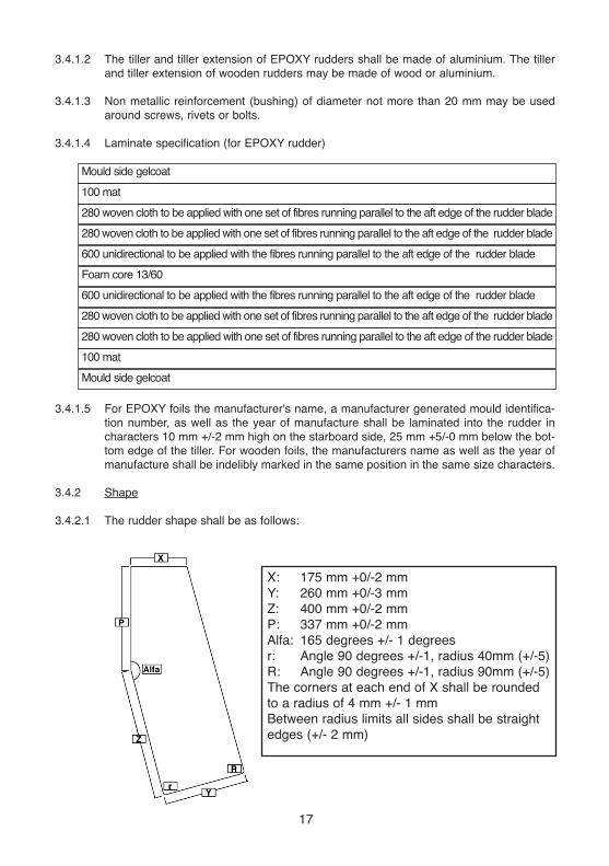
3.4.2 Shape
3.4.2.1 The rudder shape shall be as follows:
17
280 woven cloth to be applied with one set of fibres running parallel to the aft edge of the rudder blade
100 mat
Mould side gelcoat
280 woven cloth to be applied with one set of fibres running parallel to the aft edge of the rudder blade
600 unidirectional to be applied with the fibres running parallel to the aft edge of the rudder blade
Foam core 13/60
600 unidirectional to be applied with the fibres running parallel to the aft edge of the rudder blade
280 woven cloth to be applied with one set of fibres running parallel to the aft edge of the rudder blade
280 woven cloth to be applied with one set of fibres running parallel to the aft edge of the rudder blade
100 mat
Mould side gelcoat
X: 175 mm +0/-2 mm
Y: 260 mm +0/-3 mm
Z: 400 mm +0/-2 mm
P: 337 mm +0/-2 mm
Alfa: 165 degrees +/- 1 degrees
r: Angle 90 degrees +/-1, radius 40mm (+/-5)
R: Angle 90 degrees +/-1, radius 90mm (+/-5)
The corners at each end of X shall be rounded
to a radius of 4 mm +/- 1 mm
Between radius limits all sides shall be straight
edges (+/- 2 mm)

3.4.2.2 The thickness of the rudder (excluding bevels) shall be not less than 14 mm (12 mm for
wooden construction) and not more than 15 mm. Bevelling is permitted between the
edges and the bevelling limits, situated 60 mm from all edges. No bevelling is permitted
on the top of the rudder head.
3.4.2.3 The tiller shall be removable and shall be fixed to the rudder by two metal bolts of 5 mm
+/-1.5 mm diameter. The fitting connecting tiller and tiller extension is optional. Tiller, tiller
extension and fittings shall have no sharp projections.
3.4.2.4 The tiller and tiller extension shall each be not more than 750 mm long and their com-
bined length shall not be more than 1200 mm.
3.4.3 The assembled rudder, tiller and tiller extension shall float, and their total weight shall
not be less than 1.5 kg. Ballasting of any part of this assembly is prohibited.
3.4.4 Definition of Rudder elements
3.4.4.1 Bearing lines: two horizontal lines (parallel to the baseline) through the bearing points of
the rudder fittings.
3.4.4.2 Rudder head front line: line passing through the intersections of the forward edge of the
rudder and the two bearing lines.
3.4.5 Fixing and positioning:
Boats built before 1 March 1992 may either use the rudder positioning method which
was applicable at the time of building, or the current one. The positioning fittings of the
rudder themselves shall then comply with the correspondingly dated rules for the rudder.
3.4.5.1 Two pintles shall be fixed on the rudder, their diameter shall be not more than nominal
6mm. The distance between the upper edge of the tiller and the bearing line of the upper
pintle shall be not less than 85 mm, measured along the rudder head frontline. Two gud-
geons shall be fixed to the aft transom, with holes not less than 6 mm diameter. The dis-
tance between the bearing lines of the two gudgeons shall be not less than 200 mm. The
corresponding distance between the pintles shall be not more than 200 mm. The depth
of the pivoting holes in the two gudgeons shall not exceed 5 mm, and the distances from
those holes to the aft face of the aft transom shall not differ by more than 2 mm.
3.4.5.2 The rudder and tiller assembly shall be fitted to the aft transom so that it does not
become detached from the hull during a capsize. To this effect, an appropriate retaining
clip/spring shall be fitted on the forward edge of the rudder head, not less than 5 mm
below the bearing line of the upper pintle.
3.4.5.3 When fitted to the aft transom, the distances from the rudder head frontline to the aft face
of the aft transom, measured at the position of both bearing lines, shall be not more than
45mm and shall not differ by more than 2 mm.
18

3.5 Spars
3.5.1 Materials
3.5.1.1 The spars shall be made of either, aluminium alloy tube or, of solid wood. Wooden spars
shall be of not more than two pieces of wood. Any exploitation of tolerances in order to
achieve non-circular, tapered or otherwise variable spars, is prohibited.The wall thick-
ness of the aluminium alloy tubing shall be constant throughout the spars. Internal
sleeves, ribs and stiffening are prohibited.
3.5.1.2 Plastic, wood or metal may be used for end caps and fittings including the boom jaws.
End caps, sprit end and jaws fittings shall be permanently fixed but may be glued to the
spars. The length of the fittings and cap shall not exceed 100 mm for the lower end of
the mast, the outboard end of the boom and the jaws fitting, 60 mm for the top of the
mast and both ends of the sprit. At the top of the mast the height of the visible part of an
optional end cap shall not exceed 10 mm.
3.5.1.3 Spars shall be capable of floating approximately horizontally for thirty minutes with no
discernible water penetration for a sealed spar or loss of buoyancy for a foam filled spar.
3.5.1.4 Unless specifically permitted by these rules, fittings on spars shall be permanently fixed
by means of rivets, screws, and/or nuts and bolts.
3.5.1.5 Non-metallic protective material may be used on the sprit at the area where sprit and
mast make contact. This material shall not exceed max. 150 mm length and max. 1.5mm
thickness.
3.5.2 Mast
3.5.2.1 The mast shall be approximately circular in section. The diameter shall be 45mm ±
0.5mm.
3.5.2.2 Masts shall be of uniform section above 50 mm from the heel. Wooden masts may be
reinforced with a GRP or plastic collar which shall extend not more than 800 mm above
the heel and shall not increase the diameter by more than 4 mm.
3.5.2.3 An aluminium mast may be fitted with not more than two sleeves of GRP or plastic to
allow it to fit a larger diameter mast thwart hole and mast step. Each sleeve shall be of
uniform wall thickness and shall not extend along the mast for more than 50 mm.
3.5.2.4 The overall length of the mast shall be not more than 2350 mm.
3.5.2.5 Standing rigging of any sort is prohibited.
3.5.2.6 The mast shall have either two holes, in any direction in the horizontal plane, or two
eyes, which need not be permanently fixed, or one eye and one hole. The upper edge
of one of the holes or eyes shall be not less than 20 mm from the top of the mast and
the upper edge of the other not less than 120 mm from the top of the mast. Lacing lines
shall pass through these eyes or holes and shall be lashed through the eyelet at the
throat of the sail, see also CR. 6.6.3.1 A wind indicator or wind indicator fittings (CR.
3.5.2.12) may secure, or be secured by these lacing lines, but this does not release the
lines from the obligation of passing through the holes or eyes.
19

3.5.2.7 Distinctively coloured bands, clearly visible while racing, and each not less than 10 mmwide shall be marked on the mast as follows:(a) Band No. 1, the lower edge of which shall be not less than 610 mm from the top
of the mast.(b) Band No. 2, the upper edge of which shall be not more than 635 mm from the top
of the mast.The lower edge of Band No. 1 and the upper edge of Band No. 2 shall be permanentlymarked by a scribed line or not less than two marks made with a centre punch.
3.5.2.8 The mast shall be positioned in the mast step by means of wedges, blocks or otherdevices so that it shall be unable to move more than 3 mm in any horizontal direction.The position of the heel of the mast shall not be varied while racing.
3.5.2.9 The mast shall have a cleat in a suitable position for securing the boom downhaul.
3.5.2.10 The mast shall have, in a suitable position, for the sprit, either a cleat and one hole oreye (which need not be permanently fixed), or a toothed rack.
3.5.2.11 A locking device or other arrangement shall be fitted and used to prevent the mast fromcoming out of its step when the boat is capsized.
3.5.2.12 A wind indicator may be fitted to the top of the mast. The mast may have a fitting (whichneed not be permanently fixed) for securing the wind indicator. Such a fitting shall bepositioned within 150 mm below the top end of the mast and it shall have no sharp pro-jections. The wind indicator or its attachment fittings may be used to help secure the lac-ing lines from the throat of the sail.
3.5.2.13 The mast may have a pin stop positioned on the forward side of the mast 1680 mm +/-10 mm below the top end of the mast. This pin shall not be more than 8 mm diameterand within 10 mm of the surface of the mast and shall have no sharp projections.
3.5.3 Boom
3.5.3.1 The boom shall be approximately circular and of uniform section throughout. The diam-eter shall be not less than 29.5mm and not more than 55.5mm and at any section it shallnot vary by more than 1mm.
3.5.3.2 The boom, excluding the boom jaws, shall not exceed 2057 mm in length.
3.5.3.3 The type of boom jaws and jaws fitting is optional but thickness of the jaws shall notexceed 35 mm and the length of the jaws fittings shall not exceed 100 mm. A rope maybe fastened to the boom jaws or jaws fittings through two holes or through two eyes, andpass forward, around and over a pin positioned on the forward surface of the mast (Seealso CR 3.5.2.13).
3.5.3.4 A distinctively coloured band, clearly visible while racing, and not less than 10 mm wideshall be marked on the boom with its forward edge not more than 2000 mm from the aftedge of the mast. The inner edge of the band shall be permanently marked by a scribedline or not less than two marks made with a centre punch. The coloured band at the out-board end of the boom may be on a permanently fixed end cap, provided that no visiblepart of the end cap extends inward of the position of the forward edge of the band, andthat the cap complies with the former part of this rule, and with class rule 3.5.3.2.
3.5.3.5 Either the boom or the end cap shall have a hole or lacing eye. The forward edge of thehole or the opening of the eye shall be not more than 40 mm from the inner edge of theband at the outboard end of the boom.
20

3.5.3.6 A cleat with no sharp projections for securing a clew outhaul may be fitted on the boom.It shall be not less than 400 mm from the outer end of the boom.
3.5.3.7 The boom downhaul may be attached to the boom in an optional manner by use of afixed stop or lacing eye at a fixed position.Attached to the upper side of the boom, the bearing edge of the fitting used shall not bemore than 200mm from the inner end of the boom excluding boom jaws.Attached elsewhere, the outer edge of the fitting used shall not be more than 200mmfrom the inner end of the boom excluding boom jaws.
3.5.3.8 The method of attachment of the mainsheet or mainsheet block(s) to the boom is optional(provided they cannot slip along the boom, and the maximum clearance between the spanand the boom shall be not more than 100 mm, at any position along the boom). The posi-tion of the blocks or the length of boom strops shall not be adjusted while racing.
3.5.3.9 There shall not be any fitting, rigging or device the purpose of which is, or may be, tocontrol the position of the boom on the mast except for items specifically required or per-mitted by these rules.
3.5.4 Sprit
3.5.4.1 The sprit shall be approximately circular and of uniform section throughout. Its diametershall be 27.5mm ± 2mm.
3.5.4.2 The sprit shall be not more than 2286 mm in length, including end fittings.
3.5.4.3 The type of fitting at the upper end of the sprit shall be as shown in the rigging plan. Ifthe upper end fitting exhibits a widening after an initial narrowing, this widening shall notbe in excess of 13 mm.The fitting at the lower end of the sprit shall be either one of the fittings permitted at itsupper end, or the sprit may be fitted with an eye, a hook, or it may have a hole throughthe spar. The length of the end fittings on both ends shall not exceed 60 mm. The eye,hook or hole at the lower end of the sprit if present, shall be located within 60 mm of thisend.
3.5.5 Running Rigging
3.5.5.1 The mainsheet arrangement is optional except as controlled by CR 3.2.6.1 and CR3.5.3.8.
3.5.5.2 Downhaul. A single part downhaul of rope and/or wire shall be fitted to the boom notmore than 200 mm from the inner edge of the boom jaws. It shall be secured to a cleaton the mast. The downhaul shall not be adjustable from aft of the midship frame.
3.5.5.3 Only the lower end of the sprit shall be made fast to the mast. The only methods ofattachment and adjustment of the lower end of the sprit shall be by means of:(a) A rope or wire rope loop in conjunction with a toothed rack.The maximum dimen-
sions of the toothed rack are:Length 150 mmWidth 20 mmThickness 3 mmHeight of tooth 10 mm
or(b) A halyard consisting of not more than two parts of rope or rope/wire
combination,with no more than two single sheave blocks, to obtain no more thana double “Purchase” plus one hole or one eye, and one cleat which are fastenedon the mast. The way of attaching the blocks on the lower end of the sprit or on
21
the mast is optional. The sprit shall not be adjustable from aft of the mid-ship frame.
3.5.5.4 Outhaul. The outhaul shall be made of a rope not more than 1200 mm long. It may beadjustable. In this case it shall use no more than two purchases; no blocks are allowed;and the outhaul end shall then pass through the hole or lacing eye near the end of theboom (see also CR 3.5.3.5) and be secured to the outhaul cleat on the boom.
3.5.5.5 The use of wire is prohibited except for the boom downhaul, sprit halyard and strops onthe boom for fitting sheet blocks.
3.5.5.6 No running rigging shall be allowed inside of hollow spars.
4 ADDITIONAL RULES
4.1 Only one person shall be on board while racing.4.2
(a) The helmsman shall wear a personal flotation device to the minimum standard ISO 12402-5 (Level 50) or equivalent. All fastening devices supplied by the manufacturer shall be used in the manner intended. A whistle shall be carried securely attached to the personal flotation device.
(b) With reference to the Racing Rules of Sailing the total weight of clothing and equipment worn or carried by a competitor, excluding footwear shall not be capa-ble of exceeding 8 kg when weighed as provided in Appendix H of the Racing Rules.
(c) Hiking pants are permitted provided they are not attached to the boat and do not contain any stiffening which can extend below the knee joint.
4.3 The following equipment shall be on board while racing:(a) One or more bailers which shall be securely attached to the hull by a lanyard(s)
or elastic cord(s). One bailer shall have a minimum capacity of one litre.
(b) A painter of a single piece of buoyant rope, not less than 5 mm diameter and notless than 8 m long securely fastened to the mast thwart or mast step. (see also3.2.6.1).
c) "A paddle of wood and/or plastic, weighing not less than 200g, having corner radiiof minimum 5 mm and a blade able to contain a rectangle of 200 mm x 130 mm shall be securely attached to the hull by a lanyard or elastic cord."
4.4 An anchor need be carried only when specifically prescribed in the sailing instructions.
4.5 Unless damage renders a hull, sail, spar or foil unusable during an event, only one hull,sail, mast, boom, sprit, daggerboard and rudder shall be used throughout the event. Anysuch change of equipment shall be authorised by the Race Committee.
4.6 If there is a national Optimist Class Association of the country in which the boat is reg-istered the owner shall be a member. Where a boat is sailing in an international regattathe competitor shall be a member of a national Optimist association or other body whichis itself a member of the IODA as defined in IODA Article 3(a).
22

6 SAIL
6.1 General
6.1.1
6.1.2
6.1.3
6.1.4
6.2
6.2.1
6.2.2.
6.2.3
6.3
6.3.1
Sails shall comply with the Class Rules in force at the time of certification unless other-
wise specified below.
Anything not specifically permitted by these rules is prohibited, see also CR. 1.2.
Sails shall be made and measured in accordance with the current World Sailing “Equipment Rules of Sailing” as applicable to Optimist sails, except where varied herein.
Where a term defined or measurement given in these World Sailing Rules is used in
these rules, it is printed in “italic” type. All measurements shall be taken along the
surface of the sail and include any bolt rope and tabling. Battens shall not be
removed for sail measurement purposes.
Certification
A measurer approved by an MNA or a Class Association where so authorised by an MNA shall certify the sail in the tack and shall sign and date the certification mark.
Sailmaker
No licence is required.
The thickness of the body of the sail shall be not less than 0.15 mm. Where in the con-
struction of the body of the sail the cloth is of variable thickness, the thinnest parts of the sail as measured by a micrometer with a spindle surface of 6.4 mm +/- 0.25 mm diam-
eter shall each be at least 9 mm x 9 mm square, and the thickness of the cloth shall be deemed to be that of the thinnest parts. Sails which are not so constructed shall cease to comply with Class Rules from 1 March 2005.
The thickness in mm of the body of the sail shall be indelibly marked by the manufac-
turer, together with his signature, stamp, and date near the peak point.
For the purpose of repairing a sail, ply different to the ply of the body of the sail may be used up to a limit of one panel or one secondary reinforcement.
Mainsail
Identification
6.3.1.1 The class insignia shall conform with the dimensions and requirements as detailed in the
diagram in CR 2.7.1 and be placed in accordance with the diagram contained in Sail
Plan Sheet 4/5. No part of the class insignia shall extend beyond 1000 mm of the peak
point. The class insignia shall be placed back to back on both sides of the sail.
6.3.2 Materials.
The ply fibres shall be of polyester or cotton.
6.3.3 Construction
6.3.3.1 The construction shall be: soft sail, single ply sail.
6.3.3.2 The body of the sail shall consist of the same woven ply throughout.
6.3.3.3 The sail shall have two batten pockets in the leech. Local widening for batten insertion
(if any) shall be on the upper edge of the batten pockets. The outer end of the batten
pockets shall be parallel to the leech at that point.
6.3.3.4 The leech shall not deviate more than +5/-10 mm from a straight line between:
a. the peak point and the intersection of the leech and the upper edge of the top bat-
23

ten pocket.
b. The intersection of the leech and the lower edge of the top batten pocket on the
intersection of the leech and the upper edge of the lower batten pocket.
c. The clew point and intersection of the leech and the lower edge of the lower batten
pocket.
Sails which do not comply with CR 6.3.3.4 shall not be used after 1 March 2005.
6.3.3.5 The leech shall not deviate more than +20/-5 mm from a straight line between the inter-
section of the leech and the lower edge of the top batten pocket and the clew point. Sails
presented for first measurement after 1 March 2005 shall comply with this rule.
6.3.3.6 The following are permitted: stitching, glues, bolt ropes, tabling, 2 batten pockets, batten
pocket elastic, batten pocket patches, flutter patches, one trapezoidal window, sail
maker label, sail button(s), tell tales. Further to CR 1.2 and 6.1.2, the following are pro-
hibited: carbon fibres, titanium.
6.3.3.7 Primary reinforcements shall be made of woven ply of any thickness. The ply fibres shall
be made of polyester or cotton.
6.3.3.8 Secondary reinforcements shall be made from the same woven ply as the body of the
sail, with the exception that batten pocket patches and flutter patches may be made from
a woven cotton or polyester ply, thinner than that of the body of the sail. Edges of sec-
ondary reinforcements shall be fixed by a maximum of two lines of stitches or bonding
agents. Parallel or nearly parallel lines of stitching or bonding agent used elsewhere in
the secondary reinforcement shall be more than 40 mm apart. If two rows of closely posi-
tioned stitching are used to fix the edge of the secondary reinforcement then any inner
lines of parallel stitching shall be more than 40 mm distant from the inner line of edge
stitching.
6.3.3.9 Tabling shall be either by folds of the body of the sail, or of separate polyester or cotton
material not thinner than the body of the sail.
6.3.3.10 Each batten pocket patch shall consist of two layers of white material. Ply different to the
ply of the body of the sail may be used. Sails first presented for measurement after 1
May 2015 shall comply with this rule.
6.3.3.11 Wire or elastic cord shall not be used in the sail. Any bolt rope or tabling used to strength-
en the luff or head of the sail shall be fastened to the sail throughout its entire length. If
a bolt rope is enclosed in the tabling, it shall be sewn to the sail by visible stitches at
those corners of the sail to which the rope extends. No bolt rope is permitted in the leech
or foot.
6.3.3.12 There shall be 8 eyelets in the foot of the sail, including those at the tack and clew.
There shall be 8 eyelets in the luff of the sail, including those at the throat and tack. (See
also CR 6.4 for spacing between eyelets in luff and foot.)6.4 Dimensions
Minimum Maximum
1 Leech length - 2800 mm
2 Head length - 1240 mm
3 Diagonal 2450 mm 2580 mm
4 Distance between luff mid point and leech mid point - 1700 mm
5 Throat point to foot mid point - 2130 mm
6 Luff length - 1730 mm
7 Width of luff measurement band 5 mm -
24

Minimum Maximum
8 Length of luff measurement band 60 mm -
9 Upper edge of luff measurement band to
throat point - 600 mm
10 Thickness of woven ply anywhere in the
body of the sail - 205mm
11 Primary reinforcements:from corner measurement points - 205 mm
12 Secondary reinforcements:
from corner measurement points - 615 mm
13 Batten pocket patches at inner endof each batten pocket: smaller: - 150 mm
larger: 160 mm 200 mm14 Flutter patches - 150 mm
15 Tabling width - 40 mm
16 Seam width - 15 mm
17 Trapezoidal window opening area - 0.1 m2
18 Shortest distance from window to any
edge of sail 150 mm -
19 Batten pocket length (outside)
Upper batten pocket - 460 mm
Lower batten pocket - 550 mm
20 Batten pocket width (outside) - 40 mm
21 Peak point to intersection of leech and
lower edge of uppermost batten pocket 900 mm 1000 mm
22 Peak point to intersection of leech and
lower edge of lowermost batten pocket 1850 mm 1950 mm
23 Deviation from straight line between peak
point and upper corner of upper batten pocket -10mm + 5 mm
24 Deviation from straight line between the
lower edge of the top batten pocket and the
upper edge of the lower batten pocket: -10mm +5 mm
25 Deviation from straight line between lower
corner of lower batten pocket and clew point - 10 mm + 5 mm
26 Deviation from straight line between the
lower corner of the upper batten pocket
and clew point - 5 mm + 20 mm
27 Space between luff eyelets 230 mm 260 mm
28 Space between foot eyelets 270 mm 300 mm
29 Foot Irregularity 15 mm
6.5 Class Insignia, National Letters and Sail Numbers, Luff Measurement Band
6.5.1 Numbers and letters on sails shall be of the following dimension (see also Sail Plan
sheet 4/5)
minimum maximum
1 Height 230 mm 240 mm
2 Width (except “1” or “I”) 150 mm 160 mm
3 Width for M and W 160 mm 170 mm
4 Thickness 30 mm 40 mm
The national letters shall be placed on the same line on opposite sides of the sail with
25

letters on the starboard side of the sail closer to the luff than those on the port side of the sail (see also Sail Plan sheet 4/5).The numbers shall be placed in two rows below the letters with the starboard side numbers uppermost. The following spacing shall apply:
minimum maximum5 40 mm 50 mm6 40 mm 50 mm7
100 mm 150 mm8
Space between adjoining numbers or letters Space between rows of numbers or letters Space between the national letter groups on opposite sides of the sailDistance between the luff and the closest letter or number in each row 150 mm
9 Distance between lower edge of uppermost batten pocket and the national letter which is closest to the leech 40 mm 50 mm
10 Distance between number closest to the leech and the leech: as per RRSAppendix G1.2(b)
6.5.2 The sail shall have a sail measurement band on its luff (luff measurement band). Thisband, of a colour that strongly contrasts with the sail, shall be permanently fixed ormarked on both sides of the sail. It shall be perpendicular to the edge of the luff of thesail, and shall start at its edge. See CR 3.5.2.7 and Sail Plan for position and dimensionof bands.
6.6 Additional rules
6.6.1 Only sails endorsed in accordance with CR 2.5.6 shall be used.
6.6.2 The manufacturer of sail battens is optional. The construction material is optional exceptthat carbon fibre is prohibited.
6.6.3 Fastening and positioning.
6.6.3.1 The upper edge of the luff measurement band shall not extend above the lower edge ofBand No. 1, and the lower edge of the luff measurement band shall not extend belowthe upper edge of Band No. 2. At the throat, both mast holes or lacing eyes referred toin CR 3.5.2.6 shall be used to prevent any part of the luff measurement band risingabove the lower edge of Band No. 1.
6.6.3.2 No part of the clew point shall extend beyond the inner edge of the boom band.
6.6.3.3 The luff of the sail shall be lashed to the mast at each eyelet so as to be within 10 mmof the mast.
6.6.3.4 The foot of the sail shall be lashed to the boom at each eyelet so as to be within 10 mmof the boom. Alternatively, at the tack eyelet, it may either be lashed to the jaw fittings orattached through two holes in the jaws or jaw fittings, so as to be within 10 mm of theboom or its imaginary extension (see also Rigging Plan sheet 12/12).
6.6.3.5 The sail shall be fastened to the mast and boom with cordage only.
6.6.3.6 The peak of the sail shall be fastened to the upper end of the sprit either by means ofan eyelet at the peak, or by means of a loop made of tape or rope sewn to the peak.
26

APPENDIX A
CLASS RULES SPECIFIC TO WOOD AND WOOD/EPOXY HULLS
2.5.1
2.5.4
3.2.1
Only a measurer officially recognised by a National Authority shall measure a hull, spars, sails and equipment, and sign the declaration on the measurement form that they com-
ply with the Class Rules. Hulls shall be measured in accordance with the appropriate hull measurement instructions. After the measurer has signed the measurement form, he shall affix the World Sailing plaque to the mast thwart bulkhead as per CR 2.7.2
All hulls shall comply with the current rules or the rules current at the time the boat was first measured. Hulls first measured between 1 March 1997 and 1 March 1998 shall con-
form either to the class rules in force from 1 March 1995 or the class rules in force from 1 March 1997. Hulls first measured after 1 March 1998 shall conform to the class rules then current. Fittings, spars, sails and other equipment shall comply with the current rules unless otherwise stated in the specific class rule referring to such equipment.
Materials - WOOD AND WOOD/EPOXY
3.2.1.1 The hull shall be constructed of materials approved by World Sailing. The following are
the currently approved materials: wood.
3.2.1.2 Hulls shall be constructed from:
The builder shall on request supply a sample and specification sheet of any plywood
used.
3.2.2.1 The dimensions of the hull shall be as shown on the plans and as given in these rules,
diagrams and measurement form and shall conform with the tolerances stated therein.
3.2.2.5 The overall length excluding rudder fittings, shall be 2300 mm +/- 12 mm, measured at
the sheerline.
3.2.2.9 The forward and aft transom shall be flat with not more than 5 mm tolerance.
3.2.2.10 The inside of the daggerboard case and of the slot in the hog and bottom panel shall be
330 mm +/- 5 mm. The ends in the daggerboard case slot shall be parallel and square
to the base line. A rake to taper not exceeding 5mm is permitted. The upper edge of
the daggerboard case shall be parallel to the base line, with a tolerance of 5 mm maxi-
mum.
3.2.2.11 The inside width of the daggerboard case and the slot in the hog and bottom panel shall
be 17 mm +/- 1 mm. The fore and aft ends of the slot shall be semi-circular in cross sec-
tion. (See also CR 3.2.6.1)
27
Wood
Plywood of 6 mm minimum nominal thicknessand weighing not less than 2 kg/m2 shall beused, except that thinner plywoods may be usedfor doubling pieces and in construction of thehull bottom. (see Plan sheets)
Commercially available plywood,
of marine or other waterproof
grade suitable for boatbuilding
Glue - Epoxy resin for bonding
Glass tape and metal fasteners (optional)

3.2.2.12 The outside edges of the hull between bottom and side panels, between the bottom and
forward transom, and between the side panels and forward transom shall be rounded to
a radius of 4 mm +/-2 mm. At the aft transom side and bottom outside edges no radius is
permitted.
3.2.3 Wood and wood/epoxy Hull Construction Details
3.2.3.1 There shall be a mast thwart positioned as shown on the plan. It shall be 195 mm +/- 5
mm wide and not less than 16 mm nor more than 25 mm thick.
3.2.3.2 There shall be a mast thwart bulkhead fixed to the aft side of the mast thwart, and in
wooden hulls to the side pieces secured to the side panels, as shown on the plans.
3.2.3.3 There shall be a midship frame positioned as shown on the plans with limber holes in the
positions shown.
3.2.3.4 The shape of the hole in the mast step is optional. (See also CR 3.2.6.1(f)).
3.2.4 Construction Details - Wood
3.2.4.1 Hulls of Traditional Wood Construction
(a) The hog, bilge stringers and chine shall be of wood bonded to the inside of the
bottom panel. they shall each be of uniform thickness and shall each be of uni-
form width:
(i) for the hog 16 x 100 mm min
(ii) for the bilge stringers chine and gunwale 16 x 35 mm min.
(b) The scantlings for the frames, hog, stringers and chine shall be complied with
but exposed corners, except for the gunwale (see rule (i) below), may be round-
ed to a maximum radius of 5 mm.
(c ) not used in this version
(d) not used in this version
(e) The midship bottom frame and the daggerboard case sides shall be of plywood
with a nominal thickness of 12 mm.
(f) As optional construction. the bow and aft transoms shall be of plywood with a
nominal thickness of min. 6 mm and max. 12 mm.
(g) The bottom and side panels, knees and mast thwart bulkhead shall be of ply-
wood with a nominal thickness not less than 6 mm.
(h) The bottom and side panels shall each be of the same nominal thickness
throughout.
(i) The exposed edges of the gunwale stringer and the rubbing strake shall be
rounded to a radius of not less than 5 mm.
(j) The knees at the transom may be inset so that their upper surfaces are level
with the top of the gunwale stringers.
(k) Exposed edges of plywood may be capped with solid wood or plywood. The
depth of the capping shall not exceed the thickness of the plywood being cov-
ered and its width shall not exceed the width of the part of assembled parts
being capped.
3.2.4.2 Hulls of Wood/Epoxy Construction
(a) The hog and bilge stringers shall be of plywood bonded to the inside of the bot-
tom panel. They shall each be of uniform thickness and shall each be of uniform
width:
(i) for the hog not less than 180 mm wide;
28

(ii) for the stringers not less than 70 mm wide, except forward of the mast
thwart bulkhead where they may be tapered to conform to the shape of the
bottom panels.
(iii) the thickness of the bottom panel and hog or stringers together shall be not
less than 15 mm
(b) Alternatively the bottom may be constructed of one or more sheets of plywood
with a total uniform thickness of not less than 15 mm. When such a construction
is used, hog and stringers are not required.
(c) The scantlings shown on the plans for the frames, hog and stringers shall be
complied with but exposed corners, except for the gunwale(see rule (f) below),
which may be rounded to a maximum radius of 5 mm.
(d) The bottom panel shall either be stitched to the side panels and transoms with
copper wire at spacing of not more than 60 mm, and/or glued with epoxy glue.
The joints may be taped inside and/or outside with glass tape and resin.
(e) Joints between midship frame and bottom panel, midship frame and the sides
shall be taped with glass tape and resin or glued with epoxy glue fillets.
(f) The midship bottom frame and the daggerboard case sides shall be of plywood
with a nominal thickness of 12 mm.
(g) As optional construction. the bow and aft transoms shall be of plywood with a
nominal thickness of min. 6 mm and max. 12 mm.
(h) The bottom and side panels, knees and mast thwart bulkhead shall be of ply-
wood with a nominal thickness not less than 6 mm.
(i) The bottom and side panels shall each be of the same nominal thickness
throughout.
(j) The exposed edges of the gunwale stringer and the rubbing strake shall be
rounded to a radius of not less than 5 mm.
(k) The knees at the transom may be inset so that their upper surfaces are level
with the top of the gunwale stringers.
(l) Exposed edges of plywood may be capped with solid wood or plywood. The
depth of the capping shall not exceed the thickness of the plywood being cov-
ered and its width shall not exceed the width of the part of assembled parts
being capped.
PLANS - The following are the current official plans: (Wood and GRP)
New 95 GRP plans March 1995
Amended March 1996
Traditional Wooden Plans March 1997
Wood/Epoxy Plans March 1997
Rigging Plan March 1991 Amended 1994
Foil Plan Obsolete
Sail Plan March 1994
© 2003 World Sailing Limited
Effective: 1 January 2017, amended 13 April 2017 Last Issue: 1 January 2016
29

AddendumBelow are detailed references to the World Sailing Regulations that are mentioned in our class
rules. These extracts are accurate as of 1st January 2016, please confirm that they have not
been amended by checking on the World Sailing website.
http://www.sailing.org/tools/documents/2017RegulationsClean-[21948].pdf
World Sailing Advertising Code
20.2.4 Any Advertising and anything advertised shall meet generally accepted moral and
ethical standards. Any Advertising which is political, religious, racial or propaganda shall
not be displayed on a boat, personal equipment or any other object on board a boatwhile Racing. Attention is also drawn to the laws of individual nations which may restrict
Advertising within their territory or territorial waters. (See Class Rule 2.8)
20.3 Competitor's Advertising
20.3.2 Subject to any limitations on Advertising in the applicable class rules or the rules of the relevant System, Advertising chosen by the Person in Charge may be displayed on a boat or part there-
of, except on the areas detailed in Regulation 20.4 and Table 1. See the World Sailing website for
details of Table 1. The picture left shows the
space that can be used for both Event Advertising
and competitor advertising. Sailors may also
display advertising on their clothing provided that
it complies with class rule 2.8 and World Sailing 20.2.4 above. Please note that at some events
(IODA team racing events for example) sailors
may be required to wear bibs or other means of
identification which may cover personal
advertising. This requirement should be stipulated
in the Notice of Race for the event.
20.6 Sponsor’s Advertising of World Sailing Classes and Recognized Systems
20.6.1 A World Sailing Class and a Recognized
System may enter into a contract with a sponsorwhich will require the boats of that World Sailing Class or certified under that Recognized System
to display such sponsor's Advertising provided that:
(a) the relevant Class Association or the governing body of the Recognized System, in accordance with its rules, has previously approved the principle of a sponsorship contract; and
(b) the displaying of such sponsor's Advertising is restricted to areas reserved to the Organizing Authority as detailed in Regulation 20.4 and Table 1; and
(c) the boats are only required to display such sponsor's Advertising at events at which that World Sailing Class or that Recognized System is the Organizing Authority, or at
events for which that World Sailing Class or that Recognized System have executed a
written agreement with the Organizing Authority permitting the boats to display such sponsor's Advertising.
The International Class fulfilled the requirements of 20.6.1 in 2011 and have first claim to the bow
area of all Optimists at their International Class Championships
20.6.2 The National Class Association of a World Sailing Class or the national governing
body of a Recognized System shall not, without the prior written consent of respectively
the World Sailing Class Association or the international governing body, enter into a
sponsorship contract requiring the boats to display Advertising.
30