Embed Size (px)
Citation preview
Utah Agricultural Education Plant Science I
Scale and Measuring
Concept: The ability measure items accurately and to draw them to scale in designs create final designs that are accurate and reliable. .
Objectives: 1. Identify the differences between a ruler, architect scale, and a engineer scale.2. Given 5 items be able to measure them to 1/32 of an inch. 3. Add and subtract fractions without the use of a calculator. 4. Convert fractions into decimals with use of a calculator. 5. Demonstrate how to use a scale and determine length.
Introduction: Drawing items to actual size is impractical and cost prohibitive. Draw to scale and reading those drawing allow for designs to be accurate and affordable.
References:1. Your instructor.2. Textbook
Student Activities:1. Complete Assignment Sheets2. Take the test on the unit.
Assignment Points Available Points EarnedHow to read a ruler 10 ___________Fractions 25 ___________Architect Scale Worksheet 25 ___________Scale and Measuring Quiz 10 ___________
Total Points 70 ___________
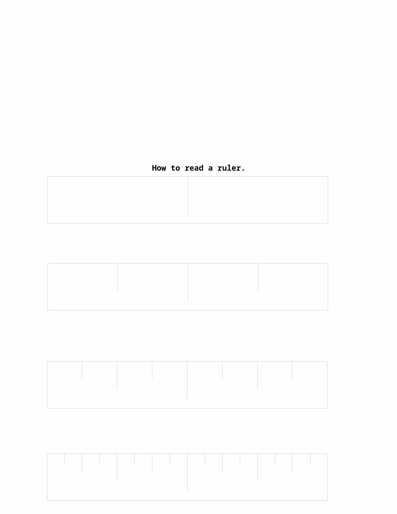
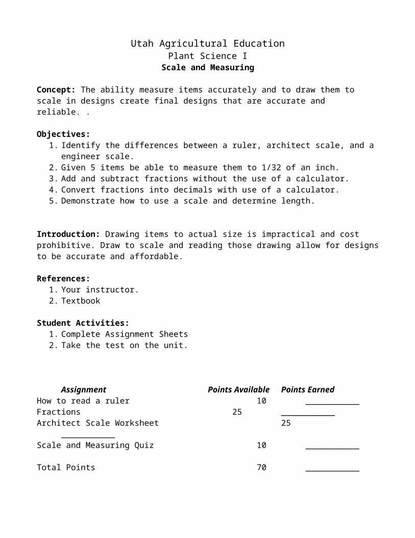
How to read a ruler.
Arrange the fractions from smallest to largest.
¼” ½” ¾”
1” 1/8” 3/8”
5/8” 7/8” 1/16”
3/16” 5/16” 7/16”
9/16” 11/16” 13/16”
15/16”
Smallest
1.
2.
3.
4.
5.
6.
7.
8.
9.
10.
11.
12.
13.
14.
15.
16.
Fractions converted to decimals.
Using a calculator convert the following
fractions to decimals.
¼”
½”
¾”
1”
1/8
3/8
5/8
7/8
1/16
3/16
5/16
7/16
9/16
11/16
13/16
15/16
16/16
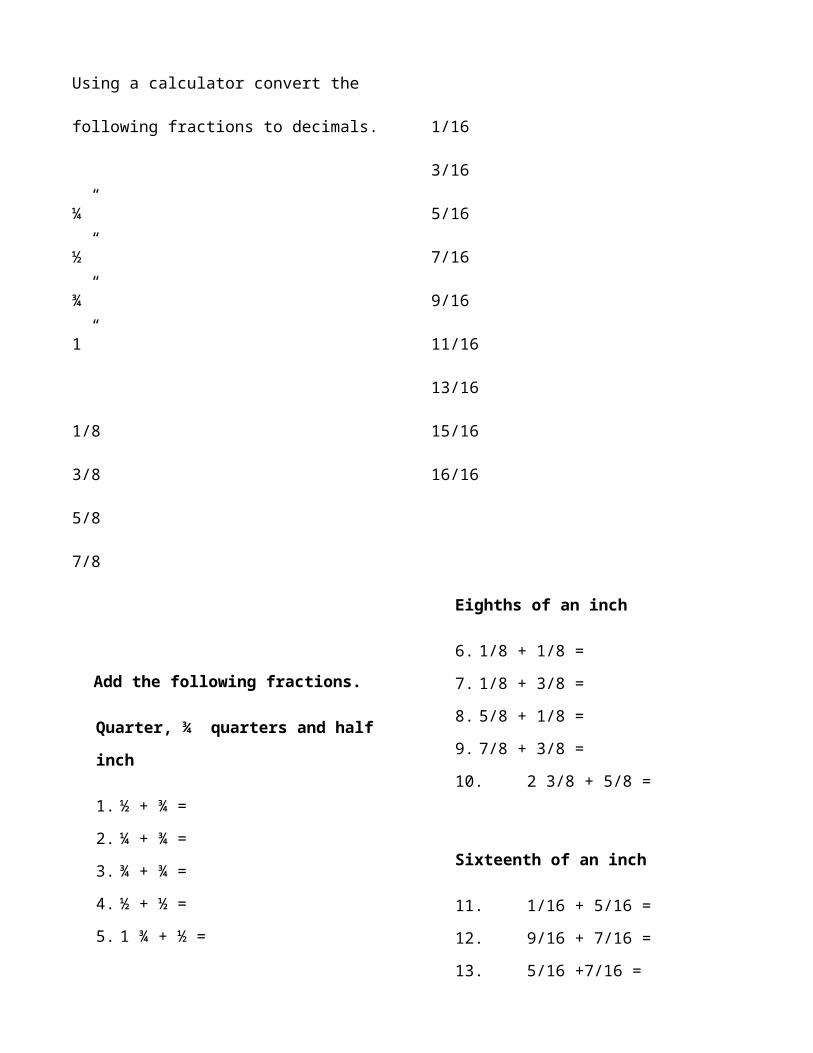
Add the following fractions.
Quarter, ¾ quarters and half inch
1. ½ + ¾ =
2. ¼ + ¾ =
3. ¾ + ¾ =
4. ½ + ½ =
5. 1 ¾ + ½ =
Eighths of an inch
6. 1/8 + 1/8 =
7. 1/8 + 3/8 =
8. 5/8 + 1/8 =
9. 7/8 + 3/8 =
10. 2 3/8 + 5/8 =
Sixteenth of an inch
11. 1/16 + 5/16 =
12. 9/16 + 7/16 =
13. 5/16 +7/16 =
14. 15/16 + 3/16 =
15. 1 1/16 + 9/16 =
All fractions
16. ½ + 1/8 =
17. 5/16 + ¾ =
18. 9/16 + 1/8 =
19. ¾ + 15/16 =
20. 2 7/16 +3 3/8 =
Subtract the following fractions.
Quarter, ¾ quarters and half inch
21. ¾ - ½ =
22. ¾ - ¾ =
23. ¾ - ¾ =
24. 1 - ½ =
25. 1 ¾ - ½ =
Eighths of an inch
26. 1/8 - 1/8 =
27. 3/8 -1/8 =
28. 5/8 - 1/8 =
29. 7/8 - 3/8 =
30. 2 3/8 - 5/8 =
Sixteenth of an inch
31. 5/16 - 1/16 =
32. 9/16 - 7/16 =
33. 7/16 - 5/16 =
34. 15/16 - 3/16 =
35. 1 1/16 - 9/16 =
All fractions
36. ½ - 1/8 =
37. ¾ - 5/16 =
38. 9/16 - 1/8 =
39. 15/16 – ¾ =
40. 3 3/8 – 2 7/16 =
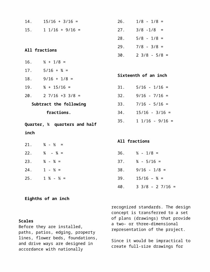
ScalesBefore they are installed, paths, patios, edging, property lines, flower beds, foundations, and drive ways are designed in accordance with nationally recognized standards. The design concept is transferred to a set of plans (drawings) that provide a two- or three-dimensional representation of the project.
Since it would be impractical to create full-size drawings for these objects, they are reduced to a manageable size (scale) so they can be studied. The selected scale normally is found in the title block. In order to interpret the size of what the renderings represent, the plan reviewer must use a tool called a “scale.” The word “scale” is used synonymously to represent the tool and the size reduction in the drawing. The scale tool provides a quick method for measuring the object and interpreting its eventual size when finished.
Selecting the Correct Tool Traditional scales are prism-shaped tools that look similar to the rulers you may have used in elementary school. There are two types of drafting scales used in design and construction:
1. Engineer, or civil, scales, such as 1˝ = 10´ or 1˝ = 50´, are used for measuring roads, water mains, and topographical features. The distance relationships also may be shown as 1:10 or 1:50.
2. Architect scales, such as 1/4˝ = 1´-0˝ (1/48 size) or 1/8˝ = 1´-0˝ (1/96 size), are used for structures and buildings. They are used to measure interior and exterior dimensions such as rooms, walls, doors, windows, and landscapes.
Look closely at the dimensions shown on the faces of the architect scale. Architect scales have numbers that run incrementally both from left to right and from right to left. A whole number or fraction to the left or right of the number line indicates the scale those numbers represent. Architect scales use fractions and have the following dimensional relationships:
-The scale marked “16” is a standard ruler. -You must learn to read both from left to right, and right to left. Note in the example below, the numbers on the 1/8-inch scale increase from left to right. The numbers on the 1/4-inch scale increase from right to left. -Note that the “0” point on an architect scale is not at the extreme end of the measuring line. The numbers “below” the “0” represent fractions of one foot.
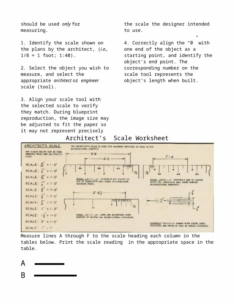
Using the Tool and Interpreting the Results You should never use your scale to draw lines. It should be used only for measuring.
1. Identify the scale shown on the plans by the architect, (i.e., 1/8 = 1 foot; 1:40).
2. Select the object you wish to measure, and select the appropriate architect or engineer scale (tool).
3. Align your scale tool with the selected scale to verify they match. During blueprint reproduction, the image size may be adjusted to fit the paper so it may not represent precisely the scale the designer intended to use.
4. Correctly align the “0” with one end of the object as a starting point, and identify the object’s end point. The corresponding number on the scale tool represents the object’s length when built.

Architect’s Scale Worksheet
Measure lines A through F to the scale heading each column in the tables below. Print the scale reading in the appropriate space in the table.
ABC D E F
ARCHITECT'S SCALELine 3/32" = 1' 1/8" = 1"' 1/4" = 1' 3/8" = 1' 1/2" = 1'
1 1/2" = 1" 3" = 1'
A
B
C
D
E
F


![INDEX [] · Web viewScale of Pay - 5200- 20200 Grade Pay (Rs.) - 1800,1900,2000,2400,2800 (iii) Category B – Pay Band - 2 Scale of Pay - 9300-34800 Grade Pay (Rs.) - 4200,4600,4800](https://img.pdfslide.us/doc/110x75/5b223e9e7f8b9a407b8b49f9/index-web-viewscale-of-pay-5200-20200-grade-pay-rs-18001900200024002800.jpg)


![[PPT]PowerPoint Presentation - amcknight / FrontPageamcknight.pbworks.com/w/file/fetch/69919068/Scale Factor... · Web viewScale factor = new measurement old measurement Scale factor](https://img.pdfslide.us/doc/110x75/5af654497f8b9a92719015f2/pptpowerpoint-presentation-amcknight-factorweb-viewscale-factor-new-measurement.jpg)