Embed Size (px)
Citation preview

FUJITSU VRFPRODUCT CATALOGUE
2016/17
SPLITMULTI SPLIT
VRFVENTILATION
VRFVENTILATION

002
Automatically create model selection information • Each unit can be automatically set by entering the required
performance, type, and temperature conditions for each indoor unit and then dragging and dropping into the outdoor unit.
• Piping and wiring diagrams can be created automatically and it is easy to set branches, grouping, and options.
• The additional refrigerant charging amount is automatically calculated when the pipe length is entered.
• It is also easy to set the remote controller groups, central controller and converters.
• The equipment list including the equipment information is created automatically.
Output the format that matches the application The information specific to your project can be exported in a number of industry standard file formats.
• Word format (rtf) • Excel format (csv)• Adobe Format (PDF)• Auto CAD format (DXF) • 2D Data (DXF) • 3D Data (RFA)
Update your Design SimulatorDatabase can be easily updated online using AutoUpdate function through FTP.
Fujitsu General provides the Building Information Modeling (BIM) object models and contents for our VRF system and some products to the architect, designer and contractor using Autodesk® Revit® technology from our Website and Autodesk® Seek Website, etc.
BIM Building Information Modeling
3D and 2D product data
We provide 3D data that closely resemble the actual product appearance. 2D CAD design operations are supported and 2D display is also provided. The data can also be output in other formats, such as DXF and DWG, which are used by other design CAD.
Installation information
Other information, such as symbols showing the airflow direction that are required for installation drawings, is built in and can be automatically reflected in 2D drawings. Installation drawings can be created easily.
Installation limitation
The equipment installation limitation range is shown. Installation requirements, such as distance from the wall, is automatically displayed to make it easy to produce highly reliable layout designs.
Product specifications & link information
Contains the basic information required for air conditioner design, including unit size, capacity, input power, noise, and airflow rate. These data can be procured from the Fujitsu General Website, Design Simulator, and Autodesk® Seek Website.
Design SimulatorSUPPORT
Information on the latest history update is demanded.
Information on the latest history update replied.
User side(PC) FTP server side (PC)
003
V R
F
PRODUCT CATEGORY NEW RELEASES
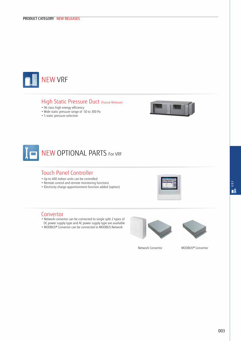
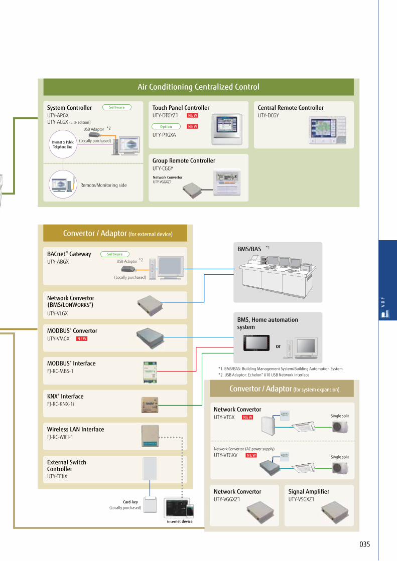
Touch Panel Controller• Up to 400 indoor units can be controlled.• Remote control and remote monitoring functions• Electricity charge apportionment function added (option)
Convertor• Network convertor can be connected to single split 2 types of
DC power supply type and AC power supply type are available• MODBUS® Convertor can be connected to MODBUS Network
High Static Pressure Duct (Future Release)
• 96 class high energy efficiency• Wide static pressure range of 50 to 300 Pa• 5 static pressure selection
NEW VRF
NEW OPTIONAL PARTS For VRF
Network Convertor MODBUS® Convertor

004
AIRSTAGE™ VRF Systems can be designed to effectively provide an air conditioning solution from a large domestic residence through to a large scale commercial building.
AIRSTAGE™ VRF Systems can be designed to create an air conditioning solution to suit most buildings requirements.
005 AIRSTAGE™ Outline
006 All Type Lineup
009 AIRSTAGE™ Outdoor Units
• AIRSTAGE™ VR-II Heat Recovery Modular Type
• AIRSTAGE™ V-III Heat Pump Modular Type
• AIRSTAGE™ V-II Heat Pump Modular Type
• AIRSTAGE™ J-II Heat pump type
• AIRSTAGE™ J-IIS Heat pump type
028 Indoor Unit Lineup
034 Controller
058 Optional Parts for VRF
064 VENTILATION
VRF

005
V R
F
Heat Pump type for heating or cooling operation
4 HP, 5 HP, 6 HP 3 ModelsSingle phase
VR-II & V-III Common Features008 Design Flexibility
4 HP, 5 HP, 6 HP 3 ModelsSingle phase
OutlineSERIES
Heat Recovery Modular type for simultaneous heating and cooling operation
8 HP - 48 HP 34 Models• Space saving combination: 8 HP to 48 HP/ 21 models• Energy efficiency combination: 16 HP to 44 HP/ 13 model
Heat Pump Modular type for heating or cooling operation
8 HP - 54 HP 39 Models• Space saving combination: 8 HP to 54 HP/ 24 models• Energy efficiency combination: 16 HP to 46 HP/ 15 models

006
22.48
28.010
33.512
40.014
45.016
50.418
55.920
61.522
67.024
Capacity (kW) 73.526
15.1-15.56
14.05
12.14HP
AJY054LALHAJY045LALHAJY040LALH
AJY054LCLAHAJY045LCLAHAJY040LCLAH
J-II series* Heat PumpPage 022 ~
Set Model
Set Model
VR-II
serie
s H
eat R
ecov
ery
AJYA72GALH AJYA90GALH AJY108GALH AJY126GALH AJY144GALH
AJY144GALHH
AJY162GALH AJY180GALH AJY198GALH AJY216GALH AJY234GALH
AJY198GALHH AJY216GALHH AJY234GALHH
J-IIS series Heat PumpPage 024 ~
Space savingPage 016 ~
Energy efficiencyPage 016 ~
Space savingPage 010 ~
Energy efficiencyPage 010 ~
Set Model
Set Model
V-III
serie
s Hea
t Pum
p
AJY072LALBH AJY090LALBH AJY108LALBH AJY126LALBH AJY144LALBH
AJY144LALBHH
AJY162LALBH AJY180LALBH AJY198LALBH AJY216LALBH AJY234LALBH
AJY162LALBHH AJY180LALBHH AJY216LALBHH AJY234LALBHH
All Type Lineup
Outdoor units
Indoor units
Indoor units Capacity range 1.1 kW to 28.0 kW (J-II & J-IIS can be connected up to 14.0 kW.)
* Model numbers may change without prior notice
Slim Duct(With drain pump)
Wall Mounted(EEV internal/EEV external)Ceiling Wall Mounted
Cassette
Floor/CeilingHighStatic Pressure Duct
Compact Cassette Medium Static PressureDuct

007
V R
F
85.030
90.032
78.528
95.034
100.536
107.038
112.040
118.542
123.544
130.046
135.048
140.050
145.052
150.054
AJY252GALH AJY270GALH AJY288GALH AJY306GALH AJY324GALH AJY342GALH AJY360GALH AJY378GALH AJY396GALH AJY414GALH AJY432GALH
AJY342GALHHAJY252GALHH AJY270GALHH AJY288GALHH AJY306GALHH AJY324GALHH AJY360GALHH AJY378GALHH AJY396GALHH
AJY252LALBH AJY270LALBH AJY288LALBH AJY306LALBH AJY324LALBH AJY342LALBH AJY360LALBH AJY378LALBH AJY396LALBH AJY414LALBH AJY432LALBH AJY450LALBH AJY468LALBH AJY486LALBH
AJY252LALBHH AJY270LALBHH AJY288LALBHH AJY306LALBHH AJY324LALBHH AJY342LALBHH AJY360LALBHH AJY378LALBHH AJY396LALBHH AJY414LALBHH
Various Easy-To-Use ControllersUser's needs are supported by offering a variety of controls, such as individual control, central control, and building management control options.
Ventilation2 type 8 models & DX Solution for Air Handling Applications
Controllers
CentralRemote Controller
GroupRemote Controller
Touch PanelController
System ControllerSystem Controller Lite
(Software)
WiredRemote Controller
SimpleRemote Controller
WirelessRemote Controller
Wired Remote Controller(Touch Panel)
Outdoor Air Unit3 models
Energy Recovery Ventilator5 models
N E W
DX Solutions for Air Handling Applications
Ventilation

008
Design Flexibility Overall piping length Max. 1,000 mWorld’s top class overall piping length of 1,000 m allows for application in a wide variety of buildings.
High static pressureThe outdoor unit can have a condenser hood easily connected with a static pressure of 82 Pa*4 standard. This allows outdoor units to be installed within plant rooms in high rise buildings.
Large diameter fan and DC motor has been utilized allowing an external static pressure of 82 Pa*4.
Common Features
InstallationExample
Previous model V-III series
*4: For V-III series. VR-II series & V-II series are 80 Pa
Max. 90 m*2*3
Pipe length from first separation tube to the farthest indoor unit
Max. 50 m
Height difference between outdoor and indoor units
Max. 15 m
Height difference between indoor and indoor units
Max. 165 m*1
*1: VR-II series & V-III series V-II series is max. 150 m
Actual pipe length
For the outdoor unit stated below: 40 m max.
*2: V-III series. The limitation on the pipe length between the farthest IU and the nearest IU originated from the first separation tube must be 60 m or less.
*3: VR-II series are max. 60 m.
AIRSTAGE™ VR-II series, V-III series & V-II series
82 Pa*4
High capacity connectionSeries Connectable indoor unit
capacity rangeConnectable indoor
unit number
AIRSTAGE™ VR-II series Heat Recovery Modular type 50% to 150%*5 up to 64
AIRSTAGE™ V-III seriesHeat Pump Modular type 50% to 150%*6 up to 64
AIRSTAGE™ J-II series Heat Pump type 50% to 130%*5 up to 9
AIRSTAGE™ J-IIS series Heat Pump type 50%*7 to 130%*5 up to 8
*5: Conditions of maximum connectable indoor unit capacity ratio is as the chart above.
*6: Max. capacities in the combinations including the 18 HP outdoor unit fall below 150%.
*7: Only 4 HP is 46%
VRII & VIII

009
V R
F
OUTDOOR UNITS
Heat Recovery Modular type
010
Heat Pump Modular type
016
Heat Pump for Small Capacity type
022
024

010
Heat Recovery Modular TypeAIRSTAGETM SERIES OUTDOOR UNIT
Smart and cutting edge designExtensive lineup from 8HP to 48HP in 2HP incrementConnectable indoor unit capacity ratio up to 150%
System OutlineSimultaneous cooling and heating operation using 1 refrigerant systemCooling and heating can be freely selected for each indoor unit to provide simultaneous cooling and heating in the rooms with large temperature differences, etc.
Annual cooling operationUse annual cooling operation for the rooms and other spaces that require constant temperature control throughout the year.
Handles changes in the temperature differenceThe operation mode can be freely changed when there are large temperature differences during the day, such as between seasons.
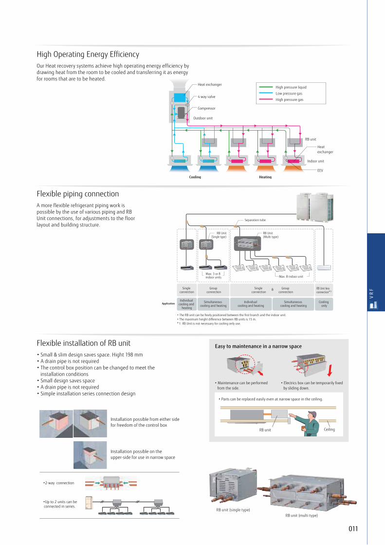
High pressure liquid
Low pressure gas
High pressure gas
Indoor unit
Outdoor unit
Cooling Heating
RB unit
Heat exchanger
EEV
Heat exchanger
Compressor
4 way valve
High Operating Energy EfficiencyOur Heat recovery systems achieve high operating energy efficiency by drawing heat from the room to be cooled and transferring it as energy for rooms that are to be heated.
011
V R
F
Flexible piping connectionA more flexible refrigerant piping work is possible by the use of various piping and RB Unit connections, for adjustments to the floor layout and building structure.
*
&
Application
RB unit (multi type)RB unit (single type)
RB unit Ceiling
Easy to maintenance in a narrow spaceFlexible installation of RB unit• Small & slim design saves space. Hight 198 mm• A drain pipe is not required• The control box position can be changed to meet the
installation conditions• Small design saves space• A drain pipe is not required• Simple installation series connection design

012
• Combinations other than the followings are not recommended.
Outdoor units lineup
Space saving combination
22.4 kW (8HP)
AJYA72GALHUNIT : AJYA72GALH
28.0 kW (10HP)
AJYA90GALHUNIT : AJYA90GALH
33.5 kW (12HP)
AJY108GALHUNIT : AJY108GALH
40.0 kW (14HP)
AJY126GALHUNIT : AJY126GALH
45.0 kW (16HP)
AJY144GALHUNIT : AJY144GALH
50.4 kW (18HP)
AJY162GALHUNIT : AJYA90/A72GALH
56.0 kW (20HP)
AJY180GALHUNIT : AJYA90/A90GALH
61.5 kW (22HP)
AJY198GALHUNIT : AJY108/A90GALH
67.0 kW (24HP)
AJY216GALHUNIT : AJY108/108GALH
73.0 kW (26HP)
AJY234GALHUNIT : AJY144/A90GALH
78.5 kW (28HP)
AJY252GALHUNIT : AJY144/108GALH
85.0 kW (30HP)
AJY270GALHUNIT : AJY144/126GALH
90.0 kW (32HP)
AJY288GALHUNIT : AJY144/144GALH
95.0 kW (34HP)
AJY306GALHUNIT : AJY108/108/A90GALH
100.5 kW (36HP)
AJY324GALHUNIT : AJY108/108/108GALH
106.5 kW (38HP)
AJY342GALHUNIT : AJY144/108/A90GALH
112.0 kW (40HP)
AJY360GALHUNIT : AJY144/108/108GALH
118.0 kW (42HP)
AJY378GALHUNIT : AJY144/144/A90GALH
123.5 kW (44HP)
AJY396GALHUNIT : AJY144/144/108GALH
130.0 kW (46HP)
AJY414GALHUNIT : AJY144/144/126GALH
135.0 kW (48HP)
AJY432GALHUNIT : AJY144/144/144GALH
Energy efficiency combination
44.8 kW (16HP)
AJY144GALHHUNIT : AJYA72/A72GALH
62.4 kW (22HP)
AJY198GALHHUNIT : AJY126/A72GALH
67.2 kW (24HP)
AJY216GALHHUNIT : AJYA72/A72/A72GALH
72.8 kW (26HP)
AJY234GALHHUNIT : AJYA90/A72/A72GALH
78.4 kW (28HP)
AJY252GALHHUNIT : AJYA90/A90/A72GALH
84.0 kW (30HP)
AJY270GALHHUNIT : AJYA90/A90/A90GALH
90.4 kW (32HP)
AJY288GALHHUNIT : AJY126/A90/A72GALH
96.0 kW (34HP)
AJY306GALHHUNIT : AJY126/A90/A90GALH
102.4 kW (36HP)
AJY324GALHHUNIT : AJY126/126/A72GALH
108.0 kW (38HP)
AJY342GALHHUNIT : AJY126/126/A90GALH
113.0 kW (40HP)
AJY360GALHHUNIT : AJY144/126/A90GALH
120.0 kW (42HP)
AJY378GALHHUNIT : AJY126/126/126GALH
125.0 kW (44HP)
AJY396GALHHUNIT : AJY144/126/126GALH

013
V R
F
8,10,12HP : AJYA72GALH / AJYA90GALH / AJY108GALH14,16HP : AJY126GALH / AJY144GALH
8, 10, 12 HP 14, 16 HP
Dimensions(Unit : mm)
8-12×7 (Hole)
1240
1690
732
(Bol
t pitc
h)
1000 (Bolt pitch)840 (Bolt pitch)80
B CA
765
8-12 × 17 (Hole)
1690
1576
1339
765 930
530(Bolt pitch)
80
690 (Bolt pitch)
732
(Bol
t pitc
h)
B CA
8, 10, 12 HP
14, 16 HP
Front side knockout positionA
Power supply cable port
Pipe port
Transmission cable port
Transmission cable port
7343 Ø 43.7
Ø 22.2
Ø 22.2
95 7
510
100 125
199
Ø 34.5
Power supply cable port
Power supply cable port
Ø 50
Left side knockout position
Transmission cable port
Transmission cable port
Ø 43.7
Ø 22.2Ø 22.2
Ø 34.5Power supply cable port
Power supply cable port
Power supply cable port
Ø 50
B
Bottom side knockout position
Top viewPipe port
80
197
82
42
C

014
Outdoor units specifications
Energy Efficiency Combination
Note : Specifications are based on the following conditions.
Cooling : Indoor temperature of 27°CDB / 19°CWB, and outdoor temperature of 35°CDB / 24°CWB.
Heating : Indoor temperature of 20°CDB / (15°CWB), and outdoor temperature of 7°CDB / 6°CWB.
Pipe length : 7.5 m; Height difference between outdoor unit and indoor unit : 0 m.
When cooling operation will be conducted at outdoor air temperature below -5°C,
the outdoor unit must be installed in a position that is higher than or equal to those of indoor units.
HPRating Capacity range
mm
mm
˚CDB
kW
kW
kW
kg
kg
Space Saving Combination
HPRating Capacity range
mm
mm
˚CDB
kW
kW
kW
kW
W/W
W/W
m3/h
dB(A)
Pa
Cooling
Heating
Cooling
Heating
Cooling
Heating
Cooling
Heating
Unit 1
Unit 2
Unit 3
Set Model name
Maximum Connectable Indoor Unit*1
Indoor unit connectable capacity
Dimensions
Weight
Refrigerant charge
Connection pipe
diameter
Operation range
Power source
Capacity
Sound pressure level*2 /
Power Level
Input power
EER
COP
Air flow late
Maximum external static pressure
Compressor motor output
Min Recc MCB
Height
Width
Depth
Liquid
Discharge Gas
Suction Gas
Cooling
Heating
Cooling/Heating
8
22.4
25.0
5.45
5.70
4.11
4.39
11,100
56 / 77
58 / 80
80
7.5
20
1,690
930
765
262
11.8
12.70
15.88
22.22
-10 to 46
-20 to 21
-10 to 21
15
11.2-33.6
AJYA72GALH
AJYA72GALH
10
28.0
31.5
7.11
7.33
3.94
4.30
11,100
58 / 79
59 / 81
80
7.5
25
1,690
930
765
262
11.8
12.70
19.05
22.22
-10 to 46
-20 to 21
-10 to 21
16
14.0-42.0
AJYA90GALH
AJYA90GALH
12
33.5
37.5
9.75
9.62
3.44
3.90
11,100
59 / 80
61 / 83
80
7.5
25
1,690
930
765
262
11.8
12.70
19.05
28.58
-10 to 46
-20 to 21
-10 to 21
17
16.8-50.2
AJY108GALH
AJY108GALH
14
40.0
45.0
11.34
10.90
3.53
4.13
13,000
60 / 81
61 / 83
80
11.0
40
1,690
1,240
765
286
11.8
12.70
22.22
28.58
-10 to 46
-20 to 21
-10 to 21
21
20.0-60.0
AJY126GALH
AJY126GALH
16
45.0
50.0
13.61
12.77
3.31
3.92
13,000
61 / 82
61 / 83
80
11.0
40
1,690
1,240
765
286
11.8
12.70
22.22
28.58
-10 to 46
-20 to 21
-10 to 21
24
22.5-67.5
AJY144GALH
AJY144GALH
18
50.4
56.5
12.56
13.03
4.01
4.34
11,100×2
60 / 81
62 / 84
80
7.5×2
25 + 20
1,690
930×2
765
262×2
11.8×2
15.88
22.22
28.58
-10 to 46
-20 to 21
-10 to 21
27
25.2-75.6
AJY162GALH
AJYA90GALH
AJYA72GALH
20
56.0
63.0
14.22
14.66
3.94
4.30
11,100×2
61 / 82
62 / 84
80
7.5×2
25 + 25
1,690
930×2
765
262×2
11.8×2
15.88
22.22
28.58
-10 to 46
-20 to 21
-10 to 21
30
28.0-84.0
AJY180GALH
AJYA90GALH
AJYA90GALH
22
61.5
69.0
16.86
16.95
3.65
4.07
11,100×2
62 / 83
63 / 85
80
7.5×2
25 + 25
1,690
930×2
765
262×2
11.8×2
15.88
28.58
34.92
-10 to 46
-20 to 21
-10 to 21
32
30.8-92.2
AJY198GALH
AJY108GALH
AJYA90GALH
24
67.0
75.0
19.50
19.24
3.44
3.90
11,100×2
62 / 83
64 / 86
80
7.5×2
25 + 25
1,690
930×2
765
262×2
11.8×2
15.88
28.58
34.92
-10 to 46
-20 to 21
-10 to 21
35
33.5-100.5
AJY216GALH
AJY108GALH
AJY108GALH
3-phase 4 wire , 400 V, 50Hz
kg
kg
kW
W/W
W/W
m3/h
dB(A)
Pa
Cooling
Heating
Cooling
Heating
Cooling
Heating
Cooling
Heating
Unit 1
Unit 2
Unit 3
Set Model name
Maximum Connectable Indoor Unit*1
Indoor unit connectable capacity
Dimensions
Weight
Refrigerant charge
Connection pipe
diameter
Operation range
Power source
Capacity
Sound pressure level*2 /
Power Level
Input power
EER
COP
Air flow late
Maximum external static pressure
Compressor motor output
Min Recc MCB
Height
Width
Depth
Liquid
Discharge Gas
Suction Gas
Cooling
Heating
Cooling/Heating
16
44.8
50.0
10.90
11.40
4.11
4.39
11,100×2
59 / 80
61 / 83
80
7.5×2
20 + 20
1,690
930×2
765
262×2
11.8×2
12.70
22.22
28.58
-10 to 46
-20 to 21
-10 to 21
24
22.4-67.2
AJY144GALHH
AJYA72GALH
AJYA72GALH
22
62.4
70.0
16.79
16.60
3.72
4.22
13,000+11,100
61 / 82
63 / 85
80
11.0+7.5
40 + 20
1,690
1,240+930
765
286+262
11.8×2
15.88
28.58
34.92
-10 to 46
-20 to 21
-10 to 21
33
31.2-93.6
AJY198GALHH
AJY126GALH
AJYA72GALH
24
67.2
75.0
16.35
17.10
4.11
4.39
11,100×3
61 / 82
63 / 85
80
7.5×3
20 + 20 + 20
1,690
930×3
765
262×3
11.8×3
15.88
28.58
34.92
-10 to 46
-20 to 21
-10 to 21
36
33.6-100.8
AJY216GALHH
AJYA72GALH
AJYA72GALH
AJYA72GALH
26
72.8
81.5
18.01
18.73
4.04
4.35
11,100×3
62 / 83
63 / 85
80
7.5×3
20 + 20 + 20
1,690
930×3
765
262×3
11.8×3
15.88
28.58
34.92
-10 to 46
-20 to 21
-10 to 21
39
36.4-109.2
AJY234GALHH
AJYA90GALH
AJYA72GALH
AJYA72GALH
28
78.4
88.0
19.67
20.36
3.99
4.32
11,100×3
62 / 83
63 / 85
80
7.5×3
25 + 25 + 20
1,690
930×3
765
262×3
11.8×3
15.88
28.58
34.92
-10 to 46
-20 to 21
-10 to 21
42
39.2-117.6
AJY252GALHH
AJYA90GALH
AJYA90GALH
AJYA72GALH
30
84.0
94.5
21.33
21.99
3.94
4.30
11,100×3
63 / 84
64 / 86
80
7.5×3
25 + 25 + 25
1,690
930×3
765
262×3
11.8×3
19.05
28.58
34.92
-10 to 46
-20 to 21
-10 to 21
45
42.0-126.0
AJY270GALHH
AJYA90GALH
AJYA90GALH
AJYA90GALH
3-phase 4 wire , 400 V, 50Hz
36
AMP
AMP

015
V R
F
36
100.5
112.5
29.25
28.86
3.44
3.90
11,100×3
64 / 85
65 / 87
80
7.5×3
25 + 25 + 25
1,690
930×3
765
286×3
11.8×3
19.05
28.58
41.27
-10 to 46
-20 to 21
-10 to 21
53
50.3-150.7
AJY324GALH
AJY108GALH
AJY108GALH
AJY108GALH
34
95.0
106.5
26.61
26.57
3.57
4.01
11,100×3
63 / 85
65 / 87.2
80
7.5×3
25 + 25 + 25
1,690
930×3
765
286×3
11.8×3
19.05
28.58
34.92
-10 to 46
-20 to 21
-10 to 21
50
47.5-142.5
AJY306GALH
AJY108GALH
AJY108GALH
AJYA90GALH
32
90.0
100.0
27.22
25.54
3.31
3.92
13,000×2
64 / 85
64 / 86
80
11.0×2
40 + 40
1,690
1,240×2
765
286×2
11.8×2
19.05
28.58
34.92
-10 to 46
-20 to 21
-10 to 21
48
45.0-135.0
AJY288GALH
AJY144GALH
AJY144GALH
30
85.0
95.0
24.95
23.67
3.41
4.01
13,000×2
64 / 84.5
64 / 86
80
11.0×2
40 + 40
1,690
1,240×2
765
286×2
11.8×2
19.05
28.58
34.92
-10 to 46
-20 to 21
-10 to 21
45
42.5-127.5
AJY270GALH
AJY144GALH
AJY126GALH
28
78.5
87.5
23.36
22.39
3.36
3.91
13,000+11,100
63 / 84
64 / 86
80
11.0+7.5
40 + 25
1,690
1,240+930
765
286+262
11.8×2
15.88
28.58
34.92
-10 to 46
-20 to 21
-10 to 21
42
39.3-117.7
AJY252GALH
AJY144GALH
AJY108GALH
26
73.0
81.5
20.72
20.10
3.52
4.05
13,000+11,100
63 / 84
63 / 85
80
11.0+7.5
25 + 40
1,690
1,240+930
765
286+262
11.8×2
15.88
28.58
34.92
-10 to 46
-20 to 21
-10 to 21
39
36.5-109.5
AJY234GALH
AJY144GALH
AJYA90GALH
38
106.5
119.0
30.47
29.72
3.50
4.00
13,000+11,100×2
64 / 85
65 / 87
80
11.0+7.5×2
40 + 25 + 25
1,690
1,240+930×2
765
286+262×2
11.8×3
19.05
34.92
41.27
-10 to 46
-20 to 21
-10 to 21
57
53.3-159.7
AJY342GALH
AJY144GALH
AJY108GALH
AJYA90GALH
40
112.0
125.0
33.11
32.01
3.38
3.91
13,000+11,100×2
65 / 85.5
66 / 87.7
80
11.0+7.5×2
40 + 25 + 25
1,690
1,240+930×2
765
286+262×2
11.8×3
19.05
34.92
41.27
-10 to 46
-20 to 21
-10 to 21
60
56.0-168.0
AJY360GALH
AJY144GALH
AJY108GALH
AJY108GALH
42
118.0
131.5
34.33
32.87
3.44
4.00
13,000×2+11,100
65 / 86
65 / 87
80
11.0×2+7.5
40 + 40 + 25
1,690
1,240×2+930
765
286×2+262
11.8×3
19.05
34.92
41.27
-10 to 46
-20 to 21
-10 to 21
63
59.0-177.0
AJY378GALH
AJY144GALH
AJY144GALH
AJYA90GALH
44
123.5
137.5
36.97
35.16
3.34
3.91
13,000×2+11,100
65 / 86
66 / 88
80
11.0×2+7.5
40+40+25
1,690
1,240×2+930
765
286×2+262
11.8×3
19.05
34.92
41.27
-10 to 46
-20 to 21
-10 to 21
64
61.8-185.2
AJY396GALH
AJY144GALH
AJY144GALH
AJY108GALH
46
130.0
145.0
38.56
36.44
3.37
3.98
13,000×3
65 / 86
66 / 88
80
11.0×3
40 + 40 + 40
1,690
1,240×3
765
286×3
11.8×3
19.05
34.92
41.27
-10 to 46
-20 to 21
-10 to 21
64
65.0-195.0
AJY414GALH
AJY144GALH
AJY144GALH
AJY126GALH
48
135.0
150.0
40.83
38.31
3.31
3.92
13,000×3
66 / 87
66 / 88
80
11.0×3
40 + 40 + 40
1,690
1,240×3
765
286×3
11.8×3
19.05
34.92
41.27
-10 to 46
-20 to 21
-10 to 21
64
67.5-202.5
AJY432GALH
AJY144GALH
AJY144GALH
AJY144GALH
3-phase 4 wire , 400 V, 50Hz
42
120.0
135.0
34.02
32.70
3.53
4.13
13,000×3
65 / 86
66 / 88
80
11.0×3
40 + 40 + 40
1,690
1,240×3
765
286×3
11.8×3
19.05
34.92
41.27
-10 to 46
-20 to 21
-10 to 21
64
60.0-180.0
AJY378GALHH
AJY126GALH
AJY126GALH
AJY126GALH
40
113.0
126.5
32.06
31.00
3.52
4.08
13,000×2+11,100
65 / 86
65 / 87
80
11.0×2+7.5
40 + 40 + 25
1,690
1,240×2+930
765
286×2+262
11.8×3
19.05
34.92
41.27
-10 to 46
-20 to 21
-10 to 21
60
56.5-169.5
AJY360GALHH
AJY144GALH
AJY126GALH
AJYA90GALH
38
108.0
121.5
29.79
29.13
3.63
4.17
13,000×2+11,100
64 / 86
65 / 87
80
11.0×2+7.5
40 + 40 + 25
1,690
1,240×2+930
765
286×2+262
11.8×3
19.05
34.92
41.27
-10 to 46
-20 to 21
-10 to 21
57
54.0-162.0
AJY342GALHH
AJY126GALH
AJY126GALH
AJYA90GALH
36
102.4
115.0
28.13
27.50
3.64
4.18
13,000×2+11,100
64 / 85
65 / 87
80
11.0×2+7.5
40 + 40 + 20
1,690
1,240×2+930
765
286×2+262
11.8×3
19.05
28.58
41.27
-10 to 46
-20 to 21
-10 to 21
54
51.2-153.6
AJY324GALHH
AJY126GALH
AJY126GALH
AJYA72GALH
34
96.0
108.0
25.56
25.56
3.76
4.23
13,000+11,100×2
64 / 85
65 / 87
80
11.0+7.5×2
40 + 25 + 25
1,690
1,240+930×2
765
286+262×2
11.8×3
19.05
28.58
34.92
-10 to 46
-20 to 21
-10 to 21
51
48.0-144.0
AJY306GALHH
AJY126GALH
AJYA90GALH
AJYA90GALH
32
90.4
101.5
23.90
23.93
3.78
4.24
13,000+11,100×2
63 / 84
64 / 86
80
11.0+7.5×2
40 + 25 + 20
1,690
1,240+930×2
765
286+262×2
11.8×3
19.05
28.58
34.92
-10 to 46
-20 to 21
-10 to 21
48
45.2-135.6
AJY288GALHH
AJY126GALH
AJYA90GALH
AJYA72GALH
44
125.0
140.0
36.29
34.57
3.44
4.05
13,000×3
65 / 86
66 / 88
80
11.0×3
40 + 40 + 40
1,690
1,240×3
765
286×3
11.8×3
19.05
34.92
41.27
-10 to 46
-20 to 21
-10 to 21
64
62.5-187.5
AJY396GALHH
AJY144GALH
AJY126GALH
AJY126GALH
3-phase 4 wire , 400 V, 50Hz
*1 Minimum connectable indoor unit number is 2. *2 The noise value is the value when measured in an anechoic room.
When measured in the actual installed state, surrounding noise and reflections are
received and the measured value is usually larger than the indicated value.
13
Heat Recovery Modular Type

016
Heat Pump Modular TypeAIRSTAGETM SERIES OUTDOOR UNIT
Smart and cutting edge designExtensive lineup from 8HP to 48HP in 2HP incrementConnectable indoor unit capacity ratio up to 150%
System OutlineExcellent energy savingHeat pump inverter type realizes the highly energy saving air conditioning for individual cooling and heating operation by all inverter technology for seasonal efficiency.
High design flexibility for various building air conditioningHigh design flexibly meets the various needs of high-rise building air conditioning such as outdoor unit roof top concentrated installation and each floor installation by large capacity combination, sufficient connection capacity, and high static pressure design.
Easy installation and maintenanceThe flexible communication method and piping connections makes installation and maintenance easy even for large systems.

017
V R
F
Features
Efficiency in actual operationTop class high COP is achieved for all combinations by our unique heat exchanger structure, high efficient DC twin compressor, and our own technologies.
Space saving combination
Energy efficiency combination
For 24 HP CombinationSpace saving Energy efficiency
(COP)
2
3
4
5
(HP)
(COP)
(HP)2
3
4
5
16 18 20 24* 26 28 30 32 34 36 38 40 42 44 48
4.35
4.84
4.344.03
3.67 3.67
4.34 4.28 4.153.90 3.90 3.83
3.67 3.67 3.674.02 3.95 3.81 3.81 3.81 3.67 3.673.67 3.67
8 10 12 14 16 18 20 22 24* 26 28 30 32 34 36 38 40 42 44 46 48 50 52 54
4.84 4.844.55 4.52 4.63 4.61
4.42 4.45 4.30 4.34 4.21 4.11 4.03 3.89 3.77
COP 17% UP
Front intake port (corner cut air inhaling structure)In multiple outdoor unit installations, the unique front intake design improves airflow into the Heat Exchanger.
3 phase DC fan motorEfficiency is substantially improved by high efficient motor with sophisticated driver control. In addition, low noise is realized by DC fan motor.
Sine-wave DC inverter controlHigh efficiency is realized by adoption of reduced switching loss IPM.
Subcool heat exchangerHigh Heat Exchange efficiency is achieved by using an internal projection shape double pipe construction.
High efficient and large capacity DC inverter compressorLarge capacity high efficient DC twin rotary compressor with excellent intermediate capability.
Powerful large propeller fanBy using CFD*1 technology, a newly designed fan achieves high performance and low noise operation.*1. CFD = Computational Fluid Dynamics
Energy saving technology that boosted operation efficiency
4-face heat exchanger Heat exchange efficiency is significantly improved by the introduction of a new 4-face heat exchanger that increases effective surface area.

018
• Combinations other than the followings are not recommended.
Outdoor units lineup
Space saving combination
22.4 kW (8HP)
AJY072LALBHUNIT : AJY072LALBH
28.0 kW (10HP)
AJY090LALBHUNIT : AJY090LALBH
33.5 kW (12HP)
AJY108LALBHUNIT : AJY108LALBH
40.0 kW (14HP)
AJY126LALBHUNIT : AJY126LALBH
45.0 kW (16HP)
AJY144LALBHUNIT : AJY144LALBH
50.0 kW (18HP)
AJY162LALBHUNIT : AJY162LALBH
56.0 kW (20HP)
AJY180LALBHUNIT : AJY090/090LALBH
62.4 kW (22HP)
AJY198LALBHUNIT : AJY126/072LALBH
68.0 kW (24HP)
AJY216LALBHUNIT : AJY126/090LALBH
73.0 kW (26HP)
AJY234LALBHUNIT : AJY144/090LALBH
78.0 kW (28HP)
AJY252LALBHUNIT : AJY162/090LALBH
85.0 kW (30HP))
AJY270LALBHUNIT : AJY144/126LALBH
90.0 kW (32HP)
AJY288LALBHUNIT : AJY144/144LALBH
95.0 kW (34HP)
AJY306LALBHUNIT : AJY162/144LALBH
100.0 kW (36HP)
AJY324LALBHUNIT : AJY162/162LALBH
106.0 kW (38HP)
AJY342LALBHUNIT : AJY162/090/090LALBH
113.0 kW (40HP)
AJY360LALBHUNIT : AJY144/126/090LALBH
118.0 kW (42HP)
AJY378LALBHUNIT : AJY144/144/090LALBH
123.0 kW (44HP)
AJY396LALBHUNIT : AJY162/144/090LALBH
128.0 kW (46HP)
AJY414LALBHUNIT : AJY162/162/090LALBH
135.0 kW (48HP)
AJY432LALBHUNIT : AJY144/144/144LALBH
140.0 kW (50HP)
AJY450LALBHUNIT : AJY162/144/144LALBH
145.0 kW (52HP)
AJY468LALBHUNIT : AJY162/162/144LALBH
150.0 kW (54HP)
AJY486LALBHUNIT : AJY162/162/162LALBH
Energy efficiency combination
44.8 kW (16HP)
AJY144LALBHHUNIT : AJY072/072LALBH
50.4kW (18HP)
AJY162LALBHHUNIT : AJY090/072LALBH
55.9 kW (20HP)
AJY180LALBHHUNIT : AJY108/072LALBH
67.2 kW (24HP)
AJY216LALBHHUNIT : AJY072/072/072LALBH
72.8 kW (26HP)
AJY234LALBHHUNIT : AJY090/072/072LALBH
78.3 kW (28HP)
AJY252LALBHHUNIT : AJY108/072/072LALBH
84.8 kW (30HP)
AJY270LALBHHUNIT : AJY126/072/072LALBH
89.4 kW (32HP)
AJY288LALBHHUNIT : AJY108/108/072LALBH
95.9 kW (34HP)
AJY306LALBHHUNIT : AJY126/108/072LALBH
100.5 kW (36HP)
AJY324LALBHHUNIT : AJY108/108/108LALBH
107.0 kW (38HP)
AJY342LALBHHUNIT : AJY126/108/108LALBH
113.5 kW (40HP)
AJY360LALBHHUNIT : AJY126/126/108LALBH
120.0 kW (42HP)
AJY378LALBHHUNIT : AJY126/126/126LALBH
125.0 kW (44HP)
AJY396LALBHHUNIT : AJY144/126/126LALBH
130.0 kW (46HP)
AJY414LALBHHUNIT : AJY144/144/126LALBH

019
V R
F
8,10HP : AJY072LALBH / AJY090LALBH12,14,16HP : AJY108LALBH / AJY126LALBH / AJY144LALBH / AJY162LALBH
8, 10 HP 12, 14, 16 HP
Dimensions(Unit : mm)
8-12×7 (Hole)
1240
1690
732
(Bol
t pitc
h)
1000 (Bolt pitch)840 (Bolt pitch)80
B CA
765
8-12 × 17 (Hole)
1690
1576
1339
765 930
530(Bolt pitch)
80
690 (Bolt pitch)
732
(Bol
t pitc
h)
B CA
8, 10 HP
12, 14, 16 HP
Front side knockout positionA
Power supply cable port
Pipe port
Transmission cable port
Transmission cable port
7343 Ø 43.7
Ø 22.2
Ø 22.2
95 7
510
100 125
199
Ø 34.5
Power supply cable port
Power supply cable port
Ø 50
Left side knockout position
Transmission cable port
Transmission cable port
Ø 43.7
Ø 22.2Ø 22.2
Ø 34.5Power supply cable port
Power supply cable port
Power supply cable port
Ø 50
B
Bottom side knockout position
Top viewPipe port
80
197
82
42
C

020
Outdoor units specifications
Space Saving Combination
HPRating Capacity range
m3/h
kW
kW
mm
mm
mm
mm
˚C
W/W
dB(A)
kW
Capacity
Power source
Pa
kW
AMP
kg
kg
Cooling
Heating
Cooling
Heating
Cooling
Heating
High
Cooling
Heating
Cooling
Unit 1
Unit 2
Unit 3
Model name
Maximum Connectable Indoor Unit*1
Indoor unit connectable capacity
Input power
EER
COP
Air flow rate
Dimensions
Weight
Refrigerant charge
Connection
pipe diameter
Operation
range
Sound pressure level*2 /
Power Level
Maximum external static pressure
Compressor motor output
Min Recc MCB
Height
Width
Depth
Liquid
Gas
Cooling
Heating
8
22.4
25.0
5.20
5.17
4.31
4.84
11,100
56 / 77
58 / 80
82
7.5
20
1,690
930
765
252
11.7
12.70
22.22
-15 to 46
-20 to 21
17
11.2-33.6
AJY072LALBH
AJY072LALBH
10
28.0
31.5
7.28
7.25
3.85
4.35
11,100
58 / 79
59 / 81
82
7.5
25
1,690
930
765
252
11.7
12.70
22.22
-15 to 46
-20 to 21
21
14.0-42.0
AJY090LALBH
AJY090LALBH
12
33.5
37.5
8.96
8.65
3.74
4.34
13,000
57 / 78
60 / 83
82
11.0
25
1,690
1,240
765
275
11.8
12.70
28.58
-15 to 46
-20 to 21
26
16.8-50.2
AJY108LALBH
AJY108LALBH
14
40.0
45.0
10.96
11.17
3.65
4.03
13,000
60 / 81
62 / 84
82
11.0
40
1,690
1,240
765
275
11.8
12.70
28.58
-15 to 46
-20 to 21
30
20.0-60.0
AJY126LALBH
AJY126LALBH
16
45.0
50.0
13.01
13.63
3.46
3.67
13,700
62 / 83
64 / 86
82
11.0
40
1,690
1,240
765
275
11.8
12.70
28.58
-15 to 46
-20 to 21
34
22.5-67.5
AJY144LALBH
AJY144LALBH
18
50.0
50.0
16.56
13.63
3.02
3.67
13,700
63 / 84
64 / 86
82
11.0
40
1,690
1,240
765
275
11.8
15.88
28.58
-15 to 46
-20 to 21
39
25.0-67.5
AJY162LALBH
AJY162LALBH
20
56.0
63.0
14.56
14.50
3.85
4.34
11,100×2
61 / 82
62 / 84
82
7.5×2
25+25
1,690
930×2
765
252×2
11.7×2
15.88
28.58
-5 to 46
-20 to 21
43
28.0-84.0
AJY180LALBH
AJY090LALBH
AJY090LALBH
22
62.4
70.0
16.16
16.34
3.86
4.28
13,000+11,100
61 / 82
63 / 85
82
11.0+7.5
40+20
1,690
1,240+930
765
275+252
11.8+11.7
15.88
34.92
-5 to 46
-20 to 21
47
31.2-93.6
AJY198LALBH
AJY126LALBH
AJY072LALBH
24
68.0
76.5
18.24
18.42
3.73
4.15
13,000+11,100
62 / 83
64 / 86
82
11.0+7.5
40+25
1,690
1,240+930
765
275+252
11.8+11.7
15.88
34.92
-5 to 46
-20 to 21
52
34.0-102.0
AJY216LALBH
AJY126LALBH
AJY090LALBH
28
78.0
81.5
23.84
20.88
3.27
3.90
13,700+11,100
64 / 85
65 / 87
82
11.0+7.5
40+25
1,690
1,240+930
765
275+252
11.8+11.7
15.88
34.92
-5 to 46
-20 to 21
60
39.0-109.5
AJY252LALBH
AJY162LALBH
AJY090LALBH
26
73.0
81.5
20.29
20.88
3.60
3.90
13,000+11,100
63 / 84
65 / 87
82
11.0+7.5
40+25
1,690
1,240+930
765
275+252
11.8+11.7
15.88
34.92
-5 to 46
-20 to 21
56
36.5-109.5
AJY234LALBH
AJY144LALBH
AJY090ALBH
3-phase 4 wire, 400 V, 50Hz
Energy Efficiency Combination
HPRating Capacity range
m3/h
kW
kW
mm
mm
mm
mm
˚C
W/W
dB(A)
kW
Capacity
Power source
Pa
kW
AMP
kg
kg
Cooling
Heating
Cooling
Heating
Cooling
Heating
High
Cooling
Heating
Cooling
Unit 1
Unit 2
Unit 3
Model name
Maximum Connectable Indoor Unit*1
Indoor unit connectable capacity
Input power
EER
COP
Air flow rate
Dimensions
Weight
Refrigerant charge
Connection
pipe diameter
Operation
range
Sound pressure level*2 /
Power Level
Maximum external static pressure
Compressor motor output
Min Recc MCB
Height
Width
Depth
Liquid
Gas
Cooling
Heating
16
44.8
50.0
10.40
10.34
4.31
4.84
11,100×2
59 / 80
61 / 83
82
7.5×2
20+20
1,690
930×2
765
252×2
11.7×2
12.70
28.58
-5 to 46
-20 to 21
34
22.4-67.2
AJY144LALBHH
AJY072LALBH
AJY072LALBH
18
50.4
56.5
12.48
12.42
4.04
4.55
11,100×2
60 / 81
62 / 84
82
7.5×2
25+20
1,690
930×2
765
252×2
11.7×2
15.88
28.58
-5 to 46
-20 to 21
39
25.2-75.6
AJY162LALBHH
AJY090LALBH
AJY072LALBH
20
55.9
62.5
14.16
13.82
3.95
4.52
13,000+11,100
60 / 81
62 / 85
82
11.0+7.5
25+20
1,690
1,240+930
765
275+252
11.8+11.7
15.88
28.58
-5 to 46
-20 to 21
43
28.0-83.8
AJY180LALBHH
AJY108LALBH
AJY072LALBH
24
67.2
75.0
15.60
15.51
4.31
4.84
11,100×3
61 / 82
63 / 85
82
7.5×3
20+20+20
1,690
930×3
765
252×3
11.7×3
15.88
34.92
-5 to 46
-20 to 21
52
33.6-100.8
AJY216LALBHH
AJY072LALBH
AJY072LALBH
AJY072LALBH
26
72.8
81.5
17.68
17.59
4.12
4.63
11,000×3
62 / 83
63 / 85
82
7.5×3
25+20+20
1,690
930×3
765
252×3
11.7×3
15.88
34.92
-5 to 46
-20 to 21
56
36.4-109.2
AJY234LALBHH
AJY090LALBH
AJY072LALBH
AJY072LALBH
28
78.3
87.5
19.36
18.99
4.04
4.61
13,000+11,100×2
61 / 82
64 / 86
82
11.0+7.5×2
25+20+20
1,690
1,240+930×2
765
275+252×2
11.8+11.7×2
15.88
34.92
-5 to 46
-20 to 21
60
39.2-117.4
AJY252LALBHH
AJY108LALBH
AJY072LALBH
AJY072LALBH
30
84.8
95.0
21.36
21.51
3.97
4.42
13,000+11,100×2
63 / 84
65 / 87
82
11.0+7.5×2
40+20+20
1,690
1,240+930×2
765
275+252×2
11.8+11.7×2
19.05
34.92
-5 to 46
-20 to 21
64
42.4-127.2
AJY270LALBHH
AJY126LALBH
AJY072LALBH
AJY072LALBH
3-phase 4 wire, 400 V, 50Hz
Note : Specifications are based on the following conditions.
Cooling : Indoor temperature of 27°CDB / 19°CWB, and outdoor temperature of
35°CDB / 24°CWB.
Heating : Indoor temperature of 20°CDB / (15°CWB), and outdoor temperature of
7°CDB / 6°CWB.
Pipe length : 7.5 m; Height difference between outdoor unit and indoor unit : 0 m.
When cooling operation will be conducted at outdoor air temperature below -5°C,
the outdoor unit must be installed in a position that is higher than or equal to those of
indoor units.

021
V R
F
Heat Pump Modular Type
36
100.0
100.0
33.12
27.26
3.02
3.67
13,700×2
66 / 87
67 / 89
82
11.0×2
40+40
1,690
1,240×2
765
275×2
11.8×2
19.05
41.27
-5 to 46
-20 to 21
64
50.0-135.0
AJY324LALBH
AJY162LALBH
AJY162LALBH
34
95.0
100.0
29.57
27.26
3.21
3.67
13,700×2
66 / 87
67 / 89
82
11.0×2
40+40
1,690
1,240×2
765
275×2
11.8×2
19.05
34.92
-5 to 46
-20 to 21
64
47.5-135.0
AJY306LALBH
AJY162LALBH
AJY144LALBH
32
90.0
100.0
26.02
27.26
3.46
3.67
13,700×2
65 / 86
67 / 89
82
11.0×2
40+40
1,690
1,240×2
765
275×2
11.8×2
19.05
34.92
-5 to 46
-20 to 21
64
45.0-135.0
AJY288LALBH
AJY144LALBH
AJY144LALBH
30
85.0
95.0
23.97
24.80
3.55
3.83
13,700+13,000
64 / 85
66 / 88
82
11.0×2
40+40
1,690
1,240×2
765
275×2
11.8×2
19.05
34.92
-5 to 46
-20 to 21
64
42.5-127.5
AJY270LALBH
AJY144LALBH
AJY126LALBH
38
106.0
113.0
31.12
28.13
3.41
4.02
13,700+11,100×2
65 / 86
66 / 88
82
11.0+7.5×2
40+25+25
1,690
1,240+930×2
765
275+252×2
11.8+11.7×2
19.05
41.27
-5 to 46
-20 to 21
64
53.0-151.5
AJY342LALBH
AJY162LALBH
AJY090LALBH
AJY090LALBH
40
113.0
126.5
31.25
32.05
3.62
3.95
13,700+13,000+11,100
65 / 86
67 / 89
82
11.0×2+7.5
40+40+25
1,690
1,240×2+930
765
275×2+252
11.8×2+11.7
19.05
41.27
-5 to 46
-20 to 21
64
56.5-169.5
AJY360LALBH
AJY144LALBH
AJY126LALBH
AJY090LALBH
42
118.0
131.5
33.30
34.51
3.54
3.81
13,700×2+11,100
66 / 87
68 / 90
82
11.0×2+7.5
40+40+25
1,690
1,240×2+930
765
275×2+252
11.8×2+11.7
19.05
41.27
-5 to 46
-20 to 21
64
59.0-177.0
AJY378LALBH
AJY144LALBH
AJY144LALBH
AJY090LALBH
44
123.0
131.5
36.85
34.51
3.34
3.81
13,700×2+11,100
66 / 87
68 / 90
82
11.0×2+7.5
40+40+25
1,690
1,240×2+930
765
275×2+252
11.8×2+11.7
19.05
41.27
-5 to 46
-20 to 21
64
61.5-177.0
AJY396LALBH
AJY162LALBH
AJY144LALBH
AJY090LALBH
46
128.0
131.5
40.40
34.51
3.17
3.81
13,700×2+11,100
67 / 87
68 / 90
82
11.0×2+7.5
40+40+40
1,690
1,240×2+930
765
275×2+252
11.8×2+11.7
19.05
41.27
-5 to 46
-20 to 21
64
64.0-177.0
AJY414LALBH
AJY162LALBH
AJY162LALBH
AJY090LALBH
48
135.0
150.0
39.03
40.89
3.46
3.67
13,700×3
67 / 88
69 / 91
82
11.0×3
40+40+40
1,690
1,240×3
765
275×3
11.8×3
19.05
41.27
-5 to 46
-20 to 21
64
67.5-202.5
AJY432LALBH
AJY144LALBH
AJY144LALBH
AJY144LALBH
50
140.0
150.0
42.58
40.89
3.29
3.67
13,700×3
67 / 88
69 / 91
82
11.0×3
40+40+40
1,690
1,240×3
765
275×3
11.8×3
19.05
41.27
-5 to 46
-20 to 21
64
70.0-202.5
AJY450LALBH
AJY162LALBH
AJY144LALBH
AJY144LALBH
52
145.0
150.0
46.13
40.89
3.14
3.67
13,700×3
67 / 88
69 / 91
82
11.0×3
40+40+40
1,690
1,240×3
765
275×3
11.8×3
19.05
41.27
-5 to 46
-20 to 21
64
72.5-202.5
AJY468LALBH
AJY162LALBH
AJY162LALBH
AJY144LALBH
54
150.0
150.0
49.68
40.89
3.02
3.67
13,700×3
68 / 89
69 / 91
82
11.0×3
40+40+40
1,690
1,240×3
765
275×3
11.8×3
19.05
41.27
-5 to 46
-20 to 21
64
75.0-202.5
AJY486LALBH
AJY162LALBH
AJY162LALBH
AJY162LALBH
3-phase 4 wire, 400 V, 50Hz
44
125.0
140.0
34.93
35.97
3.58
3.89
13,700+13,000×2
66 / 87
68 / 90
82
11.0×3
40+40+40
1,690
1,240×3
765
275×3
11.8×3
19.05
41.27
-5 to 46
-20 to 21
64
62.5-187.5
AJY396LALBHH
AJY144LALBH
AJY126LALBH
AJY126LALBH
46
130.0
145.0
36.98
38.43
3.52
3.77
13,700×2+13,000
66 / 87
68 / 90
82
11.0×3
40+40+40
1,690
1,240×3
765
275×3
11.8×3
19.05
41.27
-5 to 46
-20 to 21
64
65.0-195.0
AJY414LALBHH
AJY144LALBH
AJY144LALBH
AJY126LALBH
42
120.0
135.0
32.88
33.51
3.65
4.03
13,000×3
65 / 86
67 / 89
82
11.0×3
40+40+40
1,690
1,240×3
765
275×3
11.8×3
19.05
41.27
-5 to 46
-20 to 21
64
60.0-180.0
AJY378LALBHH
AJY126LALBH
AJY126LALBH
AJY126LALBH
40
113.5
127.5
30.88
30.99
3.68
4.11
13,000×3
64 / 85
66 / 88
82
11.0×3
40+40+25
1,690
1,240×3
765
275×3
11.8×3
19.05
41.27
-5 to 46
-20 to 21
64
56.8-170.2
AJY360LALBHH
AJY126LALBH
AJY126LALBH
AJY108LALBH
36
100.5
112.5
26.88
25.95
3.74
4.34
13,000×3
63 / 83
65 / 88
82
11.0×3
25+25+25
1,690
1,240×3
765
275×3
11.8×3
19.05
41.27
-5 to 46
-20 to 21
50.3-150.7
AJY324LALBHH
AJY108LALBH
AJY108LALBH
AJY108LALBH
38
107.0
120.0
28.88
28.47
3.70
4.21
13,000×3
64 / 84
65 / 88
82
11.0×3
40+25+25
1,690
1,240×3
765
275×3
11.8×3
19.05
41.27
-5 to 46
-20 to 21
53.5-160.5
AJY342LALBHH
AJY126LALBH
AJY108LALBH
AJY108LALBH
34
95.9
107.5
25.12
24.99
3.82
4.30
13,000×2+11,100
63 / 84
65 / 88
82
11.0×2+7.5
40+25+20
1,690
1,240×2+930
765
275×2+252
11.8×2+11.7
19.05
34.92
-5 to 46
-20 to 21
64
48.0-143.8
AJY306LALBHH
AJY126LALBH
AJY108LALBH
AJY072LALBH
89.4
100.0
23.12
22.47
3.87
4.45
13,000×2+11,100
61 / 82
64 / 87
82
11.0×2+7.5
25+25+20
1,690
1,240×2+930
765
275×2+252
11.8×2+11.7
19.05
34.92
-5 to 46
-20 to 21
64
44.7-134.1
32
AJY288LALBHH
AJY108LALBH
AJY108LALBH
AJY072LALBH
3-phase 4 wire, 400 V, 50Hz
*1 Minimum connectable indoor unit number is 2.
However ARXC72 and ARXC90 can be used signal connection.
*2 The noise value is the value when measured in an anechoic room.
When measured in the actual installed state, surrounding noise and reflections are
received and the measured value is usually larger than the indicated value.

022
Heat Pump for Small Capacity Type AIRSTAGETM SERIES OUTDOOR UNIT
Fujitsu General provides air conditioning systemsfor a wide range of applicationsfrom small office buildings and stores to large houses.
NEW
Height difference between outdoor and indoor units
For the outdoor unit stated below: 40 m max.
Max. 180 mTotal pipe length
50 m max.
Height difference between indoor and indoor units
15m max.
Actual piping length
120 m max.
Piping length from first separation tube to the farthest indoor unit
40 m max.
System OutlineHigh energy efficiencyHeat pump inverter control is used to achieve an efficient cooling and heating operation in any indoor unit combination.
Flexible systems for small- and medium-size buildings air conditioningSpace saving design and long piping design allow for flexible installation on the roofs or balconies of smalland medium-size buildings.Multiple indoor units of various capacities and types can be connected.
4,5,8HP

023
V R
FV
R F
4,5,6HP : AJYA40LALH / AJYA45LALH / AJYA54LALH*
SpecificationsRating Capacity range HP 4 5 6
Model name AJYA40LALH AJYA45LALH AJYA54LALHMaximum Connectable Indoor Unit 7 8 9
Power source 230/1/50 230/1/50 230/1/50
CapacityCooling
kW12.1 14.0 15.5
Heating 13.6 16.0 18.0
Input powerCooling
kW3.25 3.89 4.49
Heating 3.17 3.81 4.56EER Cooling W/W 3.72 3.60 3.45COP Heating W/W 4.29 4.20 3.95
m3/h 6,200 6,400 6,900
Sound pressure /Power level
CoolingdB(A)
50 / 66 51 / 67 53 / 69Heating 52 / 66 53 / 67 53 / 69
Min Recc MCB AMP 32 32 32
Net DimensionsHeight
mm1,334 1,334 1,334
Width 970 970 970Depth 370 370 370
Weight kg 117 117 117Refrigerant charge kg 4.8 5.3 5.3
Connection pipe diameter
Liquidmm
3/8 3/8 3/8Gas 5/8 5/8 5/8
Total pipe lengthm
120 120 120Max. height difference 30 30 30
Operation rangeCooling -5 to 46 -5 to 46 -5 to 46Heating -20 to 21 -20 to 21 -20 to 21
Note: Specifications are based on the following conditions.Cooling : Indoor temperature of 27°CDB / 19°CWB, and outdoor temperature of 35°CDB / 24°CWB.Heating : Indoor temperature of 20°CDB / (15°CWB), and outdoor temperature of 7°CDB / 6°CWB.Pipe length : 7.5 m; Height difference between outdoor unit and indoor unit : 0 m.The protective function may work when using it outside the operation range.*Model number may change without prior notice
Dimensions(Unit : mm)
650
970 32 12370
Terminal blocks (Transmission)
Terminal blocks (Power)
3-Way valve (Liquid)
3-Way valve (Gas)
Ø28 (Cable port)
Pipe portPipe port
Pipe & cable port
Pipe port89
50438
622
65 15
1450
21 55 21 65
166
370
43(L
iqui
d)
51(G
as)
(410
)
40
3213
34
907
297
(Gas
valve
)
279
5095 12
050 50
25
87131
(Liqu
id va
lve)
1000
111
70
155
14221
227
305
341
154
36
Ø28 (Cable port)Ø28 (Cable port)
Ø28 (Cable port)Ø28 (Cable port)
A
Ø28 (Cable port)

024
Heat Pump for Small Capacity TypeAIRSTAGETM SERIES OUTDOOR UNIT
Fujitsu General provides air conditioning systemsfor a wide range of applicationsfrom small office buildings and stores to large houses.
System OutlineSpace saving and low sound level designEconomical individual air conditioning is realized by ALL-DC technology, large capacity DC twin rotary compressor, and 3-row heat exchanger though the size is compact.
Flexible systems for homes, shops, small-size buildingss air conditioningDue to compact size design and flexible piping design, J-IIS series can be installed easily at the place where the installation space is limited such as homes, shops, and small offices. Multiple indoor units of various capacities and types can be connected.

025
V R
F
Features
Current model / 6 HP classHeight:1334 mmWeight:117 kg
It Can be Easily Carried and Installed Obscure Place
Model / 6 HP class
Height difference
25%998 mm
Light weight
87 kg26%
Small and light weight outdoor unitThis model is much more compact than conventional 6HP comparable outdoor units. Even when installed on the balcony it fits within the height of the fence. The compact size with a height of less than 1 m allows it to be installed under windows and in tight spaces
Large propeller fanHigh performance and low noise realized by large propeller and optimization of angle.
Smooth airflow grilleThis grille was aerodynamically designed for good efficiency with little blow loss.
DC fan motorMiniaturized, low noise, high efficiency, multi-stage DC fan motor is mounted.
Compact and high performance DC twin rotary compressorEfficiency in all load regions is good. Especially good performance from low to medium at normal operation.
Large heat exchangerHeat exchange performance is substantially improved by mounting of 3-row large heat exchanger.
Advanced high efficiency technology
DC inverter controlEfficiency is improved by mounting of new active filter module.
High heat transfer copper tube (Improved lead angle)
High efficiencycompressor motor
Optimized refrigerant flow design
Highly accurate parts
Low noise rubber
Com
pres
sor
effic
ienc
y
High
HighCompressor capacity
100%

026
Features
Max. 80 m
Total pipe length
Height difference between indoor and indoor units
Max. 15 m
Actual piping length
Max. 50 m
Piping length from first separation tube to the farthest indoor unit
Max. 40 m
Height difference between outdoor and indoor units
Max. 30 m
Long piping lengthOur advanced refrigerant control technology allows us to achieve a total refrigerant piping length of 80 m. This opens up new possibilities in system design.
Non-stop oil recovery operationA comfortable room condition is maintained during oil recovery mode because the product continues to operate without stopping the cooling or heating operation.
Easier InstallationConnection check function : Possible to confirm whether wiring connection and address setting are correct by a quick check run function.
Previous model J-II series (Heating operation)
Time
ON
OFF
Operation stopped at oil recovery
Time
ON
Non-stop oil recovery operation
*1

027
V R
FV
R F
4,5,6HP : AJY040LCLAH / AJY045LCLAH / AJY054LCLAH
Specifications
Dimensions(Unit : mm)
Top view
Front viewRear view
Side view
Detail ABottom view
Note : Specifications are based on the following conditions.
Cooling : Indoor temperature of 27°CDB / 19°CWB, and outdoor temperature of 35°CDB / 24°CWB.
Heating : Indoor temperature of 20°CDB / (15°CWB), and outdoor temperature of 7°CDB / 6°CWB.
Pipe length : 7.5 m; Height difference between outdoor unit and indoor unit : 0 m.
The protective function may work when using it outside the operation range.
HP
V/Ø/Hz
Rating capacity range
m3/h
kW
kW
mm
mm
mm
mm
˚C
m
W/W
dB(A)
Capacity
Power source
kg
Cooling
Heating
Cooling
Heating
Cooling
Heating
Cooling
Heating
Maximum connectable indoor unit
Input power
EER
COP
Airflow rate
Dimensions
Weight
kgRefrigerant charge
Total pipe length
Max. Height difference
Connection
Pipe diameter
Operation
Range
Sound Pressure
Power level
Min Recc MCB
Height
Width
Depth
Liquid
Gas
Cooling
Heating
Model name
5
AJY045LCLAH
8
230/1/50
14.0
16.0
4.43
3.93
3.16
4.07
4,200
53 / 69
55 / 69
32
998
970
370
86
4.0
3/8
5/8
80
30
-5 to 46
-20 to 21
6
AJY054LCLAH
8
230/1/50
15.1
16.5
5.32
4.26
2.84
3.87
4,200
54 / 70
56 / 70
32
998
970
370
87
4.0
3/8
5/8
80
30
-5 to 46
-20 to 21
7
230/1/50
12.1
13.6
3.44
3.09
3.52
4.40
4,040
51 / 67
54 / 68
32
998
970
370
86
4.0
3/8
5/8
80
30
-5 to 46
-20 to 21
4
AJY040LCLAH
AMP

028
Indoor units
Indoor Unit Lineup12 Types, 66 Models, Capacity range from 1.1 kW to 28.0 kW
Capacity range (kW) 1.1 2.2 2.8 3.6 4.5 5.6Model code 4 7 9 12 14 18
Cassette
4-way Compact Cassette
AUXB04GALH AUXB07GALH AUXB09GALH AUXB12GALH AUXB14GALH AUXB18GALH
4-way Cassette
AUXD18GALH
Duct
Slim Duct(With drain pump)
ARXD04GALH ARXD07GALH ARXD09GALH ARXD12GALH ARXD14GALH ARXD18GALH
Medium Static Pressure Duct
High Static Pressure Duct
Floor
Floor (*Same as Ceiling models)
ABYA12GATH ABYA14GATH ABYA18GATH
Slim Concealed Floor(*Same as Slim Duct models)
ARXD04GALH ARXD07GALH ARXD09GALH ARXD12GALH ARXD14GALH ARXD18GALH
Ceiling Ceiling
ABYA12GATH ABYA14GATH ABYA18GATH
Wall Mounted
Wall Mounted
ASYA04GACH ASYA07GACH ASYA09GACH ASYA12GACH ASYA14GACH ASYA18GACH
Wall Mounted(EEV external) ASHE04GACH ASHE07GACH ASHE09GACH ASHE12GACH ASHE14GACH
With this model, connection of EV kit is necessary.

029
V R
F
7.1 9.0 11.2 12.5 14.0 18.0 22.4 25.0 28.024 30 36 45 54 60 72 90 96
AUXB24GALH
AUXD24GALH
AUXA30GALH AUXA36GALH AUXA45GALH AUXA54GALH
ARXD24GALH
ARXA24GBLH ARXA30GBLH ARXA36GBLH ARXA45GBLH
ARXC36GBTH ARXC45GATH ARXC60GATH*1 ARXC72GBTH*1 ARXC90GBTH*1 ARXC96GATH*1
ABYA24GATH
ARXD24GALH
ABYA24GATH ABYA30GATH ABYA36GATH ABYA45GATH ABYA54GATH
ASYA24GACH ASYA30GACH
*1: ARXC60/72/90G/96G cannot be connected to J-IIS and J-III series.
Future Release

030
4-way Compact Cassette
Indoor Units Specifications
4-way Cassette
Model No. AUXB04GALH AUXB07GALH AUXB09GALH AUXB12GALH AUXB14GALH AUXB18GALH AUXB24GALHPower Source 230v ~ 50Hz
Capacity
UK Total Cooling
KW
0.80 1.60 2.10 2.70 3.30 4.20 5.30 UK Sensible Cooling 0.70 1.50 1.70 2.30 2.70 3.20 4.40 UK Heating 1.20 2.60 3.00 3.80 4.70 5.90 7.40 Nominal Cooling 1.10 2.20 2.80 3.60 4.50 5.60 7.10 Nominal Heating 1.30 2.80 3.20 4.10 5.00 6.30 8.00
Input Power Watts 23 25 25 29 35 36 84High
m3/hr530 540 550 600 680 710 1,030
Med 420/450 htg/clg *1 450 450 530 590 580 830 Low 300/350 htg/clg*1 350 350 390 390 400 450
Sound Pressure level
HighdB(A)
34 34 35 37 38 41 50 Med 28/30 htg/clg *1 30 30 34 34 35 44 Low 21/25 htg/clg *1 25 25 27 27 27 30
Dimensions (H x W x D) mm 245 x 570 x 570 (grille 50 x 700 x 700)Weight kg 15 17Connection pipe dia
inches1/4 3/81/2 5/8
Pipe length : 7.5 m; Height difference between outdoor unit and indoor unit : 0 m. Voltage : 230 [V]. *1: This value is under cooling operation. *1: This value is under cooling operation.
Model No. AUXD18GALH AUXD24GALH AUXA30GALH AUXA36GALH AUXA45GALH AUXA54GALHPower Source 230v ~50Hz
Capacity
UK Total Cooling
KW
4.20 5.30 6.70 8.30 9.30 10.40 UK Sensible Cooling 3.90 4.80 6.00 7.10 7.70 8.40 UK Heating 5.90 7.40 9.30 11.60 13.00 14.90 Nominal Cooling 5.60 7.10 9.00 11.20 12.50 14.00 Nominal Heating 6.30 8.00 10.00 12.50 14.00 16.00
Input Power Watts 39 46 59 80 99 119High
m3/hr1,150 1,280 1,600 1,800 1,900 2,000
Med 940 1,040 1,300 1,300 1,370 1,370 Low 870 870 1,100 1,100 1,100 1,100
Sound Pressure level
HighdB(A)
36 38 40 44 46 47 Med 30 33 38 38 39 39 Low 29 29 33 33 33 33
Dimensions (H x W x D) mm 246 x 840 x 840 288 x 840 x 840 (grille 50 x 950 x 950)Weight kg 22 27Connection pipe dia
inches3/8
5/8 3/4
*Price includes Grille, to be ordered separately
UK Heating: indoor temperature 20°CDB and outdoor temperature 0°C
Linwood now offer an extensive range of plenum boxes to suit the Fujitsu General UK range of ducted air conditioning systemsInstalling split system air conditioning fan coil units (fcu’s) just got easier with these purpose made plenum boxes designed to save you time and money when fitting VRF or single ducted split air conditioning systems.
Easy to use online ordering & live order processing via www.linwoodplenums.co.uk/fujitsu-plenums.htmlContact details:Team Linwood,Rear of Sound Leisure LtdSandleas Way, CrossgatesLeeds, LS15 BAR
Email: [email protected]: 0113 868 0410 Mob: 07946 344474

031
V R
F
Slim Duct / Slim Concealed Floor
Medium Static Pressure Duct
High Static Pressure Duct
Model No. ARXD04GALH ARXD07GALH ARXD09GALH ARXD12GALH ARXD14GALH ARXD18GALH ARXD24GALHPower Source 230v ~50Hz
Capacity
UK Total Cooling
KW
0.80 1.60 2.10 2.70 3.30 4.20 5.30 UK Sensible Cooling 0.70 1.50 1.80 2.30 2.90 3.50 4.90 UK Heating 1.20 2.60 3.00 3.70 4.70 5.90 7.40 Nominal Cooling 1.10 2.20 2.80 3.60 4.50 5.60 7.10 Nominal Heating 1.30 2.80 3.20 4.00 5.00 6.30 8.00
Input Power Watts 38 44 50 54 92 83 122High
m3/hr510 550 600 600 800 940 1,330
Med 400/470 htg/clg *1 490 550 510 710 840 1,240 Low 320/440 htg/clg *1 440 480 450 610 750 1,100
Static PressurePa
0 to 90 0 to 90 0 to 90 0 to 90 0 to 90 0 to 90 0 to 50Standard static pressure 25 25 25 25 25 25 25
Sound Pressure
level
HighdB(A)
26 28 29 30 34 34 35Med 21/25 htg/clg 25 26 27 32 32 32Low 20/22 htg/clg 22 24 24 28 28 29
Dimensions (H x W x D) mm 198 x 700 x 620 198 x 900 x 620 198 x 1,100 x 620Weight kg 17 18 22 26
Connection pipe dia
inches (mm)
1/4 3/81/2 5/8
Model No. ARXA24GBLH ARXA30GBLH ARXA36GBLH ARXA45GBLHPower Source 230v ~ 50Hz
Capacity
UK Total Cooling
KW
5.30 6.70 8.30 9.30 UK Sensible Cooling 4.70 5.60 7.00 7.90 UK Heating 7.40 9.30 11.60 13.00 Nominal Cooling 7.10 9.00 11.20 12.50 Nominal Heating 8.00 10.00 12.50 14.00
Input Power Watts 94 108 194 240High
m3/hr1,280 1,410 1,840 1,970
Med 990 1,280 1,600 1,860 Low 840 1,150 1,470 1,640
Static PressurePa
0 to 150 0 to 150 0 to 150 0 to 150Standard static pressure 40 50 50 60
Sound Pressure level
HighdB(A)
31 34 37 41 Med 27 32 35 38 Low 23 29 33 36
Dimensions (H x W x D) mm 270 x 1,135 x 700Weight kg 36 40
Connection pipe dia
inches1/4
5/8 3/4
Model No. ARXC36GATH ARXC45GATH ARXC60GATH* ARXC72GATH* ARXC90GATH*Power Source 230v ~ 50Hz
Capacity
UK Total Cooling
KW
8.30 9.30 13.40 16.60 18.60 UK Sensible Cooling 7.40 9.20 12.20 15.10 15.60 UK Heating 11.60 13.00 18.60 23.30 26.00 Nominal Cooling 11.20 12.50 18.00 22.40 25.00 Nominal Heating 12.50 14.00 20.00 25.00 28.00
Input Power Watts 405 715 730 1100 1250High
m3/hr2,600 3,500 3,500 3,900 4,300
Med 1,950 3,000 3,000 3,300 4,000 Low 1,450 2,460 2,460 3,000 3,500
Static PressurePa
100 to 200 100 to 250 100 to 250 50 to 300 100 to 300Standard static pressure 100 100 100 260 250
Sound Pressure level
HighdB(A)
45 49 49 51 53 Med 38 45 45 48 51 Low 32 42 42 45 49
Dimensions (H x W x D) mm 400 x 1,050 x 500 450 x 1,550 x 700Weight kg 43 46 83 85Connection pipe dia
Liquid inches (mm)
3/8 Flare 1/2 BrazedGas 3/4 Flare 7/8 Brazed
*ARXC60/72/90GALH can not be connected to J-II or J-IIS outdoot units

032
Indoor Units SpecificationsFloor / Ceiling
Ceiling
Model No. ABYA12GATH ABYA14GATH ABYA18GATH ABYA24GATHPower Source 230v ~ 50Hz
Capacity
UK Total Cooling
KW
2.70 3.30 4.20 5.30 UK Sensible Cooling 2.40 3.00 3.80 4.20 UK Heating 3.70 4.70 5.90 7.40 Nominal Cooling 3.60 4.50 5.60 7.10 Nominal Heating 4.00 5.00 6.30 8.00
Input Power Watts 30 42 74 99High
m3/hr660 780 1,000 1,000
Med 570 640 720 820 Low 490 550 580 680
Sound Pressure level
HighdB(A)
36 40 46 47 Med 32 36 39 42 Low 28 34 35 37
Dimensions (H x W x D) mm 199 x 990 x 655Weight kg 25 26 26 27Connection pipe dia inches
1/4 3/81/2 5/8
Model No. ABYA30GATH ABYA36GATH ABYA45GATH ABYA54GATH
Power Source 230v ~ 50Hz
Capacity
UK Total Cooling
KW
6.70 8.30 9.30 10.40
UK Sensible Cooling 6.10 6.90 7.90 8.90
UK Heating 9.30 11.60 13.00 14.90
Nominal Cooling 9.00 11.20 12.50 14.00
Nominal Heating 10.00 12.50 14.00 16.00
Input Power Watts 66 85 131 180
Airflow Rate
High
m3/hr
1,630 1,690 2,010 2,270
Med 1,370 1,400 1,600 1,780
Low 1,140 1,170 1,230 1,280
Sound Pressure
level
High
dB(A)
42 45 48 51
Med 38 38 42 45
Low 33 34 35 36
Dimensions (H x W x D) mm 240 x 1,660 x 700
Weight kg 46 48
Connection pipe dia
Liquid (flare)inches
3/8 3/8
Gas (flare) 5/8 3/4
Refrigerant Leak DetectionTo meet the requirements of EN378 (to be revised in 2016) all split / VRF systems installed in an occupied space with a refrigerant charge in excess of 0.44kg/m3 (R410a) must have a leak detector with audible alarm fitted.
Fujitsu’s Design Simulator software can be used to accurately calculate the actual refrigerant charge based on system size and proposed pipe-work lengths and configuration.
Refrigerant leak detection systems are available from a number of specialist suppliers some of who offer installation, commissioning and maintenance services along with their products these companies include but are not limited too.
Aquilar, CPC (UK) Ltd, TQ Environmental, Murco Gas detection systems, Amos Detection, JAVAC

033
V R
F
Wall Mounted
Wall Mounted
Model No. ASYA04GACH ASYA07GACH ASYA09GACH ASYA12GACH ASYA14GACHPower Source 230v ~50Hz
Capacity
UK Total Cooling
KW
0.80 1.60 2.10 2.70 3.30 UK Sensible Cooling 0.70 1.60 1.90 2.30 2.80 UK Heating 1.20 2.60 3.00 3.80 4.70 Nominal Cooling 1.10 2.20 2.80 3.60 4.50 Nominal Heating 1.30 2.80 3.20 4.10 5.00
Input Power Watts 13 17 18 22 34High
m3/hr450 490 500 560 670
Med 370/440 htg/clg *1 450 450 480 490Low 320/420 htg/clg *1 370/420 htg/clg *1 370/420 htg/clg *1 420 420
Sound Pressure levelHigh
dB(A)33 35 36 39 44
Med 27/32 htg/clg *1 33 33 35 37Low 22/31 htg/clg *1 27/31 htg/clg *1 27/31 htg/clg *1 31 32
Dimensions (H x W x D) mm 275 x 790 x 215Weight kg 9
Connection pipe dia inches1/41/2
EV Kit N/A
Model No. ASYE07GACH ASYE09GACH ASYE12GACH ASYE14GACHPower Source 230v ~ 50Hz
Capacity
UK Total Cooling
KW
1.60 2.10 2.70 3.30 UK Sensible Cooling 1.60 1.90 2.30 2.80 UK Heating 2.60 3.00 3.80 4.70 Nominal Cooling 2.20 2.80 3.60 4.50 Nominal Heating 2.80 3.20 4.10 5.00
Input Power Watts 15 16 21 34High
m3/hr490 500 460 680
Med 450 450 480 490Low 370/420 htg/clg *1 370/420 htg/clg *1 420 420
Sound Pressure levelHigh
dB(A)34 35 38 43
Med 32 32 34 35Low 26/30 htg/clg *1 26/30 htg/clg *1 30 30
Dimensions (H x W x D) mm 275 x 790 x 215Weight kg 9
Connection pipe dia inches1/41/2
EV Kit UTR-EV09XB UTR-EV14XB
Model No. ASYA18GACH ASYA24GACH ASYA30GACHPower Source 230v ~ 50Hz
Capacity
UK Total Cooling
KW
4.20 5.30 5.90 UK Sensible Cooling 3.50 4.60 5.10 UK Heating 5.90 7.40 8.40 Nominal Cooling 5.60 7.10 8.00 Nominal Heating 6.30 8.00 9.00
Input Power Watts 32 60 91High
m3/hr840 1,100 1,240
Med 770 910 980Low 690 730 770
Sound Pressure levelHigh
dB(A)41 48 52
Med 39 43 45Low 35 35 35
Dimensions (H x W x D) mm 320 x 998 x 228Weight kg 15
Connection pipe dia inches3/85/8
Wall Mounted

034
Controller
Control system overviewUser’s needs are supported by offering a variety of controls, such as individual control, central control and building management control options.
Air Conditioning Individual Control
Service & Maintenance Tool
Simple Remote ControllerUTY-RHKY
Withoutoperation mode
Wireless Remote ControllerUTY-LNHY
Wired Remote Controller(Touch panel)UTY-RNRYZ1
Wired Remote ControllerUTY-RLRY
Simple Remote ControllerUTY-RSKY
USB Adaptor *2
(Locally purchased)
Service ToolUTY-ASGX
Software SoftwareWeb Monitoring SystemUTY-AMGX
Indoor unit
Transmission line
USB adapter(Locally purchased)
Outdoor unit
Web Monitoring Tool
VRF Network System SideMonitoring Side
orInternet
Public TelephoneLine
For All AIRSTAGETM series
035
V R
F
Convertor / Adaptor (for external device)
USB Adaptor *2BACnet® GatewayUTY-ABGX
Network Convertor(BMS/LONWORKS®)UTY-VLGX
External Switch ControllerUTY-TEKX
(Locally purchased)
SoftwareBMS/BAS
or
Card-key(Locally purchased)
*1
BMS, Home automation system
MODBUS® InterfaceFJ-RC-MBS-1
Wireless LAN InterfaceFJ-RC-WIFI-1
*1. BMS/BAS: Building Management System/Building Automation System
*2. USB Adaptor: Echelon® U10 USB Network Interface
Internet deviceI t net devicet d i
Convertor / Adaptor (for system expansion)
Network Convertor
Air Conditioning Centralized Control
System ControllerUTY-APGXUTY-ALGX (Lite edition)
USB Adaptor *2
(Locally purchased)
Software
Remote/Monitoring side
Internet or PublicTelephone Line
Group Remote ControllerUTY-CGGY
Network ConvertorUTY-VGGXZ1
KNX® InterfaceFJ-RC-KNX-1i
Single splitSU MO TU WE TH FR SA
7
3 126 9 15 18 21
UTY-VTGX N E W
Single splitSU MO TU WE TH FR SA
7
3 126 9 15 18 21UTY-VTGXVNetwork Convertor (AC power supply)
N E W
Network ConvertorUTY-VGGXZ1
Signal AmplifierUTY-VSGXZ1
Touch Panel ControllerUTY-DTGYZ1 N E W
Central Remote ControllerUTY-DCGY
MODBUS® ConvertorUTY-VMGX N E W
Option N E W
UTY-PTGXA

036
Comparison table of Controllers
ItemWired Remote
Controller(Touch panel)
WiredRemote
Controller
SimpleRemote
Controller
SimpleRemote
Controller*1
WirelessRemote
Controller
Group Remote
Controller
Central Remote
Controller
Touch Panel
Controller
SystemController Lite
SystemController
Model name UTY-RNRYZ1 UTY-RLRY UTY-RSKY UTY-RHKY UTY-LNHY UTY-CGGY UTY-DCGY UTY-DTGYZ1 UTY-ALGX UTY-APGX
Max. controllable remote controller groups 1 1 1 1 1 8 100 400 400 1600
Max. controllable indoor units 16 16 16 16 16 128 100 400 400 1600
Max. controllable groups — — — — — — 16 400 400 1600
Air c
ondi
tion
ing
cont
rol f
unct
ion
On / Off
Operation mode setting —
Fan speed setting
Room temp. setting
Room temp. set point limitation — — — —
Test operation — — — —
— — —
— — —
Group setting — — — — — —
RC prohibition — — — — — —
Anti freeze setting — — — — —
Economy mode setting — — —
Dis
play
Error —
Defrosting — —
Current time — —
Day of week — — — —
R.C. prohibition —
Cooling/heating priority —
Address display —
Room temp — — — — — — — — —
Multi language — — — — —
Summer time — — — — —
Name registration — — — — —
Backlight — — — — —
— — — — — — — — —
Tim
er
Schedule timer
Period Week Week — — — Week Week Year Year Year
On/off, Temp, Mode, Times per day 8 4 — — — 4 20 20 144 144
On/off timer — — — — — — —
Sleep timer — — — — — — — — —
Program timer — — — — — — — — —
Auto off timer — — — — — — — —
Day off — — — —
Min. unit of timer setting (Minutes) 10 • 30 30 — — 5 10 10 10 10 10
Cont
rol
Status monitoring system — — — — — —
Electricity charge apportionment — — — — — — —
Error history — — —
Emergency stop — — — — — — *2 *2 — —
Remote management — — — — — — —
Energy saving management — — — — — — — —
— — — — — — —
Key lock Child lock Child lock — — — Child lock Passwordsetting
Passwordsetting
Passwordsetting
Passwordsetting
*1 “Operation mode” setting is not available for this model. : Supported : Optional function*2 This function is available only through external input control. — : Not supported yet

037
V R
F
Wired Remote Controller (Touch Panel )
Features
Easy operation by high-definition large STN-LCD touch panel screen• Easy finger touch operation with LCD panel• Built-in weekly/Daily timer(ON/OFF,Temp.,Mode)• Backlight enables easy operation in a darkened room• Room temperature display • Control up to 16 indoor units• Corresponds to 12 different languages (English, Chinese, French, German, Spanish, Russian, Polish, Italian,
Greek, Portuguese, Turkish and Dutch)• 2-wire type
UTY-RNRYZ1
High performance and compact sizeIn addition to the individual control, weekly timer, and various energy saving controls can be realized using one remote controller only.
Individualcontrol
Thermosensor
Weeklytimer
Auto off timer
Accurate and comfortable controlIndoor temperature can be detected accurately by the inclusion of a thermo sensor in the body of the wired controller. Room temperature
display
Room temperature sensor
Various energy saving controlAuto OFF timer• The indoor unit automatically is turned off
when it reaches to the preset operating time frame.
• The time frame of the “Auto off timer” can be flexibly scheduled.
• Can be set off time 30 to 240 minutesNormal Time
ON
8 17 24
Over Time
ONOFF Auto OFF
Set interval time (17:00 to 24:00)
1 hour 1 hour
ON Auto OFF
Ex.) At interval time hour (17:00 to 24:00) to prevent forgetting to turn off Set off time : 1 hour
SpecificationsModel name UTY-RNRYZ1
Power Source DC 12 V
Dimensions (H × W × D) (mm) 120 × 120 × 20.4
Weight (g) 220
DC12 V is supplied by the indoor unit.
16 indoor unitsMax. Controllable
2 schedules Weekly Timer
Set Temperature Auto Return
Set Temperature Upper and Lower Limit Setting

038
Wired Remote Controller
Features
• Various timer setup (ON / OFF / WEEKLY) are possible.• The room temperature can be controlled by detecting the temperature accurately with Built-in thermo sensor.• When a failure occurs, the error code is displayed.• Error history. (Last 16 error codes can be accessed.)• 2-wire type
UTY-RLRY
High visibility and easy operation• “Mode”, “Set Temp”, and “Fan” are displayed at large size on
the top screen.• Each function to be set is indicated by an icon.• Control guide is displayed and operation is simple and
straightforward.
Set contents can be displayed clearer with large LCD.
Sophisticated control buttonsSimple operation with easy 4-way navigation pad
High performance and compact sizeIn addition to the individual control, weekly timer, and various energy saving controls can be realized using only one remote controller.
Individualcontrol
Thermosensor
Weeklytimer
Auto off timer
Auto-off timer• The indoor unit automatically turns off after a
set time has passed.
Weekly timer function• Not only time setting On / Off,
but also setting of the operation mode and set temperature can be set by Weekly timer function.
Various energy saving controlSet Temperature Auto Return
Set Temperature Upper and Lower Limit Setting
Operationstatus Auto OFF Auto OFF
OFF
ON
Auto-off timer can be set from 30 to 240 minutes
4 types (ON, OFF, ON, OFF) can be set on every day of the week in a week.
24°CON
8:00 12:00 13:00 17:00
OFF ON OFF
Working hour Working hour
SpecificationsModel name UTY-RLRY
Power Source DC 12 V
Dimensions (H × W × D) (mm) 120 × 120 × 17
Weight (g) 170
DC12 V is supplied by the indoor unit.
16 indoor unitsMax. Controllable
While Stocks Last

039
V R
F
Simple Remote Controller
Features
Compact remote controller provides access to basic functions• Up to 16 indoor units can be controlled with one remote controller.• Suitable for hotels or offices as it is easily operated with no complex functions.• 3-wire type
UTY-RSKY / UTY-RHKY (Without operation mode)
SpecificationsModel name UTY-RSKY UTY-RHKY
Power Source DC 12 V DC 12 V
Dimensions (H × W × D) (mm) 120 × 75 × 14 120 × 75 × 14
Weight (g) 90 90
DC12 V is supplied by the indoor unit.
16 indoor unitsMax. Controllable
Withoutoperation mode
Easy-to-use operation• Provides access to basic operations, such as Start / Stop, Fan control, Operation mode switching, and Room
temperature setting.• A large On / Off button is provided in the centre of the remote controller for easy operation.• Can be used jointly with other individual control unit. • Following an error display, diagnostics can be carried out on the controller.
Backlight• Backlight enables easy operation in a darkened room.• Backlight activates during all button operations, and lasts 10
seconds in Operation mode and 5 seconds in stop mode after a button is pressed.
Simple installationCan be mounted on the European Mounting Box (Installation dimension: 60mm) or the JIS Built-in Box (Installation dimension: 83.5mm).
Functions
European switch box JIS built-in box
83.5
mm
60mm
Model
OperationUTY-RSKY UTY-RHKY
On / Off
Fan control
Operation mode —*1
Room temp. setting
*1: “Operation mode” setting is not available. It is recommend to use together with other type controller.

040
Wireless Remote Controller
Features
Simple and sophisticated operations with a choice of 4 daily timers• A single controller controls up to 16 indoor units.
UTY-LNHY
16 indoor units
4 daily timers
Max. Controllable
Selectable
Built-in timers4 timer programs: On / Off / Program / SleepProgram timer: Operates ON/OFF timer once within 24 hoursSleep timer: Corrects the set temperature automatically during sleep time
Easy installation and operationCode selector switch prevents indoor unit mix-up (up to 4 codes)Wide and precise transmitting range
IR Receiver Unit
IR Receiver Unit
Features
Necessary to control for all Duct types* by Wireless Remote Controller*Only Large Airflow Duct can not be connected to IR Receiver Unit.
Features
Cassette type indoor unit can be controlled with Wireless Remote Controller
UTB-YWC
UTY-LRHYB1
IR Receiver Unit
Duct type indoor unit
WirelessRemote Controller
WirelessRemote Controller
IR Receiver Unit
SpecificationsModel name UTY-LNHY UTB-YWC UTY-LRHYB1
Battery 1.5 V (R03 / LR03 / AAA) × 2 DC 5 V DC 5 V
Dimensions (H × W × D) (mm) 170 × 56 × 19 145 × 90 × 30 193.9 × 193.9 × 31.2
Weight (g) 85 150 140
DC12 V is supplied by the indoor unit.

041
V R
F
Group Remote Controller
8remote controller groups
64group R.C. in a VRF network system
Max. Controllable
Max. Controllable
SpecificationsModel name UTY-CGGY
Power Supply DC 12 V
Dimensions (H × W × D) (mm) 120 × 120 × 18
Weight (g) 200
DC12 V is supplied by the indoor unit.
Features
Group control of indoor units with simple operation• Up to 8 remote controller groups can be controlled by one Group Remote Controller.• Up to 64 Group Remote Controllers can be connected in one VRF network system.• Network Convertor is required to connect Group Remote Controllers to a VRF network system. (Network
Convertor allows up to 4 Group Remote Controllers)• 3-wire type
UTY-CGGY
Control up to 8 remote controller groups• Single Group Remote Controller controls and monitors up to 8 remote controller groups.
High performance and compact sizeON / OFF, Operating mode, Room temperature and Fan speed setting can be controlled / monitored centrally or individually.
Built-in weekly timersThe weekly timer is provided as a standard function.
Refrigerantsystem 2
Refrigerantsystem 1
Hotel
Restaurant
Lobby
21
LoungeOffice room
Guest room
Group Remote Controller
NetworkConvertor
Restaurant
Lobby
Office & Lounge
Group Remote Controller 1: To control office room, lounge, restaurant and lobby (8 remote controller groups)
Group Remote Controller 2: To control guest room and launge (7 remote controller groups)
Centralcontrol
ON/OFFcontrol
Weeklytimer

042
Central Remote Controller
Features
For small- and medium-sized buildings and tenants
• Individual control and monitor of 100 indoor units • 5 inch TFT color screen • High visibility and easy operation • External input / output contact • Detachable power supply unit• Corresponds to 7 different languages like English, Chinese, French, German, Spanish, Russian, Polish.
UTY-DCGY
100 indoor unitsMax. Controllable
16 groupsMax. Controllable
System overview• It allows multiple indoor units grouping (Max.16 groups controlled)• Interlock with external device
Easy Installation• The control panel and power supply
unit can be installed separately. • For flexibility in installation, the
Control panel can be built into the wall or fix on the wall.
Functions• Diverse control of indoor units• Weekly timer • Automatic clock adjustment• Error history
Group : Division A Group : Division B
Group : Hallway
Group : Division C
Group : 3F
Emergency stop function
Group : Tenant A Group : Tenant B Group : Tenant C
Group : 2F
Control panel + Power supply unit
Control panel
CeilingPower supply unit
SW BOX
Setting pattern 1 Setting pattern 2
Wall
Wall
SpecificationsModel name UTY-DCGY
Control Panel Power Supply Unit
Power Supply DC 5 V 100-240 V, 50-60Hz, Single phase
Dimensions (H × W × D) (mm) 120 × 162 × 25.7 99 × 135 × 39.2
Weight (g) 308 355

043
V R
F
Touch Panel Controller
400 indoor unitsMax. Controllable
400 groupsMax. Controllable
Specifications
Features
•Large-sized 7.5-inch TFT color•LCD Easy finger touch operation•Stylish shape and design to suit all application•No additional component is required for installation•Up to 400 indoor units can be controlled•Selectable 2 display types (Icon / List) in monitoring mode•Corresponds to 7 different languages, English, Chinese, French, German, Spanish, Russian, Polish.
UTY-DTGYZ1
Remote monitoring and operation (UTY-DTGYZ1 Only)
• Air conditioner can be monitored and controlled via LAN from PC.• Error contents are notified automatically by E-mail at error occurrence to handle the trouble promptly.
Electricity charge apportionment (UTY-DTGYZ1 Only) (Option: UTY-PTGXA)
• Electricity charge apportionment can be performed easily, when billing users for the air conditioning power consumed.
Easy installation• Touch Panel Controller is easily mounted to the wall.• Flat back surface allows to be installed wherever it is needed.• No additional component is required for installation.
Diverse operation management
Individual control Flexible grouping Schedule control Indoor units operation monitoring
Operation mode setting
Operation status monitoring
LANor
Internet
Error notification by E-mail
VRF network system
Electricitycharges
VRF network system
Electricitymeter
Electric power company
Signal line*
LAN cable
Block (Tenant) A
Block (Tenant) B
*: Electricity meter (1unit) can be connected to external input connector of the TPC unit.
In this case, electricity meter cannot be connected to outdoor unit simultaneously.
NEW
100 outdoor unitsMax. Controllable
Model name UTY-DTGYZ1 N E W UTY-PTGXA N E W UTY-DTGY*
Power Supply 100-240 V 50/60Hz, Single phase DC 5V (USB Bus power) 100-240 V 50/60Hz, Single phase
Dimensions (H × W × D) (mm) 260 × 246 × 54 62 × 17 × 10 260 × 246 × 54
Weight (g) 2,150 9 2,150
Interface Transmission/LAN/USB/EXT IN/EXT OUT/Reset SW USB USB 2.0
*Not compatible with UTY-PTGXA
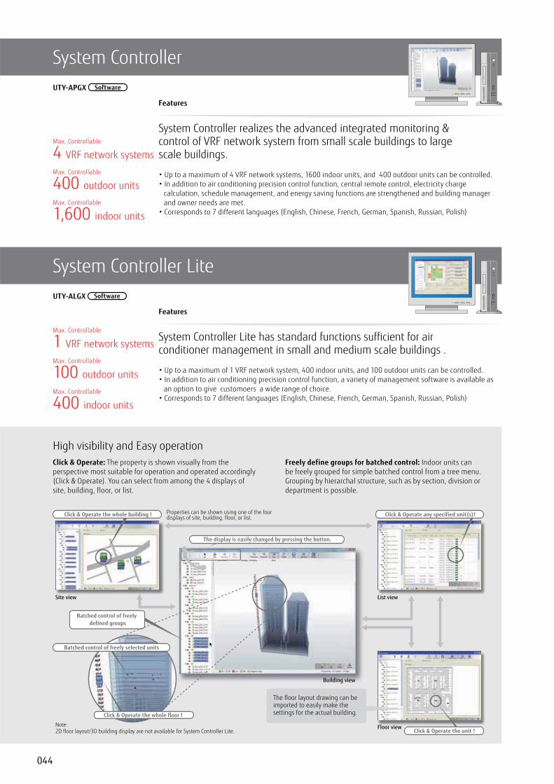
044
System Controller
Features
System Controller realizes the advanced integrated monitoring & control of VRF network system from small scale buildings to large scale buildings.
• Up to a maximum of 4 VRF network systems, 1600 indoor units, and 400 outdoor units can be controlled.• In addition to air conditioning precision control function, central remote control, electricity charge
calculation, schedule management, and energy saving functions are strengthened and building manager and owner needs are met.
• Corresponds to 7 different languages (English, Chinese, French, German, Spanish, Russian, Polish)
UTY-APGX Software
Features
System Controller Lite has standard functions sufficient for air conditioner management in small and medium scale buildings .
• Up to a maximum of 1 VRF network system, 400 indoor units, and 100 outdoor units can be controlled.• In addition to air conditioning precision control function, a variety of management software is available as
an option to give customoers a wide range of choice.• Corresponds to 7 different languages (English, Chinese, French, German, Spanish, Russian, Polish)
UTY-ALGX Software
4 VRF network systems
1 VRF network systems
400 outdoor units
100 outdoor units
1,600 indoor units
400 indoor units
Max. Controllable
Max. Controllable
Max. Controllable
Max. Controllable
Max. Controllable
Max. Controllable
System Controller Lite
Click & Operate: The property is shown visually from the perspective most suitable for operation and operated accordingly (Click & Operate). You can select from among the 4 displays of site, building, floor, or list.
Freely define groups for batched control: Indoor units can be freely grouped for simple batched control from a tree menu. Grouping by hierarchal structure, such as by section, division or department is possible.
High visibility and Easy operation
Site view
Building view
List view
Properties can be shown using one of the four displays of site, building, floor, or list.
The floor layout drawing can be imported to easily make the settings for the actual building.
Site ie List ie
Batched control of freelydefined groups
Click & Operate the whole building ! Click & Operate any specified unit(s)!
The display is easily changed by pressing the button.
Click & Operate the whole floor !
Batched control of freely selected units
Floor viewClick & Operate the unit !
Note:2D floor layout/3D building display are not available for System Controller Lite.

045
V R
F
Standard
Diverse operation management & Data managementfor System Controller and System Controller Lite
Schedule management• Annual schedules can be set for each remote controller group /
user defined group.
• Start / stop, operating mode, remote controller prohibition, and temperature settings can be set up to 143 times per day at 10 minute intervals for up to 101 configurations for each remote controller group.
• Settings can be made for periods straddling midnight.
• Allows programming of special settings for holidays, including public holidays, for a complete year.
• Low noise operation of outdoor unit can be scheduled.
Diverse control of indoor unit and outdoor unit• Indoor unit operation state, operation mode, etc. are displayed• Indoor unit start / stop and operation mode switching• Room temperature set point limitation• Outdoor unit low noise setting
Remote controller prohibitionThis prohibits changes to the operation mode, temperature, start/stop, etc.
Error display & E-mail notificationError is notified with popup message, audible sound and E-mail real time when error occurs. Error for the past 1 year are logged and can be reviewed later.
Operating & control recordDisplays the history of operation status and control.
Data base import/exportImports/exports registration data, layout data, and image data. Only the administrator can make this setting.
Automatic clock adjustmentThe time setting of each controller can be set in batch automatically.
StandardOption
Electricity charge apportionmentfor System Controller
for System Controller Lite UTY-PLGXA1
System Configuration Example
Electricity charge apportionment calculation frameworkSuppose you want to find the power consumed by the air conditioners of each tenant from the electricity charge for each month. With electricity charge apportionment function, used energy apportionment ratio will be provided, calculating in detail the energy consumed by the units used by each tenant. This information is then used to calculate the charges for the electricity consumed for air conditioning by each tenant from the total electricity charges in the bill from the electric power company. (See figure at right)The detailed calculation takes into consideration such things as unused rooms and nighttime electricity charges and shows them in a charges calculation sheet.
3Ø, 4 wire 400V, 50Hz
Signal transmission lineRB Unit
1Ø, 2wire 230V, 50Hz
System Controller
Outdoorunit
Tenant A-1 Tenant A-2 Tenant A-3
Tenant A-4 Tenant A-5 Tenant A-6
Tenant B-1 Tenant B-2 Tenant B-3
Tenant C-1 Tenant C-2 Tenant C-3
PowPoPowePowePowerPowerPowerPdistributiibutibutibutbuibibib ononoo
boardrdrdrdrdrddd
PowePowePowPoPowerPowerPowerPdistributibutibutbuibutiibibib ononoo
boardrdrdrdrdrdrdd
Electricity charges (air conditioning)Electric power
company
Energy used by each unit is calculated
Tenant B
Tenant C
Tenant A
Energy apportioned by the outdoor unit to each indoor unit is calculated
Tenant A Tenant B
Tenant C
Tenant A
ElectricBill
Tenant B
ElectricBill
Tenant C
ElectricBill
Electricity charges by tenant are calculated
The distribution ratio for energy used by each indoor unit is calculated and the electricity charges for the energy used by each indoor unit are calculated from the total electricity charges.
Indoor unit energy used
Apportioned energy
Indoor unit total energy used
The energy used by each indoor unit and the energy apportioned by the outdoor unit are added together to calculate the total amount of energy used.

046
StandardOption
System Controller may be used on site or remotely over various networks for remote central control. System Controller requires 2 softwares working together. VRF Controller runs on site and communicate with VRF system.VRF Explorer runs remotely and provides user interface and communicate with the VRF Controller. VRF Controller and VRF Explorer program may run in a single PC or in different PCs separated by network. By using VRF Explorer software, one PC can perform central control of 10 VRF system sites with max. 20 buildings per site.
Remote managementfor System Controller
for System Controller Lite UTY-PLGXA1
On site central control Remote central control
Building Management Company A (In charge of the day shift)
Internetor
Telephone Lineor
LAN
Internetor
Telephone Lineor
LAN
Building management company,management center, etc.
BuildingManagement Company B
(In charge of the night shift)
Security Company
Headquarters Management Center
A maximum of 10 locations, such as offices or factories
1 VRF Explorer can control or monitor up to 10 sites.
Office ManagementCenter
VRF Explorer
VRF Explorer
VRF Explorer
VRF ExplorerVRF Explorer
VRF Explorer
VRF Controller
VRF Controller
1 VRF Controller can be monitored from any number of VRF Explorers (Up to 5 connections simultaneously).
Internetor
Telephone Lineor
LAN
VRF Explorer
VRF Controller
Central Monitoring Screenfor all Properties
Special Property Detailed Monitoring Screen
Max. 4 VRF network systems per site
OptionOption
A variety of energy saving operations can be set and managed depending on the season, weather, and time period. Excellent energy saving operation is performed while keeping users comfortable.
Energy saving graph data: This graph compares the electricity consumption with the previous month and previous year to make it easy to analyze the energy saving effect.
Energy saving management
Indoor unit rotation operationThe operation of indoor units can be automatically rotated within a group in accordance with the set annual schedule to reduce power consumption while maintaining comfort. The indoor unit operation stoppage rate can be selected.
Peak cut operationA power meter is connected to detect the total power consumption while shifting the indoor unit set temperature, set the indoor unit forced thermostat off, and taking other measures to carefully control the power consumed while maintaining comfort and conducting control to maintain the target power consumption set for each time. The indoor units to be controlled can be freely grouped and the control level can be set.
Outdoor unit capacity saveOutdoor unit capacity save switches the outdoor unit capability upper limit to suppress power consumption during hot summers and cold winters by averaging the power saving effect of each refrigerant system. You can select from 50% or more of the capacity upper limit.
for System Controller UTY-PEGX
Energy Saving Management Main Screen
for System Controller Lite UTY-PLGXE1

047
V R
F
FUNCTIONS SUMMARY
Function Type
System controller
UTY-APGX UTY-PEGX UTY-ALGX
UTY-PLGXR1
UTY-PLGXA1
UTY-PLGXE1
System
Max. VRF networks supported 4 - 1 - - -Max. indoor unit / remote controller groups per VRF network 400 - 400 - - -Max. outdoor units per System controller 100 - 100 - - -Max. indoor units / remote controller groups per System controller 1600 - 400 - - -Max. outdoor units per System controller 400 - 100 - - -
Site supervision
Multi site display 10 - 10 - - -Number of building / 1 site 20 - - - - -
200 - - - - -50 - - - - -
3D graphical layout view - - - - -2D graphical layout view - - - - -List display - - - -Tree display - - - -Group display - - - -
Error management
- - - -Audible alarm - - - -
- - - -
HistoryError history - - - -Operation history - - - -Control history - - - -
Operation control
Individual control
On/Off - - - -Operation mode - - - -Room temperature - - - -Fan speed - - - -
- - - -Economy mode - - - -Room temperature set point limitation - - - -Test operation - - - -Antifreeze - - - -Outdoor unit low noise setting - - - -
Individual management
Remote control prohibition setting - - - -Temperature upper and lower limit setting - - - -Filter sign reset - - - -
OtherMemory operation - - - -Pattern operation - - - -
Schedule
Annual Schedule - - - -Special day setting - - - -On /off per day 72 - 72 - - -On / off per week 504 - 504 - - -Day off - - - -Min. unit of timer setting (Minutes) 10 - 10 - - -Low noise mode Weekly schedule - - - -
Remote managemment
Remote monitoring - - - -Remote operation control - - - -Remote function setting - - - -
Electricity charge apportionment
Apportionment charge/bill calculation - - - -Tenant (block) setting - - - -Common facilities apportionment setting - - - -Rated power consumption allotment setting - - - -Individual calculation at cooling and heating - * - - -Electricity meter supported - - - -
Energy saving management
Indoor unit rotation - - - -Peak cut control - - - -Outdoor unit capacity save - - - -Record of energy saving operation - - - -Energy saving information - - - -Power consumption monitor - - - -Electricity meter supported
OthersDatabase import/export - - - -Automatic clock adjustment - - - -Multi language 7 languages - 7 languages - - -
*:Power calculation application software is necessary, please contact the local FGL representative. : Available. - : Not available.
Personal computer system requirementsSystem Controller System Controller Lite
Operating system
• Microsoft® Windows Vista® Home Premium (32-bit) SP2, Windows Vista® Business (32-bit) SP2• Microsoft® Windows® 7 Home Premium (32-bit or 64-bit) SP1, Windows® 7 Professional (32-bit or 64-bit) SP1• Microsoft® Windows® 8 (32-bit or 64-bit), Windows® 8 Pro (32-bit or 64-bit)• Microsoft® Windows® 8.1 (32-bit or 64-bit), Windows® 8.1 Pro (32-bit or 64-bit)• Microsoft® Windows® 10 Home (32-bit or 64-bit), Windows® 10 Pro (32-bit or 64-bit)[Supported languages] English, Chinese, French, German, Russian, Spanish, and Polish
CPU Intel® CoreTM i3 2 GHz or higher
Memory • 2 GB or more (for Windows Vista® and Windows® 7 [32-bit])• 4 GB or more (for Windows® 7 [64-bit], Windows® 8, Windows® 8.1, and Windows® 10)
HDD 40 GB or more of free spaceDisplay 1024 x 768 or higher resolution
Interface
•Ethernet port (for getting access to the Internet using LAN) or Modem (for getting access to the Internet using Public Telephone Line)
•USB ports (Maximum of 6 ports) (Required only for the Server PC that works as VRF Controller)
- Maximum of 2 USB ports are required for WibuKey connection - Maximum of 4 USB ports are required for Echelon® U10 USB Network Interface * Maximum number of required USB port depends on the applicable system
•Ethernet port (for getting access to the Internet using LAN) or Modem (for getting access to the Internet using Public Telephone Line)
•USB ports (Maximum of 5 ports) (Required only for the Server PC that works as VRF Controller)
- Maximum of 4 USB ports are required for WibuKey connection - 1 USB port is required for Echelon® U10 USB Network Interface * The maximum number of required USB port depends on the applicable
Graphic accelerator Microsoft® DirectX® 9.0c compatibleSoftware Adobe® Reader® 9.0 or laterOptical drive DVD-ROM drive
•Personal computer that satisfies the following system requirements •Echelon® U10 USB Network Interface – TP/FT-10 Channel (Model number: 75010R) (Required for each VRF Network.)
PACKING LIST
Type
For System controller For System controller Lite
System Controller System Controller LiteEnergy manager Remote access Electricity charge
apportionment Energy saving
Model name UTY-APGX UTY-PEGX UTY-ALGX UTY-PLGXR1 UTY-PLGXA1 UTY-PLGXE1
DVD-ROM 1 1 1 — — —
WibuKey*1(Software protection key) 1 1 1 1 1 1
*1: Software protection key to be inserted in a USB slot running System Controller or System Controller Lite. System Controller or System Controller Lite may only run on a PC with Wibu Key. However, WibuKey is not required for remote VRF Explorer software.

048
BACnet® Gateway
Features
• It is possible to connect medium to large sized BMS to VRF network system via BACnet®, a global standard for open networks.
• A maximum of 1600 indoor units with 4 VRF network systems (a maximum of 400 indoor units & 100 outdoor units for one network system) can be connected to one BACnet® Gateway.
• It is possible to control or monitor VRF network system from BMS via BACnet® Gateway. • Compatible with BACnet® (ANSI / ASHRAE-135-2004) application specific controller (B-ASC). • Compatible with BACnet®/IP over Ethernet.• Scheduling function, Alarm & Event functions as well as Electricity Change Apportionment function are
provided in BACnet® Gateway.• Connection between VRF network system to personal computer is possible via small U10 USB interface.
However, both U10 USB interface & personal computer are locally purchased items.• Corresponds to 7 different languages, English, Chinese, French, German, Spanish, Russian, Polish.
UTY-ABGX Software
DVD-ROM(Software)
SoftwareProtection Key
4VRF network systems
400 outdoor units
1,600 indoor units
Max. Controllable
Max. Controllable
Max. Controllable
Installation example
Lighting facilities
Security system
Automatic fire alarm interface
Ventilation system
BACnet® Operator Workstation (B-OWS)
USB adaptor(Locally purchased)
USB adaptor(Locally purchased)
USB adaptor(Locally purchased)
USB adaptor(Locally purchased)
DVD-ROM(Software)
SoftwareProtection Key
(UTY-ABGX)BACnet® Gateway
VRF network system 1
VRF network system 2
Indoor unit
BACnet
Max. 4 VRF network systems*1: USB adaptor is U10 USB Network Interface of Echelon® Corporation.
®
= USB cable= Transmission line (VRF Network)= Ethernet
*1
Indoor unit
Outdoor unit
Outdoor unit
RB Unit
RB Unit
Personal computer system requirementsUTY-ABGX
Operating system
• Microsoft® Windows Vista® Home Premium (32-bit) SP2, Windows Vista® Business (32-bit) SP2• Microsoft® Windows® 7 Home Premium (32-bit or 64-bit) SP1, Windows® 7 Professional (32-bit or 64-bit) SP1• Microsoft® Windows® 8 (32-bit or 64-bit), Windows® 8 Pro (32-bit or 64-bit)• Microsoft® Windows® 8.1 (32-bit or 64-bit), Windows® 8.1 Pro (32-bit or 64-bit)• Microsoft® Windows® 10 Home (32-bit or 64-bit), Windows® 10 Pro (32-bit or 64-bit)[Supported languages] English, Chinese, French, German, Russian, Spanish, and Polish
CPU Intel® CoreTM i3 2 GHz or higher
Memory • 2 GB or more (for Windows Vista® and Windows® 7 [32-bit])• 4 GB or more (for Windows® 7 [64-bit], Windows® 8, Windows® 8.1, and Windows® 10)
HDD 40 GB or more of free spaceDisplay 1024 x 768 or higher resolution
Interface
• Ethernet port (for getting access to the Internet using LAN)• USB ports (Maximum of 5 ports) - 1 USB port is required for WibuKey connection - Maximum of 4 USB ports are required for Echelon® U10 USB Network Interface
Software Adobe® Reader® 9.0 or laterOptical drive DVD-ROM drive
Packing listName and shape Quantity
DVD-ROM 1
WibuKey(Software protection key) 1
•Personal computer that satisfies the following system requirements •Echelon® U10 USB Network Interface – TP/FT-10 Channel (Model number: 75010R) (Required for each VRF Network.)

049
V R
F
Network Convertor for
Installation example
Features
• For connection between VRF network system and a open network for management of small to medium-sized BMS and VRF network system.
• The UTY-VLGX permits central monitoring and control of a VRF network system from a BMS through a interface.
• Up to 128 Indoor units can be connected to one Network Convertor for
UTY-VLGX
4 units to BMS
100 outdoor units
128 indoor units
Max. Controllable
Max. Controllable
Max. Controllable
General-purpose building control computer( device)
VRF network system 1
Lighting facilities
Security system
Automatic fire alarm interface
Ventilation system
Max. 128 indoor unitsMax. 100 outdoor units
VRF network system 2
Max. 128 indoor unitsMax. 100 outdoor units
Network
Max. 4 NetworkConvertors
RB Unit
RB Unit
RB Unit
RB Unit
RB Unit
RB Unit
Specifications Dimensions (Unit : mm)
Transmission specifications (BMS side)
Model name UTY-VLGX
Power Supply 208-240V 50/60Hz, Single phase
Power Consumption (W) 4.5
Dimensions (H × W × D) (mm) 67 × 288 × 211
Weight (g) 1,500
Transmission speed 78 kbps
Transceiver FT-X1 (Echelon® Corporation)
Transmission way form Free topology
Terminal resistor None(It attaches at the terminal of a network.)

050
MODBUS® Convertor
Connectable MAX 9Up to 9 convertors can be connected to a VRF network. The simultaneous controls such as ON/OFF or temperature settings can be done for each zone.
Traceability of sources of connection errorIt is easy to locate the source of error if any connection errors should occur after completion of installation works.
SpecificationsModel name UTY-VMGX
Power Supply AC220/240V 50/60Hz
Input power (W) Max. 2
Dimensions (H × W × D) (mm) 54 × 260 × 150
Weight (g) 1,100
Features
The MODOBUS Convertor allows a complete integration of air conditioners into MODBUS Networks.
• Compact and lightweight design• Direct connection to MODBUS Network• Up to 128 indoor units can be controlled in one MODBUS Convertor• The MODBUS Convertor permits central monitoring and control of air conditioners from BMS or Central
Controller.
UTY-VMGX
9 units to one VRF
100 outdoor units
128 indoor units
Max. Controllable
Max. Controllable
Selectable
BMS/CentralController
MODBUS Network
MODBUS Convertor for VRF
Lighting facilities
Security system
Automatic fire alarm interface
Windows bind VRF Outdoor unit
VRF Indoor unit
VRF Indoor unit
VRF System (Lon Network)
Controller
* BMS : Bulding Management System
Tenant B
Hotel
Restaurant
Lobby
Office & Lounge
Tenant C
Tenant A
Example : If any connection error occurs, it
will tell you where the problem is in either “
BMS controller to MODBUS Convertor” or “
VRF system to MODBUS Convertor”,
BMS/CentralController
MODBUS Convertor
Test Run ON!
Check item !
MODBUS Network
NEW

051
V R
F
MODBUS® Interface
Specifications
KNX® Interface
Features
The MODBUS Interface allows a complete integration of air conditioners into MODBUS Networks.
• Simple installation due to small and compact size.• No separate external power supply required.• The MODBUS Interface permits central monitoring and control of air conditioners from BMS.
FJ-RC-MBS-1
Max. 63MODBUS Interface
BMS/Central Controller
MODBUS Network The MODBUS Interface can be used withor without Wired Remote Controller.
Wired Remote Controller
VRF Indoor unit
Split Indoor unit
VRF Indoor unit
Model name FJ-RC-MBS-1
Dimensions (H × W × D) (mm) 93×53×58
Weight (g) 85
Model name FJ-RC-KNX-1i
Dimensions (H × W × D) (mm) 70×70×28
Weight (g) 70
Features
The KNX Interface allows a complete integration of air conditioners with KNX Network systems.
• Simple installation due to small and compact size.• No separate external power supply required (just KNX bus power).• Can be used for single indoor units and group controlled (up to 16) indoor units.
FJ-RC-KNX-1i
KNX Network
KNXInterface
Lighting facilities
Security system
Automatic fire alarm interface
Windows bind
Split Indoor unit
VRF Indoor unit
The KNX Interface can be used with or without Wired Remote Controller.
or
Wired Remote Controller
Home Controller

052
Wireless LAN Interface
Features
• It is the most advanced solution to remotely manage an Air Conditioning system using all sort of mobile devices such as Smartphones, Tablets and PC
• No separate external power supply required• Can be used for single indoor units and group controlled (up to 16) indoor units
FJ-RC-WIFI-1
Smartphone
Tablet
PC
SmartInternet
Indoor unit
Router(Locally purchased)
Wireless LANInterface
Basic control• Turning the units on and off• Mode control (Heat, Cool, Dry, Auto, Fan)• Fan speed setting• Louver position (Airflow direction setting)• Room temperature display• Set temperature control• Multi Language• One Scene and Timer
Advanced control (Optional functions)• Climate working modes (ECO, Comfort, Powerful) (future release)• Schedulable functionalities (ON/OFF, Modes, Set point temperature, Fan Speed, Louver position)• Set temperature limitation (future release)• Multiple Scenes & Timers and Calendar function
Notifications and history• Alerts e-mail notification (future release)• Air conditioning malfunction alerts• Connectivity monitoring and alerts• History (future release)
SpecificationsModel name FJ-RC-WIFI-1
Dimensions (H × W × D) (mm) 70×108×28
Weight (g) 80
(Application screen image)
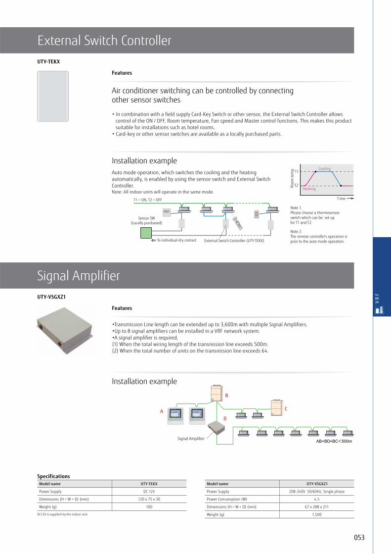
053
V R
F
External Switch Controller
Features
Air conditioner switching can be controlled by connecting other sensor switches
• In combination with a field supply Card-Key Switch or other sensor, the External Switch Controller allows control of the ON / OFF, Room temperature, Fan speed and Master control functions. This makes this product suitable for installations such as hotel rooms.
• Card-key or other sensor switches are available as a locally purchased parts.
UTY-TEKX
Installation exampleAuto mode operation, which switches the cooling and the heating automatically, is enabled by using the sensor switch and External Switch Controller. Note: All indoor units will operate in the same mode.
Installation example
Note 1. Please choose a thermosensor switch which can be set up for T1 and T2.
Note 2. The remote controller's operation is prior to the auto mode operation.
Room
tem
p.
T ime
T1
T2
Cooling
Heating
SU MO TU WE TH FR SA
7
3 126 9 15 18 21
T1 = ON, T2 = OFF
To individual dry contact
Sensor SW(Locally purchased)
External Switch Controller (UTY-TEKX)
Signal Amplifier
Features
•Transmission Line length can be extended up to 3,600m with multiple Signal Amplifiers.•Up to 8 signal amplifiers can be installed in a VRF network system.•A signal amplifier is required,(1) When the total wiring length of the transnission line exceeds 500m.(2) When the total number of units on the transnission line exceeds 64.
UTY-VSGXZ1
B
AD
Signal Amplifier
C
SpecificationsModel name UTY-TEKX
Power Supply DC 12V
Dimensions (H × W × D) (mm) 120 x 75 x 30
Weight (g) 100
DC12V is supplied by the indoor unit.
Model name UTY-VSGXZ1
Power Supply 208-240V 50/60Hz, Single phase
Power Consumption (W) 4.5
Dimensions (H × W × D) (mm) 67 x 288 x 211
Weight (g) 1,500

054
Network Convertor for single split
Features
• The network convertors are required when connecting single split system to VRF network system.• Compact and light weight design• Connectable to both types of 2-wire and 3-wire remote controllers
UTY-VTGX / UTY-VTGXV
UTY-VTGXDC power supply type
UTY-VTGXVAC power supply type
16single indoor units
Max. Controllable
100 Network Convertors
Max. Controllable
Installation example.• 2 types of 1 remote controller type and 2 remote controllers type are available.• Power supply (AC220-240V, 50/60Hz) is required for 2 remote controllers type.
VRF network System
Network Convertor(for 1 remote controller)
Network Convertor(for 2 remote controllers)
AC230V
SpecificationsModel name UTY-VTGX UTY-VTGXV
Power Supply polar 3-wire DC12V non-polar 2-wire DC12V 50/60Hz AC220/240V
Input power (W) Max. 1.2 Max. 3
Dimensions (H × W × D) (mm) 43 × 117 × 140 54 × 260 × 150
Weight (g) 250 1,100
NEW
• 2-wire and 3-wire type of the wired remote controller can be connectable.
• A central control can be provided for the single split systems. (Up to 100 units of Network Convertor is connectable in one VRF network system)
VRF network System
VRF network System
Up to 100 units ofNetwork Converter
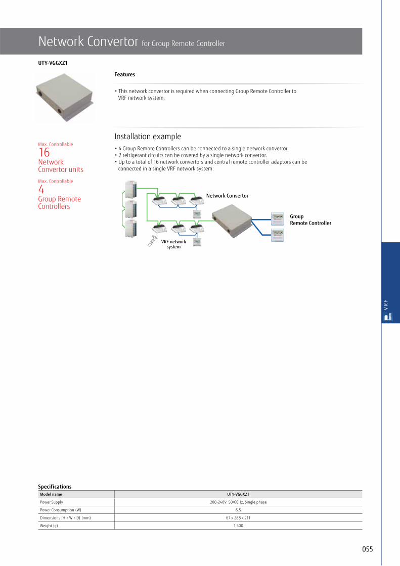
055
V R
F
Network Convertor for Group Remote Controller
SpecificationsModel name UTY-VGGXZ1
Power Supply 208-240V 50/60Hz, Single phase
Power Consumption (W) 6.5
Dimensions (H × W × D) (mm) 67 x 288 x 211
Weight (g) 1,500
Features
• This network convertor is required when connecting Group Remote Controller to VRF network system.
UTY-VGGXZ1
Installation example• 4 Group Remote Controllers can be connected to a single network convertor.• 2 refrigerant circuits can be covered by a single network convertor.• Up to a total of 16 network convertors and central remote controller adaptors can be
connected in a single VRF network system.
16NetworkConvertor units
4Group RemoteControllers
Max. Controllable
Max. Controllable
VRF networksystem
Network Convertor
Group Remote Controller

056
Web Monitoring Tool
Personal computer system requirementsUTY-AMGX
Operating system
• Microsoft® Windows Vista® Home Premium (32-bit) SP2, Windows Vista® Business (32-bit) SP2• Microsoft® Windows® 7 Professional (32-bit or 64-bit) SP1• Microsoft® Windows® 8 Pro (32-bit or 64-bit)• Microsoft® Windows® 8.1 Pro (32-bit or 64-bit)
CPU 1 GHz or higher
Memory • 1 GB or more (for Windows Vista®, Windows® 7 [32-bit], Windows® 8 [32-bit], and Windows® 8.1 [32-bit])• 2 GB or more (for Windows® 7 [64-bit], Windows® 8 [64-bit], and Windows® 8.1 [64-bit])
HDD 40 GB or more of free spaceDisplay 1024 x 768 or higher resolution
Interface
• Ethernet port (for getting access to the Internet using LAN) or Modem (for getting access to the Internet using Public Telephone Line)• USB ports (Maximum of 5 ports) - 1 USB port is required for WibuKey connection - Maximum of 4 USB ports are required for Echelon® U10 USB Network Interface
Software Internet Explorer® 8, 9, 10 or 11 / Adobe® Reader® 9.0 or laterOptical drive DVD-ROM drive
Packing listName and shape Quantity
DVD-ROM 1
WibuKey(Software protection key) 1
•Personal computer that satisfies the following system requirements•Echelon® U10 USB Network Interface – TP/FT-10 Channel (Model number: 75010R) (Required for each VRF Network.))
Features
Product features• Troubleshooting is performed by monitoring each air conditioning unit remotely during periodical system
checks.• Error notification can be automatically transmitted to several locations using the internet*1.• Requires either a dedicated internet connection or public telephone line.• Determination of an error occurrence can be made through error warnings and equipment status
information obtained from a remote location.• The monitoring data in a remote side can be optionally downloaded. And, this data can be displayed in
offline mode of the service tool.• Monitoring side computer is not required to install special software, requires only general web browser.
*1: Use of internet mail system required.
UTY-AMGX Software
Web Monitoring System
Indoor unit
Transmission line
USB adapter(Locally purchased)
Outdoor unit
Web Monitoring Tool
VRF Network System SideMonitoring Side
orInternet
Public Telephone Line
Support 4 VRF network systemsUSB adaptor (max. 4 adaptors per PC) permit, monitoring of up to 1,600 indoor units.Suitable for large-scale buildings or hotels.
Indoor unitMax. 400
VRF NetworkSystem 2
Indoor unitMax. 400
VRF NetworkSystem 3
Indoor unitMax. 400
VRF NetworkSystem 4
Indoor unitMax. 400
VRF NetworkSystem 1
USB adaptors
4VRF network system can be supported
400outdoor units
Max. Monitor and controll
1,600indoor unitscan be supported

057
V R
F
Service Tool
Features
Extensive monitoring and analysis functions for installation and maintenance
• Operation status can be checked and analyzed to detect even the smallest abnormalities• Storage of data on system operation status on a PC allows access even from off site.• Up to 400 indoor units (a single VRF network system) can be controlled and monitored for large scale
buildings or hotels• This software can be connected to any point of transmission line with USB adaptor (locally purchased)
UTY-ASGX Software
Wiring connection
Functions
(Locallypurchased)
Refrigerant piping
Tran
smis
sion
line
Indoor unit
Indoor unit
USB adaptor(Locally purchased)
•Equipment Detail (Diagram)
•Equipment Detail (List)•Error History•Remote File Download•System List•Commissioning Tool
Personal computer system requirementsUTY-ASGX
Operating system
• Microsoft® Windows Vista® Home Premium (32-bit) SP2, Windows Vista® Business (32-bit) SP2• Microsoft® Windows® 7 Professional (32-bit or 64-bit) SP1• Microsoft® Windows® 8 Pro (32-bit or 64-bit)• Microsoft® Windows® 8.1 Pro (32-bit or 64-bit)
CPU 1 GHz or higher
Memory • 1 GB or more (for Windows Vista®, Windows® 7 [32-bit], Windows® 8 [32-bit], and Windows® 8.1 [32-bit])• 2 GB or more (for Windows® 7 [64-bit], Windows® 8 [64-bit], and Windows® 8.1 [64-bit])
HDD 10 GB or more of free spaceDisplay 1024 x 768 or higher resolution
Interface• 2 USB ports - 1 USB port is required for WibuKey connection - 1 USB port is required for Echelon® U10 USB Network Interface
Software Internet Explorer® 8, 9, 10 or 11 / Adobe® Reader® 9.0 or laterOptical drive DVD-ROM drive
Packing listName and shape Quantity
DVD-ROM 1
WibuKey(Software protection key) 1
•Personal computer that satisfies the following system requirements•Echelon® U10 USB Network Interface – TP/FT-10 Channel (Model number: 75010R) (Required for each VRF Network.)
100outdoor units
400indoor units
Max. Monitor and controll
Max. Monitor and controll

058
OPTIONAL PARTS FOR VRF
Connection Units
Separation Tube
UTP-AX054A
Gas Pipe
Liquid Pipe
UTP-AX090A
Gas Pipe
Liquid Pipe
UTP-AX180A
Gas Pipe
Liquid Pipe
UTP-AX567A
Gas Pipe
Liquid Pipe
UTP-BX090A
SuctionGas Pipe
DischargeGas Pipe
Liquid Pipe
UTP-BX180A
SuctionGas Pipe
DischargeGas Pipe
Liquid Pipe
UTP-BX567A
SuctionGas Pipe
DischargeGas Pipe
Liquid Pipe
UTP-LX180A
For DX-Kit
Header Outdoor Unit Branch Kit
UTR-H0906L / UTR-H1806L
Gas Pipe
Liquid Pipe
UTR-H0908L / UTR-H1808L
Gas Pipe
Liquid Pipe
UTP-CX567A
Gas Pipe
Liquid Pipe
UTP-J0906A / UTP-J1806A
Suction Gas Pipe
Discharge Gas Pipe
Liquid Pipe
UTP-J0908A / UTP-J1808A
Suction Gas Pipe
Discharge Gas Pipe
Liquid Pipe
UTP-DX567A
Suction Gas Pipe
Discharge Gas Pipe
Liquid Pipe
e
e
e
EV Kit RB Unit
Model code 09 : UTR-EV09XB Model code 12 : UTR-EV14XB
For Compact Wall Mounted type
UTP-RX01AH / UTP-RX01BH UTP-RX01CH
Single type
UTP-RX04BH
Multi type

059
OPTI
ONAL
PAR
TS
fo
r VRF
Specifications
Separation TubeModel name UTP-AX054A UTP-AX090A UTP-AX180A UTP-AX567A
Total cooling capacity of indoor unit (kW) 19.6 or less 28.0 or less 28.1 to 56.0 56.1 or more
Model name UTP-BX090A UTP-BX180A UTP-BX567A
Total cooling capacity of indoor unit (kW) 28.0 or less 28.1 to 56.0 56.1 or more
Header
Model name3-6 Branches UTR-H0906L UTR-H1806L
3-8 Branches UTR-H0908L UTR-H1808L
Total cooling capacity of indoor unit (kW) 28.0 or less 28.1 to 56.0
Model name3-6 Branches UTP-J0906A UTP-J1806A
3-8 Branches UTP-J0908A UTP-J1808A
Total cooling capacity of indoor unit (kW) 28.0 or less 28.1 to 56.0
Outdoor unit Branch kitModel name UTP-CX567A (for V-II/V-III) UTP-DX567A (for VR-II)
Number of outdoor unit2 outdoor units 1
3 outdoor units 2
EV KitModel name UTR-EV09XB UTR-EV14XB
Application modelASYE04GACHASYE07GACHASYE09GACH
ASYE12GACHASYE14GACH
RB UnitType Single type Multi type
Model name UTP-RX01AH UTP-RX01BH UTP-RX01CH UTP-RX04BH
Power source V/Ø/Hz 230/ 1 / 50
Input power W 17 24 31 96
Number of branches 1 1 1 4
Maximum capacity of connectableindoor units (Q)
kW Q≧ 8.0 Q≦ 18.0 Q≦ 28.0 Q≦ 56.1*1
Maximum capacity of connectableindoor units per branch (Q)
kW Q≧ 8.0 Q≦ 18.0 Q≦ 28.0 Q≦ 18.0
Maximum number of connectableindoor units per branch 3 8 8 8
Dimensions (H×W×D) mm 198×298×268 260×658×428
*1: In case of two RB units connected in series ( total 8-branches ), maximum capacity of connectable indoor units is up to 56.0 kW.

060
Controllers
For Individual Control
Wired Remote Controller (Touch Panel )UTY-RNRYZ1
Wired Remote Controller UTY-RLRY
Simple Remote Controller UTY-RSKYWith operation mode
Simple Remote Controller UTY-RHKYWithout operation mode
Wireless Remote Controller UTY-LNHY
IR Receiver Unit UTB-YWCFor All Duct types except Large Airflow Duct
IR Receiver Unit UTY-LRHYB1For Cassette type
For Centralized Control
Group Remote Controller UTY-CGGY
Central Remote Controller UTY-DCGY
OptionUTY-PTGXA
Touch Panel Controller UTY-DTGYZ1 UTY-DTGY
System Controller Lite UTY-ALGX
OptionUTY-PLGXA1UTY-PLGXR1UTY-PLGXE1
OptionUTY-PEGX
System Controller UTY-APGX
USB Adaptor (Field supplied) USB75010RFor system controllers

061
OPTI
ONAL
PAR
TS
fo
r VRF
Convertors / Adaptors
For External device
BACnet® Gateway UTY-ABGX
DVD-ROM(Software)
Software Protection Key
Network Convertor for LONWORKS®UTY-VLGX
MODBUS® Convertor for VRF UTY-VMGX
MODBUS® Interface FJ-RC-MBS-1
KNX® Interface FJ-RC-KNX-1i
Wireless LAN Interface FJ-RC-WIFI-1
For System expansion
Network Convertor for single splitUTY-VTGX
Network Convertor for single splitUTY-VTGXV AC power supply type
Network Convertor for Group Remote ControllerUTY-VGGXZ1
Signal Amplifier UTY-VSGXZ1
External Switch Controller UTY-TEKX
Panels
For Cassette type
Cassette Grille UTG-UFYC-WFor Compact Cassette type
Cassette Grille UTG-UGYA-WFor Cassette type
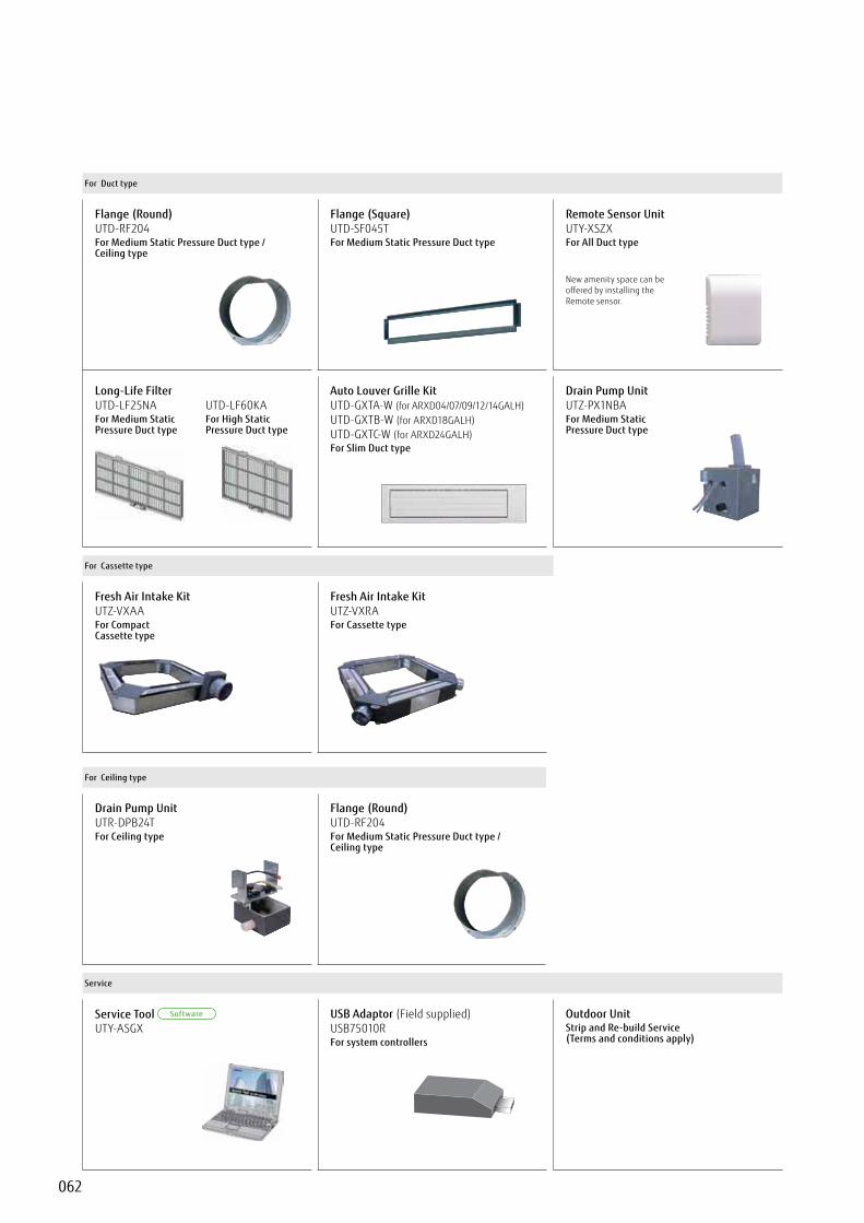
062
For Duct type
Flange (Round) UTD-RF204For Medium Static Pressure Duct type / Ceiling type
Flange (Square) UTD-SF045TFor Medium Static Pressure Duct type
Remote Sensor Unit UTY-XSZXFor All Duct type
New amenity space can be offered by installing the Remote sensor.
Long-Life FilterUTD-LF25NAFor Medium Static Pressure Duct type
UTD-LF60KAFor High Static Pressure Duct type
Auto Louver Grille Kit UTD-GXTA-W (for ARXD04/07/09/12/14GALH) UTD-GXTB-W (for ARXD18GALH) UTD-GXTC-W (for ARXD24GALH) For Slim Duct type
Drain Pump Unit UTZ-PX1NBAFor Medium Static Pressure Duct type
For Cassette type
Fresh Air Intake Kit UTZ-VXAAFor Compact Cassette type
Fresh Air Intake Kit UTZ-VXRAFor Cassette type
For Ceiling type
Drain Pump Unit UTR-DPB24TFor Ceiling type
Flange (Round) UTD-RF204For Medium Static Pressure Duct type / Ceiling type
Service
Service Tool UTY-ASGX
USB Adaptor (Field supplied) USB75010RFor system controllers
Outdoor Unit Strip and Re-build Service(Terms and conditions apply)

063
OPTI
ONAL
PAR
TS
fo
r VRF
Others
Communication system: External Connect Kit
For Indoor unit
UTY-XWZXZ7 UTY-XWZXZD
UTY-XWZXZBUTY-XWZXZE
UTY-XWZXZC
For Outdoor unit
UTY-XWZXZ6
UTY-XWZXZ9
UTY-XWZXZF
For RB unit
UTY-XWZXZ6
UTY-XWZXZB
For Central Remote Controller
UTY-XWZXZ7
UTY-XWZXZ8
UTY-XWZXZA
For Touch Panel Controller
UTY-XWZXZA
Function list
Indoor unit Outdoor unit
Controller Other
Central RemoteController
Touch PanelController RB Unit
Inpu
t
Operation / Stop UTY-XWZXZDUTY-XWZXZB ———— ———— ———— ————
All On / All Off ———— ———— UTY-XWZXZ7UTY-XWZXZ8
*3
*3 ————
Batch Stop ———— UTY-XWZXZ6 ———— ———— ————
Forced Stop UTY-XWZXZDUTY-XWZXZB ———— ———— ———— ————
Emergency Stop UTY-XWZXZDUTY-XWZXZB UTY-XWZXZ6 UTY-XWZXZ7
UTY-XWZXZ8*3
*3 ————
Forced Thermostat off UTY-XWZXZEUTY-XWZXZ7 ———— ———— ———— ————
Low Noise Mode Operation ———— UTY-XWZXZ6 ———— ———— ————
Cooling / Heating Priority ———— UTY-XWZXZ6*1 ———— ———— UTY-XWZXZ6UTY-XWZXZB
“Outdoor Unit Operation Peak Control” ———— UTY-XWZXZ6 ———— ———— ————
“Power Usage Information fromElectricity Meter” ———— UTY-XWZXZF ———— *3
*3 ————
Out
put
Operation Status UTY-XWZXZC UTY-XWZXZ6 UTY-XWZXZA UTY-XWZXZA ————
Error Status UTY-XWZXZC UTY-XWZXZ6 UTY-XWZXZA UTY-XWZXZA ————
Indoor Unit Fun Operation Status UTY-XWZXZC ———— ———— ———— ————
Auxiliary Heater Output UTY-XWZXZC*2 ———— ———— ———— ————
Base Heater ———— UTY-XWZXZ9 ———— ———— ————
*1. Heat Pump type only : Dry Contact : Apply Voltage*2. Duct type only*3. Touch Panel Controller has these functions for Dry contact and Apply voltage, however, above External Connect Kit is not
necessary because Touch Panel Controller has an external input terminal block.

064
High Efficiency and low noise levels are achieved by using a highly efficient heat exchange process. A comfortable air conditioned space is achieved by conveniently selecting whether to use heat exchange or normal ventilation setting, according to the requirements of the conditioned space.
Effective heat exchange and simultaneous fresh air ventilation
066 Energy Recovery Ventilator
068 Outdoor Air Unit
070 DX-Kit for air handling applications
VENTILATION
Energy RecoveryVentilatorPage 066
Outdoor Air UnitPage 068
DX-Kit for air handling applicationsPage 070
Airflow rate (m3/h)
UTZ-BD025B UTZ-BD035B
250 350
UTZ-BD050B
500
UTZ-BD080B
800
UTZ-BD100B
1000 1500 2000
ARXH054GTAH ARXH072GTAH ARXH096GTAH
Connectable Capacity class (kW) 5.0 6.3 8.0 10.0 12.5 14.0 20.0 40.025.0 50.0
Control unitUTY-VDGX
EEV unitUTP-VX30A
Control unitUTY-VDGX
EEV unitUTP-VX60A
Control unitUTY-VDGX
EEV unitUTP-VX90A
Control unitUTY-VDGX
EEV unitUTP-VX90A × 2

065
Specifications
N - neutral wire of module power supplyDA - controlling at the damper of ERV unitL - live wire of module power supplyHI - controlling of fan speed (high speed)EH - controling of fan speed (medium speed) - is not usedLO - controlling at fan speed (low speed)
- common terminal for the contact FAFA - external input for ON/OFF of ERV unit (connected - ON, disconnected - OFF)CM - terminal for wired remote cootroller (white wire)+12 - terminal for wired remote controller (red wire)
- common (GND) terminal for wired remote controller (black wire) and outdoor temperature sensorTH - terminal tor outdoor temperature sensor
Model name UTI-ERV UTY-RNKY
Power Supply 208-240V 50/60Hz, Single Phase from UTI-ERV
Power Consumption (W) 6.5 -
Dimensions (H × W × D) (mm) 67 x 288 x 211 120 x 120 x 18
Weight (g) 1,500 160
*UTY-RNKY to be ordered separately
Optional Hard-wired Controller Interface
Features
In order to use a Fujitsu hard-wired controller c/w time clock with the ERV units an interface is required. The UTI-ERV interface provides the following features:-
UTI-ERV interface supplied with outside air intake duct sensor for control of the ERV bypass dampere.g. heat recovery or “free cooling” bypass mode.Dry contact terminals for remote on/off e.g. from BMS.Allows the use of a Fujitsu UTY-RNKY* hard wired controller which has the following features:-Allows ERV fan speed selection from remote controller - Hi/Low (ERV HI/low fan speeds can also be changedby re-configuring the tapings on the fan motors).• Controller has an integral 7 day programmable time clock.• HW Controller has built-in room temperature sensor and temperature selection.• Filter clean indicator facility.• Manual or Auto control of ERV bypass damper.
UTI-ERV
Wired Diagram
Description of the buttons of remote controller* UTY-RNKY1 Start/Stop Button2 Set Temperature Button3 Master Control Button4 Fan Control Button5 Recovery ventilator ON/OFF6 Timer Mode (CLOCK ADJUST) Button7 DAY (DAY OFF) Button8 SET BACK Button9 Set Time Button10 DELETE Button11 SET Button12 NIA13 N/A14 Filter Button15 Operation Lamp16 Timer and Clock Display17 Operation Mode Display18 Fan Speed Display19 Operation Lock Display20 Temperature Display21 Function Display DELETE Button
ECO SET Button

066
Features
Energy Recovery Ventilator
Energy recovery ventilator unit offers maximum comfort and greater energy savings.
Adopts a highly efficient counter-flow heat exchange element
Heat exchanger Outside air
Exhaust air
Supply airRoom air
Heat exchange ventilationWhen a room is cooled or heated, the exhausted cooling / heating energy is recovered by heat-exchange ventilation.
Normal ventilationThe operation is used during periods when the room space requires no cooling or heating effect, i.e. when there is minimal temperature difference between the indoor and outdoor environments.
Heat exchange ventilation and normal ventilation
Outside airExhaust air
SuRoom air
Energy efficiency and ecologyEnergy consumption is dramatically reduced by using a counter-flow heat-exchange element. Air conditioning load is reduced by approximately 20%, resulting in significant energy savings. Recovers up to 77% of the heat in the outgoing air.
Features of heat exchange elementWith the cross-flow element, air moves in a straight line across the element. With the counter-flow element, air flows through the element for a longer time (longer distance), so the heat-exchange effect remains unchanged.
Quiet operationSignificantly reducing low pressure loss and noise allows low-noise operation.
Extended range of an external static pressureAn external static pressure is improved by adopting a powerful fan motor. This allows for application in a wide variety building.
Other element(Cross-flow element)
Fujitsu element(Counter-flow element)

067
VEN
TILA
TION
UTZ-BD025B UTZ-BD035B UTZ-BD080B UTZ-BD100BUTZ-BD050B
Slim shape and easier installationCounter-flow heat exchange element used for reduced noise and slimmer, more compact body shape. UTZ-BD025B
Height
270 mm
UTZ-BD080B/BD100B
Height
388 mm
m
Specifications250 m3/h 350 m3/h 500 m3/h 800 m3/h 1000 m3/h
Model No. UTZ-BD025B UTZ-BD035B UTZ-BD050B UTZ-BD080B UTZ-BD100B
Power source 220 - 240V, 50Hz
Hea
t Ex
chan
ge
Vent
ilatio
n
Input power (Extra high)/High/Low W 128 / 123 / 96 190 / 185 / 168 289 / 225 / 185 418 / 378 / 295 464 / 432 / 311(Extra high)/High/Low m3/h 250 / 250 / 190 350 / 350 / 240 500 / 500 / 440 800 / 800 / 630 1000 / 1000 / 700(Extra high)/High/Low l/s 69 / 69 / 52 97 / 97 / 66 138 / 138 / 122 222 / 222 / 175 277 / 277 / 194
External static pressure (Extra high)/High/Low Pa 105 / 95 / 45 140 / 60 / 45 120 / 60 / 35 140 / 110 / 55 105 / 80 / 75Temperature Exchange (Extra high)/High/Low % 75 / 75 / 77 75 / 75 / 78 75 / 75 / 76 75 / 75 / 76 75 / 75 / 79
Energy Exchange (Extra high)/High/Low % 63 / 63 / 65 66 / 66 / 71 62 / 62 / 64 65 / 65 / 68 65 / 65 / 70
Energy Exchange (Extra high)/High/Low % 70 / 70 / 72 69 / 69 / 73 67 / 67 / 69 71 / 71 / 74 71 / 71 / 76
Sound pressure level (Extra high)/High/Low dB* 31.5 / 30.5 / 26.5 33 / 31 / 25.5 37.5 / 35.5 / 32.5 37.5 / 37 / 34.5 38.5 / 37.5 / 34.5
Nor
mal
Ve
ntila
tion
Input power (Extra high)/High/Low W 128 / 123 / 96 190 / 185 / 168 289 / 225 / 185 418 / 378 / 295 464 / 432 / 311
(Extra high)/High/Lowm3/h 250 / 250 / 190 350 / 350 / 240 500 / 500 / 440 800 / 800 / 630 1000 / 1000 / 700
l/s 69 / 69 / 52 97 / 97 / 66 138 / 138 / 122 222 / 222 / 175 277 / 277 / 194External static pressure (Extra high)/High/Low Pa 105 / 95 / 45 140 / 60 / 45 120 / 60 / 35 140 / 110 / 55 105 / 80 / 75Sound pressure level (Extra high)/High/Low dB* 31.5 / 30.5 / 26.5 33 / 31 / 25.5 38.5 / 38 / 32.5 37.5 / 37 / 34.5 40.5 / 39.5 / 36.5
Dimensions W×D×H mm 882 x 599 x 270 1050 x 804 x 317 1090 x 904 x 317 1322 x 884 x 388 1322 x 1134 x 388Weight kg 29 49 57 71 83Outlet duct diameter mm 150 150 200 250 250Operation range °C -10 to 40 -10 to 40 -10 to 40 -10 to 40 -10 to 40Maximum humidity % 85 85 85 85 85
* The noise level must be measured 1.5 m below the centre of the unit.
Dimensions(Unit : mm)
Maintenance space
Maintenance opening
UTZ-BD025B UTZ-BD035B UTZ-BD050B UTZ-BD080B UTZ-BD100B
A 810 978 1018 1250 1250B 599 804 904 884 1134C 315 580 640 428 678D 142 112 132 228 228E 600 600 600 600 600F 655 860 960 940 1190G 19 19 19 19 19H 270 317 317 388 388I 135 159 159 194 194J 159 182 182 218 218K 882 1050 1090 1322 1322L 414 470 470 612 612M 95 70 127 85 85N 219 162 210 258 258O 144 144 194 242 242
Model : UTZ-BD025B / UTZ-BD035B / UTZ-BD050B / UTZ-BD080B / UTZ-BD100B
Reverse mountable direct air supply / exhaust system Adoption of straight air supply / exhaust system: Duct design is simplified because the air supply / exhaust ducts are straight.Since each unit can be mounted in reverse position, only one inspection hole is needed for two units: Two units can share one inspection hole so duct work is easier and more flexible.
Straightunit
Reversemounted unit
Outside airExhaust air Exhaust air
Supply airRoom air Room air
Inspectionhatch
Inspectioncover

068
Features
The heat pump method efficiently processes the outdoor air for cooling and heating and supplies 100% fresh air into a room.
Outdoor Air Unit
One VRF system can provide air conditioning and air supply at the same time.
Outdoor Air Unit can be connected in a same VRF*1 system as one of indoor unit series and can create fresh and comfortable air supply together from our high advanced technology.*1. Connectable VRF series:J-IIS, J-II, V-II, VR-II In J-II series alone, OAU is prohibit to
connect under the ambient temperature of 40°C or higher.
High energy savings and flexible duct design by using DC motor
• Greatly reduces electricity consumption by adopting permanent magnet compared to when using an AC motor.
• Compared with AC motor, changing the speed makes it possible to respond flexibly to the external static pressure from 50 Pa to 240 Pa. Even if damper equipment is not used, static pressure can be adjusted and duct design is easy.
• Static pressure can be set easily using wired remote controller.
Top class compact design• Top class lightweight compact design at just 425 mm in height, 55 kg in weight
for ARXH072 type. This unit can be installed easily even at narrow space.
Outdoor Air Unit
* Make sure the connected capacity is within the range of 50% to 100% of the outdoor unit capacity. In addition, if there are mixed connections with indoor units, make the Outdoor Air Unit connection capacity 30% or less of the outdoor unit capacity.
FreshAir
FreshAirOutdoor Air
Unit
VRF systemDuct
Wired R.C. Wired R.C. Wired R.C.
Heat Exchanger
Fan
Indoor unit Indoor unit
425 mm
1367 mm
572 mm
(ARXH072 type)
55 kg(072 type)
(When external static pressure is small)
(When external static pressure is large)
Damper opening small (Locally purchased) Damper opening large (Locally purchased)
DC Motor
AC Motor
High speed(Constant)
High speed(Constant)
Low speed High speed
50 to 240 Pa(096 type)

069
VEN
TILA
TION
ARXH054GTAH ARXH072GTAH ARXH096GTAH
Model name ARXH054GTAH ARXH072GTAH ARXH096GTAH
Power source V/Ø/Hz 230/1/50 230/1/50 230/1/50
CapacityCooling
kW14.0 22.4 28.0
Heating 8.9 13.9 17.4Input Power Cooling/Heating W 179 292 370
m3/h 1,080 1,680 2,100l/s 300 466 583
Static Pressure Standard (range) Pa 185 (50-185) 200 (50-200) 200 (50-240)Sound Pressure Level dB (A) 42 44 47Dimensions (H x W x D) mm 425×1,367×572 425×1,367×572 450×1,583×700Weight kg 48 55 71Connection Pipe Diameter (Small / Large) mm Ø9.52/Ø19.05 Ø12.70/Ø22.22 Ø12.70/Ø22.22
Operation RangeCooling
ºCDB5 to 43 5 to 43 5 to 43
Heating -7 to 21 -7 to 21 -7 to 21Refrigerant R410A R410A R410A
Note : Specifications are based on the following conditions. Cooling : Outdoor temperature of 33°CDB / 28°CWB. Pipe length : 7.5 m Voltage : 230 [V]. Heating : Outdoor temperature of 0°CDB / -2.9°CWB.
Dimensions(Unit : mm)
Front view
Top viewSide view (L)
Side view (R)
(Drain hose)
Safety drain port
Main drain port
Front view
Top viewSide view (L)
Side view (R)
(Drain hose)
Safety drain port
Main drain port
Specifications
Front view
Top viewSide view (L)
Side view (R)
Safety drain port
Main drain port
(Drain hose)
ARXH054GTAH
ARXH072GTAH ARXH096GTAH
Various ControllerSupplied variety of controllers as options, such as individual controller, central controller, and building management controller.
Individual Controller
WiredRemote Controller
SimpleRemote Controller
WirelessRemote Controller
WiredRemote Controller
(Touch Panel)
Central Controller
Touch PanelController
CentralRemote Controller
GroupRemote Controller
System ControllerSystem Controller Lite
(Software)
* The temperature setting is discharged air temperature setting. The air volume is set to a constant speed.
Model : ARXH054GTAH / ARXH072GTAH / ARXH096GTAH Production by order
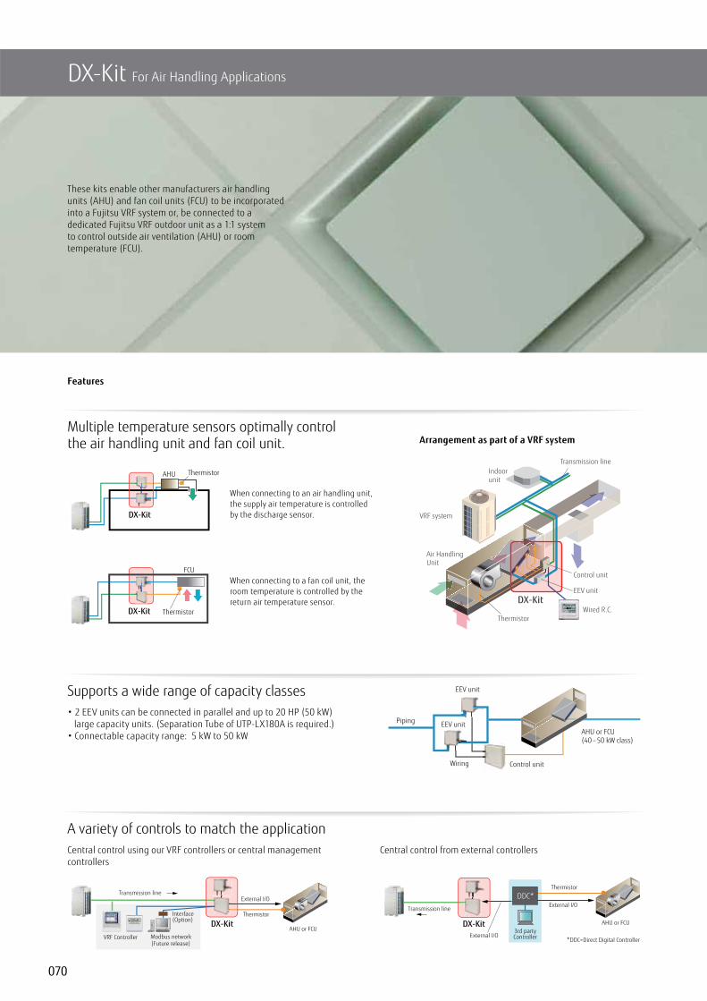
070
Features
These kits enable other manufacturers air handling units (AHU) and fan coil units (FCU) to be incorporated into a Fujitsu VRF system or, be connected to a dedicated Fujitsu VRF outdoor unit as a 1:1 system to control outside air ventilation (AHU) or room temperature (FCU).
DX-Kit For Air Handling Applications
Multiple temperature sensors optimally control the air handling unit and fan coil unit. Arrangement as part of a VRF system
Wired R.C.
VRF system
Indoorunit
EEV unit
Control unit
DX-Kit
Transmission line
Thermistor
Air HandlingUnit
AHU Thermistor
DX-Kit
ThermistorDX-Kit
FCU
When connecting to an air handling unit, the supply air temperature is controlled by the discharge sensor.
When connecting to a fan coil unit, the room temperature is controlled by the return air temperature sensor.
Supports a wide range of capacity classes• 2 EEV units can be connected in parallel and up to 20 HP (50 kW)
large capacity units. (Separation Tube of UTP-LX180A is required.)• Connectable capacity range: 5 kW to 50 kW
A variety of controls to match the applicationCentral control using our VRF controllers or central management controllers
AHU or FCU(40 – 50 kW class)
Control unit
EEV unit
EEV unit
Piping
Wiring
Thermistor
External I/OTransmission line
VRF Controller Modbus network
Interface(Option)
AHU or FCUDX-Kit
(Future release)
Central control from external controllers
External I/O
External I/O3rd partyController
Transmission line
AHU or FCU
Thermistor
DDC*
*DDC=Direct Digital Controller
DX-Kit

071
VEN
TILA
TION
Functions Summary
Inputs• ON/OFF• Setting temperature• Capacity demand• Heating / Cooling operation mode• Fault information
Outputs• ON/OFF indication• Fan ON/OFF indication• Thermo ON/OFF indication• Defrost indication• Fault indication
MODBUS® ControlPossible to control via a MODBUS enabled BMS by using optional interface.
For 2EEV units connection (option)Separation Tube: UTP-LX180A
Connectable capacity
Piping and wiring length
Installation Limitation• Connectable VRF series: J-IIS, J-II, V-II, VR-II
• Connectable DX-Kit system capacity range: 50 to 100% of the outdoor unit capacity
• Connectable DX-Kit system capacity range with indoor units: 30% or less of the outdoor unit capacity
• Max. wiring length from control unit: 10 m
• Max. piping length between EEV unit and indoor unit: 5 m
• Outdoor installation: Control unit (IP54 class) and EEV unit can be installed at an outdoor space.
Air Handling Unit
Within 30% of total capacity
50%–100% of outdoor unit capacity
50%–100% of outdoor unit capacity
Air Handling Unit
Air Handling Unit
Max. wiring length 10 m
Max. wiring length 15 m
Max. piping length 10 m
EEV unit
Control unit
Control unit: UTY-VDGXEEV unit: UTP-VX30A / UTP-VX60A / UTP-VX90A
EEV unitUTP-VX30A
EEV unitUTP-VX60A
EEV unitUTP-VX90A
Control unitUTY-VDGX
SpecificationsConnectable Capacity class 5.0 kW 6.3 kW 8.0 kW 10.0 kW 12.5 kW 14.0 kW 20.0 kW 25.0 kW 40.0 kW 50.0 kW
CapacityCooling
kW5.6 6.3 8.0 10.0 12.5 14.0 22.4 25.0 40.0 50.4
Heating 6.3 7.1 9.0 11.2 14.0 16.0 25.0 28.0 45.0 56.5
Control unit UTY-VDGX
Power source V/Ø/Hz 230/1/50Dimensions (H × W × D) mm 400 × 400 × 120List Price 750
EEV unit UTP-VX30A UTP-VX60A UTP-VX90A UTP-VX90A×2
Connection pipe diameter (Liquid)mm
3/8 1/2 1/2 1/2Dimensions (H × W × D) 160 × 220 × 90
Note: Specifications are based on the following conditions.Cooling: Indoor temperature of 27°CDB / 19°CWB, and outdoor temperature of 35°CDB / 24°CWB.Heating: Indoor temperature of 20°CDB / (15°CWB), and outdoor temperature of 7°CDB / 6°CWB.Pipe length: 7.5 m Voltage : 230 [V].

Notice for specificationsI.U.=Indoor Unit O.U.=Outdoor Unit Qu=Quiet *=Not decided yet• Specifications and design are subject to change without notice for future improvement.• For further details, please check with our authorised dealer.• Cooling / Heating capacities are based on the following conditions.
• Performance test is in accordance with EN14511• Seasonal efficiency test is on accordance with EN14825• Sound power test is in accordance with EN12102
Cooling Indoor temp.Outdoor temp.
: 27°C DB/19°C WB: 35°C DB/24°C WB Heating : 20°C DB
: 7°C DB/6°C WBIndoor temp.Outdoor temp.
• Actual products’ colors may be different from the colors shown in this printed material.
Copyright© 2008-2015 Fujitsu General Limited. All rights reserved.
• The products or equipments in this catalogue contain fluorinated greenhouse gases.• “ ” and “ ” are worldwide trademarks of FUJITSU GENERAL LIMITED and are registered trademarks in Japan and other countries or areas.
• “ ” is a worldwide trademark of FUJITSU GENERAL LIMITED.• iPhone and iPad are trademarks of Apple Inc., registered in the U.S. and other countries.• Other company and product names mentioned herein may be registered trademarks, trademarks or trade names of their respective owners.
“
Fujitsu General Central Air-conditioner (Wuxi) Co., Ltd.
ISO 9001Certified number: 15914Q10065R4M
ISO 14001Certified number: 15912E10022R3M
Fujitsu General (Shanghai) Co., Ltd.
ISO 9001Certified number: 01 100 79269
ISO 14001Certified number: CNBJ311153-UK
Fujitsu General (Thailand) Co., Ltd.
ISO 9001Certified number: 01 100 89394
ISO 14001Certified number: 01 104 9245/01
FUJITSU GENERAL AIR CONDITIONING (UK)Unit 150, Centennial Park, Centennial Avenue,Elstree, Borehamwood, Herts WD6 3SG
www.fujitsu-general.com/uk