Embed Size (px)
Citation preview

2016 Region V Collegiate Soil Judging Contest
Guidebook Host: University of Nebraska – Lincoln
October 9 – 14th, 2016 Lincoln, NE

The University of Nebraska-Lincoln is proud to host the 2016 Region V Soil Judging Competition in Lincoln, Nebraska October 9-14. Lincoln lies within the Central Lowlands physiographic province near the eastern border of the Great Plains. The soils formed here are predominantly developed in glacial sediments, bedrock, eolian materials (loess and eolian sand), colluvium, and alluvial deposits. Most of the land immediately surrounding Lincoln has been cleared of its native grassland vegetation for either row-crop agriculture or grazing purposes. The practice pits and contest sites were chosen to expose you to soils formed in these different depositional environments and land use patterns. We had significant help in putting this contest together. Mark Kuzila (Emeritus Professor, UNL) offered his expertise early in our decision making on the locations of practice and competition pits. Jacki Loomis (UNL) assisted with scheduling and identifying hotel and meeting rooms. We are most grateful for the assistance of USDA-NRCS staff for their support of the contest, and indebted to the federal, private, and state landowners who allowed us the generous use of their property for the practice pits and contest sites. We are hoping that your visit to Lincoln is enjoyable and that you benefit from the interactions with your colleagues, the experience of describing soils in a different setting, and the challenges of the competition. Paul R. Hanson Dan Shurtliff Associate Director and Associate Professor Assistant Nebraska State Soil Scientist School of Natural Resources Natural Resources Conservation Service University of Nebraska – Lincoln Lincoln, NE Lincoln, NE Ryan Ragsdale Neil Dominy Soil Conservationist Nebraska State Soil Scientist Natural Resources Conservation Service Natural Resources Conservation Service Syracuse, NE Lincoln, NE
PREFACE

Introduction ............................................................................................................................................... 1 Contest Rules, Scoring, and Procedures ................................................................................................... 2 Scorecard Instructions ............................................................................................................................... 4
A. Soil Morphology ..................................................................................................................... 5 A-1. Designations for Horizons and Layers ................................................................................ 5 A-2. Boundary .............................................................................................................................. 6 A-3. Texture and Rock Fragments ............................................................................................... 7 A-4. Color .................................................................................................................................... 9 A-5. Redoximorphic Features ...................................................................................................... 9 A-6. Structure ............................................................................................................................... 10 A-7. Moist Consistence ................................................................................................................ 13 A-8. Effervescence ....................................................................................................................... 13
B. Soil Hydrology and Profile Properties ................................................................................................ 14 B-1. Hydraulic Conductivity ........................................................................................................ 14 B-2. Depth to Root Restricting Layer .......................................................................................... 15 B-3. Water Retention Difference ................................................................................................. 16 B-4. Soil Wetness Class ............................................................................................................... 17
C. Site Characteristics .............................................................................................................................. 18 C-1. Landform.............................................................................................................................. 18 C-2. Parent Material ..................................................................................................................... 19 C-3. Slope .................................................................................................................................... 19 C-4. Hillslope Position ................................................................................................................. 20 C-5. Surface Runoff ..................................................................................................................... 21
D. Soil Classification ............................................................................................................................... 22 D-1. Epipedons ............................................................................................................................ 22 D-2. Diagnostic Subsurface Horizons and Characteristics .......................................................... 22 D-3. Order, Suborder, Great Group ............................................................................................. 22 D-4. Particle Size Control Section and Family Particle Size Class ............................................. 23
E. Soil Interpretations .............................................................................................................................. 24 E-1. Septic Tank Absorption Fields ............................................................................................. 24 E-2. Dwellings and Basements .................................................................................................... 25 E-3. Ecological Site Description .................................................................................................. 25
Abbreviations and USDA Soil Textural Triangle ..................................................................................... 27 Site Information and Rotation Procedures ................................................................................................ 28 References ................................................................................................................................................. 29 Appendix ................................................................................................................................................... 30 Scorecard ................................................................................................................................................... 33
TABLE OF CONTENTS

1
Soil judging provides an opportunity for students to study soils through direct experience in the field. Students learn to describe soil properties, identify different kinds of soils and associated landscape features, and interpret soil information for agriculture and other land uses. These skills are developed by studying a variety of soils formed from a wide range of parent materials and vegetation in different topographic settings. It is hoped that by learning about soils and their formation, students will gain an appreciation for soil as a natural resource. We all depend on soil for growing crops and livestock, building materials, replenishing water supplies, and waste disposal. It is increasingly clear that if we do not take care for our soils, loss of productivity and environmental degradation follow. By understanding more about soils and their management through activities like soil judging, we stand a better chance of conserving soil and other natural resources for future generations. Students in soil judging participate in regional and national contests held annually in different states. These contests are an enjoyable and valuable learning experience, giving students an opportunity to get a first-hand view of soils and land use outside their home areas. As an activity within the American Society of Agronomy, soil judging in the United States is divided into seven regions. Our Region V includes universities from the states of Iowa, Kansas, Minnesota, Missouri, Nebraska, North Dakota, and South Dakota. Collegiate soil judging originated in the southeastern United States in 1956 and began in the Midwest in 1958 with a contest hosted by Kansas State University. Today, over 40 universities are involved with soil judging through the American Society of Agronomy. This guidebook is organized into several sections that describe the format and content of the contest. The contest involves soil description and interpretation at sites by students, who record their observations on a scorecard. The content sections of this guidebook follow the organization of soil and related information given on the contest scorecard. Those sections include soil morphology, soil hydrology and profile properties, site characteristics (geomorphology), soil classification, and soil interpretations. This guidebook contains information related to the 2016 Region V Soil Judging Contest. Coaches are encouraged to consult other sources of information as well including the Soil Survey Manual (Soil Division Staff, 1993), Field Book for Describing and Sampling Soils v. 3.0, Keys to Soil Taxonomy 12th edition (Soil Survey Staff, 2014), Soil Taxonomy 2nd edition (Soil Survey Staff, 1999) and the Illustrated Guide to Soil Taxonomy (Soil Survey Staff, 2014). Other resources available for coaches to consult include web soil survey, official series descriptions, Google Earth, and traditional soil surveys for block diagrams and narratives. Contest region-specific sources of information are included in the References section. Many portions of the text in this guidebook have been adapted from previous Region V contest guidebooks and we recognize that contributions of those writers to this effort.
INTRODUCTION

2
Table 1. Contest Events and Schedule
Date/Time Activity Location Notes
Sunday, Oct. 9 6:30 PM
Welcome Dinner and Introduction to Area Soils, Geomorphology and Land-Use
Main Lobby of Hardin Hall East Campus, Lincoln, NE
Dinner Provided With Registration
Monday Oct. 10 – Wednesday Oct. 12
Practice Pits TBD Team Rotation Schedule will be provided
Wednesday, Oct. 12 6:00 PM
Team Dinner and Coaches Meeting
UNL East Campus Union, Lincoln, NE
Dinner Provided With Registration - Official Contestants Must Be Identified to Contest Organizers by 6:00 PM
Thursday, Oct. 13 7:00 AM - 7:00 PM
Contest Day TBD Lunch Provided With Registration
Friday, Oct. 14 8:00 AM
Awards Breakfast UNL East Campus Union, Lincoln, NE
Breakfast Provided With Registration
The contest will be held on Thursday October 13th, 2016 and will consist of five sites: two individual-judged sites in the morning and three team-judged sites in the afternoon. At each site, a pit will be excavated, and control area(s) will be designated for the measurement of horizon depths and boundaries. This area will constitute the officially scored profile and must remain undisturbed and unblocked by all team members. A tape measure will be fixed within the control area. The site number, number of horizons to be described, the profile depth to be described, and any additional information or laboratory data deemed necessary for correct classification will be shown on a card that corresponds to that pit. A maximum of six horizons will be described at each site. A marker will be placed at the base of the third horizon. A monitor at each site will enforce the rules, answer any questions, keep time limits, and clean the soil from the base of the pit as needed. A team usually consists of four contestants from each school, but can be as few as three. A limited number of alternates may participate in the judging of the contest sites, depending upon space availability. However, the coach must designate the four official contestants prior to the contest (by 6:00 PM Wednesday October 12th, 2016). The individual scorecards of the alternates will also be graded but not counted in the team score for the contest. Alternates are eligible for individual awards and can participate in the team judging. Each school will be allowed one team for the group judging. A list of abbreviations will be given to each contestant along with the scorecards just before the contest. The abbreviations appearing on this list or the corresponding, clearly written terminology will be graded as correct responses. Unofficial abbreviations or illegible responses will be scored incorrect.
CONTEST RULES, SCORING, AND PROCEDURES
3
Contestants provide the following materials for their own use: - clipboard - acid bottle (10% or 1M HCl) - calculator - clinometer or Abney level - water bottle - pencils (number 2 pencil is required)* - hand lens - Munsell Color Charts - knife - containers for soil samples - rock hammer - 2mm sieve - tape measure - hand towel
*A number 2 pencil is required because of the waterproof paper used for the official scorecards. This will be an “open book” contest; i.e., any relevant written materials (including this guidebook) will be allowed in the contest. A clinometer and color book will be at each pit for emergency situations as well as extra water, acid, and scorecards. Each site will have its own unique color-marked scorecard. Each individual contestant or team will be given a packet the morning of the contest that has color- marked scorecards corresponding to each site, plus a sheet of abbreviations. NOTE: all students’ cell phones must be turned off and left in a secured team area (van, etc.) during the contest! Sixty minutes will be allowed for judging each site. The time in and out of the pit for the individually-judged sites will be as follows: 5 minutes in, 5 minutes out, 10 minutes in, 10 minutes out, 5 minutes in, 5 minutes out, and 20 minutes open to finish. NOTE: This timing schedule may be modified depending on the number of teams and contestants participating. Each individual will have at least 60 minutes at each site. For the team judging, this timing may be modified (depending on the number of teams), but each team will have a minimum of 60 minutes at each site (including 30 minutes alone in the pit). The team score will be the aggregate of the top three individual scores at each individually-judged site plus the team-judged sites. The clay content of one horizon at one of the individually-judged sites will be used to break ties in team and individual scores. To break a tie in team scores, the mean clay content will be calculated from the estimates provided by all members of a given team. The team with the mean estimate closest to the actual value will receive the higher placing. If this does not break the tie, the next lowest horizon will be used in the same manner. The clay content of the tie breaker horizon will be compared to that estimated by the individual in order to break a tie between individuals. If this does not break the tie, the next lowest horizon will be used in the same manner. Results will be announced at a breakfast awards ceremony on Friday morning, October 14th, 2016. The results as announced will be final. Every effort will be made to avoid errors in determining the contest results. Trophies will be awarded to the top three teams in overall score, the top three teams in team judging, and the top five individuals. Placings in the overall team score will be used to determine the teams qualifying for the National Collegiate Soil Judging Contest. According to current rules, the top three (if 4-7 teams participate) or four (if 8-9 teams participate) teams from Region V will qualify for the 2017 National Contest.

4
The scorecard (attached at the end of this guidebook) consists of five parts:
A. Soil Morphology B. Soil Hydrology and Profile Properties C. Site Characteristics D. Soil Classification E. Site Interpretations
Numbers in parentheses after each item in a section indicate the points scored for one correct judgment. If a pedon has more than one parent material or diagnostic subsurface horizon, five points will be awarded for each correct answer. In these sections of the scorecard, negative credit (minus 5 points for each incorrect answer, with a minimum score of zero for any section) will be used to reduce guessing. More than one entry in other items of the scorecard will be considered incorrect and will result in no credit for that item. Official judges, in consultation with a quorum of coaches, have the prerogative of giving full or partial credit for alternative answers to fit a given site or condition (e.g., hydraulic conductivity where 3 points are given if the answer is close to the correct answer).
SCORECARD INSTRUCTIONS

5
For entering answers in the morphology section of the scorecard, the provided standard abbreviations may be used or the word(s) may be written out. Abbreviations or words that are ambiguous or may be interpreted as an incorrect answer will not receive credit. The Munsell color notation (e.g., 10YR 4/2) should be used and not the color names. If spaces on the scorecard for the soil morphology section do not require an answer (e.g., if no concentrations are present in a horizon), a dash or blank in those spaces will be considered correct. The Field Book for Describing and Sampling Soils (version 3.0, 2012), Chapter 3 of the Soil Survey Manual (1993) entitled, “Examination and Description of Soils”, and Chapter 18 of Keys to Soil Taxonomy 12th Edition (2014) entitled “Designations for Horizons and Layers” should be used as a guide for horizon symbols and descriptions.
A-1. DESIGNATIONS FOR HORIZONS AND LAYERS
The number of horizons to be described and the total depth of soil to judge will be provided on an information card at each site. Narrow transition horizons (< 8 cm thick) should be regarded as a gradual boundary and the center used as the measuring point for the boundary depth. Horizons that can be thinner than 8 cm and should be described are O, A or E. These horizons must be at least 2 cm thick to be described. Three kinds of symbols are used in various combinations to designate horizons and layers in Section A of the contest scorecard: capital letters, lower case letters, and Arabic numerals. Capital letters are used to designate master horizons (or in some cases, transition horizons). Lower case letters are used as suffixes to indicate specific characteristics of the master horizon and layers. Arabic numerals are used both as suffixes to indicate vertical subdivisions within a horizon or layer and as prefixes to indicate lithologic discontinuities. Prefix: Lithologic discontinuities will be shown by the appropriate Arabic numeral. A dash or a blank will receive credit where there is no prefix on the master horizon. Master: The appropriate master horizon (A, E, B, C, R), as well as any transitional horizons (e.g., BC) or combination horizons having dual properties of two master horizons (e.g., B/E), should be entered as needed. Organic (O) horizons are made up of organic soil materials, but will not be described in this contest. The presence of an O horizon may influence surface runoff rates. Horizon Suffixes: Enter the appropriate lower case letter or letters. For this contest you should be familiar with the following letter suffixes: b, g, k, n, p, r, ss, t, w, and z. If used in combination, the suffixes must be written in the correct sequence in order to receive full credit. A “B” horizon must always have a suitable suffix. Horizon suffixes may be used with transitional horizons if appropriate. If a horizon suffix is not applicable, enter a dash or leave the space blank.
A. SOIL MORPHOLOGY
6
Number: Arabic numerals are used as suffixes to indicate vertical subdivisions within a horizon or layer. Sequential subhorizons having the same master horizon and suffix letter designations should be numbered to indicate a vertical sequence. For other horizons, enter a dash or leave the space blank. Primes: Although unlikely to be needed in this area, it may be appropriate to give the same designation to two or more horizons in a pedon if the horizons are separated by a horizon of a different kind. The prime is used on the lower of the two horizons having identical letter designations and should be entered with the capital letter for the master horizon.
A-2. BOUNDARY
A-2-1. Depth of Lower Boundary
Record the depth of the lower boundary for each horizon to the nearest centimeter (if an O horizon is present, start measurement at the base of the O horizon). For the last horizon depth, a dash or a blank (or the lower depth of the thickness of the profile to be described) is acceptable. Measurements of horizon depth should be made in the undisturbed area of the pit reserved for this purpose. This area will be clearly marked. Depth measurements should be made using the tape measure that is anchored to the pit face within the control area, even if the boundary is not parallel with the surface. Boundary measurements should be made at the center of the boundary separating the two horizons, especially when the distinctness of the boundary is not abrupt. Answers will be considered correct for depth measurements of boundaries if they are within the following limits above or below the depth determined by the official judges: for abrupt (includes very abrupt) boundaries +1 cm; for clear boundaries + 2 cm; for gradual boundaries + 4 cm; and for diffuse boundaries + 8 cm. Partial credit for depth measurements may be given at the discretion of the official judges where the boundary is not smooth. Thin transitional horizons less than 8 cm thick will be regarded as a gradual boundary, with the center used as the measuring point. A and E horizons thinner than 8 cm should be described if they are at least 2 cm thick. If a lithic or paralithic contact occurs at or above the specific judging depth, the contact should be marked as a subsurface characteristic in Part D of the scorecard and should be considered in evaluating the hydraulic conductivity, water retention difference, and effective soil depth. Otherwise, the lowest horizon (if not exposed to 150 cm) should be mentally extended to a depth of 150 cm for making all relevant evaluations. If a lithic or paralithic contact occurs within the specified judging depth, the contact should be considered as one of the requested horizons, and the appropriate horizon nomenclature should be applied (i.e., Cr or R). However, morphological features of Cr or R horizons need not be provided in Part A of the scorecard. If the contestant gives morphological features for a Cr or R horizon, it will be ignored by the graders and will not count against the contestant’s score.
A-2-2. Distinctness of Boundary
The distinctness of boundaries separating various horizons must be described if they fall within the designated profile depth indicated by the judges for each site. Categories of distinctness of boundaries include: abrupt

7
(includes very abrupt), less than 2 cm; clear, 2 to 5 cm; gradual, 5 to 15 cm; and diffuse, more than 15 cm. There will be no distinctness category given for the last horizon unless there is a lithic or paralithic contact at the lower boundary for the last horizon. Otherwise, a dash or a blank is acceptable for distinctness of the last horizon to be described.
A-3. TEXTURE
Texture refers to the proportion of sand, silt, and clay-sized particles in soil. These proportions are expressed on a percentage basis, with sand, silt, and clay always adding up to 100%. Textural classes, shown in the USDA texture triangle (see Appendix), group soil textures that behave and manage similarly.
A-3-1. Texture Classes Soil texture classes are those defined in the Soil Survey Manual (1993). Any deviation from the standard nomenclature will be considered incorrect (e.g., silty loam). Sandy loam, loamy sand, and sand should be further specified (see textures and abbreviations listed below) if the soil is dominated by a particular size of sand other than medium sand. Include very coarse sand with coarse sand. Table 2. Textural Classes and Abbreviations
Texture Symbol Texture Symbol
Coarse sand COS Sandy Loam SL
Sand S Loam L
Fine Sand FS Sandy Clay Loam SCL
Very Fine Sand VFS Silt Loam SIL
Loamy Coarse Sand LCOS Silt SI
Loamy Sand LS Silty Clay Loam SICL
Loamy Fine Sand LFS Clay Loam CL
Loamy Very Fine Sand LVFS Sandy Clay SC
Coarse Sandy Loam COSL Silty Clay SIC
Fine Sandy Loam FSL Clay C
Very Fine Sandy Loam VFSL
Contestants will determine soil texture classes by hand. The official judges will use field estimates along with laboratory data on selected samples to determine the soil texture class.

8
A-3-2. Percentage of Clay Clay percentage estimates should be entered in the space provided. Answers within ± 4% of the official value will be given credit.
A-3-3. Rock Fragment Modifier Modifications of texture classes are required whenever rock fragments > 2 mm occupy more than 15% of the soil volume. For this contest, assume that all rock fragments do not slake in water and are strongly cemented. The modifiers and adjectives used to describe rock fragments denote quantity, shape, and size characteristics. The “quantity” modifier (e.g., very) is based on the total rock fragment content. The “shape” modifier distinguishes flat rock fragments from other shapes. The “size” modifier (e.g., cobble) is based on the largest, dominant fragment size. For a mixture of sizes (e.g., gravel and stones), the smaller size must exceed two times the amount of the larger size to be named (e.g., 30% gravel and 14% stones = very gravelly, 20% gravel and 14% stones = stony) (Schoeneberger et al., 2012). Table 3. Rock fragment modifier size and shape requirements and symbols
Size (Diameter) Adjective Symbol
Rounded, Subrounded, Angular, Irregular
0.2 cm - 7.5 cm 7.6 cm - 25.0 cm 25.1 cm - 60.0 cm > 60.0 cm
Gravel Cobbly Stony Bouldery
GR CB ST BD
Flat
0.2 cm - 15 cm 15.1 cm - 38.0 cm 38.0 cm - 60 cm > 60 cm
Channery Flaggy Stony Bouldery
CH FL ST BD

9
Table 4. Modifiers by percent rock fragment (> 2 mm) present by volume
Percent Rock by Volume
Rock Fragment Modifier
< 15% No special term used with the soil texture class. Enter a dash or leave blank.
15 - 35% Use “gravelly”, “cobbly”, “stony”, “bouldery”, “channery” or “flaggy” as a modifier of the texture term (e.g. gravelly loam or GR-L)
35 - 60% Use “very (V) + size adjective” as a modifier of the texture term (e.g. very cobble fine sandy loam or CBV-FSL).
60 - 90% Use “extremely (X) + size adjective” as a modifier of the texture term (e.g.. extremely stony clay loam or STX-CL)
> 90% Use “coarse fragment noun” as the coarse fragment term (e.g. boulders or BD) and dash or leave blank the soil texture class and the % clay boxes.
A-4. COLOR
Munsell soil color charts are used to determine the moist soil matrix color for each horizon described. Color must be designated by hue, value, and chroma. Space is provided to enter the hue, value, and chroma for each horizon separately on the scorecard. At the discretion of the official judges, more than one color may be given full credit. Color is to be judged for each horizon by selecting soil material to represent that horizon. The color of the surface horizon will be determined on a moist, rubbed sample. For lower horizons (in some soils this may also include the lower portion of the epipedon) selected peds should be collected from near the central part of the horizon and broken to expose the matrix. If peds are dry, they should be moistened before the matrix color is determined. Moist color is that color when there is no further change in soil color when additional water is added. For Bt horizons with continuous clay films, care should be taken to ensure that the color of a ped interior rather than a clay film is described for the matrix color.
A-5. REDOXIMORPHIC FEATURES
Redoximorphic (redox, RMF) features are caused by the reduction and oxidation of iron and manganese associated with soil wetness/dryness and not rock color. Characteristic color patterns are created by these processes. Redox features are colors in soils resulting from the concentration (gain) or depletion (loss) of pigment when compared to the soil matrix color. Reduced iron (Fe2+) and manganese (Mn2+) ions may be removed from a soil if vertical or lateral fluxes of water occur. Wherever iron and manganese is oxidized and precipitated, they form either soft masses or hard concretions and nodules. Redox features are used for identifying aquic conditions and determining soil wetness class. For this contest only the presence or absence of redoximorphic features (Y or N) in terms of redox concentrations, redox depletions, and reduced matrix will be evaluated. Movement of iron and manganese as a result of redox processes in a soil may result in redoximorphic features that are defined as follows:

10
Redox Concentrations – These are zones of apparent pedogenic accumulation of Fe-Mn oxides, and include: nodules and concretions (firm, irregular shaped bodies with diffuse to sharp boundaries; masses (soft bodies of variable shapes in the soil matrix; zones of high chroma color (“red/orange” for Fe and “black”/purple for Mn); and pore linings (zones of accumulation along pores). Dominant processes involved are chemical dissolution and precipitation; oxidation and reduction; and physical and/or biological removal, transport and accrual.
Presence: Yes (Y) RMF concentrations are present No (N) RMF concentrations are not present
Redox Depletions – These are zones of low chroma (2 or less) and normally high value (4 or more) where either Fe-Mn oxides alone or Fe-Mn oxides and clays have been removed by illuviation.
Presence: Yes (Y) RMF depletions are present No (N) RMF depletions are not present
Reduced Matrix – This is a soil matrix that has low chroma (2 or less) and the color value is usually 4 or more. Reduced matrix would be used when a horizon has a “g” subordinate distinction (subhorizon) designation. This feature is not included separately on the scorecard, but if a reduced matrix is identified for a horizon, redox depletions should also be marked. The color of the redox feature must differ from that of the soil matrix by at least one color chip in order to be described. For determination of a seasonal high water table, depletions of chroma 2 or less and value of 4 or more must be present. If this color requirement is not met, the depletions should be described, but the depletions do not affect the soil wetness class or site interpretations. Low chroma (≤ 2) in the soil may be due to drainage, parent material, or other features. However, parent material variations and other such features should not be considered in evaluating soil wetness or soil drainage characteristics. Colors associated with the following mottled features will not be considered as redox features: carbonates, krotovina, rock colors (lithochromic colors), roots, or mechanical mixtures of horizons such as B horizon materials in an Ap horizon.
A-6. STRUCTURE
Soil structure refers to the aggregation of primary soil particles into secondary compound groups or clusters of particles. These units are separated by natural planes, zones, or surfaces of weakness. Dominant type (formerly called shape) and grade of structure for each horizon are to be judged. If the horizon lacks definite structural arrangements or if there is no observable aggregation, “structureless” should be recorded in the grade column and either “massive” or “single grain” (whichever is appropriate) should be recorded in the type column. If various types of structure exist within the horizon, contestants should record the type and grade of structure that is most dominant. Compound structure (e.g., prismatic parting to angular or subangular blocky structure) is common in some soils. In this case, structure having the stronger grade should be described. If the structures are of equal grade, the structure type with the largest peds should be described. The term "blocky" always requires a modifier, either angular or subangular blocky. Blocky will not receive full credit if used alone.

11
A-6-1. Grade
The grade of structure is determined by the distinctness of the aggregates and their durability. Expression of structure grade is often moisture dependent and so may change with drying of the soil. Table 5. Structural Grades
Type Code Description
Structureless 0 The condition in which there is no observable aggregation or no definite, orderly arrangement of natural lines of weakness.
Weak 1 The soil breaks into very few poorly formed, indistinct peds, most of which are destroyed in the process of removal. The shape of structure is barely observable in place.
Moderate 2 The soil contains well-formed, distinct peds in the disturbed soil when removed by hand. They are moderately durable with little unaggregated material. The shape of structure observed in the undisturbed pit face may be indistinct.
Strong 3
Durable peds are very evident in undisturbed soil of the pit face with very little or no unaggregated material when peds are removed from the soil. The peds adhere weakly to one another, are rigid upon displacement, and become separated when the soil is disturbed.

12
A-6-2. Type
Types of soil structure are described below from the Field Book for Describing and Sampling Soils, version 3.0, 2012. Table 6. Structural Types
Type Abbreviation Description
Granular GR
Spheroids or polyhedrons bound by curved planes or very irregular surfaces which have slight or no accommodation to the faces of surrounding peds. The aggregates may or may not be highly porous.
Platy PL Plate-like with the horizontal dimension significantly greater than the vertical dimension. Plates are approximately parallel to the soil surface.
Subangular Blocky
SBK
Polyhedron-like structural units that are approximately the same size in all dimensions. Peds have mixed rounded and flattened faces with many rounded vertices. These structural units are casts of the molds formed by the faces of the surrounding peds
Angular Blocky
ABK Similar to subangular blocky but block-like units have flattened faces and many sharply angular vertices.
Prismatic PR
Prism-like with the two horizontal dimensions considerably less than the vertical. Vertical faces are well defined and arranged around a vertical line with angular vertices. The structural units have angular tops or caps.
Columnar COL Same as prismatic but with rounded tops or caps.
Wedge WEG Elliptical, interlocking lenses that terminate in acute angles, bounded by slickensides. Characteristic in Vertisols but may be present in other soils.
Massive MA No structure is apparent, and the material is coherent.
Single-Grained
SGR No structure is apparent, and soil fragments and single mineral grains do not cohere (e.g., loose sand).

13
A-7. MOIST CONSISTENCE
Soil consistence refers to the resistance of the soil to deformation or rupture at a specified moisture level and is a measure of internal soil strength. Consistence is largely a function of soil moisture, texture, structure, organic matter content, and type of clay, as well as adsorbed cations. Moist consistence is determined on a ped or soil fragment using the criteria in the following table: Table 7. Moist Consistence
Type Abbreviation Description
Loose LO Soil is non-coherent (e.g., loose sand).
Very Friable VFR Soil crushes very easily under gentle pressure between thumb and finger but is coherent when pressed.
Friable FR Soil crushes easily under gentle to moderate pressure between thumb and forefinger and is coherent when pressed.
Firm FI Soil crushes under moderate pressure between thumb and forefinger, but resistance to crushing is distinctly noticeable.
Very Firm VFI Soil crushes or breaks only when strong force is applied between thumb and forefinger.
Extremely Firm EFI
Soil cannot be crushed or broken between thumb and forefinger but can be by squeezing slowly between hands. “Rigid” consistence will be included in this category.
A-8. EFFERVESCENCE
Calcium carbonate is an important constituent of some parent materials and soils in Nebraska. Some
primary loess and glacial till in Nebraska are calcareous, and carbonate bedrock (limestone and dolomite) is
locally common. During weathering and soil formation in Nebraska’s subhumid climate, carbonates have
been translocated and leached by percolating water.
Carbonates may be visible as whitish material in the field or they may be disseminated and not visible.
Dilute hydrochloric acid (10% or 1M HCl) is used to test for carbonates in the field. Calcium carbonate
effervesces when treated with the HCl. To avoid problems with variability, presence or absence of
carbonate as judged by visible effervescence will be determined, rather than classes of effervescence as
given in the Soil Survey Manual. Team members should have their own acid bottles for this determination. Presence: Yes (Y) – Effervescence in any degree Absence: No (N, -, or blank) – No effervescence

14
B-1. HYDRAULIC CONDUCTIVITY
In this contest, the vertical, saturated hydraulic conductivity of the surface horizon (Hydraulic Conductivity/Surface) and the most limiting horizon (Hydraulic Conductivity/Limiting) within the depth specified to be described by the official judges will be estimated. “Limiting layer” refers to the horizon or layer with the slowest hydraulic conductivity. If lithic or paralithic contact occurs at or above the specified judging depth, the hydraulic conductivity for the limiting layer is very low. Although unlikely, it is possible for the surface horizon to be the limiting horizon with respect to saturated hydraulic conductivity. In this case, the surface conductivity would be reported in two places on the scorecard. For a discussion of factors affecting hydraulic conductivity, refer to the Soil Survey Manual (Soil Survey Staff, 1993). (NOTE: Please see how the official judges handle restrictive layers at the practice sites.) Rock fragments will usually increase the saturated hydraulic conductivity. Due to the difficulty in measuring and estimating hydraulic conductivity of the surface and the limiting layer, the contest scoring will be 5 points for the correct response and 3 points if the adjacent category (higher or lower) is selected. The classes to be used are: Table 8. Hydraulic Conductivity Classes
Class Hydraulic
Conductivity Description
Very High > 100 µm/s
(> 36.0 cm/hr)
Usually includes textures of coarse sand, sand, and loamy coarse sand. It also includes textures of loamy sand and sandy loam if they are especially "loose" because of high organic matter content. Horizons containing large quantities of rock fragments with insufficient fines to fill many voids between the fragments are also in this class.
High 10 to 100 µm/s
(3.7 to 36.0 cm/hr)
Usually includes textures of fine sand, very fine sand, loamy sand, loamy fine sand, loamy very fine sand, coarse sandy loam, sandy loam, and fine sandy loam.
Moderately High
1 to 10 µm/s (0.36 to 3.6 cm/hr)
Includes textures of very fine sandy loam, sandy clay loam, loam, silt loam, and silt.
Moderately Low 0.1 to 1 µm/s
(0.36 to 3.6 cm/hr)
Includes textures of sandy clay, clay loam, silty clay loam. It also includes a texture of silt loam if it has a low organic matter content and a high clay content.
Low 0.01 to 0.1 µm/s
(0.0036 to 0.036 cm/hr)
Usually includes textures of clay and silty clay that have moderate structure and a moderate organic matter content as well as low to moderate shrink-swell potential (mixed or kaolinitic mineralogy).
B. SOIL HYDROLOGY AND PROFILE PROPERTIES

15
Class Hydraulic
Conductivity Description
Very Low < 0.01 µm/s
(< 0.0036 cm/hr)
Usually includes textures of clay and silty clay with a low organic matter content and weak or massive structure or clay or silty clay textures with moderate to high shrink-swell potential (montmorillonitic mineralogy). Mark very low on the scorecard if a lithic or paralithic contact occurs at or above the specified judging depth.
B-2. DEPTH TO ROOT RESTRICTING LAYER
The depth of soil to a restrictive layer, or effective soil depth, is the depth of soil that can be easily penetrated by plant roots. The depth to a restrictive layer is measured from the mineral soil surface. If that depth falls on the boundary between two classes, use the deeper class on the scorecard. Besides its direct importance for plant growth, this property also relates to key factors such as water relationships and nutrient supplying capacity. Materials considered restrictive to plant roots include: dense till, layers of coarse sand or gravel, cemented horizons and fragipans, bedrock, and other materials with very low permeability. It should be noted that the presence or absence of roots may be helpful in determining effective rooting depth, but is not always a reliable indicator. In many cases, the plants growing at the site may be shallow rooted or, conversely, a few roots may actually penetrate into or through the restrictive layer, especially along fractures or planes of weakness. The classes to be used are: Table 9. Effective Rooting Depth Classes
Depth Class Depth to Restricting Layer
Very Deep > 150 cm
Deep 100-150 cm
Moderately Deep 50-100 cm
Shallow 25-50 cm
Very Shallow < 25cm

16
B-3. WATER RETENTION DIFFERENCE
Water retention difference (WRD) refers to the soil water held between 0.033 MPa (field capacity) and 1.5 MPa tension (permanent wilting point), which approximates the range of available water for plants. The amount of available water stored in the soil is calculated for the top 150 cm of soil or to a root-limiting layer, whichever is shallower. Total WRD is calculated by summing the amount of water held in each horizon or portion of a horizon if it extends below 150 cm. If a horizon or layer is restrictive to roots (see previous discussion on restrictive layers), this and all horizons below should be excluded from WRD calculations. If the depth that is designated for describing soil morphology is less than 150 cm, you may assume that the water retention properties of the last horizon extend to 150 cm or to the top of a lithic or paralithic contact if either of these is observed at a depth shallower than 150 cm. The relationship between water retained per centimeter of soil and the various textures is given in the following table. Rock fragments are assumed to hold no water that is available for plant use. Therefore, if a soil contains rock fragments, the volume occupied by the rock fragments must be estimated, and the water retention difference corrected accordingly. For example, if a silt loam A horizon is 25 cm thick and contains coarse fragments which occupy 10% of this volume, the available water-holding capacity of that horizon would be 4.5 cm of water rather than 5.0 cm. We will use the following general relationships between texture and water retention difference: Table 10. Texture and Water Retention Difference Relationships
Texture Class or Material Type cm water/cm soil
All sands, loamy coarse sand 0.05
Loamy sand, loamy fine sand, loamy very fine sand, coarse sandy loam 0.10
Sandy loam, fine sandy loam, sandy clay loam, sandy clay, silty clay, clay 0.15
Very fine sandy loam, loam, silt loam, silt, silty clay loam, clay loam 0.20
Table 11. Water Retention Difference Classes
Water Retention Difference Class cm of available water
Very Low < 7.5 cm of available water
Low 7.5 to 14.9 cm of available water
Medium 15.0 to 22.5 cm of available water
High > 22.5 cm of available water
17
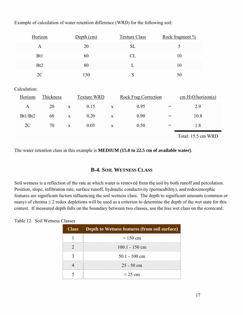
Example of calculation of water retention difference (WRD) for the following soil:
Horizon Depth (cm) Texture Class Rock fragment %
A 20 SL 5
Bt1 60 CL 10
Bt2 80 L 10
2C 150 S 50
Calculation:
Horizon Thickness Texture WRD Rock Frag Correction cm H2O/horizon(s)
A 20 x 0.15 x 0.95 = 2.9
Bt1/Bt2 60 x 0.20 x 0.90 = 10.8
2C 70 x 0.05 x 0.50 = 1.8
Total: 15.5 cm WRD
The water retention class in this example is MEDIUM (15.0 to 22.5 cm of available water).
B-4. SOIL WETNESS CLASS
Soil wetness is a reflection of the rate at which water is removed from the soil by both runoff and percolation. Position, slope, infiltration rate, surface runoff, hydraulic conductivity (permeability), and redoximorphic features are significant factors influencing the soil wetness class. The depth to significant amounts (common or many) of chroma ≤ 2 redox depletions will be used as a criterion to determine the depth of the wet state for this contest. If measured depth falls on the boundary between two classes, use the less wet class on the scorecard. Table 12. Soil Wetness Classes
Class Depth to Wetness features (from soil surface)
1 > 150 cm
2 100.1 - 150 cm
3 50.1 - 100 cm
4 25 - 50 cm
5 < 25 cm

18
C-1. LANDFORM
A landform is a physical, recognizable form or feature of the Earth’s surface that usually has a characteristic shape and is produced by natural causes. Parent materials are commonly associated with particular landforms. The landforms recognized for the soil judging contest in this region of Nebraska are: Upland: Upland refers to geomorphic landforms, not otherwise designated, that are generally above present-day valleys and which may be underlain by bedrock or sediments of glacial, eolian, or colluvial/pedisediment materials. Upland Depression: A closed basin within an upland that is not directly connected to an integrated surface drainage system. Surface accumulations of organic-enriched soil and redoximorphic features are commonly found in these areas, but are not necessary for identification. Stream Terrace: A step-like surface or platform along a stream valley that represents a remnant of an abandoned floodplain. Where occurring in valley floors, this landform is commonly smooth, having low relief, and may or may not be dissected by an under-fitted stream. It consists of a relatively level surface, cut or built by a stream and a steeper descending slope (scarp or riser). Floodplain: A nearly level alluvial plain that borders a stream and is subject to flooding unless artificially protected. The floodplain refers to the lowest level or levels associated with a stream valley and is sometimes referred to as bottom soil, stream bottom, or first bottom. Sediments may or may not be stratified. Soils found in a floodplain position normally have little profile development beneath the A horizon other than a structure or color horizon. If coarse fragments are present, they are normally rounded or subrounded. Footslope: A landform located at the base of a hillslope where the deposition of colluvium/pedisediment occurs. The surface is usually concave in profile.
C. SITE CHARACTERISTICS

19
C-2. PARENT MATERIAL
Parent material refers to the material in which soils form. Parent materials include bedrock, various kinds of unconsolidated sediments, and "pre-weathered" materials. Organic parent materials will not be considered in this contest. Soils may be developed in more than one parent material and this should be indicated on the scorecard. For this contest, a parent material should be > 8 cm thick to be indicated on the scorecard. A different parent material should also be indicated if it is present in the last horizon of the described profile. The parent materials recognized for the soil judging contest in this region of Nebraska are: Alluvium/Glacial Outwash: Alluvium includes material transported by water and deposited on active floodplains, stream terraces and alluvial fans. Stratification may or may not be evident. Glacial outwash, a type of alluvium, generally consists of coarse-textured sediments that have been sorted and deposited by streams flowing from melting glaciers. Outwash typically consists of stratified sands and gravels that occur in the form of valley fills (valley trains and or outwash terraces) or as widespread outwash plains. Colluvium/Local Alluvium: Colluvium consists of sediment that has accumulated on hillslopes, near the base of slopes (e.g., footlsopes), in depressions or along small upland intermittent streams. Colluvium is unconsolidated material transported or moved by gravity and by local, unconcentrated runoff that accumulates on and near the base of slopes. The sediment is typically poorly sorted mixture of particle sizes. Rock fragments of local origin are often angular in shape. Glacial Till: Glacial till, or simply till, is sediment deposited directly by glaciers, with little or no transport by water. It is generally an unsorted, unstratified, and unconsolidated mixture of clay, silt, sand, gravel, and larger coarse fragments. Residuum: Materials weathered in place from bedrock. Loess: Loess consists of fine-textured, wind-deposited sediment that is dominantly of silt size (or in some cases very fine sands). Loess may contain significant amounts of clay, depending on the distance from the loess source. Eolian Sand: Eolian sand consists of well sorted sandy sediments deposited by wind.
C-3. SLOPE
Slope refers to the inclination of the surface of the soil area. It has length, shape, and gradient. Gradient is usually expressed in percent slope and is the difference in elevation, in feet, for each one hundred feet of horizontal distance. Slope may be measured by an Abney Level or by a clinometer. Slope classes are based on the gradient. The percentage limits for slope classes are indicated on the scorecard. Stakes or markers will be provided at each site for determining slope, and the slope should be measured between these two markers. If the slope measurement falls on the boundary between two slope classes, use the steeper class on the scorecard.

20
C-4. HILLSLOPE POSITION
The slope positions given below and shown in the diagram (from Ruhe, 1969) represent geomorphic segments of the topography in which the soil is located. These slope components have characteristic geometries and greatly influence soils through differences in slope stability, water movement, and other slope processes. Slope positions at the contest site should be determined by the dominant position between the slope markers. Summit: The highest level of an upland landform with a relatively gentle slope. It is often the most stable part of a landscape. If the site is on a summit and has a slope < 2%, the summit should be selected on the scorecard. Shoulder: The rounded (convex-up) hillslope component below the summit. It is the transitional zone from the summit to the backslope and is erosional in origin. Backslope: The steepest slope position that forms the principal segment of many hillslopes. It is commonly linear along the slope and is also erosional in origin. It is located between the shoulder and footslope positions. Footslope: The slope position at the base of a hillslope that is commonly rounded, concave-up along the slope. It is transitional between the erosional backslope and depositional toeslope. Accumulation of sediments often occurs at this slope position. If the site is on a footslope and has a slope of < 2%, the footslope should be selected on the scorecard. None: This designation will be used when slope at the site is < 2% and the site is not in a well-defined example of one of the slope positions given above. This includes toeslope positions, or broad nearly level upland plains, stream terraces, or floodplains.

21
C-5. SURFACE RUNOFF
Surface runoff refers to the relative rate at which water is removed by flow over the ground surface. The rate and amount of runoff are determined by soil characteristics, management practices, climatic factors (e.g., rainfall intensity), vegetative cover, and topography. For this contest, we will use the six runoff classes described in the Soil Survey Manual (Soil Survey Division Staff, 1993). The following table, which illustrates the relationship between soils with various slopes and surface hydraulic conductivity (infiltration), will be used to determine the surface runoff class. The amount of vegetative cover should also be considered. Where there is good vegetative cover or an O horizon at the surface, use the next lower surface runoff class. Vegetative cover should be judged between the slope stakes. Students should mark “Negligible” for sites in topographic depressions with no surface runoff (i.e., sites subject to ponding). Table 13. Surface Runoff Classes
Slope Gradient
Saturated Hydraulic Conductivity Class
Very High High Moderately
HighModerately
LowLow Very Low
< 2% Negligible Negligible Negligible Low Moderate High
2 - 5% Negligible Very Low Low Moderate High Very High
5 - 9% Very Low Low Moderate High Very High Very High
9 - 18% Very Low Low Moderate High Very High Very High
> 18% Low Moderate High Very High Very High Very High

22
D-1. EPIPEDONS
The kind of epipedon will be determined. Where necessary for distinguishing between epipedons, laboratory data will be supplied. Possible epipedons include: Anthropic, Mollic, and Ochric.
D-2. DIAGNOSTIC SUBSURFACE HORIZONS AND FEATURES
Indicate all diagnostic subsurface horizons and characteristics that are present. More than one may be present. If none is present, mark “none” for full credit. Remember that negative credit will be given for incorrect answers to discourage guessing (although a total score for one answer will never be less than zero). Possible diagnostic horizons or features include: Albic, Argillic, Calcic, Cambic, Lamellae, Lithic Contact, Lithologic Discontinuity, or None. Where needed, laboratory data will be supplied for determining the diagnostic feature.
D-3. ORDER, SUBORDER, GREAT GROUP
Classify the soil in the appropriate order, suborder, and great group according to Keys to Soil Taxonomy (12th Edition, 2014). Table 14. Potential Great Groups
Order Suborder Great Group
Vertisol Aquert Endoaquert
Udert Hapludert
Mollisol Alboll Argialboll
Aquoll Argiaquoll
Calciaquoll
Epiaquoll
Endoaquoll
Udoll Paleudoll
Argiudoll
Hapludoll
Alfisol Aqualf Albaqualf
Epiaqualf
Endoaqualf
D. SOIL CLASSIFICATION

23
Order Suborder Great Group
Udalf Paleudalf
Hapludalf
Inceptisol Aquept Epiaquept
Endoaquept
Halaquept
Udept Eutrudept
Entisol Aquent Psammaquent
Fluvaquent
Endoaquent
Psamment Udipsamment
Fluvent Udifluvent
Orthent Udorthent
D-4. PARTICLE SIZE CONTROL SECTION AND FAMILY PARTICLE SIZE CLASS
Determine the family particle-size class control section for the soil; calculate the weighted percentage sand, silt, clay, and, if needed, rock fragment content in the control section; and determine the family particle-size class. For soils with contrasting particle-size classes, just mark that this is the case on the scorecard without specifying the class.

24
This section illustrates applications of soil information to land use and ecological site suitability. The criteria given in the tables were modified and adapted from those given in either the National Soils Handbook or the MLRA 106 Ecological Site Quick Reference Guide. Soil interpretations involve the determination of the degree of limitation within each soil for a specified use. The most restrictive soil property determines the limitation rating. In cases where the base of the pit does not extend to the depth indicated in the following tables (i.e. 180 cm for some criteria), assume that the lowest horizon in the pit extends to the depth of interest.
E-1. SEPTIC TANK ABSORPTION FIELDS
The following table is used for evaluating limitations for septic tank absorption fields. The soil between the depths of 60 cm and 180 cm should be considered in making septic tank ratings. If the profile is not visible to 180 cm, assume the last visible horizon continues to 180 cm. Table 15. Septic Tank Absorption Fields
Criteria Limitations
Slight Moderate Severe
Hydraulic Conductivity of the most limiting layer (60 – 180 cm)
Moderate --- High or Low
Wetness Class 1 2 3, 4, 5
Average Rocks > 7.5 cm diameter (60 – 180 cm)
< 15% 15 – 35% > 35%
Depth to Bedrock > 180 cm 100 – 180 cm < 100 cm
Slope < 9% 9 – 14% > 14%
Flooding/Ponding None --- Rare, Occasional,
Frequently
E. SOIL INTERPRETATIONS

25
E-2. DWELLINGS WITHOUT BASEMENTS
The following table is used for evaluating soil limitations for dwellings without basements. The soil between the depths of 25 cm and 100 cm should be considered for dwellings without basements. Table 17. Dwellings without Basements
Criteria Limitations
Slight Moderate Severe
Texture of the most limiting horizon (25 – 100 cm)
S, LS, SL L, SCL SI, SIL, SICL, SIC, CL, SC, C
Average Rocks > 7.5 cm diameter (60 – 180 cm)
< 15% 15 – 35% > 35%
Wetness Class 1, 2 3 4, 5
Depth to Hard Bedrock (R) > 100 cm 50 – 100 cm < 50 cm
Depth to Soft Bedrock (Cr) > 50 cm < 50 cm ---
Slope < 9% 9 – 14% > 14%
Flooding/Ponding None Rare Occasional or
More
E-3. Ecological Site Description
The following flow chart is to be used for classifying and describing a region’s soil for evaluating land suitability to be used for managing ecological sites. The chart was adapted from the MLRA 106 Ecological Site Quick Reference Guide website (https://efotg.sc.egov.usda.gov/references/public/NE/MLRA_106_ECOLOGICAL_SITE_QUICK_REFERENCE.pdf).

26

27
Abbreviations are provided in Tables throughout this guidebook. A sheet of abbreviations will be given to contestants on the day of the contest. Combined USDA Soil Textural Triangle (black) and Family Particle-Size Classes (red).
ABBREVIATIONS & USDA TEXTURAL TRIANGLE

28
Example of Information to be Posted at Each Judging Site SITE # Describe 6 horizons between the surface shown by the top of the ruler and a depth of 150 cm. The yellow scorecard will be used at this site. (Any additional instructions or data will be indicated here.) Note: Identification of horizons, diagnostic horizons and characteristics, and taxa will primarily be based on morphology. If morphological criteria are met, assume lab-determined criteria are too, unless lab data are given. For example, if the soil meets the moist color, base saturation, thickness, lack of stratification, and organic carbon criteria for a mollic epipedon, it can be assumed that all other criteria for the mollic epipedon and Mollisols are met. Lab data will be provided. Site and Rotation Procedures: Each site will have its own color-marked scorecard. Each contestant will be given a packet at the beginning of the contest that has scorecards of different colors, plus a sheet of abbreviations. Extra copies of the scorecard will be available at each site for emergencies. The information posted at each site will include scorecard color information. Individual Sites: An example of a full contestant number is as follows: A1L-In. The “A” is the team code (school abbreviation) and the “1” is the contestant number. Each contestant ID number will contain either an “L” or an “R”. This tells whether the left or the right face is to be judged. Finally, there is an “-In” or an “-Out”. This designates whether the contestant starts in or out of the judging pit first at the first site. If a contestant starts in the judging pit at the first site, that contestant will start out of the judging pit at the second site, and vice versa. Each contestant will be in the pit first one time and out of the pit first one time during the individual part of the contest. In addition, two team members of each team will describe the left face and two team members will describe the right face. Alternates will be assigned to even out contestant numbers at each site.
SITE INFORMATION AND ROTATION PROCEDURE

29
Rhue, R.V. 1969. Quaternary landscapes in Iowa. Iowa State University Press, Ames. Schoeneberger, P.J., D.A. Wysocki, E.C. Benham, and Soil Survey Staff. 2012. Field book for describing and sampling soils, Version 3.0. Natural Resources Conservation Service, National Soil Survey Center, Lincoln, NE. http://www.nrcs.usda.gov/Internet/FSE_DOCUMENTS/nrcs142p2_052523.pdf Soil Survey Division Staff. 1993. Soil survey manual. USDA Handbook 18. U.S. Government Printing Office, Washington, DC. http://www.nrcs.usda.gov/wps/portal/nrcs/detail/soils/ref/?cid=nrcs142p2_054262 Soil Survey Staff. 2014. Keys to Soil Taxonomy, 12th edition. USDA-Natural Resources Conservation Service, Washington, DC. http://www.nrcs.usda.gov/wps/portal/nrcs/detail/soils/survey/class/?cid=nrcs142p2_053580 Soil Survey Staff. 1999. Soil Taxonomy: a basic system of soil classification for making and interpreting soil surveys. USDA-NRCS Agricultural Handbook 436. 2nd edition. U.S. Government Printing Office, Washington, D.C. http://www.nrcs.usda.gov/wps/portal/nrcs/main/soils/survey/class/taxonomy/ Soil Survey Staff. 2015. Illustrated guide to soil taxonomy. U.S. Department of Agriculture, Natural Resources Conservation Service, National Soil Survey Center, Lincoln, Nebraska. http://www.nrcs.usda.gov/wps/portal/nrcs/detail/soils/survey/class/?cid=nrcs142p2_053580 U.S. Department of Agriculture, Natural Resources Conservation Service. National soil survey handbook, title 430-VI. Available online. http://www.soils.usda.gov/wps/portal/nrcs/detail/soils/ref/?cid=nrcs142p2_054242 Vepraskas, M.J. 1999. Redoximorphic features for identifying aquic conditions. North Carolina Agricultural Research Service Technical Bulletin no. 301. North Carolina State University, Raleigh.
REFERENCES

30
Region V and National Soil Judging Contest Dates and Locations (Most information compiled by M.D. Ransom and O.W. Bidwell, Kansas State University).
Date Region V Location National Location Region Host
1958 Manhattan, KS --- ---
1959 Brainerd, MN --- ---
1960-61 Lincoln, NE Lexington, KY 2
1961-62 None St. Paul, MN 5
1962-63 None Lubbock, TX 4
1963-64 None Madison, WI 3
1964-65 None Raleigh, NC 2
1965-66 Ames, IA Las Cruces, NM 6
1966-67 Manhattan, KS Ithaca, NY 1
1967-68 St. Paul, MN Manhattan, KS 5
1968-69 Lincoln, NE Stillwater, OK 4
1969-70 Rolla, MO Lansing, MI 3
1970-71 Ames, IA Tucson, AZ 6
1971-72 Manhattan, KS Blacksburg, VA 2
1972-73 St. Paul, MN University Park, MD 1
1973-74 North Platte, NE Boone, IA 5
1974-75 Fargo, ND College Station, TX 4
1975-76 Columbia, MO Urbana, IL 3
1976-77 Brookings, SD Clemson, SC 2
1977-78 Manhattan, KS Las Cruces, NM 6
1978-79 Ames, IA Bozeman, MT 7
1979-80 Brainerd, MN State College, PA 1
1980-81 Brookings, SD Lincoln, NE 5
1981-82 Manhattan, KS Fayetteville, AR 4
APPENDIX

31
Date Region V Location National Location Region Host
1982-83 Ames, IA Columbus, OH 3
1983-84 Elba, MN San Luis Obispo, CA 6
1984-85 Lincoln, NE Knoxville, TN 2
1985-86 Lake Metigoshe, ND Fort Collins, CO 7
1986-87 Lake of the Ozarks, MO Ithaca, NY 1
1987-88 Rock Springs Ranch, KS Near Brookings, SD 5
1988-89 Roaring River State Park, MO Stephenville, TX 4
1989-90 Boone County, IA West Lafayette, IN 3
1990-91 Long Lake Conservation Camp, MN Murray, KY 2
1991-92 Aurora, NE Davis, CA 6
1992-93 Brookings, SD Corvallis, OR 7
1993-94 Rock Springs, KS Near College Park, MD 1
1994–95 Poplar Bluff, MO Lake of the Ozarks, MO 5
1995-96 Near Ames, IA Stillwater, OK 4
1996-97 Camp Ihduhapi, Minnesota Madison, WI 3
1997-98 Holt County, Nebraska Athens, GA 2
1998-99 Brookings, SD Tucson, AZ 6
1999-2000 Manhattan, KS Moscow, ID 7
2000-2001 Mt. Vernon, MO University Park, PA 1
2001-2002 Decorah, IA Red Wing, MN 5
2002-2003 Lake Shetek, MN College Station, TX 4
2003-2004 Columbia, MO Normal, IL 3
2004-2005 Norfolk, NE Auburn, AL 2
2005-2006 Sturgis, SD San Luis Obispo, CA 6
2006-2007 Manhattan, KS Logan, UT 7
2007-2008 Griswold, IA West Greenwich, RI 1
2008-2009 Cloquet, MN Springfield, MO 5
2009-2010 Columbia, MO Lubbock, TX 4
2010-2011 North Platte, NE Bend, OR 7

32
Date Region V Location National Location Region Host
2011-2012 Pierre, SD Morgantown, WV 2
2012-2013 Maryville, MO Platteville, WI 3
2013-2014 Springfield, MO Delaware Valley College, PA 1
2014-2015 Ames, IA University of Arkansas-Monticello 4
2015-2016 Grand Rapids, MN Manhattan, KS 5
2016-2017 Lincoln, NE Host – Northern Illinois
University 3

Site Number: __________________ Horizons: ________________ Contestant Number: _____________ Lower Depth: __________ cm
Nail Depth: ____________ cm A. Soil Morphology
Horizons Boundary Texture Color Redox. Structure Moist Cons.
Efferv Total
Prefix (2)
Master (4)
Suffix (2)
No. (2)
Lower Depth
(2)
Dist. (2)
Rock Frag. (2)
Class (4)
Clay% (2) Hue (2) Value
(2) Chroma
(2)
Conc. yes/no
(2)
Depl. yes/no
(2)
Grade (2)
Type (2) (2) yes/no
(2) Total (40)
B. Soil Hydrology and Profile Properties Part B Score __________ Part A Score __________
Hydraulic Conductivity: Surface Layer (5)
Hydraulic Conductivity: Limiting Layer (5)
Depth to Root Restricting Layer (5)
Water Retention Difference to 150 cm (5)
Soil Wetness Class (5) Score Summary
____ Very High ____ Very High ____ Very Deep (> 150 cm) ____ High (> 22.5 cm) ____ Class 1 (> 150 cm) Part A ______ ____ High ____ High ____ Deep (100-150 cm) ____ Medium (15-22.5 cm) ____ Class 2 (100-150 cm) Part B ______ ____ Moderately High ____ Moderately High ____ Mod. Deep (50-100 cm) ____ Low (7.5-15 cm) ____ Class 3 (50-100 cm) Part C ______ ____ Moderately Low ____ Moderately Low ____ Shallow (25-50 cm) ____ Very Low (< 7.5 cm) ____ Class 4 (25-50 cm) Part D ______ ____ Low ____ Low ____ Very Shallow (0-25 cm) ____ Class 5 (0-25 cm) Part E ______ ____ Very Low ____ Very Low TOTAL _______
Region 5 Collegiate Soil Judging Contest Host: University of Nebraska – Lincoln
October 2016 – Draft Scorecard

C. Site Characteristics Landform (5) Parent Material (5)* Slope (5) Hillslope Position (5) Surface Runoff (5)
____ Floodplain ____ Alluvium ____ 0-2 % ____ Summit ____ Negligible (or Ponded) ____ Stream Terrace ____ Colluvium ____ 2-5 % ____ Shoulder ____ Very Low ____ Upland ____ Eolian Sand ____ 5-9 % ____ Backslope ____ Low ____ Upland Depression ____ Glacial Till ____ 9-14 % ____ Footslope ____ Medium
____ Loess ____ 14-18 % ____ None ____ High ____ Residuum ____ 18-25 % ____ Very High
____ > 25 %
D. Soil Classification Part C Score __________
Epipedon (5) Diagnostic Subsurface
Horizons & Characteristics (5)*
Order (5) Suborder (5) Great Group (5) Family Particle Size
Class (5)
____ Mollic ____ Albic ____ Vertisol ____ Aquert ____ Endoaquert ____ Hapludalf ____ Sandy ____ Anthropic ____ Argillic ____ Mollisol ____ Udert ____ Hapludert ____ Epiaquept ____ Loamy ____ Ochric ____ Cambic ____ Alfisol ____ Alboll ____ Argiaquoll ____ Endoaquept ____ Silty
____ Calcic ____ Inceptisol ____ Aquoll ____ Calciaquoll ____ Eutrudept ____ Coarse Loamy ____ Slickensides ____ Entisol ____ Udoll ____ Epiaquoll ____ Psammaquent ____ Fine Loamy ____ Lithic Contact ____ Aqualf ____ Endoaquoll ____ Fluvaquent ____ Coarse Silty ____ Paralithic Contact ____ Udalf ____ Paleudoll ____ Endoaquent ____ Fine Silty ____ None ____ Aquept ____ Argiudoll ____ Udispsamment ____ Fine
____ Udept ____ Hapludoll ____ Udifluvent ____ Very Fine ____ Aquent ____ Albaqualf ____ Udorthent ____ Sandy Skeletal ____ Psamment ____ Epiaqualf ____ Loamy Skeletal ____ Fluvent ____ Endoaqualf ____ Silty Skeletal ____ Orthent ____ Paleudalf ____ Contrasting (any)
Particle Size Control Section ____ 0 cm to root limiting layer (limiting layer < 36 cm depth) ____ Upper 50 cm of argillic horizon____ 25-100 cm ____ Upper boundary of argillic to 100 cm (contrasting particle size class)____ 25 cm to root limiting layer (36-100 cm depth) ____ All of the argillic where it is < 50 cm thick
E. Site Interpretations Part D Score __________
Septic Tank Absorption Field (5) Dwellings without
Basements (5) Ecological Site Description (5)
Part E Score __________ ____ Slight ____ Slight _______________________ ____ Moderate ____ Moderate____ Severe ____ Severe