Embed Size (px)
Citation preview
IEC 61439Die neue Norm für Niederspannungs-SchaltgerätekombinationenIEC 61439 = EN 61439 = VDE 0660-600
2016

IEC61439 | 2CPC 000 XXX B0101 3
Foreword / introduction
This workbook contains general information and proposals for designing, planning and building low voltage switchgear and controlgear ASSEMBLIES in compliance with the applicable laws, directives and provisions.
Basic knowledge in electrical engineering is essential for planning low voltage switchgear and controlgear ASSEMBLIES.
This workbook includes general and special information which is essential for safe, reliable and economical low voltage switchgear and controlgear ASSEMBLY operation.
In addition, the topics designed to protect people and assets are being dealt with.
This document is designed to assist you and enables us to secure our common success.
Distribution boards in the low voltage networkDistribution boards serve as link between electrical appliances and users. They form the visible part of an electrical system and represent the electrical company having installed the ASSEMBLY.
The requirements in terms of flexibility and safety for distribution boards are particularly high:
– Personal protection– Property protection– High operational and functional safety– Ease of use
Solid design to prevent unprofitable investment:– Optimum adaptability to use cases– Cooperation between user / planner / manufacturer
to balance specifications and costs
4 2CPC 000 XXX B0101 | IEC61439
Why a new standard? Who is the manufacturer?
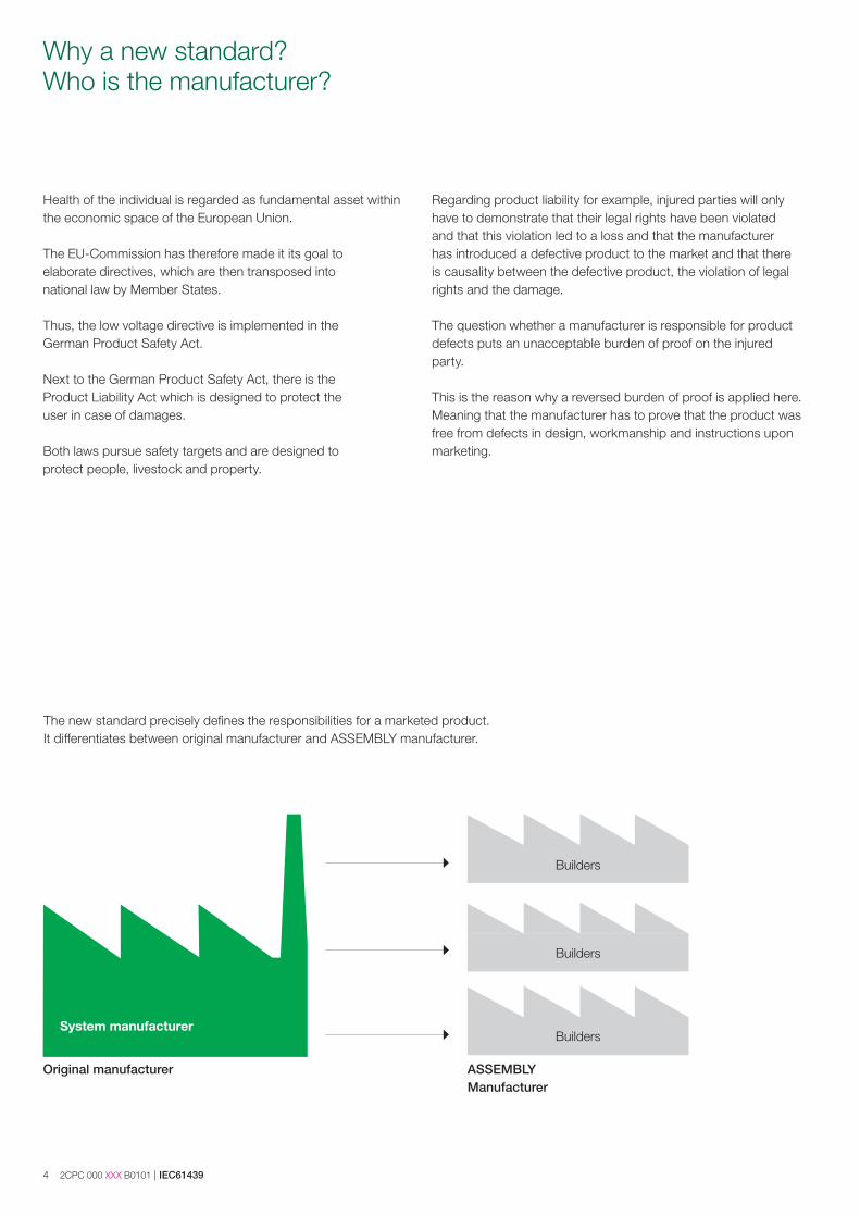
The new standard precisely defines the responsibilities for a marketed product. It differentiates between original manufacturer and ASSEMBLY manufacturer.
System manufacturer
Original manufacturer ASSEMBLY Manufacturer
Builders
Builders
Builders
Health of the individual is regarded as fundamental asset within the economic space of the European Union.
The EU-Commission has therefore made it its goal to elaborate directives, which are then transposed into national law by Member States.
Thus, the low voltage directive is implemented in the German Product Safety Act.
Next to the German Product Safety Act, there is the Product Liability Act which is designed to protect the user in case of damages.
Both laws pursue safety targets and are designed to protect people, livestock and property.
Regarding product liability for example, injured parties will only have to demonstrate that their legal rights have been violated and that this violation led to a loss and that the manufacturer has introduced a defective product to the market and that there is causality between the defective product, the violation of legal rights and the damage.
The question whether a manufacturer is responsible for product defects puts an unacceptable burden of proof on the injured party.
This is the reason why a reversed burden of proof is applied here. Meaning that the manufacturer has to prove that the product was free from defects in design, workmanship and instructions upon marketing.
IEC61439 | 2CPC 000 XXX B0101 5
These processes are essentially implemented by the original manufacturer. In case that the ASSEMBLY manufacturer does not install an ASSEMBLY in compliance with the instructions of the original manufacturer, the ASSEMBLY manufacturer will become
original manufacturer for that alteration and will have to carry out the design verification in accordance with the described proce-dures.
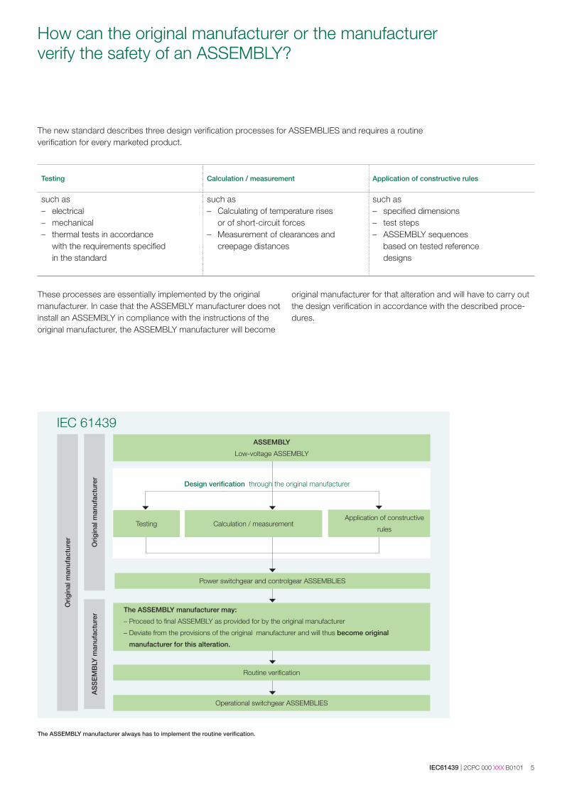
The ASSEMBLY manufacturer always has to implement the routine verification.
How can the original manufacturer or the manufacturer verify the safety of an ASSEMBLY?
The new standard describes three design verification processes for ASSEMBLIES and requires a routine verification for every marketed product.
Testing Calculation / measurement Application of constructive rules
such as – electrical– mechanical – thermal tests in accordance
with the requirements specified in the standard
such as – Calculating of temperature rises
or of short-circuit forces– Measurement of clearances and
creepage distances
such as– specified dimensions – test steps – ASSEMBLY sequences
based on tested reference designs
Orig
inal
man
ufac
ture
r
AS
SE
MB
LY m
anuf
actu
rer
Orig
inal
man
ufac
ture
r
ASSEMBLY
Low-voltage ASSEMBLY
Testing Calculation / measurement
Power switchgear and controlgear ASSEMBLIES
Application of constructive
rules
Routine verification
The ASSEMBLY manufacturer may:
– Proceed to final ASSEMBLY as provided for by the original manufacturer
– Deviate from the provisions of the original manufacturer and will thus become original
manufacturer for this alteration.
Operational switchgear ASSEMBLIES
IEC 61439
Design verification through the original manufacturer
6 2CPC 000 XXX B0101 | IEC61439
How can a low-voltage switchgear and controlgear ASSEMBLY be realized safely?
The new standard does not only precisely define the responsibil-ities of the market participants, but also specifies the dimensions of low-voltage switchgear and controlgear ASSEMBLIES.
In addition it presents the possibilities and limits for the market participants in order to guarantee to the user safe low-voltage switchgear and controlgear ASSEMBLIES.
It is also designed to specify the documentation required for
low-voltage switchgear and controlgear ASSEMBLIES and/or the required verifications.
Which are the dimensioning specifications enabling design verification?
One important aspect emphasised in the IEC 61439 is the earth-ing system as this has important consequences for planing the electrical circuits.
IEC61439 | 2CPC 000 XXX B0101 7
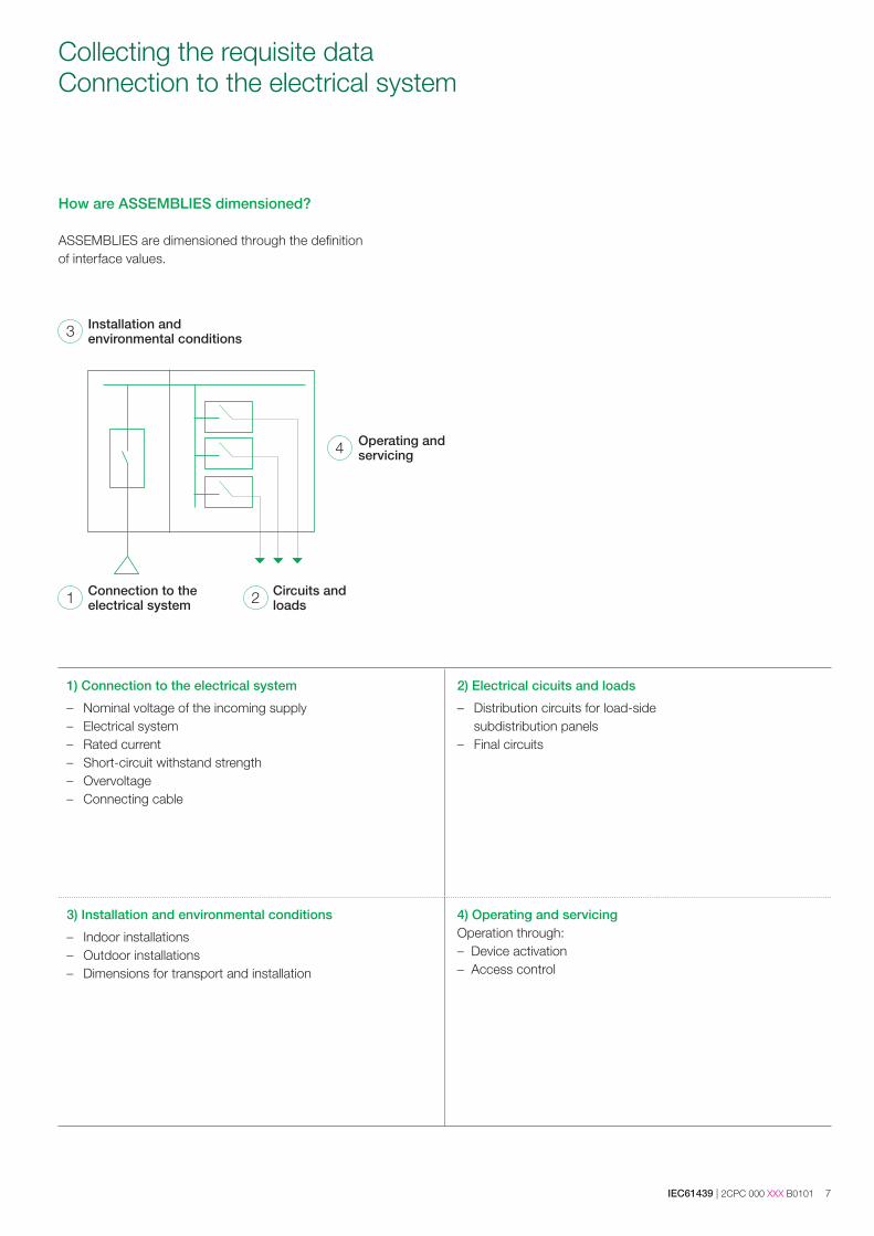
Collecting the requisite dataConnection to the electrical system
How are ASSEMBLIES dimensioned?
ASSEMBLIES are dimensioned through the definition of interface values.
1) Connection to the electrical system
– Nominal voltage of the incoming supply– Electrical system– Rated current– Short-circuit withstand strength – Overvoltage – Connecting cable
2) Electrical cicuits and loads
– Distribution circuits for load-side subdistribution panels
– Final circuits
3) Installation and environmental conditions
– Indoor installations– Outdoor installations– Dimensions for transport and installation
4) Operating and servicingOperation through: – Device activation– Access control
Installation and environmental conditions
Connection to the electrical system
Circuits and loads
Operating and servicing
1 2
4
3
8 2CPC 000 XXX B0101 | IEC61439
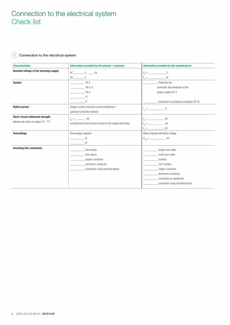
Connection to the electrical system Check list
Characteristics Information provided by the planner / customer Information provided by the manufacturer
Nominal voltage of the incoming supplyAC _______ V _____ Hz
DC _______ V
Ue = ____________ V
fn = ____________ Hz
System __________ TN-C
__________ TN-C-S
__________ TN-S
__________ TT
__________ IT
__________ Protection by
automatic disconnection of the
power supply (PC I)
__________ protection by protective insulation (PC II)
Rated current Supply current (nominal current transformer /
upstream protective device)InA = ___________ A
Short-circuit withstand strength
(please see notes on pages 73 - 77)Icp = _______ kA
(uninfluenced short-circuit current at the supply terminals)
Ipk = ___________ kA
Icw = ___________ kA
Icc = ___________ kA
Overvoltage Overvoltage category
__________ III
__________ IV
Rated impulse withstand voltage
Uimp = ___________ kV
Incoming line connection__________ from below
__________ from above
__________ copper conductor
__________ aluminium conductor
__________ Connection using terminal blocks
__________ single-core cable
__________ multi-core cable
__________ number
__________ mm² section
__________ copper conductor
__________ aluminium conductor
__________ connection to equipment
__________ connection using terminal blocks
Connection to the electrical system1
IEC61439 | 2CPC 000 XXX B0101 9
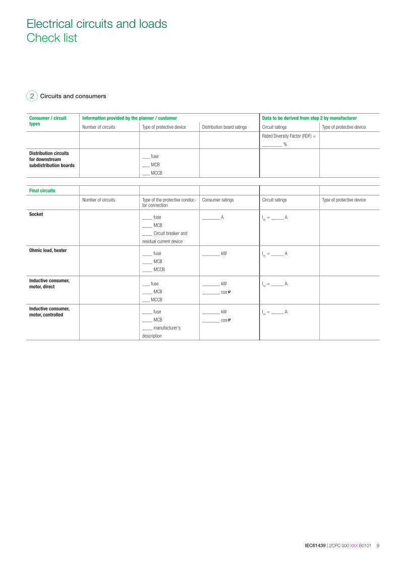
Consumer / circuit types
Information provided by the planner / customer Data to be derived from step 2 by manufacturer
Number of circuits Type of protective device Distribution board ratings Circuit ratings Type of protective device
Rated Diversity Factor (RDF) =
________ %
Distribution circuits for downstream subdistribution boards
___ fuse
___ MCB
___ MCCB
Final circuits
Number of circuits Type of the protective conduc-tor connection
Consumer ratings Circuit ratings Type of protective device
Socket____ fuse
____ MCB
____ Circuit breaker and
residual current device
_______ A Inc = _____ A
Ohmic load, heater____ fuse
____ MCB
____ MCCB
_______ kW Inc = _____ A
Inductive consumer, motor, direct ___ fuse
____ MCB
___ MCCB
_______ kW
_______ cos
Inc = _____ A
Inductive consumer, motor, controlled ____ fuse
____ MCB
____ manufacturer's
description
_______ kW
_______ cos
Inc = _____ A
Circuits and consumers2
Electrical circuits and loads Check list
10 2CPC 000 XXX B0101 | IEC61439
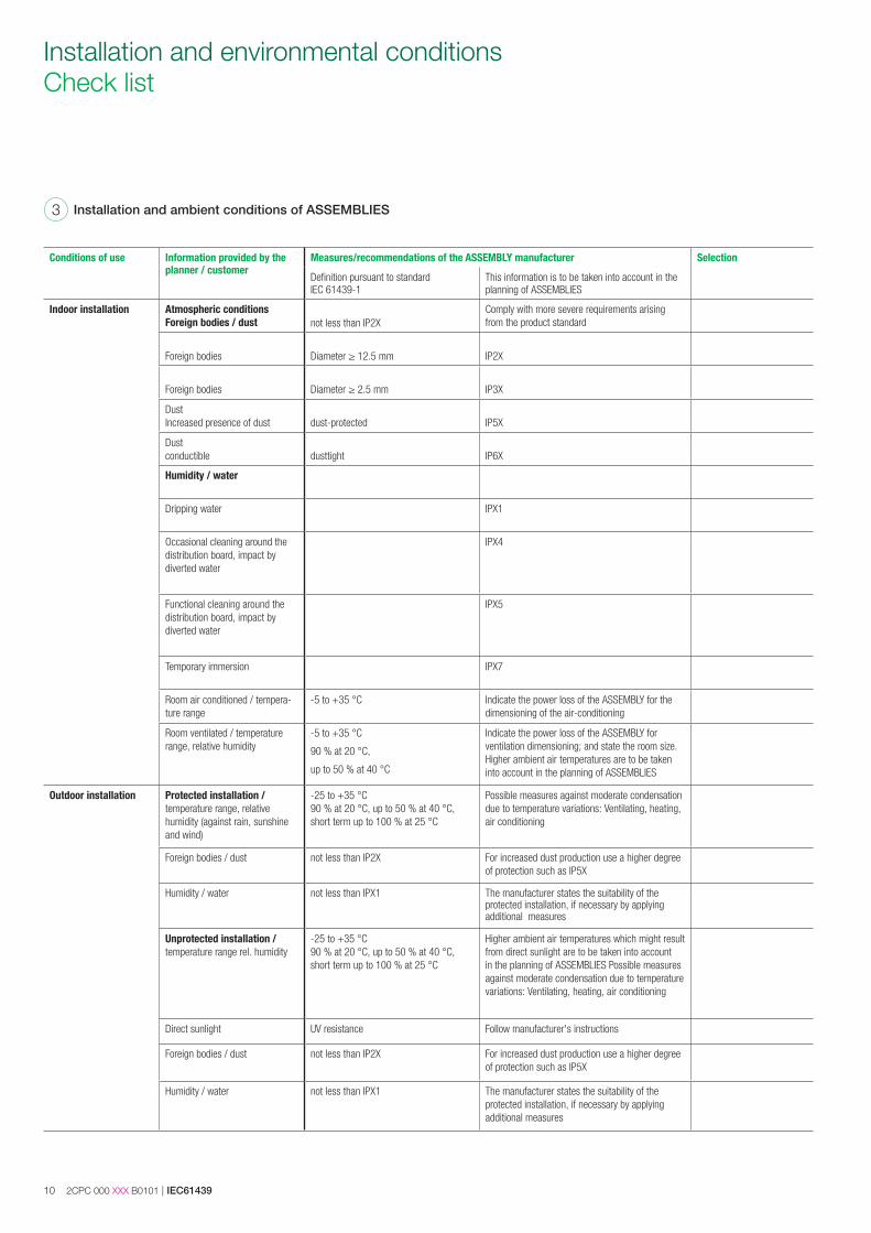
Installation and environmental conditions Check list
Installation and ambient conditions of ASSEMBLIES3
Conditions of use Information provided by the planner / customer
Measures/recommendations of the ASSEMBLY manufacturer Selection
Definition pursuant to standard IEC 61439-1
This information is to be taken into account in the planning of ASSEMBLIES
Indoor installation Atmospheric conditions Foreign bodies / dust not less than IP2X
Comply with more severe requirements arising from the product standard
Foreign bodies Diameter ≥ 12.5 mm IP2X
Foreign bodies Diameter ≥ 2.5 mm IP3X
DustIncreased presence of dust dust-protected IP5X
Dustconductible dusttight IP6X
Humidity / water
Dripping water IPX1
Occasional cleaning around the distribution board, impact by diverted water
IPX4
Functional cleaning around the distribution board, impact by diverted water
IPX5
Temporary immersion IPX7
Room air conditioned / tempera-ture range
-5 to +35 °C Indicate the power loss of the ASSEMBLY for the dimensioning of the air-conditioning
Room ventilated / temperature range, relative humidity
-5 to +35 °C
90 % at 20 °C,
up to 50 % at 40 °C
Indicate the power loss of the ASSEMBLY for ventilation dimensioning; and state the room size. Higher ambient air temperatures are to be taken into account in the planning of ASSEMBLIES
Outdoor installation Protected installation / temperature range, relative humidity (against rain, sunshine and wind)
-25 to +35 °C90 % at 20 °C, up to 50 % at 40 °C, short term up to 100 % at 25 °C
Possible measures against moderate condensation due to temperature variations: Ventilating, heating, air conditioning
Foreign bodies / dust not less than IP2X For increased dust production use a higher degree of protection such as IP5X
Humidity / water not less than IPX1 The manufacturer states the suitability of the protected installation, if necessary by applying additional measures
Unprotected installation / temperature range rel. humidity
-25 to +35 °C90 % at 20 °C, up to 50 % at 40 °C, short term up to 100 % at 25 °C
Higher ambient air temperatures which might result from direct sunlight are to be taken into account in the planning of ASSEMBLIES Possible measures against moderate condensation due to temperature variations: Ventilating, heating, air conditioning
Direct sunlight UV resistance Follow manufacturer's instructions
Foreign bodies / dust not less than IP2X For increased dust production use a higher degree of protection such as IP5X
Humidity / water not less than IPX1 The manufacturer states the suitability of the protected installation, if necessary by applying additional measures
IEC61439 | 2CPC 000 XXX B0101 11
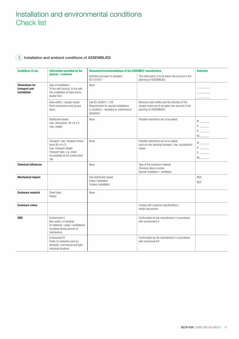
Installation and environmental conditions Check list
Installation and ambient conditions of ASSEMBLIES3
Conditions of use Information provided by the planner / customer
Measures/recommendations of the ASSEMBLY manufacturer Selection
Definition pursuant to standard IEC 61439-1
This information is to be taken into account in the planning of ASSEMBLIES
Dimensions for transport and installation
Type of installation:To the wall (recess), to the wall, free installation to base frame, double floor
None _________
_________
_________
Aisle widths / escape routes: Room dimensions and access doors
See IEC 60364-7-729Requirements for special installations or locations – operating or maintenance gangways
Minimum aisle widths and the direction of the escape routes are to be taken into account in the planning of ASSEMBLIES
Distribution board:max. dimensions: W x H x Dmax. weight
None Possible restrictions are to be statedW ______
H ______
D ______
kg ______
Transport: max. transport dimen-sions W x H x D, max. transport weightTransport type, e.g. craneAccessibility at the construction site
None Possible restrictions are to be stated, such as only standing transport, max. acceleration values
W ______
H ______
D ______
kg ______
Chemical influences None Type of the enclosure material Chemical device versionSpecial installation / ventilation
Mechanical impact Sub-distribution boardIndoor installation Outdoor installation
IK05
IK07
Enclosure material Sheet steelPlastic
None
Enclosure colour Comply with customer specifications / tender documents
EMC Environment A Non-public or industrial LV networks / areas / installations including strong sources of interference
Confirmation by the manufacturer in accordance with environment A
Environment BPublic LV networks such as domestic, commercial and light industrial locations
Confirmation by the manufacturer in accordance with environment B
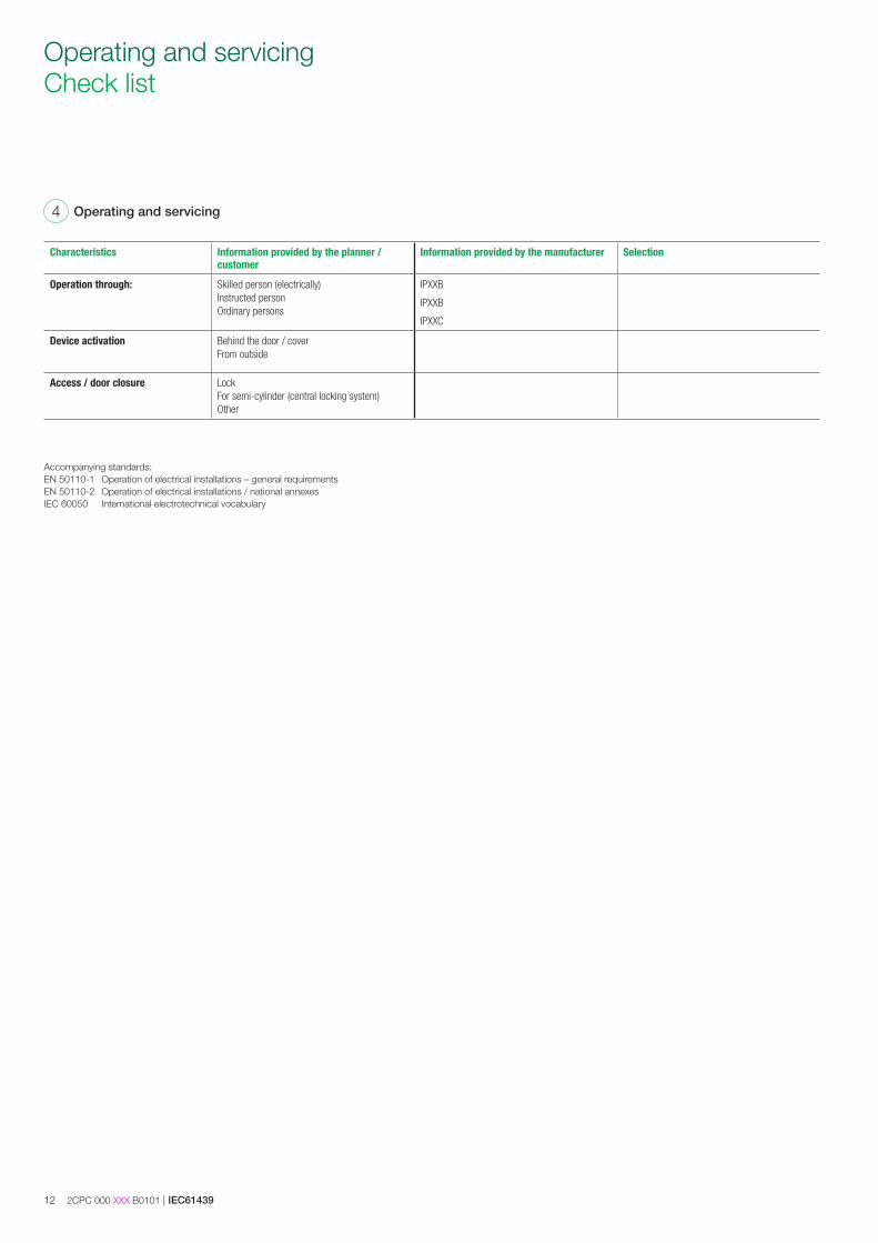
12 2CPC 000 XXX B0101 | IEC61439
Operating and servicing4
Characteristics Information provided by the planner / customer
Information provided by the manufacturer Selection
Operation through: Skilled person (electrically)Instructed personOrdinary persons
IPXXB
IPXXB
IPXXC
Device activation Behind the door / coverFrom outside
Access / door closure LockFor semi-cylinder (central locking system)Other
Accompanying standards:EN 50110-1 Operation of electrical installations – general requirementsEN 50110-2 Operation of electrical installations / national annexesIEC 60050 International electrotechnical vocabulary
Operating and servicing Check list
IEC61439 | 2CPC 000 XXX B0101 13
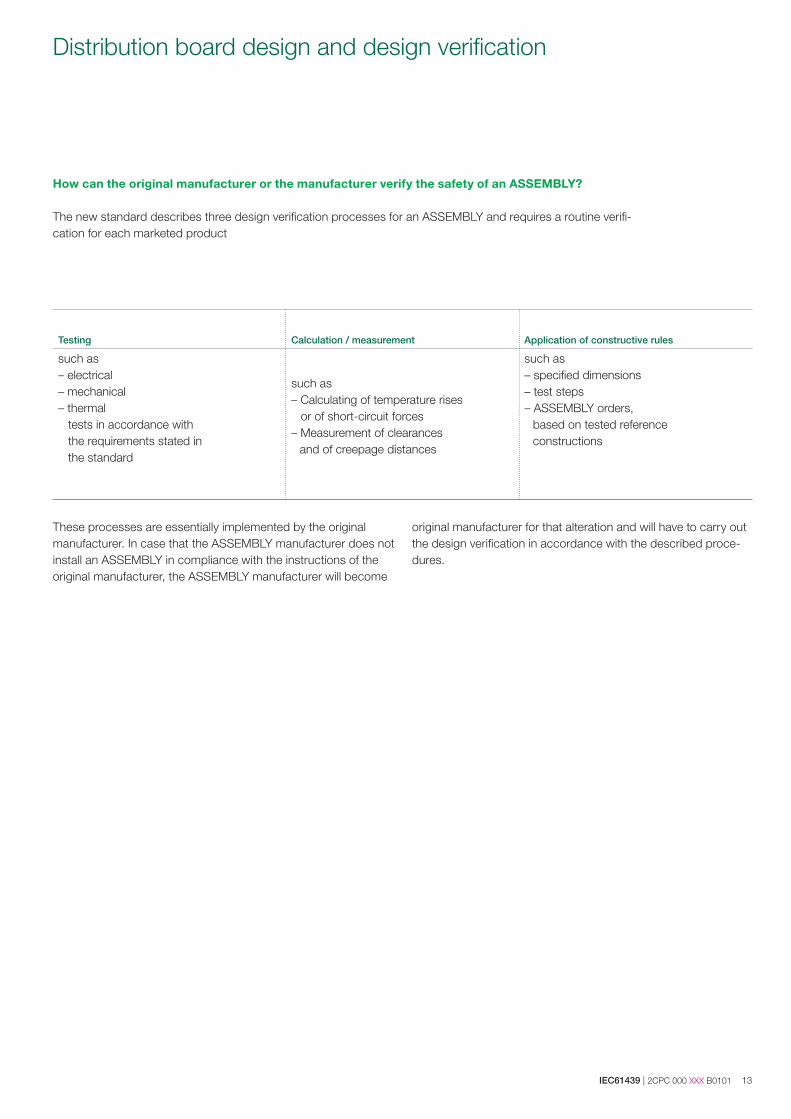
Distribution board design and design verification
How can the original manufacturer or the manufacturer verify the safety of an ASSEMBLY?
The new standard describes three design verification processes for an ASSEMBLY and requires a routine verifi-cation for each marketed product
Testing Calculation / measurement Application of constructive rules
such as – electrical– mechanical – thermal tests in accordance with the requirements stated in the standard
such as – Calculating of temperature rises or of short-circuit forces– Measurement of clearances and of creepage distances
such as– specified dimensions – test steps – ASSEMBLY orders, based on tested reference constructions
These processes are essentially implemented by the original manufacturer. In case that the ASSEMBLY manufacturer does not install an ASSEMBLY in compliance with the instructions of the original manufacturer, the ASSEMBLY manufacturer will become
original manufacturer for that alteration and will have to carry out the design verification in accordance with the described proce-dures.
14 2CPC 000 XXX B0101 | IEC61439
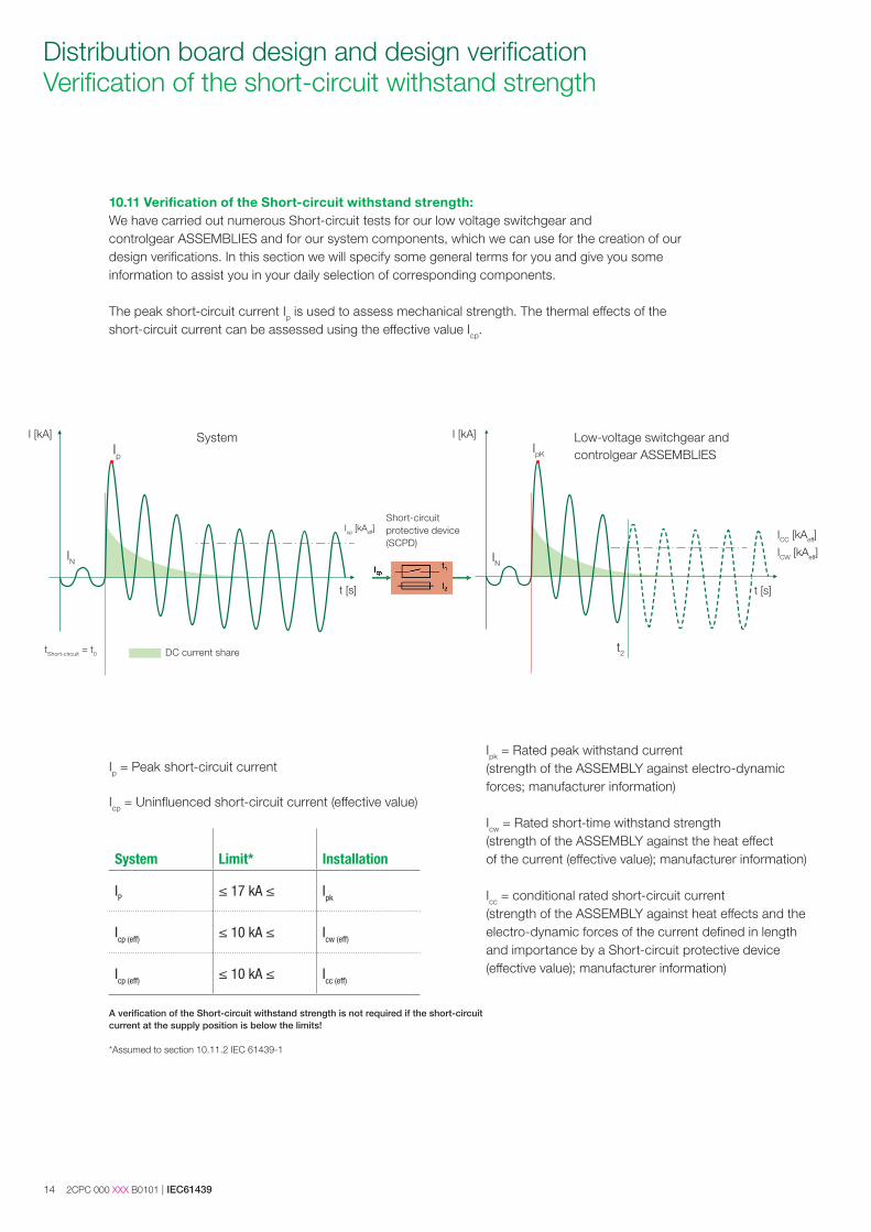
Distribution board design and design verification Verification of the short-circuit withstand strength
10.11 Verification of the Short-circuit withstand strength:We have carried out numerous Short-circuit tests for our low voltage switchgear and controlgear ASSEMBLIES and for our system components, which we can use for the creation of our design verifications. In this section we will specify some general terms for you and give you some information to assist you in your daily selection of corresponding components.
The peak short-circuit current Ip is used to assess mechanical strength. The thermal effects of the short-circuit current can be assessed using the effective value Icp.
Ip = Peak short-circuit current
Icp = Uninfluenced short-circuit current (effective value)
Ipk = Rated peak withstand current (strength of the ASSEMBLY against electro-dynamic forces; manufacturer information)
Icw = Rated short-time withstand strength (strength of the ASSEMBLY against the heat effectof the current (effective value); manufacturer information)
Icc = conditional rated short-circuit current (strength of the ASSEMBLY against heat effects and the electro-dynamic forces of the current defined in length and importance by a Short-circuit protective device (effective value); manufacturer information)
System Low-voltage switchgear and controlgear ASSEMBLIES
t [s]
Icp [kAeff]
IN IN
I [kA] I [kA]IpK
IN
t [s]
Short-circuitprotective device (SCPD)
DC current sharetShort-circuit = t0
t [s]
Icp [kAeff] ICC [kAeff]
ICW [kAeff]
Ip
IN
t2
System Limit* Installation
IP ≤ 17 kA ≤ Ipk
Icp (eff) ≤ 10 kA ≤ Icw (eff)
Icp (eff) ≤ 10 kA ≤ Icc (eff)
A verification of the Short-circuit withstand strength is not required if the short-circuit current at the supply position is below the limits!
*Assumed to section 10.11.2 IEC 61439-1
IEC61439 | 2CPC 000 XXX B0101 15
Distribution board design and design verification Short circuit – key terms*1
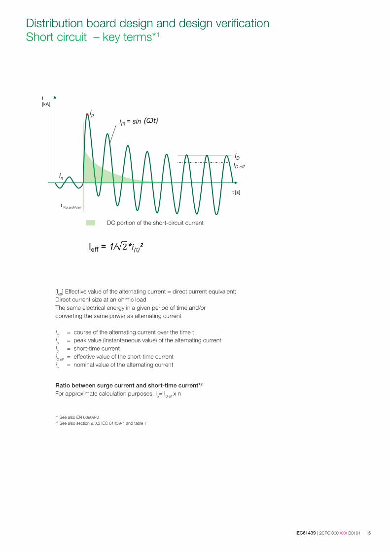
[Ieff] Effective value of the alternating current = direct current equivalent:Direct current size at an ohmic loadThe same electrical energy in a given period of time and/or converting the same power as alternating current
i(t) = course of the alternating current over the time tip = peak value (instantaneous value) of the alternating currentiD = short-time currentiD eff = effective value of the short-time currentin = nominal value of the alternating current
Ratio between surge current and short-time current*2
For approximate calculation purposes: Ip= ID eff x n
*1 See also EN 60909-0*2 See also section 9.3.3 IEC 61439-1 and table 7
DC portion of the short-circuit current
16 2CPC 000 XXX B0101 | IEC61439
Distribution board design and design verification Verification of the short-circuit withstand strength
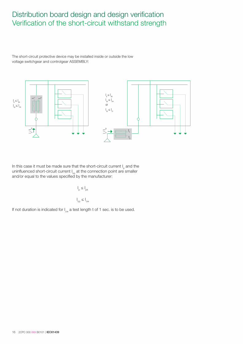
The short-circuit protective device may be installed inside or outside the low voltage switchgear and controlgear ASSEMBLY:
In this case it must be made sure that the short-circuit current Ip and the uninfluenced short-circuit current Icp at the connection point are smaller and/or equal to the values specified by the manufacturer:
Ip ≤ Ipk
Icp ≤ Icw
If not duration is indicated for Icw a test length t of 1 sec. is to be used.
Ip ≤ Ipk
Icp ≤ Icw
or
Icp ≤ Icc
t1
t2
t 1 t 2
Ip ≤ Ipk
Icp ≤ Icw
I p / I
cp
I p / I
cp
IEC61439 | 2CPC 000 XXX B0101 17
Distribution board design and design verification Verification of the short-circuit withstand strength
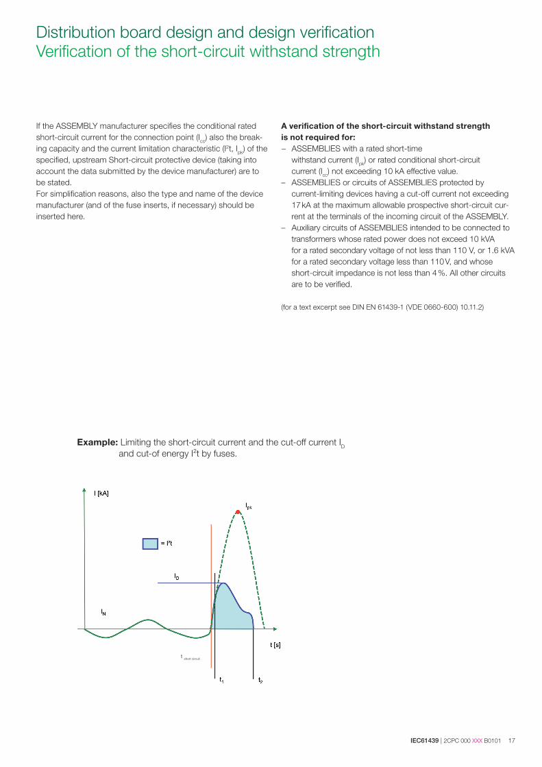
If the ASSEMBLY manufacturer specifies the conditional rated short-circuit current for the connection point (Icc) also the break-ing capacity and the current limitation characteristic (I2t, Ipk) of the specified, upstream Short-circuit protective device (taking into account the data submitted by the device manufacturer) are to be stated. For simplification reasons, also the type and name of the device manufacturer (and of the fuse inserts, if necessary) should be inserted here.
A verification of the short-circuit withstand strength is not required for: − ASSEMBLIES with a rated short-time
withstand current (Ipk) or rated conditional short-circuit current (Icc) not exceeding 10 kA effective value.
– ASSEMBLIES or circuits of ASSEMBLIES protected by current-limiting devices having a cut-off current not exceeding 17 kA at the maximum allowable prospective short-circuit cur-rent at the terminals of the incoming circuit of the ASSEMBLY.
– Auxiliary circuits of ASSEMBLIES intended to be connected to transformers whose rated power does not exceed 10 kVA for a rated secondary voltage of not less than 110 V, or 1.6 kVA for a rated secondary voltage less than 110 V, and whose short-circuit impedance is not less than 4 %. All other circuits are to be verified.
(for a text excerpt see DIN EN 61439-1 (VDE 0660-600) 10.11.2)
Example: Limiting the short-circuit current and the cut-off current ID and cut-of energy I²t by fuses.
t short circuit
18 2CPC 000 XXX B0101 | IEC61439
Distribution board design and design verification Transformer nominal values table
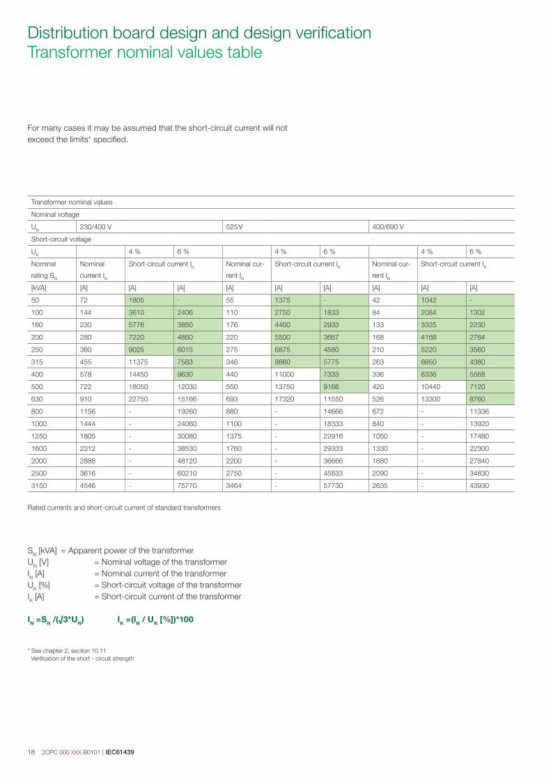
For many cases it may be assumed that the short-circuit current will not exceed the limits* specified.
SN [kVA] = Apparent power of the transformerUN [V] = Nominal voltage of the transformer IN [A] = Nominal current of the transformerUK [%] = Short-circuit voltage of the transformer IK [A] = Short-circuit current of the transformer
IN =SN /(√3*UN) IK =(IN / UN [%])*100
* S ee chapter 2, section 10.11 Verification of the short - circuit strength
Transformer nominal values
Nominal voltage
UN 230/400 V 525 V 400/690 V
Short-circuit voltage
UK 4 % 6 % 4 % 6 % 4 % 6 %
Nominal
rating SN
Nominal
current IN
Short-circuit current IK Nominal cur-
rent IN
Short-circuit current IK Nominal cur-
rent IN
Short-circuit current IK
[kVA] [A] [A] [A] [A] [A] [A] [A] [A] [A]
50 72 1805 - 55 1375 - 42 1042 -
100 144 3610 2406 110 2750 1833 84 2084 1302
160 230 5776 3850 176 4400 2933 133 3325 2230
200 280 7220 4860 220 5500 3667 168 4168 2784
250 360 9025 6015 275 6875 4580 210 5220 3560
315 455 11375 7583 346 8660 5775 263 6650 4380
400 578 14450 9630 440 11000 7333 336 8336 5568
500 722 18050 12030 550 13750 9166 420 10440 7120
630 910 22750 15166 693 17320 11550 526 13300 8760
800 1156 - 19260 880 - 14666 672 - 11336
1000 1444 - 24060 1100 - 18333 840 - 13920
1250 1805 - 30080 1375 - 22916 1050 - 17480
1600 2312 - 38530 1760 - 29333 1330 - 22300
2000 2888 - 48120 2200 - 36666 1680 - 27840
2500 3616 - 60210 2750 - 45833 2090 - 34830
3150 4546 - 75770 3464 - 57730 2635 - 43930
Rated currents and short-circuit current of standard transformers
IEC61439 | 2CPC 000 XXX B0101 19
Distribution board design and design verification Verification of temperature rises
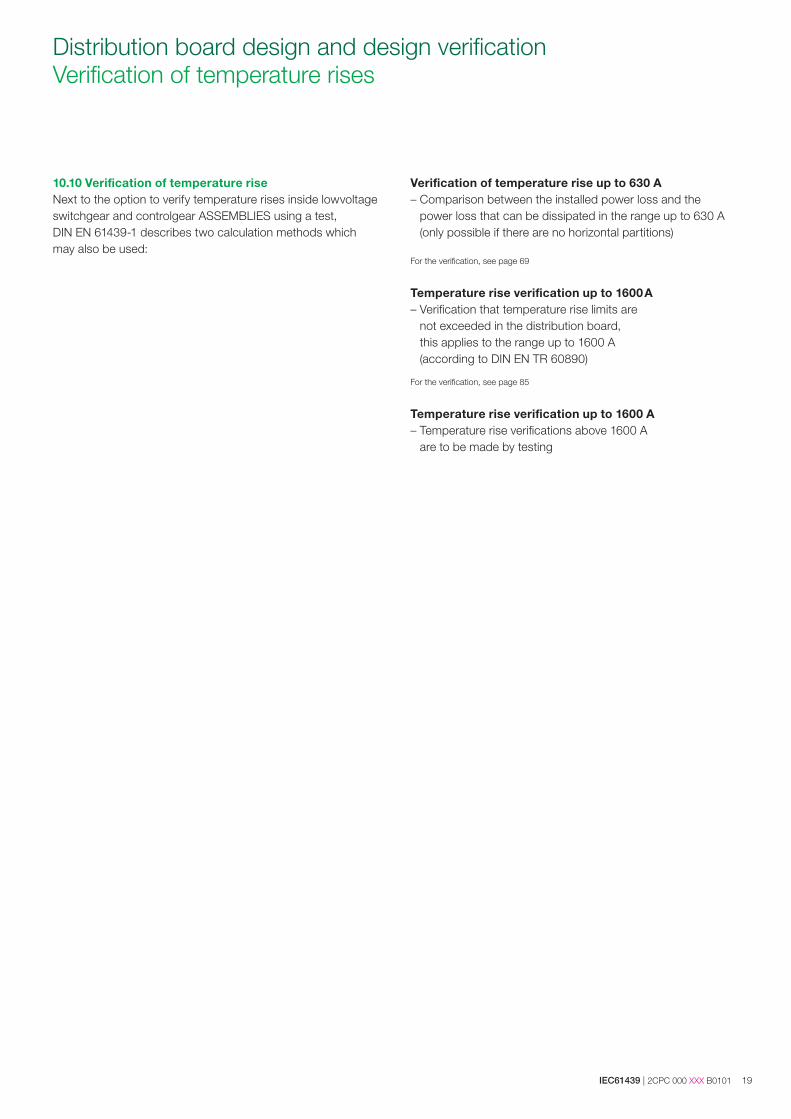
10.10 Verification of temperature riseNext to the option to verify temperature rises inside lowvoltage switchgear and controlgear ASSEMBLIES using a test, DIN EN 61439-1 describes two calculation methods which may also be used:
Verification of temperature rise up to 630 A – Comparison between the installed power loss and the
power loss that can be dissipated in the range up to 630 A (only possible if there are no horizontal partitions)
For the verification, see page 69
Temperature rise verification up to 1600 A– Verification that temperature rise limits are
not exceeded in the distribution board, this applies to the range up to 1600 A (according to DIN EN TR 60890)
For the verification, see page 85
Temperature rise verification up to 1600 A– Temperature rise verifications above 1600 A
are to be made by testing
20 2CPC 000 XXX B0101 | IEC61439
Distribution board design and design verification Verification of temperature rises
10.10 Verification of temperature riseNext to the option to verify temperature rises inside low voltage switchgear and controlgear AS-SEMBLIES using a test, IEC 61439-1 describes two calculation methods which may also be used:
– Comparison between the installed power loss and the power loss that can bedissipated in the power range up to 630 A (only possible if there are no horizontalpartitions)
– Verification that temperature rise limits are not exceeded in the distribution board,this applies to the power range up to 1600 A (according to IEC TR 60890)
Verification of temperature rise up to 630 ATemperature rises up to 630 A may be verified under the assumption that the heat loss of all equipment and electrical conductors is evenly distributed across the enclosure. For this method the standard demands that no internal form separation restricts the heat flow.Since the actual distribution of the heat sources in enclosures does not necessarily comply with the above-stated ideal conditions, the standard requires for calculated verification methods (up to 630 A) the application of a reduction factor (derating factor). There are two different starting conditions: a) the operating currents (load currents) are known or b) the rated current is specified by the preselection of equipment.
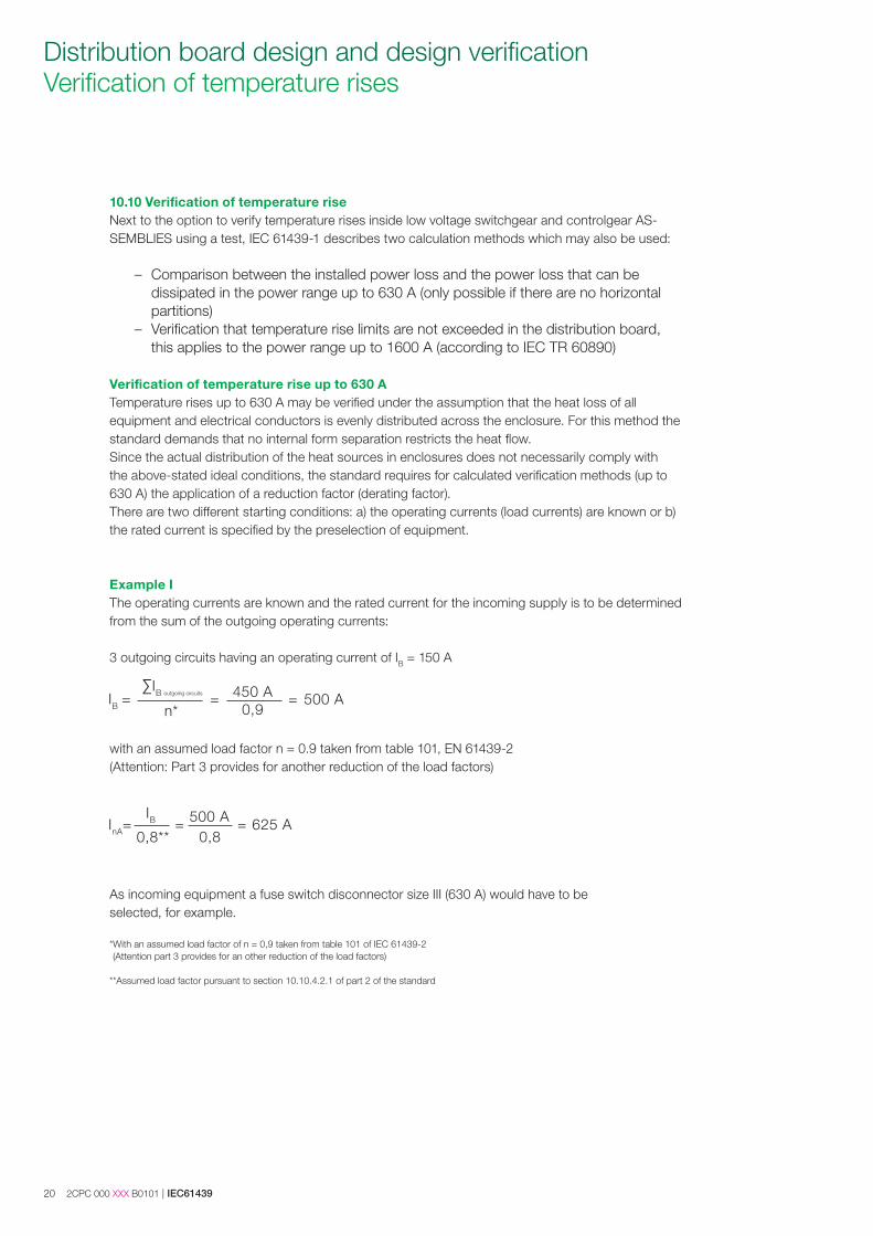
Example IThe operating currents are known and the rated current for the incoming supply is to be determined from the sum of the outgoing operating currents:
3 outgoing circuits having an operating current of IB = 150 A
with an assumed load factor n = 0.9 taken from table 101, EN 61439-2 (Attention: Part 3 provides for another reduction of the load factors)
As incoming equipment a fuse switch disconnector size III (630 A) would have to be selected, for example.
* With an assumed load factor of n = 0,9 taken from table 101 of IEC 61439-2 (Attention part 3 provides for an other reduction of the load factors)
**Assumed load factor pursuant to section 10.10.4.2.1 of part 2 of the standard
IEC61439 | 2CPC 000 XXX B0101 21
Distribution board design and design verification Verification of temperature rises
Example II
The operating current of the outgoing circuit is defined by the equipment selection so that the rated current of the outgoing circuit is calculated as follows:
Disconnector size 00, 160 A
Inc=IB · 0.8* = 160 A · 0.8 = 128 A
Reducing the rated current of each circuit leads also to another reduction of the power loss to be taken into account regarding the power losses occurring with the rated current.
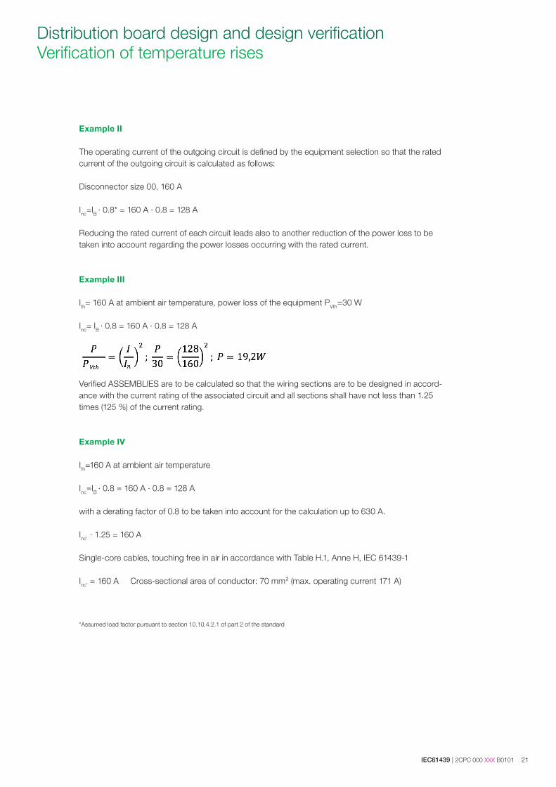
Example III
Ith= 160 A at ambient air temperature, power loss of the equipment PVth=30 W
Inc= IB · 0.8 = 160 A · 0.8 = 128 A
𝑃𝑃𝑃𝑃h=𝑃𝑃𝑃2; 𝑃30=1281602; 𝑃=19.2𝑃
Verified ASSEMBLIES are to be calculated so that the wiring sections are to be designed in accord-ance with the current rating of the associated circuit and all sections shall have not less than 1.25 times (125 %) of the current rating.
Example IV
Ith=160 A at ambient air temperature
Inc=IB · 0.8 = 160 A · 0.8 = 128 A
with a derating factor of 0.8 to be taken into account for the calculation up to 630 A.
Inc’ · 1.25 = 160 A
Single-core cables, touching free in air in accordance with Table H.1, Anne H, IEC 61439-1
Inc’ = 160 A Cross-sectional area of conductor: 70 mm² (max. operating current 171 A)
*Assumed load factor pursuant to section 10.10.4.2.1 of part 2 of the standard
22 2CPC 000 XXX B0101 | IEC61439
Distribution board design and design verification Verification of temperature rises
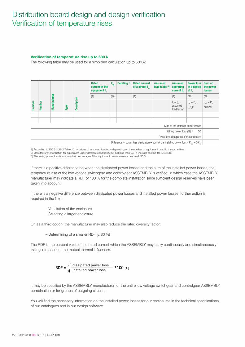
Verification of temperature rise up to 630 AThe following table may be used for a simplified calculation up to 630 A:
Posi
tion
Num
ber
Man
ufac
ture
r
Type
Desc
riptio
n
Ratedcurrent of theequipment In
Pvn Derating 1) Rated current of a circuit Inc
Assumed load factor 2)
Assumed operating current IB
Power loss of a device at IB
Sum of the power losses
(A) (W) (A) (A) (W) (W)
IB = Inc · assumed load factor
PB = Pvn ·
(IB/In)2
PvB = PB ·
number
Sum of the installed power losses
Wiring power loss (%) 3) 30
Power loss dissipation of the enclosure
Difference = power loss dissipation – sum of the installed power loss= Pvzul – ∑PvB
1) According to IEC 61439-2 Table 101 – Values of assumed loading – depending on the number of equipment used in the same time 2) Manufacturer information for equipment under different conditions, but not less than 0.8 in line with section 10.10.4.2.1c3) The wiring power loss is assumed as percentage of the equipment power losses – proposal: 30 %
If there is a positive difference between the dissipated power losses and the sum of the installed power losses, the temperature rise of the low voltage switchgear and controlgear ASSEMBLY is verified! In which case the ASSEMBLY manufacturer may indicate a RDF of 100 % for the complete installation since sufficient design reserves have been taken into account.
If there is a negative difference between dissipated power losses and installed power losses, further action is required in the field:
– Ventilation of the enclosure– Selecting a larger enclosure
Or, as a third option, the manufacturer may also reduce the rated diversity factor:
– Determining of a smaller RDF (≤ 80 %)
The RDF is the percent value of the rated current which the ASSEMBLY may carry continuously and simultaneously taking into account the mutual thermal influences.
It may be specified by the ASSEMBLY manufacturer for the entire low voltage switchgear and controlgear ASSEMBLY combination or for groups of outgoing circuits.
You will find the necessary information on the installed power losses for our enclosures in the technical specifications of our catalogues and in our design software.
dissipated power loss installed power loss
IEC61439 | 2CPC 000 XXX B0101 23
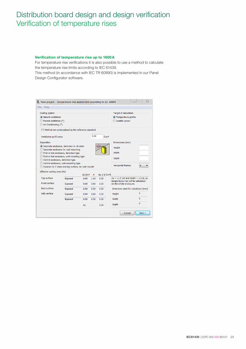
Distribution board design and design verification Verification of temperature rises
Verification of temperature rise up to 1600 AFor temperature rise verifications it is also possible to use a method to calculate the temperature rise limits according to IEC 61439.This method (in accordance with IEC TR 60890) is implemented in our Panel Design Configurator software.
24 2CPC 000 XXX B0101 | IEC61439
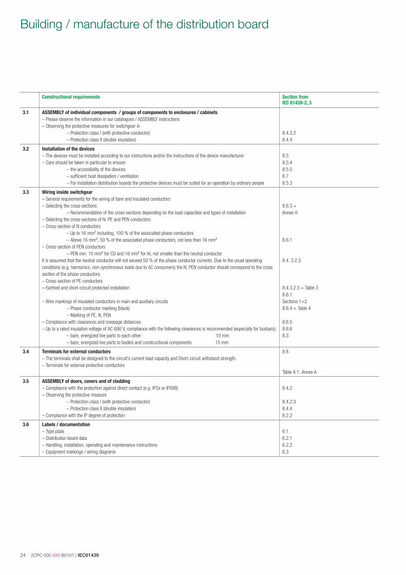
Building / manufacture of the distribution board
Constructional requirements Section from IEC 61439-2, 3
3.1 ASSEMBLY of individual components / groups of components to enclosures / cabinets– Please observe the information in our catalogues / ASSEMBLY instructions– Observing the protective measures for switchgear in – Protection class I (with protective conductor) – Protection class II (double insulation)
8.4.3.28.4.4
3.2 Installation of the devices– The devices must be installed according to our instructions and/or the instructions of the device manufacturer– Care should be taken in particular to ensure: – the accessibility of the devices – sufficient heat dissipation / ventilation – For installation distribution boards the protective devices must be suited for an operation by ordinary people
8.58.5.48.5.58.78.5.3
3.3 Wiring inside switchgear– General requirements for the wiring of bare and insulated conductors – Selecting the cross-sections – Recommendation of the cross-sections depending on the load capacities and types of installation– Selecting the cross-sections of N, PE and PEN conductors– Cross-section of N conductors – Up to 16 mm² including, 100 % of the associated phase conductors – Above 16 mm², 50 % of the associated phase conductors, not less than 16 mm²– Cross-section of PEN conductors – PEN min. 10 mm² for CU and 16 mm² for Al, not smaller than the neutral conductorIt is assumed that the neutral conductor will not exceed 50 % of the phase conductor currents. Due to the usual operating conditions (e.g. harmonics, non-synchronous loads due to AC consumers) the N, PEN conductor should correspond to the cross section of the phase conductors.– Cross-section of PE conductors– Earthed and short-circuit protected installation
– Wire markings of insulated conductors in main and auxiliary circuits – Phase conductor marking (black) – Marking of PE, N, PEN– Compliance with clearances and creepage distances– Up to a rated insulation voltage of AC 690 V, compliance with the following clearances is recommended (especially for busbars): – bare, energized live parts to each other: 10 mm – bare, energized live parts to bodies and constructional components: 15 mm
8.6.3 + Annex H
8.6.1
8.4. 3.2.3
8.4.3.2.3 + Table 38.6.1 Sections 1+28.6.4 + Table 4
8.6.58.6.68.3
3.4 Terminals for external conductors– The terminals shall be designed to the circuit's current load capacity and Short-circuit withstand strength. – Terminals for external protective conductors
8.8
Table A.1, Annex A
3.5 ASSEMBLY of doors, covers and of cladding– Compliance with the protection against direct contact (e.g. IP2x or IPXXB)– Observing the protective measure – Protection class I (with protective conductor) – Protection class II (double insulation)– Compliance with the IP degree of protection
8.4.2
8.4.2.38.4.48.2.2
3.6 Labels / documentation– Type plate– Distribution board data– Handling, installation, operating and maintenance instructions– Equipment markings / wiring diagrams
6.16.2.16.2.26.3
IEC61439 | 2CPC 000 XXX B0101 25
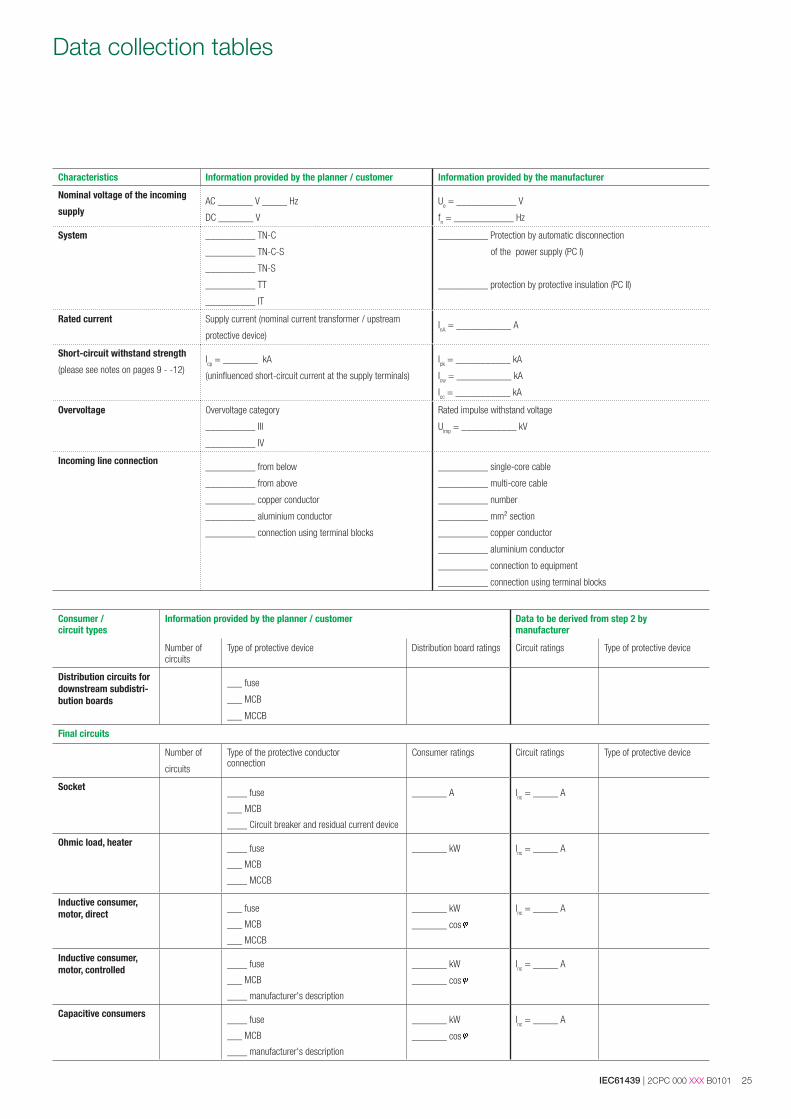
Data collection tables
Characteristics Information provided by the planner / customer Information provided by the manufacturer
Nominal voltage of the incoming
supplyAC _______ V _____ Hz
DC _______ V
Ue = ____________ V
fn = ____________ Hz
System __________ TN-C
__________ TN-C-S
__________ TN-S
__________ TT
__________ IT
__________ Protection by automatic disconnection
of the power supply (PC I)
__________ protection by protective insulation (PC II)
Rated current Supply current (nominal current transformer / upstream
protective device)InA = ___________ A
Short-circuit withstand strength
(please see notes on pages 9 - -12)Icp = _______ kA
(uninfluenced short-circuit current at the supply terminals)
Ipk = ___________ kA
Icw = ___________ kA
Icc = ___________ kA
Overvoltage Overvoltage category
__________ III
__________ IV
Rated impulse withstand voltage
Uimp = ___________ kV
Incoming line connection__________ from below
__________ from above
__________ copper conductor
__________ aluminium conductor
__________ connection using terminal blocks
__________ single-core cable
__________ multi-core cable
__________ number
__________ mm² section
__________ copper conductor
__________ aluminium conductor
__________ connection to equipment
__________ connection using terminal blocks
Consumer / circuit types
Information provided by the planner / customer Data to be derived from step 2 by manufacturer
Number of circuits
Type of protective device Distribution board ratings Circuit ratings Type of protective device
Distribution circuits for downstream subdistri-bution boards
___ fuse
___ MCB
___ MCCB
Final circuits
Number of
circuits
Type of the protective conductorconnection
Consumer ratings Circuit ratings Type of protective device
Socket____ fuse
___ MCB
____ Circuit breaker and residual current device
_______ A Inc = _____ A
Ohmic load, heater____ fuse
___ MCB
____ MCCB
_______ kW Inc = _____ A
Inductive consumer, motor, direct ___ fuse
___ MCB
___ MCCB
_______ kW
_______ cos
Inc = _____ A
Inductive consumer, motor, controlled ____ fuse
___ MCB
____ manufacturer's description
_______ kW
_______ cos
Inc = _____ A
Capacitive consumers____ fuse
___ MCB
____ manufacturer's description
_______ kW
_______ cos
Inc = _____ A
26 2CPC 000 XXX B0101 | IEC61439
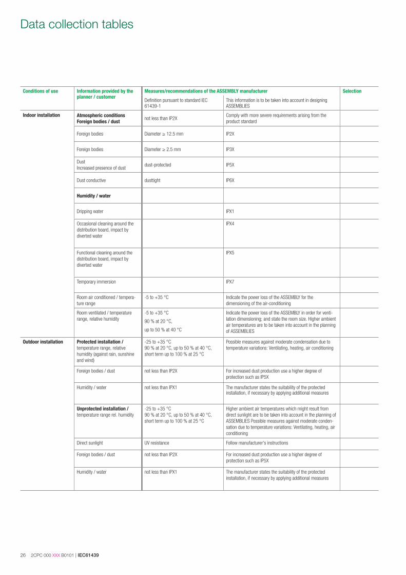
Data collection tables
Conditions of use Information provided by the planner / customer
Measures/recommendations of the ASSEMBLY manufacturer Selection
Definition pursuant to standard IEC 61439-1
This information is to be taken into account in designing ASSEMBLIES
Indoor installation Atmospheric conditions Foreign bodies / dust
not less than IP2XComply with more severe requirements arising from the product standard
Foreign bodies Diameter ≥ 12.5 mm IP2X
Foreign bodies Diameter ≥ 2.5 mm IP3X
DustIncreased presence of dust
dust-protected IP5X
Dust conductive dusttight IP6X
Humidity / water
Dripping water IPX1
Occasional cleaning around the distribution board, impact by diverted water
IPX4
Functional cleaning around the distribution board, impact by diverted water
IPX5
Temporary immersion IPX7
Room air conditioned / tempera-ture range
-5 to +35 °C Indicate the power loss of the ASSEMBLY for the dimensioning of the air-conditioning
Room ventilated / temperature range, relative humidity
-5 to +35 °C
90 % at 20 °C,
up to 50 % at 40 °C
Indicate the power loss of the ASSEMBLY in order for venti-lation dimensioning; and state the room size. Higher ambient air temperatures are to be taken into account in the planning of ASSEMBLIES
Outdoor installation Protected installation / temperature range, relative humidity (against rain, sunshine and wind)
-25 to +35 °C90 % at 20 °C, up to 50 % at 40 °C, short term up to 100 % at 25 °C
Possible measures against moderate condensation due to temperature variations: Ventilating, heating, air conditioning
Foreign bodies / dust not less than IP2X For increased dust production use a higher degree of protection such as IP5X
Humidity / water not less than IPX1 The manufacturer states the suitability of the protected installation, if necessary by applying additional measures
Unprotected installation / temperature range rel. humidity
-25 to +35 °C90 % at 20 °C, up to 50 % at 40 °C, short term up to 100 % at 25 °C
Higher ambient air temperatures which might result from direct sunlight are to be taken into account in the planning of ASSEMBLIES Possible measures against moderate conden-sation due to temperature variations: Ventilating, heating, air conditioning
Direct sunlight UV resistance Follow manufacturer's instructions
Foreign bodies / dust not less than IP2X For increased dust production use a higher degree of protection such as IP5X
Humidity / water not less than IPX1 The manufacturer states the suitability of the protected installation, if necessary by applying additional measures
IEC61439 | 2CPC 000 XXX B0101 27
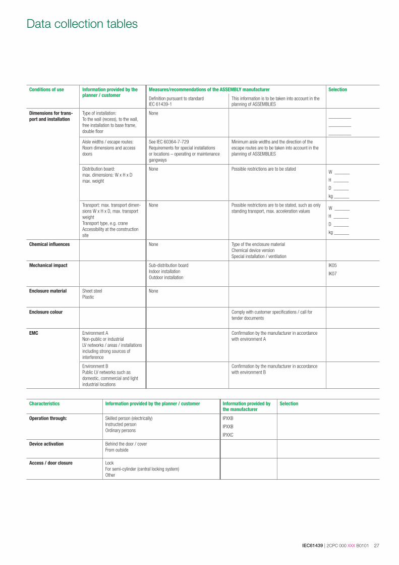
Data collection tables
Conditions of use Information provided by the planner / customer
Measures/recommendations of the ASSEMBLY manufacturer Selection
Definition pursuant to standard IEC 61439-1
This information is to be taken into account in the planning of ASSEMBLIES
Dimensions for trans-port and installation
Type of installation:To the wall (recess), to the wall, free installation to base frame, double floor
None _________
_________
_________
Aisle widths / escape routes: Room dimensions and access doors
See IEC 60364-7-729Requirements for special installations or locations – operating or maintenance gangways
Minimum aisle widths and the direction of the escape routes are to be taken into account in the planning of ASSEMBLIES
Distribution board:max. dimensions: W x H x Dmax. weight
None Possible restrictions are to be statedW ______
H ______
D ______
kg ______
Transport: max. transport dimen-sions W x H x D, max. transport weightTransport type, e.g. craneAccessibility at the construction site
None Possible restrictions are to be stated, such as only standing transport, max. acceleration values
W ______
H ______
D ______
kg ______
Chemical influences None Type of the enclosure materialChemical device versionSpecial installation / ventilation
Mechanical impact Sub-distribution boardIndoor installation Outdoor installation
IK05
IK07
Enclosure material Sheet steelPlastic
None
Enclosure colour Comply with customer specifications / call for tender documents
EMC Environment A Non-public or industrial LV networks / areas / installations including strong sources of interference
Confirmation by the manufacturer in accordance with environment A
Environment BPublic LV networks such as domestic, commercial and light industrial locations
Confirmation by the manufacturer in accordance with environment B
Characteristics Information provided by the planner / customer Information provided by the manufacturer
Selection
Operation through: Skilled person (electrically)Instructed personOrdinary persons
IPXXB
IPXXB
IPXXC
Device activation Behind the door / coverFrom outside
Access / door closure LockFor semi-cylinder (central locking system)Other
28 2CPC 000 XXX B0101 | IEC61439
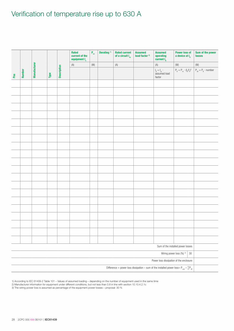
Verification of temperature rise up to 630 A
1) According to IEC 61439-2 Table 101 – Values of assumed loading – depending on the number of equipment used in the same time 2) Manufacturer information for equipment under different conditions, but not less than 0.8 in line with section 10.10.4.2.1c3) The wiring power loss is assumed as percentage of the equipment power losses – proposal: 30 %
Pos
Num
ber
Man
ufac
ture
r
Type
Desc
riptio
n
Ratedcurrent of theequipment In
Pvn Derating 1) Rated current of a circuit Inc
Assumed load factor 2)
Assumed operating current IB
Power loss of a device at IB
Sum of the power losses
(A) (W) (A) (A) (W) (W)
IB = Inc · assumed load factor
PB = Pvn · (IB/In)2 PvB = PB · number
Sum of the installed power losses
Wiring power loss (%) 3) 30
Power loss dissipation of the enclosure
Difference = power loss dissipation – sum of the installed power loss= Pvzul – ∑PvB

Contact us
ABB STRIEBEL & JOHN GmbH & Co. KGAm Fuchsgraben 2 - 3 77880 Sasbach Germany Phone: + 49 7841 609 0Fax: + 49 7841 609 545 E-Mail: [email protected]
www.striebelundjohn.com
We reserve the right to make technical changes or modify the contents of this document without prior notice. With regard to purchase orders, the agreed particulars shall prevail. ABB STRIEBEL & JOHN does not accept any responsibility whatsoever for potential errors or possible lack of information in this document.
We reserve all rights in this document and in the subject matter and illustrations contained therein. Any reproduction, disclosure to third parties or utilization of its contents - in whole or in parts - is forbidden without prior written consent of ABB STRIEBEL & JOHN.
Copyright © 2016 ABB STRIEBEL & JOHNAll rights reserved