Embed Size (px)
Citation preview


NOTE: All non-FAA approved parts in this catalog are signified by a (—) in the approval column. Parts without FAA approval may still be purchased, however, installation of these parts on U. S. Type Certificated products will require additional FAA approvals.I
Company Profile i Lighting Regulations ii ORION™ 1-2 CHROMA™ 3-4 Anti-Collision/Position 4-13 Power Supplies 14-17 Self-Contained Lightheads 18-22 Position Lights 23-24 Parmetheus Plus™ Replacement Lights 25-26 Parmetheus Pro™ Replacement Lights 27 Bonanza Product Suggestions 28 Exterior Lighthead Modules 29-35 MB500 Product Suggestions 36 Interior Lighting 37-42 Experimental 43 Miscellaneous 44 Cross Reference Charts 45-56
Greg Ginnetti
Original location of Whelen Engineering
First rotating beacon
Jeff Argersinger Jessie Bernier Trish WilleBryan Bochinski
TABLE OF CONTENTS
It All Started 1952 in a Garage with the First Rotating Beacon. A privately owned company, Whelen has experienced positive growth for over 60 years. The pride and commitment of its work force, whose employment longevity averages over 22 years, is rewarded through a profit sharing plan established by the Whelen family since the company was founded. The development of the first aviation light helped launch Whelen into the automotive safety lighting industry as well. Whelen currently provides safety lighting for Police, Fire, EMS, and DOT professionals as well as many other industries. The production volumes seen in the automotive sector have allowed Whelen to invest in the latest automated assembly equipment in order to compete world-wide. Last year Whelen purchased over 60 million LEDs for use in their extensive family of products. In the 1970s Whelen introduced the Outdoor Warning Siren ... totally electronic and capable of not just warning tones but also high-powered voice messages. The Mass Notification Division has saved lives around the world. At Whelen Engineering, our goal is to bring innovative, life saving products to market more quickly while maintaining strict quality control throughout the process. We have accomplished this through a vertical manufacturing initiative to eliminate or reduce out-sourcing; the use of robotics and state- of-the-art production equipment; and, perhaps most importantly, a motiv- ated workforce of over 1400 employees. This allows us to meet and adapt to our customer’s changing needs in the shortest amount of time.
n Two manufacturing facilities totaling over 1 million square feet.n Largest staff of Design Engineers in the industry.n Research and development.n Partnering with OEMs on new vehicle design and product integration.n Plastics injection molding machines from 30 to 2000 tons capacity.n In-house plastics, hard-coating, metallizing, & sheet metal fabrication.n On-site test lab for environmental dust, moisture, vibration, etc, acoustic anechoic sound chamber, industry certifications (SAE, AMECA, FAA to name a few).n Sales and Technical Personnel are trained at the factory training center and return for updates on a regular schedule.n Worldwide network of Sales, Service and Training.
WHERE IT ALL BEGAN.....
Makers of Aviation, Automotive and Industrial Safety Lighting since 1952 Whelen Aviation Warning Products are all designed, assembled, tested and manufactured in the United States of America. CONTACT US: WWW.WHELEN.COM or [email protected]
®
ENGINEERING COMPANY, INC.
MANUFACTURING FACILITIESConnecticut plant New Hampshire plant
NOTE: All non-FAA approved parts in this catalog are signified by a (—) in the approval column. Parts without FAA approval may still be purchased, however, installation of these parts on U. S. Type Certificated products will require additional FAA approvals. II
LIGHTING REGULATIONS
REQUIREMENTS, LOCATIONS, & DISTRIBUTION PATTERNS
INSTALLATION LOCATIONS
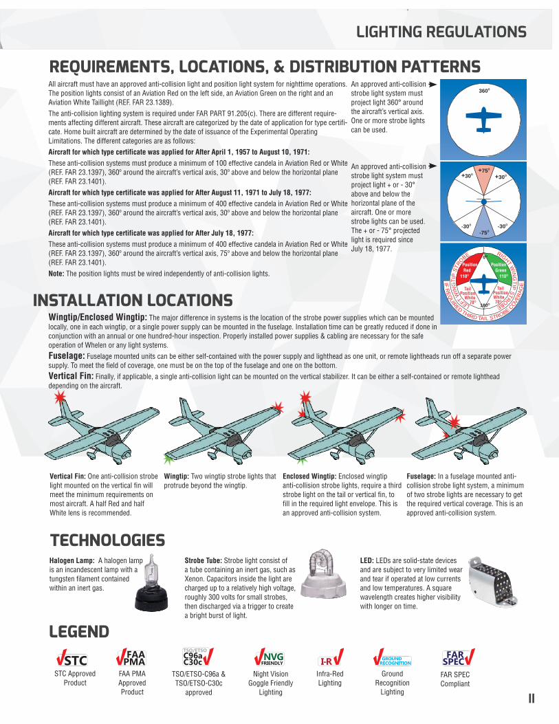
All aircraft must have an approved anti-collision light and position light system for nighttime operations. The position lights consist of an Aviation Red on the left side, an Aviation Green on the right and an Aviation White Taillight (REF. FAR 23.1389). The anti-collision lighting system is required under FAR PART 91.205(c). There are different require-ments affecting different aircraft. These aircraft are categorized by the date of application for type certifi-cate. Home built aircraft are determined by the date of issuance of the Experimental Operating Limitations. The different categories are as follows:Aircraft for which type certificate was applied for After April 1, 1957 to August 10, 1971:These anti-collision systems must produce a minimum of 100 effective candela in Aviation Red or White (REF. FAR 23.1397), 360º around the aircraft’s vertical axis, 30º above and below the horizontal plane (REF. FAR 23.1401).Aircraft for which type certificate was applied for After August 11, 1971 to July 18, 1977:These anti-collision systems must produce a minimum of 400 effective candela in Aviation Red or White (REF. FAR 23.1397), 360º around the aircraft’s vertical axis, 30º above and below the horizontal plane (REF. FAR 23.1401).Aircraft for which type certificate was applied for After July 18, 1977:These anti-collision systems must produce a minimum of 400 effective candela in Aviation Red or White (REF. FAR 23.1397), 360º around the aircraft’s vertical axis, 75º above and below the horizontal plane (REF. FAR 23.1401).Note: The position lights must be wired independently of anti-collision lights.
An approved anti-collision strobe light system must project light 360° around the aircraft’s vertical axis. One or more strobe lights can be used.
An approved anti-collision strobe light system must project light + or - 30° above and below the horizontal plane of the aircraft. One or more strobe lights can be used. The + or - 75° projected light is required since July 18, 1977.
360º
-75º-30º -30º
+75º+30º +30º
LEFTW
ING
TIP
STR
O
BE
IFR
EQ
UIRED
THIRD TAIL STROBE
COVE
RA
GE
RIGHTW
ING
TIP
STROBE
PositionGreen
110º
PositionRed
110º
TailPosition
White70º
TailPositionWhite70º
0º
180º
Wingtip/Enclosed Wingtip: The major difference in systems is the location of the strobe power supplies which can be mounted locally, one in each wingtip, or a single power supply can be mounted in the fuselage. Installation time can be greatly reduced if done in conjunction with an annual or one hundred-hour inspection. Properly installed power supplies & cabling are necessary for the safe operation of Whelen or any light systems.Fuselage: Fuselage mounted units can be either self-contained with the power supply and lighthead as one unit, or remote lightheads run off a separate power supply. To meet the field of coverage, one must be on the top of the fuselage and one on the bottom.Vertical Fin: Finally, if applicable, a single anti-collision light can be mounted on the vertical stabilizer. It can be either a self-contained or remote lighthead depending on the aircraft.
Vertical Fin: One anti-collision strobe light mounted on the vertical fin will meet the minimum requirements on most aircraft. A half Red and half White lens is recommended.
Wingtip: Two wingtip strobe lights that protrude beyond the wingtip.
Enclosed Wingtip: Enclosed wingtip anti-collision strobe lights, require a third strobe light on the tail or vertical fin, to fill in the required light envelope. This is an approved anti-collision system.
Fuselage: In a fuselage mounted anti-collision strobe light system, a minimum of two strobe lights are necessary to get the required vertical coverage. This is an approved anti-collision system.
LEGEND
Halogen Lamp: A halogen lamp is an incandescent lamp with a tungsten filament contained within an inert gas.
LED: LEDs are solid-state devices and are subject to very limited wear and tear if operated at low currents and low temperatures. A square wavelength creates higher visibility with longer on time.
Strobe Tube: Strobe light consist of a tube containing an inert gas, such as Xenon. Capacitors inside the light are charged up to a relatively high voltage, roughly 300 volts for small strobes, then discharged via a trigger to create a bright burst of light.
TECHNOLOGIES
STC FAAPMA
C96aTSO/ETSO
C30c NVGFRIENDLY
GROUNDRECOGNITION
FARSPECI-R
TSO/ETSO-C96a & TSO/ETSO-C30c
approved
Night Vision Goggle Friendly
Lighting
Infra-Red Lighting
Ground Recognition
Lighting
STC Approved Product
FAA PMA Approved Product
FAR SPEC Compliant
NOTE: All non-FAA approved parts in this catalog are signified by a (—) in the approval column. Parts without FAA approval may still be purchased, however, installation of these parts on U. S. Type Certificated products will require additional FAA approvals.1
SELF-CONTAINED POSITION/ANTI-COLLISION LIGHTHEADS
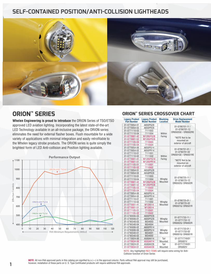
ORION™ SERIESWhelen Engineering is proud to introduce the ORION Series of TSO/ETSO approved LED aviation lighting. Incorporating the latest state-of-the-art LED Technology available in an all-inclusive package, the ORION series eliminates the need for external flasher boxes. Flush mountable for a wide variety of applications with minimal integration and easily retrofitable to the Whelen legacy strobe products. The ORION series is quite simply the brightest form of LED Anti-collision and Position lighting available.
400
500
600
700
800
900
1000
1100
0 10 20 30 40 50 60 70 80 90 100 110 120 FAA Minimum Requirements (400cd)
Performance Output
E�ec
tive
Cand
ela
ORION 600 TSO’d
ORION 650E TSO’d
ORION 500 TSO’d
Legacy Product Part Number
Legacy Product Model Number
Moutning Location
Orion Replacement Model Number
01-0770054-01 A650PG28
WithinFaring
01-0790701-11 / 01-0790701-12
OR6502GE / OR6502RE
*NOTE Not to be mounted on
exterior of aircraft
01-0770054-03 A650PR2801-0771110-03 711100301-0771110-04 711100401-0770001-42 W1285PG2801-0770001-52 W1285PR2801-0771105-03 711050301-0771105-04 711050401-0770054-00 A650PG14
WithinFaring
01-0790701-01 / 01-0790701-02
OR6501GE / OR6501RE
*NOTE Not to be mounted on
exterior of aircraft
01-0770054-02 A650PR1401-0771110-01 711100101-0771110-02 711100201-0770001-41 W1285PG1401-0770001-51 W1285PR1401-0771105-01 711050101-0771105-02 711050201-0770054-01 A650PG28
WingtipMounted
01-0790725-11 / 01-0790725-12
OR6502G/ OR6502R
01-0770054-03 A650PR2801-0771110-03 711100301-0771110-04 711100401-0770001-42 W1285PG2801-0770001-52 W1285PR2801-0771105-03 711050301-0771105-04 711050401-0770054-00 A650PG14
WingtipMounted
01-0790725-01 / 01-0790725-02
OR6501G/ OR6501R
01-0770054-02 A650PR1401-0771110-01 711100101-0771110-02 711100201-0770001-41 W12851401-0770001-51 W12851401-0771105-01 711050101-0771105-02 711050201-0790006-03 A600PR28
WingtipMounted
01-0771733-11 / 01-0771733-12
OR6002G/ OR6002R
01-0790006-01 A600PG2801-0790340-03 903400301-0790340-04 903400401-0790006-02 A600PR14
WingtipMounted
01-0771733-01 / 01-0771733-02
OR6001G/ OR6001R
01-0790006-00 A600PG1401-0790340-01 903400101-0790340-02 903400201-0770024-00 A500AV14 Tail
Mounted01-0771774V01
OR5001V01-0770034-00 A555AV1401-0770024-01 A500AV28 Tail
Mounted01-0771774V01
OR5002V01-0770034-01 A555AV28
ORION™ SERIES CROSSOVER CHART
NOTE: Any highlighted RED ITEMS will require extra wiring for Anti-Collision function of Orion Series
NOTE: All non-FAA approved parts in this catalog are signified by a (—) in the approval column. Parts without FAA approval may still be purchased, however, installation of these parts on U. S. Type Certificated products will require additional FAA approvals. 2
SELF-CONTAINED POSITION/ANTI-COLLISION LIGHTHEADS
ORION™ 600
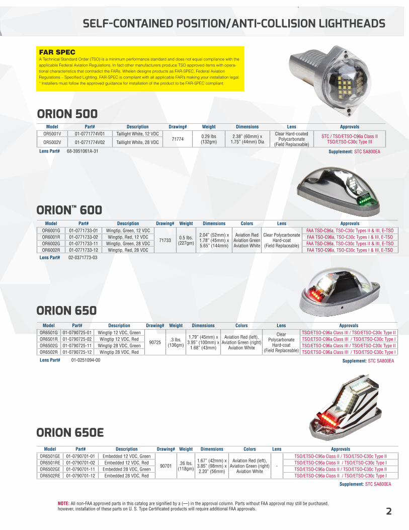
FAR SPEC A Technical Standard Order (TSO) is a minimum performance standard and does not equal compliance with the applicable Federal Aviation Regulations. In fact other manufacturers produce TSO approved items with opera-tional characteristics that contradict the FARs. Whelen designs products as FAR-SPEC, Federal Aviation Regulations – Specified Lighting. FAR-SPEC is compliant with all applicable FAR’s making your installation legal. * Installers must follow the approved guidance for installation of the product to be FAR-SPEC compliant
ORION 500Model Part# Description Drawing# Weight Dimensions Lens Approvals
OR5001V 01-0771774V01 Taillight White, 12 VDC71774 0.29 lbs
(132gm)2.38” (60mm) x
1.75” (44mm) Dia
Clear Hard-coated Polycarbonate
(Field Replaceable)
STC / TSO/ETSO-C96a Class II TSO/ETSO-C30c Type III OR5002V 01-0771774V02 Taillight White, 28 VDC
Supplement: STC SA800EA
Supplement: STC SA800EA
Supplement: STC SA800EA
Model Part# Description Drawing# Weight Dimensions Colors Lens ApprovalsOR6001G 01-0771733-01 Wingtip, Green, 12 VDC
71733 0.5 lbs.(227gm)
2.04” (52mm) x1.78” (45mm) x5.65” (144mm)
Aviation Red Aviation Green Aviation White
Clear Polycarbonate Hard-coat
(Field Replaceable)
FAA TSO-C96a, TSO-C30c Types II & III, E-TSOOR6001R 01-0771733-02 Wingtip, Red, 12 VDC FAA TSO-C96a, TSO-C30c Types I & III, E-TSOOR6002G 01-0771733-11 Wingtip, Green, 28 VDC FAA TSO-C96a, TSO-C30c Types II & III, E-TSOOR6002R 01-0771733-12 Wingtip, Red, 28 VDC FAA TSO-C96a, TSO-C30c Types I & III, E-TSO
Model Part# Description Drawing# Weight Dimensions Colors Lens ApprovalsOR6501G 01-0790725-01 Wingtip 12 VDC, Green
90725 .3 lbs. (136gm)
1.79” (45mm) x3.95” (100mm) x
1.68” (43mm)
Aviation Red (left), Aviation Green (right)
Aviation White
Clear Polycarbonate
Hard-coat (Field Replaceable)
TSO/ETSO-C96a Class III / TSO/ETSO-C30c Type IIOR6501R 01-0790725-02 Wingtip 12 VDC, Red TSO/ETSO-C96a Class III / TSO/ETSO-C30c Type IOR6502G 01-0790725-11 Wingtip 28 VDC, Green TSO/ETSO-C96a Class III / TSO/ETSO-C30c Type IIOR6502R 01-0790725-12 Wingtip 28 VDC, Red TSO/ETSO-C96a Class III / TSO/ETSO-C30c Type I
Model Part# Description Drawing# Weight Dimensions Colors Lens ApprovalsOR6501GE 01-0790701-01 Embedded 12 VDC, Green
90701 .26 lbs. (118gm)
1.67” (42mm) x3.85” (98mm) x2.20” (56mm)
Aviation Red (left), Aviation Green (right)
Aviation White-
TSO/ETSO-C96a Class II / TSO/ETSO-C30c Type IIOR6501RE 01-0790701-02 Embedded 12 VDC, Red TSO/ETSO-C96a Class II / TSO/ETSO-C30c Type IOR6502GE 01-0790701-11 Embedded 28 VDC, Green TSO/ETSO-C96a Class II / TSO/ETSO-C30c Type IIOR6502RE 01-0790701-12 Embedded 28 VDC, Red TSO/ETSO-C96a Class II / TSO/ETSO-C30c Type I
Lens Part#
Lens Part#
02-0371773-03
68-3951061A-31
ORION 650E
ORION 650
Lens Part# 01-0251094-00
NOTE: All non-FAA approved parts in this catalog are signified by a (—) in the approval column. Parts without FAA approval may still be purchased, however, installation of these parts on U. S. Type Certificated products will require additional FAA approvals.33
SELF-CONTAINED POSITION/ANTI-COLLISION LIGHTHEADS
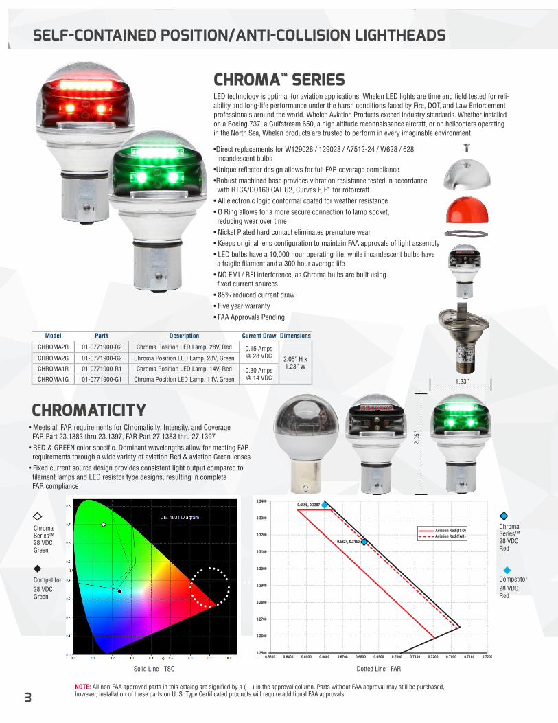
LED technology is optimal for aviation applications. Whelen LED lights are time and field tested for reli-ability and long-life performance under the harsh conditions faced by Fire, DOT, and Law Enforcement professionals around the world. Whelen Aviation Products exceed industry standards. Whether installed on a Boeing 737, a Gulfstream 650, a high altitude reconnaissance aircraft, or on helicopters operating in the North Sea, Whelen products are trusted to perform in every imaginable environment.
•Direct replacements for W129028 / 129028 / A7512-24 / W628 / 628 incandescent bulbs•Unique reflector design allows for full FAR coverage compliance•Robust machined base provides vibration resistance tested in accordance with RTCA/DO160 CAT U2, Curves F, F1 for rotorcraft• All electronic logic conformal coated for weather resistance• O Ring allows for a more secure connection to lamp socket, reducing wear over time• Nickel Plated hard contact eliminates premature wear• Keeps original lens configuration to maintain FAA approvals of light assembly• LED bulbs have a 10,000 hour operating life, while incandescent bulbs have a fragile filament and a 300 hour average life• NO EMI / RFI interference, as Chroma bulbs are built using fixed current sources• 85% reduced current draw • Five year warranty• FAA Approvals Pending
TYPICAL FILAMENT LAMP CHROMALED RED
CHROMA LED GREEN
2.05
”
1.23”
0.6824, 0.3160
Aviation Red (TSO)Aviation Red (FAR)
0.6596, 0.3387
Chroma Series™ 28 VDC Green
Chroma Series™ 28 VDC Red
Competitor 28 VDC Green
Competitor28 VDC Red
Solid Line - TSO Dotted Line - FAR
• Meets all FAR requirements for Chromaticity, Intensity, and Coverage FAR Part 23.1383 thru 23.1397, FAR Part 27.1383 thru 27.1397• RED & GREEN color specific. Dominant wavelengths allow for meeting FAR requirements through a wide variety of aviation Red & aviation Green lenses• Fixed current source design provides consistent light output compared to filament lamps and LED resistor type designs, resulting in complete FAR compliance
CHROMATICITY
CHROMA™ SERIES
Model Part# Description Current Draw Dimensions
CHROMA2R 01-0771900-R2 Chroma Position LED Lamp, 28V, Red 0.15 Amps @ 28 VDC 2.05” H x
1.23” WCHROMA2G 01-0771900-G2 Chroma Position LED Lamp, 28V, Green
CHROMA1R 01-0771900-R1 Chroma Position LED Lamp, 14V, Red 0.30 Amps @ 14 VDCCHROMA1G 01-0771900-G1 Chroma Position LED Lamp, 14V, Green
NOTE: All non-FAA approved parts in this catalog are signified by a (—) in the approval column. Parts without FAA approval may still be purchased, however, installation of these parts on U. S. Type Certificated products will require additional FAA approvals. 4
CHROMA™ SERIES
6
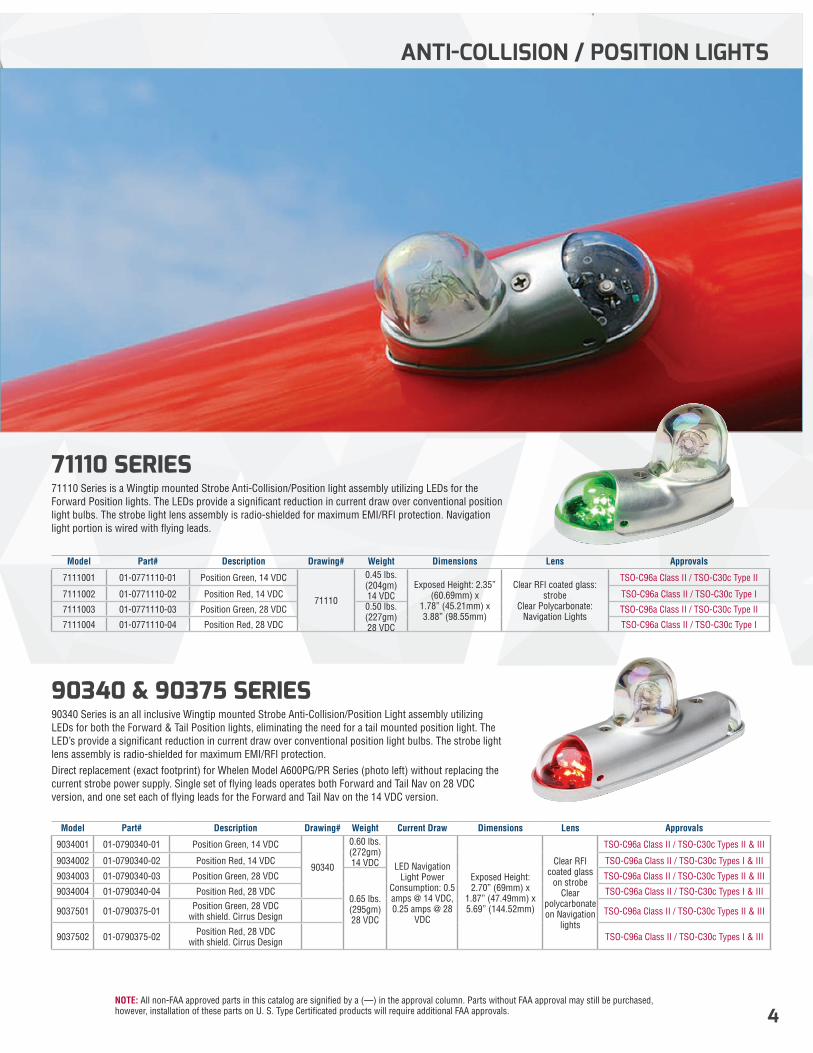
71110 SERIES71110 Series is a Wingtip mounted Strobe Anti-Collision/Position light assembly utilizing LEDs for the Forward Position lights. The LEDs provide a significant reduction in current draw over conventional position light bulbs. The strobe light lens assembly is radio-shielded for maximum EMI/RFI protection. Navigation light portion is wired with flying leads.
90340 & 90375 SERIES90340 Series is an all inclusive Wingtip mounted Strobe Anti-Collision/Position Light assembly utilizing LEDs for both the Forward & Tail Position lights, eliminating the need for a tail mounted position light. The LED’s provide a significant reduction in current draw over conventional position light bulbs. The strobe light lens assembly is radio-shielded for maximum EMI/RFI protection.Direct replacement (exact footprint) for Whelen Model A600PG/PR Series (photo left) without replacing the current strobe power supply. Single set of flying leads operates both Forward and Tail Nav on 28 VDC version, and one set each of flying leads for the Forward and Tail Nav on the 14 VDC version.
Model Part# Description Drawing# Weight Dimensions Lens Approvals
7111001 01-0771110-01 Position Green, 14 VDC
71110
0.45 lbs. (204gm) 14 VDC
Exposed Height: 2.35” (60.69mm) x
1.78” (45.21mm) x3.88” (98.55mm)
Clear RFI coated glass: strobe
Clear Polycarbonate: Navigation Lights
TSO-C96a Class II / TSO-C30c Type II
7111002 01-0771110-02 Position Red, 14 VDC TSO-C96a Class II / TSO-C30c Type I
7111003 01-0771110-03 Position Green, 28 VDC 0.50 lbs. (227gm) 28 VDC
TSO-C96a Class II / TSO-C30c Type II
7111004 01-0771110-04 Position Red, 28 VDC TSO-C96a Class II / TSO-C30c Type I
Model Part# Description Drawing# Weight Current Draw Dimensions Lens Approvals
9034001 01-0790340-01 Position Green, 14 VDC
90340
0.60 lbs. (272gm) 14 VDC LED Navigation
Light Power Consumption: 0.5 amps @ 14 VDC, 0.25 amps @ 28
VDC
Exposed Height: 2.70” (69mm) x
1.87” (47.49mm) x5.69” (144.52mm)
Clear RFI coated glass
on strobe Clear
polycarbonate on Navigation
lights
TSO-C96a Class II / TSO-C30c Types II & III
9034002 01-0790340-02 Position Red, 14 VDC TSO-C96a Class II / TSO-C30c Types I & III
9034003 01-0790340-03 Position Green, 28 VDC
0.65 lbs. (295gm) 28 VDC
TSO-C96a Class II / TSO-C30c Types II & III
9034004 01-0790340-04 Position Red, 28 VDC TSO-C96a Class II / TSO-C30c Types I & III
9037501 01-0790375-01 Position Green, 28 VDC with shield. Cirrus Design TSO-C96a Class II / TSO-C30c Types II & III
9037502 01-0790375-02 Position Red, 28 VDC with shield. Cirrus Design TSO-C96a Class II / TSO-C30c Types I & III
ANTI-COLLISION / POSITION LIGHTS
NOTE: All non-FAA approved parts in this catalog are signified by a (—) in the approval column. Parts without FAA approval may still be purchased, however, installation of these parts on U. S. Type Certificated products will require additional FAA approvals.5
ANTI-COLLISION / POSITION LIGHTS
“...AN ALL LED UPGRADE TO CESSNA CITATION WINGTIP STROBE LEGACY PRODUCTS ”
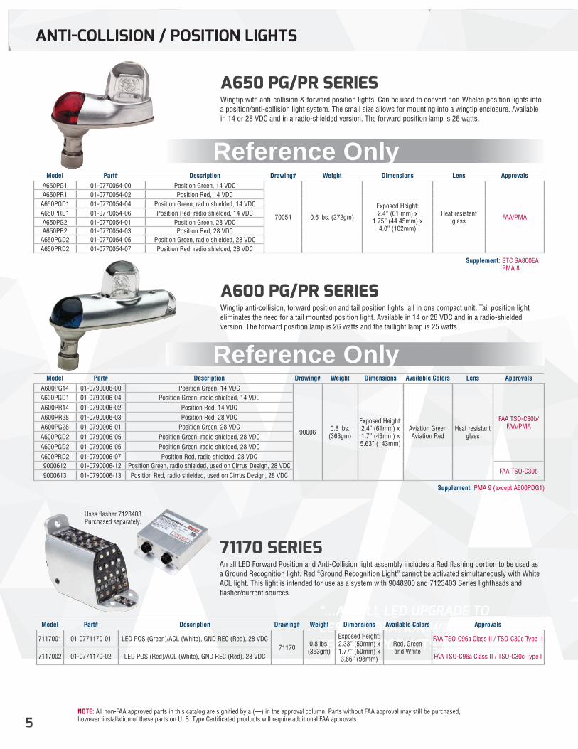
A650 PG/PR SERIES Wingtip with anti-collision & forward position lights. Can be used to convert non-Whelen position lights into a position/anti-collision light system. The small size allows for mounting into a wingtip enclosure. Available in 14 or 28 VDC and in a radio-shielded version. The forward position lamp is 26 watts.
A600 PG/PR SERIESWingtip anti-collision, forward position and tail position lights, all in one compact unit. Tail position light eliminates the need for a tail mounted position light. Available in 14 or 28 VDC and in a radio-shielded version. The forward position lamp is 26 watts and the taillight lamp is 25 watts.
71170 SERIES An all LED Forward Position and Anti-Collision light assembly includes a Red flashing portion to be used as a Ground Recognition light. Red “Ground Recognition Light” cannot be activated simultaneously with White ACL light. This light is intended for use as a system with 9048200 and 7123403 Series lightheads and flasher/current sources.
Uses flasher 7123403. Purchased separately.
Model Part# Description Drawing# Weight Dimensions Lens ApprovalsA650PG1 01-0770054-00 Position Green, 14 VDC
70054 0.6 lbs. (272gm)
Exposed Height: 2.4” (61 mm) x
1.75” (44.45mm) x 4.0” (102mm)
Heat resistent glass FAA/PMA
A650PR1 01-0770054-02 Position Red, 14 VDCA650PGD1 01-0770054-04 Position Green, radio shielded, 14 VDCA650PRD1 01-0770054-06 Position Red, radio shielded, 14 VDCA650PG2 01-0770054-01 Position Green, 28 VDCA650PR2 01-0770054-03 Position Red, 28 VDC
A650PGD2 01-0770054-05 Position Green, radio shielded, 28 VDCA650PRD2 01-0770054-07 Position Red, radio shielded, 28 VDC
Model Part# Description Drawing# Weight Dimensions Available Colors Lens ApprovalsA600PG14 01-0790006-00 Position Green, 14 VDC
90006 0.8 lbs. (363gm)
Exposed Height: 2.4” (61mm) x 1.7” (43mm) x 5.63” (143mm)
Aviation Green Aviation Red
Heat resistant glass
FAA TSO-C30b/FAA/PMA
A600PGD1 01-0790006-04 Position Green, radio shielded, 14 VDCA600PR14 01-0790006-02 Position Red, 14 VDCA600PR28 01-0790006-03 Position Red, 28 VDCA600PG28 01-0790006-01 Position Green, 28 VDCA600PGD2 01-0790006-05 Position Green, radio shielded, 28 VDCA600PGD2 01-0790006-05 Position Green, radio shielded, 28 VDCA600PRD2 01-0790006-07 Position Red, radio shielded, 28 VDC9000612 01-0790006-12 Position Green, radio shielded, used on Cirrus Design, 28 VDC
FAA TSO-C30b9000613 01-0790006-13 Position Red, radio shielded, used on Cirrus Design, 28 VDC
Model Part# Description Drawing# Weight Dimensions Available Colors Approvals
7117001 01-0771170-01 LED POS (Green)/ACL (White), GND REC (Red), 28 VDC71170 0.8 lbs.
(363gm)
Exposed Height: 2.33” (59mm) x 1.77” (50mm) x 3.86” (98mm)
Red, Green and White
FAA TSO-C96a Class II / TSO-C30c Type II
7117002 01-0771170-02 LED POS (Red)/ACL (White), GND REC (Red), 28 VDC FAA TSO-C96a Class II / TSO-C30c Type I
Supplement: STC SA800EA PMA 8
Supplement: PMA 9 (except A600PDG1)
Reference Only
Reference Only
NOTE: All non-FAA approved parts in this catalog are signified by a (—) in the approval column. Parts without FAA approval may still be purchased, however, installation of these parts on U. S. Type Certificated products will require additional FAA approvals. 6
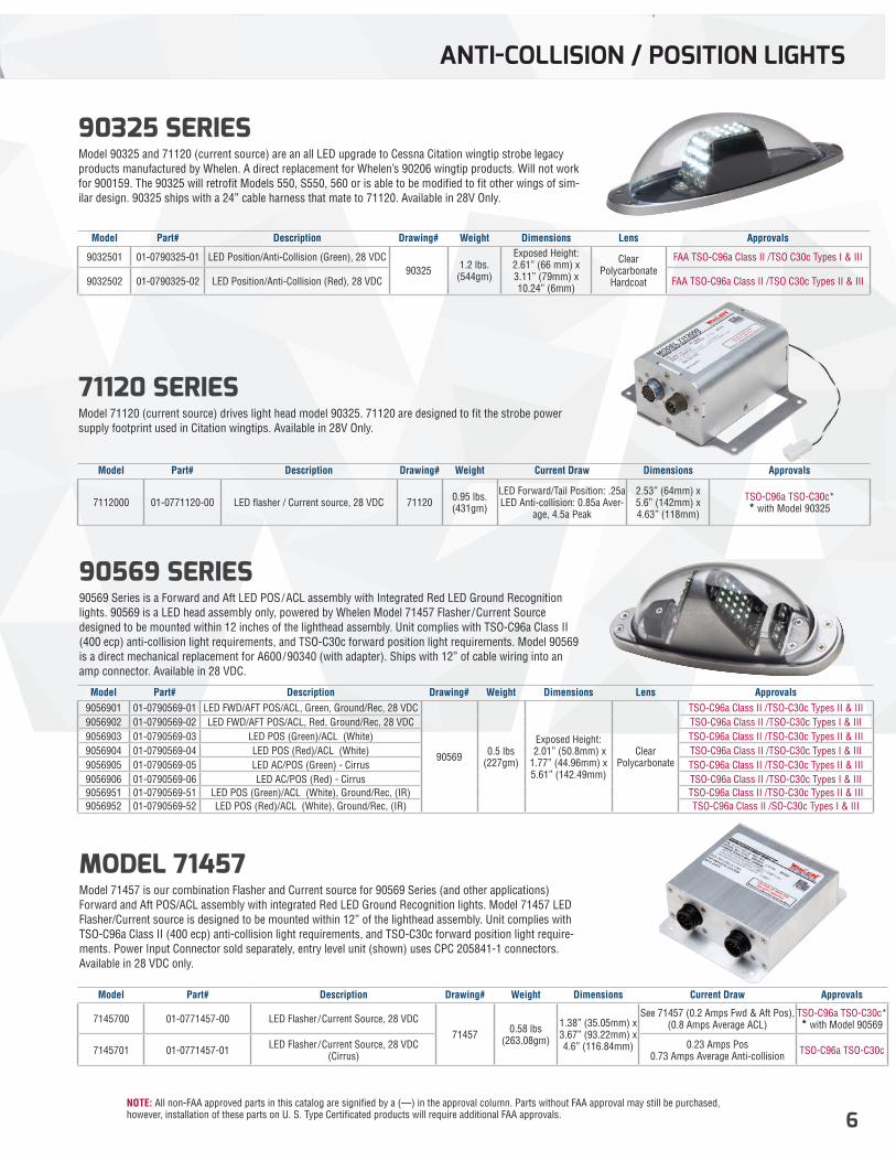
90569 SERIES 90569 Series is a Forward and Aft LED POS/ACL assembly with Integrated Red LED Ground Recognition lights. 90569 is a LED head assembly only, powered by Whelen Model 71457 Flasher/Current Source designed to be mounted within 12 inches of the lighthead assembly. Unit complies with TSO-C96a Class II (400 ecp) anti-collision light requirements, and TSO-C30c forward position light requirements. Model 90569 is a direct mechanical replacement for A600/90340 (with adapter). Ships with 12” of cable wiring into an amp connector. Available in 28 VDC.
MODEL 71457 Model 71457 is our combination Flasher and Current source for 90569 Series (and other applications) Forward and Aft POS/ACL assembly with integrated Red LED Ground Recognition lights. Model 71457 LED Flasher/Current source is designed to be mounted within 12” of the lighthead assembly. Unit complies with TSO-C96a Class II (400 ecp) anti-collision light requirements, and TSO-C30c forward position light require-ments. Power Input Connector sold separately, entry level unit (shown) uses CPC 205841-1 connectors. Available in 28 VDC only.
Model Part# Description Drawing# Weight Dimensions Lens Approvals9056901 01-0790569-01 LED FWD/AFT POS/ACL, Green, Ground/Rec, 28 VDC
90569 0.5 lbs (227gm)
Exposed Height: 2.01” (50.8mm) x1.77” (44.96mm) x5.61” (142.49mm)
Clear Polycarbonate
TSO-C96a Class II /TSO-C30c Types II & III9056902 01-0790569-02 LED FWD/AFT POS/ACL, Red, Ground/Rec, 28 VDC TSO-C96a Class II /TSO-C30c Types I & III9056903 01-0790569-03 LED POS (Green)/ACL (White) TSO-C96a Class II /TSO-C30c Types II & III9056904 01-0790569-04 LED POS (Red)/ACL (White) TSO-C96a Class II /TSO-C30c Types I & III9056905 01-0790569-05 LED AC/POS (Green) - Cirrus TSO-C96a Class II /TSO-C30c Types II & III9056906 01-0790569-06 LED AC/POS (Red) - Cirrus TSO-C96a Class II /TSO-C30c Types I & III9056951 01-0790569-51 LED POS (Green)/ACL (White), Ground/Rec, (IR) TSO-C96a Class II /TSO-C30c Types II & III9056952 01-0790569-52 LED POS (Red)/ACL (White), Ground/Rec, (IR) TSO-C96a Class II /SO-C30c Types I & III
Model Part# Description Drawing# Weight Dimensions Current Draw Approvals
7145700 01-0771457-00 LED Flasher/Current Source, 28 VDC71457 0.58 lbs
(263.08gm)
1.38” (35.05mm) x 3.67” (93.22mm) x4.6” (116.84mm)
See 71457 (0.2 Amps Fwd & Aft Pos), (0.8 Amps Average ACL)
TSO-C96a TSO-C30c** with Model 90569
7145701 01-0771457-01 LED Flasher/Current Source, 28 VDC (Cirrus)
0.23 Amps Pos 0.73 Amps Average Anti-collision TSO-C96a TSO-C30c
ANTI-COLLISION / POSITION LIGHTS
90325 SERIES Model 90325 and 71120 (current source) are an all LED upgrade to Cessna Citation wingtip strobe legacy products manufactured by Whelen. A direct replacement for Whelen’s 90206 wingtip products. Will not work for 900159. The 90325 will retrofit Models 550, S550, 560 or is able to be modified to fit other wings of sim-ilar design. 90325 ships with a 24” cable harness that mate to 71120. Available in 28V Only.
71120 SERIES Model 71120 (current source) drives light head model 90325. 71120 are designed to fit the strobe power supply footprint used in Citation wingtips. Available in 28V Only.
Model Part# Description Drawing# Weight Dimensions Lens Approvals
9032501 01-0790325-01 LED Position/Anti-Collision (Green), 28 VDC90325 1.2 lbs.
(544gm)
Exposed Height: 2.61” (66 mm) x 3.11” (79mm) x 10.24” (6mm)
Clear Polycarbonate
Hardcoat
FAA TSO-C96a Class II /TSO C30c Types I & III
9032502 01-0790325-02 LED Position/Anti-Collision (Red), 28 VDC FAA TSO-C96a Class II /TSO C30c Types II & III
Model Part# Description Drawing# Weight Current Draw Dimensions Approvals
7112000 01-0771120-00 LED flasher / Current source, 28 VDC 71120 0.95 lbs. (431gm)
LED Forward/Tail Position: .25a LED Anti-collision: 0.85a Aver-
age, 4.5a Peak
2.53” (64mm) x 5.6” (142mm) x 4.63” (118mm)
TSO-C96a TSO-C30c** with Model 90325
NOTE: All non-FAA approved parts in this catalog are signified by a (—) in the approval column. Parts without FAA approval may still be purchased, however, installation of these parts on U. S. Type Certificated products will require additional FAA approvals.7
ANTI-COLLISION / POSITION LIGHTS
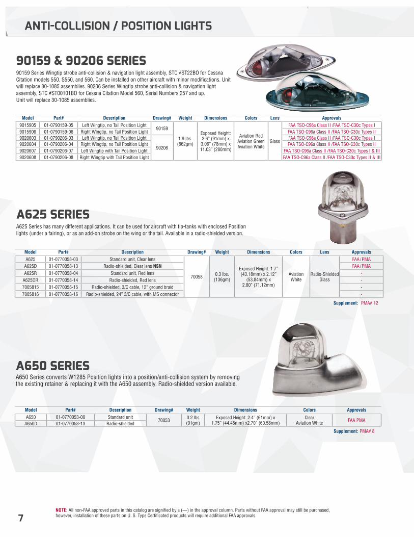
90159 & 90206 SERIES 90159 Series Wingtip strobe anti-collision & navigation light assembly, STC #ST22BO for Cessna Citation models 550, S550, and 560. Can be installed on other aircraft with minor modifications. Unit will replace 30-1085 assemblies. 90206 Series Wingtip strobe anti-collision & navigation light assembly, STC #ST00101BO for Cessna Citation Model 560, Serial Numbers 257 and up. Unit will replace 30-1085 assemblies.
A625 SERIES A625 Series has many different applications. It can be used for aircraft with tip-tanks with enclosed Position lights (under a fairing), or as an add-on strobe on the wing or the tail. Available in a radio-shielded version.
A650 SERIES A650 Series converts W1285 Position lights into a position/anti-collision system by removing the existing retainer & replacing it with the A650 assembly. Radio-shielded version available.
Model Part# Description Drawing# Weight Dimensions Colors Lens Approvals9015905 01-0790159-05 Left Wingtip, no Tail Position Light
90159
1.9 lbs. (862gm)
Exposed Height: 3.6” (91mm) x 3.06” (78mm) x 11.03” (280mm)
Aviation Red Aviation Green Aviation White
Glass
FAA TSO-C96a Class II /FAA TSO-C30c Types I9015906 01-0790159-06 Right Wingtip, no Tail Position Light FAA TSO-C96a Class II /FAA TSO-C30c Types II9020603 01-0790206-03 Left Wingtip, no Tail Position Light
90206
FAA TSO-C96a Class II /FAA TSO-C30c Types I9020604 01-0790206-04 Right Wingtip, no Tail Position Light FAA TSO-C96a Class II /FAA TSO-C30c Types II9020607 01-0790206-07 Left Wingtip with Tail Position Light FAA TSO-C96a Class II /FAA TSO-C30c Types I & III9020608 01-0790206-08 Right Wingtip with Tail Position Light FAA TSO-C96a Class II /FAA TSO-C30c Types II & III
Model Part# Description Drawing# Weight Dimensions Colors Lens ApprovalsA625 01-0770058-03 Standard unit, Clear lens
70058 0.3 lbs. (136gm)
Exposed Height: 1.7” (43.18mm) x 2.12”
(53.84mm) x 2.80” (71.12mm)
Aviation White
Radio-ShieldedGlass
FAA/PMAA625D 01-0770058-13 Radio-shielded, Clear lens NSN FAA/PMAA625R 01-0770058-04 Standard unit, Red lens -
A625DR 01-0770058-14 Radio-shielded, Red lens -7005815 01-0770058-15 Radio-shielded, 3/C cable, 12” ground braid -7005816 01-0770058-16 Radio-shielded, 24” 3/C cable, with MS connector -
Model Part# Description Drawing# Weight Dimensions Colors ApprovalsA650 01-0770053-00 Standard unit
70053 0.2 lbs. (91gm)
Exposed Height: 2.4” (61mm) x1.75” (44.45mm) x2.70” (60.58mm)
Clear Aviation White FAA PMA
A650D 01-0770053-13 Radio-shielded
Supplement: PMA# 12
Supplement: PMA# 8
NOTE: All non-FAA approved parts in this catalog are signified by a (—) in the approval column. Parts without FAA approval may still be purchased, however, installation of these parts on U. S. Type Certificated products will require additional FAA approvals. 8
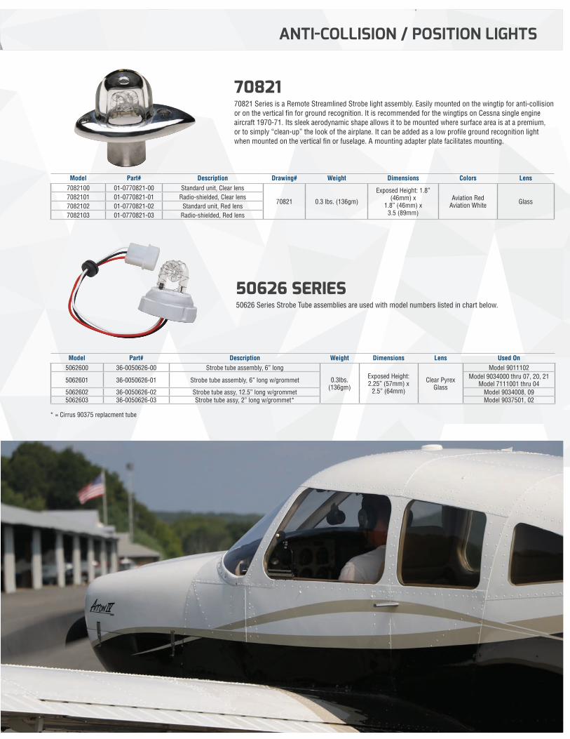
7082170821 Series is a Remote Streamlined Strobe light assembly. Easily mounted on the wingtip for anti-collision or on the vertical fin for ground recognition. It is recommended for the wingtips on Cessna single engine aircraft 1970-71. Its sleek aerodynamic shape allows it to be mounted where surface area is at a premium, or to simply “clean-up” the look of the airplane. It can be added as a low profile ground recognition light when mounted on the vertical fin or fuselage. A mounting adapter plate facilitates mounting.
50626 SERIES 50626 Series Strobe Tube assemblies are used with model numbers listed in chart below.
Model Part# Description Drawing# Weight Dimensions Colors Lens7082100 01-0770821-00 Standard unit, Clear lens
70821 0.3 lbs. (136gm)
Exposed Height: 1.8” (46mm) x
1.8” (46mm) x3.5 (89mm)
Aviation RedAviation White Glass
7082101 01-0770821-01 Radio-shielded, Clear lens7082102 01-0770821-02 Standard unit, Red lens7082103 01-0770821-03 Radio-shielded, Red lens
Model Part# Description Weight Dimensions Lens Used On5062600 36-0050626-00 Strobe tube assembly, 6” long
0.3lbs. (136gm)
Exposed Height: 2.25” (57mm) x
2.5” (64mm)
Clear Pyrex Glass
Model 9011102
5062601 36-0050626-01 Strobe tube assembly, 6” long w/grommet Model 9034000 thru 07, 20, 21Model 7111001 thru 04
5062602 36-0050626-02 Strobe tube assy, 12.5” long w/grommet Model 9034008, 095062603 36-0050626-03 Strobe tube assy, 2” long w/grommet* Model 9037501, 02
ANTI-COLLISION / POSITION LIGHTS
* = Cirrus 90375 replacment tube
NOTE: All non-FAA approved parts in this catalog are signified by a (—) in the approval column. Parts without FAA approval may still be purchased, however, installation of these parts on U. S. Type Certificated products will require additional FAA approvals.9
ANTI-COLLISION / POSITION LIGHTS
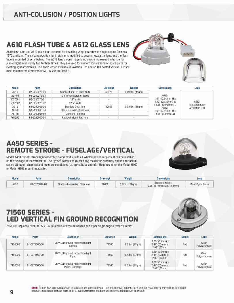
A610 FLASH TUBE & A612 GLASS LENS A610 flash tube and A612 glass lens are used for installing wingtip strobes in single engine Cessnas 1972 and later. The existing position light retainer is modified to accommodate the lens, and the flash tube is mounted directly behind. The A612 lens unique magnifying design increases the horizontal plane’s light intensity by two to three times. They are used for custom installations or spare parts for existing light assemblies. The A612 lens is available in Aviation Red and an RFI coated version. Lenses meet material requirements of MIL-C-7989B Class B.
A450 SERIES - REMOTE STROBE - FUSELAGE/VERTICALModel A450 remote strobe light assembly is compatible with all Whelen power supplies. It can be installed on the fuselage or the vertical fin. The Pyrex® Glass lens (Clear only) makes the assembly suitable for use in severe vibration, chemical and moisture conditions (i.e. agricultural aircraft). Requires either the Model H102 or Model H103 mounting adapter.
71560 SERIES - LED VERTICAL FIN GROUND RECOGNITION7156000 Replaces 7078600 & 7105000 and is utilized on Cessna and Piper single engine restart aircraft.
Model Part# Description Drawing# Weight Dimensions LensA610 02-0250276-00 Standard unit, 6” leads NSN 50276 0.09 lbs. (41gm)
A610: 1.6” (40.64mm) H x 1.12” (28.39mm) W x 1.56” (39.64mm) L
A612: 1.6” (40.64mm) H x 1.75” (44mm) Dia
A612: RF Coated Clear & Aviation Red
A610M 02-0250276-03 Molex connector, 6” leads - -5027601 02-0250276-01 14” leads - -5027602 02-0250276-02 12.5” leads - -
A612 68-2290005-30 Standard Clear lens 90005 0.08 lbs. (36gm)A612C 68-2290005-34 Radio-shielded, Clear lens - -A612R 68-2290005-50 Standard Red lens - -
A612RC 68-2290005-54 Radio-shielded, Red lens - -
Model Part# Description Drawing# Weight Dimensions Lens
A450 01-0770032-00 Standard assembly, Clear lens 70032 0.3lbs. (136gm) Exposed Height: 2.25” (57mm) x 2.5” (64mm) Clear Pyrex Glass
Model Part# Description Drawing# Weight Dimensions Colors Lens
7156000 01-0771560-00 28 V LED ground recognition lightCessna 71560 0.2 lbs. (97gm)
1.39” (35mm) x 2.47” (63mm) x 2.09” (53mm)
Red Clear Polycarbonate
7156020 01-0771560-20 28 V LED ground recognition lightPiper 71560 0.2 lbs. (97gm)
1.39” (35mm) x 2.47” (63mm) x 2.09” (53mm)
Red Clear Polycarbonate
7156050 01-0771560-50 28 V LED ground recognition lightPiper (Teardrop) 71560 0.2 lbs. (97gm)
1.39” (35mm) x 2.47” (63mm) x 2.09” (53mm)
Red Clear Polycarbonate
NOTE: All non-FAA approved parts in this catalog are signified by a (—) in the approval column. Parts without FAA approval may still be purchased, however, installation of these parts on U. S. Type Certificated products will require additional FAA approvals. 10
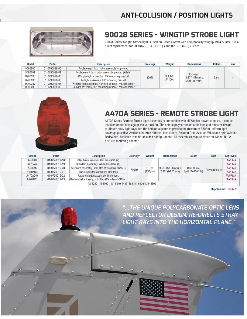
90028 SERIES - WINGTIP STROBE LIGHT90028 Series Wingtip Strobe light is used on Beech aircraft with commonality wingtip 1974 & later. It is a direct replacement for 30-0467-( ), 30-1331-( ) and the 30-1467-( ) Series.
A470A SERIES - REMOTE STROBE LIGHTA470A Series Remote Strobe Light assembly is compatible with all Whelen power supplies. It can be installed on the fuselage or the vertical fin. The unique polycarbonate optic lens and reflector design re-directs stray light rays into the horizontal plane to provide the maximum 360º of uniform light coverage possible. Available in three different lens colors, Aviation Red, Aviation White and split Aviation Red/White. Available in radio-shielded configurations. All assemblies require either the Model H102 or H103 mounting adapter.
Model Part# Description Drawing# Weight Dimensions Colors Lens9002800 01-0790028-00 Replacement flash tube assembly, unpainted
90028 0.4 lbs. (181gm)
Exposed: 1.87” (48mm) x2.25” (57mm)
Clear -
9002801 01-0790028-01 Replacement flash tube assembly, painted (White)D900283 01-0790028-03 Wingtip light assembly, 45º mounting bracketD900285 01-0790028-05 Taillight assembly, 90º mounting bracketD900287 01-0790028-07 Wingtip light assembly, 45º mtg. bracket, MS connectorD900289 01-0790028-09 Taillight assembly, 90º mounting bracket, MS connector
Model Part# Description Drawing# Weight Dimensions Colors Lens ApprovalsA470AR 01-0770019-18 Standard assembly, Red lens NSN (a)
70019 0.3 lbs. (136gm)
3.50” (88.90mm) x 2.58” (66.53mm)
Red, WhiteSplit (Red/White) Polycarbonate
FAA/PMAA470AW 01-0770019-19 Standard assembly, White lens NSN (b) FAA/PMAA470AS 01-0770019-20 Standard assembly, split Red/White lens NSN (*) FAA/PMA
A470ADR 01-0770019-21 Radio-shielded assembly, Red lens FAA/PMAA470ADW 01-0770019-22 Radio-shielded assembly, White lens FAA/PMAA470ADS 01-0770019-23 Radio-shielded ass’y, split Red/White lens NSN (c) FAA/PMA
(a) 6220-14851001, (b) 6340-14331362, (c) 6220-13844609
“...THE UNIQUE POLYCARBONATE OPTIC LENS AND REFLECTOR DESIGN, RE-DIRECTS STRAY LIGHT RAYS INTO THE HORIZONTAL PLANE.”
ANTI-COLLISION / POSITION LIGHTS
Supplement: PMA# 2
NOTE: All non-FAA approved parts in this catalog are signified by a (—) in the approval column. Parts without FAA approval may still be purchased, however, installation of these parts on U. S. Type Certificated products will require additional FAA approvals.11
ANTI-COLLISION / POSITION LIGHTS
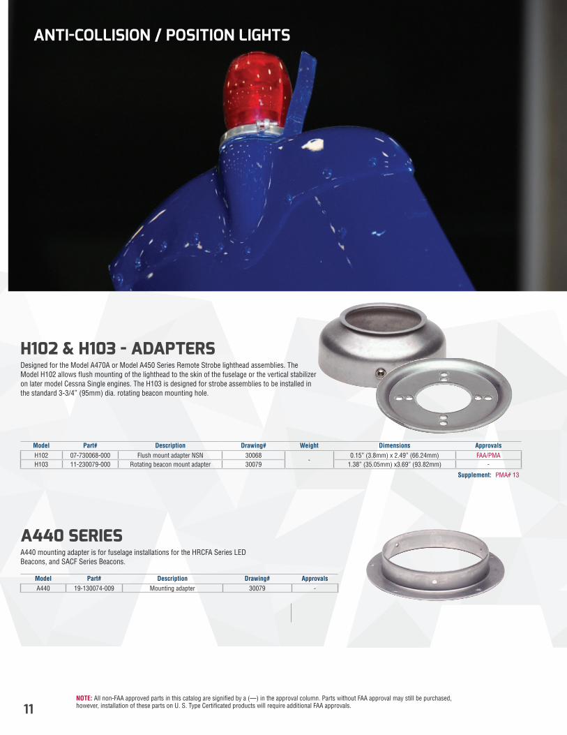
H102 & H103 - ADAPTERS Designed for the Model A470A or Model A450 Series Remote Strobe lighthead assemblies. The Model H102 allows flush mounting of the lighthead to the skin of the fuselage or the vertical stabilizer on later model Cessna Single engines. The H103 is designed for strobe assemblies to be installed in the standard 3-3/4” (95mm) dia. rotating beacon mounting hole.
A440 SERIESA440 mounting adapter is for fuselage installations for the HRCFA Series LED Beacons, and SACF Series Beacons.
Model Part# Description Drawing# Weight Dimensions ApprovalsH102 07-730068-000 Flush mount adapter NSN 30068
-0.15” (3.8mm) x 2.49” (66.24mm) FAA/PMA
H103 11-230079-000 Rotating beacon mount adapter 30079 1.38” (35.05mm) x3.69” (93.82mm) -
Model Part# Description Drawing# ApprovalsA440 19-130074-009 Mounting adapter 30079 -
Supplement: PMA# 13
NOTE: All non-FAA approved parts in this catalog are signified by a (—) in the approval column. Parts without FAA approval may still be purchased, however, installation of these parts on U. S. Type Certificated products will require additional FAA approvals. 12
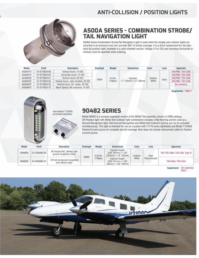
A500A SERIES - COMBINATION STROBE/TAIL NAVIGATION LIGHTA500A Series Combination Strobe/Tail Navigation Light is used when the wingtip anti-collision lights are mounted in an enclosure and can’t provide 360º of strobe coverage. It is a direct replacement for the stan-dard tail position light. Available in a radio-shielded version. Voltage (14 or 28) and mounting (horizontal or vertical) must be specified when ordering.
90482 SERIES Model 90482 is a compact upgraded version of the 90354 Tail assembly (shown in 2008 catalog). Aft Position light with White Anti-Collision light combination includes a Red flashing portion used as a Ground Recognition light. Red Ground Recognition and White Anti-Collision lighting can not be activated simultaneously. This light is intended for use as a system with 71170 series lightheads and Model 7123403 Flasher/Current source for complete aircraft coverage. Item does not include interconnect cable for Flasher/Current source.
Model Part# Description Drawing# Weight Dimensions Color Lens ApprovalsA500AV14 01-0770024-00 Vertical mount, 14 VDC
70024 0.3 lbs. (136gm)
Exposed: 1.7” (43mm x 1.5” (38mm)
Aviation White Glass
FAA/PMA, TSO-C30bA500AH14 01-0770024-02 Horizontal mount, 14 VDC FAA/PMA, TSO-C30bA500AV28 01-0770024-01 Vertical mount, 28 VDC FAA/PMA, TSO-C30bA500AVD2 01-0770024-05 Vertical mount, radio-shielded, 28 VDC FAA/PMA, TSO-C30bA500ASP2 01-0770024-25 Vertical mount, 50” cables, 28 VDC No connectorA500ABV2 01-0770024-15 Beech Special, MS connector, 24 VDC -
Model Part# Description Drawing# Weight Dimensions Color Lens Approvals
9048200 01-0790482-00 Aft Position/ACL (White) with ground recognition (Red)
90482 0.35 lbs. (159gm)
Exposed Height: 3.60” (91mm) x 1.25”
(32mm) x 1.78” (45mm) Aviation White
Clear Polycarbonate
FAA TSO-C96a/ TSO-C30c Type III
9048202 01-0790482-02 LED tail nav/ground recognition anti-collision light
Exposed Height: 3.60” (91mm) x 1.40”
(36mm) x 1.56” (40mm)TSO-C96a/ TSO-C30c
ANTI-COLLISION / POSITION LIGHTS
Supplement: STC SA615EA PMA 1
Uses flasher 7123403, purchased separately.
Supplement: PMA# 7
NOTE: All non-FAA approved parts in this catalog are signified by a (—) in the approval column. Parts without FAA approval may still be purchased, however, installation of these parts on U. S. Type Certificated products will require additional FAA approvals.13
POWER SUPPLIES
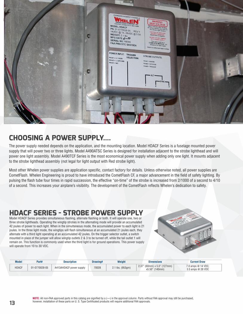
CHOOSING A POWER SUPPLY....The power supply needed depends on the application, and the mounting location. Model HDACF Series is a fuselage mounted power supply that will power two or three lights. Model A490ATSC Series is designed for installation adjacent to the strobe lighthead and will power one light assembly. Model A490TCF Series is the most economical power supply when adding only one light. It mounts adjacent to the strobe lighthead assembly (not legal for light output with Red strobe light).
Most other Whelen power supplies are application specific, contact factory for details. Unless otherwise noted, all power supplies are CometFlash. Whelen Engineering is proud to have introduced the CometFlash CF, a major advancement in the field of safety lighting. By pulsing the flash tube four times in rapid succession, the effective “on-time” of the strobe is increased from 2/1000 of a second to 4/10 of a second. This increases your airplane’s visibility. The development of the CometFlash reflects Whelen’s dedication to safety.
HDACF SERIES - STROBE POWER SUPPLY Model HDACF Series provides simultaneous flashing, alternate flashing or both. It will operate one, two or three strobe lightheads. Operating the wingtip strobes in the alternating mode will provide an accumulated 42 joules of power to each light. When in the simultaneous mode, the accumulated power to each light is 21 joules. In the three light mode, the wingtips will flash simultaneous at an accumulated 21 joules each, they alternate with a third light operating at an accumulated 42 joules. On the trigger selector outlet, a switch mounted in place of the jumper will allow wingtip outlets 2 & 3 to be turned off, while the tail outlet 1 will remain on. This function is commonly used when the third light is for ground operations. This power supply will operate from 10 to 30 VDC.
Model Part# Description Drawing# Weight Dimensions Current Draw
HDACF 01-0770028-05 A413AHDACF power supply 70028 2.1 lbs. (953gm) 2.37” (60mm) x 5.0” (127mm) x5.50” (140mm)
7.0 amps @ 14 VDC; 3.5 amps @ 28 VDC
NOTE: All non-FAA approved parts in this catalog are signified by a (—) in the approval column. Parts without FAA approval may still be purchased, however, installation of these parts on U. S. Type Certificated products will require additional FAA approvals. 14
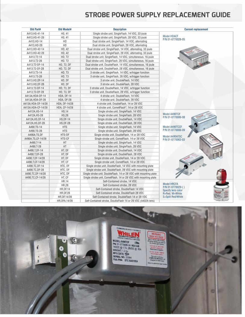
Old Part# Old Model# Description Current replacementA413,HS-41-14 HS, 41 Single strobe unit, SingleFlash, 14 VDC, 33 joule
Model HDACF P/N 01-0770028-05
A413,HS-41-28 HS, 41 Single strobe unit, SingleFlash, 28 VDC, 33 jouleA413,HD-14 HD Dual strobe unit, SingleFlash, 14 VDC, alternatingA413,HD-28 HD Dual strobe unit, SingleFlash, 28 VDC, alternating
A413,HD-42-14 HD, 42 Dual strobe unit, SingleFlash, 14 VDC, alternating, 33 jouleA413,HD-42-28 HD, 42 Dual strobe unit, SingleFlash, 28 VDC, alternating, 33 joule
A413,T2-14 HD, T2 Dual strobe unit, SingleFlash, 14 VDC, simultaneous, 16 jouleA413,T2-28 HD, T2 Dual strobe unit, SingleFlash, 28 VDC, simultaneous, 16 joule
A413,T2-DF-14 HD, T2, DF Dual strobe unit, DoubleFlash, 14 VDC, simultaneous, 16 jouleA413,T2-DF-28 HD, T2, DF Dual strobe unit, DoubleFlash, 28 VDC, simultaneous, 16 joule
A413,T3-14 HD, T3 3 strobe unit, SingleFlash, 14 VDC, w/trigger functionA413,T3-28 HD, T3 3 strobe unit, SingleFlash, 28 VDC, w/trigger function
A413,HD,DF-14 HD, DF 3 strobe unit, DoubleFlash, 14 VDCA413,HD,DF-28 HD, DF 3 strobe unit, DoubleFlash, 28 VDCA413,T3-DF-14 HD, T3, DF 3 strobe unit, DoubleFlash, 14 VDC, w/trigger functionA413,T3-DF-28 HD, T3, DF 3 strobe unit, DoubleFlash, 28 VDC, w/trigger function
A413A,HDA-DF-14 HDA, DF-14 4 strobe unit, DoubleFlash, 14 VDCA413A,HDA-DF-28 HDA, DF-28 4 strobe unit, DoubleFlash, 28 VDC
A413A,HDA-DF-14/28 HDA, DF-14/28 4 strobe unit, DoubleFlash, 14 or 28 VDCA413A,HDA-CF-14/28 HDA, CF-14/28 4 strobe unit, CometFlash®, 14 or 28 VDC
A412A,HS-14 HS,14 Single strobe unit, SingleFlash, 14 VDC Model A490TCF P/N 01-0770006-08 Model A490TCCF P/N 01-0770006-09 Model A490ATSC P/N 01-0770062-03
A412A,HS-28 HS,28 Single strobe unit, SingleFlash, 28 VDCA412A,HS,DF-14 HS,DF-14 Single strobe unit, DoubleFlash, 14 VDCA412A,HS,DF-28 HS,DF-28 Single strobe unit, DoubleFlash, 28 VDC
A490,TS-14 HTS Single strobe unit, SingleFlash, 14 VDCA490,TS-28 HTS Single strobe unit, SingleFlash, 28 VDC
A490A,TS,DF HTS-DF Single strobe unit, DoubleFlash, 14 or 28 VDCA490A,TS,CF-14/28 HTS-CF Single strobe unit, CometFlash, 14 or 28 VDC
A490,T-14 HT Single strobe unit, SingleFlash, 14 VDCA490,T-28 HT Single strobe unit, SingleFlash, 28 VDC
A490,T,DF-14 HT, DF Single strobe unit, DoubleFlash, 14 VDCA490,T,DF-28 HT, DF Single strobe unit, DoubleFlash, 28 VDC
A490,T,DF-14/28 HT, DF Single strobe unit, DoubleFlash, 14 or 28 VDCA490,T,CF-14/28 HT, CF Single strobe unit, CometFlash, 14 or 28 VDCA490,TC,DF-14 HTC, DF Single strobe unit, DoubleFlash, 14 VDC with mounting plateA490,TC,DF-28 HTC, DF Single strobe unit, DoubleFlash, 28 VDC with mounting plate
A490,TC,DF-14/28 HTC, DF Single strobe unit, DoubleFlash, 14 or 28 VDC with mounting plateA490,TC,CF-14/28 HT, CF Single strobe unit, CometFlash, 14 or 28 VDC with mounting plate
HR,14 Self-Contained strobe, 14 VDC Model HRCFA P/N 01-0770029-( ) Specify lens color R=Red, W=White S=Split Red/White
HR,28 Self-Contained strobe, 28 VDCHR,DF,14 Self-Contained strobe, DoubleFlash 14 VDCHR,DF,28 Self-Contained strobe, DoubleFlash 28 VDC
HR,DF,14/28 Self-Contained strobe, DoubleFlash 14 or 28 VDCHR,DFA,14/28 Self-Contained strobe, DoubleFlash 14 or 28 VDC (A402A lens)
POWER SUPPLIESSTROBE POWER SUPPLY REPLACEMENT GUIDE
NOTE: All non-FAA approved parts in this catalog are signified by a (—) in the approval column. Parts without FAA approval may still be purchased, however, installation of these parts on U. S. Type Certificated products will require additional FAA approvals.15
“...A DIRECT REPLACEMENT FOR THE STANDARD TAIL POSITION LIGHT.”
POWER SUPPLIES
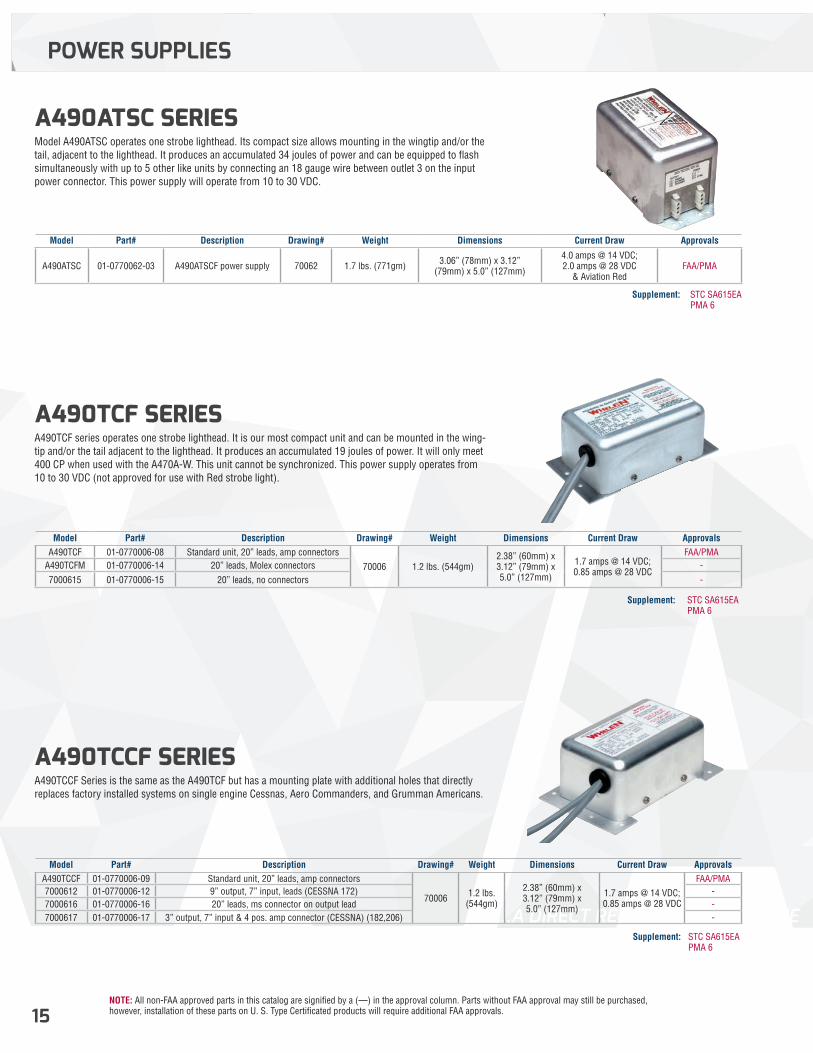
A490TCF SERIES A490TCF series operates one strobe lighthead. It is our most compact unit and can be mounted in the wing-tip and/or the tail adjacent to the lighthead. It produces an accumulated 19 joules of power. It will only meet 400 CP when used with the A470A-W. This unit cannot be synchronized. This power supply operates from 10 to 30 VDC (not approved for use with Red strobe light).
A490ATSC SERIES Model A490ATSC operates one strobe lighthead. Its compact size allows mounting in the wingtip and/or the tail, adjacent to the lighthead. It produces an accumulated 34 joules of power and can be equipped to flash simultaneously with up to 5 other like units by connecting an 18 gauge wire between outlet 3 on the input power connector. This power supply will operate from 10 to 30 VDC.
A490TCCF SERIES A490TCCF Series is the same as the A490TCF but has a mounting plate with additional holes that directly replaces factory installed systems on single engine Cessnas, Aero Commanders, and Grumman Americans.
Model Part# Description Drawing# Weight Dimensions Current Draw ApprovalsA490TCF 01-0770006-08 Standard unit, 20” leads, amp connectors
70006 1.2 lbs. (544gm)2.38” (60mm) x 3.12” (79mm) x5.0” (127mm)
1.7 amps @ 14 VDC; 0.85 amps @ 28 VDC
FAA/PMAA490TCFM 01-0770006-14 20” leads, Molex connectors -
7000615 01-0770006-15 20” leads, no connectors -
Model Part# Description Drawing# Weight Dimensions Current Draw Approvals
A490ATSC 01-0770062-03 A490ATSCF power supply 70062 1.7 lbs. (771gm) 3.06” (78mm) x 3.12” (79mm) x 5.0” (127mm)
4.0 amps @ 14 VDC; 2.0 amps @ 28 VDC
& Aviation RedFAA/PMA
Model Part# Description Drawing# Weight Dimensions Current Draw ApprovalsA490TCCF 01-0770006-09 Standard unit, 20” leads, amp connectors
70006 1.2 lbs. (544gm)
2.38” (60mm) x 3.12” (79mm) x5.0” (127mm)
1.7 amps @ 14 VDC; 0.85 amps @ 28 VDC
FAA/PMA7000612 01-0770006-12 9” output, 7” input, leads (CESSNA 172) -7000616 01-0770006-16 20” leads, ms connector on output lead -7000617 01-0770006-17 3” output, 7” input & 4 pos. amp connector (CESSNA) (182,206) -
Supplement: STC SA615EA PMA 6
Supplement: STC SA615EA PMA 6
Supplement: STC SA615EA PMA 6
NOTE: All non-FAA approved parts in this catalog are signified by a (—) in the approval column. Parts without FAA approval may still be purchased, however, installation of these parts on U. S. Type Certificated products will require additional FAA approvals. 16
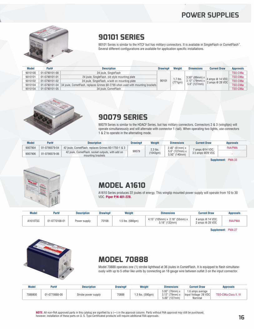
90079 SERIES 90079 Series is similar to the HDACF Series, but has military connectors. Connectors 2 & 3 (wingtips) will operate simultaneously and will alternate with connector 1 (tail). When operating two lights, use connectors 1 & 2 to operate in the alternating mode.
90101 SERIES 90101 Series is similar to the HTCF but has military connectors. It is available in SingleFlash or CometFlash®. Several different configurations are available for application specific installations.
MODEL 70888 Model 70888 operates one (1) strobe lighthead at 36 joules in CometFlash. It is equipped to flash simultane-ously with up to 5 other like units by connecting an 18 gauge wire between outlet 3 on the input connector.
MODEL A1610 A1610 Series produces 22 joules of energy. This wingtip mounted power supply will operate from 10 to 30 VDC. Piper P/N 481-228.
Model Part# Description Drawing# Weight Dimensions Current Draw Approvals
9007904 01-0790079-04 42 joule, CometFlash, replaces Grimes 60-1750-1 & 390079 2.3 lbs.
(1043gm)
2.40” (61mm) x 5.0” (127mm) x5.50” (140mm)
7 amps @14 VDC; 3.5 amps @28 VDC
FAA/PMA
9007906 01-0790079-06 42 joule, CometFlash, socket outputs, with add on mounting brackets -
Model Part# Description Drawing# Weight Dimensions Current Draw Approvals9010100 01-0790101-00 24 joule, SingleFlash
90101 1.7 lbs. (771gm)
3.50” (89mm) x 3.12” (79mm) x 5.0” (127mm)
4 amps @ 14 VDC; 2 amps @ 28 VDC
TSO-C96a9010101 01-0790101-01 24 joule, SingleFlash, old style mounting plate TSO-C96a9010102 01-0790101-02 24 joule, SingleFlash, w/add on mounting plate TSO-C96a9010104 01-0790101-04 34 joule, CometFlash, replaces Grimes 60-2799 when used with mounting brackets TSO-C96a9010104 01-0790101-05 34 joule, CometFlash TSO-C96a
Model Part# Description Drawing# Weight Dimensions Current Draw Approvals
7088800 01-0770888-00 Strobe power supply 70888 1.3 lbs. (590gm)3.00” (76mm) x 3.12” (79mm) x5.00” (127mm)
1.6 amps averageInput Voltage: 28 VDC
NominalTSO-C96a Class II, III
Model Part# Description Drawing# Weight Dimensions Current Draw Approvals
A1610TSC 01-0770168-01 Power supply 70168 1.5 lbs. (680gm) 4.15” (105mm) x 2.18” (55mm) x5.18” (132mm)
4 amps @ 14 VDC; 2 amps @ 28 VDC FAA/PMA
POWER SUPPLIES
Supplement: PMA 33
Supplement: PMA 27
NOTE: All non-FAA approved parts in this catalog are signified by a (—) in the approval column. Parts without FAA approval may still be purchased, however, installation of these parts on U. S. Type Certificated products will require additional FAA approvals.17
SELF-CONTAINED ANTI-COLLISION
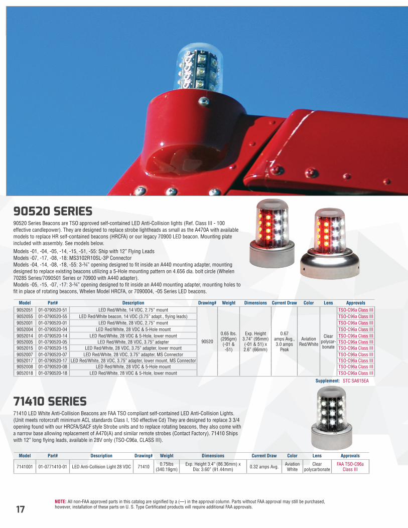
90520 SERIES 90520 Series Beacons are TSO approved self-contained LED Anti-Collision lights (Ref. Class III - 100 effective candlepower). They are designed to replace strobe lightheads as small as the A470A with available models to replace HR self-contained beacons (HRCFA) or our legacy 70900 LED beacon. Mounting plate included with assembly. See models below.Models -01, -04, -05, -14, -15, -51, -55: Ship with 12” Flying Leads Models -07, -17, -08, -18: MS3102R10SL-3P Connector Models -04, -14, -08, -18, -55: 3-¾” opening designed to fit inside an A440 mounting adapter, mounting designed to replace existing beacons utilizing a 5-Hole mounting pattern on 4.656 dia. bolt circle (Whelen 70285 Series/7090501 Series or 70900 with A440 adapter). Models -05, -15, -07, -17: 3-¾” opening designed to fit inside an A440 mounting adapter, mounting holes to fit in place of rotating beacons, Whelen Model HRCFA, or 7090004, -05 Series LED beacons.
71410 SERIES 71410 LED White Anti-Collision Beacons are FAA TSO compliant self-contained LED Anti-Collision Lights. (Unit meets rotorcraft minimum ACL standards Class I, 150 effective Cd) They are designed to replace 3 3/4 opening found with our HRCFA/SACF style Strobe units and to replace rotating beacons, they also come with a narrow base allowing replacement of A470(A) and similar remote strobes (Contact Factory). 71410 Ships with 12” long flying leads, available in 28V only (TSO-C96a, CLASS III).
Model Part# Description Drawing# Weight Dimensions Current Draw Color Lens Approvals9052051 01-0790520-51 LED Red/White, 14 VDC, 2.75” mount
90520
0.65 lbs. (295gm) (-01 & -51)
Exp. Height 3.74” (95mm) (-01 & 51) x2.6” (66mm)
0.67 amps Avg., 3.0 amps
Peak
Aviation Red/White
Clear polycar- bonate
TSO-C96a Class III9052055 01-0790520-55 LED Red/White beacon, 14 VDC (3.75” adapt., flying leads) TSO-C96a Class III9052001 01-0790520-01 LED Red/White, 28 VDC, 2.75” mount TSO-C96a Class III9052004 01-0790520-04 LED Red/White, 28 VDC & 5-Hole mount TSO-C96a Class III9052014 01-0790520-14 LED Red/White, 28 VDC & 5-Hole, lower mount TSO-C96a Class III9052005 01-0790520-05 LED Red/White, 28 VDC, 3.75” adapter TSO-C96a Class III9052015 01-0790520-15 LED Red/White, 28 VDC, 3.75” adapter, lower mount TSO-C96a Class III9052007 01-0790520-07 LED Red/White, 28 VDC, 3.75” adapter, MS Connector TSO-C96a Class III9052017 01-0790520-17 LED Red/White, 28 VDC, 3.75” adapter, lower mount, MS Connector TSO-C96a Class III9052008 01-0790520-08 LED Red/White, 28 VDC & 5-Hole mount TSO-C96a Class III9052018 01-0790520-18 LED Red/White, 28 VDC & 5-Hole, lower mount TSO-C96a Class III
Model Part# Description Drawing# Weight Dimensions Current Draw Color Lens Approvals
7141001 01-0771410-01 LED Anti-Collision Light 28 VDC 71410 0.75lbs (340.19gm)
Exp. Height 3.4” (86.36mm) x Dia: 3.60” (91.44mm) 0.32 amps Avg. Aviation
WhiteClear
polycarbonateFAA TSO-C96a
Class III
Supplement: STC SA615EA
NOTE: All non-FAA approved parts in this catalog are signified by a (—) in the approval column. Parts without FAA approval may still be purchased, however, installation of these parts on U. S. Type Certificated products will require additional FAA approvals. 18
SELF-CONTAINED ANTI-COLLISION
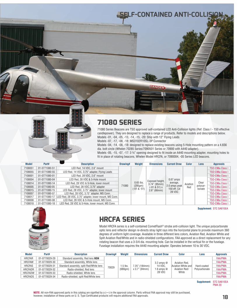
71080 SERIES 71080 Series Beacons are TSO approved self-contained LED Anti-Collision lights (Ref. Class I - 150 effective candlepower). They are designed to replace a range of products. Refer to models and descriptions below.Models -01, -04, -05, -13, -14, -15, -20: Ship with 12” Flying Leads Models -07, -17, -08, -18: MS3102R10SL-3P Connector Models -04, -14, -08, -18: designed to replace existing beacons using 5-Hole mounting pattern on a 4.656 dia. bolt circle (Whelen 70285 Series/7090501 Series or 70900 with A440 adapter). Models -05, -15, -07, -17: 3 ¾” opening designed to fit inside an A440 mounting adapter, mounting holes to fit in place of rotating beacons, Whelen Model HRCFA, or 7090004, -05 Series LED beacons.
HRCFA SERIES Model HRCFA series is a self-contained CometFlash® strobe anti-collision light. The unique polycarbonate optic lens and reflector design re-directs stray light rays into the horizontal plane to provide maximum 360 degrees of uniform light coverage. Available in three different lens colors, Aviation Red, Aviation White and Split Aviation Red/White and in radio-shielded configurations. FAA approved as a direct replacement for any rotating beacon that uses a 3-3/4 dia. mounting hole. Can be installed in the vertical fin or the fuselage. Fuselage installation requires the A440 mounting adapter. Operates between 10 to 30 VDC.
Model Part# Description Drawing# Weight Dimensions Current Draw Color Lens Approvals7108051 01-0771080-51 LED Red, 14 VDC, 2.6” mount
71080 0.65 lbs. (295gm)
(-01 & -51)
Exposed height, 3.74” (95mm) (-01 & 51) x2.6” (66mm)
0.67 amps average,
2.0 amps peak150 eff. Cd
28 VDC
Aviation Red
Clear polycar-bonate
TSO-C96a Class I7108055 01-0771080-55 LED Red, 14 VDC, 3.75” adapter, Flying Leads TSO-C96a Class I7108001 01-0771080-01 LED Red, 28 VDC, 2.6” mount TSO-C96a Class I7108004 01-0771080-04 LED Red, 28 VDC & 5-Hole mount TSO-C96a Class I7108014 01-0771080-14 LED Red, 28 VDC & 5-Hole, lower mount TSO-C96a Class I7108005 01-0771080-05 LED Red, 28 VDC, 3.75” adapter TSO-C96a Class I7108015 01-0771080-15 LED Red, 28 VDC, 3.75” adapter, lower mount TSO-C96a Class I7108007 01-0771080-07 LED Red, 28 VDC, 3.75” adapter, MS Conn. TSO-C96a Class I7108017 01-0771080-17 LED Red, 28 VDC, 3.75” adapter, lower mount, MS Conn. TSO-C96a Class I7108008 01-0771080-08 LED Red, 28 VDC & 5-Hole mount, MS Conn. TSO-C96a Class I7108018 01-0771080-18 LED Red, 28 VDC & 5-Hole, lower mount, MS Conn. TSO-C96a Class I
Model Part# Description Drawing# Weight Dimensions Current Draw Color Lens ApprovalsHRCFAR 01-0770029-29 Standard assembly, Red lens NSN
70029 1.5 lbs. (680gm)
7.25” (184mm) x 3.7” (94mm)
3.2 amps @ 14 VDC,
1.6 amps @ 28 VDC
Aviation Red, Aviation White and
Aviation Red/White
Hard-coated Polycarbonate
FAA/PMAHRCFAW 01-0770029-30 Standard assembly, White lens FAA/PMAHRCFAS 01-0770029-31 Standard assembly, split Red/White lens FAA/PMA
HRCFADR 01-0770029-32 Radio-shielded, Red lens FAA/PMAHRCFADW 01-0770029-33 Radio-shielded, White lens FAA/PMAHRCFADS 01-0770029-34 Radio-shielded, split Red/White lens FAA/PMA
Supplement: STC SA615EA
Supplement: STC SA615EA PMA 20
NOTE: All non-FAA approved parts in this catalog are signified by a (—) in the approval column. Parts without FAA approval may still be purchased, however, installation of these parts on U. S. Type Certificated products will require additional FAA approvals.19
SELF CONTAINED ANTI-COLLISION
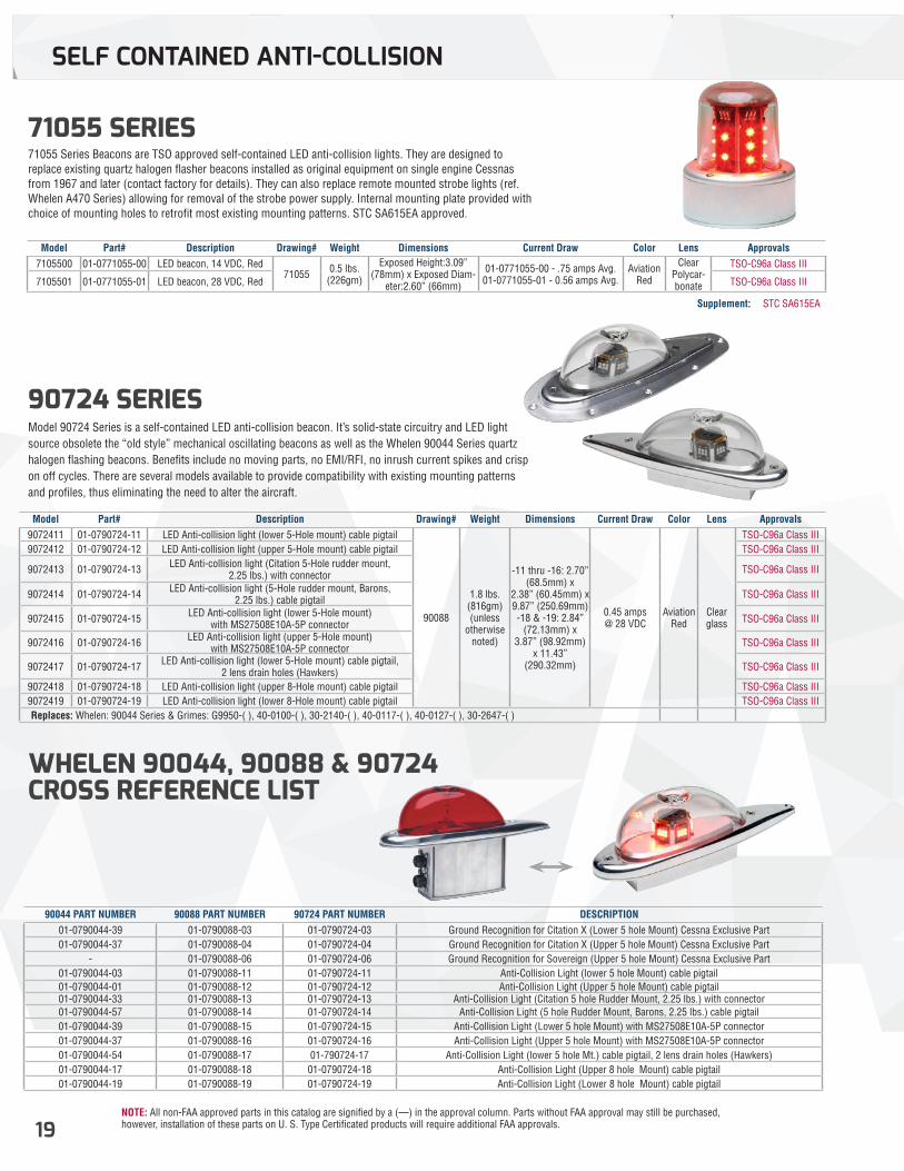
71055 SERIES 71055 Series Beacons are TSO approved self-contained LED anti-collision lights. They are designed to replace existing quartz halogen flasher beacons installed as original equipment on single engine Cessnas from 1967 and later (contact factory for details). They can also replace remote mounted strobe lights (ref. Whelen A470 Series) allowing for removal of the strobe power supply. Internal mounting plate provided with choice of mounting holes to retrofit most existing mounting patterns. STC SA615EA approved.
90724 SERIES Model 90724 Series is a self-contained LED anti-collision beacon. It’s solid-state circuitry and LED light source obsolete the “old style” mechanical oscillating beacons as well as the Whelen 90044 Series quartz halogen flashing beacons. Benefits include no moving parts, no EMI/RFI, no inrush current spikes and crisp on off cycles. There are several models available to provide compatibility with existing mounting patterns and profiles, thus eliminating the need to alter the aircraft.
WHELEN 90044, 90088 & 90724 CROSS REFERENCE LIST
Model Part# Description Drawing# Weight Dimensions Current Draw Color Lens Approvals7105500 01-0771055-00 LED beacon, 14 VDC, Red
71055 0.5 lbs. (226gm)
Exposed Height:3.09” (78mm) x Exposed Diam-
eter:2.60” (66mm)
01-0771055-00 - .75 amps Avg. 01-0771055-01 - 0.56 amps Avg.
Aviation Red
Clear Polycar-bonate
TSO-C96a Class III
7105501 01-0771055-01 LED beacon, 28 VDC, Red TSO-C96a Class III
Model Part# Description Drawing# Weight Dimensions Current Draw Color Lens Approvals9072411 01-0790724-11 LED Anti-collision light (lower 5-Hole mount) cable pigtail
90088
1.8 lbs. (816gm) (unless
otherwise noted)
-11 thru -16: 2.70” (68.5mm) x
2.38” (60.45mm) x 9.87” (250.69mm) -18 & -19: 2.84”
(72.13mm) x 3.87” (98.92mm)
x 11.43” (290.32mm)
0.45 amps @ 28 VDC
Aviation Red
Clear glass
TSO-C96a Class III9072412 01-0790724-12 LED Anti-collision light (upper 5-Hole mount) cable pigtail TSO-C96a Class III
9072413 01-0790724-13 LED Anti-collision light (Citation 5-Hole rudder mount, 2.25 lbs.) with connector TSO-C96a Class III
9072414 01-0790724-14 LED Anti-collision light (5-Hole rudder mount, Barons, 2.25 lbs.) cable pigtail TSO-C96a Class III
9072415 01-0790724-15 LED Anti-collision light (lower 5-Hole mount) with MS27508E10A-5P connector TSO-C96a Class III
9072416 01-0790724-16 LED Anti-collision light (upper 5-Hole mount) with MS27508E10A-5P connector TSO-C96a Class III
9072417 01-0790724-17 LED Anti-collision light (lower 5-Hole mount) cable pigtail, 2 lens drain holes (Hawkers) TSO-C96a Class III
9072418 01-0790724-18 LED Anti-collision light (upper 8-Hole mount) cable pigtail TSO-C96a Class III9072419 01-0790724-19 LED Anti-collision light (lower 8-Hole mount) cable pigtail TSO-C96a Class III
Replaces: Whelen: 90044 Series & Grimes: G9950-( ), 40-0100-( ), 30-2140-( ), 40-0117-( ), 40-0127-( ), 30-2647-( )
90044 PART NUMBER 90088 PART NUMBER 90724 PART NUMBER DESCRIPTION01-0790044-39 01-0790088-03 01-0790724-03 Ground Recognition for Citation X (Lower 5 hole Mount) Cessna Exclusive Part01-0790044-37 01-0790088-04 01-0790724-04 Ground Recognition for Citation X (Upper 5 hole Mount) Cessna Exclusive Part
- 01-0790088-06 01-0790724-06 Ground Recognition for Sovereign (Upper 5 hole Mount) Cessna Exclusive Part01-0790044-03 01-0790088-11 01-0790724-11 Anti-Collision Light (lower 5 hole Mount) cable pigtail01-0790044-01 01-0790088-12 01-0790724-12 Anti-Collision Light (Upper 5 hole Mount) cable pigtail01-0790044-33 01-0790088-13 01-0790724-13 Anti-Collision Light (Citation 5 hole Rudder Mount, 2.25 lbs.) with connector 01-0790044-57 01-0790088-14 01-0790724-14 Anti-Collision Light (5 hole Rudder Mount, Barons, 2.25 lbs.) cable pigtail01-0790044-39 01-0790088-15 01-0790724-15 Anti-Collision Light (Lower 5 hole Mount) with MS27508E10A-5P connector01-0790044-37 01-0790088-16 01-0790724-16 Anti-Collision Light (Upper 5 hole Mount) with MS27508E10A-5P connector01-0790044-54 01-0790088-17 01-790724-17 Anti-Collision Light (lower 5 hole Mt.) cable pigtail, 2 lens drain holes (Hawkers)01-0790044-17 01-0790088-18 01-0790724-18 Anti-Collision Light (Upper 8 hole Mount) cable pigtail01-0790044-19 01-0790088-19 01-0790724-19 Anti-Collision Light (Lower 8 hole Mount) cable pigtail
Supplement: STC SA615EA
NOTE: All non-FAA approved parts in this catalog are signified by a (—) in the approval column. Parts without FAA approval may still be purchased, however, installation of these parts on U. S. Type Certificated products will require additional FAA approvals. 20
SELF-CONTAINED ANTI-COLLISION
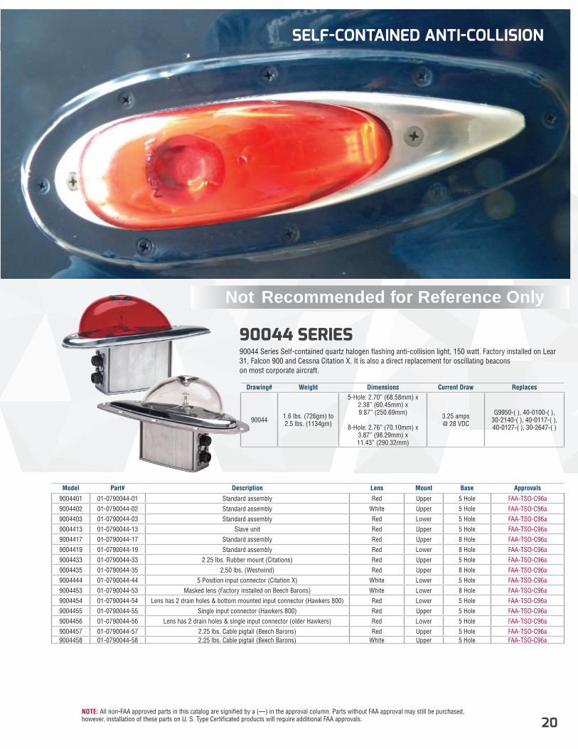
90044 SERIES 90044 Series Self-contained quartz halogen flashing anti-collision light, 150 watt. Factory installed on Lear 31, Falcon 900 and Cessna Citation X. It is also a direct replacement for oscillating beacons on most corporate aircraft.
Drawing# Weight Dimensions Current Draw Replaces
90044 1.6 lbs. (726gm) to 2.5 lbs. (1134gm)
5-Hole: 2.70” (68.58mm) x 2.38” (60.45mm) x 9.87” (250.69mm)
8-Hole: 2.76” (70.10mm) x
3.87” (98.29mm) x 11.43” (290.32mm)
3.25 amps @ 28 VDC
G9950-( ), 40-0100-( ), 30-2140-( ), 40-0117-( ), 40-0127-( ), 30-2647-( )
Model Part# Description Lens Mount Base Approvals
9004401 01-0790044-01 Standard assembly Red Upper 5 Hole FAA-TSO-C96a9004402 01-0790044-02 Standard assembly White Upper 5 Hole FAA-TSO-C96a9004403 01-0790044-03 Standard assembly Red Lower 5 Hole FAA-TSO-C96a9004413 01-0790044-13 Slave unit Red Upper 5 Hole FAA-TSO-C96a9004417 01-0790044-17 Standard assembly Red Upper 8 Hole FAA-TSO-C96a9004419 01-0790044-19 Standard assembly Red Lower 8 Hole FAA-TSO-C96a9004433 01-0790044-33 2.25 lbs. Rubber mount (Citations) Red Upper 5 Hole FAA-TSO-C96a9004435 01-0790044-35 2.50 lbs. (Westwind) Red Upper 8 Hole FAA-TSO-C96a9004444 01-0790044-44 5 Position input connector (Citation X) White Lower 5 Hole FAA-TSO-C96a9004453 01-0790044-53 Masked lens (Factory installed on Beech Barons) White Lower 8 Hole FAA-TSO-C96a9004454 01-0790044-54 Lens has 2 drain holes & bottom mounted input connector (Hawkers 800) Red Lower 5 Hole FAA-TSO-C96a9004455 01-0790044-55 Single input connector (Hawkers 800) Red Upper 5 Hole FAA-TSO-C96a9004456 01-0790044-56 Lens has 2 drain holes & single input connector (older Hawkers) Red Lower 5 Hole FAA-TSO-C96a9004457 01-0790044-57 2.25 lbs. Cable pigtail (Beech Barons) Red Upper 5 Hole FAA-TSO-C96a9004458 01-0790044-58 2.25 lbs. Cable pigtail (Beech Barons) White Upper 5 Hole FAA-TSO-C96a
Not Recommended for Reference Only
NOTE: All non-FAA approved parts in this catalog are signified by a (—) in the approval column. Parts without FAA approval may still be purchased, however, installation of these parts on U. S. Type Certificated products will require additional FAA approvals.21
SELF-CONTAINED ANTI-COLLISION
23
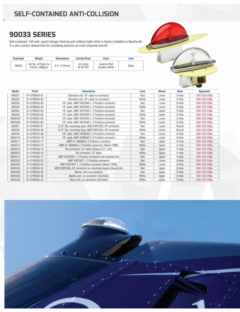
90033 SERIES Self-contained, 150 watt, quartz halogen flashing anti-collision light which is factory installed on Beechcraft. It is also a direct replacement for oscillating beacons on most corporate aircraft.
Drawing# Weight Dimensions Current Draw Color Lens
90033 0.6 lbs. (272gm) to 0.9 lbs. (408gm) 4.4” (112mm) 5.5 amps
@ 28 VDCAviation Red
Aviation White Glass
Model Part# Description Lens Mount Base Approvals900331 01-0790033-01 Standard unit, 18” cable no connector Red Lower 2 Hole FAA-TSO-C96a900332 01-0790033-02 Standard unit, 18” cable no connector White Lower 2 Hole FAA-TSO-C96a900333 01-0790033-03 18” cable, AMP #207846-1, 2 Position connector Red Lower 8 Hole FAA-TSO-C96a900334 01-0790033-04 18” cable, AMP #207846-1, 2 Position connector White Lower 8 Hole FAA-TSO-C96a900335 01-0790033-05 18” cable, AMP #207846-1, 2 Position connector Red Upper 5 Hole FAA-TSO-C96a900336 01-0790033-06 18” cable, AMP #207846-1, 2 Position connector White Upper 5 Hole FAA-TSO-C96a
900335D 01-0790033-5D 18” cable, AMP #207846-1, 2 Position connector Red Lower 5 Hole FAA-TSO-C96a900336D 01-0790033-6D 18” cable, AMP #207846-1, 2 Position connector White Lower 5 Hole FAA-TSO-C96a900337 01-0790033-07 5.12” Dia. mounting base, MS3102R10SL-3P connector Red Lower Round FAA-TSO-C96a900338 01-0790033-08 5.12” Dia. mounting base, MS3102R10SL-3P connector White Lower Round FAA-TSO-C96a900339 01-0790033-09 18” cable, AMP #208530-1, 8 Position connector Red Lower 8 Hole FAA-TSO-C96a
9003310 01-0790033-10 18” cable, AMP #208530-1, 8 Position connector White Lower 8 Hole FAA-TSO-C96a9003311 01-0790033-11 AMP #1-480698-0, 2 Position connector Red Upper 5 Hole FAA-TSO-C96a9003312 01-0790033-12 AMP #1-480698-0, 2 Position connector (Beech 1900) White Upper 5 Hole FAA-TSO-C96a9003313 01-0790033-13 No connector, 13” leads (Cessna CJ1, CJ2) Red Upper 2 Hole FAA-TSO-C96a9003314 01-0790033-14 No connector, 13” leads White Upper 2 Hole FAA-TSO-C96a9003317 01-0790033-17 AMP #207846-1, 2 Position connector with masked lens Red Upper 2 Hole FAA-TSO-C96a9003323 01-0790033-23 AMP #207567-1, 3 Position connector Red Lower 8 Hole FAA-TSO-C96a9003324 01-0790033-24 AMP #207567-1, 3 Position connector (Beech 1900) White Lower 8 Hole FAA-TSO-C96a9003325 01-0790033-25 MS3102R10SL-3P connector on mounting bracket (Beech Jet) Red Upper 5 Hole FAA-TSO-C96a9003329 01-0790033-29 Master unit, no connector Red Upper 5 Hole FAA-TSO-C96a9003330 01-0790033-30 Master unit, no connector (Fairchild) White Upper 5 Hole FAA-TSO-C96a9003332 01-0790033-32 Slave unit, no connector (Fairchild) White Lower 2 Hole FAA-TSO-C96a
NOTE: All non-FAA approved parts in this catalog are signified by a (—) in the approval column. Parts without FAA approval may still be purchased, however, installation of these parts on U. S. Type Certificated products will require additional FAA approvals. 22
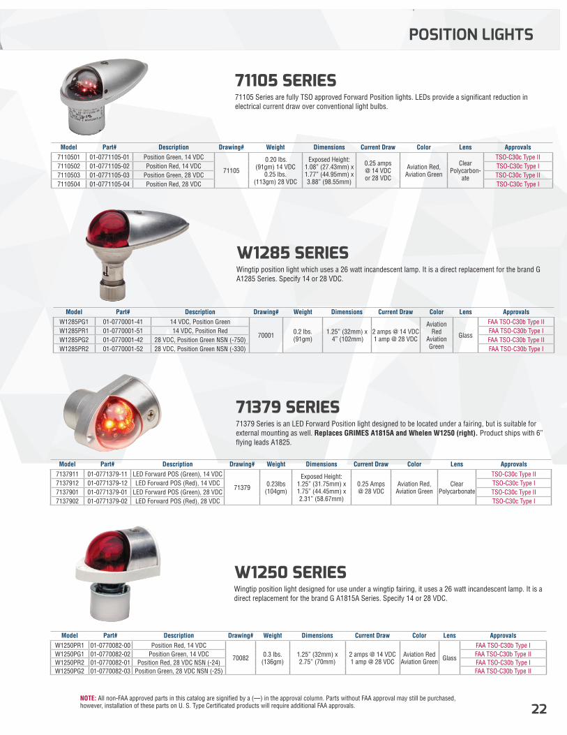
W1285 SERIES Wingtip position light which uses a 26 watt incandescent lamp. It is a direct replacement for the brand G A1285 Series. Specify 14 or 28 VDC.
71105 SERIES 71105 Series are fully TSO approved Forward Position lights. LEDs provide a significant reduction in electrical current draw over conventional light bulbs.
Model Part# Description Drawing# Weight Dimensions Current Draw Color Lens ApprovalsW1285PG1 01-0770001-41 14 VDC, Position Green
70001 0.2 lbs. (91gm)
1.25” (32mm) x 4” (102mm)
2 amps @ 14 VDC1 amp @ 28 VDC
Aviation Red
Aviation Green
Glass
FAA TSO-C30b Type IIW1285PR1 01-0770001-51 14 VDC, Position Red FAA TSO-C30b Type IW1285PG2 01-0770001-42 28 VDC, Position Green NSN (-750) FAA TSO-C30b Type IIW1285PR2 01-0770001-52 28 VDC, Position Green NSN (-330) FAA TSO-C30b Type I
Model Part# Description Drawing# Weight Dimensions Current Draw Color Lens Approvals7110501 01-0771105-01 Position Green, 14 VDC
71105
0.20 lbs. (91gm) 14 VDC
0.25 lbs. (113gm) 28 VDC
Exposed Height: 1.08” (27.43mm) x1.77” (44.95mm) x 3.88” (98.55mm)
0.25 amps @ 14 VDC or 28 VDC
Aviation Red, Aviation Green
Clear Polycarbon-
ate
TSO-C30c Type II7110502 01-0771105-02 Position Red, 14 VDC TSO-C30c Type I7110503 01-0771105-03 Position Green, 28 VDC TSO-C30c Type II7110504 01-0771105-04 Position Red, 28 VDC TSO-C30c Type I
POSITION LIGHTS
W1250 SERIES Wingtip position light designed for use under a wingtip fairing, it uses a 26 watt incandescent lamp. It is a direct replacement for the brand G A1815A Series. Specify 14 or 28 VDC.
Model Part# Description Drawing# Weight Dimensions Current Draw Color Lens ApprovalsW1250PR1 01-0770082-00 Position Red, 14 VDC
70082 0.3 lbs. (136gm)
1.25” (32mm) x 2.75” (70mm)
2 amps @ 14 VDC 1 amp @ 28 VDC
Aviation Red Aviation Green Glass
FAA TSO-C30b Type IW1250PG1 01-0770082-02 Position Green, 14 VDC FAA TSO-C30b Type IIW1250PR2 01-0770082-01 Position Red, 28 VDC NSN (-24) FAA TSO-C30b Type IW1250PG2 01-0770082-03 Position Green, 28 VDC NSN (-25) FAA TSO-C30b Type II
71379 SERIES 71379 Series is an LED Forward Position light designed to be located under a fairing, but is suitable for external mounting as well. Replaces GRIMES A1815A and Whelen W1250 (right). Product ships with 6” flying leads A1825.
Model Part# Description Drawing# Weight Dimensions Current Draw Color Lens Approvals7137911 01-0771379-11 LED Forward POS (Green), 14 VDC
71379 0.23lbs (104gm)
Exposed Height: 1.25” (31.75mm) x1.75” (44.45mm) x2.31” (58.67mm)
0.25 Amps @ 28 VDC
Aviation Red, Aviation Green
Clear Polycarbonate
TSO-C30c Type II7137912 01-0771379-12 LED Forward POS (Red), 14 VDC TSO-C30c Type I7137901 01-0771379-01 LED Forward POS (Green), 28 VDC TSO-C30c Type II7137902 01-0771379-02 LED Forward POS (Red), 28 VDC TSO-C30c Type I
NOTE: All non-FAA approved parts in this catalog are signified by a (—) in the approval column. Parts without FAA approval may still be purchased, however, installation of these parts on U. S. Type Certificated products will require additional FAA approvals.23
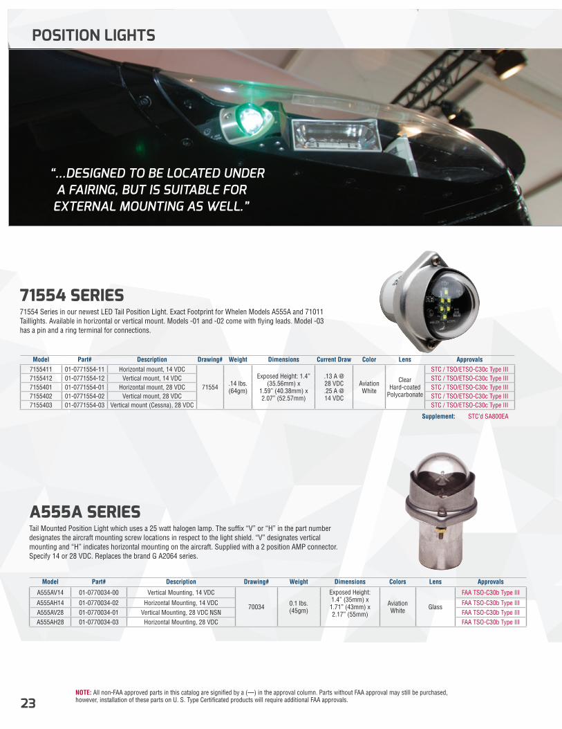
71554 SERIES 71554 Series in our newest LED Tail Position Light. Exact Footprint for Whelen Models A555A and 71011 Taillights. Available in horizontal or vertical mount. Models -01 and -02 come with flying leads. Model -03 has a pin and a ring terminal for connections.
A555A SERIES Tail Mounted Position Light which uses a 25 watt halogen lamp. The suffix “V” or “H” in the part number designates the aircraft mounting screw locations in respect to the light shield. “V” designates vertical mounting and “H” indicates horizontal mounting on the aircraft. Supplied with a 2 position AMP connector. Specify 14 or 28 VDC. Replaces the brand G A2064 series.
Model Part# Description Drawing# Weight Dimensions Current Draw Color Lens Approvals7155411 01-0771554-11 Horizontal mount, 14 VDC
71554 .14 lbs. (64gm)
Exposed Height: 1.4” (35.56mm) x
1.59” (40.38mm) x 2.07” (52.57mm)
.13 A @ 28 VDC.25 A @ 14 VDC
Aviation White
Clear Hard-coated
Polycarbonate
STC / TSO/ETSO-C30c Type III7155412 01-0771554-12 Vertical mount, 14 VDC STC / TSO/ETSO-C30c Type III7155401 01-0771554-01 Horizontal mount, 28 VDC STC / TSO/ETSO-C30c Type III7155402 01-0771554-02 Vertical mount, 28 VDC STC / TSO/ETSO-C30c Type III7155403 01-0771554-03 Vertical mount (Cessna), 28 VDC STC / TSO/ETSO-C30c Type III
Model Part# Description Drawing# Weight Dimensions Colors Lens Approvals
A555AV14 01-0770034-00 Vertical Mounting, 14 VDC
70034 0.1 lbs. (45gm)
Exposed Height: 1.4” (35mm) x 1.71” (43mm) x 2.17” (55mm)
Aviation White Glass
FAA TSO-C30b Type III
A555AH14 01-0770034-02 Horizontal Mounting, 14 VDC FAA TSO-C30b Type IIIA555AV28 01-0770034-01 Vertical Mounting, 28 VDC NSN FAA TSO-C30b Type IIIA555AH28 01-0770034-03 Horizontal Mounting, 28 VDC FAA TSO-C30b Type III
Supplement: STC’d SA800EA
POSITION LIGHTS
“...DESIGNED TO BE LOCATED UNDER A FAIRING, BUT IS SUITABLE FOR EXTERNAL MOUNTING AS WELL.”
NOTE: All non-FAA approved parts in this catalog are signified by a (—) in the approval column. Parts without FAA approval may still be purchased, however, installation of these parts on U. S. Type Certificated products will require additional FAA approvals. 24
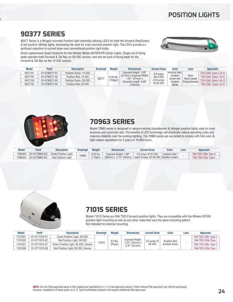
90377 SERIES 90377 Series is a Wingtip mounted Position light assembly utilizing LED’s for both the forward (Red/Green) & tail position (White) lights, eliminating the need for a tail mounted position light. The LED’s provide a s ignificant reduction in current draw over conventional position light bulbs. Direct replacement (exact footprint) for the Whelen Model A675PG/PR Series (right). Single set of flying leads operates both Forward & Tail Nav on 28 VDC version, and one set each of flying leads for the Forward & Tail Nav on the 14 VDC version.
POSITION LIGHTS
Model Part# Description Drawing# Weight Dimensions Current Draw Color Lens Approvals9037701 01-0790377-01 Position Green, 14 VDC
90377 0.35 lbs. (159gm)
Exposed Height: 1.08” (27mm) x Exposed Width:
1.87” (47mm) x Exposed Length: 5.69”
(145mm)
0.5 amps @14 VDC0.25 amps @ 28 VDC
Aviation Red, Aviation
Green and Aviation White
Clear Hard-coated
Polycarbonate
TSO-C30c Types II & III9037702 01-0790377-02 Position Red, 14 VDC TSO-C30c Types I & III9037703 01-0790377-03 Position Green, 28 VDC TSO-C30c Types II & III9037704 01-0790377-04 Position Red, 28 VDC TSO-C30c Types I & III
70963 SERIES Model 70963 series is designed to replace existing incandescent & halogen position lights used on most business and commuter jets. The benefits of LED technology will drastically reduce operating costs and improve reliability over the existing lighting. The 70963 series are warranted to comply with FAA color & light output regulations for 5 years or 10,000 hours.
Model Part# Description Drawing# Weight Dimensions Current Draw Color Lens Approvals7096303 01-0770963-03 Green Position Light
70963 0.25 lbs. (113gm)
Exposed Height: 1.98” (50mm) x 2.10” (53mm)
0.3 amps @ 28 VDC Input Voltage 22-30 VDC
Aviation Red Aviation Green -
FAA TSO-C30c Type II7096304 01-0770963-04 Red Position Light FAA TSO-C30c Type I
71015 SERIES Model 71015 Series are FAA TSO’d forward position lights. They are compatible with the Whelen W1250 position light mounting as well as any other make that uses the same mounting pattern. Not intended for external mounting.
Model Part# Description Drawing# Weight Dimensions Current Draw Color Lens Approvals7101501 01-0771015-01 Green Position Light, 28 VDC
71015 0.2 lbs. (91gm)
Exposed Height: 1.33” (34mm) x 2.41” (61mm)
0.3 amps @ 28 VDC
Aviation Red Aviation Green -
FAA TSO-C30c Type II7101502 01-0771015-02 Red Position Light, 28 VDC FAA TSO-C30c Type I7101507 01-0771015-07 Green Position Light, 28 VDC, Cessna FAA TSO-C30c Type II7101508 01-0771015-08 Red Position Light, 28 VDC, Cessna FAA TSO-C30c Type I
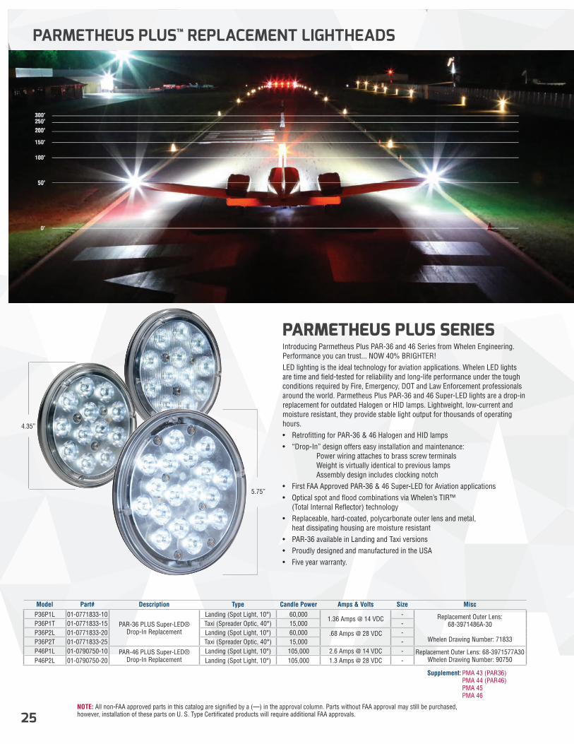
NOTE: All non-FAA approved parts in this catalog are signified by a (—) in the approval column. Parts without FAA approval may still be purchased, however, installation of these parts on U. S. Type Certificated products will require additional FAA approvals.25
PARMETHEUS PLUS SERIES Introducing Parmetheus Plus PAR-36 and 46 Series from Whelen Engineering.Performance you can trust... NOW 40% BRIGHTER!LED lighting is the ideal technology for aviation applications. Whelen LED lights are time and field-tested for reliability and long-life performance under the tough conditions required by Fire, Emergency, DOT and Law Enforcement professionals around the world. Parmetheus Plus PAR-36 and 46 Super-LED lights are a drop-in replacement for outdated Halogen or HID lamps. Lightweight, low-current and moisture resistant, they provide stable light output for thousands of operating hours.• Retrofitting for PAR-36 & 46 Halogen and HID lamps• “Drop-In” design offers easy installation and maintenance: � Power wiring attaches to brass screw terminals � Weight is virtually identical to previous lamps � Assembly design includes clocking notch• First FAA Approved PAR-36 & 46 Super-LED for Aviation applications• Optical spot and flood combinations via Whelen’s TIR™ (Total Internal Reflector) technology• Replaceable, hard-coated, polycarbonate outer lens and metal, heat dissipating housing are moisture resistant• PAR-36 available in Landing and Taxi versions• Proudly designed and manufactured in the USA• Five year warranty.
PARMETHEUS PLUS™ REPLACEMENT LIGHTHEADS
Model Part# Description Type Candle Power Amps & Volts Size MiscP36P1L 01-0771833-10
PAR-36 PLUS Super-LED® Drop-In Replacement
Landing (Spot Light, 10°) 60,0001.36 Amps @ 14 VDC
- Replacement Outer Lens: 68-3971486A-30
Whelen Drawing Number: 71833
P36P1T 01-0771833-15 Taxi (Spreader Optic, 40°) 15,000 -P36P2L 01-0771833-20 Landing (Spot Light, 10°) 60,000 .68 Amps @ 28 VDC -P36P2T 01-0771833-25 Taxi (Spreader Optic, 40°) 15,000 -P46P1L 01-0790750-10 PAR-46 PLUS Super-LED®
Drop-In ReplacementLanding (Spot Light, 10°) 105,000 2.6 Amps @ 14 VDC - Replacement Outer Lens: 68-3971577A30
Whelen Drawing Number: 90750P46P2L 01-0790750-20 Landing (Spot Light, 10°) 105,000 1.3 Amps @ 28 VDC -
Supplement: PMA 43 (PAR36) PMA 44 (PAR46) PMA 45 PMA 46
4.35”
5.75”

NOTE: All non-FAA approved parts in this catalog are signified by a (—) in the approval column. Parts without FAA approval may still be purchased, however, installation of these parts on U. S. Type Certificated products will require additional FAA approvals. 26
PARMETHEUS PLUS™ REPLACEMENT LIGHTHEADS
TAXI
GE Bulb # Parmetheus Plus Parmetheus Original
4416 P36P1L PLED1L4505 P36P2L PLED2L4509 P36P1L PLED1L4587 P36P2T PLED2T4591 P36P2L PLED2L4593 P36P2T PLED2T4594 P36P2L PLED2L4595 P36P1L PLED1L4596 P36P2L PLED2L4623 P36P2T PLED2T4626 P36P2T PLED2T4627 P36P2T PLED2T
Q4631 P36P1L PLED1LQ4632 P36P1L PLED1L4413 P46PIL PLED461L4421 P46P1L PLED461L4435 P46P1L PLED461L4522 P46P1L PLED461L4537 P46P1L PLED461L4551 P46P2L PLED462L4553 P46P2L PLED462L4554 P46P2L PLED462L
Q4554 P46P2L PLED462LQ4566 P46P2L PLED462L4570 P46P2L PLED462L4571 P46P2L PLED462L
0
10000
20000
30000
40000
50000
60000
70000
-57
-53
-49
-45
-41
-37
-33
-29
-25
-21
-17
-13 -9 -5 -1 3 7 11
15
19
23
27
31
35
39
43
47
51
55
59
PAR+ 14 Landing
PAR+ 14Taxi
PAR+ 28 Landing
PAR+ 28 Taxi
AeroLeds LX
HORIZONTAL ANGLE
BE
AM
CA
ND
LE
PO
WE
R
USABLE LIGHT INTENSITIES
TESTING RESULTS BULB CHART
Verticle Angle
10
5
0
-5
-10Horizontal Angle Horizontal Angle-30 -25 -20 -15 -10 -5 0 5 10 15 20 25 30 -30 -25 -20 -15 -10 -5 0 5 10 15 20 25 30
Luminous Intensity in units of Candela is the energy emitted in one direction perceived by the human eye, & Luminous Flux in units of Lumens is the total energy emitted in all directions perceived by the human eye. These isocandela plots show usable light intensities at horizontal and vertical angles up and down. The colors indicate intensities of the light output. The warmer the colors, the more intense the light output. Parmetheus Plus color temperatures reach 6,000 degree Kelvin, which simulates mid-day light.
LANDING TAXI
LANDING TAXI
DIS
CO
NT
INU
ED
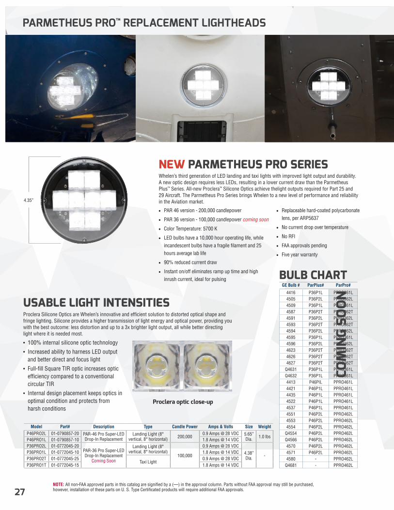
NOTE: All non-FAA approved parts in this catalog are signified by a (—) in the approval column. Parts without FAA approval may still be purchased, however, installation of these parts on U. S. Type Certificated products will require additional FAA approvals.27
OR500 SERIES
PARMETHEUS PRO™ REPLACEMENT LIGHTHEADS
USABLE LIGHT INTENSITIESProclera Silicone Optics are Whelen’s innovative and efficient solution to distorted optical shape and fringe lighting. Silicone provides a higher transmission of light energy and optical power, providing you with the best outcome: less distortion and up to a 3x brighter light output, all while better directing light where it is needed most.
• 100% internal silicone optic technology
• Increased ability to harness LED output and better direct and focus light
• Full-fill Square TIR optic increases optic efficiency compared to a conventional circular TIR
• Internal design placement keeps optics in optimal condition and protects from harsh conditions
NEW PARMETHEUS PRO SERIES Whelen’s third generation of LED landing and taxi lights with improved light output and durability. A new optic design requires less LEDs, resulting in a lower current draw than the Parmetheus Plus™ Series. All-new Proclera™ Silicone Optics achieve thelight outputs required for Part 25 and 29 Aircraft. The Parmetheus Pro Series brings Whelen to a new level of performance and reliability in the Aviation market.
• PAR 46 version - 200,000 candlepower
• PAR 36 version - 100,000 candlepower coming soon
• Color Temperature: 5700 K
• LED bulbs have a 10,000 hour operating life, while incandescent bulbs have a fragile filament and 25 hours average lab life
• 90% reduced current draw
• Instant on/off eliminates ramp up time and high inrush current, ideal for pulsing
• Replaceable hard-coated polycarbonate lens, per ARP5637
• No current drop over temperature
• No RFI
• FAA approvals pending
• Five year warranty
Model Part# Description Type Candle Power Amps & Volts Size WeightP46PRO2L 01-0790857-20 PAR-46 Pro Super-LED
Drop-In ReplacementLanding Light (8°
vertical, 8° horizontal) 200,0000.9 Amps @ 28 VDC 5.65”
Dia. 1.0 lbsP46PRO1L 01-0790857-10 1.8 Amps @ 14 VDCP36PRO2L 01-0772045-20
PAR-36 Pro Super-LED Drop-In Replacement
Coming Soon
Landing Light (8° vertical, 8° horizontal)
100,000
0.9 Amps @ 28 VDC
4.38” Dia. -
P36PRO1L 01-0772045-10 1.8 Amps @ 14 VDCP36PRO2T 01-0772045-25
Taxi Light0.9 Amps @ 28 VDC
P36PRO1T 01-0772045-15 1.8 Amps @ 14 VDC
GE Bulb # ParPlus# ParPro#
4416 P36P1L PPRO361L4505 P36P2L PPRO362L4509 P36P1L PPRO361L4587 P36P2T PPRO362T4591 P36P2L PPRO362L4593 P36P2T PPRO362T4594 P36P2L PPRO362L4595 P36P1L PPRO361L4596 P36P2L PPRO362L4623 P36P2T PPRO362T4626 P36P2T PPRO362T4627 P36P2T PPRO362T
Q4631 P36P1L PPRO361LQ4632 P36P1L PPRO361L4413 P46PIL PPRO461L4421 P46P1L PPRO461L4435 P46P1L PPRO461L4522 P46P1L PPRO461L4537 P46P1L PPRO461L4551 P46P2L PPRO462L4553 P46P2L PPRO462L4554 P46P2L PPRO462L
Q4554 P46P2L PPRO462LQ4566 P46P2L PPRO462L4570 P46P2L PPRO462L4571 P46P2L PPRO462L4580 - PPRO462L
Q4681 - PPRO462L
BULB CHART
COM
ING
SOO
N
Proclera optic close-up
4.35”
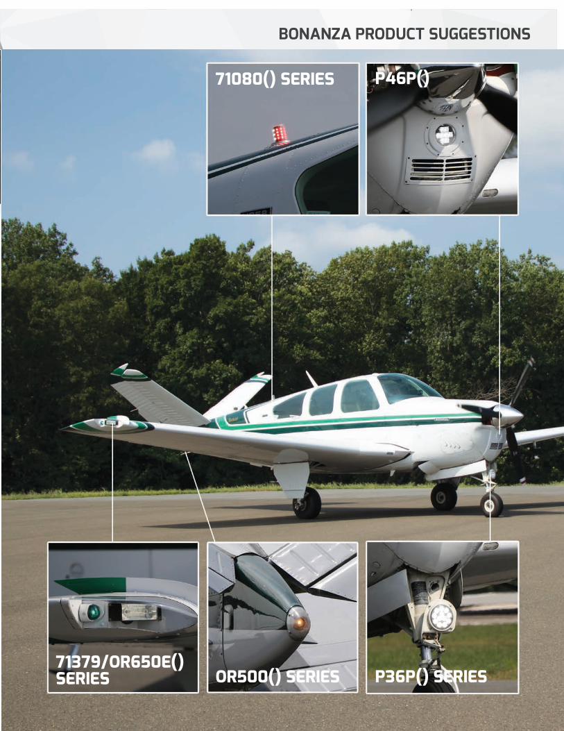
NOTE: All non-FAA approved parts in this catalog are signified by a (—) in the approval column. Parts without FAA approval may still be purchased, however, installation of these parts on U. S. Type Certificated products will require additional FAA approvals. 28
BONANZA PRODUCT SUGGESTIONS
Horizontal Angle
-30 -25 -20 -15 -10 -5 0 5 10 15 20 25 30
71080() SERIES
P36P() SERIES71379/OR650E() SERIES OR500() SERIES
P46P()
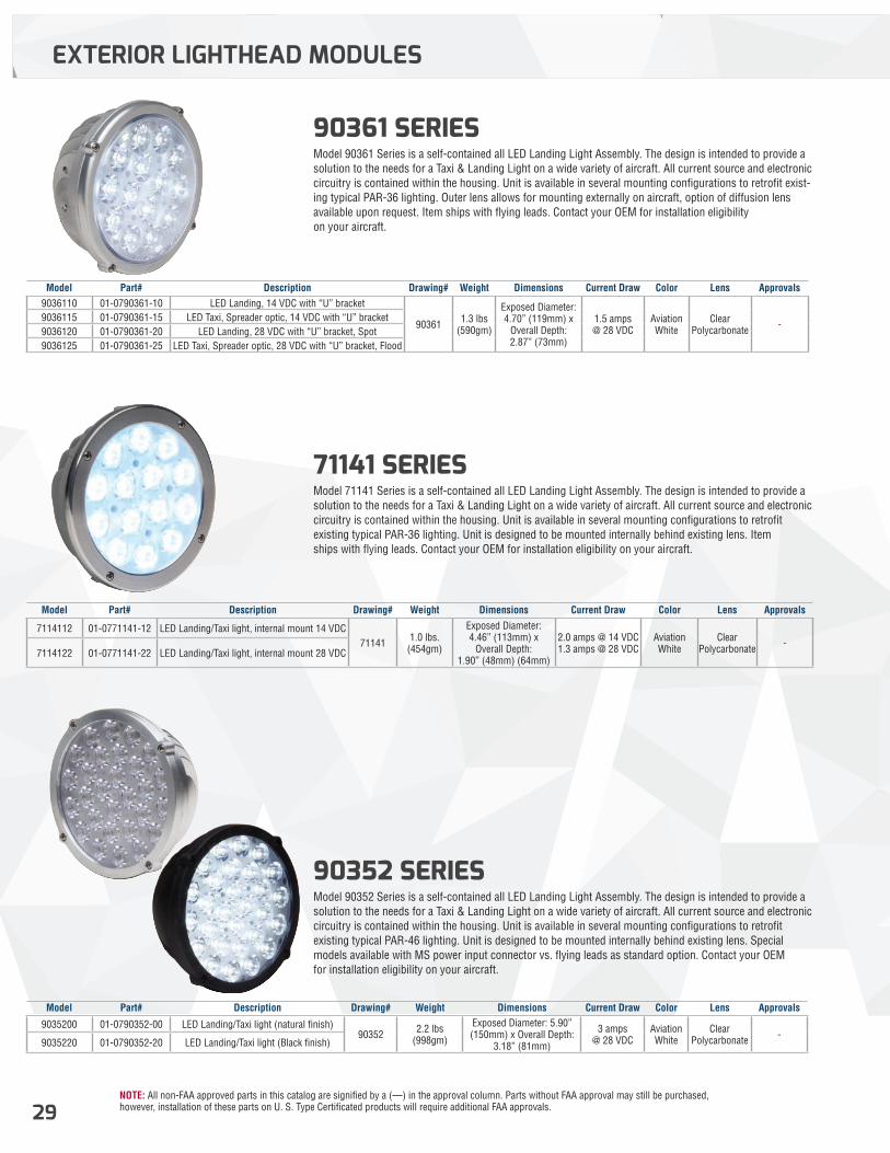
NOTE: All non-FAA approved parts in this catalog are signified by a (—) in the approval column. Parts without FAA approval may still be purchased, however, installation of these parts on U. S. Type Certificated products will require additional FAA approvals.29
90361 SERIES Model 90361 Series is a self-contained all LED Landing Light Assembly. The design is intended to provide a solution to the needs for a Taxi & Landing Light on a wide variety of aircraft. All current source and electronic circuitry is contained within the housing. Unit is available in several mounting configurations to retrofit exist-ing typical PAR-36 lighting. Outer lens allows for mounting externally on aircraft, option of diffusion lens available upon request. Item ships with flying leads. Contact your OEM for installation eligibility on your aircraft.
71141 SERIES Model 71141 Series is a self-contained all LED Landing Light Assembly. The design is intended to provide a solution to the needs for a Taxi & Landing Light on a wide variety of aircraft. All current source and electronic circuitry is contained within the housing. Unit is available in several mounting configurations to retrofit existing typical PAR-36 lighting. Unit is designed to be mounted internally behind existing lens. Item ships with flying leads. Contact your OEM for installation eligibility on your aircraft.
90352 SERIES Model 90352 Series is a self-contained all LED Landing Light Assembly. The design is intended to provide a solution to the needs for a Taxi & Landing Light on a wide variety of aircraft. All current source and electronic circuitry is contained within the housing. Unit is available in several mounting configurations to retrofit existing typical PAR-46 lighting. Unit is designed to be mounted internally behind existing lens. Special models available with MS power input connector vs. flying leads as standard option. Contact your OEM for installation eligibility on your aircraft.
EXTERIOR LIGHTHEAD MODULES
Model Part# Description Drawing# Weight Dimensions Current Draw Color Lens Approvals9036110 01-0790361-10 LED Landing, 14 VDC with “U” bracket
90361 1.3 lbs (590gm)
Exposed Diameter: 4.70” (119mm) x
Overall Depth: 2.87” (73mm)
1.5 amps @ 28 VDC
Aviation White
Clear Polycarbonate -
9036115 01-0790361-15 LED Taxi, Spreader optic, 14 VDC with “U” bracket9036120 01-0790361-20 LED Landing, 28 VDC with “U” bracket, Spot9036125 01-0790361-25 LED Taxi, Spreader optic, 28 VDC with “U” bracket, Flood
Model Part# Description Drawing# Weight Dimensions Current Draw Color Lens Approvals
9035200 01-0790352-00 LED Landing/Taxi light (natural finish)90352 2.2 lbs
(998gm)
Exposed Diameter: 5.90” (150mm) x Overall Depth:
3.18” (81mm)
3 amps @ 28 VDC
Aviation White
Clear Polycarbonate -
9035220 01-0790352-20 LED Landing/Taxi light (Black finish)
Model Part# Description Drawing# Weight Dimensions Current Draw Color Lens Approvals
7114112 01-0771141-12 LED Landing/Taxi light, internal mount 14 VDC71141 1.0 lbs.
(454gm)
Exposed Diameter: 4.46” (113mm) x
Overall Depth: 1.90” (48mm) (64mm)
2.0 amps @ 14 VDC 1.3 amps @ 28 VDC
Aviation White
Clear Polycarbonate -
7114122 01-0771141-22 LED Landing/Taxi light, internal mount 28 VDC
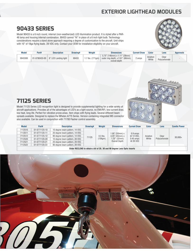
NOTE: All non-FAA approved parts in this catalog are signified by a (—) in the approval column. Parts without FAA approval may still be purchased, however, installation of these parts on U. S. Type Certificated products will require additional FAA approvals. 30
90433 SERIES Model 90433 is a 6 inch round, internal (non-weatherized) LED illumination product. It is styled after a PAR-46 lamp and housing internal combination. 90433 cannot “fit” in place of a 6 inch light bulb. Technology considerations require a stand alone approach requiring a degree of customization to the aircraft. Unit ships with 10” of 18ga flying leads. 28 VDC only. Contact your OEM for installation eligibility on your aircraft.
71125 SERIES Model 71125 Series LED recognition light is designed to provide supplemental lighting for a wide variety of aircraft applications. Provides all of the advantages of LED’s as a light source, no EMI/RFI, low current draw, low heat, long life. Perfect for vibration prone areas. Item ships with flying leads. Several different beam spreads available. Designed to replace the Whelen A775 Series. Version containing integrated MS connector also available. Can be used in conjunction with 71700 Flasher control assembly.
EXTERIOR LIGHTHEAD MODULES
Model Part# Description Drawing# Weight Dimensions Current Draw Color Lens Approvals
9043300 01-0790433-00 6” LED Landing light 90433 1.7 lbs. (771gm)5.75” (146mm) x 1.11” (28mm) outer ring depth, x 2.61” (66mm)
overall depth2 amps Aviation
WhiteClear
Polycarbonate -
Model Part# Description Drawing# Weight Dimensions Current Draw Color Lens Candle Power7112510 01-0771125-10 10 degree beam pattern, 14 VDC
71125 0.3 lbs. (136gm)
1.95” (50mm) x 3.25” (83mm) x 1.25” (32mm) Overall Depth
0.9 amps @ 14 VDC,0.45 amps @ 28 VDC
Aviation White
Clear Polycarbonate 30,000+
7112511 01-0771125-11 20 degree beam pattern, 14 VDC7112512 01-0771125-12 90 degree beam pattern, 14 VDC7112520 01-0771125-20 10 degree beam pattern, 28 VDC7112521 01-0771125-21 20 degree beam pattern, 28 VDC7112522 01-0771125-22 90 degree beam pattern, 28 VDC
Order RECLENS to obtain a kit of 20, 30 and 90 degree Lens Optic Inserts
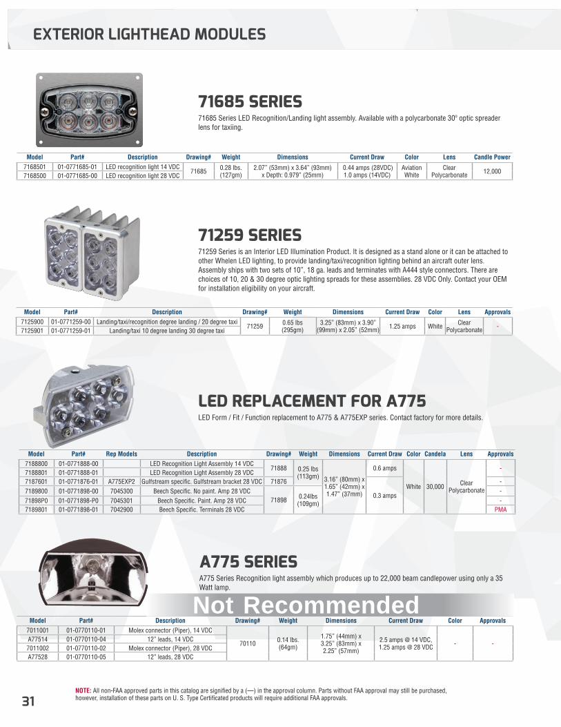
NOTE: All non-FAA approved parts in this catalog are signified by a (—) in the approval column. Parts without FAA approval may still be purchased, however, installation of these parts on U. S. Type Certificated products will require additional FAA approvals.31
71259 SERIES 71259 Series is an Interior LED Illumination Product. It is designed as a stand alone or it can be attached to other Whelen LED lighting, to provide landing/taxi/recognition lighting behind an aircraft outer lens. Assembly ships with two sets of 10”, 18 ga. leads and terminates with A444 style connectors. There are choices of 10, 20 & 30 degree optic lighting spreads for these assemblies. 28 VDC Only. Contact your OEM for installation eligibility on your aircraft.
71685 SERIES 71685 Series LED Recognition/Landing light assembly. Available with a polycarbonate 30º optic spreader lens for taxiing.
EXTERIOR LIGHTHEAD MODULES
Model Part# Description Drawing# Weight Dimensions Current Draw Color Lens Approvals7125900 01-0771259-00 Landing/taxi/recognition degree landing / 20 degree taxi
71259 0.65 lbs (295gm)
3.25” (83mm) x 3.90” (99mm) x 2.05” (52mm) 1.25 amps White Clear
Polycarbonate -7125901 01-0771259-01 Landing/taxi 10 degree landing 30 degree taxi
Model Part# Description Drawing# Weight Dimensions Current Draw Color Lens Candle Power7168501 01-0771685-01 LED recognition light 14 VDC
71685 0.28 lbs. (127gm)
2.07” (53mm) x 3.64” (93mm) x Depth: 0.979” (25mm)
0.44 amps (28VDC) 1.0 amps (14VDC)
Aviation White
Clear Polycarbonate 12,000
7168500 01-0771685-00 LED recognition light 28 VDC
LED REPLACEMENT FOR A775 LED Form / Fit / Function replacement to A775 & A775EXP series. Contact factory for more details.
Model Part# Rep Models Description Drawing# Weight Dimensions Current Draw Color Candela Lens Approvals7188800 01-0771888-00 LED Recognition Light Assembly 14 VDC
71888 0.25 lbs (113gm) 3.16” (80mm) x
1.65” (42mm) x 1.47” (37mm)
0.6 amps
White 30,000 Clear Polycarbonate
-7188801 01-0771888-01 LED Recognition Light Assembly 28 VDC7187601 01-0771876-01 A775EXP2 Gulfstream specific. Gulfstream bracket 28 VDC 71876
0.3 amps
-7189800 01-0771898-00 7045300 Beech Specific. No paint. Amp 28 VDC
71898 0.24lbs (109gm)
-71898P0 01-0771898-P0 7045301 Beech Specific. Paint. Amp 28 VDC -7189801 01-0771898-01 7042900 Beech Specific. Terminals 28 VDC PMA
A775 SERIES A775 Series Recognition light assembly which produces up to 22,000 beam candlepower using only a 35 Watt lamp.
Model Part# Description Drawing# Weight Dimensions Current Draw Color Approvals7011001 01-0770110-01 Molex connector (Piper), 14 VDC
70110 0.14 lbs. (64gm)
1.75” (44mm) x 3.25” (83mm) x2.25” (57mm)
2.5 amps @ 14 VDC, 1.25 amps @ 28 VDC - -
A77514 01-0770110-04 12” leads, 14 VDC7011002 01-0770110-02 Molex connector (Piper), 28 VDCA77528 01-0770110-05 12” leads, 28 VDC
Not Recommended
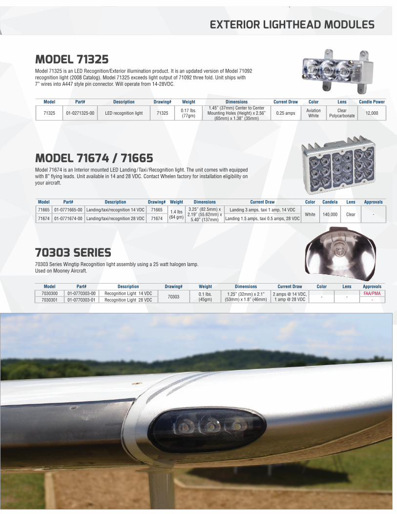
NOTE: All non-FAA approved parts in this catalog are signified by a (—) in the approval column. Parts without FAA approval may still be purchased, however, installation of these parts on U. S. Type Certificated products will require additional FAA approvals. 32
MODEL 71325 Model 71325 is an LED Recognition/Exterior illumination product. It is an updated version of Model 71092 recognition light (2008 Catalog). Model 71325 exceeds light output of 71092 three fold. Unit ships with 7” wires into A447 style pin connector. Will operate from 14-28VDC.
MODEL 71674 / 71665 Model 71674 is an Interior mounted LED Landing/Taxi /Recognition light. The unit comes with equipped with 8” flying leads. Unit available in 14 and 28 VDC. Contact Whelen factory for installation eligibility on your aircraft.
EXTERIOR LIGHTHEAD MODULES
Model Part# Description Drawing# Weight Dimensions Current Draw Color Lens Candle Power
71325 01-0271325-00 LED recognition light 71325 0.17 lbs. (77gm)
1.45” (37mm) Center to Center Mounting Holes (Height) x 2.56”
(65mm) x 1.38” (35mm)0.25 amps Aviation
WhiteClear
Polycarbonate 12,000
Model Part# Description Drawing# Weight Dimensions Current Draw Color Candela Lens Approvals
71665 01-0771665-00 Landing/taxi/recognition 14 VDC 71665 1.4 lbs (64 gm)
3.25” (82.5mm) x 2.19” (55.62mm) x
5.40” (137mm)
Landing 3 amps, taxi 1 amp, 14 VDCWhite 140,000 Clear -
71674 01-0771674-00 Landing/taxi/recognition 28 VDC 71674 Landing 1.5 amps, taxi 0.5 amps, 28 VDC
70303 SERIES 70303 Series Wingtip Recognition light assembly using a 25 watt halogen lamp. Used on Mooney Aircraft.
Model Part# Description Drawing# Weight Dimensions Current Draw Color Lens Approvals7030300 01-0770303-00 Recognition Light 14 VDC
70303 0.1 lbs. (45gm)
1.25” (32mm) x 2.1” (53mm) x 1.8” (46mm)
2 amps @ 14 VDC, 1 amp @ 28 VDC - -
FAA/PMA7030301 01-0770303-01 Recognition Light 28 VDC -
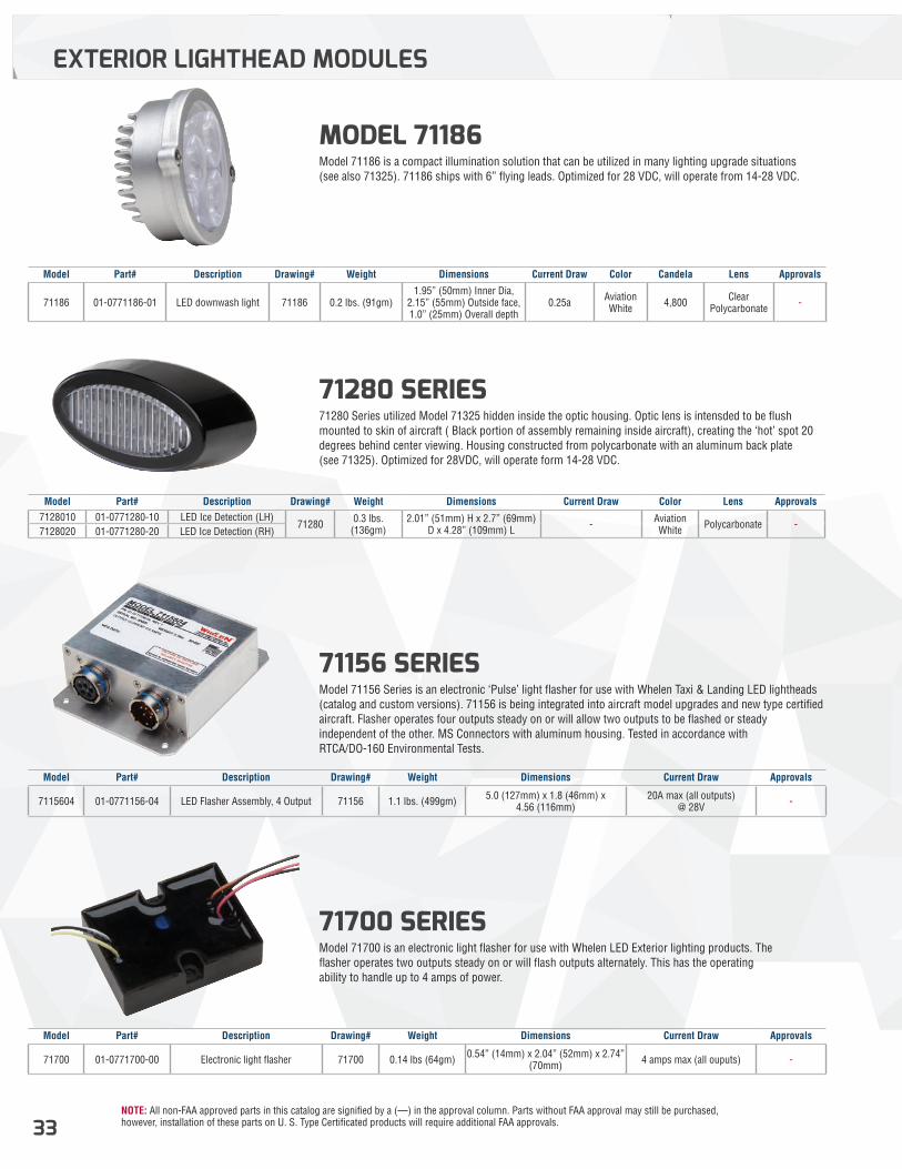
NOTE: All non-FAA approved parts in this catalog are signified by a (—) in the approval column. Parts without FAA approval may still be purchased, however, installation of these parts on U. S. Type Certificated products will require additional FAA approvals.33
71280 SERIES 71280 Series utilized Model 71325 hidden inside the optic housing. Optic lens is intensded to be flush mounted to skin of aircraft ( Black portion of assembly remaining inside aircraft), creating the ‘hot’ spot 20 degrees behind center viewing. Housing constructed from polycarbonate with an aluminum back plate (see 71325). Optimized for 28VDC, will operate form 14-28 VDC.
MODEL 71186 Model 71186 is a compact illumination solution that can be utilized in many lighting upgrade situations (see also 71325). 71186 ships with 6” flying leads. Optimized for 28 VDC, will operate from 14-28 VDC.
71156 SERIES Model 71156 Series is an electronic ‘Pulse’ light flasher for use with Whelen Taxi & Landing LED lightheads (catalog and custom versions). 71156 is being integrated into aircraft model upgrades and new type certified aircraft. Flasher operates four outputs steady on or will allow two outputs to be flashed or steady independent of the other. MS Connectors with aluminum housing. Tested in accordance with RTCA/DO-160 Environmental Tests.
71700 SERIES Model 71700 is an electronic light flasher for use with Whelen LED Exterior lighting products. The flasher operates two outputs steady on or will flash outputs alternately. This has the operating ability to handle up to 4 amps of power.
EXTERIOR LIGHTHEAD MODULES
Model Part# Description Drawing# Weight Dimensions Current Draw Color Lens Approvals7128010 01-0771280-10 LED Ice Detection (LH)
71280 0.3 lbs. (136gm)
2.01” (51mm) H x 2.7” (69mm) D x 4.28” (109mm) L - Aviation
White Polycarbonate -7128020 01-0771280-20 LED Ice Detection (RH)
Model Part# Description Drawing# Weight Dimensions Current Draw Color Candela Lens Approvals
71186 01-0771186-01 LED downwash light 71186 0.2 lbs. (91gm)1.95” (50mm) Inner Dia,
2.15” (55mm) Outside face, 1.0” (25mm) Overall depth
0.25a Aviation White 4,800 Clear
Polycarbonate -
Model Part# Description Drawing# Weight Dimensions Current Draw Approvals
7115604 01-0771156-04 LED Flasher Assembly, 4 Output 71156 1.1 lbs. (499gm) 5.0 (127mm) x 1.8 (46mm) x 4.56 (116mm)
20A max (all outputs) @ 28V -
Model Part# Description Drawing# Weight Dimensions Current Draw Approvals
71700 01-0771700-00 Electronic light flasher 71700 0.14 lbs (64gm) 0.54” (14mm) x 2.04” (52mm) x 2.74” (70mm) 4 amps max (all ouputs) -
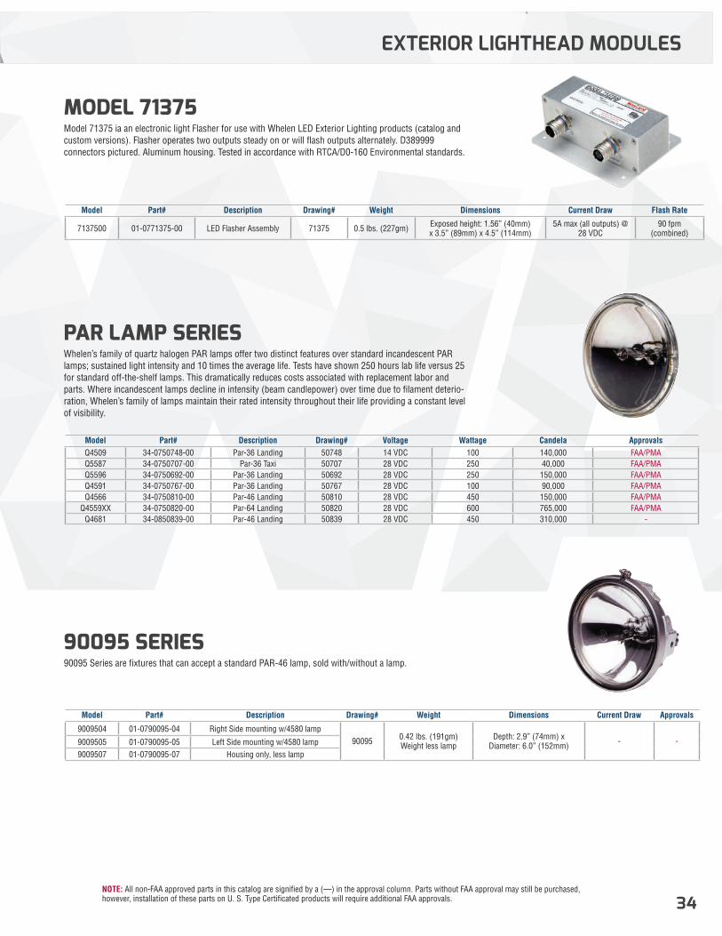
NOTE: All non-FAA approved parts in this catalog are signified by a (—) in the approval column. Parts without FAA approval may still be purchased, however, installation of these parts on U. S. Type Certificated products will require additional FAA approvals. 34
MODEL 71375 Model 71375 ia an electronic light Flasher for use with Whelen LED Exterior Lighting products (catalog and custom versions). Flasher operates two outputs steady on or will flash outputs alternately. D389999 connectors pictured. Aluminum housing. Tested in accordance with RTCA/D0-160 Environmental standards.
PAR LAMP SERIES Whelen’s family of quartz halogen PAR lamps offer two distinct features over standard incandescent PAR lamps; sustained light intensity and 10 times the average life. Tests have shown 250 hours lab life versus 25 for standard off-the-shelf lamps. This dramatically reduces costs associated with replacement labor and parts. Where incandescent lamps decline in intensity (beam candlepower) over time due to filament deterio-ration, Whelen’s family of lamps maintain their rated intensity throughout their life providing a constant level of visibility.
90095 SERIES90095 Series are fixtures that can accept a standard PAR-46 lamp, sold with/without a lamp.
EXTERIOR LIGHTHEAD MODULES
Model Part# Description Drawing# Weight Dimensions Current Draw Flash Rate
7137500 01-0771375-00 LED Flasher Assembly 71375 0.5 lbs. (227gm) Exposed height: 1.56” (40mm) x 3.5” (89mm) x 4.5” (114mm)
5A max (all outputs) @ 28 VDC
90 fpm (combined)
Model Part# Description Drawing# Voltage Wattage Candela ApprovalsQ4509 34-0750748-00 Par-36 Landing 50748 14 VDC 100 140,000 FAA/PMAQ5587 34-0750707-00 Par-36 Taxi 50707 28 VDC 250 40,000 FAA/PMAQ5596 34-0750692-00 Par-36 Landing 50692 28 VDC 250 150,000 FAA/PMAQ4591 34-0750767-00 Par-36 Landing 50767 28 VDC 100 90,000 FAA/PMAQ4566 34-0750810-00 Par-46 Landing 50810 28 VDC 450 150,000 FAA/PMA
Q4559XX 34-0750820-00 Par-64 Landing 50820 28 VDC 600 765,000 FAA/PMAQ4681 34-0850839-00 Par-46 Landing 50839 28 VDC 450 310,000 -
Model Part# Description Drawing# Weight Dimensions Current Draw Approvals
9009504 01-0790095-04 Right Side mounting w/4580 lamp90095 0.42 lbs. (191gm)
Weight less lampDepth: 2.9” (74mm) x
Diameter: 6.0” (152mm) - -9009505 01-0790095-05 Left Side mounting w/4580 lamp9009507 01-0790095-07 Housing only, less lamp
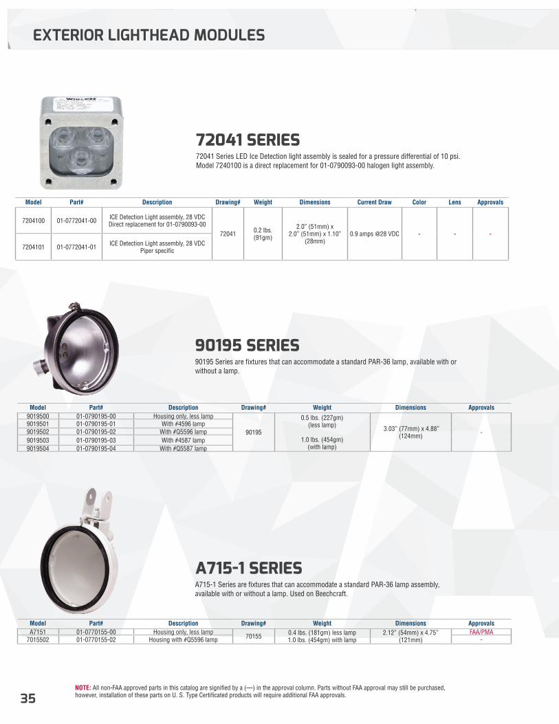
NOTE: All non-FAA approved parts in this catalog are signified by a (—) in the approval column. Parts without FAA approval may still be purchased, however, installation of these parts on U. S. Type Certificated products will require additional FAA approvals.35
72041 SERIES 72041 Series LED Ice Detection light assembly is sealed for a pressure differential of 10 psi. Model 7240100 is a direct replacement for 01-0790093-00 halogen light assembly.
Model Part# Description Drawing# Weight Dimensions Current Draw Color Lens Approvals
7204100 01-0772041-00 ICE Detection Light assembly, 28 VDCDirect replacement for 01-0790093-00
72041 0.2 lbs. (91gm)
2.0” (51mm) x 2.0” (51mm) x 1.10”
(28mm)0.9 amps @28 VDC - - -
7204101 01-0772041-01 ICE Detection Light assembly, 28 VDC Piper specific
90195 SERIES 90195 Series are fixtures that can accommodate a standard PAR-36 lamp, available with or without a lamp.
A715-1 SERIES A715-1 Series are fixtures that can accommodate a standard PAR-36 lamp assembly, available with or without a lamp. Used on Beechcraft.
Model Part# Description Drawing# Weight Dimensions Approvals9019500 01-0790195-00 Housing only, less lamp
90195
0.5 lbs. (227gm) (less lamp)
1.0 lbs. (454gm) (with lamp)
3.03” (77mm) x 4.88” (124mm) -
9019501 01-0790195-01 With #4596 lamp9019502 01-0790195-02 With #Q5596 lamp9019503 01-0790195-03 With #4587 lamp9019504 01-0790195-04 With #Q5587 lamp
Model Part# Description Drawing# Weight Dimensions ApprovalsA7151 01-0770155-00 Housing only, less lamp
70155 0.4 lbs. (181gm) less lamp 1.0 lbs. (454gm) with lamp
2.12” (54mm) x 4.75” (121mm)
FAA/PMA7015502 01-0770155-02 Housing with #Q5596 lamp -
EXTERIOR LIGHTHEAD MODULES
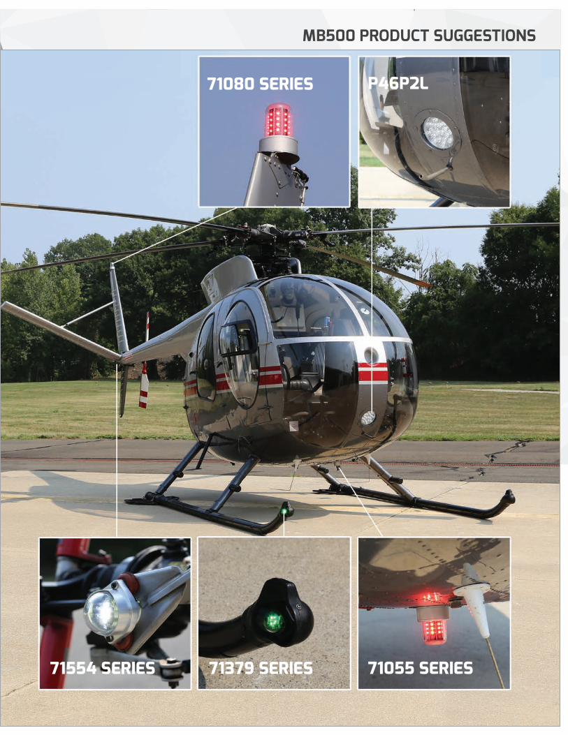
NOTE: All non-FAA approved parts in this catalog are signified by a (—) in the approval column. Parts without FAA approval may still be purchased, however, installation of these parts on U. S. Type Certificated products will require additional FAA approvals. 36
MB500 PRODUCT SUGGESTIONS
71080 SERIES
71055 SERIES71379 SERIES71554 SERIES
P46P2L
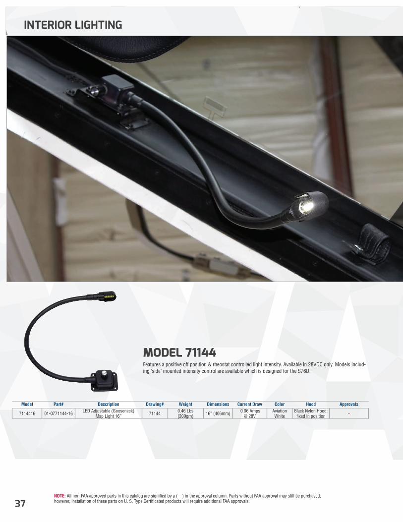
NOTE: All non-FAA approved parts in this catalog are signified by a (—) in the approval column. Parts without FAA approval may still be purchased, however, installation of these parts on U. S. Type Certificated products will require additional FAA approvals.37
MODEL 71144 Features a positive off position & rheostat controlled light intensity. Available in 28VDC only. Models includ-ing ‘side’ mounted intensity control are available which is designed for the S76D.
INTERIOR LIGHTING
Model Part# Description Drawing# Weight Dimensions Current Draw Color Hood Approvals
7114416 01-0771144-16 LED Adjustable (Gooseneck) Map Light 16” 71144 0.46 Lbs
(209gm) 16” (406mm) 0.06 Amps @ 28V
Aviation White
Black Nylon Hood: fixed in position -
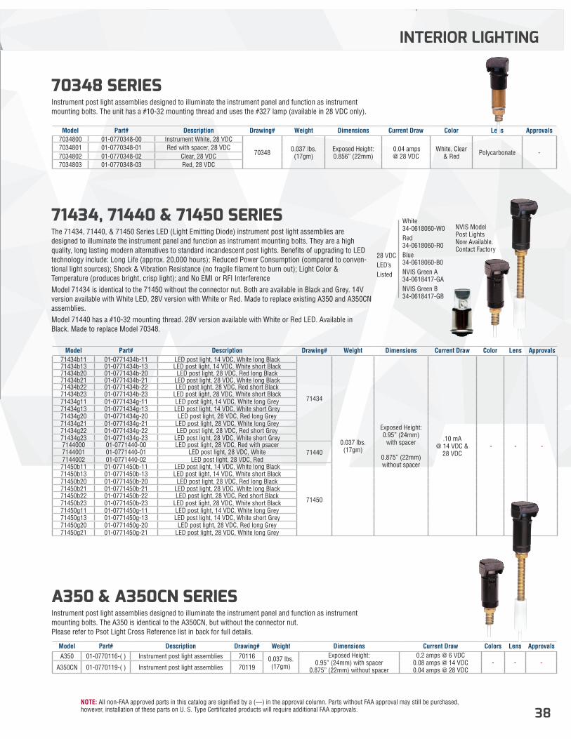
NOTE: All non-FAA approved parts in this catalog are signified by a (—) in the approval column. Parts without FAA approval may still be purchased, however, installation of these parts on U. S. Type Certificated products will require additional FAA approvals. 38
71434, 71440 & 71450 SERIES The 71434, 71440, & 71450 Series LED (Light Emitting Diode) instrument post light assemblies are designed to illuminate the instrument panel and function as instrument mounting bolts. They are a high quality, long lasting modern alternatives to standard incandescent post lights. Benefits of upgrading to LED technology include: Long Life (approx. 20,000 hours); Reduced Power Consumption (compared to conven-tional light sources); Shock & Vibration Resistance (no fragile filament to burn out); Light Color & Temperature (produces bright, crisp light); and No EMI or RFI InterferenceModel 71434 is identical to the 71450 without the connector nut. Both are available in Black and Grey. 14V version available with White LED, 28V version with White or Red. Made to replace existing A350 and A350CN assemblies.Model 71440 has a #10-32 mounting thread. 28V version available with White or Red LED. Available in Black. Made to replace Model 70348.
70348 SERIES Instrument post light assemblies designed to illuminate the instrument panel and function as instrument mounting bolts. The unit has a #10-32 mounting thread and uses the #327 lamp (available in 28 VDC only).
A350 & A350CN SERIES Instrument post light assemblies designed to illuminate the instrument panel and function as instrument mounting bolts. The A350 is identical to the A350CN, but without the connector nut. Please refer to Psot Light Cross Reference list in back for full details.
INTERIOR LIGHTING
Model Part# Description Drawing# Weight Dimensions Current Draw Color Lens Approvals71434b11 01-0771434b-11 LED post light, 14 VDC, White long Black
71434
0.037 lbs. (17gm)
Exposed Height: 0.95” (24mm)
with spacer
0.875” (22mm) without spacer
.10 mA @ 14 VDC &
28 VDC - - -
71434b13 01-0771434b-13 LED post light, 14 VDC, White short Black71434b20 01-0771434b-20 LED post light, 28 VDC, Red long Black 71434b21 01-0771434b-21 LED post light, 28 VDC, White long Black71434b22 01-0771434b-22 LED post light, 28 VDC, Red short Black71434b23 01-0771434b-23 LED post light, 28 VDC, White short Black71434g11 01-0771434g-11 LED post light, 14 VDC, White long Grey71434g13 01-0771434g-13 LED post light, 14 VDC, White short Grey71434g20 01-0771434g-20 LED post light, 28 VDC, Red long Grey71434g21 01-0771434g-21 LED post light, 28 VDC, White long Grey71434g22 01-0771434g-22 LED post light, 28 VDC, Red short Grey71434g23 01-0771434g-23 LED post light, 28 VDC, White short Grey7144000 01-0771440-00 LED post light, 28 VDC, Red with psacer
714407144001 01-0771440-01 LED post light, 28 VDC, White7144002 01-0771440-02 LED post light, 28 VDC, Red71450b11 01-0771450b-11 LED post light, 14 VDC, White long Black
71450
71450b13 01-0771450b-13 LED post light, 14 VDC, White short Black71450b20 01-0771450b-20 LED post light, 28 VDC, Red long Black71450b21 01-0771450b-21 LED post light, 28 VDC, White long Black71450b22 01-0771450b-22 LED post light, 28 VDC, Red short Black71450b23 01-0771450b-23 LED post light, 28 VDC, White short Black71450g11 01-0771450g-11 LED post light, 14 VDC, White long Grey71450g13 01-0771450g-13 LED post light, 14 VDC, White short Grey71450g20 01-0771450g-20 LED post light, 28 VDC, Red long Grey71450g21 01-0771450g-21 LED post light, 28 VDC, White long Grey
Model Part# Description Drawing# Weight Dimensions Current Draw Color Lens Approvals7034800 01-0770348-00 Instrument White, 28 VDC
70348 0.037 lbs. (17gm)
Exposed Height: 0.856” (22mm)
0.04 amps @ 28 VDC
White, Clear & Red Polycarbonate -
7034801 01-0770348-01 Red with spacer, 28 VDC7034802 01-0770348-02 Clear, 28 VDC7034803 01-0770348-03 Red, 28 VDC
Model Part# Description Drawing# Weight Dimensions Current Draw Colors Lens ApprovalsA350 01-0770116-( ) Instrument post light assemblies 70116 0.037 lbs.
(17gm)
Exposed Height: 0.95” (24mm) with spacer
0.875” (22mm) without spacer
0.2 amps @ 6 VDC 0.08 amps @ 14 VDC 0.04 amps @ 28 VDC
- - -A350CN 01-0770119-( ) Instrument post light assemblies 70119
White 34-0618060-W0Red 34-0618060-R0Blue 34-0618060-B0NVIS Green A 34-0618417-GANVIS Green B 34-0618417-GB
28 VDCLED’sListed
NVIS Model Post Lights Now Available.Contact Factory
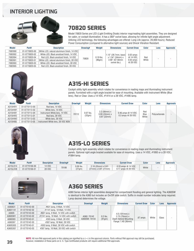
NOTE: All non-FAA approved parts in this catalog are signified by a (—) in the approval column. Parts without FAA approval may still be purchased, however, installation of these parts on U. S. Type Certificated products will require additional FAA approvals.39
A315-HI SERIES Cockpit utility light assembly which rotates for convenience in reading maps and illuminating instrument panels. Furnished with a right angle bracket for ease of mounting. Available with Instrument White (Blue lens), Red or Clear. Uses a 14 VDC, #1414 or a 28 VDC, #1495 lamp.
70820 SERIES Model 70820 Series are LED (Light Emitting Diode) interior map/reading light assemblies. They are designed for cabin, or cockpit illumination. It has a 360° swivel base, allowing for infinite light angle adjustment. Utilizing LED technology, the following advantages are offered: Long Life (approx. 20,000 hours); Reduced Power Consumption (compared to alternative light sources) and Shock Vibration Resistant.
A315-LO SERIES Cockpit utility light assembly which rotates for convenience in reading maps and illuminating instrument panels. Optional right angle bracket available for ease of mounting. Uses a 14 VDC, #1893 or a 28 VDC, #1864 lamp.
A360 SERIES A360 Series interior light assemblies designed for compartment flooding and general lighting. The A360SW is identical to the A360 but includes an On/Off slide switch. Suffix in model number indicates lamp required. Lamp desired determines the voltage.
INTERIOR LIGHTING
Model Part# Description Drawing# Weight Dimensions Current Draw Color Lens ApprovalsA315HIR1 01-0770113-00 Red lens, 14 VDC
70113 0.07 lbs. (32gm)
2.2 (56mm) x 0.93 (24mm) x 0.87 (22mm)
0.46 amps @ 14 VDC 0.3 amps @ 28 VDC
Red Blue
WhitePolycarbonate -
A315HIW1 01-0770113-02 White lens, 14 VDCA315HIB1 01-0770113-04 Instrument White lens, 14 VDCA315HIR2 01-0770113-01 Red lens, 28 VDCA315HIW2 01-0770113-03 White lens, 28 VDCA315HIB2 01-0770113-05 Instrument White lens, 28 VDC NSN
Model Part# Description Drawing# Weight Dimensions Current Draw Color Lens Approvals7082000 01-0770820-00 White LED, natural aluminum finish, 14 VDC
70820 0.19 lbs. (86gm)
1.13” (28.7mm, base) x 1.34” (34mm) x 2.66” (67.56mm
swivel dia.)
0.02 amps @ 14 VDC, 0.02 amps @ 28 VDC
Red White - -
7082002 01-0770820-02 White LED, Black anodized finish, 14 VDC7082004 01-0770820-04 Red LED, Black anodized finish, 14 VDC7082001 01-0770820-01 White LED, natural aluminum finish, 28 VDC7082003 01-0770820-03 White LED, Black anodized finish, 28 VDC7082005 01-0770820-05 Red LED, Black anodized finish, 28 VDC
Model Part# Description Drawing# Weight Dimensions Current Draw Color Lens ApprovalsA315LO14 01-0770106-00 14 VDC
70106 0.06 lbs. (27gm)
2.18 (55mm) x 0.81 (21mm) x 0.81 (21mm)
0.33 amps @ 14 VDC 0.17 amps @ 28 VDC White - -
A315LO28 01-0770106-01 28 VDC
Model Part# Description Drawing# Weight Dimensions Current Draw Color Lens ApprovalsA360631 01-0770142-00 #631 lamp, 9 Watt, 14 VDC
A360: 70142 A360SW: 70143
0.2 lbs. (91gm)
4.0 (101mm) x 2.75 (70mm) x
Depth Behind Mounting Flange: 1.40 (36mm)
.67 amps White Glass -
A3601141 01-0770142-02 #1141 lamp, 18 Watt, 14 VDCA360S 01-0770143-00 #631 lamp, 9 Watt, 14 VDC with switch
A360SW1 01-0770143-02 #1141 lamp, 18 Watt, 14 VDC with switchA360303 01-0770142-01 #303 lamp, 9 Watt, 28 VDCA360307 01-0770142-03 #307 lamp, 18 Watt, 28 VDC
A360S303 01-0770143-01 #303 lamp, 9 Watt, 28 VDC with switchA360S307 01-0770143-03 #307 lamp, 18 Watt, 28 VDC with switch
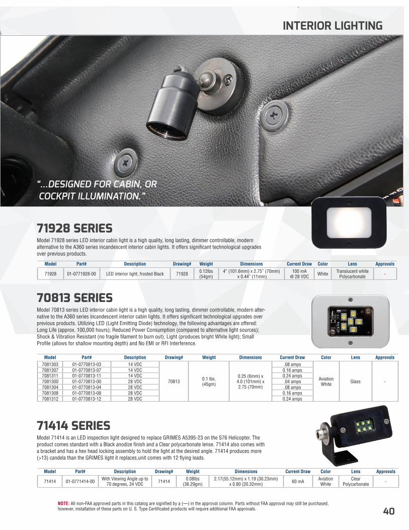
NOTE: All non-FAA approved parts in this catalog are signified by a (—) in the approval column. Parts without FAA approval may still be purchased, however, installation of these parts on U. S. Type Certificated products will require additional FAA approvals. 40
70813 SERIES Model 70813 series LED interior cabin light is a high quality, long lasting, dimmer controllable, modern alter-native to the A360 series incandescent interior cabin lights. It offers significant technological upgrades over previous products. Utilizing LED (Light Emitting Diode) technology, the following advantages are offered: Long Life (approx. 100,000 hours); Reduced Power Consumption (compared to alternative light sources); Shock & Vibration Resistant (no fragile filament to burn out); Light (produces bright White light); Small Profile (allows for shallow mounting depth) and No EMI or RFI Interference.
71414 SERIES Model 71414 is an LED inspection light designed to replace GRIMES A5395-23 on the S76 Helicopter. The product comes standard with a Black anodize finish and a Clear polycarbonate lense. 71414 also comes with a bracket and has a hex head locking assembly to hold the light at the desired angle. 71414 produces more (>13) candela than the GRIMES light it replaces,unit comes with 12 flying leads.
71928 SERIES Model 71928 series LED interior cabin light is a high quality, long lasting, dimmer controllable, modern alternative to the A360 series incandescent interior cabin lights. It offers significant technological upgrades over previous products.
INTERIOR LIGHTING
Model Part# Description Drawing# Weight Dimensions Current Draw Color Lens Approvals7081303 01-0770813-03 14 VDC
70813 0.1 lbs. (45gm)
0.25 (6mm) x4.0 (101mm) x 2.75 (70mm)
.08 amps
Aviation White Glass -
7081307 01-0770813-07 14 VDC 0.16 amps7081311 01-0770813-11 14 VDC 0.24 amps7081300 01-0770813-00 28 VDC .04 amps7081304 01-0770813-04 28 VDC .08 amps7081308 01-0770813-08 28 VDC 0.16 amps7081312 01-0770813-12 28 VDC 0.24 amps
Model Part# Description Drawing# Weight Dimensions Current Draw Color Lens Approvals
71414 01-0771414-00 With Viewing Angle up to 70 degrees, 24 VDC 71414 0.08lbs
(36.29gm)2.17(55.12mm) x 1.19 (30.23mm)
x 0.80 (20.32mm) 60 mA Aviation White
Clear Polycarbonate -
Model Part# Description Drawing# Weight Dimensions Current Draw Color Lens Approvals
71928 01-0771928-00 LED interior light, frosted Black 71928 0.12lbs (54gm)
4” (101.6mm) x 2.75” (70mm) x 0.44” (11mm)
100 mA @ 28 VDC White Translucent white
Polycarbonate -
“...DESIGNED FOR CABIN, OR COCKPIT ILLUMINATION.”
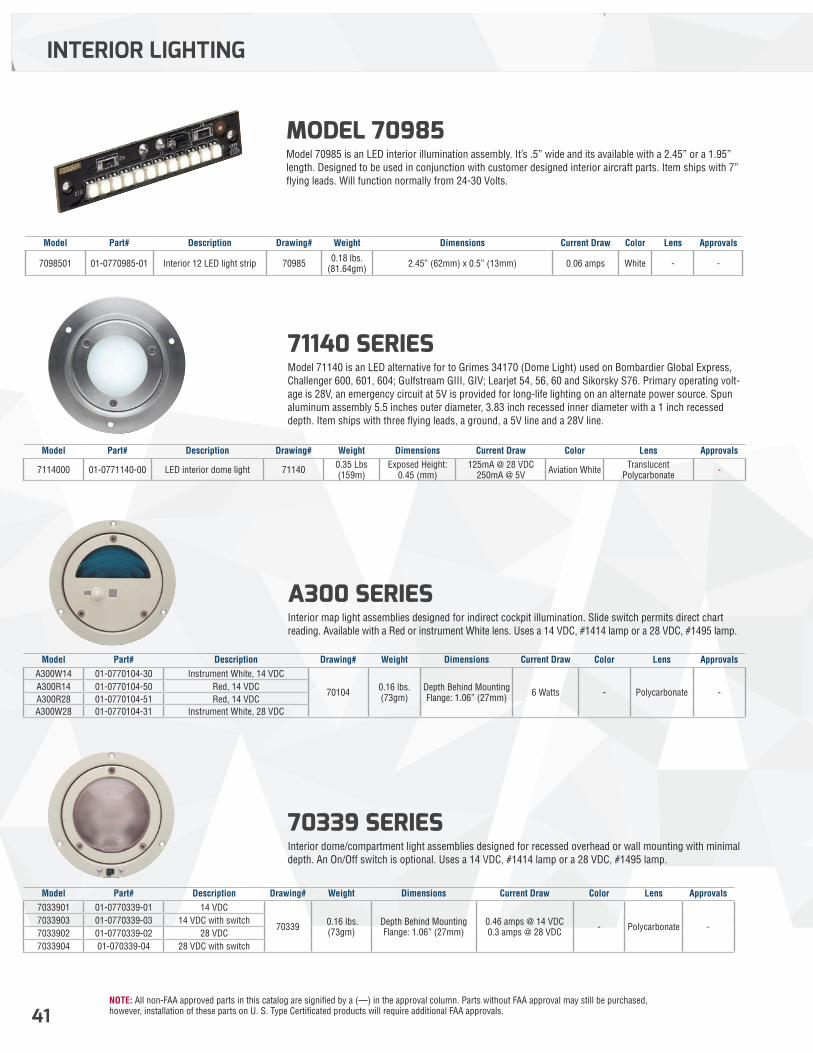
NOTE: All non-FAA approved parts in this catalog are signified by a (—) in the approval column. Parts without FAA approval may still be purchased, however, installation of these parts on U. S. Type Certificated products will require additional FAA approvals.41
A300 SERIES Interior map light assemblies designed for indirect cockpit illumination. Slide switch permits direct chart reading. Available with a Red or instrument White lens. Uses a 14 VDC, #1414 lamp or a 28 VDC, #1495 lamp.
71140 SERIES Model 71140 is an LED alternative for to Grimes 34170 (Dome Light) used on Bombardier Global Express, Challenger 600, 601, 604; Gulfstream GIII, GIV; Learjet 54, 56, 60 and Sikorsky S76. Primary operating volt-age is 28V, an emergency circuit at 5V is provided for long-life lighting on an alternate power source. Spun aluminum assembly 5.5 inches outer diameter, 3.83 inch recessed inner diameter with a 1 inch recessed depth. Item ships with three flying leads, a ground, a 5V line and a 28V line.
70339 SERIES Interior dome/compartment light assemblies designed for recessed overhead or wall mounting with minimal depth. An On/Off switch is optional. Uses a 14 VDC, #1414 lamp or a 28 VDC, #1495 lamp.
INTERIOR LIGHTING
Model Part# Description Drawing# Weight Dimensions Current Draw Color Lens ApprovalsA300W14 01-0770104-30 Instrument White, 14 VDC
70104 0.16 lbs. (73gm)
Depth Behind Mounting Flange: 1.06” (27mm) 6 Watts - Polycarbonate -
A300R14 01-0770104-50 Red, 14 VDCA300R28 01-0770104-51 Red, 14 VDCA300W28 01-0770104-31 Instrument White, 28 VDC
Model Part# Description Drawing# Weight Dimensions Current Draw Color Lens Approvals
7114000 01-0771140-00 LED interior dome light 71140 0.35 Lbs (159m)
Exposed Height: 0.45 (mm)
125mA @ 28 VDC 250mA @ 5V Aviation White Translucent
Polycarbonate -
Model Part# Description Drawing# Weight Dimensions Current Draw Color Lens Approvals
7098501 01-0770985-01 Interior 12 LED light strip 70985 0.18 lbs. (81.64gm) 2.45” (62mm) x 0.5” (13mm) 0.06 amps White - -
Model Part# Description Drawing# Weight Dimensions Current Draw Color Lens Approvals7033901 01-0770339-01 14 VDC
70339 0.16 lbs. (73gm)
Depth Behind Mounting Flange: 1.06” (27mm)
0.46 amps @ 14 VDC 0.3 amps @ 28 VDC - Polycarbonate -
7033903 01-0770339-03 14 VDC with switch7033902 01-0770339-02 28 VDC7033904 01-070339-04 28 VDC with switch
MODEL 70985 Model 70985 is an LED interior illumination assembly. It’s .5” wide and its available with a 2.45” or a 1.95” length. Designed to be used in conjunction with customer designed interior aircraft parts. Item ships with 7” flying leads. Will function normally from 24-30 Volts.
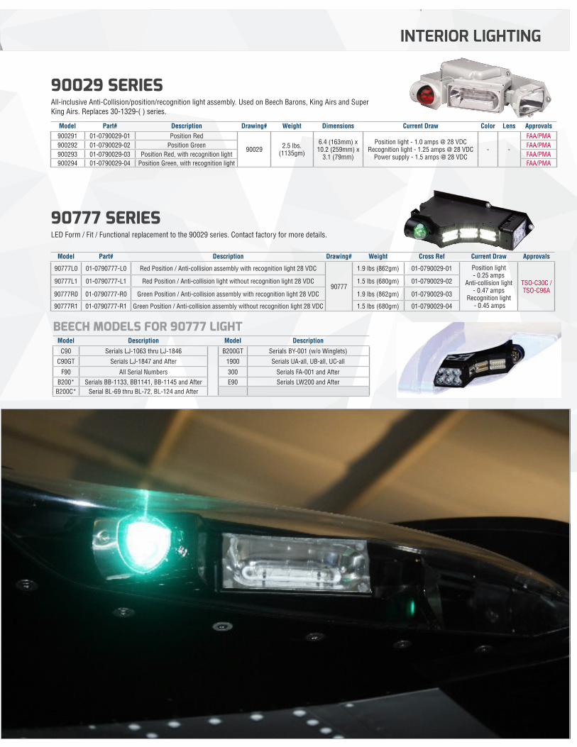
NOTE: All non-FAA approved parts in this catalog are signified by a (—) in the approval column. Parts without FAA approval may still be purchased, however, installation of these parts on U. S. Type Certificated products will require additional FAA approvals. 42
INTERIOR LIGHTING
42
90777 SERIES LED Form / Fit / Functional replacement to the 90029 series. Contact factory for more details.
BEECH MODELS FOR 90777 LIGHT
90029 SERIES All-inclusive Anti-Collision/position/recognition light assembly. Used on Beech Barons, King Airs and Super King Airs. Replaces 30-1329-( ) series.
Model Part# Description Drawing# Weight Dimensions Current Draw Color Lens Approvals900291 01-0790029-01 Position Red
90029 2.5 lbs. (1135gm)
6.4 (163mm) x 10.2 (259mm) x
3.1 (79mm)
Position light - 1.0 amps @ 28 VDC Recognition light - 1.25 amps @ 28 VDC
Power supply - 1.5 amps @ 28 VDC- -
FAA/PMA900292 01-0790029-02 Position Green FAA/PMA900293 01-0790029-03 Position Red, with recognition light FAA/PMA900294 01-0790029-04 Position Green, with recognition light FAA/PMA
Model Part# Description Drawing# Weight Cross Ref Current Draw Approvals
90777L0 01-0790777-L0 Red Position / Anti-collision assembly with recognition light 28 VDC
90777
1.9 lbs (862gm) 01-0790029-01 Position light - 0.25 amps
Anti-collision light - 0.47 amps
Recognition light - 0.45 amps
TSO-C30C / TSO-C96A
90777L1 01-0790777-L1 Red Position / Anti-collision light without recognition light 28 VDC 1.5 lbs (680gm) 01-0790029-02
90777R0 01-0790777-R0 Green Position / Anti-collision assembly with recognition light 28 VDC 1.9 lbs (862gm) 01-0790029-03
90777R1 01-0790777-R1 Green Position / Anti-collision assembly without recognition light 28 VDC 1.5 lbs (680gm) 01-0790029-04
Model Description Model Description
C90 Serials LJ-1063 thru LJ-1846 B200GT Serials BY-001 (w/o Winglets)
C90GT Serials LJ-1847 and After 1900 Serials UA-all, UB-all, UC-all
F90 All Serial Numbers 300 Serials FA-001 and AfterB200* Serials BB-1133, BB1141, BB-1145 and After E90 Serials LW200 and After
B200C* Serial BL-69 thru BL-72, BL-124 and After
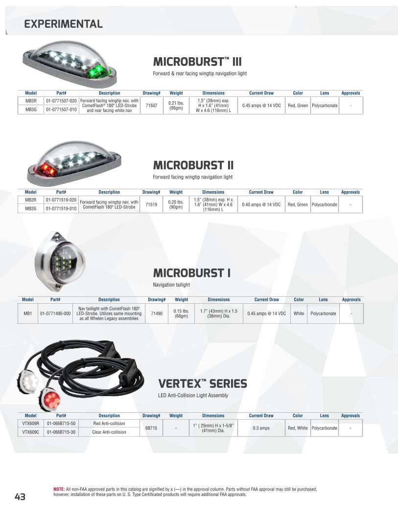
NOTE: All non-FAA approved parts in this catalog are signified by a (—) in the approval column. Parts without FAA approval may still be purchased, however, installation of these parts on U. S. Type Certificated products will require additional FAA approvals.43
EXPERIMENTAL
MICROBURST™ III Forward & rear facing wingtip navigation light
MICROBURST II Forward facing wingtip navigation light
MICROBURST I Navigation tailight
VERTEX™ SERIES LED Anti-Collision Light Assembly
Model Part# Description Drawing# Weight Dimensions Current Draw Color Lens Approvals
MB3R 01-0771507-020 Forward facing wingtip nav, with CometFlash® 180º LED-Strobe
and rear facing white nav71507 0.21 lbs.
(95gm)
1.5” (38mm) exp. H x 1.6” (41mm)
W x 4.6 (116mm) L0.45 amps @ 14 VDC Red, Green Polycarbonate -
MB3G 01-0771507-010
Model Part# Description Drawing# Weight Dimensions Current Draw Color Lens Approvals
MB2R 01-0771519-020 Forward facing wingtip nav, with CometFlash 180º LED-Strobe 71519 0.20 lbs.
(90gm)
1.5” (38mm) exp. H x 1.6” (41mm) W x 4.6
(116mm) L0.40 amps @ 14 VDC Red, Green Polycarbonate -
MB2G 01-0771519-010
Model Part# Description Drawing# Weight Dimensions Current Draw Color Lens Approvals
VTX609R 01-066B715-50 Red Anti-collision6B715 - 1” ( 25mm) H x 1-5/8”
(41mm) Dia. 0.3 amps Red, White Polycarbonate -VTX609C 01-066B715-30 Clear Anti-collision
Model Part# Description Drawing# Weight Dimensions Current Draw Color Lens Approvals
MB1 01-0771490-000Nav taillight with CometFlash 180º
LED-Strobe. Utilizes same mounting as all Whelen Legacy assemblies
71490 0.15 lbs. (68gm)
1.7” (43mm) H x 1.5 (38mm) Dia. 0.45 amps @ 14 VDC White Polycarbonate -
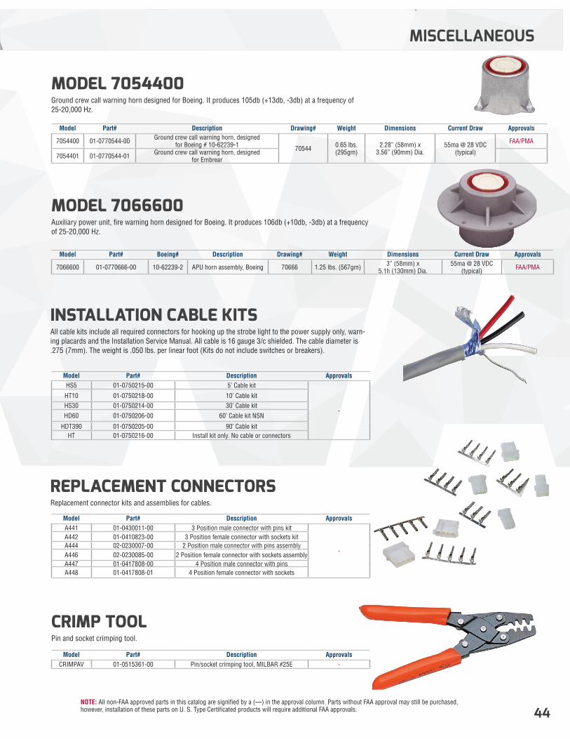
NOTE: All non-FAA approved parts in this catalog are signified by a (—) in the approval column. Parts without FAA approval may still be purchased, however, installation of these parts on U. S. Type Certificated products will require additional FAA approvals. 44
MISCELLANEOUS
INSTALLATION CABLE KITSAll cable kits include all required connectors for hooking up the strobe light to the power supply only, warn-ing placards and the Installation Service Manual. All cable is 16 gauge 3/c shielded. The cable diameter is .275 (7mm). The weight is .050 lbs. per linear foot (Kits do not include switches or breakers).
MODEL 7066600 Auxiliary power unit, fire warning horn designed for Boeing. It produces 106db (+10db, -3db) at a frequency of 25-20,000 Hz.
CRIMP TOOL Pin and socket crimping tool.
MODEL 7054400 Ground crew call warning horn designed for Boeing. It produces 105db (+13db, -3db) at a frequency of 25-20,000 Hz.
REPLACEMENT CONNECTORSReplacement connector kits and assemblies for cables.
Model Part# Description ApprovalsHS5 01-0750215-00 5’ Cable kit
-
HT10 01-0750218-00 10’ Cable kitHS30 01-0750214-00 30’ Cable kitHD60 01-0750206-00 60’ Cable kit NSN
HDT390 01-0750205-00 90’ Cable kitHT 01-0750216-00 Install kit only. No cable or connectors
Model Part# Description ApprovalsCRIMPAV 01-0515361-00 Pin/socket crimping tool, MILBAR #25E -
Model Part# Description ApprovalsA441 01-0430011-00 3 Position male connector with pins kit
-
A442 01-0410823-00 3 Position female connector with sockets kitA444 02-0230007-00 2 Position male connector with pins assemblyA446 02-0230085-00 2 Position female connector with sockets assemblyA447 01-0417808-00 4 Position male connector with pinsA448 01-0417808-01 4 Position female connector with sockets
Model Part# Description Drawing# Weight Dimensions Current Draw Approvals
7054400 01-0770544-00 Ground crew call warning horn, designed for Boeing # 10-62239-1 70544 0.65 lbs.
(295gm)2.28” (58mm) x
3.56” (90mm) Dia.55ma @ 28 VDC
(typical)
FAA/PMA
7054401 01-0770544-01 Ground crew call warning horn, designed for Embrear
Model Part# Boeing# Description Drawing# Weight Dimensions Current Draw Approvals
7066600 01-0770666-00 10-62239-2 APU horn assembly, Boeing 70666 1.25 lbs. (567gm) 3” (58mm) x 5.1h (130mm) Dia.
55ma @ 28 VDC (typical) FAA/PMA
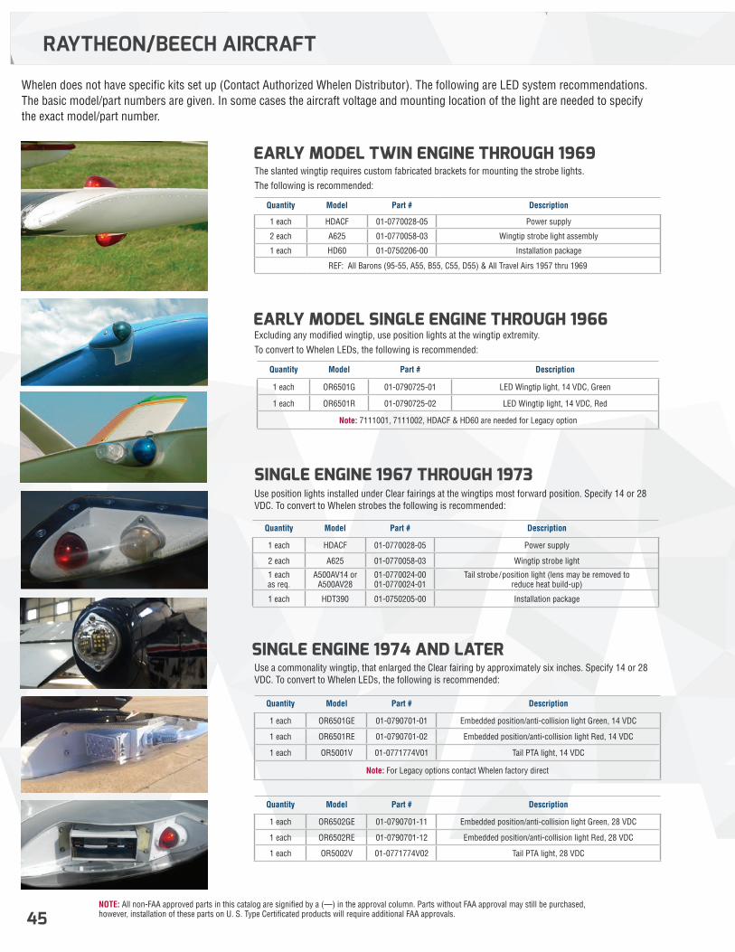
NOTE: All non-FAA approved parts in this catalog are signified by a (—) in the approval column. Parts without FAA approval may still be purchased, however, installation of these parts on U. S. Type Certificated products will require additional FAA approvals.45
SINGLE ENGINE 1974 AND LATER
SINGLE ENGINE 1967 THROUGH 1973
EARLY MODEL TWIN ENGINE THROUGH 1969
EARLY MODEL SINGLE ENGINE THROUGH 1966
Whelen does not have specific kits set up (Contact Authorized Whelen Distributor). The following are LED system recommendations. The basic model/part numbers are given. In some cases the aircraft voltage and mounting location of the light are needed to specify the exact model/part number.
Use a commonality wingtip, that enlarged the Clear fairing by approximately six inches. Specify 14 or 28 VDC. To convert to Whelen LEDs, the following is recommended:
Use position lights installed under Clear fairings at the wingtips most forward position. Specify 14 or 28 VDC. To convert to Whelen strobes the following is recommended:
The slanted wingtip requires custom fabricated brackets for mounting the strobe lights. The following is recommended:
Excluding any modified wingtip, use position lights at the wingtip extremity. To convert to Whelen LEDs, the following is recommended:
Quantity Model Part # Description
1 each OR6501GE 01-0790701-01 Embedded position/anti-collision light Green, 14 VDC
1 each OR6501RE 01-0790701-02 Embedded position/anti-collision light Red, 14 VDC
1 each OR5001V 01-0771774V01 Tail PTA light, 14 VDC
Note: For Legacy options contact Whelen factory direct
Quantity Model Part # Description
1 each OR6502GE 01-0790701-11 Embedded position/anti-collision light Green, 28 VDC
1 each OR6502RE 01-0790701-12 Embedded position/anti-collision light Red, 28 VDC
1 each OR5002V 01-0771774V02 Tail PTA light, 28 VDC
Quantity Model Part # Description
1 each HDACF 01-0770028-05 Power supply
2 each A625 01-0770058-03 Wingtip strobe light
1 each as req.
A500AV14 or A500AV28
01-0770024-00 01-0770024-01
Tail strobe/position light (lens may be removed to reduce heat build-up)
1 each HDT390 01-0750205-00 Installation package
Quantity Model Part # Description
1 each HDACF 01-0770028-05 Power supply
2 each A625 01-0770058-03 Wingtip strobe light assembly
1 each HD60 01-0750206-00 Installation package
REF: All Barons (95-55, A55, B55, C55, D55) & All Travel Airs 1957 thru 1969
Quantity Model Part # Description
1 each OR6501G 01-0790725-01 LED Wingtip light, 14 VDC, Green
1 each OR6501R 01-0790725-02 LED Wingtip light, 14 VDC, Red
Note: 7111001, 7111002, HDACF & HD60 are needed for Legacy option
RAYTHEON/BEECH AIRCRAFT
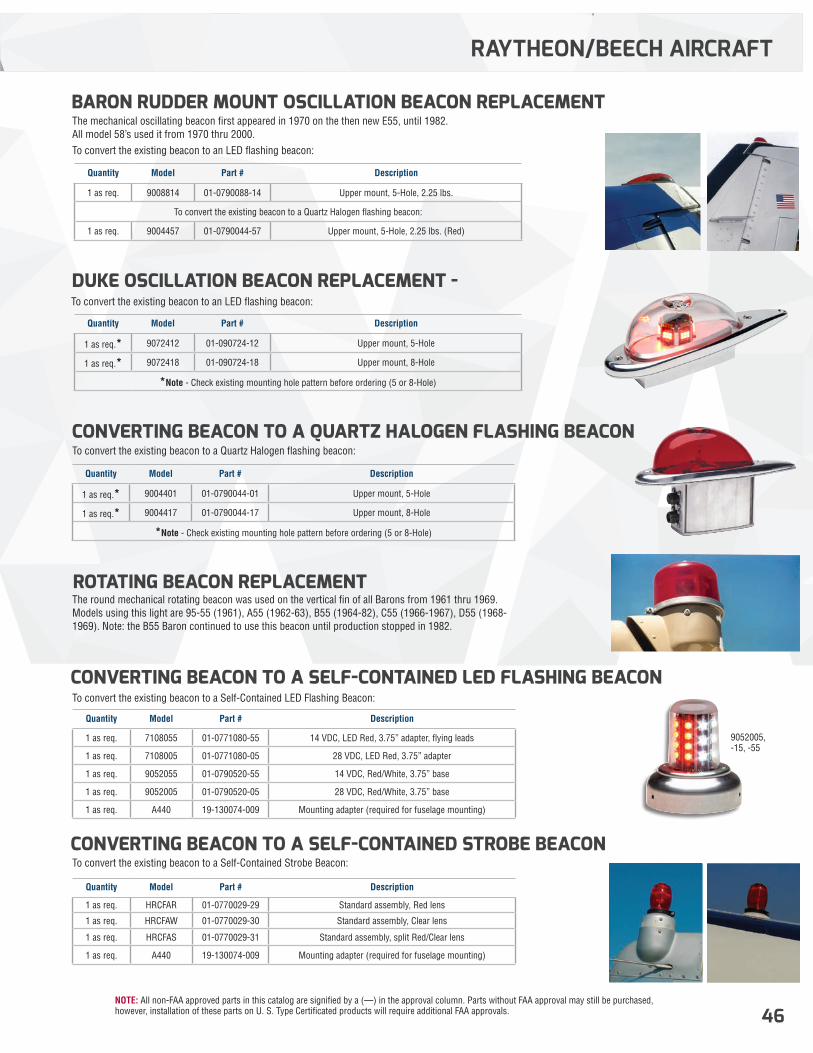
NOTE: All non-FAA approved parts in this catalog are signified by a (—) in the approval column. Parts without FAA approval may still be purchased, however, installation of these parts on U. S. Type Certificated products will require additional FAA approvals. 46
RAYTHEON/BEECH AIRCRAFT
DUKE OSCILLATION BEACON REPLACEMENT -
BARON RUDDER MOUNT OSCILLATION BEACON REPLACEMENT
ROTATING BEACON REPLACEMENT
CONVERTING BEACON TO A SELF-CONTAINED LED FLASHING BEACON
CONVERTING BEACON TO A SELF-CONTAINED STROBE BEACON
To convert the existing beacon to a Quartz Halogen flashing beacon:
To convert the existing beacon to an LED flashing beacon:
The mechanical oscillating beacon first appeared in 1970 on the then new E55, until 1982. All model 58’s used it from 1970 thru 2000.To convert the existing beacon to an LED flashing beacon:
The round mechanical rotating beacon was used on the vertical fin of all Barons from 1961 thru 1969. Models using this light are 95-55 (1961), A55 (1962-63), B55 (1964-82), C55 (1966-1967), D55 (1968-1969). Note: the B55 Baron continued to use this beacon until production stopped in 1982.
To convert the existing beacon to a Self-Contained LED Flashing Beacon:
To convert the existing beacon to a Self-Contained Strobe Beacon:
Quantity Model Part # Description
1 as req.* 9004401 01-0790044-01 Upper mount, 5-Hole
1 as req.* 9004417 01-0790044-17 Upper mount, 8-Hole
*Note - Check existing mounting hole pattern before ordering (5 or 8-Hole)
Quantity Model Part # Description
1 as req.* 9072412 01-090724-12 Upper mount, 5-Hole
1 as req.* 9072418 01-090724-18 Upper mount, 8-Hole
*Note - Check existing mounting hole pattern before ordering (5 or 8-Hole)
Quantity Model Part # Description
1 as req. 9008814 01-0790088-14 Upper mount, 5-Hole, 2.25 lbs.
To convert the existing beacon to a Quartz Halogen flashing beacon:
1 as req. 9004457 01-0790044-57 Upper mount, 5-Hole, 2.25 lbs. (Red)
Quantity Model Part # Description
1 as req. 7108055 01-0771080-55 14 VDC, LED Red, 3.75” adapter, flying leads
1 as req. 7108005 01-0771080-05 28 VDC, LED Red, 3.75” adapter
1 as req. 9052055 01-0790520-55 14 VDC, Red/White, 3.75” base
1 as req. 9052005 01-0790520-05 28 VDC, Red/White, 3.75” base
1 as req. A440 19-130074-009 Mounting adapter (required for fuselage mounting)
Quantity Model Part # Description
1 as req. HRCFAR 01-0770029-29 Standard assembly, Red lens
1 as req. HRCFAW 01-0770029-30 Standard assembly, Clear lens
1 as req. HRCFAS 01-0770029-31 Standard assembly, split Red/Clear lens
1 as req. A440 19-130074-009 Mounting adapter (required for fuselage mounting)
9052005, -15, -55
CONVERTING BEACON TO A QUARTZ HALOGEN FLASHING BEACON
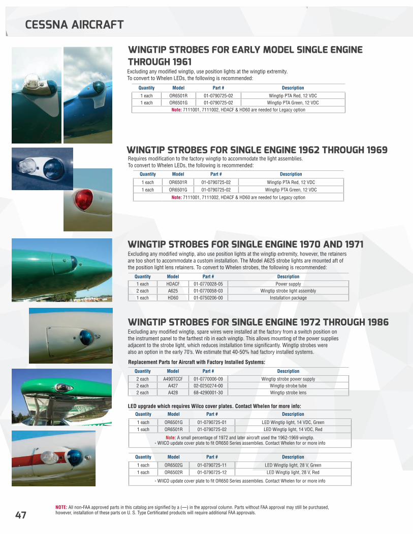
NOTE: All non-FAA approved parts in this catalog are signified by a (—) in the approval column. Parts without FAA approval may still be purchased, however, installation of these parts on U. S. Type Certificated products will require additional FAA approvals.47
WINGTIP STROBES FOR SINGLE ENGINE 1970 AND 1971
WINGTIP STROBES FOR SINGLE ENGINE 1962 THROUGH 1969
WINGTIP STROBES FOR EARLY MODEL SINGLE ENGINE THROUGH 1961
WINGTIP STROBES FOR SINGLE ENGINE 1972 THROUGH 1986
Excluding any modified wingtip, also use position lights at the wingtip extremity, however, the retainers are too short to accommodate a custom installation. The Model A625 strobe lights are mounted aft of the position light lens retainers. To convert to Whelen strobes, the following is recommended:
Requires modification to the factory wingtip to accommodate the light assemblies. To convert to Whelen LEDs, the following is recommended:
Excluding any modified wingtip, use position lights at the wingtip extremity. To convert to Whelen LEDs, the following is recommended:
Excluding any modified wingtip, spare wires were installed at the factory from a switch position on the instrument panel to the farthest rib in each wingtip. This allows mounting of the power supplies adjacent to the strobe light, which reduces installation time significantly. Wingtip strobes were also an option in the early 70’s. We estimate that 40-50% had factory installed systems.
Replacement Parts for Aircraft with Factory Installed Systems:
LED upgrade which requires Wilco cover plates. Contact Whelen for more info:
Quantity Model Part # Description
1 each HDACF 01-0770028-05 Power supply2 each A625 01-0770058-03 Wingtip strobe light assembly1 each HD60 01-0750206-00 Installation package
Quantity Model Part # Description
1 each OR6501R 01-0790725-02 Wingtip PTA Red, 12 VDC
1 each OR6501G 01-0790725-02 Wingtip PTA Green, 12 VDC
Note: 7111001, 7111002, HDACF & HD60 are needed for Legacy option
Quantity Model Part # Description
1 each OR6501R 01-0790725-02 Wingtip PTA Red, 12 VDC1 each OR6501G 01-0790725-02 Wingtip PTA Green, 12 VDC
Note: 7111001, 7111002, HDACF & HD60 are needed for Legacy option
Quantity Model Part # Description
2 each A490TCCF 01-0770006-09 Wingtip strobe power supply2 each A427 02-0250274-00 Wingtip strobe tube2 each A428 68-4290001-30 Wingtip strobe lens
Quantity Model Part # Description
1 each OR6501G 01-0790725-01 LED Wingtip light, 14 VDC, Green1 each OR6501R 01-0790725-02 LED Wingtip light, 14 VDC, Red
Note: A small percentage of 1972 and later aircraft used the 1962-1969 wingtip. - WIlCO update cover plate to fit OR650 Series assemblies. Contact Whelen for or more info
Quantity Model Part # Description
1 each OR6502G 01-0790725-11 LED Wingtip light, 28 V, Green1 each OR6502R 01-0790725-12 LED Wingtip light, 28 V, Red
- WIlCO update cover plate to fit OR650 Series assemblies. Contact Whelen for or more info
CESSNA AIRCRAFT
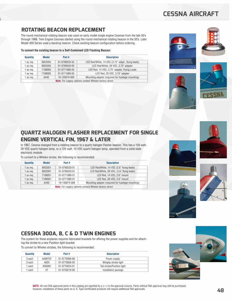
NOTE: All non-FAA approved parts in this catalog are signified by a (—) in the approval column. Parts without FAA approval may still be purchased, however, installation of these parts on U. S. Type Certificated products will require additional FAA approvals. 48
CESSNA AIRCRAFT
ROTATING BEACON REPLACEMENT
CESSNA 300A, B, C & D TWIN ENGINES
QUARTZ HALOGEN FLASHER REPLACEMENT FOR SINGLE ENGINE VERTICAL FIN, 1967 & LATER
The round mechanical rotating beacon was used on early model single engine Cessnas from the late 50’s through 1966. Twin Engine Cessnas started using the round mechanical rotating beacon in the 50’s. Later Model 400 Series used a teardrop beacon. Check existing beacon configuration before ordering.
The system for these airplanes requires fabricated brackets for affixing the power supplies and for attach-ing the strobe to a new Position light bracket.To convert to Whelen strobes, the following is recommended:
In 1967, Cessna changed from a rotating beacon to a quartz halogen Flasher beacon. This has a 150 watt, 28 VDC quartz halogen lamp, or a 125 watt, 14 VDC quartz halogen lamp, operated from a solid-state electronic module. To convert to a Whelen strobe, the following is recommended:
To convert the existing beacon to a Self-Contained LED Flashing Beacon:
Quantity Model Part # Description
1 as req. 9052055 01-0790520-55 LED Red/White, 14 VDC (3.75” adapt., flying leads)1 as req. 9052005 01-0790520-05 LED Red/White, 28 VDC, 3.75” adapter1 as req. 7108055 01-0771080-55 LED Red, 14 VDC, 3.75” adapter, Flying Leads1 as req. 7108005 01-0771080-05 LED Red, 28 VDC, 3.75” adapter1 as req. A440 19-130074-009 Mounting adapter (required for fuselage mounting)
Note: For Legacy options contact Whelen factory direct
Quantity Model Part # Description
3 each A490TCF 01-0770006-08 Power supply2 each A625 01-0770058-03 Wingtip strobe light1 each A500AV 01-0770024-01 Tail strobe/Position light1 each HT 01-0750216-00 Installation package
Quantity Model Part # Description
1 as req. 9052051 01-0790520-51 LED Red/White, 14 VDC (2.6” flying leads)1 as req. 9052001 01-0790520-01 LED Red/White, 28 VDC, (2.6” flying leads)1 as req. 7108051 01-0771080-51 LED Red, 14 VDC, 2.6” mount1 as req. 7108001 01-0771080-01 LED Red, 28 VDC, 2.6” mount1 as req. A440 19-130074-009 Mounting adapter (required for fuselage mounting)
Note: For Legacy options contact Whelen factory direct
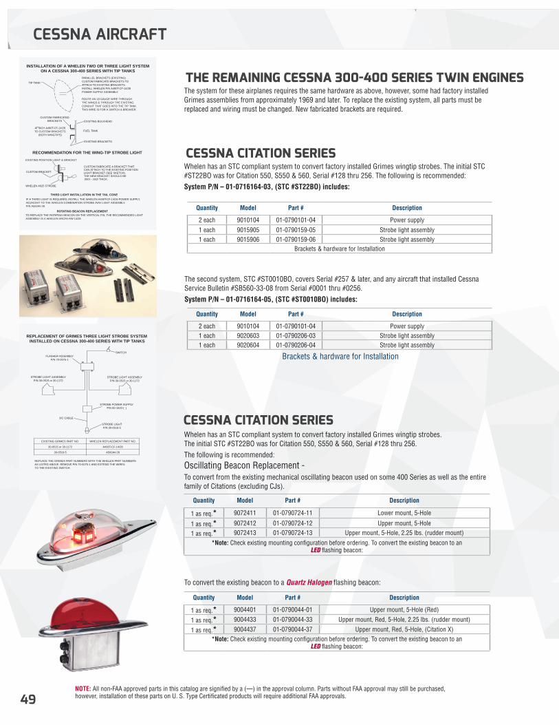
NOTE: All non-FAA approved parts in this catalog are signified by a (—) in the approval column. Parts without FAA approval may still be purchased, however, installation of these parts on U. S. Type Certificated products will require additional FAA approvals.49
CESSNA CITATION SERIES
CESSNA CITATION SERIES
THE REMAINING CESSNA 300-400 SERIES TWIN ENGINES
The second system, STC #ST0010BO, covers Serial #257 & later, and any aircraft that installed Cessna Service Bulletin #SB560-33-08 from Serial #0001 thru #0256. System P/N – 01-0716164-05, (STC #ST0010BO) includes:
Whelen has an STC compliant system to convert factory installed Grimes wingtip strobes. The initial STC #ST22BO was for Citation 550, S550 & 560, Serial #128 thru 256. The following is recommended: System P/N – 01-0716164-03, (STC #ST22BO) includes:
To convert the existing beacon to a Quartz Halogen flashing beacon:
Whelen has an STC compliant system to convert factory installed Grimes wingtip strobes. The initial STC #ST22BO was for Citation 550, S550 & 560, Serial #128 thru 256. The following is recommended:Oscillating Beacon Replacement -To convert from the existing mechanical oscillating beacon used on some 400 Series as well as the entire family of Citations (excluding CJs).
The system for these airplanes requires the same hardware as above, however, some had factory installed Grimes assemblies from approximately 1969 and later. To replace the existing system, all parts must be replaced and wiring must be changed. New fabricated brackets are required.
Quantity Model Part # Description
2 each 9010104 01-0790101-04 Power supply1 each 9020603 01-0790206-03 Strobe light assembly1 each 9020604 01-0790206-04 Strobe light assembly
Brackets & hardware for Installation
Quantity Model Part # Description
2 each 9010104 01-0790101-04 Power supply
1 each 9015905 01-0790159-05 Strobe light assembly1 each 9015906 01-0790159-06 Strobe light assembly
Brackets & hardware for Installation
Quantity Model Part # Description
1 as req.* 9072411 01-0790724-11 Lower mount, 5-Hole
1 as req.* 9072412 01-0790724-12 Upper mount, 5-Hole
1 as req.* 9072413 01-0790724-13 Upper mount, 5-Hole, 2.25 lbs. (rudder mount)
*Note: Check existing mounting configuration before ordering. To convert the existing beacon to an LED flashing beacon:
Quantity Model Part # Description
1 as req.* 9004401 01-0790044-01 Upper mount, 5-Hole (Red)
1 as req.* 9004433 01-0790044-33 Upper mount, Red, 5-Hole, 2.25 lbs. (rudder mount)
1 as req.* 9004437 01-0790044-37 Upper mount, Red, 5-Hole, (Citation X)*Note: Check existing mounting configuration before ordering. To convert the existing beacon to an
LED flashing beacon:
REPLACEMENT OF GRIMES THREE LIGHT STROBE SYSTEMINSTALLED ON CESSNA 300-400 SERIES WITH TIP TANKS
SWITCHFLASHER ASSEMBLY
P/N 70-0075-1
STROBE LIGHT ASSEMBLYP/N 30-0515 or 30-1172
STROBE LIGHT ASSEMBLYP/N 30-0515 or 30-1172
STROBE POWER SUPPLYP/N 60-1520-( )
3/C CABLE
STROBE LIGHTP/N 30-0516-5
REPLACE THE GRIMES PART NUMBERS WITH THE WHELEN PART NUMBERSAS LISTED ABOVE. REMOVE P/N 70-0075-1 AND EXTEND THE WIRESTO THE EXISTING SWITCH.
EXISTING GRIMES PART NO.
30-0515 or 30-1172
30-0516-5
WHELEN REPLACEMENT PART NO.
A490T-CF-14/28
A500AV-28
INSTALLATION OF A WHELEN TWO OR THREE LIGHT SYSTEMON A CESSNA 300-400 SERIES WITH TIP TANKS
EXISTING BULKHEAD
TIP TANK
PARALLEL BRACKETS (EXISTING)CUSTOM FABRICATE BRACKETS TOATTACH TO EXISTING BRACKETS.INSTALL WHELEN P/N A490T-CF-14/28POWER SUPPLY ASSEMBLY.
ROUTE AN 18 GAUGE WIRE THROUGHTHE WINGS & THROUGH THE EXISTINGCONDUIT THAT GOES INTO THE TIP TANK.THIS WIRE IS FOR A SWITCH & BREAKER.
CUSTOM FABRICATEDBRACKETS
ATTACH A490T-CF-14/28TO CUSTOM BRACKETS
(BOTH WINGTIPS)
THIRD LIGHT INSTALLATION IN THE TAIL CONE
EXISTING POSITION LIGHT & BRACKET
CUSTOM FABRICATE A BRACKET THAT CAN ATTACH TO THE EXISTING POSITION LIGHT BRACKET (SEE SKETCH). THE NEW BRACKET SHOULD BE.050î - .062î THICK.
FUEL TANK
EXISTING BRACKETS
RECOMMENDATION FOR THE WING-TIP STROBE LIGHT
CUSTOM BRACKET
WHELEN A625 STROBE
IF A THIRD LIGHT IS REQUIRED, INSTALL THE WHELEN A490T-CF-14/28 POWER SUPPLY, ADJACENT TO THE WHELEN COMBINATION STROBE /NAV LIGHT ASSEMBLY, P/N A500AV-28
ROTATING BEACON REPLACEMENTTO REPLACE THE ROTATING BEACON ON THE VERTICAL FIN, THE RECOMMENDED LIGHTASSEMBLY IS A WHELEN HRCFA-RW-14/28
CESSNA AIRCRAFT
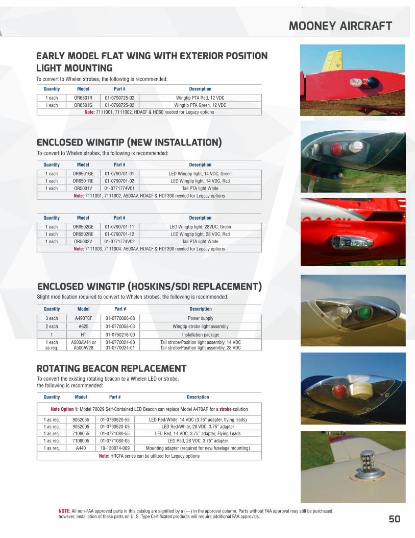
NOTE: All non-FAA approved parts in this catalog are signified by a (—) in the approval column. Parts without FAA approval may still be purchased, however, installation of these parts on U. S. Type Certificated products will require additional FAA approvals. 50
EARLY MODEL FLAT WING WITH EXTERIOR POSITION LIGHT MOUNTING
ROTATING BEACON REPLACEMENT
ENCLOSED WINGTIP (NEW INSTALLATION)
ENCLOSED WINGTIP (HOSKINS/SDI REPLACEMENT)
To convert to Whelen strobes, the following is recommended:
To convert the existing rotating beacon to a Whelen LED or strobe, the following is recommended:
To convert to Whelen strobes, the following is recommended:
Slight modification required to convert to Whelen strobes, the following is recommended:
Quantity Model Part # Description
1 each OR6501R 01-0790725-02 Wingtip PTA Red, 12 VDC1 each OR6501G 01-0790725-02 Wingtip PTA Green, 12 VDC
Note: 7111001, 7111002, HDACF & HD60 needed for Legacy options
Quantity Model Part # Description
Note Option 1: Model 70029 Self-Contained LED Beacon can replace Model A470AR for a strobe solution
1 as req. 9052055 01-0790520-55 LED Red/White, 14 VDC (3.75” adapter, flying leads)1 as req. 9052005 01-0790520-05 LED Red/White, 28 VDC, 3.75” adapter1 as req. 7108055 01-0771080-55 LED Red, 14 VDC, 3.75” adapter, Flying Leads1 as req. 7108005 01-0771080-05 LED Red, 28 VDC, 3.75” adapter1 as req. A440 19-130074-009 Mounting adapter (required for new fuselage mounting)
Note: HRCFA series can be utilized for Legacy options
Quantity Model Part # Description
1 each OR6501GE 01-0790701-01 LED Wingtip light, 14 VDC, Green1 each OR6501RE 01-0790701-02 LED Wingtip light, 14 VDC, Red1 each OR5001V 01-0771774V01 Tail PTA light White
Note: 7111001, 7111002, A500AV, HDACF & HDT390 needed for Legacy options
Quantity Model Part # Description
1 each OR6502GE 01-0790701-11 LED Wingtip light, 28VDC, Green1 each OR6502RE 01-0790701-12 LED Wingtip light, 28 VDC, Red1 each OR5002V 01-0771774V02 Tail PTA light White
Note: 7111003, 7111004, A500AV, HDACF & HDT390 needed for Legacy options
Quantity Model Part # Description
3 each A490TCF 01-0770006-08 Power supply
2 each A625 01-0770058-03 Wingtip strobe light assembly
1 HT 01-0750216-00 Installation package
1 each as req.
A500AV14 or A500AV28
01-0770024-00 01-0770024-01
Tail strobe/Position light assembly, 14 VDC Tail strobe/Position light assembly, 28 VDC
MOONEY AIRCRAFT
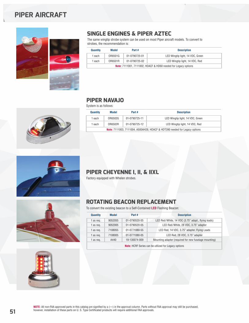
NOTE: All non-FAA approved parts in this catalog are signified by a (—) in the approval column. Parts without FAA approval may still be purchased, however, installation of these parts on U. S. Type Certificated products will require additional FAA approvals.51
PIPER CHEYENNE I, II, & IIXL
PIPER NAVAJO
SINGLE ENGINES & PIPER AZTEC
ROTATING BEACON REPLACEMENT
Factory equipped with Whelen strobes.
System is as follows:
The same wingtip strobe system can be used on most Piper aircraft models. To convert to strobes, the recommendation is:
To convert the existing beacon to a Self-Contained LED Flashing Beacon:
Quantity Model Part # Description
1 each OR6502G 01-0790725-11 LED Wingtip light, 14 VDC, Green
1 each OR6502R 01-0790725-12 LED Wingtip light, 14 VDC, Red
Note: 7111003, 7111004, A500AH28, HDACF & HDT390 needed for Legacy options
Quantity Model Part # Description
1 as req. 9052055 01-0790520-55 LED Red/White, 14 VDC (3.75” adapt., flying leads)
1 as req. 9052005 01-0790520-05 LED Red/White, 28 VDC, 3.75” adapter
1 as req. 7108055 01-0771080-55 LED Red, 14 VDC, 3.75” adapter, Flying Leads
1 as req. 7108005 01-0771080-05 LED Red, 28 VDC, 3.75” adapter
1 as req. A440 19-130074-009 Mounting adapter (required for new fuselage mounting)
Note: HCRF Series can be utilized for Legacy options
Quantity Model Part # Description
1 each OR6501G 01-0790725-01 LED Wingtip light, 14 VDC, Green
1 each OR6501R 01-0790725-02 LED Wingtip light, 14 VDC, Red
Note: 7111001, 7111002, HDACF & HD60 needed for Legacy options
PIPER AIRCRAFT
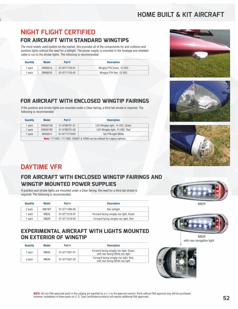
NOTE: All non-FAA approved parts in this catalog are signified by a (—) in the approval column. Parts without FAA approval may still be purchased, however, installation of these parts on U. S. Type Certificated products will require additional FAA approvals. 52
FOR AIRCRAFT WITH ENCLOSED WINGTIP FAIRINGS AND WINGTIP MOUNTED POWER SUPPLIES
EXPERIMENTAL AIRCRAFT WITH LIGHTS MOUNTED ON EXTERIOR OF WINGTIP
FOR AIRCRAFT WITH ENCLOSED WINGTIP FAIRINGS
FOR AIRCRAFT WITH STANDARD WINGTIPS
If position and strobe lights are mounted under a Clear fairing, the need for a third tail strobe is required. The following is recommended:
MB2R
MB3Rwith rear navigation light
If the position and strobe lights are mounted under a Clear fairing, a third tail strobe is required. The following is recommended:
The most widely used system on the market, this provides all of the components for anti-collision and position lights without the need for a taillight. The power supply is mounted in the fuselage and shielded cable is run to the strobe lights. The following is recommended:
Quantity Model Part # Description
2 each MB1WT 01-0771490-00 Nav taillight
1 each MB2G 01-0771519-01 Forward facing wingtip nav light, Green
1 each MB2R 01-0771519-02 Forward facing wingtip nav light, Red
Quantity Model Part # Description
1 each MB3G 01-0771507-01 Forward facing wingtip nav light, Green, with rear facing White nav light
3 each MB3R 01-0771507-02 Forward facing wingtip nav light, Red, with rear facing White nav light
Quantity Model Part # Description
1 each OR6501GE 01-0790701-01 LED Wingtip light, 14 VDC, Green1 each OR6501RE 01-0790701-02 LED Wingtip light, 14 VDC, Red
1 each OR5001V 01-0771774V01 Tail PTA light White
Note: 7111001, 7111002, HDACF & HD60 can be utilized for Legacy options
Quantity Model Part # Description
1 each OR6001G 01-0771733-01 Wingtip PTA Green, 12 VDC
1 each OR6001R 01-0771733-02 Wingtip PTA Red, 12 VDC
HOME BUILT & KIT AIRCRAFT
NIGHT FLIGHT CERTIFIED
DAYTIME VFR
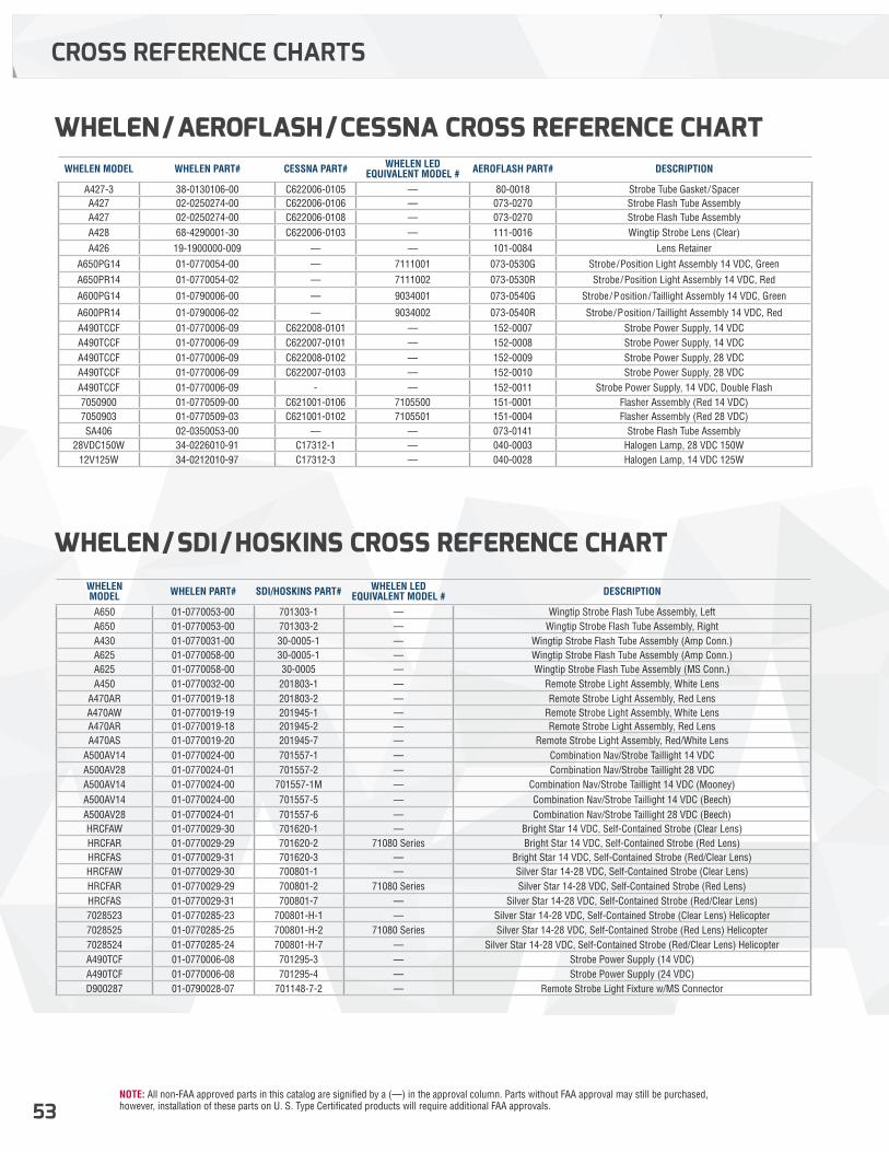
NOTE: All non-FAA approved parts in this catalog are signified by a (—) in the approval column. Parts without FAA approval may still be purchased, however, installation of these parts on U. S. Type Certificated products will require additional FAA approvals.53
CROSS REFERENCE CHARTS
WHELEN/AEROFLASH/CESSNA CROSS REFERENCE CHART
WHELEN/SDI/HOSKINS CROSS REFERENCE CHART
WHELEN MODEL WHELEN PART# CESSNA PART# WHELEN LED EQUIVALENT MODEL # AEROFLASH PART# DESCRIPTION
A427-3 38-0130106-00 C622006-0105 — 80-0018 Strobe Tube Gasket /SpacerA427 02-0250274-00 C622006-0106 — 073-0270 Strobe Flash Tube AssemblyA427 02-0250274-00 C622006-0108 — 073-0270 Strobe Flash Tube AssemblyA428 68-4290001-30 C622006-0103 — 111-0016 Wingtip Strobe Lens (Clear)A426 19-1900000-009 — — 101-0084 Lens Retainer
A650PG14 01-0770054-00 — 7111001 073-0530G Strobe/Position Light Assembly 14 VDC, GreenA650PR14 01-0770054-02 — 7111002 073-0530R Strobe/Position Light Assembly 14 VDC, Red
A600PG14 01-0790006-00 — 9034001 073-0540G Strobe/Position/Taillight Assembly 14 VDC, Green
A600PR14 01-0790006-02 — 9034002 073-0540R Strobe/Position/Taillight Assembly 14 VDC, RedA490TCCF 01-0770006-09 C622008-0101 — 152-0007 Strobe Power Supply, 14 VDCA490TCCF 01-0770006-09 C622007-0101 — 152-0008 Strobe Power Supply, 14 VDCA490TCCF 01-0770006-09 C622008-0102 — 152-0009 Strobe Power Supply, 28 VDCA490TCCF 01-0770006-09 C622007-0103 — 152-0010 Strobe Power Supply, 28 VDCA490TCCF 01-0770006-09 - — 152-0011 Strobe Power Supply, 14 VDC, Double Flash7050900 01-0770509-00 C621001-0106 7105500 151-0001 Flasher Assembly (Red 14 VDC)7050903 01-0770509-03 C621001-0102 7105501 151-0004 Flasher Assembly (Red 28 VDC)SA406 02-0350053-00 — — 073-0141 Strobe Flash Tube Assembly
28VDC150W 34-0226010-91 C17312-1 — 040-0003 Halogen Lamp, 28 VDC 150W12V125W 34-0212010-97 C17312-3 — 040-0028 Halogen Lamp, 14 VDC 125W
WHELENMODEL WHELEN PART# SDI/HOSKINS PART# WHELEN LED
EQUIVALENT MODEL # DESCRIPTION
A650 01-0770053-00 701303-1 — Wingtip Strobe Flash Tube Assembly, LeftA650 01-0770053-00 701303-2 — Wingtip Strobe Flash Tube Assembly, RightA430 01-0770031-00 30-0005-1 — Wingtip Strobe Flash Tube Assembly (Amp Conn.)A625 01-0770058-00 30-0005-1 — Wingtip Strobe Flash Tube Assembly (Amp Conn.)A625 01-0770058-00 30-0005 — Wingtip Strobe Flash Tube Assembly (MS Conn.)A450 01-0770032-00 201803-1 — Remote Strobe Light Assembly, White Lens
A470AR 01-0770019-18 201803-2 — Remote Strobe Light Assembly, Red LensA470AW 01-0770019-19 201945-1 — Remote Strobe Light Assembly, White LensA470AR 01-0770019-18 201945-2 — Remote Strobe Light Assembly, Red LensA470AS 01-0770019-20 201945-7 — Remote Strobe Light Assembly, Red/White Lens
A500AV14 01-0770024-00 701557-1 — Combination Nav/Strobe Taillight 14 VDCA500AV28 01-0770024-01 701557-2 — Combination Nav/Strobe Taillight 28 VDCA500AV14 01-0770024-00 701557-1M — Combination Nav/Strobe Taillight 14 VDC (Mooney)A500AV14 01-0770024-00 701557-5 — Combination Nav/Strobe Taillight 14 VDC (Beech)A500AV28 01-0770024-01 701557-6 — Combination Nav/Strobe Taillight 28 VDC (Beech)HRCFAW 01-0770029-30 701620-1 — Bright Star 14 VDC, Self-Contained Strobe (Clear Lens)HRCFAR 01-0770029-29 701620-2 71080 Series Bright Star 14 VDC, Self-Contained Strobe (Red Lens)HRCFAS 01-0770029-31 701620-3 — Bright Star 14 VDC, Self-Contained Strobe (Red/Clear Lens)HRCFAW 01-0770029-30 700801-1 — Silver Star 14-28 VDC, Self-Contained Strobe (Clear Lens)HRCFAR 01-0770029-29 700801-2 71080 Series Silver Star 14-28 VDC, Self-Contained Strobe (Red Lens)HRCFAS 01-0770029-31 700801-7 — Silver Star 14-28 VDC, Self-Contained Strobe (Red/Clear Lens)7028523 01-0770285-23 700801-H-1 — Silver Star 14-28 VDC, Self-Contained Strobe (Clear Lens) Helicopter7028525 01-0770285-25 700801-H-2 71080 Series Silver Star 14-28 VDC, Self-Contained Strobe (Red Lens) Helicopter7028524 01-0770285-24 700801-H-7 — Silver Star 14-28 VDC, Self-Contained Strobe (Red/Clear Lens) HelicopterA490TCF 01-0770006-08 701295-3 — Strobe Power Supply (14 VDC)A490TCF 01-0770006-08 701295-4 — Strobe Power Supply (24 VDC)D900287 01-0790028-07 701148-7-2 — Remote Strobe Light Fixture w/MS Connector
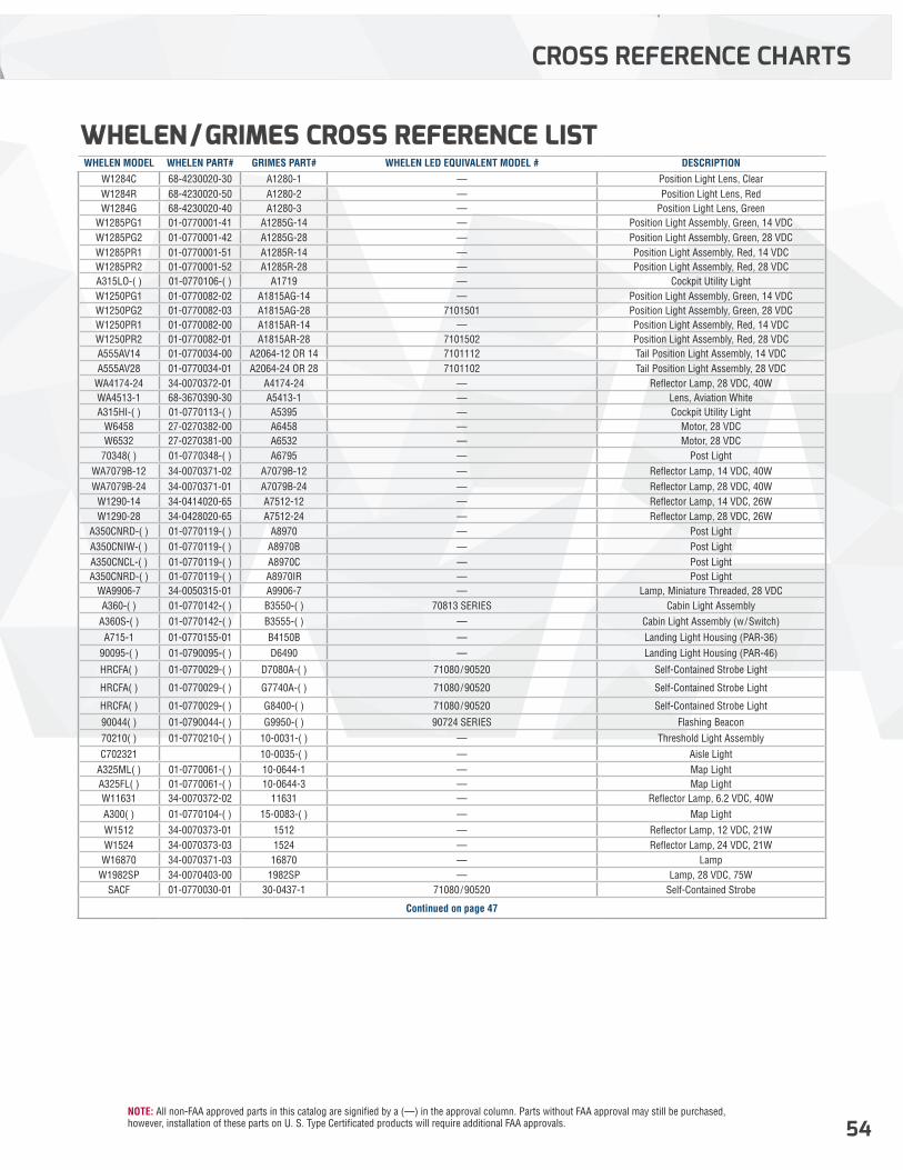
NOTE: All non-FAA approved parts in this catalog are signified by a (—) in the approval column. Parts without FAA approval may still be purchased, however, installation of these parts on U. S. Type Certificated products will require additional FAA approvals. 54
CROSS REFERENCE CHARTS
WHELEN MODEL WHELEN PART# GRIMES PART# WHELEN LED EQUIVALENT MODEL # DESCRIPTION
W1284C 68-4230020-30 A1280-1 — Position Light Lens, ClearW1284R 68-4230020-50 A1280-2 — Position Light Lens, RedW1284G 68-4230020-40 A1280-3 — Position Light Lens, Green
W1285PG1 01-0770001-41 A1285G-14 — Position Light Assembly, Green, 14 VDCW1285PG2 01-0770001-42 A1285G-28 — Position Light Assembly, Green, 28 VDCW1285PR1 01-0770001-51 A1285R-14 — Position Light Assembly, Red, 14 VDCW1285PR2 01-0770001-52 A1285R-28 — Position Light Assembly, Red, 28 VDCA315LO-( ) 01-0770106-( ) A1719 — Cockpit Utility LightW1250PG1 01-0770082-02 A1815AG-14 — Position Light Assembly, Green, 14 VDCW1250PG2 01-0770082-03 A1815AG-28 7101501 Position Light Assembly, Green, 28 VDCW1250PR1 01-0770082-00 A1815AR-14 — Position Light Assembly, Red, 14 VDCW1250PR2 01-0770082-01 A1815AR-28 7101502 Position Light Assembly, Red, 28 VDCA555AV14 01-0770034-00 A2064-12 OR 14 7101112 Tail Position Light Assembly, 14 VDCA555AV28 01-0770034-01 A2064-24 OR 28 7101102 Tail Position Light Assembly, 28 VDC
WA4174-24 34-0070372-01 A4174-24 — Reflector Lamp, 28 VDC, 40WWA4513-1 68-3670390-30 A5413-1 — Lens, Aviation WhiteA315HI-( ) 01-0770113-( ) A5395 — Cockpit Utility Light
W6458 27-0270382-00 A6458 — Motor, 28 VDCW6532 27-0270381-00 A6532 — Motor, 28 VDC
70348( ) 01-0770348-( ) A6795 — Post LightWA7079B-12 34-0070371-02 A7079B-12 — Reflector Lamp, 14 VDC, 40WWA7079B-24 34-0070371-01 A7079B-24 — Reflector Lamp, 28 VDC, 40W
W1290-14 34-0414020-65 A7512-12 — Reflector Lamp, 14 VDC, 26WW1290-28 34-0428020-65 A7512-24 — Reflector Lamp, 28 VDC, 26W
A350CNRD-( ) 01-0770119-( ) A8970 — Post LightA350CNIW-( ) 01-0770119-( ) A8970B — Post LightA350CNCL-( ) 01-0770119-( ) A8970C — Post LightA350CNRD-( ) 01-0770119-( ) A8970IR — Post Light
WA9906-7 34-0050315-01 A9906-7 — Lamp, Miniature Threaded, 28 VDCA360-( ) 01-0770142-( ) B3550-( ) 70813 SERIES Cabin Light Assembly
A360S-( ) 01-0770142-( ) B3555-( ) — Cabin Light Assembly (w/Switch)A715-1 01-0770155-01 B4150B — Landing Light Housing (PAR-36)
90095-( ) 01-0790095-( ) D6490 — Landing Light Housing (PAR-46)
HRCFA( ) 01-0770029-( ) D7080A-( ) 71080/90520 Self-Contained Strobe Light
HRCFA( ) 01-0770029-( ) G7740A-( ) 71080/90520 Self-Contained Strobe Light
HRCFA( ) 01-0770029-( ) G8400-( ) 71080/90520 Self-Contained Strobe Light
90044( ) 01-0790044-( ) G9950-( ) 90724 SERIES Flashing Beacon70210( ) 01-0770210-( ) 10-0031-( ) — Threshold Light AssemblyC702321 10-0035-( ) — Aisle Light
A325ML( ) 01-0770061-( ) 10-0644-1 — Map LightA325FL( ) 01-0770061-( ) 10-0644-3 — Map LightW11631 34-0070372-02 11631 — Reflector Lamp, 6.2 VDC, 40WA300( ) 01-0770104-( ) 15-0083-( ) — Map LightW1512 34-0070373-01 1512 — Reflector Lamp, 12 VDC, 21WW1524 34-0070373-03 1524 — Reflector Lamp, 24 VDC, 21W
W16870 34-0070371-03 16870 — LampW1982SP 34-0070403-00 1982SP — Lamp, 28 VDC, 75W
SACF 01-0770030-01 30-0437-1 71080/90520 Self-Contained Strobe
Continued on page 47
WHELEN/GRIMES CROSS REFERENCE LIST
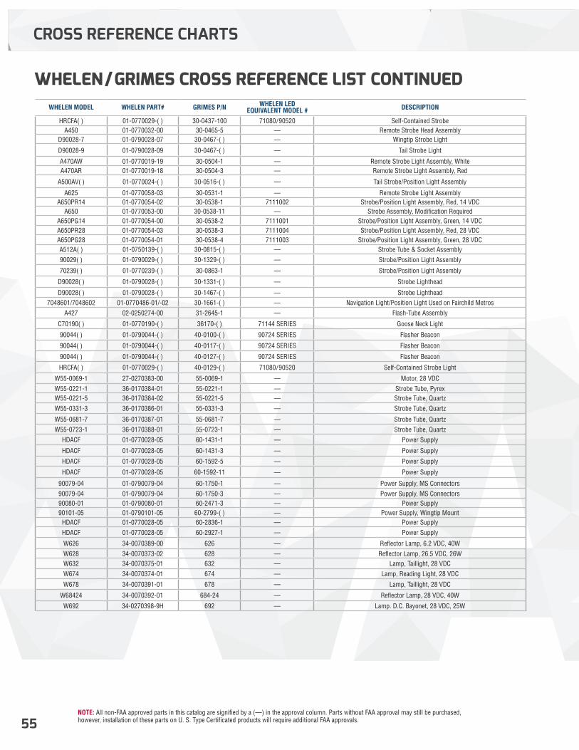
NOTE: All non-FAA approved parts in this catalog are signified by a (—) in the approval column. Parts without FAA approval may still be purchased, however, installation of these parts on U. S. Type Certificated products will require additional FAA approvals.55
CROSS REFERENCE CHARTS
WHELEN MODEL WHELEN PART# GRIMES P/N WHELEN LED EQUIVALENT MODEL # DESCRIPTION
HRCFA( ) 01-0770029-( ) 30-0437-100 71080/90520 Self-Contained StrobeA450 01-0770032-00 30-0465-5 — Remote Strobe Head Assembly
D90028-7 01-0790028-07 30-0467-( ) — Wingtip Strobe Light
D90028-9 01-0790028-09 30-0467-( ) — Tail Strobe Light
A470AW 01-0770019-19 30-0504-1 — Remote Strobe Light Assembly, WhiteA470AR 01-0770019-18 30-0504-3 — Remote Strobe Light Assembly, Red
A500AV( ) 01-0770024-( ) 30-0516-( ) — Tail Strobe/Position Light Assembly
A625 01-0770058-03 30-0531-1 — Remote Strobe Light AssemblyA650PR14 01-0770054-02 30-0538-1 7111002 Strobe/Position Light Assembly, Red, 14 VDC
A650 01-0770053-00 30-0538-11 — Strobe Assembly, Modification RequiredA650PG14 01-0770054-00 30-0538-2 7111001 Strobe/Position Light Assembly, Green, 14 VDCA650PR28 01-0770054-03 30-0538-3 7111004 Strobe/Position Light Assembly, Red, 28 VDCA650PG28 01-0770054-01 30-0538-4 7111003 Strobe/Position Light Assembly, Green, 28 VDCA512A( ) 01-0750139-( ) 30-0815-( ) — Strobe Tube & Socket Assembly90029( ) 01-0790029-( ) 30-1329-( ) — Strobe/Position Light Assembly
70239( ) 01-0770239-( ) 30-0863-1 — Strobe/Position Light Assembly
D90028( ) 01-0790028-( ) 30-1331-( ) — Strobe Lighthead
D90028( ) 01-0790028-( ) 30-1467-( ) — Strobe Lighthead7048601/7048602 01-0770486-01/-02 30-1661-( ) — Navigation Light/Position Light Used on Fairchild Metros
A427 02-0250274-00 31-2645-1 — Flash-Tube Assembly
C70190( ) 01-0770190-( ) 36170-( ) 71144 SERIES Goose Neck Light
90044( ) 01-0790044-( ) 40-0100-( ) 90724 SERIES Flasher Beacon
90044( ) 01-0790044-( ) 40-0117-( ) 90724 SERIES Flasher Beacon
90044( ) 01-0790044-( ) 40-0127-( ) 90724 SERIES Flasher Beacon
HRCFA( ) 01-0770029-( ) 40-0129-( ) 71080/90520 Self-Contained Strobe Light
W55-0069-1 27-0270383-00 55-0069-1 — Motor, 28 VDCW55-0221-1 36-0170384-01 55-0221-1 — Strobe Tube, PyrexW55-0221-5 36-0170384-02 55-0221-5 — Strobe Tube, QuartzW55-0331-3 36-0170386-01 55-0331-3 — Strobe Tube, Quartz
W55-0681-7 36-0170387-01 55-0681-7 — Strobe Tube, QuartzW55-0723-1 36-0170388-01 55-0723-1 — Strobe Tube, Quartz
HDACF 01-0770028-05 60-1431-1 — Power Supply
HDACF 01-0770028-05 60-1431-3 — Power Supply
HDACF 01-0770028-05 60-1592-5 — Power Supply
HDACF 01-0770028-05 60-1592-11 — Power Supply
90079-04 01-0790079-04 60-1750-1 — Power Supply, MS Connectors90079-04 01-0790079-04 60-1750-3 — Power Supply, MS Connectors90080-01 01-0790080-01 60-2471-3 — Power Supply90101-05 01-0790101-05 60-2799-( ) — Power Supply, Wingtip Mount
HDACF 01-0770028-05 60-2836-1 — Power SupplyHDACF 01-0770028-05 60-2927-1 — Power Supply
W626 34-0070389-00 626 — Reflector Lamp, 6.2 VDC, 40WW628 34-0070373-02 628 — Reflector Lamp, 26.5 VDC, 26WW632 34-0070375-01 632 — Lamp, Taillight, 28 VDCW674 34-0070374-01 674 — Lamp, Reading Light, 28 VDC
W678 34-0070391-01 678 — Lamp, Taillight, 28 VDC
W68424 34-0070392-01 684-24 — Reflector Lamp, 28 VDC, 40W
W692 34-0270398-9H 692 — Lamp. D.C. Bayonet, 28 VDC, 25W
WHELEN/GRIMES CROSS REFERENCE LIST CONTINUED
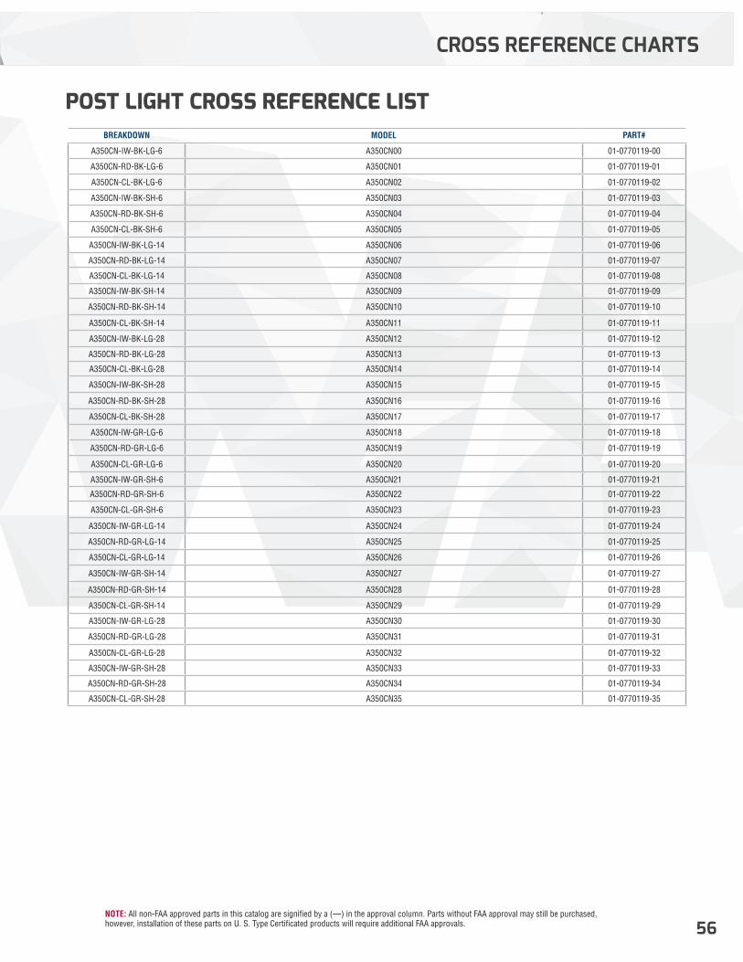
NOTE: All non-FAA approved parts in this catalog are signified by a (—) in the approval column. Parts without FAA approval may still be purchased, however, installation of these parts on U. S. Type Certificated products will require additional FAA approvals. 56
CROSS REFERENCE CHARTS
BREAKDOWN MODEL PART#
A350CN-IW-BK-LG-6 A350CN00 01-0770119-00
A350CN-RD-BK-LG-6 A350CN01 01-0770119-01
A350CN-CL-BK-LG-6 A350CN02 01-0770119-02
A350CN-IW-BK-SH-6 A350CN03 01-0770119-03
A350CN-RD-BK-SH-6 A350CN04 01-0770119-04
A350CN-CL-BK-SH-6 A350CN05 01-0770119-05
A350CN-IW-BK-LG-14 A350CN06 01-0770119-06
A350CN-RD-BK-LG-14 A350CN07 01-0770119-07
A350CN-CL-BK-LG-14 A350CN08 01-0770119-08
A350CN-IW-BK-SH-14 A350CN09 01-0770119-09
A350CN-RD-BK-SH-14 A350CN10 01-0770119-10
A350CN-CL-BK-SH-14 A350CN11 01-0770119-11
A350CN-IW-BK-LG-28 A350CN12 01-0770119-12
A350CN-RD-BK-LG-28 A350CN13 01-0770119-13
A350CN-CL-BK-LG-28 A350CN14 01-0770119-14
A350CN-IW-BK-SH-28 A350CN15 01-0770119-15
A350CN-RD-BK-SH-28 A350CN16 01-0770119-16
A350CN-CL-BK-SH-28 A350CN17 01-0770119-17
A350CN-IW-GR-LG-6 A350CN18 01-0770119-18
A350CN-RD-GR-LG-6 A350CN19 01-0770119-19
A350CN-CL-GR-LG-6 A350CN20 01-0770119-20
A350CN-IW-GR-SH-6 A350CN21 01-0770119-21
A350CN-RD-GR-SH-6 A350CN22 01-0770119-22
A350CN-CL-GR-SH-6 A350CN23 01-0770119-23
A350CN-IW-GR-LG-14 A350CN24 01-0770119-24
A350CN-RD-GR-LG-14 A350CN25 01-0770119-25
A350CN-CL-GR-LG-14 A350CN26 01-0770119-26
A350CN-IW-GR-SH-14 A350CN27 01-0770119-27
A350CN-RD-GR-SH-14 A350CN28 01-0770119-28
A350CN-CL-GR-SH-14 A350CN29 01-0770119-29
A350CN-IW-GR-LG-28 A350CN30 01-0770119-30
A350CN-RD-GR-LG-28 A350CN31 01-0770119-31
A350CN-CL-GR-LG-28 A350CN32 01-0770119-32
A350CN-IW-GR-SH-28 A350CN33 01-0770119-33
A350CN-RD-GR-SH-28 A350CN34 01-0770119-34
A350CN-CL-GR-SH-28 A350CN35 01-0770119-35
POST LIGHT CROSS REFERENCE LIST

Distributed by:
2018 AVIATION LIGHTING CATALOG
WARRANTY, SERVICE AND REPAIRUNITED STATESWhelen Engineering Co., Inc. 51 Winthrop Road Chester, CT 06412 Tel: 860-526-9504 Fax: 860-526-2009 www.whelen.com
AVIATION TECHNICAL SUPPORTCustomer Support 860-526-9504 [email protected]
CUSTOMER SERVICE860-526-9504 Ext. 6 [email protected]
FACTORY REPAIR INFOBuilding B 51 Winthrop Road Chester, CT 06412-0684
Please include:A copy of the sales receipt if qualified for warranty coverage. A short description of the problem. Your name, return address and daytime phone number. For complete warranty and repair information, refer to your Whelen User Direct Warranty statement or contact Whelen Engineering.
Whelen Engineering reserves the right to upgrade and improve products without notice.© 2017 Whelen Engineering Company, Inc. Printed in U.S.A.Code No. 12620F - 12/05/2017