Embed Size (px)
Citation preview
2015D039
D-ILA® Projector
DLA-X550R/X5000/XC5890R/RS400 Series
DLA-XC6890 Series
DLA-X750R/X7000/XC7890R/RS500 Series
DLA-X950R/X9000/RS600/PX1 Series
JVC External Control Command
Communication Specification
Ver. 1.0
11/Dec/2015
JVCKENWOOD Corp. Projector Division
(*)D-ILA is the trademark of JVCKENWOOD Corp.
Document No. PJ06030001B

Contents
2 / 47 2015D039
PJ05030305B
CONTENTS
1 OUTLINE ................................................... 4
2 INTERFACE ............................................... 4
2.1 Terminal .......................................................... 4
2.2 External Controller Connector ........................ 4
2.3 Communication Line ....................................... 4
3 PROTOCOL ............................................... 5
3.1 Communication specification .......................... 5
3.2 Data format ..................................................... 5
3.3 Header table ................................................... 5
3.4 Unit ID table .................................................... 6
3.5 Command table............................................... 6
3.6 Parameter ....................................................... 7
3.6.1 Numeric value parameters .............................. 7
3.6.2 Special parameter ........................................... 7
3.7 Exit code ......................................................... 8
3.8 Error handling ................................................. 8
3.9 Communication sequence .............................. 9
4 COMMAND CONTROL ............................ 10
4.1 NULL command ............................................ 10
4.1.1 Operation....................................................... 10
4.1.2 Reference ...................................................... 10
4.2 Power [PoWer] ............................................... 11
4.2.1 Operation....................................................... 11
4.2.2 Reference ...................................................... 12
4.3 Input [InPut]................................................... 13
4.3.1 Operation....................................................... 14
4.3.2 Reference ...................................................... 14
4.4 Remote control pass-through [RemoteCode] 15
4.4.1 Operation....................................................... 16
4.5 Setup [SetUp] ............................................... 17
4.5.1 Operation....................................................... 18
4.6 Gamma data of Gamma table “Custom 1/2/3”
[GammaRed, Green, Blue] ..................................... 19
4.6.1 Operation....................................................... 20
4.6.2 Reference ...................................................... 20
4.7 Panel Alignment (zone) Data [Panel
Alignment(Zone) Red, Blue] ................................... 20
4.7.1 Operation....................................................... 22
4.7.2 Reference ...................................................... 22
4.8 Source Asking [SourCe] ................................ 23
4.8.1 Reference ...................................................... 23
4.9 Model status asking [MoDel] ......................... 24
4.9.1 Reference ...................................................... 24
4.10 Adjustment [AdjustmentCommand]............ 25
4.10.1 Special data ................................................... 30
4.10.2 Special2 Data................................................. 38
4.10.3 Special3 Data................................................. 38
4.10.4 Special9 Data................................................. 39
4.10.5 Special10 Data............................................... 39
4.10.6 Special14 Data............................................... 39
4.10.7 Operation ....................................................... 40
4.10.8 Reference ...................................................... 41
LAN setup [Lan Setup] ............................................ 44
4.10.9 Operation ....................................................... 45
4.10.10 Reference ................................................... 46

Contents
3 / 47 2015D039
PJ05030305B
Table Number
Table 4-1 NULL CMD ................................................ 10
Table 4-2 POWER CMD ........................................... 11
Table 4-3 POWER CMD DATA ................................. 11
Table 4-4 POWER CMD STATUS ............................ 11
Table 4-5 INPUT CMD .............................................. 13
Table 4-6 INPUT CMD DATA ................................... 13
Table 4-7 REMO CMD .............................................. 15
Table 4-8 REMO CMD DATA ................................... 15
Table 4-9 SETUP CMD ............................................. 17
Table 4-10 SETUP CMD SUB .................................. 17
Table 4-11 GAMMA DATA CMD ............................... 19
Table 4-12 PANEL ALIGNMENT(ZONE) DATA CMD
............................................................................. 21
Table 4-13 SOURCE CMD ....................................... 23
Table 4-14 SOURCE CMD DATA ............................. 23
Table 4-15 MODEL STATUS CMD ........................... 24
Table 4-16 MODEL STATUS CMD DATA ................ 24
Table 4-17 ADJUSTMENT CMD ............................... 25
Table 4-18 ADJUSTMENT CMD SUB ...................... 25
Table 4-21 PICTURE MODE CMD DATA ................. 30
Table 4-22 CLEAR BLACK CMD DATA .................... 30
Table 4-23 INTELLIGENT LENS APERTURE CMD
DATA .................................................................... 30
Table 4-24 COLOR PROFILE CMD DATA ............... 31
Table 4-25 COLOR TEMP TABLE CMD DATA ........ 31
Table 4-26 COLOR TEMP CORRECTION CMD DATA
............................................................................. 32
Table 4-27 GAMMA CMD DATA ............................... 32
Table 4-28 GAMMA CORRECTION CMD DATA ...... 32
Table 4-29 COLOR MANAGEMENT CMD DATA ... 33
Table 4-30 CLEAR MOTION DRIVE CMD DATA ..... 33
Table 4-31 MOTION ENHANCE CMD DATA .......... 33
Table 4-32 LAMP POWER CMD DATA .................. 33
Table 4-33 MPC ANALYZE CMD DATA ................. 33
Table 4-34 4K E-SHIFT CMD DATA ....................... 33
Table 4-35 ORIGINAL RESOLUTION CMD DATA . 33
Table 4-36 HDMI INPUT LEVEL CMD DATA ........... 34
Table 4-37 HDMI COLOR SPACE CMD DATA ...... 34
Table 4-38 HDMI 2D/3D CMD DATA ...................... 34
Table 4-39 HDMI 3D Phase CMD DATA ................. 34
Table 4-40 ASPECT CMD DATA ............................. 34
Table 4-41 MASK CMD DATA ................................. 34
Table 4-42 LENS CONTROL (Focus / Zoom / Shift)
CMD DATA ........................................................... 35
Table 4-43 LENS COVER CMD DATA .................. 35
Table 4-44 Above CMD DATA ................................... 35
Table 4-45 INSTALLATION STYLE CMD DATA ....... 35
Table 4-46 ANAMORPHIC CMD DATA ................... 35
Table 4-47 PANEL ALIGNMENT CMD DATA ......... 35
Table 4-48 HIGH ALTITUDE CMD DATA ................ 35
Table 4-49 BACK COLOR CMD DATA.................... 36
Table 4-50 MENU POSITION CMD DATA .............. 36
Table 4-51 Source Display, Logo CMD DATA ......... 36
Table 4-52 LANGUAGE CMD DATA ....................... 37
Table 4-53 TRIGGER CMD DATA ........................... 37
Table 4-54 OFF TIMER CMD DATA ........................ 37
Table 4-55 ECO MODE CMD DATA........................ 37
Table 4-56 CONTROL 4 CMD DATA....................... 37
Table 4-57 INPUT CMD DATA ................................ 38
Table 4-58 SOURCE CMD DATA ............................ 38
Table 4-59 DEEP COLOR CMD DATA.................... 38
Table 4-60 COLOR SPACE CMD DATA ................. 38
Table 4-63 LENS MEMORY SAVE CMD DATA<
operation> ........................................................... 39
Table 4-64 LENS MEMORY SAVE CMD DATA<
Reference> .......................................................... 39
Table 4-65 LAN SETUP CMD ................................... 44
Table 4-66 LAN SETUP CMD SUB ........................... 44
Table 4-67 DHCP Client ............................................ 44
Table 4-68 NETWORK RESTART ............................ 44

1 Outline
4 / 47 2015D039
PJ05030305B
1 Outline
This specification describes how to control the D-ILA projector * by using an external controller through the RS-232C interface.
* DLA-X550R/X5000/XC5890R/RS400, DLA-XC6890R, DLA-X750R/DLA-X7000/XC7890R/RS600 and DLA-X950R/X9000/RS600Interface
2 Interface
2.1 Terminal D-SUB 9pin Male terminal
Pin No. Name Pin No. Name
1 NC 6 NC
2 RXD 7 NC
3 TXD 8 NC
4 NC 9 NC
5 GND
2.2 External Controller Connector
Serial port connector (RS-232C)
For type of the connector and pin layout, please refer to each controller’s specifications.
2.3 Communication Line
This control system uses RXD (receive data), TXD(transmit data) and GND line. Use an RS-232C crossover cable to connect the
projector to the external controller like as PC.

3 Protocol
5 / 47 2015D039
PJ05030305B
3 Protocol
3.1 Communication specification
Communication System Asynchronous
Interface RS-232C
Baud rate 19200 bps
Data length 8 bits
Parity None
Stop bit 1 bit
Flow control None
Communication code ASCII character code
ST b0 b1 b2 b3 b4 b5 b6 b7 SP
3.2 Data format
Control commands consist of Header, Unit ID, Command, Data and End. (Refer to the below)
*The length of the control command varies according to function.
1 byte 2 bytes 2 bytes n+1 bytes 1 byte
Header Unit ID Command Data[0] L Data[n] End
Header: Indicates the start of communication (see paragraph 3.3, Header table).
Unit ID: Specifies the device to be controlled.
Command: See paragraph 3.5, Command table.
Data [i]: Parameter corresponding to the command (data i = 0, 1, ., n).
End: Indicates the end of communication.
3.3 Header table
Added header varies according to type of control command.
HEX ASCII Type
0x21 '!' Operation command
0x3F '?' Reference command
0x40 '@' Response command
0x06 ACK ACK
Operation command: Added when there is an operation command notification.
Reference command: Added when there is a reference command notification.
Response command: Added when there is a response command notice in response to a reference.
ACK: ACK response is given if the command reception is normal.
3 Protocol
6 / 47 2015D039
PJ05030305B
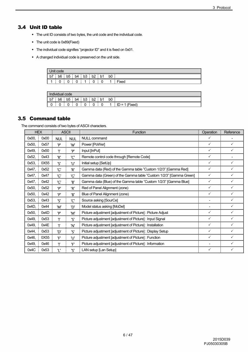
3.4 Unit ID table
� The unit ID consists of two bytes, the unit code and the individual code.
� The unit code is 0x89(Fixed)
� The individual code signifies “projector ID” and it is fixed on 0x01.
� A changed individual code is preserved on the unit side.
Unit code
b7 b6 b5 b4 b3 b2 b1 b0
1 0 0 0 1 0 0 1 Fixed
Individual code
b7 b6 b5 b4 b3 b2 b1 b0
0 0 0 0 0 0 0 1 ID = 1 (Fixed)
3.5 Command table
The command consists of two bytes of ASCII characters.
HEX ASCII Function Operation Reference
0x00, 0x00 NUL NUL NULL command � -
0x50, 0x57 'P' 'W' Power [PoWer] � �
0x49, 0x50 'I' 'P' Input [InPut] � �
0x52, 0x43 'R' 'C' Remote control code through [Remote Code] � -
0x53, 0X55 'S' 'U' Initial setup [SetUp] � �
0x47, 0x52 'G' 'R' Gamma data (Red) of the Gamma table ”Custom 1/2/3” [Gamma Red] � �
0x47, 0x47 'G' 'G' Gamma data (Green) of the Gamma table ”Custom 1/2/3” [Gamma Green] � �
0x47, 0x42 'G' 'B' Gamma data (Blue) of the Gamma table ”Custom 1/2/3” [Gamma Blue] � �
0x50, 0x52 ‘P’ ‘R’ Red of Panel Alignment (zone) � �
0x50, 0x42 ‘P’ ‘B’ Blue of Panel Alignment (zone) � �
0x53, 0x43 'S' 'C' Source asking [SourCe] - �
0x4D, 0x44 'M' 'D' Model status asking [MoDel] - �
0x50, 0x4D 'P' 'M' Picture adjustment [adjustment of Picture] : Picture Adjust � �
0x49, 0x53 'I' 'S' Picture adjustment [adjustment of Picture] : Input Signal � �
0x49, 0x4E 'I' 'N' Picture adjustment [adjustment of Picture] : Installation � �
0x44, 0x53 'D' 'S' Picture adjustment [adjustment of Picture] : Display Setup � �
0x46, 0X55 'F' 'U' Picture adjustment [adjustment of Picture] : Function � �
0x49, 0x46 'I' 'F' Picture adjustment [adjustment of Picture] : Information - �
0x4C 0x53 'L' 'S' LAN setup [Lan Setup] � �

3 Protocol
7 / 47 2015D039
PJ05030305B
3.6 Parameter
3.6.1 Numeric value parameters
Signed 2-byte hexadecimal code represented by 4 (byte) characters.
Ex-1)
The parameter indication ‘20’ (decimal):
Since ‘20’ (decimal) is represented as ‘0014’ in signed 2-byte hexadecimal, its parameter is:
‘0014’(30H 30H 31H 34H)
Ex-2)
The parameter to indicate ‘-2’ (decimal):
Since ‘-2’ (decimal) is represented as ‘FFFE’ in signed 2-byte hexadecimal, its parameter is:
‘FFFE’(46H 46H 46H 45H)
3.6.2 Special parameter
The parameters are generally interpreted with ASCII characters.
But some of the commands have a unique interpretation (for the details, see the section on Command sequences).
HEX ASCII Meaning
0x2B '+' '+'
0x2D '-' '-'
0x30 '0' OFF/NO/Disable
0x31 '1' ON/YES/Enable
0x30 ~ 0x39 '0'~'9' '0'~'9'
0x41 ~ 0x5A 'A'~'Z' 'A'~'Z'

3 Protocol
8 / 47 2015D039
PJ05030305B
3.7 Exit code
0x0A(LineFeed) fixed.
3.8 Error handling
� An external controller should not transmit the next commands until it receives an ACK that the transmitted unit ID and the
command match.
� The specifications for timeout and retry when an ACK response has not been received are not specified here; the specifications
unique to the external controller may be used.
� If the byte interval is blank for 50 ms or longer, initialize the transmit-receive sequence (the received data is discarded).
� If a unit ID other than its own is received, it is ignored.
� If the unit ID matches but an undefined header/command is received, it is ignored.
� If the header/command is normal but an undefined parameter is received, it is ignored.
� Even if the command receipt is normal (ACK response) and the parameter is valid, it may be ignored, depending on the state of
the projector. For the details, see the instruction manual for the projector (for example, projector, power ON operation in the
power cooling state, etc.).
3 Protocol
9 / 47 2015D039
PJ05030305B
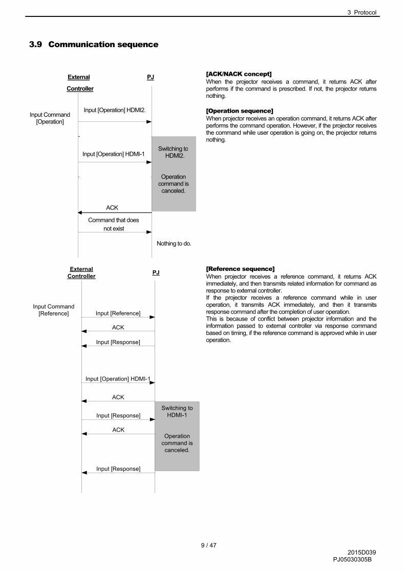
3.9 Communication sequence
[ACK/NACK concept]
When the projector receives a command, it returns ACK after performs if the command is prescribed. If not, the projector returns nothing.
[Operation sequence]
When projector receives an operation command, it returns ACK after performs the command operation. However, if the projector receives the command while user operation is going on, the projector returns nothing.
[Reference sequence]
When projector receives a reference command, it returns ACK immediately, and then transmits related information for command as response to external controller. If the projector receives a reference command while in user operation, it transmits ACK immediately, and then it transmits response command after the completion of user operation. This is because of conflict between projector information and the information passed to external controller via response command based on timing, if the reference command is approved while in user operation.
Switching to
HDMI-1
Operation
command is
canceled.
External
ControllerPJ
Input [Reference]
ACK
Input Command
[Reference]
Input [Operation] HDMI-1
ACK
Input [Response]
Input [Response]
ACK
Input [Response]
Switching toHDMI2.
Operationcommand is canceled.
Input [Operation] HDMI2.
ACK
Input Command[Operation]
Input [Operation] HDMI-1
ACK
Nothing to do.
Command that does
not exist
PJ
Controller
External
ACK
4 Command control
10 / 47 2015D039
PJ05030305B
4 Command control
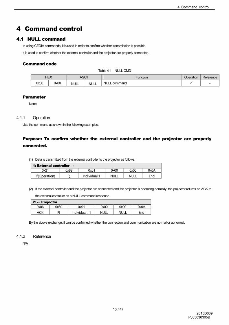
4.1 NULL command
In using CEDIA commands, it is used in order to confirm whether transmission is possible.
It is used to confirm whether the external controller and the projector are properly connected.
Command code
Table 4-1 NULL CMD
HEX ASCII Function Operation Reference
0x00 0x00 NULL NULL NULL command � -
Parameter
None
4.1.1 Operation
Use the command as shown in the following examples.
Purpose: To confirm whether the external controller and the projector are properly
connected.
(1) Data is transmitted from the external controller to the projector as follows.
1: External controller →
0x21 0x89 0x01 0x00 0x00 0x0A
'!'(Operation) PJ Individual:1 NULL NULL End
(2) If the external controller and the projector are connected and the projector is operating normally, the projector returns an ACK to
the external controller as a NULL command response.
2: ← Projector
0x06 0x89 0x01 0x00 0x00 0x0A
ACK PJ Individual : 1 NULL NULL End
By the above exchange, it can be confirmed whether the connection and communication are normal or abnormal.
4.1.2 Reference
N/A

4 Command control
11 / 47 2015D039
PJ05030305B
4.2 Power [PoWer]
Used for power ON/OFF operation and for referencing the power setting state of the projector.
Command code
Table 4-2 POWER CMD
HEX ASCII Function Operation Reference
0x50 0x57 'P' 'W' Power [POWER] � �
Parameters
Table 4-3 POWER CMD DATA
HEX ASCII Operation
0x30 '0' Power OFF
0x31 '1' Power ON
【Data 0】
Table 4-4 POWER CMD STATUS
4.2.1 Operation
Use the command as shown in the following examples.
Purpose: To turn the Projector’s power OFF. (Current state: Power-ON)
(1) Data is transmitted from the external controller to the Projector as follows.
1: External controller →
0x21 0x89 0x01 0x50 0x57 0x30 0x0A
'!'(Operation) PJ Individual : 1 'P' 'W' OFF End
(2) If the projector receives data (1) and the command reception is normal, the projector returns an ACK as follows.
2: ← Projector
0x06 0x89 0x01 0x50 0x57 0x0A
ACK PJ Individual : 1 'P' 'W' End
(3) The projector turns power OFF.
The power can be turned OFF by the above exchange.
� The power-OFF operation can be done by a sequence similar to that for power-ON.
� The projector ignores data in the same state. For example, even if power-ON data is sent with the projector in power-ON mode,
no projector operation is done.
HEX ASCII Operation
0x30 '0' Standby
0x31 '1' Lamp On
0x32 '2' Cooling
0x33 '3' Reserved
0x34 '4' Error
4 Command control
12 / 47 2015D039
PJ05030305B
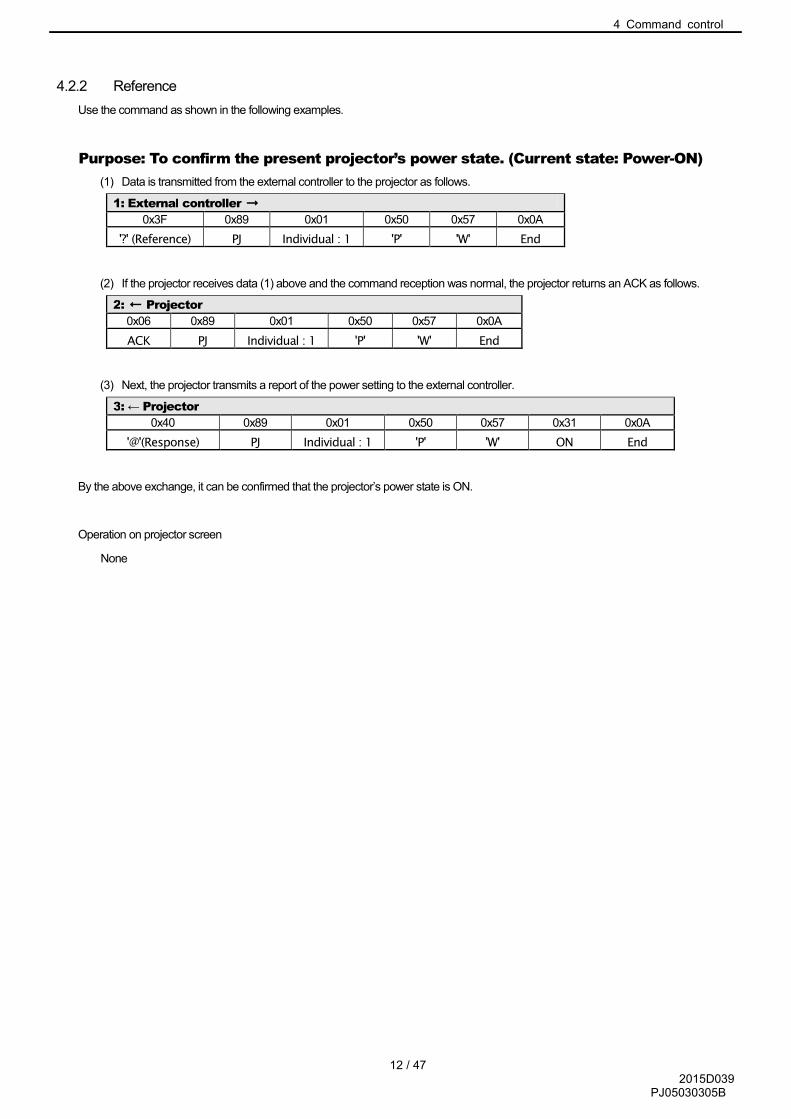
4.2.2 Reference
Use the command as shown in the following examples.
Purpose: To confirm the present projector’s power state. (Current state: Power-ON)
(1) Data is transmitted from the external controller to the projector as follows.
1: External controller →
0x3F 0x89 0x01 0x50 0x57 0x0A
'?' (Reference) PJ Individual : 1 'P' 'W' End
(2) If the projector receives data (1) above and the command reception was normal, the projector returns an ACK as follows.
2: ← Projector
0x06 0x89 0x01 0x50 0x57 0x0A
ACK PJ Individual : 1 'P' 'W' End
(3) Next, the projector transmits a report of the power setting to the external controller.
3: ← Projector
0x40 0x89 0x01 0x50 0x57 0x31 0x0A
'@'(Response) PJ Individual : 1 'P' 'W' ON End
By the above exchange, it can be confirmed that the projector’s power state is ON.
Operation on projector screen
None

4 Command control
13 / 47 2015D039
PJ05030305B
4.3 Input [InPut]
Used for input switching operation and referencing the input settings of the projector.
Setting is automatically stored in the projector when input is changed.
Command code
Table 4-5 INPUT CMD
HEX ASCII Function Operation Reference
0x49 0x50 'I' 'P' Input switch [INPUT] � �
Parameters
Data length: 1 or 2
【Data 0】
Table 4-6 INPUT CMD DATA
HEX ASCII Operation
0x36 '6' HDMI-1
0x37 '7' HDMI-2
� The input switching operation is not done if the parameter data is sent to a terminal that is not provided on the projector.
� The toggle sequence follows the sequence of Operation panel on the projector.
4 Command control
14 / 47 2015D039
PJ05030305B
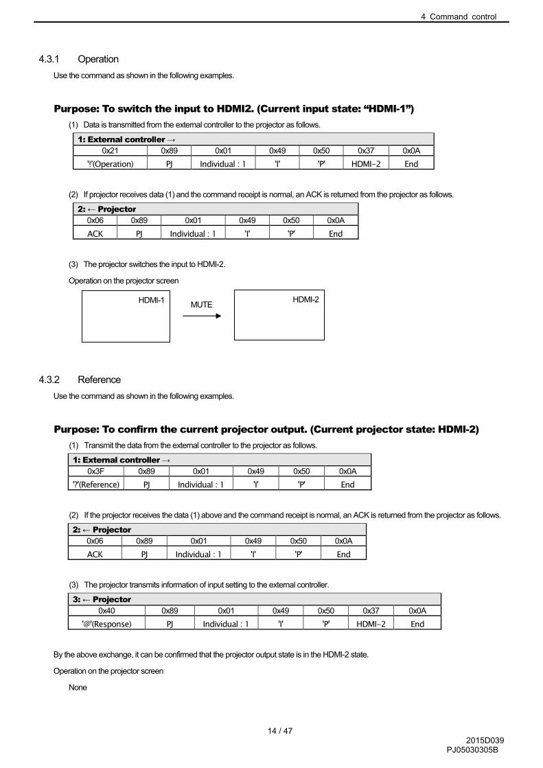
4.3.1 Operation
Use the command as shown in the following examples.
Purpose: To switch the input to HDMI2. (Current input state: “HDMI-1”)
(1) Data is transmitted from the external controller to the projector as follows.
1: External controller →
0x21 0x89 0x01 0x49 0x50 0x37 0x0A
'!'(Operation) PJ Individual : 1 'I' 'P' HDMI-2 End
(2) If projector receives data (1) and the command receipt is normal, an ACK is returned from the projector as follows.
2: ← Projector
0x06 0x89 0x01 0x49 0x50 0x0A
ACK PJ Individual : 1 'I' 'P' End
(3) The projector switches the input to HDMI-2.
Operation on the projector screen
4.3.2 Reference
Use the command as shown in the following examples.
Purpose: To confirm the current projector output. (Current projector state: HDMI-2)
(1) Transmit the data from the external controller to the projector as follows.
1: External controller →
0x3F 0x89 0x01 0x49 0x50 0x0A
'?'(Reference) PJ Individual : 1 'I' 'P' End
(2) If the projector receives the data (1) above and the command receipt is normal, an ACK is returned from the projector as follows.
2: ← Projector
0x06 0x89 0x01 0x49 0x50 0x0A
ACK PJ Individual : 1 'I' 'P' End
(3) The projector transmits information of input setting to the external controller.
3: ← Projector
0x40 0x89 0x01 0x49 0x50 0x37 0x0A
'@'(Response) PJ Individual : 1 'I' 'P' HDMI-2 End
By the above exchange, it can be confirmed that the projector output state is in the HDMI-2 state.
Operation on the projector screen
None
HDMI-1 HDMI-2 MUTE

4 Command control
15 / 47 2015D039
PJ05030305B
4.4 Remote control pass-through [RemoteCode]
By selecting JVC remote control code, the same operation as user remote control can be achieved.
Remote control code consists of one byte of custom code and one byte of function/operation code.
Remote control code varies according to the projector and its state.
For the details of the remote control codes, see the key code specifications of each model.
Command code
Table 4-7 REMO CMD
HEX ASCII Function Operation Reference
0x52 0x43 'R' 'C' Remote control pass-through [Remote Code] �
Parameters
Data length: 4
Table 4-8 REMO CMD DATA
HEX ASCII Operation
0x30 ~ 0x39 '0' ~ ’9’ Remote control code setting
0x41 ~ 0x46 'A' ~ ’F’ Remote control code setting
� The remote control code specification is in hexadecimal digits.
� The operation transition with the remote control codes is the same as from the user remote control.
� For the details of the remote control codes, see the key code specifications.

4 Command control
16 / 47 2015D039
PJ05030305B
4.4.1 Operation
Use the command as shown in the following examples.
Purpose: To display MENU screen by press the “MENU” of remote control code
[0x732E].
(1) Transmit the data from the external controller to the projector as follows.
1: External controller →
0x21 0x89 0x01 0x52 0x43 0x37 0x33 0x32 0x45 0x0A
'!'(Operation) PJ Individual : 1 'R' 'C' '7' '3' '2' ‘E' End
(2) If the projector receives the data (1) above and the command receipt is normal, an ACK is returned from the projector as follows.
2: ← Projector
0x06 0x89 0x01 0x52 0x43 0x0A
ACK PJ Individual : 1 'R' 'C' End
(3) The projector produces a MENU screen.
By the above exchange, the MENU screen can be produced.

4 Command control
17 / 47 2015D039
PJ05030305B
4.5 Setup [SetUp]
Used to change the initial setting.
Command code
Table 4-9 SETUP CMD
HEX ASCII Function
0x53 0X55R 'S' 'U' Initial setting [SetUp]
Parameters
Data length: No regulation
Sub command table (Mandatory command only)
Table 4-10 SETUP CMD SUB
HEX ASCII Function Last
Memory
Opera
tion
Refe
rence
0x52 0x53 'R' 'S' Switch the external control command protocol
No � -
0x52 0x43 ‘R’ ‘C’ Switch the IR code No � �
� It consists of “Sub command” + “Setting”. The Sub command consists of ASCII character two bytes.
Sub commands parameters are as follow.
Parameters when the Sub command is [0x52,0x53] : Data length 1
HEX ASCII Operation
0x31 ‘1’ Compatible command system
Parameters when the Sub command is [0x52,0x43] : Data length 1
HEX ASCII Operation
0x30 ‘0’ A code(0x73)
0x31 ‘1’ B code(0x63)
4 Command control
18 / 47 2015D039
PJ05030305B
4.5.1 Operation
Use the command as shown in the following examples.
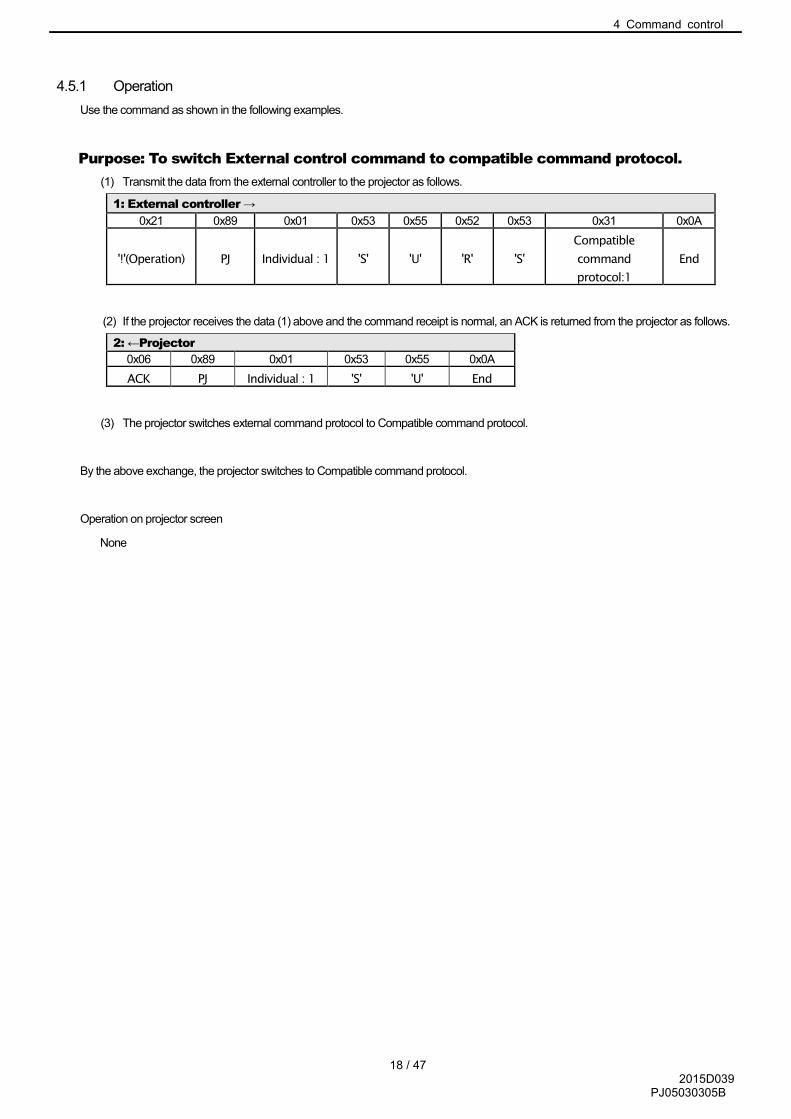
Purpose: To switch External control command to compatible command protocol.
(1) Transmit the data from the external controller to the projector as follows.
1: External controller →
0x21 0x89 0x01 0x53 0x55 0x52 0x53 0x31 0x0A
'!'(Operation) PJ Individual : 1 'S' 'U' 'R' 'S'
Compatible
command
protocol:1
End
(2) If the projector receives the data (1) above and the command receipt is normal, an ACK is returned from the projector as follows.
2: ←Projector
0x06 0x89 0x01 0x53 0x55 0x0A
ACK PJ Individual : 1 'S' 'U' End
(3) The projector switches external command protocol to Compatible command protocol.
By the above exchange, the projector switches to Compatible command protocol.
Operation on projector screen
None
4 Command control
19 / 47 2015D039
PJ05030305B
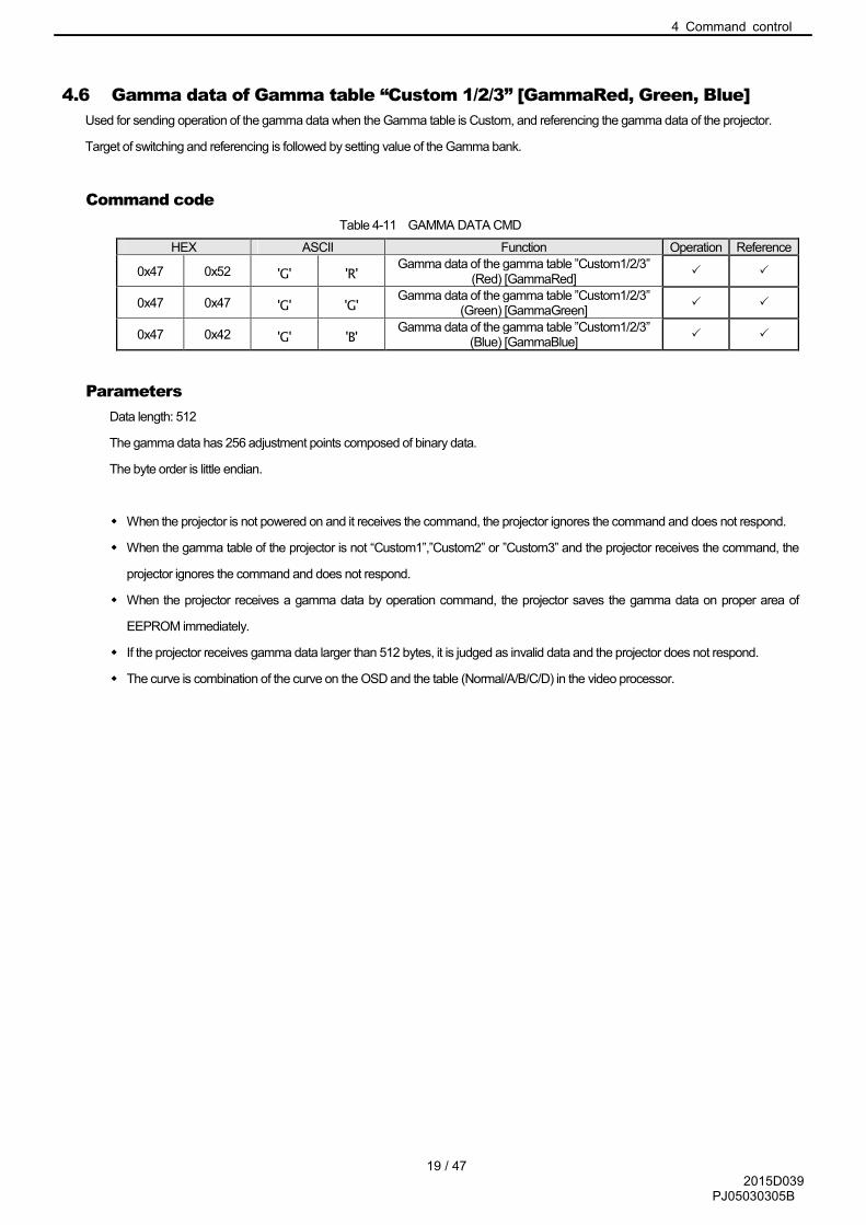
4.6 Gamma data of Gamma table “Custom 1/2/3” [GammaRed, Green, Blue]
Used for sending operation of the gamma data when the Gamma table is Custom, and referencing the gamma data of the projector.
Target of switching and referencing is followed by setting value of the Gamma bank.
Command code
Table 4-11 GAMMA DATA CMD
HEX ASCII Function Operation Reference
0x47 0x52 'G' 'R' Gamma data of the gamma table ”Custom1/2/3”
(Red) [GammaRed] � �
0x47 0x47 'G' 'G' Gamma data of the gamma table ”Custom1/2/3”
(Green) [GammaGreen] � �
0x47 0x42 'G' 'B' Gamma data of the gamma table ”Custom1/2/3”
(Blue) [GammaBlue] � �
Parameters
Data length: 512
The gamma data has 256 adjustment points composed of binary data.
The byte order is little endian.
� When the projector is not powered on and it receives the command, the projector ignores the command and does not respond.
� When the gamma table of the projector is not “Custom1”,”Custom2” or ”Custom3” and the projector receives the command, the
projector ignores the command and does not respond.
� When the projector receives a gamma data by operation command, the projector saves the gamma data on proper area of
EEPROM immediately.
� If the projector receives gamma data larger than 512 bytes, it is judged as invalid data and the projector does not respond.
� The curve is combination of the curve on the OSD and the table (Normal/A/B/C/D) in the video processor.

4 Command control
20 / 47 2015D039
PJ05030305B
4.6.1 Operation
Use the command as shown in the following examples.
Purpose: To send red gamma data of the gamma table “Custom1/2/3” to the projector.
(1) Transmit the data from the external controller to the projector as follows.
1: External controller →
0x21 0x89 0x01 0x47 0x52 0x0A
'!'(Operation) PJ Individual : 1 'G' 'R' End
(2) If the projector receives the data (1) above and the command receipt is normal, an ACK is returned from the projector as follows.
2: ←Projector
0x06 0x89 0x01 0x47 0x52 0x0A
ACK PJ Individual : 1 'G' 'R' End
(3) The external controller transmits 512 bytes of binary data to the projector.
(4) If the projector receives data (3) above and the command receipt was normal, an ACK is returned from the projector as follows.
4: ←Projector
0x06 0x89 0x01 0x47 0x52 0x0A
ACK PJ Individual : 1 'G' 'R' End
4.6.2 Reference
Use the command as shown in the following examples.
Purpose: To confirm the green gamma data of the current gamma table “Custom3”.
(Current Gamma bank: Custom3)
(1) Transmit the data from the external controller to the projector as follows.
1: External controller →
0x3F 0x89 0x01 0x47 0x47 0x0A
'?'(Reference) PJ Individual : 1 'G' 'G' End
(2) If the projector receives the data (1) above and the command receipt is normal, an ACK is returned from the projector as follows.
2: ← Projector
0x06 0x89 0x01 0x47 0x47 0x0A
ACK PJ Individual : 1 'G' 'G' End
(3) The projector transmits 512 bytes binary data to the external controller.
4.7 Panel Alignment (zone) Data [Panel Alignment(Zone) Red, Blue]
Used for transmitting operation and referencing Panel Alignment (zone) data

4 Command control
21 / 47 2015D039
PJ05030305B
Command Code
Table 4-12 PANEL ALIGNMENT(ZONE) DATA CMD
HEX ASCII Function transmitting referencing
0x50 0x52 ‘P’ ‘R’ Data of Red [Panel Alignment(Zone)Red] � �
0x50 0x42 ‘P’ ‘B’ Data of Blue [Panel Alignment(Zone)Blue � �
Parameters
Data Length: 256
Horizontal and Vertical data of 11x11 Adjustment zone composed of binary data. Data could be -31 (0xE1) to +31(0x1F).
Data is assigned by 2 bytes and its order is from Horizontal to Vertical. The order of Adjustment zone is shown at a table below.
121 (Adjustment zone) x 2 (Horizontal / Vertical) + 13 (reserved) =256 Byte
Data No. Horizontal position of zone Vertical position of zone Horizontal / Vertical
1 0 0 Horizontal
2 Vertical
3 1 0 Horizontal
4 Vertical
5 2 0 Horizontal
6 Vertical
(skip)
21 10 0 Horizontal
22 Vertical
23 0 1 Horizontal
24 Vertical
(skip)
239 9 10 Horizontal
240 Vertical
241 10 10 Horizontal
242 Vertical
243-256 Reserved
The Byte order is little endian.
� When the projector is not powered on and it receives the command, the projector ignores the command and does not respond.
� If the projector receives gamma data larger than 256 bytes, it is judged as invalid data and the projector does not respond.

4 Command control
22 / 47 2015D039
PJ05030305B
4.7.1 Operation
Use the command as shown in the following examples.
Purpose:To send red Alignment (zone) data to the projector.
(1) Transmit the data from the external controller to the projector as follows.
1: External Controller →
0x21 0x89 0x01 0x50 0x52 0x0A
‘!’(Operation) PJ Individual : 1 ‘P’ ‘R’ End
(2) If the projector receives the data (1) above and the command receipt is normal, an ACK is returned from the projector as follows.
2: ← Projector
0x06 0x89 0x01 0x50 0x52 0x0A
ACK PJ Individual : 1 ‘P’ ‘R’ End
(3) The external controller transmits 256 bytes of binary data to the projector.
(4) If the projector receives data (3) above and the command receipt was normal, an ACK is returned from the projector as follows.
4: ← Projector
0x06 0x89 0x01 0x50 0x52 0x0A
ACK PJ Individual : 1 ‘P’ ‘R’ End
4.7.2 Reference
Use the command as shown in the following examples.
Purpose:To confirm Blue data of the current Panel Alignment (zone)
(1) Transmit the data from the external controller to the projector as follows.
1: External Controller →
0x3F 0x89 0x01 0x50 0x42 0x0A
‘?’(reference) PJ Individual:1 ‘P’ ‘B’ End
(2) If the projector receives the data (1) above and the command receipt is normal, an ACK is returned from the projector as
follows.
2: ← Projector
0x06 0x89 0x01 0x50 0x42 0x0A
ACK PJ Individual : 1 ‘P’ ‘B’ End
(3) The projector transmits 256 bytes binary data to the external controller.

4 Command control
23 / 47 2015D039
PJ05030305B
4.8 Source Asking [SourCe]
Use to refer signal input status of the projector.
Command code
Table 4-13 SOURCE CMD
HEX ASCII Function Operation Reference
0x53 0x43 'S' 'C' Source asking [SourCe] �
Parameters
Data length: 1
【Data 0】
Table 4-14 SOURCE CMD DATA
HEX ASCII Operation
0x30 '0' No signal or out of range
0x31 '1' Available signal is input to the projector.
� When the projector is not powered on and it receives the command, the projector ignores the command and does not respond.
4.8.1 Reference
Use the command as shown in the following examples.
Purpose: To confirm the current status of the projector. (Current status: No signal or
out of range)
(1) Transmit the data from the external controller to the projector as follows.
1: External controller →
0x3F 0x89 0x01 0x53 0x43 0x0A
'?'(Reference) PJ Individual : 1 'S' 'C' End
(2) If the projector receives the data (1) above and the command receipt is normal, an ACK is returned from the projector as follows.
2: ← Projector
0x06 0x89 0x01 0x53 0x43 0x0A
ACK PJ Individual : 1 'S' 'C' End
(3) The projector transmits the status of the input signal to the external controller.
3: ← Projector
0x40 0x89 0x01 0x53 0x43 0x30 0x0A
'@'(Response) PJ Individual : 1 'S' 'C' No signal or out of range End
By the above exchange, it can be confirmed that whether the status of input signal of the projector is no signal or out of range.

4 Command control
24 / 47 2015D039
PJ05030305B
4.9 Model status asking [MoDel]
Used for referring model status of the projector.
Command code
Table 4-15 MODEL STATUS CMD
HEX ASCII Function Operation Reference
0x4D 0x44 'M' 'D' Model status asking [MoDel] - �
Parameters
Data length: 14
Table 4-16 MODEL STATUS CMD DATA
Parameters
0x49 0x4C 0x41 0x46 0x50 0x4A 0x20 0x2D 0x2D 0x20 0x58 0x48 0x50 (*)
‘I’ ‘L’ ‘A’ ‘F’ ‘P’ ‘J’ SP ‘-‘ ‘-‘ SP ‘X’ ‘H’ ‘P’ ‘(*)’
(*) DLA-X550R,X5000,XC5890R,RS400 = ’1’(0x31), DLA-XC6890 = ‘2’ (0x32),
DLA-X750R,X7000,XC7890R,RS500,X950R,X9000,RS600,PX1 = ‘3’ (0x33)
4.9.1 Reference
Use the command as shown in the following examples.
Purpose: To confirm the model status of the current projector.
(1) Transmit the data from the external controller to the projector as follows.
1: External controller →
0x3F 0x89 0x01 0x4D 0x44 0x0A
'?'(Reference) PJ Individual : 1 'M' 'D' End
(2) If the projector receives the data (1) above and the command receipt is normal, an ACK is returned from the projector as follows.
2: ← Projector
0x06 0x89 0x01 0x4D 0x44 0x0A
ACK PJ Individual : 1 'M' 'D' End
(3) The projector transmits a report of the model status to the external controller.
3: ← Projector
0x40 0x89 0x01 0x4D 0x44 Parameters 14 bytes 0x0A
'@'(Response) PJ Individual : 1 'M' 'D' Model status End
By the above exchange, it can be confirmed model status of the projector.

4 Command control
25 / 47 2015D039
PJ05030305B
4.10 Adjustment [AdjustmentCommand]
Used for adjusting some function.
Command code
Table 4-17 ADJUSTMENT CMD
HEX ASCII Function
0x50 0x4D 'P' 'M' Picture Adjust
0x49 0x53 ‘I’ ‘S’ Input Signal
0x49 0x4E ‘I’ ‘N’ Installation
0x44 0x53 ‘D’ ‘S’ Display Setup
0x46 0X55R ‘F’ ‘U’ Function
0x49 0x46 I' ‘F’ Information
Parameter1
Parameter1: Sub command
Data length: ASCII character 2 bytes
Parameter1 table is as follow.
Table 4-18 ADJUSTMENT CMD SUB
Command Code
Parameter1 Function
Opera
tion
Refe
rence
Data type Model
X550R
/X5000/
RS
400 / X
C5890
XC
6890
X750R
/X950R
XC
7890
RS
500/R
S600
X7000/X
9000/P
X1
'P' 'M' ‘P’ ‘M’ Picture Mode switch � � Special 4 � � �
'P' 'M' ‘A’ ‘N’ Clear Black � � Special � � �
'P' 'M' ‘D’ ‘I’ Intelligent Lens Aperture � � Special � � �
'P' 'M' ‘P’ ‘R’ Color Profile switch (*1) � � Special � � �
'P' 'M' ‘C’ ‘L’ Color Temperature table switch � � Special � � �
'P' 'M' ‘C’ ‘C’ Color Temperature Correction switch � � Special � � �
'P' 'M' ‘G’ ‘R’ Color Temperature Gain (Red) adjustment � � Numeric � � �
'P' 'M' ‘G’ ‘G’ Color Temperature Gain (Green) adjustment � � Numeric � � �
'P' 'M' ‘G’ ‘B’ Color Temperature Gain (Blue) adjustment � � Numeric � � �
'P' 'M' ‘O’ ‘R’ Color Temperature Offset (Red) adjustment � � Numeric � � �
'P' 'M' ‘O’ ‘G’ Color Temperature Offset (Green) adjustment � � Numeric � � �
'P' 'M' ‘O’ ‘B’ Color Temperature Offset (Blue) adjustment � � Numeric � � �
'P' 'M' ‘G’ ‘T’ Gamma Table switch � � Special � � �
'P' 'M' ‘F’ ‘W’ Picture Tone (White) adjustment � � Numeric � � �
'P' 'M' ‘F’ ‘R’ Picture Tone (Red) adjustment � � Numeric � � �
'P' 'M' ‘F’ ‘G’ Picture Tone (Green) adjustment � � Numeric � � �
'P' 'M' ‘F’ ‘B’ Picture Tone (Blue) adjustment � � Numeric � � �
'P' 'M' ‘C’ ‘N’ Contrast adjustment � � Numeric � � �
'P' 'M' ‘B’ ‘R’ Brightness adjustment � � Numeric � � �
'P' 'M' ‘C’ ‘O’ Color adjustment � � Numeric � � �
'P' 'M' ‘T’ ‘I’ Tint adjustment � � Numeric � � �
'P' 'M' ‘R’ ‘N’ NR adjustment � � Numeric � � �
'P' 'M' ‘G’ ‘C’ Gamma Correction switch � � Special 4 � � �
'P' 'M' 'D' 'R' Gamma Red data � � Special 2 � � �
'P' 'M' 'D' 'G' Gamma Green data � � Special 2 � � �
'P' 'M' 'D' 'B' Gamma Blue data � � Special 2 � � �
'P' 'M' ‘R’ ‘W’ Bright Level White � � Numeric � � �
'P' 'M' ‘R’ ‘R’ Bright Level Red � � Numeric � � �
'P' 'M' ‘R’ ‘G Dark Level Green � � Numeric � � �
'P' 'M' ‘R’ ‘B’ Dark Level Blue � � Numeric � � �
'P' 'M' ‘K’ ‘W’ Dark Level White � � Numeric � � �
'P' 'M' ‘K’ ‘R’ Dark Level Red � � Numeric � � �

4 Command control
26 / 47 2015D039
PJ05030305B
'P' 'M' ‘K’ ‘G Dark Level Green � � Numeric � � �
'P' 'M' ‘K’ ‘B’ Dark Level Blue � � Numeric � � �
'P' 'M' ‘C’ ‘B’ Color Management table � � Special � � �
'P' 'M' ‘A’ ‘R’ Axis Position (Red) adjustment � � Numeric � � �
'P' 'M' ‘A’ ‘Y’ Axis Position (Yellow) adjustment � � Numeric � � �
'P' 'M' ‘A’ ‘G’ Axis Position (Green) adjustment � � Numeric � � �
'P' 'M' ‘A’ ‘C’ Axis Position (Cyan) adjustment � � Numeric � � �
'P' 'M' ‘A’ ‘B’ Axis Position (Blue) adjustment � � Numeric � � �
'P' 'M' ‘A’ ‘M’ Axis Position (Magenta) adjustment � � Numeric � � �
'P' 'M' ‘H’ ‘R’ HUE (Red) adjustment � � Numeric � � �
'P' 'M' ‘H’ ‘Y’ HUE (Yellow) adjustment � � Numeric � � �
'P' 'M' ‘H’ ‘G’ HUE (Green) adjustment � � Numeric � � �
'P' 'M' ‘H’ ‘C’ HUE (Cyan) adjustment � � Numeric � � �
'P' 'M' ‘H’ ‘B’ HUE (Blue) adjustment � � Numeric � � �
'P' 'M' ‘H’ ‘M’ HUE (Magenta) adjustment � � Numeric � � �
'P' 'M' ‘S’ ‘R’ SATURATION (Red) adjustment � � Numeric � � �
'P' 'M' ‘S’ ‘Y’ SATURATION (Yellow) adjustment � � Numeric � � �
'P' 'M' ‘S’ ‘G’ SATURATION (Green) adjustment � � Numeric � � �
'P' 'M' ‘S’ ‘C’ SATURATION (Cyan) adjustment � � Numeric � � �
'P' 'M' ‘S’ ‘B’ SATURATION (Blue) adjustment � � Numeric � � �
'P' 'M' ‘S’ ‘M’ SATURATION (Magenta) adjustment � � Numeric � � �
'P' 'M' ‘L’ ‘R’ BRIGHTNESS (Red) adjustment � � Numeric � � �
'P' 'M' ‘L’ ‘Y’ BRIGHTNESS (Yellow) adjustment � � Numeric � � �
'P' 'M' ‘L’ ‘G’ BRIGHTNESS (Green) adjustment � � Numeric � � �
'P' 'M' ‘L’ ‘C’ BRIGHTNESS (Cyan) adjustment � � Numeric � � �
'P' 'M' ‘L’ ‘B’ BRIGHTNESS (Blue) adjustment � � Numeric � � �
'P' 'M' ‘L’ ‘M’ BRIGHTNESS (Magenta) adjustment � � Numeric � � �
'P' 'M' ‘C’ ‘M’ Clear Motion Drive � � Special � � �
'P' 'M' ‘M’ ‘E’ Motion Enhance � � Special � � �
'P' 'M' ‘L’ ‘A’ Lens Aperture � � Numeric � � �
'P' 'M' ‘L’ 'P' Lamp Power � � Special � � �
'P' 'M' ‘M’ 'A' MPC Analyze � � Special � � �
‘P’ ‘M’ ‘U’ ‘S’ 4K e-shift � � Special � � �
‘P’ ‘M’ ‘R’ ‘P’ Original Resolution � � Special � � �
‘P’ ‘M’ ‘E’ ‘N’ Enhance � � Numeric � � �
‘P’ ‘M’ ‘D’ ‘Y’ Dynamic Contrast � � Numeric � � �
‘P’ ‘M’ ‘S’ ‘T’ Smoothing � � Numeric � � �
‘P’ ‘M’ ‘U’ ‘1’ Name Edit of Picture Mode User1 � � Special 10 � � �
‘P’ ‘M’ ‘U’ ‘2’ Name Edit of Picture Mode User2 � � Special 10 � � �
‘P’ ‘M’ ‘U’ ‘3’ Name Edit of Picture Mode User3 � � Special 10 � � �
‘P’ ‘M’ ‘U’ ‘4’ Name Edit of Picture Mode User4 � � Special 10 � � �
‘P’ ‘M’ ‘U’ ‘5’ Name Edit of Picture Mode User5 � � Special 10 � � �
‘P’ ‘M’ ‘U’ ‘6’ Name Edit of Picture Mode User6 � � Special 10 � � �
‘I’ ‘S’ ‘I’ ‘L’ HDMI Input Level switch � � Special � � �
‘I’ ‘S’ ‘H’ ‘S’ HDMI Color Space switch � � Special � � �
‘I’ ‘S’ ‘3’ ‘D’ HDMI 2D/3D switch � � Special � � �
‘I’ ‘S’ ‘3’ ‘P’ HDMI 3D Phase adjustment � � Numeric � � �
‘I’ ‘S’ ‘P’ ‘H’ Picture Position (Horizontal) adjustment � � Numeric � � �
‘I’ ‘S’ ‘P’ ‘V’ Picture Position (Vertical) adjustment � � Numeric � � �
‘I’ ‘S’ ‘A’ ‘S’ Aspect switch � � Special � � �
‘I’ ‘S’ ‘M’ ‘A’ Mask switch � � Special � � �
‘I’ ‘S’ ‘M’ ‘L’ Mask (Left) adjustment (*2) � Numeric � � �
‘I’ ‘S’ ‘M’ ‘R’ Mask (Right) adjustment (*2) � Numeric � � �
‘I’ ‘S’ ‘M’ ‘T’ Mask (Top) adjustment (*2) � Numeric � � �
‘I’ ‘S’ ‘M’ ‘B’ Mask (Bottom) adjustment (*2) � Numeric � � �
‘I’ ‘S’ ‘F’ ‘M’ Film Mode switch � � Special � � �
‘I’ ‘S’ ‘L’ ‘V’ Parallax of 3D conversion adjustment � � Numeric � � �
‘I’ ‘S’ ‘C’ ‘A’ Crosstalk Cancel (White) adjustment � � Numeric � � �
‘I’ ‘N’ ‘F’ ‘N’ Focus Near adjustment (*3) � � Special � � �
‘I’ ‘N’ ‘F’ ‘F’ Focus Far adjustment (*3) � � Special � � �
‘I’ ‘N’ ‘Z’ ‘T’ Zoom Tele adjustment (*3) � � Special � � �
‘I’ ‘N’ ‘Z’ ‘W’ Zoom Wide adjustment (*3) � � Special � � �
‘I’ ‘N’ ‘S’ ‘L’ Shift Left adjustment (*3) � � Special � � �
‘I’ ‘N’ ‘S’ ‘R’ Shift Right adjustment (*3) � � Special � � �
‘I’ ‘N’ ‘S’ ‘U’ Shift Up adjustment (*3) � � Special � � �
‘I’ ‘N’ ‘S’ ‘D’ Shift Down adjustment (*3) � � Special � � �
‘I’ ‘N’ ‘C’ ‘V’ Lens Cover switch � � Special - - �

4 Command control
27 / 47 2015D039
PJ05030305B
‘I’ ‘N’ ‘I’ ‘P’ Image Pattern switch � � Special � � �
‘I’ ‘N’ ‘L’ ‘L’ Lens Lock switch � � Special � � �
‘I’ ‘N’ ‘X’ ‘R’ Pixel Adjust (Horizontal Red) adjustment � � Numeric � � �
‘I’ ‘N’ ‘X’ ‘B’ Pixel Adjust (Horizontal Blue) adjustment � � Numeric � � �
‘I’ ‘N’ ‘Y’ ‘R’ Pixel Adjust (Vertical Red) adjustment � � Numeric � � �
‘I’ ‘N’ ‘Y’ ‘B’ Pixel Adjust (Vertical Blue) adjustment � � Numeric � � �
‘I’ ‘N’ ‘I’ ‘S’ Installation Style switch � � Special � � �
‘I’ ‘N’ ‘K’ ‘V’ Keystone (Vertical) adjustment � � Numeric � � �
‘I’ ‘N’ ‘V’ ‘S’ Anamorphic switch � � Special � � �
‘I’ ‘N’ ‘S’ ‘A’ Screen Adjust Data � � Numeric � � �
‘I’ ‘N’ ‘S’ ‘C’ Screen Adjust switch � � Special � � �
‘I’ ‘N’ ‘P’ ‘A’ Panel Alignment switch � � Special � � �
‘I’ ‘N’ ‘M’ ‘S’ Store Lens memory � � Special 9 � � �
‘I’ ‘N’ ‘M’ ‘L’ Load Lens memory � - Special � � �
‘I’ ‘N’ ‘M’ ‘1’ Name Edit of Lens Memory 1 � � Special 10 � � �
‘I’ ‘N’ ‘M’ ‘2’ Name Edit of Lens Memory 2 � � Special 10 � � �
‘I’ ‘N’ ‘M’ ‘3’ Name Edit of Lens Memory 3 � � Special 10 � � �
‘I’ ‘N’ ‘M’ ‘4’ Name Edit of Lens Memory 4 � � Special 10 � � �
‘I’ ‘N’ ‘M’ ‘5’ Name Edit of Lens Memory 5 � � Special 10 � � �
‘I’ ‘N’ ‘M’ ‘6’ Name Edit of Lens Memory 6 � � Special 10 - - �
‘I’ ‘N’ ‘M’ ‘7’ Name Edit of Lens Memory 7 � � Special 10 - - �
‘I’ ‘N’ ‘M’ ‘8’ Name Edit of Lens Memory 8 � � Special 10 - - �
‘I’ ‘N’ ‘M’ ‘9’ Name Edit of Lens Memory 9 � � Special 10 - - �
‘I’ ‘N’ ‘M’ ‘A’ Name Edit of Lens Memory 10 � � Special 10 - - �
‘I’ ‘N’ ‘1’ ‘N’ Focus Near adjustment (1 shot)(*3) � � None � � �
‘I’ ‘N’ ‘1’ ‘F’ Focus Far adjustment (1 shot) (*3) � � None � � �
‘I’ ‘N’ ‘1’ ‘T’ Zoom Tele adjustment (1 shot) (*3) � � None � � �
‘I’ ‘N’ ‘1’ ‘W’ Zoom Wide adjustment (1 shot) (*3) � � None � � �
‘I’ ‘N’ ‘1’ ‘L’ Shift Left adjustment (1 shot) (*3) � � None � � �
‘I’ ‘N’ ‘1’ ‘R’ Shift Right adjustment (1 shot) (*3) � � None � � �
‘I’ ‘N’ ‘1’ ‘U’ Shift Up adjustment (1 shot) (*3) � � None � � �
‘I’ ‘N’ ‘1’ ‘D’ Shift Down adjustment (1 shot) (*3) � � None � � �
‘I’ ‘N’ ‘H’ ‘A’ High Altitude mode switch � � Special � � �
‘D’ ‘S’ ‘B’ ‘C’ Back Color switch � � Special � � �
‘D’ ‘S’ ‘M’ ‘P’ Menu Position switch � � Special � � �
‘D’ ‘S’ ‘S’ ‘D’ Source Display switch � � Special � � �
‘D’ ‘S’ ‘L’ ‘O’ Logo switch � � Special � � �
‘D’ ‘S’ ‘L’ ‘A’ Language switch � � Special � � �
‘F’ ‘U’ ‘T’ ‘R’ Trigger switch � � Special � � �
‘F’ ‘U’ ‘O’ ‘T’ Off Timer switch � � Special � � �
‘F’ ‘U’ ‘E’ ‘M’ Eco Mode switch � � Special � � �
‘F’ ‘U’ ‘C’ ‘F’ Control4 � � Special � � �
‘I' ‘F’ ‘I’ ‘N’ Input display - � Special � � �
‘I' ‘F’ ‘I’ ‘S’ Source display - � Special 4 � � �
‘I' ‘F’ ‘R’ ‘H’ Horizontal Resolution display - � Numeric � � �
‘I' ‘F’ ‘R’ ‘V’ Vertical Resolution display - � Numeric � � �
‘I' ‘F’ ‘F’ ‘H’ Horizontal Frequency display (*4) - � Numeric � � �
‘I' ‘F’ ‘F’ ‘V’ Vertical Frequency display (*4) - � Numeric � � �
‘I' ‘F’ ‘D’ ‘C’ Deep Color display - � Special � � �
‘I' ‘F’ ‘X’ ‘V’ Color space display - � Special � � �
‘I' ‘F’ ‘L’ ‘T’ Lamp Time display - � Numeric � � �
‘I’ ‘F’ ‘S’ ‘V’ Soft Version Display - � Special 14 � � �
‘I' ‘F’ ‘C’ ‘I’ Calibrator Information transmission/display (*5) - � Special 3 � � �
'P' 'M' ‘C’ ‘I’ Calibrator Information transmission/display (*5) � � Special 3 - � �
Always available regardless of the adjustment mode .

4 Command control
28 / 47 2015D039
PJ05030305B
(*1) Only the parameter that follows Picture Mode is effective. (Refer to the table of Picture Mode vs. Color Profile that
described in “Color Profile” section of Functional Spec.)
[Example] Picture Mode = Natural Video(0x38) -> Accepted, Anime1(0x36) -> Rejected
Picture Mode = Film Film1(0x31) -> Accepted, Standard(0x33) -> Rejected
If the corresponded parameter is only one, PJ ignores setting command.
(*2) Setting operations of Mask Left / Right / Top / Bottom [ISML, ISMR, ISMT, ISMB] command are only effective when
Mask Setting [ISMA] is set to “Custom1-3”.
(*3) Because of electrical limitation, only one motor can be driven at the same time.(Same as 1 shot mode)
If the projector receives a motor drive request when other motor is driving, the projector rejects its request.
When a driving motor reaches its limit, the projector stops the motor automatically.
(*4) Parameter is equal to the result in which 100 is multiplied with the actual value.
[Example] When Horz. Frequency is 63.98 kHz : Parameter = 63.98 * 100 = 6398 = 0x18FE
(*5) Both commands are completely same.
.

4 Command control
29 / 47 2015D039
PJ05030305B
Parameter2
Parameter2 data depends on Sub command.
Data length is as follow depending on Sub command.
Data type Data length Note
Numeric 4 bytes ASCII character
Special 1 byte ASCII character
Special2 512 bytes Binary data(for Gamma)
Special3 18 bytes ASCII character (Information for Calibrator)
Special4 2 bytes ASCII character
Special5 384 bytes Binary data
Special6 2 bytes ASCII character
Special7 384 bytes Binary data
Special9 1 byte(operation) /3 byte (reference) ASCII character
Special10 10 bytes ASCII character
Special13 2 bytes ASCII character
Special14 6 bytes ASCII character
� When the projector is not powered on and it receives the command, the projector ignores the command and does not respond.

4 Command control
30 / 47 2015D039
PJ05030305B
4.10.1 Special data
Picture mode
Table 4-19 PICTURE MODE CMD DATA
HEX ASCII Operation
X550R
/X5000/
RS
400 /
XC
5890
XC
6890
X750R
/X950R
XC
7890
RS
500/R
S600
X7000/X
9000/P
X1
0x30 0x30 0 0 Film - - �
0x30 0x31 0 1 Cinema � � �
0x30 0x32 0 2 Animation � � �
0x30 0x33 0 3 Natural � � �
0x30 0x36 0 6 THX - - �
0x30 0x43 0 C User1 � � �
0x30 0x44 0 D User2 � � �
0x30 0x45 0 E User3 � � �
0x30 0x46 0 F User4 � � �
0x31 0x30 1 0 User5 � � �
0x31 0x31 1 1 User6 � � �
Clear Black
Table 4-20 CLEAR BLACK CMD DATA
HEX ASCII Operation
X550R
/X5000/
RS
400 /
XC
5890
XC
6890
X750R
/X950R
XC
7890
RS
500/R
S600
X7000/X
9000/P
X1
0x30 0 Off � � �
0x31 1 Low � � �
0x32 2 High � � �
Intelligent Lens Aperture
Table 4-21 INTELLIGENT LENS APERTURE CMD DATA
HEX ASCII Operation
X550R
/X5000/
RS
400 /
XC
5890
XC
6890
X750R
/X950R
XC
7890
RS
500/R
S600
X7000/X
9000/P
X1
0x30 0 Off � � �
0x31 1 Auto1 � � �
0x32 2 Auto2 � � �

4 Command control
31 / 47 2015D039
PJ05030305B
Color Profile
Table 4-22 COLOR PROFILE CMD DATA
HEX ASCII Operation
X550R
/X5000/
RS
400 / X
C5890
XC
6890
X750R
/X950R
XC
7890
RS
500/R
S600
X7000/X
9000/P
X
1
0x30 0x30 0 0 Off � � �
0x30 0x31 0 1 Film1 - - �
0x30 0x32 0 2 Film2 - - �
0x30 0x33 0 3 Standard � � �
0x30 0x34 0 4 Cinema1 � � �
0x30 0x35 0 5 Cinema2 - - �
0x30 0x36 0 6 Anime1 � � �
0x30 0x37 0 7 Anime2 - - �
0x30 0x38 0 8 Video � � �
0x30 0x39 0 9 x.v.Color - - �
0x30 0x43 0 C 3D Cinema � � �
0x30 0x44 0 D THX - - �
0x30 0x45 0 E Custom1 � � �
0x30 0x46 0 F Custom2 � � �
0x31 0x30 1 0 Custom3 � � �
0x31 0x31 1 1 Custom4 � � �
0x31 0x32 1 2 Custom5 � � �
0x31 0x33 1 3 Film3 - - �
0x31 0x34 1 4 3D Video � � �
0x31 0x35 1 5 3D Animation � � �
0x31 0x45 1 E 3D Film - - �
0x32 0x30 2 0 3D THX - - �
0x32 0x31 2 1 Reference - - �
0x32 0x32 2 2 Custom6 � � �
Color Temp. Table Data
Table 4-23 COLOR TEMP TABLE CMD DATA
HEX ASCII Operation
0x30 ‘0’ 5500K
0x32 ‘2’ 6500K
0x34 ‘4’ 7500K
0x38 ‘8’ 9300K
0x39 ‘9’ High Bright
0x41 ‘A’ Custom1
0x42 ‘B’ Custom2
0x43 ‘C’ Custom3
0x44 ‘D’ Xenon1
0x45 ‘E’ Xenon2
0x46 ‘F’ Xenon3

4 Command control
32 / 47 2015D039
PJ05030305B
Color Temp. Correction Data
Table 4-24 COLOR TEMP CORRECTION CMD DATA
HEX ASCII Operation
0x30 ‘0’ 5500K
0x32 ‘2’ 6500K
0x34 ‘4’ 7500K
0x38 ‘8’ 9300K
0x39 ‘9’ High Bright
0x44 ‘D’ Xenon1
0x45 ‘E’ Xenon2
0x46 ‘F’ Xenon3
Gamma Table Data
Table 4-25 GAMMA CMD DATA
HEX ASCII Operation
0x30 ‘0’ Normal
0x31 ‘1’ A
0x32 ‘2’ B
0x33 ‘3’ C
0x34 ‘4’ Custom1
0x35 ‘5’ Custom2
0x36 ‘6’ Custom3
0x37 ‘7’ D
0x41 ‘A’ Film1
0x42 ‘B’ Film2
Gamma Correction Data
Table 4-26 GAMMA CORRECTION CMD DATA
HEX ASCII Operation
0x30 0x30 ‘0 0’ Normal
0x30 0x31 ‘0 1’ A
0x30 0x32 ‘0 2’ B
0x30 0x33 ‘0 3’ C
0x30 0x34 ‘0 4’ Import
0x30 0x35 ‘0 5’ 1.8
0x30 0x36 ‘0 6’ 1.9
0x30 0x37 ‘0 7’ 2.0
0x30 0x38 ‘0 8’ 2.1
0x30 0x39 ‘0 9’ 2.2
0x30 0x41 ‘0 A’ 2.3
0x30 0x42 ‘0 B’ 2.4
0x30 0x43 ‘0 C’ 2.5
0x30 0x44 ‘0 D’ 2.6
0x30 0x45 ‘0 E’ Film1
0x30 0x46 ‘0 F’ Film2
0x31 0x34 ‘1 4’ D
4 Command control
33 / 47 2015D039
PJ05030305B
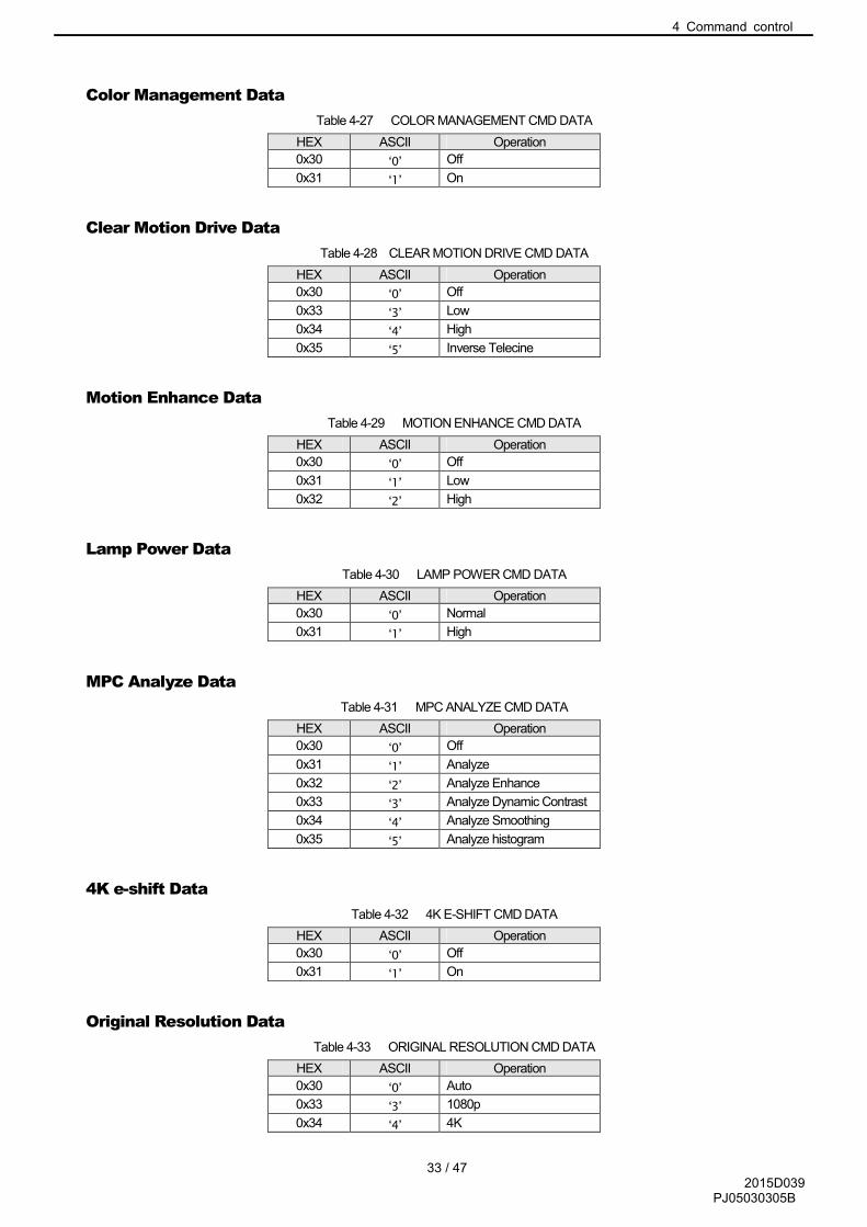
Color Management Data
Table 4-27 COLOR MANAGEMENT CMD DATA
HEX ASCII Operation
0x30 ‘0’ Off
0x31 ‘1’ On
Clear Motion Drive Data
Table 4-28 CLEAR MOTION DRIVE CMD DATA
HEX ASCII Operation
0x30 ‘0’ Off
0x33 ‘3’ Low
0x34 ‘4’ High
0x35 ‘5’ Inverse Telecine
Motion Enhance Data
Table 4-29 MOTION ENHANCE CMD DATA
HEX ASCII Operation
0x30 ‘0’ Off
0x31 ‘1’ Low
0x32 ‘2’ High
Lamp Power Data
Table 4-30 LAMP POWER CMD DATA
HEX ASCII Operation
0x30 ‘0’ Normal
0x31 ‘1’ High
MPC Analyze Data
Table 4-31 MPC ANALYZE CMD DATA
HEX ASCII Operation
0x30 ‘0’ Off
0x31 ‘1’ Analyze
0x32 ‘2’ Analyze Enhance
0x33 ‘3’ Analyze Dynamic Contrast
0x34 ‘4’ Analyze Smoothing
0x35 ‘5’ Analyze histogram
4K e-shift Data
Table 4-32 4K E-SHIFT CMD DATA
HEX ASCII Operation
0x30 ‘0’ Off
0x31 ‘1’ On
Original Resolution Data
Table 4-33 ORIGINAL RESOLUTION CMD DATA
HEX ASCII Operation
0x30 ‘0’ Auto
0x33 ‘3’ 1080p
0x34 ‘4’ 4K

4 Command control
34 / 47 2015D039
PJ05030305B
HDMI Input Level Data
Table 4-34 HDMI INPUT LEVEL CMD DATA
HEX ASCII Operation
0x30 ‘0’ Standard(16-235)
0x31 ‘1’ Enhanced(0-255)
0x32 ‘2’ Super White(16-255)
0x33 ‘3’ Auto
HDMI Color Space Data
Table 4-35 HDMI COLOR SPACE CMD DATA
HEX ASCII Operation
0x30 ‘0’ Auto
0x31 ‘1’ YCbCr(4:4:4)
0x32 ‘2’ YCbCr(4:2:2)
0x33 ‘3’ RGB
HDMI 2D/3D Data
Table 4-36 HDMI 2D/3D CMD DATA
HEX ASCII Operation
0x30 ‘0’ 2D
0x31 ‘1’ Auto
0x33 ‘3’ Side By Side
0x34 ‘4’ Top and Bottom
HDMI 3D Phase Data
Table 4-37 HDMI 3D Phase CMD DATA
HEX ASCII Operation
0x30 ‘0’ Standard
0x31 ‘1’ Flip(L/R Switch)
Aspect Data
Table 4-38 ASPECT CMD DATA
HEX ASCII Operation
0x30 ‘0’ 4:3
0x31 ‘1’ 16:9
0x32 ‘2’ Zoom
0x33 ‘3’ Auto
0x34 ‘4’ Just
0x35 ‘5’ Full
Mask Data
Table 4-39 MASK CMD DATA
HEX ASCII Operation
0x30 ‘0’ Cutom 1
0x31 ‘1’ Custom 2
0x32 ‘2’ Off
0x33 ‘3’ Custom 3

4 Command control
35 / 47 2015D039
PJ05030305B
Lens Control(Focus Near, Focus Far, Zoom Tele, Zoom Wide, Shift Left, Shift Right,
Shift Up, Shift Down) Data
Table 4-40 LENS CONTROL (Focus / Zoom / Shift) CMD DATA
HEX ASCII Operation
0x30 ‘0’ Stop
0x31 ‘1’ Start
Lens Cover Data
Table 4-41 LENS COVER CMD DATA
HEX ASCII Operation
0x30 ‘0’ Auto
0x31 ‘1’ Open
Lens Image Pattern, Lens Lock, Screen Adjust Data
Table 4-42 Above CMD DATA
HEX ASCII Operation
0x30 ‘0’ Off
0x31 ‘1’ On
Installation Style Data
Table 4-43 INSTALLATION STYLE CMD DATA
HEX ASCII Operation
0x30 ‘0’ Front
0x31 ‘1’ Ceiling Mount (F)
0x32 ‘2’ Rear
0x33 ‘3’ Ceiling Mount (R)
Anamorphic Data
Table 4-44 ANAMORPHIC CMD DATA
HEX ASCII Operation
0x30 ‘0’ Off
0x31 ‘1’ A
0x32 ‘2’ B
Panel Alignment Switch Data
Table 4-45 PANEL ALIGNMENT CMD DATA
HEX ASCII Operation
0x30 ‘0’ Off
0x31 ‘1’ Memory1
0x31 ‘2’ Memory2
High Altitude mode Data
Table 4-46 HIGH ALTITUDE CMD DATA
HEX ASCII Operation
0x30 ‘0’ Off
0x31 ‘1’ On

4 Command control
36 / 47 2015D039
PJ05030305B
Back Color Data
Table 4-47 BACK COLOR CMD DATA
HEX ASCII Operation
0x30 ‘0’ Blue
0x31 ‘1’ Black
Menu Position Data
Table 4-48 MENU POSITION CMD DATA
HEX ASCII Operation
0x30 ‘0’ Left-Top
0x31 ‘1’ Right-Top
0x32 ‘2’ Center
0x33 ‘3’ Left-Bottom
0x34 ‘4’ Right-Bottom
0x35 ‘5’ Left
0x36 ‘6’ Right
Source Display, Logo Data
Table 4-49 Source Display, Logo CMD DATA
HEX ASCII Operation
0x30 ‘0’ Off
0x31 ‘1’ On

4 Command control
37 / 47 2015D039
PJ05030305B
Language Data
Table 4-50 LANGUAGE CMD DATA
HEX ASCII Operation
0x30 ‘0’ Japanese
0x31 ‘1’ English
0x32 ‘2’ German
0x33 ‘3’ Spanish
0x34 ‘4’ Italian
0x35 ‘5’ French
0x36 ‘6’ Portuguese
0x37 ‘7’ Dutch
0x38 ‘8’ Swedish
0x39 ‘9’ Norwegian
0x41 ‘A’ Russian
0x42 ‘B’ Chinese(Simplified Chinese)
0x43 ‘C’ Chinese (Traditional Chinese)
Trigger Data
Table 4-51 TRIGGER CMD DATA
HEX ASCII Operation
0x30 ‘0’ Off
0x31 ‘1’ On(Power)
0x32 ‘2’ On(Anamo)
Off Timer Data
Table 4-52 OFF TIMER CMD DATA
HEX ASCII Operation
0x30 ‘0’ Off
0x31 ‘1’ 1 Hour
0x32 ‘2’ 2 Hours
0x33 ‘3’ 3 Hours
0x34 ‘4’ 4 Hours
Eco Mode Data
Table 4-53 ECO MODE CMD DATA
HEX ASCII Operation
0x30 ‘0’ Off
0x31 ‘1’ On
Control 4 Data
Table 4-54 CONTROL 4 CMD DATA
HEX ASCII Operation
0x30 ‘0’ Off
0x31 ‘1’ On

4 Command control
38 / 47 2015D039
PJ05030305B
Input Data
Table 4-55 INPUT CMD DATA
HEX ASCII Operation
0x36 '6' HDMI-1
0x37 '7' HDMI-2
Source Data
Table 4-56 SOURCE CMD DATA
HEX ASCII Operation
0x30 0x32 0 2 480p
0x30 0x33 0 3 576p
0x30 0x34 0 4 720p50
0x30 0x35 0 5 720p60
0x30 0x36 0 6 1080i50
0x30 0x37 0 7 1080i60
0x30 0x38 0 8 1080p24
0x30 0x39 0 9 1080p50
0x30 0x41 0 A 1080p60
0x30 0x42 0 B No Signal
0x30 0x43 0 C 720p 3D
0x30 0x44 0 D 1080i 3D
0x30 0x45 0 E 1080p 3D
0x31 0x30 1 0 4K(4096)60
0x31 0x31 1 1 4K(4096)50
0x31 0x32 1 2 4K(4096)30
0x31 0x33 1 3 4K(4096)25
0x310x34 1 4 4K(4096)24
0x31 0x35 1 5 4K(3840)60
0x31 0x36 1 6 4K(3840)50
0x31 0x37 1 7 4K(3840)30
0x31 0x38 1 8 4K(3840)25
0x31 0x39 1 9 4K(3840)24
Deep Color Data
Table 4-57 DEEP COLOR CMD DATA
HEX ASCII Operation
0x30 ‘0’ 8 bit
0x31 ‘1’ 10 bit
0x32 ‘2’ 12 bit
Color Space Data
Table 4-58 COLOR SPACE CMD DATA
HEX ASCII Operation
0x30 ‘0’ RGB
0x31 ‘1’ YUV
0x32 ‘2’ x.v.Color
4.10.2 Special2 Data
This is the same as Gamma data [GammaRed, Green, Blue] of Gamma table ”Custom 1/2/3”.
4.10.3 Special3 Data
This is the same as Model Status Asking [MoDel].

4 Command control
39 / 47 2015D039
PJ05030305B
4.10.4 Special9 Data
Parameter relating to save lens memory. Parameter format and meanings are depend on <Operation.> and <Reference>.
<Operation>
Table 4-59 LENS MEMORY SAVE CMD DATA<operation>
HEX ASCII
Operation X550R
/X5000/
RS
400 /
XC
5890
XC
6890
X750R
/X950R
XC
7890
RS
500/R
S600
X7000/X
9000/P
X1
0x30 0 Memory1 � � �
0x31 1 Memory2 � � �
0x32 2 Memory3 � � �
0x33 3 Memory4 � � �
0x34 4 Memory5 � � �
0x35 5 Memory6 - - �
0x36 6 Memory7 - - �
0x37 7 Memory8 - - �
0x38 8 Memory9 - - �
0x39 9 Memory10 - - �
<Reference>
Saved condition on Memory1-10 (Either Not-Saved / saved) is returned with 1 byte each. 10 bytes in Total are returned.
Table 4-60 LENS MEMORY SAVE CMD DATA<Reference>
HEX ASCII Operation
0x30 ‘0’ Not- Saved
0x31 ‘1’ Saved
4.10.5 Special10 Data
Parameter relating to editing names of Lens Memory 1/2/3/4/5/6/7/8/9/10 and User 1/2/3/4/5/6 in Picture Mode. 10 Byte ASCII characters.
Communication format is same as Calibrator information transmission/display [PMCI].
4.10.6 Special14 Data
Data Length: 6
2 byte +0x2D(’-‘)+3 byte

4 Command control
40 / 47 2015D039
PJ05030305B
4.10.7 Operation
Use the command as shown in the following examples.
(Example 1) Switching Picture Mode
Purpose: To set Color Temp. Table to ‘6500K’
(1) Transmitting Data from External controller to Projector as follows.
1: External Controller →
0x21 0x89 0x01 0x50 0x4D 0x43 0x4C 0x32 0x0A
'!'(Operation) PJ Individual : 1 ‘P’ ‘M’ ‘C’ ‘L’ 6500K End
(2) If the projector receives the data (1) above and the command receipt is normal, an ACK is returned from the projector as follows.
2: ←Projector
0x06 0x89 0x01 0x50 0x4D 0x0A
ACK PJ Individual : 1 ‘P’ ‘M’ End
(3) The projector sets the Color Temp. Table to ‘6500K’.
(Example 2) Contrast adjustment
Purpose: To set Contrast to +20.
(1) Transmit the data from the external controller to the projector as follows.
1: External controller →
0x21 0x89 0x01 0x50 0x4D 0x43 0x4E 0x30 0x30 0x31 0x34 0x0A
'!'(Operation) PJ Individual : 1 ‘P’ ‘M’ ‘C’ ‘N’ ‘0’ ‘0’ ‘1’ ‘4’ End
(2) If the projector receives the data (1) above and the command receipt is normal, an ACK is returned from the projector as follows.
2: ←Projector
0x06 0x89 0x01 0x50 0x4D 0x0A
ACK PJ Individual : 1 ‘P’ ‘M’ End
(3) The projector sets the contrast to +20.

4 Command control
41 / 47 2015D039
PJ05030305B
(Example 3) Gamma adjustment
Purpose: To transmit gamma data of red to the projector.
(1) Transmit the data from the external controller to the projector as follows.
1: External controller →
0x21 0x89 0x01 0x50 0x4D 0x44 0x52 0x0A
'!'(Operation) PJ Individual : 1 ‘P’ ‘M’ ‘D’ 'R' End
(2) If the projector receives the data (1) above and the command receipt is normal, an ACK is returned from the projector as follows.
2: ←Projector
0x06 0x89 0x01 0x50 0x4D 0x0A
ACK PJ Individual : 1 ‘P’ ‘M’ End
(3) The external controller sends 512 bytes binary data to the projector.
3: External controller →
512 byte
Data parameter
(4) If the projector receives data (3) above and receipt was normal, an ACK is returned from the projector as follows.
4: ←Projector
0x06 0x89 0x01 0x50 0x4D 0x0A
ACK PJ Individual : 1 ‘P’ ‘M’ End
4.10.8 Reference
Use the command as shown in the following examples.
(Example1) Confirm Picture Mode
Purpose: To Confirm Current Picture Mode (Picture Mode: Natural)
(1) Transmit the data from the external controller to the projector as follows.
1: External Controller →
0x3F 0x89 0x01 0x50 0x4D 0x50 0x4D 0x0A
'?'(Reference) PJ Individual : 1 ‘P’ ‘M’ ‘P’ ‘M’ End
(2) If the projector receives the data (1) above and the command receipt is normal, an ACK is returned from the projector as follows.
2: ← Projector
0x06 0x89 0x01 0x50 0x4D 0x0A
ACK PJ Individual : 1 ‘P’ ‘M’ End
(3) Then, the projector transmits Picture Mode to the External Controller.
3: ← Projector
0x40 0x89 0x01 0x50 0x4D 0x30 0x33 0x0A
'@'(Reference) PJ Individual: 1 ‘P’ ‘M’ Natural End
By the above exchange, it can be confirmed that the projector’s Picture Mode is ‘Natural’.
(Example 2) Brightness confirmation
Purpose: To confirm the brightness. (Current brightness: -3)
(1) Transmit the data from the external controller to the projector as follows.

4 Command control
42 / 47 2015D039
PJ05030305B
1: External controller →
0x3F 0x89 0x01 0x50 0x4D 0x42 0x52 0x0A
'?'(Reference) PJ Individual : 1 ‘P’ ‘M’ ‘B’ ‘R’ End
(2) If the projector receives the data (1) above and the command receipt is normal, an ACK is returned from the projector as follows.
2: ← Projector
0x06 0x89 0x01 0x50 0x4D 0x0A
ACK PJ Individual : 1 ‘P’ ‘M’ End
(3) The projector transmits brightness setting “-3” to the external controller.
3: ← Projector
0x40 0x89 0x01 0x50 0x4D 0x46 0x46 0x46 0x44 0x0A
'@'(Response) PJ Individual : 1 ‘P’ ‘M’ ‘F’ ‘F’ ‘F’ ‘D’ End
By the above exchange, it can be confirmed that the projector’s brightness is set to “-3”.
(Example 3) Gamma confirmation
Purpose: To confirm the Green gamma data.
(1) Transmit the data from the external controller to the projector as follows.
1: External controller →
0x3F 0x89 0x01 0x50 0x4D 0x44 0x47 0x0A
'?'(Reference) PJ Individual : 1 ‘P’ ‘M’ ‘D’ 'G' End
(2) If the projector receives the data (1) above and the command receipt is normal, an ACK is returned from the projector as follows.
2: ← Projector
0x06 0x89 0x01 0x50 0x4D 0x0A
ACK PJ Individual : 1 ‘P’ ‘M’ End
(3) The projector transmits 512 bytes binary data to the external controller.

4 Command control
43 / 47 2015D039
PJ05030305B
(Example 4) Confirm Software Version
Purpose: Confirm Software Version
(1) Transmit the data from the external controller to the projector as follows.
1: External Controller →
0x3F 0x89 0x01 0x49 0x46 0x53 0x56 0x0A
'?'(Reference) PJ Individual:1 ‘I’ ‘F’ ‘S’ ‘V’ End
(2) If the projector receives the data (1) above and the command receipt is normal, an ACK is returned from the projector as follows.
2: ←Projector
0x06 0x89 0x01 0x49 0x46 0x0A
ACK PJ Individual : 1 ‘I’ ‘F’ End
(3) Then, the Projector transmits Software version to the external controller.
3: ←Projector
0x06 0x89 0x01 0x49 0x46 0x30 0x33 0x2D 0x30 0x30 0x35 0x0A
ACK PJ Individual : 1 ‘I’ ‘F’ ‘0’ ‘3’ ‘-’ ‘0’ ‘0’ ‘5’ End
By the above exchange, it can be confirmed that the Software version is “03.005”.

4 Command control
44 / 47 2015D039
PJ05030305B
LAN setup [Lan Setup]
Used to setup LAN configuration.
Command code
Table 4-61 LAN SETUP CMD
HEX ASCII Function
0x4C 0x53 'L' 'S' LAN setup [Lan Setup]
Parameter1
Data length: No regulation
Sub command table (Mandatory command only)
Table 4-62 LAN SETUP CMD SUB
HEX ASCII Function Last
memory Operation Reference
0x44 0x53 'D' 'S' DHCP Client setting Yes � �
0x49 0x50 ‘I’ ‘P’ IP Address setting Yes �
(When ‘DHCP Client’ is Off.) �
0x53 0x4D ‘S’ ‘M’ Subnet Mask setting Yes �
(When ‘DHCP Client’ is Off.) �
0x44 0x47 ‘D’ ‘G’ Default Gateway setting Yes �
(When ‘DHCP Client’ is Off.) �
0x4D 0x41 ‘M’ ‘A’ MAC Address setting Yes - �
0x52 0x53 ‘R’ ‘S’ Network reboot No � -
0x50 0x54 ‘P’ ‘T’ Port setting Yes � �
� It consists of “Sub command” + “setting”. Sub command consists of ASCII character 2 bytes.
Parameter2
Sub command parameters are as follows.
Parameters when Sub command is [0x44,0x53]: Data length 1
Table 4-63 DHCP Client
HEX ASCII Operation
0x30 ‘0’ Off(Static)
0x31 ‘1’ On
Parameters when Sub command is [0x49,0x50] [0x53,0x4D] [0x44,0x47]: Data length 8
Parameters when Sub command is [0x4D,0x41]: Data length 12
Parameters when Sub command is [0x52,0x53]: Data length 1
Table 4-64 NETWORK RESTART
HEX ASCII Operation
0x31 ‘1’ Network Restart
Parameters when Sub command is [0x50,0x54]: Data length 4

4 Command control
45 / 47 2015D039
PJ05030305B
4.10.9 Operation
Use the command as shown in the following examples.
(Example1) DHCP Client setting
Purpose: To set DHCP Client to On.
(1) Transmit the data from the external controller to the projector as follows.
1: External controller →
0x21 0x89 0x01 0x4C 0x53 0x44 0x53 0x31 0x0A
'!'(Operation) PJ Individual : 1 'L' 'S' 'D' 'S' On End
(2) If the projector receives the data (1) above and the command receipt is normal, an ACK is returned from the projector as follows.
2: ←Projector
0x06 0x89 0x01 0x4C 0x53 0x0A
ACK PJ Individual : 1 'L' 'S' End
(3) The projector set DHCP Client to On.
(Example2) IP Address setting
Purpose: To set IP Address to 192.168.1.10.
(1) Transmit the data from the external controller to the projector as follows.
1: External controller →
0x21 0x89 0x01 0x4C 0x53 0x49 0x50 0x43 0x30 0x41 0x38 0x30 0x31 0x30 0x41 0x0A
'!'(Operation) PJ Individual : 1 'L' 'S' ‘I’ ‘P’ 192(=0xC0) 168(=0xA8) 1(=0x01) 10(=0x0A) End
(2) If the projector receives the data (1) above and the command receipt is normal, an ACK is returned from the projector as follows.
2: ←Projector
0x06 0x89 0x01 0x4C 0x53 0x0A
ACK PJ Individual : 1 'L' 'S' End
(3) The projector saves “192.168.1.10.” to IP Address. (Valid after network reboot)
(Example3) Network reboot
To reboot Network
(1) Transmit the data from the external controller to the projector as follows.
1: External controller →
0x21 0x89 0x01 0x4C 0x53 0x52 0x53 0x31 0x0A
'!'(Operation) PJ Individual : 1 'L' 'S' ‘R’ ‘S’ Execute End
(2) If the projector receives the data (1) above and the command receipt is normal, an ACK is returned from the projector as follows.
2: ←Projector
0x06 0x89 0x01 0x4C 0x53 0x0A
ACK PJ Individual : 1 'L' 'S' End
(3) The projector reboots the Network.

4 Command control
46 / 47 2015D039
PJ05030305B
(Example4) Port setting
Purpose: To set the Port to 10000(=0x2710).
(1) Transmit the data from the external controller to the projector as follows.
1: External controller →
0x21 0x89 0x01 0x4C 0x53 0x50 0x54 0x32 0x37 0x31 0x30 0x0A
'!'(Operation) PJ Individual : 1 'L' 'S' ‘P’ ‘T’ 10000(=0x2710) End
(2) If the projector receives the data (1) above and the command receipt is normal, an ACK is returned from the projector as follows.
2: ←Projector
0x06 0x89 0x01 0x4C 0x53 0x0A
ACK PJ Individual : 1 'L' 'S' End
(3) The projector saves 10000 to the Port. (No matter what the Network reboot)
4.10.10 Reference
Use the command as shown in the following examples.
(Example1) DHCP Client confirmation
Purpose: To confirm DHCP Client.
(1) Transmit the data from the external controller to the projector as follows.
1: External controller →
0x3F 0x89 0x01 0x4C 0x53 0x44 0x53 0x0A
'?'(Reference) PJ Individual : 1 'L' 'S' 'D' 'S' End
(2) If the projector receives the data (1) above and the command receipt is normal, an ACK is returned from the projector as follows.
2: ← Projector
0x06 0x89 0x01 0x4C 0x53 0x0A
ACK PJ Individual : 1 'L' 'S' End
(3) The projector transmits DHCP Client to the external controller.
3: ← Projector
0x40 0x89 0x01 0x4C 0x53 0x30 0x0A
'@'(Response) PJ Individual : 1 'L' 'S' Off End
By the exchange above, it can be confirmed that the projector DHCP Client is set to Off.

4 Command control
47 / 47 2015D039
PJ05030305B
(Example2) MAC Address confirmation
Purpose: To confirm the current MAC Address.
(1) Transmit the data from the external controller to the projector as follows.
1: External controller →
0x3F 0x89 0x01 0x4C 0x53 0x4D 0x41 0x0A
'?'(Reference) PJ Individual : 1 'L' 'S' ‘M’ ‘A’ End
(2) If the projector receives the data (1) above and the command receipt is normal, an ACK is returned from the projector as follows.
2: ← Projector
0x06 0x89 0x01 0x4C 0x53 0x0A
ACK PJ Individual : 1 'L' 'S' End
(3) The projector transmits MAC Address to the external controller.
3: ← Projector
0x40 0x89 0x01 0x4C 0x53
'@'(Response) PJ Individual : 1 'L' 'S'
0x30 0x30 0x38 0x30 0x38 0x38 0x31 0x32 0x33 0x34 0x35 0x56 0x0A
00 80 88 12 34 56 End
By the above exchange, it can be confirmed that the projector’s MAC Address is set to “00:80:88:12:34:56”.
(Example3) Port confirmation
Purpose: To confirm the current Port.
(1) Transmit the data from the external controller to the projector as follows.
1: External controller →
0x3F 0x89 0x01 0x4C 0x53 0x50 0x54 0x0A
'?'(Reference) PJ Individual : 1 'L' 'S' ‘P’ ‘T’ End
(2) If the projector receives the data (1) above and the command receipt is normal, an ACK is returned from the projector as follows.
2: ← Projector
0x06 0x89 0x01 0x4C 0x53 0x0A
ACK PJ Individual : 1 'L' 'S' End
(3) The projector transmits Port to the external controller.
3: ← Projector
0x40 0x89 0x01 0x4C 0x53 0x35 0x30 0x34 0x41 0x0A
'@'(Response) PJ Individual : 1 'L' 'S' 20554(=504A) End
By the above exchange, it can be confirmed that the projector’s port is set to 20554(=0x504A).

![[hal-00759030, v1] Spec: A Framework for the Specification and … · 2015. 11. 3. · built Spec: a UIBuilder for Pharo with a focus on reuse. With Spec, widget properties are dened](https://img.pdfslide.us/doc/110x75/6066057e56e40400485d8dc6/hal-00759030-v1-spec-a-framework-for-the-specification-and-2015-11-3-built.jpg)

![Key Management Interoperability Protocol Specification ...docs.oasis-open.org/kmip/spec/v1.2/csd01/kmip-spec-v1.… · Web view[ISO16609] ISO, Banking -- Requirements for message](https://img.pdfslide.us/doc/110x75/6032d9816b3d5c21f36cd2a4/key-management-interoperability-protocol-specification-docsoasis-openorgkmipspecv12csd01kmip-spec-v1.jpg)