Embed Size (px)
Citation preview

12/31/2015
1
1
2015 Wall Bracing
Simplified
Wall Bracing(Circumscribed Rectangle)
“Classic”
Wall Bracing
(Braced Wall Lines)
R602.12
Braced wall methodology – 2 options
R602.102
■ Braced wall lines
(BWLs)
■ Braced wall
panels (BWPs)
Classic Wall Bracing R602.10
3
Braced Wall Lines
(BWLs)
Determining Spacing and Length
of Braced Wall Lines
4
BWL Topics
■ Basic engineering
■ Length
■ Offsets
■ Spacing between BWLs
■ Angled walls

12/31/2015
2
A
Basic Engineering
Walls perpendicular to the wind resist
“out-of-plane” loading
B
C
5
Walls parallel to the wind resist “in-plane”
loading
Basic Engineering
6
A
B
C
7
BWL Requirements R602.10.1
■ Straight
■ Run in each plan direction
■ Required on each floor
A
1
2
B C
3
8
BWL Length R602.10.1.1
BWL Length = Distance between ends
(aka “start/stop” points)
BWLs start/stop at:
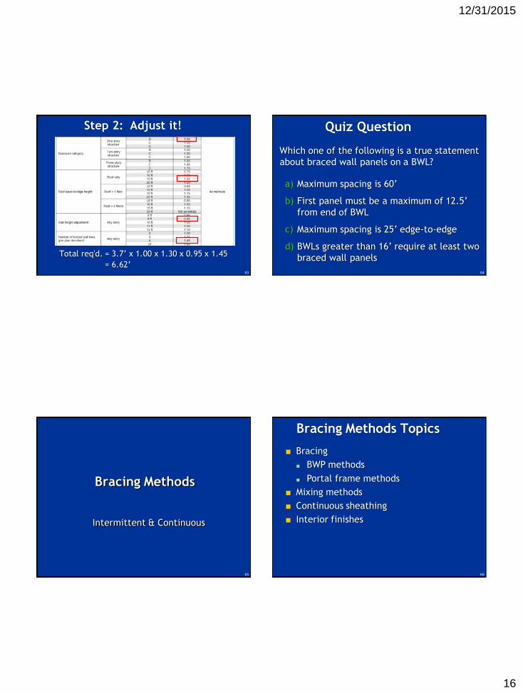
■ Intersections with
perpendicular
BWLs
■ Diagonal BWLs
■ The end of the
building

12/31/2015
3
9
Where there is no perpendicular BWL,
BWLs can stop at the end of the farthest exterior wall.
BWL Length R602.10.1.1
BasementBasement
BasementBasement
10
BWL Offsets R602.10.1.2
The walls of the house are permitted to
offset from the BWL:
■ ≤ 4’ on either
side of the BWL
■ BWL is not
required to align
with actual
wall(s)
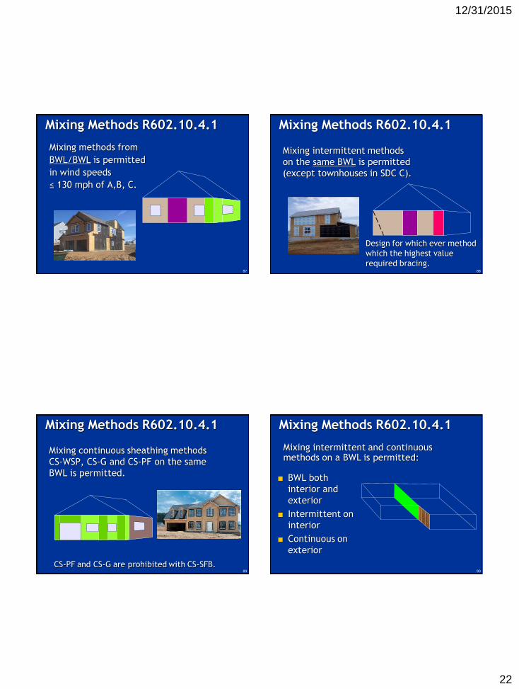
AA
B
CC
The length of a BWL is measured between the points where it intersects perpendicularly with other BWLs.
BWL C
Starts
Stops
4’
30’
4’
The BWL may be longer or shorter than the actual house wall length
BWL Length and Offsets
CBA
11R602.10.1.1 12
BWL spacing is equivalent to its “sail area.”
■ Sail area is
perpendicular
to wind load
■ BWLs resist
parallel wind
load
BWL Spacing R602.10.1.3

12/31/2015
4
13
Bigger “sails” require more bracing
Sail area
35’ 60’ >60’
BWL Spacing R602.10.1.3
14
BWL Spacing R602.10.1.3
■ 4 wind zones: ≤110, ≤115, ≤120, <130,
<140
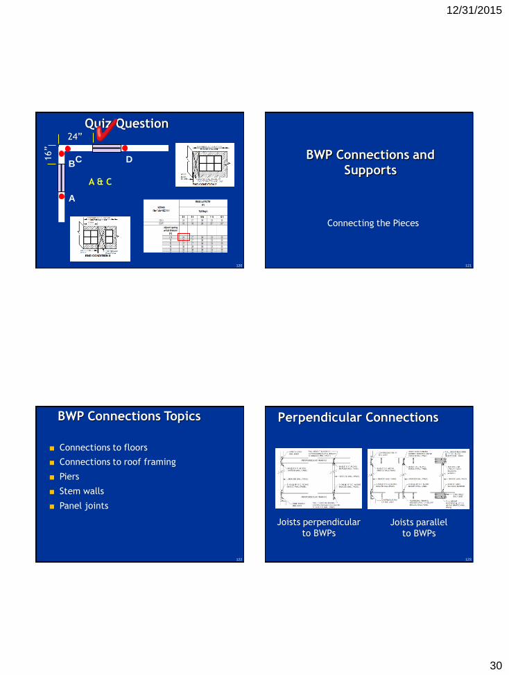
■ 60’ max spacing between BWLs
15
BWL 1 spacing: “where is my help?”
A
B
C
BWL Spacing R602.10.1.3
60’
15’
45’
30’ 1
6’
10’ 2
4’
Use average spacing = (30 + 16) ÷ 2 = 23’
14’
16
BWL 2 spacing: “where is my help?”
BWL Spacing R602.10.1.3
60’
15’
45’
30’ 1
6’
10’ 2
4’
Use average spacing = (30+10+14)÷3 = 18’
14’
A C
B

12/31/2015
5
17
BWL 4 spacing: “where is my help?”
BWL Spacing R602.10.1.3
60’
15’
45’
30’
10’
Use average spacing = (24+16+14+16)÷4 =
17.5’
24’
16’
14’
A C
B
18
BWL A spacing: “where is my help?”
BWL Spacing R602.10.1.3
60’
15’
45’
30’
10’
Use average spacing = (60+45) ÷ 2 = 52.5’
24’
16’
A
B
C
19
BWL B spacing: “where is my help?”
BWL Spacing R602.10.1.3
60’
15’
45’
30’
10’
Use average length = (15+45+15)÷3 = 25’
24’
16’
A
B
C
20
BWL Figure R602.10.1.1

12/31/2015
6
21
Angled walls ≤ 8’ use projected corner
Angled walls > 8’ create new BWL
Separate
BWL when
wall is > 8’
Projected
corner
Length
Angled Walls R602.10.1.4
A B
1
2
3
LengthA B
22
Quiz Question
Which walls resist the
wind load shown?
□ Red
□ White
□ Green
□ Green and Yellow
□ Red and White
23
Quiz Question
What are fewest number of BWLs for this house?
1
23
4
5
6
7
□ 5
□ 6
□ 7
□ 8
24
Quiz Question
□ 30’long –
30’spacing
□ 30’long –
35’spacing
□ 30’long –
40’ spacing
□ 40’long –
35’ spacing
4’
30’
4’
40’
30’
B C
What is the length of BWL B?
What is the spacing for BWL B?
A

12/31/2015
7
On your handout, draw
your own BWLs
1
2
3
A
B
D
C
A B
C
1
2
3
More
efficient
resolution
30
Braced Wall Panels
(BWPs)
Determining Location, Spacing,
Number

12/31/2015
8
31
BWP Topics
■ BWP minimum requirements
■ Locations on a BWL
■ Distance between BWPs
■ Minimum number of BWPs
32
BWPs R602.10.2
Length
Heig
ht
Braced wall panels:
■ Full height, 12’ max.
■ Minimum length
33
BWPs R602.10.2
Cannot be considered as
same BWP
Braced wall panels:
■ Full height, 12’ max.
■ Minimum length
■ No horizontal offsets
34
BWPs R602.10.2
Cannot be considered as
same BWP
Braced wall panels:
■ Full height, 12’ max.
■ Minimum length
■ No horizontal offsets
■ No vertical offsets

12/31/2015
9
35
BWPs R602.10.2
Braced wall panels:
■ Full height, 12’ max.
■ Minimum length
■ No horizontal offsets
■ No vertical offsets
■ Vertical and horizontal
joints permitted
36
BWPs must begin at the end of a BWL, or
begin within 10’ of the end.
Location R602.10.2.2
10’
37
BWPs cannot be > 20’ edge to edge.
Distance between BWPs
R602.10.2.2
20’ max 20’ max
38
Number of BWPs R602.10.2.3
Minimum 2 BWPs required per BWL.
BWLs ≤ 16’ long
Two BWPs (any length)
...or one BWP 48” long
BWLs > 16’ long
Two BWPs (any length)

12/31/2015
10
39
BWL Placement Tip
When a wall is more than 8', BWL placement is
strict. For instance:
All sunroom walls must be on a BWL.
All sunroom walls must have bracing.
>8’
40
BWL Placement Tip
When walls are ≤ 8', BWLs can be placed
strategically to reduce bracing. For instance:
Rear walls of house, and
Rear wall of sunroom
Share a BWL.
≤8’
41
BWL Placement Tip
If the rear walls of the house have sufficient
bracing,
Then rear wall of the sunroom could also be
all glass.
≤8’
42
Assuming the most efficient BWL layout,
what is the minimum number of 48" BWPs
required on the long and short walls?
Quiz Question
□ 0 long, 0 short
□ 1 long, 0 short
□ 0 long, 1 short
□ 1 long, 1 short7’
13’

12/31/2015
11
43
Required Length of Bracing
How much bracing is required?
44
Required Length of
Bracing Topics
■ Applicability
■ Required length of bracing
■ Wind Tables
■ Wind Adjustment factor
■ Seismic Tables
■ Seismic Adjustment factor
45
Applicability R602.10.3
All buildings in
SDC A-B-C: use windB A
C
Exception- Townhouses in SCD C: Must apply both wind and seismic
46
Required Length of
Bracing R602.10.3
Determining Required Length of Bracing:
Step 1. Choose it!Select required amount from table
Step 2. Adjust it!Multiply by adjustment factors
Step 3. Compare it!Actual bracing must be > required

12/31/2015
12
Table R602.10.3(4) Adjustments for SeismicTable R602.10.3 (3) Required Bracing based on Seismic
Table R602.10.3 (1) Required Bracing based on WindTable R602.10.3(2) Adjustments for Wind
Required Length of
Bracing R602.10.3
47
≤ 115
48
■ Wind speed:
■ ≤ 110 ■ ≤ 115 ■ ≤ 120 ■ < 130■ < 140
■ Story
■ BWL spacing
■ Bracing method
Notice: amount of bracing required is expressed in “feet.”
Table R602.10.3(1)
Required amount of bracing is a function of:
49
• Interpolation allowed
Table R602.10.3(1)
50
Adjustment – Exposure
Category BUrban – suburban
Wooded
Factor = 1.0
Category CGrasslands, flat plains
Scattered trees
Near water in hurricane prone
regions
Category DUnobstructed, flat
Outside hurricane prone regions
Unbroken ice, salt flats
Exposure
Category
Consult Table
R301.2(1)
Table R602.10.3(2):

12/31/2015
13
51
Adjustment – Eave-to-Ridge
10’ eave to ridge height
Factor = 1.0
Steep roof pitch
Eave to
Ridge
Height
Relatively flat roof
Table R602.10.3(2):
52
Adjustment – Wall height
Wall <10’: factor <1.0
Wall =10’: factor =1.0
Wall >10’: factor >1.0
Wall height
Table R602.10.3(2):
53
Adjustment – Number of BWLs
Number of braced wall lines in a given direction
2 BWLs
1.00
3 BWLs
1.30
4 BWLs
1.45
≥5 BWLs
1.60
Table R602.10.3(2): 60’ wide house, 90 mph, 1 story, CS-WSP
Req’d. bracing = 18’
30’
Req’d. bracing = 10’
9’9’
60’30’
5’ 5’
30’
5’ 5’
Req’d. bracing = 20’
With adjustment = 15’ x 1.3 = 19.5’
5’
5’
30’
5’
Most bracing on intermediate wall!!
30’
5’ 5’
Req’d. bracing = 15’
Adjustment – Number of BWLs

12/31/2015
14
55
■ May be eliminated - use
adjustment factor per
Table R602.10(2)(not applicable with Method GB
and portal frames)
1.4
Interior Finish
Interior finish material on all BWPs:
■ ½” gypsum board nailed or screwed
■ Equivalent material permitted
56
■ Change nails (screws)
from 7” o.c. to 4” o.c.
along edges
■ Reduce bracing by 30%
Factor = 0.7
0.7
Adjustment – Gypsum
Board Fastening
57
Example
Find required length of bracing for BWL 3:
■ 115 mph wind
■ Suburban site
■ 1st of 2 story
■ 15’ eave-ridge
■ 12’ walls
4’ BWPs, Method-WSP,
Typical of 4
Second floor
33’
18
'15'
Step 1: Choose it!
Tabular value = 10.5’18‘
1
5'
58

12/31/2015
15
59
Step 2: Adjust it!
Total reqd. = 10.5’ x 1.00 x 1.15 x 1.10 x 1.30
= 17.3’ required 60
Step 3: Compare it!
Required: 17.3’ of wall bracing
Actual: 16’ of wall bracing
FailsSecond floor
33’
61
Quiz Question
What is the min.
required length of
bracing of BWL 4?
■ 1 story
■ Wall height = 9’
■ Eave-to-ridge = 15’
■ Method SFB
■ 109 mph wind
■ Exposure B
20’
10’
10’
15’
20’
5’
15’
30’
65’
15’15’
1 2
3
4
7
9
8
6
5
62
Step 1: Choose it!
3.7’21’
12/31/2015
16
63
Total req'd. = 3.7’ x 1.00 x 1.30 x 0.95 x 1.45
= 6.62’
Step 2: Adjust it!
64
Quiz Question
Which one of the following is a true statement
about braced wall panels on a BWL?
a) Maximum spacing is 60’
b) First panel must be a maximum of 12.5’
from end of BWL
c) Maximum spacing is 25’ edge-to-edge
d) BWLs greater than 16’ require at least two
braced wall panels
65
Bracing Methods
Intermittent & Continuous
66
Bracing Methods Topics
■ Bracing
■ BWP methods
■ Portal frame methods
■ Mixing methods
■ Continuous sheathing
■ Interior finishes

12/31/2015
17
Table R602.10.4 Bracing Methods
67
Continuous
Table R602.10.4 Bracing Methods
Intermittent
68
Intermittent:Sheathing at BWP locations only
Continuous: Sheath entire wall, including above and below openings
Table R602.10.4 Bracing Methods
Based segmented shear walls
Based on perforated shear walls
69
Intermittent■ LIB: let-in bracing
■ WSP: wood structural panels
■ SFB: structural fiber board
■ GB: gypsum board
■ PFH: portal frame with hold-downs
■ PFG: portal frame at garage
Continuous sheathing
■ CS-WSP: wood structural panels
■ CS-SFB: structural fiberboard
■ CS-G: wood structural panels adjacent at garage
■ CS-PF: wood structural panel portal frame
Table R602.10.4 Bracing Methods
70
LIB: Let-in Bracing■ 1x4 wood or metal strap
■ 45º to 60º angle
■ 2-8d nails per stud & top & bottom plates
60º max 45º min
Heig
ht

12/31/2015
18
71
WSP: Wood Structural Panel
■ Minimum 3/8” thick OSB or plywood
■ Typical fasteners: 6d nails @ 6” o.c. edges,
12” field
■ 48” minimum length
Heig
ht
Length72
SFB: Structural Fiberboard
■ ½” or 25/32” - stud spacing @ 16” o.c. only
■ Typical fasteners: 8d common nails at
3” o.c. edges, 6” field
■ 48” minimum length
Heig
ht
Length
73
GB: Gypsum Board
■ ½” minimum thickness
■ 48” minimum length (double sided)
■ Typical fasteners: Type W or S screws
■ Fastener spacing: 7” edge/field
Heig
ht
Length74
PFH
16” minimum length.
10’
maxim
um
panel
heig
ht

12/31/2015
19
75
Single Portal Frame
Panel Length
Heig
ht
Single Portal
Single portal frame when abutting a continuing wall
76
Double Portal Frame
Double portal frame when there is no
abutting wall continuation
Heig
ht
Double PortalPanel Length
Panel Length
77
Portal Frames
■ Tested assembly
■ Cannot be
engineered
■ Must construct
exactly as shown78
PFG
24” minimum length.
10
’ m
ax
imu
mp
an
el h
eig
ht

12/31/2015
20
79
Continuous Sheathing
All surfaces must be sheathed, including
above and below windows, doors, gable end
walls, etc. for the entire length of the BWL80
CS-WSP
■ Minimum 3/8” thick OSB or plywood
■ Typical fasteners: 6d nails @ 6” o.c.
edges, 12” o.c. field
■ 24” minimum length
LENGTH
HE
IGH
T
81
■ ½” structural fiberboard
■ Typical fasteners: 8d common nails at
3” o.c. edges, 6” field
■ 24” minimum length
■ Wind speed ≤ 100 mph
CS-SFB
LENGTH
HE
IGH
T
82
■ Minimum 3/8” thick OSB or plywood
■ Typical fasteners: 6d nails @ 6” o.c.
edges, 12” o.c. field
■ No floor above; one side of garage only
■ 24” minimum length
LENGTH
HE
IGH
T
CS-G

12/31/2015
21
83
CS-PF
16” minimum length.
No more than four CS-PF panels in one BWL.
10
’ m
ax
imu
mp
an
el h
eig
ht
84
CS-PF
Can be constructed on a raised floor.
85
Pony Walls on Portal Frames
Design capacity of strap and studs.
86
Mixing Methods R602.10.4.1
Mixing methods from story/story is permitted.
12/31/2015
22
87
Mixing methods from
BWL/BWL is permitted
in wind speeds
≤ 130 mph of A,B, C.
Mixing Methods R602.10.4.1
88
Mixing intermittent methods
on the same BWL is permitted
(except townhouses in SDC C).
Design for which ever method
which the highest value
required bracing.
Mixing Methods R602.10.4.1
89
Mixing continuous sheathing methods
CS-WSP, CS-G and CS-PF on the same
BWL is permitted.
CS-PF and CS-G are prohibited with CS-SFB.
Mixing Methods R602.10.4.1
90
■ BWL both
interior and
exterior
■ Intermittent on
interior
■ Continuous on
exterior
Mixing intermittent and continuous methods on a BWL is permitted:
Mixing Methods R602.10.4.1

12/31/2015
23
91
Mixing intermittent and continuous methods on a BWL is permitted:
■ Required bracing
per GB
■ Continuous
portions must have
end conditions
■ Prohibited in
townhouses in SDC C
Mixing Methods R602.10.4.1
92
Example BWL2:
Interior portions
will be GB.
Exterior portions
will be CS-WSP and CS-PF.
Mixing Methods R602.10.4.1
20’
10
’
10’
15
’
20’
5’
15
’
30
’
65
’
15’15’
220’
10
’
10’
15
’
20’
5’
15
’
30
’
65
’
15’15’
2
94
Quiz Question
True or False:
A braced wall line may contain panels
with Method GB and Method CS-WSP.
True:
Method CS-WSP can be mixed on the
same braced wall line with an
intermittent method, typically GB.
95
Quiz Question
Which of the following statements is correct
regarding CS-PF?
2’
10’
8’
12’
a) BWP length is 2’
b) BWP length is 10’
c) BWP is required
on each side of
the opening
d) 2’ pony wall atop a 10’ portal frame is
prohibited

12/31/2015
24
96
Quiz QuestionWhat size studs and tension strap
are needed for:
10’ tall PFH with 3’ tall pony
wall atop
16’ long opening.
Suburban area, 100 mph
a) 2x4, 4175 lbs
b) 2x6, 2650 lbs
c) 2x6, 3150 lbs
d) Design required (DR)
e) Not allowed97
Panel Lengths
Minimum Length and Contribution
98
BWP Length Topics
■ Minimum lengths
■ Contributing length
■ Partial credit
99
Min. Panel Length R602.10.5
The length necessary to be considered a
braced wall panel.
Interpolation permitted

12/31/2015
25
100
For CS-WSP and CS-SFB, length is based on height of adjacent opening.
Min. Panel Length R602.10.5
101
For panels between openings of differing
heights, the taller opening governs.
Heig
ht
Panel Length 1
96”
80” 64”
Panel Length 2
Panel Length 3
Min. Panel Length R602.10.5
102
5’-
2”
9’-
0”
27” minimum?
5’-2” Window = 62”
Min. Panel Length R602.10.5
103
6’-
8”
9’-
0”
30” minimum?
6’-8” Door = 80”
Min. Panel Length R602.10.5

12/31/2015
26
104
Contributing Length R602.10.5.1
The length a panel can contribute towards
the minimum required length of bracing.
105
Partial Credit R602.10.5.2
For intermittent methods: DWB, WSP, SFB,
PBS, PCP and HPS.
Does not apply to continuous methods.
106
Angled BWPs R602.10.
Only projected length can contribute.
Can only apply to one BWL.
107
Using CS-PF, what is
the minimum length
of the panel shown?
Quiz Question
□ 16”
□ 18”
□ 20”
□ 22”
10’-
0”
7’-
0”
2’
?

12/31/2015
27
108
Using continuous sheathing, what is the
minimum length of the panel shown?
Quiz Question
□ 22”
□ 24”
□ 33”
□ 36”
11’-
0”
8’-
0”
?
109
Quiz Question
How much length does an 30” long x 10’ tall
PFG contribute towards the required wall
bracing?
□ 30”□ 24” □ 45” □ 48”
110
GB
Quiz Question
What is the total contributing length
of the braced wall panels in BWL B?
SFB
SFB SFB
PF
H 18”
54”
sin
gle
sid
ed48”
48”48”
16” 16”
CS-PF
CS-WSP
WS
P
48
”
WS
P
48
”
WS
P
48
”
10
’
3’
10
’
□ 61”
□ 75”
□ 88”
□ 96”
B CA
= 27”
= 48”
111
Ends of BWLs with
Continuous Sheathing
End Panels and Return Panels

12/31/2015
28
112
Ends of BWLs with
Continuous Sheathing Topics
■ Return panels
■ End panels
■ Hold-downs
113
Cont. Sheathing R602.10.7Table R602.10.7 End Conditions for BWLs
with Continuous Sheathing
114
End Condition 1:
Return panel
24” for CS-WSP
32” for CS-SFB
BWP at end of the BWL
Cont. Sheathing R602.10.7
Intermittent
Intermittent
OR
OR
Continuous
Continuous
ContinuousContinuousContinuous
ContinuousContinuousContinuous
115
End Condition 2:
plus 800# hold-down
BWP at end of the BWL
NO return
panel
Cont. Sheathing R602.10.7

12/31/2015
29
ContinuousContinuousContinuousContinuous
116
End Condition 3:
48” BWP at end of the BWL
NO return
panel
Cont. Sheathing R602.10.7
ContinuousContinuousContinuous
117
End Panel:
D ≥ 24” for CS-WSP
≥ 32” for CS-SFB
End Condition 4:
Return panel
24” for CS-WSP
32” for CS-SFB
Cont. Sheathing R602.10.7
ContinuousContinuousContinuous
118
End Condition 5:
No end panel -
BWP within 10’ of the end
of the BWL plus 800# h.d.
NO return
panel
Cont. Sheathing R602.10.7
Hold-down goes on last stud of the qualified stud
119
Quiz Question
Where do the 800# hold-downs belong?
□ A □ B
□ C □ D
□ A & C □ A & D
□ B & C □ B & D
Both BWLs are CS-WSP
24”
16”
A
BC D
2’ x 5’ windows
8’ wall height
12/31/2015
30
120
Quiz Question
A & C
24”
16”
A
BC D
121
BWP Connections and
Supports
Connecting the Pieces
122
BWP Connections Topics
■ Connections to floors
■ Connections to roof framing
■ Piers
■ Stem walls
■ Panel joints
123
Perpendicular Connections
R602.10.7
Joists perpendicular
to BWPsJoists parallel
to BWPs

12/31/2015
31
124
Bracing between rafters/trusses in wind ≤
100 mph at BWP location only.
■ 0” - 9.25” heels - no bracing required
■ 9.25” – 15.25” heels - 2x bracing
■ 15.25” – 48” heels –soffit or vert. panel
■ > 48” heels – RDP design
BWP Connections to roof R602.10.8.1
125
9.25”- 15.25”
2x blocking required
BWP Connections to Roof R602.10.8.1
0”- 9.25”
No blocking required
126
15.25” – 48” : soffit panel OR
BWP Connections to roof R602.10.8.1
127
15.25” – 48” : Vertical blocking panel
Greater than 48” : RDP design required
BWP Connections to roof R602.10.8.1

12/31/2015
32
128
Piers/Posts R602.10.9
Structures supported on piers or
posts must be designed by an RDP
129
Short Stem Walls Tall Stem Walls
BWP @ CMU Stem Walls R602.10.9
130
Threaded Rod Typical CrossAlternate Section
Rods may be anchored in footing
after concrete is poured.
Epoxy connection must have a
pull-out capacity of 5,000 lbs.
BWP @ CMU Stem Walls R602.10.9
131
BWP Joints R602.10.10
BWPs can be constructed
of more than one piece of
sheathing:
■ Vertical joints at studs.
■ Horizontal joints with
blocking.
■ Edge nailing at all joints.
■ Sheathing sheets may also
be placed horizontally.

12/31/2015
33
132
Bracing Information R602.10
Building official may require all BWLs, BWPs and hold-downs be identified and located on the plans for each floor
SFB
SFB SFB
GB
WS
P
48
”4
8”48”
48”48”
16” 16”
CS-PF
CS-WSP CS-WSP CS-WSP
24” 33” 24”
WS
P
48
”
WS
P
48
”
WS
P
48
”
Hold-down
10
’
3’
10
’
23’
A B C
133
Intermittent vs. Continuous
Min. 48”
CS-WSP
Min. 24”
Min. 16”
CS-PF
Proprietary
Min. 12”
WSP
135
Whole House Exercise
136
New Form
Two page work sheet for verifying compliance

12/31/2015
34
1 2
3
4
Determine if BWL3 complies
90 mph, Exp B,
9’ WALL HEIGHT
800 #
H.D
.
3
138
24’4.1’
1.0
9:12 pitch on 24’ wide house
= 9’ eave to ridge height
Interpolating table = 0.94
0.95
1.0--
3.66’
CS-WSP 3.5’
CS-WSP 4.3’CS-WSP 5.5’CS-WSP 10.7’
24.0’
3.5’4.3’5.5’10.7’interpolation
40’
1
2
3
A
B
D
C

12/31/2015
35
141
1
2
3
A
B C
D
A
X
1.0
0.95
1.45
15.0
1.07
34.010.2
CS-WSP 4.8
19.0
CS-WSP 11.8
CS-WSP 2.5
28
142
1
2
3
A
B C
D
B
X
1.0
0.95
1.45
1.9
0.7
9.62.0
0
143
1
2
3
A
B C
D
C
X
1.0
0.95
1.45
3.5
0.7
20.83.6
CS-WSP 3.7
7.4
CS-WSP 3.7
10
none
144
1
2
3
A
B C
D
D
X
1.0
0.95
1.45
21.7
1.07
50.814.7
CS-WSP 7.0
19.0
CS-WSP 12.0

12/31/2015
36
145
1
2
3
A
B C
D
1
X
1.0
0.95
1.3
1.7
0.7
10.02.0
0
146
1
2
3
A
B C
D
2
X
1.0
0.95
1.3
23.0
1.07
28.017.4
CS-WSP 3.0
34.1
CS-WSP 5.25
CS-WSP 19.3
using GB
GB 3.0
BWL 2 runs inside and outside
the building.
To accommodate the 20' edge-
to-edge, a BWP is needed
inside the sunroom.
The common interior wall can
be a double sided GB.
Tabular required length of
bracing is based on Method
GB.
60
147
1
2
3
A
B C
D
3
X
1.0
0.95
1.3
11.2
1.07
28.08.5
CS-WSP 2.5
27.0
CS-WSP 3.0
CS-WSP 4.0
60
CS-WSP 4.0CS-WSP 3.0CS-WSP 2.5CS-PF 2 @ 4 . 0
149
Table R602.10.3(2) Footnote
c. The adjustment factor is
permitted to be 1.0
OPTION
when determining bracing
amounts of intermediate
braced wall lines
provided the bracing amounts on
adjacent braced wall lines are
based on a spacing and number
that neglects the intermediate
braced wall line.

12/31/2015
37
150
BWL #3 example cont.:
•When calculating BWL 2:
– Use adjustment factor of 1.00.
– Based on spacing of 30’.
•When calculating BWLs 1 and 3:
– Assume BWL 2 is not there.
– That would mean only two remaining BWLs in the same plan direction.
– Design BWL 1: 10’ 40’ spacing BWL 3: 30’ 40’ spacing.
– Use adjustment factor of 1.00 for BWL 1 and 3.
Table R602.10.3(2) Footnote
20.5’ (was 15.5’)x 1.00 (exp B)x 1.10 (eave ht) x1.10 (12’ wall)x 1.00 # of BWL
24.8’ required
(Previously 24.4’)