Embed Size (px)
Citation preview


2 | P a g e
3 | P a g e
TABLE OF CONTENTS
ADMINISTRATION .................................................................................................................................................. 5
SECTION I – GENERAL CONDITIONS AND PROCEDURES ............................................................................................ 6
A. Scope ............................................................................................................................................................ 6
B. Engineering/Landscape Design .................................................................................................................... 6
C. Submission of Engineering/Landscape Design ............................................................................................. 6
D. Design Review .............................................................................................................................................. 7
E. Design Final Review ...................................................................................................................................... 7
F. Right-of-Way Documents ............................................................................................................................. 7
G. Construction Approval .................................................................................................................................. 8
H. Engineering Supervision ............................................................................................................................... 8
I. Testing and Inspection ................................................................................................................................. 9
J. Municipal Acceptance .................................................................................................................................. 9
K. As-Built Drawings ....................................................................................................................................... 10
SECTION II – PREPARATION OF ENGINEERING DRAWINGS ...................................................................................... 11
A. Design Drawings ........................................................................................................................................ 11
B. Drawing Size, Material and Basic Layout ................................................................................................... 11
C. Scales .......................................................................................................................................................... 11
D. General Requirements ................................................................................................................................ 11
TECHNICAL SPECIFICATIONS ................................................................................................................................ 13
SECTION III – WATER MAINS & ACCESSORIES .......................................................................................................... 14
A. Network ...................................................................................................................................................... 14
B. Mains and Design ....................................................................................................................................... 14
C. Pipe and Fittings ......................................................................................................................................... 15
D. Hydrants ..................................................................................................................................................... 16
E. Valves and Valve Boxes .............................................................................................................................. 17
F. Cathodic Protection .................................................................................................................................... 17
G. Backfilling ................................................................................................................................................... 18
H. Testing ........................................................................................................................................................ 19
SECTION IV – SANITARY SEWER & ACCESSORIES ..................................................................................................... 21
I. Mains and Design ...................................................................................................................................... 21
J. Manholes .................................................................................................................................................... 23
SECTION V – STORM SEWER & ACCESSORIES .......................................................................................................... 24
A. Mains and Design ....................................................................................................................................... 24
B. Manholes .................................................................................................................................................... 27
C. Catchbasins ................................................................................................................................................ 28
D. Storm Water Management Facilities ......................................................................................................... 29
E. Storm Water on Private Development ....................................................................................................... 31
F. Backfilling ................................................................................................................................................... 31
SECTION VI – SERVICE CONNECTIONS ..................................................................................................................... 31
A. General ....................................................................................................................................................... 31
4 | P a g e
B. Water Service Connections ......................................................................................................................... 31
C. Sanitary Service Connections...................................................................................................................... 33
D. Shallow Utility Services ............................................................................................................................... 33
SECTION VII – ROADS & LANES ................................................................................................................................ 34
A. Classification and Design............................................................................................................................ 34
B. Design Criteria ............................................................................................................................................ 34
C. Driveways ................................................................................................................................................... 35
D. Transportation Impact Assessments .......................................................................................................... 35
E. Cul-de-Sacs ................................................................................................................................................. 36
F. Sidewalks, Curb and Gutters ...................................................................................................................... 36
G. Roadway Construction ............................................................................................................................... 37
H. Roadway Illumination ................................................................................................................................ 42
I. Traffic Control Signage ............................................................................................................................... 43
J. Bus Stops .................................................................................................................................................... 43
K. Canada Post/Community Mailbox Locations ............................................................................................. 43
SECTION VIII – EROSION & SEDIMENTATION CONTROL .......................................................................................... 43
SECTION IX – LANDSCAPING .................................................................................................................................... 45
A. Boulevard and Median Requirements ........................................................................................................ 45
B. Storm Water Management Facility Requirements ..................................................................................... 46
C. Topsoil and Grading ................................................................................................................................... 46
D. Fencing ....................................................................................................................................................... 48
E. Bollards ...................................................................................................................................................... 48
F. Trails ........................................................................................................................................................... 49
G. Site Furniture .............................................................................................................................................. 49
H. Trees, Shrubs and Plantings ....................................................................................................................... 49
I. Seeding ....................................................................................................................................................... 51
J. Sodding ....................................................................................................................................................... 52
K. Turf Maintenance, Fertilizing and Weed Control ....................................................................................... 52
L. Natural Area and Tree Protection .............................................................................................................. 53

5 | P a g e
ADMINISTRATION
6 | P a g e
SECTION I – GENERAL CONDITIONS AND PROCEDURES A. Scope
1. These Municipal Development Standards shall apply to the design and installation of
infrastructure and landscaping within the City of Spruce Grove. They apply to the design and installation of storm and sanitary sewers, water mains and roads, together with their respective connections and appurtenances and any other services, which are required to be designed and/or installed. They also apply to installation of any landscaping-related requirements.
2. These Development Standards do not cover the design or installation of street lighting, power, gas, telephone and television services, but does include coordination with the various utility companies and Canada Post for community mailbox locations.
3. The Detail Drawings as referred to in various sections shall form an integral part of these design standards.
B. Engineering/Landscape Design 1. The Developer shall retain a Consulting Engineer and an AALA-accredited Landscape
Architect (if landscaping is required), who shall be responsible for the design and preparation of drawings and specifications for all infrastructure (except lighting, telephone, power, natural gas, and cable TV) and landscaping as required within the City of Spruce Grove. These shall be designed in accordance with the Municipal Development Standards that are available from the Planning and Infrastructure Department.
2. The Design Drawings shall show all existing and proposed infrastructure. It shall be the Consulting Engineer or Landscape Architect’s responsibility to coordinate with the utility companies and Canada Post, the location of their existing and proposed services.
C. Development Agreement Request and Drawing Submission 1. Upon completion of the Design Drawings, a qualified Consulting Engineer or Landscape
Architect shall apply to the Engineer by submitting a Development Agreement Request Form (Appendix A-1), together with all information and supporting documentation as outlined on the request form.
2. All proposed streets should be named, when available, on the drawings, names to have
been approved by Planning and Infrastructure.
3. The Consulting Engineer or Landscape Architect shall bring to the attention of the Developer the need for any rights-of-way outside the subdivision that the Developer may have to obtain.
7 | P a g e
D. Design Review 1. The City shall review all design drawings, specifications and relevant data. Any revisions
discussed with the Consulting Engineer or Landscape Architect shall be incorporated in the final design drawings. The City will review the drawings with respect to adherence to the Municipal Development Standards, but will not accept responsibility for engineering omissions and errors on or relating to the design drawings and specifications. Any revisions required by the City shall be communicated to the Developer’s Consulting Engineer or Landscape Architect. Such revisions shall be incorporated into the final design drawings to be resubmitted to the City for final review.
2. All subsequent revisions submitted to the City shall include three (3) complete sets of plans and one PDF copy of the engineering drawings.
3. Red-line revisions can be used to propose minor amendments to active, reviewed development plans (engineering/landscape) to reflect any engineering or field changes (deletions, substitutions, relocations). If changes are deemed in excess of the intent of a redline drawing, the City Engineer, at his sole discretion, may require a full resubmission of the construction drawings as per Section I.C. Red-line revision submissions shall include three (3) complete sets of plans and one PDF copy and must be accompanied by a copy of the original set of drawings (showing City of Spruce Grove “Reviewed” stamp).
E. Design Final Review
1. Upon completion of all revisions, the Consulting Engineer or Landscape Architect shall submit three sets of Design Drawings to Planning and Infrastructure.
2. When the design is reviewed and determined to be in accordance with City standards by Planning and Infrastructure, one signed copy of the design drawings shall be returned to the Consulting Engineer or Landscape Architect indicating of the City’s review.
3. No work shall be commenced within any new parcel of land on any of the infrastructure to be provided by the Developer, until the City has reviewed, signed and returned the Design Drawings, and all approvals by Alberta Environment or any other outside agencies are obtained.
F. Right-of-Way Documents Where easement documents and/or right-of-way plans are deemed necessary, they shall be prepared by a registered Land Surveyor at the Developers' expense and registered against the affected parcel titles.
8 | P a g e
G. Construction Approval 1. Upon receipt of reviewed Drawings and specifications, the Developer may proceed to
install Municipal Infrastructure subject to: a) satisfactory execution of a Development Agreement or a Development Permit if
applicable; b) all conditions of City Policy 7005 have been met.
2. The City must be notified of the time and date of a start up meeting so that a
representative may attend.
3. Underground subdivision services shall not be permitted to operate as part of existing Municipal Services until the respective subdivision services have been inspected, tested and approved by the City of Spruce Grove.
4. In addition to Section I.G.3., the City requires that all weather, all season access be constructed to the following minimum standard prior to the issuance of any Development Permits:
a) Curb & gutter in place on both sides of road; b) Properly constructed subgrade; c) Compacted granular base to design depth and filled to gutter elevations; and d) Tested and approved fire protection.
H. Engineering Supervision 1. The Consulting Engineer or Landscape Architect shall be responsible for the layout,
inspection and approval of materials and the supervision of installation of all infrastructures. The Consulting Engineer/Landscape Architect or authorized representatives shall be available at all times to inspect the site during the installation of infrastructure.
2. In addition to supervision carried out by the Consulting Engineer or Landscape Architect, the City will periodically inspect the work and assist in coordinating the subdivision works with any related Municipal works. The City shall bring the use of any unacceptable materials or practices to the attention of the Developer and/or the Consulting Engineer. If remedial action is not taken to the satisfaction of the City, the Engineer may order the work to cease.
3. If the Consulting Engineer or Landscape Architect wishes to make any changes in design either before or during the execution of the work, he shall first submit a marked print showing proposed revisions to the Planning and Infrastructure Department. If approval is granted for the revision, the original drawing shall be immediately revised and new prints issued. These two operations may be carried out simultaneously.
9 | P a g e
I. Testing and Inspection 1. It shall be the responsibility of the Consulting Engineer to ensure that the Contractor
disinfects and tests all water mains and tests all sewer prior to the acceptance by the City.
2. A CCTV inspection of both the sanitary sewer and storm sewer is to be supplied to the City prior to the issuance of both Construction Completion Certificate and Final
Acceptance Certificate.
J. Municipal Acceptance Requirements for Construction Completion Certificates and Final Acceptance Certificates shall be as follows: 1. Upon satisfactory completion of the construction of each Municipal Improvement or group
of Improvements as per the Development Agreement, and after all the deficiencies have been corrected, the City shall issue a Construction Completion Certificate to the Developer, notifying: a) acceptance of the work by the City; b) proposed maintenance period expiry date.
2. Each group of Municipal Improvements (Underground, Surface, or Landscaping) included under the same Development Agreement shall be CCC’d/FAC’d at the same date. Separate CCC’s/FAC’s will not be provided for improvements included within the same Development Agreement, unless otherwise agreed upon by the City.
3. FAC maintenance periods will be as per the Development Agreement and CCC Request Form (Appendix A-2). The Developer shall be responsible for, and at his own expense, the remedy of any defect, fault or deficiency in completed work during the maintenance periods. Landscaping FAC will not be granted if any replaced trees have not experienced at least one full growing season. If any trees have been replaced with less than one full growing season remaining before FAC inspection, the City may grant a “conditional” FAC at which time the City will begin regular maintenance only on trees that have been accepted. FAC will only be granted once ALL trees and landscaping have been accepted.
4. Upon completion of the maintenance period and after receipt of required reports and as-built drawings, as outlined in FAC Request Form (Appendix A-3), final inspection and correction of all deficiencies thereof, the City will issue a Final Acceptance Certificate.
5. Consulting Engineer/Landscape Architect shall submit a CCC or FAC Request Form (Appendix A-2 and A-3) to the City in order to coordinate an inspection date and time. The City will review all reports and information provided with the CCC/FAC Request Form (Appendix A-2 and A-3) and schedule an inspection within 30 days of receiving it.
10 | P a g e
6. Unless otherwise approved by the City, the deadline for CCC inspections for both Underground Utilities and Surface Improvements will be November 1st.
7. FAC inspections for Surface Improvements, where the warranty period is due to expire
after September 1st, can, at the approval of the City, be conducted three (3) months in advance of expiration. All deficiencies must be corrected and a re-inspection scheduled closer to the actual warranty expiration date, where additional deficiencies may be identified. Should the re-inspection of the corrected deficiencies not be completed prior to weather related restrictions, the FAC will not be issued until the following spring where a full re-inspection will be required.
8. Fencing, entrance features, masonry pillars, and retaining walls will be inspected separately from other landscaping. At least 30 days prior to any fencing FAC inspection, the Landscape Architect shall provide the City with as-built survey data showing the bottom-of-fence elevations as outlined in Section IX.D.9.
9. Prior to a CCC inspection of the Underground Utilities, the City will require confirmation from the Consulting Engineer and/or the City of Spruce Grove’s Public Works department that a flushing meter was obtained from the City for all flushing operations of new lines, as per Section III.H. Should a meter not be obtained, the Developer’s contractor will be required to obtain a meter from the City and repeat all flushing operations.
10. During the CCC or FAC inspection, the Consulting Engineer/Landscape Architect will record a list of any deficiencies, which will be signed on-site by the City and the Consulting Engineer/Landscape Architect at the conclusion of the inspection.
11. Upon completion of the inspection, the Consulting Engineer/Landscape Architect will provide the City with a copy of the list of recorded deficiencies, as well as an 11x17 reduction of the approved drawings showing locations of each deficiency.
12. All deficiencies must be corrected within the same construction season to a maximum of
six (6) months from the time of the initial inspection or a full re-inspection will be required.
13. The City will issue two (or three) copies of the approved or rejected CCC or FAC certificate to the Consulting Engineer/Landscape Architect upon satisfactory inspection of the site and acceptance of all corrected deficiencies and submissions.
K. As-Built Drawings The Consultant shall deliver “as-built” drawings to the City prior to the Final Acceptance inspection. The Consultant shall supply:
One (1) paper copy of the full set of as-built drawings;
One (1) CD with the full set of AutoCAD drawings in NAD83, 10TM Projection, as well as the full set of drawings in PDF format.
11 | P a g e
SECTION II – PREPARATION OF ENGINEERING DRAWINGS A. Design Drawings
The Consulting Engineer or Landscape Architect shall submit three (3) sets of Design Drawings to Planning and Infrastructure for review.
B. Drawing Size, Material and Basic Layout
1. The standard drawing size of 590mm x 840mm will be used.
2. Use plan profile sheets with profile located at the bottom of the sheet.
C. Scales
When practical, Drawing Scales shall be:
Overall Plans 1:1000
Plan/Profile Horizontal 1:500 Vertical 1:50
D. General Requirements
1. Elevations shall be relative to the geodetic datum.
2. A north arrow, adjacent lots and drawing numbers, street names, and the legal
description of the parcel being subdivided shall be shown on the drawing. In general, the north arrow should be orientated towards the top of the plan.
3. Drawing Requirements – The following overall drawings shall form a part of the whole design set: a) Cover Sheet
This will show the name of the subdivision, stage of development and names of the Developer and Consulting Engineer
b) Index Drawing This drawing will be prepared on a scale of 1:1000 or a reduction thereof to fit the standard size sheet and will indicate that portion of the street, which relates to a particular plan/profile sheet.
c) Road, Sidewalk and Walkway Drawing
This drawing will be drawn to a scale of 1:1000 and will indicate all locations and widths of roads, sidewalks and walkways; and locations of catchbasins shall be shown.
12 | P a g e
d) Lot Grading Drawing
This drawing shall be drawn to a scale of 1:1000 and will indicate the original contours, proposed finished lot corner elevations, proposed lot grade, sewer connection inverts, directions of surface drainage flows.
e) Sanitary Sewer, Storm Sewer & Water Main Overall Drawing This drawing will be drawn to a scale of 1:1000 and will indicate the alignments and locations of mains, size of mains, direction of flows and locations of appurtenances.
f) Shallow Utilities Drawing This drawing indicates the alignments of power, gas, telephone and cable television and shall be drawn to the same scale as the Index Drawing.
g) Overall Street Furniture Drawing This drawing shall be drawn to a scale of 1:1000 and will indicate all surface features, i.e.: Power poles, hydrants, valves, pedestals, community mail boxes, future driveway locations, service locations, traffic control and street identification signage, etc.
h) Detailed Plan/Profiles Generally all underground infrastructure and surface improvement profiles are shown on the same drawing.
i) Erosion and Sedimentation Control Plan This drawing indicates and defines all procedures intended to control erosion and sedimentation during both the construction and maintenance periods.
j) Landscape Drawings Landscape drawings shall include an overall key plan drawn at a scale of 1:000, a boulevard planting and fencing plan drawn at a scale of 1:750 or 1:500. Shrub beds planting will be shown at a scale of 1:200 or 1:100. The landscaping drawings will show all proposed landscaping improvements including trees, shrubs, turf, grading, pathways, berms, fencing, and any other landscaping amenities, as well as construction/installation details of each landscape amenity.

13 | P a g e
TECHNICAL SPECIFICATIONS
14 | P a g e
SECTION III – WATER MAINS & ACCESSORIES A. Network
The water distribution network design in a new development shall conform to the Water Distribution System (2 Zone) as outlined in the City of Spruce Grove’s report titled “2007 Water Master Plan Update” dated November, 2007 and all subsequent amendments. The minimum size of distribution main shall be:
a) Residential 200mm diameter except for cul-de-sacs where minimum size shall be 100mm diameter.
b) Industrial/Commercial/Institutional 250mm diameter
B. Mains and Design
1. Design
New developments will be designed and constructed such that the water distribution and transmission systems through the area will be looped. For the initial stages of a larger development, the Engineer, at his sole discretion may waive this requirement. Cul-de-sacs exceeding 170m in length require looping. a) The design population shall be the ultimate population in the area under
consideration.
b) An analysis shall be made for Peak Hour Demand and the mains sized such that there shall be A Minimum Residual Pressure of 280kPa at ground level at any node in the network.
c) Separate analysis shall also be made for Peak Demand plus a Fire Flow of 18,000 L/min at a node adjacent to high value property, e.g. a school or shopping center and also where the said fire flow shall be at a node furthest from the source of supply into the network. The residual pressure in all cases for the node under consideration shall not be less than 140 kPa at ground level.
d) For future reference to the City of Spruce Grove, a set of printouts plus accompanying schematic diagrams of the network system showing notation used for the pipes and nodes and also the diameters and lengths of the pipes may be requested together with the design plans.
2. Alignments Water mains in streets shall generally be located as illustrated on Detail Drawings CS-01 to CS-05. Water mains will generally be located on the side of the right-of-way having the most number of lots and shall continue at the same alignment the entire length of the street.
15 | P a g e
3. Depth of Bury Water mains shall be designed at a minimum depth of 2.8m from the road, lane or utility to the top of the main.
C. Pipe and Fittings 1. All polyvinyl chloride pressure pipe and fittings shall confirm to CSA B137.3 Rigid
Polyvinyl Chloride (PVC) Pipe for Pressure Applications. The pipe shall be made from clean, virgin approved class 12454-B PVC compound conforming to ASTM resin specification D1784. PVC water pipe shall be blue in color and shall utilize integral bell gasket joints. Pipe to be delivered in 6.1m nominal lengths a) PVC Class Pipe and Fittings: To AWWA C900, pressure class 150.
b) PVC series pipe is to be designated for a pressure rating of 1620kPa (235psi)
and shall be designated DR18 with cast iron outside diameters. The pipe shall be hydrostatic proof tested at 280kPa (40.0psi). Fittings shall comply with Uni-Bell Pipe Specifications UN-B-12, CSA B137.3, and designed for a pressure for 1620kPa.
c) PVC molded fittings to CSA B137.2 Class 150.
2. Cast iron fittings from 150mm to 1200mm in diameter shall conform to the following specifications: ASA A21.10 and AWWA C-110. Fittings shall be supplied with bell and spigot joints complete with rubber gaskets and shall conform to the following specifications: ASA A21.10 and AWWA C-111. Cast iron fittings shall be encased in polyethylene in accordance with AWWA C-105.
3. Cast Ductile Iron Couplings to be Robar couplings or approved equivalent, complete with stainless steel nuts and bolts, compatible with outside diameters of pipe to be coupled in locations approved by the Engineer. All couplings to be wrapped with Denso Tape after installation.
4. All sub-surface bolted connections in contact with the soil shall be made using stainless steel nuts and bolts and shall be wrapped in Denso Tape (i.e. hydrants, valves, dresser couplings, etc.). Nuts and bolts shall be ANSI type 303 stainless steel conforming to ASTM specification A-3200.
5. Thrust blocking shall be concrete having a minimum compressive strength of 20mPa at 28 days. Concrete shall be made using Type 50 sulfate resistant cement.
6. Timer blocking shall be either hemlock or fir, which has been pressure creosote treated.
16 | P a g e
D. Hydrants 1. General
Hydrants shall be located at a maximum spacing of 150m in single-family residential areas and 120m in multi-family, commercial and industrial areas. Hydrant location shall be such that the distance to any building does not exceed 75m. Additional hydrants shall be installed at high value properties if deemed necessary by the City of Spruce Grove. Cul-de-sacs longer than 120m require an additional hydrant. Hydrants shall be located at the projection of lot lines. Where hydrants are installed at intersections, they shall be installed at the beginning of the curb return. Hydrants installed in areas with a high ground water table or areas with wetter than average soil conditions should be plugged and noted at time of CCC.
2. Dry Barrel Hydrants
Dry Barrel Hydrants to AWWA C502 with two (2) 65mm threaded hose outlets (threads to local standard Alberta Mutual Aid Thread), on (1) 100mm "Storz" internal lug type 3, 316 Stainless Steel pumper quick connect coupler, 150mm riser barrel, 125mm bottom valve and 150mm connection for main and to match existing hydrants in community. Hydrants to open counter clockwise. Hydrants to be Canada Valve or McAvity. a) Valve stem seal to be complete with “O” ring seals.
b) All exterior bolts to be stainless steel.
c) Operating nuts to be 3 sided with each side being an arc 36.5mm long to local standards.
d) Bottom connection to be push-on type joint.
e) Wrap all exterior bolts with Denso Mastic and Denso Tape.
f) Drain outlet to be plugged in high ground water areas.
g) The hydrant depth of 2.8m includes a 600mm hydrant extension and breakaway flange.
h) After installation, hydrants, barrels, and caps to be painted to the following specification:
CGSB 1-GP-59M General Paint 16-202 Hi Vis Yellow (see Detail WR-01)
17 | P a g e
E. Valves and Valve Boxes
1. General
Valves shall be located such that: a) No more than 20 dwelling units are affected by a shutdown.
b) No more than 2 hydrants are taken out of service during a shutdown.
c) No more than 3 valves are required to affect a shutdown.
d) Valves are required at each end of PULs and/or easements containing water mains.
Valves shall be located at the projection of lot lines.
2. Gate Valves To AWWA C509, standard iron body, epoxy coated, bronze mounted, resilient seat with non rising stems, suitable for 1mPa with push-on type coupling joints. a) All exterior bolts to be stainless steel and wrapped in Denso Mastic and Denso
Tape.
b) Valves to open counter clockwise.
3. Valve Boxes Cast iron or PVC valve boxes: three (3) piece sliding type adjustable over a minimum of 450mm complete with valve operating extension rod, 25mm x 25mm cross section, of such length that when set on valve operating nut, top of rod will not be more than 150mm below cover. Base to be large round type with minimum diameter of 300mm. Top of box to be marked “WATER”.
4. Hot Tap Connections
When a hot tap connection is made to an existing water main, the hot tap valve may not be the main line valve. An additional valve will be required. Valve casing and operating rod for a hot tap valve should not be installed. The location of the hot tap valve shall be identified on the as-built drawings.
F. Cathodic Protection
1. All couplings, fittings and valves must be cathodically protected with 2.3kg (5lb) zinc
anodes and all hydrants must be cathodically protected with a 5.5kg (12lb) zinc anode.
2. Anodes shall be packaged in a permeable cloth bag or cardboard chip type tube containing a backfill mixture.
18 | P a g e
3. Connect wires to fittings with a tack weld.
4. A certificate of compliance is required from manufacturer stating that the specifications as noted above have been met.
5. A minimum of 2 liters (0.5 gallons) of water is to be poured on each 2.3kg (5lb) anode and 3 liters (0.75 gallons) on each 5.5kg (12lb) anode to initiate the anode operation. An alternative is to soak the above anodes in water for a minimum of ten (10) minutes.
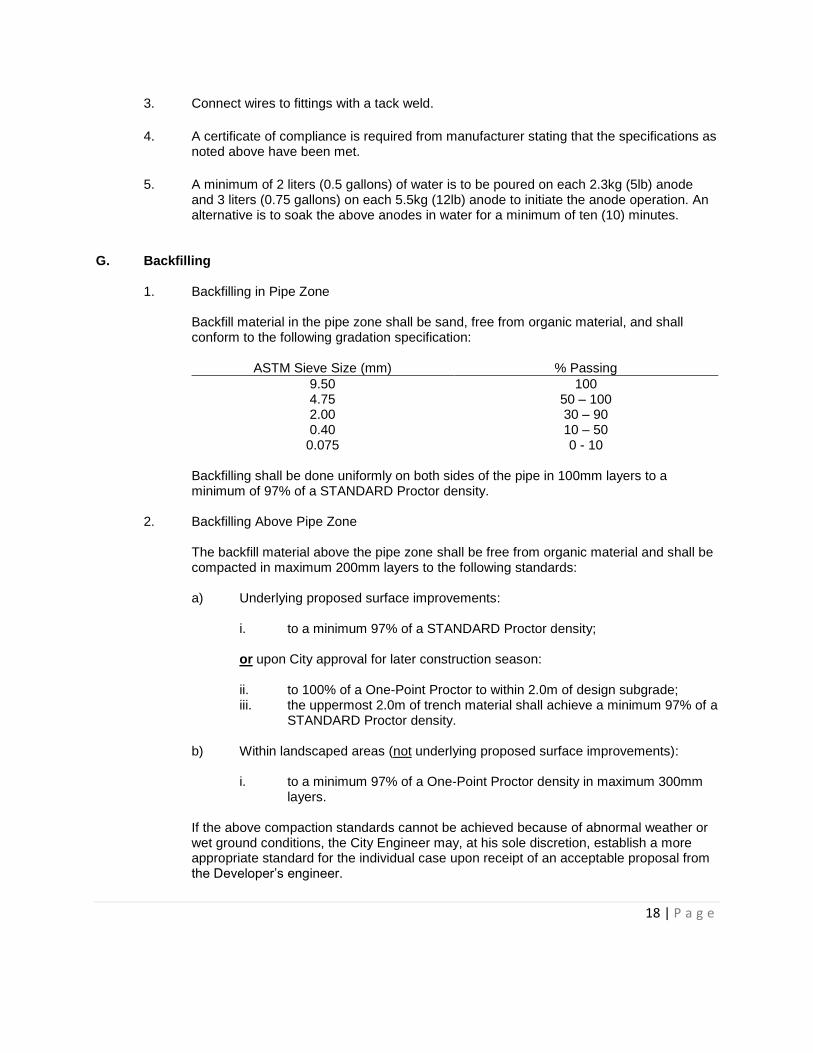
G. Backfilling
1. Backfilling in Pipe Zone
Backfill material in the pipe zone shall be sand, free from organic material, and shall conform to the following gradation specification:
ASTM Sieve Size (mm) % Passing
9.50 100 4.75 50 – 100 2.00 30 – 90 0.40 10 – 50 0.075 0 - 10
Backfilling shall be done uniformly on both sides of the pipe in 100mm layers to a minimum of 97% of a STANDARD Proctor density.
2. Backfilling Above Pipe Zone
The backfill material above the pipe zone shall be free from organic material and shall be compacted in maximum 200mm layers to the following standards:
a) Underlying proposed surface improvements:
i. to a minimum 97% of a STANDARD Proctor density;
or upon City approval for later construction season:
ii. to 100% of a One-Point Proctor to within 2.0m of design subgrade; iii. the uppermost 2.0m of trench material shall achieve a minimum 97% of a
STANDARD Proctor density.
b) Within landscaped areas (not underlying proposed surface improvements): i. to a minimum 97% of a One-Point Proctor density in maximum 300mm
layers. If the above compaction standards cannot be achieved because of abnormal weather or wet ground conditions, the City Engineer may, at his sole discretion, establish a more appropriate standard for the individual case upon receipt of an acceptable proposal from the Developer’s engineer.
19 | P a g e
Compaction testing will be based on a minimum of one (1) density test per 150 lineal meters of trench for each 1.5m of depth. If a density test indicates insufficient compaction at any depth, then two (2) more densities, which are proportionally representative of the trench length, will be taken at that depth. Then if the average of the three (3) tests is below the required density, the area will be re-compacted to meet the specified density.
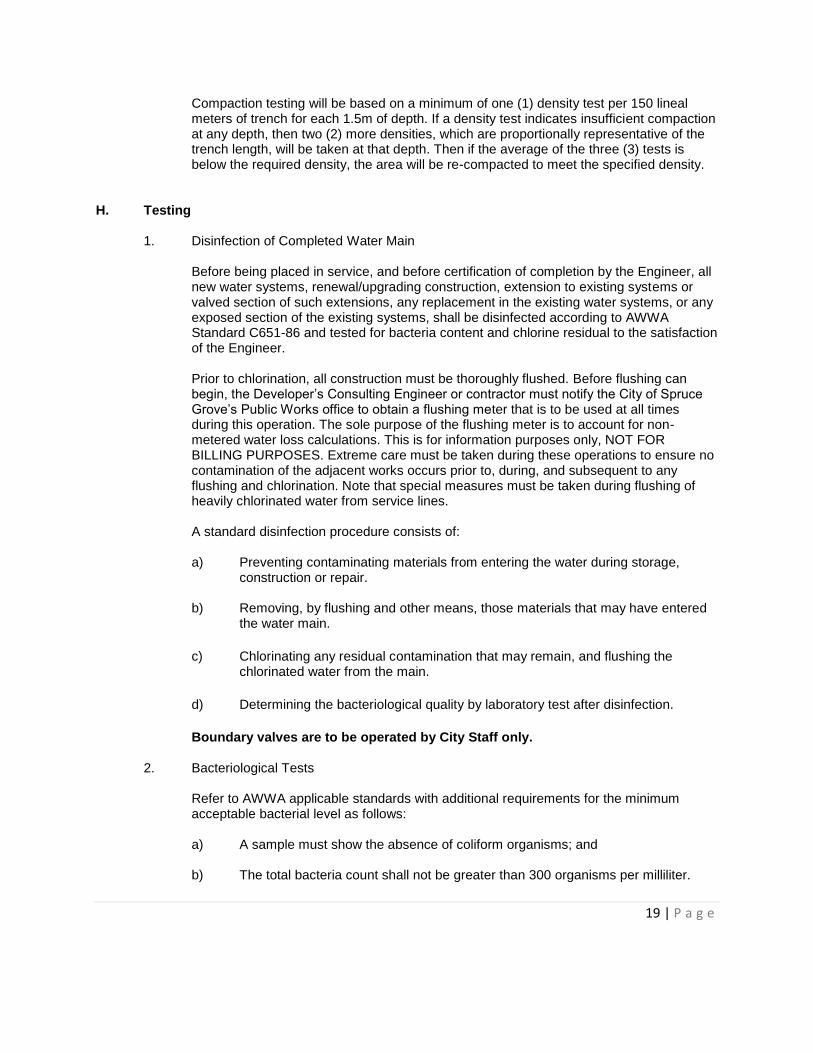
H. Testing
1. Disinfection of Completed Water Main
Before being placed in service, and before certification of completion by the Engineer, all new water systems, renewal/upgrading construction, extension to existing systems or valved section of such extensions, any replacement in the existing water systems, or any exposed section of the existing systems, shall be disinfected according to AWWA Standard C651-86 and tested for bacteria content and chlorine residual to the satisfaction of the Engineer. Prior to chlorination, all construction must be thoroughly flushed. Before flushing can begin, the Developer’s Consulting Engineer or contractor must notify the City of Spruce Grove’s Public Works office to obtain a flushing meter that is to be used at all times during this operation. The sole purpose of the flushing meter is to account for non-metered water loss calculations. This is for information purposes only, NOT FOR BILLING PURPOSES. Extreme care must be taken during these operations to ensure no contamination of the adjacent works occurs prior to, during, and subsequent to any flushing and chlorination. Note that special measures must be taken during flushing of heavily chlorinated water from service lines. A standard disinfection procedure consists of:
a) Preventing contaminating materials from entering the water during storage,
construction or repair.
b) Removing, by flushing and other means, those materials that may have entered the water main.
c) Chlorinating any residual contamination that may remain, and flushing the chlorinated water from the main.
d) Determining the bacteriological quality by laboratory test after disinfection.
Boundary valves are to be operated by City Staff only.
2. Bacteriological Tests Refer to AWWA applicable standards with additional requirements for the minimum acceptable bacterial level as follows:
a) A sample must show the absence of coliform organisms; and
b) The total bacteria count shall not be greater than 300 organisms per milliliter.
20 | P a g e
c) If 1 to 10 coliform organisms are detected in the initial sampling, then the site should be resampled. If the presence of coliforms is confirmed. The disinfection and bacteriological sampling cycle shall be repeated.
d) If there are 10 or more coliform organisms and/or the total bacteria count is greater than 300, the disinfection-bacteriological sampling cycle shall be repeated.
e) It shall be the responsibility of the Developer to ensure that water from newly constructed water mains will not be used for drinking or other domestic purposes until the mains have been disinfected, and samples have been taken and certified by an approved laboratory as being free from bacterial contamination.
3. Cross Connection/Back Flow Device
Back flow devices must be installed in all commercial, industrial, and institutional buildings to prevent the potential risk of contaminants entering the distribution system through back flow or back siphonage. All back flow devices must be tested and records maintained and submitted to the City Public Works department on an annual basis.
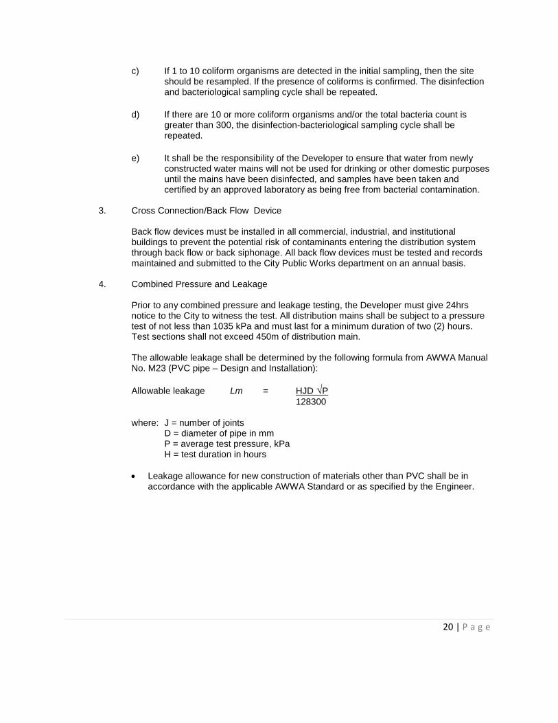
4. Combined Pressure and Leakage
Prior to any combined pressure and leakage testing, the Developer must give 24hrs notice to the City to witness the test. All distribution mains shall be subject to a pressure test of not less than 1035 kPa and must last for a minimum duration of two (2) hours. Test sections shall not exceed 450m of distribution main. The allowable leakage shall be determined by the following formula from AWWA Manual No. M23 (PVC pipe – Design and Installation):
Allowable leakage Lm = HJD √P
128300 where: J = number of joints D = diameter of pipe in mm P = average test pressure, kPa H = test duration in hours
Leakage allowance for new construction of materials other than PVC shall be in accordance with the applicable AWWA Standard or as specified by the Engineer.
21 | P a g e
SECTION IV – SANITARY SEWER & ACCESSORIES The sanitary sewer collection system in a new development shall conform to the City of Spruce Grove’s “Sanitary Sewer Master Plan (2012)” June 2013 as well as all subsequent amendments. The minimum size of the main shall be 200mm diameter. A. Mains and Design
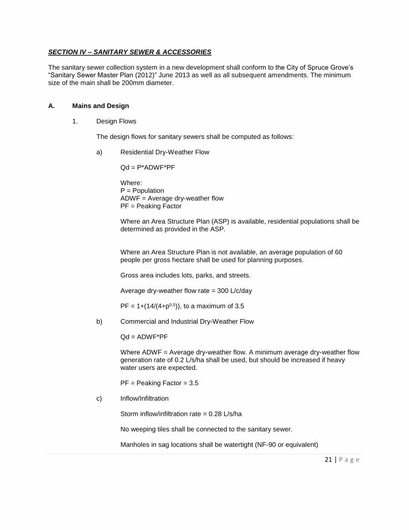
1. Design Flows
The design flows for sanitary sewers shall be computed as follows: a) Residential Dry-Weather Flow
Qd = P*ADWF*PF Where: P = Population ADWF = Average dry-weather flow PF = Peaking Factor Where an Area Structure Plan (ASP) is available, residential populations shall be determined as provided in the ASP. Where an Area Structure Plan is not available, an average population of 60 people per gross hectare shall be used for planning purposes. Gross area includes lots, parks, and streets. Average dry-weather flow rate = 300 L/c/day PF = 1+(14/(4+p0.5)), to a maximum of 3.5
b) Commercial and Industrial Dry-Weather Flow Qd = ADWF*PF Where ADWF = Average dry-weather flow. A minimum average dry-weather flow generation rate of 0.2 L/s/ha shall be used, but should be increased if heavy water users are expected. PF = Peaking Factor = 3.5
c) Inflow/Infiltration Storm inflow/infiltration rate = 0.28 L/s/ha No weeping tiles shall be connected to the sanitary sewer. Manholes in sag locations shall be watertight (NF-90 or equivalent)
22 | P a g e
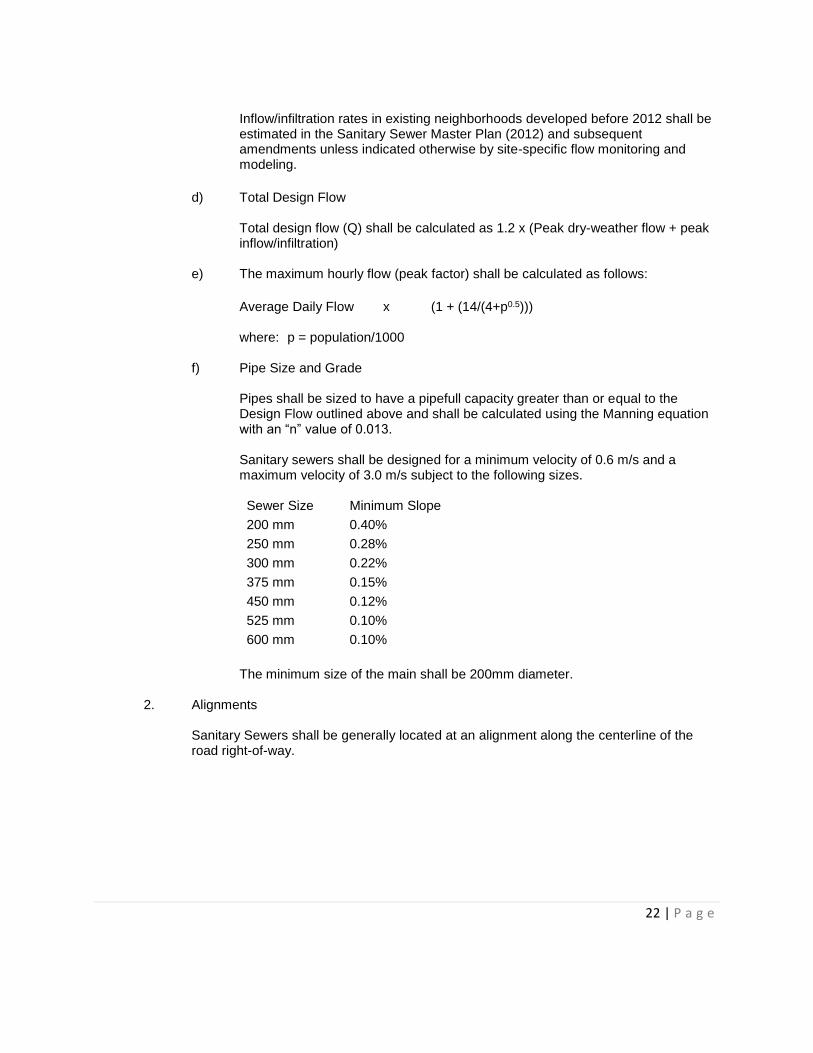
Inflow/infiltration rates in existing neighborhoods developed before 2012 shall be estimated in the Sanitary Sewer Master Plan (2012) and subsequent amendments unless indicated otherwise by site-specific flow monitoring and modeling.
d) Total Design Flow Total design flow (Q) shall be calculated as 1.2 x (Peak dry-weather flow + peak inflow/infiltration)
e) The maximum hourly flow (peak factor) shall be calculated as follows:
Average Daily Flow x (1 + (14/(4+p0.5)))
where: p = population/1000
f) Pipe Size and Grade Pipes shall be sized to have a pipefull capacity greater than or equal to the Design Flow outlined above and shall be calculated using the Manning equation with an “n” value of 0.013. Sanitary sewers shall be designed for a minimum velocity of 0.6 m/s and a maximum velocity of 3.0 m/s subject to the following sizes. Sewer Size Minimum Slope
200 mm 0.40%
250 mm 0.28%
300 mm 0.22%
375 mm 0.15%
450 mm 0.12%
525 mm 0.10%
600 mm 0.10%
The minimum size of the main shall be 200mm diameter.
2. Alignments
Sanitary Sewers shall be generally located at an alignment along the centerline of the road right-of-way.
23 | P a g e
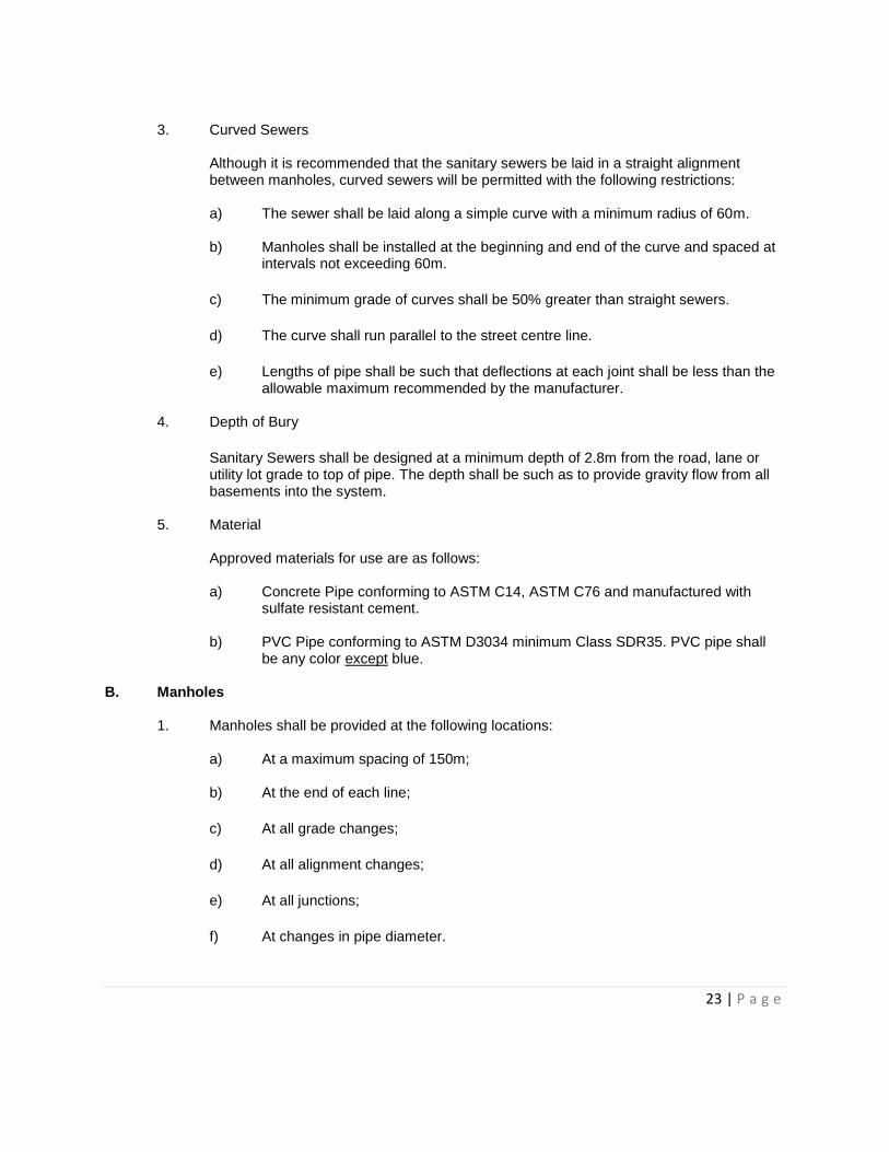
3. Curved Sewers
Although it is recommended that the sanitary sewers be laid in a straight alignment between manholes, curved sewers will be permitted with the following restrictions: a) The sewer shall be laid along a simple curve with a minimum radius of 60m.
b) Manholes shall be installed at the beginning and end of the curve and spaced at
intervals not exceeding 60m.
c) The minimum grade of curves shall be 50% greater than straight sewers.
d) The curve shall run parallel to the street centre line.
e) Lengths of pipe shall be such that deflections at each joint shall be less than the allowable maximum recommended by the manufacturer.
4. Depth of Bury
Sanitary Sewers shall be designed at a minimum depth of 2.8m from the road, lane or utility lot grade to top of pipe. The depth shall be such as to provide gravity flow from all basements into the system.
5. Material
Approved materials for use are as follows: a) Concrete Pipe conforming to ASTM C14, ASTM C76 and manufactured with
sulfate resistant cement.
b) PVC Pipe conforming to ASTM D3034 minimum Class SDR35. PVC pipe shall be any color except blue.
B. Manholes 1. Manholes shall be provided at the following locations:
a) At a maximum spacing of 150m;
b) At the end of each line;
c) At all grade changes;
d) At all alignment changes;
e) At all junctions;
f) At changes in pipe diameter.

24 | P a g e
2. Drop Manholes An interior drop manhole is required when the difference in elevation between the incoming and outgoing inverts is greater than 600mm and the incoming pipe diameter is 300mm or less. (See Detail SY-02 or SY-03)
3. Sampling Manholes Sampling manholes are required on all industrial, commercial and institutional sites; multi-family parcels and condominium developments to the satisfaction of the City Engineer. Multi-family is defined as residential development containing three (3) or more dwellings contained on one site. Condominium development is defined as a group of housing units where individual owners have full certificate of title to the unit along with an undivided interest in the common property serving the development.
4. Types of Manholes a) Standard 1200mm diameter precast manhole shall be used. (Detail SY-01)
b) Precast manhole vaults may be used if approved by the City Engineer.
c) All Sanitary manholes shall be supplied with the TF/NF-80 frame and cover. Single hole in manhole cover shall be plugged in all low areas or potential ponding areas. (see Detail SY-05)
C. Backfilling
See Section III.G
SECTION V – STORM SEWER & ACCESSORIES A. Mains and Design
1. The design formula for storm run-off shall be:
Q = CIA 360 where: Q = Discharge in m3 per second C = Runoff coefficient A = Area in hectares I = Intensity of rainfall
2. Intensity of Rainfall
The intensity of rainfall shall be determined by the Five-Year Intensity Chart on the IDF curves for the Edmonton Municipal Airport.
25 | P a g e
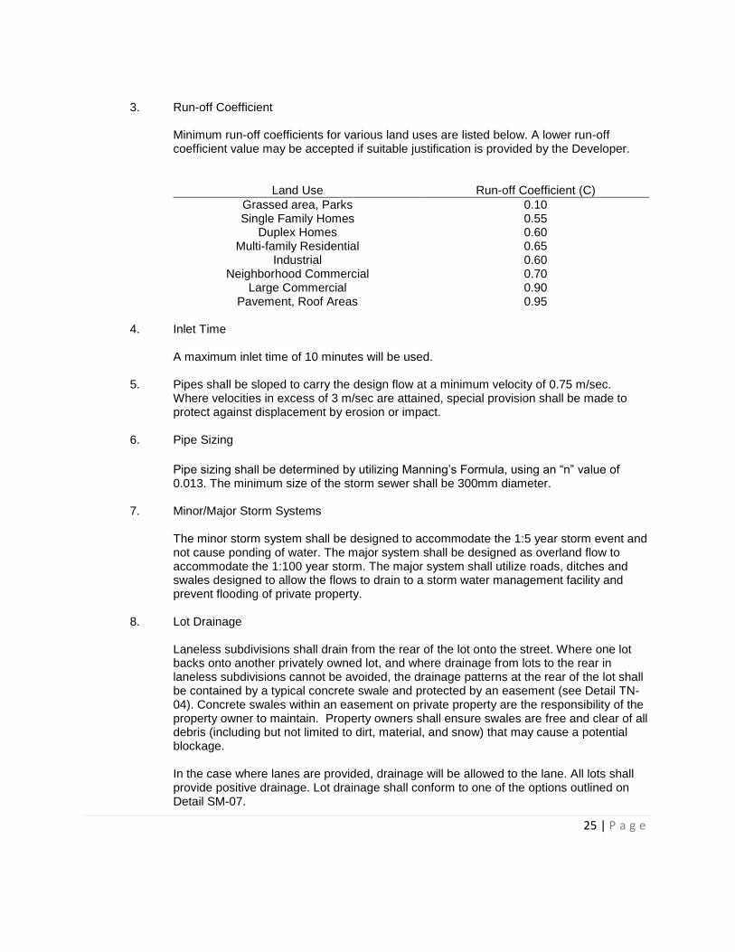
3. Run-off Coefficient
Minimum run-off coefficients for various land uses are listed below. A lower run-off coefficient value may be accepted if suitable justification is provided by the Developer.
Land Use Run-off Coefficient (C)
Grassed area, Parks 0.10 Single Family Homes 0.55
Duplex Homes 0.60 Multi-family Residential 0.65
Industrial 0.60 Neighborhood Commercial 0.70
Large Commercial 0.90 Pavement, Roof Areas 0.95
4. Inlet Time
A maximum inlet time of 10 minutes will be used.
5. Pipes shall be sloped to carry the design flow at a minimum velocity of 0.75 m/sec. Where velocities in excess of 3 m/sec are attained, special provision shall be made to protect against displacement by erosion or impact.
6. Pipe Sizing
Pipe sizing shall be determined by utilizing Manning’s Formula, using an “n” value of 0.013. The minimum size of the storm sewer shall be 300mm diameter.
7. Minor/Major Storm Systems The minor storm system shall be designed to accommodate the 1:5 year storm event and not cause ponding of water. The major system shall be designed as overland flow to accommodate the 1:100 year storm. The major system shall utilize roads, ditches and swales designed to allow the flows to drain to a storm water management facility and prevent flooding of private property.
8. Lot Drainage Laneless subdivisions shall drain from the rear of the lot onto the street. Where one lot backs onto another privately owned lot, and where drainage from lots to the rear in laneless subdivisions cannot be avoided, the drainage patterns at the rear of the lot shall be contained by a typical concrete swale and protected by an easement (see Detail TN-04). Concrete swales within an easement on private property are the responsibility of the property owner to maintain. Property owners shall ensure swales are free and clear of all debris (including but not limited to dirt, material, and snow) that may cause a potential blockage. In the case where lanes are provided, drainage will be allowed to the lane. All lots shall provide positive drainage. Lot drainage shall conform to one of the options outlined on Detail SM-07.
26 | P a g e
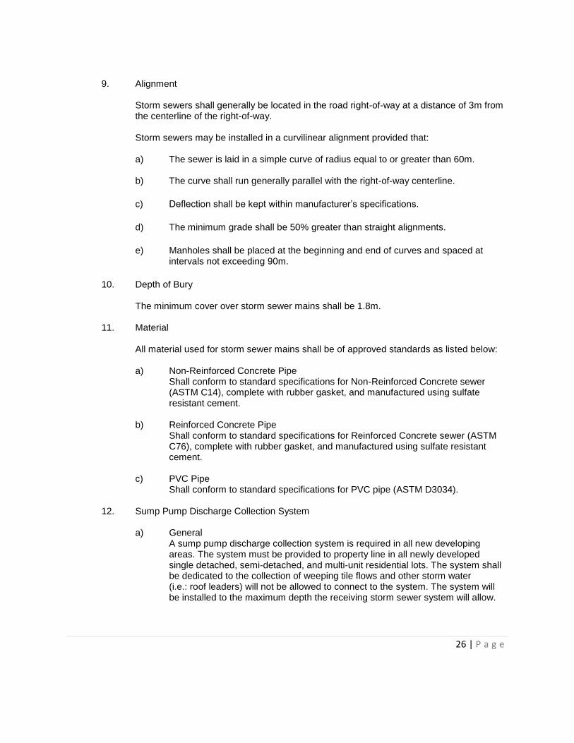
9. Alignment
Storm sewers shall generally be located in the road right-of-way at a distance of 3m from the centerline of the right-of-way. Storm sewers may be installed in a curvilinear alignment provided that: a) The sewer is laid in a simple curve of radius equal to or greater than 60m.
b) The curve shall run generally parallel with the right-of-way centerline.
c) Deflection shall be kept within manufacturer’s specifications.
d) The minimum grade shall be 50% greater than straight alignments.
e) Manholes shall be placed at the beginning and end of curves and spaced at intervals not exceeding 90m.
10. Depth of Bury The minimum cover over storm sewer mains shall be 1.8m.
11. Material All material used for storm sewer mains shall be of approved standards as listed below: a) Non-Reinforced Concrete Pipe
Shall conform to standard specifications for Non-Reinforced Concrete sewer (ASTM C14), complete with rubber gasket, and manufactured using sulfate resistant cement.
b) Reinforced Concrete Pipe Shall conform to standard specifications for Reinforced Concrete sewer (ASTM C76), complete with rubber gasket, and manufactured using sulfate resistant cement.
c) PVC Pipe Shall conform to standard specifications for PVC pipe (ASTM D3034).
12. Sump Pump Discharge Collection System
a) General
A sump pump discharge collection system is required in all new developing areas. The system must be provided to property line in all newly developed single detached, semi-detached, and multi-unit residential lots. The system shall be dedicated to the collection of weeping tile flows and other storm water (i.e.: roof leaders) will not be allowed to connect to the system. The system will be installed to the maximum depth the receiving storm sewer system will allow.
27 | P a g e
b) Alignment The system will be installed 0.6m within the road right-of-way and will be connected to a catchbasin or storm manhole. Cleanouts will be installed at a maximum spacing of 100m.
c) Sizing and Material Minimum pipe size and grade: 150mm – 0.6% Service connection minimum size and grade: 100mm – 2.0% Material to be PVC SDR35
d) Clean outs The criteria for clean out or manhole locations in the storm sewer service.
B. Manholes
1. Manhole Location
Manholes shall be provided at the following locations: a) at a maximum spacing of 150m for all mains;
b) special study required to determine optimum spacing for mains 1500mm and
above;
c) at changes in pipe diameter;
d) at grade changes;
e) at alignment changes;
f) at the end of each line.
The maximum spacing of storm sewer manholes may be required to be reduced by 50% on curvilinear alignments. All manholes shall be supplied with the TF/NF-80 floating frame and cover. (see Detail SM-06)
2. Types of Manholes a) Standard 1200mm diameter precast manholes shall be used on mains 600mm in
diameter or less, as shown on Detail SM-01.
b) A “Perched” manhole shall be used on mains 625mm to 1050mm in diameter, as shown on Detail SM-02.
c) A “T-Riser” manhole shall be used on mains 1200mm in diameter and larger, providing that there is no deflection in alignment or change in grade. (see Detail SM-03)
The City Engineer must approve all precast manhole vaults.
28 | P a g e
3. StormCeptor Manholes
StormCeptor manholes are to be installed where required by the City to protect storm water quality.
C. Catchbasins
1. Catchbasins
Surface drainage shall not run a distance greater than 150m in streets or 200m in lanes, utility Lots and Walkways. Catchbasins shall be set back from intersections and shall not conflict with future driveways. Catchbasins will be required at the end of concrete swales, as deemed necessary by the City Engineer, to avoid surface drainage across walkways and/or trails.
2. Catchbasin Leads Catchbasin leads shall connect directly to manholes. Single catchbasins require 250mm diameter leads and twinned catchbasins require a common 300mm lead. All leads shall have a minimum 2% grade. The length of a catchbasin lead shall not exceed 30m. Catchbasin leads shall be concrete or PVC (SDR35) within local and collector residential roads.
3. Twinned Catchbasins If a twinned catchbasin is required to drain an area, the twinned unit shall consist of a catchbasin and a catchbasin manhole interconnected by means of a 250mm pipe. The lead from the catchbasin manhole to the mainline manhole shall be 300mm diameter and have a minimum grade of 2%.
4. Types of Catchbasins and Catchbasin Manholes All catchbasins shall be built with a 900mm barrel. (see Detail SM-04) Catchbasin manholes shall be built with a 1200mm barrel. (see Detail SM-05) All catchbasin rings must have the same alignment as the barrel. No staggering or stepping of rings allowed. The following is a list of accepted catchbasin frames and covers. Other catchbasin assemblies may be used upon approval by the City Engineer.
F-39 DK-7 F-51 with side inlet K-7
F-36 (1 piece) F-38
29 | P a g e
D. Storm Water Management Facilities
1. Design
The Storm Water Management Facility (SWMF) shall be designed to contain runoff in excess of predevelopment rates on a temporary basis. Predevelopment rates shall be used as follows: a) 1.8 l/sec/ha for the area draining into Dog Creek south of Highway 16A;
b) 2.5 l/sec/ha for all other areas.
SWMF shall be designed and constructed for water quality to reduce the Total Suspended Solids (TTS) to at least 85% for a particle size of 75µm.
2. Dry Ponds
a) Should only be used when topological or planning constraints exist that limit the
use of wet ponds or wetlands.
b) Should only be used when downstream water quality system is in place.
c) Designed to store the 1:100 runoff event to predevelopment flow rates.
d) Maximum active retention storage depth of 1.5m.
e) Maximum water level should be below the adjacent footing levels.
f) Maximum slopes of 4:1.
g) Minimum freeboard of 0.6m.
h) Minimum bottom of pond slope of 1%.
i) Must be landscaped and constructed to restrict erosion.
30 | P a g e
3. Wet Ponds a) Designed to store the 1:100 runoff event to predevelopment flow rates.
b) Maximum slope above active storage zone is 4:1.
c) Maximum slope in active storage zone is 5:1.
d) Minimum permanent pool depth of 2.0m.
e) Maximum active detention storage depth of 2.0m. The maximum water level should be above the adjacent footing levels.
f) May require downstream water quality system. The establishment of vegetative zones in and around a wet pond can enhance the pollutant removal capacity.
g) Must be landscaped in accordance to Section IX.B.
h) Warning signs must be posted on the perimeter of wet ponds to prohibit activities that may present a danger to public health and safety or interfere with the operation of the facility.
4. Constructed Wetlands a) Designed to store the 1:100 runoff event to predevelopment flow rates.
b) Maximum slope above active storage zone is 4:1.
c) Approximately 10% of the wetland surface area should be a 1.5m – 20.0m deep
forebay upstream of the wetland area for settleable solids removal.
d) Average active water depth of 0.3m with 1.0m deep zones for flow redistribution.
e) Bottom slope of 1%.
f) Maximum active pool depth of 1.5m. The maximum water level should be above the adjacent footing levels.
g) Must be landscaped in accordance with Section IX.B.
h) Warning signs must be posted on the perimeter of wetlands to prohibit activities that may present a danger to public health and safety or interfere with the operation of the facility.
31 | P a g e
E. Storm Water on Private Development Storm water management shall be practiced on all commercial/industrial/institutional/multi-family sites as required. Each site shall be evaluated and discharges to existing SWMF shall be to the approval of the City Engineer.
F. Backfilling
See Section III.G
SECTION VI – SERVICE CONNECTIONS Service connections shall be placed as illustrated in Details SE-01 to SE-04. The minimum size of service for single-family detached, semi-detached and street oriented row housing units shall be as follows: Water 20mm diameter Sanitary 100mm diameter A. General
1. Services larger than those indicated will be required when, in the opinion of the Engineer,
the length of service pipe or other conditions warrants.
2. The size and location of services to non-residential, row housing developments and multi-unit residential buildings shall be subject to the approval of the Engineer.
3. Each single-family detached, semi-detached and street oriented row housing units must have a separate service.
a) Depth of Bury Service lines shall be designed to have a minimum depth of bury from invert of service to finished grade of 2.6m.
b) Alignment The sanitary, storm and water services shall be laid in a single trench to the alignments shown in Details SE-01 and SE-02.
B. Water Service Connections
1. General
Wherever possible, tap main under pressure. Service connections shall be tapped into the upper portion of the water main at a minimum angle of 45° from horizontal. Tappings shall have a minimum spacing of 600mm. Use tapping machine to tap and thread CC into
32 | P a g e
the main. Use special care to prevent cuttings from falling into the main. Lay copper service on 75mm of clean inorganic sand to the designated location of the curb stop. Attach curb stop and set service box to grade. Brace boxes securely to keep plumb during backfilling. Test for operation both before and after pressure test. A 5.5kg zinc anode shall be clamped to the service line and CC consistent with Detail SE-03. Maximum size of tapping without utilizing service clamps shall be: 20mm tap on a 150mm Main 25mm tap on a 200mm Main
2. Materials a) Copper Tubing
i. Wolverine type K, ASTM B88 or approved equivalent
b) Main Stops i. Cambridge Brass 102-A1H1, 102-A3H3, 102-A4H4, 105-A5H5, 102-
A7H7; ii. Ford F1000-3 for 20mm and F1000-4 for 25mm; iii. Mueller H-15008
c) Curb Stops
i. Cambridge Brass 203-H3H3, 203-H4H4, 203-H5H5, 203-H6H6, 203-H7H7;
ii. Ford B44-333SW for 20mm and B44-444SW for 25mm; iii. Mueller, Oriseal Mark II B-25219F All curb stops to be epoxy coated with stainless steel rods.
d) Service Saddles
40mm and 50mm only, bronze body with stainless steel straps i. Robar #2706 ii. Romac #202BS
e) Material for Water Service
150mm and larger shall be PVC in accordance with AWWA C-900
f) CC Chairs To suit curb stop manufacturer 20mm – 50mm
g) Service Clamps Required where main stop exceeds 20mm (for 100mm to 150mm diameter mains) and 25mm (for 200mm to 400mm diameter mains). To be made from stainless steel.
33 | P a g e
C. Sanitary Service Connections 1. General
Connect services to mains with manufactured tee or wye fitting placed in mains or by cutting into mains and installing manufactured tee saddles. Take care to avoid cracking the main and remove all cuttings from main. Secure joint between saddle and main with mortar or other means acceptable to the Engineer. Install service line at a uniform gradient as specified on a minimum of 75mm clean, inorganic sand. Support service lines adequately to prevent dislocation, buckling or settlement. Where water lines must be laid below sewer lines, ensure backfill over the water line is a minimum of 97% Standard Proctor density to prevent settlements. When a connection cannot be made directly into the house, plug the end of the sewer service to prevent entry of water and dirt. Services being tied directly into manholes cannot go through ladder rungs. Services must be aligned to avoid conflict with manhole ladder.
Bends in the sewer service are permitted at these locations only: a) 45° bend with wye or 22.5° bend with tee connector at main.
b) 45° bend at top of riser.
c) 22.5° maximum bend at property line for house service connection.
2. Risers Where services are required to connect to mains in excess of 4.25m deep, install risers and properly plug in accordance with Drawing SY-04. Firmly support risers and anchor to the trench wall to minimize the possibility of damage to the riser during backfilling operations.
3. Materials Sewer service shall be PVC SDR35 conforming to CSA Specifications B182.1, or the latest revision thereof.
4. Backfill See Section III.G
D. Shallow Utility Services The City requires a minimum separation of 1.5m between power and any water/sanitary services.
34 | P a g e
SECTION VII – ROADS & LANES A. Classification and Design
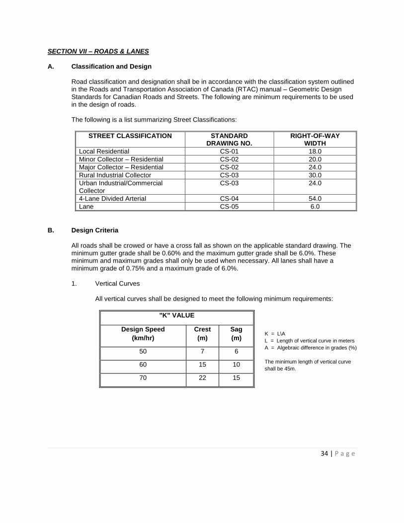
Road classification and designation shall be in accordance with the classification system outlined in the Roads and Transportation Association of Canada (RTAC) manual – Geometric Design Standards for Canadian Roads and Streets. The following are minimum requirements to be used in the design of roads. The following is a list summarizing Street Classifications:
STREET CLASSIFICATION
STANDARD DRAWING NO.
RIGHT-OF-WAY WIDTH
Local Residential CS-01 18.0
Minor Collector – Residential CS-02 20.0
Major Collector – Residential CS-02 24.0
Rural Industrial Collector CS-03 30.0
Urban Industrial/Commercial Collector
CS-03 24.0
4-Lane Divided Arterial CS-04 54.0
Lane CS-05 6.0
B. Design Criteria All roads shall be crowed or have a cross fall as shown on the applicable standard drawing. The minimum gutter grade shall be 0.60% and the maximum gutter grade shall be 6.0%. These minimum and maximum grades shall only be used when necessary. All lanes shall have a minimum grade of 0.75% and a maximum grade of 6.0%. 1. Vertical Curves
All vertical curves shall be designed to meet the following minimum requirements:
"K" VALUE
Design Speed
(km/hr)
Crest
(m)
Sag
(m)
50 7 6
60 15 10
70 22 15
K = L\A
L = Length of vertical curve in meters
A = Algebraic difference in grades (%)
The minimum length of vertical curve
shall be 45m.
35 | P a g e
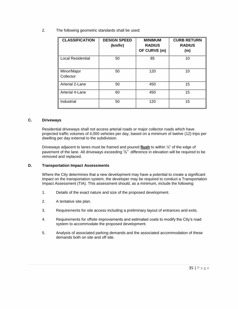
2. The following geometric standards shall be used:
CLASSIFICATION DESIGN SPEED
(km/hr)
MINIMUM
RADIUS
OF CURVE (m)
CURB RETURN
RADIUS
(m)
Local Residential 50 85 10
Minor/Major
Collector
50 120 10
Arterial 2-Lane 50 450 15
Arterial 4-Lane 60 450 15
Industrial 50 120 15
C. Driveways
Residential driveways shall not access arterial roads or major collector roads which have projected traffic volumes of 4,000 vehicles per day, based on a minimum of twelve (12) trips per dwelling per day external to the subdivision. Driveways adjacent to lanes must be framed and poured flush to within ¼” of the edge of
pavement of the lane. All driveways exceeding ½” difference in elevation will be required to be removed and replaced.
D. Transportation Impact Assessments Where the City determines that a new development may have a potential to create a significant impact on the transportation system, the developer may be required to conduct a Transportation Impact Assessment (TIA). This assessment should, as a minimum, include the following: 1. Details of the exact nature and size of the proposed development.
2. A tentative site plan.
3. Requirements for site access including a preliminary layout of entrances and exits.
4. Requirements for offsite improvements and estimated costs to modify the City’s road
system to accommodate the proposed development.
5. Analysis of associated parking demands and the associated accommodation of these demands both on site and off site.
36 | P a g e
E. Cul-de-Sacs
The normal maximum length of a cul-de-sac is 120m. Cul-de-sacs exceeding 120m and less than 170m will require an additional fire hydrant. Where cul-de-sacs exceed 170m, a provision must be made for a 6m public utility lot for emergency access and water looping at the end of the cul-de-sac. Cul-de-sac islands are not permitted.
F. Sidewalks, Curb and Gutters 1. Walkability Plan
Developer will submit to the Engineer a Walkability Plan for the subdivision area. Sidewalks, curb and gutters shall be installed according to the Walkability Plan, the standard drawings, and to approved grades and cross-sections. Sidewalks are not required in cul-de-sacs with less than 10 lots.
The Walkability Plan should include the need for sidewalks on both sides of local residential streets as follows:
a) Where, in the opinion of the Engineer, residential densities require sidewalks on
both sides for capacity and/or safety;
b) Where, in the opinion of the Engineer, local residential streets provide logical pedestrian linkages to amenities such as, but not limited to, schools, parks, natural areas, transit stops, and commercial areas.
2. Materials
The concrete for sidewalks, curb and gutters shall meet the following requirements: Minimum Compressive Strength (at 28 days) 30.0 mPa Maximum Size of Course Aggregate 25mm Slump 25-75mm Entrained Air Content 5.5% – 8% After October 1st, the concrete shall reach 30mPa in seven (7) days. All materials and admixtures used in the construction of the sidewalks, curb and gutters shall conform to applicable CSA and ASTM standards and specifications. Curing compound shall be placed on the concrete. It shall be a resin base, impervious membrane and shall conform to ASTM C309 Type I. It shall be sufficiently free from permanent color to result in no profound change in color than that of natural concrete.
3. Placing of Concrete All subgrade shall be cement modified using a minimum of 10 kilograms of Portland cement per square meter per 150mm of compacted depth. The subgrade shall be compacted to 100% Standard Proctor density. For separate sidewalks only, the top

37 | P a g e
150mm of subgrade shall be compacted to 98% Standard Proctor density, at a moisture content not more than three percent (3%) greater, or one percent (1%) under, the optimum moisture content. The requirement for cement is to be determined by a geotechnical engineer at the time of construction. The subgrade shall be free from any deflection under heavy loading. (See Section VII.E.2 – “Proof Rolling of Subgrade”) Prior to placing any concrete, a minimum of 150mm of 20mm granular base course shall be placed and compacted to a minimum of 100% Standard Proctor density on the prepared subgrade. The concrete shall be vibrated into place according to the standard drawing cross-sections. Backfilling behind the sidewalks, curb, and gutters shall be done soon after placement of the concrete. It shall be done carefully as not to damage the concrete. Heavy equipment used for road construction shall not be used near the concrete for a period of seven (7) days or until the concrete has reached a compressive strength of 70% of the specified 28-day strength.
4. Testing Compaction testing of the subgrade shall be done a minimum of one (1) field density test per 100 linear metres of subgrade. Additional testing may be required at the direction of the Engineer. Concrete testing (including slump, air content, temperature, and compressive strength cylinders) shall be made for a minimum of one (1) test per each 50m3 of concrete placed and a minimum of one (1) complete test for each day of placing. All testing shall conform to applicable CSA and ASTM standards and specifications.
G. Roadway Construction
1. Common Excavation/Subgrade Preparation
All subgrade shall be cement modified using a minimum of 10 kilograms of Portland cement per square meter per 150mm of compacted depth. The subgrade shall be prepared for the entire width of the carriageway, plus the full width of the curb and gutter, or monolithic curb, gutter and sidewalk, to 150mm back of curb or monolithic sidewalk. The top 150mm of subgrade shall be compacted to 100% of Standard Proctor density or in accordance with the recommended density as per the Geotechnical Report, at a moisture content not more than three percent (3%) greater, or one percent (1%) under, the optimum moisture content.
2. Proof Rolling of Subgrade Proof rolling or load testing shall be performed on the subgrade after compaction testing is completed and approved to help detect isolated unstable areas. The City of Spruce Grove shall be given sufficient notice of the date and time of the proof roll test so that a representative from the City may witness the test. The following procedures shall be followed:
38 | P a g e
a) Proof roll the entire surface with as many passes as necessary, by slowly driving
a fully loaded tandem truck or equivalent over the area.
b) The Consulting Engineer, the contractor and the City shall closely observe this operation and mark out areas where weakness is indicated.
c) Weak areas shall receive additional compacting effort or be replaced with
suitable material until satisfactory results are achieved.
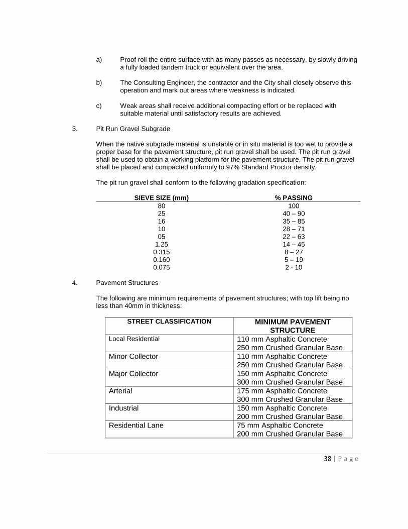
3. Pit Run Gravel Subgrade When the native subgrade material is unstable or in situ material is too wet to provide a proper base for the pavement structure, pit run gravel shall be used. The pit run gravel shall be used to obtain a working platform for the pavement structure. The pit run gravel shall be placed and compacted uniformly to 97% Standard Proctor density. The pit run gravel shall conform to the following gradation specification:
SIEVE SIZE (mm) % PASSING
80 100 25 40 – 90 16 35 – 85 10 28 – 71 05 22 – 63
1.25 14 – 45 0.315 8 – 27 0.160 5 – 19 0.075 2 - 10
4. Pavement Structures
The following are minimum requirements of pavement structures; with top lift being no less than 40mm in thickness:
STREET CLASSIFICATION MINIMUM PAVEMENT STRUCTURE
Local Residential
110 mm Asphaltic Concrete 250 mm Crushed Granular Base
Minor Collector
110 mm Asphaltic Concrete 250 mm Crushed Granular Base
Major Collector
150 mm Asphaltic Concrete 300 mm Crushed Granular Base
Arterial
175 mm Asphaltic Concrete 300 mm Crushed Granular Base
Industrial
150 mm Asphaltic Concrete 200 mm Crushed Granular Base
Residential Lane
75 mm Asphaltic Concrete 200 mm Crushed Granular Base
39 | P a g e
A geotechnical investigation shall be conducted on each project to identify site-specific conditions. The report shall confirm or upgrade the previously listed minimum pavement structures.
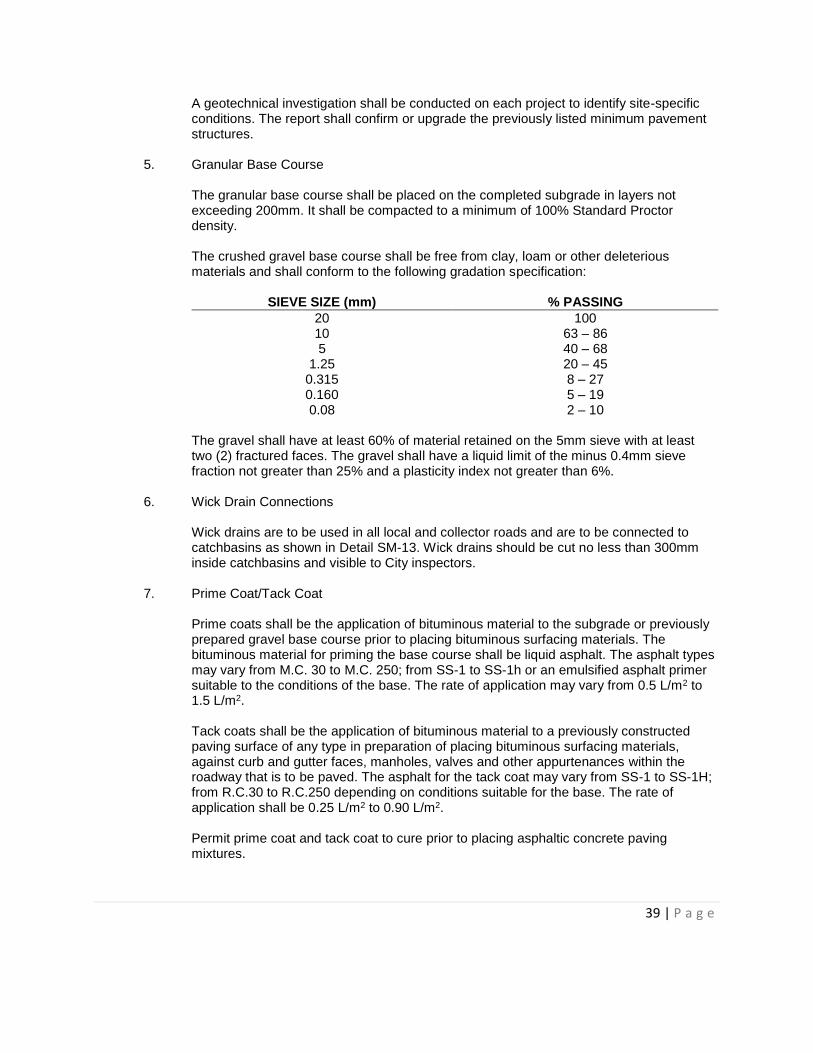
5. Granular Base Course The granular base course shall be placed on the completed subgrade in layers not exceeding 200mm. It shall be compacted to a minimum of 100% Standard Proctor density. The crushed gravel base course shall be free from clay, loam or other deleterious materials and shall conform to the following gradation specification:
SIEVE SIZE (mm) % PASSING
20 100 10 63 – 86 5 40 – 68
1.25 20 – 45 0.315 8 – 27 0.160 5 – 19 0.08 2 – 10
The gravel shall have at least 60% of material retained on the 5mm sieve with at least two (2) fractured faces. The gravel shall have a liquid limit of the minus 0.4mm sieve fraction not greater than 25% and a plasticity index not greater than 6%.
6. Wick Drain Connections
Wick drains are to be used in all local and collector roads and are to be connected to catchbasins as shown in Detail SM-13. Wick drains should be cut no less than 300mm inside catchbasins and visible to City inspectors.
7. Prime Coat/Tack Coat Prime coats shall be the application of bituminous material to the subgrade or previously prepared gravel base course prior to placing bituminous surfacing materials. The bituminous material for priming the base course shall be liquid asphalt. The asphalt types may vary from M.C. 30 to M.C. 250; from SS-1 to SS-1h or an emulsified asphalt primer suitable to the conditions of the base. The rate of application may vary from 0.5 L/m2 to 1.5 L/m2. Tack coats shall be the application of bituminous material to a previously constructed paving surface of any type in preparation of placing bituminous surfacing materials, against curb and gutter faces, manholes, valves and other appurtenances within the roadway that is to be paved. The asphalt for the tack coat may vary from SS-1 to SS-1H; from R.C.30 to R.C.250 depending on conditions suitable for the base. The rate of application shall be 0.25 L/m2 to 0.90 L/m2. Permit prime coat and tack coat to cure prior to placing asphaltic concrete paving mixtures.
40 | P a g e
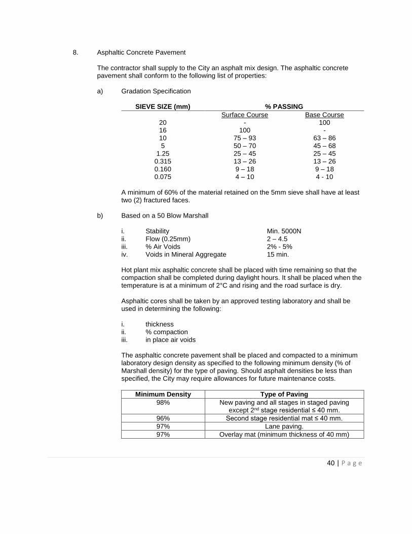
8. Asphaltic Concrete Pavement The contractor shall supply to the City an asphalt mix design. The asphaltic concrete pavement shall conform to the following list of properties: a) Gradation Specification
SIEVE SIZE (mm) % PASSING
Surface Course Base Course 20 - 100 16 100 - 10 75 – 93 63 – 86 5 50 – 70 45 – 68
1.25 25 – 45 25 – 45 0.315 13 – 26 13 – 26 0.160 9 – 18 9 – 18 0.075 4 – 10 4 - 10
A minimum of 60% of the material retained on the 5mm sieve shall have at least two (2) fractured faces.
b) Based on a 50 Blow Marshall i. Stability Min. 5000N ii. Flow (0.25mm) 2 – 4.5 iii. % Air Voids 2% - 5% iv. Voids in Mineral Aggregate 15 min. Hot plant mix asphaltic concrete shall be placed with time remaining so that the compaction shall be completed during daylight hours. It shall be placed when the temperature is at a minimum of 2°C and rising and the road surface is dry. Asphaltic cores shall be taken by an approved testing laboratory and shall be used in determining the following: i. thickness ii. % compaction iii. in place air voids The asphaltic concrete pavement shall be placed and compacted to a minimum laboratory design density as specified to the following minimum density (% of Marshall density) for the type of paving. Should asphalt densities be less than specified, the City may require allowances for future maintenance costs.
Minimum Density Type of Paving
98% New paving and all stages in staged paving except 2nd stage residential ≤ 40 mm.
96% Second stage residential mat ≤ 40 mm.
97% Lane paving.
97% Overlay mat (minimum thickness of 40 mm)
41 | P a g e
9. Testing Quality control testing shall be done during the road construction at the following minimum intervals: a) Subgrade preparation – field density one (1) test per 1000m2 b) Sub-base construction – field density one (1) test per 1000m2 c) Asphaltic concrete placement:
i. One (1) sample of asphalt for complete marshall testing including: oil
content, stability flow, air voids and VMA for each 2000m2 or a minimum of one (1) per day of placing.
ii. In place asphalt core testing for thickness, density and air voids at one (1) per 1000m2.
All testing shall be done in accordance with applicable CSA and ASTM standards and specifications.
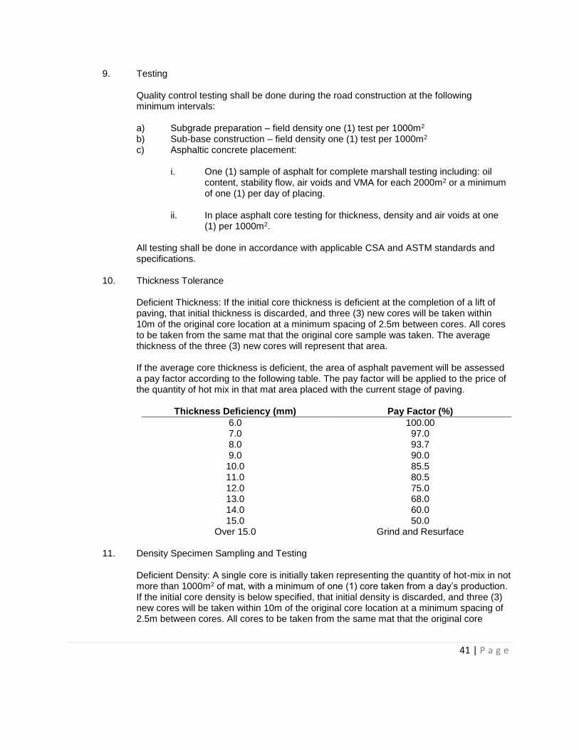
10. Thickness Tolerance Deficient Thickness: If the initial core thickness is deficient at the completion of a lift of paving, that initial thickness is discarded, and three (3) new cores will be taken within 10m of the original core location at a minimum spacing of 2.5m between cores. All cores to be taken from the same mat that the original core sample was taken. The average thickness of the three (3) new cores will represent that area. If the average core thickness is deficient, the area of asphalt pavement will be assessed a pay factor according to the following table. The pay factor will be applied to the price of the quantity of hot mix in that mat area placed with the current stage of paving.
Thickness Deficiency (mm) Pay Factor (%)
6.0 100.00 7.0 97.0 8.0 93.7 9.0 90.0 10.0 85.5 11.0 80.5 12.0 75.0 13.0 68.0 14.0 60.0 15.0 50.0
Over 15.0 Grind and Resurface
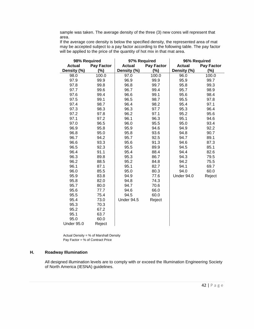
11. Density Specimen Sampling and Testing Deficient Density: A single core is initially taken representing the quantity of hot-mix in not more than 1000m2 of mat, with a minimum of one (1) core taken from a day’s production. If the initial core density is below specified, that initial density is discarded, and three (3) new cores will be taken within 10m of the original core location at a minimum spacing of 2.5m between cores. All cores to be taken from the same mat that the original core
42 | P a g e
sample was taken. The average density of the three (3) new cores will represent that area. If the average core density is below the specified density, the represented area of mat may be accepted subject to a pay factor according to the following table. The pay factor will be applied to the price of the quantity of hot mix in that mat area.
98% Required 97% Required 96% Required Actual
Density (%) Pay Factor
(%) Actual
Density (%) Pay Factor
(%) Actual
Density (%) Pay Factor
(%)
98.0 100.0 97.0 100.0 96.0 100.0 97.9 99.9 96.9 99.9 95.9 99.7 97.8 99.8 96.8 99.7 95.8 99.3 97.7 99.6 96.7 99.4 95.7 98.9 97.6 99.4 96.6 99.1 95.6 98.4 97.5 99.1 96.5 98.7 95.5 97.8 97.4 98.7 96.4 98.2 95.4 97.1 97.3 98.3 96.3 97.7 95.3 96.4 97.2 97.8 96.2 97.1 95.2 95.6 97.1 97.2 96.1 96.3 95.1 94.6 97.0 96.5 96.0 95.5 95.0 93.4 96.9 95.8 95.9 94.6 94.9 92.2 96.8 95.0 95.8 93.6 94.8 90.7 96.7 94.2 95.7 92.5 94.7 89.1 96.6 93.3 95.6 91.3 94.6 87.3 96.5 92.3 95.5 89.9 94.5 85.1 96.4 91.1 95.4 88.4 94.4 82.6 96.3 89.8 95.3 86.7 94.3 79.5 96.2 88.5 95.2 84.8 94.2 75.5 96.1 87.1 95.1 82.7 94.1 69.7 96.0 85.5 95.0 80.3 94.0 60.0 95.9 83.8 94.9 77.6 Under 94.0 Reject 95.8 82.0 94.8 74.3 95.7 80.0 94.7 70.6 95.6 77.7 94.6 66.0 95.5 75.4 94.5 60.0 95.4 73.0 Under 94.5 Reject 95.3 70.3 95.2 67.2 95.1 63.7 95.0 60.0
Under 95.0 Reject
H. Roadway Illumination All designed illumination levels are to comply with or exceed the Illumination Engineering Society of North America (IESNA) guidelines.
Actual Density = % of Marshall Density
Pay Factor = % of Contract Price
43 | P a g e
I. Traffic Control Signage All signage to be designed and installed in accordance with the Manual of Uniform Traffic Control Devices for Canada prepared by the Transportation Association of Canada. All traffic control and street identification signage must be in place prior to surface works Construction Completion Certificate (CCC) inspection. In the event that permanent signage cannot be installed prior to Construction Completion Certificate (CCC) inspection, temporary traffic control signage must be in place. Temporary signage must be to the satisfaction of the City Engineer.
J. Bus Stops Bus stops shall be installed, as required, in accordance with Details TN-13 and TN-14.
K. Canada Post/Community Mailbox Locations Developers to construct concrete bases for all Community Mailbox Locations to the satisfaction of Canada Post.
SECTION VIII – EROSION & SEDIMENTATION CONTROL An Erosion and Sedimentation Control (E&SC) plan is required to define all procedures intended to control such during both the construction and maintenance periods. The following shall be included in the E&SC plan:
1. Limits of soil disturbance.
2. Construction details (installation, inspection, and maintenance guidance notes and schematics) of all E&SC measures to be installed during the project.
3. The locations and dimensions of existing storm infrastructure onsite and for the
surrounding area (i.e. catchbasins, storm pipes, drainage swales, stormwater ponds).
4. Erosion control matting on slopes >3:1.
5. Protection of all storm sewer inlets.
6. Location and details of stabilized construction entrance to limit tracking of sediment offsite, complete with a designated concrete wash station constructed of impermeable material to limit soil contamination.
7. For each phase of construction, indicate which controls will be in place and when they will
be removed.
44 | P a g e
8. Long term stockpiles shall be clearly marked on the drawings. Protection measures for stockpiles shall be provided depending on locations and proximity of sediment transport to surrounding areas.
9. Details for implementation of landscaping and other practices, if required, for permanent site stabilization (i.e. erosion control blankets, turf reinforcement mats, seeding, sodding, retaining walls, riprap, and paving). The landscaping/permanent site stabilization drawing should also identify any temporary measures required to be installed, inspected, and maintained in the periods between project completion and final stabilization (identify the company/person responsible for inspection and maintenance during this period, as well as who is responsible of the removal of any other control measures).
10. The following notes should be added directly to the drawings:
a) Prior to construction start-up, it is mandatory for the project proponent or prime
contractor to schedule to pre-construction meeting to discuss scheduling, roles and responsibilities, stabilized entrances, temporary storage facilities, pollution and all existing and future E&SC practices to be implemented.
b) The following information must be on-site and available upon request: i. the E&SC report and/or drawings, including any amendments ii. documentation (including photos and inspection records) detailing
implementation and maintenance of E&SC practices
c) Inspections of all E&SC practices must be completed and documented at a minimum of every seven (7) days as well as at all critical times when erosion and sediment releases could occur (inspections must be completed and documented within 24 hours of significant snowmelt and heavy and/or prolonged rainfall events).
d) Deficiencies documented during the inspection of E&SC practices must be corrected promptly, and maintenance documented.
e) Prior authorization is required by the City of Spruce Grove for pumping or
directing impounding surface water and/or groundwater into a storm sewer. Please contact the City of Spruce Grove Engineering Department for information regarding dewatering.
45 | P a g e
SECTION IX – LANDSCAPING A. Boulevard and Median Requirements
General Conditions are as follows: 1. Boulevard trees are required on each side of minor and major collector roads at the
following frequency:
One tree per 10m (each side) for Ulmus americana One tree per 8m (each side) for Ulmus americana ‘Brandon’, Fraxinus, and Quercus One tree per 6m (each side) for Tilia and Ornamentals
2. Coniferous trees should not be used in collector road boulevards.
3. Minimum branching height for boulevard trees (deciduous) shall be 1500mm, with a
caliper of 65mm.
4. Black Ash, Poplars, Aspen (with the exception of Swedish Columnar), Willow, Birch, and fruit-bearing trees are not acceptable as boulevard trees. All Green Ash shall be seedless.
5. Trees shall be set back a minimum of 1.5m from the median curb or collector road curb, unless otherwise approved by the City.
6. All planting beds are to have a minimum of 100mm depth deciduous wood chip mulch.
7. Where possible, trees shall be set back a minimum distance, measured from the centre of the tree trunk, as follows:
Distance from light poles and power furniture 3.5m Distance from fire hydrants 3.5m Distance from stop and yield signs 3.5m Distance from transit zones 3.5m Distance from other signs 2.0m Distance from shallow underground utilities 1.0m Distance from sanitary and storm sewers 1.5m Distance from watermains 1.5m Distance from collector road median curb face 1.5m Distance from collector road blvd curb face 1.5m Distance from driveways 1.5m Distance from sidewalks 1.0m Distance from beginning of curve return 7.5m
8. All collector boulevards are to be graded and shall be sodded on 100mm depth topsoil.
9. Local road boulevards which are adjacent to backs of private lots must be graded, topsoiled and sodded.
46 | P a g e
10. Landscape designs for median islands may include trees, shrubs, groundcovers, soil mix for planting beds, mulch, topsoil and sod if approved by the City.
11. Turf area within road islands will be allowed only at the discretion of the City.
12. All paving stone and paving stone headers, concrete or other special hard-surfaced treatment shall be constructed to the satisfaction of the City.
B. Storm Water Management Facility Requirements General conditions for landscaping of storm water management facilities are as follows: 1. Storm water management facilities must be landscaped to maintain slopes consistent
with Section V.D.
2. To be landscaped with extensive planting, both submergent and emergent. Design should include shoreline fringe areas and perimeter planting to provide aesthetics, safety and enhanced pollutant removal.
3. Trees to be planted at a frequency of 75 trees per plantable hectare (area between NWL and property line). Appropriate shrubs may be substituted at a rate of five shrubs to one tree if site conditions dictate.
4. Deciduous trees require a minimum caliper of 50mm.
5. Coniferous trees shall be a minimum height of 1.8m and a maximum height of 2.4m. Root balls shall measure between 80cm and 90cm in diameter, with trunks centered on the rootball, and must be balled and burlapped or basketed according to the digging standards outlined in Section 3.4 of the Canadian Standards for Nursery Stock as set by the Canadian Nursery Landscape Association.
6. Landscaping must be designed and constructed to restrict erosion. Matting or approved equal shall be used on banks, culverts, slopes and any other areas where excessive erosion may occur.
7. All storm water management facilities shall be topsoiled, seeded or sodded consistent with Section IX.C, Section IX.I, and Section IX.J.
8. Warning signs are required at main entrances to prohibit activities that may present a danger to public health or safety, or interfere with the operation of the facility.
9. The City may require trails and site furniture to be installed in the facility.
C. Topsoil and Grading
General conditions are as follows: 1. Stockpiled topsoil (on-site or imported) shall be natural, fertile agricultural soil capable of
sustaining vigorous plant growth. It shall be best quality, free of any foreign material, lumps, clay, stumps, tree roots, rocks, quack grass and noxious weeds.
47 | P a g e
Sand Minimum 35% by dry mass Clay Maximum 30% by dry mass Silt Minimum 35% by dry mass Organic Matter Between 5% and 10% by dry mass Toxic Chemicals none pH Value 5.5 – 7.5 Electrical Conductivity Less than 2 mhos/cm2
2. Native on-site topsoil may be used provided it meets the above requirements or is
amended with approved soil amendments. Amendments shall be approved by Developer’s Consultant. Native topsoil must be free of roots, branches, clay, stones larger than 25mm, subsoil, other debris, and screened (not shredded) through a 5mm screen.
3. Soils analysis shall be performed by a soils test lab accredited by the Standards Council of Canada in the Canadian Association for Environmental Analytical Laboratories (CAEAL). Such analysis shall be performed on samples from each topsoil source and shall determine nitrogen, phosphorus, potash, soluble salt content, electrical conductivity, pH value and physical values of sand, clay, silt and organic matter. Recommendations for amendments to be requested from soils lab. Prior to fine grading, planting, seeding or sodding, the Developer’s Consultant shall submit the soils test analysis reports to the City and soil amendments will be determined on a site-by-site basis with City approval.
4. Soil mix for planting beds must meet the topsoil specifications listed above and be a 3-1-1 mix of topsoil, sand and peat. Other composted soil mixes may be accepted, as approved by the Developer’s Consultant.
5. Topsoil shall be fine graded to a tolerance of ± 25mm and to ensure positive drainage. 6. Topsoil shall be compacted to firmness sufficient to show a heel print of not more than
3mm deep. The upper 50mm shall be of a fine texture and free of stones or lumps 6mm or larger. Sufficient allowance shall be made for settlement.
7. Ensure interface edges between walkways, trails, existing turf, playgrounds, site furnishings, natural tree stands and all surrounding property receive required amounts of topsoil for the landscape application and form a smooth even transition with positive drainage.
8. Cut smooth falls to catch basin and manhole rims, and finish flush.
9. Do not bury refuse or foreign material of any kind on site. Excavate and remove immediately from site all soil contaminated by oil, gasoline or any other substance harmful to healthy, vigorous plant growth.
48 | P a g e
D. Fencing
All fence locations and styles shall be included in development agreements and generally be as follows: 1. Chain link fencing is required where private lots are adjacent to open park space and
storm ponds.
2. Screen fencing is required where the side or rear yard of private property is adjacent to a collector or arterial road, and where the rear property line of private property is adjacent to a local road.
3. Screen fencing is required when private property is adjacent to walkways and trails, unless otherwise approved by the City.
4. Double-board (or equivalent) noise-rated fencing may be required by the City in areas where noise berming on arterial roads is insufficient.
5. Screen fencing may be wood, precast concrete or other materials approved by the City. All metal components and fasteners used for fencing shall be rust and corrosion-resistant.
6. All wood screen fencing shall receive two coats of stain, unless otherwise approved by the City. Lumber posts shall be pressure treated. If the design of the wood screen fence is to be left un-stained (if approved by City), all lumber shall be pressure treated. All nails used for wood fencing shall be hot-tipped galvanized “ardox”.
7. All chain link components shall be galvanized. Posts, rails, fittings and wire shall be powder-coated to match mesh colour. Mesh shall be vinyl-coated.
8. All fences shall be installed inside private property, with a clearance of 150mm from property line to edge of post.
9. All fences shall maintain a clearance of 50mm between bottom of fence and finish grade (design grade), with an allowable tolerance of plus or minus 50mm. Prior to any fence FAC inspection, the Landscape Architect shall provide the City with as-built survey data showing the bottom-of-fence elevation. On wood fencing, the bottom-of-fence elevation is the lowest edge of the bottom stringer. On chain link fencing, the bottom-of-fence elevation is the bottom tension wire.
10. All fences shall be installed in accordance with details LG-04 and LG-05, unless otherwise required or approved by the City.
E. Bollards
All bollard locations and styles shall be included in development agreements and generally be as follows: 1. Bollards shall be installed in locations required to prevent unauthorized vehicular traffic to
open space areas, public utility lots, etc.
49 | P a g e
2. Emergency access and maintenance access style bollards will be required at entrances
to public utility lots.
3. The Landscape Architect shall contact the City for current bollard installation detail and style requirements, and these shall be shown on landscape drawing submissions to the City for approval.
F. Trails
All trail locations and styles shall be included in area structure plans and development agreements and generally be as follows: 1. All asphalt trails shall be installed in accordance with detail LG-07. 2. Trail signage, when required by the City, shall be consistent with detail LG-03.
G. Site Furniture
When required, site furniture shall be installed as follows: 1. Site furniture shall be powder-coated to prevent rust and corrosion.
2. All furniture shall be installed level, plumb, straight and centered in accordance with
manufacturer’s specifications.
3. All site furniture must be installed on a concrete base pad. Concrete shall be 30MPa Type 30 with a 5.5-8% air content, with 10M rebar spaced 300mm x 300mm, and poured to a depth of 150mm.
4. Concrete shall receive a broom finish and sawcut control joints on a 2500mm grid.
5. Where concrete base pad is to be poured adjacent to existing concrete, a 15mm fibre joint will be installed for expansion, and 10M dowels spaced 750mm O.C. will be drilled into existing concrete and embedded into new pour.
6. Where concrete base pad is to be poured adjacent to existing asphalt, the adjacent asphalt edge will be sawcut to a flush 90 degree vertical edge.
H. Trees, Shrubs and Plantings General planting conditions shall be as follows:
1. Trees are to be low maintenance, hardy plant species common to the Northern Alberta
climate.
2. All plant material shall meet horticultural standards of the Canadian Nursery Landscape Association (CNLA) regarding grading, quality, and nomenclature or other standards.
50 | P a g e
3. Nursery-grown plants shall have a healthy, well-developed root system and be true to type, structurally sound, well-balanced, healthy and vigorous, of normal growth habits, and densely foliated when in leaf.
4. Only elm grown in Alberta is acceptable. Proof is origin is required.
5. Minimum coniferous tree height shall be 1.8m and maximum coniferous tree height shall be 2.4m. Root balls shall measure between 80cm and 90cm in diameter, with trunks centered on the rootball, and must be balled and burlapped or basketed according to the digging standards outlined in Section 3.4 of the Canadian Standards for Nursery Stock as set by the Canadian Nursery Landscape Association.
6. Minimum deciduous tree caliper shall be 65mm.
7. Minimum branching height for boulevard trees (deciduous) shall be 1500mm.
8. Black Ash, Poplars, Aspen (with the exception of Swedish Columnar), Willow, Birch, and fruit-bearing trees are not acceptable as boulevard trees. All Green Ash shall be seedless.
9. Trees not planted within planting beds must have a one-metre diameter ring of 100mm depth deciduous wood chip mulch covering the exposed rootball. Mulch shall be pulled away from the tree trunk for a distance of one or two inches to prevent disease growth at the base of the tree.
10. Materials uses for tree ties should have a flat, smooth surface and be elastic to allow for slight movement of the tree. Suitable materials include rubber strips or webbing and belting.
11. Tree stakes shall be 2100mm-long, primed and painted metal T-bar stakes, 40mm X
40mm X 5mm thick. The top 300mm of the tree stake shall be painted based on the year of the tree installation as follows:
Year ending with Colour
“1” and “6” White “2” and “7” Yellow “3” and “8” Blue “4” and “9” Black “5” and “0” Green
12. Tree ties and stakes shall be removed by the Developer upon issuance of Final
Acceptance by the City. 13. All trees and shrubs shall be installed in accordance with details LG-01 and LG-02. At
any time prior to installation of trees and shrubs, the City may require that a different tree or shrub planting detail be used.
14. Trees shall be watered regularly throughout the maintenance period. Tree pruning shall be performed by an “I.S.A. Certified Arborist” as defined by the International Society of Arboriculture.
51 | P a g e
I. Seeding
General seeding conditions are as follows: 1. Use only Certified Canada No. 1 varieties in accordance with the Canadian Seeds Act
and Regulations and having minimum purity of 97% and germination of 75%, and be mixed to the following by weight: General Parks Mix (200kg per hectare) 25% Creeping Red Fescue – minimum 2 varieties 30% Kentucky Bluegrass – minimum 2 varieties 20% Domestic Wheatgrass – single variety 15% Chewings Fescue – single variety 10% Perennial Ryegrass – single variety
Boulevard Mix (225kg per hectare) 30% Turf-type Tall Fescue – single variety 20% Hard Fescue – single variety 20% Domestic Wheatgrass – single variety 20% Creeping Red Fescue – minimum 2 varieties 10% Perennial Ryegrass – single variety
Naturalization Mix and Storm Water Management Facilities (150kg per hectare) 30% Slender/Awned/Bearded Wheatgrass 25% Mountain Brome 25% Sheep Fescue 5% Green Needle Grass 5% Western Wheatgrass 5% Northern/Streambank Wheatgrass 5% Fringed/Nodding Brome
2. Developer shall provide the City with seed tags indicating analysis of seed mixture,
percentage of pure seed by weight, year of production, net mass, date tagged, and location.
3. Drill seeding shall be to a depth of 10mm.
4. Seed mixes for special conditions to be developed on an as needed, site-specific basis as approved on landscape drawings.
5. Seed to be installed on 150mm depth topsoil.
6. Prior to and during establishment of turf, weeds must be controlled at all times.
7. Maintain all seeded areas in a healthy, vigorous, growing condition until Final Acceptance by the City, as per Section IX.J.
52 | P a g e
8. If seed fails to germinate within four (4) growing months, cultivate and reseed until
germination takes place. Re-seed on a regular basis: all areas which show deterioration, are bare, burned out, are thin or washed out throughout maintenance period, as per Section IX.K.8.
9. Seeded areas will be accepted when permanent grass cover has been established, the turf is free of bare and dead spots, is relatively weed-free, and no soil is visible when the grass has been cut to 65mm height on the third cutting.
J. Sodding General sod requirements are as follows: 1. Nursery grown, minimum 70% Kentucky Bluegrass blend (minimum of three (3) varieties,
blended equally) and 25% Creeping Red Fescue, of Certified Canada No. 1 Seed.
2. Sod to be healthy and vigorous with a strong, fibrous root system, free of stones, burned or bare spots, disease, insect infestation, netting, and contain no more than 1% weeds and other grasses.
3. Cut in accordance with recommendations of Nursery Sod Growers Association of Alberta, approximately 0.5m2 in area and 13-25mm in soil thickness.
4. Sod to be installed on 100mm depth topsoil.
5. Roll sod to remove depressions and irregularities. Correct any areas that settle. Maintain all sodded areas in a healthy vigorous growing condition until issuance of Final Acceptance by the City.
6. Dry sod will be rejected. Water sod as necessary to ensure vitality.
7. Prior to and during establishment of turf, weeds must be controlled at all times.
8. Maintain all sodded areas in a healthy vigorous growing condition until issuance of Final Acceptance by the City, as per Section IX.J.
9. Depending on sod condition, additional supplementary fertilizer may be required based on soil analysis.
K. Turf Maintenance, Fertilizing and Weed Control
Turf maintenance, fertilizing and weed control conditions are as follows: 1. It is preferred that all landscape maintenance work described in this section shall be
executed by a “Landscape Industry Certified Technician” or a “Lawn Care Technician” as defined by the Canadian Nursery Landscape Association (CNLA) and in strict accordance with specifications and best horticultural practice.
2. Program timing of maintenance operations to growth, weather conditions and use of site.
53 | P a g e
3. Seeded areas requiring mowing are to be cut when grass covers 70% of the area and is
less then 100mm in height. Grass is to be maintained at 65mm in second year. Naturalized areas are not required to be maintained at a specific height, but are to be cut at a frequency required to control and minimize weeds.
4. Mow sodded areas regularly to maintain height at 65mm. 5. Trim edges of sodded areas neatly, by hand clipping, if necessary, and remove all
clippings from planting bed, tree saucers and pavement. 6. Re-sod or top-dress areas which show deterioration or which are thin, bare or burned out. 7. Repair all damages resulting from erosion, washouts or any other cause.
8. Top-dressing for reseeding of turfed areas shall be a 2-1-1 mix of peatmoss, sand and
either soil or compost. Scarify base areas prior to soil mix and seed application. 9. Formulation ratio of fertilizers used at time of seeding, sodding and as supplementary
nutrition during maintenance/guarantee period to be determined from soil test results. 10. All seeded and sodded areas to be irrigated as required during maintenance/guarantee
period. 11. Weeds to be controlled throughout construction and maintenance period includes but not
limited to: dandelion, jimsonweed, quackgrass, horsetail, morning glory, rush grass, mustard, lambsquarter, chickweed, crabgrass, Canada thistle, tansy ragwort, scentless chamomile, Bermuda grass, bindweed, bent grass, perennial sorrel, brome grass, red root pigweed, buckweed, toadflax, foxtail, and perennial sow thistle, leafy surge, field scabious and common tansy and all noxious and restricted weeds as identified under the Alberta Weed Control Act.
12. Developer’s Consultant shall keep copies of written monthly maintenance logs reporting dates of maintenance trips, work performed, materials used, written confirmation of watering dates, and written confirmation of dates and types of fertilizer. The City may request copies of these logs at anytime during the maintenance period, or as a condition of Municipal acceptance (FAC).
L. Natural Area and Tree Protection
Natural Area and Tree protection standards are as follows:
1. A natural area is an area identified in the Municipal Development Plan, or at the time of redistricting, for conservation, preservation or restoration of all natural features, biodiversity and ecological processes. Natural areas may include wetlands, stands of trees or other natural features. Passive and appreciative recreation activities may take place in these areas such as walking, bird watching and picnicing.
2. Any proposed development which would adversely affect a natural area as identified in the Municipal Development Plan requires a natural areas assessment. The scope of this
54 | P a g e
assessment will be determined by the Planning and Development department through discussions with the proponent.
3. In order to protect the roots, and therefore the health of the trees, no activities including grading or placement of soil, storage of materials or equipment, shall occur over the roots of any tree designated for protection. In addition, activities within the designated buffer zones as determined in the natural areas assessment shall be limited to remediation of those buffers and augmentation of vegetation as directed by a certified arborist.
4. Temporary protective fencing at least 1.2m in height shall be in place around any trees or natural areas to be retained prior to any clearing, grubbing, grading, or other construction-related activities. This fencing shall be in place until the completion of construction activities.
5. At a minimum, protecting fencing shall be placed outside of the rootzone for those trees that will be retained on the site as identified by a certified arborist. Where a buffer is required in the natural areas assessment, the protective fencing shall be located on the outside of the buffer setback.
6. Failure to erect the protective barrier may result in a fine being issued or stop order issued against the property owner.
7. If the required boundary fencing has been damaged, it shall be repaired and replaced immediately.
8. When construction activities must occur within a natural area’s buffer or within a tree route zone, such as the extension of a drainage channel or required main utility line, additional mitigation measures and a specific plan for those construction activities must be prepared by a certified arborist.
9. Disturbance of a natural area, buffer or any other area to be left undisturbed shall be reported to the City for resolution.

55 | P a g e
APPENDIX A

April 2015 Page 1
Appendix A-1 Municipal Engineering Standards
Development Agreement
Request Form
Development Agreement Request Form
To: Project Leader, Approvals and Technical Services Date:
City of Spruce Grove, Planning and Infrastructure 315 Jespersen Avenue Subdivision File No.: Spruce Grove, AB T7X 3E8
Note: Consultant to complete checklist in Section 1 on Page 2 of this form.
Subdivision/Project Name:
Legal Name of Party Entering Into Development Agreement:
Representative Name: Phone:
Mailing Address: Email:
Name of Consultant:
Representative Name:
Phone: Email:
I of the firm (Consultant)
hereby certify that the Design has been completed in accordance with the City of Spruce Grove’s
Municipal Engineering Standards and the requirements of all governmental or other public
authorities having jurisdiction.
Signature Date:
TO BE COMPLETED BY THE CITY
Reviewed By:
Signature: Date:
Development Agreement Request: Accepted: Rejected:
Reason for Rejection (attach additional pages if necessary):
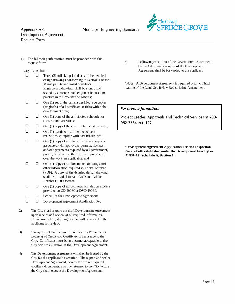
Appendix A-1 Municipal Engineering Standards
Development Agreement
Request Form
Page | 2
1) The following information must be provided with this
request form:
City Consultant
Three (3) full size printed sets of the detailed
design drawings conforming to Section 1 of the
Municipal Development Standards.
Engineering drawings shall be signed and
sealed by a professional engineer licensed to
practice in the Province of Alberta;
One (1) set of the current certified true copies
(originals) of all certificate of titles within the
development area;
One (1) copy of the anticipated schedule for
construction activities;
One (1) copy of the construction cost estimate;
One (1) itemized list of expected cost
recoveries, complete with cost breakdown;
One (1) copy of all plans, forms, and reports
associated with approvals, permits, licenses,
and/or agreements required by all government,
public, or private authorities with jurisdiction
over the work, as applicable; and
One (1) copy of all documents, drawings and
other information required in Adobe Acrobat
(PDF). A copy of the detailed design drawings
shall be provided in AutoCAD and Adobe
Acrobat (PDF) format.
One (1) copy of all computer simulation models
provided on CD-ROM or DVD-ROM.
Schedules for Development Agreement
Development Agreement Application Fee
2) The City shall prepare the draft Development Agreement
upon receipt and review of all required information.
Upon completion, draft agreement will be issued to the
applicant for review.
3) The applicant shall submit offsite levies (1st payment),
Letter(s) of Credit and Certificate of Insurance to the
City. Certificates must be in a format acceptable to the
City prior to execution of the Development Agreement.
4) The Development Agreement will then be issued by the
City for the applicant’s execution. The signed and sealed
Development Agreement, complete with all required
ancillary documents, must be returned to the City before
the City shall execute the Development Agreement.
5) Following execution of the Development Agreement
by the City, two (2) copies of the Development
Agreement shall be forwarded to the applicant.
*Note: A Development Agreement is required prior to Third
reading of the Land Use Bylaw Redistricting Amendment.
*Development Agreement Application Fee and Inspection
Fee are both established under the Development Fees Bylaw
(C-856-13) Schedule A, Section 1.
For more information:
Project Leader, Approvals and Technical Services at 780-
962-7634 ext. 127
Appendix A-2 Municipal Engineering Standards
CCC Request Form
Page | 1
1) The following information must be provided with this
request form:
City Consultant
One (1) copy of a report and/or letter from the
Developer/Consultant stating that they have
reviewed the results of all testing and
inspections conducted and summarizing any
findings to be brought to the attention of the
City. The report/letter shall verify that the
surface grading requirements have been met
within a defined tolerance. The report/letter
shall be duly signed and sealed by a
professional engineer licensed to practice in the
Province of Alberta. In addition to the
preceding, the report/letter must be
accompanied by the following:
Report summarizing the results of hydrostatic
pressure testing;
Report summarizing the results of cleaning and
disinfection of the new water mains;
Bacteriological test results for new water
mains;
Closed-circuit television (CCTV) videos and
inspection logs for new sanitary and storm
sewer mains, complete with summary report;
Compaction test results for all backfill and/or
subgrade/sub-base;
Asphalt core test results (thickness/density/air
voids;
Topsoil lab analysis (landscaping)*
Any previously rejected CCC applications, if
applicable.
Three (3) copies of all applicable operation and
maintenance manuals (where applicable).
Development Agreement Inspection Fee.
(Due with CCC Request for Underground only)
Infrastructure summary tables as follows:
Roadway length summary by
type/subtype;
Walkway length summary by road type;
Curb and gutter length summary by road
type;
Water main length summary by diameter
and material;
Hydrant summary, total public and
private;
Water main fitting totals by type;
Water main valve total by type; Water service curb stop total;
Wastewater main length summary by
diameter and material;
Wastewater manhole total number and
vertical metreage;
Storm main length summary by
diameter and material;
Foundation drain discharge collection
sewer length summary by diameter and
material;
Storm water manhole total number and
vertical metreage;
Catch basin manhole total number and
vertical metreage;
Catch basin total number by type;
Oil and grit interceptor total number by
type;
Swale length summary; and
Culvert length summary by diameter.
All landscaping quantities including
topsoil, seed, sod, mulch, plant material,
site furniture and fencing.
2) Within 30 days of receipt of CCC Request Form,
provided all requirements are met in order to process the
application, the City shall schedule a CCC inspection.
(Weather and ground conditions permitting) The
Consultant and all applicable contractors shall attend the
CCC inspections) with the City’s representative(s).
3) At the discretion of the City, the City may grant
reasonable requests to conduct inspections on portions of
the Development in advance of the application for the
CCC in order to identify and address any potential
deficiencies in underground infrastructure prior to the
commencement of construction of surface
improvements. The City shall not be obliged to issue a
partial CCC on any completed works inspected in this
manner. The CCC will be issued only upon completion
of all infrastructure and improvements identified within
the Development Agreement.
4) Where the CCC inspection reveals deficiencies to be
corrected, the Consultant shall provide a list of such
deficiencies to the Developer and City within two weeks
of the inspection date. The Developer shall be
responsible for immediately correcting such deficiencies
and notifying the City when such is complete. The City
shall conduct another CCC inspection within 30 days of
Appendix A-2 Municipal Engineering Standards
CCC Request Form
Page | 2
such notification. (Weather and ground conditions
permitting.) Should the City note any remaining
outstanding deficiencies at subsequent CCC inspections,
the CCC inspection cycle shall repeat until all
deficiencies are corrected to the satisfaction of the City.
Where more than two CCC inspections are necessary due
to the Developer’s inability to have site prepared and
ready or to correct outstanding deficiencies to the
satisfaction of the City, the City reserves the right to
charge a special inspection fee to the Developer to
recover the costs to the City for excessive/unnecessary
re-inspections.
5) The City will issue the CCC upon satisfactory
inspection of the site and acceptance of all required
submissions.
6) The warranty period shall start upon the City’s
issuance of the Construction Completion Certificate
and shall be effective the date of the inspection which
showed all deficiencies have been rectified.
7) Unless otherwise approved by the City’s land
development inspector the deadline for CCC
inspections for both Underground Utilities and Surface
Improvements will be November 1st.
Unless otherwise approved by the City’s landscaping
inspector, the deadline for CCC inspections for
Landscape Improvements will be October 15th.
*Development Agreement Application Fee and Inspection
Fee are both established under the Development Fees Bylaw
(C-856-13) Schedule A, Section 1.
Submit application to:
Development Supervisor at 780-962-7620
Engineering Inspections at 780-962-7634 ext. 106
Landscape Inspections at 780-962-7596
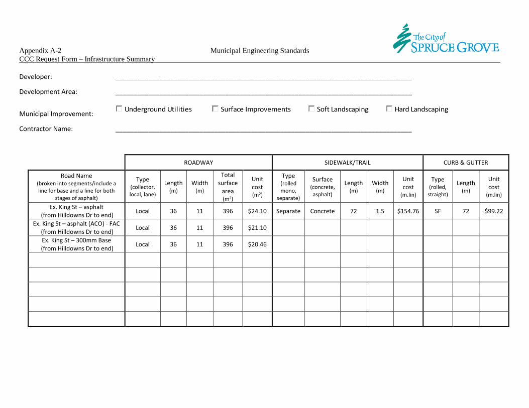
Appendix A-2 Municipal Engineering Standards
CCC Request Form – Infrastructure Summary
Developer: _________________________________________________________________________________
Development Area: _________________________________________________________________________________
Municipal Improvement: Underground Utilities
Surface Improvements
Soft Landscaping Hard Landscaping
Contractor Name: _________________________________________________________________________________
ROADWAY SIDEWALK/TRAIL CURB & GUTTER
Road Name (broken into segments/include a line for base and a line for both
stages of asphalt)
Type (collector, local, lane)
Length (m)
Width (m)
Total surface
area (m2)
Unit cost (m2)
Type (rolled mono,
separate)
Surface (concrete, asphalt)
Length (m)
Width (m)
Unit cost
(m.lin)
Type (rolled,
straight)
Length (m)
Unit cost
(m.lin)
Ex. King St – asphalt (from Hilldowns Dr to end)
Local 36 11 396 $24.10 Separate Concrete 72 1.5 $154.76 SF 72 $99.22
Ex. King St – asphalt (ACO) - FAC (from Hilldowns Dr to end)
Local 36 11 396 $21.10
Ex. King St – 300mm Base (from Hilldowns Dr to end)
Local 36 11 396 $20.46
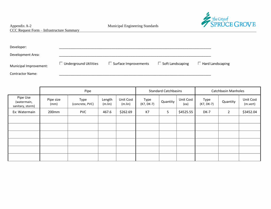
Appendix A-2 Municipal Engineering Standards
CCC Request Form – Infrastructure Summary
Developer: _________________________________________________________________________________
Development Area: _________________________________________________________________________________
Municipal Improvement: Underground Utilities
Surface Improvements
Soft Landscaping Hard Landscaping
Contractor Name: _________________________________________________________________________________
Pipe Standard Catchbasins Catchbasin Manholes
Pipe Use (watermain,
sanitary, storm)
Pipe size (mm)
Type (concrete, PVC)
Length (m.lin)
Unit Cost (m.lin)
Type (K7, DK-7)
Quantity Unit Cost
(ea) Type
(K7, DK-7) Quantity
Unit Cost (m.vert)
Ex: Watermain 200mm PVC 467.6 $262.69 K7 5 $4525.55 DK-7 2 $3452.04
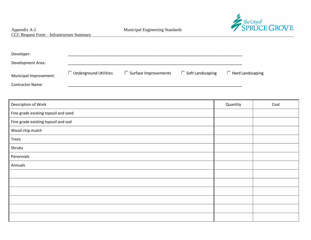
Appendix A-2 Municipal Engineering Standards
CCC Request Form – Infrastructure Summary
Developer: _________________________________________________________________________________
Development Area: _________________________________________________________________________________
Municipal Improvement: Underground Utilities
Surface Improvements
Soft Landscaping Hard Landscaping
Contractor Name: _________________________________________________________________________________
Description of Work Quantity Cost
Fine grade existing topsoil and seed
Fine grade existing topsoil and sod
Wood chip mulch
Trees
Shrubs
Perennials
Annuals
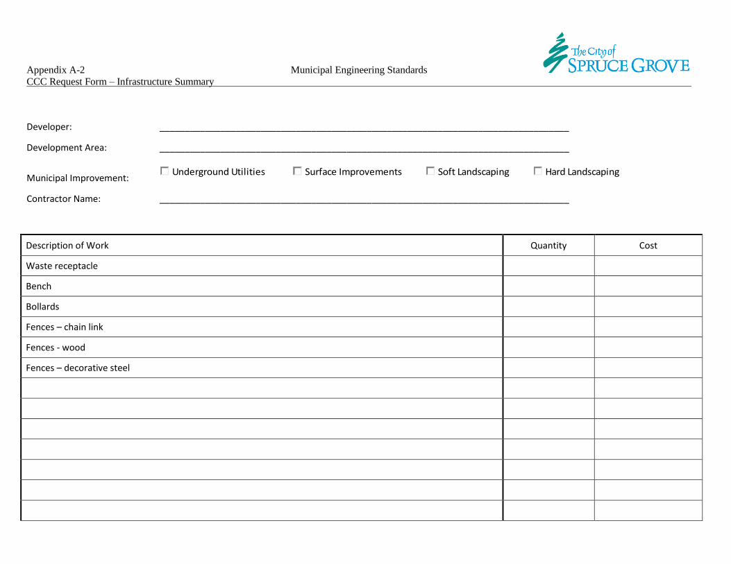
Appendix A-2 Municipal Engineering Standards
CCC Request Form – Infrastructure Summary
Developer: _________________________________________________________________________________
Development Area: _________________________________________________________________________________
Municipal Improvement: Underground Utilities
Surface Improvements
Soft Landscaping Hard Landscaping
Contractor Name: _________________________________________________________________________________
Description of Work Quantity Cost
Waste receptacle
Bench
Bollards
Fences – chain link
Fences - wood
Fences – decorative steel

Appendix A-2
CONSTRUCTION COMPLETION CERTIFICATE UNDERGROUND UTILITIES SURFACE IMPROVEMENTS
DEVELOPMENT AREA:
DEVELOPER:
CONTRACTOR:
MUNICIPAL IMPROVEMENT*:
*(attachment outlining location must be included with this application)
DATE OF APPLICATION:
Pursuant to the Development Agreement between The City of Spruce Grove and the Developer named herein,
I, , of , (Consulting Firm)
confirm that as of the above date, the said Municipal Improvement is complete and constructed in accordance with the
approved construction drawings and with The City of Spruce Grove’s Municipal Development Standards, and I hereby
recommend this Municipal Improvement for Construction Completion approval.
Professional Seal
Project Manager Date
Signing Officer (Professional Engineer) Date
Inspection date:
Is this a re-inspection? N
Y Date of previous inspection:
Inspection Results:
Rejected/re-inspection required
Deficiency corrections/follow-up required by:
I hereby certify that all noted deficiencies have been corrected.
Project Manager Date
Approved
Authorized City Inspector Date
Director of Engineering Date
Maintenance Period End Date:

Appendix A-2
CONSTRUCTION COMPLETION CERTIFICATE LANDSCAPING
DEVELOPMENT AREA:
DEVELOPER:
CONTRACTOR:
MUNICIPAL IMPROVEMENT*:
*(attachment outlining location must be included with this application)
DATE OF APPLICATION:
Pursuant to the Development Agreement between The City of Spruce Grove and the Developer named herein,
I, , of , (Consulting Firm)
confirm that as of the above date, the said Municipal Improvement is complete and constructed in accordance with the
approved construction drawings and with The City of Spruce Grove’s Municipal Development Standards, and I hereby
recommend this Municipal Improvement for Construction Completion approval.
Professional Seal
Project Manager Date
Signing Officer (Professional Landscape Architect) Date
Inspection date:
Is this a re-inspection? N
Y Date of previous inspection:
Inspection Results:
Rejected/re-inspection required
Deficiency corrections/follow-up required by:
I hereby certify that all noted deficiencies have been corrected.
Project Manager Date
Approved
Authorized City Inspector Date
Director of Engineering Date
Maintenance Period End Date:
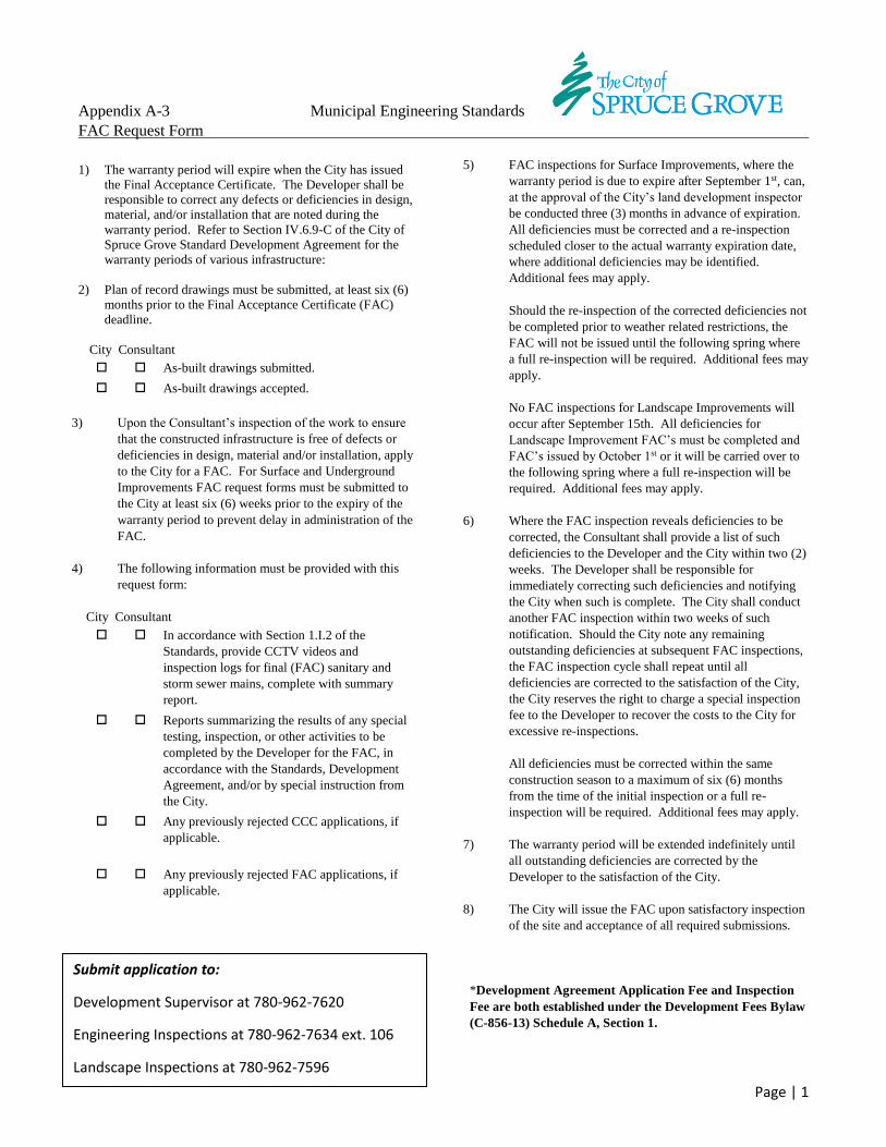
Appendix A-3 Municipal Engineering Standards
FAC Request Form
Page | 1
1) The warranty period will expire when the City has issued
the Final Acceptance Certificate. The Developer shall be
responsible to correct any defects or deficiencies in design,
material, and/or installation that are noted during the
warranty period. Refer to Section IV.6.9-C of the City of
Spruce Grove Standard Development Agreement for the
warranty periods of various infrastructure:
2) Plan of record drawings must be submitted, at least six (6)
months prior to the Final Acceptance Certificate (FAC)
deadline.
City Consultant
As-built drawings submitted.
As-built drawings accepted.
3) Upon the Consultant’s inspection of the work to ensure
that the constructed infrastructure is free of defects or
deficiencies in design, material and/or installation, apply
to the City for a FAC. For Surface and Underground
Improvements FAC request forms must be submitted to
the City at least six (6) weeks prior to the expiry of the
warranty period to prevent delay in administration of the
FAC.
4) The following information must be provided with this
request form:
City Consultant
In accordance with Section 1.I.2 of the
Standards, provide CCTV videos and
inspection logs for final (FAC) sanitary and
storm sewer mains, complete with summary
report.
Reports summarizing the results of any special
testing, inspection, or other activities to be
completed by the Developer for the FAC, in
accordance with the Standards, Development
Agreement, and/or by special instruction from
the City.
Any previously rejected CCC applications, if
applicable.
Any previously rejected FAC applications, if
applicable.
5) FAC inspections for Surface Improvements, where the
warranty period is due to expire after September 1st, can,
at the approval of the City’s land development inspector
be conducted three (3) months in advance of expiration.
All deficiencies must be corrected and a re-inspection
scheduled closer to the actual warranty expiration date,
where additional deficiencies may be identified.
Additional fees may apply.
Should the re-inspection of the corrected deficiencies not
be completed prior to weather related restrictions, the
FAC will not be issued until the following spring where
a full re-inspection will be required. Additional fees may
apply.
No FAC inspections for Landscape Improvements will
occur after September 15th. All deficiencies for
Landscape Improvement FAC’s must be completed and
FAC’s issued by October 1st or it will be carried over to
the following spring where a full re-inspection will be
required. Additional fees may apply.
6) Where the FAC inspection reveals deficiencies to be
corrected, the Consultant shall provide a list of such
deficiencies to the Developer and the City within two (2)
weeks. The Developer shall be responsible for
immediately correcting such deficiencies and notifying
the City when such is complete. The City shall conduct
another FAC inspection within two weeks of such
notification. Should the City note any remaining
outstanding deficiencies at subsequent FAC inspections,
the FAC inspection cycle shall repeat until all
deficiencies are corrected to the satisfaction of the City,
the City reserves the right to charge a special inspection
fee to the Developer to recover the costs to the City for
excessive re-inspections.
All deficiencies must be corrected within the same
construction season to a maximum of six (6) months
from the time of the initial inspection or a full re-
inspection will be required. Additional fees may apply.
7) The warranty period will be extended indefinitely until
all outstanding deficiencies are corrected by the
Developer to the satisfaction of the City.
8) The City will issue the FAC upon satisfactory inspection
of the site and acceptance of all required submissions.
*Development Agreement Application Fee and Inspection
Fee are both established under the Development Fees Bylaw
(C-856-13) Schedule A, Section 1.
Submit application to:
Development Supervisor at 780-962-7620
Engineering Inspections at 780-962-7634 ext. 106
Landscape Inspections at 780-962-7596

Appendix A-3
FINAL ACCEPTANCE CERTIFICATE UNDERGROUND UTILITIES SURFACE IMPROVEMENTS
DEVELOPMENT AREA:
DEVELOPER:
CONTRACTOR:
MUNICIPAL IMPROVEMENT*:
*(attachment outlining location must be included with this application)
DATE OF APPLICATION:
Pursuant to the Development Agreement between The City of Spruce Grove and the Developer named herein,
I, , of , (Consulting Firm)
confirm that as of the above date, the said Municipal Improvement is complete and constructed in accordance with the
approved construction drawings and with The City of Spruce Grove’s Municipal Development Standards, and I hereby
recommend this Municipal Improvement for Construction Completion approval.
Professional Seal
Project Manager Date
Signing Officer (Professional Engineer) Date
Maintenance Period End Date:
Inspection date:
Is this a re-inspection? N
Y Date of previous inspection:
Inspection Results:
Rejected/re-inspection required
Deficiency corrections/follow-up required by:
I hereby certify that all noted deficiencies have been corrected.
Project Manager Date
Approved
Authorized City Inspector Date
Director of Engineering Date

Appendix A-3
FINAL ACCEPTANCE CERTIFICATE LANDSCAPING
DEVELOPMENT AREA:
DEVELOPER:
CONTRACTOR:
MUNICIPAL IMPROVEMENT*:
*(attachment outlining location must be included with this application)
DATE OF APPLICATION:
Pursuant to the Development Agreement between The City of Spruce Grove and the Developer named herein,
I, , of , (Consulting Firm)
confirm that as of the above date, the said Municipal Improvement is complete and constructed in accordance with the
approved construction drawings and with The City of Spruce Grove’s Municipal Development Standards, and I hereby
recommend this Municipal Improvement for Construction Completion approval.
Professional Seal
Project Manager Date
Signing Officer (Professional Landscape Architect) Date
Maintenance Period End Date:
Inspection date:
Is this a re-inspection? N
Y Date of previous inspection:
Inspection Results:
Rejected/re-inspection required
Deficiency corrections/follow-up required by:
I hereby certify that all noted deficiencies have been corrected.
Project Manager Date
Approved
Authorized City Inspector Date
Director of Engineering Date