Embed Size (px)
Citation preview

User-Specific QoS Aware Scheduling andImplementation in Wireless Systems
Chao He and Richard D. GitlinDepartment of Electrical Engineering
University of South FloridaTampa, Florida 33620, USA
Email: [email protected], [email protected]
Abstract—In this paper, we explore user-specific QoS re-quirements and associated schedulers that are very critical inoptimizing the spectral allocation for wireless systems. Two user-specific QoS aware schedulers are proposed that considers theuser-specific QoS requirements in the allocation of resources.Depending upon whether improving the MOS (Mean OpinionScore) or both the system capacity and the MOS is the goal,a MOS improvement scheduler or MOS-plus-capacity improve-ment scheduler is proposed for VoIP applications. Detailed systemimplementation analysis based upon LTE system specification isperformed, and it is shown that very modest modifications tocurrent protocols are needed to support user-specific QoS awarescheduling. System simulations are performed for a set of VoIPusers assigned specific QoS target levels in the OPNET Modelerfor LTE systems. Simulation results show that appreciable MOSor/and system capacity improvement can be achieved if suchuser-specific QoS requirements are considered in the proposeduser-specific QoS aware schedulers. Also, it is shown that thescheduling period of up to 1000 ms doesn’t significantly impairthe system performance.
Keywords—AMR, implementation, MAC, MOS, system capacity.
I. INTRODUCTION
In today’s wireless 4G LTE networks, the spectral alloca-tion of resources is either independent of the users’ specificperceived QoS (Quality of Service), or at most relies on aset of pre-defined fixed priorities [1], [2]. Although in thesestandards, the MAC and the PHY layers have an increasedrole in optimizing the usage of the spectral resources andimplementing link quality-aware techniques, optimization isstill largely independent of the application context, the users’requirements, and the users’ perception of performance degra-dation. The allocation of resources, does not take into accountthe QoS required by different applications and their users,beyond simply assigning fixed priorities to traffic classes.Indeed, for a given application type, different users may requiredifferent levels of QoS.
As a motivating example, consider the fact that the per-ceived voice quality of different languages may differ sub-stantially when allocated the same data rate and BER (BitError Rate), because of the different spectral content of suchlanguages and because of a particular user’s auditory spectralresponse (with variations typically due to aging), making theuser more or less sensitive to a particular type of distortion[3]. Consequently, the same amount of degradation, as expe-rienced by individual applications and their users, may have
substantially different perceptual effects. Another example isthe varying talking environments, where some users have aconversation under very noisy conditions, whereas some otherusers converse under very quiet conditions, thus making usersmore or less sensitive to packet losses. If the same amount ofspectral resource is allocated to users in very noisy and quietbackgrounds, then quite a different user experience will likelybe incurred.
The user-specific QoS aware scheduling algorithms werefirst addressed in [4]–[6], where it was shown that significantMOS improvement or/and system capacity can be achieved ifuser-specific QoS requirements are considered in the schedul-ing algorithms. In this paper, the scheduling algorithms arepresented briefly, and we will focus on the analysis of detailedimplementation complexity for LTE systems where the user-specific QoS related protocol adaptation and scheduling periodare addressed.
The rest of the paper is organized as follows. In SectionII, user-specific QoS aware schedulers are described. Detailedimplementation analysis of user-specific QoS aware schedulersis provided in Section III. Section IV presents the OPNETLTE system simulations. Finally, our conclusions are given inSection V.
II. USER-SPECIFIC QOS SCHEDULER
A. User-Specific MOS Formulas
In this paper, user-specific QoS requirements are character-ized by their different sensitivities to packet losses. To reflectthis different sensitivity, a user-specific packet loss sensitivityfactor, α, is introduced to the ITU-T G.107 E-Model equation[7]:
R = R0 − Id − α · Ieff (1)
where R0 is the basic signal-to-noise ratio which has a defaultvalue of 93.2 [8], Id represents the impairments due to delay,which is the same for all the codec modes, and Ieff representsthe effect of packet losses and depends on the codec (e.g.,AMR mode) that is used. The parameter Id is calculated as[8]:
Id = 0.024d+ 0.11(d− 177.3)U(d− 177.3) (2)
where d is the end-to-end delay in milliseconds and U is theunit step function.
2015 IEEE Wireless Telecommunications Symposium (WTS) New York City, USA April 15-17, 2015

For AMR codecs, the Ieff is given by [7]:
Ieff = Ie + (95− Ie)(100Ppl
100Ppl
burstR +Bpl
) (3)
where Ppl represents packet loss ratio, BurstR is the averagelength of observed bursts in an arrival sequence to the averagelength of bursts expected for the network under ”random”loss ratio. In this paper we assume the packet losses areindependent and hence we set BurstR = 1. The parameterBpl is the robustness factor which is set to 10 for all AMRcodec modes. The parameter Ie is defined for all AMR codecmodes in [9], where eight AMR-NB codec modes are definedin LTE [10].
The parameter R is converted to MOS according to (4):
MOS =
1, when R < 0
1 + 0.035R+R(R− 60)
·(100−R) · 7 · 10−6, when R ∈ [0, 100]
4.5, when R > 100(4)
From (1)-(4), it is clear that the lower the delay, or thelower the packet loss ratio, the higher the MOS value.
In this paper, without loss of generality and also for sim-plicity of illustration, the packet loss sensitivity factor α takesvalues from the following set {0.8, 1.0, 1.2}. Correspondingly,users are classified into 3 categories: users with higher (1.2),normal (1.0), and lower (0.8) sensitivity factors. The higher thevalue of the sensitivity factor α, the more the user is sensitiveto packet loss.
Figure 1 shows the MOS as a function of different AMRdata rates for different sensitivity factors α, given an end-to-end delay of 150 ms [11] and packet loss ratio of 0.05. Fora comparison between AMR12.2K mode and α = 1.0 withAMR10.2K/7.95K mode and α = 0.8, we find the latter casemay, under certain conditions, have a higher MOS than theformer one. If the scheduler can know, or adaptively learn, eachuser’s specific sensitivity factor, it can degrade the AMR modefor users with a lower sensitivity factor, while maintaining acomparable MOS as that of users with higher AMR mode buta normal sensitivity factor. With this approach, more users canbe supported, thus achieving the target of improving systemcapacity.
B. Motivation for MOS Optimization
Figure 2 shows the decreased or increased MOS percentagedue to the different sensitivity factors α for different users.The MOS of VoIP users with α of 1.2 is decreased by ˜15%,whereas the MOS of VoIP users with α of 0.8 is increased by˜15%, when a packet loss ratio of 5% and end-to-end delayof 150 ms are assumed. As the packet loss ratio increases, theMOS will decrease or increase even more.
Therefore, the MOS of VoIP users with α of 1.2 needs tobe improved to the corresponding MOS value with α of 1.0,whereas the MOS of VoIP users with α of 0.8 can be decreasedto the MOS value of α of 1.0, as depicted in Fig. 2. There aretwo approaches to decrease the MOS of VoIP users with α of0.8:
Fig. 1. VoIP MOS as a function of AMR data rate given a packet loss ratioof 0.05 and end-to-end delay of 150 ms.
Fig. 2. De(in)creased MOS as a function of packet loss ratio given an end-to-end delay of 150 ms and AMR12.2K.
1) Approach I: This category of users can be deprioritized,that is, given a lower scheduling priority in the MAC scheduler.The MOS optimization only scheduler in the next section usesthis method to optimize the MOS.
2) Approach II: The data rate (i.e., AMR mode) of thiscategory of users can be degraded, so that a higher systemcapacity can be achieved. However, these users are scheduledas normal users in the MAC scheduler. The MOS optimizationplus capacity improvement scheduler in the next section usesthis method to optimize the MOS.
C. User-Specific QoS Aware Schedulers
1) MOS Optimization only Scheduler: The MOS of userswith α = 1.2 will be increased, that is, given a higherscheduling priority, whereas users with α = 1.0 have a normalscheduling priority, and the MOS of users with α = 0.8 aredecreased a little and given a lower scheduling priority. Thisscheduler is denoted as the USQA-M scheduler.
2) MOS Optimization plus Capacity Improvement Sched-uler: The MOS of users with α = 1.2 will be increased,that is, given a higher scheduling priority, whereas users withα = 1.0 have a normal scheduling priority and users withα = 0.8 are used to improve the capacity by degrading theirAMR codec modes.
2015 IEEE Wireless Telecommunications Symposium (WTS) New York City, USA April 15-17, 2015
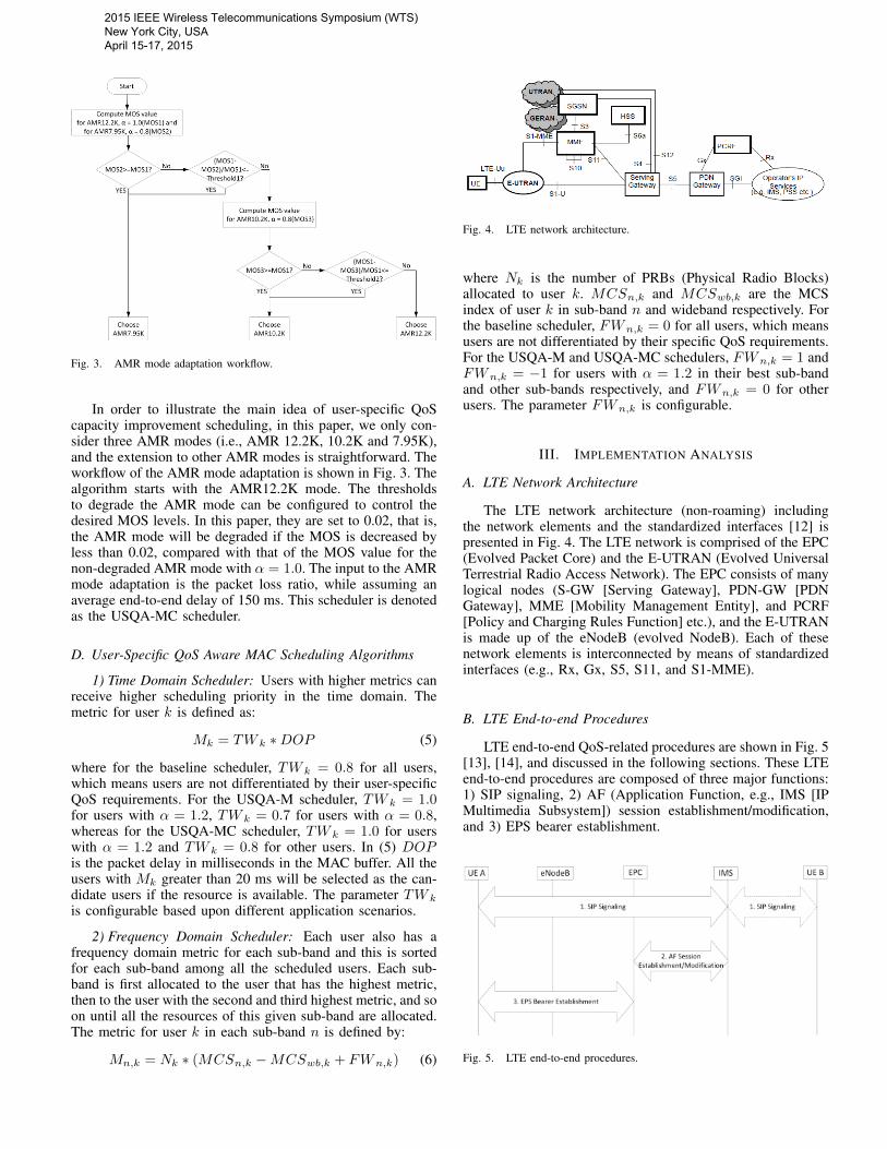
Fig. 3. AMR mode adaptation workflow.
In order to illustrate the main idea of user-specific QoScapacity improvement scheduling, in this paper, we only con-sider three AMR modes (i.e., AMR 12.2K, 10.2K and 7.95K),and the extension to other AMR modes is straightforward. Theworkflow of the AMR mode adaptation is shown in Fig. 3. Thealgorithm starts with the AMR12.2K mode. The thresholdsto degrade the AMR mode can be configured to control thedesired MOS levels. In this paper, they are set to 0.02, that is,the AMR mode will be degraded if the MOS is decreased byless than 0.02, compared with that of the MOS value for thenon-degraded AMR mode with α = 1.0. The input to the AMRmode adaptation is the packet loss ratio, while assuming anaverage end-to-end delay of 150 ms. This scheduler is denotedas the USQA-MC scheduler.
D. User-Specific QoS Aware MAC Scheduling Algorithms
1) Time Domain Scheduler: Users with higher metrics canreceive higher scheduling priority in the time domain. Themetric for user k is defined as:
Mk = TW k ∗DOP (5)
where for the baseline scheduler, TW k = 0.8 for all users,which means users are not differentiated by their user-specificQoS requirements. For the USQA-M scheduler, TW k = 1.0for users with α = 1.2, TW k = 0.7 for users with α = 0.8,whereas for the USQA-MC scheduler, TW k = 1.0 for userswith α = 1.2 and TW k = 0.8 for other users. In (5) DOPis the packet delay in milliseconds in the MAC buffer. All theusers with Mk greater than 20 ms will be selected as the can-didate users if the resource is available. The parameter TW k
is configurable based upon different application scenarios.
2) Frequency Domain Scheduler: Each user also has afrequency domain metric for each sub-band and this is sortedfor each sub-band among all the scheduled users. Each sub-band is first allocated to the user that has the highest metric,then to the user with the second and third highest metric, and soon until all the resources of this given sub-band are allocated.The metric for user k in each sub-band n is defined by:
Mn,k = Nk ∗ (MCSn,k −MCSwb,k + FWn,k) (6)
Fig. 4. LTE network architecture.
where Nk is the number of PRBs (Physical Radio Blocks)allocated to user k. MCSn,k and MCSwb,k are the MCSindex of user k in sub-band n and wideband respectively. Forthe baseline scheduler, FWn,k = 0 for all users, which meansusers are not differentiated by their specific QoS requirements.For the USQA-M and USQA-MC schedulers, FWn,k = 1 andFWn,k = −1 for users with α = 1.2 in their best sub-bandand other sub-bands respectively, and FWn,k = 0 for otherusers. The parameter FWn,k is configurable.
III. IMPLEMENTATION ANALYSIS
A. LTE Network Architecture
The LTE network architecture (non-roaming) includingthe network elements and the standardized interfaces [12] ispresented in Fig. 4. The LTE network is comprised of the EPC(Evolved Packet Core) and the E-UTRAN (Evolved UniversalTerrestrial Radio Access Network). The EPC consists of manylogical nodes (S-GW [Serving Gateway], PDN-GW [PDNGateway], MME [Mobility Management Entity], and PCRF[Policy and Charging Rules Function] etc.), and the E-UTRANis made up of the eNodeB (evolved NodeB). Each of thesenetwork elements is interconnected by means of standardizedinterfaces (e.g., Rx, Gx, S5, S11, and S1-MME).
B. LTE End-to-end Procedures
LTE end-to-end QoS-related procedures are shown in Fig. 5[13], [14], and discussed in the following sections. These LTEend-to-end procedures are composed of three major functions:1) SIP signaling, 2) AF (Application Function, e.g., IMS [IPMultimedia Subsystem]) session establishment/modification,and 3) EPS bearer establishment.
Fig. 5. LTE end-to-end procedures.
2015 IEEE Wireless Telecommunications Symposium (WTS) New York City, USA April 15-17, 2015

C. LTE QoS Related Protocols
From Section III.B, the LTE QoS related protocols areshown as follows:
1) SIP Protocol: The SIP protocol is used to create,modify, and terminate sessions such as Internet multimediaconferences, Internet telephone calls [15]. It uses the SDP(Session Description Protocol) to describe a session.
2) Diameter Base Protocol (Rx and Gx Interfaces): TheDiameter base protocol provides an Authentication, Authoriza-tion and Accounting (AAA) framework for applications suchas network access or IP mobility [14].
3) GTP-C (Control) Protocol (S5 and S11 Interfaces):The control plane of the GPRS Tunneling Protocol (GTP) isresponsible for creating, maintaining and deleting tunnels onSx (e.g., S5, S11) interfaces [16].
4) S1-AP Protocol (S1-MME Interface): The S1-AP proto-col provides the signaling service between the E-UTRAN andthe EPC [17].
D. LTE QoS Parameters Mapping
The AF can map from SDP within the AF session sig-naling to Service Information passed to the PCRF over theRx interface. The PCRF maps messages from the ServiceInformation received over the Rx interface to the AuthorizedIP QoS parameters that are passed to the PCEF (Policy andCharging Enforcement Function) in the PDN-GW via the Gxinterface. The PCEF maps messages from the Authorized IPQoS parameters received from the PCRF to the access specificQoS parameters, which are the QoS parameters that the MAClayer can access [18].
E. User-Specific QoS Parameter Acquisition
There are two methods to acquire the user-specific QoSparameters to be used by the user-specific QoS aware MACschedulers. The first one is to obtain the user-specific QoSparameters dynamically through the signaling messages (i.e.,SIP, Diameter protocol etc.) that are delivered to the MAClayer. The other is to acquire the user-specific QoS parametersthrough the SPR (Subscriber Profile Repository) database inthe PCRF that are delivered to the MAC layer. The differencebetween these two methods is in how the PCRF obtains theuser-specific QoS parameters. After the PCRF acquires theQoS parameters, the subsequent procedures will be the sameso that the pertinent QoS parameters are conveyed to the MAClayer.
For the first method, as noted above, the user-specific QoSparameters are obtained by the PCRF through signaling fromthe SIP and Rx interface protocols.
For the second method, no special SIP signaling is requiredbefore the PCRF sends the QoS parameters further to the PCEFthrough the Gx interface. In most commercial systems, the net-work operator can obtain the user-specific QoS requirementsthat are based primarily upon age. When users subscribe toa service from the network operator, they often provide theirrelevant information such as age, name that can be used bythe network to derive the user-specific QoS parameters. To bemore specific, when a bearer is to be established or modified,
Fig. 6. System architecture.
the PCRF inquires of the SPR database about the relevantinformation of this user. If the relevant information shows thatthis user is older than a given age (e.g., 55), this user will beconsidered as a user with a lower sensitivity factor; otherwise,they are regarded as a normal user.
F. System Architecture
The system architecture and interfaces based on the LTEsystem are illustrated in Fig. 6, where only relevant modulesare shown [19]. In order to implement the user-specific QoSaware schedulers, the AMR mode adaptation algorithm wouldbe implemented in the Rate Adaptation module, whereas theuser-specific MAC scheduling algorithms would be imple-mented in the eNodeB MAC layer. These are software onlychanges and can be readily accommodated in future versionsof LTE [or in future 5G systems].
G. Optimization Process
As an example of the optimization process, when a voicesession is to be initialized through the SIP protocol [20], thesender and receiver UE applications will negotiate with eachother the application level QoS parameters such as supportedAMR codec modes through the IMS [21]. User-specific QoSparameters could also be sent to the IMS by UE.
Next, user-specific QoS requirements will be mapped fromthe subscription database in the network (e.g., SPR) [2], [18] oruser-specific QoS parameters obtained from UE during sessioninitiation, as described in Section III.E. The user-specific QoSparameters shall be delivered to the MAC/PHY Layer in theeNodeB by the EPC/IMS and used to perform the user-specificQoS aware scheduling.
Finally, after the process of rate adaptation, the receiverUE will send the rate control command (e.g., CMR [CodecMode Request] for VoIP) to the sender UE through the RTPor RTCP protocol [21]–[23] if the data rate is to be changed.Meanwhile the MAC layer in the eNodeB will perform theuser-specific QoS aware scheduling.
It should be noted that, due to the changing channelenvironment for each user and varying network condition,the optimization process should be dynamic and periodic toachieve the maximum system performance gain.
H. Protocol Adaptation
Based upon the analysis above, the following protocoladaptation is proposed to support the user-specific QoS awarescheduling. As described above in Sections III.A-G, the
2015 IEEE Wireless Telecommunications Symposium (WTS) New York City, USA April 15-17, 2015

TABLE I. USER-SPECIFIC SDP MEDIA TYPE DEFINITION
User-specific QoS Media Type
Audio (low sensitivity factor) 100 (0 + 100)Audio (normal sensitivity factor) 0
Audio (high sensitivity factor) 200 (0 + 200)
Gx, S5/S11, and S1-MME interface protocols need to beadapted for the second user-specific QoS parameters acqui-sition method. For the first acquisition method in addition SIPand Rx interface protocol adaptation is needed. Moreover, theRTCP protocol that is used to convey the rate control commandalso needs to be analyzed to support the user-specific QoSaware scheduling.
1) SIP Protocol: When dynamic user-specific QoS infor-mation needs to be conveyed from the UE to the IMS, theSIP protocol [15], [20] needs to be adapted accordingly. Thebody of a SIP message contains a description of the session,encoded in SDP [24]. An SDP session description consists ofa session-level section followed by zero or more media-levelsections. Each media-level section starts with an ”m=” line.The ”m=” line is defined as follows:
m=<media><port><proto><fmt>
<media> is the media type. Currently defined media are”audio”, ”video”, ”text”, ”application”, and ”message”.
So if user-specific QoS requirements need to be conveyedfrom the UE to the IMS, one method is to implicitly convey theuser-specific QoS requirement through the media type field.A user-specific Audio type can be added and defined, e.g.,100 indicates the user-specific Audio media type with a lowersensitivity factor, and 200 indicates the user-specific Audiomedia type with a higher sensitivity factor as described in TableI. If new media types are defined this way, correspondingly,in the network and the peer UE, the media type field needs tobe parsed differently.
2) RTCP Protocol: When an adapted data rate mode needsto be signaled from the receiver UE to the sender UE, ituses the RTCP protocol. The current RTCP protocol supportsthe rate adaptation signaling, so it can be reused without anymodification [21].
3) Rx Interface: The Media-Component-Description AVP(Attribute Value Pair) is conveyed in the Diameter AARmessage, and it contains Service Information for a single mediacomponent within an AF session [25]. If the user-specific QoSparameters need to be conveyed from the UE, the Media-Component-Description AVP definition needs to be modified.The media-type field in the Media-Component-DescriptionAVP can be used to convey the user-specific QoS requirementsas Section 1) above on the SIP protocol describes. Similarly thePCRF needs to parse the media-type field differently accordingto Table I.
4) Gx Interface: The PCRF may provide authorized QoSinformation to the PCEF after using the mapping rules tomap from the Service Information to the authorized QoSinformation. The authorized QoS information shall be pro-visioned within a CCA or RAR Diameter message as QoS-Information AVP. The provisioning of the authorized QoS
TABLE II. MAPPING FROM USER-SPECIFIC QOS TO QCI
User-specific QoS QCI
Voice (low sensitivity factor) 101 (1 + 100)Voice (normal sensitivity factor) 1
Voice (high sensitivity factor) 201 (1 + 200)
(which is composed of QCI, ARP and bitrates) is performedfrom the PCRF to the PCEF [26].
In the PCRF, the QCI field needs to be derived basedupon the SPR database or the Service Information obtainedfrom the AF through the Rx interface. If the user-specific QoSinformation is conveyed from the Rx interface, the PCRF canderive the QCI value according to the media type field in theService Information. If the user-specific QoS information isnot conveyed from the Rx interface, the PCRF can use thedata from the SPR database to derive the user-specific QoSparameters as shown in Section III.E. Specifically, since theQCI values 0, 10-64, 67-68, and 71-255 are reserved for futureuse [2], the basic QCI value (i.e., the QCI value derived whenno user specific QoS requirements are considered) plus 100 canbe used to denote the user-specific QoS with a lower sensitivityfactor, while the basic QCI value plus 200 can be used todenote the user-specific QoS with a higher sensitivity factor.The mapping from the user-specific QoS information to theQCI value for VoIP is shown in Table II.
5) S5/S11 Interface: The Create Bearer Request messageshall be sent on the S5 interface by the PDN-GW to theS-GW and on the S11 interface by the S-GW to the MMEas part of the EPS Bearer establishment procedure [16]. TheBearer Quality of Service (Bearer QoS) is transferred via GTPtunnels through the Create Bearer Request message, wherethe QCI field has been redefined and added additional user-specific QoS values as described above in Section 4) on theGx interface, the QCI doesn’t need any further modificationexcept different parsing according to Table II in the respectiveprotocols. The PDN-GW and S-GW only needs to forward theBearer QoS information to the subsequent nodes of S-GW andMME respectively.
6) S1-MME Interface: The E-RAB Setup Request Messageis sent by the MME to request the eNodeB to assign resourceson Uu and S1 interfaces for one or several E-RABs [17]. TheE-RAB Level QoS Parameters are conveyed in the E-RABSetup Request Message, where the QCI has been redefined andadded additional user-specific QoS information as describedabove in Section 4) on the Gx interface. This message doesn’tneed any further modification except different parsing accord-ing to Table II in the respective protocols. Finally the MAClayer can make user of this user-specific QoS informationto perform a more advanced resource scheduling, i.e., user-specific QoS aware scheduling.
I. Scheduling Period
We assume the scheduling period of the rate adaptationalgorithms is the frame period of applications, that is, 20 msfor VoIP AMR applications. It is necessary to explore whatthe system capacity gain will be if the scheduling periodis increased in a tradeoff for the reduced complexity. Thesimulation results in Section IV are shown when the schedulingperiod is increased from 20 to 2000 ms for VoIP users.
2015 IEEE Wireless Telecommunications Symposium (WTS) New York City, USA April 15-17, 2015

TABLE III. SYSTEM SIMULATION CONFIGURATION
Parameter Assumption
Cellular layout 1 macrocellCell radius 1 kilometer
Path loss model 3GPP suburban macrocellMobility model Random Way Point (30/60 km/h)
Carrier frequency Uplink:1920MHzDownlink:2110MHz
System bandwidth 10MHzChannel model ITU Vehicle A
Total BS TX power 40dBmUE power 23dBm
VoIP codec modes AMR12.2K, AMR10.2K, AMR7.95KNumber of users 54 VoIP users
SchedulerDynamic scheduling
USQA-M, USQA-MC schedulerand Baseline scheduler
Other assumptions Ideal uplink receiver(no block error and packet loss)
TABLE IV. SYSTEM SIMULATION CASES
Cases Assumption USQAscheduler
Case 1
54 VoIP users(18 users’ α = 0.8,18 users’ α = 1.0,
18 users’ α = 1.2), 30 km/h.
USQA-Mscheduler
Case 2 Same as Case 1. USQA-MCscheduler
Case 3 54 VoIP users (α = 0.8), 30 km/h. USQA-MCscheduler
Case 4 54 VoIP users (α = 0.8), 60 km/h. USQA-MCscheduler
IV. SYSTEM SIMULATION
A. System Simulation Configuration
The system simulation was run using the OPNET 17.5Modeler with the LTE modules. The system simulation config-uration is partly based upon LTE macrocell system simulationbaseline parameters [27] as shown in Table III. the simulationwas performed to evaluate the downlink scheduling, with anideal uplink receiver.
B. System Simulation Cases
Four cases were simulated as described in Table IV. Cases1 and 2 are used to evaluate the performance of the USQA-Mand USQA-MC schedulers respectively, where 54 VoIP usershave different sensitivity factors α (18 users’ α = 0.8, 18users’ α = 1.0 and 18 users’ α = 1.2). Cases 3-4 are used totest the scheduling period for cases of vehicular speeds of 30km/h and 60 km/h respectively.
C. System Simulation Results
In this paper, the downlink MAC throughput is used toderive the approximate system capacity improvement. Systemcapacity improvement is measured by the increase in themaximum supportable number of users by the system. A roughmapping from the downlink MAC throughput to the system
TABLE V. AVERAGE MOS VALUE
Cases Scheduler User category MOS MOSimprovement
Case 1 USQA-M User(1.2) 3.86 9%User(1.0) 3.84 -1%User(0.8) 3.87 -2%
Baseline User(1.2) 3.54 N/AUser(1.0) 3.88 N/AUser(0.8) 3.95 N/A
Case 2 USQA-MC User(1.2) 3.75 6%User(1.0) 3.83 -1.3%User(0.8) 3.90 -1.3%
Baseline User(1.2) 3.54 N/AUser(1.0) 3.88 N/AUser(0.8) 3.95 N/A
TABLE VI. SYSTEM CAPACITY COMPARISON
Cases Scheduler VoIP MACthroughput (Mbps)
Capacityimprovement
Case 2 USQA-MC 1.000 4.5%Baseline 1.045 N/A
capacity improvement can be done based upon (7).
1/MAC throughput for USQA-MC
1/MAC throughput for Baseline− 1 (7)
The simulation results for MOS value and capacity areshown in Table V and VI respectively.
For Case 1, the average MOS of VoIP users with α = 1.2is increased by ˜9%, whereas the average MOS of VoIP userswith α = 0.8 is decreased a little.
For Case 2, the system capacity is increased by ˜4.5%,whereas the average MOS of VoIP users with α = 1.2 isincreased by ˜6%. The MOS gain is not as good as that ofCase 1. The reason is that users with α = 0.8 are scheduled asnormal users in the MAC scheduler so that they have a normalscheduling priority to compete for resources with users withα = 1.2. In this case, only 1/3 of the users have sensitivityfactors of 0.8. As this ratio increases, the system capacityimprovement gain will further be increased, as verified inCases 3-4 where all users have a sensitivity factor of α = 0.8.
Figure 7 show the VoIP capacity as a function of schedulingperiod from 20 ms to 2000 ms. From Fig. 7, we find thatas the scheduling period increases, the performance gain willdecrease correspondingly. As the scheduling period increasesto 1000 ms, the capacity improvement will fall below 10% forthe case of 60 km/h, whereas the capacity improvement is stillgood for the case of 30 km/h.
V. CONCLUSIONS
In this paper, we introduce the concept of user-specific QoSrequirements and demonstrate its importance in spectral allo-cation. Two user-specific QoS aware schedulers are proposedaimed at improving the MOS or both the MOS and the systemcapacity in wireless systems for VoIP applications. Detailedsystem implementation analysis based upon LTE systems isperformed to show that very modest modifications on currentLTE protocols are needed to support the user-specific QoS
2015 IEEE Wireless Telecommunications Symposium (WTS) New York City, USA April 15-17, 2015

Fig. 7. VoIP Capacity improvement as a function of scheduling period.
aware scheduling. Simulation results demonstrate that appre-ciable MOS improvement or/and capacity improvement canbe observed for these two schedulers, and also show that thescheduling period of rate adaptation algorithms of up to 1000ms doesn’t significantly impact the system performance.
ACKNOWLEDGMENT
This research was supported by NSF Grant 1352883. Wewould like to thank Drs. Huseyin Arslan and Zygmunt Haasfor many stimulating and enlightening discussions during thisresearch. We would like to thank Riverbed for providing itsNetModeler Suite of simulation software.
REFERENCES
[1] H. Ekstrom, “QoS control in the 3gpp evolved packet system,” IEEECommun. Mag., vol. 47, no. 2, pp. 76–83, 2009.
[2] 3GPP, “TS 23.203 - v12.6.0 - digital cellular telecommunications sys-tem (phase 2+); universal mobile telecommunications system (UMTS);LTE; policy and charging control architecture.”
[3] J. D. Pearson, C. H. Morrell, S. GordonSalant, L. J. Brant, E. J.Metter, L. L. Klein, and J. L. Fozard, “Gender differences in alongitudinal study of ageassociated hearing loss,” J. Acoust. Soc. Am.,vol. 97, no. 2, pp. 1196–1205, Feb. 1995.
[4] C. He and R. D. Gitlin, “User specific QoS and its applicationin resources scheduling for wireless system,” in ICA3PP 2014, pp.809-821, Aug. 2014.
[5] C. He and R. D. Gitlin, “Application-specific and QoS-aware schedulingfor wireless systems,” in IEEE PIMRC 2014, pp. 1147–1151, Sep.2014.
[6] C. He, G. E. Arrobo, and R. D. Gitlin, “Improving system capacitybased upon user-specific QoS for heterogeneous networks,” in IEEEWCNC 2015, Mar. 2015.
[7] ITU-T, “ITU-T G.107-the e-model: a computational model for use intransmission planning,” Dec. 2011.
[8] R. G. Cole and J. H. Rosenbluth, “Voice over IP performancemonitoring,” SIGCOMM Comput. Commun. Rev., vol. 31, no. 2, pp.9–24, Apr. 2001.
[9] F. Mertz and P. Vary, “Efficient voice communication inWirelesspacket networks,” in 2008 ITG Conference on Voice Communication(SprachKommunikation), Oct. 2008, pp. 1–4.
[10] 3GPP, “TS 26.071 - v11.0.0 - mandatory speech CODEC speechprocessing functions;AMR speech CODEC; general description.”
[11] ITU-T, “ITU-t g.114-one-way transmission time,” May 2003.
[12] 3GPP, “TS 23.401 - v10.10.0 - LTE; general packet radio service(GPRS) enhancements for evolved universal terrestrial radio accessnetwork (e-UTRAN) access.”
[13] 3GPP, “TS 24.301 - v12.6.0 - universal mobile telecommunicationssystem (UMTS); LTE; non-access-stratum (NAS) protocol for evolvedpacket system (EPS); stage 3.”
[14] J. Arkko, E. Guttman, P. R. Calhoun, and J. Loughney, “Diameterbase protocol.” [Online]. Available: https://tools.ietf.org/html/rfc3588
[15] G. Camarillo, M. Handley, J. Peterson, J. Rosenberg, A. Johnston,H. Schulzrinne, and R. Sparks, “SIP: Session initiation protocol.”[Online]. Available: http://tools.ietf.org/html/rfc3261
[16] 3GPP, “TS 29.274 - v12.6.0 -universal mobile telecommunicationssystem (UMTS); LTE; 3gpp evolved packet system (EPS); evolvedgeneral packet radio service (GPRS) tunnelling protocol for controlplane (GTPv2-c); stage 3.”
[17] 3GPP, “TS 36.413 - v10.6.0 - LTE; evolved universal terrestrial radioaccess network (e-UTRAN); s1 application protocol (s1ap).”
[18] 3GPP, “TS 29.213 - v11.8.0 - digital cellular telecommunications system(phase 2+); universal mobile telecommunications system (UMTS); LTE;policy and charging control signalling flows and quality of service (QoS)parameter mapping.”
[19] 3GPP, “TS 36.300 - v12.2.0 - evolved universal terrestrial radio access(e-UTRA);overall description; stage 2.”
[20] 3GPP, “TS 24.229 - v10.12.0 - digital cellular telecommunications sys-tem (phase 2+); universal mobile telecommunications system (UMTS);LTE;IP multimedia call control protocol based on session initiationprotocol (SIP) and session description protocol (SDP); stage 3.”
[21] 3GPP, “TS 26.114 - v10.3.0 - universal mobile telecommunicationssystem (UMTS); LTE; IP multimedia subsystem (IMS); multimediatelephony; media handling and interaction.”
[22] M. Westerlund, A. Lakaniemi, J. Sjoberg, and Q. Xie, “RTP payloadformat and file storage format for the adaptive multi-rate (AMR)and adaptive multi-rate wideband (AMR-WB) audio codecs.” [Online].Available: https://tools.ietf.org/html/rfc4867
[23] 3GPP, “TS 26.101 - v12.0.0 - digital cellular telecommunications sys-tem (phase 2+); universal mobile telecommunications system (UMTS);LTE; mandatory speech codec speech processing functions; adaptivemulti-rate (AMR) speech codec frame structure.”
[24] M. Handley, C. Perkins, and V. Jacobson, “SDP: Session descriptionprotocol.” [Online]. Available: http://tools.ietf.org/html/rfc4566
[25] 3GPP, “TS 29.214 - v12.5.0 -universal mobile telecommunicationssystem (UMTS); LTE; policy and charging control over rx referencepoint.”
[26] 3GPP, “TS 29.212 - v12.6.0 -universal mobile telecommunicationssystem (UMTS); LTE; policy and charging control (PCC); referencepoints.”
[27] 3GPP, “TS 25.814 - v7.1.0 - physical layer aspects for evolved universalterrestrial radio access (UTRA).”
2015 IEEE Wireless Telecommunications Symposium (WTS) New York City, USA April 15-17, 2015