Embed Size (px)
Citation preview
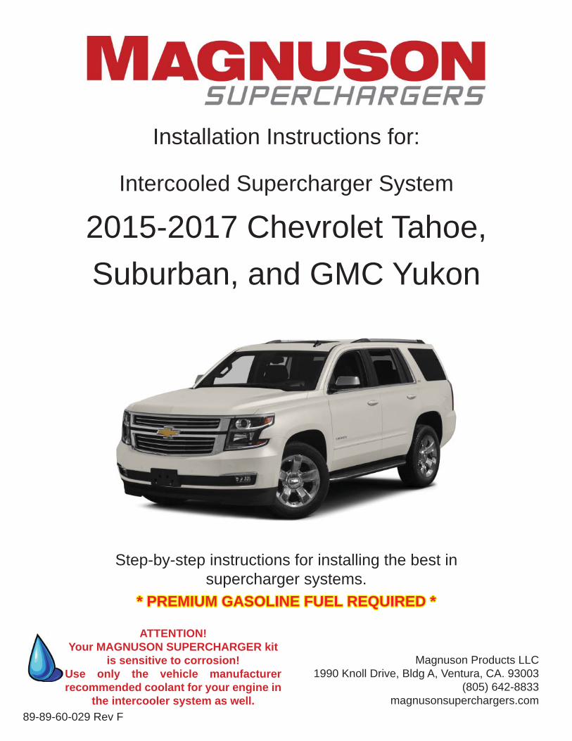
Installation Instructions for:
Intercooled Supercharger System
2015-2017 Chevrolet Tahoe, Suburban, and GMC Yukon
Step-by-step instructions for installing the best in supercharger systems.
Magnuson Products LLC 1990 Knoll Drive, Bldg A, Ventura, CA. 93003
(805) 642-8833magnusonsuperchargers.com
* PREMIUM GASOLINE FUEL REQUIRED ** PREMIUM GASOLINE FUEL REQUIRED *
89-89-60-029 Rev F
ATTENTION!Your MAGNUSON SUPERCHARGER kit
is sensitive to corrosion! Use only the vehicle manufacturer recommended coolant for your engine in
the intercooler system as well.
INSTALLATION MANUALMagnuson ProductsIntercooled Supercharger SystemGM 5.3L DI Liter Engines
Please take a few moments to review this manual thoroughly before you begin work: Make a quick parts check to make certain your kit is complete (see shipper parts list in this package). If you discover shipping damage or shortage, please call your dealer immediately. Take a look at exactly what you are going to need in terms of tools, time, and experience. Review our limited warranty with care. When unpacking the supercharger kit DO NOT lift the supercharger assembly by the black plastic bypass actuator. This is pre-set from the factory and can be altered if used as a lifting point!
Caution: Relieve the fuel system pressure before servicing fuel system components in order to reduce the risk of fi re and personal injury. After relieving the system pressure, a small amount of fuel may be released when servicing the fuel lines or connections. In order to reduce the risk of personal injury, cover the regulator and fuel line fi ttings with a shop towel before disconnecting. This will catch any fuel that may leak out. Place the towel in an approved container when the job is complete.
This supercharger system requires the use of only premium gasoline fuel,This supercharger system requires the use of only premium gasoline fuel,91 octane or better. It is NOT compatible with E85, Ethanol, or Flex fuels.91 octane or better. It is NOT compatible with E85, Ethanol, or Flex fuels.
Magnuson Products recommend that you run a minimum of one (1) tank of premium fuel through your vehicle prior to installation of the system to prevent any possible damage that may occur due to running the supercharged engine on lower octane fuel. DO NOT add octane booster to existing fuel in your vehicle.DO NOT add octane booster to existing fuel in your vehicle.
Magnuson Products Supercharger systems are designed for engines and vehicles in “GOOD” mechanical condition. Magnuson Products recommend that a basic engine system “Health Check” be performed prior to the installation of this supercharger system. Be sure to check for any pending or actual OBDII codes and fi x/repair any of the stock systems/components causing these codes. If there are codes prior to the installation they will be there after the installation.
Magnuson Products also recommend the following services to be performed on your vehicle before starting and running the vehicle post supercharger system installation:• Fuel Filter change• Engine oil and oil fi lter change using the vehicle manufacturer’s specifi ed products
NOTE: It is VERY IMPORTANT to use the factory specifi ed oil viscosity. The original equipmentmanufacturer has selected this grade of oil to work with your other engine systems such as hydraulic chain tensioners and variable cam controls. Deviation from this specifi cation may cause these systems to fail or not function properly. Please refer to your owner’s manual for the recommended oil viscosity for your engine and application.
• On newer vehicles not requiring new spark plugs it is important to verify the spark plug air gap.
On older vehicles Magnuson Products recommend these additional services to be performed:
• New spark plugs with the air gap set at the factory specifi cations OR new specifi cations if required bythe installation manual.• Engine coolant system pressure test and fl ush and refi ll. NOTE: YOU MUST USE THE GMNOTE: YOU MUST USE THE GMSPECIFIED COOLANT MIXTURE!SPECIFIED COOLANT MIXTURE!
Non “Magnuson Approved” calibrations or “tuning” will Void ALL warranties and CARB certifi cation.
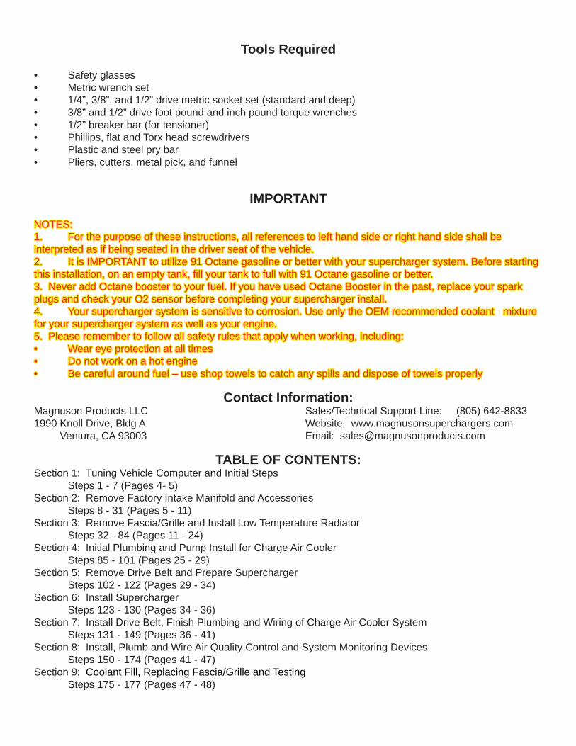
Tools Required
• Safety glasses• Metric wrench set• 1/4”, 3/8”, and 1/2” drive metric socket set (standard and deep)• 3/8” and 1/2” drive foot pound and inch pound torque wrenches• 1/2” breaker bar (for tensioner)• Phillips, fl at and Torx head screwdrivers• Plastic and steel pry bar• Pliers, cutters, metal pick, and funnel
IMPORTANT
NOTES: NOTES: 1. For the purpose of these instructions, all references to left hand side or right hand side shall be1. For the purpose of these instructions, all references to left hand side or right hand side shall beinterpreted as if being seated in the driver seat of the vehicle.interpreted as if being seated in the driver seat of the vehicle.2. It is IMPORTANT to utilize 91 Octane gasoline or better with your supercharger system. Before starting2. It is IMPORTANT to utilize 91 Octane gasoline or better with your supercharger system. Before startingthis installation, on an empty tank, fi ll your tank to full with 91 Octane gasoline or better.this installation, on an empty tank, fi ll your tank to full with 91 Octane gasoline or better.3. Never add Octane booster to your fuel. If you have used Octane Booster in the past, replace your spark3. Never add Octane booster to your fuel. If you have used Octane Booster in the past, replace your sparkplugs and check your O2 sensor before completing your supercharger install.plugs and check your O2 sensor before completing your supercharger install.4. Your supercharger system is sensitive to corrosion. Use only the OEM recommended coolant mixture4. Your supercharger system is sensitive to corrosion. Use only the OEM recommended coolant mixturefor your supercharger system as well as your engine.for your supercharger system as well as your engine.5. Please remember to follow all safety rules that apply when working, including:5. Please remember to follow all safety rules that apply when working, including:• Wear eye protection at all times• Wear eye protection at all times• Do not work on a hot engine• Do not work on a hot engine• Be careful around fuel – use shop towels to catch any spills and dispose of towels properly• Be careful around fuel – use shop towels to catch any spills and dispose of towels properly
Contact Information:Magnuson Products LLC Sales/Technical Support Line: (805) 642-88331990 Knoll Drive, Bldg A Website: www.magnusonsuperchargers.com Ventura, CA 93003 Email: [email protected]
TABLE OF CONTENTS:Section 1: Tuning Vehicle Computer and Initial Steps
Steps 1 - 7 (Pages 4- 5)Section 2: Remove Factory Intake Manifold and Accessories
Steps 8 - 31 (Pages 5 - 11)Section 3: Remove Fascia/Grille and Install Low Temperature Radiator
Steps 32 - 84 (Pages 11 - 24)Section 4: Initial Plumbing and Pump Install for Charge Air Cooler
Steps 85 - 101 (Pages 25 - 29)Section 5: Remove Drive Belt and Prepare Supercharger
Steps 102 - 122 (Pages 29 - 34)Section 6: Install Supercharger
Steps 123 - 130 (Pages 34 - 36)Section 7: Install Drive Belt, Finish Plumbing and Wiring of Charge Air Cooler System
Steps 131 - 149 (Pages 36 - 41)Section 8: Install, Plumb and Wire Air Quality Control and System Monitoring Devices
Steps 150 - 174 (Pages 41 - 47)Section 9: Coolant Fill, Replacing Fascia/Grille and Testing
Steps 175 - 177 (Pages 47 - 48)
Table of ContentsSection 1: Tuning Vehicle Computer and Initial Steps 5Section 1: Tuning Vehicle Computer and Initial Steps 5Section 2: Remove Factory Intake Manifold and Accessories 6Section 2: Remove Factory Intake Manifold and Accessories 6Section 3: Remove Fascia/Grille and Install Low Temperature Radiator 12Section 3: Remove Fascia/Grille and Install Low Temperature Radiator 12Section 4: Initial Plumbing and Pump Install for Charge Air Cooler 25Section 4: Initial Plumbing and Pump Install for Charge Air Cooler 25Section 5: Remove Drive Belt and Prepare Supercharger 29Section 5: Remove Drive Belt and Prepare Supercharger 29Section 6: Install Supercharger 34Section 6: Install Supercharger 34Section 7: Install Drive Belt, Finish Plumbing and Wiring of Intercooler System 36Section 7: Install Drive Belt, Finish Plumbing and Wiring of Intercooler System 36Section 8: Install Air Quality Control and System Monitoring Devices 41Section 8: Install Air Quality Control and System Monitoring Devices 41Section 9: Coolant Fill, Replacing Fascia/Grille and Testing 47Section 9: Coolant Fill, Replacing Fascia/Grille and Testing 47
2015-2017 GM Tahoe, Suburban, and Yukon
04/17 Page 4 www.magnusonsuperchargers.com
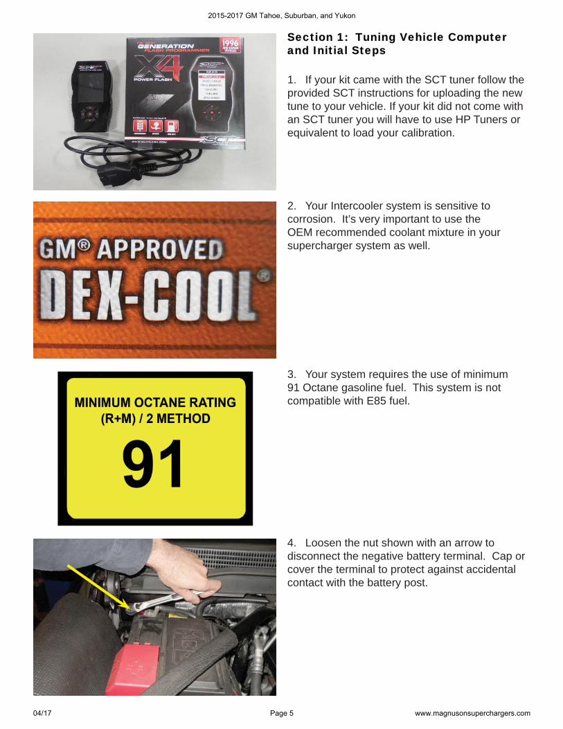
Section 1: Tuning Vehicle Computer Section 1: Tuning Vehicle Computer and Initial Stepsand Initial Steps
1. If your kit came with the SCT tuner follow the provided SCT instructions for uploading the new tune to your vehicle. If your kit did not come with an SCT tuner you will have to use HP Tuners or equivalent to load your calibration.
2. Your Intercooler system is sensitive to corrosion. It’s very important to use the OEM recommended coolant mixture in your supercharger system as well.
3. Your system requires the use of minimum 91 Octane gasoline fuel. This system is not compatible with E85 fuel.
4. Loosen the nut shown with an arrow to disconnect the negative battery terminal. Cap or cover the terminal to protect against accidental contact with the battery post.
2015-2017 GM Tahoe, Suburban, and Yukon
04/17 Page 5 www.magnusonsuperchargers.com
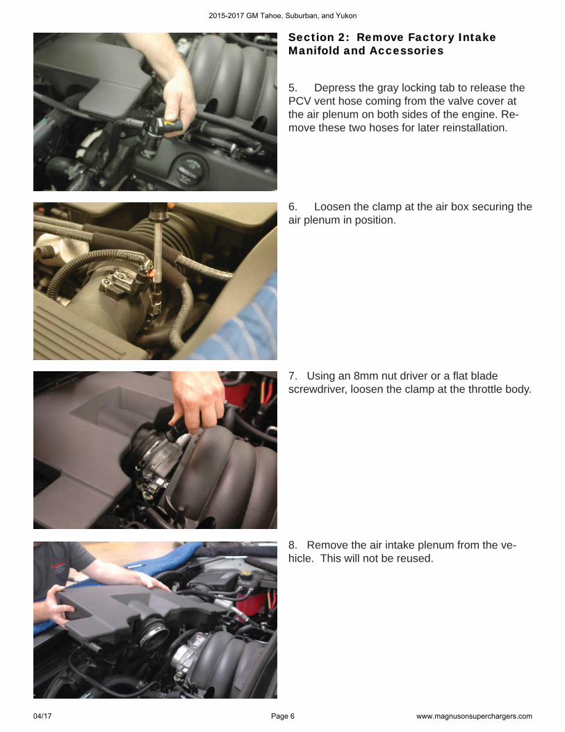
Section 2: Remove Factory Intake Section 2: Remove Factory Intake Manifold and AccessoriesManifold and Accessories
5. Depress the gray locking tab to release the PCV vent hose coming from the valve cover at the air plenum on both sides of the engine. Re-move these two hoses for later reinstallation.
8. Remove the air intake plenum from the ve-hicle. This will not be reused.
6. Loosen the clamp at the air box securing the air plenum in position.
7. Using an 8mm nut driver or a fl at blade screwdriver, loosen the clamp at the throttle body.
2015-2017 GM Tahoe, Suburban, and Yukon
04/17 Page 6 www.magnusonsuperchargers.com
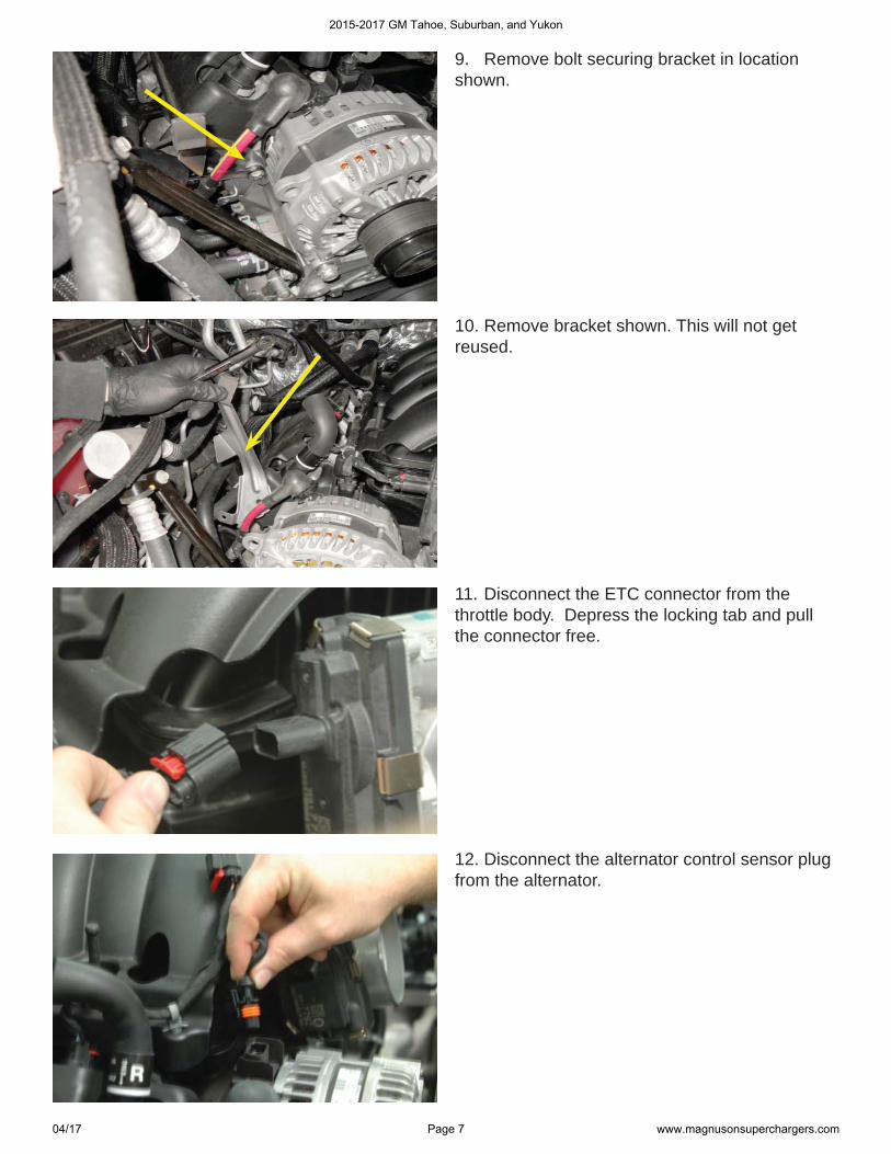
11. Disconnect the ETC connector from the throttle body. Depress the locking tab and pull the connector free.
9. Remove bolt securing bracket in location shown.
10. Remove bracket shown. This will not get reused.
12. Disconnect the alternator control sensor plug from the alternator.
2015-2017 GM Tahoe, Suburban, and Yukon
04/17 Page 7 www.magnusonsuperchargers.com
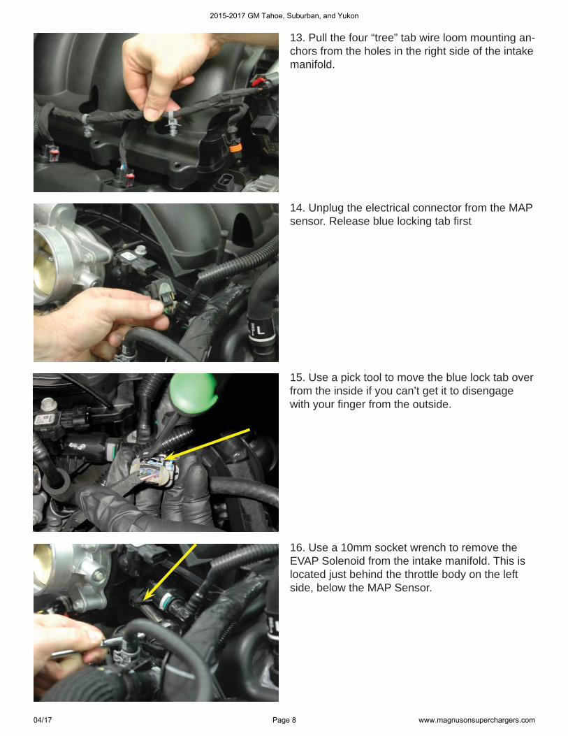
13. Pull the four “tree” tab wire loom mounting an-chors from the holes in the right side of the intake manifold.
14. Unplug the electrical connector from the MAP sensor. Release blue locking tab fi rst
16. Use a 10mm socket wrench to remove the EVAP Solenoid from the intake manifold. This is located just behind the throttle body on the left side, below the MAP Sensor.
15. Use a pick tool to move the blue lock tab over from the inside if you can’t get it to disengage with your fi nger from the outside.
2015-2017 GM Tahoe, Suburban, and Yukon
04/17 Page 8 www.magnusonsuperchargers.com
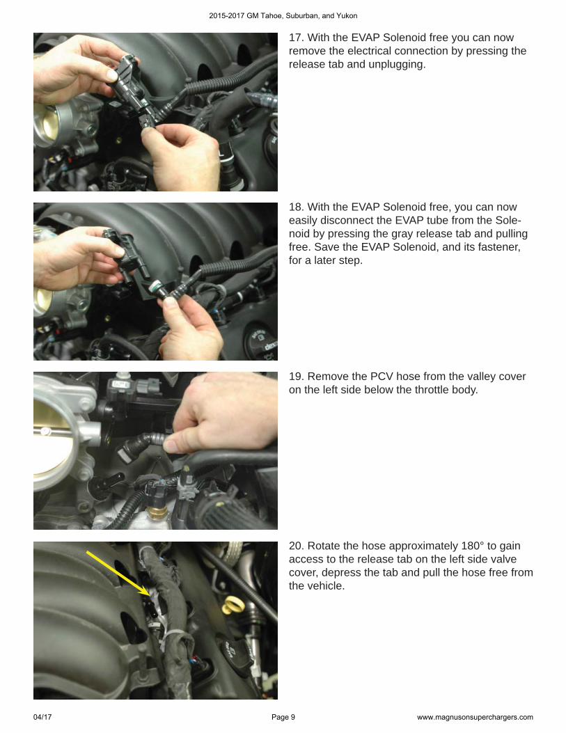
17. With the EVAP Solenoid free you can now remove the electrical connection by pressing the release tab and unplugging.
18. With the EVAP Solenoid free, you can now easily disconnect the EVAP tube from the Sole-noid by pressing the gray release tab and pulling free. Save the EVAP Solenoid, and its fastener, for a later step.
19. Remove the PCV hose from the valley cover on the left side below the throttle body.
20. Rotate the hose approximately 180° to gain access to the release tab on the left side valve cover, depress the tab and pull the hose free from the vehicle.
2015-2017 GM Tahoe, Suburban, and Yukon
04/17 Page 9 www.magnusonsuperchargers.com
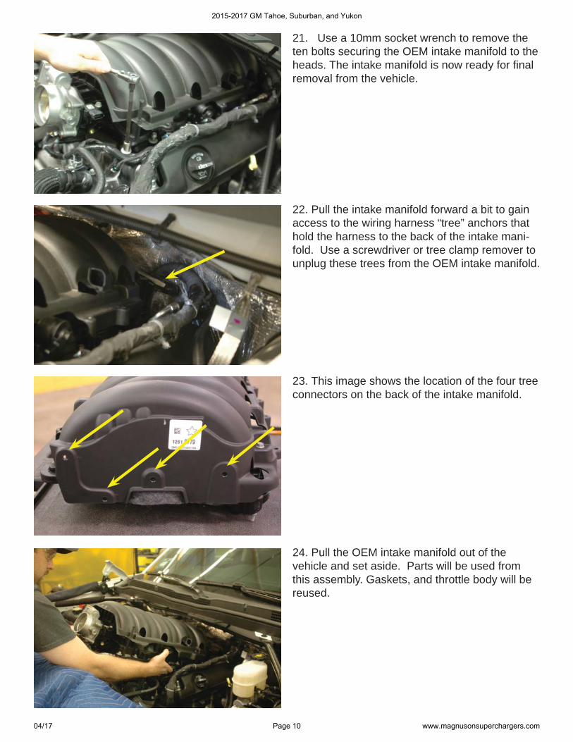
21. Use a 10mm socket wrench to remove the ten bolts securing the OEM intake manifold to the heads. The intake manifold is now ready for fi nal removal from the vehicle.
22. Pull the intake manifold forward a bit to gain access to the wiring harness “tree” anchors that hold the harness to the back of the intake mani-fold. Use a screwdriver or tree clamp remover to unplug these trees from the OEM intake manifold.
23. This image shows the location of the four tree connectors on the back of the intake manifold.
24. Pull the OEM intake manifold out of the vehicle and set aside. Parts will be used from this assembly. Gaskets, and throttle body will be reused.
2015-2017 GM Tahoe, Suburban, and Yukon
04/17 Page 10 www.magnusonsuperchargers.com
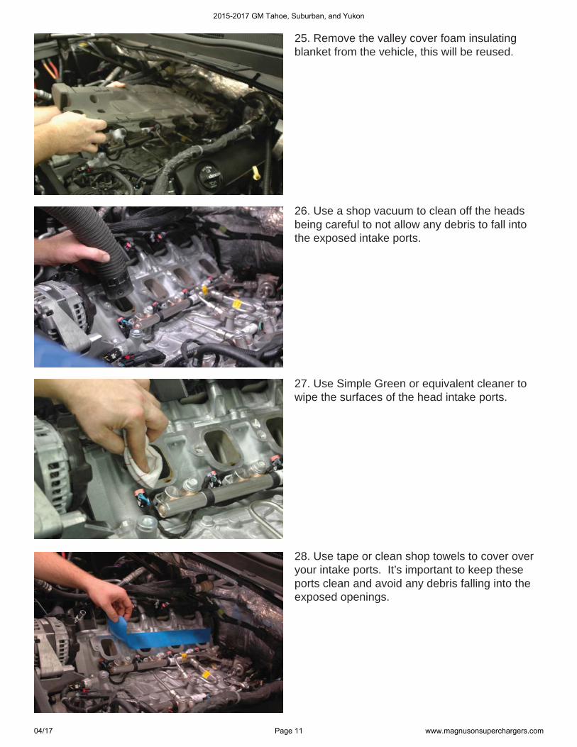
25. Remove the valley cover foam insulating blanket from the vehicle, this will be reused.
26. Use a shop vacuum to clean off the heads being careful to not allow any debris to fall into the exposed intake ports.
27. Use Simple Green or equivalent cleaner to wipe the surfaces of the head intake ports.
28. Use tape or clean shop towels to cover over your intake ports. It’s important to keep these ports clean and avoid any debris falling into the exposed openings.
2015-2017 GM Tahoe, Suburban, and Yukon
04/17 Page 11 www.magnusonsuperchargers.com
Section 3: Remove Fascia/Grille and Section 3: Remove Fascia/Grille and Install Low Temperature RadiatorInstall Low Temperature Radiator
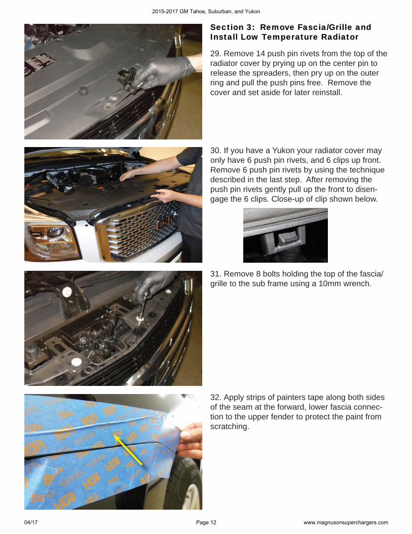
29. Remove 14 push pin rivets from the top of the radiator cover by prying up on the center pin to release the spreaders, then pry up on the outer ring and pull the push pins free. Remove the cover and set aside for later reinstall.
31. Remove 8 bolts holding the top of the fascia/grille to the sub frame using a 10mm wrench.
32. Apply strips of painters tape along both sides of the seam at the forward, lower fascia connec-tion to the upper fender to protect the paint from scratching.
30. If you have a Yukon your radiator cover may only have 6 push pin rivets, and 6 clips up front. Remove 6 push pin rivets by using the technique described in the last step. After removing the push pin rivets gently pull up the front to disen-gage the 6 clips. Close-up of clip shown below.
2015-2017 GM Tahoe, Suburban, and Yukon
04/17 Page 12 www.magnusonsuperchargers.com
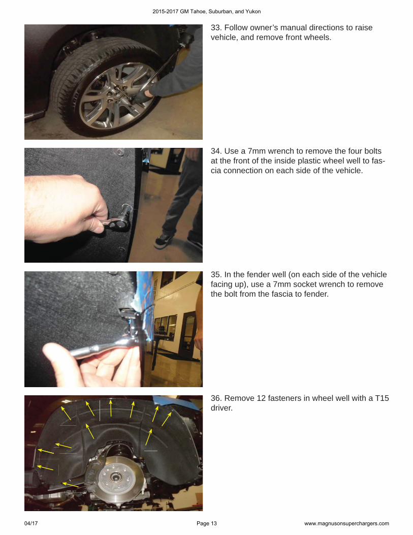
33. Follow owner’s manual directions to raise vehicle, and remove front wheels.
34. Use a 7mm wrench to remove the four bolts at the front of the inside plastic wheel well to fas-cia connection on each side of the vehicle.
35. In the fender well (on each side of the vehicle facing up), use a 7mm socket wrench to remove the bolt from the fascia to fender.
36. Remove 12 fasteners in wheel well with a T15 driver.
2015-2017 GM Tahoe, Suburban, and Yukon
04/17 Page 13 www.magnusonsuperchargers.com
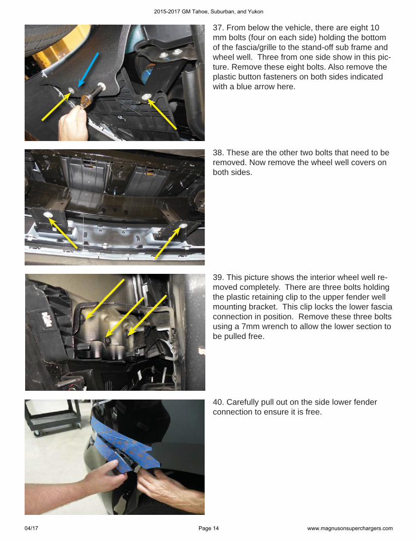
37. From below the vehicle, there are eight 10 mm bolts (four on each side) holding the bottom of the fascia/grille to the stand-off sub frame and wheel well. Three from one side show in this pic-ture. Remove these eight bolts. Also remove the plastic button fasteners on both sides indicated with a blue arrow here.
38. These are the other two bolts that need to be removed. Now remove the wheel well covers on both sides.
39. This picture shows the interior wheel well re-moved completely. There are three bolts holding the plastic retaining clip to the upper fender well mounting bracket. This clip locks the lower fascia connection in position. Remove these three bolts using a 7mm wrench to allow the lower section to be pulled free.
40. Carefully pull out on the side lower fender connection to ensure it is free.
2015-2017 GM Tahoe, Suburban, and Yukon
04/17 Page 14 www.magnusonsuperchargers.com
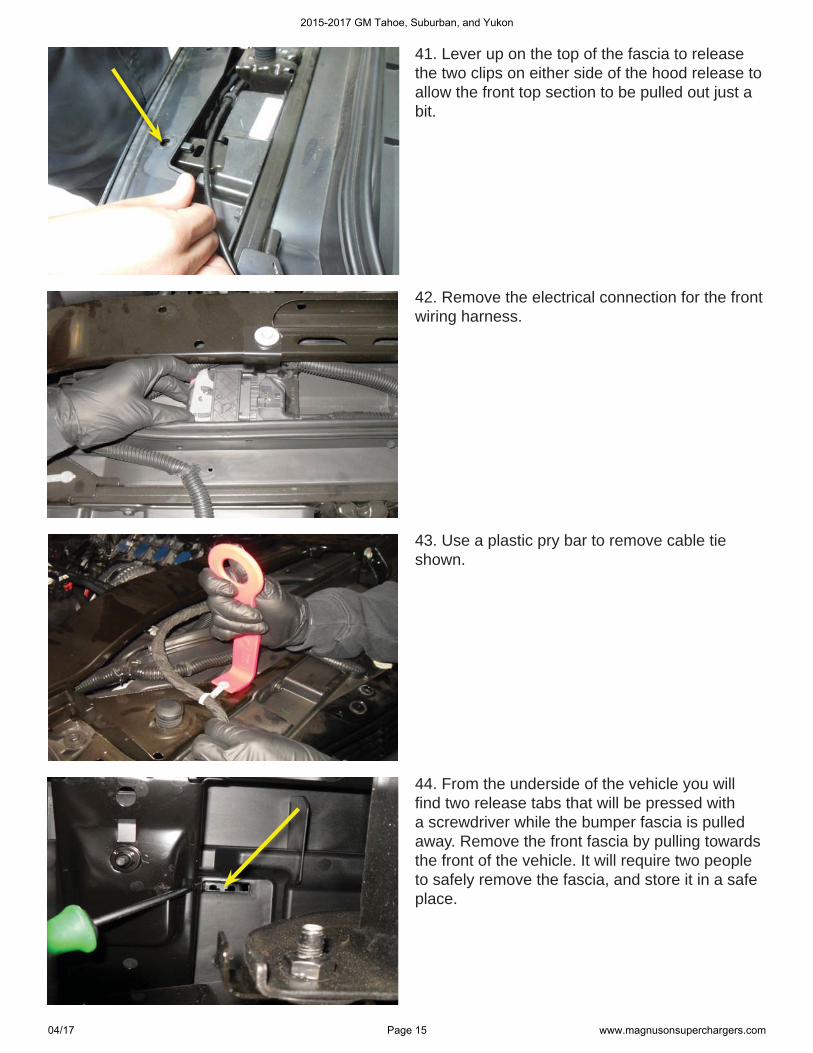
41. Lever up on the top of the fascia to release the two clips on either side of the hood release to allow the front top section to be pulled out just a bit.
42. Remove the electrical connection for the front wiring harness.
43. Use a plastic pry bar to remove cable tie shown.
44. From the underside of the vehicle you will fi nd two release tabs that will be pressed with a screwdriver while the bumper fascia is pulled away. Remove the front fascia by pulling towards the front of the vehicle. It will require two people to safely remove the fascia, and store it in a safe place.
2015-2017 GM Tahoe, Suburban, and Yukon
04/17 Page 15 www.magnusonsuperchargers.com
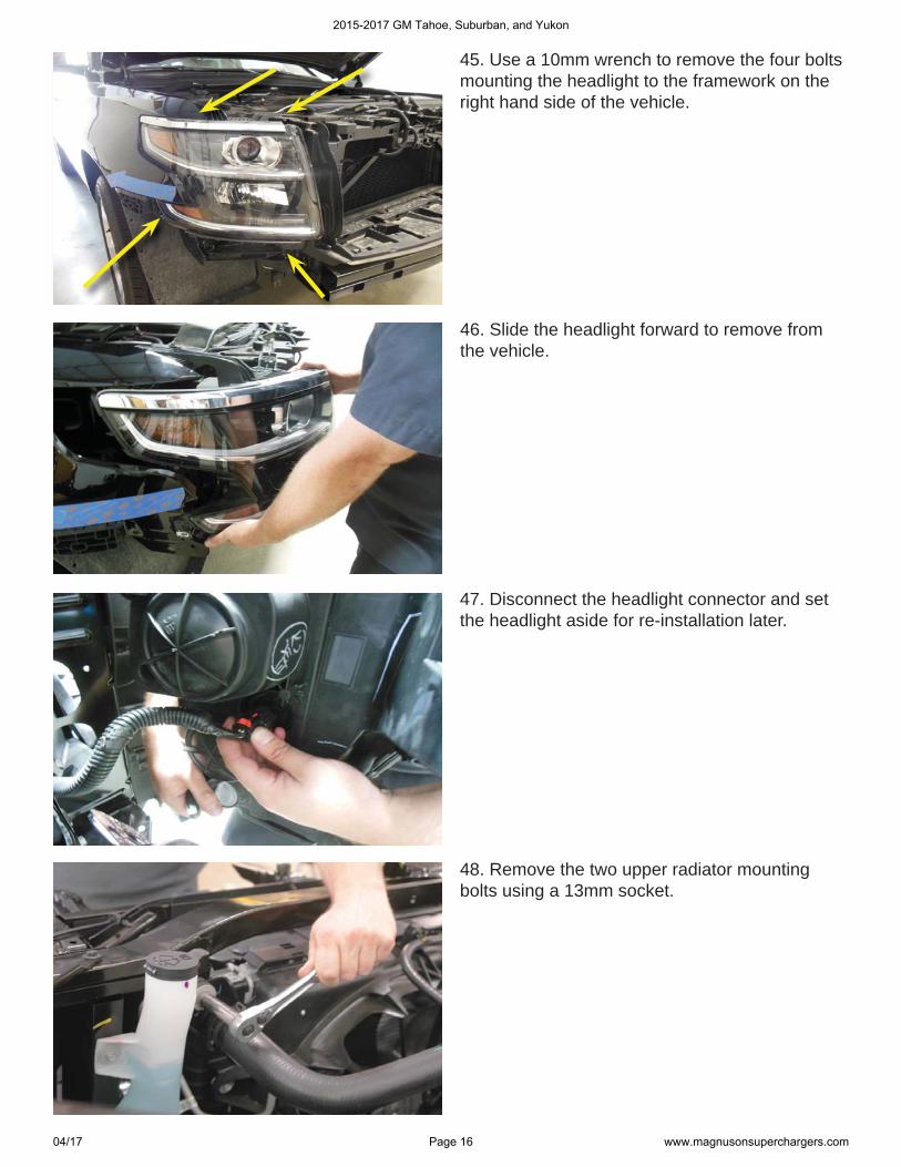
45. Use a 10mm wrench to remove the four bolts mounting the headlight to the framework on the right hand side of the vehicle.
46. Slide the headlight forward to remove from the vehicle.
47. Disconnect the headlight connector and set the headlight aside for re-installation later.
48. Remove the two upper radiator mounting bolts using a 13mm socket.
2015-2017 GM Tahoe, Suburban, and Yukon
04/17 Page 16 www.magnusonsuperchargers.com
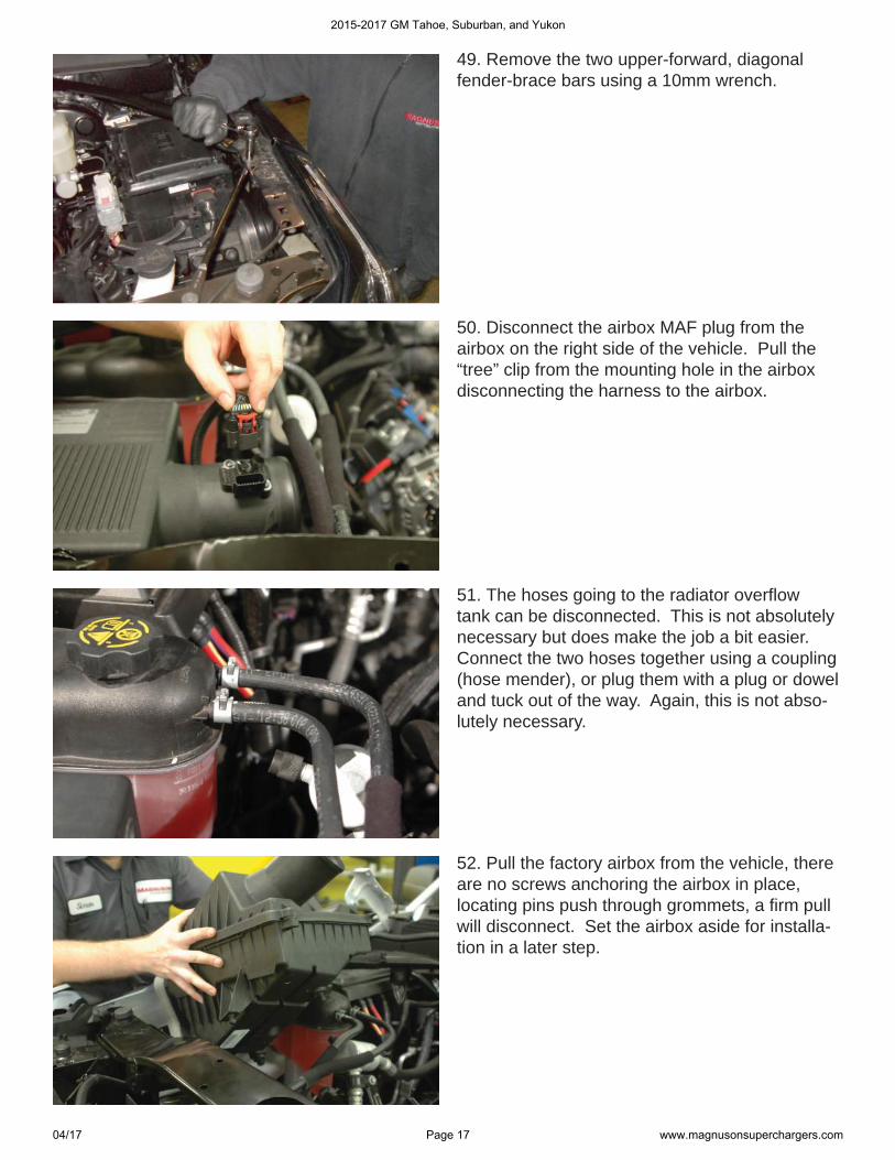
49. Remove the two upper-forward, diagonal fender-brace bars using a 10mm wrench.
50. Disconnect the airbox MAF plug from the airbox on the right side of the vehicle. Pull the “tree” clip from the mounting hole in the airbox disconnecting the harness to the airbox.
51. The hoses going to the radiator overfl ow tank can be disconnected. This is not absolutely necessary but does make the job a bit easier. Connect the two hoses together using a coupling (hose mender), or plug them with a plug or dowel and tuck out of the way. Again, this is not abso-lutely necessary.
52. Pull the factory airbox from the vehicle, there are no screws anchoring the airbox in place, locating pins push through grommets, a fi rm pull will disconnect. Set the airbox aside for installa-tion in a later step.
2015-2017 GM Tahoe, Suburban, and Yukon
04/17 Page 17 www.magnusonsuperchargers.com
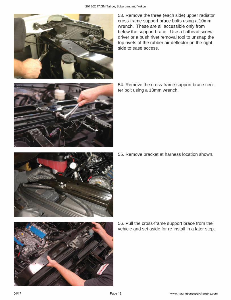
53. Remove the three (each side) upper radiator cross-frame support brace bolts using a 10mm wrench. These are all accessible only from below the support brace. Use a fl athead screw-driver or a push rivet removal tool to unsnap the top rivets of the rubber air defl ector on the right side to ease access.
54. Remove the cross-frame support brace cen-ter bolt using a 13mm wrench.
56. Pull the cross-frame support brace from the vehicle and set aside for re-install in a later step.
55. Remove bracket at harness location shown.
2015-2017 GM Tahoe, Suburban, and Yukon
04/17 Page 18 www.magnusonsuperchargers.com
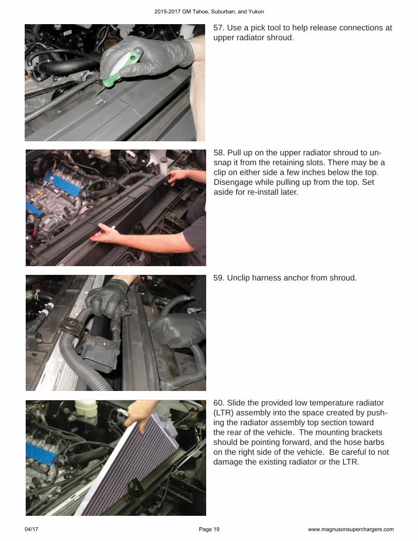
57. Use a pick tool to help release connections at upper radiator shroud.
58. Pull up on the upper radiator shroud to un-snap it from the retaining slots. There may be a clip on either side a few inches below the top. Disengage while pulling up from the top. Set aside for re-install later.
60. Slide the provided low temperature radiator (LTR) assembly into the space created by push-ing the radiator assembly top section toward the rear of the vehicle. The mounting brackets should be pointing forward, and the hose barbs on the right side of the vehicle. Be careful to not damage the existing radiator or the LTR.
59. Unclip harness anchor from shroud.
2015-2017 GM Tahoe, Suburban, and Yukon
04/17 Page 19 www.magnusonsuperchargers.com
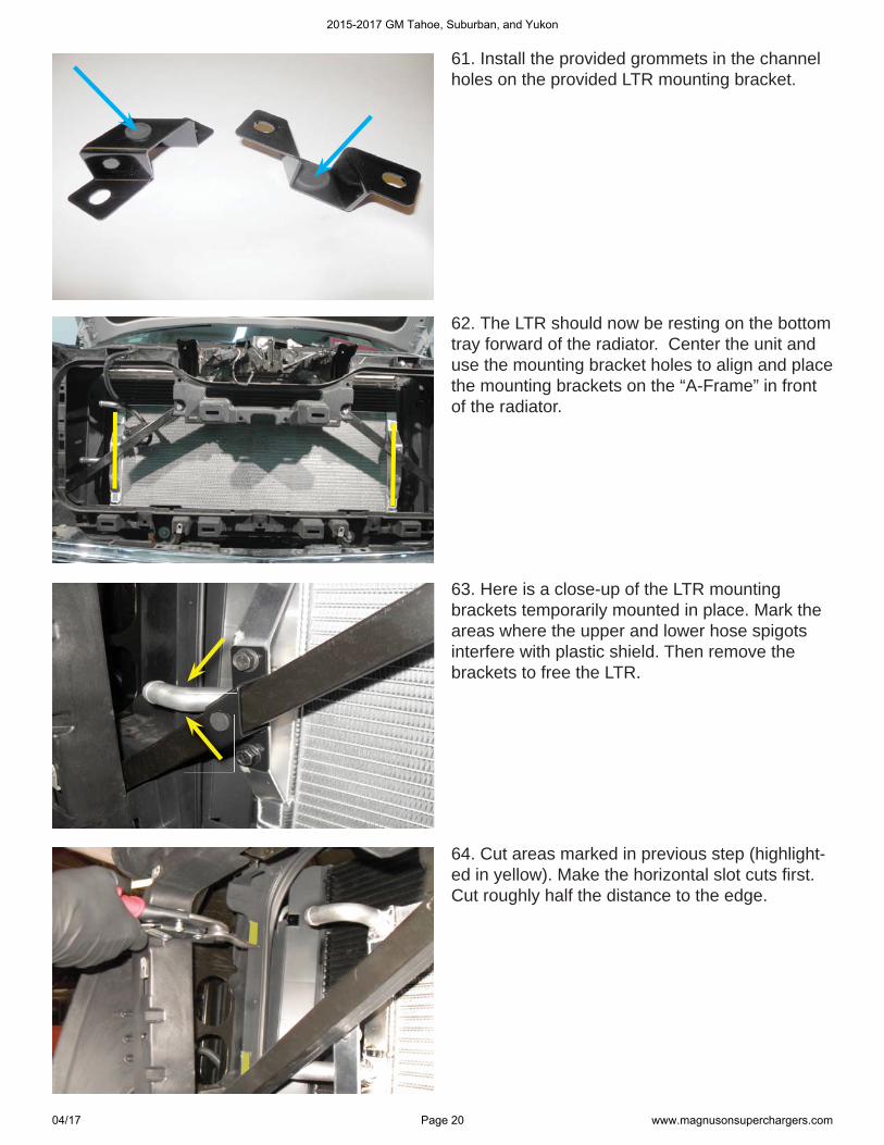
61. Install the provided grommets in the channel holes on the provided LTR mounting bracket.
62. The LTR should now be resting on the bottom tray forward of the radiator. Center the unit and use the mounting bracket holes to align and place the mounting brackets on the “A-Frame” in front of the radiator.
63. Here is a close-up of the LTR mounting brackets temporarily mounted in place. Mark the areas where the upper and lower hose spigots interfere with plastic shield. Then remove the brackets to free the LTR.
64. Cut areas marked in previous step (highlight-ed in yellow). Make the horizontal slot cuts fi rst. Cut roughly half the distance to the edge.
2015-2017 GM Tahoe, Suburban, and Yukon
04/17 Page 20 www.magnusonsuperchargers.com
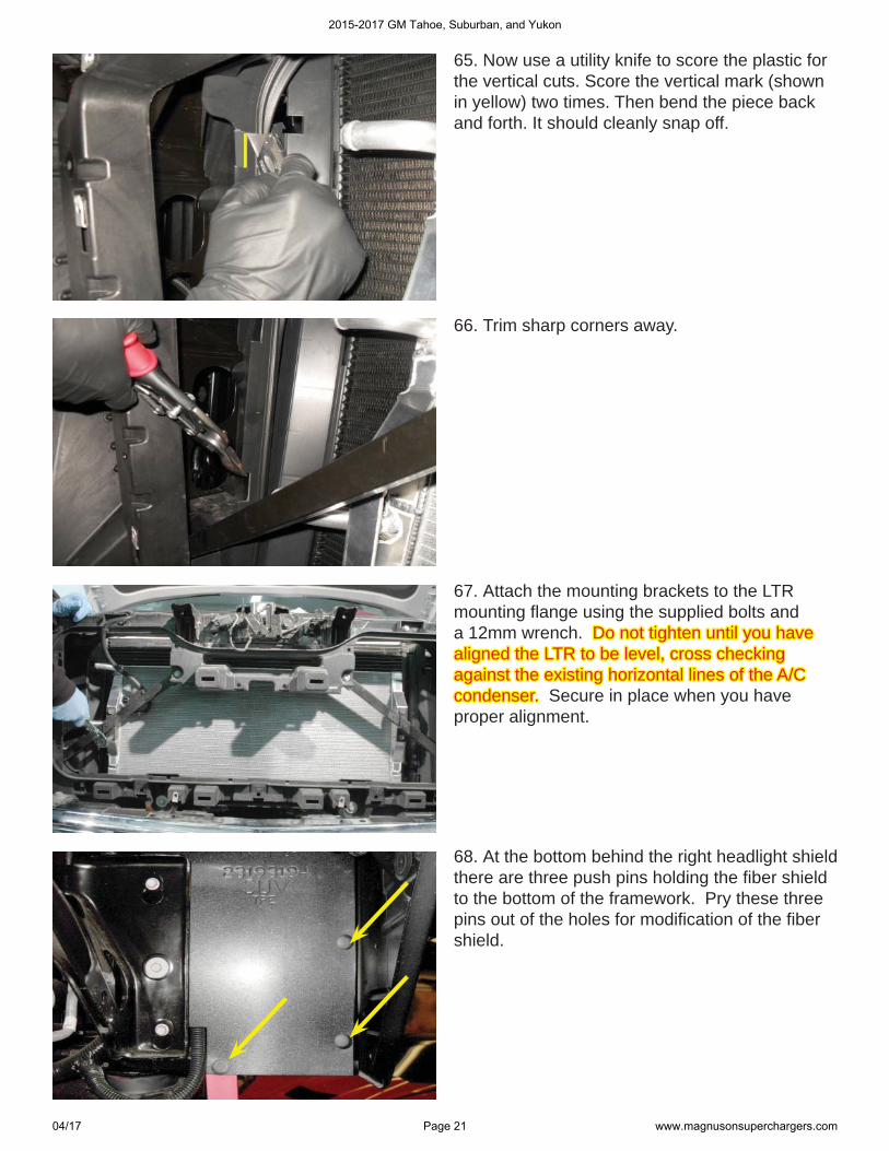
65. Now use a utility knife to score the plastic for the vertical cuts. Score the vertical mark (shown in yellow) two times. Then bend the piece back and forth. It should cleanly snap off.
66. Trim sharp corners away.
67. Attach the mounting brackets to the LTR mounting fl ange using the supplied bolts and a 12mm wrench. Do not tighten until you have Do not tighten until you have aligned the LTR to be level, cross checking aligned the LTR to be level, cross checking against the existing horizontal lines of the A/C against the existing horizontal lines of the A/C condenser. condenser. Secure in place when you have proper alignment.
68. At the bottom behind the right headlight shield there are three push pins holding the fi ber shield to the bottom of the framework. Pry these three pins out of the holes for modifi cation of the fi ber shield.
2015-2017 GM Tahoe, Suburban, and Yukon
04/17 Page 21 www.magnusonsuperchargers.com

4-1/4”4-1/4”
4-3/4”4-3/4”
69. Pull the shield up and mark as shown in this picture. Cut this section of the headlight shield off for intercooler plumbing access.
70. Tuck the headlight shield back in place, and press the supplied edge grip seal over the bottom of the headlight opening as shown in this picture.
71. Remove the one 10mm nut and two 13mm bolts indicated, set aside for later re-installation.
Upper LTRUpper LTR
Lower LTRLower LTR
To IC PumpTo IC Pump
To CACTo CAC
Inner Hard Inner Hard LineLine
Outer Hard LineOOLLLLLLLLLiLLLLLLL
72. Here are the coolant hard lines showing their relative location and orientation.
2015-2017 GM Tahoe, Suburban, and Yukon
04/17 Page 22 www.magnusonsuperchargers.com
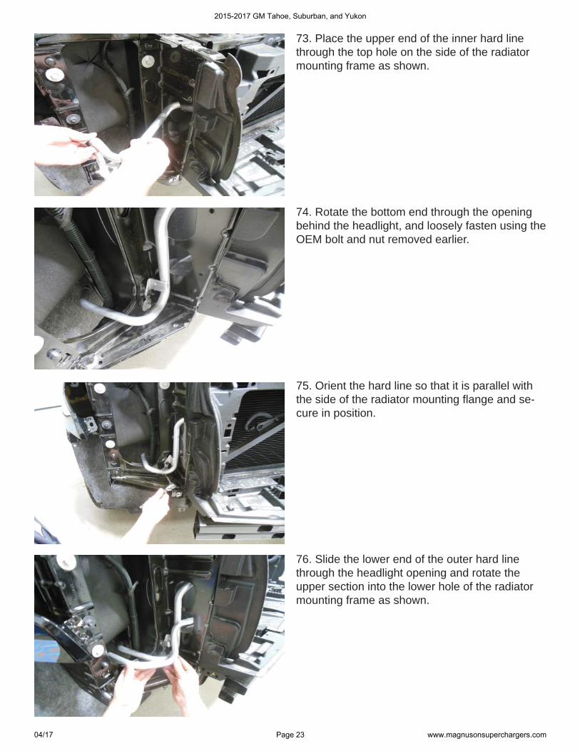
73. Place the upper end of the inner hard line through the top hole on the side of the radiator mounting frame as shown.
74. Rotate the bottom end through the opening behind the headlight, and loosely fasten using the OEM bolt and nut removed earlier.
75. Orient the hard line so that it is parallel with the side of the radiator mounting fl ange and se-cure in position.
76. Slide the lower end of the outer hard line through the headlight opening and rotate the upper section into the lower hole of the radiator mounting frame as shown.
2015-2017 GM Tahoe, Suburban, and Yukon
04/17 Page 23 www.magnusonsuperchargers.com
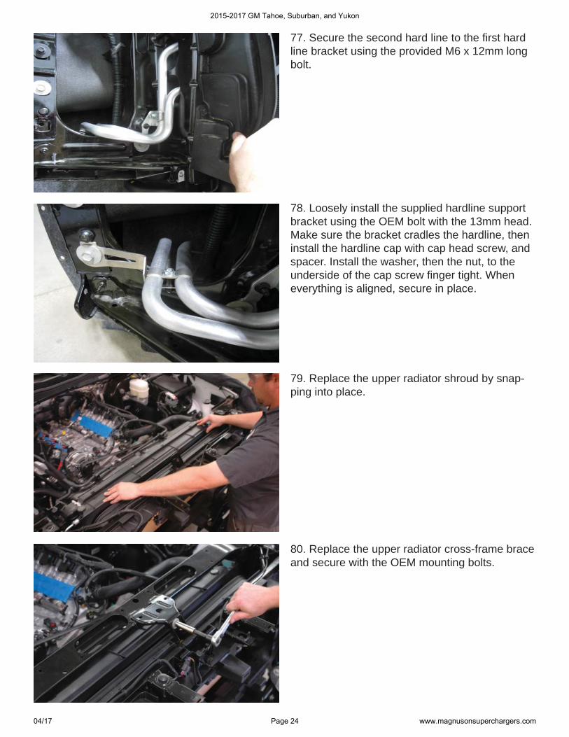
77. Secure the second hard line to the fi rst hard line bracket using the provided M6 x 12mm long bolt.
78. Loosely install the supplied hardline support bracket using the OEM bolt with the 13mm head. Make sure the bracket cradles the hardline, then install the hardline cap with cap head screw, and spacer. Install the washer, then the nut, to the underside of the cap screw fi nger tight. When everything is aligned, secure in place.
79. Replace the upper radiator shroud by snap-ping into place.
80. Replace the upper radiator cross-frame brace and secure with the OEM mounting bolts.
2015-2017 GM Tahoe, Suburban, and Yukon
04/17 Page 24 www.magnusonsuperchargers.com
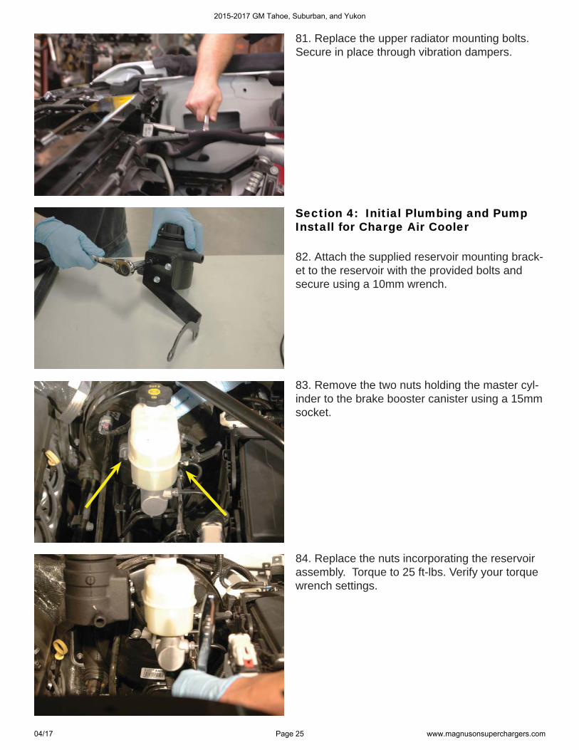
81. Replace the upper radiator mounting bolts. Secure in place through vibration dampers.
Section 4: Initial Plumbing and Pump Section 4: Initial Plumbing and Pump Install for Charge Air CoolerInstall for Charge Air Cooler
82. Attach the supplied reservoir mounting brack-et to the reservoir with the provided bolts and secure using a 10mm wrench.
83. Remove the two nuts holding the master cyl-inder to the brake booster canister using a 15mm socket.
84. Replace the nuts incorporating the reservoir assembly. Torque to 25 ft-lbs. Verify your torque wrench settings.
2015-2017 GM Tahoe, Suburban, and Yukon
04/17 Page 25 www.magnusonsuperchargers.com
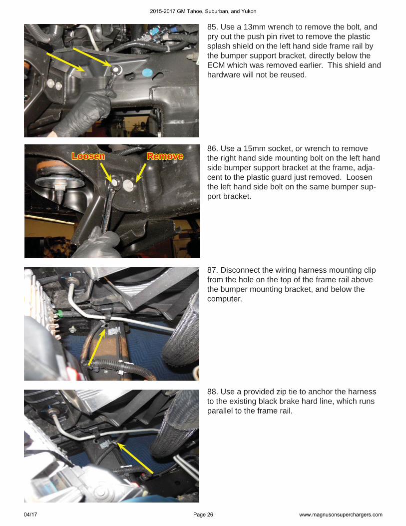
85. Use a 13mm wrench to remove the bolt, and pry out the push pin rivet to remove the plastic splash shield on the left hand side frame rail by the bumper support bracket, directly below the ECM which was removed earlier. This shield and hardware will not be reused.
LoosenLoosen RemoveRemove86. Use a 15mm socket, or wrench to remove the right hand side mounting bolt on the left hand side bumper support bracket at the frame, adja-cent to the plastic guard just removed. Loosen the left hand side bolt on the same bumper sup-port bracket.
87. Disconnect the wiring harness mounting clip from the hole on the top of the frame rail above the bumper mounting bracket, and below the computer.
88. Use a provided zip tie to anchor the harness to the existing black brake hard line, which runs parallel to the frame rail.
2015-2017 GM Tahoe, Suburban, and Yukon
04/17 Page 26 www.magnusonsuperchargers.com
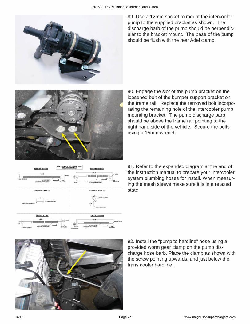
89. Use a 12mm socket to mount the intercooler pump to the supplied bracket as shown. The discharge barb of the pump should be perpendic-ular to the bracket mount. The base of the pump should be fl ush with the rear Adel clamp.
90. Engage the slot of the pump bracket on the loosened bolt of the bumper support bracket on the frame rail. Replace the removed bolt incorpo-rating the remaining hole of the intercooler pump mounting bracket. The pump discharge barb should be above the frame rail pointing to the right hand side of the vehicle. Secure the bolts using a 15mm wrench.
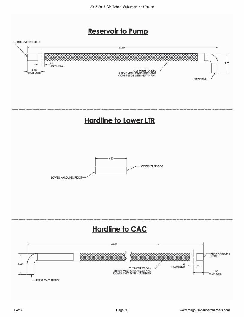
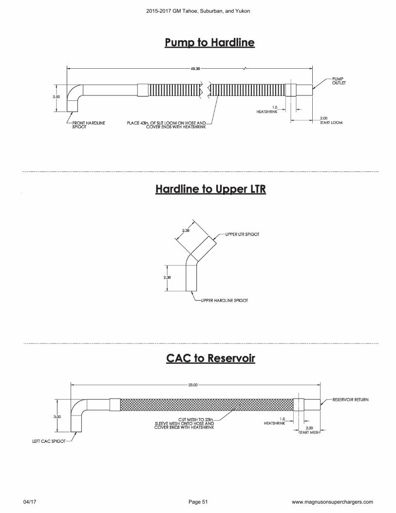
91. Refer to the expanded diagram at the end of the instruction manual to prepare your intercooler system plumbing hoses for install. When measur-ing the mesh sleeve make sure it is in a relaxed state.
92. Install the “pump to hardline” hose using a provided worm gear clamp on the pump dis-charge hose barb. Place the clamp as shown with the screw pointing upwards, and just below the trans cooler hardline.
2015-2017 GM Tahoe, Suburban, and Yukon
04/17 Page 27 www.magnusonsuperchargers.com
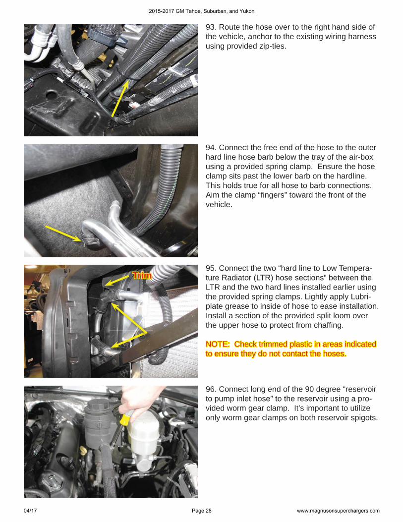
93. Route the hose over to the right hand side of the vehicle, anchor to the existing wiring harness using provided zip-ties.
94. Connect the free end of the hose to the outer hard line hose barb below the tray of the air-box using a provided spring clamp. Ensure the hose clamp sits past the lower barb on the hardline.This holds true for all hose to barb connections. Aim the clamp “fi ngers” toward the front of the vehicle.
95. Connect the two “hard line to Low Tempera-ture Radiator (LTR) hose sections” between the LTR and the two hard lines installed earlier using the provided spring clamps. Lightly apply Lubri-plate grease to inside of hose to ease installation. Install a section of the provided split loom over the upper hose to protect from chaffi ng.
NOTE: Check trimmed plastic in areas indicated NOTE: Check trimmed plastic in areas indicated to ensure they do not contact the hoses. to ensure they do not contact the hoses.
96. Connect long end of the 90 degree “reservoir to pump inlet hose” to the reservoir using a pro-vided worm gear clamp. It’s important to utilize only worm gear clamps on both reservoir spigots.
TrimTrim
2015-2017 GM Tahoe, Suburban, and Yukon
04/17 Page 28 www.magnusonsuperchargers.com
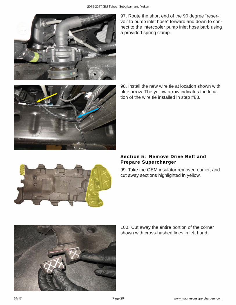
97. Route the short end of the 90 degree “reser-voir to pump inlet hose” forward and down to con-nect to the intercooler pump inlet hose barb using a provided spring clamp.
98. Install the new wire tie at location shown with blue arrow. The yellow arrow indicates the loca-tion of the wire tie installed in step #88.
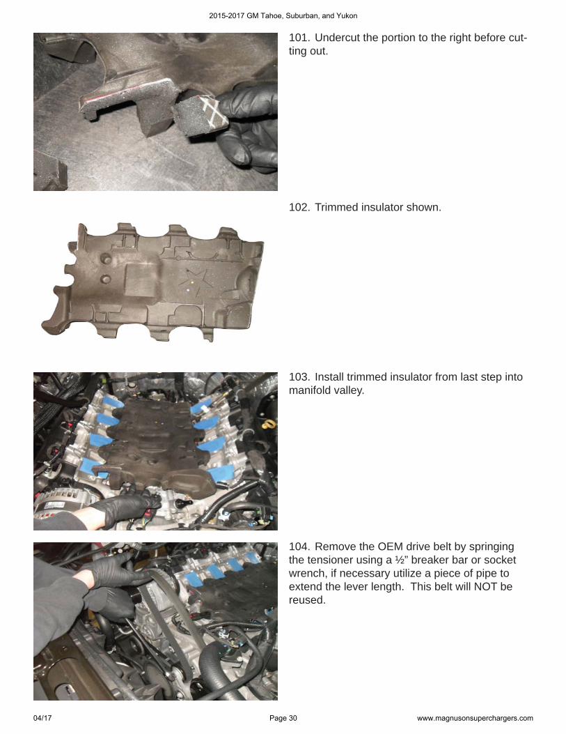
Section 5: Remove Drive Belt and Section 5: Remove Drive Belt and Prepare SuperchargerPrepare Supercharger99. Take the OEM insulator removed earlier, and cut away sections highlighted in yellow.
100. Cut away the entire portion of the corner shown with cross-hashed lines in left hand.
2015-2017 GM Tahoe, Suburban, and Yukon
04/17 Page 29 www.magnusonsuperchargers.com
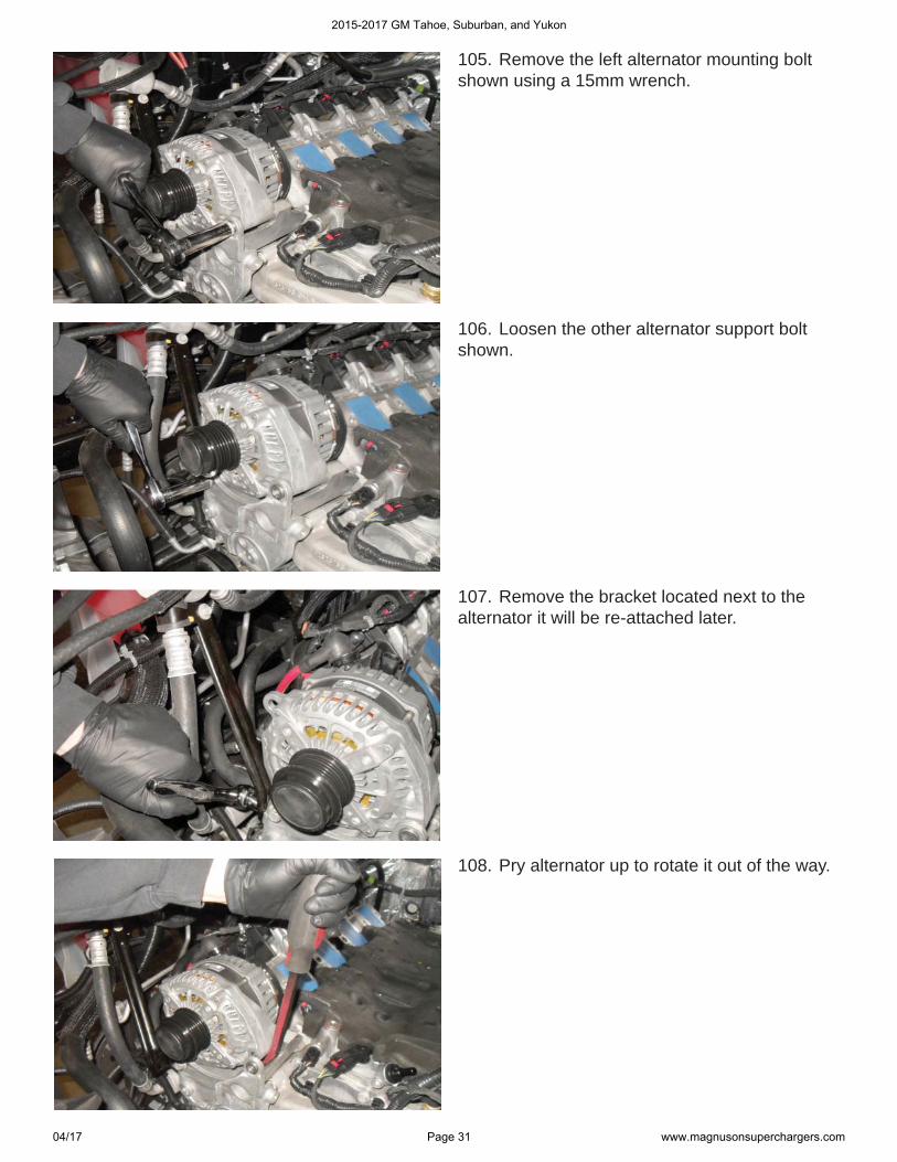
101. Undercut the portion to the right before cut-ting out.
102. Trimmed insulator shown.
104. Remove the OEM drive belt by springing the tensioner using a ½” breaker bar or socket wrench, if necessary utilize a piece of pipe to extend the lever length. This belt will NOT be reused.
103. Install trimmed insulator from last step into manifold valley.
2015-2017 GM Tahoe, Suburban, and Yukon
04/17 Page 30 www.magnusonsuperchargers.com
105. Remove the left alternator mounting bolt shown using a 15mm wrench.
106. Loosen the other alternator support bolt shown.
107. Remove the bracket located next to the alternator it will be re-attached later.
108. Pry alternator up to rotate it out of the way.
2015-2017 GM Tahoe, Suburban, and Yukon
04/17 Page 31 www.magnusonsuperchargers.com
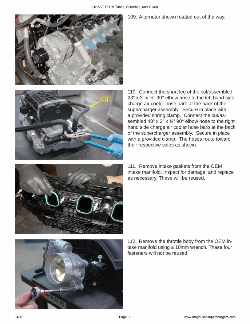
109. Alternator shown rotated out of the way.
110. Connect the short leg of the cut/assembled 23” x 3” x ¾” 90° elbow hose to the left hand side charge air cooler hose barb at the back of the supercharger assembly. Secure in place with a provided spring clamp. Connect the cut/as-sembled 48” x 3” x ¾” 90° elbow hose to the right hand side charge air cooler hose barb at the back of the supercharger assembly. Secure in place with a provided clamp. The hoses route toward their respective sides as shown.
112. Remove the throttle body from the OEM in-take manifold using a 10mm wrench. These four fasteners will not be reused.
111. Remove intake gaskets from the OEM intake manifold. Inspect for damage, and replace as necessary. These will be reused.
48”
2015-2017 GM Tahoe, Suburban, and Yukon
04/17 Page 32 www.magnusonsuperchargers.com
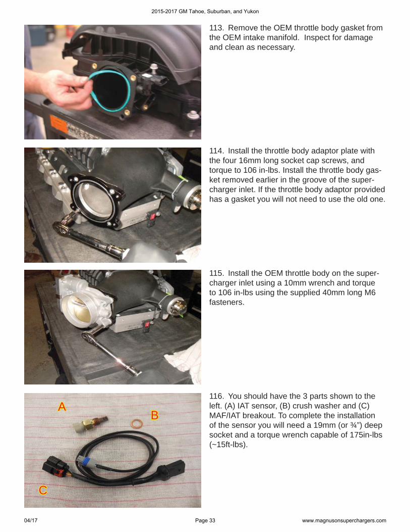
113. Remove the OEM throttle body gasket from the OEM intake manifold. Inspect for damage and clean as necessary.
114. Install the throttle body adaptor plate with the four 16mm long socket cap screws, and torque to 106 in-lbs. Install the throttle body gas-ket removed earlier in the groove of the super-charger inlet. If the throttle body adaptor provided has a gasket you will not need to use the old one.
115. Install the OEM throttle body on the super-charger inlet using a 10mm wrench and torque to 106 in-lbs using the supplied 40mm long M6 fasteners.
BBAA
CC
116. You should have the 3 parts shown to the left. (A) IAT sensor, (B) crush washer and (C) MAF/IAT breakout. To complete the installation of the sensor you will need a 19mm (or ¾”) deep socket and a torque wrench capable of 175in-lbs (~15ft-lbs).
2015-2017 GM Tahoe, Suburban, and Yukon
04/17 Page 33 www.magnusonsuperchargers.com
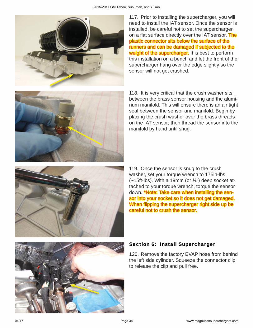
117. Prior to installing the supercharger, you will need to install the IAT sensor. Once the sensor is installed, be careful not to set the supercharger on a fl at surface directly over the IAT sensor. The The plastic connector sits below the surface of the plastic connector sits below the surface of the runners and can be damaged if subjected to the runners and can be damaged if subjected to the weight of the supercharger. weight of the supercharger. It is best to perform this installation on a bench and let the front of the supercharger hang over the edge slightly so the sensor will not get crushed.
118. It is very critical that the crush washer sits between the brass sensor housing and the alumi-num manifold. This will ensure there is an air tight seal between the sensor and manifold. Begin by placing the crush washer over the brass threads on the IAT sensor; then thread the sensor into the manifold by hand until snug.
Section 6: Install SuperchargerSection 6: Install Supercharger
120. Remove the factory EVAP hose from behind the left side cylinder. Squeeze the connector clip to release the clip and pull free.
119. Once the sensor is snug to the crush washer, set your torque wrench to 175in-lbs (~15ft-lbs). With a 19mm (or ¾”) deep socket at-tached to your torque wrench, torque the sensor down. *Note: Take care when installing the sen-*Note: Take care when installing the sen-sor into your socket so it does not get damaged. sor into your socket so it does not get damaged. When fl ipping the supercharger right side up be When fl ipping the supercharger right side up be careful not to crush the sensor. careful not to crush the sensor.
2015-2017 GM Tahoe, Suburban, and Yukon
04/17 Page 34 www.magnusonsuperchargers.com
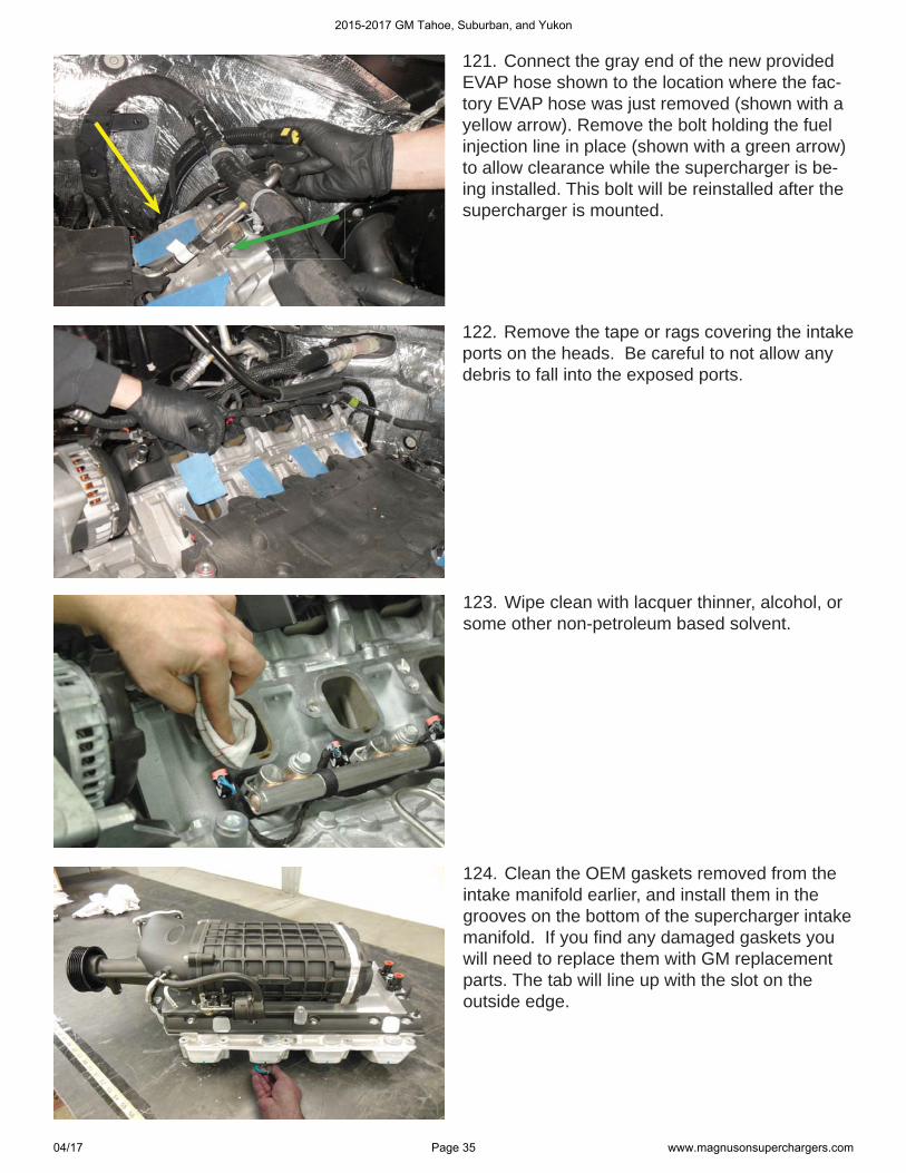
121. Connect the gray end of the new provided EVAP hose shown to the location where the fac-tory EVAP hose was just removed (shown with a yellow arrow). Remove the bolt holding the fuel injection line in place (shown with a green arrow) to allow clearance while the supercharger is be-ing installed. This bolt will be reinstalled after the supercharger is mounted.
122. Remove the tape or rags covering the intake ports on the heads. Be careful to not allow any debris to fall into the exposed ports.
123. Wipe clean with lacquer thinner, alcohol, or some other non-petroleum based solvent.
124. Clean the OEM gaskets removed from the intake manifold earlier, and install them in the grooves on the bottom of the supercharger intake manifold. If you fi nd any damaged gaskets you will need to replace them with GM replacement parts. The tab will line up with the slot on the outside edge.
2015-2017 GM Tahoe, Suburban, and Yukon
04/17 Page 35 www.magnusonsuperchargers.com
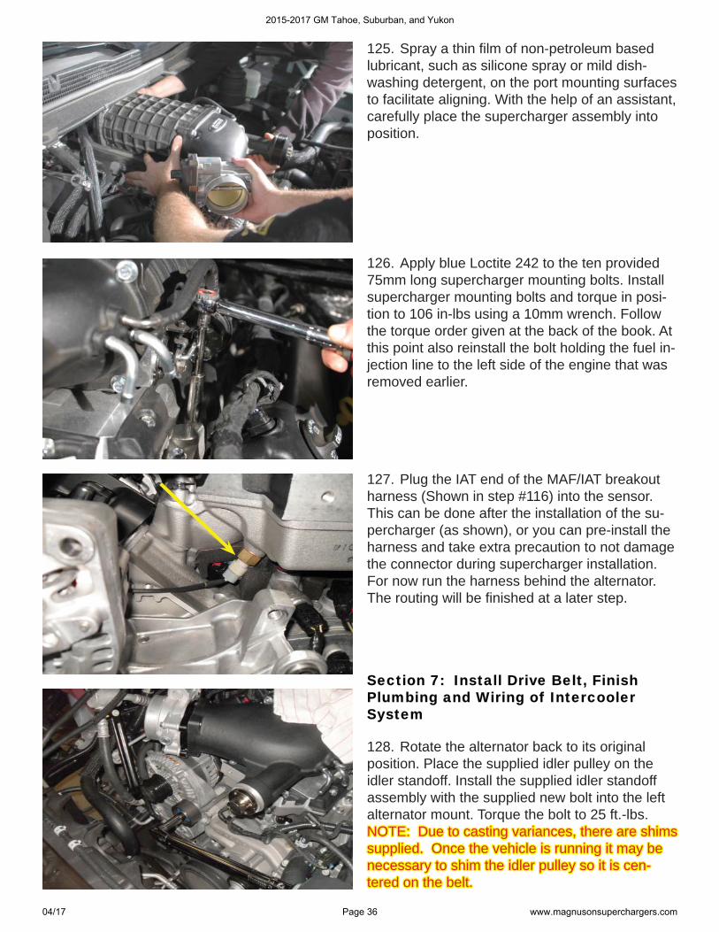
125. Spray a thin fi lm of non-petroleum based lubricant, such as silicone spray or mild dish-washing detergent, on the port mounting surfaces to facilitate aligning. With the help of an assistant, carefully place the supercharger assembly into position.
126. Apply blue Loctite 242 to the ten provided 75mm long supercharger mounting bolts. Install supercharger mounting bolts and torque in posi-tion to 106 in-lbs using a 10mm wrench. Follow the torque order given at the back of the book. At this point also reinstall the bolt holding the fuel in-jection line to the left side of the engine that was removed earlier.
127. Plug the IAT end of the MAF/IAT breakout harness (Shown in step #116) into the sensor. This can be done after the installation of the su-percharger (as shown), or you can pre-install the harness and take extra precaution to not damage the connector during supercharger installation. For now run the harness behind the alternator. The routing will be fi nished at a later step.
Section 7: Install Drive Belt, Finish Section 7: Install Drive Belt, Finish Plumbing and Wiring of Intercooler Plumbing and Wiring of Intercooler SystemSystem
128. Rotate the alternator back to its original position. Place the supplied idler pulley on the idler standoff. Install the supplied idler standoff assembly with the supplied new bolt into the left alternator mount. Torque the bolt to 25 ft.-lbs. NOTE: Due to casting variances, there are shims NOTE: Due to casting variances, there are shims supplied. Once the vehicle is running it may be supplied. Once the vehicle is running it may be necessary to shim the idler pulley so it is cen-necessary to shim the idler pulley so it is cen-tered on the belt.tered on the belt.
2015-2017 GM Tahoe, Suburban, and Yukon
04/17 Page 36 www.magnusonsuperchargers.com
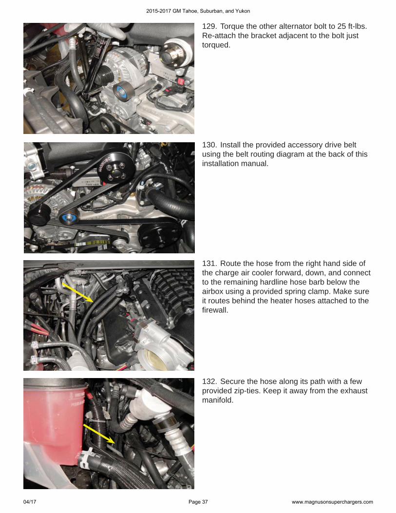
129. Torque the other alternator bolt to 25 ft-lbs. Re-attach the bracket adjacent to the bolt just torqued.
131. Route the hose from the right hand side of the charge air cooler forward, down, and connect to the remaining hardline hose barb below the airbox using a provided spring clamp. Make sure it routes behind the heater hoses attached to the fi rewall.
132. Secure the hose along its path with a few provided zip-ties. Keep it away from the exhaust manifold.
130. Install the provided accessory drive belt using the belt routing diagram at the back of this installation manual.
2015-2017 GM Tahoe, Suburban, and Yukon
04/17 Page 37 www.magnusonsuperchargers.com
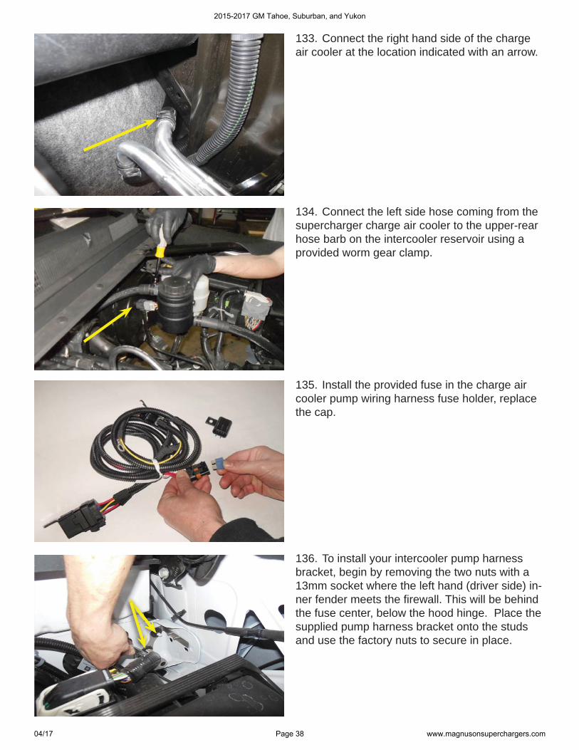
133. Connect the right hand side of the charge air cooler at the location indicated with an arrow.
134. Connect the left side hose coming from the supercharger charge air cooler to the upper-rear hose barb on the intercooler reservoir using a provided worm gear clamp.
135. Install the provided fuse in the charge air cooler pump wiring harness fuse holder, replace the cap.
136. To install your intercooler pump harness bracket, begin by removing the two nuts with a 13mm socket where the left hand (driver side) in-ner fender meets the fi rewall. This will be behind the fuse center, below the hood hinge. Place the supplied pump harness bracket onto the studs and use the factory nuts to secure in place.
2015-2017 GM Tahoe, Suburban, and Yukon
04/17 Page 38 www.magnusonsuperchargers.com
RelayRelayFuse holderFuse holder
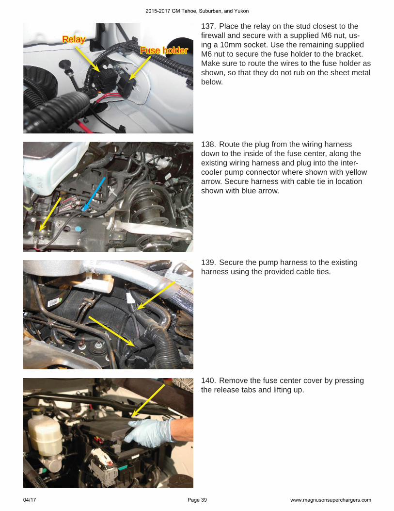
137. Place the relay on the stud closest to the fi rewall and secure with a supplied M6 nut, us-ing a 10mm socket. Use the remaining supplied M6 nut to secure the fuse holder to the bracket. Make sure to route the wires to the fuse holder as shown, so that they do not rub on the sheet metal below.
138. Route the plug from the wiring harness down to the inside of the fuse center, along the existing wiring harness and plug into the inter-cooler pump connector where shown with yellow arrow. Secure harness with cable tie in location shown with blue arrow.
139. Secure the pump harness to the existing harness using the provided cable ties.
140. Remove the fuse center cover by pressing the release tabs and lifting up.
2015-2017 GM Tahoe, Suburban, and Yukon
04/17 Page 39 www.magnusonsuperchargers.com
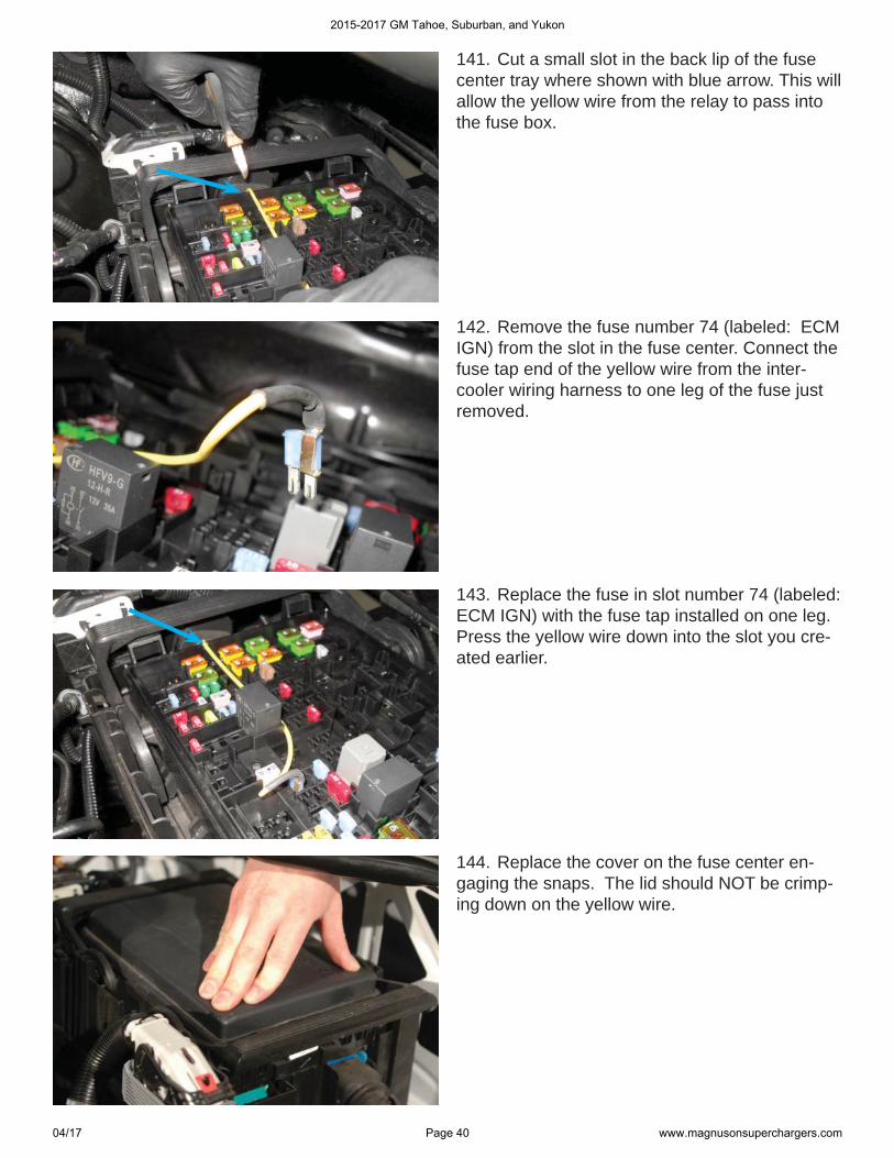
141. Cut a small slot in the back lip of the fuse center tray where shown with blue arrow. This will allow the yellow wire from the relay to pass into the fuse box.
142. Remove the fuse number 74 (labeled: ECM IGN) from the slot in the fuse center. Connect the fuse tap end of the yellow wire from the inter-cooler wiring harness to one leg of the fuse just removed.
143. Replace the fuse in slot number 74 (labeled: ECM IGN) with the fuse tap installed on one leg. Press the yellow wire down into the slot you cre-ated earlier.
144. Replace the cover on the fuse center en-gaging the snaps. The lid should NOT be crimp-ing down on the yellow wire.
2015-2017 GM Tahoe, Suburban, and Yukon
04/17 Page 40 www.magnusonsuperchargers.com
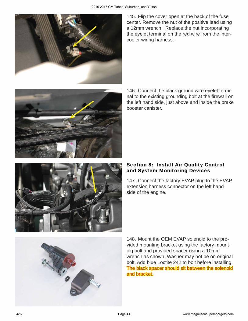
145. Flip the cover open at the back of the fuse center. Remove the nut of the positive lead using a 12mm wrench. Replace the nut incorporating the eyelet terminal on the red wire from the inter-cooler wiring harness.
146. Connect the black ground wire eyelet termi-nal to the existing grounding bolt at the fi rewall on the left hand side, just above and inside the brake booster canister.
Section 8: Install Air Quality Control Section 8: Install Air Quality Control and System Monitoring Devicesand System Monitoring Devices
147. Connect the factory EVAP plug to the EVAP extension harness connector on the left hand side of the engine.
148. Mount the OEM EVAP solenoid to the pro-vided mounting bracket using the factory mount-ing bolt and provided spacer using a 10mm wrench as shown. Washer may not be on original bolt. Add blue Loctite 242 to bolt before installing. The black spacer should sit between the solenoid The black spacer should sit between the solenoid and bracket. and bracket.
2015-2017 GM Tahoe, Suburban, and Yukon
04/17 Page 41 www.magnusonsuperchargers.com
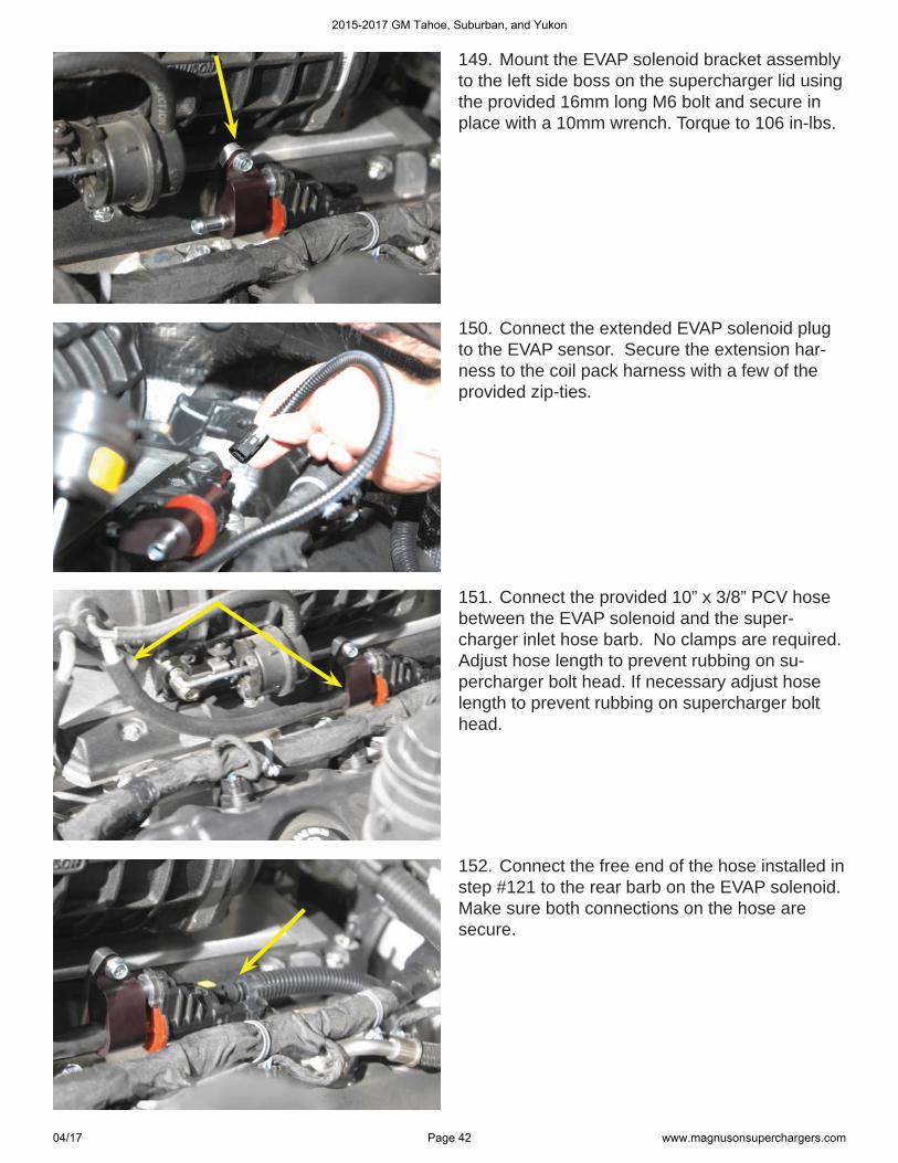
149. Mount the EVAP solenoid bracket assembly to the left side boss on the supercharger lid using the provided 16mm long M6 bolt and secure in place with a 10mm wrench. Torque to 106 in-lbs.
150. Connect the extended EVAP solenoid plug to the EVAP sensor. Secure the extension har-ness to the coil pack harness with a few of the provided zip-ties.
151. Connect the provided 10” x 3/8” PCV hose between the EVAP solenoid and the super-charger inlet hose barb. No clamps are required. Adjust hose length to prevent rubbing on su-percharger bolt head. If necessary adjust hose length to prevent rubbing on supercharger bolt head.
152. Connect the free end of the hose installed in step #121 to the rear barb on the EVAP solenoid. Make sure both connections on the hose are secure.
2015-2017 GM Tahoe, Suburban, and Yukon
04/17 Page 42 www.magnusonsuperchargers.com
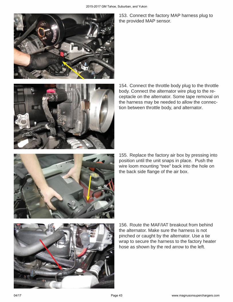
153. Connect the factory MAP harness plug to the provided MAP sensor.
154. Connect the throttle body plug to the throttle body. Connect the alternator wire plug to the re-ceptacle on the alternator. Some tape removal on the harness may be needed to allow the connec-tion between throttle body, and alternator.
155. Replace the factory air box by pressing into position until the unit snaps in place. Push the wire loom mounting “tree” back into the hole on the back side fl ange of the air box.
156. Route the MAF/IAT breakout from behind the alternator. Make sure the harness is not pinched or caught by the alternator. Use a tie wrap to secure the harness to the factory heater hose as shown by the red arrow to the left.
2015-2017 GM Tahoe, Suburban, and Yukon
04/17 Page 43 www.magnusonsuperchargers.com
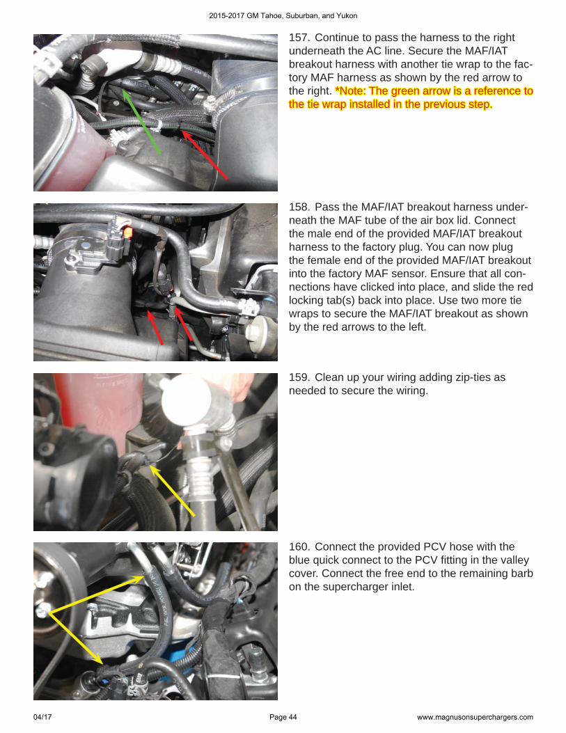
157. Continue to pass the harness to the right underneath the AC line. Secure the MAF/IAT breakout harness with another tie wrap to the fac-tory MAF harness as shown by the red arrow to the right. *Note: The green arrow is a reference to *Note: The green arrow is a reference to the tie wrap installed in the previous step.the tie wrap installed in the previous step.
158. Pass the MAF/IAT breakout harness under-neath the MAF tube of the air box lid. Connect the male end of the provided MAF/IAT breakout harness to the factory plug. You can now plug the female end of the provided MAF/IAT breakout into the factory MAF sensor. Ensure that all con-nections have clicked into place, and slide the red locking tab(s) back into place. Use two more tie wraps to secure the MAF/IAT breakout as shown by the red arrows to the left.
159. Clean up your wiring adding zip-ties as needed to secure the wiring.
160. Connect the provided PCV hose with the blue quick connect to the PCV fi tting in the valley cover. Connect the free end to the remaining barb on the supercharger inlet.
2015-2017 GM Tahoe, Suburban, and Yukon
04/17 Page 44 www.magnusonsuperchargers.com
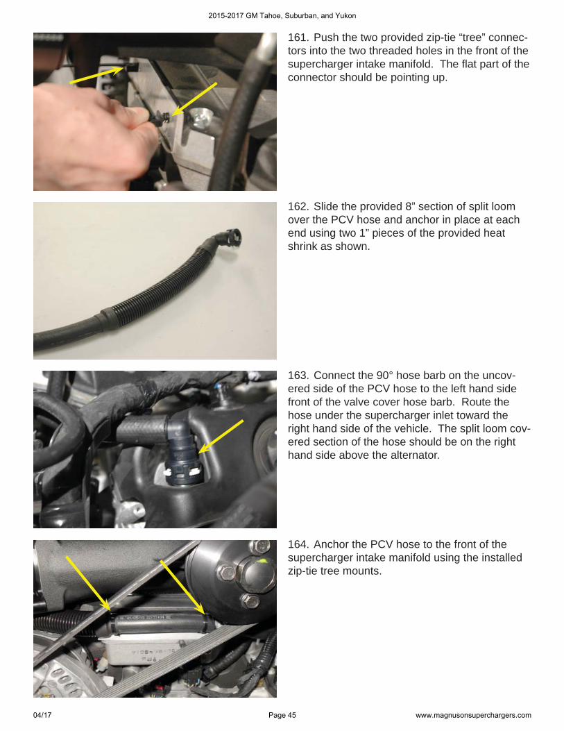
161. Push the two provided zip-tie “tree” connec-tors into the two threaded holes in the front of the supercharger intake manifold. The fl at part of the connector should be pointing up.
162. Slide the provided 8” section of split loom over the PCV hose and anchor in place at each end using two 1” pieces of the provided heat shrink as shown.
163. Connect the 90° hose barb on the uncov-ered side of the PCV hose to the left hand side front of the valve cover hose barb. Route the hose under the supercharger inlet toward the right hand side of the vehicle. The split loom cov-ered section of the hose should be on the right hand side above the alternator.
164. Anchor the PCV hose to the front of the supercharger intake manifold using the installed zip-tie tree mounts.
2015-2017 GM Tahoe, Suburban, and Yukon
04/17 Page 45 www.magnusonsuperchargers.com
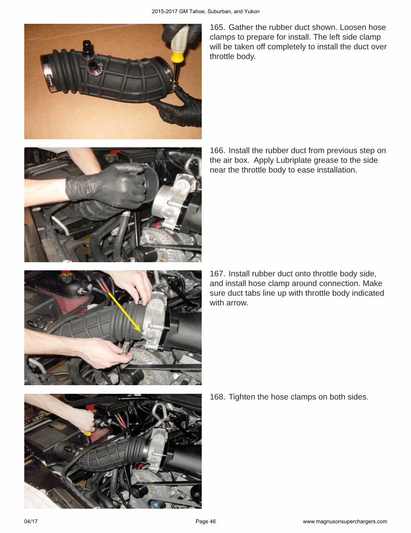
165. Gather the rubber duct shown. Loosen hose clamps to prepare for install. The left side clamp will be taken off completely to install the duct over throttle body.
166. Install the rubber duct from previous step on the air box. Apply Lubriplate grease to the side near the throttle body to ease installation.
167. Install rubber duct onto throttle body side, and install hose clamp around connection. Make sure duct tabs line up with throttle body indicated with arrow.
168. Tighten the hose clamps on both sides.
2015-2017 GM Tahoe, Suburban, and Yukon
04/17 Page 46 www.magnusonsuperchargers.com
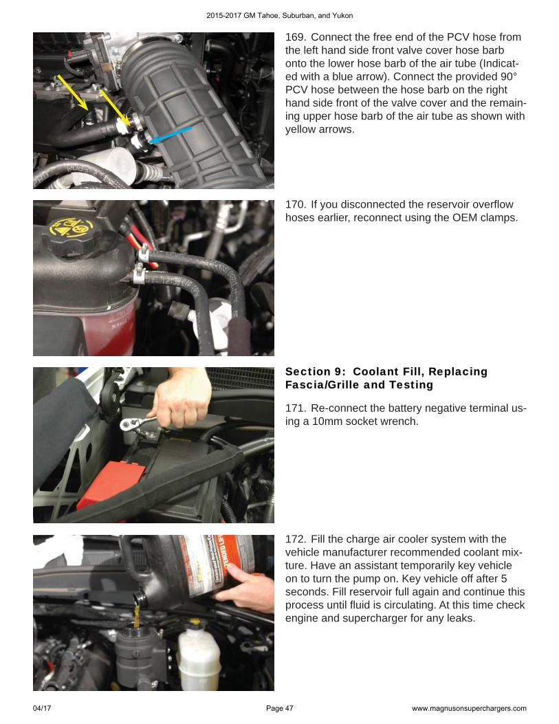
169. Connect the free end of the PCV hose from the left hand side front valve cover hose barb onto the lower hose barb of the air tube (Indicat-ed with a blue arrow). Connect the provided 90° PCV hose between the hose barb on the right hand side front of the valve cover and the remain-ing upper hose barb of the air tube as shown with yellow arrows.
170. If you disconnected the reservoir overfl ow hoses earlier, reconnect using the OEM clamps.
Section 9: Coolant Fill, Replacing Section 9: Coolant Fill, Replacing Fascia/Grille and TestingFascia/Grille and Testing
171. Re-connect the battery negative terminal us-ing a 10mm socket wrench.
172. Fill the charge air cooler system with the vehicle manufacturer recommended coolant mix-ture. Have an assistant temporarily key vehicle on to turn the pump on. Key vehicle off after 5 seconds. Fill reservoir full again and continue this process until fl uid is circulating. At this time check engine and supercharger for any leaks.
2015-2017 GM Tahoe, Suburban, and Yukon
04/17 Page 47 www.magnusonsuperchargers.com
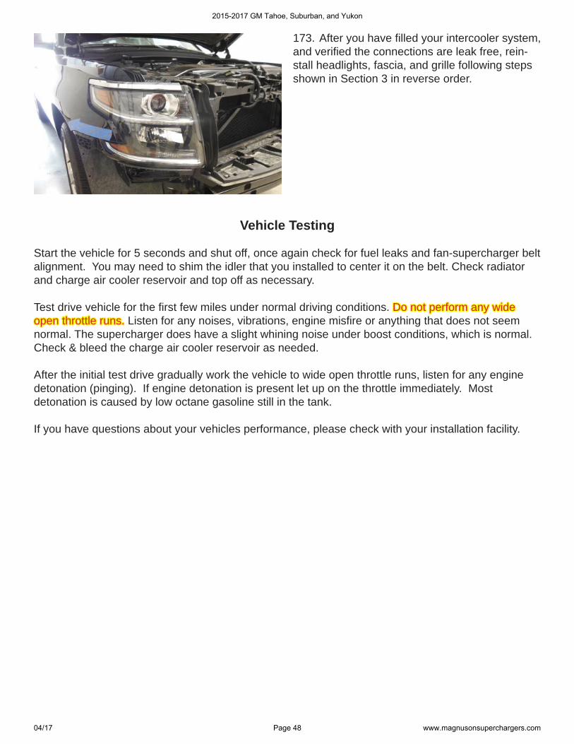
173. After you have fi lled your intercooler system,and verifi ed the connections are leak free, rein-stall headlights, fascia, and grille following stepsshown in Section 3 in reverse order.
Vehicle Testing
Start the vehicle for 5 seconds and shut off, once again check for fuel leaks and fan-supercharger belt alignment. You may need to shim the idler that you installed to center it on the belt. Check radiator and charge air cooler reservoir and top off as necessary.
Test drive vehicle for the fi rst few miles under normal driving conditions. Do not perform any wide Do not perform any wide open throttle runs.open throttle runs. Listen for any noises, vibrations, engine misfi re or anything that does not seem normal. The supercharger does have a slight whining noise under boost conditions, which is normal. Check & bleed the charge air cooler reservoir as needed.
After the initial test drive gradually work the vehicle to wide open throttle runs, listen for any engine detonation (pinging). If engine detonation is present let up on the throttle immediately. Most detonation is caused by low octane gasoline still in the tank.
If you have questions about your vehicles performance, please check with your installation facility.
2015-2017 GM Tahoe, Suburban, and Yukon
04/17 Page 48 www.magnusonsuperchargers.com
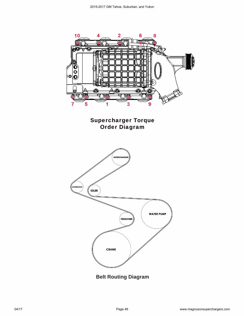
Belt Routing Diagram
Supercharger Torque Supercharger Torque Order DiagramOrder Diagram
2015-2017 GM Tahoe, Suburban, and Yukon
04/17 Page 49 www.magnusonsuperchargers.com
2015-2017 GM Tahoe, Suburban, and Yukon
04/17 Page 50 www.magnusonsuperchargers.com
2015-2017 GM Tahoe, Suburban, and Yukon
04/17 Page 51 www.magnusonsuperchargers.com
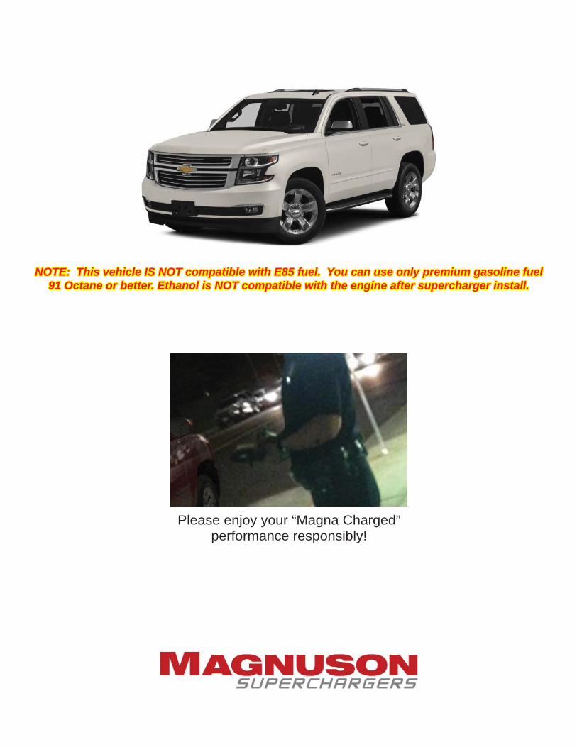
Please enjoy your “Magna Charged” performance responsibly!
NOTE: This vehicle IS NOT compatible with E85 fuel. You can use only premium gasoline fuelNOTE: This vehicle IS NOT compatible with E85 fuel. You can use only premium gasoline fuel91 Octane or better. Ethanol is NOT compatible with the engine after supercharger install.91 Octane or better. Ethanol is NOT compatible with the engine after supercharger install.