Embed Size (px)
Citation preview
2015-2016 AIAA Graduate Missile Design Team
Aerospace Systems Design Lab, Georgia Tech
Academic Advisor: Dr. Dimitri N. Mavris
Technical Advisor: Dr. Bradford Robertson
Team Members
Project Manager: Jeffery T. McNabb
Chief Engineer: Andrew K. Hull
Michael J. Jones
Roger Lascorz
AIAA Missile Design Competition May 16, 2016 Georgia Institute of Technology
2
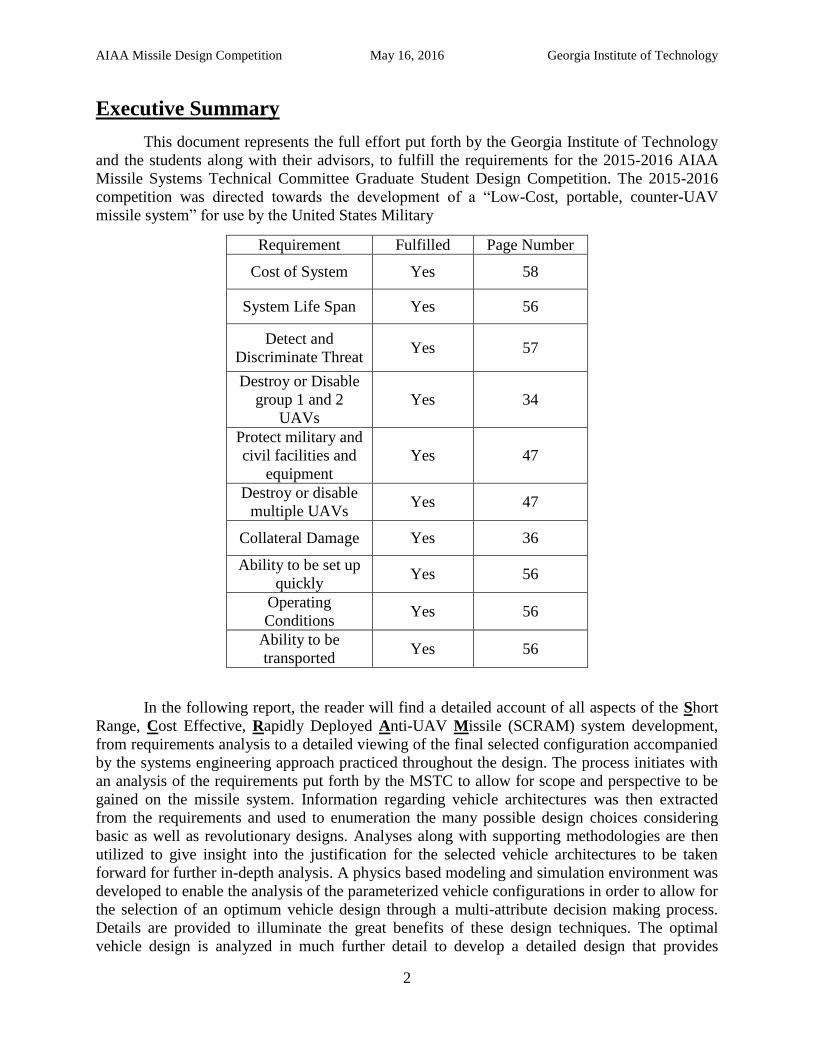
Executive Summary
This document represents the full effort put forth by the Georgia Institute of Technology
and the students along with their advisors, to fulfill the requirements for the 2015-2016 AIAA
Missile Systems Technical Committee Graduate Student Design Competition. The 2015-2016
competition was directed towards the development of a “Low-Cost, portable, counter-UAV
missile system” for use by the United States Military
Requirement Fulfilled Page Number
Cost of System Yes 58
System Life Span Yes 56
Detect and
Discriminate Threat Yes 57
Destroy or Disable
group 1 and 2
UAVs
Yes 34
Protect military and
civil facilities and
equipment
Yes 47
Destroy or disable
multiple UAVs Yes 47
Collateral Damage Yes 36
Ability to be set up
quickly Yes 56
Operating
Conditions Yes 56
Ability to be
transported Yes 56
In the following report, the reader will find a detailed account of all aspects of the Short
Range, Cost Effective, Rapidly Deployed Anti-UAV Missile (SCRAM) system development,
from requirements analysis to a detailed viewing of the final selected configuration accompanied
by the systems engineering approach practiced throughout the design. The process initiates with
an analysis of the requirements put forth by the MSTC to allow for scope and perspective to be
gained on the missile system. Information regarding vehicle architectures was then extracted
from the requirements and used to enumeration the many possible design choices considering
basic as well as revolutionary designs. Analyses along with supporting methodologies are then
utilized to give insight into the justification for the selected vehicle architectures to be taken
forward for further in-depth analysis. A physics based modeling and simulation environment was
developed to enable the analysis of the parameterized vehicle configurations in order to allow for
the selection of an optimum vehicle design through a multi-attribute decision making process.
Details are provided to illuminate the great benefits of these design techniques. The optimal
vehicle design is analyzed in much further detail to develop a detailed design that provides

AIAA Missile Design Competition May 16, 2016 Georgia Institute of Technology
3
insight into mission concept of operations, missile program development cost, and risk
assessment of collateral damage. Finally, concluding remarks are provided to discuss critical
areas of importance within low cost missile design.
The following report will provide both breadth and depth in the analysis of low cost
missile design as it is done today and suggest a full missile designs that can provided the United
States with a military capability that is currently absent.
AIAA Missile Design Competition May 16, 2016 Georgia Institute of Technology
4
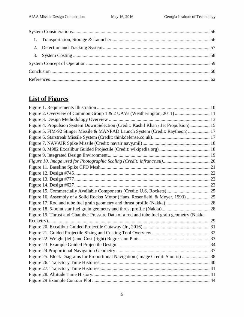
Table of Contents Executive Summary ........................................................................................................................ 2
List of Figures ................................................................................................................................. 5
List of Tables .................................................................................................................................. 6
Introduction ..................................................................................................................................... 8
Requirements .................................................................................................................................. 9
Threat ........................................................................................................................................ 10
Cost & Storage .......................................................................................................................... 11
Concept of Operations (CONOPS) ........................................................................................... 12
Design Methodology ..................................................................................................................... 13
Analysis of Alternatives ................................................................................................................ 14
1. Identifying the Design Space ............................................................................................. 14
2. Down Sizing the Design Space .......................................................................................... 14
3. Assessment of Current Alternatives................................................................................... 16
Modeling and Simulation Environment ........................................................................................ 19
1. General Methodology ........................................................................................................ 19
A. Integrated Design Environment .................................................................................. 19
2. Geometry Generation ......................................................................................................... 20
3. Aerodynamics Analysis ..................................................................................................... 23
4. Missile Sizing and Costing ................................................................................................ 24
5. Guided Projectile Sizing and Costing ................................................................................ 31
6. Missile and Guided Projectile Warhead Sizing ................................................................. 34
7. Trajectory and Guidance Analysis ..................................................................................... 36
8. CONOPS Analysis ............................................................................................................. 42
Decision Making ........................................................................................................................... 46
1. Decision Making Methodology ......................................................................................... 46
2. Final Design Selection ....................................................................................................... 47
Detailed Missile Design ................................................................................................................ 51
1. Geometric and Weight Data............................................................................................... 51
2. Performance and Aerodynamic Data ................................................................................. 53
3. Trajectory ........................................................................................................................... 54
4. Stability and Guidance & Controls .................................................................................... 55
AIAA Missile Design Competition May 16, 2016 Georgia Institute of Technology
5
System Considerations .................................................................................................................. 56
1. Transportation, Storage & Launcher .................................................................................. 56
2. Detection and Tracking System ......................................................................................... 57
3. System Costing .................................................................................................................. 58
System Concept of Operation ....................................................................................................... 59
Conclusion .................................................................................................................................... 60
References ..................................................................................................................................... 62
List of Figures
Figure 1. Requirements Illustration .............................................................................................. 10
Figure 2. Overview of Common Group 1 & 2 UAVs (Weatherington, 2011) ............................. 11
Figure 3. Design Methodology Overview .................................................................................... 13
Figure 4. Propulsion System Down Selection (Credit: Kashif Khan / Jet Propulsion) ................ 15
Figure 5. FIM-92 Stinger Missile & MANPAD Launch System (Credit: Raytheon) .................. 17
Figure 6. Starstreak Missile System (Credit: thinkdefense.co.uk)................................................ 17
Figure 7. NAVAIR Spike Missile (Credit: navair.navy.mil) ........................................................ 18
Figure 8. M982 Excalibur Guided Projectile (Credit: wikipedia.org) .......................................... 18
Figure 9. Integrated Design Environment ..................................................................................... 19
Figure 10. Image used for Photographic Scaling (Credit: infrance.su) ....................................... 20
Figure 11. Baseline Spike CFD Mesh........................................................................................... 21
Figure 12. Design #745 ................................................................................................................. 22
Figure 13. Design #777 ................................................................................................................. 23
Figure 14. Design #627 ................................................................................................................. 23
Figure 15. Commercially Available Components (Credit: U.S. Rockets) .................................... 25
Figure 16. Assembly of a Solid Rocket Motor (Hans, Rosenfield, & Meyer, 1993) ................... 25
Figure 17. Rod and tube fuel grain geometry and thrust profile (Nakka) ..................................... 28
Figure 18. 5-point star fuel grain geometry and thrust profile (Nakka)........................................ 28
Figure 19. Thrust and Chamber Pressure Data of a rod and tube fuel grain geometry (Nakka
Rcoketry)....................................................................................................................................... 29
Figure 20. Excalibur Guided Projectile Cutaway (Jr., 2016) ........................................................ 31
Figure 21. Guided Projectile Sizing and Costing Tool Overview ................................................ 32
Figure 22. Weight (left) and Cost (right) Regression Plots .......................................................... 33
Figure 23. Example Guided Projectile Design ............................................................................. 34
Figure 24 Proportional Navigation Geometry .............................................................................. 37
Figure 25. Block Diagrams for Proportional Navigation (Image Credit: Siouris) ....................... 38
Figure 26. Trajectory Time Histories ............................................................................................ 40
Figure 27. Trajectory Time Histories ............................................................................................ 41
Figure 28. Altitude Time History.................................................................................................. 41
Figure 29 Example Contour Plot .................................................................................................. 44
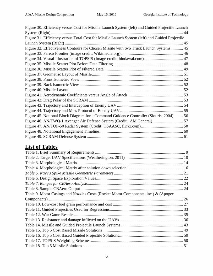
AIAA Missile Design Competition May 16, 2016 Georgia Institute of Technology
6
Figure 30. Efficiency versus Cost for Missile Launch System (left) and Guided Projectile Launch
System (Right) .............................................................................................................................. 44
Figure 31. Efficiency versus Total Cost for Missile Launch System (left) and Guided Projectile
Launch System (Right) ................................................................................................................. 45
Figure 32. Effectiveness Contours for Chosen Missile with two Truck Launch Systems ........... 45
Figure 33. Pareto Frontier (image credit: Wikimedia.org) ........................................................... 46
Figure 34. Visual Illustration of TOPSIS (Image credit: hindawai.com) ..................................... 47
Figure 35. Missile Scatter Plot Before Data Filtering................................................................... 48
Figure 36. Missile Scatter Plot of Filtered Data ........................................................................... 49
Figure 37. Geometric Layout of Missile ....................................................................................... 51
Figure 38. Front Isometric View ................................................................................................... 52
Figure 39. Back Isometric View ................................................................................................... 52
Figure 40. Missile Layout ............................................................................................................. 52
Figure 41. Aerodynamic Coefficients versus Angle of Attack ..................................................... 53
Figure 42. Drag Polar of the SCRAM .......................................................................................... 53
Figure 43. Trajectory and Interception of Enemy UAV ............................................................... 54
Figure 44. Trajectory and Miss Protocol of Enemy UAV ............................................................ 55
Figure 45. Notional Block Diagram for a Command Guidance Controller (Siouris, 2004) ......... 56
Figure 46. AN/TWQ-1 Avenger Air Defense System (Credit: AM General) ............................. 57
Figure 47. AN/TQP-50 Radar System (Credit: USAASC, flickr.com) ........................................ 58
Figure 48. Notational Engagement Timeline ................................................................................ 60
Figure 49. SCRAM Defense System ............................................................................................ 61
List of Tables Table 1. Brief Summary of Requirements ...................................................................................... 9
Table 2. Target UAV Specifications (Weatherington, 2011) ....................................................... 10
Table 3. Morphological Matrix ..................................................................................................... 14
Table 4. Morphological Matrix after solution down selection ..................................................... 16
Table 5. Navy's Spike Missile Geometric Parameters .................................................................. 21
Table 6. Design Space Exploration Values................................................................................... 22
Table 7. Ranges for CBAero Analysis........................................................................................... 24
Table 8. Sample CBAero Output .................................................................................................. 24
Table 9. Motor Casings and Nozzles Costs (Rocket Motor Components, inc.) & (Apogee
Components). ................................................................................................................................ 26
Table 10. Low-cost fuel grain performance and cost ................................................................... 27
Table 11. Guided Projectiles Used for Regressions ...................................................................... 33
Table 12. War Game Results ........................................................................................................ 35
Table 13. Resistance and damage inflicted on the UAVs ............................................................. 36
Table 14. Missile and Guided Projectile Launch Systems ........................................................... 43
Table 15. Top 5 Cost Based Missile Solutions ............................................................................. 49
Table 16. Top 5 Cost Based Guided Projectile Solutions ............................................................. 50
Table 17. TOPSIS Weighting Schemes ........................................................................................ 50
Table 18. Top 5 Missile Solutions ................................................................................................ 51

AIAA Missile Design Competition May 16, 2016 Georgia Institute of Technology
7
Table 19. Weight Breakdown ....................................................................................................... 52
AIAA Missile Design Competition May 16, 2016 Georgia Institute of Technology
8
Introduction
The Global War on Terror was launched in the days following the multiple terrorist
attacks on September 9, 2001. The United States and its allies launched a multi-faceted operation
against several terrorist faction located through the country of Afghanistan. Unlike previous
military engagements in the Middle East such as Operation Desert Storm, the main goal in the
Global War on Terror is to root out terrorist through counter-insurgency operations. This
introduces several issues as the U.S. military doctrine was built around “high-intensity” or
“conventional” warfare against adversaries with similar forces and operational tactics whereas
counter-insurgency operations are centered around adversaries with much smaller forces and a
completely different set of operational tactics. Adversaries in this realm often rely on asymmetric
warfare tactics in their efforts to seek victory. Asymmetric enemies attempt to circumvent or
undermine US strengths while exploiting weaknesses using innovative, low cost, nontraditional
tactics, weapons or technologies. One of the most prominent asymmetric threats being
developed by the enemy are combat utilized, radio controlled, small autonomous aircraft. These
aircraft can be turned into an aerial equivalent of an improvised explosive device, or spy on
sensitive areas when equipped with a camera. At present there is no cost-efficient protection
against them.
This project seeks to develop a weapon system, usable by the US armed forces that will
enable rapid protection capabilities of specified area in a cost-efficient manner. This system will
enable units to engage any enemy UAV around an operational base. Additionally, the capability
of being able to rapidly move the weapon system from one base of operation to another will be
an integral capability of the system. Furthermore, the system can provide the ability to protect
both civilian and military installations in urban and rural operational environments.
There is currently no single weapon system that possesses these capabilities while
remaining cost-efficient against the wide array of possible UAV threats. There are significant
technical difficulties that render design and development of a cost-efficient system into a
difficult engineering problem. To overcome these technical difficulties, the best systems
engineering practice must be utilized. The missile needs to be physically and functionally
decomposed into a series of possible engineering decisions. The final design of the system will
be achievable only though an examination of all solutions produced by these choices. This final
selection will require a thorough evaluation of all possible solutions based upon design criteria.
By creating an optimized defensive system, the effectiveness of the United States military
to defend assets from enemy UAV incursions will be drastically increased. It will provide the
capability of being able to deploy counter UAV defensive systems rapidly in a variety of combat
environments. The low-cost, counter-UAV missile will thwart enemy attempts to deploy small
UAVs in a combat manner against friendly assets.
AIAA Missile Design Competition May 16, 2016 Georgia Institute of Technology
9
Requirements
The need for a low cost deterrent against unmanned aerial vehicles (UAVs) is evident as
the capabilities of small UAVs by enemy forces increases. Small radio controlled UAVs have
become possible threats carrying improvised explosives or cameras to spy on critical areas as
their technology becomes more available. A low-cost counter-UAV weapon system would
protect military and civil facilities, sensitive equipment, and personnel from the growing threat
of militarized small UAVs.
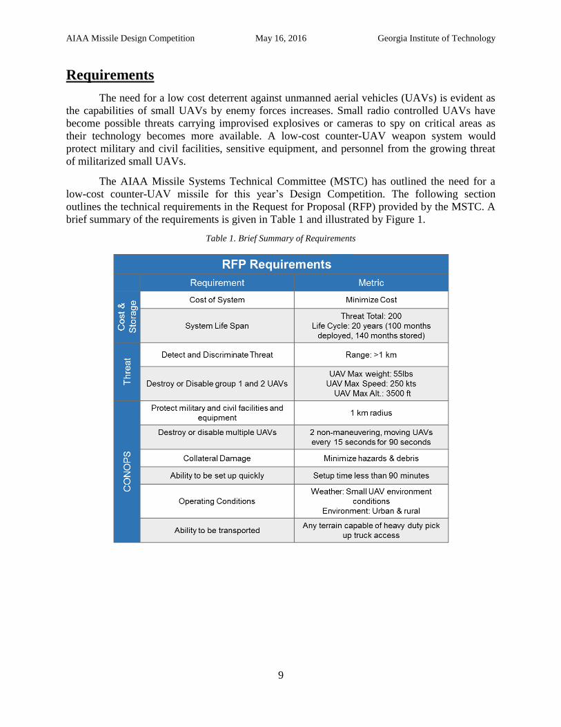
The AIAA Missile Systems Technical Committee (MSTC) has outlined the need for a
low-cost counter-UAV missile for this year’s Design Competition. The following section
outlines the technical requirements in the Request for Proposal (RFP) provided by the MSTC. A
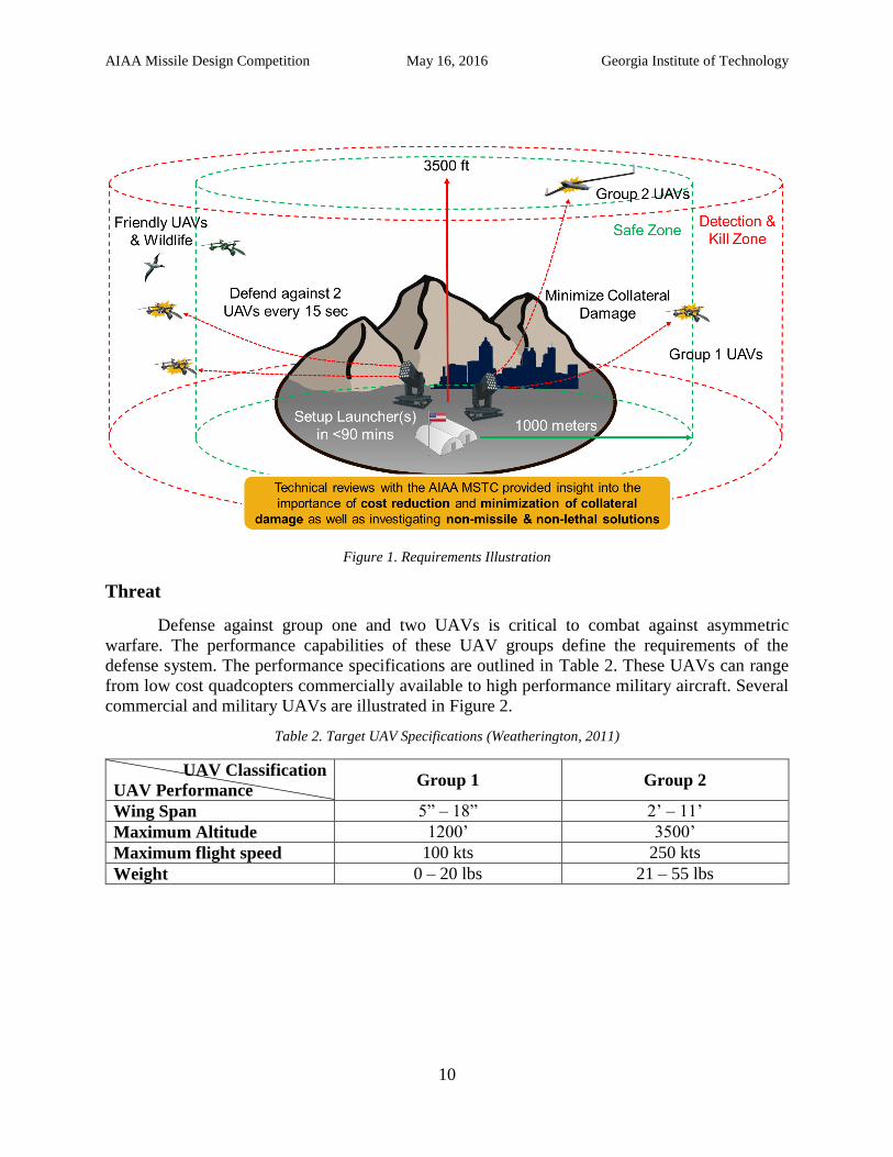
brief summary of the requirements is given in Table 1 and illustrated by Figure 1.
Table 1. Brief Summary of Requirements
AIAA Missile Design Competition May 16, 2016 Georgia Institute of Technology
10
Figure 1. Requirements Illustration
Threat
Defense against group one and two UAVs is critical to combat against asymmetric
warfare. The performance capabilities of these UAV groups define the requirements of the
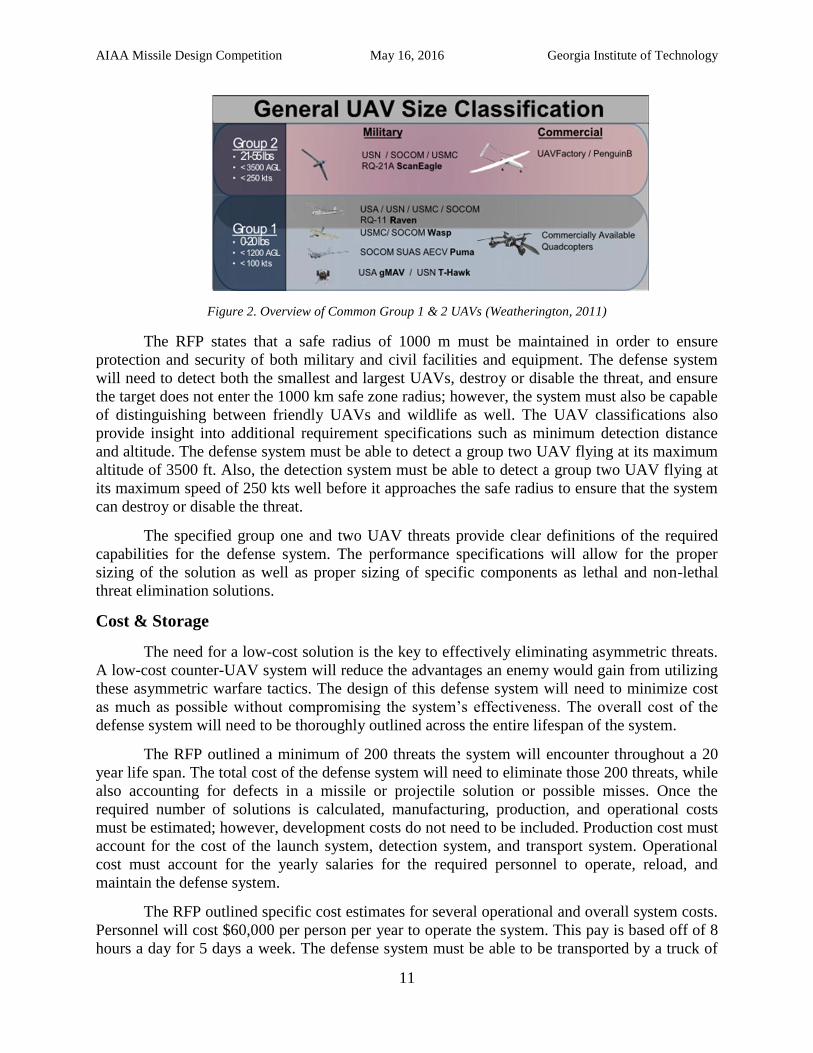
defense system. The performance specifications are outlined in Table 2. These UAVs can range
from low cost quadcopters commercially available to high performance military aircraft. Several
commercial and military UAVs are illustrated in Figure 2.
Table 2. Target UAV Specifications (Weatherington, 2011)
UAV Classification
UAV Performance Group 1 Group 2
Wing Span 5” – 18” 2’ – 11’
Maximum Altitude 1200’ 3500’
Maximum flight speed 100 kts 250 kts
Weight 0 – 20 lbs 21 – 55 lbs
AIAA Missile Design Competition May 16, 2016 Georgia Institute of Technology
11
Figure 2. Overview of Common Group 1 & 2 UAVs (Weatherington, 2011)
The RFP states that a safe radius of 1000 m must be maintained in order to ensure
protection and security of both military and civil facilities and equipment. The defense system
will need to detect both the smallest and largest UAVs, destroy or disable the threat, and ensure
the target does not enter the 1000 km safe zone radius; however, the system must also be capable
of distinguishing between friendly UAVs and wildlife as well. The UAV classifications also
provide insight into additional requirement specifications such as minimum detection distance
and altitude. The defense system must be able to detect a group two UAV flying at its maximum
altitude of 3500 ft. Also, the detection system must be able to detect a group two UAV flying at
its maximum speed of 250 kts well before it approaches the safe radius to ensure that the system
can destroy or disable the threat.
The specified group one and two UAV threats provide clear definitions of the required
capabilities for the defense system. The performance specifications will allow for the proper
sizing of the solution as well as proper sizing of specific components as lethal and non-lethal
threat elimination solutions.
Cost & Storage
The need for a low-cost solution is the key to effectively eliminating asymmetric threats.
A low-cost counter-UAV system will reduce the advantages an enemy would gain from utilizing
these asymmetric warfare tactics. The design of this defense system will need to minimize cost
as much as possible without compromising the system’s effectiveness. The overall cost of the
defense system will need to be thoroughly outlined across the entire lifespan of the system.
The RFP outlined a minimum of 200 threats the system will encounter throughout a 20
year life span. The total cost of the defense system will need to eliminate those 200 threats, while
also accounting for defects in a missile or projectile solution or possible misses. Once the
required number of solutions is calculated, manufacturing, production, and operational costs
must be estimated; however, development costs do not need to be included. Production cost must
account for the cost of the launch system, detection system, and transport system. Operational
cost must account for the yearly salaries for the required personnel to operate, reload, and
maintain the defense system.
The RFP outlined specific cost estimates for several operational and overall system costs.
Personnel will cost $60,000 per person per year to operate the system. This pay is based off of 8
hours a day for 5 days a week. The defense system must be able to be transported by a truck of
AIAA Missile Design Competition May 16, 2016 Georgia Institute of Technology
12
similar size and capabilities to a Silverado 2500 or F-250 or on a trailer pulled by the specified
truck. If the truck can leave the area once the system is set up, the cost of the vehicle does not
need to be included in the overall system cost. The cost of any support equipment that must stay
in the area to allow the system to properly operate must be included in the cost.
The defense system must also be able to operate for at least 20 years. This will include a
deployed versus storage time of 100 months deployed and 140 months in storage. Degradation of
propellant and explosive solutions will need to be accounted for as well as the longevity of
electronic components such as the storage and recharge of solutions that require one or more
batteries.
Production of this defense system will begin in October 2018 and must be ready for
operations by December 2023. With a required system life span of 20 years, the defense system
will end its operations in December 2043. This timeline must be taken into consideration when
choosing technologies that may not be ready for production by the required start date. Choosing
technologies with a lower Technology Readiness Level (TRL) may require more testing and
development between the end of the design process and the start of production, which may raise
the overall system costs or delay the program.
Cost, storage, and the project timeline are all important requirements that must be met in
the final solution. However, the minimization of cost is one of the most critical requirements
from the RFP and will be stressed throughout the design and analysis of the defense system.
Concept of Operations (CONOPS)
The proposed concept of operations brings many more system design considerations to
the table. The RFP outlines a possible combat scenario that the defense system will have to be
capable of effectively defending against. Other requirements that fit into the category are the
systems transportability and setup time, operating conditions, and minimization of collateral
damage.
First, the defense system must be capable of rapid deployment to any location that a truck
is capable of reaching and be setup within 90 minutes of arriving at a given defense location.
Once setup, the system must be capable of operating in any weather conditions that a group one
or two UAV is capable of operating in. Along with rugged rural environments, the system must
also be capable of operating in urban environments. However, the use of a defense system in
urban environments brings importance to the minimization of collateral damage outlined in the
RFP. The final defense system must minimize collateral damage to provide a system that is
capable of effectively operating in urban environments. Along with the minimization of cost, the
minimization of collateral damage is also a very important requirement that was stressed by the
AIAA MSTC to account for through the investigation of both unique and non-lethal solutions.
Minimizing collateral damage will increase the capabilities of the defense system, allowing for
urban assets to be effectively protected without harm to the surrounding population.
The system must protect military and civil assets from waves of non-maneuvering UAVs.
As mentioned earlier, the system must protect a 1000 m radius from the specified combat
scenario. The scenario provided in the RFP outlines that the system will encounter two UAVs
every 15 seconds for 90 seconds. In total, the defense system must disable or destroy 12 UAVs
in a 90 second interval. The system will encounter another 6 waves of two UAVS 60 minutes
AIAA Missile Design Competition May 16, 2016 Georgia Institute of Technology
13
after the first set of 12 threats are eliminated. Between the two distinct groups of UAVs, a new
supply of ammunition (e.g. missiles or projectiles) will be available from a storage facility within
a 15 minute drive from the defense system. This scenario means that a multi-launcher system
must be reloaded within the 30 minute time frame that the new supply of ammunition arrives and
the next group of UAVs approach. However, if a single launch system is used, such as a
MANPAD, more than one launcher may be required to defend against the waves and a much
shorter reload time of less than 15 seconds may also be required to ensure the system can be
reloaded between the waves of two UAVs.
Design Methodology
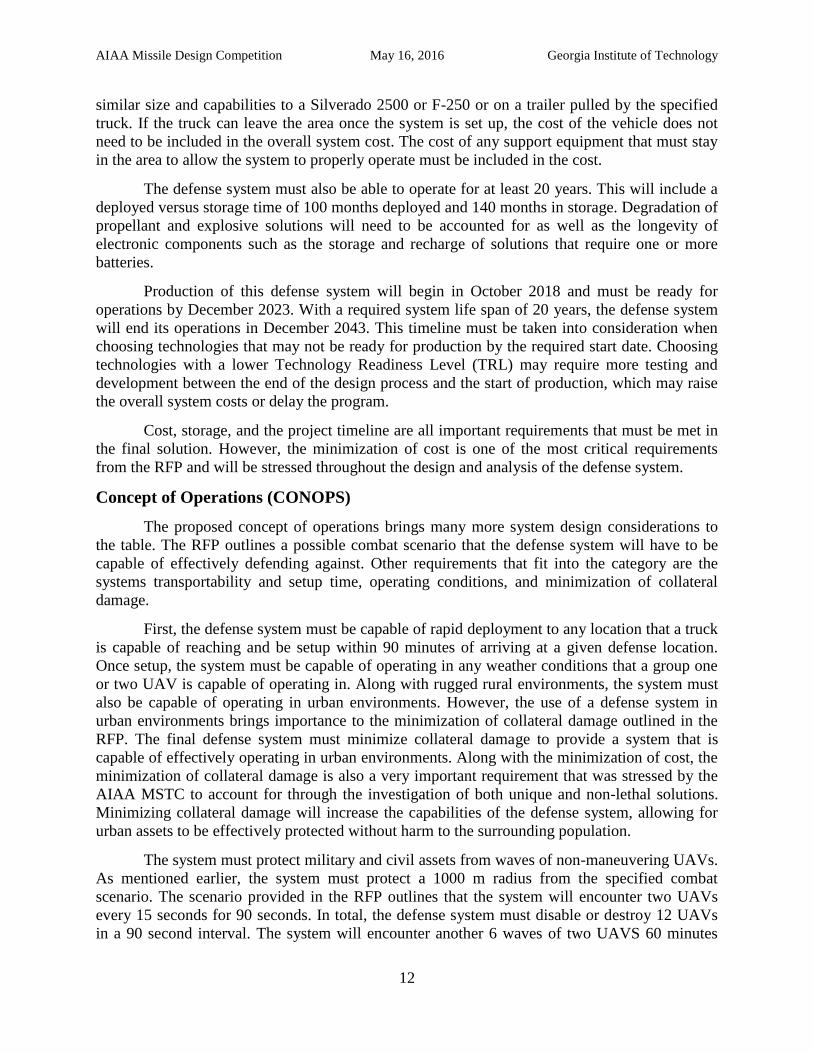
For this missile design study, a V-elimination design methodology was utilized. The
design methodology is shown in Figure 3.
Figure 3. Design Methodology Overview
First, the total design space is identified through a detailed literature search. This
literature search identifies all possible options that are able to be combined to generate a surface
to air missile that will disable any threat faced. The process is formally defined as Analysis of
Alternatives. From there a high level elimination is performed that eliminates all options that are
non-cost effective for destroying small UAV targets. Next, from the remaining options
alternatives a feasibility study is performed on the remaining options through the utilization of a
modeling and simulation environment. The unfeasible design alternatives are then filtered out
leaving only the feasible alternatives. The remaining alternatives are then grouped into two
families: missile and guided projectile designs. From there, a multi-attribute process is used to
down select to a set of perspective. The next step is to examine the systems utilized and the cost
associated with each design to down select from to perspective designs to a final design. Once
the final design sis selected a detailed study is performed on it to determine the total associated
system and cost that are associated with it.
AIAA Missile Design Competition May 16, 2016 Georgia Institute of Technology
14
Analysis of Alternatives
1. Identifying the Design Space
From the requirements analysis, a literature search was conducted to determine all
feasible design permutations for surface to air missile was conducted. The purpose of the
literature search was to populate a morphological matrix from which any design alternative can
be selected that has the potential to satisfy the requirements. The literature search was subdivided
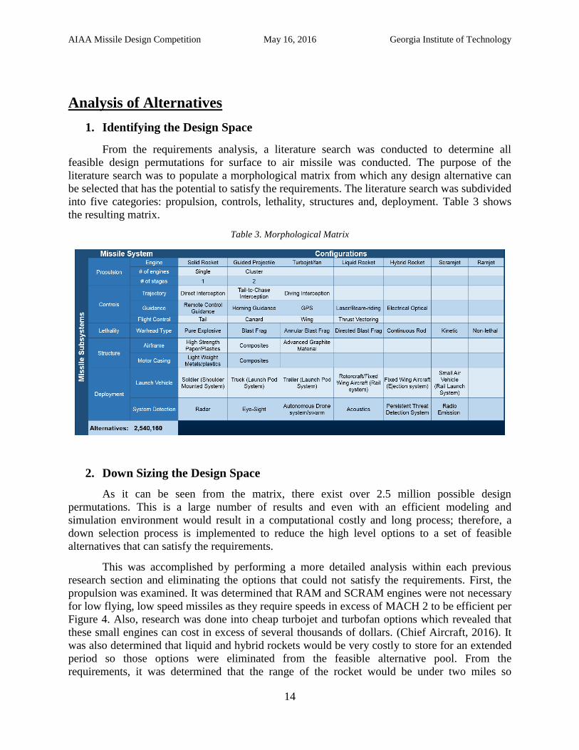
into five categories: propulsion, controls, lethality, structures and, deployment. Table 3 shows
the resulting matrix.
Table 3. Morphological Matrix
2. Down Sizing the Design Space
As it can be seen from the matrix, there exist over 2.5 million possible design
permutations. This is a large number of results and even with an efficient modeling and
simulation environment would result in a computational costly and long process; therefore, a
down selection process is implemented to reduce the high level options to a set of feasible
alternatives that can satisfy the requirements.
This was accomplished by performing a more detailed analysis within each previous
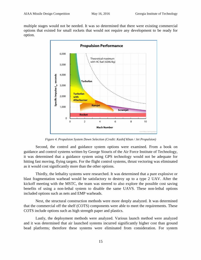
research section and eliminating the options that could not satisfy the requirements. First, the
propulsion was examined. It was determined that RAM and SCRAM engines were not necessary
for low flying, low speed missiles as they require speeds in excess of MACH 2 to be efficient per
Figure 4. Also, research was done into cheap turbojet and turbofan options which revealed that
these small engines can cost in excess of several thousands of dollars. (Chief Aircraft, 2016). It
was also determined that liquid and hybrid rockets would be very costly to store for an extended
period so those options were eliminated from the feasible alternative pool. From the
requirements, it was determined that the range of the rocket would be under two miles so
AIAA Missile Design Competition May 16, 2016 Georgia Institute of Technology
15
multiple stages would not be needed. It was so determined that there were existing commercial
options that existed for small rockets that would not require any development to be ready for
option.
Figure 4. Propulsion System Down Selection (Credit: Kashif Khan / Jet Propulsion)
Second, the control and guidance system options were examined. From a book on
guidance and control systems written by George Siouris of the Air Force Institute of Technology,
it was determined that a guidance system using GPS technology would not be adequate for
hitting fast moving, flying targets. For the flight control systems, thrust vectoring was eliminated
as it would cost significantly more than the other options.
Thirdly, the lethality systems were researched. It was determined that a pure explosive or
blast fragmentation warhead would be satisfactory to destroy up to a type 2 UAV. After the
kickoff meeting with the MSTC, the team was steered to also explore the possible cost saving
benefits of using a non-lethal system to disable the same UAVS. These non-lethal options
included options such as nets and EMP warheads.
Next, the structural construction methods were more deeply analyzed. It was determined
that the commercial off the shelf (COTS) components were able to meet the requirements. These
COTS include options such as high strength paper and plastics.
Lastly, the deployment methods were analyzed. Various launch method were analyzed
and it was determined that air launched systems incurred significantly higher cost than ground
bead platforms; therefore these systems were eliminated from consideration. For system
AIAA Missile Design Competition May 16, 2016 Georgia Institute of Technology
16
detection methods, it was determined that a radar based system would be the most cost effective
system as well as having been battle tested in a large variety of combat situations.
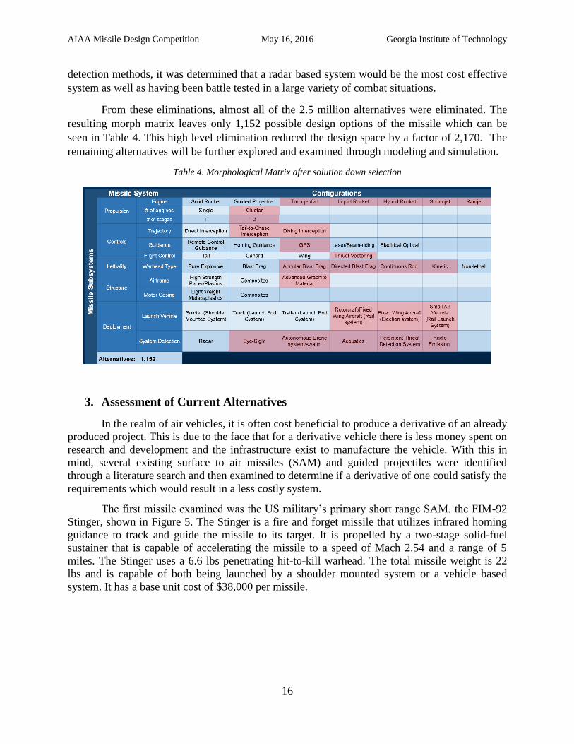
From these eliminations, almost all of the 2.5 million alternatives were eliminated. The
resulting morph matrix leaves only 1,152 possible design options of the missile which can be
seen in Table 4. This high level elimination reduced the design space by a factor of 2,170. The
remaining alternatives will be further explored and examined through modeling and simulation.
Table 4. Morphological Matrix after solution down selection
3. Assessment of Current Alternatives
In the realm of air vehicles, it is often cost beneficial to produce a derivative of an already
produced project. This is due to the face that for a derivative vehicle there is less money spent on
research and development and the infrastructure exist to manufacture the vehicle. With this in
mind, several existing surface to air missiles (SAM) and guided projectiles were identified
through a literature search and then examined to determine if a derivative of one could satisfy the
requirements which would result in a less costly system.
The first missile examined was the US military’s primary short range SAM, the FIM-92
Stinger, shown in Figure 5. The Stinger is a fire and forget missile that utilizes infrared homing
guidance to track and guide the missile to its target. It is propelled by a two-stage solid-fuel
sustainer that is capable of accelerating the missile to a speed of Mach 2.54 and a range of 5
miles. The Stinger uses a 6.6 lbs penetrating hit-to-kill warhead. The total missile weight is 22
lbs and is capable of both being launched by a shoulder mounted system or a vehicle based
system. It has a base unit cost of $38,000 per missile.
AIAA Missile Design Competition May 16, 2016 Georgia Institute of Technology
17
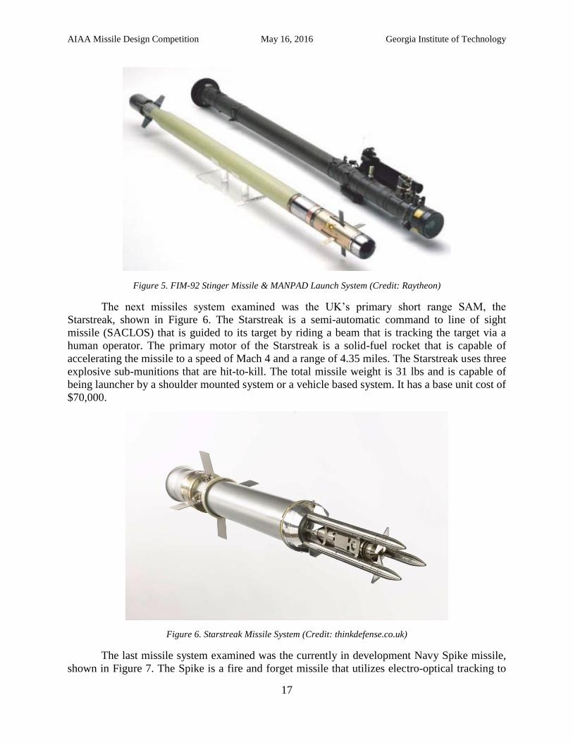
Figure 5. FIM-92 Stinger Missile & MANPAD Launch System (Credit: Raytheon)
The next missiles system examined was the UK’s primary short range SAM, the
Starstreak, shown in Figure 6. The Starstreak is a semi-automatic command to line of sight
missile (SACLOS) that is guided to its target by riding a beam that is tracking the target via a
human operator. The primary motor of the Starstreak is a solid-fuel rocket that is capable of
accelerating the missile to a speed of Mach 4 and a range of 4.35 miles. The Starstreak uses three
explosive sub-munitions that are hit-to-kill. The total missile weight is 31 lbs and is capable of
being launcher by a shoulder mounted system or a vehicle based system. It has a base unit cost of
$70,000.
Figure 6. Starstreak Missile System (Credit: thinkdefense.co.uk)
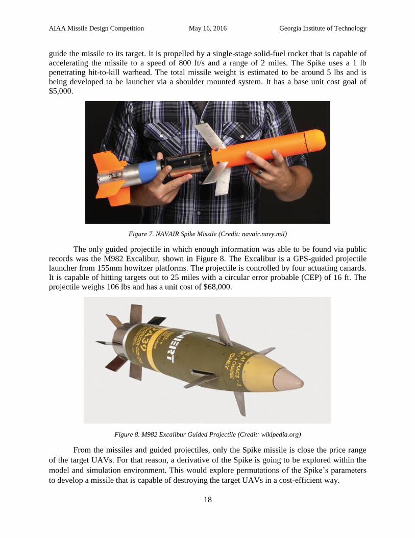
The last missile system examined was the currently in development Navy Spike missile,
shown in Figure 7. The Spike is a fire and forget missile that utilizes electro-optical tracking to
AIAA Missile Design Competition May 16, 2016 Georgia Institute of Technology
18
guide the missile to its target. It is propelled by a single-stage solid-fuel rocket that is capable of
accelerating the missile to a speed of 800 ft/s and a range of 2 miles. The Spike uses a 1 lb
penetrating hit-to-kill warhead. The total missile weight is estimated to be around 5 lbs and is
being developed to be launcher via a shoulder mounted system. It has a base unit cost goal of
$5,000.
Figure 7. NAVAIR Spike Missile (Credit: navair.navy.mil)
The only guided projectile in which enough information was able to be found via public
records was the M982 Excalibur, shown in Figure 8. The Excalibur is a GPS-guided projectile
launcher from 155mm howitzer platforms. The projectile is controlled by four actuating canards.
It is capable of hitting targets out to 25 miles with a circular error probable (CEP) of 16 ft. The
projectile weighs 106 lbs and has a unit cost of $68,000.
Figure 8. M982 Excalibur Guided Projectile (Credit: wikipedia.org)
From the missiles and guided projectiles, only the Spike missile is close the price range
of the target UAVs. For that reason, a derivative of the Spike is going to be explored within the
model and simulation environment. This would explore permutations of the Spike’s parameters
to develop a missile that is capable of destroying the target UAVs in a cost-efficient way.
AIAA Missile Design Competition May 16, 2016 Georgia Institute of Technology
19
Modeling and Simulation Environment
1. General Methodology
There exist many different options available for modeling and simulation (M&S) of a
particular missile design discipline that can provide varying fidelity and computational efficiency
levels. The development of the M&S environment for the conceptual design of a low cost
counter-UAV missile was to blend highly accurate analyses from industry accepted tools with
computationally in-expensive in-house developed codes. The enabling technique for this method
was to create an Integrated Design Environment (IDE) that connects all aspects of the design
environment with one another. This enabled information to pass through system automatically
which allowed for many design loop iterations to be performed in a short period of time. A
higher number of design loop iterations passes more detailed information about each design onto
the decision making process.
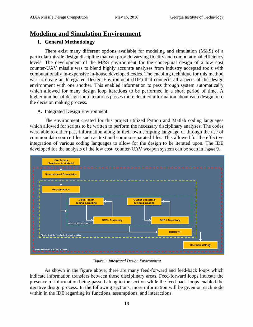
A. Integrated Design Environment
The environment created for this project utilized Python and Matlab coding languages
which allowed for scripts to be written to perform the necessary disciplinary analyses. The codes
were able to either pass information along in their own scripting language or through the use of
common data source files such as text and comma separated files. This allowed for the effective
integration of various coding languages to allow for the design to be iterated upon. The IDE
developed for the analysis of the low cost, counter-UAV weapon system can be seen in Figure 9.
Figure 9. Integrated Design Environment
As shown in the figure above, there are many feed-forward and feed-back loops which
indicate information transfers between those disciplinary areas. Feed-forward loops indicate the
presence of information being passed along to the section while the feed-back loops enabled the
iterative design process. In the following sections, more information will be given on each node
within in the IDE regarding its functions, assumptions, and interactions.
AIAA Missile Design Competition May 16, 2016 Georgia Institute of Technology
20
2. Geometry Generation Prior to any calculations performed for each discipline, a generalized sense of the
geometry needed to be developed. This includes size and outer dimensions of the vehicle along
with the wetted area. Using information available from Fleeman’s Missile Design text book, the
most important geometric values that would need to be utilized in the creation of a family of new
geometries are:
Fuselage Length
Fuselage Diameter
Front Wing Span
Front Wing Sweep
Front Wing Root-Tip ratio
Front Wing Location
Front Wing Thickness-Chord Ratio
Front Wing Airfoil Shape
Rear Wing Span
Rear Wing Sweep
Rear Wing Root-tip Ratio
Rear Wing Thickness-Chord Ratio
Rear Wing Airfoil Shape
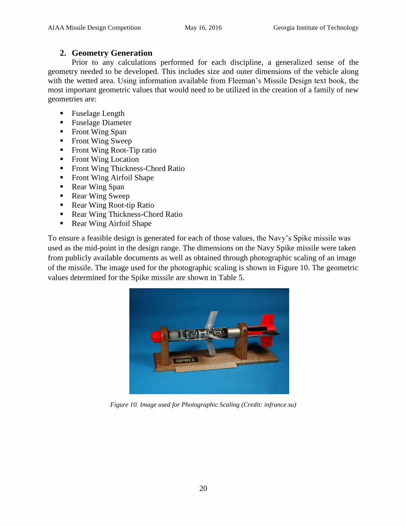
To ensure a feasible design is generated for each of those values, the Navy’s Spike missile was
used as the mid-point in the design range. The dimensions on the Navy Spike missile were taken
from publicly available documents as well as obtained through photographic scaling of an image
of the missile. The image used for the photographic scaling is shown in Figure 10. The geometric
values determined for the Spike missile are shown in Table 5.
Figure 10. Image used for Photographic Scaling (Credit: infrance.su)
AIAA Missile Design Competition May 16, 2016 Georgia Institute of Technology
21
Table 5. Navy's Spike Missile Geometric Parameters
Geometric Parameter Value
Fuselage Length 25”
Fuselage Diameter 2.5”
Front Wing Span 8.8”
Front Wing Sweep 23o
Front Wing Root-Tip ratio 1
Front Wing Location* 44%
Front Wing Thickness-Chord Ratio 0.1
Front Wing Airfoil Shape NACA 0010
Rear Wing Span 6”
Rear Wing Sweep 19 o
Rear Wing Root-tip Ratio 0.83
Rear Wing Location* 84%
Rear Wing Thickness-Chord Ratio 0.1
Rear Wing Airfoil Shape NACA 0010
*Percent of fuselage length
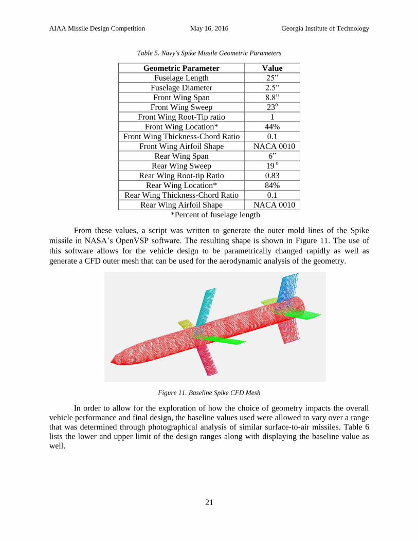
From these values, a script was written to generate the outer mold lines of the Spike
missile in NASA’s OpenVSP software. The resulting shape is shown in Figure 11. The use of
this software allows for the vehicle design to be parametrically changed rapidly as well as
generate a CFD outer mesh that can be used for the aerodynamic analysis of the geometry.
Figure 11. Baseline Spike CFD Mesh
In order to allow for the exploration of how the choice of geometry impacts the overall
vehicle performance and final design, the baseline values used were allowed to vary over a range
that was determined through photographical analysis of similar surface-to-air missiles. Table 6
lists the lower and upper limit of the design ranges along with displaying the baseline value as
well.
AIAA Missile Design Competition May 16, 2016 Georgia Institute of Technology
22
Table 6. Design Space Exploration Values
Parameter Min. Baseline Max
Fuselage Length 12 25 36
Fuselage Diameter 0.5 2.5 4.5
Front Wing Span 0 8.8 12
Front Wing Sweep 0 23 40
Front Wing Root 0.5 1.3 2
Front Wing Tip 0.5 1.3 2
Front Wing Location* 33% 44% 54%
Front Wing Thickness-Chord Ratio 0.04 0.1 0.14
Rear Wing Span 0 6 8
Rear Wing Sweep 0 19 30
Rear Wing Root 1.2 2.4 3.6
Rear Wing Tip 1.2 2 3.6
Rear Wing Thickness-Chord Ratio 0.04 0.1 0.14
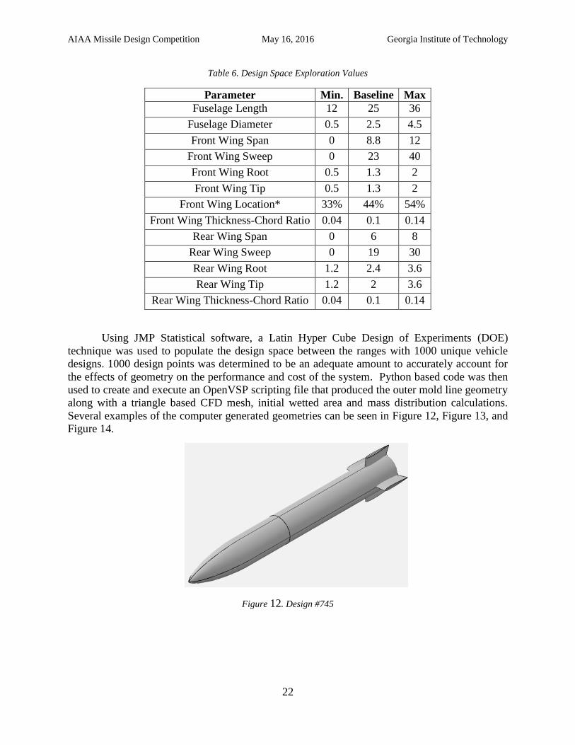
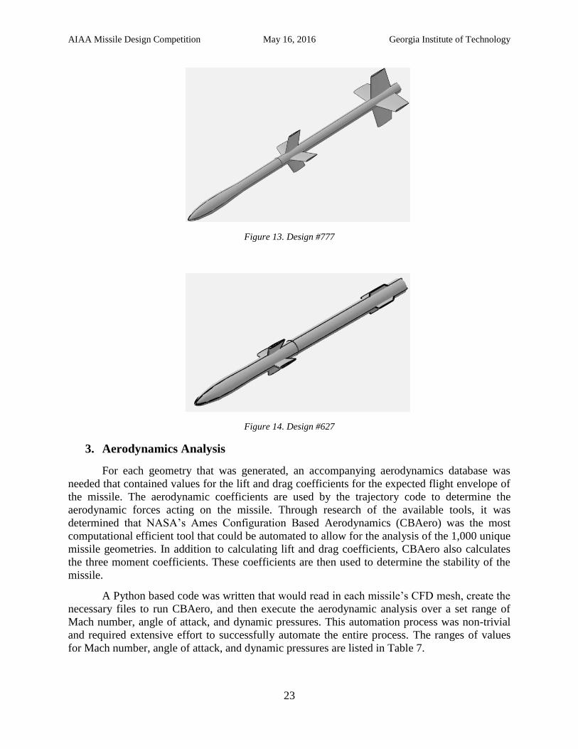
Using JMP Statistical software, a Latin Hyper Cube Design of Experiments (DOE)
technique was used to populate the design space between the ranges with 1000 unique vehicle
designs. 1000 design points was determined to be an adequate amount to accurately account for
the effects of geometry on the performance and cost of the system. Python based code was then
used to create and execute an OpenVSP scripting file that produced the outer mold line geometry
along with a triangle based CFD mesh, initial wetted area and mass distribution calculations.
Several examples of the computer generated geometries can be seen in Figure 12, Figure 13, and
Figure 14.
Figure 12. Design #745
AIAA Missile Design Competition May 16, 2016 Georgia Institute of Technology
23
Figure 13. Design #777
Figure 14. Design #627
3. Aerodynamics Analysis
For each geometry that was generated, an accompanying aerodynamics database was
needed that contained values for the lift and drag coefficients for the expected flight envelope of
the missile. The aerodynamic coefficients are used by the trajectory code to determine the
aerodynamic forces acting on the missile. Through research of the available tools, it was
determined that NASA’s Ames Configuration Based Aerodynamics (CBAero) was the most
computational efficient tool that could be automated to allow for the analysis of the 1,000 unique
missile geometries. In addition to calculating lift and drag coefficients, CBAero also calculates
the three moment coefficients. These coefficients are then used to determine the stability of the
missile.
A Python based code was written that would read in each missile’s CFD mesh, create the
necessary files to run CBAero, and then execute the aerodynamic analysis over a set range of
Mach number, angle of attack, and dynamic pressures. This automation process was non-trivial
and required extensive effort to successfully automate the entire process. The ranges of values
for Mach number, angle of attack, and dynamic pressures are listed in Table 7.
AIAA Missile Design Competition May 16, 2016 Georgia Institute of Technology
24
Table 7. Ranges for CBAero Analysis
Parameter Min. Max. Increment
Mach number 0.1 1.3 0.2
Angle of Attack 0o 25
o 5
o
Dynamic Pressure 14.5 psi 87 psi 14.5 psi
A portion of the aerodynamic database that was created using CBAero for the baseline
missile is listed in Table 8.
Table 8. Sample CBAero Output
Mach
Number
Angle of
Attack
Dynamic
Pressure CL CD CMl CMm CMn
0.1 0o 14.5 psi -0.000376 0.1351 0.000001 0.000202 0.000000
0.1 0o 29 psi 0.09101 0.02853 -0.000001 -0.006464 0.000019
0.1 0o 43.5 psi 0.1780 0.06255 -0.000001 -0.01018 0.000011
0.1 0o 58 psi 0.2608 0.1111 -0.000003 -0.01248 0.000013
0.1 0o 72.5 psi 0.3351 0.1745 -0.000005 -0.01420 0.000014
0.1 0o 87 psi 0.3991 0.2533 -0.000007 -0.01641 0.000012
4. Missile Sizing and Costing
Sizing of the missile includes proper volume requirements for the guidance and controls
system, warhead, and propulsion system. The propulsion system chosen during down selection
of the morphological matrix left both a solid rocket motor and a guided projectile as possible
solutions. The missile sizing section will outline the solid rocket motor sizing as well as the
overall costing estimate for each missile geometry.
Solid rocket motor
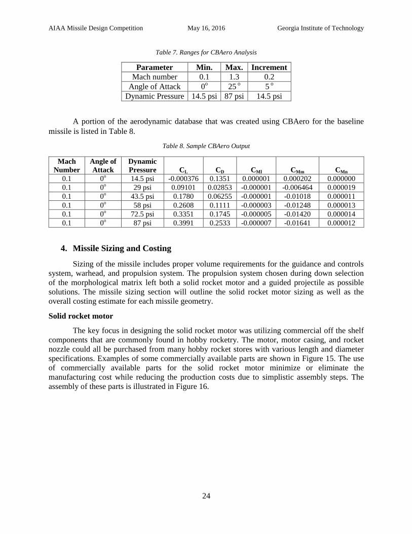
The key focus in designing the solid rocket motor was utilizing commercial off the shelf
components that are commonly found in hobby rocketry. The motor, motor casing, and rocket
nozzle could all be purchased from many hobby rocket stores with various length and diameter
specifications. Examples of some commercially available parts are shown in Figure 15. The use
of commercially available parts for the solid rocket motor minimize or eliminate the
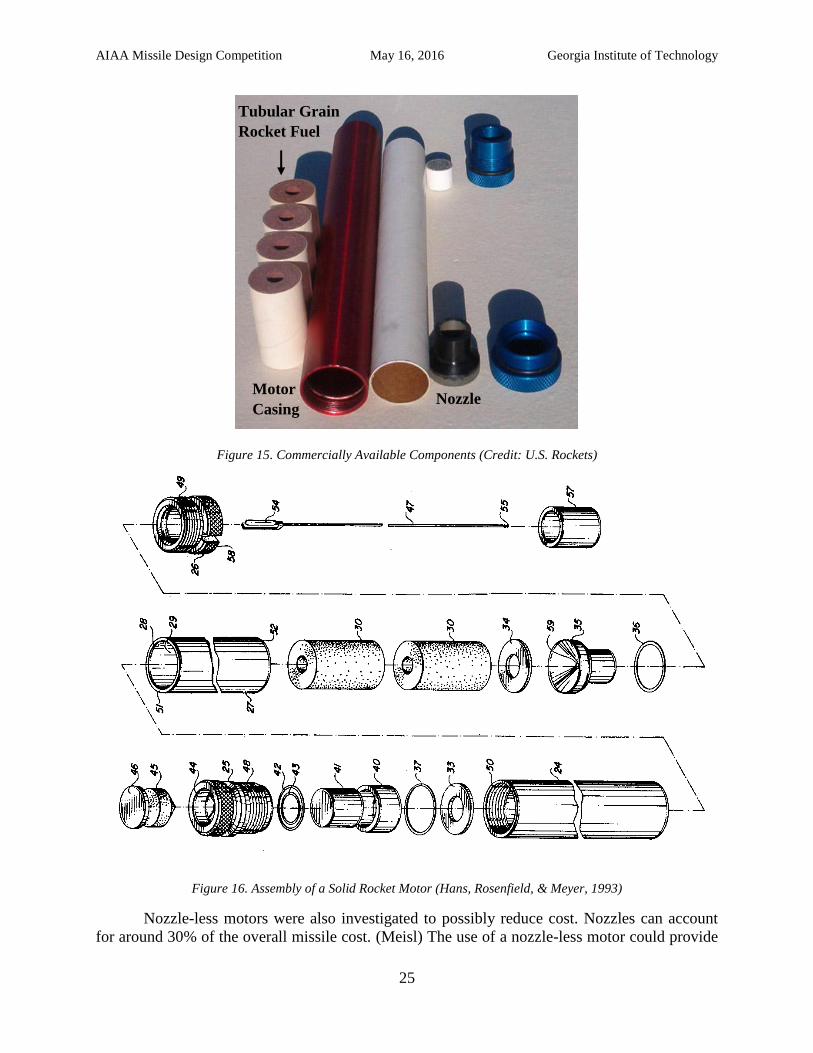
manufacturing cost while reducing the production costs due to simplistic assembly steps. The
assembly of these parts is illustrated in Figure 16.
AIAA Missile Design Competition May 16, 2016 Georgia Institute of Technology
25
Figure 15. Commercially Available Components (Credit: U.S. Rockets)
Figure 16. Assembly of a Solid Rocket Motor (Hans, Rosenfield, & Meyer, 1993)
Nozzle-less motors were also investigated to possibly reduce cost. Nozzles can account
for around 30% of the overall missile cost. (Meisl) The use of a nozzle-less motor could provide
Nozzle Motor
Casing
Tubular Grain
Rocket Fuel
AIAA Missile Design Competition May 16, 2016 Georgia Institute of Technology
26
a significant reduction in cost; however, the loss in performance may be significant.
Commercially available nozzles were found to be widely available and low-cost. The cost for a
54 mm nozzle to use with the baseline missile would only be around $28 USD. (Rocket Motor
Components, inc.). Due to the low cost of commercially available nozzles, the team chose to use
a nozzle to avoid the degradation of engine performance throughout the burn.
The team identified several motor diameters that were both smaller and larger than the
baseline missile with a 54 mm diameter. The common diameters chosen for sizing were 34 mm,
54 mm, 75 mm, 98 mm, and 150 mm. The price estimates for both the motor casings and nozzles
are shown in Table 9.
Table 9. Motor Casings and Nozzles Costs (Rocket Motor Components, inc.) & (Apogee Components).
Diameter 34 mm
(1.33 in)
54 mm
(2.12 in)
75 mm
(2.95 in)
98 mm
(3.86 in)
150 mm
(5.9 in)
Motor Casing
Cost
[2016USD]
$85 $150 $400 $600 $1000
Nozzle Cost
[2016USD] $4 $28 $55 $100 $200
Along with the commercial off the shelf components, several common and low-cost solid
rocket fuel grains were investigated as well to allow for performance, cost, and density tradeoffs.
Four fuel grains were chosen: aluminum powder, magnesium powder, smokeless black powder,
and a double base nitroglycerine/nitrocellulose mixture. A cost per pound, density, specific
impulse (Isp), burn rate, and corresponding compositions were identified for each of the fuel
grains. Note that the burn rate of the fuel is assumed to be constant, which will be discussed later
in this section. The fuel grain data is outlined in Table 10.
.
AIAA Missile Design Competition May 16, 2016 Georgia Institute of Technology
27
Table 10. Low-cost fuel grain performance and cost
Fuel Grain Cost
(2106USD/lb)
Density
(lb/ft3)
Isp (s) Burn Rate
(in/s) Composition
Aluminum
Powder1 ~$10+2 44-125 250-
270 0.472
Ammonium Perchlorate
(68%),
Aluminum (18%),
R45M Binder (14%)
Magnesium
Powder3 ~$4-$7.253 56-69 200-
210 -
Ammonium Nitrate
(60%),
Magnesium (20%),
R20LM Binder (20%)
Smokeless
Black Powder1 ~$4-$6.354 34-44 80-90 0.354 -
Double Base5
(nitroglycerine /
nitrocellulose)
$7+6 93-100 235-
250
0.591-
0.984
Nitrocellulose (51.5%),
Nitroglycerine (43.0%),
Plasticizer (1.0%), Other
(4.5%)
Note: 1: (Jacob's Rocketry), 2: (Micron Metals, Inc.), 3: (Micron Metals, Inc.), 4: (Graf & Sons), 5: (Zandbergen,
2014), 6: (Goodboatgear.com)
The aluminum powder provides the highest performance and density of the four fuels. It
is composed of 68% ammonium perchlorate and 18% aluminum powder for the oxidizer and fuel
respectively. The solid fuel also contains 14% R45M as a binder to ensure the fuel maintains its
solid and stable state.
The magnesium powder provides a lower cost solution with a lower density and Isp
range. This fuel grain is composed of 60% Ammonium Nitrate as the oxidizer, 20% magnesium
as the fuel, and 20% R20LM as the binder. However, after further research, magnesium powder
was found to be hazardous to handle, costly to transport, and has poor availability. (Nakka
Rocketry, 2010). Due to these findings, magnesium powder was not pursued as a potential fuel
grain option.
The smokeless black powder provides the lowest cost solution; however it also has the
lowest Isp and lowest density ranges. Smokeless black powder provides a more efficient
propellant than the traditional black powder by leaving fewer residues behind, allowing for a
larger mass flow.
The double base propellant provided a middle range cost per pound while still providing
high performance characteristics with Isp values ranging from 235-250. The fuel is mainly made
up of a mixture of nitrocellulose and nitroglycerine.
The fuel grain geometry was also investigated to provide a simplistic design with low
manufacturing costs. Simple geometries such as a rod and tube or star geometry, illustrated in
Figure 17 and Figure 18, provided a constant thrust profile, simplifying the sizing calculations.
Since the requirements specify the threats as non-maneuvering targets, a constant thrust profile
would satisfy the proposed CONOPS.
AIAA Missile Design Competition May 16, 2016 Georgia Institute of Technology
28
Figure 17. Rod and tube fuel grain geometry and thrust profile (Nakka)
Figure 18. 5-point star fuel grain geometry and thrust profile (Nakka)
Another step taken to provide simple solid rocket motor sizing and design is the
assumption of a constant burning rate. The burning rate of a solid rocket motor depends on the
chamber pressure and fuel grain properties. The chamber pressure typically changes throughout
the burn, making it difficult to determine specific burn rates for a given propellant. The chamber
pressure of a solid rocket motor also depends on other characteristics such as the geometry of the
grain and throat of the nozzle. Saint-Robert’s Law, also known as the burning rate law, is
represented by Equation 1. (Purdue University, 2008).
(Eq. 1)
where is the burning rate in units of length per time, is the burning rate coefficient, is the
chamber pressure, and is the burning rate exponent. The difficulty in determining the burn rate
of a solid rocket motor is that both the burning rate coefficient and exponent need to be
determined experimentally in order to utilize Equation
(Eq. 1. However, since a constant thrust fuel grain geometry was chosen, a constant
chamber pressure could also be assumed. Experimental data from a rod and tube solid rocket
motor was found that designed the motor for both constant thrust and constant chamber pressure.
This data is illustrated in Figure 19. Thrust and Chamber Pressure Data of a rod and tube fuel grain
geometry. Choosing a solid rocket motor with both a constant thrust and chamber pressure allows
for the assumption of a constant burn rate throughout the burn of the propellant. The burn rates
listed in
AIAA Missile Design Competition May 16, 2016 Georgia Institute of Technology
29
Table 10 correspond to each of the propellants; however they are assumed to be average values
from a variety of motor designs. There is uncertainty in the design of the motor due to the
assumed burn rate values chosen for each propellant, but the chosen burn rates are assumed to be
fair approximations for the first order sizing and analysis of the solid rocket motor.
Figure 19. Thrust and Chamber Pressure Data of a rod and tube fuel grain geometry (Nakka Rcoketry)
Overall, the focus in the design of the solid rocket motor is the reduction in cost and
simplification of the design. The use of commercially available components and fuel provide
significant reduction in manufacturing costs while the simplification in the design reduces the
production costs.
Sizing & Costing
The sizing of the missile begins with the scaling if the geometry generated in OpenVSP.
Using the length to diameter ratio, the geometry was scaled to each of the chosen missile
diameters. The next step was to initialize the burnout mass of the missile and calculate an initial
propellant mass guess. The initial burnout mass of the missile was determined by summing up
the mass of the warhead, guidance and controls, and structural components. These mass values
were determined by using the baseline missile to calibrate the empty mass estimation. The 54
mm diameter missile with a double base propellant was used to properly estimate the weight of
the guidance, controls, and structure of the missile by using the publicly available weight values
from the NAVAIR Spike missile. The missile had an overall mass of 2.4 kg (5.1 lbs) and a
warhead mass of 0.45 kg (1 lb). This calibration resulted in a mass of 0.75 kg (1.65 lbs) for the
guidance and controls system and a mass of 0.45 kg (1 lb) for the structural components. Next
the initial propellant mass was determined for each given propellant by rearranging the rocket
equation, shown by Equation 2, in terms of the propellant mass, shown by Equation 3.
(
) (Eq. 2)
(
) (Eq. 3)
AIAA Missile Design Competition May 16, 2016 Georgia Institute of Technology
30
where is the mass of the propellant, is the mass after burnout of the propellant, is
the initial guess for the missile’s maximum velocity, is the gravitational constant, is the
specific impulse of the propellant, and is the burnout time of the propellant. The initial guess
for the maximum velocity was chosen to be 269 m/s (600 mph) which is the estimated speed of
the NAVAIR Spike missile. The actual maximum speed may still be classified. The initial burn
time was estimated to be five seconds for each propellant. This value was only used to initial the
propellant mass and was not based off of any data.
The next step in the sizing of the missile was to develop a MATLAB code that would
size the propellant given a specified range. An iterative process was implemented to update the
acceleration, velocity, mass, time step, and position of the missile until the specified range was
achieved. The thrust, mass flow rate, and propellant surface area estimates were also required to
initialize the analysis. A time step of 0.05 seconds was used to until the missile reached a range
of 1600 meters (5249 feet) traveling at a 15 degree angle of attack. This analysis accounted for
drag forces throughout the flight of the missile by using drag coefficient data from the
aerodynamics analysis. The gravitational force was also accounted for throughout the sizing
analysis.
Every time the missile ran out of fuel before meeting the required range, 0.05 kg of fuel
was added to the initial propellant mass and the analysis was restarted until the correct amount of
propellant was determined. Once complete, new values for burn time, mass flow rate, motor
length, maximum velocity, and thrust were calculated and the range sizing analysis was run
again. This loop was executed 10 times to produce a properly sized missile before checking each
missile’s feasibility based off of available volume and running it through the trajectory analysis.
The missile sizing code also calculated the overall cost of the sized missile. The code
kept track of the motor casing and nozzle costs that corresponded to each design. The code also
had hard coded values for the guidance, controls, and warhead cost as well as the cost per pound
of the propellant. Since the guidance and controls system repurposed a smart phone, the cost of
system was estimated to be $850 USD. This included $650 USD for the smart phone and an
extra $200 USD for the servos and batteries required for the controls system. The cost of the
warhead was chosen to be $8 per pound based off of the cost of the IMX-101 explosive.
(Thompson, 2010). The cost of the fuselage and fins were not accounted for in the costing
analysis. Once the missile was sized, the cost of the propellant was calculated on a per pound
basis and added to the fixed cost of each missile diameter size.
Feasibility check
Both the guidance & controls and the warhead modules of the missile were based off the
volume used for the baseline NAVAIR Spike missile. The team assumed that the control system
for the baseline and new solution will be similar. Based off that assumption, the dimensions of
the baseline missile were found to have a 57 mm (2.24 in) fuselage diameter and a length of 340
mm (13.4 in) for guidance & controls and a length of 90 mm (3.54 in) for the warhead. This
produced a volume of 8.68 x 10⁻⁴
m3 (52.9 in
3) that would be required to house the guidance and
control system for each missile. The warhead required less volume than guidance & controls and
will be separately sized to reflect the requirements. The volume required for the warhead will be
scaled down from the baseline missile which has 0.45 kg (1 lb) of explosives that require 2.30 x
10-4
m3 (14 in
3).
AIAA Missile Design Competition May 16, 2016 Georgia Institute of Technology
31
Once the solid rocket motor was sized, the volume required to house the guidance &
controls, warhead, and propellant was compared to the available volume after scaling the missile
geometry to each missile diameter. If there was more than 30% empty volume in the missile
geometry, the solution was considered infeasible. Also, if the missile required more than 30%
more of the available volume, the missile was considered infeasible. This feasibility check
allowed for the impractical solutions to be filtered out from the analysis to reduce the overall run
time of the code. The feasible missile designs will be passed forward to the trajectory analysis
for further sizing and performance feasibility checks.
5. Guided Projectile Sizing and Costing
Guided projectile technology is still in development with most projectile’s technology
readiness levels around seven or eight. The data on how they work and their performance
characteristics and cost are classified. Initially, the team looked at the DARPA EXACTO which
is a fifty caliber guided projectile (Ackerman, 2015). The team believed a fifty caliber bullet
imparted enough kinetic energy on impact to destroy group one and two UAVs and a fifty caliber
bullet would be easy to store. This bullet would also be able to be used from multiple launch
platforms that include fifty caliber guns including trucks, UAVs, and soldiers. However, the
highly classified nature of the EXACTO made it extremely difficult for the team to understand
how the bullet works to enable the team to design a version that would satisfy the requirements.
Therefore, the team chose to scale larger guided projectiles that have the required information to
design them available to fit the requirements. These larger projectiles are very similar to missiles,
they just do not have a propulsion system as shown in Figure 20.
Figure 20. Excalibur Guided Projectile Cutaway (Jr., 2016)
The sizing and costing tool of the guided projectiles occurred in three phases, weight,
propulsion system, and volumetric sizing and costing as shown in Figure 21. Guided Projectile
Sizing and Costing Tool Overview. The weight sizing and costing determines the weight and cost of
the projectile minus the warhead and propulsion system weight and cost. The warhead weight
and cost is determined using the warhead sizing tool. The propulsion system sizing and costing
AIAA Missile Design Competition May 16, 2016 Georgia Institute of Technology
32
determines the amount of smokeless powder required to propel the projectile the required range
with enough velocity to maneuver during the endgame scenario and determine how much the
required powder would cost. The volumetric sizing determines how to scale the geometries from
the geometry code to be able to fit the assumed control system volume and warhead volume
while allowing the projectile to fit in commercially available caliber guns.
Figure 21. Guided Projectile Sizing and Costing Tool Overview
A guided projectile is very similar to a missile without the propulsion system. However,
all of the thrust is imparted onto the projectile in the barrel causing the projectile to see much
higher g-loadings than missiles. This increased g-loading requires increased structural support
and electronics specifically designed for the high loadings. The cost and increased weight caused
by these additions could not be determined based on a literature search. Therefore, the weight
and cost of the projectile was determined using regressions of the current in development and in
use guided projectiles. The parameters of the four projectiles used for the regressions are shown
in Table 11. (Jr., 2016), (David Gudjohnsen, 2005), (Excalibur XM982 Precision Engagement
Projectiles, 2007), (5-inch U.S. Navy Guided Projectile, 2014), (Industry Advances Long Range,
Precision Munitions (by: BAE Systems), 2015), (Systems, 2015), (Ackerman, 2015). The weight
minus the warhead weight of the projectile was found using the weight versus range regression
shown in Figure 22 on the left. The warhead weight was assumed to be zero for each projectile
regressed on due to the lack of public data on the warheads, if they have them. The regression
was used to find an equation that relates the weight of the system to its range as shown in
Equation 4. The four guided projectiles gave a poor regression due to the low number of points
even though the R2 is very close to one. So, a twenty percent margin of safety was added to this
regression to account for any errors in the regression. Only two of the regressed projectiles cost
data was publically available. These two were used in another regression to find a way to relate
the missile cost to its weight and range as shown in Figure 22 on the right. The regression related
the unit cost to the weight and the range of the projectile via Equation 5.
Weight Estimate
Volumetric Sizing
Propulsion Sizing
Overall Costing
2D Muzzle Velocity
Input
Weight Regression
s
Warhead Weight
Warhead & Controls Volumes
Gun Calibers
Cost Regression
s
Propulsion Cost
Trajectory Analysis
Guided Projectile Sizing and Costing
AIAA Missile Design Competition May 16, 2016 Georgia Institute of Technology
33
Table 11. Guided Projectiles Used for Regressions
Range (ft) Weight (lbs) Cost ($)
M982 Excalibur 131233.6 106 68000
LM 5-inch 155/62 Ags 393700.8 102 Unknown
BAE MS-SGP 314960.6 110 55000
Exacto 7874 0.057 Unknown
Figure 22. Weight (left) and Cost (right) Regression Plots
0031.0
)9017.3
)Rangelog(ln(
Weight (Eq. 4)
Weight*31.749Range*0871.0Cost (Eq. 5)
The weight estimating portion of the guided projectile sizing and costing module uses the
previously discussed weight regression equation to estimate the weight of the projectile based on
the maximum range of the projectile. The maximum range used in the regressions was assumed
to be two to two and a half kilometers based on the requirement analysis. The estimated weight is
assumed to have an error of approximately plus or minus twenty percent.
The estimated weight as well as the weight of the warhead was used to get a mass
estimate of the total projectile. This mass along with internal ballistic modeling calculates the
required mass of propellant to achieve a specific muzzle velocity. The initial guess for required
muzzle velocity was based on two dimensional projectile motion by assuming constant velocity,
no drag, and flat earth. Subsequent muzzle velocities were calculated based on the required
velocities from the trajectory code. The muzzle velocity is used with the total mass of the
projectile along with the chemical properties of smokeless powder to calculate required
propellant based on internal ballistic models from Terminal Ballistics by Marvin E. Beckman
(Backman, 1976). Smokeless powder was assumed to be primarily made of nitrocellulose whose
chemical properties were used to determine its chemical properties. The propellant grain was
also assumed to be cylindrical since it is the simplest and most cost effective type of grain shape.
The calculated mass of propellant was used to calculate the cost of propellant based on one
3
100003
200003
300003
400003
500003
0 50 100 150
Ran
ge(f
t)
Weight (lbs)
EXACTO
500
550
600
650
1000 2000 3000 4000 5000C
ost
per
Po
un
d (
$/l
bs)
Range per Pound (ft/lbs)
AIAA Missile Design Competition May 16, 2016 Georgia Institute of Technology
34
pound of smokeless powder is equal to twenty US dollars (Shop All Smokeless Powder Here:,
2016).
The volumetric sizing scaled the geometries to fit various commercially produced caliber
guns. It achieved this by scaling the diameter to calibers with the most commonly available guns.
The calibers used were 2, 2.4, 3.2, 4.7, and 5 inches. The volumetric sizing also checks to make
sure the missile could fit the warhead and control system into the projectile based on the volume
required for the sized warhead and the assumed smartphone sized control system.
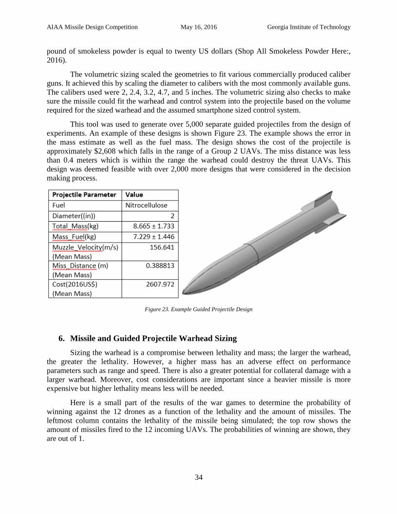
This tool was used to generate over 5,000 separate guided projectiles from the design of
experiments. An example of these designs is shown Figure 23. The example shows the error in
the mass estimate as well as the fuel mass. The design shows the cost of the projectile is
approximately $2,608 which falls in the range of a Group 2 UAVs. The miss distance was less
than 0.4 meters which is within the range the warhead could destroy the threat UAVs. This
design was deemed feasible with over 2,000 more designs that were considered in the decision
making process.
Figure 23. Example Guided Projectile Design
6. Missile and Guided Projectile Warhead Sizing
Sizing the warhead is a compromise between lethality and mass; the larger the warhead,
the greater the lethality. However, a higher mass has an adverse effect on performance
parameters such as range and speed. There is also a greater potential for collateral damage with a
larger warhead. Moreover, cost considerations are important since a heavier missile is more
expensive but higher lethality means less will be needed.
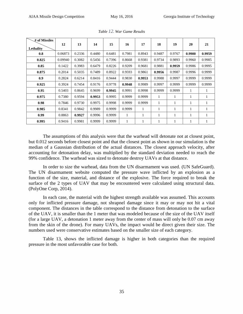
Here is a small part of the results of the war games to determine the probability of
winning against the 12 drones as a function of the lethality and the amount of missiles. The
leftmost column contains the lethality of the missile being simulated; the top row shows the
amount of missiles fired to the 12 incoming UAVs. The probabilities of winning are shown, they
are out of 1.
AIAA Missile Design Competition May 16, 2016 Georgia Institute of Technology
35
Table 12. War Game Results
# of Missiles
Lethality
12 13 14 15 16 17 18 19 20 21
0.8 0.06873 0.2336 0.4480 0.6481 0.7981 0.8943 0.9487 0.9767 0.9900 0.9959
0.825 0.09940 0.3082 0.5456 0.7396 0.8668 0.9381 0.9734 0.9893 0.9960 0.9985
0.85 0.1422 0.3983 0.6479 0.8226 0.9209 0.9681 0.9881 0.9959 0.9986 0.9995
0.875 0.2014 0.5035 0.7489 0.8922 0.9593 0.9861 0.9956 0.9987 0.9996 0.9999
0.9 0.2824 0.6214 0.8416 0.9444 0.9830 0.9953 0.9988 0.9997 0.9999 0.9999
0.925 0.3924 0.7454 0.9176 0.9778 0.9948 0.9989 0.9997 0.9999 0.9999 0.9999
0.95 0.5403 0.8645 0.9699 0.9945 0.9991 0.9998 0.9999 0.9999 1 1
0.975 0.7380 0.9594 0.9953 0.9995 0.9999 0.9999 1 1 1 1
0.98 0.7846 0.9730 0.9975 0.9998 0.9999 0.9999 1 1 1 1
0.985 0.8341 0.9842 0.9989 0.9999 0.9999 1 1 1 1 1
0.99 0.8863 0.9927 0.9996 0.9999 1 1 1 1 1 1
0.995 0.9416 0.9981 0.9999 0.9999 1 1 1 1 1 1
The assumptions of this analysis were that the warhead will detonate not at closest point,
but 0.012 seconds before closest point and that the closest point as shown in our simulation is the
median of a Gaussian distribution of the actual distances. The closest approach velocity, after
accounting for detonation delay, was multiplied by the standard deviation needed to reach the
99% confidence. The warhead was sized to detonate destroy UAVs at that distance.
In order to size the warhead, data from the UN disarmament was used. (UN SafeGuard).
The UN disarmament website computed the pressure wave inflicted by an explosion as a
function of the size, material, and distance of the explosive. The force required to break the
surface of the 2 types of UAV that may be encountered were calculated using structural data.
(PolyOne Corp, 2014).
In each case, the material with the highest strength available was assumed. This accounts
only for inflicted pressure damage, not shrapnel damage since it may or may not hit a vital
component. The distances in the table correspond to the distance from detonation to the surface
of the UAV, it is smaller than the 1 meter that was modeled because of the size of the UAV itself
(for a large UAV, a detonation 1 meter away from the center of mass will only be 0.07 cm away
from the skin of the drone). For many UAVs, the impact would be direct given their size. The
numbers used were conservative estimates based on the smaller size of each category.
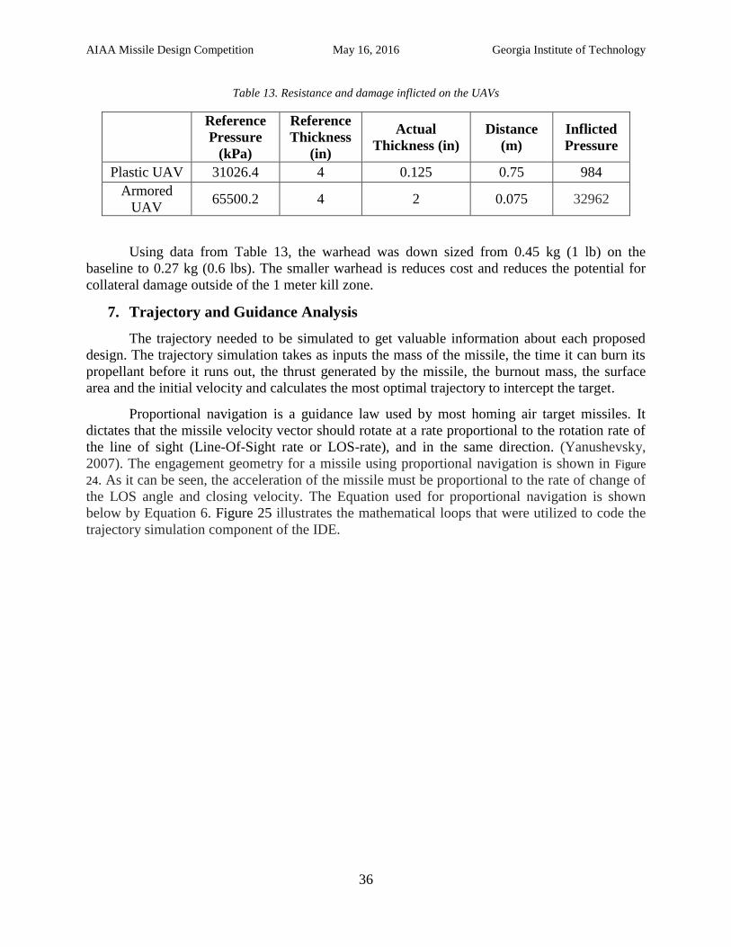
Table 13, shows the inflicted damage is higher in both categories than the required
pressure in the most unfavorable case for both.
AIAA Missile Design Competition May 16, 2016 Georgia Institute of Technology
36
Table 13. Resistance and damage inflicted on the UAVs
Reference
Pressure
(kPa)
Reference
Thickness
(in)
Actual
Thickness (in)
Distance
(m)
Inflicted
Pressure
Plastic UAV 31026.4 4 0.125 0.75 984
Armored
UAV 65500.2 4 2 0.075 32962
Using data from Table 13, the warhead was down sized from 0.45 kg (1 lb) on the
baseline to 0.27 kg (0.6 lbs). The smaller warhead is reduces cost and reduces the potential for
collateral damage outside of the 1 meter kill zone.
7. Trajectory and Guidance Analysis
The trajectory needed to be simulated to get valuable information about each proposed
design. The trajectory simulation takes as inputs the mass of the missile, the time it can burn its
propellant before it runs out, the thrust generated by the missile, the burnout mass, the surface
area and the initial velocity and calculates the most optimal trajectory to intercept the target.
Proportional navigation is a guidance law used by most homing air target missiles. It
dictates that the missile velocity vector should rotate at a rate proportional to the rotation rate of
the line of sight (Line-Of-Sight rate or LOS-rate), and in the same direction. (Yanushevsky,
2007). The engagement geometry for a missile using proportional navigation is shown in Figure
24. As it can be seen, the acceleration of the missile must be proportional to the rate of change of
the LOS angle and closing velocity. The Equation used for proportional navigation is shown
below by Equation 6. Figure 25 illustrates the mathematical loops that were utilized to code the
trajectory simulation component of the IDE.
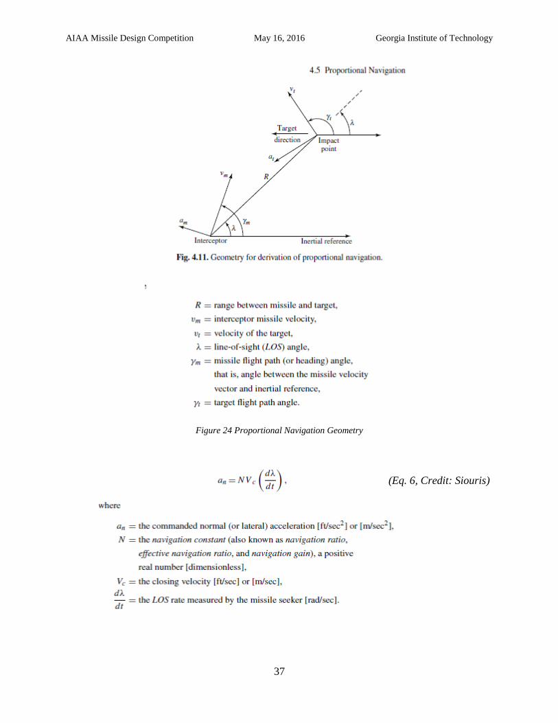
AIAA Missile Design Competition May 16, 2016 Georgia Institute of Technology
37
Figure 24 Proportional Navigation Geometry
(Eq. 6, Credit: Siouris)
AIAA Missile Design Competition May 16, 2016 Georgia Institute of Technology
38
Figure 25. Block Diagrams for Proportional Navigation (Image Credit: Siouris)
The simulation starts by assuming a correction factor which determines how many
seconds ahead or behind the target the missile is initially fired. Several correction factors are
tried and the best one in terms of closest approach is the one retained. The corrector factors
correct for the future movement of the missile, the fact that it is not stationary. They are
generated by trying different numbers between a lower and an upper bound and trying them all.
They determine how many seconds ahead or behind the target is the missile shot. That
calculation is done assuming the direction and velocity of the target will stay constant which
models a non-maneuvering target as stated in the RFP.
For each correction factor, the initial angle of attack is computed. Based on the angle of
attack and dynamic pressure, the coefficient of lift and coefficient of drag are calculated using
interpolation from a table that is dependent on the fin configuration of the missile being
simulated.
The missile information keeps being updated and the coefficients of lift and drag keep
being recalculated as the dynamic pressure and the angle of attack change. The position is
updated based on the forces acting on the missile which are lift, drag, weight, and thrust. Mass is
also being updated constantly, since propellant is being burned. Different mass affects the weight
force felt by the missile and the inertia the missile has to acceleration when acted upon by the
aforementioned forces.
The missile updates its direction regularly based on the relative distance between it and
the target. However, it is not allowed to turn too quickly but it is limited by realistic turn rates.
Because of this, the target cannot be hit exactly all the time, but the data obtained is more
reliable.
AIAA Missile Design Competition May 16, 2016 Georgia Institute of Technology
39
The missile keeps going until it reaches its closest approach, and realizes it is moving
farther from the target. At this point, the absolute majority of the times, the missile will detonate
in real life. However, because we are sizing it to be able to go up to a safe distance and detonate
there to minimize collateral damage should the missile miss, the simulation makes the missile
turn upwards and go until it reaches the safe height times the safety factor.
The height the missile needs to go before it is allowed to detonate is a fixed height based
on the time needed for the pellets from the warhead to slow down to terminal velocity. The
height amount is based on the height for the pellets since it is the part of the missile that takes the
longest to decelerate. Having the debris and the pellets decelerate as much as possible minimizes
the damage to people and structures on the ground.
Figure 26. shows the trajectory histogram where thrust, acceleration, and the velocity in
the different directions, as a function of time. As the figure shows, the thrust was assumed
constant. Also, the acceleration was considerably higher at the beginning that at the rest due to
the lower drag at lower speed with a small spike of acceleration latter due to maneuvering. The
velocities in all directions show a similar pattern, fast increase at the beginning until a first cruise
state is reached and then a small increase that leads to a faster cruise until the missile starts
decelerating. Because the direction is changing, the different components of velocity do not have
exactly the same shape. This is especially noticeable in the z component of velocity, which
actually makes a dip around the 5 second mark when the other 2 components increase. It is also
the only component to have the second cruise be smaller than the first. However, due to the
missile being shot ahead of the target to intercept it and the fact that maneuvers are small, the
differences are small.
AIAA Missile Design Competition May 16, 2016 Georgia Institute of Technology
40
Figure 26. Trajectory Time Histories
Figure 27 shows the altitude, range, lift, drag, angle of attack and Mach number as a
function of time. The altitude starts from the zero reference point and increases slowly at first
until cruise is achieved where it goes linear until the target is near, when the missile decelerates.
This graph is shown without the termination protocol, which is just shooting up to the safety
distance to minimize collateral damage, because it obscured the part of the graph at the
beginning, which is more important. A separate graph with the safety protocol will be shown
later. The range as a function of time is also shown. It has a similar behavior due to the changes
in velocity and we can see that it goes past the 1000 meter requirement. The lift starts very small
due to the small initial velocity. When cruise arrives it stabilizes. Then it does a small dip due to
the decrease of angle of attack but it quickly goes back up due to the increase speed. It falls
sharply when velocity does. Drag follows a similar behavior than lift but with a lower magnitude
overall. The angle of attack starts pretty high and it is almost constant until about 5 seconds,
when it drops to about 14 degrees and slowly decreases after that. The Mach number increases
rapidly at the beginning due to the small drag at low speeds until it reaches cruise. Then, the
missile changes the angle of attack and it reduces its drag which allows it to transition to the
second cruise where it maintains its current states until it is close to target and starts decelerating.
AIAA Missile Design Competition May 16, 2016 Georgia Institute of Technology
41
Figure 27. Trajectory Time Histories
Illustrated in Figure 28 is the height as a function of time with the part of the safety
protocol shown. As it can be seen, since all the thrust is being used to reach a safe height, a
higher climb is achieved. Also, because the mass is decreasing, the inertia goes down, which
allows for faster climb.
Figure 28. Altitude Time History
From the simulation of the trajectory, crucial information was extracted. The information
includes the closest approach distance, the closest approach velocity, the closest approach time,
the burnout velocity, and whether or not the missile trajectory is a success. A heavy missile or
one with too little propellant or thrust could fail to reach the safety height. The closest approach
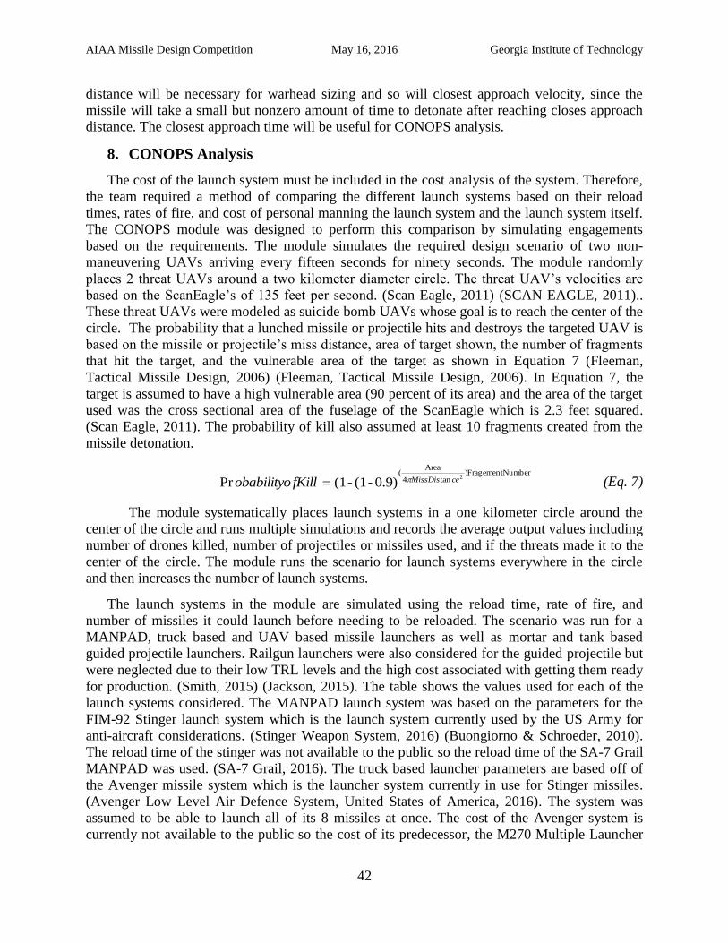
AIAA Missile Design Competition May 16, 2016 Georgia Institute of Technology
42
distance will be necessary for warhead sizing and so will closest approach velocity, since the
missile will take a small but nonzero amount of time to detonate after reaching closes approach
distance. The closest approach time will be useful for CONOPS analysis.
8. CONOPS Analysis
The cost of the launch system must be included in the cost analysis of the system. Therefore,
the team required a method of comparing the different launch systems based on their reload
times, rates of fire, and cost of personal manning the launch system and the launch system itself.
The CONOPS module was designed to perform this comparison by simulating engagements
based on the requirements. The module simulates the required design scenario of two non-
maneuvering UAVs arriving every fifteen seconds for ninety seconds. The module randomly
places 2 threat UAVs around a two kilometer diameter circle. The threat UAV’s velocities are
based on the ScanEagle’s of 135 feet per second. (Scan Eagle, 2011) (SCAN EAGLE, 2011)..
These threat UAVs were modeled as suicide bomb UAVs whose goal is to reach the center of the
circle. The probability that a lunched missile or projectile hits and destroys the targeted UAV is
based on the missile or projectile’s miss distance, area of target shown, the number of fragments
that hit the target, and the vulnerable area of the target as shown in Equation 7 (Fleeman,
Tactical Missile Design, 2006) (Fleeman, Tactical Missile Design, 2006). In Equation 7, the
target is assumed to have a high vulnerable area (90 percent of its area) and the area of the target
used was the cross sectional area of the fuselage of the ScanEagle which is 2.3 feet squared.
(Scan Eagle, 2011). The probability of kill also assumed at least 10 fragments created from the
missile detonation.
Number)Fragementtan4
Area(
2
0.9)-(1 - (1Pr ceMissDisfKillobabilityo (Eq. 7)
The module systematically places launch systems in a one kilometer circle around the
center of the circle and runs multiple simulations and records the average output values including
number of drones killed, number of projectiles or missiles used, and if the threats made it to the
center of the circle. The module runs the scenario for launch systems everywhere in the circle
and then increases the number of launch systems.
The launch systems in the module are simulated using the reload time, rate of fire, and
number of missiles it could launch before needing to be reloaded. The scenario was run for a
MANPAD, truck based and UAV based missile launchers as well as mortar and tank based
guided projectile launchers. Railgun launchers were also considered for the guided projectile but
were neglected due to their low TRL levels and the high cost associated with getting them ready
for production. (Smith, 2015) (Jackson, 2015). The table shows the values used for each of the
launch systems considered. The MANPAD launch system was based on the parameters for the
FIM-92 Stinger launch system which is the launch system currently used by the US Army for
anti-aircraft considerations. (Stinger Weapon System, 2016) (Buongiorno & Schroeder, 2010).
The reload time of the stinger was not available to the public so the reload time of the SA-7 Grail
MANPAD was used. (SA-7 Grail, 2016). The truck based launcher parameters are based off of
the Avenger missile system which is the launcher system currently in use for Stinger missiles.
(Avenger Low Level Air Defence System, United States of America, 2016). The system was
assumed to be able to launch all of its 8 missiles at once. The cost of the Avenger system is
currently not available to the public so the cost of its predecessor, the M270 Multiple Launcher
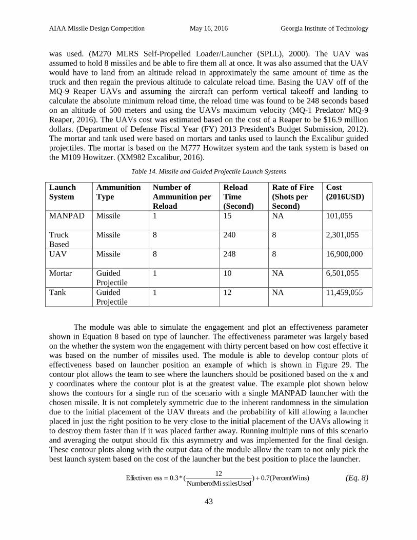
AIAA Missile Design Competition May 16, 2016 Georgia Institute of Technology
43
was used. (M270 MLRS Self-Propelled Loader/Launcher (SPLL), 2000). The UAV was
assumed to hold 8 missiles and be able to fire them all at once. It was also assumed that the UAV
would have to land from an altitude reload in approximately the same amount of time as the
truck and then regain the previous altitude to calculate reload time. Basing the UAV off of the
MQ-9 Reaper UAVs and assuming the aircraft can perform vertical takeoff and landing to
calculate the absolute minimum reload time, the reload time was found to be 248 seconds based
on an altitude of 500 meters and using the UAVs maximum velocity (MQ-1 Predator/ MQ-9
Reaper, 2016). The UAVs cost was estimated based on the cost of a Reaper to be $16.9 million
dollars. (Department of Defense Fiscal Year (FY) 2013 President's Budget Submission, 2012).
The mortar and tank used were based on mortars and tanks used to launch the Excalibur guided
projectiles. The mortar is based on the M777 Howitzer system and the tank system is based on
the M109 Howitzer. (XM982 Excalibur, 2016).
Table 14. Missile and Guided Projectile Launch Systems
Launch
System
Ammunition
Type
Number of
Ammunition per
Reload
Reload
Time
(Second)
Rate of Fire
(Shots per
Second)
Cost
(2016USD)
MANPAD Missile 1 15 NA 101,055
Truck
Based
Missile 8 240 8 2,301,055
UAV Missile 8
248
8
16,900,000
Mortar Guided
Projectile
1 10 NA 6,501,055
Tank Guided
Projectile
1 12 NA 11,459,055
The module was able to simulate the engagement and plot an effectiveness parameter
shown in Equation 8 based on type of launcher. The effectiveness parameter was largely based
on the whether the system won the engagement with thirty percent based on how cost effective it
was based on the number of missiles used. The module is able to develop contour plots of
effectiveness based on launcher position an example of which is shown in Figure 29. The
contour plot allows the team to see where the launchers should be positioned based on the x and
y coordinates where the contour plot is at the greatest value. The example plot shown below
shows the contours for a single run of the scenario with a single MANPAD launcher with the
chosen missile. It is not completely symmetric due to the inherent randomness in the simulation
due to the initial placement of the UAV threats and the probability of kill allowing a launcher
placed in just the right position to be very close to the initial placement of the UAVs allowing it
to destroy them faster than if it was placed farther away. Running multiple runs of this scenario
and averaging the output should fix this asymmetry and was implemented for the final design.
These contour plots along with the output data of the module allow the team to not only pick the
best launch system based on the cost of the launcher but the best position to place the launcher.
)sPercentWin(7.0)ssilesUsedNumberofMi
12(*3.0essEffectiven (Eq. 8)
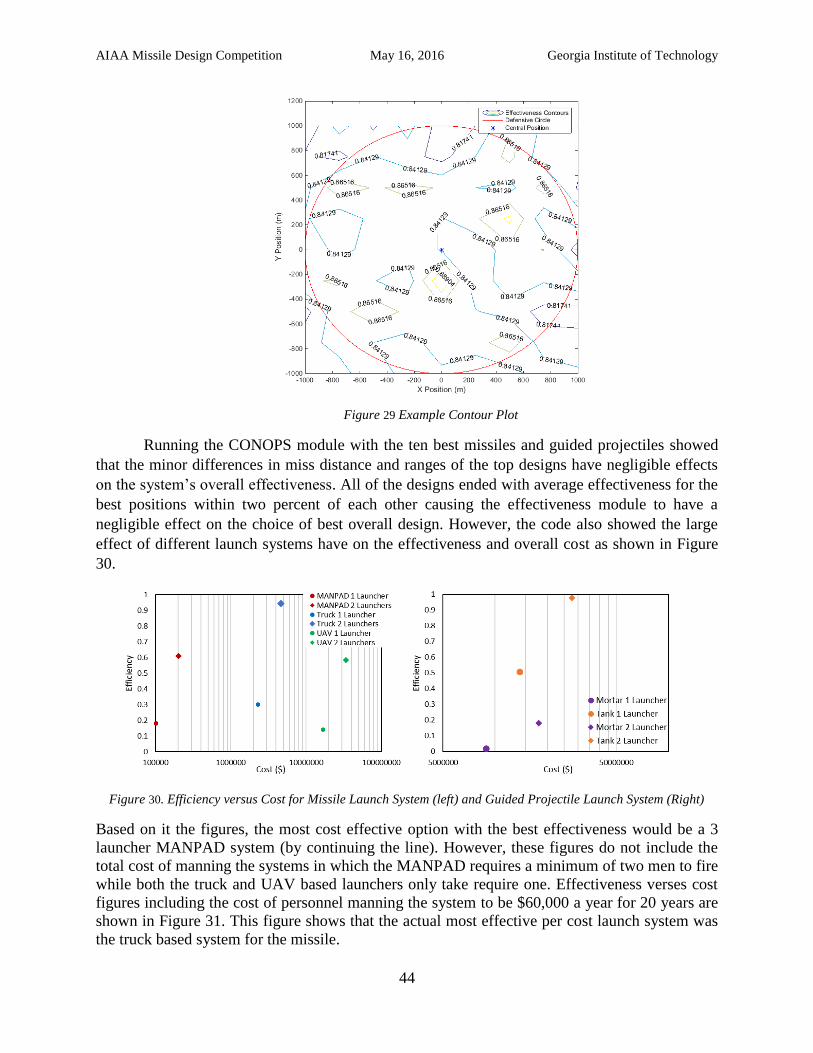
AIAA Missile Design Competition May 16, 2016 Georgia Institute of Technology
44
Figure 29 Example Contour Plot
Running the CONOPS module with the ten best missiles and guided projectiles showed
that the minor differences in miss distance and ranges of the top designs have negligible effects
on the system’s overall effectiveness. All of the designs ended with average effectiveness for the
best positions within two percent of each other causing the effectiveness module to have a
negligible effect on the choice of best overall design. However, the code also showed the large
effect of different launch systems have on the effectiveness and overall cost as shown in Figure
30.
Figure 30. Efficiency versus Cost for Missile Launch System (left) and Guided Projectile Launch System (Right)
Based on it the figures, the most cost effective option with the best effectiveness would be a 3
launcher MANPAD system (by continuing the line). However, these figures do not include the
total cost of manning the systems in which the MANPAD requires a minimum of two men to fire
while both the truck and UAV based launchers only take require one. Effectiveness verses cost
figures including the cost of personnel manning the system to be $60,000 a year for 20 years are
shown in Figure 31. This figure shows that the actual most effective per cost launch system was
the truck based system for the missile.
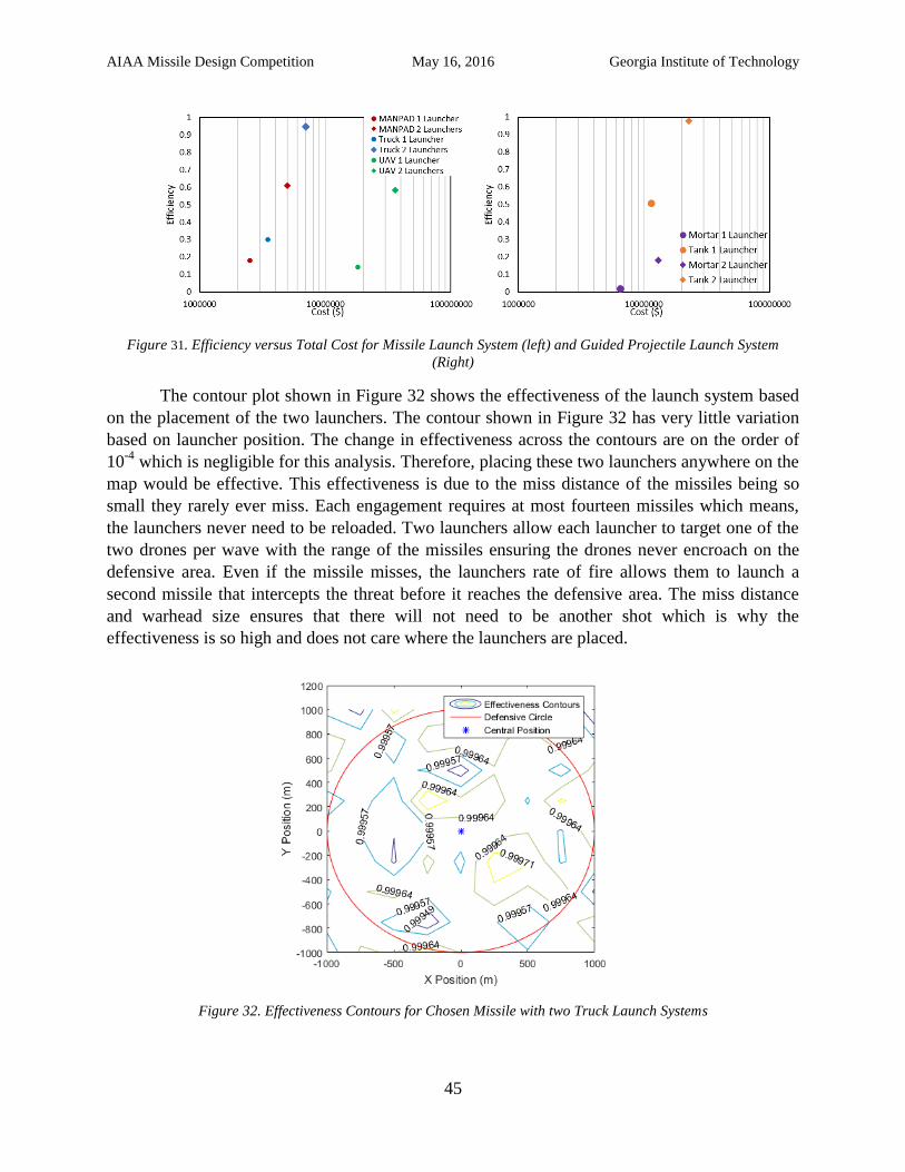
AIAA Missile Design Competition May 16, 2016 Georgia Institute of Technology
45
Figure 31. Efficiency versus Total Cost for Missile Launch System (left) and Guided Projectile Launch System
(Right)
The contour plot shown in Figure 32 shows the effectiveness of the launch system based
on the placement of the two launchers. The contour shown in Figure 32 has very little variation
based on launcher position. The change in effectiveness across the contours are on the order of
10-4
which is negligible for this analysis. Therefore, placing these two launchers anywhere on the
map would be effective. This effectiveness is due to the miss distance of the missiles being so
small they rarely ever miss. Each engagement requires at most fourteen missiles which means,
the launchers never need to be reloaded. Two launchers allow each launcher to target one of the
two drones per wave with the range of the missiles ensuring the drones never encroach on the
defensive area. Even if the missile misses, the launchers rate of fire allows them to launch a
second missile that intercepts the threat before it reaches the defensive area. The miss distance
and warhead size ensures that there will not need to be another shot which is why the
effectiveness is so high and does not care where the launchers are placed.
Figure 32. Effectiveness Contours for Chosen Missile with two Truck Launch Systems
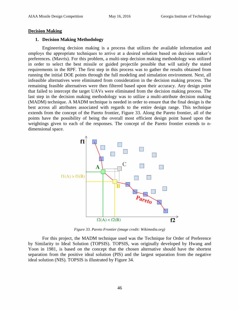
AIAA Missile Design Competition May 16, 2016 Georgia Institute of Technology
46
Decision Making
1. Decision Making Methodology
Engineering decision making is a process that utilizes the available information and
employs the appropriate techniques to arrive at a desired solution based on decision maker’s
preferences. (Mavris). For this problem, a multi-step decision making methodology was utilized
in order to select the best missile or guided projectile possible that will satisfy the stated
requirements in the RPF. The first step in this process was to gather the results obtained from
running the initial DOE points through the full modeling and simulation environment. Next, all
infeasible alternatives were eliminated from consideration in the decision making process. The
remaining feasible alternatives were then filtered based upon their accuracy. Any design point
that failed to intercept the target UAVs were eliminated from the decision making process. The
last step in the decision making methodology was to utilize a multi-attribute decision making
(MADM) technique. A MADM technique is needed in order to ensure that the final design is the
best across all attributes associated with regards to the entire design range. This technique
extends from the concept of the Pareto frontier, Figure 33. Along the Pareto frontier, all of the
points have the possibility of being the overall most efficient design point based upon the
weightings given to each of the responses. The concept of the Pareto frontier extends to n-
dimensional space.
Figure 33. Pareto Frontier (image credit: Wikimedia.org)
For this project, the MADM technique used was the Technique for Order of Preference
by Similarity to Ideal Solution (TOPSIS). TOPSIS, was originally developed by Hwang and
Yoon in 1981, is based on the concept that the chosen alternative should have the shortest
separation from the positive ideal solution (PIS) and the largest separation from the negative
ideal solution (NIS). TOPSIS is illustrated by Figure 34.
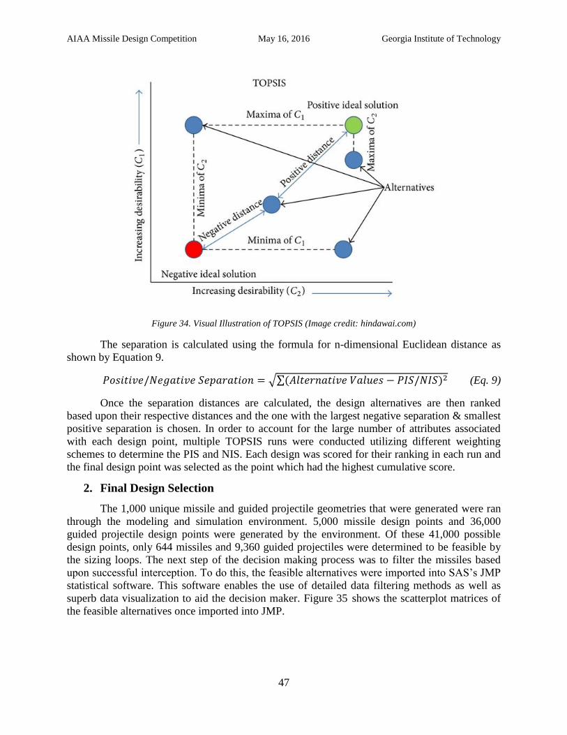
AIAA Missile Design Competition May 16, 2016 Georgia Institute of Technology
47
Figure 34. Visual Illustration of TOPSIS (Image credit: hindawai.com)
The separation is calculated using the formula for n-dimensional Euclidean distance as
shown by Equation 9.
√∑ (Eq. 9)
Once the separation distances are calculated, the design alternatives are then ranked
based upon their respective distances and the one with the largest negative separation & smallest
positive separation is chosen. In order to account for the large number of attributes associated
with each design point, multiple TOPSIS runs were conducted utilizing different weighting
schemes to determine the PIS and NIS. Each design was scored for their ranking in each run and
the final design point was selected as the point which had the highest cumulative score.
2. Final Design Selection
The 1,000 unique missile and guided projectile geometries that were generated were ran
through the modeling and simulation environment. 5,000 missile design points and 36,000
guided projectile design points were generated by the environment. Of these 41,000 possible
design points, only 644 missiles and 9,360 guided projectiles were determined to be feasible by
the sizing loops. The next step of the decision making process was to filter the missiles based
upon successful interception. To do this, the feasible alternatives were imported into SAS’s JMP
statistical software. This software enables the use of detailed data filtering methods as well as
superb data visualization to aid the decision maker. Figure 35 shows the scatterplot matrices of
the feasible alternatives once imported into JMP.
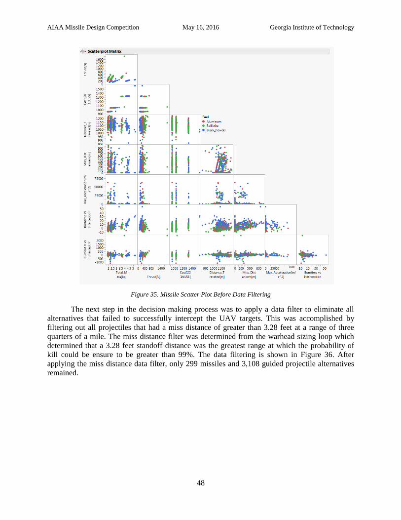
AIAA Missile Design Competition May 16, 2016 Georgia Institute of Technology
48
Figure 35. Missile Scatter Plot Before Data Filtering
The next step in the decision making process was to apply a data filter to eliminate all
alternatives that failed to successfully intercept the UAV targets. This was accomplished by
filtering out all projectiles that had a miss distance of greater than 3.28 feet at a range of three
quarters of a mile. The miss distance filter was determined from the warhead sizing loop which
determined that a 3.28 feet standoff distance was the greatest range at which the probability of
kill could be ensure to be greater than 99%. The data filtering is shown in Figure 36. After
applying the miss distance data filter, only 299 missiles and 3,108 guided projectile alternatives
remained.
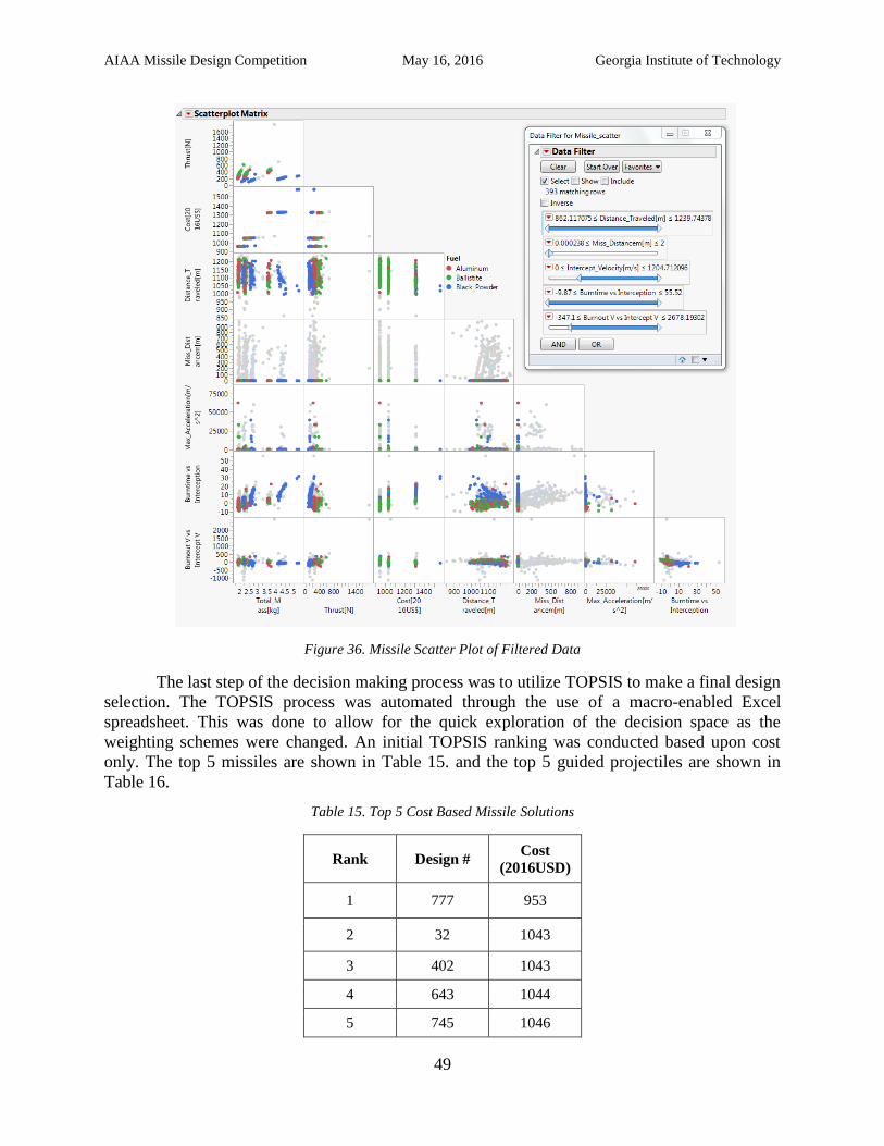
AIAA Missile Design Competition May 16, 2016 Georgia Institute of Technology
49
Figure 36. Missile Scatter Plot of Filtered Data
The last step of the decision making process was to utilize TOPSIS to make a final design
selection. The TOPSIS process was automated through the use of a macro-enabled Excel
spreadsheet. This was done to allow for the quick exploration of the decision space as the
weighting schemes were changed. An initial TOPSIS ranking was conducted based upon cost
only. The top 5 missiles are shown in Table 15. and the top 5 guided projectiles are shown in
Table 16.
Table 15. Top 5 Cost Based Missile Solutions
Rank Design # Cost
(2016USD)
1 777 953
2 32 1043
3 402 1043 4 643 1044 5 745 1046
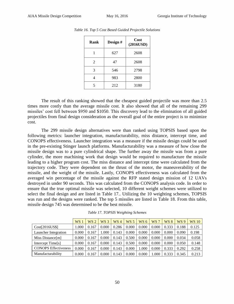
AIAA Missile Design Competition May 16, 2016 Georgia Institute of Technology
50
Table 16. Top 5 Cost Based Guided Projectile Solutions
Rank Design # Cost
(2016USD)
1 627 2608
2 47 2608
3 546 2798 4 983 2800 5 212 3180
The result of this ranking showed that the cheapest guided projectile was more than 2.5
times more costly than the average missile cost. It also showed that all of the remaining 299
missiles’ cost fell between $950 and $1050. This discovery lead to the elimination of all guided
projectiles from final design consideration as the overall goal of the entire project is to minimize
cost.
The 299 missile design alternatives were than ranked using TOPSIS based upon the
following metrics: launcher integration, manufacturability, miss distance, intercept time, and
CONOPS effectiveness. Launcher integration was a measure if the missile design could be used
in the pre-existing Stinger launch platforms. Manufacturability was a measure of how close the
missile design was to a pure cylindrical shape. The further away the missile was from a pure
cylinder, the more machining work that design would be required to manufacture the missile
leading to a higher program cost. The miss distance and intercept time were calculated from the
trajectory code. They were dependent on the thrust of the motor, the maneuverability of the
missile, and the weight of the missile. Lastly, CONOPS effectiveness was calculated from the
averaged win percentage of the missile against the RFP stated design mission of 12 UAVs
destroyed in under 90 seconds. This was calculated from the CONOPS analysis code. In order to
ensure that the true optimal missile was selected, 10 different weight schemes were utilized to
select the final design and are listed in Table 17.. Utilizing the 10 weighting schemes, TOPSIS
was run and the designs were ranked. The top 5 missiles are listed in Table 18. From this table,
missile design 745 was determined to be the best missile.
Table 17. TOPSIS Weighting Schemes
WS 1 WS 2 WS 3 WS 4 WS 5 WS 6 WS 7 WS 8 WS 9 WS 10
Cost[2016US$] 1.000 0.167 0.000 0.286 0.000 0.000 0.000 0.333 0.188 0.125
Launcher Integration 0.000 0.167 1.000 0.143 0.000 0.000 0.000 0.000 0.090 0.198
Miss Distance[m] 0.000 0.167 0.000 0.143 0.500 0.000 0.000 0.000 0.034 0.058
Intercept Time[s] 0.000 0.167 0.000 0.143 0.500 0.000 0.000 0.000 0.050 0.148
CONOPS Effectiveness 0.000 0.167 0.000 0.143 0.000 1.000 0.000 0.333 0.292 0.258
Manufacturability 0.000 0.167 0.000 0.143 0.000 0.000 1.000 0.333 0.345 0.213
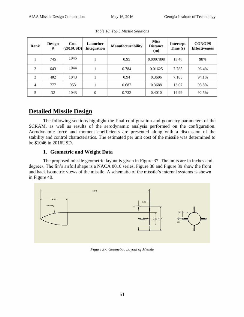
AIAA Missile Design Competition May 16, 2016 Georgia Institute of Technology
51
Table 18. Top 5 Missile Solutions
Rank Design
#
Cost
(2016USD)
Launcher
Integration Manufacturability
Miss
Distance
(m)
Intercept
Time (s)
CONOPS
Effectiveness
1 745 1046 1 0.95 0.0007808 13.48 98%
2 643 1044 1 0.784 0.01625 7.785 96.4%
3 402 1043 1 0.94 0.3606 7.185 94.1%
4 777 953 1 0.687 0.3688 13.07 93.8%
5 32 1043 0 0.732 0.4010 14.99 92.5%
Detailed Missile Design
The following sections highlight the final configuration and geometry parameters of the
SCRAM, as well as results of the aerodynamic analysis performed on the configuration.
Aerodynamic force and moment coefficients are presented along with a discussion of the
stability and control characteristics. The estimated per unit cost of the missile was determined to
be $1046 in 2016USD.
1. Geometric and Weight Data
The proposed missile geometric layout is given in Figure 37. The units are in inches and
degrees. The fin’s airfoil shape is a NACA 0010 series. Figure 38 and Figure 39 show the front
and back isometric views of the missile. A schematic of the missile’s internal systems is shown
in Figure 40.
Figure 37. Geometric Layout of Missile
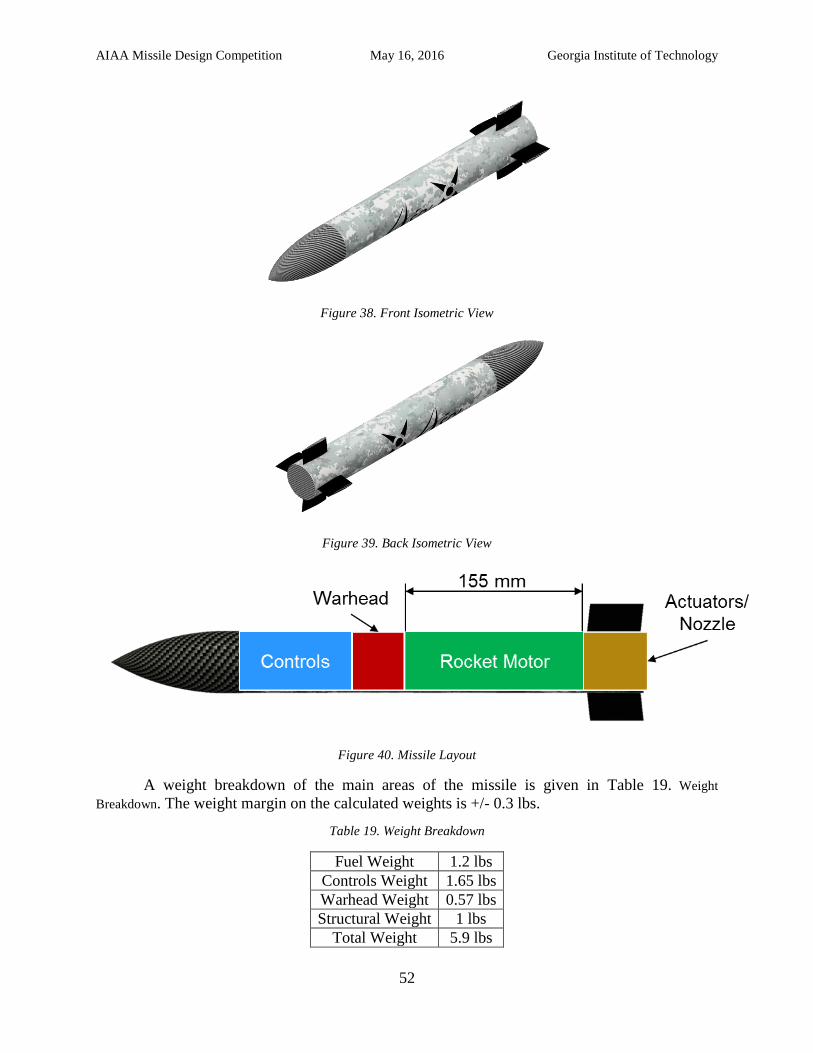
AIAA Missile Design Competition May 16, 2016 Georgia Institute of Technology
52
Figure 38. Front Isometric View
Figure 39. Back Isometric View
Figure 40. Missile Layout
A weight breakdown of the main areas of the missile is given in Table 19. Weight
Breakdown. The weight margin on the calculated weights is +/- 0.3 lbs.
Table 19. Weight Breakdown
Fuel Weight 1.2 lbs
Controls Weight 1.65 lbs
Warhead Weight 0.57 lbs
Structural Weight 1 lbs
Total Weight 5.9 lbs
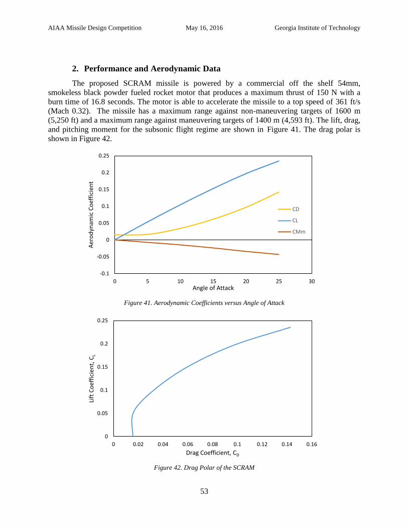
AIAA Missile Design Competition May 16, 2016 Georgia Institute of Technology
53
2. Performance and Aerodynamic Data
The proposed SCRAM missile is powered by a commercial off the shelf 54mm,
smokeless black powder fueled rocket motor that produces a maximum thrust of 150 N with a
burn time of 16.8 seconds. The motor is able to accelerate the missile to a top speed of 361 ft/s
(Mach 0.32). The missile has a maximum range against non-maneuvering targets of 1600 m
(5,250 ft) and a maximum range against maneuvering targets of 1400 m (4,593 ft). The lift, drag,
and pitching moment for the subsonic flight regime are shown in Figure 41. The drag polar is
shown in Figure 42.
Figure 41. Aerodynamic Coefficients versus Angle of Attack
Figure 42. Drag Polar of the SCRAM
-0.1
-0.05
0
0.05
0.1
0.15
0.2
0.25
0 5 10 15 20 25 30
Aer
od
ynam
ic C
oef
fici
ent
Angle of Attack
CD
CL
CMm
0
0.05
0.1
0.15
0.2
0.25
0 0.02 0.04 0.06 0.08 0.1 0.12 0.14 0.16
Lift
Co
effi
cien
t, C
L
Drag Coefficient, CD
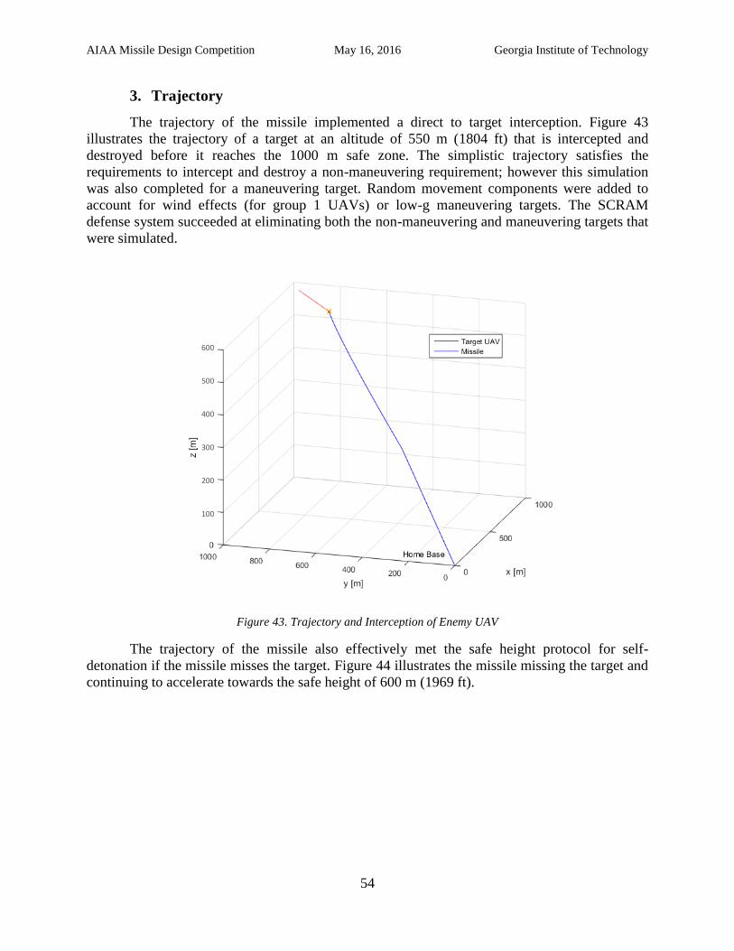
AIAA Missile Design Competition May 16, 2016 Georgia Institute of Technology
54
3. Trajectory
The trajectory of the missile implemented a direct to target interception. Figure 43
illustrates the trajectory of a target at an altitude of 550 m (1804 ft) that is intercepted and
destroyed before it reaches the 1000 m safe zone. The simplistic trajectory satisfies the
requirements to intercept and destroy a non-maneuvering requirement; however this simulation
was also completed for a maneuvering target. Random movement components were added to
account for wind effects (for group 1 UAVs) or low-g maneuvering targets. The SCRAM
defense system succeeded at eliminating both the non-maneuvering and maneuvering targets that
were simulated.
Figure 43. Trajectory and Interception of Enemy UAV
The trajectory of the missile also effectively met the safe height protocol for self-
detonation if the missile misses the target. Figure 44 illustrates the missile missing the target and
continuing to accelerate towards the safe height of 600 m (1969 ft).
600
500
400
300
200
100
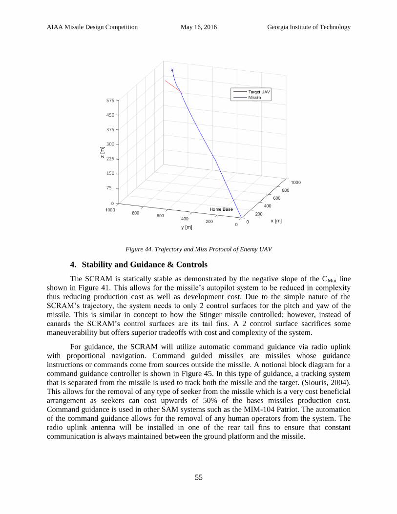
AIAA Missile Design Competition May 16, 2016 Georgia Institute of Technology
55
Figure 44. Trajectory and Miss Protocol of Enemy UAV
4. Stability and Guidance & Controls
The SCRAM is statically stable as demonstrated by the negative slope of the CMm line
shown in Figure 41. This allows for the missile’s autopilot system to be reduced in complexity
thus reducing production cost as well as development cost. Due to the simple nature of the
SCRAM’s trajectory, the system needs to only 2 control surfaces for the pitch and yaw of the
missile. This is similar in concept to how the Stinger missile controlled; however, instead of
canards the SCRAM’s control surfaces are its tail fins. A 2 control surface sacrifices some
maneuverability but offers superior tradeoffs with cost and complexity of the system.
For guidance, the SCRAM will utilize automatic command guidance via radio uplink
with proportional navigation. Command guided missiles are missiles whose guidance
instructions or commands come from sources outside the missile. A notional block diagram for a
command guidance controller is shown in Figure 45. In this type of guidance, a tracking system
that is separated from the missile is used to track both the missile and the target. (Siouris, 2004).
This allows for the removal of any type of seeker from the missile which is a very cost beneficial
arrangement as seekers can cost upwards of 50% of the bases missiles production cost.
Command guidance is used in other SAM systems such as the MIM-104 Patriot. The automation
of the command guidance allows for the removal of any human operators from the system. The
radio uplink antenna will be installed in one of the rear tail fins to ensure that constant
communication is always maintained between the ground platform and the missile.
575
450
375
300
225
150
75
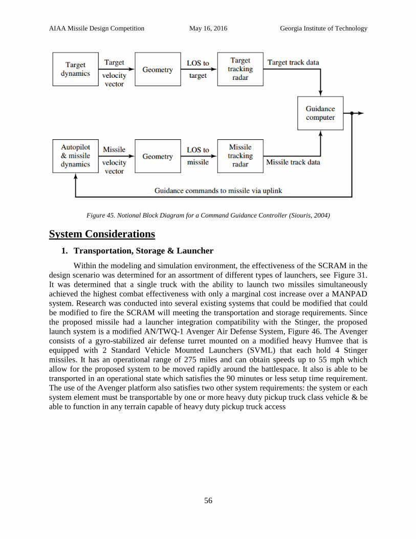
AIAA Missile Design Competition May 16, 2016 Georgia Institute of Technology
56
Figure 45. Notional Block Diagram for a Command Guidance Controller (Siouris, 2004)
System Considerations
1. Transportation, Storage & Launcher
Within the modeling and simulation environment, the effectiveness of the SCRAM in the
design scenario was determined for an assortment of different types of launchers, see Figure 31.
It was determined that a single truck with the ability to launch two missiles simultaneously
achieved the highest combat effectiveness with only a marginal cost increase over a MANPAD
system. Research was conducted into several existing systems that could be modified that could
be modified to fire the SCRAM will meeting the transportation and storage requirements. Since
the proposed missile had a launcher integration compatibility with the Stinger, the proposed
launch system is a modified AN/TWQ-1 Avenger Air Defense System, Figure 46. The Avenger
consists of a gyro-stabilized air defense turret mounted on a modified heavy Humvee that is
equipped with 2 Standard Vehicle Mounted Launchers (SVML) that each hold 4 Stinger
missiles. It has an operational range of 275 miles and can obtain speeds up to 55 mph which
allow for the proposed system to be moved rapidly around the battlespace. It also is able to be
transported in an operational state which satisfies the 90 minutes or less setup time requirement.
The use of the Avenger platform also satisfies two other system requirements: the system or each
system element must be transportable by one or more heavy duty pickup truck class vehicle & be
able to function in any terrain capable of heavy duty pickup truck access
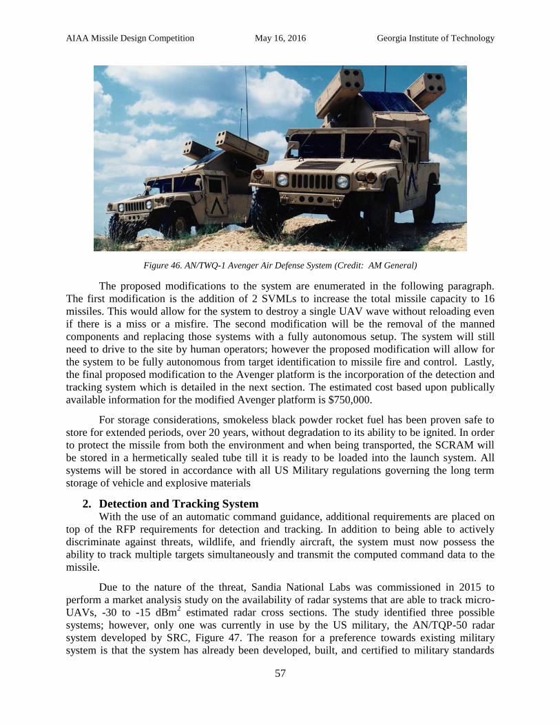
AIAA Missile Design Competition May 16, 2016 Georgia Institute of Technology
57
Figure 46. AN/TWQ-1 Avenger Air Defense System (Credit: AM General)
The proposed modifications to the system are enumerated in the following paragraph.
The first modification is the addition of 2 SVMLs to increase the total missile capacity to 16
missiles. This would allow for the system to destroy a single UAV wave without reloading even
if there is a miss or a misfire. The second modification will be the removal of the manned
components and replacing those systems with a fully autonomous setup. The system will still
need to drive to the site by human operators; however the proposed modification will allow for
the system to be fully autonomous from target identification to missile fire and control. Lastly,
the final proposed modification to the Avenger platform is the incorporation of the detection and
tracking system which is detailed in the next section. The estimated cost based upon publically
available information for the modified Avenger platform is $750,000.
For storage considerations, smokeless black powder rocket fuel has been proven safe to
store for extended periods, over 20 years, without degradation to its ability to be ignited. In order
to protect the missile from both the environment and when being transported, the SCRAM will
be stored in a hermetically sealed tube till it is ready to be loaded into the launch system. All
systems will be stored in accordance with all US Military regulations governing the long term
storage of vehicle and explosive materials
2. Detection and Tracking System With the use of an automatic command guidance, additional requirements are placed on
top of the RFP requirements for detection and tracking. In addition to being able to actively
discriminate against threats, wildlife, and friendly aircraft, the system must now possess the
ability to track multiple targets simultaneously and transmit the computed command data to the
missile.
Due to the nature of the threat, Sandia National Labs was commissioned in 2015 to
perform a market analysis study on the availability of radar systems that are able to track micro-
UAVs, -30 to -15 dBm2 estimated radar cross sections. The study identified three possible
systems; however, only one was currently in use by the US military, the AN/TQP-50 radar
system developed by SRC, Figure 47. The reason for a preference towards existing military
system is that the system has already been developed, built, and certified to military standards
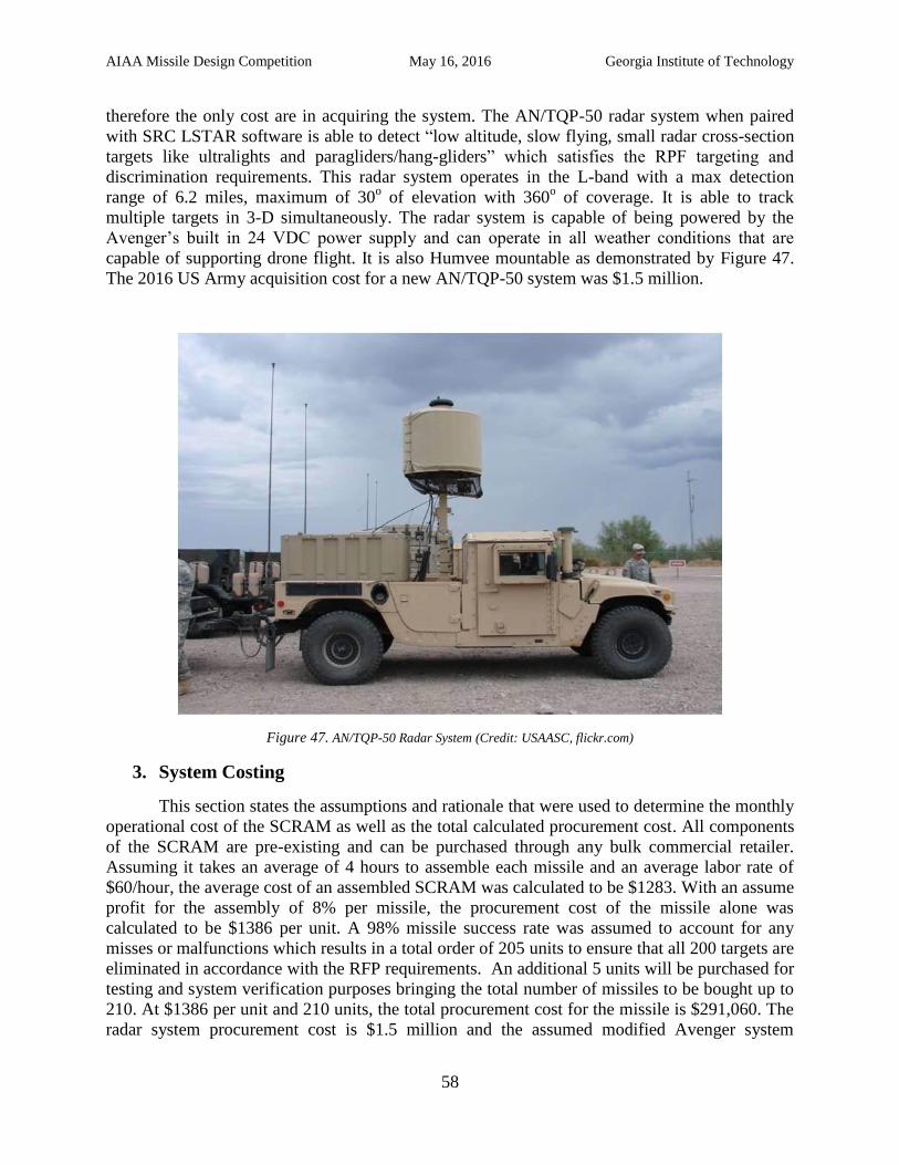
AIAA Missile Design Competition May 16, 2016 Georgia Institute of Technology
58
therefore the only cost are in acquiring the system. The AN/TQP-50 radar system when paired
with SRC LSTAR software is able to detect “low altitude, slow flying, small radar cross-section
targets like ultralights and paragliders/hang-gliders” which satisfies the RPF targeting and
discrimination requirements. This radar system operates in the L-band with a max detection
range of 6.2 miles, maximum of 30o of elevation with 360
o of coverage. It is able to track
multiple targets in 3-D simultaneously. The radar system is capable of being powered by the
Avenger’s built in 24 VDC power supply and can operate in all weather conditions that are
capable of supporting drone flight. It is also Humvee mountable as demonstrated by Figure 47.
The 2016 US Army acquisition cost for a new AN/TQP-50 system was $1.5 million.
Figure 47. AN/TQP-50 Radar System (Credit: USAASC, flickr.com)
3. System Costing
This section states the assumptions and rationale that were used to determine the monthly
operational cost of the SCRAM as well as the total calculated procurement cost. All components
of the SCRAM are pre-existing and can be purchased through any bulk commercial retailer.
Assuming it takes an average of 4 hours to assemble each missile and an average labor rate of
$60/hour, the average cost of an assembled SCRAM was calculated to be $1283. With an assume
profit for the assembly of 8% per missile, the procurement cost of the missile alone was
calculated to be $1386 per unit. A 98% missile success rate was assumed to account for any
misses or malfunctions which results in a total order of 205 units to ensure that all 200 targets are
eliminated in accordance with the RFP requirements. An additional 5 units will be purchased for
testing and system verification purposes bringing the total number of missiles to be bought up to
210. At $1386 per unit and 210 units, the total procurement cost for the missile is $291,060. The
radar system procurement cost is $1.5 million and the assumed modified Avenger system
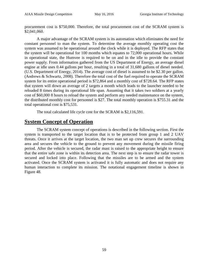
AIAA Missile Design Competition May 16, 2016 Georgia Institute of Technology
59
procurement cost is $750,000. Therefore, the total procurement cost of the SCRAM system is
$2,041,060.
A major advantage of the SCRAM system is its automation which eliminates the need for
constant personnel to man the system. To determine the average monthly operating cost the
system was assumed to be operational around the clock while it is deployed. The RFP states that
the system will be operational for 100 months which equates to 72,000 operational hours. While
in operational state, the Humvee is required to be on and in the idle to provide the constant
power supply. From information gathered from the US Department of Energy, an average diesel
engine at idle uses 0.44 gallons per hour, resulting in a total of 31,680 gallons of diesel needed.
(U.S. Department of Energy, 2014). The average cost of diesel is assumed to be $2.30 per gallon.
(Andrews & Schwartz, 2008). Therefore the total cost of the fuel required to operate the SCRAM
system for its entire operational period is $72,864 and a monthly cost of $728.64. The RFP states
that system will down an average of 2 targets a month which leads to the launcher needed to be
reloaded 8 times during its operational life span. Assuming that it takes two soldiers at a yearly
cost of $60,000 8 hours to reload the system and perform any needed maintenance on the system,
the distributed monthly cost for personnel is $27. The total monthly operation is $755.31 and the
total operational cost is $75,531.
The total calculated life cycle cost for the SCRAM is $2,116,591.
System Concept of Operation
The SCRAM system concept of operations is described in the following section. First the
system is transported to the target location that is to be protected from group 1 and 2 UAV
threats. Once it arrives at the target location, the two man set up crew secures the surrounding
area and secures the vehicle to the ground to prevent any movement during the missile firing
period. After the vehicle is secured, the radar mast is raised to the appropriate height to ensure
that the entire safe zone is within its detection area. The next step is to ensure the radar tower is
secured and locked into place. Following that the missiles are to be armed and the system
activated. Once the SCRAM system is activated it is fully automatic and does not require any
human interaction to complete its mission. The notational engagement timeline is shown in
Figure 48.
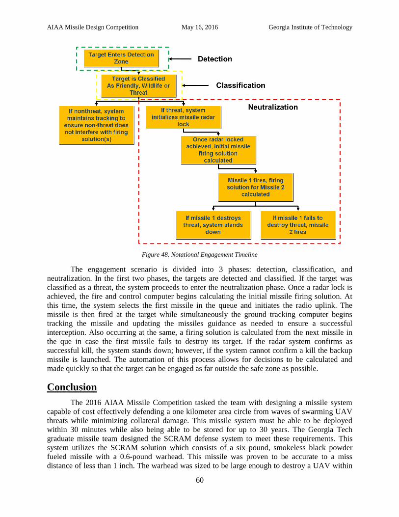
AIAA Missile Design Competition May 16, 2016 Georgia Institute of Technology
60
Figure 48. Notational Engagement Timeline
The engagement scenario is divided into 3 phases: detection, classification, and
neutralization. In the first two phases, the targets are detected and classified. If the target was
classified as a threat, the system proceeds to enter the neutralization phase. Once a radar lock is
achieved, the fire and control computer begins calculating the initial missile firing solution. At
this time, the system selects the first missile in the queue and initiates the radio uplink. The
missile is then fired at the target while simultaneously the ground tracking computer begins
tracking the missile and updating the missiles guidance as needed to ensure a successful
interception. Also occurring at the same, a firing solution is calculated from the next missile in
the que in case the first missile fails to destroy its target. If the radar system confirms as
successful kill, the system stands down; however, if the system cannot confirm a kill the backup
missile is launched. The automation of this process allows for decisions to be calculated and
made quickly so that the target can be engaged as far outside the safe zone as possible.
Conclusion
The 2016 AIAA Missile Competition tasked the team with designing a missile system
capable of cost effectively defending a one kilometer area circle from waves of swarming UAV
threats while minimizing collateral damage. This missile system must be able to be deployed
within 30 minutes while also being able to be stored for up to 30 years. The Georgia Tech
graduate missile team designed the SCRAM defense system to meet these requirements. This
system utilizes the SCRAM solution which consists of a six pound, smokeless black powder
fueled missile with a 0.6-pound warhead. This missile was proven to be accurate to a miss
distance of less than 1 inch. The warhead was sized to be large enough to destroy a UAV within
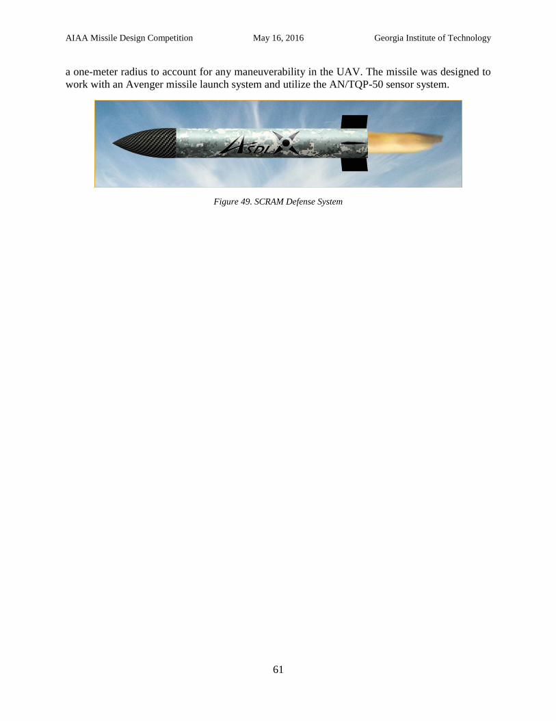
AIAA Missile Design Competition May 16, 2016 Georgia Institute of Technology
61
a one-meter radius to account for any maneuverability in the UAV. The missile was designed to
work with an Avenger missile launch system and utilize the AN/TQP-50 sensor system.
Figure 49. SCRAM Defense System
AIAA Missile Design Competition May 16, 2016 Georgia Institute of Technology
62
References 5-inch U.S. Navy Guided Projectile. (2014). Retrieved from lockheedmartin.com:
http://www.lockheedmartin.com/content/dam/lockheed/data/mfc/pc/navy-5-inch-guided-
projectile/mfc-navy-5-inch-guided-projectile-pc.pdf
Ackerman, E. (2015, April 19). DARPA's Self-Steering EXACTO Bullets Home in on Moving
Targets. Retrieved from IEEE Spectrum: http://spectrum.ieee.org/tech-
talk/aerospace/military/darpas-selfsteering-bullets-home-in-on-moving-targets
Andrews, A., & Schwartz, M. (2008, July 23). CRS Report for Congress: Department of Defense
Fuel Costs in Iraq.
Apogee Components. (n.d.). AeroTech Casings. Retrieved from www. apogeerockets.com.
Avenger Low Level Air Defence System, United States of America. (2016). Retrieved from army-
technology.com: http://www.army-technology.com/projects/avenger/
Backman, M. E. (1976). Terminal Ballistics. National Technical Information Service.
Buongiorno, M., & Schroeder, M. (2010). Black Market Prices for Man-portable Air Defense
Systems. Retrieved from fas.org:
https://fas.org/programs/ssp/asmp/issueareas/manpads/black_market_prices.pdf
Chief Aircraft. (2016, May). JetCat Turbines. Retrieved from www.chiefaircraft.com.
David Gudjohnsen, M. W. (2005, April). Development of the XM982 Excalibur Fuzing.
ndia.org.
(2012). Department of Defense Fiscal Year (FY) 2013 President's Budget Submission. Air Force.
Excalibur XM982 Precision Engagement Projectiles. (2007). dote.osd.mil. Army Program.
Fleeman, E. L. (2006). Tactical Missile Design. Reston: American Institute of Aeronautics and
Astronautics.
Fleeman, E. L. (2006). Tactical Missile Design. Reston: American Institute of Aeronautics and
Astronautics, Inc.
Goodboatgear.com. (n.d.). Matson Nitrocellulose Lacquer Finish. Retrieved from
www.goodboatgear.com.
Graf & Sons. (n.d.). Black Powder & Cannon Fuse. Retrieved from www.grafs.com.
Hans, P. C., Rosenfield, G. C., & Meyer, D. H. (1993). US Patent No. 5212946A.
Industry Advances Long Range, Precision Munitions (by: BAE Systems). (2015). Retrieved from
navyrecognition.com: http://www.navyrecognition.com/index.php/news/naval-
exhibitions/sea-air-space-2015/2576-industry-advances-long-range-precision-munitions-
by-bae-systems.html
Jackson, J. (2015). The U.S. Naval Institute on Naval Innovation. Naval Institute Press.
AIAA Missile Design Competition May 16, 2016 Georgia Institute of Technology
63
Jacob's Rocketry. (n.d.). Types of Propellants. Retrieved from www.jacobsrocketry.com.
Jr., S. J. (2016, January 12). Breaking Defense. Retrieved from
http://breakingdefense.com/2016/01/excalibur-goes-to-sea-raytheon-smart-artillery-
shoots-back/: http://breakingdefense.com/2016/01/excalibur-goes-to-sea-raytheon-smart-
artillery-shoots-back/
M270 MLRS Self-Propelled Loader/Launcher (SPLL). (2000). Retrieved from fas.org:
http://fas.org/man/dod-101/sys/land/m270.htm
Mavris, D. (n.d.). Introduction to Decision Making and Multi-attribute Decision Making
(MADM). Atlanta, GA: Georgia Institute of Technology.
Meisl, C. J. (n.d.). Missile Propulsion Cost Modeling. Canoga Park, CA: Rocketdyne, Division
of Rockwell International.
Micron Metals, Inc. (n.d.). AL-100 Atomized Aluminum Powder. Retrieved from
www.micronmetals.com.
Micron Metals, Inc. (n.d.). MG-301, White Magnesium Carbonate Powder. Retrieved from
www.micronmetlas.com.
MQ-1 Predator/ MQ-9 Reaper. (2016). Retrieved from AeroWeb: http://www.bga-
aeroweb.com/Defense/MQ-1-Predator-MQ-9-Reaper.html
Nakka Rcoketry. (n.d.). Paradigm Rocket Motor. Retrieved from www.nakka-rocketry.net.
Nakka Rocketry. (2010). Experiments with Ammonium Nitrate / Aluminum Based Propellant
Formulations. Retrieved from ww.nakka-rocketry.net.
Nakka, R. (n.d.). Solid Rocket Motor Theory - Propellant Grain. Retrieved from www.nakka-
rocketry.net.
PolyOne Corp. (2014). ABS Sheet Solutions. Retrieved from www.curbellplastics.com.
Purdue University. (2008). AAE 439 Lecture: Solid Rocket Propulsion Systems.
Rocket Motor Components, inc. (n.d.). Single-Throat Nozzles. Retrieved from
www.rocketmotorparts.com.
SA-7 Grail. (2016). Retrieved from globalsecurity.org:
http://www.globalsecurity.org/military/world/russia/sa-7.htm
Scan Eagle. (2011). Retrieved from U.S. Air Force:
https://web.archive.org/web/20130710112005/http://www.af.mil/information/factsheets/f
actsheet.asp?id=10468
SCAN EAGLE. (2011). Retrieved from U.S. Air Force:
https://web.archive.org/web/20130710112005/http://www.af.mil/information/factsheets/f
actsheet.asp?id=10468
AIAA Missile Design Competition May 16, 2016 Georgia Institute of Technology
64
Shop All Smokeless Powder Here:. (2016). Retrieved from Midsouth Shooters Supply:
http://www.midsouthshooterssupply.com/Dept/Reloading/Smokeless-Powder
Siouris, G. M. (2004). Missile Guidance and Control Systems. New York: Springer-Verlag New
York, Inc.
Smith, B. (2015). Innovative Naval. Retrieved from onr.navy.mil:
http://www.onr.navy.mil/en/Conference-Event-ONR/Future-Force-
Expo/~/media/Files/Conferences/EXPO-2015/Proceedings/IR-Smith-INPs.ashx
Stinger Weapon System. (2016). Retrieved from Raytheon:
http://www.raytheon.com/capabilities/products/stinger/
Systems, B. (2015). Multi Service - Standard Guided Projectile (MS-SGP).
Thompson, M. (2010). Less Dangerous Explosives. Time Magazine.
U.S. Department of Energy. (2014, December). Fact #861 February 23, 2015 Idle Fuel
Consumption for Selected Gasoline and Diesel Vehicles. Retrieved from
www.energy.gov.
UN SafeGuard. (n.d.). Kingery-Bulmash Blast Paramter Calculator, International Ammunition
Technical Guidelines. Retrieved from www.un.org/disarmament.
Weatherington, D. (2011). Future Of Unmanned Aircraft Systems In A Fiscally Constrained
Environment.
XM982 Excalibur. (2016). Retrieved from globalsecurity.org/: globalsecurity.org/
Yanushevsky. (2007). Modern Missile Guidance.
Zandbergen, B. (2014). Solid Rocket Propellants and their Properties. Retrieved from
www.lr.tudelft.nl.