Embed Size (px)
Citation preview

1
Ronni A. Schnell, DMD, MAGDBoston University Henry M Goldman School of Dental Medicine
February 8, 2014
University of AlabamaSchool of Dentistry Alumni Association
ALUMNI WEEKEND
Ronni A. Schnell, DMD, MAGDBoston University Henry M Goldman School of Dental Medicine
February 8, 2014
Go Ahead… Bite Into That Apple!The A-Z of Implant-Assisted
Overdentures © 2014
University of Alabama School of Dentistry Alumni Association
ALUMNI WEEKEND 2014
Implant - Assisted
Overdentures
This is a Prosthetically driven restoration
with an Attachment modality
• Owen CP. Guidelines for a minimum acceptable protocol for the construction of complete dentures. Int J Prosthodont. 2006;19:467-474
• Zarb GA, Bolender CL: Prosthodontic Treatment for Edentulous Patients: Complete Dentures and Implant-Supported Prostheses, 12h Ed., C V Mosby (2003)
Rule #1
The attachments are in addition to all other acceptable requirements for denture
retention
“The restoration of a lower edentulous mandible with a minimum of 2 implants and a complete denture has been the
Standard of Care since 2002”At the very least, it is the duty of the dental practitioner to inform
their patients of this treatment option.(Informed Consent)
Massachusetts Board of Registration
The Standard of Care continually evolves with the advent of new materials, new procedures and new court rulings
Fenton AH, The Decade of Overdentures 1970-1980, J Prosthet Dent 1998; 79(1):31-6McGill Consensus Statement, Int J Oral Maxillofacial Implants 2002;17(4):601-2
Where/how do we start?
Relatively easy if…
Pt is edentulous…and desires an implant restoration…
Evaluation must include:
Medical history Dental history Existing dentition Prosthesis history Existing prosthesis evaluation Patient motivation / desire
Treatment Planning To insure ideal placement, coordinated
treatment with the restorative dentist and the surgeon must occur
Radiographs / CT scans Photographs MOUNTED Diagnostic casts Diagnostic wax ups / Trial tooth set ups Templates
Gone are the days where a patient will go to the surgeon first and return with a mouth full of implants that you will be
asked to restore.

2
Assessing the angulation of the maxillary implant
fixtures
Greater than 40°must have a custom abutment restoration
What do you say to an edentulous patient who says:
“I want implants…”
What do you say to an edentulous patient who says:
“I need dentures…”
What do you say to an edentulous patient who says:
“ My new dentures don’t fit…”
This patient will present with one of 5 scenarios…
–Existing prosthesis»Acceptable dentures»Unacceptable dentures
–Remaining dentition–Hopeless dentition–No dentition (edentulous)
Though the end result may be an implant retained overdenture,
evaluation of the 5 scenarios may produce variations in treatment plans
The common denominator in all cases is that you must
start with an acceptable denture
No acceptable denture…. no occlusal plane and VDO….
no space analysis
Why?
In all cases, we are retrofitting the implant attachments to an acceptable denture

3
The Acceptable Denture•VDO
•Occlusion
•Occlusal Plane
•Neutral Zone / Lip and cheek support
•Esthetics
•Space available
•If retro-fitting… Generally fabricated within the past 1-2 years
? The Unacceptable Denture…
Evaluation of the Existing Prosthesis
Evaluation of the Existing Prosthesis
•VDO•Occlusion•Occlusal Plane•Lip and cheek support•Esthetics•Space remaining•Age generally 1-2 years
•Freeway space
•Closest speaking space
•Space of Donders
•Inter-arch space
•VDR – 2 to 3 mm
Evaluation of the Existing Prosthesis
•No anterior in centric
•No incisal guidance
•No canine guidance
•CO=CR
•VDO•Occlusion•Occlusal Plane•Lip and cheek support•Esthetics•Space remaining•Age generally 1-2 years
Evaluation of the Existing Prosthesis
•Interpupillary line
•“A” and “C”
•VDO•Occlusion•Occlusal Plane•Lip and cheek support•Esthetics•Space remaining•Age generally 1-2 years
•Inter-pupillary line
•“A” + “C”
1/2-2/3 height of RMP
Significance?
•Support / balance
•Displacement
•Neutral Zone evaluation
Evaluation of the Existing Prosthesis
•VDO•Occlusion•Occlusal Plane•Lip and cheek support•Esthetics•Space remaining•Age generally 1-2 years
Evaluation of the Existing Prosthesis
•VDO•Occlusion•Occlusal Plane•Lip and cheek support•Esthetics•Space remaining•Age generally 1-2 years
Evaluation of the Existing Prosthesis
•VDO•Occlusion•Occlusal Plane•Lip and cheek support•Esthetics•Space remaining•Age generally 1-2 years
Evaluation of the Existing Prosthesis
•VDO•Occlusion•Occlusal Plane•Lip and cheek support•Esthetics•Space remaining•Age generally 1-2 years
When retro-fitting…
It is important to have fresh and compatible materials with which to work
4
Rule #2
Space Analysis
Multiple Methods:
An acceptable denture allows an accurate Space Analysis
Clear matrix of existing denture superimposed on a cast of the residual ridge
Patient Remount of “duplicate denture” opposing existing occlusion
During IntermaxillaryRecords or Tooth Set-up
Always REQUIRES evaluation at the correct VDO
This means:
For a Complete Denture – a mounting @ VDO is required
For a Partial Denture – if VDO cannot be assured by hand articulation – a mounting is also required
A Space Analysis… Space Analysis for an Implant Overdenture
Determines the inter‐occlusal distance or vertical room necessary for:
– Denture tooth 2mm– Denture base 2mm– Attachment component 2mm– Implant abutment +– Implant fixture ~5mm (compared to the root)
TOTAL 10‐11 mm
Shortly post - insertion of immediate dentures…
Insufficient space as determined by a clear
Vacuform matrix
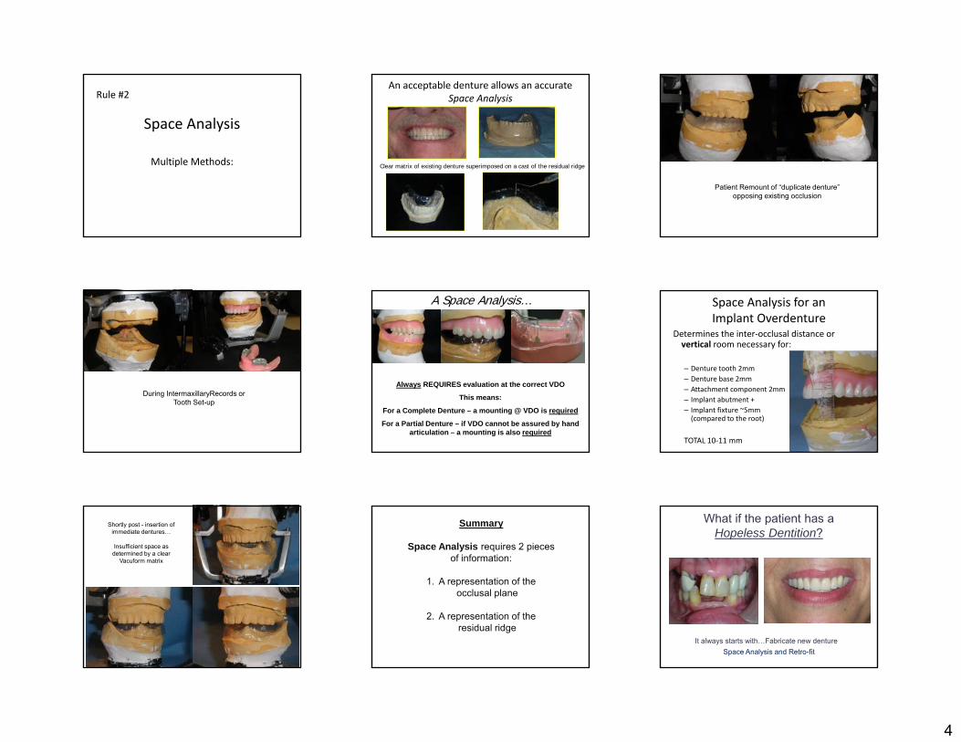
Summary
Space Analysis requires 2 pieces of information:
1. A representation of the occlusal plane
2. A representation of the residual ridge
What if the patient has a Hopeless Dentition?
It always starts with…Fabricate new dentureSpace Analysis and Retro-fit

5
What is the treatment plan for a patient with a hopeless dentition?
Fabricate immediate/interim denture Clear template (processed with denture) CT scan Implant placement – then:
a. Reline / rebase and retrofit attachments OR
b. Remake and retrofit to new overdenture
Templates (or Stents)
Diagnostic / radiographic
Surgical
Diagnostic / Radiographic Template
Is a clear duplicate of an acceptable dentureor a diagnostic wax up, fitted with: Gutta percha or Stainless steels markers
Allows for evaluation of bone CT Scan – 3D evaluation Panoramic – vertical height only
Denture duplicated in clear acrylic Markers placed in areas most desirable for
implant fixtures
Most common areas: Lingual to cuspids For 2 implants
Within pre-molars For 4 implants
Diagnostic / Radiographic TemplateDetermine appropriate location on
cast
Canines?
Cuspid position is transferred to cast
Cuspids are marked as preferred area for
evaluation with template by CT scan
Lab Rx? Process CU/CL in (specify) shade acrylic Lab remount; Pin = ___ De-cast and return for finish and polish Process duplicate lower denture in clear acrylic Prepare parallel channels – in area specified…
lingual to cuspids centered to (specify) posterior tooth #
Place radiographic markers to evaluate for implant placement during CT scan
Dentures are is processed and returned, along with duplicate
denture, with markers
New CU/CL fabricated
Template is tried in for fit and comfort during CT scan
The template is worn during the CT scan
The markers show up in one or more segments
iCAT Scan

6
Patient Name:
ID
Age
Sex F
Patient Information
Grayscale Information Level Width
Description
First image (upper)corrisponds to cut 55. Second image (lower) corrisponds with cut 75.
Surgical TemplateIn most cases the diagnostic template may be
modified for surgical use by:
removal of the radiographic markers and
placement of guide pin holes for fixture positioning
The channels remaining after
removing the guttapercha markers,
will now guide the pilot drill
Slide courtesy of Dr. Hamid Shafie
Duplicate Denture If the patient has an acceptable existing denture, then we will only
need to duplicate this denture Arrange with the lab, in advance, to borrow the patient’s denture for
approximately 1 day
The denture is embedded in this special duplicating flask with alginate on both sides, registering both the polished and intaglio sides. When the denture is removed, the space left by the denture can now
be filled with clear ortho resin and a clear duplicate of the denture will be created.
Attachment Selection Patient’s prosthetic expectations Patient’s financial capability Drs’ personal choice Laboratory experience Available inter-arch space # of implants
Anatomy of ridge Availability of bone
…Begin with the end in mind…What type of restoration is the patient expecting?Keep it simple…
Classification of Attachments
Resiliency
Load distribution characteristics
Resiliency - definition
Movement between the denture & the abutment
The more the prosthesis is allowed to move, the more forces are transferred to the
residual ridge
Rotary Resilient
Stud (i.e. ERA and Locator) Hinge, vertical , rotation Provides 95% load relief to the implant 95% Tissue/Ridge support
The more resilient the attachment, the more you must rely on the ridge and tissue for support
ERA Housing
7
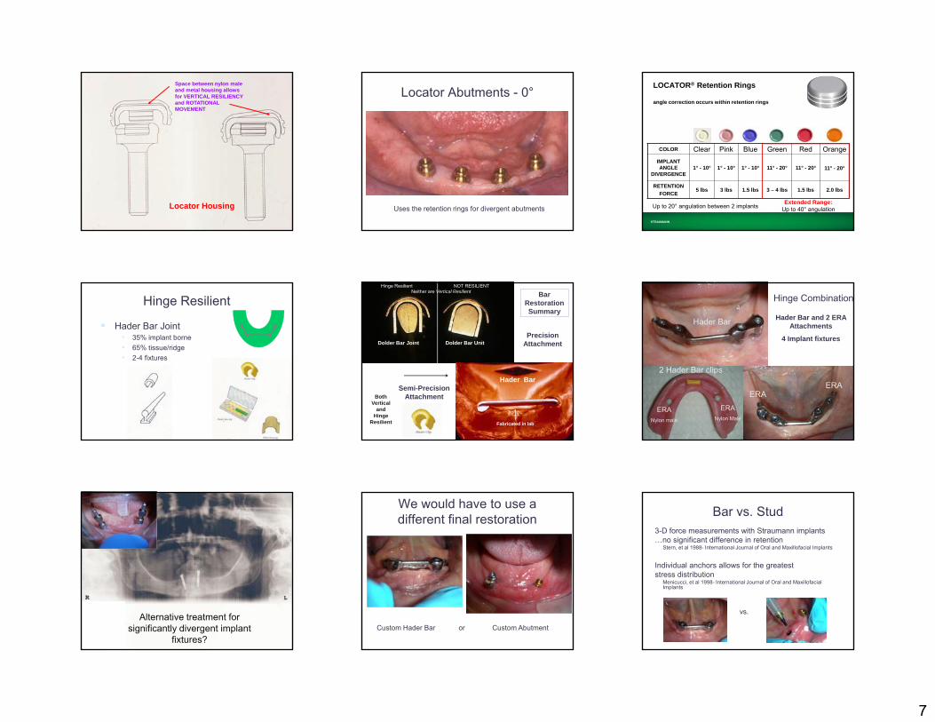
Space between nylon male and metal housing allows for VERTICAL RESILIENCY and ROTATIONAL MOVEMENT
Locator Housing
Locator Abutments - 0°
Uses the retention rings for divergent abutments
STRAUMANN
LOCATOR® Retention Rings
angle correction occurs within retention rings
COLOR Clear Pink Blue Green Red OrangeIMPLANT ANGLE
DIVERGENCE1° - 10° 1° - 10° 1° - 10° 11° - 20° 11° - 20° 11° - 20°
RETENTIONFORCE
5 lbs 3 lbs 1.5 lbs 3 – 4 lbs 1.5 lbs 2.0 lbs
Up to 20° angulation between 2 implants Extended Range:Up to 40° angulation
Hinge Resilient
Hader Bar Joint• 35% implant borne• 65% tissue/ridge• 2-4 fixtures
Dolder Bar Joint Dolder Bar Unit
Hader Bar
Precision Attachment
Semi-Precision Attachment
Fabricated in lab
Bar RestorationSummary
Hinge Resilient NOT RESILIENTNeither are Vertical Resilient
Both Vertical
and Hinge
Resilient
Hader Bar and 2 ERA Attachments
4 Implant fixtures
Hinge Combination
Hader Bar
2 Hader Bar clips
ERANylon Male
ERANylon male
ERAERA
Alternative treatment for significantly divergent implant
fixtures?
We would have to use a different final restoration
Custom Hader Bar or Custom Abutment
Bar vs. Stud3-D force measurements with Straumann implants…no significant difference in retention
Stern, et al 1988- International Journal of Oral and Maxillofacial Implants
Individual anchors allows for the greatest stress distribution
Menicucci, et al 1998- International Journal of Oral and Maxillofacial Implants
vs.

8
Bar vs. Stud Can increase retention and
decrease movement if in combination
Requires additional inter-arch distance
Incr cost (lab fab) Occupies more space w/i
denture May require FW for strength
Simplest restoration Lower cost (vs. bar) Prefabricated components Low profile require minimum
space
Longevity of Retention Clips/Snaps Depends on:
Size of arch Type of diet Oral habits Home care Angulation of stud / bar attachment OCCLUSION
The OCCLUSAL SCHEME
Rules of Denture Occlusion:No Anterior Contact in CRNo incisal guidance in protrusiveNo canine guidance in lateralCR=CO
Occlusal Plane = 1/2 to 2/3 height RMPNO porcelain teeth unless the opposing is
fixed (and even then, use caution) Lingual Contact Occlusion
Mand Central Fossa Centered to the mand ridge
Mand Central Fossa Lingual to the mand ridge
CONTACTLingual to the mand ridge
Lingual Contact Occlusion
Begin with anatomical maxillary posterior teeth (30°-33°) Eliminate the additional lateral impact of the maxillary buccal
cusps by reducing the buccal cusp Flatten lower posterior teeth to 0-20° Bilateral Simultaneous contact in all movements
Eliminate Maxillary Buccal Cusp interferencesTo eliminate additional lateral forces
How does tooth selection affectOcclusion?
• Monoplane delivers less lateral force but is harder to remain in “balance”
• Anatomical delivers more lateral force but is easier to remain in “balance”
• Lingual Contact Occlusion uses a modified anatomical tooth to reduce lateral force and is easier to remain in “balance”
Cusped teeth deliver greater lateral force than
Flat teeth
Common Causes of Attachment Wear
Biting the overdenture into place Cleaning the abutments with an abrasive cleaner
Denture Cleansers – can soften the nylon over time Placement of a nylon attachment with too much retention
– excessive wear on metal component Tobacco chewing and smoking Using metal that is too soft when casting a plastic pattern Over-shellblasting when de-casting processed denture PATH-
If the attachments are not within 5° of parallel to each other Path of insertion not consistent with anterior (or posterior) tissue
undercuts
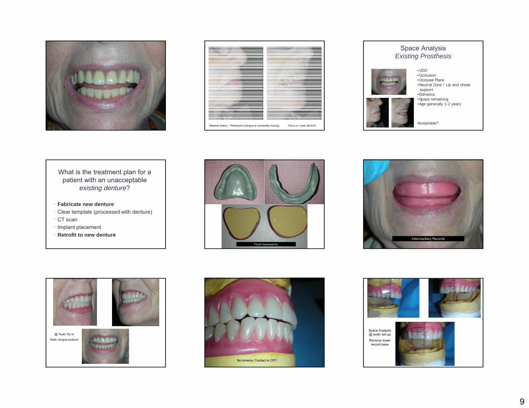
Photo AlbumPatient’s chief complaint:
“My dentures are loose; can you place implants?”
9
Medical history – Parkinson’s (tongue is constantly moving) This is a 1 year old IU/IL
Space Analysis Existing Prosthesis
•VDO•Occlusion•Occlusal Plane•Neutral Zone / Lip and cheek support
•Esthetics•Space remaining•Age generally 1-2 years
Acceptable?
What is the treatment plan for a patient with an unacceptable
existing denture?
Fabricate new denture Clear template (processed with denture) CT scan Implant placement Retrofit to new denture
Final Impressions
Intermaxillary Records
@ Tooth Try-in
Note: tongue posture
No Anterior Contact in CR !
Space Analysis @ tooth set-up
Remove lower record base
10
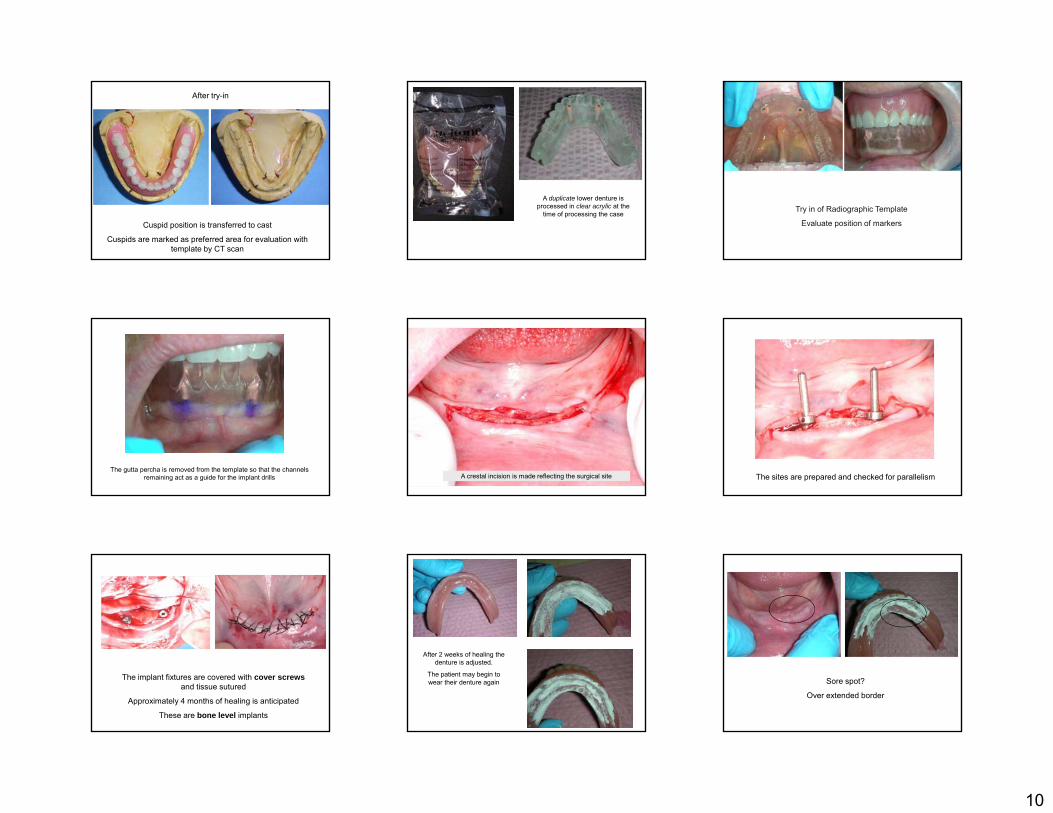
After try-in
Cuspid position is transferred to cast
Cuspids are marked as preferred area for evaluation with template by CT scan
A duplicate lower denture is processed in clear acrylic at the
time of processing the case Try in of Radiographic Template
Evaluate position of markers
The gutta percha is removed from the template so that the channels remaining act as a guide for the implant drills A crestal incision is made reflecting the surgical site The sites are prepared and checked for parallelism
The implant fixtures are covered with cover screwsand tissue sutured
Approximately 4 months of healing is anticipated
These are bone level implants
After 2 weeks of healing the denture is adjusted.
The patient may begin to wear their denture again Sore spot?
Over extended border
11
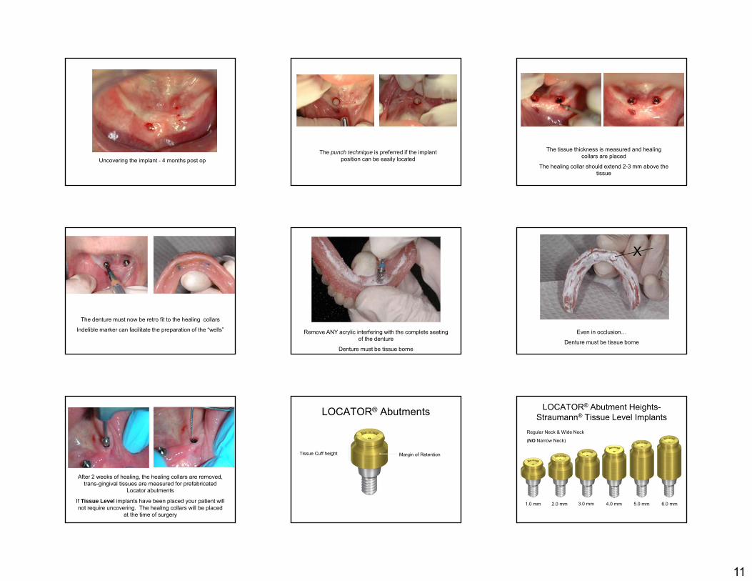
Uncovering the implant - 4 months post opThe punch technique is preferred if the implant
position can be easily located
The tissue thickness is measured and healing collars are placed
The healing collar should extend 2-3 mm above the tissue
The denture must now be retro fit to the healing collars
Indelible marker can facilitate the preparation of the “wells” Remove ANY acrylic interfering with the complete seating of the denture
Denture must be tissue borne
Even in occlusion…
Denture must be tissue borne
X
After 2 weeks of healing, the healing collars are removed, trans-gingival tissues are measured for prefabricated
Locator abutments
If Tissue Level implants have been placed your patient will not require uncovering. The healing collars will be placed
at the time of surgery
LOCATOR® Abutments
Tissue Cuff height Margin of Retention
LOCATOR® Abutment Heights-Straumann® Tissue Level Implants
1.0 mm 2.0 mm 3.0 mm 4.0 mm 5.0 mm 6.0 mm
Regular Neck & Wide Neck
(NO Narrow Neck)
12
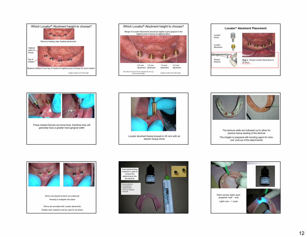
Which Locator® Abutment height to choose?
Measure distance from top of implant to highest point of tissue for each implant.
Remove healing caps /healing abutments.
Highest point of tissue
Top of implant
Images courtesy of Dr. Bob Vogel
Which Locator® Abutment height to choose?Margin of Locator Abutments should be slightly supra-gingival to the
highest point of tissue for each location.
4.0 mm abutment
1.0 mm abutment
1.0 mm abutment
4.0 mm abutment
Images courtesy of Dr. Bob VogelNet effect is that all of the abutments end up
at the same height
Locator® Abutment Placement
Step 1: Torque Locator Abutments to 35 Ncm.
Locator Abutment
Torque Wrench
Locator Driver
These implant fixtures are bone level, therefore they will generally have a greater trans-gingival width
Locator abutment being torqued to 35 ncm with an electric torque driver
The denture wells are hollowed out to allow for passive tissue seating of the denture
The intaglio is prepared with bonding agent for intra-oral pick-up of the attachments
Shims are placed to block out undercuts
Housing is snapped into place
Shims are provided with Locator abutments
Rubber dam material must be used for all others
Armamentarium:OverdentureAttachmentsPick-up materialVarnish
Auto-polymerizing material is used to
cement the attachments into
the denture
Paint varnish within each prepared “well” - only
Light cure – 1 cycle
13
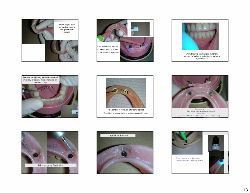
Place finger over perforation prior to
filling wells with acrylic
Mix and express material
Fill each well only ½ way
Coat surface of attachmentWhile the auto-polymerizing material is
setting, the patient is instructed to remain in light occlusion
Test the set with any extruded material introrally or excess mixed material on
the bench top
The denture is removed after complete set
The shims are removed and excess material trimmed
Evaluate pick-up
1. Check that both attachments have been picked up
2. Look for voids
3. Voids are OK if attachment does not move (they will be filled in later)
OKVOID
Trim excess flash first
Then fill in the void
First repaint and light cure varnish in area to be repaired
14
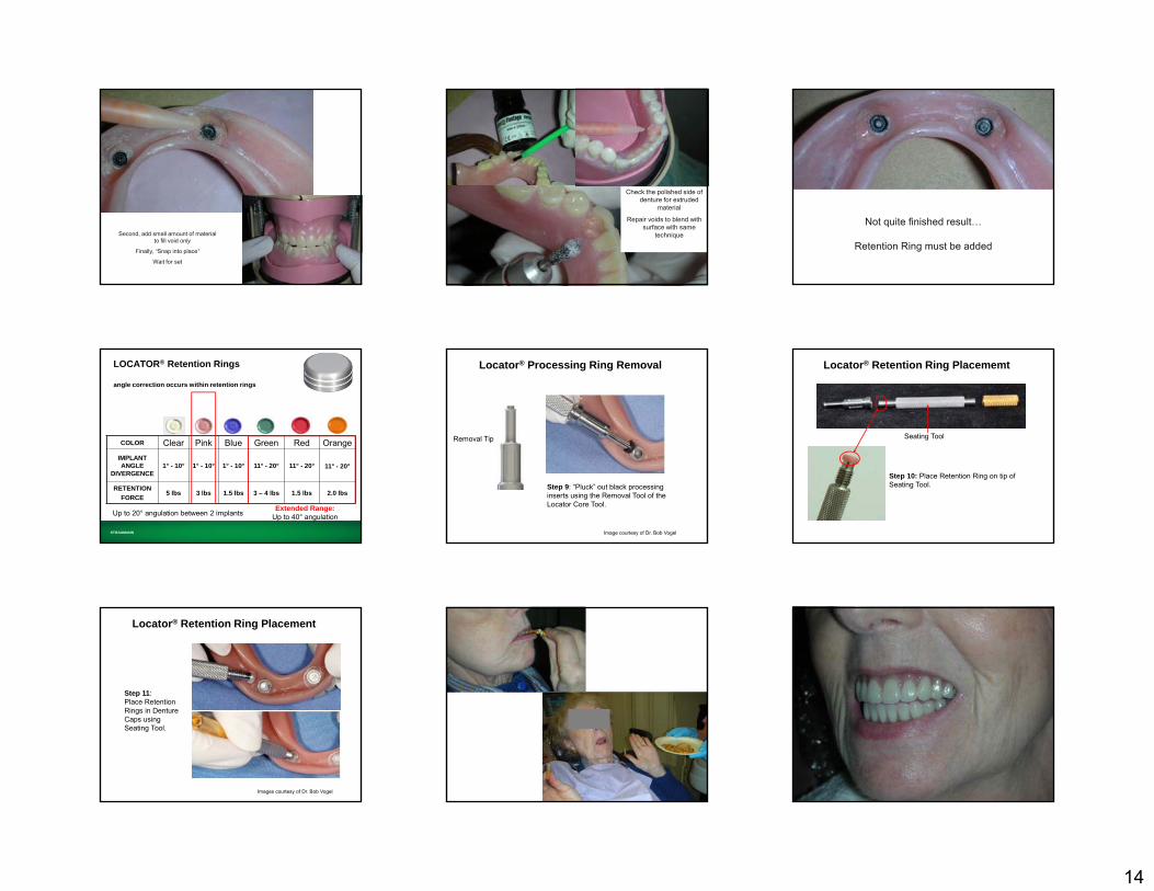
Second, add small amount of material to fill void only
Finally, “Snap into place”
Wait for set
Check the polished side of denture for extruded
material
Repair voids to blend with surface with same
technique
Not quite finished result…
Retention Ring must be added
STRAUMANN
LOCATOR® Retention Rings
angle correction occurs within retention rings
COLOR Clear Pink Blue Green Red OrangeIMPLANT ANGLE
DIVERGENCE1° - 10° 1° - 10° 1° - 10° 11° - 20° 11° - 20° 11° - 20°
RETENTIONFORCE
5 lbs 3 lbs 1.5 lbs 3 – 4 lbs 1.5 lbs 2.0 lbs
Up to 20° angulation between 2 implants Extended Range:Up to 40° angulation
Step 9: “Pluck” out black processing inserts using the Removal Tool of the Locator Core Tool.
Locator® Processing Ring Removal
Removal Tip
Image courtesy of Dr. Bob Vogel
Seating Tool
Step 10: Place Retention Ring on tip of Seating Tool.
Locator® Retention Ring Placememt
Locator® Retention Ring Placement
Step 11:Place Retention Rings in Denture Caps using Seating Tool.
Images courtesy of Dr. Bob Vogel
15
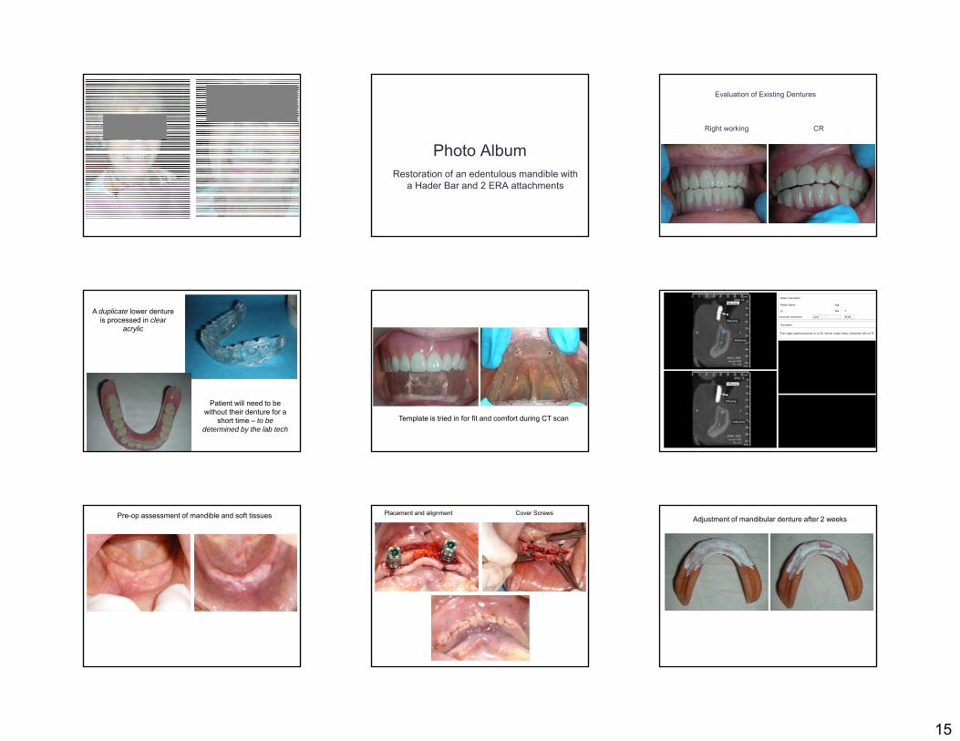
Photo AlbumRestoration of an edentulous mandible with
a Hader Bar and 2 ERA attachments
Evaluation of Existing Dentures
Right working CR
A duplicate lower denture is processed in clear
acrylic
Patient will need to be without their denture for a
short time – to be determined by the lab tech
Template is tried in for fit and comfort during CT scan
Patient Name:
ID
Age
Sex F
Patient Information
Grayscale Information Level Width
Description
First image (upper)corrisponds to cut 55. Second image (lower) corrisponds with cut 75.
Pre-op assessment of mandible and soft tissues Placement and alignment Cover ScrewsAdjustment of mandibular denture after 2 weeks

16
Soft liner placed after sutures are removed Evaluation of implant fixtures prior to restoration Uncovering of implant fixtures 4 months post-op
Implant fixture position not obvious
Crestal incision to remove cover screws and replace with healing collars
Healing collar should extend 2-3 mm
Denture retrofit to healing collars using PIP
2 weeks post uncovering
showing poor OH and plaque accumulation
Tissue conditioner (Coe-Comfort) placed OH reviewed and stressed
TC + Healing Collar helps provide additional stability while healing
2 weeks later…
17
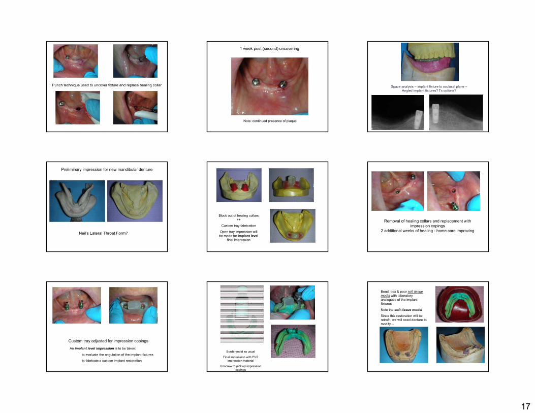
Punch technique used to uncover fixture and replace healing collar
1 week post (second) uncovering
Note: continued presence of plaque
Space analysis – implant fixture to occlusal plane –Angled implant fixtures? Tx options?
Preliminary impression for new mandibular denture
Neil’s Lateral Throat Form?
Block out of healing collars ++
Custom tray fabrication
Open tray impression will be made for implant level
final impression
Removal of healing collars and replacement with impression copings
2 additional weeks of healing - home care improving
Custom tray adjusted for impression copings
An implant level impression is to be taken:
to evaluate the angulation of the implant fixtures
to fabricate a custom implant restoration
Border mold as usual
Final impression with PVS impression material
Unscrew to pick up impression copings
Bead, box & pour soft tissue model with laboratory analogues of the implant fixtures
Note the soft tissue model
Since this restoration will be retrofit, we will need denture to modify…

18
Intermaxillary records with Record base & Occlusion rim Incorporation of metal substructure within denture
Lab Rx?
Please fabricate a custom Hader Bar restoration with 2 ERA attachments off the distal to fit within the confines of the lower try in / denture
Metal substructure will be incorporated into the final prosthesis
Lab returns Hader Bar restoration underneath modified denture
Hader Bar + 2 ERA attachments
Bar is parallel to the occlusal plane
ERA attachments centered to the ridge
Path of Insertion of attachments must match
path of insertion of denture
ERA placement is ┴ to path
Evaluation of final fit or implant restoration and modified denture
A silicone putty matrix is made to maintain
tooth position
While the substructure of the denture is
fabricated
Implant restoration Wax up of substructure
Metal substructure Processed denture incorporating substructure
Embedded substructure in processed denture
2 Hader Bar clips 2 ERA attachments
19
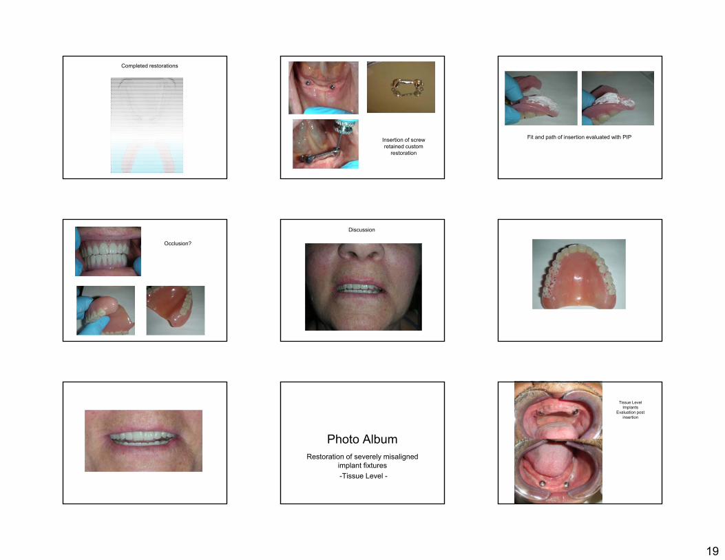
Completed restorations
Insertion of screw retained custom
restoration
Fit and path of insertion evaluated with PIP
Occlusion?
Discussion
Photo AlbumRestoration of severely misaligned
implant fixtures-Tissue Level -
Tissue Level Implants
Evaluation post insertion
20
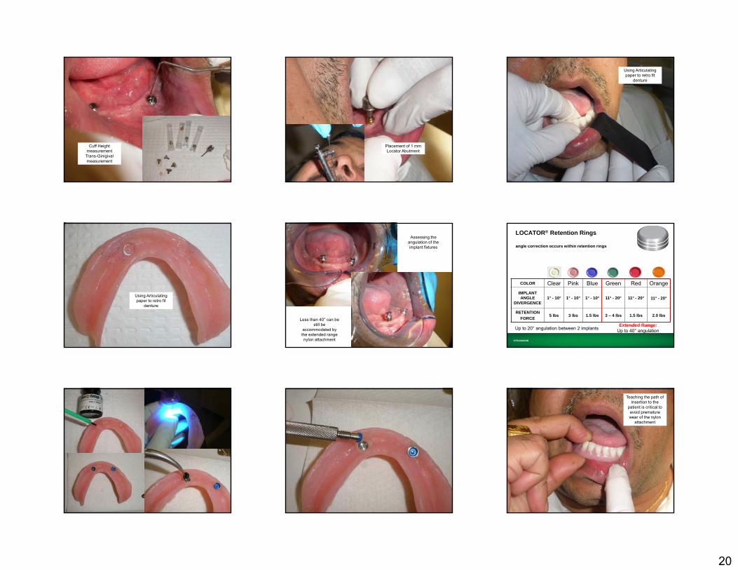
Cuff Height measurement
Trans-Ginigival measurement
Placement of 1 mm Locator Abutment
Using Articulating paper to retro fit
denture
Using Articulating paper to retro fit
denture
Assessing the angulation of the implant fixtures
Less than 40° can be still be
accommodated by the extended range nylon attachment STRAUMANN
LOCATOR® Retention Rings
angle correction occurs within retention rings
COLOR Clear Pink Blue Green Red OrangeIMPLANT ANGLE
DIVERGENCE1° - 10° 1° - 10° 1° - 10° 11° - 20° 11° - 20° 11° - 20°
RETENTIONFORCE
5 lbs 3 lbs 1.5 lbs 3 – 4 lbs 1.5 lbs 2.0 lbs
Up to 20° angulation between 2 implants Extended Range:Up to 40° angulation
Teaching the path of insertion to the
patient is critical to avoid premature wear of the nylon
attachment
21
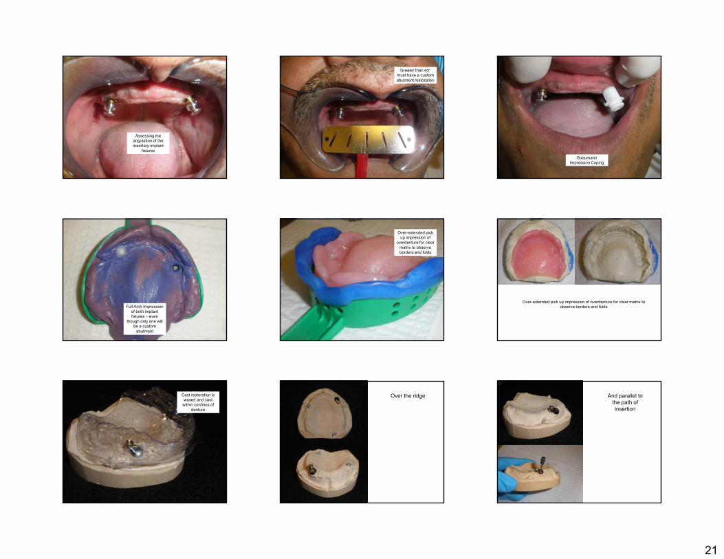
Assessing the angulation of the maxillary implant
fixtures
Greater than 40°must have a custom abutment restoration
Straumann Impression Coping
Full Arch Impression of both implant fixtures – even
though only one will be a custom
abutment
Over-extended pick up impression of
overdenture for clear matrix to observe borders and folds
Over-extended pick up impression of overdenture for clear matrix to observe borders and folds
Cast restoration is waxed and cast
within confines of denture
Over the ridge And parallel to the path of insertion

22
The other abutment is a conventional
Locator
The other abutment is a conventional
Locator
Block out is CRITICAL before
attachment pick up
A standard retentive
attachment may now be used
Relining an Attachment Overdenture
Similar to that of a conventional denture* Assess occlusion, VDO and CR
Snap on light attachments or impression copings intra-orally
Border mold and final impressions functionally
Remove denture and snap on lab analogues before pouring cast
*See Relines, Rebases and Repairs
The Final Impression
Fit the denture adjusting any part that touches the metal housing
The denture must be ENTIRELY TISSUE BORNE
Border Mold and Rubber Base final impression as usual- “picking-up” new metal housings in the impression
23
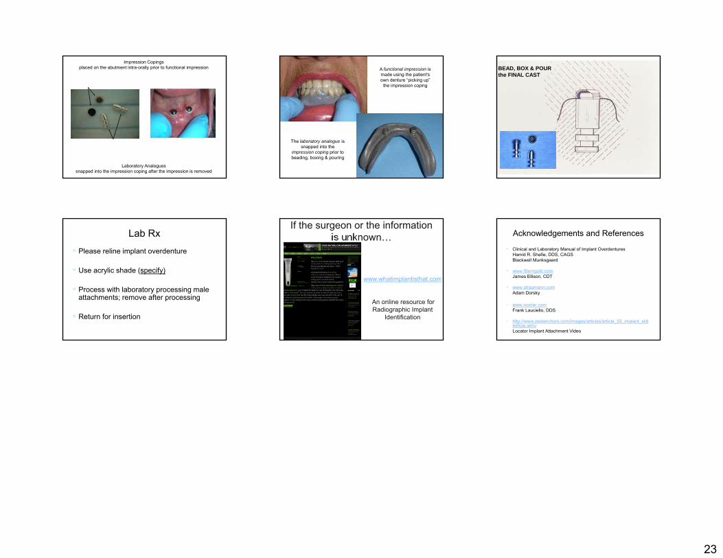
Impression Copings placed on the abutment intra-orally prior to functional impression
Laboratory Analogues snapped into the impression coping after the impression is removed
A functional impression is made using the patient's own denture “picking up”
the impression coping
The laboratory analogue is snapped into the
impression coping prior to beading, boxing & pouring
BEAD, BOX & POUR the FINAL CAST
Lab Rx
Please reline implant overdenture
Use acrylic shade (specify)
Process with laboratory processing male attachments; remove after processing
Return for insertion
If the surgeon or the information is unknown…
www.whatimplantisthat.com
An online resource for Radiographic Implant
Identification
Acknowledgements and References
Clinical and Laboratory Manual of Implant OverdenturesHamid R. Shafie, DDS, CAGSBlackwell Munksgaard
www.Sterngold.comJames Ellison, CDT
www.straumann.comAdam Dorsky
• www.ivoclar.comFrank Lauciello, DDS
• http://www.zestanchors.com/images/articles/article_55_implant_slideshow.wmvLocator Implant Attachment Video