Embed Size (px)
Citation preview
F. WIRING LOOMS
2014 USER MANUAL
98CUP_2013 Release
F-2
F WIRING LOOMS
CONTENTS
F WIRING LOOMS 2
F.2 CHASSIS LOOM (8201412199) 3 F.3 ENGINE LOOM (8201412197) 13 F.4 FRONT LOOM (8201412200) 20 F.5 FRONT LEFT DOOR WIPER LOOM (8201412201) 25 F.6 GROUND WIRES 25 F.7 +12V WIRES 26 F.8 XAP MASTER RELAY (7711160136) 27 F.9 BREAKOUT BOX (8201412528) 27 F.10 CBNT (8201406559) 27 F.11 LAP BEACON (8201387068) 28 F.12 WHEEL SPEED SENSOR INTERFACE (8201406560) 28 F.13 CHASSIS LOOM FREE CONNECTORS 29 F.14 GPS RECEIVER (OPTION) 8201406558 30 F.15 FIRE EXTINGUISHER LOOM (98CUP00095) 30
98CUP_2013 Release
F-3
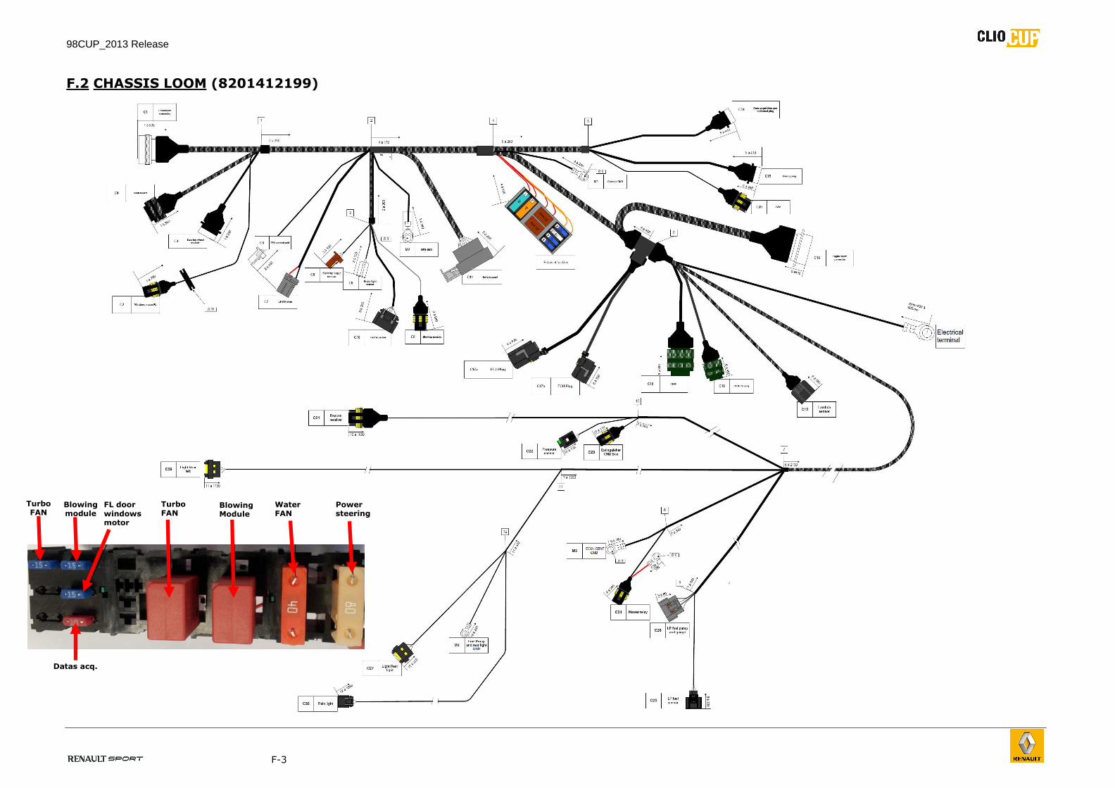
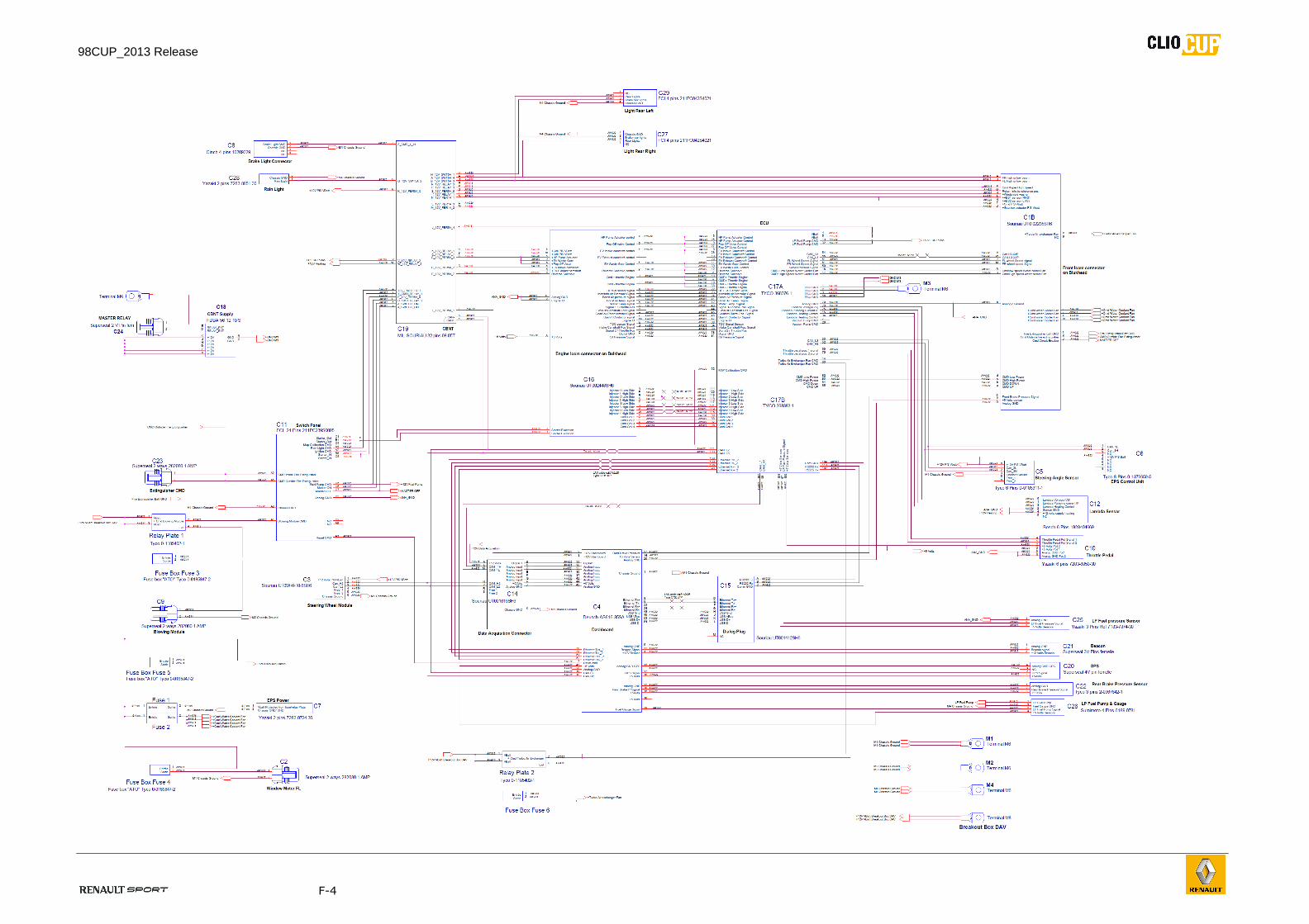
F.2 CHASSIS LOOM (8201412199)
Datas acq.
Turbo FAN
Blowing module
FL door windows motor
Turbo FAN
Blowing Module
Water FAN
Power steering
98CUP_2013 Release
F-4
98CUP_2013 Release
F-5
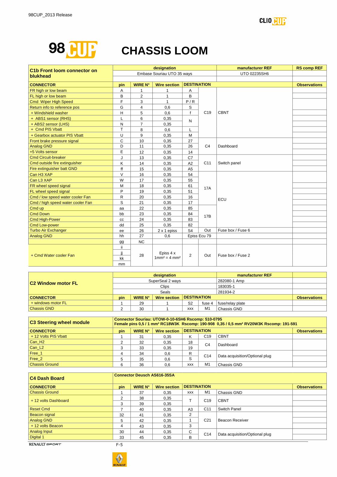
CHASSIS LOOM
C1b Front loom connector on blukhead
designation manufacturer REF RS comp REF Embase Souriau UTO 35 ways UTO 02235SH6
CONNECTOR pin WIRE N° Wire section DESTINATION Observations FR high or low beam A 1 1 A
C19 CBNT
FL high or low beam B 2 1 B Cmd Wiper High Speed F 3 1 P / R
Return info to reference pos G 4 0,6 S + Windshield washer H 5 0,6 f + ABS1 sensor (RHS) L 6 0,35
N
+ ABS2 sensor (LHS) N 7 0,35 + Cmd PIS Vbatt T 8 0,6 L + Gearbox actuator PIS Vbatt U 9 0,35 M Front brake pressure signal C 10 0,35 27
C4 Dashboard
Analog GND D 11 0,35 26 +5 Volts sensor E 12 0,35 14 Cmd Circuit-breaker J 13 0,35 C7
C11 Switch panel
Cmd outside fire extinguisher K 14 0,35 A2 Fire extinguisher batt GND ff 15 0,35 A5
Can H3 XAP V 16 0,35 54
17A
ECU
Can L3 XAP W 17 0,35 55 FR wheel speed signal M 18 0,35 61 FL wheel speed signal P 19 0,35 51 Cmd / low speed water cooler Fan R 20 0,35 16 Cmd / high speed water cooler Fan S 21 0,35 17 Cmd up aa 22 0,35 85
17B
Cmd Down bb 23 0,35 84 Cmd High-Power cc 24 0,35 83 Cmd Low-power dd 25 0,35 82 Turbo Air Exchanger ee 26 2 x 1 episs S4 Out Fuse box / Fuse 6 Analog GND hh 27 0,6 Episs Ecu 79 gg NC
+ Cmd Water cooler Fan
ii
28 Episs 4 x
1mm² = 4 mm² 2 Out Fuse box / Fuse 2
jj kk
mm
C2 Window motor FL
designation manufacturer REF SuperSeal 2 ways 282080-1 Amp
Clips 183035-1 Seals 281934-2
CONNECTOR pin WIRE N° Wire section DESTINATION Observations + windows motor FL 1 29 1 S2 fuse 4 fuse/relay plate Chassis GND 2 30 1 xxx M1 Chassis GND
C3 Steering wheel module Connector Souriau: UTOW -0-10-6SH6 Rscomp: 510 -0795 Female pins 0,5 / 1 mm² RC18W3K Rscomp: 190-908 0 ,35 / 0,5 mm² RV20W3K Rscomp: 191-591
CONNECTOR pin WIRE N° Wire section DESTINATION Observations + 12 Volts PIS Vbatt 1 31 0,35 K C19 CBNT Can_H2 2 32 0,35 18
C4 Dashboard Can_L2 3 33 0,35 19 Free_1 4 34 0,6 R
C14 Data acquisition/Optional plug
Free_2 5 35 0,6 S Chassis Ground 6 36 0,6 xxx M1 Chassis GND
C4 Dash Board Connector Deusch AS616 -35SA
CONNECTOR pin WIRE N° Wire section DESTINATION Observations Chassis Ground 1 37 0,35 xxx M1 Chassis GND
+ 12 volts Dashboard 2 38 0,35
T C19 CBNT
3 39 0,35 Reset Cmd 7 40 0,35 A3 C11 Switch Panel Beacon signal 32 41 0,35 2
C21 Beacon Receiver
Analog GND 5 42 0,35 1 + 12 volts Beacon 4 43 0,35 3 Analog Input 30 44 0,35 C
C14 Data acquisition/Optional plug
Digital 1 33 45 0,35 B
98CUP_2013 Release
F-6
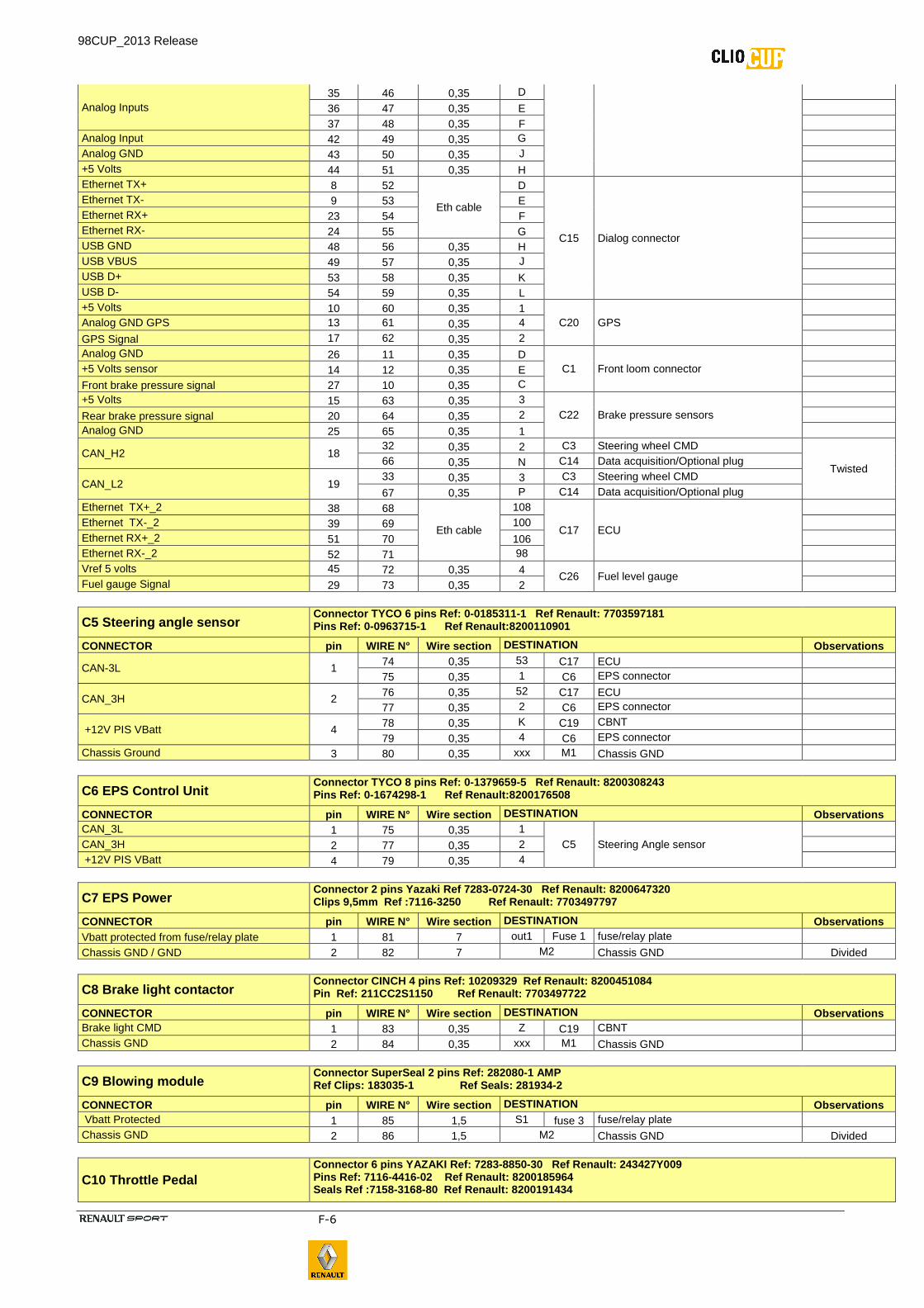
Analog Inputs 35 46 0,35 D
36 47 0,35 E
37 48 0,35 F Analog Input 42 49 0,35 G Analog GND 43 50 0,35 J +5 Volts 44 51 0,35 H Ethernet TX+ 8 52
Eth cable
D
C15 Dialog connector
Ethernet TX- 9 53 E Ethernet RX+ 23 54 F Ethernet RX- 24 55 G USB GND 48 56 0,35 H USB VBUS 49 57 0,35 J USB D+ 53 58 0,35 K USB D- 54 59 0,35 L +5 Volts 10 60 0,35 1
C20 GPS
Analog GND GPS 13 61 0,35 4 GPS Signal 17 62 0,35 2 Analog GND 26 11 0,35 D
C1 Front loom connector
+5 Volts sensor 14 12 0,35 E
Front brake pressure signal 27 10 0,35 C +5 Volts 15 63 0,35 3
C22 Brake pressure sensors
Rear brake pressure signal 20 64 0,35 2 Analog GND 25 65 0,35 1
CAN_H2 18 32 0,35 2 C3 Steering wheel CMD
Twisted 66 0,35 N C14 Data acquisition/Optional plug
CAN_L2 19 33 0,35 3 C3 Steering wheel CMD
67 0,35 P C14 Data acquisition/Optional plug Ethernet TX+_2 38 68
Eth cable
108
C17 ECU
Ethernet TX-_2 39 69 100 Ethernet RX+_2 51 70 106 Ethernet RX-_2 52 71 98 Vref 5 volts 45 72 0,35 4
C26 Fuel level gauge
Fuel gauge Signal 29 73 0,35 2
C5 Steering angle sensor Connector TYCO 6 pins Ref: 0 -0185311-1 Ref Renault: 7703597181 Pins Ref: 0-0963715-1 Ref Renault:8200110901
CONNECTOR pin WIRE N° Wire section DESTINATION Observations
CAN-3L 1 74 0,35 53 C17 ECU
75 0,35 1 C6 EPS connector
CAN_3H 2 76 0,35 52 C17 ECU
77 0,35 2 C6 EPS connector
+12V PIS VBatt 4 78 0,35 K C19 CBNT
79 0,35 4 C6 EPS connector Chassis Ground 3 80 0,35 xxx M1 Chassis GND
C6 EPS Control Unit Connector TYCO 8 pins Ref: 0 -1379659-5 Ref Renault: 8200308243 Pins Ref: 0-1674298-1 Ref Renault:8200176508
CONNECTOR pin WIRE N° Wire section DESTINATION Observations CAN_3L 1 75 0,35 1
C5 Steering Angle sensor
CAN_3H 2 77 0,35 2 +12V PIS VBatt 4 79 0,35 4
C7 EPS Power Connector 2 pins Yazaki Ref 7283 -0724-30 Ref Renault: 8200647320 Clips 9,5mm Ref :7116-3250 Ref Renault: 77 03497797
CONNECTOR pin WIRE N° Wire section DESTINATION Observations Vbatt protected from fuse/relay plate 1 81 7 out1 Fuse 1 fuse/relay plate Chassis GND / GND 2 82 7 M2 Chassis GND Divided
C8 Brake light contactor Connector CINCH 4 pins Ref: 10209329 Ref Renault: 8200451084 Pin Ref: 211CC2S1150 Ref Renault: 770349772 2
CONNECTOR pin WIRE N° Wire section DESTINATION Observations Brake light CMD 1 83 0,35 Z C19 CBNT Chassis GND 2 84 0,35 xxx M1 Chassis GND
C9 Blowing module Connector SuperSeal 2 pins Ref: 282080 -1 AMP Ref Clips: 183035-1 Ref Seals: 281934 -2
CONNECTOR pin WIRE N° Wire section DESTINATION Observations Vbatt Protected 1 85 1,5 S1 fuse 3 fuse/relay plate Chassis GND 2 86 1,5 M2 Chassis GND Divided
C10 Throttle Pedal Connector 6 pins YAZAKI Ref: 7283 -8850-30 Ref Renault: 243427Y009 Pins Ref: 7116-4416-02 Ref Renault: 8200185964 Seals Ref :7158-3168-80 Ref Renault: 8200191434
98CUP_2013 Release
F-7
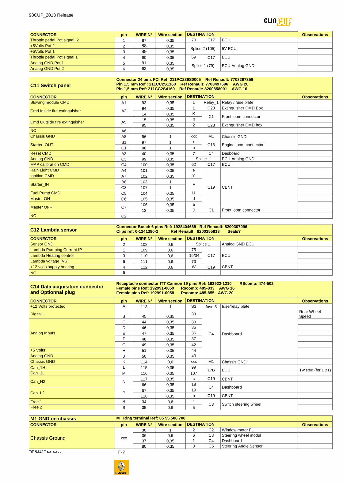
CONNECTOR pin WIRE N° Wire section DESTINATION Observations Throttle pedal Pot signal 2 1 87 0,35 70 C17 ECU +5Volts Pot 2 2 88 0,35
Splice 2 (105) 5V ECU
+5Volts Pot 1 3 89 0,35 Throttle pedal Pot signal 1 4 90 0,35 69 C17 ECU Analog GND Pot 1 5 91 0,35
Splice 1 (79) ECU Analog GND
Analog GND Pot 2 6 92 0,35
C11 Switch panel Connector 24 pins FCI Ref: 211PC239S0005 Ref Ren ault: 7703297356 Pin 1,5 mm Ref : 211CC2S1160 Ref Renault: 770349 7696 AWG 20 Pin 1,5 mm Ref: 211CC2S4160 Ref Renault: 8200858 001 AWG 16
CONNECTOR pin WIRE N° Wire section DESTINATION Observations Blowing module CMD A1 93 0,35 1 Relay_1 Relay / fuse plate
Cmd Inside fire extinguisher A2 94 0,35 1 C23 Extinguisher CMD Box
14 0,35 K C1 Front loom connector
Cmd Outside fire extinguisher A5 15 0,35 ff 95 0,35 2 C23 Extinguisher CMD box
NC A6 Chassis GND A8 96 1 xxx M1 Chassis GND
Starter_OUT B1 97 1 t
C16 Engine loom connector
C1 98 1 u Reset CMD A3 40 0,35 7 C4 Dasboard Analog GND C3 99 0,35 Splice 1 ECU Analog GND MAP calibration CMD C4 100 0,35 62 C17 ECU Rain Light CMD A4 101 0,35 e
C19 CBNT
Ignition CMD A7 102 0,35 Y
Starter_IN B8 103 1
F
C8 107 1 Fuel Pump CMD C5 104 0,35 U Master ON C6 105 0,35 d
Master OFF C7 106 0,35 a
13 0,35 J C1 Front loom connector NC C2
C12 Lambda sensor Connector Bosch 6 pins Ref: 1928404669 Ref Renaul t: 8200307096 Clips ref: 0-1241380-2 Ref Renault: 8200 355813 Seals?
CONNECTOR pin WIRE N° Wire section DESTINATION Observations Sensor GND 2 108 0,6 Splice 1 Analog GND ECU Lambda Pumping Current IP 1 109 0,6 75
C17 ECU
Lambda Heating control 3 110 0,6 15/34 Lambda voltage (VS) 6 111 0,6 73 +12 volts supply heating 4 112 0,6 W C19 CBNT
NC 5
C14 Data acquisition connector and Optionnal plug
Receptacle connector ITT Cannon 19 pins Ref: 192922 -1210 RScomp: 474 -502 Female pins Ref: 192991-0059 Rscomp: 485-833 AWG 16 Female pins Ref: 192991-0058 Rscomp: 485-855 AWG 20
CONNECTOR pin WIRE N° Wire section DESTINATION Observations +12 Volts protected A 113 1 S3 fuse 5 fuse/relay plate
Digital 1 B 45 0,35
33
C4 Dashboard
Rear Wheel Speed
Analog Inputs
C 44 0,35 30
D 46 0,35 35
E 47 0,35 36 F 48 0,35 37
G 49 0,35 42 +5 Volts H 51 0,35 44 Analog GND J 50 0,35 43 Chassis GND K 114 0,6 xxx M1 Chassis GND
Can_1H L 115 0,35 99 17B ECU Twisted (for DB1)
Can_1L M 116 0,35 107
Can_H2 N 117 0,35 c C19 CBNT
66 0,35 18 C4 Dashboard
Can_L2 P 67 0,35 19
118 0,35 b C19 CBNT
Free 1 R 34 0,6 4 C3 Switch steering wheel
Free 2 S 35 0,6 5
M1 GND on chassis M_ Ring terminal Ref: 05 55 506 700 CONNECTOR pin WIRE N° Wire section DESTINATION Observations
Chassis Ground xxx
30 1 2 C2 Window motor FL 36 0,6 6 C3 Steering wheel modul 37 0,35 1 C4 Dashboard 80 0,35 3 C5 Steering Angle Sensor

98CUP_2013 Release
F-8
84 0,35 2 C8 Brake Light Contactor 96 1 A8 C11 Switch Panel 114 0,6 K C14 Data Acquisition
M2 GND on chassis M_ Ring terminal Ref: 05 55 506 700 CONNECTOR pin WIRE N° Wire section DESTINATION Observations
Chassis Ground Divided xxx 82 7 2 C7 EPS Power 86 1,5 2 C9 Blowing Module
C15 Dialog plug Receptacle connector ITT Cannon 12 pins Ref: 192922 -1210 RScomp: 474 -502 Female pins Ref: 192991-0059 Rscomp: 485-833 AWG 16 Female pins Ref: 192991-0058 Rscomp: 485-855 AWG 20
CONNECTOR pin WIRE N° Wire section DESTINATION Observations RS232 TX A 119 0,35 102
C17 ECU
RS232 RX B 120 0,35 110
Comm GND C 121 0,35 109 Ethernet TX+ D 52
ETH Cable
8
C4 Dashboard
Ethernet TX- E 53 9 Ethernet RX+ F 54 23 Ethernet RX- G 55 24 USB GND H 56 0,35 48 USB VBUS J 57 0,35 49 USB D+ K 58 0,35 53 USB D- L 54 0,35 54 M
C16 Engine loom connector on bulkhead
Receptacle connector 48 sockets Souriau Serie UTO r éf: UTO02448SH6
CONNECTOR pin WIRE N° Wire section DESTINATION Observations Intake camshaft pos signal B 122 0,35 64
C17 Connector 17 A ECU Channels 1 to 81
NC C Digital GND D 123 0,6 78 TDC sensor signal E 124 0,35 63 Signal 2 / Throttle pos F 125 0,35 66 Signal 1 / Throttle pos G 126 0,35 43 Cmd + throttle engine H 127 0,6 18/37
Cmd - throttle engine J 128 0,6 19/38 Boost air temp. signal L 129 0,35 41
Boost air pressure signal M 130 0,35 24 HP fuel sensor signal (rail pressure) X 131 0,35 22 Engine ID aa 132 0,35 47 HP pump actuator control c 133 0,6 6/25
Water temp signal d 134 0,35 42 EV intake camshaft control e 135 0,6 9/28 EV Waste Gate control f 136 0,6 11/30 Pop Off valve control g 137 0,6 8/27 Manifold air pressure signal h 138 0,35 23 NC i Oil pressure signal j 139 0,35 81 Gearbox potentiometer signal w 140 0,35 45 UP Shift contactor signal x 141 0,35 46 Reverse solenoid control y 142 0,6 12/31 Engine ID v 143 0,35
Splice 1
Analog GND K 144 0,6 +5 Volts A 145 0,6 Splice 2 (105)
Connector 17 B ECU Channels 82 to 121
Injector N°1 Low side N 146 0,6 114
B
Injector N°1 High side P 147 0,6 120
Injector N°2 Low side R 148 0,6 115
Injector N°2 High side S 149 0,6 118
Injector N°3 Low side T 150 0,6 117
Injector N°3 High side U 151 0,6 121
Injector N°4 Low side V 152 0,6 119
Injector N°4 High side W 153 0,6 116
Cmd Coil 1 Y 154 0,6 89
Cmd Coil 2 Z 155 0,6 88
Cmd Coil 3 a 156 0,6 87
Cmd Coil 4 b 157 0,6 86
Starter excitation t 97
2 x 1 B1
C11 Switch panel
u 98 C1
+ COIL PIS Vbatt k 158 0,6 h
C19 CBNT
m 159 0,6 g + HP pump actuator n 160 0,6 C Splice CBNT
98CUP_2013 Release
F-9
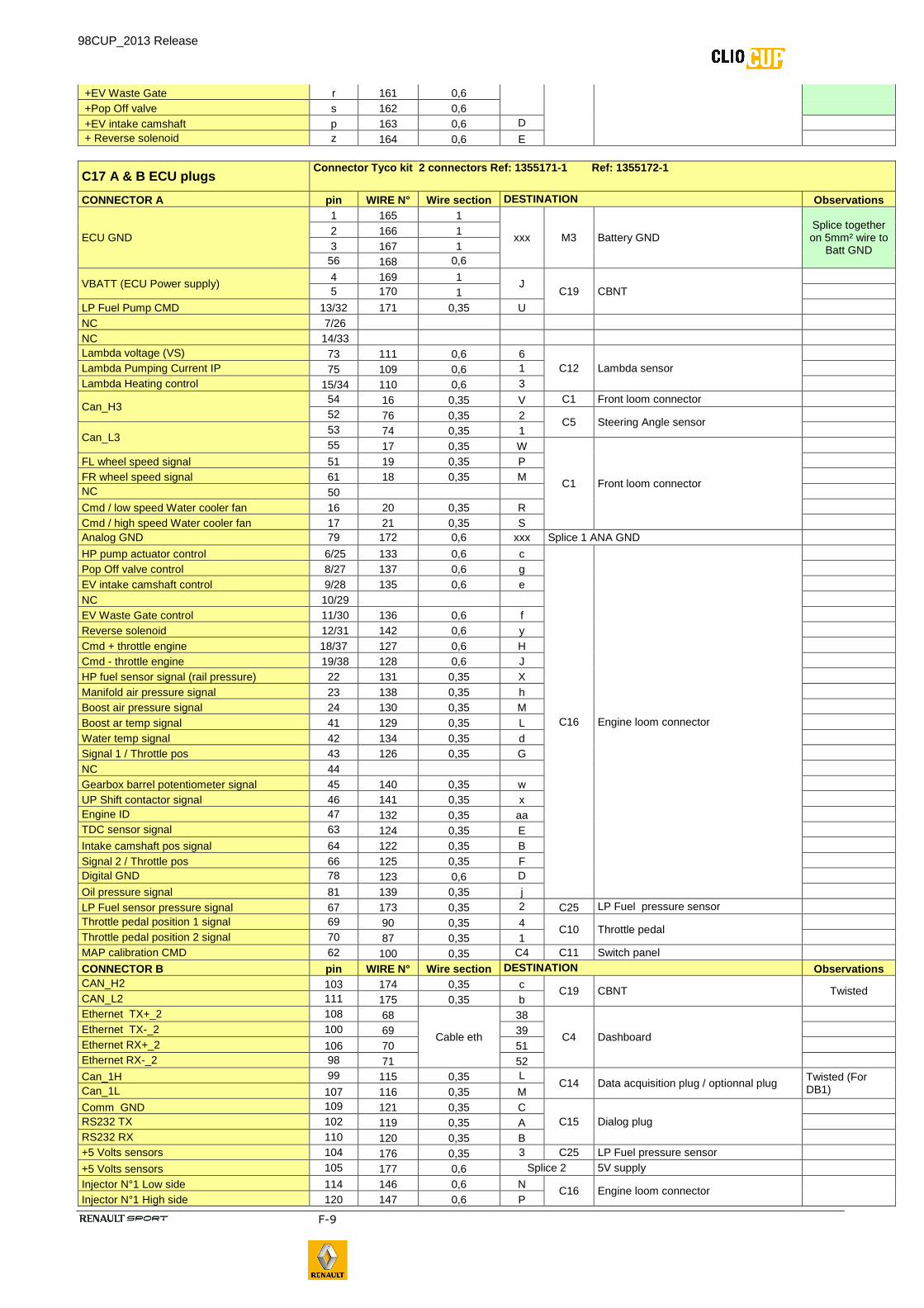
+EV Waste Gate r 161 0,6 +Pop Off valve s 162 0,6 +EV intake camshaft p 163 0,6 D + Reverse solenoid z 164 0,6 E
C17 A & B ECU plugs Connector Tyco kit 2 connectors Ref: 1355171 -1 Ref: 1355172-1
CONNECTOR A pin WIRE N° Wire section DESTINATION Observations
ECU GND
1 165 1
xxx M3 Battery GND Splice together on 5mm² wire to
Batt GND
2 166 1 3 167 1
56 168 0,6
VBATT (ECU Power supply) 4 169 1
J C19 CBNT
5 170 1
LP Fuel Pump CMD 13/32 171 0,35 U NC 7/26 NC 14/33 Lambda voltage (VS) 73 111 0,6 6
C12 Lambda sensor
Lambda Pumping Current IP 75 109 0,6 1 Lambda Heating control 15/34 110 0,6 3
Can_H3 54 16 0,35 V C1 Front loom connector 52 76 0,35 2
C5 Steering Angle sensor
Can_L3 53 74 0,35 1 55 17 0,35 W
C1 Front loom connector
FL wheel speed signal 51 19 0,35 P FR wheel speed signal 61 18 0,35 M NC 50 Cmd / low speed Water cooler fan 16 20 0,35 R Cmd / high speed Water cooler fan 17 21 0,35 S Analog GND 79 172 0,6 xxx Splice 1 ANA GND
HP pump actuator control 6/25 133 0,6 c
C16 Engine loom connector
Pop Off valve control 8/27 137 0,6 g EV intake camshaft control 9/28 135 0,6 e NC 10/29 EV Waste Gate control 11/30 136 0,6 f Reverse solenoid 12/31 142 0,6 y Cmd + throttle engine 18/37 127 0,6 H
Cmd - throttle engine 19/38 128 0,6 J
HP fuel sensor signal (rail pressure) 22 131 0,35 X
Manifold air pressure signal 23 138 0,35 h Boost air pressure signal 24 130 0,35 M
Boost ar temp signal 41 129 0,35 L
Water temp signal 42 134 0,35 d Signal 1 / Throttle pos 43 126 0,35 G NC 44 Gearbox barrel potentiometer signal 45 140 0,35 w UP Shift contactor signal 46 141 0,35 x Engine ID 47 132 0,35 aa TDC sensor signal 63 124 0,35 E Intake camshaft pos signal 64 122 0,35 B Signal 2 / Throttle pos 66 125 0,35 F Digital GND 78 123 0,6 D Oil pressure signal 81 139 0,35 j LP Fuel sensor pressure signal 67 173 0,35 2 C25 LP Fuel pressure sensor Throttle pedal position 1 signal 69 90 0,35 4
C10 Throttle pedal
Throttle pedal position 2 signal 70 87 0,35 1 MAP calibration CMD 62 100 0,35 C4 C11 Switch panel
CONNECTOR B pin WIRE N° Wire section DESTINATION Observations CAN_H2 103 174 0,35 c
C19 CBNT Twisted CAN_L2 111 175 0,35 b Ethernet TX+_2 108 68
Cable eth
38
C4 Dashboard
Ethernet TX-_2 100 69 39 Ethernet RX+_2 106 70 51 Ethernet RX-_2 98 71 52
Can_1H 99 115 0,35 L C14 Data acquisition plug / optionnal plug
Twisted (For DB1) Can_1L 107 116 0,35 M
Comm GND 109 121 0,35 C C15 Dialog plug
RS232 TX 102 119 0,35 A RS232 RX 110 120 0,35 B +5 Volts sensors 104 176 0,35 3 C25 LP Fuel pressure sensor +5 Volts sensors 105 177 0,6 Splice 2 5V supply Injector N°1 Low side 114 146 0,6 N
C16 Engine loom connector Injector N°1 High side 120 147 0,6 P
98CUP_2013 Release
F-10
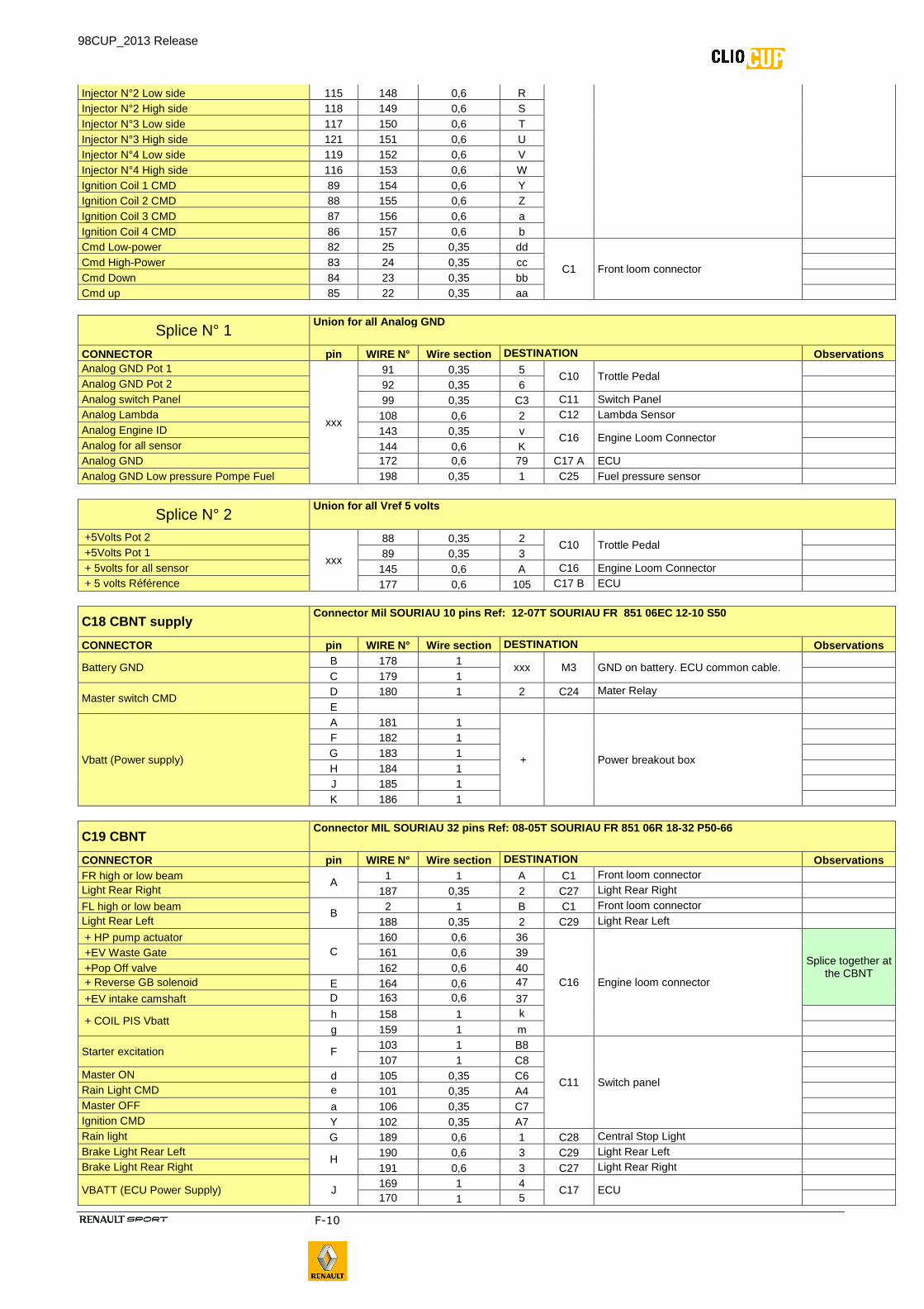
Injector N°2 Low side 115 148 0,6 R Injector N°2 High side 118 149 0,6 S Injector N°3 Low side 117 150 0,6 T Injector N°3 High side 121 151 0,6 U Injector N°4 Low side 119 152 0,6 V Injector N°4 High side 116 153 0,6 W Ignition Coil 1 CMD 89 154 0,6 Y
Ignition Coil 2 CMD 88 155 0,6 Z Ignition Coil 3 CMD 87 156 0,6 a Ignition Coil 4 CMD 86 157 0,6 b Cmd Low-power 82 25 0,35 dd
C1 Front loom connector
Cmd High-Power 83 24 0,35 cc Cmd Down 84 23 0,35 bb Cmd up 85 22 0,35 aa
Splice N° 1 Union for all Analog GND
CONNECTOR pin WIRE N° Wire section DESTINATION Observations Analog GND Pot 1
xxx
91 0,35 5 C10 Trottle Pedal
Analog GND Pot 2 92 0,35 6 Analog switch Panel 99 0,35 C3 C11 Switch Panel Analog Lambda 108 0,6 2 C12 Lambda Sensor Analog Engine ID 143 0,35 v
C16 Engine Loom Connector
Analog for all sensor 144 0,6 K Analog GND 172 0,6 79 C17 A ECU Analog GND Low pressure Pompe Fuel 198 0,35 1 C25 Fuel pressure sensor
Splice N° 2 Union for all Vref 5 volts
+5Volts Pot 2
xxx
88 0,35 2 C10 Trottle Pedal
+5Volts Pot 1 89 0,35 3 + 5volts for all sensor 145 0,6 A C16 Engine Loom Connector + 5 volts Référence 177 0,6 105 C17 B ECU
C18 CBNT supply Connector Mil SOURIA U 10 pins Ref: 12 -07T SOURIAU FR 851 06EC 12-10 S50
CONNECTOR pin WIRE N° Wire section DESTINATION Observations
Battery GND B 178 1
xxx M3 GND on battery. ECU common cable.
C 179 1
Master switch CMD D 180 1 2 C24 Mater Relay E
Vbatt (Power supply)
A 181 1
+ Power breakout box
F 182 1 G 183 1 H 184 1 J 185 1 K 186 1
C19 CBNT Connector MIL SOURIAU 32 pins Ref: 08 -05T SOURIAU FR 851 06R 18-32 P50-66
CONNECTOR pin WIRE N° Wire section DESTINATION Observations FR high or low beam
A 1 1 A C1 Front loom connector
Light Rear Right 187 0,35 2 C27 Light Rear Right FL high or low beam
B 2 1 B C1 Front loom connector
Light Rear Left 188 0,35 2 C29 Light Rear Left + HP pump actuator
C 160 0,6 36
C16 Engine loom connector
Splice together at the CBNT
+EV Waste Gate 161 0,6 39 +Pop Off valve 162 0,6 40 + Reverse GB solenoid E 164 0,6 47
+EV intake camshaft D 163 0,6 37
+ COIL PIS Vbatt h 158 1 k g 159 1 m
Starter excitation F 103 1 B8
C11 Switch panel
107 1 C8
Master ON d 105 0,35 C6 Rain Light CMD e 101 0,35 A4 Master OFF a 106 0,35 C7 Ignition CMD Y 102 0,35 A7 Rain light G 189 0,6 1 C28 Central Stop Light Brake Light Rear Left
H 190 0,6 3 C29 Light Rear Left
Brake Light Rear Right 191 0,6 3 C27 Light Rear Right
VBATT (ECU Power Supply) J 169 1 4
C17 ECU
170 1 5
98CUP_2013 Release
F-11
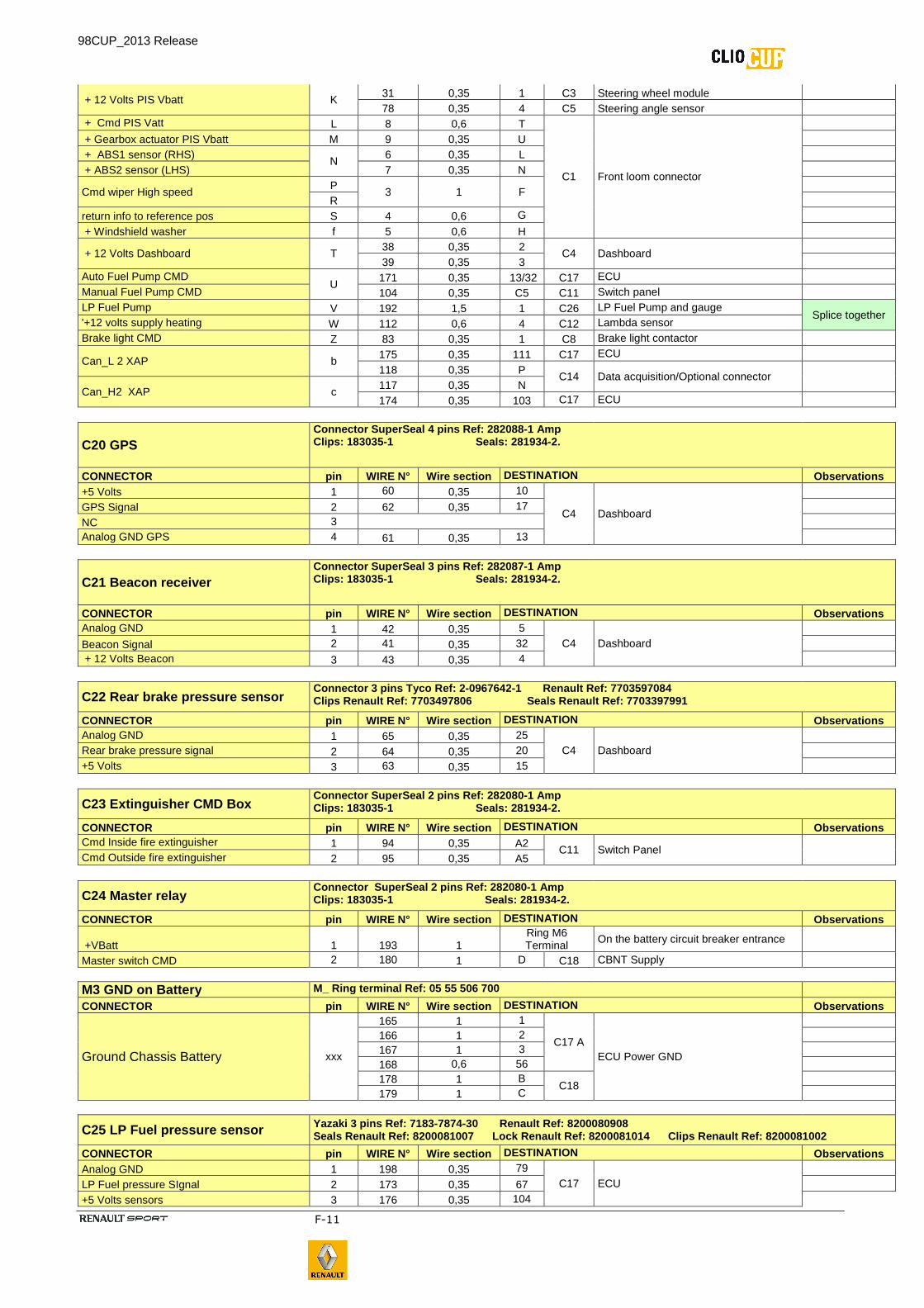
+ 12 Volts PIS Vbatt K 31 0,35 1 C3 Steering wheel module 78 0,35 4 C5 Steering angle sensor
+ Cmd PIS Vatt L 8 0,6 T
C1 Front loom connector
+ Gearbox actuator PIS Vbatt M 9 0,35 U + ABS1 sensor (RHS)
N 6 0,35 L
+ ABS2 sensor (LHS) 7 0,35 N
Cmd wiper High speed P
3 1 F
R return info to reference pos S 4 0,6 G + Windshield washer f 5 0,6 H
+ 12 Volts Dashboard T 38 0,35 2
C4 Dashboard
39 0,35 3 Auto Fuel Pump CMD
U 171 0,35 13/32 C17 ECU
Manual Fuel Pump CMD 104 0,35 C5 C11 Switch panel LP Fuel Pump V 192 1,5 1 C26 LP Fuel Pump and gauge
Splice together '+12 volts supply heating W 112 0,6 4 C12 Lambda sensor Brake light CMD Z 83 0,35 1 C8 Brake light contactor
Can_L 2 XAP b 175 0,35 111 C17 ECU 118 0,35 P
C14 Data acquisition/Optional connector Can_H2 XAP c
117 0,35 N 174 0,35 103 C17 ECU
C20 GPS Connector SuperSeal 4 pins Ref: 282088 -1 Amp Clips: 183035-1 Seals: 28 1934-2.
CONNECTOR pin WIRE N° Wire section DESTINATION Observations +5 Volts 1 60 0,35 10
C4 Dashboard
GPS Signal 2 62 0,35 17 NC 3 Analog GND GPS 4 61 0,35 13
C21 Beacon receiver Connector SuperSeal 3 pins Ref: 282087 -1 Amp Clips: 183035-1 Seals: 28 1934-2.
CONNECTOR pin WIRE N° Wire section DESTINATION Observations Analog GND 1 42 0,35 5
C4 Dashboard
Beacon Signal 2 41 0,35 32 + 12 Volts Beacon 3 43 0,35 4
C22 Rear brake pressure sensor Connector 3 pins Tyco Ref: 2 -0967642-1 Renault Ref: 7703597084 Clips Renault Ref: 7703497806 Seal s Renault Ref: 7703397991
CONNECTOR pin WIRE N° Wire section DESTINATION Observations Analog GND 1 65 0,35 25
C4 Dashboard
Rear brake pressure signal 2 64 0,35 20 +5 Volts 3 63 0,35 15
C23 Extinguisher CMD Box Connector SuperSeal 2 pins Ref: 282080 -1 Amp Clips: 183035-1 Seals: 28 1934-2.
CONNECTOR pin WIRE N° Wire section DESTINATION Observations Cmd Inside fire extinguisher 1 94 0,35 A2
C11 Switch Panel Cmd Outside fire extinguisher 2 95 0,35 A5
C24 Master relay Connector SuperSeal 2 pins Ref: 282080 -1 Amp Clips: 183035-1 Seals: 281934-2.
CONNECTOR pin WIRE N° Wire section DESTINATION Observations
+VBatt 1 193 1 Ring M6 Terminal
On the battery circuit breaker entrance
Master switch CMD 2 180 1 D C18 CBNT Supply
M3 GND on Battery M_ Ring terminal Ref: 05 55 506 700 CONNECTOR pin WIRE N° Wire section DESTINATION Observations
Ground Chassis Battery xxx
165 1 1
C17 A ECU Power GND
166 1 2 167 1 3 168 0,6 56 178 1 B
C18
179 1 C
C25 LP Fuel pressure sensor Yazaki 3 pins Ref: 7183-7874-30 Renault Ref: 8200080908 Seals Renault Ref: 8200081007 Lock Renault Ref : 8200081014 Clips Renault Ref: 8200081002
CONNECTOR pin WIRE N° Wire section DESTINATION Observations Analog GND 1 198 0,35 79
C17 ECU
LP Fuel pressure SIgnal 2 173 0,35 67 +5 Volts sensors 3 176 0,35 104
98CUP_2013 Release
F-12
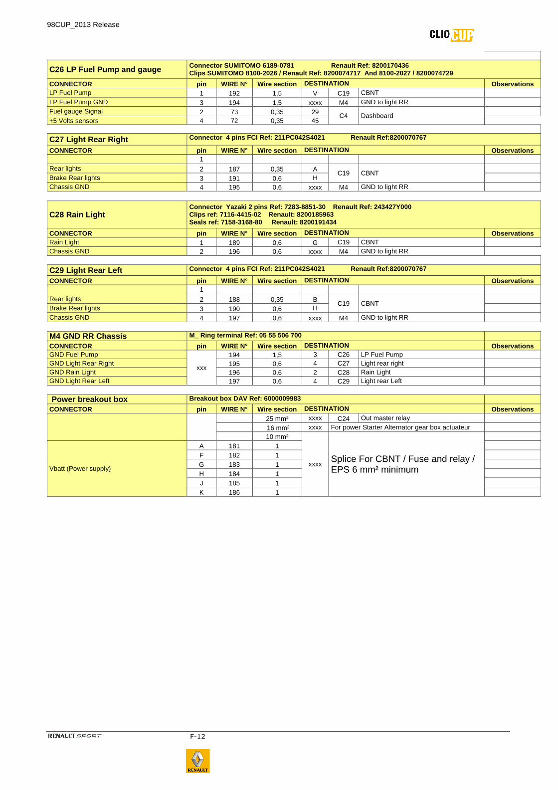
C26 LP Fuel Pump and gauge Connector SUMITOMO 6189-0781 Renault Ref: 8200170436 Clips SUMITOMO 8100-2026 / Renault Ref: 8200074717 And 8100-2027 / 8200074729
CONNECTOR pin WIRE N° Wire section DESTINATION Observations LP Fuel Pump 1 192 1,5 V C19 CBNT LP Fuel Pump GND 3 194 1,5 xxxx M4 GND to light RR Fuel gauge Signal 2 73 0,35 29 C4 Dashboard +5 Volts sensors 4 72 0,35 45
C27 Light Rear Right Connector 4 pins FCI Ref: 211PC042S4021 Renault Ref:8200070767
CONNECTOR pin WIRE N° Wire section DESTINATION Observations 1 Rear lights 2 187 0,35 A
C19 CBNT
Brake Rear lights 3 191 0,6 H Chassis GND 4 195 0,6 xxxx M4 GND to light RR
C28 Rain Light Connector Yazaki 2 pins Ref: 7283-8851-30 Renau lt Ref: 243427Y000 Clips ref: 7116-4415-02 Renault: 8200185963 Seals ref: 7158-3168-80 Renault: 8200191434
CONNECTOR pin WIRE N° Wire section DESTINATION Observations Rain Light 1 189 0,6 G C19 CBNT Chassis GND 2 196 0,6 xxxx M4 GND to light RR
C29 Light Rear Left Connector 4 pins FCI Ref: 211PC042S4021 Renault Ref:8200070767
CONNECTOR pin WIRE N° Wire section DESTINATION Observations 1 Rear lights 2 188 0,35 B
C19 CBNT
Brake Rear lights 3 190 0,6 H Chassis GND 4 197 0,6 xxxx M4 GND to light RR
M4 GND RR Chassis M_ Ring terminal Ref: 05 55 506 700 CONNECTOR pin WIRE N° Wire section DESTINATION Observations GND Fuel Pump
xxx
194 1,5 3 C26 LP Fuel Pump GND Light Rear Right 195 0,6 4 C27 Light rear right GND Rain Light 196 0,6 2 C28 Rain Light GND Light Rear Left 197 0,6 4 C29 Light rear Left
Power breakout box Breakout box DAV Ref: 6000009983 CONNECTOR pin WIRE N° Wire section DESTINATION Observations
25 mm² xxxx C24 Out master relay 16 mm² xxxx For power Starter Alternator gear box actuateur 10 mm²
xxxx Splice For CBNT / Fuse and relay / EPS 6 mm² minimum
Vbatt (Power supply)
A 181 1 F 182 1 G 183 1 H 184 1 J 185 1 K 186 1
98CUP_2013 Release
F-13
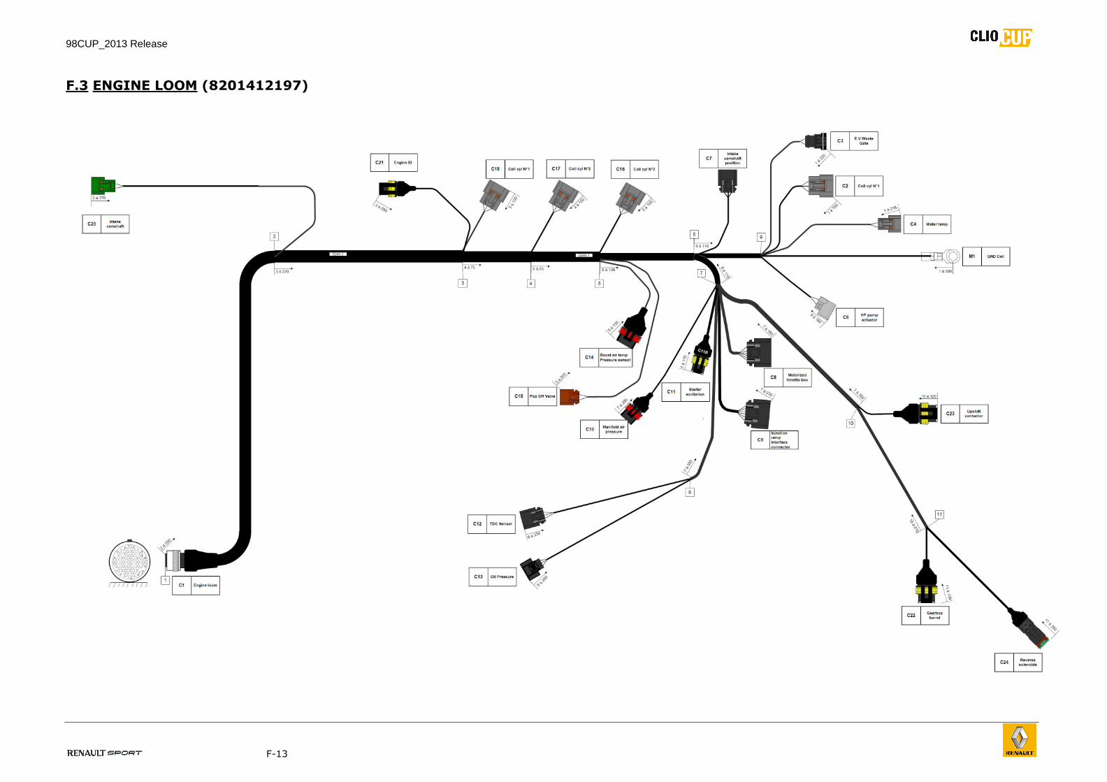
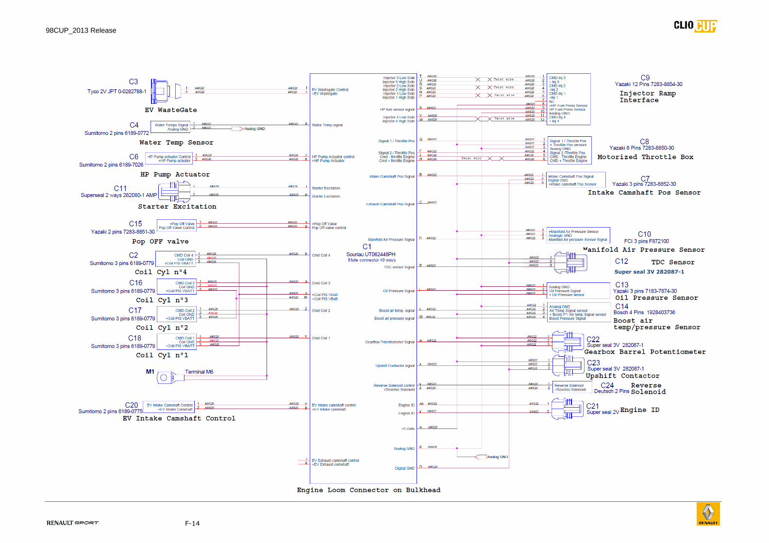
F.3 ENGINE LOOM (8201412197)
98CUP_2013 Release
F-14
Super seal 3V 282087-1
98CUP_2013 Release
F-15
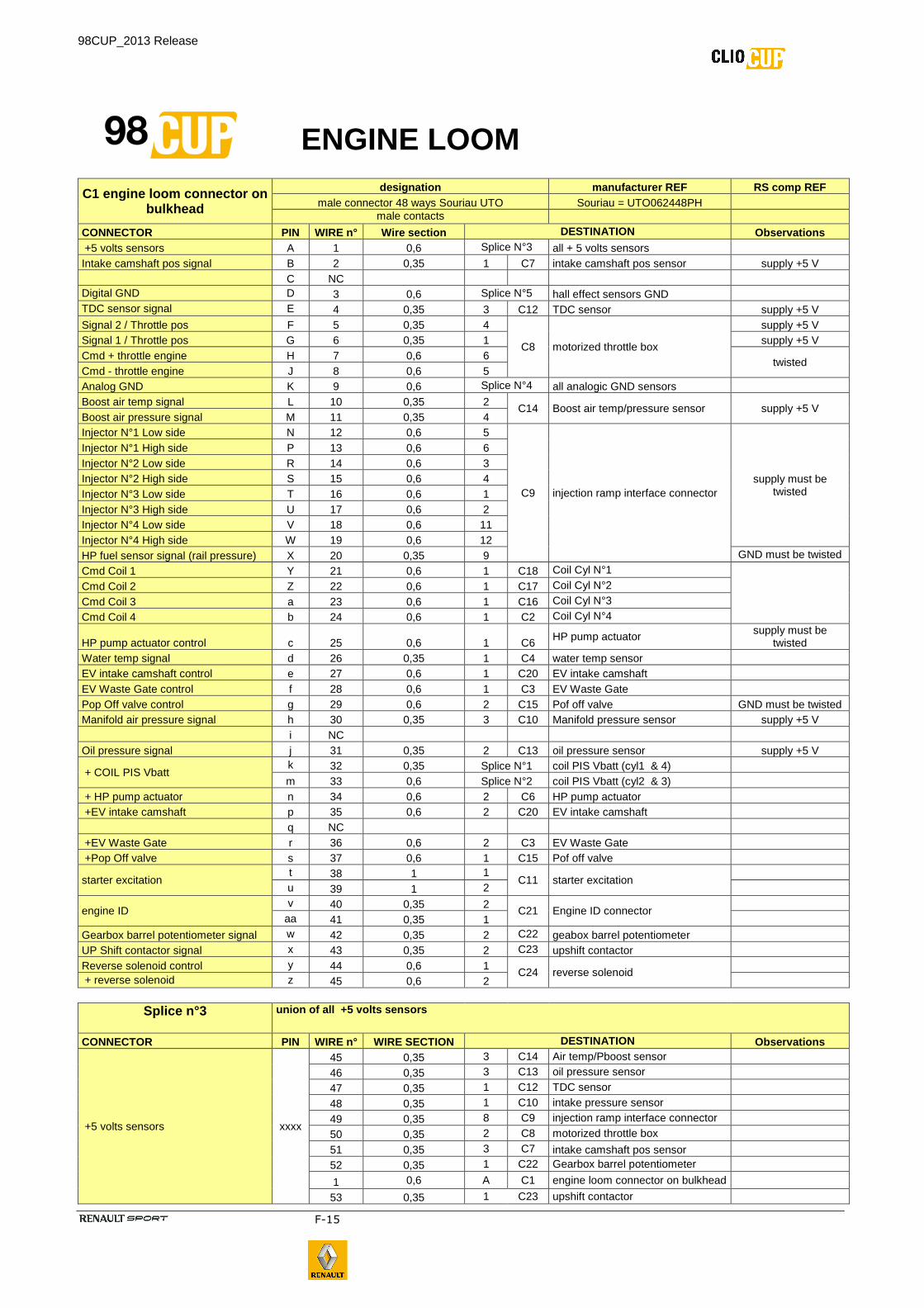
ENGINE LOOM
C1 engine loom connector on bulkhead
designation manufacturer REF RS comp REF male connector 48 ways Souriau UTO Souriau = UTO062448PH
male contacts
CONNECTOR PIN WIRE n° Wire section DESTINATION Observations +5 volts sensors A 1 0,6 Splice N°3 all + 5 volts sensors Intake camshaft pos signal B 2 0,35 1 C7 intake camshaft pos sensor supply +5 V C NC Digital GND D 3 0,6 Splice N°5 hall effect sensors GND TDC sensor signal E 4 0,35 3 C12 TDC sensor supply +5 V Signal 2 / Throttle pos F 5 0,35 4
C8 motorized throttle box
supply +5 V Signal 1 / Throttle pos G 6 0,35 1 supply +5 V Cmd + throttle engine H 7 0,6 6
twisted Cmd - throttle engine J 8 0,6 5 Analog GND K 9 0,6 Splice N°4 all analogic GND sensors Boost air temp signal L 10 0,35 2
C14 Boost air temp/pressure sensor supply +5 V Boost air pressure signal M 11 0,35 4 Injector N°1 Low side N 12 0,6 5
C9 injection ramp interface connector supply must be
twisted
Injector N°1 High side P 13 0,6 6 Injector N°2 Low side R 14 0,6 3 Injector N°2 High side S 15 0,6 4 Injector N°3 Low side T 16 0,6 1 Injector N°3 High side U 17 0,6 2 Injector N°4 Low side V 18 0,6 11 Injector N°4 High side W 19 0,6 12 HP fuel sensor signal (rail pressure) X 20 0,35 9 GND must be twisted
Cmd Coil 1 Y 21 0,6 1 C18 Coil Cyl N°1
Cmd Coil 2 Z 22 0,6 1 C17 Coil Cyl N°2
Cmd Coil 3 a 23 0,6 1 C16 Coil Cyl N°3
Cmd Coil 4 b 24 0,6 1 C2 Coil Cyl N°4
HP pump actuator control c 25 0,6 1 C6 HP pump actuator
supply must be twisted
Water temp signal d 26 0,35 1 C4 water temp sensor EV intake camshaft control e 27 0,6 1 C20 EV intake camshaft EV Waste Gate control f 28 0,6 1 C3 EV Waste Gate Pop Off valve control g 29 0,6 2 C15 Pof off valve GND must be twisted Manifold air pressure signal h 30 0,35 3 C10 Manifold pressure sensor supply +5 V i NC Oil pressure signal j 31 0,35 2 C13 oil pressure sensor supply +5 V
+ COIL PIS Vbatt k 32 0,35 Splice N°1 coil PIS Vbatt (cyl1 & 4) m 33 0,6 Splice N°2 coil PIS Vbatt (cyl2 & 3)
+ HP pump actuator n 34 0,6 2 C6 HP pump actuator +EV intake camshaft p 35 0,6 2 C20 EV intake camshaft q NC +EV Waste Gate r 36 0,6 2 C3 EV Waste Gate +Pop Off valve s 37 0,6 1 C15 Pof off valve
starter excitation t 38 1 1
C11 starter excitation
u 39 1 2
engine ID v 40 0,35 2
C21 Engine ID connector
aa 41 0,35 1 Gearbox barrel potentiometer signal w 42 0,35 2 C22 geabox barrel potentiometer UP Shift contactor signal x 43 0,35 2 C23 upshift contactor Reverse solenoid control y 44 0,6 1
C24 reverse solenoid
+ reverse solenoid z 45 0,6 2
Splice n°3 union of all +5 volts sensors
CONNECTOR PIN WIRE n° WIRE SECTION DESTINATION Observations
+5 volts sensors xxxx
45 0,35 3 C14 Air temp/Pboost sensor 46 0,35 3 C13 oil pressure sensor 47 0,35 1 C12 TDC sensor 48 0,35 1 C10 intake pressure sensor 49 0,35 8 C9 injection ramp interface connector 50 0,35 2 C8 motorized throttle box 51 0,35 3 C7 intake camshaft pos sensor 52 0,35 1 C22 Gearbox barrel potentiometer
1 0,6 A C1 engine loom connector on bulkhead 53 0,35 1 C23 upshift contactor
98CUP_2013 Release
F-16
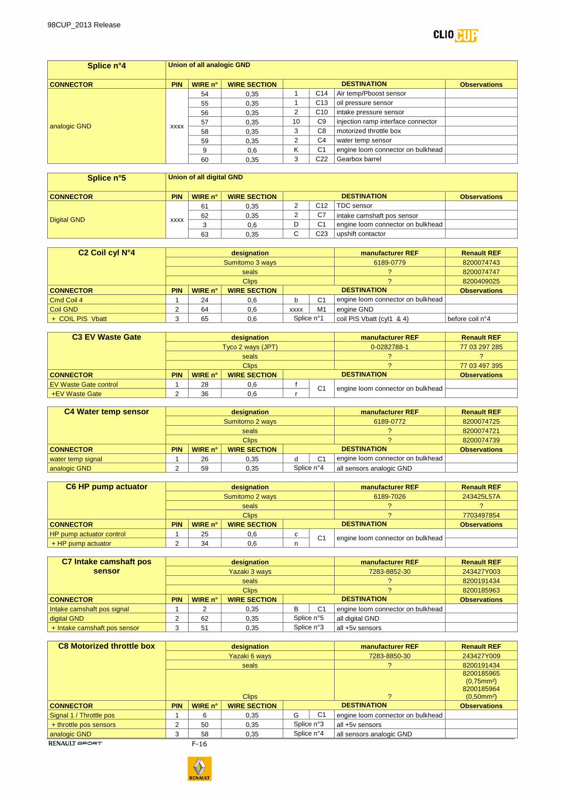
Splice n°4 Union of all analogic GND
CONNECTOR PIN WIRE n° WIRE SECTION DESTINATION Observations
analogic GND xxxx
54 0,35 1 C14 Air temp/Pboost sensor 55 0,35 1 C13 oil pressure sensor 56 0,35 2 C10 intake pressure sensor 57 0,35 10 C9 injection ramp interface connector 58 0,35 3 C8 motorized throttle box 59 0,35 2 C4 water temp sensor 9 0,6 K C1 engine loom connector on bulkhead 60 0,35 3 C22 Gearbox barrel
Splice n°5 Union of all digital GND
CONNECTOR PIN WIRE n° WIRE SECTION DESTINATION Observations
Digital GND xxxx
61 0,35 2 C12 TDC sensor 62 0,35 2 C7 intake camshaft pos sensor 3 0,6 D C1 engine loom connector on bulkhead 63 0,35 C C23 upshift contactor
C2 Coil cyl N°4 designation manufacturer REF Renault REF Sumitomo 3 ways 6189-0779 8200074743
seals ? 8200074747 Clips ? 8200409025
CONNECTOR PIN WIRE n° WIRE SECTION DESTINATION Observations Cmd Coil 4 1 24 0,6 b C1 engine loom connector on bulkhead Coil GND 2 64 0,6 xxxx M1 engine GND + COIL PIS Vbatt 3 65 0,6 Splice n°1 coil PIS Vbatt (cyl1 & 4) before coil n°4
C3 EV Waste Gate designation manufacturer REF Renault REF Tyco 2 ways (JPT) 0-0282788-1 77 03 297 285
seals ? ? Clips ? 77 03 497 395
CONNECTOR PIN WIRE n° WIRE SECTION DESTINATION Observations EV Waste Gate control 1 28 0,6 f
C1 engine loom connector on bulkhead
+EV Waste Gate 2 36 0,6 r
C4 Water temp sensor designation manufacturer REF Renault REF Sumitomo 2 ways 6189-0772 8200074725
seals ? 8200074721 Clips ? 8200074739
CONNECTOR PIN WIRE n° WIRE SECTION DESTINATION Observations water temp signal 1 26 0,35 d C1 engine loom connector on bulkhead analogic GND 2 59 0,35 Splice n°4 all sensors analogic GND
C6 HP pump actuator designation manufacturer REF Renault REF
Sumitomo 2 ways 6189-7026 243425L57A seals ? ? Clips ? 7703497854
CONNECTOR PIN WIRE n° WIRE SECTION DESTINATION Observations HP pump actuator control 1 25 0,6 c
C1 engine loom connector on bulkhead
+ HP pump actuator 2 34 0,6 n
C7 Intake camshaft pos sensor
designation manufacturer REF Renault REF Yazaki 3 ways 7283-8852-30 243427Y003
seals ? 8200191434 Clips ? 8200185963
CONNECTOR PIN WIRE n° WIRE SECTION DESTINATION Observations Intake camshaft pos signal 1 2 0,35 B C1 engine loom connector on bulkhead digital GND 2 62 0,35 Splice n°5 all digital GND + Intake camshaft pos sensor 3 51 0,35 Splice n°3 all +5v sensors
C8 Motorized throttle box designation manufacturer REF Renault REF Yazaki 6 ways 7283-8850-30 243427Y009
seals ? 8200191434
Clips ?
8200185965 (0,75mm²)
8200185964 (0,50mm²)
CONNECTOR PIN WIRE n° WIRE SECTION DESTINATION Observations Signal 1 / Throttle pos 1 6 0,35 G C1 engine loom connector on bulkhead + throttle pos sensors 2 50 0,35 Splice n°3 all +5v sensors analogic GND 3 58 0,35 Splice n°4 all sensors analogic GND
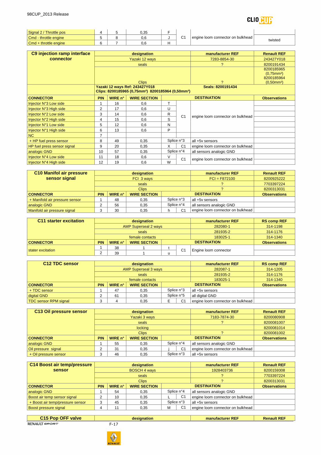
98CUP_2013 Release
F-17
Signal 2 / Throttle pos 4 5 0,35 F C1 engine loom connector on bulkhead
Cmd - throttle engine 5 8 0,6 J
twisted Cmd + throttle engine 6 7 0,6 H
C9 injection ramp interface connector
designation manufacturer REF Renault REF Yazaki 12 ways 7283-8854-30 243427Y018
seals ? 8200191434
Clips ?
8200185965 (0,75mm²)
8200185964 (0,50mm²)
Yazaki 12 ways Ref: 243427Y018 Seals: 8200191434 Clips: 8200185965 (0,75mm²) 8200185964 (0,50mm²)
CONNECTOR PIN WIRE n° WIRE SECTION DESTINATION Observations Injector N°3 Low side 1 16 0,6 T
C1 engine loom connector on bulkhead
Injector N°3 High side 2 17 0,6 U Injector N°2 Low side 3 14 0,6 R Injector N°2 High side 4 15 0,6 S Injector N°1 Low side 5 12 0,6 N Injector N°1 High side 6 13 0,6 P NC 7 + HP fuel press sensor 8 49 0,35 Splice n°3 all +5v sensors HP fuel press sensor signal 9 20 0,35 X C1 engine loom connector on bulkhead analogic GND 10 57 0,35 Splice n°4 all sensors analogic GND Injector N°4 Low side 11 18 0,6 V
C1 engine loom connector on bulkhead
Injector N°4 High side 12 19 0,6 W
C10 Manifol air pressure sensor signal
designation manufacturer REF Renault REF FCI 3 ways FCI = F872100 8200925222
seals ? 7703397224 Clips ? 8200313031
CONNECTOR PIN WIRE n° WIRE SECTION DESTINATION Observations + Manifold air pressure sensor 1 48 0,35 Splice n°3 all +5v sensors analogic GND 2 56 0,35 Splice n°4 all sensors analogic GND Manifold air pressure signal 3 30 0,35 h C1 engine loom connector on bulkhead
C11 starter excitation designation manufacturer REF RS comp REF AMP Superseal 2 ways 282080-1 314-1198
seals 281935-2 314-1176 female contacts 183025-1 314-1340
CONNECTOR PIN WIRE n° WIRE SECTION DESTINATION Observations
stater excitation 1 38 1 t
C1 Engine loom connector
2 39 1 u
C12 TDC sensor designation manufacturer REF RS comp REF AMP Superseal 3 ways 282087-1 314-1205
seals 281935-2 314-1176 female contacts 183025-1 314-1340
CONNECTOR PIN WIRE n° WIRE SECTION DESTINATION Observations + TDC sensor 1 47 0,35 Splice n°3 all +5v sensors digital GND 2 61 0,35 Splice n°5 all digital GND TDC sensor RPM signal 3 4 0,35 E C1 engine loom connector on bulkhead
C13 Oil pressure sensor designation manufacturer REF Renault REF Yazaki 3 ways 7183-7874-30 8200080908
seals ? 8200081007 locking 8200081014 Clips ? 8200081002
CONNECTOR PIN WIRE n° WIRE SECTION DESTINATION Observations analogic GND 1 55 0,35 Splice n°4 all sensors analogic GND Oil pressure signal 2 31 0,35 j C1 engine loom connector on bulkhead + Oil pressure sensor 3 46 0,35 Splice n°3 all +5v sensors
C14 Boost air temp/pressure sensor
designation manufacturer REF Renault REF BOSCH 4 ways 1928403736 8200159308
seals ? 7703397224 Clips ? 8200313031
CONNECTOR PIN WIRE n° WIRE SECTION DESTINATION Observations analogic GND 1 54 0,35 Splice n°4 all sensors analogic GND Boost air temp sensor signal 2 10 0,35 L C1 engine loom connector on bulkhead + Boost air temp/pressure sensor 3 45 0,35 Splice n°3 all +5v sensors Boost pressure signal 4 11 0,35 M C1 engine loom connector on bulkhead
C15 Pop OFF valve designation manufacturer REF Renault REF
98CUP_2013 Release
F-18
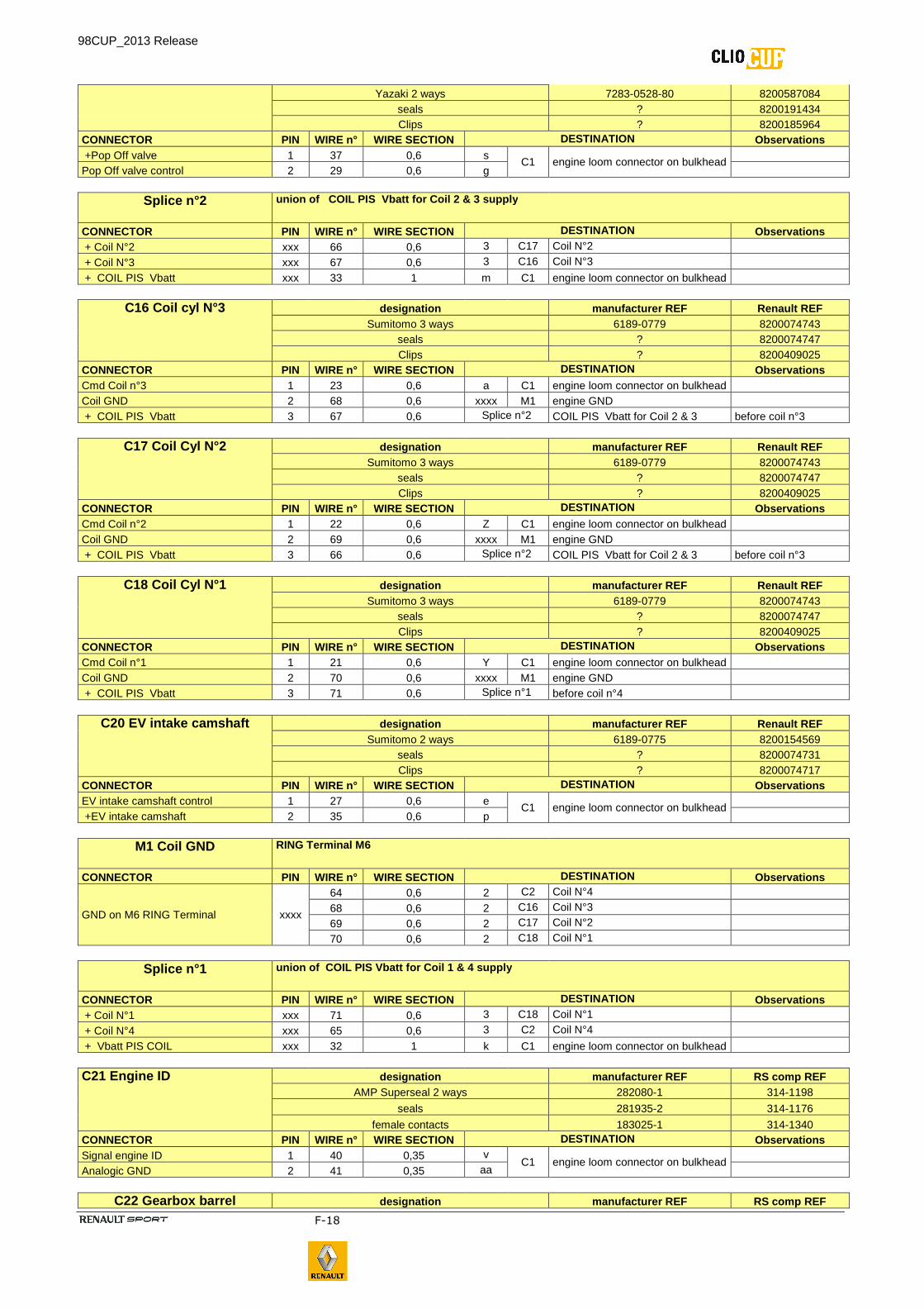
Yazaki 2 ways 7283-0528-80 8200587084 seals ? 8200191434 Clips ? 8200185964
CONNECTOR PIN WIRE n° WIRE SECTION DESTINATION Observations +Pop Off valve 1 37 0,6 s
C1 engine loom connector on bulkhead
Pop Off valve control 2 29 0,6 g
Splice n°2 union of COIL PIS Vbatt for Coil 2 & 3 supply
CONNECTOR PIN WIRE n° WIRE SECTION DESTINATION Observations + Coil N°2 xxx 66 0,6 3 C17 Coil N°2 + Coil N°3 xxx 67 0,6 3 C16 Coil N°3 + COIL PIS Vbatt xxx 33 1 m C1 engine loom connector on bulkhead
C16 Coil cyl N°3 designation manufacturer REF Renault REF Sumitomo 3 ways 6189-0779 8200074743
seals ? 8200074747 Clips ? 8200409025
CONNECTOR PIN WIRE n° WIRE SECTION DESTINATION Observations Cmd Coil n°3 1 23 0,6 a C1 engine loom connector on bulkhead Coil GND 2 68 0,6 xxxx M1 engine GND + COIL PIS Vbatt 3 67 0,6 Splice n°2 COIL PIS Vbatt for Coil 2 & 3 before coil n°3
C17 Coil Cyl N°2 designation manufacturer REF Renault REF Sumitomo 3 ways 6189-0779 8200074743
seals ? 8200074747 Clips ? 8200409025
CONNECTOR PIN WIRE n° WIRE SECTION DESTINATION Observations Cmd Coil n°2 1 22 0,6 Z C1 engine loom connector on bulkhead Coil GND 2 69 0,6 xxxx M1 engine GND + COIL PIS Vbatt 3 66 0,6 Splice n°2 COIL PIS Vbatt for Coil 2 & 3 before coil n°3
C18 Coil Cyl N°1 designation manufacturer REF Renault REF Sumitomo 3 ways 6189-0779 8200074743
seals ? 8200074747 Clips ? 8200409025
CONNECTOR PIN WIRE n° WIRE SECTION DESTINATION Observations Cmd Coil n°1 1 21 0,6 Y C1 engine loom connector on bulkhead Coil GND 2 70 0,6 xxxx M1 engine GND + COIL PIS Vbatt 3 71 0,6 Splice n°1 before coil n°4
C20 EV intake camshaft designation manufacturer REF Renault REF Sumitomo 2 ways 6189-0775 8200154569
seals ? 8200074731 Clips ? 8200074717
CONNECTOR PIN WIRE n° WIRE SECTION DESTINATION Observations EV intake camshaft control 1 27 0,6 e
C1 engine loom connector on bulkhead
+EV intake camshaft 2 35 0,6 p
M1 Coil GND RING Terminal M6
CONNECTOR PIN WIRE n° WIRE SECTION DESTINATION Observations
GND on M6 RING Terminal xxxx
64 0,6 2 C2 Coil N°4 68 0,6 2 C16 Coil N°3 69 0,6 2 C17 Coil N°2 70 0,6 2 C18 Coil N°1
Splice n°1 union of COIL PIS Vbatt for Coil 1 & 4 supply
CONNECTOR PIN WIRE n° WIRE SECTION DESTINATION Observations + Coil N°1 xxx 71 0,6 3 C18 Coil N°1 + Coil N°4 xxx 65 0,6 3 C2 Coil N°4 + Vbatt PIS COIL xxx 32 1 k C1 engine loom connector on bulkhead
C21 Engine ID designation manufacturer REF RS comp REF AMP Superseal 2 ways 282080-1 314-1198
seals 281935-2 314-1176
female contacts 183025-1 314-1340 CONNECTOR PIN WIRE n° WIRE SECTION DESTINATION Observations Signal engine ID 1 40 0,35 v
C1 engine loom connector on bulkhead
Analogic GND 2 41 0,35 aa
C22 Gearbox barrel designation manufacturer REF RS comp REF
98CUP_2013 Release
F-19
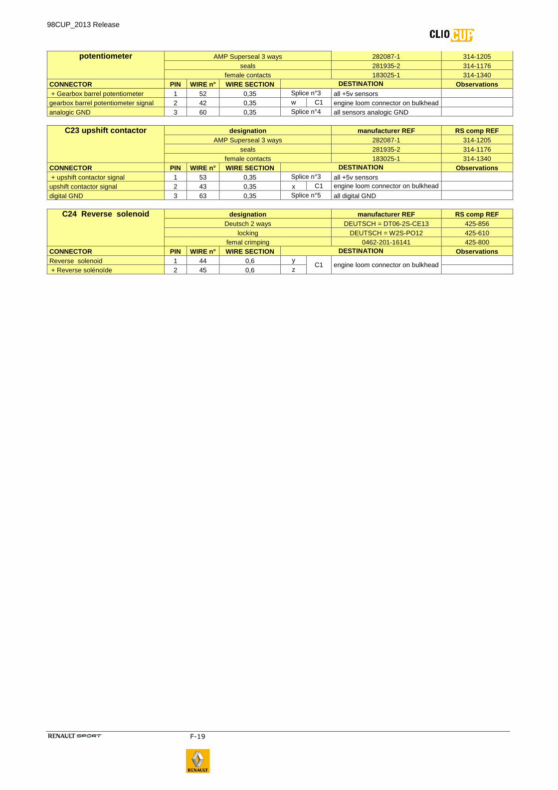
potentiometer AMP Superseal 3 ways 282087-1 314-1205 seals 281935-2 314-1176
female contacts 183025-1 314-1340 CONNECTOR PIN WIRE n° WIRE SECTION DESTINATION Observations + Gearbox barrel potentiometer 1 52 0,35 Splice n°3 all +5v sensors gearbox barrel potentiometer signal 2 42 0,35 w C1 engine loom connector on bulkhead analogic GND 3 60 0,35 Splice n°4 all sensors analogic GND
C23 upshift contactor designation manufacturer REF RS comp REF AMP Superseal 3 ways 282087-1 314-1205
seals 281935-2 314-1176 female contacts 183025-1 314-1340
CONNECTOR PIN WIRE n° WIRE SECTION DESTINATION Observations + upshift contactor signal 1 53 0,35 Splice n°3 all +5v sensors upshift contactor signal 2 43 0,35 x C1 engine loom connector on bulkhead digital GND 3 63 0,35 Splice n°5 all digital GND
C24 Reverse solenoid designation manufacturer REF RS comp REF Deutsch 2 ways DEUTSCH = DT06-2S-CE13 425-856
locking DEUTSCH = W2S-PO12 425-610 femal crimping 0462-201-16141 425-800
CONNECTOR PIN WIRE n° WIRE SECTION DESTINATION Observations Reverse solenoid 1 44 0,6 y
C1 engine loom connector on bulkhead
+ Reverse solénoïde 2 45 0,6 z
98CUP_2013 Release
F-20
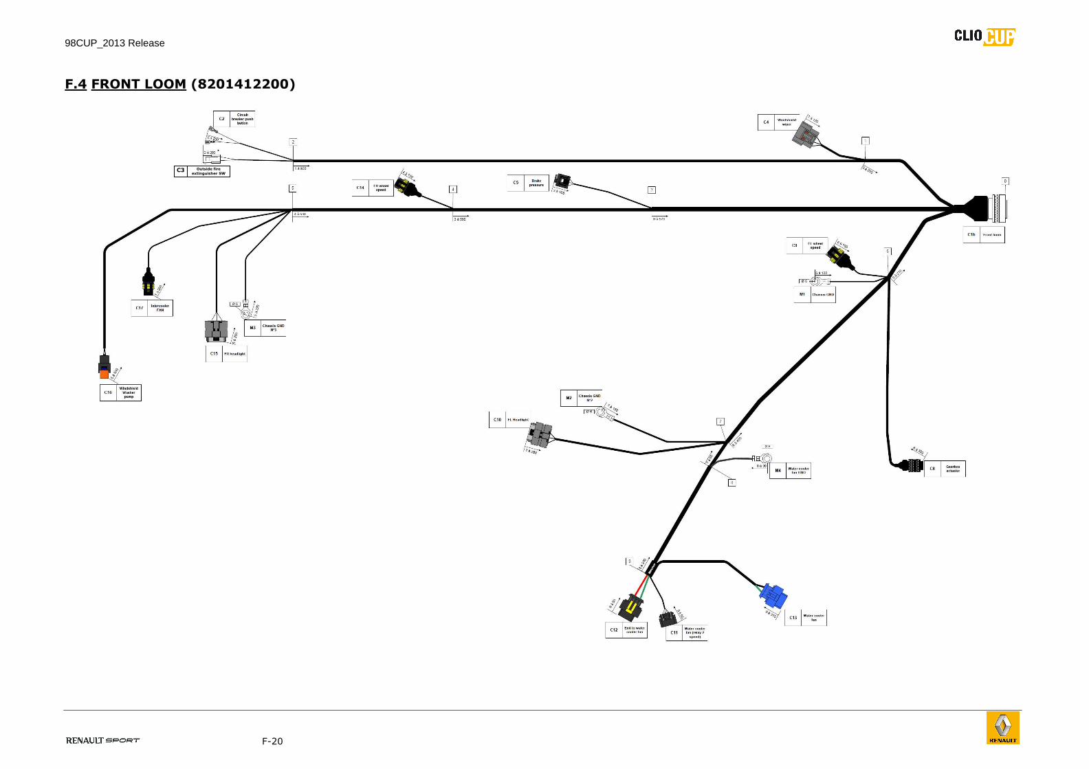
F.4 FRONT LOOM (8201412200)
Outside fire
extinguisher SW C3

98CUP_2013 Release
F-21
98CUP_2013 Release
F-22
FRONT LOOM
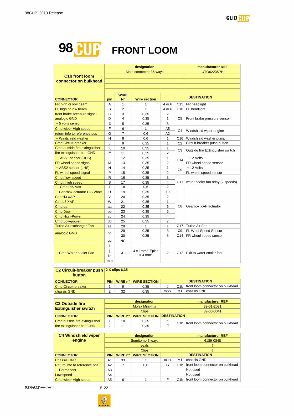
C1b front loom connector on bulkhead
designation manufacturer REF Male connector 35 ways UTO62235PH
CONNECTOR pin WIRE
N° Wire section DESTINATION
FR high or low beam A 1 1 4 or 6 C15 FR headlight FL high or low beam B 2 1 4 or 6 C10 FL headlight front brake pressure signal C 3 0,35 2
C5 Front brake pressure sensor analogic GND D 4 0,35 1 + 5 volts sensor E 5 0,35 3 Cmd wiper High speed F 6 1 A5
C4 Windshield wiper engine return info to reference pos G 7 0,6 A2 + Windshield washer H 8 0,6 1 C16 Windshield washer pump Cmd Circuit-breaker J 9 0,35 1 C2 Circuit-breaker push button Cmd outside fire extinguisher K 10 0,35 1
C3 Outside fire Extinguisher switch fire extinguisher batt GND ff 11 0,35 2 + ABS1 sensor (RHS) L 12 0,35 1
C14 + 12 Volts
FR wheel speed signal M 13 0,35 2 FR wheel speed sensor + ABS2 sensor (LHS) N 14 0,35 1
C9 + 12 Volts
FL wheel speed signal P 15 0,35 2 FL wheel speed sensor Cmd / low speed R 16 0,35 3
C11 water cooler fan relay (2 speeds) Cmd / high speed S 17 0,35 4 + Cmd PIS Vatt T 18 0,6 2
+ Gearbox actuator PIS Vbatt U 19 0,35 10
C8 Gearbox XAP actuator
Can H3 XAP V 20 0,35 2 Can L3 XAP W 21 0,35 1 Cmd up aa 22 0,35 6 Cmd Down bb 23 0,35 5 Cmd High-Power cc 24 0,35 4 Cmd Low-power dd 25 0,35 7 Turbo Air exchanger Fan ee 28 1 1 C17 Turbo Air Fan
analogic GND hh 29 0,35 3 C9 FL Weel Speed Sensor 30 0,35 3 C14 FR wheel speed sensor
gg NC
+ Cmd Water cooler Fan
ii
31 4 x 1mm² Episs
= 4 mm² 2 C12 Exit to water cooler fan jj
kk mm
C2 Circuit -breaker push button
2 X clips 6,35
CONNECTOR PIN WIRE n° WIRE SECTION DESTINATION
Cmd Circuit-breaker 1 9 0,35 J C1b front loom connector on bulkhead
chassis GND 2 32 0,35 xxxx M1 chassis GND
C3 Outside fire Extinguisher switch
designation manufacturer REF Molex Mini-fit jr 39-01-2021
Clips 39-00-0041 CONNECTOR PIN WIRE n° WIRE SECTION DESTINATION
Cmd outside fire extinguisher 1 10 0,35 K C1b front loom connector on bulkhead
fire extinguisher batt GND 2 11 0,35 ff
C4 Windshield wiper engine
designation manufacturer REF Sumitomo 5 ways 6189-0848
seals ? Clips ?
CONNECTOR PIN WIRE n° WIRE SECTION DESTINATION
Chassis GND A1 33 1 xxxx M1 chassis GND
Return info to reference pos A2 7 0,6 G C1b front loom connector on bulkhead
+ Permanent A3 Not used
Low speed A4 Not used
Cmd wiper High speed A5 6 1 F C1b front loom connector on bulkhead
98CUP_2013 Release
F-23
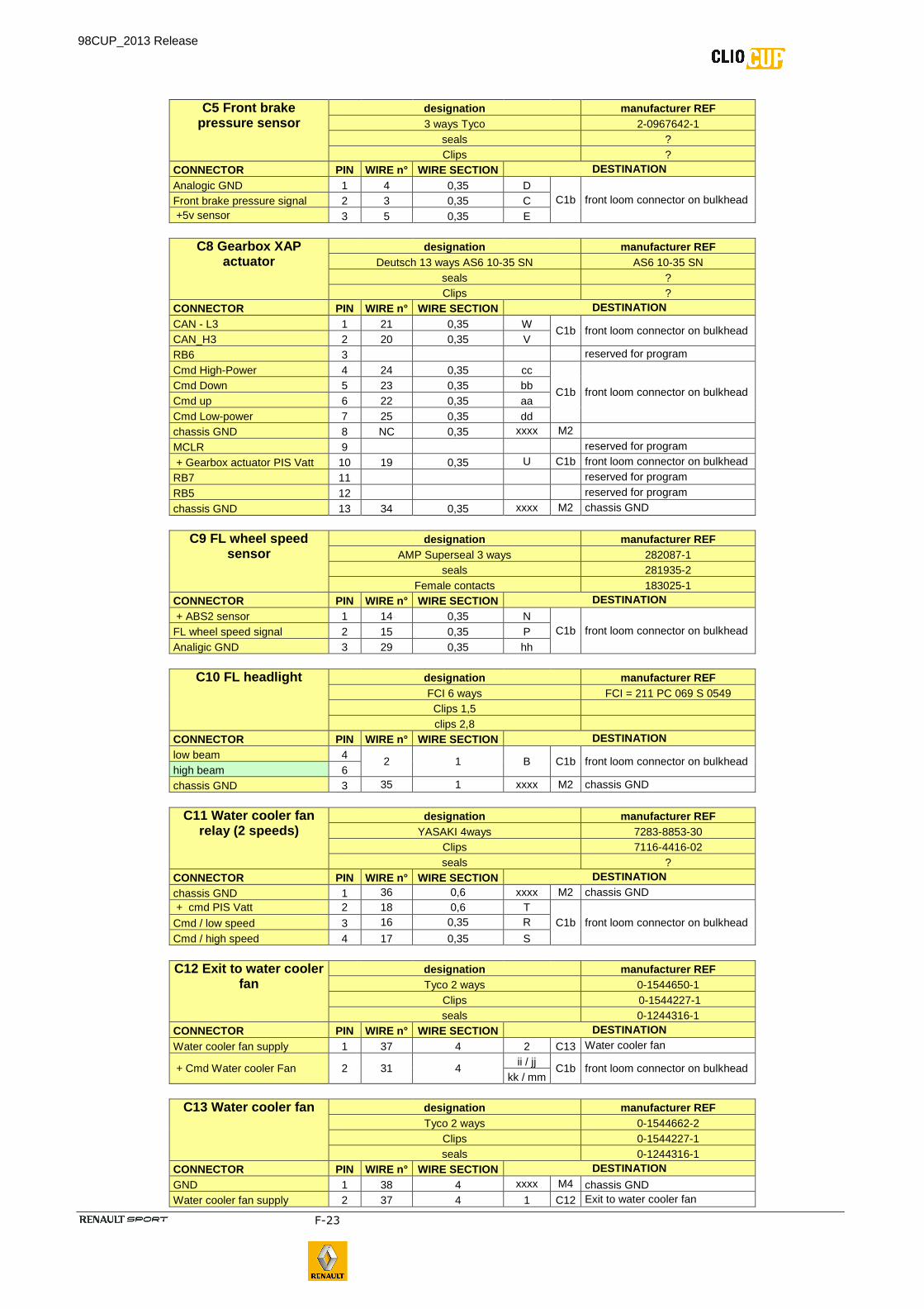
C5 Front brake pressure sensor
designation manufacturer REF 3 ways Tyco 2-0967642-1
seals ? Clips ?
CONNECTOR PIN WIRE n° WIRE SECTION DESTINATION
Analogic GND 1 4 0,35 D C1b front loom connector on bulkhead Front brake pressure signal 2 3 0,35 C
+5v sensor 3 5 0,35 E
C8 Gearbox XAP actuator
designation manufacturer REF Deutsch 13 ways AS6 10-35 SN AS6 10-35 SN
seals ? Clips ?
CONNECTOR PIN WIRE n° WIRE SECTION DESTINATION
CAN - L3 1 21 0,35 W C1b front loom connector on bulkhead
CAN_H3 2 20 0,35 V RB6 3 reserved for program
Cmd High-Power 4 24 0,35 cc
C1b front loom connector on bulkhead Cmd Down 5 23 0,35 bb Cmd up 6 22 0,35 aa Cmd Low-power 7 25 0,35 dd chassis GND 8 NC 0,35 xxxx M2
MCLR 9 reserved for program
+ Gearbox actuator PIS Vatt 10 19 0,35 U C1b front loom connector on bulkhead
RB7 11 reserved for program
RB5 12 reserved for program
chassis GND 13 34 0,35 xxxx M2 chassis GND
C9 FL wheel speed sensor
designation manufacturer REF AMP Superseal 3 ways 282087-1
seals 281935-2 Female contacts 183025-1
CONNECTOR PIN WIRE n° WIRE SECTION DESTINATION
+ ABS2 sensor 1 14 0,35 N C1b front loom connector on bulkhead FL wheel speed signal 2 15 0,35 P
Analigic GND 3 29 0,35 hh
C10 FL headlight designation manufacturer REF FCI 6 ways FCI = 211 PC 069 S 0549 Clips 1,5 clips 2,8
CONNECTOR PIN WIRE n° WIRE SECTION DESTINATION
low beam 4 2 1 B C1b front loom connector on bulkhead
high beam 6 chassis GND 3 35 1 xxxx M2 chassis GND
C11 Water cooler fan relay (2 speeds)
designation manufacturer REF YASAKI 4ways 7283-8853-30
Clips 7116-4416-02 seals ?
CONNECTOR PIN WIRE n° WIRE SECTION DESTINATION
chassis GND 1 36 0,6 xxxx M2 chassis GND + cmd PIS Vatt 2 18 0,6 T
C1b front loom connector on bulkhead Cmd / low speed 3 16 0,35 R
Cmd / high speed 4 17 0,35 S
C12 Exit to water cooler fan
designation manufacturer REF Tyco 2 ways 0-1544650-1
Clips 0-1544227-1 seals 0-1244316-1
CONNECTOR PIN WIRE n° WIRE SECTION DESTINATION
Water cooler fan supply 1 37 4 2 C13 Water cooler fan
+ Cmd Water cooler Fan 2 31 4 ii / jj
C1b front loom connector on bulkhead kk / mm
C13 Water cooler fan designation manufacturer REF Tyco 2 ways 0-1544662-2
Clips 0-1544227-1 seals 0-1244316-1
CONNECTOR PIN WIRE n° WIRE SECTION DESTINATION
GND 1 38 4 xxxx M4 chassis GND Water cooler fan supply 2 37 4 1 C12 Exit to water cooler fan
98CUP_2013 Release
F-24
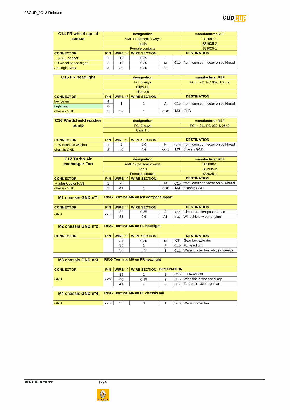
C14 FR wheel speed sensor
designation manufacturer REF AMP Superseal 3 ways 282087-1
seals 281935-2 Female contacts 183025-1
CONNECTOR PIN WIRE n° WIRE SECTION DESTINATION
+ ABS1 sensor 1 12 0,35 L C1b front loom connector on bulkhead FR wheel speed signal 2 13 0,35 M
Analogic GND 3 30 0,35 hh
C15 FR headlight designation manufacturer REF FCI 6 ways FCI = 211 PC 069 S 0549 Clips 1,5 clips 2,8
CONNECTOR PIN WIRE n° WIRE SECTION DESTINATION
low beam 4 1 1 A C1b front loom connector on bulkhead
high beam 6 chassis GND 3 39 1 xxxx M3 GND
C16 Windshield washer pump
designation manufacturer REF FCI 2 ways FCI = 211 PC 022 S 0549 Clips 1,5
CONNECTOR PIN WIRE n° WIRE SECTION DESTINATION
+ Windshield washer 1 8 0,6 H C1b front loom connector on bulkhead
chassis GND 2 40 0,6 xxxx M3 chassis GND
C17 Turbo Air exchanger Fan
designation manufacturer REF AMP Superseal 2 ways 282080-1
Seals 281935-2 Female contacts 183025-1
CONNECTOR PIN WIRE n° WIRE SECTION DESTINATION
+ Inter Cooler FAN 1 28 1 ee C1b front loom connector on bulkhead
chassis GND 2 41 1 xxxx M3 chassis GND
M1 chassis G ND n°1 RING Terminal M6 on left damper support
CONNECTOR PIN WIRE n° WIRE SECTION DESTINATION
GND xxxx 32 0,35 2 C2 Circuit-breaker push button 33 0,6 A1 C4 Windshield wiper engine
M2 chassis GND n°2 RING Terminal M6 on FL headlight
CONNECTOR PIN WIRE n° WIRE SECTION DESTINATION
34 0,35 13 C8 Gear box actuator 35 1 3 C10 FL headlight 36 0,5 1 C11 Water cooler fan relay (2 speeds)
M3 chassis GND n°3 RING Terminal M6 on FR headlight
CONNECTOR PIN WIRE n° WIRE SECTION DESTINATION
GND xxxx 39 1 3 C15 FR headlight
40 0,35 2 C16 Windshield washer pump
41 1 2 C17 Turbo air exchanger fan
M4 chassis GND n°4 RING Terminal M6 on FL chassis rail
GND xxxx 38 3 1 C13 Water cooler fan
98CUP_2013 Release
F-25
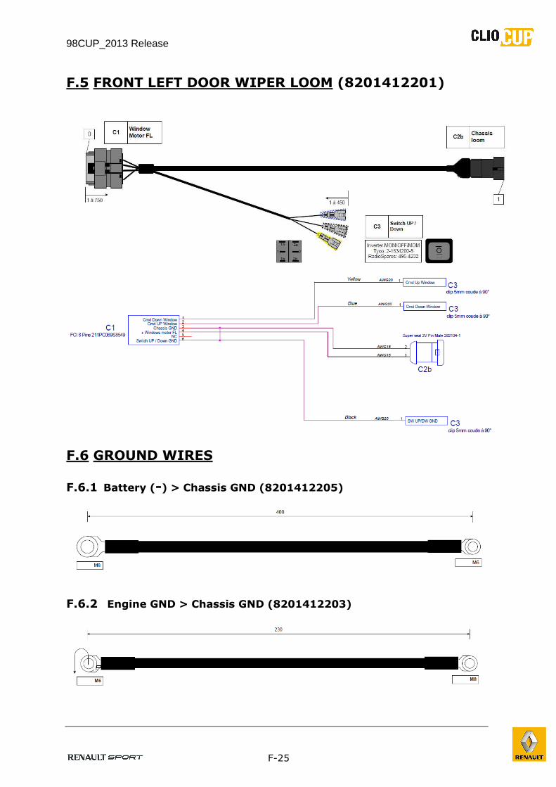
F.5 FRONT LEFT DOOR WIPER LOOM (8201412201)
F.6 GROUND WIRES
F.6.1 Battery (-) > Chassis GND (8201412205)
F.6.2 Engine GND > Chassis GND (8201412203)
98CUP_2013 Release
F-26
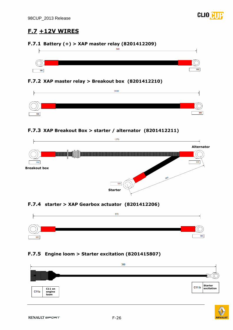
F.7 +12V WIRES
F.7.1 Battery (+) > XAP master relay (8201412209)
F.7.2 XAP master relay > Breakout box (8201412210)
F.7.3 XAP Breakout Box > starter / alternator (8201412211)
F.7.4 starter > XAP Gearbox actuator (8201412206)
F.7.5 Engine loom > Starter excitation (8201415807)
Breakout box
Alternator
Starter
C11 on
engine loom
Starter excitation
98CUP_2013 Release
F-27
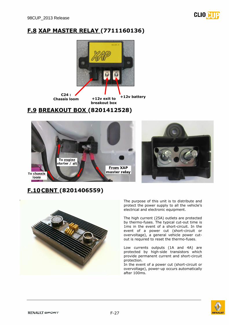
F.8 XAP MASTER RELAY (7711160136)
F.9 BREAKOUT BOX (8201412528)
F.10 CBNT (8201406559)
The purpose of this unit is to distribute and
protect the power supply to all the vehicle’s
electrical and electronic equipment.
The high current (25A) outlets are protected
by thermo-fuses. The typical cut-out time is
1ms in the event of a short-circuit. In the
event of a power cut (short-circuit or
overvoltage), a general vehicle power cut-
out is required to reset the thermo-fuses.
Low currents outputs (1A and 4A) are
protected by high-side transistors which
provide permanent current and short-circuit
protection.
In the event of a power cut (short-circuit or
overvoltage), power-up occurs automatically
after 100ms.
C24 :
Chassis loom +12v battery
+12v exit to
breakout box
box
98CUP_2013 Release
F-28
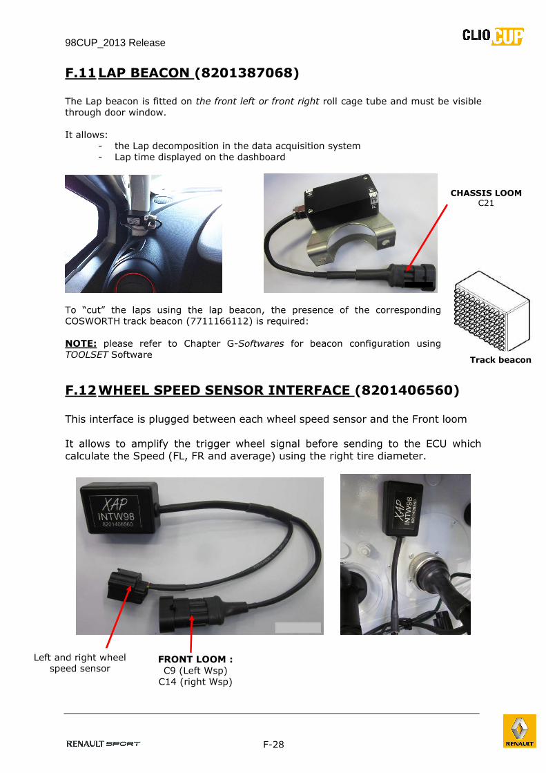
F.11 LAP BEACON (8201387068) The Lap beacon is fitted on the front left or front right roll cage tube and must be visible
through door window.
It allows:
- the Lap decomposition in the data acquisition system
- Lap time displayed on the dashboard
To “cut” the laps using the lap beacon, the presence of the corresponding
COSWORTH track beacon (7711166112) is required:
NOTE: please refer to Chapter G-Softwares for beacon configuration using
TOOLSET Software
F.12 WHEEL SPEED SENSOR INTERFACE (8201406560) This interface is plugged between each wheel speed sensor and the Front loom
It allows to amplify the trigger wheel signal before sending to the ECU which calculate the Speed (FL, FR and average) using the right tire diameter.
CHASSIS LOOM C21
Track beacon
FRONT LOOM :
C9 (Left Wsp)
C14 (right Wsp)
Left and right wheel speed sensor
98CUP_2013 Release
F-29
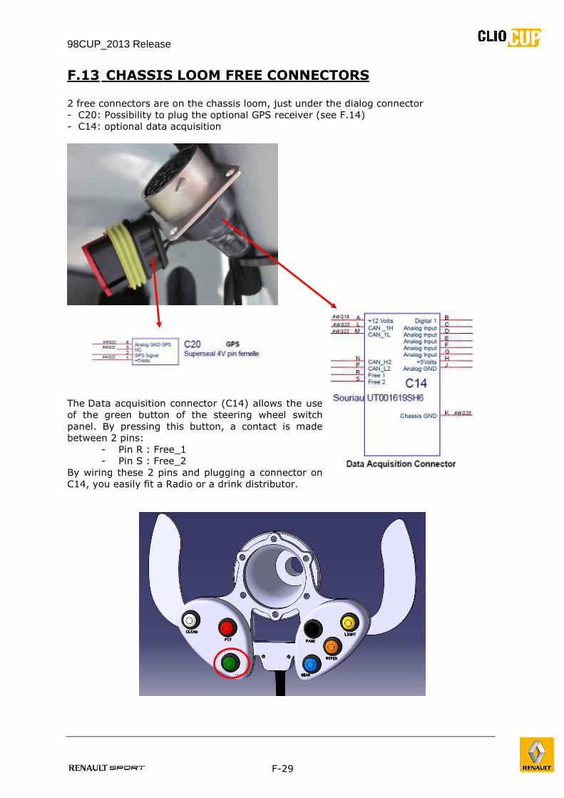
F.13 CHASSIS LOOM FREE CONNECTORS
2 free connectors are on the chassis loom, just under the dialog connector
- C20: Possibility to plug the optional GPS receiver (see F.14)
- C14: optional data acquisition
The Da ta acquisition connector (C14) allows the use
of the green button of the steering wheel switch
panel. By pressing this button, a contact is made
between 2 pins:
- Pin R : Free_1
- Pin S : Free_2
By wiring these 2 pins and plugging a connector on
C14, you easily fit a Radio or a drink distributor.
98CUP_2013 Release
F-30
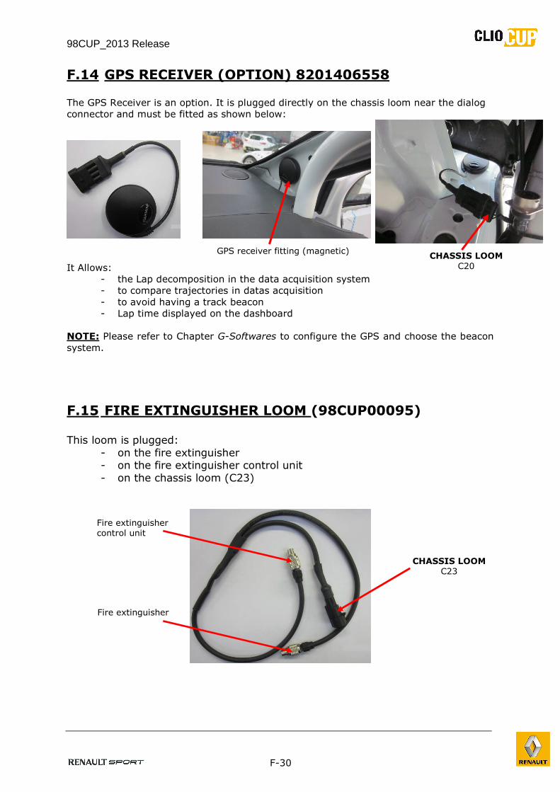
F.14 GPS RECEIVER (OPTION) 8201406558
The GPS Receiver is an option. It is plugged directly on the chassis loom near the dialog
connector and must be fitted as shown below:
It Allows:
- the Lap decomposition in the data acquisition system
- to compare trajectories in datas acquisition
- to avoid having a track beacon
- Lap time displayed on the dashboard
NOTE: Please refer to Chapter G-Softwares to configure the GPS and choose the beacon
system.
F.15 FIRE EXTINGUISHER LOOM (98CUP00095)
This loom is plugged:
- on the fire extinguisher - on the fire extinguisher control unit
- on the chassis loom (C23)
CHASSIS LOOM C23
CHASSIS LOOM
C20
Fire extinguisher
Fire extinguisher control unit
GPS receiver fitting (magnetic)