Embed Size (px)
Citation preview
Materials and Design 53 (2014) 209–216
Contents lists available at SciVerse ScienceDirect
Materials and Design
journal homepage: www.elsevier .com/locate /matdes
Reduction of thermal residual stresses of laminated polymer compositesby addition of carbon nanotubes
0261-3069/$ - see front matter � 2013 Elsevier Ltd. All rights reserved.http://dx.doi.org/10.1016/j.matdes.2013.07.007
⇑ Corresponding author. Tel./fax: +98 21 7749 1206.E-mail address: [email protected] (M.M. Shokrieh).
M.M. Shokrieh ⇑, A. Daneshvar, S. AkbariComposites Research Laboratory, Center of Excellence in Experimental Solid Mechanics and Dynamics, School of Mechanical Engineering, Iran University of Science and Technology,Tehran 16846-13114, Iran
a r t i c l e i n f o a b s t r a c t
Article history:Received 30 December 2012Accepted 2 July 2013Available online 16 July 2013
Keywords:Polymer compositesThermal residual stressesMulti-walled Carbon nanotubesCoefficient of thermal expansionYoung’s modulus
This paper studies the effects of multi-walled carbon nanotubes (MWCNTs) on the thermal residual stres-ses in polymeric fibrous composites. Reinforced ML-506 epoxy nanocomposites with different amountsof homogeneously dispersed MWCNTs (0.1 wt.%, 0.5 wt.% and 1 wt.%) were fabricated using the sonica-tion technique. Thermo-mechanical analysis and tensile tests of the specimens were carried out to char-acterize the thermal and mechanical properties of MWCNTs/epoxy composites. Due to the negativethermal expansion and high modulus of MWCNTs, addition of MWCNTs resulted in a great reductionof the coefficient of thermal expansion (CTE) of epoxy. The MWCNTs also moderately increased theYoung’s modulus of the epoxy. Then, the effects of adding MWCNTs on micro and macro-residual stressesin carbon fiber (CF)/epoxy laminated composites were investigated using the energy method and theclassical lamination theory (CLT), respectively. The results indicated that the addition of low amountsof MWCNTs leads to a considerable reduction in thermal residual stress components in both micro andmacro levels.
� 2013 Elsevier Ltd. All rights reserved.
1. Introduction
In laminated polymer composites, due to their inherent inho-mogeneous nature, residual stresses are generated during the cur-ing process. These stresses adversely influence dimensionalstability and strength of composite laminates and could result inpremature failure, delamination, warpage and matrix cracking[1–3]. Thus, it is important to develop techniques to reduce thesestresses. The most approaches employed so far for this purposeare confined to modifying curing cycles [4–8].
Residual stresses in laminated composites, based on their re-sources, are studied from two points of view; micro residual stres-ses in a unidirectional ply and macro residual stresses in laminatedcomposites. Micro and macro residual stresses originate from inde-pendent sources. The residual stress in micro-scale is mainly theresult of the mismatch in coefficient of thermal expansion (CTE)and Young’s modulus between the fibers and the matrix, while atthe macro-mechanical level, expansion and contraction of differentlayers with different orientations is the major source of residualstresses. Therefore, residual stresses in each layer of laminatedpolymer composites can be determined separately on the micro-and macro-scales.
In recent years, an increasing number of materials with nega-tive thermal expansion have been discovered. One of the mostimportant applications of the negative thermal expansion materi-als is to compensate for undesirable effects of high thermal expan-sion of other materials. Regarding this fact, addition of nano-additives with negative CTE to polymer matrix is a potential ap-proach to effectively reduce thermal residual stresses in fiber-rein-forced polymer composites. The thermal residual stresses aremainly functions of CTE and Young’s modulus of the compositeconstituents. Compared with polymer matrix, nano-additives likeCNTs and CNFs have much higher Young’s modulus and much low-er CTE. Thus, these nano-additives could be dispersed into thepolymer to modify its thermal and elastic behavior.
Numerous experimental studies demonstrated the great capa-bility of CNTs for the modification of thermal and mechanical prop-erties of the polymer matrix [9–12]. Compared with two-phasecomposites (nano-additive and matrix), less studies have been car-ried out on the thermal and mechanical properties of three-phasecomposites (nano-additive, fibers and matrix). Some researchersreported significant reduction of CTE of fibrous composites dueto addition of small amounts of nano-additives [13,14].
On the other hand, very little research has so far been con-ducted on the nano-additives effects on thermal residual stressesof composites. Nishino et al. [15] studied the effect of tungstate zir-conium phosphate (ZWP) particles on CTE of polyether ether ke-tone (PEEK) polymers. They experimentally showed that by
210 M.M. Shokrieh et al. / Materials and Design 53 (2014) 209–216
incorporating 40 vol.% ZWP particles with negative CTE, the CTE ofthe ZWP/PEEK composite reduces about 62% and becomes identicalto the CTE of aluminum. This reduction in CTE was found to beeffective for the decrease of the residual stress at the interface be-tween aluminum plate and the ZWP/PEEK composites. Also, Hsiaoand Gangireddy [16] showed that the use of CNFs results in thereduction of the spring-in phenomenon in L-shaped glass/polyestercomposite parts. Badrinarayanan et al. [17] could remarkably re-duce the warpage of un-symmetric carbon fiber-reinforced com-posite laminates by using zirconium tungstate (ZrW2O8) nano-particles. Although these studies show that the enhancement ofdimensional stability in composite components could be accom-plished by using nano-additives, but no previous work, to the bestof the authors’ knowledge, has quantitatively studied the effect ofnano-additives on the micro and macro residual stresses distribu-tion in the laminated polymer composites.
This paper presents a study on MWCNTs effects on thermalresidual stresses in polymeric fibrous composites. For this purpose,the CLT and the energy method are coupled with the experimentalcharacterization results to study MWCNTs effects on the thermo-mechanical properties of MWCNTs/epoxy and MWCNTs/CF/epoxynanocomposites as well as, ultimately, on the micro- and macro-residual stress components. A significant trend of reduction in bothmicro and macro-residual stresses was found when the MWCNTsweight fraction increased. These findings confirm that MWCNTspossess excellent potential to be used as a thermal expansion com-pensator for the modification of the thermal behavior of the epoxyand to reduce the thermal residual stresses of the fiber/epoxy lam-inated composites.
2. Experimental procedure
In this study, two-phase MWCNTs/epoxy composites and three-phase MWCNTs/CF/epoxy composites were fabricated and charac-terized. The MWCNTs were dispersed into the epoxy matrix withthree weight ratios of 0.1%, 0.5% and 1% which were then rein-forced with carbon fibers. A detailed description of these experi-ments is presented in the following sections.
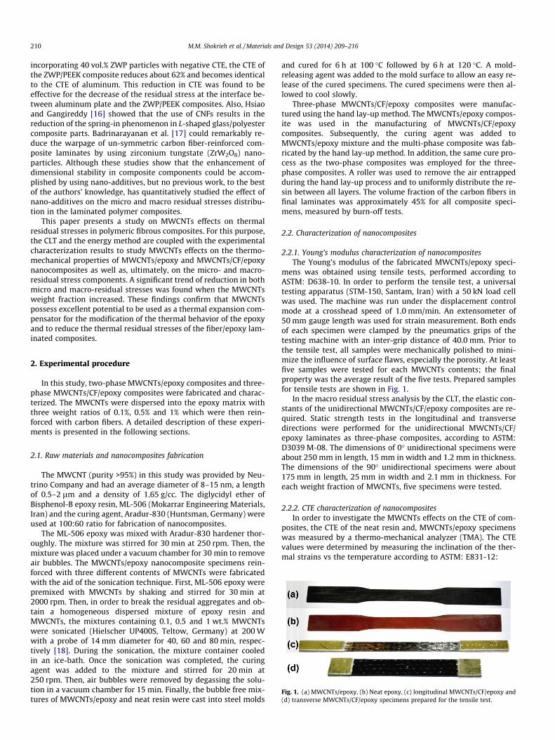
Fig. 1. (a) MWCNTs/epoxy, (b) Neat epoxy, (c) longitudinal MWCNTs/CF/epoxy and(d) transverse MWCNTs/CF/epoxy specimens prepared for the tensile test.
2.1. Raw materials and nanocomposites fabrication
The MWCNT (purity >95%) in this study was provided by Neu-trino Company and had an average diameter of 8–15 nm, a lengthof 0.5–2 lm and a density of 1.65 g/cc. The diglycidyl ether ofBisphenol-B epoxy resin, ML-506 (Mokarrar Engineering Materials,Iran) and the curing agent, Aradur-830 (Huntsman, Germany) wereused at 100:60 ratio for fabrication of nanocomposites.
The ML-506 epoxy was mixed with Aradur-830 hardener thor-oughly. The mixture was stirred for 30 min at 250 rpm. Then, themixture was placed under a vacuum chamber for 30 min to removeair bubbles. The MWCNTs/epoxy nanocomposite specimens rein-forced with three different contents of MWCNTs were fabricatedwith the aid of the sonication technique. First, ML-506 epoxy werepremixed with MWCNTs by shaking and stirred for 30 min at2000 rpm. Then, in order to break the residual aggregates and ob-tain a homogeneous dispersed mixture of epoxy resin andMWCNTs, the mixtures containing 0.1, 0.5 and 1 wt.% MWCNTswere sonicated (Hielscher UP400S, Teltow, Germany) at 200 Wwith a probe of 14 mm diameter for 40, 60 and 80 min, respec-tively [18]. During the sonication, the mixture container cooledin an ice-bath. Once the sonication was completed, the curingagent was added to the mixture and stirred for 20 min at250 rpm. Then, air bubbles were removed by degassing the solu-tion in a vacuum chamber for 15 min. Finally, the bubble free mix-tures of MWCNTs/epoxy and neat resin were cast into steel molds
and cured for 6 h at 100 �C followed by 6 h at 120 �C. A mold-releasing agent was added to the mold surface to allow an easy re-lease of the cured specimens. The cured specimens were then al-lowed to cool slowly.
Three-phase MWCNTs/CF/epoxy composites were manufac-tured using the hand lay-up method. The MWCNTs/epoxy compos-ite was used in the manufacturing of MWCNTs/CF/epoxycomposites. Subsequently, the curing agent was added toMWCNTs/epoxy mixture and the multi-phase composite was fab-ricated by the hand lay-up method. In addition, the same cure pro-cess as the two-phase composites was employed for the three-phase composites. A roller was used to remove the air entrappedduring the hand lay-up process and to uniformly distribute the re-sin between all layers. The volume fraction of the carbon fibers infinal laminates was approximately 45% for all composite speci-mens, measured by burn-off tests.
2.2. Characterization of nanocomposites
2.2.1. Young’s modulus characterization of nanocompositesThe Young’s modulus of the fabricated MWCNTs/epoxy speci-
mens was obtained using tensile tests, performed according toASTM: D638-10. In order to perform the tensile test, a universaltesting apparatus (STM-150, Santam, Iran) with a 50 kN load cellwas used. The machine was run under the displacement controlmode at a crosshead speed of 1.0 mm/min. An extensometer of50 mm gauge length was used for strain measurement. Both endsof each specimen were clamped by the pneumatics grips of thetesting machine with an inter-grip distance of 40.0 mm. Prior tothe tensile test, all samples were mechanically polished to mini-mize the influence of surface flaws, especially the porosity. At leastfive samples were tested for each MWCNTs contents; the finalproperty was the average result of the five tests. Prepared samplesfor tensile tests are shown in Fig. 1.
In the macro residual stress analysis by the CLT, the elastic con-stants of the unidirectional MWCNTs/CF/epoxy composites are re-quired. Static strength tests in the longitudinal and transversedirections were performed for the unidirectional MWCNTs/CF/epoxy laminates as three-phase composites, according to ASTM:D3039 M-08. The dimensions of 0� unidirectional specimens wereabout 250 mm in length, 15 mm in width and 1.2 mm in thickness.The dimensions of the 90� unidirectional specimens were about175 mm in length, 25 mm in width and 2.1 mm in thickness. Foreach weight fraction of MWCNTs, five specimens were tested.
2.2.2. CTE characterization of nanocompositesIn order to investigate the MWCNTs effects on the CTE of com-
posites, the CTE of the neat resin and, MWCNTs/epoxy specimenswas measured by a thermo-mechanical analyzer (TMA). The CTEvalues were determined by measuring the inclination of the ther-mal strains vs the temperature according to ASTM: E831-12:
M.M. Shokrieh et al. / Materials and Design 53 (2014) 209–216 211
a ¼ DL=L0DT ð1Þ
where, DL is the change in the length of the composite specimendue to heating, L0 is the initial length of test specimen and DT isthe temperature difference, over which the change in the specimenlength is determined. The TMA was carried out using a thermo-mechanical analyzer (TMA-120, Seiko Instruments, Tokyo, Japan).The tested specimens had dimensions of 7 � 7 � 6 mm. The testwas run up to 140 �C at a constant heating rate of approximately0.1�C/s. The effect of the weight fraction of MWCNTs was assessedby measuring the CTE of MWCNTs/epoxy composites at three differ-ent weight fractions of 0.1%, 0.5%, and 1%.
3. Residual stresses
3.1. Energy method
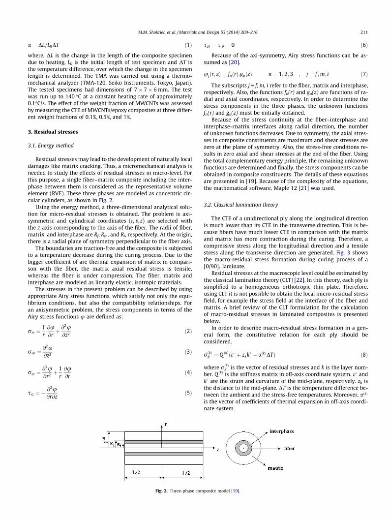
Residual stresses may lead to the development of naturally localdamages like matrix cracking. Thus, a micromechanical analysis isneeded to study the effects of residual stresses in micro-level. Forthis purpose, a single fiber–matrix composite including the inter-phase between them is considered as the representative volumeelement (RVE). These three phases are modeled as concentric cir-cular cylinders, as shown in Fig. 2.
Using the energy method, a three-dimensional analytical solu-tion for micro-residual stresses is obtained. The problem is axi-symmetric and cylindrical coordinates (r, h, z) are selected withthe z-axis corresponding to the axis of the fiber. The radii of fiber,matrix, and interphase are Rf, Rm, and Ri, respectively. At the origin,there is a radial plane of symmetry perpendicular to the fiber axis.
The boundaries are traction-free and the composite is subjectedto a temperature decrease during the curing process. Due to thebigger coefficient of are thermal expansion of matrix in compari-son with the fiber, the matrix axial residual stress is tensile,whereas the fiber is under compression. The fiber, matrix andinterphase are modeled as linearly elastic, isotropic materials.
The stresses in the present problem can be described by usingappropriate Airy stress functions, which satisfy not only the equi-librium conditions, but also the compatibility relationships. Foran axisymmetric problem, the stress components in terms of theAiry stress functions u are defined as:
rrr ¼1r@u@rþ @
2u@z2 ð2Þ
rhh ¼@2u@z2 ð3Þ
rzz ¼@2u@r2 þ
1r@u@r
ð4Þ
srz ¼ �@2u@r@z
ð5Þ
Fig. 2. Three-phase com
szh ¼ srh ¼ 0 ð6Þ
Because of the axi-symmetry, Airy stress functions can be as-sumed as [20].
ujðr; zÞ ¼ fnðrÞ:gnðzÞ n ¼ 1;2;3 ; j ¼ f ;m; i ð7Þ
The subscripts j = f, m, i refer to the fiber, matrix and interphase,respectively. Also, the functions fn(r) and gn(z) are functions of ra-dial and axial coordinates, respectively. In order to determine thestress components in the three phases, the unknown functionsfn(r) and gn(z) must be initially obtained.
Because of the stress continuity at the fiber–interphase andinterphase–matrix interfaces along radial direction, the numberof unknown functions decreases. Due to symmetry, the axial stres-ses in composite constituents are maximum and shear stresses arezero at the plane of symmetry. Also, the stress-free conditions re-sults in zero axial and shear stresses at the end of the fiber. Usingthe total complementary energy principle, the remaining unknownfunctions are determined and finally, the stress components can beobtained in composite constituents. The details of these equationsare presented in [19]. Because of the complexity of the equations,the mathematical software, Maple 12 [21] was used.
3.2. Classical lamination theory
The CTE of a unidirectional ply along the longitudinal directionis much lower than its CTE in the transverse direction. This is be-cause fibers have much lower CTE in comparison with the matrixand matrix has more contraction during the curing. Therefore, acompressive stress along the longitudinal direction and a tensilestress along the transverse direction are generated. Fig. 3 showsthe macro-residual stress formation during curing process of a[0/90]s laminate.
Residual stresses at the macroscopic level could be estimated bythe classical lamination theory (CLT) [22]. In this theory, each ply issimplified to a homogeneous orthotropic thin plate. Therefore,using CLT it is not possible to obtain the local micro-residual stressfield, for example the stress field at the interface of the fiber andmatrix. A brief review of the CLT formulation for the calculationof macro-residual stresses in laminated composites is presentedbelow.
In order to describe macro-residual stress formation in a gen-eral form, the constitutive relation for each ply should beconsidered.
rðkÞR ¼ Q ðkÞðe� þ zkk� � aðkÞDTÞ ð8Þ
where rðkÞR is the vector of residual stresses and k is the layer num-ber. Q ðkÞ is the stiffness matrix in off-axis coordinate system. e� andk� are the strain and curvature of the mid-plane, respectively. zk isthe distance to the mid-plane. DT is the temperature difference be-tween the ambient and the stress-free temperatures. Moreover, aðkÞ
is the vector of coefficients of thermal expansion in off-axis coordi-nate system.
posite model [19].
Txε
Tyε
RxxσRyyσ
ε
(a)
(b)
(c)
Fig. 3. Macro-residual stress formation in a [0/90]s laminate. (a) Initial stress freestate, (b) hypothetical unconstrained final state and (c) actual final state.
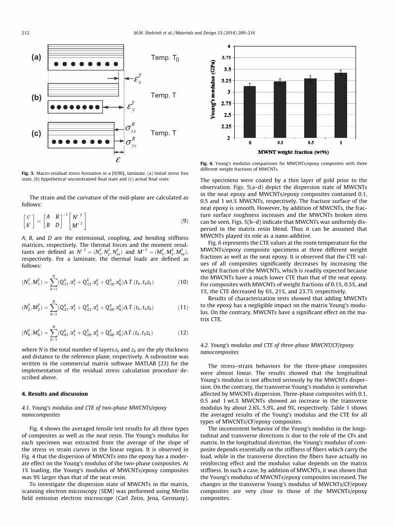
Fig. 4. Young’s modulus comparisons for MWCNTs/epoxy composites with threedifferent weight fractions of MWCNTs.
212 M.M. Shokrieh et al. / Materials and Design 53 (2014) 209–216
The strain and the curvature of the mid-plane are calculated asfollows:
e�
k�
� �¼
A B
B D
� ��1N� T
M� T
" #ð9Þ
A, B, and D are the extensional, coupling, and bending stiffnessmatrices, respectively. The thermal forces and the moment resul-tants are defined as N� T ¼ ðNT
x ;NTy ;N
TxyÞ and M� T ¼ ðMT
x ;MTy ;M
TxyÞ;
respectively. For a laminate, the thermal loads are defined asfollows:
ðNT1;M
T1Þ ¼
XN
k¼1
ðQ k11:a
k1 þ Q k
12:ak2 þ Q k
16:ak6ÞD T:ðtk; tkzkÞ ð10Þ
ðNT2;M
T2Þ ¼
XN
k¼1
ðQ k21:a
k1 þ Q k
22:ak2 þ Q k
26:ak6ÞD T:ðtk; tkzkÞ ð11Þ
ðNT6;M
T6Þ ¼
XN
k¼1
ðQ k61:a
k1 þ Q k
26:ak2 þ Q k
66:ak6ÞDT:ðtk; tkzkÞ ð12Þ
where N is the total number of layers.tk and zk are the ply thicknessand distance to the reference plane, respectively. A subroutine waswritten in the commercial matrix software MATLAB [23] for theimplementation of the residual stress calculation procedure de-scribed above.
4. Results and discussion
4.1. Young’s modulus and CTE of two-phase MWCNTs/epoxynanocomposites
Fig. 4 shows the averaged tensile test results for all three typesof composites as well as the neat resin. The Young’s modulus foreach specimen was extracted from the average of the slope ofthe stress vs strain curves in the linear region. It is observed inFig. 4 that the dispersion of MWCNTs into the epoxy has a moder-ate effect on the Young’s modulus of the two-phase composites. At1% loading, the Young’s modulus of MWCNTs/epoxy compositeswas 9% larger than that of the neat resin.
To investigate the dispersion state of MWCNTs in the matrix,scanning electron microscopy (SEM) was performed using Merlinfield emission electron microscope (Carl Zeiss, Jena, Germany).
The specimens were coated by a thin layer of gold prior to theobservation. Figs. 5(a–d) depict the dispersion state of MWCNTsin the neat epoxy and MWCNTs/epoxy composites contained 0.1,0.5 and 1 wt.% MWCNTs, respectively. The fracture surface of theneat epoxy is smooth. However, by addition of MWCNTs, the frac-ture surface roughness increases and the MWCNTs broken stemcan be seen. Figs. 5(b–d) indicate that MWCNTs was uniformly dis-persed in the matrix resin blend. Thus it can be assumed thatMWCNTs played its role as a nano-additive.
Fig. 6 represents the CTE values at the room temperature for theMWCNTs/epoxy composite specimens at three different weightfractions as well as the neat epoxy. It is observed that the CTE val-ues of all composites significantly decreases by increasing theweight fraction of the MWCNTs, which is readily expected becausethe MWCNTs have a much lower CTE than that of the neat epoxy.For composites with MWCNTs of weight fractions of 0.1%, 0.5%, and1%, the CTE decreased by 6%, 21%, and 23.7% respectively.
Results of characterization tests showed that adding MWCNTsto the epoxy has a negligible impact on the matrix Young’s modu-lus. On the contrary, MWCNTs have a significant effect on the ma-trix CTE.
4.2. Young’s modulus and CTE of three-phase MWCNT/CF/epoxynanocomposites
The stress–strain behaviors for the three-phase compositeswere almost linear. The results showed that the longitudinalYoung’s modulus is not affected seriously by the MWCNTs disper-sion. On the contrary, the transverse Young’s modulus is somewhataffected by MWCNTs dispersion. Three-phase composites with 0.1,0.5 and 1 wt.% MWCNTs showed an increase in the transversemodulus by about 2.6%, 5.9%, and 9%, respectively. Table 1 showsthe averaged results of the Young’s modulus and the CTE for alltypes of MWCNTs/CF/epoxy composites.
The inconsistent behavior of the Young’s modulus in the longi-tudinal and transverse directions is due to the role of the CFs andmatrix. In the longitudinal direction, the Young’s modulus of com-posite depends essentially on the stiffness of fibers which carry theload, while in the transverse direction the fibers have actually noreinforcing effect and the modulus value depends on the matrixstiffness. In such a case, by addition of MWCNTs, it was shown thatthe Young’s modulus of MWCNTs/epoxy composites increased. Thechanges in the transverse Young’s modulus of MWCNTs/CF/epoxycomposites are very close to those of the MWCNTs/epoxycomposites.
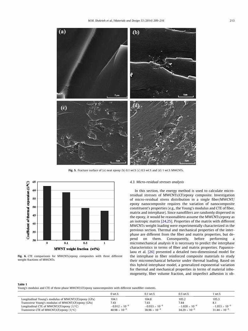
Fig. 5. Fracture surface of (a) neat epoxy (b) 0.1 wt.% (c) 0.5 wt.% and (d) 1 wt.% MWCNTs.
Fig. 6. CTE comparisons for MWCNTs/epoxy composites with three differentweight fractions of MWCNTs.
Table 1Young’s modulus and CTE of three-phase MWCNT/CF/epoxy nanocomposites with differen
0 wt.%
Longitudinal Young’s modulus of MWCNT/CF/epoxy (GPa) 104.1Transverse Young’s modulus of MWCNT/CF/epoxy (GPa) 7.43Longitudinal CTE of MWCNT/CF/epoxy (1/�C) �0.912 � 10�6
Transverse CTE of MWCNT/CF/epoxy (1/�C) 40.98 � 10�6
M.M. Shokrieh et al. / Materials and Design 53 (2014) 209–216 213
4.3. Micro-residual stresses analysis
In this section, the energy method is used to calculate micro-residual stresses of MWCNTs/CF/epoxy composite. Investigationof micro-residual stress distribution in a single fiber/MWCNT/epoxy nanocomposite requires the variation of nanocompositeconstituent’s properties (e.g., the Young’s modulus and CTE of fiber,matrix and interphase). Since nanofillers are randomly dispersed inthe epoxy, it would be reasonableto assume the MWCNTs/epoxy asan isotropic matrix [24,25]. Properties of the matrix with differentMWCNTs weight loading were experimentally characterized in theprevious section. Thermal and mechanical properties of the inter-phase are different from the fiber and matrix properties, but de-pend on them. Consequently, before performing amicromechanical analysis it is necessary to predict the interphasecharacteristics in terms of fiber and matrix properties. Papanico-laou et al. [26] presented a detailed two-dimensional model forthe interphase in fiber reinforced composite materials to studytheir micromechanical behavior under thermal loading. Based onthis hybrid interphase model, a generalized exponential variationfor thermal and mechanical properties in terms of material inho-mogeneity, fiber volume fraction, and imperfect adhesion is ob-
t nanofiller contents.
0.1 wt.% 0.5 wt.% 1 wt.%
104.8 105.2 105.37.63 7.84 8.1�0.933 � 10�6 �1.028 � 10�6 �1.053 � 10�6
38.96 � 10�6 34.29 � 10�6 31.44 � 10�6
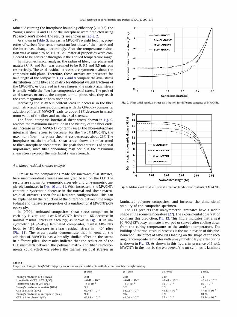
Fig. 7. Fiber axial residual stress distribution for different contents of MWCNTs.
214 M.M. Shokrieh et al. / Materials and Design 53 (2014) 209–216
tained. Assuming the interphase bounding efficiency (ki = 0.2), theYoung’s modulus and CTE of the interphase were predicted usingPapanicolaou’s model. The results are shown in Table. 2.
As shown in Table. 2, increasing MWCNTs weight loading, prop-erties of carbon fiber remain constant but those of the matrix andthe interphase change accordingly. Also, the temperature reduc-tion was assumed to be 100 �C. All material properties were con-sidered to be constant throughout the applied temperature range.
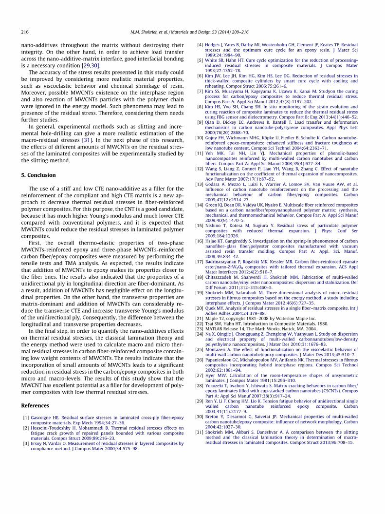
In micromechanical analysis, the radius of fiber, interphase andmatrix (Rf, Ri and Rm) was assumed to be 6, 6.5 and 8.5 micronsrespectively. The axial residual stresses are symmetric about thecomposite mid-plane. Therefore, these stresses are presented forhalf length of the composite. Figs. 7 and 8 compare the axial stressdistribution in the fiber and matrix for different weight fractions ofthe MWCNTs. As observed in these figures, the matrix axial stressis tensile, while the fiber has compressive axial stress. The peak ofaxial stresses occurs at the composite mid-plane. Also, they reachthe zero magnitude at both fiber ends.
Increasing the MWCNTs content leads to decrease in the fiberand matrix axial stresses. Comparing with the CF/epoxy composite,addition of 1 wt.% MWCNT leads to about 18% decrease in maxi-mum value of the fiber and matrix axial stresses.
The fiber–interphase interfacial shear stress, shown in Fig. 9,reaches the maximum magnitude in the vicinity of the fiber ends.An increase in the MWCNTs content causes the fiber–interphaseinterfacial shear stress to decrease. For the 1 wt.% MWCNTs, themaximum fiber–interphase shear stress decreases about 21%. Theinterphase–matrix interfacial shear stress shows a similar trendto fiber–interphase shear stress. The peak shear stress is of criticalimportance, since fiber debonding may occur, if the maximumshear stress exceeds the interfacial shear strength.
Fig. 8. Matrix axial residual stress distribution for different contents of MWCNTs.
4.4. Macro-residual stresses analysis
Similar to the comparisons made for micro-residual stresses,here macro-residual stresses are analyzed based on the CLT. Theresults are shown for symmetric cross-ply and un-symmetric an-gle-ply laminates in Figs. 10 and 11. With increase in the MWCNTscontent, a systematic decrease in the normal and shear macro-residual stresses is seen for all laminate configurations. This canbe explained by the reduction of the difference between the longi-tudinal and transverse properties of a unidirectional MWCNTs/CF/epoxy ply.
In [0/90]s laminated composites, shear stress component ineach ply is zero and 1 wt.% MWCNTs leads to 16% decrease innormal residual stress in each ply, as shown in Fig. 10. In un-symmetric [452/�452] laminated composites, 1 wt.% MWCNTsleads to 18% decrease in shear residual stress in �45� plies(Fig. 11). The stress results demonstrate that, in general, theaddition of MWCNTs has a broadly similar effect on the stressin different plies. The results indicate that the reduction of theCTE mismatch between the polymer matrix and fiber reinforce-ments could effectively reduce the thermal residual stresses in
Table 2Properties of single fiber/MWCNTs/epoxy nanocomposites constituents with different nan
0 wt.%
Young’s modulus of CF (GPa) 230Longitudinal CTE of CF (1/�C) �0.41 � 10�6
Transverse CTE of CF (1/�C) 15 � 10�6
Young’s modulus of matrix (GPa) 3.13CTE of matrix (1/�C) 62.46 � 10�6
Young’s modulus of interphase (GPa) 9.39CTE of interphase (1/�C) 46.85 � 10�6
laminated polymer composites, and increase the dimensionalstability of the composite specimen.
The CLT predicts that un-symmetric laminates have a saddleshape at the room-temperature [27]. The experimental observationconfirms this prediction, Fig. 12. This figure indicates that a neat[02/902] CF/epoxy laminate is warped or curved after cooling downfrom the curing temperature to the ambient temperature. Thebuildup of thermal residual stresses is the main reason of this phe-nomenon. The effect of MWCNTs loading on the shape of the rect-angular composite laminates with un-symmetric layup after curingis shown in Fig. 13. As shown in this figure, in presence of 1 wt.%MWCNTs in the matrix, the warpage of the un-symmetric laminate
ofiller weight loadings.
0.1 wt.% 0.5 wt.% 1 wt.%
230 230 230�0.41 � 10�6 �0.41 � 10�6 �0.41 � 10�6
15 � 10�6 15 � 10�6 15 � 10�6
3.23 3.3 3.4258.72 � 10�6 49.33 � 10�6 47.65 � 10�6
9.69 9.9 10.2644.04 � 10�6 37 � 10�6 35.74 � 10�6

Fig. 9. Fiber–interphase interfacial shear stress distribution for different contents ofMWCNTs.
Fig. 10. Normal residual stress vs MWCNT in each ply of [0/90]s MWCNTs/CF/epoxynanocomposites.
Fig. 11. Shear residual stress vs MWCNT in each ply of ply of [452/�452] MWCNTs/CF/epoxy nanocomposites.
Fig. 12. Room-temperature shape of CF/epoxy laminate with un-symmetric [02/902] layup.
Fig. 13. Effect of MWCNTs loading on the warpage and curvature of MWCNTs/CF/epoxy laminates with un-symmetric [02/902] layup.
M.M. Shokrieh et al. / Materials and Design 53 (2014) 209–216 215
decreases noticeably. This finding is consistent with the earlier re-ports of the enhanced dimensional stability of the composite com-
ponents reinforced with nano-additives with negative thermalexpansivity [15–17].
It is expected that the introduction of the higher weight frac-tions of MWCNTs into matrix will lead to more reduction in theresidual stresses. However, attaining acceptable quality of the dis-persion of the MWCNTs in higher weight fractions could createserious practical challenges. This is because when the content ofMWCNTs reaches a certain limit, the possibility of MWCNTs aggre-gation significantly increases, and the MWCNTs become in homo-geneous in the matrix.
The present study clearly explain how the decrease of thermalresidual stresses in polymer composites is achieved through thedecrease of the matrix CTE and increase of matrix Young’s modu-lus, which accordingly results in the decrease of the transverseCTE of the unidirectional ply and increase of its Young’s modulus.
Prior to the use of nano-additives for the residual stress de-crease in polymer composites, it is very important to ensure thatthe addition of the selected nano-additives results in an enhance-ment of the thermal and mechanical properties of the polymer.This is because the incorporation of nano-additives does not al-ways improve the properties of polymer composites. For example,Yokozeki et al. [28] reported that the addition of the cup-stackedCNTs has no considerable effect on the CTE and Young’s modulusof CF/epoxy prepregs. Therefore, the optimization of thermal resid-ual stresses significantly depends on a clear understanding of therespective role played by the type of the matrix and nano-additiveas well as the interaction between the matrix and nano-additive.
The transfer of the excellent thermal and mechanical propertiesof nano-additives into weaker polymer matrix and the subsequenttransforming into fiber-reinforced composite is still a practicalchallenge. The effective use of nano-additives in composite appli-cations extremely depends on the homogeneous dispersion of
216 M.M. Shokrieh et al. / Materials and Design 53 (2014) 209–216
nano-additives throughout the matrix without destroying theirintegrity. On the other hand, in order to achieve load transferacross the nano-additive-matrix interface, good interfacial bondingis a necessary condition [29,30].
The accuracy of the stress results presented in this study couldbe improved by considering more realistic material properties,such as viscoelastic behavior and chemical shrinkage of resin.Moreover, possible MWCNTs existence on the interphase regionand also reaction of MWCNTs particles with the polymer chainwere ignored in the energy model. Such phenomena may lead topresence of the residual stress. Therefore, considering them needsfurther studies.
In general, experimental methods such as slitting and incre-mental hole-drilling can give a more realistic estimation of themacro-residual stresses [31]. In the next phase of this research,the effects of different amounts of MWCNTs on the residual stres-ses of the laminated composites will be experimentally studied bythe slitting method.
5. Conclusion
The use of a stiff and low CTE nano-additive as a filler for thereinforcement of the compliant and high CTE matrix is a new ap-proach to decrease thermal residual stresses in fiber-reinforcedpolymer composites. For this purpose, the CNT is a good candidate,because it has much higher Young’s modulus and much lower CTEcompared with conventional polymers, and it is expected thatMWCNTs could reduce the residual stresses in laminated polymercomposites.
First, the overall thermo-elastic properties of two-phaseMWCNTs-reinforced epoxy and three-phase MWCNTs-reinforcedcarbon fiber/epoxy composites were measured by performing thetensile tests and TMA analysis. As expected, the results indicatethat addition of MWCNTs to epoxy makes its properties closer tothe fiber ones. The results also indicated that the properties of aunidirectional ply in longitudinal direction are fiber-dominant. Asa result, addition of MWCNTs has negligible effect on the longitu-dinal properties. On the other hand, the transverse properties arematrix-dominant and addition of MWCNTs can considerably re-duce the transverse CTE and increase transverse Young’s modulusof the unidirectional ply. Consequently, the difference between thelongitudinal and transverse properties decreases.
In the final step, in order to quantify the nano-additives effectson thermal residual stresses, the classical lamination theory andthe energy method were used to calculate macro and micro ther-mal residual stresses in carbon fiber-reinforced composite contain-ing low weight contents of MWCNTs. The results indicate that theincorporation of small amounts of MWCNTs leads to a significantreduction in residual stress in the carbon/epoxy composites in bothmicro and macro-levels. The results of this study show that theMWCNT has excellent potential as a filler for development of poly-mer composites with low thermal residual stresses.
References
[1] Gascoigne HE. Residual surface stresses in laminated cross-ply fiber-epoxycomposite materials. Exp Mech 1994;34:27–36.
[2] Hosseini-Toudeshky H, Mohammadi B. Thermal residual stresses effects onfatigue crack growth of repaired panels bounded with various compositematerials. Compos Struct 2009;89:216–23.
[3] Ersoy N, Vardar O. Measurement of residual stresses in layered composites bycompliance method. J Compos Mater 2000;34:575–98.
[4] Hodges J, Yates B, Darby MI, Wostenholm GH, Clement JF, Keates TF. Residualstresses and the optimum cure cycle for an epoxy resin. J Mater Sci1989;24:1984–90.
[5] White SR, Hahn HT. Cure cycle optimization for the reduction of processing-induced residual stresses in composite materials. J Compos Mater1993;27:1352–78.
[6] Kim JW, Lee JH, Kim HG, Kim HS, Lee DG. Reduction of residual stresses inthick-walled composite cylinders by smart cure cycle with cooling andreheating. Compos Struct 2006;75:261–6.
[7] Kim SS, Murayama H, Kageyama K, Uzawa K, Kanai M. Studyon the curingprocess for carbon/epoxy composites to reduce thermal residual stress.Compos Part A: Appl Sci Manuf 2012;43(8):1197–202.
[8] Kim HS, Yoo SH, Chang SH. In situ monitoring of the strain evolution andcuring reaction of composite laminates to reduce the thermal residual stressusing FBG sensor and dielectrometry. Compos Part B: Eng 2013;44(1):446–52.
[9] Qian D, Dickey EC, Andrews R, Rantell T. Load transfer and deformationmechanisms in carbon nanotube-polystyrene composites. Appl Phys Lett2000;76(20):2868–70.
[10] Gojny FH, Wichmann MHG, Köpke U, Fiedler B, Schulte K. Carbon nanotube-reinforced epoxy-composites: enhanced stiffness and fracture toughness atlow nanotube content. Compos Sci Technol 2004;64:2363–71.
[11] Yeh MK, Tai NH, Lin YJ. Mechanical properties of phenolic-basednanocomposites reinforced by multi-walled carbon nanotubes and carbonfibers. Compos Part A: Appl Sci Manuf 2008;39(4):677–84.
[12] Wang S, Liang Z, Gonnet P, Liao YH, Wang B, Zhang C. Effect of nanotubefunctionalization on the coefficient of thermal expansion of nanocomposites.Adv Func Mater 2007;17(1):87–92.
[13] Godara A, Mezzo L, Luizi F, Warrier A, Lomov SV, Van Vuure AW, et al.Influence of carbon nanotube reinforcement on the processing and themechanical behaviour of carbon fiber/epoxy composites. Carbon2009;47(12):2914–23.
[14] Green KJ, Dean DR, Vaidya UK, Nyairo E. Multiscale fiber reinforced compositesbased on a carbon nanofiber/epoxynanophased polymer matrix: synthesis,mechanical, and thermomechanical behavior. Compos Part A: Appl Sci Manuf2009;40(9):1470–5.
[15] Nishino T, Kotera M, Sugiura Y. Residual stress of particulate polymercomposites with reduced thermal expansion. J Phys: Conf Ser2009;184:12026.
[16] Hsiao KT, Gangireddy S. Investigation on the spring-in phenomenon of carbonnanofiber–glass fiber/polyester composites manufactured with vacuumassisted resin transfer molding. Compos Part A: Appl. Sci. Manuf.2008;39:834–42.
[17] Badrinarayanan P, Rogalski MK, Kessler MR. Carbon fiber-reinforced cyanateester/nano-ZrW2O8 composites with tailored thermal expansion. ACS ApplMater Interfaces 2012;4(2):510–7.
[18] Chitsazzadeh M, Shahverdi H, Shokrieh MM. Fabrication of multi-walledcarbon nanotube/vinyl ester nanocomposites: dispersion and stabilization. DefDiff Forum. 2011;312–315:460–5.
[19] Shokrieh MM, Safarabadi M. Three-dimensional analysis of micro-residualstresses in fibrous composites based on the energy method: a study includinginterphase effects. J Compos Mater 2012;46(6):727–35.
[20] Quek MY. Analysis of residual stresses in a single fiber–matrix composite. Int JAdhes Adhes 2004;24:379–88.
[21] Maple 12, copyright 1981–2008 by Waterloo Maple Inc.[22] Tsai SW, Hahn HT. Introduction to Composite Materials. 1980.[23] MATLAB Release 14, The Math Works, Natick, MA. 2004.[24] Na X, Qingjie J, Chongguang Z, Chenglong W, Yuanyuan L. Study on dispersion
and electrical property of multi-walled carbonnanotubes/low-densitypolyethylene nanocomposites. J Mater Des 2010;31:1676–83.
[25] Montazeri A. The effect of functionalization on the viscoelastic behavior ofmulti-wall carbon nanotube/epoxy composites. J Mater Des 2013;45:510–7.
[26] Papanicolaou GC, Michalopoulou MV, Anifantis NK. Thermal stresses in fibrouscomposites incorporating hybrid interphase regions. Compos Sci Technol2002;62:1881–94.
[27] Hyer MW. Calculation of the room-temperature shapes of unsymmetriclaminates. J Compos Mater 1981;15:296–310.
[28] Yokozeki T, Iwahori Y, Ishiwata S. Matrix cracking behaviors in carbon fiber/epoxy laminates filled with cup-stacked carbon nanotubes (CSCNTs). ComposPart A: Appl Sci Manuf 2007;38(3):917–24.
[29] Ren Y, Li F, Cheng HM, Lio K. Tension fatigue behavior of unidirectional singlewalled carbon nanotube reinforced epoxy composite. Carbon2003;41(11):2177–9.
[30] Breton Y, D’esarmot G, Saivetat JP. Mechanical properties of multi-walledcarbon nanotube/epoxy composite: influence of network morphology. Carbon2004;42:1027–30.
[31] Shokrieh MM, Akbari S, Daneshvar A. A comparison between the slittingmethod and the classical lamination theory in determination of macro-residual stresses in laminated composites. Compos Struct 2013;96:708–15.


![Asymmetric Thermal Stresses of Hollow FGM Cylinders with ... · quadrature method. Heyliger [29] carried out an exact three-dimensional analysis of a laminated piezoelectric cylinder](https://img.pdfslide.us/doc/110x75/5e3e4cfdf852441cc11f3b1a/asymmetric-thermal-stresses-of-hollow-fgm-cylinders-with-quadrature-method.jpg)