Embed Size (px)
DESCRIPTION
Logbook Submission Part 1 Constructing Environments University of Melbourne
Citation preview

CONSTRUCTING ENVIRONMENTS
LOGBOOK SUBMISSION
ACHINI ATTANAYAKE
698278

CONTENTS
WEEK 1................................................................................................................................................. 3
WEEK 2................................................................................................................................................. 7
WEEK 3................................................................................................................................................. 12
WEEK 4................................................................................................................................................. 24
WEEK 5................................................................................................................................................. 33
WEEK 6................................................................................................................................................. 39
WEEK 7................................................................................................................................................. 46
WEEK 8................................................................................................................................................. 51
WEEK 9................................................................................................................................................. 56
WEEK10................................................................................................................................................. 61
CONSTRUCTION WORKSHOP REPORT.................................................................................................67
REFERENCES..........................................................................................................................................69
2

Applied force
Figure 2: Original Plan
In the tute, the aim was to build the tallest structure
using MDF blocks. We also had to accommodate
sufficient room for a toy horse.
Our original plan was to have a large square
foundation, with tall walls built on the sides. At one
end, there was to be a small rectangular opening for
the toy horse. The ceiling of the structure was to be
resolved later during the process.
We used two methods of brick arrangement for the
foundation.
Opening for horse
View from
above
Figure 3: Brick arrangement No. 1.
Note: Compression is in action
Figure 4: Brick arrangement No. 2
The MDF blocks whilst sturdy and suitable for
compressive loads, lacked a frictional surface.
Hence, despite the blocks’ neat appearance, we
struggle to keep the arrangement in a tidy manner.
Figure 5: Brick arrangement No. 1 (Picture: Achini Attanayake)
Figure 7: The placement of the walls
Note: Arrows show load paths
The original size of the foundation was approximately
19×19 blocks. However, we reconsidered its size as there
was a limited timeframe as well as a restricted supply of
resources. The altered sized was approximately 10×10
blocks.
View from above
Original foundation
Reaction force
Figure 6: Altered foundation (Picture: Achini Attanayake)
Figure 1: Models constructed to support
a brick
During our first week, we were introduced to the
concept of compression. We made paper structures
which would be able to support a brick.
Most of the successful models were short and stout in
nature.
WEEK 1: COMPRESSION
3

Figure 8: Finished model due to lack of time
(Picture: Achini Attanayake)
Figure 10: Deconstruction of the model
Note: Arrows show the load paths
During the deconstruction process, each side
collapsed after around 3-4 blocks were removed.
The others also opted to place their blocks in the same
arrangement (See Figure 3). However, some groups
placed blocks on its side in order to increase height at a
faster rate.
This group closed off the ceiling by gradually
decreasing the size of the surrounding circles.
Unlike us, all of them preferred circular bases.
Figure 12: Another group’s model
(Picture: Achini Attanayake)
Figure 13: The winning model
(Picture: Achini Attanayake)
Figure 9: Deconstruction of the model
(Picture: Achini Attanayake)
Figure 11: Alternative brick arrangement
Note: Arrows show the load paths
4

WEEK 1 KNOWLEDGE MAP References: see Reference list on pg. 69-72
5

BEAM: a rigid structural piece which carries and transfers transverse loads to supporting members (Ching, 2008)
COMPRESSION: when an external load pushes on a member, the particles within the material are condensed together
(Newton, 2014)
LOAD PATH: the most direct path taken by applied loads (Newton, 2014)
MASONRY: stonework
POINT LOAD: a load located at one point
REACTION FORCE: an equal and opposite force to an applied action
6
WEEK 1 GLOSSARY

WEEK 2: FRAME
The aim was to build a high structure using
thin long pieces of balsa wood.
We incorrectly cut the wood into shorter
pieces.
Figure 15: The base (Picture: Achini Attanayake)
Fixed joint
This was to be a structural skeletal system.
Therefore, we tried to employ certain aspects
like lateral bracing.
However, the wood pieces proved to be too
short to provide bracing between the sides.
Figure 18: Construction of the sides (Picture: Achini Attanayake)
Adding another triangular formation proved to
be sufficient support.
Figure 14: Models
During the lecture, we were taught the importance
of certain framing techniques. As seen in Figure 14,
diagonal structures are more stable and stronger
than vertical members.
We tried applying this technique when constructing
our tower.
Figure 16: Fixed joint (Newton, 2014)
Figure 17: Lateral bracing
7

Figure 19: Construction of the sides (Picture: Achini Attanayake)
We added a supporting leg on the
side to prevent structure from toppling
over.
We increased its height by sticking wood
pieces together. We also added triangular
formations to keep the sides in place.
The balsa was too soft and hence, it kept
snapping on occasions. The sticky tape
was an unreliable source of binding
material as its stickiness wore off. Glue
took too long to work effectively.
Figure 20: Finished model (Picture: Achini Attanayake)
Figure 22: Stressing process (Picture: Achini Attanayake)
Stress point
When put under stress, our structure took a while
to break. This was due to the short pieces of
wood which provided more sturdiness than
longer pieces.
Figure 21: Load paths in
finished model
Figure 23: Load paths in model while under stress
Point load
8

Others also utilised triangular formations in their structures.
Figure 24: This group used lateral bracing and hence, their
structure was very stable.
Figure 25: The winning structure used the same approach as
us but it collapsed easily due to the longer pieces.
Figure 24 (on left) and Figure 25 (on right): Other models
(Pictures: Achini Attanayake)
8 9

WEEK 2 KNOWLEDGE MAP
10
References: see Reference list on pg. 69-72
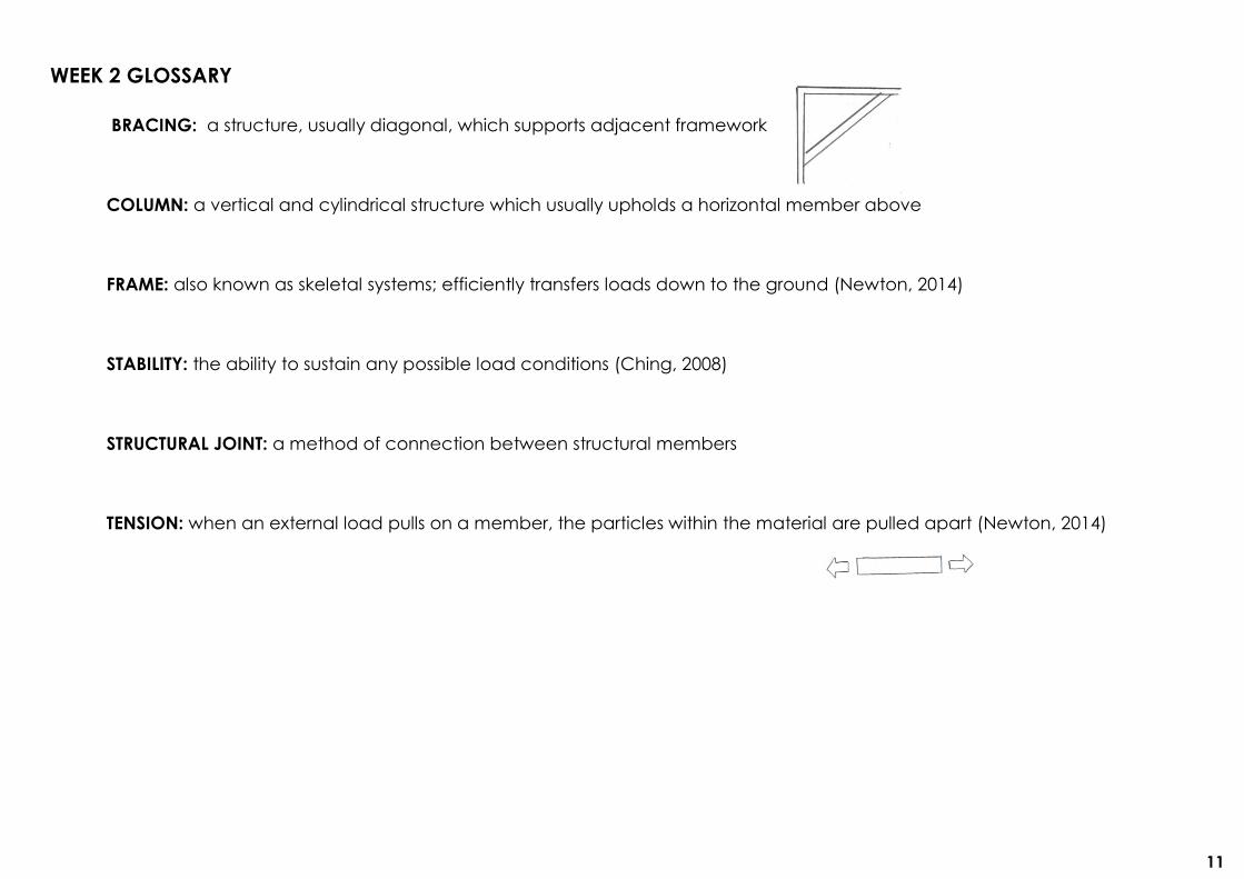
BRACING: a structure, usually diagonal, which supports adjacent framework
COLUMN: a vertical and cylindrical structure which usually upholds a horizontal member above
FRAME: also known as skeletal systems; efficiently transfers loads down to the ground (Newton, 2014)
STABILITY: the ability to sustain any possible load conditions (Ching, 2008)
STRUCTURAL JOINT: a method of connection between structural members
TENSION: when an external load pulls on a member, the particles within the material are pulled apart (Newton, 2014)
WEEK 2 GLOSSARY
11

Figure 29: Columns (Picture:
Achini Attanayake) Figure 30: Fixed joint
(Newton, 2014)
Fixed joint
WEEK 3: FOOTINGS AND FOUNDATIONS
12
A solid and skeletal system is seen at Lot 6
Cafe.
Load-bearing concrete columns and slab
are used as part of the skeletal system.
They were constructed in situ.
The glazed windows are a primary feature
of this building. Thus, this building is rather
expressive due to the large window
presence.
Fixed joints are only used in Lot 6 Cafe as
it is a rigid structure.
The structures surrounding this building are
predominantly made from brick.
Lot 6 Cafe
A surface structure is the major
system here.
Steel rods hold up the above
structure, which is South Lawn.
Rebar is used for reinforcement.
Each column provides space for
the roots of a tree above.
The flooring consists of a concrete
pad.
The car park is a concealed
structure as it is situated
underground.
Figure 26: Lot 6 Cafe (Picture: Achini Attanayake)
Figure 27: Load paths
Underground Car park and South Lawn
Brick
Slab
Column
Windows
Figure 28: Underground car park (Picture: Achini Attanayake)

13
Arts West Student Centre
Figure 31: Beams and Trusses (Picture: Achini
Attanayake)
The skeletal structure is the
predominant system in this buliding.
Concrete, wooden and stainless
steel beams runs along the roofing.
Glass and brick are used for the
solid system.
Trusses are the major feature of the
building.
As this is a rigid structure, only fixed
joints are used. Figure 32: Truss and
concrete (Picture: Achini Attanayake)
Figure 33: Load paths
Stairs on west Union House
Trusses
Beams
Truss
The skeletal structure is the
dominant systeem.
The staircase is constructed from
galvinised steel.
There are alumunium cable ties
which are held in place by
cantilevers. However, the structure
is not in suspension or in tension.
The weight of the structure is
actually supported by columns
(Figure 34). Note that there are
fixed joints between these columns
and beams.
The structure is expressive and its
skeletal system is fully exposed.
Figure 34: Stairs on west Union House (Picture: Achini Attanayake)
Figure 35: Pin joint (Picture: Achini Attanayake)
Figure 36: Pin joint (Newton, 2014)
Column Pin joint
Cantilever
Cable ties
14
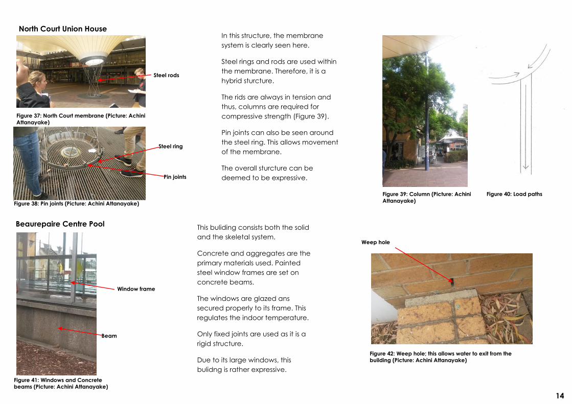
North Court Union House
Figure 37: North Court membrane (Picture: Achini
Attanayake)
Figure 39: Column (Picture: Achini
Attanayake) Figure 38: Pin joints (Picture: Achini Attanayake)
In this structure, the membrane
system is clearly seen here.
Steel rings and rods are used within
the membrane. Therefore, it is a
hybrid sturcture.
The rids are always in tension and
thus, columns are required for
compressive strength (Figure 39).
Pin joints can also be seen around
the steel ring. This allows movement
of the membrane.
The overall sturcture can be
deemed to be expressive.
Figure 40: Load paths
Pin joints
Steel ring
Steel rods
Beaurepaire Centre Pool
Figure 41: Windows and Concrete
beams (Picture: Achini Attanayake)
Figure 42: Weep hole; this allows water to exit from the
building (Picture: Achini Attanayake)
This buliding consists both the solid
and the skeletal system.
Concrete and aggregates are the
primary materials used. Painted
steel window frames are set on
concrete beams.
The windows are glazed ans
secured properly to its frame. This
regulates the indoor temperature.
Only fixed joints are used as it is a
rigid structure.
Due to its large windows, this
bulidng is rather expressive.
Weep hole
Window frame
Beam

15
Oval Pavilion
This buliding utilises a skeletal sturctural
system.
The substructure consists of concrete
stumps and padding below.
Timber stud framing is used with spans
and spacings.
There is also a steel beam on the ridge of
the roof which acts as a bearer.
Only fixed joints are used as it is a rigid
structure.
The building is rather concealed.
Figure 43: Oval Pavilion (Picture: Achini Attanayake)
Figure 44: Span and spacing (Newton, 2014)
Melbourne School of Design
A skeletal sturctural system can be seen here.
In situ concrete beams and columns are the
dominant structures. Expansion joints are used within
these members. Many concrete cantilevers are also
used in the structure.
Since it is still in construction, scaffolding can still be
seen on site.
Glazed windows are also a major feature.
Only fixed joints are used as it is a rigid structure.
The building can be said to be concealed.
Figure 46: MSD building (Picture: Achini
Attanayake) Figure 45: MSD building
(Picture: Achini Attanayake)
Figure 47: Expansion joint (Ching, 2008)
Cantilever
SPAN
SPACING

16
Old Geology South Lecture Theatre Entry
Figure 48: Theatre entrance (Picture: Achini
Attanayake)
Figure 49: Cantilever (Picture: Achini Attanayake)
This entrance consists of a skeletal sturctural system.
The cantilever-like structure is load bearing.
The walls surrounding the entry is constructed from
brick veneer, which encompasses the encolsure
system.
The windows are glazed however, they are not
carrying any loads despite its large presence within
the structure.
As a rigid structure, only fixed joints can be seen here.
Due to the dominant cantilever, the building can be
deemed expressive.
Figure 50: Load paths
Frank Tate Pavilion
Figure 51: Frank Tate pavilion (Picture: Achini
Attanayake)
Cantilever
Figure 52: Timber structure (Picture: Achini Attanayake)
The pavilion clearly shows its skeletal system.
Timber and concrete are the two main materials of
this structure.
Steel beams and columns, and concrete columns
support the loads.
The timber structure is mainly for aesthetic reasons.
As a rigid structure, only fixed joints can be seen
here.
The pavilion is designed to be open for ventilation
and therefore, its is an expressive structure.
Fixed joints
Timber Concrete
Steel

17
WEEK 3 KNOWLEDGE MAPS References: see Reference list on pg. 69-72

18
References: see Reference list on pg.69-72

19
References: see Reference list on pg. 69-72

20
References: see Reference list on pg. 69-72

21
References: see Reference list on pg. 69-72
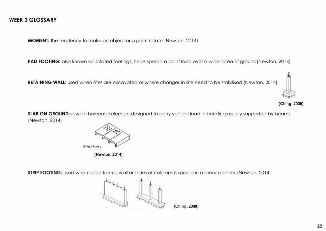
MOMENT: the tendency to make an object or a point rotate (Newton, 2014)
PAD FOOTING: also known as isolated footings; helps spread a point load over a wider area of ground(Newton, 2014)
RETAINING WALL: used when sites are excavated or where changes in site need to be stabilised (Newton, 2014)
SLAB ON GROUND: a wide horizontal element designed to carry vertical load in bending usually supported by beams
(Newton, 2014)
STRIP FOOTING: used when loads from a wall or series of columns is spread in a linear manner (Newton, 2014)
WEEK 3 GLOSSARY
(Ching, 2008)
(Ching, 2008)
(Newton, 2014)
22

SUBSTRUCTURE: the lowest division of a building; foundation (Ching, 2008)
(Ching, 2008)
23

WEEK 4: FLOORS SYSTEMS AND HORIZONTAL ELEMENTS
24
Scale, Annotation and Working Drawing
Convention
Why is scale used?
To visualise different aspects and
structures of a building in relation to each
other on a smaller scale, i.e. for
comparison
For practicality purposes
To examine certain components in detail
How is scale used?
A ratio of units is used
The ratio varies, depending on
the scale used
Preferred working units/scale for structures
1:100→whole structure
1:20→floors, elevation, plans
1:50→walls
1:15→canopy
Construction Documentation Questionnaire
List the types of information found in the title
block on the floor plan page.
Project name
Scale
Architecture
Orientation
Client
Why might this information be important?
It gives context to the project.
TITLE BLOCK
DRAWING CONTENT-PLANS
What type of information is shown in this
floor plan?
Floor space
Dimensions
Provide an example of the dimensions
as they appear on this floor plan? What
units are used for dimensions?
Social room→86.8 m²
Square metres
Is there a grid? What system is used for
identifying the grid lines?
Yes, there is a grid
Alphabet-number system

(Cox
Architecture,
2012)
25
What is the purpose of the legend?
To represent certain elements
using symbols
Why are some parts of the drawing
annotated? Illustrate how the
annotations are associated with the
relevant part of the drawing.
It shows information that cannot
be illustrated or represented by
symbols
Illustrate how references to other
drawings are shown on the plan. What
do these symbols mean?
Arrows show the direction of the cut
taken.
The numbers within the circle indicate
page number references.
How are windows and doors identified?
Provide an example of each. Is there a
rationale to their numbering? What do
these numbers mean? Can you find the
answer somewhere in the drawings?
Each number represents the same type of
door/window and size.
Door Tag with Room Tag (Cox Architecture, 2012)
Window Tag with Room Tag (Cox Architecture, 2012)
Illustrate how floor levels are noted on
the plan.
Floor level (metres) above datum
(Cox Architecture, 2012)
Are some areas of the drawing
clouded? Why?
Yes, some sections are clouded
They are particular instructions
and notes for a certain structure,
i.e. revisions
(Cox Architecture, 2012)

What type of information is shown in this
elevation? How does it differ from the
information shown on the plan?
It shows the side views of the
building
The texture of the materials used
can be seen
Are dimensions shown? If so, how do
they differ from the dimensions on the
plan? Provide an example of the
dimensions as they relate to the
elevation.
The length and height of some
structures are shown in
millimetres.
For example, the height of the
function parapet is 1115mm.
In the prior plans, these
dimensions were in metres.
What types of levels are shown on the
elevations? Illustrate how levels are
shown in relation to the elevation.
Finished floor level
(Cox Architecture, 2012)
Spot level
(Cox Architecture, 2012)
Is there a grid? If so, how/where is it
shown?
Yes partially, only numbers are
shown
They are located along the
vertical axis
What types of information on the
elevations are expressed using words?
Illustrate how this is done.
Design elements
Instructions
Illustrate how the doors and windows
are identified on the elevations.
Door Tag with Room Tag
(Cox Architecture, 2012)
Window Tag with Room Tag
(Cox Architecture, 2012)
Find where this elevation is located on
the plans.
Refer to the drawing number
DRAWING CONTENT-ELEVATIONS
(Cox Architecture, 2012)
26

27
DRAWING CONTENT-SECTIONS
What type of information is shown in this
section? How does it differ from the
information shown on the plan and
elevation?
A cross-section through the
building
It shows the indoor and other
hidden elements from a side view
Illustrate how the section drawing
differentiates between building
elements that are cut through and those
that are shown in elevation (beyond).
Provide example of how different
materials are shown on the sections.
Find where this section is located on the
plans.
Refer to the drawing number
DRAWING CONTENT-DETAILS
What sorts of things are detailed?
Walls
Canopy
Roof and facade
Function room
Pop up window
Fireplace
Are the details compressed using break
lines? Why?
Yes, because this allows the
details to be analysed at a closer
scale and thus, this shows the
finer elements
Provide examples of how different
materials are shown on drawings at this
scale.
Elevation (Cox
Architecture, 2012)
Section (Cox Architecture,
2012)
(Cox Architecture, 2012)
(Cox Architecture, 2012)

28
Find the locations of these details on the
plans, elevations and sections.
Refer to the drawing number
The drawing set seems to be consistent with
the observations from last week. In Figure 53,
the social room can be seen with the bay
window structure. These in accordance with
the drawings as the plans, elevations and
sections have both the social room and the
bay window featured together.
Like the drawings, these two structures are
constructed from vertical and horizontal
timber elements.
Furthermore, the number of windows from last
week’s observation is consistent with the
plans.
Also, the existing turret roof is being
maintained as instructed in the drawings.
Part 3
Figure 53: Oval Pavilion (Picture: Achini Attanayake)
The scale of the building is obviously larger
than the scale used in the drawings. Hence,
this is why a ratio was used to represent large
elements of the structure in a smaller and
more practical size.
The architectural drawings show all the
materials, texture, detailing and the size of
major elements of the overall building.
The structural drawings examine the smaller
elements of the building such as trusses, the
grandstand, wall braces and connection
joints.
Therefore, when compared with the structural
diagrams, the architectural drawings seem
more superficial as it excludes the finer details
of the building.
Bay window Social room

29
WEEK 4 KNOWLEDGE MAPS References: see Reference list on pg. 69-72

30
References: see Reference list on pg. 69-72

CONCRETE PLANK: a flat beam used for floor or roof decking
GIRDER: a beam which is used to support the ends of joists
JOIST: a horizontal member used to support a floor or ceiling which have limited overhang potential (Ching, 2008)
SPACING: the repeating distance between a series of lie or similar elements (Newton, 2014)
WEEK 4 GLOSSARY
(Newton, 2014)
(Newton, 2014)
31
1

SPAN: the distance measured between two structural supports (Newton, 2014)
STEEL DECKING: boards or planks of corrugated metal used usually for relatively short spans (Ching, 2008)
(Ching, 2008)
32
WEEK 5: COLUMNS, GRIDS AND WALL SYSTEMS
33
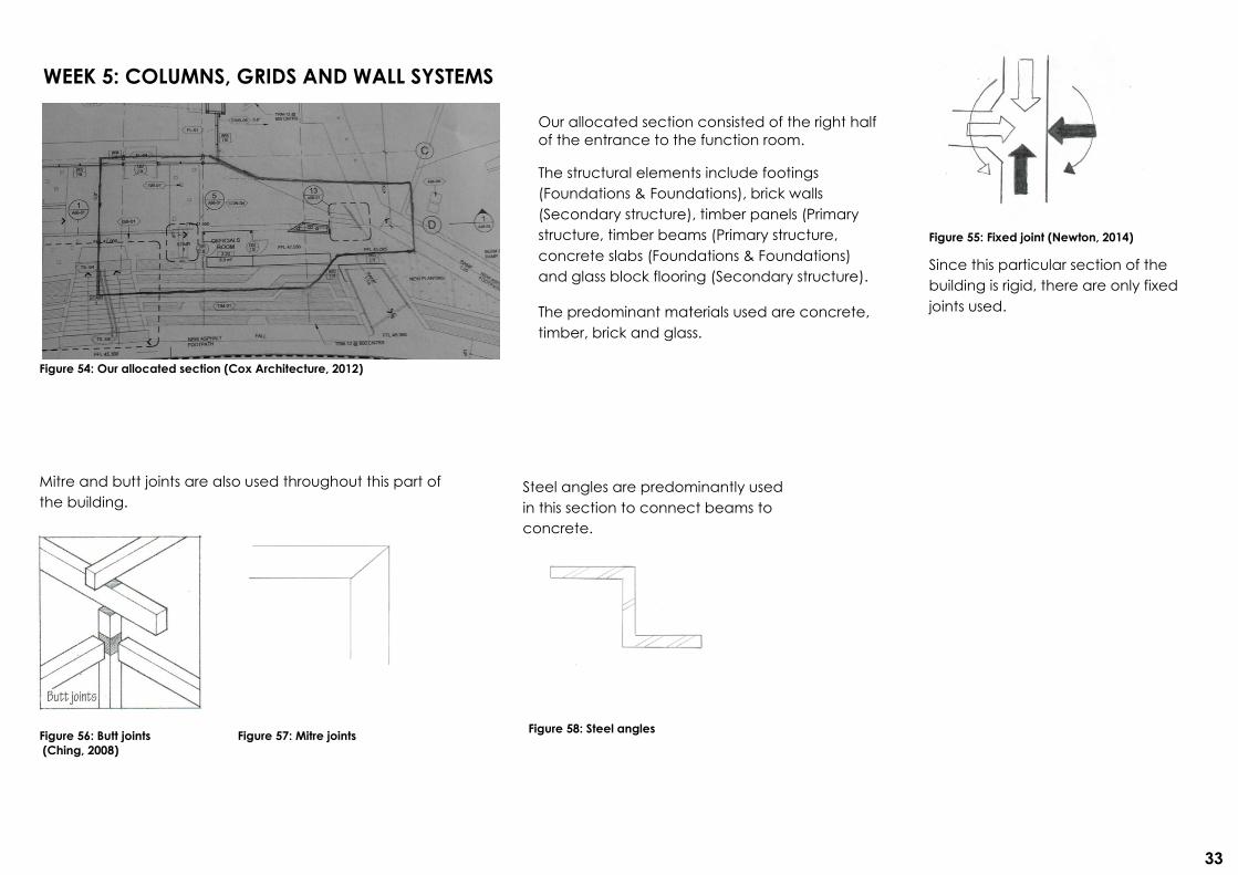
Figure 54: Our allocated section (Cox Architecture, 2012)
Our allocated section consisted of the right half
of the entrance to the function room.
The structural elements include footings
(Foundations & Foundations), brick walls
(Secondary structure), timber panels (Primary
structure, timber beams (Primary structure,
concrete slabs (Foundations & Foundations)
and glass block flooring (Secondary structure).
The predominant materials used are concrete,
timber, brick and glass.
Figure 55: Fixed joint (Newton, 2014)
Since this particular section of the
building is rigid, there are only fixed
joints used.
Steel angles are predominantly used
in this section to connect beams to
concrete.
Mitre and butt joints are also used throughout this part of
the building.
Figure 56: Butt joints
(Ching, 2008) Figure 57: Mitre joints
Figure 58: Steel angles

34
Figure 59: Column (Picture: Achini
Attanayake)
Figure 60: Wall (Picture: Achini
Attanayake)
We began constructing the walls, panels,
columns and beams.
We used balsa wood as we were familiar with the
product and could cut different shapes from it.
However, due to the thinness of the sheet, we
had to stick several layers to make it stable as
seen in the columns (Figure 59).
Figure 61: Finished product (Picture: Achini
Attanayake)
Unfortunately, due to time restraints
and lack of group cooperation, we
didn’t finish our model.
Figure 62: Load paths
Figure 63, 64: Other groups models
(Pictures: Achini Attanayake)
In Figure 63, their section was the same as
ours. However, they choose to focus on the
roof structure and its timber framing.
Figure 64 had a similar structure to our own as
it consisted of concrete walls and columns.
Slab
Beam
Wall
Column

35
WEEK 5 KNOWLEDGE MAPS References: see Reference list on pg. 69-72

36
References: see Reference list on pg. 69-72

AXIAL LOAD: the load that creates a force which runs parallel to the axis of a member
BUCKLING: when a structure becomes unstable and begins to bend
LINTEL: a horizontal structural member which spans an opening, usually doors or windows
NOGGING: a supporting member placed between joists and studs; also known as dwang
SEASONED TIMBER: when moisture is removed from timber to provide increased dimensional stability (Newton, 2014)
WEEK 5 GLOSSARY
(Ching, 2008)
(Prointeriordesigner.com, 2014)
37

STUD: a vertical member used in the framework of a wall (refer to diagram above)
38


![Part C Application Submission Forms[1]](https://img.pdfslide.us/doc/110x75/5477abe9b4af9f807b8b459b/part-c-application-submission-forms1.jpg)
