Embed Size (px)
Citation preview
2013 Virginia Concrete Conference Joint Maintenance and Best Practices in Deck Joint Replacement
Jeff Milton Bridge Preservation Specialist Structure and Bridge Division March 8, 2013
Presentation Outline
2
Why Joints?
Purpose of Joints
Typical Joint Systems Used in Virginia
Leaking Joints
Virginia Bridge Program
Joint Maintenance Procedures
Why Joints?
3
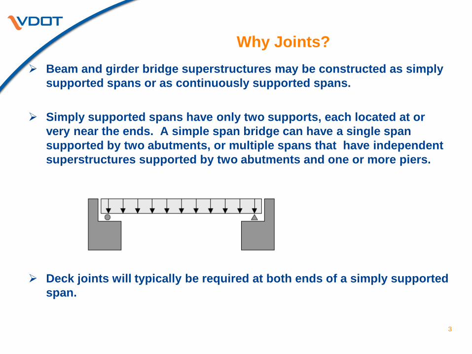
Beam and girder bridge superstructures may be constructed as simply supported spans or as continuously supported spans.
Simply supported spans have only two supports, each located at or very near the ends. A simple span bridge can have a single span supported by two abutments, or multiple spans that have independent superstructures supported by two abutments and one or more piers.
Deck joints will typically be required at both ends of a simply supported span.
Why Joints?
4
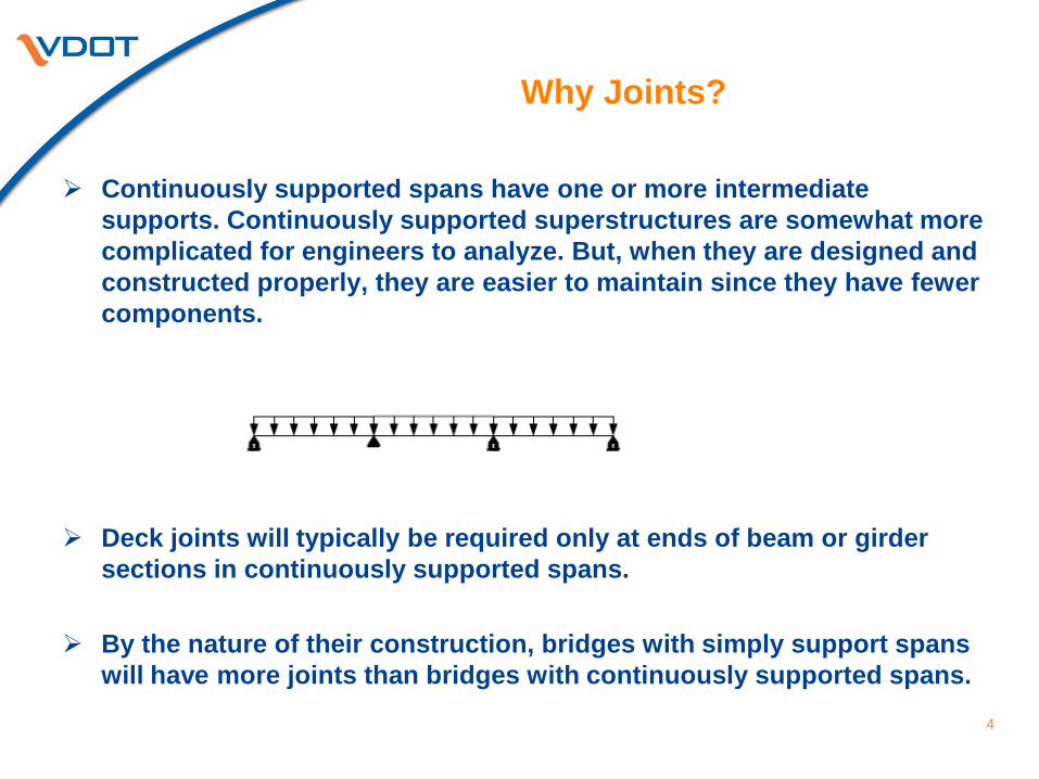
Continuously supported spans have one or more intermediate
supports. Continuously supported superstructures are somewhat more complicated for engineers to analyze. But, when they are designed and constructed properly, they are easier to maintain since they have fewer components.
Deck joints will typically be required only at ends of beam or girder
sections in continuously supported spans.
By the nature of their construction, bridges with simply support spans will have more joints than bridges with continuously supported spans.
Purpose of Joints
5
The purpose of bridge deck expansion joints is to accommodate movement of the superstructure. Superstructure movement is caused by the following : Expansion and contraction caused by temperature variation Concrete shrinkage and creep Live load deflection Wind and seismic loads Settlement
Typical Joint Systems Used in Virginia
6
The following types of joint systems may be found on existing bridges
in Virginia: Armored Joints – Open or Sealed Hot Poured Sealer /Expansion Material Preformed Elastomeric Compression Seals Poured (Silicone) Seals Asphalt Plug Joints (limited number) Strip Seals Sliding Plate Joints Finger Joints Cushion Seal (previously denoted as elastomeric expansion dam – limited
number remaining)
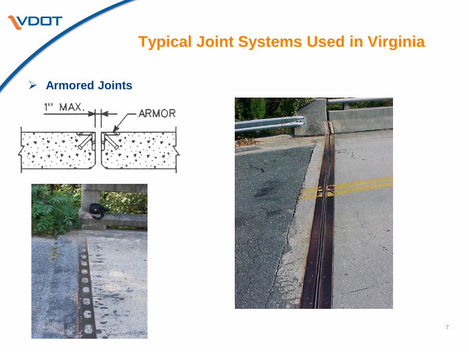
Typical Joint Systems Used in Virginia
7
Armored Joints
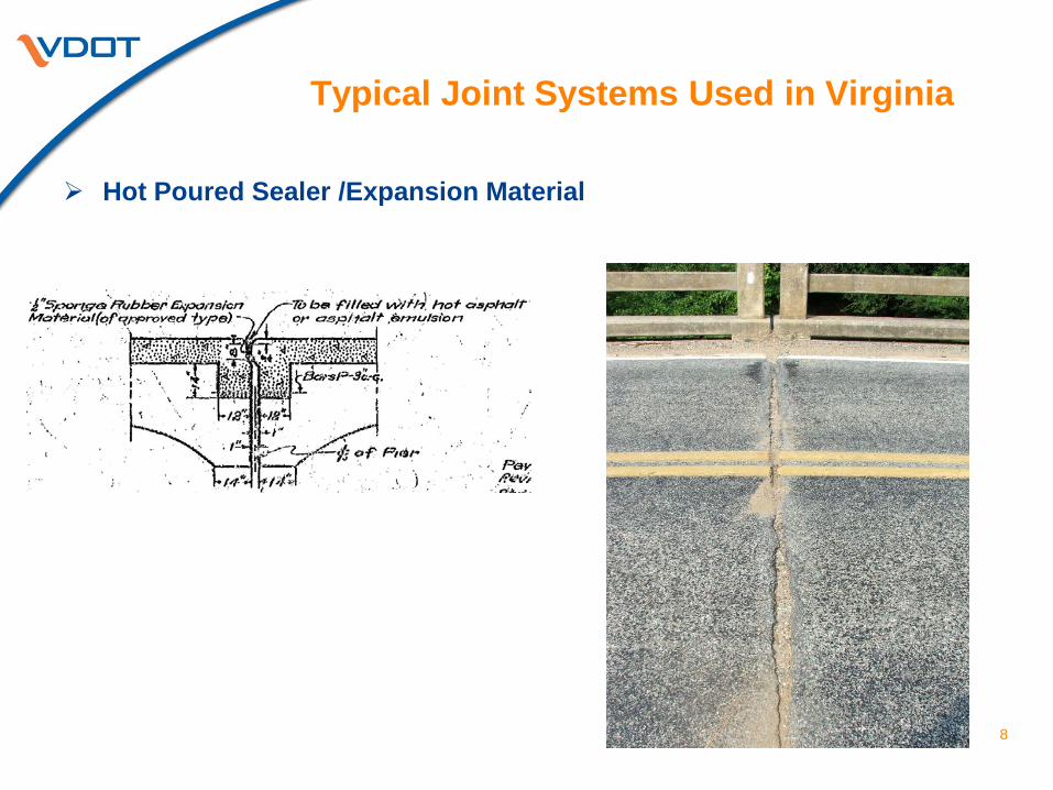
Typical Joint Systems Used in Virginia
8
Hot Poured Sealer /Expansion Material
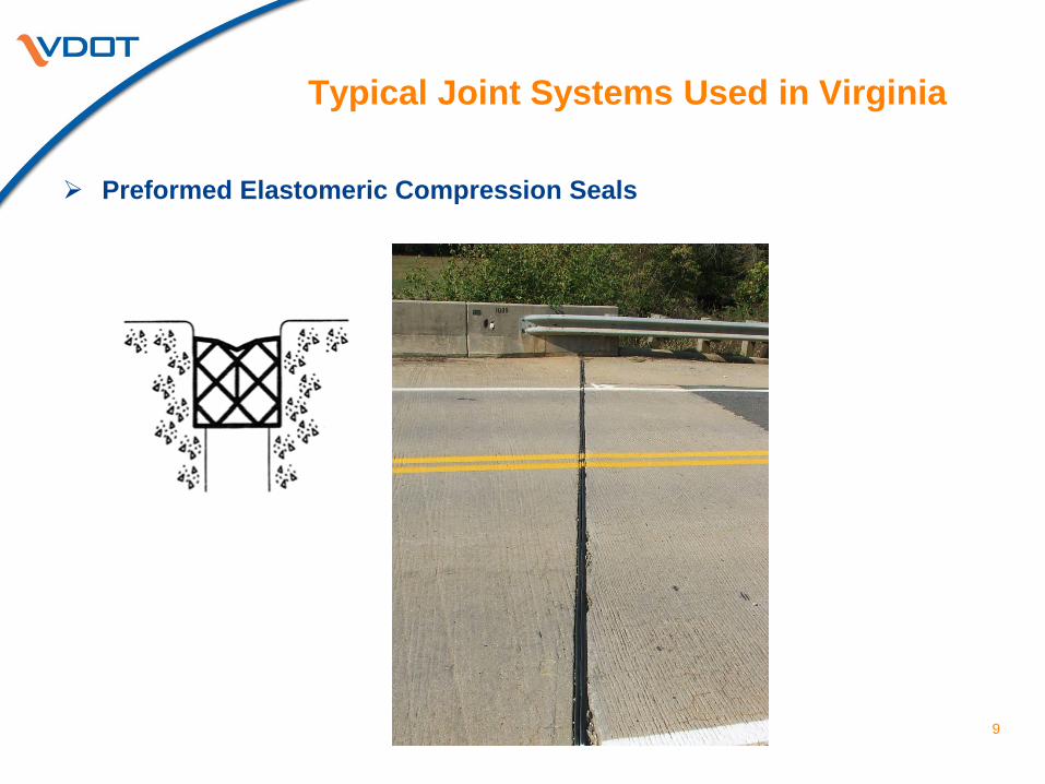
Typical Joint Systems Used in Virginia
9
Preformed Elastomeric Compression Seals
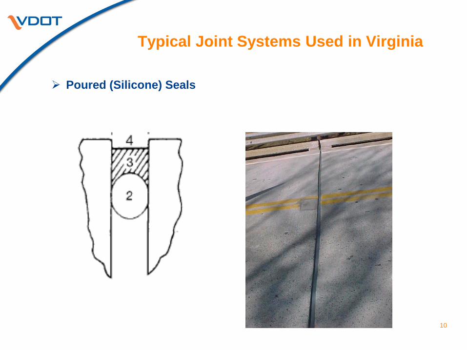
Typical Joint Systems Used in Virginia
10
Poured (Silicone) Seals
Typical Joint Systems Used in Virginia
11
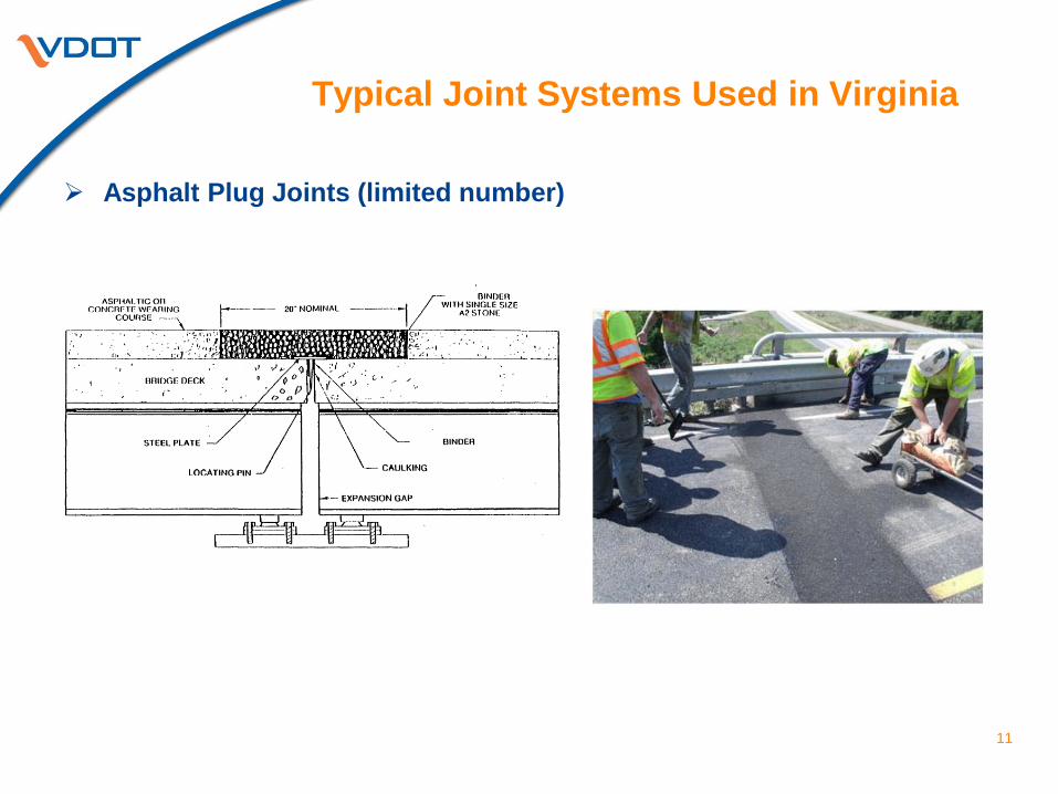
Asphalt Plug Joints (limited number)
Typical Joint Systems Used in Virginia
12
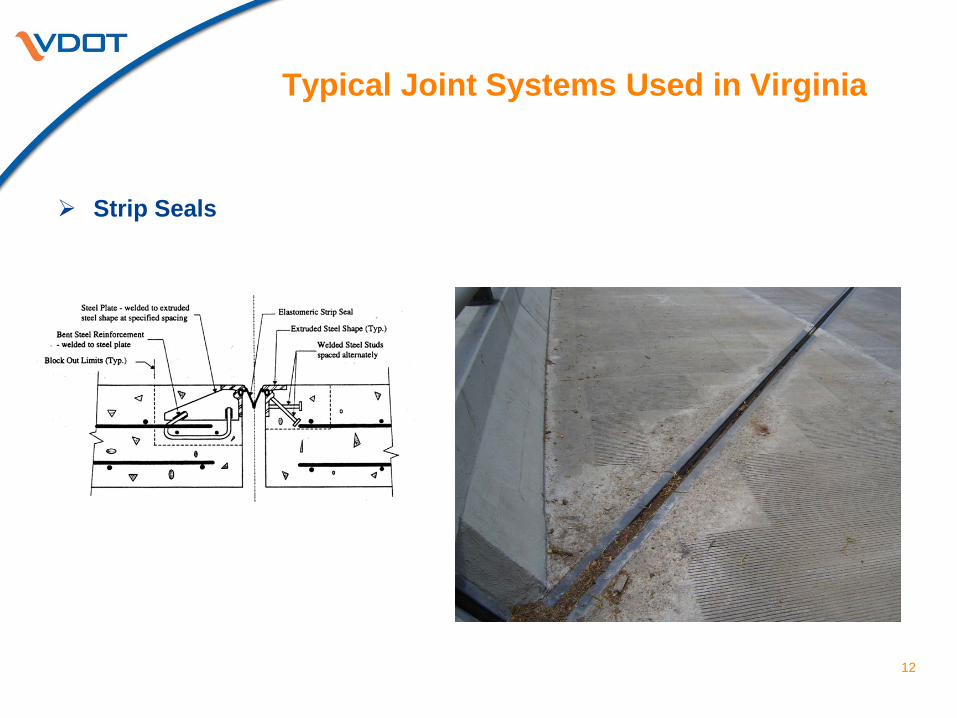
Strip Seals
Typical Joint Systems Used in Virginia
13
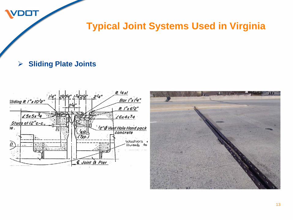
Sliding Plate Joints
Typical Joint Systems Used in Virginia
14
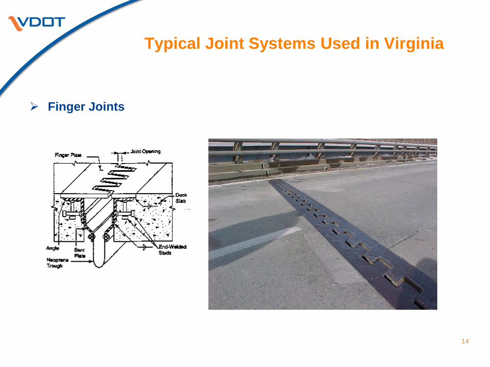
Finger Joints
Typical Joint Systems Used in Virginia
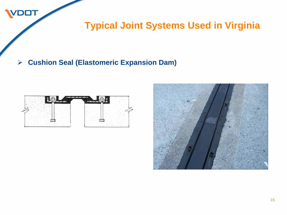
15
Cushion Seal (Elastomeric Expansion Dam)
Leaking Joints
16
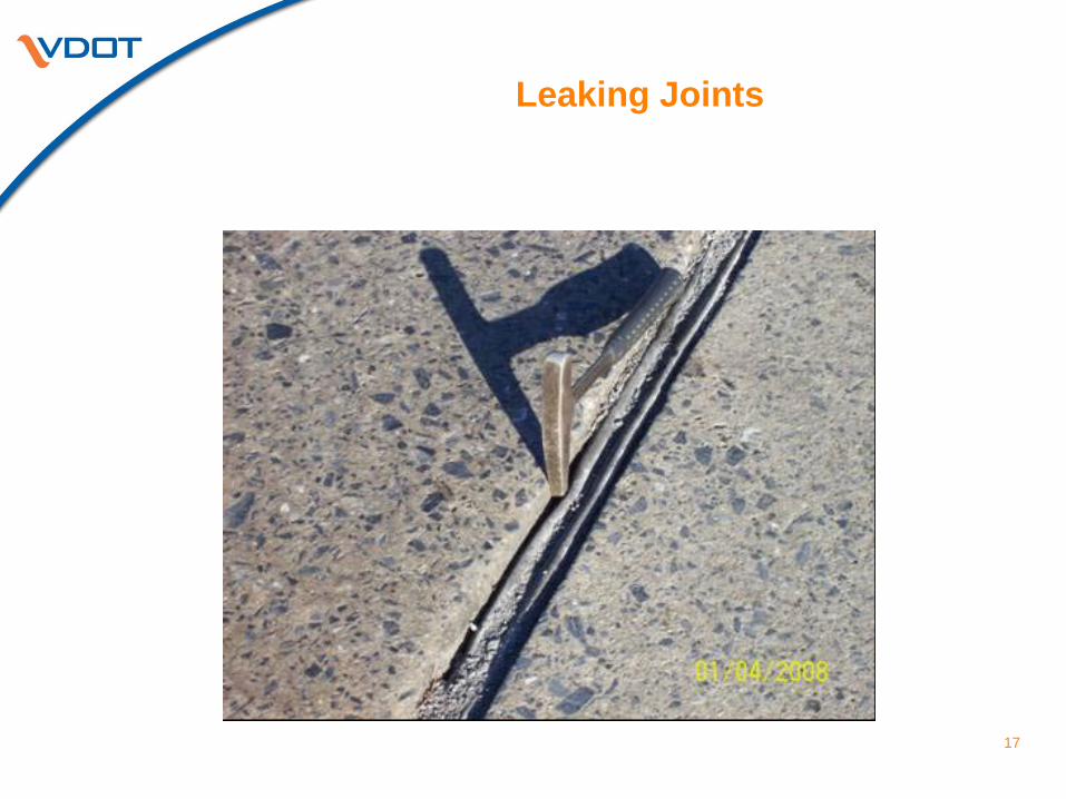
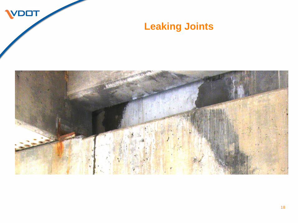
Leaking bridge deck expansion joints allow run-off water and deicing
chemicals to pass through the joints and onto superstructure and substructure members.
The following bridge components are adversely affected by leaking joints: End Diaphragms Beam/Girder Ends Bearings Substructure Seat Areas Other Substructure Areas
Leaking joints cause significant deterioration and damage to bridge
components and are a nationwide bridge maintenance problem. Many millions of dollars are spent each year repairing the damage caused by leaking joints.
Leaking Joints
17
Leaking Joints
18
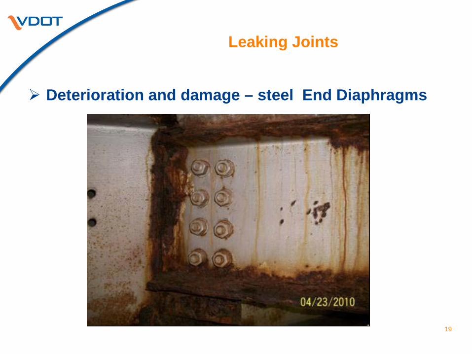
Leaking Joints
Deterioration and damage – steel End Diaphragms
19
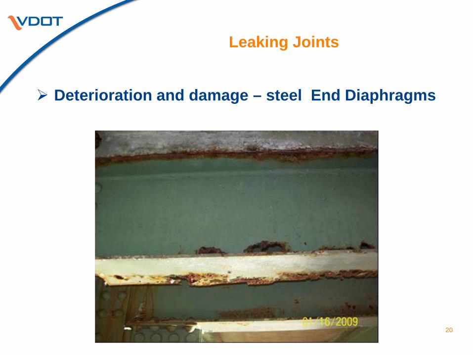
Leaking Joints
Deterioration and damage – steel End Diaphragms
20
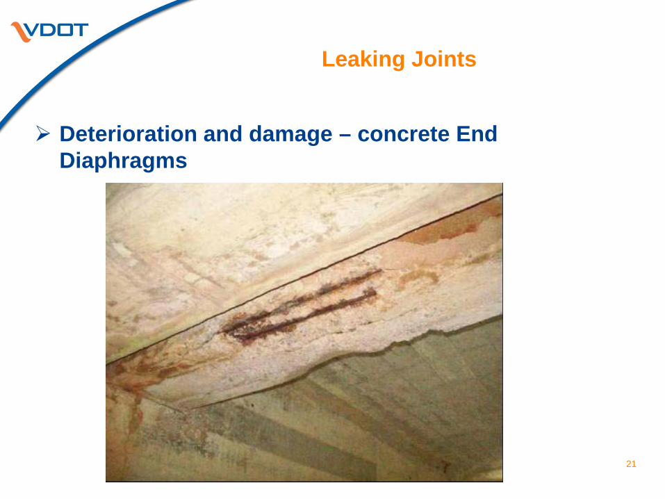
Leaking Joints
Deterioration and damage – concrete End Diaphragms
21
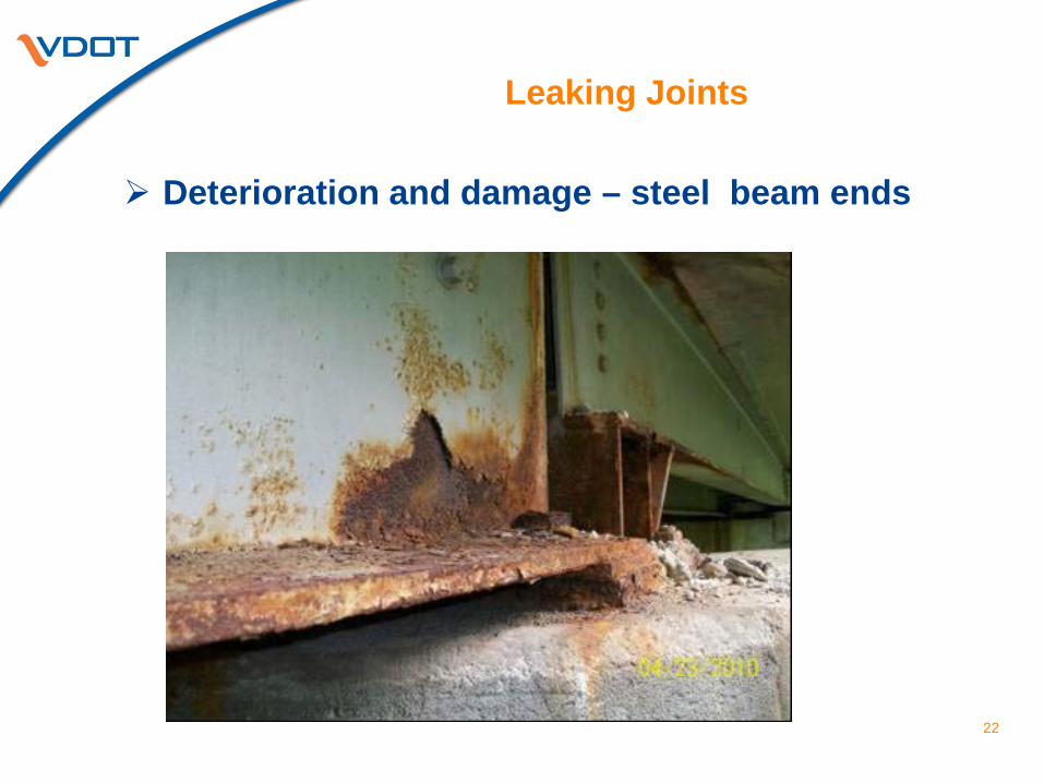
Leaking Joints
Deterioration and damage – steel beam ends
22
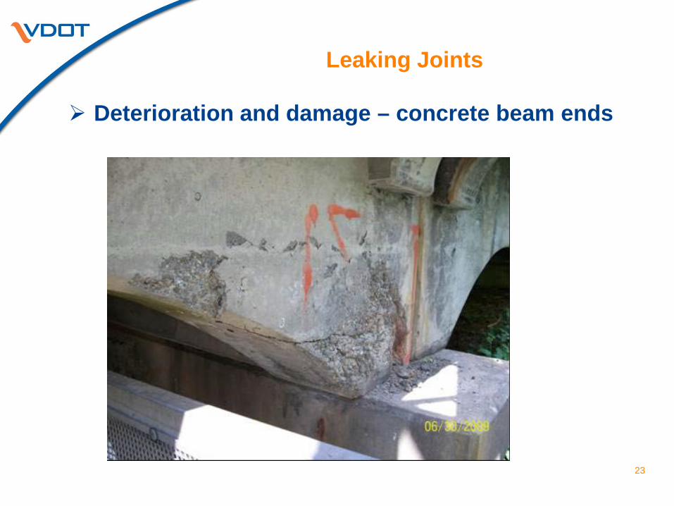
Leaking Joints
Deterioration and damage – concrete beam ends
23
Leaking Joints
Deterioration and damage – bearings
24
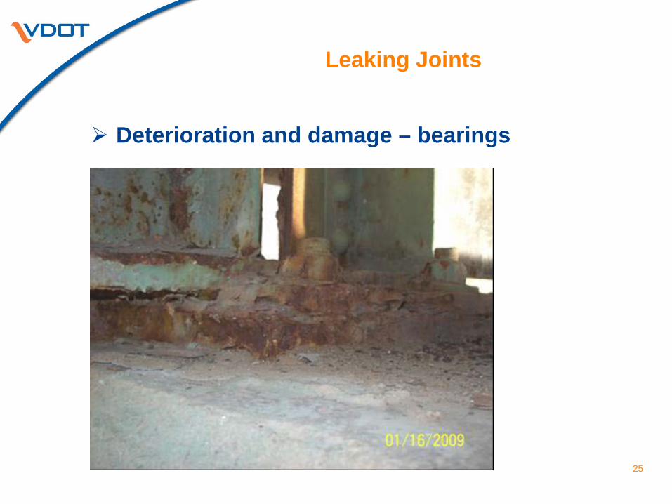
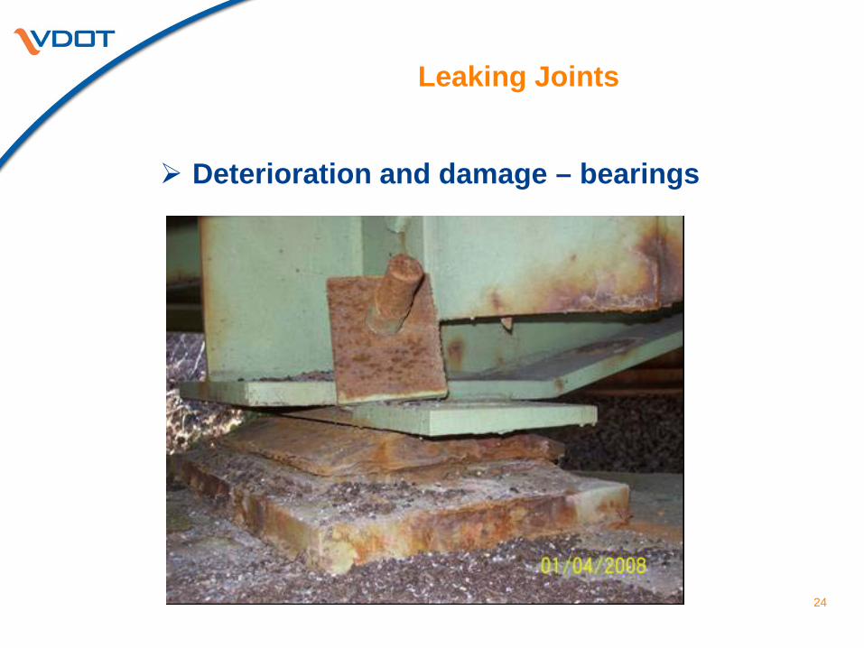
Leaking Joints
Deterioration and damage – bearings
25
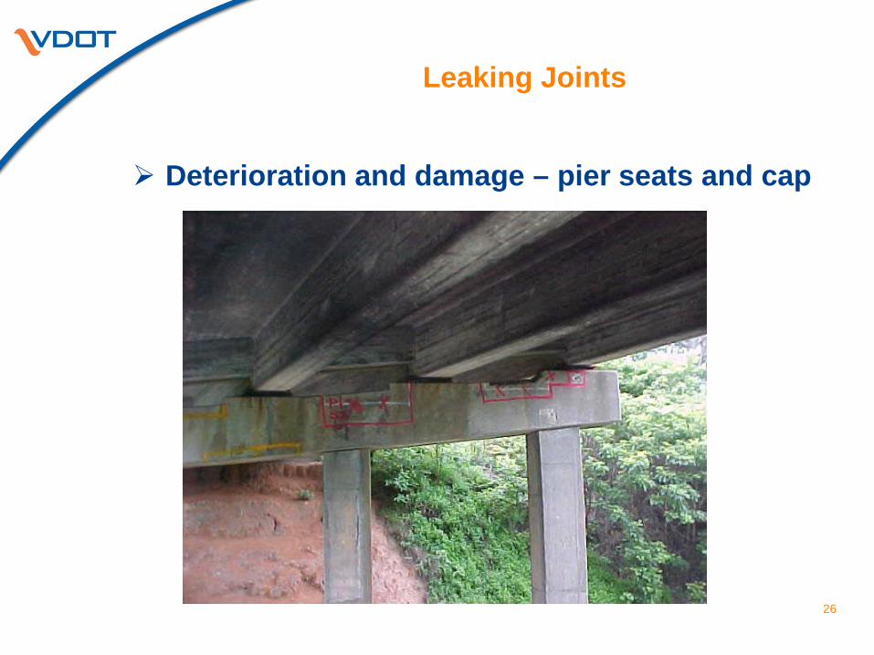
Leaking Joints
Deterioration and damage – pier seats and cap
26
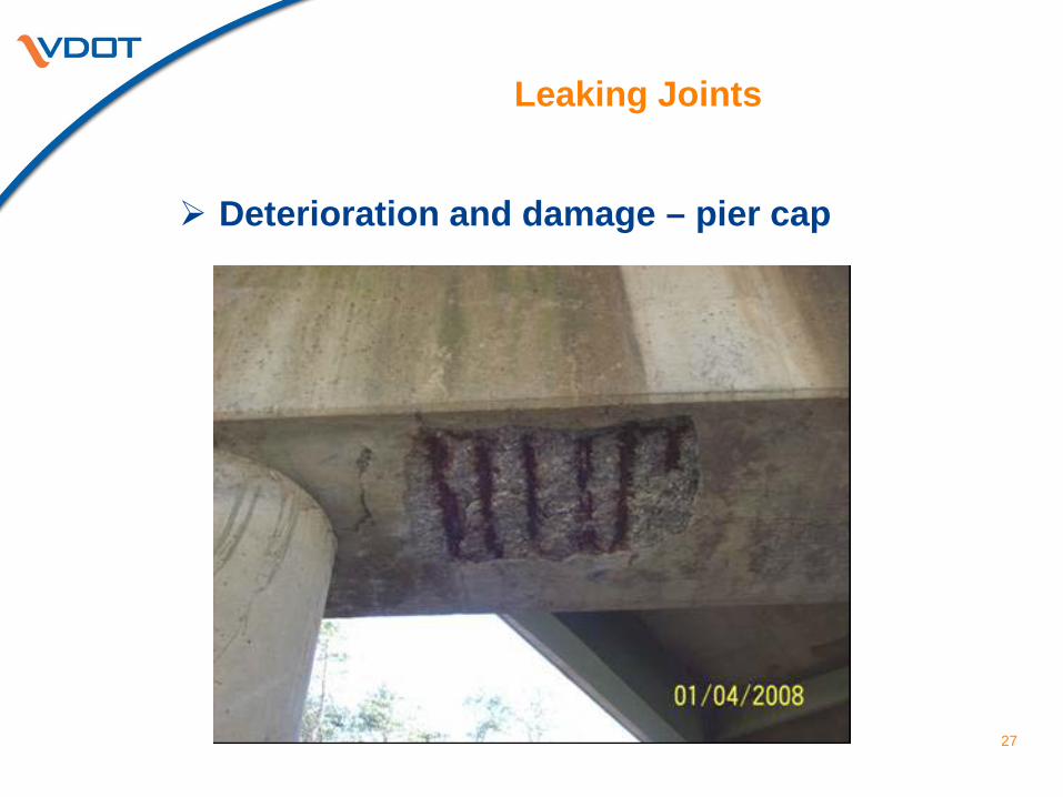
Leaking Joints
Deterioration and damage – pier cap
27
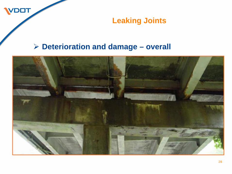
Leaking Joints
Deterioration and damage – overall
28
Virginia’s Bridge Program
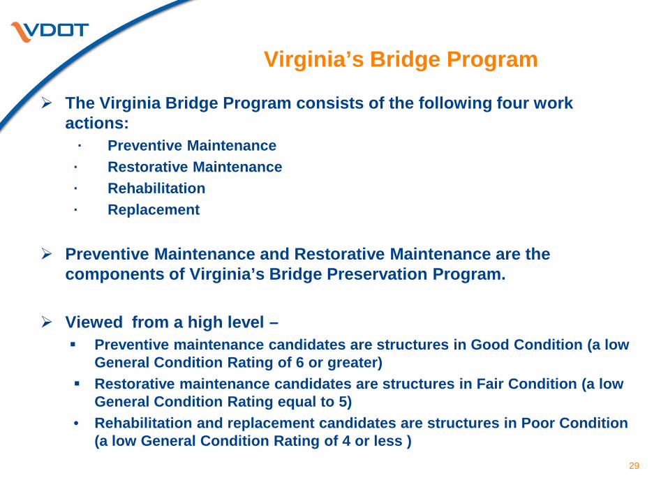
The Virginia Bridge Program consists of the following four work actions:
· Preventive Maintenance · Restorative Maintenance · Rehabilitation · Replacement
Preventive Maintenance and Restorative Maintenance are the components of Virginia’s Bridge Preservation Program.
Viewed from a high level –
Preventive maintenance candidates are structures in Good Condition (a low General Condition Rating of 6 or greater)
Restorative maintenance candidates are structures in Fair Condition (a low General Condition Rating equal to 5)
• Rehabilitation and replacement candidates are structures in Poor Condition (a low General Condition Rating of 4 or less )
29
Virginia’s Bridge Program
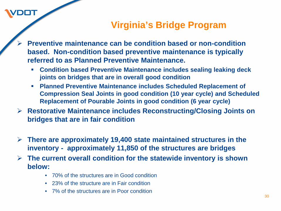
Preventive maintenance can be condition based or non-condition based. Non-condition based preventive maintenance is typically referred to as Planned Preventive Maintenance. Condition based Preventive Maintenance includes sealing leaking deck
joints on bridges that are in overall good condition Planned Preventive Maintenance includes Scheduled Replacement of
Compression Seal Joints in good condition (10 year cycle) and Scheduled Replacement of Pourable Joints in good condition (6 year cycle)
Restorative Maintenance includes Reconstructing/Closing Joints on bridges that are in fair condition
There are approximately 19,400 state maintained structures in the inventory - approximately 11,850 of the structures are bridges
The current overall condition for the statewide inventory is shown below:
• 70% of the structures are in Good condition • 23% of the structure are in Fair condition • 7% of the structures are in Poor condition
30
Joint Maintenance
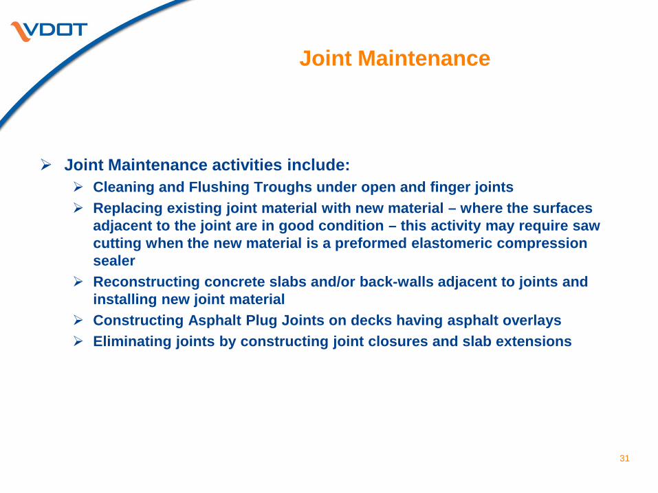
Joint Maintenance activities include: Cleaning and Flushing Troughs under open and finger joints Replacing existing joint material with new material – where the surfaces
adjacent to the joint are in good condition – this activity may require saw cutting when the new material is a preformed elastomeric compression sealer
Reconstructing concrete slabs and/or back-walls adjacent to joints and installing new joint material
Constructing Asphalt Plug Joints on decks having asphalt overlays Eliminating joints by constructing joint closures and slab extensions
31
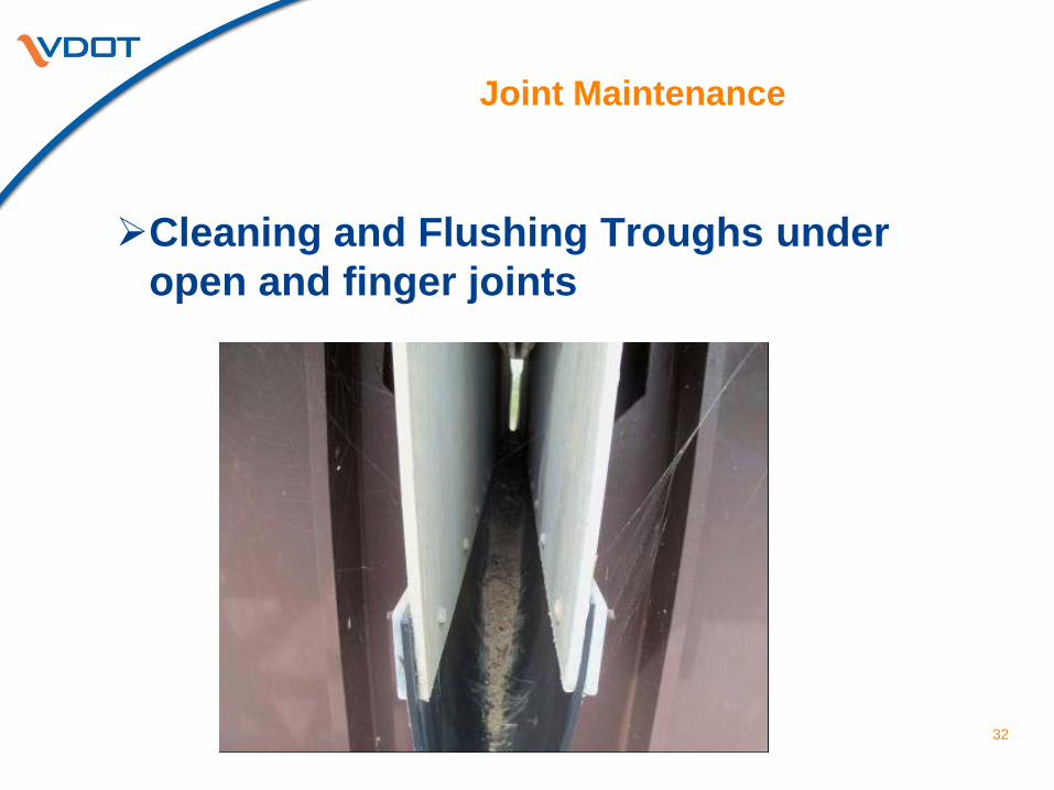
Joint Maintenance
Cleaning and Flushing Troughs under
open and finger joints
32
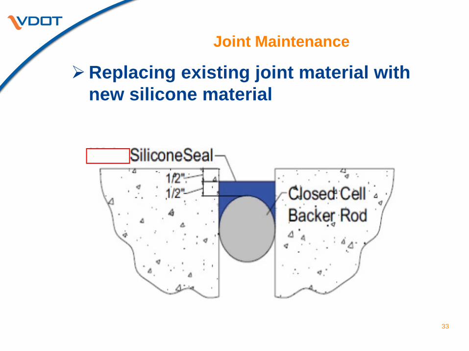
Joint Maintenance
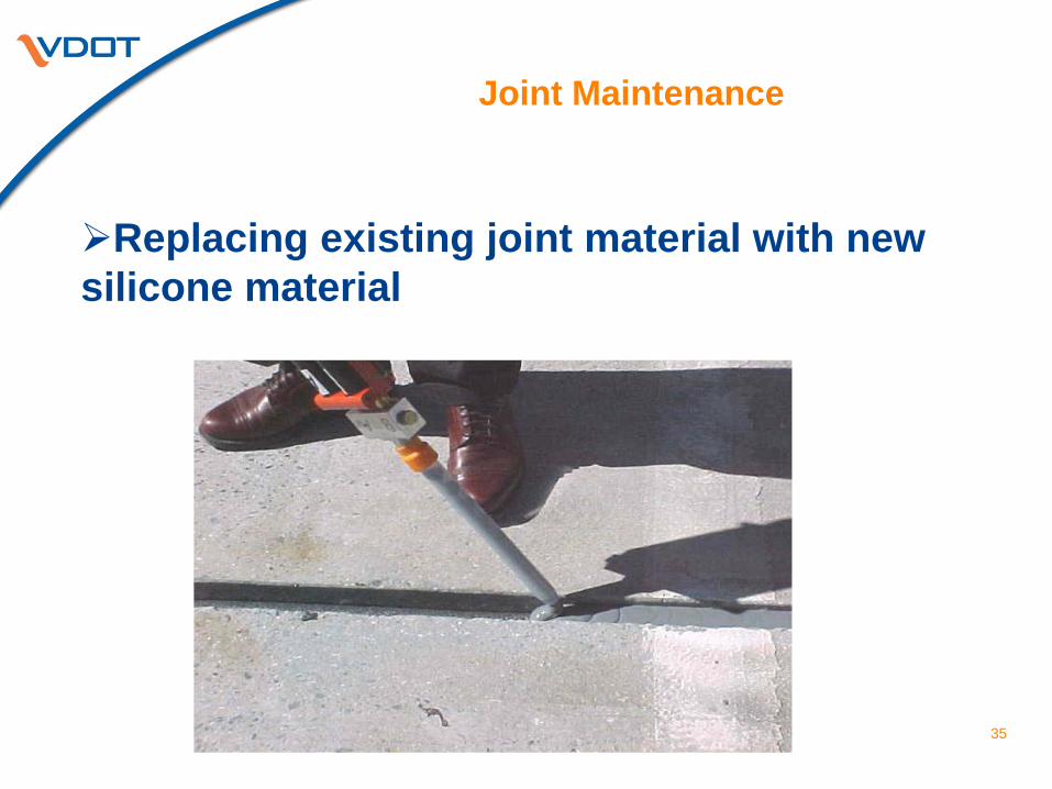
Replacing existing joint material with new silicone material
33
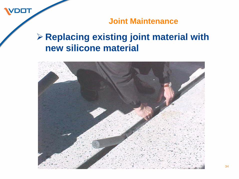
Joint Maintenance
Replacing existing joint material with new silicone material
34
Joint Maintenance
35
Replacing existing joint material with new silicone material
Joint Maintenance
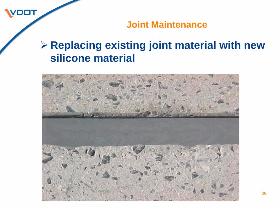
Replacing existing joint material with new silicone material
36
Joint Maintenance
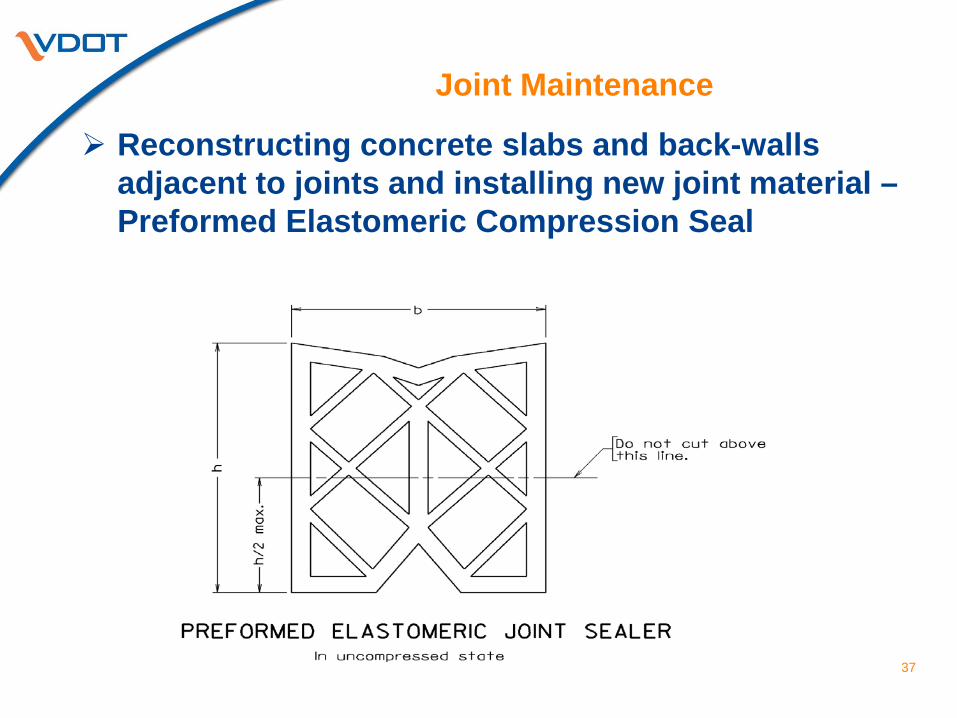
Reconstructing concrete slabs and back-walls adjacent to joints and installing new joint material – Preformed Elastomeric Compression Seal
37
Joint Maintenance
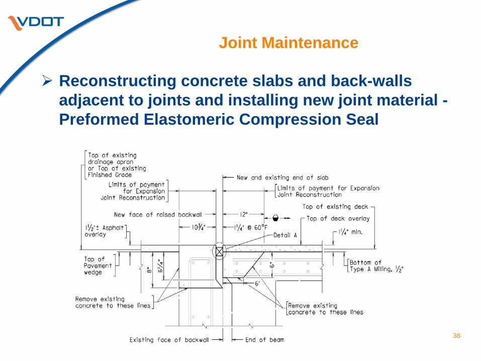
Reconstructing concrete slabs and back-walls adjacent to joints and installing new joint material - Preformed Elastomeric Compression Seal
38
Joint Maintenance
Reconstructing concrete slabs and back-walls adjacent to joints and installing new joint material - Preformed Elastomeric Compression Seal
39
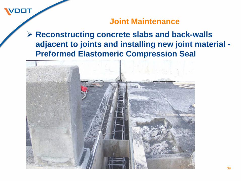
Joint Maintenance
Reconstructing concrete slabs and back-walls adjacent to joints and installing new joint material – Preformed Elastomeric Compression Seal
40
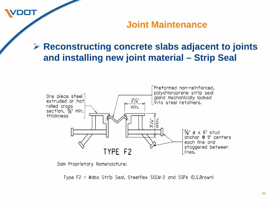
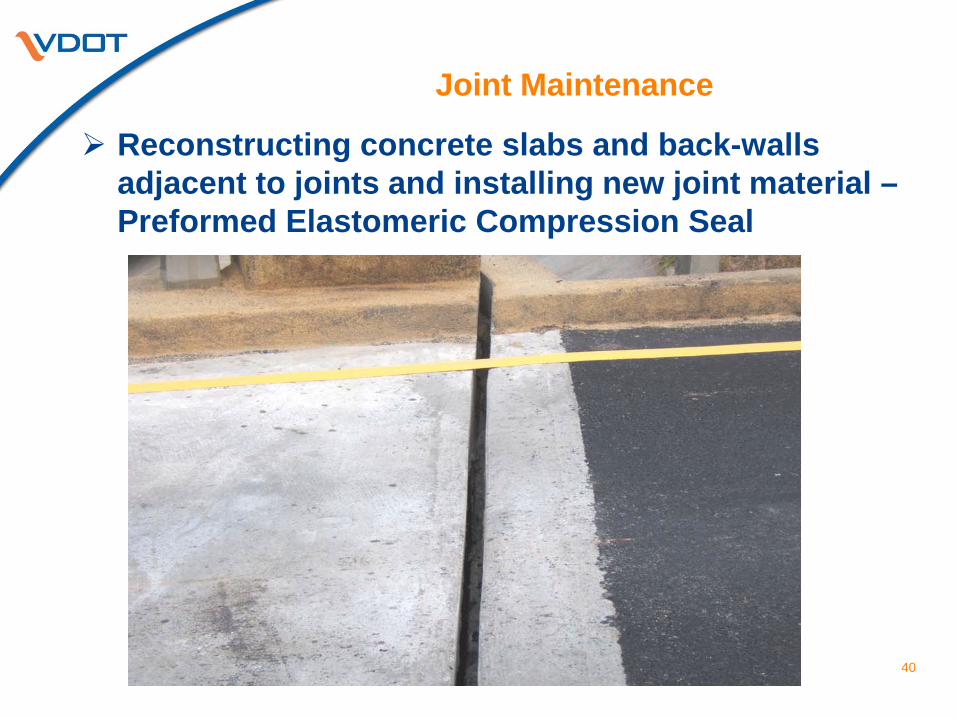
Joint Maintenance
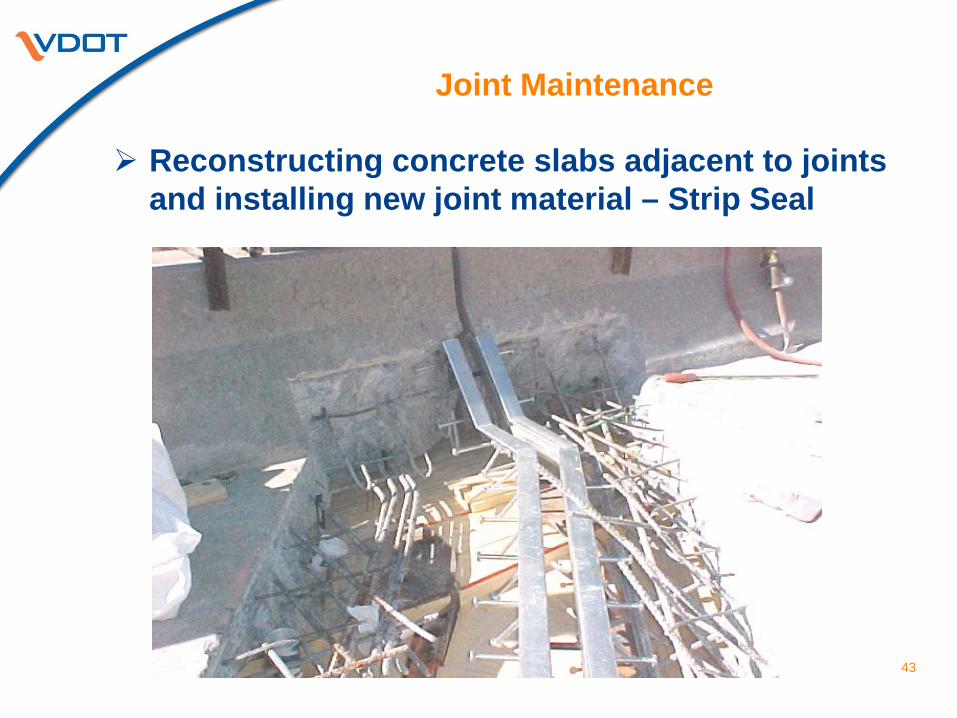
Reconstructing concrete slabs adjacent to joints and installing new joint material – Strip Seal
41
Joint Maintenance
Reconstructing concrete slabs adjacent to joints and installing new joint material – Strip Seal
42
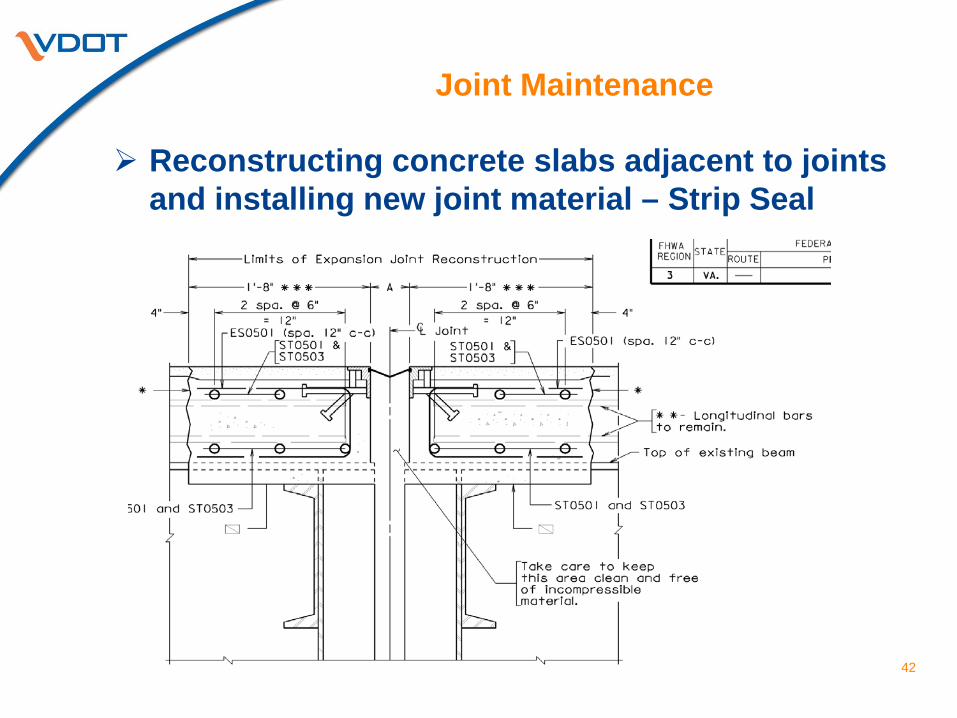
Joint Maintenance
Reconstructing concrete slabs adjacent to joints and installing new joint material – Strip Seal
43
Joint Maintenance
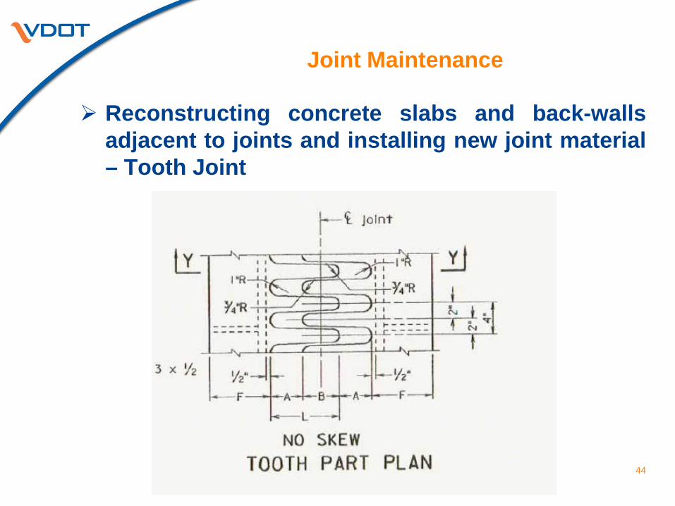
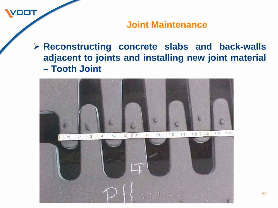
Reconstructing concrete slabs and back-walls adjacent to joints and installing new joint material – Tooth Joint
44
Joint Maintenance
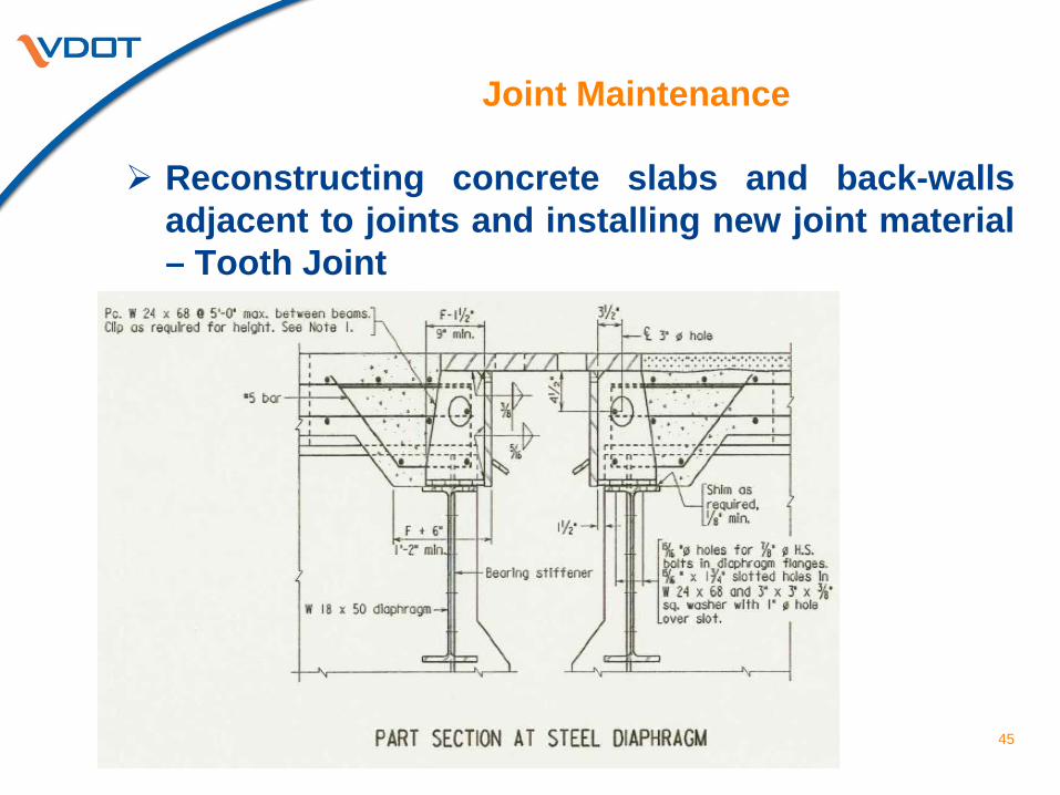
Reconstructing concrete slabs and back-walls adjacent to joints and installing new joint material – Tooth Joint
45
Joint Maintenance
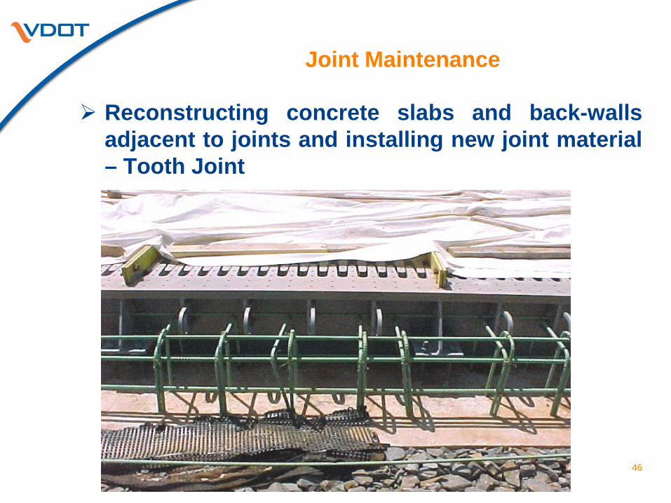
Reconstructing concrete slabs and back-walls adjacent to joints and installing new joint material – Tooth Joint
46
Joint Maintenance
Reconstructing concrete slabs and back-walls adjacent to joints and installing new joint material – Tooth Joint
47
Joint Maintenance
Check Points for reconstructing concrete slabs and back-walls adjacent
to joints: • Mark area of concrete to be removed as shown on plan details • Outline area with saw cut to a depth of 1” • Remove concrete as shown on the plan details using hand tools and
pneumatic hammers. Pneumatic hammers should have maximum weight of 30 pounds and should be worked at an angle of 45 to 60 degrees to the plane of the surface being removed
• Set and secure forms for joint – adjusting joint opening as necessary for temperature
• Clean area by abrasive blast cleaning • Place new reinforcing steel as shown on plan details and check reinforcing
steel for section loss – bars that has lost ¼ or more of their original cross sectional area shall be lapped with new bars of the same size – lap shall be 30 diameters on each side
• Remove dust and debris from area and ensure that existing concrete is in a saturated-surface dry condition before placing new concrete
• Measure and record dimensions of area before placing new concrete • Place, consolidate, and cure new concrete
48
Joint Maintenance
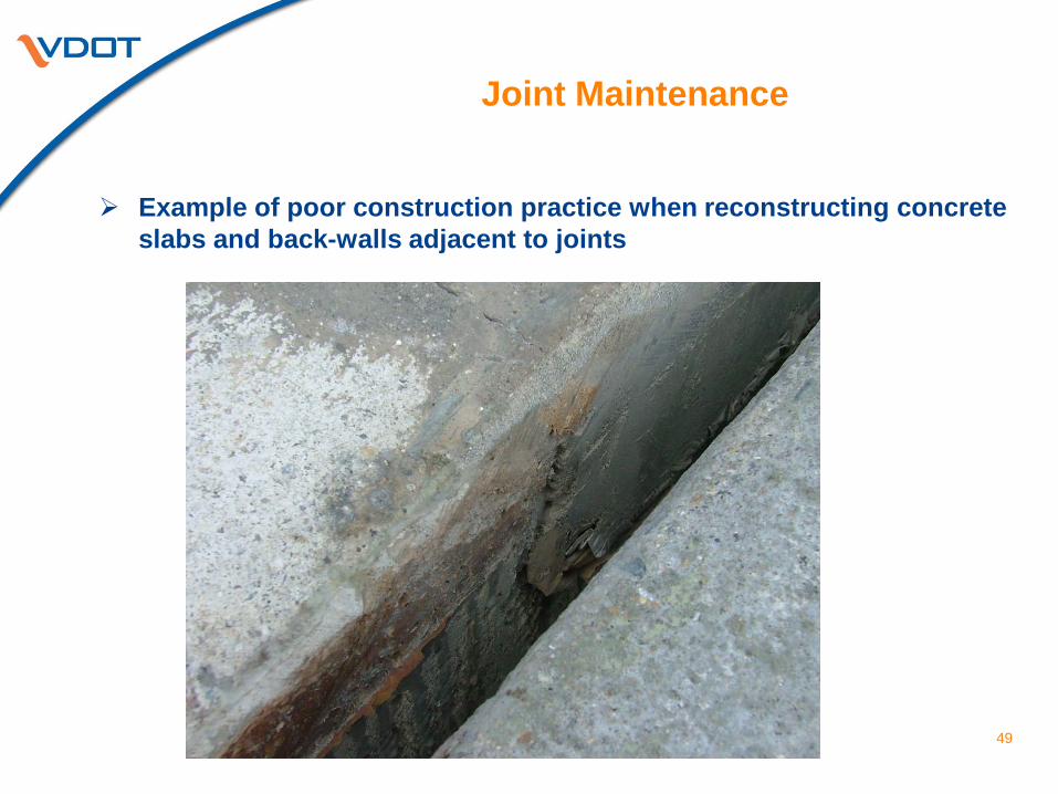
Example of poor construction practice when reconstructing concrete
slabs and back-walls adjacent to joints
49
Joint Maintenance
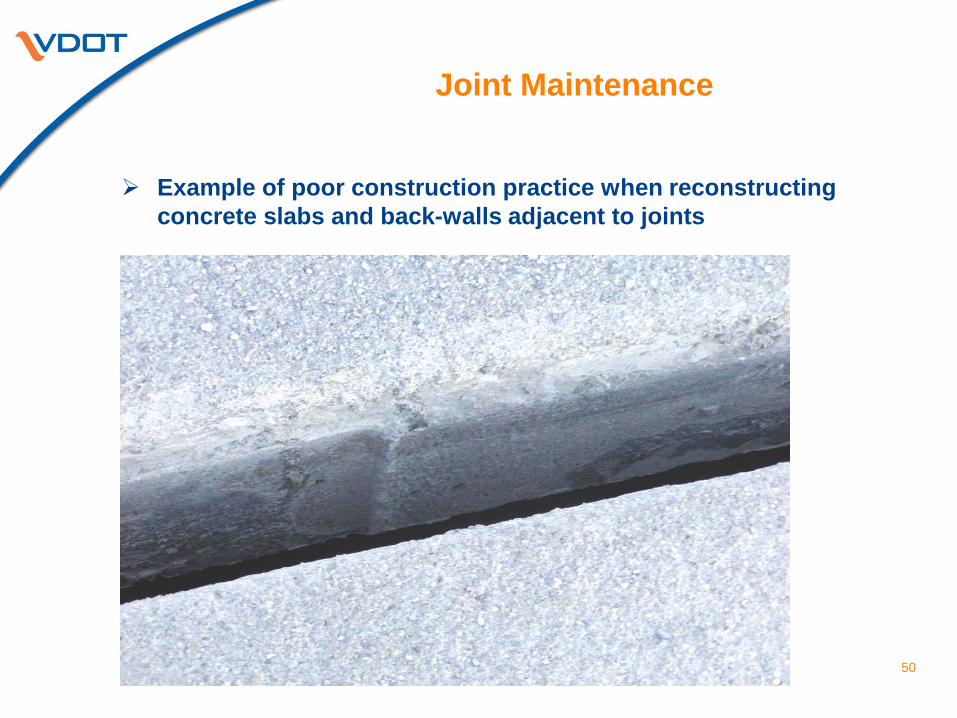
Example of poor construction practice when reconstructing
concrete slabs and back-walls adjacent to joints
50
Joint Maintenance
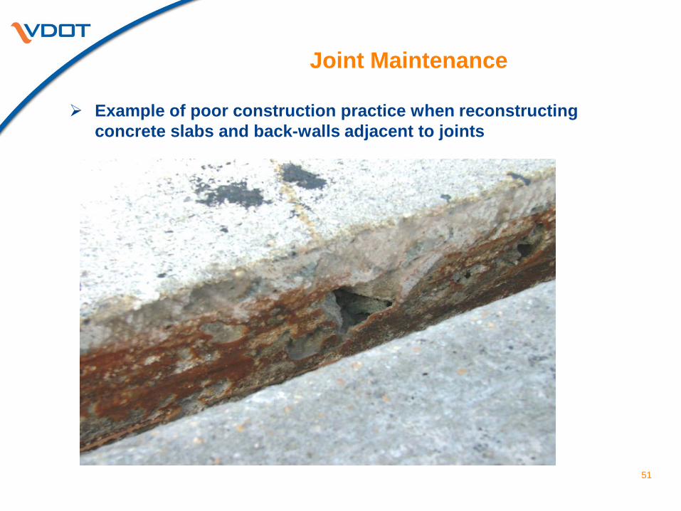
Example of poor construction practice when reconstructing concrete slabs and back-walls adjacent to joints
51
Joint Maintenance
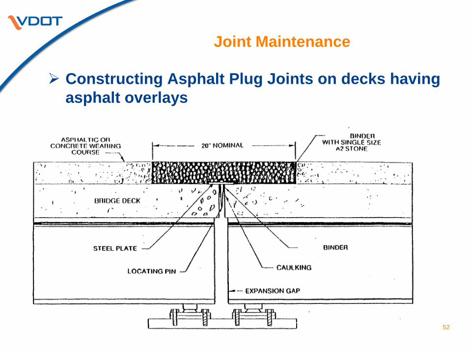
Constructing Asphalt Plug Joints on decks having asphalt overlays
52
Joint Maintenance
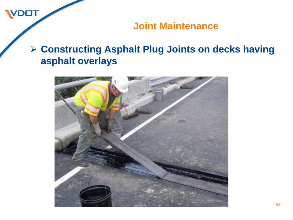
Constructing Asphalt Plug Joints on decks having asphalt overlays
53
Joint Maintenance
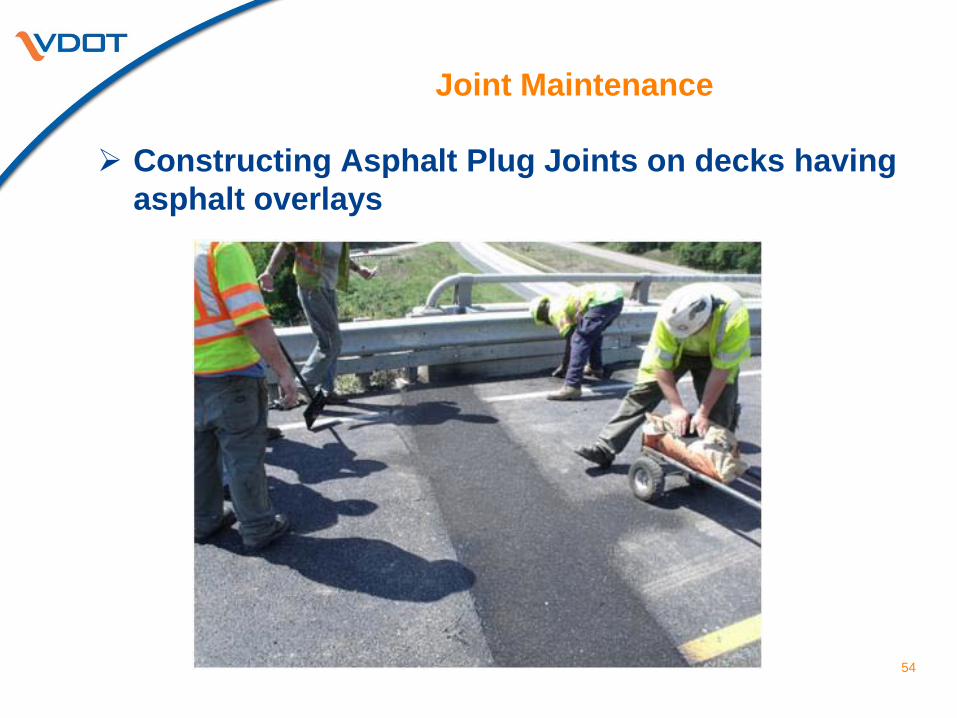
Constructing Asphalt Plug Joints on decks having asphalt overlays
54
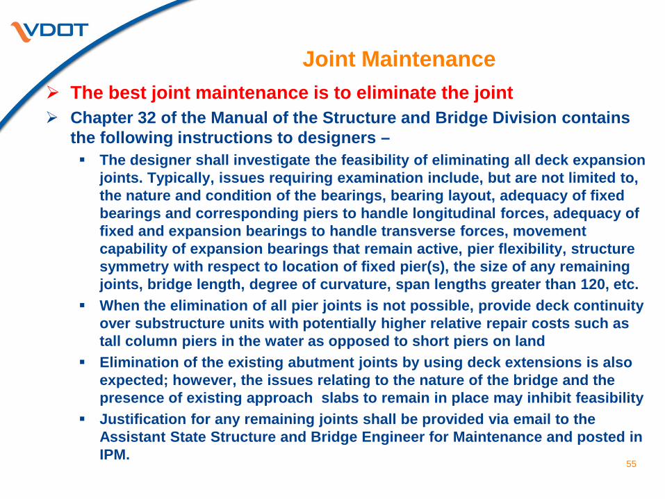
Joint Maintenance The best joint maintenance is to eliminate the joint Chapter 32 of the Manual of the Structure and Bridge Division contains
the following instructions to designers – The designer shall investigate the feasibility of eliminating all deck expansion
joints. Typically, issues requiring examination include, but are not limited to, the nature and condition of the bearings, bearing layout, adequacy of fixed bearings and corresponding piers to handle longitudinal forces, adequacy of fixed and expansion bearings to handle transverse forces, movement capability of expansion bearings that remain active, pier flexibility, structure symmetry with respect to location of fixed pier(s), the size of any remaining joints, bridge length, degree of curvature, span lengths greater than 120, etc.
When the elimination of all pier joints is not possible, provide deck continuity over substructure units with potentially higher relative repair costs such as tall column piers in the water as opposed to short piers on land
Elimination of the existing abutment joints by using deck extensions is also expected; however, the issues relating to the nature of the bridge and the presence of existing approach slabs to remain in place may inhibit feasibility
Justification for any remaining joints shall be provided via email to the Assistant State Structure and Bridge Engineer for Maintenance and posted in IPM.
55
Joint Maintenance
56
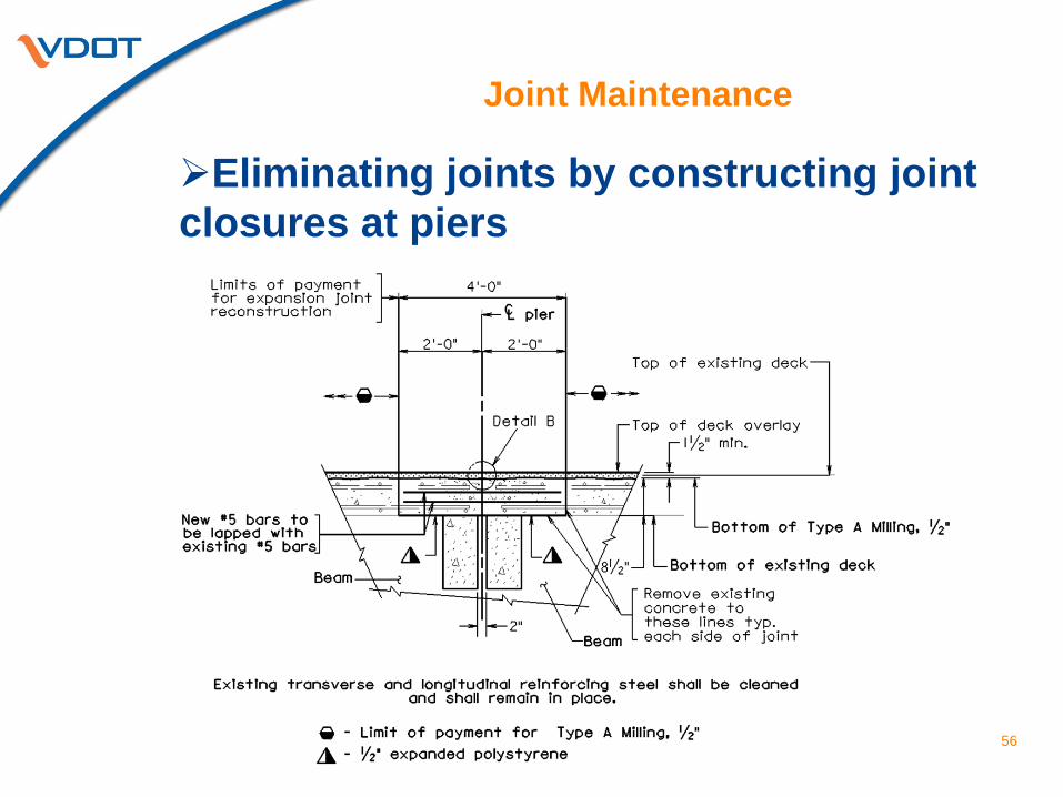
Eliminating joints by constructing joint closures at piers
Joint Maintenance
57
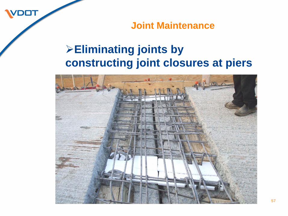
Eliminating joints by constructing joint closures at piers
Joint Maintenance
58
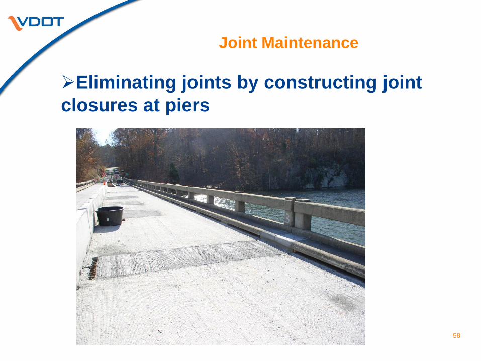
Eliminating joints by constructing joint closures at piers
Joint Maintenance
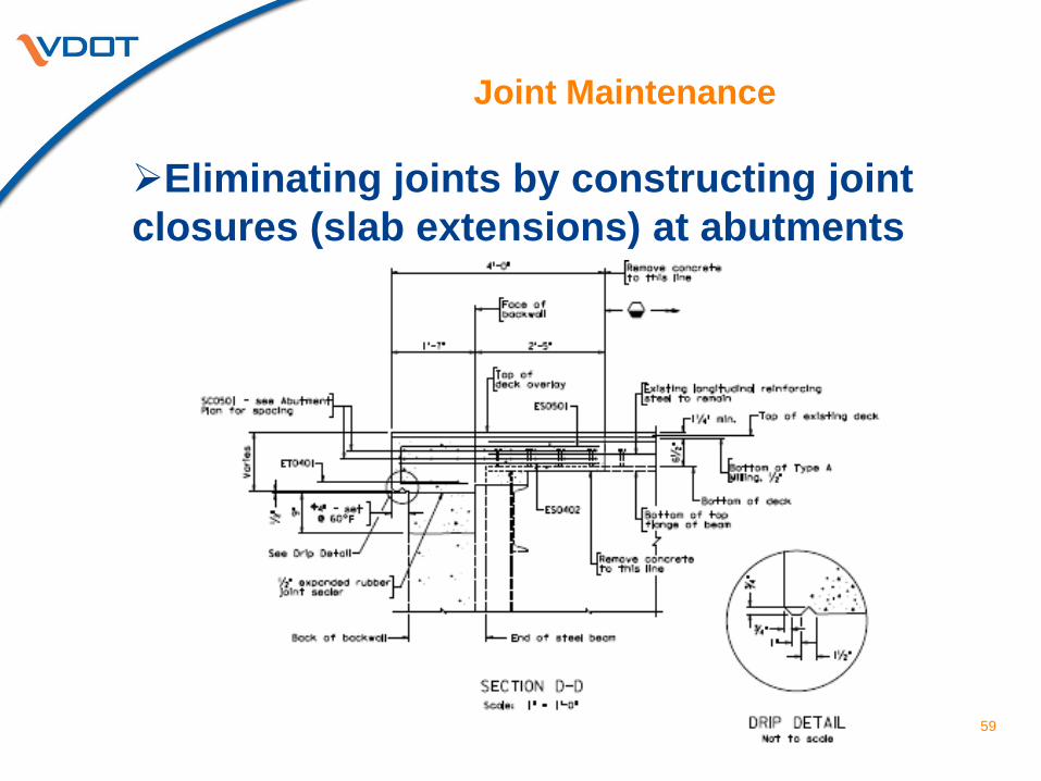
59
Eliminating joints by constructing joint closures (slab extensions) at abutments
Joint Maintenance
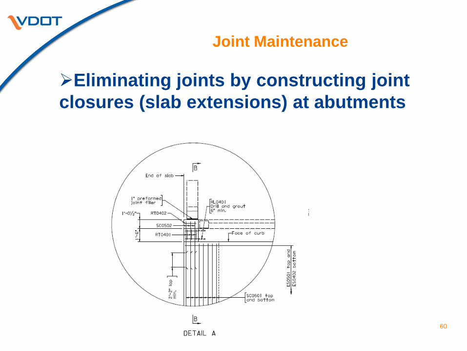
60
Eliminating joints by constructing joint closures (slab extensions) at abutments
Joint Maintenance
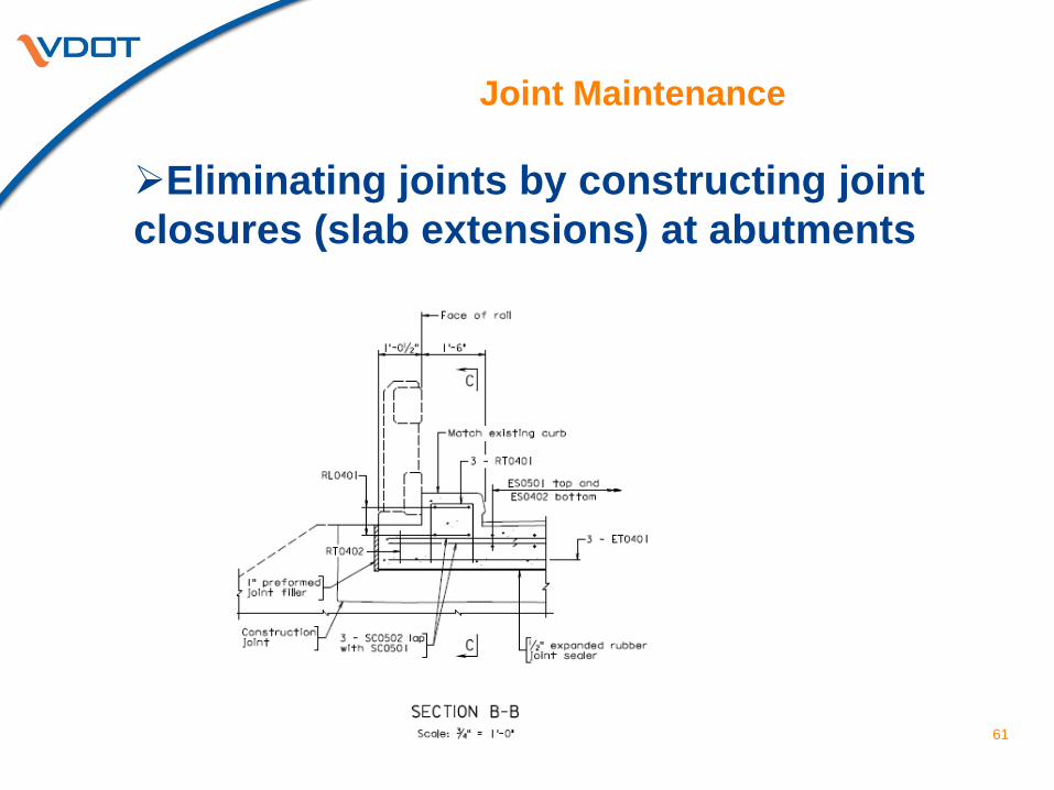
61
Eliminating joints by constructing joint closures (slab extensions) at abutments
Joint Maintenance
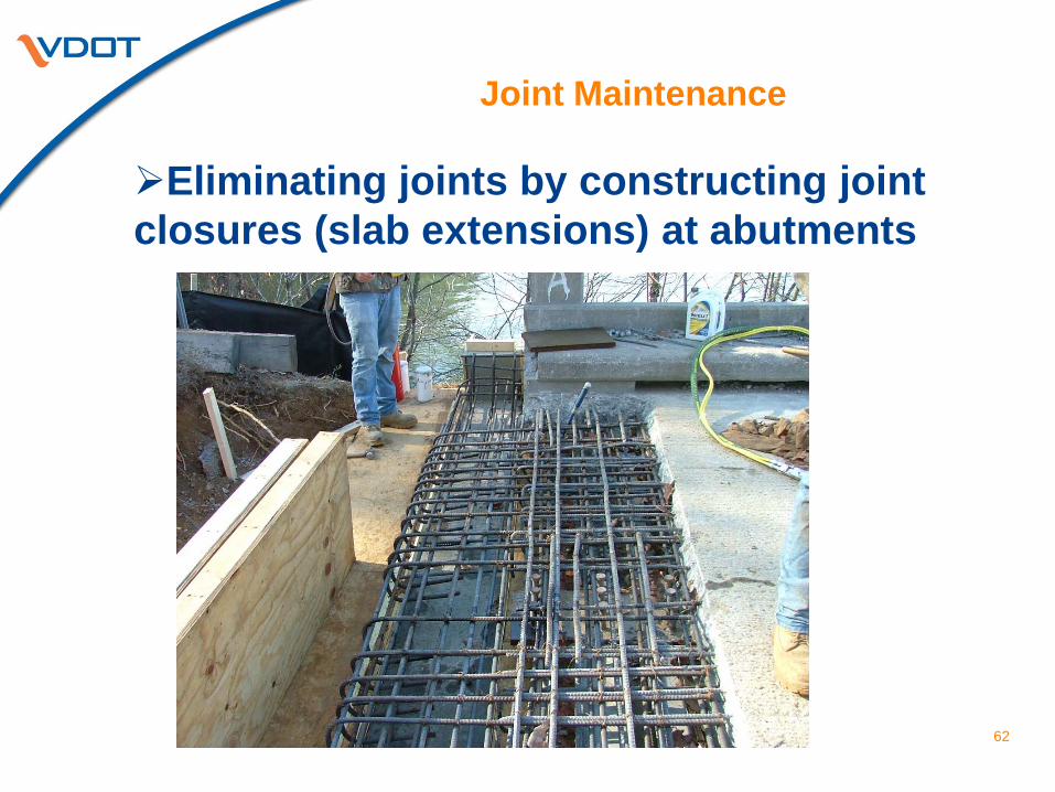
62
Eliminating joints by constructing joint closures (slab extensions) at abutments
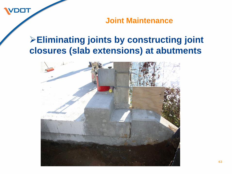
Joint Maintenance
63
Eliminating joints by constructing joint closures (slab extensions) at abutments
Thank you for your time and attention Questions??
2013 Virginia Concrete Conference Joint Maintenance and Best Practices in Deck Joint Replacement Jeff Milton Bridge Preservation Specialist Structure and Bridge Division