Embed Size (px)
DESCRIPTION
Design journal for Studio AIR 2013, semester 1, at the University of Melbourne.
Citation preview
1
A COLLABORATION OF EXPLORATION, EXPERIMENTATION AND THE
WESTERN GATEWAY DESIGN PROJECT
LOLA DIGBY-DIERCKS
2
DESIGN STUDIO AIR ABPL30048// LOLA DIGBY-DIERCKS 538221.SEMESTER TWO// 2013.TUTORS// DANIEL DAVIS AND KIRILLY BARNETT.
3
A journal to explore the journey through Architecture Design Studio: Air, semester one 2013.A personal introduction is included as well as exploration into the relation-ship between architecture and digital exposure.
4
5
C O N T E N T S
ONEA1.0 CASE FOR INNOVATION
1.1.0 Personal Background 8 1.2.0 Architecture as a Discourse 13 1.3.0 Computational Architecture 18 1.4.0 Parametric Modelling 20 1.5.0 Algorithmic Explorations 26 1.6.0 Case for Innovation conclusion 28
TWOB2.0 DESIGN APPROACH
2.1.0 Design Focus 34 2.2.0 Case Study 1.0 42 2.3.0 Case Study 2.0 48 2.4.0 Technique: Development 56 2.5.0 Technique: Prototypes 68 2.6.0 Technique Proposal 78 2.7.0 Design Approach conclusion 80
THREEC3.0 PROJECT PROPOSAL
3.1.0 Gateway Project: Design Concept 86 3.2.0 Gateway Project: Tectonic Elements 98 3.3.0 Gateway Project: Final Model Fabrication 104 3.4.0 How HAZE is Experienced 124 3.5.0 Beyond ‘Project Proposal’ 126 3.6.0 Project Proposal conclusion 128
References (part one, two and three) 130

6
7
CASE FOR INNOVATION
‘The pencil and computer are, if left to their own devices, equally dumb and only as good as the
person driving them.’
Norman Foster
8
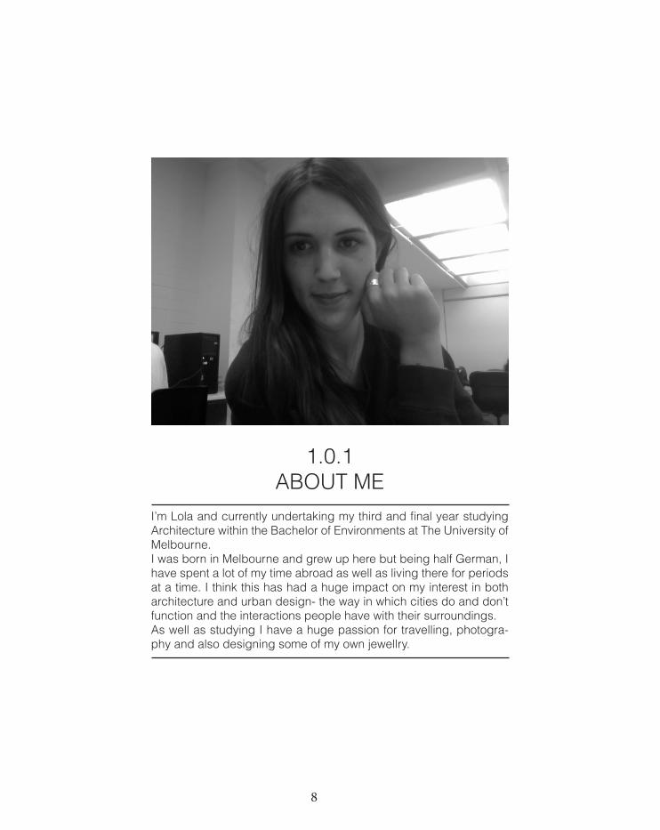
1.0.1 ABOUT ME
I’m Lola and currently undertaking my third and final year studying Architecture within the Bachelor of Environments at The University of Melbourne. I was born in Melbourne and grew up here but being half German, I have spent a lot of my time abroad as well as living there for periods at a time. I think this has had a huge impact on my interest in both architecture and urban design- the way in which cities do and don’t function and the interactions people have with their surroundings.As well as studying I have a huge passion for travelling, photogra-phy and also designing some of my own jewellry.
9
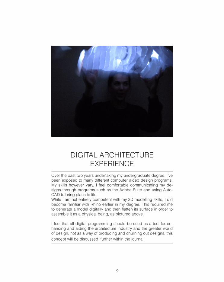
DIGITAL ARCHITECTURE EXPERIENCE
Over the past two years undertaking my undergraduate degree, I’ve been exposed to many different computer aided design programs. My skills however vary, I feel comfortable communicating my de-signs through programs such as the Adobe Suite and using Auto-CAD to bring plans to life. While I am not entirely competent with my 3D modelling skills, I did become familiar with Rhino earlier in my degree. This required me to generate a model digitally and then flatten its surface in order to assemble it as a physical being, as pictured above. I feel that all digital programming should be used as a tool for en-hancing and aiding the architecture industry and the greater world of design, not as a way of producing and churning out designs, this concept will be discussed further within the journal.
10
LOLA DIGBY-DIERCKS538221
IN COLLARBORATION WITH ALVAR AALTOABPL20028: ARCHITECTURE DESIGN STUDIO: WATER
SEMESTER TWO: 2012, ALIX SMITH
THE DESIGN INCORPORATES THE CRISP AND UNCOMPLICATED WORK OF ALVAR AALTO BUT ALSO REFLECTS THE AESTHETIC OF MYSELF. CLEAN LINES WITH PRACTICAL SPACES FINISHED WITH MATERIALS WHICH REFLECT THE HUMAN ABILITY. NATURE IS USED TO GLORIFY THE DESIGN AND ACTS AS THE CENTRAL FOCUS POINT. THE DESIGN ALSO COMMUNICATES THE USERS OF THIS AREA, THE AMOUNT OF SPACE THAT IS NEEDED TO ALLOW PATRONS TO COMFORTABLY PARTICIPATE IN RECREATIONAL ACTIVITIES AND ENJOY THEIR SURROUNDINGS.
MAIN ENTRANCE; CAFE SPACE KIOSK SERVICE AREA
VIEWS TO NATURE;EASTERN SIDE OF KIOSK, RESTAURANT, OFFICE SPACE, BOAT STORAGE.
MAIN ACCESS AND ENTRY POINT
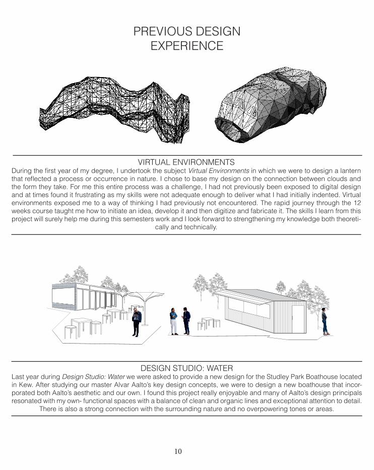
VIRTUAL ENVIRONMENTSDuring the first year of my degree, I undertook the subject Virtual Environments in which we were to design a lantern that reflected a process or occurrence in nature. I chose to base my design on the connection between clouds and the form they take. For me this entire process was a challenge, I had not previously been exposed to digital design and at times found it frustrating as my skills were not adequate enough to deliver what I had initially indented. Virtual environments exposed me to a way of thinking I had previously not encountered. The rapid journey through the 12 weeks course taught me how to initiate an idea, develop it and then digitize and fabricate it. The skills I learn from this project will surely help me during this semesters work and I look forward to strengthening my knowledge both theoreti-
cally and technically.
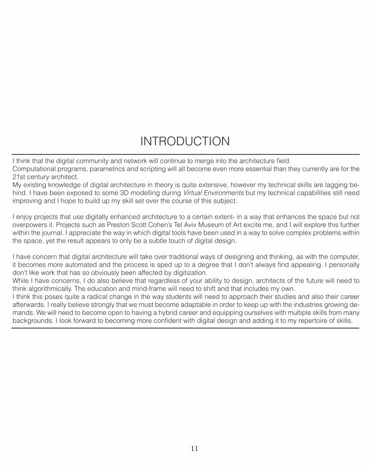
DESIGN STUDIO: WATERLast year during Design Studio: Water we were asked to provide a new design for the Studley Park Boathouse located in Kew. After studying our master Alvar Aalto’s key design concepts, we were to design a new boathouse that incor-porated both Aalto’s aesthetic and our own. I found this project really enjoyable and many of Aalto’s design principals resonated with my own- functional spaces with a balance of clean and organic lines and exceptional attention to detail.
There is also a strong connection with the surrounding nature and no overpowering tones or areas.
PREVIOUS DESIGN EXPERIENCE
11
I think that the digital community and network will continue to merge into the architecture field. Computational programs, parametrics and scripting will all become even more essential than they currently are for the 21st century architect.My existing knowledge of digital architecture in theory is quite extensive, however my technical skills are lagging be-hind. I have been exposed to some 3D modelling during Virtual Environments but my technical capabilities still need improving and I hope to build up my skill set over the course of this subject.
I enjoy projects that use digitally enhanced architecture to a certain extent- in a way that enhances the space but not overpowers it. Projects such as Preston Scott Cohen’s Tel Aviv Museum of Art excite me, and I will explore this further within the journal. I appreciate the way in which digital tools have been used in a way to solve complex problems within the space, yet the result appears to only be a subtle touch of digital design.
I have concern that digital architecture will take over traditional ways of designing and thinking, as with the computer, it becomes more automated and the process is sped up to a degree that I don’t always find appealing. I personally don’t like work that has so obviously been affected by digitization. While I have concerns, I do also believe that regardless of your ability to design, architects of the future will need to think algorithmically. The education and mind-frame will need to shift and that includes my own. I think this poses quite a radical change in the way students will need to approach their studies and also their career afterwards. I really believe strongly that we must become adaptable in order to keep up with the industries growing de-mands. We will need to become open to having a hybrid career and equipping ourselves with multiple skills from many backgrounds. I look forward to becoming more confident with digital design and adding it to my repertoire of skills.
INTRODUCTION
12
Using architecture as a way to link Wyndham to the city [of Melbourne] along the Princes Freeway will be the key com-ponent within the Western Gateway Design Project during this semester. In my opinion, architecture forms a physical object that is able to provoke discussion or discourse in some manner. In the case of this Western Gateway Design Project, architecture will be used to create discourse involving the link between two independent urban spaces and the journey connecting them.
It will be vital to use the stages within Case for Innovation, to explore the way architecture, computational architecture and parametric modelling can help mould the final design and also the way it influences architecture as a whole. The later stages of Design Approach and Project Proposal will further cement this idea that designing is an indented pro-cess, modified and altered along the journey.
Wyndham City is seeking an ‘exciting, eye-catching’ installation that both inspires and enriches the municipal and this can only be achieved through careful, thoughtful and experimental exploration, followed by a sufficient design process which is informed by earlier investigation. I intend to use Case For Innovation as a starting point of research, explora-tion and experimentation, before starting the design process of the Western Gateway Design Project. Ultimately, to form a successful piece of work and to fulfill the brief, I believe the final structure will need to involve the users emotionally, intellectually and/or physically.
RELATIONSHIP BETWEEN WESTERN GATEWAY DESIGN PROJECT AND CASE FOR INNOVATION
13
Architecture was once more simple to define, a type of art where a professional worked to confine spaces and build-ings were independent pieces (Williams 2005, 104-105).
As William states, architecture is more than just architec-ture. It is unavoidable in our every day lives and to a cer-tain extent, every inhabited part of the world is faced with some sort of architecture lining its streets. It has the ability to define and determine the way we navigate through cit-ies and suburban dwellings (Williams 2005, 103). Architecture can also be used to construct knowledge and map the world to signify and highlight specific points or zones (Dutton and Hurst Mann 1996, 1). As Greg discusses in Fold, Bodies and Blobs (1998, 170), no two blobs are alike and while they have the ability to be disconnected from any given place, they are also respon-sible for melding with their context.
When discussing architecture as a discourse, it is the relationship between architecture and its publics that is explored (ArchDaily 2013). It functions at the junction of power, relations of production, culture and representa-tion (Dutton and Hurst Mann 1996, 1). It is an integral link between the building of our identities and dissimilarities, and constructing and shaping the world as we know and understand it. This is particularly evident in the two precedents I have chosen to discuss below- Klein Bottle House and Helios House. Both deal with different social issues within dif-ferent contexts. The Klein Bottle House relates directly to this idea of linking the building to our identity through ar-chitecture. It deals with using space and shape to give
representation to those who inhabit it. Helios House deals with social concerns in a much more public manner. Its primary function is not to be a physical being but to use its existence to create awareness for a deeper cause.
So why is it, that traditionally, architectural discourse de-bates have been based on inquiry of style and moralistic dispute? (Leach 1997, xiii). Not on social or locality rea-sons, or based upon the very public that will most view it? This seems particularly important when assessing and undertaking the upcoming Gateway Project, in which the architectural ‘solution’ will be viewed by different back-grounds with no cultural and social limitation and not lim-ited to highlighting location, instead aiming to emphasize the journey between Wyndham City, full of natural, cul-tural, social and historical feature, and the City [of Mel-bourne]. I think when architecture is used as discourse, it would always be more than just the physical being that is dis-cussed. Its stature should be used to discuss larger is-sues and I am to do so throughout the semester.
The following precedents are architecture projects that I believe also operate as discourse. These works will act as examples to further strengthen my argument that the final piece of architecture produced within this project will fun-damentally act as discourse and benefit both the people of Wyndham City and the general public.
1.2.0ARCHITECTURE AS A DISCOURSE
14
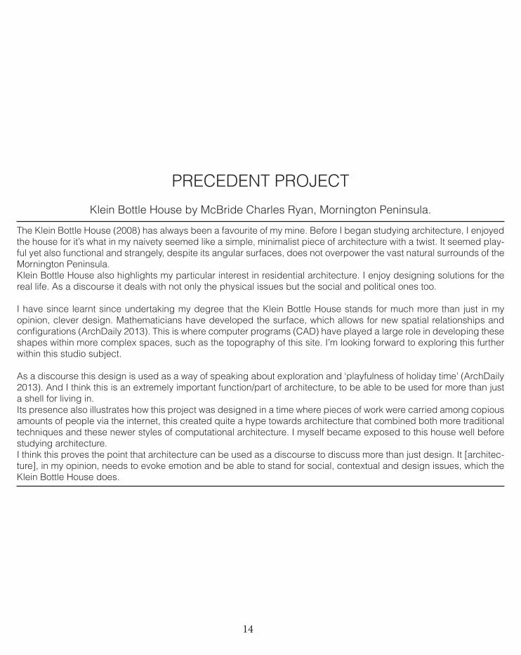
The Klein Bottle House (2008) has always been a favourite of my mine. Before I began studying architecture, I enjoyed the house for it’s what in my naivety seemed like a simple, minimalist piece of architecture with a twist. It seemed play-ful yet also functional and strangely, despite its angular surfaces, does not overpower the vast natural surrounds of the Mornington Peninsula. Klein Bottle House also highlights my particular interest in residential architecture. I enjoy designing solutions for the real life. As a discourse it deals with not only the physical issues but the social and political ones too.
I have since learnt since undertaking my degree that the Klein Bottle House stands for much more than just in my opinion, clever design. Mathematicians have developed the surface, which allows for new spatial relationships and configurations (ArchDaily 2013). This is where computer programs (CAD) have played a large role in developing these shapes within more complex spaces, such as the topography of this site. I’m looking forward to exploring this further within this studio subject.
As a discourse this design is used as a way of speaking about exploration and ‘playfulness of holiday time’ (ArchDaily 2013). And I think this is an extremely important function/part of architecture, to be able to be used for more than just a shell for living in. Its presence also illustrates how this project was designed in a time where pieces of work were carried among copious amounts of people via the internet, this created quite a hype towards architecture that combined both more traditional techniques and these newer styles of computational architecture. I myself became exposed to this house well before studying architecture. I think this proves the point that architecture can be used as a discourse to discuss more than just design. It [architec-ture], in my opinion, needs to evoke emotion and be able to stand for social, contextual and design issues, which the Klein Bottle House does.
PRECEDENT PROJECT
Klein Bottle House by McBride Charles Ryan, Mornington Peninsula.
15 1
16
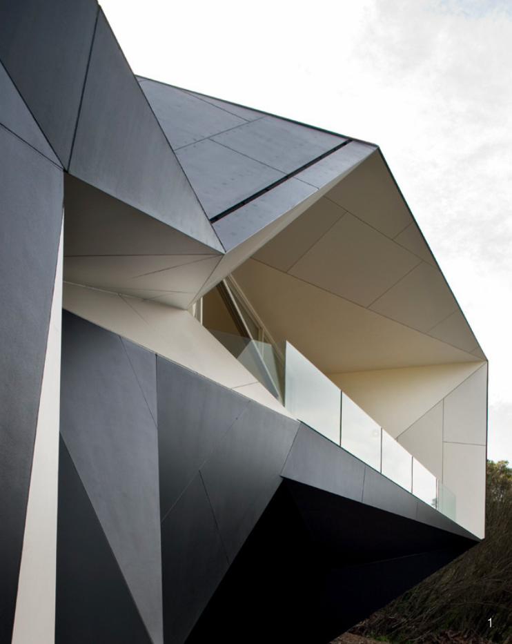
Helios House (2007) is the perfect example of how good design can help break down social moulds and be used as discourse, without compromising on cutting edge design. It’s architectural status acts as a way of discussing and exploring greater change, rather than just focusing on its physical status.Designed to ‘take small steps towards a sustainable future’ (Johnston Marklee 2013). Helios House is aiming to be the gas station of the future. The client, BP, is using Helios House as a way to show off its research into cleaner fuels, which unlike many other companies, has invested large amounts of money into its research and development. The design and concept behind it encourages users to discover ideas and carry them back into their own lives by fostering dialogue and education within an environment that normally promotes anything but (Jodidio 2011, 98).I particularly enjoy this interactive type of architecture, it has the ability to give back to the very people that view and use it daily. Users are encouraged to take part in the ‘living lab’ where they can encounter ideas to translate back into their own lives (BP 2013). This is a very different concept to other petrol stations.
From a design point of view, its stainless steel, triangle shaped shell, mimics the way in which programs such as Rhino, which we will be using during the semester, are able to create a tessellated structure. And in the case of Helios House, it is the cladding that has integrated technical innovation with careful composition. Its prefabricated panels also allow the whole design to unify into one structure through its complex geometry (Metal-Mag 2013).
Helios House gels with many of Schumacher framework for architecture in his writing New Framework for Architecture (2011, 18), especially in terms of how the discourse of architecture should also reflect its social and political impact and responsibility. I think this is extremely important, that architecture be flexible and adaptive to not only its physical surroundings but also its social and contextual ones too. Helios House is a perfect example of success, without compromising innovative and clever design. It is able to involve its users physically, to see, touch and understand the issues surrounding the problems with oil consumption and use.
PRECEDENT PROJECT
Helios House by Johnston Marklee, Los Angeles.
17 2
18
Contemporary computational design techniques have become almost an extension to the architect and many others in the design field. They have become a tool to bet-ter express ourselves and to communicate ideas. In more recent years, it’s certainly the tools and programs that have become available that have allowed designers to explore beyond the confines lay down by more tradi-tional design approaches.They (computational design techniques) have the pow-er to record and then recall an almost unlimited amount of commands, tasks and memories in a fraction of time, which humans are just not capable of undertaking.
Even with the aid of technology, designing involves a process. It’s made up of different stages no matter what equipment is being used and requires certain steps to be undertaken to achieve a final result.It is with the use of computer aided programs, that this process is able to be probed, altered and recorded, and then recalled in far less time than before we gained ac-cess to its use. Yehuda (2004, 7) speaks of how computers by default, if programmed and used correctly, are able to follow any command to their own logical conclusion. They are able to do it quickly, repeat themselves over and over and follow a set of guidelines given, to complete the task to the most minute of details. They are then able to format and present the chosen information, in the largest ar-ray of ways possible, all with a few clicks of a button. So how are humans able to compete? Or do most forget
that there is indeed a human behind these computer pro-grams that has ultimate control over the outcome?
This raises a very valid point, even with computer aided programming available, it still only functions on the ba-sis that there is a human behind the computer, someone to express and input ideas. As Kostas Terzidis states (2006, 11), the dominant mode of utilizing computers in architecture today is the process of using already con-ceptualized ideas from the designer and entering, ma-nipulating and storing them within the computers system. This cements the fact that no matter the technology be-ing used, it is still the human that must make up new sets of instructions for the computer. Using computers in the design world relies on communication and shared knowl-edge.
While it is fairly easy for the computer to transmit informa-tion to the human, it is extremely difficult for the human to communicate to the computer (Yehuda 2007, 7).This is very evident when a designer is not familiar with a program and must painstakingly try to transfer an idea or design from their mind to the computer, which relies on receiving information through interpreted codes. Does this mean, in some cases, that designers choose to avoid this hurdle by opting to design something within the com-puters limitations rather than their own? In some cases, yes. Or does this then mean that in some instances, when the wrong human is behind the screen, or perhaps a less familiar [to computer aided programming] human, that
1.3.0CONTEMPORARY COMPUTATIONAL DESIGN
TECHNIQUES
19
contemporary computational design techniques become less of an advantage and more of a hindrance? Also in some cases, yes.
As Kolarevic (2003, 6) supports, for many architects in particular, this arrival of curvilinear forms, after being trained in the process of ‘euclidean geometry,’ presents many difficulties.Below are three key types of techniques related with the ‘assistance to human designers’ as identified by Yehuda (2007, 8). They summarize the different ways in which computational techniques can be used to a certain ex-tent, depending on what the designer wishes to achieve. This places the emphasis again on the fact that while a computer is capable of achieving almost every task giv-en, it comes down to the communication skills between it and the human.
1. Drafting or modelling; where computers are re-stricted to just supporting humans by creating lines and geometric objects- communicating the humans ideas.2. Analytical systems; where the computer is able to issue evaluation of the designers’ result.3. Knowledge-based; the computer is able to put forth design solutions for the human designer.
It seems many designers use a combination of tech-niques.
Contemporary computational design techniques are not exactly new, however with time they continue to update and grow.I believe that ideally, this unison between designers and computers should not result in the computerisation of any-thing and everything but to use the technology available as a tool to integrate ‘conception and production’ in a manner that was not possible before its possession (Ko-larevic 2003, 4). As with all things computer based- the possibilities are endless and it’s a matter of wait and see.
20
‘Can architecture afford not to use computation’ was one of the statements put forward during the various learning’s in week three. It seems that all arms point in the direction of no; no archiecture cannot afford to ignore computation-al design and therefore also parametric modelling.
As Robert Woodbury (2010, 7) states, ‘design is change. Parametric modeling represents change.’ And isn’t that what architecture and design is all about, evolving and adjusting to variation along the process or over a period of time?However I pose the question, has the use of parametrics within architecture and the greater design field shaped up to be what everyone expected? Or what indeed did they expect? And what will the future hold?
Woodbury (2010) and Mark Burry (2011) both agree that the use of parametrics for designers is overall positive. Having said that, they both also agree that its use is not easy, one must be mathematically informed and more than computer literate. And to both teach and learn para-metric modelling requires a deep understanding of more than just what is seen at the surface.
Some of the key problems [with parametrics] that were identified within the lecture (Smith, 2007) are as follows:
1. Front loading; projects need to be carefully planned, step-by-step. This removes some of the spontaneity and the freedom to explore.
2. Major changes; changing the skeleton/fabric of a parametric model can cause it to ‘break’, this means that again, the design needs to be carefully planned or chang-es greatly alter its completion.3. Reusing and sharing; with parametric design [and scripting], it is extremely difficult to share models/designs/scripts with those that do not possess the same level of knowledge. Burry also concluded this within his research.4. Seeing change; smaller changes are much harder to recognize when they are embedded within a larger data set. Thus harder to also find faults.
These disadvantages [with parametric design] were sup-ported by Burry to a certain extent; he put forward some further potential dangers within the scripting community. These dangers included:“Death of the pencil sketch”“Enfranchising the amateur”Design becoming ‘automated’Becoming repetitiveConcern for emergence of a style over substance.
I think these are all valid concerns. It seems a shame that because of the inevitable amounts of current and new programs emerging, that designers could potentially loose sight of their true designs, their underpinning rea-son for creating objects and structures. Once programs become popular, they also hold the likeli-hood of spreading a certain style, or perhaps a certain trend. Thus generating a repetitive style or manner.
1.4.0PARAMETRIC MODELLING
21
Another key point that was identified throughout week threes lectures, readings and discussions, that I think is particularly relevant, is that the education for students needs to be updated to reflect this change in what will become obligatory skills for the future.
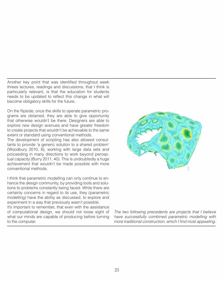
On the flipside; once the skills to operate parametric pro-grams are obtained, they are able to give opportunity that otherwise wouldn’t be there. Designers are able to explore new design avenues and have greater freedom to create projects that wouldn’t be achievable to the same extent or standard using conventional methods. The development of scripting has also allowed consul-tants to provide ‘a generic solution to a shared problem’ (Woodbury 2010, 8), working with large data sets and proceeding in many directions to work beyond percep-tual capacity (Burry 2011, 40). This is undoubtedly a huge achievement that wouldn’t be made possible with more conventional methods.
I think that parametric modelling can only continue to en-hance the design community, by providing tools and solu-tions to problems constantly being faced. While there are certainly concerns in regard to its use, they (parametric modelling) have the ability as discussed, to explore and experiment in a way that previously wasn’t possible.It’s important to remember, that even with the assistance of computational design, we should not loose sight of what our minds are capable of producing before turning to the computer.
The two following precedents are projects that I believe have successfully combined parametric modelling with more traditional construction, which I find most appealing.
3
22
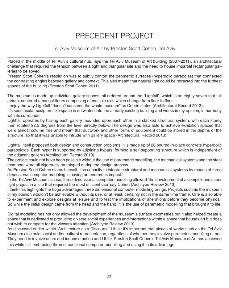
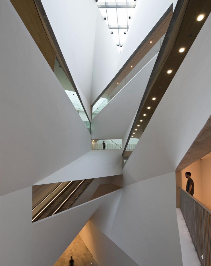
Placed in the middle of Tel Aviv’s cultural hub, lays the Tel Aviv Museum of Art building (2007-2011), an architectural challenge that required the tension between a tight and triangular site and the need to house impartial rectangular gal-leries to be soved. Preston Scott Cohen’s resolution was to subtly contort the geometric surfaces (hyperbolic parabolas) that connected the contrasting angles between gallery and context. This also meant that natural light could be refracted into the furthest spaces of the building (Preston Scott Cohen 2011).
The museum is made up individual gallery spaces, all ordered around the “Lighfall”, which is an eighty-seven foot tall atrium, centered amongst floors comprising of multiple axis which change from floor to floor. I enjoy the way Lightfall “doesn’t consume the whole museum” as Cohen states (Architectural Record 2013).It’s spectacular sculpture like space is entwinted into the already existing building and works in my opinion, in harmony with its surrounds.Lightfall operates by having each gallery mounded upon each other in a stacked structural system, with each storey then rotated 22.5 degrees from the level directly below. The design was also able to achieve exhibition spaces that were almost column free and meant that ductwork and other forms of equipment could be stored in the depths of the structure, so that it was unable to intrude with gallery space (Architectural Record 2013).
Lightfall itself proposed both design and construction problems, it is made up of 28 poured-in-place concrete hyperbolic paraboloids. Each hypar is supported by adjoining hypars, forming a self-supporting structure which is independent of the adjacent gallery (Architectural Record 2013). The project could not have been possible without the use of parametric modelling, the mechanical systems and the steel members were all vigorously prototyped during the design process. As Preston Scott Cohen states himself ‘the capacity to integrate structural and mechanical systems by means of three dimensional computer modeling is having an enormous impact.’ In the Tel Aviv Museum’s case, three dimensional computer modelling allowed ‘the development of a complex and super tight project in a site that required the most efficient use’ say Cohen (Architype Review 2013). I think this highlights the huge advantages three dimensional computer modelling brings. Projects such as the museum in my opinion wouldn’t be achievable without its use, or at least, certainly not in the same time frame. One is also able to experiment and explore designs at leisure and to test the implications of alterations before they become physical. So while the initial design came from the head and the hand, it is the use of parametric modelling that brought it to life.
Digital modeling has not only allowed the development of the museum’s surface geometries but it also helped create a space that is dedicated to producing diverse social experiences and interactions within a space that houses art but does not wish to compete for the viewers attention (Architype Review 2013).As discussed earlier within ‘Architecture as a Discourse’ I think it’s important that pieces of works such as the Tel Aviv Museum also hold social and/or cultural representation, regardless of whether they involve parametric modelling or not. They need to involve users and induce emotion and I think Preston Scott Cohen’s Tel Aviv Museum of Art has achieved this while still embracing three dimensional computer modelling and using it to its advantage.
PRECEDENT PROJECT
Tel Aviv Museum of Art by Preston Scott Cohen, Tel Aviv.
23 4
24
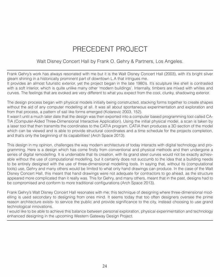
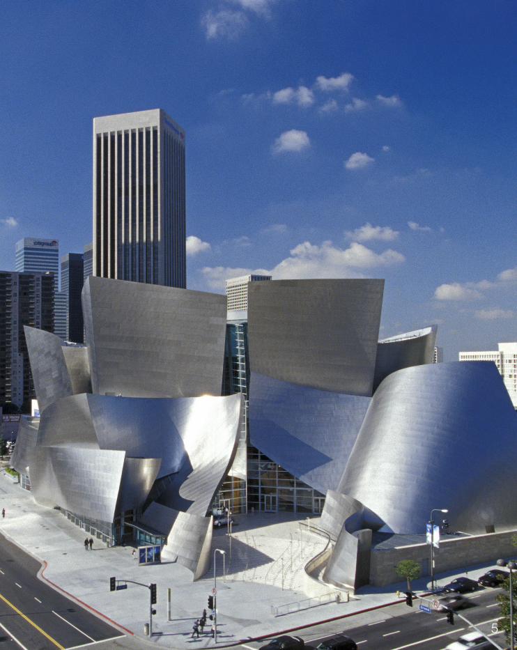
Frank Gehry’s work has always resonated with me but it is the Walt Disney Concert Hall (2003), with it’s bright silver gleam shining in a historically prominent part of downtown L.A that intrigues me. It provides an almost futuristic exterior, yet the project began in the late 1980’s. It’s sculpture like shell is contrasted with a soft interior, which is quite unlike many other ‘modern buildings’. Internally, timbers are mixed with whites and curves. The feelings that are evoked are very different to what you expect from the cool, clunky, shadowing exterior.
The design process began with physical models initially being constructed, stacking forms together to create shapes without the aid of any computer modelling at all. It was all about spontaneous experimentation and exploration and from that process, a pattern of sail like forms emerged (Kolarevic 2003, 152).It wasn’t until a much later date that the design was then exported into a computer based programming tool called CA-TIA (Computer-Aided Three-Dimensional Interactive Application). Using the initial physical model, a scan is taken by a laser tool that then transmits the coordinates to the CATIA program. CATIA then produces a 3D section of the model which can be viewed and is able to provide structural coordinates and a time schedule for the projects completion, and that’s only the beginning of its capabilities! (Arch Space 2013).
This design in my opinion, challenges the way modern architecture of today interacts with digital technology and pro-gramming. Here is a design which has come firstly from conventional and physical methods and then undergone a series of digital remodelling. It is undeniable that its creation, with its grand steel curves would not be exactly achiev-able without the use of computational modelling, but it certainly does not succumb to the idea that a building needs to be entirely designed with the use of three-dimensional modelling tools. In saying that, without its (computational tools) use, Gehry and many others would be limited to what only hand drawings can produce. In the case of the Walt Disney Concert Hall, this meant that hand drawings were not adequate for contractors to go ahead, as the structure appeared more complicated than it really was. This for Gehry, and many others, meant that in the past, designs had to be compromised and conform to more traditional configurations (Arch Space 2013).
Frank Gehry’s Walt Disney Concert Hall resonates with me; this technique of designing where three-dimensional mod-elling is used secondary to designing from ones mind. It seems today that too often designers oversee the prime reason architecture exists- to service the public and provide significance to the city, instead choosing to use grand technological innovations.I would like to be able to achieve this balance between personal exploration, physical experimentation and technology enhanced designing in the upcoming Western Gateway Design Project.
PRECEDENT PROJECT
Walt Disney Concert Hall by Frank O. Gehry & Partners, Los Angeles.
25 5
26
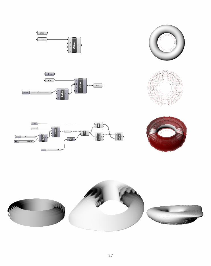
Throughout the Case for Innovation stage, I have been undertaking my own individual exploration of algorithmic pieces within Grasshopper. These pieces of experimentation have been used to apply the knowledge learnt throughout this Case for Innovation in a more practical way after discussions, lectures and readings. They have also been useful to trial and test various techniques before the upcoming stages.A more interesting example of my work is shown, however more experimentation will be undertaken in the next stage.
ALGORITHMIC EXPLORATIONS
To the right is a driftwood surface that has been created from quite a regular shape but has been altered after the initial finish was generated. As a surface, I think driftwood provides a really interesting fabrication technique and as I demonstrate, it can be ma-nipulated to form many different finishes.
Having the ability to alter a surface post creation shows the potential it has to be used in a project such as the one we will be undertaking. Small alterations can be made to the surface to reflect perhaps social, contextual or physical changes that need to be displayed.
27
28
After concluding this section, I have some clear direction about where I would like my design to head for the Western Gateway De-sign Project. I feel there a few key elements that need to be captured within the design and subsequently need to be explored during the design approach stage.I believe that the brief calls for a strong link between design and con-text while still encapsulating place-making aspects and qualities. The journey between Wyndham and the city needs to be captured but careful consideration also needs to be taken towards the physi-cal surroundings and the fact there is lots of traffic moving through this area. I think it will be crucial to design in this manner so; that as the brief calls, the wide public can enjoy its installation and it can be used as an indicator that metropolitan Melbourne is arriving. It also needs to be new, inspiring and brave. I hope to express this within my design so that a new discourse along the site can be created.
1.6.0CASE FOR INNOVATION CONCLUSION
28
29
Up until this point, the journey through this studio is becoming more and more exciting.I am becoming more confident and informed about both the theo-retic and technical side of computational design. While I am still not overly competent with my technical skills, I am more so than ever appreciating the benefits of using it across the whole design field and after extensive research and reading, I can see that there is no turning back- it’s here to stay and we will all have to adapt to using it within the future. And while I maintain that I don’t believe compu-tational architecture should take over traditional techniques is all re-gards, I am more open to the idea of combining the two disciplines. I think this reflects how my understanding of the topic has greatly developed from the beginning of the semester. I am excited to keep exploring further and applying the knowledge learnt within this se-mester to the final project but also to the broader scheme of things.
LEARNING OUTCOMES
29

30
31
The following two sections are a reflection of the collaboration between myself and my amazing group members, Ailie Miller and Thomas Chiew. Without them, this simply would not have been possible. With them, thank-you is an understatement.

32
33
DESIGN APPROACH
‘Design is as much a matter of finding problems as it is solving them.’
Bryan Lawson
34
This section of the journal will explore and explain the area of interest chosen. Evidence will be provided to illustrate design explorations that have been undertaken within case-studies and also general re-search. Specific techniques will also be used and further developed for the future design.The chosen design approach will have a clear reason for its choos-ing, reflecting why it is the most suitable method in comparison to other approaches.
The brief calls for an exciting structure to be designed, in order to create a defining experience for Wyndham. It is sectioning that is capable of representing natural or given movements and able to capture a moment in time rather than being a static object like many other techniques. As put forward in Case for Innovation, I believe architecture needs to stand for more than just being an object. It needs to create discus-sion and/or harness a concept or meaning. This notion will continue to be probed throughout Design Approach.As the brief calls, this project is about creating a new discourse for the city of Wyndham and we hope to be able to deliver that within our final design, using sectioning as a delivery mode.
2.1.0DESIGN FOCUS
35
SECTIONING TECHNIQUE
Our group selected the research field of sectioning. Sectioning consists of slicing a portion or an entire structure into individual segments. In turn it is able to become an object of more substance and meaning, something that is able to be manipulated and reflective. Sectioning has been used in many instances before, particularly within sculptures and architectural pieces. Not only is it a practical method of designing but also extremely effective in terms of what it wishes to achieve.
We believe sectioning offers:• A dynamic surface allowing for diverse manipulation which can relate to given inputs.• Each surface can be used as an individual form of expression.• Three-dimensional objects are able to become two-dimensional surfaces. • Flexibility both as a surface- the way in which the voids between each individual section can be controlled to represent information and also in terms of what views are created; control over what is revealed and concealed. • A practical approach to achieving the brief; sectioning allows for views to be framed and for the design to house single members while still maintaining a complete form.
Sectioning presents us with a unique technique, allowing the dy-namic manipulation of a three-dimensional formation, one that al-lows for imputs or the spaces between sections to be utilized. These spaces are also able to represent their own identity or can be used to reveal areas previously hidden or draw attention to others. Illu-sion and perception can also be carefully altered through the use of sectioning and this will be a key focus within our proposed design as we seek to create a new defining moment within the Wyndham
36
Using our chosen research field, the following conceptual ideas were generated. While they are quite sketchy, and still in the initial stages, our group feel they are a good starting point and I hope to capture how the fol-lowing ideas have develop throughout the remainder of this journal:
1. Correlation between Wyndham City and neighboring cities. Physically there is a change in topography. And that can then have a profound affect emotionally on users.Wyndham is quite open, more natural, while the city tends contains harsher angles, linear shapes, compacted and constricted.Plugging in points from the site’s contours to create a physical rep-resentation juxtaposed against the city-scape could be interesting to explore.
2. Using time as a motivator. Sections can represent moments in movement, perhaps simulate a natural or artificial process.Explore the distances between each individual ‘slice’ of the section. What could those distances represent? Speed, travel, growth, par-ticles of time? Or could they be manipulated to represent something more conceptual? Could provide information or be left bare so it’s open to interpretation.
3. Using sections to elaborate/highlight/reveal areas or to block out and conceal certain points. What do we choose to reveal and what do we choose to conceal?
4. Illusions can be created or optical illusions. Added depth to the structure, experienced from before the approach.This becomes quite suggestive, you can perceive something as be-ing there, or not being there. Do different people view illusions in different ways?
The following precedents were used to begin investigating the capa-bilities of sectioning as a technique and to also commence forming some conceptual background to our project. Each precedent was selected based on what information or techniques could be extracted from the design and potentially be applied to our own.
INITIAL DIRECTION
37
38
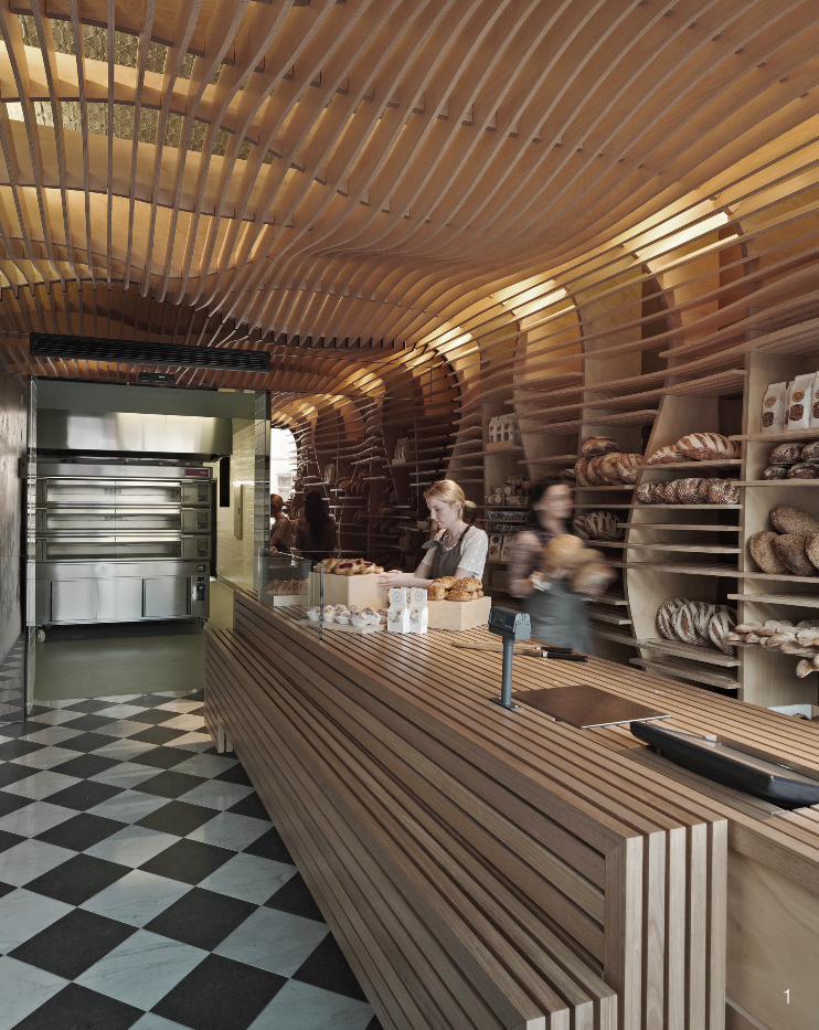
March studios designed the bakery shop front fit out using CNC routed plywood, which has formed an almost cur-tain falling sheet from ceiling down to the floor, strung across the wall, in an extremely undulated and fluid manner (Melbourne Design Awards 2013). This has been achieved through the use of sectioning which has resulted in an extremely compelling piece of work.
This design offers flexible solutions, both pre and post designing and construction. The open spaces between each section are able to accommodate the areas and also voids needed. It also has the unique ability to be rearranged later, change according to mood/season or on a more practical level by being able to be slotted together or taken apart depending on what needs to be displayed. I find this to be a very interesting con-cept, where the architecture is no longer static and becomes almost interactive. It [the design] also provides a literal representation of the shops agenda, using the fit out to convey program and activ-ity. It becomes sculpture like, an aesthetic marker.
The design also draws users in from the street and acts as a conversation starter outside which can then be experi-enced internally. It’s simple in form and uses understated materials to form a piece of raw and exposed work, where the frame work and the elements behind the design can be viewed.I think these are both very valid points in terms of a starting point for our own design. Incorporating some sort of inter-action- whether that be physical or emotional is important, as a way of creating discourse for Wyndham City and its Baker D Chirico’s design that provides a realistic solution to some of the issues we wish to address. It’s uncomplicated and not trying to defy or over-power its surrounds.
I enjoy the way in which this project combines sectioning with a mixed shape surface. It creates an undu-lated form rather than a linear one. From a practical view point, I also think this fit out offers a resolution to the client, which is much like what we are being asked to achieve but on a different level and in a different manner. The structure is able to be altered according to what is needed- bigger or smaller shelves, space for blocking out areas, space to highlight new products etc. I think this is a very captivating concept and one that could be further explored and applied to our own project. I also really enjoy the use of a more ‘raw’ material (plywood) in this case, which works to the advantage of this project and doesn’t overwhelm the space. This will certainly be another factor to consider within our own work.
DESIGN EXPLORATIONBaker D Chirico by March Studios, Carlton.
39 1
40
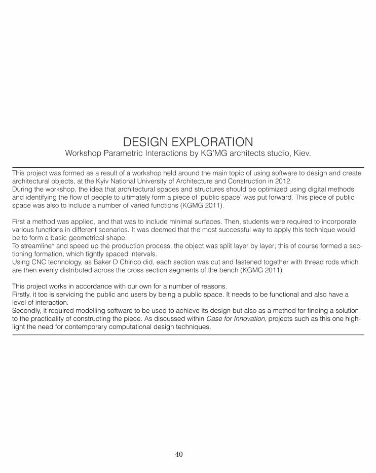
This project was formed as a result of a workshop held around the main topic of using software to design and create architectural objects, at the Kyiv National University of Architecture and Construction in 2012. During the workshop, the idea that architectural spaces and structures should be optimized using digital methods and identifying the flow of people to ultimately form a piece of ‘public space’ was put forward. This piece of public space was also to include a number of varied functions (KGMG 2011).
First a method was applied, and that was to include minimal surfaces. Then, students were required to incorporate various functions in different scenarios. It was deemed that the most successful way to apply this technique would be to form a basic geometrical shape. To streamline* and speed up the production process, the object was split layer by layer; this of course formed a sec-tioning formation, which tightly spaced intervals. Using CNC technology, as Baker D Chirico did, each section was cut and fastened together with thread rods which are then evenly distributed across the cross section segments of the bench (KGMG 2011).
This project works in accordance with our own for a number of reasons. Firstly, it too is servicing the public and users by being a public space. It needs to be functional and also have a level of interaction. Secondly, it required modelling software to be used to achieve its design but also as a method for finding a solution to the practicality of constructing the piece. As discussed within Case for Innovation, projects such as this one high-light the need for contemporary computational design techniques.
DESIGN EXPLORATIONWorkshop Parametric Interactions by KG’MG architects studio, Kiev.
41 2
42
2.2.0CASE STUDY 1.0 PROJECT TASK
BANQ Restaurant by Office dA, Boston.
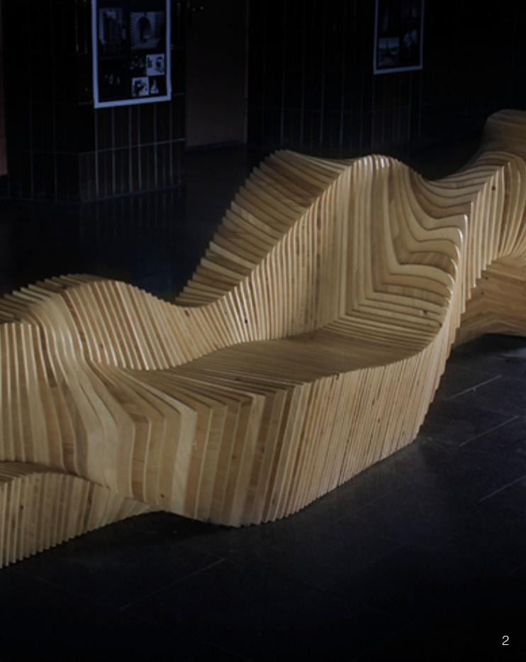
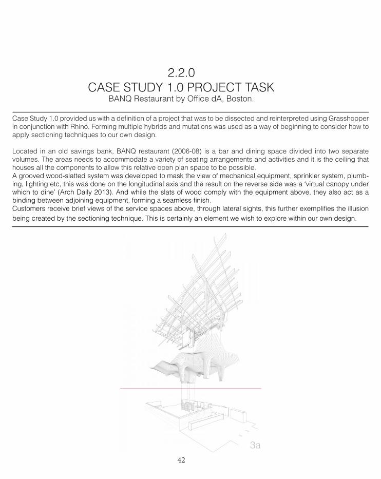
Case Study 1.0 provided us with a definition of a project that was to be dissected and reinterpreted using Grasshopper in conjunction with Rhino. Forming multiple hybrids and mutations was used as a way of beginning to consider how to apply sectioning techniques to our own design.
Located in an old savings bank, BANQ restaurant (2006-08) is a bar and dining space divided into two separate volumes. The areas needs to accommodate a variety of seating arrangements and activities and it is the ceiling that houses all the components to allow this relative open plan space to be possible. A grooved wood-slatted system was developed to mask the view of mechanical equipment, sprinkler system, plumb-ing, lighting etc, this was done on the longitudinal axis and the result on the reverse side was a ‘virtual canopy under which to dine’ (Arch Daily 2013). And while the slats of wood comply with the equipment above, they also act as a binding between adjoining equipment, forming a seamless finish.Customers receive brief views of the service spaces above, through lateral sights, this further exemplifies the illusion being created by the sectioning technique. This is certainly an element we wish to explore within our own design.
3a
43 3
44
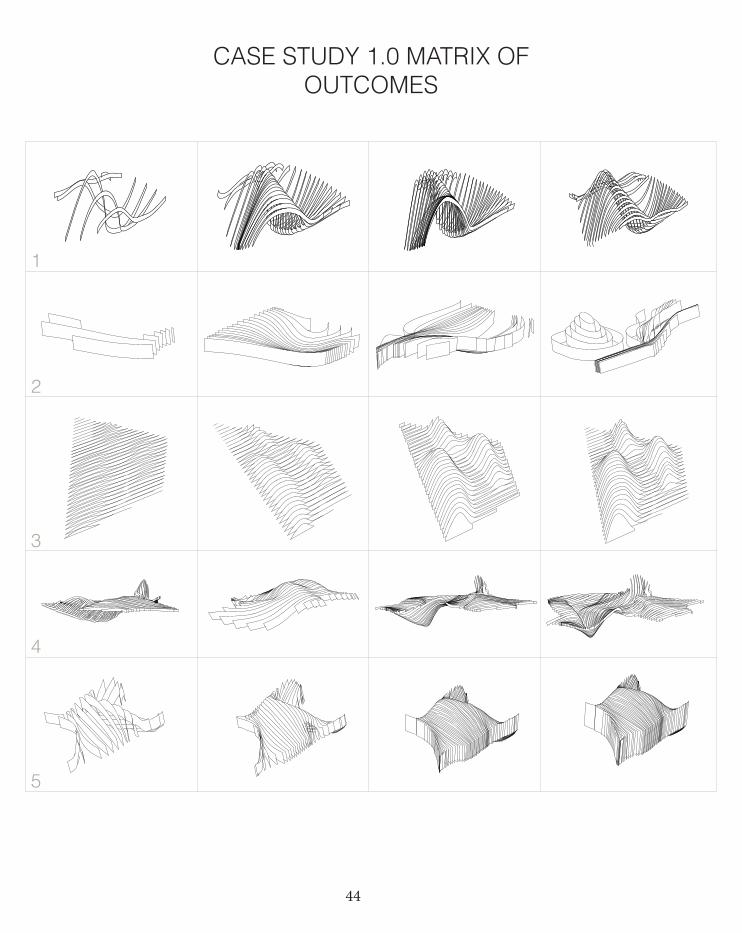
CASE STUDY 1.0 MATRIX OF OUTCOMES
1
2
3
4
5
45
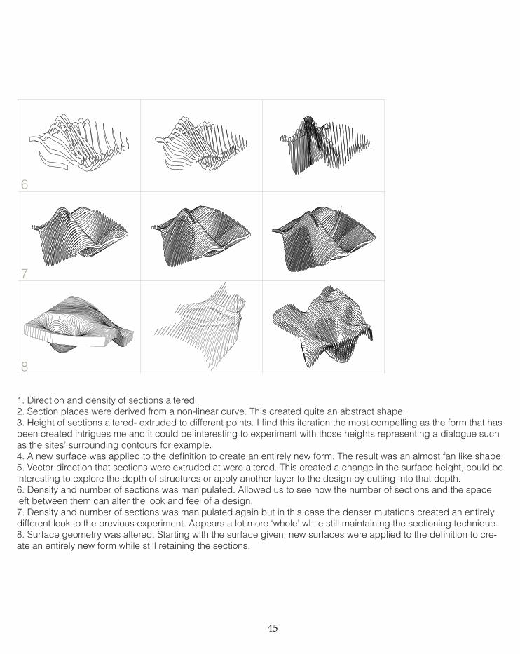
6
7
8
1. Direction and density of sections altered.2. Section places were derived from a non-linear curve. This created quite an abstract shape.3. Height of sections altered- extruded to different points. I find this iteration the most compelling as the form that has been created intrigues me and it could be interesting to experiment with those heights representing a dialogue such as the sites’ surrounding contours for example.4. A new surface was applied to the definition to create an entirely new form. The result was an almost fan like shape.5. Vector direction that sections were extruded at were altered. This created a change in the surface height, could be interesting to explore the depth of structures or apply another layer to the design by cutting into that depth.6. Density and number of sections was manipulated. Allowed us to see how the number of sections and the space left between them can alter the look and feel of a design.7. Density and number of sections was manipulated again but in this case the denser mutations created an entirely different look to the previous experiment. Appears a lot more ‘whole’ while still maintaining the sectioning technique. 8. Surface geometry was altered. Starting with the surface given, new surfaces were applied to the definition to cre-ate an entirely new form while still retaining the sections.
46
CASE STUDY 1.0 OUTCOMES
The different forms that were created were a result of changing the vari-ous parameters. Some forms explored were based more on a surface while others focused on the potential possibilities of sectioning.
Our design space consisted of creating a large scope of iterations and then analyzing which ones produced the most successful version/s and assessing how that could be applied to our own future design. We were trying to achieve techniques that could help us inform our fu-ture design. However in the case of BANQ, the outcomes that produced were not entirely in keeping with what we wish to achieve. I feel this is because the BANQ definition is very location driven- it responds to the site (the restaurant) and wouldn’t be so successful in our own site- a vast open space beside a highway.
Architectural application= great for fit out, creates an extremely effec-tive look. More of a surface than a structure. However some of its principals are still able to cross over into our own, such as the way it has the ability to conceal certain areas and highlight others. Visually it is very captivating
47
CASE STUDY 1.0 CONCLUSION
After generating research, exploring precedents and using the BANQ restaurant definition; also keeping in mind key components that our group would like to incorporate as a response to the brief, the follow-ing concepts and design options have been generated moving into the next stages of this design journey:
To define a unique experience for Wyndham City, rather than it informing the design. Harnessing the key link between the brief, the site and the user. Concept of time, speed and how this is experienced becomes [in our opinion] the most relevant factor within this project.
Time and speed as a dictator: idea of manipulating the perception of time and speed. What that journey means and how the ‘experience’ for Wyndham City can be relived after the user has been exposed to the design; extend the experience, both physically and emotionallyEmotionally leaving a lingering thought after a physical experience has taken placeAchieved through the use of sectioning and manipulating the spaces between them.
Animation through movement: using the journey/period of time in which the vehicle experiences the design to cast an animation or message.
Experimentation with perspective: sectioning is able to exhibit different views at various points of view. Different angles at different distances could produce altered imagery. This could be extremely effective given the site is only experienced for approximately 30-40 seconds (travelling at approximately 100 km/hour), so any way of prolonging the experi-ence or providing more than just one experience could be extremely beneficial.
Directly transposing a surface into sections: this idea has been a con-stant throughout our whole experimentation phase of Case Study 1.0. While it could perhaps be perceived as being too literal, it could also have the ability to cast extremely interesting imagery of perhaps the surrounding landscape, social issues within the muncipal or upcoming events for example. As stated within the Baker D Chirico precedent, sectioning allows for flexibility within design. The design can physically be altered according to season/mood.
48
2.3.0CASE STUDY 2.0 PROJECT TASK
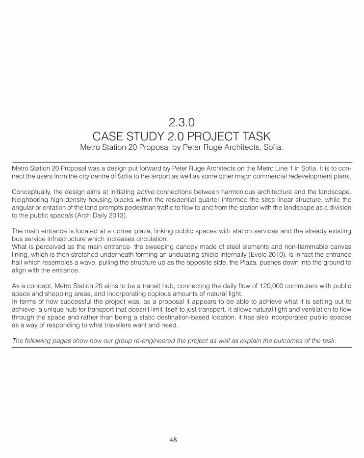
Metro Station 20 Proposal by Peter Ruge Architects, Sofia.
Metro Station 20 Proposal was a design put forward by Peter Ruge Architects on the Metro Line 1 in Sofia. It is to con-nect the users from the city centre of Sofia to the airport as well as some other major commercial redevelopment plans.
Conceptually, the design aims at initiating active connections between harmonious architecture and the landscape. Neighboring high-density housing blocks within the residential quarter informed the sites linear structure, while the angular orientation of the land prompts pedestrian traffic to flow to and from the station with the landscape as a division to the public space/s (Arch Daily 2013).
The main entrance is located at a corner plaza, linking public spaces with station services and the already existing bus service infrastructure which increases circulation. What is perceived as the main entrance- the sweeping canopy made of steel elements and non-flammable canvas lining, which is then stretched underneath forming an undulating shield internally (Evolo 2010), is in fact the entrance hall which resembles a wave, pulling the structure up as the opposite side, the Plaza, pushes down into the ground to align with the entrance.
As a concept, Metro Station 20 aims to be a transit hub, connecting the daily flow of 120,000 commuters with public space and shopping areas, and incorporating copious amounts of natural light. In terms of how successful the project was, as a proposal it appears to be able to achieve what it is setting out to achieve- a unique hub for transport that doesn’t limit itself to just transport. It allows natural light and ventilation to flow through the space and rather than being a static destination-based location, it has also incorporated public spaces as a way of responding to what travellers want and need.
The following pages show how our group re-engineered the project as well as explain the outcomes of the task.
49 4
50
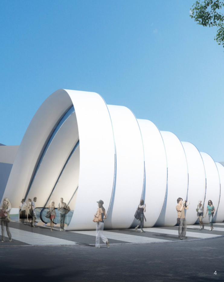
1. This iteration was our first attempt, where sections were used to intercept a loft. While it achieved some of the features of the original Metro Station 20 proposal, it lacked much more. Unable to achieve an smooth bottom sur-face. Each strip was cut off on an angle, hence not achieving a shape that would be flush with the ground. The slight curve to the arch of each strip was also a challenge and so was determining a way to allow each subsequent arch/strip to be slightly smaller than the previous.2. Used a different surface to begin the process. Firstly no angle was given to the shape, just extruded from the curve, this created a flat surface. This was then tweaked by inputting an angle however the response was not the de-sired look and the cut line was altered. Next step consisted of placing the angle in the correct position so that lastly, the form was able to be smoothed out. The result was a lot more successful than the previous attempt.3. This line shows the above iteration in top view to illustrate the effect changes in angle had on the surface.4. The last attempt was our most successful and result was an almost complete re-engineering of the case study. This was achieved through applying yet another new surface which in turn proved to be correct.
CASE STUDY 2.0 MATRIX OF OUTCOMES
1
2
3
4
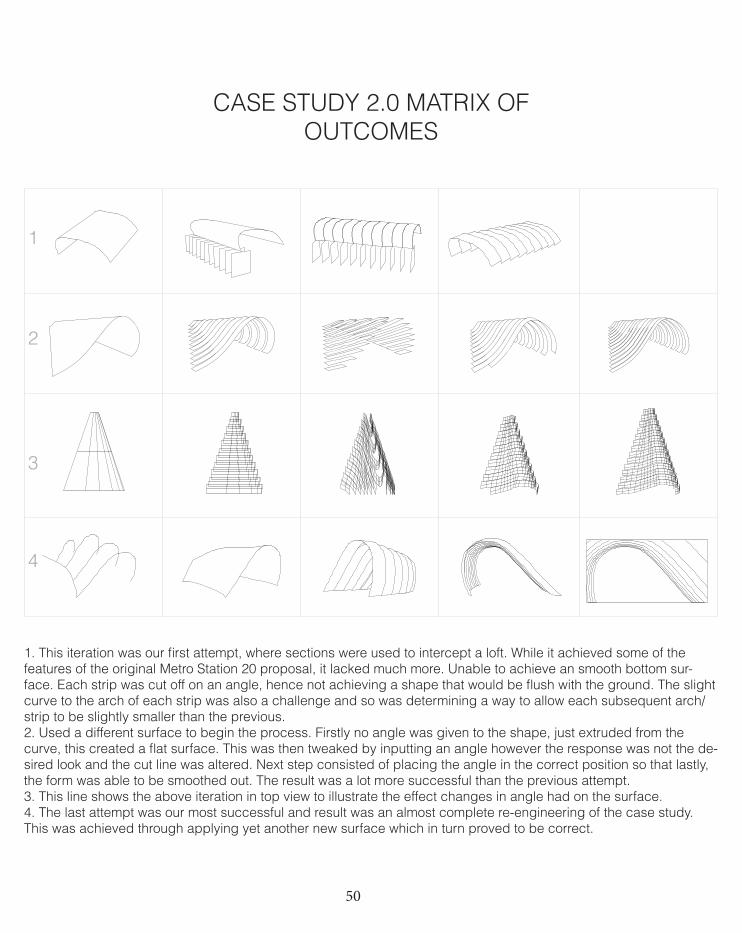
51Prototype of re-engineered Metro Station 20 proposal.
52
While the outcome of our first few attempts at re-engineering Case Study 2.0 didn’t result in a structure that quite resembled the original defini-tion, the more experimenting that was undertaken, the closer we got. At first there were certainly some components that weren’t translated in the actual design. These included each strip being cut off on an angle, hence not achieving a shape that would be flush with the ground. The slight curve to the arch of each strip was also a challenge and so was determining a way to allow each subsequent arch/strip to be slightly smaller than the previous. I suspect that these differences occurred mainly due to a lack of knowledge about how to achieve those elements using grasshopper. As discussed earlier in the journal, this can become quite frustrating when the skills are not acquired to communicate to the program what we wish to achieve. As we began to break down the components that were not working, it became a lot easier to revolve the issues on a case by case basis.
This particular definition allowed us to explore techniques that could further inform our future design. While we were not able to capture all of the elements of the surprisingly challenging design- we were able to regenerate more than its basic structure. Had we not been constrained by the original form, it would have been in-teresting to explore some other components, such as the voids between each section, which relates more closely to what we wish to achieve within our own design. It might have also been beneficial to see if we could apply this definition to our own direction of ‘speed’, however I do suspect that this particular case study’s design would have been hard to manipulate a form that reflected this idea of elongation and speed/time, I feel a larger (in size) design is needed to evoke those emotions.
CASE STUDY 2.0 OUTCOMES
53
Case Study 2.0 has been an important part of our design process. Looking at the Metro Station 20 proposal was the first step we took in making decisions about what our future design should and shouldn’t incorporate and we were able to explore how that potentially could be achieved. While Metro Station 20 did contain sectioning, its form for us was not so suiting. Over the course of case study 2.0, we have be-come more and more interested in this concept of the manipula-tion of time and speed and the relationship they both hold with each other and also the future users of the Wyndham City site. In order to achieve such an effect, we believe our form needs to be more flexible in the design and also incorporate space between each section to allow this skew in perspective. These ideas and more will be explored in the next phases.
CASE STUDY 2.0 CONCLUSION
54
DESIGN EXPLORATIONBlaze Sculpture by McChesney Architects, Middlesbrough.
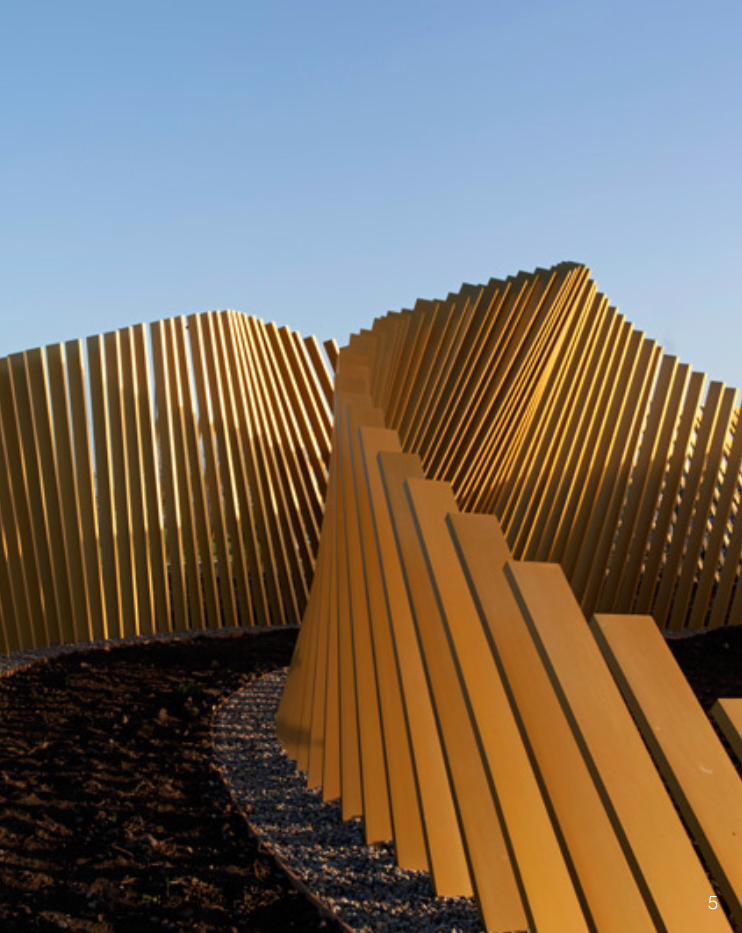
As our design exploration has evolved over the past modules, some precedents become more relevant to our design direction than others. One such project is the Blaze sculpture (2007) which was ‘designed to populate the disparate roadside verges of the A66 in Middlesbrough’ (McChesney 2013). This strikingly similar brief to our own has meant that we have been able to study how a design solution was formed and apply some of those resolutions to our own design. While Blaze does not deal with a concept such as the manipulation of time and speed, its design does form various perspectives for the passers by. This is achieved by positioning its 472 aluminium posts at varied angles, creating a crisscross pattern (Design Boom 2012). The material choice within this project is also of interest, using gold anodized aluminum, the staves are able to catch sunlight which create interesting formations and the positioning of these posts are not fixed, which also allows them to move slightly with the wind (Design Boom 2012). This could be a very interesting idea to consider further into our own design.
55 5
56
2.4.0TECHNIQUE: DEVELOPMENT
You created this PDF from an application that is not licensed to print to novaPDF printer (http://www.novapdf.com)
You created this PDF from an application that is not licensed to print to novaPDF printer (http://www.novapdf.com)
You created this PDF from an application that is not licensed to print to novaPDF printer (http://www.novapdf.com)
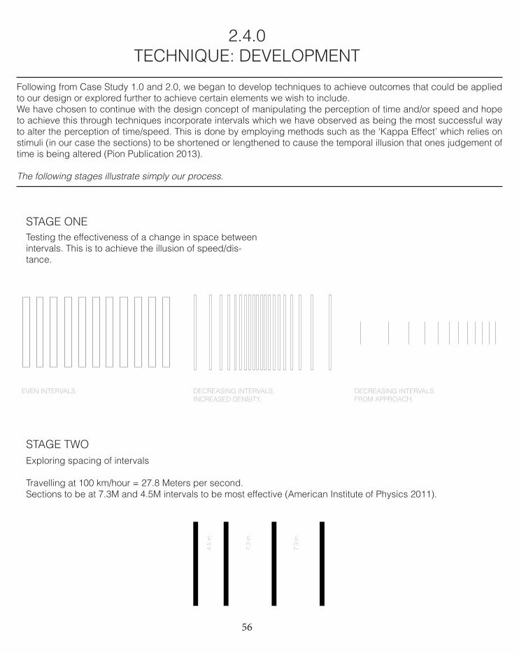
EVEN INTERVALS. DECREASING INTERVALS, INCREASED DENSITY.
DECREASING INTERVALS FROM APPROACH.
Following from Case Study 1.0 and 2.0, we began to develop techniques to achieve outcomes that could be applied to our design or explored further to achieve certain elements we wish to include. We have chosen to continue with the design concept of manipulating the perception of time and/or speed and hope to achieve this through techniques incorporate intervals which we have observed as being the most successful way to alter the perception of time/speed. This is done by employing methods such as the ‘Kappa Effect’ which relies on stimuli (in our case the sections) to be shortened or lengthened to cause the temporal illusion that ones judgement of time is being altered (Pion Publication 2013).
The following stages illustrate simply our process.
STAGE ONETesting the effectiveness of a change in space between intervals. This is to achieve the illusion of speed/dis-tance.
STAGE TWO
4.5
m.
7.3
m.
7.3
m.
Exploring spacing of intervals
Travelling at 100 km/hour = 27.8 Meters per second.Sections to be at 7.3M and 4.5M intervals to be most effective (American Institute of Physics 2011).
57
You created this PDF from an application that is not licensed to print to novaPDF printer (http://www.novapdf.com)
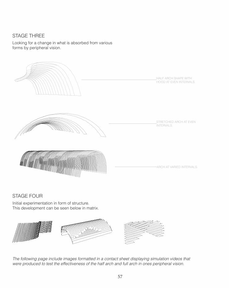
STAGE THREE
STAGE FOUR
Looking for a change in what is absorbed from various forms by peripheral vision.
Initial experimentation in form of structure.This development can be seen below in matrix.
You created this PDF from an application that is not licensed to print to novaPDF printer (http://www.novapdf.com)
You created this PDF from an application that is not licensed to print to novaPDF printer (http://www.novapdf.com)
HALF ARCH SHAPE WITH HOOD AT EVEN INTERVALS.
STRETCHED ARCH AT EVEN INTERVALS.
ARCH AT VARIED INTERVALS.
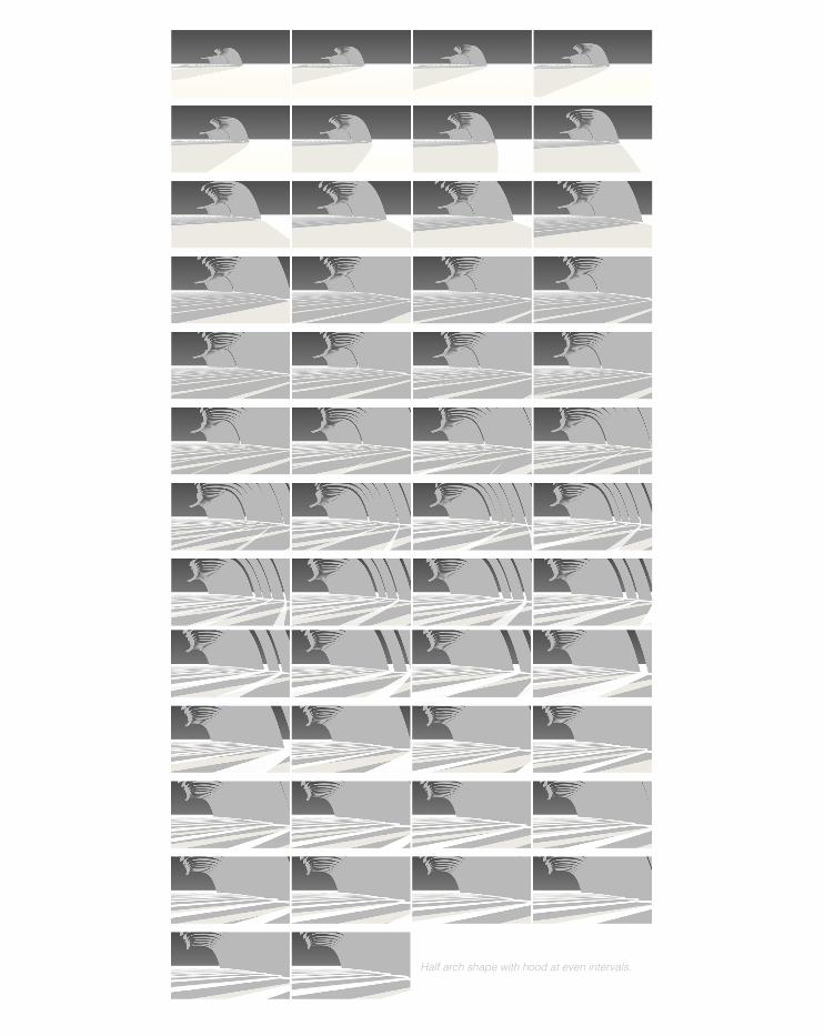
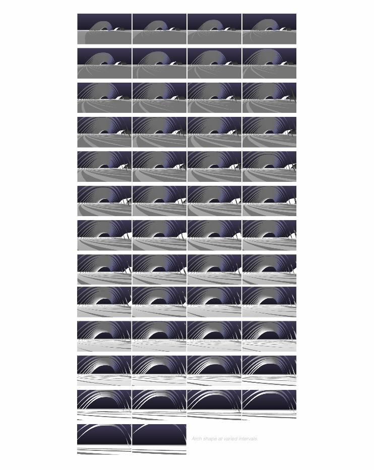
The following page include images formatted in a contact sheet displaying simulation videos that were produced to test the effectiveness of the half arch and full arch in ones peripheral vision.
58
Half arch shape with hood at even intervals.
59
Arch shape at varied intervals.
60
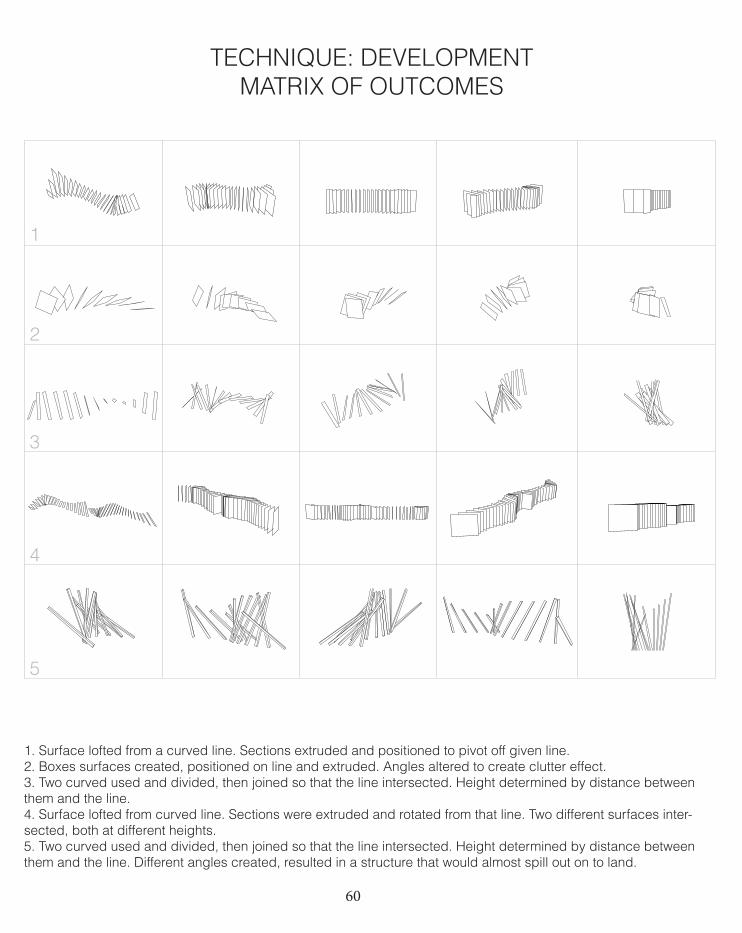
1. Surface lofted from a curved line. Sections extruded and positioned to pivot off given line.2. Boxes surfaces created, positioned on line and extruded. Angles altered to create clutter effect.3. Two curved used and divided, then joined so that the line intersected. Height determined by distance between them and the line. 4. Surface lofted from curved line. Sections were extruded and rotated from that line. Two different surfaces inter-sected, both at different heights.5. Two curved used and divided, then joined so that the line intersected. Height determined by distance between them and the line. Different angles created, resulted in a structure that would almost spill out on to land.
TECHNIQUE: DEVELOPMENT MATRIX OF OUTCOMES
2 curved, divided up, then joint so line intersects. height determined by distance between them and the line
1
2
3
4
5
61
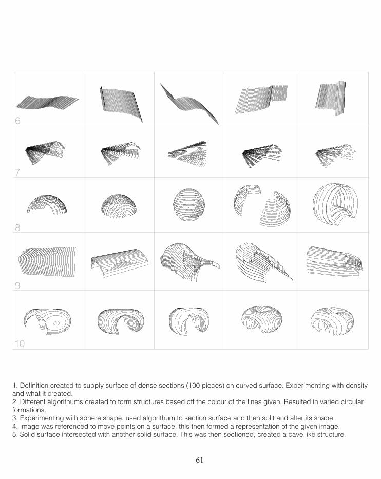
1. Definition created to supply surface of dense sections (100 pieces) on curved surface. Experimenting with density and what it created. 2. Different algorithums created to form structures based off the colour of the lines given. Resulted in varied circular formations. 3. Experimenting with sphere shape, used algorithum to section surface and then split and alter its shape.4. Image was referenced to move points on a surface, this then formed a representation of the given image.5. Solid surface intersected with another solid surface. This was then sectioned, created a cave like structure.
6
7
8
9
10
62
Evaluation is a rational process (Yehuda 2004, 12)Following on from experimenting with the techniques that were gathered during the matrix exploration (above), we began focusing on deriving a form that better expressed what we wish to achieve. We did this by applying Kaylay’s “search” techniques. Yehuda describes the search process of consisting of two steps- producing candidate solu-tions and then choosing the right, or perhaps most suitable solution, which shall then be further examined and then repeated (Yehuda 2004, 18). And this certainly describes the process we have undertaken and will continue to do until a final design has been chosen.
The following search process’ have been identified by Yehuda (2004, 19):• Depth first. A favorable candidate is explored to its logical end, it either meets the goal, or fails. In which case another candidate solution is examined.• Breadth first. A number of alternative ways to develop a candidate solution are investigated before any one of them is taken to its logical conclusion. • Best first. All available candidate solutions are assessed, and the one which appears to be most promising is chosen for further development.
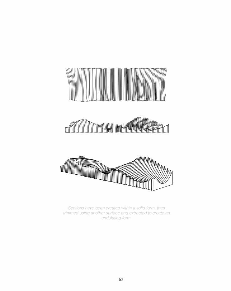
Below is an illustration of the direction our group is taking in regards to the form. I think we have followed more of a ‘breadth first’ method, where we have worked on developing ways to achieve our concept be-fore looking to the form. However is some cases we have also taken a ‘depth first’ approach as seen below. While we have not applied our interval technique (that evokes feeling of time/speed), we have began applying an un-dulating form to a solid piece that we can then apply this to.
TECHNIQUE: DEVELOPMENT OUTCOMES
63
Sections have been created within a solid form, then trimmed using another surface and extracted to create an
undulating form.
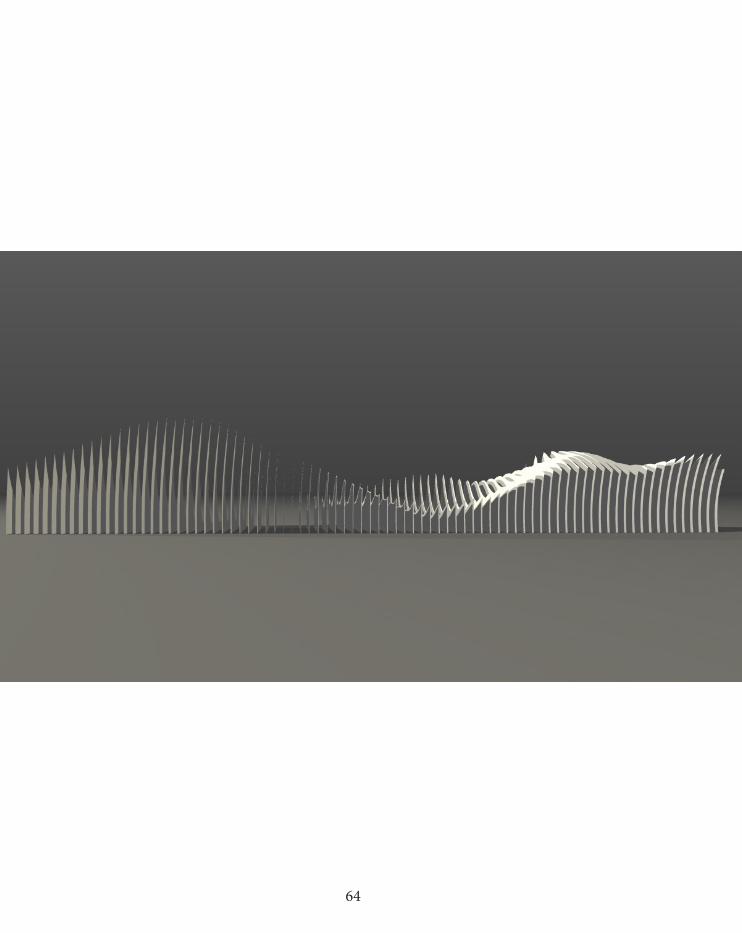
64
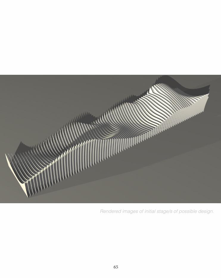
65
Rendered images of initial stage/s of possible design.
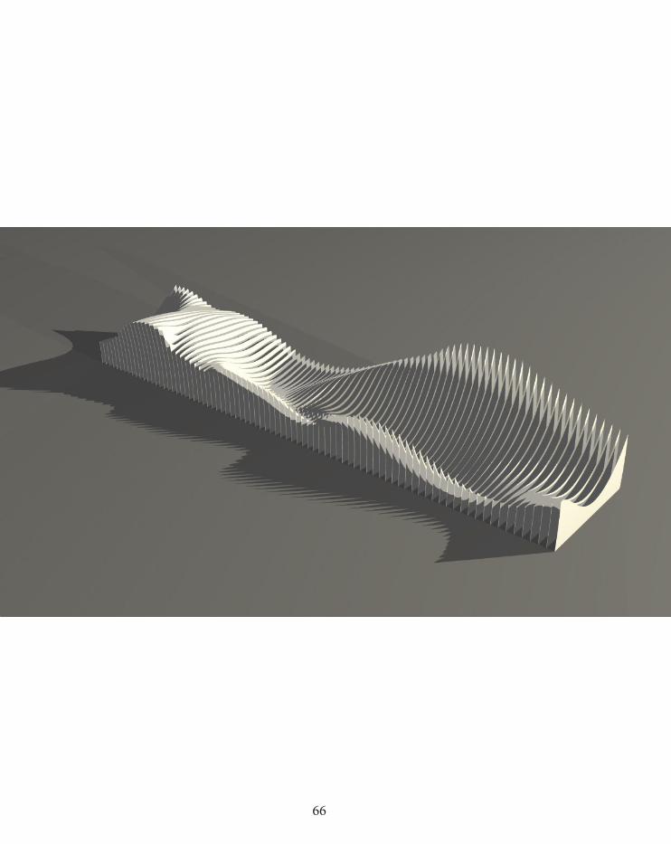
66
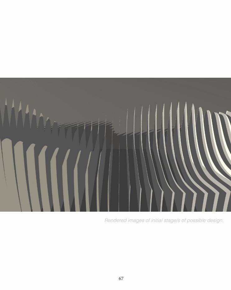
67
Rendered images of initial stage/s of possible design.
68
2.5.0TECHNIQUE PROTOTYPE
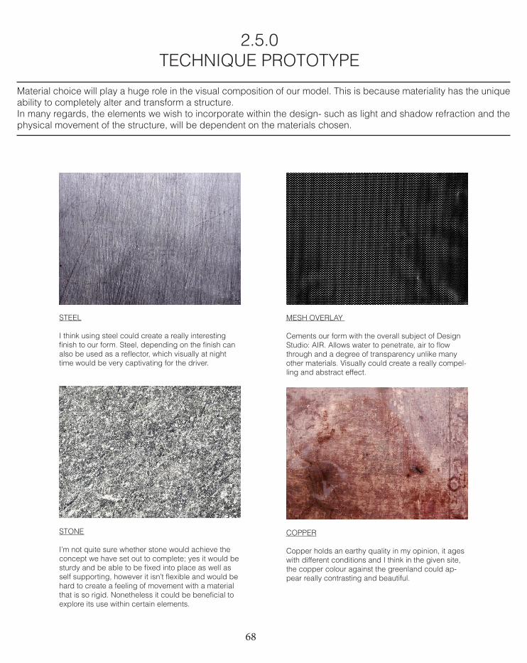
Material choice will play a huge role in the visual composition of our model. This is because materiality has the unique ability to completely alter and transform a structure.In many regards, the elements we wish to incorporate within the design- such as light and shadow refraction and the physical movement of the structure, will be dependent on the materials chosen.
MESH OVERLAY
Cements our form with the overall subject of Design Studio: AIR. Allows water to penetrate, air to flow through and a degree of transparency unlike many other materials. Visually could create a really compel-ling and abstract effect.
STEEL
I think using steel could create a really interesting finish to our form. Steel, depending on the finish can also be used as a reflector, which visually at night time would be very captivating for the driver.
STONE
I’m not quite sure whether stone would achieve the concept we have set out to complete; yes it would be sturdy and be able to be fixed into place as well as self supporting, however it isn’t flexible and would be hard to create a feeling of movement with a material that is so rigid. Nonetheless it could be beneficial to explore its use within certain elements.
COPPER
Copper holds an earthy quality in my opinion, it ages with different conditions and I think in the given site, the copper colour against the greenland could ap-pear really contrasting and beautiful.
69
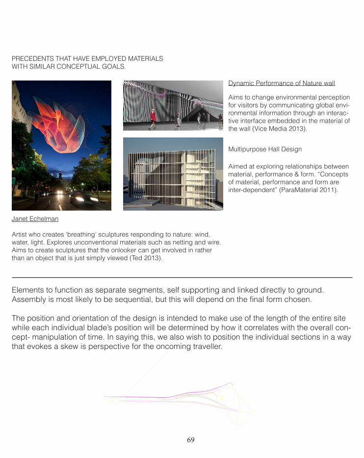
PRECEDENTS THAT HAVE EMPLOYED MATERIALS WITH SIMILAR CONCEPTUAL GOALS.
Janet Echelman
Artist who creates ‘breathing’ sculptures responding to nature: wind, water, light. Explores unconventional materials such as netting and wire.Aims to create sculptures that the onlooker can get involved in rather than an object that is just simply viewed (Ted 2013).
Dynamic Performance of Nature wall
Aims to change environmental perception for visitors by communicating global envi-ronmental information through an interac-tive interface embedded in the material of the wall (Vice Media 2013).
Multipurpose Hall Design
Aimed at exploring relationships between material, performance & form. “Concepts of material, performance and form are inter-dependent” (ParaMaterial 2011).
Elements to function as separate segments, self supporting and linked directly to ground. Assembly is most likely to be sequential, but this will depend on the final form chosen. The position and orientation of the design is intended to make use of the length of the entire site while each individual blade’s position will be determined by how it correlates with the overall con-cept- manipulation of time. In saying this, we also wish to position the individual sections in a way that evokes a skew is perspective for the oncoming traveller.
70
TECHNIQUE PROTOTYPEDELIVERABLES: MATERIALS
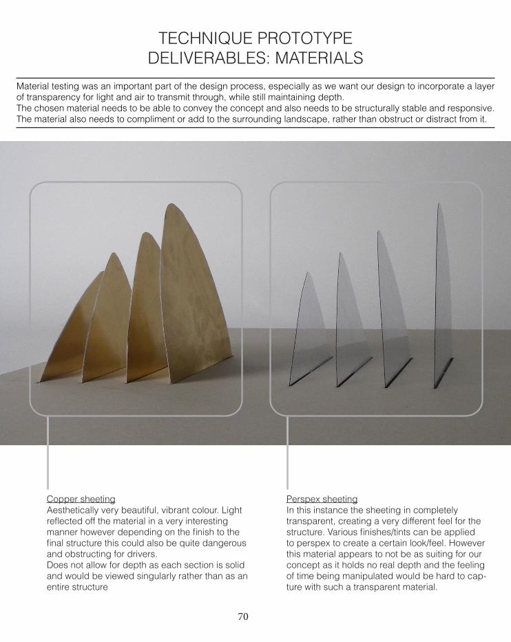
Material testing was an important part of the design process, especially as we want our design to incorporate a layer of transparency for light and air to transmit through, while still maintaining depth.The chosen material needs to be able to convey the concept and also needs to be structurally stable and responsive. The material also needs to compliment or add to the surrounding landscape, rather than obstruct or distract from it.
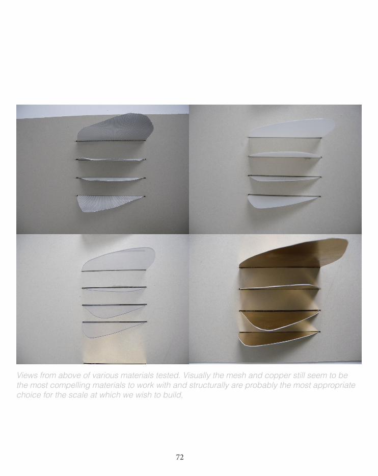
Copper sheetingAesthetically very beautiful, vibrant colour. Light reflected off the material in a very interesting manner however depending on the finish to the final structure this could also be quite dangerous and obstructing for drivers.Does not allow for depth as each section is solid and would be viewed singularly rather than as an entire structure
Perspex sheetingIn this instance the sheeting in completely transparent, creating a very different feel for the structure. Various finishes/tints can be applied to perspex to create a certain look/feel. However this material appears to not be as suiting for our concept as it holds no real depth and the feeling of time being manipulated would be hard to cap-ture with such a transparent material.
71
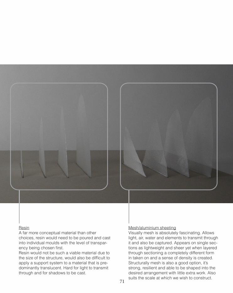
ResinA far more conceptual material than other choices, resin would need to be poured and cast into individual moulds with the level of transpar-ency being chosen first. Resin would not be such a viable material due to the size of the structure, would also be difficult to apply a support system to a material that is pre-dominantly translucent. Hard for light to transmit through and for shadows to be cast.
Mesh/aluminium sheetingVisually mesh is absolutely fascinating. Allows light, air, water and elements to transmit through it and also be captured. Appears on single sec-tions as lightweight and sheer yet when layered through sectioning a completely different form in taken on and a sense of density is created. Structurally mesh is also a good option, it’s strong, resilient and able to be shaped into the desired arrangement with little extra work. Also suits the scale at which we wish to construct.
72
Views from above of various materials tested. Visually the mesh and copper still seem to be the most compelling materials to work with and structurally are probably the most appropriate choice for the scale at which we wish to build,
73
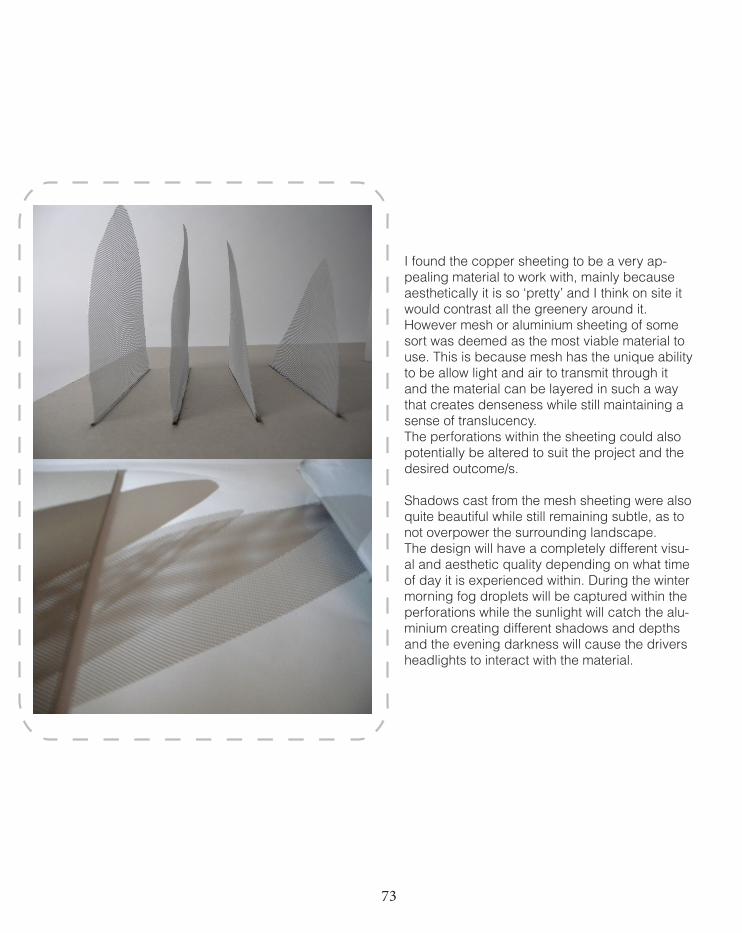
I found the copper sheeting to be a very ap-pealing material to work with, mainly because aesthetically it is so ‘pretty’ and I think on site it would contrast all the greenery around it. However mesh or aluminium sheeting of some sort was deemed as the most viable material to use. This is because mesh has the unique ability to be allow light and air to transmit through it and the material can be layered in such a way that creates denseness while still maintaining a sense of translucency. The perforations within the sheeting could also potentially be altered to suit the project and the desired outcome/s.
Shadows cast from the mesh sheeting were also quite beautiful while still remaining subtle, as to not overpower the surrounding landscape. The design will have a completely different visu-al and aesthetic quality depending on what time of day it is experienced within. During the winter morning fog droplets will be captured within the perforations while the sunlight will catch the alu-minium creating different shadows and depths and the evening darkness will cause the drivers headlights to interact with the material.
74
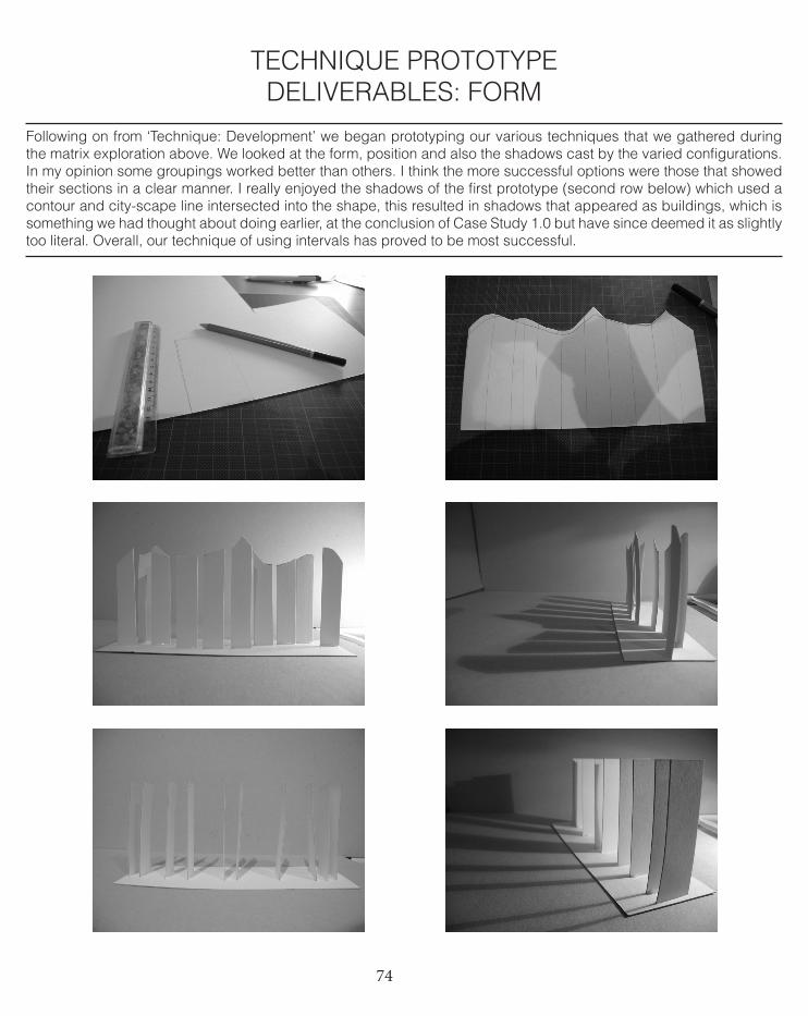
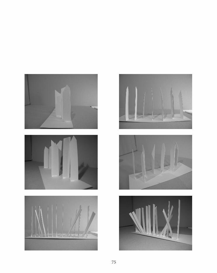
Following on from ‘Technique: Development’ we began prototyping our various techniques that we gathered during the matrix exploration above. We looked at the form, position and also the shadows cast by the varied configurations. In my opinion some groupings worked better than others. I think the more successful options were those that showed their sections in a clear manner. I really enjoyed the shadows of the first prototype (second row below) which used a contour and city-scape line intersected into the shape, this resulted in shadows that appeared as buildings, which is something we had thought about doing earlier, at the conclusion of Case Study 1.0 but have since deemed it as slightly too literal. Overall, our technique of using intervals has proved to be most successful.
TECHNIQUE PROTOTYPEDELIVERABLES: FORM
75
76
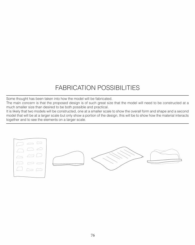
FABRICATION POSSIBILITIES
Some thought has been taken into how the model will be fabricated. The main concern is that the proposed design is of such great size that the model will need to be constructed at a much smaller size than desired to be both possible and practical.It is likely that two models will be constructed, one at a smaller scale to show the overall form and shape and a second model that will be at a larger scale but only show a portion of the design, this will be to show how the material interacts together and to see the elements on a larger scale.
77
The next stage within our design process will be as follows:
Refinement of form.Focusing on executing our concept. Will form reflect the most effective way to apply time manipulation? Or will it reflect a deeper matter?
Adding of more substance. In order to communicate this effect of time manipulation to the user, we hope to incorporate a secondary layer/element to our design. This is so that it becomes less of a static object and holds more substance.
Further exploration of materiality.Assessing the effect materiality will have on our final design.
FUTURE DIRECTION
78
2.6.0TECHNIQUE PROPOSAL
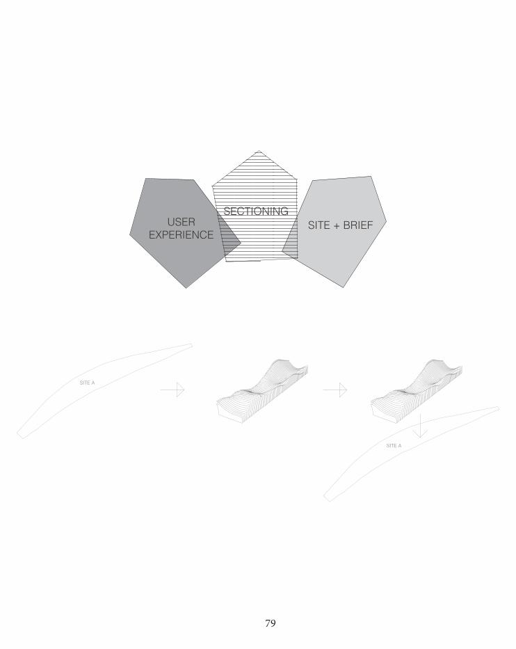
The brief has asked for an exciting, eye catching installation that inspires and enriches the municipality. It shall be something that enhances the physical environment and have longevity and appeal.While the form of our design continues to develop as we apply new techniques and ideas as well as fine tune other areas, it appears that our overall concept and direction will be successfully applied to the site. This is because our key goal of creating a skew in perspective with time/speed being the main driver, relies on using sectioning, which by their very nature require vast space to achieve the aesthetic and emotional response we want. This is where our concept gels with the brief and site. The Wyndham City site is a bare stretch of land, yearning for something to occupy it, something to reveal and highlight certain areas and create a buzz to the area. For our group, it seems only logical for the design to make use of the entire space provided, or at least a large proportion of it. This will in turn create a wider visual scope for the users to encounter.
My own belief approaching this project is also that the design needs to be fundamentally site relative and that it should be able to accommodate the areas needs, rather than being designed first and moulding the landscape to house it, in an attempt to fit in with its surroundings.
I feel our design is innovative and most of all relevant to the Wyndham City council because it aims at providing a defin-ing feature that relates to what the user is there to do primarily- travelling and passing by. It also aims to be a concept that is experienced and re-lived after the driver has physically seen it. I think that if we are able to successfully achieve this evoking of emotions, it will truly be a unique experience and different to what the competition jury has seen before- our design isn’t just about the static and fixed physical form, it’s about the notion behind it too. And while the concept will be a challenge to achieve, we believe we can overcome any issues that arise and in turn provide a much more preferable choice in design than other possible options.
79
SITE A
SITE A
USEREXPERIENCE
SECTIONINGSITE + BRIEF
80
Mid semester presentations asked us to focus on some new ideas we had not generated. The idea of time as movement was suggest-ed and to think about the project as perhaps a piece of kinetic art. It was also suggested that we approach explore a less fixed form. While I’m not certain that quite fits in with our concept, I do think it raises a valid point in that we need to incorporate movement of some sort rather than a very rigid structure. The whole Design Approach module has been quite a rapid and intense process. We began thinking beyond the physical design, more about the emotions we wish to evoke and then explored how we could best represent that physically.The site and brief has always been our principal driver, we want the project to achieve what we set out to do; creating a unique and cap-tivating piece in a site relative manner.
The next stage for us will be to really focus on a form that delivers what we have set out to achieve. It will be exciting, site orientated and help set a new discourse for Wyndham City.
2.7.0 DESIGN APPROACH CONCLUSION
81
The shift of focus from Case for Innovation to Design Approach has been very fascinating. It has also been a very fulfilling experience to apply the information researched and acquired during Case for Innovation and utilize it in a more practical manner during Design Approach. This module has seen our group begin with a concept and develop it over a number of stages conceptually, digitally and physically. The more we explore and venture into the design, the more refined our ideas become and it has been really intriguing to gain an idea, ex-periment with it, develop it and then start the process all over again. I think a major advantage for our group is that we have always been realistic in our approach on all levels. We have assessed the brief and responded to it in what we feel is the most appropriate manner and realistic for our skill set. I still feel I lack many skills in regard to computational designing, however I do believe with a strong con-cept, a design that is both appropriate, applicable and adhering to the brief is achievable I am looking forward to furthering our design and making some con-crete decisions about the final direction it takes.
LEARNING OUTCOMES

82
83
PROJECT PROPOSAL
‘Simplicity is the ultimate sophistication’
Leonardo da Vinci
84
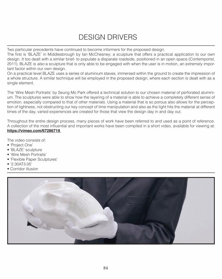
Two particular precedents have continued to become informers for the proposed design. The first is ‘BLAZE’ in Middlesbrough by Ian McChesney; a sculpture that offers a practical application to our own design. It too dealt with a similar brief- to populate a disparate roadside, positioned in an open space (Contemporist, 2011). BLAZE is also a sculpture that is only able to be engaged with when the user is in motion, an extremely impor-tant factor within our own design. On a practical level BLAZE uses a series of aluminium staves, immersed within the ground to create the impression of a whole structure. A similar technique will be employed in the proposed design, where each section is dealt with as a single element.
The ‘Wire Mesh Portraits’ by Seung Mo Park offered a technical solution to our chosen material of perforated alumini-um. The sculptures were able to show how the layering of a material is able to achieve a completely different sense of emotion, especially compared to that of other materials. Using a material that is so porous also allows for the percep-tion of lightness, not obstructing our key concept of time manipulation and also as the light hits the material at different times of the day, varied experiences are created for those that view the design day in and day out.
Throughout the entire design process, many pieces of work have been referred to and used as a point of reference. A collection of the most influential and important works have been compiled in a short video, available for viewing at: https://vimeo.com/67286719
The video consists of:• ‘Project One’• ‘BLAZE’ sculpture• ‘Wire Mesh Portraits’• ‘Flexible Paper Sculptures’• ‘2.30AT3.05’• Corridor illusion
DESIGN DRIVERS
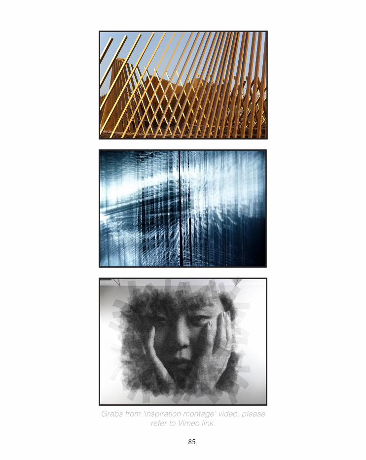
85
Grabs from ‘inspiration montage’ video, please refer to Vimeo link.
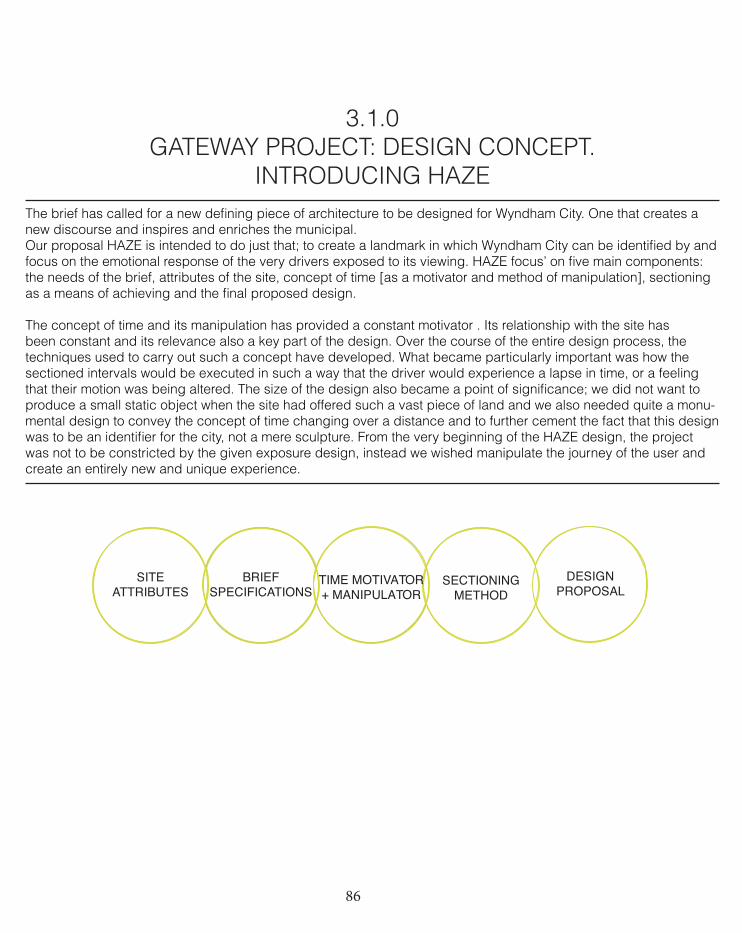
86
SITEATTRIBUTES
BRIEF SPECIFICATIONS
SECTIONING METHOD
TIME MOTIVATOR + MANIPULATOR
DESIGNPROPOSAL
3.1.0GATEWAY PROJECT: DESIGN CONCEPT.
INTRODUCING HAZEThe brief has called for a new defining piece of architecture to be designed for Wyndham City. One that creates a new discourse and inspires and enriches the municipal. Our proposal HAZE is intended to do just that; to create a landmark in which Wyndham City can be identified by and focus on the emotional response of the very drivers exposed to its viewing. HAZE focus’ on five main components: the needs of the brief, attributes of the site, concept of time [as a motivator and method of manipulation], sectioning as a means of achieving and the final proposed design.
The concept of time and its manipulation has provided a constant motivator . Its relationship with the site has been constant and its relevance also a key part of the design. Over the course of the entire design process, the techniques used to carry out such a concept have developed. What became particularly important was how the sectioned intervals would be executed in such a way that the driver would experience a lapse in time, or a feeling that their motion was being altered. The size of the design also became a point of significance; we did not want to produce a small static object when the site had offered such a vast piece of land and we also needed quite a monu-mental design to convey the concept of time changing over a distance and to further cement the fact that this design was to be an identifier for the city, not a mere sculpture. From the very beginning of the HAZE design, the project was not to be constricted by the given exposure design, instead we wished manipulate the journey of the user and create an entirely new and unique experience.
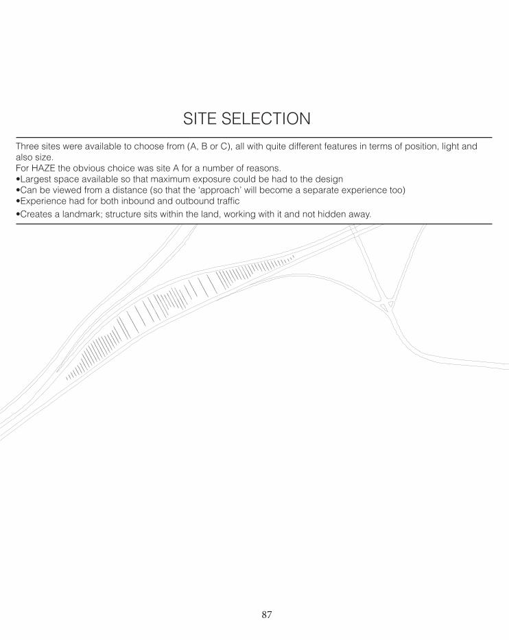
87You created this PDF from an application that is not licensed to print to novaPDF printer (http://www.novapdf.com)
SITE SELECTIONThree sites were available to choose from (A, B or C), all with quite different features in terms of position, light and also size. For HAZE the obvious choice was site A for a number of reasons. •Largest space available so that maximum exposure could be had to the design•Can be viewed from a distance (so that the ‘approach’ will become a separate experience too) •Experience had for both inbound and outbound traffic•Creates a landmark; structure sits within the land, working with it and not hidden away.
88
A ‘brep’ was created by intersecting a solid form with the designed surface that we wished to use, which was then trimmed in Rhino. This was able to create a solid form that had a flat base but curved edges.For this design stage we used Rhino as we felt it allowed for a quicker and more effective visual manipulation, al-lowing for more human interaction with the form rather than having to manipulate it through another computerised medium leaving us feeling less in control. By doing so, it enabled us to create simple variations of the structure and to understand the relationship between the driver and the design.The complete form along with a curve (as we desired straight edged sections, a vertical curve was referenced,) is evident in the design.
After applying the Grasshopper algorithm we were left with extruded curves that were split into the area that had been intersected with the referenced brep and curve. Any surfaces that did not belong to the brep were removed in Rhino. Once these stages had been completed, manually sections were deleted to create the ‘slowing’ down and ‘speeding’ up of time effect, this was done manually as we had a very specific rationale to how many sections we needed at what point along the structure and this way we had far more power.
Refer to following page for individual functions of algorithm.
WORKFLOW OF DESIGN DEFINITION
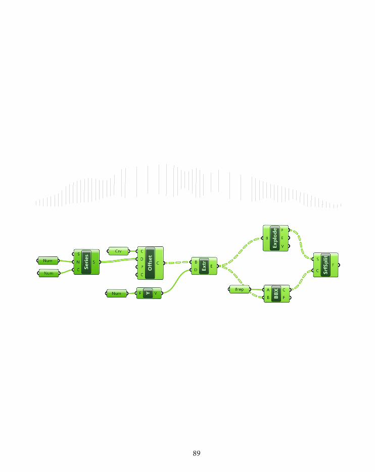
89
You created this PDF from an application that is not licensed to print to novaPDF printer (http://www.novapdf.com)
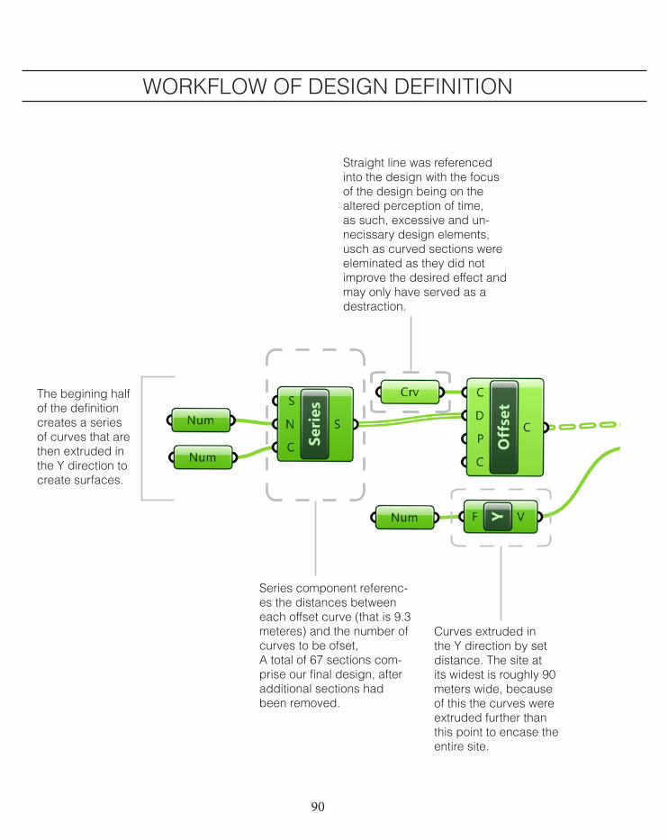
90
The begining half of the definition creates a series of curves that are then extruded in the Y direction to create surfaces.
Series component referenc-es the distances between each offset curve (that is 9.3 meteres) and the number of curves to be ofset, A total of 67 sections com-prise our final design, after additional sections had been removed.
Curves extruded in the Y direction by set distance. The site at its widest is roughly 90 meters wide, because of this the curves were extruded further than this point to encase the entire site.
Straight line was referenced into the design with the focus of the design being on the altered perception of time, as such, excessive and un-necissary design elements, usch as curved sections were eleminated as they did not improve the desired effect and may only have served as a destraction.
WORKFLOW OF DESIGN DEFINITION
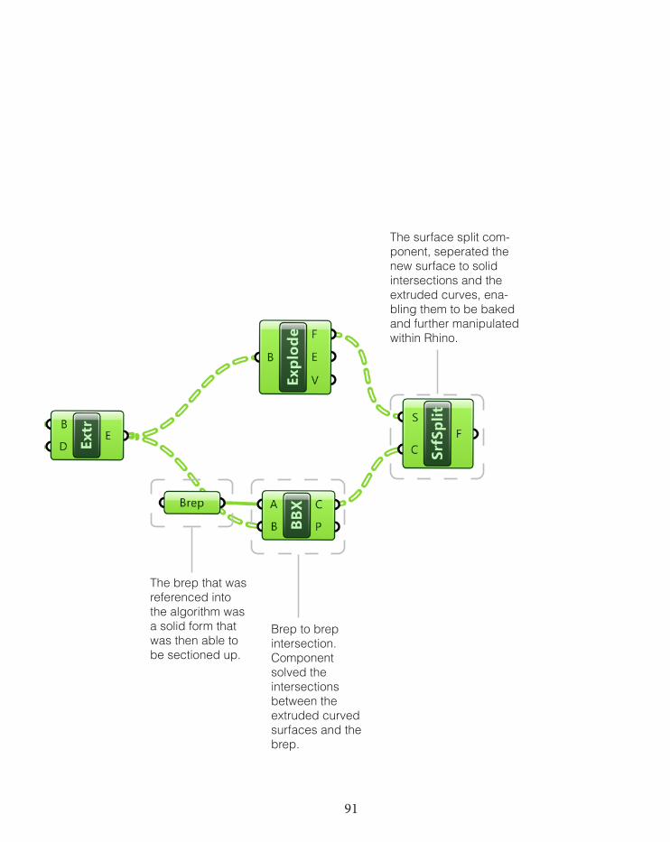
91
The brep that was referenced into the algorithm was a solid form that was then able to be sectioned up.
Brep to brep intersection.Component solved the intersections between the extruded curved surfaces and the brep.
The surface split com-ponent, seperated the new surface to solid intersections and the extruded curves, ena-bling them to be baked and further manipulated within Rhino.
92
SEQUENCE OF EXPERIENCE
HAZE is designed to highlight and draw attention the perceived change in the speed of time. The commuter is intrinsically aware that they are travelling at 100km per hour, however they have no point of refer-ence to make this speed known. Time and movement can be measurable through the motion of constant objects. The kappa effect is a psychologi-cal phenomenon related to the perception of time, speed and distance, it is a temporal illusion that is able to alter a persons judgement of time (Britannica 2013). The kappa effect occurs when the distance between two stimuli are shortened or lengthened. This became the basis of our design.For the notion of time manipulation to be successful, the driver must be aware of an interchanging in speed and thus needs to be able to contrast their experiences. Due to this, both the ‘fast’ and ‘slow’ sections of the design have been repeated twice to complement one another and support the previous section.The height each set of sections were also predetermined by the design intent so that there would be both a monu-mental and focal point aspect. It was therefore required to have areas of substantial height to allow the design to be viewed from a distance at the approach. The middle sections, where the heights of the sections drop to 1.5 meters and spacing increases to 3 sections per second is intended to give a ‘breath’ or a ‘silence’ to the design, a short 3 seconds where the driver can contemplate the apparent time manipulation they have just experienced. They are then able to be made visually aware of the growing form to which they are moving towards.The overall design contains a sense of symmetry as it is to be viewed from either directions as both inward and out-bound commuters view it.
In order for HAZE to be a success, both in terms of addressing the brief and as a concept carried out for its users, a sequence of experience needed to be established;
1
2
3
4
Concept of time manipulation to be achieved.
Whole site to be used to achieve maximum exposure to the site and the concept.
Maximum height was chosen at 14m, this was so another experience is created from the approach, with the peaks of the tallest members being glimpsed from afar. 14m was also deemed a practical choice while still main-taining a perception of monumentality
Each individual section acts as a member within a wider context. The position of each section is determined to how it is able to relate to its provided concept.
5 Material determined by what it is able to offer in both the short term experience- level of depth while maintaining transparency and long term experience- different perspective received at different times of the day.
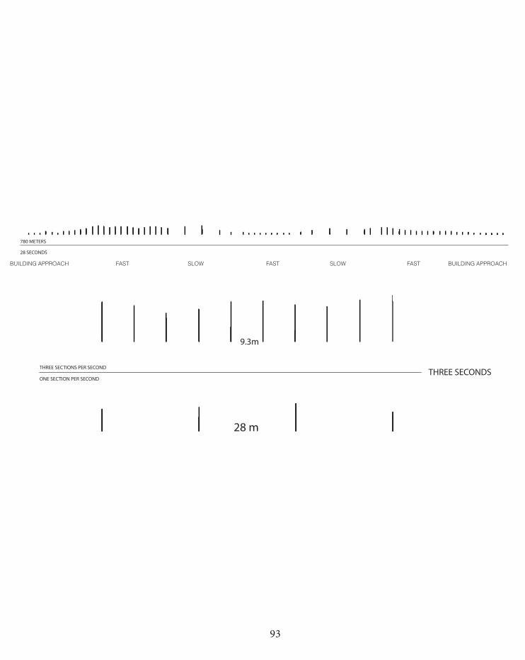
93
THREE SECONDSTHREE SECTIONS PER SECOND
ONE SECTION PER SECOND
28 m
9.3m
780 METERS
28 SECONDS
THREE SECONDSTHREE SECTIONS PER SECOND
ONE SECTION PER SECOND
28 m
9.3m
780 METERS
28 SECONDS
FASTBUILDING APPROACH SLOW FAST SLOW FAST BUILDING APPROACH
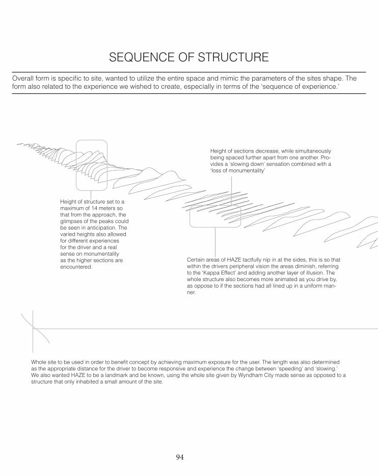
94
SEQUENCE OF STRUCTURE
Whole site to be used in order to benefit concept by achieving maximum exposure for the user. The length was also determined as the appropriate distance for the driver to become responsive and experience the change between ‘speeding’ and ‘slowing.’ We also wanted HAZE to be a landmark and be known, using the whole site given by Wyndham City made sense as opposed to a structure that only inhabited a small amount of the site.
Height of structure set to a maximum of 14 meters so that from the approach, the glimpses of the peaks could be seen in anticipation. The varied heights also allowed for different experiences for the driver and a real sense on monumentality as the higher sections are encountered.
Certain areas of HAZE tactfully nip in at the sides, this is so that within the drivers peripheral vision the areas diminish, referring to the ‘Kappa Effect’ and adding another layer of illusion. The whole structure also becomes more animated as you drive by, as oppose to if the sections had all lined up in a uniform man-ner.
Overall form is specific to site, wanted to utilize the entire space and mimic the parameters of the sites shape. The form also related to the experience we wished to create, especially in terms of the ‘sequence of experience.’
Height of sections decrease, while simultaneously being spaced further apart from one another. Pro-vides a ‘slowing down’ sensation combined with a ‘loss of monumentality’
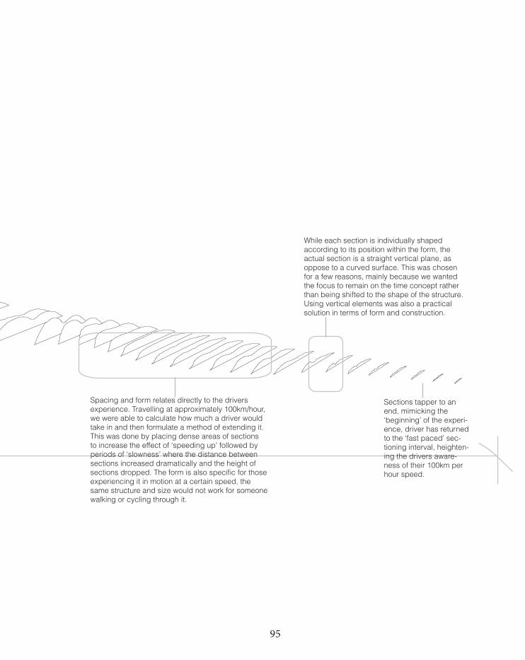
95
Spacing and form relates directly to the drivers experience. Travelling at approximately 100km/hour, we were able to calculate how much a driver would take in and then formulate a method of extending it. This was done by placing dense areas of sections to increase the effect of ‘speeding up’ followed by periods of ‘slowness’ where the distance between sections increased dramatically and the height of sections dropped. The form is also specific for those experiencing it in motion at a certain speed, the same structure and size would not work for someone walking or cycling through it.
While each section is individually shaped according to its position within the form, the actual section is a straight vertical plane, as oppose to a curved surface. This was chosen for a few reasons, mainly because we wanted the focus to remain on the time concept rather than being shifted to the shape of the structure. Using vertical elements was also a practical solution in terms of form and construction.
Sections tapper to an end, mimicking the ‘beginning’ of the experi-ence, driver has returned to the ‘fast paced’ sec-tioning interval, heighten-ing the drivers aware-ness of their 100km per hour speed.
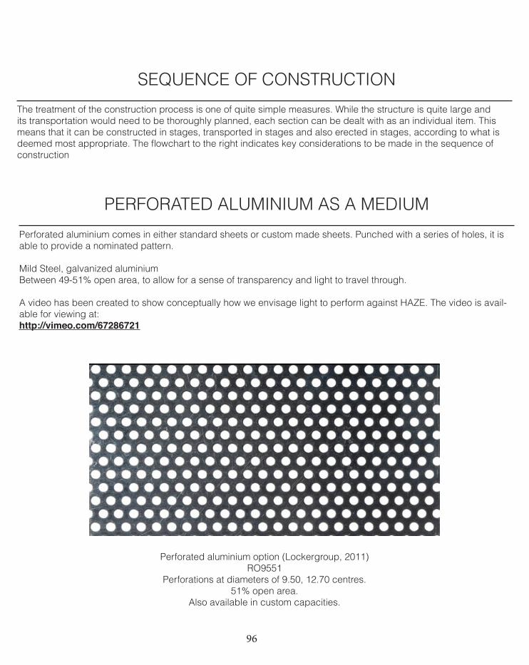
96
SEQUENCE OF CONSTRUCTION
The treatment of the construction process is one of quite simple measures. While the structure is quite large and its transportation would need to be thoroughly planned, each section can be dealt with as an individual item. This means that it can be constructed in stages, transported in stages and also erected in stages, according to what is deemed most appropriate. The flowchart to the right indicates key considerations to be made in the sequence of construction
PERFORATED ALUMINIUM AS A MEDIUM
Perforated aluminium comes in either standard sheets or custom made sheets. Punched with a series of holes, it is able to provide a nominated pattern.
Mild Steel, galvanized aluminiumBetween 49-51% open area, to allow for a sense of transparency and light to travel through.
A video has been created to show conceptually how we envisage light to perform against HAZE. The video is avail-able for viewing at:http://vimeo.com/67286721
Perforated aluminium option (Lockergroup, 2011)RO9551
Perforations at diameters of 9.50, 12.70 centres.51% open area.
Also available in custom capacities.
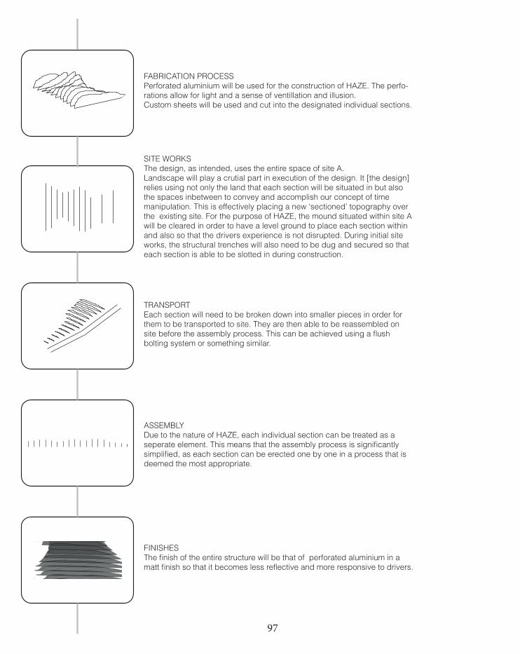
97
FABRICATION PROCESSPerforated aluminium will be used for the construction of HAZE. The perfo-rations allow for light and a sense of ventillation and illusion. Custom sheets will be used and cut into the designated individual sections.
SITE WORKSThe design, as intended, uses the entire space of site A. Landscape will play a crutial part in execution of the design. It [the design] relies using not only the land that each section will be situated in but also the spaces inbetween to convey and accomplish our concept of time manipulation. This is effectively placing a new ‘sectioned’ topography over the existing site. For the purpose of HAZE, the mound situated within site A will be cleared in order to have a level ground to place each section within and also so that the drivers experience is not disrupted. During initial site works, the structural trenches will also need to be dug and secured so that each section is able to be slotted in during construction.
TRANSPORTEach section will need to be broken down into smaller pieces in order for them to be transported to site. They are then able to be reassembled on site before the assembly process. This can be achieved using a flush bolting system or something similar.
ASSEMBLYDue to the nature of HAZE, each individual section can be treated as a seperate element. This means that the assembly process is significantly simplified, as each section can be erected one by one in a process that is deemed the most appropriate.
FINISHESThe finish of the entire structure will be that of perforated aluminium in a matt finish so that it becomes less reflective and more responsive to drivers.
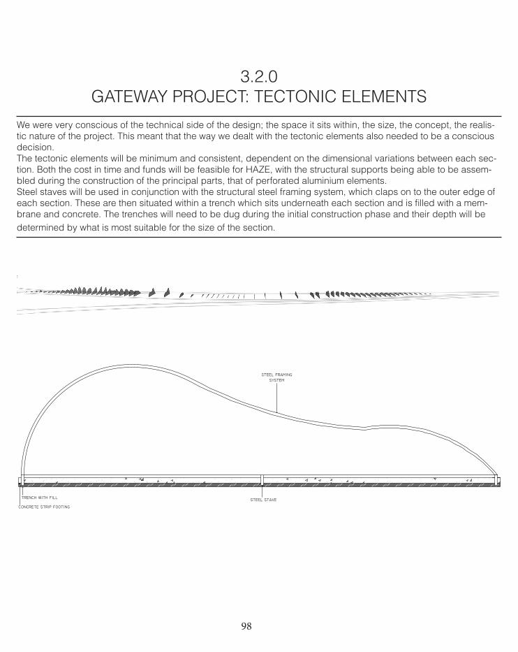
98
3.2.0 GATEWAY PROJECT: TECTONIC ELEMENTS
We were very conscious of the technical side of the design; the space it sits within, the size, the concept, the realis-tic nature of the project. This meant that the way we dealt with the tectonic elements also needed to be a conscious decision. The tectonic elements will be minimum and consistent, dependent on the dimensional variations between each sec-tion. Both the cost in time and funds will be feasible for HAZE, with the structural supports being able to be assem-bled during the construction of the principal parts, that of perforated aluminium elements.Steel staves will be used in conjunction with the structural steel framing system, which claps on to the outer edge of each section. These are then situated within a trench which sits underneath each section and is filled with a mem-brane and concrete. The trenches will need to be dug during the initial construction phase and their depth will be determined by what is most suitable for the size of the section.
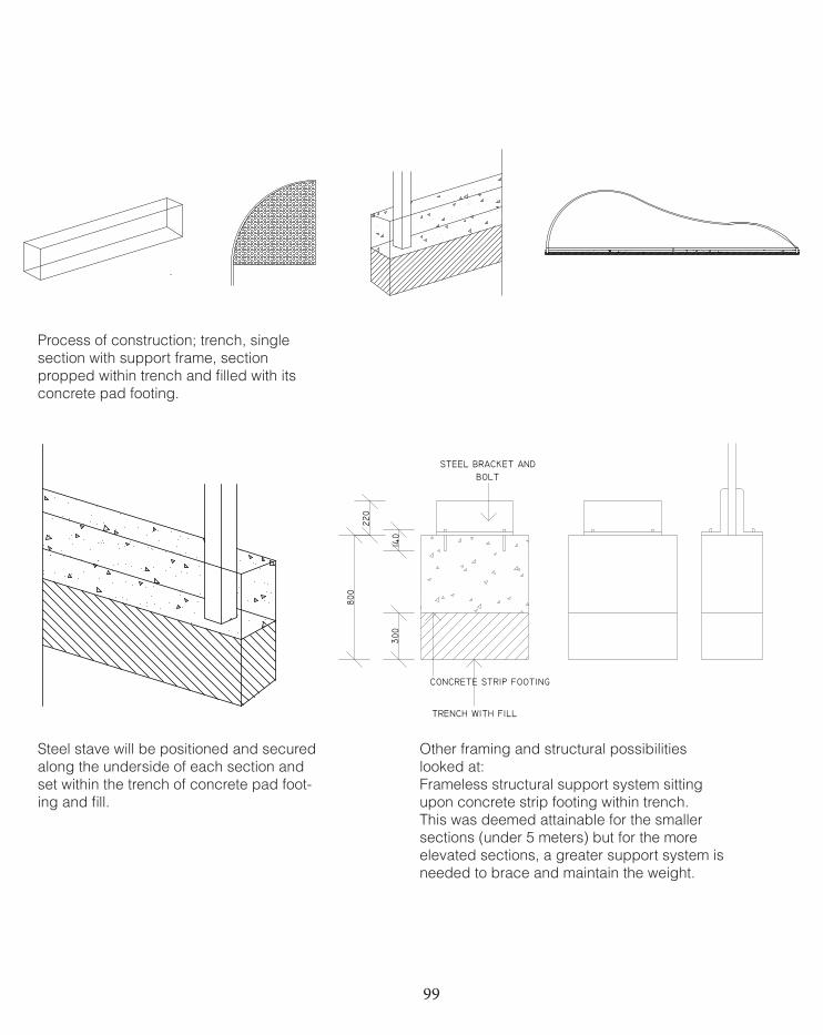
99
Other framing and structural possibilities looked at:Frameless structural support system sitting upon concrete strip footing within trench.This was deemed attainable for the smaller sections (under 5 meters) but for the more elevated sections, a greater support system is needed to brace and maintain the weight.
Steel stave will be positioned and secured along the underside of each section and set within the trench of concrete pad foot-ing and fill.
Process of construction; trench, single section with support frame, section propped within trench and filled with its concrete pad footing.
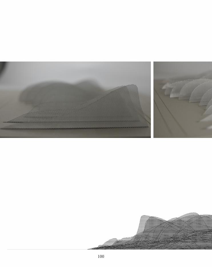
100
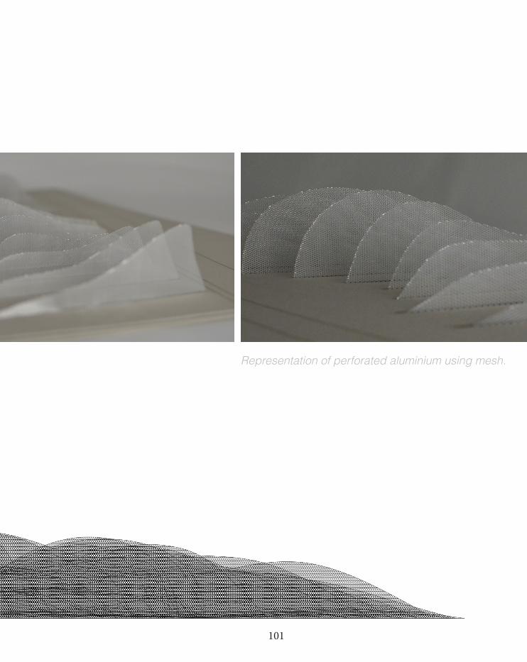
101
Representation of perforated aluminium using mesh.
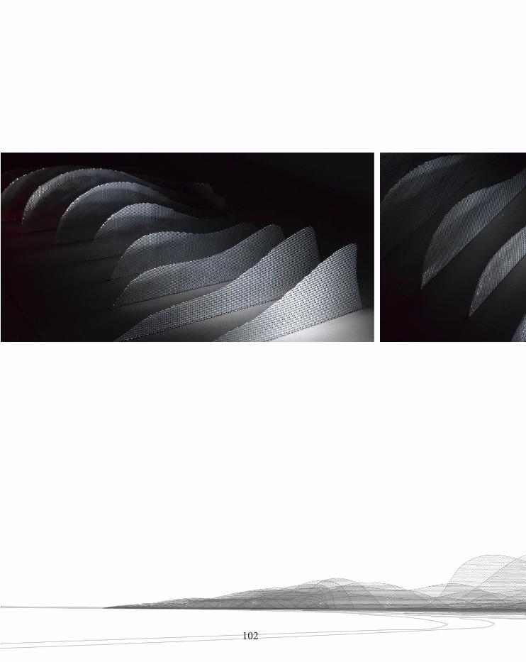
102
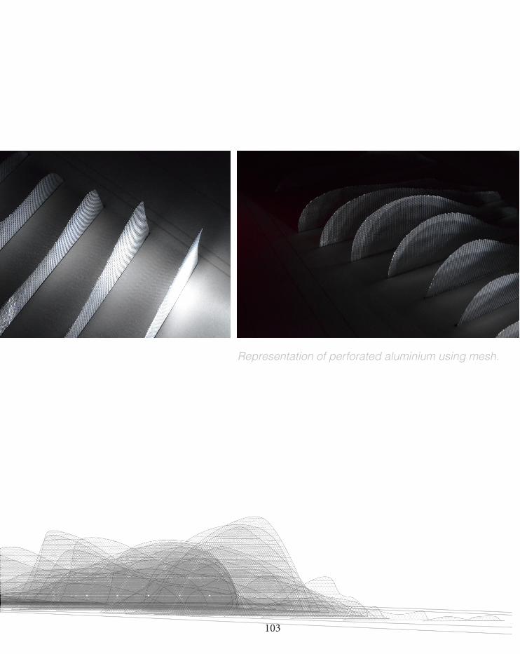
103
Representation of perforated aluminium using mesh.
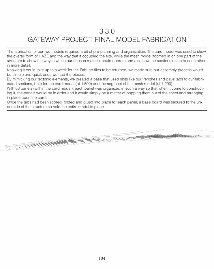
104
3.3.0 GATEWAY PROJECT: FINAL MODEL FABRICATION
The fabrication of our two models required a bit of pre-planning and organization. The card model was used to show the overall form of HAZE and the way that it occupied the site, while the mesh model zoomed in on one part of the structure to show the way in which our chosen material could operate and also how the sections relate to each other in more detail.Knowing it could take up to a week for the FabLab files to be returned, we made sure our assembly process would be simple and quick once we had the pieces.By mimicking our tectonic elements, we created a base that used slots like our trenches and gave tabs to our fabri-cated sections, both for the card model (at 1:500) and the segment of the mesh model (at 1:200). With 66 panels (within the card model), each panel was organized in such a way so that when it come to construct-ing it, the panels would be in order and it would simply be a matter of popping them out of the sheet and arranging in place upon the card. Once the tabs had been scored, folded and glued into place for each panel, a base board was secured to the un-derside of the structure so hold the entire model in place.
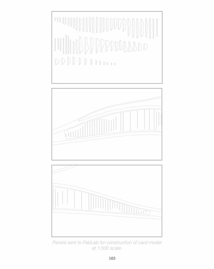
105
SHEET 2: 1mm Boxboard
Panels sent to FabLab for construction of card model at 1:500 scale.
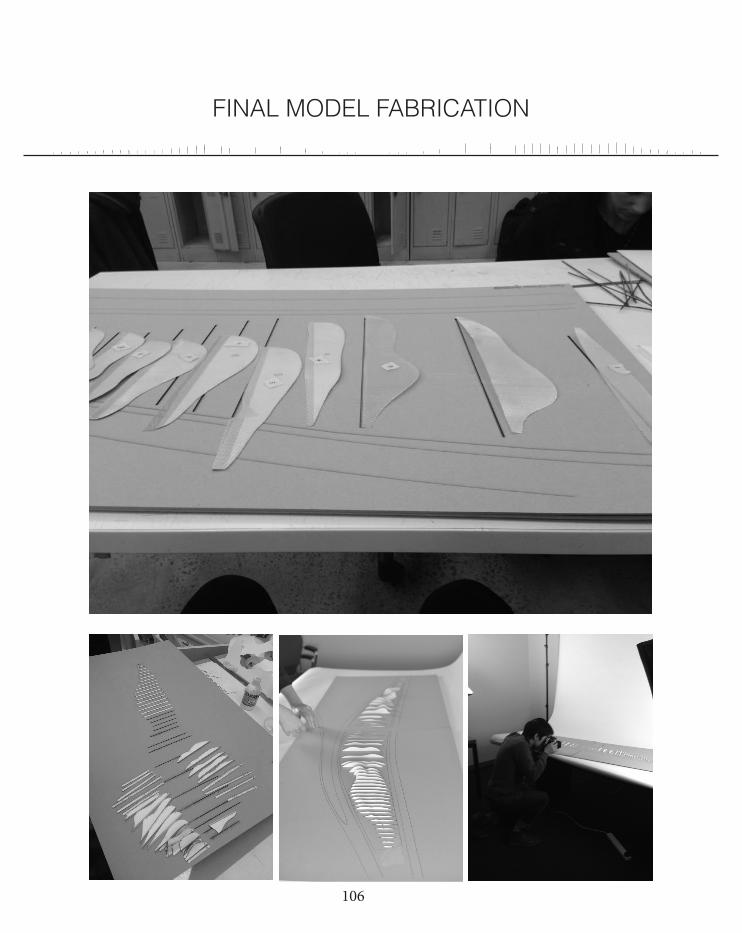
106
FINAL MODEL FABRICATION
You created this PDF from an application that is not licensed to print to novaPDF printer (http://www.novapdf.com)
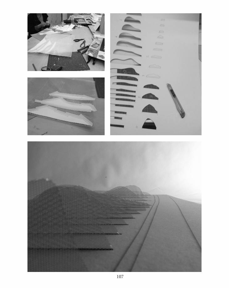
107
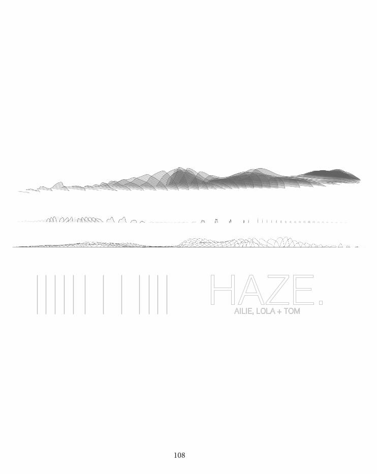
108
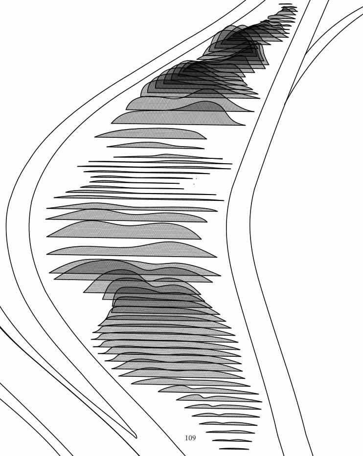
109
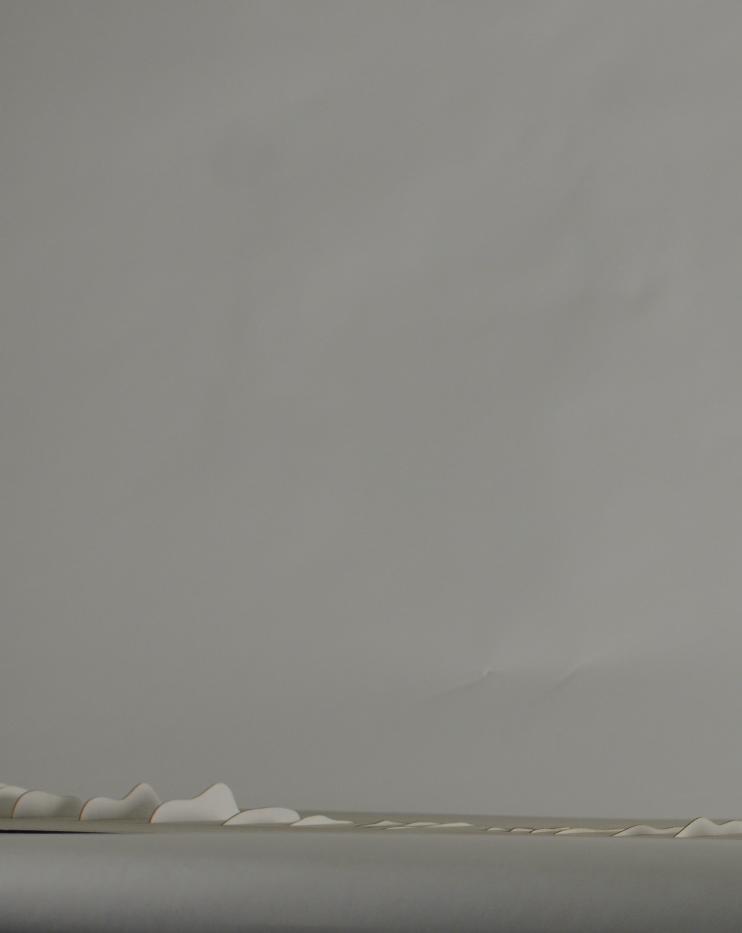
110
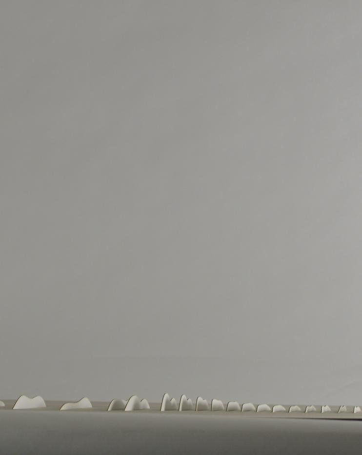
111
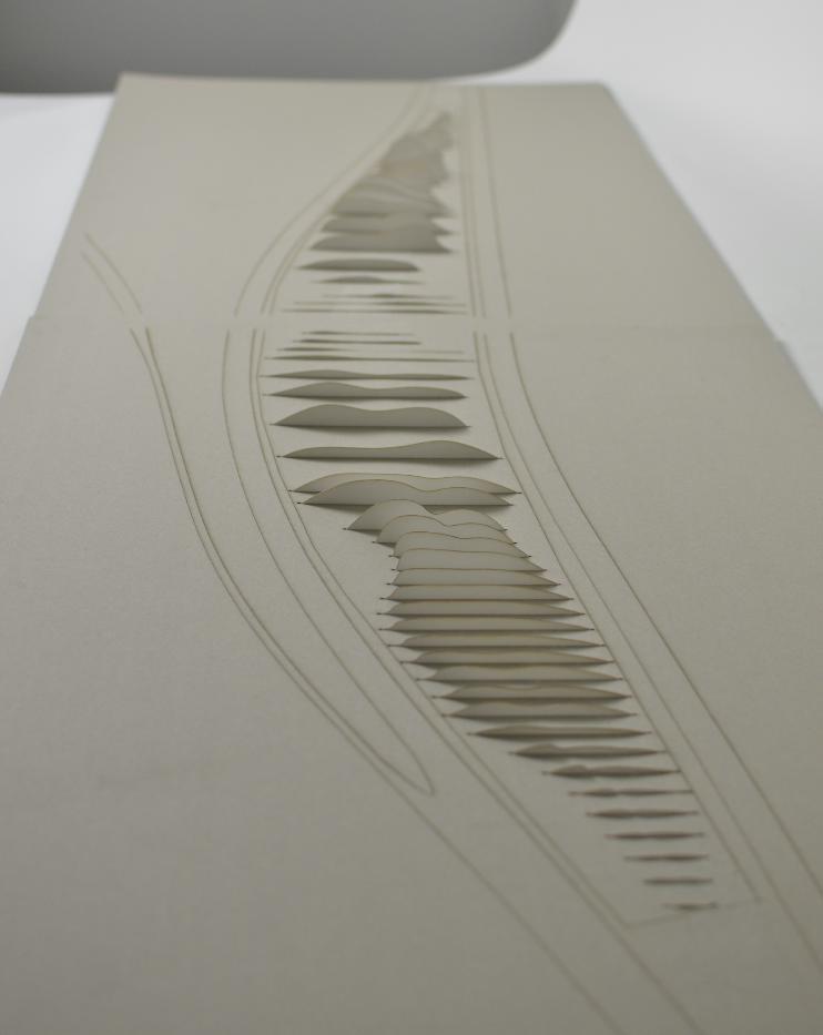
112
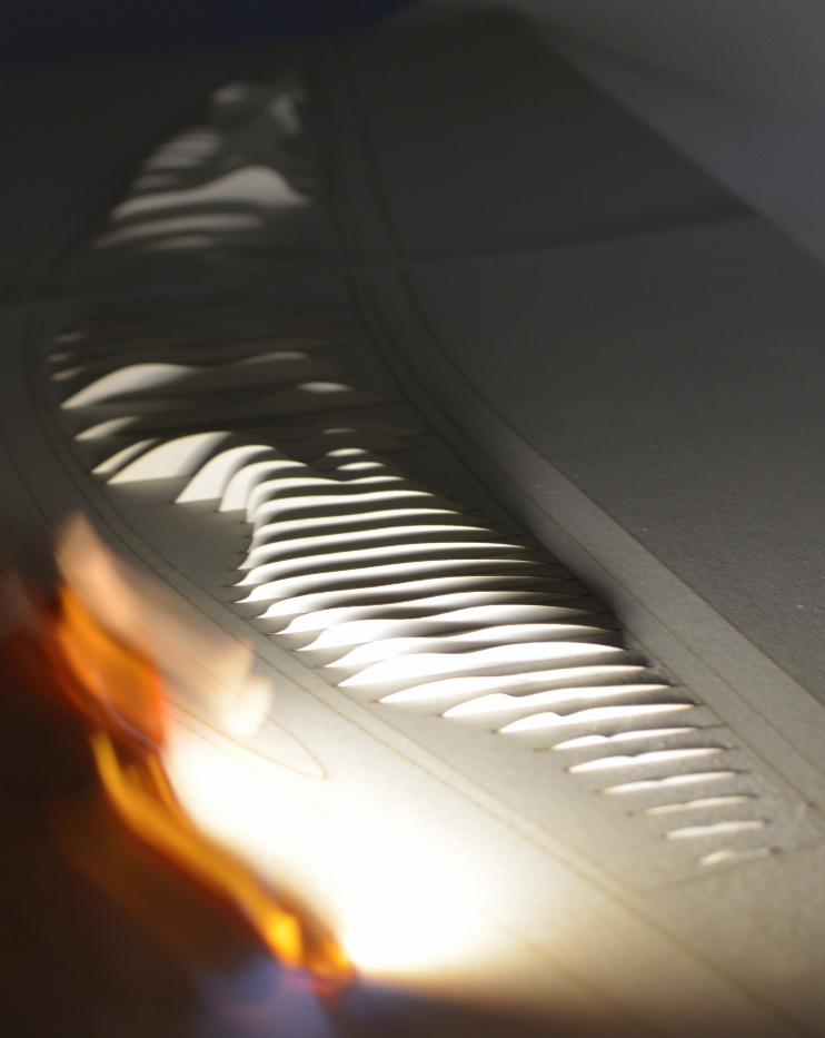
113
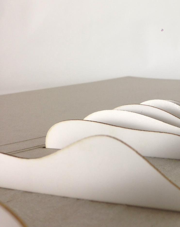
114
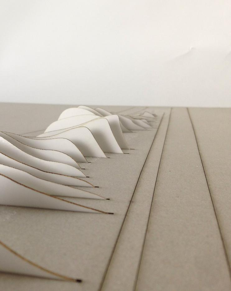
115
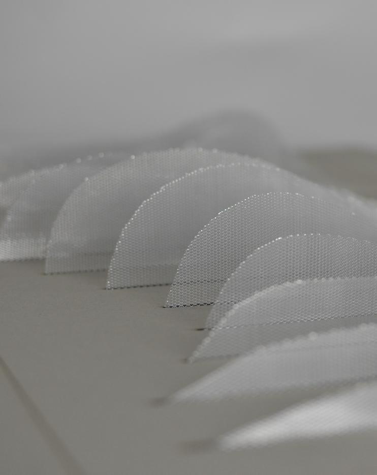
116
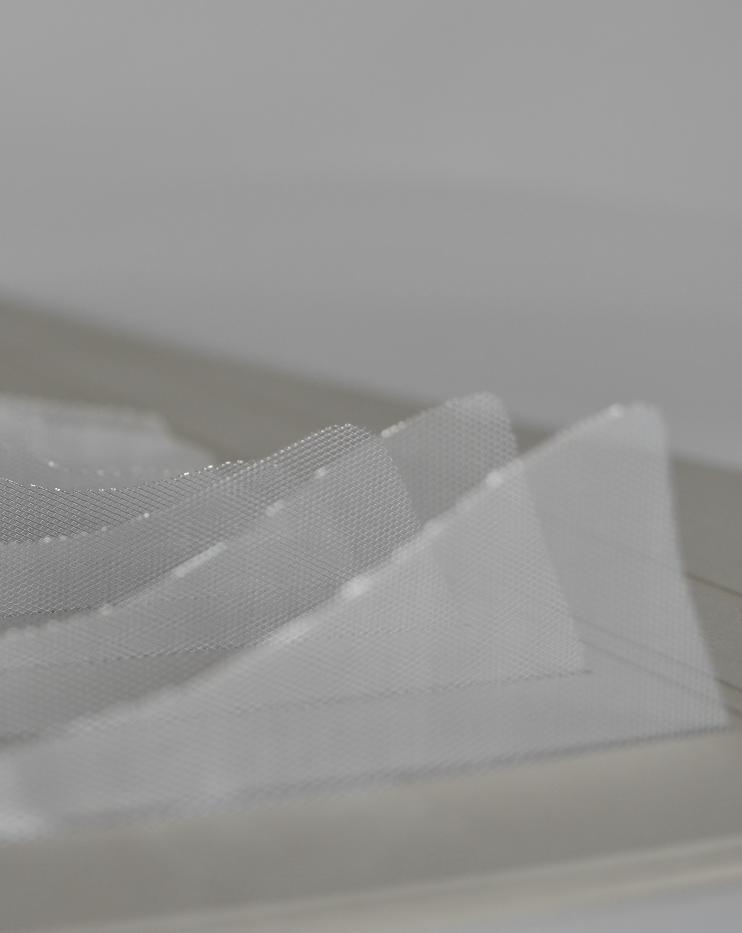
117
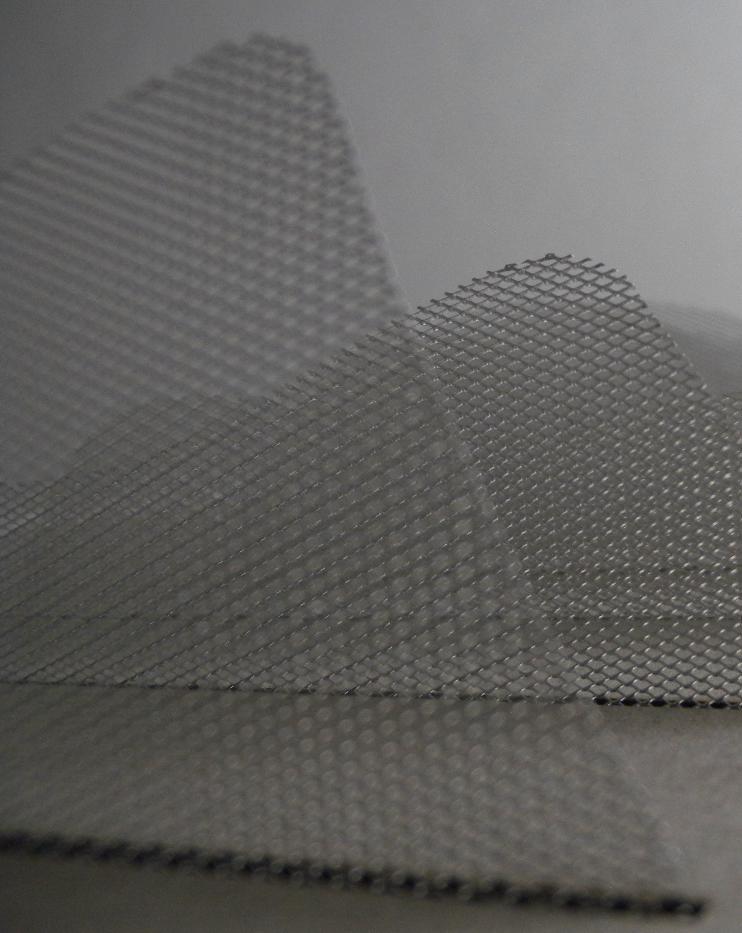
118
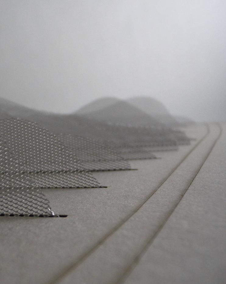
119
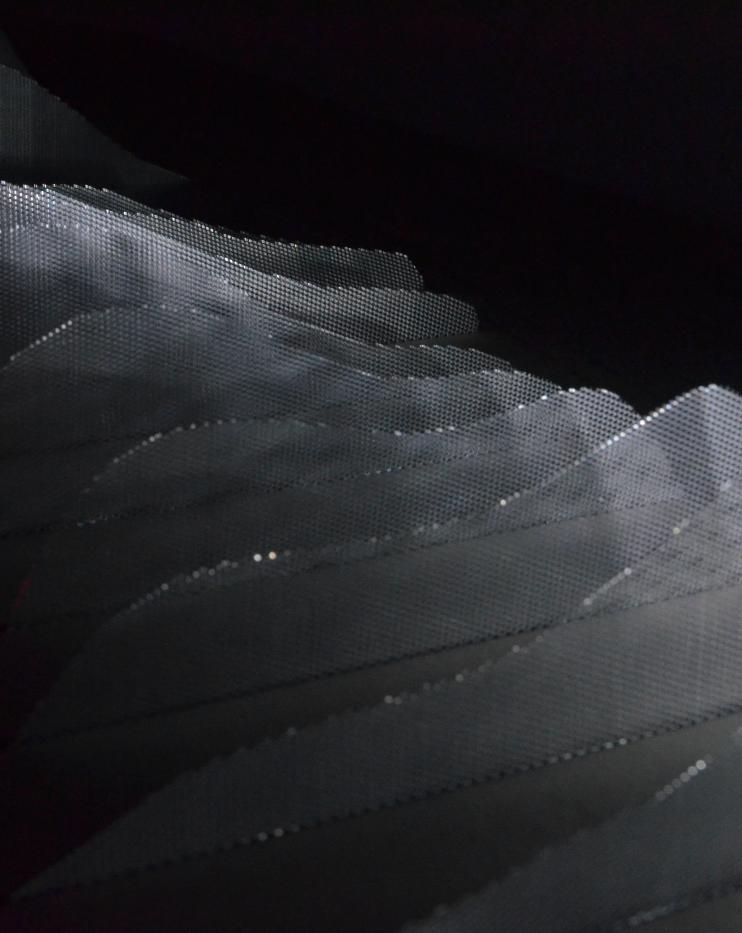
120
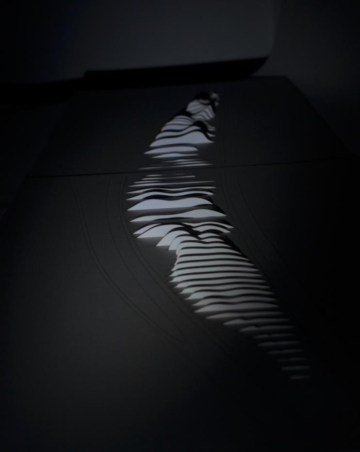
121
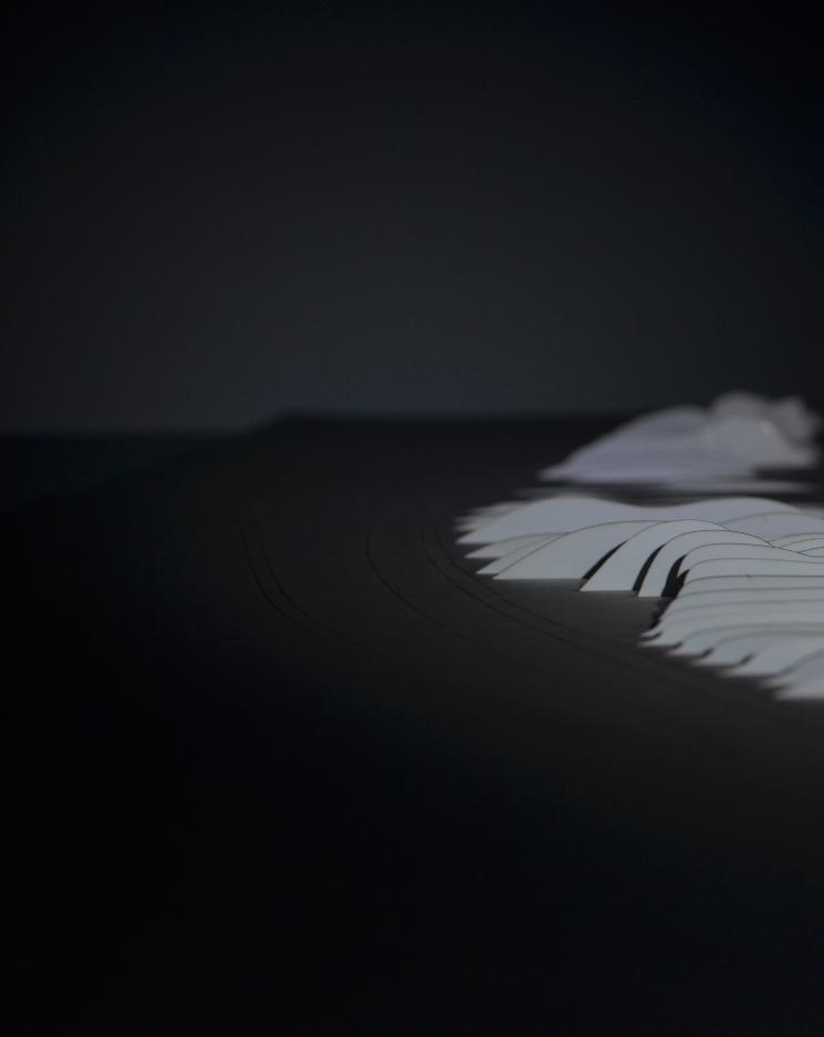
122
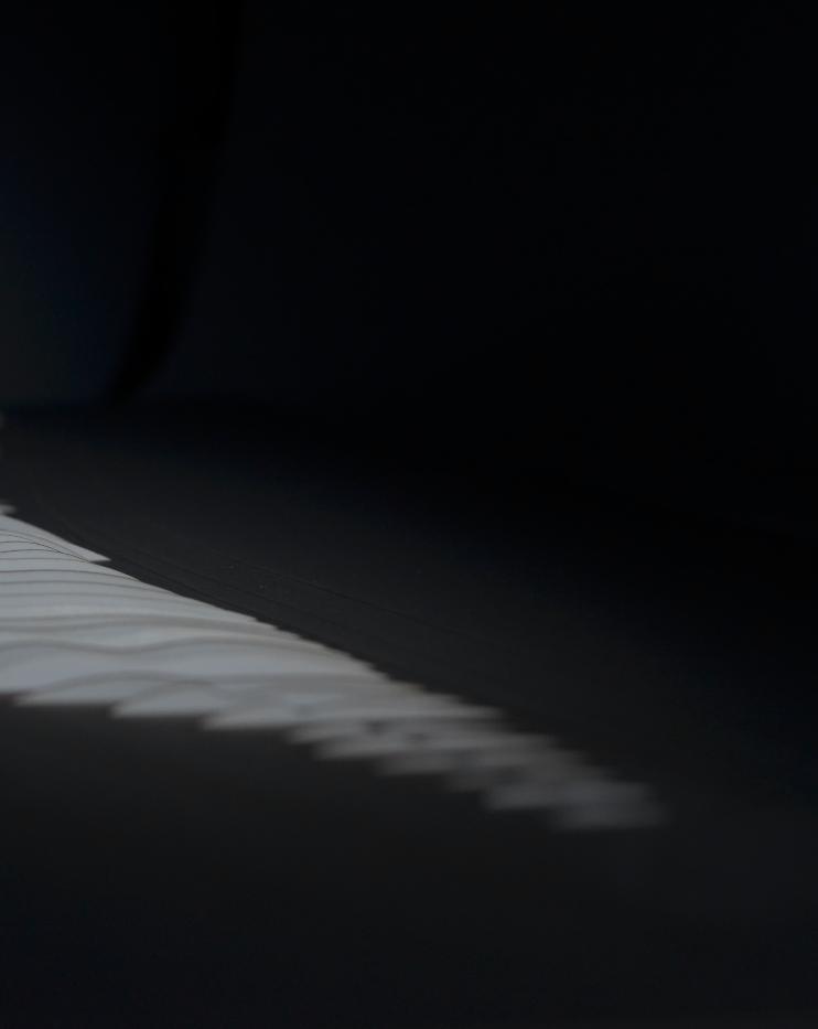
123
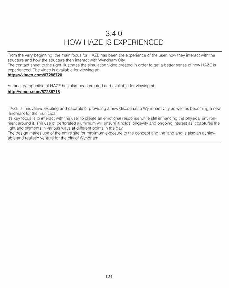
124
3.4.0 HOW HAZE IS EXPERIENCED
From the very beginning, the main focus for HAZE has been the experience of the user, how they interact with the structure and how the structure then interact with Wyndham City.The contact sheet to the right illustrates the simulation video created in order to get a better sense of how HAZE is experienced. The video is available for viewing at: https://vimeo.com/67286720
An arial perspective of HAZE has also been created and available for viewing at:http://vimeo.com/67286718
HAZE is innovative, exciting and capable of providing a new discourse to Wyndham City as well as becoming a new landmark for the municipal. It’s key focus is to interact with the user to create an emotional response while still enhancing the physical environ-ment around it. The use of perforated aluminium will ensure it holds longevity and ongoing interest as it captures the light and elements in various ways at different points in the day.The design makes use of the entire site for maximum exposure to the concept and the land and is also an achiev-able and realistic venture for the city of Wyndham.
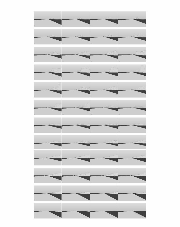
125
126
3.5.0BEYOND ‘PROJECT PROPOSAL’
Following from the final critic, there were a few ideas taken away.The critics agreed and understood our subtle and simple treatment to the site, I think this was an extremely important part of our project. We were not trying to outdo or outsmart ourselves with un-achievable techniques, instead we had a strong concept that we believed was the most relevant and engaging to the brief, site and user and we focused on methods of achieving it. The effect of scale and density within the material was brought up as a point to consider and to think about how the sunlight etc would cast upon it. While we did touch on it, I think this matter, had we had a bit more time would have been really beautiful explore. It would’ve been nice to really focus on the overall effect of the material and the after-math upon the users- how big of a difference did this material make compared to that of copper or stone or plastic?Realistically the final HAZE design would need more thought in to its structural support, especially in terms of how the more monumental sections at up to 14 meters high would hold up. I think a system such as the one we proposed could work but would need more attention and our lack in engineering skills prevented us on truly proving how the system would work.I truly believe that HAZE is innovative and exciting for Wyndham City while still being realistic and an intrinsically subtle treatment to its natural surroundings. It’s all well and good to design a whiz bang, ultra modern and gravity de-fying piece of architecture but if it isn’t site and brief suiting and holds no substance; I really cannot understand the point. I think HAZE is understated yet its concept and mass is unavoidable to those who interact with the site, exactly what the brief has called to. I think the combination of the form, material and size is also innovative and fresh, unlike the other sculptures that occupy the Wyndham region.
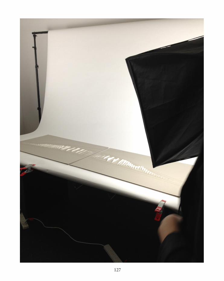
127
128
3.6.0PROJECT PROPOSAL CONCLUSION
Project Proposal sees the end to our project HAZE and also the entire subject as a whole.Project Proposal is really the icing on the cake in terms of seeing my initial argument of architecture holding more meaning than being just static from Case for Innovation through to our groups concept being born and explored within Design Approach and now refined and fabricated in Project Proposal. This last module has been very realistic and practical and I enjoy dealing with both these aspects, a lot. Project Proposal has also meant making rational decisions and staying organized and punc-tual, again something I enjoy doing. It has been really enjoyable, although at times frustrating, to watch what started as a concept on paper finish as a physical model. We never intended to try and out-do ourselves in terms of a com-plex design aided by parametric modelling, we simply wanted to execute a concept that we truly felt was exciting, innovative, heavily user-orientated and achievable. None of our group is overly computational savvy but now in our final stages of concluding the project, we have proved to ourselves that simple can work and still be just as effective as complicated, if not more so.The overall form of HAZE is much as we intended it to be. It com-bines intervals at varied distances to achieve a sense of time manipulation, it uses varied heights to create diversity and be experienced from afar and it utilizes the entire site, I think this is particularly important, both in terms of executing the concept and addressing the brief of creating a defining, talking point for the municipal.
129
LEARNING OUTCOMES
Wow. What a whirlwind this last stage has been! Project Proposal has been a great wrap-up to a very fast past learning experience. Looking firstly to the learning objectives outlined at the beginning of the semester I feel that myself and our group have certainly addressed each point. We have interrogated the brief and made rationale decisions about what we believed was the most interest-ing, exciting yet suitable treatment for the proposed design. From the very beginning we were extremely aware of how we wanted the user to feel, to capture emotions that we believe are not often experienced in a project such as the one put forward. Once we had the basis of our design we were then able to start modelling various iterations, testing to see which form best rep-resented the concept of time manipulation we wished to achieve. Details such as the material choice were also an important part of the process, we wanted the material to be able to also add another ‘layer’ to the design and be able to be penetrated by light and air, just as this very subject alludes to. For us HAZE was always a clear contender for the choice in design and the development of the proposal was a natural progression to the conceptual and physical ideas and events that were unfolding along the process.
This entire subject from beginning to end has certainly effected and slightly altered my knowledge of architecture. The subject being almost entirely digital is a very different treatment to what I have previously experienced. Admittedly I am still not overly comfortable with computational methods in terms of three-dimensional design-ing however I do appreciate it more and have a far better under-standing of what can be achieved and the way in which it can have such an influence on design. For me it comes down to a lack of skill and confidence using programs such as Rhino and Grasshopper as appose to not recognizing their advantages.
Besides being a little frustrated at time, I have really enjoyed this entire project, especially seeing a concept start on paper and finish as a physical model sitting in front of us. The culmination of research and experimentation that informed the design has also been really fascinating and I look forward to applying all the newly acquired knowledge and experiences to my future undertakings.
130
REFERENCES
Following pages include reference information for:One: Case for InnovationTwo: Design ApproachThree: Project Proposal
131
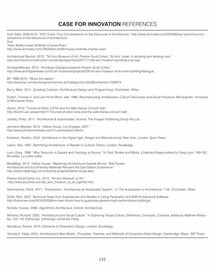
132
Arch Daily. 2008-2013. “NYC Event: Four Conversations on the Discourse of Architecture.” http://www.archdaily.com/200466/nyc-event-four-con-versations-on-the-discourse-of-architecture/And“Klein Bottle house/ McBride Charles Ryan.” http://www.archdaily.com/7952/klein-bottle-house-mcbride-charles-ryan/
Architectural Record. 2013. “Tel Aviv Museum of Art, Preston Scott Cohen, Tel Aviv, Israel. A spiraling and twisting core.”http://archrecord.construction.com/projects/portfolio/2011/11/tel-aviv-museum-spiraling-core.asp
ArchitypeReview, 2013. “Architype Dialogue presents Preston Scott Cohen.” http://www.architypereview.com/2-art-museums/projects/235-tel-aviv-museum-of-art-amir-building/dialogue
BP. 1996-2013. “About the station.”http://www.bp.com/sectiongenericarticle.do?categoryId=2222&contentId=7028375
Burry, Mark. 2011. Scripting Cultures: Architectural Design and Programming. Chichester: Wiley.
Dutton, Thomas A. and Lian Hurst Mann, eds. 1996. Reconstructing Architecture: Critical Discourses and Social Practices. Minneapolis: University of Minnesota Press.
Illumin. 2012. “Curves of Steel: CATIA and the Walt Disney Concert Hall.” http://illumin.usc.edu/printer/177/curves-of-steel-catia-and-the-walt-disney-concert-hall/.
Jodidio, Philip. 2011. Architecture & Automobiles. Victoria: The Images Publishing Group Pty Ltd.
Johnston Marklee. 2013. “Helios House, Los Angeles, 2007.”http://www.johnstonmarklee.com/?n=archive&id=2&info
Kolarevic, Branko. 2003. Architecture in the Digital Age: Design and Manufacturing. New York; London: Spon Press.
Leach, Neil. 1997. Rethinking Architecture: A Reader in Cultural Theory. London: Routledge.
Lynn, Greg. 1998. “Why Tectonics is Square and Topology is Groovy.” In Fold, Bodies and Blobs: Collected Essays edited by Greg Lynn, 169-182. Bruxelles: La Lettre volée.
MetalMag. 2013. “Helios House - Metalmag Architectural Awards Winner: Wall Panels,Architecture and Eco-Friendly Materials Reinvent the Gas-Station Experience.”http://www.metalmag.com/industrial-projects/helios-house.aspx
Preston Scott Cohen Inc. 2013. “Tel Aviv Museum of Art.” http://www.pscohen.com/tel_aviv_museum_of_art_lightfall.html
Schumacher, Patrik. 2011. “Introduction : Architecture as Autopoietic System.” In The Autopoiesis of Architecture, 1-28. Chichester: Wiley.
Smith, Rick. 2007. Technical Notes from Experiences and Studies in Using Parametric and BIM Architectural Software. http://hokrenew.com/2010/02/09/bim-bam-boom-how-to-guarantee-greener-high-performance-buildings/.
Terzidis, Kostas. 2006. Algorithmic Architecture. Oxford: Architectural.
Williams, Richard. 2005. “Architecture and Visual Culture.” In Exploring Visual Culture: Definitions, Concepts, Contexts, edited by Matthew Ramp-ley, 102-116. Edinburgh: Edinburgh University Press.
Woodbury, Robert. 2010. Elements of Parametric Design. London: Routledge.
Yehuda E. Kalay. 2004. Architecture’s New Media : Principles, Theories, and Methods of Computer-Aided Design. Cambridge, Mass.: MIT Press.
CASE FOR INNOVATION REFERENCES

133
1. Klein Bottle HouseImage obtained via:http://www.home-designing.com/wp-content/uploads/2009/07/klein-bottle-house-australia.JPG
2. Helios HouseImage obtained via:http://farm4.static.flickr.com/3220/2972898105_133cf38094_b.jpg
3. ICD | ITKE Research Pavilion 2011 / ICD / ITKE University of StuttgartImage obtained via:http://www.archdaily.com/200685/icditke-research-pavilion-icd-itke-university-of-stuttgart/
4. Tel Aviv Museum of ArtImage obtained via:http://candelafilms.files.wordpress.com/2012/02/amit_geron_tlv_museum_125.jpg
5. Walt Disney Concert HallImage obtained via:http://beauty-places.com/wp-content/uploads/2012/10/Walt-Disney-Concert-Hall-Wallpaper-HD-.jpg
CASE FOR INNOVATION IMAGE REFERENCES
134
American Institute of Physics. 2011. “Slowing down speeders.” http://www.aip.org/dbis/stories/2006/15233.html
Arch Daily. 2008-2013. “BanQ / Office dA.” http://www.archdaily.com/42581/banq-office-da/And“Station 20 Proposal / Peter Ruge Architekten.”http://www.archdaily.com/198764/station-20-proposal-peter-ruge-architekten/
Design Boom. 2012. “McChesney Architects: Blaze Installation.”http://www.designboom.com/design/mcchesney-architects-blaze-installation/
Evolo. 2010. “Sofia Metro Station Proposal / Peter Ruge Architekten.” http://www.evolo.us/architecture/sofia-metro-station-proposal-peter-ruge-architekten/
KGMG. 2011. “Workshop Parametric Interactions.” http://kgmg.org/main.php?l=en&p=projects&n=39
McChesney. 2013. “Blaze.” http://www.mcchesney.co.uk/projects/middlesbrough/
Melbourne Design Awards. 2013. “Baker D Chirico.“ http://melbournedesignawards.com.au/mda2012/entry_details.asp?ID=10580&Category_ID=4750
ParaMaterial. 2011. “Multipurpose Hall Design . 01” http://paramaterial.net/2011/12/02/multipurpose-hall-design-04-2/
Pion Publication. 2013. “Temporal illusion called ‘kappa effect’ in event perception.” http://www.perceptionweb.com/abstract.cgi?id=v050602 Ted. 2013. “Speakers Janet Echelman: Artist.” http://www.ted.com/speakers/janet_echelman.html”
Vice Media. 2013. “Dynamic Performance of Nature.” http://gallery.thecreatorsproject.com/gallery/Dynamic-Performance-of-Nature/2467715
Yehuda E. Kalay. 2004. Architecture’s New Media : Principles, Theories, and Methods of Computer-Aided Design. Cambridge: MIT Press.
DESIGN APPROACH REFERENCES
135
1. Baker D ChiricoImage obtained via:http://www.recitymagazine.com/media/97.258.1332225610.01-recity%20magaziene%20-%20Baker%20march%20studio%20DC%20007.jpg
2. Workshop Parametric InteractionsImage obtained via:http://kgmg.org/main.php?l=en&p=research&n=39
3. BANQ Restaurant Image obtained via:http://4.bp.blogspot.com/_p0SiaVlfkm0/S-5gr7DY0SI/AAAAAAAAAlw/Hre5UQ4ew3w/s1600/BANQ_restaurant_by_Office_dA_photos_by_John_Horner_at_yatzer_6.jpg
3a. BANQ Restaurant AxonometricImage obtained via:http://www.recitymagazine.com/media/133.374.1337171495.1259702368-exploded-axo-582x900%20%281%29.jpg
4. Metro Station 20 ProposalImage obtained via:http://ad009cdnb.archdaily.net/wp-content/uploads/2012/01/1326145523-03-station20-perspective-from-main-plaza.jpg
5. Blaze SculptureImage obtained via: http://www.designboom.com/weblog/images/images_2/2011/jenny/0-blaze/blaze01.jpg
DESIGN APPROACH REFERENCES
136
Britannica. 2013. “kappa effect.” http://www.britannica.com/EBchecked/topic/311805/kappa-effect
Contemporist. 2011. “Blaze Sculpture by Ian McChesney.” http://www.contemporist.com/2011/12/08/blaze-sculpture-by-ian-mcchesney/
Locker Group. 2011. “Product Profile.” http://www.locker.com.au/general-industrial/perforated-general-industrial.html
PROJECT PROPOSAL REFERENCES
137
DESIGN DRIVERS; page 86.‘Project One’ http://www.liftarchitects.com/journal/2011/6/14/projection-one.html‘BLAZE’ sculpture http://www.youtube.com/watch?v=p9RetutNlcA‘Wire Mesh Portraits’http://www.youtube.com/watch?feature=player_embedded&v=x7m19g5s4B8‘Flexible Paper Sculptures’http://vimeo.com/54967505‘2.30AT3.05’ by Florian Lichthttp://vimeo.com/5112227Corridor illusionhttp://gizmodo.com/5981603/20-optical-illusions-that-might-break-your-mind
ALL RHINO IMAGES, DIAGRAMS, MODEL PHOTOS AND SIMULATION VIDEOS HAVE BEEN CREATED OR CAPTURED BY EITHER MYSELF OR MY GROUP MEMBERS AILIE MILLER AND THOMAS CHIEW.
PROJECT PROPOSAL IMAGE/VIDEO REFERENCES

138

139