Embed Size (px)
Citation preview
1 5 0 0 / 2 5 0 0 / 3 5 0 0Chrysler Group LLC
O W N E R ’ S M A N U A L
2 0 1 3
20
13 R
AM
TR
UC
K 15
00
/25
00
/35
00
13D241-126-AB First Edition Printed in U.S.A.
R A M T R U C K

VEHICLES SOLD IN CANADAWith respect to any Vehicles Sold in Canada, the nameChrysler Group LLC shall be deemed to be deleted and thename Chrysler Canada Inc. used in substitution therefore.
DRIVING AND ALCOHOLDrunken driving is one of the most frequent causes of acci-dents.
Your driving ability can be seriously impaired with blood alcohollevels far below the legal minimum. If you are drinking, don’tdrive. Ride with a designated non-drinking driver, call a cab, afriend, or use public transportation.
WARNING!
Driving after drinking can lead to an accident. Your per-ceptions are less sharp, your reflexes are slower, and yourjudgment is impaired when you have been drinking.Never drink and then drive.
This manual illustrates and describes the operation of featuresand equipment that are either standard or optional on thisvehicle. This manual may also include a description of featuresand equipment that are no longer available or were not orderedon this vehicle. Please disregard any features and equipmentdescribed in this manual that are not on this vehicle.
Chrysler Group LLC reserves the right to make changes indesign and specifications, and/or make additions to or im-provements to its products without imposing any obligationupon itself to install them on products previously manufac-tured.
Copyright © 2012 Chrysler Group LLC

TABLE OF CONTENTSSECTION PAGE
1 INTRODUCTION . . . . . . . . . . . . . . . . . . . . . . . . . . . . . . . . . . . . . . . . . . . . . . . . . . . . . . . . . . . . . 3
2 THINGS TO KNOW BEFORE STARTING YOUR VEHICLE . . . . . . . . . . . . . . . . . . . . . . . . . . . . . 9
3 UNDERSTANDING THE FEATURES OF YOUR VEHICLE . . . . . . . . . . . . . . . . . . . . . . . . . . . . 125
4 UNDERSTANDING YOUR INSTRUMENT PANEL . . . . . . . . . . . . . . . . . . . . . . . . . . . . . . . . . . 253
5 STARTING AND OPERATING . . . . . . . . . . . . . . . . . . . . . . . . . . . . . . . . . . . . . . . . . . . . . . . . . 335
6 WHAT TO DO IN EMERGENCIES . . . . . . . . . . . . . . . . . . . . . . . . . . . . . . . . . . . . . . . . . . . . . . 569
7 MAINTAINING YOUR VEHICLE . . . . . . . . . . . . . . . . . . . . . . . . . . . . . . . . . . . . . . . . . . . . . . . 627
8 MAINTENANCE SCHEDULES . . . . . . . . . . . . . . . . . . . . . . . . . . . . . . . . . . . . . . . . . . . . . . . . . 695
9 IF YOU NEED CONSUMER ASSISTANCE . . . . . . . . . . . . . . . . . . . . . . . . . . . . . . . . . . . . . . . . 703
10 INDEX . . . . . . . . . . . . . . . . . . . . . . . . . . . . . . . . . . . . . . . . . . . . . . . . . . . . . . . . . . . . . . . . . . . . 713
1
2
3
4
5
6
7
8
9
10


INTRODUCTION
CONTENTS� INTRODUCTION . . . . . . . . . . . . . . . . . . . . . . . .4
� HOW TO USE THIS MANUAL . . . . . . . . . . . . . .4
� WARNINGS AND CAUTIONS . . . . . . . . . . . . . .6
� VAN CONVERSIONS/CAMPERS . . . . . . . . . . . .6
� VEHICLE IDENTIFICATION NUMBER . . . . . . . .6
� VEHICLE MODIFICATIONS/ALTERATIONS . . . .7
1

INTRODUCTION
Congratulations on selecting your new Chrysler GroupLLC vehicle. Be assured that it represents precisionworkmanship, distinctive styling, and high quality - allessentials that are traditional to our vehicles.
This Owner’s Manual has been prepared with the assis-tance of service and engineering specialists to acquaintyou with the operation and maintenance of your vehicle.It is supplemented by Warranty Information, and variouscustomer-oriented documents. Please take the time toread these publications carefully. Following the instruc-tions and recommendations in this manual will helpassure safe and enjoyable operation of your vehicle.
NOTE: After reviewing the owner information, itshould be stored in the vehicle for convenient referenc-ing and remain with the vehicle when sold.
When it comes to service, remember that your authorizeddealer knows your vehicle best, has factory-trained tech-nicians and genuine parts, and cares about your satisfac-tion.
HOW TO USE THIS MANUAL
Consult the Table of Contents to determine which sectioncontains the information you desire.
Since the specification of your vehicle depends on theitems of equipment ordered, certain descriptions andillustrations may differ from your vehicle’s equipment.
The detailed index at the back of this Owner’s Manualcontains a complete listing of all subjects.
Consult the following table for a description of thesymbols that may be used on your vehicle or throughoutthis Owner’s Manual:
4 INTRODUCTION

1
INTRODUCTION 5

WARNINGS AND CAUTIONS
This Owners Manual contains WARNINGS against op-erating procedures that could result in a collision orbodily injury. It also contains CAUTIONS against proce-dures that could result in damage to your vehicle. If youdo not read this entire Owners Manual, you may missimportant information. Observe all Warnings and Cau-tions.
VAN CONVERSIONS/CAMPERS
The Manufacturer’s Warranty does not apply to bodymodifications or special equipment installed by vanconversion/camper manufacturers/body builders. Referto the Warranty Information book, Section 2.1.C. Suchequipment includes video monitors, VCRs, heaters,stoves, refrigerators, etc. For warranty coverage andservice on these items, contact the applicable manufac-turer.
Operating instructions for the special equipment in-stalled by the conversion/camper manufacturer shouldalso be supplied with your vehicle. If these instructionsare missing, please contact your authorized dealer forassistance in obtaining replacement documents from theapplicable manufacturer.
For information on the Body Builders Guide refer to:www.dodgebodybuilder.com. This website contains di-mensional and technical specifications for your vehicle. Itis intended for Second Stage Manufacturer’s technicalsupport. For service issues, contact your authorizeddealer.
VEHICLE IDENTIFICATION NUMBER
The Vehicle Identification Number (VIN) is found on theleft front corner of the instrument panel, visible throughthe windshield. This number also appears on the vehicle
6 INTRODUCTION

frame and underbody as well as the Automobile Infor-mation Disclosure Label affixed to a window on yourvehicle, the vehicle registration and title.
NOTE: It is illegal to remove or alter the VIN.
VEHICLE MODIFICATIONS/ALTERATIONS
WARNING!
Any modifications or alterations to this vehicle couldseriously affect its roadworthiness and safety andmay lead to a collision resulting in serious injury ordeath.
Vehicle Identification Number
1
INTRODUCTION 7


THINGS TO KNOW BEFORE STARTING YOUR VEHICLE
CONTENTS� A WORD ABOUT YOUR KEYS . . . . . . . . . . . . .12
▫ Ignition System . . . . . . . . . . . . . . . . . . . . . . . .12
▫ Key Fob . . . . . . . . . . . . . . . . . . . . . . . . . . . . .14
▫ Removing Key Fob From Ignition . . . . . . . . . .16
▫ Key-In-Ignition Reminder . . . . . . . . . . . . . . . .18
� SENTRY KEY® . . . . . . . . . . . . . . . . . . . . . . . . .18
▫ Replacement Keys . . . . . . . . . . . . . . . . . . . . .19
▫ Customer Key Programming . . . . . . . . . . . . . .20
▫ General Information . . . . . . . . . . . . . . . . . . . .20
� VEHICLE SECURITY ALARM — IF EQUIPPED . . .21
▫ Rearming Of The System . . . . . . . . . . . . . . . . .21
▫ To Arm The System. . . . . . . . . . . . . . . . . . . . .21
▫ To Disarm The System . . . . . . . . . . . . . . . . . . .21
▫ Security System Manual Override . . . . . . . . . . .22
� ILLUMINATED ENTRY — IF EQUIPPED . . . . . .22
� REMOTE KEYLESS ENTRY (RKE) —IF EQUIPPED . . . . . . . . . . . . . . . . . . . . . . . . . .23
▫ Remote Unlock The Doors . . . . . . . . . . . . . . .24
▫ To Lock The Doors . . . . . . . . . . . . . . . . . . . . .26
▫ Sound Horn With Remote Key Lock . . . . . . . . .27
2

▫ Using The Panic Alarm . . . . . . . . . . . . . . . . . .27
▫ RKE Air Suspension (Remote Lowering Of TheVehicle) — If Equipped . . . . . . . . . . . . . . . . . .28
▫ Programming Additional Transmitters . . . . . . . .29
▫ Transmitter Battery Replacement . . . . . . . . . . .29
▫ General Information . . . . . . . . . . . . . . . . . . . .30
� REMOTE STARTING SYSTEM —IF EQUIPPED . . . . . . . . . . . . . . . . . . . . . . . . . .30
▫ How To Use Remote Start . . . . . . . . . . . . . . . .31
� DOOR LOCKS . . . . . . . . . . . . . . . . . . . . . . . . .34
▫ Manual Door Locks . . . . . . . . . . . . . . . . . . . . .34
▫ Power Door Locks — If Equipped . . . . . . . . . .35
▫ Child-Protection Door Lock . . . . . . . . . . . . . . .37
� KEYLESS ENTER-N-GO™ . . . . . . . . . . . . . . . . .38
� WINDOWS . . . . . . . . . . . . . . . . . . . . . . . . . . .42
▫ Power Windows – If Equipped . . . . . . . . . . . .42
▫ Wind Buffeting . . . . . . . . . . . . . . . . . . . . . . .46
� OCCUPANT RESTRAINTS . . . . . . . . . . . . . . . .46
▫ Lap/Shoulder Belts . . . . . . . . . . . . . . . . . . . .50
▫ Lap/Shoulder Belt Untwisting Procedure . . . . .58
▫ Adjustable Upper Shoulder Belt Anchorage . . .59
▫ Center Lap Belts . . . . . . . . . . . . . . . . . . . . . . .60
▫ Seat Belts In Passenger Seating Positions . . . . . .60
▫ Automatic Locking Retractor (ALR) Mode – IfEquipped . . . . . . . . . . . . . . . . . . . . . . . . . . . .61
▫ Energy Management Feature . . . . . . . . . . . . . .62
▫ Seat Belt Pretensioners . . . . . . . . . . . . . . . . . .62
10 THINGS TO KNOW BEFORE STARTING YOUR VEHICLE

▫ Enhanced Seat Belt Use Reminder System(BeltAlert®) . . . . . . . . . . . . . . . . . . . . . . . . . .63
▫ Seat Belts And Pregnant Women . . . . . . . . . . .64
▫ Seat Belt Extender . . . . . . . . . . . . . . . . . . . . .64
▫ Supplemental Restraint System (SRS) —Air Bags . . . . . . . . . . . . . . . . . . . . . . . . . . . .65
▫ Air Bag System Components . . . . . . . . . . . . . .66
▫ Advanced Front Air Bag Features . . . . . . . . . . .67
▫ Air Bag Deployment Sensors And Controls . . . .71
▫ Event Data Recorder (EDR) . . . . . . . . . . . . . . .83
▫ Child Restraints . . . . . . . . . . . . . . . . . . . . . . .84
� ENGINE BREAK-IN RECOMMENDATIONS . . .118
� SAFETY TIPS . . . . . . . . . . . . . . . . . . . . . . . . .119
▫ Transporting Passengers . . . . . . . . . . . . . . . . .119
▫ Exhaust Gas . . . . . . . . . . . . . . . . . . . . . . . . .120
▫ Safety Checks You Should Make Inside TheVehicle . . . . . . . . . . . . . . . . . . . . . . . . . . . . .121
▫ Periodic Safety Checks You Should Make OutsideThe Vehicle . . . . . . . . . . . . . . . . . . . . . . . . .123
2
THINGS TO KNOW BEFORE STARTING YOUR VEHICLE 11

A WORD ABOUT YOUR KEYS
Fob with Remote Keyless Entry (RKE) — If Equipped
Your vehicle uses a keyless ignition system. This systemconsists of a Fob with Remote Keyless Entry (RKE)transmitter and an Ignition Node Module (IGNM) withintegral ignition switch. You can insert the Fob into theignition switch with either side up.
Standard Blade Ignition Key — If Equipped
Your vehicle may use a standard blade key ignitionsystem. The authorized dealer that sold you your vehiclehas the key code numbers for your vehicle locks. Thesenumbers can be used to order duplicate keys from yourauthorized dealer. Ask your authorized dealer for thesenumbers and keep them in a safe place. You can insert thedouble-sided standard blade key into the ignition switchwith either side up.
Ignition System
Your vehicle may be equipped with either an IgnitionNode Module (IGNM) which operates similar to a stan-dard ignition switch, or a Keyless Ignition Node (KIN)which allows the driver to operate the ignition switchwith the push of a button, as long as the Remote KeylessEntry (RKE) transmitter is in the passenger compartment.
Ignition Node Module (IGNM) — If Equipped
The Ignition Node Module (IGNM) operates similar to anignition switch. It has four operating positions, three withdetents and one that is spring-loaded. The detent posi-tions are OFF, ACC, and ON/RUN. The START positionis a spring-loaded momentary contact position. Whenreleased from the START position, the switch automati-cally returns to the ON/RUN position.
12 THINGS TO KNOW BEFORE STARTING YOUR VEHICLE

Keyless Ignition Node (KIN) — If Equipped
This feature allows the driver to operate the ignitionswitch with the push of a button, as long as the RemoteKeyless Entry (RKE) transmitter is in the passengercompartment.
The Keyless Ignition Node (KIN) has four operatingpositions, three of which are labeled and will illuminatewhen in position. The three positions are OFF, ACC, andON/RUN. The fourth position is START, during startRUN will illuminate.
NOTE: In case the ignition switch does not change withthe push of a button, the RKE transmitter (Key Fob) mayhave a low or dead battery. In this situation a back upmethod can be used to operate the ignition switch. Putthe nose side (side opposite of the emergency key) of theKey Fob against the ENGINE START/STOP button andpush to operate the ignition switch.
Ignition Node Module (IGNM)
1 — OFF2 — ACC (ACCESSORY)3 — ON/RUN4 — START
2
THINGS TO KNOW BEFORE STARTING YOUR VEHICLE 13

NOTE: For further information, refer to Starting Proce-dures in ”STARTING AND OPERATING”.
Key Fob
The Key Fob operates the ignition switch. Insert thesquare end of the key fob into the ignition switch locatedon the instrument panel and rotate to the desired posi-tion. It also contains the Remote Keyless Entry (RKE)transmitter and an emergency key, which stores in therear of the Key Fob.
The emergency key allows for entry into the vehicleshould the battery in the vehicle or the RKE transmittergo dead. You can keep the emergency key with you whenvalet parking.
To remove the emergency key, slide the mechanical latchat the top of the Key Fob sideways with your thumb andthen pull the key out with your other hand.
Keyless Ignition Node (KIN)
1 — OFF2 — ACC (ACCESSORY)3 — ON/RUN
14 THINGS TO KNOW BEFORE STARTING YOUR VEHICLE

NOTE: You can insert the double-sided emergency keyinto the lock cylinder with either side up.
Emergency Key Removal (WIN) Emergency Key Removal Keyless Enter-N-Go™ Fob(KIN)
2
THINGS TO KNOW BEFORE STARTING YOUR VEHICLE 15
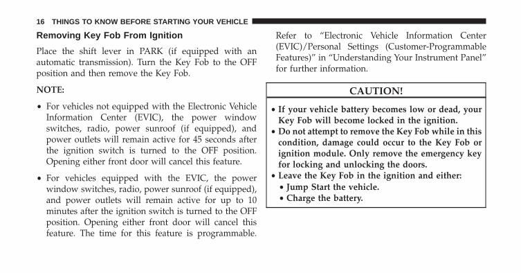
Removing Key Fob From Ignition
Place the shift lever in PARK (if equipped with anautomatic transmission). Turn the Key Fob to the OFFposition and then remove the Key Fob.
NOTE:
• For vehicles not equipped with the Electronic VehicleInformation Center (EVIC), the power windowswitches, radio, power sunroof (if equipped), andpower outlets will remain active for 45 seconds afterthe ignition switch is turned to the OFF position.Opening either front door will cancel this feature.
• For vehicles equipped with the EVIC, the powerwindow switches, radio, power sunroof (if equipped),and power outlets will remain active for up to 10minutes after the ignition switch is turned to the OFFposition. Opening either front door will cancel thisfeature. The time for this feature is programmable.
Refer to “Electronic Vehicle Information Center(EVIC)/Personal Settings (Customer-ProgrammableFeatures)” in “Understanding Your Instrument Panel”for further information.
CAUTION!
• If your vehicle battery becomes low or dead, yourKey Fob will become locked in the ignition.
• Do not attempt to remove the Key Fob while in thiscondition, damage could occur to the Key Fob orignition module. Only remove the emergency keyfor locking and unlocking the doors.
• Leave the Key Fob in the ignition and either:• Jump Start the vehicle.• Charge the battery.
16 THINGS TO KNOW BEFORE STARTING YOUR VEHICLE

WARNING!
• Before exiting a vehicle, always apply the parkingbrake, shift the transmission into PARK, and pushignition button to place ignition in OFF position.When leaving the vehicle, always lock your ve-hicle.
• Never leave children alone in a vehicle, or withaccess to an unlocked vehicle.
• Allowing children to be in a vehicle unattended isdangerous for a number of reasons. A child orothers could be seriously or fatally injured. Chil-dren should be warned not to touch the parkingbrake, brake pedal or the shift lever.
(Continued)
WARNING! (Continued)• Do not leave the Key Fob in or near the vehicle, or
in a location accessible to children, and do notleave Keyless Enter-N-Go™ in the ACC or ON/RUN mode. A child could operate power windows,other controls, or move the vehicle.
• Do not leave children or animals inside parkedvehicles in hot weather. Interior heat build-up maycause serious injury or death.
CAUTION!
An unlocked car is an invitation to thieves. Alwaysremove the key from the ignition and lock all doorswhen leaving the vehicle unattended.
2
THINGS TO KNOW BEFORE STARTING YOUR VEHICLE 17

Key-In-Ignition Reminder
Opening the driver’s door when the Key Fob is in theignition and the ignition switch position is OFF or ACC,a chime will sound to remind you to remove the Key Fob.
NOTE:
• �Keyed� Ignition systems will chime in OFF or ACCwhen the driver door is open.
• “Keyless� Ignition systems will chime in ACC or RUNwhen the driver door is open.
• If equipped with Electronic Vehicle Information Center(EVIC) the EVIC will display “Key In Ignition”.
SENTRY KEY®
The Sentry Key® Immobilizer System prevents unau-thorized vehicle operation by disabling the engine. Thesystem does not need to be armed or activated. Operationis automatic, regardless of whether the vehicle is lockedor unlocked.
The system uses a Key Fob with a factory-mated RemoteKeyless Entry (RKE) transmitter, a Keyless Ignition Node(KIN) and a RF receiver to prevent unauthorized vehicleoperation. Therefore, only Key Fobs that are pro-grammed to the vehicle can be used to start and operatethe vehicle. The system will not allow the engine to crankif an invalid Key Fob is used to start and operate thevehicle. The system will shut the engine off in twoseconds if an invalid Key Fob is used to start the engine.
NOTE: A Key Fob that has not been programmed is alsoconsidered an invalid key.
18 THINGS TO KNOW BEFORE STARTING YOUR VEHICLE
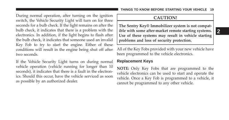
During normal operation, after turning on the ignitionswitch, the Vehicle Security Light will turn on for threeseconds for a bulb check. If the light remains on after thebulb check, it indicates that there is a problem with theelectronics. In addition, if the light begins to flash afterthe bulb check, it indicates that someone used an invalidKey Fob to try to start the engine. Either of theseconditions will result in the engine being shut off aftertwo seconds.
If the Vehicle Security Light turns on during normalvehicle operation (vehicle running for longer than 10seconds), it indicates that there is a fault in the electron-ics. Should this occur, have the vehicle serviced as soonas possible by an authorized dealer.
CAUTION!
The Sentry Key® Immobilizer system is not compat-ible with some after-market remote starting systems.Use of these systems may result in vehicle startingproblems and loss of security protection.
All of the Key Fobs provided with your new vehicle havebeen programmed to the vehicle electronics.
Replacement Keys
NOTE: Only Key Fobs that are programmed to thevehicle electronics can be used to start and operate thevehicle. Once a Key Fob is programmed to a vehicle, itcannot be programmed to any other vehicle.
2
THINGS TO KNOW BEFORE STARTING YOUR VEHICLE 19

CAUTION!
• Always remove the Key Fobs from the vehicle andlock all doors when leaving the vehicle unat-tended.
• For vehicles equipped with Keyless Enter-N-Go™,always remember to place the ignition in the OFFposition.
At the time of purchase, the original owner is providedwith a four-digit Personal Identification Number (PIN).Keep the PIN in a secure location. This number isrequired for authorized dealer replacement of Key Fobs.Duplication of Key Fobs may be performed at an autho-rized dealer, this procedure consists of programming ablank Key Fob to the vehicle electronics. A blank Key Fobis one that has never been programmed.
NOTE: When having the Sentry Key® Immobilizer Sys-tem serviced, bring all vehicle keys with you to anauthorized dealer.
Customer Key Programming
Programming Key Fobs or RKE transmitters may beperformed at an authorized dealer.
General Information
The Sentry Key® system complies with FCC rules Part 15and with RSS-210 of Industry Canada. Operation issubject to the following conditions:
• This device may not cause harmful interference.
• This device must accept any interference that may bereceived, including interference that may cause unde-sired operation.
20 THINGS TO KNOW BEFORE STARTING YOUR VEHICLE

VEHICLE SECURITY ALARM — IF EQUIPPED
The Vehicle Security Alarm monitors the vehicle doorsand ignition for unauthorized operation. When the Ve-hicle Security Alarm is activated, interior switches fordoor locks are disabled. The system provides both au-dible and visible signals, for the first three minutes thehorn will sound and the headlights will turn on, the parklamps and/or turn signals will flash and Vehicle SecurityLight will flash repeatedly. For an additional 15 minutesonly, the headlights will turn on, the park lamps and/orturn signals and Vehicle Security Light will flash.
Rearming Of The System
The Vehicle Security Alarm will rearm itself after the 15additional minutes of headlights and Vehicle SecurityLight flashing, if the system has not been disabled. If thecondition which initiated the alarm is still present, thesystem will ignore that condition and monitor the re-maining doors and ignition.
To Arm The System
The Vehicle Security Alarm will set when you use thepower door locks, or use the Remote Keyless Entry (RKE)transmitter to lock the doors. After all the doors arelocked and closed, the Vehicle Security Light in theinstrument panel cluster will flash rapidly for about 16seconds to indicate that the alarm is being set. After thealarm is set, the Vehicle Security Light will flash at aslower rate to indicate that the system is armed.
To Disarm The System
Use the RKE transmitter to unlock the door. If somethinghas triggered the Vehicle Security Alarm in your absence,the horn will sound three times when you unlock thedoors and the exterior lights will blink three times. Checkthe vehicle for tampering.
The Vehicle Security Alarm will also disarm if a pro-grammed Sentry Key® is inserted into the ignition
2
THINGS TO KNOW BEFORE STARTING YOUR VEHICLE 21

switch. To exit the alarming mode, press the RKE trans-mitter UNLOCK button, or insert a programmed SentryKey® into the ignition switch.
The Vehicle Security Alarm is designed to protect yourvehicle; however, you can create conditions where thesystem will give you a false alarm. If one of the previ-ously described arming sequences has occurred, theVehicle Security Alarm will arm regardless of whetheryou are in the vehicle or not. If you remain in the vehicleand open a door, the alarm will sound. If this occurs,disarm the Vehicle Security Alarm.
Security System Manual Override
The Vehicle Security Alarm will not arm if you lock thedoors using the manual door lock plunger.
ILLUMINATED ENTRY — IF EQUIPPED
The courtesy lights will turn on when you use theRemote Keyless Entry (RKE) transmitter to unlock thedoors or open any door.
This feature also turns on the approach lighting in theoutside mirrors (if equipped). Refer to “Mirrors” in“Understanding The Features Of Your Vehicle” for fur-ther information.
The lights will fade to off after approximately 30 seconds,or they will immediately fade to off once the ignitionswitch is turned to ON/RUN from the OFF position.
22 THINGS TO KNOW BEFORE STARTING YOUR VEHICLE

NOTE:
• The front courtesy overhead console and door cour-tesy lights will not turn off if the dimmer control is inthe “Dome ON” position (rotate horizontal thumbwheel on the bottom of the switch to the far rightdetent position).
• The illuminated entry system will not operate if thedimmer control is in the “Dome OFF” position (rotatehorizontal thumb wheel on the bottom of the switch tothe far left detent position).
REMOTE KEYLESS ENTRY (RKE) — IFEQUIPPED
The RKE system allows you to lock or unlock all doors,tailgate, and the RamBox® (if equipped) as well asactivate the Panic Alarm from distances up to approxi-mately 33 ft (10 m) using a hand-held radio transmitterwith integrated key. The transmitter does not need to bepointed at the vehicle to activate the system. Press andrelease the LOCK button on the RKE transmitter to lockall doors, the tailgate and the RamBox® (if equipped).The turn signal lights will flash and the horn will chirp toacknowledge the signal.
2
THINGS TO KNOW BEFORE STARTING YOUR VEHICLE 23

NOTE: Inserting the Key Fob with RKE transmitter intothe ignition switch disables the system from respondingto any button presses from that RKE transmitter. Drivingat speeds 5 mph (8 km/h) and above disables the systemfrom responding to all RKE transmitter buttons for allRKE transmitters.
Key Fob With Remote Keyless Entry (RKE) Transmitter(WIN)
24 THINGS TO KNOW BEFORE STARTING YOUR VEHICLE

Remote Unlock The Doors
Press and release the UNLOCK button on the RKEtransmitter once to unlock the driver’s door (If EVIC issetup for driver door first, otherwise this will unlock alldoors), or press the unlock button twice within five
seconds to unlock all doors, the tailgate and the Ram-Box® (if equipped). The turn signal lights will flash toacknowledge the unlock signal. The illuminated entrysystem will also turn on.
Remote Key Unlock, Driver Door/All Doors First
This feature lets you program the system to unlock eitherthe driver’s door or all doors on the first press of theUNLOCK button on the RKE transmitter. To change thecurrent setting, proceed as follows:
• For vehicles equipped with the EVIC, refer to “Elec-tronic Vehicle Information Center (EVIC)/Customer-Programmable Features (System Setup)” in “Under-standing Your Instrument Panel” for furtherinformation.
• For vehicles not equipped with the EVIC, perform thefollowing procedure:
Key Fob With RKE Transmitter Keyless Enter-N-Go™Fob (KIN)
2
THINGS TO KNOW BEFORE STARTING YOUR VEHICLE 25

1. Press and hold the LOCK button on a programmedRKE transmitter for at least four seconds, but nolonger than ten seconds. Then, press and hold theUNLOCK button while still holding the LOCK button.
2. Release both buttons at the same time.
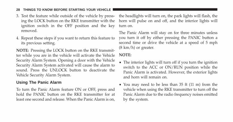
3. Test the feature while outside of the vehicle by press-ing the LOCK/UNLOCK buttons on the RKE trans-mitter with the ignition switch in the OFF position andthe key removed.
4. Repeat these steps if you want to return this feature toits previous setting.
NOTE: Pressing the LOCK button on the RKE transmit-ter while you are inside the vehicle will activate theVehicle Security Alarm System. Opening a door with theVehicle Security Alarm System activated will cause thealarm to sound. Press the UNLOCK button to deactivatethe Vehicle Security Alarm System.
Flash Lamps With Remote Key Lock
This feature will cause the turn signal lights to flash whenthe doors are locked or unlocked with the RKE transmit-ter. This feature can be turned on or turned off. To changethe current setting, proceed as follows:
• For vehicles equipped with the EVIC, refer to “Elec-tronic Vehicle Information Center (EVIC)/Customer-Programmable Features (System Setup)” in “Under-standing Your Instrument Panel” for furtherinformation.
• For vehicles not equipped with the EVIC, perform thefollowing procedure:
1. Press and hold the UNLOCK button on a programmedRKE transmitter for at least four seconds, but nolonger than ten seconds. Then, press and hold theLOCK button while still holding the UNLOCK button.
2. Release both buttons at the same time.
26 THINGS TO KNOW BEFORE STARTING YOUR VEHICLE

3. Test the feature while outside of the vehicle by press-ing the LOCK/UNLOCK buttons on the RKE trans-mitter with the ignition switch in the OFF position andthe key removed.
4. Repeat these steps if you want to return this feature toits previous setting.
NOTE: Pressing the LOCK button on the RKE transmit-ter while you are in the vehicle will activate the VehicleSecurity Alarm System. Opening a door with the VehicleSecurity Alarm System activated will cause the alarm tosound. Press the UNLOCK button to deactivate theVehicle Security Alarm System.
To Lock The Doors
Press and release the LOCK button on the RKE transmit-ter to lock all doors, the tailgate and the RamBox® (ifequipped). The turn signal lights will flash and the hornwill chirp to acknowledge the signal.
Sound Horn With Remote Key Lock
This feature will cause the horn to chirp when the doorsare locked with the RKE transmitter. This feature can beturned on or turned off. To change the current setting,proceed as follows:
• For vehicles equipped with the EVIC, refer to “Elec-tronic Vehicle Information Center (EVIC)/Customer-Programmable Features (System Setup)” in “Under-standing Your Instrument Panel” for furtherinformation.
• For vehicles not equipped with the EVIC, perform thefollowing procedure:
1. Press the LOCK button on a programmed RKE trans-mitter for at least four seconds, but no longer than tenseconds. Then, press the PANIC button while stillholding the LOCK button.
2. Release both buttons at the same time.
2
THINGS TO KNOW BEFORE STARTING YOUR VEHICLE 27
3. Test the feature while outside of the vehicle by press-ing the LOCK button on the RKE transmitter with theignition switch in the OFF position and the keyremoved.
4. Repeat these steps if you want to return this feature toits previous setting.
NOTE: Pressing the LOCK button on the RKE transmit-ter while you are in the vehicle will activate the VehicleSecurity Alarm System. Opening a door with the VehicleSecurity Alarm System activated will cause the alarm tosound. Press the UNLOCK button to deactivate theVehicle Security Alarm System.
Using The Panic Alarm
To turn the Panic Alarm feature ON or OFF, press andhold the PANIC button on the RKE transmitter for atleast one second and release. When the Panic Alarm is on,
the headlights will turn on, the park lights will flash, thehorn will pulse on and off, and the interior lights willturn on.
The Panic Alarm will stay on for three minutes unlessyou turn it off by either pressing the PANIC button asecond time or drive the vehicle at a speed of 5 mph(8 km/h) or greater.
NOTE:
• The interior lights will turn off if you turn the ignitionswitch to the ACC or ON/RUN position while thePanic Alarm is activated. However, the exterior lightsand horn will remain on.
• You may need to be less than 35 ft (11 m) from thevehicle when using the RKE transmitter to turn off thePanic Alarm due to the radio frequency noises emittedby the system.
28 THINGS TO KNOW BEFORE STARTING YOUR VEHICLE

RKE Air Suspension (Remote Lowering Of TheVehicle) — If Equipped
For easy entry and loading, your vehicle can belowered by pressing the Key Fob air suspen-sion lowering button two times. When Remotekey FOB lowering is requested, the vehicle will
send a series of chirps and flashes to alert the customerthat the operation has begun and will continue thesealerts until it successfully lowers.
The following conditions must be met for the vehicle tolower remotely:
The vehicle must not already be in Entry/Exit (Park) rideheight.
The vehicle battery must be fully charged.
All doors must be closed.
The ignition key must be out of the vehicle.
Cancelling Remote Lowering Vehicle lowering can becancelled at anytime. When vehicle lowering is can-celled, the vehicle will raise up to the next definedlevel and lock out the remote lowering feature until theignition has been cycled ON/OFF.
To cancel vehicle lowering, press the Key Fob air suspen-sion lowering button one time during the loweringprocess. When vehicle lowering is cancelled the horn willchirp two times and the hazard lights will flash fourtimes. Once raising is completed, the horn will chirp onetime.
NOTE: For further information, refer to “Air SuspensionSystem in ”STARTING AND OPERATING”.
Programming Additional Transmitters
If you do not have a programmed RKE transmitter,contact your authorized dealer for details.
2
THINGS TO KNOW BEFORE STARTING YOUR VEHICLE 29

Transmitter Battery Replacement
The recommended replacement battery is one CR2032battery.
NOTE:
• Perchlorate Material — special handling may apply.See www.dtsc.ca.gov/hazardouswaste/perchlorate
• Do not touch the battery terminals that are on the backhousing or the printed circuit board.
1. With the RKE transmitter buttons facing down, use aflat blade screwdriver to pry the two halves of the RKEtransmitter apart. Make sure not to damage the sealduring removal.
2. Remove and replace the battery. Avoid touching thenew battery with your fingers. Skin oils may causebattery deterioration. If you touch a battery, clean itwith rubbing alcohol.
3. To assemble the RKE transmitter case, snap the twohalves together.
General Information
This device complies with Part 15 of the FCC rules andRSS 210 of Industry Canada. Operation is subject to thefollowing conditions:
• This device may not cause harmful interference.
• This device must accept any interference received,including interference that may cause undesired op-eration.
NOTE: Changes or modifications not expressly ap-proved by the party responsible for compliance couldvoid the user’s authority to operate the equipment.
If your RKE transmitter fails to operate from a normaldistance, check for these two conditions:
30 THINGS TO KNOW BEFORE STARTING YOUR VEHICLE
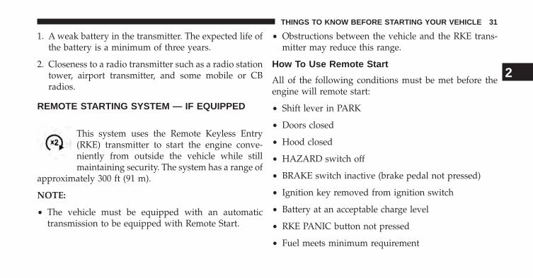
1. A weak battery in the transmitter. The expected life ofthe battery is a minimum of three years.
2. Closeness to a radio transmitter such as a radio stationtower, airport transmitter, and some mobile or CBradios.
REMOTE STARTING SYSTEM — IF EQUIPPED
This system uses the Remote Keyless Entry(RKE) transmitter to start the engine conve-niently from outside the vehicle while stillmaintaining security. The system has a range of
approximately 300 ft (91 m).
NOTE:
• The vehicle must be equipped with an automatictransmission to be equipped with Remote Start.
• Obstructions between the vehicle and the RKE trans-mitter may reduce this range.
How To Use Remote Start
All of the following conditions must be met before theengine will remote start:
• Shift lever in PARK
• Doors closed
• Hood closed
• HAZARD switch off
• BRAKE switch inactive (brake pedal not pressed)
• Ignition key removed from ignition switch
• Battery at an acceptable charge level
• RKE PANIC button not pressed
• Fuel meets minimum requirement
2
THINGS TO KNOW BEFORE STARTING YOUR VEHICLE 31

• System not disabled from previous remote start event
• Vehicle theft alarm not active
WARNING!
• Do not start or run an engine in a closed garage orconfined area. Exhaust gas contains Carbon Mon-oxide (CO) which is odorless and colorless. CarbonMonoxide is poisonous and can cause serious in-jury or death when inhaled.
• Keep Remote Keyless Entry (RKE) transmittersaway from children. Operation of the Remote StartSystem, windows, door locks or other controlscould cause serious injury or death.
Remote Start Abort Message On Electronic VehicleInformation Center (EVIC) — If Equipped
The following messages will display in the EVIC if thevehicle fails to remote start or exits remote start prema-turely:
• Remote Start Aborted — Door Ajar
• Remote Start Aborted — Hood Ajar
• Remote Start Aborted — Fuel Low
• Remote Start Aborted — System Fault
• Remote Start Disabled — Start Vehicle to Reset
The EVIC message stays active until the ignition is turnedto the ON/RUN position.
32 THINGS TO KNOW BEFORE STARTING YOUR VEHICLE
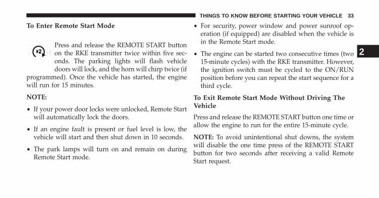
To Enter Remote Start Mode
Press and release the REMOTE START buttonon the RKE transmitter twice within five sec-onds. The parking lights will flash vehicledoors will lock, and the horn will chirp twice (if
programmed). Once the vehicle has started, the enginewill run for 15 minutes.
NOTE:
• If your power door locks were unlocked, Remote Startwill automatically lock the doors.
• If an engine fault is present or fuel level is low, thevehicle will start and then shut down in 10 seconds.
• The park lamps will turn on and remain on duringRemote Start mode.
• For security, power window and power sunroof op-eration (if equipped) are disabled when the vehicle isin the Remote Start mode.
• The engine can be started two consecutive times (two15-minute cycles) with the RKE transmitter. However,the ignition switch must be cycled to the ON/RUNposition before you can repeat the start sequence for athird cycle.
To Exit Remote Start Mode Without Driving TheVehicle
Press and release the REMOTE START button one time orallow the engine to run for the entire 15-minute cycle.
NOTE: To avoid unintentional shut downs, the systemwill disable the one time press of the REMOTE STARTbutton for two seconds after receiving a valid RemoteStart request.
2
THINGS TO KNOW BEFORE STARTING YOUR VEHICLE 33

To Exit Remote Start Mode And Drive The Vehicle
Before the end of the 15-minute cycle, press and releasethe UNLOCK button on the RKE transmitter to unlockthe doors and disarm the Vehicle Security Alarm System(if equipped). Then, prior to the end of the 15 minutecycle, press and release the START/STOP button.
NOTE:
• The message “Push Start Button” will display in theEVIC until you push the START button.
• “Remote Start Active — Push Start Button” will dis-play in the EVIC until you press the start button. Referto “Electronic Vehicle Information Center (EVIC)” forfurther information.
Remote Start Comfort Systems — If Equipped
When remote start is activated, the heated steeringwheel, and driver heated seat features will automaticallyturn on in cold weather. In warm weather, the driver
vented seat feature will automatically turn on when theremote start is activated. These features will stay onthrough the duration of remote start or until the ignitionswitch is turned to the ON/RUN position.
The Remote Start Comfort System can be activated anddeactivated through the Electronic Vehicle InformationCenter (EVIC). For more information on Remote StartComfort System operation refer to “Electronic VehicleInformation Center (EVIC)/Customer-ProgrammableFeatures (System Setup)” in “Understanding Your Instru-ment Panel”.
DOOR LOCKS
Manual Door Locks
Front and rear doors may be locked by moving the lockknob down or unlocked by moving the lock knob up.
34 THINGS TO KNOW BEFORE STARTING YOUR VEHICLE

Front doors may be opened with the inside door handlewithout lifting the lock knob.
Doors locked before closing will remain locked whenclosed.
The emergency key will unlock the driver door lock onyour vehicle.
WARNING!
• Do not leave children or animals inside parkedvehicles in hot weather. Interior heat build-up maycause serious injury or death.
• For personal security and safety in the event of ancollision, lock the vehicle doors as you drive aswell as when you park and leave the vehicle.
• Before exiting a vehicle, always apply the parkingbrake, shift the transmission into PARK, and re-move the Key Fob from the ignition. When leavingthe vehicle, always lock your vehicle.
• Never leave children alone in a vehicle, or withaccess to an unlocked vehicle.
(Continued)
Door Lock Knob
2
THINGS TO KNOW BEFORE STARTING YOUR VEHICLE 35

WARNING! (Continued)• Allowing children to be in a vehicle unattended is
dangerous for a number of reasons. A child orothers could be seriously or fatally injured. Chil-dren should be warned not to touch the parkingbrake, brake pedal or the shift lever.
• Do not leave the Key Fob in or near the vehicle, orin a location accessible to children, and do notleave a vehicle equipped with Keyless Enter-N-Goin the ACC or ON/RUN mode. A child couldoperate power windows, other controls, or movethe vehicle.
Power Door Locks — If Equipped
A power door LOCK switch is on each front door trimpanel. Use this switch to lock or unlock the doors.
If you press the power door LOCK switch while the KeyFob is in the ignition, and any front door is open, thepower locks will not operate. This prevents you fromaccidentally locking your Key Fob in the vehicle. Remov-ing the Key Fob or closing the door will allow the locks to
Power Door Lock Switch Location
36 THINGS TO KNOW BEFORE STARTING YOUR VEHICLE

operate. A chime will sound if the Key Fob is in theignition switch and a door is open, as a reminder toremove the Key Fob.
Automatic Door Locks — If Equipped
The auto door lock feature default condition is enabled.When enabled, the door locks will lock automaticallywhen the vehicle’s speed exceeds 15 mph (24 km/h). Theauto door lock feature can be enabled or disabled by yourauthorized dealer per written request of the customer.Please see your authorized dealer for service.
Auto Unlock Doors — If Equipped
This feature unlocks all of the doors of the vehicle wheneither front door is opened. This will occur only after thevehicle has been shifted into the PARK position after thevehicle has been driven (shifted out of PARK and alldoors closed).
Auto Unlock Doors Programming — If Equipped
The Auto Unlock Doors feature can be enabled or dis-abled as follows:
For vehicles equipped with the EVIC, refer to “ElectronicVehicle Information Center (EVIC)/Personal Settings(System Setup)” in “Understanding Your InstrumentPanel” for further information.
NOTE: Use the Auto Unlock Doors feature in accor-dance with local laws.
2
THINGS TO KNOW BEFORE STARTING YOUR VEHICLE 37

Child-Protection Door Lock
To provide a safer environment for children riding in therear seat, the rear doors (if equipped) of your vehiclehave the Child-Protection Door Lock system.
To use the system, open each rear door, use a flat bladescrewdriver (or emergency key) and rotate the dial to
engage and disengage the Child-Protection locks. Whenthe system on a door is engaged, that door can only beopened by using the outside door handle even if theinside door lock is in the unlocked position.
Child-Protection Door Lock Location Child Lock Control
38 THINGS TO KNOW BEFORE STARTING YOUR VEHICLE

WARNING!
Avoid trapping anyone in a vehicle in a collision.Remember that the rear doors can only be openedfrom the outside when the Child-Protection locks areengaged.
NOTE:
• After setting the Child-Protection Door Lock system,always test the door from the inside to make certain itis in the desired position.
• For emergency exit with the system engaged, move thedoor lock switch to the UNLOCK position, roll downthe window and open the door with the outside doorhandle.
KEYLESS ENTER-N-GO™
The Passive Entry system is an enhancement to thevehicle’s Remote Keyless Entry (RKE) system and afeature of Keyless Enter-N-Go™. For further information,refer to “Keyless Enter-N-Go™” in “STARTING ANDOPERATING”. This feature allows you to lock andunlock the vehicle’s door(s) without having to press theRKE transmitter lock or unlock buttons.
NOTE:
• Passive Entry may be programmed ON/OFF; refer to“Uconnect® settings” in “Understanding Your Instru-ment Panel” for further information.
• If wearing gloves on your hands, or if it has beenraining on the Passive Entry door handle, the unlocksensitivity can be affected, resulting in a slower re-sponse time.
2
THINGS TO KNOW BEFORE STARTING YOUR VEHICLE 39

• If the vehicle is unlocked by the Passive Entry DoorHandle, and no door goes ajar within 60 seconds, thevehicle will re-lock and if equipped will arm the theftalarm.
• The vehicles theft alarm can be armed/disarmed bypressing the passive entry key fob lock/unlock buttons(if equipped).
To Unlock From The Driver’s Side:
With a valid Passive Entry RKE transmitter within 5 ft(1.5 m) of the driver door handle, grab the front driverdoor handle to unlock the driver’s door automatically.The interior door panel lock knob will raise when thedoor is unlocked.
NOTE: If “Unlock All Doors 1st Press” is programmed alldoors will unlock when you grab hold of the frontdriver’s door handle. To select between “Unlock DriverDoor 1st Press” and “Unlock All Doors 1st Press”, refer to“Uconnect® Settings” in “Understanding Your Instru-ment Panel” for further information.
Grab The Door Handle To Unlock
40 THINGS TO KNOW BEFORE STARTING YOUR VEHICLE

To Unlock From The Passenger Side:
With a valid Passive Entry RKE transmitter within 5 ft(1.5 m) of the passenger door handle, grab the frontpassenger door handle to unlock all doors automatically.The interior door panel lock knob will raise when thedoor is unlocked.
NOTE: All doors will unlock when the front passengerdoor handle is grabbed regardless of the driver’s doorunlock preference setting (“Unlock Driver Door 1stPress” or “Unlock All Doors 1st Press”).
Preventing Inadvertent Locking Of Passive Entry RKETransmitter In Vehicle
To minimize the possibility of unintentionally locking aPassive Entry RKE transmitter inside your vehicle, the
Passive Entry system is equipped with an automatic doorunlock feature which will function if the ignition switchis in the OFF position.
If one of the vehicle doors is open and the door panelswitch is used to lock the vehicle, once all open doorshave been closed the vehicle checks the inside andoutside of the vehicle for any valid Passive Entry RKEtransmitters. If one of the vehicle’s Passive Entry RKEtransmitters is detected inside the vehicle, and no othervalid Passive Entry RKE transmitters are detected out-side the vehicle, the Passive Entry System automaticallyunlocks all vehicle doors and chirps the horn three times(on the third attempt ALL doors will lock and the PassiveEntry RKE transmitter can be locked in the vehicle).
2
THINGS TO KNOW BEFORE STARTING YOUR VEHICLE 41

To Lock The Vehicle’s Doors
With one of the vehicle’s Passive Entry RKE transmitterswithin 5 ft (1.5 m) of the driver or passenger front doorhandles, press the door handle LOCK button to lock alldoors.
Press The Door Handle Button To Lock
Do NOT grab the door handle, when pressing the doorhandle lock button. This could unlock the door(s).
42 THINGS TO KNOW BEFORE STARTING YOUR VEHICLE

NOTE:
• After pressing the door handle LOCK button, youmust wait two seconds before you can lock or unlockthe doors, using either Passive Entry door handle. Thisis done to allow you to check if the vehicle is locked bypulling the door handle, without the vehicle reactingand unlocking.
• The Passive Entry system will not operate if the RKEtransmitter battery is dead.
The vehicle doors can also be locked by using the RKEtransmitter lock button or the lock button located on thevehicle’s interior door panel.
Do NOT Grab The Door Handle When Locking
2
THINGS TO KNOW BEFORE STARTING YOUR VEHICLE 43

WINDOWS
Power Windows – If Equipped
The control on the left front door panel has UP-DOWNswitches that give you fingertip control of all powerwindows. There is a single opening and closing switch onthe front passenger door for passenger window controland on the rear doors of the Crew Cab models. Thewindows will operate when the ignition switch is turnedto the ON/RUN or ACC position, and for up to 10minutes after the ignition is turned OFF or until a frontdoor is opened.
NOTE: The Key Off Power Delay feature will allow thepower windows to operate for up to 10 minutes after theignition is turned OFF. This feature is cancelled wheneither front door is opened.
Power Window Switches
44 THINGS TO KNOW BEFORE STARTING YOUR VEHICLE

WARNING!
• Never leave children alone in a vehicle, or withaccess to an unlocked vehicle. Allowing children tobe in a vehicle unattended is dangerous for anumber of reasons. A child or others could beseriously or fatally injured. Children should bewarned not to touch the parking brake, brake pedalor the shift lever.
• Do not leave the key fob in or near the vehicle (orin a location accessible to children), and do notleave a vehicle equipped with Keyless Enter-N-Go™ in the ACC or ON/RUN mode. A child couldoperate power windows, other controls, or movethe vehicle.
Auto-Down
Both the driver and front passenger window switch havean Auto-Down feature. Press the window switch past the
first detent, release, and the window will go downautomatically. To cancel the Auto-Down movement, op-erate the switch in either the up or down direction andrelease the switch.
To stop the window from going all the way down duringthe Auto-Down operation, pull up on the switch briefly.
To open the window part way, press to the first detentand release it when you want the window to stop.
Auto-Up Feature With Anti-Pinch Protection(4-Door Models Driver And Front Passenger DoorOnly) — If Equipped
Lift the window switch fully upward to the seconddetent, release, and the window will go up automatically.
To stop the window from going all the way up during theAuto Up operation, push down on the switch briefly.
2
THINGS TO KNOW BEFORE STARTING YOUR VEHICLE 45

To close the window part way, lift the window switch tothe first detent and release when you want the window tostop.
NOTE: If the window runs into any obstacle during theauto-closure, it will reverse direction and then go backdown. Remove the obstacle and use the window switchagain to close the window. Any impact due to rough roadconditions may trigger the auto reverse function unex-pectedly during auto closure. If this happens, pull theswitch lightly to the first detent and hold to close thewindow manually.
WARNING!
There is no anti-pinch protection when the windowis almost closed. Be sure to clear all objects from thewindow before closing.
Reset Auto-Up
Should the Auto Up feature stop working, the windowprobably needs to be reset. To reset Auto Up:
1. Pull the window switch up to close the windowcompletely and continue to hold the switch up for anadditional two seconds after the window is closed.
2. Push the window switch down firmly to the seconddetent to open the window completely and continueto hold the switch down for an additional two secondsafter the window is fully open.
Window LOCKOUT Switch (4–Door Models Only)
The window LOCKOUT switch on the driver’s doorallows you to disable the window control on the frontpassenger and rear passenger doors. To disable thewindow controls on the front passenger and rear passen-ger doors, press the window LOCK button into the
46 THINGS TO KNOW BEFORE STARTING YOUR VEHICLE

latched or down position. To enable the window controls,press the window LOCK button again and return theswitch to the released or up position.
Wind Buffeting
Wind buffeting can be described as the perception ofpressure on the ears or a helicopter-type sound in the
ears. Your vehicle may exhibit wind buffeting with thewindows down, or the sunroof (if equipped) in certainopen or partially open positions. This is a normal occur-rence and can be minimized. If the buffeting occurs withthe rear windows open, then open the front and rearwindows together to minimize the buffeting. If thebuffeting occurs with the sunroof open, adjust the sun-roof opening to minimize the buffeting.
OCCUPANT RESTRAINTS
Some of the most important safety features in yourvehicle are the restraint systems:
• Three-point lap and shoulder belts for the driver andall passengers
• Front seat belts may incorporate pretensioners thatmay enhance occupant protection by managing occu-pant energy during an impact event
Window Lockout Switch
2
THINGS TO KNOW BEFORE STARTING YOUR VEHICLE 47

• Advanced Front Air Bags for driver and frontpassenger
• Supplemental Side Air Bag Inflatable Curtains (SABIC)— if equipped
• Supplemental Seat-Mounted Side Air Bags (SAB)
• An energy-absorbing steering column and steeringwheel
• Knee bolsters/blockers for front seat occupants
• All seat belt systems (except driver’s, front center andsecond row center position) include Automatic Lock-ing Retractors (ALRs), which lock the seat belt web-bing into position by extending the belt all the way outand then adjusting the belt to the desired length torestrain a child seat or secure a large item in a seat —if equipped
Please pay close attention to the information in thissection. It tells you how to use your restraint systemproperly, to keep you and your passengers as safe aspossible.
If you will be carrying children too small for adult-sizedseat belts, the seat belts or the Lower Anchors and Tetherfor CHildren (LATCH) feature also can be used to holdinfant and child restraint systems. For more informationon LATCH, refer to Lower Anchors and Tether forCHildren (LATCH).
NOTE: The Advanced Front Air Bags have a multistageinflator design. This allows the air bag to have differentrates of inflation based on several factors, including theseverity and type of collision.
48 THINGS TO KNOW BEFORE STARTING YOUR VEHICLE

Here are some simple steps you can take to minimize therisk of harm from a deploying air bag:
1. Children 12 years old and under should always ridebuckled up in a rear seat.
WARNING!
Infants in rear facing child restraints should neverride in the front seat of a vehicle with a passengerAdvanced Front Air Bag. An air bag deployment cancause severe injury or death to infants in that position.
Children that are not big enough to wear the vehicle seatbelt properly (see section on Child Restraints) should besecured in the rear seat in child restraints or belt-positioning booster seats. Older children who do not usechild restraints or belt-positioning booster seats shouldride properly buckled up in the rear seat. Never allowchildren to slide the shoulder belt behind them or undertheir arm.
If a child from 1 to 12 years old (not in a rear facing childseat) must ride in the front passenger seat, move the seatas far back as possible and use the proper child restraint.(Refer to “Child Restraints”).
You should read the instructions provided with yourchild restraint to make sure that you are using it properly.
2. All occupants should always wear their lap andshoulder belts properly.
3. The driver and front passenger seats should bemoved back as far as practical to allow the AdvancedFront Air Bags room to inflate.
4. Do not lean against the door or window. If yourvehicle has side air bags, and deployment occurs, theside air bags will inflate forcefully into the spacebetween you and the door.
2
THINGS TO KNOW BEFORE STARTING YOUR VEHICLE 49

5. If the air bag system in this vehicle needs to bemodified to accommodate a disabled person, contactthe Customer Center. Phone numbers are providedunder �If You Need Assistance�.
WARNING!
• Relying on the air bags alone could lead to moresevere injuries in a collision. The air bags workwith your seat belt to restrain you properly. Insome collisions, the air bags won’t deploy at all.Always wear your seat belts even though you haveair bags.
(Continued)
WARNING! (Continued)• Being too close to the steering wheel or instrument
panel during Advanced Front Air Bag deploymentcould cause serious injury, including death. AirBags need room to inflate. Sit back, comfortablyextending your arms to reach the steering wheel orinstrument panel.
• Supplemental Side Air Bag Inflatable Curtain(SABIC) and Seat-Mounted Side Air Bags (SAB)also need room to inflate. Do not lean against thedoor or window. Sit upright in the center of theseat.
(Continued)
50 THINGS TO KNOW BEFORE STARTING YOUR VEHICLE

WARNING! (Continued)• In a collision, you and your passengers can suffer
much greater injuries if you are not properly buck-led up. You can strike the interior of your vehicle orother passengers, or you can be thrown out of thevehicle. Always be sure you and others in yourvehicle are buckled up properly.
• Being too close to the Supplemental Side Air BagInflatable Curtain (SABIC) and/or Seat-MountedSide Air Bag (SAB) during deployment could causeyou to be severely injured or killed.
Buckle up even though you are an excellent driver, evenon short trips. Someone on the road may be a poor driverand cause a collision that includes you. This can happenfar away from home or on your own street.
Research has shown that seat belts save lives, and theycan reduce the seriousness of injuries in a collision. Some
of the worst injuries happen when people are thrownfrom the vehicle. Seat belts reduce the possibility ofejection and the risk of injury caused by striking theinside of the vehicle. Everyone in a motor vehicle shouldbe belted at all times.
Lap/Shoulder Belts
All seating positions except the Quad Cab®, Mega Cab®and Crew Cab front center seating position have combi-nation lap/shoulder belts. The belt webbing retractor isdesigned to lock during very sudden stops or collisions.This feature allows the shoulder part of the belt to movefreely with you under normal conditions. However, in acollision the belt will lock and reduce the risk of youstriking the inside of the vehicle or being thrown out.
2
THINGS TO KNOW BEFORE STARTING YOUR VEHICLE 51

WARNING!
• It is dangerous to ride in a cargo area, inside oroutside of a vehicle. In a collision, people riding inthese areas are more likely to be seriously injuredor killed.
• Do not allow people to ride in any area of yourvehicle that is not equipped with seats and seatbelts.
• Be sure everyone in your vehicle is in a seat usinga seat belt properly.
(Continued)
WARNING! (Continued)• Wearing a seat belt incorrectly is dangerous. Seat
belts are designed to go around the large bones ofyour body. These are the strongest parts of yourbody and take the forces of a collision the best.Wearing your belt in the wrong place could makeyour injuries in a collision much worse. You mightsuffer internal injuries, or you could even slide outof part of the belt. Follow these instructions to wearyour seat belt safely and to keep your passengerssafe, too.
• Two people should never be belted into a singleseat belt. People belted together can crash into oneanother in a collision, hurting one another badly.Never use a lap/shoulder belt or a lap belt for morethan one person, no matter what their size.
52 THINGS TO KNOW BEFORE STARTING YOUR VEHICLE

Lap/Shoulder Belt Operating Instructions
1. Enter the vehicle and close the door. Sit back andadjust the seat.
2. The seat belt latch plate is above the back of the frontseat, next to your arm in the rear seat. Grasp the latchplate and pull out the belt. Slide the latch plate up thewebbing as far as necessary to allow the belt to goaround your lap.
Pulling Out Latch Plate And Webbing
2
THINGS TO KNOW BEFORE STARTING YOUR VEHICLE 53

3. When the belt is long enough to fit, insert the latchplate into the buckle until you hear a “click.”
WARNING!
• A belt buckled into the wrong buckle will notprotect you properly. The lap portion could ride toohigh on your body, possibly causing internal inju-ries. Always buckle your belt into the bucklenearest you.
• A belt that is too loose will not protect you prop-erly. In a sudden stop you could move too farforward, increasing the possibility of injury. Wearyour seat belt snugly.
(Continued)
Latch Plate To Buckle
54 THINGS TO KNOW BEFORE STARTING YOUR VEHICLE
WARNING! (Continued)• A belt that is worn under your arm is dangerous.
Your body could strike the inside surfaces of thevehicle in a collision, increasing head and neckinjury. A belt worn under the arm can cause inter-nal injuries. Ribs aren’t as strong as shoulderbones. Wear the belt over your shoulder so thatyour strongest bones will take the force in a colli-sion.
• A shoulder belt placed behind you will not protectyou from injury during a collision. You are morelikely to hit your head in a collision if you do notwear your shoulder belt. The lap and shoulder beltare meant to be used together.
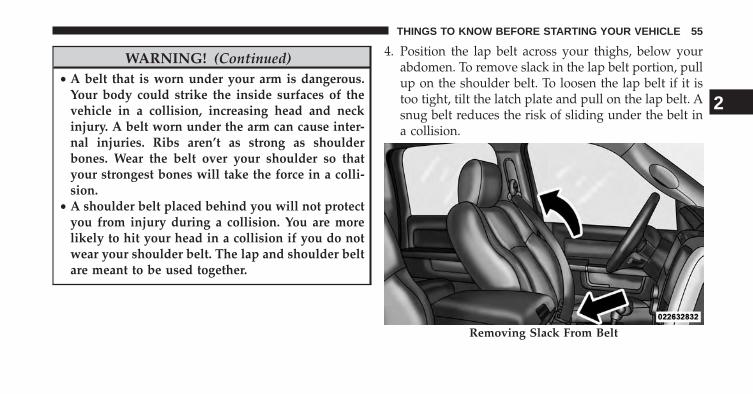
4. Position the lap belt across your thighs, below yourabdomen. To remove slack in the lap belt portion, pullup on the shoulder belt. To loosen the lap belt if it istoo tight, tilt the latch plate and pull on the lap belt. Asnug belt reduces the risk of sliding under the belt ina collision.
Removing Slack From Belt
2
THINGS TO KNOW BEFORE STARTING YOUR VEHICLE 55

WARNING!
• A lap belt worn too high can increase the risk ofinternal injury in a collision. The belt forces won’tbe at the strong hip and pelvic bones, but acrossyour abdomen. Always wear the lap belt as low aspossible and keep it snug.
• A twisted belt may not protect you properly. In acollision, it could even cut into you. Be sure the beltis straight. If you can’t straighten a belt in a vehicle,take it to your authorized dealer immediately andhave it fixed.
5. Position the shoulder belt on your chest so that it iscomfortable and not resting on your neck. The retrac-tor will withdraw any slack in the belt.
6. To release the belt, push the red button on the buckle.The belt will automatically retract to its stowed posi-tion. If necessary, slide the latch plate down thewebbing to allow the belt to retract fully.
WARNING!
A frayed or torn belt could rip apart in a collision andleave you with no protection. Inspect the belt systemperiodically, checking for cuts, frays, or loose parts.Damaged parts must be replaced immediately. Donot disassemble or modify the system. Seat beltassemblies must be replaced after a collision if theyhave been damaged (bent retractor, torn webbing,etc.) or if the air bag deployed.
56 THINGS TO KNOW BEFORE STARTING YOUR VEHICLE

Regular Cab Front Center Three Point Belt
1. The front center seat belt on the Regular Cab may bedisconnected to open up utilization of the storageareas behind the front seats. The black latch plate canbe detached from the black keyed seat belt bucklelocated on the inboard side of the passenger seat.Insert the seat belt tongue into the center red slot onthe black buckle. The black buckle latch plate can beremoved when the seat belt tongue is pressed into thebuckle. Allow the retractor to take up the extra web-bing, and the buckles will hang vertically from the cabback exit bezel, thus freeing up all the area behind thefront seats.
Detaching Buckle With Seat Belt Tongue
2
THINGS TO KNOW BEFORE STARTING YOUR VEHICLE 57

2. To reattach the seat belt to the front center seat, pullthe black buckle latch plate forward from the cab backpanel and insert it into the black keyed buckle untilthere is an audible “click”. For proper seat belt usage,refer “Lap/Shoulder Belt Operating Instructions”.
Inserting Latch Plate
In Use Position
58 THINGS TO KNOW BEFORE STARTING YOUR VEHICLE

WARNING!
• If the black latch and black buckle are not properlyconnected when the seat belt is used by an occu-pant, the seat belt will not be able to provideproper restraint and will increase the risk of injuryin a collision.
• When reattaching the black latch and black buckle,ensure the seat belt webbing is not twisted. If thewebbing is twisted, follow the preceding proce-dure to detach the black latch and black buckle,untwist the webbing, and reattach the black latchand black buckle.
Lap/Shoulder Belt Untwisting Procedure
Use the following procedure to untwist a twisted lap/shoulder belt.
1. Position the latch plate as close as possible to theanchor point.
2. At about 6 to 12 in (15 to 30 cm) above the latch plate,grasp and twist the belt webbing 180 degrees to createa fold that begins immediately above the latch plate.
3. Slide the latch plate upward over the folded webbing.The folded webbing must enter the slot at the top ofthe latch plate.
4. Continue to slide the latch plate up until it clears thefolded webbing.
Adjustable Upper Shoulder Belt Anchorage
In the front row outboard seats, the shoulder belt can beadjusted upward or downward to help position the belt
2
THINGS TO KNOW BEFORE STARTING YOUR VEHICLE 59

away from your neck. Press the button located on theupper belt guide, and then move it up or down to theposition that fits you best.
As a guide, if you are shorter than average you willprefer a lower position, and if you are taller than average
you will prefer a higher position. When you release theanchorage, try to move it up or down to make sure thatit is locked in position.
Center Lap Belts
The center seating position for the Quad Cab®, MegaCab® and Crew Cab front seat has a lap belt only. Tofasten the lap belt, slide the latch plate into the buckleuntil you hear a “click”. To lengthen the lap belt, tilt thelatch plate and pull. To remove slack, pull the loose endof the webbing. Wear the lap belt snug against the hips.Sit back and erect in the seat, then adjust the belt astightly as is comfortable.
Adjusting Upper Shoulder Belt
60 THINGS TO KNOW BEFORE STARTING YOUR VEHICLE

WARNING!
• A lap belt worn too loose or too high is dangerous.• A belt worn too loose can allow you to slip down
and under the belt in a collision.• A belt that is too loose or too high will apply crash
forces to the abdomen, not to the stronger hipbones. In either case, the risk of internal injuries isgreater. Wear a lap belt low and snug.
Seat Belts In Passenger Seating Positions
The seat belts in the passenger seating positions areequipped with Automatic Locking Retractors (ALR)which are used to secure a child restraint system. Foradditional information, refer to “Installing Child Re-straints Using The Vehicle Seat Belt” under the “ChildRestraints” section. The chart below defines the type offeature for each seating position.
For Quad Cab®, Mega Cab® and Crew Cab Only
Driver Center PassengerFirst Row N/A Cinch ALR
Second Row ALR Cinch ALR
• N/A — Not Applicable
• ALR — Automatic Locking Retractor
For Standard Cab Only
Driver Center PassengerFirst Row N/A ALR ALR
Second Row N/A N/A N/A
• N/A — Not Applicable
• ALR — Automatic Locking Retactor
2
THINGS TO KNOW BEFORE STARTING YOUR VEHICLE 61

If the passenger seating position is equipped with anALR and is being used for normal usage:
Only pull the belt webbing out far enough to comfortablywrap around the occupant’s mid-section so as to notactivate the ALR. If the ALR is activated, you will hear aratcheting sound as the belt retracts. Allow the webbingto retract completely in this case and then carefully pullout only the amount of webbing necessary to comfort-ably wrap around the occupant’s mid-section. Slide thelatch plate into the buckle until you hear a �click.�
Automatic Locking Retractor (ALR) Mode – IfEquipped
In this mode, the shoulder belt is automatically pre-locked. The belt will still retract to remove any slack inthe shoulder belt.
When To Use The Automatic Locking Mode
Use the Automatic Locking Mode anytime a child safetyseat is installed in a seating position that has a belt withthis feature. Children 12 years old and under shouldalways be properly restrained in the rear seat.
How To Engage The Automatic Locking Mode
1. Buckle the combination lap and shoulder belt.
2. Grasp the shoulder portion and pull downward untilthe entire belt is extracted.
3. Allow the belt to retract. As the belt retracts, you willhear a clicking sound. This indicates the safety belt isnow in the Automatic Locking Mode.
How To Disengage The Automatic Locking Mode
Unbuckle the combination lap/shoulder belt and allow itto retract completely to disengage the Automatic Locking
62 THINGS TO KNOW BEFORE STARTING YOUR VEHICLE

Mode and activate the vehicle sensitive (emergency)locking mode.
WARNING!
• The belt and retractor assembly must be replaced ifthe seat belt assembly Automatic Locking Retractor(ALR) feature or any other seat belt function is notworking properly when checked according to theprocedures in the Service Manual.
• Failure to replace the belt and retractor assemblycould increase the risk of injury in collisions.
Energy Management Feature
This vehicle has a safety belt system with an EnergyManagement feature in the front seating positions to helpfurther reduce the risk of injury in the event of a head-oncollision.
This safety belt system has a retractor assembly that isdesigned to release webbing in a controlled manner. Thisfeature is designed to help reduce the belt force acting onthe occupant’s chest.
Seat Belt Pretensioners
The seat belts for both front seating positions areequipped with pretensioning devices that are designed toremove slack from the seat belt in the event of a collision.These devices may improve the performance of the seatbelt by assuring that the belt is tight around the occupantearly in a collision. Pretensioners work for all size occu-pants, including those in child restraints.
NOTE: These devices are not a substitute for proper seatbelt placement by the occupant. The seat belt still must beworn snugly and positioned properly.
2
THINGS TO KNOW BEFORE STARTING YOUR VEHICLE 63

The pretensioners are triggered by the Occupant Re-straint Controller (ORC). Like the air bags, the preten-sioners are single use items. A deployed pretensioner ora deployed air bag must be replaced immediately.
Enhanced Seat Belt Use Reminder System(BeltAlert®)
BeltAlert® is a feature intended to remind the driver andfront passenger (if equipped with front passengerBeltAlert®) to fasten their seat belts. The feature is activewhenever the ignition is on. If the driver or front seatpassenger is unbelted, the Seat Belt Reminder Light willturn on and remain on until both front seat belts arefastened.
The BeltAlert® warning sequence begins after the vehiclespeed is over 5 mph (8 km/h), by blinking the Seat BeltReminder Light and sounding an intermittent chime.Once the sequence starts, it will continue for the entireduration or until the respective seatbelts are fastened.
After the sequence completes, the Seat Belt ReminderLight remains illuminated until the respective seat beltsare fastened. The driver should instruct all other occu-pants to fasten their seat belts. If a front seat belt isunbuckled while traveling at speeds greater than 5 mph(8 km/h), BeltAlert® will provide both audio and visualnotification.
The front passenger seat BeltAlert® is not active whenthe front passenger seat is unoccupied. BeltAlert® maybe triggered when an animal or heavy object is on thefront passenger seat or when the seat is folded flat (ifequipped). It is recommended that pets be restrained inthe rear seat in pet harnesses or pet carriers that aresecured by seat belts, and cargo is properly stowed.
BeltAlert® can be enabled or disabled by your autho-rized dealer. Chrysler Group LLC does not recommenddeactivating BeltAlert®.
64 THINGS TO KNOW BEFORE STARTING YOUR VEHICLE

NOTE: Although BeltAlert® has been deactivated, theSeat Belt Reminder Light will continue to illuminatewhile the driver’s or front passenger (if equipped withBeltAlert®) seat belt remains unfastened.
Seat Belts And Pregnant Women
We recommend that pregnant women use seat beltsthroughout their pregnancies. Keeping the mother safe isthe best way to keep the baby safe.
Pregnant women should wear the lap part of the beltacross the thighs and as snug across the hips as possible.Keep the belt low so that it does not come across theabdomen. That way the strong bones of the hips will takethe force if there is a collision.
Seat Belt Extender
If a seat belt is too short even when fully extended andwhen the adjustable upper shoulder belt anchorage (ifequipped) is in its lowest position, your authorizeddealer can provide you with a seat belt extender. Thisextender should be used only if the existing belt is notlong enough. When it is not required, remove the ex-tender and store it.
WARNING!
Using a seat belt extender when not needed canincrease the risk of injury in a collision. Only usewhen the seat belt is not long enough when it is wornlow and snug and in the recommended seating posi-tions. Remove and store the extender when notneeded.
2
THINGS TO KNOW BEFORE STARTING YOUR VEHICLE 65
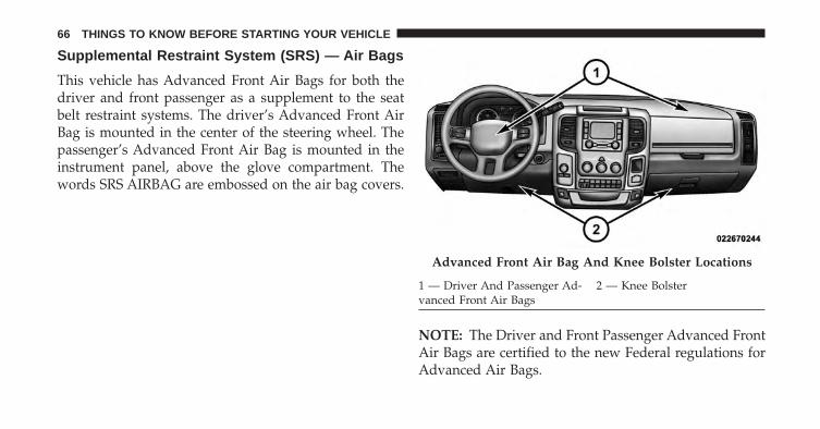
Supplemental Restraint System (SRS) — Air Bags
This vehicle has Advanced Front Air Bags for both thedriver and front passenger as a supplement to the seatbelt restraint systems. The driver’s Advanced Front AirBag is mounted in the center of the steering wheel. Thepassenger’s Advanced Front Air Bag is mounted in theinstrument panel, above the glove compartment. Thewords SRS AIRBAG are embossed on the air bag covers.
NOTE: The Driver and Front Passenger Advanced FrontAir Bags are certified to the new Federal regulations forAdvanced Air Bags.
Advanced Front Air Bag And Knee Bolster Locations
1 — Driver And Passenger Ad-vanced Front Air Bags
2 — Knee Bolster
66 THINGS TO KNOW BEFORE STARTING YOUR VEHICLE

The Advanced Front Air Bags have a multistage inflatordesign. This allows the air bag to have different rates ofinflation based on several factors, including the severityand type of collision.
This vehicle may be equipped with a driver and/or frontpassenger seat belt buckle switch that detects whetherthe driver or front passenger seat belt is fastened. Theseat belt buckle switch may adjust the inflation rate of theAdvanced Front Air Bags.
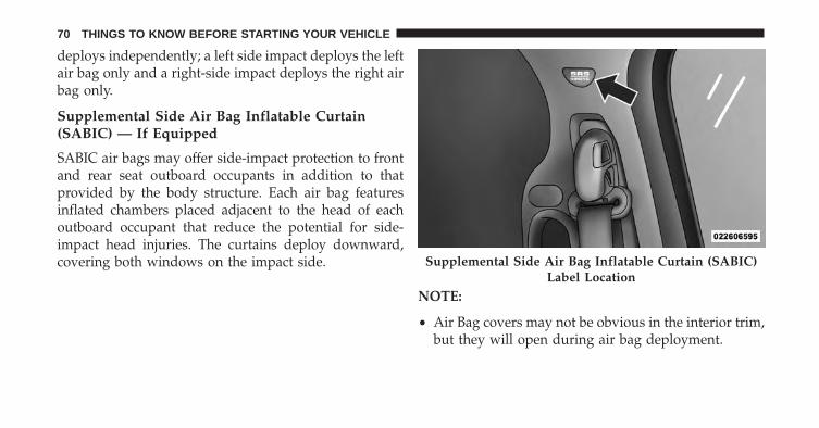
This vehicle may also be equipped with SupplementalSide Air Bag Inflatable Curtains (SABIC) to protect thedriver, front, and rear passengers sitting next to a win-dow. If the vehicle is equipped with SABIC air bags, theyare located above the side windows and their covers arealso labeled: SRS AIRBAG.
This vehicle may also be equipped with SupplementalSeat-Mounted Side Air Bags (SAB) to provide enhancedprotection for an occupant during a side impact. If the
vehicle is equipped with Supplemental Seat-MountedSide Air Bags they are located in the outboard side of thefront seats.
NOTE:
• Air Bag covers may not be obvious in the interior trim,but they will open during air bag deployment.
• After any collision, the vehicle should be taken to anauthorized dealer immediately.
Air Bag System Components
Your vehicle may be equipped with the following air bagsystem components:
• Occupant Restraint Controller (ORC)
• Air Bag Warning Light
• Steering Wheel and Column
• Instrument Panel
2
THINGS TO KNOW BEFORE STARTING YOUR VEHICLE 67

• Knee Impact Bolster
• Driver Advanced Front Air Bag
• Passenger Advanced Front Air Bag
• Supplemental Seat-Mounted Side Air Bags (SAB) — ifequipped
• Supplemental Side Air Bag Inflatable Curtains (SABIC)— if equipped
• Front and Side Impact Sensors
• Seat Belt Buckle Switch
• Seat Belt Pretensioners
Advanced Front Air Bag Features
The Advanced Front Air Bag system has multistagedriver and front passenger air bags. This system providesoutput appropriate to the severity and type of collision as
determined by the Occupant Restraint Controller (ORC),which may receive information from the front impactsensors (if equipped).
The first stage inflator is triggered immediately during animpact that requires air bag deployment. This low outputis used in less severe collisions. A higher energy output isused for more severe collisions.
WARNING!
• No objects should be placed over or near the airbag on the instrument panel, because any suchobjects could cause harm if the vehicle is in acollision severe enough to cause the air bag toinflate.
(Continued)
68 THINGS TO KNOW BEFORE STARTING YOUR VEHICLE

WARNING! (Continued)• Do not put anything on or around the air bag
covers or attempt to open them manually. You maydamage the air bags and you could be injuredbecause the air bags may no longer be functional.The protective covers for the air bag cushions aredesigned to open only when the air bags areinflating.
• Do not drill, cut or tamper with the knee bolster inany way.
• Do not mount any accessories to the knee bolstersuch as alarm lights, stereos, citizen band radios,etc.
Supplemental Seat-Mounted Side Air Bags (SAB)— If Equipped
Supplemental Seat-Mounted Side Air Bags may provideenhanced protection to help protect an occupant during a
side impact. The Supplemental Seat-Mounted Side AirBag is marked with an air bag label sewn into theoutboard side of the front seats.
When the air bag deploys, it opens the seam between thefront and side of the seat’s trim cover. Each air bag
Supplemental Seat-Mounted Side Air Bag Label
2
THINGS TO KNOW BEFORE STARTING YOUR VEHICLE 69
deploys independently; a left side impact deploys the leftair bag only and a right-side impact deploys the right airbag only.
Supplemental Side Air Bag Inflatable Curtain(SABIC) — If Equipped
SABIC air bags may offer side-impact protection to frontand rear seat outboard occupants in addition to thatprovided by the body structure. Each air bag featuresinflated chambers placed adjacent to the head of eachoutboard occupant that reduce the potential for side-impact head injuries. The curtains deploy downward,covering both windows on the impact side.
NOTE:
• Air Bag covers may not be obvious in the interior trim,but they will open during air bag deployment.
Supplemental Side Air Bag Inflatable Curtain (SABIC)Label Location
70 THINGS TO KNOW BEFORE STARTING YOUR VEHICLE

• Being too close to the SAB and SABIC air bags duringdeployment could cause you to be severely injured orkilled.
• Should a vehicle rollover occur, the pretensioners (ifequipped) and/or SAB and SABIC air bags on bothsides of the vehicle may deploy.
The system includes side impact sensors (if equipped)that are calibrated to deploy the side air bags duringimpacts that require air bag occupant protection.
WARNING!
• If your vehicle is equipped with left and rightSupplemental Side Air Bag Inflatable Curtain(SABIC), do not stack luggage or other cargo uphigh enough to block the location of the SABIC.The area where the SABIC is located should remainfree from any obstructions.
• Do not use accessory seat covers or place objectsbetween you and the side air bags; the performancecould be adversely affected and/or objects could bepushed into you, causing serious injury.
• If your vehicle is equipped with SABIC air bags,do not have any accessory items installed whichwill alter the roof, including adding a sunroof toyour vehicle. Do not add roof racks that requirepermanent attachments (bolts or screws) for instal-lation on the vehicle roof. Do not drill into the roofof the vehicle for any reason.
2
THINGS TO KNOW BEFORE STARTING YOUR VEHICLE 71
SAB and SABIC air bags are a supplement to the seat beltrestraint system. Occupants, including children who areup against or very close to SAB or SABIC air bags can beseriously injured or killed. Occupants, especially chil-dren, should not lean on or sleep against the door, sidewindows, or area where the SAB or SABIC air bagsinflate, even if they are in an infant or child restraint.
Always sit upright as possible with your back against theseat back, use the seat belts properly, and use theappropriate sized child restraint, infant restraint orbooster seat recommended for the size and weight of thechild.
Knee Impact Bolsters
The Knee Impact Bolsters help protect the knees of thedriver and front passengers, and position front occupantsfor the best interaction with the Advanced Front AirBags.
Along with seat belts and pretensioners, Advanced FrontAir Bags work with the knee impact bolsters to provideimproved protection for the driver and front passenger.Side air bags also work with seat belts to improveoccupant protection.
Air Bag Deployment Sensors And Controls
Occupant Restraint Controller (ORC)
The ORC is part of a Federally regulated safety systemrequired for this vehicle.
The ORC determines if deployment of the front and/orside air bags in a frontal or side collision is required.Based on the impact sensor’s signals, a central electronicORC deploys the Advanced Front Air Bags, SABIC airbags — if equipped, SAB air bags — if equipped, andfront seat belt pretensioners — if equipped, as required,depending on several factors, including the severity andtype of impact.
72 THINGS TO KNOW BEFORE STARTING YOUR VEHICLE

Advanced Front Air Bags are designed to provide addi-tional protection by supplementing the seat belts incertain frontal collisions depending on several factors,including the severity and type of collision. AdvancedFront Air Bags are not expected to reduce the risk ofinjury in rear, rollover, or side collisions.
The Advanced Front Air Bags will not deploy in allfrontal collisions, including some that may produce sub-stantial vehicle damage — for example, some pole colli-sions, truck underrides, and angle offset collisions. Onthe other hand, depending on the type and location ofimpact, Advanced Front Air Bags may deploy in crasheswith little vehicle front-end damage but that produce asevere initial deceleration.
The side air bags will not deploy in all side collisions.Side air bag deployment will depend on the severity andtype of collision.
Because air bag sensors measure vehicle decelerationover time, vehicle speed and damage by themselves arenot good indicators of whether or not an air bag shouldhave deployed.
Seat belts are necessary for your protection in all colli-sions, and also are needed to help keep you in position,away from an inflating air bag.
The ORC monitors the readiness of the electronic parts ofthe air bag system whenever the ignition switch is in theSTART or ON/RUN position. If the key is in the LOCKposition, in the ACC position, or not in the ignition, theair bag system is not on and the air bags will not inflate.
2
THINGS TO KNOW BEFORE STARTING YOUR VEHICLE 73

The ORC contains a backup power supply system thatmay deploy the air bags even if the battery loses power orit becomes disconnected prior to deployment.
Also, the ORC turns on the Air Bag WarningLight in the instrument panel for approxi-mately four to eight seconds for a self-checkwhen the ignition is first turned on. After the
self-check, the Air Bag Warning Light will turn off. If theORC detects a malfunction in any part of the system, itturns on the Air Bag Warning Light, either momentarilyor continuously. A single chime will sound if the lightcomes on again after initial startup.
It also includes diagnostics that will illuminate the instru-ment cluster Air Bag Warning Light if a malfunction isnoted that could affect the air bag system. The diagnos-tics also record the nature of the malfunction.
WARNING!
Ignoring the Air Bag Warning Light in your instru-ment panel could mean you won’t have the air bagsto protect you in a collision. If the light does not comeon as a bulb check when the ignition is first turnedon, stays on after you start the vehicle, or if it comeson as you drive, have an authorized dealer service theair bag system immediately.
Driver And Passenger Advanced Front Air BagInflator Units
The Driver and Passenger Advanced Front Air BagInflator Units are located in the center of the steeringwheel and on the right side of the instrument panel.When the ORC detects a collision requiring the Ad-vanced Front Air Bags, it signals the inflator units. A largequantity of non-toxic gas is generated to inflate theAdvanced Front Air Bags. Different air bag inflation rates
74 THINGS TO KNOW BEFORE STARTING YOUR VEHICLE

are possible, based on several factors, including thecollision type and severity. The steering wheel hub trimcover and the upper right side of the instrument panelseparate and fold out of the way as the air bags inflate totheir full size. The air bags fully inflate in about 50 to 70milliseconds. This is about half of the time it takes toblink your eyes. The air bags then quickly deflate whilehelping to restrain the driver and front passenger.
The Advanced Front Air Bag gas is vented through thevent holes in the sides of the air bag. In this way, the airbags do not interfere with your control of the vehicle.
Supplemental Seat-Mounted Side Air Bag (SAB)Inflator Units — If Equipped
The Supplemental Seat-Mounted Side Air Bags are de-signed to activate only in certain side collisions.
The ORC determines if a side collision requires the sideair bags to inflate, based on the severity and type ofcollision.
Based on the severity and type of collision, the side airbag inflator on the crash side of the vehicle may betriggered, releasing a quantity of non-toxic gas. Theinflating SAB exits through the seat seam into the spacebetween the occupant and the door. The SAB fully inflatein about 10 milliseconds. The side air bag moves at a veryhigh speed and with such a high force that it could injureyou if you are not seated properly, or if items arepositioned in the area where the side air bag inflates. Thisespecially applies to children.
Supplemental Side Air Bag Inflatable Curtain(SABIC) Inflator Units — If Equipped
During collisions where the impact is confined to aparticular area of the side of the vehicle, the ORC maydeploy the SABIC air bags, depending on the severity
2
THINGS TO KNOW BEFORE STARTING YOUR VEHICLE 75

and type of collision. In these events, the ORC willdeploy the SABIC only on the impact side of the vehicle.
A quantity of non-toxic gas is generated to inflate the sidecurtain air bag. The inflating side curtain air bag pushesthe outside edge of the headliner out of the way andcovers the window. The air bag inflates in about 30milliseconds (about one-quarter of the time that it takesto blink your eyes) with enough force to injure you if youare not belted and seated properly, or if items arepositioned in the area where the side curtain air baginflates. This especially applies to children. The sidecurtain air bag is only about 3-1/2 in (9 cm) thick whenit is inflated.
Because air bag sensors estimate deceleration over time,vehicle speed and damage are not good indicators ofwhether or not an air bag should have deployed.
Front And Side Impact Sensors
In front and side impacts, impact sensors can aid theORC in determining appropriate response to impactevents.
Enhanced Accident Response System
In the event of an impact causing air bag deployment, ifthe communication network remains intact, and thepower remains intact, depending on the nature of theevent the ORC will determine whether to have theEnhanced Accident Response System perform the follow-ing functions:
• Cut off fuel to the engine.
• Flash hazard lights as long as the battery has power oruntil the ignition key is turned off.
• Turn on the interior lights, which remain on as long asthe battery has power or until the ignition key isremoved.
76 THINGS TO KNOW BEFORE STARTING YOUR VEHICLE

• Unlock the doors automatically.
In order to reset the Enhanced Accident Response Systemfunctions after an event, the ignition switch must bechanged from IGN ON to IGN OFF.
9-1-1 Call Operating Instructions – If Equipped
1. Press the 9-1-1 Call button on the Rearview Mirror;
NOTE: In case the 9-1-1 Call button is pushed in error,there will be a 10 second delay before the 9-1-1 Callsystem initiates a call to a 9-1-1 operator. To cancel the9-1-1 Call connection, press the 9-1-1 Call button on theRearview Mirror or press the cancellation button on thePhone Screen . Termination of the 9-1-1 Call will turn thegreen LED light on the Rearview Mirror off.
2. The LED light located between the Assist and 9-1-1buttons on the Rearview Mirror will turn green once aconnection to a 9-1-1 operator has been made;
3. Once a connection between the vehicle and a 9-1-1operator is made, the 9-1-1 Call system may transmitthe following important vehicle information to a 9-1-1operator:
• indication that the occupant placed a 9-1-1 Call;
• the vehicle brand; and
• the last known GPS coordinates of the vehicle.
4. You should be able to speak with the 9-1-1 operatorthrough the vehicle audio system to determine ifadditional help is needed.
NOTE: Once a connection is made between the vehicle’s9-1-1 Call system and the 9-1-1 operator, the 9-1-1 opera-tor may be able to open a voice connection with thevehicle to determine if additional help is needed. Oncethe 9-1-1 operator opens a voice connection with thevehicle’s 9-1-1 Call system, the operator should be able tospeak with you or other vehicle occupants and hear
2
THINGS TO KNOW BEFORE STARTING YOUR VEHICLE 77

sounds occurring in the vehicle. The vehicle’s 9-1-1 Callsystem will attempt to remain connected with the 9-1-1operator until the 9-1-1 operator terminates the connec-tion.
5. The 9-1-1 operator may attempt to contact appropriateemergency responders and provide them with impor-tant vehicle information and GPS coordinates.
WARNING!
• If anyone in the vehicle could be in danger (e.g.,fire or smoke is visible, dangerous road conditionsor location), do not wait for voice contact from a9-1-1 operator. All occupants should exit the vehicleimmediately and move to a safe location.
(Continued)
WARNING! (Continued)• The 9-1-1 Call system is embedded into the vehi-
cle’s electrical system. Do not add aftermarketelectrical equipment to the vehicle’s electrical sys-tem. This may prevent your vehicle from sending asignal to initiate an emergency call. To avoid inter-ference that can cause the 9-1-1 Call system to fail,never add aftermarket equipment (e.g., two-waymobile radio, CB radio, data recorder, etc.) to yourvehicle’s electrical system or modify the antennason your vehicle.
• Modifications to any part of the 9-1-1 Call systemcould cause the air bag system to fail when youneed it. You could be injured if the air bag systemis not there to help protect you.
78 THINGS TO KNOW BEFORE STARTING YOUR VEHICLE
9-1-1 Call System Limitations
Vehicles sold in Canada and Mexico DO NOT have 9-1-1Call system capabilities.
9-1-1 or other emergency line operators in Canada andMexico may not answer or respond to 9-1-1 system calls.
If the 9-1-1 Call system detects a malfunction, any of thefollowing may occur at the time the malfunction isdetected, and at the beginning of each ignition cycle:
• The Rearview Mirror light located between the Assistand 9-1-1 buttons will continuously be illuminatedred;
• The Phone Screen will display the following message“Vehicle phone requires service. Please contact yourdealer.”; and,
• An In-Vehicle Audio message will state “Vehicle phonerequires service. Please contact your dealer.”
WARNING!
• Ignoring the Rearview Mirror light could mean youwill not have 9-1-1 Call services. If the RearviewMirror light is illuminated, have an authorizeddealer service the 9-1-1 Call system immediately.
• The ORC turns on the Air Bag Warning Light onthe instrument panel if a malfunction in any part ofthe system is detected. If the Air Bag Warning Lightis illuminated, have an authorized dealer servicethe ORC system immediately.
Even if the 9-1-1 Call system is fully functional, factorsbeyond Chrysler Group LLC’s control may prevent orstop the 9-1-1 Call system operation. These include, butare not limited to, the following factors:
• The ignition key has been removed from the ignitionand the delayed accessories mode is active;
2
THINGS TO KNOW BEFORE STARTING YOUR VEHICLE 79

• The ignition key is in OFF position;
• The vehicle’s electrical systems are not intact;
• The 9-1-1 Call system software and/or hardware aredamaged during a crash;
• The vehicle battery loses power or becomes discon-nected during a vehicle crash;
• Wireless and/or Global Positioning Satellite signalsare unavailable or obstructed;
• Equipment malfunction at the 9-1-1 operator facility;
• Operator error by the 9-1-1 operator;
• Wireless network congestion;
• Weather; and
• Buildings, structures, geographic terrain, or tunnels.
NOTE: Never place anything on or near the vehicle’swireless and GPS antennas. You could prevent wirelessand GPS signal reception, which can prevent your vehiclefrom placing an emergency call. Wireless and GPS signalreception is required for the 9-1-1 Call system to functionproperly.
General Information
This device complies with Part 15 of the FCC Rules.Operation is subject to the following two conditions: (1)This device may not cause harmful interference, and (2)this device must accept any interference received, includ-ing interference that may cause undesired operation.
If A Deployment Occurs
The Advanced Front Air Bags are designed to deflateimmediately after deployment.
80 THINGS TO KNOW BEFORE STARTING YOUR VEHICLE

NOTE: In a rollover the pretensioners and/or SAB andSABIC - if equipped air bags may deploy on both sides ofthe vehicle.
If you do have a collision which deploys the air bags, anyor all of the following may occur:
• The nylon air bag material may sometimes causeabrasions and/or skin reddening to the driver andfront passenger as the air bags deploy and unfold. Theabrasions are similar to friction rope burns or thoseyou might get sliding along a carpet or gymnasiumfloor. They are not caused by contact with chemicals.They are not permanent and normally heal quickly.However, if you haven’t healed significantly within afew days, or if you have any blistering, see your doctorimmediately.
• As the air bags deflate, you may see some smoke-likeparticles. The particles are a normal by-product of theprocess that generates the non-toxic gas used for air
bag inflation. These airborne particles may irritate theskin, eyes, nose, or throat. If you have skin or eyeirritation, rinse the area with cool water. For nose orthroat irritation, move to fresh air. If the irritationcontinues, see your doctor. If these particles settle onyour clothing, follow the garment manufacturer’s in-structions for cleaning.
Do not drive your vehicle after the air bags have de-ployed. If you are involved in another collision, the airbags will not be in place to protect you.
WARNING!
Deployed air bags and seat belt pretensioners cannotprotect you in another collision. Have the air bags,seat belt pretensioners, and the front seat belt retrac-tor assemblies replaced by an authorized dealer im-mediately. Also, have the Occupant Restraint Con-troller (ORC) system serviced as well.
2
THINGS TO KNOW BEFORE STARTING YOUR VEHICLE 81

Maintaining Your Air Bag System
WARNING!
• Modifications to any part of the air bag systemcould cause it to fail when you need it. You couldbe injured if the air bag system is not there toprotect you. Do not modify the components orwiring, including adding any kind of badges orstickers to the steering wheel hub trim cover or theupper right side of the instrument panel. Do notmodify the front bumper, vehicle body structure, oradd aftermarket side steps or running boards.
• It is dangerous to try to repair any part of the airbag system yourself. Be sure to tell anyone whoworks on your vehicle that it has an air bag system.
(Continued)
WARNING! (Continued)• Do not attempt to modify any part of your air bag
system. The air bag may inflate accidentally or maynot function properly if modifications are made.Take your vehicle to an authorized dealer for anyair bag system service. If your seat, including yourtrim cover and cushion, needs to be serviced in anyway (including removal or loosening/tightening ofseat attachment bolts), take the vehicle to yourauthorized dealer. Only manufacturer approvedseat accessories may be used. If it is necessary tomodify the air bag system for persons with dis-abilities, contact your authorized dealer.
82 THINGS TO KNOW BEFORE STARTING YOUR VEHICLE

Air Bag Warning Light
You will want to have the air bags ready toinflate for your protection in a collision. TheAir Bag Warning Light monitors the internalcircuits and interconnecting wiring associated
with air bag system electrical components. While the airbag system is designed to be maintenance free, if any ofthe following occurs, have an authorized dealer servicethe air bag system immediately.
• The Air Bag Warning Light does not come on duringthe four to eight seconds when the ignition switch isfirst turned to the ON/RUN position.
• The Air Bag Warning Light remains on after the four toeight-second interval.
• The Air Bag Warning Light comes on intermittently orremains on while driving.
NOTE: If the speedometer, tachometer, or any enginerelated gauges are not working, the Occupant RestraintController (ORC) may also be disabled. The air bags maynot be ready to inflate for your protection. Promptlycheck the fuse block for blown fuses. Refer to the labellocated on the inside of the fuse block cover for theproper air bag fuses. See your authorized dealer if thefuse is good.
Event Data Recorder (EDR)
This vehicle is equipped with an event data recorder(EDR). The main purpose of an EDR is to record, incertain crash or near crash-like situations, such as an airbag deployment or hitting a road obstacle, data that willassist in understanding how a vehicle’s systems per-formed. The EDR is designed to record data related to
2
THINGS TO KNOW BEFORE STARTING YOUR VEHICLE 83

vehicle dynamics and safety systems for a short period oftime, typically 30 seconds or less. The EDR in this vehicleis designed to record such data as:
• How various systems in your vehicle were operating;
• Whether or not the driver and passenger safety beltswere buckled/fastened;
• How far (if at all) the driver was depressing theaccelerator and/or brake pedal; and,
• How fast the vehicle was traveling.
These data can help provide a better understanding ofthe circumstances in which crashes and injuries occur.
NOTE: EDR data are recorded by your vehicle only if anon-trivial crash situation occurs; no data are recorded bythe EDR under normal driving conditions and no per-sonal data (e.g., name, gender, age, and crash location)
are recorded. However, other parties, such as law en-forcement, could combine the EDR data with the type ofpersonally identifying data routinely acquired during acrash investigation.
To read data recorded by an EDR, special equipment isrequired, and access to the vehicle or the EDR is needed.In addition to the vehicle manufacturer, other parties,such as law enforcement, that have the special equip-ment, can read the information if they have access to thevehicle or the EDR.
Child Restraints
Everyone in your vehicle needs to be buckled up at alltimes, including babies and children. Every state in theUnited States, and every Canadian province, requiresthat small children ride in proper restraint systems. Thisis the law, and you can be prosecuted for ignoring it.
84 THINGS TO KNOW BEFORE STARTING YOUR VEHICLE
Children 12 years or younger should ride properlybuckled up in a rear seat, if available. According to crashstatistics, children are safer when properly restrained inthe rear seats rather than in the front.
There are different sizes and types of restraints forchildren from newborn size to the child almost largeenough for an adult safety belt. Always check the childseat Owner’s Manual to make sure you have the correctseat for your child.
Before buying any restraint system, make sure that it hasa label certifying that it meets all applicable SafetyStandards. You should also make sure that you can installit in the vehicle where you will use it.
NOTE: For additional information, refer towww.seatcheck.org or call 1–866–SEATCHECK. Cana-dian residents should refer to Transport Canada’s web-site for additional information: http://www.tc.gc.ca/eng/roadsafety/safedrivers-childsafety-index-53.htm
WARNING!
In a collision, an unrestrained child can become aprojectile inside the vehicle. The force required tohold even an infant on your lap could become sogreat that you could not hold the child, no matterhow strong you are. The child and others could bebadly injured. Any child riding in your vehicleshould be in a proper restraint for the child’s size.
2
THINGS TO KNOW BEFORE STARTING YOUR VEHICLE 85

Summary Of Recommendations For Restraining Children In Vehicles
Child Size, Height, Weight or Age Recommended Type of Child RestraintInfants and Toddlers Children who are two years old or
younger and who have not reachedthe height or weight limits of their
child restraint
Either an Infant Carrier or a Convert-ible Child Restraint, facing rearward in
the rear seat of the vehicle
Small Children Children who are at least two yearsold or who have out-grown the height
or weight limit of their rear-facingchild restraint
Forward-Facing Child Restraint with afive-point Harness, facing forward in
the rear seat of the vehicle
Larger Children Children who have out-grown theirforward-facing child restraint, but aretoo small to properly fit the vehicle’s
seat belt
Belt Positioning Booster Seat and thevehicle seat belt, seated in the rear seat
of the vehicle
Children Too Large forChild Restraints
Children 12 years old or younger,who have out-grown the height orweight limit of their booster seat
Vehicle Seat Belt, seated in the rearseat of the vehicle
86 THINGS TO KNOW BEFORE STARTING YOUR VEHICLE

Infants And Child Restraints
Safety experts recommend that children ride rearward-facing in the vehicle until they are two years old or untilthey reach either the height or weight limit of their rearfacing child safety seat. Two types of child restraints canbe used rearward-facing: infant carriers and convertiblechild seats.
The infant carrier is only used rearward-facing in thevehicle. It is recommended for children from birth untilthey reach the weight or height limit of the infant carrier.Convertible child seats can be used either rearward-facing or forward-facing in the vehicle. Convertible childseats often have a higher weight limit in the rearward-facing direction than infant carriers do, so they can beused rearward-facing by children who have outgrowntheir infant carrier but are still less than at least two yearsold. Children should remain rearward-facing until they
reach the highest weight or height allowed by theirconvertible child seat.
WARNING!
• Never place a rear facing infant seat in front of anair bag. A deploying passenger Advanced Front AirBag can cause death or serious injury to a child 12years or younger, including a child in a rearwardfacing infant seat.
• Only use a rearward-facing child restraint in a rearseat.
Older Children And Child Restraints
Children who are two years old or who have outgrowntheir rear-facing convertible child seat can ride forward-facing in the vehicle. Forward-facing child seats andconvertible child seats used in the forward-facing direc-tion are for children who are over two years old or who
2
THINGS TO KNOW BEFORE STARTING YOUR VEHICLE 87

have outgrown the rear-facing weight or height limit oftheir rear-facing convertible child seat. Children shouldremain in a forward-facing child seat with a harness foras long as possible, up to the highest weight or heightallowed by the child seat.
All children whose weight or height is above theforward-facing limit for the child seat should use abelt-positioning booster seat until the vehicle’s seat beltsfit properly. If the child cannot sit with knees bent overthe vehicle’s seat cushion while the child’s back is againstthe seatback, they should use a belt-positioning boosterseat. The child and belt-positioning booster seat are heldin the vehicle by the seat belt.
WARNING!
• Improper installation can lead to failure of aninfant or child restraint. It could come loose in acollision. The child could be badly injured orkilled. Follow the child restraint manufacturer’sdirections exactly when installing an infant orchild restraint.
• When your child restraint is not in use, secure it inthe vehicle with the seat belt or LATCH anchor-ages, or remove it from the vehicle. Do not leave itloose in the vehicle. In a sudden stop or accident, itcould strike the occupants or seatbacks and causeserious personal injury.
88 THINGS TO KNOW BEFORE STARTING YOUR VEHICLE

Children Too Large For Booster Seats
Children who are large enough to wear the shoulder beltcomfortably, and whose legs are long enough to bendover the front of the seat when their back is against theseatback, should use the seat belt in a rear seat. Use thissimple 5-step test to decide whether the child can use thevehicle’s seat belt alone:
1. Can the child sit all the way back against the back ofthe vehicle seat?
2. Do the child’s knees bend comfortably over the frontof the vehicle seat – while they are still sitting all theway back?
3. Does the shoulder belt cross the child’s shoulderbetween their neck and arm?
4. Is the lap part of the belt as low as possible, touchingthe child’s thighs and not their stomach?
5. Can the child stay seated like this for the whole trip?
If the answer to any of these questions was “no,” then thechild still needs to use a booster seat in this vehicle. If thechild is using the lap/shoulder belt, check belt fit peri-odically. A child’s squirming or slouching can move thebelt out of position. If the shoulder belt contacts the faceor neck, move the child closer to the center of the vehicle.Never allow a child to put the shoulder belt under an armor behind their back.
2
THINGS TO KNOW BEFORE STARTING YOUR VEHICLE 89

Recommendations For Attaching Child Restraints — Quad Cab®/Crew Cab
Restraint Type CombinedWeight of theChild + Child
Restraint
Use any attachment method shown with an “X” BelowLATCH –
Lower AnchorsOnly
Seat Belt Only LATCH –Lower Anchors
+ Top TetherAnchor
Seat Belt + TopTether Anchor
Rear-FacingChild Restraint
Up to 65 lbs(29.5 kg)
X X
Rear-FacingChild Restraint
More than65 lbs (29.5 kg)
X
Forward-FacingChild Restraint
Up to 65 lbs(29.5 kg)
X X
Forward-FacingChild Restraint
More than65 lbs (29.5 kg)
X
90 THINGS TO KNOW BEFORE STARTING YOUR VEHICLE

Recommendations For Attaching Child Restraints — Standard Cab, Mega Cab®
Restraint Type CombinedWeight of theChild + Child
Restraint
Use any attachment method shown with an “X” BelowLATCH –
Lower AnchorsOnly
Seat Belt Only LATCH –Lower Anchors
+ Top TetherAnchor
Seat Belt + TopTether Anchor
Rear-FacingChild Restraint
Up to 65 lbs(29.5 kg)
X X
Rear-FacingChild Restraint
More than65 lbs (29.5 kg)
X
Forward-FacingChild Restraint
Up to 65 lbs(29.5 kg)
X X
Forward-FacingChild Restraint
More than65 lbs (29.5 kg)
X
2
THINGS TO KNOW BEFORE STARTING YOUR VEHICLE 91

Lower Anchors and Tethers for Children (LATCH)Restraint System
Your vehicle is equipped with the child restraint anchor-age system called LATCH, which stands for Lower
Anchors and Tethers for CHildren. The LATCH systemhas three vehicle anchor points for installing LATCH-equipped child seats. There are two lower anchorageslocated at the back of the seat cushion where it meets theseatback and one top tether anchorage located behind theseating position. These anchorages are used to installLATCH-equipped child seats without using the vehicle’sseat belts. Some seating positions may have a top tetheranchorage but no lower anchorages. In these seatingpositions, the seat belt must be used with the top tetheranchorage to install the child restraint. Please see thefollowing table for more information.
92 THINGS TO KNOW BEFORE STARTING YOUR VEHICLE

LATCH Positions For Installing Child Restraints In This Vehicle
Standard Cab
Lower Anchorage Symbol 2 anchorages per seatingposition
Top Tether Anchorage Symbol
Quad Cab®/Crew Cab Full Bench
Lower Anchorage Symbol 2 anchorages per seatingposition
Top Tether Anchorage Symbol
2
THINGS TO KNOW BEFORE STARTING YOUR VEHICLE 93

Quad Cab®/Mega Cab®/Crew Cab Split Bench
Lower Anchorage Symbol 2 anchorages per seatingposition
Top Tether Anchorage Symbol
94 THINGS TO KNOW BEFORE STARTING YOUR VEHICLE

Quad Cab®/Crew Cab
What is the weight limit (child’sweight + weight of the child re-straint) for using the LATCH an-chorage system to attach the childrestraint?
65 lbs (29.5 kg) Use the LATCH anchorage systemuntil the combined weight of the
child and the child restraint is65 lbs (29.5 kg). Use the seat beltand tether anchor instead of the
LATCH system once the combinedweight is more than 65 lbs
(29.5 kg).Can the LATCH anchorages andthe seat belt be used together toattach a rear-facing or forward-
facing child restraint?
No Do not use the seat belt when youuse the LATCH anchorage systemto attach a rear-facing or forward-
facing child restraint.Can a child seat be installed in the
center position using the innerLATCH lower anchorages?
No Use the seat belt and tether anchorto install a child seat in the center
seating position.
2
THINGS TO KNOW BEFORE STARTING YOUR VEHICLE 95

Can two child restraints be at-tached using a common lower
LATCH anchorage?
No Never “share” a LATCH anchoragewith two or more child restraints.
If the center position does not havededicated LATCH lower anchor-ages, use the seat belt to install achild seat in the center position
next to a child seat using theLATCH anchorages in an outboard
position.Can the rear-facing child restraint
touch the back of the front passen-ger seat?
Yes The child seat may touch the backof the front passenger seat if thechild restraint manufacturer alsoallows contact. See your child re-straint owner’s manual for more
information.Can the head restraints be re-
moved?No
96 THINGS TO KNOW BEFORE STARTING YOUR VEHICLE

Mega Cab®/Standard Cab
What is the weight limit (child’sweight + weight of the child re-straint) for using the LATCH an-chorage system to attach the childrestraint?
65 lbs (29.5 kg) Use the LATCH anchorage systemuntil the combined weight of the
child and the child restraint is65 lbs (29.5 kg). Use the seat beltalone instead of the LATCH an-
chorage system once the combinedweight is more than 65 lbs
(29.5 kg).Can the LATCH anchorages andthe seat belt be used together toattach a rear-facing or forward-
facing child restraint?
No Do not use the seat belt when youuse the LATCH anchorage systemto attach a rear-facing or forward-
facing child restraint.
2
THINGS TO KNOW BEFORE STARTING YOUR VEHICLE 97

Can two child restraints be at-tached using a common lower
LATCH anchorage?
No Never “share” a LATCH anchoragewith two or more child restraints.
If the center position does not havededicated LATCH lower anchor-ages, use the seat belt to install achild seat in the center position
next to a child seat using theLATCH anchorages in an outboard
position.Can the rear-facing child restraint
touch the back of the front passen-ger seat?
Yes The child seat may touch the backof the front passenger seat if thechild restraint manufacturer alsoallows contact. See your child re-straint owner’s manual for more
information.Can the head restraints be re-
moved?No
98 THINGS TO KNOW BEFORE STARTING YOUR VEHICLE

Locating The LATCH Anchorages — QuadCab®/Mega Cab®/Crew Cab
The lower anchorages are round bars that arefound at the rear of the seat cushion where itmeets the seatback. They are just visible whenyou lean into the rear seat to install the child
restraint. You will easily feel them if you run your fingeralong the gap between the seatback and seat cushion.
Quad Cab®/Mega Cab®/Crew Cab Rear Outboard SeatsDriver Side
2
THINGS TO KNOW BEFORE STARTING YOUR VEHICLE 99

Locating The LATCH Anchorages
In addition, Regular Cab models have tetherstrap anchorages behind the front center andright seats. Quad Cab®, Mega Cab® and CrewCab models have tether strap anchorages lo-
cated behind each of the rear seats.
1 — Tether Strap Hook2 — Tether Strap to Child Restraint3 — Tether Anchor
Regular Cab Tether Strap Mounting
100 THINGS TO KNOW BEFORE STARTING YOUR VEHICLE
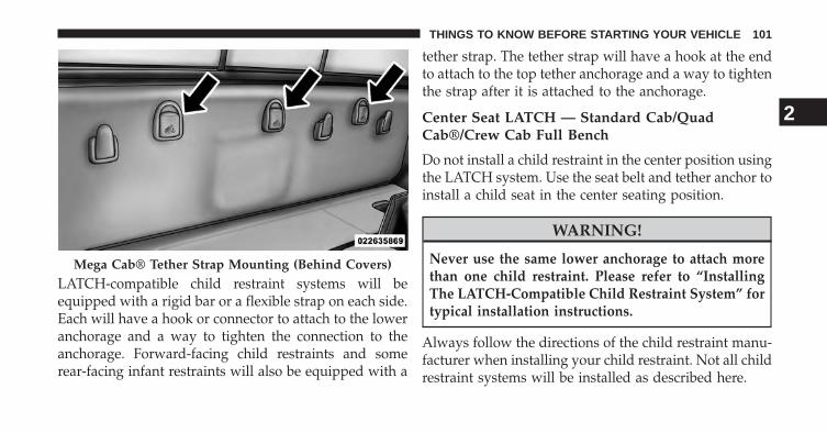
LATCH-compatible child restraint systems will beequipped with a rigid bar or a flexible strap on each side.Each will have a hook or connector to attach to the loweranchorage and a way to tighten the connection to theanchorage. Forward-facing child restraints and somerear-facing infant restraints will also be equipped with a
tether strap. The tether strap will have a hook at the endto attach to the top tether anchorage and a way to tightenthe strap after it is attached to the anchorage.
Center Seat LATCH — Standard Cab/QuadCab®/Crew Cab Full Bench
Do not install a child restraint in the center position usingthe LATCH system. Use the seat belt and tether anchor toinstall a child seat in the center seating position.
WARNING!
Never use the same lower anchorage to attach morethan one child restraint. Please refer to “InstallingThe LATCH-Compatible Child Restraint System” fortypical installation instructions.
Always follow the directions of the child restraint manu-facturer when installing your child restraint. Not all childrestraint systems will be installed as described here.
Mega Cab® Tether Strap Mounting (Behind Covers)
2
THINGS TO KNOW BEFORE STARTING YOUR VEHICLE 101

Center Seat LATCH — Quad Cab®/MegaCab®/Crew Cab Split Bench
If a child restraint installed in the center position blocksthe seat belt webbing or buckle for the outboard position,do not use that outboard position. If a child seat in thecenter position blocks the outboard LATCH anchors orseat belt, do not install a child seat in that outboardposition.
WARNING!
Never use the same lower anchorage to attach morethan one child restraint. Please refer to “InstallingThe LATCH-Compatible Child Restraint System” fortypical installation instructions.
Always follow the directions of the child restraint manu-facturer when installing your child restraint. Not all childrestraint systems will be installed as described here.
To Install A LATCH-compatible Child Restraint
1. If the selected seating position has a Switchable Auto-matic Locking Retractor (ALR) seat belt, stow the seatbelt, following the instructions below. See the section“Installing Child Restraints Using the Vehicle SeatBelt” to check what type of seat belt each seatingposition has.
2. Loosen the adjusters on the lower straps and on thetether strap of the child seat so that you can moreeasily attach the hooks or connectors to the vehicleanchorages.
3. Place the child seat between the lower anchorages forthat seating position. For some second row seats, youmay need to recline the seat and / or raise the headrestraint to get a better fit.
102 THINGS TO KNOW BEFORE STARTING YOUR VEHICLE

4. Attach the lower hooks or connectors of the childrestraint to the lower anchorages in the selected seat-ing position.
5. If the child restraint has a tether strap, connect it to thetop tether anchorage. See the section “Installing ChildRestraints Using the Top Tether Anchorage” for direc-tions to attach a tether anchor.
6. Tighten all of the straps as you push the child restraintrearward and downward into the seat. Remove slackin the straps according to the child restraint manufac-turer’s instructions.
7. Test that the child restraint is installed tightly bypulling back and forth on the child seat at the beltpath. It should not move more than 1 inch (25.4 mm)in any direction.
How To Stow An Unused ALR Seatbelt
When using the LATCH attaching system to install achild restraint, stow all ALR seat belts that are not beingused by other occupants or being used to secure childrestraints. An unused belt could injure a child if they playwith it and accidentally lock the seatbelt retractor. Beforeinstalling a child restraint using the LATCH system,buckle the seat belt behind the child restraint and out ofthe child’s reach. If the buckled seat belt interferes withthe child restraint installation, instead of buckling itbehind the child restraint, route the seat belt through thechild restraint belt path and then buckle it. Do not lockthe seatbelt. Remind all children in the vehicle that theseat belts are not toys and that they should not play withthem.
2
THINGS TO KNOW BEFORE STARTING YOUR VEHICLE 103

WARNING!
Improper installation of a child restraint to theLATCH anchorages can lead to failure of the re-straint. The child could be badly injured or killed.Follow the child restraint manufacturer’s directionsexactly when installing an infant or child restraint.
Installing Child Restraints Using The Vehicle SeatBelt
The seat belts in the passenger seating positions areequipped with either a Switchable Automatic LockingRetractor (ALR) or a cinching latch plate or both. Bothtypes of seat belts are designed to keep the lap portion of
the seat belt tight around the child restraint so that it isnot necessary to use a locking clip. The ALR retractor canbe “switched” into a locked mode by pulling all of thewebbing out of the retractor and then letting the webbingretract back into the retractor. If it is locked, the ALR willmake a clicking noise while the webbing is pulled backinto the retractor. For additional information on ALR,refer to the “Automatic Locking Mode” description un-der “Occupant Restraints.” The cinching latch plate isdesigned to hold the lap portion of the seatbelt tightwhen webbing is pulled tight and straight through achild restraint’s belt path. Please see the table below andthe following sections for more information about bothtypes of seat belts.
104 THINGS TO KNOW BEFORE STARTING YOUR VEHICLE

Lap/Shoulder Belt Systems for Installing Child Restraints in this Vehicle
Standard Cab
Quad Cab®/Mega Cab®/Crew Cab
2
THINGS TO KNOW BEFORE STARTING YOUR VEHICLE 105

Quad Cab®/Crew Cab
What is the weight limit (child’s weight +weight of the child restraint) for using theTether Anchor with the seat belt to attach aforward facing child restraint?
Weight limit of theChild Restraint
Always use the tether anchor when usingthe seat belt to install a forward facing childrestraint, up to the recommended weightlimit of the child restraint.
Can the rear-facing child restraint touch theback of the front passenger seat?
Yes Contact between the front passenger seatand the child restraint is allowed, if the childrestraint manufacturer also allows contact.
Can the head restraints be removed? NoCan the buckle stalk be twisted to tightenthe seat belt against the belt path of the childrestraint?
Yes In positions with cinching latch plates(CINCH), the buckle stalk may be twistedup to 3 full turns. Do not twist the bucklestalk in a seating position with an ALRretractor.
106 THINGS TO KNOW BEFORE STARTING YOUR VEHICLE

Mega Cab®/Standard Cab
What is the weight limit (child’s weight +weight of the child restraint) for using theTether Anchor with the seat belt to attach aforward facing child restraint?
65 lbs (29.5 kg) The Tether Anchor can be used with the seatbelt until the combined weight of the childand the child restraint is 65 lbs (29.5 kg). Usethe seat belt without the Tether Anchor oncethe combined weight is more than 65 lbs(29.5 kg).
Can the rear-facing child restraint touch theback of the front passenger seat?
Yes Contact between the front passenger seatand the child restraint is allowed, if the childrestraint manufacturer also allows contact.
Can the head restraints be removed? NoCan the buckle stalk be twisted to tightenthe seat belt against the belt path of the childrestraint?
Yes In positions with cinching latch plates(CINCH), the buckle stalk may be twistedup to 3 full turns. Do not twist the bucklestalk in a seating position with an ALRretractor.
2
THINGS TO KNOW BEFORE STARTING YOUR VEHICLE 107

Installing A Child Restraint with a SwitchableAutomatic Locking Retractor (ALR)
1. Place the child seat in the center of the seatingposition. For some second row seats, you may need torecline the seat and/or raise the head restraint to get abetter fit.
2. Pull enough of the seat belt webbing from the retractorto pass it through the belt path of the child restraint.Do not twist the belt webbing in the belt path.
3. Slide the latch plate into the buckle until you hear a“click.”
4. Pull on the webbing to make the lap portion tightagainst the child seat.
5. To lock the seat belt, pull down on the shoulder part ofthe belt until you have pulled all the seat belt webbingout of the retractor. Then, allow the webbing to retractback into the retractor. As the webbing retracts, youwill hear a clicking sound. This means the seat belt isnow in the Automatic Locking mode.
6. Try to pull the webbing out of the retractor. If it islocked, you should not be able to pull out any web-bing. If the retractor is not locked, repeat step 5.
7. Finally, pull up on any excess webbing to tighten thelap portion around the child restraint while you pushthe child restraint rearward and downward into thevehicle seat.
108 THINGS TO KNOW BEFORE STARTING YOUR VEHICLE

8. If the child restraint has a top tether strap and theseating position has a top tether anchorage, connectthe tether strap to the anchorage and tighten the tetherstrap. Refer to “Lower Anchors and Tethers for Chil-dren (LATCH) Restraint System” for directions toattach a tether anchor.
9. Test that the child restraint is installed tightly bypulling back and forth on the child seat at the beltpath. It should not move more than 1 inch (25.4 mm)in any direction.
Any seat belt system will loosen with time, so check thebelt occasionally, and pull it tight if necessary.
Installing A Child Restraint With A CinchingLatch Plate (CINCH) — If Equipped
1. Place the child seat in the center of the seatingposition. For some second row seats, you may need torecline the seat and / or raise the head restraint to geta better fit.
2. Next, pull enough of the seat belt webbing from theretractor to pass it through the belt path of the childrestraint. Do not twist the belt webbing in the beltpath.
3. Slide the latch plate into the buckle until you hear a“click.”
4. Finally, pull up on any excess webbing to tighten thelap portion around the child restraint while you pushthe child restraint rearward and downward into thevehicle seat.
2
THINGS TO KNOW BEFORE STARTING YOUR VEHICLE 109

5. If the child restraint has a top tether strap and theseating position has a top tether anchorage, connectthe tether strap to the anchorage and tighten the tetherstrap. Refer to “Lower Anchors and Tethers for Chil-dren (LATCH) Restraint System” for directions toattach a tether anchor.
6. Test that the child restraint is installed tightly bypulling back and forth on the child seat at the beltpath. It should not move more than 1 inch (25.4 mm)in any direction.
Any seat belt system will loosen with time, so check thebelt occasionally, and pull it tight if necessary.
If the buckle or the cinching latch plate is too close to thebelt path opening of the child restraint, you may have
trouble tightening the seat belt. If this happens, discon-nect the latch plate from the buckle and twist the shortbuckle-end belt up to three full turns to shorten it. Insertthe latch plate into the buckle with the release buttonfacing out, away from the child restraint. Repeat steps 4to 6, above, to complete the installation of the childrestraint.
If the belt still cannot be tightened after you shorten thebuckle, disconnect the latch plate from the buckle, turnthe buckle around one half turn, and insert the latch plateinto the buckle again. If you still cannot make the childrestraint installation tight, try a different seating position.
110 THINGS TO KNOW BEFORE STARTING YOUR VEHICLE

Installing Child Restraints Using The Top TetherAnchorage
Regular and Mega Cab® Trucks: In the regular cabtruck, the top tether anchorages are located behind thecenter and right passenger seats. In the mega cab truck,the top tether anchorages are located behind each rearseating position. There is a plastic cover over each an-chorage. To attach the tether strap of the child restraint:
1. Place the child restraint on the seat and adjust thetether strap so that it will reach over the seat back,under the head restraint and to the tether anchordirectly behind the seat.
1 — Tether Strap Hook2 — Tether Strap to Child Restraint3 — Tether Anchor
Regular Cab Tether Strap Mounting
2
THINGS TO KNOW BEFORE STARTING YOUR VEHICLE 111

2. Route the tether strap to provide the most direct pathbetween the anchorage and the child seat. The tetherstrap should go between the head restraint postsunderneath the head restraint. You may need to adjustthe head restraint to the upward position to pass thetether strap underneath the head restraint and be-tween its posts.
3. Lift the cover (if so equipped), and attach the hook tothe square opening in the sheet metal. Tighten thetether strap according to the child seat manufacturer’sinstructions.
WARNING!
Never place a rear facing infant seat in front of an airbag. A deploying passenger Advanced Front Air Bagcan cause death or serious injury to a child 12 years or
(Continued)
Mega Cab® Tether Strap Mounting
112 THINGS TO KNOW BEFORE STARTING YOUR VEHICLE

WARNING! (Continued)younger, including a child in a rearward facing infantseat.
Quad Cab® or Crew Cab Trucks: The top tether an-chorages in this vehicle are tether strap loops locatedbetween the rear glass and the back of the rear seat.There is a tether strap loop located behind each seatingposition. Follow the steps below to attach the tetherstrap of the child restraint.
Right or Left Outboard Seats:
1. Raise the head restraint and reach between the rearseat and rear glass to access the tether strap loop.
Head Restraint In Raised Position
2
THINGS TO KNOW BEFORE STARTING YOUR VEHICLE 113

2. Place a child restraint on the seat and adjust the tetherstrap so that it will reach over the seat back, under thehead restraint, through the tether strap loop behindthe seat and over to the tether strap loop behind thecenter seat.
3. Pass the tether strap hook under the head restraintbehind the child seat, though the tether strap loopbehind the seat and over to the center tether straploop.
Tether Strap Loop With Center Head Restraint In RaisedPosition
Tether Strap Through Outboard Tether Strap Loop
114 THINGS TO KNOW BEFORE STARTING YOUR VEHICLE

4. Attach the hook to the center tether strap loop (seediagram). Tighten the tether strap according to thechild seat manufacturer’s instructions.
NOTE: If there are child seats in both of the outboard (leftand right) seating positions, the tether strap hooks ofboth child seats should be connected to the center tetherstrap loop. This is the correct way to tether two outboardchild seats.
Tether Strap Through Outboard Tether Strap Loop AndAttached To Center Tether Strap Loop
2
THINGS TO KNOW BEFORE STARTING YOUR VEHICLE 115

Center Seat:
1. Raise the head restraint and reach between the rearseat and rear glass to access the tether strap loop.
2. Place a child restraint on the seat and adjust the tetherstrap so that it will reach over the seat back, under thehead restraint, through the tether strap loop behindthe seat and over to the tether strap loop behind eitherthe right or left outboard seat.
3. Pass the tether strap hook under the head restraintbehind the child seat, though the tether strap loopbehind the seat and over to the right or left outboardtether strap loop.
Tether Strap Loop With Head Restraint In RaisedPosition
116 THINGS TO KNOW BEFORE STARTING YOUR VEHICLE
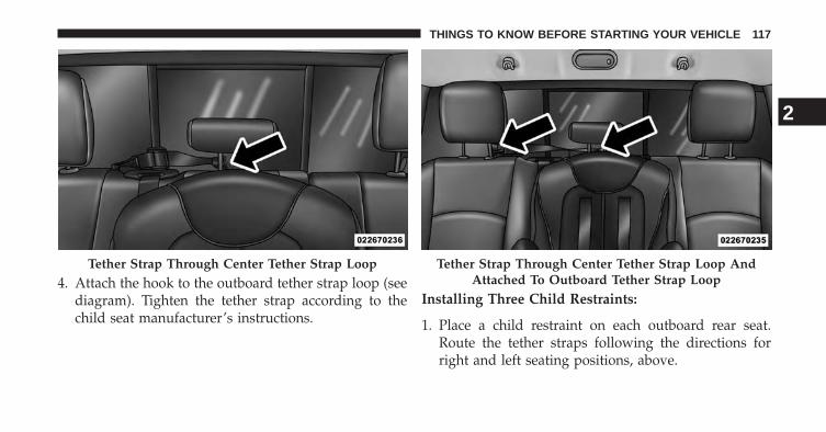
4. Attach the hook to the outboard tether strap loop (seediagram). Tighten the tether strap according to thechild seat manufacturer’s instructions.
Installing Three Child Restraints:
1. Place a child restraint on each outboard rear seat.Route the tether straps following the directions forright and left seating positions, above.
Tether Strap Through Center Tether Strap Loop Tether Strap Through Center Tether Strap Loop AndAttached To Outboard Tether Strap Loop
2
THINGS TO KNOW BEFORE STARTING YOUR VEHICLE 117
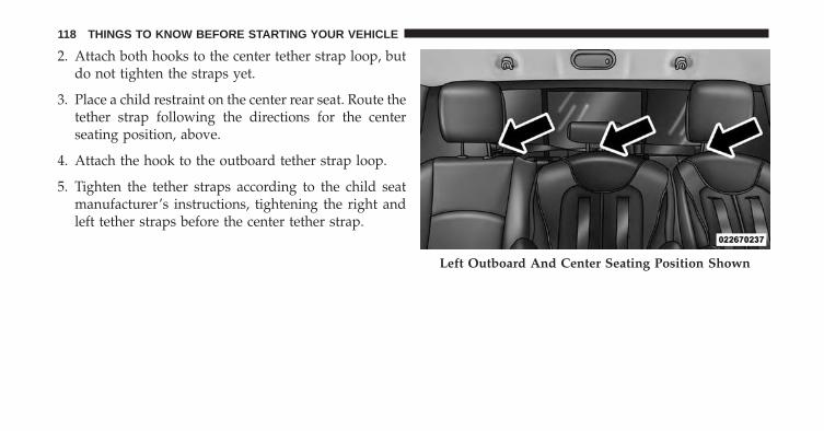
2. Attach both hooks to the center tether strap loop, butdo not tighten the straps yet.
3. Place a child restraint on the center rear seat. Route thetether strap following the directions for the centerseating position, above.
4. Attach the hook to the outboard tether strap loop.
5. Tighten the tether straps according to the child seatmanufacturer’s instructions, tightening the right andleft tether straps before the center tether strap.
Left Outboard And Center Seating Position Shown
118 THINGS TO KNOW BEFORE STARTING YOUR VEHICLE

WARNING!
• An incorrectly anchored tether strap could lead toincreased head motion and possible injury to thechild. Use only the anchorage position directlybehind the child seat to secure a child restraint toptether strap.
• If your vehicle is equipped with a split rear seat,make sure the tether strap does not slip into theopening between the seatbacks as you removeslack in the strap.
Transporting Pets
Air Bags deploying in the front seat could harm your pet.An unrestrained pet will be thrown about and possiblyinjured, or injure a passenger during panic braking or ina collision.
Pets should be restrained in the rear seat in pet harnessesor pet carriers that are secured by seat belts.
ENGINE BREAK-IN RECOMMENDATIONS
A long break-in period is not required for the engine anddrivetrain (transmission and axle) in your vehicle.
Drive moderately during the first 300 miles (500 km).After the initial 60 miles (100 km), speeds up to 50 or55 mph (80 or 90 km/h) are desirable.
While cruising, brief full-throttle acceleration within thelimits of local traffic laws contributes to a good break-in.Wide-open throttle acceleration in low gear can be detri-mental and should be avoided.
The engine oil installed in the engine at the factory is ahigh-quality energy conserving type lubricant. Oilchanges should be consistent with anticipated climateconditions under which vehicle operations will occur. Forthe recommended viscosity and quality grades, refer to“Maintenance Procedures” in “Maintaining Your Ve-hicle”.
2
THINGS TO KNOW BEFORE STARTING YOUR VEHICLE 119
CAUTION!
Never use Non-Detergent Oil or Straight Mineral Oilin the engine or damage may result.
NOTE: A new engine may consume some oil during itsfirst few thousand miles (kilometers) of operation. Thisshould be considered a normal part of the break-in andnot interpreted as an indication of difficulty.
SAFETY TIPS
Transporting Passengers
NEVER TRANSPORT PASSENGERS IN THE CARGOAREA.
WARNING!
• Do not leave children or animals inside parkedvehicles in hot weather. Interior heat build-up maycause serious injury or death.
• It is extremely dangerous to ride in a cargo area,inside or outside of a vehicle. In a collision, peopleriding in these areas are more likely to be seriouslyinjured or killed.
• Do not allow people to ride in any area of yourvehicle that is not equipped with seats and seatbelts.
• Be sure everyone in your vehicle is in a seat andusing a seat belt properly.
120 THINGS TO KNOW BEFORE STARTING YOUR VEHICLE

Exhaust Gas
WARNING!
Exhaust gases can injure or kill. They contain carbonmonoxide (CO), which is colorless and odorless.Breathing it can make you unconscious and caneventually poison you. To avoid breathing (CO),follow these safety tips:• Do not run the engine in a closed garage or in
confined areas any longer than needed to moveyour vehicle in or out of the area.
• If you are required to drive with the trunk/liftgateopen, make sure that all windows are closed andthe climate control BLOWER switch is set at highspeed. DO NOT use the recirculation mode.
(Continued)
WARNING! (Continued)• If it is necessary to sit in a parked vehicle with the
engine running, adjust your heating or coolingcontrols to force outside air into the vehicle. Set theblower at high speed.
The best protection against carbon monoxide entry intothe vehicle body is a properly maintained engine exhaustsystem.
Whenever a change is noticed in the sound of the exhaustsystem, when exhaust fumes can be detected inside thevehicle, or when the underside or rear of the vehicle isdamaged, have a competent mechanic inspect the com-plete exhaust system and adjacent body areas for broken,damaged, deteriorated, or mispositioned parts. Openseams or loose connections could permit exhaust fumesto seep into the passenger compartment. In addition,inspect the exhaust system each time the vehicle is raisedfor lubrication or oil change. Replace as required.
2
THINGS TO KNOW BEFORE STARTING YOUR VEHICLE 121

Safety Checks You Should Make Inside TheVehicle
Seat Belts
Inspect the belt system periodically, checking for cuts,frays, and loose parts. Damaged parts must be replacedimmediately. Do not disassemble or modify the system.
Front seat belt assemblies must be replaced after acollision. Rear seat belt assemblies must be replaced aftera collision if they have been damaged (i.e., bent retractor,torn webbing, etc.). If there is any question regarding beltor retractor condition, replace the belt.
Air Bag Warning Light
The light should come on and remain on forfour to eight seconds as a bulb check when theignition switch is first turned ON. If the light isnot lit during starting, see your authorized
dealer. If the light stays on, flickers, or comes on whiledriving, have the system checked by an authorizeddealer.
Defroster
Check operation by selecting the defrost mode and placethe blower control on high speed. You should be able tofeel the air directed against the windshield. See yourauthorized dealer for service if your defroster is inoper-able.
Floor Mat Safety Information
Always use floor mats designed to fit the footwell of yourvehicle. Use only floor mats that leave the pedal areaunobstructed and that are firmly secured so that theycannot slip out of position and interfere with the pedalsor impair safe operation of your vehicle in other ways.
122 THINGS TO KNOW BEFORE STARTING YOUR VEHICLE

WARNING!
Pedals that cannot move freely can cause loss ofvehicle control and increase the risk of serious per-sonal injury.• Always make sure that floor mats are properly
attached to the floor mat fasteners.• Never place or install floor mats or other floor
coverings in the vehicle that cannot be properlysecured to prevent them from moving and interfer-ing with the pedals or the ability to control thevehicle.
• Never put floor mats or other floor coverings on topof already installed floor mats. Additional floormats and other coverings will reduce the size of thepedal area and interfere with the pedals.
(Continued)
WARNING! (Continued)• Check mounting of mats on a regular basis. Always
properly reinstall and secure floor mats that havebeen removed for cleaning.
• Always make sure that objects cannot fall into thedriver footwell while the vehicle is moving. Ob-jects can become trapped under the brake pedaland accelerator pedal causing a loss of vehiclecontrol.
• If required, mounting posts must be properly in-stalled, if not equipped from the factory.
Failure to properly follow floor mat installation ormounting can cause interference with the brakepedal and accelerator pedal operation causing loss ofcontrol of the vehicle.
2
THINGS TO KNOW BEFORE STARTING YOUR VEHICLE 123

Periodic Safety Checks You Should Make OutsideThe Vehicle
Tires
Examine tires for excessive tread wear and uneven wearpatterns. Check for stones, nails, glass, or other objectslodged in the tread or sidewall. Inspect the tread for cutsand cracks. Inspect sidewalls for cuts, cracks and bulges.Check the wheel nuts for tightness. Check the tires(including spare) for proper cold inflation pressure.
Lights
Have someone observe the operation of brake lights andexterior lights while you work the controls. Check turnsignal and high beam indicator lights on the instrumentpanel.
Door Latches
Check for positive closing, latching, and locking.
Fluid Leaks
Check area under vehicle after overnight parking for fuel,engine coolant, oil, or other fluid leaks. Also, if gasolinefumes are detected or if fuel, power steering fluid(2500,3500,4500,5500 Models Only), or brake fluid leaksare suspected, the cause should be located and correctedimmediately.
124 THINGS TO KNOW BEFORE STARTING YOUR VEHICLE

UNDERSTANDING THE FEATURES OF YOUR VEHICLE
CONTENTS� MIRRORS . . . . . . . . . . . . . . . . . . . . . . . . . . . .131
▫ Inside Day/Night Mirror . . . . . . . . . . . . . . . .131
▫ Automatic Dimming Mirror — If Equipped . . .131
▫ Automatic Dimming Mirror With Rear ViewCamera Display — If Equipped . . . . . . . . . . .132
▫ Outside Mirrors . . . . . . . . . . . . . . . . . . . . . .133
▫ Outside Mirrors Folding Feature . . . . . . . . . . .134
▫ Power Folding Outside Mirrors — IfEquipped . . . . . . . . . . . . . . . . . . . . . . . . . . .135
▫ Power Mirrors — If Equipped . . . . . . . . . . . .135
▫ Heated Mirrors — If Equipped . . . . . . . . . . .137
▫ Driver’s Outside Automatic Dimming Mirror —If Equipped. . . . . . . . . . . . . . . . . . . . . . . . . .137
▫ Illuminated Vanity Mirror — If Equipped . . . .137
▫ “Slide-On-Rod” Features Of Sun Visor — IfEquipped . . . . . . . . . . . . . . . . . . . . . . . . . . .138
▫ Trailer Towing Mirrors — If Equipped . . . . . .139
� SEATS . . . . . . . . . . . . . . . . . . . . . . . . . . . . . .140
▫ Driver’s Power Seat — If Equipped . . . . . . . .140
▫ Passenger’s Power Seat — If Equipped . . . . . .142
3
▫ Power Lumbar — If Equipped . . . . . . . . . . . .143
▫ Heated Seats — If Equipped . . . . . . . . . . . . . .143
▫ Ventilated Seats — If Equipped . . . . . . . . . . . .146
▫ Manual Seat Adjuster — If Equipped. . . . . . . .147
▫ 40-20-40 Front Bench Seat — If Equipped . . . .148
▫ Mega Cab® Rear Seat Features . . . . . . . . . . . .148
▫ Head Restraints . . . . . . . . . . . . . . . . . . . . . .153
� DRIVER MEMORY SEAT — IF EQUIPPED . . . .155
▫ Programming The Memory Feature . . . . . . . . .155
▫ Linking And Unlinking The Remote Keyless EntryTransmitter To Memory . . . . . . . . . . . . . . . . .157
▫ Memory Position Recall . . . . . . . . . . . . . . . . .158
� TO OPEN AND CLOSE THE HOOD . . . . . . . . .158
� LIGHTS . . . . . . . . . . . . . . . . . . . . . . . . . . . . .160
▫ Headlights . . . . . . . . . . . . . . . . . . . . . . . . . .161
▫ Automatic Headlights — If Equipped . . . . . . .161
▫ Headlights On With Wipers (Available WithAutomatic Headlights Only) . . . . . . . . . . . . . .162
▫ Daytime Running Lights (DRL) —If Equipped . . . . . . . . . . . . . . . . . . . . . . . . .162
▫ Headlight Delay . . . . . . . . . . . . . . . . . . . . . .163
▫ SmartBeam™ — If Equipped . . . . . . . . . . . . .163
▫ Parking Lights And Panel Lights. . . . . . . . . . .165
▫ Fog Lights — If Equipped . . . . . . . . . . . . . . .165
▫ Lights-On Reminder . . . . . . . . . . . . . . . . . . .166
▫ Battery Saver. . . . . . . . . . . . . . . . . . . . . . . . .166
▫ Interior Lights . . . . . . . . . . . . . . . . . . . . . . .166
126 UNDERSTANDING THE FEATURES OF YOUR VEHICLE

▫ Cargo Light . . . . . . . . . . . . . . . . . . . . . . . . .170
▫ Multifunction Lever . . . . . . . . . . . . . . . . . . .171
▫ Turn Signals . . . . . . . . . . . . . . . . . . . . . . . . .171
▫ Lane Change Assist . . . . . . . . . . . . . . . . . . .172
▫ Flash-To-Pass . . . . . . . . . . . . . . . . . . . . . . . .172
▫ High/Low Beam Switch . . . . . . . . . . . . . . . .172
� WINDSHIELD WIPERS AND WASHERS . . . . . .172
▫ Windshield Wipers . . . . . . . . . . . . . . . . . . . .172
▫ Windshield Wiper Operation . . . . . . . . . . . . .173
▫ Intermittent Wiper System . . . . . . . . . . . . . . .173
▫ Windshield Washers . . . . . . . . . . . . . . . . . . .173
▫ Mist Feature . . . . . . . . . . . . . . . . . . . . . . . . .174
▫ Rain Sensing Wipers — If Equipped . . . . . . . .175
� TILT STEERING COLUMN . . . . . . . . . . . . . . .176
� HEATED STEERING WHEEL — IF EQUIPPED . .177
� DRIVER ADJUSTABLE PEDALS —IF EQUIPPED . . . . . . . . . . . . . . . . . . . . . . . . .179
� ELECTRONIC SPEED CONTROL . . . . . . . . . . .180
▫ To Activate . . . . . . . . . . . . . . . . . . . . . . . . . .181
▫ To Set A Desired Speed . . . . . . . . . . . . . . . . .182
▫ To Deactivate . . . . . . . . . . . . . . . . . . . . . . . .182
▫ To Resume Speed . . . . . . . . . . . . . . . . . . . . .182
▫ To Vary The Speed Setting . . . . . . . . . . . . . . .182
▫ To Accelerate For Passing . . . . . . . . . . . . . . . .183
� PARKSENSE® REAR PARK ASSIST — IFEQUIPPED . . . . . . . . . . . . . . . . . . . . . . . . . . .184
▫ ParkSense® Sensors . . . . . . . . . . . . . . . . . . . .184
3
UNDERSTANDING THE FEATURES OF YOUR VEHICLE 127

▫ ParkSense® Warning Display . . . . . . . . . . . . .183
▫ ParkSense® Display . . . . . . . . . . . . . . . . . . . .184
▫ Enabling And Disabling ParkSense® . . . . . . . .187
▫ Service The ParkSense® Rear Park AssistSystem . . . . . . . . . . . . . . . . . . . . . . . . . . . . .188
▫ Cleaning The ParkSense® System . . . . . . . . . .188
▫ ParkSense® System Usage Precautions. . . . . . .189
� PARKVIEW® REAR BACK UP CAMERA — IFEQUIPPED . . . . . . . . . . . . . . . . . . . . . . . . . . .191
▫ Turning ParkView® On Or Off — WithUconnect® 5.0 . . . . . . . . . . . . . . . . . . . . . . . .193
▫ Turning ParkView® On Or Off — WithUconnect® 8.4A/8.4AN . . . . . . . . . . . . . . . . .193
� OVERHEAD CONSOLE — IF EQUIPPED . . . . .193
▫ Courtesy/Reading Lights . . . . . . . . . . . . . . .194
� GARAGE DOOR OPENER — IF EQUIPPED. . . .195
▫ Before You Begin Programming HomeLink® . .196
▫ Programming A Rolling Code . . . . . . . . . . . . .197
▫ Programming A Non-Rolling Code . . . . . . . . .199
▫ Canadian/Gate Operator Programming . . . . . .200
▫ Using HomeLink®. . . . . . . . . . . . . . . . . . . . .201
▫ Security . . . . . . . . . . . . . . . . . . . . . . . . . . . .202
▫ Troubleshooting Tips . . . . . . . . . . . . . . . . . . .202
▫ General Information. . . . . . . . . . . . . . . . . . . .203
� POWER SUNROOF — IF EQUIPPED . . . . . . . .204
▫ Opening Sunroof — Express . . . . . . . . . . . . . .205
128 UNDERSTANDING THE FEATURES OF YOUR VEHICLE

▫ Closing Sunroof — Express. . . . . . . . . . . . . . .205
▫ Pinch Protect Feature . . . . . . . . . . . . . . . . . . .206
▫ Venting Sunroof — Express . . . . . . . . . . . . . .206
▫ Sunshade Operation. . . . . . . . . . . . . . . . . . . .206
▫ Wind Buffeting . . . . . . . . . . . . . . . . . . . . . . .206
▫ Sunroof Maintenance . . . . . . . . . . . . . . . . . . .207
▫ Ignition Off Operation . . . . . . . . . . . . . . . . . .207
� ELECTRICAL POWER OUTLETS . . . . . . . . . . .207
� CIGAR LIGHTER AND ASH RECEIVER — IFEQUIPPED . . . . . . . . . . . . . . . . . . . . . . . . . . .211
� POWER INVERTER — IF EQUIPPED . . . . . . . .212
� CUPHOLDERS . . . . . . . . . . . . . . . . . . . . . . . .213
▫ Front Seat Cupholders — (40–20–40 Seats) . . . .213
▫ Front Instrument Panel Cupholders — FloorMounted Shifter . . . . . . . . . . . . . . . . . . . . . .214
▫ Rear Cupholder — Quad Cab®. . . . . . . . . . . .214
▫ Rear Cupholder — Crew Cab . . . . . . . . . . . . .215
� STORAGE . . . . . . . . . . . . . . . . . . . . . . . . . . . .215
▫ Glove Box Storage . . . . . . . . . . . . . . . . . . . . .215
▫ Door Storage . . . . . . . . . . . . . . . . . . . . . . . . .217
▫ Center Storage Compartment — If Equipped . .218
▫ Second Row In-Floor Storage Bin — IfEquipped . . . . . . . . . . . . . . . . . . . . . . . . . . .220
▫ Seatback Storage . . . . . . . . . . . . . . . . . . . . . .221
▫ Storage (Regular Cab) . . . . . . . . . . . . . . . . . .222
▫ Storage and Seats (Crew Cab) . . . . . . . . . . . . .222
3
UNDERSTANDING THE FEATURES OF YOUR VEHICLE 129

▫ Plastic Grocery Bag Retainers (Regular CabModels) . . . . . . . . . . . . . . . . . . . . . . . . . . . .223
� REAR WINDOW FEATURES . . . . . . . . . . . . . .224
▫ Rear Window Defroster . . . . . . . . . . . . . . . . .224
▫ Power Sliding Rear Window — If Equipped . . .224
▫ Manual Sliding Rear Window —If Equipped . . . . . . . . . . . . . . . . . . . . . . . . .225
� FOLD FLAT LOAD FLOOR — IF EQUIPPED . . .225
� PICKUP BOX . . . . . . . . . . . . . . . . . . . . . . . . .227
� RAMBOX® — IF EQUIPPED . . . . . . . . . . . . . .229
▫ RamBox® Integrated Box Side Storage Bins . . .230
▫ Locking And Unlocking RamBox® . . . . . . . . .232
▫ RamBox® Safety Warning. . . . . . . . . . . . . . . .233
▫ Bed Extender — If Equipped . . . . . . . . . . . . .234
▫ Bed Rail Tie-Down System . . . . . . . . . . . . . .241
� SLIDE-IN CAMPERS . . . . . . . . . . . . . . . . . . . .243
▫ Camper Applications . . . . . . . . . . . . . . . . . . .243
� EASY-OFF TAILGATE . . . . . . . . . . . . . . . . . . .244
▫ Disconnecting the Rear Camera or RemoteKeyless Entry — If Equipped . . . . . . . . . . . . .244
▫ Removing The Tailgate. . . . . . . . . . . . . . . . . .245
▫ Locking Tailgate . . . . . . . . . . . . . . . . . . . . . .246
� TRI-FOLD TONNEAU COVER-IF EQUIPPED . . .247
▫ Tri-Fold Tonneau Cover — If Equipped . . . . . .247
▫ Tri-Fold Tonneau Cover Removal . . . . . . . . . .247
▫ Tri-Fold Tonneau Cover Installation AndCleaning . . . . . . . . . . . . . . . . . . . . . . . . . . . .249
130 UNDERSTANDING THE FEATURES OF YOUR VEHICLE

MIRRORS
Inside Day/Night Mirror
A single ball joint mirror is provided in the vehicle. It isa twist on mirror that has a fixed position at the wind-shield. The mirror installs on the windshield button witha counterclockwise rotation and requires no tools formounting. The mirror head can be adjusted up, down,left, and right for various drivers. The mirror should beadjusted to center on the view through the rear window.
Headlight glare from vehicles behind you can be reducedby moving the small control under the mirror to the nightposition (toward the rear of the vehicle). The mirrorshould be adjusted while the small control under themirror is set in the day position (toward the windshield).
Adjusting Rearview Mirror
3
UNDERSTANDING THE FEATURES OF YOUR VEHICLE 131
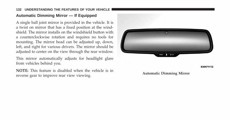
Automatic Dimming Mirror — If Equipped
A single ball joint mirror is provided in the vehicle. It isa twist on mirror that has a fixed position at the wind-shield. The mirror installs on the windshield button witha counterclockwise rotation and requires no tools formounting. The mirror head can be adjusted up, down,left, and right for various drivers. The mirror should beadjusted to center on the view through the rear window.
This mirror automatically adjusts for headlight glarefrom vehicles behind you.
NOTE: This feature is disabled when the vehicle is inreverse gear to improve rear view viewing. Automatic Dimming Mirror
132 UNDERSTANDING THE FEATURES OF YOUR VEHICLE
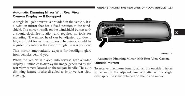
Automatic Dimming Mirror With Rear ViewCamera Display — If Equipped
A single ball joint mirror is provided in the vehicle. It isa twist on mirror that has a fixed position at the wind-shield. The mirror installs on the windshield button witha counterclockwise rotation and requires no tools formounting. The mirror head can be adjusted up, down,left, and right for various drivers. The mirror should beadjusted to center on the view through the rear window.
This mirror automatically adjusts for headlight glarefrom vehicles behind you.
When the vehicle is placed into reverse gear a videodisplay illuminates to display the image generated by therear view camera located on the tailgate handle. The autodimming feature is also disabled to improve rear viewviewing.
Outside Mirrors
To receive maximum benefit, adjust the outside mirrorsto center on the adjacent lane of traffic with a slightoverlap of the view obtained on the inside mirror.
Automatic Dimming Mirror With Rear View Camera
3
UNDERSTANDING THE FEATURES OF YOUR VEHICLE 133
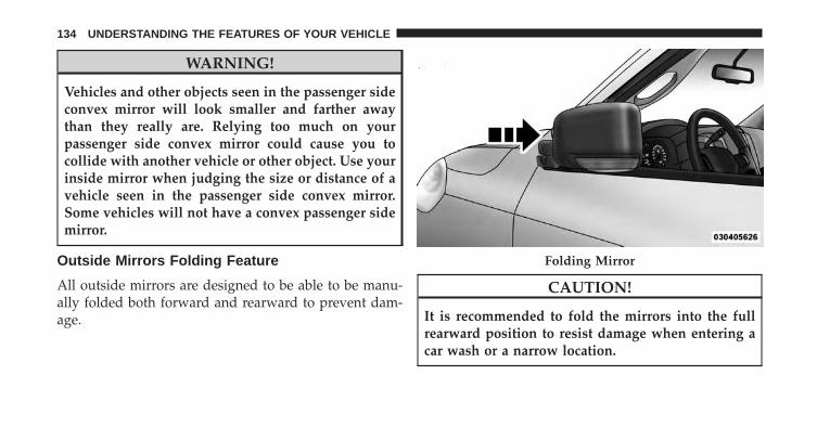
WARNING!
Vehicles and other objects seen in the passenger sideconvex mirror will look smaller and farther awaythan they really are. Relying too much on yourpassenger side convex mirror could cause you tocollide with another vehicle or other object. Use yourinside mirror when judging the size or distance of avehicle seen in the passenger side convex mirror.Some vehicles will not have a convex passenger sidemirror.
Outside Mirrors Folding Feature
All outside mirrors are designed to be able to be manu-ally folded both forward and rearward to prevent dam-age.
CAUTION!
It is recommended to fold the mirrors into the fullrearward position to resist damage when entering acar wash or a narrow location.
Folding Mirror
134 UNDERSTANDING THE FEATURES OF YOUR VEHICLE
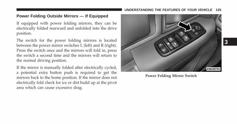
Power Folding Outside Mirrors — If Equipped
If equipped with power folding mirrors, they can beelectrically folded rearward and unfolded into the driveposition.
The switch for the power folding mirrors is locatedbetween the power mirror switches L (left) and R (right).Press the switch once and the mirrors will fold in, pressthe switch a second time and the mirrors will return tothe normal driving position.
If the mirror is manually folded after electrically cycled,a potential extra button push is required to get themirrors back to the home position. If the mirror does notelectrically fold check for ice or dirt build up at the pivotarea which can cause excessive drag.
Power Folding Mirror Switch
3
UNDERSTANDING THE FEATURES OF YOUR VEHICLE 135
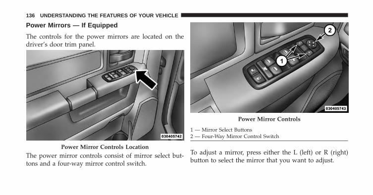
Power Mirrors — If Equipped
The controls for the power mirrors are located on thedriver’s door trim panel.
The power mirror controls consist of mirror select but-tons and a four-way mirror control switch.
To adjust a mirror, press either the L (left) or R (right)button to select the mirror that you want to adjust.
Power Mirror Controls Location
Power Mirror Controls
1 — Mirror Select Buttons2 — Four-Way Mirror Control Switch
136 UNDERSTANDING THE FEATURES OF YOUR VEHICLE
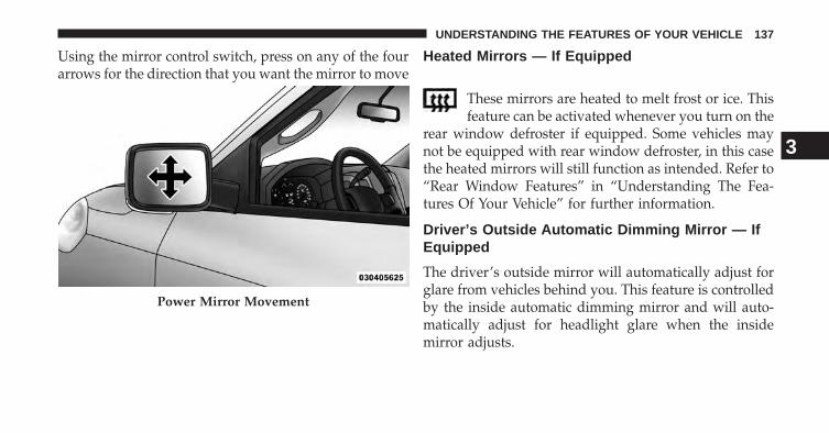
Using the mirror control switch, press on any of the fourarrows for the direction that you want the mirror to move
Heated Mirrors — If Equipped
These mirrors are heated to melt frost or ice. Thisfeature can be activated whenever you turn on the
rear window defroster if equipped. Some vehicles maynot be equipped with rear window defroster, in this casethe heated mirrors will still function as intended. Refer to“Rear Window Features” in “Understanding The Fea-tures Of Your Vehicle” for further information.
Driver’s Outside Automatic Dimming Mirror — IfEquipped
The driver’s outside mirror will automatically adjust forglare from vehicles behind you. This feature is controlledby the inside automatic dimming mirror and will auto-matically adjust for headlight glare when the insidemirror adjusts.
Power Mirror Movement
3
UNDERSTANDING THE FEATURES OF YOUR VEHICLE 137

Illuminated Vanity Mirror — If Equipped
Illuminated vanity mirrors are located on each sun visor.To use the mirror, rotate the sun visor down and swingthe mirror cover upward. The lights will turn on auto-matically. Closing the mirror cover turns off the light.
“Slide-On-Rod” Features Of Sun Visor — IfEquipped
The sun visor “Slide-On-Rod” feature allows for addi-tional flexibility in positioning the visor to block out thesun.
To use the “Slide-On-Rod” feature, rotate the sun visordownward and unclip it. Pull the sun visor along the“Slide-On-Rod” until the sun visor is in the desiredposition.
Illuminated Vanity Mirror
138 UNDERSTANDING THE FEATURES OF YOUR VEHICLE

Trailer Towing Mirrors — If Equipped
These mirrors are designed with an adjustable mirrorhead to provide a greater vision range when towingextra-wide loads. To change position inboard or out-board, the mirror head should be rotated (flipped in orout).
“Slide-On-Rod” Extender
Trailer Towing Position
3
UNDERSTANDING THE FEATURES OF YOUR VEHICLE 139

NOTE: Fold the trailer towing mirrors rearward prior toentering an automated car wash.
A small blindspot mirror is located next to main mirrorand can be adjusted separately.
SEATS
Seats are a part of the Occupant Restraint System of thevehicle.
WARNING!
• It is dangerous to ride in a cargo area, inside oroutside of a vehicle. In a collision, people riding inthese areas are more likely to be seriously injuredor killed.
• Do not allow people to ride in any area of yourvehicle that is not equipped with seats and seatbelts. In a collision, people riding in these areas aremore likely to be seriously injured or killed.
• Be sure everyone in your vehicle is in a seat andusing a seat belt properly.
Blindspot Mirror
140 UNDERSTANDING THE FEATURES OF YOUR VEHICLE
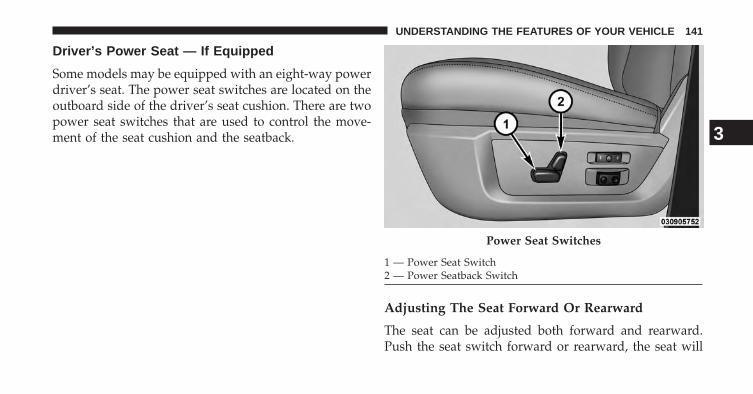
Driver’s Power Seat — If Equipped
Some models may be equipped with an eight-way powerdriver’s seat. The power seat switches are located on theoutboard side of the driver’s seat cushion. There are twopower seat switches that are used to control the move-ment of the seat cushion and the seatback.
Adjusting The Seat Forward Or Rearward
The seat can be adjusted both forward and rearward.Push the seat switch forward or rearward, the seat will
Power Seat Switches
1 — Power Seat Switch2 — Power Seatback Switch
3
UNDERSTANDING THE FEATURES OF YOUR VEHICLE 141

move in the direction of the switch. Release the switchwhen the desired position has been reached.
Adjusting The Seat Up Or Down
The height of the seats can be adjusted up or down. Pullupward or push downward on the seat switch, the seatwill move in the direction of the switch. Release theswitch when the desired position is reached.
Tilting The Seat Up Or Down
The angle of the seat cushion can be adjusted in fourdirections. Pull upward or push downward on the frontor rear of the seat switch, the front or rear of the seatcushion will move in the direction of the switch. Releasethe switch when the desired position is reached.
Reclining The Seatback
The angle of the seatback can be adjusted forward orrearward. Push the seatback switch forward or rearward,
the seat will move in the direction of the switch. Releasethe switch when the desired position is reached.
WARNING!
• Adjusting a seat while driving may be dangerous.Moving a seat while driving could result in loss ofcontrol which could cause a collision and seriousinjury or death.
• Seats should be adjusted before fastening the seatbelts and while the vehicle is parked. Seriousinjury or death could result from a poorly adjustedseat belt.
• Do not ride with the seatback reclined so that theshoulder belt is no longer resting against your chest.In a collision you could slide under the seat belt,which could result in serious injury or death.
142 UNDERSTANDING THE FEATURES OF YOUR VEHICLE

CAUTION!
Do not place any article under a power seat orimpede its ability to move as it may cause damage tothe seat controls. Seat travel may become limited ifmovement is stopped by an obstruction in the seat’spath.
Passenger’s Power Seat — If Equipped
Some models are equipped with a six-way power pas-senger seat. The power seat switch is located on theoutboard side of the seat. The switch is used to controlthe movement of the seat and seat cushion.
Adjusting The Seat Forward Or Rearward
The seat can be adjusted both forward and rearward.Push the seat switch forward or rearward, the seat willmove in the direction of the switch. Release the switchwhen the desired position has been reached.
Adjusting The Seat Up Or Down
The height of the seats can be adjusted up or down. Pullupward or push downward on the seat switch, the seatwill move in the direction of the switch. Release theswitch when the desired position is reached.
3
UNDERSTANDING THE FEATURES OF YOUR VEHICLE 143

Power Lumbar — If Equipped
Vehicles equipped with power driver or passenger seatsmay be also be equipped with power lumbar. The powerlumbar switch is located on the outboard side of thepower seat. Push the switch forward to increase thelumbar support. Push the switch rearward to decreasethe lumbar support.
Heated Seats — If Equipped
On some models, the front and rear seats may beequipped with heaters located in the seat cushions.
Lumbar Control Switch
144 UNDERSTANDING THE FEATURES OF YOUR VEHICLE

WARNING!
• Persons who are unable to feel pain to the skinbecause of advanced age, chronic illness, diabetes,spinal cord injury, medication, alcohol use, exhaus-tion or other physical condition must exercise carewhen using the seat heater. It may cause burnseven at low temperatures, especially if used forlong periods of time.
• Do not place anything on the seat or seatback thatinsulates against heat, such as a blanket or cushion.This may cause the seat heater to overheat. Sittingin a seat that has been overheated could causeserious burns due to the increased surface tempera-ture of the seat.
Front Heated Seats
There are two heated seat switches as well as soft-keys inthe radio that allow the driver and passenger to operate
the seats independently. The controls for each seat arelocated near the bottom center of the instrument panel(below the climate controls) or in the radio unit.
You can choose from HIGH, LOW or OFF heat settings.Amber indicator lights in each switch indicate the level ofheat in use. Two indicator lights will illuminate forHIGH, one for LOW and none for OFF.
Press the switch once to select HIGH-level heating. Press the switch a sec-ond time to select LOW-level heating.Press the switch a third time to shutthe heating elements OFF. This is thesame procedure for the soft-keys in theradio.
NOTE:
• Once a heat setting is selected, heat will be felt withintwo to five minutes.
3
UNDERSTANDING THE FEATURES OF YOUR VEHICLE 145

• The engine must be running for the heated seats tooperate.
The heated seats switch from HIGH to LOW and fromLOW to OFF automatically, based on time and tempera-ture of the seat. The heated seats can operate on HIGHheat for a maximum of 20 minutes before switching toLOW heat at that time, the number of illuminated LEDschanges from two to one, indicating the change. Once aseat has switched to the LOW heat setting it may operatefor a maximum of 40 minutes before automaticallyshutting OFF. The heated seats can shut OFF early or maynot turn on when the seat is already warm.
Vehicle Equipped With Remote Start
On models that are equipped with remote start, thedriver’s heated seat can be programmed to come onduring a remote start. Refer to “Remote Starting System— If Equipped” in “Things to Know Before Starting YourVehicle” for further information.
Rear Heated Seats
On some models, the two outboard seats are equippedwith heated seats. The heated seat switches for theseseats are located on the rear of the center console.
There are two heated seat switches that allow the rearpassengers to operate the seats independently. You canchoose from HIGH, LOW or OFF heat settings. Amberindicator lights in each switch indicate the level of heat inuse. Two indicator lights will illuminate for HIGH, onefor LOW and none for OFF.
Press the switch once to select HIGH-levelheating. Press the switch a second time to selectLOW-level heating. Press the switch a thirdtime to shut the heating elements OFF.
NOTE:
• Once a heat setting is selected, heat will be felt withintwo to five minutes.
146 UNDERSTANDING THE FEATURES OF YOUR VEHICLE
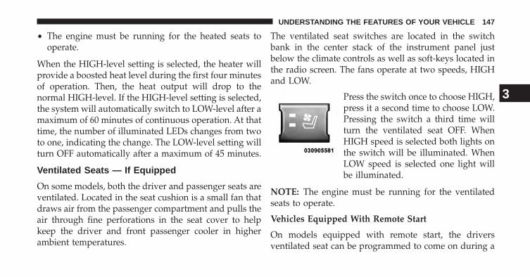
• The engine must be running for the heated seats tooperate.
When the HIGH-level setting is selected, the heater willprovide a boosted heat level during the first four minutesof operation. Then, the heat output will drop to thenormal HIGH-level. If the HIGH-level setting is selected,the system will automatically switch to LOW-level after amaximum of 60 minutes of continuous operation. At thattime, the number of illuminated LEDs changes from twoto one, indicating the change. The LOW-level setting willturn OFF automatically after a maximum of 45 minutes.
Ventilated Seats — If Equipped
On some models, both the driver and passenger seats areventilated. Located in the seat cushion is a small fan thatdraws air from the passenger compartment and pulls theair through fine perforations in the seat cover to helpkeep the driver and front passenger cooler in higherambient temperatures.
The ventilated seat switches are located in the switchbank in the center stack of the instrument panel justbelow the climate controls as well as soft-keys located inthe radio screen. The fans operate at two speeds, HIGHand LOW.
Press the switch once to choose HIGH,press it a second time to choose LOW.Pressing the switch a third time willturn the ventilated seat OFF. WhenHIGH speed is selected both lights onthe switch will be illuminated. WhenLOW speed is selected one light willbe illuminated.
NOTE: The engine must be running for the ventilatedseats to operate.
Vehicles Equipped With Remote Start
On models equipped with remote start, the driversventilated seat can be programmed to come on during a
3
UNDERSTANDING THE FEATURES OF YOUR VEHICLE 147

remote start. Refer to “Remote Starting System — IfEquipped” in “Things to Know Before Starting YourVehicle” for further information.
Manual Seat Adjuster — If Equipped
Both front seats are adjustable forward or rearward. Themanual seat adjustment handle is located under the seatcushion at the front edge of each seat.
While sitting in the seat, pull up on the handle and slidethe seat forward or backward. Release the bar once youhave reached the desired position. Then, using bodypressure, move forward and rearward on the seat to besure that the seat adjusters have latched.
Manual Seat Adjuster
148 UNDERSTANDING THE FEATURES OF YOUR VEHICLE

WARNING!
• Adjusting a seat while driving may be dangerous.Moving a seat while driving could result in loss ofcontrol which could cause a collision and seriousinjury or death.
• Seats should be adjusted before fastening the seatbelts and while the vehicle is parked. Seriousinjury or death could result from a poorly adjustedseat belt.
Dump Feature — Manual Recline Seat Only
Actuating the recliner handle will allow the seatback toswing (dump) forward on manual recliner seats. This“dump” feature allows access to the storage bin behindthe seat.
WARNING!
• Do not stand or lean in front of the seat whileactuating the handle. The seatback may swingforward and hit you causing injury.
• To avoid injury, place your hand on the seatbackand actuate the handle, then position the seatbackin the desired position.
40-20-40 Front Bench Seat — If Equipped
The seat is divided into three segments. The outboardseat portions are each 40% of the total width of the seat.On some models the back of the center portion (20%)easily folds down to provide an armrest/center storagecompartment.
3
UNDERSTANDING THE FEATURES OF YOUR VEHICLE 149

Mega Cab® Rear Seat Features
Reclining Rear Seats — If Equipped
The recliner handle is located on the outside of the seatcushion. To adjust the seatback, lift upward on thehandle, lean back on the seatback and when you reachthe desired position, release the handle.
WARNING!
Do not ride with the seatback reclined so that theshoulder belt is no longer resting against your chest.In a collision you could slide under the seat belt,which could result in serious injury or death.
Rear Seat Recliner Handle
150 UNDERSTANDING THE FEATURES OF YOUR VEHICLE

Folding Rear Seat (Table Mode) — If Equipped
Both the left and right rear seatbacks can be folded downand used as a table.
To fold down either rear seatback:
1. Lift the handle, located next to the head restraint.
2. Fold the seatback forward.
3. Lift the seatback, to return the seat to the uprightposition. Be sure the seatback is locked in place.
Table Mode Handle
Table Mode
3
UNDERSTANDING THE FEATURES OF YOUR VEHICLE 151
Folding Rear Seat — If Equipped
Both the outboard rear seats will drop and move forwardwhen the seatback is folded flat.
WARNING!
• It is dangerous to ride in a cargo area, inside oroutside of a vehicle. In a collision, people riding inthese areas are more likely to be seriously injuredor killed.
• Do not allow people to ride in any area of yourvehicle that is not equipped with seats and seatbelts.
• Be sure everyone in your vehicle is in a seat andusing a seat belt properly.
(Continued)
WARNING! (Continued)• Cargo must be securely tied down before driving
your vehicle. Improperly secured cargo can flyaround in a sudden stop or collision and strikesomeone in the vehicle, causing serious injury ordeath.
To fold either rear seat flat:
1. Lift the handle, located on the outboard side of eitherof the rear seats.
152 UNDERSTANDING THE FEATURES OF YOUR VEHICLE

2. Fold the seatback down and push the seat forward. 3. Lift the seatback, to return the seat to the uprightposition. Be sure the seat is locked in place.
Handle Rear Passenger Fold-Flat Seats
3
UNDERSTANDING THE FEATURES OF YOUR VEHICLE 153

WARNING!
An improperly latched seat could cause serious in-jury or death. Make sure that the seatback is securelylocked into position. If the seatback in not securelylocked into position the seat will not provide theproper stability for child seats and/or passengers.
Head Restraints
Head restraints are designed to reduce the risk of injuryby restricting head movement in the event of a rearimpact. Head restraints should be adjusted so that the topof the head restraint is located above the top of your ear.
WARNING!
The head restraints for all occupants must be prop-erly adjusted prior to operating the vehicle or occu-pying a seat. Head restraints should never be ad-justed while the vehicle is in motion. Driving avehicle with the head restraints improperly adjustedor removed could cause serious injury or death in theevent of a collision.
Front Head Restraints
To raise the head restraint, pull upward on the headrestraint. To lower the head restraint, press the adjust-ment button, located on the base of the head restraint,and push downward on the head restraint.
154 UNDERSTANDING THE FEATURES OF YOUR VEHICLE

Rear Head Restraints
The rear seats are equipped with adjustable head re-straints. To raise the head restraint, pull upward on thehead restraint. To lower the head restraint, press theadjustment button, located on the base of the headrestraint, and push downward on the head restraint.
NOTE:
• The rear center head restraint (Crew Cab and QuadCab) has only one adjustment position that is used toaid in the routing of a tether. Refer to “OccupantRestraints” in “Things to Know Before Starting YourVehicle” for further information.
Adjustment Button Adjustment Button
3
UNDERSTANDING THE FEATURES OF YOUR VEHICLE 155

• The head restraints should only be removed by quali-fied technicians, for service purposes only. If either ofthe head restraints require removal, see your autho-rized dealer.
DRIVER MEMORY SEAT — IF EQUIPPED
This feature allows the driver to store up to two differentmemory profiles for easy recall through a memoryswitch. Each memory profile contains desired positionsettings for the driver seat, side mirrors, adjustablepedals (if equipped) and a set of desired radio stationpresets. Your Remote Keyless Entry (RKE) transmittercan also be programmed to recall the same positionswhen the UNLOCK button is pressed.
NOTE: Your vehicle is equipped with two RKE trans-mitters. One RKE transmitter can be linked to memoryposition 1 and the other transmitter can be linked tomemory position 2.
The memory seat buttons are located on the outboardside of the drivers seat cushion.
Programming The Memory Feature
NOTE: To create a new memory profile, perform thefollowing:
Memory Seat Buttons
156 UNDERSTANDING THE FEATURES OF YOUR VEHICLE

Vehicles Equipped With Keyless Enter-N-Go
1. Without pressing the brake pedal, push the ENGINESTART/STOP button and cycle the ignition to theON/RUN position (Do not start the engine).
2. Adjust all memory profile settings to desired prefer-ences (seat, side mirrors, adjustable pedals and radiostation presets).
3. Press and release the S (Set) button on the memoryswitch.
4. Within five seconds, press and release either of thememory buttons (1) or (2). The Electronic VehicleInformation Center (EVIC) will display whichmemory position has been set.
Vehicles Not Equipped With Keyless Enter-N-Go
1. Insert the ignition key fob, and turn the ignition switchto the ON/RUN position.
2. Adjust all memory profile settings to desired prefer-ences (seat, side mirrors, adjustable pedals [ifequipped], power tilt and telescopic steering column[if equipped], and radio station presets).
3. Press and release the S (Set) button on the memoryswitch.
4. Within five seconds, press and release either of thememory buttons (1) or (2). The Electronic VehicleInformation Center (EVIC) will display whichmemory position has been set.
NOTE:
• Memory profiles can be set without the vehicle inPARK, but the vehicle must be in PARK to recall amemory profile.
• The Recall Memory with Remote Linked to Memoryfeature can be enabled through the Electronic VehicleInformation Center (EVIC), refer to “Electronic Vehicle
3
UNDERSTANDING THE FEATURES OF YOUR VEHICLE 157

Information Center (EVIC)/Customer-ProgrammableFeatures” in “Understanding Your Instrument Panel”for further information.
Linking And Unlinking The Remote Keyless EntryTransmitter To Memory
Your RKE transmitters can be programmed to recall oneof two pre-programmed memory profiles by pressing theUNLOCK button on the RKE transmitter.
NOTE: Before programming your RKE transmitters youmust select the “Remote Linked to Memory” featurethrough the Electronic Vehicle Information Center(EVIC), refer to “Electronic Vehicle Information Center(EVIC)/Customer-Programmable Features” in “Under-standing Your Instrument Panel” for further information.
To program your RKE transmitters, perform the follow-ing:
1. Remove the Key Fob from the ignition (or change theignition to OFF, for vehicles equipped with KeylessEnter-N-Go).
2. Select desired memory profile (1) or (2).
NOTE: If a memory profile has not already been set,refer to �Programming The Memory Feature� for instruc-tions on how to set a memory profile.
3. Once the profile has been recalled, press and releasethe SET (S) button on the memory switch, then pressand release button (1) or (2) accordingly. “MemoryProfile Set” (1 or 2) will display in the instrumentcluster on vehicles equipped with the EVIC.
158 UNDERSTANDING THE FEATURES OF YOUR VEHICLE

4. Press and release the LOCK button on the RKEtransmitter within 10 seconds.
NOTE: Your RKE transmitters can be unlinked to yourmemory settings by following steps 1-4 above and press-ing the UNLOCK button (instead of LOCK) on the RKEtransmitter in Step 4.
Memory Position Recall
NOTE: The vehicle must be in PARK to recall memorypositions. If a recall is attempted when the vehicle is notin PARK, a message will be displayed in the ElectronicVehicle Information Center (EVIC).
Driver One Memory Position Recall
• To recall the memory settings for driver one using thememory switch , press MEMORY button number 1 onthe memory switch.
• To recall the memory settings for driver one using theRKE transmitter, press the UNLOCK button on theRKE transmitter linked to memory position 1.
Driver Two Memory Position Recall
• To recall the memory setting for driver two using thememory switch, press MEMORY button number 2 onthe memory switch.
• To recall the memory settings for driver two using theRKE transmitter, press the UNLOCK button on theRKE transmitter linked to memory position 2.
A recall can be cancelled by pressing any of theMEMORY buttons during a recall (S, 1, or 2). When arecall is cancelled, the driver’s seat, driver’s mirror andthe pedals stop moving. A delay of one second will occurbefore another recall can be selected.
3
UNDERSTANDING THE FEATURES OF YOUR VEHICLE 159

TO OPEN AND CLOSE THE HOOD
To open the hood, two latches must be released.
1. Pull the hood release lever located below the steeringwheel at the base of the instrument panel.
2. Reach into the opening beneath the center of the hoodand push the safety latch lever to the left to release it,before raising the hood.
Hood Release
Safety Latch Location (1500 Series Shown)
160 UNDERSTANDING THE FEATURES OF YOUR VEHICLE

CAUTION!
To prevent possible damage, do not slam the hood toclose it. Use a firm downward push at the front centerof the hood to ensure that both latches engage.
WARNING!
Be sure the hood is fully latched before driving yourvehicle. If the hood is not fully latched, it could openwhen the vehicle is in motion and block your vision.Failure to follow this warning could result in seriousinjury or death.
LIGHTS
The headlight switch is located on the left side of theinstrument panel, next to the steering wheel. The head-light switch controls the operation of the headlights,parking lights, instrument panel lights, cargo lights andfog lights (if equipped).
Headlight Switch Location
3
UNDERSTANDING THE FEATURES OF YOUR VEHICLE 161
Your vehicle is equipped with plastic headlight and foglight (if equipped) lenses that are lighter and less suscep-tible to stone breakage than glass lights. Plastic is not asscratch resistant as glass and therefore different lenscleaning procedures must be followed.
To minimize the possibility of scratching the lenses andreducing light output, avoid wiping with a dry cloth. Toremove road dirt, wash with a mild soap solution fol-lowed by rinsing.
CAUTION!
Do not use abrasive cleaning components, solvents,steel wool or other abrasive materials to clean thelenses.
Headlights
To turn on the headlights, rotate the headlightswitch clockwise to the headlight position.When the headlight switch is on, the parkinglights, taillights, license plate light and instru-
ment panel lights are also turned on. To turn off theheadlights, rotate the headlight switch back to the O (Off)position.
Automatic Headlights — If Equipped
This system automatically turns the headlights on or offaccording to ambient light levels. To turn the system on,rotate the headlight switch to the AUTO position.
162 UNDERSTANDING THE FEATURES OF YOUR VEHICLE

When the system is on, the Headlight Delay feature isalso on. This means the headlights will stay on for up to90 seconds after you turn the ignition switch to the OFFposition. To turn the automatic headlights off, turn theheadlight switch out of the AUTO position.
NOTE: The engine must be running before the head-lights will turn on in the Automatic Mode.
Headlights On With Wipers (Available WithAutomatic Headlights Only)
When this feature is active, the headlights will turn onapproximately 10 seconds after the wipers are turned onif the headlight switch is placed in the AUTO position. Inaddition, the headlights will turn off when the wipers areturned off, if they were turned on by this feature.
Refer to “Electronic Vehicle Information Center (EVIC)/Customer-Programmable Features (SETUP)” in “Under-standing Your Instrument Panel” for further information.
Daytime Running Lights (DRL) — If Equipped
The headlights on your vehicle will illuminate when theengine is started and the transmission is in any gearexcept PARK. This provides a constant �Lights ON�condition until the ignition is turned OFF. The lights
Automatic Headlight Position
3
UNDERSTANDING THE FEATURES OF YOUR VEHICLE 163

illuminate at less than 50% of normal intensity. If theparking brake is applied, the Daytime Running Lights(DRL) will turn OFF. Also, if a turn signal is activated, theDRL lamp on the same side of the vehicle may turn off forthe duration of the turn signal activation. Once the turnsignal is no longer active, the DRL lamp will illuminate.
Headlight Delay
To aid in your exit, your vehicle is equipped with aheadlight delay that will leave the headlights on forapproximately 90 seconds. This delay is initiated whenthe ignition is turned OFF while the headlight switch ison, and then the headlight switch is cycled off. Headlightdelay can be cancelled by either turning the headlightswitch on then off, or by turning the ignition ON.
The headlight delay time is programmable on vehiclesequipped with an Electronic Vehicle Information Center(EVIC). Refer to “Electronic Vehicle Information Center
(EVIC)/Customer-Programmable Features” in “Under-standing Your Instrument Panel” for further information.
SmartBeam™ — If Equipped
The SmartBeam™ system provides increased forwardlighting at night by automating high beam controlthrough the use of a digital camera mounted on theinside rearview mirror. This camera detects vehicle spe-cific light and automatically switches from high beams tolow beams until the approaching vehicle is out of view.
NOTE:
• SmartBeam™ can be turned on or off using theUconnect® System, refer to “Uconnect® Settings” in“Understanding Your Instrument Panel” for furtherinformation.
• Broken, muddy, or obstructed headlights and taillightsof vehicles in the field of view will cause headlights toremain on longer (closer to the vehicle). Also, dirt, film,
164 UNDERSTANDING THE FEATURES OF YOUR VEHICLE

and other obstructions on the windshield or cameralens will cause the system to function improperly.
If the windshield or SmartBeam™ mirror is replaced, theSmartBeam™ mirror must be re-aimed to ensure properperformance. See your local authorized dealer.
To Activate
1. Select “Automatic High Beams — ON” through theEVIC. Refer to “Electronic Vehicle Information Center(EVIC)/Customer-Programmable Features” in “Un-derstanding Your Instrument Panel” for further infor-mation.
2. Rotate the headlight switch counterclockwise to theAUTO (A) position.
3. Push the multifunction lever away from you to switchthe headlights to the high beam position. Refer to“Multifunction Lever” in this section for further infor-mation.
NOTE: This system will not activate until the vehicle isat, or above, 25 mph (40 km/h).
To Deactivate
Perform either of the following steps to deactivate theSmartBeam™ system.
1. Select “Automatic High Beams — OFF” through theEVIC. Refer to “Electronic Vehicle Information Center(EVIC)/Customer-Programmable Features” in “Un-derstanding Your Instrument Panel” for further infor-mation.
2. Pull the multifunction lever toward you to switch theheadlights from the high beam to the low beamposition.
3. Rotate the headlight switch clockwise from the AUTO(A) to the on position.
3
UNDERSTANDING THE FEATURES OF YOUR VEHICLE 165

Parking Lights And Panel Lights
To turn on the parking lights and instrumentpanel lights, rotate the headlight switch clockwise.
To turn off the parking lights, rotate the headlight switchback to the O (Off) position.
Fog Lights — If Equipped
The fog lights are turned on by rotating the headlightswitch to the parking light or headlight position andpushing in the headlight rotary control.
The fog lights will operate only when the parking lightsare on or when the vehicle headlights are on low beam.An indicator light located in the instrument cluster willilluminate when the fog lights are on. The fog lights will
Fog Light Switch
166 UNDERSTANDING THE FEATURES OF YOUR VEHICLE

turn off when the switch is pushed a second time, whenthe headlight switch is rotated to the off position, or thehigh beam is selected.
Lights-On Reminder
If the headlights, parking lights, or cargo lights are left onafter the ignition is turned OFF, a chime will sound whenthe driver’s door is opened.
Battery Saver
To protect the life of your vehicle’s battery, load sheddingis provided for both the interior and exterior lights.
If the ignition is OFF and any door is left ajar for 10minutes or the dimmer control is rotated all the way upto the dome ON position for 10 minutes, the interiorlights will automatically turn off.
If the headlights remain on while the ignition is cycledOFF, the exterior lights will automatically turn off after
eight minutes. If the headlights are turned on and left onfor eight minutes while the ignition is OFF, the exteriorlights will automatically turn off.
NOTE: Battery saver mode is cancelled if the ignition isON.
Interior Lights
Courtesy and dome lights are turned on when the frontdoors are opened, when the dimmer control (rotatingwheel on the bottom of the switch) is rotated to the farright detent position, or if equipped, when the UNLOCKbutton is pressed on the Remote Keyless Entry (RKE)transmitter. When a door is open and the interior lightsare on, rotating the dimmer control all the way left, to theOFF detent, will cause all the interior lights to go out.This is also known as the �Party� mode because it allowsthe doors to stay open for extended periods of timewithout discharging the vehicle’s battery.
3
UNDERSTANDING THE FEATURES OF YOUR VEHICLE 167

The brightness of the instrument panel as well as theambient lighting can be regulated by rotating the dimmercontrol right (brighter) or left (dimmer). When the head-lights are on you can supplement the brightness of theodometer, trip odometer, radio and overhead console byrotating the control to the right until you hear a click. Thisfeature is termed the “Parade” mode and is useful whenheadlights are required during the day.
Courtesy/Reading Lights
Both lights in the overhead console and rear passengercompartment will illuminate as courtesy lights when adoor is opened, when the dimmer control is rotated to thecourtesy light position (full right position), or when theUNLOCK button is pressed on the Remote Keyless Entry
Dimmer Control
168 UNDERSTANDING THE FEATURES OF YOUR VEHICLE

(RKE) transmitter, if equipped. These lights are alsooperated individually as reading lights by pressing onthe corresponding lens.
NOTE: The courtesy/reading lights will remain on untilthe switch is pressed a second time, so be sure they havebeen turned off before leaving the vehicle. If the interiorlights are left on after the ignition is turned OFF, they willautomatically turn off after 15 minutes.
Front Courtesy/Reading Lights
Rear Passenger Courtesy/Reading Light
3
UNDERSTANDING THE FEATURES OF YOUR VEHICLE 169

Ambient Light
The overhead console is equipped with an ambient lightfeature. This light casts illumination for improved visibil-ity of the floor console area.
Cargo Light
The cargo lights are turned on by pressing on the cargobutton.
The cargo lights will also turn on for approximately 30seconds when a RKE transmitter UNLOCK button ispressed, as part of the Illuminated Entry feature.
Ambient LightCargo Light Switch
170 UNDERSTANDING THE FEATURES OF YOUR VEHICLE

Multifunction Lever
The multifunction lever is located on the left side of thesteering column.
Turn Signals
Move the multifunction lever up or down and the arrowson each side of the instrument cluster flash to showproper operation of the front and rear turn signal lights.
NOTE: If either light remains on and does not flash, orthere is a very fast flash rate, check for a defective outsidelight bulb. If an indicator fails to light when the lever ismoved, it would suggest that the indicator bulb isdefective.
Turn Signal Lever
3
UNDERSTANDING THE FEATURES OF YOUR VEHICLE 171

Lane Change Assist
Tap the lever up or down once, without moving beyondthe detent, and the turn signal (right or left) will flashthree times then automatically turn off.
Flash-To-Pass
You can signal another vehicle with your headlights bypartially pulling the multifunction lever toward the steer-ing wheel. This will cause the high beam headlights toturn on until the lever is released.
High/Low Beam Switch
Push the multifunction lever toward the instrumentpanel to switch the headlights to high beam. Pulling themultifunction lever back toward the steering wheel willturn the low beams back on, or shut the high beams off.
WINDSHIELD WIPERS AND WASHERS
Windshield Wipers
The wipers and washers are operated by a switch in themultifunction lever. Turn the end of the handle to selectthe desired wiper speed.
High/Low Beam Switch
172 UNDERSTANDING THE FEATURES OF YOUR VEHICLE

Windshield Wiper Operation
Rotate the end of the lever upward, to the first detent pastthe intermittent settings for low-speed wiper operation.Rotate the end of the lever upward to the second detentpast the intermittent settings for high-speed wiper opera-tion.
Intermittent Wiper System
The intermittent feature of this system was designed foruse when weather conditions make a single wiping cycle,with a variable pause between cycles, desirable. Formaximum delay between cycles, rotate the control knobinto the upper end of the delay range.
The delay interval decreases as you rotate the knob untilit enters the low continual speed position. The delay canbe regulated from a maximum of about 18 secondsbetween cycles, to a cycle every one second. The delayintervals will double in duration when the vehicle speedis 10 mph (16 km/h) or less.
Windshield Washers
To use the windshield washer, push the washer knob,located on the end of the multifunction lever, inward tothe second detent. Washer fluid will be sprayed and thewiper will operate for two to three cycles after the washerknob is released from this position. If the washer knob is
Windshield Wiper/Washer Switch
3
UNDERSTANDING THE FEATURES OF YOUR VEHICLE 173

depressed while in the delay range, the wiper willoperate for several seconds after the washer knob isreleased. It will then resume the intermittent intervalpreviously selected. If the washer knob is pushed whilein the off position, the wiper will turn on and cycleapproximately three times after the wash knob is re-leased.
To prevent freeze-up of your windshield washer systemin cold weather, select a solution or mixture that meets orexceeds the temperature range of your climate. Thisrating information can be found on most washer fluidcontainers.
WARNING!
Sudden loss of visibility through the windshieldcould lead to a collision. You might not see othervehicles or other obstacles. To avoid sudden icing of
(Continued)
WARNING! (Continued)the windshield during freezing weather, warm thewindshield with the defroster before and duringwindshield washer use.
Mist Feature
When a single wipe to clear off road mist or spray froma passing vehicle is needed, push the washer knob,located on the end of the multifunction lever, inward tothe first detent and release. The wipers will cycle onetime and automatically shut off.
NOTE: The mist feature does not activate the washerpump; therefore, no washer fluid will be sprayed on thewindshield. The wash function must be used in order tospray the windshield with washer fluid.
174 UNDERSTANDING THE FEATURES OF YOUR VEHICLE
Rain Sensing Wipers — If Equipped
This feature senses moisture on the windshield andautomatically activates the wipers for the driver. Thefeature is especially useful for road splash or oversprayfrom the windshield washers of the vehicle ahead. Rotatethe end of the multifunction lever to one of five settingsto activate this feature.
The sensitivity of the system can be adjusted with themultifunction lever. Wiper delay position 1 is the leastsensitive, and wiper delay position 5 is the most sensi-tive. Setting 3 should be used for normal rain conditions.Settings 1 and 2 can be used if the driver desires lesswiper sensitivity. Setting 5 can be used if the driverdesires more sensitivity. Place the wiper switch in theOFF position when not using the system.
NOTE:
• The Rain Sensing feature will not operate when thewiper switch is in the low or high-speed position.
• The Rain Sensing feature may not function properlywhen ice, or dried salt water is present on thewindshield.
• Use of Rain-X® or products containing wax or siliconemay reduce Rain Sensing performance.
• A customer programmable feature in the ElectronicVehicle Information Center (EVIC) allows the RainSensing feature to be turned off. Refer to “ElectronicVehicle Information Center (EVIC)/Personal Settings(Customer-Programmable Features)” in “Understand-ing Your Instrument Panel” for further information.
The Rain Sensing system has protection features for thewiper blades and arms, and will not operate under thefollowing conditions:
• Low Ambient Temperature — When the ignition isfirst turned ON, the Rain Sensing system will not
3
UNDERSTANDING THE FEATURES OF YOUR VEHICLE 175

operate until the wiper switch is moved, vehicle speedis greater than 0 mph (0 km/h), or the outside tem-perature is greater than 32°F (0°C).
• Transmission In NEUTRAL Position — When theignition is ON, and the transmission is in the NEU-TRAL position, the Rain Sensing system will notoperate until the wiper switch is moved, vehicle speedis greater than 5 mph (8 km/h), or the shift lever ismoved out of the NEUTRAL position.
Remote Start Mode Inhibit — On vehicles equippedwith Remote Starting system, Rain Sensing wipers arenot operational when the vehicle is in the remote startmode. Once the operator is in the vehicle and has placedthe ignition switch in the RUN position, rain sensingwiper operation can resume, if it has been selected, andno other inhibit conditions (mentioned previously) exist.
TILT STEERING COLUMN
This feature allows you to tilt the steering columnupward or downward. The tilt lever is located on thesteering column, below the multifunction lever.
Pull the lever toward the steering wheel to unlock thesteering column. With one hand firmly on the steeringwheel, move the steering column up or down, as desired.Release the lever to lock the steering column firmly inplace.
176 UNDERSTANDING THE FEATURES OF YOUR VEHICLE

WARNING!
Do not adjust the steering column while driving.Adjusting the steering column while driving or driv-ing with the steering column unlocked, could cause
(Continued)
WARNING! (Continued)the driver to lose control of the vehicle. Failure tofollow this warning may result in serious injury ordeath.
HEATED STEERING WHEEL — IF EQUIPPED
The steering wheel contains a heating element that helpswarm your hands in cold weather. The heated steeringwheel has only one temperature setting. Once the heatedsteering wheel has been turned on it will operate forapproximately 30 to 80 minutes before automaticallyshutting off. The heated steering wheel can shut off earlyor may not turn on when the steering wheel is alreadywarm.
Tilt Steering Lever
3
UNDERSTANDING THE FEATURES OF YOUR VEHICLE 177

The heated steering wheel switch is located on the switchbank below the climate controls. There are also soft-keysin the radio screen that will activate the heated steeringwheel.
Press the switch to turn on the heatedsteering wheel. The light on the switchwill illuminate to indicate the steeringwheel heater is on. Pressing the switcha second time will turn off the heatedsteering wheel and light indicator.
NOTE: The engine must be running for the heatedsteering wheel to operate.
Vehicles Equipped With Remote Start
On models that are equipped with remote start, theheated steering wheel can be programmed to come onduring a remote start. Refer to “Remote Starting System
— If Equipped” in “Things to Know Before Starting YourVehicle” for further information.
WARNING!
• Persons who are unable to feel pain to the skinbecause of advanced age, chronic illness, diabetes,spinal cord injury, medication, alcohol use, exhaus-tion, or other physical conditions must exercisecare when using the steering wheel heater. It maycause burns even at low temperatures, especially ifused for long periods.
• Do not place anything on the steering wheel thatinsulates against heat, such as a blanket or steeringwheel covers of any type and material. This maycause the steering wheel heater to overheat.
178 UNDERSTANDING THE FEATURES OF YOUR VEHICLE

DRIVER ADJUSTABLE PEDALS — IF EQUIPPED
The adjustable pedals system is designed to allow agreater range of driver comfort for steering wheel tilt andseat position. This feature allows the brake, accelerator,and clutch pedals (if equipped) to move toward or awayfrom the driver to provide improved position with thesteering wheel.
The adjustable pedal switch is located to the left side ofthe steering column.
• The pedals can be adjusted with the ignition OFF.
• The pedals cannot be adjusted when the vehicle is inREVERSE or when the Electronic Speed Control Sys-tem is on. The following messages will be displayed onvehicles equipped with the Electronic Vehicle Informa-tion System (EVIC) if the pedals are attempted to be
Adjustable Pedals Switch
3
UNDERSTANDING THE FEATURES OF YOUR VEHICLE 179

adjusted when the system is locked out (“AdjustablePedal Disabled — Cruise Control Engaged” or “Ad-justable Pedal Disabled — Vehicle In Reverse”.
NOTE:
• Always adjust the pedals to a position that allows fullpedal travel.
• Further small adjustments may be necessary to findthe best possible seat/pedal position.
CAUTION!
Do not place any article under the adjustable pedalsor impede its ability to move as it may cause damageto the pedal controls. Pedal travel may become lim-ited if movement is stopped by an obstruction in theadjustable pedal’s path.
WARNING!
Do not adjust the pedals while the vehicle is moving.You could lose control and have an accident. Alwaysadjust the pedals while the vehicle is parked.
ELECTRONIC SPEED CONTROL
When engaged, the Electronic Speed Control takes overaccelerator operations at speeds greater than 25 mph(50 km/h).
The Electronic Speed Control buttons are located on theright side of the steering wheel.
180 UNDERSTANDING THE FEATURES OF YOUR VEHICLE

NOTE: In order to ensure proper operation, the Elec-tronic Speed Control System has been designed to shutdown if multiple Speed Control functions are operated atthe same time. If this occurs, the Electronic Speed ControlSystem can be reactivated by pushing the ElectronicSpeed Control ON/OFF button and resetting the desiredvehicle set speed.
To Activate
Push the ON/OFF button. The Cruise Indicator Light inthe instrument cluster will illuminate. To turn the systemoff, push the ON/OFF button a second time. The CruiseIndicator Light will turn off. The system should beturned off when not in use.
Electronic Speed Control Switches
1 — ON/OFF 2 — RES +4 — CANCEL 3 — SET -
3
UNDERSTANDING THE FEATURES OF YOUR VEHICLE 181

WARNING!
Leaving the Electronic Speed Control system onwhen not in use is dangerous. You could accidentallyset the system or cause it to go faster than you want.You could lose control and have an accident. Alwaysleave the system OFF when you are not using it.
To Set A Desired Speed
Turn the Electronic Speed Control ON. When the vehiclehas reached the desired speed, press the SET (-) buttonand release. Release the accelerator and the vehicle willoperate at the selected speed.
NOTE: The vehicle should be traveling at a steady speedand on level ground before pressing the SET button.
To Deactivate
A soft tap on the brake pedal, pushing the CANCELbutton, or normal brake pressure while slowing the
vehicle will deactivate Electronic Speed Control withouterasing the set speed memory. Pressing the ON/OFFbutton or turning the ignition switch OFF erases the setspeed memory.
To Resume Speed
To resume a previously set speed, push the RES (+)button and release. Resume can be used at any speedabove 20 mph (32 km/h).
To Vary The Speed Setting
When the Electronic Speed Control is set, you can in-crease speed by pushing the RES (+) button. If the buttonis continually pressed, the set speed will continue toincrease until the button is released, then the new setspeed will be established.
Pressing the RES (+) button once will result in a 1 mph(1.6 km/h) increase in set speed. Each subsequent tap ofthe button results in an increase of 1 mph (1.6 km/h).
182 UNDERSTANDING THE FEATURES OF YOUR VEHICLE
To decrease speed while the Electronic Speed Control isset, push the SET (-) button. If the button is continuallyheld in the SET (-) position, the set speed will continue todecrease until the button is released. Release the buttonwhen the desired speed is reached, and the new set speedwill be established.
Pressing the SET (-) button once will result in a 1 mph(1.6 km/h) decrease in set speed. Each subsequent tap ofthe button results in a decrease of 1 mph (1.6 km/h).
To Accelerate For Passing
Press the accelerator as you would normally. When thepedal is released, the vehicle will return to the set speed.
Using Electronic Speed Control On Hills
The transmission may downshift on hills to maintain thevehicle set speed.
NOTE: The Electronic Speed Control system maintainsspeed up and down hills. A slight speed change onmoderate hills is normal.
On steep hills, a greater speed loss or gain may occur soit may be preferable to drive without Electronic SpeedControl.
WARNING!
Electronic Speed Control can be dangerous where thesystem cannot maintain a constant speed. Your ve-hicle could go too fast for the conditions, and youcould lose control and have an accident. Do not useElectronic Speed Control in heavy traffic or on roadsthat are winding, icy, snow-covered or slippery.
3
UNDERSTANDING THE FEATURES OF YOUR VEHICLE 183

PARKSENSE® REAR PARK ASSIST — IFEQUIPPED
The ParkSense® Rear Park Assist system provides visualand audible indications of the distance between the rearfascia and a detected obstacle when backing up, e.g.during a parking maneuver. Refer to ParkSense® SystemUsage Precautions for limitations of this system andrecommendations.
ParkSense® will retain the last system state (enabled ordisabled) from the last ignition cycle when the ignition ischanged to the ON/RUN position.
ParkSense® can be active only when the shift lever is inREVERSE. If ParkSense® is enabled at this shift lever
position, the system will remain active until the vehiclespeed is increased to approximately 7 mph (11 km/h) orabove. The system will become active again if the vehiclespeed is decreased to speeds less than approximately6 mph (9 km/h).
ParkSense® Sensors
The four ParkSense® sensors, located in the rear fascia/bumper, monitor the area behind the vehicle that iswithin the sensors’ field of view. The sensors can detectobstacles from approximately 18 in (45 cm) up to 79 in(200 cm) from the rear fascia/bumper in the horizontaldirection, depending on the location, type and orienta-tion of the obstacle.
184 UNDERSTANDING THE FEATURES OF YOUR VEHICLE

ParkSense® Warning Display
The ParkSense® Warning screen will only be displayed ifSound and Display is selected from the Customer- Pro-grammable Features section of the Electronic VehicleInformation Center (EVIC) or from the Uconnect Touch®System (if available). Refer to “Electronic Vehicle Infor-mation Center (EVIC)/Personal Settings (Customer-Programmable Features)” or �Uconnect Touch® Settings”(if available) in “Understanding Your Instrument Panel”for further information.
The ParkSense® Warning screen is located within theElectronic Vehicle Information Center (EVIC). It providesvisual warnings to indicate the distance between the rearfascia/bumper and the detected obstacle. Refer to “Elec-tronic Vehicle Information Center (EVIC)/Settings” inUnderstanding Your Instrument Panel” for further infor-mation.
ParkSense® Display
When the vehicle is in REVERSE, the warning displaywill turn ON indicating the system status.
The system will indicate a detected obstacle by showinga single arc in the left and/or right rear regions based onthe object’s distance and location relative to the vehicle.
If an object is detected in the left and/or right rear region,the display will show a single solid arc in the left and/orright rear region and the system will produce a tone. Asthe vehicle moves closer to the object, the display willshow the single arc moving closer to the vehicle and thetone will change from a single 1/2 second tone to slow, tofast, to continuous.
3
UNDERSTANDING THE FEATURES OF YOUR VEHICLE 185

Single 1/2 Second Tone Slow Tone
186 UNDERSTANDING THE FEATURES OF YOUR VEHICLE
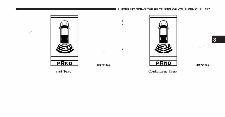
Fast Tone Continuous Tone
3
UNDERSTANDING THE FEATURES OF YOUR VEHICLE 187
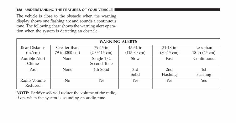
The vehicle is close to the obstacle when the warningdisplay shows one flashing arc and sounds a continuoustone. The following chart shows the warning alert opera-tion when the system is detecting an obstacle:
WARNING ALERTSRear Distance
(in/cm)Greater than
79 in (200 cm)79-45 in
(200-115 cm)45-31 in
(115-80 cm)31-18 in
(80-45 cm)Less than
18 in (45 cm)Audible Alert
ChimeNone Single 1/2
Second ToneSlow Fast Continuous
Arc None 4th Solid 3rdSolid
2ndFlashing
1stFlashing
Radio VolumeReduced
No Yes Yes Yes Yes
NOTE: ParkSense® will reduce the volume of the radio,if on, when the system is sounding an audio tone.
188 UNDERSTANDING THE FEATURES OF YOUR VEHICLE

Enabling And Disabling ParkSense®
ParkSense® can be enabled and disabled with theParkSense® switch.
When the ParkSense switch is pressed to dis-able the system, the instrument cluster willdisplay the “PARKSENSE OFF” message forapproximately five seconds. Refer to “Elec-
tronic Vehicle Information Center (EVIC)” in “Under-standing Your Instrument Panel” for further information.When the shift lever is moved to REVERSE and thesystem is disabled, the EVIC will display the“PARKSENSE OFF” message for as long as the vehicle isin REVERSE.
NOTE: The ParkSense® system will automatically dis-able when the system detects that a trailer with trailerbrakes has been connected to the Integrated Trailer BrakeModule. The EVIC will display “PARKSENSE OFF”message for as long as the vehicle is in reverse.
The ParkSense® switch LED will be ON whenParkSense® is disabled or defective. The ParkSense®switch LED will be OFF when the system is enabled.
Service The ParkSense® Rear Park AssistSystem
When the ParkSense® Rear Park Assist System is mal-functioning, the instrument cluster will actuate a singlechime, once per ignition cycle, and it will display the�PARKSENSE UNAVAILABLE WIPE REAR SENSORS�or the �PARKSENSE UNAVAILABLE SERVICE RE-QUIRED� message. Refer to “Electronic Vehicle Informa-tion Center (EVIC)” in “Understanding Your InstrumentPanel” for further information. When the shift lever ismoved to REVERSE and the system has detected afaulted condition, the EVIC will display the�PARKSENSE UNAVAILABLE WIPE REAR SENSORS�
3
UNDERSTANDING THE FEATURES OF YOUR VEHICLE 189

or the �PARKSENSE UNAVAILABLE SERVICE RE-QUIRED� message for as long as the vehicle is in RE-VERSE. Under this condition, ParkSense® will not oper-ate.
If �PARKSENSE UNAVAILABLE WIPE REAR SENSORS�appears in the Electronic Vehicle Information Center(EVIC) make sure the outer surface and the underside ofthe rear fascia/bumper is clean and clear of snow, ice,mud, dirt or other obstruction, and then cycle the igni-tion. If the message continues to appear, see an autho-rized dealer.
If �PARKSENSE UNAVAILABLE SERVICE REQUIRED�appears in the EVIC, see your authorized dealer.
Cleaning The ParkSense® System
Clean the ParkSense® sensors with water, car wash soapand a soft cloth. Do not use rough or hard cloths. Do notscratch or poke the sensors. Otherwise, you could dam-age the sensors.
ParkSense® System Usage Precautions
NOTE:
• Ensure that the rear bumper is free of snow, ice, mud,dirt and debris to keep the ParkSense® system oper-ating properly.
• Jackhammers, large trucks, and other vibrations couldaffect the performance of ParkSense®.
• When you turn ParkSense® off, the instrument clusterwill display �PARKSENSE OFF�. Furthermore, onceyou turn ParkSense® off, it remains off until you turnit on again, even if you cycle the ignition key.
• When you move the shift lever to the REVERSEposition and ParkSense® is turned off, the instrumentcluster will display �PARKSENSE OFF� message for aslong as the vehicle is in REVERSE.
190 UNDERSTANDING THE FEATURES OF YOUR VEHICLE

• ParkSense®, when on, will reduce the volume of theradio when it is sounding a tone.
• Clean the ParkSense® sensors regularly, taking carenot to scratch or damage them. The sensors must notbe covered with ice, snow, slush, mud, dirt or debris.Failure to do so can result in the system not workingproperly. The ParkSense® system might not detect anobstacle behind the fascia/bumper, or it could providea false indication that an obstacle is behind thefascia/bumper.
• Objects such as bicycle carriers, trailer hitches, etc.,must not be placed within 12 in (30 cm) from the rearfascia/bumper while driving the vehicle. Failure to doso can result in the system misinterpreting a closeobject as a sensor problem, causing the �PARKSENSEUNAVAILABLE SERVICE REQUIRED� message to bedisplayed in the instrument cluster.
• On vehicles equipped with a tailgate, ParkSense®should be disabled when the tailgate is in the loweredor open position and the vehicle is in REVERSE. Alowered tailgate could provide a false indication thatan obstacle is behind the vehicle.
CAUTION!
• ParkSense® is only a parking aid and it is unable torecognize every obstacle, including small obstacles.Parking curbs might be temporarily detected or notdetected at all. Obstacles located above or belowthe sensors will not be detected when they are inclose proximity.
• The vehicle must be driven slowly when usingParkSense® in order to be able to stop in timewhen an obstacle is detected. It is recommendedthat the driver looks over his/her shoulder whenusing ParkSense®.
3
UNDERSTANDING THE FEATURES OF YOUR VEHICLE 191
WARNING!
• Drivers must be careful when backing up evenwhen using ParkSense®. Always check carefullybehind your vehicle, look behind you, and be sureto check for pedestrians, animals, other vehicles,obstructions, and blind spots before backing up.You are responsible for safety and must continue topay attention to your surroundings. Failure to do socan result in serious injury or death.
(Continued)
WARNING! (Continued)• Before using ParkSense®, it is strongly recom-
mended that the ball mount and hitch ball assem-bly is disconnected from the vehicle when thevehicle is not used for towing. Failure to do so canresult in injury or damage to vehicles or obstaclesbecause the hitch ball will be much closer to theobstacle than the rear fascia when the loudspeakersounds the continuous tone. Also, the sensorscould detect the ball mount and hitch ball assem-bly, depending on its size and shape, giving a falseindication that an obstacle is behind the vehicle.
192 UNDERSTANDING THE FEATURES OF YOUR VEHICLE

PARKVIEW® REAR BACK UP CAMERA — IFEQUIPPED
Your vehicle may be equipped with the ParkView® RearBack Up Camera that allows you to see a image of therear surroundings of your vehicle whenever the shiftlever is put into REVERSE. The image will be displayedin the rearview mirror — if equipped or Uconnect®screen — if equipped along with a caution note to “checkentire surroundings” across the top of the screen. Afterfive seconds this note will disappear. The ParkView®camera is located to the left of the tailgate handle.
When the vehicle is shifted out of REVERSE, the rearcamera mode is exited.
Active guide lines are overlaid on the image to illustratethe width of the vehicle and its projected backup pathbased on the steering wheel position. The active guidelines will show separate zones that will help indicate thedistance to the rear of the vehicle.
The following table shows the approximate distances foreach zone:
Zones Distance to the rear of the vehicleRed 0 - 1 ft (0 - 30 cm)
Yellow 1 ft - 3 ft (30 cm - 1 m)Green 3 ft or greater (1 m or greater)
WARNING!
Drivers must be careful when backing up even whenusing the ParkView® Rear Back Up Camera. Alwayscheck carefully behind your vehicle, and be sure tocheck for pedestrians, animals, other vehicles, ob-structions, or blind spots before backing up. You areresponsible for the safety of your surroundings andmust continue to pay attention while backing up.Failure to do so can result in serious injury or death.
3
UNDERSTANDING THE FEATURES OF YOUR VEHICLE 193

CAUTION!
• To avoid vehicle damage, ParkView® should onlybe used as a parking aid. The ParkView® camera isunable to view every obstacle or object in yourdrive path.
• To avoid vehicle damage, the vehicle must bedriven slowly when using ParkView® to be able tostop in time when an obstacle is seen. It is recom-mended that the driver look frequently over his/hershoulder when using ParkView®.
NOTE: If snow, ice, mud, or any foreign substance buildsup on the camera lens, clean the lens, rinse with water,and dry with a soft cloth. Do not cover the lens.
Turning ParkView® On Or Off — With Uconnect® 5.0
1. Press the “Settings” button.
2. Press the “Safety & Assistance” soft-key.
3. Press the check box soft key next to “Parkview®Backup Camera” to enable/disable.
Turning ParkView® On Or Off — With Uconnect®8.4A/8.4AN
1. Press the “Settings” soft-key.
2. Press the “Safety & Driving Assistance” soft-key.
3. Press the check box soft key next to “Parkview®Backup Camera” to enable/disable.
OVERHEAD CONSOLE — IF EQUIPPED
The overhead console is located on the headliner abovethe review mirror. The overhead console contains thefollowing features:• Courtesy/Reading Lights• Power Sunroof Switch — If Equipped
• Power Sliding Rear Window Switch — If Equipped• Universal Garage Door Opener — If Equipped
194 UNDERSTANDING THE FEATURES OF YOUR VEHICLE

Courtesy/Reading Lights
Both lights in the overhead console and rear passengercompartment will illuminate as courtesy lights when adoor is opened, when the dimmer control is rotated to thecourtesy light position (full right position), or when theUNLOCK button is pressed on the Remote Keyless Entry
(RKE) transmitter, if equipped. These lights are alsooperated individually as reading lights by pressing onthe corresponding lens.
Overhead Console
Front Courtesy/Reading Lights
3
UNDERSTANDING THE FEATURES OF YOUR VEHICLE 195

NOTE: The courtesy/reading lights will remain on untilthe switch is pressed a second time, so be sure they havebeen turned off before leaving the vehicle. If the interiorlights are left on after the ignition is turned OFF, they willautomatically turn off after 15 minutes.
GARAGE DOOR OPENER — IF EQUIPPED
HomeLink® replaces up to three hand-held transmittersthat operate devices such as garage door openers, motor-ized gates, lighting or home security systems. TheHomeLink® unit is powered by your vehicles 12 Voltbattery.
The HomeLink® buttons that are located in the overheadconsole designate the three different HomeLink® chan-nels.
Rear Passenger Courtesy/Reading Light
196 UNDERSTANDING THE FEATURES OF YOUR VEHICLE

NOTE: HomeLink® is disabled when the Vehicle Secu-rity Alarm is active.
Before You Begin Programming HomeLink®
Ensure your vehicle is parked outside of the garagebefore you begin programming.
For efficient programming and accurate transmission ofthe radio-frequency signal it is recommended that a newbattery be placed in the hand-held transmitter of thedevice that is being programmed to the HomeLink®system.
Erase all channels before you begin programming. Toerase the channels place the ignition in the ON/RUNposition and press and hold the two outside HomeLink®buttons (I and III) for up 20 seconds. The ElectronicVehicle Information Center (EVIC) will display “CLEAR-ING CHANNELS”. Release the buttons when the EVICdisplays “CHANNELS CLEARED”.
HomeLink® Buttons
3
UNDERSTANDING THE FEATURES OF YOUR VEHICLE 197

NOTE:
• Erasing all channels should only be performed whenprogramming HomeLink® for the first time. Do noterase channels when programming additional buttons.
• If you have any problems, or require assistance, pleasecall toll-free 1–800–355–3515 or, on the Internet atwww.HomeLink.com for information or assistance.
Programming A Rolling Code
For programming garage door openers that were manu-factured after 1995. These garage door openers can beidentified by the “LEARN” or “TRAIN” button locatedwhere the hanging antenna is attached to the garage dooropener. It is NOT the button that is normally used toopen and close the door. The name and color of thebutton may vary by manufacturer. 1. Turn the ignition switch to the ON/RUN position.
Training The Garage Door Opener
1 — Door Opener2 — Training Button
198 UNDERSTANDING THE FEATURES OF YOUR VEHICLE

2. Place the hand-held transmitter 1 to 3 inches (3 to 8cm) away from the HomeLink® button you wish toprogram.
3. Simultaneously press and hold both the Homelink®button you want to program and the hand-held trans-mitter button.
4. Continue to hold buttons until the EVIC displaychanges from “CHANNEL # TRAINING” to “CHAN-NEL # TRAINED”, then release both buttons.
NOTE:
• It may take up to 30 seconds or longer in some casesfor the channel to train.
• If the EVIC displays “DID NOT TRAIN” repeat fromStep 2.
5. At the garage door opener motor (in the garage),locate the “LEARN” or “TRAINING” button. This canusually be found where the hanging antenna wire isattached to the garage door opener/device motor.Firmly press and release the “LEARN” or “TRAIN-ING” button. On some garage door openers/devicesthere may be a light that blinks when the garage dooropener/device is in the LEARN/TRAIN mode.
NOTE: You have 30 seconds in which to initiate the nextstep after the LEARN button has been pressed.
6. Return to the vehicle and press the programmedHomeLink® button twice (holding the button for twoseconds each time). The EVIC will display “CHAN-NEL # TRANSMIT”. If the garage door opener/deviceactivates, programming is complete.
NOTE: If the garage door opener/device does not acti-vate, press the button a third time (for two seconds) tocomplete the training.
3
UNDERSTANDING THE FEATURES OF YOUR VEHICLE 199

To program the remaining two HomeLink® buttons,repeat each step for each remaining button. DO NOTerase the channels.
Reprogramming A Single HomeLink® Button
To reprogram a channel that has been previously trained,follow these steps:
1. Turn the ignition switch to the ON/RUN position.
2. Press and hold the desired HomeLink® button untilthe EVIC displays “CHANNEL # TRAINING” Do notrelease the button.
3. Without releasing the button proceed with “Program-ming A Rolling Code” Step 2 and follow all remainingsteps.
Programming A Non-Rolling Code
For programming Garage Door Openers manufacturedbefore 1995.
1. Turn the ignition switch to the ON/RUN position.
2. Place the hand-held transmitter 1 to 3 inches (3 to 8cm) away from the HomeLink® button you wish toprogram.
3. Simultaneously press and hold both the Homelink®button you want to program and the hand-held trans-mitter button.
4. Continue to hold buttons until the EVIC displaychanges from “CHANNEL # TRAINING” to “CHAN-NEL # TRAINED”, then release both buttons.
NOTE:
• It may take up to 30 seconds or longer in some casesfor the channel to train.
• If the EVIC displays “DID NOT TRAIN” repeat fromStep 2.
200 UNDERSTANDING THE FEATURES OF YOUR VEHICLE

5. Press and hold the programmed HomeLink® button.The EVIC will display “CHANNEL # TRANSMIT”. Ifthe garage door opener/device activates, program-ming is complete.
To program the remaining two HomeLink® buttons,repeat each step for each remaining button. DO NOTerase the channels.
Reprogramming A Single HomeLink® Button
To reprogram a channel that has been previously trained,follow these steps:
1. Cycle the ignition to the ON/RUN position.
2. Press and hold the desired HomeLink® button untilthe indicator light begins to flash after 20 seconds. Donot release the button.
3. Without releasing the button proceed with “Program-ming A Non-Rolling Code” Step 2 and follow allremaining steps.
Canadian/Gate Operator Programming
For programming transmitters in Canada/United Statesthat require the transmitter signals to “time-out” afterseveral seconds of transmission.
Canadian radio frequency laws require transmitter sig-nals to time-out (or quit) after several seconds of trans-mission – which may not be long enough for HomeLink®to pick up the signal during programming. Similar to thisCanadian law, some U.S. gate operators are designed totime-out in the same manner.
It may be helpful to unplug the device during the cyclingprocess to prevent possible overheating of the garagedoor or gate motor.
1. Turn the ignition switch to the ON/RUN position.
2. Place the hand-held transmitter 1 to 3 inches (3 to 8cm) away from the HomeLink® button you wish toprogram.
3
UNDERSTANDING THE FEATURES OF YOUR VEHICLE 201

3. Simultaneously press and hold both the Homelink®button while you press and release (“cycle”), yourhand-held transmitter every two seconds.
4. Continue to hold buttons until the EVIC displaychanges from “CHANNEL # TRAINING” to “CHAN-NEL # TRAINED”, then release both buttons.
NOTE:
• It may take up to 30 seconds or longer in some casesfor the channel to train.
• If the EVIC displays “DID NOT TRAIN” repeat fromStep 2.
5. Press and hold the programmed HomeLink® button.The EVIC will display “CHANNEL # TRANSMIT”. Ifthe device is plugged in and activates, programming iscomplete.
If you unplugged the garage door opener/device forprogramming, plug it back in at this time.
Reprogramming A Single HomeLink® Button
To reprogram a channel that has been previously trained,follow these steps:
1. Turn the ignition switch to the ON/RUN position.
2. Press and hold the desired HomeLink® button untilthe EVIC displays “CHANNEL # TRAINING” Do notrelease the button.
3. Without releasing the button proceed with“Canadian/Gate Operator Programming” Step 2 andfollow all remaining steps.
Using HomeLink®
To operate, press and release the programmedHomeLink® button. Activation will now occur for the
202 UNDERSTANDING THE FEATURES OF YOUR VEHICLE

programmed device (i.e., garage door opener, gate opera-tor, security system, entry door lock, home/office light-ing, etc.,). The hand-held transmitter of the device mayalso be used at any time.
Security
It is advised to erase all channels before you sell or turnin your vehicle.
To erase the channels press and hold the two outsideHomeLink® buttons (I and III) for up 20 seconds. TheElectronic Vehicle Information Center (EVIC) will display“CLEARING CHANNELS”. Release the buttons whenthe EVIC displays “CHANNELS CLEARED”.
The HomeLink® Universal Transceiver is disabled whenthe Vehicle Security Alarm is active.
Troubleshooting Tips
If you are having trouble programming HomeLink®,here are some of the most common solutions:
• Replace the battery in the original hand-held transmit-ter.
• Press the LEARN button on the Garage Door Openerto complete the training for a Rolling Code.
• Did you unplug the device for programming andremember to plug it back in?
If you have any problems, or require assistance, pleasecall toll-free 1–800–355–3515 or, on the Internet atwww.HomeLink.com for information or assistance.
3
UNDERSTANDING THE FEATURES OF YOUR VEHICLE 203

WARNING!
• Your motorized door or gate will open and closewhile you are programming the universal trans-ceiver. Do not program the transceiver if people,pets or other objects are in the path of the door orgate. Only use this transceiver with a garage dooropener that has a “stop and reverse” feature asrequired by Federal safety standards. This includesmost garage door opener models manufacturedafter 1982. Do not use a garage door opener withoutthese safety features. Call toll-free 1–800–355–3515or, on the Internet at www.HomeLink.com forsafety information or assistance.
• Vehicle exhaust contains carbon monoxide, a dan-gerous gas. Do not run your vehicle in the garagewhile programming the transceiver. Exhaust gascan cause serious injury or death.
General Information
This device complies with FCC rules Part 15 and IndustryCanada RSS-210. Operation is subject to the followingtwo conditions:
1. This device may not cause harmful interference.
2. This device must accept any interference that may bereceived including interference that may cause unde-sired operation.
204 UNDERSTANDING THE FEATURES OF YOUR VEHICLE

NOTE:
• The transmitter has been tested and it complies withFCC and IC rules. Changes or modifications not ex-pressly approved by the party responsible for compli-ance could void the user’s authority to operate thedevice.
• The term IC before the certification/registration num-ber only signifies that Industry Canada technical speci-fications were met.
POWER SUNROOF — IF EQUIPPED
The power sunroof switch is located on the overheadconsole between the courtesy/reading lights.
Power Sunroof Switch
3
UNDERSTANDING THE FEATURES OF YOUR VEHICLE 205

WARNING!
• Never leave children unattended in a vehicle, anddo not leave the key in the ignition switch (or leavethe ignition of a vehicle equipped with KeylessEnter-N-Go™ in the ACC or ON/Run position).Occupants, particularly unattended children, canbecome entrapped by the power sunroof whileoperating the power sunroof switch. Such entrap-ment may result in serious injury or death.
• In a collision, there is a greater risk of being thrownfrom a vehicle with an open sunroof. You couldalso be seriously injured or killed. Always fastenyour seat belt properly and make sure all passen-gers are also properly secured.
• Do not allow small children to operate the sunroof.Never allow your fingers, other body parts, or anyobject, to project through the sunroof opening.Injury may result.
Opening Sunroof — Express
Press the switch rearward and release it within one-halfsecond and the sunroof will open automatically from anyposition. The sunroof will open fully and stop automati-cally. This is called “Express Open”. During ExpressOpen operation, any movement of the sunroof switchwill stop the sunroof.
Closing Sunroof — Express
Press the switch forward and release it within one-halfsecond and the sunroof will close automatically from anyposition. The sunroof will close fully and stop automati-cally. This is called “Express Close”. During ExpressClose operation, any movement of the switch will stopthe sunroof.
206 UNDERSTANDING THE FEATURES OF YOUR VEHICLE
Pinch Protect Feature
This feature will detect an obstruction in the opening ofthe sunroof during Express Close operation. If an ob-struction in the path of the sunroof is detected, thesunroof will automatically retract. Remove the obstruc-tion if this occurs. Next, press the switch forward andrelease to Express Close.
NOTE: If three consecutive sunroof close attempts resultin Pinch Protect reversals, the fourth close attempt will bea Manual Close movement with Pinch Protect disabled.Press and hold close switch to fully close sunroof.
Venting Sunroof — Express
Press and release the Vent button within one half secondand the sunroof will open to the vent position. This iscalled “Express Vent”, and it will occur regardless ofsunroof position. During Express Vent operation, anymovement of the switch will stop the sunroof.
Sunshade Operation
The sunshade can be opened manually. However, thesunshade will open automatically as the sunroof opens.
NOTE: The sunshade cannot be closed if the sunroof isopen.
Wind Buffeting
Wind buffeting can be described as the perception ofpressure on the ears or a helicopter-type sound in theears. Your vehicle may exhibit wind buffeting with thewindows down, or the sunroof (if equipped) in certainopen or partially open positions. This is a normal occur-rence and can be minimized. If the buffeting occurs withthe rear windows open, open the front and rear windowstogether to minimize the buffeting. If the buffeting occurswith the sunroof open, adjust the sunroof opening tominimize the buffeting or open any window.
3
UNDERSTANDING THE FEATURES OF YOUR VEHICLE 207

Sunroof Maintenance
Use only a nonabrasive cleaner and a soft cloth to cleanthe glass panel.
Ignition Off Operation
For Vehicles Not Equipped With The Electronic VehicleInformation Center (EVIC)
The power sunroof switch will remain active for 45seconds after the ignition switch is turned to the LOCKposition. Opening either front door will cancel thisfeature.
For Vehicles Equipped With The EVIC
The power sunroof switch will remain active for up toapproximately ten minutes after the ignition switch isturned to the LOCK position. Opening either front doorwill cancel this feature.
ELECTRICAL POWER OUTLETS
The auxiliary 12 Volt (13 Amp) power outlets can providepower for in-cab accessories designed for use with thestandard “cigar lighter” plug. The 12 Volt power outletshave a cap attached to the outlet indicating “12V DC”,together with either a key symbol or a battery symbol.
A key symbol indicates that the key must be in theON/RUN or ACC positions for the outlet to providepower. The battery symbol indicates that the outlet isconnected to the battery, and can provide power at alltimes.
NOTE: To ensure proper operation a MOPAR® knoband element must be used.
208 UNDERSTANDING THE FEATURES OF YOUR VEHICLE

CAUTION!
• Do not exceed the maximum power of 160 Watts (13Amps) at 12 Volts. If the 160 Watt (13 Amp) powerrating is exceeded the fuse protecting the systemwill need to be replaced.
• Power outlets are designed for accessory plugsonly. Do not insert any other object in the poweroutlets as this will damage the outlet and blow thefuse. Improper use of the power outlet can causedamage not covered by your New Vehicle LimitedWarranty.
The auxiliary power outlets can be found in the followinglocations:
• Lower left and lower right of the center stack whenequipped with a bench seat
Power Outlets — Center Stack
3
UNDERSTANDING THE FEATURES OF YOUR VEHICLE 209

• Center console when equipped with bucket seats.
• Inside the upper lid of the center storage compartment— if equipped.
• Rear of the center console storage compartment —Quad Cab® or Crew Cab.
Power Outlet — Center Console
Power Outlet — Upper Lid
210 UNDERSTANDING THE FEATURES OF YOUR VEHICLE

The key symbol indicates that this outlet can supplypower when the key is in the ON/RUN or ACC posi-tions.
All accessories connected to the outlet(s) should beremoved or turned off when the vehicle is not in use toprotect the battery against discharge.
WARNING!
To avoid serious injury or death:• Only devices designed for use in this type of outlet
should be inserted into any 12 Volt outlet.• Do not touch with wet hands.• Close the lid when not in use and while driving the
vehicle.• If this outlet is mishandled, it may cause an electric
shock and failure.Power Outlet — Rear Center Console
3
UNDERSTANDING THE FEATURES OF YOUR VEHICLE 211

CAUTION!
• Many accessories that can be plugged in drawpower from the vehicle’s battery, even when not inuse (i.e., cellular phones, etc.). Eventually, ifplugged in long enough, the vehicle’s battery willdischarge sufficiently to degrade battery life and/orprevent the engine from starting.
• Accessories that draw higher power (i.e., coolers,vacuum cleaners, lights, etc.), will discharge thebattery even more quickly. Only use these intermit-tently and with greater caution.
• After the use of high power draw accessories, orlong periods of the vehicle not being started (withaccessories still plugged in), the vehicle must bedriven a sufficient length of time to allow thegenerator to recharge the vehicle’s battery.
CIGAR LIGHTER AND ASH RECEIVER — IFEQUIPPED
A removable ash receiver and cigar lighter are available.For vehicles with a bench seat the cupholder tray can beused to hold the ash receiver.
212 UNDERSTANDING THE FEATURES OF YOUR VEHICLE

POWER INVERTER — IF EQUIPPED
A 115 Volt (150 Watts Maximum) outlet is located on thecenter stack of the instrument panel, to the right of theradio. This outlet can power cellular phones, electronicsand other low power devices requiring power up to 150Watts. Certain high-end video games, such as Playsta-tion3 and XBox360 will exceed this power limit, as willmost power tools.
The power inverter is designed with built-in overloadprotection. If the power rating of 150 Watts is exceeded,the power inverter will automatically shut down. Oncethe electrical device has been removed from the outlet theinverter should automatically reset.
Optional Floor Shifter
1 — Cigar Lighter2 — Ash Receiver
3
UNDERSTANDING THE FEATURES OF YOUR VEHICLE 213

To turn on the power outlet, simply plug in the device.The outlet automatically turns off when the device isunplugged.
NOTE: Due to built-in overload protection, the powerinverter will shut down if the power rating is exceeded.
WARNING!
To avoid serious injury or death:• Do not insert any objects into the receptacles.• Do not touch with wet hands.• Close the lid when not in use.• If this outlet is mishandled, it may cause an electric
shock and failure.
CUPHOLDERS
Front Seat Cupholders — (40–20–40 Seats)
The cupholders are located on the backside of the centerportion of the front seat (20). Fold down the centersection of the front seat to gain access to the cupholders.
Power Inverter Outlet
214 UNDERSTANDING THE FEATURES OF YOUR VEHICLE

Front Instrument Panel Cupholders — FloorMounted Shifter
For vehicles equipped with bucket seats there are twocupholders located in the floor console.
Rear Cupholder — Quad Cab®
Quad Cab® vehicles may be equipped with a rearcupholder that consists of two cup wells for rear passen-ger convenience.
Cupholders Rear Cup Wells
3
UNDERSTANDING THE FEATURES OF YOUR VEHICLE 215

Rear Cupholder — Crew Cab
Crew Cab vehicles are equipped with rear cupholderslocated in the center armrest.
STORAGE
Glove Box Storage
The glove box is located on the passenger side of theinstrument panel and features both an upper and lowerstorage area.
Crew Cab Rear Armrest Cupholder
216 UNDERSTANDING THE FEATURES OF YOUR VEHICLE

To open the upper glove box push upward on the handlerelease. The glove box door will automatically open.
Glove Box
1 — Upper Glove Box2 — Lower Glove Box Upper Glove Box
3
UNDERSTANDING THE FEATURES OF YOUR VEHICLE 217

To open the lower glove box, pull on the handle to releasethe latch and lower the door.
Door Storage
Front Door Storage — If Equipped
Storage areas and bottle holders (drivers side only) arelocated in the door trim panels.
Lower Glove Box
Front Door Storage
218 UNDERSTANDING THE FEATURES OF YOUR VEHICLE

Rear Door Storage — Crew Cab
Storage compartments are located in both the driver andpassenger door trim panels.
Center Storage Compartment — If Equipped
The center storage compartment is located between thedriver and passenger seats. The storage compartmentprovides an armrest and contains both and upper andlower storage area.
Rear Door Storage
Center Storage Compartment
3
UNDERSTANDING THE FEATURES OF YOUR VEHICLE 219

WARNING!
• This armrest is not a seat. Anyone seated on thearmrest could be seriously injured during vehicleoperation, or a collision. Only use the center seat-ing position when the armrest is fully upright.
• In a collision, the latch may open if the total weightof the items stored exceeds about 10 lbs (4.5 kg).These items could be thrown about endangeringoccupants of the vehicle. Items stored should notexceed a total of 10 lbs (4.5 kg).
Pull on the upper handle on the front of the armrest toraise the cover. The upper storage area contains a 12 Voltpower outlet that can be used to power small electricaldevices, refer to “Electrical Power Outlets” for furtherinformation.
With the upper lid closed, pull on the lower handle toopen the lower storage bin.
Upper Storage Compartment
220 UNDERSTANDING THE FEATURES OF YOUR VEHICLE

WARNING!
Do not operate this vehicle with a console compart-ment lid in the open position. Cellular phones, musicplayers, and other handheld electronic devicesshould be stowed while driving. Use of these deviceswhile driving can cause an accident due to distrac-tion, resulting in death or injury.
Lower Storage Bin
3
UNDERSTANDING THE FEATURES OF YOUR VEHICLE 221

Second Row In-Floor Storage Bin — If Equipped
In-floor storage bins are located in front of the secondrow seats and can be used for extra storage. The storagebins have removable liners that can be easily removed forcleaning.
To open in-floor storage bin, lift upward on the handle ofthe latch and open the lid.
NOTE: The front seat may have to be moved forward tofully open the lid.
In-Floor Storage Bin And Latch Opened Storage Bin
222 UNDERSTANDING THE FEATURES OF YOUR VEHICLE

Seatback Storage
Located in the back of both the driver and passengerfront seats are pockets that can be used for storage.
Storage (Regular Cab)
The storage bin is located behind the front seats and runsthe length of the cab.
Drivers Side Seatback Storage Storage Bin
3
UNDERSTANDING THE FEATURES OF YOUR VEHICLE 223

Storage and Seats (Crew Cab)
The Crew Cab models provide additional storage underthe rear seats. Lift the seats to access the storage com-partment.
To open the storage compartments, lift upward on thehandle of the latch and open the lid.
CAUTION!
Always lift the storage compartment lids by usingthe handle. Failure to lift the lids by using the handlecan result in damage to the lids.
Plastic Grocery Bag Retainers (Regular CabModels)
Retainer hooks which will hold plastic grocery baghandles are built into the back panel of the cab, behindthe rear seat.
Crew Cab Storage
224 UNDERSTANDING THE FEATURES OF YOUR VEHICLE

REAR WINDOW FEATURES
Rear Window Defroster
The rear window defroster button is located onthe climate control panel. Press this button to turn
on the rear window defroster and the heated outsidemirrors (if equipped). An indicator in the button willilluminate when the rear window defroster is on. Therear window defroster automatically turns off after ap-proximately 10 minutes. For an additional five minutes ofoperation, press the button a second time.
NOTE: To prevent excessive battery drain, use the rearwindow defroster only when the engine is operating.
Grocery Bag Hooks
3
UNDERSTANDING THE FEATURES OF YOUR VEHICLE 225
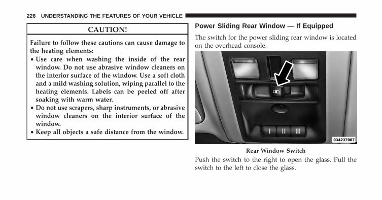
CAUTION!
Failure to follow these cautions can cause damage tothe heating elements:• Use care when washing the inside of the rear
window. Do not use abrasive window cleaners onthe interior surface of the window. Use a soft clothand a mild washing solution, wiping parallel to theheating elements. Labels can be peeled off aftersoaking with warm water.
• Do not use scrapers, sharp instruments, or abrasivewindow cleaners on the interior surface of thewindow.
• Keep all objects a safe distance from the window.
Power Sliding Rear Window — If Equipped
The switch for the power sliding rear window is locatedon the overhead console.
Push the switch to the right to open the glass. Pull theswitch to the left to close the glass.
Rear Window Switch
226 UNDERSTANDING THE FEATURES OF YOUR VEHICLE
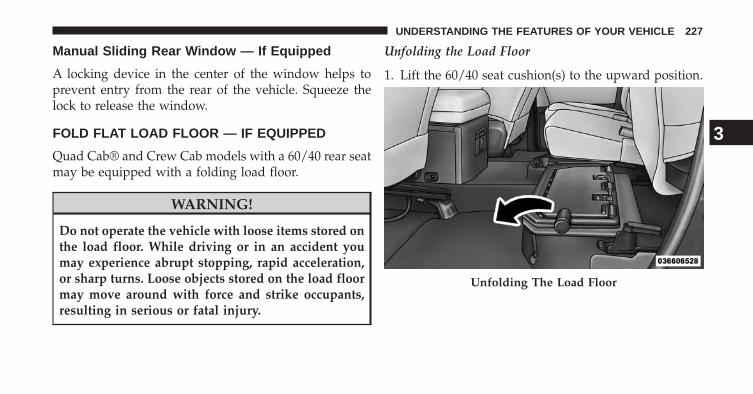
Manual Sliding Rear Window — If Equipped
A locking device in the center of the window helps toprevent entry from the rear of the vehicle. Squeeze thelock to release the window.
FOLD FLAT LOAD FLOOR — IF EQUIPPED
Quad Cab® and Crew Cab models with a 60/40 rear seatmay be equipped with a folding load floor.
WARNING!
Do not operate the vehicle with loose items stored onthe load floor. While driving or in an accident youmay experience abrupt stopping, rapid acceleration,or sharp turns. Loose objects stored on the load floormay move around with force and strike occupants,resulting in serious or fatal injury.
Unfolding the Load Floor
1. Lift the 60/40 seat cushion(s) to the upward position.
Unfolding The Load Floor
3
UNDERSTANDING THE FEATURES OF YOUR VEHICLE 227

2. Grasp the knob on the load floor and lift the knob untilthe load floor unfolds into position.
3. Reverse the procedure to store the load floor.
Positioning the Load Floor for Storage Access Underthe Seat
1. Lift the 60/40 seat cushion(s) to the upward position.
2. Unsnap the securing snap located at either side of theload floor.
3. Lift the load floor up to access storage under the loadfloor.
WARNING!
Do not drive with the load floor in the up position.When stopping fast or in an accident, the load floorcould move to the down position causing seriousinjury.Load Floor In Open Position
228 UNDERSTANDING THE FEATURES OF YOUR VEHICLE

4. Reverse the procedure to put the load floor back in thesecured down position before you operate the vehicle.
PICKUP BOX
The pickup box has many features designed for utilityand convenience.
Load Floor Securing Straps
Pick Up Box Features1 — Upper Load Floor Indents2 — Bulk Head Dividers3 — Cleats
3
UNDERSTANDING THE FEATURES OF YOUR VEHICLE 229

NOTE: If you are installing a Toolbox, Ladder Rack orHeadache Rack at the front of the Pickup Box, you mustuse Mopar Box Reinforcement Brackets that are availablefrom your authorized dealer.
You can carry wide building materials (sheets of ply-wood, etc.) by building a raised load floor. Place lumberacross the box in the indentations provided above thewheel housings and in the bulkhead dividers to form thefloor.
WARNING!
• The pickup box is intended for load carrying pur-poses only, not for passengers, who should sit inseats and use seat belts.
(Continued)
WARNING! (Continued)• Care should always be exercised when operating a
vehicle with unrestrained cargo. Vehicle speedsmay need to be reduced. Severe turns or roughroads may cause shifting or bouncing of the cargothat may result in vehicle damage. If wide buildingmaterials are to be frequently carried, the installa-tion of a support is recommended. This will re-strain the cargo and transfer the load to the pickupbox floor.
• If you wish to carry more than 600 lbs (272 kg) ofmaterial suspended above the wheelhouse, sup-ports must be installed to transfer the weight of theload to the pickup box floor or vehicle damage mayresult. The use of proper supports will permitloading up to the rated payload.
• Unrestrained cargo may be thrown forward in anaccident causing serious or fatal injury.
230 UNDERSTANDING THE FEATURES OF YOUR VEHICLE

There are stampings in the sheet metal on the inner sidebulkheads of the box in front of and behind both wheelhousings. Place wooden boards across the box from sideto side to create separate load compartments in thepickup box.
There are four tie-down cleats bolted to the lower sides ofthe pickup box that can sustain loads up to 1000 lbs(450 kg) total.
RAMBOX® — IF EQUIPPED
The RamBox® system is an integrated pickup box storageand cargo management system consisting of three features:
• Integrated box side storage bins
• Cargo extender/divider
• Bed rail tie-down system
RamBox® Integrated Box Side Storage BinsCargo storage bins are located on both sides of the pickupbox. The cargo storage bins provide watertight, lockable,illuminated storage for up to 150 lbs (68 kg) for 1500series vehicles or 300 lbs (136 kg) for 2500 and 3500 seriesvehicles of evenly distributed cargo.
RamBox® Cargo Storage Bins
3
UNDERSTANDING THE FEATURES OF YOUR VEHICLE 231
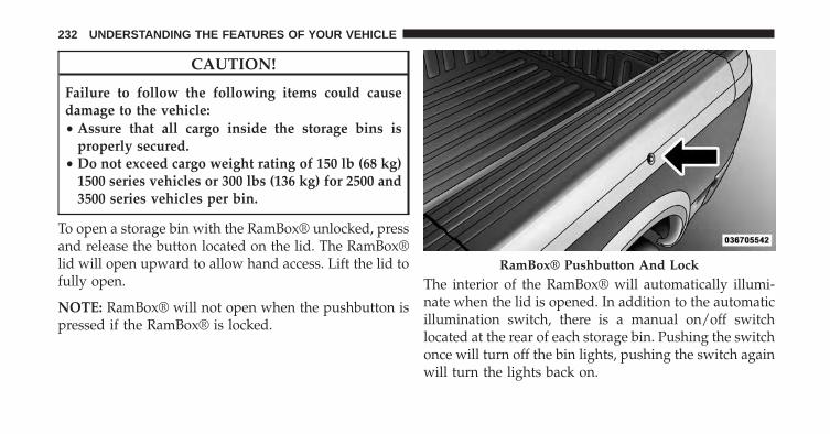
CAUTION!
Failure to follow the following items could causedamage to the vehicle:• Assure that all cargo inside the storage bins is
properly secured.• Do not exceed cargo weight rating of 150 lb (68 kg)
1500 series vehicles or 300 lbs (136 kg) for 2500 and3500 series vehicles per bin.
To open a storage bin with the RamBox® unlocked, pressand release the button located on the lid. The RamBox®lid will open upward to allow hand access. Lift the lid tofully open.
NOTE: RamBox® will not open when the pushbutton ispressed if the RamBox® is locked.
The interior of the RamBox® will automatically illumi-nate when the lid is opened. In addition to the automaticillumination switch, there is a manual on/off switchlocated at the rear of each storage bin. Pushing the switchonce will turn off the bin lights, pushing the switch againwill turn the lights back on.
RamBox® Pushbutton And Lock
232 UNDERSTANDING THE FEATURES OF YOUR VEHICLE

CAUTION!
Leaving the lid open for extended periods of timecould cause the vehicle battery to discharge. If the lidis required to stay open for extended periods of time,
(Continued)
CAUTION! (Continued)it is recommended that the bin lights be turned offmanually using the on/off switch.
Cargo bins feature two removable drain plugs (to allowwater to drain from bins). To remove plug, pull up on theedge. To install push plug downward into drain hole.
NOTE: Provisions are provided in the bins for cargodividers and shelf supports. These accessories (in addi-tion to other RamBox® accessories) are available fromMOPAR®.
Locking And Unlocking RamBox®
Press and release the LOCK or UNLOCK button on theRKE transmitter to lock and unlock all doors, the tailgateand the RamBox® (if equipped). Refer to “Remote Key-less Entry” for further details.The RamBox® storage binscan be locked using the vehicle key. To lock and unlock
RamBox® Light Switch
3
UNDERSTANDING THE FEATURES OF YOUR VEHICLE 233
the storage bin, insert the key into the keyhole on thepushbutton and turn clockwise to lock or counterclock-wise to unlock. Always return the key to the upright(vertical) position before removing the key from thepushbutton.
CAUTION!
• Ensure cargo bin lids are closed and latched beforemoving or driving vehicle.
• Loads applied to the top of the bin lid should beminimized to prevent damage to the lid andlatching/hinging mechanisms.
• Damage to the RamBox® bin may occur due toheavy/sharp objects placed in bin that shift due tovehicle motion. In order to minimize potential fordamage, secure all cargo to prevent movement andprotect inside surfaces of bin from heavy/sharpobjects with appropriate padding.
RamBox® Safety Warning
Carefully follow these warnings to help prevent personalinjury or damage to your vehicle:
WARNING!
• Always close the storage bin covers when yourvehicle is unattended.
• Do not allow children to have access to the storagebins. Once in the storage bin, young children maynot be able to escape. If trapped in the storage bin,children can die from suffocation or heat stroke.
• In an accident, serious injury could result if thestorage bin covers are not properly latched.
• Do not drive the vehicle with the storage bin coversopen.
• Keep the storage bin covers closed and latchedwhile the vehicle is in motion.
• Do not use a storage bin latch as a tie down.
234 UNDERSTANDING THE FEATURES OF YOUR VEHICLE

RamBox® Storage Bin Cover Emergency ReleaseLever — If Equipped
As a security measure, a Storage Bin Cover EmergencyRelease is built into the storage bin cover latching mecha-nism.
NOTE: In the event of an individual being locked insidethe storage bin, the storage bin cover can be opened frominside of the bin by pulling on the glow-in-the-dark leverattached to the storage bin cover latching mechanism.
Bed Extender — If Equipped
The bed extender has three functional positions:
• Storage Position
• Divider Position
• Extender Position
Storage Position
The storage position for the bed extender is at the front ofthe truck bed which maximizes the bed cargo area whennot in use.
Storage Bin Cover Emergency Release Lever
3
UNDERSTANDING THE FEATURES OF YOUR VEHICLE 235

To install the bed extender into the storage position,perform the following:
1. Make sure the center handle is unlocked using thevehicle key and rotate the center handle vertically torelease the extender side gates.
Center Handle And Lock
1 — Center Handle Lock2 — Handle
236 UNDERSTANDING THE FEATURES OF YOUR VEHICLE
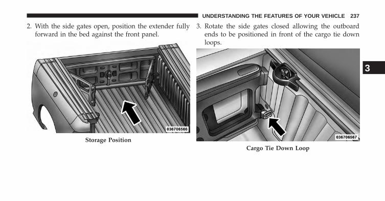
2. With the side gates open, position the extender fullyforward in the bed against the front panel.
3. Rotate the side gates closed allowing the outboardends to be positioned in front of the cargo tie downloops.
Storage PositionCargo Tie Down Loop
3
UNDERSTANDING THE FEATURES OF YOUR VEHICLE 237

4. Rotate the center handle horizontally to secure the sidegates in the closed position.
5. Lock the center handle using the vehicle key to securethe panel into place and assist against theft.
Divider Position
The divider position is intended for managing your cargoand assisting in keeping cargo from moving around thebed. There are 11 divider slots along the bed inner panelswhich allow for various positions to assist in managingyour cargo.
To install the bed extender into a divider position per-form the following:
1. Make sure the center handle is unlocked using thevehicle key and rotate the center handle vertically torelease the extender side gates.
Side Gates Closed
238 UNDERSTANDING THE FEATURES OF YOUR VEHICLE

2. With the side gates open, position the extender so theoutboard ends align with the intended slots in thesides of the bed.
3. Rotate the side gates closed so that the outboard endsare secured into the intended slots of the bed.
Center Handle And Lock
1 — Center Handle Lock2 — Handle
Aligning Gate To Slots
3
UNDERSTANDING THE FEATURES OF YOUR VEHICLE 239
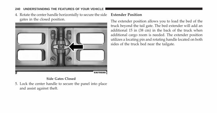
4. Rotate the center handle horizontally to secure the sidegates in the closed position.
5. Lock the center handle to secure the panel into placeand assist against theft.
Extender Position
The extender position allows you to load the bed of thetruck beyond the tail gate. The bed extender will add anadditional 15 in (38 cm) in the back of the truck whenadditional cargo room is needed. The extender positionutilizes a locating pin and rotating handle located on bothsides of the truck bed near the tailgate.
Side Gates Closed
240 UNDERSTANDING THE FEATURES OF YOUR VEHICLE

To install the bed extender into the extender positionperform the following:
1. Lower the tailgate.
2. Make sure the center handle is unlocked and rotate thecenter handle vertically in order to release the ex-tender side gates.
3. Fit the end of the side gate ends onto the pin andhandle.
Extender Position
Extender Installation
3
UNDERSTANDING THE FEATURES OF YOUR VEHICLE 241

4. Rotate the handles to the horizontal position to secureinto place.
WARNING!
To reduce the risk of potential injury or propertydamage:• Cargo must be secured.• Do not exceed cargo load rating of your vehicle.• Secure all loads to truck utilizing cargo tie downs.• Extender should not be used as cargo tie down.• When vehicle is in motion do not exceed 150 lbs
(68 kg) load on the tailgate.• The bed extender is not intended for off road use.• When not in use, the extender/divider should be in
stowed or divider position with the tailgate closed.• When in use all handles are to be in the locked
position.Locking Tab
242 UNDERSTANDING THE FEATURES OF YOUR VEHICLE

Bed Rail Tie-Down System
CAUTION!
The maximum load per cleat should not exceed250 lbs (113 kg) and the angle of the load on each cleatshould not exceed 45 degrees above horizontal, ordamage to the cleat or cleat rail may occur.
There are two adjustable cleats on each side of the bedthat can be used to assist in securing cargo.
Each cleat must be located and tightened down in one ofthe detents, along either rail, in order to keep cargoproperly secure.
To move the cleat to any position on the rail, turn the nutcounterclockwise, approximately three turns. Then pull
Adjustable Cleats
3
UNDERSTANDING THE FEATURES OF YOUR VEHICLE 243
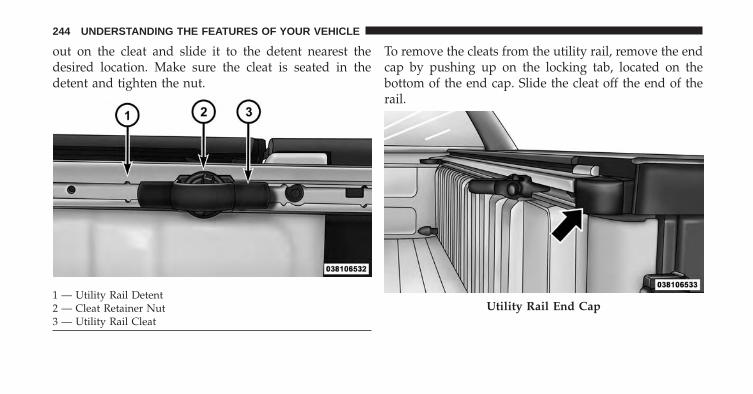
out on the cleat and slide it to the detent nearest thedesired location. Make sure the cleat is seated in thedetent and tighten the nut.
To remove the cleats from the utility rail, remove the endcap by pushing up on the locking tab, located on thebottom of the end cap. Slide the cleat off the end of therail.
1 — Utility Rail Detent2 — Cleat Retainer Nut3 — Utility Rail Cleat
Utility Rail End Cap
244 UNDERSTANDING THE FEATURES OF YOUR VEHICLE

SLIDE-IN CAMPERS
Camper Applications
Certain truck models are not recommended for slide-incampers. To determine if your vehicle is excluded, pleaserefer to the “Consumer Information Truck-Camper Load-ing” document available from your authorized dealer.For safety reasons, follow all instructions in this impor-tant document.
NOTE: When a cap or pickup camper is installed on avehicle, an alternate Center High-Mounted Stop Light(CHMSL) must be provided.
EASY-OFF TAILGATE
To simplify mounting of a camper unit with an overhang,the tailgate can be removed.
NOTE: If your vehicle is equipped with a rear camera orRKE the electrical connector must be disconnected priorto removing the tailgate.
3
UNDERSTANDING THE FEATURES OF YOUR VEHICLE 245

Disconnecting the Rear Camera or RemoteKeyless Entry — If Equipped
1. Open the tailgate to access the rear camera or RKEconnector bracket located on the rear sill.
2. Remove the connector bracket from the sill by press-ing inward in the locking tab.
3. Disconnect the chassis wiring harness, ensuring theconnector bracket does not fall into the sill.Connector Bracket
Locking Tab
246 UNDERSTANDING THE FEATURES OF YOUR VEHICLE

4. Connect the chassis plug and bracket (provided in theglove box) to the chassis wiring harness and insert thebracket back into the sill.
5. Connect the tailgate plug (provided in the glove box)to the tailgate wiring harness to ensure that theterminals do not corrode.
6. Tape the tailgate harness and bracket against theforward-facing surface of the tailgate. This will pre-vent damaging the connector and bracket when stor-ing or reinstalling the tailgate.
Removing The Tailgate
1. Disconnect the wiring harness for the rear camera andor power locks (if equipped), refer to “Disconnectingthe Rear Camera — If Equipped” in this section.
2. Unlatch the tailgate and remove the support cables byreleasing the lock tang from the pivot.
NOTE: Make sure tailgate is supported when removingsupport cables.
3
UNDERSTANDING THE FEATURES OF YOUR VEHICLE 247
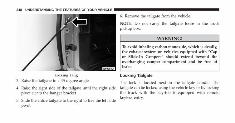
3. Raise the tailgate to a 45 degree angle.
4. Raise the right side of the tailgate until the right sidepivot clears the hanger bracket.
5. Slide the entire tailgate to the right to free the left sidepivot.
6. Remove the tailgate from the vehicle.
NOTE: Do not carry the tailgate loose in the truckpickup box.
WARNING!
To avoid inhaling carbon monoxide, which is deadly,the exhaust system on vehicles equipped with “Capor Slide-In Campers” should extend beyond theoverhanging camper compartment and be free ofleaks.
Locking Tailgate
The lock is located next to the tailgate handle. Thetailgate can be locked using the vehicle key or by lockingthe truck with the key-fob if equipped with remotekeyless entry.
Locking Tang
248 UNDERSTANDING THE FEATURES OF YOUR VEHICLE

TRI-FOLD TONNEAU COVER-IF EQUIPPED
Tri-Fold Tonneau Cover — If Equipped
Your vehicle may be equipped with a Tri-Fold TonneauCover which consists of different features:
• Easy Tri-Fold cover
• Tonneau fore aft locator
• Crosscar inside bed locator
• Front and rear clamps
• Stowage strap
• Locking Capability
NOTE: The Tonneau Cover can be folded up and securedat the front of the box without removing completely.
Tri-Fold Tonneau Cover Removal
To remove the Tonneau Cover follow the following steps:
1. Lower the tailgate.
2. Pull down on the clamp on both driver and passengersides.
3. Pick up on the cover and fold it back into the secondpanel.
4. Be sure both clamps are pushed completely down.
5. Pick up on the cover and fold it back into the thirdpanel.
6. Once in the third panel position pull down on theclamp on both sides.
7. Be sure to clip both straps together to insure the coverstays together.
3
UNDERSTANDING THE FEATURES OF YOUR VEHICLE 249

8. With two people remove the cover.
Clamped Position
NOTE: If clamp wire is damaged replace immediately.
Semi Clamped Position
250 UNDERSTANDING THE FEATURES OF YOUR VEHICLE
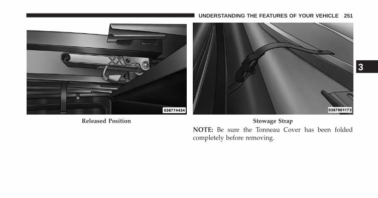
NOTE: Be sure the Tonneau Cover has been foldedcompletely before removing.
Released Position Stowage Strap
3
UNDERSTANDING THE FEATURES OF YOUR VEHICLE 251

Tri-Fold Tonneau Cover Installation And Cleaning
Position the folded Tonneau Cover on the truck bed andpush the Cover forward against the front of the truckbed. The Tonneau Cover centers itself when placed on thevehicle. Disengage the stowage straps and unfold theTonneau Cover then attach the rear clamps to the truckbed flange to secure the Tonneau Cover to the vehicle.
The Tonneau Cover clamps can be locked when in theclamped position by placing a lock through the lockinghole.
NOTE: Be sure the Tonneau Cover is secured beforedriving after installation.
For proper cleaning of the Tonneau Cover use MOPAR®Whitewall &Vinyl Top Cleaner and MOPAR® Leather &Vinyl Conditioner/Protectant.
Locking Hole
252 UNDERSTANDING THE FEATURES OF YOUR VEHICLE

UNDERSTANDING YOUR INSTRUMENT PANEL
CONTENTS� INSTRUMENT PANEL FEATURES . . . . . . . . . .255
� INSTRUMENT CLUSTER — PREMIUM . . . . . . .256
� INSTRUMENT CLUSTER DESCRIPTIONS . . . . .257
� ELECTRONIC VEHICLE INFORMATION CENTER(EVIC) . . . . . . . . . . . . . . . . . . . . . . . . . . . . . . .267
▫ Electronic Vehicle Information Center (EVIC)Displays . . . . . . . . . . . . . . . . . . . . . . . . . . . .269
▫ Engine Oil Change Indicator System . . . . . . . .271
▫ Electronic Vehicle Information Center (EVIC)Messages . . . . . . . . . . . . . . . . . . . . . . . . . . .273
▫ EVIC Amber Telltales . . . . . . . . . . . . . . . . . . .277
▫ EVIC White Telltales . . . . . . . . . . . . . . . . . . .279
▫ EVIC Red Telltales . . . . . . . . . . . . . . . . . . . . .279
▫ EVIC Green Telltales . . . . . . . . . . . . . . . . . . .280
▫ EVIC Selectable Menu Items . . . . . . . . . . . . . .280
▫ Personal Settings (Customer-ProgrammableFeatures) . . . . . . . . . . . . . . . . . . . . . . . . . . .283
▫ Screen Setup Driver Selectable Items . . . . . . . .292
� Uconnect® ACCESS SETTINGS . . . . . . . . . . . . .294
▫ Hard-Keys . . . . . . . . . . . . . . . . . . . . . . . . . .294
▫ Soft-Keys . . . . . . . . . . . . . . . . . . . . . . . . . . .295
4

� Uconnect® RADIOS — IF EQUIPPED . . . . . . . .309
� iPod®/USB/MP3 CONTROL — IF EQUIPPED . .310
� STEERING WHEEL AUDIO CONTROLS — IFEQUIPPED . . . . . . . . . . . . . . . . . . . . . . . . . . .310
▫ Radio Operation . . . . . . . . . . . . . . . . . . . . . .311
▫ CD Player . . . . . . . . . . . . . . . . . . . . . . . . . . .311
� CD/DVD DISC MAINTENANCE . . . . . . . . . . .311
� RADIO OPERATION AND MOBILE PHONES . .312
� CLIMATE CONTROLS . . . . . . . . . . . . . . . . . . .312
▫ Manual Climate Controls Without Touch-Screen —If Equipped . . . . . . . . . . . . . . . . . . . . . . . . .313
▫ Manual Climate Controls With Touch-Screen — IfEquipped . . . . . . . . . . . . . . . . . . . . . . . . . . .318
▫ Automatic Climate Controls With Touch-Screen —If Equipped . . . . . . . . . . . . . . . . . . . . . . . . .323
▫ Summer Operation . . . . . . . . . . . . . . . . . . . .329
▫ Winter Operation. . . . . . . . . . . . . . . . . . . . . .330
▫ Vacation/Storage . . . . . . . . . . . . . . . . . . . . .330
▫ Window Fogging and Frosting . . . . . . . . . . . .330
▫ Outside Air Intake . . . . . . . . . . . . . . . . . . . . .330
▫ Operating Tips Chart . . . . . . . . . . . . . . . . . . .331
254 UNDERSTANDING YOUR INSTRUMENT PANEL

INSTRUMENT PANEL FEATURES
1 — Headlight Switch 7 — 115v Power Inverter Outlet 13 — Gear Selector/Transfer Case Position Switch2 — Instrument Cluster 8 — Power Outlet 14 — Ignition Switch3 — Radio 9 — Lower Switch Bank (Engine Start/Stop, ESC
OFF, TOW/HAUL, Electronic Trailer Brake, AirSuspension, Park Assist) — If Equipped
15 — Hood Release
4 — Hazard Switch 10 — Instrument Panel Drawer 16 — Parking Brake Release5 — Upper Glove Compartment 11 — Climate Controls6 — Lower Glove Compartment 12 — Power Outlet/Cigar Lighter
4
UNDERSTANDING YOUR INSTRUMENT PANEL 255

INSTRUMENT CLUSTER — PREMIUM
256 UNDERSTANDING YOUR INSTRUMENT PANEL
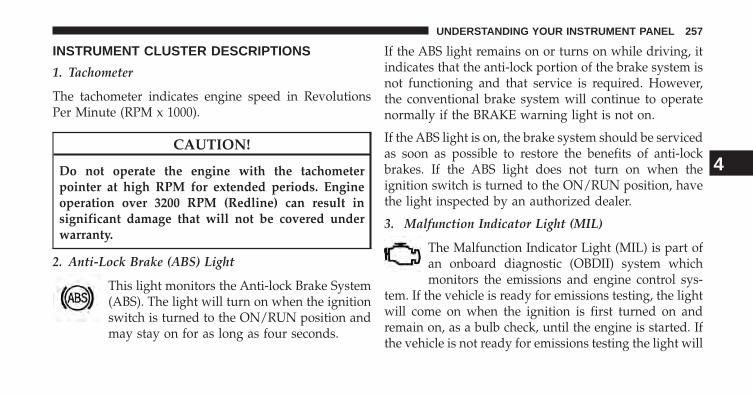
INSTRUMENT CLUSTER DESCRIPTIONS
1. Tachometer
The tachometer indicates engine speed in RevolutionsPer Minute (RPM x 1000).
CAUTION!
Do not operate the engine with the tachometerpointer at high RPM for extended periods. Engineoperation over 3200 RPM (Redline) can result insignificant damage that will not be covered underwarranty.
2. Anti-Lock Brake (ABS) Light
This light monitors the Anti-lock Brake System(ABS). The light will turn on when the ignitionswitch is turned to the ON/RUN position andmay stay on for as long as four seconds.
If the ABS light remains on or turns on while driving, itindicates that the anti-lock portion of the brake system isnot functioning and that service is required. However,the conventional brake system will continue to operatenormally if the BRAKE warning light is not on.
If the ABS light is on, the brake system should be servicedas soon as possible to restore the benefits of anti-lockbrakes. If the ABS light does not turn on when theignition switch is turned to the ON/RUN position, havethe light inspected by an authorized dealer.
3. Malfunction Indicator Light (MIL)
The Malfunction Indicator Light (MIL) is part ofan onboard diagnostic (OBDII) system whichmonitors the emissions and engine control sys-
tem. If the vehicle is ready for emissions testing, the lightwill come on when the ignition is first turned on andremain on, as a bulb check, until the engine is started. Ifthe vehicle is not ready for emissions testing the light will
4
UNDERSTANDING YOUR INSTRUMENT PANEL 257

come on when the ignition is first turned on and remainon for 15 seconds, then blink for 5 seconds, and remainon until the vehicle is started. If the bulb does not comeon during starting, have the condition investigatedpromptly.If this light comes on and remains on while driving, itsuggests a potential engine control problem and the needfor system service.Although your vehicle will usually be drivable and notneed towing, see your authorized dealer for service assoon as possible.
CAUTION!
Prolonged driving with the Malfunction IndicatorLight (MIL) on could cause damage to the enginecontrol system. It also could affect fuel economy anddrivability. If the MIL is flashing, severe catalytic
(Continued)
CAUTION! (Continued)converter damage and power loss will soon occur.Immediate service is required.
WARNING!
A malfunctioning catalytic converter, as referencedabove, can reach higher temperatures than in normaloperating conditions. This can cause a fire if youdrive slowly or park over flammable substances suchas dry plants, wood, cardboard, etc. This could resultin death or serious injury to the driver, occupants orothers.
4. Turn Signal Indicators
The arrow will flash with the exterior turn signalwhen the turn signal lever is operated.
258 UNDERSTANDING YOUR INSTRUMENT PANEL

NOTE:
A continuous chime will sound if the vehicle is drivenmore than 1 mile (1.6 km) with either turn signal on.
Check for an inoperative outside light bulb if eitherindicator remains on and does not flash, or flashes at arapid rate.
5. Voltmeter
When the engine is running, the gauge indicatesthe electrical system voltage. The pointer should
stay within the normal range if the battery is charged. Ifthe pointer moves to either extreme left or right andremains there during normal driving, the electrical sys-tem should be serviced.
NOTE: The voltmeter may show a gauge fluctuation atvarious engine temperatures. This cycling operation iscaused by the post-heat cycle of the intake manifoldheater system. The number of cycles and the length of thecycling operation is controlled by the engine controlmodule. Post-heat operation can run for several minutes,and then the electrical system and voltmeter needle willstabilize.
6. Brake Warning Light
This light monitors various brake functions,including brake fluid level and parking brakeapplication. If the brake light turns on it mayindicate that the parking brake is applied, that
the brake fluid level is low, or that there is a problem withthe Anti-lock Brake System reservoir.
If the light remains on when the parking brake has beendisengaged, and the fluid level is at the full mark on themaster cylinder reservoir, it indicates a possible brake
4
UNDERSTANDING YOUR INSTRUMENT PANEL 259

hydraulic system malfunction or that a problem with theBrake Booster has been detected by the Anti-Lock BrakeSystem (ABS) / Electronic Stability Control (ESC) system.In this case, the light will remain on until the conditionhas been corrected. If the problem is related to the brakebooster, the ABS pump will run when applying the brakeand a brake pedal pulsation may be felt during each stop.
The dual brake system provides a reserve braking capac-ity in the event of a failure to a portion of the hydraulicsystem. A leak in either half of the dual brake system isindicated by the Brake Warning Light, which will turn onwhen the brake fluid level in the master cylinder hasdropped below a specified level.
The light will remain on until the cause is corrected.
NOTE: The light may flash momentarily during sharpcornering maneuvers, which change fluid level condi-tions. The vehicle should have service performed, andthe brake fluid level checked.
If brake failure is indicated, immediate repair is neces-sary.
WARNING!
Driving a vehicle with the red brake light on isdangerous. Part of the brake system may have failed.It will take longer to stop the vehicle. You could havea collision. Have the vehicle checked immediately.
Vehicles equipped with the ABS, are also equipped withElectronic Brake Force Distribution (EBD). In the event ofan EBD failure, the Brake Warning Light will turn onalong with the ABS Light. Immediate repair to the ABSsystem is required.
Operation of the Brake Warning Light can be checked byturning the ignition switch from the OFF position to theON/RUN position. The light should illuminate for ap-proximately two seconds. The light should then turn off
260 UNDERSTANDING YOUR INSTRUMENT PANEL

unless the parking brake is applied or a brake fault isdetected. If the light does not illuminate, have the lightinspected by an authorized dealer.
The light also will turn on when the parking brake isapplied with the ignition switch in the ON/RUN posi-tion.
NOTE: This light shows only that the parking brake isapplied. It does not show the degree of brake application.
7. High Beam Indicator
This light shows that the high beam headlights areon. Push the multifunction control lever away
from you to switch the headlights to high beam. Pull thelever toward you to switch the headlights back to lowbeam. If the driver’s door is open, and the headlights orpark lights are left on, the high beam indicator light willremain illuminated and a chime will sound.
8. Seat Belt Reminder Light
When the ignition switch is first turned to ON/RUN, this light will turn on for four to eightseconds as a bulb check. During the bulb check, if
the driver’s seat belt is unbuckled, a chime will sound.After the bulb check or when driving, if the driver’s seatbelt remains unbuckled, the seat belt reminder light willflash or remain on continuously. Refer to “OccupantRestraints” in “Things To Know Before Starting YourVehicle” for further information.
9. Air Bag Warning Light
This light will turn on for four to eight secondsas a bulb check when the ignition switch is firstturned to ON/RUN. If the light is either not onduring starting, stays on, or turns on while
driving, have the system inspected at an authorized
4
UNDERSTANDING YOUR INSTRUMENT PANEL 261

dealer as soon as possible. Refer to “Occupant Restraints”in “Things To Know Before Starting Your Vehicle” forfurther information.
10. Oil Pressure Gauge — If Equipped
The pointer should always indicate some oil pres-sure when the engine is running. A continuous high orlow reading under normal driving conditions may indi-cate a lubrication system malfunction. Immediate serviceshould be obtained from an authorized dealer.
11. Speedometer
The speedometer shows the vehicle speed in miles perhour and/or kilometers per hour (mph/km/h).
12. Park/Headlight ON Indicator — If Equipped
This indicator will illuminate when the parklights or headlights are turned on.
13. Cargo Light — If Equipped
The cargo light will illuminate when the cargolight is activated by pressing the cargo lightbutton on the headlight switch.
14. Fuel Gauge
Shows level of fuel in tank when ignition switch is in theON/RUN position.
15. Vehicle Security Light — If Equipped
This light will flash at a fast rate for approxi-mately 15 seconds, when the vehicle securityalarm is arming, and then will flash slowlyuntil the vehicle is disarmed.
16. Tire Pressure Monitoring Telltale Light
Each tire, including the spare (if provided),should be checked monthly when cold andinflated to the inflation pressure recommended
262 UNDERSTANDING YOUR INSTRUMENT PANEL

by the vehicle manufacturer on the vehicle placard or tireinflation pressure label. (If your vehicle has tires of adifferent size than the size indicated on the vehicleplacard or tire inflation pressure label, you should deter-mine the proper tire inflation pressure for those tires.)
As an added safety feature, your vehicle has beenequipped with a Tire Pressure Monitoring System(TPMS) that illuminates a low tire pressure telltale whenone or more of your tires is significantly under-inflated.Accordingly, when the low tire pressure telltale illumi-nates, you should stop and check your tires as soon aspossible, and inflate them to the proper pressure. Drivingon a significantly under-inflated tire causes the tire tooverheat and can lead to tire failure. Under-inflation alsoreduces fuel efficiency and tire tread life, and may affectthe vehicle’s handling and stopping ability.
Please note that the TPMS is not a substitute for propertire maintenance, and it is the driver’s responsibility to
maintain correct tire pressure, even if under-inflation hasnot reached the level to trigger illumination of the TPMSlow tire pressure telltale.
Your vehicle has also been equipped with a TPMSmalfunction indicator to indicate when the system is notoperating properly. The TPMS malfunction indicator iscombined with the low tire pressure telltale. When thesystem detects a malfunction, the telltale will flash forapproximately one minute and then remain continuouslyilluminated. This sequence will continue upon subse-quent vehicle start-ups as long as the malfunction exists.When the malfunction indicator is illuminated, the sys-tem may not be able to detect or signal low tire pressureas intended. TPMS malfunctions may occur for a varietyof reasons, including the installation of replacement oralternate tires or wheels on the vehicle that prevent theTPMS from functioning properly. Always check theTPMS malfunction telltale after replacing one or moretires or wheels on your vehicle, to ensure that the
4
UNDERSTANDING YOUR INSTRUMENT PANEL 263

replacement or alternate tires and wheels allow the TPMSto continue to function properly.
CAUTION!
The TPMS has been optimized for the originalequipment tires and wheels. TPMS pressures andwarning have been established for the tire sizeequipped on your vehicle. Undesirable system opera-tion or sensor damage may result when using re-placement equipment that is not of the same size,type, and/or style. Aftermarket wheels can causesensor damage. Do not use tire sealant from a can orbalance beads if your vehicle is equipped with aTPMS, as damage to the sensors may result.
NOTE: The TPMS telltale is also accompanied by a “LowTire” message in the odometer (Base Cluster), or in theElectronic Vehicle Information Center (EVIC) screen in-dicating “Low Tire” for EVIC enabled clusters.
17. Front Fog Light Indicator — If Equipped
This indicator will illuminate when the front foglights are on.
18. Electronic Vehicle Information Center (EVIC)
The Electronic Vehicle Information Center (EVIC) fea-tures a driver-interactive display that is located in theinstrument cluster. For further information, refer to“Electronic Vehicle Information Center (EVIC)”.
19. Shift Lever Indicator
The Shift Lever Indicator is self-contained within theinstrument cluster. It displays the gear position of theautomatic transmission.
264 UNDERSTANDING YOUR INSTRUMENT PANEL

NOTE: The highest available transmission gear is dis-played in the lower right corner of the Electronic VehicleInformation Center (EVIC) whenever the ElectronicRange Select (ERS) feature is active. Use the +/- selectoron the shift lever to activate ERS. Refer to “AutomaticTransmission” in “Starting And Operating” for furtherinformation.
20. Electronic Vehicle Information Center (EVIC) Menu
The Electronic Vehicle Information Center (EVIC) fea-tures a driver-interactive display that is located in theinstrument cluster. For further information, refer to“Electronic Vehicle Information Center (EVIC)”.
21. Electronic Stability Control (ESC) OFF IndicatorLight — If Equipped
This light indicates the Electronic Stability Con-trol (ESC) is off.
22. TOW/HAUL
The TOW HAUL button is located on the centerstack upper switch bank. This light will illumi-nate when TOW HAUL mode is selected.
23. Electronic Stability Control (ESC) Activation/Malfunction Indicator Light — If Equipped
The “ESC Activation/Malfunction IndicatorLight” in the instrument cluster will come onwhen the ignition switch is turned to theON/RUN position. It should go out with the
engine running. If the “ESC Activation/Malfunction In-dicator Light” comes on continuously with the enginerunning, a malfunction has been detected in the ESCsystem. If this light remains on after several ignitioncycles, and the vehicle has been driven several miles(kilometers) at speeds greater than 30 mph (48 km/h), seeyour authorized dealer as soon as possible to have theproblem diagnosed and corrected.
4
UNDERSTANDING YOUR INSTRUMENT PANEL 265

NOTE:
The “ESC Off Indicator Light” and the “ESC Activation/Malfunction Indicator Light” come on momentarily eachtime the ignition switch is turned to ON/RUN.
Each time the ignition is turned to ON/RUN, the ESCsystem will be ON, even if it was turned off previously.
The ESC system will make buzzing or clicking soundswhen it is active. This is normal; the sounds will stopwhen ESC becomes inactive following the maneuver thatcaused the ESC activation.
24. Temperature Gauge
The temperature gauge shows engine coolant tempera-ture. Any reading within the normal range indicates thatthe engine cooling system is operating satisfactorily.
The gauge pointer will likely indicate a higher tempera-ture when driving in hot weather, up mountain grades,or when towing a trailer. It should not be allowed toexceed the upper limits of the normal operating range.
CAUTION!
Driving with a hot engine cooling system coulddamage your vehicle. If the temperature gauge reads“H” pull over and stop the vehicle. Idle the vehiclewith the air conditioner turned off until the pointerdrops back into the normal range. If the pointerremains on the “H” and you hear continuous chimes,turn the engine off immediately and call an autho-rized dealer for service.
266 UNDERSTANDING YOUR INSTRUMENT PANEL

WARNING!
A hot engine cooling system is dangerous. You orothers could be badly burned by steam or boilingcoolant. You may want to call an authorized dealerfor service if your vehicle overheats. If you decide tolook under the hood yourself, see “Maintaining YourVehicle.” Follow the warnings under the “CoolingSystem Pressure Cap” paragraph.
ELECTRONIC VEHICLE INFORMATION CENTER(EVIC)
The Electronic Vehicle Information Center (EVIC) fea-tures a driver-interactive display that is located in theinstrument cluster.
4
UNDERSTANDING YOUR INSTRUMENT PANEL 267

This system allows the driver to select a variety of usefulinformation by pressing the switches mounted on thesteering wheel. The EVIC consists of the following:
• Digital Speedometer
• Vehicle Info
• Fuel Economy Info
• Trip A
• Trip B
• Stop/Start Info (If Equipped)
• Trailer Tow
• Audio
• Stored Messages
• Screen Setup
• Vehicle Settings (Not Equipped with a Uconnect®Access 5.0 & 8.4 radio)
The system allows the driver to select information bypressing the following buttons mounted on the steeringwheel:
EVIC Steering Wheels Buttons
268 UNDERSTANDING YOUR INSTRUMENT PANEL

• UP Arrow Button
Press and release the UP arrow button to scrollupward through the main menu and sub-menus (Fuel Economy, Trip A, Trip B, Audio,Stored Messages, Screen Set Up).
• DOWN Arrow Button
Press and release the DOWN arrow button toscroll downward through the main menu andsub-menus (Fuel Economy, Trip A, Trip B,Audio, Stored Messages, Screen Set Up).
• SELECT/RIGHT Arrow Button
Press and release the SELECT/RIGHT arrowbutton to access/select the information screensor sub-menu screens of a main menu item.Press and hold the SELECT/RIGHT arrow
button for two seconds to reset displayed/selected fea-tures that can be reset.
• LEFT Arrow Button
Press the LEFT arrow button to return to themain menu from an info screen or sub-menuitem.
4
UNDERSTANDING YOUR INSTRUMENT PANEL 269

Electronic Vehicle Information Center (EVIC)Displays
The EVIC displays are located in the center portion of thecluster and consists of eight sections:
1. Main Screen — The inner ring of the display willilluminate in grey under normal conditions, yellow fornon critical warnings, red for critical warnings andwhite for on demand information.
2. Audio / Phone Information and Sub-menu Informa-tion — Whenever there are sub-menus available, theposition within the sub-menus is shown here.
3. Selectable Information (Compass, Temp, Range toEmpty, Trip A, Trip B, Average MPG, Trailer Trip(distance only), Trailer Brake Gain)
4. Telltales/Indicators
5. Shift Lever Status (PRNDL)
6. Selectable Menu Icons
7. Air Suspension Status – If Equipped
8. 4WD Status
270 UNDERSTANDING YOUR INSTRUMENT PANEL

9. Selectable Gauge 2
10. Selectable Gauge 1
The main display area will normally display the mainmenu or the screens of a selected feature of the mainmenu. The main display area also displays “pop up”messages that consist of approximately 60 possible warn-ing or information messages. These pop up messages fallinto several categories:
• Five Second Stored Messages
When the appropriate conditions occur, this type ofmessage takes control of the main display area for fiveseconds and then returns to the previous screen. Most ofthe messages of this type are then stored (as long as thecondition that activated it remains active) and can bereviewed from the “Messages” main menu item. As longas there is a stored message, an “i” will be displayed in
the EVIC’s compass/outside temp line. Examples of thismessage type are “Right Front Turn Signal Lamp Out”and “Low Tire Pressure”.
• Unstored Messages
This message type is displayed indefinitely or until thecondition that activated the message is cleared. Examplesof this message type are “Turn Signal On” (if a turn signalis left on) and “Lights On” (if driver leaves the vehicle).
• Unstored Messages Until RUN
These messages deal primarily with the Remote Startfeature. This message type is displayed until the ignitionis in the RUN state. Examples of this message type are“Remote Start Aborted - Door Ajar” and “Press BrakePedal and Push Button to Start”.
• Five Second Unstored Messages
When the appropriate conditions occur, this type ofmessage takes control of the main display area for five
4
UNDERSTANDING YOUR INSTRUMENT PANEL 271
seconds and then returns to the previous screen. Anexample of this message type is “Automatic High BeamsOn”.
Engine Oil Change Indicator System
Oil Change Required
Your vehicle is equipped with an engine oil changeindicator system. The “Oil Change Required” messagewill flash in the EVIC display for approximately 10seconds after a single chime has sounded, to indicate thenext scheduled oil change interval. The engine oil changeindicator system is duty cycle based, which means theengine oil change interval may fluctuate, dependentupon your personal driving style.
Unless reset, this message will continue to display eachtime you turn the ignition switch to the ON/RUNposition or cycle the ignition to the ON/RUN position ifequipped with Keyless Enter-N-Go™. To turn off the
message temporarily, press and release the MENU but-ton. To reset the oil change indicator system (afterperforming the scheduled maintenance) refer to the fol-lowing procedure.
Vehicles Equipped With Keyless Enter-N-Go™
1. Without pressing the brake pedal, press the ENGINESTART/STOP button and cycle the ignition to theON/ RUN position (Do not start the engine.)
2. Fully depress the accelerator pedal, slowly, three timeswithin 10 seconds.
3. Without pressing the brake pedal, press the ENGINESTART/STOP button once to return the ignition to theOFF/LOCK position.
Vehicles Not Equipped With Keyless Enter-N-Go™
1. Turn the ignition switch to the ON/RUN position (Donot start the engine.)
272 UNDERSTANDING YOUR INSTRUMENT PANEL
2. Fully depress the accelerator pedal, slowly, three timeswithin 10 seconds.
3. Turn the ignition switch to the OFF/LOCK position.
NOTE: If the indicator message illuminates when youstart the vehicle, the oil change indicator system did notreset. If necessary, repeat this procedure.
Electronic Vehicle Information Center (EVIC)Messages
• Front Seatbelts Unbuckled
• Driver Seatbelt Unbuckled
• Passenger Seatbelt Unbuckled
• Service Airbag System
• Traction Control Off
• Washer Fluid Low
• Oil Pressure Low
• Oil Change Due
• Fuel Low
• Service Antilock Brake System
• Service Electronic Throttle Control
• Service Power Steering
• Cruise Off
• Cruise Ready
• Cruise Set To XXX MPH
• Tire Pressure Screen With Low Tire(s) “Inflate Tire toXX”
• Service Tire Pressure System
• Parking Brake Engaged
4
UNDERSTANDING YOUR INSTRUMENT PANEL 273

• Brake Fluid Low
• Service Electronic Braking System
• Engine Temperature Hot
• Battery Voltage Low
• Service Electronic Throttle Control
• Lights On
• Right Turn Signal Light Out
• Left Turn Signal Light Out
• Turn Signal On
• Vehicle Not in Park
• Key in Ignition
• Key in Ignition Lights On
• Remote Start Active Key to Run
• Remote Start Active Push Start Button
• Remote Start Aborted Fuel Low
• Remote Start Aborted Too Cold
• Remote Start Aborted Door Open
• Remote Start Aborted Hood Open
• Remote Start Aborted Trunk Open
• Remote Start Aborted Time Expired
• Remote Start Disabled Start to Reset
• Service Airbag System
• Service Airbag Warning Light
• Driver Seatbelt Unbuckled
• Passenger Seatbelt Unbuckled
• Front Seatbelts Unbuckled
274 UNDERSTANDING YOUR INSTRUMENT PANEL
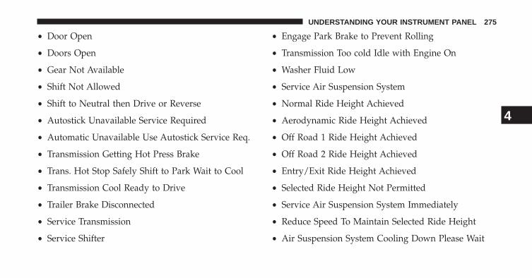
• Door Open
• Doors Open
• Gear Not Available
• Shift Not Allowed
• Shift to Neutral then Drive or Reverse
• Autostick Unavailable Service Required
• Automatic Unavailable Use Autostick Service Req.
• Transmission Getting Hot Press Brake
• Trans. Hot Stop Safely Shift to Park Wait to Cool
• Transmission Cool Ready to Drive
• Trailer Brake Disconnected
• Service Transmission
• Service Shifter
• Engage Park Brake to Prevent Rolling
• Transmission Too cold Idle with Engine On
• Washer Fluid Low
• Service Air Suspension System
• Normal Ride Height Achieved
• Aerodynamic Ride Height Achieved
• Off Road 1 Ride Height Achieved
• Off Road 2 Ride Height Achieved
• Entry/Exit Ride Height Achieved
• Selected Ride Height Not Permitted
• Service Air Suspension System Immediately
• Reduce Speed To Maintain Selected Ride Height
• Air Suspension System Cooling Down Please Wait
4
UNDERSTANDING YOUR INSTRUMENT PANEL 275

• Vehicle Cannot Be Lowered Door Open
• Off Road 2 Watch For Clearance
• Entry/Exit Watch For Clearance
• Air Suspension Temporarily Disabled For jacking AndTire Change
• Battery Low Start Engine To Change Ride Height
• Stop/Start Ready – If Equipped
• Stop/Start Not Ready – If Equipped
• Stop/Start Not Ready Hood Open – If Equipped
• Stop/Start Not Ready Battery Charging – If Equipped
• Stop/Start Not Ready Trailer Tow/Haul Selected – IfEquipped
• Stop/Start Not Ready 4WD/Low Range Selected – IfEquipped
• Stop/Start Not Ready Fuel Level Low – If Equipped
• Stop/Start Not Ready Steep Incline – If Equipped
• Stop/Start Not Ready Extreme Outside Temperature –If Equipped
• Stop/Start Not Ready Engine Temperature Too High –If Equipped
• Stop/Start Not Ready Engine Temperature Too Low –If Equipped
• Stop/Start Not Ready Driver Seatbelt Unbuckled – IfEquipped
• Stop/Start Not Ready Driver Door Open – If Equipped
• Stop/Start Not Ready Cabin Cooling Or Heating – IfEquipped
• Stop/Start Not Ready Not Ready Max Cooling OrHeating – If Equipped
276 UNDERSTANDING YOUR INSTRUMENT PANEL

• Stop/Start Not Ready Max Cooling Or Heating Se-lected – If Equipped
• Stop/Start Not Ready Front Defrost Selected – IfEquipped
• Stop/Start Not Ready Steering Wheel Turned – IfEquipped
• Stop/Start Autostop Active – If Equipped
• Stop/Start To Restart Press Clutch Or Shift To Neutral– If Equipped
• Stop/Start Req’d Fault Detected – If Equipped
• Stop/Start Cannot Autostart Hood Open – IfEquipped
• Stop/Start Unavailable Service Battery – If Equipped
• Stop/Start Unavailable Service Stop/Start System – IfEquipped
• Stop/Start To Restart Shift Out Of Park – If Equipped
• Stop/Start Off – If Equipped
• Autostop Duration – If Equipped
The Reconfigurable Telltales section is divided into thewhite telltales area on the right, amber telltales in themiddle, and red telltales on the left.
EVIC Amber Telltales
This area will show reconfigurable amber caution tell-tales. These telltales include:
• Low Fuel Telltale
When the fuel level reaches approximately 3.0 gal(11.0 L) this light will turn on, and remain on until
fuel is added.
4
UNDERSTANDING YOUR INSTRUMENT PANEL 277

• Windshield Washer Fluid Low Indicator
This telltale will turn on to indicate the wind-shield washer fluid is low.
• Low Coolant Level Indicator
This telltale will turn on to indicate the vehiclecoolant level is low.
• Transmission Temperature Warning Telltale
This telltale indicates that the transmissionfluid temperature is running hot. This mayoccur with severe usage, such as trailer towing.If this telltale turns on, safely pull over and
stop the vehicle. Then, shift the transmission into NEU-TRAL and run the engine at idle or faster until the lightturns off.
• Air Suspension Payload Protection Telltale
This telltale will turn on to indicate that themaximum payload may have been exceeded orload leveling cannot be achieved at its currentride height.
Protection Mode will automatically be selected in orderto “protect” the air suspension system, air suspensionadjustment is limited due to payload.
• Service Stop/Start System Telltale - If Equipped
This telltale will turn on to indicate that theStop/Start is Unavailable, service Stop/Startsystem.
CAUTION!
Continuous driving with the Transmission Tempera-ture Warning Light illuminated will eventually causesevere transmission damage or transmission failure.
278 UNDERSTANDING YOUR INSTRUMENT PANEL

WARNING!
If you continue operating the vehicle when theTransmission Temperature Warning Light is illumi-nated you could cause the fluid to boil over, come incontact with hot engine or exhaust components andcause a fire.
EVIC White Telltales
• Electronic Speed Control Ready
This light will turn on when the electronicspeed control is ON. For further information,refer to “Electronic Speed Control” in “Under-standing The Features Of Your Vehicle.”
EVIC Red Telltales
This area will show reconfigurable red telltales. Thesetelltales include:
• Door Ajar
This light will turn on to indicate that one ormore doors may be ajar.
• Oil Pressure Warning Light
This telltale indicates low engine oil pressure. Ifthe light turns on while driving, stop the vehicle and shutoff the engine as soon as possible. A chime will sound forfour minutes when this light turns on.
Do not operate the vehicle until the cause is corrected.This light does not show how much oil is in the engine.The engine oil level must be checked under the hood.
4
UNDERSTANDING YOUR INSTRUMENT PANEL 279

• Oil Temperature Warning Light
This telltale indicates engine oil temperature ishigh. If the light turns on while driving, stopthe vehicle and shut off the engine as soon aspossible.
• Charging System Light
This light shows the status of the electrical charg-ing system. If the light stays on or comes on while
driving, turn off some of the vehicle’s non-essentialelectrical devices or increase engine speed (if at idle). Ifthe charging system light remains on, it means that thevehicle is experiencing a problem with the chargingsystem. Obtain SERVICE IMMEDIATELY. See an autho-rized dealer.
If jump starting is required, refer to “Jump StartingProcedures” in “What To Do In Emergencies”.
• Electronic Throttle Control (ETC) Light
This light informs you of a problem with theElectronic Throttle Control (ETC) system. Thelight will come on when the ignition is firstturned ON and remain on briefly as a bulb
check. If the light does not come on during starting, havethe system checked by an authorized dealer.
If a problem is detected, the light will come on while theengine is running. Cycle the ignition key when thevehicle has completely stopped and the shift lever isplaced in the PARK position. The light should turn off.
If the light remains lit with the engine running, yourvehicle will usually be drivable. However, see an autho-rized dealer for service as soon as possible. If the light isflashing when the engine is running, immediate service isrequired. You may experience reduced performance, anelevated/rough idle or engine stall and your vehicle mayrequire towing.
280 UNDERSTANDING YOUR INSTRUMENT PANEL

• Engine Temperature Warning Light
This light warns of an overheated engine condi-tion. As temperatures rise and the gauge ap-
proaches H, this indicator will illuminate and a singlechime will sound after reaching a set threshold. Furtheroverheating will cause the temperature gauge to pass H,the indicator will continuously flash and a continuouschime will occur until the engine is allowed to cool.
If the light turns on while driving, safely pull over andstop the vehicle. If the A/C system is on, turn it off. Also,shift the transmission into NEUTRAL and idle the ve-hicle. If the temperature reading does not return tonormal, turn the engine off immediately and call forservice. Refer to “If Your Engine Overheats” in “What ToDo In Emergencies” for more information.
EVIC Green Telltales
• Electronic Speed Control SET
This telltale will illuminate green when theelectronic speed control is SET. For furtherinformation, refer to “Electronic Speed Con-trol” in “Understanding The Features Of Your
Vehicle.”
EVIC Selectable Menu Items
Press and release the UP or DOWN arrow buttons untilthe desired Selectable Menu icon is highlighted in theEVIC.
4
UNDERSTANDING YOUR INSTRUMENT PANEL 281

Digital Speedometer
Press and release the UP or DOWN arrow buttonuntil the Digital display icon is highlighted in theEVIC. Press and release the SELECT/RIGHTarrow button to change the display
between km/h and mph.
Vehicle Info (Customer Information Features)
Press and release the UP or DOWN arrow buttonuntil the Vehicle Info icon is highlighted in theEVIC. Press and release the SELECT/RIGHTarrow button and Coolant Temp will be dis-
played. Press the LEFT or SELECT/RIGHT arrow button toscroll through the following information sub-menus:
Air Suspension – If Equipped
Transmission Temperature – Automatic TransmissionOnly
Oil Temp
Oil Life
Multimeter
Tire Pressure
Press and release the UP or DOWN arrow button until“Tire Pressure” is highlighted in the EVIC. Press andrelease the SELECT/RIGHT arrow button and one of thefollowing will be displayed:
If tire pressure is OK for all tires a vehicle ICON isdisplayed with tire pressure values in each corner of theICON.
If one or more tires have low pressure, “Inflate Tire ToXX” is displayed with the vehicle ICON and the tire
282 UNDERSTANDING YOUR INSTRUMENT PANEL

pressure values in each corner of the ICON with thepressure value of the low tire displayed in a differentcolor than the other tire pressure value.
If the Tire Pressure system requires service, “Service TirePressure System” is displayed.
Tire PSI is an information only function and cannot bereset. Press and release the LEFT arrow button to returnto the main menu.
Refer to “Tire Pressure Monitoring System (TPMS)”under “Starting and Operating” for further information.
Trip A
Press and release the UP or DOWN arrowbutton until the Trip A icon is highlighted inthe EVIC (Toggle left or right to select Trip A orTrip B). (Toggle left or right to select Trip A or
Trip B) The Trip A information will display the following:
• Distance
• Average Fuel Economy
• Average Speed
• Elapsed Time
Hold the SELECT/RIGHT arrow button to reset all theinformation.
Trip B
Press and release the Left or Right arrow but-ton until the Trip B icon is highlighted in theEVIC (Toggle left or right to select Trip A orTrip B). The Trip B information will display thefollowing:
• Distance
• Average Fuel Economy
4
UNDERSTANDING YOUR INSTRUMENT PANEL 283

• Average Speed
• Elapsed Time
Hold the SELECT/RIGHT arrow button to reset all theinformation.
Fuel Economy
Press and release the UP or DOWN arrowbutton until the Fuel Economy icon ishighlighted.
• Average Fuel Economy/Miles Per Gallon (MPG Bar-graph)
• Range To Empty (RTE)
• Current Miles Per Gallon (MPG)
Stop/Start – If Equipped
Press and release the UP or DOWN arrowbutton until the Stop/Start icon is highlightedin the EVIC. Press and release the SELECT/RIGHT arrow button to display the Stop/Startstatus.
Trailer Tow
Press and release the UP or DOWN arrowbutton until the Trailer Tow icon is highlighted.Press the SELECT/RIGHT arrow button andthe next screen will display the following
trailer trip information:
• Trailer Trip
• Trailer Brake
284 UNDERSTANDING YOUR INSTRUMENT PANEL

Audio
Press and release the UP or DOWN arrowbutton until the Audio display icon is high-lighted in the EVIC. Press and release theSELECT/RIGHT arrow button to display the
active source.
Screen Setup
Press and release the UP or DOWN arrowbutton until the Screen Setup display icon ishighlighted in the EVIC. Press and release theSELECT/RIGHT arrow button to enter the
Screen Setup sub-menu. The Screen Setup feature allowsyou to change what information is displayed in theinstrument cluster as well as the location that informationis displayed.
Stored Messages
Press and release the UP or DOWN button until “Mes-sages: XX” displays highlighted in the EVIC. If there ismore than one message, pressing the SELECT/RIGHTbutton will display a stored warning message. Press andrelease the UP and DOWN buttons if there is more thanone message to step through the remaining stored mes-sages. If there are no message, pressing the SELECT/RIGHT button will do nothing.
Personal Settings (Customer-ProgrammableFeatures)
For vehicles equipped a 3.5” EVIC screen
Personal Settings allows the driver to set and recallfeatures when the transmission is in PARK.
Press and release the UP and DOWN button until Per-sonal Settings displays in the EVIC.
4
UNDERSTANDING YOUR INSTRUMENT PANEL 285
Press and release the SELECT/RIGHT arrow button todisplay one of the following choices.
For vehicles equipped with a 7” EVIC screen and notequipped with a Uconnect® Access 8.4 radio.
Personal Settings allows the driver to set and recallfeatures when the transmission is in PARK.
Use the UP or DOWN button until Personal Settingsdisplays in the EVIC.
Press and release the SELECT/RIGHT arrow button toEnter Vehicle Settings
Use the UP or DOWN button to display one of thefollowing choices.
NOTE: Your vehicle may or may not be equipped withthe following settings.
Language
When in this display you may select one of six languagesfor all display nomenclature, including the trip functionsand the navigation system (if equipped). Press the UP orDOWN button while in this display and scroll throughthe language choices. Press the SELECT button to selectEnglish, Spanish (Español), French (Français), Italian,German, Dutch. Then, as you continue, the informationwill display in the selected language.
Units
Press and release the UP or DOWN button until “Units”displays in the EVIC and press the SELECT button. TheEVIC, odometer, and navigation system (if equipped) canbe changed between English and Metric units of mea-sure. To make your selection, press and release theSELECT button the selected setting will be displayed.
286 UNDERSTANDING YOUR INSTRUMENT PANEL

Nav–Turn By Turn – If Equipped
When this feature is selected, the navigation systemutilizes voice commands, guiding through the driveroute, mile by mile, turn-by-turn until the final destina-tion is reached. To make your selection, press and releasethe SELECT button until a check-mark appears next tothe feature showing the system has been activated or thecheck-mark is removed showing the system has beendeactivated.
Park Assist System — If Equipped
The Rear Park Assist system will scan for objects behindthe vehicle when the transmission is in the REVERSEposition and the vehicle speed is less than 11 mph(18 km/h). The system can be enabled with Sound Onlyor Sound and Display. To make your selection, scroll upor down until the preferred setting is highlighted, thenpress and release the SELECT button until a check-markappears next to the setting, showing that the setting has
been selected. Refer to “Rear Park Assist System” in“Understanding The Features Of Your Vehicle” for sys-tem function and operating information.
Tilt Mirror In Reverse
When this feature is selected and the shift lever is placedin reverse gear, the side mirrors tilt downward to allowthe driver to see into the previous blind spot and avoidobjects in close proximity to the rear of the vehicle. Tomake your selection, press and release the SELECTbutton until a check-mark appears next to the featureshowing the system has been activated or the check-markis removed showing the system has been deactivated.
Auto Wipers — If Equipped
When ON is selected, the system will automaticallyactivate the windshield wipers if it senses moisture onthe windshield. To make your selection, press and releasethe SELECT button until a check-mark appears next tothe feature showing the system has been activated or the
4
UNDERSTANDING YOUR INSTRUMENT PANEL 287

check-mark is removed showing the system has beendeactivated. When the system is deactivated, the systemreverts to the standard intermittent wiper operation.
Hill Start Assist (HSA)
When on is selected, the HSA system is active. Refer to“Electronic Brake Control System” in “Starting AndOperating” for system function and operating informa-tion. To make your selection, press and release theSELECT button until a check-mark appears next to thefeature showing the system has been activated or thecheck-mark is removed showing the system has beendeactivated.
Headlamp Off Delay
When this feature is selected, the driver can choose tohave the headlights remain on for 0, 30, 60, or 90 secondswhen exiting the vehicle. To make your selection, scrollup or down until the preferred setting is highlighted,
then press and release the SELECT button until a check-mark appears next to the setting, showing that the settinghas been selected.
Illuminated Approach
When this feature is selected, the headlights will activateand remain on for 0, 30, 60, or 90 seconds when the doorsare unlocked with the RKE transmitter. To make yourselection, scroll up or down until the preferred setting ishighlighted, then press and release the SELECT buttonuntil a check-mark appears next to the setting, showingthat the setting has been selected.
Headlamps With Wipers
When this feature is selected and the HEADLIGHTswitch is in the AUTO position, the headlights will turnon approximately 10 seconds after the wipers are turnedon. The headlights will also turn off when the wipers areturned off if they were turned on by this feature. To makeyour selection, press and release the SELECT button until
288 UNDERSTANDING YOUR INSTRUMENT PANEL

a check-mark appears next to the feature showing thesystem has been activated or the check-mark is removedshowing the system has been deactivated.
Automatic High Beams — If Equipped
When this feature is selected, the high beam headlightswill deactivate automatically under certain conditions. Tomake your selection, press and release the SELECTbutton until a check-mark appears next to the featureshowing the system has been activated or the check-markis removed showing the system has been deactivated.Refer to “Lights/SmartBeam™ — If Equipped” in “Un-derstanding The Features Of Your Vehicle” for furtherinformation.
Flash Lamps With Lock
When this feature is selected, the front and rear turnsignals will flash when the doors are locked or unlockedwith the RKE transmitter. This feature may be selectedwith or without the sound horn on lock feature selected.
To make your selection, press and release the SELECTbutton until a check-mark appears next to the featureshowing the system has been activated or the check-markis removed showing the system has been deactivated.
Auto Lock Doors
When this feature is selected, all doors will lock auto-matically when the vehicle reaches a speed of 15 mph(24 km/h). To make your selection, press and release theSELECT button until a check-mark appears next to thefeature showing the system has been activated, or thecheck-mark is removed showing the system has beendeactivated.
Auto Unlock Doors
When this feature is selected, all doors will unlock whenthe vehicle is stopped and the transmission is in thePARK or NEUTRAL position and the driver’s door isopened. To make your selection, press and release theSELECT button until a check-mark appears next to the
4
UNDERSTANDING YOUR INSTRUMENT PANEL 289

feature showing the system has been activated, or thecheck-mark is removed showing the system has beendeactivated.
Horn with Remote Start
When this feature is selected, a short horn sound willoccur when the RKE transmitter REMOTE START buttonis pressed. To make your selection, press and release theSELECT button until a check-mark appears next to thefeature showing the system has been activated or thecheck-mark is removed showing the system has beendeactivated.
Sound Horn With Remote Lock
When this feature is selected, a short horn sound willoccur when the RKE transmitter LOCK button is pressed.This feature may be selected with or without the FlashLamps with Lock feature. To make your selection, press
and release the SELECT button until a check-mark ap-pears next to the feature showing the system has beenactivated or the check-mark is removed showing thesystem has been deactivated.
Remote Unlock Sequence
When Unlock Driver Door Only On 1st Press is selected,only the driver’s door will unlock on the first press of theRKE transmitter UNLOCK button. When Driver Door 1stPress is selected, you must press the RKE transmitterUNLOCK button twice to unlock the passenger’s doors.When Unlock All Doors On 1st Press is selected, all ofthe doors will unlock on the first press of the RKEtransmitter UNLOCK button. To make your selection,scroll up or down until the preferred setting is high-lighted, then press and release the SELECT button until acheck-mark appears next to the setting, showing that thesetting has been selected.
290 UNDERSTANDING YOUR INSTRUMENT PANEL
Key Fob Linked To Memory
When this feature is selected the memory seat, mirror,and radio settings will return to the memory set positionwhen the RKE transmitter UNLOCK button is pressed. Ifthis feature is not selected then the memory seat, mirror,and radio settings can only return to the memory setposition using the seat mounted switch. To make yourselection, press and release the SELECT button until acheck-mark appears next to the feature showing thesystem has been activated or the check-mark is removedshowing the system has been deactivated.
Keyless Enter-N-Go™ (Passive Entry)
This feature allows you to lock and unlock the vehicle’sdoor(s) without having to press the RKE transmitter lockor unlock buttons. To make your selection, press andrelease the SELECT button until a check-mark appearsnext to the feature showing the system has been activatedor the check-mark is removed showing the system has
been deactivated. Refer to “Keyless Enter-N-Go™” in“Things To Know Before Starting Your Vehicle”.
Remote Start Comfort Sys.
When this feature is selected and the remote start isactivated, the heated steering wheel and driver heatedseat features will automatically turn on in cold weather.In warm weather, the driver vented seat feature willautomatically turn on when the remote start is activated.These features will stay on through the duration ofremote start or until the key is turned to RUN. To makeyour selection, press and release the SELECT button untila check-mark appears next to the feature showing thesystem has been activated or the check-mark is removedshowing the system has been deactivated.
Key-Off Power Delay
When this feature is selected, the power windowswitches, radio, hands-free system (if equipped), DVDvideo system (if equipped), power sunroof (if equipped),
4
UNDERSTANDING YOUR INSTRUMENT PANEL 291

and power outlets will remain active for up to 10 minutesafter the ignition switch is turned OFF. Opening eitherfront vehicle door will cancel this feature. To make yourselection, scroll up or down until the preferred setting ishighlighted, then press and release the SELECT buttonuntil a check-mark appears next to the setting, showingthat the setting has been selected.
Air Suspension Display Alerts – If Equipped
When All is selected, all the Air Suspension Alerts will bedisplayed. When Warnings Only is selected only the AirSuspension Warnings will be displayed. To make yourselection, scroll up or down until the preferred setting ishighlighted, then press and release the SELECT buttonuntil a check-mark appears next to the setting, showingthat the setting has been selected.
Aero Ride Height Mode (1500 Only) – If Equipped
When this feature is selected the Ride Height will auto-matically be adjusted depending on the vehicle speed. To
make your selection, press and release the SELECTbutton until a check-mark appears next to the featureshowing the system has been activated or the check-markis removed showing the system has been deactivated.
Tire/Jack Mode – If Equipped
When this feature is selected the air suspension system isdisabled to assist with changing a spare tire. To makeyour selection, press and release the SELECT button untila check-mark appears next to the feature showing thesystem has been activated or the check-mark is removedshowing the system has been deactivated.
Transport Mode – If Equipped
When this feature is selected the air suspension system isdisabled to assist with flat bed towing. To make yourselection, press and release the SELECT button until acheck-mark appears next to the feature showing thesystem has been activated or the check-mark is removedshowing the system has been deactivated.
292 UNDERSTANDING YOUR INSTRUMENT PANEL

Wheel Alignment Mode – If Equipped
Before performing a wheel alignment this mode must beenabled. Refer to your authorized dealer for furtherinformation.
Horn with Remote Lower – If Equipped
When this feature is selected, a short horn sound willoccur when the RKE transmitter REMOTE LOWER but-ton is pressed. To make your selection, press and releasethe SELECT button until a check-mark appears next tothe feature showing the system has been activated or thecheck-mark is removed showing the system has beendeactivated.
Lights with Remote Lower – If Equipped
When this feature is selected, the front and rear turnsignals will flash when the RKE transmitter REMOTELOWER button is pressed. This feature may be selectedwith or without the sound horn on lower feature selected.
To make your selection, press and release the SELECTbutton until a check-mark appears next to the featureshowing the system has been activated or the check-markis removed showing the system has been deactivated.
Trailer Select
When this feature is selected, the Trailer Type can beselected between “Trailer 1”, “Trailer 2”, “Trailer 3” and“Trailer 4”. To make your selection, scroll up or downuntil the preferred setting is highlighted, then press andrelease the SELECT button until a check-mark appearsnext to the setting, showing that the setting has beenselected.
Trailer Brake Type
When this feature is selected, the Trailer Brake Type canbe changed between “Light Electric”, “Heavy Electric”,“Light EOH” and “Heavy EOH”. To make your selection,scroll up or down until the preferred setting is high-lighted, then press and release the SELECT button until a
4
UNDERSTANDING YOUR INSTRUMENT PANEL 293

check-mark appears next to the setting, showing that thesetting has been selected. Refer to “Integrated TrailerBrake Module” in “Starting And Operating.”
Trailer Name
When this feature is selected, the Trailer name can beselected from 16 names. To make your selection, scroll upor down until the preferred setting is highlighted, thenpress and release the SELECT button until a check-markappears next to the setting, showing that the setting hasbeen selected.
Calibrate Compass
Refer to “Compass Display” for more information.
Compass Variance
Refer to “Compass Display” for more information.
Screen Setup Driver Selectable Items
Odometer
• 000
• 000.0
Upper Left
• None
• Compass
• Outside Temp (default setting)
• Trans Temp
• Oil Temp
• Time
• Range To Empty (RTE)
• Average MPG
294 UNDERSTANDING YOUR INSTRUMENT PANEL

• Current MPG
• Trip A
• Trip B
• Trailer Trip (distance only)
• Trailer Brake Gain
Upper Right
• None
• Compass (default setting)
• Outside Temp
• Trans Temp
• Oil Temp
• Time
• Range To Empty (RTE)
• Average MPG
• Current MPG
• Trip A
• Trip B
• Trailer Trip (distance only)
• Trailer Brake Gain
Lower Left
• None (default setting)
• Compass
• Outside Temp
• Trans Temp
• Oil Temp
• Time
4
UNDERSTANDING YOUR INSTRUMENT PANEL 295

• Range
• AVG MPG
• Current MPG
• Trailer Brake Gain
Lower Right
• None (default setting)
• Compass
• Outside Temp
• Trans Temp
• Oil Temp
• Time
• Range
• AVG MPG
• Current MPG
• Trailer Brake Gain
Restore To Defaults (Restores All Settings To DefaultSettings)
• Cancel
• Okay
Uconnect® ACCESS SETTINGS
The Uconnect® Access system uses a combination of softand hard keys located on the center of the instrumentpanel that allows you to access and change the customerprogrammable features.
Hard-Keys
Hard-Keys are located below the Uconnect® Accesssystem in the center of the instrument panel. In addition,there is a Scroll/Enter control knob located on the right
296 UNDERSTANDING YOUR INSTRUMENT PANEL

side of the Climate Controls in the center of the instru-ment panel. Turn the control knob to scroll throughmenus and change settings (i.e., 30, 60, 90), press thecenter of the control knob one or more times to select orchange a setting (i.e., ON, OFF).
Your Uconnect® Access system may also have a ScreenOff and Back hard-keys located below the system.
Press the Screen Off hard-key to turn off the Uconnect®Access screen. Press the Screen Off hard-key a secondtime to turn the screen on.
Press the Back hard-key to exit out of a Menu or certainoption on the Uconnect® Access system.
Soft-Keys
Soft-Keys are accessible on the Uconnect® Access dis-play.
Customer Programmable Features — Uconnect®Access 8.4 Settings
Press the Apps soft-key, then press the Settings soft-keyto display the menu setting screen. In this mode theUconnect® Access system allows you to access program-mable features that may be equipped such as Display,Clock, Safety/Assistance, Lights, Doors & Locks,Auto-On Comfort & Remote Start, Engine Off Operation,Compass Settings, Audio, Phone/Bluetooth and Siri-usXM Setup.
NOTE: Only one touchscreen area may be selected at atime.
When making a selection, press the soft-key to enter thedesired mode. Once in the desired mode press andrelease the preferred setting until a check-mark appearsnext to the setting, showing that setting has been se-lected. Once the setting is complete either press the BackArrow soft-key or the Back hard-key to return to the
4
UNDERSTANDING YOUR INSTRUMENT PANEL 297

previous menu or press the X soft-key to close out of thesettings screen. Pressing the Up or Down Arrow soft-keyson the right side of the screen will allow you to toggle upor down through the available settings.
Display
After pressing the Display soft-key the following settingswill be available.
• Display Mode
When in this display you may select one of the autodisplay settings. To change Mode status, touch andrelease the Day, Night or Auto soft-key. Then touch thearrow back soft-key.
• Display Brightness With Headlights ON
When in this display, you may select the brightness withthe headlights on. Adjust the brightness with the + and –
setting soft-keys or by selecting any point on the scalebetween the + and – soft-keys. Then touch the arrow backsoft-key.
• Display Brightness With Headlights OFF
When in this display, you may select the brightness withthe headlights off. Adjust the brightness with the + and –setting soft-keys or by selecting any point on the scalebetween the + and – soft-keys. Then touch the arrow backsoft-key.
• Set Language
When in this display, you may select one of threelanguages for all display nomenclature, including the tripfunctions and the navigation system (if equipped). Touchthe Set Language soft-key and then touch the desiredlanguage soft-key until a check-mark appears next to thelanguage, showing that setting has been selected. Touchthe back arrow soft-key to return to the previous menu.
298 UNDERSTANDING YOUR INSTRUMENT PANEL

• Units
When in this display, you may select to have the EVIC,odometer, and navigation system (if equipped) changedbetween US and Metric units of measure. Touch US orMetric until a check-mark appears next to the setting,showing that setting has been selected. Touch the backarrow soft-key to return to the previous menu.
• Voice Response Length
When in this display, you may change the Voice Re-sponse Length settings. To change the Voice ResponseLength, touch the Brief or Detailed soft-key until acheck-mark appears next to the setting, showing thatsetting has been selected. Touch the back arrow soft-keyto return to the previous menu.
• Touchscreen Beep
When in this display, you may turn on or shut off thesound heard when a touch screen button (soft-key) is
pressed. Touch the Touchscreen Beep soft-key until acheck-mark appears next to the setting, showing thatsetting has been selected. Touch the back arrow soft-keyto return to the previous menu.
• Navigation Turn-By-Turn In Cluster — If Equipped
When this feature is selected, the turn-by-turn directionswill appear in the display as the vehicle approaches adesignated turn within a programmed route. To makeyour selection, touch the Navigation Turn-By-Turn InCluster soft-key, until a check-mark appears next to thesetting, showing that setting has been selected. Touch theback arrow soft-key to return to the previous menu.
• Fuel Saver Display In Cluster
The “ECO” message is located in the instrument clusterdisplay, this message can be turned on or off. To makeyour selection, touch the Fuel Saver Display soft-key,
4
UNDERSTANDING YOUR INSTRUMENT PANEL 299
until a check-mark appears next to the setting, showingthat setting has been selected. Touch the back arrowsoft-key to return to the previous menu.
Clock
After pressing the Clock soft-key the following settingswill be available.
• Sync Time With GPS
When in this display, you may automatically have theradio set the time. To change the Sync Time setting touchthe Sync with GPS Time soft-key until a check-markappears next to the setting, showing that setting has beenselected. Touch the back arrow soft-key to return to theprevious menu.
• Set Time Hours
When in this display, you may adjust the hours. The Syncwith GPS Time soft-key must be unchecked. To makeyour selection touch the + or - soft-keys to adjust the
hours up or down. Touch the back arrow soft-key toreturn to the previous menu or touch the X soft-key toclose out of the settings screen.
• Set Time Minutes
When in this display, you may adjust the minutes. TheSync with GPS Time soft-key must be unchecked. Tomake your selection touch the + or - soft-keys to adjustthe minutes up or down. Touch the back arrow soft-keyto return to the previous menu or touch the X soft-key toclose out of the settings screen.
• Time Format
When in this display, you may select the time formatdisplay setting. Touch the Time Format soft-key until acheck-mark appears next to the 12hrs or 24hrs setting,showing that setting has been selected. Touch the backarrow soft-key to return to the previous menu.
300 UNDERSTANDING YOUR INSTRUMENT PANEL

Safety / Assistance
After pressing the Safety / Assistance soft-key the fol-lowing settings will be available.
• Park Assist
The Rear Park Assist system will scan for objects behindthe vehicle when the transmission shift lever is in RE-VERSE and the vehicle speed is less than 11 mph(18 km/h). The system can be enabled with Sound Onlyor Sound and Display. To change the Park Assist status,touch and release Sound Only or Sounds and Displaybutton. Then touch the arrow back soft-key. Refer to“ParkSense® Rear Park Assist” in “Understanding TheFeatures Of Your Vehicle” for system function and oper-ating information.
• Tilt Mirrors In Reverse
When this feature is selected, the outside sideview mir-rors will tilt downward when the ignition is in the RUN
position and the transmission shift lever is in the RE-VERSE position. The mirrors will move back to theirprevious position when the transmission is shifted out ofREVERSE. To make your selection, touch the Tilt MirrorsIn Reverse soft-key, until a check-mark appears next tosetting, showing that setting has been selected. Touch theback arrow soft-key to return to the previous menu.
• ParkView® Backup Camera
Your vehicle may be equipped with the ParkView® RearBack Up Camera that allows you to see an on-screenimage of the rear surroundings of your vehicle wheneverthe shift lever is put into REVERSE. The image will bedisplayed on the radio touchscreen display along with acaution note to “check entire surroundings” across thetop of the screen. After five seconds, this note willdisappear. The ParkView® camera is located on the rearof the vehicle above the rear License plate. To make yourselection, touch the ParkView® Backup Camera soft-key,
4
UNDERSTANDING YOUR INSTRUMENT PANEL 301

until a check-mark appears next to setting, showing thatsetting has been selected. Touch the back arrow soft-keyto return to the previous menu.
• Rain Sensing Auto Wipers
When this feature is selected, the system will automati-cally activate the windshield wipers if it senses moistureon the windshield. To make your selection, touch theRain Sensing soft-key, until a check-mark appears next tosetting, showing that setting has been selected. Touch theback arrow soft-key to return to the previous menu.
• Hill Start Assist — If Equipped
When this feature is selected, the Hill Start Assist (HSA)system is active. Refer to “Electronic Brake ControlSystem” in “Starting And Operating” for system functionand operating information. To make your selection, touchthe Hill Start Assist soft-key, until a check-mark appears
next to setting, showing that setting has been selected.Touch the back arrow soft-key to return to the previousmenu.
• Four Corner Air Suspension Modes — If Equipped
There are four air suspension modes designed to protectthe system in unique situations. Tire Jack Mode is se-lected to assist in changing a spare tire. Transport Modeis selected to assist when the vehicle is being flat bedtowed. Wheel Alignment Mode is selected before per-forming a wheel alignment, refer to your authorizeddealer for information. Protection Mode will automati-cally be selected in order to “protect” the air suspensionsystem when the payload has been exceeded or loadleveling cannot be achieved.
Lights
After pressing the Lights soft-key the following settingswill be available.
302 UNDERSTANDING YOUR INSTRUMENT PANEL

• Headlight Illumination On Approach
When this feature is selected, the headlights will activateand remain on for 0, 30, 60, or 90 seconds when the doorsare unlocked with the Remote Keyless Entry (RKE)transmitter. To change the Illuminated Approach status,touch the + or - soft-key to select your desired timeinterval. Touch the back arrow soft-key to return to theprevious menu.
• Headlights With Wipers — If Equipped
When this feature is selected, and the headlight switch isin the AUTO position, the headlights will turn on ap-proximately 10 seconds after the wipers are turned on.The headlights will also turn off when the wipers areturned off if they were turned on by this feature. To makeyour selection, touch the Headlights With Wipers softkey,until a check-mark appears next to setting, showing thatsetting has been selected. Touch the back arrow soft-keyto return to the previous menu.
• Auto Dim High Beams “SmartBeam™” — IfEquipped
When this feature is selected, the high beam headlightswill deactivate automatically under certain conditions. Tomake your selection, touch the Auto High Beams softkey,until a check-mark appears next to setting, showing thatsetting has been selected. Touch the back arrow soft-keyto return to the previous menu. Refer to “Lights/ Smart-Beam™ — If Equipped” in “Understanding The FeaturesOf Your Vehicle” for further information.
• Daytime Running Lights – If Equipped
When this feature is selected, the headlights will turn onwhenever the engine is running. To make your selection,touch the Daytime Running Lights soft-key, until acheck-mark appears next to setting, showing that settinghas been selected. Touch the back arrow soft-key toreturn to the previous menu.
4
UNDERSTANDING YOUR INSTRUMENT PANEL 303

• Flash Headlights With Lock
When this feature is selected, the headlights will flashwhen the doors are locked or unlocked with the RemoteKeyless Entry (RKE) transmitter. This feature may beselected with or without the sound horn on lock featureselected. To make your selection, touch the Flash Head-lights with Lock soft-key, until a check-mark appearsnext to setting, showing that setting has been selected.Touch the back arrow soft-key to return to the previousmenu.
Doors & Locks
After pressing the Doors & Locks soft-key the followingsettings will be available.
• Auto Unlock On Exit
When this feature is selected, all doors will unlock whenthe vehicle is stopped and the transmission is in thePARK or NEUTRAL position and the driver’s door is
opened. To make your selection, touch the Auto UnlockOn Exit soft-key, until a check-mark appears next tosetting, showing that setting has been selected. Touch theback arrow soft-key to return to the previous menu.
• Sound Horn With Lock
When this feature is selected, the horn will sound whenthe door locks are activated. To make your selection,touch the Sound Horn With Lock soft-key, until a check-mark appears next to setting, showing that setting hasbeen selected. Touch the back arrow soft-key to return tothe previous menu.
• Sound Horn With Remote Start
When this feature is selected, the horn will sound whenthe remote start is activated. To make your selection,touch the Sound Horn With Remote Start soft-key, until acheck-mark appears next to setting, showing that settinghas been selected. Touch the back arrow soft-key toreturn to the previous menu.
304 UNDERSTANDING YOUR INSTRUMENT PANEL
• 1st Press Of Key Fob Unlocks
When 1st Press Of Key Fob Unlocks is selected, only thedriver’s door will unlock on the first press of the RemoteKeyless Entry (RKE) transmitter UNLOCK button. When1st Press Of Key Fob Unlocks is selected, you must pressthe RKE transmitter UNLOCK button twice to unlock thepassenger’s doors. When Unlock All Doors On 1st Pressis selected, all of the doors will unlock on the first pressof the RKE transmitter UNLOCK button.
NOTE: If the vehicle is programmed 1st Press Of KeyFob Unlocks, all doors will unlock no matter whichPassive Entry equipped door handle is grasped. If 1stPress Of Key Fob Unlocks is programmed, only thedriver’s door will unlock when the driver’s door isgrasped. With Passive Entry, if 1st Press Of Key FobUnlocks is programmed touching the handle more thanonce will only result in the driver’s door opening. Ifdriver door first is selected, once the driver door is
opened, the interior door lock/unlock switch can be usedto unlock all doors (or use RKE transmitter).
• Passive Entry
This feature allows you to lock and unlock the vehicle’sdoor(s) without having to press the Remote KeylessEntry (RKE) transmitter lock or unlock buttons. To makeyour selection, touch the Passive Entry soft-key, until acheck-mark appears next to setting, showing that settinghas been selected. Touch the back arrow soft-key toreturn to the previous menu. Refer to “Keyless Enter-N-Go™” in “Things To Know Before Starting Your Vehicle”.
• Memory To FOB — If Equipped
This feature provides automatic driver seat positioning toenhance driver mobility when entering and exiting thevehicle. To make your selection, touch the MemoryLinked To FOB soft-key, until a check-mark appears nextto setting, showing that setting has been selected. Touchthe back arrow soft-key to return to the previous menu.
4
UNDERSTANDING YOUR INSTRUMENT PANEL 305

NOTE: The seat will return to the memorized seatlocation (if Recall Memory with Remote Key Unlock is setto ON) when the Remote Keyless Entry (RKE) transmitteris used to unlock the door. Refer to “Driver MemorySeat” in “Understanding The Features Of Your Vehicle”for further information.
Auto-On Comfort & Remote Start
After pressing the Auto-On Comfort & Remote Startsoft-key the following settings will be available.
• Horn With Remote Start
When this feature is selected, the horn will sound whenthe remote start is activated. To make your selection,touch the Sound Horn With Remote Start soft-key, until acheck-mark appears next to setting, showing that settinghas been selected. Touch the back arrow soft-key toreturn to the previous menu.
• Auto-On Driver Heated/Ventilated Seat & SteeringWheel With Vehicle Start — If Equipped
When this feature is selected the driver’s heated seat andheated steering wheel will automatically turn on whentemperatures are below 40° F (4.4° C). When tempera-tures are above 80° F (26.7° C) the driver vented seat willturn on. To make your selection, touch the Auto HeatedSeats soft-key, until a check-mark appears next to setting,showing that setting has been selected. Touch the backarrow soft-key to return to the previous menu.
Engine Off Options
After pressing the Engine Off Options soft-key the fol-lowing settings will be available.
• Engine Off Power Delay
When this feature is selected, the power windowswitches, radio, Uconnect® phone system (if equipped),DVD video system (if equipped), power sunroof (if
306 UNDERSTANDING YOUR INSTRUMENT PANEL

equipped), and power outlets will remain active for up to10 minutes after the ignition is cycled to OFF. Openingeither front door will cancel this feature. To change theEngine Off Power Delay status touch the 0 seconds, 45seconds, 5 minutes or 10 minutes soft-key. Then touch thearrow back soft-key.
• Headlight Off Delay
When this feature is selected, the driver can choose tohave the headlights remain on for 0, 30, 60, or 90 secondswhen exiting the vehicle. To change the Headlight OffDelay status touch the + or - soft-key to select yourdesired time interval. Touch the back arrow soft-key toreturn to the previous menu.
Compass Settings – If Equipped
After pressing the Compass Settings soft-key the follow-ing settings will be available.
• Variance
Compass Variance is the difference between MagneticNorth and Geographic North. To compensate for thedifferences the variance should be set for the zone wherethe vehicle is driven, per the zone map. Once properlyset, the compass will automatically compensate for thedifferences, and provide the most accurate compassheading.
NOTE: Keep magnetic materials away from the top ofthe instrument panel, such as iPod’s, Mobile Phones,Laptops and Radar Detectors. This is where the compassmodule is located, and it can cause interference with thecompass sensor, and it may give false readings.
4
UNDERSTANDING YOUR INSTRUMENT PANEL 307
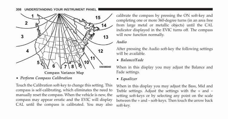
• Perform Compass Calibration
Touch the Calibration soft-key to change this setting. Thiscompass is self-calibrating, which eliminates the need tomanually reset the compass. When the vehicle is new, thecompass may appear erratic and the EVIC will displayCAL until the compass is calibrated. You may also
calibrate the compass by pressing the ON soft-key andcompleting one or more 360-degree turns (in an area freefrom large metal or metallic objects) until the CALindicator displayed in the EVIC turns off. The compasswill now function normally.
Audio
After pressing the Audio soft-key the following settingswill be available.
• Balance/Fade
When in this display you may adjust the Balance andFade settings.
• Equalizer
When in this display you may adjust the Bass, Mid andTreble settings. Adjust the settings with the + and –setting soft-keys or by selecting any point on the scalebetween the + and – soft-keys. Then touch the arrow backsoft-key.
Compass Variance Map
308 UNDERSTANDING YOUR INSTRUMENT PANEL

NOTE: Bass/Mid/Treble allow you to simply slide yourfinger up or down to change the setting as well as touchdirectly on the desired setting.
• Speed Adjusted Volume
This feature increases or decreases volume relative tovehicle speed. To change the Speed Adjusted Volumetouch the Off, 1, 2 or 3 soft-key. Then touch the arrowback soft-key.
• Surround Sound
This feature provides simulated surround sound mode.To make your selection, touch the Surround Soundsoft-key, select On or Off followed by pressing the arrowback soft-key.
Phone/Bluetooth
After pressing the Phone/Bluetooth soft-key the follow-ing settings will be available.
• Paired Devices
This feature shows which phones are paired to thePhone/Bluetooth system. For further information, referto the Uconnect® Access User’s Manual.
Air Suspension – If Equipped
After pressing the Suspension soft-key the followingsettings will be available.
• Sound Horn with Remote Lower
When this feature is selected, a short horn sound willoccur when the RKE transmitter REMOTE LOWER but-ton is pressed. Touch the box next to your selection anda check-mark appears next to the feature showing thesystem has been activated or the check-mark is removedshowing the system has been deactivated..
4
UNDERSTANDING YOUR INSTRUMENT PANEL 309

• Flash Lights with Remote Lower
When this feature is selected, the front and rear turnsignals will flash when the RKE transmitter REMOTELOWER button is pressed twice. This feature may beselected with or without the sound horn on lower featureselected. Touch the box next to your selection and acheck-mark appears next to the feature showing thesystem has been activated or the check-mark is removedshowing the system has been deactivated.
• Suspension Display Messages
When All is selected, all the Air Suspension Alerts will bedisplayed. When Warnings Only is selected only the AirSuspension Warnings will be displayed.
• Automatic Aero Mode
When this feature is selected the Ride Height will auto-matically be adjusted depending on the vehicle speed.Touch the box next to your selection and a check-mark
appears next to the feature showing the system has beenactivated or the check-mark is removed showing thesystem has been deactivated.
• Tire Jack Mode
When this feature is selected the air suspension system isdisabled to assist with changing a spare tire. Touch thebox next to your selection and a check-mark appears nextto the feature showing the system has been activated orthe check-mark is removed showing the system has beendeactivated.
• Transport Mode
When this feature is selected the air suspension system isdisabled to assist with flat bed towing. Touch the boxnext to your selection and a check-mark appears next tothe feature showing the system has been activated or thecheck-mark is removed showing the system has beendeactivated.
310 UNDERSTANDING YOUR INSTRUMENT PANEL

• Wheel Alignment Mode
Before performing a wheel alignment this mode must beenabled. Refer to your authorized dealer for furtherinformation.
SiriusXM Setup
After pressing the SIRIUS Setup soft-key the followingsettings will be available.
• Channel Skip
SiriusXM can be programmed to designate a group ofchannels that are the most desirable to listen to or toexclude undesirable channels while scanning. To makeyour selection, touch the Channel Skip soft-key, select thechannels you would like to skip followed by pressing thearrow back soft-key.
• Subscription Information
New vehicle purchasers or lessees will receive a freelimited time subscription to SiriusXM Satellite Radiowith your radio. Following the expiration of the freeservices, it will be necessary to access the information onthe Subscription Information screen in order to re-subscribe.
Touch the Subscription Info soft-key to access the Sub-scription Information screen.
Write down the SIRIUS ID numbers for your receiver. Toreactivate your service, either call the number listed onthe screen or visit the provider online.
NOTE: SiriusXM Travel Link is a separate subscriptionand is available for U.S. residents only.
4
UNDERSTANDING YOUR INSTRUMENT PANEL 311

Uconnect® RADIOS — IF EQUIPPED
For detailed information about your Uconnect® radiorefer to your Uconnect® Supplement Manual.
iPod®/USB/MP3 CONTROL — IF EQUIPPED
Located inside the center console upper lid, this featureallows an iPod® or external USB device to be pluggedinto the USB port.
iPod® control supports Mini, 4G, Photo, Nano, 5G iPod®and iPhone® devices. Some iPod® software versionsmay not fully support the iPod® control features. Pleasevisit Apple’s website for software updates.
For further information, refer to the Uconnect® AccessUser’s Manual.
STEERING WHEEL AUDIO CONTROLS — IFEQUIPPED
The remote sound system controls are located on the backsurface of the steering wheel. Reach behind the wheel toaccess the switches.
Remote Sound System Controls (Back View Of SteeringWheel)
312 UNDERSTANDING YOUR INSTRUMENT PANEL

The right hand control is a rocker type switch with apushbutton in the center. Pressing the top of the switchwill increase the volume, and pressing the bottom of theswitch will decrease the volume.
The button located in the center of the right hand controlwill switch modes to Radio, CD or other valid audiosource.
The left hand control is a rocker type switch with apushbutton in the center. The function of the left handcontrol is different depending on which mode you are in.
The following describes the left hand control operation ineach mode.
Radio Operation
Pressing the top of the switch will SEEK up for the nextlistenable station and pressing the bottom of the switchwill SEEK down for the next listenable station.
The button located in the center of the left hand controlwill tune to the next pre-set station that you haveprogrammed in the radio pre-set pushbuttons.
CD Player
Pressing the top of the switch once will go to the nexttrack on the CD. Pressing the bottom of the switch oncewill go to the beginning of the current track or to thebeginning of the previous track if it is within one secondafter the current track begins to play.
If you press the switch up or down twice it plays thesecond track, three times, it will play the third, etc.
CD/DVD DISC MAINTENANCE
To keep a CD/DVD in good condition, take the followingprecautions:
1. Handle the disc by its edge; avoid touching thesurface.
4
UNDERSTANDING YOUR INSTRUMENT PANEL 313

2. If the disc is stained, clean the surface with a soft cloth,wiping from center to edge.
3. Do not apply paper or tape to the disc; avoid scratch-ing the disc.
4. Do not use solvents such as benzene, thinner, cleaners,or anti-static sprays.
5. Store the disc in its case after playing.
6. Do not expose the disc to direct sunlight.
7. Do not store the disc where temperatures may becometoo high.
NOTE: If you experience difficulty in playing a particulardisc, it may be damaged (i.e., scratched, reflective coatingremoved, a hair, moisture or dew on the disc) oversized,or have protection encoding. Try a known good discbefore considering disc player service.
RADIO OPERATION AND MOBILE PHONES
Under certain conditions, the mobile phone being on inyour vehicle can cause erratic or noisy performance fromyour radio. This condition may be lessened or eliminatedby relocating the mobile phone antenna. This condition isnot harmful to the radio. If your radio performance doesnot satisfactorily “clear” by the repositioning of theantenna, it is recommended that the radio volume beturned down or off during mobile phone operation whennot using Uconnect® (if equipped).
CLIMATE CONTROLS
The Climate Control System allows you to regulate thetemperature, amount, and direction of air circulatingthroughout the vehicle. The controls are located on theinstrument panel below the radio.
314 UNDERSTANDING YOUR INSTRUMENT PANEL

Manual Climate Controls Without Touch-Screen— If Equipped
The controls for the manual heating and air conditioningsystem in this vehicle consist of a series of outer rotarydials and inner push knobs. These comfort controls canbe set to obtain desired interior conditions.
1 – Front Blower 4 – RECIRCULATION Control2 – Temperature Control 5 – Air Conditioning (A/C)3 – MODE Control 6 – DEFROST Mode
4
UNDERSTANDING YOUR INSTRUMENT PANEL 315

Front Blower Control
There are four blower speeds. Use thiscontrol to regulate the amount of airforced through the system in anymode you select. The blower speedincreases as you move the controlclockwise from the OFF position.
NOTE: For vehicles equipped with Remote Start, theclimate controls will not function during Remote Startoperation if the blower control is left in the OFF position.
Temperature Control
Use this control to regulate the tem-perature of the air inside the passengercompartment. Rotating the knob coun-terclockwise, from top center into theblue area of the scale, indicates coolertemperatures. Rotating the knob clock-wise, into the red area, indicates
warmer temperatures.
NOTE: If your air conditioning performance seemslower than expected, check the front of the A/C con-denser (located in front of the radiator), for an accumu-lation of dirt or insects. Clean with a gentle water sprayfrom behind the radiator and through the condenser.Fabric front fascia protectors may reduce airflow to thecondenser, reducing air conditioning performance.
316 UNDERSTANDING YOUR INSTRUMENT PANEL

Mode Control (Air Direction)
Mode control allows you to choosefrom several patterns of air distribu-tion. You can select either a primarymode, as identified by the symbols, ora blend of two of these modes. Thecloser the control is to a particularmode, the more air distribution you
receive from that mode.
Panel Mode
Air is directed through the outlets in the instru-ment panel. These outlets can be adjusted to directairflow.
Bi-Level Mode
Air is directed through the panel and floor outlets.
NOTE: There is a difference in temperature (inany conditions other than full cold or full hot), betweenthe upper and lower outlets for added comfort. Thewarmer air goes to the floor outlets. This feature givesimproved comfort during sunny but cool conditions.
Floor Mode
Air is directed through the floor outlets with asmall amount through the defrost and side win-
dow demist outlets.
Mix Mode
Air is directed through the floor, defrost and sidewindow demist outlets. This setting works best in
4
UNDERSTANDING YOUR INSTRUMENT PANEL 317

cold or snowy conditions that require extra heat at thewindshield. This setting is good for maintaining comfort,while reducing moisture on the windshield.
Defrost Mode
Air is directed through the windshield and sidewindow demist outlets. Use the DEFROST mode
with maximum blower and warm temperature settingsfor best windshield and side window defrosting.
NOTE: The air conditioning compressor operates in MIXand DEFROST, or a blend of these modes even if the A/Cbutton is not pressed. This dehumidifies the air to helpdry the windshield. To improve fuel economy, use thesemodes only when necessary.
Recirculation Control
Press this button to choose between outside airintake or recirculation of the air inside thevehicle. A LED will illuminate when you are inRecirculation mode. Only use the Recirculation
mode to temporarily block out any outside odors, smoke,or dust, and to cool the interior rapidly upon initialstart-up in very hot or humid weather.
NOTE:
• If the RECIRCULATION button is pressed when thesystem is in Defrost mode the Recirculation LEDindicator will flash three times and then turn off toindicate Recirculation mode is not allowed.
• Continuous use of the Recirculation mode may makethe inside air stuffy and window fogging may occur.Extended use of this mode is not recommended.
318 UNDERSTANDING YOUR INSTRUMENT PANEL

• In cold or damp weather, the use of the Recirculationmode will cause windows to fog on the inside becauseof moisture buildup inside the vehicle. For maximumdefogging, select the outside air position.
• The A/C can be deselected manually without disturb-ing the mode control selection by pressing the A/Cbutton.
Air Outlets
The airflow from each of the instrument panel outlets canbe adjusted for direction, and turned on or off to controlairflow.
NOTE: For maximum airflow to the rear, the centerinstrument panel outlets can be directed toward the rearseat passengers.
Economy Mode
If ECONOMY mode is desired, press the A/C button toturn off the LED indicator and the A/C compressor.
Rotate the temperature control knob to the desired tem-perature. Also, make sure to select only Panel, Bi-Level orFloor modes.
Stop/Start System – If Equipped
While in an Autostop, the Climate Controls system mayautomatically adjust airflow to maintain cabin comfort.Customer settings will be maintained upon return to anengine running condition.
Air Conditioning Operation
Push the A/C button to engage the AirConditioning (A/C). A LED will illu-minate when the A/C system isengaged.
4
UNDERSTANDING YOUR INSTRUMENT PANEL 319

MAX A/C
For maximum cooling, when MAX A/C is selected theA/C is turned on automatically and the air isrecirculated.
NOTE: A/C cannot be deselected when in MAX A/Cposition. The LED will blink three times if the A/Cbutton is pushed.
Manual Climate Controls With Touch-Screen — IfEquipped
Hard-Keys
The hard-keys are located below the radio touch-screen.
Climate Controls — Hard-keys
320 UNDERSTANDING YOUR INSTRUMENT PANEL

Soft-Keys
Soft-keys are accessible on the radio touch-screen.
Button Descriptions (Applies To Both Hard-keys AndSoft-keys)
1. A/C Button
Press and release to change the current setting, theindicator illuminates when A/C is ON. Performing thisfunction again will cause the A/C operation to switchinto manual mode and the A/C indicator will turn off.
2. Recirculation Button
Press and release to change the current setting, theindicator illuminates when ON.
3. Front Defrost Button
Press and release to change the current airflow setting toDefrost mode. The indicator illuminates when this fea-ture is ON. Performing this function will cause the ATCto switch into manual mode. The blower speed may
Temperature Controls — Soft-keys
4
UNDERSTANDING YOUR INSTRUMENT PANEL 321

increase when Defrost mode is selected. If the frontdefrost mode is turned off the climate system will returnthe previous setting.
4. Defrost Button
Press and release this button to turn on the rear windowdefroster (if equipped) and the heated outside mirrors (ifequipped). An indicator will illuminate when the rearwindow defroster is on. The rear window defrosterautomatically turns off after 10 minutes.
CAUTION!
Failure to follow these cautions can cause damage tothe heating elements:
(Continued)
CAUTION! (Continued)• Use care when washing the inside of the rear
window. Do not use abrasive window cleaners onthe interior surface of the window. Use a soft clothand a mild washing solution, wiping parallel to theheating elements. Labels can be peeled off aftersoaking with warm water.
• Do not use scrapers, sharp instruments, or abrasivewindow cleaners on the interior surface of thewindow.
• Keep all objects a safe distance from the window.
5. Modes
The airflow distribution mode can be adjusted so aircomes from the instrument panel outlets, floor outlets,demister outlets and defrost outlets. The Mode settingsare as follows:
322 UNDERSTANDING YOUR INSTRUMENT PANEL

• Panel ModeAir comes from the outlets in the instrumentpanel. Each of these outlets can be individuallyadjusted to direct the flow of air. The air vanes of
the center outlets and outboard outlets can be moved upand down or side to side to regulate airflow direction.There is a shut off wheel located below the air vanes toshut off or adjust the amount of airflow from theseoutlets.• Bi-Level Mode
Air comes from the instrument panel outlets andfloor outlets. A slight amount of air is directedthrough the defrost and side window demisteroutlets.
NOTE: BI-LEVEL mode is designed under comfort con-ditions to provide cooler air out of the panel outlets andwarmer air from the floor outlets.
• Floor ModeAir comes from the floor outlets. A slight amountof air is directed through the defrost and sidewindow demister outlets.
• Mix ModeAir comes from the floor, defrost and side windowdemister outlets. This mode works best in cold orsnowy conditions.
6. Blower Control
Blower control is used to regulate the amount of air forcedthrough the climate system. There are seven blower speedsavailable. Adjusting the blower will cause automatic modeto switch to manual operation. The speeds can be selectedusing either hard-keys or soft-keys as follows:
Hard-key
The blower speed increases as you turn the controlclockwise from the lowest blower setting. The blowerspeed decreases as you turn the knob counter-clockwise.
4
UNDERSTANDING YOUR INSTRUMENT PANEL 323

Soft-key
Use the small blower icon to reduce the blower settingand the large blower icon to increase the blower setting.Blower can also be selected by pressing the blower bararea between the icons.
7. Climate Control OFF Button
Press and release this button to turn the Climate ControlON/OFF.
8. Temperature Control Down Button
Push the button for cooler temperature settings. On thetouch-screen, slide the temperature bar towards the bluearrow soft-key for cooler temperature settings.
9. Temperature Control Up Button
Push the button for warmer temperature settings. On thetouch-screen, slide the temperature bar towards the bluearrow soft-key for cooler temperature settings.
Recirculation Control
When outside air contains smoke, odors, orhigh humidity, or if rapid cooling is desired,you may wish to recirculate interior air bypressing the RECIRCULATION control button.
Recirculation mode should only be used temporarily. Therecirculation LED will illuminate on the blower controlknob when this button is selected. Push the button asecond time to turn off the Recirculation mode LED andallow outside air into the vehicle.
NOTE: In cold weather, use of Recirculation mode maylead to excessive window fogging. The Recirculationmode is not allowed in Defrost mode to improve windowclearing operation. Recirculation will be disabled auto-matically if these modes are selected.
324 UNDERSTANDING YOUR INSTRUMENT PANEL

Automatic Climate Controls With Touch-Screen— If Equipped
Hard-Keys
The hard-keys located below the radio touch-screen.
Soft-Keys
Soft-keys are accessible on the radio touch-screen.
Dual Zone Automatic Climate Controls — Hard-keys
Dual Zone Automatic Temperature Controls — Soft-keys
4
UNDERSTANDING YOUR INSTRUMENT PANEL 325

Button Descriptions (Applies To Both Hard-keys AndSoft-keys)
1. A/C Button
Press and release to change the current setting, theindicator illuminates when A/C is ON. Performing thisfunction again will cause the A/C operation to switchinto manual mode and the A/C indicator will turn off.
2. Recirculation Button
Press and release to change the current setting, theindicator illuminates when ON.
3. Front Defrost Button
Press and release to change the current airflow setting toDefrost mode. The indicator illuminates when this fea-ture is ON. Performing this function will cause the ATCto switch into manual mode. The blower speed may
increase when Defrost mode is selected. If the frontdefrost mode is turned off the climate system will returnthe previous setting.
4. Defrost
Press and release this button to turn on the rear windowdefroster and the heated outside mirrors (if equipped).An indicator will illuminate when the rear windowdefroster is on. The rear window defroster automaticallyturns off after 10 minutes.
CAUTION!
Failure to follow these cautions can cause damage tothe heating elements:
(Continued)
326 UNDERSTANDING YOUR INSTRUMENT PANEL

CAUTION! (Continued)• Use care when washing the inside of the rear
window. Do not use abrasive window cleaners onthe interior surface of the window. Use a soft clothand a mild washing solution, wiping parallel to theheating elements. Labels can be peeled off aftersoaking with warm water.
• Do not use scrapers, sharp instruments, or abrasivewindow cleaners on the interior surface of thewindow.
• Keep all objects a safe distance from the window.
5. Modes
The airflow distribution mode can be adjusted so aircomes from the instrument panel outlets, floor outlets,demister outlets and defrost outlets. The Mode settingsare as follows:
• Panel ModeAir comes from the outlets in the instrumentpanel. Each of these outlets can be individuallyadjusted to direct the flow of air. The air vanes of
the center outlets and outboard outlets can be moved upand down or side to side to regulate airflow direction.There is a shut off wheel located below the air vanes toshut off or adjust the amount of airflow from theseoutlets.• Bi-Level Mode
Air comes from the instrument panel outlets andfloor outlets. A slight amount of air is directedthrough the defrost and side window demister
outlets.
NOTE: BI-LEVEL mode is designed under comfort con-ditions to provide cooler air out of the panel outlets andwarmer air from the floor outlets.
4
UNDERSTANDING YOUR INSTRUMENT PANEL 327

• Floor ModeAir comes from the floor outlets. A slight amountof air is directed through the defrost and sidewindow demister outlets.
• Mix ModeAir comes from the floor, defrost and side windowdemister outlets. This mode works best in cold orsnowy conditions.
6. Blower Control
Blower control is used to regulate the amount of air forcedthrough the climate system. There are seven blower speedsavailable. Adjusting the blower will cause automatic modeto switch to manual operation. The speeds can be selectedusing either hard-keys or soft-keys as follows:
Hard-key
The blower speed increases as you turn the controlclockwise from the lowest blower setting. The blowerspeed decreases as you turn the knob counter-clockwise.
Soft-key
Use the small blower icon to reduce the blower settingand the large blower icon to increase the blower setting.Blower can also be selected by pressing the blower bararea between the icons.
7. Climate Control OFF Button
Press and release this button to turn the Climate ControlON/OFF.
8. Driver Temperature Controls
Push the Up button for warmer temperature settings.Push the Down button for cooler temperature settings.On the touch-screen, slide the temperature bar towardsthe red arrow soft-key for warmer temperature settingsor slide the temperature bar towards the blue arrowsoft-key for cooler temperature settings.
328 UNDERSTANDING YOUR INSTRUMENT PANEL

9. Passenger Temperature Controls
Push the Up button for warmer temperature settings.Push the Down button for cooler temperature settings.On the touch-screen, slide the temperature bar towardsthe red arrow soft-key for warmer temperature settingsor slide the temperature bar towards the blue arrowsoft-key for cooler temperature settings.
10. AUTO Temperature Control
Controls airflow temperature, distribution, volume, andthe amount of air recirculation automatically. Press andrelease to select. Refer to “Automatic Operation” formore information. Performing this function will causethe ATC to switch between manual mode and automaticmodes.
11. SYNC
Press the Sync soft-key to toggle the Sync feature On/Off.The Sync indicator is illuminated when this feature isenabled. Sync is used to synchronize the passengertemperature setting with the driver temperature setting.Changing the passenger temperature setting while inSync will automatically exit this feature.
4
UNDERSTANDING YOUR INSTRUMENT PANEL 329

Automatic Operation
1. Press the AUTO hard-key or soft-key button on theAutomatic Temperature Control (ATC) Panel.
2. Next, adjust the temperature you would like thesystem to maintain by adjusting the driver and pas-senger temperature hard or soft control buttons. Oncethe desired temperature is displayed, the system willachieve and automatically maintain that comfort level.
3. When the system is set up for your comfort level, it isnot necessary to change the settings. You will experi-ence the greatest efficiency by simply allowing thesystem to function automatically.
NOTE:
• It is not necessary to move the temperature settings forcold or hot vehicles. The system automatically adjuststhe temperature, mode, and blower speed to providecomfort as quickly as possible.
Dual Zone Automatic Temperature Controls — Soft-keys
330 UNDERSTANDING YOUR INSTRUMENT PANEL

• The temperature can be displayed in U.S. or Metricunits by selecting the US/M customer-programmablefeature. Refer to the “Uconnect® Access System Set-tings” in this section of the manual.
To provide you with maximum comfort in the Automaticmode, during cold start-ups the blower fan will remainon low until the engine warms up. The blower willincrease in speed and transition into Auto mode.
Recirculation Control
When outside air contains smoke, odors, orhigh humidity, or if rapid cooling is desired,you may wish to recirculate interior air bypressing the RECIRCULATION control button.
Recirculation mode should only be used temporarily. Therecirculation LED will illuminate on the soft and hardkeys when either button is selected. Push either soft or
hard key a second time to turn off the Recirculation modeLED and allow outside air into the vehicle.
NOTE: In cold weather, use of Recirculation mode maylead to excessive window fogging. The Recirculationmode is not allowed in Defrost mode to improve windowclearing operation. Recirculation will be disabled auto-matically if these modes are selected.
Summer Operation
The engine cooling system in air conditioned vehiclesmust be protected with a high-quality antifreeze coolantto provide proper corrosion protection and to protectagainst engine overheating. A solution of 50% ethyleneglycol antifreeze coolant and 50% water is recommended.Refer to “Maintenance Procedures” in “Maintaining YourVehicle” for proper coolant selection.
4
UNDERSTANDING YOUR INSTRUMENT PANEL 331
Winter Operation
To ensure the best possible heater and defroster perfor-mance, make sure the engine cooling system is function-ing properly and the proper amount, type, and concen-tration of coolant is used. Refer to “MaintenanceProcedures” in “Maintaining Your Vehicle” for propercoolant selection. Use of the air Recirculation modeduring Winter months is not recommended because itmay cause window fogging.
Vacation/Storage
Any time you store your vehicle or keep it out of service(i.e., vacation) for two weeks or more, run the airconditioning system at idle for about five minutes infresh air with the blower setting in high. This will ensureadequate system lubrication to minimize the possibilityof compressor damage when the system is started again.
Window Fogging and Frosting
Vehicle windows tend to fog on the inside of the glass inmild, rainy and/or humid weather. Windows may froston the inside of the glass in very cold weather. To clearthe windows, select Defrost or Mix mode and increasethe front blower speed. Do not use the Recirculationmode without A/C for long periods, as fogging mayoccur.
Outside Air Intake
Make sure the air intake, located directly in front of thewindshield, is free of obstructions such as leaves. Leavescollected in the air intake may reduce airflow, can causeodor, and if they enter the plenum they could plug thewater drains. In Winter months make sure the air intakeis clear of ice, slush and snow.
332 UNDERSTANDING YOUR INSTRUMENT PANEL

Operating Tips Chart
4
UNDERSTANDING YOUR INSTRUMENT PANEL 333


STARTING AND OPERATING
CONTENTS� STARTING PROCEDURES . . . . . . . . . . . . . . . .342
▫ Normal Starting. . . . . . . . . . . . . . . . . . . . . . .342
▫ Automatic Transmission . . . . . . . . . . . . . . . .342
▫ Keyless Enter-N-Go™ . . . . . . . . . . . . . . . . . .343
▫ Normal Starting. . . . . . . . . . . . . . . . . . . . . . .343
▫ Extreme Cold Weather(Below –20°F Or −29°C) . . . . . . . . . . . . . . . .345
▫ If Engine Fails To Start . . . . . . . . . . . . . . . . .345
▫ After Starting . . . . . . . . . . . . . . . . . . . . . . . .346
� STOP/START SYSTEM — IF EQUIPPED . . . . . .346
▫ Automatic Mode . . . . . . . . . . . . . . . . . . . . . .346
▫ Possible Reasons The Engine Does Not AUTOSTOP . . . . . . . . . . . . . . . . . . . . . . . . . . . . . .347
▫ To Start The Engine While In Autostop Mode . . .348
▫ To Manually Turn Off The Start Stop System . .349
▫ To Manually Turn On The Start Stop System . .350
▫ System Malfunction . . . . . . . . . . . . . . . . . . . .350
� ENGINE BLOCK HEATER — IF EQUIPPED . . .351
� AUTOMATIC TRANSMISSION . . . . . . . . . . . .352
▫ Key Ignition Park Interlock. . . . . . . . . . . . . . .353
5

▫ Brake/Transmission Shift Interlock System . . .354
▫ Eight–Speed Automatic Transmission — IfEquipped . . . . . . . . . . . . . . . . . . . . . . . . . . .354
▫ Six–Speed Automatic Transmission If Equipped —1500 Models Only . . . . . . . . . . . . . . . . . . . . .361
▫ Six–Speed Automatic Transmission (5.7L Engine)— 2500/3500 Models Only . . . . . . . . . . . . . .373
� FOUR-WHEEL DRIVE OPERATION — IFEQUIPPED . . . . . . . . . . . . . . . . . . . . . . . . . . .384
▫ Manually Shifted Transfer Case –If Equipped. . . . . . . . . . . . . . . . . . . . . . . . . .384
▫ Electronically Shifted Transfer Case (Four-PositionSwitch) – If Equipped . . . . . . . . . . . . . . . . . .388
▫ Electronically Shifted Transfer Case (Five-PositionSwitch) – If Equipped . . . . . . . . . . . . . . . . . .394
▫ Electronically Shifted Transfer Case (Five-PositionSwitch) – If Equipped . . . . . . . . . . . . . . . . . .398
� AIR SUSPENSION SYSTEM — IF EQUIPPED . .406
▫ Description . . . . . . . . . . . . . . . . . . . . . . . . . .406
▫ Air Suspension Modes . . . . . . . . . . . . . . . . . .410
▫ Electronic Vehicle Information Center (EVIC)Display Messages . . . . . . . . . . . . . . . . . . . . .411
▫ Operation . . . . . . . . . . . . . . . . . . . . . . . . . . .412
� AXLE LOCKER SYSTEM (2500 MODELS ONLY) —IF EQUIPPED. . . . . . . . . . . . . . . . . . . . . . . . . .413
� STABILIZER/SWAY BAR SYSTEM — POWERWAGON ONLY . . . . . . . . . . . . . . . . . . . . . . . .416
� SAFE OFF-ROAD DRIVING — POWER WAGONONLY . . . . . . . . . . . . . . . . . . . . . . . . . . . . . . .418
336 STARTING AND OPERATING
▫ Off-Road Driving Tips And VehicleCharacteristics . . . . . . . . . . . . . . . . . . . . . . .418
▫ Driving In Snow, Mud And Sand . . . . . . . . . .421
▫ Crossing Obstacles (Rocks And Other HighPoints) . . . . . . . . . . . . . . . . . . . . . . . . . . . . .422
▫ Hill Climbing . . . . . . . . . . . . . . . . . . . . . . . .425
▫ Driving Through Water . . . . . . . . . . . . . . . . .428
▫ Airing Down For Off-Road Driving . . . . . . . . .430
▫ Vehicle Recovery . . . . . . . . . . . . . . . . . . . . . .431
▫ After Driving Off-Road . . . . . . . . . . . . . . . . .440
� LIMITED-SLIP DIFFERENTIAL . . . . . . . . . . . . .436
� DRIVING ON SLIPPERY SURFACES . . . . . . . . .437
▫ Acceleration . . . . . . . . . . . . . . . . . . . . . . . . .437
▫ Traction . . . . . . . . . . . . . . . . . . . . . . . . . . . .437
� DRIVING THROUGH WATER . . . . . . . . . . . . .438
▫ Flowing/Rising Water . . . . . . . . . . . . . . . . . .438
▫ Shallow Standing Water . . . . . . . . . . . . . . . . .438
� OFF-ROAD DRIVING TIPS . . . . . . . . . . . . . . .440
▫ After Driving Off-Road . . . . . . . . . . . . . . . . .440
� WINCH USAGE (POWER WAGON ONLY) — IFEQUIPPED . . . . . . . . . . . . . . . . . . . . . . . . . . .442
▫ Things To Know Before Using Your Winch. . . .442
▫ Understanding The Features Of Your Winch. . .444
▫ Winch Accessories . . . . . . . . . . . . . . . . . . . .446
▫ Operating Your Winch . . . . . . . . . . . . . . . . . .447
▫ Rigging Techniques . . . . . . . . . . . . . . . . . . . .461
� POWER STEERING . . . . . . . . . . . . . . . . . . . . .463
5
STARTING AND OPERATING 337

� FUEL SAVER TECHNOLOGY 5.7L ENGINE ONLY– IF EQUIPPED . . . . . . . . . . . . . . . . . . . . . . . .464
� PARKING BRAKE . . . . . . . . . . . . . . . . . . . . . .464
� BRAKE SYSTEM . . . . . . . . . . . . . . . . . . . . . . .467
▫ 3500 Dual Rear Wheel Models Only . . . . . . . .467
� ELECTRONIC BRAKE CONTROL SYSTEM . . . .467
▫ Anti-Lock Brake System (ABS) . . . . . . . . . . . .467
▫ Traction Control System (TCS) – If Equipped . .468
▫ Brake Assist System (BAS) – If Equipped . . . .469
▫ Hill Start Assist (HSA) – If Equipped. . . . . . . .469
▫ Electronic Stability Control (ESC) –If Equipped . . . . . . . . . . . . . . . . . . . . . . . . .473
▫ ESC Activation/Malfunction Indicator Light AndESC OFF Indicator Light . . . . . . . . . . . . . . . .477
▫ Trailer Sway Control (TSC) – If Equipped . . . .478
� TIRE SAFETY INFORMATION . . . . . . . . . . . . .479
▫ Tire Markings . . . . . . . . . . . . . . . . . . . . . . . .479
▫ Tire Identification Number (TIN). . . . . . . . . . .483
▫ Tire Terminology And Definitions . . . . . . . . . .484
▫ Tire Loading And Tire Pressure . . . . . . . . . . .485
� TIRES — GENERAL INFORMATION. . . . . . . . .490
▫ Tire Pressure . . . . . . . . . . . . . . . . . . . . . . . .490
▫ Tire Inflation Pressures . . . . . . . . . . . . . . . . .491
▫ Tire Pressures For High Speed Operation . . . .493
▫ Radial Ply Tires . . . . . . . . . . . . . . . . . . . . . .493
▫ All Season Tires – If Equipped . . . . . . . . . . . .493
▫ Summer Or Three Season Tires – If Equipped. .494
338 STARTING AND OPERATING

▫ Snow Tires . . . . . . . . . . . . . . . . . . . . . . . . . .494
▫ Spare Tire Matching Original Equipped Tire AndWheel – If Equipped . . . . . . . . . . . . . . . . . . .495
▫ Compact Spare Tire – If Equipped . . . . . . . . .495
▫ Full Size Spare – If Equipped . . . . . . . . . . . . .496
▫ Limited-Use Spare – If Equipped . . . . . . . . . .496
▫ Tire Spinning . . . . . . . . . . . . . . . . . . . . . . . .497
▫ Tread Wear Indicators . . . . . . . . . . . . . . . . . .497
▫ Life Of Tire . . . . . . . . . . . . . . . . . . . . . . . . .498
▫ Replacement Tires . . . . . . . . . . . . . . . . . . . . .499
� SUPPLEMENTAL TIRE PRESSURE INFORMATION— IF EQUIPPED . . . . . . . . . . . . . . . . . . . . . . .500
� TIRE CHAINS . . . . . . . . . . . . . . . . . . . . . . . . .501
� TIRE ROTATION RECOMMENDATIONS . . . . .503
▫ Directional Tires – If Equipped . . . . . . . . . . . .504
▫ Dual Rear Wheels – If Equipped . . . . . . . . . .504
� TIRE PRESSURE MONITOR SYSTEM (TPMS) . .505
▫ Base System . . . . . . . . . . . . . . . . . . . . . . . . .508
▫ Premium System – If Equipped. . . . . . . . . . . .510
▫ Tire Pressure Monitor System (TPMS) Tire LightLoad Inflation Switch Description (2500 Models) –If Equipped. . . . . . . . . . . . . . . . . . . . . . . . . .514
▫ General Information . . . . . . . . . . . . . . . . . . .518
� FUEL REQUIREMENTS . . . . . . . . . . . . . . . . . .518
▫ 3.6L And 4.7L Engine . . . . . . . . . . . . . . . . . . .518
▫ 5.7L Engine . . . . . . . . . . . . . . . . . . . . . . . . . .519
▫ Reformulated Gasoline . . . . . . . . . . . . . . . . .519
▫ Gasoline/Oxygenate Blends . . . . . . . . . . . . . .520
5
STARTING AND OPERATING 339

▫ E-85 Usage In Non-Flex Fuel Vehicles . . . . . . .520
▫ MMT In Gasoline . . . . . . . . . . . . . . . . . . . . .521
▫ Materials Added To Fuel . . . . . . . . . . . . . . . .521
▫ Fuel System Cautions. . . . . . . . . . . . . . . . . . .521
▫ Carbon Monoxide Warnings . . . . . . . . . . . . .522
� FLEXIBLE FUEL (4.7L ENGINE ONLY) — IFEQUIPPED . . . . . . . . . . . . . . . . . . . . . . . . . . .523
▫ E-85 General Information . . . . . . . . . . . . . . .523
▫ Ethanol Fuel (E-85) . . . . . . . . . . . . . . . . . . . .524
▫ Fuel Requirements . . . . . . . . . . . . . . . . . . . .524
▫ Selection Of Engine Oil For Flexible Fuel Vehicles(E-85) And Gasoline Vehicles . . . . . . . . . . . . .525
▫ Starting . . . . . . . . . . . . . . . . . . . . . . . . . . . .525
▫ Cruising Range . . . . . . . . . . . . . . . . . . . . . . .526
▫ Replacement Parts . . . . . . . . . . . . . . . . . . . .526
▫ Maintenance . . . . . . . . . . . . . . . . . . . . . . . .526
� ADDING FUEL . . . . . . . . . . . . . . . . . . . . . . . .527
▫ Loose Fuel Filler Cap Message . . . . . . . . . . . .528
� VEHICLE LOADING . . . . . . . . . . . . . . . . . . . .529
▫ Certification Label . . . . . . . . . . . . . . . . . . . .529
� TRAILER TOWING . . . . . . . . . . . . . . . . . . . . .531
▫ Common Towing Definitions . . . . . . . . . . . . .531
▫ Trailer Hitch Type and Maximum TrailerWeight . . . . . . . . . . . . . . . . . . . . . . . . . . . . .536
▫ Trailer Towing Weights (Maximum TrailerWeight Ratings) . . . . . . . . . . . . . . . . . . . . . .537
▫ Trailer And Tongue Weight . . . . . . . . . . . . . .541
▫ Towing Requirements . . . . . . . . . . . . . . . . . .542
340 STARTING AND OPERATING

▫ Towing Tips . . . . . . . . . . . . . . . . . . . . . . . . .552
� SNOWPLOW . . . . . . . . . . . . . . . . . . . . . . . . .553
▫ 1500 Models Only . . . . . . . . . . . . . . . . . . . . .553
▫ 2500/3500 Models Only . . . . . . . . . . . . . . . . .554
� RECREATIONAL TOWING (BEHINDMOTORHOME, ETC.) . . . . . . . . . . . . . . . . . . .557
▫ Towing This Vehicle Behind Another Vehicle . .557
▫ Recreational Towing – Two-Wheel DriveModels . . . . . . . . . . . . . . . . . . . . . . . . . . . . .559
▫ Recreational Towing – Four-Wheel DriveModels . . . . . . . . . . . . . . . . . . . . . . . . . . . . .560
5
STARTING AND OPERATING 341

STARTING PROCEDURES
Before starting your vehicle, adjust your seat, adjust bothinside and outside mirrors, and fasten your seat belt.
The starter should not be operated for more than 15-second intervals. Waiting a few seconds between suchintervals will protect the starter from overheating.
WARNING!
Never leave children alone in a vehicle, or withaccess to an unlocked vehicle. Leaving children in avehicle unattended is dangerous for a number ofreasons. A child or others could be seriously orfatally injured. Children should be warned not totouch the parking brake, brake pedal or the shiftlever. Do not leave the key fob in or near the vehicle,or in a location accessible to children, and do not
(Continued)
WARNING! (Continued)leave a vehicle equipped with Keyless Enter-N-Go™(if equipped) in the ACC or ON/RUN mode. A childcould operate power windows, other controls, ormove the vehicle.
Normal Starting
Normal starting of either a warm or cold engine isobtained without pumping or pressing the acceleratorpedal. Turn the key fob to the START position and releasewhen the engine starts. If the engine fails to start within10 seconds, turn the key fob to the OFF position, wait fiveseconds, then repeat the “Normal Starting” procedure.
Automatic Transmission
Start the engine with the shift lever in the NEUTRAL orPARK position. Apply the brake before shifting into anydriving range.
342 STARTING AND OPERATING

NOTE: This vehicle is equipped with a transmissionshift interlocking system. The brake pedal must bepressed to shift out of PARK.
Tip Start Feature
Do not press the accelerator. Turn the ignition switchbriefly to the START position and release it. The startermotor will continue to run but will automatically disen-gage when the engine is running.
Keyless Enter-N-Go™
This feature allows the driver to oper-ate the ignition switch with the pushof a button, as long as the RemoteStart/Keyless Enter-N-Go™ FOBIK isin the passenger compartment.
Normal Starting
Using The ENGINE START/STOP Button
1. The transmission must be in PARK or NEUTRAL.
2. Press and hold the brake pedal while pressing theENGINE START/STOP button once.
3. The system takes over and attempts to start thevehicle. If the vehicle fails to start, the starter willdisengage automatically after 10 seconds.
4. If you wish to stop the cranking of the engine prior tothe engine starting, press the button again.
NOTE: Normal starting of either a cold or a warmengine is obtained without pumping or pressing theaccelerator pedal.
5
STARTING AND OPERATING 343

To Turn Off The Engine Using ENGINESTART/STOP Button
1. Place the shift lever in PARK, then press and releasethe ENGINE START/STOP button.
2. The ignition switch will return to the OFF position.
3. If the shift lever is not in PARK, the ENGINE START/STOP button must be held for two seconds and vehiclespeed must be above 5 mph (8 km/h) before theengine will shut off. The ignition switch position willremain in the ACC position until the shift lever is inPARK and the button is pressed twice to the OFFposition. If the shift lever is not in PARK and theENGINE START/STOP button is pressed once, theEVIC (if equipped) will display a “Vehicle Not InPark” message and the engine will remain running.Never leave a vehicle out of the PARK position, or itcould roll.
NOTE: If the ignition switch is left in the ACC or RUN(engine not running) position and the transmission is inPARK, the system will automatically time out after 30minutes of inactivity and the ignition will switch to theOFF position.
ENGINE START/STOP Button Functions – WithDriver’s Foot OFF The Brake Pedal (In PARK OrNEUTRAL Position)
The ENGINE START/STOP button operates similar to anignition switch. It has four positions, OFF, ACC, RUNand START. To change the ignition switch positionswithout starting the vehicle and use the accessoriesfollow these steps.
1. Starting with the ignition switch in the OFF position:
2. Press the ENGINE START/STOP button once tochange the ignition switch to the ACC position (EVICdisplays “ACC”),
344 STARTING AND OPERATING

3. Press the ENGINE START/STOP button a second timeto change the ignition switch to the RUN position(EVIC displays “RUN”),
4. Press the ENGINE START/STOP button a third timeto return the ignition switch to the OFF position (EVICdisplays “OFF”).
Extreme Cold Weather (Below –20°F Or −29°C)
To ensure reliable starting at these temperatures, use ofan externally powered electric engine block heater (avail-able from your authorized dealer) is recommended.
If Engine Fails To Start
If the engine fails to start after you have followed the“Normal Starting” procedure, it may be flooded. Pushthe accelerator pedal all the way to the floor and hold itthere while cranking the engine. This should clear anyexcess fuel in case the engine is flooded.
CAUTION!
To prevent damage to the starter, do not crank theengine for more than 15 seconds at a time. Wait 10 to15 seconds before trying again.
WARNING!
• Never pour fuel or other flammable liquids intothe throttle body air inlet opening in an attempt tostart the vehicle. This could result in a flash firecausing serious personal injury.
• Do not attempt to push or tow your vehicle to get itstarted. Vehicles equipped with an automatic trans-mission cannot be started this way. Unburned fuelcould enter the catalytic converter and once theengine has started, ignite and damage the converterand vehicle.
(Continued)
5
STARTING AND OPERATING 345

WARNING! (Continued)• If the vehicle has a discharged battery, booster
cables may be used to obtain a start from a boosterbattery or the battery in another vehicle. This typeof start can be dangerous if done improperly. Referto “Jump Starting” in “What To Do In Emergen-cies” for further information.
If the engine has been flooded, it may start to run, but nothave enough power to continue running when the keyfob is released. If this occurs, continue cranking with theaccelerator pedal pushed all the way to the floor. Releasethe accelerator pedal and the key fob once the engine isrunning smoothly.
If the engine shows no sign of starting after two 15-second periods of cranking with the accelerator pedalheld to the floor, the “Normal Starting” procedure shouldbe repeated.
After Starting
The idle speed is controlled automatically and it willdecrease as the engine warms up.
STOP/START SYSTEM — IF EQUIPPED
The Stop/Start function is developed to save fuel andreduce emissions. The system will stop the engine auto-matically during a vehicle stop if the required conditionsare met. Releasing the brake pedal will automaticallyre-start the vehicle.
Automatic Mode
The Stop/Start feature is enabled after every normalcustomer engine start. It will remain in STOP/STARTNOT READY until you drive forward with a vehiclespeed greater than 5 mph (8 km/h). At that time, thesystem will go into STOP/START READY and if all otherconditions are met, can go into an STOP/START AUTOSTOP ACTIVE “Autostop” mode.
346 STARTING AND OPERATING

To Activate The Autostop Mode, The Following MustOccur:
1. The system must be in STOP/START READY state. ASTOP/START READY message will be displayed inthe Electronic Vehicle Information Center (EVIC)within the Stop/Start section. Refer to “ElectronicVehicle Information Center (EVIC)” in “Understand-ing Your Instrument Panel” for further information.
2. The vehicle must be completely stopped.
3. The transmission Gear Selector must be in Drive andthe brake pedal depressed.
The engine will shut down, the tachometer will move tothe zero position and the stop/start telltale will illumi-nate indicating you are in an Autostop. While in an
Autostop, the Climate Controls system may automati-cally adjust airflow to maintain cabin comfort. Customersettings will be maintained upon return to an enginerunning condition.
Possible Reasons The Engine Does Not AUTOSTOP
Prior to engine shut down, the system will check manysafety and comfort conditions to see if they are fulfilled.In following situations the engine will not stop:
• Driver’s seat belt is not buckled
• Driver’s door is not closed
• Outside temperature is less than 1°F (–17°C) or greaterthan 104°F (40°C)
• The vehicle is on a steep grade
• Cabin heating or cooling is in process and an accept-able cabin temperature has not been achieved
5
STARTING AND OPERATING 347

• HVAC is set to full defrost mode at a high blowerspeed
• Engine has not reached normal operating temperature
• Battery discharged
• The transmission is not in DRIVE
• Hood is open
• Vehicle is in 4LO transfer case mode
Other factors which can inhibit AutoStop include: fuellevel, accelerator pedal input, engine temp too high andsteering angle.
It may be possible for the vehicle to be driven severaltimes without the STOP/START system going into aSTOP/START READY state under more extreme condi-tions of the items listed above.
To Start The Engine While In Autostop Mode
While in DRIVE the engine will start when the brakepedal is released or the throttle pedal is depressed. Thetransmission will automatically reengage upon enginerestart. During this transition the brakes will hold thevehicle to avoid undesired vehicle movement.
Conditions that will cause the engine to start automati-cally while in Autostop mode
The Engine Will Start Automatically When:
• The transmission selector is moved from DRIVE toREVERSE or NEUTRAL
• To maintain cabin temperature near the HVAC settings
• HVAC is set to full defrost mode
• Autostop time exceeds 5 minutes
• Battery voltage drops too low
348 STARTING AND OPERATING

• Low brake vacuum e.g. after several brake pedalapplications
• STOP/START OFF switch is pressed
• 4WD system is put into 4LO mode
• The emissions system requires it
• A STOP/START system error occurs
Conditions that force an automatic shift to PARK whilein Autostop mode:
The Engine Will Not Start Automatically and the Trans-mission will be placed in PARK if:
• The driver door is open and brake pedal released
• The driver door is open and the driver seat belt isunbuckled
• The engine hood has been opened
• A STOP/START system error occurs
The engine may then be restarted by moving the trans-mission shift selector out of PARK (e.g. to DRIVE) or, insome cases, only by a KEY START. The Electronic VehicleInformation Center (EVIC) will display a SHIFT OUT OFPARK message, or a STOP/START KEY START RE-QUIRED message, to indicate which action is required.Refer to “Electronic Vehicle Information Center (EVIC)”in “Understanding Your Instrument Panel” for furtherinformation.
5
STARTING AND OPERATING 349

To Manually Turn Off The Start Stop System
1. Press the STOP/START Off switch (located on theswitch bank). The light on the switch will illuminate.
2. The STOP/START OFF message will appear in Elec-tronic Vehicle Information Center (EVIC). Refer to“Electronic Vehicle Information Center (EVIC)” in“Understanding Your Instrument Panel” for furtherinformation.
3. At the next vehicle stop (after turning off the STOP/START system) the engine will not be stopped.
4. If the STOP/START system is manually turned off, theengine can only be started and stopped by cycling theignition switch.
5. The STOP/START system will reset itself back to anON condition every time the key is turned off andback on.
To Manually Turn On The Start Stop System
1. Press the STOP/START Off switch (located on theswitch bank).
STOP/START OFF Switch
350 STARTING AND OPERATING

2. The light on the switch will turn off.
System Malfunction
If there is a malfunction in the STOP/START system, thesystem will not shut down the engine. A SERVICESTOP/START SYSTEM message will appear in the Elec-tronic Vehicle Information Center (EVIC). Refer to “Elec-tronic Vehicle Information Center (EVIC)” in “Under-standing Your Instrument Panel” for further information.
The system will need to be checked by your authorizeddealer.
ENGINE BLOCK HEATER — IF EQUIPPED
The engine block heater warms the engine, and permitsquicker starts in cold weather. Connect the cord to astandard 110-115 Volt AC electrical outlet with agrounded, three-wire extension cord.
1500 Models
The engine block heater cord is routed under the hood onthe passenger side of the vehicle near the right head lampassembly. It is located between the front grill and theradiator, but underneath the black upper seal.
2500/3500 Models
The engine block heater cord is routed through the grilleby the right front tow hook.
It includes a removable cap that is secured by a tetheredstrap. It also has a c-clip that is used for storage when notin use for the winter months. During winter months,remove the heater cord wiring assembly from itself onthe c-clip.
The engine block heater must be plugged in at least onehour to have an adequate warming effect on the engine.
5
STARTING AND OPERATING 351

WARNING!
Remember to disconnect the engine block heatercord before driving. Damage to the 110-115 Voltelectrical cord could cause electrocution.
AUTOMATIC TRANSMISSION
CAUTION!
Damage to the transmission may occur if the follow-ing precautions are not observed:• Shift into PARK only after the vehicle has come to
a complete stop.• Shift into or out of REVERSE only after the vehicle
has come to a complete stop and the engine is atidle speed.
(Continued)
CAUTION! (Continued)• Do not shift between PARK, REVERSE, NEU-
TRAL, or DRIVE when the engine is above idlespeed.
• Before shifting into any gear, make sure your footis firmly pressing the brake pedal.
NOTE: You must press and hold the brake pedal whileshifting out of PARK.
352 STARTING AND OPERATING

WARNING!
• It is dangerous to shift out of PARK or NEUTRALif the engine speed is higher than idle speed. Ifyour foot is not firmly pressing the brake pedal, thevehicle could accelerate quickly forward or in re-verse. You could lose control of the vehicle and hitsomeone or something. Only shift into gear whenthe engine is idling normally and your foot isfirmly pressing the brake pedal.
(Continued)
WARNING! (Continued)• Unintended movement of a vehicle could injure
those in or near the vehicle. As with all vehicles,you should never exit a vehicle while the engine isrunning. Before exiting a vehicle, always apply theparking brake, shift the transmission into PARK,turn the engine OFF, and remove the key fob. Whenthe ignition is in the OFF position, the transmis-sion shifter is locked in PARK, securing the vehicleagainst unwanted movement.
• When leaving the vehicle, always remove the keyfob and lock your vehicle.
(Continued)
5
STARTING AND OPERATING 353

WARNING! (Continued)• Never leave children alone in a vehicle, or with
access to an unlocked vehicle. Allowing children tobe in a vehicle unattended is dangerous for anumber of reasons. A child or others could beseriously or fatally injured. Children should bewarned not to touch the parking brake, brake pedalor the transmission shifter.
• Do not leave the key fob in or near the vehicle (orin a location accessible to children), and do notleave Keyless Enter-N-Go™ (if equipped) in theACC or ON/RUN position. A child could operatepower windows, other controls, or move the ve-hicle.
Key Ignition Park Interlock
This vehicle is equipped with a Key Ignition Park Inter-lock which requires the transmission shifter to be in
PARK before the ignition switch can be turned to the OFFposition. The key fob can only be removed from theignition when the ignition is in the OFF position, and theshifter is locked in PARK whenever the ignition switch isin the OFF position.
NOTE: If a malfunction occurs, the system will trap thekey fob in the ignition switch to warn you that this safetyfeature is inoperable. The engine can be started andstopped but the key fob cannot be removed until youobtain service.
Brake/Transmission Shift Interlock System
This vehicle is equipped with a Brake Transmission ShiftInterlock System (BTSI) that holds the transmissionshifter in PARK unless the brakes are applied. To shift thetransmission out of PARK, the engine must be runningand the brake pedal must be pressed.
354 STARTING AND OPERATING

In 8-speed vehicles, the brake pedal must also be pressedto shift from NEUTRAL into DRIVE or REVERSE whenthe vehicle is stopped or moving at low speeds.
Eight–Speed Automatic Transmission — IfEquipped
Your vehicle is equipped with a state of the art, fuelefficient eight-speed transmission. The electronic shiftercontrol is located on the instrument panel. The transmis-sion gear (PRND) is displayed both above the shiftercontrol and in the Electronic Vehicle Information Center(EVIC). To select a gear range, simply rotate the shiftercontrol. You must press the brake pedal to shift thetransmission out of PARK (see Brake/Transmission ShiftInterlock System). You must also press the brake pedal toshift from NEUTRAL into DRIVE or REVERSE, when thevehicle is stopped or moving at low speeds. To shift pastmultiple gear ranges at once (such as Park to Drive),
simply rotate the shifter control to the appropriate detent.Select the DRIVE range for normal driving.
The electronically-controlled transmission provides aprecise shift schedule. The transmission electronics areself-calibrating; therefore, the first few shifts on a newvehicle may be somewhat abrupt. This is a normalcondition, and precision shifts will develop within a fewhundred miles (kilometers).
Only shift from DRIVE to PARK or REVERSE when theaccelerator pedal is released and the vehicle is stopped.Be sure to keep your foot on the brake pedal whenshifting between these gears.
The transmission shifter control has only PARK, RE-VERSE, NEUTRAL, and DRIVE positions. Manual down-shifts can be made using the Electronic Range Select(ERS) switches (described later in this section). Pressingthe GEAR-/GEAR+ switches (on the steering wheel)while in the DRIVE position will select the highest
5
STARTING AND OPERATING 355

available transmission gear, and will display that gear inthe instrument cluster as 8, 7, 6, 5, 4, 3, 2, 1.
Gear Ranges
DO NOT race the engine when shifting from PARK orNEUTRAL into another gear range.
NOTE: After selecting any gear range, wait a moment toallow the selected gear to engage before accelerating.This is especially important when the engine is cold.
PARK
This range supplements the parking brake by locking thetransmission. The engine can be started in this range.Never attempt to use PARK while the vehicle is inmotion. Apply the parking brake when leaving thevehicle in this range.
When parking on a level surface, you may shift thetransmission into PARK first, and then apply the parkingbrake.
When parking on a hill, apply the parking brake beforeshifting the transmission to PARK. As an added precau-tion, turn the front wheels toward the curb on a downhillgrade and away from the curb on an uphill grade.
Electronic Transmission Shifter
356 STARTING AND OPERATING

NOTE: On four-wheel drive vehicles be sure that thetransfer case is in a drive position.
WARNING!
• Never use the PARK position as a substitute for theparking brake. Always apply the parking brakefully when parked to guard against vehicle move-ment and possible injury or damage.
• Your vehicle could move and injure you and othersif it is not in PARK. Check by trying to move theshift lever out of PARK with the brake pedalreleased. Make sure the transmission is in PARKbefore leaving the vehicle.
(Continued)
WARNING! (Continued)• It is dangerous to shift out of PARK or NEUTRAL
if the engine speed is higher than idle speed. Ifyour foot is not firmly pressing the brake pedal, thevehicle could accelerate quickly forward or in re-verse. You could lose control of the vehicle and hitsomeone or something. Only shift into gear whenthe engine is idling normally and your foot isfirmly pressing the brake pedal.
(Continued)
5
STARTING AND OPERATING 357

WARNING! (Continued)• Unintended movement of a vehicle could injure
those in or near the vehicle. As with all vehicles,you should never exit a vehicle while the engine isrunning. Before exiting a vehicle, always apply theparking brake, shift the transmission into PARK,turn the engine OFF, and remove the key fob. Whenthe ignition is in the OFF position, the shift lever islocked in PARK, securing the vehicle against un-wanted movement.
• When leaving the vehicle, always remove the keyfob and lock your vehicle.
(Continued)
WARNING! (Continued)• Never leave children alone in a vehicle, or with
access to an unlocked vehicle. Allowing children tobe in a vehicle unattended is dangerous for anumber of reasons. A child or others could beseriously or fatally injured. Children should bewarned not to touch the parking brake, brake pedalor the shift lever. Do not leave the key fob in ornear the vehicle (or in a location accessible tochildren), and do not leave the ignition of a vehicleequipped with Keyless Enter-N-Go™ in the ACCor ON/RUN position. A child could operate powerwindows, other controls, or move the vehicle.
358 STARTING AND OPERATING

CAUTION!
• DO NOT race the engine when shifting fromPARK or NEUTRAL into another gear range, as thiscan damage the drivetrain.
• Before moving the shift lever out of PARK, you muststart the engine, and also press the brake pedal.Otherwise, damage to the shift lever could result.
The following indicator should be used to ensure thatyou have engaged the transmission into the PARK posi-tion:
• With brake pedal released, look at the transmissiongear position display and verify that it indicates thePARK position.
REVERSE
This range is for moving the vehicle backward. Shift intoREVERSE only after the vehicle has come to a complete stop.
NEUTRAL
Use this range when the vehicle is standing for prolongedperiods with the engine running. The engine may bestarted in this range. Apply the parking brake and shiftthe transmission into PARK if you must leave the vehicle.
WARNING!
Do not coast in NEUTRAL and never turn off theignition to coast down a hill. These are unsafepractices that limit your response to changing trafficor road conditions. You might lose control of thevehicle and have a collision.
CAUTION!
Towing the vehicle, coasting, or driving for any otherreason with the transmission in NEUTRAL can cause
(Continued)
5
STARTING AND OPERATING 359

CAUTION! (Continued)severe transmission damage. Refer to “RecreationalTowing” in “Starting And Operating” and “Towing ADisabled Vehicle” in “What To Do In Emergencies”for further information.
DRIVE
This range should be used for most city and highwaydriving. It provides the smoothest upshifts and down-shifts, and the best fuel economy. The transmissionautomatically upshifts through all forward gears. TheDRIVE position provides optimum driving characteris-tics under all normal operating conditions.
When frequent transmission shifting occurs (such aswhen operating the vehicle under heavy loading condi-tions, in hilly terrain, traveling into strong head winds, orwhile towing heavy trailers), use the Electronic RangeSelect (ERS) switches (refer to �Electronic Range Select
(ERS) Operation� in this section) to select a lower gearrange. Under these conditions, using a lower gear rangewill improve performance and extend transmission lifeby reducing excessive shifting and heat buildup.
During extremely cold temperatures (-22°F [-30°C] orbelow), transmission operation may be modified depend-ing on engine and transmission temperature as well asvehicle speed. Normal operation will resume once thetransmission temperature has risen to a suitable level.
Transmission Limp Home Mode
Transmission function is monitored electronically forabnormal conditions. If a condition is detected that couldresult in transmission damage, Transmission Limp HomeMode is activated. In this mode, the transmission mayoperate only in certain gears, or may not shift at all.Vehicle performance may be severely degraded and theengine may stall. In some situations, the transmissionmay not re-engage if the engine is turned off and
360 STARTING AND OPERATING
restarted. The Malfunction Indicator Light (MIL) may beilluminated. A message in the instrument cluster willinform the driver of the more serious conditions, andindicate what actions may be necessary.
In the event of a momentary problem, the transmissioncan be reset to regain all forward gears by performing thefollowing steps:
NOTE: In cases where the instrument cluster messageindicates the transmission may not re-engage after en-gine shutdown, perform this procedure only in a desiredlocation (preferably, at your authorized dealer).
1. Stop the vehicle.
2. Shift the transmission into PARK, if possible.
3. Turn the engine OFF.
4. Wait approximately 30 seconds.
5. Restart the engine.
6. Shift into the desired gear range. If the problem is nolonger detected, the transmission will return to normaloperation.
NOTE: Even if the transmission can be reset, we recom-mend that you visit your authorized dealer at yourearliest possible convenience. Your authorized dealer hasdiagnostic equipment to determine if the problem couldrecur.
If the transmission cannot be reset, authorized dealerservice is required.
Electronic Range Select (ERS) Operation – 8 SpeedTransmission
The Electronic Range Select (ERS) switches allow thedriver to limit the highest available gear when thetransmission is in DRIVE. For example, if you shift thetransmission into 3 (third gear), the transmission will not
5
STARTING AND OPERATING 361
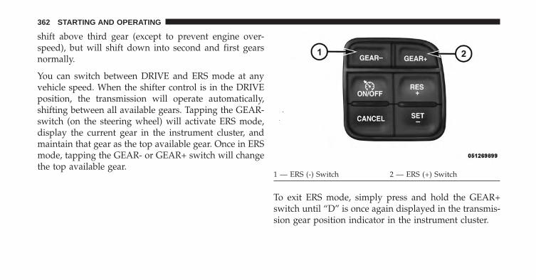
shift above third gear (except to prevent engine over-speed), but will shift down into second and first gearsnormally.
You can switch between DRIVE and ERS mode at anyvehicle speed. When the shifter control is in the DRIVEposition, the transmission will operate automatically,shifting between all available gears. Tapping the GEAR-switch (on the steering wheel) will activate ERS mode,display the current gear in the instrument cluster, andmaintain that gear as the top available gear. Once in ERSmode, tapping the GEAR- or GEAR+ switch will changethe top available gear.
To exit ERS mode, simply press and hold the GEAR+switch until “D” is once again displayed in the transmis-sion gear position indicator in the instrument cluster.
1 — ERS (-) Switch 2 — ERS (+) Switch
362 STARTING AND OPERATING

WARNING!
Do not downshift for additional engine braking on aslippery surface. The drive wheels could lose theirgrip and the vehicle could skid, causing a collision orpersonal injury.
When to Use TOW/HAUL Mode
When driving in hilly areas, towing a trailer, carrying aheavy load, etc., and frequent transmission shifting oc-curs, press the TOW/HAUL switch to activate TOW/HAUL mode. This will improve performance and reducethe potential for transmission overheating or failure dueto excessive shifting. The “TOW/HAUL Indicator Light” will illuminate in the
instrument cluster to indicate that TOW/HAUL modehas been activated. Pressing the switch a second timerestores normal operation. Normal operation is always
TOW/HAUL Switch
5
STARTING AND OPERATING 363

the default at engine start-up. If TOW/HAUL mode isdesired, the switch must be pressed each time the engineis started.
Six–Speed Automatic Transmission If Equipped— 1500 Models Only
The shift lever position display (located in the instrumentcluster) indicates the transmission gear range. The shiftlever is mounted either on the right side of the steeringcolumn (if equipped) or on the console (if equipped). Youmust press the brake pedal to move the shift lever out ofPARK (refer to “Brake/Transmission Shift Interlock Sys-tem” in this section). To drive, move the shift lever fromPARK or NEUTRAL to the DRIVE position. Pull the shiftlever toward you when shifting into REVERSE or PARK,or when shifting out of PARK (column shift only).
The electronically-controlled transmission provides aprecise shift schedule. The transmission electronics areself-calibrating; therefore, the first few shifts on a new
vehicle may be somewhat abrupt. This is a normalcondition, and precision shifts will develop within a fewhundred miles (kilometers).
Only shift from DRIVE to PARK or REVERSE when theaccelerator pedal is released and the vehicle is stopped.Be sure to keep your foot on the brake pedal whenshifting between these gears.
The transmission shift lever has only PARK, REVERSE,NEUTRAL, and DRIVE shift positions. Manual down-shifts can be made using the Electronic Range Select(ERS) shift control (refer to “Electronic Range Select (ERS)Operation” in this section). Pressing the ERS (-/+)switches (column shift) or moving the shift lever to theleft or right (-/+) (console shift) while in the DRIVEposition will select the highest available transmissiongear, and will display that gear in the instrument clusteras 6, 5, 4, 3, 2, 1.
364 STARTING AND OPERATING
Gear Ranges
DO NOT race the engine when shifting from PARK orNEUTRAL into another gear range.
NOTE: After selecting any gear range, wait a moment toallow the selected gear to engage before accelerating.This is especially important when the engine is cold.
PARK
This range supplements the parking brake by locking thetransmission. The engine can be started in this range.Never attempt to use PARK while the vehicle is inmotion. Apply the parking brake when leaving thevehicle in this range.
When parking on a level surface, you may place the shiftlever in PARK first, and then apply the parking brake.
When parking on a hill, apply the parking brake beforeplacing the shift lever in PARK, otherwise the load on the
transmission locking mechanism may make it difficult tomove the shift lever out of PARK. As an added precau-tion, turn the front wheels toward the curb on a downhillgrade and away from the curb on an uphill grade.
WARNING!
• Never use the PARK position as a substitute for theparking brake. Always apply the parking brakefully when parked to guard against vehicle move-ment and possible injury or damage.
• Your vehicle could move and injure you and othersif it is not completely in PARK. Check by trying tomove the shift lever clockwise without first pullingit toward you (column shift), or rearward with thebrake pedal released (console shift), after you haveplaced it in PARK. Make sure the transmission is inPARK before leaving the vehicle.
(Continued)
5
STARTING AND OPERATING 365

WARNING! (Continued)• It is dangerous to shift out of PARK or NEUTRAL
if the engine speed is higher than idle speed. Ifyour foot is not firmly pressing the brake pedal, thevehicle could accelerate quickly forward or in re-verse. You could lose control of the vehicle and hitsomeone or something. Only shift into gear whenthe engine is idling normally and your foot isfirmly pressing the brake pedal.
(Continued)
WARNING! (Continued)• Unintended movement of a vehicle could injure
those in and near the vehicle. As with all vehicles,you should never exit a vehicle while the engine isrunning. Before exiting a vehicle, always apply theparking brake, shift the transmission into PARK,turn the engine OFF, and remove the key fob. Whenthe ignition is in the OFF position, the shift lever islocked in PARK, securing the vehicle against un-wanted movement.
• When leaving the vehicle, always remove the keyfob and lock your vehicle.
(Continued)
366 STARTING AND OPERATING

WARNING! (Continued)• Never leave children alone in a vehicle, or with
access to an unlocked vehicle. Allowing children tobe in a vehicle unattended is dangerous for anumber of reasons. A child or others could beseriously or fatally injured. Children should bewarned not to touch the parking brake, brake pedalor the shift lever. Do not leave the key fob in ornear the vehicle (or in a location accessible tochildren), and do not leave Keyless Enter-N-Go™(if equipped) in the ACC or ON/RUN position. Achild could operate power windows, other controls,or move the vehicle.
CAUTION!
• Before moving the shift lever out of PARK, youmust turn the ignition switch from the OFF posi-tion to the ON/RUN position, and also press thebrake pedal. Otherwise, damage to the shift levercould result.
• DO NOT race the engine when shifting fromPARK or NEUTRAL into another gear range, as thiscan damage the drivetrain.
The following indicators should be used to ensure thatyou have engaged the shift lever into the PARK position:
• When shifting into PARK, pull the column-mountedshift lever toward you and move it all the waycounterclockwise until it stops. For console-mountedshifter, move the shift lever all the way forward and tothe left until it stops.
5
STARTING AND OPERATING 367
• Release the shift lever and make sure it is fully seatedin the PARK gate.
• Look at the shift lever position display and verify thatit indicates the PARK position.
• With brake pedal released, verify that the shift leverwill not move out of PARK.
REVERSE
This range is for moving the vehicle backward. Use thisrange only after the vehicle has come to a complete stop.
NEUTRAL
Use this range when the vehicle is standing for prolongedperiods with the engine running. The engine may bestarted in this range. Apply the parking brake and shiftthe transmission into PARK if you must leave the vehicle.
WARNING!
Do not coast in NEUTRAL and never turn off theignition to coast down a hill. These are unsafepractices that limit your response to changing trafficor road conditions. You might lose control of thevehicle and have a collision.
CAUTION!
Towing the vehicle, coasting, or driving for any otherreason with the transmission in NEUTRAL can causesevere transmission damage. Refer to “RecreationalTowing” in “Starting And Operating” and “Towing ADisabled Vehicle” in “What To Do In Emergencies”for further information.
368 STARTING AND OPERATING

DRIVE
This range should be used for most city and highwaydriving. It provides the smoothest upshifts and down-shifts, and the best fuel economy. The transmissionautomatically upshifts through underdrive first and sec-ond gears, direct third gear and overdrive fourth andfifth gears. The DRIVE position provides optimum driv-ing characteristics under all normal operating conditions.
To access all six available gears, you must use theElectronic Range Select (ERS) shift control, describedbelow.
When frequent transmission shifting occurs (such aswhen operating the vehicle under heavy loading condi-tions, in hilly terrain, traveling into strong head winds, orwhile towing heavy trailers), use the Electronic RangeSelect (ERS) shift control (refer to “Electronic RangeSelect (ERS) Operation)” in this section) to select a lowergear range. Under these conditions, using a lower gear
range will improve performance and extend transmissionlife by reducing excessive shifting and heat buildup.
If the transmission temperature exceeds normal operat-ing limits, the powertrain controller will modify thetransmission shift schedule and expand the range oftorque converter clutch engagement. This is done toprevent transmission damage due to overheating.
If the transmission becomes extremely hot or is in dangerof overheating, the “Transmission Temperature WarningLight” may illuminate and the transmission may operatedifferently until the transmission cools down.
NOTE: Use caution when operating a heavily loadedvehicle at low speeds (such as towing a trailer up a steepgrade, or in stop-and-go traffic) during hot weather. Inthese conditions, torque converter slip can impose asignificant additional heat load on the cooling system.Downshifting the transmission to the lowest possiblegear (when climbing a grade), or shifting to NEUTRAL
5
STARTING AND OPERATING 369

(when stopped in heavy traffic) can help to reduce thisexcess heat generation.
During cold temperatures, transmission operation maybe modified depending on engine and transmissiontemperature as well as vehicle speed. This feature im-proves warm up time of the engine and transmission toachieve maximum efficiency. Engagement of both thetorque converter clutch and the top overdrive gear areinhibited until the transmission fluid is warm (refer to the“Note” under “Torque Converter Clutch” in this section).During extremely cold temperatures (-16°F [-27°C] orbelow), operation may briefly be limited to first anddirect gears only. Normal operation will resume once thetransmission temperature has risen to a suitable level.
Transmission Limp Home Mode
Transmission function is monitored electronically forabnormal conditions. If a condition is detected that couldresult in transmission damage, Transmission Limp Home
Mode is activated. In this mode, the transmission remainsin direct gear regardless of which forward gear is se-lected. PARK, REVERSE, and NEUTRAL will continue tooperate. The Malfunction Indicator Light (MIL) may beilluminated. Limp Home Mode allows the vehicle to bedriven to an authorized dealer for service without dam-aging the transmission.
In the event of a momentary problem, the transmissioncan be reset to regain all forward gears by performing thefollowing steps:
1. Stop the vehicle.
2. Shift the transmission into PARK.
3. Turn the ignition switch to the OFF position.
4. Wait approximately 10 seconds.
5. Restart the engine.
370 STARTING AND OPERATING

6. Shift into the desired gear range. If the problem is nolonger detected, the transmission will return to normaloperation.
NOTE: Even if the transmission can be reset, we recom-mend that you visit your authorized dealer at yourearliest possible convenience. Your authorized dealer hasdiagnostic equipment to determine if the problem couldrecur.
If the transmission cannot be reset, authorized dealerservice is required.
Electronic Range Select (ERS) Operation -Six-Speed Transmission
The Electronic Range Select (ERS) shift control allows thedriver to limit the highest available gear when the shiftlever is in the DRIVE position. For example, if you shift
the transmission into 3 (third gear), the transmission willnever shift above third gear, but will shift down intosecond and first gears normally.
Use of ERS (or TOW/HAUL mode) also enables anadditional underdrive gear which is not normally usedduring through-gear accelerations. This additional gearcan improve vehicle performance and cooling capabilitywhen towing a trailer on certain grades. In ERS mode,gears 1 though 3 are underdrive gears, and ERS 4 is directdrive. ERS 5 and 6 (Overdrive gears) are the same as thenormal fourth and fifth gears.
You can switch between DRIVE and ERS mode at anyvehicle speed. When the shift lever is in the DRIVEposition, the transmission will operate automatically,shifting between all available gears. Tapping the ERS (-)switch (column shift) or tapping the shift lever to the left(-) (console shift) will activate ERS mode, display thecurrent gear in the instrument cluster, and maintain that
5
STARTING AND OPERATING 371
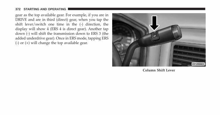
gear as the top available gear. For example, if you are inDRIVE and are in third (direct) gear, when you tap theshift lever/switch one time in the (-) direction, thedisplay will show 4 (ERS 4 is direct gear). Another tapdown (-) will shift the transmission down to ERS 3 (theadded underdrive gear). Once in ERS mode, tapping ERS(-) or (+) will change the top available gear.
Column Shift Lever
372 STARTING AND OPERATING

To exit ERS mode, simply press and hold the shift lever tothe right (+) (console shift) or press the ERS (+) switch(column shift) until “D” is once again displayed in theshift lever position indicator in the instrument cluster.
WARNING!
Do not downshift for additional engine braking on aslippery surface. The drive wheels could lose theirgrip and the vehicle could skid, causing an accidentor personal injury.
NOTE: To select the proper gear position for maximumdeceleration (engine braking), simply press and hold theshift lever to the left (-) (console shift) or the ERS (-)switch down (column shift). The transmission will shiftto the range from which the vehicle can best be sloweddown.Console Shift Lever
5
STARTING AND OPERATING 373

Overdrive Operation
The automatic transmission includes an electronicallycontrolled Overdrive (fourth and fifth gears). The trans-mission will automatically shift into Overdrive if thefollowing conditions are present:
• the shift lever is in the DRIVE position,
• the transmission fluid has reached an adequatetemperature,
• the engine coolant (antifreeze) has reached an ad-equate temperature,
• vehicle speed is sufficiently high, and
• the TOW/HAUL switch has not been activated.
When To Use TOW/HAUL Mode
When driving in hilly areas, towing a trailer, carrying aheavy load, etc., and frequent transmission shifting oc-curs, press the TOW/HAUL switch to activate TOW/
HAUL mode. This will improve performance and reducethe potential for transmission overheating or failure dueto excessive shifting. When operating in TOW/HAULmode, transmission upshifts are delayed, and the trans-mission will automatically downshift (for engine brak-ing) during steady braking maneuvers.
TOW/HAUL Switch
374 STARTING AND OPERATING

The “TOW/HAUL Indicator Light” will illuminate in theinstrument cluster to indicate that TOW/HAUL modehas been activated. Pressing the switch a second timerestores normal operation. Normal operation is alwaysthe default at engine start-up. If TOW/HAUL mode isdesired, the switch must be pressed each time the engineis started.
Torque Converter Clutch
A feature designed to improve fuel economy has beenincluded in the automatic transmission on your vehicle.A clutch within the torque converter engages automati-cally at calibrated speeds. This may result in a slightlydifferent feeling or response during normal operation inthe upper gears. When the vehicle speed drops or duringsome accelerations, the clutch automatically disengages.
NOTE:
• The torque converter clutch will not engage, and thetransmission will not shift into the top overdrive gear,until the transmission fluid and engine coolant arewarm [usually after 1 to 3 miles (2 to 5 km) of driving].Because top gear is disabled, and the engine speed ishigher when the torque converter clutch is not en-gaged, it may seem as if the transmission is not shiftingproperly when cold. This is normal. Using the Elec-tronic Range Select (ERS) shift control, when thetransmission is sufficiently warm, will demonstratethat the transmission is able to shift into and out ofOverdrive.
• If the vehicle has not been driven for several days, thefirst few seconds of operation after shifting the trans-mission into gear may seem sluggish. This is due to thefluid partially draining from the torque converter intothe transmission. This condition is normal and will not
5
STARTING AND OPERATING 375
cause damage to the transmission. The torque con-verter will refill within five seconds after starting theengine.
Six–Speed Automatic Transmission (5.7L Engine)— 2500/3500 Models Only
The shift lever position display (located in the instrumentcluster) indicates the transmission gear range. The shiftlever is mounted on the right side of the steering column.You must press the brake pedal to move the shift leverout of PARK (refer to “Brake/Transmission Shift Inter-lock System” in this section). To drive, move the shiftlever from PARK or NEUTRAL to the DRIVE position.Pull the shift lever toward you when shifting into RE-VERSE or PARK, or when shifting out of PARK.
The electronically-controlled transmission provides aprecise shift schedule. The transmission electronics areself-calibrating; therefore, the first few shifts on a new
vehicle may be somewhat abrupt. This is a normalcondition, and precision shifts will develop within a fewhundred miles (kilometers).
Only shift from DRIVE to PARK or REVERSE when theaccelerator pedal is released and the vehicle is stopped.Be sure to keep your foot on the brake pedal whenshifting between these gears.
The transmission shift lever has only PARK, REVERSE,NEUTRAL, and DRIVE shift positions. Manual down-shifts can be made using the Electronic Range Select(ERS) shift control (refer to “Electronic Range Select (ERS)Operation” in this section). Pressing the ERS (-/+)switches (on the shift lever) while in the DRIVE positionwill select the highest available transmission gear, andwill display that gear in the instrument cluster as 6, 5, 4,3, 2, 1.
376 STARTING AND OPERATING

Gear Ranges
DO NOT race the engine when shifting from PARK orNEUTRAL into another gear range.
NOTE: After selecting any gear range, wait a moment toallow the selected gear to engage before accelerating.This is especially important when the engine is cold.
PARK
This range supplements the parking brake by locking thetransmission. The engine can be started in this range.Never attempt to use PARK while the vehicle is inmotion. Apply the parking brake when leaving thevehicle in this range.
When parking on a level surface, you may place the shiftlever in PARK first, and then apply the parking brake.
When parking on a hill, apply the parking brake beforeplacing the shift lever in PARK, otherwise the load on the
transmission locking mechanism may make it difficult tomove the shift lever out of PARK. As an added precau-tion, turn the front wheels toward the curb on a downhillgrade and away from the curb on an uphill grade.
WARNING!
• Never use the PARK position as a substitute for theparking brake. Always apply the parking brakefully when parked to guard against vehicle move-ment and possible injury or damage.
• Your vehicle could move and injure you and othersif it is not completely in PARK. Check by trying tomove the shift lever clockwise without first pullingit toward you after you have placed it in PARK.Make sure the transmission is in PARK beforeleaving the vehicle.
(Continued)
5
STARTING AND OPERATING 377

WARNING! (Continued)• It is dangerous to shift out of PARK or NEUTRAL
if the engine speed is higher than idle speed. Ifyour foot is not firmly pressing the brake pedal, thevehicle could accelerate quickly forward or in re-verse. You could lose control of the vehicle and hitsomeone or something. Only shift into gear whenthe engine is idling normally and your foot isfirmly pressing the brake pedal.
(Continued)
WARNING! (Continued)• Unintended movement of a vehicle could injure
those in and near the vehicle. As with all vehicles,you should never exit a vehicle while the engine isrunning. Before exiting a vehicle, always apply theparking brake, shift the transmission into PARK,turn the engine OFF, and remove the key fob. Whenthe ignition is in the OFF position, the shift lever islocked in PARK, securing the vehicle against un-wanted movement.
• When leaving the vehicle, always remove the keyfob and lock your vehicle.
(Continued)
378 STARTING AND OPERATING

WARNING! (Continued)• Never leave children alone in a vehicle, or with
access to an unlocked vehicle. Allowing children tobe in a vehicle unattended is dangerous for anumber of reasons. A child or others could beseriously or fatally injured. Children should bewarned not to touch the parking brake, brake pedalor the shift lever. Do not leave the key fob in ornear the vehicle (or in a location accessible tochildren), and do not leave a vehicle equipped withKeyless Enter-N-Go™ (if equipped) in the ACC orON/RUN position. A child could operate powerwindows, other controls, or move the vehicle.
CAUTION!
• Before moving the shift lever out of PARK, youmust turn the ignition switch from the OFF posi-tion to the ON/RUN position, and also press thebrake pedal. Otherwise, damage to the shift levercould result.
• DO NOT race the engine when shifting fromPARK or NEUTRAL into another gear range, as thiscan damage the drivetrain.
The following indicators should be used to ensure thatyou have engaged the shift lever into the PARK position:
• When shifting into PARK, pull the shift lever towardyou and move it all the way counterclockwise until itstops.
• Release the shift lever and make sure it is fully seatedin the PARK gate.
5
STARTING AND OPERATING 379

• Look at the shift lever position display and verify thatit indicates the PARK position.
• With brake pedal released, verify that the shift leverwill not move out of PARK.
REVERSE
This range is for moving the vehicle backward. Shift intoREVERSE only after the vehicle has come to a completestop.
NEUTRAL
Use this range when the vehicle is standing for prolongedperiods with the engine running. The engine may bestarted in this range. Apply the parking brake and shiftthe transmission into PARK if you must leave the vehicle.
WARNING!
Do not coast in NEUTRAL and never turn off theignition to coast down a hill. These are unsafepractices that limit your response to changing trafficor road conditions. You might lose control of thevehicle and have a collision.
CAUTION!
Towing the vehicle, coasting, or driving for any otherreason with the transmission in NEUTRAL can causesevere transmission damage. Refer to “RecreationalTowing” in “Starting And Operating” and “Towing ADisabled Vehicle” in “What To Do In Emergencies”for further information.
380 STARTING AND OPERATING

DRIVE
This range should be used for most city and highwaydriving. It provides the smoothest upshifts and down-shifts, and the best fuel economy. The transmissionautomatically upshifts through underdrive first, second,and third gears, direct fourth gear and overdrive fifth andsixth gears. The DRIVE position provides optimum driv-ing characteristics under all normal operating conditions.
When frequent transmission shifting occurs (such aswhen operating the vehicle under heavy loading condi-tions, in hilly terrain, traveling into strong head winds, orwhile towing heavy trailers), use the Electronic RangeSelect (ERS) shift control (refer to “Electronic RangeSelect (ERS) Operation” in this section) to select a lowergear range. Under these conditions, using a lower gearrange will improve performance and extend transmissionlife by reducing excessive shifting and heat buildup.
If the transmission temperature exceeds normal operat-ing limits, the powertrain controller will modify thetransmission shift schedule and expand the range oftorque converter clutch engagement. This is done toprevent transmission damage due to overheating.
If the transmission becomes extremely hot or is in dangerof overheating, the “Transmission Temperature WarningLight” may illuminate and the transmission may operatedifferently until the transmission cools down.
NOTE: Use caution when operating a heavily loadedvehicle at low speeds (such as towing a trailer up a steepgrade, or in stop-and-go traffic) during hot weather. Inthese conditions, torque converter slip can impose asignificant additional heat load on the cooling system.Downshifting the transmission to the lowest possiblegear (when climbing a grade), or shifting to NEUTRAL(when stopped in heavy traffic) can help to reduce thisexcess heat generation.
5
STARTING AND OPERATING 381

During cold temperatures, transmission operation maybe modified depending on engine and transmissiontemperature as well as vehicle speed. This feature im-proves warm up time of the engine and transmission toachieve maximum efficiency. Engagement of both thetorque converter clutch and the top overdrive gear areinhibited until the transmission fluid is warm (refer to the“Note” under “Torque Converter Clutch” in this section).During extremely cold temperatures (-16°F [-27°C] orbelow), operation may briefly be limited to first anddirect gears only. Normal operation will resume once thetransmission temperature has risen to a suitable level.
Transmission Limp Home Mode
Transmission function is monitored electronically forabnormal conditions. If a condition is detected that couldresult in transmission damage, Transmission Limp HomeMode is activated. In this mode, the transmission remainsin fourth gear regardless of which forward gear is
selected. PARK, REVERSE, and NEUTRAL will continueto operate. The Malfunction Indicator Light (MIL) may beilluminated. Limp Home Mode allows the vehicle to bedriven to an authorized dealer for service without dam-aging the transmission.
In the event of a momentary problem, the transmissioncan be reset to regain all forward gears by performing thefollowing steps:
1. Stop the vehicle.
2. Shift the transmission into PARK.
3. Turn the ignition switch to the OFF position.
4. Wait approximately 10 seconds.
5. Restart the engine.
6. Shift into the desired gear range. If the problem is nolonger detected, the transmission will return to normaloperation.
382 STARTING AND OPERATING

NOTE: Even if the transmission can be reset, we recom-mend that you visit your authorized dealer at yourearliest possible convenience. Your authorized dealer hasdiagnostic equipment to determine if the problem couldrecur.
If the transmission cannot be reset, authorized dealerservice is required.
Electronic Range Select (ERS) Operation
The Electronic Range Select (ERS) shift control allows thedriver to limit the highest available gear when the shiftlever is in the DRIVE position. For example, if you shiftthe transmission into 3 (third gear), the transmission willnever shift above third gear, but will shift down intosecond and first gears normally.
You can switch between DRIVE and ERS mode at anyvehicle speed. When the shift lever is in the DRIVEposition, the transmission will operate automatically,
shifting between all available gears. Tapping the ERS (-)switch will activate ERS mode, display the current gear inthe instrument cluster, and maintain that gear as the topavailable gear. Once in ERS mode, tapping ERS (-) or (+)will change the top available gear.
Column Shift Lever
5
STARTING AND OPERATING 383

To exit ERS mode, simply press and hold the ERS (+)switch until “D” is once again displayed in the shift leverposition indicator in the instrument cluster.
WARNING!
Do not downshift for additional engine braking on aslippery surface. The drive wheels could lose theirgrip and the vehicle could skid, causing a collision orpersonal injury.
NOTE: To select the proper gear position for maximumdeceleration (engine braking), simply press and hold theERS (-) switch down. The transmission will shift to therange from which the vehicle can best be slowed down.
Overdrive Operation
The automatic transmission includes an electronicallycontrolled Overdrive (fifth and sixth gears). The trans-mission will automatically shift into Overdrive if thefollowing conditions are present:
• the shift lever is in the DRIVE position,
• the transmission fluid has reached an adequatetemperature,
• the engine coolant has reached an adequatetemperature,
• vehicle speed is sufficiently high, and
• the TOW/HAUL switch has not been activated.
When To Use TOW/HAUL Mode
When driving in hilly areas, towing a trailer, carrying aheavy load, etc., and frequent transmission shifting oc-curs, press the TOW/HAUL switch to activate TOW/
384 STARTING AND OPERATING

HAUL mode. This will improve performance and reducethe potential for transmission overheating or failure dueto excessive shifting. When operating in TOW/HAULmode, transmission upshifts are delayed, and the trans-mission will automatically downshift (for engine brak-ing) during steady braking maneuvers.
The “TOW/HAUL Indicator Light” will illuminate in theinstrument cluster to indicate that TOW/HAUL modehas been activated. Pressing the switch a second timerestores normal operation. Normal operation is alwaysthe default at engine start-up. If TOW/HAUL mode isdesired, the switch must be pressed each time the engineis started.
Torque Converter Clutch
A feature designed to improve fuel economy has beenincluded in the automatic transmission on your vehicle.A clutch within the torque converter engages automati-cally at calibrated speeds. This may result in a slightlydifferent feeling or response during normal operation inthe upper gears. When the vehicle speed drops or duringsome accelerations, the clutch automatically disengages.
TOW/HAUL Switch
5
STARTING AND OPERATING 385

NOTE:
• The torque converter clutch will not engage, and thetransmission will not shift to sixth gear, until thetransmission fluid and engine coolant are warm [usu-ally after 1 to 3 miles (2 to 5 km) of driving]. Becausesixth gear is disabled, and engine speed is higher whenthe torque converter clutch is not engaged, it mayseem as if the transmission is not shifting properlywhen cold. This is normal. Using the Electronic RangeSelect (ERS) shift control, when the transmission issufficiently warm, will demonstrate that the transmis-sion is able to shift into and out of Overdrive.
• If the vehicle has not been driven for several days, thefirst few seconds of operation after shifting the trans-mission into gear may seem sluggish. This is due to thefluid partially draining from the torque converter intothe transmission. This condition is normal and will not
cause damage to the transmission. The torque con-verter will refill within five seconds after starting theengine.
FOUR-WHEEL DRIVE OPERATION — IFEQUIPPED
Four-wheel drive trucks are equipped with either amanually shifted transfer case or an electronically shiftedtransfer case. Refer to the operating instructions for yourtransfer case, located in this section for further informa-tion.
Manually Shifted Transfer Case – If Equipped
The transfer case provides four mode positions.
• Two-wheel drive high range (2H)
• Four-wheel drive high range (4H)
• Neutral (N)
386 STARTING AND OPERATING

• Four-wheel drive low range (4L)
This transfer case is intended to be driven in the 2Hposition for normal street and highway conditions suchas dry, hard surfaced roads.
When additional traction is required, the 4H and 4Lpositions can be used to lock the front and rear drive-shafts together and force the front and rear wheels torotate at the same speed. This is accomplished by simplymoving the shift lever to the desired positions. The 4Hand 4L positions are intended for loose, slippery roadsurfaces only. Driving in the 4H and 4L positions on dry,hard surfaced roads may cause increased tire wear anddamage to the driveline components.
The “Transfer Case Position Indicator Light” in theinstrument cluster will alert the driver that the vehicle isin four-wheel drive and that the front and rear drive-shafts are locked together. This light will illuminate when
the transfer case is shifted into either the 4H or 4Lposition. There is no light for the 2H or NEUTRALpositions.
When operating your vehicle in 4L, the engine speed isapproximately three times that of the 2H or 4H positionsat a given road speed. Take care not to overspeed theengine and do not exceed 25 mph (40 km/h).
Proper operation of four-wheel drive vehicles dependson tires of equal size, type and circumference on eachwheel. Any difference will adversely affect shifting andcan cause damage to the drivetrain.
NOTE: Do not attempt to make a shift while only thefront or rear wheels are spinning. The transfer case is notequipped with a synchronizer and therefore the front andrear driveshaft speeds must be equal for the shift to takeplace. Shifting while only the front or rear wheels arespinning can cause damage to the transfer case.
5
STARTING AND OPERATING 387

Because four-wheel drive provides improved traction,there is a tendency to exceed safe turning and stoppingspeeds. Do not go faster than road conditions permit.
NOTE: Delayed shifts out of four-wheel drive may beexperienced due to uneven tire wear, low or uneven tirepressures, excessive vehicle loading, or cold tempera-tures.
WARNING!
You or others could be injured or killed if you leavethe vehicle unattended with the transfer case in theNEUTRAL position without first fully engaging theparking brake. The transfer case NEUTRAL positiondisengages both the front and rear driveshafts fromthe powertrain and will allow the vehicle to moveregardless of the transmission position. The parkingbrake should always be applied when the driver isnot in the vehicle.
For additional information on the appropriate use of eachtransfer case mode position, see the information below:
2H
Rear-Wheel Drive High Range - This range is for normalstreet and highway driving on dry hard surfaced roads.
4H
Four-Wheel Drive High Range - This range locks thefront and rear driveshafts together forcing the front andrear wheels to rotate at the same speed. Additionaltraction for loose, slippery road surfaces only.
N
Neutral - This range disengages the front and reardriveshafts from the powertrain. To be used for flattowing behind another vehicle. Refer to “RecreationalTowing” in “Starting and Operating” for further infor-mation.
388 STARTING AND OPERATING

4L
Four-Wheel Drive Low Range - This range locks the frontand rear driveshafts together forcing the front and rearwheels to rotate at the same speed. Additional tractionand maximum pulling power for loose, slippery roadsurfaces only. Do not exceed 25 mph (40 km/h).
CAUTION!
Do not use 4L (Low) range when operating thevehicle on dry pavement. Driveline hardware dam-age can result.
Shifting Procedure – Manually Shifted TransferCase
2H To 4H
Shifting between 2H and 4H can be made with thevehicle stopped or in motion. If the vehicle is in motion,shifts can be made up to 55 mph (88 km/h). With the
vehicle in motion, the transfer case will engage/disengage faster if you momentarily release the accelera-tor pedal after completing the shift. Apply a constantforce when shifting the transfer case lever.
2H Or 4H To 4L
With the vehicle rolling at 2 to 3 mph (3 to 5 km/h), shiftthe transmission into NEUTRAL. While the vehicle iscoasting at 2 to 3 mph (3 to 5 km/h), shift the transfercase lever firmly to the desired position. Do not pause intransfer case NEUTRAL.
NOTE:
• Pausing in transfer case NEUTRAL in vehiclesequipped with an automatic transmission may requireshutting the engine OFF to avoid gear clash whilecompleting the shift. If difficulty occurs, shift thetransmission into NEUTRAL, hold foot on brake, andturn the engine OFF. Make shift to the desired mode.
5
STARTING AND OPERATING 389

• Shifting into or out of 4L is possible with the vehiclecompletely stopped, however difficulty may occur dueto the mating clutch teeth not being properly aligned.Several attempts may be required for clutch teethalignment and shift completion to occur. The preferredmethod is with the vehicle rolling 2 to 3 mph (3 to5 km/h). Avoid attempting to engage or disengage 4Lwith the vehicle moving faster than 2 to 3 mph (3 to5 km/h).
• Do not attempt to shift into or from 4L while thetransmission is in gear.
Transfer Case Position Indicator Light
The “Transfer Case Position Indicator Light” in theinstrument cluster is used to alert the driver that the frontaxle is fully engaged and all four wheels are driving.
Electronically Shifted Transfer Case(Four-Position Switch) – If Equipped
This is an electronic shift transfer case and is operated bythe 4WD Control Switch (Transfer Case Switch), which islocated on the instrument panel.
Transfer Case Switch (Four-Position)
390 STARTING AND OPERATING

This electronically shifted transfer case provides fourmode positions:
• Two-wheel drive high range (2WD)
• Four-wheel drive lock range (4WD LOCK)
• Four-wheel drive low range (4WD LOW)
• Neutral (NEUTRAL)
This electronically shifted transfer case is designed to bedriven in the two-wheel drive position (2WD) for normalstreet and highway conditions on dry, hard surfaced roads.
When additional traction is required, the transfer case 4WDLOCK and 4WD LOW positions can be used to lock thefront and rear driveshafts together, forcing the front andrear wheels to rotate at the same speed. This is accom-plished by rotating the 4WD Control Switch to the desiredposition. Refer to “Shifting Procedure” in this section forspecific shifting instructions. The 4WD LOCK and 4WD
LOW positions are designed for loose, slippery road sur-faces only. Driving in the 4WD LOCK and 4WD LOWpositions on dry hard surfaced roads may cause increasedtire wear and damage to the driveline components.
NOTE: The transfer case NEUTRAL position is selectedby pressing the recessed button located on the lower lefthand corner of the 4WD Control Switch. The transfer caseNEUTRAL position is to be used for recreational towingonly. Refer to “Recreational Towing” in “Starting andOperating” for further information.
Transfer Case Position Indicator Lights
The Transfer Case Position Indicator Lights (4WD and4LOW) are located in the instrument cluster and indicatethe current and desired transfer case selection. When youselect a different transfer case position, the indicatorlights will do the following:
5
STARTING AND OPERATING 391
If All Shift Conditions Are Met:
1. The current position indicator light will turn OFF.
2. The selected position indicator light will flash until thetransfer case completes the shift.
3. When the shift is complete, the indicator light for theselected position will stop flashing and remain ON.
If One Or More Shift Conditions Are Not Met:
1. The indicator light for the current position will remainON.
2. The newly selected position indicator light will con-tinue to flash.
3. The transfer case will not shift.
NOTE: Before retrying a selection, make certain that allthe necessary requirements for selecting a new transfercase position have been met. To retry the selection, turnthe control knob back to the current position, wait fiveseconds, and retry selection. To find the shift require-ments, refer to the �Shifting Procedure� for your transfercase, located in this section.
The “SVC 4WD Warning Light” monitors the electronicshift four-wheel drive system. If this light remains onafter engine start up or illuminates during driving, itmeans that the four-wheel drive system is not function-ing properly and that service is required.
WARNING!
Always engage the parking brake when poweringdown the vehicle if the “SVC 4WD Warning Light” isilluminated. Not engaging the parking brake may
(Continued)
392 STARTING AND OPERATING
WARNING! (Continued)allow the vehicle to roll, which may cause personalinjury.
NOTE: Do not attempt to make a shift while only thefront or rear wheels are spinning, as this can causedamage to driveline components.
When operating your vehicle in 4WD LOW, the enginespeed is approximately three times that of the 2WD or4WD LOCK positions at a given road speed. Take carenot to overspeed the engine and do not exceed 25 mph(40 km/h).
Proper operation of four-wheel drive vehicles dependson tires of equal size, type and circumference on eachwheel. Any difference in tire size can cause damage to thedrivetrain.
Because four-wheel drive provides improved traction,there is a tendency to exceed safe turning and stoppingspeeds. Do not go faster than road conditions permit.
WARNING!
You or others could be injured or killed if you leavethe vehicle unattended with the transfer case in theNEUTRAL position without first fully engaging theparking brake. The transfer case NEUTRAL positiondisengages both the front and rear driveshafts fromthe powertrain and will allow the vehicle to moveregardless of the transmission position. The parkingbrake should always be applied when the driver isnot in the vehicle.
5
STARTING AND OPERATING 393
For additional information on the appropriate use of eachtransfer case mode position, see the information below:
2WD
Rear Wheel Drive High Range - This range is for normalstreet and highway driving on dry, hard surfaced roads.
4WD LOCK
Four-Wheel Drive Lock Range - This range locks the frontand rear driveshafts together forcing the front and rearwheels to rotate at the same speed. This range providesadditional traction for loose, slippery road surfaces only.
4WD LOW
Four-Wheel Drive Low Range - This range provides lowspeed four-wheel drive. It locks the front and reardriveshafts together forcing the front and rear wheels torotate at the same speed. This range provides additionaltraction and maximum pulling power for loose, slipperyroad surfaces only. Do not exceed 25 mph (40 km/h).
N
Neutral - This range disengages both the front and reardriveshafts from the powertrain. To be used for flattowing behind another vehicle. Refer to “RecreationalTowing” in “Starting and Operating” for further infor-mation.
394 STARTING AND OPERATING

Shifting Procedure
NOTE:
• If any of the requirements to select a new transfer caseposition have not been met, the transfer case will notshift. The position indicator light for the previousposition will remain ON and the newly selected posi-tion indicator light will continue to flash until all therequirements for the selected position have been met.To retry a shift: return the control knob back to theoriginal position, make certain all shift requirementshave been met, wait five seconds and try the shiftagain.
• If all the requirements to select a new transfer caseposition have been met, the current position indicatorlight will turn OFF, the selected position indicator lightwill flash until the transfer case completes the shift.
When the shift is complete, the position indicator lightfor the selected position will stop flashing and remainON.
2WD To 4WD LOCK
Rotate the 4WD control switch to the desired position.Shifts between 2WD and 4WD LOCK can be done withthe vehicle stopped or in motion. With the vehicle inmotion, the transfer case will engage/disengage faster ifyou momentarily release the accelerator pedal after turn-ing the control switch. If the vehicle is stopped, theignition switch must be in the ON position with theengine either running or off. This shift cannot be com-pleted if the ignition switch is in the ACC position.
NOTE: The four-wheel drive system will not allow shiftsbetween 2WD/4WD LOCK if the front and/or rearwheels are spinning (no traction). In this situation, theselected position indicator light will flash and the origi-nal position indicator light will remain ON. At this time,
5
STARTING AND OPERATING 395

reduce speed and stop spinning the wheels to completethe shift.
2WD Or 4WD LOCK To 4WD LOW
NOTE: When shifting into or out of 4WD LOW somegear noise may be heard. This noise is normal and is notdetrimental to the vehicle or occupants.
Shifting can be performed with the vehicle rolling 2 to3 mph (3 to 5 km/h) or completely stopped. You can useeither of the following procedures:
Preferred Procedure
1. With the engine running, slow the vehicle to 2 to3 mph (3 to 5 km/h).
2. Shift the transmission into NEUTRAL.
3. While still rolling, rotate the transfer case controlswitch to the desired position.
4. After the desired position indicator light is ON (notflashing), shift the transmission back into gear.
Alternate Procedure
1. Bring the vehicle to a complete stop.
2. With the ignition switch in the ON position and theengine either OFF or running, shift the transmissioninto NEUTRAL.
3. Rotate the transfer case control switch to the desiredposition.
4. After the desired position indicator light is ON (notflashing), shift the transmission back into gear.
396 STARTING AND OPERATING

NOTE:
• If Steps 1 or 2 of either the Preferred or AlternateProcedure are not satisfied prior to attempting theshift, then the desired position indicator light will flashcontinuously while the original position indicator lightis ON, until all requirements have been met.
• The ignition switch must be in the ON position for ashift to take place and for the position indicator lightsto be operable. If the ignition switch is not in the ONposition, the shift will not take place and no positionindicator lights will be on or flashing.
Electronically Shifted Transfer Case(Five-Position Switch) – If Equipped
This is an electronic shift transfer case and is operated bythe 4WD Control Switch (Transfer Case Switch), which islocated on the instrument panel.
This electronically shifted transfer case provides fivemode positions:
• Two-wheel drive high range (2WD)
• Four-wheel drive automatic range (4WD AUTO)
• Four-wheel drive lock range (4WD LOCK)
Transfer Case Switch (Five–Position)
5
STARTING AND OPERATING 397
• Four-wheel drive low range (4WD LOW)
• Neutral (NEUTRAL)
This electronically shifted transfer case is designed to bedriven in the two–wheel drive position (2WD) or four-wheel drive position (4WD AUTO) for normal street andhighway conditions on dry hard surfaced roads). Drivingthe vehicle in 2WD will have greater fuel economybenefits as the front axle is not engaged in 2WD.
For variable driving conditions, the 4WD AUTO modecan be used. In this mode, the front axle is engaged, butthe vehicle’s power is sent to the rear wheels. Four-wheeldrive will be automatically engaged when the vehiclesenses a loss of traction. Because the front axle is en-gaged, this mode will result in lower fuel economy thanthe 2WD mode.
When additional traction is required, the transfer case4WD LOCK and 4WD LOW positions can be used to lockthe front and rear driveshafts together forcing the front
and rear wheels to rotate at the same speed. This isaccomplished by rotating the 4WD Control Switch to thedesired position. Refer to “Shifting Procedure” for spe-cific shifting instructions. The 4WD LOCK and 4WDLOW positions are designed for loose, slippery roadsurfaces only. Driving in the 4WD LOCK and 4WD LOWpositions on dry hard surfaced roads may cause in-creased tire wear and damage to the driveline compo-nents.
NOTE: The transfer case NEUTRAL position is selectedby depressing the recessed button located on the lowerleft hand corner of the 4WD Control Switch. The transfercase NEUTRAL position is to be used for recreationaltowing only. Refer to “Recreational Towing” in “Startingand Operating” for further information.
Transfer Case Position Indicator Lights
The Transfer Case Position Indicator Lights (4WD,4LOW, and 4WD AUTO) are located in the instrument
398 STARTING AND OPERATING

cluster and indicate the current and desired transfer caseselection. When you select a different transfer case posi-tion, the indicator lights will do the following:
If All Shift Conditions Are Met:
1. The current position indicator light will turn OFF.
2. The selected position indicator light will flash until thetransfer case completes the shift.
3. When the shift is complete, the indicator light for theselected position will stop flashing and remain ON.
If One Or More Shift Conditions Are Not Met:
1. The indicator light for the current position will remainON.
2. The newly selected position indicator light will con-tinue to flash.
3. The transfer case will not shift.
NOTE: Before retrying a selection, make certain that allthe necessary requirements for selecting a new transfercase position have been met. To retry the selection, turnthe control knob back to the current position, wait fiveseconds, and retry selection. To find the shift require-ments, refer to the �Shifting Procedure� for your transfercase, located in this section.
The “SVC 4WD Warning Light” monitors the electronicshift four-wheel drive system. If this light remains onafter engine start up or illuminates during driving, itmeans that the four-wheel drive system is not function-ing properly and that service is required.
WARNING!
Always engage the parking brake when poweringdown the vehicle if the “SVC 4WD Warning Light” isilluminated. Not engaging the parking brake may
(Continued)
5
STARTING AND OPERATING 399

WARNING! (Continued)allow the vehicle to roll which may cause personalinjury or death.
NOTE: Do not attempt to make a shift while only thefront or rear wheels are spinning. This could causedamage to driveline components.
When operating your vehicle in 4WD LOW, the enginespeed is approximately three times that of the 2WD, 4WDAUTO or 4WD LOCK positions at a given road speed.Take care not to overspeed the engine and do not exceed25 mph (40 km/h).
Proper operation of four-wheel drive vehicles dependson tires of equal size, type and circumference on eachwheel. Any difference in tire size can cause damage to thedrivetrain.
Because four-wheel drive provides improved traction,there is a tendency to exceed safe turning and stoppingspeeds. Do not go faster than road conditions permit.
WARNING!
You or others could be injured or killed if you leavethe vehicle unattended with the transfer case in theNEUTRAL position without first fully engaging theparking brake. The transfer case NEUTRAL positiondisengages both the front and rear driveshafts fromthe powertrain and will allow the vehicle to moveregardless of the transmission position. The parkingbrake should always be applied when the driver isnot in the vehicle.
400 STARTING AND OPERATING

For additional information on the appropriate use of eachtransfer case mode position, see the information below:
2WD
Rear-Wheel Drive High Range - This range is for normalstreet and highway driving on dry hard surfaced roads.
4WD AUTO
Four-Wheel Drive Auto Range - This range sends powerto the rear wheels. The four–wheel drive system will beautomatically engaged when the vehicle senses a loss oftraction. Additional traction for varying road conditions.
4WD LOCK
Four-Wheel Drive Lock Range - This range locks the frontand rear driveshafts together forcing the front and rearwheels to rotate at the same speed. Additional tractionfor loose, slippery road surfaces only.
4WD LOW
Four-Wheel Drive Low Range - This range provides lowspeed four-wheel drive. Locks the front and rear drive-shafts together forcing the front and rear wheels to rotateat the same speed. Additional traction and maximumpulling power for loose, slippery road surfaces only. Donot exceed 25 mph (40 km/h).
N
Neutral - This range disengages both the front and reardriveshafts from the powertrain. To be used for flattowing behind another vehicle. Refer to “RecreationalTowing” in “Starting and Operating” for further infor-mation.
5
STARTING AND OPERATING 401

Electronically Shifted Transfer Case(Five-Position Switch) – If Equipped
This is an electronic shift transfer case and is operated bythe 4WD Control Switch (Transfer Case Switch), which islocated on the instrument panel.
This electronically shifted transfer case provides fivemode positions:
• Two-wheel drive high range (2WD)
• Four-wheel drive automatic range (4WD AUTO)
• Four-wheel drive lock range (4WD LOCK)
• Four-wheel drive low range (4WD LOW)
• Neutral (NEUTRAL)
This electronically shifted transfer case is designed to bedriven in the two–wheel drive position (2WD) or four-wheel drive position (4WD AUTO) for normal street andhighway conditions on dry hard surfaced roads). Drivingthe vehicle in 2WD will have greater fuel economybenefits as the front axle is not engaged in 2WD.
For variable driving conditions, the 4WD AUTO modecan be used. In this mode, the front axle is engaged, butthe vehicle’s power is sent to the rear wheels. Four-wheel
Transfer Case Switch (Five–Position)
402 STARTING AND OPERATING

drive will be automatically engaged when the vehiclesenses a loss of traction. Because the front axle is en-gaged, this mode will result in lower fuel economy thanthe 2WD mode.
When additional traction is required, the transfer case4WD LOCK and 4WD LOW positions can be used to lockthe front and rear driveshafts together forcing the frontand rear wheels to rotate at the same speed. This isaccomplished by rotating the 4WD Control Switch to thedesired position. Refer to “Shifting Procedure” for spe-cific shifting instructions. The 4WD LOCK and 4WDLOW positions are designed for loose, slippery roadsurfaces only. Driving in the 4WD LOCK and 4WD LOWpositions on dry hard surfaced roads may cause in-creased tire wear and damage to the driveline compo-nents.
NOTE: The transfer case NEUTRAL position is selectedby depressing the recessed button (with a ballpoint penor similar object) located in the center of the 4WD ControlSwitch. The transfer case NEUTRAL position is to beused for recreational towing only. Refer to “RecreationalTowing” in “Starting and Operating” for further infor-mation.
Transfer Case Position Indicator Lights
The Transfer Case Position Indicator Lights (4WD,4LOW, and 4WD AUTO) are located in the instrumentcluster and indicate the current and desired transfer caseselection. When you select a different transfer case posi-tion, the indicator lights will do the following:
If All Shift Conditions Are Met:
1. The current position indicator light will turn OFF.
2. The selected position indicator light will flash until thetransfer case completes the shift.
5
STARTING AND OPERATING 403

3. When the shift is complete, the indicator light for theselected position will stop flashing and remain ON.
If One Or More Shift Conditions Are Not Met:
1. The indicator light for the current position will remainON.
2. The newly selected position indicator light will con-tinue to flash.
3. The transfer case will not shift.
NOTE: Before retrying a selection, make certain that allthe necessary requirements for selecting a new transfercase position have been met. To retry the selection, turnthe control knob back to the current position, wait fiveseconds, and retry selection. To find the shift require-ments, refer to the �Shifting Procedure� for your transfercase, located in this section.
The “SVC 4WD Warning Light” monitors the electronicshift four-wheel drive system. If this light remains on
after engine start up or illuminates during driving, itmeans that the four-wheel drive system is not function-ing properly and that service is required.
WARNING!
Always engage the parking brake when poweringdown the vehicle if the “SVC 4WD Warning Light” isilluminated. Not engaging the parking brake mayallow the vehicle to roll which may cause personalinjury or death.
NOTE: Do not attempt to make a shift while only thefront or rear wheels are spinning. This could causedamage to driveline components.
When operating your vehicle in 4WD LOW, the enginespeed is approximately three times that of the 2WD, 4WD
404 STARTING AND OPERATING

AUTO or 4WD LOCK positions at a given road speed.Take care not to overspeed the engine and do not exceed25 mph (40 km/h).
Proper operation of four-wheel drive vehicles dependson tires of equal size, type and circumference on eachwheel. Any difference in tire size can cause damage to thedrivetrain.
Because four-wheel drive provides improved traction,there is a tendency to exceed safe turning and stoppingspeeds. Do not go faster than road conditions permit.
WARNING!
You or others could be injured or killed if you leavethe vehicle unattended with the transfer case in theNEUTRAL position without first fully engaging theparking brake. The transfer case NEUTRAL position
(Continued)
WARNING! (Continued)disengages both the front and rear driveshafts fromthe powertrain and will allow the vehicle to moveregardless of the transmission position. The parkingbrake should always be applied when the driver isnot in the vehicle.
For additional information on the appropriate use of eachtransfer case mode position, see the information below:
2WD
Rear-Wheel Drive High Range - This range is for normalstreet and highway driving on dry hard surfaced roads.
4WD AUTO
Four-Wheel Drive Auto Range - This range sends powerto the rear wheels. The four–wheel drive system will beautomatically engaged when the vehicle senses a loss oftraction. Additional traction for varying road conditions.
5
STARTING AND OPERATING 405
4WD LOCK
Four-Wheel Drive Lock Range - This range locks the frontand rear driveshafts together forcing the front and rearwheels to rotate at the same speed. Additional tractionfor loose, slippery road surfaces only.
4WD LOW
Four-Wheel Drive Low Range - This range provides lowspeed four-wheel drive. Locks the front and rear drive-shafts together forcing the front and rear wheels to rotateat the same speed. Additional traction and maximumpulling power for loose, slippery road surfaces only. Donot exceed 25 mph (40 km/h).
N
Neutral - This range disengages both the front and reardriveshafts from the powertrain. To be used for flat
towing behind another vehicle. Refer to “RecreationalTowing” in “Starting and Operating” for further infor-mation.
Shifting Procedure
NOTE:
• If any of the requirements to select a new transfer caseposition have not been met, the transfer case will notshift. The position indicator light for the previousposition will remain ON and the newly selected posi-tion indicator light will continue to flash until all therequirements for the selected position have been met.
• If all the requirements to select a new transfer caseposition have been met, the current position indicatorlight will turn OFF, the selected position indicator lightwill flash until the transfer case completes the shift.
406 STARTING AND OPERATING

When the shift is complete, the position indicator lightfor the selected position will stop flashing and remainON.
2WD To 4WD AUTO Or 4WD LOCK
Press the desired position on the 4WD Control Switch toshift the transfer case. Shifts between 2WD and 4WDAUTO and 4WD LOCK can be done with the vehiclestopped or in motion. With the vehicle in motion, thetransfer case will engage/disengage faster if you momen-tarily release the accelerator pedal after turning thecontrol switch. If the vehicle is stopped, the ignitionswitch must be in the ON position with the engine eitherrunning or OFF. This shift cannot be completed if theignition switch is in the ACC position.
2WD Or 4WD AUTO Or 4WD LOCK To 4WD LOW
NOTE: When shifting into or out of 4WD LOW somegear noise may be heard. This noise is normal and is notdetrimental to the vehicle or occupants.
Shifting can be performed with the vehicle rolling 2 to3 mph (3 to 5 km/h) or completely stopped. Use either ofthe following procedures:
Preferred Procedure
1. With the engine running, slow the vehicle to 2 to3 mph (3 to 5 km/h).
2. Shift the transmission into NEUTRAL.
3. While still rolling, press the desired position on thetransfer case control switch.
4. After the desired position indicator light is ON (notflashing), shift the transmission back into gear.
5
STARTING AND OPERATING 407

Alternate Procedure
1. Bring the vehicle to complete stop.
2. With the ignition switch in the ON position and theengine either OFF or running, shift the transmissioninto NEUTRAL.
3. Press the desired position on the transfer case controlswitch.
4. After the desired position indicator light is ON (notflashing), shift the transmission back into gear.
NOTE:
• If Steps 1 or 2 of either the Preferred or AlternateProcedure are not satisfied prior to attempting the shiftor if they no longer are being met while the shiftattempt is in process, the desired position indicatorlight will flash continuously while the original positionindicator light is ON, until all requirements have beenmet.
• The ignition switch must be in the ON position for ashift to take place and for the position indicator lightsto be operable. If the ignition switch is not in the ONposition, then the shift will not take place and noposition indicator lights will be on or flashing.
408 STARTING AND OPERATING

Shifting Procedure
NOTE:
• If any of the requirements to select a new transfer caseposition have not been met, the transfer case will notshift. The position indicator light for the previousposition will remain ON and the newly selected posi-tion indicator light will continue to flash until all therequirements for the selected position have been met.To retry a shift: return the control knob back to theoriginal position, make certain all shift requirementshave been met, wait five seconds and try the shiftagain.
• If all the requirements to select a new transfer caseposition have been met, the current position indicatorlight will turn OFF, the selected position indicator lightwill flash until the transfer case completes the shift.When the shift is complete, the position indicator lightfor the selected position will stop flashing and remainON.
5
STARTING AND OPERATING 409

AIR SUSPENSION SYSTEM — IF EQUIPPED
Description
The air suspension system provides full time load level-ing capability along with the benefit of being able toadjust vehicle height by the push of a button.
1 — Up Button2 — Down Button3 — Entry/Exit Mode Indicator Lamp(Customer selectable)4 — Normal Ride Height Indicator Lamp(Customer selectable)5 — Off-Road 1 Indicator Lamp (Customer selectable)6 — Off-Road 2 Indicator Lamp (Customer selectable)
NOTE: The vehicle will automatically enter Aero Modewhen the vehicle speed remains between 62 mph(100 km/h) and 66 mph (106 km/h) for greater than 20seconds or if the vehicle speed exceeds 66 mph(106 km/h).
• Normal Ride Height (NRH) – This is the standardposition of the suspension and is meant for normaldriving.Air Suspension Switch
410 STARTING AND OPERATING

• Off-Road 1 (OR1) (Raises the vehicle approximately1 in (26 mm) – This position should be the primaryposition for all off-road driving until Off Road 2 (OR2)is needed. A smoother and more comfortable ride willresult. To enter OR1, press the “Up” button once fromthe NRH position while the vehicle speed is below35 mph (56 km/h). When in the OR1 position, if thevehicle speed remains between 40 mph (64 km/h) and50 mph (80 km/h) for greater than 20 seconds or if thevehicle speed exceeds 50 mph (80 km/h), the vehiclewill be automatically lowered to NRH. Off-Road 1may not be available due to vehicle payload, an EVICmessage will be displayed when this occurs. Refer to“Electronic Vehicle Information Center (EVIC)” in“Understanding Your Instrument Panel” for furtherinformation.
• Off-Road 2 (OR2) (Raises the vehicle approximately2 in (51 mm) – This position is intended for off-roading
use only where maximum ground clearance is re-quired. To enter OR2, press the “Up” button twicefrom the NRH position or once from the OR1 positionwhile vehicle speed is below 20 mph (32 km/h). Whilein OR2, if the vehicle speed exceeds 25 mph (40 km/h)the vehicle height will be automatically lowered toOR1. Off-Road 2 may not be available due to vehiclepayload, an EVIC message will be displayed when thisoccurs. Refer to “Electronic Vehicle Information Center(EVIC)” in “Understanding Your Instrument Panel”for further information.
• If the vehicle is in OFFROAD1 or OFFROAD2 setting,be aware of your surroundings, you may not have theclearance required for certain areas and vehicle dam-age may occur.
• Aero Mode (Lowers the vehicle approximately .6 in(15 mm) – 1500 Models Only – This position providesimproved aerodynamics by lowering the vehicle. The
5
STARTING AND OPERATING 411
vehicle will automatically enter Aero Mode when thevehicle speed remains between 62 mph (100 km/h)and 66 mph (106 km/h) for greater than 20 seconds orif the vehicle speed exceeds 66 mph (106 km/h). Thevehicle will return to NRH from Aero Mode if thevehicle speed remains between 30 mph (48 km/h) and35 mph (56 km/h) for greater than 20 seconds or if thevehicle speed falls below 30 mph (48 km/h).
NOTE: Aero Mode may be disabled through vehiclesettings in the Electronic Vehicle Information Center(EVIC) or in the Uconnect™ Access 8.4 Radio (IfEquipped). Refer to “Electronic Vehicle Information Cen-ter (EVIC)” in “Understanding Your Instrument Panel”or “Uconnect™ Access Settings” in “Understanding YourInstrument Panel” for further information.
• Entry/Exit Mode (Lowers the vehicle approximately 2in (51 mm) – This position lowers the vehicle for easierpassenger entry and exit as well as lowering the rear of
the vehicle for easier loading and unloading of cargo.To enter Entry/Exit Mode, press the “Down” buttononce from the NHR while the vehicle speed is below33 mph (53 km/h). Once the vehicle speed goes below15 mph (24 km/h) the vehicle height will begin tolower. If the vehicle speed remains between 15 mph(24 km/h) and 25 mph (40 km/h) for greater than 60seconds, or the vehicle speed exceeds 25 mph(40 km/h) the Entry/Exit change will be cancelled. Toreturn to Normal Height Mode, press the “Up” buttononce while in Entry/Exit or drive the vehicle over15 mph (24 km/h). Entry/Exit mode may not beavailable due to vehicle payload, an EVIC messagewill be displayed when this occurs. Refer to �ElectronicVehicle Information Center (EVIC)� in �UnderstandingYour Instrument Panel� for further information.
412 STARTING AND OPERATING

NOTE: Entry/Exit mode may be achieved using yourkey fob for easier entry/loading. Refer to “A Word AboutYour Keys” in “Things To Know Before Starting YourVehicle” for further information.
• When in ENTRY/EXIT setting, be aware of yoursurroundings, you may not have the clearance re-quired for certain areas and vehicle damage mayoccur.
The system requires that the ignition be in ON/RUNposition or the engine running for all user requestedchanges. When lowering the vehicle all of the doors,must be closed. If a door is opened at any time while thevehicle is lowering the change will not be completeduntil the open door(s) is closed.
This system uses a lifting and lowering pattern whichkeeps the headlights from incorrectly shining into on-coming traffic. When raising the vehicle, the rear of the
vehicle will move up first and then the front. Whenlowering the vehicle, the front will move down first andthen the rear.
After the engine is turned off, it may be noticed that theair suspension system operates briefly, this is normal. Thesystem is correcting the position of the vehicle to ensurea proper appearance.
To assist with changing a spare tire, the air suspensionsystem has a feature which allows the automatic levelingto be disabled. Refer to “Electronic Vehicle InformationCenter (EVIC)” in “Understanding Your InstrumentPanel” for further information.
NOTE: If equipped with a touch screen radio allenabling/disabling of air suspension features must bedone through the radio. Refer to “Uconnect™ AccessSettings” in “Understanding Your Instrument Panel” forfurther information.
5
STARTING AND OPERATING 413

WARNING!
The air suspension system uses a high pressurevolume of air to operate the system. To avoid per-sonal injury or damage to the system, see yourauthorized dealer for service.
Air Suspension Modes
The Air Suspension system has multiple modes to protectthe system in unique situations:
• Tire/Jack Mode• To assist with changing a spare tire, the air suspen-
sion system has a feature which allows the automaticleveling to be disabled. This mode is intended to beused with engine running. Refer to “Electronic Ve-hicle Information Center (EVIC)” in “UnderstandingYour Instrument Panel” for further information.
• Transport Mode• To assist with flat bed towing, the air suspension
system has a feature which will put the vehicle intoEntry/Exit height and disable the automatic loadleveling system. This mode is intended to be usedwith engine running. Refer to “Electronic VehicleInformation Center (EVIC)” in “Understanding YourInstrument Panel” for further information.
• Wheel Alignment Mode• Before performing a wheel alignment this mode
must be enabled. Refer to “Electronic Vehicle Infor-mation Center (EVIC)” in “Understanding Your In-strument Panel” for further information.
• Protection Mode• In order to “protect” the air suspension system, the
vehicle will enter Protection Mode when load level-ing cannot be achieved. Some driving may be re-quired to clear the protection mode telltale in the
414 STARTING AND OPERATING

EVIC. Refer to “Electronic Vehicle Information Cen-ter (EVIC)” in “Understanding Your InstrumentPanel” for further information.
NOTE:
• If equipped with a touch screen radio all enabling/disabling of air suspension features must be donethrough the radio. Refer to “Uconnect® Access Set-tings” in “Understanding Your Instrument Panel” forfurther information.
Electronic Vehicle Information Center (EVIC)Display Messages
When the appropriate conditions exist, a message willappear in the EVIC display. Refer to “Electronic VehicleInformation Center (EVIC)” in “Understanding YourInstrument Panel” for further information.
An audible chime will be heard whenever a system errorhas been detected.
Operation
The indicator lamps 3 through 6 will illuminate to showthe current position of the vehicle. Flashing indicatorlamps will show a position which the system is workingto achieve. When raising, if multiple indicator lamps areflashing, the highest flashing indicator lamp is the posi-tion the system is working to achieve. When lowering, ifmultiple indicators are flashing, the lowest solid indica-tor lamp is the position the system is working to achieve.
Pressing the “UP” button once will move the suspensionone position higher from the current position, assumingall conditions are met (i.e. key in ON/RUN position,engine running, speed below threshold, etc). The “UP”button can be pressed multiple times, each press willraise the requested level by one position up to a maxi-mum position of OR2 or the highest position allowedbased on current conditions (i.e. vehicle speed, etc).
5
STARTING AND OPERATING 415

Pressing the “DOWN” button once will move the sus-pension one position lower from the current level, as-suming all conditions are met (i.e. key in ON/RUNposition, engine running, doors closed, speed belowthreshold, etc). The “DOWN” button can be pressedmultiple times, each press will lower the requested levelby one position down to a minimum of Entry/Exit Modeor the lowest position allowed based on current condi-tions (i.e. vehicle speed, etc.)
Automatic height changes will occur based on vehiclespeed and the current vehicle height. The indicator lampsand EVIC messages will operate the same for automaticchanges and user requested changes.
• Off-Road 2 (OR2) – Indicator lamps 3, 4, 5, and 6 willbe illuminated when the vehicle is in OR2.
• Off-Road 1 (OR1) – Indicator lamps 3,4 and 5 will beilluminated when the vehicle is in OR1.
• Normal Ride Height (NRH)/Aero Mode – Indicatorlamps 3 and 4 will be illuminated when the vehicle isin this position.
• Entry/Exit Mode – Indicator lamp 3 will be illumi-nated when the vehicle is in Entry Exit Mode. Entry/Exit mode can be requested up to 33 mph (53 km/h).If vehicle speed is reduced to, and kept below, 15 mph(24 km/h) indicator lamp 4 will flash and indicatorlamp 3 will remain solid until Entry/Exit Mode isachieved at which point indicator lamp 4 will turn off.
• Transport Mode – No indicator lamps will be illumi-nated. Transport Mode is disabled by driving thevehicle.
• Tire/Jack Mode – indicator lamps 3 and 6 will beilluminated. Tire/Jack Mode is disabled by driving thevehicle.
416 STARTING AND OPERATING

• Wheel Alignment Mode – indicator lamps 3 and 4 willbe illuminated. Wheel Alignment Mode is disabled bydriving the vehicle.
AXLE LOCKER SYSTEM (2500 MODELS ONLY) —IF EQUIPPED
This vehicle is equipped with electronically locking frontand rear differentials. These differentials, when engaged,mechanically lock together the axle shafts forcing thewheels to spin at an equal rate. This allows the vehicle tomaintain its momentum and prevents it from becomingstuck. The locking front and rear differentials should onlybe engaged during low-speed, extreme off-road situa-tions where one wheel is likely to not be in contact withthe ground. It is not recommended to drive the vehiclewith the differentials locked on pavement due to thereduced ability to turn and speed limitations.
CAUTION!
• Do not lock the front or rear axle on hard surfacedroads. The ability to steer the vehicle is reducedand damage to the drivetrain may occur when theaxles are locked on hard surfaced roads.
• Do not try to lock the rear axle if the vehicle isstuck and the tires are spinning. You can damagedrivetrain components. Lock the rear axle beforeattempting situations or navigating terrain, whichcould possibly cause the vehicle to become stuck.
The locking axles are controlled by the axle locker switch.
The switch has three positions, AXLE UNLOCK, REARLOCK, and FRONT/REAR LOCK. Under normal driv-ing conditions, the switch should be left in the AXLEUNLOCK position. In the AXLE UNLOCK position, thefront and rear axles are unlocked. In the REAR LOCK
5
STARTING AND OPERATING 417

position, the rear axle is locked. In the FRONT/REARLOCK position, the front and rear axles are locked.
NOTE: Even when the axles are in the AXLE UNLOCKposition, the limited slip differential in the rear axle stillprovides torque biasing capability for moderate lowtraction environments.
During the command to lock the axle, the indicator lightwill flash until the axle is locked. After the lock commandhas been successfully executed, the light will remain onsolid.
To lock the rear axle, place the vehicle in 4LO. Refer to“Four Wheel Drive Operation” in “Starting and Operat-ing” for further information. Move the axle locker switchposition to REAR LOCK while traveling less than 3 mph(5 km/h). The RR indicator light will remain on when therear axle is locked.
NOTE: Left to right wheel speed difference may benecessary to allow the axle to fully lock. If the indicatorlight is flashing after placing the switch in the REARLOCK or FRONT/REAR LOCK position, drive the ve-hicle in a turn or on loose gravel to expedite the lockingaction.
WARNING!
Do not use the locked axle position for normaldriving. A locked front axle is intended for off-roaddriving only. Locking the front axle during on-roaddriving will reduce the steering ability. This couldcause a collision and you may be seriously injured.
To lock the front axle; move the axle locker switch toFRONT/REAR LOCK while traveling less than 3 mph(5 km/h). The indicator light will be solid when the frontaxle is locked.
418 STARTING AND OPERATING

NOTE: The rear axle must be locked before the front axlewill lock.
To unlock the front axle; move the axle locker switch toREAR LOCK. The FRONT/REAR LOCK indicator lightwill go out when the axle is unlocked.
NOTE: The axle lockers could be torque locked due toside to side loads on the axle. Driving slowly whileturning the steering wheel from a left hand turn to a righthand turn or driving in REVERSE for a short distancemay be required to release the torque lock and unlock theaxles.
To unlock the rear axle; move the axle locker switch toAXLE UNLOCK. The REAR LOCK indicator light will goout when the rear axle is unlocked.
STABILIZER/SWAY BAR SYSTEM — POWERWAGON ONLY
Your vehicle is equipped with an electronic disconnectingstabilizer/sway bar. This system allows greater frontsuspension travel in off-road situations.
Due to the use of taller springs, this vehicle has anincreased ride height of approximately 1.9 in (48.3 mm)in the front and 1.5 in (38.1 mm) in the rear. A majoradvantage to increasing ride height is the positive effectit has on approach/departure and break over angles.
This system is controlled by the electronic control swaybar switch located on the instrument panel.
5
STARTING AND OPERATING 419

The switch has two positions; On-Road and Off-Road.The system is normally in the On-Road mode, indicatedby a solid green light. The stabilizer/sway bar should
remain in the On-Road mode during normal drivingconditions.
WARNING!
Do not disconnect the stabilizer bar and drive onhard surfaced roads or at speeds above 18 mph(29 km/h), you may lose control of the vehicle, whichcould result in serious injury or death. The frontstabilizer bar enhances vehicle stability and is nec-essary for maintaining control of the vehicle. Thesystem monitors vehicle speed and will attempt toreconnect the stabilizer bar at speeds over 18 mph(29 km/h). This is indicated by a flashing off roadlight and solid on road light. Once vehicle speed isreduced below 14 mph (22 km/h), the system willattempt to return to the Off-Road mode.
To disconnect the stabilizer/sway bar, shift to either 4HIor 4LO as shown in “Four Wheel Drive Operation” and
1 — On Road2 — Off Road
420 STARTING AND OPERATING

press the right hand Off Road stabilizer/sway bar buttonto obtain the Off-Road position. The amber indicatorlight will flash until the stabilizer/sway bar has beenfully disconnected.
NOTE: The stabilizer/sway bar may be torque lockeddue to left and right suspension height differences. Thiscondition is due to driving surface differences or vehicleloading. In order for the stabilizer/sway bar todisconnect/reconnect, the right and left halves of the barmust be aligned. This alignment may require that thevehicle be driven onto level ground or rocked from sideto side.
To return to the On-Road mode; press the left hand OnRoad stabilizer/sway bar button .
WARNING!
If the stabilizer/sway bar will not return to On-Roadmode, vehicle stability is greatly reduced. Do notattempt to drive the vehicle over 18 mph (29 km/h).Driving faster than 18 mph (29 km/h) may cause lossof control of the vehicle, which could result inserious injury or death. Contact your local servicecenter for assistance.
SAFE OFF-ROAD DRIVING — POWER WAGONONLY
Off-Road Driving Tips And Vehicle Characteristics
Your vehicle has excellent on and off-road capabilities.These off-road capabilities will allow you to explorethose wilderness trails where few travel, providing asource of exciting and satisfying recreation. Before youventure out, you should contact your local governmental
5
STARTING AND OPERATING 421

agency to determine the designated off-road vehicle(ORV) trails or recreation areas. You should always treadlightly and only use established roads, trails or ORVrecreational areas. The National Forest Service, Bureau ofLand Management or local Department of Natural Re-sources are a wealth of information and usually havemaps with marked trails.
Skid Plates And Underbody Protection
Steel skid plates protect the major driveline componentsof the truck including the fuel tank, transfer case andsteering damper. In addition, this vehicle is equippedwith boxed cross members and fore/aft rails. This addi-tional protection allows the vehicle to be utilized insevere off-road situations that would be considered im-passable by a normal truck.
Ramp Travel Index (RTI)
The ramp travel index is the distance, in inches, that youcan drive your vehicle with one wheel on a 20-degree
ramp without lifting any other wheel off the ground. Thisdistance up the ramp divided by the wheelbase of thevehicle and multiplied by 1,000 is the RTI. This vehiclehas an RTI of 655, which means you can articulate onefront wheel 32 inches in the air while the other threewheels remain in contact with the ground.
Water Fording Characteristics
Water fording characteristic is the vehicle’s ability tocross a body of still water, where the powertrain anddrivetrain are safe from water ingestion. This vehicle hashigh water fording characteristics with the ability to crossa pool of water, without stopping, 24 inches deep at amaximum speed of 10 mph (16 km/h) and a pool ofwater 30 inches deep at a maximum speed of 5 mph(8 km/h), both with an entrance ramp angle of 1.3degrees.
422 STARTING AND OPERATING

CAUTION!
The door sill height is 25 inches. Water may intrudeinto the interior of the vehicle at greater depths.
Simultaneous Brake And Throttle Operation
Many off-road driving conditions require the simultane-ous use of the brake and throttle (two footed driving).When climbing rocks, logs, or other stepped objects,using light brake pressure with light throttle will keep thevehicle from jerking or lurching. This technique is alsoused when you need to stop and restart a vehicle on asteep incline.
The Basics Of Off-Road Driving
You will encounter many types of terrain driving off-road. You should be familiar with the terrain and areabefore proceeding. There are many types of surfaceconditions: hard packed dirt, gravel, rocks, grass, sand,
mud, snow and ice. Every surface has a different effect onyour vehicle’s steering, handling and traction. Control-ling your vehicle is one of the keys to successful off-roaddriving, so always keep a firm grip on the steering wheeland maintain a good driving posture. Avoid suddenaccelerations, turns or braking. In most cases there are noroad signs, posted speed limits or signal lights. Thereforeyou will need to use your own good judgment on what issafe and what isn’t. When on a trail you should always belooking ahead for surface obstacles and changes interrain. The key is to plan your future driving route whileremembering what you are currently driving over.
CAUTION!
Never park your vehicle over dry grass or othercombustible materials. The heat from your vehicleexhaust system could cause a fire.
5
STARTING AND OPERATING 423

WARNING!
Always wear your seat belt and firmly tie downcargo. Unsecured cargo can become projectiles in anoff-road situation.
When To Use Low Range
When driving off-road, shift into 4L (Low Range) foradditional traction or to improve handling and control onslippery or difficult terrain. Due to the lower gearing, lowrange will allow the engine to operate in a higher powerrange. This will allow you to idle over obstacles anddown hills, with improved control and less effort. Also,use 4L (Low Range) in rain, ice, snow, mud, sand, to getheavy loads rolling, improve traction, or whenever 4H(High Range) traction will not do the job.
Driving In Snow, Mud And Sand
There is a drastic reduction in traction when driving insnow, mud or sand. The vehicle will be less responsive tosteering, acceleration and braking inputs. Therefore youshould accelerate slowly, leave greater stopping distancesand avoid abrupt vehicle maneuvers. You want to keep aslow constant steady pace. The key is to maintain thevehicle’s momentum.
• Snow – In heavy snow or for additional control andtraction at slower speeds, shift the transmission to alow gear and shift the transfer case to 4L (Low Range)if necessary. Do not shift to a lower gear than necessaryto maintain headway. Over-revving the engine canspin the wheels and traction will be lost. If you start toslow to a stop, try turning your steering wheel no morethan a ¼ turn quickly back and forth, while stillapplying throttle. This will allow the tires to get a fresh�bite� and help maintain your momentum.
424 STARTING AND OPERATING

CAUTION!
On icy or slippery roads, do not downshift at highengine RPMs or vehicle speeds because engine brak-ing may cause skidding and loss of control.
• Mud – Deep mud creates a great deal of suctionaround the tires and is very difficult to get through.You should use 4L (Low Range) with a gear lowenough to maintain your momentum without shifting.If you start to slow to a stop, try turning your steeringwheel no more than a ¼ turn quickly back and forthfor additional traction. Mud holes pose an increasedthreat of vehicle damage and getting stuck. They arenormally full of debris from previous vehicles gettingstuck. As a good practice before entering any mudhole, get out and determine how deep it is, if there areany hidden obstacles and if the vehicle can be safelyrecovered if stuck.
• Sand – Soft sand is very difficult to travel through withfull tire pressure. When crossing soft sandy spots in atrail maintain your vehicle’s momentum and do notstop. The key to driving in soft sand using the appro-priate tire pressure, accelerating slowly, avoidingabrupt maneuvers and maintaining the vehicle’s mo-mentum. If you are going to be driving on large softsandy areas or dunes, reduce your tire pressure to aminimum of 15 psi (103 kPa) to allow for a greater tiresurface area. Reduced tire pressure will drasticallyimprove your traction and handling, while driving onthe soft sand, but you must return the tires to normalair pressure before driving on pavement or other hardsurfaces. Be sure you have a way to air the tires backup prior to reducing the pressure.
5
STARTING AND OPERATING 425

CAUTION!
Reduced tire pressures may cause tire unseating andtotal loss of air pressure. To reduce the risk of tireunseating, while at a reduced tire pressure, reduceyour speed and avoid sharp turns or abrupt maneu-vers.
Crossing Obstacles (Rocks And Other HighPoints)
While driving off road, you will encounter many types ofterrain. These varying types of terrain bring differenttypes of obstacles. Before proceeding review the pathahead to determine the correct approach and your abilityto safely recover the vehicle if something goes wrong.Keeping a firm grip on the steering wheel, bring thevehicle to a complete stop and then inch the vehicleforward until it makes contact with the object. Apply the
throttle lightly while holding a light brake pressure andease the vehicle up and over the object.
WARNING!
Crossing obstacles can cause abrupt steering systemloading which could cause you to loose control ofyour vehicle.
Using A Spotter
There are many times where it is hard to see the obstacleor determine the correct path. Determining the correctpath can be extremely difficult when you are confrontingmany obstacles. In these cases have someone guide youover, through, or around the obstacle. Have the personstand a safe distance in front of you where they can seethe obstacle, watch your tires and undercarriage, andguide you through.
426 STARTING AND OPERATING

Crossing Large Rocks
When approaching large rocks, choose a path whichensures you drive over the largest with your tires. Thiswill lift your undercarriage over the obstacle. The tread ofthe tire is tougher and thicker than the side wall and isdesigned to take the abuse. Always look ahead and makeevery effort to cross the large rocks with your tires.
CAUTION!
• Never attempt to straddle a rock that is largeenough to strike your axles or undercarriage.
• Never attempt to drive over a rock which is largeenough to contact the door sills.
Crossing A Ravine, Gully, Ditch, Washout Or Rut
When crossing a ravine, gully, ditch, washout or a largerut, the angled approach is the key to maintaining your
vehicle’s mobility. Approach these obstacles at a 45-degree angle and let each tire go through the obstacleindependently. You need to use caution when crossinglarge obstacles with steep sides. Do not attempt to crossany large obstacle with steep sides at an angle greatenough to put the vehicle at risk of a rollover. If you getcaught in a rut, dig a small trench to the right or left at a45-degree angle ahead of the front tires. Use the removeddirt to fill the rut ahead of the turnout you just created.You should now be able to drive out following the trenchyou just created at a 45-degree angle.
WARNING!
There is an increased risk of rollover when crossingan obstacle, at any angle, with steep sides.
5
STARTING AND OPERATING 427

Crossing Logs
To cross a log, approach it at a slight angle (approxi-mately 10 to 15 degrees). This allows one front tire to beon top of the log while the other just starts to climb thelog. While climbing the log, modulate your brake andaccelerator to avoid spinning the log out from under yourtires. Then ease the vehicle off the log using your brakes.
CAUTION!
Do not attempt to cross a log with a greater diameterthan the running ground clearance or the vehicle willbecome high centered.
Getting High Centered
If you get hung up or high centered on an object, get outof the vehicle and try to determine what the vehicle ishung up on, where it is contacting the underbody and
what is the best direction to recover the vehicle. Depend-ing on what you are in contact with, jack the vehicle upand place a few rocks under the tires so the weight is offof the high point when you let the vehicle down. You canalso try rocking the vehicle or winching the vehicle offthe object.
CAUTION!
Winching or rocking the vehicle off hard objectsincreases the risk of underbody damage.
Hill Climbing
Hill climbing requires good judgment and a good under-standing of your abilities and your vehicle’s limitations.Hills can cause serious problems. Some are just too steepto climb and should not be attempted. You should always
428 STARTING AND OPERATING

feel confident with the vehicle and your abilities. Youshould always climb hills straight up and down. Neverattempt to climb a hill on an angle.
• Before Climbing A Steep Hill – As you approach ahill consider its grade or steepness. Determine if it istoo steep. Look to see what the traction is on the hillside trail. Is the trail straight up and down? What is ontop and the other side? Are there ruts, rocks, branchesor other obstacles on the path? Can you safely recoverthe vehicle if something goes wrong? If everythinglooks good and you feel confident, then change trans-mission into a lower gear, shift the transfer case into 4L(Low) and proceed with caution. You should use firstgear and 4L (Low Range) for very steep hills.
• Driving Up Hill – Once you have determined yourability to proceed and have shifted into the appropri-ate gear, line your vehicle up for the straightest pos-sible run. Accelerate with an easy constant throttle and
apply more power as you start up the hill. Do not raceforward into a steep grade, the abrupt change of gradecould cause you to lose control. If the front end beginsto bounce, ease off the throttle slightly to bring all fourtires back on the ground. As you approach the crest ofthe hill ease off the throttle and slowly proceed overthe top. If the wheels start to slip as you approach thecrest of a hill, ease off the accelerator and maintainheadway by turning the steering wheel no more thana ¼ turn quickly back and forth. This will provide afresh �bite� into the surface and will usually provideenough traction to complete the climb. If you do notmake it to the top, place the vehicle in REVERSE andback straight down the grade using engine resistancealong with the vehicle brakes.
5
STARTING AND OPERATING 429

WARNING!
Never attempt to climb a hill at an angle or turnaround on a steep grade. Driving across an inclineincreases the risk of a roll over, which may result insevere injury or death.
• Driving Down Hill – Before driving down a steep hillyou need to determine if it is too steep for a safedescent. What is the surface traction? Is the grade toosteep to maintain a slow controlled descent? Are thereobstacles? Is it a straight descent? Is there plenty ofdistance at the base of the hill to regain control if thevehicle descends too fast? If you feel confident in yourability to proceed then make sure you are in 4L (LowRange) with the transmission in first gear (manuallyselect first gear on automatic transmissions) and pro-ceed with caution. Allow engine braking to control the
descent and apply your brakes if necessary, but do notallow the tires to lock.
WARNING!
Do not descend a steep grade in NEUTRAL. Usevehicle brakes in conjunction with engine braking.Descending a grade too fast could cause you to losecontrol and be seriously injured or killed.
• Driving Across An Incline – If at all possible avoiddriving across an incline. If it is necessary, know yourvehicle’s abilities. Driving across an incline placesmore weight on the down hill wheels, which increasesthe possibilities of a down hill slide or rollover. Makesure the surface has good traction with firm and stablesoils. If possible transverse the incline at an angleheading slightly up or down.
430 STARTING AND OPERATING

WARNING!
Driving across an incline increases the risk of arollover , which may result in severe injury.
• If You Stall Or Begin To Lose Headway – If you stallor begin to lose headway while climbing a steep hill,allow your vehicle to come to a stop and immediatelyapply the brake. Restart the engine and shift intoREVERSE. Back slowly down the hill allowing thecompression braking of the engine and transmission tohelp regulate your speed. If the brakes are required tocontrol vehicle speed, apply them lightly and avoidlocking or skidding the tires.
WARNING!
If the engine stalls or you lose headway or cannotmake it to the top of a steep hill or grade, neverattempt to turn around. To do so may result intipping and rolling the vehicle, which may result insevere injury. Always back carefully straight down ahill in REVERSE. Never back down a hill in NEU-TRAL using only the vehicle brakes. Never drivediagonally across a hill, always drive straight up ordown.
Driving Through Water
Extreme care should be taken crossing any type of water.Water crossings should be avoided if possible and onlybe attempted when necessary, in a safe responsiblemanner. You should only drive through areas which aredesignated and approved. You should tread lightly and
5
STARTING AND OPERATING 431
avoid damage to the environment. You should knowyour vehicle’s abilities and be able to recover it ifsomething goes wrong. You should never stop or shut avehicle off when crossing deep water unless you ingestedwater into the engine air intake. If the engine stalls do notattempt to restart it. Determine if it has ingested waterfirst. The key to any crossing is low and slow. You wantto use first gear in 4L (Low Range) and proceed veryslowly with a constant slow speed (3-5 mph [5–8 km/h]maximum) and light throttle. Keep the vehicle moving;do not try to accelerate through the crossing. Aftercrossing any water higher than the bottom of the axledifferentials, you should inspect all of the vehicle fluidsfor signs of water ingestion.
CAUTION!
Water ingestion into the axles, transmission, transfercase, engine or vehicle interior can occur if you drivetoo fast or through too deep of water. Water can causepermanent damage to engine, driveline or othervehicle components and your brakes will be lesseffective once wet and/or muddy.
• Before You Cross Any Type Of Water – As youapproach any type of water you need to determine ifyou can cross it safely and responsibly. If necessary, getout and walk through the water or probe it with astick. You need to be sure of its depth, approach angle,current and bottom condition. Be careful of murky ormuddy waters, check for hidden obstacles. Make sureyou will not be intruding on any wildlife and you canrecover the vehicle if necessary. The key to a safe
432 STARTING AND OPERATING

crossing is the water depth, current and bottom con-ditions. On soft bottoms the vehicle will sink in,effectively increasing the water level on the vehicle. Besure to consider this when determining the depth andthe ability to safely cross.
• Crossing Puddles, Pools, Flooded Areas Or OtherStanding Water – Puddles, pools, flooded or otherstanding water areas normally contain murky ormuddy waters. These water types normally containhidden obstacles and make it difficult to determine anaccurate water depth, approach angle, and bottomcondition. Murky or muddy water holes are whereyou want to hook up tow straps prior to entering. Thismakes for a faster, cleaner and easier vehicle recovery.If you are able to determine you can safely cross, thanproceed using the low and slow method.
CAUTION!
Muddy waters can reduce the cooling system effec-tiveness by depositing debris onto the radiator.
• Crossing Ditches, Streams, Shallow Rivers Or OtherFlowing Water – Flowing water can be extremelydangerous. Never attempt to cross a fast runningstream or river even in shallow water. Fast movingwater can easily push your vehicle downstreamsweeping it out of control. Even in very shallow water,a high current can still wash the dirt out from aroundyour tires putting you and your vehicle in jeopardy.There is still a high risk of personal injury and vehicledamage with slower water currents in depths greaterthan the vehicle’s running ground clearance. Youshould never attempt to cross flowing water which isdeeper than the vehicle’s running ground clearance.Even the slowest current can push the heaviest vehicle
5
STARTING AND OPERATING 433

downstream out of control if the water is deep enoughto push on the large surface area of the vehicle’s body.Before you proceed determine the speed of the current,the water’s depth, approach angle, bottom conditionand if there are any obstacles, then cross at an angleheading slightly upstream using the low and slowtechnique.
WARNING!
Never drive through fast moving deep water. It canpush your vehicle downstream, sweeping it out ofcontrol. This could put you and your passengers atrisk of injury or drowning.
Airing Down For Off-Road Driving
Running lower tire pressure off-road can improve yourride comfort and vehicle traction. Reducing the tire air
pressure allows the tire to bulge slightly, improving itssurface area for better flotation and ability to mold orform to the ground contour. Different terrain, tires, andvehicles require different tire pressure. Hard surfaces likerock and heavier vehicles require higher pressures thansofter surfaces such as sand and lighter vehicles. You willneed to experiment to determine what is right for yoursituation. It is easier and faster to let air out than it is toreplace it so, start high and lower it as required. Remem-ber you must return the tires to normal air pressurebefore driving on road or at highway conditions. Be sureyou have a way to return the tires to their normal on roadair pressure.
CAUTION!
Reduced tire pressure increases the risk of tire dam-age and may cause tire unseating with total loss of air
(Continued)
434 STARTING AND OPERATING

CAUTION! (Continued)pressure. To reduce the risk of tire unseating, while ata reduced tire pressure, drive at slower speeds andavoid sharp turns or abrupt maneuvers.
Vehicle Recovery
If you drive off-road, you may encounter a situationwhere you will need to recover your vehicle. Vehiclerecovery should always be given consideration beforeattempting a questionable obstacle. You should never gooff-road driving without the ability to recover yourvehicle from a situation. Having another vehicle withyou usually works best for most situations. The firstthing to do is assess the situation. Why are you stuck?Are you hung up on something? Would it be easier to goforward or to go backward? Can you still move thevehicle? Is there an anchor point to winch to? Are youalone or do you have another vehicle to help? Is there
high risk of vehicle damage during the recovery process?Answering these questions will help you determine thebest method of recovery. If you can still move the vehicleslightly and the only issue is slick ground, then rockcycling your vehicle would be the first choice. If you haveample room, an additional vehicle and there is low risk ofvehicle impingement on the surroundings, then using atow strap to the vehicle tow hooks would be fast andeasy. If the vehicle is severely hung up or in a situationwhere great care needs to be taken during the recovery,then nothing can do the job better than a winch. If you areseverely hung up on something you should jack thevehicle up and stack something under the wheels toallow the vehicle to roll off the object without causingfurther damage. This should be tried before attemptingany recovery method.
5
STARTING AND OPERATING 435

CAUTION!
Pulling the vehicle off an obstacle, without firstclearing the object, may result in additional under-body damage.
• Rock Cycling Your Vehicle – Rock cycling your ve-hicle is one of the easiest, fastest and most commonlyused methods. This simply involves shifting yourvehicle from DRIVE to REVERSE, while applyingthrottle after each shift. During this process, for addi-tional traction, try turning your steering wheel quicklyback and forth no more than a ¼ turn. If you are stuckin mud, sand, or snow try spinning your tires duringthis process to clean the debris from the tread andimprove the traction. You want to create a rockingmotion with the vehicle. This helps build vehiclemomentum, which hopefully gets you out. Rememberto ease off and on the accelerator before and after the
shift. If after a few rock cycles your vehicle is not free,stop and try another method of recovery. Continuousrock cycling will only cause unnecessary damage toyour vehicle and the environment.
CAUTION!
Damage can occur when spinning your tires at anexcessive high speed. Do not spin your tires fasterthan an indicated 30 mph (48 km/h).
• Using The Tow Hooks With A Tow Strap – Tow strapsare a quick and easy way to recover your vehicle fromminor situations if you have a secondary vehicle whichis not stuck. The tow hooks on your vehicle aredesigned to take the abusive force generated duringvehicle recovery. Do not use the bumper or any othervehicle component as an attachment point. Using towstraps requires coordination between the two drivers.Good communication and line of sight are required for
436 STARTING AND OPERATING

a safe recovery. First connect the tow strap to thecorrect attachment points on both vehicles. Thereshould be a least 20 to 30 feet between the vehicles toallow for a safe recovery. If necessary join two towstraps together using a 1 ½ inch hard wood dowel.This will keep the straps from becoming knotted and issafer than using a clevis pin if the strap breaks. Nexthave the tow vehicle backup, leaving two to three feetworth of slack in the strap. Then the tow vehicle, usinglight throttle, should accelerate tightening the strapproviding the pulling force needed to free the vehicle.The vehicle being recovered should assist in the recov-ery, at the time of the snap, by slowly spinning the tiresin the same direction as the pulling vehicle. After thevehicle becomes free, the driver of the previously stuckvehicle should signal they are free and should hit theirbrakes stopping both vehicles. The driver of the pull-ing vehicle should let off the throttle without using the
brakes, once signaled by the other driver. This se-quence is important to avoid having the recoveredvehicle hit the pulling vehicle.
WARNING!
Never use tow straps with end hooks or link twostraps with a clevis pin. These heavy metal objectscould become projectiles if a strap breaks, whichcould cause severe injury. Never leave more than twoor three feet of slack in the strap. More slack than thisgreatly increases the risk of injury and vehicle dam-age. Always keep everyone at least 30 feet away froma strapping or winching situation.
• Winching (Refer To “Winch Operation” For Addi-tional Information) – Winching is most commonlyused in the following situations: there is no supportvehicle available, a high controlled force is required to
5
STARTING AND OPERATING 437

recover the vehicle, there is a high risk of environmen-tal or vehicle damage, or where nothing else seems towork. A winch can deliver a high pulling force with agreat deal of control. It allows you to walk the vehicleout of the situation in a slow controlled manner. Thiscontrol works well for avoiding further vehicle dam-age. Once you decide it is time to use the winch lookfor a good anchor point. It needs to be strong enoughto hold more than the vehicle’s weight and provide adirection of pull as straight as possible. Use block andtackle if necessary to improve the angle of pull orincrease the winch’s pulling force. If the anchor pointis a tree use a strap around its base and hook the cableto the strap. If it is another vehicle, then place thatvehicle in PARK and block the front tires. If you cannotfind an anchor point within reach try using your sparetire by burying it. Once you have determined ananchor point hook up the cable, ensuring there are aleast five wraps of cable left on the drum, and place afloor mat or something else over the strung out cable.
Placing something over the strung out cable helpskeep the cable on the ground if it breaks. Next, placethe vehicle in first gear and apply a very light throttleas you power the winch in. Be careful not to allowslack in the cable as you recover the vehicle. Do not tryto guide the cable into the drum. If it starts to bunch upon one end, let it. You can re-spool the cable after-wards. Never use a winch cable as a tow strap andalways stand back while winching.
WARNING!
Winch cables are under high tension when in use andcan become a projectile if they fail. Never stand overor straddle the winch cable. Never jerk or overloadthe winch cable. Never stand in front of the vehiclewhile winching. Failure to follow these instructionscan result in serious or fatal injury.
438 STARTING AND OPERATING

After Driving Off-Road
Off-road operation puts more stress on your vehicle thandoes most on-road driving. After going off-road, it isalways a good idea to check for damage. That way youcan get any problems taken care of right away and haveyour vehicle ready when you need it.
• Completely inspect the underbody of your vehicle.Check tires, body structure, steering, suspension, andexhaust system for damage.
• Inspect the radiator for mud and debris and clean asrequired.
• Check threaded fasteners for looseness, particularly onthe chassis, drivetrain components, steering, and sus-pension. Retighten them, if required, and torque to thevalues specified in the Service Manual.
• Check for accumulations of plants or brush. Thesethings could be a fire hazard. They might hide damageto fuel lines, brake hoses, axle pinion seals, andpropeller shafts.
• After extended operation in mud, sand, water, orsimilar dirty conditions, have the radiator, fan, brakerotors, wheels, brake linings, and axle yokes inspectedand cleaned as soon as possible.
WARNING!
Abrasive material in any part of the brakes may causeexcessive wear or unpredictable braking. You mightnot have full braking power when you need it toprevent a collision. If you have been operating yourvehicle in dirty conditions, get your brakes checkedand cleaned as necessary.
5
STARTING AND OPERATING 439

• If you experience unusual vibration after driving inmud, slush or similar conditions, check the wheels forimpacted material. Impacted material can cause awheel imbalance and freeing the wheels of it willcorrect the situation.
LIMITED-SLIP DIFFERENTIAL
The limited-slip differential provides additional tractionon snow, ice, mud, sand and gravel, particularly whenthere is a difference between the traction characteristicsof the surface under the right and left rear wheels. Duringnormal driving and cornering, the limited-slip unit per-forms similarly to a conventional differential. On slip-pery surfaces, however, the differential delivers more ofthe driving effort to the rear wheel having the bettertraction.
The limited-slip differential is especially helpful duringslippery driving conditions. With both rear wheels on aslippery surface, a slight application of the accelerator
will supply maximum traction. When starting with onlyone rear wheel on an excessively slippery surface, slightmomentary application of the parking brake may benecessary to gain maximum traction.
WARNING!
On vehicles equipped with a limited-slip differentialnever run the engine with one rear wheel off theground since the vehicle may drive through the rearwheel remaining on the ground. You could losecontrol of the vehicle.
Care should be taken to avoid sudden accelerations whenboth rear wheels are on a slippery surface. This couldcause both rear wheels to spin, and allow the vehicle toslide sideways on the crowned surface of a road or in aturn.
440 STARTING AND OPERATING

DRIVING ON SLIPPERY SURFACES
Acceleration
Rapid acceleration on snow covered, wet, or other slip-pery surfaces may cause the driving wheels to pullerratically to the right or left. This phenomenon occurswhen there is a difference in the surface traction underthe rear (driving) wheels.
WARNING!
Rapid acceleration on slippery surfaces is dangerous.Unequal traction can cause sudden pulling of the rearwheels. You could lose control of the vehicle andpossibly have a collision. Accelerate slowly andcarefully whenever there is likely to be poor traction(ice, snow, wet mud, loose sand, etc.).
Traction
When driving on wet or slushy roads, it is possible for awedge of water to build up between the tire and roadsurface. This is known as hydroplaning and may causepartial or complete loss of vehicle control and stoppingability. To reduce this possibility, the following precau-tions should be observed:
1. Slow down during rainstorms or when the roads areslushy.
2. Slow down if the road has standing water or puddles.
3. Replace tires when tread wear indicators first becomevisible.
4. Keep tires properly inflated.
5. Maintain sufficient distance between your vehicle andthe vehicle in front of you to avoid a collision in asudden stop.
5
STARTING AND OPERATING 441

DRIVING THROUGH WATER
Driving through water more than a few inches/centimeters deep will require extra caution to ensuresafety and prevent damage to your vehicle.
Flowing/Rising Water
WARNING!
Do not drive on or across a road or path where wateris flowing and/or rising (as in storm run-off). Flow-ing water can wear away the road or path’s surfaceand cause your vehicle to sink into deeper water.Furthermore, flowing and/or rising water can carryyour vehicle away swiftly. Failure to follow thiswarning may result in injuries that are serious orfatal to you, your passengers, and others around you.
Shallow Standing Water
Although your vehicle is capable of driving throughshallow standing water, consider the following Cautionand Warning before doing so.
CAUTION!
• Always check the depth of the standing waterbefore driving through it. Never drive throughstanding water that is deeper than the bottom ofthe tire rims mounted on the vehicle.
• Determine the condition of the road or the paththat is under water and if there are any obstacles inthe way before driving through the standing water.
• Do not exceed 5 mph (8 km/h) when drivingthrough standing water. This will minimize waveeffects.
(Continued)
442 STARTING AND OPERATING

CAUTION! (Continued)• Driving through standing water may cause damage
to your vehicle’s drivetrain components. Alwaysinspect your vehicle’s fluids (i.e., engine oil, trans-mission, axle, etc.) for signs of contamination (i.e.,fluid that is milky or foamy in appearance) afterdriving through standing water. Do not continue tooperate the vehicle if any fluid appears contami-nated, as this may result in further damage. Suchdamage is not covered by the New Vehicle LimitedWarranty.
• Getting water inside your vehicle’s engine cancause it to lock up and stall out, and cause seriousinternal damage to the engine. Such damage is notcovered by the New Vehicle Limited Warranty.
WARNING!
• Driving through standing water limits your vehi-cle’s traction capabilities. Do not exceed 5 mph(8 km/h) when driving through standing water.
• Driving through standing water limits your vehi-cle’s braking capabilities, which increases stoppingdistances. Therefore, after driving through stand-ing water, drive slowly and lightly press on thebrake pedal several times to dry the brakes.
• Getting water inside your vehicle’s engine cancause it to lock up and stall out, and leave youstranded.
• Failure to follow these warnings may result ininjuries that are serious or fatal to you, your pas-sengers, and others around you.
5
STARTING AND OPERATING 443

OFF-ROAD DRIVING TIPS
Care should be taken when attempting to climb steephills or driving diagonally across a hill or slope. If naturalobstacles force you to travel diagonally up or down a hill,choose a mild angle and keep as little side tilt as possible.Keep the vehicle moving and make turns slowly andcautiously.
If you must back down a hill, back straight down usingREVERSE gear. Never back down in NEUTRAL or diago-nally across the hill.
When driving over sand, mud, and other soft terrain,shift to low gear and drive steadily. Apply the acceleratorslowly to avoid spinning the wheels.
Do not reduce the tire pressures for this type of driving.
After Driving Off-Road
Off-road operation puts more stress on your vehicle thandoes most on-road driving. After going off-road, it is
always a good idea to check for damage. That way youcan get any problems taken care of right away and haveyour vehicle ready when you need it.
• Completely inspect the underbody of your vehicle.Check tires, body structure, steering, suspension, andexhaust system for damage.
• Inspect the radiator for mud and debris and clean asrequired.
• Check threaded fasteners for looseness, particularly onthe chassis, drivetrain components, steering, and sus-pension. Retighten them, if required, and torque to thevalues specified in the Service Manual.
• Check for accumulations of plants or brush. Thesethings could be a fire hazard. They might hide damageto fuel lines, brake hoses, axle pinion seals, andpropeller shafts.
444 STARTING AND OPERATING

• After extended operation in mud, sand, water, orsimilar dirty conditions, have the radiator, fan, brakerotors, wheels, brake linings, and axle yokes inspectedand cleaned as soon as possible.
WARNING!
Abrasive material in any part of the brakes may causeexcessive wear or unpredictable braking. You mightnot have full braking power when you need it toprevent a collision. If you have been operating yourvehicle in dirty conditions, get your brakes checkedand cleaned as necessary.
• If you experience unusual vibration after driving inmud, slush or similar conditions, check the wheels forimpacted material. Impacted material can cause awheel imbalance and freeing the wheels of it willcorrect the situation.
WINCH USAGE (POWER WAGON ONLY) — IFEQUIPPED
Things To Know Before Using Your Winch
General Winch Information
Your vehicle is equipped with an electric vehicle recoverywinch. This winch uses the electrical power from thevehicle charging system to power a motor that windswire rope into the winch drum via planetary gear reduc-tion. By nature, a winch is capable of generating veryhigh forces and should be used with care. Do not operatethe winch without reading and understanding the com-plete winch owner’s manual.
Tensioning The Wire Rope
The winch rope must be properly tensioned before use.Follow the instructions below to tension the rope:
1. Un-spool the wire rope leaving five wraps of rope onthe winch drum.
5
STARTING AND OPERATING 445

2. Attach the hook to a suitable anchor point.
CAUTION!
Be certain the anchor will withstand the load re-quired to tension the wire rope.
3. Apply at least 500 lbs (227 kg) of tension to the ropewhile winding the rope. Always use care to ensure therope does not pile up on one side of the drum and isneatly wound onto the drum.
CAUTION!
Wire rope must spool on the winch drum in thedirection indicated on the drum rotation decal on thewinch.
Low Voltage Interrupt
Your winch is equipped with a device that will interruptwinch function if the vehicle charging system voltagedrops to a low level. The winch will not power-in or outfor 30 seconds if this device is tripped. If the interrupt istripped, the vehicle should be operated at high idle for afew minutes to allow the vehicle charging system torecover before continuing to winch.
Winch Motor Thermal Protection
Your winch is equipped with a thermal protection devicein the motor. If the winch is operated for an excessiveduration, the device may interrupt motor function toprotect the winch motor. During this time the winch willpower-out but will not power-in. Allow the winch motorto cool for a few minutes before continuing to winch. Thewinch will resume normal function once the motor cools.
446 STARTING AND OPERATING

Understanding The Features Of Your Winch
Winch Components
5
STARTING AND OPERATING 447

1. Motor: The winch motor is powered by the vehiclecharging system and features a thermal protectionswitch that automatically stops motor function in thepower-in direction if the motor gets too hot.
2. Remote Socket: The remote socket allows the remotecontrol to be attached to the control pack to allow thewinch to function.
3. Winch Drum With Integral Brake: The winch drumallows the wire rope to be stored on the winch andtransmits force to the wire rope. The winch isequipped with an integral brake that will stop rotationof the winch drum if the winch motor is stopped.
4. 3-Stage Planetary Gear Set:Provides balance betweenspeed and pulling power.
5. Wire Rope: The wire rope allows the winch to beconnected to an anchor to provide a pulling force.
6. Clutch Lever: The clutch lever allows the winch drumto be disconnected from the winch motor to allow thewire rope to be pulled from the winch by hand.
7. Remote Control: The remote control provides theinterface between the winch operator and the winch.The remote control provides the ability to power thewinch in, out, and stop the winch. To operate thewinch, the toggle switch is pressed down to power thewinch in and up to power the winch out. The winchwill stop if the switch is left in the neutral (center)position.
CAUTION!
If not installed, the hook strap must be placed on thehook.
Fairlead: The fairlead acts as a guide for the wire ropeand minimizes damage to the rope.
448 STARTING AND OPERATING

Winch Accessories
The following accessories are necessary to attach thewinch to anchors, change direction of pull, and for safewinching.
Gloves: Wire rope, throughuse, will develop �barbs�which can slice skin. It is ex-tremely important to wearprotective gloves while oper-ating the winch or handlingthe wire rope. Avoid loose fit-ting clothes or anything thatcould become entangled inthe wire rope and other mov-ing parts.
Snatch/Block Pulley: Usedproperly, the multi-purposesnatch block allows you to (1)increase the winch’s pullingpower; and (2) change yourpulling direction withoutdamaging the wire rope.Proper use of the snatch blockis covered in �Before YouPull.�
5
STARTING AND OPERATING 449
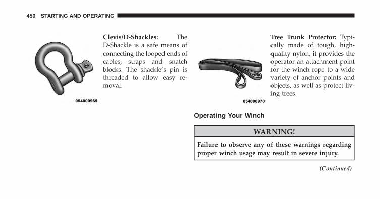
Clevis/D-Shackles: TheD-Shackle is a safe means ofconnecting the looped ends ofcables, straps and snatchblocks. The shackle’s pin isthreaded to allow easy re-moval.
Tree Trunk Protector: Typi-cally made of tough, high-quality nylon, it provides theoperator an attachment pointfor the winch rope to a widevariety of anchor points andobjects, as well as protect liv-ing trees.
Operating Your Winch
WARNING!
Failure to observe any of these warnings regardingproper winch usage may result in severe injury.
(Continued)
450 STARTING AND OPERATING

WARNING! (Continued)• Always use supplied hook strap to hold the hook
when spooling wire rope in or out.• Never use as a hoist.• Never use to move persons.• Never exceed winch or wire rope rated capacity.• Always wear heavy leather gloves when handling
the wire rope.• Never touch wire rope or hook while in tension or
under load.• Never engage or disengage clutch if winch is under
load, wire rope is in tension, or wire rope drum ismoving.
• Always stand clear of wire rope and load and keepothers away during winching.
(Continued)
WARNING! (Continued)• Always keep hands and clothing clear of the wire
rope, hook and fairlead opening during operationand when spooling.
• Never wrap wire rope back onto itself. Always usea choker chain, wire choker rope or tree trunkprotector on the anchor.
• Never attach a recovery strap to the winch hook toincrease the length of a pull.
• Never attempt to tow a vehicle with the recoverystrap attached directly to the winch hook.
• Never use �bungee� straps that develop tremendousand potentially dangerous amounts of force whenstretched.
• Always disconnect the remote control when not inuse.
(Continued)
5
STARTING AND OPERATING 451

WARNING! (Continued)• Never winch when there are less than five wraps of
wire rope around the winch drum.• Always pass remote control through a window to
avoid pinching lead in door, then using remoteinside a vehicle.
• Never leave the remote control plugged into thewinch while free spooling, rigging or sitting idle.
General Information
Practice using your winch before you get stuck. Some keypoints to remember when using your winch are:
1. Always take your time to assess the situation and planyour pull carefully.
2. Always take your time when using a winch.
3. Use the right equipment for the situation.
4. Always wear leather gloves and do not allow the wirerope to slip through your hands when handling therope.
5. Only the operator should handle the wire rope andremote control.
6. Think safety at all times.
Vehicle Recovery Using The Winch
CAUTION!
• Always Know Your Winch: Take the time to fullyread and understand the included Installation andOperations Guide, and Basic Guide to WinchingTechniques, in order to understand your winch andthe winching operation.
(Continued)
452 STARTING AND OPERATING

CAUTION! (Continued)• Always inspect winch installation and wire rope
condition before operating the winch. Frayed,kinked or damaged wire rope must be replacedimmediately. Loose or damaged winch installationmust be corrected immediately.
• Always be sure any element which can interferewith safe winching operations is removed prior toinitiating winching.
• Always keep remote control lead clear of the drum,wire rope and rigging.
• Inspect for cracks, pinches, frayed wires, or looseconnections. Replace if damaged.
• Be careful not to pull the Winch Cable Collarthrough the rollers. Watch and listen to Winch forproper snugness.
1. Inspect the winch, winch mount, and wire rope fordamage. Do not use the winch if the mount is loose orrope shows excessive wear or damage.
2. Put on gloves.
5
STARTING AND OPERATING 453

3. Disengage the clutch to allow free spooling of thewinch drum, rotate the clutch lever on the winch todisengage. Freespooling conserves battery power.
4. Free the winch hook and attach the hook strap. Freethe winch hook from its anchor point. Attach the hookstrap to the hook (if not attached).
5. Pull the wire to the anchor point. Pull out enough wirerope to reach your anchor point. Be sure to keep acertain amount of tension on the wire as it can becometwisted and over-wrapped when slackened, leading towire rope damage. To prevent losing the end, hold thehook strap while you work.
Free Spool
Hook Strap
454 STARTING AND OPERATING

6. Secure to the anchor point. Once you have establishedyour anchor point, secure the tree-trunk protector orchoker-chain around the object. CAUTION!
Always be certain the anchor you select will with-stand the load.
Tree Trunk Protector
5
STARTING AND OPERATING 455

NOTE: How to choose an anchor point: A secure anchoris critical to winching operations. An anchor must bestrong enough to hold while winching. Natural anchorsinclude trees, stumps and rocks. Hook the cable as low aspossible. If no natural anchors are available when recov-ering another vehicle, your vehicle becomes the anchorpoint. In this case, be sure to put the transmission inNEUTRAL, apply the hand brake and block its wheels toprevent your vehicle from moving. Ideally, you’ll wantan anchor point that will enable you to pull straight in thedirection the vehicle will move. This allows the wire ropeto wind tightly and evenly onto the spooling drum. Ananchor point as far away as possible will provide thewinch with its greatest pulling power.
7. Attach the Clevis/D-shackle and Tree Trunk Protector.Attach the shackle to the two ends of the strap or chainand through the hook loop, being careful not to overtighten (tighten and back-off 1/2 turn).
8. Lock the clutch. Lock the winch drum by rotating theclutch lever on the winch to engage.
NOTE: Always ensure the clutch is fully engaged ordisengaged.
Clevis/D-Shackles
456 STARTING AND OPERATING

9. Connect the remote control to the winch control box,located behind the front bumper. Be careful not to letthe remote control cord dangle in front of the winch. Ifyou choose to control the winch from inside yourvehicle, always pass the remote through a window toavoid pinching the cord in the door. Always discon-nect the remote control when not in use.
10. Put wire rope under tension. Using the remote con-trol switch, slowly wind the wire rope until no slackremains. Once the wire rope is under tension, standwell clear of it and never step over it.
11. Check your anchor. Make sure all connections aresecured and free of debris before continuing with thewinching procedure.
5
STARTING AND OPERATING 457

12. Check wire rope. The wire rope should be neatlywound around the spooling drum. Improper wind-ing can cause damage to the wire rope.
In certain situations you maydecide to throw a heavy blan-ket or similar object over thewire rope. A heavy blanketcan absorb energy should thewire rope break. Place it onthe wire rope midway be-tween the winch and the an-chor point. Do this before thewire rope is put under ten-
sion. Do not approach or move the blanket once tensionis applied. Do not allow it to get pulled into the fairlead.If it is necessary to move or remove the blanket, slack thetension on the wire rope first.
458 STARTING AND OPERATING
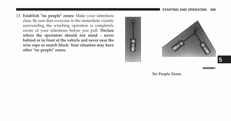
13. Establish �no people� zones: Make your intentionsclear. Be sure that everyone in the immediate vicinitysurrounding the winching operation is completelyaware of your intentions before you pull. Declarewhere the spectators should not stand - neverbehind or in front of the vehicle and never near thewire rope or snatch block. Your situation may haveother �no people� zones.
No People Zones
5
STARTING AND OPERATING 459

14. Begin winching. With the winching vehicles engineon and light tension already on the wire rope, beginwinching slowly and steadily. Be sure that the wirerope is winding evenly and tightly around the spool-ing drum. For additional assistance, the winchedvehicle can be slowly driven while being pulled bythe winch. Continue pulling until the vehicle is onstable ground. If you are able to drive the vehicle, thewinching operation is complete.
NOTE:
• Avoid overheating the winch motor. For extendedwinching, stop at reasonable intervals to allow thewinch motor to cool down.
Using The Remote Control
460 STARTING AND OPERATING

• What to look for under load: The wire rope mustalways spool onto the drum as indicated by the drumrotation decal on the winch. As you power-in, makesure the wire rope winds evenly and tightly on thedrum. This prevents the outer wire wraps from draw-ing into the inner wraps, binding and damaging thewire rope. Avoid shock loads by using the controlswitch intermittently to take up wire rope slack. Shockloads can momentarily far exceed the winch and wirerope ratings. During side pulls the wire rope tends tostack up at one end of the drum. This stack can becomelarge enough to cause serious damage to the winch. So,line up pulls as straight ahead as possible and stopwinching if the wire rope comes close to the tie rods ormounting plate. To fix an uneven stack, spool out thatsection of the rope and reposition it to the opposite endof the drum, which will free up space for continuedwinching.
15. Secure vehicle. Once recovery of the vehicle is com-plete, be sure to secure the vehicle’s brakes and shiftthe transmission to PARK. Release tension in the wirerope.
16. Disconnect the wire rope, and disconnect from theanchor.
17. Rewind the wire rope. The person handling the wirerope should walk the rope in and not let it slidethrough the hand, control the winch at all times. 5
STARTING AND OPERATING 461

WARNING!
To prevent serious injury, NEVER put your fingersinside the hook area as you are powering-in.
NOTE: How to spool under no load: Arrange the re-mote control lead so it cannot be caught in the winch.Arrange the wire rope so it will not kink or tangle whenspooled. Be sure any wire rope already on the spoolingdrum is wound tightly and evenly layered. Tighten andstraighten the layer if necessary. Keep the wire ropeunder light tension and spool the wire rope back andonto the winch drum in even layers. Stop frequently totighten and straighten the layers as necessary. Repeat thisprocess until the winch hook is the same distance as thefull length of the remote control from the winch. Pinchthe hook between your thumb and forefinger and attachthe hook strap. Hold the hook strap between the thumband forefinger to keep tension on the wire rope. Walk thewire rope towards the fairlead, carefully spooling in theremaining wire rope. By pulsing the remote controlswitch.
462 STARTING AND OPERATING
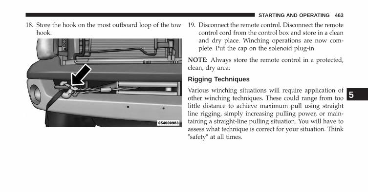
18. Store the hook on the most outboard loop of the towhook.
19. Disconnect the remote control. Disconnect the remotecontrol cord from the control box and store in a cleanand dry place. Winching operations are now com-plete. Put the cap on the solenoid plug-in.
NOTE: Always store the remote control in a protected,clean, dry area.
Rigging Techniques
Various winching situations will require application ofother winching techniques. These could range from toolittle distance to achieve maximum pull using straightline rigging, simply increasing pulling power, or main-taining a straight-line pulling situation. You will have toassess what technique is correct for your situation. Think�safety� at all times.
5
STARTING AND OPERATING 463

How To Change The Pulling Direction
All winching operations should have a straight line fromthe winch to the object being pulled. This minimizes the
wire rope collecting on one side of the drum affectingpulling efficiency and damaging wire rope. A snatchblock, secured to a point directly in front of the vehiclewill enable you to change your pulling direction whilestill allowing the wire rope to be at 90° to wind properlyonto the spooling drum.
Increasing Pulling Power
In some cases, you may find yourself needing morepulling power. The use of snatch blocks increases me-chanical advantage and that increases your pullingpower.
Change Pulling Directions
464 STARTING AND OPERATING

Double Line
Because pulling power decreases with the number oflayers of wire rope on the winch drum, you can use asnatch block to double line out more wire rope. Thisdecreases the number of layers of wire rope on the drum,and increases pulling power. Start by feeding out enough
wire rope to free the winch hook. Attach the hook to yourvehicle’s frame/tow hook and run the wire rope througha snatch block. Disengage the clutch and, using thesnatch block, pull out enough wire to reach your anchorpoint. Do not attach the hook to the mounting kit. Secureto the anchor point with a tree trunk protector or chokerchain. Attach the clevis/shackle. Attach the shackle to thetwo ends of the strap/chain, being careful not to overtighten (tighten and back-off 1/2 turn).
POWER STEERING
The standard power steering system will give you goodvehicle response and increased ease of maneuverabilityin tight spaces. The system will provide mechanicalsteering capability if power assist is lost.
5
STARTING AND OPERATING 465
If for some reason the power assist is interrupted, it willstill be possible to steer your vehicle. Under these condi-tions, you will observe a substantial increase in steeringeffort, especially at very low vehicle speeds and duringparking maneuvers.
NOTE:
• Increased noise levels at the end of the steering wheeltravel are considered normal and do not indicate thatthere is a problem with the power steering system.
• Upon initial start-up in cold weather, the power steer-ing pump may make noise for a short amount of time.This is due to the cold, thick fluid in the steeringsystem. This noise should be considered normal, and itdoes not in any way damage the steering system.
WARNING!
Continued operation with reduced power steeringassist could pose a safety risk to yourself and others.Service should be obtained as soon as possible.
CAUTION!
Prolonged operation of the steering system at the endof the steering wheel travel will increase the steeringfluid temperature and it should be avoided whenpossible. Damage to the power steering pump mayoccur.
466 STARTING AND OPERATING
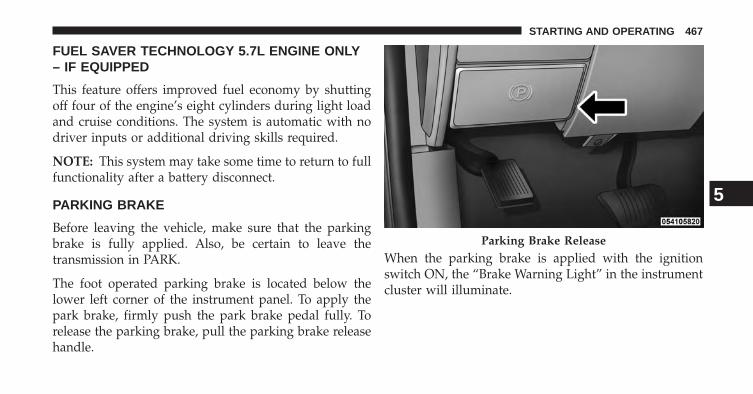
FUEL SAVER TECHNOLOGY 5.7L ENGINE ONLY– IF EQUIPPED
This feature offers improved fuel economy by shuttingoff four of the engine’s eight cylinders during light loadand cruise conditions. The system is automatic with nodriver inputs or additional driving skills required.
NOTE: This system may take some time to return to fullfunctionality after a battery disconnect.
PARKING BRAKE
Before leaving the vehicle, make sure that the parkingbrake is fully applied. Also, be certain to leave thetransmission in PARK.
The foot operated parking brake is located below thelower left corner of the instrument panel. To apply thepark brake, firmly push the park brake pedal fully. Torelease the parking brake, pull the parking brake releasehandle.
When the parking brake is applied with the ignitionswitch ON, the “Brake Warning Light” in the instrumentcluster will illuminate.
Parking Brake Release
5
STARTING AND OPERATING 467

NOTE:
• When the parking brake is applied and the transmis-sion is placed in gear, the “Brake Warning Light” willflash. If vehicle speed is detected, a chime will soundto alert the driver. Fully release the parking brakebefore attempting to move the vehicle.
• This light only shows that the parking brake is ap-plied. It does not show the degree of brake application.
When parking on a hill, it is important to turn the frontwheels toward the curb on a downhill grade and awayfrom the curb on an uphill grade. Apply the parkingbrake before placing the shift lever in PARK, otherwisethe load on the transmission locking mechanism maymake it difficult to move the shift lever out of PARK. Theparking brake should always be applied whenever thedriver is not in the vehicle.
WARNING!
• Never use the PARK position as a substitute for theparking brake. Always apply the parking brakefully when parked to guard against vehicle move-ment and possible injury or damage.
• Never leave children alone in a vehicle, or withaccess to an unlocked vehicle. Leaving unattendedchildren in a vehicle is dangerous for a number ofreasons. A child or others could be seriously orfatally injured.
• Do not leave the key fob in or near the vehicle (orin a location accessible to children, and do notleave a vehicle equipped with Keyless Enter-N-Goin the ACC or ON/RUN mode). A child couldoperate power windows, other controls, or movethe vehicle.
(Continued)
468 STARTING AND OPERATING

WARNING! (Continued)• Be sure the parking brake is fully disengaged
before driving; failure to do so can lead to brakefailure and a collision.
• Always fully apply the parking brake when leav-ing your vehicle or it may roll and cause damage orinjury. Also, be certain to leave the transmission inPARK. Failure to do so may cause the vehicle to rolland cause damage or injury.
CAUTION!
If the Brake System Warning Light remains on withthe parking brake released, a brake system malfunc-tion is indicated. Have the brake system serviced byan authorized dealer immediately.
BRAKE SYSTEM
If power assist is lost for any reason (for example,repeated brake applications with the engine off), thebrakes will still function. However, you will experience asubstantial increase in braking effort to stop the vehicle.
If either the front or rear hydraulic system loses normalbraking capability, the remaining system will still func-tion with some loss of overall braking effectiveness. Thiswill be evident by increased pedal travel during applica-tion, greater pedal force required to slow or stop, andactivation of the “Brake Warning Light” and the “ABSWarning Light” (if equipped) during brake use.
3500 Dual Rear Wheel Models Only
The brake system power assist is provided by a hydro-boost unit which shares fluid with the power steeringsystem. You may experience some clicking or hissingnoises from the hydro-boost system during hard brakingconditions.
5
STARTING AND OPERATING 469

NOTE: Under cold temperatures, pedal effort will behigher than normal until the power steering fluid reachesoperating temperature.
ELECTRONIC BRAKE CONTROL SYSTEM
Your vehicle is equipped with an advanced electronicbrake control system that includes Anti-Lock Brake Sys-tem (ABS), Traction Control System (TCS), Brake AssistSystem (BAS), Hill Start Assist (HSA), Electronic StabilityControl (ESC) and Trailer Sway Control (TSC). All of thesystems work together to enhance vehicle stability andcontrol in various driving conditions, and are commonlyreferred to as ESC.
Anti-Lock Brake System (ABS)
The ABS aids the driver in maintaining vehicle controlunder adverse braking conditions. The system controlshydraulic brake pressure to prevent wheel lockup andhelp avoid skidding on slippery surfaces during braking.
NOTE: ABS improves steering control of the vehicleduring hard braking maneuvers.
WARNING!
• ABS cannot prevent the natural laws of physicsfrom acting on the vehicle, nor can it increasebraking or steering efficiency beyond that affordedby the condition of the vehicle brakes and tires orthe traction afforded.
• The ABS cannot prevent collisions, including thoseresulting from excessive speed in turns, followinganother vehicle too closely, or hydroplaning.
• The capabilities of an ABS-equipped vehicle mustnever be exploited in a reckless or dangerousmanner which could jeopardize the user’s safety orthe safety of others.
470 STARTING AND OPERATING

Traction Control System (TCS) – If Equipped
The TCS monitors the amount of wheel spin of each ofthe driven wheels. If wheel spin is detected, brakepressure is applied to the slipping wheel(s), and enginepower is reduced to provide enhanced acceleration andstability. A feature of the TCS functions similarly to alimited-slip differential and controls the wheel spinacross a driven axle. If one wheel on a driven axle isspinning faster than the other, the system will apply thebrake of the spinning wheel. This will allow more enginetorque to be applied to the wheel that is not spinning.This feature remains active even if TCS and ESC are inthe “Partial Off” mode. Refer to “Electronic StabilityControl (ESC)” in this section of this manual. This brakepressure modulation transfers drive torque from slippingto non-slipping wheels to provide optimal forward trac-tion.
Brake Assist System (BAS) – If Equipped
The BAS is designed to optimize the vehicle’s brakingcapability during emergency braking maneuvers. TheBAS detects an emergency braking situation by sensingthe rate and amount of brake application and thenapplies optimum pressure to the brakes. The systemapplies optimum pressure to the brakes in emergencybraking conditions. This can help reduce braking dis-tances. The BAS complements the ABS. Applying thebrakes very quickly results in the best BAS assistance. Toreceive the benefit of BAS, you must apply continuousbraking pressure during the stopping sequence. Do notreduce brake pedal pressure unless braking is no longerdesired.
Once the brake pedal is released, the BAS is deactivated.
5
STARTING AND OPERATING 471

WARNING!
• The BAS cannot prevent the natural laws of phys-ics from acting on the vehicle, nor can it increasebraking efficiency beyond that afforded by thecondition of the vehicle brakes and tires or thetraction afforded.
• The BAS cannot prevent collisions, including thoseresulting from excessive speed in turns, followinganother vehicle too closely, or hydroplaning.
• The capabilities of a BAS-equipped vehicle mustnever be exploited in a reckless or dangerousmanner which could jeopardize the user’s safety orthe safety of others.
Hill Start Assist (HSA) – If Equipped
The HSA system is designed to assist the driver inlaunching a vehicle on an incline. HSA will maintain thelevel of brake pressure the driver inputs for a short
duration once the driver takes his foot off of the brakepedal. If the driver does not apply the throttle during thisshort duration, the system will release brake pressureand the vehicle will roll down the incline. The system willrelease brake pressure in proportion to the amount ofthrottle applied.
During operation, HSA will activate the brake controlsystem and a clicking noise may occur. If your foot is onthe brake pedal during operation you may feel a slightpedal movement. The clicking and pedal movement isnormal and both will stop when HSA becomes inactive.
HSA Activation Criteria
The following criteria must be met in order for HSA toactivate:
• Vehicle must be stopped
• Vehicle must be on a 7% or greater incline
472 STARTING AND OPERATING

• Gear selection matches vehicle uphill direction (i.e.,vehicle facing uphill is in forward gear; vehicle back-ing uphill is in REVERSE gear).
WARNING!
There may be situations on minor hills (i.e., less than7%), with a loaded vehicle or while pulling a trailerwhere the system will not activate and slight rollingmay occur, which could cause a collision with an-other vehicle or object. Always remember the driveris responsible for braking the vehicle.
The system will only work if the intended direction of thevehicle and vehicle gear match. For example, if theintended direction is forward up a hill and the vehicle isin DRIVE and the activation criteria are met, HSA willactivate.
The system will work in REVERSE and all forward gears,and will not activate if the vehicle is placed in NEU-TRAL.
Towing And Hauling With HSA
The HSA system does not know if your vehicle is loadedor towing a trailer unless the TOW/HAUL switch, lo-cated on the center stack, is selected. When activated, the“TOW/HAUL Indicator Light” will illuminate in theinstrument cluster. Refer to “Automatic Transmission” in“Starting and Operating” for further information. Inorder to accommodate the extra weight entailed undertowing and hauling conditions and to increase drivercomfort while launching on a hill, the system recognizeswhen the TOW/HAUL switch is activated and compen-sates by releasing brake pressure at a slower rate whilethrottle is applied in order to prevent the vehicle fromrolling down the hill.
5
STARTING AND OPERATING 473

WARNING!
• If you use a trailer brake controller with yourtrailer, your trailer brakes may be activated anddeactivated with the brake switch. If so, when thebrake pedal is released, there may not be enoughbrake pressure to hold the vehicle and trailer on ahill and this could cause a collision with anothervehicle or object behind you. In order to avoidrolling down the incline while resuming accelera-tion, manually activate the trailer brake or applymore vehicle brake pressure prior to releasing thebrake pedal. Always remember the driver is re-sponsible for braking the vehicle.
(Continued)
WARNING! (Continued)• HSA is not a parking brake. If you stop the vehicle
on a hill without putting the transmission in PARKor using the parking brake, it will roll down theincline and could collide with another vehicle,object or person, and cause serious or fatal injury.Always remember to use the parking brake whileparking on a hill and that the driver is responsiblefor braking the vehicle.
HSA Off
Non-EVIC Equipped Vehicles
If you wish to turn off the HSA system, follow thisprocedure:
1. Start with the engine OFF, and the vehicle in PARKwith the wheels straight.
474 STARTING AND OPERATING

2. Start the engine.
3. With the engine running and the brake applied, rotatethe steering wheel 180° counterclockwise from center.
4. Press the “ESC Off” switch four times within 20seconds. The “ESC Off Indicator Light” should appearand disappear four times.
5. Rotate the steering wheel 360° clockwise (180° clock-wise from center).
6. Cycle ignition switch OFF then ON.
7. If the sequence was completed properly, the “ESC OffIndicator Light” will blink several times to confirmHSA is off.
Steps 1 through 7 must be completed within 90 secondsto turn off HSA. Repeat steps 1 through 7 to re-enableHSA functionality.
EVIC Equipped Vehicles
HSA is a Customer Programmable Feature on a EVICequipped vehicle. If you wish to turn off the HSA feature,refer to “Electronic Vehicle Information Center (EVIC)/Customer Programmable Features” in “UnderstandingYour Instrument Panel” for further information.
Electronic Stability Control (ESC) – If Equipped
The ESC system enhances directional control and stabil-ity of the vehicle under various driving conditions. ESCcorrects for oversteering or understeering of the vehicleby applying the brake of the appropriate wheel to assistin counteracting the oversteer or understeer condition.Engine power may also be reduced to help the vehiclemaintain the desired path.
ESC uses sensors in the vehicle to determine the vehiclepath intended by the driver and compares it to the actualpath of the vehicle. When the actual path does not match
5
STARTING AND OPERATING 475

the intended path, ESC applies the brake of the appro-priate wheel to assist in counteracting the oversteer orundersteer condition.
• Oversteer - when the vehicle is turning more thanappropriate for the steering wheel position.
• Understeer - when the vehicle is turning less thanappropriate for the steering wheel position.
All Two-Wheel Drive Vehicles And Four-WheelDrive Vehicles In 2WD, 4WD AUTO, Or 4WDLOCK Modes Can Choose The Following ESCOperating Modes:
ESC On
This is the normal operating mode for ESC in 2WD/4WDAUTO/4WD LOCK modes and in 2WD vehicles. When-ever the vehicle is started or the transfer case (ifequipped) is shifted from 4WD LOW or Neutral, back to4WD LOCK or 4WD AUTO, the ESC system will be in
this mode. This mode should be used for almost alldriving situations. ESC should only be turned to “PartialOff” or “ESC Off” for specific reasons as noted below.
WARNING!
Electronic Stability Control (ESC) cannot prevent thenatural laws of physics from acting on the vehicle, norcan it increase the traction afforded by prevailing roadconditions. ESC cannot prevent accidents, includingthose resulting from excessive speed in turns, drivingon very slippery surfaces, or hydroplaning. ESC alsocannot prevent accidents resulting from loss of vehiclecontrol due to inappropriate driver input for the con-ditions. Only a safe, attentive, and skillful driver canprevent accidents. The capabilities of an ESC equippedvehicle must never be exploited in a reckless or dan-gerous manner which could jeopardize the user’ssafety or the safety of others.
476 STARTING AND OPERATING

ESC Partial Off
This mode is entered by momentarily pressing the “ESCOff” switch. When in �Partial Off� mode, the TCS portionof ESC, except for the “limited slip” feature described inthe TCS section, has been disabled and the �ESC OffIndicator Light� will be illuminated. All other stabilityfeatures of ESC function normally. This mode is intendedto be used if the vehicle is in deep snow, sand, or gravelconditions and more wheel spin than TCS would nor-mally allow is required to gain traction. To turn ESC onagain, momentarily press the “ESC Off” switch. This willrestore the normal “ESC On” mode of operation.
NOTE: To improve the vehicle’s traction when drivingwith snow chains or starting off in deep snow, sand orgravel, it may be desirable to switch to the “Partial Off”mode by pressing the “ESC Off” switch. Once the situa-tion requiring ESC to be switched to the “Partial Off”mode is overcome, turn ESC back on by momentarilypressing the “ESC Off” switch. This may be done whilethe vehicle is in motion.
5
STARTING AND OPERATING 477

WARNING!
• When in “Partial Off” mode, the TCS functionalityof ESC, (except for the limited slip feature de-scribed in the TCS section), has been disabled andthe “ESC Off Indicator Light” will be illuminated.When in “Partial Off” mode, the engine powerreduction feature of TCS is disabled, and theenhanced vehicle stability offered by the ESC sys-tem is reduced.
• Trailer Sway control (TSC) is disabled when theESC system is in the �Partial Off� mode.
All Four-Wheel Drive Vehicles In 4WD AUTO And4WD LOCK Modes Can Also Choose TheFollowing ESC Operating Mode. This Is The OnlyESC Operating Mode in 4WD LOW:
Full Off
This mode is intended for off-road use when ESC stabil-ity features could inhibit vehicle maneuverability due totrail conditions. This mode is entered by pressing andholding the “ESC Off” switch for five seconds when thevehicle is stopped and the engine is running. After fiveseconds, the “ESC Off Indicator Light” will illuminateand the “ESC Off” message will appear in the odometer.Press and release the trip odometer button located on theinstrument cluster to clear this message.
478 STARTING AND OPERATING

NOTE: The “ESC OFF” message will display and theaudible chime will sound when the shift lever is placedinto the PARK position from any other position and thenmoved out of the PARK position. This will occur even ifthe message was previously cleared.
In this mode, ESC and TCS except for the “limited slip”feature described in the TCS section are turned off untilthe vehicle reaches a speed of 40 mph (64 km/h). At40 mph (64 km/h) the system returns to “Partial Off”mode, described above. When the vehicle speed dropsbelow 35 mph (56 km/h) the ESC system shuts off. ESCis off at low vehicle speeds so that it will not interferewith off-road driving but ESC function returns to providethe stability feature at speeds above 40 mph (64 km/h).The “ESC Off Indicator Light” will always be illuminatedwhen ESC is off. To turn ESC on again, momentarilypress the “ESC Off” switch. This will restore the normal“ESC On” mode of operation.
“ESC Off” is the only operating mode for ESC in 4WDLOW. Whenever the vehicle is started in 4WD LOW orthe transfer case (if equipped) is shifted from 4WD LOCKor NEUTRAL, to 4WD LOW, the ESC system will be inthis mode.
WARNING!
In the ESC �Full Off� mode, the engine torque reduc-tion and stability features are disabled. Therefore,the enhanced vehicle stability offered by ESC isunavailable. In an emergency evasive maneuver theESC system will not engage to assist in maintainingstability. “ESC Off” mode is intended for off-highway or off-road use only.
5
STARTING AND OPERATING 479

ESC Activation/Malfunction Indicator Light AndESC OFF Indicator Light
The “ESC Activation/Malfunction IndicatorLight” in the instrument cluster will come onwhen the ignition switch is turned to the ONposition. It should go out with the engine
running. If the “ESC Activation/Malfunction IndicatorLight” comes on continuously with the engine running, amalfunction has been detected in the ESC system. If thislight remains on after several ignition cycles, and thevehicle has been driven several miles (kilometers) atspeeds greater than 30 mph (48 km/h), see your autho-rized dealer as soon as possible to have the problemdiagnosed and corrected.
The “ESC Activation/Malfunction Indicator Light” (lo-cated in the instrument cluster) starts to flash as soon asthe tires lose traction and the ESC system becomes active.The “ESC Activation/Malfunction Indicator Light” also
flashes when TCS is active. If the “ESC Activation/Malfunction Indicator Light” begins to flash during ac-celeration, ease up on the accelerator and apply as littlethrottle as possible. Be sure to adapt your speed anddriving to the prevailing road conditions.
NOTE:
• The “ESC Activation/Malfunction Indicator Light”and the “ESC OFF Indicator Light” come on momen-tarily each time the ignition switch is turned ON.
• Each time the ignition is turned ON, the ESC systemwill be ON even if it was turned off previously.
• The ESC system will make buzzing or clicking soundswhen it is active. This is normal; the sounds will stop
480 STARTING AND OPERATING
when ESC becomes inactive following the maneuverthat caused the ESC activation.
The “ESC OFF Indicator Light” indicates theElectronic Stability Control (ESC) is off.
Trailer Sway Control (TSC) – If Equipped
The TSC system uses sensors in the vehicle to recognizean excessively swaying trailer and will take the appro-priate actions to attempt to stop the sway. The systemmay reduce engine power and apply the brake of theappropriate wheel(s) to counteract the sway of the trailer.TSC will become active automatically once an excessivelyswaying trailer is recognized. No driver action is re-quired. Note that TSC cannot stop all trailers fromswaying. Always use caution when towing a trailer andfollow the trailer tongue weight recommendations. Referto “Trailer Towing” in “Starting and Operating” for
further information. When TSC is functioning, the “ESCOff Indicator Light” will flash, the engine power may bereduced and you may feel the brakes being applied toindividual wheels to attempt to stop the trailer fromswaying. TSC is disabled when the ESC system is in the“Partial Off” or “Full Off” modes.
TSC is only active in the default “ESC On” mode. TSCcan be disabled by pressing the “ESC Off” switch andentering “ESC Partial Off” mode. It is not active in the“ESC Partial Off” or “ESC Off” modes. Refer to the ESCportion of this section for an explanation of the differentESC operating modes.
WARNING!
If TSC activates while driving, slow the vehicledown, stop at the nearest safe location, and adjust thetrailer load to eliminate trailer sway.
5
STARTING AND OPERATING 481

TIRE SAFETY INFORMATION
Tire Markings
NOTE:
• P (Passenger) - Metric tire sizing is based on U.S.design standards. P-Metric tires have the letter “P”molded into the sidewall preceding the size designa-tion. Example: P215/65R15 95H.
• European-Metric tire sizing is based on Europeandesign standards. Tires designed to this standard havethe tire size molded into the sidewall beginning withthe section width. The letter �P� is absent from this tiresize designation. Example: 215/65R15 96H.
• LT (Light Truck) - Metric tire sizing is based on U.S.design standards. The size designation for LT-Metrictires is the same as for P-Metric tires except for theletters “LT” that are molded into the sidewall preced-ing the size designation. Example: LT235/85R16.
• Temporary spare tires are spares designed for tempo-rary emergency use only. Temporary high pressure
1 — U.S. DOT Safety StandardsCode (TIN)
4 — Maximum Load
2 — Size Designation 5 — Maximum Pressure3 — Service Description 6 — Treadwear, Traction and
Temperature Grades
482 STARTING AND OPERATING

compact spare tires have the letter “T” or “S” moldedinto the sidewall preceding the size designation. Ex-ample: T145/80D18 103M.
• High flotation tire sizing is based on U.S. designstandards and it begins with the tire diameter moldedinto the sidewall. Example: 31x10.5 R15 LT.
Tire Sizing Chart
EXAMPLE:Size Designation:
P = Passenger car tire size based on U.S. design standards�....blank....� = Passenger car tire based on European design standardsLT = Light truck tire based on U.S. design standardsT or S = Temporary spare tire31 = Overall diameter in inches (in)215 = Section width in millimeters (mm)65 = Aspect ratio in percent (%)
— Ratio of section height to section width of tire10.5 = Section width in inches (in)
5
STARTING AND OPERATING 483

EXAMPLE:R = Construction code
— �R� means radial construction— �D� means diagonal or bias construction
15 = Rim diameter in inches (in)Service Description:
95 = Load Index— A numerical code associated with the maximum load a tire can carry
H = Speed Symbol— A symbol indicating the range of speeds at which a tire can carry a load corresponding toits load index under certain operating conditions— The maximum speed corresponding to the speed symbol should only be achieved underspecified operating conditions (i.e., tire pressure, vehicle loading, road conditions, andposted speed limits)
484 STARTING AND OPERATING

EXAMPLE:Load Identification:
�....blank....� = Absence of any text on the sidewall of the tire indicates a Standard Load (SL) tireExtra Load (XL) = Extra load (or reinforced) tireLight Load (LL) = Light load tireC, D, E, F, G = Load range associated with the maximum load a tire can carry at a specified pressure
Maximum Load— Maximum load indicates the maximum load this tire is designed to carryMaximum Pressure— Maximum pressure indicates the maximum permissible cold tire inflation pressure forthis tire
Tire Identification Number (TIN)
The TIN may be found on one or both sides of the tire,however, the date code may only be on one side. Tireswith white sidewalls will have the full TIN, including thedate code, located on the white sidewall side of the tire.
Look for the TIN on the outboard side of black sidewalltires as mounted on the vehicle. If the TIN is not found onthe outboard side, then you will find it on the inboardside of the tire.
5
STARTING AND OPERATING 485

EXAMPLE:DOT MA L9 ABCD 0301
DOT = Department of Transportation— This symbol certifies that the tire is in compliance with the U.S. Department of Transportation tiresafety standards and is approved for highway use
MA = Code representing the tire manufacturing location (two digits)L9 = Code representing the tire size (two digits)ABCD = Code used by the tire manufacturer (one to four digits)03 = Number representing the week in which the tire was manufactured (two digits)
— 03 means the 3rd week01 = Number representing the year in which the tire was manufactured (two digits)
— 01 means the year 2001— Prior to July 2000, tire manufacturers were only required to have one number to represent theyear in which the tire was manufactured. Example: 031 could represent the 3rd week of 1981 or 1991
486 STARTING AND OPERATING

Tire Terminology And Definitions
Term DefinitionB-Pillar The vehicle B-Pillar is the structural member of the body located
behind the front door.Cold Tire Inflation Pressure Cold tire inflation pressure is defined as the tire pressure after
the vehicle has not been driven for at least 3 hours, or driven lessthan 1 mile (1.6 km) after sitting for a three hour period. Inflationpressure is measured in units of PSI (pounds per square inch) orkPa (kilopascals).
Maximum Inflation Pressure The maximum inflation pressure is the maximum permissiblecold tire inflation pressure for this tire. The maximum inflationpressure is molded into the sidewall.
Recommended Cold Tire InflationPressure
Vehicle manufacturer’s recommended cold tire inflation pressureas shown on the tire placard.
Tire Placard A paper label permanently attached to the vehicle describing thevehicle’s loading capacity, the original equipment tire sizes andthe recommended cold tire inflation pressures.
5
STARTING AND OPERATING 487

Tire Loading And Tire Pressure
Tire And Loading Information Placard Location
NOTE: The proper cold tire inflation pressure is listed onthe driver’s side B-Pillar or the rear edge of the driver’sside door.
B-Pillar Location for Tire And Loading InformationPlacard
488 STARTING AND OPERATING

Tire And Loading Information Placard
This placard tells you important information aboutthe:1) number of people that can be carried in the vehicle
2) total weight your vehicle can carry3) tire size designed for your vehicle4) cold tire inflation pressures for the front, rear, andspare tires.
Loading
The vehicle maximum load on the tire must not exceedthe load carrying capacity of the tire on your vehicle. Youwill not exceed the tire’s load carrying capacity if youadhere to the loading conditions, tire size, and cold tireinflation pressures specified on the Tire and LoadingInformation placard and in the “Vehicle Loading” sectionof this manual.
NOTE: Under a maximum loaded vehicle condition,gross axle weight ratings (GAWRs) for the front and rearaxles must not be exceeded. For further information onGAWRs, vehicle loading, and trailer towing, refer to“Vehicle Loading” in this section.
Tire and Loading Information Placard
5
STARTING AND OPERATING 489

To determine the maximum loading conditions of yourvehicle, locate the statement “The combined weight ofoccupants and cargo should never exceed XXX lbs orXXX kg” on the Tire and Loading Information placard.The combined weight of occupants, cargo/luggage andtrailer tongue weight (if applicable) should never exceedthe weight referenced here.
Steps For Determining Correct Load Limit
1. Locate the statement “The combined weight of occu-pants and cargo should never exceed XXX lbs orXXX kg” on your vehicle’s placard.
2. Determine the combined weight of the driver andpassengers that will be riding in your vehicle.
3. Subtract the combined weight of the driver and pas-sengers from XXX lbs or XXX kg.
4. The resulting figure equals the available amount ofcargo and luggage load capacity. For example, if“XXX” amount equals 1,400 lbs (635 kg) and there willbe five 150 lb (68 kg) passengers in your vehicle, theamount of available cargo and luggage load capacityis 650 lbs (295 kg) (since 5 x 150 = 750, and 1400 – 750= 650 lbs [295 kg]).
5. Determine the combined weight of luggage and cargobeing loaded on the vehicle. That weight may notsafely exceed the available cargo and luggage loadcapacity calculated in Step 4.
6. If your vehicle will be towing a trailer, load from yourtrailer will be transferred to your vehicle. Consult thismanual to determine how this reduces the availablecargo and luggage load capacity of your vehicle.
490 STARTING AND OPERATING

NOTE:
• The following table shows examples on how to calcu-late total load, cargo/luggage, and towing capacitiesof your vehicle with varying seating configurationsand number and size of occupants. This table is forillustration purposes only and may not be accurate forthe seating and load carry capacity of your vehicle.
• For the following example, the combined weight ofoccupants and cargo should never exceed 865 lbs(392 kg).
5
STARTING AND OPERATING 491

492 STARTING AND OPERATING

WARNING!
Overloading of your tires is dangerous. Overloadingcan cause tire failure, affect vehicle handling, andincrease your stopping distance. Use tires of therecommended load capacity for your vehicle. Neveroverload them.
TIRES — GENERAL INFORMATION
Tire Pressure
Proper tire inflation pressure is essential to the safe andsatisfactory operation of your vehicle. Three primaryareas are affected by improper tire pressure:
Safety
WARNING!
• Improperly inflated tires are dangerous and cancause collisions.
• Under-inflation increases tire flexing and can re-sult in over-heating and tire failure.
• Over-inflation reduces a tire’s ability to cushionshock. Objects on the road and chuckholes cancause damage that result in tire failure.
• Over-inflated or under-inflated tires can affect ve-hicle handling and can fail suddenly, resulting inloss of vehicle control.
• Unequal tire pressures can cause steering prob-lems. You could lose control of your vehicle.
(Continued)
5
STARTING AND OPERATING 493

WARNING! (Continued)• Unequal tire pressures from one side of the vehicle
to the other can cause the vehicle to drift to theright or left.
• Always drive with each tire inflated to the recom-mended cold tire inflation pressure.
Economy
Improper inflation pressures can cause uneven wearpatterns to develop across the tire tread. These abnormalwear patterns will reduce tread life resulting in a need forearlier tire replacement. Under-inflation also increasestire rolling resistance resulting in higher fuel consump-tion.
Ride Comfort And Vehicle Stability
Proper tire inflation contributes to a comfortable ride.Over-inflation produces a jarring and uncomfortableride. Both under-inflation and over-inflation affect the
stability of the vehicle and can produce a feeling ofsluggish response or over responsiveness in the steering.
Unequal tire pressures from side to side may cause erraticand unpredictable steering response.
Unequal tire pressure from side to side may cause thevehicle to drift left or right.
Tire Inflation Pressures
The proper cold tire inflation pressure is listed on thedriver’s side “B” Pillar or rear edge of the driver’s sidedoor.
Some vehicles may have Supplemental Tire PressureInformation for vehicle loads that are less than themaximum loaded vehicle condition. Refer to “Supple-mental Tire Pressure Information” in “Starting and Op-erating” for further information.
The pressure should be checked and adjusted as well asinspecting for signs of tire wear or visible damage at least
494 STARTING AND OPERATING

once a month. Use a good quality pocket-type gauge tocheck tire pressure. Do not make a visual judgementwhen determining proper inflation. Radial tires may lookproperly inflated even when they are under-inflated.
CAUTION!
After inspecting or adjusting the tire pressure, al-ways reinstall the valve stem cap. This will preventmoisture and dirt from entering the valve stem,which could damage the valve stem.
Inflation pressures specified on the placard are always“cold tire inflation pressure.” Cold tire inflation pressureis defined as the tire pressure after the vehicle has notbeen driven for at least three hours or driven less than 1mile (1.6 km) after a three hour period. The cold tireinflation pressure must not exceed the maximum infla-tion pressure molded into the tire sidewall.
Check tire pressures more often if subject to a wide rangeof outdoor temperatures as tire pressures vary withtemperature changes.
Tire pressures change by approximately 1 psi (7 kPa) per12°F (7°C) of air temperature change. Keep this in mindwhen checking tire pressure inside a garage, especially inthe Winter.
Example: If garage temperature = 68°F (20°C) and theoutside temperature = 32°F (0°C) then the cold tireinflation pressure should be increased by 3 psi (21 kPa),which equals 1 psi (7 kPa) for every 12°F (7°C) for thisoutside temperature condition.
Tire pressure may increase from 2 to 6 psi (13 to 40 kPa)during operation. Do not reduce this normal pressurebuild up or your tire pressure will be too low.
5
STARTING AND OPERATING 495

Tire Pressures For High Speed Operation
The manufacturer advocates driving at safe speeds andwithin posted speed limits. Where speed limits or condi-tions are such that the vehicle can be driven at highspeeds, maintaining correct tire inflation pressure is veryimportant. Increased tire pressure and reduced vehicleloading may be required for high-speed vehicle opera-tion. Refer to your authorized tire or original equipmentvehicle dealer for recommended safe operating speeds,loading and cold tire inflation pressures.
WARNING!
High speed driving with your vehicle under maxi-mum load is dangerous. The added strain on yourtires could cause them to fail. You could have aserious collision. Do not drive a vehicle loaded to themaximum capacity at continuous speeds above75 mph (120 km/h).
Radial Ply Tires
WARNING!
Combining radial ply tires with other types of tireson your vehicle will cause your vehicle to handlepoorly. The instability could cause a collision. Al-ways use radial ply tires in sets of four (or six, in thecase of trucks with dual rear wheels). Never combinethem with other types of tires.
Cuts and punctures in radial tires are repairable only inthe tread area because of sidewall flexing. Consult yourauthorized tire dealer for radial tire repairs.
All Season Tires – If Equipped
All Season tires provide traction for all seasons (spring,summer, fall and winter). Traction levels may vary be-tween different all season tires. All season tires can beidentified by the M+S, M&S, M/S or MS designation on
496 STARTING AND OPERATING

the tire sidewall. Use all season tires only in sets of four;failure to do so may adversely affect the safety andhandling of your vehicle.
Summer Or Three Season Tires – If Equipped
Summer tires provide traction in both wet and dryconditions, and are not intended to be driven in snow oron ice. Summer tires will not contain the all seasondesignation or mountain/snowflake symbol on the tiresidewall. Use summer tires only in sets of four; failure todo so may adversely affect the safety and handling ofyour vehicle.
Snow Tires
Some areas of the country require the use of snow tiresduring the winter. Snow tires can be identified by amountain/snowflake symbol on the tire sidewall.
If you need snow tires, select tires equivalent in size andtype to the original equipment tires. Use snow tires onlyin sets of four; failure to do so may adversely affect thesafety and handling of your vehicle.
Snow tires generally have lower speed ratings than whatwas originally equipped with your vehicle and shouldnot be operated at sustained speeds over 75 mph(120 km/h). For speeds above 75 mph (120 km/h) refer tooriginal equipment or an authorized tire dealer forrecommended safe operating speeds, loading and coldtire inflation pressures.
While studded tires improve performance on ice, skidand traction capability on wet or dry surfaces may bepoorer than that of non-studded tires. Some states pro-hibit studded tires; therefore, local laws should bechecked before using these tire types.
5
STARTING AND OPERATING 497
Spare Tire Matching Original Equipped Tire AndWheel – If Equipped
Your vehicle may be equipped with a spare tire andwheel equivalent in look and function to the originalequipment tire and wheel found on the front or rear axleof your vehicle. This spare tire may be used in the tirerotation for your vehicle. If your vehicle has this optionrefer to an authorized tire dealer for the recommendedtire rotation pattern.
Compact Spare Tire – If Equipped
The compact spare is for temporary emergency use only.You can identify if your vehicle is equipped with acompact spare by looking at the spare tire description onthe Tire and Loading Information Placard located on thedriver’s side door opening or on the sidewall of the tire.Compact spare tire descriptions begin with the letter “T”or “S” preceding the size designation. Example: T145/80D18 103M.
T, S = Temporary Spare Tire
Since this tire has limited tread life the original equip-ment tire should be repaired (or replaced) and reinstalledon your vehicle at the first opportunity.
Do not install a wheel cover or attempt to mount aconventional tire on the compact spare wheel, since thewheel is designed specifically for the compact spare tire.Do not install more than one compact spare tire andwheel on the vehicle at any given time.
WARNING!
Compact spares are for temporary emergency useonly. With these spares, do not drive more than50 mph (80 km/h). Temporary use spares have limitedtread life. When the tread is worn to the tread wearindicators, the temporary use spare tire needs to be
(Continued)
498 STARTING AND OPERATING

WARNING! (Continued)replaced. Be sure to follow the warnings, whichapply to your spare. Failure to do so could result inspare tire failure and loss of vehicle control.
Full Size Spare – If Equipped
The full size spare is for temporary emergency use only.This tire may look like the originally equipped tire on thefront or rear axle of your vehicle, but it is not. This sparetire may have limited tread life. When the tread is wornto the tread wear indicators, the temporary use full sizespare tire needs to be replaced. Since it is not the same asyour original equipment tire, replace (or repair) theoriginal equipment tire and reinstall on the vehicle at thefirst opportunity.
Limited-Use Spare – If Equipped
The limited-use spare tire is for temporary emergencyuse only. This tire is identified by a label located on the
limited-use spare wheel. This label contains the drivinglimitations for this spare. This tire may look like theoriginal equipped tire on the front or rear axle of yourvehicle, but it is not. Installation of this limited-use sparetire affects vehicle handling. Since it is not the same asyour original equipment tire, replace (or repair) theoriginal equipment tire and reinstall on the vehicle at thefirst opportunity.
WARNING!
Limited-use spares are for emergency use only. In-stallation of this limited-use spare tire affects vehiclehandling. With this tire, do not drive more than thespeed listed on the limit-use spare wheel. Keepinflated to the cold tire inflation pressures listed onyour Tire and Loading Information Placard locatedon the driver’s side B-Pillar or the rear edge of the
(Continued)
5
STARTING AND OPERATING 499

WARNING! (Continued)driver’s side door. Replace (or repair) the originalequipment tire at the first opportunity and reinstall iton your vehicle. Failure to do so could result in lossof vehicle control.
Tire Spinning
When stuck in mud, sand, snow, or ice conditions, do notspin your vehicle’s wheels above 30 mph (48 km/h) orfor longer than 30 seconds continuously without stop-ping when you are stuck.
Refer to “Freeing A Stuck Vehicle” in “What To Do InEmergencies” for further information.
WARNING!
Fast spinning tires can be dangerous. Forces gener-ated by excessive wheel speeds may cause tire dam-age or failure. A tire could explode and injure some-one. Do not spin your vehicle’s wheels faster than30 mph (48 km/h) for more than 30 seconds continu-ously when you are stuck, and do not let anyone neara spinning wheel, no matter what the speed.
Tread Wear Indicators
Tread wear indicators are in the original equipment tiresto help you in determining when your tires should bereplaced.
500 STARTING AND OPERATING
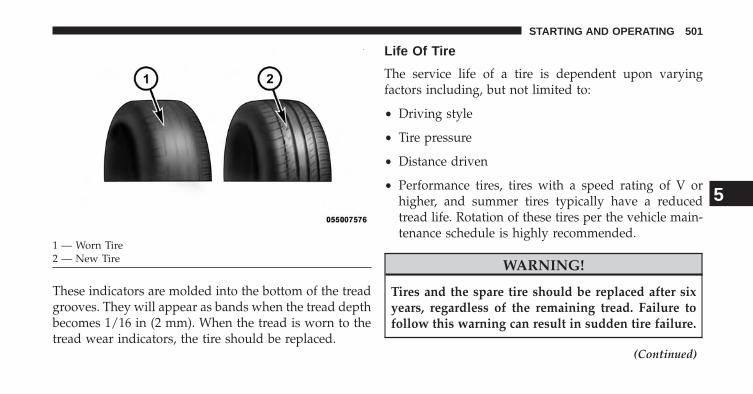
These indicators are molded into the bottom of the treadgrooves. They will appear as bands when the tread depthbecomes 1/16 in (2 mm). When the tread is worn to thetread wear indicators, the tire should be replaced.
Life Of Tire
The service life of a tire is dependent upon varyingfactors including, but not limited to:
• Driving style
• Tire pressure
• Distance driven
• Performance tires, tires with a speed rating of V orhigher, and summer tires typically have a reducedtread life. Rotation of these tires per the vehicle main-tenance schedule is highly recommended.
WARNING!
Tires and the spare tire should be replaced after sixyears, regardless of the remaining tread. Failure tofollow this warning can result in sudden tire failure.
(Continued)
1 — Worn Tire2 — New Tire
5
STARTING AND OPERATING 501
WARNING! (Continued)You could lose control and have a collision resultingin serious injury or death.
Keep dismounted tires in a cool, dry place with as littleexposure to light as possible. Protect tires from contactwith oil, grease, and gasoline.
Replacement Tires
The tires on your new vehicle provide a balance of manycharacteristics. They should be inspected regularly forwear and correct cold tire inflation pressure. The manu-facturer strongly recommends that you use tires equiva-lent to the originals in size, quality and performancewhen replacement is needed. Refer to the paragraph on“Tread Wear Indicators”. Refer to the “Tire and LoadingInformation” placard for the size designation of your tire.
The Load Index and Speed Symbol for your tire will befound on the original equipment tire sidewall. See theTire Sizing Chart example found in the Tire SafetyInformation section of this manual for more informationrelating to the Load Index and Speed Symbol of a tire.
It is recommended to replace the two front tires or tworear tires as a pair. Replacing just one tire can seriouslyaffect your vehicle’s handling. If you ever replace awheel, make sure that the wheel’s specifications matchthose of the original wheels.
It is recommended you contact your authorized tire ororiginal equipment vehicle dealer with any questionsyou may have on tire specifications or capability. Failureto use equivalent replacement tires may adversely affectthe safety, handling, and ride of your vehicle.
502 STARTING AND OPERATING

WARNING!
• Do not use a tire, wheel size or rating other thanthat specified for your vehicle. Some combinationsof unapproved tires and wheels may change sus-pension dimensions and performance characteris-tics, resulting in changes to steering, handling, andbraking of your vehicle. This can cause unpredict-able handling and stress to steering and suspen-sion components. You could lose control and havea collision resulting in serious injury or death. Useonly the tire and wheel sizes with load ratingsapproved for your vehicle.
• Never use a tire with a smaller load index orcapacity, other than what was originally equippedon your vehicle. Using a tire with a smaller loadindex could result in tire overloading and failure.You could lose control and have a collision.
(Continued)
WARNING! (Continued)• Failure to equip your vehicle with tires having
adequate speed capability can result in sudden tirefailure and loss of vehicle control.
CAUTION!
Replacing original tires with tires of a different sizemay result in false speedometer and odometer read-ings.
SUPPLEMENTAL TIRE PRESSURE INFORMATION— IF EQUIPPED
A light load vehicle condition is defined as two passen-gers [150 lbs (68 kg) each] plus 200 lbs (91 kg) of cargo.Cold tire inflation pressures for a lightly loaded vehiclewill be found on the face of the driver’s door.
5
STARTING AND OPERATING 503

TIRE CHAINS
NOTE: Chains must be the proper size for the vehicle asrecommended by the chain manufacturer.
CAUTION!
To avoid damage to your vehicle or tires, observe thefollowing precautions:• Because of restricted traction device clearance be-
tween tires and other suspension components, it isimportant that only traction devices in good condi-tion are used. Broken devices can cause seriousdamage. Stop the vehicle immediately if noiseoccurs that could indicate device breakage. Removethe damaged parts of the device before further use.
• Install device as tightly as possible and then re-tighten after driving about ½ mile (0.8 km).
• Do not exceed 30 mph (48 km/h).
(Continued)
CAUTION! (Continued)• Drive cautiously and avoid severe turns and large
bumps, especially with a loaded vehicle.• Do not drive for prolonged period on dry pave-
ment.• Observe the traction device manufacturer’s instruc-
tions on the method of installation, operatingspeed, and conditions for use. Always use thesuggested operating speed of the device manufac-turer’s if it is less than 30 mph (48 km/h).
• Do not use traction devices on a compact spare tire.
WARNING!
Using tires of different size and type (M+S, Snow)between front and rear axles can cause unpredictablehandling. You could lose control and have a collision.
504 STARTING AND OPERATING

These cautions apply to all chain traction devices, includ-ing link and cable (radial) chains.
NOTE:
• On 4x2 and 4x4 1500 model trucks, the use of class “S”snow chains is permitted on the rear wheels only oftrucks equipped with P265/70R17 tires.
• On 4x2 2500 model trucks, the use of class “U” snowchains is permitted on the rear wheels only of trucksequipped with LT245/70R17 or LT265/70R17 tires.
• On 4x4 2500 model trucks, the use of class “U” snowchains is permitted on the rear wheels only of trucksequipped with LT245/70R17, LT265/70R17, or LT285/70R17 tires.
• On 4x2 and 4x4 3500 SRW (Single Rear Wheel) modeltrucks, the use of class “U” snow chains is permittedon the rear wheels only of trucks equipped withLT265/70R17 tires.
• On 4x2 and 4x4 3500 DRW (Dual Rear Wheel) modeltrucks, the use of class “U” snow chains is permittedon the front and rear wheels of trucks equipped withLT235/80R17 tires.
CAUTION!
Do not use tire chains on the front wheels of anymodel except for 3500 DRW (Dual Rear Wheel)trucks equipped with LT235/80R17 tires. There maynot be adequate clearance for the chains and you arerisking structural or body damage to your vehicle. Donot use tire chains on the rear wheels of 1500 modeltrucks equipped with LT275/70R17, P275/60R20, or285/45R22 tires. There may not be adequate clearancefor the chains and you are risking structural or bodydamage to your vehicle.
5
STARTING AND OPERATING 505

TIRE ROTATION RECOMMENDATIONS
Tires on the front and rear axles of vehicles operate atdifferent loads and perform different steering, driving,and braking functions. For these reasons, they wear atunequal rates.
These effects can be reduced by timely rotation of tires.The benefits of rotation are especially worthwhile withaggressive tread designs such as those on all season typetires. Rotation will increase tread life, help to maintainmud, snow and wet traction levels and contribute to asmooth, quiet ride.
Refer to the “Maintenance Schedule” for the propermaintenance intervals. More frequent rotation is permis-sible if desired. The reasons for any rapid or unusualwear should be corrected prior to rotation being per-formed.
The suggested rotation method is the “forward cross”shown in the following diagram. This rotation patterndoes not apply to some directional tires that must not bereversed.
Tire Rotation
506 STARTING AND OPERATING

Directional Tires – If Equipped
For the R/T package with 22” tires & wheels, tire rotationmust be performed with consideration of the tire rotationdirection. The recommended rotation pattern for direc-tional tires is shown below.
Dual Rear Wheels – If Equipped
The tires used on dual wheel assemblies should bematched for wear to prevent overloading one tire in a set.To check if tires are even, lay a straight edge across allfour tires. The straight edge should touch all the tires.
Tire Rotation Tire Rotation
5
STARTING AND OPERATING 507

CAUTION!
3500 Dual Rear Tires may only have one approveddirection of rotation. This is to accommodate theasymmetrical design (tread pattern) of the On/Off-Road tire and the use of Outline White Letter (OWL)tires.• When replacing a flat, the spare tire may have to be
remounted on the rim, or installed at a differentlocation, to maintain the correct placement of thetire on the wheel relative to the tire/wheel positionon the truck. For example, if the spare is used toreplace an outer rear tire it will have to be re-mounted on the rim so that the wheel is dishedinward. That way the tread design of asymmetricaltires and the white writing of the OWL tires willmaintain proper position.
TIRE PRESSURE MONITOR SYSTEM (TPMS)
The Tire Pressure Monitor System (TPMS) will warn thedriver of a low tire pressure based on the vehicle recom-mended cold placard pressure.
The tire pressure will vary with temperature by about 1psi (6.9 kPa) for every 12°F (6.5°C). This means that whenthe outside temperature decreases, the tire pressure willdecrease. Tire pressure should always be set based oncold inflation tire pressure. This is defined as the tirepressure after the vehicle has not been driven for at leastthree hours, or driven less than 1 mile (1.6 km) after athree hour period. The cold tire inflation pressure mustnot exceed the maximum inflation pressure molded intothe tire sidewall. Refer to “Tires – General Information”in “Starting and Operating” for information on how toproperly inflate the vehicle’s tires. The tire pressure will
508 STARTING AND OPERATING

also increase as the vehicle is driven - this is normal andthere should be no adjustment for this increased pres-sure.
The TPMS will warn the driver of a low tire pressure ifthe tire pressure falls below the low-pressure warninglimit for any reason, including low temperature effectsand natural pressure loss through the tire.
The TPMS will continue to warn the driver of low tirepressure as long as the condition exists, and will not turnoff until the tire pressure is at or above the recommendedcold placard pressure. Once the low tire pressure warn-ing (Tire Pressure Monitoring [TPM] Telltale Light) illu-minates, you must increase the tire pressure to therecommended cold placard pressure in order for the “TirePressure Monitoring Telltale Light” to turn off. Thesystem will automatically update and the “Tire PressureMonitoring Telltale Light” will turn off once the systemreceives the updated tire pressures. The vehicle may need
to be driven for up to 20 minutes above 15 mph(25 km/h) in order for the TPMS to receive this informa-tion.
For example, your vehicle may have a recommendedcold (parked for more than three hours) placard pressureof 30 psi (207 kPa). If the ambient temperature is 68°F(20°C) and the measured tire pressure is 27 psi (186 kPa),a temperature drop to 20°F (-7°C) will decrease the tirepressure to approximately 23 psi (158 kPa). This tirepressure is sufficiently low enough to turn ON the “TirePressure Monitoring Telltale Light.” Driving the vehiclemay cause the tire pressure to rise to approximately 27psi (186 kPa), but the “Tire Pressure Monitoring TelltaleLight” will still be ON. In this situation, the “TirePressure Monitoring Telltale Light” will turn OFF onlyafter the tires are inflated to the vehicle’s recommendedcold placard pressure value.
5
STARTING AND OPERATING 509
CAUTION!
• The TPMS has been optimized for the originalequipment tires and wheels. TPMS pressures andwarning have been established for the tire sizeequipped on your vehicle. Undesirable system op-eration or sensor damage may result when usingreplacement equipment that is not of the same size,type, and/or style. Aftermarket wheels can causesensor damage. Do not use aftermarket tire sealantsor balance beads if your vehicle is equipped with aTPMS, as damage to the sensors may result.
• After inspecting or adjusting the tire pressure,always reinstall the valve stem cap. This willprevent moisture and dirt from entering the valvestem, which could damage the TPM sensor.
NOTE:
• The TPMS is not intended to replace normal tire careand maintenance or to provide warning of a tire failureor condition.
• The TPMS should not be used as a tire pressure gaugewhile adjusting your tire pressure.
• Driving on a significantly under-inflated tire causesthe tire to overheat and can lead to tire failure.Under-inflation also reduces fuel efficiency and tiretread life, and may affect the vehicle’s handling andstopping ability.
• The TPMS is not a substitute for proper tire mainte-nance, and it is the driver’s responsibility to maintaincorrect tire pressure using an accurate tire pressuregauge, even if under-inflation has not reached the levelto trigger illumination of the “Tire Pressure Monitor-ing Telltale Light.”
510 STARTING AND OPERATING

• Seasonal temperature changes will affect tire pressure,and the TPMS will monitor the actual tire pressure inthe tire.
Base System
The Tire Pressure Monitor System (TPMS) uses wirelesstechnology with wheel rim mounted electronic sensors tomonitor tire pressure levels. Sensors mounted to eachwheel as part of the valve stem transmit tire pressurereadings to the receiver module.
NOTE: It is particularly important for you to check thetire pressure in all of the tires on your vehicle monthlyand to maintain the proper pressure.
The TPMS consists of the following components:
• Receiver module,
• Four TPM sensors, and
• TPM Telltale Light
The matching full size spare wheel and tire assembly (ifequipped) has a TPM sensor. The matching full size sparecan be used in place of any of the four road tires. TheTPMS will only monitor the pressure in the full size sparewhen it is used in place of a road tire. Otherwise, a sparewith a pressure below the low-pressure limit will notcause the “Tire Pressure Monitoring Telltale Light” toilluminate or the chime to sound.
Tire Pressure Monitoring Low Pressure Warnings
The “Tire Pressure Monitoring Telltale Light” willilluminate in the instrument cluster, a “LOW TIRE
PRESSURE” message will display in the EVIC, and achime will sound when tire pressure is low in one ormore of the four active road tires. An �Inflate to XX�message will also be displayed. Should this occur, youshould stop as soon as possible, check the inflationpressure of each tire on your vehicle, and inflate each tire
5
STARTING AND OPERATING 511

to the vehicle’s recommended cold placard pressurevalue as shown in the �Inflate to XX� message. Once thesystem receives the updated tire pressures, the systemwill automatically update and the “Tire Pressure Moni-toring Telltale Light” and “LOW TIRE PRESSURE” mes-sage will turn off. The vehicle may need to be driven forup to 20 minutes above 15 mph (25 km/h) in order for theTPMS to receive this information.
Service TPMS Warning
If a system fault is detected, the “Tire Pressure Monitor-ing Telltale Light” will flash on and off for 75 seconds andthen remain on solid. The system fault will also sound achime. If the ignition switch is cycled, this sequence willrepeat, providing the system fault still exists. The “TirePressure Monitoring Telltale Light” will turn off whenthe fault condition no longer exists. A system fault canoccur due to any of the following:
1. Signal interference due to electronic devices or drivingnext to facilities emitting the same radio frequencies asthe TPM sensors.
2. Installing aftermarket window tinting that containsmaterials that may block radio wave signals.
3. Accumulation of snow or ice around the wheels orwheel housings.
4. Using tire chains on the vehicle.
5. Using wheels/tires not equipped with TPM sensors.
Vehicles with Full Size Spare
1. The matching full size spare wheel and tire assemblyhas a TPM sensor that can be monitored by the TPMS.
512 STARTING AND OPERATING

2. If you install the full size spare in place of a road tirethat has a pressure below the low-pressure warninglimit, upon the next ignition switch cycle, a chime willsound, a “LOW TIRE PRESSURE” message will bedisplayed, and the “Tire Pressure Monitoring TelltaleLight” will turn ON. An �Inflate to XX� message willalso be displayed.
3. Driving the vehicle for up to 20 minutes above 15 mph(24 km/h) will turn off the “Tire Pressure MonitoringTelltale Light” and “LOW TIRE PRESSURE” message,as long as no tire pressure is below the low-pressurewarning limit in any of the four active road tires.
Premium System – If Equipped
The Tire Pressure Monitor System (TPMS) uses wirelesstechnology with wheel rim mounted electronic sensors tomonitor tire pressure levels. Sensors mounted to eachwheel as part of the valve stem transmit tire pressurereadings to the receiver module.
NOTE: It is particularly important for you to check thetire pressure in all of the tires on your vehicle monthlyand to maintain the proper pressure.
The TPMS consists of the following components:
• Receiver module,
• Four TPM sensors,
• Various TPMS messages, which display in the Elec-tronic Vehicle Information Center (EVIC), and
• TPM Telltale Light
The matching full size spare wheel and tire assembly (ifequipped) has a TPM sensor. The full size spare can beused in place of any of the four road tires. A spare with apressure below the low-pressure limit will not cause the“Tire Pressure Monitoring Telltale Light” to illuminate orthe chime to sound.
5
STARTING AND OPERATING 513

Tire Pressure Monitoring Low Pressure Warnings
The “Tire Pressure Monitoring Telltale Light” willilluminate in the instrument cluster and a chime
will sound when tire pressure is low in one or more of thefour active road tires. In addition, the EVIC will displaya “LOW TIRE PRESSURE” message for a minimum offive seconds and a graphic showing the pressure valuesof each tire with the low tire pressure values flashing orin a different color. An �Inflate to XX� message will also bedisplayed.
Should this occur, you should stop as soon as possibleand inflate the tires with a low pressure condition (thoseflashing or in a different color in the EVIC graphic) to thevehicle’s recommended cold placard pressure inflationvalue as shown in the �Inflate to XX� message. Once thesystem receives the updated tire pressures, the systemwill automatically update, the graphic display in the
514 STARTING AND OPERATING
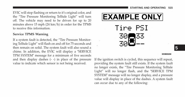
EVIC will stop flashing or return to it’s original color, andthe “Tire Pressure Monitoring Telltale Light” will turnoff. The vehicle may need to be driven for up to 20minutes above 15 mph (24 km/h) in order for the TPMSto receive this information.
Service TPMS Warning
If a system fault is detected, the “Tire Pressure Monitor-ing Telltale Light” will flash on and off for 75 seconds andthen remain on solid. The system fault will also sound achime. In addition, the EVIC will display a �SERVICETPM SYSTEM� message for a minimum of five secondsand then display dashes (- -) in place of the pressurevalue to indicate which sensor is not being received.
If the ignition switch is cycled, this sequence will repeat,providing the system fault still exists. If the system faultno longer exists, the “Tire Pressure Monitoring TelltaleLight” will no longer flash, and the �SERVICE TPMSYSTEM� message will no longer display, and a pressurevalue will display in place of the dashes. A system faultcan occur due to any of the following:
5
STARTING AND OPERATING 515
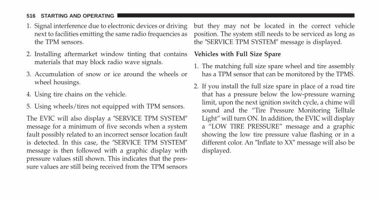
1. Signal interference due to electronic devices or drivingnext to facilities emitting the same radio frequencies asthe TPM sensors.
2. Installing aftermarket window tinting that containsmaterials that may block radio wave signals.
3. Accumulation of snow or ice around the wheels orwheel housings.
4. Using tire chains on the vehicle.
5. Using wheels/tires not equipped with TPM sensors.
The EVIC will also display a �SERVICE TPM SYSTEM�message for a minimum of five seconds when a systemfault possibly related to an incorrect sensor location faultis detected. In this case, the �SERVICE TPM SYSTEM�message is then followed with a graphic display withpressure values still shown. This indicates that the pres-sure values are still being received from the TPM sensors
but they may not be located in the correct vehicleposition. The system still needs to be serviced as long asthe �SERVICE TPM SYSTEM� message is displayed.
Vehicles with Full Size Spare
1. The matching full size spare wheel and tire assemblyhas a TPM sensor that can be monitored by the TPMS.
2. If you install the full size spare in place of a road tirethat has a pressure below the low-pressure warninglimit, upon the next ignition switch cycle, a chime willsound and the “Tire Pressure Monitoring TelltaleLight” will turn ON. In addition, the EVIC will displaya “LOW TIRE PRESSURE” message and a graphicshowing the low tire pressure value flashing or in adifferent color. An �Inflate to XX� message will also bedisplayed.
516 STARTING AND OPERATING

3. After driving the vehicle for up to 20 minutes above15 mph (25 km/h) the “Tire Pressure MonitoringTelltale Light” will turn OFF and the pressure valuewill be updated and stop flashing or return to it’soriginal color, as long as no tire pressure is below thelow-pressure warning limit in any of the four activeroad tires.
Tire Pressure Monitor System (TPMS) Tire LightLoad Inflation Switch Description (2500 Models) –If Equipped
WARNING!
Never operate your vehicle with the TPMS and tirepressures set to the Light Load Inflation Pressuresettings if carrying more than two occupants (150 lbs[68 kg] each) plus 200 pounds (91 kg) of cargo. Thevehicle “Light Load Definition” is found in the
(Continued)
WARNING! (Continued)Supplemental Tire Pressure Information Label whichis located on the rear face of the driver door opening.Failure to do so may cause you to lose controlresulting in an accident, causing serious or fatalinjury.
The TPMS tire light load inflation switch will allow thedriver to switch between the max load inflation pressure(cold) low pressure warning threshold and the light loadinflation pressure (cold) low pressure warning thresholddepending on the vehicle’s load condition. The Tire andLoading Information label defines the recommendedfront and rear cold tire inflation pressures for the vehiclewhen operating in the Max Load condition. A Supple-mental Tire Pressure Information label is also availabledefining Light Load tire inflation pressures when oper-ating in the Light Load condition. When the tire light
5
STARTING AND OPERATING 517
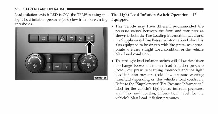
load inflation switch LED is ON, the TPMS is using thelight load inflation pressure (cold) low inflation warningthresholds.
Tire Light Load Inflation Switch Operation – IfEquipped
• This vehicle may have different recommended tirepressure values between the front and rear tires asshown in both the Tire Loading Information Label andthe Supplemental Tire Pressure Information Label. It isalso equipped to be driven with tire pressures appro-priate to either a Light Load condition or the vehicleMax Load condition.
• The tire light load inflation switch will allow the driverto change between the max load inflation pressure(cold) low pressure warning threshold and the lightload inflation pressure (cold) low pressure warningthreshold depending on the vehicle’s load condition.Refer to the “Supplemental Tire Pressure Information”label for the vehicle’s Light Load inflation pressuresand “Tire and Loading Information” label for thevehicle’s Max Load inflation pressures.
518 STARTING AND OPERATING
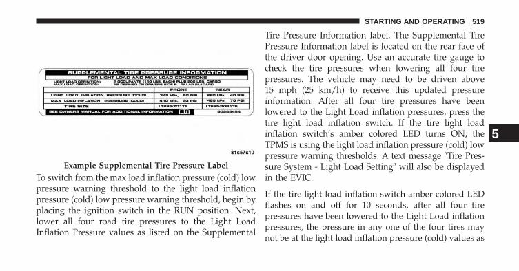
To switch from the max load inflation pressure (cold) lowpressure warning threshold to the light load inflationpressure (cold) low pressure warning threshold, begin byplacing the ignition switch in the RUN position. Next,lower all four road tire pressures to the Light LoadInflation Pressure values as listed on the Supplemental
Tire Pressure Information label. The Supplemental TirePressure Information label is located on the rear face ofthe driver door opening. Use an accurate tire gauge tocheck the tire pressures when lowering all four tirepressures. The vehicle may need to be driven above15 mph (25 km/h) to receive this updated pressureinformation. After all four tire pressures have beenlowered to the Light Load inflation pressures, press thetire light load inflation switch. If the tire light loadinflation switch’s amber colored LED turns ON, theTPMS is using the light load inflation pressure (cold) lowpressure warning thresholds. A text message �Tire Pres-sure System - Light Load Setting� will also be displayedin the EVIC.
If the tire light load inflation switch amber colored LEDflashes on and off for 10 seconds, after all four tirepressures have been lowered to the Light Load inflationpressures, the pressure in any one of the four tires maynot be at the light load inflation pressure (cold) values as
Example Supplemental Tire Pressure Label
5
STARTING AND OPERATING 519

indicated for the Light Load condition as defined on theSupplemental Tire Pressure Information label located onthe rear face of the driver door. A text message �CannotEnter Light Load Setting - Please Adjust Tire Pressure�text message will also be displayed in the EVIC. Using anaccurate tire pressure gauge, re-check the tire pressuresfor the light load inflation pressure (cold) value.
WARNING!
It is the driver’s responsibility to change to the maxload inflation pressure (cold) low pressure warningthreshold condition when not driving in the lightload condition as defined as two occupants (150 lbs[68 kg] each) plus 200 pounds (91 kg) of cargo. Thevehicle “Light Load Definition” is found in theSupplemental Tire Pressure Information label lo-cated on the rear face of the driver door. Failure to doso may cause you to lose control resulting in anaccident, causing serious or fatal injury.
To switch back to the max load inflation pressure (cold)low pressure warning threshold, press the tire light loadinflation switch. It is not necessary to first fill the tires tothe max load inflation pressure (cold) values to switchthe TPMS system to the max load inflation pressure(cold) low pressure warning threshold. If after pressingthe tire light load inflation switch, and tire pressures arebelow the max load inflation pressure (cold) low pressurewarning thresholds, the “Tire Pressure Monitoring Tell-tale Light” (located in the instrument cluster) will turnON and a chime will sound. An �inflate to XX� messagewill also be displayed. The tire pressures are now re-quired to be inflated to the max load inflation pressure(cold) values described on the Tire and Loading Informa-tion label. The Tire and Loading Information label islocated on the drivers side B-pillar. If the tire light loadinflation switch LED turns OFF, the TPMS has been resetand the TPMS is using the max load inflation pressure
520 STARTING AND OPERATING

(cold) low pressure warning thresholds. A text message�Tire Pressure System - Maximum Load Setting� will alsobe displayed in the EVIC.
General Information
This device complies with Part 15 of the FCC rules andRSS 210 of Industry Canada. Operation is subject to thefollowing conditions:
• This device may not cause harmful interference.
• This device must accept any interference received,including interference that may cause undesired op-eration.
The TPM sensors are regulated under one of the follow-ing licenses:
United States MRXC4W4MA4Canada 2546A-C4W4MA4
FUEL REQUIREMENTS
3.6L And 4.7L Engine
These engines are designed to meet allemissions regulations and provide excel-lent fuel economy and performance whenusing high quality unleaded “regular”gasoline having an octane rating of 87. The
use of premium gasoline is not recommended, as it willnot provide any benefit over regular gasoline in theseengines.
5.7L Engine
This engine is designed to meet all emis-sions regulations and provide satisfactoryfuel economy and performance when us-ing high quality unleaded gasoline having
5
STARTING AND OPERATING 521

an octane range of 87 to 89. The manufacturer recom-mends the use of 89 octane for optimum performance.The use of premium gasoline is not recommended, as itwill not provide any benefit over regular gasoline inthese engines.
Light spark knock at low engine speeds is not harmful toyour engine. However, continued heavy spark knock athigh speeds can cause damage and immediate service isrequired. Poor quality gasoline can cause problems suchas hard starting, stalling, and hesitations. If you experi-ence these symptoms, try another brand of gasolinebefore considering service for the vehicle.
Over 40 auto manufacturer’s world wide have issued andendorsed consistent gasoline specifications (the World-wide Fuel Charter, WWFC) which define fuel propertiesnecessary to deliver enhanced emissions, performance,and durability for your vehicle. The manufacturer recom-mends the use of gasolines that meet the WWFC speci-fications, if they are available.
Reformulated Gasoline
Many areas of the country require the use of cleanerburning gasoline referred to as “Reformulated Gasoline.”Reformulated gasolines contain oxygenates and are spe-cifically blended to reduce vehicle emissions and im-prove air quality.
The manufacturer supports the use of reformulated gaso-lines. Properly blended reformulated gasolines will pro-vide excellent performance and durability of engine andfuel system components.
Gasoline/Oxygenate Blends
Some fuel suppliers blend unleaded gasoline with oxy-genates such as 10% ethanol, MTBE, and ETBE. Oxygen-ates are required in some areas of the country during thewinter months to reduce carbon monoxide emissions.Fuels blended with these oxygenates may be used inyour vehicle.
522 STARTING AND OPERATING

CAUTION!
Do not use gasolines containing Methanol or E-85Ethanol. Use of these blends may result in startingand driveability problems and may damage criticalfuel system components.
Problems that result from using methanol/gasoline or E-85ethanol blends are not the responsibility of the manufac-turer. While MTBE is an oxygenate made from methanol, itdoes not have the negative effects of methanol.
E-85 Usage In Non-Flex Fuel Vehicles
Non-FFV vehicles are compatible with gasoline contain-ing 10% ethanol (E10). Gasoline with higher ethanolcontent may void the vehicle’s warranty.
If a Non-FFV vehicle is inadvertently fueled with E-85fuel, the engine will have some or all of these symptoms:
• operate in a lean mode
• OBD II “Malfunction Indicator Light” on
• poor engine performance
• poor cold start and cold drivability
• increased risk for fuel system component corrosion
To fix a Non-FFV vehicle inadvertently fueled once withE-85 perform the following:
• drain the fuel tank (see your authorized dealer)
• change the engine oil and oil filter
• disconnect and reconnect the battery to reset theengine controller memory
More extensive repairs will be required for prolongedexposure to E-85 fuel.
MMT In Gasoline
MMT is a manganese-containing metallic additive that isblended into some gasoline to increase octane. Gasoline
5
STARTING AND OPERATING 523

blended with MMT provides no performance advantagebeyond gasoline of the same octane number withoutMMT. Gasoline blended with MMT reduces spark pluglife and reduces emissions system performance in somevehicles. The manufacturer recommends that gasolinewithout MMT be used in your vehicle. The MMT contentof gasoline may not be indicated on the gasoline pump,therefore, you should ask your gasoline retailer whetherthe gasoline contains MMT. MMT is prohibited in Federaland California reformulated gasoline.
Materials Added To Fuel
All gasoline sold in the United States is required tocontain effective detergent additives. Use of additionaldetergents or other additives is not needed under normalconditions and they would result in additional cost.Therefore, you should not have to add anything to thefuel.
Fuel System Cautions
CAUTION!
Follow these guidelines to maintain your vehicle’sperformance:• The use of leaded gas is prohibited by Federal law.
Using leaded gasoline can impair engine perfor-mance and damage the emissions control system.
• An out-of-tune engine or certain fuel or ignitionmalfunctions can cause the catalytic converter tooverheat. If you notice a pungent burning odor orsome light smoke, your engine may be out of tuneor malfunctioning and may require immediate ser-vice. Contact your authorized dealer for serviceassistance.
(Continued)
524 STARTING AND OPERATING

CAUTION! (Continued)• The use of fuel additives, which are now being
sold as octane enhancers, is not recommended.Most of these products contain high concentrationsof methanol. Fuel system damage or vehicle perfor-mance problems resulting from the use of suchfuels or additives is not the responsibility of themanufacturer.
NOTE: Intentional tampering with the emissions controlsystem can result in civil penalties being assessed againstyou.Carbon Monoxide Warnings
WARNING!Carbon monoxide (CO) in exhaust gases is deadly.Follow the precautions below to prevent carbonmonoxide poisoning:
(Continued)
WARNING! (Continued)• Do not inhale exhaust gases. They contain carbon
monoxide, a colorless and odorless gas, which cankill. Never run the engine in a closed area, such asa garage, and never sit in a parked vehicle with theengine running for an extended period. If thevehicle is stopped in an open area with the enginerunning for more than a short period, adjust theventilation system to force fresh, outside air intothe vehicle.
• Guard against carbon monoxide with proper main-tenance. Have the exhaust system inspected everytime the vehicle is raised. Have any abnormalconditions repaired promptly. Until repaired, drivewith all side windows fully open.
5
STARTING AND OPERATING 525
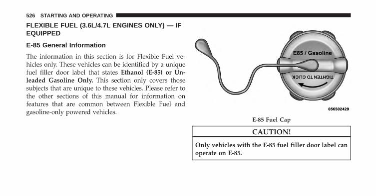
FLEXIBLE FUEL (3.6L/4.7L ENGINES ONLY) — IFEQUIPPED
E-85 General Information
The information in this section is for Flexible Fuel ve-hicles only. These vehicles can be identified by a uniquefuel filler door label that states Ethanol (E-85) or Un-leaded Gasoline Only. This section only covers thosesubjects that are unique to these vehicles. Please refer tothe other sections of this manual for information onfeatures that are common between Flexible Fuel andgasoline-only powered vehicles.
CAUTION!
Only vehicles with the E-85 fuel filler door label canoperate on E-85.
E-85 Fuel Cap
526 STARTING AND OPERATING
Ethanol Fuel (E-85)
E-85 is a mixture of approximately 85% fuel ethanol and15% unleaded gasoline.
WARNING!
Ethanol vapors are extremely flammable and couldcause serious personal injury. Never have any smok-ing materials lit in or near the vehicle when remov-ing the fuel filler tube cap (gas cap) or filling thetank. Do not use E-85 as a cleaning agent and neveruse it near an open flame.
Fuel Requirements
Your vehicle will operate on both unleaded gasoline withan octane rating of 87, or E-85 fuel, or any mixture ofthese two. For best results, a refueling pattern thatalternates between E-85 and unleaded gasoline should beavoided.
When you do switch fuel types it is recommended that:
• you do not switch when the fuel gauge indicates lessthan 1/4 full
E-85 Badge
5
STARTING AND OPERATING 527
• you do not add less than 5 gallons (19 Liters) whenrefueling
• you operate the vehicle immediately after refueling fora period of at least 5 minutes
Observing these precautions will avoid possible hardstarting and/or significant deterioration in driveabilityduring warm up.
NOTE:
• When the ambient temperature is above 90° F (32° C),you may experience hard starting and rough idlefollowing start up even if the above recommendationsare followed.
• Some additives used in regular gasoline are not fullycompatible with E-85 and may form deposits in yourengine. To eliminate driveability issues that may be
caused by these deposits, a supplemental gasolineadditive, such as MOPAR® Injector Cleanup orTechron may be used.
Selection Of Engine Oil For Flexible Fuel Vehicles(E-85) And Gasoline Vehicles
FFV vehicles operated on E-85 require specially formu-lated engine oils. These special requirements are includedin MOPAR® engine oils, and in equivalent oils meetingChrysler Specification MS-6395. The manufacturer onlyrecommends engine oils that are API Certified and meetthe requirements of Material Standard MS-6395. MS-6395contains additional requirements, developed during ex-tensive fleet testing, to provide additional protection toChrysler Group LLC engines. Use MOPAR® or anequivalent oil meeting the specification MS-6395.
Starting
The characteristics of E-85 fuel make it unsuitable for usewhen ambient temperatures fall below 0°F (-18°C). In the
528 STARTING AND OPERATING

range of 0°F (-18°C) to 32°F (0°C), you may experience anincrease in the time it takes for your engine to start, anda deterioration in driveability (sags and/or hesitations)until the engine is fully warmed up.
NOTE: Use of the engine block heater (if equipped) isbeneficial for E-85 startability when the ambient tempera-ture is less than 32°F (0°C).
Cruising Range
Because E-85 fuel contains less energy per gallon/literthan gasoline, you will experience an increase in fuelconsumption. You can expect your miles per gallon(mpg)/miles per liter and your driving range to decreaseby about 30%, compared to gasoline operation.
Replacement Parts
Many components in your Flexible Fuel Vehicle (FFV) aredesigned to be compatible with ethanol. Always be sure
that your vehicle is serviced with correct ethanol com-patible parts.
CAUTION!
Replacing fuel system components with non-ethanolcompatible components can damage your vehicle.
Maintenance
CAUTION!
Do not use ethanol mixture greater than 85% in yourvehicle. It will cause difficulty in cold starting andmay affect driveability.
5
STARTING AND OPERATING 529

ADDING FUEL
The fuel filler cap (gas cap) is located behind the fuelfiller door, on the left side of the vehicle. Open the fueldoor and remove the fuel cap by turning it counter-clockwise.
NOTE: When removing the fuel filler cap, lay the captether in the hook, located on the fuel filler door.
CAUTION!
• Damage to the fuel system or emissions controlsystem could result from using an improper fueltank filler tube cap (gas cap).
• A poorly fitting gas cap could let impurities intothe fuel system.
• A poorly fitting gas cap may cause the “Malfunc-tion Indicator Light (MIL)” to turn on.
• To avoid fuel spillage and overfilling, do not “topoff” the fuel tank after filling. When the fuelnozzle “clicks” or shuts off, the fuel tank is full.
Fuel Filler Cap
530 STARTING AND OPERATING

WARNING!
• Never have any smoking materials lit in or near thevehicle when the gas cap is removed or the tank isbeing filled.
• Never add fuel to the vehicle when the engine isrunning.
• A fire may result if gasoline is pumped into aportable container that is inside of a vehicle. Youcould be burned. Always place gas containers onthe ground while filling.
NOTE:
• Tighten the gas cap until you hear a “clicking” sound.This is an indication that the gas cap is tightenedproperly. The MIL in the instrument cluster may turnon if the gas cap is not secured properly. Make surethat the gas cap is tightened each time the vehicle isrefueled.
• When the fuel nozzle “clicks” or shuts off, the fuel tankis full.
Loose Fuel Filler Cap Message
If the vehicle diagnostic system determinesthat the fuel filler cap is loose, improperlyinstalled, or damaged, a loose gascap indicatorwill display in the EVIC telltale display area.
Refer to “Electronic Vehicle Information Center (EVIC) in“Understanding Your Instrument Panel” for further in-formation. Tighten the fuel filler cap properly and pressthe SELECT button to turn off the message. If theproblem continues, the message will appear the next timethe vehicle is started.
5
STARTING AND OPERATING 531

VEHICLE LOADING
Certification Label
As required by National Highway Traffic Safety Admin-istration regulations, your vehicle has a certification labelaffixed to the driver’s side door or pillar.
This label contains the month and year of manufacture,Gross Vehicle Weight Rating (GVWR), Gross Axle WeightRating (GAWR) front and rear, and Vehicle IdentificationNumber (VIN). A Month-Day-Hour (MDH) number isincluded on this label and indicates the Month, Day andHour of manufacture. The bar code that appears on thebottom of the label is your VIN.
Gross Vehicle Weight Rating (GVWR)
The GVWR is the total permissible weight of your vehicleincluding driver, passengers, vehicle, options and cargo.The label also specifies maximum capacities of front and
rear axle systems (GAWR). Total load must be limited soGVWR and front and rear GAWR are not exceeded.
Payload
The payload of a vehicle is defined as the allowable loadweight a truck can carry, including the weight of thedriver, all passengers, options and cargo.
Gross Axle Weight Rating (GAWR)
The GAWR is the maximum permissible load on the frontand rear axles. The load must be distributed in the cargoarea so that the GAWR of each axle is not exceeded.
Each axle GAWR is determined by the components in thesystem with the lowest load carrying capacity (axle,springs, tires or wheels). Heavier axles or suspensioncomponents sometimes specified by purchasers for in-creased durability does not necessarily increase the vehi-cle’s GVWR.
532 STARTING AND OPERATING

Tire Size
The tire size on the Vehicle Certification Label representsthe actual tire size on your vehicle. Replacement tiresmust be equal to the load capacity of this tire size.
Rim Size
This is the rim size that is appropriate for the tire sizelisted.
Inflation Pressure
This is the cold tire inflation pressure for your vehicle forall loading conditions up to full GAWR.
Curb Weight
The curb weight of a vehicle is defined as the total weightof the vehicle with all fluids, including vehicle fuel, at fullcapacity conditions, and with no occupants or cargoloaded into the vehicle. The front and rear curb weight
values are determined by weighing your vehicle on acommercial scale before any occupants or cargo areadded.
Loading
The actual total weight and the weight of the front andrear of your vehicle at the ground can best be determinedby weighing it when it is loaded and ready for operation.
The entire vehicle should first be weighed on a commer-cial scale to insure that the GVWR has not been exceeded.The weight on the front and rear of the vehicle shouldthen be determined separately to be sure that the load isproperly distributed over the front and rear axle. Weigh-ing the vehicle may show that the GAWR of either thefront or rear axles has been exceeded but the total load iswithin the specified GVWR. If so, weight must be shiftedfrom front to rear or rear to front as appropriate until thespecified weight limitations are met. Store the heavier
5
STARTING AND OPERATING 533

items down low and be sure that the weight is distributedequally. Stow all loose items securely before driving.
Improper weight distributions can have an adverse effecton the way your vehicle steers and handles and the waythe brakes operate.
CAUTION!
Do not load your vehicle any heavier than the GVWRor the maximum front and rear GAWR. If you do,parts on your vehicle can break, or it can change theway your vehicle handles. This could cause you tolose control. Also overloading can shorten the life ofyour vehicle.
TRAILER TOWING
In this section you will find safety tips and informationon limits to the type of towing you can reasonably dowith your vehicle. Before towing a trailer, carefullyreview this information to tow your load as efficientlyand safely as possible.
To maintain warranty coverage, follow the requirementsand recommendations in this manual concerning ve-hicles used for trailer towing.
Common Towing Definitions
The following trailer towing related definitions will assistyou in understanding the following information:
Gross Vehicle Weight Rating (GVWR)
The GVWR is the total allowable weight of your vehicle.This includes driver, passengers, cargo and tongueweight. The total load must be limited so that you do not
534 STARTING AND OPERATING

exceed the GVWR. Refer to “Vehicle Loading/VehicleCertification Label” in “Starting and Operating” forfurther information.
Gross Trailer Weight (GTW)
The GTW is the weight of the trailer plus the weight of allcargo, consumables and equipment (permanent or tem-porary) loaded in or on the trailer in its �loaded andready for operation� condition. The recommended way tomeasure GTW is to put your fully loaded trailer on avehicle scale. The entire weight of the trailer must besupported by the scale.
Gross Combination Weight Rating (GCWR)
The GCWR is the total permissible weight of your vehicleand trailer when weighed in combination.
NOTE: The GCWR rating includes a 150 lbs (68 kg)allowance for the presence of a driver.
Gross Axle Weight Rating (GAWR)
The GAWR is the maximum capacity of the front and rearaxles. Distribute the load over the front and rear axlesevenly. Make sure that you do not exceed either front orrear GAWR. Refer to “Vehicle Loading/Vehicle Certifica-tion Label” in “Starting and Operating” for furtherinformation.
WARNING!
It is important that you do not exceed the maximumfront or rear GAWR. A dangerous driving conditioncan result if either rating is exceeded. You could losecontrol of the vehicle and have an accident.
5
STARTING AND OPERATING 535

Tongue Weight (TW)
The tongue weight is the downward force exerted on thehitch ball by the trailer. In most cases it should not bemore than 10% of the trailer load. You must consider thisas part of the load on your vehicle.
Frontal Area
The frontal area is the maximum height multiplied by themaximum width of the front of a trailer.
Trailer Sway Control
The trailer sway control can be a mechanical telescopinglink that can be installed between the hitch receiver andthe trailer tongue that typically provides adjustable fric-tion associated with the telescoping motion to dampenany unwanted trailer swaying motions while traveling.
If equipped, the electronic Trailer Sway Control (TSC)recognizes a swaying trailer and automatically appliesindividual wheel brakes and/or reduces engine power toattempt to eliminate the trailer sway.
Weight-Carrying Hitch
A weight-carrying hitch supports the trailer tongueweight, just as if it were luggage located at a hitch ball orsome other connecting point of the vehicle. These kindsof hitches are the most popular on the market today andthey are commonly used to tow small- and medium-sized trailers.
Weight-Distributing Hitch
A weight-distributing system works by applying lever-age through spring (load) bars. They are typically usedfor heavier loads to distribute trailer tongue weight to thetow vehicle’s front axle and the trailer axle(s). When usedin accordance with the manufacturer’s directions, it pro-vides for a more level ride, offering more consistent
536 STARTING AND OPERATING
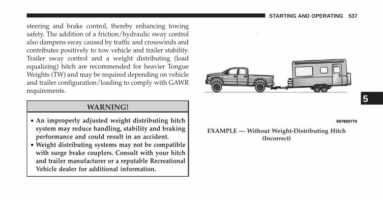
steering and brake control, thereby enhancing towingsafety. The addition of a friction/hydraulic sway controlalso dampens sway caused by traffic and crosswinds andcontributes positively to tow vehicle and trailer stability.Trailer sway control and a weight distributing (loadequalizing) hitch are recommended for heavier TongueWeights (TW) and may be required depending on vehicleand trailer configuration/loading to comply with GAWRrequirements.
WARNING!
• An improperly adjusted weight distributing hitchsystem may reduce handling, stability and brakingperformance and could result in an accident.
• Weight distributing systems may not be compatiblewith surge brake couplers. Consult with your hitchand trailer manufacturer or a reputable RecreationalVehicle dealer for additional information.
EXAMPLE — Without Weight-Distributing Hitch(Incorrect)
5
STARTING AND OPERATING 537

Fifth-Wheel Hitch
The fifth-wheel hitch is a special high platform with acoupling that mounts over the rear axle of the tow vehiclein the truck bed. It connects a vehicle and fifth-wheeltrailer with a coupling king pin.
EXAMPLE — With Weight-Distributing Hitch (Correct) EXAMPLE — Improper Adjustment of Weight-Distributing Hitch (Incorrect)
538 STARTING AND OPERATING

Gooseneck Hitch
The gooseneck hitch employs a pivoted coupling armwhich attaches to a ball mounted in the bed of a pickuptruck. The coupling arm connects to the hitch mountedover the rear axle in the truck bed.
Trailer Hitch Type and Maximum Trailer Weight
The following chart provides the maximum trailerweight a given factory equipped trailer hitch type cantow and should be used to assist you in selecting thecorrect trailer hitch for your intended towing condition.
Trailer Hitch Type and Maximum Trailer WeightHitch Type Max. Trailer Hitch Max.
Trailer WeightClass III BumperHitch - 1500 Model
5,000 lbs (2268 kg)
Trailer Hitch Type and Maximum Trailer WeightClass IV - 1500Model
11,000 lbs (4989 kg)
Class V - 2500/3500Models
17,000 lbs (7711 kg)
Fifth Wheel - 2500/3500 Models
25,000 lbs (11339 kg)
Gooseneck - 2500Model
20,000 lbs (9071 kg)
Gooseneck - 3500Model
35,000 lbs (15875 kg)
Refer to the “Trailer Towing Weights (MaximumTrailer Weight Ratings)” for the Maximum Gross
Trailer Weight (GTW) towable for your given drive-train.
All trailer hitches should be professionally installed onyour vehicle.
5
STARTING AND OPERATING 539

Trailer Towing Weights (Maximum Trailer Weight Ratings)
The rear bumper is intended to tow trailers up to a 5,000 lbs (2 268 kg) without added equipment or alterations tothe standard equipment.
Ram 1500 4x2
ST SLT/Outdoorsman Sport/Laramie3.6L V-68–Speed
AutomaticTransmission
Standard Towing: 5,000 lbs(2 268 kg)
Max Towing: 6,500 lbs(2 948 kg)
Max Payload: 1,910 lbs (866 kg)
Standard Towing: 5,000 lbs(2 268 kg)
Max Towing: 6,500 lbs(2 948 kg)
Max Payload: 1,890 lbs (857 kg)
–
4.7L V-86–Speed
AutomaticTransmission
Standard Towing: 5,000 lbs(2 268 kg)
Max Towing: 7,700 lbs(3 492 kg)
Max Payload: 1,750 lbs (793 kg)
Standard Towing: 5,000 lbs(2 268 kg)
Max Towing: 7,700 lbs(3 492 kg)
Max Payload: 1,720 lbs (780 kg)
–
540 STARTING AND OPERATING
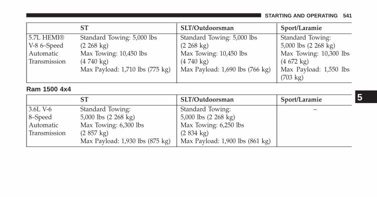
ST SLT/Outdoorsman Sport/Laramie5.7L HEMI®V-8 6–SpeedAutomaticTransmission
Standard Towing: 5,000 lbs(2 268 kg)Max Towing: 10,450 lbs(4 740 kg)Max Payload: 1,710 lbs (775 kg)
Standard Towing: 5,000 lbs(2 268 kg)Max Towing: 10,450 lbs(4 740 kg)Max Payload: 1,690 lbs (766 kg)
Standard Towing:5,000 lbs (2 268 kg)Max Towing: 10,300 lbs(4 672 kg)Max Payload: 1,550 lbs(703 kg)
Ram 1500 4x4
ST SLT/Outdoorsman Sport/Laramie3.6L V-68–SpeedAutomaticTransmission
Standard Towing:5,000 lbs (2 268 kg)Max Towing: 6,300 lbs(2 857 kg)Max Payload: 1,930 lbs (875 kg)
Standard Towing:5,000 lbs (2 268 kg)Max Towing: 6,250 lbs(2 834 kg)Max Payload: 1,900 lbs (861 kg)
–
5
STARTING AND OPERATING 541

ST SLT/Outdoorsman Sport/Laramie4.7L V-86–SpeedAutomaticTransmission
Standard Towing:5,000 lbs (2 268 kg)Max Towing: 7,500 lbs(3 401 kg)Max Payload: 1,570 lbs (712 kg)
Standard Towing:5,000 lbs (2 268 kg)Max Towing: 7,450 lbs(3 379 kg)Max Payload: 1,530 lbs (694 kg)
–
5.7L HEMI®V-8 6–SpeedAutomatic
Transmission
Standard Towing: 5,000 lbs(2 268 kg)
Max Towing: 10,350 lbs(4 694 kg)
Max Payload: 1,480 lbs (671 kg)
Standard Towing: 5,000 lbs(2 268 kg)
Max Towing: 10,300 lbs(4 672 kg)
Max Payload: 1,450 lbs (657 kg)
Standard Towing:5,000 lbs (2 268 kg)
Max Towing: 10,050 lbs(4 558 kg)
Max Payload: 1,380 lbs(625 kg)
542 STARTING AND OPERATING
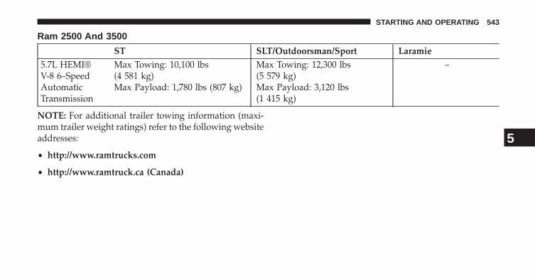
Ram 2500 And 3500
ST SLT/Outdoorsman/Sport Laramie5.7L HEMI®V-8 6–SpeedAutomaticTransmission
Max Towing: 10,100 lbs(4 581 kg)Max Payload: 1,780 lbs (807 kg)
Max Towing: 12,300 lbs(5 579 kg)Max Payload: 3,120 lbs(1 415 kg)
–
NOTE: For additional trailer towing information (maxi-mum trailer weight ratings) refer to the following websiteaddresses:
• http://www.ramtrucks.com
• http://www.ramtruck.ca (Canada)
5
STARTING AND OPERATING 543
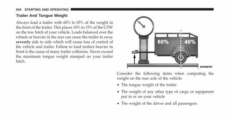
Trailer And Tongue Weight
Always load a trailer with 60% to 65% of the weight inthe front of the trailer. This places 10% to 15% of the GTWon the tow hitch of your vehicle. Loads balanced over thewheels or heavier in the rear can cause the trailer to swayseverely side to side which will cause loss of control ofthe vehicle and trailer. Failure to load trailers heavier infront is the cause of many trailer collisions. Never exceedthe maximum tongue weight stamped on your trailerhitch.
Consider the following items when computing theweight on the rear axle of the vehicle:
• The tongue weight of the trailer
• The weight of any other type of cargo or equipmentput in or on your vehicle
• The weight of the driver and all passengers.
544 STARTING AND OPERATING
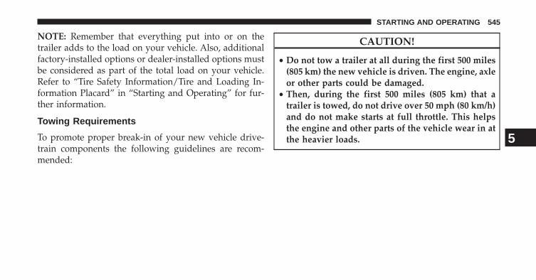
NOTE: Remember that everything put into or on thetrailer adds to the load on your vehicle. Also, additionalfactory-installed options or dealer-installed options mustbe considered as part of the total load on your vehicle.Refer to “Tire Safety Information/Tire and Loading In-formation Placard” in “Starting and Operating” for fur-ther information.
Towing Requirements
To promote proper break-in of your new vehicle drive-train components the following guidelines are recom-mended:
CAUTION!
• Do not tow a trailer at all during the first 500 miles(805 km) the new vehicle is driven. The engine, axleor other parts could be damaged.
• Then, during the first 500 miles (805 km) that atrailer is towed, do not drive over 50 mph (80 km/h)and do not make starts at full throttle. This helpsthe engine and other parts of the vehicle wear in atthe heavier loads. 5
STARTING AND OPERATING 545

WARNING!
Improper towing can lead to a collision. Follow theseguidelines to make your trailer towing as safe aspossible:• Make certain that the load is secured in the trailer
and will not shift during travel. When traileringcargo that is not fully secured, dynamic load shiftscan occur that may be difficult for the driver tocontrol. You could lose control of your vehicle andhave a collision.
• When hauling cargo or towing a trailer, do notoverload your vehicle or trailer. Overloading cancause a loss of control, poor performance or dam-age to brakes, axle, engine, transmission, steering,suspension, chassis structure or tires.
(Continued)
WARNING! (Continued)• Safety chains must always be used between your
vehicle and trailer. Always connect the chains tothe hook retainers of the vehicle hitch. Cross thechains under the trailer tongue and allow enoughslack for turning corners.
• Vehicles with trailers should not be parked on agrade. When parking, apply the parking brake onthe tow vehicle. Put the tow vehicle transmission inPARK. For four-wheel drive vehicles, make surethe transfer case is not in NEUTRAL. Always,block or �chock� the trailer wheels.
• GCWR must not be exceeded.
(Continued)
546 STARTING AND OPERATING

WARNING! (Continued)• Total weight must be distributed between the tow
vehicle and the trailer such that the following fourratings are not exceeded:
1. GVWR
2. GTW
3. GAWR
4. Trailer tongue weight rating for the trailer hitchutilized .
Towing Requirements – Tires
• Do not attempt to tow a trailer while using a compactspare tire.
• Proper tire inflation pressures are essential to the safeand satisfactory operation of your vehicle. Refer to
“Tires – General Information” in “Starting and Oper-ating” for proper tire inflation procedures.
• Check the trailer tires for proper tire inflation pres-sures before trailer usage.
• Check for signs of tire wear or visible tire damagebefore towing a trailer. Refer to “Tires – GeneralInformation” in “Starting and Operating” for theproper inspection procedure.
• When replacing tires, refer to “Tires – General Infor-mation” in “Starting and Operating” for proper tirereplacement procedures. Replacing tires with a higherload carrying capacity will not increase the vehicle’sGVWR and GAWR limits.
5
STARTING AND OPERATING 547

Towing Requirements – Trailer Brakes
• Do not interconnect the hydraulic brake system orvacuum system of your vehicle with that of the trailer.This could cause inadequate braking and possiblepersonal injury.
• An electronically actuated trailer brake controller isrequired when towing a trailer with electronicallyactuated brakes. When towing a trailer equipped witha hydraulic surge actuated brake system, an electronicbrake controller is not required.
• Trailer brakes are recommended for trailers over1,000 lbs (454 kg) and required for trailers in excess of1,653 lbs (750 kg).
CAUTION!
If the trailer weighs more than 1,000 lbs (454 kg)loaded, it should have its own brakes and theyshould be of adequate capacity. Failure to do thiscould lead to accelerated brake lining wear, higherbrake pedal effort, and longer stopping distances.
WARNING!
• Do not connect trailer brakes to your vehicle’shydraulic brake lines. It can overload your brakesystem and cause it to fail. You might not havebrakes when you need them and could have anaccident.
(Continued)
548 STARTING AND OPERATING

WARNING! (Continued)• Towing any trailer will increase your stopping
distance. When towing you should allow for addi-tional space between your vehicle and the vehiclein front of you. Failure to do so could result in anaccident.
Integrated Trailer Brake Module – If Equipped
Your vehicle may have an Integrated Trailer Brake Mod-ule (ITBM) for Electric and Electric Over Hydraulic(EOH) trailer brakes.
NOTE: This module has been designed and verifiedwith electric trailer brakes and new electric over hydrau-lic systems. Some previous EOH systems may not becompatible with ITBM.
1 — GAIN Adjustment Button2 — GAIN Adjustment Button3 — Manual Brake Control Lever
5
STARTING AND OPERATING 549

The user interface consists of the following:
Manual Brake Control Lever
Slide the manual brake control lever to the right toactivate power to the trailer’s electric brakes independentof the tow vehicle’s brakes. If the manual brake controllever is activated while the brake is also applied, thegreater of the two inputs determines the power sent tothe trailer brakes.
The trailer and the vehicle’s brake lamps will come onwhen either vehicle braking or manual trailer brakes areapplied.
Trailer Brake Status Indicator Light
This light indicates the trailer electrical connection status.
If no electrical connection is detected after the ignition isturned on, pressing the GAIN adjustment button or
sliding the manual brake control lever will display theGAIN setting for 10 seconds and the “Trailer Brake StatusIndicator Light” will not be displayed.
If a fault is detected in the trailer wiring or the IntegratedTrailer Brake Module (ITBM), the “Trailer Brake StatusIndicator Light” will flash.
GAIN Adjustment Buttons (+/-)
Pressing these buttons will adjust the brake controlpower output to the trailer brakes in 0.5 increments. TheGAIN setting can be increased to a maximum of 10 ordecreased to a minimum of 0 (no trailer braking).
GAIN
The GAIN setting is used to set the trailer brake controlfor the specific towing condition and should be changedas towing conditions change. Changes to towing condi-tions include trailer load, vehicle load, road conditionsand weather.
550 STARTING AND OPERATING

Adjusting GAIN
NOTE: This should only be performed in a traffic freeenvironment at speeds of approximately 20–25 mph(30–40 km/h).
1. Make sure the trailer brakes are in good workingcondition, functioning normally, and properly ad-justed. See your trailer dealer if necessary.
2. Hook up the trailer and make the electrical connec-tions according to the trailer manufacturer’s instruc-tions.
3. When a trailer with electric/EOH brakes is pluggedin, the trailer connected message should appear in theEVIC (if the connection is not recognized by the ITBM,braking functions will not be available), the GAINsetting will illuminate and the correct type of trailermust be selected from the EVIC options.
4. Press the UP or DOWN button on the steering wheeluntil “VEHICLE SETTINGS” appears on the screen.
5. Press the RIGHT arrow on the steering wheel to enter“VEHICLE SETTINGS”.
6. Press the UP or DOWN buttons until Trailer BrakeType appears on the screen.
NOTE:1500 Models Only– Light Electric and HeavyElectric will only be available due to the tow capacities ofthe vehicle.
7. Press the RIGHT arrow and then press the UP orDOWN buttons until the proper Trailer Brake Typeappears on the screen.
8. In a traffic-free environment, tow the trailer on a dry,level surface at a speed of 20–25 mph (30–40 km/h)and squeeze the manual brake control lever com-pletely.
5
STARTING AND OPERATING 551

9. If the trailer wheels lockup (indicated by squealingtires), reduce the GAIN setting; if the trailer wheelsturn freely, increase the GAIN setting.
Repeat Steps 8 and 9 until the GAIN setting is at a pointjust below trailer wheel lockup. If towing a heavier
trailer, trailer wheel lockup may not be attainable evenwith the maximum GAIN setting of 10.
Light Electric Heavy Electric Light EOH Heavy EOHType of TrailerBrakes
Electric TrailerBrakes
Electric TrailerBrakes
Electric over Hy-draulic TrailerBrakes
Electric over Hy-draulic TrailerBrakes
Load *Under 10,000 lbs *Above 10,000 lbs *Under 10,000 lbs *Above 10,000 lbs
* The suggested selection depends and may changedepending on the customer preferences for braking per-formance. Condition of the trailer brakes, driving androad state may also affect the selection.
EVIC Display Messages
The trailer brake control interacts with the ElectronicVehicle Information Center (EVIC). Display messages,
along with a single chime, will be displayed when amalfunction is determined in the trailer connection,trailer brake control, or on the trailer. Refer to “ElectronicVehicle Information Center” in “Understanding YourInstrument Panel” for further information.
552 STARTING AND OPERATING
CAUTION!
Connecting a trailer that is not compatible with theITBM system may result in reduced or complete lossof trailer braking. There may be a increase in stop-ping distance or trailer instability which could resultin damage to your vehicle, trailer, or other property.
WARNING!
Connecting a trailer that is not compatible with theITBM system may result in reduced or complete lossof trailer braking. There may be a increase in stop-ping distance or trailer instability which could resultin personal injury.
NOTE:
• An aftermarket controller may be available for usewith trailers with air or electric-over-hydraulic trailerbrake systems. To determine the type of brakes onyour trailer and the availability of controllers, checkwith your trailer manufacturer or dealer.
• Removal of the ITBM will cause errors and it maycause damage to the electrical system and electronicmodules of the vehicle. See your authorized dealer ifan aftermarket module is to be installed.
Towing Requirements – Trailer Lights And Wiring
Whenever you pull a trailer, regardless of the trailer size,stoplights and turn signals on the trailer are required formotoring safety.
5
STARTING AND OPERATING 553

The Trailer Tow Package may include a four- and seven-pin wiring harness. Use a factory approved trailer har-ness and connector.
NOTE: Do not cut or splice wiring into the vehicleswiring harness.
The electrical connections are all complete to the vehiclebut you must mate the harness to a trailer connector.Refer to the following illustrations.
Four-Pin Connector
1 — Female Pins 4 — Park2 — Male Pin 5 — Left Stop/Turn3 — Ground 6 — Right Stop/Turn
554 STARTING AND OPERATING
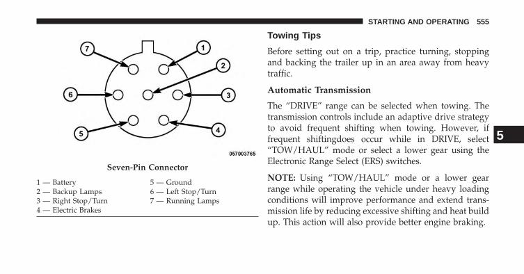
Towing Tips
Before setting out on a trip, practice turning, stoppingand backing the trailer up in an area away from heavytraffic.
Automatic Transmission
The “DRIVE” range can be selected when towing. Thetransmission controls include an adaptive drive strategyto avoid frequent shifting when towing. However, iffrequent shiftingdoes occur while in DRIVE, select“TOW/HAUL” mode or select a lower gear using theElectronic Range Select (ERS) switches.
NOTE: Using “TOW/HAUL” mode or a lower gearrange while operating the vehicle under heavy loadingconditions will improve performance and extend trans-mission life by reducing excessive shifting and heat buildup. This action will also provide better engine braking.
Seven-Pin Connector
1 — Battery 5 — Ground2 — Backup Lamps 6 — Left Stop/Turn3 — Right Stop/Turn 7 — Running Lamps4 — Electric Brakes
5
STARTING AND OPERATING 555

When towing a loaded trailer up steep grades at lowspeeds (20 mph [32 km/h] or below), holding yourvehicle in first gear (using the ERS switches) can help toavoid transmission overheating.
If you regularly tow a trailer for more than 45 minutes ofcontinuous operation, then change the automatic trans-mission fluid and filter(s) as specified for �police, taxi,fleet, or frequent trailer towing.�. Refer to “MaintenanceSchedule” for the proper maintenance intervals.
NOTE: Check the automatic transmission fluid levelbefore towing (6-speed automatic only).
Tow/Haul Mode
To reduce potential for automatic transmission overheat-ing, turn the “TOW/HAUL” feature ON when driving inhilly areas, or select a lower gear range (using theElectronic Range Select (ERS) switches) on more severegrades.
Electronic Speed Control – If Equipped
• Do not use in hilly terrain or with heavy loads.
• When using the speed control, if you experience speeddrops greater than 10 mph (16 km/h), disengage untilyou can get back to cruising speed.
• Use speed control in flat terrain and with light loads tomaximize fuel efficiency.
Cooling System
To reduce potential for engine and transmission over-heating, take the following actions:
City Driving
When stopped for short periods of time, shift the trans-mission into NEUTRAL and increase engine idle speed.
Highway Driving
Reduce speed.
556 STARTING AND OPERATING

Air Conditioning
Turn off temporarily.
Air Suspension System
To aid in attaching/detaching the trailer from the vehicle,the air suspension system can be used. Refer to “AirSuspension System” in “Starting and Operating” forfurther information.
NOTE: The vehicle must remain in the engine runningposition while attaching a trailer for proper leveling ofthe air suspension system.
SNOWPLOW
1500 Models Only
NOTE: Do not use this model vehicle for snowplowapplications.
WARNING!
Snowplows and other aftermarket equipment shouldnot be added to the front end of your vehicle. Theairbag crash sensors may be affected by the change inthe front end structure. The airbags could deployunexpectedly or could fail to deploy during a colli-sion resulting in serious injury or death.
CAUTION!
Using this vehicle for snowplow applications cancause damage to the vehicle.
WARNING!
Attaching a snowplow to this vehicle could adverselyaffect performance of the airbag system in a collision.
(Continued)
5
STARTING AND OPERATING 557

WARNING! (Continued)Do not expect that the airbag will perform as de-scribed earlier in this manual.
2500/3500 Models Only
Snowplow Prep Packages are available as a factoryinstalled option. These packages include componentsnecessary to equip your vehicle with a snowplow.
NOTE: Before installation of a snowplow it is highlyrecommended that the owner/installer obtain and followthe recommendations contained within the current BodyBuilders Guide. See your authorized dealer, installer orsnowplow manufacturer for this information. There areunique electrical systems that must be connected toproperly assure operator safety and prevent overloadingvehicle systems.
WARNING!
Attaching a snowplow to this vehicle could adverselyaffect performance of the airbag system in a collision.Do not expect that the airbag will perform as de-scribed earlier in this manual.
CAUTION!
The “Lamp Out” indicator could illuminate if exte-rior lamps are not properly installed.
Before Plowing
• Check the hydraulic system for leaks and proper fluidlevel.
• Check the mounting bolts and nuts for propertightness.
558 STARTING AND OPERATING

• Check the runners and cutting edge for excessive wear.The cutting edge should be 1/4 to 1/2 in (6 cm to 1.2cm) above ground in snow plowing position.
• Check that snowplow lighting is connected and func-tioning properly.
Snowplow Prep Package Model Availability
For Information about snowplow applications visitwww.ramtrucks.com or refer to the current Body Build-ers Guide.
1. The maximum number of occupants in the truckshould not exceed two.
2. The total GVWR or the Front GAWR or the RearGAWR should never be exceeded.
3. Cargo capacity will be reduced by the addition ofoptions or passengers, etc.
The loaded vehicle weight, including the snowplow system,all aftermarket accessories, driver, passengers, options, andcargo, must not exceed either the Gross Vehicle Weight(GVWR) or Gross Axle Weight (GAWR) ratings. Theseweights are specified on the Safety Compliance Certifica-tion Label on the driver’s side door opening.
NOTE: Detach the snowplow when transporting pas-sengers.
Vehicle front end wheel alignment was set to specifica-tions at the factory without consideration for the weightof the plow. Front end toe-in should be checked and resetif necessary at the beginning and end of the snowplowseason. This will help prevent uneven tire wear.
The blade should be lowered whenever the vehicle isparked.
5
STARTING AND OPERATING 559

Maintain and operate your vehicle and snowplow equip-ment following the recommendations provided by thespecific snowplow manufacturer.
Over The Road Operation With SnowplowAttached
The blade restricts air flow to the radiator and causes theengine to operate at higher than normal temperatures.Therefore, when transporting the plow, angle the bladecompletely and position it as low as road or surfaceconditions permit. Do not exceed 40 mph (64 km/h). Theoperator should always maintain a safe stopping distanceand allow adequate passing clearance.
Operating Tips
Under ideal snow plowing conditions, 20 mph (32 km/h)should be maximum operating speed. The operatorshould be familiar with the area and surface to becleaned. Reduce speed and use extreme caution whenplowing unfamiliar areas or under poor visibility.
General Maintenance
Snowplows should be maintained in accordance with theplow manufacturer’s instructions.
Keep all snowplow electrical connections and batteryterminals clean and free of corrosion.
When plowing snow, to avoid transmission and drivetraindamage, the following precautions should be observed.
• Operate with transfer case in 4L when plowing small orcongested areas where speeds are not likely to exceed15 mph (24 km/h). At higher speeds operate in 4H.
• Vehicles with automatic transmissions should use 4Lrange when plowing deep or heavy snow for extendedperiods of time to avoid transmission overheating.
• Do not shift the transmission unless the engine hasreturned to idle and wheels have stopped. Make apractice of stepping on the brake pedal while shiftingthe transmission.
560 STARTING AND OPERATING

RECREATIONAL TOWING (BEHIND MOTORHOME, ETC.)Towing This Vehicle Behind Another Vehicle
Towing Condition Wheels OFFThe Ground
Two-WheelDrive Models
Four-Wheel Drive Models
Flat Tow NONE NOTALLOWED
See Instructions• Automatic transmission in PARK• Manual transmission in gear (NOT in
NEUTRAL)• Transfer case in NEUTRAL (N)• Tow in forward direction
Dolly Tow Front NOTALLOWED
NOT ALLOWED
Rear OK NOT ALLOWEDOn Trailer ALL OK OK
5
STARTING AND OPERATING 561

NOTE: Vehicles equipped with air suspension must belowered to the “Entry/Exit” (lowest) level, and haveautomatic leveling disabled, before tying them down(from the body) on a trailer or flatbed truck. Refer to “AirSuspension – If Equipped” for more information. If thevehicle cannot be lowered to the “Entry/Exit” level (forexample, engine will not run), tie-downs must be fas-tened to the axles (not to the body). Failure to followthese instructions may cause fault codes to be set and/orcause loss of proper tie-down tension.
Recreational Towing – Two-Wheel Drive Models
DO NOT flat tow this vehicle. Damage to the drivetrainwill result.
Recreational towing (for two-wheel drive models) isallowed ONLY if the rear wheels are OFF the ground.This may be accomplished using a tow dolly or vehicletrailer. If using a tow dolly, follow this procedure:
1. Properly secure the dolly to the tow vehicle, followingthe dolly manufacturer’s instructions.
2. Drive the rear wheels onto the tow dolly.
3. Firmly apply the parking brake. Place automatic trans-mission in PARK, manual transmission in gear (not inNEUTRAL).
4. Properly secure the rear wheels to the dolly, followingthe dolly manufacturer’s instructions.
5. Remove the key fob from the ignition switch.
6. Install a suitable clamping device, designed for tow-ing, to secure the front wheels in the straight position.
562 STARTING AND OPERATING

CAUTION!
• Towing with the rear wheels on the ground willcause severe transmission damage. Damage fromimproper towing is not covered under the NewVehicle Limited Warranty.
• Do not disconnect the driveshaft because fluid mayleak from the transmission, causing damage tointernal parts.
Recreational Towing – Four-Wheel Drive Models
NOTE: Both the manual shift and electronic shift trans-fer cases must be shifted into NEUTRAL (N) for recre-ational towing. Automatic transmissions must be shiftedinto PARK for recreational towing. Manual transmissionsmust be placed in gear (NOT in NEUTRAL) for recre-ational towing. Refer to the following for the propertransfer case NEUTRAL (N) shifting procedure for yourvehicle.
CAUTION!
• Front or rear wheel lifts must not be used. Internaldamage to the transmission or transfer case willoccur if a front or rear wheel lift is used whenrecreational towing.
(Continued)
5
STARTING AND OPERATING 563

CAUTION! (Continued)• Tow only in the forward direction. Towing this
vehicle backwards can cause severe damage to thetransfer case.
• Automatic transmissions must be placed in PARKfor recreational towing.
• Manual transmissions must be placed in gear (notin Neutral) for recreational towing.
• Before recreational towing, perform the procedureoutlined under “Shifting Into NEUTRAL (N)” to becertain that the transfer case is fully in NEUTRAL(N). Otherwise, internal damage will result.
• Towing this vehicle in violation of the above re-quirements can cause severe transmission and/ortransfer case damage. Damage from improper tow-ing is not covered under the New Vehicle LimitedWarranty.
(Continued)
CAUTION! (Continued)• Do not disconnect the rear driveshaft because fluid
will leak from the transfer case, causing damage tointernal parts.
• Do not use a bumper-mounted clamp-on tow baron your vehicle. The bumper face bar will bedamaged.
Shifting Into NEUTRAL (N)
Use the following procedure to prepare your vehicle forrecreational towing.
WARNING!
You or others could be injured or killed if you leavethe vehicle unattended with the transfer case in theNEUTRAL (N) position without first fully engaging
(Continued)
564 STARTING AND OPERATING

WARNING! (Continued)the parking brake. The transfer case NEUTRAL (N)position disengages both the front and rear drive-shafts from the powertrain and will allow the vehicleto move, even if the transmission is in PARK. Theparking brake should always be applied when thedriver is not in the vehicle.
CAUTION!
It is necessary to follow these steps to be certain that thetransfer case is fully in NEUTRAL (N) before recre-ational towing to prevent damage to internal parts.
1. Bring the vehicle to a complete stop, with the enginerunning. Firmly apply the parking brake.
2. Shift the transmission to NEUTRAL.
3. Press and hold the brake pedal.
4. Depress the clutch pedal on a manual transmission.
5.• With manual shift transfer case, shift the transfer
case lever into NEUTRAL (N).• With electronic shift transfer case, press and hold the
transfer case NEUTRAL (N) button. Some modelshave a small, recessed �N� button (at the center of thetransfer case switches) that must be pressed using aballpoint pen or similar object. Other models have arectangular NEUTRAL switch, below the rotarytransfer case control knob. The NEUTRAL (N) indi-cator light will blink while the shift is in progress.The light will stop blinking (stay on solid) when theshift to NEUTRAL (N) is complete. After the shift iscompleted and the NEUTRAL (N) light stays on,release the NEUTRAL (N) button.
6. Release the parking brake.
7. Shift the transmission into REVERSE.
5
STARTING AND OPERATING 565
8. Release the brake pedal (and clutch pedal on manualtransmissions) for five seconds and ensure that there isno vehicle movement.
9. Repeat steps 7 and 8 with automatic transmission inDRIVE or manual transmission in first gear.
10. Shift the transmission to NEUTRAL. Firmly applythe parking brake. Turn OFF the engine. For vehicleswith Keyless Enter-N-Go, press and hold the EN-GINE START/STOP button until the engine shuts off.
11. Shift the transmission into PARK or place manualtransmission in gear (NOT in Neutral). On 8-speedtransmissions the shifter will automatically selectPARK when the engine is turned off.
12. Turn the ignition switch to the OFF position, thencycle the key or the Keyless Enter-N-Go button to theRUN position and back to the OFF position. Removethe key fob from the ignition switch.
13. Attach the vehicle to the tow vehicle using a suitabletow bar.
14. Release the parking brake.
NOTE: With electronic shift transfer case:
• Steps 2 through 4 are requirements that must be metprior to pressing the NEUTRAL (N) button, and mustcontinue to be met until the shift has been completed.If any of these requirements are not met prior topressing the NEUTRAL (N) button or are no longermet during the shift, the NEUTRAL (N) indicator lightwill flash continuously until all requirements are metor until the NEUTRAL (N) button is released.
• The ignition switch must be in the ON/RUN positionfor a shift to take place and for the position indicatorlights to be operable. If the ignition switch is not in theON/RUN position, the shift will not take place and noposition indicator lights will be on or flashing.
566 STARTING AND OPERATING
• A flashing NEUTRAL (N) position indicator lightindicates that shift requirements have not been met.
Shifting Out Of NEUTRAL (N)
Use the following procedure to prepare your vehicle fornormal usage.
1. Bring the vehicle to a complete stop, leaving it con-nected to the tow vehicle.
2. Firmly apply the parking brake.
3. Press and hold the brake pedal.
4. Start the engine. Shift the transmission into NEU-TRAL. Depress the clutch pedal on a manual trans-mission.• With manual shift transfer case, shift the transfer
case lever to the desired position.• With electronic shift transfer case with rotary selector
switch, press and hold the transfer case NEUTRAL
(N) button until the NEUTRAL (N) indicator lightturns off. After the NEUTRAL (N) indicator lightturns off, release the NEUTRAL (N) button. After theNEUTRAL (N) button has been released, the transfercase will shift to the position indicated by the selec-tor switch.
• With electronic shift transfer case with pushbuttonselector switch, press and hold the switch for thedesired transfer case position, until the NEUTRAL(N) indicator light turns off and the desired positionindicator light turns on.
NOTE: When shifting out of transfer case NEUTRAL(N), turning the engine OFF is not required, but may behelpful to avoid gear clash. With the 8-speed automatictransmission, the engine must remain running, sinceturning the engine OFF will shift the transmission toPARK (and the transmission must be in NEUTRAL forthe transfer case to shift out of NEUTRAL).
5
STARTING AND OPERATING 567

5. Turn the engine OFF. Shift automatic transmission intoPARK. On 8-speed transmissions the shifter will auto-matically select PARK when the engine is turned off.
6. Release the brake pedal (and clutch pedal on a manualtransmission).
7. Disconnect vehicle from the tow vehicle.
8. Start the engine.
9. Press and hold the brake pedal.
10. Release the parking brake.
11. Shift the transmission into gear, release the brakepedal (and clutch pedal on manual transmissions),and check that the vehicle operates normally.
NOTE: With electronic shift transfer case:
• Steps 3 and 4 are requirements that must be met priorto pressing the button to shift out of NEUTRAL (N),and must continue to be met until the shift has beencompleted. If any of these requirements are not metbefore pressing the button or are no longer met duringthe shift, the NEUTRAL (N) indicator light will flashcontinuously until all requirements are met or until thebutton is released.
• The ignition switch must be in the ON/RUN positionfor a shift to take place and for the position indicatorlights to be operable. If the ignition switch is not in theON/RUN position, the shift will not take place and noposition indicator lights will be on or flashing.
• A flashing NEUTRAL (N) position indicator lightindicates that shift requirements have not been met.
568 STARTING AND OPERATING

WHAT TO DO IN EMERGENCIES
CONTENTS� HAZARD WARNING FLASHERS . . . . . . . . . . .571
� IF YOUR ENGINE OVERHEATS . . . . . . . . . . . .571
� JACKING AND TIRE CHANGING 1500 SERIESTRUCKS . . . . . . . . . . . . . . . . . . . . . . . . . . . . .572
▫ Jack Location. . . . . . . . . . . . . . . . . . . . . . . . .591
▫ Removal Of Jack And Tools (1500 Series) . . . . .573
▫ Removing The Spare Tire . . . . . . . . . . . . . . . .593
▫ Preparations . . . . . . . . . . . . . . . . . . . . . . . . .596
▫ Jack Instructions (1500 Series) . . . . . . . . . . . . .579
▫ To Stow The Flat Or Spare . . . . . . . . . . . . . . .585
▫ Reinstalling The Jack And Tools (1500 Series) . .587
▫ Hub Caps/Wheel Covers — If Equipped . . . .589
▫ Wheel Nuts . . . . . . . . . . . . . . . . . . . . . . . . .590
� JACKING AND TIRE CHANGING 2500 AND3500 SERIES TRUCKS . . . . . . . . . . . . . . . . . . .591
▫ Jack Location. . . . . . . . . . . . . . . . . . . . . . . . .591
▫ Removal Of Jack And Tools(2500, 3500 Series) . . . . . . . . . . . . . . . . . . . . .591
▫ Removing The Spare Tire . . . . . . . . . . . . . . . .593
▫ Preparations . . . . . . . . . . . . . . . . . . . . . . . . .596
6

▫ Jack Instructions (2500, 3500 Series) . . . . . . . . .597
▫ To Stow The Flat Or Spare . . . . . . . . . . . . . . .604
▫ Reinstalling The Jack And Tools (2500 And3500 Series) . . . . . . . . . . . . . . . . . . . . . . . . . .606
▫ Hub Caps/Wheel Covers — If Equipped . . . .608
▫ Wheel Nuts . . . . . . . . . . . . . . . . . . . . . . . . .590
� HOISTING . . . . . . . . . . . . . . . . . . . . . . . . . . .612
� JUMP-STARTING PROCEDURES. . . . . . . . . . . .612
▫ Preparations For Jump-Start . . . . . . . . . . . . . .613
▫ Jump-Starting Procedure . . . . . . . . . . . . . . . .614
� FREEING A STUCK VEHICLE . . . . . . . . . . . . .616
� EMERGENCY TOW HOOKS — IF EQUIPPED . .618
� SHIFT LEVER OVERRIDE . . . . . . . . . . . . . . . .618
▫ Column Shifter — If Equipped . . . . . . . . . . . .619
▫ Center Console Shifter — If Equipped . . . . . . .620
� MANUAL PARK RELEASE — 8 SPEEDTRANSMISSION (3.6L Engine) . . . . . . . . . . . . .621
� TOWING A DISABLED VEHICLE . . . . . . . . . . .622
▫ Two-Wheel Drive Models . . . . . . . . . . . . . . . .625
▫ Four-Wheel Drive Models. . . . . . . . . . . . . . . .626
570 WHAT TO DO IN EMERGENCIES
HAZARD WARNING FLASHERS
The Hazard Warning flasher switch is located on theupper switch bank just below the radio.
Press the switch to turn on the Hazard Warningflasher. When the switch is activated, all direc-
tional turn signals will flash on and off to warn oncomingtraffic of an emergency. Press the switch a second time toturn off the Hazard Warning flashers.
This is an emergency warning system and it should notbe used when the vehicle is in motion. Use it when yourvehicle is disabled and it is creating a safety hazard forother motorists.
When you must leave the vehicle to seek assistance, theHazard Warning flashers will continue to operate eventhough the ignition is placed in the OFF position.
NOTE: With extended use the Hazard Warning flashersmay wear down your battery.
IF YOUR ENGINE OVERHEATS
In any of the following situations, you can reduce thepotential for overheating by taking the appropriate ac-tion.
• On the highways — slow down.
• In city traffic — while stopped, place the transmissionin NEUTRAL, but do not increase the engine idlespeed.
NOTE: There are steps that you can take to slow downan impending overheat condition:
• If your air conditioner (A/C) is on, turn it off. The A/Csystem adds heat to the engine cooling system andturning the A/C off can help remove this heat.
• You can also turn the temperature control to maximumheat, the mode control to floor and the blower controlto high. This allows the heater core to act as a
6
WHAT TO DO IN EMERGENCIES 571

supplement to the radiator and aids in removing heatfrom the engine cooling system.
CAUTION!
Driving with a hot cooling system could damageyour vehicle. If the temperature gauge reads HOT(H), pull over and stop the vehicle. Idle the vehiclewith the air conditioner turned off until the pointerdrops back into the normal range. If the pointerremains on HOT (H), and you hear continuouschimes, turn the engine off immediately and call forservice.
WARNING!
You or others can be badly burned by hot enginecoolant (antifreeze) or steam from your radiator. Ifyou see or hear steam coming from under the hood,do not open the hood until the radiator has had timeto cool. Never try to open a cooling system pressurecap when the radiator or coolant bottle is hot.
JACKING AND TIRE CHANGING 1500 SERIESTRUCKS
WARNING!
• Do not attempt to change a tire on the side of thevehicle close to moving traffic. Pull far enough offthe road to avoid the danger of being hit whenoperating the jack or changing the wheel.
(Continued)
572 WHAT TO DO IN EMERGENCIES

WARNING! (Continued)• Being under a jacked-up vehicle is dangerous. The
vehicle could slip off the jack and fall on you. Youcould be crushed. Never put any part of your bodyunder a vehicle that is on a jack. If you need to getunder a raised vehicle, take it to a service centerwhere it can be raised on a lift.
• Never start or run the engine while the vehicle ison a jack.
• The jack is designed to be used as a tool forchanging tires only. The jack should not be used tolift the vehicle for service purposes. The vehicleshould be jacked on a firm level surface only.Avoid ice or slippery areas.
NOTE: To assist with changing a spare tire, the airsuspension system has a feature which allows the auto-matic leveling to be disabled. Refer to “Electronic VehicleInformation Center (EVIC)” in “Understanding YourInstrument Panel” for further information.
Jack Location
The jack and jack tools are stored under the frontpassenger seat.
Removal Of Jack And Tools (1500 Series)
To access the jack and jack tools you must remove theplastic access cover, located on the side of the frontpassengers seat. To remove the cover, pull the front partof the cover (closest to the front of the seat) toward youto release a locking tab. Once the front of the cover isloose, slide the cover toward the front of the seat until itis free from the seat frame.
6
WHAT TO DO IN EMERGENCIES 573

Remove the jack and tools by turning the wing boltcounterclockwise, remove the wing bolt and then slidethe assembly out from under the seat.
Release the tool bag straps from the jack and removetools from bag.
Jack Access Cover Jack And Tools (1500 Series)
574 WHAT TO DO IN EMERGENCIES

WARNING!
After using the jack and tools, always reinstall themin the original carrier and location. While drivingyou may experience abrupt stopping, rapid accelera-tion or sharp turns. A loose jack, tools, bracket orother objects in the vehicle may move around withforce, resulting in serious injury.
Jack And Tool Bag6
WHAT TO DO IN EMERGENCIES 575
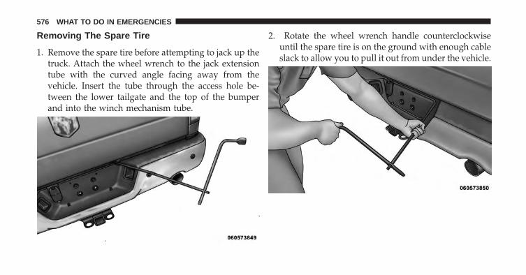
Removing The Spare Tire
1. Remove the spare tire before attempting to jack up thetruck. Attach the wheel wrench to the jack extensiontube with the curved angle facing away from thevehicle. Insert the tube through the access hole be-tween the lower tailgate and the top of the bumperand into the winch mechanism tube.
2. Rotate the wheel wrench handle counterclockwiseuntil the spare tire is on the ground with enough cableslack to allow you to pull it out from under the vehicle.
576 WHAT TO DO IN EMERGENCIES

3. Pull the spare tire out from under the vehicle to gainaccess to the spare tire retainer.
4. Lift the spare tire with one hand to give clearance totilt the retainer at the end of the cable.
6
WHAT TO DO IN EMERGENCIES 577

5. Pull the retainer through the center of the wheel.
NOTE: The winch mechanism is designed for use withthe jack extension tube only. Use of an air wrench or otherpower tools is not recommended and can damage thewinch.
Preparations
1. Park the vehicle on a firm, level surface. Avoid ice orslippery areas.
WARNING!
Do not attempt to change a tire on the side of thevehicle close to moving traffic, pull far enough offthe road to avoid the danger of being hit whenoperating the jack or changing the wheel.
2. Turn on the Hazard Warning flasher.
3. Set the parking brake.
4. Place the shift lever into PARK. On four-wheel drivevehicles, shift the transfer case to the 4L position.
578 WHAT TO DO IN EMERGENCIES

5. Turn the ignition OFF.
Block both the front and rear of thewheel diagonally opposite the jackingposition. For example, if the right frontwheel is being changed, block the leftrear wheel.
NOTE: Passengers should not remain in the vehiclewhen the vehicle is being jacked.
Jack Instructions (1500 Series)
WARNING!
Carefully follow these tire changing warnings to helpprevent personal injury or damage to your vehicle:
(Continued)
WARNING! (Continued)• Always park on a firm, level surface as far from the
edge of the roadway as possible before raising thevehicle.
• Turn on the Hazard Warning flasher.• Block the wheel diagonally opposite the wheel to
be raised.• Set the parking brake firmly and set an automatic
transmission in PARK; a manual transmission inREVERSE.
• Never start or run the engine with the vehicle on ajack.
• Do not let anyone sit in the vehicle when it is on ajack.
• Do not get under the vehicle when it is on a jack. Ifyou need to get under a raised vehicle, take it to aservice center where it can be raised on a lift.
(Continued)
6
WHAT TO DO IN EMERGENCIES 579

WARNING! (Continued)• Only use the jack in the positions indicated and for
lifting this vehicle during a tire change.• If working on or near a roadway, be extremely
careful of motor traffic.• To assure that spare tires, flat or inflated, are
securely stowed, spares must be stowed with thevalve stem facing out.
CAUTION!
Do not attempt to raise the vehicle by jacking onlocations other than those indicated in the JackingInstructions for this vehicle.
1. Remove the spare wheel, jack, and tools from storage.
2. Using the wheel wrench, loosen, but do not remove,the wheel nuts by turning them counterclockwise oneturn while the wheel is still on the ground.
3. Placement of the jack:
4x2 Series Trucks Front Jacking Location
There is a jack location indicator on the rear portion of thelower control arm.
Jack Warning Label
580 WHAT TO DO IN EMERGENCIES

When changing a front wheel, place the scissor jackunder the rear portion of the lower control arm as shownbelow.
4X2 Front Jacking Location Indicator 4X2 Front Jacking Location6
WHAT TO DO IN EMERGENCIES 581

4x4 Series Trucks Front Jacking Location
There is a jack location indicator on the rear portion of thelower control arm.
When changing a front wheel, place the scissor jackunder the rear portion of the lower control arm as shownbelow.
4x2 and 4x4 Rear Jacking Location
Operate the jack using the jack drive tube and the wheelwrench. The tube extension may be used but is notrequired.
For 4x2 and 4x4 trucks, when changing a rear wheel,assemble the jack drive tube to the jack and connect the
4X4 Front Jacking Location Indicator
4X4 Front Jacking Location
582 WHAT TO DO IN EMERGENCIES

drive tube to the extension tube. Place the jack under theaxle between the wheel and the shock bracket with thedrive tubes extending to the rear.
Connect the jack tube extension and wheel wrench.
CAUTION!
Before raising the wheel off the ground, make surethat the jack will not damage surrounding truck partsand adjust the jack position as required.
4. By rotating the lug wrench clockwise, raise the vehicleuntil the wheel just clears the surface.
WARNING!
Raising the vehicle higher than necessary can makethe vehicle unstable and cause a collision. It couldslip off the jack and hurt someone near it. Raise thevehicle only enough to remove the tire.
Rear Jacking Location
6
WHAT TO DO IN EMERGENCIES 583

5. Remove the wheel nuts and pull the wheel off. Installthe spare wheel and wheel nuts with the cone shapedend of the wheel nuts toward the wheel. To avoid therisk of forcing the vehicle off the jack, do not fullytighten the wheel nuts until the vehicle has beenlowered.
6. Using the lug wrench, finish tightening the wheel nutsusing a crisscross pattern. The correct wheel nuttightness for a cone type wheel nut is 120–140 ft lbs(160–190 N·m) torque, for a flanged type wheel nut is130–160 ft lbs (175–215 N·m) torque. If in doubt aboutthe correct tightness, have them checked with a torquewrench by your authorized dealer or at a servicestation.
WARNING!
A loose tire or jack thrown forward in a collision orhard stop could injure someone in the vehicle. Al-ways stow the jack parts and the extra tire and wheelin the places provided.
7. Install the wheel center cap and remove the wheelblocks. Do not install chrome or aluminum wheelcenter caps on the spare wheel. This may result in capdamage.
8. Lower the jack to its fully closed position. If the bottlejack will not lower by turning the dial (thumbwheel)by hand, it may be necessary to use the jack drive tubein order to lower the jack. Stow the replaced tire, jack,and tools as previously described.
9. Adjust the tire pressure when possible.
584 WHAT TO DO IN EMERGENCIES

NOTE: Do not oil wheel studs. For chrome wheels, donot substitute with chrome plated wheel nuts.
To Stow The Flat Or Spare
NOTE: Vehicles equipped with aluminum wheels can-not be stored under the vehicle because the wheelretainer will not fit through the wheel pilot hole. Securethe flat tire in the bed of the truck. Have the flat tirerepaired or replaced immediately.
WARNING!
A loose tire thrown forward in a collision or hardstop could injure the occupants in the vehicle. Havethe deflated (flat) tire repaired or replaced immedi-ately.
1. Turn the wheel so that the valve stem is facing theground and toward the rear of the vehicle for conve-nience in checking the spare tire inflation. Slide thewheel retainer through the center of the wheel.
6
WHAT TO DO IN EMERGENCIES 585

2. Lift the spare tire with one hand to give clearance totilt the retainer at the end of the cable and position itproperly across the wheel opening.
3. Attach the wheel wrench to the jack extension tubewith the curved angle facing away from the vehicle.Insert the tube through the access hole between thelower tailgate and the top of the bumper and into thewinch mechanism tube.
586 WHAT TO DO IN EMERGENCIES

4. Rotate the lug wrench handle clockwise until thewheel is drawn into place against the underside of thevehicle. Continue to rotate until you feel the winchmechanism slip, or click three or four times. It cannotbe overtightened. Push against the tire several times toensure it is firmly in place.
NOTE: The winch mechanism is designed for use withthe jack extension tube only. Use of an air wrench or otherpower tools is not recommended and can damage thewinch.
6
WHAT TO DO IN EMERGENCIES 587

Reinstalling The Jack And Tools (1500 Series)
1. Tighten the jack all the way down by turning the jackturn-screw counterclockwise until the jack is snug.
2. Position the jack and tool bag. Make sure the lugwrench is under the jack near the jack turn-screw.
3. Secure the tool bag straps to the jack.
4. Place the jack and tools in the storage position holdingthe jack by the jack turn-screw, slip the jack and toolsunder the seat so that the bottom slot engages into thefastener on the floor.
Jack And Tool Bag
Jack And Tools Tied
588 WHAT TO DO IN EMERGENCIES

NOTE: Ensure that the jack slides into the front holddown location.
5. Turn the wing bolt clockwise to secure to the floor pan.Reinstall the plastic cover.
WARNING!
After using the jack and tools, always reinstall themin the original carrier and location. While driving
(Continued)
Jack Hold Down Fastener Jack And Tools (1500 Series)6
WHAT TO DO IN EMERGENCIES 589

WARNING! (Continued)you may experience abrupt stopping, rapid accelera-tion or sharp turns. A loose jack, tools, bracket orother objects in the vehicle may move around withforce, resulting in serious injury.
Hub Caps/Wheel Covers — If Equipped
The hub caps must be removed before raising the vehicleoff the ground.
CAUTION!
Use a back-and-forth motion to remove the hub cap.Do not use a twisting motion when removing the hubcap, damage to the hub cap finish may occur.
You must use the flat end of the lug wrench to pry off thewheel skins. Insert the flat tip completely and using a
back-and-forth motion, loosen the wheel skin. Repeat thisprocedure around the tire until the skin pops off.
Replace the wheel skins first using a rubber mallet. Whenreplacing the hub caps, tilt the cap retainer over the lugnut bolt circle and strike the high side down with arubber mallet. Be sure that the hub caps and wheel skinsare firmly seated around the wheel.
Wheel Nuts
All wheel nuts should be tightened occasionally to elimi-nate the possibility of wheel studs being sheared or thebolt holes in the wheels becoming elongated. This isespecially important during the first few hundred miles/kilometers of operation to allow the wheel nuts tobecome properly set. All wheel nuts should first be firmlyseated against the wheel. The wheel nuts should then betightened to recommended torque. Tighten the wheelnuts to final torque in increments. Progress around thebolt circle, tightening the wheel nut opposite to the wheel
590 WHAT TO DO IN EMERGENCIES

nut just previously tightened until final torque isachieved. Recommended torques are shown in the fol-lowing chart.
TypeNut
StudSize
Hex Size TorqueFt Lbs
TorqueNewtonMeters
Cone M14 x 1.5 22 mm 120-140 160-190Flanged M14 x 1.5 22 mm 130-160 175-215
JACKING AND TIRE CHANGING 2500 AND 3500SERIES TRUCKS
WARNING!
• Do not attempt to change a tire on the side of thevehicle close to moving traffic. Pull far enough offthe road to avoid the danger of being hit whenoperating the jack or changing the wheel.
(Continued)
WARNING! (Continued)• Being under a jacked-up vehicle is dangerous. The
vehicle could slip off the jack and fall on you. Youcould be crushed. Never put any part of your bodyunder a vehicle that is on a jack. If you need to getunder a raised vehicle, take it to a service centerwhere it can be raised on a lift.
(Continued)
6
WHAT TO DO IN EMERGENCIES 591

WARNING! (Continued)• Never start or run the engine while the vehicle is
on a jack.• The jack is designed to be used as a tool for
changing tires only. The jack should not be used tolift the vehicle for service purposes. The vehicleshould be jacked on a firm level surface only.Avoid ice or slippery areas.
Jack Location
The jack and jack tools are stored under the frontpassenger seat.
Removal Of Jack And Tools (2500, 3500 Series)
To access the jack and jack tools you must remove theplastic access cover, located on the side of the frontpassengers seat. To remove the cover, pull the front partof the cover (closest to the front of the seat) toward you
to release a locking tab. Once the front of the cover isloose, slide the cover toward the front of the seat until itis free from the seat frame.
Remove the jack and tools by turning the wing boltcounterclockwise, remove the wing bolt and then slidethe assembly out from under the seat.
Jack Access Cover
592 WHAT TO DO IN EMERGENCIES
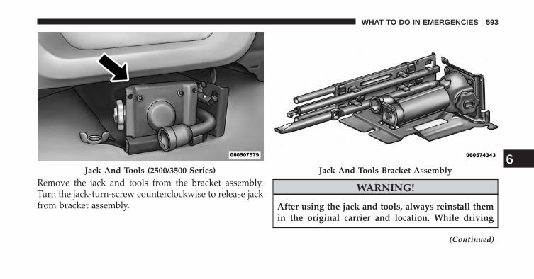
Remove the jack and tools from the bracket assembly.Turn the jack-turn-screw counterclockwise to release jackfrom bracket assembly.
WARNING!
After using the jack and tools, always reinstall themin the original carrier and location. While driving
(Continued)
Jack And Tools (2500/3500 Series) Jack And Tools Bracket Assembly6
WHAT TO DO IN EMERGENCIES 593

WARNING! (Continued)you may experience abrupt stopping, rapid accelera-tion or sharp turns. A loose jack, tools, bracket orother objects in the vehicle may move around withforce, resulting in serious injury.
Removing The Spare Tire
1. Remove the spare tire before attempting to jack up thetruck. Attach the wheel wrench to the jack extensiontube with the curved angle facing away from thevehicle. Insert the tube through the access hole be-tween the lower tailgate and the top of the bumperand into the winch mechanism tube.
594 WHAT TO DO IN EMERGENCIES

2. Rotate the wheel wrench handle counterclockwiseuntil the spare tire is on the ground with enough cableslack to allow you to pull it out from under the vehicle.
3. Pull the spare tire out from under the vehicle to gainaccess to the spare tire retainer.
6
WHAT TO DO IN EMERGENCIES 595

4. Lift the spare tire with one hand to give clearance totilt the retainer at the end of the cable.
5. Pull the retainer through the center of the wheel.
NOTE: The winch mechanism is designed for use withthe jack extension tube only. Use of an air wrench or otherpower tools is not recommended and can damage thewinch.
596 WHAT TO DO IN EMERGENCIES

Preparations
1. Park the vehicle on a firm, level surface. Avoid ice orslippery areas.
WARNING!
Do not attempt to change a tire on the side of thevehicle close to moving traffic, pull far enough offthe road to avoid the danger of being hit whenoperating the jack or changing the wheel.
2. Turn on the Hazard Warning flasher.
3. Set the parking brake.
4. Place the shift lever into PARK. On four-wheel drivevehicles, shift the transfer case to the 4L position.
5. Turn the ignition OFF.
Block both the front and rear of thewheel diagonally opposite the jackingposition. For example, if the right frontwheel is being changed, block the leftrear wheel.
NOTE: Passengers should not remain in the vehiclewhen the vehicle is being jacked. 6
WHAT TO DO IN EMERGENCIES 597

Jack Instructions (2500, 3500 Series)
WARNING!Carefully follow these tire changing warnings to helpprevent personal injury or damage to your vehicle:• Always park on a firm, level surface as far from the
edge of the roadway as possible before raising thevehicle.
• Turn on the Hazard Warning flasher.• Block the wheel diagonally opposite the wheel to
be raised.• Set the parking brake firmly and set an automatic
transmission in PARK; a manual transmission inREVERSE.
• Never start or run the engine with the vehicle on ajack.
(Continued)
WARNING! (Continued)• Do not let anyone sit in the vehicle when it is on a
jack.• Do not get under the vehicle when it is on a jack. If
you need to get under a raised vehicle, take it to aservice center where it can be raised on a lift.
• Only use the jack in the positions indicated and forlifting this vehicle during a tire change.
• If working on or near a roadway, be extremelycareful of motor traffic.
• To assure that spare tires, flat or inflated, aresecurely stowed, spares must be stowed with thevalve stem facing out.
598 WHAT TO DO IN EMERGENCIES

CAUTION!
Do not attempt to raise the vehicle by jacking onlocations other than those indicated in the JackingInstructions for this vehicle.
1. Remove the spare wheel, jack, and tools from storage.
2. Using the lug wrench, loosen, but do not remove, thewheel nuts by turning them counterclockwise oneturn while the wheel is still on the ground.
3. Placement of the jack:Jack Warning Label
6
WHAT TO DO IN EMERGENCIES 599
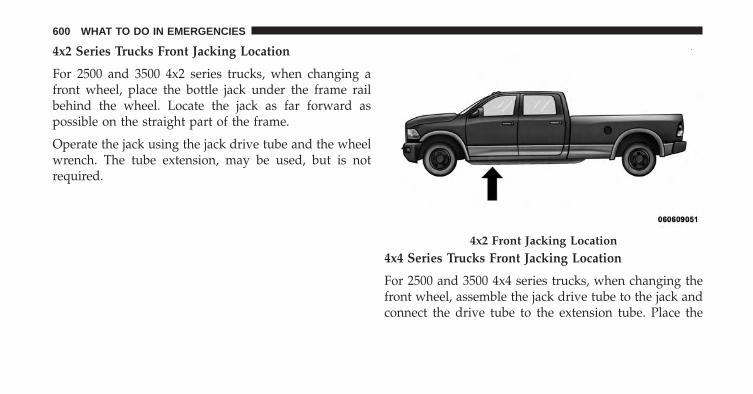
4x2 Series Trucks Front Jacking Location
For 2500 and 3500 4x2 series trucks, when changing afront wheel, place the bottle jack under the frame railbehind the wheel. Locate the jack as far forward aspossible on the straight part of the frame.
Operate the jack using the jack drive tube and the wheelwrench. The tube extension, may be used, but is notrequired.
4x4 Series Trucks Front Jacking Location
For 2500 and 3500 4x4 series trucks, when changing thefront wheel, assemble the jack drive tube to the jack andconnect the drive tube to the extension tube. Place the
4x2 Front Jacking Location
600 WHAT TO DO IN EMERGENCIES

jack under the axle as close to the tire as possible with thedrive tubes extending to the front. Connect the jack tubeextension and wheel wrench.
4x2 and 4x4 Rear Jacking Location
For 4x2 and 4x4 trucks, when changing a rear wheel,assemble the jack drive tube to the jack and connect the
drive tube to the extension tube. Place the jack under theaxle between the spring and the shock absorber with thedrive tubes extending to the rear.
Connect the jack tube extension and wheel wrench.4x4 Front Jacking Location Rear Jacking Location (All)
6
WHAT TO DO IN EMERGENCIES 601

CAUTION!
Before raising the wheel off the ground, make surethat the jack will not damage surrounding truck partsand adjust the jack position as required.
NOTE: If the bottle jack will not lower by turning thedial (thumbwheel) by hand, it may be necessary to usethe jack drive tube in order to lower the jack.
4. By rotating the wheel wrench clockwise, raise thevehicle until the wheel just clears the surface.
WARNING!
Raising the vehicle higher than necessary can makethe vehicle unstable and cause a collision. It couldslip off the jack and hurt someone near it. Raise thevehicle only enough to remove the tire.
5. Remove the wheel nuts and pull the wheel off. Onsingle rear-wheel (SRW) trucks, install the spare wheeland wheel nuts with the cone shaped end of the wheelnuts toward the wheel. On 3500 dual rear-wheelmodels (DRW) the wheel nuts are a two-piece assem-bly with a flat face. Lightly tighten the wheel nuts. Toavoid the risk of forcing the vehicle off the jack, do notfully tighten the wheel nuts until the vehicle has beenlowered.
6. Using the lug wrench, finish tightening the wheel nutsusing a crisscross pattern. The correct wheel nuttightness for a cone type wheel nut is 120–140 ft lbs(160–190 N·m) torque, for a flanged type wheel nut is130–160 ft lbs (175–215 N·m) torque. If in doubt aboutthe correct tightness, have them checked with a torquewrench by your authorized dealer or at a servicestation.
602 WHAT TO DO IN EMERGENCIES

WARNING!
A loose tire or jack thrown forward in a collision orhard stop could injure someone in the vehicle. Al-ways stow the jack parts and the extra tire and wheelin the places provided.
7. Install the wheel center cap and remove the wheelblocks. Do not install chrome or aluminum wheelcenter caps on the spare wheel. This may result in capdamage.
8. Lower the jack to its fully closed position. If the bottlejack will not lower by turning the dial (thumbwheel)by hand, it may be necessary to use the jack drive tubein order to lower the jack. Stow the replaced tire, jack,and tools as previously described.
9. Adjust the tire pressure when possible.
NOTE: Do not oil wheel studs. For chrome wheels, donot substitute with chrome plated wheel nuts.
To Stow The Flat Or Spare
NOTE: Have the flat tire repaired or replaced immedi-ately.
WARNING!
A loose tire thrown forward in a collision or hardstop could injure the occupants in the vehicle. Havethe deflated (flat) tire repaired or replaced immedi-ately.
6
WHAT TO DO IN EMERGENCIES 603
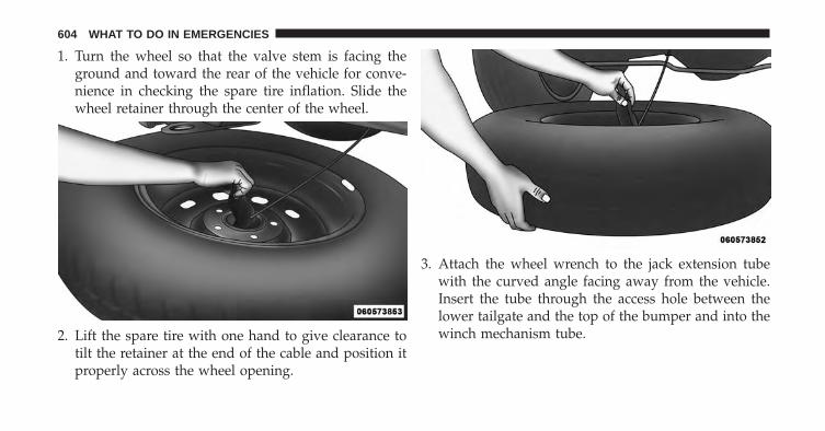
1. Turn the wheel so that the valve stem is facing theground and toward the rear of the vehicle for conve-nience in checking the spare tire inflation. Slide thewheel retainer through the center of the wheel.
2. Lift the spare tire with one hand to give clearance totilt the retainer at the end of the cable and position itproperly across the wheel opening.
3. Attach the wheel wrench to the jack extension tubewith the curved angle facing away from the vehicle.Insert the tube through the access hole between thelower tailgate and the top of the bumper and into thewinch mechanism tube.
604 WHAT TO DO IN EMERGENCIES

4. Rotate the lug wrench handle clockwise until thewheel is drawn into place against the underside of thevehicle. Continue to rotate until you feel the winchmechanism slip, or click three or four times. It cannotbe overtightened. Push against the tire several times toensure it is firmly in place.
NOTE: The winch mechanism is designed for use withthe jack extension tube only. Use of an air wrench or otherpower tools is not recommended and can damage thewinch.
6
WHAT TO DO IN EMERGENCIES 605

Reinstalling The Jack And Tools (2500 And 3500Series)
1. Tighten the jack all the way down by turning the jackturn-screw counterclockwise until the jack is snug.
2. Position the jack and tools into bracket assembly.Make sure the lug wrench is under the jack near thejack turn-screw. Snap tools into bracket assembly clips.Install the jack into bracket assembly and turn thejack-turn-screw clockwise until jack is snug intobracket assembly.
3. Place the jack and tool bracket assembly in the storageposition holding the jack by the jack turn-screw, slipthe jack and tools under the seat so that the bottom slotengages into the fastener on the floor.
Jack And Tools Bracket Assembly
606 WHAT TO DO IN EMERGENCIES

NOTE: Ensure that the jack and tool bracket assemblyslides into the front hold down location.
4. Turn the wing bolt clockwise to secure to the floor pan.Reinstall the plastic cover.
Hub Caps/Wheel Covers — If Equipped
The hub caps must be removed before raising the vehicleoff the ground.
Jack Hold Down Fastener Jack And Tools (2500/3500 Series)6
WHAT TO DO IN EMERGENCIES 607

CAUTION!
Use extreme caution when removing the front andrear center caps. Damage can occur to the center capand/or the wheel if screwdriver type tools are used. Apulling motion, not a pry off motion, is recom-mended to remove the caps.
For single rear wheel (SRW) models, use the blade on theend of the lug wrench to pry the hub cap off. Insert theblade end into the pry off notch and carefully pop off thehub cap with a back and forth motion.
On 3500 models with dual rear wheels (DRW), you mustfirst remove the hub caps. The jack handle driver has ahook at one end that will fit in the pry off notch of therear hub caps. Position the hook and pull out on theratchet firmly. The hub cap should pop off. The wheelskins can now be removed. For the front hub cap on
models use the blade on the end of the lug wrench to prythe caps off. The wheel skin can now be removed.
CAUTION!
• Use a back and forth motion to remove the hub cap.Do not use a twisting motion when removing thehub cap, damage to the hub cap; finish may occur.
• The rear hub caps on the dual rear wheel has twopry off notches. Make sure that the hook of the jackhandle driver is located squarely in the cap notchbefore attempting to pull off.
You must use the flat end of the lug wrench to pry off thewheel skins. Insert the flat tip completely and using aback and forth motion, loosen the wheel skin. Repeat thisprocedure around the tire until the skin pops off.
Replace the wheel skins first using a rubber mallet. Whenreplacing the hub caps, tilt the cap retainer over the lug
608 WHAT TO DO IN EMERGENCIES

nut bolt circle and strike the high side down with arubber mallet. Be sure that the hub caps and wheel skinsare firmly seated around the wheel.
Wheel Nuts
All wheel nuts should be tightened occasionally to elimi-nate the possibility of wheel studs being sheared or thebolt holes in the wheels becoming elongated. This isespecially important during the first few hundred miles/kilometers of operation to allow the wheel nuts to
become properly set. All wheel nuts should first be firmlyseated against the wheel. The wheel nuts should then betightened to recommended torque. Tighten the wheelnuts to final torque in increments. Progress around thebolt circle, tightening the wheel nut opposite to the wheelnut just previously tightened until final torque isachieved. Recommended torques are shown in the fol-lowing chart.
TypeNut
StudSize
Hex Size TorqueFt Lbs
TorqueNewtonMeters
Cone M14 x 1.5 22 mm 120-140 160-190Flanged M14 x 1.5 22 mm 130-160 175-215
6
WHAT TO DO IN EMERGENCIES 609

8-Stud — Dual Rear Wheels
Dual wheels are flat-mounted and center-piloted. The lugnuts are a two-piece assembly. When the tires are beingrotated or replaced, clean these lug nuts and add twodrops of oil at the interface between the hex and thewasher.
Slots in the wheels will assist in properly orienting theinner and outer wheels. Align these slots when assem-bling the wheels for best access to the tire valve on theinner wheel. The tires of both dual wheels must becompletely off the ground when tightening, to ensurewheel centering and maximum wheel clamping.
Dual wheel models require a special heavy-duty lug nuttightening adapter (included with the vehicle) to cor-rectly tighten the lug nuts. Also, when it is necessary toremove and install dual rear wheels, use a proper vehiclelifting device.
NOTE: When installing a spare tire as part of a dual rearwheel end combination, the tire diameter of the twoindividual tires must be compared. If there is a significantdifference, the larger tire should be installed in a frontlocation. The correct direction of rotation for dual tireinstallations must also be observed.
Oiling Location
610 WHAT TO DO IN EMERGENCIES

These dual rear wheels should be tightened as follows:
1. Tighten the wheel nuts in the numbered sequence to asnug fit.
2. Retighten the wheel nuts in the same sequence to thetorques listed in the table. Go through the sequence a
second time to verify that specific torque has beenachieved. Retighten to specifications at 100 miles(160 km) and after 500 miles (800 km).
It is recommended that wheel stud nuts be kept torquedto specifications at all times. Torque wheel stud nuts tospecifications at each lubrication interval.
HOISTING
A conventional floor jack may be used at the jackinglocations. Refer to the graphics that show jacking loca-tions. However, a floor jack or frame hoist must never beused on any other parts of the underbody.
CAUTION!
Never use a floor jack directly under the differentialhousing of a loaded truck or damage to your vehiclemay result.
Tightening Pattern
6
WHAT TO DO IN EMERGENCIES 611

JUMP-STARTING PROCEDURES
If your vehicle has a discharged battery it can be jump-started using a set of jumper cables and a battery inanother vehicle or by using a portable battery boosterpack. Jump-starting can be dangerous if done improperlyso please follow the procedures in this section carefully.
NOTE: When using a portable battery booster packfollow the manufacturer’s operating instructions andprecautions.
CAUTION!
Do not use a portable battery booster pack or anyother booster source with a system voltage greaterthan 12 Volts or damage to the battery, starter motor,alternator or electrical system may occur.
WARNING!
Do not attempt jump-starting if the battery is frozen.It could rupture or explode and cause personal injury.
Preparations For Jump-Start
The battery in your vehicle is located in the front of theengine compartment, behind the left headlight assembly.
NOTE: The positive battery post is covered with aprotective cap. Lift up on the cap to gain access to thepositive battery post.
612 WHAT TO DO IN EMERGENCIES

WARNING!
• Take care to avoid the radiator cooling fan when-ever the hood is raised. It can start anytime theignition switch is ON. You can be injured bymoving fan blades.
• Remove any metal jewelry such as rings, watchbands and bracelets that could make an inadvertentelectrical contact. You could be seriously injured.
• Batteries contain sulfuric acid that can burn yourskin or eyes and generate hydrogen gas which isflammable and explosive. Keep open flames orsparks away from the battery.
1. Set the parking brake, shift the automatic transmissioninto PARK and turn the ignition to LOCK.
2. Turn off the heater, radio, and all unnecessary electri-cal accessories.
Positive Battery Post6
WHAT TO DO IN EMERGENCIES 613

3. If using another vehicle to jump-start the battery, parkthe vehicle within the jumper cables reach, set theparking brake and make sure the ignition is OFF.
WARNING!
Do not allow vehicles to touch each other as thiscould establish a ground connection and personalinjury could result.
Jump-Starting Procedure
WARNING!
Failure to follow this procedure could result in per-sonal injury or property damage due to battery ex-plosion.
CAUTION!
Failure to follow these procedures could result indamage to the charging system of the booster vehicleor the discharged vehicle.
1. Connect the positive (+) end of the jumper cable to thepositive (+) post of the discharged vehicle.
2. Connect the opposite end of the positive (+) jumpercable to the positive (+) post of the booster battery.
3. Connect the negative end (-) of the jumper cable to thenegative (-) post of the booster battery.
4. Connect the opposite end of the negative (-) jumpercable to a good engine ground (exposed metal part ofthe discharged vehicle’s engine) away from the batteryand the fuel injection system.
614 WHAT TO DO IN EMERGENCIES
WARNING!
Do not connect the cable to the negative post (-) of thedischarged battery. The resulting electrical sparkcould cause the battery to explode and could result inpersonal injury.
5. Start the engine in the vehicle that has the boosterbattery, let the engine idle a few minutes, and thenstart the engine in the vehicle with the dischargedbattery.
Once the engine is started, remove the jumper cables inthe reverse sequence:
6. Disconnect the negative (-) jumper cable from theengine ground of the vehicle with the dischargedbattery.
7. Disconnect the negative end (-) of the jumper cablefrom the negative (-) post of the booster battery.
8. Disconnect the opposite end of the positive (+) jumpercable from the positive (+) post of the booster battery.
9. Disconnect the positive (+)end of the jumper cablefrom the positive (+) post of the discharged vehicle.
If frequent jump-starting is required to start your vehicleyou should have the battery and charging system in-spected at your authorized dealer.
CAUTION!
Accessories plugged into the vehicle power outletsdraw power from the vehicle’s battery, even when notin use (i.e., cellular phones, etc.). Eventually, ifplugged in long enough without engine operation,the vehicle’s battery will discharge sufficiently todegrade battery life and/or prevent the engine fromstarting.
6
WHAT TO DO IN EMERGENCIES 615

FREEING A STUCK VEHICLE
If your vehicle becomes stuck in mud, sand, or snow, itcan often be moved using a rocking motion. Turn thesteering wheel right and left to clear the area around thefront wheels. Then shift back and forth between DRIVEand REVERSE (with automatic transmission) or 2nd gearand REVERSE (with manual transmission), while gentlypressing the accelerator. Use the least amount of accel-erator pedal pressure that will maintain the rockingmotion, without spinning the wheels or racing the en-gine.
NOTE: For trucks equipped with 8-speed automatictransmission, shifts between DRIVE and REVERSE canonly be achieved at wheel speeds of 5 mph or less.
CAUTION!
Racing the engine or spinning the wheels may lead totransmission overheating and failure. Allow the en-gine to idle with the transmission in NEUTRAL for atleast one minute after every five rocking-motioncycles. This will minimize overheating and reducethe risk of transmission failure during prolongedefforts to free a stuck vehicle.
NOTE: Press the �ESC Off� switch, to place the ElectronicStability Control (ESC) system in �Partial Off� mode,before rocking the vehicle. Refer to “Electronic BrakeControl” in “Starting And Operating” for further infor-mation. Once the vehicle has been freed, press the �ESCOff� switch again to restore �ESC On� mode.
616 WHAT TO DO IN EMERGENCIES

CAUTION!
• When “rocking” a stuck vehicle by shifting be-tween DRIVE/2nd gear and REVERSE, do not spinthe wheels faster than 15 mph (24 km/h), or drive-train damage may result.
• Revving the engine or spinning the wheels too fastmay lead to transmission overheating and failure.It can also damage the tires. Do not spin the wheelsabove 30 mph (48 km/h) while in gear (no trans-mission shifting occurring).
WARNING!
Fast spinning tires can be dangerous. Forces gener-ated by excessive wheel speeds may cause damage, oreven failure, of the axle and tires. A tire couldexplode and injure someone. Do not spin your vehi-cle’s wheels faster than 30 mph (48 km/h) or forlonger than 30 seconds continuously without stop-ping when you are stuck and do not let anyone neara spinning wheel, no matter what the speed.
6
WHAT TO DO IN EMERGENCIES 617

EMERGENCY TOW HOOKS — IF EQUIPPED
Your vehicle may be equipped with emergency towhooks.
NOTE: For off-road recovery, it is recommended to useboth of the front tow hooks to minimize the risk ofdamage to the vehicle.
WARNING!
• Do not use a chain for freeing a stuck vehicle.Chains may break, causing serious injury or death.
• Stand clear of vehicles when pulling with towhooks. Tow straps may become disengaged, caus-ing serious injury.
CAUTION!
Tow hooks are for emergency use only to rescue avehicle stranded off-road. Do not use tow hooks fortow truck hookup or highway towing. You coulddamage your vehicle.
SHIFT LEVER OVERRIDE
If a malfunction occurs and the shift lever cannot bemoved out of the PARK position, you can use one of thefollowing procedures to temporarily move the shift lever:
618 WHAT TO DO IN EMERGENCIES
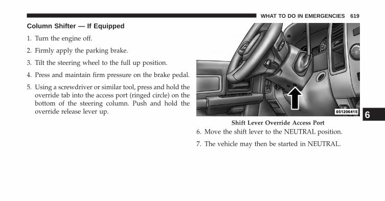
Column Shifter — If Equipped
1. Turn the engine off.
2. Firmly apply the parking brake.
3. Tilt the steering wheel to the full up position.
4. Press and maintain firm pressure on the brake pedal.
5. Using a screwdriver or similar tool, press and hold theoverride tab into the access port (ringed circle) on thebottom of the steering column. Push and hold theoverride release lever up.
6. Move the shift lever to the NEUTRAL position.
7. The vehicle may then be started in NEUTRAL.
Shift Lever Override Access Port6
WHAT TO DO IN EMERGENCIES 619

Center Console Shifter — If Equipped
1. Turn the engine off.
2. Firmly apply the parking brake.
3. Using a small screwdriver or similar tool, remove theshift lever override access cover which is located onthe right side of the shift lever.
4. Press and maintain firm pressure on the brake pedal.
5. Using a screwdriver or similar tool, press and hold theoverride tab through the access port on the centerconsole.
6. Move the shift lever to the NEUTRAL position.
7. The vehicle may then be started in NEUTRAL.
8. Reinstall the shift lever override access cover.
Shift Lever Override Access Cover
620 WHAT TO DO IN EMERGENCIES

MANUAL PARK RELEASE — 8 SPEEDTRANSMISSION (3.6L Engine)
WARNING!
Always secure your vehicle by fully applying theparking brake, before activating the Manual ParkRelease. Activating the Manual Park Release willallow your vehicle to roll away if it is not secured bythe parking brake or by proper connection to a towvehicle. Activating the Manual Park Release on anunsecured vehicle could lead to serious injury ordeath for those in or around the vehicle.
In order to push or tow the vehicle in cases where thetransmission will not shift out of PARK (such as a deadbattery), a Manual Park Release is available.
Follow these steps to use the Manual Park Release:
1. Firmly apply the parking brake.
Manual Park Release Pull Strap6
WHAT TO DO IN EMERGENCIES 621
2. Using a small screwdriver or similar tool, remove theManual Park Release access cover, which is just abovethe parking brake release handle, below and to the leftof the steering column.
3. Using the screwdriver or similar tool, push theManual Park Release lever locking tab (just below themiddle of the lever) to the right.
4. While holding the locking tab in the disengagedposition, pull the tether strap to rotate the leverrearward, until it locks in place pointing towards thedriver’s seat. Release the locking tab and verify thatthe Manual Park Release lever is locked in the releasedposition.
5. The vehicle is now out of PARK and can be towed.Release the parking brake only when the vehicle issecurely connected to a tow vehicle.
To Reset The Manual Park Release:
1. Push the locking tab to the right, to unlock the lever.
2. Rotate the Manual Park Release lever forward to itsoriginal position, until the locking tab snaps into placeto secure the lever.
3. Pull gently on the tether strap to confirm that the leveris locked in its stowed position.
4. Re-install the access cover.
622 WHAT TO DO IN EMERGENCIES

TOWING A DISABLED VEHICLE
This section describes procedures for towing a disabledvehicle using a commercial wrecker service. If the trans-mission and drivetrain are operable, disabled vehiclesmay also be towed as described under “RecreationalTowing” in the “Starting and Operating” section.
NOTE: Vehicles equipped with air suspension must belowered to the Park (lowest) level, and have automaticleveling disabled, before tying them down (from thebody) on a trailer or flatbed truck. Refer to �Air Suspen-sion� in �Starting and Operating� for more information. Ifthe vehicle cannot be lowered to the Park level (forexample, engine will not run), tie-downs must be fas-tened to the axles (not to the body). Failure to followthese instructions may cause fault codes to be set and/orcause loss of proper tie-down tension.
6
WHAT TO DO IN EMERGENCIES 623

TowingCondition
WheelsOFF theGround
2WD Models 4WD Models
Flat Tow NONE If transmission is operable:• Transmission in NEUTRAL• 30 mph (48 km/h) max speed• 15 miles (24 km) max distance(6–speed transmission)• 30 miles (48 km) max distance(8–speed transmission)
See instructions in “Recreational Tow-ing” under “Starting and Operating”• Auto Transmission in PARK• Manual Transmission in gear ( NOTNEUTRAL)• Transfer Case in NEUTRAL• Tow in forward direction
Wheel Liftor Dolly
Tow
Front NOT ALLOWEDRear OK NOT ALLOWED
Flatbed ALL BEST METHOD BEST METHOD
Proper towing or lifting equipment is required to preventdamage to your vehicle. Use only tow bars and otherequipment designed for this purpose, following equip-ment manufacturer’s instructions. Use of safety chains is
mandatory. Attach a tow bar or other towing device tomain structural members of the vehicle, not to bumpersor associated brackets. State and local laws regardingvehicles under tow must be observed.
624 WHAT TO DO IN EMERGENCIES
If you must use the accessories (wipers, defrosters, etc.)while being towed, the ignition must be in the ON/RUNposition, not the ACC position.
If the key fob is unavailable or the vehicle’s battery isdischarged, see ”Manual Park Release” or “Shift LeverOverride” in “What To Do In Emergencies” for instruc-tions on shifting the automatic transmission out of PARKfor towing.
CAUTION!
Do not use sling type equipment when towing.When securing the vehicle to a flat bed truck, do notattach to front or rear suspension components. Dam-age to your vehicle may result from improper towing.
Two-Wheel Drive Models
The manufacturer recommends towing your vehicle withall four wheels OFF the ground using a flatbed.
If flatbed equipment is not available, and the transmis-sion is operable, the vehicle may be towed (with rearwheels on the ground) under the following conditions:
• The transmission must be in NEUTRAL.
• The towing speed must not exceed 30 mph (48 km/h).
• The towing distance must not exceed 15 miles (24 km)for 6-speed transmission, or 30 miles (48 km) for8-speed transmission.
If the transmission is not operable, or the vehicle must betowed faster than 30 mph (48 km/h) or farther than 15miles (24 km), for 6-speed transmission, or 30 miles(48 km) for 8-speed transmission, tow with the rearwheels OFF the ground. Acceptable methods are to towthe vehicle on a flatbed, or with the front wheels raisedand the rear wheels on a towing dolly, or (when using asuitable steering wheel stabilizer to hold the front wheels
6
WHAT TO DO IN EMERGENCIES 625

in the straight position) with the rear wheels raised andthe front wheels on the ground.
CAUTION!
Towing this vehicle in violation of the above require-ments can cause severe transmission damage. Dam-age from improper towing is not covered under theNew Vehicle Limited Warranty.
Four-Wheel Drive Models
The manufacturer recommends towing with all wheelsOFF the ground. Acceptable methods are to tow thevehicle on a flatbed or with one end of vehicle raised andthe opposite end on a towing dolly.
If flatbed equipment is not available, and the transfercase is operable, the vehicle may be towed (in theforward direction, with ALL wheels on the ground), IF
the transfer case is in NEUTRAL (N) and the transmis-sion is in PARK (for automatic transmissions) or in gear(NOT in Neutral, for manual transmissions). Refer to“Recreational Towing” in “Starting And Operating” fordetailed instructions.
CAUTION!
• Front or rear wheel lifts must not be used. Internaldamage to the transmission or transfer case willoccur if a front or rear wheel lift is used whentowing.
• Towing this vehicle in violation of the above re-quirements can cause severe transmission and/ortransfer case damage. Damage from improper tow-ing is not covered under the New Vehicle LimitedWarranty.
626 WHAT TO DO IN EMERGENCIES

MAINTAINING YOUR VEHICLE
CONTENTS� ENGINE COMPARTMENT — 3.6L . . . . . . . . . .630
� ENGINE COMPARTMENT — 4.7L . . . . . . . . . .631
� ENGINE COMPARTMENT — 5.7L . . . . . . . . . .632
� ONBOARD DIAGNOSTIC SYSTEM (OBD II) . . .633
▫ Loose Fuel Filler Cap Message . . . . . . . . . . . .633
� EMISSIONS INSPECTION AND MAINTENANCEPROGRAMS . . . . . . . . . . . . . . . . . . . . . . . . . .634
� REPLACEMENT PARTS . . . . . . . . . . . . . . . . . .635
� DEALER SERVICE . . . . . . . . . . . . . . . . . . . . . .635
� MAINTENANCE PROCEDURES . . . . . . . . . . .636
▫ Engine Oil . . . . . . . . . . . . . . . . . . . . . . . . . .637
▫ Engine Oil Filter . . . . . . . . . . . . . . . . . . . . . .640
▫ Engine Air Cleaner Filter . . . . . . . . . . . . . . . .640
▫ Maintenance-Free Battery . . . . . . . . . . . . . . .641
▫ Air Conditioner Maintenance . . . . . . . . . . . . .642
▫ Front Driveshaft Lubrication – 2500/3500(Four-Wheel Drive) Models (Ram TrucksOnly) . . . . . . . . . . . . . . . . . . . . . . . . . . . . . .643
▫ Body Lubrication . . . . . . . . . . . . . . . . . . . . .643
▫ Windshield Wiper Blades . . . . . . . . . . . . . . .644
7

▫ Adding Washer Fluid . . . . . . . . . . . . . . . . . .645
▫ Exhaust System . . . . . . . . . . . . . . . . . . . . . .645
▫ Cooling System . . . . . . . . . . . . . . . . . . . . . .648
▫ Brake System . . . . . . . . . . . . . . . . . . . . . . . .654
▫ Rear Axle And 4x4 Front Driving Axle FluidLevel . . . . . . . . . . . . . . . . . . . . . . . . . . . . . .656
▫ Transfer Case . . . . . . . . . . . . . . . . . . . . . . . .656
▫ Automatic Transmission . . . . . . . . . . . . . . . .659
▫ Appearance Care And Protection FromCorrosion . . . . . . . . . . . . . . . . . . . . . . . . . . .662
� FUSES . . . . . . . . . . . . . . . . . . . . . . . . . . . . . .669
▫ POWER DISTRIBUTION CENTER . . . . . . . . .669
� VEHICLE STORAGE . . . . . . . . . . . . . . . . . . . .678
� REPLACEMENT BULBS . . . . . . . . . . . . . . . . .679
� BULB REPLACEMENT . . . . . . . . . . . . . . . . . .680
▫ Base Quad / Premium Bi-Halogen: Low BeamHeadlamp, High Beam Headlamp, Front ParkAnd Turn – If Equipped . . . . . . . . . . . . . . . .680
▫ Fog Lamps – If Equipped . . . . . . . . . . . . . . .683
▫ Rear Tail/Stop, Turn Signal And BackupLamps . . . . . . . . . . . . . . . . . . . . . . . . . . . . .683
▫ Center High-Mounted Stoplamp (CHMSL) WithCargo Lamp . . . . . . . . . . . . . . . . . . . . . . . . .684
▫ Cab Top Clearance Lamps – If Equipped . . . .686
▫ Rear Lamp Bar ID Marker (Dual Rear Wheels) —If Equipped. . . . . . . . . . . . . . . . . . . . . . . . . .687
▫ Side Marker Lamps (Dual Rear Wheels) — IfEquipped . . . . . . . . . . . . . . . . . . . . . . . . . . .688
� FLUID CAPACITIES . . . . . . . . . . . . . . . . . . . .689
628 MAINTAINING YOUR VEHICLE

� FLUIDS, LUBRICANTS AND GENUINEPARTS . . . . . . . . . . . . . . . . . . . . . . . . . . . . . .691
▫ Engine . . . . . . . . . . . . . . . . . . . . . . . . . . . . .691
▫ Chassis . . . . . . . . . . . . . . . . . . . . . . . . . . . .692
7
MAINTAINING YOUR VEHICLE 629

ENGINE COMPARTMENT — 3.6L
1 — Air Cleaner Filter 5 — Battery2 — Engine Oil Dipstick 6 — Washer Fluid Reservoir3 — Engine Oil Fill 7 — Power Distribution Center (Fuses)4 — Brake Fluid Reservoir 8 — Engine Coolant Reservoir
630 MAINTAINING YOUR VEHICLE

ENGINE COMPARTMENT — 4.7L
1 — Air Cleaner Filter 6 — Power Distribution Center (Fuses)2 — Automatic Transmission Dipstick 7 — Washer Fluid Reservoir3 — Engine Oil Dipstick 8 — Engine Oil Fill4 — Brake Fluid Reservoir 9 — Coolant Pressure Cap5 — Battery 10 — Engine Coolant Reservoir
7
MAINTAINING YOUR VEHICLE 631

ENGINE COMPARTMENT — 5.7L
1 — Air Cleaner Filter 7 — Washer Fluid Reservoir2 — Automatic Transmission Dipstick 8 — Power Distribution Center (Fuses)3 — Engine Oil Fill 9 — Power Steering Fluid Reservoir (2500/3500 Models Only)4 — Engine Oil Dipstick 10 — Coolant Pressure Cap5 — Brake Fluid Reservoir 11 — Engine Coolant Reservoir6 — Battery
632 MAINTAINING YOUR VEHICLE

ONBOARD DIAGNOSTIC SYSTEM (OBD II)
Your vehicle is equipped with a sophisticated onboarddiagnostic system called OBD II. This system monitorsthe performance of the emissions, engine, and automatictransmission control systems. When these systems areoperating properly, your vehicle will provide excellentperformance and fuel economy, as well as engine emis-sions well within current government regulations.
If any of these systems require service, the OBD II systemwill turn on the “Malfunction Indicator Light (MIL).” Itwill also store diagnostic codes and other information toassist your service technician in making repairs. Al-though your vehicle will usually be drivable and notneed towing, see your authorized dealer for service assoon as possible.
CAUTION!
• Prolonged driving with the MIL on could causefurther damage to the emission control system. Itcould also affect fuel economy and drivability. Thevehicle must be serviced before any emissions testscan be performed.
• If the MIL is flashing, while the engine is running,severe catalytic converter damage and power losswill soon occur. Immediate service is required.
Loose Fuel Filler Cap Message
If the vehicle diagnostic system determinesthat the fuel filler cap is loose, improperlyinstalled, or damaged, a loose gascap indicatorwill display in the EVIC telltale display area.
Refer to “Electronic Vehicle Information Center (EVIC) in
7
MAINTAINING YOUR VEHICLE 633
“Understanding Your Instrument Panel” for further in-formation. Tighten the fuel filler cap properly and pressthe SELECT button to turn off the message. If theproblem continues, the message will appear the next timethe vehicle is started.
A loose, improperly installed, or damaged fuel filler capmay also turn on the Malfunction Indicator Light (MIL).
EMISSIONS INSPECTION AND MAINTENANCEPROGRAMS
In some localities, it may be a legal requirement to passan inspection of your vehicle’s emissions control system.Failure to pass could prevent vehicle registration.
For states that require an Inspection and Mainte-nance (I/M), this check verifies the “MalfunctionIndicator Light (MIL)” is functioning and is not
on when the engine is running, and that the OBD IIsystem is ready for testing.
Normally, the OBD II system will be ready. The OBD IIsystem may not be ready if your vehicle was recentlyserviced, recently had a dead battery or a battery replace-ment. If the OBD II system should be determined notready for the I/M test, your vehicle may fail the test.
Your vehicle has a simple ignition key-actuated test,which you can use prior to going to the test station. Tocheck if your vehicle’s OBD II system is ready, you mustdo the following:
1. Turn the ignition switch to the ON position, but do notcrank or start the engine.
2. If you crank or start the engine, you will have to startthis test over.
3. As soon as you turn the ignition switch to the ONposition, you will see the MIL symbol come on as partof a normal bulb check.
634 MAINTAINING YOUR VEHICLE

4. Approximately 15 seconds later, one of two things willhappen:
• The MIL will flash for about 10 seconds and thenreturn to being fully illuminated until you turn OFFthe ignition or start the engine. This means that yourvehicle’s OBD II system is not ready and you shouldnot proceed to the I/M station.
• The MIL will not flash at all and will remain fullyilluminated until you turn OFF the ignition or start theengine. This means that your vehicle’s OBD II systemis ready and you can proceed to the I/M station.
If your OBD II system is not ready, you should see yourauthorized dealer or repair facility. If your vehicle wasrecently serviced or had a battery failure or replacement,you may need to do nothing more than drive yourvehicle as you normally would in order for your OBD IIsystem to update. A recheck with the above test routinemay then indicate that the system is now ready.
Regardless of whether your vehicle’s OBD II system isready or not, if the MIL is illuminated during normalvehicle operation you should have your vehicle servicedbefore going to the I/M station. The I/M station can failyour vehicle because the MIL is on with the enginerunning.
REPLACEMENT PARTS
Use of genuine MOPAR® parts for normal/scheduledmaintenance and repairs is highly recommended to en-sure the designed performance. Damage or failurescaused by the use of non-MOPAR® parts for mainte-nance and repairs will not be covered by the manufac-turer’s warranty.
DEALER SERVICE
Your authorized dealer has the qualified service person-nel, special tools, and equipment to perform all serviceoperations in an expert manner. Service Manuals are
7
MAINTAINING YOUR VEHICLE 635

available which include detailed service information foryour vehicle. Refer to these Service Manuals beforeattempting any procedure yourself.
NOTE: Intentional tampering with emissions controlsystems may void your warranty and could result in civilpenalties being assessed against you.
WARNING!
You can be badly injured working on or around amotor vehicle. Only do service work for which youhave the knowledge and the proper equipment. Ifyou have any doubt about your ability to perform aservice job, take your vehicle to a competent me-chanic.
MAINTENANCE PROCEDURES
The pages that follow contain the required maintenanceservices determined by the engineers who designed yourvehicle.
Besides those maintenance items specified in the fixedmaintenance schedule, there are other components whichmay require servicing or replacement in the future.
CAUTION!
• Failure to properly maintain your vehicle or per-form repairs and service when necessary couldresult in more costly repairs, damage to othercomponents or negatively impact vehicle perfor-mance. Immediately have potential malfunctionsexamined by an authorized dealer or qualifiedrepair center.
(Continued)
636 MAINTAINING YOUR VEHICLE

CAUTION! (Continued)• Your vehicle has been built with improved fluids
that protect the performance and durability of yourvehicle and also allow extended maintenance inter-vals. Do not use chemical flushes in these compo-nents as the chemicals can damage your engine,transmission, power steering or air conditioning.Such damage is not covered by the New VehicleLimited Warranty. If a flush is needed because ofcomponent malfunction, use only the specifiedfluid for the flushing procedure.
Engine Oil
Checking Oil Level
To assure proper lubrication of your vehicle’s engine, theengine oil must be maintained at the correct level. Checkthe oil level at regular intervals, such as every fuel stop.
The best time to check the engine oil level is about fiveminutes after a fully warmed up engine is shut off.
Checking the oil while the vehicle is on level ground willimprove the accuracy of the oil level readings. Alwaysmaintain the oil level within the SAFE zone on thedipstick. Adding one quart of oil when the reading is atthe bottom of the SAFE zone will result in a reading at thetop of the safe zone on these engines.
CAUTION!
Overfilling or underfilling the crankcase will causeoil aeration or loss of oil pressure. This could damageyour engine. 7
MAINTAINING YOUR VEHICLE 637
Change Engine Oil
The oil change indicator system will remind you that it istime to take your vehicle in for scheduled maintenance.Refer to the “Maintenance Schedule” for further informa-tion.
NOTE:Under no circumstances should oil change inter-vals exceed 10,000 miles (16,000 km) or twelve months,whichever occurs first.
Engine Oil Selection
For best performance and maximum protection under alltypes of operating conditions, the manufacturer onlyrecommends engine oils that are API Certified and meetthe requirements of Chrysler Material Standard MS-6395.
American Petroleum Institute (API) Engine OilIdentification Symbol
This symbol means that the oil hasbeen certified by the AmericanPetroleum Institute (API). Themanufacturer only recommendsAPI Certified engine oils.
CAUTION!
Do not use chemical flushes in your engine oil as thechemicals can damage your engine. Such damage isnot covered by the New Vehicle Limited Warranty.
638 MAINTAINING YOUR VEHICLE

Engine Oil Viscosity
SAE 5W-20 engine oil is recommended for all operatingtemperatures. This engine oil improves low temperaturestarting and vehicle fuel economy. The engine oil fillercap also shows the recommended engine oil viscosity foryour engine. For information on engine oil filler caplocation, refer to “Engine Compartment” in “MaintainingYour Vehicle” for further information.
NOTE: Vehicles equipped with a 5.7L engine must useSAE 5W-20 oil. Failure to do so may result in improperoperation of the Multi-Displacement System (MDS). Re-fer to “Multi-Displacement System” in “Starting andOperating” for further information.
Lubricants which do not have both the engine oil certi-fication mark and the correct SAE viscosity grade num-ber should not be used.
NOTE: For 2500/3500 trucks with a 5.7L engine operat-ing under a gross combined weight rating of 14,000 lbs (6350 kg) or greater, SAE 5W-30 engine oil is recommendedfor all operating temperatures.
Synthetic Engine Oils
You may use synthetic engine oils provided the recom-mended oil quality requirements are met, and the recom-mended maintenance intervals for oil and filter changesare followed.
Disposing Of Used Engine Oil And Oil Filters
Care should be taken in disposing of used engine oil andoil filters from your vehicle. Used oil and oil filters,indiscriminately discarded, can present a problem to theenvironment. Contact your authorized dealer, servicestation or governmental agency for advice on how andwhere used oil and oil filters can be safely discarded inyour area.
7
MAINTAINING YOUR VEHICLE 639

Engine Oil Filter
The engine oil filter should be replaced with a new filterat every engine oil change.
Engine Oil Filter Selection
This manufacturer’s engines have a full-flow type oilfilter. Use a filter of this type for replacement. The qualityof replacement filters varies considerably. Only highquality filters should be used to assure most efficientservice. MOPAR® engine oil filters are a high quality oilfilter and are recommended.
Engine Air Cleaner Filter
Refer to the “Maintenance Schedule” for the propermaintenance intervals.
WARNING!
The air induction system (air cleaner, hoses, etc.) canprovide a measure of protection in the case of enginebackfire. Do not remove the air induction system (aircleaner, hoses, etc.) unless such removal is necessaryfor repair or maintenance. Make sure that no one isnear the engine compartment before starting thevehicle with the air induction system (air cleaner,hoses, etc.) removed. Failure to do so can result inserious personal injury.
Engine Air Cleaner Filter Selection
The quality of replacement engine air cleaner filtersvaries considerably. Only high quality filters should beused to assure most efficient service. MOPAR® engine aircleaner filters are a high quality filter and are recom-mended.
640 MAINTAINING YOUR VEHICLE
Maintenance-Free Battery
Your vehicle is equipped with a maintenance-free battery.You will never have to add water, nor is periodic main-tenance required.
WARNING!
• Battery fluid is a corrosive acid solution and canburn or even blind you. Do not allow battery fluidto contact your eyes, skin, or clothing. Do not leanover a battery when attaching clamps. If acidsplashes in eyes or on skin, flush the area imme-diately with large amounts of water. Refer to“Jump-Starting Procedures” in “What To Do InEmergencies” for further information.
(Continued)
WARNING! (Continued)• Battery gas is flammable and explosive. Keep
flame or sparks away from the battery. Do not usea booster battery or any other booster source withan output greater than 12 Volts. Do not allow cableclamps to touch each other.
• Battery posts, terminals, and related accessoriescontain lead and lead compounds. Wash handsafter handling.
7
MAINTAINING YOUR VEHICLE 641

CAUTION!
• It is essential when replacing the cables on thebattery that the positive cable is attached to thepositive post and the negative cable is attached tothe negative post. Battery posts are marked positive(+) and negative (-) and are identified on thebattery case. Cable clamps should be tight on theterminal posts and free of corrosion.
• If a “fast charger” is used while the battery is in thevehicle, disconnect both vehicle battery cables be-fore connecting the charger to the battery. Do notuse a “fast charger” to provide starting voltage.
Air Conditioner Maintenance
For best possible performance, your air conditionershould be checked and serviced by an authorized dealerat the start of each warm season. This service shouldinclude cleaning of the condenser fins and a performancetest. Drive belt tension should also be checked at thistime.
CAUTION!
Do not use chemical flushes in your air conditioningsystem as the chemicals can damage your air condi-tioning components. Such damage is not covered bythe New Vehicle Limited Warranty.
642 MAINTAINING YOUR VEHICLE

WARNING!
• Use only refrigerants and compressor lubricantsapproved by the manufacturer for your air condi-tioning system. Some unapproved refrigerants areflammable and can explode, injuring you. Otherunapproved refrigerants or lubricants can cause thesystem to fail, requiring costly repairs. Refer toWarranty Information Book, located on the DVD,for further warranty information.
• The air conditioning system contains refrigerantunder high pressure. To avoid risk of personalinjury or damage to the system, adding refrigerantor any repair requiring lines to be disconnectedshould be done by an experienced technician.
Refrigerant Recovery And Recycling
R-134a Air Conditioning Refrigerant is a hydrofluoro-carbon (HFC) that is endorsed by the Environmental
Protection Agency and is an ozone-saving product. How-ever, the manufacturer recommends that air conditioningservice be performed by authorized dealer or otherservice facilities using recovery and recycling equipment.
NOTE: Use only manufacturer approved A/C systemsealers, stop leak products, seal conditioners, compressoroil, and refrigerants.
Front Driveshaft Lubrication – 2500/3500(Four-Wheel Drive) Models (Ram Trucks Only)
Lubricate the front driveshaft grease fitting at each oilchange. Refer to the “Maintenance Schedule” for theproper maintenance intervals. Use MOPAR® Type MS-6560 (lithium-based grease), or equivalent.
Body Lubrication
Locks and all body pivot points, including such items asseat tracks, door hinge pivot points and rollers, liftgate,
7
MAINTAINING YOUR VEHICLE 643
tailgate, sliding doors and hood hinges, should be lubri-cated periodically with a lithium based grease, such asMOPAR® Spray White Lube to assure quiet, easy opera-tion and to protect against rust and wear. Prior to theapplication of any lubricant, the parts concerned shouldbe wiped clean to remove dust and grit; after lubricatingexcess oil and grease should be removed. Particularattention should also be given to hood latching compo-nents to ensure proper function. When performing otherunderhood services, the hood latch, release mechanismand safety catch should be cleaned and lubricated.
The external lock cylinders should be lubricated twice ayear, preferably in the Fall and Spring. Apply a smallamount of a high quality lubricant, such as MOPAR®Lock Cylinder Lubricant directly into the lock cylinder.
Windshield Wiper Blades
Clean the rubber edges of the wiper blades and thewindshield periodically with a sponge or soft cloth and amild nonabrasive cleaner. This will remove accumula-tions of salt or road film.
Operation of the wipers on dry glass for long periodsmay cause deterioration of the wiper blades. Always usewasher fluid when using the wipers to remove salt or dirtfrom a dry windshield.
Avoid using the wiper blades to remove frost or ice fromthe windshield. Keep the blade rubber out of contact withpetroleum products such as engine oil, gasoline, etc.
NOTE: Life expectancy of wiper blades varies depend-ing on geographical area and frequency of use. Poorperformance of blades may be present with chattering,marks, water lines or wet spots. If any of these conditionsare present, clean the wiper blades or replace as neces-sary.
644 MAINTAINING YOUR VEHICLE

Adding Washer Fluid
The fluid reservoir is located under the hood and shouldbe checked for fluid level at regular intervals. Fill thereservoir with windshield washer solvent only (not ra-diator antifreeze). When refilling the washer fluid reser-voir, take some washer fluid and apply it to a cloth ortowel and wipe the wiper blades clean. This will helpblade performance.
To prevent freeze-up of your windshield washer system incold weather, select a solution or mixture that meets orexceeds the temperature range of your climate. This ratinginformation can be found on most washer fluid containers.
WARNING!
Commercially available windshield washer solventsare flammable. They could ignite and burn you. Caremust be exercised when filling or working aroundthe washer solution.
After the engine has warmed up, operate the defroster fora few minutes to reduce the possibility of smearing orfreezing the fluid on the cold windshield. Windshieldwasher solution used with water as directed on thecontainer, aids cleaning action, reduces the freezing pointto avoid line clogging, and is not harmful to paint or trim.
Exhaust System
The best protection against carbon monoxide entry intothe vehicle body is a properly maintained engine exhaustsystem.
If you notice a change in the sound of the exhaust system;or if the exhaust fumes can be detected inside the vehicle;or when the underside or rear of the vehicle is damaged;have an authorized technician inspect the complete ex-haust system and adjacent body areas for broken, dam-aged, deteriorated, or mispositioned parts. Open seamsor loose connections could permit exhaust fumes to seepinto the passenger compartment. In addition, have the
7
MAINTAINING YOUR VEHICLE 645

exhaust system inspected each time the vehicle is raisedfor lubrication or oil change. Replace as required.
WARNING!
• Exhaust gases can injure or kill. They containcarbon monoxide (CO), which is colorless andodorless. Breathing it can make you unconsciousand can eventually poison you. To avoid breathingCO, refer to “Safety Tips/Exhaust Gas” in “ThingsTo Know Before Starting Your Vehicle” for furtherinformation.
• A hot exhaust system can start a fire if you parkover materials that can burn. Such materials mightbe grass or leaves coming into contact with yourexhaust system. Do not park or operate your ve-hicle in areas where your exhaust system can con-tact anything that can burn.
CAUTION!
• The catalytic converter requires the use of un-leaded fuel only. Leaded gasoline will destroy theeffectiveness of the catalyst as an emissions controldevice and may seriously reduce engine perfor-mance and cause serious damage to the engine.
• Damage to the catalytic converter can result if yourvehicle is not kept in proper operating condition.In the event of engine malfunction, particularlyinvolving engine misfire or other apparent loss ofperformance, have your vehicle serviced promptly.Continued operation of your vehicle with a severemalfunction could cause the converter to overheat,resulting in possible damage to the converter andvehicle.
646 MAINTAINING YOUR VEHICLE
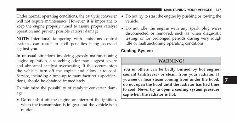
Under normal operating conditions, the catalytic converterwill not require maintenance. However, it is important tokeep the engine properly tuned to assure proper catalystoperation and prevent possible catalyst damage.
NOTE: Intentional tampering with emissions controlsystems can result in civil penalties being assessedagainst you.
In unusual situations involving grossly malfunctioningengine operation, a scorching odor may suggest severeand abnormal catalyst overheating. If this occurs, stopthe vehicle, turn off the engine and allow it to cool.Service, including a tune-up to manufacturer’s specifica-tions, should be obtained immediately.
To minimize the possibility of catalytic converter dam-age:
• Do not shut off the engine or interrupt the ignition,when the transmission is in gear and the vehicle is inmotion.
• Do not try to start the engine by pushing or towing thevehicle.
• Do not idle the engine with any spark plug wiresdisconnected or removed, such as when diagnostictesting, or for prolonged periods during very roughidle or malfunctioning operating conditions.
Cooling System
WARNING!
You or others can be badly burned by hot enginecoolant (antifreeze) or steam from your radiator. Ifyou see or hear steam coming from under the hood,do not open the hood until the radiator has had timeto cool. Never try to open a cooling system pressurecap when the radiator is hot.
7
MAINTAINING YOUR VEHICLE 647

Engine Coolant Checks
Check the engine coolant (antifreeze) protection every 12months (before the onset of freezing weather, whereapplicable). If the engine coolant (antifreeze) is dirty orrusty in appearance, the system should be drained,flushed and refilled with fresh coolant. Check the front ofthe A/C condenser (if equipped) or radiator for anyaccumulation of bugs, leaves, etc. If dirty, clean by gentlyspraying water from a garden hose vertically down theface of the A/C condenser (if equipped) or the back of theradiator core.
Check the engine cooling system hoses for brittle rubber,cracking , tears, cuts and tightness of the connection atthe coolant recovery bottle and radiator. Inspect theentire system for leaks.
With the engine at normal operating temperature (butnot running), check the cooling system pressure cap forproper vacuum sealing by draining a small amount ofengine coolant (antifreeze) from the radiator drain cock.
The radiator drain cock is located in the lower radiatortank. If the cap is sealing properly, the engine coolant(antifreeze) will begin to drain from the coolant expan-sion bottle. DO NOT REMOVE THE COOLANT PRES-SURE CAP WHEN THE COOLING SYSTEM IS HOT.
Cooling System – Drain, Flush, And Refill
If the engine coolant (antifreeze) is dirty or contains aconsiderable amount of sediment, clean and flush with areliable cooling system cleaner. Follow with a thoroughrinsing to remove all deposits and chemicals. Properlydispose of old engine coolant (antifreeze).
Refer to the “Maintenance Schedule” for the propermaintenance intervals.
Selection Of Coolant
Refer to “Fluids, Lubricants, and Genuine Parts” in“Maintaining Your Vehicle” for further information.
648 MAINTAINING YOUR VEHICLE

CAUTION!
• Mixing of engine coolant (antifreeze) other thanspecified Organic Additive Technology (OAT) en-gine coolant (antifreeze), may result in enginedamage and may decrease corrosion protection.Organic Additive Technology (OAT) engine cool-ant is different and should not be mixed withHybrid Organic Additive Technology (HOAT) en-gine coolant (antifreeze) or any “globally compat-ible” coolant (antifreeze). If a non-OAT enginecoolant (antifreeze) is introduced into the coolingsystem in an emergency, it should be flushed withOAT coolant and replaced with the specified OATengine coolant (antifreeze) as soon as possible.
(Continued)
CAUTION! (Continued)• Do not use water alone or alcohol-based engine
coolant (antifreeze) products. Do not use additionalrust inhibitors or antirust products, as they may notbe compatible with the radiator engine coolant andmay plug the radiator.
• This vehicle has not been designed for use withpropylene glycol-based engine coolant (antifreeze).Use of propylene glycol-based engine coolant (an-tifreeze) is not recommended.
Adding Coolant
Your vehicle has been built with an improved enginecoolant (OAT coolant conforming to MS-12106) thatallows extended maintenance intervals. This engine cool-ant (antifreeze) can be used up to ten years or 150,000miles (240,000 km) before replacement. To prevent reduc-ing this extended maintenance period, it is important that
7
MAINTAINING YOUR VEHICLE 649

you use the same engine coolant (OAT coolant conform-ing to MS-12106) throughout the life of your vehicle.
Please review these recommendations for using OrganicAdditive Technology (OAT) engine coolant (antifreeze)that meets the requirements of Chrysler Material Stan-dard MS-12106. When adding engine coolant (antifreeze):
• We recommend using MOPAR® Antifreeze/Coolant10 Year/150,000 Mile Formula OAT (Organic AdditiveTechnology) that meets the requirements of ChryslerMaterial Standard MS-12106.
• Mix a minimum solution of 50% OAT engine coolantthat meets the requirements of Chrysler Material Stan-dard MS-12106 and distilled water. Use higher concen-trations (not to exceed 70%) if temperatures below−34° F (−37° C) are anticipated.
• Use only high purity water such as distilled or deion-ized water when mixing the water/engine coolant
(antifreeze) solution. The use of lower quality waterwill reduce the amount of corrosion protection in theengine cooling system.
Please note that it is the owner’s responsibility to main-tain the proper level of protection against freezing ac-cording to the temperatures occurring in the area wherethe vehicle is operated.
NOTE: Mixing engine coolant (antifreeze) types is notrecommended and can result in cooling system damage.Drain, flush, and refill as soon as possible to avoiddamage if coolant types are mixed in an emergency.
Cooling System Pressure Cap
The cap must be fully tightened to prevent loss of enginecoolant (antifreeze), and to ensure that the engine coolant(antifreeze) will return to the radiator from the coolantexpansion bottle.
650 MAINTAINING YOUR VEHICLE

The cap should be inspected and cleaned if there is anyaccumulation of foreign material on the sealing surfaces.
WARNING!
• The warning words “DO NOT OPEN HOT” on thecooling system pressure cap are a safety precaution.Never add engine coolant (antifreeze) when theengine is overheated. Do not loosen or remove thecap to cool an overheated engine. Heat causespressure to build up in the cooling system. Toprevent scalding or injury, do not remove thepressure cap while the system is hot or underpressure.
• Do not use a pressure cap other than the onespecified for your vehicle. Personal injury or en-gine damage may result.
Disposal Of Used Engine Coolant
Used ethylene glycol-based engine coolant (antifreeze) isa regulated substance requiring proper disposal. Checkwith your local authorities to determine the disposalrules for your community. To prevent ingestion by ani-mals or children, do not store ethylene glycol-basedengine coolant (antifreeze) in open containers or allow itto remain in puddles on the ground. If ingested by a childor pet, seek emergency assistance immediately. Clean upany ground spills immediately.
Checking Coolant Level
With the engine OFF and cold, the level of the enginecoolant should be between the MIN and MAX range onthe dipstick.
7
MAINTAINING YOUR VEHICLE 651
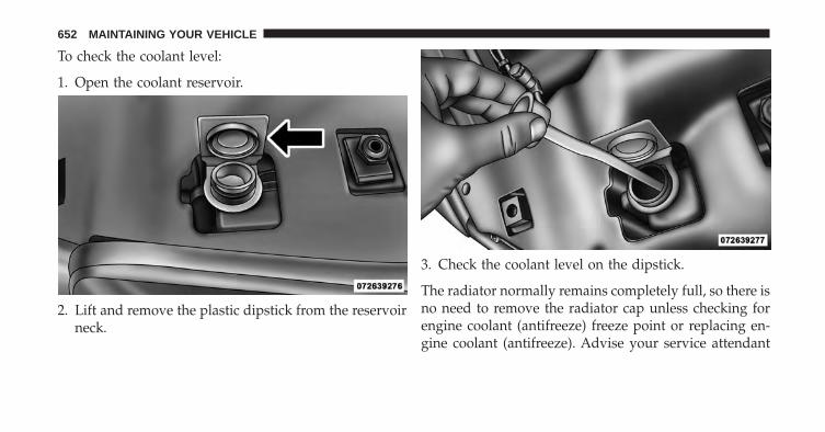
To check the coolant level:
1. Open the coolant reservoir.
2. Lift and remove the plastic dipstick from the reservoirneck.
3. Check the coolant level on the dipstick.
The radiator normally remains completely full, so there isno need to remove the radiator cap unless checking forengine coolant (antifreeze) freeze point or replacing en-gine coolant (antifreeze). Advise your service attendant
652 MAINTAINING YOUR VEHICLE

of this. As long as the engine operating temperature issatisfactory, the coolant bottle need only be checked oncea month.
When additional engine coolant (antifreeze) is needed tomaintain the proper level, it should be added to thecoolant bottle. Do not overfill.
Points To Remember
NOTE: When the vehicle is stopped after a few miles/kilometers of operation, you may observe vapor comingfrom the front of the engine compartment. This is nor-mally a result of moisture from rain, snow, or highhumidity accumulating on the radiator and being vapor-ized when the thermostat opens, allowing hot enginecoolant (antifreeze) to enter the radiator.
If an examination of your engine compartment shows noevidence of radiator or hose leaks, the vehicle may besafely driven. The vapor will soon dissipate.
• Do not overfill the coolant expansion bottle.
• Check the coolant freeze point in the radiator and inthe coolant expansion bottle. If engine coolant (anti-freeze) needs to be added, the contents of the coolantexpansion bottle must also be protected againstfreezing.
• If frequent engine coolant (antifreeze) additions arerequired, the cooling system should be pressure testedfor leaks.
• Maintain engine coolant (antifreeze) concentration at aminimum of 50% OAT coolant (conforming to MS-12106) and distilled water for proper corrosion protec-tion of your engine which contains aluminumcomponents.
• Make sure that the coolant expansion bottle overflowhoses are not kinked or obstructed.
7
MAINTAINING YOUR VEHICLE 653

• Keep the front of the radiator clean. If your vehicle isequipped with air conditioning, keep the front of thecondenser clean.
• Do not change the thermostat for Summer or Winteroperation. If replacement is ever necessary, installONLY the correct type thermostat. Other designs mayresult in unsatisfactory engine coolant (antifreeze)performance, poor gas mileage, and increasedemissions.
Brake System
In order to assure brake system performance, all brakesystem components should be inspected periodically.Refer to the “Maintenance Schedule” for the propermaintenance intervals.
WARNING!
Riding the brakes can lead to brake failure andpossibly a collision. Driving with your foot resting orriding on the brake pedal can result in abnormallyhigh brake temperatures, excessive lining wear, andpossible brake damage. You would not have your fullbraking capacity in an emergency.
Brake Fluid Level Check
The fluid level of the master cylinder should be checkedwhen performing under the hood service or immediatelyif the brake system warning lamp indicates systemfailure.
654 MAINTAINING YOUR VEHICLE

The brake master cylinder has a translucent plasticreservoir. On the outboard side of the reservoir, there is a“MAX” dot and an “MIN” dot. The fluid level must bekept within these two dots. Do not add fluid above theMAX mark because leakage may occur at the cap.
With disc brakes the fluid level can be expected to fall asthe brake linings wear. However, an unexpected drop influid level may be caused by a leak and a system checkshould be conducted.
Use only the manufacturer’s recommended brake fluid.Refer to “Fluids, Lubricants, and Genuine Parts” in“Maintaining Your Vehicle” for further information.
WARNING!
• Use only manufacturer’s recommended brakefluid. Refer to “Fluids, Lubricants, and GenuineParts” in “Maintaining Your Vehicle” for furtherinformation. Using the wrong type of brake fluidcan severely damage your brake system and/orimpair its performance. The proper type of brakefluid for your vehicle is also identified on theoriginal factory installed hydraulic master cylinderreservoir.
(Continued)7
MAINTAINING YOUR VEHICLE 655

WARNING! (Continued)• To avoid contamination from foreign matter or
moisture, use only new brake fluid or fluid that hasbeen in a tightly closed container. Keep the mastercylinder reservoir cap secured at all times. Brakefluid in a open container absorbs moisture from theair resulting in a lower boiling point. This maycause it to boil unexpectedly during hard or pro-longed braking, resulting in sudden brake failure.This could result in a collision.
• Overfilling the brake fluid reservoir can result inspilling brake fluid on hot engine parts, causingthe brake fluid to catch fire. Brake fluid can alsodamage painted and vinyl surfaces, care should betaken to avoid its contact with these surfaces.
WARNING! (Continued)• Do not allow petroleum based fluid to contaminate
the brake fluid. Brake seal components could bedamaged, causing partial or complete brake failure.This could result in a collision.
Rear Axle And 4x4 Front Driving Axle Fluid Level
For normal service, periodic fluid level checks are notrequired. When the vehicle is serviced for other reasonsthe exterior surfaces of the axle assembly should beinspected. If gear oil leakage is suspected inspect thefluid level. Refer to “Fluids, Lubricants, and GenuineParts” in “Maintaining Your Vehicle” for further informa-tion. This inspection should be made with the vehicle ina level position.
656 MAINTAINING YOUR VEHICLE

For 1500 Model axles, the fluid level should be even withthe bottom of the fill hole (within 1/4 in (6.4 mm) of edgeof hole) for the FDU215 HD front axle and C235FE rearaxle.
For all 2500/3500 Model axles, the fluid level should be1/4 in ± 1/4 in (6.4 mm ± 6.4 mm) below the fill hole onthe 9.25 in front and 3/4 in ± 1/4 in (19 mm ± 6.4 mm) on10.5 in rear axles. The 11.5 in rear axle level should be 1/4in ± 1/4 in (6.4 mm ± 6.4 mm) below the fill hole.
Drain And Refill
Refer to the “Maintenance Schedule” for the propermaintenance intervals.
Lubricant Selection
Refer to “Fluids, Lubricants, and Genuine Parts” in“Maintaining Your Vehicle” for further information.
NOTE: The presence of water in the gear lubricant willresult in corrosion and possible failure of differentialcomponents. Operation of the vehicle in water, as may beencountered in some off-highway types of service, willrequire draining and refilling the axle to avoid damage.
Limited-Slip Differentials
1500 Model rear axles equipped with a Limited SlipDifferential require that 5 oz. (148 ml) MOPAR® LimitedSlip Additive be added to the gear lubricant. Refer to“Fluids, Lubricants, and Genuine Parts” in “MaintainingYour Vehicle” for further information. The MOPAR®Limited Slip Additive should be added to the gearlubricant whenever a fluid change is made to an axleequipped with a Limited Slip Differential.
2500/3500 Model axles DO NOT REQUIRE any limitedslip oil additive (friction modifiers).
7
MAINTAINING YOUR VEHICLE 657

NOTE: When refilling an axle with a Limited Slip Differ-ential, the Limited Slip Additive should be added beforethe gear lubricant is added to insure proper additive fill.
Transfer Case
Drain And Refill
Refer to the “Maintenance Schedule” for the propermaintenance intervals.
Lubricant Selection
Refer to “Fluids, Lubricants, and Genuine Parts” in“Maintaining Your Vehicle” for further information.
Fluid Level Check
This fluid level can be checked by removing the fillerplug. The fluid level should be to the bottom edge of thefiller plug hole with the vehicle in a level position.
Automatic Transmission
Selection Of Lubricant
It is important to use the proper transmission fluid toensure optimum transmission performance and life. Useonly the manufacturer’s recommended transmissionfluid. Refer to “Fluids, Lubricants, and Genuine Parts” in“Maintaining Your Vehicle” for fluid specifications. It isimportant to maintain the transmission fluid at thecorrect level using the recommended fluid. No chemicalflushes should be used in any transmission; only theapproved lubricant should be used.
658 MAINTAINING YOUR VEHICLE

CAUTION!
• Using a transmission fluid other than the manufac-turer’s recommended fluid may cause deteriorationin transmission shift quality and/or torque con-verter shudder, and will require more frequentfluid and filter changes. Refer to “Fluids, Lubri-cants, and Genuine Parts” in “Maintaining YourVehicle” for fluid specifications.
Special Additives
The manufacturer strongly recommends against usingany special additives in the transmission. AutomaticTransmission Fluid (ATF) is an engineered product andits performance may be impaired by supplemental addi-tives. Therefore, do not add any fluid additives to thetransmission. The only exception to this policy is the use
of special dyes for diagnosing fluid leaks. Avoid usingtransmission sealers as they may adversely affect seals.
CAUTION!
Do not use chemical flushes in your transmission asthe chemicals can damage your transmission compo-nents. Such damage is not covered by the NewVehicle Limited Warranty.
Fluid Level Check - Six-Speed Transmission
It is best to check the fluid level when the transmission isat normal operating temperature (170-180°F / 77-82°C).This normally occurs after at least 15 miles (25 km) ofdriving. At normal operating temperature the fluid can-not be held comfortably between the fingertips. You canread the transmission sump temperature in the EVICdisplay (see Electronic Vehicle Information Center [EVIC]for further information).
7
MAINTAINING YOUR VEHICLE 659

Use the following procedure to check the transmissionfluid level properly:
1. Monitor the transmission temperature using the EVICdisplay, and operate the vehicle as required to reachthe normal operating temperature.
2. Park the vehicle on level ground.
3. Run the engine at normal idle speed for at least 60seconds, and leave the engine running for the rest ofthis procedure.
4. Fully apply the parking brake and press the brakepedal.
5. Place the shift lever momentarily into each gear posi-tion (allowing time for the transmission to fully en-gage in each position), ending with the lever in PARK.
6. Remove the dipstick, wipe it clean and reinsert it untilseated.
7. Remove the dipstick again and note the fluid level onboth sides. The fluid level reading is only valid if thereis a solid coating of oil on both sides of the dipstick.Note that the holes in the dipstick will be full of fluidif the actual level is at or above the hole. The fluid levelshould be between the “HOT” (upper) reference holeson the dipstick at normal operating temperature. If thefluid level is low, add fluid through the dipstick tubeto bring it to the proper level. Do not overfill. UseONLY the recommended fluid (see �Fluids, Lubri-cants, and Genuine Parts� for fluid specifications).After adding any quantity of oil through the dipsticktube, wait a minimum of two minutes for the oil tofully drain into the transmission before rechecking thefluid level.
660 MAINTAINING YOUR VEHICLE

NOTE: If it is necessary to check the transmission belowthe operating temperature, the fluid level should bebetween the two “COLD” (lower) holes on the dipstickwith the fluid at 60-70°F / 16-21°C. Only use the COLDregion of the dipstick as a rough reference when settingthe fluid level after a transmission service or fluidchange. Re-check the fluid level, and adjust as required,once the transmission reaches normal operating tempera-ture.
CAUTION!
If the fluid temperature is below 50°F (10°C) it maynot register on the dipstick. Do not add fluid untilthe temperature is elevated enough to produce anaccurate reading. Run the engine at idle, in PARK, towarm the fluid.
8. Check for leaks. Release the parking brake.
NOTE: To prevent dirt and water from entering thetransmission after checking or replenishing fluid, makesure that the dipstick cap is properly reseated. It isnormal for the dipstick cap to spring back slightly fromits fully seated position, as long as its seal remainsengaged in the dipstick tube.
Fluid And Filter Changes
Refer to the “Maintenance Schedule” for the propermaintenance intervals.
In addition, change the fluid and filter(s) if the transmis-sion is disassembled for any reason.
Appearance Care And Protection From Corrosion
Protection Of Body And Paint From Corrosion
Vehicle body care requirements vary according to geo-graphic locations and usage. Chemicals that make roadspassable in snow and ice and those that are sprayed ontrees and road surfaces during other seasons are highly
7
MAINTAINING YOUR VEHICLE 661
corrosive to the metal in your vehicle. Outside parking,which exposes your vehicle to airborne contaminants,road surfaces on which the vehicle is operated, extremehot or cold weather and other extreme conditions willhave an adverse effect on paint, metal trim, and under-body protection.
The following maintenance recommendations will enableyou to obtain maximum benefit from the corrosionresistance built into your vehicle.
What Causes Corrosion?
Corrosion is the result of deterioration or removal ofpaint and protective coatings from your vehicle.
The most common causes are:
• Road salt, dirt and moisture accumulation.
• Stone and gravel impact.
• Insects, tree sap and tar.
• Salt in the air near seacoast localities.
• Atmospheric fallout/industrial pollutants.
Washing
• Wash your vehicle regularly. Always wash your ve-hicle in the shade using MOPAR® Car Wash, or a mildcar wash soap, and rinse the panels completely withclear water.
• If insects, tar, or other similar deposits have accumu-lated on your vehicle, use MOPAR® Super Kleen Bugand Tar Remover to remove.
• Use a high quality cleaner wax, such as MOPAR®Cleaner Wax to remove road film, stains and to protectyour paint finish. Take care never to scratch the paint.
• Avoid using abrasive compounds and power buffingthat may diminish the gloss or thin out the paint finish.
662 MAINTAINING YOUR VEHICLE

CAUTION!
• Do not use abrasive or strong cleaning materialssuch as steel wool or scouring powder that willscratch metal and painted surfaces.
• Use of power washers exceeding 1,200 psi (8 274kPa) can result in damage or removal of paint anddecals.
Special Care
• If you drive on salted or dusty roads or if you drivenear the ocean, hose off the undercarriage at least oncea month.
• It is important that the drain holes in the lower edgesof the doors, rocker panels, and trunk be kept clear andopen.
• If you detect any stone chips or scratches in the paint,touch them up immediately. The cost of such repairs isconsidered the responsibility of the owner.
• If your vehicle is damaged due to a collision or similarcause that destroys the paint and protective coating,have your vehicle repaired as soon as possible. Thecost of such repairs is considered the responsibility ofthe owner.
• If you carry special cargo such as chemicals, fertilizers,de-icer salt, etc., be sure that such materials are wellpackaged and sealed.
• If a lot of driving is done on gravel roads, considermud or stone shields behind each wheel.
• Use MOPAR® Touch Up Paint on scratches as soon aspossible. Your authorized dealer has touch up paint tomatch the color of your vehicle.
7
MAINTAINING YOUR VEHICLE 663

Wheel And Wheel Trim Care
• All wheels and wheel trim, especially aluminum andchrome plated wheels, should be cleaned regularlywith a mild soap and water to prevent corrosion.
• To remove heavy soil and/or excessive brake dust, useMOPAR® Wheel Cleaner.
CAUTION!
Do not use scouring pads, steel wool, a bristle brush,or metal polishes. Do not use oven cleaner. Theseproducts may damage the wheel’s protective finish.Avoid automatic car washes that use acidic solutionsor harsh brushes that may damage the wheel’s pro-tective finish. Only MOPAR® Wheel Cleaner orequivalent is recommended.
Stain Repel Fabric Cleaning Procedure – IfEquipped
Stain Repel seats may be cleaned in the following man-ner:
• Remove as much of the stain as possible by blottingwith a clean, dry towel.
• Blot any remaining stain with a clean, damp towel.
• For tough stains, apply MOPAR® Total Clean, or amild soap solution to a clean, damp cloth and removestain. Use a fresh, damp towel to remove soap residue.
• For grease stains, apply MOPAR® Multi-PurposeCleaner to a clean, damp cloth and remove stain. Usea fresh, damp towel to remove soap residue.
• Do not use any harsh solvents or any other form ofprotectants on Stain Repel products.
664 MAINTAINING YOUR VEHICLE

Interior Care
Use MOPAR® Total Clean to clean fabric upholstery andcarpeting.
Use MOPAR® Total Clean to clean vinyl upholstery.
MOPAR® Total Clean is specifically recommended forleather upholstery.
Your leather upholstery can be best preserved by regularcleaning with a damp soft cloth. Small particles of dirtcan act as an abrasive and damage the leather upholsteryand should be removed promptly with a damp cloth.Stubborn soils can be removed easily with a soft clothand MOPAR® Total Clean. Care should be taken to avoidsoaking your leather upholstery with any liquid. Pleasedo not use polishes, oils, cleaning fluids, solvents, deter-gents, or ammonia-based cleaners to clean your leatherupholstery. Application of a leather conditioner is notrequired to maintain the original condition.
WARNING!
Do not use volatile solvents for cleaning purposes.Many are potentially flammable, and if used inclosed areas they may cause respiratory harm.
Cleaning Headlights
Your vehicle is equipped with plastic headlights and foglights (if equipped) that are lighter and less susceptible tostone breakage than glass headlights.
Plastic is not as scratch resistant as glass and thereforedifferent lens cleaning procedures must be followed.
To minimize the possibility of scratching the lenses andreducing light output, avoid wiping with a dry cloth. Toremove road dirt, wash with a mild soap solution fol-lowed by rinsing.
Do not use abrasive cleaning components, solvents, steelwool or other aggressive material to clean the lenses.
7
MAINTAINING YOUR VEHICLE 665

Glass Surfaces
All glass surfaces should be cleaned on a regular basiswith MOPAR® Glass Cleaner, or any commercialhousehold-type glass cleaner. Never use an abrasive typecleaner. Use caution when cleaning the inside rear win-dow equipped with electric defrosters or the right rearquarter window equipped with the radio antenna. Donot use scrapers or other sharp instrument that mayscratch the elements.
When cleaning the rear view mirror, spray cleaner on thetowel or rag that you are using. Do not spray cleanerdirectly on the mirror.
Cleaning Plastic Instrument Cluster Lenses
The lenses in front of the instruments in this vehicle aremolded in clear plastic. When cleaning the lenses, caremust be taken to avoid scratching the plastic.
1. Clean with a wet soft rag. A mild soap solution may beused, but do not use high alcohol content or abrasivecleaners. If soap is used, wipe clean with a clean damprag.
2. Dry with a soft cloth.
Seat Belt Maintenance
Do not bleach, dye or clean the belts with chemicalsolvents or abrasive cleaners. This will weaken the fabric.Sun damage can also weaken the fabric.
If the belts need cleaning, use a mild soap solution orlukewarm water. Do not remove the belts from the car towash them. Dry with a soft cloth.
Replace the belts if they appear frayed or worn or if thebuckles do not work properly.
666 MAINTAINING YOUR VEHICLE

Tri-Fold Soft Tonneau Cover Care
For cleaning and protecting the vinyl Tri-Fold Tonneaucover, use MOPAR® Whitewall & Vinyl Top Cleaner andMOPAR® Leather and Vinyl Conditioner/Protectant.
Spray-On Bedliner – If Equipped
During ownership, the shine and luster of the Spray-OnBedliner can fade from oxidation, road dirt, heavy-dutyhauling and hard water stains. Weathering and UVexposure will lead to fading, dulling, and loss of glossover time.
To help maintain the appearance of your Spray-OnBedliner, the manufacturer recommends you periodicallyrinse all loose dirt from your truck bed and clean yourtruck at least twice per year using the MOPAR®Spray-On Bedliner Conditioner available at your localauthorized dealer.
To Help Maintain The Appearance Of Your Spray-OnBedliner, Follow The Steps Below:
1. Rinse your truck bed out with water to remove anyloose dirt and debris.
2. Mix a mild soap or detergent with water with a softcloth or brush.
3. Rinse bedliner with water.
4. Once dry, apply a small amount of MOPAR®Spray-On Bedliner Conditioner to a moist towel orsponge and wipe over the entire surface of the truckbedliner.
WARNING!
Do not use silicon-based protection products to cleanyour bedliner. Silicon-based products can becomeslippery and may result in personal injury.
7
MAINTAINING YOUR VEHICLE 667

Spray-On Bedliners are chemically-resistant to manydifferent types of chemicals (including gasoline, oil,hydraulic fluids) for short periods of time. If a spilloccurs on your Spray-On Bedliner, rinse the truck out assoon as possible to avoid permanent damage.
Repairing The Spray-On Bedliner
While extremely tough, it is possible to damage aSpray-On Bedliner. One common condition is whenloading a heavy pallet and dragging that pallet across thefloor of the bed. If a nail or sharp point is exposed underthe weight of the pallet a scratch or tear is possible. Whilenot covered by your new vehicle warranty, a cosmetic fixto cover the metal exposed by the scratch is required. Torepair a tear or gouge, follow the directions provided inthe MOPAR® Quick Repair Kit.
FUSES
POWER DISTRIBUTION CENTER
The Power Distribution Center is located in the enginecompartment near the battery. This center contains car-tridge fuses, micro fuses, relays, and circuit breakers. Adescription of each fuse and component may be stampedon the inside cover, otherwise the cavity number of eachfuse is stamped on the inside cover that corresponds tothe following chart.
668 MAINTAINING YOUR VEHICLE

Cavity Car-tridgeFuse
MicroFuse
Description
F01 80 AmpRed
Rad Fan ControlModule – If
equippedF03 60 Amp
YellowRad Fan – If
EquippedF05 40 Amp
GreenCompressor for Air
Suspension – IfEquipped
F06 40 AmpGreen
Antilock Brakes/Electronic Stability
Control PumpF07 40 Amp
GreenStarter Solenoid
Power Distribution Center Location7
MAINTAINING YOUR VEHICLE 669

Cavity Car-tridgeFuse
MicroFuse
Description
F08 40 AmpGreen
Emissions Diesel –If Equipped
F09 40 AmpGreen
Diesel Fuel Heater– If Equipped
F10 40 AmpGreen
Body Controller /Exterior Lighting #2
F10 50 AmpRed
Body Controller /Exterior Lighting #2– If Equipped with
Stop/StartF11 30 Amp
PinkIntegrated TrailerBrake Module – If
Equipped
Cavity Car-tridgeFuse
MicroFuse
Description
F12 40 AmpGreen
Body Controller #3/ Interior Lights
F13 40 AmpGreen
Blower Motor
F14 40 AmpGreen
Body Controller #4/ Power Locks
F15 30 AmpPink
Electric Park BrakeRight Side – If
EquippedF19 30 Amp
PinkSCR – If Equipped
F20 30 AmpPink
Passenger DoorModule
670 MAINTAINING YOUR VEHICLE

Cavity Car-tridgeFuse
MicroFuse
Description
F21 30 AmpPink
Drive Train ControlModule
F22 20 AmpYellow
Engine ControlModule
F23 30 AmpPink
Body Controller #1
F24 30 AmpPink
Driver Door Mod-ule
F25 30 AmpPink
Front Wiper LowSpeed
F25 30 AmpPink
Front Wiper HighSpeed
Cavity Car-tridgeFuse
MicroFuse
Description
F26 30 AmpPink
Antilock Brakes/Stability ControlModule/Valves
F28 20 AmpYellow
Trailer Tow BackupLights – IfEquipped
F29 20 AmpYellow
Trailer Tow ParkingLights – IfEquipped
F30 30 AmpPink
Trailer Tow Recep-tacle
F32 30 AmpPink
Drive Train ControlModule – IfEquipped
7
MAINTAINING YOUR VEHICLE 671

Cavity Car-tridgeFuse
MicroFuse
Description
F33 20 AmpYellow
Diesel Fuel Heater#1 – If Equipped /
Rear Blower – IfEquipped
F34 30 AmpPink
Vehicle System In-terface Module #2 –
If EquippedF35 30 Amp
PinkSunroof – IfEquipped
F36 30 AmpPink
Rear Defroster– IfEquipped
F37 30 AmpPink
Diesel Fuel Heater#2 if equipped
Cavity Car-tridgeFuse
MicroFuse
Description
F38 30 AmpPink
Power Inverter115V AC– If
EquippedF39 30 Amp
PinkVehicle System In-terface Module #1–
If EquippedF41 10 Amp
RedActive Grill Shutter
F42 20 AmpYellow
Horn
F43 10 AmpRed
Snow Plow (Left) –If Equipped
F44 10 AmpRed
Diagnostic Port
672 MAINTAINING YOUR VEHICLE

Cavity Car-tridgeFuse
MicroFuse
Description
F46 10 AmpRed
Tire Pressure Moni-tor
F47 10 AmpRed
Snow Plow (Right)– If Equipped
F49 10 AmpRed
Instrument PanelCluster
F50 20 AmpYellow
Air SuspensionControl Module – If
EquippedF51 10 Amp
RedIgnition Node
Module / KeylessIgnition
F52 5 AmpTan
Battery Sensor
Cavity Car-tridgeFuse
MicroFuse
Description
F53 20 AmpYellow
Trailer Tow – LeftTurn/Stop Lights
F54 20 AmpYellow
Adjustable Pedals
F55 20 AmpYellow
E38 Radio – IfEquipped
F56 15 AmpBlue
Additional DieselContent – If
EquippedF57 20 Amp
YellowTransmission 7
MAINTAINING YOUR VEHICLE 673

Cavity Car-tridgeFuse
MicroFuse
Description
F58 20 AmpYellow
(Gas En-gine) /25 AmpNatural(DieselEngine)
Engine CoolingPump
F60 15 AmpBlue
Underhood Lamp
F61 20 AmpYellow
Power Take-offUnit – If Equipped
F62 10 AmpRed
Air ConditioningClutch
Cavity Car-tridgeFuse
MicroFuse
Description
F63 20 AmpYellow
IgnitionCoils (Gas),Urea Heater (Diesel)
F64 25 AmpNatural
Fuel Injectors /Powertrain
F65 10 AmpRed
USB interface
F66 10 AmpRed
Sunroof / Passen-ger Window
Switches / RainSensor
F67 10 AmpRed
CD / DVD /Bluetooth Hands-free Module – If
Equipped
674 MAINTAINING YOUR VEHICLE

Cavity Car-tridgeFuse
MicroFuse
Description
F69 15 AmpBlue
Mod SCR 12V – IfEquipped
F70 30 AmpGreen
Fuel Pump Motor
F71 25 AmpNatural
Amplifier
F72 10 AmpRed
Voltage StabilizerModules – If
Equipped
Cavity Car-tridgeFuse
MicroFuse
Description
F74 20 AmpYellow(Gas
Engine)/ 10AmpRed
(DieselEngine)
Brake VacuumPump Gas/Diesel –
If Equipped
F75 10 AmpRed
Coolant Tempera-ture Valve Actuator
F76 10 AmpRed
Antilock Brakes/Electronic Stability
Control
7
MAINTAINING YOUR VEHICLE 675
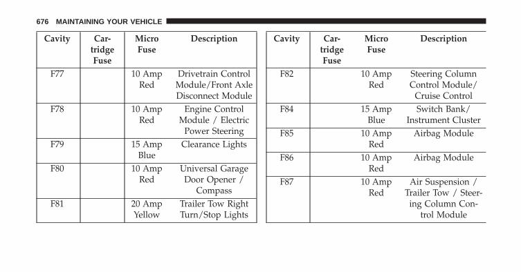
Cavity Car-tridgeFuse
MicroFuse
Description
F77 10 AmpRed
Drivetrain ControlModule/Front AxleDisconnect Module
F78 10 AmpRed
Engine ControlModule / Electric
Power SteeringF79 15 Amp
BlueClearance Lights
F80 10 AmpRed
Universal GarageDoor Opener /
CompassF81 20 Amp
YellowTrailer Tow RightTurn/Stop Lights
Cavity Car-tridgeFuse
MicroFuse
Description
F82 10 AmpRed
Steering ColumnControl Module/
Cruise ControlF84 15 Amp
BlueSwitch Bank/
Instrument ClusterF85 10 Amp
RedAirbag Module
F86 10 AmpRed
Airbag Module
F87 10 AmpRed
Air Suspension /Trailer Tow / Steer-
ing Column Con-trol Module
676 MAINTAINING YOUR VEHICLE

Cavity Car-tridgeFuse
MicroFuse
Description
F88 15 AmpBlue
Instrument PanelCluster
F90/F91 20 AmpYellow
Power Outlet (Rearseats) Customer
SelectableF93 20 Amp
YellowCigar Lighter
F94 10 AmpRed
Shifter / TransferCase Module
F95 10 AmpRed
Rear Camera /Park Assist
F96 10 AmpRed
Rear Seat HeaterSwitch
Cavity Car-tridgeFuse
MicroFuse
Description
F97 25 AmpNatural
Rear Heated Seats& Heated Steering
Wheel – IfEquipped
F98 25 AmpNatural
Front Heated Seats– If Equipped
F99 10 AmpRed
Climate Control
F101 15 AmpBlue
ElectrochromaticMirror / SmartHigh Beams – If
EquippedF104 20 Amp
YellowPower Outlets (In-strument Panel/Center Console)
7
MAINTAINING YOUR VEHICLE 677
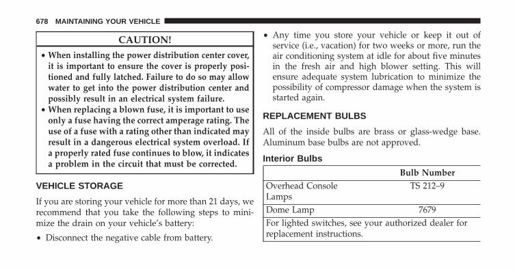
CAUTION!
• When installing the power distribution center cover,it is important to ensure the cover is properly posi-tioned and fully latched. Failure to do so may allowwater to get into the power distribution center andpossibly result in an electrical system failure.
• When replacing a blown fuse, it is important to useonly a fuse having the correct amperage rating. Theuse of a fuse with a rating other than indicated mayresult in a dangerous electrical system overload. Ifa properly rated fuse continues to blow, it indicatesa problem in the circuit that must be corrected.
VEHICLE STORAGE
If you are storing your vehicle for more than 21 days, werecommend that you take the following steps to mini-mize the drain on your vehicle’s battery:
• Disconnect the negative cable from battery.
• Any time you store your vehicle or keep it out ofservice (i.e., vacation) for two weeks or more, run theair conditioning system at idle for about five minutesin the fresh air and high blower setting. This willensure adequate system lubrication to minimize thepossibility of compressor damage when the system isstarted again.
REPLACEMENT BULBS
All of the inside bulbs are brass or glass-wedge base.Aluminum base bulbs are not approved.
Interior Bulbs
Bulb NumberOverhead ConsoleLamps
TS 212–9
Dome Lamp 7679For lighted switches, see your authorized dealer forreplacement instructions.
678 MAINTAINING YOUR VEHICLE

Exterior Bulbs
Bulb NumberBase Quad Headlamp –Low Beam
H11
Base Quad Headlamp –High Beam
9005
Front Turn Signal Lamp(Base Quad Headlamp)
3157NA
Premium Bi HalogenProjector Headlamp -Low Beam
HIR2
Premium Bi HalogenProjector Headlamp -High Beam
9005
Front Turn Signal Lamp(Premium Headlamp)
LED (Serviced at Autho-rized Dealer)
Bulb NumberFog Lamp (Horizontalshape)
9145
Fog Lamp (Verticalshape)
9006
Center High MountedStop Lamp (CHMSL)
921
Rear Cargo Lamp 921Cab Roof Marker Lamps 194NABase Rear Tail/Turn andStop Lamp
3157K
Premium Rear Tail/Turnand Stop Lamp
LED (Serviced at Autho-rized Dealer)
Premium Backup Lamp T20Rear Lamp Bar IDMarker Lamp
194
7
MAINTAINING YOUR VEHICLE 679

Bulb NumberSide Marker Lamps(Dual Rear Wheels)
194
Backup Lamp 921Rear License Plate Lamp 194
BULB REPLACEMENT
Base Quad / Premium Bi-Halogen: Low BeamHeadlamp, High Beam Headlamp, Front Park AndTurn – If Equipped
1. Open the hood.
2. Disconnect and isolate the negative battery cable.
3. Remove the four plastic push-in fasteners that securethe upper radiator seal to the grille support and bothfender ledges.
4. Remove the two plastic push-in rivets that secure theupper radiator seal to the radiator.
5. Remove the upper radiator seal from the vehicle.
6. Remove the two headlamp assembly attachment screws.
680 MAINTAINING YOUR VEHICLE

7. Reach into the front wheel house ahead of the frontwheel, remove the fastener, and lift the cover over theaccess hole in the front of the wheel house splashshield. Access to the rear of the lamp can be gainedthrough this access hole.
8. Reach through the access hole of the wheel housesplash shield and lift the slide lock upward far enoughto disengage it from the lock post on the back of thefront lamp unit housing.
9. Remove the headlamp assembly. Grasp the outboardedge of the lamp and pull it straight forward todisengage the ball stud from the plastic grommet.
10. Disconnect the wiring harness connectors from thebulb socket.
11. Replace bulb(s) as necessary.
7
MAINTAINING YOUR VEHICLE 681

CAUTION!
• Do not contaminate the bulb glass by touching itwith your fingers or by allowing it to contact otheroily surfaces. Shortened bulb life will result.
• Always use the correct bulb size and type forreplacement. An incorrect bulb size or type mayoverheat and cause damage to the lamp, the bulbsocket, or the lamp wiring.
NOTE: There are access covers over both headlamp bulbaccess holes in the quad front lamp unit housing (ifequipped). These covers MUST be reinstalled after thebulb has been replaced.
Fog Lamps – If Equipped
1. Reach under and behind the front bumper to accessthe back of the front fog lamp housing.
2. Disconnect the fog lamp wiring harness connectorfrom the fog lamp bulb.
3. Rotate the bulb counterclockwise ¼ turn to unlock thebulb from the housing.
4. Pull the bulb straight out from the housing.
CAUTION!
Do not contaminate the bulb glass by touching itwith your fingers or by allowing it to contact otheroily surfaces. Shortened bulb life will result.
Rear Tail/Stop, Turn Signal And Backup Lamps
1. Remove the two screws that pass through the bedsheetmetal.
682 MAINTAINING YOUR VEHICLE

2. Pull the outboard side of the lamp rearward farenough to unsnap the two receptacles on the outboardside of the lamp housing from the two plastic snappost retainers in the outer box side panel.
3. Disconnect the wiring harness connectors from thebulb socket.
4. Rotate the bulb socket counterclockwise 1/4 turn tounlock it from the housing.
5. Pull the bulb straight out of the socket.
7
MAINTAINING YOUR VEHICLE 683

CAUTION!
Do not contaminate the bulb glass by touching itwith your fingers or by allowing it to contact otheroily surfaces. Shortened bulb life will result.
6. Reverse the procedure to install the bulb and housing.
Center High-Mounted Stoplamp (CHMSL) WithCargo Lamp
1. Remove the two screws holding the housing/lens tothe body as shown.
2. Separate the connector holding the housing and wir-ing harness to the body.
684 MAINTAINING YOUR VEHICLE

3. Turn the desired bulb socket ¼ turn and remove thesocket and bulb from housing.
4. Pull the desired bulb straight from the socket.
CAUTION!
Do not contaminate the bulb glass by touching itwith your fingers or by allowing it to contact otheroily surfaces. Shortened bulb life will result.
• Outside Bulbs: Cargo Lamps• Inside Bulb: Center High-Mounted Stop Lamp
7
MAINTAINING YOUR VEHICLE 685

5. Reverse the procedure for installation of bulbs andhousing.
Cab Top Clearance Lamps – If Equipped
1. Remove the two screws from the top of the lamp.
2. Rotate the socket ¼ turn and pull it from the lampassembly.
3. Pull the bulb straight from it’s socket and replace.
686 MAINTAINING YOUR VEHICLE

Rear Lamp Bar ID Marker (Dual Rear Wheels) — IfEquipped
1. Loosen the two screws and the housing to gain accessto the bulb sockets.
2. Turn the socket ¼ turn counterclockwise to access thebulb.
3. Pull the bulb straight out from the socket.
4. Reverse the procedure for installation of the bulbs andhousing.
7
MAINTAINING YOUR VEHICLE 687

Side Marker Lamps (Dual Rear Wheels) — IfEquipped
1. Push rearward on the side marker lamp assembly.
2. Pull the entire assembly from the fender.
3. Turn the socket ¼ turn counterclockwise and removefrom assembly to access the bulb.
4. Pull the bulb straight out from socket.
5. Reverse the procedure for installation of the bulbs andhousing.
688 MAINTAINING YOUR VEHICLE

FLUID CAPACITIES
U.S. MetricFuel (Approximate)1500 Regular Cab Shortbed/Crew Quad Cab Models 26 Gallons 98 Liters1500 Regular Cab Longbed/Crew Quad Cab Models (Optional) 32 Gallons 121 Liters2500/3500 Shortbed Models 34 Gallons 129 Liters2500/3500 Longbed Models 35 Gallons 132 LitersEngine Oil With Filter3.6L Engine (We recommend you use SAE 5W-20, API Certified) 6 Quarts 5.6 Liters4.7L Engine (We recommend you use SAE 5W-20, API Certified) 6 Quarts 5.6 Liters5.7L Engine (We recommend you use SAE 5W-20, API Certified) 7 Quarts 6.6 Liters5.7L Engine (We recommend you use SAE 5W-30, API Certified).For 2500/3500 trucks operating under a gross combined weightrating greater than 14,000 lbs (6 350 kg).
7 Quarts 6.6 Liters7
MAINTAINING YOUR VEHICLE 689

U.S. MetricCooling System3.6L Engine (We recommend you use MOPAR® Antifreeze/Coolant 10 Year/150,000 Mile Formula.)
14 Quarts 13 Liters
4.7L Engine (We recommend you use MOPAR® Antifreeze/Coolant 10 Year/150,000 Mile Formula.)
14 Quarts 13 Liters
5.7L Engine – 1500 Models (We recommend you use MOPAR®Antifreeze/Coolant 10 Year/150,000 Mile Formula.)
16 Quarts 15 Liters
5.7L Engine – 2500/3500 Models (We recommend you useMOPAR® Antifreeze/Coolant 10 Year/150,000 Mile Formula.)
18.7 Quarts 17.7 Liters
5.7L Engine – 2500/3500 Models w/Heavy Duty (We recommendyou use MOPAR® Antifreeze/Coolant 10 Year/150,000 Mile For-mula.)
19.2 Quarts 18.2 Liters
690 MAINTAINING YOUR VEHICLE

FLUIDS, LUBRICANTS AND GENUINE PARTS
Engine
Component Fluid, Lubricant, or Genuine PartEngine Coolant We recommend you use MOPAR® Antifreeze/Coolant
10 Year/150,000 Mile Formula OAT (Organic AdditiveTechnology).
Engine Oil We recommend you use API Certified SAE 5W-20Engine Oil, meeting the requirements of Chrysler Ma-terial Standard MS-6395.
Engine Oil – 5.7L Engine For 2500/3500 trucks operatingunder a gross combined weight rating greater than14,000 lbs/(6,350 kg.)
We recommend you use API Certified SAE 5W-30Engine Oil, meeting the requirements of Chrysler Ma-terial Standard MS-6395.
Engine Oil Filter We recommend you use MOPAR® brand Engine OilFilters.
Spark Plugs – 3.6L Engine We recommend you use MOPAR® Spark Plugs (Gap0.043 in [1.1 mm])
7
MAINTAINING YOUR VEHICLE 691
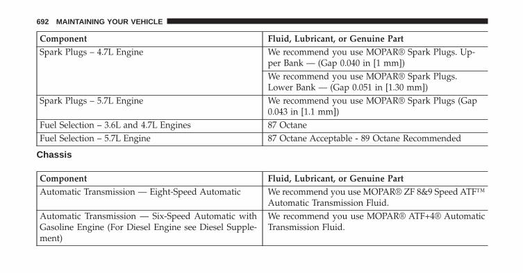
Component Fluid, Lubricant, or Genuine PartSpark Plugs – 4.7L Engine We recommend you use MOPAR® Spark Plugs. Up-
per Bank — (Gap 0.040 in [1 mm])We recommend you use MOPAR® Spark Plugs.Lower Bank — (Gap 0.051 in [1.30 mm])
Spark Plugs – 5.7L Engine We recommend you use MOPAR® Spark Plugs (Gap0.043 in [1.1 mm])
Fuel Selection – 3.6L and 4.7L Engines 87 OctaneFuel Selection – 5.7L Engine 87 Octane Acceptable - 89 Octane Recommended
Chassis
Component Fluid, Lubricant, or Genuine PartAutomatic Transmission — Eight-Speed Automatic We recommend you use MOPAR® ZF 8&9 Speed ATF™
Automatic Transmission Fluid.Automatic Transmission — Six-Speed Automatic withGasoline Engine (For Diesel Engine see Diesel Supple-ment)
We recommend you use MOPAR® ATF+4® AutomaticTransmission Fluid.
692 MAINTAINING YOUR VEHICLE
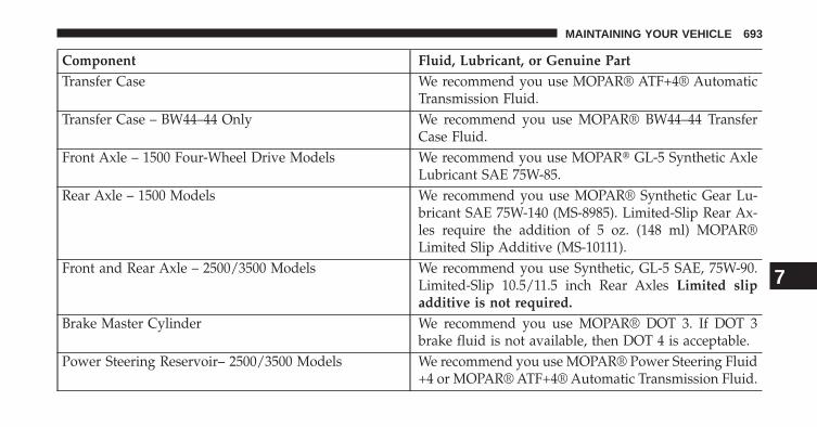
Component Fluid, Lubricant, or Genuine PartTransfer Case We recommend you use MOPAR® ATF+4® Automatic
Transmission Fluid.Transfer Case – BW44–44 Only We recommend you use MOPAR® BW44–44 Transfer
Case Fluid.Front Axle – 1500 Four-Wheel Drive Models We recommend you use MOPAR� GL-5 Synthetic Axle
Lubricant SAE 75W-85.Rear Axle – 1500 Models We recommend you use MOPAR® Synthetic Gear Lu-
bricant SAE 75W-140 (MS-8985). Limited-Slip Rear Ax-les require the addition of 5 oz. (148 ml) MOPAR®Limited Slip Additive (MS-10111).
Front and Rear Axle – 2500/3500 Models We recommend you use Synthetic, GL-5 SAE, 75W-90.Limited-Slip 10.5/11.5 inch Rear Axles Limited slipadditive is not required.
Brake Master Cylinder We recommend you use MOPAR® DOT 3. If DOT 3brake fluid is not available, then DOT 4 is acceptable.
Power Steering Reservoir– 2500/3500 Models We recommend you use MOPAR® Power Steering Fluid+4 or MOPAR® ATF+4® Automatic Transmission Fluid.
7
MAINTAINING YOUR VEHICLE 693


MAINTENANCE SCHEDULES
CONTENTS� MAINTENANCE SCHEDULE . . . . . . . . . . . . .696
▫ Maintenance Chart . . . . . . . . . . . . . . . . . . .697
8
MAINTENANCE
SCHEDULES

MAINTENANCE SCHEDULE
Your vehicle is equipped with an automatic oil changeindicator system. The oil change indicator system willremind you that it is time to take your vehicle in forscheduled maintenance.
Based on engine operation conditions, the oil changeindicator message will illuminate. This means that ser-vice is required for your vehicle. Operating conditionssuch as frequent short-trips, trailer tow, extremely hot orcold ambient temperatures, and E85 fuel usage willinfluence when the “Oil Change Required” message isdisplayed. Severe Operating Conditions can cause thechange oil message to illuminate as early as 3,500 miles(5,600 km) since last reset. Have your vehicle serviced assoon as possible, within the next 500 miles (805 km).
Your authorized dealer will reset the oil change indicatormessage after completing the scheduled oil change. If ascheduled oil change is performed by someone other than
your authorized dealer, the message can be reset by refer-ring to the steps described under “Electronic Vehicle Infor-mation Center (EVIC)/Oil Change Required” in “Under-standing Your Instrument Panel” for further information.
NOTE: Under no circumstances should oil change inter-vals exceed 10,000 miles (16,000 km) or twelve months,whichever comes first.
Once A Month Or Before A Long Trip:
• Check engine oil level
• Check windshield washer fluid level
• Check the tire inflation pressures and look for unusualwear or damage
• Check the fluid levels of the coolant reservoir, brakemaster cylinder, power steering (2500/3500 ModelsOnly) and transmission as needed
• Check function of all interior and exterior lights
8
MAINTENANCE
SCHEDULES
696 MAINTENANCE SCHEDULES

Required Maintenance
Refer to the Maintenance Schedules on the followingpages for required maintenance.
At Every Oil Change Interval As Indicated By OilChange Indicator System:
• Change oil and filter.• Rotate the tires. Rotate at the first sign of irregu-
lar wear, even if it occurs before the oil indicatorsystem turns on.
• Inspect battery and clean and tighten terminals asrequired.
• Inspect automatic transmission fluid if equippedwith dipstick.
At Every Oil Change Interval As Indicated By OilChange Indicator System:
• Inspect brake pads, shoes, rotors, drums, hosesand park brake.
• Inspect engine cooling system protection andhoses.
• Inspect exhaust system.• Inspect engine air cleaner if using in dusty or
off-road conditions.• Lube the front drive shaft fitting (2500/3500 (4x4)
models only).
8
MAINTENANCE
SCHEDULES
MAINTENANCE SCHEDULES 697
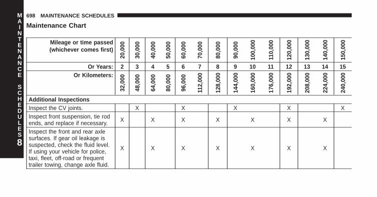
Maintenance Chart
Mileage or time passed(whichever comes first)
20,0
00
30,0
00
40,0
00
50,0
00
60,0
00
70,0
00
80,0
00
90,0
00
100,
000
110,
000
120,
000
130,
000
140,
000
150,
000
Or Years: 2 3 4 5 6 7 8 9 10 11 12 13 14 15Or Kilometers:
32,0
00
48,0
00
64,0
00
80,0
00
96,0
00
112,
000
128,
000
144,
000
160,
000
176,
000
192,
000
208,
000
224,
000
240,
000
Additional InspectionsInspect the CV joints. X X X X XInspect front suspension, tie rodends, and replace if necessary. X X X X X X X
Inspect the front and rear axlesurfaces. If gear oil leakage issuspected, check the fluid level.If using your vehicle for police,taxi, fleet, off-road or frequenttrailer towing, change axle fluid.
X X X X X X X8
MAINTENANCE
SCHEDULES
698 MAINTENANCE SCHEDULES

Mileage or time passed(whichever comes first)
20,0
00
30,0
00
40,0
00
50,0
00
60,0
00
70,0
00
80,0
00
90,0
00
100,
000
110,
000
120,
000
130,
000
140,
000
150,
000
Or Years: 2 3 4 5 6 7 8 9 10 11 12 13 14 15Or Kilometers:
32,0
00
48,0
00
64,0
00
80,0
00
96,0
00
112,
000
128,
000
144,
000
160,
000
176,
000
192,
000
208,
000
224,
000
240,
000
Inspect the brake linings, parkingbrake function. X X X X X X X
Inspect transfer case fluid. X X XAdditional MaintenanceReplace engine air filter. X X X X XReplace spark plugs(3.6L engine).** X
Replace the top row (intake side)of spark plugs (4.7L Engine).** X X X X X
Replace the side row (exhaustside) of spark plugs(4.7L Engine).**
X
8
MAINTENANCE
SCHEDULES
MAINTENANCE SCHEDULES 699

Mileage or time passed(whichever comes first)
20,0
00
30,0
00
40,0
00
50,0
00
60,0
00
70,0
00
80,0
00
90,0
00
100,
000
110,
000
120,
000
130,
000
140,
000
150,
000
Or Years: 2 3 4 5 6 7 8 9 10 11 12 13 14 15Or Kilometers:
32,0
00
48,0
00
64,0
00
80,0
00
96,0
00
112,
000
128,
000
144,
000
160,
000
176,
000
192,
000
208,
000
224,
000
240,
000
Replace spark plugs(5.7L engine).** X X X X X
Replace the ignition cables(4.7L Engine). X
Flush and replace the enginecoolant at 10 years or 150,000miles (240,000 km) whichevercomes first.
X X
Change automatic transmissionfluid and filter(s), if using yourvehicle for police, taxi, fleet, orfrequent trailer towing.
X
8
MAINTENANCE
SCHEDULES
700 MAINTENANCE SCHEDULES

Mileage or time passed(whichever comes first)
20,0
00
30,0
00
40,0
00
50,0
00
60,0
00
70,0
00
80,0
00
90,0
00
100,
000
110,
000
120,
000
130,
000
140,
000
150,
000
Or Years: 2 3 4 5 6 7 8 9 10 11 12 13 14 15Or Kilometers:
32,0
00
48,0
00
64,0
00
80,0
00
96,0
00
112,
000
128,
000
144,
000
160,
000
176,
000
192,
000
208,
000
224,
000
240,
000
Change automatic transmissionfluid and filter. X
Inspect the transfer case fluid,change for any of the following:police, taxi, fleet, or frequenttrailer towing.
X
Change the transfer case fluid. XInspect and replace PCV valve ifnecessary. X
** The spark plug change interval is mileage based only,yearly intervals do not apply.
8
MAINTENANCE
SCHEDULES
MAINTENANCE SCHEDULES 701

WARNING!
• You can be badly injured working on or around amotor vehicle. Do only service work for which youhave the knowledge and the right equipment. Ifyou have any doubt about your ability to perform aservice job, take your vehicle to a competent me-chanic.
• Failure to properly inspect and maintain your ve-hicle could result in a component malfunction andeffect vehicle handling and performance. Thiscould cause an accident.
8
MAINTENANCE
SCHEDULES
702 MAINTENANCE SCHEDULES

IF YOU NEED CONSUMER ASSISTANCE
CONTENTS� SUGGESTIONS FOR OBTAINING SERVICE FOR
YOUR VEHICLE . . . . . . . . . . . . . . . . . . . . . . .705
▫ Prepare For The Appointment. . . . . . . . . . . . .705
▫ Prepare A List . . . . . . . . . . . . . . . . . . . . . . . .705
▫ Be Reasonable With Requests . . . . . . . . . . . . .705
� IF YOU NEED ASSISTANCE . . . . . . . . . . . . . .705
▫ Chrysler Group LLC Customer Center. . . . . . .706
▫ Chrysler Canada Inc. Customer Center . . . . . .706
▫ In Mexico contact: . . . . . . . . . . . . . . . . . . . . .707
▫ Customer Assistance For The Hearing Or SpeechImpaired (TDD/TTY). . . . . . . . . . . . . . . . . . .707
▫ Service Contract . . . . . . . . . . . . . . . . . . . . . .707
� WARRANTY INFORMATION . . . . . . . . . . . . .708
� MOPAR® PARTS . . . . . . . . . . . . . . . . . . . . . . .709
� REPORTING SAFETY DEFECTS . . . . . . . . . . . .709
▫ In The 50 United States AndWashington, D.C.. . . . . . . . . . . . . . . . . . . . . .709
▫ In Canada . . . . . . . . . . . . . . . . . . . . . . . . . . .709
� PUBLICATION ORDER FORMS . . . . . . . . . . . .7109
� DEPARTMENT OF TRANSPORTATION UNIFORMTIRE QUALITY GRADES . . . . . . . . . . . . . . . . .711
▫ Treadwear . . . . . . . . . . . . . . . . . . . . . . . . . . .711
▫ Traction Grades . . . . . . . . . . . . . . . . . . . . . . .711
▫ Temperature Grades. . . . . . . . . . . . . . . . . . . .712
704 IF YOU NEED CONSUMER ASSISTANCE

SUGGESTIONS FOR OBTAINING SERVICE FORYOUR VEHICLE
Prepare For The Appointment
If you are having warranty work done, be sure to havethe right papers with you. Take your warranty folder. Allwork to be performed may not be covered by thewarranty. Discuss additional charges with the servicemanager. Keep a maintenance log of your vehicle’sservice history. This can often provide a clue to thecurrent problem.
Prepare A List
Make a written list of your vehicle’s problems or thespecific work you want done. If you’ve had an accidentor work done that is not on your maintenance log, let theservice advisor know.
Be Reasonable With Requests
If you list a number of items and you must have yourvehicle by the end of the day, discuss the situation withthe service advisor and list the items in order of priority.At many authorized dealer, you may obtain a rentalvehicle at a minimal daily charge. If you need a rental, itis advisable to make these arrangements when you callfor an appointment.
IF YOU NEED ASSISTANCE
The manufacturer and its authorized dealer are vitallyinterested in your satisfaction. We want you to be happywith our products and services.
Warranty service must be done by an authorized dealer.We strongly recommend that you take the vehicle to anauthorized dealer. They know your vehicle the best, andare most concerned that you get prompt and high qualityservice. The manufacturer’s authorized dealer have the
9
IF YOU NEED CONSUMER ASSISTANCE 705

facilities, factory-trained technicians, special tools, andthe latest information to ensure the vehicle is fixedcorrectly and in a timely manner.
This is why you should always talk to an authorizeddealer service manager first. Most matters can be re-solved with this process.
• If for some reason you are still not satisfied, talk to thegeneral manager or owner of the authorized dealer.They want to know if you need assistance.
• If an authorized dealer is unable to resolve the con-cern, you may contact the manufacturer’s customercenter.
Any communication to the manufacturer’s customer cen-ter should include the following information:
• Owner’s name and address
• Owner’s telephone number (home and office)
• Authorized dealer name
• Vehicle Identification Number (VIN)
• Vehicle delivery date and mileage
Chrysler Group LLC Customer Center
P.O. Box 21–8004
Auburn Hills, MI 48321–8004
Phone: (866) 726–4636
Chrysler Canada Inc. Customer Center
P.O. Box 1621
Windsor, Ontario N9A 4H6
Phone: (800) 465–2001 English / (800) 387–9983 French
706 IF YOU NEED CONSUMER ASSISTANCE

In Mexico contact:
Av. Prolongacion Paseo de la Reforma, 1240
Sante Fe C.P. 05109
Mexico, D. F.
In Mexico City: 5081-7568
Outside Mexico City: 1-800-505-1300
Customer Assistance For The Hearing Or SpeechImpaired (TDD/TTY)
To assist customers who have hearing difficulties, themanufacturer has installed special TDD (Telecommuni-cation Devices for the Deaf) equipment at its customercenter. Any hearing or speech impaired customer, whohas access to a TDD or a conventional teletypewriter(TTY) in the United States, can communicate with themanufacturer by dialing 1–800–380–CHRY.
Canadian residents with hearing difficulties that requireassistance can use the special needs relay service offeredby Bell Canada. For TTY teletypewriter users, dial 711and for Voice callers, dial 1 800 855-0511 to connect witha Bell Relay Service operator.
Service Contract
You may have purchased a service contract for a vehicleto help protect you from the high cost of unexpectedrepairs after the manufacturer’s New Vehicle LimitedWarranty expires. The manufacturer stands behind onlythe manufacturer’s service contracts. If you purchased amanufacturer’s service contract, you will receive PlanProvisions and an Owner Identification Card in the mailwithin three weeks of the vehicle delivery date. If youhave any questions about the service contract, call themanufacturer’s Service Contract National CustomerHotline at 1-800-521-9922 (Canadian residents, call (800)465–2001 English / (800) 387–9983 French).
9
IF YOU NEED CONSUMER ASSISTANCE 707

The manufacturer will not stand behind any servicecontract that is not the manufacturer’s service contract. Itis not responsible for any service contract other than themanufacturer’s service contract. If you purchased a ser-vice contract that is not a manufacturer’s service contract,and you require service after the manufacturer’s NewVehicle Limited Warranty expires, please refer to thecontract documents, and contact the person listed inthose documents.
We appreciate that you have made a major investmentwhen you purchased the vehicle. An authorized dealerhas also made a major investment in facilities, tools, andtraining to assure that you are absolutely delighted withthe ownership experience. You will be pleased with theirsincere efforts to resolve any warranty issues or relatedconcerns.
WARNING!
Engine exhaust, some of its constituents, and certainvehicle components contain, or emit, chemicalsknown to the State of California to cause cancer andbirth defects, or other reproductive harm. In addi-tion, certain fluids contained in vehicles and certainproducts of component wear contain, or emit, chemi-cals known to the State of California to cause cancerand birth defects, or other reproductive harm.
WARRANTY INFORMATION
See the Warranty Information Booklet, located on theDVD, for the terms and provisions of Chrysler GroupLLC warranties applicable to this vehicle and market.
708 IF YOU NEED CONSUMER ASSISTANCE
MOPAR® PARTS
MOPAR® fluids, lubricants, parts, and accessories areavailable from an authorized dealer. They are recom-mended for your vehicle in order to help keep the vehicleoperating at its best.
REPORTING SAFETY DEFECTS
In The 50 United States And Washington, D.C.
If you believe that your vehicle has a defect that couldcause a crash or cause injury or death, you shouldimmediately inform the National Highway Traffic SafetyAdministration (NHTSA) in addition to notifying themanufacturer.
If NHTSA receives similar complaints, it may open aninvestigation, and if it finds that a safety defect exists ina group of vehicles, it may order a recall and remedy
campaign. However, NHTSA cannot become involved inindividual problems between you, your authorizeddealer, and the manufacturer.
To contact NHTSA, you may either call the Auto SafetyHotline toll free at 1–888–327–4236 (TTY: 1–800–424–9153), or go to http://www.safercar.gov; or write to:Administrator, NHTSA, 1200 New Jersey Avenue, SE.,West Building, Washington, D.C. 20590. You can alsoobtain other information about motor vehicle safety fromhttp://www.safercar.gov.
In Canada
If you believe that your vehicle has a safety defect, youshould contact the Customer Service Department imme-diately. Canadian customers who wish to report a safetydefect to the Canadian government should contact Trans-port Canada, Motor Vehicle Defect Investigations andRecalls at 1-800-333-0510 or go to http://www.tc.gc.ca/roadsafety/
9
IF YOU NEED CONSUMER ASSISTANCE 709

PUBLICATION ORDER FORMS
To order the following manuals, you may use either thewebsite or the phone numbers listed below. Visa, Mas-tercard, American Express, and Discover orders are ac-cepted. If you prefer mailing your payment, please callfor an order form.
NOTE: A street address is required when orderingmanuals (no P.O. Boxes).
Service Manuals
These comprehensive Service Manuals provide the infor-mation that students and professional technicians need indiagnosing/troubleshooting, problem solving, maintain-ing, servicing, and repairing Chrysler Group LLC ve-hicles. A complete working knowledge of the vehicle,system, and/or components is written in straightforwardlanguage with illustrations, diagrams, and charts.
Diagnostic Procedure Manuals
Diagnostic Procedure Manuals are filled with diagrams,charts and detailed illustrations. These practical manualsmake it easy for students and technicians to find and fixproblems on computer-controlled vehicle systems andfeatures. They show exactly how to find and correctproblems the first time, using step-by-step troubleshoot-ing and drivability procedures, proven diagnostic testsand a complete list of all tools and equipment.
Owner’s Manuals
These Owner’s Manuals have been prepared with theassistance of service and engineering specialists to ac-quaint you with specific Chrysler Group LLC vehicles.Included are starting, operating, emergency and mainte-nance procedures as well as specifications, capabilitiesand safety tips.
710 IF YOU NEED CONSUMER ASSISTANCE

Call toll free at:
• 1–800–890–4038 (U.S.)
• 1–800–387–1143 (Canada)
Or
Visit us on the Worldwide Web at:
• www.techauthority.com
DEPARTMENT OF TRANSPORTATION UNIFORMTIRE QUALITY GRADES
The following tire grading categories were established bythe National Highway Traffic Safety Administration. Thespecific grade rating assigned by the tire’s manufacturerin each category is shown on the sidewall of the tires onyour vehicle.
All passenger car tires must conform to Federal safetyrequirements in addition to these grades.
Treadwear
The Treadwear grade is a comparative rating, based onthe wear rate of the tire when tested under controlledconditions on a specified government test course. Forexample, a tire graded 150 would wear one and one-halftimes as well on the government course as a tire graded100. The relative performance of tires depends upon theactual conditions of their use, however, and may departsignificantly from the norm due to variations in drivinghabits, service practices, and differences in road charac-teristics and climate.
Traction Grades
The Traction grades, from highest to lowest, are AA, A, B,and C. These grades represent the tire’s ability to stop onwet pavement, as measured under controlled conditionson specified government test surfaces of asphalt and 9
IF YOU NEED CONSUMER ASSISTANCE 711

concrete. A tire marked C may have poor traction perfor-mance.
WARNING!
The traction grade assigned to this tire is based onstraight-ahead braking traction tests, and does notinclude acceleration, cornering, hydroplaning, orpeak traction characteristics.
Temperature Grades
The temperature grades are A (the highest), B, and C,representing the tire’s resistance to the generation of heatand its ability to dissipate heat, when tested undercontrolled conditions on a specified indoor laboratorytest wheel. Sustained high temperature can cause thematerial of the tire to degenerate and reduce tire life, andexcessive temperature can lead to sudden tire failure. Thegrade C corresponds to a level of performance, which all
passenger car tires must meet under the Federal MotorVehicle Safety Standard No. 109. Grades B and A repre-sent higher levels of performance on the laboratory testwheel, than the minimum required by law.
WARNING!
The temperature grade for this tire is established fora tire that is properly inflated and not overloaded.Excessive speed, under-inflation, or excessive load-ing, either separately or in combination, can causeheat buildup and possible tire failure.
712 IF YOU NEED CONSUMER ASSISTANCE

INDEX
10

Adding Engine Coolant (Antifreeze) . . . . . . . . . . . .649Adding Fuel . . . . . . . . . . . . . . . . . . . . . . . . . . . . .530Additives, Fuel . . . . . . . . . . . . . . . . . . . . . . . . . . .524Adjustable Pedals . . . . . . . . . . . . . . . . . . . . . . . . .179Airbag. . . . . . . . . . . . . . . . . . . . . . . . . . . . . . . . . .66Airbag Deployment . . . . . . . . . . . . . . . . . . . . . . . .80Airbag Light . . . . . . . . . . . . . . . . . . . . . . . . . . . . .74Airbag Maintenance . . . . . . . . . . . . . . . . . . . . . . . .82Airbag, Side . . . . . . . . . . . . . . . . . . . . . . . . . . . . . .69Airbag, Window (Side Curtain) . . . . . . . . . . . . . . . .70Air Cleaner, Engine (Engine Air Cleaner Filter) . . . .640Air Conditioner Maintenance . . . . . . . . . . . . . . . . .642Air Conditioning. . . . . . . . . . . . . . . . . . . . . . . . . .315Air Conditioning Controls . . . . . . . . . . . . . . . . . . .315Air Conditioning Refrigerant . . . . . . . . . . . . . . . . .642Air Conditioning System . . . . . . . . . . . . . . . . . . . .315Air Pressure, Tires. . . . . . . . . . . . . . . . . . . . . . . . .494Air Suspension . . . . . . . . . . . . . . . . . . . . . . . . . . .410Alarm Light . . . . . . . . . . . . . . . . . . . . . . . . . . . . .262
Alarm, Panic . . . . . . . . . . . . . . . . . . . . . . . . . . . . .28Alarm (Security Alarm) . . . . . . . . . . . . . . . . . . . . . .21Alarm System (Security Alarm) . . . . . . . . . . . . . . . .21Alterations/Modifications, Vehicle . . . . . . . . . . . . . . .7Antifreeze (Engine Coolant) . . . . . . . . . . . . . . . . . .648
Disposal . . . . . . . . . . . . . . . . . . . . . . . . . . . . . .651Anti-Lock Brake System (ABS) . . . . . . . . . . . . . . . .470Anti-Lock Warning Light . . . . . . . . . . . . . . . . . . . .257Anti-Theft Security Alarm (Theft Alarm) . . . . . . . . . .21Anti-Theft System. . . . . . . . . . . . . . . . . . . . . . . . . .21Appearance Care . . . . . . . . . . . . . . . . . . . . . . . . .661Ashtray . . . . . . . . . . . . . . . . . . . . . . . . . . . . . . . .212Auto Down Power Windows . . . . . . . . . . . . . . . . . .45Automatic Door Locks . . . . . . . . . . . . . . . . . . . . . .37Automatic Headlights . . . . . . . . . . . . . . . . . . . . . .162Automatic Temperature Control (ATC) . . . . . . . . . .325Automatic Transmission . . . . . . . . . . . . . . . . . . . .355
Adding Fluid . . . . . . . . . . . . . . . . . . . . . . . . . .660Fluid and Filter Changes . . . . . . . . . . . . . . . . . .661
714 INDEX
Fluid Level Check . . . . . . . . . . . . . . . . . . . . . . .658Fluid Type . . . . . . . . . . . . . . . . . . . . . . . . . . . .658Shifting . . . . . . . . . . . . . . . . . . . . . . . . . . . . . .364Special Additives . . . . . . . . . . . . . . . . . . . . . . .659
Axle Fluid . . . . . . . . . . . . . . . . . . . . . . . . . . . . . .656Axle Lubrication (Axle Fluid) . . . . . . . . . . . . . . . . .656
Back-Up Camera. . . . . . . . . . . . . . . . . . . . . . . . . .193Bar, Stabilizer/Sway System. . . . . . . . . . . . . . . . . .419Battery . . . . . . . . . . . . . . . . . . . . . . . . . . . . . . . . .641
Keyless Transmitter Replacement (RKE) . . . . . . . .30Belts, Seat . . . . . . . . . . . . . . . . . . . . . . . . . . . . . . .51Body Builders Guide . . . . . . . . . . . . . . . . . . . . . . . .6Body Mechanism Lubrication . . . . . . . . . . . . . . . . .643B-Pillar Location . . . . . . . . . . . . . . . . . . . . . . . . . .488Brake Assist System . . . . . . . . . . . . . . . . . . . . . . .471Brake Control System, Electronic . . . . . . . . . . . . . .470Brake Fluid . . . . . . . . . . . . . . . . . . . . . . . . . . . . .654
Brake System . . . . . . . . . . . . . . . . . . . . . . . . . . . .469Anti-Lock (ABS) . . . . . . . . . . . . . . . . . . . . . . . .470Fluid Check . . . . . . . . . . . . . . . . . . . . . . . . . . .654Master Cylinder . . . . . . . . . . . . . . . . . . . . . . . .654Parking . . . . . . . . . . . . . . . . . . . . . . . . . . . . . .467Warning Light . . . . . . . . . . . . . . . . . . . . . . . . .259
Brake/Transmission Interlock. . . . . . . . . . . . . . . . .354Bulb Replacement . . . . . . . . . . . . . . . . . . . . . . . . .678Bulbs, Light . . . . . . . . . . . . . . . . . . . . . . . . . . . . .124
Cab Top Clearance Lights . . . . . . . . . . . . . . . . . . .686Camera, Rear . . . . . . . . . . . . . . . . . . . . . . . . . . . .193Camper . . . . . . . . . . . . . . . . . . . . . . . . . . . . . . . .245Capacities, Fluid . . . . . . . . . . . . . . . . . . . . . . . . . .689Caps, Filler
Oil (Engine) . . . . . . . . . . . . . . . . . . . . . . . . . . .639Radiator (Coolant Pressure) . . . . . . . . . . . . . . . .650
Carbon Monoxide Warning . . . . . . . . . . . . . . . . . .121
10
INDEX 715

Cargo Light . . . . . . . . . . . . . . . . . . . . . . . . . . . . .170Car Washes . . . . . . . . . . . . . . . . . . . . . . . . . . . . .662Cellular Phone . . . . . . . . . . . . . . . . . . . . . . . . . . .314Center High Mounted Stop Light . . . . . . . . . . . . . .684Center Seat Storage Compartment . . . . . . . . . . . . .219Certification Label. . . . . . . . . . . . . . . . . . . . . . . . .532Chart, Tire Sizing . . . . . . . . . . . . . . . . . . . . . . . . .483Check Engine Light (Malfunction Indicator Light) . .257Checking Your Vehicle For Safety . . . . . . . . . . . . . .120Checks, Safety . . . . . . . . . . . . . . . . . . . . . . . . . . .120Child Restraint . . . . . . . . . . . . . . . . . . . . . . . . . . . .84Cigar Lighter . . . . . . . . . . . . . . . . . . . . . . . . . . . .212Clean Air Gasoline . . . . . . . . . . . . . . . . . . . . . . . .522Cleaning
Wheels . . . . . . . . . . . . . . . . . . . . . . . . . . . . . . .664Climate Control . . . . . . . . . . . . . . . . . . . . . . . . . .314Cold Weather Operation . . . . . . . . . . . . . . . . . . . .345Compact Disc (CD) Maintenance . . . . . . . . . . . . . .313Compact Spare Tire . . . . . . . . . . . . . . . . . . . . . . . .498
Console, Overhead . . . . . . . . . . . . . . . . . . . . . . . .194Contract, Service . . . . . . . . . . . . . . . . . . . . . . . . . .707Coolant Pressure Cap (Radiator Cap) . . . . . . . . . . .650Cooling System. . . . . . . . . . . . . . . . . . . . . . . . . . .647
Adding Coolant (Antifreeze) . . . . . . . . . . . . . . .649Coolant Capacity . . . . . . . . . . . . . . . . . . . . . . .689Coolant Level . . . . . . . . . . . . . . . . . . . . . . . . . .648Disposal of Used Coolant . . . . . . . . . . . . . . . . .651Drain, Flush, and Refill . . . . . . . . . . . . . . . . . . .648Inspection . . . . . . . . . . . . . . . . . . . . . . . . . . . .651Points to Remember . . . . . . . . . . . . . . . . . . . . .653Pressure Cap . . . . . . . . . . . . . . . . . . . . . . . . . .650Radiator Cap . . . . . . . . . . . . . . . . . . . . . . . . . .650Selection of Coolant (Antifreeze) . . . . . . . . . . . . .648
Corrosion Protection . . . . . . . . . . . . . . . . . . . . . . .661Cupholders . . . . . . . . . . . . . . . . . . . . . . . . . . . . .214Customer Assistance . . . . . . . . . . . . . . . . . . . . . . .705
Data Recorder, Event . . . . . . . . . . . . . . . . . . . . . . .83
716 INDEX

Daytime Running Lights . . . . . . . . . . . . . . . . . . . .163Dealer Service. . . . . . . . . . . . . . . . . . . . . . . . . . . .635Defroster, Rear Window. . . . . . . . . . . . . . . . . . . . .225Defroster, Windshield . . . . . . . . . . . . . . . . . . . . . .122Delay (Intermittent) Wipers . . . . . . . . . . . . . . . . . .173Differential, Limited-Slip . . . . . . . . . . . . . . . . . . . .440Disabled Vehicle Towing . . . . . . . . . . . . . . . . . . . .623Disposal
Antifreeze (Engine Coolant) . . . . . . . . . . . . . . . .651Door Locks . . . . . . . . . . . . . . . . . . . . . . . . . . . . . .34Door Locks, Automatic . . . . . . . . . . . . . . . . . . . . . .37Driving
Off-Pavement . . . . . . . . . . . . . . . . . . . . . . . . . .421Off-Road . . . . . . . . . . . . . . . . . . . . . . . . . . . . .421Through Flowing, Rising, or Shallow StandingWater . . . . . . . . . . . . . . . . . . . . . . . . . . . . . . . .442
Dual Rear Wheels . . . . . . . . . . . . . . . . . . . . . . . . .507
E-85 Fuel . . . . . . . . . . . . . . . . . . . . . . . . . . . . . . .526Electrical Power Outlets. . . . . . . . . . . . . . . . . . . . .208Electric Rear Window Defrost. . . . . . . . . . . . . . . . .225Electronically Shifted Transfer Case. . . . . . . . . . . . .390Electronic Brake Control System . . . . . . . . . . . . . . .470
Anti-Lock Brake System . . . . . . . . . . . . . . . . . .470Brake Assist System . . . . . . . . . . . . . . . . . . . . .471Traction Control System . . . . . . . . . . . . . . . . . . .471
Electronic Range Select (ERS) . . . . . . . . . . . . . . . . .361Electronic Speed Control (Cruise Control) . . . . . . . .180Electronic Stability Control (ESC) . . . . . . . . . . . . . .475Electronic Vehicle Information Center (EVIC) . . . . . .193Emergency Brake . . . . . . . . . . . . . . . . . . . . . . . . .467Emergency, In Case of
Freeing Vehicle When Stuck . . . . . . . . . . . . . . . .616Hazard Warning Flasher . . . . . . . . . . . . . . . . . .571Jump Starting . . . . . . . . . . . . . . . . . . . . . . . . . .612Tow Hooks . . . . . . . . . . . . . . . . . . . . . . . . . . . .618
Emission Control System Maintenance . . . . . . . . . .634 10
INDEX 717

Engine . . . . . . . . . . . . . . . . . . . . . . . . . . . . . . . . .631Air Cleaner . . . . . . . . . . . . . . . . . . . . . . . . . . .640Block Heater . . . . . . . . . . . . . . . . . . . . . . . . . .351Break-In Recommendations . . . . . . . . . . . . . . . .119Compartment . . . . . . . . . . . . . . . . . . . . . . . . . .630Compartment Identification . . . . . . . . . . . . . . . .630Coolant (Antifreeze) . . . . . . . . . . . . . . . . . . . . .691Exhaust Gas Caution . . . . . . . . . . . . . . . . . . . . .121Flooded, Starting . . . . . . . . . . . . . . . . . . . . . . .345Fuel Requirements . . . . . . . . . . . . . . . . . . . . . .521Jump Starting . . . . . . . . . . . . . . . . . . . . . . . . . .612Oil . . . . . . . . . . . . . . . . . . . . . . . . . . . . . . . . . .637Oil Filler Cap . . . . . . . . . . . . . . . . . . . . . . . . . .639Oil Selection . . . . . . . . . . . . . . . . . . . . . . . . . . .638Oil Synthetic . . . . . . . . . . . . . . . . . . . . . . . . . .639Overheating . . . . . . . . . . . . . . . . . . . . . . . . . . .571
Enhanced Accident Response Feature . . . . . . . . . . . .76Entry System, Illuminated . . . . . . . . . . . . . . . . . . . .22Ethanol . . . . . . . . . . . . . . . . . . . . . . . . . . . . . . . .522
Event Data Recorder . . . . . . . . . . . . . . . . . . . . . . . .83Exhaust Gas Caution . . . . . . . . . . . . . . . . . . . . . . .121Exhaust System. . . . . . . . . . . . . . . . . . . . . . . . . . .121Exterior Lighting. . . . . . . . . . . . . . . . . . . . . . . . . .162Exterior Lights . . . . . . . . . . . . . . . . . . . . . . . . . . .124
FiltersAir Cleaner . . . . . . . . . . . . . . . . . . . . . . . . . . .640Engine Oil . . . . . . . . . . . . . . . . . . . . . . . . . . . .640Engine Oil Disposal . . . . . . . . . . . . . . . . . . . . .639
FlashersTurn Signal . . . . . . . . . . . . . . . . . . . . . . . . . . .124
Flat Tire Stowage . . . . . . . . . . . . . . . . . . . . . . . . .585Flexible Fuel Vehicles
Cruising Range . . . . . . . . . . . . . . . . . . . . . . . . .529Engine Oil . . . . . . . . . . . . . . . . . . . . . . . . . . . .528Fuel Requirements . . . . . . . . . . . . . . . . . . . . . .526Maintenance . . . . . . . . . . . . . . . . . . . . . . . . . . .529Replacement Parts . . . . . . . . . . . . . . . . . . . . . . .529
718 INDEX

Starting . . . . . . . . . . . . . . . . . . . . . . . . . . . . . .528Flooded Engine Starting . . . . . . . . . . . . . . . . . . . .345Fluid, Brake . . . . . . . . . . . . . . . . . . . . . . . . . . . . .692Fluid Capacities . . . . . . . . . . . . . . . . . . . . . . . . . .689Fluid Leaks . . . . . . . . . . . . . . . . . . . . . . . . . . . . .124Fluid Level Checks
Brake . . . . . . . . . . . . . . . . . . . . . . . . . . . . . . . .654Fluids, Lubricants and Genuine Parts . . . . . . . . . . .691Fog Lights . . . . . . . . . . . . . . . . . . . . . . . . . . . . . .166Fold Flat Load Floor . . . . . . . . . . . . . . . . . . . . . . .227Four-Way Hazard Flasher . . . . . . . . . . . . . . . . . . .571Four Wheel Drive . . . . . . . . . . . . . . . . . . . . . . . . .386Freeing A Stuck Vehicle . . . . . . . . . . . . . . . . . . . . .616Front Axle (Differential) . . . . . . . . . . . . . . . . . . . . .656Fuel . . . . . . . . . . . . . . . . . . . . . . . . . . . . . . . . . . .521
Adding . . . . . . . . . . . . . . . . . . . . . . . . . . . . . .530Additives . . . . . . . . . . . . . . . . . . . . . . . . . . . . .524Clean Air . . . . . . . . . . . . . . . . . . . . . . . . . . . . .522Ethanol . . . . . . . . . . . . . . . . . . . . . . . . . . . . . .522
Filler Cap (Gas Cap) . . . . . . . . . . . . . . . . . . . . .531Gasoline . . . . . . . . . . . . . . . . . . . . . . . . . . . . . .521Materials Added . . . . . . . . . . . . . . . . . . . . . . . .524Methanol . . . . . . . . . . . . . . . . . . . . . . . . . . . . .522Octane Rating . . . . . . . . . . . . . . . . . . . . . . . . . .521Requirements . . . . . . . . . . . . . . . . . . . . . . . . . .521Tank Capacity . . . . . . . . . . . . . . . . . . . . . . . . . .689
Fuel, Flexible . . . . . . . . . . . . . . . . . . . . . . . . . . . .526Fuel System Caution . . . . . . . . . . . . . . . . . . . . . . .530Fuses . . . . . . . . . . . . . . . . . . . . . . . . . . . . . . . . . .668
Gas Cap (Fuel Filler Cap) . . . . . . . . . . . . . . . . . . .531Gasoline, Clean Air . . . . . . . . . . . . . . . . . . . . . . . .522Gasoline (Fuel) . . . . . . . . . . . . . . . . . . . . . . . . . . .521Gasoline, Reformulated . . . . . . . . . . . . . . . . . . . . .522Gauges
Speedometer . . . . . . . . . . . . . . . . . . . . . . . . . .262Tachometer . . . . . . . . . . . . . . . . . . . . . . . . . . . .257
Gear Ranges . . . . . . . . . . . . . . . . . . . . . . . . . . . . .365 10
INDEX 719

Gear Select Lever Override . . . . . . . . . . . . . . . . . .618General Information . . . . . . . . . . . . . . . . . . . . . . . .20Glass Cleaning . . . . . . . . . . . . . . . . . . . . . . . . . . .666Grocery Bag Retainer. . . . . . . . . . . . . . . . . . . . . . .224Gross Axle Weight Rating . . . . . . . . . . . . . . . . . . .535Gross Vehicle Weight Rating. . . . . . . . . . . . . . . . . .534Guide, Body Builders . . . . . . . . . . . . . . . . . . . . . . . .6GVWR . . . . . . . . . . . . . . . . . . . . . . . . . . . . . . . . .532
HazardDriving Through Flowing, Rising, or ShallowStanding Water . . . . . . . . . . . . . . . . . . . . . . . . .442
Hazard Warning Flasher . . . . . . . . . . . . . . . . . . . .571Headlights . . . . . . . . . . . . . . . . . . . . . . . . . . . . . .680
Automatic . . . . . . . . . . . . . . . . . . . . . . . . . . . .162Cleaning . . . . . . . . . . . . . . . . . . . . . . . . . . . . .665High Beam . . . . . . . . . . . . . . . . . . . . . . . . . . . .172High Beam/Low Beam Select Switch . . . . . . . . .172Passing . . . . . . . . . . . . . . . . . . . . . . . . . . . . . .172
Switch . . . . . . . . . . . . . . . . . . . . . . . . . . . . . . .162Head Restraints . . . . . . . . . . . . . . . . . . . . . . . . . .154Heated Mirrors . . . . . . . . . . . . . . . . . . . . . . . . . . .137Heater . . . . . . . . . . . . . . . . . . . . . . . . . . . . . . . . .315Heater, Engine Block . . . . . . . . . . . . . . . . . . . . . . .351High Beam/Low Beam Select (Dimmer) Switch . . . .172Hitches
Trailer Towing . . . . . . . . . . . . . . . . . . . . . . . . .539Hoisting . . . . . . . . . . . . . . . . . . . . . . . . . . . . . . . .611Hood Release . . . . . . . . . . . . . . . . . . . . . . . . . . . .160Hub Caps. . . . . . . . . . . . . . . . . . . . . . . . . . . . . . .590
Ignition . . . . . . . . . . . . . . . . . . . . . . . . . . . . . . . . .16Key . . . . . . . . . . . . . . . . . . . . . . . . . . . . . . . . . .12
Ignition Key Removal . . . . . . . . . . . . . . . . . . . . . . .16Illuminated Entry . . . . . . . . . . . . . . . . . . . . . . . . . .22Immobilizer (Sentry Key) . . . . . . . . . . . . . . . . . . . .18Infant Restraint . . . . . . . . . . . . . . . . . . . . . . . . . . .84Inflation Pressure Tires . . . . . . . . . . . . . . . . . . . . .503
720 INDEX
Inside Rearview Mirror . . . . . . . . . . . . . . . . . . . . .131Instrument Cluster . . . . . . . . . . . . . . . . . . . . . . . .257Instrument Panel and Controls . . . . . . . . . . . . . . . .255Instrument Panel Lens Cleaning . . . . . . . . . . . . . . .666Integrated Trailer Brake Controls . . . . . . . . . . . . . .549Interior Appearance Care . . . . . . . . . . . . . . . . . . . .665Interior Lights . . . . . . . . . . . . . . . . . . . . . . . . . . .167Intermittent Wipers (Delay Wipers). . . . . . . . . . . . .173Introduction . . . . . . . . . . . . . . . . . . . . . . . . . . . . . .4Inverter Outlet (115V) . . . . . . . . . . . . . . . . . . . . . .213
Jack Location . . . . . . . . . . . . . . . . . . . . . . . . . . . .572Jump Starting . . . . . . . . . . . . . . . . . . . . . . . . . . . .612
Key-In Reminder . . . . . . . . . . . . . . . . . . . . . . . . . .18Keyless Enter-N-Go . . . . . . . . . . . . . . . . . . . . . . . .39Keyless Entry System . . . . . . . . . . . . . . . . . . . . . . .23Key, Programming . . . . . . . . . . . . . . . . . . . . . . . . .20Key, Replacement . . . . . . . . . . . . . . . . . . . . . . . . . .19
Keys . . . . . . . . . . . . . . . . . . . . . . . . . . . . . . . . . . .12Key, Sentry (Immobilizer) . . . . . . . . . . . . . . . . . . . .18
Lane Change and Turn Signals . . . . . . . . . . . . . . . .171Lane Change Assist . . . . . . . . . . . . . . . . . . . . . . . .172Lap/Shoulder Belts. . . . . . . . . . . . . . . . . . . . . . . . .51Latches . . . . . . . . . . . . . . . . . . . . . . . . . . . . . . . .124Lead Free Gasoline . . . . . . . . . . . . . . . . . . . . . . . .521Leaks, Fluid . . . . . . . . . . . . . . . . . . . . . . . . . . . . .124Life of Tires . . . . . . . . . . . . . . . . . . . . . . . . . . . . .501Light Bulbs. . . . . . . . . . . . . . . . . . . . . . . . . . . . . .124Lights . . . . . . . . . . . . . . . . . . . . . . . . . . . . . . . . .124
Airbag . . . . . . . . . . . . . . . . . . . . . . . . . . . . . . . .74Alarm . . . . . . . . . . . . . . . . . . . . . . . . . . . . . . .262Anti-Lock . . . . . . . . . . . . . . . . . . . . . . . . . . . . .257Automatic Headlights . . . . . . . . . . . . . . . . . . . .162Brake Assist Warning . . . . . . . . . . . . . . . . . . . .480Brake Warning . . . . . . . . . . . . . . . . . . . . . . . . .259Bulb Replacement . . . . . . . . . . . . . . . . . . . . . . .680 10
INDEX 721

Cap Top Clearance . . . . . . . . . . . . . . . . . . . . . .686Cargo . . . . . . . . . . . . . . . . . . . . . . . . . . . . . . .170Center Mounted Stop . . . . . . . . . . . . . . . . . . . .684Check Engine (Malfunction Indicator) . . . . . . . . .257Courtesy/Reading . . . . . . . . . . . . . . . . . . . . . .168Daytime Running . . . . . . . . . . . . . . . . . . . . . . .163Electronic Stability Program (ESP) Indicator . . . . .480Exterior . . . . . . . . . . . . . . . . . . . . . . . . . . . . . .124Fog . . . . . . . . . . . . . . . . . . . . . . . . . . . . . . . . .166Four-Wheel Drive Indicator . . . . . . . . . . . . . . . .390Hazard Warning Flasher . . . . . . . . . . . . . . . . . .571Headlights . . . . . . . . . . . . . . . . . . . . . . . . . . . .162High Beam . . . . . . . . . . . . . . . . . . . . . . . . . . . .172High Beam Indicator . . . . . . . . . . . . . . . . . . . . .261High Beam/Low Beam Select . . . . . . . . . . . . . . .172Illuminated Entry . . . . . . . . . . . . . . . . . . . . . . . .22Instrument Cluster . . . . . . . . . . . . . . . . . . . . . .257Interior . . . . . . . . . . . . . . . . . . . . . . . . . . . . . .167Oil Pressure . . . . . . . . . . . . . . . . . . . . . . . . . . .262
Passing . . . . . . . . . . . . . . . . . . . . . . . . . . . . . .172Seat Belt Reminder . . . . . . . . . . . . . . . . . . . . . .261Security Alarm (Theft Alarm) . . . . . . . . . . . . . . .262Service . . . . . . . . . . . . . . . . . . . . . . . . . . . . . . .678Side Marker . . . . . . . . . . . . . . . . . . . . . . . . . . .688SmartBeams . . . . . . . . . . . . . . . . . . . . . . . . . . .164Theft Alarm (Security Alarm) . . . . . . . . . . . . . . .262Tire Pressure Monitoring (TPMS) . . . . . . . . . . . .262Traction Control . . . . . . . . . . . . . . . . . . . . . . . .480Transfer Case . . . . . . . . . . . . . . . . . . . . . . . . . .390Turn Signal . . . . . . . . . . . . . . . . . . . . . . . . . . .124Warning (Instrument Cluster Description) . . . . . .257
Limited-Slip Differential . . . . . . . . . . . . . . . . . . . .440Loading Vehicle . . . . . . . . . . . . . . . . . . . . . . . . . .532
Tires . . . . . . . . . . . . . . . . . . . . . . . . . . . . . . . .488Locks . . . . . . . . . . . . . . . . . . . . . . . . . . . . . . . . . .34
Automatic Door . . . . . . . . . . . . . . . . . . . . . . . . .37Child Protection . . . . . . . . . . . . . . . . . . . . . . . . .38Door . . . . . . . . . . . . . . . . . . . . . . . . . . . . . . . . .34
722 INDEX

Power Door . . . . . . . . . . . . . . . . . . . . . . . . . . . .36Low Tire Pressure System . . . . . . . . . . . . . . . . . . .508Lubrication, Body . . . . . . . . . . . . . . . . . . . . . . . . .643
Maintenance Free Battery. . . . . . . . . . . . . . . . . . . .641Maintenance Procedures . . . . . . . . . . . . . . . . . . . .636Maintenance Schedule . . . . . . . . . . . . . . . . . . . . . .696Malfunction Indicator Light (Check Engine). . . . . . .634Manual, Service . . . . . . . . . . . . . . . . . . . . . . . . . .710Manual Transmission
Fluid Level Check . . . . . . . . . . . . . . . . . . . . . . .658Lubricant Selection . . . . . . . . . . . . . . . . . . . . . .692
Memory Seat . . . . . . . . . . . . . . . . . . . . . . . . . . . .156Methanol . . . . . . . . . . . . . . . . . . . . . . . . . . . . . . .522Mirrors . . . . . . . . . . . . . . . . . . . . . . . . . . . . . . . .131
Electric Powered . . . . . . . . . . . . . . . . . . . . . . . .136Heated . . . . . . . . . . . . . . . . . . . . . . . . . . . . . . .137Memory . . . . . . . . . . . . . . . . . . . . . . . . . . . . . .156Outside . . . . . . . . . . . . . . . . . . . . . . . . . . . . . .133
Rearview . . . . . . . . . . . . . . . . . . . . . . . . . . . . .131Trailer Towing . . . . . . . . . . . . . . . . . . . . . . . . .139
Modifications/Alterations, Vehicle . . . . . . . . . . . . . . .7Monitor, Tire Pressure System . . . . . . . . . . . . . . . .508Mopar Parts . . . . . . . . . . . . . . . . . . . . . . . . . . . . .635MTBE/ETBE . . . . . . . . . . . . . . . . . . . . . . . . . . . .522Multi-Function Control Lever . . . . . . . . . . . . . . . . .171
Navigation System (Uconnect® gps) . . . . . . . . . . . .193New Vehicle Break-In Period . . . . . . . . . . . . . . . . .119
Occupant Restraints . . . . . . . . . . . . . . . . . . . . . . . .47Occupant Restraints (Sedan) . . . . . . . . . . . . . . . . . .69Octane Rating, Gasoline (Fuel) . . . . . . . . . . . . . . . .521Off-Pavement Driving (Off-Road) . . . . . . . . . . . . . .421Off-Road Driving (Off-Pavement) . . . . . . . . . . . . . .421Oil, Engine . . . . . . . . . . . . . . . . . . . . . . . . . . . . . .637
Capacity . . . . . . . . . . . . . . . . . . . . . . . . . . . . .689Change Interval . . . . . . . . . . . . . . . . . . . . . . . .638 10
INDEX 723

Dipstick . . . . . . . . . . . . . . . . . . . . . . . . . . . . . .637Disposal . . . . . . . . . . . . . . . . . . . . . . . . . . . . . .639Filter . . . . . . . . . . . . . . . . . . . . . . . . . . . . . . . .640Filter Disposal . . . . . . . . . . . . . . . . . . . . . . . . .639Identification Logo . . . . . . . . . . . . . . . . . . . . . .638Recommendation . . . . . . . . . . . . . . . . . . . . . . .638Synthetic . . . . . . . . . . . . . . . . . . . . . . . . . . . . .639Viscosity . . . . . . . . . . . . . . . . . . . . . . . . . . . . .639
Oil Filter, Selection . . . . . . . . . . . . . . . . . . . . . . . .640Onboard Diagnostic System . . . . . . . . . . . . . . . . . .633Operating Precautions . . . . . . . . . . . . . . . . . . . . . .633Operator Manual (Owner’s Manual) . . . . . . . . . . . . .4Outside Rearview Mirrors . . . . . . . . . . . . . . . . . . .133Overdrive. . . . . . . . . . . . . . . . . . . . . . . . . . . . . . .374Overdrive OFF Switch . . . . . . . . . . . . . . . . . . . . . .374Overhead Console. . . . . . . . . . . . . . . . . . . . . . . . .194Overheating, Engine . . . . . . . . . . . . . . . . . . . . . . .266Owner’s Manual (Operator Manual) . . . . . . . . . . . . .4
Paint Care . . . . . . . . . . . . . . . . . . . . . . . . . . . . . .661Panic Alarm . . . . . . . . . . . . . . . . . . . . . . . . . . . . . .28Parking Brake. . . . . . . . . . . . . . . . . . . . . . . . . . . .467Park Sense System, Rear . . . . . . . . . . . . . . . . . . . .184Passing Light . . . . . . . . . . . . . . . . . . . . . . . . . . . .172Pedals, Adjustable. . . . . . . . . . . . . . . . . . . . . . . . .179Personal Settings. . . . . . . . . . . . . . . . . . . . . . . . . .285Pets . . . . . . . . . . . . . . . . . . . . . . . . . . . . . . . . . . .119Pets, Transporting . . . . . . . . . . . . . . . . . . . . . . . . .119Pickup Box. . . . . . . . . . . . . . . . . . . . . . . . . . . . . .229Placard, Tire and Loading Information . . . . . . . . . .489Power
Distribution Center (Fuses) . . . . . . . . . . . . . . . .668Door Locks . . . . . . . . . . . . . . . . . . . . . . . . . . . .36Mirrors . . . . . . . . . . . . . . . . . . . . . . . . . . . . . .136Outlet (Auxiliary Electrical Outlet) . . . . . . . . . . .208Seats . . . . . . . . . . . . . . . . . . . . . . . . . . . . . . . .141Sliding Rear Window . . . . . . . . . . . . . . . . . . . .226Steering . . . . . . . . . . . . . . . . . . . . . . . . . . . . . .465
724 INDEX
Sunroof . . . . . . . . . . . . . . . . . . . . . . . . . . . . . .205Windows . . . . . . . . . . . . . . . . . . . . . . . . . . . . . .44
Power Steering Fluid. . . . . . . . . . . . . . . . . . . . . . .692Pregnant Women and Seat Belts . . . . . . . . . . . . . . . .65Pretensioners
Seat Belts . . . . . . . . . . . . . . . . . . . . . . . . . . . . . .63Programmable Electronic Features . . . . . . . . . . . . .285Programming Transmitters (Remote Keyless Entry) . . .23
Radial Ply Tires . . . . . . . . . . . . . . . . . . . . . . . . . .496Radiator Cap (Coolant Pressure Cap) . . . . . . . . . . .648Radio Operation . . . . . . . . . . . . . . . . . . . . . . . . . .314Rain Sensitive Wiper System . . . . . . . . . . . . . . . . .175Ramp Travel Index . . . . . . . . . . . . . . . . . . . . . . . .422Rear Axle (Differential) . . . . . . . . . . . . . . . . . . . . .656Rear Cargo Area Utility Rails . . . . . . . . . . . . . . . . .243Rear Park Sense System. . . . . . . . . . . . . . . . . . . . .184Rear Seat, Folding . . . . . . . . . . . . . . . . . . . . . . . . .151Rear Window Features . . . . . . . . . . . . . . . . . . . . .225
Rear Window, Sliding . . . . . . . . . . . . . . . . . . . . . .227Reclining Rear Seats . . . . . . . . . . . . . . . . . . . . . . .150Recorder, Event Data . . . . . . . . . . . . . . . . . . . . . . .83Recreational Towing . . . . . . . . . . . . . . . . . . . . . . .561
Shifting into Transfer Case Neutral (N) . . . . . . . .564Shifting out of Transfer Case Neutral (N) . . . . . .567
Reformulated Gasoline . . . . . . . . . . . . . . . . . . . . .522Refrigerant . . . . . . . . . . . . . . . . . . . . . . . . . . . . . .643Reminder, Seat Belt. . . . . . . . . . . . . . . . . . . . . . . . .64Remote Control
Starting System . . . . . . . . . . . . . . . . . . . . . . . . .31Remote Keyless Entry (RKE) . . . . . . . . . . . . . . . . . .23Remote Sound System (Radio) Controls . . . . . . . . .312Remote Starting System. . . . . . . . . . . . . . . . . . . . . .31Replacement Bulbs . . . . . . . . . . . . . . . . . . . . . . . .678Replacement Keys . . . . . . . . . . . . . . . . . . . . . . . . .19Replacement Parts. . . . . . . . . . . . . . . . . . . . . . . . .635Replacement Tires . . . . . . . . . . . . . . . . . . . . . . . . .502Reporting Safety Defects . . . . . . . . . . . . . . . . . . . .709 10
INDEX 725

Restraint, Head. . . . . . . . . . . . . . . . . . . . . . . . . . .154Restraints, Child . . . . . . . . . . . . . . . . . . . . . . . . . . .84Restraints, Occupant . . . . . . . . . . . . . . . . . . . . . . . .47Rotation, Tires . . . . . . . . . . . . . . . . . . . . . . . . . . .506
Safety Checks Inside Vehicle . . . . . . . . . . . . . . . . .122Safety Checks Outside Vehicle . . . . . . . . . . . . . . . .124Safety Defects, Reporting . . . . . . . . . . . . . . . . . . . .709Safety, Exhaust Gas . . . . . . . . . . . . . . . . . . . . . . . .121Safety Information, Tire . . . . . . . . . . . . . . . . . . . . .482Safety Tips . . . . . . . . . . . . . . . . . . . . . . . . . . . . . .120Schedule, Maintenance . . . . . . . . . . . . . . . . . . . . .696Seat Belt Maintenance . . . . . . . . . . . . . . . . . . . . . .666Seat Belt Reminder . . . . . . . . . . . . . . . . . . . . . . . . .64Seat Belts . . . . . . . . . . . . . . . . . . . . . . . . . . . . . . . .47
Adjustable Upper Shoulder Anchorage . . . . . . . . .59And Pregnant Women . . . . . . . . . . . . . . . . . . . . .65Child Restraint . . . . . . . . . . . . . . . . . . . . . . . . . .84Extender . . . . . . . . . . . . . . . . . . . . . . . . . . . . . .65
Front Seat . . . . . . . . . . . . . . . . . . . . . . . . . . . . .51Inspection . . . . . . . . . . . . . . . . . . . . . . . . . . . .122Pretensioners . . . . . . . . . . . . . . . . . . . . . . . . . . .63Reminder . . . . . . . . . . . . . . . . . . . . . . . . . . . . .261Untwisting Procedure . . . . . . . . . . . . . . . . . . . . .59
Seats . . . . . . . . . . . . . . . . . . . . . . . . . . . . . . . . . .140Adjustment . . . . . . . . . . . . . . . . . . . . . . . . . . .140Folding Floor . . . . . . . . . . . . . . . . . . . . . . . . . .227Memory . . . . . . . . . . . . . . . . . . . . . . . . . . . . . .156Power . . . . . . . . . . . . . . . . . . . . . . . . . . . . . . .141Rear Folding . . . . . . . . . . . . . . . . . . . . . . . . . .151Reclining Rear . . . . . . . . . . . . . . . . . . . . . . . . .150
Security Alarm (Theft Alarm). . . . . . . . . . . . . . . . . .21Selection of Coolant (Antifreeze). . . . . . . . . . . . . . .691Sentry Key (Immobilizer) . . . . . . . . . . . . . . . . . . . .18Sentry Key Programming . . . . . . . . . . . . . . . . . . . .20Sentry Key Replacement . . . . . . . . . . . . . . . . . . . . .19Service Assistance . . . . . . . . . . . . . . . . . . . . . . . . .705Service Contract . . . . . . . . . . . . . . . . . . . . . . . . . .707
726 INDEX

Service Manuals . . . . . . . . . . . . . . . . . . . . . . . . . .710Settings, Personal . . . . . . . . . . . . . . . . . . . . . . . . .285Shifting . . . . . . . . . . . . . . . . . . . . . . . . . . . . . . . .352
Automatic Transmission . . . . . . . . . . . . . . . . . .355Transfer Case . . . . . . . . . . . . . . . . . . . . . . . . . .389Transfer Case, Shifting into Transfer Case Neutral(N) . . . . . . . . . . . . . . . . . . . . . . . . . . . . . . . . .564Transfer Case, Shifting out of Transfer Case Neutral(N) . . . . . . . . . . . . . . . . . . . . . . . . . . . . . . . . .567
Shift Lever Override . . . . . . . . . . . . . . . . . . . . . . .618Shoulder Belts . . . . . . . . . . . . . . . . . . . . . . . . . . . .51Shoulder Belt Upper Anchorage . . . . . . . . . . . . . . . .59Side Airbag . . . . . . . . . . . . . . . . . . . . . . . . . . . . . .75Signals, Turn . . . . . . . . . . . . . . . . . . . . . . . . . . . .124Sliding Rear Window
Power . . . . . . . . . . . . . . . . . . . . . . . . . . . . . . .226SmartBeams . . . . . . . . . . . . . . . . . . . . . . . . . . . . .164Snow Chains (Tire Chains) . . . . . . . . . . . . . . . . . . .504Snow Plow. . . . . . . . . . . . . . . . . . . . . . . . . . . . . .557
Snow Tires . . . . . . . . . . . . . . . . . . . . . . . . . . . . . .497Spare Tire. . . . . . . . . . . . . . . . . . . . . . . . . . . . . . .498Spark Plugs . . . . . . . . . . . . . . . . . . . . . . . . . . . . .691Speed Control (Cruise Control). . . . . . . . . . . . . . . .180Speedometer. . . . . . . . . . . . . . . . . . . . . . . . . . . . .262Stabilizer/Sway Bar System . . . . . . . . . . . . . . . . . .419Starting . . . . . . . . . . . . . . . . . . . . . . . . . . . . . . . . .31
Automatic Transmission . . . . . . . . . . . . . . . . . .342Cold Weather . . . . . . . . . . . . . . . . . . . . . . . . . .345Engine Fails to Start . . . . . . . . . . . . . . . . . . . . .345Remote . . . . . . . . . . . . . . . . . . . . . . . . . . . . . . .31
Starting Procedures (Gas Engines) . . . . . . . . . . . . .342Steering
Power . . . . . . . . . . . . . . . . . . . . . . . . . . . . . . .465Wheel, Heated . . . . . . . . . . . . . . . . . . . . . . . . .177Wheel, Tilt . . . . . . . . . . . . . . . . . . . . . . . . . . . .176
Steering Wheel Audio Controls . . . . . . . . . . . . . . .312Steering Wheel Mounted Sound System Controls . . .312Storage Compartment, Center Seat . . . . . . . . . . . . .219 10
INDEX 727

Storage, Vehicle. . . . . . . . . . . . . . . . . . . . . . . . . . .332Storing Your Vehicle . . . . . . . . . . . . . . . . . . . . . . .678Sun Roof . . . . . . . . . . . . . . . . . . . . . . . . . . . . . . .205Supplemental Tire Pressure Information . . . . . . . . .503Suspension, Air. . . . . . . . . . . . . . . . . . . . . . . . . . .410Sway Control, Trailer. . . . . . . . . . . . . . . . . . . . . . .481Synthetic Engine Oil . . . . . . . . . . . . . . . . . . . . . . .639System, Remote Starting . . . . . . . . . . . . . . . . . . . . .31
Tachometer. . . . . . . . . . . . . . . . . . . . . . . . . . . . . .257Tailgate . . . . . . . . . . . . . . . . . . . . . . . . . . . . . . . .245Temperature Control, Automatic (ATC) . . . . . . . . . .325Tilt Steering Column . . . . . . . . . . . . . . . . . . . . . . .176Tip Start. . . . . . . . . . . . . . . . . . . . . . . . . . . . . . . .343Tire and Loading Information Placard . . . . . . . . . . .488Tire Markings . . . . . . . . . . . . . . . . . . . . . . . . . . . .482Tires . . . . . . . . . . . . . . . . . . . . . . . . . . . . . . . . . .124
Aging (Life of Tires) . . . . . . . . . . . . . . . . . . . . .501Air Pressure . . . . . . . . . . . . . . . . . . . . . . . . . . .493
Chains . . . . . . . . . . . . . . . . . . . . . . . . . . . . . . .504Compact Spare . . . . . . . . . . . . . . . . . . . . . . . . .498Dual . . . . . . . . . . . . . . . . . . . . . . . . . . . . . . . .507General Information . . . . . . . . . . . . . . . . . . . . .493High Speed . . . . . . . . . . . . . . . . . . . . . . . . . . .496Inflation Pressures . . . . . . . . . . . . . . . . . . . . . . .494Life of Tires . . . . . . . . . . . . . . . . . . . . . . . . . . .501Load Capacity . . . . . . . . . . . . . . . . . . . . . . . . .488Pressure Monitor System (TPMS) . . . . . . . . . . . .508Pressure Warning Light . . . . . . . . . . . . . . . . . . .262Quality Grading . . . . . . . . . . . . . . . . . . . . . . . .711Radial . . . . . . . . . . . . . . . . . . . . . . . . . . . . . . .496Replacement . . . . . . . . . . . . . . . . . . . . . . . . . . .502Rotation . . . . . . . . . . . . . . . . . . . . . . . . . . . . . .506Safety . . . . . . . . . . . . . . . . . . . . . . . . . . . . . . .482Sizes . . . . . . . . . . . . . . . . . . . . . . . . . . . . . . . .483Snow Tires . . . . . . . . . . . . . . . . . . . . . . . . . . . .497Spinning . . . . . . . . . . . . . . . . . . . . . . . . . . . . .500Tread Wear Indicators . . . . . . . . . . . . . . . . . . . .500
728 INDEX
Tire Safety Information . . . . . . . . . . . . . . . . . . . . .482Tongue Weight/Trailer Weight . . . . . . . . . . . . . . . .544Tonneau Cover . . . . . . . . . . . . . . . . . . . . . . . . . . .667Tonneau Cover Cleaning . . . . . . . . . . . . . . . . . . . .667Torque Converter Clutch . . . . . . . . . . . . . . . . . . . .375Tow Hooks, Emergency . . . . . . . . . . . . . . . . . . . . .618Towing . . . . . . . . . . . . . . . . . . . . . . . . . . . . . . . .534
Disabled Vehicle . . . . . . . . . . . . . . . . . . . . . . . .623Guide . . . . . . . . . . . . . . . . . . . . . . . . . . . . . . .540Recreational . . . . . . . . . . . . . . . . . . . . . . . . . . .561Weight . . . . . . . . . . . . . . . . . . . . . . . . . . . . . . .540
Traction . . . . . . . . . . . . . . . . . . . . . . . . . . . . . . . .441Traction Control . . . . . . . . . . . . . . . . . . . . . . . . . .471Trailer Sway Control (TSC) . . . . . . . . . . . . . . . . . .481Trailer Towing . . . . . . . . . . . . . . . . . . . . . . . . . . .534
Cooling System Tips . . . . . . . . . . . . . . . . . . . . .556Hitches . . . . . . . . . . . . . . . . . . . . . . . . . . . . . .539Minimum Requirements . . . . . . . . . . . . . . . . . .545Mirrors . . . . . . . . . . . . . . . . . . . . . . . . . . . . . .139
Trailer and Tongue Weight . . . . . . . . . . . . . . . . .544Wiring . . . . . . . . . . . . . . . . . . . . . . . . . . . . . . .553
Trailer Towing Guide. . . . . . . . . . . . . . . . . . . . . . .540Trailer Weight . . . . . . . . . . . . . . . . . . . . . . . . . . . .540Transfer Case . . . . . . . . . . . . . . . . . . . . . . . . . . . .658
Electronically Shifted . . . . . . . . . . . . . . . . . . . . .390Fluid . . . . . . . . . . . . . . . . . . . . . . . . . . . . . . . .692
Transmission . . . . . . . . . . . . . . . . . . . . . . . . . . . .355Automatic . . . . . . . . . . . . . . . . . . . . . . . . . . . .355Fluid . . . . . . . . . . . . . . . . . . . . . . . . . . . . . . . .692Maintenance . . . . . . . . . . . . . . . . . . . . . . . . . . .658Shifting . . . . . . . . . . . . . . . . . . . . . . . . . . . . . .352
Transmitter Battery Service (Remote Keyless Entry) . .30Transmitter Programming (Remote Keyless Entry) . . .23Transmitter, Remote Keyless Entry (RKE) . . . . . . . . .23Tread Wear Indicators . . . . . . . . . . . . . . . . . . . . . .500Turn Signals . . . . . . . . . . . . . . . . . . . . . . . . . . . . .171
Uniform Tire Quality Grades . . . . . . . . . . . . . . . . .711 10
INDEX 729

Unleaded Gasoline . . . . . . . . . . . . . . . . . . . . . . . .521Untwisting Procedure, Seat Belt . . . . . . . . . . . . . . . .59Utility Rails, Rear Cargo Area . . . . . . . . . . . . . . . .243
Vehicle Identification Number (VIN) . . . . . . . . . . . . .6Vehicle Loading . . . . . . . . . . . . . . . . . . . . . . . . . .489Vehicle Modifications/Alterations . . . . . . . . . . . . . . .7Vehicle Storage . . . . . . . . . . . . . . . . . . . . . . . . . . .332
Warning Lights (Instrument Cluster Description) . . .257Warnings and Cautions. . . . . . . . . . . . . . . . . . . . . . .6Warranty Information . . . . . . . . . . . . . . . . . . . . . .708Washers, Windshield . . . . . . . . . . . . . . . . . . . . . . .173Washing Vehicle . . . . . . . . . . . . . . . . . . . . . . . . . .662Water
Driving Through . . . . . . . . . . . . . . . . . . . . . . . .442Wheel and Wheel Trim . . . . . . . . . . . . . . . . . . . . .664Wheel and Wheel Trim Care . . . . . . . . . . . . . . . . .664Wheel Cover . . . . . . . . . . . . . . . . . . . . . . . . . . . .590
Wheel Nut Torque. . . . . . . . . . . . . . . . . . . . . . . . .590Winch . . . . . . . . . . . . . . . . . . . . . . . . . . . . . . . . .445
Accessories . . . . . . . . . . . . . . . . . . . . . . . . . . . .449Operation . . . . . . . . . . . . . . . . . . . . . . . . . . . . .450Rigging Techniques . . . . . . . . . . . . . . . . . . . . . .463Usage . . . . . . . . . . . . . . . . . . . . . . . . . . . . . . .445
Wind Buffeting. . . . . . . . . . . . . . . . . . . . . . . . . . . .47Window Fogging . . . . . . . . . . . . . . . . . . . . . . . . .332Windows . . . . . . . . . . . . . . . . . . . . . . . . . . . . . . . .44
Power . . . . . . . . . . . . . . . . . . . . . . . . . . . . . . . .44Rear Sliding . . . . . . . . . . . . . . . . . . . . . . . . . . .227
Windshield Defroster. . . . . . . . . . . . . . . . . . . . . . .122Windshield Washers . . . . . . . . . . . . . . . . . . . . . . .172
Fluid . . . . . . . . . . . . . . . . . . . . . . . . . . . . . . . .172Windshield Wiper Blades . . . . . . . . . . . . . . . . . . . .644Windshield Wipers . . . . . . . . . . . . . . . . . . . . . . . .172Wiper Blade Replacement . . . . . . . . . . . . . . . . . . .644Wipers, Intermittent . . . . . . . . . . . . . . . . . . . . . . .173Wipers, Rain Sensitive . . . . . . . . . . . . . . . . . . . . . .175
730 INDEX
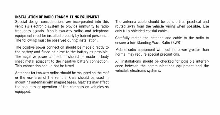
VEHICLES SOLD IN CANADAWith respect to any Vehicles Sold in Canada, the name
Chrysler Group LLC shall be deemed to be deleted and the
name Chrysler Canada Inc. used in substitution therefore.
DRIVING AND ALCOHOLDrunken driving is one of the most frequent causes of
accidents.
Your driving ability can be seriously impaired with blood
alcohol levels far below the legal minimum. If you are
drinking, don’t drive. Ride with a designated non-drinking
driver, call a cab, a friend, or use public transportation.
WARNING!
Driving after drinking can lead to an accident. Your
perceptions are less sharp, your reflexes are slower,
and your judgment is impaired when you have been
drinking. Never drink and then drive.
This manual illustrates and describes the operation of
features and equipment that are either standard or optional
on this vehicle. This manual may also include a description
of features and equipment that are no longer available or
were not ordered on this vehicle. Please disregard any
features and equipment described in this manual that are
not on this vehicle.
Chrysler Group LLC reserves the right to make changes in
design and specifications, and/or make additions to or
improvements to its products without imposing any obliga-
tion upon itself to install them on products previously
manufactured.
Copyright © 2012 Chrysler Group LLC
INSTALLATION OF RADIO TRANSMITTING EQUIPMENTSpecial design considerations are incorporated into this
vehicle’s electronic system to provide immunity to radio
frequency signals. Mobile two-way radios and telephone
equipment must be installed properly by trained personnel.
The following must be observed during installation.
The positive power connection should be made directly to
the battery and fused as close to the battery as possible.
The negative power connection should be made to body
sheet metal adjacent to the negative battery connection.
This connection should not be fused.
Antennas for two-way radios should be mounted on the roof
or the rear area of the vehicle. Care should be used in
mounting antennas with magnet bases. Magnets may affect
the accuracy or operation of the compass on vehicles so
equipped.
The antenna cable should be as short as practical and
routed away from the vehicle wiring when possible. Use
only fully shielded coaxial cable.
Carefully match the antenna and cable to the radio to
ensure a low Standing Wave Ratio (SWR).
Mobile radio equipment with output power greater than
normal may require special precautions.
All installations should be checked for possible interfer-
ence between the communications equipment and the
vehicle’s electronic systems.

300


![Alvarion BreezeMAX 2300-2500-3500 [QuantumWimax.com]](https://img.pdfslide.us/doc/110x75/5467679daf79596f338b54a5/alvarion-breezemax-2300-2500-3500-quantumwimaxcom.jpg)