Embed Size (px)
Citation preview

2013 MicrowaveService Training
All models

Samsung HA Warranty• ALL Warranties are subject to change, always verify. • 1 Year Parts & Labor Base Warranty, Labor may not apply over 1 year• Some items may have longer Warranties, Check Owners Manual or
800-SAMSUNG – M/W oven 10 years on Magnetron Tubes
• No Damage Warranty, Consumer or Stock• One Year, One Call for Consumer Education• Stock Repair, 18 months from date of manufacture• One Stock Repairs allowed under Warranty

Specialty Tools
Fine Point extended test probes
Option 2 – safety pins
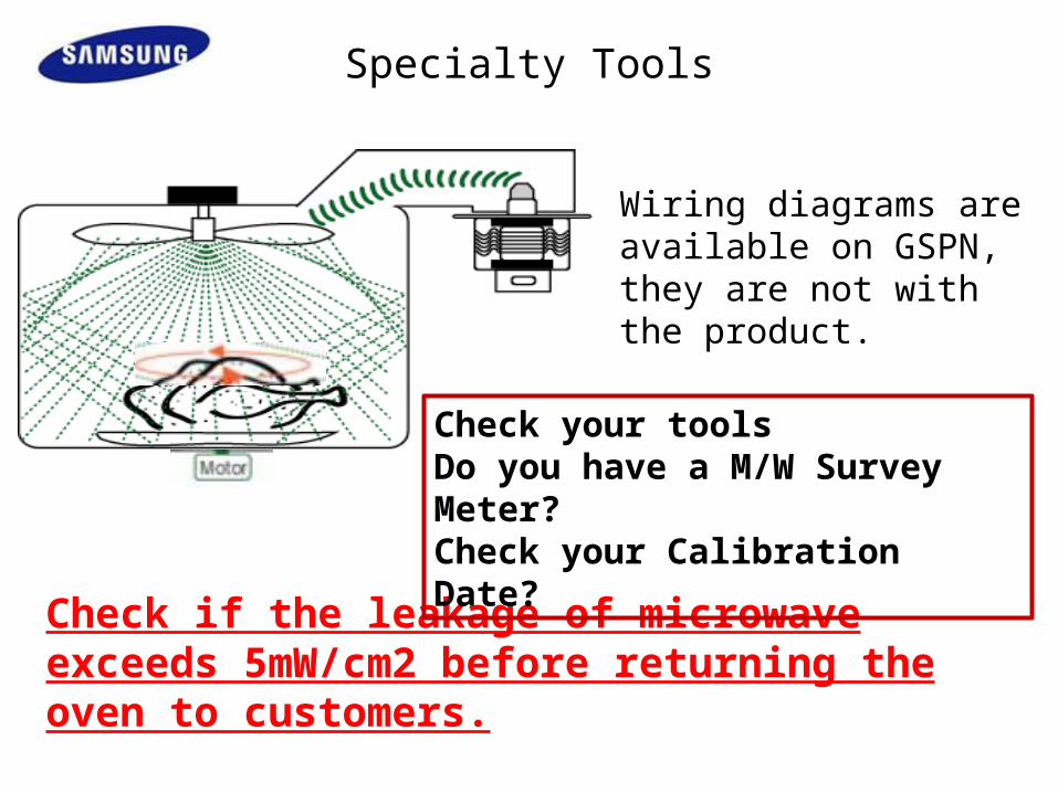
Check if the leakage of microwave exceeds 5mW/cm2 before returning the oven to customers.
Check your toolsDo you have a M/W Survey Meter?Check your Calibration Date?
Wiring diagrams are available on GSPN, they are not with the product.
Specialty Tools

Fast Track Troubleshooting
1
2
3
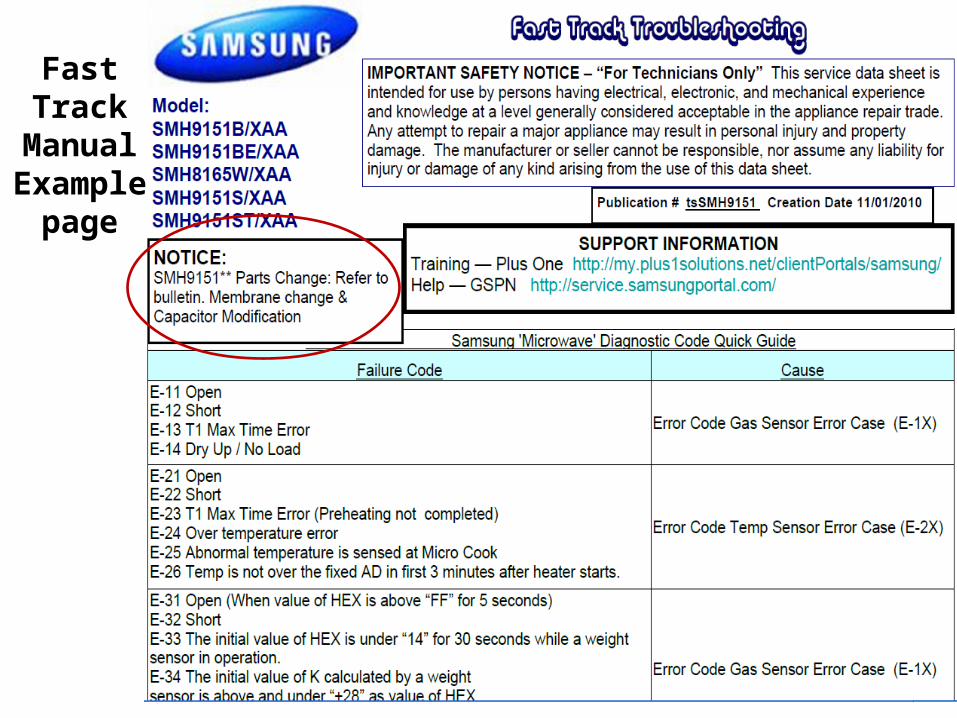
Fast Track
Manual Example
page

Fast Track
Manual Example
page
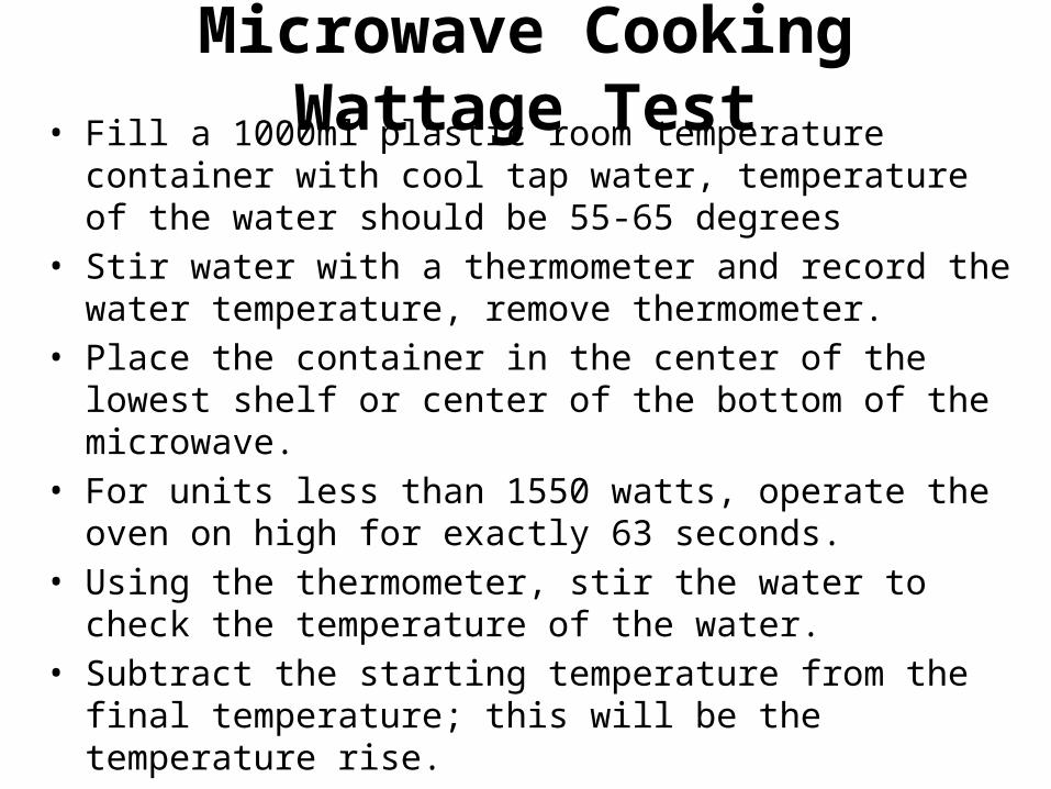
Microwave Cooking Wattage Test• Fill a 1000ml plastic room temperature container with cool tap
water, temperature of the water should be 55-65 degrees • Stir water with a thermometer and record the water
temperature, remove thermometer. • Place the container in the center of the lowest shelf or center of
the bottom of the microwave. • For units less than 1550 watts, operate the oven on high for
exactly 63 seconds. • Using the thermometer, stir the water to check the temperature
of the water. • Subtract the starting temperature from the final temperature;
this will be the temperature rise. • NOTE: Check line voltage under load, lower line voltage will
lower the power output.

Temp Rise Output Temp Rise Output
5 194 23 891
6 232 24 930
7 271 25 969
8 310 26 1007
9 349 27 1046
10 387 28 1085
11 426 29 1124
12 464 30 1162
13 504 31 1201
14 542 32 1240
15 581 33 1279
16 620 34 1317
17 659 35 1356
18 697 36 1395
19 736 37 1434
20 775 38 1472
21 814 39 1511
22 852 40 1550
Cooking Wattage Test Chart
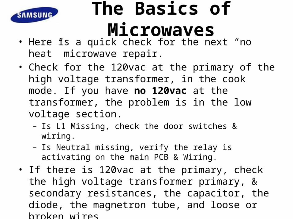
The Basics of Microwaves• Here is a quick check for the next “no heat” microwave repair. • Check for the 120vac at the primary of the high voltage
transformer, in the cook mode. If you have no 120vac at the transformer, the problem is in the low voltage section. – Is L1 Missing, check the door switches & wiring. – Is Neutral missing, verify the relay is activating on the main PCB &
Wiring.
• If there is 120vac at the primary, check the high voltage transformer primary, & secondary resistances, the capacitor, the diode, the magnetron tube, and loose or broken wires
• This procedure will keep you focused on the proper section, low voltage/high voltage, and reduce service time.

Microwave is completely dead no interior light and no display with line Voltage present at outlet.
Gain access to control panel by removing top grill. Test for 120vac at the primary interlock switch (lower switch) or L1 at connector. Voltage present indicates fuses and TCOs are good and problem is with the main control. No
voltage present proceed to testing of fuses and TCOs (Thermal Cut Outs)
Primary interlock Switch
CN201 pin 1

SMH9187 PCB
Power here means TCOs and line fuse are OK

SMH9187 PCB
RY203 closes the neutral line to the HV x-former.120vac between these points, and the mag cooling fan is running, means 120vac to the HV x-former and main board is OK.

Cavity TCO can be found at the top in the area of light and stirrer motor on all models
Mag TCO is N/C and will open at approx 300 F and reset at approx 145 F . The Base and cavity TCO
are not resettable
Once the unit is removed from cabinet remove the case to access Magnetron TCO . Remove top access panel to reach cavity TCO . Replace parts as needed. Model specific component testing and location can be located in the service
manual found here on GSPN in the service manual.
Top View

Access to the fuse and base TCO on most models can be gained through opening when control panel is removed. Some units may have two fuses and all units will have two lower TCOs. One is the Hood TCO and is N/O
(104/158 F) and the other is a Thermal Cut Out and is N/C (opens at 248F)If both the fuse and TCO check good unit will have to be removed from
cabinet for further diagnosing to check Cavity and Magnetron TCOs .CAUTION : Always be aware of capacitor location and discharge to prevent
electrical shock.
FUSE
BASE
HOOD
Note: Placement of lower TCOs may very by model. Remember one is N/O and the other N/C
FUSE

Neutral is closed because secondary Sw is not activated

Blue

SMH9187 PCB
CN201 disconnected removes neutral from the Lamp & Fan circuits for circuit check.

The door switches are 120vac. Resistance can cause the circuit not to work.Test switch with an ohm meter, on low resistance scale. Remove switch, press the switch at least 20 times, if any resistance this means the switch is bad.
Secondary Interlock Switch

Wiring Diagram Testing components, High Voltage
Danger High Voltage!!!

Remove wire leads1. A resistance check between input terminals of the magnetron indicates 0-1Ω or is normal, ∞ is an open filament 2. A resistance check between the case of magnetron and one of input terminals of magnetron indicates ∞ (unlimited) is normal, any resistance is defective.
Transformer & Magnetron Testing

High Voltage Capacitor
1. Check continuity of the capacitor with the meter set at the highest resistance scale. 2. Once the capacitor is charged, a normal capacitor shows continuity for a short time, and then indicates 9MΩ.3. A shorted capacitor will show continuous continuity.4. An open capacitor will show 9MΩ constantly.5. Resistance between each terminal and chassis should read infinite.
High Voltage Diode
1. Isolate the diode from the circuit by disconnecting its leads. 2. With the ohm-meter set at the highest resistance scale, measure across the diode terminals. 3. Reverse the meter leads and read the resistance. A meter with 9V or higher voltage batteries should be used to check the front- to back resistance of the diode. (Put 9v battery in series with the meter) (Otherwise, an infinite resistance may be read in both directions.).4. The resistance of a normal diode will be infinite in one direction and several hundred KΩ in the other direction.
Capacitor and Diode Testing

Loose screw will cause arcing

24
Microwaves
• Unit stops working after 5 – 30 seconds– Check for Fan blade off Mag tube cooling fan motor• Order Motor/Blade• Glue blade on shaft after roughing shaft
• Display has flashing and quits in a few seconds• Check for Mag tube leaking

Table of Contents
Tools Fast Tracks Troubleshooting