Embed Size (px)
Citation preview

Report onProposals
2013 Annual Revision Cycle
NOTE: The proposed NFPA documents addressed in this Report on
Proposals (ROP) and in a follow-up Report on Comments (ROC) will
only be presented for action when proper Amending Motions have been
submitted to the NFPA by the deadline of April 5, 2013. The June 2013
NFPA Conference & Expo will be held June 10–13, 2013, at McCormick
Place Convention Center, Chicago, IL. During the meeting, the Association
Technical Meeting (Tech Session) will be held June 12–13, 2013.
Documents that receive no motions will not be presented at the meeting
and instead will be forwarded directly to the Standards Council for action on
issuance. For more information on the rules and for up-to-date information
on schedules and deadlines for processing NFPA documents, check the
NFPA website (www.nfpa.org) or contact NFPA Standards Administration.
ISSN 1079-5332 Copyright © 2012 All Rights Reserved
NFPA and National Fire Protection Association are registered trademarks of the National Fire Protection Association, Quincy, MA 02169.
National Fire Protection Association®1 BATTERYMARCH PARK, QUINCY, MA 02169-7471
A compilation of NFPA® TechnicalCommittee Reports on Proposals for public review and comment
Public Comment Deadline: August 31, 2012

Information on NFPA Codes and Standards Development
I. Applicable Regulations. The primary rules governing the processing of NFPA documents (codes, standards, recommended practices, and guides) are the NFPA Regulations Governing Committee Projects (Regs). Other applicable rules include NFPA Bylaws, NFPA Technical Meeting Convention Rules, NFPA Guide for the Conduct of Participants in the NFPA Standards Development Process, and the NFPA Regulations Governing Petitions to the Board of Directors from Decisions of the Standards Council. Most of these rules and regulations are contained in the NFPA Directory. For copies of the Directory, contact Codes and Standards Administration at NFPA Headquarters; all these documents are also available on the NFPA website at “www.nfpa.org.”
The following is general information on the NFPA process. All participants, however, should refer to the actual rules and regulations for a full understanding of this process and for the criteria that govern participation.
II. Technical Committee Report. The Technical Committee Report is defined as “the Report of the Technical Committee and Technical Correlating Committee (if any) on a document consisting of the ROP and ROC.” A Technical Committee Report consists of the Report on Proposals (ROP), as modified by the Report on Comments (ROC), published by the Association.
III. Step 1: Report on Proposals (ROP). The ROP is defined as “a report to the Association on the actions taken by Technical Committees and/or Technical Correlating Committees, accompanied by a ballot statement and one or more proposals on text for a new document or to amend an existing document.” Any objection to an action in the ROP must be raised through the filing of an appropriate Comment for consideration in the ROC or the objection will be considered resolved.
IV. Step 2: Report on Comments (ROC). The ROC is defined as “a report to the Association on the actions taken by Technical Committees and/or Technical Correlating Committees accompanied by a ballot statement and one or more comments resulting from public review of the Report on Proposals (ROP).” The ROP and the ROC together constitute the Technical Committee Report. Any outstanding objection following the ROC must be raised through an appropriate Amending Motion at the Association Technical Meeting or the objection will be considered resolved.
V. Step 3a: Action at Association Technical Meeting. Following the publication of the ROC, there is a period during which those wishing to make proper Amending Motions on the Technical Committee Reports must signal their intention by submitting a Notice of Intent to Make a Motion. Documents that receive notice of proper Amending Motions (Certified Amending Motions) will be presented for action at the annual June Association Technical Meeting. At the meeting, the NFPA membership can consider and act on these Certified Amending Motions as well as Follow-up Amending Motions, that is, motions that become necessary as a result of a previous successful Amending Motion. (See 4.6.2 through 4.6.9 of Regs for a summary of the available Amending Motions and who may make them.) Any outstanding objection following action at an Association Technical Meeting (and any further Technical Committee consideration following successful Amending Motions, see Regs at 4.7) must be raised through an appeal to the Standards Council or it will be considered to be resolved.
VI. Step 3b: Documents Forwarded Directly to the Council. Where no Notice of Intent to Make a Motion (NITMAM) is received and certified in accordance with the Technical Meeting Convention Rules, the document is forwarded directly to the Standards Council for action on issuance. Objections are deemed to be resolved for these documents.
VII. Step 4a: Council Appeals. Anyone can appeal to the Standards Council concerning procedural or substantive matters related to the development, content, or issuance of any document of the Association or on matters within the purview of the authority of the Council, as established by the Bylaws and as determined by the Board of Directors. Such appeals must be in written form and filed with the Secretary of the Standards Council (see 1.6 of Regs). Time constraints for filing an appeal must be in accordance with 1.6.2 of the Regs. Objections are deemed to be resolved if not pursued at this level.
VIII. Step 4b: Document Issuance. The Standards Council is the issuer of all documents (see Article 8 of Bylaws). The Council acts on the issuance of a document presented for action at an Association Technical Meeting within 75 days from the date of the recommendation from the Association Technical Meeting, unless this period is extended by the Council (see 4.8 of Regs). For documents forwarded directly to the Standards Council, the Council acts on the issuance of the document at its next scheduled meeting, or at such other meeting as the Council may determine (see 4.5.6 and 4.8 of Regs).
IX. Petitions to the Board of Directors. The Standards Council has been delegated the responsibility for the administration of the codes and standards development process and the issuance of documents. However, where extraordinary circumstances requiring the intervention of the Board of Directors exist, the Board of Directors may take any action necessary to fulfill its obligations to preserve the integrity of the codes and standards development process and to protect the interests of the Association. The rules for petitioning the Board of Directors can be found in the Regulations Governing Petitions to the Board of Directors from Decisions of the Standards Council and in 1.7 of the Regs.
X. For More Information. The program for the Association Technical Meeting (as well as the NFPA website as information becomes available) should be consulted for the date on which each report scheduled for consideration at the meeting will be presented. For copies of the ROP and ROC as well as more information on NFPA rules and for up-to-date information on schedules and deadlines for processing NFPA documents, check the NFPA website (www.nfpa.org) or contact NFPA Codes & Standards Administration at (617) 984-7246.
i
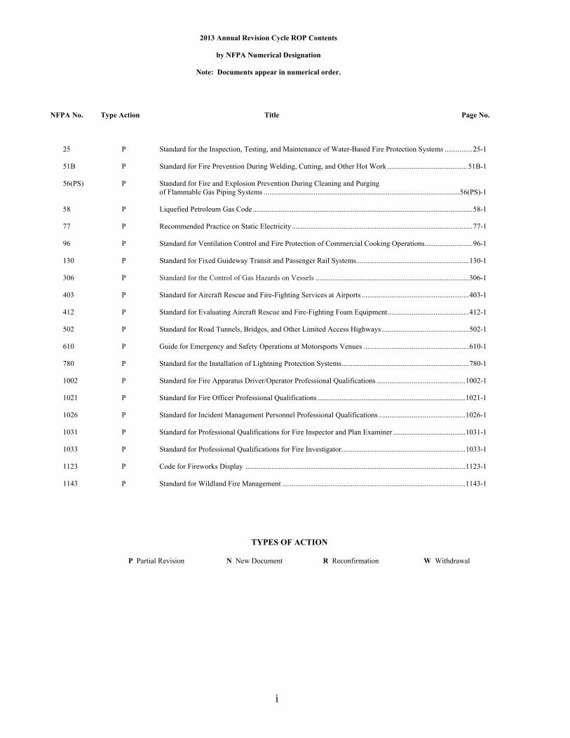
2013 Annual Revision Cycle ROP Contents
by NFPA Numerical Designation
Note: Documents appear in numerical order.
NFPA No. Type Action Title Page No.
25 P Standard for the Inspection, Testing, and Maintenance of Water-Based Fire Protection Systems ............... 25-1 51B P Standard for Fire Prevention During Welding, Cutting, and Other Hot Work ........................................... 51B-1 56(PS) P Standard for Fire and Explosion Prevention During Cleaning and Purging of Flammable Gas Piping Systems .......................................................................................................... 56(PS)-1 58 P Liquefied Petroleum Gas Code ....................................................................................................................... 58-1 77 P Recommended Practice on Static Electricity .................................................................................................. 77-1 96 P Standard for Ventilation Control and Fire Protection of Commercial Cooking Operations.......................... 96-1 130 P Standard for Fixed Guideway Transit and Passenger Rail Systems ............................................................. 130-1 306 P Standard for the Control of Gas Hazards on Vessels ................................................................................... 306-1 403 P Standard for Aircraft Rescue and Fire-Fighting Services at Airports .......................................................... 403-1 412 P Standard for Evaluating Aircraft Rescue and Fire-Fighting Foam Equipment ............................................ 412-1
502 P Standard for Road Tunnels, Bridges, and Other Limited Access Highways ............................................... 502-1 610 P Guide for Emergency and Safety Operations at Motorsports Venues ......................................................... 610-1 780 P Standard for the Installation of Lightning Protection Systems..................................................................... 780-1 1002 P Standard for Fire Apparatus Driver/Operator Professional Qualifications ................................................ 1002-1
1021 P Standard for Fire Officer Professional Qualifications ................................................................................ 1021-1
1026 P Standard for Incident Management Personnel Professional Qualifications ............................................... 1026-1 1031 P Standard for Professional Qualifications for Fire Inspector and Plan Examiner ....................................... 1031-1 1033 P Standard for Professional Qualifications for Fire Investigator ................................................................... 1033-1 1123 P Code for Fireworks Display ....................................................................................................................... 1123-1 1143 P Standard for Wildland Fire Management ................................................................................................... 1143-1
TYPES OF ACTION
P Partial Revision N New Document R Reconfirmation W Withdrawal

ii
2013 Annual Revision Cycle ROP Committees Reporting
Type Action Page No. Aircraft Rescue and Fire Fighting 403 Standard for Aircraft Rescue and Fire-Fighting Services at Airport P 403-1 412 Standard for Evaluating Aircraft Rescue and Fire-Fighting Foam Equipment P 412-1 Fixed Guideway Transit and Passenger Rail Systems 130 Standard for Fixed Guideway Transit and Passenger Rail Systems P 130-1 Forest and Rural Fire Protection 1143 Standard for Wildland Fire Management P 1143-1 Gas Hazards 306 Standard for the Control of Gas Hazards on Vessels P 306-1 Gas Process Safety 56(PS) Standard for Fire and Explosion Prevention During Cleaning and Purging of Flammable Gas Piping
Systems
P
56(PS)-1 Hot Work Operations 51B Standard for Fire Prevention During Welding, Cutting, and Other Hot Work P 51B-1 Inspection, Testing, and Maintenance of Water-Based Systems 25 Standard for the Inspection, Testing, and Maintenance of Water-Based Fire Protection Systems P 25-1 Lightning Protection 780 Standard for the Installation of Lightning Protection Systems P 780-1 Liquefied Petroleum Gases 58 Liquefied Petroleum Gas Code P 58-1 Professional Qualifications Fire Fighter Professional Qualifications 1002 Standard for Fire Apparatus Driver/Operator Professional Qualifications P 1002-1 Fire Officer Professional Qualifications 1021 Standard for Fire Officer Professional Qualifications P 1021-1 Incident Management Professional Qualifications 1026 Standard for Incident Management Personnel Professional Qualifications P 1026-1 Fire Inspector Professional Qualifications 1031 Standard for Professional Qualifications for Fire Inspector and Plan Examiner P 1031-1 1033 Standard for Professional Qualifications for Fire Investigator P 1033-1 Pyrotechnics 1123 Code for Fireworks Display P 1123-1 Road Tunnel and Highway Fire Protection 502 Standard for Road Tunnels, Bridges, and Other Limited Access Highways P 502-1 Static Electricity 77 Recommended Practice on Static Electricity P 77-1 Safety at Motorsports Venues 610 Guide for Emergency and Safety Operations at Motorsports Venues P 610-1 Venting Systems for Cooking Appliances 96 Standard for Ventilation Control and Fire Protection of Commercial Cooking Operations P 96-1

iii
COMMITTEE MEMBER CLASSIFICATIONS1,2,3,4
The following classifications apply to Committee members and represent their principal interest in the activity of the Committee. 1. M Manufacturer: A representative of a maker or marketer of a product, assembly, or system, or portion thereof,
that is affected by the standard. 2. U User: A representative of an entity that is subject to the provisions of the standard or that voluntarily uses the
standard. 3. IM Installer/Maintainer: A representative of an entity that is in the business of installing or maintaining a product,
assembly, or system affected by the standard. 4. L Labor: A labor representative or employee concerned with safety in the workplace. 5. RT Applied Research/Testing Laboratory: A representative of an independent testing laboratory or independent
applied research organization that promulgates and/or enforces standards. 6. E Enforcing Authority: A representative of an agency or an organization that promulgates and/or enforces
standards. 7. I Insurance: A representative of an insurance company, broker, agent, bureau, or inspection agency. 8. C Consumer: A person who is or represents the ultimate purchaser of a product, system, or service affected by the
standard, but who is not included in (2). 9. SE Special Expert: A person not representing (1) through (8) and who has special expertise in the scope of the
standard or portion thereof. NOTE 1: “Standard” connotes code, standard, recommended practice, or guide. NOTE 2: A representative includes an employee. NOTE 3: While these classifications will be used by the Standards Council to achieve a balance for Technical Committees, the Standards Council may determine that new classifications of member or unique interests need representation in order to foster the best possible Committee deliberations on any project. In this connection, the Standards Council may make such appointments as it deems appropriate in the public interest, such as the classification of “Utilities” in the National Electrical Code Committee. NOTE 4: Representatives of subsidiaries of any group are generally considered to have the same classification as the parent organization.

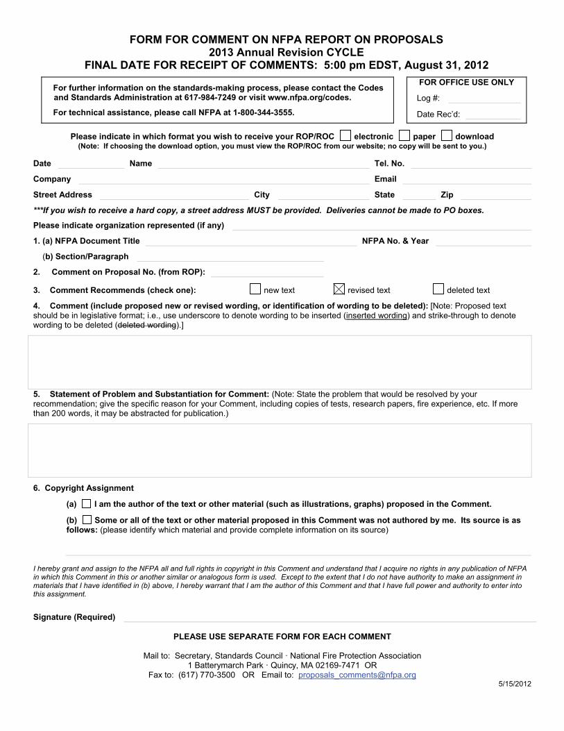
FORM FOR COMMENT ON NFPA REPORT ON PROPOSALS 2013 Annual Revision CYCLE
FINAL DATE FOR RECEIPT OF COMMENTS: 5:00 pm EDST, August 31, 2012
For further information on the standards-making process, please contact the Codes and Standards Administration at 617-984-7249 or visit www.nfpa.org/codes.
For technical assistance, please call NFPA at 1-800-344-3555.
FOR OFFICE USE ONLY
Log #:
Date Rec’d:
Please indicate in which format you wish to receive your ROP/ROC electronic paper download (Note: If choosing the download option, you must view the ROP/ROC from our website; no copy will be sent to you.)
Date 8/1/200X Name John B. Smith Tel. No. 253-555-1234
Company Email
Street Address 9 Seattle St. City Tacoma State WA Zip 98402
***If you wish to receive a hard copy, a street address MUST be provided. Deliveries cannot be made to PO boxes.
Please indicate organization represented (if any) Fire Marshals Assn. of North America
1. (a) NFPA Document Title National Fire Alarm Code NFPA No. & Year NFPA 72, 200X ed.
(b) Section/Paragraph 4.4.1.1
2. Comment on Proposal No. (from ROP): 72-7
3. Comment Recommends (check one): new text revised text deleted text
4. Comment (include proposed new or revised wording, or identification of wording to be deleted): [Note: Proposed text should be in legislative format; i.e., use underscore to denote wording to be inserted (inserted wording) and strike-through to denote wording to be deleted (deleted wording).]
Delete exception.
5. Statement of Problem and Substantiation for Comment: (Note: State the problem that would be resolved by your recommendation; give the specific reason for your Comment, including copies of tests, research papers, fire experience, etc. If more than 200 words, it may be abstracted for publication.)
A properly installed and maintained system should be free of ground faults. The occurrence of one or more ground faults should be required to cause a ‘trouble’ signal because it indicates a condition that could contribute to future malfunction of the system. Ground fault protection has been widely available on these systems for years and its cost is negligible. Requiring it on all systems will promote better installations, maintenance and reliability.
6. Copyright Assignment
(a) I am the author of the text or other material (such as illustrations, graphs) proposed in the Comment.
(b) Some or all of the text or other material proposed in this Comment was not authored by me. Its source is as follows: (please identify which material and provide complete information on its source)
I hereby grant and assign to the NFPA all and full rights in copyright in this Comment and understand that I acquire no rights in any publication of NFPA in which this Comment in this or another similar or analogous form is used. Except to the extent that I do not have authority to make an assignment in materials that I have identified in (b) above, I hereby warrant that I am the author of this Comment and that I have full power and authority to enter into this assignment.
Signature (Required)
PLEASE USE SEPARATE FORM FOR EACH COMMENT
Mail to: Secretary, Standards Council · National Fire Protection Association 1 Batterymarch Park · Quincy, MA 02169-7471 OR
Fax to: (617) 770-3500 OR Email to: [email protected]
FORM FOR COMMENT ON NFPA REPORT ON PROPOSALS 2013 Annual Revision CYCLE
FINAL DATE FOR RECEIPT OF COMMENTS: 5:00 pm EDST, August 31, 2012
For further information on the standards-making process, please contact the Codes and Standards Administration at 617-984-7249 or visit www.nfpa.org/codes.
For technical assistance, please call NFPA at 1-800-344-3555.
FOR OFFICE USE ONLY
Log #:
Date Rec’d:
Please indicate in which format you wish to receive your ROP/ROC electronic paper download (Note: If choosing the download option, you must view the ROP/ROC from our website; no copy will be sent to you.)
Date Name Tel. No.
Company Email
Street Address City State Zip
***If you wish to receive a hard copy, a street address MUST be provided. Deliveries cannot be made to PO boxes.
Please indicate organization represented (if any)
1. (a) NFPA Document Title NFPA No. & Year
(b) Section/Paragraph
2. Comment on Proposal No. (from ROP):
3. Comment Recommends (check one): new text revised text deleted text
4. Comment (include proposed new or revised wording, or identification of wording to be deleted): [Note: Proposed text should be in legislative format; i.e., use underscore to denote wording to be inserted (inserted wording) and strike-through to denote wording to be deleted (deleted wording).]
5. Statement of Problem and Substantiation for Comment: (Note: State the problem that would be resolved by your recommendation; give the specific reason for your Comment, including copies of tests, research papers, fire experience, etc. If more than 200 words, it may be abstracted for publication.)
6. Copyright Assignment
(a) I am the author of the text or other material (such as illustrations, graphs) proposed in the Comment.
(b) Some or all of the text or other material proposed in this Comment was not authored by me. Its source is as follows: (please identify which material and provide complete information on its source)
I hereby grant and assign to the NFPA all and full rights in copyright in this Comment and understand that I acquire no rights in any publication of NFPA in which this Comment in this or another similar or analogous form is used. Except to the extent that I do not have authority to make an assignment in materials that I have identified in (b) above, I hereby warrant that I am the author of this Comment and that I have full power and authority to enter into this assignment.
Signature (Required)
PLEASE USE SEPARATE FORM FOR EACH COMMENT
Mail to: Secretary, Standards Council · National Fire Protection Association 1 Batterymarch Park · Quincy, MA 02169-7471 OR
Fax to: (617) 770-3500 OR Email to: [email protected] 5/15/2012
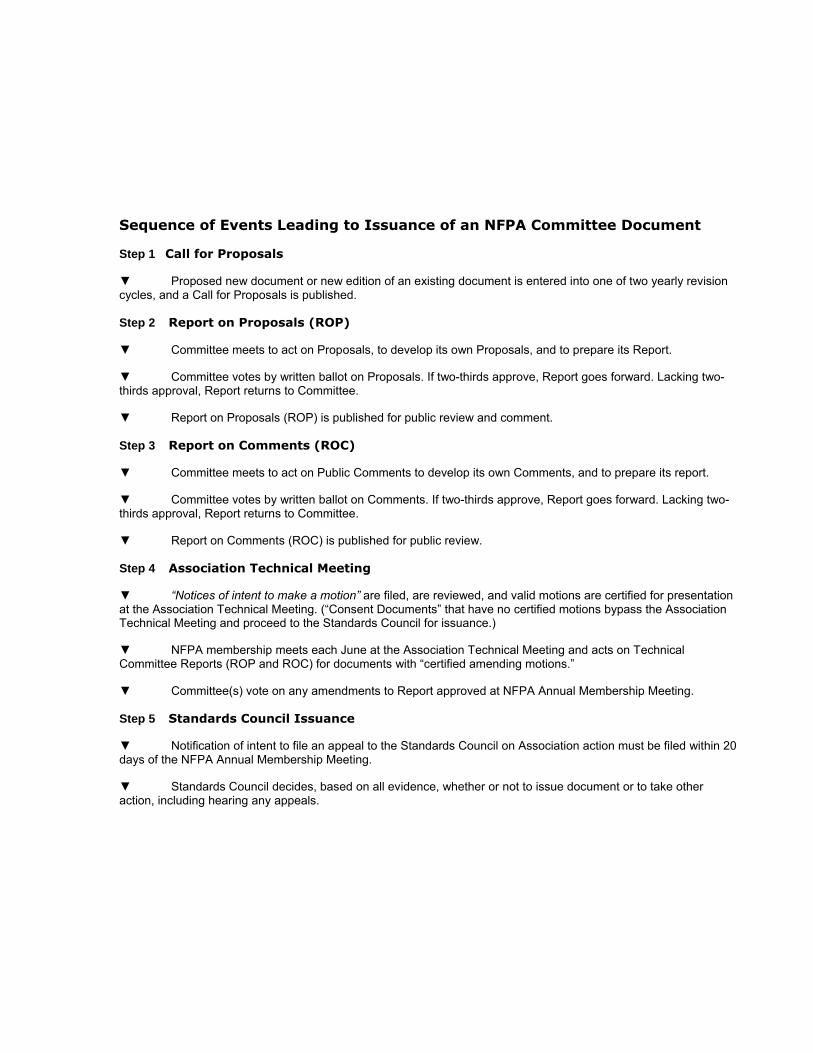
Sequence of Events Leading to Issuance of an NFPA Committee Document
Step 1 Call for Proposals
Proposed new document or new edition of an existing document is entered into one of two yearly revision cycles, and a Call for Proposals is published.
Step 2 Report on Proposals (ROP)
Committee meets to act on Proposals, to develop its own Proposals, and to prepare its Report.
Committee votes by written ballot on Proposals. If two-thirds approve, Report goes forward. Lacking two-thirds approval, Report returns to Committee.
Report on Proposals (ROP) is published for public review and comment.
Step 3 Report on Comments (ROC)
Committee meets to act on Public Comments to develop its own Comments, and to prepare its report.
Committee votes by written ballot on Comments. If two-thirds approve, Report goes forward. Lacking two-thirds approval, Report returns to Committee.
Report on Comments (ROC) is published for public review.
Step 4 Association Technical Meeting
“Notices of intent to make a motion” are filed, are reviewed, and valid motions are certified for presentation at the Association Technical Meeting. (“Consent Documents” that have no certified motions bypass the Association Technical Meeting and proceed to the Standards Council for issuance.)
NFPA membership meets each June at the Association Technical Meeting and acts on Technical Committee Reports (ROP and ROC) for documents with “certified amending motions.”
Committee(s) vote on any amendments to Report approved at NFPA Annual Membership Meeting.
Step 5 Standards Council Issuance
Notification of intent to file an appeal to the Standards Council on Association action must be filed within 20 days of the NFPA Annual Membership Meeting.
Standards Council decides, based on all evidence, whether or not to issue document or to take other action, including hearing any appeals.

The Association Technical Meeting
The process of public input and review does not end with the publication of the ROP and ROC. Following the completion of the Proposal and Comment periods, there is yet a further opportunity for debate and discussion through the Association Technical Meeting that takes place at the NFPA Annual Meeting.
The Association Technical Meeting provides an opportunity for the final Technical Committee Report (i.e., the ROP and ROC) on each proposed new or revised code or standard to be presented to the NFPA membership for the debate and consideration of motions to amend the Report. The specific rules for the types of motions that can be made and who can make them are set forth in NFPA’s rules, which should always be consulted by those wishing to bring an issue before the membership at an Association Technical Meeting. The following presents some of the main features of how a Report is handled.
The Filing of a Notice of Intent to Make a Motion. Before making an allowable motion at an Association Technical Meeting, the intended maker of the motion must file, in advance of the session, and within the published deadline, a Notice of Intent to Make a Motion. A Motions Committee appointed by the Standards Council then reviews all notices and certifies all amending motions that are proper. The Motions Committee can also, in consultation with the makers of the motions, clarify the intent of the motions and, in certain circumstances, combine motions that are dependent on each other together so that they can be made in one single motion. A Motions Committee report is then made available in advance of the meeting listing all certified motions. Only these Certified Amending Motions, together with certain allowable Follow-Up Motions (that is, motions that have become necessary as a result of previous successful amending motions) will be allowed at the Association Technical Meeting.
Consent Documents. Often there are codes and standards up for consideration by the membership that will be noncontroversial and no proper Notices of Intent to Make a Motion will be filed. These “Consent Documents” will bypass the Association Technical Meeting and head straight to the Standards Council for issuance. The remaining documents are then forwarded to the Association Technical Meeting for consideration of the NFPA membership.
What Amending Motions Are Allowed. The Technical Committee Reports contain many Proposals and Comments that the Technical Committee has rejected or revised in whole or in part. Actions of the Technical Committee published in the ROP may also eventually be rejected or revised by the Technical Committee during the development of its ROC. The motions allowed by NFPA rules provide the opportunity to propose amendments to the text of a proposed code or standard based on these published Proposals, Comments, and Committee actions. Thus, the list of allowable motions include motions to accept Proposals and Comments in whole or in part as submitted or as modified by a Technical Committee action. Motions are also available to reject an accepted Comment in whole or part. In addition, Motions can be made to return an entire Technical Committee Report or a portion of the Report to the Technical Committee for further study.
The NFPA Annual Meeting, also known as the NFPA Conference & Expo, takes place in June of each year. A second Fall membership meeting was discontinued in 2004, so the NFPA Technical Committee Report Session now runs once each year at the Annual Meeting in June.
Who Can Make Amending Motions. NFPA rules also define those authorized to make amending motions. In many cases, the maker of the motion is limited by NFPA rules to the original submitter of the Proposal or Comment or his or her duly authorized representative. In other cases, such as a Motion to Reject an accepted Comment, or to Return a Technical Committee Report or a portion of a Technical Committee Report for Further Study, anyone can make these motions. For a complete explanation, the NFPA Regs should be consulted.

Action on Motions at the Association Technical Meeting. In order to actually make a Certified Amending Motion at the Association Technical Meeting, the maker of the motion must sign in at least an hour before the session begins. In this way a final list of motions can be set in advance of the session. At the session, each proposed document up for consideration is presented by a motion to adopt the Technical Committee Report on the document. Following each such motion, the presiding officer in charge of the session opens the floor to motions on the document from the final list of Certified Amending Motions followed by any permissible Follow-Up Motions. Debate and voting on each motion proceeds in accordance with NFPA rules. NFPA membership is not required in order to make or speak to a motion, but voting is limited to NFPA members who have joined at least 180 days prior to the Association Technical Meeting and have registered for the meeting. At the close of debate on each motion, voting takes place, and the motion requires a majority vote to carry. In order to amend a Technical Committee Report, successful amending motions must be confirmed by the responsible Technical Committee, which conducts a written ballot on all successful amending motions following the meeting and prior to the document being forwarded to the Standards Council for issuance.
Standards Council Issuance
One of the primary responsibilities of the NFPA Standards Council, as the overseer of the NFPA codes and standards development process, is to act as the official issuer of all NFPA codes and standards. When it convenes to issue NFPA documents, it also hears any appeals related to the document. Appeals are an important part of assuring that all NFPA rules have been followed and that due process and fairness have been upheld throughout the codes and standards development process. The Council considers appeals both in writing and through the conduct of hearings at which all interested parties can participate. It decides appeals based on the entire record of the process as well as all submissions on the appeal. After deciding all appeals related to a document before it, the Council, if appropriate, proceeds to issue the document as an official NFPA code or standard. Subject only to limited review by the NFPA Board of Directors, the decision of the Standards Council is final, and the new NFPA code or standard becomes effective twenty days after Standards Council issuance.

77-1
Report on Proposals A2013 — Copyright, NFPA NFPA 77Report of the Committee on
Static Electricity
Charles G. Noll, ChairXiPro Technologies LLC, PA [SE]
Peter R. Apostoluk, Greif Inc., OH [M] Laurence G. Britton, Process Safety Consultant, WV [SE] Vahid Ebadat, Chilworth Technology Inc., NJ [SE] Stephen L. Fowler, Fowler Associates, Inc., SC [SE] Robert L. Gravell, E. I. duPont de Nemours & Company, Inc., NJ [U] Steven J. Gunsel, SGTechnologies, LLC, OH [SE] Raymond G. Hinske, ExxonMobil Research & Engineering Co., VA [U] Rep. American Petroleum Institute Brian Minnich, Schuetz Container Systems, NJ [M] Robert Mitchell, Intertek Testing Services, MA [RT] Jeffrey S. Patton II, The Hanover Insurance Group, MD [I] Bernard T. Price, Alliant Techsystems (ATK), UT [U] James R. Reppermund, Howell, NJ [SE] Douglas A. Rivord, Graco, Inc., MN [M] Lon D. Santis, Institute of Makers of Explosives, DC [U] Michael L. Savage, Sr., Middle Department Inspection Agency, Inc., MD [E] Don Scarbrough, Elyria, OH [SE] Thomas J. Wash, 3M Company, MN [M] Shalom Wertsberger, StaticOff, LLC, RI [M] Gene H. Wolfe, R. R. Donnelley & Sons, IL [U] G. Thomas Work II, Dow Corning Corporation, IN [U] Rep. NFPA Industrial Fire Protection Section
Alternates
John E. Capers, Austin Powder Company, OH [U] (Alt. to Lon D. Santis)C. James Dahn, Safety Consulting Engineers Inc., IL [SE] (Alt. to Vahid Ebadat) Thomas H. Pratt, Burgoyne Inc., GA [SE] (Member Emeritus)
Staff Liaison: Robert P. Benedetti
Committee Scope: This Committee shall have primary responsibility for documents on safeguarding against the fire and explosion hazards associated with static electricity, including the prevention and control of these hazards. This Committee shall also have primary responsibility for conductive and static-dissipative floors, except as this subject is addressed by the Committee on Health Care Facilities.
This list represents the membership at the time the Committee was balloted on the text of this report. Since that time, changes in the membership may have occurred. A key to classifications is found at the front of the document.
The Report of the Technical Committee on Static Electricity is presented for adoption.
This Report was prepared by the Technical Committee on Static Electricity and proposes for adoption, amendments to NFPA 77, Recommended Practice on Static Electricity, 2007 edition. NFPA 77-2007 is published in Volume 16 of the 2012 National Fire Codes and in separate pamphlet form.
This Report has been submitted to letter ballot of the Technical Committee on Static Electricity, which consists of 21 voting members. The results of the balloting, after circulation of any negative votes, can be found in the report.
77-2
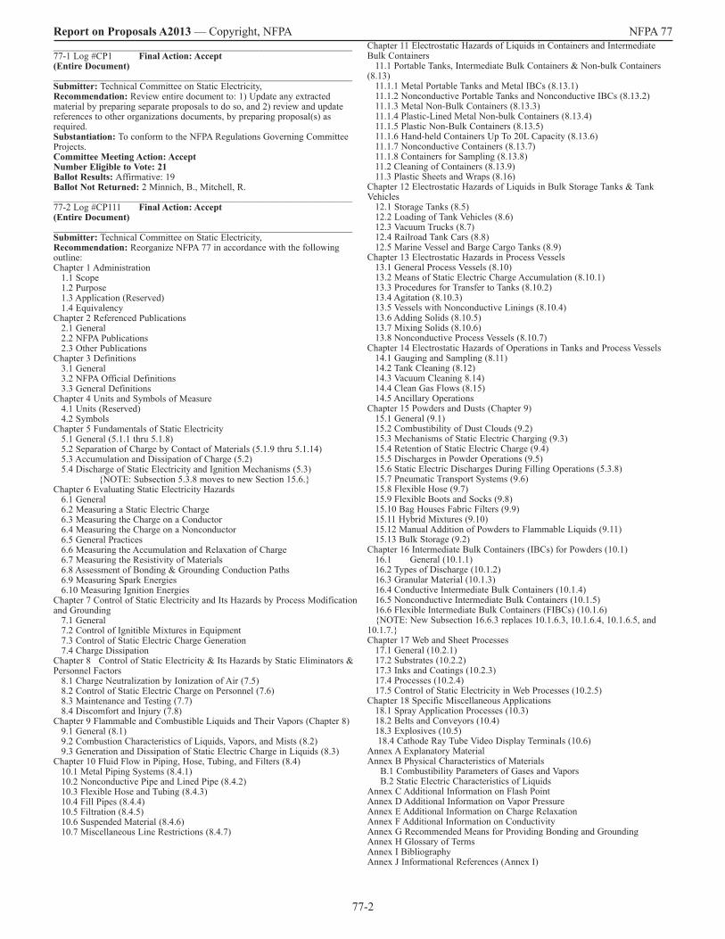
Report on Proposals A2013 — Copyright, NFPA NFPA 77_______________________________________________________________ 77-1 Log #CP1 Final Action: Accept(Entire Document)_______________________________________________________________ Submitter: Technical Committee on Static Electricity, Recommendation: Review entire document to: 1) Update any extracted material by preparing separate proposals to do so, and 2) review and update references to other organizations documents, by preparing proposal(s) as required. Substantiation: To conform to the NFPA Regulations Governing Committee Projects. Committee Meeting Action: AcceptNumber Eligible to Vote: 21 Ballot Results: Affirmative: 19 Ballot Not Returned: 2 Minnich, B., Mitchell, R._______________________________________________________________ 77-2 Log #CP111 Final Action: Accept(Entire Document)_______________________________________________________________ Submitter: Technical Committee on Static Electricity, Recommendation: Reorganize NFPA 77 in accordance with the following outline: Chapter 1 Administration 1.1 Scope 1.2 Purpose 1.3 Application (Reserved) 1.4 Equivalency Chapter 2 Referenced Publications 2.1 General 2.2 NFPA Publications 2.3 Other Publications Chapter 3 Definitions 3.1 General 3.2 NFPA Official Definitions 3.3 General Definitions Chapter 4 Units and Symbols of Measure 4.1 Units (Reserved) 4.2 Symbols Chapter 5 Fundamentals of Static Electricity 5.1 General (5.1.1 thru 5.1.8) 5.2 Separation of Charge by Contact of Materials (5.1.9 thru 5.1.14) 5.3 Accumulation and Dissipation of Charge (5.2) 5.4 Discharge of Static Electricity and Ignition Mechanisms (5.3) NOTE: Subsection 5.3.8 moves to new Section 15.6. Chapter 6 Evaluating Static Electricity Hazards 6.1 General 6.2 Measuring a Static Electric Charge 6.3 Measuring the Charge on a Conductor 6.4 Measuring the Charge on a Nonconductor 6.5 General Practices 6.6 Measuring the Accumulation and Relaxation of Charge 6.7 Measuring the Resistivity of Materials 6.8 Assessment of Bonding & Grounding Conduction Paths 6.9 Measuring Spark Energies 6.10 Measuring Ignition Energies Chapter 7 Control of Static Electricity and Its Hazards by Process Modification and Grounding 7.1 General 7.2 Control of Ignitible Mixtures in Equipment 7.3 Control of Static Electric Charge Generation 7.4 Charge Dissipation Chapter 8 Control of Static Electricity & Its Hazards by Static Eliminators & Personnel Factors 8.1 Charge Neutralization by Ionization of Air (7.5) 8.2 Control of Static Electric Charge on Personnel (7.6) 8.3 Maintenance and Testing (7.7) 8.4 Discomfort and Injury (7.8) Chapter 9 Flammable and Combustible Liquids and Their Vapors (Chapter 8) 9.1 General (8.1) 9.2 Combustion Characteristics of Liquids, Vapors, and Mists (8.2) 9.3 Generation and Dissipation of Static Electric Charge in Liquids (8.3) Chapter 10 Fluid Flow in Piping, Hose, Tubing, and Filters (8.4) 10.1 Metal Piping Systems (8.4.1) 10.2 Nonconductive Pipe and Lined Pipe (8.4.2) 10.3 Flexible Hose and Tubing (8.4.3) 10.4 Fill Pipes (8.4.4) 10.5 Filtration (8.4.5) 10.6 Suspended Material (8.4.6) 10.7 Miscellaneous Line Restrictions (8.4.7)
Chapter 11 Electrostatic Hazards of Liquids in Containers and Intermediate Bulk Containers 11.1 Portable Tanks, Intermediate Bulk Containers & Non-bulk Containers (8.13) 11.1.1 Metal Portable Tanks and Metal IBCs (8.13.1) 11.1.2 Nonconductive Portable Tanks and Nonconductive IBCs (8.13.2) 11.1.3 Metal Non-Bulk Containers (8.13.3) 11.1.4 Plastic-Lined Metal Non-bulk Containers (8.13.4) 11.1.5 Plastic Non-Bulk Containers (8.13.5) 11.1.6 Hand-held Containers Up To 20L Capacity (8.13.6) 11.1.7 Nonconductive Containers (8.13.7) 11.1.8 Containers for Sampling (8.13.8) 11.2 Cleaning of Containers (8.13.9) 11.3 Plastic Sheets and Wraps (8.16) Chapter 12 Electrostatic Hazards of Liquids in Bulk Storage Tanks & Tank Vehicles 12.1 Storage Tanks (8.5) 12.2 Loading of Tank Vehicles (8.6) 12.3 Vacuum Trucks (8.7) 12.4 Railroad Tank Cars (8.8) 12.5 Marine Vessel and Barge Cargo Tanks (8.9) Chapter 13 Electrostatic Hazards in Process Vessels 13.1 General Process Vessels (8.10) 13.2 Means of Static Electric Charge Accumulation (8.10.1) 13.3 Procedures for Transfer to Tanks (8.10.2) 13.4 Agitation (8.10.3) 13.5 Vessels with Nonconductive Linings (8.10.4) 13.6 Adding Solids (8.10.5) 13.7 Mixing Solids (8.10.6) 13.8 Nonconductive Process Vessels (8.10.7) Chapter 14 Electrostatic Hazards of Operations in Tanks and Process Vessels 14.1 Gauging and Sampling (8.11) 14.2 Tank Cleaning (8.12) 14.3 Vacuum Cleaning 8.14) 14.4 Clean Gas Flows (8.15) 14.5 Ancillary Operations Chapter 15 Powders and Dusts (Chapter 9) 15.1 General (9.1) 15.2 Combustibility of Dust Clouds (9.2) 15.3 Mechanisms of Static Electric Charging (9.3) 15.4 Retention of Static Electric Charge (9.4) 15.5 Discharges in Powder Operations (9.5) 15.6 Static Electric Discharges During Filling Operations (5.3.8) 15.7 Pneumatic Transport Systems (9.6) 15.8 Flexible Hose (9.7) 15.9 Flexible Boots and Socks (9.8) 15.10 Bag Houses Fabric Filters (9.9) 15.11 Hybrid Mixtures (9.10) 15.12 Manual Addition of Powders to Flammable Liquids (9.11) 15.13 Bulk Storage (9.2) Chapter 16 Intermediate Bulk Containers (IBCs) for Powders (10.1) 16.1 General (10.1.1) 16.2 Types of Discharge (10.1.2) 16.3 Granular Material (10.1.3) 16.4 Conductive Intermediate Bulk Containers (10.1.4) 16.5 Nonconductive Intermediate Bulk Containers (10.1.5) 16.6 Flexible Intermediate Bulk Containers (FIBCs) (10.1.6) NOTE: New Subsection 16.6.3 replaces 10.1.6.3, 10.1.6.4, 10.1.6.5, and 10.1.7. Chapter 17 Web and Sheet Processes 17.1 General (10.2.1) 17.2 Substrates (10.2.2) 17.3 Inks and Coatings (10.2.3) 17.4 Processes (10.2.4) 17.5 Control of Static Electricity in Web Processes (10.2.5) Chapter 18 Specific Miscellaneous Applications 18.1 Spray Application Processes (10.3) 18.2 Belts and Conveyors (10.4) 18.3 Explosives (10.5) 18.4 Cathode Ray Tube Video Display Terminals (10.6) Annex A Explanatory Material Annex B Physical Characteristics of Materials B.1 Combustibility Parameters of Gases and Vapors B.2 Static Electric Characteristics of Liquids Annex C Additional Information on Flash Point Annex D Additional Information on Vapor Pressure Annex E Additional Information on Charge Relaxation Annex F Additional Information on Conductivity Annex G Recommended Means for Providing Bonding and Grounding Annex H Glossary of Terms Annex I Bibliography Annex J Informational References (Annex I)

77-3
Report on Proposals A2013 — Copyright, NFPA NFPA 77Substantiation: The Technical Committee has determined that the present organization is unwieldy and that breaking up some of the chapters will benefit the user. Committee Meeting Action: AcceptNumber Eligible to Vote: 21 Ballot Results: Affirmative: 19 Ballot Not Returned: 2 Minnich, B., Mitchell, R.Comment on Affirmative: NOLL, C.: The following comments are minor and mostly editorial. 6.8 “Assessment of Bonding & Grounding Conduction Paths” should be “Assessment of Conduction Paths” as in draft. 6.9 “Measuring Spark Discharge Energies” rather than “Measuring Spark Discharge.” 6.10 is indented unnecessarily. 11.1 “Non-Bulk” rather than “Non-bulk.” 11.1.4 “Non-Bulk” rather than “Non-bulk.” 11.1.6 “Hand-Held” rather than “Hand-held.” 13.1 is not found in the draft. This will change numbering in the draft and references to it. 13.1 may be a reserved paragraph and could be eliminated to simplify changes. 15.3 needs a period at the end of the title in the draft. 15.10 “Fabric Filters” rather than “Bag Houses Fabric Filters.” Search the words “Bag House” and replace with Fabric Filter in the text. 18 “Miscellaneous Applications” rather than “Specific Miscellaneous Applications.” _______________________________________________________________ 77-3 Log #CP7 Final Action: Accept(1.1.3, A.1.1.3, 2.2)_______________________________________________________________ Submitter: Technical Committee on Static Electricity, Recommendation: (1) Revise 1.1.3 to read: “1.1.3* This recommended practice does not apply to the prevention and control of static electricity in hospital operating rooms or in areas where flammable anesthetics are administered or handled. (Reserved)”(2) Delete A.1.1.3 entirely (3) Delete from Section 2.2 and Subsection I.1.1 the citations for NFPA 99. Substantiation: NFPA 99, Standard for Health Care Facilities, no longer addresses the use of flammable anesthetics and Annex E, which addressed the issue of static electricity hazards in surgical suites, has been removed from the document. Committee Meeting Action: AcceptNumber Eligible to Vote: 21 Ballot Results: Affirmative: 19 Ballot Not Returned: 2 Minnich, B., Mitchell, R.Comment on Affirmative: NOLL, C.: The text of 1.13 (without asterisk) seems appropriate, because we do not address operating rooms in the guidance document. 1.1.8 is precedent for narrowing the scope without referencing a source for help. We should revisit paragraph 1.1.2 to consider static-related shocks that are certainly hazardous but not considered under NFPA 70. This was mentioned at the Greenville meeting in February 2012 and I believe set for consideration in the next review cycle. No action is needed in this addition. _______________________________________________________________ 77-4 Log #CP8 Final Action: Accept(1.5 (New) )_______________________________________________________________ Submitter: Technical Committee on Static Electricity, Recommendation: Add a new Section 1.5 to read: “1.5 Symbols, Units, and Formulas. The units of measure and symbols used in this recommended practice are as described in Chapter 4.”Substantiation: This complies with the Manual of Style for NFPA Technical Committee Documents. Committee Meeting Action: AcceptNumber Eligible to Vote: 21 Ballot Results: Affirmative: 19 Ballot Not Returned: 2 Minnich, B., Mitchell, R._______________________________________________________________ 77-5 Log #CP115 Final Action: Accept(Chapter 2)_______________________________________________________________ Submitter: Technical Committee on Static Electricity, Recommendation: Revise Chapter 2 to read as follows: “2.2 NFPA Publications. National Fire Protection Association, 1 Batterymarch Park, Quincy, MA 02169-7471. NFPA 30, Flammable and Combustible Liquids Code, 2012 2003 edition. NFPA 69, Standard on Explosion Prevention Systems, 2008 2002 edition. NFPA 70, National Electrical Code®, 2014 2005 edition. NFPA 495, Explosive Materials Code, 2013 2006 edition. NFPA 496, Standard for Purged and Pressurized Enclosures for Electrical Equipment, 2013 2003 edition. NFPA 498, Standard for Safe Havens and Interchange Lots for Vehicles Transporting Explosives, 2013 2006 edition. NFPA 1124, Code for the Manufacture, Transportation, Storage, and Retail Sales of Fireworks and Pyrotechnic Articles, 2013 2006 edition. NFPA 1125, Code for the Manufacture of Model Rocket and High Power Rocket Motors, 2012 2007 edition.
2.3 Other Publications. 2.3.1 AIChE Publications. American Institute of Chemical Engineers, 3 Park Avenue, New York, NY 10016-5901. Britton, L. G., “Using Material Data in Static Hazard Assessment,” Plant/Operations Progress, April 1992, pp. 56–70. 2.3.2 API Publications. American Petroleum Institute, 1220 L Street, NW, Washington, DC 20005. API RP 2003, Protection Against Ignitions Arising Out of Static, Lightning, and Stray Currents, 7th 6th edition, 2008 1998.2.3.3 ASTM Publications. ASTM International, 100 Barr Harbor Drive, P.O. Box C700, West Conshohocken, PA 19428-2959.ASTM D 257, Standard Test Methods for DC Resistance or Conductance of Insulating Materials, 2007 1999.2.3.4 CENELEC Publications. CENELEC, Rue de Stassartstraat, 35, B - 1050 Brussels, Belgium. EN 61241-2-2, Electrical Apparatus for Use in the Presence of Combustible Dust — Part 2: Test Methods; Section 2: Method for Determining the Electrical Resistivity of Dust in Layers, International Electrotechnical Commission, Brussels, 1996. 2.3.5 IME Publications. Institute of Makers of Explosives, 1120 Nineteenth Street, NW, Suite 310, Washington, DC 20036-3605. Safety Library Publication No. 3, Suggested Code of Regulations for the Manufacture, Transportation, Storage, Sale, Possession, and Use of Explosive Materials, 2009. Safety Library Publication No. 17, Safety in the Transportation, Storage, Handling, and Use of Explosive Materials, 2011.2.3.6 JIS Publications. Japan Industrial Standards. 1-3-1 Kasumigaseki, Chiyoda-ku, Tokyo 100-8901, Japan. JIS B 9915, Measuring Methods for Dust Resistivity (with Parallel Electrodes), Japan Industrial Standards, Tokyo, 1989. 2.3.7 U.S. Department of Defense Publications. U.S. Government Printing Office, Washington, DC 20402. Standard 4145.26M, Contractors’ Safety Manual for Ammunition and Explosives. Standard 6055.9, Ammunition and Explosive Safety Standards. 2.3.8 Additional Publications. BS 5958, Code of Practice for Control of Undesirable Static Electricity, Part 1, General Considerations, British Standards Institution, London, 1991. Glor, M., Electrostatic Hazards in Powder Handling, Research Studies Press, Ltd., Letchworth, Hertfordshire, England, 1988. International Safety Guide for Oil Tankers and Terminals, 4th Edition, Witherby and Co., Ltd., London, 5th edition, 2006 1996. Merriam-Webster’s Collegiate Dictionary, 11th edition, Merriam-Webster, Inc., Springfield, MA, 2003. Pratt, T. H., Electrostatic Ignitions of Fires and Explosions, Burgoyne, Inc., Marietta, GA, 1997. Walmsley, H. L., “Avoidance of Electrostatic Hazards in the Petroleum Industry,” Journal of Electrostatics, vol. 27, No. 1 and No. 2, Elsevier, New York, 1992. 2.4 References for Extracts in Recommendations Sections. NFPA 30, Flammable and Combustible Liquids Code, 2012 editionNFPA 220, Standard on Types of Building Construction, 2012 2006 edition.Substantiation: This proposal updates all referenced publications in Chapter 2 to their most current edition, in accordance with the Manual of Style for NFPA Technical Committee Documents. Committee Meeting Action: AcceptNumber Eligible to Vote: 21 Ballot Results: Affirmative: 19 Ballot Not Returned: 2 Minnich, B., Mitchell, R.Comment on Affirmative: BRITTON, L.: Need to add Britton CCPS Book reference if later comment (Ground Rods - Log 3) is accepted. Reference is discussed later under CP10. NOLL, C.: The changes accepted by committee are not found in the Draft. _______________________________________________________________ 77-6 Log #CP39 Final Action: Accept(3.3 General Definitions)_______________________________________________________________ Submitter: Technical Committee on Static Electricity, Recommendation: Add the following to the heading for Section 3.3, General Definitions: “The following terms and their definitions apply only within the scope of this Recommended Practice.”Substantiation: This statement is necessary to caution the reader that the terms and their definitions are being used within the context of static electric behavior. Committee Meeting Action: AcceptNumber Eligible to Vote: 21 Ballot Results: Affirmative: 19 Ballot Not Returned: 2 Minnich, B., Mitchell, R.Comment on Affirmative: NOLL, C.: The word “only” in the underlined section is a little strong in that these definitions have their place outside the document in general industry and are used here to help make the guidance document useful to the user community. I think “only” could be dropped without causing much concern.
77-4
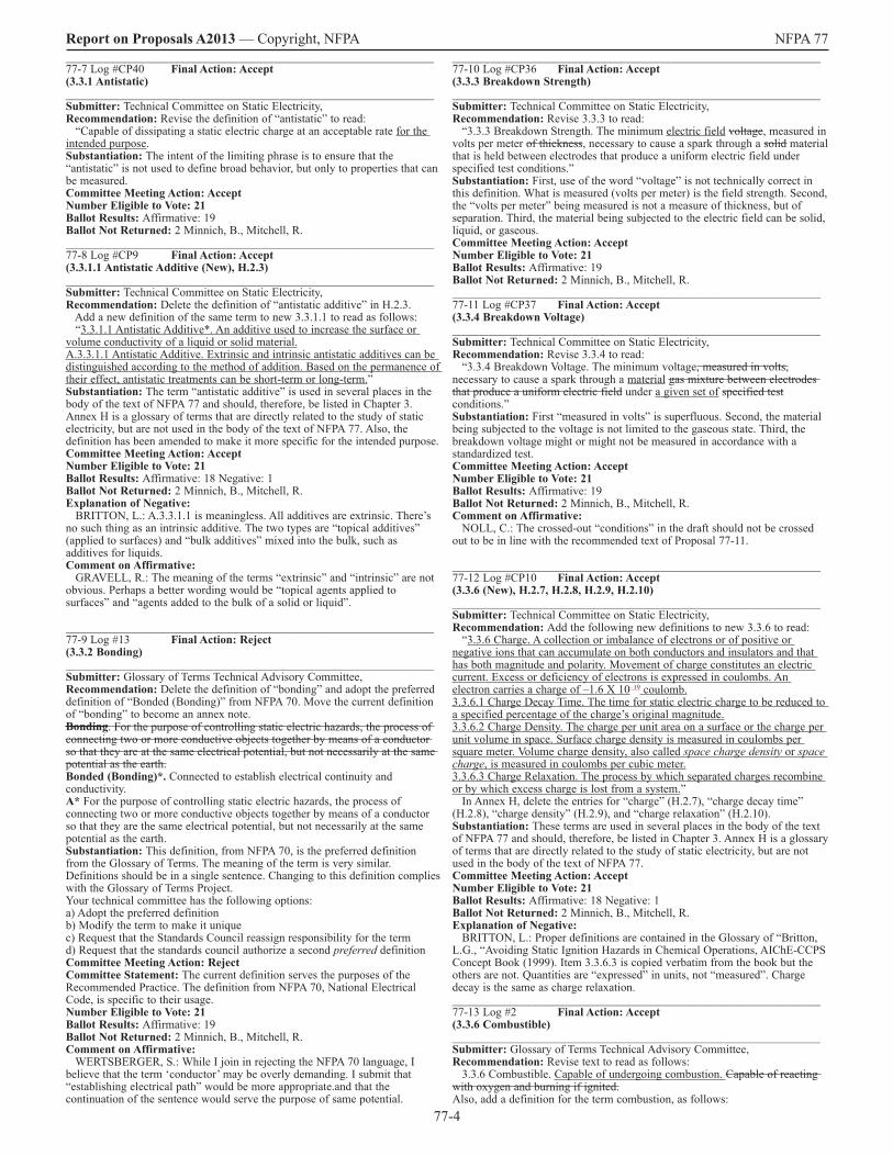
Report on Proposals A2013 — Copyright, NFPA NFPA 77_______________________________________________________________ 77-7 Log #CP40 Final Action: Accept(3.3.1 Antistatic)_______________________________________________________________ Submitter: Technical Committee on Static Electricity, Recommendation: Revise the definition of “antistatic” to read: “Capable of dissipating a static electric charge at an acceptable rate for the intended purpose.Substantiation: The intent of the limiting phrase is to ensure that the “antistatic” is not used to define broad behavior, but only to properties that can be measured. Committee Meeting Action: AcceptNumber Eligible to Vote: 21 Ballot Results: Affirmative: 19 Ballot Not Returned: 2 Minnich, B., Mitchell, R._______________________________________________________________ 77-8 Log #CP9 Final Action: Accept(3.3.1.1 Antistatic Additive (New), H.2.3)_______________________________________________________________ Submitter: Technical Committee on Static Electricity, Recommendation: Delete the definition of “antistatic additive” in H.2.3. Add a new definition of the same term to new 3.3.1.1 to read as follows: “3.3.1.1 Antistatic Additive*. An additive used to increase the surface or volume conductivity of a liquid or solid material. A.3.3.1.1 Antistatic Additive. Extrinsic and intrinsic antistatic additives can be distinguished according to the method of addition. Based on the permanence of their effect, antistatic treatments can be short-term or long-term.”Substantiation: The term “antistatic additive” is used in several places in the body of the text of NFPA 77 and should, therefore, be listed in Chapter 3. Annex H is a glossary of terms that are directly related to the study of static electricity, but are not used in the body of the text of NFPA 77. Also, the definition has been amended to make it more specific for the intended purpose. Committee Meeting Action: AcceptNumber Eligible to Vote: 21 Ballot Results: Affirmative: 18 Negative: 1 Ballot Not Returned: 2 Minnich, B., Mitchell, R.Explanation of Negative: BRITTON, L.: A.3.3.1.1 is meaningless. All additives are extrinsic. There’s no such thing as an intrinsic additive. The two types are “topical additives” (applied to surfaces) and “bulk additives” mixed into the bulk, such as additives for liquids. Comment on Affirmative: GRAVELL, R.: The meaning of the terms “extrinsic” and “intrinsic” are not obvious. Perhaps a better wording would be “topical agents applied to surfaces” and “agents added to the bulk of a solid or liquid”. _______________________________________________________________ 77-9 Log #13 Final Action: Reject(3.3.2 Bonding)_______________________________________________________________ Submitter: Glossary of Terms Technical Advisory Committee, Recommendation: Delete the definition of “bonding” and adopt the preferred definition of “Bonded (Bonding)” from NFPA 70. Move the current definition of “bonding” to become an annex note. Bonding. For the purpose of controlling static electric hazards, the process of connecting two or more conductive objects together by means of a conductor so that they are at the same electrical potential, but not necessarily at the same potential as the earth. Bonded (Bonding)*. Connected to establish electrical continuity and conductivity. A* For the purpose of controlling static electric hazards, the process of connecting two or more conductive objects together by means of a conductor so that they are the same electrical potential, but not necessarily at the same potential as the earth. Substantiation: This definition, from NFPA 70, is the preferred definition from the Glossary of Terms. The meaning of the term is very similar. Definitions should be in a single sentence. Changing to this definition complies with the Glossary of Terms Project. Your technical committee has the following options: a) Adopt the preferred definition b) Modify the term to make it unique c) Request that the Standards Council reassign responsibility for the term d) Request that the standards council authorize a second preferred definitionCommittee Meeting Action: RejectCommittee Statement: The current definition serves the purposes of the Recommended Practice. The definition from NFPA 70, National Electrical Code, is specific to their usage. Number Eligible to Vote: 21 Ballot Results: Affirmative: 19 Ballot Not Returned: 2 Minnich, B., Mitchell, R.Comment on Affirmative: WERTSBERGER, S.: While I join in rejecting the NFPA 70 language, I believe that the term ‘conductor’ may be overly demanding. I submit that “establishing electrical path” would be more appropriate.and that the continuation of the sentence would serve the purpose of same potential.
_______________________________________________________________ 77-10 Log #CP36 Final Action: Accept(3.3.3 Breakdown Strength)_______________________________________________________________ Submitter: Technical Committee on Static Electricity, Recommendation: Revise 3.3.3 to read: “3.3.3 Breakdown Strength. The minimum electric field voltage, measured in volts per meter of thickness, necessary to cause a spark through a solid material that is held between electrodes that produce a uniform electric field under specified test conditions.” Substantiation: First, use of the word “voltage” is not technically correct in this definition. What is measured (volts per meter) is the field strength. Second, the “volts per meter” being measured is not a measure of thickness, but of separation. Third, the material being subjected to the electric field can be solid, liquid, or gaseous. Committee Meeting Action: AcceptNumber Eligible to Vote: 21 Ballot Results: Affirmative: 19 Ballot Not Returned: 2 Minnich, B., Mitchell, R._______________________________________________________________ 77-11 Log #CP37 Final Action: Accept(3.3.4 Breakdown Voltage)_______________________________________________________________ Submitter: Technical Committee on Static Electricity, Recommendation: Revise 3.3.4 to read: “3.3.4 Breakdown Voltage. The minimum voltage, measured in volts, necessary to cause a spark through a material gas mixture between electrodes that produce a uniform electric field under a given set of specified test conditions.” Substantiation: First “measured in volts” is superfluous. Second, the material being subjected to the voltage is not limited to the gaseous state. Third, the breakdown voltage might or might not be measured in accordance with a standardized test. Committee Meeting Action: AcceptNumber Eligible to Vote: 21 Ballot Results: Affirmative: 19 Ballot Not Returned: 2 Minnich, B., Mitchell, R.Comment on Affirmative: NOLL, C.: The crossed-out “conditions” in the draft should not be crossed out to be in line with the recommended text of Proposal 77-11. _______________________________________________________________ 77-12 Log #CP10 Final Action: Accept(3.3.6 (New), H.2.7, H.2.8, H.2.9, H.2.10)_______________________________________________________________ Submitter: Technical Committee on Static Electricity, Recommendation: Add the following new definitions to new 3.3.6 to read: “3.3.6 Charge. A collection or imbalance of electrons or of positive or negative ions that can accumulate on both conductors and insulators and that has both magnitude and polarity. Movement of charge constitutes an electric current. Excess or deficiency of electrons is expressed in coulombs. An electron carries a charge of –1.6 X 10⁻¹⁹ coulomb.3.3.6.1 Charge Decay Time. The time for static electric charge to be reduced to a specified percentage of the charge’s original magnitude. 3.3.6.2 Charge Density. The charge per unit area on a surface or the charge per unit volume in space. Surface charge density is measured in coulombs per square meter. Volume charge density, also called space charge density or space charge, is measured in coulombs per cubic meter.3.3.6.3 Charge Relaxation. The process by which separated charges recombine or by which excess charge is lost from a system.” In Annex H, delete the entries for “charge” (H.2.7), “charge decay time” (H.2.8), “charge density” (H.2.9), and “charge relaxation” (H.2.10). Substantiation: These terms are used in several places in the body of the text of NFPA 77 and should, therefore, be listed in Chapter 3. Annex H is a glossary of terms that are directly related to the study of static electricity, but are not used in the body of the text of NFPA 77. Committee Meeting Action: AcceptNumber Eligible to Vote: 21 Ballot Results: Affirmative: 18 Negative: 1 Ballot Not Returned: 2 Minnich, B., Mitchell, R.Explanation of Negative: BRITTON, L.: Proper definitions are contained in the Glossary of “Britton, L.G., “Avoiding Static Ignition Hazards in Chemical Operations, AIChE-CCPS Concept Book (1999). Item 3.3.6.3 is copied verbatim from the book but the others are not. Quantities are “expressed” in units, not “measured”. Charge decay is the same as charge relaxation. _______________________________________________________________ 77-13 Log #2 Final Action: Accept(3.3.6 Combustible)_______________________________________________________________ Submitter: Glossary of Terms Technical Advisory Committee, Recommendation: Revise text to read as follows: 3.3.6 Combustible. Capable of undergoing combustion. Capable of reacting with oxygen and burning if ignited.Also, add a definition for the term combustion, as follows:

77-5
Report on Proposals A2013 — Copyright, NFPA NFPA 77Combustion. A chemical process of oxidation that occurs at a rate fast enough to produce heat and usually light in the form of either a glow or flame.Substantiation: It is important to have consistent definitions of terms within NFPA. The term combustible at present has 6 definitions, as follows: A substance that will burn. (430) A material or structure that will release heat energy on burning. (901) Capable of burning, generally in air under normal conditions of ambient temperature and pressure, unless otherwise specified; combustion can occur in cases where an oxidizer other than the oxygen in air is present (e.g., chlorine, fluorine, or chemicals containing oxygen in their structure). (921) Any material that, in the form in which it is used and under the conditions anticipated, will ignite and burn or will add appreciable heat to an ambient fire. (1144) Capable of undergoing combustion. (69, 82, 99, 120, 122, 214, 502, 804, 805, 820, 851, 853, 1126) Capable of reacting with oxygen and burning if ignited. (77, 220, 1141) It is therefore recommended, in order to improve consistency within NFPA documents that a simple definition which is widely used be employed in all documents. The document responsible for this definition is NFPA 220 and the same recommendation will be made to that document. This definition is also used by ASTM E 176 for committee ASTM E05 on Fire Standards. There are 5 definitions of combustion in NFPA and the one chosen is the most widely used, including NFPA 1. This definition is also used by ASTM E 176 for committee ASTM E05 on Fire Standards. Committee Meeting Action: AcceptCommittee Statement: The Technical Committee notes that Subsection 3.3.6 is designated 3.3.8 in the NFPA 77 ROP Preprint. Number Eligible to Vote: 21 Ballot Results: Affirmative: 19 Ballot Not Returned: 2 Minnich, B., Mitchell, R._______________________________________________________________ 77-14 Log #CP33 Final Action: Accept(3.3.7 Charging (New), H.2.11)_______________________________________________________________ Submitter: Technical Committee on Static Electricity, Recommendation: Move the definitions of “induction charging” and “triboelectric charging” from H.2.11 to new 3.3.7 and revise to read: “3.3.7 Charging.3.3.7.1 Induction Charging. The act of charging an object by bringing it near another charged object, then touching the first object to ground; also known as induction. Charge polarization is induced on a grounded object in the vicinity of a charged surface due to the electric field existing between the object and the surface. If the ground connection is removed from the object during this period, the induced charge remains on the object. Induction charging occurs where a person walks from a conductive floor covering onto an insulating floor in the presence of an electric field. 3.37I.2* Triboelectric Charging. Static electric charging that results from contact or friction between two dissimilar materials; also known as frictional charging and contact-separation charging. A.3.37I.2 Triboelectric charging is the most familiar, yet least understood, charge generation mechanism. Triboelectric charging results from contact or friction between two unlike materials. The amount of charge generated in this way is dependent primarily on the nature of contact, the intrinsic electrical and static electric properties of the materials involved, and the prevailing conditions of humidity and temperature. An indication of the tendency of materials to accept static electric charge in this way is given by the triboelectric series. Recent studies indicate that the amount of charge transferred depends not only on the composition of the materials but also on the capacitance of the junction. The following situations are examples of triboelectric charging: (1) Pneumatic transport of powders along pipes (2) High-speed webs of synthetic materials moving over rollers (3) Charging of the human body as a person walks across a carpet (4) Extrusion of plastics or the ejection of plastic parts from a mold Table A.3.3.7.2 illustrates typical electrostatic voltages observed as a result of triboelectric charging at two levels of relative humidity (RH). In Annex H, renumber H.2.11.1, Field Charging, to H.2.4.
Substantiation: These terms are used in several places in the body of the text of NFPA 77 and should, therefore, be listed in Chapter 3. Annex H is a glossary of terms that are directly related to the study of static electricity, but are not used in the body of the text of NFPA 77. Committee Meeting Action: AcceptNumber Eligible to Vote: 21 Ballot Results: Affirmative: 17 Negative: 2 Ballot Not Returned: 2 Minnich, B., Mitchell, R.Explanation of Negative: BRITTON, L.: See comment on 77-12 (Log #CP10). Item 3.3.7.1 is not a definition but an incorrect explanation. Induction charging is NOT the same as induction. See later comments on 77-42 (Log #CP110). GRAVELL, R.: This section contains many errors, including the statement that induction charging involves grounding, not specifying that induction charging is only relevant to conductors, and not including separation after contact in the definition of triboelectric charging. The statement that the human body becomes tribocharged as a person walks across the floor is also not true--the shoes become tribocharged and the person induction charged. Comment on Affirmative: NOLL, C.: Table needs some adjustment of tabs in both the Report on Proposals and the Draft. WERTSBERGER, S.: I believe that the word ‘touching’ (3.3.7.1, line 1) is overly restrictive, and suggest ‘electrically coupling’, or ‘electrically connecting’. _______________________________________________________________ 77-15 Log #CP11 Final Action: Accept(3.3.8 Conductive (New), 3.3.11.1 Conductive Flooring (New), 3.3.11.2 Conductive Hose (New))_______________________________________________________________ Submitter: Technical Committee on Static Electricity, Recommendation: Relocate existing definition of “Conductive” to 3.3.11 and add two new subordinate definitions to read: “3.3.11.1 Conductive Flooring. Flooring that has an average resistance between 2.5 × 10³ ohms and 1 × 10⁶ ohms, measured using specified electrodes placed a specified distance apart. 3.3.11.2 Conductive Hose. Hose that has an electrical resistance of less than 103 ohms per meter, measured between the end connectors.”Substantiation: These terms are used in several places in the body of the text of NFPA 77 and their definitions should, therefore, be listed in Chapter 3. Committee Meeting Action: AcceptNumber Eligible to Vote: 21 Ballot Results: Affirmative: 19 Ballot Not Returned: 2 Minnich, B., Mitchell, R.Comment on Affirmative: GRAVELL, R.: A lower limit on floor conductivity has no value and should be removed.
NFPA 77 Log #CP33 Rec A2013 ROP
Table A.3.3.7.2 Electrostatic Voltages Resulting from Triboelectric Charging at Two Levels of Relative Humidity (RH)
Electrostatic Voltages (kV) Situation RH
10%–20%
RH 65%–90%
Walking across a carpet 35 1.5 Walking across a vinyl floor 12 0.25 Working at a bench 6 0.1 Vinyl envelopes for work instructions 7 0.6 Poly bag picked up from bench 20 1.2 Work chair padded with polyurethane foam 18 1.5
77-6
Report on Proposals A2013 — Copyright, NFPA NFPA 77_______________________________________________________________ 77-16 Log #CP12 Final Action: Accept(3.3.12 Conductivity (New), H.2.15)_______________________________________________________________ Submitter: Technical Committee on Static Electricity, Recommendation: Add a new definition of “conductivity” to new 3.3.12 to read: “3.3.12* Conductivity (κ).* The reciprocal of resistivity, i.e., 1/resistivity. An intrinsic property of a solid or liquid that governs the way electrical charges move across its surface or through its bulk. A.3.3.12 This property can be dramatically affected by the temperature and especially by the presence of moisture or antistatic additives. Conductors such as metals and aqueous solutions have a high conductivity (low resistivity) and lose charge quickly where grounded. Insulators have a high resistivity and lose charge very slowly, even where grounded. Conductors isolated from ground can store charge and can rise to fairly high potentials in many industrial situations, resulting in hazardous spark discharges. The unit of conductivity is ohms per meter, which is the same as siemens per meter (S/m). [Note basis as reciprocal of resistivity, with units of ohm-meters.) Some authors express volume resistivity data in terms of ohm-meters (100 Ω-cm = 1 Ω-m). Conductivity is not generally assigned to a gas. In gases, free electrons or ions can be formed or injected by external means. In the presence of an electric field, the ions migrate to electrodes or charged surfaces and constitute a current. Conductivity is rarely an intrinsic property of gas. Another way to characterize conductivity is as the ratio of the electric current density to the electric field in a material.” Delete H.2.15 entirely. Substantiation: This term is used in several places in the body of the text of NFPA 77 and it needs to be defined in Chapter 3. Committee Meeting Action: AcceptNumber Eligible to Vote: 21 Ballot Results: Affirmative: 18 Negative: 1 Ballot Not Returned: 2 Minnich, B., Mitchell, R.Explanation of Negative: BRITTON, L.: See comment on 77-12 (Log #CP10). Conductivity is a constant of proportionality. It does NOT govern the way electrical charges move. Comment on Affirmative: NOLL, C.: A.3.3.12 … The unit of conductivity is the ohm-1 per meter. Some authors express volume resistivity data in terms of ohm-centimeters … _______________________________________________________________ 77-17 Log #10 Final Action: Accept in Principle(3.3.13 Nonconductive)_______________________________________________________________ Submitter: Steven J. Gunsel, SGTechnologies, LLCRecommendation: Revise text to read as follows:3.3.13 Nonconductive. Possessing the ability to resist the flow of an electric charge. Material with a conductivity less than 102 pS/m or a resistivity greater than 1010 ohm-m (1012 ohm-cm). Substantiation: The current definition is meaningless. All materials possess the ability to resist the flow of electric charge. Conductive and semiconductive are defined (Sections 3.3.8 and 3.3.15) in terms of conductivity and resistivity. Note that 102 pS/m and 1010 ohm-m, and 1012 ohm-cm are equivalent. Committee Meeting Action: Accept in PrincipleReplace the current definition of “Nonconductive” with the following: “3.3.32 Nonconductive (Insulating). For the purposes of describing static electric behavior, having the ability to accumulate charge, even when in contact with ground.”Committee Statement: The current definition of nonconductive is more related to a flowing electric current. The definition proposed by the Technical Committee is more specific to static electric phenomena. Number Eligible to Vote: 21 Ballot Results: Affirmative: 18 Negative: 1 Ballot Not Returned: 2 Minnich, B., Mitchell, R.Explanation of Negative: BRITTON, L.: Steve Gunsel’s proposed definition is from the glossary of the CCPS book (See77-12 ( Log #CP10) and is OK. The committee action labeled 3.3.32 is unclear and is not a definition. _______________________________________________________________ 77-18 Log #CP13 Final Action: Accept(3.3.14 Current (New), H.2.19)_______________________________________________________________ Submitter: Technical Committee on Static Electricity, Recommendation: Add the following new definitions to new 3.14 as follows: “3.3.14 Current (I). A measure of the rate of transport of electric charge past a specified point or across a specified surface. The symbol I is generally used for constant currents, and the symbol i is used for time-variable currents. The unit of current is the ampere. One ampere equals 1 Coulomb/sec (6.24 X 10¹⁸ electrons/sec). 3.3.14.1 Charging Current (Ic). The rate of flow of charge into a given system per unit of time, expressed in amperes.” Delete the entry for “current” in H.2.19.
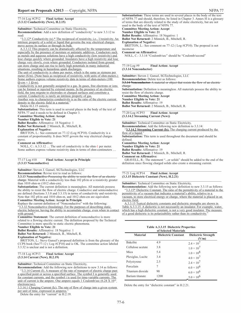
Substantiation: These terms are used in several places in the body of the text of NFPA 77 and should, therefore, be listed in Chapter 3. Annex H is a glossary of terms that are directly related to the study of static electricity, but are not used in the body of the text of NFPA 77. Committee Meeting Action: AcceptNumber Eligible to Vote: 21 Ballot Results: Affirmative: 18 Negative: 1 Ballot Not Returned: 2 Minnich, B., Mitchell, R.Explanation of Negative: BRITTON, L.: See comment on 77-12 ( Log #CP10). The proposal is not inconcise Comment on Affirmative: NOLL, C.: 3.3.14 “Coulomb/sec” should be “Coulomb/second” _______________________________________________________________ 77-19 Log #9 Final Action: Accept(3.3.14 Nonconductor)_______________________________________________________________ Submitter: Steven J. Gunsel, SGTechnologies, LLCRecommendation: Delete text as follows:3.3.14 Nonconductor. A material or object that resists the flow of an electric charge.Substantiation: Definition is meaningless. All materials possess the ability to resist the flow of electric charge. Committee Meeting Action: AcceptNumber Eligible to Vote: 21 Ballot Results: Affirmative: 19 Ballot Not Returned: 2 Minnich, B., Mitchell, R._______________________________________________________________ 77-20 Log #CP53 Final Action: Accept(3.3.14.2 Streaming Current (New))_______________________________________________________________ Submitter: Technical Committee on Static Electricity, Recommendation: Add the following new definition to 3.3.14: “3.3.14.2 Streaming Current (Is). The charging current produced by the flow of a liquid.”Substantiation: This term is used throughout the document and should be defined. Committee Meeting Action: AcceptNumber Eligible to Vote: 21 Ballot Results: Affirmative: 19 Ballot Not Returned: 2 Minnich, B., Mitchell, R.Comment on Affirmative: GRAVELL, R.: The statement “...or solids” should be added to the end of the definition since flowing charged solids also create a streaming current. _______________________________________________________________ 77-21 Log #CP14 Final Action: Accept(3.3.15 Dielectric Constant (New), H.2.21)_______________________________________________________________ Submitter: Technical Committee on Static Electricity, Recommendation: Add the following new definition to new 3.3.15 as follows: “3.3.15* Dielectric Constant. The ratio of the permittivity of a material to the permittivity of a vacuum that indicates a material’s ability, relative to a vacuum, to store electrical energy or charge, where the material is placed in an electric field. A.3.3.15 Typical dielectric constants and dielectric strengths are shown in Table A.3.3.15. A dielectric is not necessarily an insulator. For example, water, which has a high dielectric constant, is not a very good insulator. The measure of a good dielectric is its polarizability rather than its conductivity.”
Table A.3.3.15 Dielectric Properties of Selected Materials
Material Dielectric Constant Dielectric Strength (V/m)
Bakelite 4.9 2.4 × 10⁷Cellulose acetate 3.8 1.0 × 10⁷Mica 5.4 1.0 × 10⁸Plexiglas, Lucite 3.4 4.0 × 10⁷Polystyrene 2.5 2.4 × 10⁷Porcelain 7 6.0 × 10⁶Titanium dioxide 90 6.0 × 10⁶Barium titanate 1200 5.0 × 10⁶
Delete the entry for “dielectric constant” in H.2.21.

77-7
Report on Proposals A2013 — Copyright, NFPA NFPA 77Substantiation: These terms are used in several places in the body of the text of NFPA 77 and should, therefore, be listed in Chapter 3. Annex H is a glossary of terms that are directly related to the study of static electricity, but are not used in the body of the text of NFPA 77. Committee Meeting Action: AcceptNumber Eligible to Vote: 21 Ballot Results: Affirmative: 18 Negative: 1 Ballot Not Returned: 2 Minnich, B., Mitchell, R.Explanation of Negative: BRITTON, L.: See comment on 77-12 (Log CP10). Dielectric constant should be defined separately from permittivity and units should be given. _______________________________________________________________ 77-22 Log #CP15 Final Action: Accept(3.3.16 Dielectric Strength (New), H.2.22)_______________________________________________________________ Submitter: Technical Committee on Static Electricity, Recommendation: Relocate H.2.22, “Dielectric Strength” to new 3.3.16 and change “rupture” to “electric breakdown”. Substantiation: These terms are used in several places in the body of the text of NFPA 77 and should, therefore, be listed in Chapter 3. Annex H is a glossary of terms that are directly related to the study of static electricity, but are not used in the body of the text of NFPA 77. Replacement of the word “rupture” is for accuracy. Committee Meeting Action: AcceptNumber Eligible to Vote: 21 Ballot Results: Affirmative: 19 Ballot Not Returned: 2 Minnich, B., Mitchell, R.Comment on Affirmative: BRITTON, L.: Need reference for Table A.3.3.15. Table given in Britton CCPS Book (pp 234-235) contains more useful values. What is the value of listing breakdown strengths for barium titanate or titanium oxide, compared with those of nylon and PVC and Teflon? Also, Table A.3.3.15 fails to show effect of thickness. NOLL, C.: Table “B.2” should be “A.3.3.15” or “3.3.15” if it is not supplementary material. _______________________________________________________________ 77-23 Log #CP16 Final Action: Accept(3.3.17 Discharge (New), H.2.23)_______________________________________________________________ Submitter: Technical Committee on Static Electricity, Recommendation: Add the following new definitions to new 3.3.17 to read as follows: “3.3.17 Discharge. 3.3.17.1 Brush Discharge. A higher energy form of corona discharge characterized by low-frequency bursts or by streamers. Brush discharges can form between charged nonconductive surfaces and grounded conductors acting as electrodes. For positive electrodes, pre-onset or breakdown streamers are observed, and the maximum effective energy is a few millijoules. For negative electrodes, the maximum effective energy is a few tenths of a millijoule. Brush discharges can ignite flammable gas and hybrid mixtures but not dust in air. Also called cone discharge. 3.3.17.2 Bulking Brush Discharge. A partial surface discharge created during bulking of powder in containers, appearing as a luminous, branched channel flashing radially from the wall toward the center of the container. Its maximum effective energy is 10 mJ to 25 mJ. It can ignite flammable gas, hybrid mixtures, and some fine dusts in air. 3.3.17.3 Corona Discharge. An electrical discharge in the microampere range that results from a localized electrical breakdown of gases by charges on surfaces such as sharp edges, needle points, and wires. The charges can arise on conductors at high voltage or on grounded conductors that are situated near a charged surface. Corona is accompanied by a faint luminosity. 3.3.17.4 Propagating Brush Discharge. An energetic discharge caused by electrical breakdown of the dielectric layer in a capacitor. The capacitor is typically formed by charged plastic coating on a metal substrate, although plastic pipe and tote bins can also form the required charged double layer. The effective energy can exceed 1000 mJ, causing both shock to personnel and ignition hazards for a wide variety of materials, including dusts in air.” In Annex H, delete the following entries: H.2.4, H.2.6, H.2.16, H.2.17, and H.2.23 and all its subordinate entries. Substantiation: These terms are used in several places in the body of the text of NFPA 77 and should, therefore, be listed in Chapter 3. Annex H is a glossary of terms that are directly related to the study of static electricity, but are not used in the body of the text of NFPA 77. Committee Meeting Action: AcceptNumber Eligible to Vote: 21 Ballot Results: Affirmative: 18 Negative: 1 Ballot Not Returned: 2 Minnich, B., Mitchell, R.Explanation of Negative: BRITTON, L.: See comment for 77-12 (Log #CP10). Definition of brush discharge is incorrect and wrongly states “cone discharge” phenomenon is an equivalent term. Comment on Affirmative: GRAVELL, R.: Much of the detail in these definitions should be moved to the Annex; brush discharges are not “also called cone discharges;” maximum cone discharge energy is not consistent with other citations of this phenomenon (see 77-90 (Log #CP89) and 77-103 (Log #CP102)).
_______________________________________________________________ 77-24 Log #CP17 Final Action: Accept(3.3.18 Dissipative (New), H.2.24)_______________________________________________________________ Submitter: Technical Committee on Static Electricity, Recommendation: Add the following new definition to new 3.3.18 to read: “3.3.18 Dissipative*. A material or a construction that will reduce static charge to acceptable levels. Typically, this is a material having a surface resistivity between 105 ohms per square and 1012 ohms per square or a volume resistivity between 105 to 109 ohm-meters.A.3.3.18 Dissipative. Some applications might require different resistivities, while the intent is to dissipate charge.” Delete H.2.24. Substantiation: This term is used in several places in the body of the text of NFPA 77 and should, therefore, be listed in Chapter 3. Annex H is a glossary of terms that are directly related to the study of static electricity, but are not used in the body of the text of NFPA 77. Committee Meeting Action: AcceptNumber Eligible to Vote: 21 Ballot Results: Affirmative: 18 Negative: 1 Ballot Not Returned: 2 Minnich, B., Mitchell, R.Explanation of Negative: BRITTON, L.: Remove modifier “typically”. The term “dissipative” should be strictly defined and consistent with IEC document. Comment on Affirmative: GRAVELL, R.: Surface resistivity limits are humidity dependent and it should be stated that the limits shown are for 25 +/-5% RH. NOLL, C.: A.3.3.18 Change “whilke” to “while”. _______________________________________________________________ 77-25 Log #CP34 Final Action: Accept(3.3.19 Double Layer (New), H.2.25)_______________________________________________________________ Submitter: Technical Committee on Static Electricity, Recommendation: Move the definition of “double layer” from H.2.25 to new 3.3.19 to read: “3.3.19* Double Layer. A phenomenon usually associated with a solid–liquid interface where ions of one charge type are fixed to the surface of the solid, and an equal number of mobile ions of opposite charge are distributed through the neighboring region of the liquid. A.3.3.19 Double Layer. In such a system, the movement of liquid causes a displacement of the mobile ions with respect to the fixed charges on the solid surface.”Substantiation: This term is used in several places in the body of the text of NFPA 77 and should, therefore, be listed in Chapter 3. Annex H is a glossary of terms that are directly related to the study of static electricity, but are not used in the body of the text of NFPA 77. Committee Meeting Action: AcceptNumber Eligible to Vote: 21 Ballot Results: Affirmative: 19 Ballot Not Returned: 2 Minnich, B., Mitchell, R._______________________________________________________________ 77-26 Log #CP18 Final Action: Accept(3.3.20 Electrometer (New), H.2.27)_______________________________________________________________ Submitter: Technical Committee on Static Electricity, Recommendation: Relocate the definition of “electrometer” from H.2.27 to new 3.3.20. Substantiation: This term is used in several places in the body of the text of NFPA 77 and should, therefore, be listed in Chapter 3. Annex H is a glossary of terms that are directly related to the study of static electricity, but are not used in the body of the text of NFPA 77. Committee Meeting Action: AcceptNumber Eligible to Vote: 21 Ballot Results: Affirmative: 19 Ballot Not Returned: 2 Minnich, B., Mitchell, R._______________________________________________________________ 77-27 Log #CP19 Final Action: Accept(3.3.21 Flammable Limit (New), H.2.33)_______________________________________________________________ Submitter: Technical Committee on Static Electricity, Recommendation: Relocate the definitions of “lower” and “upper flammable limits” from H.2.33 to new 3.3.21. Substantiation: These terms are used in several places in the body of the text of NFPA 77 and should, therefore, be listed in Chapter 3. Annex H is a glossary of terms that are directly related to the study of static electricity, but are not used in the body of the text of NFPA 77. Committee Meeting Action: AcceptNumber Eligible to Vote: 21 Ballot Results: Affirmative: 19 Ballot Not Returned: 2 Minnich, B., Mitchell, R.

77-8
Report on Proposals A2013 — Copyright, NFPA NFPA 77_______________________________________________________________ 77-28 Log #CP20 Final Action: Accept(3.3.24 Ignition Energy (New), H.2.34)_______________________________________________________________ Submitter: Technical Committee on Static Electricity, Recommendation: Relocate the definition of “ignition energy” from H.2.34 to new 3.3.24. Substantiation: These terms are used in several places in the body of the text of NFPA 77 and should, therefore, be listed in Chapter 3. Annex H is a glossary of terms that are directly related to the study of static electricity, but are not used in the body of the text of NFPA 77. Committee Meeting Action: AcceptNumber Eligible to Vote: 21 Ballot Results: Affirmative: 19 Ballot Not Returned: 2 Minnich, B., Mitchell, R._______________________________________________________________ 77-29 Log #CP21 Final Action: Accept(3.3.25 Incendive (New), H.2.35)_______________________________________________________________ Submitter: Technical Committee on Static Electricity, Recommendation: Relocate the definition of “incendive” from H.2.35 to new 3.3.25. Substantiation: This term is used in several places in the body of the text of NFPA 77 and should, therefore, be listed in Chapter 3. Annex H is a glossary of terms that are directly related to the study of static electricity, but are not used in the body of the text of NFPA 77. Committee Meeting Action: AcceptNumber Eligible to Vote: 21 Ballot Results: Affirmative: 19 Ballot Not Returned: 2 Minnich, B., Mitchell, R._______________________________________________________________ 77-30 Log #CP22 Final Action: Accept(3.3.26 Induction (New), H.2.36)_______________________________________________________________ Submitter: Technical Committee on Static Electricity, Recommendation: Relocate the definition of “induction” from H.2.36 to new 3.3.26. Substantiation: This term is used in several places in the body of the text of NFPA 77 and should, therefore, be listed in Chapter 3. Annex H is a glossary of terms that are directly related to the study of static electricity, but are not used in the body of the text of NFPA 77. Committee Meeting Action: AcceptNumber Eligible to Vote: 21 Ballot Results: Affirmative: 19 Ballot Not Returned: 2 Minnich, B., Mitchell, R._______________________________________________________________ 77-31 Log #CP23 Final Action: Accept(3.3.27 Induction Bar (New), H.2.37)_______________________________________________________________ Submitter: Technical Committee on Static Electricity, Recommendation: Relocate the definition of “induction bar” from H.2.37 to new 3.3.27. Delete the word “highly” in the first sentence. Relocate the second sentence to Annex A. Substantiation: This term is used in several places in the body of the text of NFPA 77 and should, therefore, be listed in Chapter 3. Annex H is a glossary of terms that are directly related to the study of static electricity, but are not used in the body of the text of NFPA 77. Committee Meeting Action: AcceptNumber Eligible to Vote: 21 Ballot Results: Affirmative: 19 Ballot Not Returned: 2 Minnich, B., Mitchell, R._______________________________________________________________ 77-32 Log #CP24 Final Action: Accept(3.3.29 Ionization (new), H.2.39)_______________________________________________________________ Submitter: Technical Committee on Static Electricity, Recommendation: Relocate the definition of “ionization” from H.2.39 to new 3.3.29. Substantiation: This term is used in several places in the body of the text of NFPA 77 and should, therefore, be listed in Chapter 3. Annex H is a glossary of terms that are directly related to the study of static electricity, but are not used in the body of the text of NFPA 77. Committee Meeting Action: AcceptNumber Eligible to Vote: 21 Ballot Results: Affirmative: 19 Ballot Not Returned: 2 Minnich, B., Mitchell, R._______________________________________________________________ 77-33 Log #CP25 Final Action: Accept(3.3.30 Megohmmeter (New), H.2.43)_______________________________________________________________ Submitter: Technical Committee on Static Electricity, Recommendation: Relocate the definition of “megohmmeter” from H.2.43 to new 3.3.30. Substantiation: This term is used in several places in the body of the text of
NFPA 77 and should, therefore, be listed in Chapter 3. Annex H is a glossary of terms that are directly related to the study of static electricity, but are not used in the body of the text of NFPA 77. Committee Meeting Action: AcceptNumber Eligible to Vote: 21 Ballot Results: Affirmative: 19 Ballot Not Returned: 2 Minnich, B., Mitchell, R._______________________________________________________________ 77-34 Log #CP26 Final Action: Accept(3.3.31 Minimum Explosible Concentration (New), H.2.44)_______________________________________________________________ Submitter: Technical Committee on Static Electricity, Recommendation: Relocate the definition of “minimum explosible concentration” from H.2.44 to new 3.3.31. Substantiation: This term is used in several places in the body of the text of NFPA 77 and should, therefore, be listed in Chapter 3. Annex H is a glossary of terms that are directly related to the study of static electricity, but are not used in the body of the text of NFPA 77. Committee Meeting Action: AcceptNumber Eligible to Vote: 21 Ballot Results: Affirmative: 19 Ballot Not Returned: 2 Minnich, B., Mitchell, R._______________________________________________________________ 77-35 Log #CP27 Final Action: Accept(3.3.33 Ohms per Square (New), H.2.47)_______________________________________________________________ Submitter: Technical Committee on Static Electricity, Recommendation: Add a new definition for “Ohms per Square” in new 3.3.33 to read: “3.3.33 Ohms per Square*. A unit of measure used to describe surface resistivity that reflects the resistance value between two electrodes that form two sides of a square and is independent of the size of the square and by which the resulting value indicates how easily electrons can flow across a surface. A.3.3.33 Ohms per square is normally used to characterize the resistivity of a thin conductive layer of one material over a relatively insulative base material.” Delete H.2.47. Substantiation: This term is used in several places in the body of the text of NFPA 77 and should, therefore, be listed in Chapter 3. Annex H is a glossary of terms that are directly related to the study of static electricity, but are not used in the body of the text of NFPA 77. The definition has been amended for technical accuracy. Committee Meeting Action: AcceptNumber Eligible to Vote: 21 Ballot Results: Affirmative: 18 Negative: 1 Ballot Not Returned: 2 Minnich, B., Mitchell, R.Explanation of Negative: BRITTON, L.: See comment on 77-12 (Log #CP10). The “Ohms per square” value does NOT indicate how easily electrons move across a surface. Quite the opposite, in fact. Comment on Affirmative: GRAVELL, R.: Suggest simplifying the definition in the text to “A unit of measure used to describe surface resistivity” and moving the remaining explanatory material to the Annex. _______________________________________________________________ 77-36 Log #CP28 Final Action: Accept(3.3.34 Relaxation Time Constant (New), H.2.49)_______________________________________________________________ Submitter: Technical Committee on Static Electricity, Recommendation: Relocate the definition of “relaxation time constant” from H.2.49 to new 3.3.34. Substantiation: This term is used in several places in the body of the text of NFPA 77 and should, therefore, be listed in Chapter 3. Annex H is a glossary of terms that are directly related to the study of static electricity, but are not used in the body of the text of NFPA 77. Committee Meeting Action: AcceptNumber Eligible to Vote: 21 Ballot Results: Affirmative: 19 Ballot Not Returned: 2 Minnich, B., Mitchell, R._______________________________________________________________ 77-37 Log #CP29 Final Action: Accept(3.3.36 Resistivity (New), H.2.51)_______________________________________________________________ Submitter: Technical Committee on Static Electricity, Recommendation: Relocate the definition of “resistivity” and “surface resistivity” from H.2.51 to new 3.3.36. Add new definition of “volume resistivity” to new 3.3.36.2 per Proposal 77-123 (Log #12). Substantiation: These terms are used in several places in the body of the text of NFPA 77 and should, therefore, be listed in Chapter 3. Annex H is a glossary of terms that are directly related to the study of static electricity, but are not used in the body of the text of NFPA 77. Committee Meeting Action: AcceptNumber Eligible to Vote: 21 Ballot Results: Affirmative: 19 Ballot Not Returned: 2 Minnich, B., Mitchell, R.

77-9
Report on Proposals A2013 — Copyright, NFPA NFPA 77_______________________________________________________________ 77-38 Log #CP30 Final Action: Accept(3.3.38 Spark (New), H2.52)_______________________________________________________________ Submitter: Technical Committee on Static Electricity, Recommendation: Relocate the definition of “spark” from H.2.52 to new 3.3.38. Substantiation: This term is used in several places in the body of the text of NFPA 77 and should, therefore, be listed in Chapter 3. Annex H is a glossary of terms that are directly related to the study of static electricity, but are not used in the body of the text of NFPA 77. Committee Meeting Action: AcceptNumber Eligible to Vote: 21 Ballot Results: Affirmative: 19 Ballot Not Returned: 2 Minnich, B., Mitchell, R._______________________________________________________________ 77-39 Log #CP31 Final Action: Accept(3.3.41 Surface Streamer (New), H.2.56)_______________________________________________________________ Submitter: Technical Committee on Static Electricity, Recommendation: Relocate the first sentence of the definition of surface streamer” from H.2.56 to new 3.3.41. Relocate the second sentence of the definition to new A.3.3.41. Substantiation: This term is used in several places in the body of the text of NFPA 77 and should, therefore, be listed in Chapter 3. Annex H is a glossary of terms that are directly related to the study of static electricity, but are not used in the body of the text of NFPA 77. Committee Meeting Action: AcceptNumber Eligible to Vote: 21 Ballot Results: Affirmative: 19 Ballot Not Returned: 2 Minnich, B., Mitchell, R._______________________________________________________________ 77-40 Log #CP32 Final Action: Accept(3.3.42 Triboelectric Series (New), H.2.59)_______________________________________________________________ Submitter: Technical Committee on Static Electricity, Recommendation: Relocate the first sentence of the definition of “triboelectric series” from H.2.59 to new 3.3.42. Relocate the remainder of the definition to new A.3.3.42. Substantiation: This term is used in several places in the body of the text of NFPA 77 and should, therefore, be listed in Chapter 3. Annex H is a glossary of terms that are directly related to the study of static electricity, but are not used in the body of the text of NFPA 77. Committee Meeting Action: AcceptNumber Eligible to Vote: 21 Ballot Results: Affirmative: 19 Ballot Not Returned: 2 Minnich, B., Mitchell, R._______________________________________________________________ 77-41 Log #CP45 Final Action: Accept(4.2)_______________________________________________________________ Submitter: Technical Committee on Static Electricity, Recommendation: In 4.2, make the following changes: - delete the entries for “A” and “P” - change the symbol for “liquid conductivity” from Kappa to lower-case sigma - epsilon should read “permittivity of a material, farads/m - epsilon0 should read “permittivity of vacuum, farads/m - epsilon/epsilon0 should read “dielectric constant, kappa”. Substantiation: “A” and “P” are not used, so need not be defined. All other changes reflect current usage in the SI system of units. Committee Meeting Action: AcceptNumber Eligible to Vote: 21 Ballot Results: Affirmative: 19 Ballot Not Returned: 2 Minnich, B., Mitchell, R._______________________________________________________________ 77-42 Log #CP110 Final Action: Accept(5.2 (New 5.3))_______________________________________________________________ Submitter: Technical Committee on Static Electricity, Recommendation: Replace current Section 5.2 (new 5.3) with the following:“5.3 Charging by Induction5.3.1 Induction is the process of drawing opposite-polarity charge nearer and pushing same polarity charge further away from an electrically charged object. When an electrically neutral conductor is brought near a charged object, induction separates charge so that the opposite polarity charge is concentrated closer and the same polarity charge is concentrated further from the charged object. 5.3.2 As an example, if a person walks about, there is a redistribution of charge on his/her body as he/she approaches and leaves places where there is charge. By the term person, one includes the body, clothing, tools, flashlights, pens, and other articles carried along. The “person” includes all the mentioned items and the nature of their electrical connection. The total charge on the person does not change as he/she walks around, unless there is passage of charge from the person to his/or her environment, e.g., the charged object, the floor, the air,
or anything else in the surroundings that becomes a path for charge redistribution. 5.3.3 Induction charging of the person can occur in a variety of ways: 5.3.3.1 The person touches the charged object. In this case charge flows between the object and person, and the person’s conductivity gives charge the possibility of being distributed further from the object. 5.3.3.1.1 If the object is a conductor, charge from its entirety will be reduced by the amount transferred to the person, so that both will end up with the same voltage (potential). 5.3.3.1.2 If the object is an insulator, local discharge will occur and that charge will be distributed to the person. A moving web would be one case where the local discharges to the person would add up on the person to produce net charging that is similar to that from a conductor. The person would end up with the average voltage (potential) of the web. 5.3.3.2 An electrical discharge occurs between the person and the charged object. The result will be very similar to what happens with direct contact, and in fact, a discharge probably will occur as the person approaches and touches the charged object. The electrical discharge generally occurs from where there is a high concentration of charge – nearby regions on the person or object that are pointed or sharp (points, corners, or edges). There will be a spark or some form of corona discharge – See Section 5.5 and its subsections for descriptions of electrical discharges. 5.3.3.3 Current is conducted through shoes to the floor. If there is conduction through the shoes, charge will distribute beyond the person, and an equal amount of charge will be conducted to the person to be drawn closer to the charged object. If the shoes or floor are not good conductors, it will take time for the net charge on the person to grow and be lost as the person walks from the area. 5.3.3.4 The person touches others, structural steel, tool boxes in the area, etc., or provides other paths for charge to redistribute. Each of these actions give larger area for charge redistribution, and when those paths are broken leave net charge on the person. If shoes and floor are nonconductive, the charge will remain on the person, when he or she leaves the charged object. 5.3.3.5 There is an electrical discharge between the person and something – typically grounded – in the environment. The discharge can come from the hair, rings, finger nails, conductive clothing, etc. In the case of corona, the discharge can be into the air without a nearby grounded surface. 5.3.4 The actual redistribution of charge is complex and dynamic, and the net charge on the person changes with time. One must be careful in handling tools and actions performed while working with charged operations in industry. Gravure printing, coating, and finishing with solvent based materials are particularly hazardous as a result of induction charging. Without good static elimination, pointing a finger at process lines, and working with conductive tools can be hazardous. There are numerous opportunities for spark discharges, brought on by proximity of workers and charged objects. 5.3.5 Pneumatic conveying of bulk solids in nonconductive hoses poses special problems, because charging/discharging along the lines induces complex charges and currents in the work area. The induced charges and currents can be hazardous to workers and electronic equipment. 5.3.6 One area often overlooked is the pickup of charge by induction at one workstation, possibly in a nonhazardous area, that is carried to a hazardous location. Appropriate footwear flooring is thus advised in the hazardous area. Spark discharges from charged objects, however, are typically greater when footwear and flooring are conductive.Substantiation: This provide a more practical example of induction charging.Committee Meeting Action: AcceptNumber Eligible to Vote: 21 Ballot Results: Affirmative: 17 Negative: 2 Ballot Not Returned: 2 Minnich, B., Mitchell, R.Explanation of Negative: BRITTON, L.: This doesn’t make sense and should be rewritten. Induction charging is only applicable to conductors in electric fields. Hence the “object” in question is a conductor such as a person. One cannot explain “induction charging” without mentioning “electric field”. The later parts such as 5.3.7 have nothing to do with induction. GRAVELL, R.: This section is confusing, contains errors (e.g., a person touching another charged conductor does not become charged by induction, but capacitive sharing of charge), is written with reference to people rather than generic conductive objects, and much material should be moved to the Annex. Also, Section 5.3.5 belongs in the chapter on solids handling. Comment on Affirmative: NOLL, C.: Sections 5.2.3-5.2.6 are replaced by the new material 5.3-5.3.7. The existing material labelled “Accumulation and Dissipation of Charge is unchanged by this action.” The cross-out for this purpose was not intended. WASH, T.: 5.3.6 .... to a hazardous location. Appropriate footwear and flooring.... WERTSBERGER, S.: I believe that the term ‘voltage’ as used in 5.3.3.1.1 and 5.3.3.1.2 is meaningless, as voltage is defined as potential difference. I propose voltage be removed and potential remains.
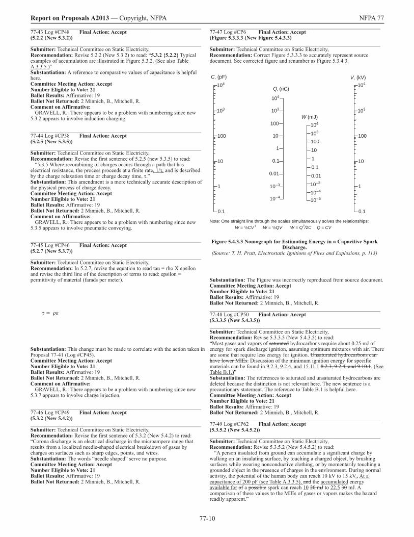
77-10
Report on Proposals A2013 — Copyright, NFPA NFPA 77_______________________________________________________________ 77-43 Log #CP48 Final Action: Accept(5.2.2 (New 5.3.2))_______________________________________________________________ Submitter: Technical Committee on Static Electricity, Recommendation: Revise 5.2.2 (New 5.3.2) to read: “5.3.2 5.2.2 Typical examples of accumulation are illustrated in Figure 5.3.2. (See also Table A.3.3.5.)”Substantiation: A reference to comparative values of capacitance is helpful here. Committee Meeting Action: AcceptNumber Eligible to Vote: 21 Ballot Results: Affirmative: 19 Ballot Not Returned: 2 Minnich, B., Mitchell, R.Comment on Affirmative: GRAVELL, R.: There appears to be a problem with numbering since new 5.3.2 appears to involve induction charging _______________________________________________________________ 77-44 Log #CP38 Final Action: Accept(5.2.5 (New 5.3.5))_______________________________________________________________ Submitter: Technical Committee on Static Electricity, Recommendation: Revise the first sentence of 5.2.5 (new 5.3.5) to read: “5.3.5 Where recombining of charges occurs through a path that has electrical resistance, the process proceeds at a finite rate, 1/τ, and is described by the charge relaxation time or charge decay time, τ.” Substantiation: This amendment is a more technically accurate description of the physical process of charge decay. Committee Meeting Action: AcceptNumber Eligible to Vote: 21 Ballot Results: Affirmative: 19 Ballot Not Returned: 2 Minnich, B., Mitchell, R.Comment on Affirmative: GRAVELL, R.: There appears to be a problem with numbering since new 5.3.5 appears to involve pneumatic conveying. _______________________________________________________________ 77-45 Log #CP46 Final Action: Accept(5.2.7 (New 5.3.7))_______________________________________________________________ Submitter: Technical Committee on Static Electricity, Recommendation: In 5.2.7, revise the equation to read tau = rho X epsilon and revise the third line of the description of terms to read: epsilon = permittivity of material (farads per meter).
Substantiation: This change must be made to correlate with the action taken in Proposal 77-41 (Log #CP45). Committee Meeting Action: AcceptNumber Eligible to Vote: 21 Ballot Results: Affirmative: 19 Ballot Not Returned: 2 Minnich, B., Mitchell, R.Comment on Affirmative: GRAVELL, R.: There appears to be a problem with numbering since new 5.3.7 appears to involve charge injection. _______________________________________________________________ 77-46 Log #CP49 Final Action: Accept(5.3.2 (New 5.4.2))_______________________________________________________________ Submitter: Technical Committee on Static Electricity, Recommendation: Revise the first sentence of 5.3.2 (New 5.4.2) to read: “Corona discharge is an electrical discharge in the microampere range that results from a localized needle-shaped electrical breakdown of gases by charges on surfaces such as sharp edges, points, and wires. Substantiation: The words “needle shaped” serve no purpose.Committee Meeting Action: AcceptNumber Eligible to Vote: 21 Ballot Results: Affirmative: 19 Ballot Not Returned: 2 Minnich, B., Mitchell, R.
_______________________________________________________________ 77-47 Log #CP6 Final Action: Accept(Figure 5.3.3.3 (New Figure 5.4.3.3)_______________________________________________________________ Submitter: Technical Committee on Static Electricity, Recommendation: Correct Figure 5.3.3.3 to accurately represent source document. See corrected figure and renumber as Figure 5.3.4.3.
104
100
10
1
0.1
0.01
10–3
10–4
104
103
100
10
1
0.1
0.01
10–3
10–4
10–5
104
103 103
10
100
1
0.1
104
103
10
100
1
0.1
W = ¹⁄₂CV ² W = ¹⁄₂QV W = Q ²/2C Q = CV
C, (pF) V, (kV)
W (mJ)
Q, (mC)
Note: One straight line through the scales simultaneously solves the relationships:
Substantiation: The Figure was incorrectly reproduced from source document.Committee Meeting Action: AcceptNumber Eligible to Vote: 21 Ballot Results: Affirmative: 19 Ballot Not Returned: 2 Minnich, B., Mitchell, R._______________________________________________________________ 77-48 Log #CP50 Final Action: Accept(5.3.3.5 (New 5.4.3.5))_______________________________________________________________ Submitter: Technical Committee on Static Electricity, Recommendation: Revise 5.3.3.5 (New 5.4.3.5) to read: “Most gases and vapors of saturated hydrocarbons require about 0.25 mJ of energy for spark discharge ignition, assuming optimum mixtures with air. There are some that require less energy for ignition. Unsaturated hydrocarbons can have lower MIEs. Discussion of the minimum ignition energy for specific materials can be found in 9.2.3, 9.2.4, and 15.11.1 8.2.3, 9.2.4, and 9.10.1. (See Table B.1.)”Substantiation: The references to saturated and unsaturated hydrocarbons are deleted because the distinction is not relevant here. The new sentence is a precautionary statement. The reference to Table B.1 is helpful here. Committee Meeting Action: AcceptNumber Eligible to Vote: 21 Ballot Results: Affirmative: 19 Ballot Not Returned: 2 Minnich, B., Mitchell, R._______________________________________________________________ 77-49 Log #CP62 Final Action: Accept(5.3.5.2 (New 5.4.5.2))_______________________________________________________________ Submitter: Technical Committee on Static Electricity, Recommendation: Revise 5.3.5.2 (New 5.4.5.2) to read: “A person insulated from ground can accumulate a significant charge by walking on an insulating surface, by touching a charged object, by brushing surfaces while wearing nonconductive clothing, or by momentarily touching a grounded object in the presence of charges in the environment. During normal activity, the potential of the human body can reach 10 kV to 15 kV., At a capacitance of 200 pF (see Table A.3.3.5), and the accumulated energy available for of a possible spark can reach 10 20 mJ to 22.5 30 mJ. A comparison of these values to the MIEs of gases or vapors makes the hazard readily apparent.”
Figure 5.4.3.3 Nomograph for Estimating Energy in a Capacitive Spark Discharge.
(Source: T. H. Pratt, Electrostatic Ignitions of Fires and Explosions, p. 113)

77-11
Report on Proposals A2013 — Copyright, NFPA NFPA 77Substantiation: The range of capacitance for the human body is 100 to 300 picoFarads. Using an average value of 200 picoFarads, the energy of a spark from the humanbody is more correctly given as 10 to 22.5 milliJoule. Committee Meeting Action: AcceptNumber Eligible to Vote: 21 Ballot Results: Affirmative: 19 Ballot Not Returned: 2 Minnich, B., Mitchell, R.Comment on Affirmative: BRITTON, L.: The committee previously decided to use 30 mJ as the maximum effective spark energy from people in the workplace and this value is given in the revised text (see later). A precise value of 22.5 mJ is unjustified by the errors involved. The important issue is at what ignition energy people and small metal objects must be grounded. GRAVELL, R.: The 15 kV value is not consistent with Table A.3.3.7.2 or other studies which have shown 20-25 kV maxima; also, the assumption of simple capacitive discharge used in calculation of energy is not legitimate since internal body resistance reduces discharge energy to 25-50% of the purely capacitive value. A more realistic conservative maximum discharge energy from an individual would be ~30 mJ, assuming 200 pF, 50% discharge efficiency, and 25 kV potential _______________________________________________________________ 77-50 Log #CP51 Final Action: Accept(Figure 6.1.2)_______________________________________________________________ Submitter: Technical Committee on Static Electricity, Recommendation: In Figure 6.1.2, add the following: - in Note 1, add a new bullet to read: “deliberate or intentional generation of electrostatic charge, e.g., an electrostatic coating process” - in Note 2, add a new bullet to read: “isolated conductive liquids, e.g., a conductive liquid in an electrostatic system where the entire system is isolated from ground”Substantiation: These two items are valid examples of the concepts depicted.Committee Meeting Action: AcceptNumber Eligible to Vote: 21 Ballot Results: Affirmative: 19 Ballot Not Returned: 2 Minnich, B., Mitchell, R.Comment on Affirmative: GRAVELL, R.: Suggested text is too wordy to neatly fit into bulleted notes. Simplify Note 1 addition to read “Intentional electrostatic charging” and Note 2 addition to read “Isolated conductive liquids” _______________________________________________________________ 77-51 Log #CP43 Final Action: Accept(Figure 6.7(b))_______________________________________________________________ Submitter: Technical Committee on Static Electricity, Recommendation: In Figure 6.7 (b), change the legend on the horizontal axis from “ohm-m” to “ohm per square”. Substantiation: This is a correction of an error.Committee Meeting Action: AcceptNumber Eligible to Vote: 21 Ballot Results: Affirmative: 19 Ballot Not Returned: 2 Minnich, B., Mitchell, R._______________________________________________________________ 77-52 Log #3 Final Action: Accept in Part(7.4.1.3.1 and 7.4.1.3.2)_______________________________________________________________ Submitter: Graham Tyers, Newson Gale Inc.Recommendation: Revise text to read as follows: 7.4.1.3.1 (third sentence): A permanent/fixed grounding system that is acceptable for power circuits or for lightning protection is more than adequate for a static electricity grounding system. Suggested added sentence or new paragraph, in between Sections 7.4.1.3.1 and 7.4.1.3.2: In field based situations such as “HAZMAT” hazardous response operations or flammable/combustible materials spill control and transfer, it may be necessary to establish a temporary or emergency grounding system in a remote location in order to dissipate static charges. In these situations, various types of conductive grounding electrodes may be used, such as rods, plates and wires which are sometimes used in combination to increase surface area contact with the earth. If the purpose of the temporary grounding system is to dissipate static electricity, a total resistance of up to 1 k ohm (1,000 Ohms) in the ground path to earth is considered adequate. This may be measured using standard ground resistance testing instruments, and is realistically and quickly achievable in most types of terrain and weather conditions.7.4.1.3.2: (additional diagram illustrating typical temporary grounding system devices is available to add to Annex G if required)Substantiation: The need for effective and safe grounding and bonding techniques and equipment for mobile/field use is absolutely vital for Hazardous Materials/Emergency Response Teams and Vacuum Truck - Environmental/Clean-up operations involving flammable or combustible materials. NFPA and other safety codes all point to ensuring proper bonding and grounding as the prime way to avoid static sparks in hazardous areas. While attending an incident involving flammable or combustible liquids, gases or bulk powders, it is necessary to ensure all potentially isolated transfer equipment, vehicles,
tanks, containers and other items are bonded and grounded to prevent accumulation of dangerous levels of static charge. However, the technical standards and guidelines for rendering an operation safe can be confusing, difficult to achieve and verify extremely time consuming to set up in a situation where time is of the essence. One very real and specific problem area is setting up and testing a satisfactory “ground” point in a remote location where a permanent grounding system is not available. In different types of terrain and climatic conditions it can be impossible to verify a proper ground according to the most commonly referenced standard (NEC Article 250) which is written to meet the requirements of electrical fault current grounding and lightning protection, both of which require a much lower “ground resistance” (<25 Ohms). NFPA 77 (7.4.1.3.1) states that in order to dissipate static charges a “resistance of 1 Meg Ohm (10^6 Ohms) or less generally is considered adequate”, however with standard instruments typically used to verify a satisfactory ground, like Clamp-on Ground Resistance Meters, an elevated resistance at this level is impossible to measure – more specialized and costly equipment is required. The proposed maximum of 1,000 Ohms (i.e. 1,000 times less than the maximum previously stated) is therefore seen as a realistic level which 1) can be achieved in most soil and weather conditions and 2) can quickly and easily tested and verified. Our own research in various types of terrain confirms that this level of ground resistance can be rapidly achieved and confirmed using commercially available test instruments, leaving the HazMat responders or Environmental Contractors to get on with the urgent matters in hand. We believe this addition to NFPA 77 will provide people in these positions to carry out their urgent tasks in a timely manner, while still continuing to work within extremely safe parameters with a wide margin of safety. Committee Meeting Action: Accept in Part Accept the amendment to 7.4.1.3.1 and the proposed new paragraph, to be designated 7.4.1.3.1.1. Do not accept the proposed amendment to 7.4.1.3.2. Committee Statement: The Technical Committee agrees with the proposed amended and new text. The addition to 7.4.1.3.2 is not accepted because the diagram referenced was not submitted. Number Eligible to Vote: 21 Ballot Results: Affirmative: 18 Negative: 1 Ballot Not Returned: 2 Minnich, B., Mitchell, R.Explanation of Negative: BRITTON, L.: 1000 ohms (7.4.1.3.1) is far too small for these situations and there’s no time to verify some unnecessarily low value under HAZMAT conditions. See “Ground Rods” in Ch 4-1.5 (pp. 73-74) of CCPS Book (77-12 (Log #CP10)). Usually <20 kilohm is attainable using a 1/5-m rod. Recommend referencing CCPS book and adding this to main reference section. _______________________________________________________________ 77-53 Log #CP61 Final Action: Accept(7.6.2 (New 8.2.2))_______________________________________________________________ Submitter: Technical Committee on Static Electricity, Recommendation: Revise 7.6.2 (New 8.2.2) to read as follows: “8.2.2 7.6.2 Conductive Flooring and Footwear. 8.2.2.1 7.6.2.1 Conductive or static dissipating antistatic flooring can provide effective dissipation of static electricity from personnel, who are adequately bonded to the floor by means of contact. Materials can be solid or they can be coatings that are selected on the basis of wear characteristics, chemical resistance, and the floor area that needs to be covered. Small areas can be handled with a grounded metal plate. Typical resistance to ground for flooring systems should be less than 108 ohms. Clean, uncoated concrete floors typically have a resistance to ground of 106 to 108 ohms. Accumulation of debris, wax, and other high-resistivity materials will compromise the conductivity of the floor. Floors should be routinely tested to confirm that they are adequately continuous with ground. 8.2.2.2* 7.6.2.2 Electrostatic dissipative (SD) (ESD) footwear used in conjunction with conductive or static dissipating flooring provides a means to control and dissipate static electric charges from the human body. Resistance to earth through SD ESD footwear and conductive or static dissipating flooring should be between 106 ohms and 108 109 ohms. For materials with very low ignition energies, the resistance to earth through footwear and flooring should be less than 106 ohms. Resistance can be measured with commercially available footwear conductivity testers. A.8.2.2.2 A.7.6.2.2 See ANSI Z41, Standard for Personal Protection — Protective Footwear. 8.2.2.3 7.6.2.3 Resistance of footwear can increase with accumulation of debris such as wax or silica powder on the sole of the footwear or on the flooring itself, use of orthopedic foot beds or orthotic devices, and reduced floor contact area. Conductivity of footwear can be tested on a periodic basis to confirm functionality. Substantiation: The text changes are intended to improve the technical accuracy of the discussion. Committee Meeting Action: AcceptNumber Eligible to Vote: 21 Ballot Results: Affirmative: 18 Negative: 1 Ballot Not Returned: 2 Minnich, B., Mitchell, R.
77-12
Report on Proposals A2013 — Copyright, NFPA NFPA 77Explanation of Negative: BRITTON, L.: In 8.2.2.1, remove word “typical” from “should be less than 100 Megohm” specification. Either this is required or it isn’t. In 8.2.2.3 change “conductivity” to “resistance”. Nobody tests the conductivity of footwear. It’s the resistance from the wearer to the ground that is measured. Comment on Affirmative: GRAVELL, R.: Reference in A.8.2.2.2 should be ASTM F-2413, not ANSI Z41; replace “conductivity” with “resistance” in last sentence of 8.2.2.3. REPPERMUND, J.: ANSI Z41 is obsolete and was superseded in 2005 by ASTM F 2413 - 05, Standard Specification for Performance Requirements for Foot Protection _______________________________________________________________ 77-54 Log #CP63 Final Action: Accept(8.1(3) (New 9.1(3)))_______________________________________________________________ Submitter: Technical Committee on Static Electricity, Recommendation: Revise 8.1(3) (New 9.1(3)) to read: “loading and unloading of tank vehiclesSubstantiation: Chapter 9 logically covers both loading and unloading.Committee Meeting Action: AcceptNumber Eligible to Vote: 21 Ballot Results: Affirmative: 19 Ballot Not Returned: 2 Minnich, B., Mitchell, R._______________________________________________________________ 77-55 Log #CP65 Final Action: Accept(8.2.1 (New 9.2.1))_______________________________________________________________ Submitter: Technical Committee on Static Electricity, Recommendation: Revise Subsection 8.2.1 (New 9.2.1) to read: “9.2.1 8.2.1 Flash Point. 9.2.1.1* 8.2.1.1 Flash point is the minimum temperature at which a liquid gives off sufficient vapor to form an ignitible mixture with air near the surface of the liquid, as determined using standard flash point apparatus described in ASTM E 502, Standard Test Method for Selection and Use of ASTM Standards for the Determination of Flash Point of Chemicals by Closed Cup Methods. Selection of Flash point is determined using a variety of test procedures and apparatus, the selection of which sometimes depends on other physical characteristics of the liquid. For reasons discussed in A.8.2.1.2, ignition might occur at temperatures lower than the reported flash point.A.9.2.1.1 A.8.2.1.1 [No Changes]9.2.1.2* 8.2.1.2 If the flash point of a liquid is at or below typical ambient temperatures, it is likely to evolve an ignitible vapor. The lower the flash point, the higher the vapor pressure and the more likely that an ignitible vapor concentration will be present to ignite. Because of the inherent errors variability in standard flash point measurements test methods, the published flash point of a particular liquid only approximates the lowest temperature at which ignition is possible for that liquid. Thus, an allowance of at least 5°C to 11°C 4°C to 9°C below the published flash point should be made in the evaluation of an ignition hazard. A minimum safety factor of 5°C is appropriate for single component liquids having a well-defined flash point. The higher minimum safety factor of 11°C is appropriate for mixed liquids of less certain composition such as fuels.A.8.2.1.2 The standard “closed cup” flash point is generally higher than true flash point known as the “lower temperature limit of flammability” or LTLF. This is the temperature at which the vapor at thermal equilibrium with the liquid achieves a concentration equal to the lower flammable limit (LFL). For single component liquids, it is found that the standard flash point can be 4°C to 6°C higher than the true flash point (LTLF). For complex fuel mixtures such as Jet Fuel A the difference can be 10°C to 15°C. 9.2.1.3 Operations at high elevations, such as mining operations, require an additional safety factor depending on the elevation. The recommended additional safety factor for each 1000 meters above sea level is 2.6°C for complex fuels, such as diesel fuels, and 1.9°C, for pure liquids such as toluene and ethanol. Elevations below 1000 meters can be neglected, because the additional correction factor is no greater than the typical error of a flash point measurement of a given sample. 9.2.1.4 8.2.1.3 In addition to the conditions described in 9.2.1.2 8.2.1.2, the following effects also can generate an ignitible vapor: (1) Off-gassing of flammable vapors from solids or low-volatility liquids (2) Switch Loading (3) Flow through common vapor headers (4)(2) Processing at pressures below atmospheric pressure(5)(3) Nonhomogeneity of the vapors above the liquid(6)(4) Mist, droplets, or foam on the surface of a liquid9.2.1.4.1 The term switch loading describes a situation that warrants special consideration. When a tank is emptied of a cargo of Class I liquid, a mixture of vapor and air is left, which can be, and often is, within the flammable range. When such a tank is refilled with a Class I liquid, any charge that reaches the tank shell will be bled off by the required bond wire. Also, there will be no flammable mixture at the surface of the rising oil level because the Class I liquid produces at its surface a mixture too rich to be ignitible. This is the situation commonly existing in tank vehicles in gasoline service. If, as occasionally happens, a static charge does accumulate on the surface sufficient to produce a spark, it occurs in a too-rich, nonignitible atmosphere and thus causes no harm.
A very different situation arises if the liquid is “switch loaded,” that is, when a Class II or Class III liquid is loaded into a tank vehicle that previously contained a Class I liquid. Class II or Class III liquids are not necessarily more potent static generators than the Class I liquid previously loaded, but the atmosphere in contact with the rising oil surface is not enriched to bring it out of the flammable range. If circumstances are such that a spark should occur either across the oil surface or from the oil surface to some other object, the spark occurs in a mixture that can be within the flammable range, and an explosion can result. It is emphasized that bonding the tank to the fill stem is not sufficient; a majority of the recorded explosions have occurred when it was believed the tank had been adequately bonded. The electrostatic potential that is responsible for the spark exists inside the tank on the surface of the liquid and cannot be removed by bonding. Measures to reduce the change of such internal static ignition can be one or more of the following: (1) Avoid spark promoters. Conductive objects floating on the oil surface increase the charge of sparking to the tank wall. Metal gauge rods or other objects projecting into the vapor space can create a spark gap as the rising liquid level approaches the projection. A common precaution is to require that fill pipes (downspouts) reach as close to the bottom of the tank as practicable. Any operation such as sampling, taking oil temperature, or gauging that involves lowering a conductive object through an opening into the vapor space on the oil should be deferred until at least 1 minute after flow has ceased. This will permit any surface charge to relax. (2) Reduce the static generation by one or more of the following: (a) Avoid splash filling and upward spraying of oil where bottom filling is used. (b) Employ reduced fill rates at the start of filling through downspouts, until the end of the spout is submerged. Some consider 3 ft/sec (0.9 m/sec) to be a suitable precaution. (c) Where filters are employed, provide relaxation time in the piping downstream from the filters. A relation time of 30 seconds is considered by some to be a suitable precaution. (3) Eliminate the flammable mixture before switch loadings by gas freeing or inerting. [30:2012] 9.2.1.5 For additional information, see Annex C.”Substantiation: This revision of the section on flash point provides additional information of interest to the user, especially the information on switch loading, which has been extracted from NFPA 30, Flammable and Combustible Liquids Code. Annex C.2.2 has been deleted because it duplicates the information in 8.2.1. Committee Meeting Action: AcceptNumber Eligible to Vote: 21 Ballot Results: Affirmative: 18 Negative: 1 Ballot Not Returned: 2 Minnich, B., Mitchell, R.Explanation of Negative: BRITTON, L.: 9.2.1.2 says the lower the flash point the more likely that an ignitable vapor will form. Not true - especially for enclosed spaces such as tanks. Methane has a low flash point. The flash point safety factors and elevation correction in A.8.2.1.2 and 9.2.1.3 need to be referenced to Britton. L.G., and Smith, J.A., “Static Hazards of the VAST”, Journal of Loss Prevention in the Process Industries 25 (2012) 309-328. In 9.2.1.4.1 the explanation of switch loading is wrong. If charge were bled off by the bond wire, there would be no hazard from surface discharges. Also, the idea that Class I liquids can’t ignite is wrong. If this were true, there would be no hazard from Class I liquids SUCH AS TOLUENE. As pointed out in the referenced Britton & Smith (2012) article, ignition is most likely about 10C above the flash point. Various recommendations are also given for safer operation. _______________________________________________________________ 77-56 Log #CP66 Final Action: Accept(8.3.3.2 (New 9.3.3.2))_______________________________________________________________ Submitter: Technical Committee on Static Electricity, Recommendation: Revise text to read as follows:9.3.3.2 8.3.3.2 Conductive liquids, defined as having conductivities greater than 104 pS/m, do not pose a hazard due to static electric charge accumulation in typical hydrocarbon and chemical processing and handling operations, provided that equipment is conductive or static dissipative and is grounded. In this recommended practice, liquids having conductivities of 50 pS/m to 104 pS/m are considered semiconductive. Substantiation: The original premise of 8.3.3.2 was that the equipment in which the liquid were being handled was grounded. Otherwise, a conductive liquid isolated from ground could accumulate enough charge to cause an ignition-capable spark if a grounded object were introduced (e.g., a sampling cup). Committee Meeting Action: AcceptNumber Eligible to Vote: 21 Ballot Results: Affirmative: 19 Ballot Not Returned: 2 Minnich, B., Mitchell, R.

77-13
Report on Proposals A2013 — Copyright, NFPA NFPA 77Comment on Affirmative: GRAVELL, R.: Demarcation of 50 pS/m as a ‘break’ point between non-conductive and semi-conductive liquids is based on dielectric constant of 2 for hydrocarbon liquids; since many solvents used in the chemical industry have dielectric constants of ~4 and equivalent relaxation time constant would be achieved for a conductivity of 100 pS/m. Suggest either using 100 pS/m or 25 times the dielectric constant in pS/m as the break point. _______________________________________________________________ 77-57 Log #CP67 Final Action: Accept(8.4.1.1 (New 10.1.1))_______________________________________________________________ Submitter: Technical Committee on Static Electricity, Recommendation: Revise text to read as follows:10.1.1 8.4.1.1 All parts of continuous all-metal piping systems should have a resistance to ground that does not exceed 10 ohms. A significantly higher resistance could indicate poor electrical contact, although this will depend on the overall system. For flanged couplings, neither paint on the flange faces nor thin plastic coatings used on nuts and bolts will normally prevent bonding across the coupling after proper torque has been applied. However, care should be taken to avoid accumulation of excessively thick coatings of paint over successive repaintings. Jumper cables and star washers are not usually needed at flanges. Star washers could even interfere with proper torquing. Electrical continuity of the ground path should be confirmed after assembly and periodically thereafter. Substantiation: The new sentence is precautionary.Committee Meeting Action: AcceptNumber Eligible to Vote: 21 Ballot Results: Affirmative: 19 Ballot Not Returned: 2 Minnich, B., Mitchell, R._______________________________________________________________ 77-58 Log #CP4 Final Action: Accept(Figure 8.4.1.4(a) (New Figure 10.1.4(a)))_______________________________________________________________ Submitter: Technical Committee on Static Electricity, Recommendation: 1. Correct Figure 8.4.1.4(a) to accurately represent source document and renumber as Figure 10.1.4(a). 2. Replace the “S” in the left-most column and in the note below the figure with lower-case Greek letter sigma.
S
10
5
100
50
1
0.5
10
5
0.1
n
(mA)Is
100
10
1
0.1
0.01
10–3
10–4
F
d
100
10
1
1
10
100
103
104
103
105
104
105
1 m
500 mm
100 mm
50 mm
10 mm
1 in.
2 in.
3 in.
4 in.
6 in.
8 in.10 in.
12 in.14 in.16 in.20 in.24 in.
(mC/m3) (m/sec)
(gal/min) (m3/hr)
Notes: (1) One straight line through the scales simultaneously solves the following equations:
(2) To convert from m/sec to ft/sec, multiply by 3.28; to convert from bbl/hr to m3/hr, multiply by 0.159.
S = 3.18 ¥ 10–5 nIs = 2.5 ¥ 10–5 n2d2 F = (p/4) nd 2
Substantiation: The Figure was incorrectly reproduced from source document. Also, the “S” for volumetric charge density should be designated by lower-case Greek letter sigma. These are corrections of errors. Committee Meeting Action: AcceptNumber Eligible to Vote: 21 Ballot Results: Affirmative: 19 Ballot Not Returned: 2 Minnich, B., Mitchell, R._______________________________________________________________ 77-59 Log #CP5 Final Action: Accept(Figure 8.4.1.4(b) (New Figure 10.1.4(b))_______________________________________________________________ Submitter: Technical Committee on Static Electricity, Recommendation: Correct Figure 8.4.1.4(b) to accurately represent source document and renumber as Figure 10.1.4(b).
Notes: (1) One straight line through the scales solves the flow relation:
F
d
100
10
1
1
10
100
103
104
103
105
104
105
1 m
500 mm
100 mm
50 mm
10 mm
1 in.
2 in.
3 in.
4 in.
6 in.
8 in.
12 in.14 in.16 in.20 in.24 in.
n(ft/sec) (m/sec)
10
5
100
10
1
0.5
0.1
1
50
20
7
10 in.
(gal/min) (m3/hr)
10.80.5
0.1
nd(m2/sec)
(2) To convert from bbl/hr to m3/hr, multiply by 0.159.F = (p /4) nd2
Substantiation: The Figure was incorrectly reproduced from source document.Committee Meeting Action: AcceptNumber Eligible to Vote: 21 Ballot Results: Affirmative: 19 Ballot Not Returned: 2 Minnich, B., Mitchell, R._______________________________________________________________ 77-60 Log #CP35 Final Action: Accept(8.4.3.4 (New 10.3.4))_______________________________________________________________ Submitter: Technical Committee on Static Electricity, Recommendation: Add a new 10.3.4.1 to read: “10.3.4.1 Hose with more than one internal spiral should not be used because it is not possible to determine if one of the spirals has lost its continuity.”Substantiation: This addition correlates with (old) 9.7.2 (new 15.8.2).Committee Meeting Action: AcceptNumber Eligible to Vote: 21 Ballot Results: Affirmative: 18 Negative: 1 Ballot Not Returned: 2 Minnich, B., Mitchell, R.Explanation of Negative: BRITTON, L.: This is an unnecessary and impractical imposition. At the very least the restriction should be limited to liquids producing ignitable vapor-air mixtures as the hose is drained. Also, if the hose has a dissipative liner there’s no problem with broken spirals. Figure 10.1.4(a) Nomograph for Estimating Charge or Nonconductive
Liquid Flowing Through a Smooth Pipe
(Source: T. H. Pratt, Electrostatic Ignitions of Fires and Explosions, p. 112.)
Figure 10.1.4(b) Nomograph for Estimating Fluid Flow Parameters.(Source: T. H. Pratt, Electrostatic Ignitions of Fires and Explosions, p. 114.)

77-14
Report on Proposals A2013 — Copyright, NFPA NFPA 77_______________________________________________________________ 77-61 Log #CP68 Final Action: Accept(8.5.2.1 (New 12.1.2.1))_______________________________________________________________ Submitter: Technical Committee on Static Electricity, Recommendation: In item (4), replace “50 m3” with “200 m3 (50,000 gal)”Substantiation: This is the correct criterion, according to IEC 60079.Committee Meeting Action: AcceptNumber Eligible to Vote: 21 Ballot Results: Affirmative: 19 Ballot Not Returned: 2 Minnich, B., Mitchell, R._______________________________________________________________ 77-62 Log #CP69 Final Action: Accept(8.5.2.1 (New 12.1.2.1))_______________________________________________________________ Submitter: Technical Committee on Static Electricity, Recommendation: Add new Items (5) and (6), to read as follows: “(5) The following applies to vertical axis storage tanks greater than 75 m3 (20,000 gal) and less than 200 m3 (50,000 gal) containing liquids that are either nonconductive or for which conductivity is unknown: (a) The product of inlet flow velocity and pipe inside diameter can be increased to 0.50 m2/sec after the fill pipe is submerged.(6) The following applies to vertical axis storage tanks greater than 1 m3 (250 gal) and less than 75 m3 (20,000 gal) containing liquids that are either nonconductive or for which conductivity is unknown: (a) The product of inlet flow velocity and pipe inside diameter can be increased to 0.38 m2/sec after the fill pipe is submerged.(b) If the liquid is nonconductive and contains a dispersed phase, such as entrained water droplets, the flow velocity should be restricted to 1 m/sec throughout the filling operation.” Renumber existing items (5) through (8) accordingly. Substantiation: This information is based on internationally accepted practice, as set forth in IEC 60079. Committee Meeting Action: AcceptNumber Eligible to Vote: 21 Ballot Results: Affirmative: 19 Ballot Not Returned: 2 Minnich, B., Mitchell, R.Comment on Affirmative: BRITTON, L.: The final IEC language is still being developed following the J. Loss Prevention article (77-55 Log #CP 65), which for the 1st time provides a quantitative method for calculating safe vd and v. I’ve been looking at the general solution v < SQRT (D/d) where D = tank diameter (m) and d = fill pipe inside diameter (m) and v = fill velocity (m/s). A volume-based expression has recently been developed. _______________________________________________________________ 77-63 Log #CP44 Final Action: Accept(8.5.2.1(8) (New 12.1.2.1(8)))_______________________________________________________________ Submitter: Technical Committee on Static Electricity, Recommendation: Revise 8.5.1.2(8) [new 12.1.2.1(8)] to read: “(8) Lines should not be blown out with air or other gases if the liquid is a Class I liquid or is handled at or above its flash point, because introducing substantial amounts of air or other gas into a tank through such a liquid can create a hazard due to charge generation, misting of the liquid, and formation of an ignitible atmosphere. unless it is certain that the operation will not overpressure the lines or the equipment into which they terminate. The smallest source pressure that will successfully clear the line should be used to minimize the volume of entrained gas delivered to the receiving vessel. Introducing substantial amounts of air or other gas into the liquid in the line can create a hazard due to misting of the liquid, subsequent charge generation, and formation of an ignitible atmosphere.”Substantiation: The last sentence of the proposed new text provides the technical justification for this revision. Committee Meeting Action: AcceptNumber Eligible to Vote: 21 Ballot Results: Affirmative: 19 Ballot Not Returned: 2 Minnich, B., Mitchell, R._______________________________________________________________ 77-64 Log #CP42 Final Action: Accept(8.5.4 (New 12.1.4))_______________________________________________________________ Submitter: Technical Committee on Static Electricity, Recommendation: Revise 8.5.4 to read as follows: 12.1.4 8.5.4 Coated and Lined Tanks. Metal tanks with nonconductive coatings or linings can be treated as conductive tanks, The presence of internal coatings or linings in grounded metal tanks can generally be neglected, provided that either one of the following criteria applies: (1) The nonconductive coating or lining has a volume resistivity equal to or lower than 109 1010 ohm-m, such as fiberglass-reinforced linings for corrosion prevention, and (2) Thickness of a painted coating is no thicker than 50 um (2 mils) 2 mm.(2) The nonconductive lining has a volume resistivity greater than 1010 ohm-m, such as polyethylene or rubber linings, but has a breakdown potential less than 4 kV.
(3) The liquid is conductive and is always in contact with ground, for example, a grounded dip tube or grounded metal valve. Also, delete the third and fourth sentences in 8.5.4.1 and delete 8.5.4.2 entirely. Substantiation: (1) The revisions made to the lead-in sentence for for purposes of clarity. (2) The change to the volume resistivity criterion is made to correlate with international standards, thus preventing conflicts. (3) The change to the thickness criterion corrects a transcription error. (4) Deletion of former item (2) recognizes that the 1010 ohm-m and 4 kV criteria are no longer recognized as valid. (5) Deletion of text in 8.5.4.1 and all of 8.5.4.2 is to remove information that is now considered to be erroneous and which could lead to a hazardous situation. Committee Meeting Action: AcceptNumber Eligible to Vote: 21 Ballot Results: Affirmative: 19 Ballot Not Returned: 2 Minnich, B., Mitchell, R.Comment on Affirmative: NOLL, C.: In the draft, the units “ohm-m” have been crossed out in item (1). _______________________________________________________________ 77-65 Log #CP70 Final Action: Accept(Table 8.6 (New Table 12.2))_______________________________________________________________ Submitter: Technical Committee on Static Electricity, Recommendation: In Table 8.6 (New Table 12.2), make the following changes: (1) In the first column, under “Maximum Loading Rate” add the following new text: “The maximum loading rate for ultra low-sulfur diesel and gas oils (< 50 ppm S) with conductivity less than 10 pS/m or unknown conductivity should not exceed (0.25/d) m/s. The loading rate can be increased to (0.38/d) m/s if S > 50 ppm or if the conductivity exceeds 10 pS/m. If S > 50 ppm and the conductivity exceeds 10 pS/m the loading rate can be increased to (0.5/d) m/s. If the conductivity exceeds 50 pS/m the loading rate can be increased to (0.5/d) m/s in both cases.” (2) In Footnote e, add “(See 9.2.1 for applicable safety factors.)” (3) In Footnote f, change “maximum fill rate” to “maximum flow velocity”. Substantiation: (1) This correlates with CENELEC 50404-2003. (2) This is a cross reference to additional information on flash point of use to the reader. (3) This is a correction of a transcription error. Committee Meeting Action: AcceptNumber Eligible to Vote: 21 Ballot Results: Affirmative: 18 Negative: 1 Ballot Not Returned: 2 Minnich, B., Mitchell, R.Explanation of Negative: HINSKE, R.: CENELEC 50404-2003 is not approved and published it is not appropriate to cite a proposed standard. This approach has been accepted by some European authorities but has not been generally accepted in the US. Part of the reason for non-acceptance is the lack of actual incidents while bottom loading at higher rates (given by the relationship v < 0.5/d) within industry provided that ALL fixed internal probes are adequately bonded. Log #CP69 (New 12.1.2.1) provides further flow velocity limitations for small tanks. _______________________________________________________________ 77-66 Log #CP71 Final Action: Accept(8.6.5 (New) (New 12.2.5))_______________________________________________________________ Submitter: Technical Committee on Static Electricity, Recommendation: Add a new 12.2.5 to read: “Unloading of Tank Vehicles. For bulk transfer of liquids from tank vehicles to storage tanks, see Section 12.1.” Renumber subsequent paragraphs accordingly. Substantiation: Relevant information for unloading of tank vehicles is missing and can be provided by means of this cross reference. Committee Meeting Action: AcceptNumber Eligible to Vote: 21 Ballot Results: Affirmative: 19 Ballot Not Returned: 2 Minnich, B., Mitchell, R._______________________________________________________________ 77-67 Log #CP72 Final Action: Accept(8.8.1 (New 12.4.1))_______________________________________________________________ Submitter: Technical Committee on Static Electricity, Recommendation: Revise 8.8.1 (New 12.4.1) to read: “In general, the precautions for railroad tank cars are similar to those for tank vehicles specified in Section 12.2 8.6. The major exception is the larger volume typical of railroad tank cars (e.g., greater than 87 m3) compared with that of tank vehicles (e.g., about 50 m3). The greater volume allows greater maximum flow velocities to be used for filling rates to be used, up to a maximum of (0.8/d) m/sec, where d is the inside diameter of the inlet in meters.”Substantiation: The measurement given, 0.8/d, is not a volume fill rate, it is a flow velocity through the piping.
77-15
Report on Proposals A2013 — Copyright, NFPA NFPA 77Committee Meeting Action: AcceptNumber Eligible to Vote: 21 Ballot Results: Affirmative: 19 Ballot Not Returned: 2 Minnich, B., Mitchell, R._______________________________________________________________ 77-68 Log #CP54 Final Action: Accept(8.10.5.4 (New 13.5.4))_______________________________________________________________ Submitter: Technical Committee on Static Electricity, Recommendation: Revise 8.10.5.4 (New 13.5.4) to read: “Fiber drums or packages should not have a loose plastic liner that can leave the package and behave like a plastic bag. All metal chimes should be grounded.” Delete the text in 8.10.5.5 (New 13.3.5) and mark the paragraph “(Reserved)”.Substantiation: The provision of 8.10.5.5 really should be a second sentence to 8.10.5.4, because it relates to fiber drums. Grounding the chime of a fiber drum is required because otherwise the chime will serve as an ungrounded conductor with the capability of releasing an ignition-capable spark, if it accumulates a charge. Committee Meeting Action: AcceptNumber Eligible to Vote: 21 Ballot Results: Affirmative: 19 Ballot Not Returned: 2 Minnich, B., Mitchell, R.Comment on Affirmative: BRITTON, L.: Suggest adding “if easily ignitable dust clouds can form”. It’s not easy to ground drum chimes especially if there’s an internal plastic bag. The dust had better be an ignition hazard. _______________________________________________________________ 77-69 Log #CP55 Final Action: Accept(8.10.7.2(2) (New 13.7.2(2)(a) and (b))_______________________________________________________________ Submitter: Technical Committee on Static Electricity, Recommendation: Revise 8.10.7.2(2) (New 13.7.2(2)) to read: “(2) Where the tank is used to store nonconductive liquids, the following criteria should be met: (a) An enclosing, grounded conductive shield should be provided to prevent external discharges. This (b) The shield should be a grounded wire mesh buried in the tank wall and should enclose all external surfaces. (b) A metal plate should be installed to provide a path through which charge can flow from the liquid contents to ground. The metal plate should have a surface area not less than 500 cm2/m3 of tank volume and should be located at the bottom of the tank and bonded to ground.” Delete item (3) and renumber remaining items accordingly. Substantiation: As written the reader could erroneously interpret the current text as offering items 92) and (3) as alternatives. This is not correct; they both apply and should be written as such. Committee Meeting Action: AcceptNumber Eligible to Vote: 21 Ballot Results: Affirmative: 19 Ballot Not Returned: 2 Minnich, B., Mitchell, R._______________________________________________________________ 77-70 Log #CP73 Final Action: Accept(8.13.4 (New 11.1.4))_______________________________________________________________ Submitter: Technical Committee on Static Electricity, Recommendation: Revise 8.13.4 (New 11.1.4) to read: “11.1.4 Plastic-Lined Metal Non–Bulk Containers. 11.1.4.1 The effects of static electricity from thin, internal coatings, such as phenolic or epoxy paints, can be ignored, provided that the thickness of the coating does not exceed lining is not thicker than 50 m (2 mils) 2 mm. A container with a thin lining up to 2 mm in thickness can be treated as a metal container. The hazards of special coatings such as fluoropolymers have not been fully evaluated and it is advised that at a minimum, liquid is not directly sprayed at such coatings above the liquid level, such as via a hand-held wand.11.1.4.2 Where the drum has a lining of nonconductive plastic thicker than 50 m (2 mils) 2 mm, it should be treated as a nonconductive container, unless it can be shown that the surface resistivity is not greater than 1010 ohms per square the lining is either conductive (volume resistivity < 105 ohm-m) or static dissipative (volume resistivity < 109 ohm-m). Conductive and static dissipative linings are adequately conductive to safely dissipate charge provided the lining is not isolated from ground by a nonconductive coating beneath it (see 8.13.4.2.1). Owing to the common use of “surface resistivity” to describe linings, it is recommended that “conductive” types be used where the volume resistivity is in doubt. To avoid spark hazards due to batch defects of “conductive” linings, a simple performance test can be used. For example, megger or tera-ohmmeter measurements can be made between the top and bottom of several lining samples to confirm the resistance is within the range provided by the lining supplier.
11.1.4.3* Removable Conductive and Static Dissipative Linings. Drums and pails usually have internal nonconductive phenolic or epoxy internal painted coatings less than 2 mil (50 microns) thick. These coatings can isolate the removable lining plus any liquid contents from ground. No special measures are needed for grounded, lined pails during ordinary liquid transfer and stirring operations, although open pails should be grounded using a clamp at the upper rim that also grounds the removable lining. The following measures should be considered for drums. (a) Open head drums should be grounded using a clamp connected across the upper chime, so that both the drum and removable lining are bonded and grounded. (b) Closed head drums can in many cases be filled via a grounded dip pipe that is fully inserted before the drum is filled. Where these measures are impractical, a helpful measure is to select drums that have coating thicknesses in the range 0.5-1 mil (12-25 microns), so that the breakdown voltage between the lining and the drum is minimized. A pragmatic solution is simply to remove part of the drum coating at the chime so that the lining contacts bare metal. A.11.1.4.3 Removal of linings that are wet with flammable material pose ignition hazards during handling and storage. Conductive and static dissipative linings should be handled by a grounded person and stored outside the operating area in a well-ventilated location. Nonconductive linings pose special hazards if they are stacked and then unstacked, creating static via rubbing. A hazard review should be considered to determine the safest way to handle and store removable linings.”Substantiation: The added information is much more comprehensive than the previous text, in that it provides more detailed guidance in handling of lined containers and container liners. Committee Meeting Action: AcceptNumber Eligible to Vote: 21 Ballot Results: Affirmative: 19 Ballot Not Returned: 2 Minnich, B., Mitchell, R.Comment on Affirmative: BRITTON, L.: Recommendations based on “Britton, L.G., “Static Ignition Hazards of ‘Conductive’ Liquids during Container Filling”, Process Safety Progress Vol 29, No. 2 (2010) which was written specifically for documentation and reference. _______________________________________________________________ 77-71 Log #CP41 Final Action: Accept(8.13.4.1 (New 11.1.4.1), 8.13.4.2 (New 11.1.4.2))_______________________________________________________________ Submitter: Technical Committee on Static Electricity, Recommendation: In both 8.13.4.1 (New 11.1.4.1) and 8.13.4.2 (New 11.1.4.2), replace “2 mm” with “2 um”. Substantiation: This corrects an error that was made when the original source material was transcribed. Committee Meeting Action: AcceptNumber Eligible to Vote: 21 Ballot Results: Affirmative: 17 Negative: 2 Ballot Not Returned: 2 Minnich, B., Mitchell, R.Explanation of Negative: BRITTON, L.: This should be “2 mils (50 microns)”. There’s no 2 micron demarcation. GRAVELL, R.: Replacement value should be 50 microns. _______________________________________________________________ 77-72 Log #CP74 Final Action: Accept(8.13.5 (New 11.1.5))_______________________________________________________________ Submitter: Technical Committee on Static Electricity, Recommendation: Revise 8.13.5 (New 11.1.5) to read: “The use of plastic containers for Class I liquids is limited by Table 9.4.3 and Paragraph 9.4.3.1 of NFPA 30, Flammable and Combustible Liquids Code. Where such containers are used for Class II and Class III liquids, the precautions for filling depend on the size of the container, the container design, and the conductivity of the liquid.” Substantiation: This provides a reference to the exact intended location in NFPA 30. Committee Meeting Action: AcceptNumber Eligible to Vote: 21 Ballot Results: Affirmative: 19 Ballot Not Returned: 2 Minnich, B., Mitchell, R._______________________________________________________________ 77-73 Log #CP75 Final Action: Accept(8.13.6.1 (New 11.1.6.1))_______________________________________________________________ Submitter: Technical Committee on Static Electricity, Recommendation: Revise 8.13.6.1 (New 11.1.6.1) to read: “Listed safety cans should be used, especially those types equipped with a flexible metal dispensing nozzle hose so they can be used without a funnel.”Substantiation: The word nozzle is the more accepted term.Committee Meeting Action: AcceptNumber Eligible to Vote: 21 Ballot Results: Affirmative: 19 Ballot Not Returned: 2 Minnich, B., Mitchell, R.
77-16
Report on Proposals A2013 — Copyright, NFPA NFPA 77_______________________________________________________________ 77-74 Log #4 Final Action: Accept in Principle(8.4 (New 14.3))_______________________________________________________________ Submitter: Steven J. Gunsel, SGTechnologies, LLCRecommendation: Revise text to read as follows:8.14* Vacuum Cleaning. Collecting liquids and solids in an ignitable atmosphere using a vacuum cleaner can create a significant hazard due to ignition from static electric discharge. If it is necessary to use such equipment in a process area, the hazards and the procedures for safe use should be carefully reviewed and clearly communicated to the potential users. If electrically powered, the vacuum cleaner should be listed for use in the applicable classified area.Substantiation: Most electrically operated vacuum cleaners employ universal motors which use commutators and brushes that spark continuously during operation. Only electric vacuum cleaners that have been designed, tested, and listed for use in the applicable hazardous atmosphere should be used. Committee Meeting Action: Accept in PrincipleRevise 8.14 to read: “8.14* Vacuum Cleaning. Collecting liquids and solids in an ignitable atmosphere using a vacuum cleaner can create a significant hazard due to ignition from static electric discharge. If it is necessary to use such equipment in a process area, the hazards and the procedures for safe use should be carefully reviewed and clearly communicated to the potential users. If electrically powered, the vacuum cleaner should be listed for use in the applicable hazardous (classified) location, as defined in Article 500 of NFPA 70, National Electrical Code. Air-operated vacuum cleaners are available for this application. Special consideration should be given to grounding the vacuum hose and the nozzle per manufacturers recommendations, regardless of the type of vacuum used.”Committee Statement: The proposed text is acceptable, but needs to be limited to electrically operated units and additional text added to cover air-operated vacuums. The Technical Committee notes that Section 8.14 is designated 14.3 in the Preprint. Number Eligible to Vote: 21 Ballot Results: Affirmative: 19 Ballot Not Returned: 2 Minnich, B., Mitchell, R._______________________________________________________________ 77-75 Log #CP83 Final Action: Accept(Chapter 9 (New Chapter 15))_______________________________________________________________ Submitter: Technical Committee on Static Electricity, Recommendation: Change the value of “108 ohm-m” to “106 ohm-m” throughout the chapter. Substantiation: Consensus of an upper limit of 106 ohm-m for the volume resistivity of conductive powders has been agreed to internationally. This value should be harmonized in NFPA-77. Committee Meeting Action: AcceptNumber Eligible to Vote: 21 Ballot Results: Affirmative: 19 Ballot Not Returned: 2 Minnich, B., Mitchell, R._______________________________________________________________ 77-76 Log #CP76 Final Action: Accept(9.1 (New 15.1))_______________________________________________________________ Submitter: Technical Committee on Static Electricity, Recommendation: Revise the first sentence of Section 9.1 (New 16.1) to read: “Powders include pellets, granules, and dust particles and other particulate solids.”Substantiation: This makes the applicability of the chapter more general.Committee Meeting Action: AcceptNumber Eligible to Vote: 21 Ballot Results: Affirmative: 19 Ballot Not Returned: 2 Minnich, B., Mitchell, R._______________________________________________________________ 77-77 Log #CP64 Final Action: Accept(9.1.1 (New) )_______________________________________________________________ Submitter: Technical Committee on Static Electricity, Recommendation: Add a new 9.1.1 (new numbering system) to read: “9.1.1. Static control measures need to be taken whenever ignitable mixtures may be present. Conversely, if ignitable mixtures can be ruled out, these measures are not required. However, it requires careful evaluation to rule out the possibility of ignitable mixtures under all conditions (see 8.2). Also, some operations may pose a risk of shocks to people (see 7.8) and, in such cases, bonding and grounding will usually correct the problem.”Substantiation: This is an appropriate introductory discussion of the focus of Chapter 9. Committee Meeting Action: AcceptNumber Eligible to Vote: 21 Ballot Results: Affirmative: 19 Ballot Not Returned: 2 Minnich, B., Mitchell, R.
_______________________________________________________________ 77-78 Log #CP77 Final Action: Accept(9.2.1 (New 15.2.1))_______________________________________________________________ Submitter: Technical Committee on Static Electricity, Recommendation: Revise 9.2.1 (New 15.2.1 to read: “A combustible dust is defined as a combustible particulate solid that presents a fire or deflagration hazard when suspended in air or other oxidizing medium over a range of concentrations, regardless of particle size or shape. any finely divided solid material 420 µm or smaller in diameter (i.e., material that will pass through a U.S. No. 40 standard sieve) that can present a fire or deflagration hazard. Substantiation: This definition is consistent with that used in NFPA 654, Standard for the Prevention of Fire and Dust Explosions from the Manufacturing, Processing, and Handling of Combustible Particulate Solids. Committee Meeting Action: AcceptNumber Eligible to Vote: 21 Ballot Results: Affirmative: 19 Ballot Not Returned: 2 Minnich, B., Mitchell, R. _______________________________________________________________ 77-79 Log #CP78 Final Action: Accept(9.2.4 (New 15.2.4))_______________________________________________________________ Submitter: Technical Committee on Static Electricity, Recommendation: Replace the second and third sentences of 9.2.4 (New 15.2.4) with the following: “For discharges typical of sparks which may be produced by charged, ungrounded conductors, ignition of a dust cloud is possible if the energy in the discharge exceeds the minimum ignition energy (MIE) of the dust. The MIE is a measure of the minimum amount of capacitive spark energy necessary to ignite a dust cloud of optimal concentration.”Substantiation: The second sentence is somewhat confusing and should be reworded for clarity Committee Meeting Action: AcceptNumber Eligible to Vote: 21 Ballot Results: Affirmative: 19 Ballot Not Returned: 2 Minnich, B., Mitchell, R.Comment on Affirmative: BRITTON, L.: “meets or exceeds” in 1st sentence. In 2nd sentence delete “is a measure of”. _______________________________________________________________ 77-80 Log #CP79 Final Action: Accept(9.3.1 (New 15.3.1))_______________________________________________________________ Submitter: Technical Committee on Static Electricity, Recommendation: In 9.3.1 (New 15.3.1), replace the word “friction” with “contact and separation.” Substantiation: The term ‘frictional charging’ is somewhat incorrect; tribocharging is more of a contact/separation phenomenon and may involve very little friction between particles Committee Meeting Action: AcceptNumber Eligible to Vote: 21 Ballot Results: Affirmative: 19 Ballot Not Returned: 2 Minnich, B., Mitchell, R. _______________________________________________________________ 77-81 Log #CP80 Final Action: Accept(9.3.3 (New 15.3.3))_______________________________________________________________ Submitter: Technical Committee on Static Electricity, Recommendation: In 9.3.3 (new 15.3.3), change “10µC/m2” to “27 µC/m2”Substantiation: Analysis of a body in free-space shows a maximum surface charge of 27 µC/m2 is possible.Committee Meeting Action: AcceptNumber Eligible to Vote: 21 Ballot Results: Affirmative: 19 Ballot Not Returned: 2 Minnich, B., Mitchell, R. _______________________________________________________________ 77-82 Log #CP81 Final Action: Accept(9.3.4 (New) (New 15.3.4))_______________________________________________________________ Submitter: Technical Committee on Static Electricity, Recommendation: Add a new 9.3.4 (new number to be 15.3.4) to read: “Electrostatic charge accumulation in particulate solids can be minimized by decreasing the powder’s bulk resistivity by increasing the moisture content of the powder, by reducing conveying speed or throughput, or by substituting processes which result in less particle contact per unit time (e.g., gravity transfer vs. pneumatic conveying). The use of ionization to reduce accumulated charge may also be effective for some applications.”
77-17
Report on Proposals A2013 — Copyright, NFPA NFPA 77Substantiation: Guidelines on how to prevent or minimize static charge generation would be useful as an additional section and are not really presented in the current edition of NFPA 77. Committee Meeting Action: AcceptNumber Eligible to Vote: 21 Ballot Results: Affirmative: 19 Ballot Not Returned: 2 Minnich, B., Mitchell, R._______________________________________________________________ 77-83 Log #CP47 Final Action: Accept(9.4.1 (New 15.4.1))_______________________________________________________________ Submitter: Technical Committee on Static Electricity, Recommendation: Revise the equation and its list of terms to read identically with the revised equation in 5.2.7 (New 5.3.7), as shown in Proposal 77-45 (Log CP46). Substantiation: This change must be made to correlate with the action taken in Proposal 77-41 (Log CP45). Committee Meeting Action: AcceptNumber Eligible to Vote: 21 Ballot Results: Affirmative: 19 Ballot Not Returned: 2 Minnich, B., Mitchell, R._______________________________________________________________ 77-84 Log #CP82 Final Action: Accept(9.4.2 (New 15.4.2))_______________________________________________________________ Submitter: Technical Committee on Static Electricity, Recommendation: Delete the second sentence of 9.4.2 (New 15.4.2).Substantiation: A discussion of liquid conductivity is not relevant in a section on powders and dusts. Committee Meeting Action: AcceptNumber Eligible to Vote: 21 Ballot Results: Affirmative: 19 Ballot Not Returned: 2 Minnich, B., Mitchell, R.Comment on Affirmative: NOLL, C.: There is something wrong with the word “transmit” in the sentence that has not been changed. It probably should be “conduct” Maybe the sentence should read “The ability of a powder to conduct or transfer electric charges is influenced by its volume resistivity.” _______________________________________________________________ 77-85 Log #CP84 Final Action: Accept(9.4.3.1 (New 15.4.3.1))_______________________________________________________________ Submitter: Technical Committee on Static Electricity, Recommendation: In 9.4.3.1 (New 15.4.3.1), add the phrase “from the charged mass of solid material” to the end of the third sentence.Substantiation: It is not completely clear where the spark originates from.Committee Meeting Action: AcceptNumber Eligible to Vote: 21 Ballot Results: Affirmative: 19 Ballot Not Returned: 2 Minnich, B., Mitchell, R._______________________________________________________________ 77-86 Log #CP85 Final Action: Accept(9.4.3.3 (New 15.4.3.3))_______________________________________________________________ Submitter: Technical Committee on Static Electricity, Recommendation: Revise the second sentence of 9.4.3.3 (New 15.4.3.3) to read: “High-resistivity powders lose charge at a slow rate, determined by their volume resistivity, even in properly grounded containers.Substantiation: Bulk resistivity also determines the rate of charge decay from high-resistivity powders. Committee Meeting Action: AcceptNumber Eligible to Vote: 21 Ballot Results: Affirmative: 19 Ballot Not Returned: 2 Minnich, B., Mitchell, R.Comment on Affirmative: NOLL, C.: “slow” should be “lower” rate. _______________________________________________________________ 77-87 Log #CP86 Final Action: Accept(9.5.1.2 (New 15.5.1.2))_______________________________________________________________ Submitter: Technical Committee on Static Electricity, Recommendation: Revise 9.5.1.2 (New 15.5.1.2) to read as follows: “15.5.1.2 9.5.1.2 It should be noted that equations 15.5.1.1a through 15.5.1.1d 9.5.1.1(a) through 9.5.1.1(d) apply only to capacitive discharges from conductors and cannot be applied to discharges from insulators. Discharge energies so estimated can be compared with the MIE of the dust to provide an insight into the probability of ignition by capacitive spark discharge (see 5.4.3 5.3.3). Layers of combustible dusts can be ignited by capacitive spark discharge, which can lead to secondary dust explosions. For a dust layer, there is no correlation with the MIE for dust cloud ignition. Capacitive spark discharges must be avoided by grounding all conductive containers, equipment, and products and personnel. Personnel that are exposed to clouds of
combustible dust that have a minimum ignition energy less than 30 mJ should also be grounded.”Substantiation: Personnel only need to be grounded if the dust cloud MIE is less than the maximum reasonable discharge energy possible from a person. This is estimated to be ~30 mJ. Committee Meeting Action: AcceptNumber Eligible to Vote: 21 Ballot Results: Affirmative: 19 Ballot Not Returned: 2 Minnich, B., Mitchell, R._______________________________________________________________ 77-88 Log #CP87 Final Action: Accept(9.5.2 (New 15.5.2))_______________________________________________________________ Submitter: Technical Committee on Static Electricity, Recommendation: Revise the last sentence of 9.5.2 (New 15.5.2) to read: “Likewise, there is no evidence suggesting that brush discharges are capable of igniting a dust cloud is available that a brush discharge can ignite dusts with MIEs greater than 3 mJ, provided that no flammable gas or vapor is present in the dust cloud.” Substantiation: The state of knowledge based on recent test work indicates that brush discharges are not capable of igniting even ignition-sensitive dust clouds having minimum ignition energies of less than 1 mJ. Committee Meeting Action: AcceptNumber Eligible to Vote: 21 Ballot Results: Affirmative: 19 Ballot Not Returned: 2 Minnich, B., Mitchell, R.Comment on Affirmative: BRITTON, L.: The restriction of zero flammable gas/vapor is too restrictive, as recognized by NFPA 68. See proposed new definition for “hybrid mixture” that uses 10% LFL for determining whether gas concentration is significant. The 10% LFL value is often 500-1000 ppm for residual hydrocarbons. If flammable gas makes a dust ignitable by brush discharge, this should be enough to designate the mixture as “hybrid”. _______________________________________________________________ 77-89 Log #CP88 Final Action: Accept(9.5.4 (New 15.5.4))_______________________________________________________________ Submitter: Technical Committee on Static Electricity, Recommendation: Revise the title of 9.5.4 (New 15.5.4 to read: “Bulking Brush Discharge (Cone Discharge).Substantiation: The two terms are used synonymously.Committee Meeting Action: AcceptNumber Eligible to Vote: 21 Ballot Results: Affirmative: 19 Ballot Not Returned: 2 Minnich, B., Mitchell, R.Comment on Affirmative: BRITTON, L.: Note that cone discharge and bulking brush discharge were erroneously defined separately in 77-23 (Log #CP16). _______________________________________________________________ 77-90 Log #CP89 Final Action: Accept(9.5.4.1 (New 15.5.4.1))_______________________________________________________________ Submitter: Technical Committee on Static Electricity, Recommendation: In 9.5.4.1 (new 15.5.4.1), replace “10 mJ” with “20 mJ”.Substantiation: An upper limit of 10 mJ for cone discharges is too low based on studies cited by Britton. A more appropriate limit is 20 mJ. Committee Meeting Action: AcceptNumber Eligible to Vote: 21 Ballot Results: Affirmative: 18 Negative: 1 Ballot Not Returned: 2 Minnich, B., Mitchell, R.Explanation of Negative: GRAVELL, R.: This is inconsistent with 77-103 (Log #CP102), which is more in line with current state of the art on this issue. It should be reworded for consistency with 77-103 (Log #CP102). _______________________________________________________________ 77-91 Log #CP91 Final Action: Accept(9.7.1 (New 15.8.1))_______________________________________________________________ Submitter: Technical Committee on Static Electricity, Recommendation: Replace the current text of 9.7.1 (New 15.8.1) with the following: “Significant static charge can be generated where non-conductive hoses are used for solids transport. This in turn can result in various types of electrostatic discharge. Such hoses should only be used in areas that are not hazardous (classified) locations per Article 500 of NFPA 70 and where solids are not capable of producing ignitable dust or vapor. Additionally, a severe shock hazard to personnel might exist.”Substantiation: Hoses made from non-conductive material can acquire significant charge during pneumatic flow of solids, leading to various types of discharges; they should not be recommended for handling combustible dusts. Committee Meeting Action: AcceptNumber Eligible to Vote: 21 Ballot Results: Affirmative: 19 Ballot Not Returned: 2 Minnich, B., Mitchell, R.
77-18
Report on Proposals A2013 — Copyright, NFPA NFPA 77_______________________________________________________________ 77-92 Log #CP92 Final Action: Accept(9.7.2 (New 15.8.2))_______________________________________________________________ Submitter: Technical Committee on Static Electricity, Recommendation: Revise 9.7.2 (new 15.8.2) to read: “Where non-conductive hose containing a spiral reinforcing wire is used the wire should make good contact with metal end couplings. Hose with more than one internal spiral wire should not be used, because it is not possible to determine if one of the spirals has lost its continuity.” Substantiation: This revision correlates with the revisions to 9.7.1 (new 15.8.1). Committee Meeting Action: AcceptNumber Eligible to Vote: 21 Ballot Results: Affirmative: 19 Ballot Not Returned: 2 Minnich, B., Mitchell, R.Comment on Affirmative: BRITTON, L.: See earlier comment on liquid hoses _______________________________________________________________ 77-93 Log #CP94 Final Action: Accept(9.8.2 (New 15.9.2))_______________________________________________________________ Submitter: Technical Committee on Static Electricity, Recommendation: Revise 9.8.2 (New 15.9.2) to read: “For Where combustible dusts are handled, the end-to-end resistance of boots and socks should be less than 108 ohms, preferably less than 106 ohms, measured with a megohmmeter. “ Substantiation: Editorial clarity.Committee Meeting Action: AcceptNumber Eligible to Vote: 21 Ballot Results: Affirmative: 18 Negative: 1 Ballot Not Returned: 2 Minnich, B., Mitchell, R.Explanation of Negative: BRITTON, L.: Need to change 108 and 106 to exponent form 10^8 and 10^6. Comment on Affirmative: WERTSBERGER, S.: Can most megaohmeters truly differentiate 106ohm from 108 ohm? _______________________________________________________________ 77-94 Log #CP95 Final Action: Accept(9.9.4 (New 15.10.4))_______________________________________________________________ Submitter: Technical Committee on Static Electricity, Recommendation: Replace the current text of 9.9.4 (New 15.10.4) to read: “In general, conductive filter media provide no extra protection where non-conductive combustible dusts alone are handled. In fact, such bags could pose an additional sparking hazard if improperly grounded or if they become loose and fall into the bottom of the baghouse. However, the use of such bags should be considered if hybrid combustible dust/flammable vapor mixtures having minimum ignition energies of less than 4 mJ are present or where combustible conductive dusts are handled.”Substantiation: There are cases where the use of conductive filter bags is justified, such as where flammable vapor atmospheres, hybrid flammable vapor/combustible dust mixtures, or low ignition energy combustible conductive dusts are handled. Committee Meeting Action: AcceptNumber Eligible to Vote: 21 Ballot Results: Affirmative: 19 Ballot Not Returned: 2 Minnich, B., Mitchell, R._______________________________________________________________ 77-95 Log #CP96 Final Action: Accept(9.10.1 (New 15.11.1))_______________________________________________________________ Submitter: Technical Committee on Static Electricity, Recommendation: Add a new second sentence to 9.10.1 (New 15.11.1) to read: “In general, vapor concentrations greater than 20% of the lower flammable limit of the vapor are necessary for such mixtures to exist.”Substantiation: The definition of ‘hybrid mixtures’ simply as mixtures where dust/vapor combinations can support combustion is extremely vague—better guidance is needed. Committee Meeting Action: AcceptNumber Eligible to Vote: 21 Ballot Results: Affirmative: 18 Negative: 1 Ballot Not Returned: 2 Minnich, B., Mitchell, R.Explanation of Negative: BRITTON, L.: See earlier comment on NFPA 68 revised definition of hybrid mixture - need to be consistent
_______________________________________________________________ 77-96 Log #CP97 Final Action: Accept(9.10.2 (New 15.11.2))_______________________________________________________________ Submitter: Technical Committee on Static Electricity, Recommendation: Revise 9.10.2 (New 15.11.2) to read: “15.11.2 9.10.2 Powders that contain enough solvent (i.e., greater than 0.5 0.2 percent by weight) so that significant concentrations of solvent vapor can accumulate in the operations in which they are handled are referred to as solvent-wet powders. In such cases, there will be the potential for developing an ignitable atmosphere in the storage vessel. Appropriate precautions must be taken to address this hazard. Even at lower concentrations, a hazard might exist if the solvent-wet powder is held for extended periods of time or at elevated temperature. Consideration should be given to applying the recommendations of Chapter 8 to solvent-wet powders unless the resistivity of the solvent-wet product is less than 106 108 ohm-m.”Substantiation: The criterion of 0.2 percent is too conservative. The 0.5 percent criterion correlates with internationally accepted practice per EN 60079-32, § 9.4, Note 1. Committee Meeting Action: AcceptNumber Eligible to Vote: 21 Ballot Results: Affirmative: 19 Ballot Not Returned: 2 Minnich, B., Mitchell, R.Comment on Affirmative: BRITTON, L.: The Britton CCPS book says 0.2-0.5 wt% according to tests. The revised text says 0.2 wt% is too conservative and 0.5 wt% should be used, but then says lower concentrations might be hazardous. Obviously, the vapor concentration depends on many factors and one should question the 0.5 wt% minimum. _______________________________________________________________ 77-97 Log #CP56 Final Action: Accept(9.11.1 (New 15.12.1))_______________________________________________________________ Submitter: Technical Committee on Static Electricity, Recommendation: Revise 9.11.1 (New 15.12.1) to read: “The most frequent cause of static electric ignitions in process vessels is the addition of solids to flammable liquids in the vessels. Even where the vessel is inerted, large additions of solids introduce air into the vessel while expelling flammable vapor from the vessel. The sudden addition of a large volume of solids can also result in static discharge from a floating pile of charged powder. See Section 13.5 for general precautions on addition of powders to vessels containing flammable liquids.”Substantiation: This cross-reference directs the reader to Section 13.5, which contains recommended safety procedures for adding solids to vessels of liquids. Committee Meeting Action: AcceptNumber Eligible to Vote: 21 Ballot Results: Affirmative: 19 Ballot Not Returned: 2 Minnich, B., Mitchell, R._______________________________________________________________ 77-98 Log #CP98 Final Action: Accept(9.11.1.3 (New 15.12.1.3))_______________________________________________________________ Submitter: Technical Committee on Static Electricity, Recommendation: Revise 9.11.1.3 (New ) to read: “The addition of solids from nonconductive plastic bags can be hazardous, even if the solids are noncombustible (e.g., silica). Bags should be constructed of static dissipative plastic or paper, plies of paper and plastic in which the nonconductive plastic film is covered by paper on both sides, or antistatic plastic. Paper bags containing a nonconductive coating on the inside surface are acceptable provided the coating is less than 2mm thick. Because grounding clips can be impractical, such bags can be effectively grounded by contact with a grounded conductive vessel, loading chute, or through by skin contact with a grounded operator, either by direct contact with the skin or by means of static dissipative gloves. Where grounding is via the operator, static dissipative shoes should also be used and it should be ensured that the floor surface resistance is less than 108 ohms.”Substantiation: (1) Gloves are often required in process operations, meaning that direct skin contact may not be possible; also, loading chutes are often used in solids transfer operations. (2) The requirement for paper on both sides of a liner is not necessary, provided the internal plastic liner is <2 mm thick and is securely attached to the paper so that it cannot leave the bag. Committee Meeting Action: AcceptNumber Eligible to Vote: 21 Ballot Results: Affirmative: 19 Ballot Not Returned: 2 Minnich, B., Mitchell, R.

77-19
Report on Proposals A2013 — Copyright, NFPA NFPA 77_______________________________________________________________ 77-99 Log #CP99 Final Action: Accept(9.11.1.4 (New 15.12.1.4))_______________________________________________________________ Submitter: Technical Committee on Static Electricity, Recommendation: Revise 9.11.1.4 (New 15.12.1.4) to read: “Fiber drums or packages should not have a loose plastic liner that can leave the package and behave like a plastic bag. In some cases it may be possible to eliminate the flammable vapor atmosphere by cooling the liquid well below flash point prior to solids addition. However, where combustible powders are handled consideration must be given to the potential for formation of hybrid mixtures.Substantiation: It is possible to remove the flammable atmosphere by cooling the liquid well below flash point prior to solids addition. Committee Meeting Action: AcceptNumber Eligible to Vote: 21 Ballot Results: Affirmative: 19 Ballot Not Returned: 2 Minnich, B., Mitchell, R._______________________________________________________________ 77-100 Log #CP57 Final Action: Accept(9.11.2 (New 15.12.2))_______________________________________________________________ Submitter: Technical Committee on Static Electricity, Recommendation: Revise text to read as follows: 15.12.2 9.11.2 Powder should not be emptied from any nonconductive container or plastic bag into a vessel that contains the presence of a flammable atmosphere. Substantiation: First, powders are commonly emptied into vessels from plastic bags and this should be recognized in this paragraph. Second, the hazard being addressed here is the potential for an ignition of vapors inside the vessel,not, as currently written of a hazardous atmosphere outside the vessel. Committee Meeting Action: AcceptNumber Eligible to Vote: 21 Ballot Results: Affirmative: 19 Ballot Not Returned: 2 Minnich, B., Mitchell, R.Comment on Affirmative: NOLL, C.: Paragraphs 15.12.2 and 15.12.3 say essentially the same thing. _______________________________________________________________ 77-101 Log #CP100 Final Action: Accept(9.12.3 (New) (New 15.13))_______________________________________________________________ Submitter: Technical Committee on Static Electricity, Recommendation: Add a new 9.12.3 (new 15.13.3) to read: “In general the use of non-conductive containers for storage of combustible conductive powders should be avoided. Where this is not possible provision for grounding of the powder should be provided, for instance, by inserting a grounded rod into the container prior to filling.”Substantiation: Consideration must be given to earthing of conductive powders when handled in nonconductive containers. Committee Meeting Action: AcceptNumber Eligible to Vote: 21 Ballot Results: Affirmative: 19 Ballot Not Returned: 2 Minnich, B., Mitchell, R._______________________________________________________________ 77-102 Log #CP101 Final Action: Accept(10.1.2.2 (New 16.2.2))_______________________________________________________________ Submitter: Technical Committee on Static Electricity, Recommendation: Revise 10.1.2.2 (New 16.2.2) to read: “Brush discharge usually is not a concern in the normal handling of granular materials. However, brush discharge can be a source of ignition where flammable gases or vapors are present, as in the handling of hybrid mixtures or very rapid discharge of a granular material from a container. Such situations should be avoided if possible.” Substantiation: The statement that “brush discharge can be a source of ignition…[where there is] very rapid discharge of granular material from a container” makes no sense here since it does not appear to refer to flammable or hybrid mixtures, but only coarse granular materials. Committee Meeting Action: AcceptNumber Eligible to Vote: 21 Ballot Results: Affirmative: 19 Ballot Not Returned: 2 Minnich, B., Mitchell, R._______________________________________________________________ 77-103 Log #CP102 Final Action: Accept(10.1.2.4 (New 16.2.4))_______________________________________________________________ Submitter: Technical Committee on Static Electricity, Recommendation: Revise 10.1.2.4 (New 16.2.4) to read: “Bulking brush discharges are believed to have an upper energy limit of 30 mJ in conductive containers less than 3 m in diameter; higher values may be possible for nonconductive containers. Bulking brush discharges contain energies on the order of 10 mJ. To minimize the risks associated with bulking brush discharge, powders that have minimum ignition energies (MIEs) of 10
mJ or less should be loaded only into containers of 2 m3 or less, unless the vessel is inerted.” Substantiation: Bulking brush discharges have been shown to have energies in excess of 10 mJ, although there is much controversy regarding the effective energy in such discharges. An upper limit of 20-30 mJ is believed possible for conductive containers up to 3 m in diameter; higher values are possible for insulative containers, where the discharge path length can be twice as large. Committee Meeting Action: AcceptNumber Eligible to Vote: 21 Ballot Results: Affirmative: 19 Ballot Not Returned: 2 Minnich, B., Mitchell, R._______________________________________________________________ 77-104 Log #CP103 Final Action: Accept(10.1.3.1 (New 16.3.1))_______________________________________________________________ Submitter: Technical Committee on Static Electricity, Recommendation: Revise 10.1.3.1 (New 16.3.1) to read: “In general the formation of combustible dust clouds is not possible for spherical particles greater than 420 microns in diameter. However, attrition of coarse particles during processing can result in fine particles which are capable of forming such clouds. The presence of fine particles in ‘as received’ coarse granular material should also be considered. Particles consisting of fibers and very thin flakes might be capable of forming combustible dust clouds even if their major dimension is greater than 420 microns. If a granular material contains only particles larger than 420 m, then ignitible dust clouds cannot be formed. However, if a granular material consists of fine particles or contains an appreciable fraction of fine particles, then ignitible dust suspensions can be formed and ignition sources cannot be tolerated.Substantiation: This statement is confusing and inconsistent with the NFPA 654 definition of combustible dust. It does not allow that processing of granular material may result in particle attrition that can form fine dusts capable of combustion Committee Meeting Action: AcceptNumber Eligible to Vote: 21 Ballot Results: Affirmative: 19 Ballot Not Returned: 2 Minnich, B., Mitchell, R.Comment on Affirmative: WERTSBERGER, S.: Fibrides? Should this be corrected to ‘hybrides’? _______________________________________________________________ 77-105 Log #CP108 Final Action: Accept(10.1.6 and 10.1.7 (New 16.6))_______________________________________________________________ Submitter: Technical Committee on Static Electricity, Recommendation: Replace the current Sections 10.1.6 and 10.1.7 with new 16.6 to read as follows:16.6 10.1.6 Flexible Intermediate Bulk Containers (FIBCs).16.6.1 10.1.6.1 Description. Flexible intermediate bulk containers (FIBCs) are basically very large fabric bags supported in a frame. They are more convenient than rigid IBCs because they can be fully collapsed after use, taking up little storage space.16.6.1.1 10.1.6.1.1 The fabric is usually polypropylene and the fabric is sewn to form a three-dimensional cube or rectangle with lifting straps. An FIBC can be filled with a powder or granular material and moved about with conventional materials-handling equipment.16.6.1.2 10.1.6.1.2 An advantage of FIBCs is that they can be unloaded quickly, typically 300 kg to 500 kg in 30 sec or less. Therefore, rates at which static electric charges are generated can often exceed the rates at which the charges can relax under common conditions of use. Accumulation of a static electric charge can be expected. 16.6.2 10.1.6.2 Charge Generation. Static electric charges can be generated during the filling and emptying of FIBCs and can accumulate on both the contents and the fabric of the FIBC. If the accumulated charge is strong enough and is released in the presence of an ignitible atmosphere, ignition can occur.16.6.3 10.1.6.3 Types of FIBCs and Their Inner Liners. International Standard IEC 61340-4-4, Standard Test Methods for Specific Applications - Electrostatic Classification of Flexible Intermediate Bulk Containers, describes four types of FIBCs: Type A, Type B, Type C, and Type D, defined by the construction of the FIBCs, the nature of their intended operation, and associated performance requirements. FIBCs should be tested in accordance with the requirements and test procedures specified in IEC 61340-4-4 and in accordance with their intended use before being used in hazardous environments. See Table 16.6.3 for a summary of FIBC use, as described in 10.1.6.4 through 10.1.6.7. The subject of inner liners is not addressed in this Recommended Practice. Guidance on the safe use of inner liners is given in IEC 61340-4-
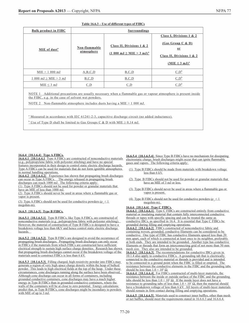
77-20
Report on Proposals A2013 — Copyright, NFPA NFPA 77
16.6.4 10.1.6.4 Type A FIBCs.16.6.4.1 10.1.6.4.1 Type A FIBCs are constructed of nonconductive materials (e.g., polypropylene fabric with polyester stitching) and have no special features incorporated in their design to control static electric discharge hazards. Type A FIBCs can be used for materials that do not form ignitible atmospheres in normal handling operations.16.6.4.2 10.1.6.4.2 Experience has shown that propagating brush discharges can occur in Type A FIBCs. The energy released in propagating brush discharges can reach 1000 mJ. The following criteria apply: (1) Type A FIBCs should not be used for powder or granular materials that have an MIE of less than 1000 mJ.(2) Type A FIBCs should never be used in areas where a flammable gas or vapor is present.(3) Type A FIBCs should not be used for conductive powders (ρv < 1 megohm-m).
16.6.5 10.1.6.5 Type B FIBCs.
16.6.5.1 10.1.6.5.1 Type B FIBCs, like Type A FIBCs, are constructed of nonconductive materials (e.g., polypropylene fabric with polyester stitching). However, the material of construction of Type B FIBCs is designed to have a breakdown voltage less than 6KV and hence control static electric discharge hazards.
16.6.5.2 10.1.6.5.2 Type B FIBCs are designed to avoid the occurrence of propagating brush discharges. Propagating brush discharges can only occur in FIBCs if the materials from which FIBCs are constructed have sufficient electrical strength to sustain high surface charge densities. Research has shown that propagating brush discharges cannot occur if the breakdown voltage of the materials used to construct FIBCs is less than 6 kV.
16.6.5.3 10.1.6.5.3 Filling charged, high resistivity powder into FIBCs may generate a region of very high space charge density within the heap of bulked powder. This leads to high electrical fields at the top of the heap. Under these circumstances, cone discharges running along the surface have been observed. Although cone discharge can occur in all forms of containers, including grounded conductive containers, cone discharges may have a much higher energy in Type B FIBCs than in grounded conductive containers, where the walls of the containers will be at close to zero potential. Energy calculations predict that, in Type B FIBCs, cone discharges might be incendiary to powders with MIE of up to 3 mJ.
16.6.5.4 10.1.6.5.4 Since Type B FIBCs have no mechanism for dissipating electrostatic charge, brush discharges might occur that can ignite flammable gases and vapors. The following criteria apply:
(1) Type B FIBCs should be made from materials with breakdown voltage less than 6 kV.
(2) Type B FIBCs should not be used for powder or granular materials that have an MIE of 3 mJ or less.
(3) Type B FIBCs should never be used in areas where a flammable gas or vapor is present.
(4) Type B FIBCs should not be used for conductive powders (ρv < 1 megohm-m).
16.6.6 10.1.6.6 Type C FIBCs.16.6.6.1 10.1.6.6.1 Type C FIBCs are constructed entirely from conductive material or insulating material that contain fully interconnected conductive threads or tapes with specific spacing and can be treated the same as conductive IBCs, as specified in 16.4. It is essential that Type C FIBCs be grounded during filling and emptying operations.16.6.6.2 10.1.6.6.2 FIBCs constructed of nonconductive fabric and containing woven, grounded, conductive filaments can be considered to be conductive. One type of FIBC has conductive filaments spaced less than 20 mm apart, each of which is connected at least once to its neighbor, preferably at both ends. They are intended to be grounded. Another type has conductive filaments or threads that form an interconnecting grid of not more than 50 mm mesh size. They also are intended to be grounded.16.6.6.3 10.1.6.6.3 The recommendations for conductive IBCs given in 10.1.4 also apply to conductive FIBCs. A grounding tab that is electrically connected to the conductive material or threads is provided and is intended to be connected to a ground point when the FIBC is filled or emptied. The resistance between the conductive elements in the FIBC and the grounding tabs should be less than 1.0 × 10⁷ Ω.16.6.6.4 10.1.6.6.4 For FIBCs constructed of multi-layer materials, the resistance between the inside or outside surface of the FIBC and the grounding tabs should be less than 1.0 × 10⁷ Ω. If the inside layer does not have a resistance to grounding tabs of less than 1.0 × 10⁷ Ω, then the material should have a breakdown voltage of less than 6 kV. All layers of multi-layer materials should remain in firm contact during filling and emptying operations. 16.6.6.5 10.1.6.6.5 Materials used to construct inner baffles, other than mesh or net baffles, should meet the requirements stated in 16.6.6.3 and 16.6.6.4.
Table 16.6.3 – Use of different types of FIBCs
Bulk product in FIBC Surroundings
MIE of dusta Non-flammable atmosphere
Class II, Divisions 1 & 2
(1 000 mJ ≥ MIE > 3 mJ)a
Class I, Divisions 1 & 2
(Gas Group C & D) or
Class II, Divisions 1 & 2
(MIE ≤ 3 mJ)a
MIE > 1 000 mJ A,B,C,D B,C,D C,Db
1 000 mJ ≥ MIE > 3 mJ B,C,D B,C,D C,Db
MIE ≤ 3 mJ C,D C,D C,Db
NOTE 1 Additional precautions are usually necessary when a flammable gas or vapour atmosphere is present inside the FIBC, e.g. in the case of solvent wet powders.
NOTE 2 Non-flammable atmosphere includes dusts having a MIE > 1 000 mJ.
a Measured in accordance with IEC 61241-2-3, capacitive discharge circuit (no added inductance). b Use of Type D shall be limited to Gas Groups C & D with MIE ≥ 0,14 mJ.
77-21
Report on Proposals A2013 — Copyright, NFPA NFPA 7716.6.7 10.1.6.7 Type D FIBCs.
16.6.7.1 10.1.6.7.1 Type D FIBCs are constructed from fabrics and/or threads with special electrostatic properties to control discharge incendivity and are intended for use without grounding in the presence of flammable vapors or gases with MIE of 0.14 mJ or greater and with combustible powders, including those with ignition energies of 3 mJ or less.
16.6.7.2 10.1.6.7.2 Before being used in hazardous environments, Type D FIBCs should be qualified as safe, i.e. by demonstrating that no incendiary discharge can occur under normal operating conditions. IEC 61340-4-4 describes test procedures for ignition testing that can be used for this purpose.
16.6.7.3 10.1.6.7.3 If Type D FIBCs are made from materials that have an insulating layer (e.g. coating, film, or lamination) on the inside of the container, the materials should have a breakdown voltage of less than 6 kV. All layers of multi-layer materials should remain in firm contact during filling and emptying operations.16.6.8 10.1.7 Liners for Flexible Intermediate Bulk Containers – ReservedSubstantiation: This rewrite correlates with internationally accepted recommendations for flexible intermediate bulk containers, as set forth in IEC 61340-4-4. Committee Meeting Action: AcceptNumber Eligible to Vote: 21 Ballot Results: Affirmative: 19 Ballot Not Returned: 2 Minnich, B., Mitchell, R.Comment on Affirmative: GRAVELL, R.: Technical content is fine, but this section should be simplified and explanatory or informational notes moved to the Annex. _______________________________________________________________ 77-106 Log #CP104 Final Action: Accept(10.2.3.3 (New 17.3.3))_______________________________________________________________ Submitter: Technical Committee on Static Electricity, Recommendation: Revise 10.2.3.3 (New 17.3.3) to read: “Measurement of coating solution conductivity can provide additional data to determine static generation and dissipation characteristics. Solvent-based coatings having conductivities less than 104 pS/m should be carefully evaluated for their ability to dissipate charge. Flammable solvent-based inks and coatings should be considered nonconductive and, therefore, incapable of dissipating a charge. Conductivity enhancers in the ink or coating cannot be relied on to assist dissipation of charge at high processing speeds. Measurement of coating solution conductivity can provide additional data to determine static generation and dissipation characteristics.Substantiation: The statement that “Flammable solvent-based inks and coatings should be considered nonconductive” isn’t necessarily true. Committee Meeting Action: AcceptNumber Eligible to Vote: 21 Ballot Results: Affirmative: 19 Ballot Not Returned: 2 Minnich, B., Mitchell, R._______________________________________________________________ 77-107 Log #CP105 Final Action: Accept(10.2.4.2 (New 17.4.2))_______________________________________________________________ Submitter: Technical Committee on Static Electricity, Recommendation: Revise 10.2.4.2 (New 17.4.2) to read: “Coating. Coating of web materials is done using both flammable and nonflammable liquids on a wide variety of equipment. Significant charge may be generated where high forces between rollers and web are present, such as in gravure coating, and where web slippage is present due to tension difference across the coating roller. This may result in a static ignition hazard where flammable coatings are used. High charge can also accumulate on the rubber backup roller and an electrostatic neutralizer may be needed if this poses an ignition hazard. Some coating processes can generate hazardous amounts of static electric charge due to their design, while others cause little effect. The operating conditions that cause high rates of charge generation include high forces between rollers and the web, such as in gravure coating. This high rate of generation is aggravated by maintaining a tension difference across the coating roller, which causes slippage. The result is a sizable charge at the point where a large amount of ignitible vapor and a large liquid surface area are present. The rubber backup roller can accumulate enough electrostatic charge to present an ignition hazard. An electrostatic charge neutralizer might be needed on the roller.Substantiation: Editorial improvement. The comments in this section apply to coating operations in general, although the way in which it is worded seems to imply that it only applies to flammable coating operations. Committee Meeting Action: AcceptNumber Eligible to Vote: 21 Ballot Results: Affirmative: 19 Ballot Not Returned: 2 Minnich, B., Mitchell, R.
_______________________________________________________________ 77-108 Log #CP106 Final Action: Accept(10.2.4.5 (New 17.4.5))_______________________________________________________________ Submitter: Technical Committee on Static Electricity, Recommendation: Delete both 10.2.4.5.1 (New 17.4.5.1) and 10.2.4.5.2 (New 17.4.5.2). Substantiation: These two paragraphs address issues which are outside the scope of NFPA 77. Committee Meeting Action: AcceptNumber Eligible to Vote: 21 Ballot Results: Affirmative: 19 Ballot Not Returned: 2 Minnich, B., Mitchell, R._______________________________________________________________ 77-109 Log #CP107 Final Action: Accept(10.2.5 (New 17.5))_______________________________________________________________ Submitter: Technical Committee on Static Electricity, Recommendation: Replace the current 10.2.5 (New 17.5) with the following: “17.5 NEW Control of Static Electricity in Web Processes.17.5.1 Charging in Web Handling Operations. Charging of webs may occur during unwinding, travel over rollers, pressing between rolls, or contact with coating rolls. Charging will generally increase with increasing web speed, tension, and roller wrap angle; a finer roll surface finish will enhance charging by increasing the area of roll/web contact. Web slippage over roll surfaces, caused by differential web speed or roll malfunction, may also significantly increase charging. 17.5.2 Potential Hazards of Charged Webs. 17.5.2.1 Static charges on a web may result in brush discharges from the web or spark discharges from ungrounded machine components or personnel which have become inductively charged as a result of their close proximity to the web. Such discharges may present shock hazards to operators or lead to fires in flammable coating operations and gravure printing. 17.5.2.2 For flammable operations, mechanical ventilation can be used in order to dilute vapors to a safe concentration well below the lower flammable limit (LFL). “Pumping” of vapors by the moving web at higher speeds may increase the volume over which such an atmosphere may be present. Vapors will always be within the flammable range close to the point of coating application; this volume should be minimized by capturing vapors as close to their source as possible. Equipment should be interlocked to shut down upon ventilation system failure or if vapor concentration becomes too high. 17.5.3 Static Charge Control 17.5.3.1 Conductive Components. Items which may become potential ignition sources via induction charging include ungrounded conductive machine components, conductive objects on or in the web, and personnel in close proximity to the operation. All conductive parts of the machine should be grounded in order to prevent them from becoming a potential spark source due to inductive charging; resistance to ground from fixed metallic objects should not exceed 10. 17.5.3.1.1 The resistance to ground of rollers should be determined upon initial installation and verified periodically thereafter. Resistance should not exceed 1 megohm. Since lubricant films can significantly increase resistance (as the bearings “float” on the lubricant), measurement should be performed during operation. The grounding of conductive rollers may also be compromised by non-conductive bearing lubricants or excessive bearing clearances, as well as build up of dirt or rust over time. Rolling or sliding contacts, such as conductive brushes, can be used to ground rollers in cases where an acceptably low resistance cannot be obtained. 17.5.3.1.2 Isolated conductive objects on or in the film may become inductively charged by the web and present a sparking hazard. Grounding of such objects, where possible, will prevent this. 17.5.3.2 Non-Conductive Webs. Grounding of non-conductive webs is not possible and other methods are necessary for static control. Existing processes should be audited to determine where significant charge is being generated. Measurements may be made with an electrostatic fieldmeter for web sections well away from grounded objects, such as rollers. 17.5.3.2.1 The first goal of a static-control program should be to minimize charge generation. Possible methods include minimizing web tension (but not to the extent that slippage occurs), ensuring that idler rollers have clean surfaces and are freely-rotating, minimizing web slippage, and increasing roller surface roughness. Non-conductive roller covers can acquire significant charge and should be replaced with static-dissipative covers where possible; otherwise the use of non-conductive covers which will minimize contact charging with the web material. 17.5.3.2.2 Humidification is sometimes used to reduce static charge on non-conductive objects by providing a monolayer of moisture that decreases surface resistivity, enhancing charge dissipation. This is often not possible in web handling operations since the speed of the operation does not allow sufficient time for uptake of atmospheric moisture by the surface of the material. Also, many plastic web materials will not be significantly affected by moisture even with extended exposure time. For these reasons humidification should not be relied upon as the sole method for static control in web handling processes, although in some cases higher humidity levels can be used to reduce static charge. 17.5.3.2.3 Ionization involves the use of devices which produce ions that
77-22
Report on Proposals A2013 — Copyright, NFPA NFPA 77neutralize surface charges and is the primary method used for static control on webs. Ionization devices may be needed at various points in a web handling system where charging occurs (reference existing figure). Such devices should extend across the full width of the web. Passive ionization involves the use of grounded tinsels, strings, needles, or brushes located a short distance (typically 5 to 25 mm) above the web. The electric field above the web is concentrated at the points of the tinsel, string, needle, or brush, resulting in breakdown and ionization of the surrounding air. Air ions having polarity opposite to charges on the web are attracted to the surface of the web, neutralizing the charge. Typically, this method can reduce surface potential to 0.5-3 kV. It is important that passive ionizing elements be positioned properly, grounded, and have points which are kept clean and sharp. Performance should be verified by periodic static charge measurements on the web downstream of the ionizer. 17.5.3.2.4 Active ionization involves the use of electrically-powered devices or radiological sources. AC ionizers are most commonly used and contain an array of high voltage pointed electrodes which emit both positive and negative air ions. Neutralization is achieved by the attraction of air ions having opposite polarity to surface charges on the web. The effectiveness of ionizers decreases greatly with distance from the web; for this reason ionizers are typically located about 25-50 mm from the web; forced air-assisted units (ionizing blowers) may be capable of neutralizing charge at somewhat greater distances. Ionizers should be located in a position so that ion flow will be towards the web rather than to a nearby grounded surfaces and in accordance with manufacturers’ recommendations. See Figure 17.5.3.2.4. 17.5.3.2.5 Performance of ionizers should be verified upon initial installation and periodically during use. Electrically-powered ionizers used in flammable vapor environments must be listed for the hazardous (classified) location in which they are installed. 17.5.3.2.6 It is particularly important to ensure that web charge is reduced to a safe level as it enters flammable coating stations. Potentially incendive brush discharges may occur if web surface charge density exceeds 10 µC/m2. To maintain a margin of safety, it is recommended that maximum indicated voltage above the web not exceed 5 kV as measured at a distance of 25 mm (field strength of 200 kV per meter). 17.5.3.2.7 An ionizer should be located as close as possible to where the web enters the coater. Surface charge should be continuously monitored after the ionizer and the process should be automatically shut down if safe electric field values are exceeded. An additional ionizer may also be required at the coater exit if charging can occurs at that point. 17.5.3.2 Personnel. Personnel should be grounded, preferably by use of static-dissipative footwear and a static dissipative flooring surface.”Substantiation: This rewrite of the section on web processes is primarily an editorial revision to clarify the presentation of the material and to cover topics not addressed previously. Committee Meeting Action: AcceptNumber Eligible to Vote: 21 Ballot Results: Affirmative: 19 Ballot Not Returned: 2 Minnich, B., Mitchell, R.Comment on Affirmative: GRAVELL, R.: Section 17.5.3.2 should be numbered 17.5.3.3; also suggest rewording to “Where personnel shocks resulting from induction charging may pose a hazard personnel should be grounded, preferably by use of static-dissipative footwear and a static-dissipative flooring surface”. WASH, T.: In Figure 17.5.3.2.4 Location of one of the static neutralizers, on the last idler before the Gravure roll is located opposite of the opening nip which is incorrect or misleading. It should be located at the opening of the nip. Nip = where film separates from the roll. _______________________________________________________________ 77-110 Log #CP58 Final Action: Accept(10.2.5.3.5 (New 17.5.3.5))_______________________________________________________________ Submitter: Technical Committee on Static Electricity, Recommendation: Revise the first sentence of 10.2.5.3.5 (New 17.5.3.5) to read: “The location of the initial inductive ionizer should be 100 mm to 150 175 mm from the roller tangent (i.e., web exit) point and 6 mm to 25 mm from the web.” Substantiation: The 175 mm measurement is not correct; it does not match what is depicted in Figure 10.2.5.3.1 (new Figure 17.5.3.1). Committee Meeting Action: AcceptNumber Eligible to Vote: 21 Ballot Results: Affirmative: 19 Ballot Not Returned: 2 Minnich, B., Mitchell, R.Comment on Affirmative: GRAVELL, R.: While the proposed change is editorially correct the use of a fixed distance does not account for different roller diameters. Rather than a fixed distance the location of the ionizer should be a minimum of 3 roller radii downstream of the film/roller separation point.
_______________________________________________________________ 77-111 Log #CP59 Final Action: Accept(10.4.2.2.2 (New 18.2.2.2.2))_______________________________________________________________ Submitter: Technical Committee on Static Electricity, Recommendation: Relocate 10.4.2.2.2 (New 18.2.2.2.2) to a new location designated 18.2.4.3. Substantiation: The subject of this text has to do with conveyor belts, not flat power transmission belts. Committee Meeting Action: AcceptNumber Eligible to Vote: 21 Ballot Results: Affirmative: 19 Ballot Not Returned: 2 Minnich, B., Mitchell, R._______________________________________________________________ 77-112 Log #CP52 Final Action: Accept(10.4.3.2 (New 18.2.3.2))_______________________________________________________________ Submitter: Technical Committee on Static Electricity, Recommendation: Add the following to the end of this paragrapH: “(See CENELEC 60079-10, Electrical Apparatus for Explosive Gas Atmospheres - Part 10: Classification of Hazardous Areas.)”Substantiation: the referenced document provides additional information to the user. Committee Meeting Action: AcceptNumber Eligible to Vote: 21 Ballot Results: Affirmative: 18 Negative: 1 Ballot Not Returned: 2 Minnich, B., Mitchell, R.Explanation of Negative: GRAVELL, R.: Cited reference is incorrect and should be CENELEC TR50504, “Electrostatics - Code of Practice for the Avoidance of Hazards Due to Static Electricity”. _______________________________________________________________ 77-113 Log #CP90 Final Action: Accept(15.5.5 (New))_______________________________________________________________ Submitter: Technical Committee on Static Electricity, Recommendation: Add a new 15.5.5 to read: “Lightning-Like Discharges. While collection of individual particle charges to create a lightning-like discharge is seen in nature (thunderstorms, volcanic eruptions), such discharges have not been seen in industrial operations.”Substantiation: Dust cloud ignition is still sometimes erroneously attributed to ‘lightning like’ discharges; this should be dispelled. Committee Meeting Action: AcceptNumber Eligible to Vote: 21 Ballot Results: Affirmative: 19 Ballot Not Returned: 2 Minnich, B., Mitchell, R. _______________________________________________________________ 77-114 Log #CP93 Final Action: Accept(15.8.3 (New))_______________________________________________________________ Submitter: Technical Committee on Static Electricity, Recommendation: Add a new 15.8.3 to read: “15.8.3 New Conductive or static dissipative hoses should be used for transport of combustible dust and in situations where a flammable external atmosphere may exist. It should be ensured that such hoses are adequately connected to conductive end fittings and are properly grounded.Substantiation: It should be stated that only conductive or static-dissipative hoses should be used for combustible dusts or where there potentially is a combustible or flammable external atmosphere. Committee Meeting Action: AcceptNumber Eligible to Vote: 21 Ballot Results: Affirmative: 19 Ballot Not Returned: 2 Minnich, B., Mitchell, R. _______________________________________________________________ 77-115 Log #CP60 Final Action: Accept(A.8.4.1 (New A.10.1))_______________________________________________________________ Submitter: Technical Committee on Static Electricity, Recommendation: In the third sentence, replace the phrase “charging current” with “streaming current”. Substantiation: Correction of error in terminology.Committee Meeting Action: AcceptNumber Eligible to Vote: 21 Ballot Results: Affirmative: 19 Ballot Not Returned: 2 Minnich, B., Mitchell, R.

77-23
Report on Proposals A2013 — Copyright, NFPA NFPA 77_______________________________________________________________ 77-116 Log #CP113 Final Action: Accept(Table B.1)_______________________________________________________________ Submitter: Technical Committee on Static Electricity, Recommendation: Correct the entries for LMIE in Table B.1 in accordance with the following:
Flammability Data for Gases and VaporsIn dry air at 1 atm, 25C except where indicated
See footnotes for explanations of symbolsGas/Vapor LMIE = G
(mJ) acetaldehyde 0.13(a)
acetone 0.19(a) acetone (in oxygen) 0.0024
acetylene 0.017 acetylene (in oxygen) 0.0002
acetylene (decomp @ 1 atm) 103-105
acetylene (decomp @ 2 atm) 102 –103
acrolein 0.13 acrylonitrile 0.16 allyl chloride 0.77(b)
ammonia 680 benzene 0.20
1,3 butadiene 0.13 n-butane 0.24
n-butane (in oxygen) 0.009 n-butyl chloride 1.24(b) carbon disulfide 0.009
cyclohexane 0.22 cyclopentadiene 0.17(a)
cyclopentane 0.24(a) cyclopropane 0.17
cyclopropane (in oxygen) 0.001 dichlorosilane 0.015 diethyl ether 0.19
diethyl ether (in oxygen) 0.0012 diisobutylene 0.23(a)
diisopropyl ether 0.23(a) dimethoxymethane (methylal) 0.12(a)
2,2-dimethylbutane 0.25 dimethyl ether 0.14(a)
dimethyl sulfide 0.48(b) di-t-butyl peroxide 0.1
ethane 0.23 ethane (in oxygen) 0.0019
ethanol 0.23(a) ethyl acetate 0.23(a) ethyl acrylate 0.18(a) ethylamine 0.19(a)
ethylene 0.084 ethylene (in oxygen) 0.00094
ethyleneimine 0.11(a) ethylene oxide 0.065
ethylene oxide (decomp) ~1500 furan 0.14(a)
n-heptane 0.23 n-hexane 0.23
n-hexane (in oxygen) 0.006 hydrogen 0.016
hydrogen (in oxygen) 0.0012 hydrogen (in nitric oxide) 8.7
hydrogen sulfide 0.068 isooctane 0.25(a)
isopropyl alcohol 0.21(a) isopropyl chloride 1.08(b)
isopropylamine 0.23(a) methane 0.21
methane (in oxygen) 0.0027 methane (in nitric oxide) 8.7
methanol 0.14 methylacetylene 0.11
Lowest MIE = lowest minimum ignition energy measured at optimum concentration (a) = Lowest MIE calculated using heat of oxidation method (b) = Lowest MIE is too high, measured at stoichiometric concentration, but is not amenable to calculation using heat of oxidation method.Substantiation: This incorporates more recently developed data for the lowest minimum ignition energies of selected gases and vapors. Committee Meeting Action: AcceptNumber Eligible to Vote: 21 Ballot Results: Affirmative: 19 Ballot Not Returned: 2 Minnich, B., Mitchell, R._______________________________________________________________ 77-117 Log #1 Final Action: Accept(D.1.2)_______________________________________________________________ Submitter: Cash Mason, Teck ComincoRecommendation: Revise text to read as follows: “...and toluene generates its lowest-MIE vapor air-mixture at about 2.6°C (26°C) (4.1 percent...”. Substantiation: Wrong data – please get your expert to check this out.Committee Meeting Action: AcceptNumber Eligible to Vote: 21 Ballot Results: Affirmative: 19 Ballot Not Returned: 2 Minnich, B., Mitchell, R._______________________________________________________________ 77-118 Log #11 Final Action: Accept in Principle(H.2.15.1.3)_______________________________________________________________ Submitter: Steven J. Gunsel, SGTechnologies, LLCRecommendation: Revise text to read as follows:H.2.15.1.3 The unit of conductivity is ohms per meter (Ω m). [note basis in reciprocal of resistivity with units of ohm-meters; mhos ohms per meter is the same as siemens per meter (S/m)]. Some authors express volume resistivity data in terms of ohm-m (100 ohm-cm = 1 ohm-m). Substantiation: Conductivity is the reciprocal of resistivity. Resistivity is usually stated in ohm-cm or ohm-m. The reciprocal of ohm-m is NOT ohm/m, but 1/(ohm-m). Mho is the symbol for 1/ohm. Note: 1 mho = 1 siemen = 1/ohm; therefore mho/m = siemens per meter Committee Meeting Action: Accept in Principle
Flammability Data for Gases and VaporsIn dry air at 1 atm, 25C except where indicated
See footnotes for explanations of symbolsGas/Vapor LMIE = G
methyl acrylate 0.18(a) methylene chloride >1000
methylene chloride (in oxygen) 0.137 methyl ethyl ketone 0.21(a)
methyl butane (isopentane) 0.21 methyl cyclohexane 0.27
methyl formate 0.13(a) n-pentane 0.24
2-methyl pentene 0.18 propadiene 0.087(a)
propane 0.24 propane (in oxygen) 0.0021
propionaldehyde 0.18(a) n-propyl chloride 1.08(b)
propylene 0.18(a) propylene oxide 0.13
isopropyl mercaptan 0.53(b) styrene 0.18(a)
tetrahydrofuran 0.19(a) tetrahydropyran 0.22
thiophene 0.39(b) toluene 0.24
trichloroethane (in oxygen) 0.092 trichlorosilane 0.017 triethylamine 0.22(a) vinyl acetate 0.16(a)
vinyl acetylene 0.082 xylene(s) 0.2
Source: Britton, L.G., “Using Heats of Oxidation to Evaluate Flammability Hazards”, Process Safety Progress, Vol. 21, No.1, March 2003

77-24
Report on Proposals A2013 — Copyright, NFPA NFPA 77Delete H.2.15.1.3 entirely. See action on Proposal 77-16 (Log #CP12). Committee Statement: The proposed action in Proposal 77-16 (Log #CP12) presents a more accurate and a more editorially clean means of addressing the concerns of the submitter. Number Eligible to Vote: 21 Ballot Results: Affirmative: 19 Ballot Not Returned: 2 Minnich, B., Mitchell, R._______________________________________________________________ 77-119 Log #8 Final Action: Accept in Principle(H.2.46)_______________________________________________________________ Submitter: Steven J. Gunsel, SGTechnologies, LLCRecommendation: Revise text to read as follows:H.2.46 Ohm. The resistance of a circuit through which a current of 1 ampere will flow when a potential difference of 1 volt is applied across the current circuit. OR The unit of electrical resistance (R), which measures the resistance between two points of a conductor when a constant difference of potential of one volt between these two points produces in this conductor a current of one ampere.Substantiation: The electrical potential across the resistance causes current to flow. An electrical potential of one volt causes a current of 1 ampere to flow through a resistance of 1 ohm. The first definition above corrects a mistake in terminology, the second definition is the preferred definition in NFPA Glossary of Terms.Committee Meeting Action: Accept in PrincipleDelete H.2.46 entirely. Committee Statement: The concept is adequately explained in the definition of “resistance” in H.2.50. This is a simpler means of meeting the submitter’s intent. Number Eligible to Vote: 21 Ballot Results: Affirmative: 19 Ballot Not Returned: 2 Minnich, B., Mitchell, R._______________________________________________________________ 77-120 Log #6 Final Action: Accept in Principle(H.2.50)_______________________________________________________________ Submitter: Steven J. Gunsel, SGTechnologies, LLCRecommendation: Revise text to read as follows:H.2.50 Resistance (R). The opposition that a device or material offers to the flow of direct current. The resistance in ohms is equal to the voltage drop, in volts, across the material element divided by the current, in amperes, through the material element for a purely resistive circuit. also known as electrical resistance.Substantiation: Resistance applies equally to both alternating and direct currents. The use of Ohm’s law for calculating the value of a resistance in ohms applies to purely resistive loads only. When alternating currents are present, special precautions must be taken to allow for inductive and capacitive circuit elements to assure an accurate measurement. Committee Meeting Action: Accept in PrincipleDelete H.2.50 and add a new definition to new 3.3.35 to read: “3.3.35 Resistance (R). The opposition that a material offers to the flow of current, expressed in ohms, which is equal to the voltage (V, volts) between two points divided by the current (I, amperes) that flows between those points.” Committee Statement: The proposed new definition is more accurate and meets the submitter’s intent. It has been relocated to Chapter 3, as the term “resistance” is used throughout the text. The Technical Committee notes that this definition is designated 3.3.35 in the Preprint. Number Eligible to Vote: 21 Ballot Results: Affirmative: 19 Ballot Not Returned: 2 Minnich, B., Mitchell, R._______________________________________________________________ 77-121 Log #7 Final Action: Accept in Principle(H.2.51)_______________________________________________________________ Submitter: Steven J. Gunsel, SGTechnologies, LLCRecommendation: Add new text to read as follows:Resistivity. The intrinsic property of all materials that opposes the flow of electric current. A low resistivity (high conductivity) indicates a material that readily allows the movement of electrical charge. The resistivity on the surface of a material often differs from the resistivity through a volume of the same material. The resistance of a material depends on its resistivity and geometry. Resistivity is the reciprocal of conductivity.Substantiation: Resistivity is a fundamental property that is critical to defining and understanding resistance. “Resistance” is used repeatedly throughout this document and proper understanding of the term is important to assure correct implementation. The definitions for surface resistivity and volume resistivity should also be improved. Committee Meeting Action: Accept in PrincipleDelete H.2.51 Heading and add a new definition of “resistivity” to 3.3.36 to read: “3.3.36 Resistivity. The intrinsic property of a honogeneous material that opposes the flow of electric current. A low resistivity (high conductivity) indicates a material that readily allows the movement of electrical charge. The resistivity across the surface of a material will differ from the resistivity
through a volume of the same material. Also, the resistance of a material depends on its resistivity and its geometry. Resistivity is the reciprocal of conductivity.”Committee Statement: The Technical Committee’s version is more technically accurate and meets the submitter’s intent. Number Eligible to Vote: 21 Ballot Results: Affirmative: 19 Ballot Not Returned: 2 Minnich, B., Mitchell, R._______________________________________________________________ 77-122 Log #5 Final Action: Accept in Principle(H.2.51.1)_______________________________________________________________ Submitter: Steven J. Gunsel, SGTechnologies, LLCRecommendation: Revise text to read as follows:H.2.51.1 Surface Resistivity. The resistivity resistance of the surface of a material an insulator, in ohms per square, as measured between the opposite sides of a square on the surface reported in units of ohms or in ohms per square and whose value in ohms is independent of the size of the square or the thickness of the surface film. The resistivity of a surface can differ from the volume resistivity of a material due to surface contamination, chemical reactivity, and atmospheric moisture. Common electrode arrangements for measuring surface resistivity of a solid material include: parallel electrodes, coaxial electrodes, a four point probe, and the van der Paaw method. Alternate: surface resistivity. resistance across opposite sides of a surface of unit length and unit width commonly expressed in ohms (or ohms/square). Measurement of surface resistivity depends upon selection of the appropriate test procedureSubstantiation: The existing definition of surface resistivity is incomplete and does not include common measurement techniques. Committee Meeting Action: Accept in Principle Accept in principle by means of Proposal 77-37 (Log #CP29). Committee Statement: See Proposal 77-37 (Log #CP29).Number Eligible to Vote: 21 Ballot Results: Affirmative: 19 Ballot Not Returned: 2 Minnich, B., Mitchell, R.Comment on Affirmative: WERTSBERGER, S.: Strange character between “...of ohms ---” and “ --ohms per square...” _______________________________________________________________ 77-123 Log #12 Final Action: Accept in Principle(H.2.51.2)_______________________________________________________________ Submitter: Steven J. Gunsel, SGTechnologies, LLCRecommendation: Revise text to read as follows:H.2.51.2 Volume resistivity. The intrinsic property resistance of a sample of material that opposes the flow of electric current through the material, expressed in ohm-meters or ohm-cm. ,having unit length and un it cross sectional area. The resistance of an object is a function of its resistivity and geometry.Substantiation: The existing definition of volume resistivity is incomplete.Committee Meeting Action: Accept in PrincipleDelete H.2.51.2 entirely. Add a new definition of “volume resistivity” to 3.3.36.2 to read as follows: “3.3.36.2 Volume Resistivity. The intrinsic property of a material that offers resistance to the flow of electric current through the material, expressed in ohm-meters (ohm-m) or ohm-centimeters (ohm-cm).A.3.3.36.2 The resistance of an object is a function of its resistivity and its geometry. Typical test procedures include ASTM D991, Standard Test Method for Rubber Property-Volume Resistivity of Electrically Conductive and Antistatic Products, and D257, Standard Test Methods for DC Resistance or Conductance of Insulating Materials.”Committee Statement: Since this term is used throughout the text of NFPA 77, it is appropriate that it be defined in Section 3.3 and not in Annex H. The Technical Committee has provided a new definition that is more technically accurate and that includes appropriate test procedures. Number Eligible to Vote: 21 Ballot Results: Affirmative: 19 Ballot Not Returned: 2 Minnich, B., Mitchell, R._______________________________________________________________ 77-124 Log #CP112 Final Action: Accept(Annex I, Bibliography (New))_______________________________________________________________ Submitter: Technical Committee on Static Electricity, Recommendation: Add a new Annex I Bibliography to read: BIBLIOGRAPHY for NFPA 77 - 2000 Cross, J. A., Electrostatics: Principles, Problems and Applications, Adam Hilger, Bristol, England, UK, 1987 [ISBN 0-85274-589-3] Guest, P. G., Static Electricity in Nature and Industry, U. S. Department of Commerce - Bureau of Mines, U. S. Government Printing Office, Washington, DC, USA, 1939 Moore, A. D., Ed., Electrostatics and Its Application, 2nd Ed., John Wiley & Sons - Wiley Interscience, New York, NY, USA, 1973 [ISBN 0-471-61450-5] Moore, A. D., Electrostatics - Exploring, Controlling, and Using Static
77-25
Report on Proposals A2013 — Copyright, NFPA NFPA 77Explanation of Negative: BRITTON, L.: Need to add Britton & Smith (2012) and Britton (2010) to document recent text changes, as noted earlier.
Electricity, 2nd Ed., Laplacian Press, Morgan Hill, CA, USA, 1997 [ISBN 1-885540-04-3] Pratt, T. H., Electrostatic Ignitions of Fires and Explosions, Burgoyne, Inc., Marietta, GA, USA, 1997, [ISBN 0-9659092-0-4] Pratt, T. H., Possible Electrostatic Hazards in Material Handling Systems, 1992 Process Plant Safety Symposium, South Texas Section, American Institute of Chemical Engineers, 1992, pp. 1114-1123 Uman, M. A., Lightning, Dover Publications, New York, NY, USA, 1989 [ISBN 0-486-64575-4] Redesignate current Annex I as Annex J. Substantiation: The Technical Committee has determined that a bibliography of books, monographs, etc. on the subject of static electricity will be a benefit to the user. Committee Meeting Action: AcceptNumber Eligible to Vote: 21 Ballot Results: Affirmative: 19 Ballot Not Returned: 2 Minnich, B., Mitchell, R._______________________________________________________________ 77-125 Log #CP116 Final Action: Accept(Annex I (New Annex J))_______________________________________________________________ Submitter: Technical Committee on Static Electricity, Recommendation: Redesignate “Annex I” as “Annex J” and revise to read as follows: “J.1.1 NFPA Publications. National Fire Protection Association, 1 Batterymarch Park, Quincy, MA 02169-7471. NFPA 30A, Code for Motor Fuel Dispensing Facilities and Repair Garages, 2012 2007 edition. NFPA 33, Standard for Spray Application Using Flammable or Combustible Materials, 2011 2007 edition. NFPA 53, Recommended Practice on Materials, Equipment, and Systems Used in Oxygen-Enriched Atmospheres, 2011 2004 edition. NFPA 69, Standard on Explosion Prevention Systems, 2008 2002 edition. NFPA 70, National Electrical Code®, 2014 2005 edition.NFPA 99, Standard for Health Care Facilities, 2005 edition. NFPA 302, Fire Protection Standard for Pleasure and Commercial Motor Craft, 20120 2004 edition. NFPA 318, Standard for the Protection of Semiconductor Fabrication Facilities, 2012 2006 edition. NFPA 326, Standard for the Safeguarding of Tanks and Containers for Entry, Cleaning, or Repair, 2010 2005 edition. NFPA 407, Standard for Aircraft Fuel Servicing, 2012 2007 edition. NFPA 780, Standard for the Installation of Lightning Protection Systems, 2011 2004 edition.J.1.2 Other Publications. J.1.2.1 AIChE Publications. American Institute of Chemical Engineers, 3 Park Avenue, New York, NY 10016-5901. Britton, L. G., “Using Material Data in Static Hazard Assessment,” Plant/Operations Progress, Vol. 11, April 1992, pp. 56–70. Britton, L. G., Avoiding Static Ignition Hazards in Chemical Operations, 1999. J.1.2.2 ANSI Publications. American National Standards Institute, Inc., 11 West 43rd Street, 4th Floor, New York, NY 10036. ANSI Z41, Standard for Personal Protection — Protective Footwear, 1999 1991.J.1.2.3 API Publications. American Petroleum Institute, 1220 L Street, NW, Washington, DC 20005. Bustin, W. M., et al., New Theory for Static Relaxation from High Resistivity Fuel, API Refining Division Proceedings, Vol. 44, No. 3, 1964. API RP 2003, Protection Against Ignitions Arising Out of Static, Lightning, and Stray Currents, 6th edition, September, 7th edition, 2008 1998.API 2219, Safe Operation of Vacuum Trucks in the Petroleum Service, 3rd 2d edition, 2005 1999.J.1.2.4 ASTM Publications. ASTM International, 100 Barr Harbor Drive, P.O. Box C700, West Conshohocken, PA 19428-2959. ASTM E 502, Standard Test Method for Selection and Use of ASTM Standards for the Determination of Flash Point of Chemicals by Closed Cup Methods, 2007 1984 (reapproved 1994).J.1.2.5 CENELEC Publications. European Committee for Electrotechnical Standardization (CENELEC), Rue de Stassart, 35, B - 1050 Brussels, Belgium. CENELEC Draft Standard Safety of Machinery — Electrotechnical Aspects, 1996. J.1.2.6 NPCA Publications. National Paint and Coatings Association, 1500 Rhode Island Avenue, NW, Washington, DC 20005-5597. Generation and Control of Static Electricity in Coatings Operations, 2010 1998.J.2 Informational References. (Reserved) J.3 References for Extracts in Informational Sections. (Reserved)”Substantiation: This proposal updates all referenced publications in Annex J (new designation) to their most current edition, in accordance with the Manual of Style for NFPA Technical Committee Documents. Committee Meeting Action: AcceptNumber Eligible to Vote: 21 Ballot Results: Affirmative: 18 Negative: 1 Ballot Not Returned: 2 Minnich, B., Mitchell, R.
77-26
Report on Proposals A2013 — Copyright, NFPA NFPA 77
PREPRINT
NFPA 77
Recommended Practice on Static Electricity
2014 Edition
NOTE: The following preprint shows how the draft of the proposed 2014 edition of NFPA 77 looks based on NFPA staff’s reading of the Committee Actions contained in the NFPA 77 Technical Committee Report of the Technical Committees on Static Electricity. (i.e., the Committee Actions in the Report on Proposals). NFPA Staff frequently prepares and makes available preprints such as this as an aid to participants in reviewing Technical Committee Reports. Participants are encouraged to review this Report on Proposals and to raise any issues they believe need resolution through the making of appropriate comments. Please submit your public comments on the proposals, not on the preprint. As mentioned previously, the preprint is only an aid for reviewing the document, incorporating the proposals.
For further information on NFPA codes and standards development rules or on how to participate in the NFPA codes and standards development process, check the NFPA website at www.nfpa.org, or contact NFPA Codes and Standards Administration at 617-770-3000, fax 617-770-3500, or email [email protected].
(1) The 2014 edition of NFPA 77 has been reorganized in accordance with Proposal 77-2 (Log #CP111). As a consequence, many sections, subsections and paragraphs have been relocated and renumbered. Where this is the case, the previous section / subsection / paragraph numbers are shown in brackets immediately following the new section / subsection / paragraph number. New numbered portions of text are denoted thus: New.
(2) Substantive and technical changes are shown in legislative (underline/strikethrough) text. Proposal numbers are shown thus: [Proposal 77-XX, Log # YY]
(3) Annex A material has been incorporated into the body of the text, immediately following the numbered paragraph to which it relates.
IMPORTANT NOTE: This NFPA document is made available for use subject to important notices and legal disclaimers. These notices and disclaimers appear in all publications containing this document and may be found under the heading “Important Notices and Disclaimers Concerning NFPA Documents.” They can also be obtained on request from NFPA or viewed at www.nfpa.org/disclaimers.
NOTICE: An asterisk (*) following the number or letter designating a paragraph indicates that explanatory material on the paragraph can be found in Annex A.
A reference in brackets [ ] following a section or paragraph indicates material that has been extracted from another NFPA document. As an aid to the user, the complete title and edition of the source documents for extracts in the recommendations sections of this document are given in Chapter 2 and those for extracts in the informational sections are given in Annex I. Editorial changes to extracted material consist of revising references to an appropriate division in this document or the inclusion of the document number with the division number when the reference is to the original document. Requests for interpretations or revisions of extracted text should be sent to the technical committee responsible for the source document.
Information on referenced publications can be found in Chapter 2 and Annex I.
Chapter 1 Administration
1.1 Scope.
1.1.1 This recommended practice applies to the identification, assessment, and control of static electricity for purposes of preventing fires and explosions.
1.1.2* This recommended practice does not apply directly to shock hazards from static electricity. However, application of the principles set forth in this recommended practice can reduce such shock hazards to personnel.
A.1.1.2 See NFPA 70, National Electrical Code, for additional information on grounding to prevent shock hazards.
1.1.3* (Reserved) This recommended practice does not apply to the prevention and control of static electricity in hospital operating rooms or in areas where flammable anesthetics are administered or handled. [Proposal 77-3, Log #CP7]
A.1.1.3 For information on the hazards of static electricity in hospital operating rooms and similar areas, see NFPA 99, Standard for Health Care Facilities. [Proposal 77-3, Log #CP7]
1.1.4* This recommended practice does not apply to lightning.
A.1.1.4 For information on the hazards of lightning, see NFPA 780, Standard for the Installation of Lightning Protection Systems.
1.1.5* This recommended practice does not apply to stray electrical currents or to induced currents from radio frequency (RF) energy.
A.1.1.5 For information on the hazards of stray electrical currents and induced radio frequency currents, see API RP 2003, Protection Against Ignitions Arising Out of Static, Lightning, and Stray Currents.
1.1.6* This recommended practice does not apply to fueling of motor vehicles, marine craft, or aircraft.
A.1.1.6 For information on the hazards of automotive and marine craft fueling, see NFPA 30A, Code for Motor Fuel Dispensing Facilities and Repair Garages, and NFPA 302, Fire Protection Standard for Pleasure and Commercial Motor Craft. For information on aircraft refueling, see NFPA 407, Standard for Aircraft Fuel Servicing.
1.1.7* This recommended practice does not apply to cleanrooms.
A.1.1.7 For information on the hazard of static electricity in cleanrooms, see NFPA 318, Standard for the Protection of Semiconductor Fabrication Facilities.
1.1.8 This recommended practice does not apply to control of static electricity and static electricity hazards involved with electronic components, which have their own requirements.
1.2 Purpose. The purpose of this recommended practice is to assist the user in controlling the hazards associated with the generation, accumulation, and discharge of static electricity by providing the following:
(1) Basic understanding of the nature of static electricity
(2) Guidelines for identifying and assessing the hazards of static electricity
(3) Techniques for controlling the hazards of static electricity
(4) Guidelines for controlling static electricity in selected industrial applications
1.3 Application. (Reserved)
1.4 Equivalency. Nothing in this recommended practice is intended to prevent the use of systems, methods, or devices of equivalent or superior quality, strength, fire resistance, effectiveness, durability, and safety over those prescribed by this recommended practice.
1.4.1 Technical documentation should be submitted to the authority having jurisdiction to demonstrate equivalency.
1.4.2 The system, method, or device should be approved for the intended purpose by the authority having jurisdiction.
1.5 New Symbols, Units, and Formulas. The units of measure and symbols used in this recommended practice are as described in Chapter 4. [Proposal 77-4, Log #CP8]
Chapter 2 Referenced Publications
2.1 General. The documents or portions thereof listed in this chapter are referenced within this recommended practice and should be considered part of the recommendations of this document.
2.2 NFPA Publications. National Fire Protection Association, 1 Batterymarch Park, Quincy, MA 02169-7471.
NFPA 30, Flammable and Combustible Liquids Code, 2012 2003 edition.
NFPA 69, Standard on Explosion Prevention Systems, 2008 2002 edition.
NFPA 70, National Electrical Code®, 2014 2005 edition.
NFPA 99, Standard for Health Care Facilities, 2005 edition. [Proposal 77-3, Log #CP7]
77-27
Report on Proposals A2013 — Copyright, NFPA NFPA 77
PREPRINT
NFPA 495, Explosive Materials Code, 2013 2006 edition.
NFPA 496, Standard for Purged and Pressurized Enclosures for Electrical Equipment,2013 2003 edition.
NFPA 498, Standard for Safe Havens and Interchange Lots for Vehicles Transporting Explosives, 2013 2006 edition.
NFPA 1124, Code for the Manufacture, Transportation, Storage, and Retail Sales of Fireworks and Pyrotechnic Articles, 2013 2006 edition.
NFPA 1125, Code for the Manufacture of Model Rocket and High Power Rocket Motors, 2012 2007 edition.
2.3 Other Publications.
2.3.1 AIChE Publications. American Institute of Chemical Engineers, 3 Park Avenue, New York, NY 10016-5901.
Britton, L. G., “Using Material Data in Static Hazard Assessment,” Plant/Operations Progress, April 1992, pp. 56–70.
2.3.2 API Publications. American Petroleum Institute, 1220 L Street, NW, Washington, DC 20005.
API RP 2003, Protection Against Ignitions Arising Out of Static, Lightning, and Stray Currents, 7th 6th edition, 2008 1998.
2.3.3 ASTM Publications. ASTM International, 100 Barr Harbor Drive, P.O. Box C700, West Conshohocken, PA 19428-2959.
ASTM D 257, Standard Test Methods for DC Resistance or Conductance of Insulating Materials, 2007 1999.
2.3.4 CENELEC Publications. CENELEC, Rue de Stassartstraat, 35, B - 1050 Brussels, Belgium.
EN 61241-2-2, Electrical Apparatus for Use in the Presence of Combustible Dust — Part 2: Test Methods; Section 2: Method for Determining the Electrical Resistivity of Dust in Layers, International Electrotechnical Commission, Brussels, 1996.
2.3.5 IME Publications. Institute of Makers of Explosives, 1120 Nineteenth Street, NW, Suite 310, Washington, DC 20036-3605.
Safety Library Publication No. 3, Suggested Code of Regulations for the Manufacture, Transportation, Storage, Sale, Possession, and Use of Explosive Materials, 2009.
Safety Library Publication No. 17, Safety in the Transportation, Storage, Handling, and Use of Explosive Materials, 2011.
2.3.6 JIS Publications. Japan Industrial Standards. 1-3-1 Kasumigaseki, Chiyoda-ku, Tokyo 100-8901, Japan.
JIS B 9915, Measuring Methods for Dust Resistivity (with Parallel Electrodes), Japan Industrial Standards, Tokyo, 1989.
2.3.7 U.S. Department of Defense Publications. U.S. Government Printing Office, Washington, DC 20402.
Standard 4145.26M, Contractors’ Safety Manual for Ammunition and Explosives.
Standard 6055.9, Ammunition and Explosive Safety Standards.
2.3.8 Additional Publications.
BS 5958, Code of Practice for Control of Undesirable Static Electricity, Part 1, General Considerations, British Standards Institution, London, 1991.
Glor, M., Electrostatic Hazards in Powder Handling, Research Studies Press, Ltd., Letchworth, Hertfordshire, England, 1988.
International Safety Guide for Oil Tankers and Terminals, 4th Edition, Witherby and Co., Ltd., London, 5th edition, 2006 1996.
Merriam-Webster’s Collegiate Dictionary, 11th edition, Merriam-Webster, Inc., Springfield, MA, 2003.
Pratt, T. H., Electrostatic Ignitions of Fires and Explosions, Burgoyne, Inc., Marietta, GA, 1997.
Walmsley, H. L., “Avoidance of Electrostatic Hazards in the Petroleum Industry,” Journal of Electrostatics, vol. 27, No. 1 and No. 2, Elsevier, New York, 1992.
2.4 References for Extracts in Recommendations Sections.
NFPA 30, Flammable and Combustible Liquids Code, 2012 edition.
NFPA 220, Standard on Types of Building Construction, 2012 2006 edition.
[All references in Chapter 2 updated per Proposal 77-5, Log #CP115]
Chapter 3 Definitions
3.1 General. The definitions contained in this chapter apply to the terms used in this recommended practice. Where terms are not defined in this chapter or within another chapter, they should be defined using their ordinarily accepted meanings within the context in which they are used. Merriam-Webster’s Collegiate Dictionary, 11th edition, is the source for the ordinarily accepted meaning.
3.2 NFPA Official Definitions.
3.2.1* Approved. Acceptable to the authority having jurisdiction.
A.3.2.1 Approved. The National Fire Protection Association does not approve, inspect, or certify any installations, procedures, equipment, or materials; nor does it approve or evaluate testing laboratories. In determining the acceptability of installations, procedures, equipment, or materials, the authority having jurisdiction may base acceptance on compliance with NFPA or other appropriate standards. In the absence of such standards, said authority may require evidence of proper installation, procedure, or use. The authority having jurisdiction may also refer to the listings or labeling practices of an organization that is concerned with product evaluations and is thus in a position to determine compliance with appropriate standards for the current production of listed items.
3.2.2* Authority Having Jurisdiction (AHJ). An organization, office, or individual responsible for enforcing the requirements of a code or standard, or for approving equipment, materials, an installation, or a procedure.
A.3.2.2 Authority Having Jurisdiction (AHJ). The phrase “authority having jurisdiction,” or its acronym AHJ, is used in NFPA documents in a broad manner, since jurisdictions and approval agencies vary, as do their responsibilities. Where public safety is primary, the authority having jurisdiction may be a federal, state, local, or other regional department or individual such as a fire chief; fire marshal; chief of a fire prevention bureau, labor department, or health department; building official; electrical inspector; or others having statutory authority. For insurance purposes, an insurance inspection department, rating bureau, or other insurance company representative may be the authority having jurisdiction. In many circumstances, the property owner or his or her designated agent assumes the role of the authority having jurisdiction; at government installations, the commanding officer or departmental official may be the authority having jurisdiction.
3.2.3* Listed. Equipment, materials, or services included in a list published by an organization that is acceptable to the authority having jurisdiction and concerned with evaluation of products or services, that maintains periodic inspection of production of listed equipment or materials or periodic evaluation of services, and whose listing states that either the equipment, material, or service meets appropriate designated standards or has been tested and found suitable for a specified purpose.
A.3.2.3 Listed. The means for identifying listed equipment may vary for each organization concerned with product evaluation; some organizations do not recognize equipment as listed unless it is also labeled. The authority having jurisdiction should utilize the system employed by the listing organization to identify a listed product.
3.2.4 Recommended Practice. A document that is similar in content and structure to a code or standard but that contains only nonmandatory provisions using the word “should” to indicate recommendations in the body of the text.
3.2.5 Should. Indicates a recommendation or that which is advised but not required.
3.3 General Definitions. The following terms and their definitions apply only within the scope of this Recommended Practice. [Proposal 77-6, Log #CP39]
3.3.1 Antistatic. Capable of dissipating a static electric charge at an acceptable rate for the intended purpose. [Proposal 77-7, Log #CP40]
3.3.1.1* New Antistatic Additive. An additive used to increase the surface or volume conductivity of a liquid or solid material.[Proposal 77-8, Log #CP9]
A.3.3.1.1 Antistatic Additive. Extrinsic and intrinsic antistatic additives can be distinguished according to the method of addition. Based on the permanence of their effect, antistatic treatments can be short-term or long-term. [Proposal 77-8, Log #CP9]
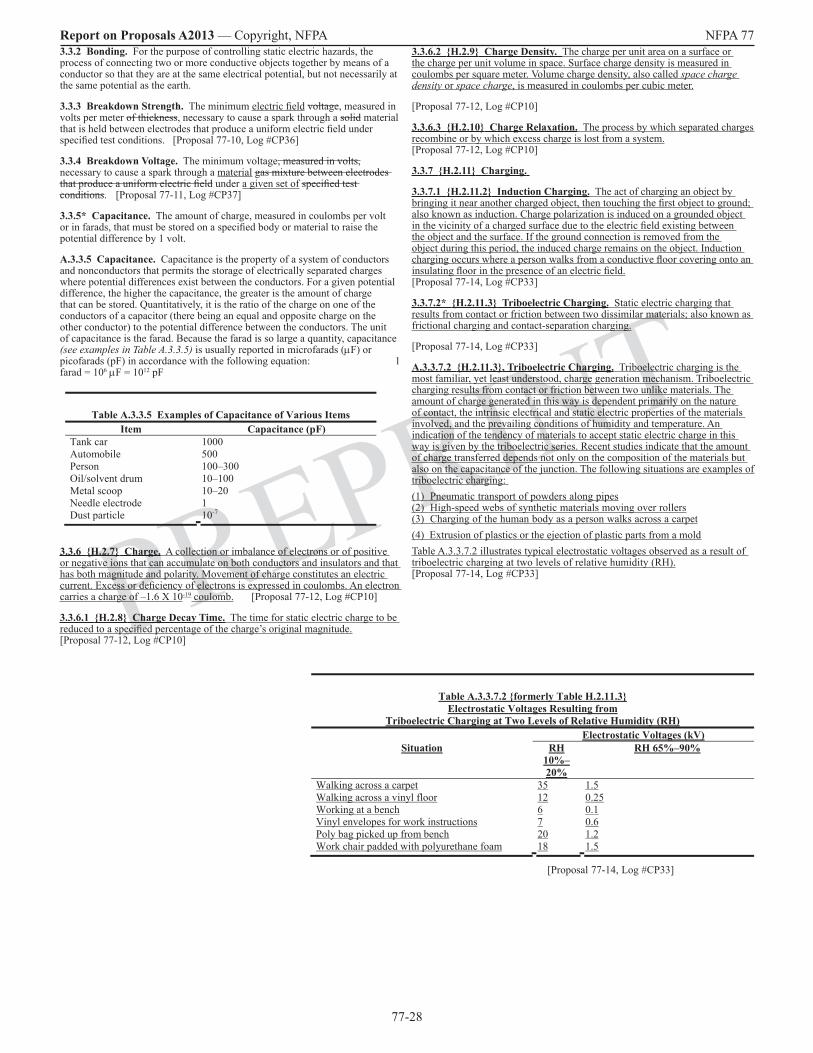
77-28
Report on Proposals A2013 — Copyright, NFPA NFPA 77
PREPRINT
3.3.2 Bonding. For the purpose of controlling static electric hazards, the process of connecting two or more conductive objects together by means of a conductor so that they are at the same electrical potential, but not necessarily at the same potential as the earth.
3.3.3 Breakdown Strength. The minimum electric field voltage, measured in volts per meter of thickness, necessary to cause a spark through a solid material that is held between electrodes that produce a uniform electric field under specified test conditions. [Proposal 77-10, Log #CP36]
3.3.4 Breakdown Voltage. The minimum voltage, measured in volts, necessary to cause a spark through a material gas mixture between electrodes that produce a uniform electric field under a given set of specified test conditions. [Proposal 77-11, Log #CP37]
3.3.5* Capacitance. The amount of charge, measured in coulombs per volt or in farads, that must be stored on a specified body or material to raise the potential difference by 1 volt.
A.3.3.5 Capacitance. Capacitance is the property of a system of conductors and nonconductors that permits the storage of electrically separated charges where potential differences exist between the conductors. For a given potential difference, the higher the capacitance, the greater is the amount of charge that can be stored. Quantitatively, it is the ratio of the charge on one of the conductors of a capacitor (there being an equal and opposite charge on the other conductor) to the potential difference between the conductors. The unit of capacitance is the farad. Because the farad is so large a quantity, capacitance (see examples in Table A.3.3.5) is usually reported in microfarads (µF) or picofarads (pF) in accordance with the following equation: 1 farad = 106 µF = 1012 pF
Table A.3.3.5 Examples of Capacitance of Various Items Item Capacitance (pF)
Tank car 1000 Automobile 500 Person 100–300 Oil/solvent drum 10–100 Metal scoop 10–20 Needle electrode 1 Dust particle 10-7
3.3.6 H.2.7 Charge. A collection or imbalance of electrons or of positive or negative ions that can accumulate on both conductors and insulators and that has both magnitude and polarity. Movement of charge constitutes an electric current. Excess or deficiency of electrons is expressed in coulombs. An electron carries a charge of –1.6 X 10⁻¹⁹ coulomb. [Proposal 77-12, Log #CP10]
3.3.6.1 H.2.8 Charge Decay Time. The time for static electric charge to be reduced to a specified percentage of the charge’s original magnitude. [Proposal 77-12, Log #CP10]
3.3.6.2 H.2.9 Charge Density. The charge per unit area on a surface or the charge per unit volume in space. Surface charge density is measured in coulombs per square meter. Volume charge density, also called space charge density or space charge, is measured in coulombs per cubic meter.
[Proposal 77-12, Log #CP10]
3.3.6.3 H.2.10 Charge Relaxation. The process by which separated charges recombine or by which excess charge is lost from a system. [Proposal 77-12, Log #CP10]
3.3.7 H.2.11 Charging.
3.3.7.1 H.2.11.2 Induction Charging. The act of charging an object by bringing it near another charged object, then touching the first object to ground; also known as induction. Charge polarization is induced on a grounded object in the vicinity of a charged surface due to the electric field existing between the object and the surface. If the ground connection is removed from the object during this period, the induced charge remains on the object. Induction charging occurs where a person walks from a conductive floor covering onto an insulating floor in the presence of an electric field. [Proposal 77-14, Log #CP33]
3.3.7.2* H.2.11.3 Triboelectric Charging. Static electric charging that results from contact or friction between two dissimilar materials; also known as frictional charging and contact-separation charging.
[Proposal 77-14, Log #CP33]
A.3.3.7.2 H.2.11.3, Triboelectric Charging. Triboelectric charging is the most familiar, yet least understood, charge generation mechanism. Triboelectric charging results from contact or friction between two unlike materials. The amount of charge generated in this way is dependent primarily on the nature of contact, the intrinsic electrical and static electric properties of the materials involved, and the prevailing conditions of humidity and temperature. An indication of the tendency of materials to accept static electric charge in this way is given by the triboelectric series. Recent studies indicate that the amount of charge transferred depends not only on the composition of the materials but also on the capacitance of the junction. The following situations are examples of triboelectric charging: (1) Pneumatic transport of powders along pipes(2) High-speed webs of synthetic materials moving over rollers(3) Charging of the human body as a person walks across a carpet(4) Extrusion of plastics or the ejection of plastic parts from a moldTable A.3.3.7.2 illustrates typical electrostatic voltages observed as a result of triboelectric charging at two levels of relative humidity (RH). [Proposal 77-14, Log #CP33]
Table A.3.3.7.2 formerly Table H.2.11.3Electrostatic Voltages Resulting from
Triboelectric Charging at Two Levels of Relative Humidity (RH) Electrostatic Voltages (kV)
Situation RH 10%–20%
RH 65%–90%
Walking across a carpet 35 1.5Walking across a vinyl floor 12 0.25Working at a bench 6 0.1Vinyl envelopes for work instructions 7 0.6Poly bag picked up from bench 20 1.2Work chair padded with polyurethane foam 18 1.5
[Proposal 77-14, Log #CP33]
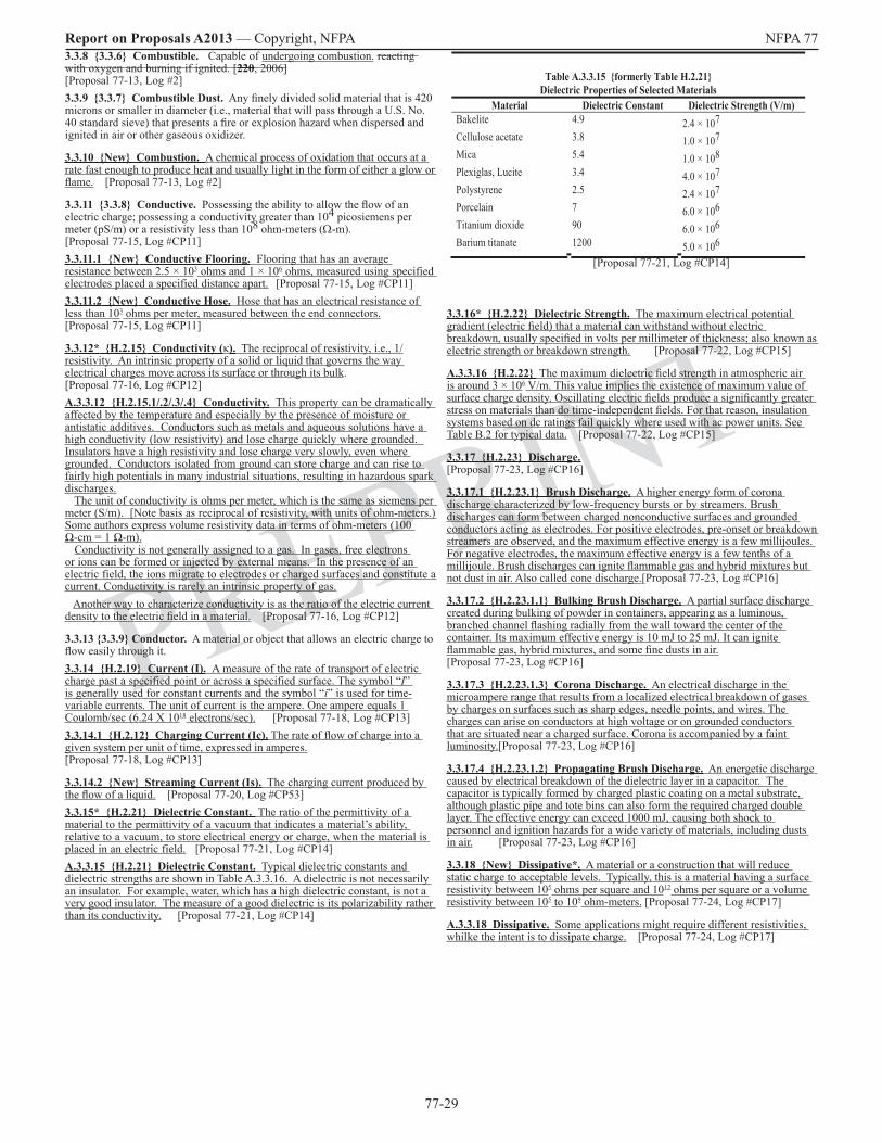
77-29
Report on Proposals A2013 — Copyright, NFPA NFPA 77
PREPRINT
3.3.8 3.3.6 Combustible. Capable of undergoing combustion. reacting with oxygen and burning if ignited. [220, 2006] [Proposal 77-13, Log #2]3.3.9 3.3.7 Combustible Dust. Any finely divided solid material that is 420 microns or smaller in diameter (i.e., material that will pass through a U.S. No. 40 standard sieve) that presents a fire or explosion hazard when dispersed and ignited in air or other gaseous oxidizer.
3.3.10 New Combustion. A chemical process of oxidation that occurs at a rate fast enough to produce heat and usually light in the form of either a glow or flame. [Proposal 77-13, Log #2]
3.3.11 3.3.8 Conductive. Possessing the ability to allow the flow of an electric charge; possessing a conductivity greater than 104 picosiemens per meter (pS/m) or a resistivity less than 108 ohm-meters (Ω-m). [Proposal 77-15, Log #CP11]3.3.11.1 New Conductive Flooring. Flooring that has an average resistance between 2.5 × 10³ ohms and 1 × 10⁶ ohms, measured using specified electrodes placed a specified distance apart. [Proposal 77-15, Log #CP11]3.3.11.2 New Conductive Hose. Hose that has an electrical resistance of less than 103 ohms per meter, measured between the end connectors. [Proposal 77-15, Log #CP11]
3.3.12* H.2.15 Conductivity (κ). The reciprocal of resistivity, i.e., 1/resistivity. An intrinsic property of a solid or liquid that governs the way electrical charges move across its surface or through its bulk. [Proposal 77-16, Log #CP12]A.3.3.12 H.2.15.1/.2/.3/.4 Conductivity. This property can be dramatically affected by the temperature and especially by the presence of moisture or antistatic additives. Conductors such as metals and aqueous solutions have a high conductivity (low resistivity) and lose charge quickly where grounded. Insulators have a high resistivity and lose charge very slowly, even where grounded. Conductors isolated from ground can store charge and can rise to fairly high potentials in many industrial situations, resulting in hazardous spark discharges. The unit of conductivity is ohms per meter, which is the same as siemens per meter (S/m). [Note basis as reciprocal of resistivity, with units of ohm-meters.) Some authors express volume resistivity data in terms of ohm-meters (100 Ω-cm = 1 Ω-m). Conductivity is not generally assigned to a gas. In gases, free electrons or ions can be formed or injected by external means. In the presence of an electric field, the ions migrate to electrodes or charged surfaces and constitute a current. Conductivity is rarely an intrinsic property of gas. Another way to characterize conductivity is as the ratio of the electric current density to the electric field in a material. [Proposal 77-16, Log #CP12]
3.3.13 3.3.9 Conductor. A material or object that allows an electric charge to flow easily through it.3.3.14 H.2.19 Current (I). A measure of the rate of transport of electric charge past a specified point or across a specified surface. The symbol “I” is generally used for constant currents and the symbol “i” is used for time-variable currents. The unit of current is the ampere. One ampere equals 1 Coulomb/sec (6.24 X 10¹⁸ electrons/sec). [Proposal 77-18, Log #CP13]3.3.14.1 H.2.12 Charging Current (Ic). The rate of flow of charge into a given system per unit of time, expressed in amperes. [Proposal 77-18, Log #CP13]
3.3.14.2 New Streaming Current (Is). The charging current produced by the flow of a liquid. [Proposal 77-20, Log #CP53]3.3.15* H.2.21 Dielectric Constant. The ratio of the permittivity of a material to the permittivity of a vacuum that indicates a material’s ability, relative to a vacuum, to store electrical energy or charge, when the material is placed in an electric field. [Proposal 77-21, Log #CP14]A.3.3.15 H.2.21 Dielectric Constant. Typical dielectric constants and dielectric strengths are shown in Table A.3.3.16. A dielectric is not necessarily an insulator. For example, water, which has a high dielectric constant, is not a very good insulator. The measure of a good dielectric is its polarizability rather than its conductivity. [Proposal 77-21, Log #CP14]
3.3.16* H.2.22 Dielectric Strength. The maximum electrical potential gradient (electric field) that a material can withstand without electric breakdown, usually specified in volts per millimeter of thickness; also known as electric strength or breakdown strength. [Proposal 77-22, Log #CP15]
A.3.3.16 H.2.22 The maximum dielectric field strength in atmospheric air is around 3 × 10⁶ V/m. This value implies the existence of maximum value of surface charge density. Oscillating electric fields produce a significantly greater stress on materials than do time-independent fields. For that reason, insulation systems based on dc ratings fail quickly where used with ac power units. See Table B.2 for typical data. [Proposal 77-22, Log #CP15]
3.3.17 H.2.23 Discharge. [Proposal 77-23, Log #CP16]
3.3.17.1 H.2.23.1 Brush Discharge. A higher energy form of corona discharge characterized by low-frequency bursts or by streamers. Brush discharges can form between charged nonconductive surfaces and grounded conductors acting as electrodes. For positive electrodes, pre-onset or breakdown streamers are observed, and the maximum effective energy is a few millijoules. For negative electrodes, the maximum effective energy is a few tenths of a millijoule. Brush discharges can ignite flammable gas and hybrid mixtures but not dust in air. Also called cone discharge.[Proposal 77-23, Log #CP16]
3.3.17.2 H.2.23.1.1 Bulking Brush Discharge. A partial surface discharge created during bulking of powder in containers, appearing as a luminous, branched channel flashing radially from the wall toward the center of the container. Its maximum effective energy is 10 mJ to 25 mJ. It can ignite flammable gas, hybrid mixtures, and some fine dusts in air. [Proposal 77-23, Log #CP16]
3.3.17.3 H.2.23.1.3 Corona Discharge. An electrical discharge in the microampere range that results from a localized electrical breakdown of gases by charges on surfaces such as sharp edges, needle points, and wires. The charges can arise on conductors at high voltage or on grounded conductors that are situated near a charged surface. Corona is accompanied by a faint luminosity.[Proposal 77-23, Log #CP16]
3.3.17.4 H.2.23.1.2 Propagating Brush Discharge. An energetic discharge caused by electrical breakdown of the dielectric layer in a capacitor. The capacitor is typically formed by charged plastic coating on a metal substrate, although plastic pipe and tote bins can also form the required charged double layer. The effective energy can exceed 1000 mJ, causing both shock to personnel and ignition hazards for a wide variety of materials, including dusts in air. [Proposal 77-23, Log #CP16]
3.3.18 New Dissipative*. A material or a construction that will reduce static charge to acceptable levels. Typically, this is a material having a surface resistivity between 105 ohms per square and 1012 ohms per square or a volume resistivity between 105 to 109 ohm-meters. [Proposal 77-24, Log #CP17]
A.3.3.18 Dissipative. Some applications might require different resistivities, whilke the intent is to dissipate charge. [Proposal 77-24, Log #CP17]
Table A.3.3.15 formerly Table H.2.21 Dielectric Properties of Selected Materials
Material Dielectric Constant Dielectric Strength (V/m) Bakelite 4.9 2.4 × 10⁷Cellulose acetate 3.8 1.0 × 10⁷Mica 5.4 1.0 × 10⁸Plexiglas, Lucite 3.4 4.0 × 10⁷Polystyrene 2.5 2.4 × 10⁷Porcelain 7 6.0 × 10⁶Titanium dioxide 90 6.0 × 10⁶Barium titanate 1200 5.0 × 10⁶
[Proposal 77-21, Log #CP14]

77-30
Report on Proposals A2013 — Copyright, NFPA NFPA 77
PREPRINT
3.3.33* H.2.47 Ohms per Square. A unit of measure used to describe surface resistivity that reflects the resistance value between two electrodes that form two sides of a square and is independent of the size of the square and by which the resulting value indicates how easily electrons can flow across a surface. [Proposal 77-35, Log #CP27]
A.3.3.33 H.2.47 Ohms per Square. Ohms per square is normally used to characterize the resistivity of a thin conductive layer of one material over a relatively insulative base material. [Proposal 77-35, Log #CP27]
3.3.34 H.2.49 Relaxation Time Constant (τ). The time, in seconds, for charge to decay by Ohm’s law to e-1 (36.7 percent) of its initial value. For a capacitor, the relaxation time constant is the product of resistance (ohms) and capacitance (farads). [Proposal 77-36, Log #CP28]
3.3.35 New Resistance. The opposition that a material offers to the flow of current, expressed in ohms, which is equal to the voltage (V, volts) between two points divided by the current (I, amperes) that flows between those points. [Proposal 77-120, Log #6]
3.3.36* H.2.51 Resistivity. The intrinsic property of a homogeneous material that opposes the flow of electric current. [Proposal 77-37, Log #CP29]
[Proposal 77-121, Log #7]
A.3.3.36 H.2.51 Resistivity. A low resistivity (high conductivity) indicates a material that readily allows the movement of electrical charge. The resistivity across the surface of a material will differ from the resistivity through a volume of the same material. Also, the resistance of a material depends on its resistivity and its geometry. Resistivity is the reciprocal of conductivity.
[Proposal 77-37, Log #CP29]
[Proposal 77-121, Log #7]
3.3.36.1 H.2.51.1 Surface Resistivity. The electric resistance of the surface of an insulator, in ohms per square, as measured between the opposite sides of a square on the surface, and whose value in ohms is independent of the size of the square or the thickness of the surface film. [Proposal 77-37, Log #CP29]
3.3.36.2* H.2.51.1 Volume Resistivity. The intrinsic property of a material that offers resistance to the flow of electric current through the material, expressed in ohm-meters (ohm-m) or ohm-centimeters (ohm-cm). [Proposal 77-123, Log #12]
A.3.3.36.2 H.2.51 Volume Resistivity. The resistance of an object is a function of its resistivity and its geometry. Typical test procedures include ASTM D991, Standard Test Method for Rubber Property-Volume Resistivity of Electrically Conductive and Antistatic Products, and D257, Standard Test Methods for DC Resistance or Conductance of Insulating Materials. [Proposal 77-123, Log #12]
3.3.37 3.3.15 Semiconductive. Possessing a conductivity between 102 pS/m and 104pS/m or a resistivity between 108 Ω-m and 1010 Ω-m.
3.3.38 H.2.52 Spark. A short-duration electric discharge due to a sudden breakdown of air or some other insulating material separating two conductors at different electric potentials, accompanied by a momentary flash of light; also known as electric spark, spark discharge, and sparkover. [Proposal 77-38, Log #CP30]
3.3.39 3.3.16 Static Electric Discharge. A release of static electricity in the form of a spark, corona discharge, brush discharge, or propagating brush discharge that might be capable of causing ignition under appropriate circumstances.
3.3.40 3.3.17 Static Electricity. An electric charge that is significant only for the effects of its electric field component and that manifests no significant magnetic field component.
3.3.41* H.2.56 Surface Streamer. A surface-to-wall discharge observed on charged liquids during tanker filling, appearing as a flash up to 30 cm long and accompanied by a crackling sound.
[Proposal 77-39, Log #CP31]
A.3.3.41 H.2.56 Surface Streamer. The effective energy is unknown but is possibly as high as approximately 10 mJ. Surface streamers are also observed on tribocharged solid surfaces, such as between aircraft windshields and metal airframe, where puncturing does not occur. [Proposal 77-39, Log #CP31]
3.3.42* H.2.59 Triboelectric Series. A ranking of materials according to their affinity for positive or negative charges. [Proposal 77-40, Log #CP32]
3.3.19* H.2.25 Double Layer. A phenomenon usually associated with a solid–liquid interface where ions of one charge type are fixed to the surface of the solid, and an equal number of mobile ions of opposite charge are distributed through the neighboring region of the liquid.[Proposal 77-25, Log #CP34]A.3.3.19 Double Layer. In such a system, the movement of liquid causes a displacement of the mobile ions with respect to the fixed charges on the solid surface. [Proposal 77-25, Log #CP34]
3.3.20 H.2.27 Electrometer. A device used to measure static electric charge with high-input impedance, typically greater than 1013 ohms, which draws negligible current from the measured object. [Proposal 77-26, Log #CP18]
3.3.21 H.2.33 Flammable Limit. [Proposal 77-27, Log #CP19]
3.3.21.1 H.2.33.1 Lower Flammable Limit (LFL). The lowest molar (or volume) concentration of a combustible substance in an oxidizing medium that will propagate a flame. [Proposal 77-27, Log #CP19]
3.3.21.2 H.2.33.2 Upper Flammable Limit (UFL). The highest molar (or volume) concentration of a combustible substance in an oxidizing medium that will propagate a flame. [Proposal 77-27, Log #CP19]
3.3.22 3.3.10 Grounding. The process of bonding one or more conductive objects to the ground, so that all objects are at zero (0) electrical potential; also referred to as earthing.
3.3.23 3.3.11 Ignitible Mixture. A gas–air, vapor–air, mist–air, or dust–air mixture, or combinations of such mixtures, that can be ignited by a sufficiently strong source of energy, such as a static electric discharge.
3.3.24 H.2.34 Ignition Energy. The energy required to effect ignition of a specified fuel mixture under specified conditions of test. [Proposal 77-28, Log #CP20]
3.3.24.1 H.2.34.1 Minimum Ignition Energy (MIE). The energy, expressed in joules, stored in a capacitor that, upon discharge, is just sufficient to effect ignition of the most ignitible mixture of a given fuel mixture under specified test conditions. [Proposal 77-28, Log #CP20]
3.3.25 H.2.35 Incendive. Able to cause ignition.
[Proposal 77-29, Log #CP21]
3.3.26 H.2.36 Induction. The process by which charges are moved to new locations on a conductor by the action of an electric field or the movement of a conductor into the influence of an existing electric field. [Proposal 77-30, Log #CP22]
3.3.27* H.2.37 Induction Bar. A passive corona device that is connected to ground and that produces corona from a grounded electrode of the induction bar when a charged object is brought close to it. [Proposal 77-31, Log #CP23]
A.3.3.27 H.2.37 Induction Bar. Ions (corona) are produced by the electrode if the charge on the object is great enough and if the object’s placement is sufficiently close that corona onset is achieved. [Proposal 77-31, Log #CP23]
3.3.28 3.3.12 Inert Gas. For the purpose of controlling static electric hazards, a nonflammable, nonreactive gas that renders the combustible material in a system incapable of supporting combustion.
3.3.29 H.2.39 Ionization. A process by which a neutral atom or molecule loses or gains electrons, thereby acquiring a net charge and becoming an ion. [Proposal 77-32, Log #CP24]
3.3.30 H.2.43 Megohmmeter. A meter used to measure high resistance values that typically operates at higher test voltages than standard ohmmeters, usually in the range of 100 volts to 1000 volts. [Proposal 77-33, Log #CP25]
3.3.31 H.2.44 Minimum Explosible Concentration (MEC). The lowest concentration of a combustible dust in air, expressed in grams per cubic meter, that will propagate a flame. [Proposal 77-34, Log #CP26]
3.3.32 3.3.13 Nonconductive (Insulating). For the purposes of describing static electric behavior, having Possessing the ability to accumulate resist the flow of an electric charge, even when in contact with ground. [Proposal 77-17, Log #10]
3.3.14 Nonconductor. A material or object that resists the flow of an electric charge. [Proposal 77-19, Log #9]

77-31
Report on Proposals A2013 — Copyright, NFPA NFPA 77
PREPRINT
A.3.3.42 H.2.59 Triboelectric Series. Where different materials are rubbed together, charge is transferred. Many researchers working in the field of triboelectricity have set up triboelectric series to show which combinations of materials would receive which charge. There is some agreement on the ranking of some materials, but most of the series are dissimilar, even where the same materials are used. [Proposal 77-40, Log #CP32]
Chapter 4 Units and Symbols of Measure
4.1 Units. (Reserved)4.2 Symbols. The following symbols are used throughout this recommended practice and are defined as follows:
A = electric current; quantity of charge passing per second through a given point (ampere; coulombs per second)C = capacitance (farads) d = diameter (meters) E electric field strength (volts per meter) e = base of Napierian (natural) logarithms = 2.718 = permittivity dielectric constant of a material (farads per meter)0 = electrical permittivity of a vacuum = 8.845 × 10⁻¹² (farads per meter) /0 = dielectric constant permittivity of a material () (farads per meter)Is = streaming current (amperes)
= liquid conductivity (siemens per meter)
= ion mobility (square meters per volt-second) m = micrometers (microns) = 10-6 meter -m = electrical resistivity (ohm-meters)
P = pressure (millimeters of mercury)Q = quantity of electrical charge (coulombs) R = electrical resistance (ohms) = volume resistivity (ohm-meters) S = electrical conductance (siemens) t = elapsed time (seconds) = charge relaxation time constant (seconds) = flow velocity (meters per second) V = electrical potential difference (volts) W = energy or work done (joules)
[Proposal 77-41, Log #CP45]
77-32
Report on Proposals A2013 — Copyright, NFPA NFPA 77
PREPRINT
Chapter 5 Fundamentals of Static Electricity
5.1 General.
5.1.1 The most common experiences of static electricity are the crackling and clinging of fabrics as they are removed from a clothes dryer or the electric shock felt when touching a metal object after walking across a carpeted floor or stepping out of an automobile. Nearly everyone recognizes that these phenomena occur mainly when the atmosphere is very dry, particularly in winter. To most people, static electricity is simply an annoyance. In many industries, particularly those where combustible materials are handled, static electricity can cause fires or explosions.
5.1.2 The word electricity is derived from elektron, the ancient Greek word for amber. The phenomenon of electrification was first noticed when pieces of amber were rubbed briskly. For centuries, the word electricity had no meaning other than the ability of some substances to attract or repel lightweight objects after being rubbed with a material such as silk or wool. Stronger electrification accompanied by luminous effects and small sparks was first observed about 300 years ago by Otto von Guericke.
5.1.3 In comparatively recent times, when the properties of flowing (current) electricity were discovered, the term static came into use to distinguish a charge that was at rest from one that was in motion. Today the term is used to describe phenomena that originate from an electric charge, regardless of whether the charge is at rest or in motion.
5.1.4 All materials, whether solid or fluid, are composed of various arrangements of atoms. Atoms are composed of positively charged nuclear components, which give them mass, surrounded by negatively charged electrons. Atoms can be considered electrically neutral in their normal state, meaning that there are equal amounts of positive and negative charge. They can become charged where there is an excess or a deficiency of electrons relative to the neutral state. Electrons are mobile and of insignificant mass and are the charge carriers most associated with static electricity.
5.1.5 In materials that are conductors of electricity, such as metals, electrons can move freely. In materials that are insulators, electrons are more tightly bound to the nuclei of the atoms and are not free to move. Examples of insulators include the following:
(1) Nonconductive glass
(2) Rubber
(3) Plastic resins
(4) Dry gases
(5) Paper
(6) Petroleum fluids
5.1.6 The mobility of electrons in materials known as semiconductors is freer than in insulators but is still less than in conductors. Semiconductive materials are commonly characterized by their high electrical resistance, which can be measured with a megohmmeter.
5.1.7 In otherwise insulating fluids, an electron can separate from one atom and move freely or attach to another atom to form a negative ion. The atom losing the electron then becomes a positive ion. Ions are charged atoms and molecules.
5.1.8 Unlike charges attract each other, and the attractive force can draw the charges together if the charges are mobile. The energy stored is the result of the work done to keep the charges separated by a finite distance.
5.2 New Separation of Charge by Contact of Materials.
5.2.1 5.1.9 Separation of charge cannot be prevented absolutely, because the origin of the charge lies at the interface of materials. Where materials are placed in contact, some electrons move from one material to the other until a balance (equilibrium condition) in energy is reached. This charge separation is most noticeable in liquids that are in contact with solid surfaces and in solids that are in contact with other solids. The flow of clean gas over a solid surface produces negligible charging.
5.2.2 5.1.10 The enhanced charging that results from materials being rubbed together (triboelectric charging) is the result of surface electrons being exposed to a broad variety of energies in an adjacent material, so that charge separation is more likely to take place. The breakup of liquids by splashing and misting results in a similar charge separation. It is necessary to transfer only about one electron for each 500,000 atoms to produce a condition that can lead to a static electric discharge. Surface contaminants at very low concentrations can play a significant role in charge separation at the interface of materials. [See Figure 5.2.2(a) and Figure 5.2.2(b).]
FIGURE 5.2.2(a) Typical Charge Generation byRelative Movement of Insulating Materials.
Existing Figure 5.1.10(a) (Source: H. L. Walmsley, “Avoidance of Electrostatic Hazards in the
Petroleum Industry,” p. 19.)
FIGURE 5.2.2(b) Typical Charge Generation by Atomization. Existing Figure 5.1.10(b)
(Source: H. L. Walmsley, “Avoidance of Electrostatic Hazards in the Petroleum Industry,” p. 19.)
5.2.3 5.1.11 Conductive materials can become charged where brought near a highly charged surface. Electrons in the conductive material are either drawn toward or forced away from the region of closest approach to the charged surface, depending on the nature of the charge on that surface. If the conductive material is then touched to ground or to a third object, additional electrons can pass to or from ground or the object. If contact is then broken and the conductive material and charged surface are separated, the charge on the isolated conductive object changes. The net charge that is transferred is called induced charge. [See Figure 5.2.3(a) through Figure 5.2.3(d).]
FIGURE 5.2.3(a) Charged Insulator with Field Lines Shown. Existing Figure 5.1.11(a)
(Source: T. H. Pratt, Electrostatic Ignitions of Fires and Explosions, p. 29.)
FIGURE 5.2.3(b) Induced Charge on Conductor, Charge Remains on Conductor as Conductor Is Removed from Contact
with Insulator. Existing Figure 5.1.11(b)
(Source: T. H. Pratt, Electrostatic Ignitions of Fires and Explosions, p. 29.)
FIGURE 5.2.3(c) Discharge of Free Charge from Conductor. [Existing Figure 5.1.11(c)
(Source: T. H. Pratt, Electrostatic Ignitions of Fires and Explosions, p. 29.)
FIGURE 5.2.3(d) Isolated Conductor Carrying a Charge (After Being Separated from Insulator).
Existing Figure 5.1.11(d)
5.2.4 5.1.12 The separation of charge on a neutral isolated conductor and its distribution near a charged insulating surface produces electrical stresses near the point of closest approach. Sharp edges on the conductor can yield a localized electrical breakdown of the gas stream, known as corona, or an electric spark across the gap. Either of these events can transfer charge between the materials, leaving the isolated conductor charged. Such a transfer occurs, for example, where a person wearing nonconductive shoes receives a static electric shock by contacting the metal frame supporting a highly charged web. As a result, the person acquires a net static electric charge and can receive a second shock after leaving the area by touching a grounded metal object, thereby allowing the acquired charge to flow to earth.
5.2.5 5.1.13 Charge can also be imparted to a surface or into the bulk of a material by directing a stream of electrons or ions against the surface or the material. If the surface or material is not conductive or is conductive but isolated from ground, the charge delivered by the bombarding stream remains after the stream stops.
5.2.6 5.1.14 Charge can also be injected into a stream of nonconductive fluid by submerging within the stream a pointed electrode on which a high voltage has been impressed.
5.3 New Charging by Induction [Proposal 77-42, Log #CP110]
5.3.1 New Induction is the process of drawing opposite-polarity charge nearer and pushing same polarity charge further away from an electrically charged object. When an electrically neutral conductor is brought near a charged object, induction separates charge so that the opposite polarity charge is concentrated closer and the same polarity charge is concentrated further from the charged object.
5.3.2 New As an example, if a person walks about, there is a redistribution of charge on his/her body as he/she approaches and leaves places where there is charge. By the term person, one includes the body, clothing, tools, flashlights, pens, and other articles carried along. The “person” includes all the mentioned items and the nature of their electrical connection. The total charge on the person does not change as he/she walks around, unless there is passage of charge from the person to his/or her environment, e.g., the charged object, the floor, the air, or anything else in the surroundings that becomes a path for charge redistribution.

77-33
Report on Proposals A2013 — Copyright, NFPA NFPA 77
PREPRINT
5.3.3 New Induction charging of the person can occur in a variety of ways:
5.3.3.1 New The person touches the charged object. In this case charge flows between the object and person, and the person’s conductivity gives charge the possibility of being distributed further from the object.
5.3.3.1.1 New If the object is a conductor, charge from its entirety will be reduced by the amount transferred to the person, so that both will end up with the same voltage (potential).
5.3.3.1.2 New If the object is an insulator, local discharge will occur and that charge will be distributed to the person. A moving web would be one case where the local discharges to the person would add up on the person to produce net charging that is similar to that from a conductor. The person would end up with the average voltage (potential) of the web.
5.3.3.2 New An electrical discharge occurs between the person and the charged object. The result will be very similar to what happens with direct contact, and in fact, a discharge probably will occur as the person approaches and touches the charged object. The electrical discharge generally occurs from where there is a high concentration of charge – nearby regions on the person or object that are pointed or sharp (points, corners, or edges). There will be a spark or some form of corona discharge – See Section 5.5 and its subsections for descriptions of electrical discharges.
5.3.3.3 New Current is conducted through shoes to the floor. If there is conduction through the shoes, charge will distribute beyond the person, and an equal amount of charge will be conducted to the person to be drawn closer to the charged object. If the shoes or floor are not good conductors, it will take time for the net charge on the person to grow and be lost as the person walks from the area.
5.3.3.4 New The person touches others, structural steel, tool boxes in the area, etc., or provides other paths for charge to redistribute. Each of these actions give larger area for charge redistribution, and when those paths are broken leave net charge on the person. If shoes and floor are nonconductive, the charge will remain on the person, when he or she leaves the charged object.
5.3.3.5 New There is an electrical discharge between the person and something – typically grounded – in the environment. The discharge can come from the hair, rings, finger nails, conductive clothing, etc. In the case of corona, the discharge can be into the air without a nearby grounded surface.
5.3.4 The actual redistribution of charge is complex and dynamic, and the net charge on the person changes with time. One must be careful in handling tools and actions performed while working with charged operations in industry. Gravure printing, coating, and finishing with solvent based materials are particularly hazardous as a result of induction charging. Without good static elimination, pointing a finger at process lines, and working with conductive tools can be hazardous. There are numerous opportunities for spark discharges, brought on by proximity of workers and charged objects.
5.3.5 New Pneumatic conveying of bulk solids in nonconductive hoses poses special problems, because charging/discharging along the lines induces complex charges and currents in the work area. The induced charges and currents can be hazardous to workers and electronic equipment.
5.3.6 New One area often overlooked is the pickup of charge by induction at one workstation, possibly in a nonhazardous area, that is carried to a hazardous location. Appropriate footwear flooring is thus advised in the hazardous area. Spark discharges from charged objects, however, are typically greater when footwear and flooring are conductive.
[Proposal 77-42, Log #CP110]
5.3 5.2 Accumulation and Dissipation of Charge. [
Proposal 77-42, Log #CP110]
5.3.1 5.2.1 A static electric charge will accumulate where the rate at which charges separate exceeds the rate at which charges recombine. Work must be done to separate charges, and there is a tendency for the charges to return to a neutral state. The potential difference, that is, the voltage, between any two points is the work per unit charge that would have to be done to move the charges from one point to the other. This work depends on the physical characteristics (that is, shape, size, and nature of materials and location of objects) of the particular system and can be expressed by the following equation: C = Q Vwhere:
C = capacitance (farads)Q = charge that has been separated (coulombs)V = potential difference (volts)
5.3.2 5.2.2 Typical examples of accumulation are illustrated in Figure 5.3.2. (See also Table A.3.3.5.) [Proposal 77-43, Log #CP48]
FIGURE 5.3.2 Examples of Charge Accumulation. Existing Figure 5.2.2
(Source: H. L. Walmsley, Avoidance of Electrostatic Hazards in the Petroleum Industry, p. 37.)
5.3.3 5.2.3 Separation of electric charge might not in itself be a potential fire or explosion hazard. There must be a discharge or sudden recombination of the separated charges to pose an ignition hazard. One of the best protections from static electric discharge is a conductive or semiconductive path that allows the controlled recombination of the charges.
5.3.4 5.2.4 In static electric phenomena, charge is generally separated by a resistive barrier, such as an air gap or insulation between the conductors, or by the insulating property of the materials being handled or processed. In many applications, particularly those in which the materials being processed are charged insulators (nonconductors), it is not easy to measure the charges or their potential differences.
5.3.5 5.2.5 Where recombining of charges occurs through a path that has electrical resistance, the process proceeds at a finite rate, 1/τ, and is described by the charge relaxation time or charge decay time, τ. [Proposal 77-44, Log #CP38]
This relaxation process is typically exponential and is expressed by the following equation:
Qt = Q0 e-t/τ
where:
Qt = charge remaining at elapsed time t (coulombs)Q0 = charge originally separated (coulombs)e = base of natural logarithms = 2.718t = elapsed time (seconds)τ = charge relaxation time constant (seconds)
5.3.6 5.2.6 The rate of charge recombination depends on the capacitance of the material and its resistance and is expressed as follows:
τ = RC
where:
τ = charge relaxation time constant (seconds)R = resistance (ohms)C = capacitance (farads)
5.3.7 5.2.7 For bulk materials, the relaxation time is often expressed in terms of the volume resistivity of the material and its electrical permittivity as follows:
τ = ρεε 0 τ = ρε [Proposal 77-45, Log #CP46]
where:
τ = charge relaxation time constant (seconds)ρ = volume resistivity (ohm-meters)
εε0 ε = electrical permittivity of material (farads per meter)5.3.8 5.2.8 The exponential decay model described in 5.3.5 5.2.5 is helpful in explaining the recombination process but is not necessarily applicable to all situations. In particular, nonexponential decay is observed where the materials supporting the charge are certain low-conductivity liquids or powders composed of combinations of insulating, semiconductive, and conductive materials. The decay in such cases is faster than the exponential model predicts.
5.3.9 5.2.9 Dissipation of static electric charges can be achieved effected by modifying the volume or surface resistivity of insulating materials with antistatic additives, by grounding isolated conductors, or by ionizing the air near insulating materials or isolated conductors. Air ionization involves introducing mobile electric charges (positive, negative, or both) into the air around the charged objects. The ions are attracted to the charged objects until the charges on the objects are neutralized. The ion current in the air serves as the mechanism that brings the neutralizing charge to the otherwise bound or isolated charge. [Proposal 77-42, Log #CP110]
5.4 5.3 Discharge of Static Electricity and Ignition Mechanisms.
5.4.1 5.3.1 General. As electric charge accumulates through separation, there is an increase in the electrical forces trying to restore a neutral condition by reuniting those charges in the form of a static electric discharge. Many types of discharges can occur and are illustrated broadly in Figure 5.4.1. For a static electric discharge to be a source of ignition, the following four conditions must be met:
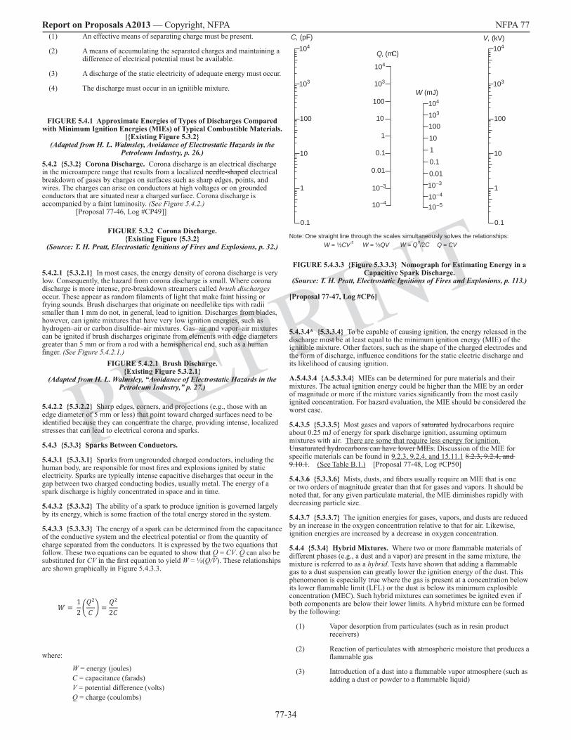
77-34
Report on Proposals A2013 — Copyright, NFPA NFPA 77
PREPRINT
(1) An effective means of separating charge must be present.
(2) A means of accumulating the separated charges and maintaining a difference of electrical potential must be available.
(3) A discharge of the static electricity of adequate energy must occur.
(4) The discharge must occur in an ignitible mixture.
FIGURE 5.4.1 Approximate Energies of Types of Discharges Compared with Minimum Ignition Energies (MIEs) of Typical Combustible Materials.
[Existing Figure 5.3.2 (Adapted from H. L. Walmsley, Avoidance of Electrostatic Hazards in the
Petroleum Industry, p. 26.)5.4.2 5.3.2 Corona Discharge. Corona discharge is an electrical discharge in the microampere range that results from a localized needle-shaped electrical breakdown of gases by charges on surfaces such as sharp edges, points, and wires. The charges can arise on conductors at high voltages or on grounded conductors that are situated near a charged surface. Corona discharge is accompanied by a faint luminosity. (See Figure 5.4.2.) [Proposal 77-46, Log #CP49]]
FIGURE 5.3.2 Corona Discharge.Existing Figure 5.3.2
(Source: T. H. Pratt, Electrostatic Ignitions of Fires and Explosions, p. 32.)
5.4.2.1 5.3.2.1 In most cases, the energy density of corona discharge is very low. Consequently, the hazard from corona discharge is small. Where corona discharge is more intense, pre-breakdown streamers called brush discharges occur. These appear as random filaments of light that make faint hissing or frying sounds. Brush discharges that originate on needlelike tips with radii smaller than 1 mm do not, in general, lead to ignition. Discharges from blades, however, can ignite mixtures that have very low ignition energies, such as hydrogen–air or carbon disulfide–air mixtures. Gas–air and vapor–air mixtures can be ignited if brush discharges originate from elements with edge diameters greater than 5 mm or from a rod with a hemispherical end, such as a human finger. (See Figure 5.4.2.1.)
FIGURE 5.4.2.1 Brush Discharge. Existing Figure 5.3.2.1
(Adapted from H. L. Walmsley, “Avoidance of Electrostatic Hazards in the Petroleum Industry,” p. 27.)
5.4.2.2 5.3.2.2 Sharp edges, corners, and projections (e.g., those with an edge diameter of 5 mm or less) that point toward charged surfaces need to be identified because they can concentrate the charge, providing intense, localized stresses that can lead to electrical corona and sparks.
5.4.3 5.3.3 Sparks Between Conductors.
5.4.3.1 5.3.3.1 Sparks from ungrounded charged conductors, including the human body, are responsible for most fires and explosions ignited by static electricity. Sparks are typically intense capacitive discharges that occur in the gap between two charged conducting bodies, usually metal. The energy of a spark discharge is highly concentrated in space and in time.
5.4.3.2 5.3.3.2 The ability of a spark to produce ignition is governed largely by its energy, which is some fraction of the total energy stored in the system.
5.4.3.3 5.3.3.3 The energy of a spark can be determined from the capacitance of the conductive system and the electrical potential or from the quantity of charge separated from the conductors. It is expressed by the two equations that follow. These two equations can be equated to show that Q = CV. Q can also be substituted for CV in the first equation to yield W = ½(Q/V). These relationships are shown graphically in Figure 5.4.3.3.
12
2
where:
W = energy (joules)C = capacitance (farads)V = potential difference (volts)Q = charge (coulombs)
104
100
10
1
0.1
0.01
10–3
10–4
104
103
100
10
1
0.1
0.01
10–3
10–4
10–5
104
103 103
10
100
1
0.1
104
103
10
100
1
0.1
W = ¹⁄₂CV ² W = ¹⁄₂QV W = Q ²/2C Q = CV
C, (pF) V, (kV)
W (mJ)
Q, (mC)
Note: One straight line through the scales simultaneously solves the relationships:
FIGURE 5.4.3.3 Figure 5.3.3.3 Nomograph for Estimating Energy in a Capacitive Spark Discharge.
(Source: T. H. Pratt, Electrostatic Ignitions of Fires and Explosions, p. 113.)
[Proposal 77-47, Log #CP6]
5.4.3.4* 5.3.3.4 To be capable of causing ignition, the energy released in the discharge must be at least equal to the minimum ignition energy (MIE) of the ignitible mixture. Other factors, such as the shape of the charged electrodes and the form of discharge, influence conditions for the static electric discharge and its likelihood of causing ignition.
A.5.4.3.4 A.5.3.3.4 MIEs can be determined for pure materials and their mixtures. The actual ignition energy could be higher than the MIE by an order of magnitude or more if the mixture varies significantly from the most easily ignited concentration. For hazard evaluation, the MIE should be considered the worst case.
5.4.3.5 5.3.3.5 Most gases and vapors of saturated hydrocarbons require about 0.25 mJ of energy for spark discharge ignition, assuming optimum mixtures with air. There are some that require less energy for ignition. Unsaturated hydrocarbons can have lower MIEs. Discussion of the MIE for specific materials can be found in 9.2.3, 9.2.4, and 15.11.1 8.2.3, 9.2.4, and 9.10.1. (See Table B.1.) [Proposal 77-48, Log #CP50]
5.4.3.6 5.3.3.6 Mists, dusts, and fibers usually require an MIE that is one or two orders of magnitude greater than that for gases and vapors. It should be noted that, for any given particulate material, the MIE diminishes rapidly with decreasing particle size.
5.4.3.7 5.3.3.7 The ignition energies for gases, vapors, and dusts are reduced by an increase in the oxygen concentration relative to that for air. Likewise, ignition energies are increased by a decrease in oxygen concentration.
5.4.4 5.3.4 Hybrid Mixtures. Where two or more flammable materials of different phases (e.g., a dust and a vapor) are present in the same mixture, the mixture is referred to as a hybrid. Tests have shown that adding a flammable gas to a dust suspension can greatly lower the ignition energy of the dust. This phenomenon is especially true where the gas is present at a concentration below its lower flammable limit (LFL) or the dust is below its minimum explosible concentration (MEC). Such hybrid mixtures can sometimes be ignited even if both components are below their lower limits. A hybrid mixture can be formed by the following:
(1) Vapor desorption from particulates (such as in resin product receivers)
(2) Reaction of particulates with atmospheric moisture that produces a flammable gas
(3) Introduction of a dust into a flammable vapor atmosphere (such as adding a dust or powder to a flammable liquid)

77-35
Report on Proposals A2013 — Copyright, NFPA NFPA 77
PREPRINT
5.4.5 5.3.5 Static Electric Discharge from the Human Body.
5.4.5.1 5.3.5.1 The human body is a good electrical conductor and has been responsible for numerous incidents of static electric discharge.
5.4.5.2 5.3.5.2 A person insulated from ground can accumulate a significant charge by walking on an insulating surface, by touching a charged object, by brushing surfaces while wearing nonconductive clothing, or by momentarily touching a grounded object in the presence of charges in the environment. During normal activity, the potential of the human body can reach 10 kV to 15 kV., At a capacitance of 200 pF (see Table A.3.3.5), and the accumulated energy available for of a possible spark can reach 10 20 mJ to 22.5 30 mJ. A comparison of these values to the MIEs of gases or vapors makes the hazard readily apparent. [Proposal 77-49, Log #CP62]
5.4.6 5.3.6 Discharges Between Conductors and Insulators.
5.4.6.1 5.3.6.1 Sparks often occur between conductors and insulators. Examples of such occurrences include situations in which plastic parts and structures, insulating films and webs, liquids, and particulate material are handled. The charging of these materials can result in surface discharges and sparks, depending on the accumulated charge and the shape of nearby conductive surfaces. The variable charge density (both in magnitude and polarity) observed on insulating surfaces is the effect of these discharges spreading over a limited part of the insulating surface.
5.4.6.2 5.3.6.2 Even with the use of static electricity neutralizers, some charges will remain in certain areas but typically are not hazardous if there is no mechanism by which they can accumulate. However, a dangerous (i.e., ignition-capable) static electric charge can result because of concentration of individual charges. Examples of how such concentration of charge can occur include stacking or nesting of empty plastic containers, winding film onto a roll or drum, and filling a vessel with a nonconductive liquid or powder.
5.4.7 5.3.7 Discharge on the Surface of an Insulator Backed by a Conductor. A surface coated with a thin (less than 8 mm) layer of an insulating material will act as a capacitor to store charge. At sufficiently high charge levels (i.e., greater than 250 µC/m2), a branching discharge will be observed on the surface of the coating. This branching discharge is referred to as a propagating brush discharge. Alternatively, an electrical breakdown through the layer can occur. The energy stored in the coating can be as high as several joules per square meter, so the energy of the discharge, however distributed in space, can be sufficient to ignite gas–air, vapor–air, and dust–air mixtures. (See Figure 5.4.7.)
FIGURE 5.4.7 Propagating Brush Discharge. Existing Figure 5.3.7
(Source: T. H. Pratt, Electrostatic Ignitions of Fires and Explosions, p. 35.)
Subsection 5.3.8 relocated to new Section 15.6
Chapter 6 Evaluating Static Electricity Hazards
6.1 General.
6.1.1 There are two basic steps in evaluating static electricity hazards:
(1) Identification of locations where charge separates and accumulates
(2) Assessment of the ignition hazards at the locations where charge separates and accumulates
6.1.2 The evaluation process specified in 6.1.1 is outlined in Figure 6.1.2.
(See Figure 6.1.2 on the following page.)
6.1.3 On-site evaluation or survey of the process should be made to identify any ungrounded conductive objects, including personnel, and any materials that could serve as electrical insulators and interfere with proper bonding and grounding. The survey should identify those locations that might pose a static electricity hazard, even if there is no evidence of accumulation of charge at the time of the evaluation.
6.1.3.1 Special attention should be given to insulating materials that are handled or processed.
6.1.3.1.1 Each process operation should be considered separately, and attention should be given to the likely range of exposure of the materials. For example,
changes in temperature and relative humidity can significantly influence the bulk conductivity and surface conductivity of materials.
6.1.3.2 It is often helpful to first complete a design review of the operation, process, or machine and a visual survey of the area. An on-site instrumented evaluation should then be conducted during actual operating conditions to determine the nature and magnitude of any static electricity hazards present.
WARNING: During an audit, precautions should be taken that are consistent with the equipment and the materials in the area where measurements are to be taken. The primary ignition hazard comes from introducing a grounded electrode, such as the housing of a field meter (see Section 6.4), into the vicinity of a charged surface, thus providing a route for a static electric discharge. The surface being measured should always be approached slowly during observation of the meter’s response. Extreme care should be taken so that neither instruments nor testing techniques cause ignition of flammable atmospheres. Appropriate safe work practices should be employed where measurements are being taken in and around physical hazards such as moving belts, webs, and pulleys.
6.2 Measuring a Static Electric Charge.
A meaningful evaluation requires using an appropriate instrument, using the instrument according to the manufacturer’s instructions, maintaining calibration of the instrument, and interpreting the measurements according to the manufacturer’s recommendations.
6.3 Measuring the Charge on a Conductor.
6.3.1 The voltage on a conductor is proportional to the charge it supports and is expressed by the following equation:
where:
V = potential difference (volts)Q = charge supported by the conductor (coulombs)C = capacitance of the conductor (farads)
6.3.2 The voltage on a conductor can be measured by direct contact using a voltmeter, provided that the impedance of the voltmeter is high enough so that it does not discharge the conductor and the capacitance is small enough so that it does not collect a significant charge from the conductor. An electrostatic voltmeter with input impedance greater than 1012 ohms can be used for measuring voltages on most ungrounded conductors. Because conductors have the same voltage at every point on their surface, the location at which the test probe of the voltmeter touches the surface of the conductor is not important.
6.4 Measuring the Charge on a Nonconductor.
6.4.1 The charge on a nonconductor cannot be measured using a direct contact electrostatic voltmeter. A noncontact electrostatic voltmeter, or field meter, must be used. A noncontact electrostatic voltmeter senses the strength of the static electric field from the net charge on or in the nonconductor. The field strength, which is proportional to the static electric force per unit charge, describes the electric forces present near a charged object. For practical purposes, an electric field is the force that a person experiences or measures around a charged object.
6.4.2 Field meters are calibrated to measure the electric field in units of volts per unit distance, typically kilovolts per meter. In most cases, the measurements are proportional to the net static electric charge on the object being measured. Field meters are referred to as field mills or charge locators, depending on their principle of operation and level of sophistication. Because the charge density on or in a nonconductor typically is not uniform, measurements should be taken at several locations.
6.4.3 Charged nonconductors exist in many forms, such as sheets, films, webs, powders, liquids, process rolls, and extrusions. Charges on these materials and objects produce electric fields that are influenced by the instrument, by the observer, and by other nearby conductive, semiconductive, or insulating materials. As a result, the electric field measured by the instrument generally is different from the electric field present before the instrument was introduced. This phenomenon is a result of a change in capacitance.
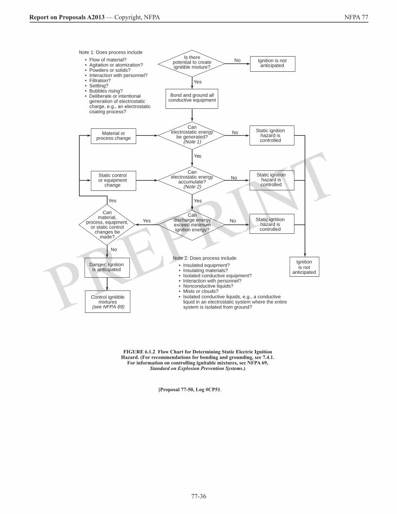
77-36
Report on Proposals A2013 — Copyright, NFPA NFPA 77
PREPRINT
Is therepotential to createignitible mixture?
Material orprocess change
Note 1: Does process include
• Flow of material?• Agitation or atomization?• Powders or solids?• Interaction with personnel?• Filtration?• Settling?• Bubbles rising?
Bond and ground allconductive equipment
Yes
No
Canelectrostatic energy
be generated?(Note 1)
Yes
No
No
No
Yes
Yes
Yes
Static controlor equipment
change
Canmaterial,
process, equipment,or static control
changes bemade?
No
Danger: Ignitionis anticipated
Control ignitiblemixtures
(see NFPA 69)
Canelectrostatic energy
accumulate?(Note 2)
Candischarge energyexceed minimumignition energy?
Ignition is notanticipated
Static ignitionhazard iscontrolled
Static ignitionhazard iscontrolled
Static ignitionhazard iscontrolled
Ignitionis not
anticipated
Note 2: Does process include
• Insulated equipment?• Insulating materials?• Isolated conductive equipment?• Interaction with personnel?• Nonconductive liquids?• Mists or clouds?
• Deliberate or intentional generation of electrostatic charge, e.g., an electrostatic coating process?
• Isolated conductive liquids, e.g., a conductive liquid in an electrostatic system where the entire system is isolated from ground?
FIGURE 6.1.2 Flow Chart for Determining Static Electric Ignition Hazard. (For recommendations for bonding and grounding, see 7.4.1.
For information on controlling ignitable mixtures, see NFPA 69, Standard on Explosion Prevention Systems.)
[Proposal 77-50, Log #CP51.

77-37
Report on Proposals A2013 — Copyright, NFPA NFPA 77
PREPRINT
6.4.4 The forces between electric charges exhibit themselves at a distance. For that reason, the effects of accumulated charge can be observed as the charged objects are approached. For example, the hands and arms of a person who approaches a highly charged object will tingle and might even draw a spark as the surface of the skin and the hair become “charged.” Sometimes these observations and sparks provide the first indication that a potentially hazardous condition exists. Charging of the human body can happen even if the person is well grounded.
6.5 General Practices.
6.5.1 The primary instrument for locating a charge on either a conductor or a nonconductor is the noncontact voltmeter or field meter. As its name implies, the instrument does not contact the charged surface directly. Rather, it senses the magnitude and the polarity of the electric field that exists at its sensing aperture. As stated in 6.4.3, the instrument and its sensing aperture disturb the electric field around the charge to be measured, so the meter reading does not accurately indicate the actual magnitude of the field where the meter is not present. Aside from that deficiency, the field meter is an inexpensive and valuable tool for locating a static electric charge.
6.5.2 In some cases, primarily cases involving flowing liquids and flowing bulk solids, it is easier to collect a sample of the charged material in an isolated vessel or cup, referred to as a Faraday cup, and to use an electrometer to measure the streaming current or net charge flowing to the cup receiving the charged material.
6.6 Measuring the Accumulation and Relaxation of Charge.
6.6.1 Measuring the rate of accumulation and relaxation of static electric charge involves measuring changing potential differences or currents.
6.6.2 Field meters and dedicated charge decay monitors can be used to observe charge relaxation on conductors and nonconductors under conditions of prescribed initial voltages.
6.6.3 Leakage currents down to about 10–13 amperes can be measured from isolated conductors using commercially available electrometers. The isolated conductor can be a Faraday cup containing a bulk solid or fluid.
6.7 Measuring the Resistivity of Materials.
Electrical resistivity of materials often consists of volume (bulk) and surface components. In electrostatic processes, the approximate ranges of resistivities that define materials as insulating, semiconductive (antistatic), or conductive are summarized in Figure 6.7.
Conductive materials
Semiconductive materials
Nonconductive materials
(a) Volume resistivity
Conductive materials
Semiconductive materials
Nonconductive materials
1 10 10 10 10 10 10 102 4 6 8 10 12 14
ohm-m
10 10 10 10 10 10 106 8 10 12 14 16 18
ohms per square10 4
(b) Surface resistivity
FIGURE 6.7 Ranges of Volume and Surface Resistivities. (Source: H. L. Walmsley, “Avoidance of Electrostatic Hazards in the
Petroleum Industry”, p. 138.)
6.7.1 Electric charges can be conducted from a solid, liquid, or powder, either across the surface or through the material.
6.7.2 The volumetric resistivity of a material can be determined by applying a potential difference across a sample of known cross section and monitoring the current through the cross section.
6.7.3 Adsorbed material, particularly water vapor, and compaction of materials are known to lower the resistivity of materials. The resistivity of many materials also has been found to vary with the applied potential difference and with the duration of the test. Various designs of cells used to measure resistivity have been developed into standard test configurations that are applicable to specific kinds of samples. Appropriate test procedures include the following:
(1) ASTM D 257, Standard Test Methods for DC Resistance or Conductance of Insulating Materials
(2) CENELEC EN 61241-2-2, Electrical Apparatus for Use in the Presence of Combustible Dust — Part 2: Test Methods; Section 2: Method for Determining the Electrical Resistivity of Dust in Layers
(3) JIS B 9915, Measuring Methods for Dust Resistivity (with Parallel Electrodes)
6.8 Assessment of Bonding and Grounding Conduction Paths.
6.8.1 As defined in 3.3.2, bonding is a process whereby two or more conductive objects are connected by means of a conductor so that they are at the same electrical potential; that is, the voltage difference between the objects is zero (0). The objects might or might not be at the same potential as the earth. In fact, a considerable potential difference between the objects and the earth could exist.
6.8.2 As defined in 3.3.10, grounding is the process of bonding one or more conductive objects to the earth so that they are all at zero (0) electrical potential.
6.8.3 In both bonding and grounding, the intent is to eliminate the occurrence of a static electric spark.
6.8.4 Identification of conductive equipment and objects within a process is critical for successful bonding and grounding. Periodic inspection and testing of bonding and grounding systems are equally important. Proper inspection and testing ensure that the chances for a static electric charge to accumulate are minimized. In bonding and grounding installations that are prone to corrosion, movement, or insulating surface coatings, self-testing bonding clamps and systems can be used to continuously test the resistance to ground and verify acceptable levels.
6.8.5 The resistance to ground of the bonding or grounding path is important, not only to ensure relaxation of the static electric charge but also to maintain worker safety and satisfy other purposes, such as for lightning protection and electrical system shock protection. Practices that constitute proper resistance to ground vary from application to application. Chapters 7 through 10 provide examples of acceptable grounding practices.
6.8.6 The resistance to ground is measured with an ohmmeter or a megohmmeter. Care should always be taken to avoid ignition hazards by using use appropriate instruments or procedures, to avoid ignition hazards based on the classification of the area.
6.9 Measuring Spark Discharge Energies.
6.9.1 The spark discharge energy for conductors is determined from the voltage on the conductor and its capacitance and is expressed by the following equations (which were also given in 5.4.3.1 5.3.3.3):
12
where:
W = energy (joules)C = capacitance (farads)V = potential difference (volts)Q = charge (coulombs)
[Proposal 77-51, Log #CP43]
77-38
Report on Proposals A2013 — Copyright, NFPA NFPA 77
PREPRINT
6.9.2 A capacitance meter often can be used to measure electrostatic charge storage capacity where the charge is stored on a conductive element.
6.10 Measuring Ignition Energies.
6.10.1 Any combustible solid (e.g., dust), liquid, vapor (vapor), or gas should be evaluated for its potential as an ignitible atmosphere in the presence of discharges of static electricity. This evaluation requires determining the MIE of the material. Some data on MIE can be found in Table B.1.
6.10.2 Standardized test equipment and procedures have been developed for measuring the MIEs of particulate and gaseous materials. The equipment is highly specialized and requires trained technicians for its operation. Typically, the equipment is operated and maintained by specialized testing firms.
Chapter 7 Control of Static Electricity and Its Hazards by Process Modification and Grounding
7.1 General.
7.1.1 The objective of controlling a static electricity hazard is to provide a means whereby charges, separated by whatever cause, can recombine harmlessly before discharges can occur.
7.1.2 Ignition hazards from static electricity can be controlled by the following methods:
(1) Removing the ignitible mixture from the area where static electricity could cause an ignition-capable discharge
(2) Reducing charge generation, charge accumulation, or both by means of process or material product modifications
(3) Neutralizing the charges, the primary methods of which are grounding isolated conductors and air ionization
7.2 Control of Ignitible Mixtures in Equipment.
7.2.1 General. Despite efforts to prevent accumulation of static electric charges through good design, many operations that involve the handling of nonconductive materials or nonconductive equipment do not lend themselves to engineered solutions. It then becomes desirable or essential, depending on the nature of the materials involved, to provide other measures, such as one of the following:
(1) Inerting of the equipment
(2) Ventilation of the equipment or the area in which it is located
(3) Relocation of the equipment to a safer area
7.2.2 Inerting.
7.2.2.1 Where an ignitible mixture is contained, such as in a processing vessel, the atmosphere can be made oxygen deficient by introducing enough inert gas (e.g., nitrogen or combustion flue gas) to make the mixture nonignitible. This technique is known as inerting.
7.2.2.2 Where operations are normally conducted in an atmosphere containing a mixture above the upper flammable limit (UFL), it might be practical to introduce the inert gas only during those periods when the mixture passes through its flammable range. NFPA 69, Standard on Explosion Prevention Systems, contains requirements for inerting systems.
7.2.3 Ventilation. Mechanical ventilation can be used to dilute the concentration of a combustible material to a point well below its lower flammable limit (LFL), in the case of a gas or vapor, or below its minimum explosible concentration (MEC), in the case of a dust. Usually, such a reduction means dilution to a concentration at or below 25 percent of the lower limit. Also, by properly directing the air movement, it might be practical to prevent the material from approaching an area of operation where an otherwise uncontrollable static electricity hazard exists.
7.2.4 Relocation. Where equipment that can accumulate a static electric charge is unnecessarily located in a hazardous area, it might be possible to relocate it to a safe location rather than to rely on other means of hazard control.
7.3 Control of Static Electric Charge Generation. Electric charges separate where materials are placed in contact and then pulled apart. Reducing process speeds and flow rates reduces the rate of charge generation. Such charge separation is found where plastic parts and structures, insulating films and webs, liquids, and particulate material are handled. If the material flows at a slow enough rate, a hazardous level of excess charge does not normally accumulate. This means of static electricity control might not be practical due to processing requirements. (See Chapters 8 through 18 10 for recommended practices in specific applications.)
7.4 Charge Dissipation.
7.4.1 Bonding and Grounding. Bonding is used to minimize the potential difference between conductive objects, even where the resulting system is not grounded. Grounding (i.e., earthing), on the other hand, equalizes the potential difference between the objects and the earth. Examples of bonding and grounding are illustrated in Figure 7.4.1.
Existing FIGURE 7.4.1 Bonding and Grounding.
7.4.1.1 A conductive object can be grounded by a direct conductive path to earth or by bonding it to another conductive object that is already connected to the ground. Some objects are inherently bonded or inherently grounded because of their contact with the ground. Examples of inherently grounded objects are underground metal piping and large metal storage tanks resting on the ground.7.4.1.2 The total resistance between a grounded object and the soil is the sum of the individual resistances of the ground wire, its connectors, other conductive materials along the intended grounding path, and the resistance of the ground electrode (i.e., ground rod) to the soil. Most of the resistance in a ground connection exists between the ground electrode and the soil. This ground resistance is quite variable because it depends on the area of contact, the resistivity of the soil, and the amount of moisture present in the soil.
7.4.1.3 To prevent the accumulation of static electricity in conductive equipment, the total resistance of the ground path to earth should be sufficient to dissipate charges that are otherwise likely to be present. A resistance of 1 megohm (106ohms) or less generally is considered adequate.
7.4.1.3.1 Where the bonding/grounding system is all metal, resistance in continuous ground paths typically is less than 10 ohms. Such systems include those having multiple components. Greater resistance usually indicates that the metal path is not continuous, usually because of loose connections or corrosion. A permanent or fixed grounding system that is acceptable for power circuits or for lightning protection is more than adequate for a static electricity grounding system. [Proposal 77-52, Log #3]
7.4.1.3.1.1 In field-based situations such as “HAZMAT” hazardous response operations or control of spills of flammable or combustible materials, it may be necessary to establish a temporary or emergency grounding system in a remote location in order to dissipate static charges. In these situations, various types of conductive grounding electrodes can be used, such as rods, plates, and wires, which are sometimes used in combination to increase the surface area of contact with the earth. If the purpose of the temporary grounding system is to dissipate static electricity, a total resistance of up to 1 k-ohm (1,000 Ohms) in the ground path to earth is considered adequate. This may be measured using standard ground resistance testing instruments and is realistically and quickly achievable in most types of terrain and weather conditions. [Proposal 77-52, Log #3]
7.4.1.3.2 Annex G contains diagrams of various grounding devices, connections, and equipment.
7.4.1.4 Where wire conductors are used, the minimum size of the bonding or grounding wire is dictated by mechanical strength, not by its current-carrying capacity. Stranded or braided wires should be used for bonding wires that will be connected and disconnected frequently. (See Annex G for additional information.)
7.4.1.5 Although grounding Grounding conductors can be insulated (e.g., a jacketed or plastic-coated cable) or uninsulated (i.e., bare conductors),. uninsulated Uninsulated conductors should be used because defects are easier to detect.
7.4.1.6 Permanent bonding or grounding connections can be made by brazing or welding. Temporary connections can be made using bolts, pressure-type ground clamps, or other special clamps. Pressure-type clamps should have sufficient pressure to penetrate any protective coating, rust, or spilled material to ensure contact with the base metal.
7.4.1.7 Workers should be grounded only through a resistance that limits the current to ground to less than 3 mA for the range of voltages experienced in the area. This method, referred to as soft grounding, is used to prevent injury from an electric shock from line voltages or stray currents.

77-39
Report on Proposals A2013 — Copyright, NFPA NFPA 77
PREPRINT
7.4.2 Humidification.
7.4.2.1 The surface resistivity of many materials can be controlled by the humidity of the surroundings. At humidities of 65 percent and higher, the surface of most materials adsorbs enough moisture to ensure a surface conductivity that is sufficient to prevent accumulation of static electricity. When the humidity falls below about 30 percent, these same materials could become good insulators, in which case accumulation of charge occurs increases.
7.4.2.2 While humidification does increase the surface conductivity of the material, the charge will dissipate only if there is a conductive path to ground.
7.4.2.3 Humidification is a not a cure-all for static electricity problems. Some insulators do not adsorb moisture from the air; high humidity, therefore, will not noticeably decrease their surface resistivity. Examples of such insulators are uncontaminated surfaces of some polymeric materials, such as plastic piping, containers, and films, and the surface of petroleum liquids. These surfaces are capable of accumulating a static electric charge even when the atmosphere has a humidity of 100 percent.
7.4.3 Charge Relaxation and Antistatic Treatments.
7.4.3.1 Based on their properties, liquid and solid materials carrying a static electric charge need time to dissipate, or “relax,” the charge. In some cases, the materials can be allowed sufficient time for the charges to relax before being introduced into a hazardous area or process.
7.4.3.2 Charge relaxation can occur only if a path to ground for conduction of the charge is available. Increasing the conductivity of the material will not eliminate hazards if the material remains isolated from ground.
7.4.3.3 A nonconductive material often can be made sufficiently conductive to dissipate static electric charge, either by adding conductive ingredients to its composition or by applying hygroscopic agents to its surface to attract atmospheric moisture.
7.4.3.4 Carbon black can be added to some plastics or rubbers to increase conductivity. Carbon-filled plastics and rubber articles are sometimes sufficiently conductive to be grounded like metal objects. Antistatic additives can also be mixed with liquid and particulate streams to foster charge relaxation.
7.4.3.5 In some cases, particularly with plastic films or sheeting, a material is added to attract atmospheric moisture to the surface, thus increasing surface conductivity. Care should be taken where antistatic plastic film or sheeting is used in low-humidity conditions. In environments with less than 30 percent humidity, film or sheeting can become nonconductive and accumulate static electric charge.
7.4.3.6 Topical hygroscopic coatings attract atmospheric moisture and make the surface of the coated material conductive. However, such coatings can be easily washed away or rubbed off or can lose effectiveness over time. This type of coating should be considered only as a temporary measure to reduce accumulation of static electric charge.
7.4.3.7 Conductive polymers, laminates with conductive elements, and metallized films have been developed for improved static dissipation.
Chapter 8 Control of Static Electricity and Its Hazards by Static Eliminators and Personnel Factors
8.1 7.5 Charge Neutralization by Ionization of Air.
8.1.1 7.5.1 General. Air can be made to contain mobile ions that are attracted to surfaces and will eliminate unbalanced static electric charge from those surfaces. In using air ionizers, certain factors that can influence their effectiveness must be considered, such as environmental conditions (e.g., dust and temperature) and positioning of the device in relation to the material processed, machine parts, and personnel. It is important to note that these control devices do not prevent the generation of static electric charge. They provide ions of opposite polarity to neutralize the generated static electric charge.
8.1.2 7.5.2 Inductive Neutralizers.
8.1.2.1 7.5.2.1 Inductive neutralizers include the following:
(1) Needle bars, which are metal bars equipped with a series of needlelike emitters
(2) Metal tubes wrapped with metal tinsel
(3) Conductive string
(4) Brushes made with metal fibers or conductive fibers
8.1.2.2 7.5.2.2 The design of each type of inductive neutralizer is based on or consists of sharply pointed elements arranged for placement in the static electric field near the charged surfaces.
8.1.2.3 7.5.2.3 A charge drawn from ground to the needlelike tips of an inductive neutralizer produces a concentrated electric field at the tips. If the tips are sharply pointed, the electrical field will be sufficient (i.e., greater than 3 kV/mm) to produce a localized electrical breakdown of the air. This electrical breakdown, known as corona, injects ions into the air that are free to move to distant charges of opposite polarity. The flow of ions produced in corona constitutes a neutralizing current. (See Figure 8.1.2.3.)
FIGURE 8.1.2.3 Example of an Induction Needle. Existing Figure 7.5.2.3
8.1.2.4 7.5.2.4 Although inexpensive and easy to install, inductive neutralizers require a minimum potential difference between the object and the needle tip to initiate corona and the neutralizing process. In the absence of this minimum charge, neutralization will not occur, and a residual potential of a few thousand volts will be left on the material where sharp inductive points are within about 12 mm of the surface.
8.1.2.5 7.5.2.5 It is critically important that inductive neutralizers are connected to a secure ground. If the inductive neutralizer is not grounded, sparks from the induction bar can occur.
8.1.3 7.5.3 Active Electric Static Neutralizers.
8.1.3.1 7.5.3.1 Electric static neutralizers use a high-voltage power supply to produce corona from sharp electrodes. The charge on any object near the device attracts charge from the corona to achieve neutralization. The use of a high-voltage power supply eliminates the limitation of inductive neutralizers in control of charges having fields below the corona onset threshold. An electric static neutralizer must be suitable for the location in which it is used and must not constitute a source of ignition. For example, where not energized or in case of failure, an electric static neutralizer can be designed to function as an induction neutralizer.
8.1.3.2 7.5.3.2 Electric static neutralizers using alternating current (ac) use a high-voltage power supply to energize the corona electrodes at 50 Hz to 60 Hz. The use of an alternating field stresses the electrodes to produce both positive and negative ions for use in the neutralizing process. Current from the power supply is capacitive-coupled to each or to several of the sharp electrodes to limit spark energy in the event of a short circuit. An electric static neutralizer must be suitable for the location in which it is used and must not constitute a source of ignition.
8.1.3.3 7.5.3.3 Electric static neutralizers that use pulsed or steady-state double-polarity direct current (dc) use a pulsed or steady field to stress the electrodes to produce ions for use in the neutralizing process. In the event of a short circuit, the spark energy is controlled by current-limiting resistors. Pulsed or double-polarity dc ionizers must be suitable for the location in which they are used and must not constitute a source of ignition.
8.1.4 7.5.4 Active Radioactive Static Neutralizers. Radioactive (nuclear) ionizers use ionizing radiation to produce ions for neutralization of static electric charges. The most common radioactive ionizers depend on alpha particle generation from the decay of polonium-210 (210Po).
8.1.4.1 7.5.4.1 Performance of radioactive ionizers deteriorates with the decay of the radioactive material. The neutralizers must be registered and installed in accordance with Nuclear Regulatory Commission regulations and replaced periodically (at least annually), because ionization capability diminishes with radioactive decay. Radioactive ionizers are often used in conjunction with inductive neutralizers to control high charge densities.
8.1.4.2 7.5.4.2 Although cost and regulatory compliance issues are associated with radioactive ionizers, they are nonincendive, require no wiring, and can reduce static electric charges to the lowest levels.
8.2 7.6 Control of Static Electric Charge on Personnel. The human body is an electrical conductor and can accumulate a static charge if insulated from ground. This charge can be generated by contact and separation of footwear with floor coverings, by induction, or by participation in various manufacturing operations. Where ignitible mixtures exist, the potential for ignition from the charged human body exists, and means to prevent accumulation of static electric charge on the human body might be necessary.
77-40
Report on Proposals A2013 — Copyright, NFPA NFPA 77
PREPRINT
8.2.1 7.6.1 Prevention of Charge Accumulation. Steps to prevent charge accumulation include use of the following:
(1) Conductive flooring and footwear
(2) Personnel-grounding devices
(3) Antistatic or conductive clothing
8.2.2 7.6.2 Conductive Flooring and Footwear.
8.2.2.1 7.6.2.1 Conductive or static dissipating antistatic flooring can provide effective dissipation of static electricity from personnel who are adequately bonded to the floor. Materials can be solid or they can be coatings that are selected on the basis of wear characteristics, chemical resistance, and the floor area that needs to be covered. Small areas can be handled with a grounded metal plate. Typical resistance to ground for flooring systems should be less than 108 ohms. Clean uncoated concrete floors typically have a resistance to ground of 106 to 108 ohms. Accumulation of debris, wax, and other high-resistivity materials will compromise the conductivity of the floor. Floors should be routinely tested to confirm that they are continuous with ground. [Proposal 77-53, Log #CP61]
8.2.2.2* 7.6.2.2 Electrostatic dissipative (SD) (ESD) footwear used in conjunction with conductive or static dissipating flooring provides a means to control and dissipate static electric charges from the human body. Resistance to earth through SD ESD footwear and conductive or static dissipating flooring should be between 106 ohms and 1089ohms. For materials with very low ignition energies, the resistance to earth through footwear and flooring should be less than 106 ohms. Resistance can be measured with commercially available footwear conductivity testers. [Proposal 77-53, Log #CP61]
A.8.2.2.2 A.7.6.2.2 See ANSI Z41, Standard for Personal Protection — Protective Footwear.
8.2.2.3 7.6.2.3 Resistance of footwear can increase with accumulation of debris such as wax or silica powder on the sole of the footwear or on the flooring itself, use of orthopedic foot beds or orthotic devices, and reduced floor contact area. Conductivity of footwear can be tested on a periodic basis to confirm functionality. [Proposal 77-53, Log #CP61]
8.2.2.4 7.6.2.4 Conductive footwear is footwear designed to have a resistance to ground through the footwear and the floor of less than 106 ohms. It is typically used where materials of low ignition energy, such as explosives and propellants, are handled. Conductive footwear should not be used where a possibility for electrocution by line voltages exists.
8.2.3* 7.6.3 Personnel Grounding Devices.
A.8.2.3 A.7.6.3 See Britton, Avoiding Static Ignition Hazards in Chemical Operations, for additional information.
8.2.3.1 7.6.3.1 Where ESD footwear will not provide adequate personnel grounding, supplementary devices should be used. Such devices include wrist straps, heel/toe grounders, and conductive overshoes.
8.2.3.2 7.6.3.2 Supplementary devices should be selected so that accumulation of hazardous static electric charge is prevented, while the risk of electrocution is not increased. In most practical situations, grounding of personnel is achieved by ensuring that the resistance from the skin to ground is approximately 108 ohms or less. The need to protect against electrocution via a grounding device imposes a minimum resistance from skin to ground of 106 ohms. Based on skin contact and contact with the floor, especially during activities where the entire sole of the footwear is not in contact with the floor (e.g., kneeling), effectiveness can be compromised. Grounding devices should have a minimum resistance of 106 ohms for shock protection.
8.2.3.3 7.6.3.3 The simplest type of commercial device is a grounding bracelet with a built-in resistor typically giving a resistance to ground of about 106 ohms for shock protection. Wrist straps of this type have the greatest utility at ventilation hoods and at other locations where limitation on the operator’s mobility can be tolerated. Breakaway wrist tether systems could be necessary where emergency egress is needed. A hood can be equipped with two external coiled grounding cords with cuff attachments that can be removed and kept by individual users.
8.2.3.4 7.6.3.4 Ground continuity should be checked periodically to the manufacturer’s specified limits using a voltmeter or volt ohmmeter or a commercial tester.
8.2.4 7.6.4 Antistatic or Conductive Clothing.
8.2.4.1 7.6.4.1 Although silk and most synthetic fibers are excellent insulators and undergarments made from these materials exhibit static phenomena, no conclusive evidence exists to indicate that wearing such undergarments constitutes a hazard. However, removal of outer garments is particularly hazardous in work areas, such as in hospital operating rooms,
explosives manufacturing facilities, and similar occupancies and where clothing is contaminated by flammable liquids. Outer garments used in such areas should be suitable for the work area and should be antistatic. NFPA 99, Standard for Health Care Facilities, provides information on test methods for evaluating the antistatic performance of wearing apparel.
8.2.4.2* 7.6.4.2 Although the likelihood of ignition by a grounded person due to any type of clothing is usually very low, the charging of personnel (e.g., where personnel are getting out of a forklift truck) is greatly increased by clothing that has high resistivity.
A.8.2.4.2 A.7.6.4.2 See Britton, Avoiding Static Ignition Hazards in Chemical Operations, for additional information.
8.2.4.3* 7.6.4.3 In oxygen-enriched atmospheres, such as those that could be present in liquid oxygen filling plants, vapor from the cooled gas can permeate an employee’s clothing, increasing its combustibility. A static electric charge that accumulates on the employee and then suddenly discharges can ignite the clothing.
A.8.2.4.3 A.7.6.4.3 See NFPA 53, Recommended Practice on Materials, Equipment, and Systems Used in Oxygen-Enriched Atmospheres.
8.2.5 7.6.5 Gloves. Gloves should be antistatic or conductive with the same resistivity as prescribed for footwear. Gloves should be tested in conjunction with the footwear.
8.2.6 7.6.6 Cleaning or Wiping Cloths.
8.2.6.1 7.6.6.1 Synthetic fabrics used in cleaning or wiping cloths can develop sufficient static electric charge to produce discharges capable of igniting solvent vapors. Flammable liquids and combustible liquids used at temperatures above their flash points, where used with synthetic cleaning or wiping cloths, increase the risk of fire. Typically, charge generation increases with the speed and vigor of the wiping action. The material being cleaned or wiped, if nonconductive, also can accumulate an incendive charge.
8.2.6.2 7.6.6.2 Cotton or synthetic fabric treated with an antistatic compound should be used if static electric charge generation needs to be controlled, especially if flammable solvents are being used for cleaning or wiping. Conductive solvents should be used. Test methods for determining the electrostatic-generating properties of fabrics can be found in NFPA 99, Standard for Health Care Facilities.
8.3 7.7 Maintenance and Testing. All provisions for control of personnel static electricity should be maintained and tested to remain effective. Preventive maintenance procedures and recommendations for clothing, footwear, and flooring can be found in NFPA 99, Standard for Health Care Facilities.
8.4 7.8 Discomfort and Injury. Static shock can result in discomfort and, under some circumstances, injury. While the discharge itself typically is not dangerous to humans, it can cause an involuntary reaction that results in a fall or entanglement with moving machinery. If charge accumulation cannot be avoided and no flammable gases or vapors are present, consideration should be given to the various methods by which contact with metal parts can be eliminated. Such methods include use of nonmetal handrails, insulated doorknobs, and other nonconductive shields.
Chapter 9 Flammable and Combustible Liquids and Their Vapor
9.1 8.1 General. This chapter discusses the assessment and control of static electricity hazards involved with the storage, handling, and use of flammable and combustible liquids and their vapors and mists. While focused on flammable and combustible liquids, the principles of this chapter also apply to noncombustible liquids and vapors (e.g., wet steam) where their storage, use, and handling can cause a static electricity ignition hazard. The chapter begins with a discussion of the combustion characteristics of liquids and their vapors and mists, followed by a discussion of charge generation and dissipation in liquids. Emphasis is then given to processes involving the following:
(1) Flow in pipe, hose, and tubing
(2) Storage tanks
(3) Loading and unloading of tank vehicles [Proposal 77-54, Log #CP63]
(4) Vacuum trucks
(5) Railroad tank cars
(6) Marine vessel and barge cargo tanks
77-41
Report on Proposals A2013 — Copyright, NFPA NFPA 77
PREPRINT
(7) Gauging and sampling
(9) Tank cleaning
(10) Portable tanks and containers
(11) Vacuum cleaning
9.1.1. Static control measures need to be taken whenever ignitable mixtures may be present. Conversely, if ignitable mixtures can be ruled out, these measures are not required. However, it requires careful evaluation to rule out the possibility of ignitable mixtures under all conditions (see 8.2). Also, some operations may pose a risk of shocks to people (see 7.8) and, in such cases, bonding and grounding will usually correct the problem. [Proposal 77-77, Log #CP64]
9.2 8.2 Combustion Characteristics of Liquids, Vapors, and Mists.
The following combustion properties of liquids need to be understood to properly assess the static electricity ignition hazard:
(1) Flash point
(2) Flammable limit and vapor pressure
(3) Ignition energy
(4) Oxidant concentration
9.2.1 8.2.1 Flash Point.
9.2.1.1* 8.2.1.1 Flash point is the minimum temperature at which a liquid gives off sufficient vapor to form an ignitible mixture with air near the surface of the liquid, as determined using standard flash point apparatus described in ASTM E 502, Standard Test Method for Selection and Use of ASTM Standards for the Determination of Flash Point of Chemicals by Closed Cup Methods. Selection of Flash point is determined using a variety of test procedures and apparatus, the selection of which sometimes depends on other physical characteristics of the liquid. For reasons discussed in A.8.2.1.2, ignition might occur at temperatures lower than the reported flash point.
[Proposal 77-55, Log #CP65]
A.9.2.1.1 A.8.2.1.1 Class I flammable liquids, which have flash points of less than 38°C, can form ignitible vapor–air mixtures under most ambient conditions. Class II and Class III combustible liquids, which have flash points of 38°C or greater, typically require some degree of preheating before they evolve enough vapor to form an ignitible mixture. Certain liquids of low fire hazard, such as solvent formulations consisting of mostly water, might be classed as combustible liquids, yet they can generate ignitible vapor–air mixtures in closed containers at less than 38°C. Similarly, certain liquids that do not have a flash point could be capable of generating an ignitible vapor–air mixture as a result of degassing or slow decomposition, especially where the vapor space is small compared with the liquid volume. (Also see Annex C.)
9.2.1.2* 8.2.1.2 If the flash point of a liquid is at or below typical ambient temperatures, it is likely to evolve an ignitible vapor. The lower the flash point, the higher the vapor pressure and the more likely that an ignitible vapor concentration will be present to ignite. Because of the inherent errors variability in standard flash point measurements test methods, the published flash point of a particular liquid only approximates the lowest temperature at which ignition is possible for that liquid. Thus, an allowance of at least 5°C to 11°C 4°C to 9°C below the published flash point should be made in the evaluation of an ignition hazard. A minimum safety factor of 5°C is appropriate for single component liquids having a well-defined flash point. The higher minimum safety factor of 11°C is appropriate for mixed liquids of less certain composition such as fuels. [Proposal 77-55, Log #CP65]
A.8.2.1.2 The standard “closed cup” flash point is generally higher than true flash point known as the “lower temperature limit of flammability” or LTLF. This is the temperature at which the vapor at thermal equilibrium with the liquid achieves a concentration equal to the lower flammable limit (LFL). For single component liquids, it is found that the standard flash point can be 4°C to 6°C higher than the true flash point (LTLF). For complex fuel mixtures such as Jet Fuel A the difference can be 10°C to 15°C. [Proposal 77-55, Log #CP65]
9.2.1.3 Operations at high elevations, such as mining operations, require an additional safety factor depending on the elevation. The recommended additional safety factor for each 1000 meters above sea level is 2.6°C for complex fuels, such as diesel fuels, and 1.9°C, for pure liquids such as toluene and ethanol. Elevations below 1000 meters can be neglected, because the additional correction factor is no greater than the typical error of a flash point measurement of a given sample. [Proposal 77-55, Log #CP65]
9.2.1.4 8.2.1.3 In addition to the conditions described in 9.2.1.2 8.2.1.2, the following effects also can generate an ignitible vapor:
(1) Off-gassing of flammable vapors from solids or low-volatility liquids
(2) Switch Loading
(3) Flow through common vapor headers
(4)(2) Processing at pressures below atmospheric pressure
(5)(3) Nonhomogeneity of the vapors above the liquid
(6)(4) Mist, droplets, or foam on the surface of a liquid [Proposal 77-55, Log #CP65]
9.2.1.4.1 The term switch loading describes a situation that warrants special consideration. When a tank is emptied of a cargo of Class I liquid, a mixture of vapor and air is left, which can be, and often is, within the flammable range. When such a tank is refilled with a Class I liquid, any charge that reaches the tank shell will be bled off by the required bond wire. Also, there will be no flammable mixture at the surface of the rising oil level because the Class I liquid produces at its surface a mixture too rich to be ignitible. This is the situation commonly existing in tank vehicles in gasoline service. If, as occasionally happens, a static charge does accumulate on the surface sufficient to produce a spark, it occurs in a too-rich, nonignitible atmosphere and thus causes no harm.
A very different situation arises if the liquid is “switch loaded,” that is, when a Class II or Class III liquid is loaded into a tank vehicle that previously contained a Class I liquid. Class II or Class III liquids are not necessarily more potent static generators than the Class I liquid previously loaded, but the atmosphere in contact with the rising oil surface is not enriched to bring it out of the flammable range. If circumstances are such that a spark should occur either across the oil surface or from the oil surface to some other object, the spark occurs in a mixture that can be within the flammable range, and an explosion can result.
It is emphasized that bonding the tank to the fill stem is not sufficient; a majority of the recorded explosions have occurred when it was believed the tank had been adequately bonded. The electrostatic potential that is responsible for the spark exists inside the tank on the surface of the liquid and cannot be removed by bonding. Measures to reduce the change of such internal static ignition can be one or more of the following:
(1) Avoid spark promoters. Conductive objects floating on the oil surface increase the charge of sparking to the tank wall. Metal gauge rods or other objects projecting into the vapor space can create a spark gap as the rising liquid level approaches the projection. A common precaution is to require that fill pipes (downspouts) reach as close to the bottom of the tank as practicable. Any operation such as sampling, taking oil temperature, or gauging that involves lowering a conductive object through an opening into the vapor space on the oil should be deferred until at least 1 minute after flow has ceased. This will permit any surface charge to relax.
(2) Reduce the static generation by one or more of the following:
(a) Avoid splash filling and upward spraying of oil where bottom filling is used.
(b) Employ reduced fill rates at the start of filling through downspouts, until the end of the spout is submerged. Some consider 3 ft/sec (0.9 m/sec) to be a suitable precaution.
(c) Where filters are employed, provide relaxation time in the piping downstream from the filters. A relation time of 30 seconds is considered by some to be a suitable precaution.
(3) Eliminate the flammable mixture before switch loadings by gas freeing or inerting. [30:2012]
9.2.1.5 For additional information, see Annex C.
[Proposal 77-55, Log #CP65]
9.2.2* 8.2.2 Flammable Limits and Vapor Pressure. Vapors or gases in air are flammable only between certain concentrations — the lower flammable limit (LFL) and the upper flammable limit (UFL). The concentrations between these limits constitute the flammable range. Below the LFL, vapors are too lean to burn; above the UFL, they are too rich to burn. Both increased pressure (above atmospheric pressure) and increased temperature widen the flammability range of typical hydrocarbons.
A.9.2.2 A.8.2.2 Operating a process at less than the LFL is often safer than operating above the UFL, particularly for tanks and other large vessels. Even if liquid in a tank rapidly generates sufficient vapor for operation above the UFL, flammable mixtures can still be present at tank openings, such as sampling

77-42
Report on Proposals A2013 — Copyright, NFPA NFPA 77
PREPRINT
ports, and the flammable range could be traversed inside the tank during start-up or some other operating condition.
Often, the atmosphere in the vessel can be inerted, as described in NFPA 69, Standard on Explosion Prevention Systems. This technique reduces the oxygen concentration below that required to sustain combustion. Inerting might not be effective near tank openings, especially in cases where additions of solids can entrain air. Also, for storage tanks, the inert gas supply should be capable of compensating for changes in temperature or in-breathing of air during tank emptying. (Also see Annex D.)
9.2.3 8.2.3 Ignition Energy. The energy needed to ignite a vapor–air mixture varies with the concentration. For most materials, the lowest ignition energy value occurs at a concentration near the midpoint between those for the LFL and UFL. The lowest value is referred to as the minimum ignition energy (MIE). Some MIEs are given in Section B.1. Figure 9.2.3 illustrates a typical relationship between ignition energy and concentration.
FIGURE 9.2.3 Minimum Ignition Energy (MIE) of Benzene as a Function of Concentration.
Existing Figure 8.2.3 (Adapted from L. G. Britton, “Using Material Data in Static Hazard
Assessment.”)
9.2.4* 8.2.4 Oxidant Concentration. Combustibility is normally determined for atmospheric air, which contains 21 percent oxygen. With an oxygen-enriched atmosphere, the flammable range expands; that is, the LFL decreases and the UFL increases. If the oxygen concentration is sufficiently reduced by inerting, however, an oxygen concentration below which no ignition is possible is reached. This concentration is referred to as the limiting oxygen concentration (LOC). By effectively inerting to below the LOC, the hazard of ignition can be eliminated, as explained in NFPA 69, Standard on Explosion Prevention Systems. Other oxidants, if present in the mixture, can be addressed similarly. Laboratory testing might be required to evaluate the hazard.
A.9.2.4 A.8.2.4 Preventing an ignitible atmosphere can be accomplished using any of the methods described in NFPA 69, Standard on Explosion Prevention Systems. Of those methods, the most common is to add a suitable inert gas, such as nitrogen, so that the resulting concentration of oxygen is not sufficient to support a flame. A safety factor is usually applied. For most flammable gases and vapors, inerting typically requires reducing the oxygen concentration to about 5 percent by volume.
9.3 8.3 Generation and Dissipation of Static Electric Charge in Liquids.
9.3.1* 8.3.1 Charge Generation. Charge separation occurs where liquids flow through pipes, hose, and filters; where splashing occurs during transfer operations; or where liquids are stirred or agitated. The greater the area of the interface between the liquid and the surfaces and the higher the flow velocity, the greater is the rate of charging. The charges become mixed with the liquid and are carried to receiving vessels, where they can accumulate. The charge is often characterized by its bulk charge density and its flow as a streaming current to the vessel. (See Figure 9.3.1.)
FIGURE 9.3.1 Examples of Charge Generation in Liquids. Existing Figure 8.3.1
(Source: H. L. Walmsley, “Avoidance of Electrostatic Hazards in the Petroleum Industry,” p. 33.)
A.9.3.1 A.8.3.1 The system of two layers having opposite net charge is referred to as an electrical double layer. Farther away from the contact surface is what is known as a diffuse layer, which has a charge of opposite polarity. Any process that shears the liquid, such as pipe flow, moves the diffuse layer downstream with the bulk of the liquid, while the bound layer charge relaxes to the wall, provided that the wall is grounded. This process, in effect, allows the diffuse layer to result in charge accumulation in the liquid. For conductive liquids such as water, the diffuse layer is only a few molecules thick. However, for nonconductive liquids, such as light petroleum distillates, the layer could be many millimeters thick. Ionic species present in liquids undergo charge separation at interfaces in a manner that results in one sign of charge being more strongly bound at the contacted surface than the other. This results in a bound layer of liquid close to the contact surface.
Where small droplets having dimensions smaller than the thickness of the double layer are formed, the formation of the droplet can pinch off a net charge. This can result in charged sprays and mists for both conductive and nonconductive liquids. The larger the area of the interface, the greater is the rate of charging. Examples of such processes are fine filtration; agitation of two-phase systems, such as water and oil; and suspension of powder in liquid.
The charges that are carried in the bulk of the flowing liquid create a current referred to as a streaming current. Although the charge is separated at the wall, flow mixes the charge into the bulk of the liquid, and a charge density, measured in coulombs per cubic meter, can be achieved. Streaming current, in coulombs per second or amperes, is equal to the volume flow rate, in cubic meters per second, multiplied by the liquid charge density, in coulombs per cubic meter.
9.3.2* 8.3.2 Charge Relaxation. Static electric charge on a liquid in a grounded conductive container will dissipate at a rate that depends on the conductivity of the liquid.
A.9.3.2 A.8.3.2 See Annex E.
9.3.2.1 8.3.2.1 For liquids with conductivity of 1 picosiemens per meter (1 pS/m) or greater, charge relaxation proceeds by exponential, or ohmic, decay, as described for semiconductive materials in 5.3.5. For liquids with conductivity less than 1 pS/m, relaxation occurs more rapidly than would be predicted by the exponential decay model. (See 5.3.8 5.2.8.)
9.3.2.2 8.3.2.2 According to the Bustin relationship (see Annex E), where low viscosity liquids (less than 30 × 10–6 m2/sec) are charged, relaxation proceeds by hyperbolic decay. However, for those same liquids, the exponential decay constant gives a conservative estimate for the relaxation time.
9.3.3 8.3.3 Factors That Affect Liquid Charging.
9.3.3.1* 8.3.3.1 In grounded systems, the conductivity of the liquid phase has the most effect on the accumulation of charge in the liquid or on materials suspended in it. A liquid is considered nonconductive (charge accumulating) if its conductivity is below 50 pS/m, assuming a dielectric constant of 2. Table B.2 lists values of conductivity for typical liquids. What is important is that the charge decays from the liquid fast enough to avoid ignition hazards. The acceptable conductivity in any particular application can be larger or smaller, depending on flow rate and processing conditions.
A.9.3.3.1 A.8.3.3.1 The mechanism of charge generation is highly complex. For flow of liquid in pipes, the charging current depends on the liquid’s electrical conductivity and dielectric constant and its viscosity and flow characteristics, which involve factors such as flow velocity, pipe diameter, and surface roughness. For equal flow characteristics, electrical conductivity is the dominant factor. This is most pronounced for low-conductivity liquids, due to trace contaminants.
Trace contaminants have a negligible effect on the liquid’s dielectric constant and viscosity but have a dominant effect on conductivity. Conductive liquids are much less affected by trace contaminants. In many systems, such as long pipes, the charge density reaches a steady state at which the rate of charge generation is balanced by the rate of charge relaxation back to ground. (Also see Annex E.)
9.3.3.2 8.3.3.2 Conductive liquids, defined as having conductivities greater than 104 pS/m, do not pose a hazard due to static electric charge accumulation in typical hydrocarbon and chemical processing and handling operations, provided that equipment is conductive or static dissipative and is grounded. In this recommended practice, liquids having conductivities of 50 pS/m to 104 pS/m are considered semiconductive. [Proposal 77-56, Log #CP66]
9.3.3.3 8.3.3.3 The charging characteristics of many industrial liquids, particularly nonpolar hydrocarbons, are the result of trace contaminants in the liquid, sometimes in concentrations of less than 1 ppm. Thus, industrial liquids can become more or less conductive by orders of magnitude, depending on the concentration of contaminants that results from process, storage, and handling practices.
9.3.3.4 8.3.3.4 Conductive liquids that at first could appear to be safe can present a significant hazard if isolated from ground by an insulating container or if suspended in air. Where isolated, essentially all charge on the conductive liquid can be released as an incendive spark. Where suspended as a mist, significant static electric fields can lead to incendive brush discharge.
9.3.3.5 8.3.3.5 In the petroleum industry, for tank-loading and distribution operations involving petroleum middle distillates, liquids in the semiconductive category are handled as conductive liquids. The use of such procedures is possible because regulations prohibit the use of nonconductive plastic hose and tanks, and multiphase mixtures and end-of-line polishing filters are not involved.
9.3.3.6 8.3.3.6 In general chemical operations, semiconductive liquids represent a distinct category in which the tendency to accumulate charge varies greatly with the operation and with liquid conductivity. These operations can involve multiphase mixtures, nonconductive tank linings, and microfilters, all of which promote charge accumulation in equipment.

77-43
Report on Proposals A2013 — Copyright, NFPA NFPA 77
PREPRINT
Chapter 10 Fluid Flow in Piping, Hose, Tubing, and Filters
10.1* 8.4.1 Metal Piping Systems.
A.10.1 A.8.4.1 See Britton, Avoiding Static Ignition Hazards in Chemical Operations, for additional information. Various theoretical and empirical models have been derived expressing either charge density or charging current in terms of flow characteristics, such as pipe diameter and flow velocity. Liquid dielectric and physical properties appear in more complex models. For turbulent flow of a nonconductive liquid through a pipe under conditions where the residence time is long compared with the relaxation time, the streaming charging current, Is, can be expressed by the following equation: [Proposal 77-115, Log #CP60]
Is = N(νx)(dy)
where:
Is = streaming current (amperes)N = constant (characterizing flow conditions, as explained in the following text)ν = flow velocity (meters per second)x = approximately 2d = diameter of conduit (meters)y = approximately 2
Various values for the constants can be found in the literature. The constant, N, has been reported to range from 3.75 × 10⁻⁶C-sec/m4 to 25 × 10-6C-sec/m4. The lower value corresponds to turbulent flow through a long, smooth pipe, while the higher value corresponds to turbulent flow through spiral-wound composite hose. An order of magnitude value for N is 1 × 10⁻⁵ C-sec/m4. While more recent studies suggest that y is equal to 1, it has been most commonly reported that both x and y are approximately equal to 2, so that the charging current is roughly proportional to the square of (ν × d). An important outcome of the studies is that (ν × d) can be used as a means of characterizing the charging current in pipe flow and as a basis for setting flow limits where filling tanks. (See Sections 8.5 and 8.6.)
10.1.1 8.4.1.1 All parts of continuous all-metal piping systems should have a resistance to ground that does not exceed 10 ohms. A significantly higher resistance could indicate poor electrical contact, although this will depend on the overall system. For flanged couplings, neither paint on the flange faces nor thin plastic coatings used on nuts and bolts will normally prevent bonding across the coupling after proper torque has been applied. However, care should be taken to avoid accumulation of excessively thick coatings of paint over successive repaintings. Jumper cables and star washers are not usually needed at flanges. Star washers could even interfere with proper torquing. Electrical continuity of the ground path should be confirmed after assembly and periodically thereafter. [Proposal 77-57, Log #CP67]
10.1.2 8.4.1.2 Bonding wires might be needed around flexible, swivel, or sliding joints. Tests and experience have shown that resistance in these joints is normally below 10 ohms, which is low enough to prevent accumulation of static charges. However, the manufacturer’s specifications should be checked or the joints should be inspected, because a few are fabricated with insulating surfaces. Where painted, slip flanges (lap joints) using nonconductive gaskets can cause loss of continuity in the grounding path. This loss of continuity can be remedied by using a conductive gasket, such as a flexible, graphite-filled, spiral-wound gasket, or by installing a jumper wire across the joint.
10.1.3 8.4.1.3 Bonding and grounding should not compromise sections of pipe that are supposed to be isolated. For example, insulating flanges could have been installed to avoid arcs from stray current or from cathodic protection systems, which provide a separate ground path.
10.1.4 8.4.1.4 Figure 10.1.4(a) and Figure 10.1.4(b) provide guidance in estimating the charge on a nonconductive liquid flowing through a smooth pipe.
S
10
5
100
50
1
0.5
10
5
0.1
n
(mA)Is
100
10
1
0.1
0.01
10–3
10–4
F
d
100
10
1
1
10
100
103
104
103
105
104
105
1 m
500 mm
100 mm
50 mm
10 mm
1 in.
2 in.
3 in.
4 in.
6 in.
8 in.10 in.
12 in.14 in.16 in.20 in.24 in.
(mC/m3) (m/sec)
(gal/min) (m3/hr)
Notes: (1) One straight line through the scales simultaneously solves the following equations:
(2) To convert from m/sec to ft/sec, multiply by 3.28; to convert from bbl/hr to m3/hr, multiply by 0.159.
S = 3.18 ¥ 10–5 nIs = 2.5 ¥ 10–5 n2d2 F = (p/4) nd 2
[Proposal 77-58, Log #CP4]
FIGURE 10.1.4(a) Figure 8.4.1.4(a) Nomograph for Estimating Charge on Nonconductive Liquid Flowing Through a Smooth Pipe.
(Source: T. H. Pratt, Electrostatic Ignitions of Fires and Explosions, p. 112.)
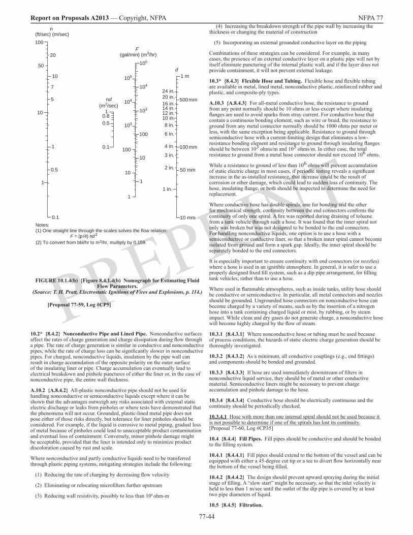
77-44
Report on Proposals A2013 — Copyright, NFPA NFPA 77
PREPRINTFIGURE 10.1.4(b) Figure 8.4.1.4(b) Nomograph for Estimating Fluid
Flow Parameters. (Source: T. H. Pratt, Electrostatic Ignitions of Fires and Explosions, p. 114.)
10.2* 8.4.2 Nonconductive Pipe and Lined Pipe. Nonconductive surfaces affect the rates of charge generation and charge dissipation during flow through a pipe. The rate of charge generation is similar in conductive and nonconductive pipes, while the rate of charge loss can be significantly slower in nonconductive pipes. For charged, nonconductive liquids, insulation by the pipe wall can result in charge accumulation of the opposite polarity on the outer surface of the insulating liner or pipe. Charge accumulation can eventually lead to electrical breakdown and pinhole punctures of either the liner or, in the case of nonconductive pipe, the entire wall thickness.
A.10.2 A.8.4.2 All-plastic nonconductive pipe should not be used for handling nonconductive or semiconductive liquids except where it can be shown that the advantages outweigh any risks associated with external static electric discharge or leaks from pinholes or where tests have demonstrated that the phenomena will not occur. Grounded, plastic-lined metal pipe does not pose either of those risks directly, but tolerance for liner pinholes should be considered. For example, if the liquid is corrosive to metal piping, gradual loss of metal because of pinholes could lead to unacceptable product contamination and eventual loss of containment. Conversely, minor pinhole damage might be acceptable, provided that the liner is intended only to minimize product discoloration caused by rust and scale.
Where nonconductive and partly conductive liquids need to be transferred through plastic piping systems, mitigating strategies include the following:
(1) Reducing the rate of charging by decreasing flow velocity
(2) Eliminating or relocating microfilters further upstream
(3) Reducing wall resistivity, possibly to less than 108 ohm-m
(4) Increasing the breakdown strength of the pipe wall by increasing the thickness or changing the material of construction
(5) Incorporating an external grounded conductive layer on the piping
Combinations of these strategies can be considered. For example, in many cases, the presence of an external conductive layer on a plastic pipe will not by itself eliminate puncturing of the internal plastic wall, and if the layer does not provide containment, it will not prevent external leakage.
10.3* 8.4.3 Flexible Hose and Tubing. Flexible hose and flexible tubing are available in metal, lined metal, nonconductive plastic, reinforced rubber and plastic, and composite-ply types.
A.10.3 A.8.4.3 For all-metal conductive hose, the resistance to ground from any point normally should be 10 ohms or less except where insulating flanges are used to avoid sparks from stray current. For conductive hose that contain a continuous bonding element, such as wire or braid, the resistance to ground from any metal connector normally should be 1000 ohms per meter or less, with the same exception being applicable. Resistance to ground through semiconductive hose with a current-limiting design that eliminates a low-resistance bonding element and resistance to ground through insulating flanges should be between 103 ohms/m and 105 ohms/m. In either case, the total resistance to ground from a metal hose connector should not exceed 106 ohms.
While a resistance to ground of less than 106 ohms will prevent accumulation of static electric charge in most cases, if periodic testing reveals a significant increase in the as-installed resistance, that increase could be the result of corrosion or other damage, which could lead to sudden loss of continuity. The hose, insulating flange, or both should be inspected to determine the need for replacement.
Where conductive hose has double spirals, one for bonding and the other for mechanical strength, continuity between the end connectors confirms the continuity of only one spiral. A fire was reported during draining of toluene from a tank vehicle through such a hose. It was found that the inner spiral not only was broken but was not designed to be bonded to the end connectors. For handling nonconductive liquids, one option is to use a hose with a semiconductive or conductive liner, so that a broken inner spiral cannot become isolated from ground and form a spark gap. Ideally, the inner spiral should be separately bonded to the end connectors.
It is especially important to ensure continuity with end connectors (or nozzles) where a hose is used in an ignitible atmosphere. In general, it is safer to use a properly designed fixed fill system, such as a dip pipe arrangement, for filling tank vehicles, rather than to use a hose.
Where used in flammable atmospheres, such as inside tanks, utility hose should be conductive or semiconductive. In particular, all metal connectors and nozzles should be grounded. Ungrounded hose connectors on nonconductive hose can become charged by a variety of means, such as by the insertion of a nitrogen hose into a tank containing charged liquid or mist, by rubbing, or by steam impact. While clean and dry gases do not generate charge, a nonconductive hose will become highly charged by the flow of steam.
10.3.1 8.4.3.1 Where nonconductive hose or tubing must be used because of process conditions, the hazards of static electric charge generation should be thoroughly investigated.
10.3.2 8.4.3.2 As a minimum, all conductive couplings (e.g., end fittings) and components should be bonded and grounded.
10.3.3 8.4.3.3 If hose are used immediately downstream of filters in nonconductive liquid service, they should be of metal or other conductive material. Semiconductive liners might be necessary to prevent charge accumulation and pinhole damage to the hose.
10.3.4 8.4.3.4 Conductive hose should be electrically continuous and the continuity should be periodically checked.
10.3.4.1 Hose with more than one internal spiral should not be used because it is not possible to determine if one of the spirals has lost its continuity. [Proposal 77-60, Log #CP35]
10.4 8.4.4 Fill Pipes. Fill pipes should be conductive and should be bonded to the filling system.
10.4.1 8.4.4.1 Fill pipes should extend to the bottom of the vessel and can be equipped with either a 45-degree cut tip or a tee to divert flow horizontally near the bottom of the vessel being filled.
10.4.2 8.4.4.2 The design should prevent upward spraying during the initial stage of filling. A “slow start” might be necessary, so that the inlet velocity is held to less than 1 m/sec until the outlet of the dip pipe is covered by at least two pipe diameters of liquid.
10.5 8.4.5 Filtration.
Notes: (1) One straight line through the scales solves the flow relation:
F
d
100
10
1
1
10
100
103
104
103
105
104
105
1 m
500 mm
100 mm
50 mm
10 mm
1 in.
2 in.
3 in.
4 in.
6 in.
8 in.
12 in.14 in.16 in.20 in.24 in.
n(ft/sec) (m/sec)
10
5
100
10
1
0.5
0.1
1
50
20
7
10 in.
(gal/min) (m3/hr)
10.80.5
0.1
nd(m2/sec)
(2) To convert from bbl/hr to m3/hr, multiply by 0.159.F = (p /4) nd2
[Proposal 77-59, Log #CP5]

77-45
Report on Proposals A2013 — Copyright, NFPA NFPA 77
PREPRINT
10.5.1 8.4.5.1 Microfilters.
10.5.1.1 8.4.5.1.1 Microfilters typically have pore sizes less than 150 µm. These filters generate very large streaming currents with nonconductive liquids, due to their large contact area. (Conductive liquids typically dissipate their charge to ground through the body of the liquid.) Streaming currents frequently are greater than those for the pipe flow entering the microfilter by two orders of magnitude, and the charge density added to the liquid can exceed 2000 CC/m3.
10.5.1.2 8.4.5.1.2 To prevent the charges described in 10.5.1.1 8.4.5.1.1 from entering the receiving vessel, the filter should be placed far enough upstream so that the charge can decay to the magnitude it would be in the pipe flow. Common industry practice is to provide 30 sec of residence time in the pipe or conductive hose downstream of the microfilter, especially if the conductivity of the liquid is not known. For nonconductive liquids that have both very low conductivity (i.e., less than 2 pS/m) and high viscosity (i.e., greater than 30 centistokes) at the lowest intended operating temperature, longer residence times might be appropriate. In those cases, a residence time of up to three times the relaxation time constant of the liquid should be considered.
10.5.2 8.4.5.2 Strainers. Mesh strainers finer than 150 µm should be treated as microfilters. Mesh strainers coarser than 150 µm can also generate significant static electric charge where fouled with accumulated debris. If such coarse strainers are used in services where debris can be expected to accumulate, then those strainers should also be treated as microfilters.
10.5.3 8.4.5.3 Polishing Filters. A polishing filter is sometimes placed at the end of a delivery line to remove debris. This filter might be a bag installed on the end of a hose and directly exposed to the vapor in the tank. Filters used in flammable liquid service should be enclosed in grounded metal housings.
10.6 8.4.6 Suspended Material. Immiscible and marginally soluble liquids and slow-dissolving solids can disperse as droplets or as an emulsion. Where a nonconductive liquid contains a dispersed phase, such as water in oil, the continuous phase determines the charge relaxation behavior. Charge generation typically is greater for such suspensions than that for a single phase.
10.7 8.4.7 Miscellaneous Line Restrictions. Piping system components, such as orifice plates, valves, elbows, and tees, increase turbulence and can increase the rate of charge generation. Brief contact with a plastic component, in particular, can cause significant charge generation. Suspended material such as water (see 10.6 8.4.6) also has been found to increase this effect.
Chapter 11 Electrostatic Hazards of Liquids in Containers and Intermediate Bulk Containers
11.1 8.13 Portable Tanks, Intermediate Bulk Containers (IBCs), and Non–Bulk Containers. The practices specified in this section should be followed to reduce static electricity hazards during filling and emptying of portable tanks, IBCs, and non-bulk containers.
11.1.1 8.13.1 Metal Portable Tanks and Metal IBCs.
11.1.1.1 8.13.1.1 Metal portable tanks and IBCs should be bottom-filled, if possible.
11.1.1.2 8.13.1.2 Where used for nonconductive flammable liquids, filters should be placed at least 30 sec upstream, as recommended in 10.5.1.2 8.4.5.1.2.
11.1.1.3 8.13.1.3 The portable tank or IBC should be bonded to the fill system prior to opening and should be closed before being disconnected from the bond.
11.1.1.4 8.13.1.4 Filling rates should be similar to those normally used for drum filling, about 225 L/min or less, unless the container is inerted.
11.1.1.5 8.13.1.5 If the fill pipe does not extend close to the bottom and the vessel is not inerted, a slow start velocity of 1 m/sec or less should be used until the fill pipe is submerged to about 150 mm.
11.1.1.6 8.13.1.6 Portable tanks and IBCs with nonconductive linings present hazards somewhat more severe than with drums, due to the larger capacity and the greater energy that can be stored for equal charge densities.
11.1.2 8.13.2 Nonconductive Portable Tanks and Nonconductive IBCs.
11.1.2.1 8.13.2.1 Filling nonconductive portable tanks or IBCs with combustible liquids at temperatures below their flash points presents no significant static electric ignition hazard. Filling such a vessel with a combustible liquid above or within 9°C of its flash point should be done as if the liquid were flammable.
11.1.2.2 8.13.2.2 Refilling a vessel that could contain flammable vapors from a previous product should not be permitted. Additionally, the routine handling of nonconductive vessels filled with any type of liquid can generate a charge on the outside surface of the vessel.
11.1.2.3 8.13.2.3 Nonconductive portable tanks and IBCs should not be used where ignitible ambient vapors are present.
11.1.2.4 8.13.2.4 Portable tanks and IBCs constructed of nonconductive materials are prohibited for use with Class I liquids by NFPA 30, Flammable and Combustible Liquids Code. Where such containers are used for Class II and Class III liquids, the precautions for filling depend on the size of the container, the container design, and the conductivity of the liquid.
11.1.3 8.13.3 Metal Non–Bulk Containers.
11.1.3.1 8.13.3.1 Where being filled, metal containers and associated fill equipment should be bonded together and grounded.
11.1.3.2 8.13.3.2 Bonding should be done with a clamp that has hardened steel points that will penetrate paint, corrosion products, and accumulated material using either screw force or a strong spring. (See Annex G for recommendations.)
11.1.3.3 8.13.3.3 The clamp should be applied prior to removal of the container bungs and at a point on the top chime that is located away from the bung openings.
11.1.3.4 8.13.3.4 The grounded fill pipe should be cut at approximately 45 degrees and be left relatively sharp to inhibit brush discharges from the liquid surface.
11.1.3.5 8.13.3.5 The tip of the fill pipe should extend to within 25 mm of the bottom of the drum and remain beneath the liquid surface until the drum is filled. Viscous liquids that flow without splashing can be deflected by a short fill nozzle to flow down the inside wall of the drum. Inerting of the drum is seldom necessary.
11.1.3.6 8.13.3.6 Where liquid is dispensed from a metal container, the container should be grounded.
11.1.3.7 8.13.3.7 Self-closing, metal dispensing valves should be used.
11.1.3.8 8.13.3.8 Where liquid is dispensed from an upright drum, the dip pipe, conductive hose, and pump should be bonded to the drum and grounded. (For funnels and receiving containers, see 8.13.6.)
11.1.4 8.13.4 Plastic-Lined Metal Non–Bulk Containers.
11.1.4.1 8.13.4.1 The effects of static electricity from thin, internal coatings, such as phenolic or epoxy paints, can be ignored, provided that the thickness of the coating does not exceed lining is not thicker than 50 µm (2 mils) 2 mm. A container with a thin lining up to 50 µm (2 mils) 2 mm in thickness can be treated as a metal container. The hazards of special coatings such as fluoropolymers have not been fully evaluated and it is advised that at a minimum, liquid is not directly sprayed at such coatings above the liquid level, such as via a hand-held wand.
[Proposals 77-70 (Log #CP73) and 77-71 (Log #CP41]
11.1.4.2 8.13.4.2 Where the drum has a lining of nonconductive plastic thicker than 50 µm (2 mils) 2 mm, it should be treated as a nonconductive container, unless it can be shown that the surface resistivity is not greater than 1010 ohms per square the lining is either conductive (volume resistivity < 105 ohm-m) or static dissipative (volume resistivity < 109
ohm-m). Conductive and static dissipative linings are adequately conductive to safely dissipate charge provided the lining is not isolated from ground by a nonconductive coating beneath it (see 8.13.4.2.1). Owing to the common use of “surface resistivity” to describe linings, it is recommended that “conductive” types be used where the volume resistivity is in doubt. To avoid spark hazards due to batch defects of “conductive” linings, a simple performance test can be used. For example, megger or tera-ohmmeter measurements can be made between the top and bottom of several lining samples to confirm the resistance is within the range provided by the lining supplier.
[Proposals 77-70 (Log #CP73) and 77-71 (Log #CP41]
11.1.4.3* (New) 8.13.4.2.1* Removable Conductive and Static Dissipative Linings. Drums and pails usually have internal nonconductive phenolic or epoxy internal painted coatings less than 2 mil (50 microns) thick. These coatings can isolate the removable lining plus any liquid contents from ground. No special measures are needed for grounded, lined pails during ordinary liquid transfer and stirring operations, although open pails should be grounded using a clamp at the upper rim that also grounds the removable lining. The following measures should be considered for drums.
77-46
Report on Proposals A2013 — Copyright, NFPA NFPA 77
PREPRINT
(a) Open head drums should be grounded using a clamp connected across the upper chime, so that both the drum and removable lining are bonded and grounded.
(b) Closed head drums can in many cases be filled via a grounded dip pipe that is fully inserted before the drum is filled.
Where these measures are impractical, a helpful measure is to select drums that have coating thicknesses in the range 0.5-1 mil (12-25 microns), so that the breakdown voltage between the lining and the drum is minimized. A pragmatic solution is simply to remove part of the drum coating at the chime so that the lining contacts bare metal. [Proposal 77-70, Log #CP73]
A.11.1.4.3 Removal of linings that are wet with flammable material pose ignition hazards during handling and storage. Conductive and static dissipative linings should be handled by a grounded person and stored outside the operating area in a well-ventilated location. Nonconductive linings pose special hazards if they are stacked and then unstacked, creating static via rubbing. A hazard review should be considered to determine the safest way to handle and store removable linings. [Proposal 77-70, Log #CP73]
11.1.5 8.13.5 Plastic Non–Bulk Containers. The use of plastic containers for Class I liquids is limited by Table 9.4.3 and Paragraph 9.4.3.1 of NFPA 30, Flammable and Combustible Liquids Code. Where such containers are used for Class II and Class III liquids, the precautions for filling depend on the size of the container, the container design, and the conductivity of the liquid. [Proposal 77-72, Log #CP74]
11.1.5.1 8.13.5.1 Because plastic containers cannot be grounded, they should not be used for Class I liquids or handled in flammable atmospheres without expert review of the hazards.
11.1.5.2 8.13.5.2 For Class II liquids, hazards of static electricity should be addressed as follows:
(1) Where the liquid might exceed its flash point during filling or emptying
(2) Where the container might be stored or handled in an ignitible ambient atmosphere
11.1.5.3 8.13.5.3 The options that can be used to address the situation specified in 11.1.5.2(1) 8.13.5.2(1) include bottom filling and cooling of the liquid prior to unloading, especially if the container has been in direct sunlight or in a hot storage area. Continuous inerting during unloading can also be considered.
11.1.5.4 8.13.5.4 For the situation specified in 11.1.5.2(2) 8.13.5.2(2), plastic containers should be stored away from containers of flammable liquids so that the hazard of static electric discharge from the external surface of the plastic container is avoided.
11.1.6 8.13.6 Hand-Held Containers Up to 20 L Capacity. The fire risk from static electricity increases with the volume of the container and the volatility of the liquid handled. Thus, the smallest-volume container capable of effectively fulfilling a particular need should normally be selected and should not exceed 20 L.
11.1.6.1 8.13.6.1 Listed safety cans should be used, especially those types equipped with a flexible metal dispensing nozzle hose so they can be used without a funnel. [Proposal 77-73, Log #CP75]
11.1.6.2 8.13.6.2 Because nonconductive containers cannot be grounded, they should be limited to 2 L for Class IA liquids and 5 L for Class IB and Class IC liquids. An exception is gasoline, for which approved 20 L plastic cans have been widely used for many years with no reported increase in ignition incidents due to static electricity compared with metal cans. That record is due in part to the rapid establishment of rich (above the UFL) gasoline vapor inside the can.
11.1.6.3 8.13.6.3 The plastic containers specified in 11.1.6.2 8.13.6.2 should not be used for other flammable liquids without review of the hazards. Unlike gasoline, conductive liquids such as alcohols can become inductively charged by a charged plastic container and give rise to sparks. In addition, the container can contain an ignitible atmosphere.
11.1.7 8.13.7 Nonconductive Containers. Subject to the volume limitations described in 11.1.6 8.13.6, it is common to handle flammable liquids in small glass or plastic containers of 0.5 L capacity or less.
11.1.7.1 8.13.7.1 Where the containers specified in 11.1.7 8.13.7 are involved in frequent transfer operations, such as a small-scale solvent blending operation, a grounded metal funnel with a spout that extends to the bottom of the container should be used for filling the container. This practice ensures that any charge induced on the liquid by the container, as could happen if the plastic container has been charged by rubbing, is dissipated through the grounded funnel.
11.1.7.2 8.13.7.2 Plastic or glass funnels should be used only where essential for compatibility reasons.
11.1.8 8.13.8 Containers for Sampling.
11.1.8.1 8.13.8.1 Ignition risk is greatly increased where an ignitible atmosphere is present outside the container; for example, where sampling is directly from a tank or a sample is transferred near a manway, because such a situation can precipitate a large fire or explosion. A grounded metal sample “thief” or glass bottle in a grounded metal sample cage can be used in such cases.
11.1.8.2 8.13.8.2 Because they are more easily charged than glass, nonconductive plastic containers should be avoided except where used in well-ventilated areas. If outdoor sampling is carried out at sample spigots that are located away from tank openings and in freely ventilated areas and if sampled quantities are 1 L or less, the fire risk is, in most cases, insufficient to necessitate any special procedures other than bonding of metal components.
11.2* 8.13.9 Cleaning of Containers.
A.11.2 A.8.13.9 See NFPA 326, Standard for the Safeguarding of Tanks and Containers for Entry, Cleaning, or Repair.
11.2.1 8.13.9.1 Containers should be bonded and grounded prior to being opened for cleaning operations such as steaming.
11.2.2 8.13.9.2 Cleaning equipment should be bonded or grounded.
11.3 8.16 Plastic Sheets and Wraps.
11.3.1 8.16.1 Nonconductive plastic sheets and wraps, such as those used to wrap shipping pallets, present hazards similar to those of plastic bags. Such sheets and wraps can generate brush discharges from their surfaces following rubbing or separation of surfaces. Isolated wet patches can also create spark hazards.
11.3.2 8.16.2 An additional problem is charging of personnel as they handle plastic sheets and wrap. Plastic sheets and wrap should not be brought into areas that can contain ignitible atmospheres. Plastic pallet wrap can be removed outside the area and, if necessary, replaced by a suitable tarpaulin or other temporary cover. Antistatic wrap is available. Tear sheets (used outside many clean areas) can generate significant static electric charge when they are pulled from a dispenser, and precautions are similar to those for plastic sheets. (Additional information on handling sheet materials is found in Chapter 17 Section 10.2.)
Chapter 12 Electrostatic Hazards of Liquids in Bulk Storage Tanks and in Tank Vehicles
12.1 8.5 Storage Tanks.
12.1.1 8.5.1 General. Liquid flowing into a tank can carry a static electric charge that will accumulate in the tank. This charge can be detected as a potential above the surface of the liquid in the tank. The maximum surface potential attained depends not only on the charge density of the incoming liquid but also on the dimensions of the tank. For commercial tanks of equal volume, the maximum potential will be greater in tanks having smaller cross-sectional areas, because liquid depth increases faster relative to the rate of charge relaxation. Smaller potentials will therefore be generated in, for example, a near-rectangular barge tank than in a cylindrical vertical tank of the same volume.
12.1.2 8.5.2 Conductive Fixed-Roof Storage Tanks. Charge accumulation in the liquid in a tank can lead to static electric discharge between the liquid surface and the tank shell, roof supports, or tank appurtenances. The charge generation rate is influenced by turbulence in the liquid and by the settling of particulate matter, such as water droplets, iron scale, and sediment.
12.1.2.1 [8.5.2.1 Precautions. If the vapor space in the tank is likely to contain an ignitible mixture (e.g., in cases where intermediate vapor pressure products or low vapor pressure products contaminated with high vapor pressure liquids are stored) or where switch loading is practiced, the following protective measures should be taken:
(1) Splash filling and upward spraying should be avoided.
(2) The fill pipe should discharge near the bottom of the tank, with minimum agitation of water and sediment on the tank bottom.
77-47
Report on Proposals A2013 — Copyright, NFPA NFPA 77
PREPRINT
(3) If possible, the inlet flow velocity should be limited during the initial stage of tank filling to reduce agitation and turbulence, and the following also should be applied:
(a) The flow velocity of the incoming liquid should be no greater than 1 m/sec until the fill pipe is submerged either two pipe diameters or 0.6 m, whichever is less.
(b) Because too low a velocity can result in entrained water settling out at low points in the piping, the inlet flow velocity should be kept as close to 1 m/sec as possible during the initial tank filling period to prevent subsequent re-entrainment of water or other contaminants that could significantly increase the product’s charging tendency when the velocity is increased.
(4)* The following applies to storage tanks greater than 200 m3 (50,000 gal) 50 m3 containing liquids that are either nonconductive or for which conductivity is unknown: [Proposal 77-61, Log #CP68]
(a) The inlet flow velocity can be increased to 7 m/sec after the fill pipe is submerged.
(b) Where operating experience has shown that the practice is acceptable, such as in the petroleum industry, the inlet flow velocity can be increased above 7 m/sec, but in no case to a velocity greater than 10 m/sec. [See Figure 10.1.4(a) and Figure 10.1.4(b) Figure 8.4.1.4(a) and Figure 8.4.1.4(b) for determining flow rate.]
A.12.1.2.1(4) A.8.5.2.1(4) See API RP 2003, Protection Against Ignitions Arising Out of Static, Lightning, and Stray Currents, for further information.
(5) New The following applies to vertical axis storage tanks greater than 75 m3 (20,000 gal) and less than 200 m3 (50,000 gal) containing liquids that are either nonconductive or for which conductivity is unknown:
(a) The product of inlet flow velocity and pipe inside diameter can be
increased to 0.50 m2/sec after the fill pipe is submerged.[Proposal 77-62, Log #CP69] (6) New The following applies to vertical axis storage tanks
greater than 1 m3 (250 gal) and less than 75 m3 (20,000 gal) containing liquids that are either nonconductive or for which conductivity is unknown:
(a) The product of inlet flow velocity and pipe inside diameter can be
increased to 0.38 m2/sec after the fill pipe is submerged.
(b) If the liquid is nonconductive and contains a dispersed phase, such as entrained water droplets, the flow velocity should be restricted to 1 m/sec throughout the filling operation. [Proposal 77-62, Log #CP69]
(7)(5) If the liquid is nonconductive and contains a dispersed phase, such as entrained water droplets, the inlet flow velocity should be restricted to 1 m/sec throughout the filling operation.
(8)(6) A 30-sec minimum residence time should be provided for liquid to flow between upstream microfilter screens and the tank. (See 10.5 8.4.5.)
(9)(7) Tanks should be inspected for ungrounded conductive objects, such as loose gauge floats and sample cans, because such objects floating on the liquid surface can promote sparks.
(10)(8) Lines should not be blown out with air or other gases if the liquid is a Class I liquid or is handled at or above its flash point, because introducing substantial amounts of air or other gas into a tank through such a liquid can create a hazard due to charge generation, misting of the liquid, and formation of an ignitible atmosphere unless it is certain that the operation will not overpressure the lines or the equipment into which they terminate. The smallest source pressure that will successfully clear the line should be used to minimize the volume of entrained gas delivered to the receiving vessel. Introducing substantial amounts of air or other gas into the liquid in the line can create a hazard due to misting of the liquid, subsequent charge generation, and formation of an ignitible atmosphere. [Proposal 77-63, Log #CP44]
12.1.2.2 8.5.2.2 Grounding.
12.1.2.2.1 8.5.2.2.1 Storage tanks for nonconductive liquids should be grounded. Storage tanks on grade-level foundations are considered inherently grounded, regardless of the type of foundation (e.g., concrete, sand, or asphalt).
12.1.2.2.2 8.5.2.2.2 For tanks on elevated foundations or supports, the resistance to ground can be as high as 106 ohms and still be considered adequately grounded for purposes of dissipation of static electric charges, but the resistance should be verified. The addition of grounding rods and similar grounding systems will not reduce the hazard associated with static electric charges in the liquid.
12.1.2.3 8.5.2.3 Spark Promoters.
12.1.2.3.1 8.5.2.3.1 A tank gauging rod, high-level sensor, or other conductive device that projects downward into the vapor space of a tank can provide a location for static electric discharge between the device and the rising liquid; therefore, these devices should meet the following criteria:
(1) They should be bonded securely and directly downward to the bottom of the tank by a conductive cable or rod to eliminate a spark gap or should be installed in a gauging well that is bonded to the tank.
(2) They should be inspected periodically to ensure that the bonding system has not become detached.
12.1.2.3.2 8.5.2.3.2 If tank fixtures are nonconductive, the potential for sparking does not exist, and no specific measures are needed. Devices that are mounted to the sidewall of the tank (e.g., level switches or temperature probes) and project a short distance into the tank might not pose a static electric discharge hazard. These situations should be evaluated on an individual basis.
12.1.2.4 8.5.2.4 Tank Mixers. In-tank jet mixing or high-velocity agitator mixing can stir up water and debris and cause splashing at the surface that can generate static electric charges. If an ignitible mixture exists at the surface, ignition is possible. Surface splashing should be minimized. Gas blanketing or inerting can be employed to eliminate the ignition hazard.
12.1.2.5 8.5.2.5 Gas Agitation.
12.1.2.5.1 8.5.2.5.1 Air, steam, or other gases should not be used for agitation because they can produce high levels of charge in liquids, mists, or foams. In addition, air agitation can create an ignitible atmosphere in the vapor space of the tank. If gas agitation is unavoidable, the vapor space should be purged prior to mixing, and the process should be started slowly to ensure that static electric charge does not accumulate faster than it can dissipate.
12.1.2.5.2 8.5.2.5.2 It should be noted that special precautions need to be taken to prevent agitation with air to because it can dilute any initial inerting. Similarly, while agitation with an inert gas can eventually result in an inert vapor space, the electrostatic charge buildup due to the agitation process can result in a spark and ignition before inerting of the tank vapor space is achieved. A waiting time should be observed prior to any gauging or sampling activities.
12.1.3 8.5.3 Conductive Floating Roof Storage Tanks. Floating roof storage tanks are inherently safe, provided that the floating roof is bonded to the tank shell. Bonding typically is achieved by shunts between the floating roof or cover and the wall of the tank. The shunts are installed for lightning protection, but they also provide protection from static electric charges that could be generated. If the floating roof is landed on its supports, charge accumulation in the surface of the liquid can occur, and the precautions for a fixed roof tank should be followed. If an internal floating roof tank is not adequately ventilated, flammable vapor can accumulate between the floating roof and the fixed roof.
12.1.4 8.5.4 Coated and Lined Tanks. Metal tanks with nonconductive coatings or linings can be treated as conductive tanks The presence of internal coatings or linings in grounded metal tanks can generally be neglected, provided that either one of the following criteria applies:
(1) The nonconductive coating or lining has a volume resistivity equal to or lower than 109 1010 ohm-m, such as fiberglass-reinforced linings for corrosion prevention, and is no thicker than 2 mm.
(2) Thickness of a painted coating does not exceed 50 µm (2 mils).
(2) The nonconductive lining has a volume resistivity greater than 1010 ohm-m, such as polyethylene or rubber linings, but has a breakdown potential less than 4 kV.
(3) The liquid is conductive and is always in contact with ground, for example, a grounded dip tube or grounded metal valve. [Proposal 77-64, Log #CP42]
12.1.4.1 8.5.4.1 Metal tanks with nonconductive coatings or linings that do not meet the criteria of 12.1.4(1) or 12.1.4(2) 8.5.4(1) or 8.5.4(2) should be treated as nonconductive tanks. Regardless of the coating or lining thickness or resistivity, the tank should be bonded to the filling system. The coating or lining is not regarded as a barrier to the flow of static electric charges. Its resistivity is of the same order of magnitude as that of the liquid, or there could be small bare areas (holidays) in the coating. [Proposal 77-64, Log #CP42]

77-48
Report on Proposals A2013 — Copyright, NFPA NFPA 77
PREPRINT
A thin coat of paint, a thin plastic liner, or a layer of metal oxide on the inside of piping, vessels, or equipment does not constitute a static electric hazard. [Proposal 77-64, Log #CP42]
12.1.5 8.5.5 Tanks Constructed of Nonconductive Materials. Tanks constructed of nonconductive materials are not permitted for storage of Class I, Class II, and Class IIIA liquids, except under special circumstances, as outlined in 21.4.1 Section 4.2 of NFPA 30, Flammable and Combustible Liquids Code. (See 13.8 8.10.7 for design and use recommendations.)
12.2 8.6 Loading of Tank Vehicles. Recommended loading precautions for tank vehicles vary with the characteristics of the liquid being handled and the design of the loading facility. A summary of recommended precautions that should be used where a flammable mixture exists in the tank vehicle compartment, based on API RP 2003, Protection Against Ignitions Arising Out of Static, Lightning, and Stray Currents, is provided in Table 12.2 Table 8.6. These precautions are intended for tank vehicles with conductive (metal) compartments. (For compartments with nonconductive linings, see Section 13.5 8.10.4. For compartments of nonconductive material, see Section 13.8 8.10.7.)(See Table 12.2 on the following page.)
12.2.1 8.6.1 Top Filling. Splash filling should be avoided by using a fill pipe that is designed according to the recommendations in Section 10.4 8.4.4.
12.2.2 8.6.2 Bottom Filling. The bottom-filling inlet should be designed with a deflector or a diverter to prevent upward spraying and generation of mist. Using a cap or a tee to direct incoming liquid sideways toward the compartment walls, rather than upward, will achieve this objective.
12.2.3 8.6.3 Switch Loading. The practice of loading a liquid having a high flash point and low conductivity into a tank that previously contained a low flash point liquid is referred to as switch loading. This practice can result in the ignition of residual flammable vapor as the tank is filled. The methods of hazard prevention are similar to those specified in 12.1.2.1(1) through 12.1.2.1(3) 8.5.2.1(1) through 8.5.2.1(3) and 12.1.2.1(5) through 12.1.2.1(8) 8.5.2.1(5) through 8.5.2.1(8). Flow velocities are found in Table 12.2 8.6.
12.2.4 8.6.4 Highway Transport. As noted in API RP 2003, Protection Against Ignitions Arising Out of Static, Lightning, and Stray Currents, tank vehicles normally do not create a static electricity hazard during transport, provided that they are compartmented or contain baffles. The compartments or baffles minimize sloshing of the liquid in the tank vehicle, which could result in significant charge generation. Clear bore (unbaffled) tank vehicles should not be used for liquids that can generate an ignitible mixture in the vapor space.
12.2.5 New Unloading of Tank Vehicles. For bulk transfer of liquids from tank vehicles to storage tanks, see Section 12.1. [Proposal 77-66, Log #CP71]
12.2.6 8.6.5 Antistatic Additives. Charge accumulation can be reduced by increasing the conductivity of the liquid by adding a conductivity-enhancing agent (antistatic additive).
12.2.6.1 8.6.5.1 Antistatic additives normally are added in parts-per-million concentrations and should be used in accordance with manufacturer instructions.
12.2.6.2 8.6.5.2 Where antistatic additives are used as a primary means of minimizing accumulation of static electric charge, the operator should verify the concentration of the additive at critical points in the system.
12.3* 8.7 Vacuum Trucks.
A.12.3 A.8.7 See API 2219, Safe Operation of Vacuum Trucks in the Petroleum Service, for general recommendations.
12.3.1 8.7.1 For control of static electricity, hose should be conductive or semiconductive.
12.3.2 8.7.2 As an alternative to the recommendation of 8.7.1, all conductive components should be bonded, and the truck should be grounded.
12.3.3 8.7.3 In no case should plastic dip pipes or plastic intermediate collection pans or drums be used.
12.4 8.8 Railroad Tank Cars.
12.4.1 8.8.1 In general, the precautions for railroad tank cars are similar to those for tank vehicles specified in Section 12.2 8.6. The major exception is the larger volume typical of railroad tank cars (e.g., greater than 87 m3) compared with that of tank vehicles (e.g., about 50 m3). The greater volume allows greater maximum flow velocities to be used for filling rates to be used, up to a maximum of (0.8/d) m/sec, where d is the inside diameter of the inlet in meters. [Proposal 77-67, Log #CP72]
12.4.2 8.8.2 Many tank cars are equipped with nonconductive bearings and nonconductive wear pads located between the car itself and the trucks (wheel assemblies). Consequently, resistance to ground through the rails might not be low enough to prevent accumulation of a static electric charge on the tank car body. Therefore, bonding of the tank car body to the fill system piping is necessary to protect against charge accumulation. In addition, because of the possibility of stray currents, loading lines should be bonded to the rails.
12.5 8.9 Marine Vessel and Barge Cargo Tanks. Marine vessel and barge cargo tanks are beyond the scope of this recommended practice. The recommendations given in the International Safety Guide for Oil Tankers and Terminals (ISGOTT) should be followed.
Chapter 13 Electrostatic Hazards in Process Vessels
13.1 8.10.1 Means of Static Electric Charge Accumulation. Accumulation of static electricity in process vessels occurs by the same methods as described in Section 12.1 8.5 for storage tanks.
13.1.1 8.10.1.1 Where a conductive and a nonconductive liquid are to be blended, the conductive liquid should be added to the vessel first, if possible, so that the conductivity of the mixture is as high as possible throughout the mixing process.
13.1.2 8.10.1.2 Re-entry of recirculation loops should be designed to minimize splashing and surface disruption, for example, by use of subsurface jets that do not break the liquid’s surface.
13.2* 8.10.2 Procedures for Transfer to Tanks.
A.13.2 A.8.10.2 See NFPA 69, Standard on Explosion Prevention Systems, for additional information.
13.2.1 8.10.2.1 When two or more nonconductive liquids are introduced into a blending tank, the less dense liquid should be loaded first to avoid a surface layer comprising the lighter, more highly charged component.
13.2.2 8.10.2.2 Splash recirculation normally should be done only if the vessel is inerted or vapor enriched.
13.3 8.10.3 Agitation. Agitators should be covered with sufficient depth of liquid before being operated, to minimize splashing, or should be operated at reduced speed until sufficient depth has been achieved. In cases where hazardous charge accumulation cannot be avoided using the measures discussed in Chapter 13 Section 8.10, the vessel can be inerted.
13.4 8.10.4 Vessels with Nonconductive Linings. The accumulation of static electric charge can result in pinhole damage to equipment such as enamel- or glass-lined reactors. Because static electric discharges often occur at the liquid interface as liquid drains from the wetted wall, a vapor ignition hazard could also exist. In some cases, it is possible to specify static dissipative coatings for the vessel or agitator. Conductive vessels and appurtenances should be bonded and grounded. In some cases, inerting might be necessary.
13.5 8.10.5 Adding Solids. The most frequent cause of static electric ignitions in process vessels is the addition of solids to flammable liquids in the vessels. Even where the vessel is inerted, large additions of solids will introduce air into the vessel while expelling flammable vapor from the vessel. The sudden addition of a large volume of solids can also result in static discharge from a floating pile of charged powder.
13.5.1 8.10.5.1 Manual addition of solids through an open port or manway should be done only in 25 kg batches.
13.5.2 8.10.5.2 Batch additions larger than 25 kg [e.g., from flexible intermediate bulk containers (see Section 16.6 10.1.6)] should be done through an intermediate hopper with a rotary valve or an equivalent arrangement. The hopper can be inerted separately to reduce air entrainment into the mixing vessel, while expulsion of vapor into the operating area can be avoided by venting the vessel to a safe location. The addition of solids from nonconductive plastic bags can be hazardous, even if the solids are noncombustible (e.g., silica).
13.5.3 8.10.5.3 Bags should be constructed of paper, plies of paper and plastic in which the nonconductive plastic film is covered by paper on both sides, or antistatic plastic. Because grounding clips can be impractical, such bags can be effectively grounded by contact with a grounded conductive vessel or skin contact with a grounded operator.
13.5.4 8.10.5.4 Fiber drums or packages should not have a loose plastic liner that can leave the package and behave like a plastic bag. All metal chimes should be grounded.[Proposal 77-68, Log #CP54]
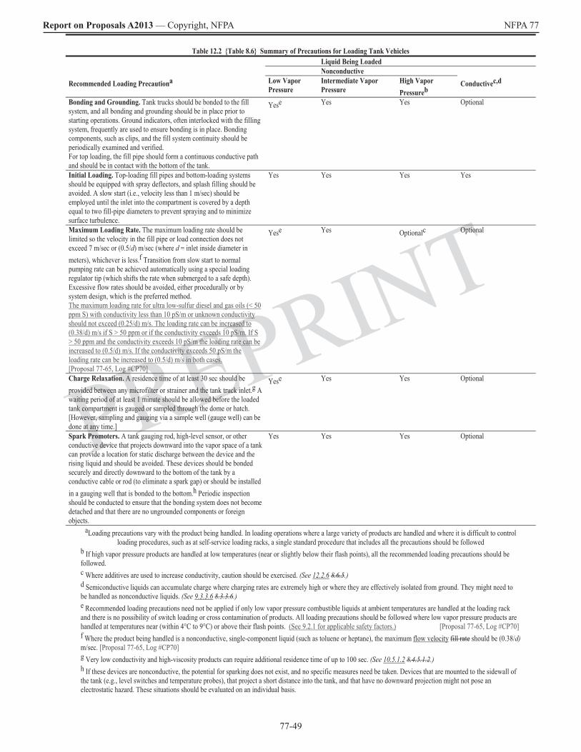
77-49
Report on Proposals A2013 — Copyright, NFPA NFPA 77
PREPRINT
Table 12.2 Table 8.6 Summary of Precautions for Loading Tank Vehicles Liquid Being Loaded Nonconductive Recommended Loading Precautiona Low Vapor
Pressure Intermediate Vapor Pressure
High Vapor Pressureb
Conductivec,d
Bonding and Grounding. Tank trucks should be bonded to the fill system, and all bonding and grounding should be in place prior to starting operations. Ground indicators, often interlocked with the filling system, frequently are used to ensure bonding is in place. Bonding components, such as clips, and the fill system continuity should be periodically examined and verified. For top loading, the fill pipe should form a continuous conductive path and should be in contact with the bottom of the tank.
Yese Yes Yes Optional
Initial Loading. Top-loading fill pipes and bottom-loading systems should be equipped with spray deflectors, and splash filling should be avoided. A slow start (i.e., velocity less than 1 m/sec) should be employed until the inlet into the compartment is covered by a depth equal to two fill-pipe diameters to prevent spraying and to minimize surface turbulence.
Yes Yes Yes Yes
Maximum Loading Rate. The maximum loading rate should be limited so the velocity in the fill pipe or load connection does not exceed 7 m/sec or (0.5/d) m/sec (where d = inlet inside diameter in meters), whichever is less.f Transition from slow start to normal pumping rate can be achieved automatically using a special loading regulator tip (which shifts the rate when submerged to a safe depth). Excessive flow rates should be avoided, either procedurally or by system design, which is the preferred method. The maximum loading rate for ultra low-sulfur diesel and gas oils (< 50 ppm S) with conductivity less than 10 pS/m or unknown conductivity should not exceed (0.25/d) m/s. The loading rate can be increased to (0.38/d) m/s if S > 50 ppm or if the conductivity exceeds 10 pS/m. If S> 50 ppm and the conductivity exceeds 10 pS/m the loading rate can be increased to (0.5/d) m/s. If the conductivity exceeds 50 pS/m the loading rate can be increased to (0.5/d) m/s in both cases. [Proposal 77-65, Log #CP70]
Yese Yes Optionalc Optional
Charge Relaxation. A residence time of at least 30 sec should be provided between any microfilter or strainer and the tank truck inlet.g A waiting period of at least 1 minute should be allowed before the loaded tank compartment is gauged or sampled through the dome or hatch. [However, sampling and gauging via a sample well (gauge well) can be done at any time.]
Yese Yes Yes Optional
Spark Promoters. A tank gauging rod, high-level sensor, or other conductive device that projects downward into the vapor space of a tank can provide a location for static discharge between the device and the rising liquid and should be avoided. These devices should be bonded securely and directly downward to the bottom of the tank by a conductive cable or rod (to eliminate a spark gap) or should be installed in a gauging well that is bonded to the bottom.h Periodic inspection should be conducted to ensure that the bonding system does not become detached and that there are no ungrounded components or foreign objects.
Yes Yes Yes Optional
aLoading precautions vary with the product being handled. In loading operations where a large variety of products are handled and where it is difficult to control loading procedures, such as at self-service loading racks, a single standard procedure that includes all the precautions should be followed
b If high vapor pressure products are handled at low temperatures (near or slightly below their flash points), all the recommended loading precautions should be followed. c Where additives are used to increase conductivity, caution should be exercised. (See 12.2.6 8.6.5.)d Semiconductive liquids can accumulate charge where charging rates are extremely high or where they are effectively isolated from ground. They might need to be handled as nonconductive liquids. (See 9.3.3.6 8.3.3.6.)e Recommended loading precautions need not be applied if only low vapor pressure combustible liquids at ambient temperatures are handled at the loading rack and there is no possibility of switch loading or cross contamination of products. All loading precautions should be followed where low vapor pressure products are handled at temperatures near (within 4°C to 9°C) or above their flash points. (See 9.2.1 for applicable safety factors.) [Proposal 77-65, Log #CP70]f Where the product being handled is a nonconductive, single-component liquid (such as toluene or heptane), the maximum flow velocity fill rate should be (0.38/d)m/sec. [Proposal 77-65, Log #CP70]g Very low conductivity and high-viscosity products can require additional residence time of up to 100 sec. (See 10.5.1.2 8.4.5.1.2.)h If these devices are nonconductive, the potential for sparking does not exist, and no specific measures need be taken. Devices that are mounted to the sidewall of the tank (e.g., level switches and temperature probes), that project a short distance into the tank, and that have no downward projection might not pose an electrostatic hazard. These situations should be evaluated on an individual basis.
77-50
Report on Proposals A2013 — Copyright, NFPA NFPA 77
PREPRINT
13.5.5 8.10.5.5 Metal chimes drums should be grounded. (Reserved) [Proposal 77-68, Log #CP54]
13.5.6 8.10.5.6 Personnel in the vicinity of openings of vessels that contain flammable liquids should be grounded, and special attention should be paid to housekeeping, because accumulation of nonconductive residues (e.g., resins) on the floor or on items such as grounding clips can impair electrical continuity.
13.6 8.10.6 Mixing Solids. Where solids are dissolved or dispersed into nonconductive liquids, the rate of charge generation can be large, depending on factors such as solids loading, particle size, and agitation rate. Dissipation of the charge frequently is achieved by raising the conductivity of the continuous phase by reformulation with conductive solvents or by the addition of antistatic additives. Alternatively, ignition hazards can be controlled by inerting.
13.7 8.10.7 Nonconductive Process Vessels.
13.7.1 8.10.7.1 In general, nonconductive process vessels should not be used with flammable liquids, which present external ignition risks if their outer surfaces become charged.
13.7.2 8.10.7.2 If a nonconductive tank is to be used and the possibility exists that the atmosphere around the tank or in the vapor space is ignitible, the following criteria should be met to ensure the safe dissipation of charge and to prevent discharges:
(1) All conductive components (e.g., a metal rim and hatch cover) should be bonded together and grounded.
(2) Where the tank is used to store nonconductive liquids, the following criteria should be met:
(a) An enclosing, grounded conductive shield should be provided to prevent external discharges. This shield should be a grounded wire mesh buried in the tank wall and should enclose all external surfaces. [Proposal 77-69, Log #CP55]
(b) The shield should be a grounded wire mesh buried in the tank wall and should enclose all external surfaces. [Proposal 77-69, Log #CP55]
(b) A metal plate should be installed to provide a path through which charge can flow from the liquid contents to ground. The metal plate should have a surface area not less than 500 cm2/m3 of tank volume and should be located at the bottom of the tank and bonded to ground. [Proposal 77-69, Log #CP55]
(3) Where used to store nonconductive liquids, the tank should have a metal plate to provide a path through which charge can flow from the liquid contents to ground, and the following criteria also should be met:
(a) The plate should have a surface area not less than 500 cm2/m3 of tank volume.
(b) The plate should be located at the bottom of the tank and bonded to ground.
[Proposal 77-69, Log #CP55]
(34) Where the tank is used to store conductive liquids, an internal grounding cable extending from the top to the bottom of the tank and connected to ground or a grounded fill line meeting the following criteria and extending to the bottom of the tank should be provided:
(a) The grounded fill line enters at the bottom of the tank.
(b) The grounded fill line does not introduce a spark promoter.[Proposal 77-69, Log #CP55]
Chapter 14 Electrostatic Hazards of Operations in Tanks and Process Vessels
14.1 8.11 Gauging and Sampling. Gauging and sampling operations, including temperature measurement, can introduce spark promoters into a storage tank or compartment. A conductive gauging well for manual sampling and gauging should be used.
14.1.1 8.11.1 Precautions. The precautions given in Section 14.1 8.11 should be taken where use of a gauging well is not possible, where the material stored is a nonconductor, or where the vapor space of the container could be ignitible.
14.1.2 8.11.2 Manual Operations. Where gauging and sampling operations are conducted manually, the personnel grounding recommendations in Section 8.2 7.6 should be considered.
14.1.3 8.11.3 Materials. Gauging and sampling systems should be either completely conductive or completely nonconductive. For example, conductive sampling and gauging devices should be used with a conductive lowering device, such as a steel tape or cable.
14.1.3.1 8.11.3.1 Chains are not electrically continuous and should not be used in flammable atmospheres.
14.1.3.2 8.11.3.2 Conductive sampling and gauging devices, including the sampling container and the lowering device, should be properly bonded to the tank or compartment.
14.1.3.3 8.11.3.3 The bonding specified in 14.1.3.2 8.11.3.2 should be accomplished by use of a bonding cable or by maintaining continuous metal-to-metal contact between the lowering device and the tank hatch.
14.1.3.4 8.11.3.4 Ideally, if nonconductive hand gauging or sampling devices are used, no waiting period is needed after loading or filling; however, it should be noted that these devices might not retain the necessary level of nonconductivity due to environmental factors such as moisture or contamination. Therefore, an appropriate waiting period should be allowed where nonconductive devices are used.
14.1.3.5 8.11.3.5 Cord made from synthetic material such as nylon should not be used due to possible charging if it slips rapidly through gloved hands. Although natural cellulosic fiber cord can, in principle, be used, such cord is frequently composed of a natural–synthetic blend, with corresponding charge-generating ability.
14.1.4 8.11.4 Gauging. Where possible, gauging should be carried out using automatic gauging systems. These systems can be used safely in tanks, provided that the gauge floats and similar devices are electrically bonded to the tank shell through a conductive lead-in tape or conductive guide wires. Free-floating, unbonded floats can be effective spark promoters and should be avoided. Noncontact gauging devices, such as radar and ultrasonic gauges, are also satisfactory, provided that electrical continuity is ensured. Isolated conductive components must not be used.
14.1.5 8.11.5 Waiting Period.
14.1.5.1 8.11.5.1 Depending on the size of the compartment and the conductivity of the product being loaded, a sufficient waiting period should be allowed for accumulated charge to dissipate.
14.1.5.2 8.11.5.2 A 30-minute waiting period should be allowed before the gauging or sampling of storage tanks greater than 40 m3, unless a gauging well is used. The waiting period before the gauging or sampling of smaller vessels can be reduced to 5 minutes for tanks between 20 m3 and 40 m3 and to 1 minute for tanks less than 20 m3. Longer waiting periods might be appropriate for very low conductivity liquids (κ< 2 pS/m) or nonconductive liquids that contain a second dispersed phase [such as a Class I liquid with more than 0.5 percent water (weight basis)]. If a gauging well is used, a waiting period is unnecessary.
14.2 8.12 Tank Cleaning.
14.2.1 8.12.1 Water Washing.
14.2.1.1 8.12.1.1 The mist created in a tank by water spraying can be highly charged. This is a particular problem with tanks larger than 100 m3, due to the size of the mist cloud that can form. Water washing using sprays should be done only in an inerted or nonflammable atmosphere.
14.2.1.2 8.12.1.2 Although specifically written for marine cargo tanks, the International Safety Guide for Oil Tankers and Terminals (ISGOTT) presents a comprehensive discussion of tank cleaning. Tanks less than 100 m3 and with all conductive components grounded have a negligible discharge hazard. Where a possibility of steam entering the tank during the water-washing process exists, the precautions in 8.12.3 should be followed.
14.2.2 8.12.2 Solvent Washing. Mist charge densities created by flammable solvents are similar to those from water washing, and similar precautions should be taken regarding grounding of conductive components.
14.2.2.1 8.12.2.1 Where an ignitible atmosphere or mist cannot be avoided because of the type of solvent or cleaning process used, the tank or vessel being cleaned should be inerted or enriched to reduce the likelihood of ignition during the cleaning process.

77-51
Report on Proposals A2013 — Copyright, NFPA NFPA 77
PREPRINT
14.2.2.2 8.12.2.2 Where the vessel is not inerted or enriched and an ignitible atmosphere is present, the following precautions should be considered where solvent is used as a cleaning agent:
(1) The solvent should be conductive.
(2) Where a solvent blend, such as reclaimed solvent, is used, the conductivity should be checked periodically.
(3) High flash point materials (at least 9°C above the maximum operating temperature during cleaning) should be used, and the flash point should be confirmed on a daily basis.
(4) The cleaning system should be conductive and bonded to the tank, and continuity tests of all bonded equipment should be done periodically.
(5) Ungrounded conductive objects should be treated in accordance with the following:
(a) They should not be introduced into the tank during the cleaning process.
(b) They should not be introduced into the tank for a sufficient period of time after the cleaning process, which might take several hours due to the generation of mist.
14.2.3 8.12.3 Steam Cleaning. Steam cleaning can create very large charge densities with correspondingly large space charge potentials that increase with the size of the tank. Therefore, the following precautions should be taken:
(1) Tanks larger than 4 m3 should be inerted before steam cleaning.
(2) All components of the steaming system should be conductive and grounded.
(3) All conductive components of the tank should be bonded and grounded.
14.2.4 8.12.4 Internal Grit Blasting.
14.2.4.1 8.12.4.1 Where possible, tanks and process vessels should be clean and free of ignitible materials (no more than 10 percent of the LFL).
14.2.4.2 8.12.4.2 Hose used for grit blasting should be grounded, and the resistance to ground from any part of the hose assembly, especially the nozzle, should not exceed 106 ohms. (See A.8.4.3.)
14.3* 8.14 Vacuum Cleaning.
Collecting liquids and solids in an ignitible atmosphere using a vacuum cleaner can create a significant hazard due to ignition from static electric discharge. If it is necessary to use such equipment in a process area, the hazards and the procedures for safe use should be carefully reviewed and clearly communicated to the potential users. If electrically powered, the vacuum cleaner should be listed for use in the applicable hazardous (classified) location, as defined in Article 500 of NFPA 70, National Electrical Code. Air-operated vacuum cleaners are available for this application. Special consideration should be given to grounding the vacuum hose and the nozzle per manufacturers recommendations, regardless of the type of vacuum used. [Proposal 77-74, Log #4]
A.14.3 A.8.14 If used for flammable liquid spills, which could involve a second phase such as spill control granules or debris, wet-dry vacuum cleaners pose a number of problems, including the following:
(1) Generation of static electricity
(2) Electrical classification of powered equipment
(3) Chemical compatibility
(4) Industrial hygiene (relative to the exhaust from the vacuum cleaner)
Commercial machines for Class I, Group D, and Class II, Group E through Group G atmospheres are typically air-operated via a venturi, so they contain no electrical power. Air supply hose and liquid recovery hose should be conductive and constructed of semiconductive fabric. Filters are also semiconductive or conductive. The design is such that all parts are continuously bonded and grounded. Normally, ground continuity at prescribed checkpoints is established before each use. Floats or similar mechanisms are employed to shut off suction once the recovery tank has reached capacity level. Additional precautions might be needed to avoid overflow via siphoning (if the recovery hose is completely submerged in liquid) or where defoaming agents are not used. For flammable liquid spills in particular, measures should be taken, including training and personnel grounding, to ensure personnel are not a source of ignition.
14.4 8.15 Clean Gas Flows.
14.4.1 8.15.1 Usually a negligible generation of static electricity occurs in single-phase gas flow. The presence of solids such as pipe scale or suspended liquids such as water or condensate will create charge, which is carried by the gas phase. The impact of the charged stream on ungrounded objects can then create spark hazards. For example, carbon dioxide discharged under pressure will form charged solid “snow.” In an ignitible atmosphere, this phenomenon can create an ignition hazard. For that reason, carbon dioxide from high-pressure cylinders or fire extinguishers should never be used to inert a container or vessel.
14.4.2 8.15.2 Gases with very low ignition energies, such as acetylene and hydrogen, that contain suspended material can be ignited by corona discharge where they are escaping from stacks at high velocity. This phenomenon is associated with electrical breakdown at the periphery of the charged stream being vented. Such discharges can occur even if the equipment is properly grounded.
14.5 new Ancillary Operations (Reserved)
Chapter 15 Powders and Dusts
15.1 9.1 General. Powders include pellets, granules, and dust particles and other particulate solids. Pellets have diameters greater than 2 mm, granules have diameters between 420 µm and 2 mm, and dusts have diameters of 420 µm or less. It should be noted that aggregates of pellets and granules will often also contain a significant amount of dust. The movement of powders in industrial operations commonly generates static electric charges. The accumulation of these charges and their subsequent discharge can lead to fires and explosions. [Proposal 77-75, Log #CP76]
15.2 9.2 Combustibility of Dust Clouds.
15.2.1 9.2.1 A combustible dust is defined as a combustible particulate solid that presents a fire or deflagration hazard when suspended in air or other oxidizing medium over a range of concentrations, regardless of particle size or shape. any finely divided solid material 420 µm or smaller in diameter (i.e., material that will pass through a U.S. No. 40 standard sieve) that can present a fire or deflagration hazard. [Proposal 77-78, Log #CP77]
15.2.2 9.2.2 For a static electric discharge to ignite a combustible dust, the following four conditions need to be met:
(1) An effective means of separating charge must be present.
(2) A means of accumulating the separated charges and maintaining a difference of electrical potential must be available.
(3) A discharge of the static electricity of adequate energy must be possible.
(4) The discharge must occur in an ignitible mixture of the dust.
15.2.3 9.2.3 A sufficient amount of dust suspended in air needs to be present for an ignition to achieve sustained combustion. This minimum amount is called the minimum explosible concentration (MEC). It is the smallest concentration, expressed in mass per unit volume, for a given particle size that will support a deflagration where uniformly suspended in air. (In this chapter, air is assumed to be the supporting atmosphere unless another oxidizing atmosphere is specified.)
15.2.4* 9.2.4 For a dust cloud to be ignited by a static electric discharge, the discharge needs to have enough energy density, both in space and in time, to effect ignition. For discharges typical of sparks which may be produced by charged, ungrounded conductors, ignition of a dust cloud is possible if the energy in the discharge exceeds the minimum ignition energy (MIE) of the dust. The MIE is a measure of the minimum amount of capacitive spark energy necessary to ignite a dust cloud of optimal concentration. However, the term used for discharge ignition, minimum ignition energy (MIE), is simply that of the energy in the discharge. The MIE of a dust cloud is the energy in a capacitive discharge at or above which ignition can occur. [Proposal 77-79, Log #CP78, 77-16, Log #CP12]
A.15.2.4 A.9.2.4 The MIE of a dust cloud is determined using a sample that is representative of the dust in a process. The equipment and procedures used over the years have been many and varied. Therefore, MIE data might not be comparable from one data set to the next. Furthermore, the conditions under which laboratory data are acquired can be different from those of the process being examined. For these reasons, comparisons of MIE data are sometimes qualitative rather than quantitative. Nevertheless, comparisons can be quite useful.

77-52
Report on Proposals A2013 — Copyright, NFPA NFPA 77
PREPRINT
The MIE of a dust decreases with decreasing particle size and with increasing temperature. The MIE could increase with increasing moisture content of the dust. The MIE of a dust varies little with the humidity of the supporting atmosphere, excluding problems with hygroscopic dusts. The factors that affect the MIE should be considered in a hazards analysis of a process.
15.3 9.3 Mechanisms of Static Electric Charging
15.3.1 9.3.1 Contact static electric charging occurs extensively in the movement of powders, both by surface friction between powders and surfaces and by contact and separation friction between individual powder particles. The charging characteristics of particles often are determined as much by surface contamination as by their chemical characteristics; thus, the magnitude and polarity of a charge are difficult to predict. [Proposal 77-80, Log #CP79]
15.3.2 9.3.2 Charging can be expected any time a powder comes into contact with another surface, such as in sieving, pouring, scrolling, grinding, micronizing, sliding, and pneumatic conveying. In those operations, the more vigorous the contact, the more charge is generated, as shown in Table 15.3.2 Table 9.3.2. The table shows that a wide range of charge densities is possible in a given operation; the actual values will depend on both the product and the operation.
Table 15.3.2 Table 9.3.2 Typical Charge Levels on Medium-Resistivity Powders Emerging from Various Powder Operations (Before Compaction)
Operation Mass Charge Density ( C/kg)
Sieving 10–5 to 10–3Pouring 10–3 to 10–1Auger or screw-feed transfer 10–2 to 1.0 Grinding 10–1 to 1.0 Micronizing 10-1 to 102Pneumatic conveying 10-1 to 103
Source: BS 5958, Code of Practice for Control of Undesirable Static Electricity, Part 1, General Considerations.
15.3.3 9.3.3 An upper limit to the amount of charge that can be carried by a powder suspended in a gas exists. This limit is set by the strength of the electric field at the surface of the particle and depends on the surface charge density, as well as the particle’s size and shape. For well-dispersed particles, the maximum surface charge density is of the order of 27 µ/ m2 10 µC/m2. This value can be used to estimate maximum charge-to-mass ratios from particle diameter and density information. [Proposal 77-81, Log #CP80]
15.3.4 New Electrostatic charge accumulation in particulate solids can be minimized by decreasing the powder’s bulk resistivity by increasing the moisture content of the powder, by reducing conveying speed or throughput, or by substituting processes which result in less particle contact per unit time (e.g., gravity transfer vs. pneumatic conveying). The use of ionization to reduce accumulated charge may also be effective for some applications. [Proposal 77-82, Log #CP81]
15.4 9.4 Retention of Static Electric Charge.
15.4.1 9.4.1 Bulk powder can retain a static electric charge, depending on its bulk resistivity and its bulk dielectric constant. The relaxation time is expressed by the following equation:
τ = ερ τ = εε0ρ
where:
τ = charge relaxation time constant (seconds)ε = permittivity of material (farads per meter)
= dielectric constant of the bulked powder 0 = permittivity of a vacuum (8.845 × 10⁻¹² sec/ohm-m)
ρ = bulk volume resistivity of the powder (ohm-meters) [Proposal 77-83, Log #CP47]
15.4.2 9.4.2 The ability of a solid to transmit electric charges is characterized by its volume resistivity. For liquids, this ability is characterized by its conductivity. [Proposal 77-84, Log #CP82]
15.4.3 9.4.3 Powders are divided into the following three groups:
(1) Low-resistivity powders having volume resistivities of up to 106 108 ohm-m, including metals, coal dust, and carbon black
(2) Medium-resistivity powders having volume resistivities between 106 108 ohm-m and 1010 ohm-m, including many organic powders and agricultural products
(3) High-resistivity powders having volume resistivities above 1010 ohm-m, including organic powders, synthetic polymers, and quartz
[Proposal 77-75, Log CP83]
15.4.3.1 9.4.3.1 Low-resistivity powders can become charged during flow. The charge rapidly dissipates where the powder is conveyed into a grounded container. However, if the powder is conveyed into a nonconductive container, the accumulated charge can result in an incendive spark from the charged mass of solid material. [Proposal 77-85, Log #CP84]
15.4.3.2 9.4.3.2 Where a medium-resistivity powder comes to rest in bulk, the charge retained depends on the resistance between the powder and ground. If the powder is placed in a grounded container, charge retention is determined by the bulk volume resistivity of the powder, which includes the interparticle resistance, as governed by the relationship expressed in Equation 15.4.1 9.4.1. If the powder is placed in a nonconductive container, charge retention is determined by the resistance of the container. The special significance of medium-resistivity powders is that they are relatively safe during handling because they do not produce bulking brush discharges or sparks.
15.4.3.3 9.4.3.3 High-resistivity powders do not produce spark discharges in themselves, but they can produce other types of discharge, such as corona, brush, bulking brush, and propagating brush discharges (see Section 5.4 5.3). High-resistivity powders lose charge at a slow rate, determined by their volume resistivity, even in properly grounded containers. Many high-resistivity powders are also hydrophobic and, in bulk, are capable of retaining charge for hours or even days. High-resistivity powders such as thermoplastic resins can have bulk resistivities up to about 1016 ohm-m. [Proposal 77-86, Log #CP85]
15.5 9.5 Discharges in Powder Operations.
15.5.1 9.5.1 Spark Discharge.
15.5.1.1 9.5.1.1 Where spark discharges occur from conductors, the energy in the spark can be estimated from the following equations or from the nomograph in Figure 5.4.3.3 5.3.3.3:
(15.5.1.1a)
12
(15.5.1.1b) 12
(15.5.1.1c)
(15.5.1.1d)
where:
W = energy (joules)C = capacitance (farads)V = potential difference (volts)Q = charge (coulombs)
12

77-53
Report on Proposals A2013 — Copyright, NFPA NFPA 77
PREPRINT
15.5.1.2 9.5.1.2 It should be noted that equations 15.5.1.1a through 15.5.1.1d 9.5.1.1(a) through 9.5.1.1(d) apply only to capacitive discharges from conductors and cannot be applied to discharges from insulators. Discharge energies so estimated can be compared with the MIE of the dust to provide an insight into the probability of ignition by capacitive spark discharge (see 5.4.3 5.3.3). Layers of combustible dusts can be ignited by capacitive spark discharge, which can lead to secondary dust explosions. For a dust layer, there is no correlation with the MIE for dust cloud ignition. Capacitive spark discharges must be avoided by grounding all conductive containers, equipment, and products and personnel. Personnel that are exposed to clouds of combustible dust that have a minimum ignition energy less than 30 mJ should also be grounded. [Proposal 77-87, Log #CP86]
15.5.2 9.5.2 Corona and Brush Discharge. Where large amounts of powder having medium or high resistivities are handled, corona and brush discharges are to be expected. No evidence is available, however, that a corona discharge is capable of igniting a dust cloud. Likewise, there is no evidence suggesting that brush discharges are capable of igniting a dust cloud is available that a brush discharge can ignite dusts with MIEs greater than 3 mJ, provided that no flammable gas or vapor is present in the dust cloud. [Proposal 77-88, Log #CP87]
15.5.3 9.5.3 Propagating Brush Discharge. Because propagating brush discharges can have energies greater than 1 J, they should be considered capable of igniting both clouds and layers of combustible dusts.
15.5.4 9.5.4 Bulking Brush Discharge (Cone Discharge).
[Proposal 77-89, Log #CP88]
15.5.4.1 9.5.4.1 Where powders that have resistivities greater than about 109 ohm-m are put into grounded conductive containers, they usually dissipate their charges by conduction at a rate slower than that of the charge accumulated in the loading process. The charge is therefore compacted, and discharges occur from the bulking point (where the particles first contact the heap) to the walls of the container. These discharges are referred to as bulking brush discharges. Experience indicates that these discharges are not capable of igniting dusts having MIEs greater than 20 mJ 10 mJ. However, such discharges have been attributed to explosions of dusts having MIEs less than 20 mJ 10 mJ. [Proposal 77-90, Log #CP89]
15.5.4.2 9.5.4.2 During the compaction process (see 15.13.1), the energy in the discharge increases as the particle size increases. Therefore, it can be expected that systems most at risk are those involving pellets having an appreciable fraction of fines (dust).
15.5.5 New Lightning-Like Discharges. While collection of individual particle charges to create a lightning-like discharge is seen in nature (thunderstorms, volcanic eruptions), such discharges have not been seen in industrial operations. [Proposal 77-113, Log #CP90]
15.6* 5.3.8 Static Electric Discharges During Filling Operations. During the filling of large silos with powders, granules, and pellets, surface flashes up to a meter in length have been observed. These discharges, referred to as bulking brush (cone) discharges, are accompanied by a crackling sound capable of being heard above the noise of the material transfer. (See Figure 15.6 5.3.8.) Bulking brush discharges have a maximum effective energy of 10 mJ to 25 mJ and are believed responsible for dust explosions in grounded silos. Similar discharges are observed during the filling of tank vehicles with nonconductive liquids. In those cases, the phenomenon is known as a surface streamer or go-devil.
A.15.6 A.5.3.8 See Britton, Avoiding Static Ignition Hazards in Chemical Operations, for additional information.
FIGURE 15.6 Bulking Brush Discharge During Filling of Silo with Bulk Powder.
Existing Figure 5.3.8
15.7 9.6 Pneumatic Transport Systems.
15.7.1 9.6.1 Pneumatic transport of powdered material through pipes or ducts can produce a static electric charge on both the product being transported and the conduit. This static electric charge remains on the material as it exits the system. Precautions against accumulation of charge should be taken where the material is collected.
15.7.2 9.6.2 Pipes and ducts should be metal and should be grounded.
15.7.2.1 9.6.2.1 Equipment to which the conduits connect should be metal and grounded to dissipate the charge impressed on it by the transport of the material.
15.7.2.2 9.6.2.2 Where the use of pipe-joining methods or installation of piping components results in an interruption of continuity of the ground path, one of the following criteria should be met:
(1) A jumper cable should be used to maintain continuity.
(2) An independent ground should be provided for the isolated section of the conduit, as shown in Figure 15.7.2.2 9.6.2.2.
FIGURE 15.7.2.2 Compression Fitting for Pneumatic Transport Duct. Existing Figure 9.6.2.2
(Source: T. H. Pratt, Electrostatic Ignitions of Fires and Explosions, p. 136.)
15.7.3 9.6.3 Nonconductive pipe or ductwork should not be used.
15.7.4 9.6.4 Short lengths of transparent plastic should not be used as flow visualizers, because they have been known to give rise to propagating brush discharges capable of igniting dusts.
15.8* 9.7 Flexible Hose.
A.15.8 A.9.7 Some flexible hose can be cut to length and put into service by simply slipping them over a pipe with a hose clamp. It is important that the spiral wires be in good metal-to-metal contact with the pipes to maintain a proper ground of the spiral. This contact can be achieved by stripping the spiral and bending it under the hose next to the pipe and under the clamp. In cases where hose with metal spirals are connected to plastic pipes, the spirals should be independently grounded.
The reason for discouraging the use of hose with more than one spiral is that if one of the spiral wires is broken in such a way that it is disconnected from ground, it can become a source of spark gap ignition.
15.8.1 9.7.1 Significant static charge can be generated where non-conductive hoses are used for solids transport. This in turn can result in various types of electrostatic discharge. Such hoses should only be used in areas that are not hazardous (classified) locations per Article 500 of NFPA 70 and where solids are not capable of producing ignitable dust or vapor. Additionally, a severe shock hazard to personnel might exist. Hose made of nonconductive material that incorporate a spiral stiffening wire should be kept in good repair to ensure that the internal wire directly contacts the metal end couplings and that the end couplings make a good connection to ground. [Proposal 77-91, Log #CP91]
15.8.2 9.7.2 Where non-conductive hose containing a spiral reinforcing wire is used the wire should make good contact with metal end couplings. Hose with more than one internal spiral wire should not be used, because it is not possible to determine if one of the spirals has lost its continuity.
[Proposal 77-92, Log #CP92]
15.8.3 New Conductive or static dissipative hoses should be used for transport of combustible dust and in situations where a flammable external atmosphere may exist. It should be ensured that such hoses are adequately connected to conductive end fittings and are properly grounded. [Proposal 77-114, Log #CP93]
15.9 9.8 Flexible Boots and Socks.
15.9.1 9.8.1 Flexible boots and socks are commonly used for gravity transfer operations. Flexible boots typically are made of plastic or rubber, while flexible socks typically are made of woven fabric. A nonconductive boot could give rise to either brush discharge or propagating brush discharge. Propagating brush discharge cannot happen with a sock, because of the low breakdown strength of the air gaps in the weave. However, there are conditions where socks can produce brush discharges (e.g., where used with flexible intermediate bulk containers). (See Section 16.6 10.1.6.)
15.9.2 9.8.2 For Where combustible dusts are handled, the end-to-end resistance of boots and socks should be less than 108 ohms, preferably less than 106 ohms, measured with a megohmmeter.[Proposal 77-93, Log #CP94]
15.9.3 9.8.3 Flexible connections should not be depended on for a bond or ground connection between process equipment. Separate bonding or grounding connections should be used.

77-54
Report on Proposals A2013 — Copyright, NFPA NFPA 77
PREPRINT
15.12* 9.11 Manual Addition of Powders to Flammable Liquids.
A.15.12 A.9.11 See Britton, Avoiding Static Ignition Hazards in Chemical Operations, for additional information.
15.12.1 9.11.1 The most frequent cause of static electric ignitions in process vessels is the addition of solids to flammable liquids in the vessels. Even where the vessel is inerted, large additions of solids introduce air into the vessel while expelling flammable vapor from the vessel. The sudden addition of a large volume of solids can also result in static discharge from a floating pile of charged powder. The most frequent cause of static electric ignitions in process vessels is the addition of solids to flammable liquids in the vessels. Even where the vessel is inerted, large additions of solids introduce air into the vessel while expelling flammable vapor from the vessel. The sudden addition of a large volume of solids can also result in static discharge from a floating pile of charged powder. See Section 13.5 for general precautions on addition of powders to vessels containing flammable liquids.” [Proposal 77-97, Log #CP56]
15.12.1.1 9.11.1.1 Manual addition of solids through an open port or manway should be done only in 25 kg batches.
15.12.1.2 9.11.1.2 Batch additions larger than 25 kg [e.g., flexible intermediate bulk containers (FIBCs) (see Section 16.1 10.1.6)] should be done through an intermediate hopper with a rotary valve or an equivalent arrangement. The hopper can be separately inerted to reduce air entrainment into the mixing vessel, while expulsion of vapor into the operating area can be avoided by venting the vessel to a safe location.
15.12.1.3 9.11.1.3 The addition of solids from nonconductive plastic bags can be hazardous, even if the solids are noncombustible (e.g., silica). Bags should be constructed of static dissipative plastic or paper, plies of paper and plastic in which the nonconductive plastic film is covered by paper on both sides, or antistatic plastic. Paper bags containing a nonconductive coating on the inside surface are acceptable provided the coating is less than 2mm thick. Because grounding clips can be impractical, such bags can be effectively grounded by contact with a grounded conductive vessel, loading chute, or through by skin contact with a grounded operator, either by direct contact with the skin or by means of static dissipative gloves. Where grounding is via the operator, static dissipative shoes should also be used and it should be ensured that the floor surface resistance is less than 108 ohms. [Proposal 77-98, Log #CP98]
15.12.1.4 9.11.1.4 Fiber drums or packages should not have a loose plastic liner that can leave the package and behave like a plastic bag. In some cases it may be possible to eliminate the flammable vapor atmosphere by cooling the liquid well below flash point prior to solids addition. However, where combustible powders are handled consideration must be given to the potential for formation of hybrid mixtures. [Proposal 77-99, Log #CP99]
15.12.1.5 9.11.1.5 Metal chimes should be grounded.
15.12.1.6 9.11.1.6 Personnel in the vicinity of openings of vessels that contain flammable liquids should be grounded, and special attention should be paid to housekeeping, because accumulation of nonconductive residues (e.g., resins) on the floor or on items such as grounding clips can impair electrical continuity.
15.12.2 9.11.2 Powder should not be emptied from any nonconductive container or plastic bag into a vessel that contains the presence of a flammable atmosphere. [Proposal 77-100, Log #CP57]
15.12.3 9.11.3 Direct emptying of powders from nonconductive plastic bags into a vessel that contains a flammable atmosphere should be strictly prohibited.
15.12.4 9.11.4 Where a thorough understanding of the process exists and where the vessel does not contain an ignitible atmosphere, adding the powder to the vessel before adding the liquid might be practical.
15.13 9.12 Bulk Storage.
15.13.1 9.12.1 Where powders are moved into bulk storage (e.g., silos, rail cars, trucks, IBCs, or FIBCs), the powder is compacted by the force of gravity. The compaction process is accompanied by bulking brush discharge, as explained in 15.5.4. In the compaction process, the energy of the discharge increases as the particle size increases. Therefore, the systems most at risk are pellets with an appreciable fraction of fines (dust).
15.13.2 9.12.2 The exact conditions for ignition-capable bulking brush discharge are not well understood. However, the following general factors that are known to increase its probability have been identified by Glor in Electrostatic Hazards in Powder Handling:
(1) Increase in the resistivity of the powder greater than 1010 ohm-m
15.10 9.9 Fabric Filters Bag Houses.
15.10.1 9.9.1 As dusts are drawn or blown into a bag house, they necessarily carry with them a static electric charge, the magnitude of which depends on the characteristics of the dust and the process, as illustrated in Table 15.3.2 9.3.2. The charge remains on the dust and accumulates on the surfaces of the bags. It is therefore important to keep all conductive equipment grounded to prevent the induction of this accumulated charge onto conductive components that could have inadvertently become ungrounded. Such induction is particularly true in the case of cage assemblies.
15.10.2 9.9.2 If cage assemblies are not well grounded, capacitive spark discharge can occur from the ungrounded cages to either the structure of the bag house or adjacent cage assemblies. Many times the bags have metal braid pigtails attached to their cuffs, the notion being that the pigtail can simply be brought through the cage and bonded to the tube sheet. This method of grounding the cage is not always successful. Furthermore, the reason for the pigtail is often misunderstood. Because the bag is nonconductive, the bag itself is not grounded. It is therefore useless to extend the metal braid down the entire length of the bag. (See Figure 15.10.2 9.9.2.)
FIGURE 15.10.2 Arrangement of Cage and Filter Bag. Existing Figure 9.9.2
(Source: T. H. Pratt, Electrostatic Ignitions of Fires and Explosions, p. 134.)
15.10.3 9.9.3 Bags and cages should be engineered so that a positive ground connection is always ensured during maintenance, even if personnel are inexperienced or inattentive. One way of ensuring this connection is by sewing two metal braids into the cuffs of the bags, 180 degrees apart. Each braid is continuous and is sewn up the inside of the cuff, across the top, and down the outside of the cuff. This method ensures that the braids always make a positive contact with the cage, the venturi, and the clamp and that such an arrangement withstands the rigors of the operation. In any case, the resistance between the cage and ground should be less than 10 ohms.
15.10.4 9.9.4 In general, conductive filter media provide no extra protection where non-conductive combustible dusts alone are handled. In fact, such bags could pose an additional sparking hazard if improperly grounded or if they become loose and fall into the bottom of the baghouse. However, the use of such bags should be considered if hybrid combustible dust/flammable vapor mixtures having minimum ignition energies of less than 4 mJ are present or where combustible conductive dusts are handled. No evidence is available that filter bags made from conductive or antistatic fabric are needed to prevent incendive discharges. On the contrary, such bags could create discharge hazards if sections of the fabric become isolated or if a bag falls into the bottom of the bag house. [Proposal 77-94, Log #CP95]
15.11* 9.10 Hybrid Mixtures.
A.15.11 A.9.10 See Britton, Avoiding Static Ignition Hazards in Chemical Operations, for additional information.
15.11.1 9.10.1 The term hybrid mixture applies to any mixture of suspended combustible dust and flammable gas or vapor where neither the dust itself nor the gas or vapor itself is present in sufficient quantity to support combustion but where the mixture of the two can support combustion. In general, vapor concentrations greater than 20% of the lower flammable limit of the vapor are necessary for such mixtures to exist. Hybrid mixtures pose particular problems because they combine the problems of the high charge densities of powder-handling operations with the low ignition energies of flammable vapors. The MIE of a hybrid mixture is difficult to assess, but a conservative estimate can be made by assuming that the MIE of the mixture is at or near the MIE of the gas alone. Because hybrid mixtures contain a flammable gas or vapor, they can be ignited by brush discharge. [Proposal 77-95, Log #CP96]
15.11.2 9.10.2 Powders that contain enough solvent (i.e., greater than 0.5 0.2 percent by weight) so that significant concentrations of solvent vapor can accumulate in the operations in which they are handled are referred to as solvent-wet powders. In such cases, there will be the potential for developing an ignitable atmosphere in the storage vessel. Appropriate precautions must be taken to address this hazard. Even at lower concentrations, a hazard might exist if the solvent-wet powder is held for extended periods of time or at elevated temperature. Consideration should be given to applying the recommendations of Chapter 8 to solvent-wet powders unless the resistivity of the solvent-wet product is less than 106 108 ohm-m. [Proposal 77-96, Log CP97]

77-55
Report on Proposals A2013 — Copyright, NFPA NFPA 77
PREPRINT
Particles consisting of fibrids and very thin flakes might be capable of forming combustible dust clouds even if their major dimension is greater than 420 microns. If a granular material contains only particles larger than 420 µm, then ignitible dust clouds cannot be formed. However, if a granular material consists of fine particles or contains an appreciable fraction of fine particles, then ignitible dust suspensions can be formed and ignition sources cannot be tolerated. [Proposal 77-104, Log #CP103]
16.3.2 10.1.3.2 Experience has shown that where powders have resistivities of less than 106 108 ohm-m, static electric charges usually relax rapidly enough to prevent their accumulation in the bulk granular material. [Proposal 77-75, Log CP83]
16.4 10.1.4 Conductive Intermediate Bulk Containers (IBCs).
16.4.1 10.1.4.1 Conductive IBCs (e.g., those constructed of metal) should be grounded during all operations in areas where an ignitible atmosphere exists.
16.4.2 10.1.4.2 The following are examples of engineering and administrative controls that should be considered to ensure that grounding of conductive containers and associated conductive equipment is accomplished during all operations:
(1) Metal funnels should be grounded.
(2) Flexible fill pipes should have any conductive components, including internal stiffening wires, connected to ground.
16.4.3 10.1.4.3 Where a nonconductive material is transferred into a conductive IBC that is grounded, any charge that has accumulated on the material will remain on the material. The process of relaxation is the slow migration of the charges through the material to the opposite charges on the wall. While this relaxation process is occurring, which can last a few seconds or many minutes, depending on the conductivity of the material, an electric field still exists at the surface of the material.
16.4.4 10.1.4.4 In the case of IBCs with open tops, the electric field can induce charges on other conductors that might be present, including ungrounded personnel. Thus, induction of surface charges onto other ungrounded conductors can occur even where conductive IBCs are properly grounded. Appropriate precautions should be taken.
16.4.5 10.1.4.5 IBCs made of conductive materials and nonconductive liners should be used only if the liners are essential (e.g., to maintain compatibility between the IBC and the material being handled). The risk of ignition and the possibility of electric shock from propagating brush discharge depend heavily on the thickness and resistivity of the liner, the handling procedure, the electrical properties of the material being handled, and the incendive nature of any combustible material that might be present.
16.4.6 10.1.4.6 In general, propagating brush discharge will not occur if the nonconductive liner has a breakdown voltage lower than 4 kV. Each situation should be considered individually.
16.5 10.1.5 Nonconductive Intermediate Bulk Containers (IBCs).
16.5.1 10.1.5.1 The term nonconductive applies to any IBC that has a volume resistivity greater than 1010 ohm-m or a surface resistivity greater than 1011 ohms.
16.5.2 10.1.5.2 Where a material is transferred into a nonconductive IBC, the container material will hinder the relaxation to ground of any static electric charge that is present on the material. In this instance, even conductive contents can accumulate charge.
16.5.3 10.1.5.3 Nonconductive IBCs should not be filled or emptied in areas where easily ignitible atmospheres (i.e., gases, flammable vapors, sensitive dusts, and hybrid mixtures with MIEs of less than 10 mJ) are present.
16.5.4 10.1.5.4 Where powders are to be added to flammable liquids from nonconductive containers, the receiving system should be closed and inerted.
16.5.5 10.1.5.5 Nonconductive IBCs should not be used with solvent-wet powders (i.e., powders containing more than 0.2 percent by weight of solvent) in locations where the ambient temperature is near or above the flash point of the solvent.
16.5.6 10.1.5.6 If a nonconductive IBC is moved into a location where flammable gases or vapors are also present, rubbing of the container should be avoided.
16.6 10.1.6 Flexible Intermediate Bulk Containers (FIBCs). [Proposal 77-105, Log #CP108]16.6.1 10.1.6.1 Description. Flexible intermediate bulk containers (FIBCs) are basically very large fabric bags supported in a frame. They are more convenient than rigid IBCs because they can be fully collapsed after use, taking up little storage space. [Proposal 77-105, Log #CP108]
(2) Increase in the particle size of the powder greater than 1 mm
(3) Increase in the charge density of the powder greater than 1 µC/kg
(4) Increase in filling rate as follows:
(a) For granules with a diameter greater than 1 mm to 2 mm, an increase greater than 20,000 kg/hr
(b) For granules with a diameter of about 0.8 mm, an increase greater than 20,000 to 30,000 kg/hr
15.13.3 New In general the use of non-conductive containers for storage of combustible conductive powders should be avoided. Where this is not possible provision for grounding of the powder should be provided, for instance, by inserting a grounded rod into the container prior to filling.
[Proposal 77-101, Log #CP100]
Chapter 16 Intermediate Bulk Containers (IBCs) for Powders
16.1 10.1.1 General. The discussion and precautions for powders and granular solids, as set forth in Chapter 15 9, also apply to operations that involve handling these materials in intermediate bulk containers (IBCs).
16.1.1 10.1.1.1 Static electric charges are generated in granular materials during the filling and emptying of IBCs. These charges result from movement and the rubbing of the granules against process equipment or against each other.
16.1.2 10.1.1.2 The amount of charge that can be accumulated on a bed of a powdered material in a grounded container depends on the resistivity of the powder, not the resistivity of a block of the material. The higher the resistivity, the lower the apparent conductivity and the longer a charge will be retained. In cases of very large resistivities, charges will relax slowly and can remain on beds of material for appreciable periods. Thus, generation and relaxation occur simultaneously where granular materials are moved about. Where the rate of generation exceeds the rate of relaxation, significant charges can accumulate.
16.2 10.1.2 Types of Discharge. Where a static electric charge accumulates on bulk containers or associated process equipment, the following four types of discharge can occur (see Section 5.3):
(1) Spark discharge
(2) Brush discharge
(3) Propagating brush discharge
(4) Bulking brush discharge
16.2.1 10.1.2.1 Spark discharges can take place between two conductors at different potentials and can release energy capable of igniting atmospheres that contain flammable gases or vapors or combustible dusts, depending on process conditions. An example of a situation in which such a discharge can occur is a conductor that is isolated from ground and located in a bin of material.
16.2.2 10.1.2.2 Brush discharge usually is not a concern in the normal handling of granular materials. However, brush discharge can be a source of ignition where flammable gases or vapors are present, as in the handling of hybrid mixtures or very rapid discharge of a granular material from a container. Such situations should be avoided if possible.
[Proposal 77-102, Log #CP101]
16.2.3 10.1.2.3 Propagating brush discharges typically contain energies of 1 J or greater, depending on process conditions. These discharges can ignite most flammable atmospheres.
16.2.4 10.1.2.4 Bulking brush discharges are believed to have an upper energy limit of 30 mJ in conductive containers less than 3 m in diameter; higher values may be possible for nonconductive containers. Bulking brush discharges contain energies on the order of 10 mJ. To minimize the risks associated with bulking brush discharge, powders that have minimum ignition energies (MIEs) of 10 mJ or less should be loaded only into containers of 2 m3 or less, unless the vessel is inerted. [Proposal 77-103, Log CP102]
16.3 10.1.3 Granular Material.
16.3.1 10.1.3.1 In general the formation of combustible dust clouds is not possible for spherical particles greater than 420 microns in diameter. However, attrition of coarse particles during processing can result in fine particles which are capable of forming such clouds. The presence of fine particles in ‘as received’ coarse granular material should also be considered.
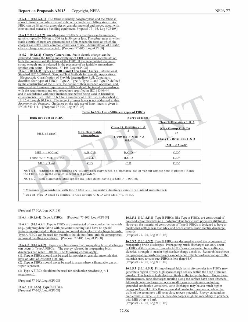
77-56
Report on Proposals A2013 — Copyright, NFPA NFPA 77
PREPRINT
16.6.5.1 10.1.6.5.1 Type B FIBCs, like Type A FIBCs, are constructed of nonconductive materials (e.g., polypropylene fabric with polyester stitching). However, the material of construction of Type B FIBCs is designed to have a breakdown voltage less than 6KV and hence control static electric discharge hazards. [Proposal 77-105, Log #CP108]
16.6.5.2 10.1.6.5.2 Type B FIBCs are designed to avoid the occurrence of propagating brush discharges. Propagating brush discharges can only occur in FIBCs if the materials from which FIBCs are constructed have sufficient electrical strength to sustain high surface charge densities. Research has shown that propagating brush discharges cannot occur if the breakdown voltage of the materials used to construct FIBCs is less than 6 kV. [Proposal 77-105, Log #CP108]
16.6.5.3 10.1.6.5.3 Filling charged, high resistivity powder into FIBCs may generate a region of very high space charge density within the heap of bulked powder. This leads to high electrical fields at the top of the heap. Under these circumstances, cone discharges running along the surface have been observed. Although cone discharge can occur in all forms of containers, including grounded conductive containers, cone discharges may have a much higher energy in Type B FIBCs than in grounded conductive containers, where the walls of the containers will be at close to zero potential. Energy calculations predict that, in Type B FIBCs, cone discharges might be incendiary to powders with MIE of up to 3 mJ. [Proposal 77-105, Log #CP108]
16.6.1.1 10.1.6.1.1 The fabric is usually polypropylene and the fabric is sewn to form a three-dimensional cube or rectangle with lifting straps. An FIBC can be filled with a powder or granular material and moved about with conventional materials-handling equipment. Proposal 77-105, Log #CP108]
16.6.1.2 10.1.6.1.2 An advantage of FIBCs is that they can be unloaded quickly, typically 300 kg to 500 kg in 30 sec or less. Therefore, rates at which static electric charges are generated can often exceed the rates at which the charges can relax under common conditions of use. Accumulation of a static electric charge can be expected. [Proposal 77-105, Log #CP108]
16.6.2 10.1.6.2 Charge Generation. Static electric charges can be generated during the filling and emptying of FIBCs and can accumulate on both the contents and the fabric of the FIBC. If the accumulated charge is strong enough and is released in the presence of an ignitible atmosphere, ignition can occur. [Proposal 77-105, Log #CP108]16.6.3 10.1.6.3 Types of FIBCs and Their Inner Liners. International Standard IEC 61340-4-4, Standard Test Methods for Specific Applications - Electrostatic Classification of Flexible Intermediate Bulk Containers, describes four types of FIBCs: Type A, Type B, Type C, and Type D, defined by the construction of the FIBCs, the nature of their intended operation, and associated performance requirements. FIBCs should be tested in accordance with the requirements and test procedures specified in IEC 61340-4-4 and in accordance with their intended use before being used in hazardous environments. See Table 16.6.3 for a summary of FIBC use, as described in 10.1.6.4 through 10.1.6.7. The subject of inner liners is not addressed in this Recommended Practice. Guidance on the safe use of inner liners is given in IEC 61340-4-4. [Proposal 77-105, Log #CP108]
Table 16.6.3 – Use of different types of FIBCs
Bulk product in FIBC Surroundings
MIE of dusta Non-flammable atmosphere
Class II, Divisions 1 & 2
(1 000 mJ ≥ MIE > 3 mJ)a
Class I, Divisions 1 & 2
(Gas Group C & D) or
Class II, Divisions 1 & 2
(MIE ≤ 3 mJ)a
MIE > 1 000 mJ A,B,C,D B,C,D C,Db
1 000 mJ ≥ MIE > 3 mJ B,C,D B,C,D C,Db
MIE ≤ 3 mJ C,D C,D C,Db
NOTE 1 Additional precautions are usually necessary when a flammable gas or vapour atmosphere is present inside the FIBC, e.g. in the case of solvent wet powders.
NOTE 2 Non-flammable atmosphere includes dusts having a MIE > 1 000 mJ.
a Measured in accordance with IEC 61241-2-3, capacitive discharge circuit (no added inductance). b Use of Type D shall be limited to Gas Groups C & D with MIE ≥ 0,14 mJ.
[Proposal 77-105, Log #CP108]
16.6.4 10.1.6.4 Type A FIBCs. [Proposal 77-105, Log #CP108]
16.6.4.1 10.1.6.4.1 Type A FIBCs are constructed of nonconductive materials (e.g., polypropylene fabric with polyester stitching) and have no special features incorporated in their design to control static electric discharge hazards. Type A FIBCs can be used for materials that do not form ignitible atmospheres in normal handling operations. [Proposal 77-105, Log #CP108]
16.6.4.2 10.1.6.4.2 Experience has shown that propagating brush discharges can occur in Type A FIBCs. The energy released in propagating brush discharges can reach 1000 mJ. The following criteria apply: (1) Type A FIBCs should not be used for powder or granular materials that have an MIE of less than 1000 mJ.(2) Type A FIBCs should never be used in areas where a flammable gas or vapor is present.(3) Type A FIBCs should not be used for conductive powders (ρv < 1 megohm-m).
[Proposal 77-105, Log #CP108]
16.6.5 10.1.6.5 Type B FIBCs. [Proposal 77-105, Log #CP108]

77-57
Report on Proposals A2013 — Copyright, NFPA NFPA 77
PREPRINT
16.6.1.1 10.1.6.1.1 The fabric is usually polypropylene and the fabric is sewn to form a three-dimensional cube or rectangle with lifting straps. An FIBC can be filled with a powder or granular material and moved about with conventional materials-handling equipment. [Proposal 77-105, Log #CP108]
16.6.1.2 10.1.6.1.2 An advantage of FIBCs is that they can be unloaded quickly, typically 300 kg to 500 kg in 30 sec or less. Therefore, rates at which static electric charges are generated can often exceed the rates at which the charges can relax under common conditions of use, and Aaccumulation of a static electric charge can be expected. In general, the precautions given in Section 10.1 for IBCs also apply to FIBCs [Proposal 77-105, Log #CP108]
16.6.2 10.1.6.2 Charge Generation. Static electric charges can be generated during the filling and emptying of FIBCs and can accumulate on both the contents and the fabric of the FIBC. If the accumulated charge is strong enough and is released in the presence of an ignitible atmosphere, ignition can occur. [Proposal 77-105, Log #CP108]
16.6.3 10.1.6.3 Nonconductive FIBCs. [Proposal 77-105, Log #CP108]
16.6.3.1 10.1.6.3.1 FIBCs constructed of nonconductive materials (e.g., polypropylene fabric with polyester stitching) have no special features incorporated in their design to minimize static electric charging. Nonconductive FIBCs can be used for materials that do not form ignitible atmospheres in normal handling operations. [Proposal 77-105, Log #CP108]
16.6.3.2 10.1.6.3.2 Experience has shown that granular materials that form dust clouds during handling can be safely handled in nonconductive FIBCs, provided that the dust clouds generated cannot be easily ignited by a static electric discharge. In other words, the material should have an MIE for a dust cloud that is greater than 100 mJ. The following criteria also apply:
(1) Nonconductive FIBCs should not be used for granular materials that have an MIE of less than 100 mJ.
(2) Nonconductive FIBCs should never be used in areas where a flammable gas or vapor is present. [Proposal 77-105, Log #CP108]
16.6.4 10.1.6.4 Conductive FIBCs. [Proposal 77-105, Log #CP108]
16.6.4.1 10.1.6.4.1 FIBCs constructed of conductive fabric can be treated the same way as conductive IBCs, as specified in 10.1.4. If conductive FIBCs are used with a liner, the recommendations of 10.1.4.5 and 10.1.4.6 also apply. It is essential that these FIBCs be grounded during all operations. [Proposal 77-105, Log #CP108]
16.6.4.2 10.1.6.4.2 FIBCs constructed of nonconductive fabric and containing woven, grounded, conductive filaments can be considered to be conductive. One type of FIBC has conductive filaments spaced less than 20 mm apart, each of which is connected at least once to its neighbor, preferably at one end. They are intended to be grounded. Another type has conductive filaments or threads that form an interconnecting grid of not more than 50 mm mesh size. They also are intended to be grounded. [Proposal 77-105, Log #CP108]
16.6.4.3 10.1.6.4.3 The recommendations for conductive IBCs given in 10.1.4 also apply to conductive FIBCs. A grounding tab that is electrically connected to the conductive threads is provided and is intended to be connected to a ground point when the FIBC is filled or emptied. [Proposal 77-105, Log #CP108]
16.6.5 10.1.6.5 Summary. Currently the manufacture and use of FIBCs are in the development stage, and many variants and combinations of fabric are being introduced. It is, therefore, not possible to make recommendations for the safe use of all the types being used in areas where an ignitible atmosphere might be present. In particular, at this time, sufficient data are not available for FIBCs constructed of layers of various conductive and nonconductive fabrics. [Proposal 77-105, Log #CP108]
10.1.7 Container Linings [Proposal 77-105, Log #CP108]
10.1.7.1 Both conductive and nonconductive liners are used in containers. Conductive liners (e.g., carbon-filled polyethylene) have been used inside nonconductive containers to provide a means for grounding. In instances where product contamination is a concern, nonconductive (e.g., polyethylene) liners have been used in both conductive (e.g., metal) and nonconductive (e.g., polypropylene) containers. In instances where very fine powders can leak through the weave of the cloth, nonconductive (e.g., polyethylene) liners have been used. [Proposal 77-105, Log #CP108]
10.1.7.2 Extreme caution should be exercised in the use of conductive liners to ensure that they do not become ungrounded. [Proposal 77-105, Log #CP108]
16.6.5.4 10.1.6.5.4 Since Type B FIBCs have no mechanism for dissipating electrostatic charge, brush discharges might occur that can ignite flammable gases and vapors. The following criteria apply:
(1) Type B FIBCs should be made from materials with breakdown voltage less than 6 kV.
(2) Type B FIBCs should not be used for powder or granular materials that have an MIE of 3 mJ or less.
(3) Type B FIBCs should never be used in areas where a flammable gas or vapor is present.
(4) Type B FIBCs should not be used for conductive powders (ρv < 1 megohm-m).
[Proposal 77-105, Log #CP108]16.6.6 10.1.6.6 Type C FIBCs. [Proposal 77-105, Log #CP108]
16.6.6.1 10.1.6.6.1 Type C FIBCs are constructed entirely from conductive material or insulating material that contain fully interconnected conductive threads or tapes with specific spacing and can be treated the same as conductive IBCs, as specified in 16.4. It is essential that Type C FIBCs be grounded during filling and emptying operations. [Proposal 77-105, Log #CP108]
16.6.6.2 10.1.6.6.2 FIBCs constructed of nonconductive fabric and containing woven, grounded, conductive filaments can be considered to be conductive. One type of FIBC has conductive filaments spaced less than 20 mm apart, each of which is connected at least once to its neighbor, preferably at both ends. They are intended to be grounded. Another type has conductive filaments or threads that form an interconnecting grid of not more than 50 mm mesh size. They also are intended to be grounded. [Proposal 77-105, Log #CP108]
16.6.6.3 10.1.6.6.3 The recommendations for conductive IBCs given in 10.1.4 also apply to conductive FIBCs. A grounding tab that is electrically connected to the conductive material or threads is provided and is intended to be connected to a ground point when the FIBC is filled or emptied. The resistance between the conductive elements in the FIBC and the grounding tabs should be less than 1.0 × 10⁷ Ω. [Proposal 77-105, Log #CP108]
16.6.6.4 10.1.6.6.4 For FIBCs constructed of multi-layer materials, the resistance between the inside or outside surface of the FIBC and the grounding tabs should be less than 1.0 × 10⁷ Ω. If the inside layer does not have a resistance to grounding tabs of less than 1.0 × 10⁷ Ω, then the material should have a breakdown voltage of less than 6 kV. All layers of multi-layer materials should remain in firm contact during filling and emptying operations. [Proposal 77-105, Log #CP108]16.6.6.5 10.1.6.6.5 Materials used to construct inner baffles, other than mesh or net baffles, should meet the requirements stated in 16.6.6.3 and 16.6.6.4. [Proposal 77-105, Log #CP108]
16.6.7 10.1.6.7 Type D FIBCs. [Proposal 77-105, Log #CP108]
16.6.7.1 10.1.6.7.1 Type D FIBCs are constructed from fabrics and/or threads with special electrostatic properties to control discharge incendivity and are intended for use without grounding in the presence of flammable vapors or gases with MIE of 0.14 mJ or greater and with combustible powders, including those with ignition energies of 3 mJ or less. [Proposal 77-105, Log #CP108]
16.6.7.2 10.1.6.7.2 Before being used in hazardous environments, Type D FIBCs should be qualified as safe, i.e. by demonstrating that no incendiary discharge can occur under normal operating conditions. IEC 61340-4-4 describes test procedures for ignition testing that can be used for this purpose. [Proposal 77-105, Log #CP108]
16.6.7.3 10.1.6.7.3 If Type D FIBCs are made from materials that have an insulating layer (e.g. coating, film, or lamination) on the inside of the container, the materials should have a breakdown voltage of less than 6 kV. All layers of multi-layer materials should remain in firm contact during filling and emptying operations. [Proposal 77-105, Log #CP108]
16.6.8 10.1.7 Liners for Flexible Intermediate Bulk Containers – Reserved
16.6.1 10.1.6.1 Description. Flexible intermediate bulk containers (FIBCs) are basically very large fabric bags supported in a frame. They are more convenient than rigid IBCs because they can be fully collapsed after use, taking up little storage space. [Proposal 77-105, Log #CP108]

77-58
Report on Proposals A2013 — Copyright, NFPA NFPA 77
PREPRINT
17.3.1 10.2.3.1 Inks used in letter presses and offset presses are typically Class IIIB liquids that have flash points above 93°C and present little fire or explosion hazard. However, inks used in silk screen, rotogravure, and flexograph printing are usually Class IB and Class IC liquids with flash points less than 38°C. Fires can occur in these inks due to the use of solvents with vapors that can be ignited by static electric discharge, as well as by other ignition sources.
17.3.2 10.2.3.2 The solutions and suspensions that are used to coat and saturate webs are diverse. While they are still wet, water-based coatings are generally conductive enough to dissipate any charge that is generated in the process, even though there might be minor concentrations of solvent present that can create an ignitible vapor layer on the web. When dry, however, these coatings are not always capable of dissipating the charge, but vapors are seldom left at this point.
17.3.3 10.2.3.3 Measurement of coating solution conductivity can provide additional data to determine static generation and dissipation characteristics. Solvent-based coatings having conductivities less than 104 pS/m should be carefully evaluated for their ability to dissipate charge. Flammable solvent-based inks and coatings should be considered nonconductive and, therefore, incapable of dissipating a charge. Conductivity enhancers in the ink or coating cannot be relied on to assist dissipation of charge at high processing speeds. Measurement of coating solution conductivity can provide additional data to determine static generation and dissipation characteristics. [Proposal 77-106, Log #CP104]
17.3.4 10.2.3.4 Black inks used in gravure printing are generally nonconductive. Where accumulations of black ink, particularly black ink used on uncoated papers, are washed or cleaned off the rubber impression rollers, the resin can be washed out of the ink buildup, leaving a residue of conductive carbon (i.e., the pigment). If this conductive residue is not thoroughly wiped off the rollers, sparking and arcing from the roller to the cylinder or other grounded press parts can occur.
17.4 10.2.4 Processes.
17.4.1 10.2.4.1 Printing Presses. All other factors being equal, printing presses that operate at higher speeds generate more static electricity. A rotogravure press, for example, can generate static electricity where the rubber roll presses the substrate against an engraved roll, which is wetted with the ink. Charge can be transferred from the engraved roll to the substrate. In a multicolored press, there is a similar arrangement for each color. The generation of charge is a function of the pressure between the rolls and the angle to the roll. The electrostatic assist (ESA) process, where used, deposits large amounts of charge onto the substrate. Note that ESA equipment must be suitable for Class I, Division 1, locations.
17.4.2 10.2.4.2 Coating. Coating of web materials is done using both flammable and nonflammable liquids on a wide variety of equipment. Significant charge may be generated where high forces between rollers and web are present, such as in gravure coating, and where web slippage is present due to tension difference across the coating roller. This may result in a static ignition hazard where flammable coatings are used. High charge can also accumulate on the rubber backup roller and an electrostatic neutralizer may be needed if this poses an ignition hazard. Some coating processes can generate hazardous amounts of static electric charge due to their design, while others cause little effect. The operating conditions that cause high rates of charge generation include high forces between rollers and the web, such as in gravure coating. This high rate of generation is aggravated by maintaining a tension difference across the coating roller, which causes slippage. The result is a sizable charge at the point where a large amount of ignitible vapor and a large liquid surface area are present. The rubber backup roller can accumulate enough electrostatic charge to present an ignition hazard. An electrostatic charge neutralizer might be needed on the roller. [Proposal 77-107, Log #CP105]
17.4.3 10.2.4.3 Saturating. Saturating is the process of immersion of a web in a liquid so that the liquid fills the pores in the web. The excess liquid is then squeezed or wiped from both sides of the web. Electrostatic charging during saturating operations is not usually a problem for most webs. Where the web is a nonwoven with substantial loft and the liquid is flammable and of low conductivity, a static electric hazard can be created.
17.4.4 10.2.4.4 Calendaring.
17.4.4.1 10.2.4.4.1 Calendaring is a process by which a substrate is squeezed at high pressure between rollers that are generally smooth. This process is used to create a dense product with a smooth surface, such as magazine cover stock. It is also used to mill and form webs from materials such as rubber and plastics. The intimate contact caused by the high pressures and the working of the materials between the nipped rollers creates charge on the web. Charging can be high enough to form corona discharge at the exit of the nip.
10.1.7.3 As in the case of conductive containers, conductive liners should be grounded during all operations. [Proposal 77-105, Log #CP108]
10.1.7.4 In the handling of materials that accumulate static electric charges, the use of liners that have resistivities greater than 1011 ohms inside conductive containers could create conditions where propagating brush discharges or capacitor-like discharges can occur. Because the conditions under which these discharges can occur are many and varied, no general recommendations can be given at this time. [Proposal 77-105, Log #CP108]
10.1.7.5 Where nonconductive liners are used in nonconductive containers, the precautions recommended should be the same as for nonconductive containers alone, as given in 10.1.5 and 10.1.7.4. [Proposal 77-105, Log #CP108]
10.1.7.6 Liners should never be removed from containers (e.g., to shake out a residue) where easily ignitible atmospheres (i.e., gases, flammable vapors, sensitive dusts, and hybrid mixtures with MIEs of less than 30 mJ) are present. [Proposal 77-105, Log #CP108]
Chapter 17 Web and Sheet Processes
17.1 10.2.1] General.
17.1.1 10.2.1.1 In web processes, such as printing, coating, spreading, and impregnating, static electricity is a frequent, annoying, and often expensive source of production problems. If flammable solvents are used in the process, static electric charges can constitute an ignition source.
17.1.2 10.2.1.2 In practice, paper or any other substrate charged with static electricity will attract or repel other objects. This phenomenon can cause difficulty in controlling the sheet or web, which is the continuous substrate that is being printed or coated. It can also cause problems with delivering and handling the printed product due to static attraction between the sheets or folded signatures. Static electric charges can transfer by induction or by contact with various objects (e.g., during handling of the paper or substrate by personnel). These static electric charges can accumulate on a person who is not adequately grounded.
17.2 10.2.2 Substrates.
17.2.1 10.2.2.1 Paper.
17.2.1.1 10.2.2.1.1 The characteristics of the surface of the paper have a great deal to do with the amount of static electric charge that is generated during processing. Generally, printing on paper causes fewer problems than printing on plastic substrates and other synthetic materials. Static electric charge accumulates on paper during the handling process. On presses and in other handling operations, static electric charge can be generated by belts driving the paper rolls, sliding of the web over idler rollers and angle bars, motion of the web through a nip, and motion of brushes and delivery belts in the folder.
17.2.1.2 10.2.2.1.2 In some operations, static electric charge is deliberately deposited on the web to improve certain operations, such as material deposition and sheet transfer. In gravure printing, for example, electrostatic assist is used to improve the transfer of ink. On high-speed offset and high-speed gravure presses, ribbon tacking is used to control the ribbons and signatures in the folder.
17.2.2 10.2.2.2 Plastics. Most plastic films are characterized by extremely high surface and bulk resistivities. This resistivity allows static electric charge to accumulate on the web after contact with machine parts, such as rollers and belts, with little dissipation occurring.
17.2.3 10.2.2.3 Fabrics and Nonwovens.
17.2.3.1 10.2.2.3.1 Fabrics are usually made of blends of natural fibers (usually hygroscopic and capable of relaxing a charge) and synthetic fibers (usually highly resistive and capable of holding a charge). The smaller the proportion of natural fibers used, the greater the incidence of static electric problems in subsequent operations. Fabrics are thin, like paper and plastic films, and accumulate static electricity in a similar manner.
17.2.3.2 10.2.2.3.2 Nonwovens often have a loft that gives them a three-dimensional structure. They are almost exclusively synthetic, so they tend to generate and hold substantial charges in the forming process. These charges can be more difficult to remove due to the depth of the loft. In a subsequent coating or saturating process, large amounts of charge can again be generated due to relative motion of the fibers and again the charge can be difficult to remove if the loft returns. The solvent-wet batt contains a relatively large volume of flammable vapor, and electrostatic discharge can cause ignition.
17.3 10.2.3 Inks and Coatings.

77-59
Report on Proposals A2013 — Copyright, NFPA NFPA 77
PREPRINT
fixed metallic objects should not exceed 10 Ω. [Proposal 77-109, Log #CP107]
17.5.3.1.1 New The resistance to ground of rollers should be determined upon initial installation and verified periodically thereafter. Resistance should not exceed 1 megohm. Since lubricant films can significantly increase resistance (as the bearings “float” on the lubricant), measurement should be performed during operation. The grounding of conductive rollers may also be compromised by non-conductive bearing lubricants or excessive bearing clearances, as well as build up of dirt or rust over time. Rolling or sliding contacts, such as conductive brushes, can be used to ground rollers in cases where an acceptably low resistance cannot be obtained. [Proposal 77-109, Log #CP107]
17.5.3.1.2 New Isolated conductive objects on or in the film may become inductively charged by the web and present a sparking hazard. Grounding of such objects, where possible, will prevent this. [Proposal 77-109, Log #CP107]
17.5.3.2 New Non-Conductive Webs. Grounding of non-conductive webs is not possible and other methods are necessary for static control. Existing processes should be audited to determine where significant charge is being generated. Measurements may be made with an electrostatic field meter for web sections well away from grounded objects, such as rollers. [Proposal 77-109, Log #CP107]
17.5.3.2.1 New The first goal of a static-control program should be to minimize charge generation. Possible methods include minimizing web tension (but not to the extent that slippage occurs), ensuring that idler rollers have clean surfaces and are freely-rotating, minimizing web slippage, and increasing roller surface roughness. Non-conductive roller covers can acquire significant charge and should be replaced with static-dissipative covers where possible; otherwise the use of non-conductive covers which will minimize contact charging with the web material. [Proposal 77-109, Log #CP107]
17.5.3.2.2 New Humidification is sometimes used to reduce static charge on non-conductive objects by providing a monolayer of moisture that decreases surface resistivity, enhancing charge dissipation. This is often not possible in web handling operations since the speed of the operation does not allow sufficient time for uptake of atmospheric moisture by the surface of the material. Also, many plastic web materials will not be significantly affected by moisture even with extended exposure time. For these reasons humidification should not be relied upon as the sole method for static control in web handling processes, although in some cases higher humidity levels can be used to reduce static charge.[Proposal 77-109, Log #CP107]
17.5.3.2.3 New Ionization involves the use of devices which produce ions that neutralize surface charges and is the primary method used for static control on webs. Ionization devices may be needed at various points in a web handling system where charging occurs (reference existing figure). Such devices should extend across the full width of the web. Passive ionization involves the use of grounded tinsels, strings, needles, or brushes located a short distance (typically 5 to 25 mm) above the web. The electric field above the web is concentrated at the points of the tinsel, string, needle, or brush, resulting in breakdown and ionization of the surrounding air. Air ions having polarity opposite to charges on the web are attracted to the surface of the web, neutralizing the charge. Typically, this method can reduce surface potential to 0.5-3 kV. It is important that passive ionizing elements be positioned properly, grounded, and have points which are kept clean and sharp. Performance should be verified by periodic static charge measurements on the web downstream of the ionizer. [Proposal 77-109, Log #CP107]
17.5.3.2.4 New Active ionization involves the use of electrically-powered devices or radiological sources. AC ionizers are most commonly used and contain an array of high voltage pointed electrodes which emit both positive and negative air ions. Neutralization is achieved by the attraction of air ions having opposite polarity to surface charges on the web. The effectiveness of ionizers decreases greatly with distance from the web; for this reason ionizers are typically located about 25-50 mm from the web; forced air-assisted units (ionizing blowers) may be capable of neutralizing charge at somewhat greater distances. Ionizers should be located in a position so that ion flow will be towards the web rather than to a nearby grounded surfaces and in accordance with manufacturers’ recommendations. See Figure 17.5.3.2.4. [Proposal 77-109, Log #CP107]
FIGURE 17.5.3.2.4 Typical Locations for Static Neutralizers. Existing Figure 10.2.5.3.1
17.5.3.2.5 New Performance of ionizers should be verified upon initial installation and periodically during use. Electrically-powered ionizers used in flammable vapor environments must be listed for the hazardous (classified) location in which they are installed. [Proposal 77-109, Log #CP107]
17.4.4.2 10.2.4.4.2 Because flammable solvents are not usually present, the effect of static electric charge is to cause operator shock and web-handling problems. Static neutralizers can effectively remove the charge.
17.4.5 10.2.4.5 Web Handling and Converting. The path of the web through processing machinery often is guided over many rollers. Movement of the web over the rollers produces static electric charge due to friction. A freely turning idler roller imparts little charge to the web. As the speed of the process increases above 60 m/min, air is drawn between the web and the roller, reducing the intimacy of contact and, thus, the rate of charge generation. If the roller does not turn freely, however, the web slips on the roller surface and can generate a large static electric charge. Periodic inspections and maintenance should be performed to ensure that the rollers are always free-turning.
17.4.5.1 10.2.4.5.1 Converting large rolls of web goods to finished product involves operations such as slitting, sheeting, folding, and packaging. These operations involve many contacting surfaces, and materials used to construct machinery for such operations are chosen for durability and resistance to wear, more so than for static electric characteristics. The machinery is designed to occupy a minimum of floor area for economy of plant space. The machines are dense with rollers, belts, and framework that variously generate charge and suppress static electric charge and provide minimal space to install static electricity neutralizers. The result is a static electric problem that can be hard to measure and hard to control. Problems include the following:
(1) Product sticking or flying
(2) Machine jams
(3) Misaligned product stacks
(4) Bad product rolls
(5) Bad packages [Proposal 77-108, Log #CP106]
17.4.5.2 10.2.4.5.2 With photosensitive materials, the charge can cause product damage, which is revealed only when the customer complains. [Proposal 77-108, Log #CP106]
17.4.6 10.2.4.6 Ribbon Tacking. On high-speed offset and gravure presses, high-voltage tacking is used to improve the delivery of signatures to the folder. These high-voltage devices should be suitable for Class II, Division 2, locations subject to accumulations of settled paper dust.
17.5 New Control of Static Electricity in Web Processes.
[Proposal 77-109, Log #CP107]17.5.1 New Charging in Web Handling Operations. Charging of webs may occur during unwinding, travel over rollers, pressing between rolls, or contact with coating rolls. Charging will generally increase with increasing web speed, tension, and roller wrap angle; a finer roll surface finish will enhance charging by increasing the area of roll/web contact. Web slippage over roll surfaces, caused by differential web speed or roll malfunction, may also significantly increase charging. [Proposal 77-109, Log #CP107]
17.5.2 New Potential Hazards of Charged Webs. [Proposal 77-109, Log #CP107]
17.5.2.1 New Static charges on a web may result in brush discharges from the web or spark discharges from ungrounded machine components or personnel which have become inductively charged as a result of their close proximity to the web. Such discharges may present shock hazards to operators or lead to fires in flammable coating operations and gravure printing.[Proposal 77-109, Log #CP107]
17.5.2.2 New For flammable operations, mechanical ventilation can be used in order to dilute vapors to a safe concentration well below the lower flammable limit (LFL). “Pumping” of vapors by the moving web at higher speeds may increase the volume over which such an atmosphere may be present. Vapors will always be within the flammable range close to the point of coating application; this volume should be minimized by capturing vapors as close to their source as possible. Equipment should be interlocked to shut down upon ventilation system failure or if vapor concentration becomes too high. [Proposal 77-109, Log #CP107]
17.5.3 New Static Charge Control [Proposal 77-109, Log #CP107]
17.5.3.1 New Conductive Components. Items which may become potential ignition sources via induction charging include ungrounded conductive machine components, conductive objects on or in the web, and personnel in close proximity to the operation. All conductive parts of the machine should be grounded in order to prevent them from becoming a potential spark source due to inductive charging; resistance to ground from
77-60
Report on Proposals A2013 — Copyright, NFPA NFPA 77
PREPRINT
17.5.3.2.6 New It is particularly important to ensure that web charge is reduced to a safe level as it enters flammable coating stations. Potentially incendive brush discharges may occur if web surface charge density exceeds 10 µC/m2. To maintain a margin of safety, it is recommended that maximum indicated voltage above the web not exceed 5 kV as measured at a distance of 25 mm (field strength of 200 kV per meter). [Proposal 77-109, Log #CP107]
17.5.3.2.7 New An ionizer should be located as close as possible to where the web enters the coater. Surface charge should be continuously monitored after the ionizer and the process should be automatically shut down if safe electric field values are exceeded. An additional ionizer may also be required at the coater exit if charging can occurs at that point. [Proposal 77-109, Log #CP107]
17.5.3.2 New Personnel. Personnel should be grounded, preferably by use of static-dissipative footwear and a static dissipative flooring surface. [Proposal 77-109, Log #CP107]
17.5.1 10.2.5.1 Higher operating speeds result in the potential for increased volumes of flammable vapors in the immediate vicinity of the area where flammable liquids are applied to the substrate. Coating technology, such as the enclosed ink gravure fountain, has minimized the volume of flammable vapors in the application area. Solvent vapors can be diluted below the lower flammable limit (LFL) by means of mechanical ventilation. The performance of the ventilation system is optimized by capturing vapors as close to their source as possible. The ventilation system should be interlocked with the equipment to ensure safe operation of the process. Vapors will always be within the flammable range in the areas close to the application process and the substrate. [Proposal 77-109, Log #CP107]
17.5.2 10.2.5.2 A common method of removing static electric charge from processing machinery is by grounding the machine. [Proposal 77-109, Log #CP107]
17.5.2.1 10.2.5.2.1 For grounding of the machine to be effective, all conductive parts of the machine should be electrically bonded together. [Proposal 77-109, Log #CP107]
17.5.2.2 10.2.5.2.2 It should be noted that the charge on the material being processed is not removed by the grounding and bonding specified in 10.2.5.2 and 10.2.5.2.1. [Proposal 77-109, Log #CP107]
17.5.3 10.2.5.3 The ionization method of charge neutralization is the most effective means for controlling static electric charge on the webs in presses and coaters. Neutralizers, also referred to as static elimination bars or inductive ionizers, are commonly used close to the substrate, but they should not touch the substrate. [Proposal 77-109, Log #CP107]
17.5.3.1 10.2.5.3.1 The reduction of charge at any one point in the operation does not prevent generation of charge in later steps of the process. Static neutralizers might be necessary at a number of locations. (See Figure 10.2.5.3.1.) [Proposal 77-109, Log #CP107]
17.5.3.2 10.2.5.3.2 High-speed operations might require a second static neutralizer at a single location, but providing more than two usually gains no additional benefit. Neutralizers should extend across the full width of the web. For fast-running presses, inductive neutralizers, such as tinsel wrapped around a bar or grounded needle points, spaced 12 mm to 25 mm apart and placed at the inlet and delivery side of each impression roller, have been found to be effective. [Proposal 77-109, Log #CP107]
17.5.3.3 10.2.5.3.3 As with all neutralizers, positioning is important, and effectiveness of individual installations should be confirmed by field measurement of residual charge or voltage. [Proposal 77-109, Log #CP107]
17.5.3.4 10.2.5.3.4 An area of web as small as 0.01 m2 or an area 115 mm in diameter might be capable of releasing an incendive discharge. The neutralizer should be installed as far as possible from grounded metal machine parts or areas where the web is supported by rollers.[Proposal 77-109, Log #CP107]
17.5.3.5 10.2.5.3.5 The location of the initial inductive ionizer should be 100 mm to175 mm from the roller tangent (i.e., web exit) point and 6 mm to 25 mm from the web. Thus, the first neutralizer after the roller might have to be placed so close to the roller that it is partially suppressed from ionizing but can minimize the area of high charge. An additional ionizer or two downstream from the roller might also be necessary to reduce the charge to the desired extent. [Proposal 77-109, Log #CP107]
17.5.3.6 10.2.5.3.6 The final location near critical rollers should be determined by adjustment and measurement to minimize web charge, as indicated by apparent voltage. [Proposal 77-109, Log #CP107]
17.5.4 10.2.5.4 Tinsel or needle points remain functional only as long as they are clean and sharp.
17.5.4.1 10.2.5.4.1 Accumulation of contaminants (e.g., ink, coating solution, or paper dust) and corrosion products should be controlled by an effective maintenance program. [Proposal 77-109, Log #CP107]
17.5.4.2 10.2.5.4.2 Visual inspection and performance verification of the neutralizers should be done at intervals that will depend on how process conditions affect performance of the neutralizers.
[Proposal 77-109, Log #CP107]
17.5.5 10.2.5.5 Humidification has been used in the past to decrease static electric charge on materials in the environment, such as in garments and floor coverings. However, with modern high-speed operations, nonconductors, such as paper and plastic films, cannot adsorb enough moisture from the atmosphere during the brief time that they are exposed to humid air to increase their surface conductivity. Plastics generally do not become sufficiently conductive, even in humid atmospheres, due to lack of ionized molecules in an acquired surface layer of moisture . Therefore, humidification should not be used as a method of control of static electricity in such processes. [Proposal 77-109, Log #CP107]
Chapter 18 Miscellaneous Applications
18.1 10.3 Spray Application Processes.
18.1.1 10.3.1 Processes that involve spray application of liquids or powders (e.g., paints, coatings, lubricants, and adhesives) can cause accumulation of static electric charges on the spray apparatus and on the surfaces of the objects being sprayed and other objects in the spray area. If the material sprayed is ignitible, static electric discharge can result in ignition.
18.1.2* 10.3.2 Personnel involved in operating or servicing electrostatic spray application equipment should be trained in the operating procedures recommended by the manufacturer of the equipment and in the control of hazards associated with the materials being sprayed and their residues.
A.18.1.2 A.10.3.2 See NFPA 33, Standard for Spray Application Using Flammable or Combustible Materials, for further information.
18.2 10.4 Belts and Conveyors.
18.2.1 10.4.1 General. Flat or V-shaped rubber or leather belts used for transmission of power and belts used for the transportation of solid materials can generate static electric charges that warrant corrective measures if a possibility exists that ignitible concentrations of flammable gases or vapors or combustible dusts or fibers might be present. The amount of charge generated increases as any of the following increases:
(1) Belt speed
(2) Belt tension
(3) Width of the contact area
18.2.2 10.4.2 Flat Belts.
18.2.2.1* 10.4.2.1 Synthetic, rubber, or leather flat belts are usually good insulators, because they are dry when operated and because they operate at elevated temperatures due to friction. Generation of static electric charge occurs where the belt leaves the pulley and can occur with either conductive or nonconductive pulleys.
A.18.2.2.1 A.10.4.2.1 Investigations into the static electric hazard in grain elevators have shown that danger exists where the voltage reaches 30,000 volts on the belt. These studies also show that low relative humidity is an important factor in that it allows voltages to increase rapidly at temperatures below freezing.
18.2.2.2* 10.4.2.2 Accumulation of static electric charge on belts can be prevented by using belts made of conductive materials or by applying a conductive dressing to the belt.
A.18.2.2.2 A.10.4.2.2 The surface resistivity of a grain conveyor belt affects its ability to accumulate a charge. Tests have shown that belts with a resistance of 106 ohms to 108 ohms are conductive enough to prevent significant accumulation of charge. According to the CENELEC draft standard Safety of Machinery — Electrotechnical Aspects, a belt is considered to be sufficiently conductive if the surface resistance is less than 3 × 10⁸ ohms.
18.2.2.2.1 10.4.2.2.1 If a dressing is used, it should be reapplied frequently, or the conductivity of the belt will diminish. Whether or not a dressing is used, belts should be kept free of accumulations.

77-61
Report on Proposals A2013 — Copyright, NFPA NFPA 77
PREPRINT
18.2.2.2.2 10.4.2.2.2 It should be noted that both conductive and nonconductive belts can generate and deposit charge on the material or objects being conveyed. [Proposal 77-111, Log #CP59]
18.2.2.2 18.2.2.3 10.4.2.3 An electrostatic neutralizer placed so that the points are close to the inside of the belt and a few centimeters away from the point where the belt leaves the pulley is also effective in draining away most of the charge. (See 17.5.3 10.2.5.3.)
18.2.3* 10.4.3 V Belts.
A.18.2.3 A.10.4.3 According to the CENELEC draft standard Safety of Machinery — Electrotechnical Aspects, V belts and similar transmission belts are considered to be sufficiently conductive if the following criterion is met:
ohm-m
where:
R = electrical resistance, measured at the inner side of the mounted transmission belt between an electrode halfway between the two pulleys and ground (ohms)B = width of a flat belt or twice the depth of the side face of a V belt (meters)
For belts constructed of different materials, a belt is considered to be sufficiently conductive if the resistance across the belt does not exceed 109 ohms, measured at 23°C and 50 percent relative humidity.
18.2.3.1 10.4.3.1 V belts are not as susceptible to hazardous accumulations of static electric charge as are flat belts. Under certain conditions of temperature and humidity, however, a V belt can generate a significant charge.
18.2.3.2 10.4.3.2 Where ignitible mixtures of gases, vapors, dusts, or fibers are present, the preferred method to limit ignition by static electric discharge is to use a direct drive instead of a belt. If a V belt is necessary for other reasons, it should be protected in accordance with 18.2.2.2 10.4.2.2.(See CENELEC 60079-10, Electrical apparatus for explosive gas atmospheres - Part 10: Classification of hazardous areas.) [Proposal 77-112, Log #CP52]
18.2.4 10.4.4 Conveyor Belts.
18.2.4.1 10.4.4.1 Belts used for the transport of solid materials usually move at speeds that are slow enough to prevent an accumulation of static electric charges. However, if the material being transported is very dry, or if the belt operates in a heated environment and at high speeds, significant charges can be generated.
18.2.4.2 10.4.4.2 Material that is spilled from the end of a conveyor belt into a hopper or chute can carry a significant charge. In such cases, the belt support and terminal pulleys should be electrically grounded or bonded to the hopper or chute. A passive or active neutralizer installed close to the end of the conveyor can also help reduce the charge. Conductive or antistatic belts cannot be expected to remove static from the conveyed product.
18.2.4.3 10.4.2.2.2 It should be noted that both conductive and nonconductive belts can generate and deposit charge on the material or objects being conveyed. [Proposal 77-111, [Log #CP59]
18.2.5 10.4.5 Pulleys and Shafts.
18.2.5.1 10.4.5.1 Metal pulleys can accumulate a charge equal and opposite to that carried by the belt that runs over them. The charge typically will pass to the supporting shaft and then through bearings to the equipment and to ground. Where nonconductive components isolate metal parts, separate bonding or grounding of those parts could be necessary.
18.2.5.2 10.4.5.2 Lubricated bearings are still sufficiently conductive to allow dissipation of a static electric charge from the shaft. However, the conductivity across bearings that operate at very high speed is not necessarily sufficient to prevent accumulation of charge where the rate of generation is also high. For that reason, shafts that rotate at high speed should be subject to the following meet the following criteria:
(1) They should be checked for accumulation of static electric charge.
(2) They should be bonded or grounded by means of a sliding metal contact to the housing, if necessary.
18.2.5.3 10.4.5.3 The effective resistance across a bearing while in operation can be measured with a common ohmmeter as follows:
(1) One of the probes should be placed on the grounded machine frame.
(2) The other probe should be allowed to rest against the rolling member.
18.2.5.3.1 10.4.5.3.1 A value of approximately 104 ohms is to be expected. If a value greater than 105 ohms is found, an auxiliary grounding brush or shoe might be needed to prevent changes with time that could allow the resistance to exceed 106 ohms. The grounding brush should be periodically checked and maintained.
18.2.5.3.2 10.4.5.3.2 Critical bearings without a brush should be measured periodically.
18.2.6 10.4.6 Maintenance of Belts and Conveyors. Belts and conveyors should be inspected frequently for slipping or jamming to lessen the chance of generation of static electricity.
18.2.6.1 10.4.6.1 Drive systems operating in hazardous environments should be designed to stall without slipping.
18.2.6.2 10.4.6.2 Lubricant does not prevent the removal of static electric charges. Therefore, all bearings should be properly lubricated. However, the flow of static electricity across the film of lubricant sometimes results in pitting of bearing surfaces. A conductive grounded brush running on the shaft or pulley prevents pitting of the bearings.
18.3 10.5] Explosives. Most explosives and materials used as solid propellants contain enough oxidizer to sustain an explosive reaction without any outside contribution. These materials typically are sensitive to static electric discharge and can be extremely hazardous to handle if suitable precautions are not taken. In addition to the recommendations contained in this recommended practice, the following documents should be consulted for more specific information:
(1) NFPA 495, Explosive Materials Code
(2) NFPA 498, Standard for Safe Havens and Interchange Lots for Vehicles Transporting Explosives
(3) NFPA 1124, Code for the Manufacture, Transportation, Storage, and Retail Sales of Fireworks and Pyrotechnic Articles
(4) NFPA 1125, Code for the Manufacture of Model Rocket and High Power Rocket Motors
(5) IME Safety Library Publication No. 3, Suggested Code of Regulations for the Manufacture, Transportation, Storage, Sale, Possession, and Use of Explosive Materials
(6) IME Safety Library Publication No. 17, Safety in the Transportation, Storage, Handling, and Use of Explosive Materials
(7) U.S. Department of Defense Standard 4145.26M, Contractors’ Safety Manual for Ammunition and Explosives
(8) U.S. Department of Defense Standard 6055.9, Ammunition and Explosive Safety Standards
18.4 10.6 Cathode Ray Tube Video Display Terminals.
18.4.1 10.6.1 A static electric charge is commonly present on the face of cathode ray tube (CRT) video display terminals, particularly on color monitors and color television screens. This charge is the direct result of the CRT’s high-energy electron beam “writing” the image on the inside surface of the screen. The charge accumulates on the nonconductive surface of the screen and can reach energies capable of igniting a flammable atmosphere, if discharge occurs. Such an atmosphere can be created by wiping the screen of an operating or recently operated CRT with a cloth or tissue that is wet with a commercial cleaner that contains a flammable liquid such as isopropyl alcohol or by using a spray-on aerosol cleaner that uses a flammable gas propellant. The static electric charge can be removed from the screen of the CRT by accessories or by proper procedures. (See 18.4.1 10.6.3.) Other video display terminals, such as liquid crystal displays, gas plasma displays, and vacuum fluorescent displays, do not present similar static electric effects. That does not mean, however, that those displays are intrinsically safe for use in hazardous locations.
18.4.2 10.6.2 In an industrial environment that is classified as hazardous in accordance with Article 500 of NFPA 70, National Electrical Code, only engineering methods are acceptable for controlling the hazard.
18.4.2.1 10.6.2.1 Due to the high voltages present, the CRT should be enclosed in a purged or pressurized enclosure, as described in NFPA 496, Standard for Purged and Pressurized Enclosures for Electrical Equipment.

77-62
Report on Proposals A2013 — Copyright, NFPA NFPA 77
PREPRINT
18.4.2.2 10.6.2.2 To protect against a static electric discharge from the screen’s surface, the screen cannot be exposed to the surrounding environment but should be located behind a window in the enclosure.
18.4.3 10.6.3 In nonhazardous locations, a commercial static electric dissipating screen that overlays the CRT screen can be used to drain the static electric charge by means of a connection to ground. The ground connection from the overlay should be secure to prevent shock or an ignition-capable spark. One safe procedure for reducing the charge on the CRT screen is to wipe the screen with a water-wet cloth or tissue immediately before using any solvent-based cleaner. This action drains off the excess charge through the operator’s body. Ideally, nonflammable or low-volatility cleaning agents should be used.
Annex A Explanatory Material
Annex A is not a part of the recommendations of this NFPA document but is included for informational purposes only. This annex contains explanatory material, numbered to correspond with the applicable text paragraphs.
All Annex A material is incorporated into the body of the text, immediately following the numbered paragraph to which it relates.
Annex B Physical Characteristics of Materials
This annex is not a part of the recommendations of this NFPA document but is included for informational purposes only.
B.1 Combustibility Parameters of Gases and Vapors. Table B.1 lists typical gases and vapors and the lowest value of their minimum ignition energies (MIEs) in millijoules; the stoichiometric composition, expressed as percent by volume in air (or other oxidant); and the flammable limits, also expressed as percent by volume in air (or other oxidant).(See Table B.1 on pages 63 thru 64.)[Proposal 77-116, Log #CP113]
B.2 Static Electric Characteristics of Liquids. Table B.2 lists typical flammable and combustible liquids and their conductivities, dielectric constants, and relaxation time constants.
(See Table B.2 on pages 65 thru 69.)
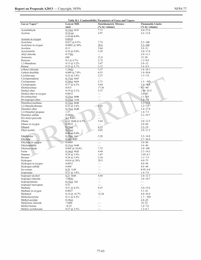
77-63
Report on Proposals A2013 — Copyright, NFPA NFPA 77
PREPRINT
Table B.1 Combustibility Parameters of Gases and Vapors Gas or Vapor* Lowest MIE
(mJ) Stoichiometric Mixture (% by volume)
Flammable Limits (% by volume)
Acetaldehyde 0.13(a) 0.37 7.73 4.0–57.0 Acetone 0.19 (a)
1.15 @ 4.5%4.97 2.6–12.8
Acetone in oxygen 0.0024 Acetylene 0.017 @ 8.5% 7.72 2.5–100 Acetylene in oxygen 0.0002 @ 40% 28.6 2.5–100Acrolein 0.13 5.64 2.8–31 Acrylonitrile 0.16 @ 9.0% 5.29 3.0–17.0 Allyl chloride 0.77(b) — 2.9–11.1 Ammonia 680 21.8 15–28 Benzene 0.2 @ 4.7% 2.72 1.3–8.0 1,3-Butadiene 0.13 @ 5.2% 3.67 2.0–12 Butane 0.25 @ 4.7% 3.12 1.6–8.4 n-Butyl chloride 1.24(b) 3.37 1.8–10.1 Carbon disulfide 0.009 @ 7.8% 6.53 1.0–50.0 Cyclohexane 0.22 @ 3.8% 2.27 1.3–7.8 Cyclopentadiene 0.17(a) 0.67 — — Cyclopentane 0.24(a) 0.54 2.71 1.5 – ND Cyclopropane 0.17 @ 6.3% 4.44 2.4–10.4 Dichlorosilane 0.015 17.36 4.7–96 Diethyl ether 0.19 @ 5.1% 3.37 1.85–36.5 Diethyl ether in oxygen 0.0012 — 2.0–82 Di-isobutylene 0.23(a) 0.96 — 1.1–6.0 Di-isopropyl ether 0.23(a) 1.14 — 1.4–7.9 Dimethoxymethane 0.12(a) 0.42 — 2.2–13.8 2,2-Dimethylbutane 0.25 @ 3.4% 2.16 1.2–7.0 Dimethyl ether 0.15(a) 0.29 — 3.4–27.0 2,2-Dimethyl propane 1.57 — 1.4–7.5 Dimethyl sulfide 0.48(b) — 2.2–19.7 Di-t-butyl peroxide 0.1 0.41 — — Ethane 0.23 0.24 @ 6.5% 5.64 3.0–12.5 Ethane in oxygen 0.0019 — 3.0–66 Ethanol 0.23(a) 6.53 3.3–19Ethyl acetate 0.23(a)
0.46 @ 5.2%4.02 2.0–11.5
Ethylamine 0.19(a) 2.4 5.28 3.5–14.0 Ethylene 0.084 0.07 — 2.7–36.0 Ethylene in oxygen 0.0009 — 3.0–80 Ethyleneimine 0.11(a) 0.48 — 3.6–46 Ethylene oxide 0.065 @ 10.8% 7.72 3.0–100 Furan 0.14(a) 0.22 4.44 2.3–14.3 Heptane 0.24 @ 3.4% 1.87 1.05–6.7 Hexane 0.24 @ 3.8% 2.16 1.1–7.5 Hydrogen 0.016 @ 28% 29.5 4.0–75 Hydrogen in oxygen 0.0012 — 4.0–94 Hydrogen sulfide 0.068 — 4.0–44 Iso-octane 0.25 1.35 — 0.95–6.0 Isopentane 0.21 @ 3.8% — 1.4–7.6 Isopropyl alcohol 0.21 0.65 4.44 2.0–12.7 Isopropyl chloride 1.08(b) — 2.8–10.7 Isopropylamine 0.23(a) 2.0 — — Isopropyl mercaptan 0.53 — — Methane 0.21 @ 8.5% 9.47 5.0–15.0 Methane in oxygen 0.0027 — 5.1–61 Methanol 0.14 @ 14.7% 12.24 6.0–36.0 Methylacetylene 0.11 @ 6.5% — 1.7 – ND Methyl acrylate 0.18(a) 2.8–25Methylene chloride >1000 — 14–22 Methyl butane <0.25 — 1.4–7.6 Methyl cyclohexane 0.27 @ 3.5% — 1.2–6.7
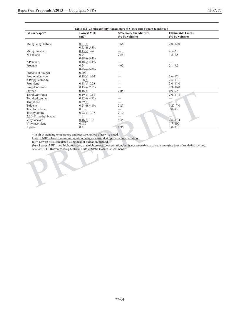
77-64
Report on Proposals A2013 — Copyright, NFPA NFPA 77
PREPRINT
Table B.1 Combustibility Parameters of Gases and Vapors (continued) Gas or Vapor* Lowest MIE
(mJ) Stoichiometric Mixture (% by volume)
Flammable Limits (% by volume)
Methyl ethyl ketone 0.21(a)
0.53 @ 5.3%3.66 2.0–12.0
Methyl formate 0.13(a) 0.4 — 4.5–23 N-Pentane 0.24
0.28 @ 3.3%2.55 1.5–7.8
2-Pentane 0.18 @ 4.4% — — Propane 0.24
0.25 @ 5.2%4.02 2.1–9.5
Propane in oxygen 0.0021 — — Propionaldehyde 0.18(a) 0.32 — 2.6–17 n-Propyl chloride 1.08(b) — 2.6–11.1 Propylene 0.18(a) 0.28 — 2.0–11.0 Propylene oxide 0.13 @ 7.5% — 2.3–36.0 Styrene 0.18(a) 2.05 0.9–6.8Tetrahydrofuran 0.19(a) 0.54 — 2.0–11.8 Tetrahydropyran 0.22 @ 4.7% — — Thiophene 0.39(b) — — Toluene 0.24 @ 4.1% 2.27 1.27–7.0 Trichlorosilane 0.017 — 7.0–83 Triethylamine 0.22(a) 0.75 2.10 — 2,2,3-Trimethyl butane 1.0 — — Vinyl acetate 0.16(a) 0.7 4.45 2.6–13.4 Vinyl acetylene 0.082 — 1.7–100 Xylene 0.2 1.96 1.0–7.0
* In air at standard temperature and pressure, unless otherwise noted. Lowest MIE = lowest minimum ignition energy measured at optimum concentration(a) = Lowest MIE calculated using heat of oxidation method(b) = Lowest MIE is too high, measured at stoichiometric concentration, but is not amenable to calculation using heat of oxidation method.Source: L. G. Britton, “Using Material Data in Static Hazard Assessment.”
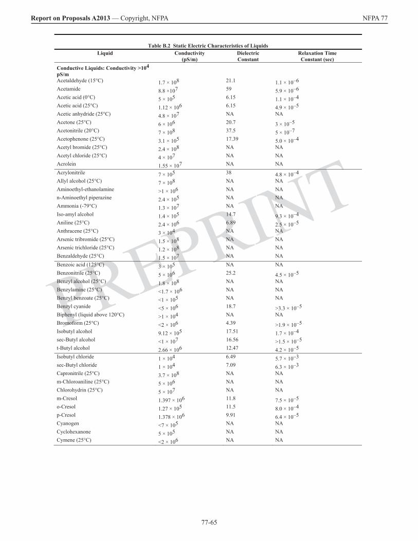
77-65
Report on Proposals A2013 — Copyright, NFPA NFPA 77
PREPRINT
Table B.2 Static Electric Characteristics of Liquids Liquid Conductivity
(pS/m) Dielectric Constant
Relaxation Time Constant (sec)
Conductive Liquids: Conductivity >104pS/m
Acetaldehyde (15°C) 1.7 × 10⁸ 21.1 1.1 × 10⁻⁶Acetamide 8.8 ×10⁷ 59 5.9 × 10⁻⁶Acetic acid (0°C) 5 × 10⁵ 6.15 1.1 × 10⁻⁴Acetic acid (25°C) 1.12 × 10⁶ 6.15 4.9 × 10⁻⁵Acetic anhydride (25°C) 4.8 × 10⁷ NA NA Acetone (25°C) 6 × 10⁶ 20.7 3 × 10⁻⁵Acetonitrile (20°C) 7 × 10⁸ 37.5 5 × 10⁻⁷Acetophenone (25°C) 3.1 × 10⁵ 17.39 5.0 × 10⁻⁴Acetyl bromide (25°C) 2.4 × 10⁸ NA NA Acetyl chloride (25°C) 4 × 10⁷ NA NA Acrolein 1.55 × 10⁷ NA NA Acrylonitrile 7 × 10⁵ 38 4.8 × 10⁻⁴Allyl alcohol (25°C) 7 × 10⁸ NA NA Aminoethyl-ethanolamine >1 × 10⁶ NA NA n-Aminoethyl piperazine 2.4 × 10⁵ NA NA Ammonia (-79°C) 1.3 × 10⁷ NA NA Iso-amyl alcohol 1.4 × 10⁵ 14.7 9.3 × 10⁻⁴Aniline (25°C) 2.4 × 10⁶ 6.89 2.5 × 10⁻⁵Anthracene (25°C) 3 × 10⁴ NA NA Arsenic tribromide (25°C) 1.5 × 10⁸ NA NA Arsenic trichloride (25°C) 1.2 × 10⁸ NA NA Benzaldehyde (25°C) 1.5 × 10⁷ NA NA Benzoic acid (125°C) 3 × 10⁵ NA NA Benzonitrile (25°C) 5 × 10⁶ 25.2 4.5 × 10⁻⁵Benzyl alcohol (25°C) 1.8 × 10⁸ NA NA Benzylamine (25°C) <1.7 × 10⁶ NA NA Benzyl benzoate (25°C) <1 × 10⁵ NA NA Benzyl cyanide <5 × 10⁶ 18.7 >3.3 × 10⁻⁵Biphenyl (liquid above 120°C) >1 × 10⁴ NA NA Bromoform (25°C) <2 × 10⁶ 4.39 >1.9 × 10⁻⁵Isobutyl alcohol 9.12 × 10⁵ 17.51 1.7 × 10⁻⁴sec-Butyl alcohol <1 × 10⁷ 16.56 >1.5 × 10⁻⁵t-Butyl alcohol 2.66 × 10⁶ 12.47 4.2 × 10⁻⁵Isobutyl chloride 1 × 10⁴ 6.49 5.7 × 10⁻³sec-Butyl chloride 1 × 10⁴ 7.09 6.3 × 10⁻³Capronitrile (25°C) 3.7 × 10⁸ NA NA m-Chloroaniline (25°C) 5 × 10⁶ NA NA Chlorohydrin (25°C) 5 × 10⁷ NA NA m-Cresol 1.397 × 10⁶ 11.8 7.5 × 10⁻⁵o-Cresol 1.27 × 10⁵ 11.5 8.0 × 10⁻⁴p-Cresol 1.378 × 10⁶ 9.91 6.4 × 10⁻⁵Cyanogen <7 × 10⁵ NA NA Cyclohexanone 5 × 10⁵ NA NA Cymene (25°C) <2 × 10⁶ NA NA

77-66
Report on Proposals A2013 — Copyright, NFPA NFPA 77
PREPRINT
Table B.2 Static Electric Characteristics of Liquids (continued) Liquid Conductivity
(pS/m) Dielectric Constant
Relaxation Time Constant (sec)
Dibutyl-o-phthalate 1.8 × 10⁵ 6.436 3.2 × 10⁻⁴Dichloroacetic acid (25°C) 7 × 10⁶ NA NA cis-Dichloroethylene 8.5 × 10⁵ 9.20 9.6 × 10⁻⁵Dichlorohydrin (25°C) 1.2 × 10⁹ NA NA Diethylamine (-33.5°C) 2.2 × 10⁵ NA NA Diethyl carbonate (25°C) 1.7 × 10⁶ 2.82 1.5 × 10⁻⁵Diethylene glycol 5.86 × 10⁷ 31.69 4.8 × 10⁻⁶Diethylenetriamine >1 × 10⁶ NA NA Diethyl oxalate (25°C) 7.6 × 10⁷ NA NA Diethyl sulfate (25°C) 2.6 × 10⁷ NA NA Dimethyl acetamide 1.1 × 10⁷ NA NA Dimethyl formamide 6 × 10⁶ 36.71 5.4 × 10⁻⁵Dimethyl sulfate (0°C) 1.6 × 10⁷ NA NA Dimethyl sulfoxide 2 × 10⁵ 46.68 2.1 × 10⁻³Diphenyl oxide <1.7 × 10⁶ 4.22 >2.2 × 10⁻⁵Epichlorohydrin (25°C) 3.4 × 10⁶ 22.6 5.9 × 10⁻⁵Ethanolamine 1.1 × 10⁹ 37.72 3.0 × 10⁻⁷Ethylacetate (25°C) 4.6 × 10⁴ 6.02 1.2 × 10⁻³Ethyl acetoacetate (25°C) 4 × 10⁶ 15.7 3.5 × 10⁻⁵Ethyl acrylate 3.35 × 10⁵ NA NA Ethyl alcohol (25°C) 1.35 × 10⁵ 24.55 1.6 × 10⁻³Ethylamine (0°C) 4 × 10⁷ NA NA Ethyl benzoate (25°C) <1 × 10⁵ 6.02 >5.3 × 10⁻⁴Ethyl bromide (25°C) <2 × 10⁶ 9.39 >4.2 × 10⁻⁵Ethyl chloride <3 × 10⁵ 9.45 >2.8 × 10⁻⁴Ethyl cyanoacetate 6.9 × 10⁷ 26.7 3.4 × 10⁻⁶Ethylene carbonate <1 × 10⁷ 89.6 >7.9 × 10⁻⁵Ethylenediamine 9 × 10⁶ 12.9 1.3 × 10⁻⁵Ethylene dibromide (25°C) <2 × 10⁴ 4.78 >2.1 × 10⁻³Ethylene glycol 1.16 × 10⁸ 37.7 2.9 × 10⁻⁶Ethylene glycol monobutyl ether 4.32 × 10⁷ 9.30 1.9 × 10⁻⁶Ethylene glycol monoethyl ether 9.3 × 10⁶ 29.6 2.8 × 10⁻⁵Ethylene glycol monomethyl ether 1.09 × 10⁸ 16.93 1.4 × 10⁻⁶Ethyleneimene 8 × 10⁸ 18.3 2.0 × 10⁻⁷Ethylene oxide 4 × 10⁶ 12.7 2.8 × 10⁻⁵Ethyl formate 1.45 × 10⁵ 7.16 4.4 × 10⁻⁴Ethylidene chloride 2.0 × 10⁵ 10.0 4.4 × 10⁻⁴Ethyl isothiocyanate (25°C) 1.26 × 10⁷ NA NA Ethyl lactate 1.0 × 10⁸ 13.1 1.2 × 10⁻⁶Ethyl nitrate (25°C) 5.3 × 10⁷ NA NA Ethyl oxalate 7.12 × 10⁷ NA NA Ethyl propionate 8.33 × 10¹⁰ 5.65 6 × 10⁻¹⁰Ethyl thiocyanate (25°C) 1.2 × 10⁸ NA NA Eugenol (25°C) <1.7 × 10⁶ NA NA

77-67
Report on Proposals A2013 — Copyright, NFPA NFPA 77
PREPRINT
Table B.2 Static Electric Characteristics of Liquids (continued) Liquid Conductivity
(pS/m) Dielectric Constant
Relaxation Time Constant (sec)
Formamide (25°C) 4 × 10⁸ 111.0 2 × 10⁻⁶Formic acid (25°C) 6.4 × 10⁹ 58.5 8.1 × 10⁻⁸Furfural (25°C) 1.5 × 10⁸ NA NA Glycerol (25°C) 6.4 × 10⁶ 42.5 5.9 × 10⁻⁵Guaiacol (25°C) 2.8 × 10⁷ NA NA Hydrogen bromide (-80°C) 8 × 10⁵ NA NA Hydrogen chloride (-96°C) 1 × 10⁶ NA NA Hydrogen cyanide (0°C) 3.3 × 10⁸ NA NA Hydrogen iodide (at boiling point) 2 × 10⁷ NA NA Iodine (110°C) 1.3 × 10⁴ NA NA Mercury (0°C) 1.063 × 10¹⁸ NA NA Methoxy triglycol >1 × 10⁶ NA NA Methyl acetamide 2 × 10⁷ 191.3 8.5 × 10⁻⁵Methyl acetate (25°C) 3.4 × 10⁸ 6.68 1.7 × 10⁻⁷Methyl alcohol (18°C) 4.4 × 10⁷ 32.70 6.6 × 10⁻⁶Methyl cyanoacetate 4.49 × 10⁷ 29.30 5.8 × 10⁻⁶Methyl ethyl ketone (25°C) 1 × 10⁷ 18.51 1.6 × 10⁻⁵Methyl formamide 8 × 10⁷ 182.4 2.0 × 10⁻⁵Methyl formate 1.92 × 10⁸ 8.5 3.9 × 10⁻⁷Methyl iodide (25°C) <2 × 10⁶ NA NA Methyl isobutyl ketone <5.2 × 10⁶ 13.11 >2.2 × 10⁻⁵Methyl nitrate (25°C) 4.5 × 10⁸ NA NA n-Methyl-2-pyrolidone 2 × 10⁶ 32.0 1.4 × 10⁻⁴Methyl thiocyanate (25°C) 1.5 × 10⁸ NA NA Naphthalene (82°C) 4 × 10⁴ NA NA Nitrobenzene (0°C) 5 × 10⁵ 34.82 6.2 × 10⁻⁴Nitroethane 5 × 10⁷ 28.06 5.0 × 10⁻⁶Nitromethane (18°C) 6 × 10⁷ 35.87 5.3 × 10–61-Nitropropane 3.3 × 10⁷ 23.24 6.2 × 10–62-Nitropropane 5 × 10⁷ 25.52 4.5 × 10⁻⁶Nitrotoluene (25°C) (ortho or meta) <2 × 10⁷ NA NA Octyl alcohol 1.39 × 10⁷ 10.34 6.9 × 10⁻⁶Phenetole (25°C) <1.7 × 10⁶ NA NA Phenol 1 × 10⁶ 9.78 8.7 × 10⁻⁵Phenyl isothiocyante (25°C) 1.4 × 10⁸ NA NA Phosgene (25°C) 7 × 10⁵ NA NA Phosphorus (25°C) 4 × 10⁸ NA NA Phosphorus oxychloride (25°C) 2.2 × 10⁸ NA NA Pinene (23°C) <2 × 10⁴ NA NA Piperidine (25°C) <2 × 10⁷ NA NA Propionaldehyde (25°C) 8.5 × 10⁷ 18.5 1.9 × 10⁻⁶Propionic acid (25°C) <1 × 10⁵ 3.44 >3.0 × 10⁻⁴Propionitrile 8.51 × 10⁶ 27.2 2.8 × 10⁻⁵Propyl acetate (i- or n-) 1 -6 × 10⁴ 6.002 NA
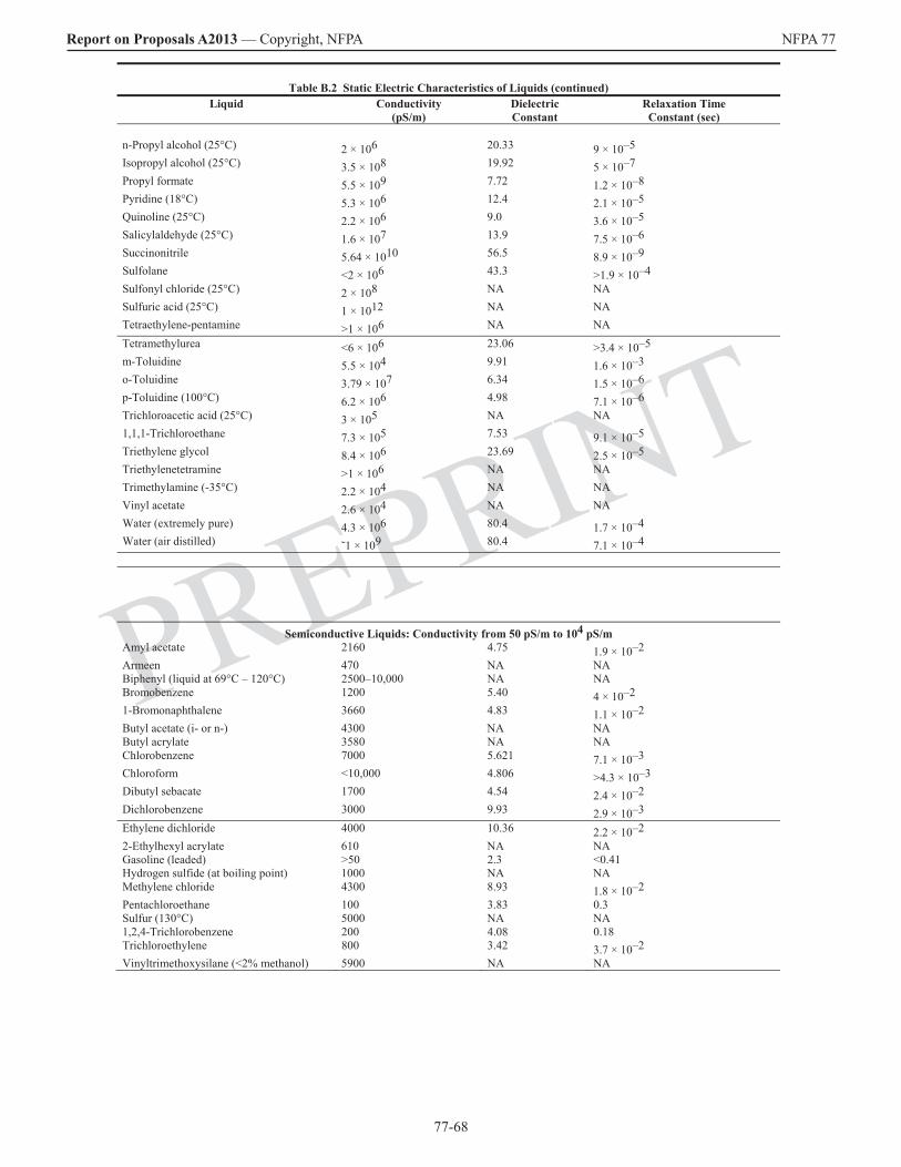
77-68
Report on Proposals A2013 — Copyright, NFPA NFPA 77
PREPRINT
Table B.2 Static Electric Characteristics of Liquids (continued) Liquid Conductivity
(pS/m) Dielectric Constant
Relaxation Time Constant (sec)
n-Propyl alcohol (25°C) 2 × 10⁶ 20.33 9 × 10⁻⁵Isopropyl alcohol (25°C) 3.5 × 10⁸ 19.92 5 × 10⁻⁷Propyl formate 5.5 × 10⁹ 7.72 1.2 × 10⁻⁸Pyridine (18°C) 5.3 × 10⁶ 12.4 2.1 × 10⁻⁵Quinoline (25°C) 2.2 × 10⁶ 9.0 3.6 × 10⁻⁵Salicylaldehyde (25°C) 1.6 × 10⁷ 13.9 7.5 × 10⁻⁶Succinonitrile 5.64 × 10¹⁰ 56.5 8.9 × 10⁻⁹Sulfolane <2 × 10⁶ 43.3 >1.9 × 10⁻⁴Sulfonyl chloride (25°C) 2 × 10⁸ NA NA Sulfuric acid (25°C) 1 × 10¹² NA NA Tetraethylene-pentamine >1 × 10⁶ NA NA Tetramethylurea <6 × 10⁶ 23.06 >3.4 × 10⁻⁵m-Toluidine 5.5 × 10⁴ 9.91 1.6 × 10⁻³o-Toluidine 3.79 × 10⁷ 6.34 1.5 × 10⁻⁶p-Toluidine (100°C) 6.2 × 10⁶ 4.98 7.1 × 10⁻⁶Trichloroacetic acid (25°C) 3 × 10⁵ NA NA 1,1,1-Trichloroethane 7.3 × 10⁵ 7.53 9.1 × 10⁻⁵Triethylene glycol 8.4 × 10⁶ 23.69 2.5 × 10⁻⁵Triethylenetetramine >1 × 10⁶ NA NA Trimethylamine (-35°C) 2.2 × 10⁴ NA NA Vinyl acetate 2.6 × 10⁴ NA NA Water (extremely pure) 4.3 × 10⁶ 80.4 1.7 × 10⁻⁴Water (air distilled) ˜1 × 10⁹ 80.4 7.1 × 10⁻⁴
Semiconductive Liquids: Conductivity from 50 pS/m to 104 pS/mAmyl acetate 2160 4.75 1.9 × 10⁻²Armeen 470 NA NA Biphenyl (liquid at 69°C – 120°C) 2500–10,000 NA NA Bromobenzene 1200 5.40 4 × 10–21-Bromonaphthalene 3660 4.83 1.1 × 10⁻²Butyl acetate (i- or n-) 4300 NA NA Butyl acrylate 3580 NA NA Chlorobenzene 7000 5.621 7.1 × 10⁻³Chloroform <10,000 4.806 >4.3 × 10⁻³Dibutyl sebacate 1700 4.54 2.4 × 10⁻²Dichlorobenzene 3000 9.93 2.9 × 10⁻³Ethylene dichloride 4000 10.36 2.2 × 10⁻²²-Ethylhexyl acrylate 610 NA NA Gasoline (leaded) >50 2.3 <0.41 Hydrogen sulfide (at boiling point) 1000 NA NA Methylene chloride 4300 8.93 1.8 × 10⁻²Pentachloroethane 100 3.83 0.3 Sulfur (130°C) 5000 NA NA 1,2,4-Trichlorobenzene 200 4.08 0.18 Trichloroethylene 800 3.42 3.7 × 10⁻²Vinyltrimethoxysilane (<2% methanol) 5900 NA NA

77-69
Report on Proposals A2013 — Copyright, NFPA NFPA 77
PREPRINT
Table B.2 Static Electric Characteristics of Liquids (continued) Nonconductive Liquids: Conductivity <50 pS/m
Anisole 10 4.33 3.8 Benzene (pure) 5 × 10⁻³ 2.3 ~100 (dissipation) Biphenyl (solid <69°C) 0.17 NA NA Bromine (17.2°C) 13 NA NA Butyl stearate 21 3.111 1.3 Caprylic acid <37 2.45 >0.58 Carbon disulfide (1°C) 7.8 × 10⁻⁴ 2.6 ~100 (dissipation) Carbon tetrachloride 4 × 10⁻⁴ 2.238 ~100 (dissipation) Chlorine (-70°C) <0.01 NA NA Cyclohexane <2 2.0 >8.8 Decalin 6 2.18 3.2 Dichlorosilane NA NA NA Diesel oil (purified) ˜0.1 ˜2 ˜100 (dissipation) Diethyl ether 30 4.6 1.4 1,4-Dioxane 0.1 2.2 ˜100 (dissipation) Ethyl benzene 30 2.3 0.68 Gasoline (straight run) ˜0.1 ˜2 ˜100 (dissipation) Gasoline (unleaded) <50 (varies) NA NA Heptane (pure) 3 × 10⁻² 2.0 ˜100 (dissipation) Hexane (pure) 1 × 10⁻⁵ 1.90 ˜100 (dissipation) Hexamethyldisilazane 29 NA NA Isovaleric acid 40 2.64 >0.58 Jet fuel 0.01–50 2.2 0.39–100 Kerosene 1–50 2.2 0.39–19 Pentachlorodiphenyl 0.8 5.06 ˜100 Silicon tetrachloride NA NA NA Stearic acid (80°C) <40 NA NA Styrene monomer 10 2.43 2.2 Sulfur (115°C) 100 NA NA Toluene <1 2.38 21 Trichlorosilane NA NA NA Turpentine 22 NA NA Xylene 0.1 2.38 ˜100
NA: Not applicable. Source: L. G. Britton, “Using Material Data in Static Hazard Assessment.”

77-70
Report on Proposals A2013 — Copyright, NFPA NFPA 77
PREPRINT
Annex C Additional Information on Flash Point
This annex is not a part of the recommendations of this NFPA document but is included for informational purposes only.
C.1 Errors in Flash Point Testing. The reported flash point of a liquid might not represent the minimum temperature at which a pool of liquid will form an ignitible atmosphere.
C.1.1 Typical closed-cup test methods involve downward flame propagation, which is more difficult than upward propagation, and the region where the test flame is introduced is normally fuel-lean relative to the liquid surface. Also, the volume of the test apparatus is too small to allow flame propagation of certain flammable vapors such as halogenated hydrocarbons.
C.1.2 Limitations of flash point test methods are discussed in ASTM E 502, Standard Test Method for Selection and Use of ASTM Standards for the Determination of Flash Point of Chemicals by Closed Cup Methods. In most cases, closed-cup flash points are lower than open-cup values.
C.2 Safety Margin for Use of Flash Point.
C.2.1 The temperature of interest in determining the hazard is the temperature at the exposed liquid surface, not that of the bulk liquid, because vapor is in equilibrium with the liquid at the surface. However, in many instances, the surface temperature is difficult to determine. While the surface temperature should be considered to the extent possible, most hazard evaluations are, by necessity and practicality, based on bulk temperature. Therefore, a safety factor should be applied where the hazard is assessed using the flash point.
C.2.2 For pure liquids in containers, the vapor should be considered potentially ignitible if the liquid temperature is within 4°C of the reported flash point. For mixtures whose composition is less certain, such as hydrocarbon mixtures, the safety factor should be at least 9°C. Where combinations of adverse effects are identified, the safety factors might have to be increased accordingly. [Proposal 77-55, Log #CP65]
C.3 Effect of Bulk Liquid Temperature.
C.3.1 The surface temperature of a quiescent liquid in a tank can significantly exceed the temperature of the bulk liquid due to heat transfer from the unwet upper walls of the tank, which in some cases could be heated by sunlight to as much as 60°C.
C.3.2 Because vapor–liquid equilibrium is established at the vapor–liquid interface, the higher surface temperature discussed in C.3.1 can result in a vapor concentration that is elevated compared to the concentration based on the bulk liquid temperature. An elevated concentration means that vapor in the tank could be ignitible, even if the bulk liquid temperature is less than the reported flash point, which can be a significant hazard during sampling. Vapor vented from large storage tanks could be at a concentration that is only 30 percent to 50 percent of theoretical saturation, based on bulk liquid temperature. This vapor also could be a significant hazard if tank vapor is assumed to be above the upper flammable limit (UFL).
C.4 Effect of Ambient Pressure.
C.4.1 The vapor pressure above a liquid depends only on the temperature at the surface and the time necessary to reach equilibrium. The fraction of the total pressure exerted by a vapor determines the composition of the vapor–air mixture. Thus, where the total pressure is reduced, as could be the case at high altitudes, the vapor concentration in air increases.
C.4.2 Because flash points are reported at a pressure of 1 atm [101.3 kPa (760 mm Hg)], an ambient pressure less than that value lowers the actual effective flash point. The flash point correction given in ASTM E 502, Standard Test Method for Selection and Use of ASTM Standards for the Determination of Flash Point of Chemicals by Closed Cup Methods, is expressed as follows:
FPcorr (°C) = C + 0.25(101.3-A)
FPcorr (°C) = C + 0.03(760-B)
FPcorr (°F) = F + 0.06 0.006(760-B) [correction of transcription error]
where:
FP corr = corrected flash pointA = ambient barometric pressure (kPa)B = ambient barometric pressure (mm Hg)C = observed flash point (°C)F = observed flash point (°F)
C.5 Effect of Low Concentration of Volatiles. Low concentrations of volatile components in a liquid mixture can accumulate in the vapor space of a container over time, which can reduce the flash point to a temperature below the reported value. This effect can result from off-gassing, chemical reaction, or some other mechanism. An example is bitumen. Similarly, if a tank truck is not cleaned after delivering gasoline, and a higher flash point liquid, such as kerosene or diesel fuel, is transferred to it, the residual gasoline will create an ignitible atmosphere both in the truck’s tank and possibly in the receiving tank as well. Solids that contain more than 0.2 weight percent flammable solvent need to be evaluated for their potential to form ignitible vapor in containers.
C.6 Liquid Mist.
C.6.1 If a liquid is dispersed in air in the form of a mist, it is possible for a flame to be propagated through the mist, even at temperatures below the liquid’s flash point.
C.6.2 In cases such as those described in C.6.1, the mist droplets behave like dust particles. The flash point of the liquid is irrelevant in determination of the combustibility of mists. Even at very low liquid temperatures, frozen liquid droplets can burn. Ease of ignition and rate of combustion both increase as the droplet size of the mist decreases. Depending on the volatility of the liquid, droplets with diameters less than 20 m to 40 m typically vaporize and ignite ahead of a flame front, and their overall combustion behavior is similar to that of a vapor.
C.6.3 Because mists usually are produced by some form of shear process, and those processes also generate static electricity, it is good practice to avoid splashing and other procedures that generate mist inside equipment.
Annex D Additional Information on Vapor Pressure
This annex is not a part of the recommendations of this NFPA document but is included for informational purposes only.
D.1 Vapor Pressure.
D.1.1 The vapor pressure can be used with a measured lower flammable limit (LFL) to estimate the flash point. Usually, the calculated flash point is less than the measured value due to limitations in the flash point test technique. Conversely, only an approximate estimate of the LFL can be made from the flash point.
D.1.2 The vapor pressure can be used to replace the concentration volume axis shown in Figure 9.2.3 8.2.3 with the corresponding temperatures required to generate the concentrations shown in the figure. This method allows the determination of the equilibrium liquid temperature at which vapor ignition is most probable, corresponding to generation of the vapor–air mixture having the lowest minimum ignition energy (MIE). For many liquids, this point is approximately halfway between the (LFL) and the upper flammable limit (UFL). For example, benzene generates its lowest MIE vapor–air mixture at about 7°C (4.8 percent benzene vapor in air), and toluene generates its lowest MIE vapor-air mixture at about 26°C 2.6°C (4.1 percent toluene vapor in air). Therefore, for operations conducted at room temperatures, toluene is more prone to ignition from a low-energy static electric discharge than is benzene. In closed containers at equilibrium, benzene becomes too rich to burn (the concentration of vapor exceeds its UFL of 8 percent) at temperatures above about 16°C. Conversely, at about 7°C, benzene is more easily ignited than toluene, because the latter will generate a vapor composition not far above its LFL. Some of the lowest-MIE compositions are given in Table B.1. [Proposal 77-117, Log #1]
D.2 High Vapor Pressure Liquids.
D.2.1 High vapor pressure liquids are defined in API RP 2003, Protection Against Ignitions Arising Out of Static, Lightning, and Stray Currents, as having “a Reid vapor pressure above 4.5 psia” (an absolute pressure of 31 kPa). At normal handling temperatures, rapid evaporation of such liquids minimizes the duration of a flammable atmosphere above the liquid during loading, and the UFL is soon exceeded. However, if there is no initial heel in the tank and the tank is not inerted, the flammable range will be traversed prior to vapor equilibrium being attained.
D.2.2 The duration of the ignitible atmosphere is minimal for liquefied gases such as propylene, but it could be considerable for certain petroleum distillate fuels. Inerting might be considered where high vapor pressure nonconductive liquids are loaded into tanks containing air with no liquid heel.

77-71
Report on Proposals A2013 — Copyright, NFPA NFPA 77
PREPRINT
D.3 Intermediate Vapor Pressure Liquids.
D.3.1 Intermediate vapor pressure liquids are defined in API RP 2003, Protection Against Ignitions Arising Out of Static, Lightning, and Stray Currents, as having “a Reid vapor pressure below 4.5 psia” (an absolute pressure of 31 kPa) and a closed-cup flash point below 38°C. They are most likely to generate ignitible mixtures in vessels at ordinary temperatures.
D.3.2 Although graphical methods have been proposed to estimate whether liquids are likely to generate ignitible atmospheres at various temperatures, based on their Reid vapor pressures, such graphs were originally derived for petroleum fuel mixtures and do not always apply to other flammable liquids.
D.4 Low Vapor Pressure Liquids.
Low vapor pressure liquids are Class II and Class III combustible liquids (i.e., with closed-cup flash points above 38°C) and will generate ignitible atmospheres only if handled at an elevated temperature, suspended as a mist, or subject to slow vapor evolution. However, static electricity generated during handling could ignite vapors present from previous operations.
Annex E Additional Information on Charge Relaxation
This annex is not a part of the recommendations of this NFPA document but is included for informational purposes only.
E.1 General. Charge relaxation is characterized by a time constant, which is the time required for a charge to dissipate to e-1 (approximately 37 percent) of its original value, assuming that charge relaxation follows exponential decay. This time constant is determined from the following equation:
where:
τ = charge relaxation time constant (seconds)ε = dielectric constant for the liquidε0 = electrical permitttivity of a vacuum = 8.845 × 10⁻¹² farads per meter
= liquid conductivity (siemens per meter)E.1.1 Overall, the time constant provides some indication of a liquid’s potential for accumulating a static electric charge. Exponential, or “ohmic,” decay has been experimentally confirmed for hydrocarbon liquids having conductivities of 1 pS/m or greater and is described by the following equation:
where:
Qt = charge density (coulombs per cubic meter)Q 0 = initial charge density (coulombs per cubic meter) e = base of natural logarithms = 2.718t = elapsed time (seconds)κ = liquid conductivity (siemens per meter)ε = dielectric constant for the liquidε0 = electrical permitttivity of a vacuum = 8.845 × 10⁻¹² farads per meter
E.1.2 According to Bustin et al. in the API publication New Theory for Static Relaxation from High Resistivity Fuel, the rate at which charge is lost depends on the conductivity of the liquid. The lower the conductivity, the slower is the relaxation. Liquids with conductivity of less than 1 pS/m relax differently when they are highly charged. The usual relationship described by Ohm’s law does not apply. Instead, for nonviscous liquids (i.e., less than 30 × 10–6 m2/sec), relaxation is proceeded by precedes hyperbolic decay.
E.1.2.1 The Bustin theory of charge relaxation has been experimentally confirmed for low-conductivity hydrocarbon liquids, both in small-scale laboratory experiments and in full-scale tests and is described by the following equation:
µ
where:
Qt = charge density (coulombs per cubic meter)Q 0 = initial charge density (coulombs per cubic meter) µ = ion mobility (square meters per volt-second), about 1 × 10⁻⁸ m2/V-sec for charged distillate oilt = elapsed time (seconds)
0 = electrical permittivity for the liquid (farads per meter)E.1.2.2 The Bustin theory of charge relaxation depends only on the initial charge density, Q0, and ion mobility, µ. The conductivity of the uncharged liquid is not a factor. In addition, Bustin charge decay theory is not very sensitive to initial charge density where the initial charge density is greater than about 100 microcoulombs per cubic meter.
Annex F Additional Information on Conductivity
This annex is not a part of the recommendations of this NFPA document but is included for informational purposes only.
F.1 Classification of Liquids Based on Conductivity. The conductivity of most flammable and combustible liquids varies from about 10–2 pS/m to 1010 pS/m (i.e., by 12 orders of magnitude). Dielectric constants usually range from 2 to 40, the higher values generally being exhibited by polar liquids, which also exhibit higher conductivity.
F.1.1 Because relaxation behavior is governed primarily by conductivity, conductivity can be used to classify liquids relative to their potential for charge accumulation as nonconductive, semiconductive, and conductive. Because conductivity is so sensitive to purity and temperature, class demarcations can be given only to within an order of magnitude.
F.1.2 It should be kept in mind that conductivity under actual conditions could be less than what is measured in the laboratory. (See Annex B for conductivity values and relaxation times for some typical liquids.)
F.2 Nonconductive Liquids.
F.2.1 Liquids that have relaxation time constants greater than 0.36 sec (equivalent to a conductivity of less than 50 pS/m for typical hydrocarbons having dielectric constants of about 2) are considered nonconductive. Examples include purified toluene and most low-sulfur diesel oils.
F.2.2 Nonconductive liquids, as specified in F.2.1, are highly susceptible to variation due to trace contamination. Corona and brush discharges, rather than spark discharges, are observed from charged nonconductive liquids. Because only partial discharge is possible, induction charging from highly charged plastic containers is not a significant hazard. Nonconductive liquids are most prone to accumulate charge in grounded metallic containers.
F.2.3 For the purposes of this recommended practice, the criterion of 50 pS/m is not ironclad; the dielectric constant also plays a role. For example, the dielectric constant of ethyl ether is 4.6, versus 2.3 for benzene. Therefore, the relaxation time constant for ethyl ether at a conductivity of 100 pS/m is approximately the same as that for benzene at a conductivity of 50 pS/m. It is the relaxation time constant, not the conductivity alone, that determines the rate of loss of charge.
F.3 Semiconductive Liquids.
F.3.1 Liquids that have relaxation time constants ranging from 0.36 sec down to 0.002 sec (equivalent to a conductivity range between 50 pS/m and 104 pS/m for typical hydrocarbons having dielectric constants of about 2) are considered conductive. Examples include crude oil and butyl acetate.

77-72
Report on Proposals A2013 — Copyright, NFPA NFPA 77
PREPRINT
F.3.2 Semiconductive liquids tend not to accumulate charge, except where charging rates are extremely high or where they are effectively isolated from ground, such as where they flow through a rubber hose or end-of-line “polishing” filters. Spark discharges are possible from the more conductive of these liquids.
F.4 Conductive Liquids.
F.4.1 Liquids that have relaxation time constants of less than 0.002 sec (equivalent to a conductivity greater than 104 pS/m for typical hydrocarbons having dielectric constants of about 2) are considered highly conductive. These liquids tend not to accumulate charge, except where handling conditions isolate them from ground. Such conditions include complete isolation in the form of a droplet suspended in air, partial isolation by suspension in another liquid, and containment in a plastic or other highly resistive container.
F.4.2 Conductive liquids are most prone to induction charging by plastic containers and are sufficiently conductive to lose much of the induced charge in the form of a spark.
F.5 Changes in Conductivity Caused by Solidification.
F.5.1 Liquids can undergo a sudden and dramatic decrease in conductivity at their freezing points, which in some cases can cause unexpected static electricity hazards. For example, the conductivity of biphenyl decreases by four orders of magnitude between the liquid phase (above 69°C) and the solid phase. A static electric ignition was reported where biphenyl at 120°C was loaded into a tank containing a thick layer of solid biphenyl from a previous operation.
F.5.2 Normally, hot biphenyl is conductive enough to rapidly dissipate charge where loaded into a grounded metal tank. However, due to the presence of the thick, insulating layer of solid biphenyl, charge was able to accumulate, and a brush discharge occurred from the liquid surface to the fill pipe.
Annex G Recommended Means for Providing Bonding and Grounding
This annex is not a part of the recommendations of this NFPA document but is included for informational purposes only.
G.1 Diagrams. Figure G.1(a) through Figure G.1(k) are reprinted from National Paint and Coatings Association (NPCA), Generation and Control of Static Electricity. Refer to this publication for additional diagrams.
Approximately6 in.
See NFPA 70
Ground rod connector
¹⁄₄ in. flexible bronze(bare) ground cableof required length
#1/0 – #1/C stranded, bare copper wirebuilding static grounding “bus”typical arrangement, routed as closeto grounding point as possible
FIGURE G.1(a) Ground Bus Connection to Ground Rod. (Source: NPCA, Generation and Control of Static Electricity.)
Sharp, hardenedstainless steelcontact points
grounding cable cut tolength required
Indentedconnection
Ground clamp
¹⁄₈ in. stainless steel (bare)
FIGURE G.1(b) Small Ground Clamp. (Source: NPCA, Generation and Control of Static Electricity.)
Bronze points withcarboloy tips anddouble brass nutsand lockwashers
Locking screw
Indented connection
¹⁄₄ in. or ³⁄₈ in.flexible bronze
(bare) grounding cable
FIGURE G.1(c) Large Ground Clamp. (Source: NPCA, Generation and Control of Static Electricity.)
Pipe clampof required size
Solvent loading/unloadingpipe with swivel joint
¹⁄₄ in. bronze (bare) groundcable of sufficient lengthto allow pipe joint to flex
FIGURE G.1(d) Pipe Grounding Jumper. (Source: NPCA, Generation and Control of Static Electricity.)
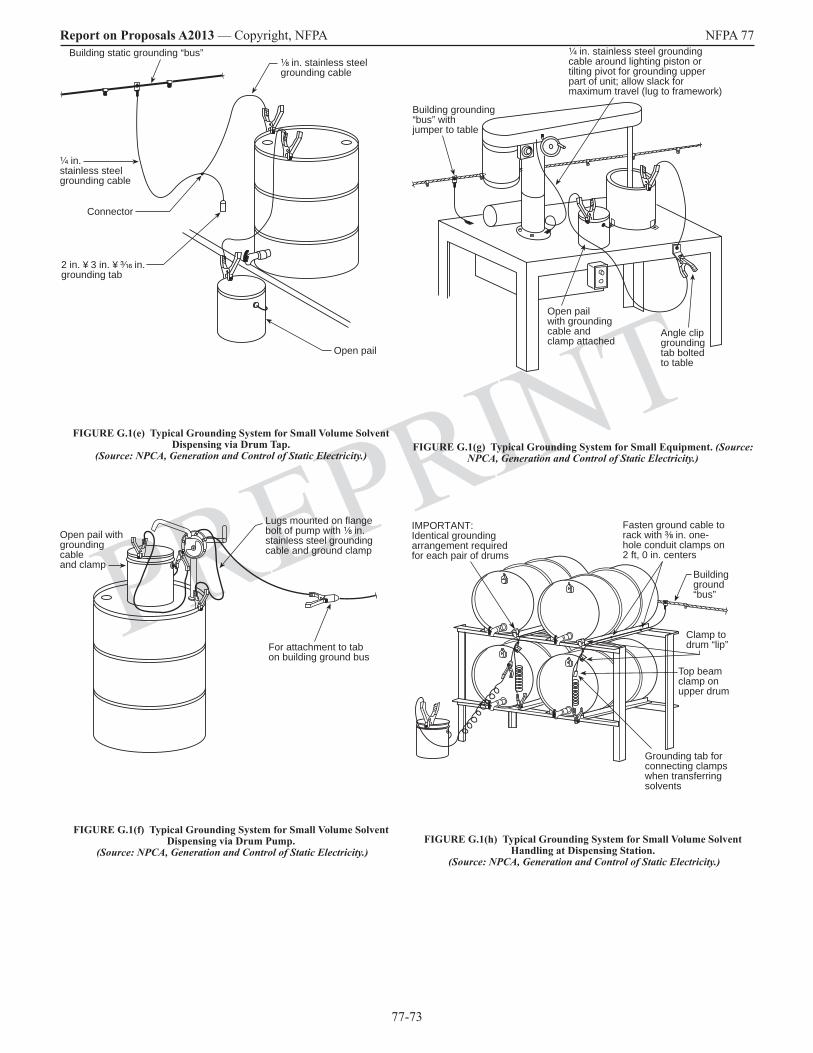
77-73
Report on Proposals A2013 — Copyright, NFPA NFPA 77
PREPRINT
¹⁄₈ in. stainless steelgrounding cable
¹⁄₄ in.stainless steelgrounding cable
Building static grounding “bus”
Connector
2 in. ¥ 3 in. ¥ ³⁄₁₆ in.grounding tab
Open pail
FIGURE G.1(e) Typical Grounding System for Small Volume Solvent Dispensing via Drum Tap.
(Source: NPCA, Generation and Control of Static Electricity.)
Open pail withgroundingcableand clamp
Lugs mounted on flangebolt of pump with ¹⁄₈ in.stainless steel groundingcable and ground clamp
For attachment to tabon building ground bus
FIGURE G.1(f) Typical Grounding System for Small Volume Solvent Dispensing via Drum Pump.
(Source: NPCA, Generation and Control of Static Electricity.)
Building grounding“bus” withjumper to table
¹⁄₄ in. stainless steel groundingcable around lighting piston ortilting pivot for grounding upperpart of unit; allow slack formaximum travel (lug to framework)
Open pailwith groundingcable andclamp attached
Angle clipgroundingtab boltedto table
FIGURE G.1(g) Typical Grounding System for Small Equipment. (Source: NPCA, Generation and Control of Static Electricity.)
IMPORTANT:Identical groundingarrangement requiredfor each pair of drums
Fasten ground cable torack with ³⁄₈ in. one-hole conduit clamps on2 ft, 0 in. centers
Buildingground“bus”
Clamp todrum “lip”
Top beamclamp onupper drum
Grounding tab forconnecting clampswhen transferringsolvents
FIGURE G.1(h) Typical Grounding System for Small Volume Solvent Handling at Dispensing Station.
(Source: NPCA, Generation and Control of Static Electricity.)
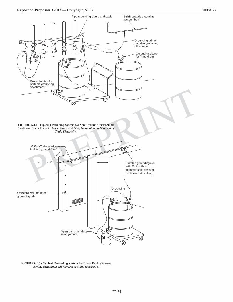
77-74
Report on Proposals A2013 — Copyright, NFPA NFPA 77
PREPRINT
Building static groundingsystem “bus”
Grounding tab forportable groundingattachment
Grounding clampfor filling drum
Pipe grounding clamp and cable
Grounding tab forportable groundingattachment
FIGURE G.1(i) Typical Grounding System for Small Volume for Portable Tank and Drum Transfer Area. (Source: NPCA, Generation and Control of
Static Electricity.)
#1/0–1/C stranded wirebuilding ground “bus”
Open pail groundingarrangement
GroundingclampStandard wall-mounted
grounding tab
Portable grounding reel with 20 ft of ⁵⁄₃₂ in. diameter stainless steel cable ratchet latching
FIGURE G.1(j) Typical Grounding System for Drum Rack. (Source: NPCA, Generation and Control of Static Electricity.)

77-75
Report on Proposals A2013 — Copyright, NFPA NFPA 77
PREPRINTH.2.9 Charge Density. The charge per unit area on a surface or the charge per unit volume in space. Surface charge density is measured in coulombs per square meter. Volume charge density, also called space charge density or space charge, is measured in coulombs per cubic meter. [Proposal 77-12, Log #CP10]
H.2.10 Charge Relaxation. The process by which separated charges recombine or excess charge is lost from a system. [Proposal 77-12, Log #CP10]
H.2.11 Charging. [Proposal 77-14, Log #CP33]
H.2.4 H.2.11.1 Field Charging. Charging of particles in an electric field as the result of ions from a corona or other source; also known as ion-bombardment charging. The maximum charge that a particle can gain by field charging is proportional to the cross-sectional area of the particle and the strength of the electric field. Field charging is a dominant particle-charging mechanism for particles larger than a few tenths of a micron. [Proposal 77-14, Log #CP33]
H.2.11.2 Induction Charging. The act of charging an object by bringing it near another charged object, then touching the first object to ground; also known as induction. Charge polarization is induced on a grounded object in the vicinity of a charged surface due to the electric field existing between the object and the surface. If the ground connection is removed from the object during this period, the induced charge remains on the object. Induction charging occurs where a person walks from a conductive floor covering onto an insulating floor in the presence of an electric field. [Proposal 77-14, Log #CP33]
H.2.11.3 Triboelectric Charging. Static electric charging that results from contact or friction between two dissimilar materials; also known as frictional charging and contact-separation charging. Triboelectric charging is the most familiar, yet least understood, charge generation mechanism. Triboelectric charging results from contact or friction between two unlike materials. The amount of charge generated in this way is dependent primarily on the nature of contact, the intrinsic electrical and static electric properties of the materials involved, and the prevailing conditions of humidity and temperature. An indication of the tendency of materials to accept static electric charge in this way is given by the triboelectric series. Recent studies indicate that the amount of charge transferred depends not only on the composition of the materials but also on the capacitance of the junction. The following situations are examples of triboelectric charging:
Typical grounding clampwith recoiling cable
Typical pipe groundingjumper at swivel connections
Trackconnection
Grounding “bus” (typical)Ground rod
Note: Any conductivelevel measuring deviceor pipe should begrounded before insertinginto any car or truck.
FIGURE G.1(k) Typical Grounding System for Tank Car or Tank Truck Loading/Unloading Station.
(Source: NPCA, Generation and Control of Static Electricity.)
Annex H Glossary of Terms
This annex is not a part of the recommendations of this NFPA document but is included for informational purposes only.
H.1 General. This glossary contains terms and definitions that are not included in Chapter 3. The terms are presented here to assist the user.
H.2 Terms.
H.2.1 Air Ionizer. A device for producing ions in air. Ions from an air ionizer can be attracted to stationary charges on nonconductive items (or items insulated from ground) to eliminate the charge imbalance. Other air ionizers are used to inject ions of a single polarity into an enclosure.
H.2.2 Alternating Current Static Neutralizer. See H.2.53.1.
H.2.3 Antistatic Additives. Additives used to change the electrostatic properties of solid and liquid materials. Extrinsic and intrinsic antistatic additives can be distinguished according to the method of addition. Based on the permanence of their effect, antistatic treatments can be short-term or long-term. [Proposal 77-8, Log #CP9]
H.2.4 Brush Discharge. See H.2.23.1. [Proposal 77-23, Log #CP16]
H.2.3 H.2.5 Bulk Density. The mass per unit volume of a dust pile or a dust deposit.
H.2.6 Bulking Brush Discharge. See H.2.23.1.1.
[Proposal 77-23, Log #CP16]
H.2.7 Charge. A collection or imbalance of electrons or of positive or negative ions that can accumulate on both conductors and insulators and that has both magnitude and polarity. Movement of charge constitutes an electric current. Excess or deficiency of electrons is expressed in coulombs. An electron carries a charge of –1.6 × 10⁻¹⁹ C. [Proposal 77-12, Log #CP10]
H.2.8 Charge Decay Time. The time for static electric charge to be reduced to a given percentage of the charge’s original level. [Proposal 77-12, Log #CP10]
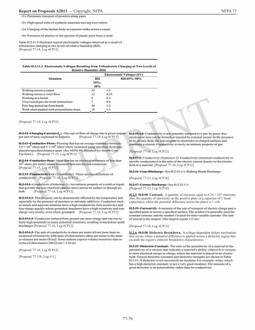
77-76
Report on Proposals A2013 — Copyright, NFPA NFPA 77
PREPRINTH.2.15.1.4 Conductivity is not generally assigned to a gas. In gases, free electrons or ions can be formed or injected by external means. In the presence of an electric field, the ions migrate to electrodes or charged surfaces and constitute a current. Conductivity is rarely an intrinsic property of gas. [Proposal 77-16, Log #CP12]
H.2.15.2 Conductivity (Definition 2). Conductivity (electrical conductivity or specific conductance) is the ratio of the electric current density to the electric field in a material. [Proposal 77-16, Log #CP12]
H.2.16 Cone Discharge. See H.2.23.1.1, Bulking Brush Discharge.
[Proposal 77-23, Log #CP16]
H.2.17 Corona Discharge. See H.2.23.1.3. [Proposal 77-23, Log #CP16]
H.2.5 H.2.18 Coulomb. A quantity of electrons equal to 6.24 × 10¹⁸ electrons; also, the quantity of electricity on the positive plate of a capacitor of 1 farad capacitance where the potential difference across the plates is 1 volt.
H.2.19 Current (I). A measure of the rate of transport of electric charge past a specified point or across a specified surface. The symbol I is generally used for constant currents, and the symbol i is used for time-variable currents. The unit of current is the ampere. One ampere equals 1 C/sec. [Proposal 77-18, Log #CP13]
H.2.6 H.2.20 Dielectric Breakdown. A voltage-dependent failure mechanism that occurs where a potential difference is applied across a dielectric region that exceeds the region’s inherent breakdown characteristics.
H.2.21 Dielectric Constant. The ratio of the permittivity of a material to the permittivity of a vacuum that indicates a material’s ability, relative to a vacuum, to store electrical energy or charge, where the material is placed in an electric field. Typical dielectric constants and dielectric strengths are shown in Table H.2.21. A dielectric is not necessarily an insulator. For example, water, which has a high dielectric constant, is not a very good insulator. The measure of a good dielectric is its polarizability rather than its conductivity.
(1) Pneumatic transport of powders along pipes
(2) High-speed webs of synthetic materials moving over rollers
(3) Charging of the human body as a person walks across a carpet
(4) Extrusion of plastics or the ejection of plastic parts from a mold
Table H.2.11.3 illustrates typical electrostatic voltages observed as a result of triboelectric charging at two levels of relative humidity (RH). [Proposal 77-14, Log #CP33]
Table H.2.11.3 Electrostatic Voltages Resulting from Triboelectric Charging at Two Levels of Relative Humidity (RH)
Electrostatic Voltages (kV)Situation RH
10%–20%
RH 65%–90%
Walking across a carpet 35 1.5Walking across a vinyl floor 12 0.25Working at a bench 6 0.1Vinyl envelopes for work instructions 7 0.6Poly bag picked up from bench 20 1.2Work chair padded with polyurethane foam 18 1.5
[Proposal 77-14, Log #CP33]
H.2.12 Charging Current (Ic). The rate of flow of charge into a given system per unit of time, expressed in amperes. [Proposal 77-18, Log #CP13]
H.2.13 Conductive Floor. Flooring that has an average resistance between 2.5 × 10³ ohms and 1 × 10⁶ ohms where measured using specified electrodes placed a specified distance apart. (See NFPA 99, Standard for Health Care Facilities.) [Proposal 77-15, Log #CP11]
H.2.14 Conductive Hose. Hose that has an electrical resistance of less than 103 ohms per meter, where measured between the end connectors. [Proposal 77-15, Log #CP11]
H.2.15 Conductivity ( κ) (1/resistivity). There are two definitions of conductivity. [Proposal 77-16, Log #CP12]
H.2.15.1 Conductivity (Definition 1). An intrinsic property of a solid or liquid that governs the way electrical charges move across its surface or through its bulk. [Proposal 77-16, Log #CP12]
H.2.15.1.1 This property can be dramatically affected by the temperature and especially by the presence of moisture or antistatic additives. Conductors such as metals and aqueous solutions have a high conductivity (low resistivity) and lose charge quickly where grounded. Insulators have a high resistivity and lose charge very slowly, even where grounded. [Proposal 77-16, Log #CP12]
H.2.15.1.2 Conductors isolated from ground can store charge and can rise to fairly high potentials in many industrial situations, resulting in hazardous spark discharges. [Proposal 77-16, Log #CP12]
H.2.15.1.3 The unit of conductivity is ohms per meter (Ω-m) [note basis in reciprocal of resistivity with units of ohm-meters; ohms per meter is the same as siemens per meter (S/m)]. Some authors express volume resistivity data in terms of ohm-meters (100 Ω-cm = 1 Ω-m). [Proposal 77-16, Log #CP12]
[Proposal 77-118, Log #11]

77-77
Report on Proposals A2013 — Copyright, NFPA NFPA 77
PREPRINTH.2.9 H.2.29 Electrostatic Field Meter. A device that estimates the electric field from a charged object by sensing the charge and the charge polarity on the surface of a conductor or insulator.
H.2.10 H.2.30 Faraday Cage. An electrically continuous, conductive enclosure that provides a shield from static electricity (region of no electrostatic field). The cage or shield is usually grounded, although grounding is not necessary.
H.2.11 H.2.31 Field Charging. See H.2.4 H.2.11.1.
H.2.12 H.2.32 Field Suppression. The observed reduction in electric field away from an object when it is brought near a grounded object. The effect results from a repositioning of the electric field lines toward the grounded surface.
H.2.33 Flammable Limit. [Proposal 77-27, Log #CP19]
H.2.33.1 Lower Flammable Limit (LFL). The lowest molar (or volume) concentration of a combustible substance in an oxidizing medium that will propagate a flame. [Proposal 77-27, Log #CP19]
H.2.33.2 Upper Flammable Limit (UFL). The highest molar (or volume) concentration of a combustible substance in an oxidizing medium that will propagate a flame. [Proposal 77-27, Log #CP19]
H.2.34 Ignition Energy. The energy required to effect ignition of a specified fuel mixture under specified conditions of test. [Proposal 77-28, Log #CP20]
H.2.34.1 Minimum Ignition Energy (MIE). The energy, expressed in joules, stored in a capacitor that, upon discharge, is just sufficient to effect ignition of the most ignitible mixture of a given fuel mixture under specified test conditions. [Proposal 77-28, Log #CP20]
H.2.35 Incendive. Able to cause ignition. [Proposal 77-29, Log #CP21]
H.2.36 Induction. The process by which charges are moved to new locations on a conductor by the action of an electric field or the movement of a conductor into the influence of an existing electric field. [Proposal 77-30, Log #CP22]
H.2.37 Induction Bar. A passive corona device that is connected to ground and that produces corona from a grounded electrode of the induction bar when a highly charged object is brought close to it. Ions (corona) are produced by the electrode if the charge on the object is great enough and if the object’s placement is sufficiently close that corona onset is achieved.
[Proposal 77-31, Log #CP23]
H.2.38 Induction Charging. See H.2.11.2. [Proposal 77-14, Log #CP33]
H.2.39 Ionization. A process by which a neutral atom or molecule loses or gains electrons, thereby acquiring a net charge and becoming an ion. [Proposal 77-32, Log #CP24]
H.2.13 H.2.40 Joule. A unit of work and energy equal to 1 W-sec.
H.2.14 H.2.41 Limiting Oxidant Concentration (LOC). The lowest molar (or volume) gas-phase concentration of oxidant at which a specified fuel can propagate a flame.
H.2.42 Lower Flammable Limit (LFL). See H.2.33.1. [Proposal 77-27, Log #CP19]
[Proposal 77-21, Log #CP14]H.2.22 Dielectric Strength. The maximum electrical potential gradient (electric field) that a material can withstand without rupture, usually specified in volts per millimeter of thickness; also known as electric strength or breakdown strength. See Table B.2 for typical data. The maximum dielectric field strength in atmospheric air is around 3 × 10⁶ V/m. This value implies the existence of maximum value of surface charge density. Oscillating electric fields produce a significantly greater stress on materials than do time-independent fields. For that reason, insulation systems based on dc ratings fail quickly where used with ac power units. [Proposal 77-22, Log #CP15]
H.2.23 Discharge. [Proposal 77-23, Log #CP16]
H.2.23.1 Brush Discharge. A higher energy form of corona discharge characterized by low-frequency bursts or by streamers. Brush discharges can form between charged nonconductive surfaces and grounded conductors acting as electrodes. For positive electrodes, pre-onset or breakdown streamers are observed, and the maximum effective energy is a few millijoules. For negative electrodes, the maximum effective energy is a few tenths of a millijoule. Brush discharges can ignite flammable gas and hybrid mixtures but not dust in air. Also called cone discharge. [Proposal 77-23, Log #CP16]
H.2.23.1.1 Bulking Brush Discharge. A partial surface discharge created during bulking of powder in containers, appearing as a luminous, branched channel flashing radially from the wall toward the center of the container. Its maximum effective energy is 10 mJ to 25 mJ. It can ignite flammable gas, hybrid mixtures, and some fine dusts in air. [Proposal 77-23, Log #CP16]
H.2.23.1.2 Propagating Brush Discharge. An energetic discharge caused by electrical breakdown of the dielectric layer in a capacitor. The capacitor is typically formed by charged plastic coating on a metal substrate, although plastic pipe and tote bins can also form the required charged double layer. The effective energy can exceed 1000 mJ, causing both shock to personnel and ignition hazards for a wide variety of materials, including dusts in air. [Proposal 77-23, Log #CP16]
H.2.23.1.3 Corona Discharge. An electrical discharge in the microampere range that results from a localized electrical breakdown of gases by charges on surfaces such as sharp edges, needle points, and wires. The charges can arise on conductors at high voltage or on grounded conductors that are situated near a charged surface. Corona is accompanied by a faint luminosity.
[Proposal 77-23, Log #CP16]
H.2.24 Dissipative. Having a surface resistivity between 105 ohms per square and 1011 ohms per square. [Proposal 77-24, Log #CP17]
H.2.25 Double Layer. A phenomenon usually associated with a solid–liquid interface where ions of one charge type are fixed to the surface of the solid, and an equal number of mobile ions of opposite charge are distributed through the neighboring region of the liquid. In such a system, the movement of liquid causes a displacement of the mobile ions with respect to the fixed charges on the solid surface. [Proposal 77-25, Log #CP34]
H.2.7 H.2.26 Electrically Powered Static Neutralizer. See H.2.53.2.
H.2.27 Electrometer. A device used to measure static electric charge with high-input impedance, typically greater than 1013 ohms, which draws negligible current from the measured object. [Proposal 77-26, Log #CP18]
H.2.8 H.2.28 Electrostatic Field. The electric force per unit charge that is produced by a distribution of charge; also called the electric field intensity or potential gradient. An electrostatic field can be most easily thought of as lines of influence originating from unit positive charges and terminating at unit negative charges or at infinity. It is, therefore, closely related to charges on surfaces and in gas streams.
Table H.2.21 Dielectric Properties of Selected MaterialsMaterial Dielectric Constant Dielectric Strength (V/m)
Bakelite 4.9 2.4 × 10⁷Cellulose acetate 3.8 1.0 × 10⁷Mica 5.4 1.0 × 10⁸Plexiglas, Lucite 3.4 4.0 × 10⁷Polystyrene 2.5 2.4 × 10⁷Porcelain 7 6.0 × 10⁶Titanium dioxide 90 6.0 × 10⁶Barium titanate 1200 5.0 × 10⁶
77-78
Report on Proposals A2013 — Copyright, NFPA NFPA 77
PREPRINT
H.2.58 Triboelectric Charging. See H.2.11.3. [Proposal 77-14, Log #CP33]
H.2.59 Triboelectric Series. A ranking of materials according to their affinity for positive or negative charges. Where different materials are rubbed together, charge is transferred. Many researchers working in the field of triboelectricity have set up triboelectric series to show which combinations of materials would receive which charge. There is some agreement on the ranking of some materials, but most of the series are dissimilar, even where the same materials are used. [Proposal 77-40, Log #CP32]
H.2.60 Upper Flammable Limit (UFL). See H.2.33.2. [Proposal 77-27, Log #CP19]
H.2.61 Volume Resistivity. See H.2.51.2. [Proposal 77-123, Log #12]
Annex I NEW Bibliography
Cross, J. A., Electrostatics: Principles, Problems and Applications, Adam Hilger, Bristol, England, UK, 1987 [ISBN 0-85274-589-3]
Guest, P. G., Static Electricity in Nature and Industry, U. S. Department of
Commerce - Bureau of Mines, U. S. Government Printing Office, Washington, DC, USA, 1939Moore, A. D., Ed., Electrostatics and Its Application, 2nd Ed., John Wiley & Sons - Wiley Interscience, New York, NY, USA, 1973 [ISBN 0-471-61450-5]
Moore, A. D., Electrostatics - Exploring, Controlling, and Using Static Electricity, 2nd Ed., Laplacian Press, Morgan Hill, CA, USA, 1997 [ISBN 1-885540-04-3]
Pratt, T. H., Electrostatic Ignitions of Fires and Explosions, Burgoyne, Inc., Marietta, GA, USA, 1997, [ISBN 0-9659092-0-4]
Pratt, T. H., Possible Electrostatic Hazards in Material Handling Systems, 1992 Process Plant Safety Symposium, South Texas Section, American Institute of Chemical Engineers, 1992, pp. 1114-1123
Uman, M. A., Lightning, Dover Publications, New York, NY, USA, 1989[ISBN 0-486-64575-4]
Annex J I Informational References
J.1 I.1 Referenced Publications. The following documents or portions thereof are referenced within this recommended practice for informational purposes only and are thus not part of the recommendations of this document unless also listed in Chapter 2.
J.1.1 I.1.1 NFPA Publications. National Fire Protection Association, 1 Batterymarch Park, Quincy, MA 02169-7471.
NFPA 30A, Code for Motor Fuel Dispensing Facilities and Repair Garages, 2012 2007 edition.
NFPA 33, Standard for Spray Application Using Flammable or Combustible Materials, 2011 2007 edition.
NFPA 53, Recommended Practice on Materials, Equipment, and Systems Used in Oxygen-Enriched Atmospheres, 2011 2004 edition.
NFPA 69, Standard on Explosion Prevention Systems, 2008 2002 edition.
NFPA 70, National Electrical Code®, 2014 2005 edition.
NFPA 99, Standard for Health Care Facilities, 2005 edition. [Proposal 77-3, Log #CP7]
NFPA 302, Fire Protection Standard for Pleasure and Commercial Motor Craft, 2012 2004 edition.
NFPA 318, Standard for the Protection of Semiconductor Fabrication Facilities, 2012 2006 edition.
H.2.43 Megohmmeter. A meter used to measure high resistance values that typically operates at higher test voltages than standard ohmmeters, usually in the range of 100 volts to 1000 volts. [Proposal 77-33, Log #CP25]
H.2.44 Minimum Explosible Concentration (MEC). The lowest concentration of a combustible dust in air, expressed in grams per cubic meter, that will propagate a flame. [Proposal 77-34, Log #CP26]
H.2.45 Minimum Ignition Energy (MIE). See H.2.34.1. [Proposal 77-28, Log #CP20]
H.2.46 Ohm. A unit of electric resistance equal to the resistance through which a current of 1 ampere will flow where there is a potential difference of 1 volt across the current. [Proposal 77-119, Log #8]
H.2.47 Ohms per Square. A unit of measure used to describe surface resistivity that reflects the resistance value between two electrodes that form two sides of a square and is independent of the size of the square. The resulting value indicates how easily electrons can flow across a surface. It is normally used as a resistivity measurement of a thin conductive layer or material over a relatively insulative base material. [Proposal 77-35, Log #CP27]
H.2.48 Propagating Brush Discharge. See H.2.23.1.2. [Proposal 77-23, Log #CP16]
H.2.49 Relaxation Time Constant (τ). The time, in seconds, for charge to decay by Ohm’s law to e–1 (36.7 percent) of its initial value. For a capacitor, the relaxation time constant is the product of resistance (ohms) and capacitance (farads). [Proposal 77-36, Log #CP28]
H.2.50 Resistance (R). The opposition that a device or material offers to the flow of direct current, equal to the voltage drop across the element divided by the current through the element; also known as electrical resistance. [Proposal 77-120, Log #6]
H.2.51 Resistivity. [Proposal 77-37, Log #CP29]
H.2.51.1 Surface Resistivity. The electric resistance of the surface of an insulator, in ohms per square, as measured between the opposite sides of a square on the surface, and whose value in ohms is independent of the size of the square or the thickness of the surface film. [Proposal 77-37, Log #CP29]
H.2.51.2 Volume Resistivity. The resistance of a sample of material, expressed in ohm-meters , having unit length and unit cross-sectional area. [Proposal 77-123, Log #12]
H.2.52 Spark. A short-duration electric discharge due to a sudden breakdown of air or some other insulating material separating two conductors at different electric potentials, accompanied by a momentary flash of light; also known as electric spark, spark discharge, and sparkover. [Proposal 77-38, Log #CP30]
H.2.15 H.2.53 Static Neutralizer.
H.2.15.1 H.2.53.1 Alternating Current Static (ac) Neutralizer. A static neutralizer that uses an alternating current corona to generate positive and negative ions. Ions from this equipment are drawn from the ionizer to neutralize charged (usually insulating) surfaces. The frequency for ac static neutralizers is usually that of line frequency, 50 Hz to 60 Hz.
H.2.15.2 H.2.53.2 Electrically Powered Static Neutralizer. A static neutralizer that uses one or more electrified needles rigidly held in a housing and a high-potential supply that powers the neutralizer. Ion generation occurs in the air space surrounding the highly charged needle points.
H.2.54 Surface Charge Density. The charge per unit area of solid surface expressed in coulombs per square meter. In air, the maximum surface charge density before air breakdown occurs is 2.65 × 10⁻⁵ C/m2. In most practical situations, only a fraction of this value is achieved. [Proposal 77-12, Log #CP10]
H.2.55 Surface Resistivity. See H.2.51.1. [Proposal 77-37, Log CP29]
H.2.56 Surface Streamer. A surface-to-wall discharge observed on charged liquids during tanker filling, appearing as a flash up to 30 cm long and accompanied by a crackling sound. The effective energy is unknown but is possibly as high as approximately 10 mJ. Surface streamers are also observed on tribocharged solid surfaces, such as between aircraft windshields and metal airframe, where puncturing does not occur. [Proposal 77-39, Log #CP31]
H.2.16 H.2.57 Tribocharging. Charge separation caused by the rubbing of surfaces, creating triboelectricity; also see 3.3.7.2 H.2.11.3, Triboelectric Charging.
77-79
Report on Proposals A2013 — Copyright, NFPA NFPA 77
PREPRINT
NFPA 326, Standard for the Safeguarding of Tanks and Containers for Entry, Cleaning, or Repair, 2010 2005 edition.
NFPA 407, Standard for Aircraft Fuel Servicing, 2011 2007 edition.
NFPA 780, Standard for the Installation of Lightning Protection Systems, 2011 2004 edition.
J.1.2 I.1.2 Other Publications.
J.1.2.1 I.1.2.1 AIChE Publications. American Institute of Chemical Engineers, 3 Park Avenue, New York, NY 10016-5901.
Britton, L. G., “Using Material Data in Static Hazard Assessment,” Plant/Operations Progress, Vol. 11, April 1992, pp. 56–70.
Britton, L. G., Avoiding Static Ignition Hazards in Chemical Operations, 1999.
J.1.2.2 I.1.2.2 ANSI Publications. American National Standards Institute, Inc., 11 West 43rd Street, 4th Floor, New York, NY 10036.
ANSI Z41, Standard for Personal Protection — Protective Footwear, 1999 1991.
J.1.2.3 I.1.2.3 API Publications. American Petroleum Institute, 1220 L Street, NW, Washington, DC 20005.
Bustin, W. M., et al., New Theory for Static Relaxation from High Resistivity Fuel, API Refining Division Proceedings, Vol. 44, No. 3, 1964.
API RP 2003, Protection Against Ignitions Arising Out of Static, Lightning, and Stray Currents, 7th 6th edition, 2008 September, 1998.
API 2219, Safe Operation of Vacuum Trucks in the Petroleum Service, 3rd 2d edition, 2005 1999.
J.1.2.4 I.1.2.4 ASTM Publications. ASTM International, 100 Barr Harbor Drive, P.O. Box C700, West Conshohocken, PA 19428-2959.
ASTM E 502, Standard Test Method for Selection and Use of ASTM Standards for the Determination of Flash Point of Chemicals by Closed Cup Methods, 2007 1984 (reapproved 1994).
J.1.2.5 I.1.2.5] CENELEC Publications. European Committee for Electrotechnical Standardization (CENELEC), Rue de Stassart, 35, B - 1050 Brussels, Belgium.
CENELEC Draft Standard Safety of Machinery — Electrotechnical Aspects, 1996.
J.1.2.6 I.1.2.6 NPCA Publications. National Paint and Coatings Association, 1500 Rhode Island Avenue, NW, Washington, DC 20005-5597.
Generation and Control of Static Electricity in Coatings Operations, 2010 1998.
J.2 I.2 Informational References. (Reserved)
J.3 I.3 References for Extracts in Informational Sections. (Reserved)[Proposal 77-125, Log #CP116]