Embed Size (px)
Citation preview
Thermal Expansion & Helical Buckling of
Pipe-in-Pipe Flowline System2012 SIMULIA Community Conference
Genesis – A “New” Brand within Technip
• The Keynote Talk by Jim O’Sullivan illustrates how advanced engineering simulations
allow Technip, across the globe and across brands & products, to Take it Further.
• Genesis is a wholly owned Technip subsidiary. Originally acquired by Technip in the early
2000s. The Genesis HQ is in London.
• Genesis professionals provide services from conceptual field studies to the detailed
engineering design and analysis of offshore oil and gas production systems from the
seafloor to the host facilities, whether on land or at the water surface.
• Today Genesis staff, which number about 1100, represent a little more than1/30th of the
Technip’s worldwide workforce.
Thermal Expansion & Helical Buckling of Pipe-in-Pipe Flowline System2
Heating cables
Carrier
pipe
Centraliser
Flowline
Optical fibre
Passive insulation
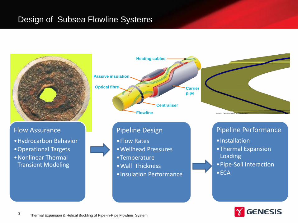
Design of Subsea Flowline Systems
Thermal Expansion & Helical Buckling of Pipe-in-Pipe Flowline System3
Flow Assurance
•Hydrocarbon Behavior
•Operational Targets
•Nonlinear Thermal Transient Modeling
Pipeline Design
•Flow Rates
•Wellhead Pressures
•Temperature
•Wall Thickness
•Insulation Performance
Pipeline Performance
•Installation
•Thermal Expansion Loading
•Pipe-Soil Interaction
•ECA
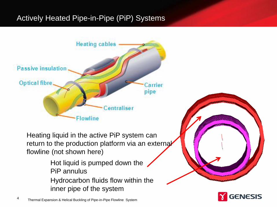
Actively Heated Pipe-in-Pipe (PiP) Systems
Thermal Expansion & Helical Buckling of Pipe-in-Pipe Flowline System4
Hydrocarbon fluids flow within the
inner pipe of the system
Hot liquid is pumped down the
PiP annulus
Heating liquid in the active PiP system can
return to the production platform via an external
flowline (not shown here)
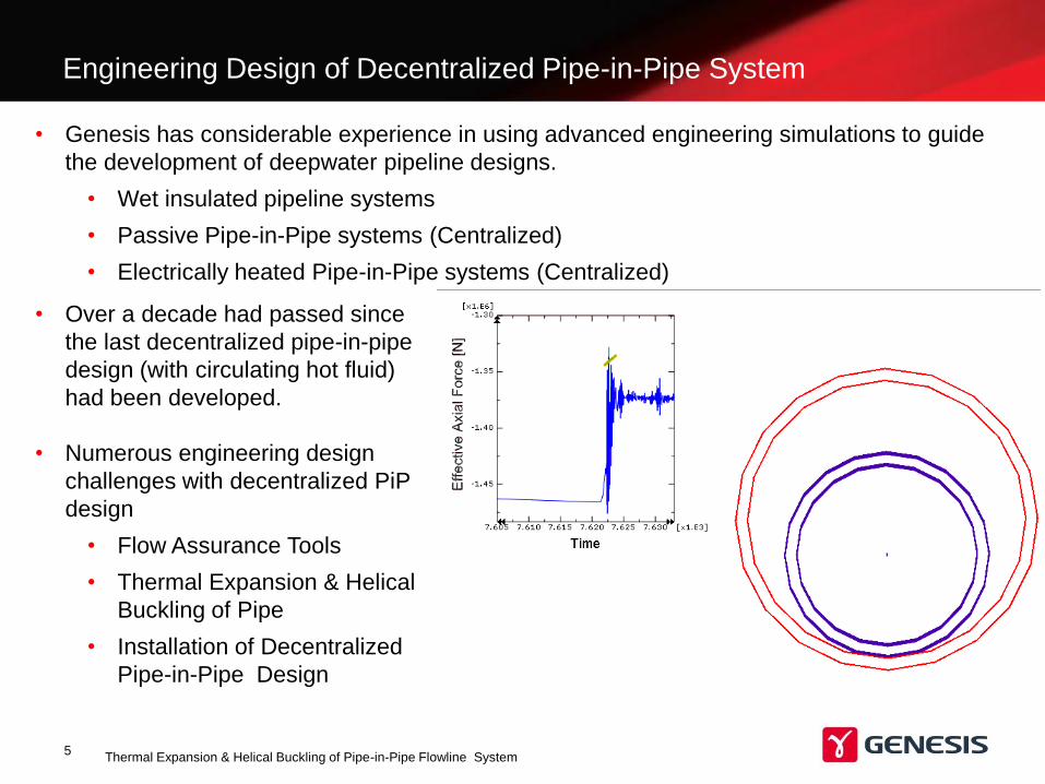
Engineering Design of Decentralized Pipe-in-Pipe System
Thermal Expansion & Helical Buckling of Pipe-in-Pipe Flowline System5
• Genesis has considerable experience in using advanced engineering simulations to guide
the development of deepwater pipeline designs.
• Wet insulated pipeline systems
• Passive Pipe-in-Pipe systems (Centralized)
• Electrically heated Pipe-in-Pipe systems (Centralized)
• Over a decade had passed since
the last decentralized pipe-in-pipe
design (with circulating hot fluid)
had been developed.
• Numerous engineering design
challenges with decentralized PiP
design
• Flow Assurance Tools
• Thermal Expansion & Helical
Buckling of Pipe
• Installation of Decentralized
Pipe-in-Pipe Design
Nonlinear FEA of Decentralized Pipe-in-Pipe System
Thermal Expansion & Helical Buckling of Pipe-in-Pipe Flowline System6
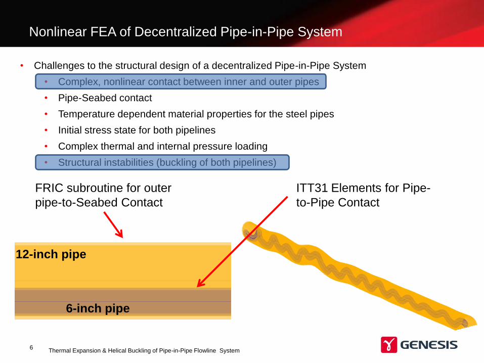
• Challenges to the structural design of a decentralized Pipe-in-Pipe System
• Complex, nonlinear contact between inner and outer pipes
• Pipe-Seabed contact
• Temperature dependent material properties for the steel pipes
• Initial stress state for both pipelines
• Complex thermal and internal pressure loading
• Structural instabilities (buckling of both pipelines)
6-inch pipe
12-inch pipe
ITT31 Elements for Pipe-
to-Pipe Contact
FRIC subroutine for outer
pipe-to-Seabed Contact
Nonlinear FEA of Decentralized Pipe-in-Pipe System
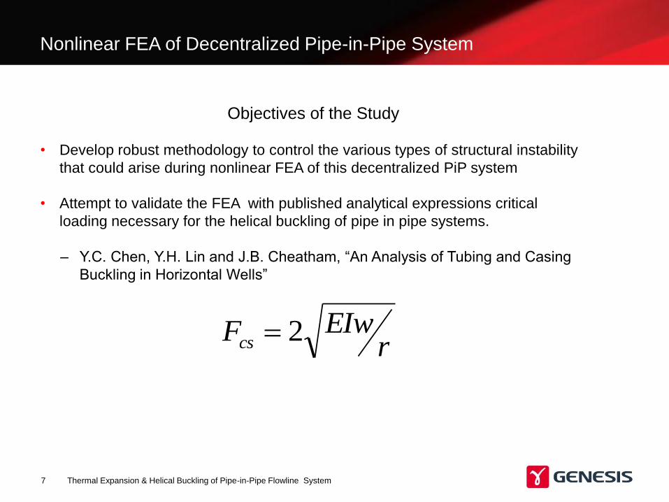
Objectives of the Study
• Develop robust methodology to control the various types of structural instability
that could arise during nonlinear FEA of this decentralized PiP system
• Attempt to validate the FEA with published analytical expressions critical
loading necessary for the helical buckling of pipe in pipe systems.
– Y.C. Chen, Y.H. Lin and J.B. Cheatham, “An Analysis of Tubing and Casing
Buckling in Horizontal Wells”
Thermal Expansion & Helical Buckling of Pipe-in-Pipe Flowline System7
r
EIwFcs 2
Thermal Expansion & Helical Buckling of Pipe-in-Pipe Flowline System8
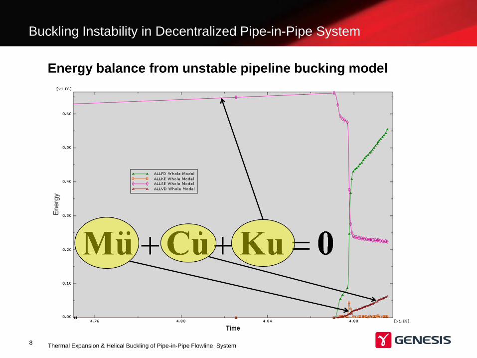
Buckling Instability in Decentralized Pipe-in-Pipe System
Energy balance from unstable pipeline bucking model
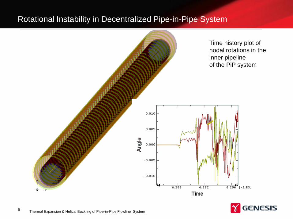
Rotational Instability in Decentralized Pipe-in-Pipe System
Thermal Expansion & Helical Buckling of Pipe-in-Pipe Flowline System9
Time history plot of
nodal rotations in the
inner pipeline
of the PiP system
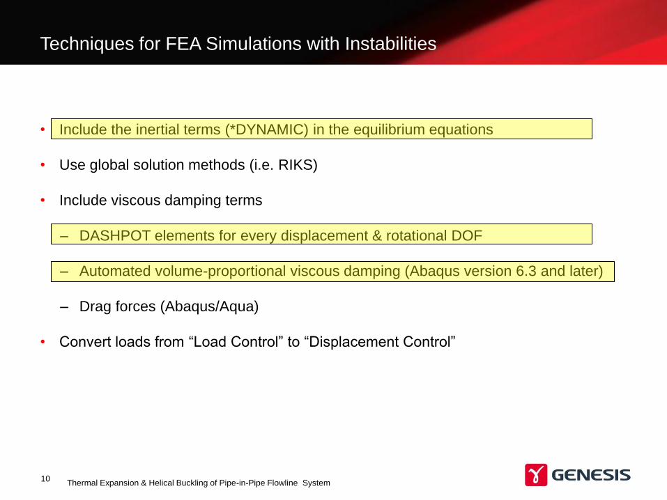
Techniques for FEA Simulations with Instabilities
Thermal Expansion & Helical Buckling of Pipe-in-Pipe Flowline System10
• Include the inertial terms (*DYNAMIC) in the equilibrium equations
• Use global solution methods (i.e. RIKS)
• Include viscous damping terms
– DASHPOT elements for every displacement & rotational DOF
– Automated volume-proportional viscous damping (Abaqus version 6.3 and later)
– Drag forces (Abaqus/Aqua)
• Convert loads from “Load Control” to “Displacement Control”
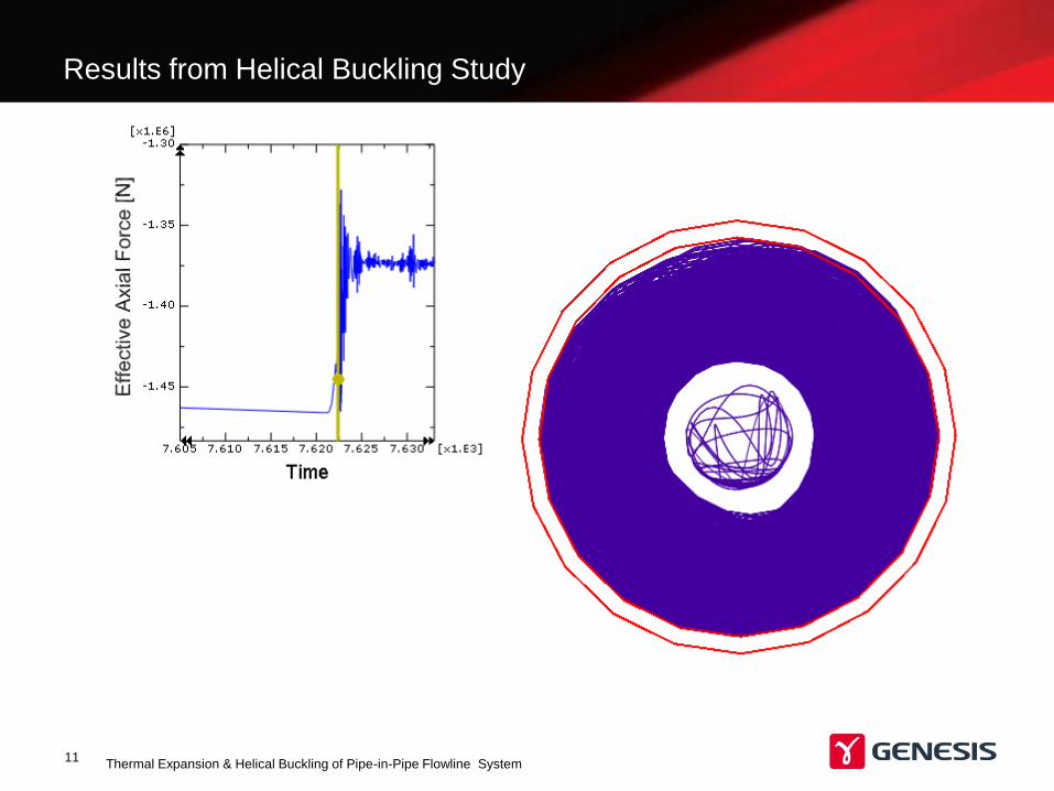
Results from Helical Buckling Study
Thermal Expansion & Helical Buckling of Pipe-in-Pipe Flowline System11
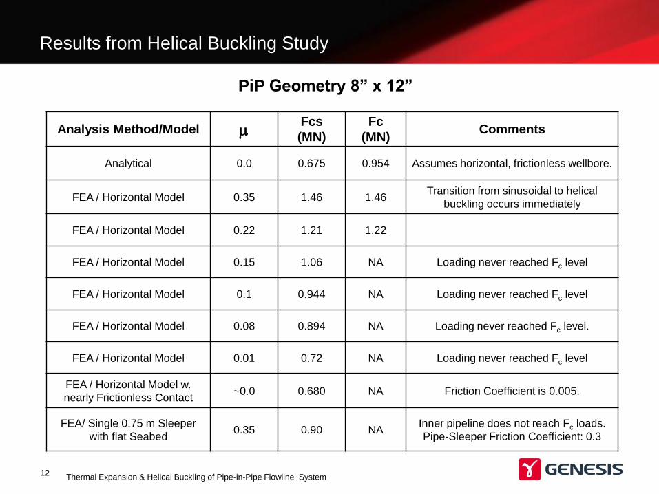
Results from Helical Buckling Study
Thermal Expansion & Helical Buckling of Pipe-in-Pipe Flowline System12
Analysis Method/Model mFcs
(MN)
Fc
(MN)Comments
Analytical 0.0 0.675 0.954 Assumes horizontal, frictionless wellbore.
FEA / Horizontal Model 0.35 1.46 1.46Transition from sinusoidal to helical
buckling occurs immediately
FEA / Horizontal Model 0.22 1.21 1.22
FEA / Horizontal Model 0.15 1.06 NA Loading never reached Fc level
FEA / Horizontal Model 0.1 0.944 NA Loading never reached Fc level
FEA / Horizontal Model 0.08 0.894 NA Loading never reached Fc level.
FEA / Horizontal Model 0.01 0.72 NA Loading never reached Fc level
FEA / Horizontal Model w.
nearly Frictionless Contact~0.0 0.680 NA Friction Coefficient is 0.005.
FEA/ Single 0.75 m Sleeper
with flat Seabed 0.35 0.90 NA
Inner pipeline does not reach Fc loads.
Pipe-Sleeper Friction Coefficient: 0.3
PiP Geometry 8” x 12”
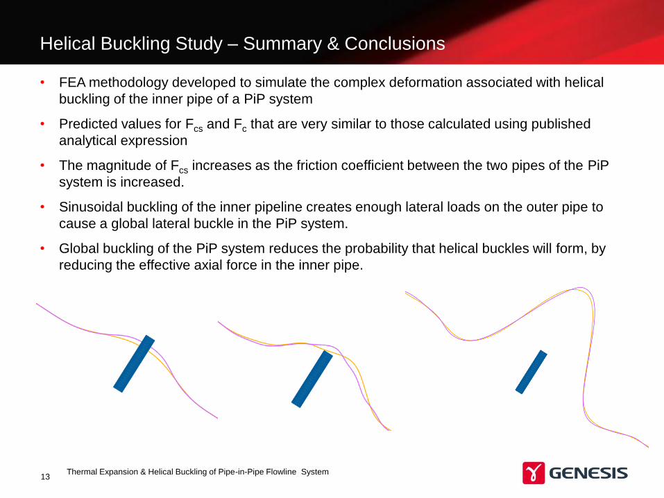
Helical Buckling Study – Summary & Conclusions
Thermal Expansion & Helical Buckling of Pipe-in-Pipe Flowline System13
• FEA methodology developed to simulate the complex deformation associated with helical
buckling of the inner pipe of a PiP system
• Predicted values for Fcs and Fc that are very similar to those calculated using published
analytical expression
• The magnitude of Fcs increases as the friction coefficient between the two pipes of the PiP
system is increased.
• Sinusoidal buckling of the inner pipeline creates enough lateral loads on the outer pipe to
cause a global lateral buckle in the PiP system.
• Global buckling of the PiP system reduces the probability that helical buckles will form, by
reducing the effective axial force in the inner pipe.