Embed Size (px)
Citation preview

Superconducting Power Equipment Technology Watch 2012
1024190


EPRI Project Manager S. Eckroad
ELECTRIC POWER RESEARCH INSTITUTE 3420 Hillview Avenue, Palo Alto, California 94304-1338 PO Box 10412, Palo Alto, California 94303-0813 USA
800.313.3774 650.855.2121 [email protected] www.epri.com
Superconducting Power Equipment Technology Watch 2012
1024190
Technical Update, December 2012
DISCLAIMER OF WARRANTIES AND LIMITATION OF LIABILITIES THIS DOCUMENT WAS PREPARED BY THE ORGANIZATION(S) NAMED BELOW AS AN ACCOUNT OF WORK SPONSORED OR COSPONSORED BY THE ELECTRIC POWER RESEARCH INSTITUTE, INC. (EPRI). NEITHER EPRI, ANY MEMBER OF EPRI, ANY COSPONSOR, THE ORGANIZATION(S) BELOW, NOR ANY PERSON ACTING ON BEHALF OF ANY OF THEM:
(A) MAKES ANY WARRANTY OR REPRESENTATION WHATSOEVER, EXPRESS OR IMPLIED, (I) WITH RESPECT TO THE USE OF ANY INFORMATION, APPARATUS, METHOD, PROCESS, OR SIMILAR ITEM DISCLOSED IN THIS DOCUMENT, INCLUDING MERCHANTABILITY AND FITNESS FOR A PARTICULAR PURPOSE, OR (II) THAT SUCH USE DOES NOT INFRINGE ON OR INTERFERE WITH PRIVATELY OWNED RIGHTS, INCLUDING ANY PARTY'S INTELLECTUAL PROPERTY, OR (III) THAT THIS DOCUMENT IS SUITABLE TO ANY PARTICULAR USER'S CIRCUMSTANCE;; OR
(B) ASSUMES RESPONSIBILITY FOR ANY DAMAGES OR OTHER LIABILITY WHATSOEVER (INCLUDING ANY CONSEQUENTIAL DAMAGES, EVEN IF EPRI OR ANY EPRI REPRESENTATIVE HAS BEEN ADVISED OF THE POSSIBILITY OF SUCH DAMAGES) RESULTING FROM YOUR SELECTION OR USE OF THIS DOCUMENT OR ANY INFORMATION, APPARATUS, METHOD, PROCESS, OR SIMILAR ITEM DISCLOSED IN THIS DOCUMENT.
REFERENCE HEREIN TO ANY SPECIFIC COMMERCIAL PRODUCT, PROCESS, OR SERVICE BY ITS TRADE NAME, TRADEMARK, MANUFACTURER, OR OTHERWISE, DOES NOT NECESSARILY CONSTITUTE OR IMPLY ITS ENDORSEMENT, RECOMMENDATION, OR FAVORING BY EPRI.
THE FOLLOWING ORGANIZATION PREPARED THIS REPORT:
Electric Power Research Institute (EPRI)
This is an EPRI Technical Update report. A Technical Update report is intended as an informal report of continuing research, a meeting, or a topical study. It is not a final EPRI technical report.
NOTE For further information about EPRI, call the EPRI Customer Assistance Center at 800.313.3774 or e-mail [email protected].
Electric Power Research Institute, EPRI, and TOGETHER…SHAPING THE FUTURE OF ELECTRICITY are registered service marks of the Electric Power Research Institute, Inc.
Copyright © 2012 Electric Power Research Institute, Inc. All rights reserved.

This publication is a corporate document that should be cited in the literature in the following manner:
Superconducting Power Equipment: Technology Watch 2012. EPRI, Palo Alto, CA: 2012. 1024190.
iii
ACKNOWLEDGMENTS The following organization prepared this report:
Electric Power Research Institute (EPRI) 1300 West W.T. Harris Blvd. Charlotte, NC 28262
Principal Investigator S. Eckroad
This report describes research sponsored by EPRI. EPRI would like to acknowledge the support of the following individuals and organizations in the preparation of this report (listed alphabetically):
Alan Lauder, Coalition for the Commercial Application of Superconductors (CCAS) Alan Wolsky, Argonne National Laboratory AMSC Bruker-EST European Organization for Nuclear Research (CERN) Federal Grid Company of Unified Energy System (FGC UES) (Russia) Furukawa/SuperPower Innopower, Inc. Institute for Advanced Sustainability Studies (IASS) Institute of Electrical Engineering, Chinese Academy of Sciences (IEE CAS) Korea Electrotechnology Research Institute (KERI) Nexans Superconductor Ricerca sul Sistema Energetico S.p.A. (RSE) (Milan, Italy) Russian Scientific R&D Cable Institute (VIINKP) Sumitomo Electric Shanghai Jiao Tong University Superconductor Week


v
ABSTRACT The demand to transport large quantities of renewable energy from wind, solar, or hydro projects in remote locations to population load centers is increasing worldwide. Improved efficiency and greater power capacity that superconducting cables provide in this application continue to attract interest. In the United States, the Tres Amigas interconnect project, which reportedly will eventually use dc superconductors, is, in part, motivated by the need to transport wind power from west to east. Interest in dc superconducting cables for long-distance transfer of bulk renewable power or for special applications such as power flow control continues to grow internationally, with continuing activities in Germany, Russia, China, Japan, and Korea. Laboratory-scale dc superconducting cables have been in operation at Chubu University in Japan since 2006. A commercial dc superconducting cable has been in operation in China for almost two years. Programs initiated in 2011 to demonstrate and ultimately implement in-grid dc superconducting cables in Germany, Russia, and Korea continued in 2012.
Urban complexes face a combination of issues that continue to make attractive the retrofitting of existing underground ac transmission cables with superconducting ac cables. The confluence of urban load growth through increased electrification, the soaring cost of urban real estate and lack of space for high-voltage substations, and the increasing need to harden the grid against man-made or natural interruptions in power for critical loads present challenges to electricity distribution planners. Superconducting cables can help by bringing power into urban centers at lower voltages, eliminating the need for high-voltage substations. Combined with fault current limiters, they can also interconnect urban substations on the distribution side of transformers, leading to a more robust power system. The landmark AmpaCity project underway in the city of Essen, Germany, illustrates this potential.
The need for fault current limiters continues, both for utility companies faced with unanticipated load growth in some parts of the grid and for independent power producers who want to interconnect with the grid at locations that cannot support increased contributions to fault current. Though there have been some realignments and/or departures among developers of superconducting fault current limiters, progress toward robust commercial offerings has been made. AMSC has announced a partnership with Nexans Superconductors to market Nexan’s medium-voltage, wire-based, fault current limiters using AMSC wire in the United States after a number of successful projects in Europe. Varian has announced availability of a high-voltage device, and a 220-kV superconducting current limiter was installed in a substation in Tianjin, China, this year.
This report provides updates on new and continuing superconducting cable and fault current limiter projects around the world. The updates are organized by national initiative, with a focus on results in 2012 supplemented by a brief review of activity prior to 2012.
Keywords Cryogenics High-temperature superconductivity (HTS) Superconducting cables Superconducting fault current limiters Superconducting transformers Superconductors


vii
CONTENTS 1 INTRODUCTION ..................................................................................................................1-1
General Comments ............................................................................................................1-1 Report Organization ...........................................................................................................1-2
2 SUPERCONDUCTING POWER CABLES ............................................................................2-1 Activities in the Americas ...................................................................................................2-1
American Electric Power: Columbus Cable Project – Update ......................................2-1 Consolidated Edison: Project HYDRA – Update ...........................................................2-2 Long Island Power Authority: LIPA 2 Project – Update .................................................2-4 Tres Amigas – Update ..................................................................................................2-6 US Navy: Helium Gas Cooled Superconducting DC Cable ...........................................2-7 Electric Power Research Institute: Novel Cryogens ......................................................2-7
Activities in Asia .................................................................................................................2-8 China: IEE-CAS Superconducting DC Cable – Update .................................................2-8 Japan: Furukawa 275 kV Class REBCO Cable Development – Update ..................... 2-11 Japan: Yokohama HTS Cable Project – Update ......................................................... 2-15 South Korea: Fault Current Limiting Cable Project...................................................... 2-17 South Korea: HTS Cable Projects – Update ............................................................... 2-17
Activities in Europe ........................................................................................................... 2-20 Germany: City of Essen AmpaCity Project ................................................................. 2-20 Netherlands: Alliander Cable Project – Update ........................................................... 2-24 Russia: St. Petersburg, HTS DC Cable Project .......................................................... 2-25 Russia: Hybrid Energy Transfer Line (ETL) – Update ................................................. 2-27 Russia: Moscow HTS Cable Project – Update ............................................................ 2-29 IASS/CERN High Current Testing Facility for Superconducting Cables ...................... 2-29
3 SUPERCONDUCTING FAULT CURRENT LIMITERS .........................................................3-1 Activities in the Americas ...................................................................................................3-1
Project HYDRA – Update .............................................................................................3-1 AMSC/Siemens 138 kV “SuperLimiterTM” HV FCL – Update .........................................3-1 Varian Power Systems – Update ..................................................................................3-3
Activities in Asia .................................................................................................................3-4 China: Shanghai 10kV SCFCL .....................................................................................3-4 China: 220 kV Iron-Core SFCL in Tianjin Substation ....................................................3-6 Korea: SFCL Projects at I’cheon and JeJu Island – Update ..........................................3-9
Activities in Europe ........................................................................................................... 3-10 Germany: ECCOFLOW Resistive Fault Current Limiter Project .................................. 3-10 Germany: AmpaCity 2G SFCL.................................................................................... 3-16 Italy: Resistive SFCL for A2A Reti Elettriche, Milan .................................................... 3-16 Germany: Boxburg SFCL Upgrade – Update.............................................................. 3-18

viii
Germany: Bruker EST Inductive FCL Project – Update .............................................. 3-19 UK: Applied Superconductivity Limited (ASL) and Zenergy ........................................ 3-21
4 CONCLUSIONS ...................................................................................................................4-1 5 REFERENCES .....................................................................................................................5-1 A SUPERCONDUCTING TECHNOLOGY PROJECTS IN THE UNITED STATES ................ A-1 B SUPERCONDUCTING TECHNOLOGY PROJECTS IN EUROPE ...................................... B-1 C SUPERCONDUCTING TECHNOLOGY PROJECTS IN CHINA ......................................... C-1 D SUPERCONDUCTING TECHNOLOGY PROJECTS IN JAPAN AND KOREA .................. D-1 E GLOSSARY OF TERMS ..................................................................................................... E-1 F REPORTS BY THE ELECTRIC POWER RESEARCH INSTITUTE ON SUPERCONDUCTIVITY FOR POWER DELIVERY APPLICATIONS .................................... F-1
EPRI Conferences, Workshops, and Tutorials on Superconductivity for Power Delivery ... F-2 Specifying and Testing Superconducting Power Equipment ........................................ F-2 Cryogenics .................................................................................................................. F-2 Superconductivity Conferences—Proceedings ............................................................ F-2
EPRI Superconducting DC Cable Program Reports .......................................................... F-3 EPRI Annual Technology Watch Reports on Superconducting Technology for Power Delivery Applications ......................................................................................................... F-3 EPRI Fault Current Limiter Survey Reports ....................................................................... F-5

ix
LIST OF FIGURES Figure 2-1 A Cross-sectional View of the HTS TriaxTM Cable ...................................................2-1 Figure 2-2 Project HYDRA Substation Interconnection Concept ..............................................2-3 Figure 2-3 Test Cable at Oak Ridge National Laboratory for Project HYDRA ...........................2-4 Figure 2-4 LIPA 2 HTS Cable System ......................................................................................2-5 Figure 2-5 Relative Critical Current of a 2nd Generation Superconductor (YBCO) as a Function of Temperature and Magnetic Field ...........................................................................2-8 Figure 2-6 Superconducting DC Cable at Alumina Electrolyzer Plant in China .........................2-9 Figure 2-7 Stirling Refrigerator and Backup System for IEE-CAS Cable ................................ 2-11 Figure 2-8 IEE-CAS DC Cable Termination ........................................................................... 2-11 Figure 2-9 Layout of the Furukawa 30 m, 275 kV HTS Cable for Demonstration.................... 2-12 Figure 2-10 Furukawa 275 kV, Single-Phase HTS Cable Installed in Shenyang, China ......... 2-12 Figure 2-11 Structure of Furukawa 275 kV, 3 kA YBCO HTS Cable ....................................... 2-13 Figure 2-12 Sumitomo 66 kV Three-In-One HTS Cable ......................................................... 2-15 Figure 2-13 Layout and Photos of Completed Installation at TEPCO Asahi (Yokohama) Substation .............................................................................................................................. 2-16 Figure 2-14 DAPAS Long-Term Vision of KEPCO Grid .......................................................... 2-20 Figure 2-15 Electrical Configuration Changes by Employing HTS Cable ................................ 2-21 Figure 2-16 Nexans Tri-axial Cable Structure ........................................................................ 2-22 Figure 2-17 Termination for Nexans 10 kV Tri-axial Cable ..................................................... 2-22 Figure 2-18 Nexans Tri-axial Cable and Termination Pre-Prototype Test Set Up ................... 2-23 Figure 2-19 AmpaCity Project Cooling System....................................................................... 2-23 Figure 2-20 Cryostat Choices for AmpaCity Project Superconducting Fault Current Limiter ... 2-24 Figure 2-21 Network Diagram in St. Petersburg, Russia, Showing Placement of HTS DC Cable ..................................................................................................................................... 2-25 Figure 2-22 Diagram of HTS DC Cable for St. Petersburg, Russia ......................................... 2-26 Figure 2-23 Hydrogen Cooled MgB2 Superconducting DC Cable ........................................... 2-28 Figure 2-24 Test Stand for Hydrogen – Superconducting Cable Energy Transfer Line (ETL) ...................................................................................................................................... 2-29 Figure 3-1 AMSC/SCE 138 kV “SuperLimiterTM” HV FCL – Schematic .....................................3-2 Figure 3-2 Single Phase Prototype of “SuperLimiterTM” HV FCL on Test at Powertech Labs ....3-3 Figure 3-3 Single-Phase Prototype of 10 kV Shanghai Resistive SFCL ...................................3-4 Figure 3-4 Structure of Modules for 10 kV Shanghai Resistive SFCL .......................................3-5 Figure 3-5 Operation of a Saturable-Core SFCL ......................................................................3-7 Figure 3-6 Pictorial of Tianjin 220 kV Iron Core SFCL ..............................................................3-8 Figure 3-7 Tianjin 220 kV Iron Core SFCL Installed at Shigezhuang Substation in Tiang, China .......................................................................................................................................3-9 Figure 3-8 Location and Applications for the Two ECCOFLOW Demonstration Sites............. 3-11 Figure 3-9 Cutaway View of ECCOFLOW 3-Phase AC SFCL Showing the Bifilar Core of One of the Three Phases and the Refrigeration and Vacuum Connections to the Unit ........... 3-13 Figure 3-10 Cutaway View of the ECCOFLOW Cryostat Showing Two of the Phase Modules ................................................................................................................................. 3-14 Figure 3-11 Single Line Diagram of ECCOFLOW SFCL ........................................................ 3-14 Figure 3-12 Simulated Currents in the ECCOFLOW SFCL and Parallel Air Core Reactor ..... 3-15 Figure 3-13 Artist’s Rendering of the Complete ECCOFLOW SFCL System .......................... 3-16 Figure 3-14 Comparison between Unlimited and Limited Short Circuit Current in RSE/A2A 9 kV SFCL ............................................................................................................................. 3-17

x
Figure 3-15 3D View of RSE/A2A 9 kV Resistive SFCL in Milan, Italy .................................... 3-18 Figure 3-16 Design of Bruker iSFCL ...................................................................................... 3-19 Figure 3-17 Principle of Operation of Bruker iSFCL ............................................................... 3-20 Figure 3-18 Comparison Performance of Bruker iSFCL with Conventional Reactors ............. 3-20 Figure 4-1 US DOE Office of Electricity HTS Funding History ..................................................4-2

xi
LIST OF TABLES Table 2-1 LIPA Phase 2 Design Improvements ........................................................................2-5 Table 2-2 IEE-CAS DC Cable Specifications ......................................................................... 2-10 Table 2-3 Summary of Tests on the Furukawa 275 kV HTS Cable ......................................... 2-14 Table 2-4 Furukawa Comparison of Conventional XLPE Cable System with 275 kV HTS Cable System ........................................................................................................................ 2-14 Table 2-5 Commissioning Test Results for Asahi Cable System ............................................ 2-17 Table 2-6 Design and Performance Parameters for AmpaCity Superconducting Fault Current Limiter .................................................................................................................................... 2-24 Table 3-1 Specification for 138 kV “SuperLimiterTM” .................................................................3-2 Table 3-2 Design Parameters for Shanghai 10 kV Resistive Fault Current Limiter ...................3-6 Table 3-3 Key Specifications of The 220 Kv / 300 MVA SI-SFCL .............................................3-7 Table 3-4 Field Test Results for Tianjin 220 kV SI-SFCL .........................................................3-9 Table 3-5 Specification Requirements for the ECCOFLOW SFCL Project ............................. 3-12 Table 3-6 Network Requirements for A2A/RSE SFCL ............................................................ 3-17 Table 3-7 Comparison of Bruker iSFCL with Conventional Reactor for Limiting Fault Current ................................................................................................................................... 3-21 Table A-1 HTS Cable Projects in the United States: Overview ................................................ A-2 Table A-2 HTS Cable Projects in the United States: Design Details ........................................ A-3 Table A-3 HTS Cable Projects in the United States: Cryostat and Refrigeration ..................... A-4 Table A-4 Fault Current Limiter Projects in the United States: Overview ................................. A-5 Table A-5 Fault Current Limiter Projects in the United States: Design Details ......................... A-5 Table A-6 Fault Current Limiter Projects in the United States: Cryostat and Refrigeration ...... A-6 Table B-1 HTS Cable Projects in Europe: Overview................................................................ B-2 Table B-2 HTS Cable Projects in Europe: Design Details ....................................................... B-3 Table B-3 HTS Cable Projects in Europe: Cryostat and Refrigeration ..................................... B-4 Table B-4 Fault Current Limiter Projects in Europe: Overview ................................................. B-5 Table B-5 Fault Current Limiter Projects in Europe: Design Details ......................................... B-6 Table B-6 Fault Current Limiter Projects in Europe: Cryostat and Refrigeration ...................... B-7 Table C-1 HTS Cable Projects in China: Overview ................................................................. C-2 Table C-2 HTS Cable Projects in China: Design Details ......................................................... C-3 Table C-3 HTS Cable Projects in China: Cryostat and Refrigeration ....................................... C-4 Table C-4 Fault Current Limiter Projects in China: Overview ................................................... C-5 Table C-5 Fault Current Limiter Projects in China: Design Details ........................................... C-6 Table C-6 Fault Current Limiter Projects in China: Cryostat and Refrigeration ........................ C-7 Table D-1 HTS Cable Projects in Japan and Korea: Overview ................................................ D-2 Table D-2 HTS Cable Projects in Japan and Korea: Design Details ........................................ D-3 Table D-3 HTS Cable Projects in Japan and Korea: Cryostat and Refrigeration ..................... D-4 Table D-4 Fault Current Limiter Projects in Japan and Korea: Overview ................................. D-5 Table D-5 Fault Current Limiter Projects in Japan and Korea: Design Details ......................... D-6 Table D-6 Fault Current Limiter Projects in Japan and Korea: Cryostat and Refrigeration ...... D-7


1-1
1 INTRODUCTION General Comments This report is the 2012 edition to an annual technology watch project sponsored by EPRI’s program in Superconductivity. Each year’s report has certain things in common as well as some differences. Earlier editions had special sections on superconducting cable basics, cryogenics, dielectric research, etc. Generally, the reports cover new activity in the past year, whether in the form of an update on projects previously reported or on newly initiated or reported projects. Appendices summarize key details on projects around the world. With the growth in the number of projects worldwide it has become necessary to focus only on projects for which there have been significant developments. Some projects that have been reported on in past editions of this report are not covered in the current report. Thus, if a known project is not found in this edition it was likely reported in an earlier report. (See Appendix F for a complete listing of EPRI reports on superconductivity, all of which are available to the public.) The 2011 report provided a fairly complete survey of all superconducting power equipment: cables, fault current limiters, transformers, energy storage, and substations. This year’s report focuses much more narrowly on cables and fault current limiters, as these are areas of considerable activity.
Three important superconductor characteristics provide benefits to electric power transmission and distribution systems. First, the extremely high current density available in superconducting materials allows devices to be smaller and lighter than conventional equivalents. Second, zero resistivity, which is a characteristic of all superconductors, lowers the losses in most devices so that they can be more efficient than conventional systems. Third, superconductors undergo an abrupt phase change from superconducting to the normal state, which can be used to produce dramatic changes in impedance in a fraction of a second. These characteristics continue to attract attention from government and industry research initiatives, manufacturers, and utilities.
The focus in superconducting developments towards cable and fault current limitation reflects lower technological barriers to commercialization in these applications. This report provides extensive coverage about the continued evolution from demonstration to commercial applications in the superconducting cable and fault current limiter fields.
Significant investment worldwide in renewable electricity generation reflects environmental and price concerns among consumers. This investment has produced a consequent interest in transporting large power quantities over long distances from remote locations with wind, solar and hydro generation to the load consuming centers. Superconducting cable technologies (particularly DC cables) offer efficiency and size advantages in these large power transfer systems. The growing interest in and development of projects using a superconducting DC cable also continue to receive coverage in this report.
1-2
Report Organization This report consists of five chapters and six appendices. Chapter Two is presents an update on superconducting power cable technology. Chapter Three covers superconductor fault current limiter research, development and demonstration activities. In both of these chapters, the material is organized by region of the world: Americas, Asia, and Europe. Within those three major regions, subsections by country are presented. In general, new projects (if any) in each country are described first, followed by updates on projects previously reported.
Chapter Four provides concluding remarks. Chapter Five contains references. Note that there are also many footnotes in the text in Chapters Two and Three that provide source information.
The first four appendices (A through D) provide a detailed inventory regarding superconducting cable and fault current limiter projects and demonstrations in progress worldwide today. These appendices are arranged by country or region of the world. Within each appendix tables for HTS cables are presented first, followed by tables for fault current limiters. Presented in table form, the projects are listed in a comparative way that will allow interested readers to quickly find appropriate examples they may wish to research further. Some projects previously reported and no longer active have been deleted from these tables to keep the information compact (the reader should refer to earlier Technology Watch reports for projects that have been removed from the tables in the appendices). The tables also contain references to additional source material.
Appendix E is a Glossary of Terms and Appendix F is a list of current EPRI reports on superconductivity. Most of the reports listed in Appendix F are available to the public at no cost.
2-1
2 SUPERCONDUCTING POWER CABLES Activities in the Americas In 2012 there were no new superconducting cable projects. We provide updates on four current projects below. In addition, some results of laboratory and institutional research by the Center for Advanced Power Systems (CAPS) at Florida State University, and by the Electric Power Research Institute are presented.
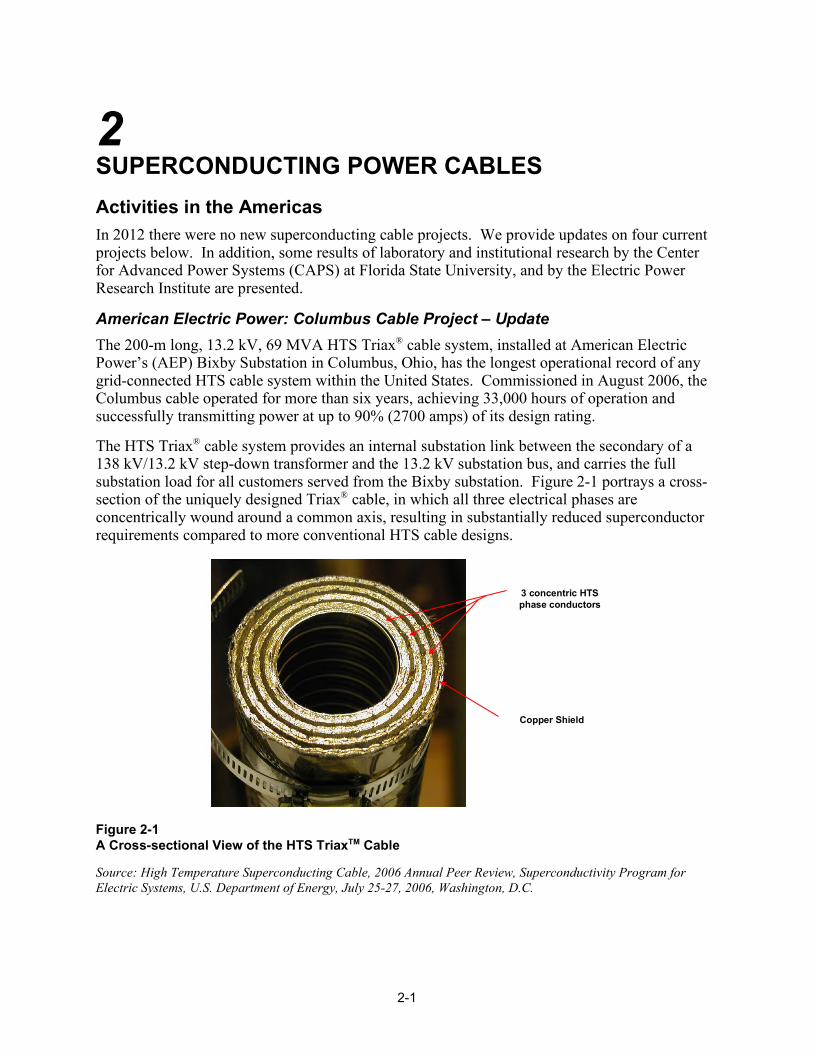
American Electric Power: Columbus Cable Project – Update The 200-m long, 13.2 kV, 69 MVA HTS Triax® cable system, installed at American Electric Power’s (AEP) Bixby Substation in Columbus, Ohio, has the longest operational record of any grid-connected HTS cable system within the United States. Commissioned in August 2006, the Columbus cable operated for more than six years, achieving 33,000 hours of operation and successfully transmitting power at up to 90% (2700 amps) of its design rating.
The HTS Triax® cable system provides an internal substation link between the secondary of a 138 kV/13.2 kV step-down transformer and the 13.2 kV substation bus, and carries the full substation load for all customers served from the Bixby substation. Figure 2-1 portrays a cross-section of the uniquely designed Triax® cable, in which all three electrical phases are concentrically wound around a common axis, resulting in substantially reduced superconductor requirements compared to more conventional HTS cable designs.
Figure 2-1 A Cross-sectional View of the HTS TriaxTM Cable
Source: High Temperature Superconducting Cable, 2006 Annual Peer Review, Superconductivity Program for Electric Systems, U.S. Department of Energy, July 25-27, 2006, Washington, D.C.
3 concentric HTS phase conductors
Copper Shield

2-2
Plans to initiate a new research phase for the Columbus cable, announced in last year’s Technology Watch, have been abandoned. The new research effort would have included replacing the existing open-cycle cooling system with an optimized closed-cycle cooling system that does not consume liquid nitrogen. The liquid nitrogen open-cycle cooling system is costly to maintain (over $100 K annually), and was never intended to be a final solution at Bixby.
Since the DOE portion of the project ended three years ago, operating costs at Bixby have been borne entirely by Southwire, the manufacturer of the cable. The host utility, AEP, has not shown the level of interest hoped for by Southwire, leading them to make a business decision to terminate the project.1 The facility will be decommissioned by the end of 2012. In closing down the project, Southwire reports that all tests to analyze the performance characteristics of the HTS cable are complete and data analysis is underway.2
Consolidated Edison: Project HYDRA – Update In 2008 the U.S. Department of Homeland Security (DHS), collaborating with Consolidated Edison (ConEd), the utility that serves Manhattan and the greater New York City area, began a project to develop, install, and operate an HTS cable system in New York City that would provide a high capacity link on the secondary side of the transformers in nearby, urban substations. The cable system would have an inherent ability to limit fault current magnitude by using 2G conductors that are specially designed to quickly transition from the superconducting state to the resistive state, thereby providing a low impedance current path during nominal operating conditions and a very high impedance path during over current conditions. The project will provide a “proof of concept” for the fault current limiting behavior as well as a platform to demonstrate a reliable and commercially viable cooling system.
This application of HTS cables, one that is receiving increasing attention world-wide, allows a system planner to parallel urban buses, producing the following advantages:
• Reduces the need for spare transformers in each substation that otherwise enable N-1 contingency planning
• Allows “freed” capacity to connect additional load without additional transformers or new substations
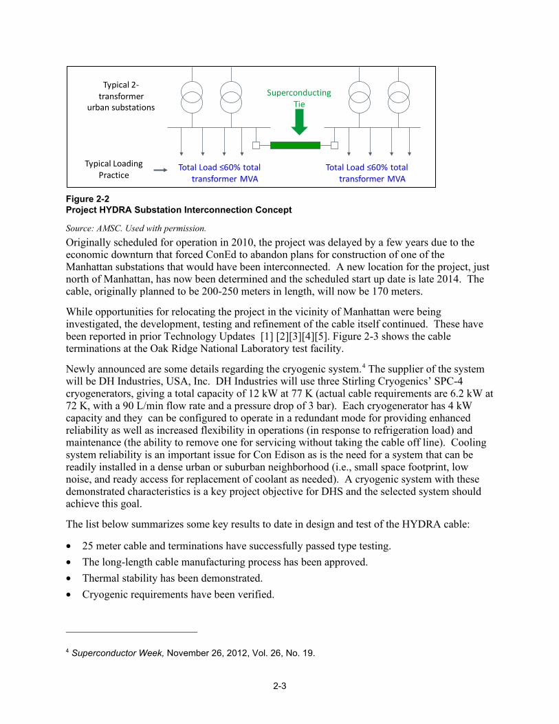
• Reduces the cost of N-1 contingency planning because fewer transformers overall are needed Typically, the interconnected substations may be fed from separate high voltage feeders. The increased connectivity achieved by the interconnection protects vulnerable, critical loads in the event of a catastrophic failure of a substation or outage on one of the independent feeders. Figure 2-2, reproduced from [1], illustrates the concept. The project lead is AMSC,3 which is also supplying the 2G wire. The cable, a tri-axial design similar to that used for the Columbus cable (see Figure 2-1), is being manufactured by Ultera, a joint venture between Southwire and NKT Cables. Cable testing is undertaken at Oak Ridge National Laboratory.
1 Private communication with David Knoll, Southwire, October 4, 2012. 2 Larry Masur, Corporate Activity in Superconductivity in the USA, presentation at ISIS-21, Portland, OR, October 4-6, 2012. 3 Formerly named American Superconductor Corporation (name was changed in 2011).
2-3
Figure 2-2 Project HYDRA Substation Interconnection Concept
Source: AMSC. Used with permission. Originally scheduled for operation in 2010, the project was delayed by a few years due to the economic downturn that forced ConEd to abandon plans for construction of one of the Manhattan substations that would have been interconnected. A new location for the project, just north of Manhattan, has now been determined and the scheduled start up date is late 2014. The cable, originally planned to be 200-250 meters in length, will now be 170 meters.
While opportunities for relocating the project in the vicinity of Manhattan were being investigated, the development, testing and refinement of the cable itself continued. These have been reported in prior Technology Updates [1] [2][3][4][5]. Figure 2-3 shows the cable terminations at the Oak Ridge National Laboratory test facility.
Newly announced are some details regarding the cryogenic system.4 The supplier of the system will be DH Industries, USA, Inc. DH Industries will use three Stirling Cryogenics’ SPC-4 cryogenerators, giving a total capacity of 12 kW at 77 K (actual cable requirements are 6.2 kW at 72 K, with a 90 L/min flow rate and a pressure drop of 3 bar). Each cryogenerator has 4 kW capacity and they can be configured to operate in a redundant mode for providing enhanced reliability as well as increased flexibility in operations (in response to refrigeration load) and maintenance (the ability to remove one for servicing without taking the cable off line). Cooling system reliability is an important issue for Con Edison as is the need for a system that can be readily installed in a dense urban or suburban neighborhood (i.e., small space footprint, low noise, and ready access for replacement of coolant as needed). A cryogenic system with these demonstrated characteristics is a key project objective for DHS and the selected system should achieve this goal.
The list below summarizes some key results to date in design and test of the HYDRA cable:
• 25 meter cable and terminations have successfully passed type testing. • The long-length cable manufacturing process has been approved. • Thermal stability has been demonstrated. • Cryogenic requirements have been verified.
4 Superconductor Week, November 26, 2012, Vol. 26, No. 19.
Typical 2-‐transformer
urban substations
Total Load transformer MVA
Total Load transformer MVA
Typical LoadingPractice
Superconducting Tie
2-4
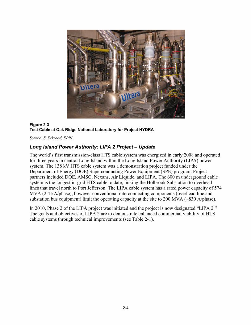
Figure 2-3 Test Cable at Oak Ridge National Laboratory for Project HYDRA
Source: S. Eckroad, EPRI.
Long Island Power Authority: LIPA 2 Project – Update The world’s first transmission-class HTS cable system was energized in early 2008 and operated for three years in central Long Island within the Long Island Power Authority (LIPA) power system. The 138 kV HTS cable system was a demonstration project funded under the Department of Energy (DOE) Superconducting Power Equipment (SPE) program. Project partners included DOE, AMSC, Nexans, Air Liquide, and LIPA. The 600 m underground cable system is the longest in-grid HTS cable to date, linking the Holbrook Substation to overhead lines that travel north to Port Jefferson. The LIPA cable system has a rated power capacity of 574 MVA (2.4 kA/phase), however conventional interconnecting components (overhead line and substation bus equipment) limit the operating capacity at the site to 200 MVA (~830 A/phase).
In 2010, Phase 2 of the LIPA project was initiated and the project is now designated “LIPA 2.” The goals and objectives of LIPA 2 are to demonstrate enhanced commercial viability of HTS cable systems through technical improvements (see Table 2-1).

2-5
Table 2-1 LIPA Phase 2 Design Improvements
Improvement Enhanced Commercial Viability
Cable constructed from 2G HTS tapes to be installed in one of the three phases
Projected to cost less to produce than 1G tapes when commercially mature Provides fault current limiting capabilities
Cable splice joint to be installed in the 2G phase leg
Allows HTS cables to be joined for added length or section repair/replacement at specified voltage and temperature requirements
Field repairable cryostat to be installed around the 2G cable
Cryostat can be repaired in the field if invaded/breached Reparability allows an HTS cable to continue operation (after repair) at a thermal state manageable by the refrigeration system
Advanced refrigeration system
Reduced number of components increases reliability and simplifies maintenance Achieves efficiencies required for HTS cable operation (approximately 20% Carnot at 20kW)
Figure 2-4 LIPA 2 HTS Cable System
Source: AMSC. Used with permission.
During 2012 all system enhancements were completed and the cable was cooled to operating temperature. Commissioning of the system was scheduled for the last week of October 2012. Unfortunately, that was the week that Hurricane Sandy (SuperStorm Sandy) was heading toward the northeastern United States. In a wise move, the testing company decided not to move its
Existing HV Termination
RedundantCooling & Control
Existing Cold Termination
Bulk LN2
Storage
Heat
Power
SCADA
Supply
Return
Replacement 2G Phase
Field Joint
2-6
equipment onto Long Island until after the storm. Now, because of the devastation on Long Island, Nexans (the cable supplier) fears that commissioning will be put off until the first of next year, 2013.5
Tres Amigas – Update Tres Amigas, LLC, a startup, merchant-transmission company based in New Mexico, is leading a project to link the three U.S. electrical grids using AC-to-DC converting stations and high-capacity DC superconducting power lines. Currently, the three grids (Western Electric Coordinating Council, Eastern Interconnect, and the Electric Reliability Council of Texas) operate asynchronously, making it difficult to move large amounts of power from one region to another. The separation of the grids presents a major hurdle to the transport of renewable energy, because it is difficult to move significant power from regions with an abundance of renewable energy to load centers with high electricity demand. Tres Amigas proposes that a common, three-way DC interconnection point between the three grids would allow renewable energies to be used where needed and would stimulate further renewable energy production by providing a path to market.
Originally proposed in 2010, the start date has continually been pushed back due to the complex arrangements with the multiple stakeholders in the project. The first two interconnection agreements – one with the Western System Coordinating Council (WSCC) and the other with the Eastern Interconnect (EI) – should be completed by the end of 2012, enabling a startup date for the facility in early 2014. Interconnection agreements between Texas and the WSCC and EI systems are complicated due to the fact that the Electric Reliability Council of Texas (ERCOT) is not under the jurisdiction of the Federal Energy Regulatory Commission (FERC) as are the eastern and western grids. Interconnection with the rest of the country could jeopardize the independence that ERCOT wishes to retain.
The 750-MW back-to-back dc-dc voltage source converters would be built in phases to accommodate increasing power exchanges over time. Initially, the converters will be interconnected with a conventional dc bus operating at about 300 kV dc. As continued power purchasing agreements are signed load is expected to grow, up to a projected maximum of 5 GW. When load approaches the 3 GW level it is planned to replace the conventional dc bus with dc superconducting cable.6
In September Tres Amigas filed to issue $1.65 B in industrial revenue bonds for construction of its facility some 12 miles north of the city of Clovis, NM. Initial costs for the first 750-MW converter are estimated at $500 M. In a second phase, $400 M would add 2.25 GW to interconnect the Texas grid (ERCOT) with the western and eastern grids. A final phase, at an estimated $1 B, would bring the power level to 5 GW, and would presumably include the superconductors in the dc link. Funding is in place to begin engineering and construction on the first phase, including $12 M from Mitsui & Co., Ltd. a Japanese industrial infrastructure services company. Several engineering firms have been retained by Tres Amigas, including Power Engineers, Burns & McDonnell, and CH2M Hill.7
5 Private communication with Frank Schmidt, Nexans, November 30, 2012. 6 Private communication with Jack McCall, AMSC, October 10, 2012. 7 Scott Blair, Engineering News Record, ENR.com,October 22, 2012.

2-7
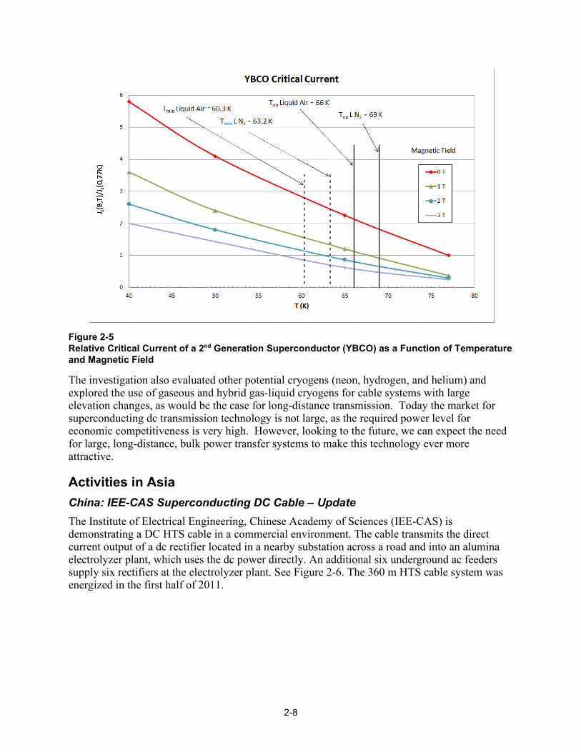
US Navy: Helium Gas Cooled Superconducting DC Cable The Center for Advanced Power Systems (CAPS) is undertaking a feasibility study for the U. S. Navy, which is looking at the desirability and means to achieve an “all electric” warship. Superconducting DC offers a smaller, lighter weight option for power distribution than the other alternatives being considered by the Navy: conventional 60 Hz ac and high frequency (300-400 Hz) ac. Because of the shipboard safety issues associated with liquid nitrogen coolant (accidental release in confined spaces) as well as the additional weight, the preferred cryogen that CAPS is investigating is gaseous helium. To date in this project, a 1 kV, 30-meter monopole 2G HTS dc cable has been fabricated by Southwire and is under test at CAPS. A cooling temperature range of 50 to 77 K is being investigated, temperatures below about 65 K being made possible by the use of helium, which liquefies at an even lower temperature. Because of the increased performance of the superconductor, the lower temperatures are of great interest (see Figure 2-5, which was developed by W. Hassenzahl and is based on a 2G tape produced by Furukawa Superpower8). For example, testing of the cable has shown that at 66 K the cable carries 6 kA, twice its capability at 77 K. On the other hand, the dielectric properties of gaseous helium are not nearly as good as those of liquid nitrogen. Thus, the work at CAPS is investigating these aspects as well as others such as thermo-mechanical issues that arise from the tight bending radii desired by the Navy. A second phase of the project is under discussion. In this a +/- 5 kV bipole cable may be built and tested. Cable configuration (e.g., coaxial versus two monopolar cables) is being debated.9
Electric Power Research Institute: Novel Cryogens In pursuit of its mission to conduct research and development related to the generation, delivery, and use of electricity for the benefit of the public the Electric Power Research Institute (EPRI) explores scenarios that would impact future electricity production, transmission, and use. Thus, in the fall of 2005, EPRI took a long-range view and convened a small workshop on the present and future technology of superconducting long-distance dc power cables. That workshop led to a four year project that is described in EPRI report 1020458, A Superconducting DC Cable, published in 2009[6]. During that study several aspects of the cryogenic system were found to require further development to meet the criteria of being both practical and universally applicable. The cryogenic system described in that report formed the basis for a new study, completed in 2012, in which additional approaches to cryogenic system design are considered [7].
The study extended one aspect of the EPRI design to improve performance and reduce costs. It addresses the issue of using liquid air as the cryogenic fluid that is used to cool the cable. The use of air instead of liquid nitrogen eliminates the potential hazard of oxygen exclusion in contained areas, and allows the system to operate at a lower temperature, which reduces the amount of superconductor required. Figure 2-5, taken from the Reference [7] report, shows the significant impact of even a slightly lower operating temperature on the current carrying capacity of 2G superconductor. 8 See Reference [7]. 9 For the discussion on the Navy project in this section, the author is indebted to Alan Wolsky, Argonne National Laboratory. A more detailed treatment is found in: A.M. Wolsky, Today’s Activity, in the U.S., to Make Economical Superconductor, and Equipment Incorporating it, for the Power Sector, sponsored by the International Energy Agency under the implanting agreement: “Cooperative Programme for Assessing the Impacts of High-Temperature Superconductivity on the Electric Power Sector.”
2-8
Figure 2-5 Relative Critical Current of a 2nd Generation Superconductor (YBCO) as a Function of Temperature and Magnetic Field
The investigation also evaluated other potential cryogens (neon, hydrogen, and helium) and explored the use of gaseous and hybrid gas-liquid cryogens for cable systems with large elevation changes, as would be the case for long-distance transmission. Today the market for superconducting dc transmission technology is not large, as the required power level for economic competitiveness is very high. However, looking to the future, we can expect the need for large, long-distance, bulk power transfer systems to make this technology ever more attractive.
Activities in Asia China: IEE-CAS Superconducting DC Cable – Update The Institute of Electrical Engineering, Chinese Academy of Sciences (IEE-CAS) is demonstrating a DC HTS cable in a commercial environment. The cable transmits the direct current output of a dc rectifier located in a nearby substation across a road and into an alumina electrolyzer plant, which uses the dc power directly. An additional six underground ac feeders supply six rectifiers at the electrolyzer plant. See Figure 2-6. The 360 m HTS cable system was energized in the first half of 2011.

2-9
Figure 2-6 Superconducting DC Cable at Alumina Electrolyzer Plant in China
Source: L. Xiao, IEE-CAS. Used with permission.
This cable is the longest and highest power installed and operating dc superconducting cable in the world at the present time, and is a notable achievement. At 10 kA, it also has the highest current, by nearly a factor of five, over any other cable in the world, ac or de. A somewhat unusual aspect of the cable is the warm dielectric design. The designation “warm dielectric” refers to the fact that the electrical insulation for the cable is outside of the cryogenic enclosure and is thus at the external ambient temperature. Most, if not all, cables since the Detroit Edison cable in the early 2000s have been of a cold dielectric design because this design lends itself to a coaxial conductor plus shield arrangement that eliminates the external magnetic field and provides for a more compact right of way. Magnetic fields degrade the current carrying capacity of a superconductor, so it is necessary to separate the plus and minus poles of a warm dielectric cable by a suitable distance, as shown in Figure 2-6. However, a warm dielectric cable is easier to make since the dielectric is extruded over the cryostat by very conventional cable manufacturing methods and machinery, and the dielectric moreover does not have to perform its function at cryogenic temperatures. In the future, superconductors with increased resistance to external magnetic fields may lead system designers to reconsider warm dielectric cables.
The cryogenic envelope has been divided into 8 segments;; each segment has a standardized joint at each end. The joints are designated type A and type B, such that a type A joint on one segment inserts into a type B joint on the adjoining segment during cable system integration and field assembly. The static heat loss for the envelope is less than 0.8 W/m. A 4 kW Stirling refrigerator with a backup system provides the cooling power. See Figure 2-7.
The four cable terminations are 6.15 m in length and 325 mm in diameter. See Figure 2-8. There are three functional parts: the main body, current lead, and chamber. Modularization is employed such that each functional part is independent. The two vertical assemblies in the figure are the coolant entry and vacuum ports.

2-10
Technical cable system specifications are summarized in Table 3-1.
Table 2-2 IEE-CAS DC Cable Specifications
Characteristic Description
Rated voltage 1.3 kV
Rated capacity 13 MW
Designed critical current ≥ 12,500 A
Rated current ≥ 10,000 A
Length 362.4 m
Outer diameter 151 mm
Minimum bending radius ≥ 3.0 m
Layers of superconductor 5
Total length of superconductor 46 km
Dielectric type Warm dielectric
Heat loss of cryostat ≤ 2 W/m
Total heat loss of system 2487 W
Refrigeration type Stirling Cycle
Refrigeration capacity 4 kW @ 77 K
Cable coolant Liquid Nitrogen

2-11
Figure 2-7 Stirling Refrigerator and Backup System for IEE-CAS Cable
Source: L. Xiao, IEE-CAS. Used with permission.
Figure 2-8 IEE-CAS DC Cable Termination
Source: L. Xiao, IEE-CAS. Used with permission.

2-12
Japan: Furukawa 275 kV Class REBCO Cable Development – Update Furukawa Electric Co., Ltd., in Japan has developed a 275 kV class HTS power cable with a rated capacity of 3 kA (three-phase power is rated 1,500 MVA). A 1 kA prototype of the cable and a single termination was fabricated for voltage and current load tests in 2010 and 2011, as reported in the 2011 Technology Watch. Now a 30-meter, single phase, demonstration cable with outdoor terminations and cooling system has been designed and installed at the Shenyang Furukawa Cable Company Ltd., in Shenyang, China. See Figure 2-9 and Figure 2-10.
Figure 2-9 Layout of the Furukawa 30 m, 275 kV HTS Cable for Demonstration
Source: S. Mukoyama, Furukawa Electric. Used with permission.
Figure 2-10 Furukawa 275 kV, Single-Phase HTS Cable Installed in Shenyang, China
Source: S. Mukoyama, Furukawa Electric. Used with permission.

2-13
Figure 2-11 shows the structure of the single core HTS cable, which is a cold dielectric design using second generation (2G) HTS tapes. Each ac phase leg of the cable consists of a coaxially wound HTS core in a single cryostat pipe. A hollow copper stranded former is wound with two layers of HTS conductor, followed by an electrical insulation layer, a single layer HTS shield, a stabilization copper layer, and a protective jacket. The copper former and the stabilization copper layer provide alternate current paths in the event of a fault leading to an over current on the HTS tapes. The cryostat is constructed of vacuum insulated, coaxial corrugated pipes with multilayer superinsulation to provide the needed flexibility as well as good thermal insulation performance. The protective jacket is a polyethylene sheath similar to conventional power cable.
Figure 2-11 Structure of Furukawa 275 kV, 3 kA YBCO HTS Cable
Source: S. Mukoyama, Furukawa Electric. Used with permission.
The 30-meter cable was installed at the end of September 2012. To confirm satisfactory properties of a 275 kV HTS cable system for utilization in power networks, Furukawa will perform long-term load cycle tests. Furukawa based its testing on the Japanese standard, JEC 3401 and IEC 62067, which are specified for high voltage extruded dielectric cable insulation (there are no corresponding standards, as yet, for HTS cables). The tests listed in Table 2-3 will be performed on a 5 m sample and a completed 30 m cable in the demonstration. The sample will be cut off from the completed cable before shipment.
Much of the electric transmission backbone in Japan operates at 275 kV. At 1,500 MVA, which is roughly the capacity of the average thermal power generator or nuclear power generator, the three-phase 275 kV HTS cable system is the highest power cable system in the world. It would also provide additional capacity for the transmission system where retrofit cable solutions are necessary.

2-14
Table 2-3 Summary of Tests on the Furukawa 275 kV HTS Cable
Item 5 Meter Sample 30 Meter Cable System
AC voltage test 1 310 kV, 10 minutes 310 kV, 10 minutes
DC IC test Electrical 4 probe method Electrical 4 probe method
Long term voltage and current loading test
NA 200 kV, 3 kA for 1 month: 16 hrs On;; 8 hrs Off
Cable loss test NA 150 kV, 3 kA, 4 msec Calorimetric method
Lightning impulse voltage test ± 1155 kV, 3 shots NA
Partial discharge test 310 kV PD measure 310 kV PD measure
AC voltage test 2 320 kV, 15 minutes 320 kV, 15 minutes
AC voltage test 3 400 kV, 30 minutes 400 kV, 30 minutes
Furukawa believes that superconducting technology will be a strong option for solving global environmental problems. They cite10 a number of advantages of their 275 kV, 3 kA HTS cable, including significantly lower transmission losses (see Table 2-4):
• HTS cable has three times capacity of nominal extruded dielectric cable and 1/3 the size • The cost of cable construction is expected to be less • The HV HTS cable seems to be suitable for new infrastructures in developing countries Table 2-4 Furukawa Comparison of Conventional XLPE Cable System with 275 kV HTS Cable System
Item XLPE Cable HTS Cable
Rating voltage 275 kV 275 kV
Rating capacity 1,500 MVA (3 circuit = 9 cables) 1,500 MVA (1 circuit = 3 cables)
Current 1.05 kA X 3 3.15 kA
Transmission loss (including refrigeration in HTS case)
240 kW/km 59 kW/km
Outer diameter 155 mm X 9 cables 150 mm X 3 cables
10 Y. Shirasaka, Furukawa’s Scope of High TC Superconducting Cable Technology, presentation at ISIS-21, Portland, OR, October 4-6, 2012.

2-15
Japan: Yokohama HTS Cable Project – Update The Yokohama Project is the first in-grid HTS cable demonstration in Japan. The installation of the 3 phase 66 kV, 5 kA (200 MVA) HTS power cable system at Tokyo Electric Power Company’s (TEPCO) Asahi substation in Yokohama was temporarily halted following the massive earthquake and subsequent tsunami in March 2011. Sumitomo Electric has manufactured the 250-m HTS cable, which consists of three single-phase coaxial cables in a single cryostat. See Figure 2-12. The cable system links a 154/66 kV transformer to the Asahi substation sub-transmission bus.
The Yokohama demonstration project is sponsored by Japan’s Ministry for Economy, Trade, and Industry (METI) through the New Energy and Industrial Technology Development Organization (NEDO), an organization responsible the development of new energy and conservation technologies for the national government.11 The goal of the project is to execute a long-term cable system evaluation in a commercial power system environment. Besides Sumitomo and METI, the project team includes Tokyo Electric Power Company (TEPCO) as the host utility, and Mayekawa Mfg. Company which is responsible for design, manufacture and installation of the cryogenic refrigeration system.
Figure 2-12 Sumitomo 66 kV Three-In-One HTS Cable
Source: H. Yumura, Sumitomo Electric. Used with permission.
Successful testing of a 30m prototype was completed in 2009 and the 250 m long HTS cable was fabricated in 2010. The cryogenic refrigeration system was installed in February 2011 just prior to the earthquake. Installation of the cable, planned to begin in March 2011, was postponed following the earthquake. Cable resumed in late 2011 and was completed in 2012. Cable cool down has been completed and the cable will be energized in late 2012. Figure 2-13 shows the completed installation.
Prior to shipping the cables to the Asahi substation pre-shipment tests were conducted. The tests included critical current measurement (before and after cable pulling and contraction tests), ac loss measurements, cable bending test and withstand voltage tests. Tests confirmed that the cables met the design requirements.
11 Funding for the project from these organizations is estimated at $33 million (Superconductor Week, Vol 26, No. 20).

2-16
The same installation method was used as for installing conventional underground cables, using a winch to pull the cable into the conduit from the feeding cable drum. At the Asahi substation there is a 180 degree bend with a radius of 5 meters for the HTS cable installation. The installation went smoothly, with the maximum pulling tension recorded at approximately 1.3 tons, less than the design value of 2 tons. A cable-to-cable joint and the terminations completed the cable installation.
Six Stirling refrigerators are installed, each having a cooling power of 1kW@ 77K or 0.8kW@ 67K. In addition, there are two LN2 circulation pumps, and a reservoir tank. The refrigerators are paired and connected in parallel in a redundant configuration so that if one fails the remaining refrigerators will handle the cooling load. By controlling the number of refrigerators in operation the cable inlet temperature is regulated to 69K±1K. For the ease of maintenance or repair, the refrigerators and pumps are designed to be removed from the cooling system without shutting down the system operation. Cable cool down was accomplished gradually first using -100 C and then -150 C nitrogen gas. This step was followed with liquid nitrogen. Cable cool down required three days.
Figure 2-13 Layout and Photos of Completed Installation at TEPCO Asahi (Yokohama) Substation
Source: H. Yumura, Sumitomo Electric. Used with permission.

2-17
An after laying commissioning test was conducted when the cable had been cooled down. The test results are summarized in Table 2-5.
Sumitomo is providing public access to the system performance monitoring system in real time. The web URL for access is: http://global-sei.com/super/cable_e/ingridj.html.
Table 2-5 Commissioning Test Results for Asahi Cable System
Test Item Test Result
System withstand pressure test No leakage up to 0.5 MPaG
IC measurement (conductor) 6.4 kA (DC, defined by 1 µV/cm @ 77.3 K
Heat loss measurement (under no-load condition)
Entire cable system: 2.4 kW @ 69 K
Pressure drop measurement (flow reat: 39 L/min)
Cable section (including joint and terminations): 0.032 MPa
DC withstand voltage test 151.8 kV to earth, 10 minutes, each phase: good
South Korea: Fault Current Limiting Cable Project South Korean researchers have presented preliminary results from design activities for a fault current limiting (FCL) cable.12 The project was carried out by Changwon National University and the Korea Electrotechnology Research Institute (KERI). The research involved development of a simplified model of the HTS cable incorporating heat generation and temperature variation, HTS resistance, and stabilizer resistance. The design of the FCL cable incorporates a stranded core former on which the HTS tapes are wound;; the former provides the fault current path. Various former materials and dimensions were evaluated to determine their effect on resistance variation and temperature rise of the FCL HTS power cable. Researchers found that formers made of brass and stainless steel were the most favorable. The research also looked into recovery times and different cable lengths. The recovery time for brass, for example, was 3.2 minutes.
South Korea: HTS Cable Projects – Update South Korea has had a government supported program in HTS cable development since 2001, beginning with the DAPAS13 program and, since about 2009, the GENI14 program. In 2011, the JeJu Island project was announced, building on the successes of both the DAPAS and GENI programs. DAPAS and GENI projects have focused primarily on cables and fault current limiters at the 22.9 kV, which is the Korean national standard distribution voltage level. These projects have been reported in previous Technology Watch reports, to which the reader is directed (they are also documented in the appendices). To a lesser extent, but now building momentum, DAPAS has been developing and testing a cable operating at 154 kV (1,000 MVA 12 Hwanjun Jung, et al., “Design of Fault Current Limiting HTS Power Cable,” 1JB-04, presented at Applied Superconductivity Conference 2012, Portland, OR. 13 Development of Advanced Power System by Applied Superconductivity Technologies 14 Green Superconducting Electric Power Network at Icheon Substation

2-18
capability), which is the standard subtransmission voltage in Korea (345 kV and 756 kV ac lines constitute the EHV transmission system with the latter utilized for the longest runs from distant nuclear plants to Seoul and other major urban load centers).
Testing of a 100 meter, 154 kV, 1 GVA cable at the Korea Electric Power Company (KEPCO) testing center at Gochang was completed in 2012. The Gochang testing center is near a nuclear power plant and thus is able to supply the level of power needed for these tests. The 154 kV cable was connected into the local 154 kV grid for these tests. The tested cable system included the cable, two terminations, and a cooling system. The cable was load cycle tested at 1.2 Uo (105 kV;; Uo = 89 kV), and cycled successfully for 40 days: on for 8 hours and off for 16 hours. AC dielectric security testing was completed at 1.5 Uo for 30 minutes. Partial discharge (PD) testing at 18.0 MHz and 1.5 Uo during the ac security test showed PD < 5 pico-coulombs (pC). A 2-meter prototype of the cable achieved a dc IC of 5,760 amps at 77 K (average IC per tape was 104.7 A). The estimated dc IC of the cable system at 70 K operating temperature is 8,985 A. Continuing research on the 154 kV HTS cable is planned for completion in about 2015, with commercialization in about 2020.
The JeJu Island project is a “real grid”15 project to strengthen the supply of power to residents and businesses on this medium-sized island off the south coast of South Korea. Both conventional submarine cable and HTS technology will be used in supplying power to the JeJu Island grid. The project duration is 5 years (2011 – 2016) and will attempt to advance the commercialization of superconducting power technology. Project goals additionally include analysis of grid behavior with superconducting ac and dc components and development of best practices for O&M of the system, including the refrigeration components.
The HTS portion of the JeJu Island project includes a 1 kilometer, 154 kV ac cable and a 500 meter, 80 kV dc cable, both located at GumAk Substation on the island. The ± 80 kV (3,125 amp) dc cable will strengthen the 154 kV link between the Hanlim Substation and GumAk and will be completed in 2014. The 154 kV (600 MVA) ac cable, to be completed in 2015, will interconnect to the Anduk Substation and provide additional grid support in that area of the island. A 154 kV (2 kA) superconducting fault current limiter is also under development and slated for deployment at GumAk in 2015. The submarine cable to the mainland is a ± 250 kV (400 MW) dc cable that was completed in 2011. The research budget for this project is $70M. Project participants include KEPCO, KERI, LS Cable, and several universities.
A high voltage dc (HVDC) superconducting cable is also under development. The cable will be ± 250 kV and will operate at 10 kA, providing a power transfer capability of 2.5 GW. The design and construction of the cable core is to be complete by 2014. A stop joint (splice) for extending the transmission distance and gas or epoxy terminations with hybrid current leads will be complete by 2017, according to KERI plans.
15 J. Cho, HTS Power Application in Korea, presentation at the International Superconductivity Industry Summit (ISIS) in Portland, OR, October 5, 2012. ISIS meetings are held every two years at rotating venues in the countries of national affiliation members.
2-19
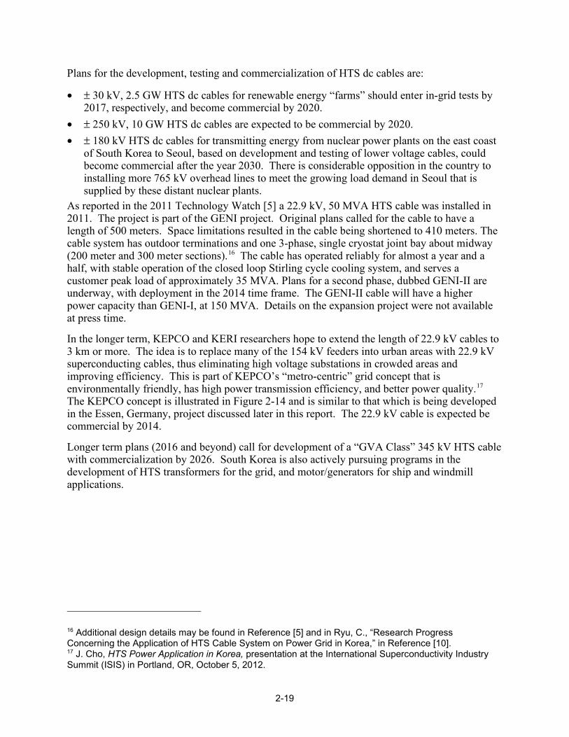
Plans for the development, testing and commercialization of HTS dc cables are:
• ± 30 kV, 2.5 GW HTS dc cables for renewable energy “farms” should enter in-grid tests by 2017, respectively, and become commercial by 2020.
• ± 250 kV, 10 GW HTS dc cables are expected to be commercial by 2020. • ± 180 kV HTS dc cables for transmitting energy from nuclear power plants on the east coast of South Korea to Seoul, based on development and testing of lower voltage cables, could become commercial after the year 2030. There is considerable opposition in the country to installing more 765 kV overhead lines to meet the growing load demand in Seoul that is supplied by these distant nuclear plants.
As reported in the 2011 Technology Watch [5] a 22.9 kV, 50 MVA HTS cable was installed in 2011. The project is part of the GENI project. Original plans called for the cable to have a length of 500 meters. Space limitations resulted in the cable being shortened to 410 meters. The cable system has outdoor terminations and one 3-phase, single cryostat joint bay about midway (200 meter and 300 meter sections).16 The cable has operated reliably for almost a year and a half, with stable operation of the closed loop Stirling cycle cooling system, and serves a customer peak load of approximately 35 MVA. Plans for a second phase, dubbed GENI-II are underway, with deployment in the 2014 time frame. The GENI-II cable will have a higher power capacity than GENI-I, at 150 MVA. Details on the expansion project were not available at press time.
In the longer term, KEPCO and KERI researchers hope to extend the length of 22.9 kV cables to 3 km or more. The idea is to replace many of the 154 kV feeders into urban areas with 22.9 kV superconducting cables, thus eliminating high voltage substations in crowded areas and improving efficiency. This is part of KEPCO’s “metro-centric” grid concept that is environmentally friendly, has high power transmission efficiency, and better power quality.17 The KEPCO concept is illustrated in Figure 2-14 and is similar to that which is being developed in the Essen, Germany, project discussed later in this report. The 22.9 kV cable is expected be commercial by 2014.
Longer term plans (2016 and beyond) call for development of a “GVA Class” 345 kV HTS cable with commercialization by 2026. South Korea is also actively pursuing programs in the development of HTS transformers for the grid, and motor/generators for ship and windmill applications.
16 Additional design details may be found in Reference [5] and in Ryu, C., “Research Progress Concerning the Application of HTS Cable System on Power Grid in Korea,” in Reference [10]. 17 J. Cho, HTS Power Application in Korea, presentation at the International Superconductivity Industry Summit (ISIS) in Portland, OR, October 5, 2012.

2-20
Figure 2-14 DAPAS Long-Term Vision of KEPCO Grid
Source: A New Project on Applying 22.9kV HTS Cables and SFCL to KEPCO Power Grid, 2008 EPRI Superconductivity Conference, Nov 11, 2008. Oak Ridge, TN. Used with permission.
Activities in Europe Germany: City of Essen AmpaCity Project The AmpaCity project is a new HTS cable plus fault current limiter planned for the city of Essen, Germany. It will be the first combination of cable plus fault current limiter in the European grid. The project sponsors are RWE Deutschland (the local utility company), Nexans Superconductors, and the Karlsruhe Institute of Technology (KIT). The project has resulted from a study conducted in 2011 in which the sponsors investigated the possibility of replacing an aging high/medium-voltage (110 kV / 10 kV) transmission/distribution infrastructure in the center of Essen with lower voltage (10 kV) HTS cables.18 The HTS cable option would reduce the number of inner city substations with large, oil-filled transformers and the number of high voltage transmission lines, saving space for commercial development. An economic analysis showed that the 10 kV HTS system was 9.2% lower in cost compared to the option of replacing portions of the 110 kV conventional transmission system. The HTS option was 6.8% higher than the cost of renovating the medium voltage system. Without an HTS option, the preferred path would have been to replace the aging medium voltage cables. The HTS system was preferred because it offers lower energy losses and requires less space than the conventional 10 kV system.
As a result of the positive findings of the study, a decision was taken to retrofit a portion of the medium voltage grid between two inner city substations in Essen with a 10 kV HTS cable system. The HTS cable system will eliminate one HV transformer at the Dellbruegge Substation and one 110 kV line between the Dellbruegge and Herkules Substations. See Figure 2-15. Both the new HTS cable and the replaced 110 kV line carry 40 MW. In addition a spare transformer vault at Herkules can be used for the FCL and the cooling system, saving additional space. At 1 km, the cable will be the longest HTS cable installation in the world.
18 Stemmle, et al., “Novel Grid concepts for Urban Area Power Supply,” Physics Procedia, 36 (2012) 884 -889.
22.9 kVSW/S
22.9 kV Superconducting Cablesto replace 154 kV conventional cables
~
154 kV S/S in the suburbs
SFCL
SFCL
SFCL
22.9 kVSW/S
22.9 kV Superconducting Cablesto replace 22.9kV conventional cables
Superconducting Transformers
22.9 kVSW/S
Downtown Area
Circuit Breaker(Normal open)
22.9 kVSW/S
22.9 kV Superconducting Cablesto replace 154 kV conventional cables
~
154 kV S/S in the suburbs
SFCL
SFCL
SFCL
22.9 kVSW/S
22.9 kV Superconducting Cablesto replace 22.9kV conventional cables
Superconducting Transformers
22.9 kVSW/S
Downtown Area
Circuit Breaker(Normal open)

2-21
Figure 2-15 Electrical Configuration Changes by Employing HTS Cable
Source: M. Stemmle, Nexans. Used with permission.
The project was started in September 2011. The installation of the cable system is expected to be complete by the 3rd Quarter of 2013, with commissioning in the 4th Quarter. Sponsors plan for a project duration of 4.5 years, during which the technical operation advantages will be evaluated. Experience will also be gained in the assessment of further HTS cable and fault current limiter (FCL) applications. If successful, larger sections of the city may be converted to the lower voltage network afforded by the HTS cables. Funding of €6 million (~$8 million) for the approximately €13.5 million ($18 million) project came from the German Federal Ministry of Economics and Technology.19 Project sponsors are funding the balance.
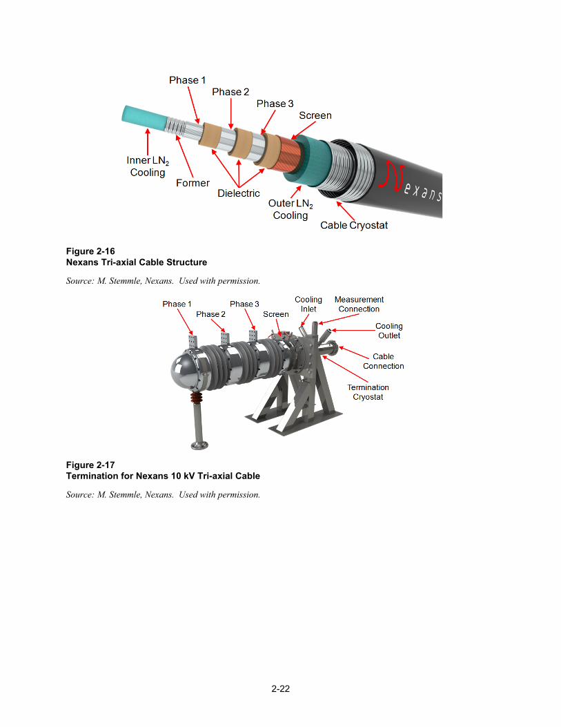
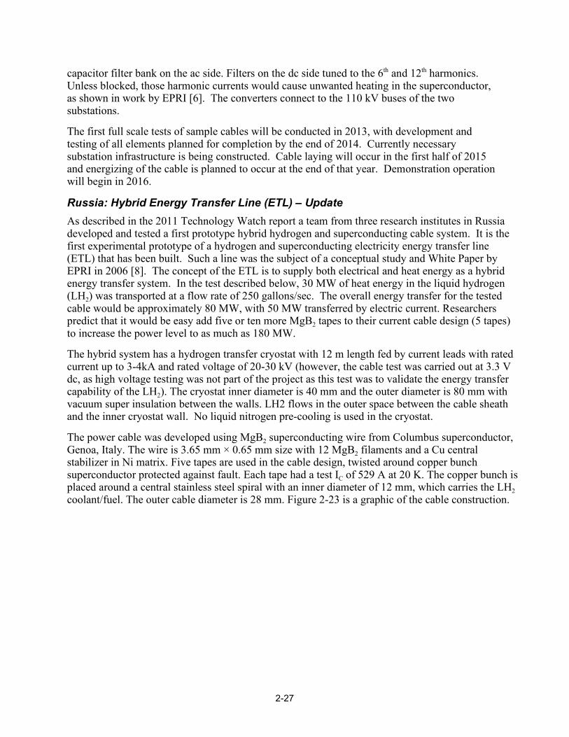
Nexans will supply the 10 kV tri-axial design cable, which will have a rated current capacity of 2.3 kA. The superconductor in the cable will be Generation 1 (1G) BSCCO in order to reduce costs. There is one HTS layer per phase. A compact termination has been designed and is only 2.3 meters in length. The cable core is manufactured at Nexans’ Halden, Norway, cable factory and assembled into the cryostat in Hanover, Germany. A 30-meter pre-prototype cable with some HTS tapes has been tested at the Hanover test facility. A prototype cable with a joint will be manufactured and tested in the 4th Q 2012. Figure 2-16 and Figure 2-17 show the cable structure and termination concept, respectively. Figure 2-18 shows the pre-prototype cable under test.
19 Superconductor Week, Volume 26, No. 2.
2-22
Figure 2-16 Nexans Tri-axial Cable Structure
Source: M. Stemmle, Nexans. Used with permission.
Figure 2-17 Termination for Nexans 10 kV Tri-axial Cable
Source: M. Stemmle, Nexans. Used with permission.

2-23
Figure 2-18 Nexans Tri-axial Cable and Termination Pre-Prototype Test Set Up
Source: M. Stemmle, Nexans. Used with permission.
The Essen project cooling system uses sub-cooled, pressurized liquid nitrogen in an open cycle arrangement, because it has lower operating costs and high reliability and availability. However, it is acknowledged that the large liquid nitrogen tank required may create visual problems in the future. Figure 2-19 shows the cooling system, which produces 4 KW at 67 K.
Figure 2-19 AmpaCity Project Cooling System
Source: M. Stemmle, Nexans. Used with permission.
The cable system will employ a superconducting fault current limiter (SFCL) at the Herkules Substation end to mitigate the potential for through faults to cause the cable to quench. Unlike the cable, the SFCL will employ 2G YBCO tapes in its construction. There are two options for the cryostat: either each phase in its own cryostat or all three phases in one cryostat. These are shown in Figure 2-20. Table 2-6 provides the design and performance details on the SFCL.

2-24
Figure 2-20 Cryostat Choices for AmpaCity Project Superconducting Fault Current Limiter
Source: M. Stemmle, Nexans. Used with permission.
Table 2-6 Design and Performance Parameters for AmpaCity Superconducting Fault Current Limiter
Parameter Value
Rated power 40 MVA
Rated voltage 10 kV
Rated current 2.3 kA
Lightning impulse withstand voltage 75 kV
Power frequency withstand voltage 28 kV
Prospective peak shjort circuit current 50 kA
Prospective short circuit current 20 kA
Limited peak short circuit current < 13 kA
Limited short circuit current < 5 kA
Limitation time 100 msec
Netherlands: Alliander Cable Project – Update This project has been put on hold due to the economic downturn in Europe. See the 2011 EPRI Technology Watch for project details. [5]

2-25
Russia: St. Petersburg, HTS DC Cable Project In work sponsored by the Federal Grid Company of Unified Energy System (FGC UES) researchers have begun a project to develop, build and install a dc superconducting cable in a central city region of St. Petersburg, Russia.20 The work is being carried out by the Research and Design Center of the FGC UES. The goals of the project are:
• Investigate design of a HTS DC link - 20kV, 50 MW for St. Petersburg network. • Create a scientific – production cooperation for the manufacturing of HTS dc cables, splices, convertors and cryogenic equipment.
• Create and demonstrate a HTS DC link. The intention of the project is to enhance the reliability of electric power supply and to limit fault currents in central section of St. Petersburg.
Investigations of the grid in more than ten scenarios showed that in the central region of the city there is the potential for a number of post fault system oscillation modes that result in power supply interruption. It was further shown that strengthening the system with a conventional XLPE cable or gas-insulated line (GIL) between two downtown substations (SS RP-9 and SS Tsentralnaya) worsened the post-fault modes because of additional current overloads in adjacent transmission lines and substations. Figure 2-21 is a diagram of the network in the center city region. The HTS dc cable option, with ac-dc converters, avoided these scenarios and furthermore strengthened the system.
Figure 2-21 Network Diagram in St. Petersburg, Russia, Showing Placement of HTS DC Cable
Source: V.E. Sytnikov, FGC UEC. Used with permission.
The HTS dc cable design that was chosen is a unipolar cable with a concentrically wound, superconducting return current layer, very similar to the dc cable designed by EPRI [6]. The 20 V.E. Sytnikov, et al., “HTS DC Cable line Project: On-going Activities in Russia,” Paper 3LB-02, presented at Applied Superconductivity Conference 2012, Portland, OR.

2-26
forward conductor operates at 20 kV and the return conductor is grounded at the RP-9 Substation. Thus, this is a coaxial cable that has no external electromagnetic field – beneficial for a downtown location. The cable structure is shown in Figure 2-22. The rated current of the proposed cable is 2.5 kA at 20 kV. As shown in Figure 2-21 it will interconnect the two downtown substations mentioned above. The approximate 2,500 meter cable will carry 50 MW. There will be five splice joints, for an average segment length of 500 meters. The cable will be buried to a depth of 10 meters.
Figure 2-22 Diagram of HTS DC Cable for St. Petersburg, Russia
Source: V.E. Sytnikov, FGC UEC. Used with permission.
The cable will use 1G BSCCO superconducting wire supplied by Sumitomo, type HT-CA. The forward conductor has 22 tapes with an IC = 160 A placed in two layers. The return conductor used 19 tapes in a single layer with IC = 180 A. A five-meter prototype of the cable demonstrated an IC of ~4.5 kA at 77.4 K.
The cable is cooled with an open-loop pressurized liquid nitrogen system that supercools the LN2 to 65 K for delivery to the cable. The coolant return temperature is about 75 K. It was determined that over the 2.5 km length of the cable a temperature drop of < 6 K was acceptable. The Nexans supplied cryostat for both the cable and the return coolant line has inside diameter of 64 mm that gives a pressure drop of 5 – 6 Bar in each at a flow rate of about 50 liters/min.
The dc cable is interconnected between two 12-pulse network commutated current-source converters, similar to those used in conventional HVDC overhead transmission links. Reactive power compensation and filtering of higher harmonics from the converters is performed with a
2-27
capacitor filter bank on the ac side. Filters on the dc side tuned to the 6th and 12th harmonics. Unless blocked, those harmonic currents would cause unwanted heating in the superconductor, as shown in work by EPRI [6]. The converters connect to the 110 kV buses of the two substations.
The first full scale tests of sample cables will be conducted in 2013, with development and testing of all elements planned for completion by the end of 2014. Currently necessary substation infrastructure is being constructed. Cable laying will occur in the first half of 2015 and energizing of the cable is planned to occur at the end of that year. Demonstration operation will begin in 2016.
Russia: Hybrid Energy Transfer Line (ETL) – Update As described in the 2011 Technology Watch report a team from three research institutes in Russia developed and tested a first prototype hybrid hydrogen and superconducting cable system. It is the first experimental prototype of a hydrogen and superconducting electricity energy transfer line (ETL) that has been built. Such a line was the subject of a conceptual study and White Paper by EPRI in 2006 [8]. The concept of the ETL is to supply both electrical and heat energy as a hybrid energy transfer system. In the test described below, 30 MW of heat energy in the liquid hydrogen (LH2) was transported at a flow rate of 250 gallons/sec. The overall energy transfer for the tested cable would be approximately 80 MW, with 50 MW transferred by electric current. Researchers predict that it would be easy add five or ten more MgB2 tapes to their current cable design (5 tapes) to increase the power level to as much as 180 MW.
The hybrid system has a hydrogen transfer cryostat with 12 m length fed by current leads with rated current up to 3-4kA and rated voltage of 20-30 kV (however, the cable test was carried out at 3.3 V dc, as high voltage testing was not part of the project as this test was to validate the energy transfer capability of the LH2). The cryostat inner diameter is 40 mm and the outer diameter is 80 mm with vacuum super insulation between the walls. LH2 flows in the outer space between the cable sheath and the inner cryostat wall. No liquid nitrogen pre-cooling is used in the cryostat.
The power cable was developed using MgB2 superconducting wire from Columbus superconductor, Genoa, Italy. The wire is 3.65 mm × 0.65 mm size with 12 MgB2 filaments and a Cu central stabilizer in Ni matrix. Five tapes are used in the cable design, twisted around copper bunch superconductor protected against fault. Each tape had a test IC of 529 A at 20 K. The copper bunch is placed around a central stainless steel spiral with an inner diameter of 12 mm, which carries the LH2 coolant/fuel. The outer cable diameter is 28 mm. Figure 2-23 is a graphic of the cable construction.

2-28
Figure 2-23 Hydrogen Cooled MgB2 Superconducting DC Cable
Source: V.S. Vysotsky, VNIIKP. Used with permission.
The transport system was test filled with liquid hydrogen (LH2) from a storage tank. The hydrogen flow rate was from 2 to 7 g/sec under pressure ranging from 0.15 to 0.45 MPa. Temperatures varied from 20 to 26 K during the test. The total cooling time was ~ 380 seconds, using about 2.3 kg of LH2. Estimated heat losses in the cryostat were less than 10 W/m. In the 2,600-amp dc current leads the losses were about 300 watts. The liquid hydrogen was not recirculated but was simply ignited and burned at the other end of the cable, emphasizing the dual purpose of the ETL. Figure 2-24 shows a photograph of the test cable and the test stand.
The voltage/current characteristics of the cable were measured at different temperatures and critical currents were determined by the 1 µV/cm voltage criterion commonly used in the industry. At 20 K the critical current of the cable was more than 2600 A and at 26 K the critical current was more than 2000 A. This confirms that the superconducting properties of MgB2 can be used for high-current power cables. The next steps are being discussed and would include higher voltages, longer transfer lines and flexible cryostats of differing design.21
21 Superconductor Week, June 30, 2012.
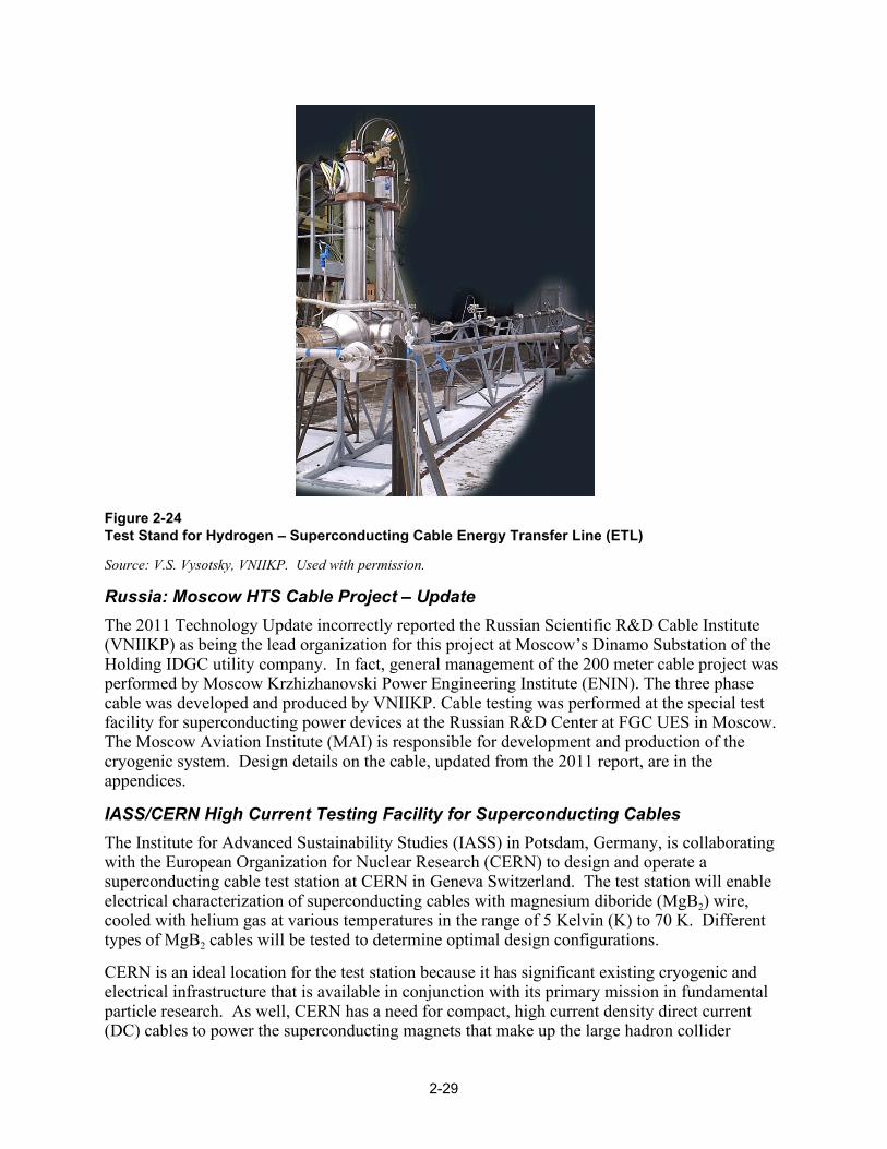
2-29
Figure 2-24 Test Stand for Hydrogen – Superconducting Cable Energy Transfer Line (ETL)
Source: V.S. Vysotsky, VNIIKP. Used with permission.
Russia: Moscow HTS Cable Project – Update The 2011 Technology Update incorrectly reported the Russian Scientific R&D Cable Institute (VNIIKP) as being the lead organization for this project at Moscow’s Dinamo Substation of the Holding IDGC utility company. In fact, general management of the 200 meter cable project was performed by Moscow Krzhizhanovski Power Engineering Institute (ENIN). The three phase cable was developed and produced by VNIIKP. Cable testing was performed at the special test facility for superconducting power devices at the Russian R&D Center at FGC UES in Moscow. The Moscow Aviation Institute (MAI) is responsible for development and production of the cryogenic system. Design details on the cable, updated from the 2011 report, are in the appendices.
IASS/CERN High Current Testing Facility for Superconducting Cables The Institute for Advanced Sustainability Studies (IASS) in Potsdam, Germany, is collaborating with the European Organization for Nuclear Research (CERN) to design and operate a superconducting cable test station at CERN in Geneva Switzerland. The test station will enable electrical characterization of superconducting cables with magnesium diboride (MgB2) wire, cooled with helium gas at various temperatures in the range of 5 Kelvin (K) to 70 K. Different types of MgB2 cables will be tested to determine optimal design configurations.
CERN is an ideal location for the test station because it has significant existing cryogenic and electrical infrastructure that is available in conjunction with its primary mission in fundamental particle research. As well, CERN has a need for compact, high current density direct current (DC) cables to power the superconducting magnets that make up the large hadron collider
2-30
(LHC). For that application, MgB2 offers a substantial performance improvement over other options at reasonable cost. The collaborative support from IASS is in conjunction with its mission to explore the possibility of using MgB2 for long distance, superconducting DC transmission of renewable power.
The test station is located in the SM-18 Laboratory at CERN where it is supported with a 20 kA DC power supply, a 6 kW liquid helium (LHe) refrigerator and a 25,000 liter LHe dewar. There are dedicated data acquisition, control and quench protection systems available.
The test station was commissioned in July 2012 and is undergoing preparation for its first test at press time. The first object will be the testing of a 20-meter MgB2 cable which has recently been constructed and is installed in the station. The cable is designed for operation at up to 20 kA (but at low voltage). The first tests will be in the temperature range from 5 K to 39K (which is the transition temperature for MgB2). The cable performance will be studied in nominal and transient conditions. Later, longer lengths – up to 60 meters – and vertical configurations will be tested as well.

3-1
3 SUPERCONDUCTING FAULT CURRENT LIMITERS Activities in the Americas There were no new projects in superconducting fault current limiters in the U.S. One current project is continuing and one was completed. An update is given on the plans to market a high voltage limiter by one U.S. developer.
Project HYDRA – Update This is a superconducting fault cable that also acts as a fault current limiter. The project is ongoing. See Section 2, Cables, for details.
AMSC/Siemens 138 kV “SuperLimiterTM” HV FCL – Update The “SuperLimiterTM” is a high voltage hybrid resistive superconductor fault current limiter (FCL) developed by AMSC and Siemens under a U.S. DOE program to provide incentives to the commercial development of superconducting technology. The FCL was to have been installed by Southern California Edison (SCE), a partner in the DOE-sponsored project, at their Devers Substation near Riverside, CA. As of 2011, a single-phase prototype had been constructed and tested. However, in 2011, the 50% funding from the DOE program to proceed with fabrication and installation at SCE of a complete 3-phase system was put on hold;; in 2012 the DOE program was completely cancelled. As a result the other project participants (Nexans, LANL1, and TcSUH,2 in addition to those already mentioned) decided to discontinue the project. The project has been reported in previous EPRI Technology Watch reports, [4] and [5]. A summary description of the device is given below as well as some graphics not previously published.
The SuperLimiterTM utilizes modular superconductor elements, which can be assembled to rather precise current limiting specifications. The hybrid design depends on the superconductor to limit the fault initially and then uses a fast operating switch to remove the superconductor from the circuit after it has quenched. After the switch opens, a conventional air-core reactor that is in parallel with the superconducting element carries the current. The superconducting module allows for fast reduction of the fault current (< 1 cycle), while the switch and air-core reactor provide long-duration limiting. This method reduces the amount of heating in the superconductor module, which speeds up the re-cooling process after a fault, thereby reducing the time required to return to normal operation after a limiting action. Figure 3-1 shows a schematic of the device and how it operates. The table in Table 3-1 summarizes key specifications for the SuperLimiterTM. Designed for 138 kV, the device that would have been tested at SCE was to be 115 kV.
1 Los Alamos National Laboratory 2 Texas Center for Superconductivity at the University of Houston
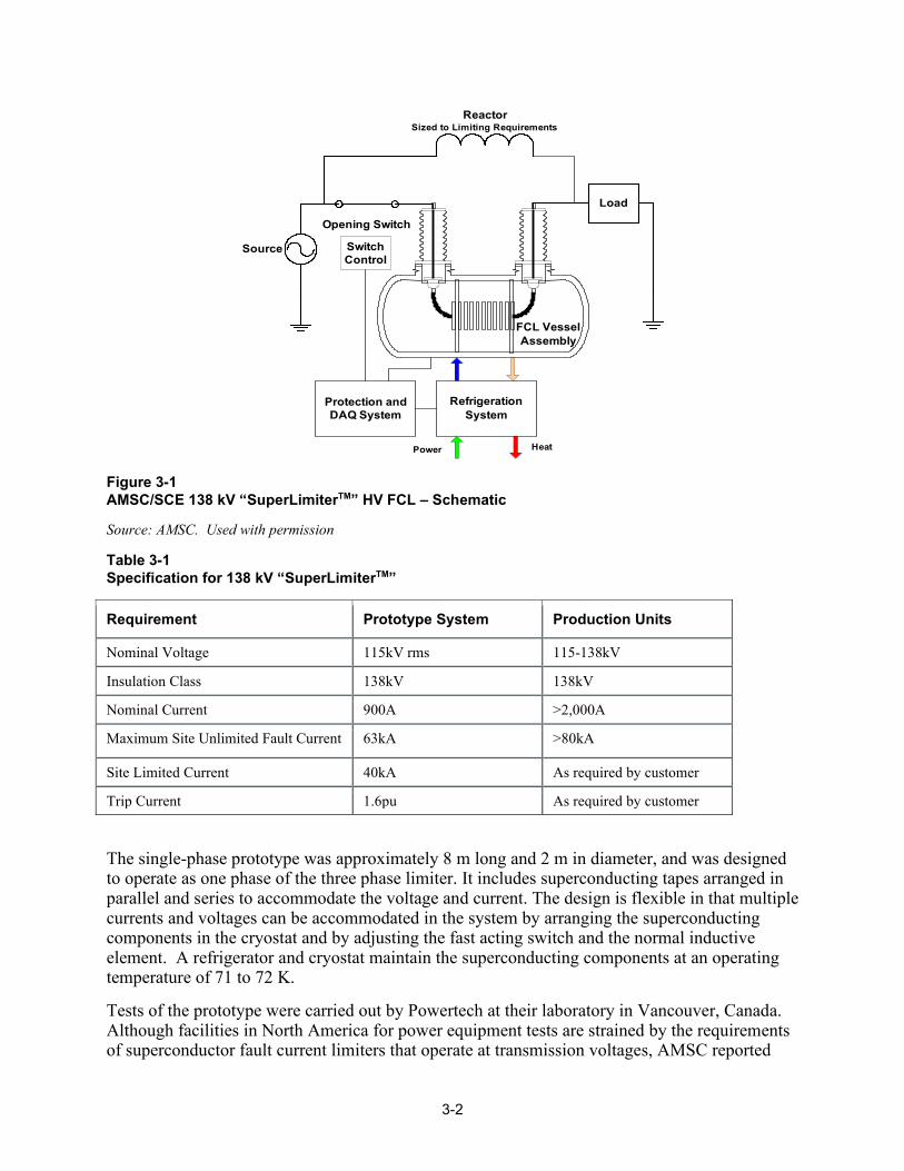
3-2
Figure 3-1 AMSC/SCE 138 kV “SuperLimiterTM” HV FCL – Schematic
Source: AMSC. Used with permission
Table 3-1 Specification for 138 kV “SuperLimiterTM”
Requirement Prototype System Production Units Nominal Voltage 115kV rms 115-138kV Insulation Class 138kV 138kV Nominal Current 900A >2,000A Maximum Site Unlimited Fault Current 63kA >80kA Site Limited Current 40kA As required by customer Trip Current 1.6pu As required by customer
The single-phase prototype was approximately 8 m long and 2 m in diameter, and was designed to operate as one phase of the three phase limiter. It includes superconducting tapes arranged in parallel and series to accommodate the voltage and current. The design is flexible in that multiple currents and voltages can be accommodated in the system by arranging the superconducting components in the cryostat and by adjusting the fast acting switch and the normal inductive element. A refrigerator and cryostat maintain the superconducting components at an operating temperature of 71 to 72 K.
Tests of the prototype were carried out by Powertech at their laboratory in Vancouver, Canada. Although facilities in North America for power equipment tests are strained by the requirements of superconductor fault current limiters that operate at transmission voltages, AMSC reported
Refrigeration System
Power Heat
FCL Vessel Assembly
Protection and DAQ System
ReactorSized to Limiting Requirements
Opening Switch
Source
Load
SwitchControl
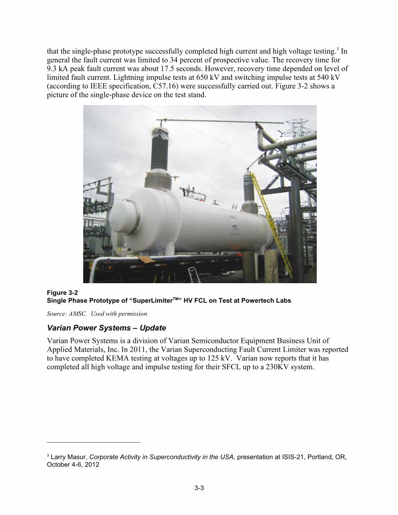
3-3
that the single-phase prototype successfully completed high current and high voltage testing.3 In general the fault current was limited to 34 percent of prospective value. The recovery time for 9.3 kA peak fault current was about 17.5 seconds. However, recovery time depended on level of limited fault current. Lightning impulse tests at 650 kV and switching impulse tests at 540 kV (according to IEEE specification, C57.16) were successfully carried out. Figure 3-2 shows a picture of the single-phase device on the test stand.
Figure 3-2 Single Phase Prototype of “SuperLimiterTM” HV FCL on Test at Powertech Labs
Source: AMSC. Used with permission
Varian Power Systems – Update Varian Power Systems is a division of Varian Semiconductor Equipment Business Unit of Applied Materials, Inc. In 2011, the Varian Superconducting Fault Current Limiter was reported to have completed KEMA testing at voltages up to 125 kV. Varian now reports that it has completed all high voltage and impulse testing for their SFCL up to a 230KV system.
3 Larry Masur, Corporate Activity in Superconductivity in the USA, presentation at ISIS-21, Portland, OR, October 4-6, 2012

3-4
The Varian limiter uses a modular approach that is highly scalable and reliable, leveraging and Applied Materials many years of experience in developing and commercializing continuous process high voltage systems. It utilizes a superconductor technology in a modular and compact platform to maximize reliability and scales from distribution to transmission voltages up to 230KV. These devices insert no significant impedance during normal operations but in fault condition the system responds instantly by adding sufficient impedance on the line to reduce the first peak and subsequent fault currents by 20–80 percent (as specified by customers). Further details on the Varian SFCL are in [5]. Varian Power Systems is currently looking for utility partners to trial their fault current limiters.
Activities in Asia China: Shanghai 10kV SCFCL The Science and Technology Commission of Shanghai Municipality (STCSM) has sponsored a project to design, test, and install in a substation a 10 kV resistive type superconducting fault current limiter (SFCL). The modeling and design work was done by the State Energy Smart Grid R&D Center of the Shanghai Jiao Tong University (SJTU) in Shanghai. Module design was completed in December 2011 and fabrication of a 10 kV, 400 A single-phase prototype completed in September 2012. For the balance of 2012, researchers at SJTU will test the performance, including the operation of the cryogenic system and the recovery time for the prototype. A photo of the prototype on test is shown in Figure 3-3.
Figure 3-3 Single-Phase Prototype of 10 kV Shanghai Resistive SFCL
Source: Z. Hong, Shanghai Jiao Tong University. Used with permission.

3-5
The YBCO tapes for the SFCL are prepared by SJTU using a pulsed laser deposition (PLD) method. For the FCL application they are cut in 1.1 meter lengths. Width is 10 mm. The measured IC to date is about 150 A.
Key features of the current limiting module are:
• 12 tapes (200A) or 24 tapes (400A) in one module • 800 A with higher Ic tapes • Clamp and solder between YBCO and copper terminals • 15 modules/phase to build 10 kV FCL A diagram of how the modules are constructed is shown in Figure 3-4.
Figure 3-4 Structure of Modules for 10 kV Shanghai Resistive SFCL
Source: Z. Hong, Shanghai Jiao Tong University. Used with permission.
Design validation of the prototype components to date has included evaluating cryostat losses and dielectric capabilities of the liquid nitrogen, voltage withstand of the tapes during quench, mechanical stability, and current limiting performance. Recovery under load and no-load conditions has been estimated to be about 3 – 4 seconds.
In March 2013, a 10 kV, 400 A 3-phase unit will be installed in a substation on Chongming Island in Shanghai. Table 3-2 lists the specifications for the Shanghai SFCL.

3-6
Table 3-2 Design Parameters for Shanghai 10 kV Resistive Fault Current Limiter
Parameter Value
Voltage 10 kV
Current 400 A
Height 2.3 m
Diameter 1.2 m
Weight 1.5 tones
Tape usage 360m/phase
Total losses 170 W
Voltage drop < 1 V
Prospective fault current 20 kA
Limited fault current 6 kA ~14 kA Adjustable
Duration of fault < 200 ms
Current limited 30%~70%
Recovery time (no load) 0.3~3.2 s
Recovery time (under load) 0.8~3.8 s
China: 220 kV Iron-Core SFCL in Tianjin Substation The EPRI 2009 Technology Watch reported on a 35 kV saturated iron core superconducting fault current limiter (SI-SCFL) developed by Innopower and installed at Puji Substation. [2] Building on the success of that project, Innopower has continued its R&D efforts on this technology with a project begun in 2008 to develop and test in the grid a 220 kV SI-SFCL project.
The 220 kV SFCL has the same operating principle and basic structural configuration as the 35 kV one, but significant differences exist between these two devices. The 35 kV SI-SFCL used ry type electrical insulation, which is appropriate for medium voltage equipment of this kind. However, at transmission voltages oil insulation is required. Other innovative changes included the use of FRP for the oil tanks, three separated oil tanks, each containing only one phase of ac coils, and a new dc magnetization scheme that was introduced to shorten the magnetization run-up time. The working principle of a saturated core SFCL is well described, and compared with resistive and other superconducting FCLs, in the EPRI 2010 Technology Watch [4]. Figure 3-5 below, from that report, illustrates the principle of operation. Table 3-3 gives the key specifications of the 220 kV / 300 MVA SI-SFCL.

3-7
Figure 3-5 Operation of a Saturable-Core SFCL
Table 3-3 Key Specifications of The 220 Kv / 300 MVA SI-SFCL
Parameters Specifications
Rated voltage (kv) 220
Rated current (A) 800
Operation frequency (Hz) 50
Voltage drop at power transmission <1.25%
Max. Prospective fault current (ka) 50
Max. Prospective fault current (ka) 30
Limiting action delay None
Magnetization recover time (msec) <500
Electric insulation A
Total weight (ton) 120
Installation volume (L×W×H)( m) 8×8×9
Figure 3-6 is a schematic of the 220 kV SISFCL, and shows the three major parts in the main body:
• DC superconductor coil with its dewar, • Iron cores • AC coils with oil tanks As shown in the schematic, six iron frames are radially placed to form a hexagonal backbone. At the center, these comprise six iron limbs in a vertical column around which the superconducting DC coil is wound. A single phase coil consists of two adjacent AC windings connected in series in one oil tank (refer to Figure 3-5 for additional understanding). There are two holes in each oil tank, through each one of which one iron limb from each of the two frames comprising that
ILineac coils
dc source
dc coil
Iron cores
ILineV1 V2
v1
v2
iDC
H(iDC)t
v1(dB1/dt)
v1 + v2
H1
B1
H2
B2
t
v2(dB2/dt)
L1
L2
iLINE
iLINE
v1
v2
iDC
H(iDC)t
v1(dB1/dt)
v1 + v2
H1
B1
H2
B2
t
v2(dB2/dt)
L1
L2
iLINE
iLINE
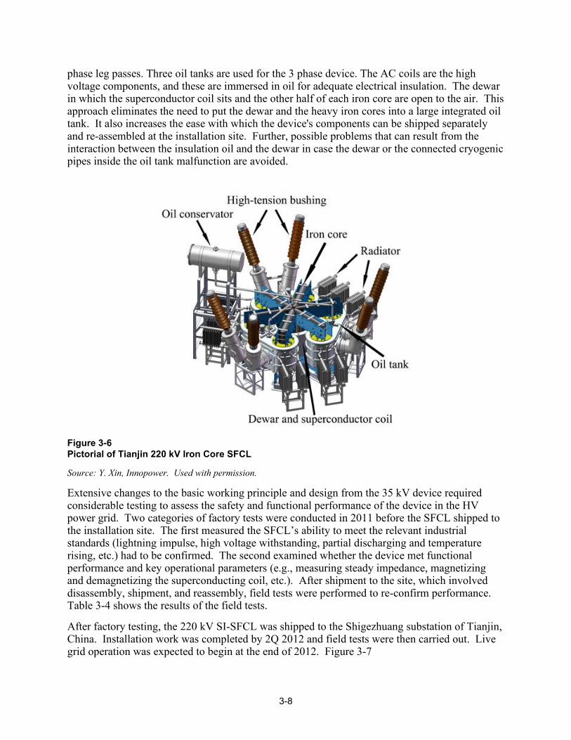
3-8
phase leg passes. Three oil tanks are used for the 3 phase device. The AC coils are the high voltage components, and these are immersed in oil for adequate electrical insulation. The dewar in which the superconductor coil sits and the other half of each iron core are open to the air. This approach eliminates the need to put the dewar and the heavy iron cores into a large integrated oil tank. It also increases the ease with which the device's components can be shipped separately and re-assembled at the installation site. Further, possible problems that can result from the interaction between the insulation oil and the dewar in case the dewar or the connected cryogenic pipes inside the oil tank malfunction are avoided.
Figure 3-6 Pictorial of Tianjin 220 kV Iron Core SFCL
Source: Y. Xin, Innopower. Used with permission.
Extensive changes to the basic working principle and design from the 35 kV device required considerable testing to assess the safety and functional performance of the device in the HV power grid. Two categories of factory tests were conducted in 2011 before the SFCL shipped to the installation site. The first measured the SFCL’s ability to meet the relevant industrial standards (lightning impulse, high voltage withstanding, partial discharging and temperature rising, etc.) had to be confirmed. The second examined whether the device met functional performance and key operational parameters (e.g., measuring steady impedance, magnetizing and demagnetizing the superconducting coil, etc.). After shipment to the site, which involved disassembly, shipment, and reassembly, field tests were performed to re-confirm performance. Table 3-4 shows the results of the field tests.
After factory testing, the 220 kV SI-SFCL was shipped to the Shigezhuang substation of Tianjin, China. Installation work was completed by 2Q 2012 and field tests were then carried out. Live grid operation was expected to begin at the end of 2012. Figure 3-7
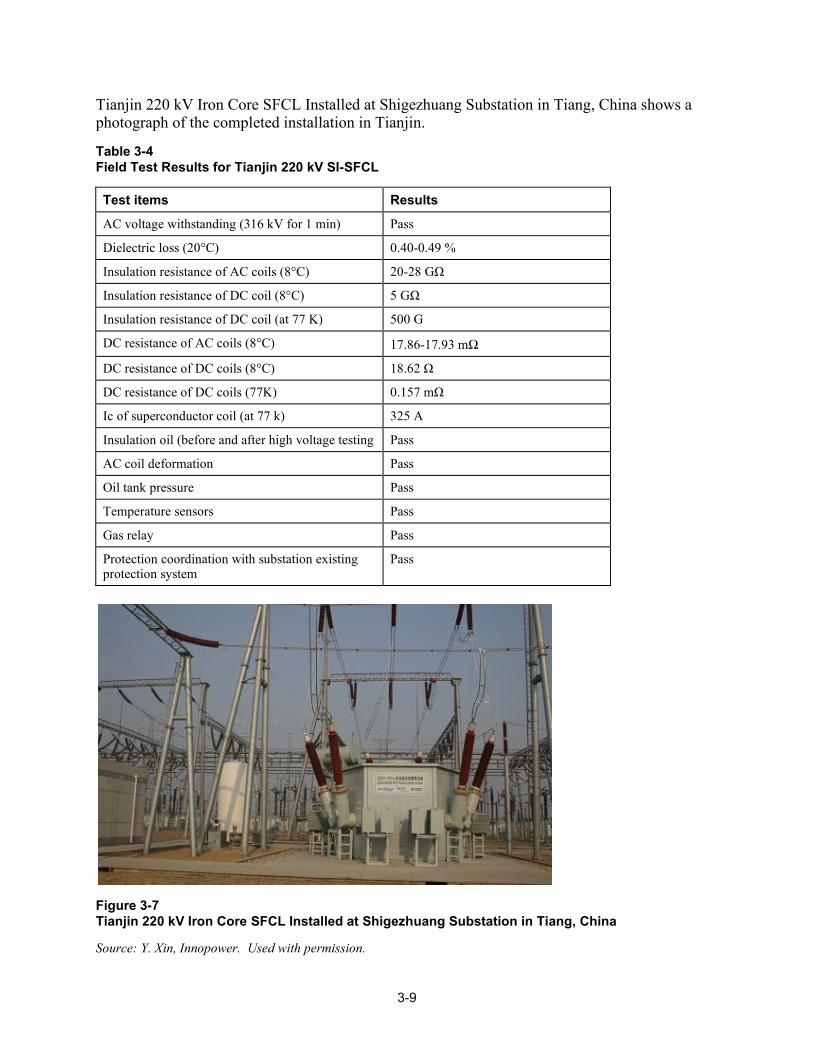
3-9
Tianjin 220 kV Iron Core SFCL Installed at Shigezhuang Substation in Tiang, China shows a photograph of the completed installation in Tianjin.
Table 3-4 Field Test Results for Tianjin 220 kV SI-SFCL
Test items Results
AC voltage withstanding (316 kV for 1 min) Pass
Dielectric loss (20°C) 0.40-0.49 %
Insulation resistance of AC coils (8°C) 20-28 G
Insulation resistance of DC coil (8°C) 5 G
Insulation resistance of DC coil (at 77 K) 500 G
DC resistance of AC coils (8°C) 17.86-17.93 mΩ
DC resistance of DC coils (8°C) 18.62
DC resistance of DC coils (77K) 0.157 m
Ic of superconductor coil (at 77 k) 325 A
Insulation oil (before and after high voltage testing Pass
AC coil deformation Pass
Oil tank pressure Pass
Temperature sensors Pass
Gas relay Pass
Protection coordination with substation existing protection system
Pass
Figure 3-7 Tianjin 220 kV Iron Core SFCL Installed at Shigezhuang Substation in Tiang, China
Source: Y. Xin, Innopower. Used with permission.

3-10
Korea: SFCL Projects at I’cheon and JeJu Island – Update The 2009 EPRI Technology Watch [2] first reported on a hybrid4 superconducting fault current limiter (SFCL) being designed for installation at I’cheon Substation. This was part of the DAPAS project reported on earlier in Chapter 2, under the section on HTS cable projects in Korea.
As reported in [2], KEPCO has longer term plans to increase its sub-transmission capacity by upgrading 154/22.9 kV, 60 MVA transformers to 100 MVA (see Figure 2-14). While the capacity increase will help accommodate the increasing load demand, it will likely increase the fault current levels on the 22.9 kV bus. The hybrid SFCL is expected to relieve the fault duty on the 22.9 kV side of the system and provide a lower-cost alternative to upgrading circuit breakers and circuit reclosers.
A 22.9 kV, 630-amp hybrid SFCL was installed in December 2010 and energized in August 2011. It is currently under commercial operation, protecting a 22.9 kV feeder to the substation. The SFCL worked as expected during a fault in February 2012. The mode of operation of the SFCL is to allow currents up to 1.2 kA rms to pass. At currents greater than 1.4 kA rms, the SFCL responds instantaneously to limit the fault. The limiter impedance is 400 mΩ. A higher current, 3 kA, version of this limiter is also under development. 22.9 kV SFCLs are expected to become commercial by 2014.
As reported in the HTS cables section of this report, South Korea has entered into a “real grid” project to upgrade the power delivery system to and on JeJu Island. See the earlier discussion in Chapter 2. This project also includes a planned 154 kV (2 to 4 kA) SFCL, which is under development and will be installed at GumAk Substation on the island in 2015 with an in-grid test in 2016 and commercialization in 2018. Details on the high voltage SFCL were not available. Longer range plans call for development of a 345 kV SFCL in 2020, with in-grid tests beginning in 2022 and commercialization in 2024.
Activities in Europe Germany: ECCOFLOW Resistive Fault Current Limiter Project ECCOFLOW is a European project with a goal to develop and test a versatile resistive-type superconducting fault current limiter (SFCL). Testing at two sites will evaluate its flexibility, reliability and efficiency. In addition to the design, building and testing of a system, the project will also investigate the technical and economical aspects of the SFCL when used in diverse applications. Project participants hope that this project will provide the first steps towards realization of standardized medium voltage SFCL.
A total of 15 partners, including 5 utilities are collaborating on this project. Principal participants in the design of the system are: Nexans SuperConductors, Hurth, Germany;; Karlsruhe Institute of Technology, Eggenstein-Leopoldshafen, Germany;; École Polytechnique Fédérale de Lausanne;; Ricerca Sistema Energetio, Milano, Italy;; and Institut Néel-G2Elab-
4 The conceptual operation of the device utilizes HTS only to activate a fast-operating switch. As the HTS becomes resistive, current flows through the driving coil and the field produced by the coil current activates the fast switch that causes the current to be diverted into a reactor. The reactor provides the limitation action throughout the remainder of the fault event.

3-11
CRETA, Grenoble, France. There are five utility companies in Europe participating: a2a in Genova, Italy;; endesa in Spain;; Vorweg Gehen;; and RWE Group. Funding for the project was received from the European Union Seventh Framework Program (FP7/2007 – 2013).
In a first-of-a-kind for demonstration projects, the ECCOFLOW SFCL will be designed and tested for two different kinds of application, both of which are commonly suggested as potentially beneficial applications for fault current limiters. In one application it will serve as a bus bar coupler in a substation, and in the other it will be installed in-line in the outgoing feeder of a HV-MV transformer. The two utility companies, at whose sites the unit will be installed are Endesa in Spain and VSE in Slovakia. Figure 3-8 is a graphic showing the location and circuit diagram for the two intended sites.
Figure 3-8 Location and Applications for the Two ECCOFLOW Demonstration Sites
Source: J. Schramm, Nexans Superconductors. Used with permission.
The different site requirements led to a more demanding specification than had been heretofore realized in previous projects by the developer. The specification requirements are summarized in Table 3-5, showing different requirements of the two utility hosts and how each parameter of the ECCOFLOW design meets the more rigorous of the two requirements . The limiter will operate at 1 kA and a rated voltage of 24 kV and will be tested in both a bus bar and a transformer feeder application.

3-12
Table 3-5 Specification Requirements for the ECCOFLOW SFCL Project
Parameter Endesa VSE ECCOFLOW
Rated voltage Ur, kV 16.5 24 24
Rated current Ir, A 1000 1005 1005
Prospective peak current ipeak, kA
21.7 25.57 25.57
First peak limiting ip, kA 10.8 17 10.8
Limitation time, msec 1000 120 1000
The SFCL design was based on REBCO tapes (see Glossary) that would meet the specifications of the two host utilities. In selecting the tape to be used researchers investigated the limitation behavior in all possible scenarios and performed modeling of the in grid behavior of the tapes in all cases. The research team then conducted a comprehensive search for coated conductors available for resistive SFCLs with the required characteristics, and found only a few candidates. These were then thoroughly investigated for the suitability in the ECCOFLOW project. The tape selected was one produced by SuperPower.
A local bifilar arrangement of five parallel conductors of about 16 meters length comprises the fault current limiting component. This permits an operating current of 1005 A rms without the need of switching components in parallel. The maximum voltage across each component is 800 V rms, with insulation comprising two layers of polyimide between conductors. Twelve components are connected in series and mechanically coupled to produce a module (“stack”). Figure 3-9 shows how the components are stacked inside the cryostat. Three such modules, one for each ac phase are installed in a single vacuum enclosure, as shown.

3-13
Figure 3-9 Cutaway View of ECCOFLOW 3-Phase AC SFCL Showing the Bifilar Core of One of the Three Phases and the Refrigeration and Vacuum Connections to the Unit
Source: J. Schramm, Nexans Superconductors. Used with permission.
Three insulated liquid/gaseous nitrogen vessels comprise the SFCL cryostat. Dual connections at both the liquid and gaseous phase regions inside the vessel ensure equal liquid nitrogen level. The vessels are placed in a triangular array inside a round vacuum vessel. The limiter modules are suspended from the lid of the nitrogen vessels. The design for the current leads between the module and the cables outside the cryostat utilizes encapsulated medium voltage connectors that are pre-manufactured and tested electrically.
Figure 3-10 provides a conceptual view of the module inside the cryostat and with the cables and connectors at the warm end of the current leads. Cooling of the limiter modules will be with Gifford-McMahon cryocoolers to re-condense the evaporated nitrogen. The G-M cold heads are installed at the top of the round vacuum tank.

3-14
Figure 3-10 Cutaway View of the ECCOFLOW Cryostat Showing Two of the Phase Modules
Source: J. Schramm, Nexans Superconductors. Used with permission.
In operation, the long limitation time of 1 second required the use of an air core reactor so that fault current can be switched away from the superconducting tapes in time to avoid excessive heating of the tapes while still effectively limiting the current for such a relatively long time. This approach also accommodates high transformer inrush currents in certain applications without causing a quench in the superconductor. Figure 3-11 shows a simplified schematic of the SFCL.
Figure 3-11 Single Line Diagram of ECCOFLOW SFCL
Source: J. Schramm, Nexans Superconductors. Used with permission.

3-15
The nominal impedance of the SFCL is about , which is only 1/2500 of the installed air core reactor imp During a fault, the superconducting tapes in the limiter modules quench and become resistive, rising to more than . The current at that point is redirected to the air core reactor for the remainder of the limitation time. In simulations, shown in Figure 3-12, the circuit breaker CB1 opens 80 ms after the initiation of a short circuit and the current fully commutes to the air core reactor. Circuit breaker CB1 will be rated for the limited current which passes the SFCL. A second circuit breaker, CB2, is provided to isolate the SFCL from the grid – an unlikely event.
Figure 3-12 Simulated Currents in the ECCOFLOW SFCL and Parallel Air Core Reactor
Source: J. Schramm, Nexans Superconductors. Used with permission.
The SFCL is packaged inside a standard 20’-ISO-container that contains the cryostat, two Gifford-McMahon cold heads, compressors, water chiller, and control system. A removable housing on the top of the container provides for easy maintenance of the cold heads. A standard concrete switchgear house provides space for the circuit breakers, and voltage and current transformers. The parallel connected air core reactor is outside. Figure 3-13 gives an artist’s view of the completed assembly.
Type testing for such a device has not been standardized. For testing the 24 kV ECCOFLOW SFCL, the short-duration power-frequency withstand voltage will be 50 kV, with a BIL withstand voltage of 125 kV. Nominal current tests and short-circuit current tests will be carried out at both full (25.6 kA) and reduced prospective short circuit current. Type testing is expected to occur early in 2013, at the RSE/CESI testing facility in Milan, Italy. The first field test will occur later in 2013 at one of the two utilities. The installation sites are currently being prepared.
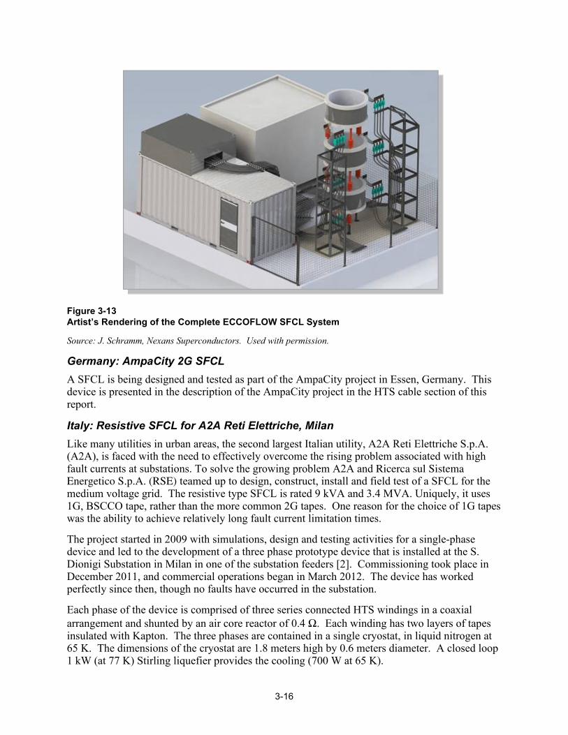
3-16
Figure 3-13 Artist’s Rendering of the Complete ECCOFLOW SFCL System
Source: J. Schramm, Nexans Superconductors. Used with permission.
Germany: AmpaCity 2G SFCL A SFCL is being designed and tested as part of the AmpaCity project in Essen, Germany. This device is presented in the description of the AmpaCity project in the HTS cable section of this report.
Italy: Resistive SFCL for A2A Reti Elettriche, Milan Like many utilities in urban areas, the second largest Italian utility, A2A Reti Elettriche S.p.A. (A2A), is faced with the need to effectively overcome the rising problem associated with high fault currents at substations. To solve the growing problem A2A and Ricerca sul Sistema Energetico S.p.A. (RSE) teamed up to design, construct, install and field test of a SFCL for the medium voltage grid. The resistive type SFCL is rated 9 kVA and 3.4 MVA. Uniquely, it uses 1G, BSCCO tape, rather than the more common 2G tapes. One reason for the choice of 1G tapes was the ability to achieve relatively long fault current limitation times.
The project started in 2009 with simulations, design and testing activities for a single-phase device and led to the development of a three phase prototype device that is installed at the S. Dionigi Substation in Milan in one of the substation feeders [2]. Commissioning took place in December 2011, and commercial operations began in March 2012. The device has worked perfectly since then, though no faults have occurred in the substation.
Each phase of the device is comprised of three series connected HTS windings in a coaxial arrangement and shunted by an air core reactor of 0.4 Ω. Each winding has two layers of tapes insulated with Kapton. The three phases are contained in a single cryostat, in liquid nitrogen at 65 K. The dimensions of the cryostat are 1.8 meters high by 0.6 meters diameter. A closed loop 1 kW (at 77 K) Stirling liquefier provides the cooling (700 W at 65 K).
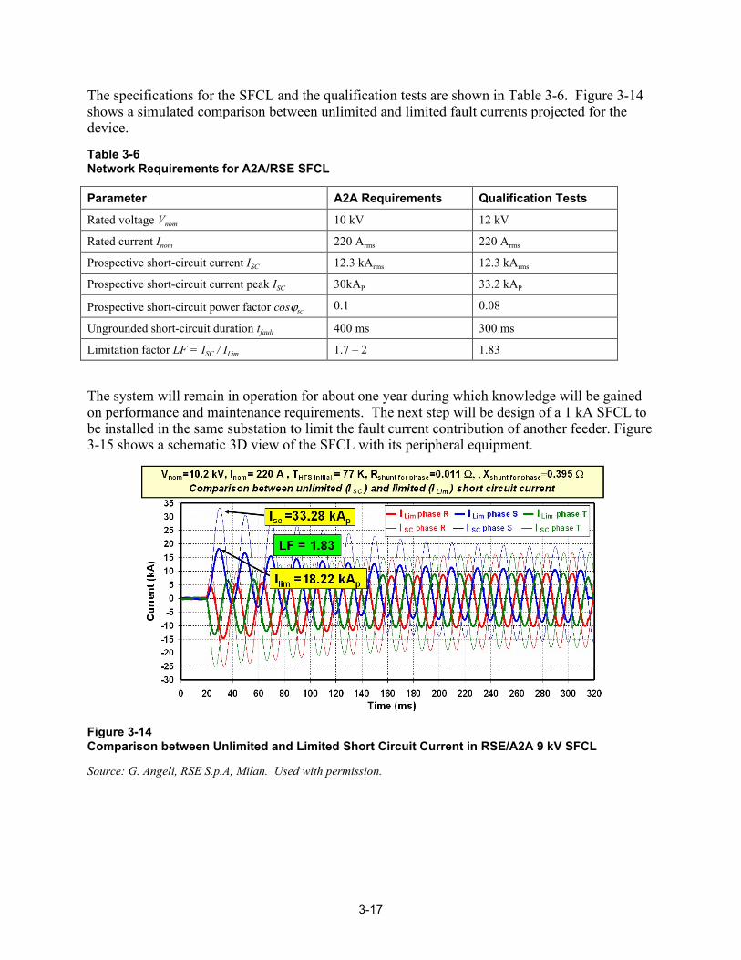
3-17
The specifications for the SFCL and the qualification tests are shown in Table 3-6. Figure 3-14 shows a simulated comparison between unlimited and limited fault currents projected for the device.
Table 3-6 Network Requirements for A2A/RSE SFCL
Parameter A2A Requirements Qualification Tests
Rated voltage Vnom 10 kV 12 kV
Rated current Inom 220 Arms 220 Arms
Prospective short-circuit current ISC 12.3 kArms 12.3 kArms
Prospective short-circuit current peak ISC 30kAP 33.2 kAP
Prospective short-circuit power factor cosϕsc 0.1 0.08
Ungrounded short-circuit duration tfault 400 ms 300 ms
Limitation factor LF = ISC / ILim 1.7 – 2 1.83
The system will remain in operation for about one year during which knowledge will be gained on performance and maintenance requirements. The next step will be design of a 1 kA SFCL to be installed in the same substation to limit the fault current contribution of another feeder. Figure 3-15 shows a schematic 3D view of the SFCL with its peripheral equipment.
Figure 3-14 Comparison between Unlimited and Limited Short Circuit Current in RSE/A2A 9 kV SFCL
Source: G. Angeli, RSE S.p.A, Milan. Used with permission.

3-18
Figure 3-15 3D View of RSE/A2A 9 kV Resistive SFCL in Milan, Italy
Source: G. Angeli, RSE S.p.A, Milan. Used with permission.
Germany: Boxburg SFCL Upgrade – Update The Nexans superconducting fault current limiter that protects the house load power supply at a lignite power plant in Boxburg, Germany, has been described in previous EPRI Technology Watch reports [5] [4]. Upgrades to this SFCL, in which the original BSSCO superconductor was replaced with second generation YBCO tapes, were undertaken at the end of 2011. SuperPower (now Furukawa/SuperPower) in Schenectady, NY, produced the 12 mm wide YBCO tapes. Nexans performed a type-test using dielectric tests and limitation tests before installation. The reliability of the unit was tested at the site in 2012 by performing switching actions on the limiter, transformers and motors.5
The upgraded SFCL has a nominal current rating of 560 A at 12 kV bus voltage, with an intermittent rating of 2,700 A without causing the device to trigger. The losses in the upgraded limiter are reduced by more than a factor of 10 and the device responds faster to a fault (see Table 2-4 in [5] for a comparison of the original and upgraded units).
5 Superconductor Week, pp. 3-4, 24 March 2012

3-19
Germany: Bruker EST Inductive FCL Project – Update For several years Bruker has been developing an inductive shielded core superconducting fault current limiter (also known as an “iSFCL”) . Developments and design details have been reported in prior EPRI Technology Watch reports [4], [5] to which the reader is referred for details. In this report we provide an update on activities in 2012, and some previously unpublished graphics that help to understand the operation of an iSFCL.
The Bruker superconductor fault current limiter design is based on an HTS tape wrapped around an iron core. The basic element of the fault current limiter is a superconducting ring made from several independent superconducting tapes that form shorted turns. The ring is bathed in liquid nitrogen and the ring arrangement and orientation is such that each tape is well ventilated. The design enables them to be cooled to nitrogen temperature very rapidly. This is particularly important after a fault when the system needs to recover before another fault occurs. Both the number of tapes in each ring and the number of rings used in an FCL depend on the installation.
Figure 3-16, Figure 3-17, and Figure 3-18 provide graphic illustration of how the iSFCL works.
Figure 3-16 Design of Bruker iSFCL
Source: F. Moriconi, Bruker EST. Used with permission.
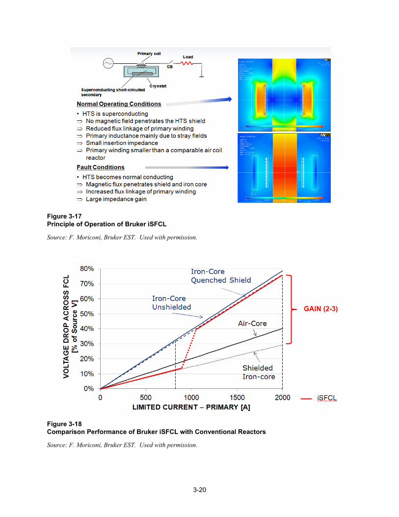
3-20
Figure 3-17 Principle of Operation of Bruker iSFCL
Source: F. Moriconi, Bruker EST. Used with permission.
Figure 3-18 Comparison Performance of Bruker iSFCL with Conventional Reactors
Source: F. Moriconi, Bruker EST. Used with permission.
3-21
In 2012 modeling and testing of a prototype device continued. A single phase sub-scale device was tested in the spring of 2012. Short circuit tests were performed as well, confirming the ability to reduce peak fault current by 80%. A comparison with a conventional reactor was also made (see Table 3-7).
A full scale, single phase device is currently under construction for testing in 2013. Bruker and the host utility, Stadtwerke Augsburg (SWA) expect to install the device in 2014, at a dedicated substation that supplies the manufacturing plant of a company that makes combined heat and power (CHP) systems, MTU Onsite Power.
Table 3-7 Comparison of Bruker iSFCL with Conventional Reactor for Limiting Fault Current
Property iSFCL 15 MVA Reactor
Total impedance (normal operation) Voltage change U Voltage change U ~10%
Operating losses 45 – 50 kW (incl. cryogenics) 95 kW
Impedance increase at fault Factor 2 None
Fault current limitation first peak Factor 5 Factor 5
UK: Applied Superconductivity Limited (ASL) and Zenergy As reported in the 2010 EPRI Technology Watch, Applied Superconductivity Limited (ASL) was founded in November 2004. Its major focus at present is the commercialization of superconducting fault current limiters. ASL matches various types of SFCLs to electric power distribution networks, where they provide protection against damage resulting from the inevitable current surges caused from time to time by short circuits.
ASL integrates SFCLs with other components as required and delivers a package to their customer that provides a viable and functional solution to the problems associated with fault currents. In the process of developing these solutions, ASL utilizes their in-house experience in network engineering, component technology, and systems integration. This novel approach to the marketing of SFCLs has allowed ASL to secure orders for the supply of the first four SFCLs to be installed into commercial networks in the U.K.
During 2011, Zenergy Power Inc. went through several administrative crises. The Board of Directors was changed twice, and, in September, a decision was made to end their program to develop superconducting fault current limiters. In 2012, Applied Superconductor announced the acquisition of portions of Zenergy Power in July 2012. Zenergy Power was the developer of the inductive limiter technology which has recently been demonstrated in ASL’s 11 kV project with Northern Powergrid at a substation in the Scunthorpe area of Yorkshire. The technology will be further demonstrated next year, when a 33kV unit will be installed at a substation in Sheffield. Key experts from Zenergy joined ASL.
ASL now has offices in the UK, Australia and the US. The acquisition of Zenergy also provides ASL with a robust patent portfolio to secure the inductive limiter technology and a number of on-going research programs with the University of Wollongong.


4-1
4 CONCLUSIONS This report has documented many of the key activities and events that occurred in 2012 in the field of superconducting cables and fault current limiters. The center of activity in superconductivity development for power delivery applications is shifting away from the United States to countries around the world. We devote this Conclusions section to a retrospect on the prospects for continued activity in the U.S. in this field.
During the 1990s and 2000s the United States was a world leader in both the development of superconducting wire and in the demonstration of power delivery applications. That position has now changed. Germany, Russia, China, Korea, and Japan all have national, government-supported superconductivity development programs which are now equaling or surpassing the level of activity that has been known in the U.S. Much of this activity has either been inspired by U.S. research or is even more fundamentally dependent on it.
The U.S. Department of Energy (US DOE) has zeroed out funding of HTS technologies in the Office of Electricity. Funding went to zero in 2012, reflecting a steady decline in funding over the past few years. See Figure 4-1. The DOE program had significant participation over the past decade and a half from academia and industry, in addition to the National Labs. However, as a result of the DOE program termination the wire research programs in the National Labs are being closed and personnel being laid off or reassigned. Academic and industry programs that were receiving funding are being terminated, in some cases before having completed their originally planned research. To a relatively smaller extent other federal agencies (e.g., Department of Homeland Security [DHS] and Advanced Research Projects Agency – Energy [ARPA-E]) have picked up specific research and demonstrations. As well, the U.S. Navy is actively supporting research in superconducting power delivery systems for its “all electric ship” program.
The world-wide growth of a superconducting wire market is continuing to infuse both cash and interest in the U.S. wire manufacturing sector. New startup companies such as Superconductor Technologies Inc. (STI) and Grid Logic are positioning themselves to compete aggressively with the two major U.S. suppliers (SuperPower and AMSC). Growing worldwide demand for wire will continue to benefit U.S. companies producing the wire, and suppliers are customizing and selling their product for specific applications, for such as
• Large scale wind generators • AC and DC power cables • Superconducting magnetic energy storage (SMES), commercial and research magnets, and fault current limiters (FCLs)
In university programs, supported by government funding, there is an increased interest in HTS wire performance under higher fields and lower temperatures (i.e., below that of liquid nitrogen). In general, performance improves at lower temperatures, particularly in higher field applications than those encountered, for example, in cables and FCLs.

4-2
There are still two active HTS cable projects in the United States: LIPA-2 and HYDRA, as reported in Chapter 2 of this report. A superconducting transformer program, reported in last year’s technology watch, is continuing. If these projects continue to move forward, U.S. utility companies will continue to have a home-base source of information and experience in this technology. However, much of the activity in cables today is outside the U.S. and there are no active or planned fault current limiter projects at the present time. As well, and very similar to the situation with conventional underground cables, all but one of the superconducting cable manufacturers in the world are in other countries. With the closure of Zenergy last year, there are no U.S. companies manufacturing fault current limiters, though Varian, in Boston, has finished testing a high voltage device and announced that it is looking for a utility partner for a demonstration.
Figure 4-1 US DOE Office of Electricity HTS Funding History
Source: Alan Lauder, Coalition for Commercial Application of Superconductors (CCAS). Used with permission.

5-1
5 REFERENCES
[1] Superconducting Power Cables: Technology Watch 2008. EPRI, Palo Alto, CA: 2008. 1015988.
[2] Superconducting Fault Current Limiters: Technology Watch 2009. EPRI, EPRI, Palo Alto, CA: 2009. 1017793.
[3] Superconducting Power Cables: Technology Watch 2009. EPRI, Palo Alto, CA: 2009. 1017792.
[4] Superconducting Power Equipment: Technology Watch 2010. EPRI, Palo Alto, CA: 2010. 1019995.
[5] Superconducting Power Equipment: Technology Watch 2011. EPRI, Palo Alto, CA: 2011. 1021890.
[6] Hassenzahl, W., et al., "Program on Technology Innovation: A Superconducting DC Cable," EPRI, EPRI, Palo Alto, CA: 2009. 1020458.
[7] Novel Approaches and Alternative Cryogens for Cooling a Superconducting Cable: A Comparison of Liquid Air with Other Fluids. EPRI, Palo Alto, CA: 2012. 1025813.
[8] The Hydrogen-Electric Energy SuperGrid. EPRI, Palo Alto, CA: 2006. 1013089.
[9] Dale, S. J., "International Status and Future Projections for Superconductivity," in International Superconductivity Industry Summit ISIS-21, Portland, OR, October 2012.
[10] "EPRI Tenth Superconductivity Conference," in Web URL: http://www.cvent.com/events/tenth-epri-superconductivity-conference/custom-18-0ac856fa88e84a97ac2058094d0a4629.aspx, 2010.


A-1
A SUPERCONDUCTING TECHNOLOGY PROJECTS IN THE UNITED STATES

A-2
Table A-1 HTS Cable Projects in the United States: Overview
Project Columbus Albany Long Island Long Island 2 New Orleans HYDRA
Location Columbus, OH. USA
Albany, NY. USA
Long Island, NY. USA
Long Island, NY. USA
New Orleans, Louisiana
Manhattan, NY. USA
Site Bixby Substation Riverside and Menands Substation
Holbrook Substation
Holbrook Substation
Labarre - Metairie Substations
Not available
Status To be decommissioned in 2012.
Decommissioned Demonstration completed – transitioned to Long Island 2
Cable to be commissioned in late 20122
Cancelled1 Qualification Testing Completed2
Developer UlteraTM SuperPower AMSC AMSC UlteraTM AMSC
Utility/ Host
American Electric Power
National Grid LIPA LIPA Entergy ConEd
In-Grid Start Date September 2006 July 2006 April 2008 2013 N/A 2014
End Date 2012 April 2008 2009 See Long Island 2
LIPA plans to operate system indefinitely.
N/A No scheduled termination date
Type (AC or DC) AC AC AC AC AC AC3
Phases 3 3 3 3 3 3
Geometry Tri-axial Triad Coaxial Coaxial Tri-axial Tri-axial
1 Project cancelled because of stagnated load growth due to the current economic downturn. 2 A 25-meter prototype has been successfully tested at Oak Ridge National Laboratory. 3 Fault tolerant cable.

A-3
Table A-2 HTS Cable Projects in the United States: Design Details
Project Columbus Albany Long Island Long Island 2 New Orleans HYDRA
Voltage 13.2 kV 34.5 kV 138 kV 138 kV 13.8 kV 13.8 kV
Rated Current 3000 Arms (69 MVA)
800 Arms (48 MVA) 2400 Arms (Cable will operate @ 800 to 900 Arms)
2400 Arms (Cable will operate @ 800 to 900 Arms)
2000 Arms (48 MVA)
4000 Arms (96 MVA)
Length 200 m 350 m 600 m 600 m 1700 meters 170 m
Fault Current 20 kArms for 15 cycles (56 kApeak asymmetrical)
23 kArms for 38 cycles (58 kApeak asymmetrical)
51 kArms for 12 cycles (~140 kApeak asymmetrical)
51 kArms for 12 cycles (~140 kApeak asymmetrical)
Not available 40 kA for 4 cycles
Dielectric Design Cold dielectric Cold dielectric Cold dielectric Cold dielectric Cold dielectric Cold dielectric
Dielectric Material
CryoflexTM LPP LPP LPP CryoflexTM CryoflexTM
HTS Material BSCCO w/brass stabilizer
Phase I: BSCCO Phase II: YBCO
BSCCO w/Cu stabilizer
YBCO fault current limiting tape
BSCCO YBCO fault current limiting tape
HTS Conductor Supplier/ Fabricator
AMSC Sumitomo (BSCCO) SuperPower (YBCO)
AMSC AMSC AMSC AMSC
AC loss ~ 1.2 W/m/phase @ 60 Hz, 3000 Arms
~0.33 W/m/phase @ 60 Hz, 800 Arms
3.5 W/m/phase @ 60 Hz, 2400 Arms
Not available Not available Not available
Cable Fabrication
ULTERATM-1 Sumitomo Nexans Nexans UlteraTM UlteraTM

A-4
Table A-3 HTS Cable Projects in the United States: Cryostat and Refrigeration
Project Columbus Albany Long Island Long Island 2 New Orleans HYDRA
Cryostat Type Flexible, stainless-steel
Flexible, Stainless-steel
Flexible, stainless-steel
Flexible, stainless-steel
Flexible, stainless-steel
Flexible, stainless-steel
Cryostat Supplier
Nexans Sumitomo Nexans Nexans Not Available Nexans
Cryostat Loss 1.3 W/m ~1.2 W/m 1.3 W/m (3 cryostats)
Not available Not available Not available
Cryogen LN2 LN2 LN2 LN2 LN2 LN2
Refrigeration Type
Open and closed loop hybrid
Closed-loop, 2 Sterling refrigerators
Closed-loop, reverse-Brayton cycle refrigerator
Closed-loop, reverse-Brayton cycle refrigerator
Not available Closed loop Stirling refrigerators4
Refrigeration Supplier
Praxair Linde5 Air Liquide Air Liquide Not available DH Industries
Refrigeration System Capacity
Open-loop: 5 kW @ 77 K Pulse tube: 1.5 kW @ 77 K6
> 5kW @ 77 K > 6 kW @ 65 K > 6 kW @ 65 K Not Available 6.2 kW @ 72 K7
4 The system will be based on the Cryogenerator SPC-4 from Stirling Cryogenics. 5 BOC before the Linde/BOC merger (the consolidated company has assumed the Linde name). 6 Two pulse tubes previously removed and replaced with a single, more efficient unit. 7 Refrigeration system capacity is 12 kW, via three 4-kW units in redundant configuration.

A-5
Table A-4 Fault Current Limiter Projects in the United States: Overview
Project SuperLimiterTM HYDRA
Location Los Angeles, CA SEE TABLE A-1
Site Devers Substation
Status Development
Developer Consortium8
Utility/ Host
Southern California Edison (SCE)
In-Grid Start Date TBD
End Date TBD
Type Hybrid Resistive
Phases 3
Table A-5 Fault Current Limiter Projects in the United States: Design Details
Project SuperLimiterTM HYDRA
Voltage 138 kV9 SEE TABLE A-2
Rated Current 1.2 kA
Expected Max Fault Current 63 kA
Current-Limiting Capability ~ 37%
Max Limiting Duration As long as required, can limit continuously
Peak Max Voltage Drop Unavailable
Let-Through Current 40 kA
Recovery Time 15 s
HTS Material YBCO fault current limiting tape
HTS Conductor Supplier/Fabricator
AMSC
Size 8m long by 3 m diameter per phase
Weight 40,000 kg per phase (including LN2)
8 AMSC, Siemens, Southern California Edison Co., Nexans, Los Alamos National Laboratory (LANL), and Texas Center for Superconductivity (TcSUH). 9 The installation at SCE was to be at 115 kV.

A-6
Table A-6 Fault Current Limiter Projects in the United States: Cryostat and Refrigeration
Project SuperLimiterTM HYDRA
Cryogen LN2 SEE TABLE A-3
Refrigeration Type Closed-Loop Remote Re-condensing System
Refrigeration Supplier Cryomech Inc.
Refrigeration System Capacity 300 W at 77 K
Nominal Operating Temperature <75 K

B-1
B SUPERCONDUCTING TECHNOLOGY PROJECTS IN EUROPE
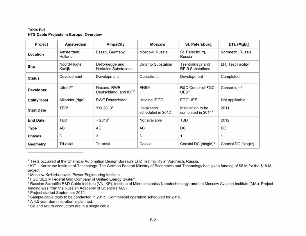
B-2
Table B-1 HTS Cable Projects in Europe: Overview
Project Amsterdam AmpaCity Moscow St. Petersburg ETL (MgB2)
Location Amsterdam, Holland
Essen, Germany Moscow, Russia St. Petersburg, Russia
Voronezh, Russia
Site Noord-Hogte Kadijk
Dellbruegge and Herkules Substations
Dinamo Substation Tsentralnaya and RP-9 Substations
LH2 Test Facility1
Status Development Development Operational Development Completed
Developer UlteraTM Nexans, RWE Deutschland, and KIT2
ENIN3 R&D Center of FGC UES4
Consortium5
Utility/Host Alliander (dgo) RWE Deutschland Holding IDGC FGC UES Not applicable
Start Date TBD2 3 Q 20136 Installation scheduled in 2012
Installation to be completed in 20147
2011
End Date TBD ~ 20188 Not available TBD 2012
Type AC AC AC DC DC
Phases 3 3 3 1 1
Geometry Tri-axial Tri-axial Coaxial Coaxial DC (single)9 Coaxial DC (single)
1 Tests occurred at the Chemical Automation Design Bureau’s LH2 Test facility in Voronezh, Russia. 2 KIT – Karlsruhe Institute of Technology. The German Federal Ministry of Economics and Technology has given funding of $8 M for the $18 M project. 3 Moscow Krzhizhanovski Power Engineering Institute. 4 FGC UES = Federal Grid Company of Unified Energy System 5 Russian Scientific R&D Cable Institute (VNIIKP), Institute of Microelectonics Nanotechnology, and the Moscow Aviation Institute (MAI). Project funding was from the Russian Academy of Science (RAS). 6 Project started September 2012. 7 Sample cable tests to be conducted in 2013. Commercial operation scheduled for 2016. 8 A 4.5 year demonstration is planned. 9 Go and return conductors are in a single cable.
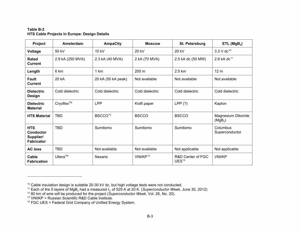
B-3
Table B-2 HTS Cable Projects in Europe: Design Details
Project Amsterdam AmpaCity Moscow St. Petersburg ETL (MgB2)
Voltage 50 kV 10 kV 20 kV 20 kV 3.3 V dc10
Rated Current
2.9 kA (250 MVA) 2.3 kA (40 MVA) 2 kA (70 MVA) 2.5 kA dc (50 MW) 2.6 kA dc11
Length 6 km 1 km 200 m 2.5 km 12 m
Fault Current
20 kA 20 kA (50 kA peak) Not available Not available Not available
Dielectric Design
Cold dielectric Cold dielectric Cold dielectric Cold dielectric Cold dielectric
Dielectric Material
CryoflexTM LPP Kraft paper LPP (?) Kapton
HTS Material TBD BSCCO12 BSCCO BSCCO Magnesium Diboride (MgB2)
HTS Conductor Supplier/ Fabricator
TBD Sumitomo Sumitomo Sumitomo Columbus Superconductor
AC loss TBD Not available Not available Not applicable Not applicable
Cable Fabrication
UlteraTM Nexans VNIIKP13 R&D Center of FGC UES14
VNIIKP
10 Cable insulation design is suitable 20-30 kV dc, but high voltage tests were not conducted. 11 Each of the 5 layers of MgB2 had a measured IC of 529 A at 20 K. (Superconductor Week, June 30, 2012) 12 80 km of wire will be produced for the project (Superconductor Week, Vol. 26, No. 20). 13 VNIIKP = Russian Scientific R&D Cable Institute. 14 FGC UES = Federal Grid Company of Unified Energy System.

B-4
Table B-3 HTS Cable Projects in Europe: Cryostat and Refrigeration
Project Amsterdam AmpaCity Moscow St. Petersburg ETL (MgB2)
Cryostat Type
Flexible, stainless-steel
Flexible, stainless-steel
Flexible, stainless-steel
Flexible, stainless-steel
Not available
Cryostat Supplier
TBD Nexans Nexans Nexans Not available
Cryostat Loss
TBD Not available 1.3 W/m Not available 10 W/m15
Cryogen LN2 LN2 LN2 LN2 LH2
Refrigeration Type
TBD Sub-cooled, pressurized, open cycle LN2
Not available Sub-cooled, pressurized, open cycle LN2
Not available
Refrigeration Supplier
TBD Not available MAI Not available Not available
Refrigeration System Capacity
TBD 4 kW at 67 K16 8 kW @ 66 K Not available Not available
15 Terminations had 300 W losses 16 Cooling system supplies both the cable and the fault current limiter.

B-5
Table B-4 Fault Current Limiter Projects in Europe: Overview
Project AmpaCity Boxburg ECCOFLOW A2A/RSE Bruker iSFCL
Location Essen, Germany Boxburg, Germany Slovakia and Spain Milan, Italy Augsburg, Germany
Site Herkules Substation Local Power Plant Multiple17 San Dionigi Substation (MI)
MTU Onsite Energy Substation
Status Development Recommissioned after retrofit
Fabrication underway Fabrication of first prototype
Development
Developer Nexans Nexans Nexans ERSE Spa Bruker EST
Utility/ Host
RWE Deutschland Vattenfall Europe Generation AG
VSE (RSE Group) and Endesa18
A2A Reti Elettriche Spa Group
SWA19
In-Grid Start Date 3 Q 201320 Fall 2009 Retrofit 2011
Late 2013 Early 2010 2014
End Date ~ 201821 TBD TBD End of 2011 TBD
Type Resistive Resistive Hybrid Resistive Inductive Shielded Core
Phases 3 3 3 3 3
17 Transformer feeder at a substation in Slovakia and busbar coupler in a substation in Spain. 18 VSE (RWE Group) in Slovakia and Endesa in Spain. 19 SWA = Stadtwerke Augsburg 20 Project started September 2012. 21 A 4.5 year demonstration is planned.
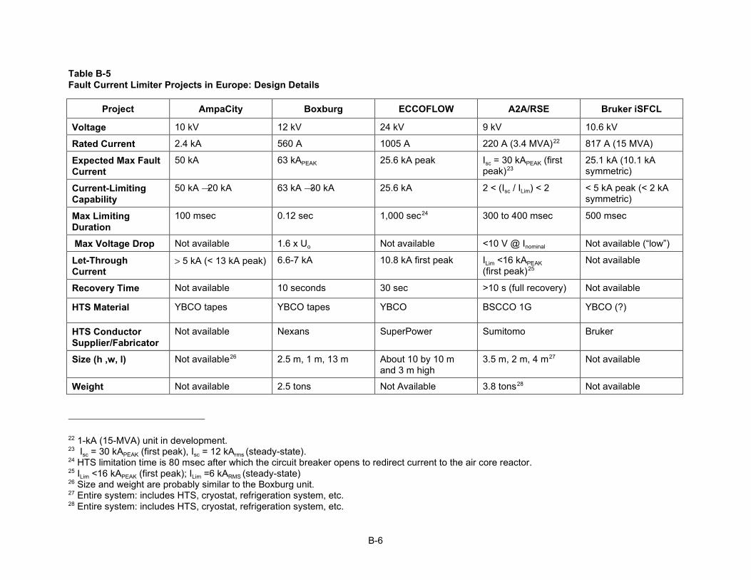
B-6
Table B-5 Fault Current Limiter Projects in Europe: Design Details
Project AmpaCity Boxburg ECCOFLOW A2A/RSE Bruker iSFCL
Voltage 10 kV 12 kV 24 kV 9 kV 10.6 kV
Rated Current 2.4 kA 560 A 1005 A 220 A (3.4 MVA)22 817 A (15 MVA)
Expected Max Fault Current
50 kA 63 kAPEAK 25.6 kA peak Isc = 30 kAPEAK (first peak)23
25.1 kA (10.1 kA symmetric)
Current-Limiting Capability
50 20 kA 25.6 kA 2 < (Isc / ILim) < 2 < 5 kA peak (< 2 kA symmetric)
Max Limiting Duration
100 msec 0.12 sec 1,000 sec24 300 to 400 msec 500 msec
Max Voltage Drop Not available 1.6 x Uo Not available <10 V @ Inominal Not available (“low”)
Let-Through Current
> 5 kA (< 13 kA peak) 6.6-7 kA 10.8 kA first peak ILim <16 kAPEAK (first peak)25
Not available
Recovery Time Not available 10 seconds 30 sec >10 s (full recovery) Not available
HTS Material YBCO tapes YBCO tapes YBCO BSCCO 1G YBCO (?)
HTS Conductor Supplier/Fabricator
Not available Nexans SuperPower Sumitomo Bruker
Size (h ,w, l) Not available26 2.5 m, 1 m, 13 m About 10 by 10 m and 3 m high
3.5 m, 2 m, 4 m27 Not available
Weight Not available 2.5 tons Not Available 3.8 tons28 Not available
22 1-kA (15-MVA) unit in development. 23 Isc = 30 kAPEAK (first peak), Isc = 12 kArms (steady-state). 24 HTS limitation time is 80 msec after which the circuit breaker opens to redirect current to the air core reactor. 25 ILim <16 kAPEAK (first peak);; ILim =6 kARMS (steady-state) 26 Size and weight are probably similar to the Boxburg unit. 27 Entire system: includes HTS, cryostat, refrigeration system, etc. 28 Entire system: includes HTS, cryostat, refrigeration system, etc.
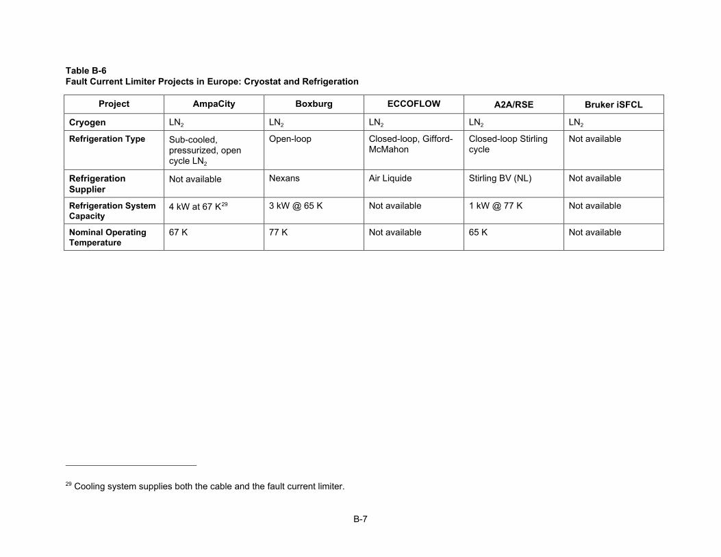
B-7
Table B-6 Fault Current Limiter Projects in Europe: Cryostat and Refrigeration
Project AmpaCity Boxburg ECCOFLOW A2A/RSE Bruker iSFCL
Cryogen LN2 LN2 LN2 LN2 LN2
Refrigeration Type Sub-cooled, pressurized, open cycle LN2
Open-loop Closed-loop, Gifford-McMahon
Closed-loop Stirling cycle
Not available
Refrigeration Supplier
Not available Nexans Air Liquide Stirling BV (NL) Not available
Refrigeration System Capacity
4 kW at 67 K29 3 kW @ 65 K Not available 1 kW @ 77 K Not available
Nominal Operating Temperature
67 K 77 K Not available 65 K Not available
29 Cooling system supplies both the cable and the fault current limiter.


C-1
C SUPERCONDUCTING TECHNOLOGY PROJECTS IN CHINA
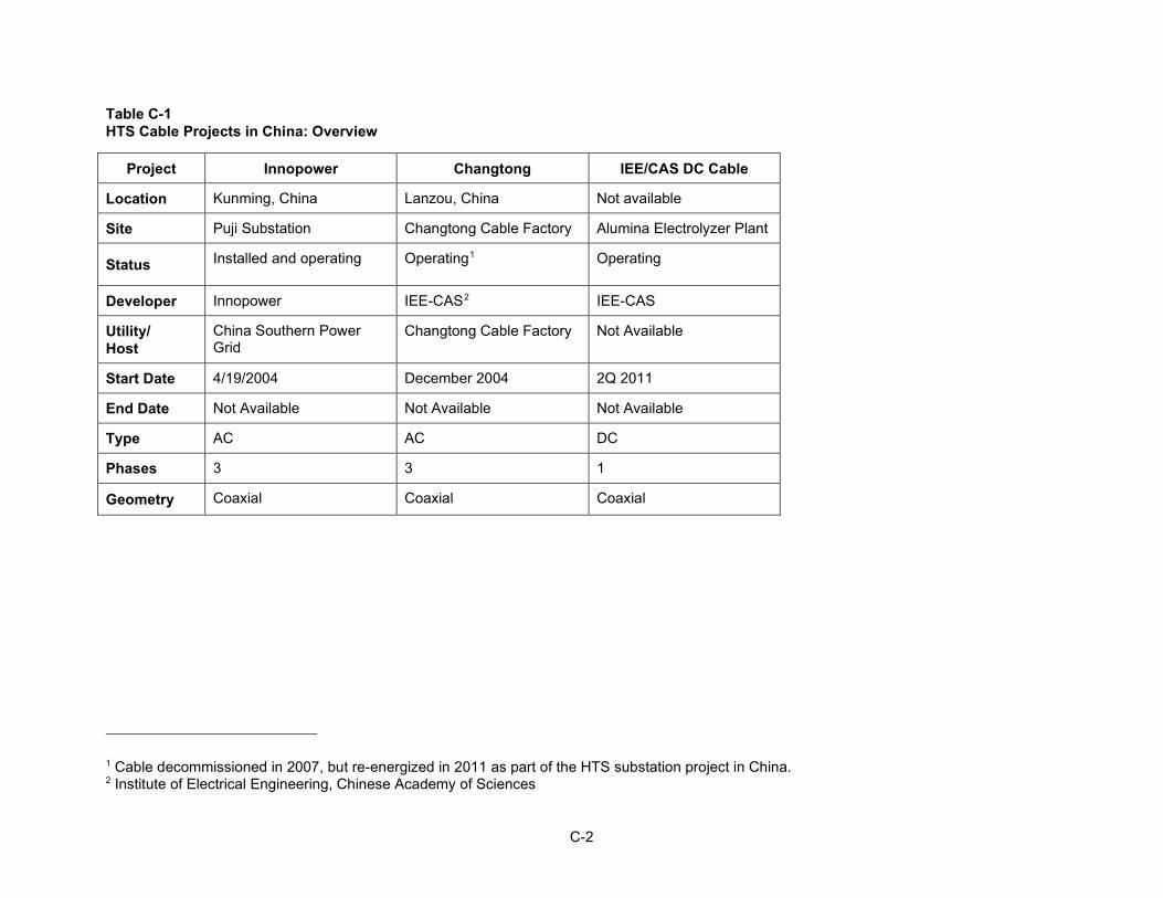
C-2
Table C-1 HTS Cable Projects in China: Overview
Project Innopower Changtong IEE/CAS DC Cable
Location Kunming, China Lanzou, China Not available
Site Puji Substation Changtong Cable Factory Alumina Electrolyzer Plant
Status Installed and operating Operating1 Operating
Developer Innopower IEE-CAS2 IEE-CAS
Utility/ Host
China Southern Power Grid
Changtong Cable Factory Not Available
Start Date 4/19/2004 December 2004 2Q 2011
End Date Not Available Not Available Not Available
Type AC AC DC
Phases 3 3 1
Geometry Coaxial Coaxial Coaxial
1 Cable decommissioned in 2007, but re-energized in 2011 as part of the HTS substation project in China. 2 Institute of Electrical Engineering, Chinese Academy of Sciences

C-3
Table C-2 HTS Cable Projects in China: Design Details
Project Innopower Changtong IEE/CAS DC Cable
Voltage 35 kV 6.6 kV 1,300 V dc
Rated Current 2000 Arms (120 MVA)
1500 Arms (17 MVA)3
≥ 10,000 A
Length 33.5 m 75 m 362.4 m
Fault Current 20 kArms for 2 s (27 kApeak asymmetrical)
Not available Not available
Dielectric Design Warm dielectric Warm dielectric Warm dielectric
Dielectric Material
XLPE XLPE XLPE (assumed)
HTS Material BSCCO BSCCO Not available
HTS Conductor Supplier/ Fabricator
Innova Superconductor Technology. Co, Ltd.
AMSC Not available
AC loss > 1 W/m/phase @ 50 Hz, 1500 Arms, 74 K
> 0.42–0.85 W/m/ phase @ 50 Hz, 1500 A
None
Cable Fabrication Shanghai Cable Works Collaborative group Not available
3 Designed for 30 MVA (10.5 kV) but operates at 17 MVA (6.6 kV).
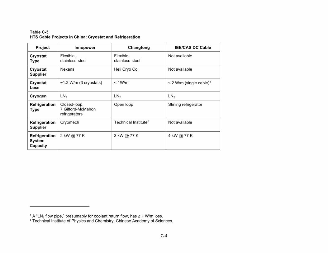
C-4
Table C-3 HTS Cable Projects in China: Cryostat and Refrigeration
Project Innopower Changtong IEE/CAS DC Cable
Cryostat Type
Flexible, stainless-steel
Flexible, stainless-steel
Not available
Cryostat Supplier
Nexans Heli Cryo Co. Not available
Cryostat Loss
~1.2 W/m (3 cryostats) < 1W/m ≤ 2 W/m (single cable)4
Cryogen LN2 LN2 LN2
Refrigeration Type
Closed-loop, 7 Gifford-McMahon refrigerators
Open loop Stirling refrigerator
Refrigeration Supplier
Cryomech Technical Institute5 Not available
Refrigeration System Capacity
2 kW @ 77 K 3 kW @ 77 K 4 kW @ 77 K
4 A “LN2 flow pipe,” presumably for coolant return flow, has ≥ 1 W/m loss. 5 Technical Institute of Physics and Chemistry, Chinese Academy of Sciences.

C-5
Table C-4 Fault Current Limiter Projects in China: Overview
Project Puji Shanghai 10kV Tianjin 220 kV
Location Kunming, China Shanghai Tianjin, China
Site Puji Substation Chongming Island Shigezhuang Substation
Status Operating Development In trial operation6
Developer Innopower SJTU7 Innopower
Utility/ Host
Yunnan Electric Power Grid
STCSM8 Unavailable
In-Grid Start Date December 2007 March 2013 Dec 2012
End Date TBD TBD TBD
Type Saturable Core Resistive Saturable Core
Phases 3 3 3
6 Live grid operation planned for launch at the end of 2012. 7 Shanghai Jiao Tong University 8 Science and Technology Commission of Shanghai Municipality

C-6
Table C-5 Fault Current Limiter Projects in China: Design Details
Project Puji Shanghai 10kV Tianjin 220 kV
Voltage 35 kV 10 kV 220 kV
Rated Current 1.5 kA (90 MVA) 400 A 800 A (300 MVA)
Expected Max Fault Current
41 kA 20 kA 50 kA
Current-Limiting Capability
~56% (23 kA) 6 – 14 kA, adjustable 30 kA
Max Limiting Duration
>200 ms @ 10 kARMS9 < 200 msec Unavailable
Max Voltage Drop <1% < 1 V < 1.25%
Let-Through Current Unavailable Unavailable Unavailable
Recovery Time <800 ms 0.8 – 3.8 sec (load) 0.3 – 3.2 sec (no load)
< 500 msec
HTS Material BSCCO-2223
YBCO tapes Unavailable
HTS Conductor Supplier/Fabricator
INNOST and AMSC SJTU10 Unavailable
Size 4.2 m high X 4 m diameter
2.3 m high X 1.2 m diameter
8 m X 8 m X 9 m high
Weight 27 tons 1.5 tons 120 tons
9 Experimental result;; design value is 23 kA. 10 Shanghai Jiao Tong University
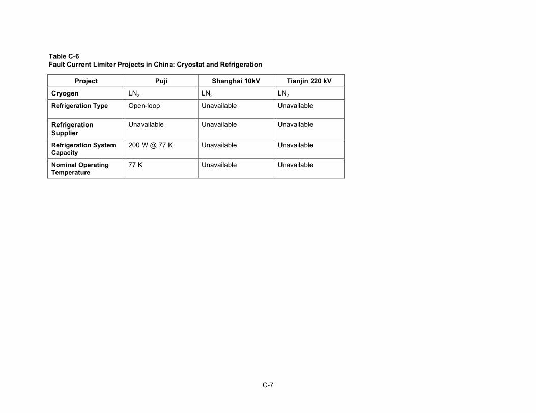
C-7
Table C-6 Fault Current Limiter Projects in China: Cryostat and Refrigeration
Project Puji Shanghai 10kV Tianjin 220 kV
Cryogen LN2 LN2 LN2
Refrigeration Type Open-loop Unavailable Unavailable
Refrigeration Supplier
Unavailable Unavailable Unavailable
Refrigeration System Capacity
200 W @ 77 K Unavailable Unavailable
Nominal Operating Temperature
77 K Unavailable Unavailable


D-1
D SUPERCONDUCTING TECHNOLOGY PROJECTS IN JAPAN AND KOREA

D-2
Table D-1 HTS Cable Projects in Japan and Korea: Overview
Project Asahi Furukawa/ Shenyang
JeJu Island AC JeJu Island DC I’cheon (GENI-I) Gochang 154 kV AC
Location Yokohama, Japan
Shenyang, China JeJu Island, South Korea
JeJu Island, South Korea
I’cheon City, South Korea
Jeonbuk, South Korea
Site Asahi Substation Furukawa cable factory in Shenyang
GumAk – Anduk Substations
GumAk – Hanlim Substations
I’cheon Substation
Gochang Power Testing Center
Status Installed & commissioned
Installed1 Development Development Completed Completed
Developer METI/NEDO/ Sumitomo2
Furukawa KEPCO3/ LS Cable / KERI4
KEPCO/ LS Cable / KERI
KEPRI5/LS Cable DAPAS6
Utility/ Host
TEPCO None KEPCO KEPCO KEPCO KEPCO
Start Date Oct. 30, 20127 Target 4Q 2012 2015 2011 - 2013 September 2011 2010
End Date 1Q 20148
Not available 2016 2016 Not available 2011 - 2012
Type AC AC AC DC AC AC
Phases 3 1 3 1 3 1
Geometry Triad Coaxial Triad Coaxial DC Triad Coaxial
1 Commissioning tests were scheduled to start October 2012. 2 METI = Ministry of Economy, Trade and Industry;; NEDO = New Energy Development Organization. 3 KEPCO = Korea Electric Power Company. 4 KERI = Korea Electrotechnical Research Institute. 5 KEPRI = Korea Electric Power Research Institute. 6 DAPAS = Development of Advanced Power System by Applied Superconductivity Technologies. 7 Project began in 2007. 8 Sumitomo plans a one-year evaluation, followed by a decision on whether to continue operation for another year.
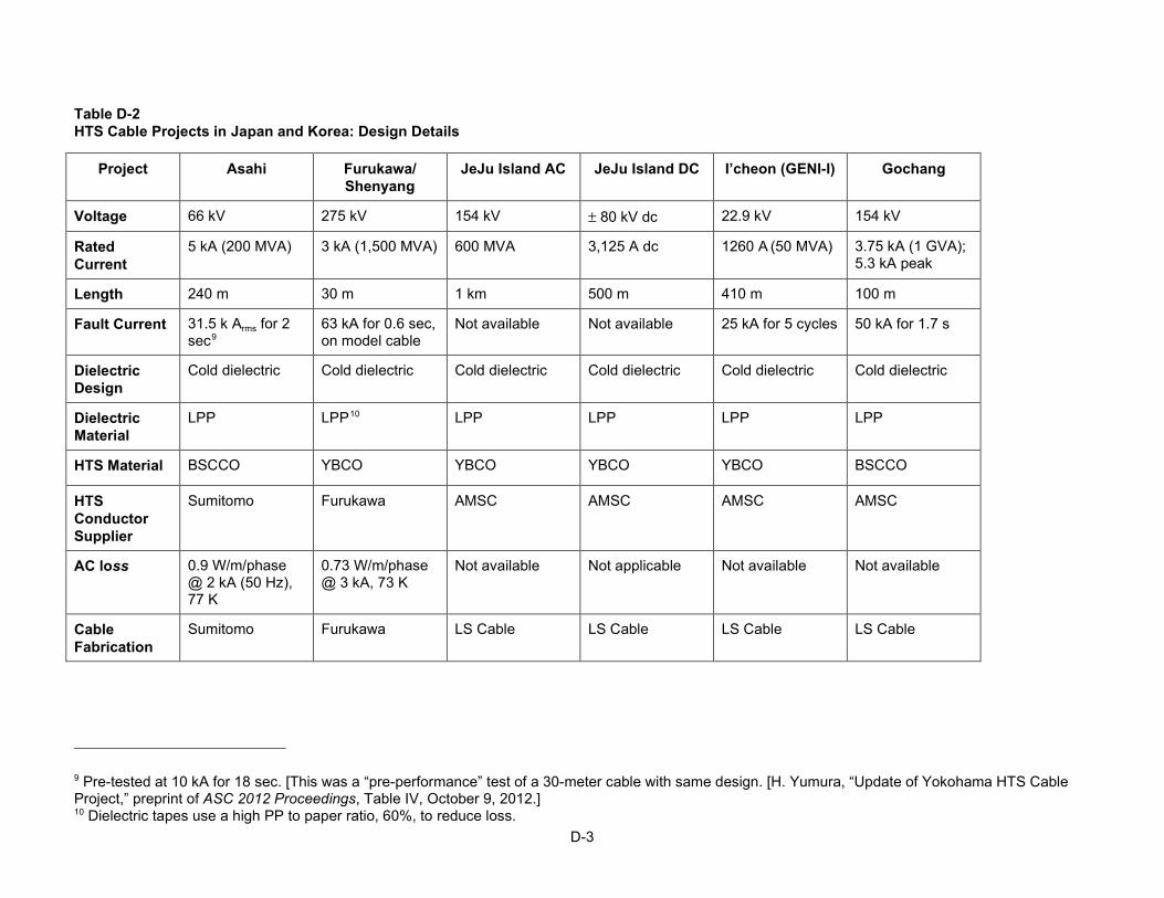
D-3
Table D-2 HTS Cable Projects in Japan and Korea: Design Details
Project Asahi Furukawa/ Shenyang
JeJu Island AC JeJu Island DC I’cheon (GENI-I) Gochang
Voltage 66 kV 275 kV 154 kV ± 80 kV dc 22.9 kV 154 kV
Rated Current
5 kA (200 MVA) 3 kA (1,500 MVA) 600 MVA 3,125 A dc 1260 A (50 MVA) 3.75 kA (1 GVA);; 5.3 kA peak
Length 240 m 30 m 1 km 500 m 410 m 100 m
Fault Current 31.5 k Arms for 2 sec9
63 kA for 0.6 sec, on model cable
Not available Not available 25 kA for 5 cycles 50 kA for 1.7 s
Dielectric Design
Cold dielectric Cold dielectric Cold dielectric Cold dielectric Cold dielectric Cold dielectric
Dielectric Material
LPP LPP10 LPP LPP LPP LPP
HTS Material BSCCO YBCO YBCO YBCO YBCO BSCCO
HTS Conductor Supplier
Sumitomo Furukawa AMSC AMSC AMSC AMSC
AC loss 0.9 W/m/phase @ 2 kA (50 Hz), 77 K
0.73 W/m/phase @ 3 kA, 73 K
Not available Not applicable Not available Not available
Cable Fabrication
Sumitomo Furukawa LS Cable LS Cable LS Cable LS Cable
9 Pre-tested at 10 kA for 18 sec. [This was a “pre-performance” test of a 30-meter cable with same design. [H. Yumura, “Update of Yokohama HTS Cable Project,” preprint of ASC 2012 Proceedings, Table IV, October 9, 2012.] 10 Dielectric tapes use a high PP to paper ratio, 60%, to reduce loss.

D-4
Table D-3 HTS Cable Projects in Japan and Korea: Cryostat and Refrigeration
Project Asahi Furukawa/ Shenyang
JeJu Island AC JeJu Island DC I’cheon (GENI-I) Gochang
Cryostat Type
Flexible, stainless-steel
Flexible, stainless-steel
Flexible, seamless aluminum
Flexible, seamless aluminum
Flexible, seamless aluminum
Flexible, seamless aluminum
Cryostat Supplier
Sumitomo Furukawa (assumed)
LS Cable LS Cable LS Cable LS Cable
Cryostat Loss
~2.7 W/m @ 69 K11
Not available Not available Not available 4.1 kW12 Not available
Cryogen LN2 LN2 LN2 LN2 LN2
Refrigeration Type
Closed-loop, 6 Stirling refrigerators
Open-loop Not available Not available Open-loop13 with Stirling refrigerators
Open-loop with Stirling refrigerators
Refrigeration Supplier
Mayekawa Not available Not available Not available Consortium14 Consortium (see I’cheon project)
Refrigeration System Capacity
6 kW @ 77K 4.8 kW @ 67 K
3 kW @ 70 K Not available Not available 6.5 kW at 77 K (2 refrigerators at 4 kW each)
650W @ 65 K15 (2 refrigerators at 650W each)
11 The entire cable system loss under no-load condition was 2.4 kW @ 69 K. Cable loss = 1.3 kW and two terminations loss = 1.1 kW. Thus, cryostat loss is ~ 2.7 W/m. Heat loss was elevated in this demonstration due to 180-degree, 5-meter radius bend that caused excessive lateral pressure leading to increased heat invasion. Typical utility construction would not have such extreme bending. 12 Cable and terminations. Cooling system has additional 1.01 kW loss. 13 Using Stirling cycle decompression units (cryogenic coolers), 6.5 kW capacity. 14 Stirling Netherland and LS Cable. 15 Sub-cooled LN2 circulated by a pump.

D-5
Table D-4 Fault Current Limiter Projects in Japan and Korea: Overview
Project Nagoya Gochang, Korea I’cheon, Korea
Location Nagoya, Japan Gochang, Junbuk Province
I’cheon City, South Korea
Site Nagoya University Gochang Power Testing Center
I’cheon Substation
Status Development16 Operation tests In operation
Developer Nagoya University Consortium17 Consortium18
Utility/ Host
TBD KEPCO KEPCO
In-Grid Start Date TBD ~ 2009 August 2011
End Date TBD Unavailable ~2014
Type HTS Transformer Hybrid Resistive Hybrid Resistive
Phases 3 3 3
16 Development prototype;; currently no plans for grid deployment. 17 DAPAS (funding, program management), KEPCO, KEPRI and LS IS (Developers). 18 Same as for Gochang unit.

D-6
Table D-5 Fault Current Limiter Projects in Japan and Korea: Design Details
Project Japan Gochang, Korea I’cheon, Korea
Voltage 22 kV/ 6.6 kV, wye-wye
22.9 kV 22.9 kV
Rated Current 52.5 / 175A;; 2 MVA
630 A (2 MVA)5 630 A (2 MVA)19
Expected Max Fault Current
Unavailable 25 kARMS asymmetric
Unavailable20
Current-Limiting Capability
Unavailable 12.5 kARMS ~5.6 kARMS
Unavailable
Max Limiting Duration
5 cycles (50-60 Hz)
1.5 seconds Unavailable
Peak Max Voltage Drop
Unavailable Unavailable Unavailable
Let-Through Current
Unavailable 630 A to 1.5 kAPEAK
1.2 kA
Recovery Time Instant-recovery under specified load conditions
~ 100 ms Unavailable
HTS Material HV: BSCCO LV: YBCO
YBCO
YBCO
HTS Conductor Supplier/Fabricator
Unavailable AMSC AMSC
Size (h ,w, l) Diameter 690 mm, height 1,000 mm
2.5 m, 1.2 m, 2.4 m
Unavailable
Weight 425 kg Less than 1 ton Unavailable
19 3-kA (120-MVA) unit in development. 20 The Specifications marked “Unavailable” are probably the same as specified for Gochang, Korea, unit.

D-7
Table D-6 Fault Current Limiter Projects in Japan and Korea: Cryostat and Refrigeration
Project Japan Gochang, Korea I’cheon, Korea
Cryogen LN2 LN2 LN2
Refrigeration Type Unavailable Closed-loop Unavailable21
Refrigeration Supplier
Unavailable Unavailable Unavailable
Refrigeration System Capacity
Unavailable 220 W @ 80 K Unavailable
Nominal Operating Temperature
77 K 71 K Unavailable
21 The Specifications marked “Unavailable” are probably the same as specified for Gochang, Korea, unit.


E-1
E GLOSSARY OF TERMS
1G Designation for a “first generation” superconductor made by sintering a ceramic compound (BSCCO) and drawing it into a silver cladding.
2G Designation for a “second generation” superconductor made by applying thin films of YBCO compound on an underlying metallic substrate
3-Phase Coaxial A superconducting cable arrangement where the three coaxial cores operate in individual cryostats.
BSCCO A high-temperature superconductor that has a critical temperature of about 110 K. The two chemical compounds made of these materials that are used for commercial superconducting applications are: BI2Sr2Ca2Cu3O10 (referred to as BSCCO) and BI2Sr2Ca1Cu2O8 (referred to as Bi-2212).
Closed-Loop System A cryogenic refrigeration system that uses some form of mechanical refrigeration to cool the liquid nitrogen. Closed-loop systems require less liquid nitrogen deliveries than do open-loop systems.
Cold Dielectric (CD) A type of superconducting cable in which the dielectric material operates within the cryogenic environment.
Coaxial When referring to an HTS ac cable system, a cable arrangement in which each coaxial cable core is placed in its own cryostat. Distinguished from a Triad design in which all three phases are in one cryostat, and from a Tri-axial design in which all three phases are wound on a single core and placed in one cryostat.
When referring to an HTS dc cable system, a cable arrangement in which the “go” and “return” poles of the cable are in a single core in a co-axial arrangement. A single cryostat would be employed.
Critical Current (IC) The current in a superconducting material that results in an electric field of 1 µV/cm. For I>Ic the superconductor operates in a resistive (normal) state.
Critical Current Density (JC)
The critical current divided by the cross-sectional area of the superconducting material.
Cryocooler A mechanical cryogenic refrigerator.
CryoflexTM A dielectric material developed by Southwire Company for use in
E-2
superconducting power cables.
Cryogenics The production of low temperatures and the study of low-temperature phenomena.
Cryogen A term applied to cryogenic fluids.
Cryogenic Refrigeration System (CRS)
A system that provides continuous cooling at cryogenic temperature.
Cryostat An apparatus designed to contain and thermally insulate a cryogenic environment.
Dielectric A substance with a high permittivity used for electric insulation.
Efficiency A term that provides a quantitative description of the effectiveness of a system—generally the ratio formed by dividing the useful output of a system by the total input.
Fault Current Limiter (FCL)
Fault current limiters generally refer to devices that provide increased impedance to a network under faulted conditions in order to reduce magnitudes of fault current. Ideally, they provide zero impedance to the network under normal conditions.
High-Temperature Superconductors (HTS)
A class of superconducting materials that achieve the superconducting state at temperatures greater than 20 K (-253ºC). Typically, HTS materials are used in superconducting power applications that can be cooled with liquid nitrogen at 77 K (-196 ºC).
Ic See Critical Current
Laminated Paper Polypropylene (LPP;; also: PPLP)
A dielectric material consisting of a thin film of polypropylene laminated without binder between two layers of Kraft paper and applied in helically wound layers around the conductors to provide adequate electric insulation. Typically used in underground power cables.
Liquid Nitrogen (LN2 or LN or LN2)
An inert substance with a boiling temperature of 77 K (-196ºC) at 1 atmosphere. Used to cryogenically cool high-temperature superconducting cables.
LPP See Laminated Paper Polypropylene.
Open-Loop System A type of cryogenic system that consumes liquid nitrogen from a tank to provide cooling. Open-loop cooling systems require frequent liquid nitrogen deliveries to refill the storage tank.
REBCO A class of high-temperature superconductors composed of a selected rare earth compound (such as yttrium – see definition for YBCO), barium, copper, and oxygen. These conductors are often referred to
E-3
as a coated conductors and are generally made as a tape.
Stabilizing Material A material that provides an alternate current path for over-currents in superconducting power applications. Copper and brass are common stabilizing materials.
Stirling Engine An engine that converts external heat into mechanical work. The advantage of this type of engine is safer operation because of a lower pressure and a conversion efficiency that is near the Carnot limit. The working fluid cycles between the cold and hot areas causing motion in a mechanical piston.
Stirling Refrigeration Cycle
The Stirling refrigerator or cryocooler operates in a cycle that is the reverse of the Stirling engine. A piston is made to move by an external driver, and the working fluid is forced to remove heat from the cold region. This type of cryocooler is very efficient even in the case of small units that remove less than 1 W at temperatures of 100 K or so.
Superconducting Fault Current Limiter (SFCL)
Fault current limiters that utilize superconducting materials to perform the limiting action. SFCLs usually utilize the non-linear voltage-current characteristic of superconductors to provide a rapid impedance increase. However, some SFCLs use superconducting dc magnets to saturate an iron core.
Superconductor An electrical conductor that carries an electrical current without a corresponding voltage (i.e., the ohmic resistance is zero).
Superinsulation A type of multilayer insulation used with a vacuum to reduce radiation of heat into a cryogenic environment. Also known as “MLI” (multi-layer insulation).
TC See Transition Temperature.
Terminations Cryogenic vessels that provide a thermal and electrical interface between an HTS power cable and external power system components.
Transition Temperature
The temperature below which a material becomes superconducting. Usually expressed in Kelvin (K) and abbreviated, TC. The transition temperature of BSCCO is 110 K and of YBCO is 92 K. Magnesium diboride (MgB2) has a transition temperature of 39 K.
Triad Superconducting cable arrangements where three coaxial cable cores are placed in a common cryostat.
Tri-axial A superconducting cable arrangement that consists of three concentric phases.
E-4
Warm Dielectric (WD)
A type of superconducting power cable with which the dielectric operates at ambient temperature and is not subjected to cryogenic conditions.
XLPE (Cross-Linked Polyethylene)
A dielectric material typically used in medium and high voltage underground power lines.
YBCO A high-temperature superconductor composed of yttrium, barium, copper, and oxygen. YBa2Cu3O7 is often referred to as a coated conductor and is generally made as a tape.
F-1
F REPORTS BY THE ELECTRIC POWER RESEARCH INSTITUTE ON SUPERCONDUCTIVITY FOR POWER DELIVERY APPLICATIONS The reports listed in this appendix are all available to the public at no charge. They may be obtained by going to EPRI’s web site, www.epri.com, and entering the report number into the Search box on the home page. Alternatively, many may be obtained by entering the link shown into the address box of your browser.
International copyright laws protect these EPRI reports. However, EPRI will favorably consider and grant reasonable requests for permission to re-publish from the reports. Many of the figures and tables in these reports are reproduced by permission of third parties. The right to re-publish or use those materials must be sought from the original copyright owner.
Please direct all requests for permission to use these materials or other inquiries to:
Steven Eckroad Electric Power Research Institute (EPRI) 1300 West WT Harris Blvd., Charlotte, NC USA
Phone: (704) 595-2717 Fax: (704) 595-2868 Email: [email protected]
Last update: 31 December 2012
F-2
EPRI Conferences, Workshops, and Tutorials on Superconductivity for Power Delivery Specifying and Testing Superconducting Power Equipment EPRI-DOE Workshop on Specifying/Testing Superconducting Power Equipment (2007)
Report Number 1016928
http://my.epri.com/portal/server.pt?Product_id=000000000001016928
Cryogenics EPRI Cryogenics Tutorial (2006)
Report Number 1010897
http://my.epri.com/portal/server.pt?Product_id=000000000001010897
EPRI Cryogenic O&M Workshop Proceedings (2004)
Report Number 1008699
http://my.epri.com/portal/server.pt?Product_id=000000000001008699
Superconductivity Conferences—Proceedings Tenth EPRI Superconductivity Conference, Tallahassee, Florida
Proceedings available on line at:
http://www.cvent.com/d/ydqbpk/2K
2009 Conference, Taejon, Republic of Korea
Report Number 1020603
http://my.epri.com/portal/server.pt?Product_id=000000000001020603
2008 Conference, Oak Ridge, TN USA
Report Number 1018498
http://my.epri.com/portal/server.pt?Product_id=000000000001018498
2002 – 2007: CD of Proceedings available on request to: [email protected]
[2001: Not available]

F-3
EPRI Superconducting DC Cable Program Reports Program on Technology Innovation: A Superconducting DC Cable (2009)
Report Number 1020458
http://my.epri.com/portal/server.pt?Product_id=000000000001020458
Program on Technology Innovation: Study on the Integration of High Temperature Superconducting DC Cables within the Eastern and Western North American Power Grids (2009)
Report Number 1020330
http://my.epri.com/portal/server.pt?Product_id=000000000001020330
Program on Technology Innovation: A Transient Response of a Superconducting DC Long Length Cable System Using Voltage Source Converters (2009)
Report Number 1020339
http://my.epri.com/portal/server.pt?Product_id=000000000001020339
Program on Technology Innovation: Superconducting DC Cable Workshop (2006)
Report Number 1013256
http://my.epri.com/portal/server.pt?Product_id=000000000001013256
EPRI Annual Technology Watch Reports on Superconducting Technology for Power Delivery Applications Superconducting Power Equipment: Technology Watch 2011
Report Number 1021890
http://my.epri.com/portal/server.pt?Abstract_id=000000000001021890
Superconducting Power Equipment: Technology Watch 2010
Report Number 1019995
http://my.epri.com/portal/server.pt?Abstract_id=000000000001019995
F-4
Superconducting Power Cables: Technology Watch 2009
Report Number 1017792
http://my.epri.com/portal/server.pt?Product_id=000000000001017792
Superconducting Fault Current Limiters: Technology Watch 2009
Report Number 1017793
http://my.epri.com/portal/server.pt?Product_id=000000000001017793
Superconducting Power Cables: Technology Watch 2008
Report Number 1015988
http://my.epri.com/portal/server.pt?Product_id=000000000001015988
Superconducting Fault Current Limiters: Technology Watch 2008
Report Number 1015989
http://my.epri.com/portal/server.pt?Product_id=000000000001015989
Superconducting Power Cables: Technology Watch 2007
Report Number 1013990
http://my.epri.com/portal/server.pt?Product_id=000000000001013990
Superconducting Power Cables: Technology Watch 2006
Report Number 1012430
http://my.epri.com/portal/server.pt?Product_id=000000000001012430
The All Superconducting Substation: Comparison with a Conventional Substation (2000)
Report Number 1000915
http://my.epri.com/portal/server.pt?Abstract_id=000000000001000915
F-5
EPRI Fault Current Limiter Survey Reports Survey of FCL Technologies – Update (2008)
http://my.epri.com/portal/server.pt?Product_id=000000000001016389
Survey of FCL Technologies (2004)
http://my.epri.com/portal/server.pt?Product_id=000000000001010760
Fault Current Limiters – Utility Needs and Perspectives (2004)
http://my.epri.com/portal/server.pt?Product_id=000000000001008696


Electric Power Research Institute 3420 Hillview Avenue, Palo Alto, California 94304-1338 PO Box 10412, Palo Alto, California 94303-0813 USA
800.313.3774 650.855.2121 [email protected] www.epri.com
Export Control Restrictions
Access to and use of EPRI Intellectual Property is granted with the specific understanding and requirement that responsibility for ensuring full compliance with all applicable U.S. and foreign export laws and regulations is being undertaken by you and your company. This includes an obligation to ensure that any individual receiving access hereunder who is not a U.S. citizen or permanent U.S. resident is permitted access under applicable U.S. and foreign export laws and regulations. In the event you are uncertain whether you or your company may lawfully obtain access to this EPRI Intellectual Property, you acknowledge that it is your obligation to consult with your company’s legal counsel to determine whether this access is lawful. Although EPRI may make available on a case-by-case basis an informal assessment of the applicable U.S. export classification for specific EPRI Intellectual Property, you and your company acknowledge that this assessment is solely for informational purposes and not for reliance purposes. You and your company acknowledge that it is still the obligation of you and your company to make your own assessment of the applicable U.S. export classification and ensure compliance accordingly. You and your company understand and acknowledge your obligations to make a prompt report to EPRI and the appropriate authorities regarding any access to or use of EPRI Intellectual Property hereunder that may be in violation of applicable U.S. or foreign export laws or regulations.
The Electric Power Research Institute, Inc. (EPRI, www.epri.com) conducts research and development relating to the generation, delivery and use of electricity for the benefit of the public. An independent, nonprofit organization, EPRI brings together its scientists and engineers as well as experts from academia and industry to help address challenges in electricity, including reliability, efficiency, health, safety and the environment. EPRI also provides technology, policy and economic analyses to drive long-range research and development planning, and supports research in emerging technologies. EPRI's members represent approximately 90 percent of the electricity generated and delivered in the United States, and international participation extends to more than 30 countries. EPRI's principal offices and laboratories are located in Palo Alto, Calif.;; Charlotte, N.C.;; Knoxville, Tenn.;; and Lenox, Mass.
Together…Shaping the Future of Electricity
© 2012 Electric Power Research Institute (EPRI), Inc. All rights reserved. Electric Power Research Institute, EPRI, and TOGETHER…SHAPING THE FUTURE OF ELECTRICITY are registered service marks of the Electric Power Research Institute, Inc.
1024190