Embed Size (px)
Citation preview

01/11 505,023M (#10009243)
�������� ���������Page 1
�2011 Lennox Industries Inc.Dallas, Texas, USA
Retain These Instructions For Future Reference
IMPORTANTVariable Speed Blower Motor (VSM) technology isrequired for use with Lennox Harmony III� ZoneControl Systems.
Only technicians qualified for zoning installationsshould perform the equipment setup in this manual.
Shipping & Packing List
Items shipped with the Harmony III� Zone Control System
include:
1 − Harmony III� Zone Control System unit
1 − Discharge Air Sensor
Additional items�ordered separately; include (see re-quirements on Page 4):
� Transformer
� Dampers
� Thermostats
� Balance Point Sensor kit (56A87)
� Pressure�switch (For Heat Pump Option):
HFC−22 (27W12); HFC−410A (27W13)
� Tee for vapor line High Pressure Switch (87071)
� Defrost Tempering Kit (67M41)
� Humiditrol® Enhanced Dehumidification Accessory
(EDA), EDA−024B (94M41), EDA−036C (94M42),EDA−060D (94M43)
� Humiditrol® Zoning Accessory (HZA) Kit (39W67) (re-
quired if Humiditrol® EDA, above, is used)
INSTALLATIONINSTRUCTIONS
Harmony III� Zoning System
ZONING505,023M01/11Supersedes 09/09
Table of Contents
Shipping & Packing List 1. . . . . . . . . . . . . . . . . . . . . . . . Introduction 2. . . . . . . . . . . . . . . . . . . . . . . . . . . . . . . . . . . Optional Dehumidification Accessories 2. . . . . . . . . . . Residential Zone Control System − Field Wiring 3. . . . System Components 4. . . . . . . . . . . . . . . . . . . . . . . . . . . Separately-Ordered System Components 4. . . . . . . . . Installation planning & selecting heat/cool equipment 6Installing Zone Control Components 6. . . . . . . . . . . . . Integrated Control Electrical Adjustments: 8. . . . . . . .
Furnace Settings (other than G71MPP & SLP98) 8Furnace Settings (G71MPP & SLP98) 10. . . . . . . . . Air Handler Settings (All applicable models) 11. . . .
Zone Control Panel Jumpers:General Information 12. . . . . . . . . . . . . . . . . . . . . . . . . Determining PIAB Jumper Settings 13. . . . . . . . . . . . Air Reduction 13. . . . . . . . . . . . . . . . . . . . . . . . . . . . . . Heat/Cool Staging 14. . . . . . . . . . . . . . . . . . . . . . . . . . . SYSTEM Configuration/E−Heat Stages 15. . . . . . . .
Common System Component Wiring 16. . . . . . . . . . . . . Component Specific Wiring 17. . . . . . . . . . . . . . . . . . . . . Zone Control Transformer Phasing 17. . . . . . . . . . . . . . Variations on common condensing unit applications:
Electric Heat, Hot Water Coil, Cooling Only 21. . . . . System Operation:
other than G71MPP & SLP98 Furnace 22. . . . . . . . . G71MPP & SLP98 Furnace 24. . . . . . . . . . . . . . . . . .
Operation & Troubleshooting Indicators 25. . . . . . . . . . . Fault Recall & Time Delay Override 26. . . . . . . . . . . . . . Time Delays 26. . . . . . . . . . . . . . . . . . . . . . . . . . . . . . . . . . New System Start−Up & Checkout 26. . . . . . . . . . . . . . . Gas Heating Checkout − Single Zone 27. . . . . . . . . . . . . Gas Heating Checkout − Multiple Zone 27. . . . . . . . . . . Gas Heating Checkout − Central Control 28. . . . . . . . . . Heat Pump Heating Checkout − Single Zone 28. . . . . . Heat Pump Heating Checkout − Multiple Zone 29. . . . . Heat Pump Heating Checkout − Central Control 29. . . . Dual Fuel Gas Heating Checkout − Single Zone 30. . . . Dual Fuel Gas Heating Checkout − Multiple Zone 31. . Dual Fuel Gas Heating Checkout − Central Control 32. Other Checkout Procedures 32. . . . . . . . . . . . . . . . . . . . Troubleshooting 34. . . . . . . . . . . . . . . . . . . . . . . . . . . . . . . Diagnostics Codes 34. . . . . . . . . . . . . . . . . . . . . . . . . . . . Troubleshooting Diagrams 36. . . . . . . . . . . . . . . . . . . . . . Troubleshooting Air Delivered by Blower 39. . . . . . . . . Minimum CFM in Variable Speed Furnaces 41. . . . . . . System Flow Diagrams 42. . . . . . . . . . . . . . . . . . . . . . . . . PIAB Calculation Worksheet 56. . . . . . . . . . . . . . . . . . . .
Litho U.S.A.
Page 2505023M 01/11
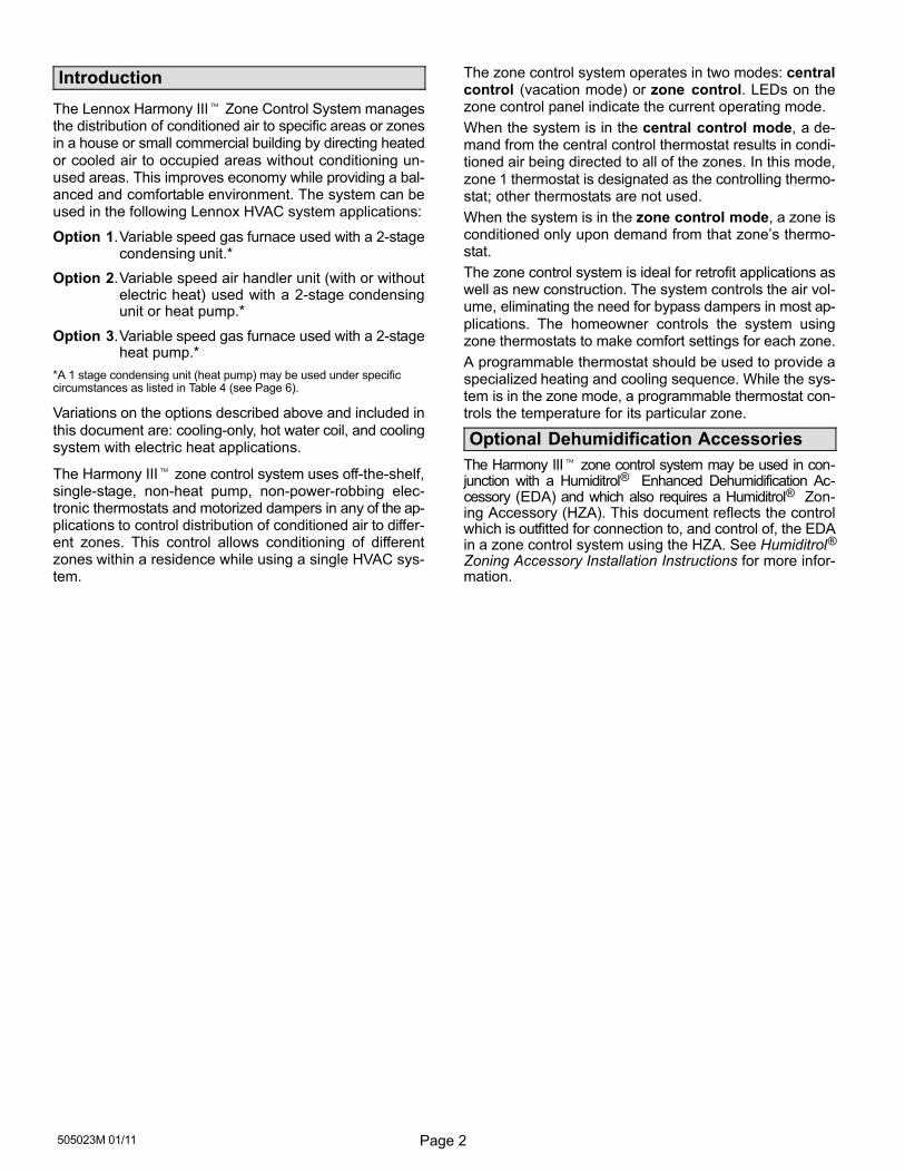
Introduction
The Lennox Harmony III� Zone Control System managesthe distribution of conditioned air to specific areas or zonesin a house or small commercial building by directing heated
or cooled air to occupied areas without conditioning un-used areas. This improves economy while providing a bal-anced and comfortable environment. The system can beused in the following Lennox HVAC system applications:
Option 1.Variable speed gas furnace used with a 2-stagecondensing unit.*
Option 2.Variable speed air handler unit (with or withoutelectric heat) used with a 2-stage condensingunit or heat pump.*
Option 3.Variable speed gas furnace used with a 2-stageheat pump.*
*A 1 stage condensing unit (heat pump) may be used under specificcircumstances as listed in Table 4 (see Page 6).
Variations on the options described above and included in
this document are: cooling−only, hot water coil, and coolingsystem with electric heat applications.
The Harmony III� zone control system uses off−the−shelf,single-stage, non-heat pump, non−power-robbing elec-tronic thermostats and motorized dampers in any of the ap-plications to control distribution of conditioned air to differ-ent zones. This control allows conditioning of differentzones within a residence while using a single HVAC sys-tem.
The zone control system operates in two modes: centralcontrol (vacation mode) or zone control. LEDs on thezone control panel indicate the current operating mode.
When the system is in the central control mode, a de-mand from the central control thermostat results in condi-tioned air being directed to all of the zones. In this mode,
zone 1 thermostat is designated as the controlling thermo-stat; other thermostats are not used.
When the system is in the zone control mode, a zone isconditioned only upon demand from that zone’s thermo-stat.
The zone control system is ideal for retrofit applications aswell as new construction. The system controls the air vol-ume, eliminating the need for bypass dampers in most ap-
plications. The homeowner controls the system usingzone thermostats to make comfort settings for each zone.
A programmable thermostat should be used to provide aspecialized heating and cooling sequence. While the sys-tem is in the zone mode, a programmable thermostat con-trols the temperature for its particular zone.
Optional Dehumidification Accessories
The Harmony III� zone control system may be used in con-junction with a Humiditrol® Enhanced Dehumidification Ac-cessory (EDA) and which also requires a Humiditrol® Zon-ing Accessory (HZA). This document reflects the controlwhich is outfitted for connection to, and control of, the EDAin a zone control system using the HZA. See Humiditrol®
Zoning Accessory Installation Instructions for more infor-mation.
Page 3 HARMONY III� ZONE CONTROL SYSTEM
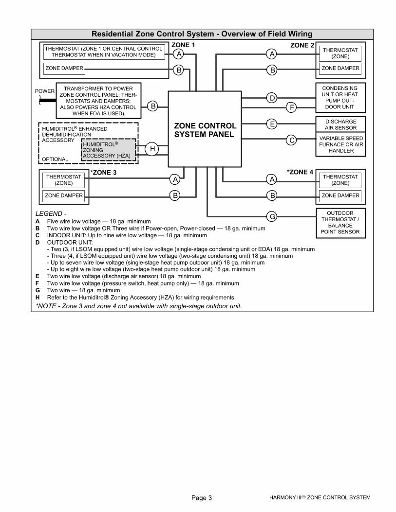
Residential Zone Control System − Overview of Field Wiring
VARIABLE SPEED
FURNACE OR AIR
HANDLER
ZONE 1 ZONE 2
*ZONE 4
POWER
THERMOSTAT (ZONE 1 OR CENTRAL CONTROL
THERMOSTAT WHEN IN VACATION MODE)
ZONE DAMPER
THERMOSTAT
(ZONE)
CONDENSING
UNIT OR HEAT
PUMP OUT-
DOOR UNIT
TRANSFORMER TO POWER
ZONE CONTROL PANEL, THER-
MOSTATS AND DAMPERS;
ALSO POWERS HZA CONTROL
WHEN EDA IS USED)
THERMOSTAT
(ZONE)
LEGEND −A Five wire low voltage � 18 ga. minimum
B Two wire low voltage OR Three wire if Power−open, Power−closed � 18 ga. minimum
C INDOOR UNIT: Up to nine wire low voltage � 18 ga. minimum
D OUTDOOR UNIT:− Two (3, if LSOM equipped unit) wire low voltage (single-stage condensing unit or EDA) 18 ga. minimum− Three (4, if LSOM equipped unit) wire low voltage (two-stage condensing unit) 18 ga. minimum− Up to seven wire low voltage (single-stage heat pump outdoor unit) 18 ga. minimum− Up to eight wire low voltage (two-stage heat pump outdoor unit) 18 ga. minimum
E Two wire low voltage (discharge air sensor) 18 ga. minimum
F Two wire low voltage (pressure switch, heat pump only) � 18 ga. minimum
G Two wire � 18 ga. minimum
H Refer to the Humiditrol® Zoning Accessory (HZA) for wiring requirements.
*NOTE − Zone 3 and zone 4 not available with single-stage outdoor unit.
OUTDOOR
THERMOSTAT /
BALANCE
POINT SENSOR
ZONE CONTROLSYSTEM PANEL
A
B
DISCHARGE
AIR SENSORE
C
D
F
ZONE DAMPER
G
*ZONE 3THERMOSTAT
(ZONE)
ZONE DAMPER
ZONE DAMPER
HUMIDITROL® ENHANCEDDEHUMIDIFICATIONACCESSORY
HUMIDITROL®
ZONINGACCESSORY (HZA)
OPTIONAL
H
A
B
B
A
B
A
B
Page 4505023M 01/11
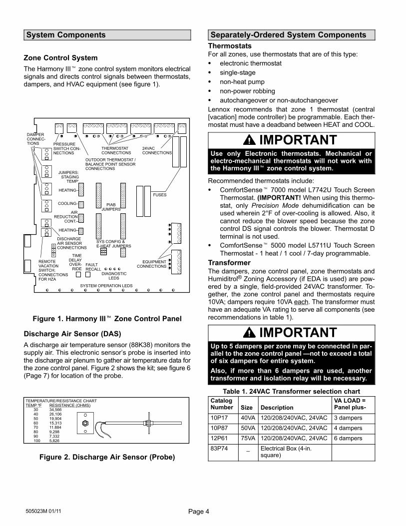
System Components
Zone Control System
The Harmony III� zone control system monitors electricalsignals and directs control signals between thermostats,dampers, and HVAC equipment (see figure 1).
JUMPERS:STAGING
TEMP‘
HEATING−−
COOLING−−
AIR REDUCTION
CONT.−−
HEATING−−
EQUIPMENTCONNECTIONS
THERMOSTATCONNECTIONS
24VACCONNECTIONS
PIABJUMPERS
SYS CONFIG &E−HEAT JUMPERS
DIAGNOSTICLEDS
TIMEDELAYOVER-
RIDEFAULTRECALL
OUTDOOR THERMOSTAT /BALANCE POINT SENSORCONNECTIONS
PRESSURESWITCH CON-NECTIONS
DISCHARGEAIR SENSORCONNECTIONS
DAMPERCONNEC-TIONS
FUSES
SYSTEM OPERATION LEDS
REMOTEVACATIONSWITCH;CONNECTIONSFOR HZA
Figure 1. Harmony III� Zone Control Panel
Discharge Air Sensor (DAS)
A discharge air temperature sensor (88K38) monitors thesupply air. This electronic sensor’s probe is inserted into
the discharge air plenum to gather air temperature data forthe zone control panel. Figure 2 shows the kit; see figure 6(Page 7) for location of the probe.
TEMPERATURE/RESISTANCE CHARTTEMP ºF RESISTANCE (OHMS)
30 34,56640 26,10650 19,90460 15,31370 11.88480 9,29890 7,332100 5,826
Figure 2. Discharge Air Sensor (Probe)
Separately-Ordered System Components
ThermostatsFor all zones, use thermostats that are of this type:
� electronic thermostat
� single-stage
� non-heat pump
� non-power robbing
� autochangeover or non−autochangeover
Lennox recommends that zone 1 thermostat (central[vacation] mode controller) be programmable. Each ther-mostat must have a deadband between HEAT and COOL.
IMPORTANTUse only Electronic thermostats. Mechanical orelectro-mechanical thermostats will not work withthe Harmony III� zone control system.
Recommended thermostats include:
� ComfortSense� 7000 model L7742U Touch Screen
Thermostat. (IMPORTANT! When using this thermo-
stat, only Precision Mode dehumidification can beused wherein 2°F of over-cooling is allowed. Also, it
cannot reduce the blower speed because the zonecontrol DS signal controls the blower. Thermostat D
terminal is not used.
� ComfortSense� 5000 model L5711U Touch Screen
Thermostat − 1 heat / 1 cool / 7−day programmable.
TransformerThe dampers, zone control panel, zone thermostats andHumiditrol® Zoning Accessory (if EDA is used) are pow-ered by a single, field−provided 24VAC transformer. To-gether, the zone control panel and thermostats require10VA; dampers require 10VA each. The transformer musthave an adequate VA rating to serve all components (see
recommendations in table 1).
IMPORTANTUp to 5 dampers per zone may be connected in par-allel to the zone control panel �not to exceed a totalof six dampers for entire system.
Also, if more than 6 dampers are used, anothertransformer and isolation relay will be necessary.
Table 1. 24VAC Transformer selection chart
CatalogNumber Size Description
VA LOAD =Panel plus−
10P17 40VA 120/208/240VAC, 24VAC 3 dampers
10P87 50VA 120/208/240VAC, 24VAC 4 dampers
12P61 75VA 120/208/240VAC, 24VAC 6 dampers
83P74 _ Electrical Box (4-in.square)
Page 5 HARMONY III� ZONE CONTROL SYSTEM
Dampers
Motorized 24VAC powered closed/spring return opendampers are standard for the Harmony III� zone controlsystem. However, �power-open/spring-close" and �power-open/power-close" dampers can be accommodated.
Remote Vacation Switch (field−provided option)
The Harmony III� zone control panel includes connec-tions for an optional remote vacation switch (see figure 1).The same connections are also used for connecting an op-
tional Humiditrol® Zoning Accessory controller (see Humi-ditrol® Zoning Accessory Installation Instructions for de-tails).
NOTE − If a remote vacation switch is connected forrouting to a convenient location for end user opera-tion, be sure the switch (field-provided) is properly la-beled and instructions provided for proper operation.
DO NOT LOCATE THE REMOTE VACATION SWITCHNEXT TO OTHER HOUSE SWITCHES! THE REC-OMMENDED LOCATION IS NEXT TO ZONE 1 THER-MOSTAT.
Pressure Switch (Heat Pump Systems Only)
A pressure switch (HFC−22 [27W12]; HFC−410A [27W13])is required for applications with a Lennox heat pump (Op-tions 2 and 3). This switch acts as a guard in case of highhead pressures during 1st− and 2nd−stage heating. Theswitch’s cut out and cut in points are shown in table 2.
Table 2. Cut−out and Cut−in (Reset) Points
Refrigerant Cut−Out Cut−in (Reset)
HCFC−22 375 psig (2551 kPa) 275 psig (1862 kPa)
HFC−410A 550 psig (3965 kPa) 425 psig (3102 kPa)
NOTE − If a pressure switch is factory installed in the unit,
do not remove the switch or switch wires.
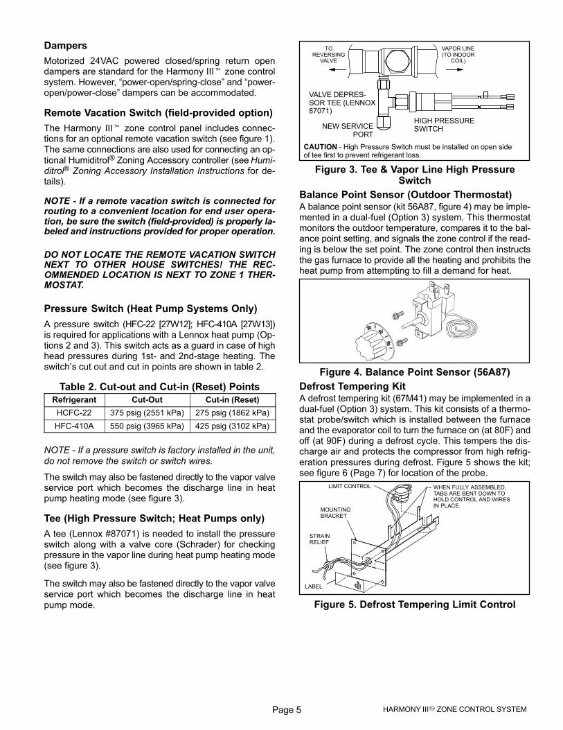
The switch may also be fastened directly to the vapor valveservice port which becomes the discharge line in heatpump heating mode (see figure 3).
Tee (High Pressure Switch; Heat Pumps only)
A tee (Lennox #87071) is needed to install the pressureswitch along with a valve core (Schrader) for checkingpressure in the vapor line during heat pump heating mode(see figure 3).
The switch may also be fastened directly to the vapor valveservice port which becomes the discharge line in heat
pump mode.
TOREVERSING
VALVE
VAPOR LINE(TO INDOOR
COIL)
HIGH PRESSURESWITCHNEW SERVICE
PORT
CAUTION − High Pressure Switch must be installed on open sideof tee first to prevent refrigerant loss.
VALVE DEPRES-SOR TEE (LENNOX87071)
Figure 3. Tee & Vapor Line High PressureSwitch
Balance Point Sensor (Outdoor Thermostat)A balance point sensor (kit 56A87, figure 4) may be imple-mented in a dual-fuel (Option 3) system. This thermostatmonitors the outdoor temperature, compares it to the bal-ance point setting, and signals the zone control if the read-
ing is below the set point. The zone control then instructsthe gas furnace to provide all the heating and prohibits theheat pump from attempting to fill a demand for heat.
Figure 4. Balance Point Sensor (56A87)
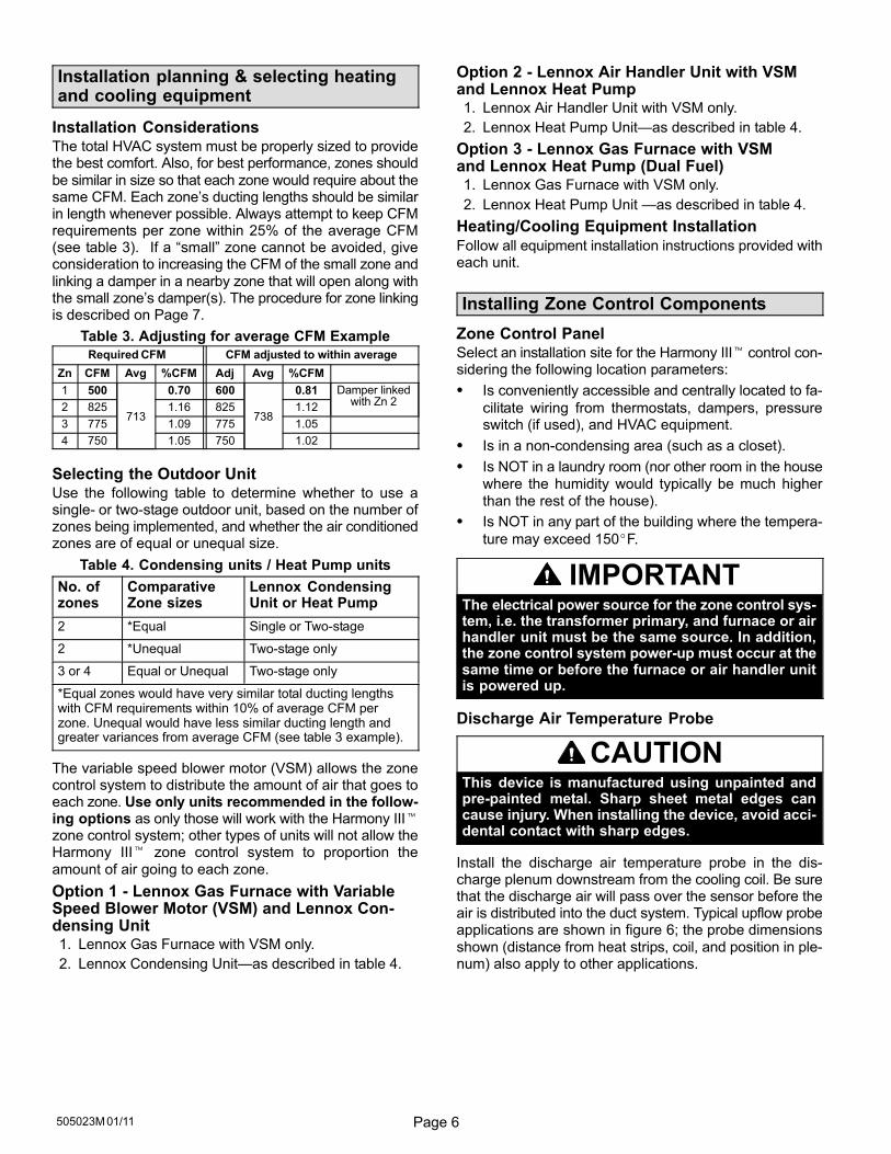
Defrost Tempering KitA defrost tempering kit (67M41) may be implemented in adual-fuel (Option 3) system. This kit consists of a thermo-stat probe/switch which is installed between the furnaceand the evaporator coil to turn the furnace on (at 80F) andoff (at 90F) during a defrost cycle. This tempers the dis-charge air and protects the compressor from high refrig-
eration pressures during defrost. Figure 5 shows the kit;see figure 6 (Page 7) for location of the probe.
LIMIT CONTROL
MOUNTINGBRACKET
STRAINRELIEF
LABEL
WHEN FULLY ASSEMBLED,TABS ARE BENT DOWN TOHOLD CONTROL AND WIRESIN PLACE.
Figure 5. Defrost Tempering Limit Control
Page 6505023M 01/11
Installation planning & selecting heatingand cooling equipment
Installation ConsiderationsThe total HVAC system must be properly sized to providethe best comfort. Also, for best performance, zones should
be similar in size so that each zone would require about thesame CFM. Each zone’s ducting lengths should be similarin length whenever possible. Always attempt to keep CFMrequirements per zone within 25% of the average CFM(see table 3). If a �small" zone cannot be avoided, giveconsideration to increasing the CFM of the small zone and
linking a damper in a nearby zone that will open along withthe small zone’s damper(s). The procedure for zone linkingis described on Page 7.
Table 3. Adjusting for average CFM Example
Required CFM CFM adjusted to within average
Zn CFM Avg %CFM Adj Avg %CFM
1 500
713
0.70 600
738
0.81 Damper linkedwith Zn 2
2 825 1.16 825 1.12
3 775 1.09 775 1.05
4 750 1.05 750 1.02
Selecting the Outdoor UnitUse the following table to determine whether to use asingle− or two−stage outdoor unit, based on the number ofzones being implemented, and whether the air conditionedzones are of equal or unequal size.
Table 4. Condensing units / Heat Pump units
No. ofzones
ComparativeZone sizes
Lennox CondensingUnit or Heat Pump
2 *Equal Single or Two−stage
2 *Unequal Two-stage only
3 or 4 Equal or Unequal Two-stage only
*Equal zones would have very similar total ducting lengthswith CFM requirements within 10% of average CFM perzone. Unequal would have less similar ducting length andgreater variances from average CFM (see table 3 example).
The variable speed blower motor (VSM) allows the zonecontrol system to distribute the amount of air that goes toeach zone. Use only units recommended in the follow-ing options as only those will work with the Harmony III�zone control system; other types of units will not allow theHarmony III� zone control system to proportion the
amount of air going to each zone.
Option 1 − Lennox Gas Furnace with VariableSpeed Blower Motor (VSM) and Lennox Con-densing Unit1. Lennox Gas Furnace with VSM only.
2. Lennox Condensing Unit�as described in table 4.
Option 2 − Lennox Air Handler Unit with VSM and Lennox Heat Pump1. Lennox Air Handler Unit with VSM only.
2. Lennox Heat Pump Unit�as described in table 4.
Option 3 − Lennox Gas Furnace with VSM and Lennox Heat Pump (Dual Fuel)1. Lennox Gas Furnace with VSM only.
2. Lennox Heat Pump Unit �as described in table 4.
Heating/Cooling Equipment Installation
Follow all equipment installation instructions provided witheach unit.
Installing Zone Control Components
Zone Control PanelSelect an installation site for the Harmony III� control con-sidering the following location parameters:
� Is conveniently accessible and centrally located to fa-
cilitate wiring from thermostats, dampers, pressureswitch (if used), and HVAC equipment.
� Is in a non−condensing area (such as a closet).
� Is NOT in a laundry room (nor other room in the house
where the humidity would typically be much higher
than the rest of the house).
� Is NOT in any part of the building where the tempera-
ture may exceed 150�F.
IMPORTANTThe electrical power source for the zone control sys-tem, i.e. the transformer primary, and furnace or airhandler unit must be the same source. In addition,the zone control system power−up must occur at thesame time or before the furnace or air handler unitis powered up.
Discharge Air Temperature Probe
CAUTIONThis device is manufactured using unpainted andpre-painted metal. Sharp sheet metal edges cancause injury. When installing the device, avoid acci-dental contact with sharp edges.
Install the discharge air temperature probe in the dis-charge plenum downstream from the cooling coil. Be surethat the discharge air will pass over the sensor before theair is distributed into the duct system. Typical upflow probeapplications are shown in figure 6; the probe dimensions
shown (distance from heat strips, coil, and position in ple-num) also apply to other applications.

Page 7 HARMONY III� ZONE CONTROL SYSTEM
plenum
coil
FURNACEFRONTVIEW
1/2 the width
of theplenum
sensor centered indischarge airflow
(ALSO see note 1)
When possible, position the probe somedistance away from the coil rather than inthe immediate coil area. The Discharge AirTemperature Sensor should be located atleast 10 inches above the coil.
Fasten the probe bracket to the plenumwith two self- tapping sheet metal screws.
Connect wires to DAS onzone control panel, NOTon AHC or IFC (see fig-ures 21 through 23)
19(254)
AIR HANDLERSIDE VIEW
ECBElectric
HeatStrips
SENSOR PROBE (centerside−to−side) − see PROBEMOUNTING DETAIL below
NOTE 1 − FOR UNITS WITH HUMIDITROL�Discharge air sensor (DAS)MUST be located on the output side of the EDA (if used; see Humiditrol Zon-ing Accessory Installation 505,337M)
SENSOR PROBEsee PROBEMOUNTING
DETAIL below
PLENUM
PROBE MOUNTING DETAIL
Figure 6. Discharge Air Temperature Sensorinstallation (Typical Upflow Furnace)
Be sure that the tip of the sensor is located approximately10 inches from the indoor coil in the discharge plenum, and1/2 the depth of the plenum, and centered over the dis-
charge airflow, side-to-side.
Defrost Tempering (Kit 67M41)Install the defrost tempering probe (if used) where shown
in figure 7. (See 504,797M installation instructions.)
plenum
coil
furnace
front
defrost temperingprobe/limit control (ifused in Option 3)
Figure 7. Defrost Tempering Probe Placement(Typical Upflow Furnace)
ThermostatsLocate each thermostat in its zone. If two or more rooms
are within a single zone, place the thermostat in a locationthat is central to all rooms. For example, if a zone containstwo bedrooms, try to place the thermostat in a hallway nearboth bedrooms.
Do not install thermostats in drafty areas, behind doors, incorners, near radiant heat sources (appliances), nearsunny windows, near concealed pipes and chimneys, nor
in unconditioned spaces such as closets or exterior walls.
Dampers
NOTE − The power source for the transformer must be the
same power source as the indoor unit’s transformer.
Motorized dampers in the supply duct system regulate airto the zones. Some applications will be unique and requiremore than one damper per zone. If additional dampers arerequired, refer to the the wiring diagram in the Common
System Component Wiring section (page 16). Also, if morethan 6 dampers are used, another transformer and isola-tion relay will be necessary.
For more effective zone isolation, the return duct systemmay also be dampered by zone. Dampers for each zonemust be wired in parallel. Install dampers in the desiredlocations; then run thermostat wire from the damper to the
zone control panel and damper relays as needed.
Zone Linking�Zone link a small zone to a large zone bywiring dampers in a manner similar to figure 8. Effectively,this distributes some of the small zone’s air to anotherzone to reduce the chance of overheating or overcoolingthe smaller zone. Table 3 (Page 6) shows an example ofan unequal zone and how to adjust to bring it within 25% of
the average CFM. Figure 8 shows how the dampers maybe linked to distribute some of the air from a small zone intoanother zone.
Zone 2 (largest zone)
Zone 1 (smallest zone)
This damper is linked to the zone 1damper; it opens when Zone 1opens to redirect some air awayfrom Zone 1 and closes only whenzone 1 damper closes.
RELAYZONE 2
DAMPER
DAMPER
DAMPER
All Zone 2dampersopen onlyfor calls toZone 2calls for air.
DAMPER
ZONE 1
Note: ZoneDampers arePower−Closetype.
Zone Demands to Small and Large Zones
ZoneDampers
Zone with Demand
None Small Sm.& Lg. Large
Sm.Zone Closed (24V) Open (0V) Open (0V) Closed (24V)
Lg.Zone
Closed (24V) Open (0V) Open (0V) Open (0V)
Closed (24V) Closed (24V) Open (0V) Open (0V)
Closed (24V) Closed (24V) Open (0V) Open (0V)
Note: Zone Dampers are Power−Close type.
Figure 8. Zone Linking
Transformer
Obtain an appropriately−rated transformer (see table 1,Page 4). Install it in either the indoor unit or in an electricaljunction box. Install the transformer in the electrical junc-
tion box near the zone control panel.
Page 8505023M 01/11
Integrated Control Electrical Adjustments (VSM Furnaces other than G71MPP & SLP98)
General Information
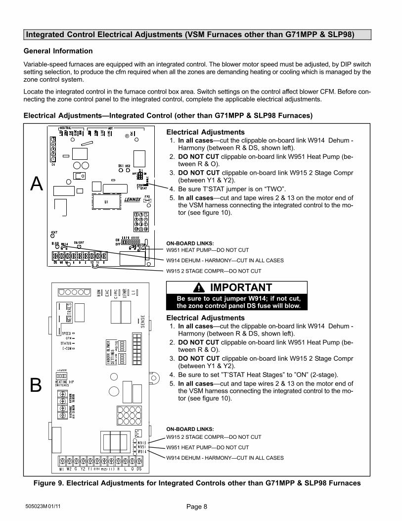
Variable-speed furnaces are equipped with an integrated control. The blower motor speed must be adjusted, by DIP switchsetting selection, to produce the cfm required when all the zones are demanding heating or cooling which is managed by thezone control system.
Locate the integrated control in the furnace control box area. Switch settings on the control affect blower CFM. Before con-necting the zone control panel to the integrated control, complete the applicable electrical adjustments.
Electrical Adjustments�Integrated Control (other than G71MPP & SLP98 Furnaces)
Electrical Adjustments1. In all cases�cut the clippable on−board link W914 Dehum −
Harmony (between R & DS, shown left).
2. DO NOT CUT clippable on−board link W951 Heat Pump (be-tween R & O).
3. DO NOT CUT clippable on−board link W915 2 Stage Compr(between Y1 & Y2).
4. Be sure T’STAT jumper is on �TWO".
5. In all cases�cut and tape wires 2 & 13 on the motor end ofthe VSM harness connecting the integrated control to the mo-tor (see figure 10).
ON−BOARD LINKS:
W951 HEAT PUMP�DO NOT CUT
W914 DEHUM − HARMONY�CUT IN ALL CASES
W915 2 STAGE COMPR�DO NOT CUT
Electrical Adjustments1. In all cases�cut the clippable on−board link W914 Dehum −
Harmony (between R & DS, shown left).
2. DO NOT CUT clippable on−board link W951 Heat Pump (be-tween R & O).
3. DO NOT CUT clippable on−board link W915 2 Stage Compr(between Y1 & Y2).
4. Be sure to set "T’STAT Heat Stages" to "ON" (2−stage).
5. In all cases�cut and tape wires 2 & 13 on the motor end ofthe VSM harness connecting the integrated control to the mo-tor (see figure 10).
ON−BOARD LINKS:
W915 2 STAGE COMPR�DO NOT CUT
W951 HEAT PUMP�DO NOT CUT
W914 DEHUM − HARMONY�CUT IN ALL CASES
®
Be sure to cut jumper W914; if not cut,the zone control panel DS fuse will blow.
IMPORTANT
Figure 9. Electrical Adjustments for Integrated Controls other than G71MPP & SLP98 Furnaces
Page 9 HARMONY III� ZONE CONTROL SYSTEM
Integrated Control Electrical Adjustments (VSM Furnaces other than G71MPP & SLP98 [cont’d])
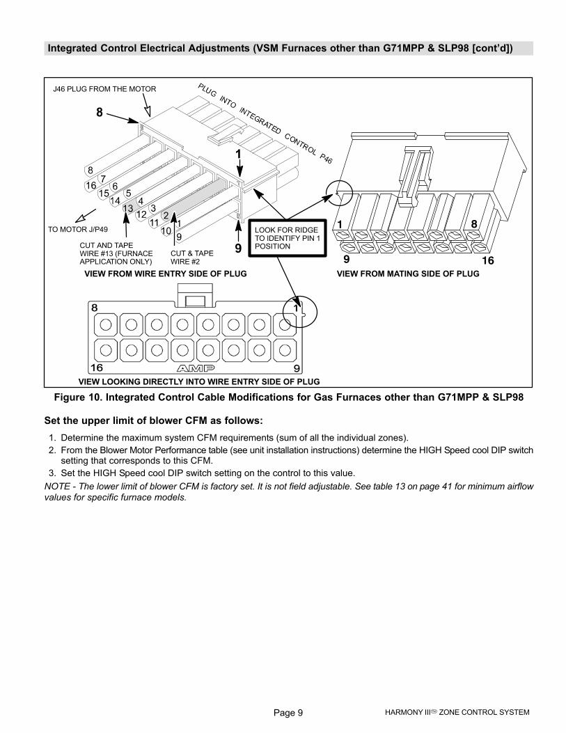
CUT AND TAPE WIRE #13 (FURNACEAPPLICATION ONLY)
LOOK FOR RIDGETO IDENTIFY PIN 1POSITION
CUT & TAPEWIRE #2
1
9VIEW FROM MATING SIDE OF PLUG
VIEW LOOKING DIRECTLY INTO WIRE ENTRY SIDE OF PLUG
VIEW FROM WIRE ENTRY SIDE OF PLUG
8
16
TO MOTOR J/P49
J46 PLUG FROM THE MOTOR
Figure 10. Integrated Control Cable Modifications for Gas Furnaces other than G71MPP & SLP98
Set the upper limit of blower CFM as follows:
1. Determine the maximum system CFM requirements (sum of all the individual zones).
2. From the Blower Motor Performance table (see unit installation instructions) determine the HIGH Speed cool DIP switchsetting that corresponds to this CFM.
3. Set the HIGH Speed cool DIP switch setting on the control to this value.
NOTE − The lower limit of blower CFM is factory set. It is not field adjustable. See table 13 on page 41 for minimum airflow
values for specific furnace models.
Page 10505023M 01/11
Integrated Control Electrical Adjustments (VSM Furnaces G71MPP & SLP98)
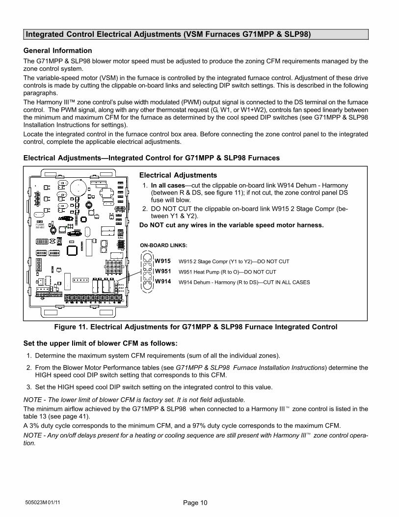
General Information
The G71MPP & SLP98 blower motor speed must be adjusted to produce the zoning CFM requirements managed by thezone control system.
The variable-speed motor (VSM) in the furnace is controlled by the integrated furnace control. Adjustment of these drivecontrols is made by cutting the clippable on-board links and selecting DIP switch settings. This is described in the followingparagraphs.
The Harmony III� zone control´s pulse width modulated (PWM) output signal is connected to the DS terminal on the furnace
control. The PWM signal, along with any other thermostat request (G, W1, or W1+W2), controls fan speed linearly betweenthe minimum and maximum CFM for the furnace as determined by the cool speed DIP switches (see G71MPP & SLP98Installation Instructions for settings).
Locate the integrated control in the furnace control box area. Before connecting the zone control panel to the integratedcontrol, complete the applicable electrical adjustments.
Electrical Adjustments�Integrated Control for G71MPP & SLP98 Furnaces
+
W915 2 Stage Compr (Y1 to Y2)�DO NOT CUT
W951 Heat Pump (R to O)�DO NOT CUT
W914 Dehum − Harmony (R to DS)�CUT IN ALL CASES
EAC
HUM
ON−BOARD LINKS:
Electrical Adjustments
1. In all cases�cut the clippable on-board link W914 Dehum − Harmony(between R & DS, see figure 11); if not cut, the zone control panel DSfuse will blow.
2. DO NOT CUT the clippable on-board link W915 2 Stage Compr (be-tween Y1 & Y2).
Do NOT cut any wires in the variable speed motor harness.
Figure 11. Electrical Adjustments for G71MPP & SLP98 Furnace Integrated Control
Set the upper limit of blower CFM as follows:
1. Determine the maximum system CFM requirements (sum of all the individual zones).
2. From the Blower Motor Performance tables (see G71MPP & SLP98 Furnace Installation Instructions) determine theHIGH speed cool DIP switch setting that corresponds to this CFM.
3. Set the HIGH speed cool DIP switch setting on the integrated control to this value.
NOTE − The lower limit of blower CFM is factory set. It is not field adjustable.
The minimum airflow achieved by the G71MPP & SLP98 when connected to a Harmony III� zone control is listed in thetable 13 (see page 41).
A 3% duty cycle corresponds to the minimum CFM, and a 97% duty cycle corresponds to the maximum CFM.
NOTE − Any on/off delays present for a heating or cooling sequence are still present with Harmony III� zone control opera-
tion.
Page 11 HARMONY III� ZONE CONTROL SYSTEM
Air Handler Control Electrical Adjustments (All model VSM Air Handlers)
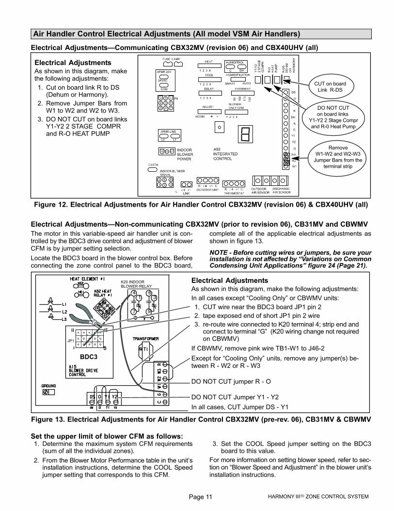
Electrical Adjustments�Communicating CBX32MV (revision 06) and CBX40UHV (all)
CUT on board
Link R−DS
Remove
W1−W2 and W2−W3
Jumper Bars from the
terminal strip
Electrical AdjustmentsAs shown in this diagram, makethe following adjustments:
1. Cut on board link R to DS (Dehum or Harmony).
2. Remove Jumper Bars fromW1 to W2 and W2 to W3.
3. DO NOT CUT on board linksY1−Y2 2 STAGE COMPRand R−O HEAT PUMP
DO NOT CUT
on board links
Y1−Y2 2 Stage Compr
and R−0 Heat Pump
Figure 12. Electrical Adjustments for Air Handler Control CBX32MV (revision 06) & CBX40UHV (all)
Electrical Adjustments�Non−communicating CBX32MV (prior to revision 06), CB31MV and CBWMV
The motor in this variable-speed air handler unit is con-trolled by the BDC3 drive control and adjustment of blowerCFM is by jumper setting selection.
Locate the BDC3 board in the blower control box. Beforeconnecting the zone control panel to the BDC3 board,
complete all of the applicable electrical adjustments asshown in figure 13.
NOTE − Before cutting wires or jumpers, be sure yourinstallation is not affected by �Variations on CommonCondensing Unit Applications" figure 24 (Page 21).
14
7
36
9
K20 INDOORBLOWER RELAY
JP1
BDC3
Electrical AdjustmentsAs shown in this diagram, make the following adjustments:
In all cases except �Cooling Only" or CBWMV units:
1. CUT wire near the BDC3 board JP1 pin 2
2. tape exposed end of short JP1 pin 2 wire
3. re−route wire connected to K20 terminal 4; strip end andconnect to terminal �G" (K20 wiring change not requiredon CBWMV)
If CBWMV, remove pink wire TB1−W1 to J46−2
Except for �Cooling Only" units, remove any jumper(s) be-tween R − W2 or R − W3
DO NOT CUT jumper R − O
DO NOT CUT Jumper Y1 − Y2
In all cases, CUT Jumper DS − Y1
Figure 13. Electrical Adjustments for Air Handler Control CBX32MV (pre−rev. 06), CB31MV & CBWMV
Set the upper limit of blower CFM as follows:1. Determine the maximum system CFM requirements
(sum of all the individual zones).
2. From the Blower Motor Performance table in the unit’sinstallation instructions, determine the COOL Speedjumper setting that corresponds to this CFM.
3. Set the COOL Speed jumper setting on the BDC3board to this value.
For more information on setting blower speed, refer to sec-tion on �Blower Speed and Adjustment" in the blower unit’sinstallation instructions.
Page 12505023M 01/11
Zone Control Panel Jumpers (General Information)
Setup for controlling equipment staging andvolume of air to zonesThis section provides information for installing jumpers onthe zone control panel jumper banks (see figure 14). Thesejumpers define how the zone control system functions tocontrol equipment staging and to deliver the properamount of CFM to the zones.
HEATING STAGINGJUMPERS
COOLING STAGINGJUMPERS
CONTINUOUS AIRREDUCTION JUMPERS
HEATING AIRREDUCTION JUMPERS
PIABJUMPERS
SYS CONFIG &E−HEAT JUMPERS
Figure 14. Zone Control Panel Jumper Banks
CAUTIONStatic electrical discharge will damage electronics.
Discharge static electricity before touching the zonecontrol panel. Touch a grounded metal object be-fore touching the circuit board.
How PIAB Jumpers affect blower operation
A variable−speed motor will operate at its minimum speedor at any increment faster up to its maximum speed. ThePercentage Into Adjustment Band (PIAB) jumpers controlthe speed variance of the motor.
When the zone control’s PIAB jumpers are set to 0%, theblower operates at the minimum air volume produced bythe air handler and when set to 100%, the blower operatesat maximum air volume produced by the air handler (seeyour air handler installation instructions for specific CFMs).
For example: if an air handler has a minimum air volume of 800 CFM,and a maximum of 1500 CFM, and the jumper is set to 0%, the airdelivered to the zone will be 800 CFM. Similarly, if the jumper is set to100%, the air delivered to the zone is 1500 CFM. By placing a jumperin the 50% position, you will direct airflow midway between the blow-er’s minimum and maximum CFM capacities.
PIAB JUMPER = 0%MIN. 800 CFM
PIAB JUMPER = 100%MAX. 1500 CFM
(MOTOR RUNS ATMINIMUM SPEED)
(MOTOR RUNS ATMAXIMUM SPEED)
(MOTOR RUNS AT VARIABLE SPEEDS)
PIAB JUMPER = 50%MID. 1150 CFM
Figure 15. VSM Adjustment Band Example
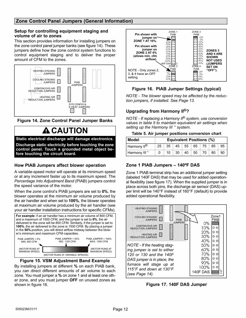
By installing jumpers at different % on each PIAB bank,you can direct different amounts of air volume to eachzone. You must jumper a % on zone 1 and at least one oth-er zone, and you must jumper OFF on unused zones asshown in figure 16.
Pin shown withjumper on
ZONE 1 AT 10%.
Pin shown withjumper on
ZONE 2 AT 0% (allows min. cfm
airflow).
ZONE 1 ZONE 3PIAB PIAB
ZONE 2 ZONE 4PIAB PIAB
NOTE − Only zones 2,3, & 4 have an OFFsetting.
ZONES 3AND 4 ARESHOWNNOT USED(JUMPERSSET ON�OFF").
Figure 16. PIAB Jumper Settings (typical)
NOTE − The blower speed may be affected by the reduc-
tion jumpers, if installed. See Page 13.
Upgrading from Harmony II®?
NOTE − If replacing a Harmony II® system, use conversionvalues in table 5 to maintain equivalent air settings whensetting up the Harmony III� system.
Table 5. Air jumper positions conversion chart
Model Equivalent Positions (%)
Harmony II® 25 35 45 55 65 75 85 95
Harmony III� 0 10 30 40 50 70 80 90
Zone 1 PIAB Jumpers – 140ºF DAS
Zone 1 PIAB terminal strip has an additional jumper setting(labeled 140F DAS) that may be used for added operation-
al flexibility (see figure 17). When the supplied jumper is inplace across both pins, the discharge air sensor (DAS) up-per limit will be 140°F instead of 160°F (default) to provideadded operational flexibility.
NOTE − If the heating stag-
ing jumper is set to either
120 or 130 and the 140F
DAS jumper is in place, the
furnace will stage up at
115°F and down at 130°F
(see Page 14).
HEATING STAGINGJUMPERS
COOLING STAGINGJUMPERS
CONTINUOUS AIRREDUCTION JUMPERS
HEATING AIRREDUCTION JUMPERS
PIABJUMPERS
Figure 17. 140F DAS Jumper
Page 13 HARMONY III� ZONE CONTROL SYSTEM
Zone Control Panel Jumpers (Determining PIAB Jumper Settings)
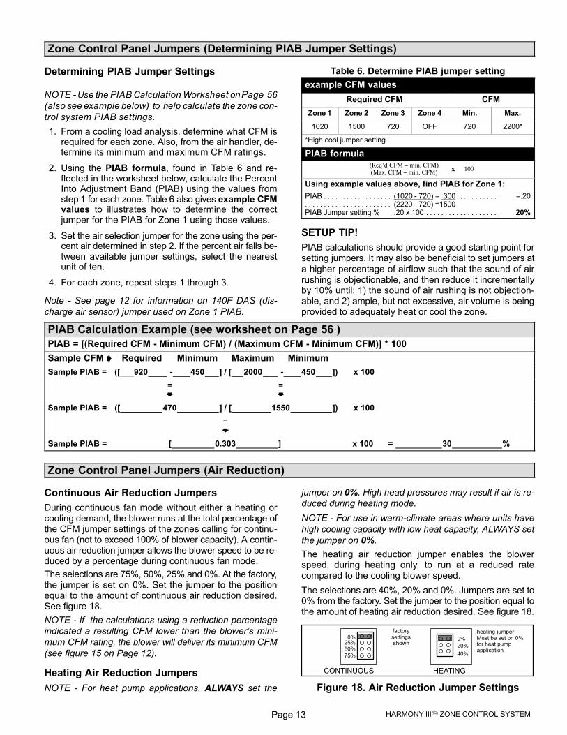
Determining PIAB Jumper Settings
NOTE − Use the PIAB Calculation Worksheet on Page 56
(also see example below) to help calculate the zone con-
trol system PIAB settings.
1. From a cooling load analysis, determine what CFM isrequired for each zone. Also, from the air handler, de-termine its minimum and maximum CFM ratings.
2. Using the PIAB formula, found in Table 6 and re-flected in the worksheet below, calculate the PercentInto Adjustment Band (PIAB) using the values fromstep 1 for each zone. Table 6 also gives example CFMvalues to illustrates how to determine the correctjumper for the PIAB for Zone 1 using those values.
3. Set the air selection jumper for the zone using the per-cent air determined in step 2. If the percent air falls be-tween available jumper settings, select the nearestunit of ten.
4. For each zone, repeat steps 1 through 3.
Note − See page 12 for information on 140F DAS (dis-
charge air sensor) jumper used on Zone 1 PIAB.
Table 6. Determine PIAB jumper setting
example CFM values
Required CFM CFM
Zone 1 Zone 2 Zone 3 Zone 4 Min. Max.
1020 1500 720 OFF 720 2200*
*High cool jumper setting
PIAB formula
100(Req’d CFM − min. CFM)(Max. CFM − min. CFM) x
Using example values above, find PIAB for Zone 1:
PIAB (1020 − 720) = 300 =.20. . . . . . . . . . . . . . . . . . . . . . . . . . . . . (2220 − 720) =1500. . . . . . . . . . . . . . . . . . . . . . .
PIAB Jumper setting % .20 x 100 20%. . . . . . . . . . . . . . . . . . . .
SETUP TIP!
PIAB calculations should provide a good starting point forsetting jumpers. It may also be beneficial to set jumpers at
a higher percentage of airflow such that the sound of airrushing is objectionable, and then reduce it incrementallyby 10% until: 1) the sound of air rushing is not objection-able, and 2) ample, but not excessive, air volume is beingprovided to adequately heat or cool the zone.
PIAB Calculation Example (see worksheet on Page 56 )
PIAB = [(Required CFM − Minimum CFM) / (Maximum CFM − Minimum CFM)] * 100
Sample CFM � Required Minimum Maximum Minimum
Sample PIAB = ([___920 − 450 ] / [ 2000 − 450 ]) x 100
= =� �
Sample PIAB = ([ 470 ] / [ 1550 ]) x 100
=�
Sample PIAB = [ 0.303 ] x 100 = 30 %
Zone Control Panel Jumpers (Air Reduction)
Continuous Air Reduction Jumpers
During continuous fan mode without either a heating orcooling demand, the blower runs at the total percentage ofthe CFM jumper settings of the zones calling for continu-ous fan (not to exceed 100% of blower capacity). A contin-uous air reduction jumper allows the blower speed to be re-duced by a percentage during continuous fan mode.
The selections are 75%, 50%, 25% and 0%. At the factory,the jumper is set on 0%. Set the jumper to the positionequal to the amount of continuous air reduction desired.See figure 18.
NOTE − If the calculations using a reduction percentage
indicated a resulting CFM lower than the blower’s mini-
mum CFM rating, the blower will deliver its minimum CFM
(see figure 15 on Page 12).
Heating Air Reduction Jumpers
NOTE − For heat pump applications, ALWAYS set the
jumper on 0%. High head pressures may result if air is re-
duced during heating mode.
NOTE − For use in warm−climate areas where units have
high cooling capacity with low heat capacity, ALWAYS set
the jumper on 0%.
The heating air reduction jumper enables the blowerspeed, during heating only, to run at a reduced ratecompared to the cooling blower speed.
The selections are 40%, 20% and 0%. Jumpers are set to0% from the factory. Set the jumper to the position equal tothe amount of heating air reduction desired. See figure 18.
CONTINUOUS HEATING
0%
20%
40%75%
50%
0%25%
factorysettingsshown
heating jumperMust be set on 0%for heat pumpapplication
Figure 18. Air Reduction Jumper Settings
Page 14505023M 01/11
Zone Control Panel Jumpers (Heat/Cool Staging)
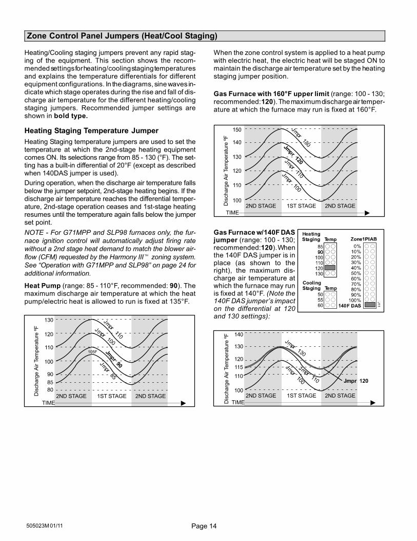
Heating/Cooling staging jumpers prevent any rapid stag-ing of the equipment. This section shows the recom-mended settings for heating/cooling staging temperaturesand explains the temperature differentials for differentequipment configurations. In the diagrams, sine waves in-dicate which stage operates during the rise and fall of dis-
charge air temperature for the different heating/coolingstaging jumpers. Recommended jumper settings areshown in bold type.
Heating Staging Temperature Jumper
Heating Staging temperature jumpers are used to set thetemperature at which the 2nd−stage heating equipmentcomes ON. Its selections range from 85 − 130 (°F). The set-ting has a built-in differential of 20°F (except as describedwhen 140DAS jumper is used).
During operation, when the discharge air temperature falls
below the jumper setpoint, 2nd-stage heating begins. If thedischarge air temperature reaches the differential temper-ature, 2nd-stage operation ceases and 1st-stage heatingresumes until the temperature again falls below the jumperset point.
NOTE − For G71MPP and SLP98 furnaces only, the fur-
nace ignition control will automatically adjust firing rate
without a 2nd stage heat demand to match the blower air-
flow (CFM) requested by the Harmony III� zoning system.
See �Operation with G71MPP and SLP98" on page 24 for
additional information.
Heat Pump (range: 85 − 110°F, recommended: 90). Themaximum discharge air temperature at which the heatpump/electric heat is allowed to run is fixed at 135°F.
105F
1ST STAGE2ND STAGE
TIME �2ND STAGED
ischarg
e A
ir T
em
pera
ture
ºF
When the zone control system is applied to a heat pumpwith electric heat, the electric heat will be staged ON tomaintain the discharge air temperature set by the heatingstaging jumper position.
Gas Furnace with 160°F upper limit (range: 100 − 130;recommended: 120). The maximum discharge air temper-ature at which the furnace may run is fixed at 160°F.
Dis
charg
e A
ir T
em
pera
ture
ºF
1ST STAGE2ND STAGE
TIME �2ND STAGE
Gas Furnace w/140F DASjumper (range: 100 − 130;recommended: 120). Whenthe 140F DAS jumper is inplace (as shown to theright), the maximum dis-charge air temperature atwhich the furnace may runis fixed at 140°F. (Note the140F DAS jumper’s impacton the differential at 120and 130 settings):
1ST STAGE2ND STAGE
TIME �2ND STAGE
Dis
charg
e A
ir T
em
pera
ture
ºF
Page 15 HARMONY III� ZONE CONTROL SYSTEM
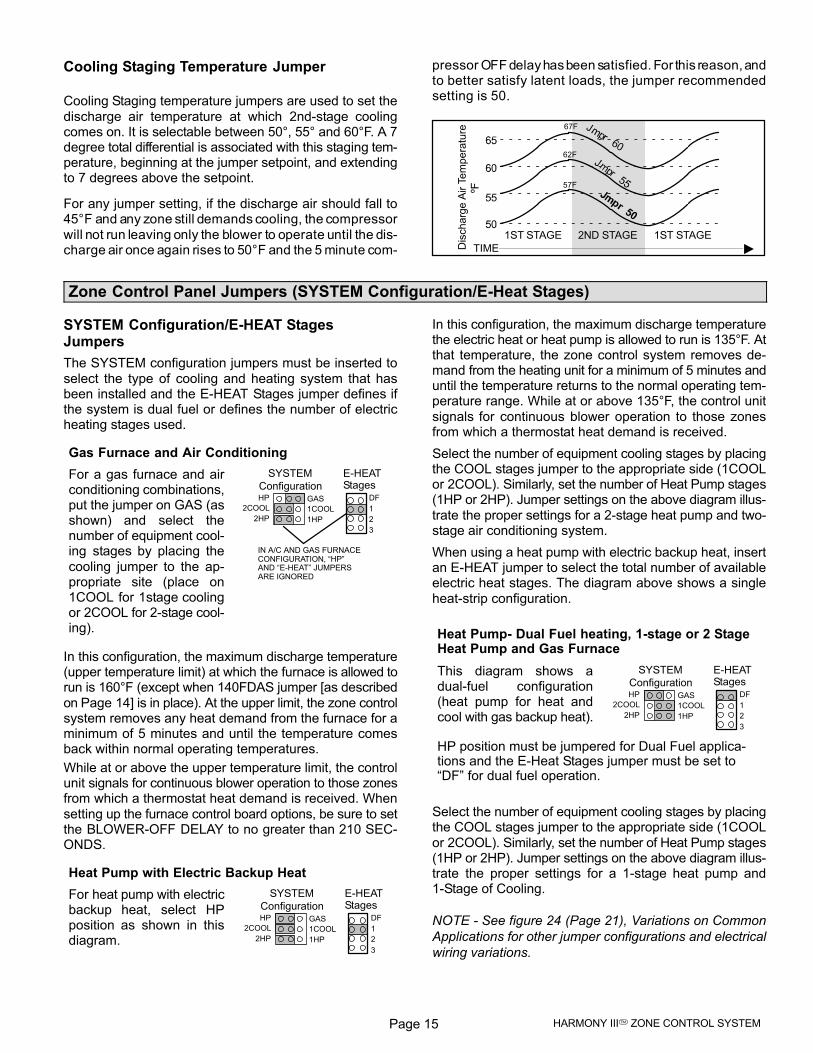
Cooling Staging Temperature Jumper
Cooling Staging temperature jumpers are used to set the
discharge air temperature at which 2nd−stage coolingcomes on. It is selectable between 50°, 55° and 60°F. A 7degree total differential is associated with this staging tem-perature, beginning at the jumper setpoint, and extendingto 7 degrees above the setpoint.
For any jumper setting, if the discharge air should fall to45°F and any zone still demands cooling, the compressor
will not run leaving only the blower to operate until the dis-charge air once again rises to 50°F and the 5 minute com-
pressor OFF delay has been satisfied. For this reason, andto better satisfy latent loads, the jumper recommendedsetting is 50.
1ST STAGE 2ND STAGE
67F
62F
57F
1ST STAGE
TIME �Dis
charg
e A
ir T
em
pera
ture
ºF
Zone Control Panel Jumpers (SYSTEM Configuration/E−Heat Stages)
SYSTEM Configuration/E−HEAT StagesJumpers
The SYSTEM configuration jumpers must be inserted to
select the type of cooling and heating system that hasbeen installed and the E−HEAT Stages jumper defines ifthe system is dual fuel or defines the number of electricheating stages used.
Gas Furnace and Air Conditioning
For a gas furnace and airconditioning combinations,put the jumper on GAS (asshown) and select thenumber of equipment cool-ing stages by placing the
cooling jumper to the ap-propriate site (place on1COOL for 1stage coolingor 2COOL for 2−stage cool-ing).
SYSTEM
ConfigurationHP
2COOL
2HP
GAS
1COOL
1HP
E−HEATStages
DF
1
2
3
IN A/C AND GAS FURNACECONFIGURATION, �HP"AND �E−HEAT" JUMPERSARE IGNORED
In this configuration, the maximum discharge temperature(upper temperature limit) at which the furnace is allowed torun is 160°F (except when 140FDAS jumper [as described
on Page 14] is in place). At the upper limit, the zone controlsystem removes any heat demand from the furnace for aminimum of 5 minutes and until the temperature comesback within normal operating temperatures.
While at or above the upper temperature limit, the controlunit signals for continuous blower operation to those zonesfrom which a thermostat heat demand is received. When
setting up the furnace control board options, be sure to setthe BLOWER-OFF DELAY to no greater than 210 SEC-ONDS.
Heat Pump with Electric Backup Heat
For heat pump with electricbackup heat, select HPposition as shown in thisdiagram.
SYSTEM
ConfigurationHP
2COOL
2HP
GAS
1COOL
1HP
E−HEATStages
DF
1
2
3
In this configuration, the maximum discharge temperaturethe electric heat or heat pump is allowed to run is 135°F. Atthat temperature, the zone control system removes de-mand from the heating unit for a minimum of 5 minutes anduntil the temperature returns to the normal operating tem-perature range. While at or above 135°F, the control unit
signals for continuous blower operation to those zonesfrom which a thermostat heat demand is received.
Select the number of equipment cooling stages by placingthe COOL stages jumper to the appropriate side (1COOLor 2COOL). Similarly, set the number of Heat Pump stages(1HP or 2HP). Jumper settings on the above diagram illus-
trate the proper settings for a 2-stage heat pump and two-stage air conditioning system.
When using a heat pump with electric backup heat, insertan E−HEAT jumper to select the total number of availableelectric heat stages. The diagram above shows a single
heat-strip configuration.
Heat Pump− Dual Fuel heating, 1−stage or 2 StageHeat Pump and Gas Furnace
This diagram shows adual−fuel configuration(heat pump for heat andcool with gas backup heat).
SYSTEM
ConfigurationHP
2COOL
2HP
GAS
1COOL
1HP
E−HEATStages
DF
1
2
3
HP position must be jumpered for Dual Fuel applica-tions and the E−Heat Stages jumper must be set to�DF" for dual fuel operation.
Select the number of equipment cooling stages by placingthe COOL stages jumper to the appropriate side (1COOL
or 2COOL). Similarly, set the number of Heat Pump stages(1HP or 2HP). Jumper settings on the above diagram illus-trate the proper settings for a 1−stage heat pump and1−Stage of Cooling.
NOTE − See figure 24 (Page 21), Variations on Common
Applications for other jumper configurations and electrical
wiring variations.
Page 16505023M 01/11
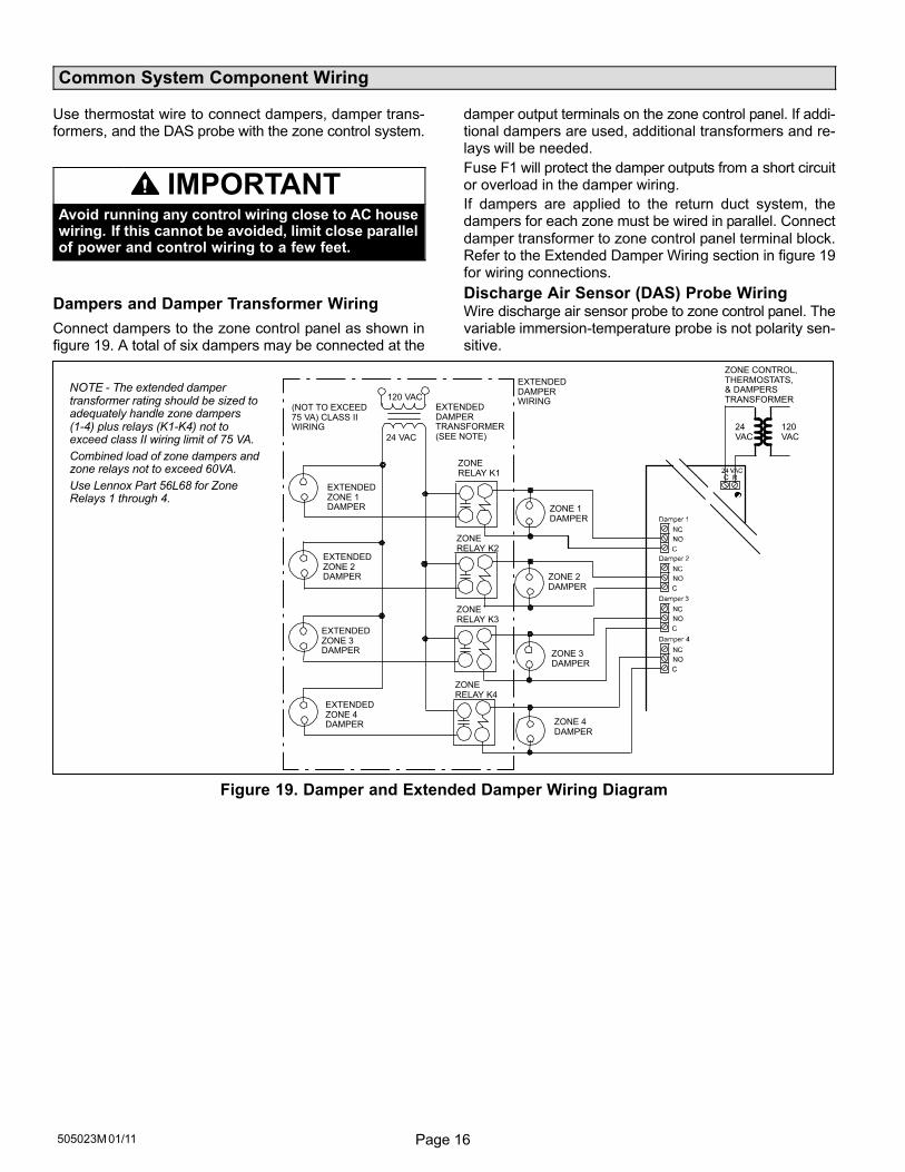
Common System Component Wiring
Use thermostat wire to connect dampers, damper trans-formers, and the DAS probe with the zone control system.
IMPORTANTAvoid running any control wiring close to AC housewiring. If this cannot be avoided, limit close parallelof power and control wiring to a few feet.
Dampers and Damper Transformer Wiring
Connect dampers to the zone control panel as shown infigure 19. A total of six dampers may be connected at the
damper output terminals on the zone control panel. If addi-tional dampers are used, additional transformers and re-lays will be needed.
Fuse F1 will protect the damper outputs from a short circuitor overload in the damper wiring.
If dampers are applied to the return duct system, thedampers for each zone must be wired in parallel. Connect
damper transformer to zone control panel terminal block.Refer to the Extended Damper Wiring section in figure 19for wiring connections.
Discharge Air Sensor (DAS) Probe WiringWire discharge air sensor probe to zone control panel. Thevariable immersion-temperature probe is not polarity sen-sitive.
120VAC
24VAC
EXTENDED DAMPERTRANSFORMER(SEE NOTE)
(NOT TO EXCEED75 VA) CLASS IIWIRING
120 VAC
24 VAC
ZONERELAY K4
ZONERELAY K3
ZONERELAY K2
ZONERELAY K1
ZONE 1DAMPER
ZONE 2DAMPER
ZONE 3DAMPER
ZONE 4DAMPER
EXTENDEDZONE 1DAMPER
EXTENDEDZONE 2DAMPER
EXTENDEDZONE 3DAMPER
EXTENDEDZONE 4DAMPER
NOTE − The extended dampertransformer rating should be sized toadequately handle zone dampers(1−4) plus relays (K1−K4) not toexceed class II wiring limit of 75 VA.
Combined load of zone dampers andzone relays not to exceed 60VA.
Use Lennox Part 56L68 for ZoneRelays 1 through 4.
EXTENDED DAMPERWIRING
ZONE CONTROL,THERMOSTATS, & DAMPERS TRANSFORMER
Figure 19. Damper and Extended Damper Wiring Diagram
Page 17 HARMONY III� ZONE CONTROL SYSTEM
Component Specific Wiring
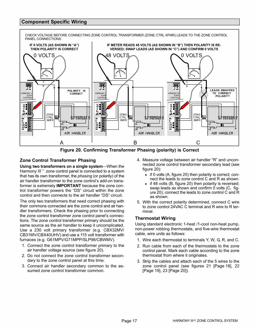
CHECK VOLTAGE BEFORE CONNECTING ZONE CONTROL TRANSFORMER (ZONE CTRL XFMR) LEADS TO THE ZONE CONTROLPANEL CONNECTIONS
IF METER READS 48 VOLTS (AS SHOWN IN �B") THEN POLARITY IS RE-
VERSED; SWAP LEADS (AS SHOWN IN �C") AND CONFIRM 0 VOLTS
IF 0 VOLTS (AS SHOWN IN �A")
THEN POLARITY IS CORRECT
Figure 20. Confirming Transformer Phasing (polarity) is Correct
Zone Control Transformer Phasing
Using two transformers on a single system�When theHarmony III� zone control panel is connected to a systemthat has its own transformer, the phasing (or polarity) of the
air handler transformer to the zone control’s add−on trans-former is extremely IMPORTANT because the zone con-trol transformer powers the �DS" circuit within the zonecontrol and then connects to the air handler �DS" circuit.
The only two transformers that need correct phasing withtheir commons connected are the zone control and air han-dler transformers. Check the phasing prior to connecting
the zone control transformer zone control panel’s connec-tions. The zone control transformer primary should be thesame source as the air handler to keep it uncomplicated.Use a 230 volt primary transformer (e.g. CBX32MV/CB31MV/CBX40UHV) and use a 115 volt transformer withfurnaces (e.g. G61MPV/G71MPP/SLP98/CBWMV).
1. Connect the zone control transformer primary to theair handler voltage source (see figure 20).
2. Do not connect the zone control transformer secon-dary to the zone control panel at this time.
3. Connect air handler secondary common to the as-sumed zone control transformer common.
4. Measure voltage between air handler �R" and uncon-nected zone control transformer secondary lead (seefigure 20):
if 0 volts (A, figure 20) then polarity is correct; con-nect the leads to zone control C and R as shown.
if 48 volts (B, figure 20) then polarity is reversed;swap leads as shown and confirm 0 volts (C, fig-ure 20); connect the leads to zone control C and Ras shown.
5. With the correct polarity determined, connect C wireto zone control 24VAC C terminal and R wire to R ter-minal.
Thermostat Wiring
Using standard electronic 1-heat /1-cool non-heat pump,non-power robbing thermostats, and five−wire thermostatcable, wire units as follows:
1. Wire each thermostat to terminals Y, W, G, R, and C.
2. Run cable from each of the thermostats to the zonecontrol panel. Mark each cable according to the zonethermostat from where it originates.
3. Strip the cables and attach each of the 5 wires to thezone control panel (see figures 21 [Page 18], 22[Page 19], 23 [Page 20]).
Page 18505023M 01/11
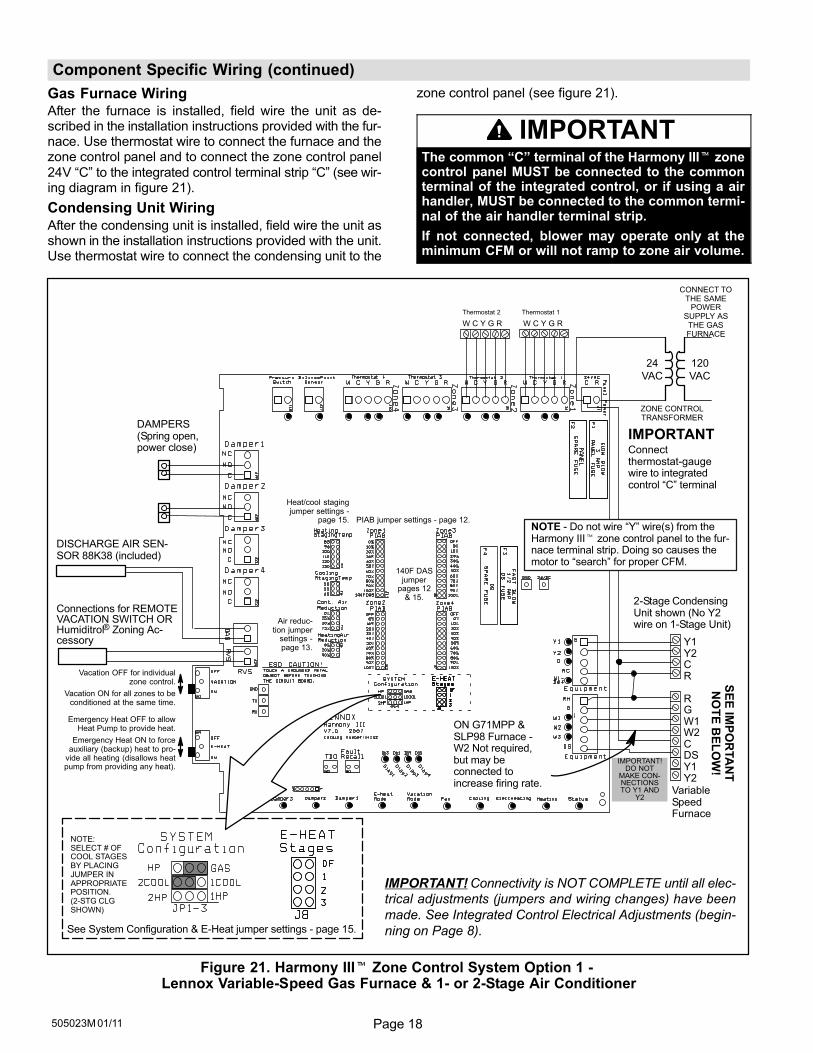
Component Specific Wiring (continued)
Gas Furnace WiringAfter the furnace is installed, field wire the unit as de-scribed in the installation instructions provided with the fur-nace. Use thermostat wire to connect the furnace and thezone control panel and to connect the zone control panel
24V �C" to the integrated control terminal strip �C" (see wir-ing diagram in figure 21).
Condensing Unit Wiring
After the condensing unit is installed, field wire the unit asshown in the installation instructions provided with the unit.Use thermostat wire to connect the condensing unit to the
zone control panel (see figure 21).
IMPORTANTThe common �C" terminal of the Harmony III� zonecontrol panel MUST be connected to the commonterminal of the integrated control, or if using a airhandler, MUST be connected to the common termi-nal of the air handler terminal strip.
If not connected, blower may operate only at theminimum CFM or will not ramp to zone air volume.
IMPORTANT!DO NOT
MAKE CON-NECTIONSTO Y1 AND
Y2
Vacation OFF for individualzone control.
Vacation ON for all zones to beconditioned at the same time.
Emergency Heat OFF to allowHeat Pump to provide heat.
Emergency Heat ON to forceauxiliary (backup) heat to pro-
vide all heating (disallows heatpump from providing any heat).
Y1Y2CR
R GW1W2CDSY1Y2
DAMPERS(Spring open,power close)
See System Configuration & E−Heat jumper settings − page 15.
PIAB jumper settings − page 12.
Air reduc-tion jumper
settings −page 13.
Heat/cool stagingjumper settings −
page 15.
120
VAC
24
VAC
IMPORTANT! Connectivity is NOT COMPLETE until all elec-
trical adjustments (jumpers and wiring changes) have been
made. See Integrated Control Electrical Adjustments (begin-
ning on Page 8).
IMPORTANTConnectthermostat-gaugewire to integratedcontrol �C" terminal
Thermostat 2 Thermostat 1
W C Y G R W C Y G R
VariableSpeedFurnace
2-Stage CondensingUnit shown (No Y2wire on 1−Stage Unit)
140F DASjumper
pages 12& 15.
NOTE − Do not wire �Y" wire(s) from theHarmony III� zone control panel to the fur-nace terminal strip. Doing so causes themotor to �search" for proper CFM.
ON G71MPP &SLP98 Furnace −W2 Not required,but may beconnected toincrease firing rate.
DISCHARGE AIR SEN-SOR 88K38 (included)
Connections for REMOTEVACATION SWITCH ORHumiditrol® Zoning Ac-cessory
CONNECT TOTHE SAME
POWERSUPPLY AS
THE GASFURNACE
SE
E IM
PO
RTA
NT
NO
TE
BE
LO
W!
NOTE:SELECT # OFCOOL STAGESBY PLACINGJUMPER INAPPROPRIATEPOSITION.(2−STG CLGSHOWN)
ZONE CONTROLTRANSFORMER
Figure 21. Harmony III� Zone Control System Option 1 − Lennox Variable-Speed Gas Furnace & 1− or 2-Stage Air Conditioner
Page 19 HARMONY III� ZONE CONTROL SYSTEM
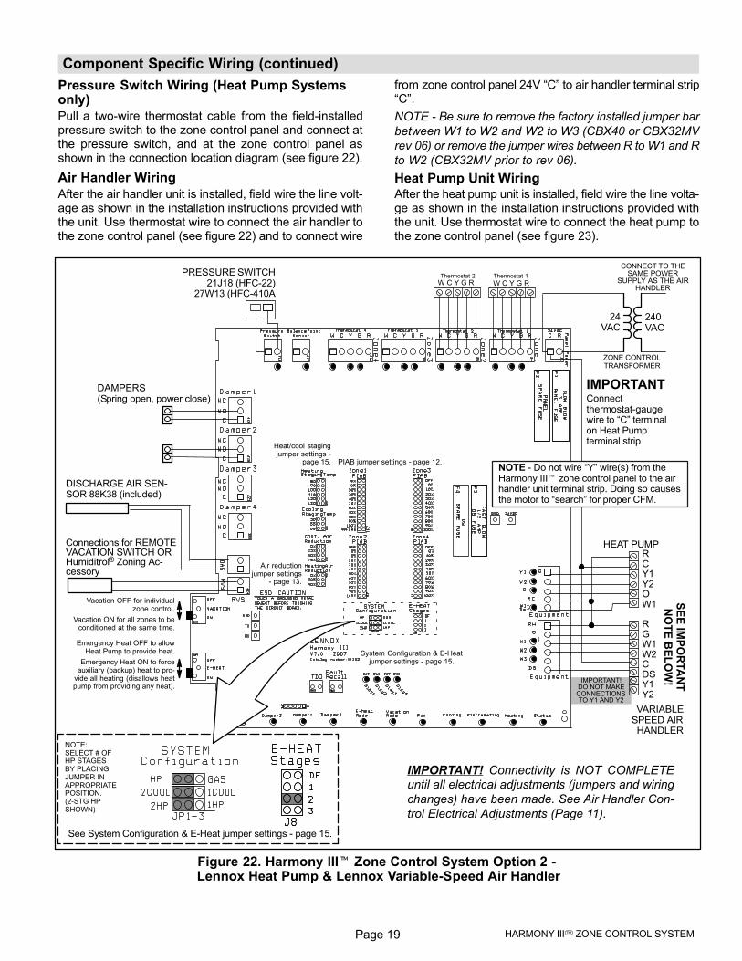
Component Specific Wiring (continued)
Pressure Switch Wiring (Heat Pump Systemsonly)
Pull a two−wire thermostat cable from the field-installedpressure switch to the zone control panel and connect atthe pressure switch, and at the zone control panel asshown in the connection location diagram (see figure 22).
Air Handler Wiring
After the air handler unit is installed, field wire the line volt-age as shown in the installation instructions provided withthe unit. Use thermostat wire to connect the air handler tothe zone control panel (see figure 22) and to connect wire
from zone control panel 24V �C" to air handler terminal strip�C".
NOTE − Be sure to remove the factory installed jumper bar
between W1 to W2 and W2 to W3 (CBX40 or CBX32MV
rev 06) or remove the jumper wires between R to W1 and R
to W2 (CBX32MV prior to rev 06).
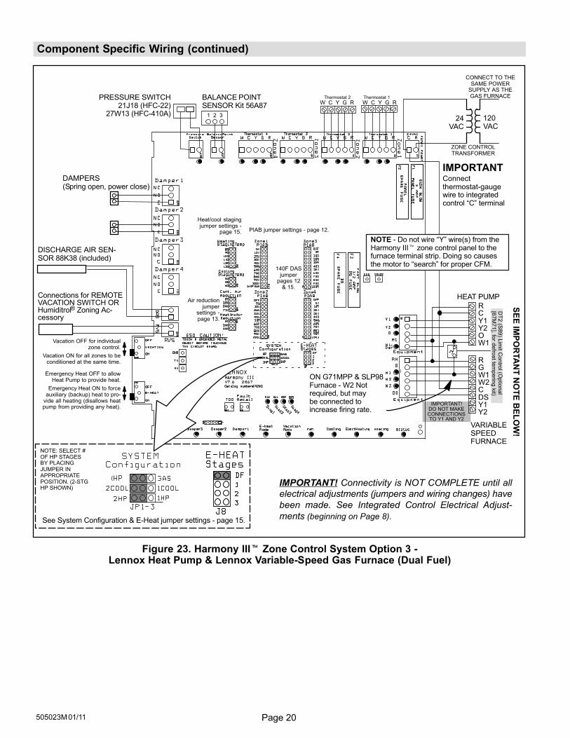
Heat Pump Unit WiringAfter the heat pump unit is installed, field wire the line volta-ge as shown in the installation instructions provided withthe unit. Use thermostat wire to connect the heat pump tothe zone control panel (see figure 23).
IMPORTANT!DO NOT MAKECONNECTIONSTO Y1 AND Y2
Vacation OFF for individualzone control.
Vacation ON for all zones to beconditioned at the same time.
Emergency Heat OFF to allowHeat Pump to provide heat.
Emergency Heat ON to forceauxiliary (backup) heat to pro-
vide all heating (disallows heatpump from providing any heat).
RCY1Y2OW1
R GW1W2CDSY1Y2
DAMPERS(Spring open, power close)
Thermostat 2 Thermostat 1
240VAC
24VAC
PRESSURE SWITCH21J18 (HFC−22)
27W13 (HFC−410A
W C Y G R W C Y G R
IMPORTANTConnectthermostat-gaugewire to �C" terminalon Heat Pumpterminal strip
VARIABLESPEED AIRHANDLER
HEAT PUMP
IMPORTANT! Connectivity is NOT COMPLETE
until all electrical adjustments (jumpers and wiring
changes) have been made. See Air Handler Con-
trol Electrical Adjustments (Page 11).
NOTE − Do not wire �Y" wire(s) from theHarmony III� zone control panel to the airhandler unit terminal strip. Doing so causesthe motor to �search" for proper CFM.
System Configuration & E−Heatjumper settings − page 15.
PIAB jumper settings − page 12.
Air reductionjumper settings
− page 13.
Heat/cool stagingjumper settings −
page 15.
DISCHARGE AIR SEN-SOR 88K38 (included)
Connections for REMOTEVACATION SWITCH ORHumiditrol® Zoning Ac-cessory
See System Configuration & E−Heat jumper settings − page 15.
SE
E IM
PO
RTA
NT
NO
TE
BE
LO
W!
CONNECT TO THESAME POWER
SUPPLY AS THE AIRHANDLER
NOTE:SELECT # OFHP STAGESBY PLACINGJUMPER INAPPROPRIATEPOSITION.(2−STG HPSHOWN)
ZONE CONTROLTRANSFORMER
Figure 22. Harmony III� Zone Control System Option 2 − Lennox Heat Pump & Lennox Variable-Speed Air Handler
Page 20505023M 01/11
Component Specific Wiring (continued)
IMPORTANT!DO NOT MAKECONNECTIONSTO Y1 AND Y2
Thermostat 2 Thermostat 1
W C Y G R W C Y G R
IMPORTANT! Connectivity is NOT COMPLETE until all
electrical adjustments (jumpers and wiring changes) have
been made. See Integrated Control Electrical Adjust-
ments (beginning on Page 8).
BALANCE POINTSENSOR Kit 56A87
DAMPERS(Spring open, power close)
PRESSURE SWITCH21J18 (HFC−22)
27W13 (HFC−410A) 1 2 3 120VAC
24VAC
Vacation OFF for individualzone control.
Vacation ON for all zones to beconditioned at the same time.
Emergency Heat OFF to allowHeat Pump to provide heat.
Emergency Heat ON to forceauxiliary (backup) heat to pro-
vide all heating (disallows heatpump from providing any heat).
RCY1Y2OW1
R GW1W2CDSY1Y2
IMPORTANTConnectthermostat-gaugewire to integratedcontrol �C" terminal
HEAT PUMP
VARIABLESPEEDFURNACE
NOTE − Do not wire �Y" wire(s) from theHarmony III� zone control panel to thefurnace terminal strip. Doing so causesthe motor to �search" for proper CFM.
PIAB jumper settings − page 12.
Air reductionjumper
settings −page 13.
Heat/cool stagingjumper settings −
page 15.
140F DASjumper
pages 12& 15.
DT
2 (S
89) L
imit C
ontro
l (Optio
nal
[67M
71], fo
r defro
st te
mperin
g k
it)
ON G71MPP & SLP98Furnace − W2 Notrequired, but may be connected toincrease firing rate.
DISCHARGE AIR SEN-SOR 88K38 (included)
Connections for REMOTEVACATION SWITCH ORHumiditrol® Zoning Ac-cessory
See System Configuration & E−Heat jumper settings − page 15.
SE
E IM
PO
RTA
NT
NO
TE
BE
LO
W!
NOTE: SELECT #OF HP STAGESBY PLACINGJUMPER INAPPROPRIATEPOSITION. (2−STGHP SHOWN)
CONNECT TO THESAME POWER
SUPPLY AS THEGAS FURNACE
ZONE CONTROLTRANSFORMER
Figure 23. Harmony III� Zone Control System Option 3 −Lennox Heat Pump & Lennox Variable-Speed Gas Furnace (Dual Fuel)
Page 21 HARMONY III� ZONE CONTROL SYSTEM
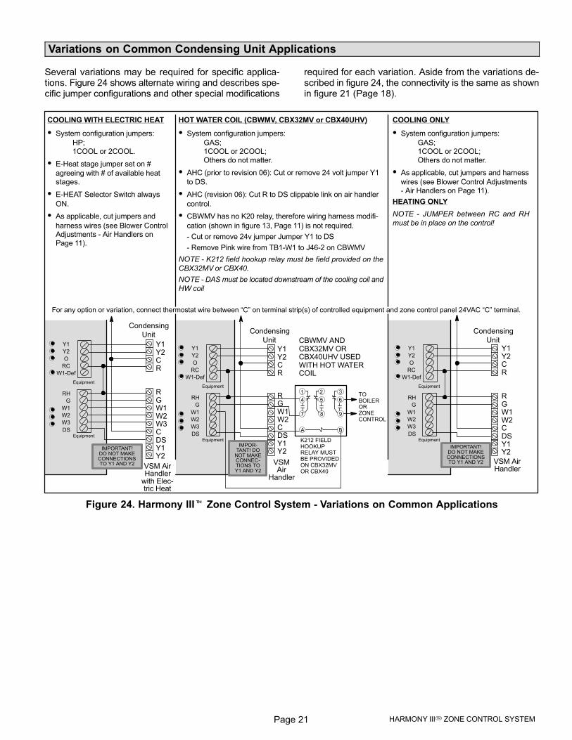
Variations on Common Condensing Unit Applications
Several variations may be required for specific applica-tions. Figure 24 shows alternate wiring and describes spe-cific jumper configurations and other special modifications
required for each variation. Aside from the variations de-scribed in figure 24, the connectivity is the same as shownin figure 21 (Page 18).
Y1Y2CR
R GW1W2CDSY1Y2
COOLING ONLY
� System configuration jumpers:
GAS; 1COOL or 2COOL;Others do not matter.
� As applicable, cut jumpers and harness
wires (see Blower Control Adjustments− Air Handlers on Page 11).
HEATING ONLY
NOTE − JUMPER between RC and RH
must be in place on the control!
HOT WATER COIL (CBWMV, CBX32MV or CBX40UHV)
� System configuration jumpers:
GAS; 1COOL or 2COOL;Others do not matter.
� AHC (prior to revision 06): Cut or remove 24 volt jumper Y1
to DS.
� AHC (revision 06): Cut R to DS clippable link on air handler
control.
� CBWMV has no K20 relay, therefore wiring harness modifi-
cation (shown in figure 13, Page 11) is not required.
− Cut or remove 24v jumper Jumper Y1 to DS
− Remove Pink wire from TB1−W1 to J46−2 on CBWMV
NOTE − K212 field hookup relay must be field provided on the
CBX32MV or CBX40.
NOTE − DAS must be located downstream of the cooling coil and
HW coil
COOLING WITH ELECTRIC HEAT
� System configuration jumpers:
HP; 1COOL or 2COOL.
� E−Heat stage jumper set on #
agreeing with # of available heatstages.
� E−HEAT Selector Switch always
ON.
� As applicable, cut jumpers and
harness wires (see Blower ControlAdjustments − Air Handlers onPage 11).
Y1Y2CR
R GW1W2W3CDSY1Y2
Y1
Y2
O
RC
W1−Def
RH
G
W1
W2
W3
DS
Equipment
Equipment
Condensing
Unit
VSM AirHandler
with Elec-tric Heat
Y1Y2CR
R GW1W2CDSY1Y2
Y1
Y2
O
RC
W1−Def
RH
G
W1
W2
W3
DS
Equipment
Equipment
Condensing
Unit
VSM AirHandler
Y1
Y2
O
RC
W1−Def
RH
G
W1
W2
W3
DS
Equipment
Equipment
Condensing
Unit CBWMV ANDCBX32MV ORCBX40UHV USEDWITH HOT WATERCOIL
TO BOILER OR ZONECONTROL
K212 FIELDHOOKUPRELAY MUSTBE PROVIDEDON CBX32MVOR CBX40
VSMAir
Handler
For any option or variation, connect thermostat wire between �C" on terminal strip(s) of controlled equipment and zone control panel 24VAC �C" terminal.
IMPORTANT!DO NOT MAKECONNECTIONSTO Y1 AND Y2
IMPOR-TANT! DO
NOT MAKECONNEC-TIONS TOY1 AND Y2
IMPORTANT!DO NOT MAKECONNECTIONSTO Y1 AND Y2
Figure 24. Harmony III� Zone Control System − Variations on Common Applications
Page 22505023M 01/11
System Operation (other than G71MPP & SLP98 Furnace)
This section describes the operation of the zone controlsystem.
Zone Thermostats
Only electronic thermostats with a �C" terminal may beused with the zone control system. The zone control sys-tem distinguishes between heat pump and heat/cool ap-plications via the SYSTEM jumper placement on the zone
control panel.
1. Cool / Heat / Auto−Changeover Modes�Zone thermo-stats send a heating or cooling signal to the zone con-trol panel. Thermostat servicing zone 1 is the centralcontrol thermostat. Zones 2, 3 and 4 each have theirown thermostat. Thermostats may be standard or au-tochangeover type.
Heat and cool demands present at the same time from
different zones (opposing demands) are satisfied on a
first come first served basis. If a heating demand and a
cooling demand reach the zone control panel at the
same time, the heating demand is satisfied first. If op-
posing demands persist, the system will work to satis-
fy the current demand for a maximum of 20 minutes,
then switch over and try to satisfy the opposing de-
mand for a maximum of 20 minutes. When either de-
mand is satisfied, the system works to satisfy the other
demand.
NOTE − Allowing opposing demands to persist mayconsume excess energy. If this condition continues,check the installation (i.e. zone arrangement, supplyregisters, return registers, zone loads etc.) and makeadjustments as necessary. Table 7 shows the time de-lays that may be expected when opposing demandsare received from the zone thermostats.
The zone control system acknowledges a new or op-posing demand as soon as it is received by illuminatingthat zone’s thermostat input lights. If the first demandis not satisfied by the time the delays elapse, the sys-tem switches over and begins satisfying the opposingdemand. During the switch-over, a delay may be im-posed before the system begins satisfying the new de-mand.
2. Fan On / Auto Mode�Zone thermostats can send acontinuous fan signal to the zone control system. Thezone control system will signal the blower to supply airto zones calling for continuous fan while no other con-ditioning calls exist. When the zone control system re-ceives a conditioning call while satisfying a demand forcontinuous fan, it signals the damper controlling thecontinuous-fan zone to close. After the conditioningdemand is satisfied, the continuous-fan zone damperis signaled to reopen.
Balance Point Setting
(Dual Fuel Systems) Balance Point Sensor (kit 56A87)communicates with the zone control panel whether or notto force the Gas Furnace to satisfy heating demands,
based on a comparison of the Balance Point setting withthe outdoor temperature. Terminals 2−3 close on tempera-ture fall to lock out heat pump.
Zone ModeThe zone control mode (Vacation switch OFF) utilizes thezone control system’s full potential. While in this mode, thezone control system will respond to demands from anyzone, controlling dampers and regulating blower CFM to
maintain comfort. When the system is in zone mode, thezone control system responds to demands from any zonethermostat. (Switch settings are shown in figures 21through 23.)
The only OPEN supply-air dampers are those zones fromwhich a demand was received; all other dampers areCLOSED. The blower operates at a speed based on the
position of the Zone PIAB selection jumpers (and the heat-ing air reduction jumper, if a call for heat is present).
NOTE − To ensure that the zone control performs optimally,
avoid mixing air between the zones.
Central (Vacation) ModeWhen in central mode (Vacation switch ON), the systemresponds only to heating or cooling demands from the cen-
tral control (Zone 1) thermostat; all zones will receive con-ditioned air. All dampers remain open and the blower oper-ates at full speed (minus the amount selected by theheating air reduction jumper). (Switch settings are shownin figures 21 through 23.)
In Fan−Auto mode, the blower will cycle on and off witheach demand. During gas or electric-strip heating, the
blower may continue after the end of a demand until theheater is cooled sufficiently.
Cooling Operation
When the Harmony III� zone control system receives athermostat cooling call, the following events occur:
� The zone control checks to make sure it has been at
least 5 minutes since the last cooling call ended to pre-vent starting against high head pressures.
� When timed−off delay is satisfied, the zone control
starts the outdoor unit with 1st−stage compressor andslowly increases the indoor blower speed to achieve
proper CFM. Four minutes must elapse at this state toallow the system to reach steady−state operation be-
fore staging again.
� The zone control checks the discharge air sensor for
proper temperature. If measured temperature is 7ºF or
more above the cooling staging jumper setting, thenY2 energizes (if available). If both stages of cooling areenergized and 4 minutes has elapsed since the last
staging event, and the discharge air sensor (DAS) de-tects a temperature less than the cooling staging jump-
er, then Y2 is staged off.
� If, at any time, the discharge air sensor measures a
temperature of 45ºF or below, the zone control de−en-
ergizes the Y1 and/or Y2 output, stopping the com-pressor and preventing the indoor coil from freezing
up. The compressor will not be energized again untilthe temperature at the DAS rises by 10ºF and thetimed−off delay expires. During this time, continuous
fan is supplied to the zones calling for cooling.
Page 23 HARMONY III� ZONE CONTROL SYSTEM
System Operation (other than G71MPP & SLP98 Furnace [cont’d])
Heating Operation
Gas furnace�In this system, when the zone control re-ceives a thermostat heating demand, the following events
occur:
� The zone control sends a W1 signal to the furnace,
which goes through its normal ignition sequence, ex-
cept that while the temperature at the DAS is below100ºF, the zone control instructs the blower to run atminimum speed.
� After the temperature at the DAS rises above 100ºF,
the zone control slowly increases the CFM delivered
until it reaches the correct setting. During a call forheat, the zone control stages the furnace up and down
to maintain the discharge air temperature between theheating staging jumper setting and 20ºF above thisjumper setting. There is a minimum 3 minute delay be-
tween staging events.
NOTE − See page 24 for additional notes on operation with
G71MPP & SLP98 furnace.
Heat Pump with Electric Heat�In this system, when thezone control receives a thermostat heating call, the follow-ing events occur:
� The zone control starts the heat pump on 1st−stage.
� If after 4 minutes, the temperature at the DAS is not
within the proper range (heating staging jumper setting
and heating staging jumper setting +20) the unitstages up or down, accordingly.
� If the air temperature cannot be maintained using the
heat pump alone, the zone control starts the electricheating stages. Should the discharge temperature ex-
ceed 135ºF, the compressor (and any electric heat thatmay be on) is turned off and continuous fan runs (if the
demand for heat remains) until the air temperaturefalls below 130ºF and the minimum timed−off delay ex-pires.
� If the heat pump goes into defrost mode, the zone con-
trol energizes all stages of compressor and the 1st−
stage of electric heat. If the defrost process lasts lon-ger than 20 minutes, the zone control, presuming a
defrost board failure, de−energizes the heat pump and
instructs electric heat to service the remainder of thecurrent heating call. (The heat pump will be tried againon the next heating call.)
Dual Fuel−Heat Pump with Gas Furnace�In this sys-tem, when it receives a thermostat heating call, the zonecontrol responds in one of two ways:
1. Outdoor temperature below balance point (bal-ance point sensor closed, red Balance Point SensorLED on): the zone control sends a W1 signal to the fur-nace to satisfy heat demands, staging the furnace tomaintain discharge air temperatures between 110ºFand 130ºF.
2. Outdoor temperature above balance point (bal-ance point sensor open, red Balance Point SensorLED off): the heat pump is first used to satisfy the de-mand. If, after 20 minutes, the heat pump fails to main-tain the required discharge air temperature, the zonecontrol will discontinue using the heat pump and initi-ate furnace heating. (A five−minute delay exists be-tween stopping the heat pump and starting the fur-nace.) In this mode, all heating calls for the next threehours are serviced with the gas furnace. Also, diag-nostic lights 2, 3, and 4 blink to indicate that the zonecontrol is operating within this 3−hour furnace lock−intime. During this time, the zone control stages the fur-nace to maintain discharge air temperatures between110ºF and 130ºF. After the 3−hour delay expires, theheat pump will again be tried on the next heating call.
Defrost Tempering (Optional)�If installed, refer to De-
frost Operation on Page 47 for Defrost Tempering operation.
Emergency heat mode
When the unit is setup for heat pump and the emergencyheat switch is turned on, the unit will satisfy all heating de-mands with electric backup heat or, in a dual fuel system,the heat demand is satisfied by the gas furnace.
Humiditrol® mode (Enhanced DehumidificationAccessory)When the unit is equipped for dehumidification (EnhancedDehumidification Accessory and Humiditrol® Zoning Ac-cessory installed), the unit will satisfy all demands for de-humidification. Refer to supplemental kit information De-
humidification Interface Kit for Harmony III� Zone Control.
Page 24505023M 01/11
System Operation (G71MPP & SLP98 Furnace)
The dehumidification on−board clippable link W914 Dehum− Harmony (R to DS) on the G71MPP & SLP98 integratedcontrol must be cut for operation with the Harmony III�zone control (see figure 11). Once the link is cut, the pres-ence of the Harmony III� zone control system, versus astandard dehumidification control, is automatically de-
tected by the integrated control.
IMPORTANT − DO NOT alter blower harness!
When the integrated control is properly connected to aHarmony III� zone control, operation is as follows:
� Integrated control DIP switches 1 and 2, which config-
ure the control for operation with various types of ther-mostats, are ignored.
� The zone control sends a W1 Signal to the furnace
which goes through its normal ignition sequence asdescribed in the G71MPP and SLP98 installationinstructions.
� The blower will start and operate at the minimum blow-
er speed after a 45 second delay.
� After the temperature of the DAS rises above 100ºF
the zone control will provide a PWM signal to the fur-
nace on terminal DS based upon the Zone PIABJumper selections (and the heating air reduction jump-
er).
� The blower speed (CFM) is set according to the pulse
width modulated (PWM) signal from the Harmony III�zone control.
� The blower speed adjusts immediately with PWM ad-
justments.
� The furnace firing rate is based on current operating
CFM and internal lookup table for midpoint tempera-
ture rise. If resulting firing rate is below minimum firingrate, it will operate at minimum fire rate. Accordingly,
if resulting firing rate is above maximum firing rate, itwill operate at maximum firing rate.
� Firing rate adjusts anytime the PWM deviates by more
than 5% (e.g. 60% > 65%).
NOTE − Integrated control DIP switches 14 thru 19 arenot disabled, and can be used in conjunction with Har-mony III to increase or decrease airflow volume duringheating operation.
NOTE − DIP switches 14−19 adjust firing rate whenHarmony is detected. Air volume is controlled by Har-mony. The furnace looks at air volume and determinesproper firing rate based on DIP switch 14−19 settings.See G71MPP & SLP98 Installation Instructions for ad-justment options.
� Integrated Control W2 terminal to Harmony III�
zone control:
Since the furnace automatically adjusts firing rate to
match CFM to achieve a target temperature rise, con-
nection of Harmony III� zone control to W2 terminal
on the integrated control is not required.
With W2 connected, lower firing rates can be used for
W1 demand usually resulting in greater comfort levels
per zone. If temperature cannot be maintained, then
W2 will quickly increase firing rates to satisfy demand.
If discharge air temperature is too low, the integrated
control W2 can be connected to Harmony III� zone
control to cause the furnace to increase firing rate. Ev-
ery two minutes, the integrated control looks at W2. If
W2 is ON, the firing rate increases by 5%. This 5% in-
crease is added to the desired firing rate as deter-
mined by the PWM. Therefore, if a 50% duty cycle cor-
responds to a 70% firing rate, after 2 minutes of W2,
that same 50% duty cycle will correspond to a 75% fir-
ing rate. This will last for the remainder of the heat
cycle.
When W2 goes from ON to OFF, the integrated control
decreases the firing rate by 5%.
Page 25 HARMONY III� ZONE CONTROL SYSTEM
Operation & Troubleshooting Indicators
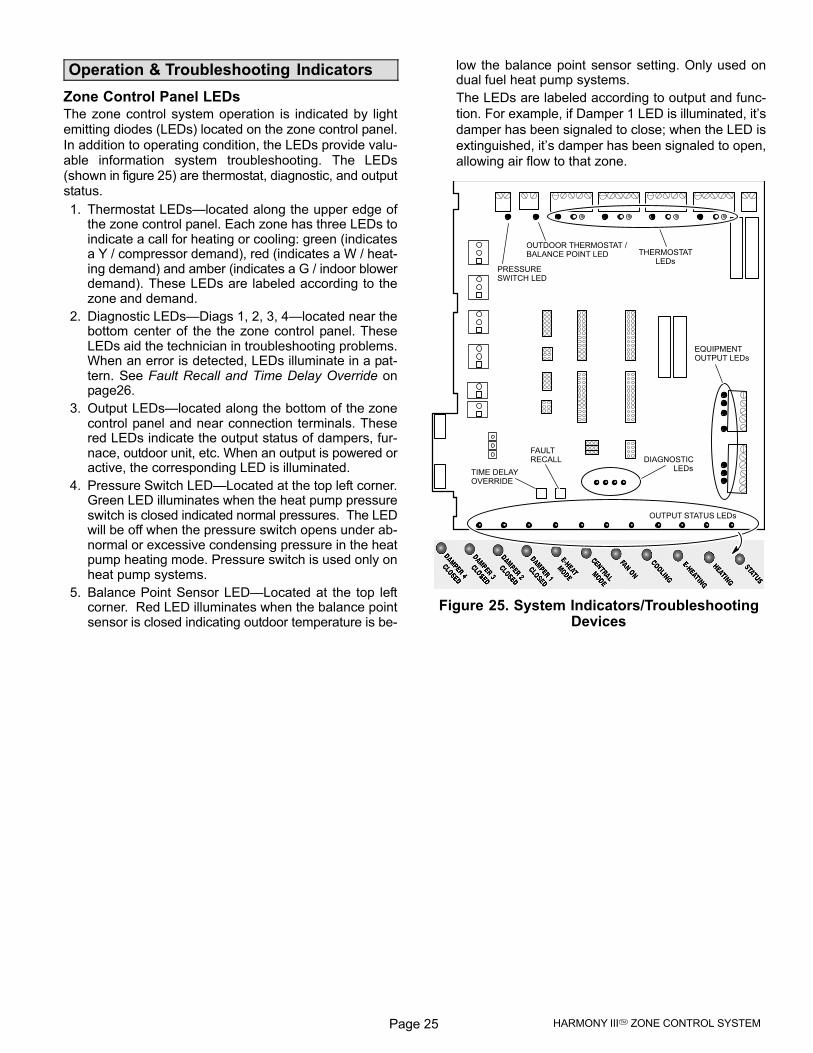
Zone Control Panel LEDsThe zone control system operation is indicated by lightemitting diodes (LEDs) located on the zone control panel.
In addition to operating condition, the LEDs provide valu-able information system troubleshooting. The LEDs(shown in figure 25) are thermostat, diagnostic, and outputstatus.
1. Thermostat LEDs�located along the upper edge ofthe zone control panel. Each zone has three LEDs toindicate a call for heating or cooling: green (indicatesa Y / compressor demand), red (indicates a W / heat-ing demand) and amber (indicates a G / indoor blowerdemand). These LEDs are labeled according to thezone and demand.
2. Diagnostic LEDs�Diags 1, 2, 3, 4�located near thebottom center of the the zone control panel. TheseLEDs aid the technician in troubleshooting problems.When an error is detected, LEDs illuminate in a pat-tern. See Fault Recall and Time Delay Override onpage26.
3. Output LEDs�located along the bottom of the zonecontrol panel and near connection terminals. Thesered LEDs indicate the output status of dampers, fur-nace, outdoor unit, etc. When an output is powered oractive, the corresponding LED is illuminated.
4. Pressure Switch LED�Located at the top left corner.Green LED illuminates when the heat pump pressureswitch is closed indicated normal pressures. The LEDwill be off when the pressure switch opens under ab-normal or excessive condensing pressure in the heatpump heating mode. Pressure switch is used only onheat pump systems.
5. Balance Point Sensor LED�Located at the top leftcorner. Red LED illuminates when the balance pointsensor is closed indicating outdoor temperature is be-
low the balance point sensor setting. Only used ondual fuel heat pump systems.
The LEDs are labeled according to output and func-
tion. For example, if Damper 1 LED is illuminated, it’s
damper has been signaled to close; when the LED is
extinguished, it’s damper has been signaled to open,
allowing air flow to that zone.
THERMOSTATLEDs
OUTPUT STATUS LEDs
DIAGNOSTICLEDs
TIME DELAYOVERRIDE
FAULTRECALL
EQUIPMENTOUTPUT LEDs
OUTDOOR THERMOSTAT /BALANCE POINT LED
PRESSURESWITCH LED
Figure 25. System Indicators/TroubleshootingDevices
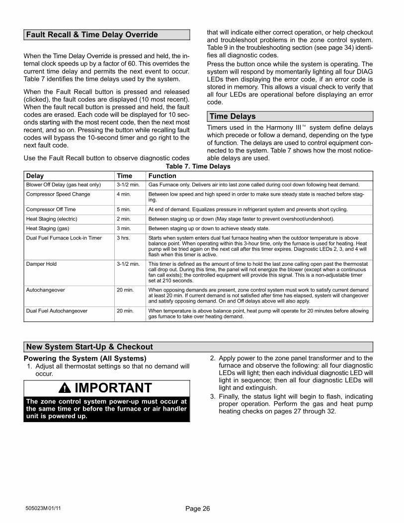
Page 26505023M 01/11
Fault Recall & Time Delay Override
When the Time Delay Override is pressed and held, the in-ternal clock speeds up by a factor of 60. This overrides the
current time delay and permits the next event to occur.Table 7 identifies the time delays used by the system.
When the Fault Recall button is pressed and released(clicked), the fault codes are displayed (10 most recent).When the fault recall button is pressed and held, the faultcodes are erased. Each code will be displayed for 10 sec-onds starting with the most recent code, then the next most
recent, and so on. Pressing the button while recalling faultcodes will bypass the 10-second timer and go right to thenext fault code.
Use the Fault Recall button to observe diagnostic codes
that will indicate either correct operation, or help checkoutand troubleshoot problems in the zone control system.Table 9 in the troubleshooting section (see page 34) identi-fies all diagnostic codes.
Press the button once while the system is operating. Thesystem will respond by momentarily lighting all four DIAGLEDs then displaying the error code, if an error code isstored in memory. This allows a visual check to verify thatall four LEDs are operational before displaying an errorcode.
Time Delays
Timers used in the Harmony III� system define delayswhich precede or follow a demand, depending on the type
of function. The delays are used to control equipment con-nected to the system. Table 7 shows how the most notice-able delays are used.
Table 7. Time Delays
Delay Time Function
Blower Off Delay (gas heat only) 3-1/2 min. Gas Furnace only. Delivers air into last zone called during cool down following heat demand.
Compressor Speed Change 4 min. Between low speed and high speed in order to make sure steady state is reached before stag-ing.
Compressor Off Time 5 min. At end of demand. Equalizes pressure in refrigerant system and prevents short cycling.
Heat Staging (electric) 2 min. Between staging up or down (May stage faster to prevent overshoot/undershoot).
Heat Staging (gas) 3 min. Between staging up or down to achieve steady state.
Dual Fuel Furnace Lock-in Timer 3 hrs. Starts when system enters dual fuel furnace heating when the outdoor temperature is abovebalance point. When operating within this 3-hour time, only the furnace is used for heating. Heatpump will be tried again on the next call after this timer expires. Diagnostic LEDs 2, 3, and 4 willflash when this timer is active.
Damper Hold 3-1/2 min. This timer is defined as the amount of time to hold the last zone calling open past the thermostatcall drop out. During this time, the panel will not energize the blower (except when a continuousfan call exists); the controlled equipment will provide this signal. This is a non−adjustable timerset at 210 seconds.
Autochangeover 20 min. When opposing demands are present, zone control system must work to satisfy current demandat least 20 min. If current demand is not satisfied after time has elapsed, system will changeoverand satisfy opposing demand. On and Off delays above will also apply.
Dual Fuel Autochangeover 20 min. When temperature is above balance point, heat pump will operate for 20 minutes before allowinggas furnace to take over heating demand.
New System Start−Up & Checkout
Powering the System (All Systems)1. Adjust all thermostat settings so that no demand will
occur.
IMPORTANTThe zone control system power−up must occur atthe same time or before the furnace or air handlerunit is powered up.
2. Apply power to the zone panel transformer and to thefurnace and observe the following: all four diagnosticLEDs will light; then each individual diagnostic LED willlight in sequence; then all four diagnostic LEDs willlight and extinguish.
3. Finally, the status light will begin to flash, indicatingproper operation. Perform the gas and heat pumpheating checks on pages 27 through 32.
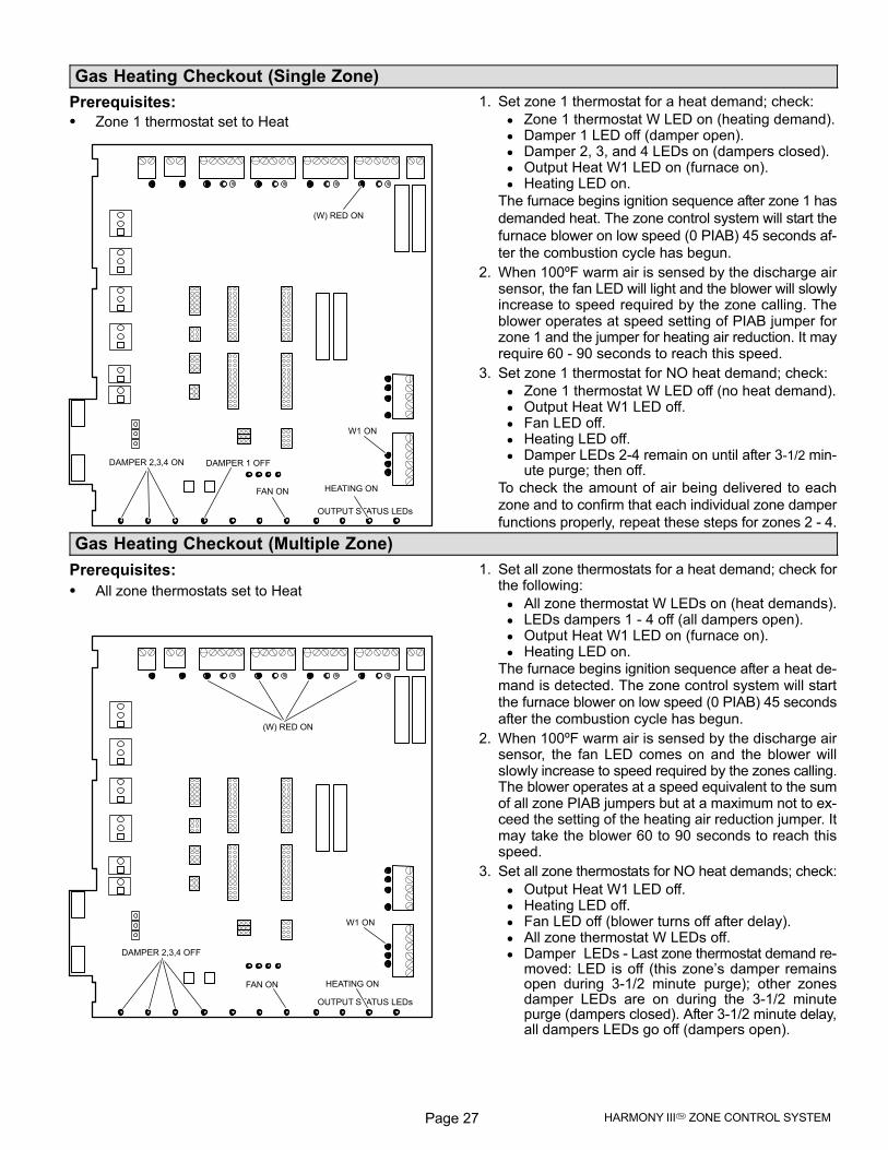
Page 27 HARMONY III� ZONE CONTROL SYSTEM
Gas Heating Checkout (Single Zone)
Prerequisites:
� Zone 1 thermostat set to Heat
OUTPUT STATUS LEDs
DAMPER 2,3,4 ON DAMPER 1 OFF
W1 ON
(W) RED ON
HEATING ONFAN ON
1. Set zone 1 thermostat for a heat demand; check:
Zone 1 thermostat W LED on (heating demand). Damper 1 LED off (damper open). Damper 2, 3, and 4 LEDs on (dampers closed). Output Heat W1 LED on (furnace on). Heating LED on.
The furnace begins ignition sequence after zone 1 has
demanded heat. The zone control system will start the
furnace blower on low speed (0 PIAB) 45 seconds af-
ter the combustion cycle has begun.
2. When 100ºF warm air is sensed by the discharge airsensor, the fan LED will light and the blower will slowlyincrease to speed required by the zone calling. Theblower operates at speed setting of PIAB jumper forzone 1 and the jumper for heating air reduction. It mayrequire 60 − 90 seconds to reach this speed.
3. Set zone 1 thermostat for NO heat demand; check:
Zone 1 thermostat W LED off (no heat demand). Output Heat W1 LED off. Fan LED off. Heating LED off. Damper LEDs 2−4 remain on until after 3-1/2 min-
ute purge; then off.
To check the amount of air being delivered to each
zone and to confirm that each individual zone damper
functions properly, repeat these steps for zones 2 − 4.
Gas Heating Checkout (Multiple Zone)
Prerequisites:
� All zone thermostats set to Heat
OUTPUT STATUS LEDs
DAMPER 2,3,4 OFF
W1 ON
(W) RED ON
HEATING ONFAN ON
1. Set all zone thermostats for a heat demand; check forthe following:
All zone thermostat W LEDs on (heat demands). LEDs dampers 1 − 4 off (all dampers open). Output Heat W1 LED on (furnace on). Heating LED on.
The furnace begins ignition sequence after a heat de-mand is detected. The zone control system will startthe furnace blower on low speed (0 PIAB) 45 secondsafter the combustion cycle has begun.
2. When 100ºF warm air is sensed by the discharge airsensor, the fan LED comes on and the blower willslowly increase to speed required by the zones calling.The blower operates at a speed equivalent to the sumof all zone PIAB jumpers but at a maximum not to ex-ceed the setting of the heating air reduction jumper. Itmay take the blower 60 to 90 seconds to reach thisspeed.
3. Set all zone thermostats for NO heat demands; check:
Output Heat W1 LED off. Heating LED off. Fan LED off (blower turns off after delay). All zone thermostat W LEDs off. Damper�LEDs − Last zone thermostat demand re-
moved: LED is off (this zone’s damper remainsopen during 3−1/2 minute�purge); other zonesdamper LEDs are on during the 3−1/2 minutepurge (dampers closed). After 3−1/2 minute delay,all dampers LEDs go off (dampers open).
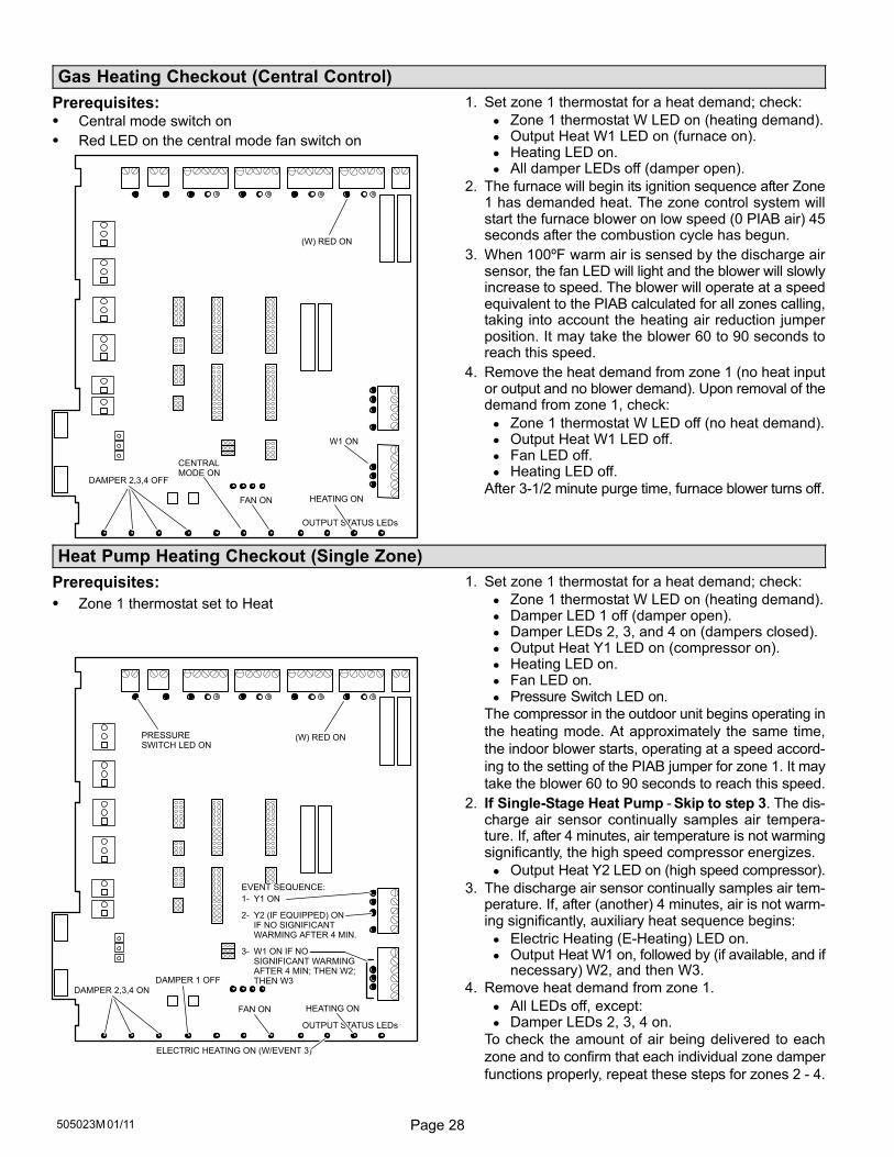
Page 28505023M 01/11
Gas Heating Checkout (Central Control)
Prerequisites:� Central mode switch on
� Red LED on the central mode fan switch on
OUTPUT STATUS LEDs
W1 ON
(W) RED ON
DAMPER 2,3,4 OFF
HEATING ONFAN ON
CENTRALMODE ON
1. Set zone 1 thermostat for a heat demand; check:
Zone 1 thermostat W LED on (heating demand). Output Heat W1 LED on (furnace on). Heating LED on. All damper LEDs off (damper open).
2. The furnace will begin its ignition sequence after Zone1 has demanded heat. The zone control system willstart the furnace blower on low speed (0 PIAB air) 45seconds after the combustion cycle has begun.
3. When 100ºF warm air is sensed by the discharge airsensor, the fan LED will light and the blower will slowlyincrease to speed. The blower will operate at a speedequivalent to the PIAB calculated for all zones calling,taking into account the heating air reduction jumperposition. It may take the blower 60 to 90 seconds toreach this speed.
4. Remove the heat demand from zone 1 (no heat inputor output and no blower demand). Upon removal of thedemand from zone 1, check:
Zone 1 thermostat W LED off (no heat demand). Output Heat W1 LED off. Fan LED off. Heating LED off.
After 3−1/2 minute purge time, furnace blower turns off.
Heat Pump Heating Checkout (Single Zone)
Prerequisites:
� Zone 1 thermostat set to Heat
OUTPUT STATUS LEDs
DAMPER 2,3,4 ONDAMPER 1 OFF
(W) RED ONPRESSURESWITCH LED ON
HEATING ONFAN ON
ELECTRIC HEATING ON (W/EVENT 3)
EVENT SEQUENCE:
1− Y1 ON
2− Y2 (IF EQUIPPED) ONIF NO SIGNIFICANTWARMING AFTER 4 MIN.
3− W1 ON IF NOSIGNIFICANT WARMINGAFTER 4 MIN; THEN W2;THEN W3
1. Set zone 1 thermostat for a heat demand; check:
Zone 1 thermostat W LED on (heating demand). Damper LED 1 off (damper open). Damper LEDs 2, 3, and 4 on (dampers closed). Output Heat Y1 LED on (compressor on). Heating LED on. Fan LED on. Pressure Switch LED on.
The compressor in the outdoor unit begins operating in
the heating mode. At approximately the same time,
the indoor blower starts, operating at a speed accord-
ing to the setting of the PIAB jumper for zone 1. It may
take the blower 60 to 90 seconds to reach this speed.
2. If Single-Stage Heat Pump − Skip to step 3. The dis-charge air sensor continually samples air tempera-ture. If, after 4 minutes, air temperature is not warmingsignificantly, the high speed compressor energizes.
Output Heat Y2 LED on (high speed compressor).
3. The discharge air sensor continually samples air tem-perature. If, after (another) 4 minutes, air is not warm-ing significantly, auxiliary heat sequence begins:
Electric Heating (E−Heating) LED on. Output Heat W1 on, followed by (if available, and if
necessary) W2, and then W3.
4. Remove heat demand from zone 1.
All LEDs off, except: Damper LEDs 2, 3, 4 on.
To check the amount of air being delivered to each
zone and to confirm that each individual zone damper
functions properly, repeat these steps for zones 2 − 4.
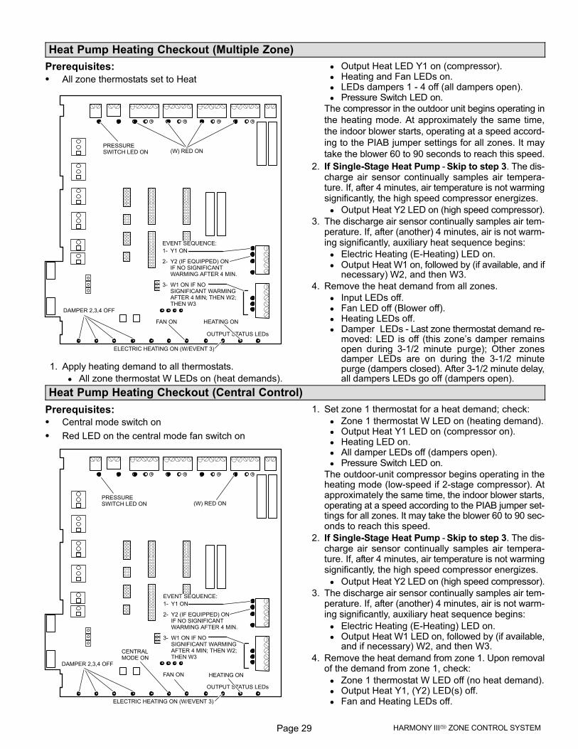
Page 29 HARMONY III� ZONE CONTROL SYSTEM
Heat Pump Heating Checkout (Multiple Zone)
Prerequisites:
� All zone thermostats set to Heat
ELECTRIC HEATING ON (W/EVENT 3)
OUTPUT STATUS LEDs
DAMPER 2,3,4 OFF
(W) RED ONPRESSURESWITCH LED ON
EVENT SEQUENCE:
1− Y1 ON
2− Y2 (IF EQUIPPED) ONIF NO SIGNIFICANTWARMING AFTER 4 MIN.
3− W1 ON IF NOSIGNIFICANT WARMINGAFTER 4 MIN; THEN W2;THEN W3
HEATING ONFAN ON
1. Apply heating demand to all thermostats.
All zone thermostat W LEDs on (heat demands).
Output Heat LED Y1 on (compressor). Heating and Fan LEDs on. LEDs dampers 1 − 4 off (all dampers open). Pressure Switch LED on.
The compressor in the outdoor unit begins operating in
the heating mode. At approximately the same time,
the indoor blower starts, operating at a speed accord-
ing to the PIAB jumper settings for all zones. It may
take the blower 60 to 90 seconds to reach this speed.
2. If Single-Stage Heat Pump − Skip to step 3. The dis-charge air sensor continually samples air tempera-ture. If, after 4 minutes, air temperature is not warmingsignificantly, the high speed compressor energizes.
Output Heat Y2 LED on (high speed compressor).
3. The discharge air sensor continually samples air tem-perature. If, after (another) 4 minutes, air is not warm-ing significantly, auxiliary heat sequence begins:
Electric Heating (E−Heating) LED on. Output Heat W1 on, followed by (if available, and if
necessary) W2, and then W3.
4. Remove the heat demand from all zones.
Input LEDs off. Fan LED off (Blower off). Heating LEDs off. Damper�LEDs − Last zone thermostat demand re-
moved: LED is off (this zone’s damper remainsopen during 3−1/2 minute�purge); Other zonesdamper LEDs are on during the 3−1/2 minutepurge (dampers closed). After 3−1/2 minute delay,all dampers LEDs go off (dampers open).
Heat Pump Heating Checkout (Central Control)
Prerequisites:
� Central mode switch on
� Red LED on the central mode fan switch on
OUTPUT STATUS LEDs
(W) RED ON
DAMPER 2,3,4 OFF
PRESSURESWITCH LED ON
EVENT SEQUENCE:
1− Y1 ON
2− Y2 (IF EQUIPPED) ONIF NO SIGNIFICANTWARMING AFTER 4 MIN.
3− W1 ON IF NOSIGNIFICANT WARMINGAFTER 4 MIN; THEN W2;THEN W3
HEATING ONFAN ON
ELECTRIC HEATING ON (W/EVENT 3)
CENTRALMODE ON
1. Set zone 1 thermostat for a heat demand; check:
Zone 1 thermostat W LED on (heating demand). Output Heat Y1 LED on (compressor on). Heating LED on. All damper LEDs off (dampers open). Pressure Switch LED on.
The outdoor-unit compressor begins operating in theheating mode (low−speed if 2-stage compressor). Atapproximately the same time, the indoor blower starts,operating at a speed according to the PIAB jumper set-tings for all zones. It may take the blower 60 to 90 sec-onds to reach this speed.
2. If Single-Stage Heat Pump − Skip to step 3. The dis-charge air sensor continually samples air tempera-ture. If, after 4 minutes, air temperature is not warmingsignificantly, the high speed compressor energizes.
Output Heat Y2 LED on (high speed compressor).
3. The discharge air sensor continually samples air tem-perature. If, after (another) 4 minutes, air is not warm-ing significantly, auxiliary heat sequence begins:
Electric Heating (E−Heating) LED on. Output Heat W1 LED on, followed by (if available,
and if necessary) W2, and then W3.
4. Remove the heat demand from zone 1. Upon removalof the demand from zone 1, check:
Zone 1 thermostat W LED off (no heat demand). Output Heat Y1, (Y2) LED(s) off. Fan and Heating LEDs off.
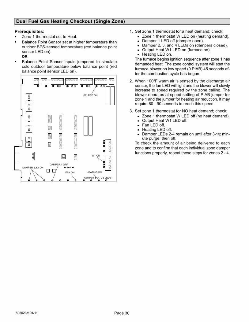
Page 30505023M 01/11
Dual Fuel Gas Heating Checkout (Single Zone)
Prerequisites:� Zone 1 thermostat set to Heat.
� Balance Point Sensor set at higher temperature than
outdoor BPS-sensed temperature (red balance pointsensor LED on).
OR
� Balance Point Sensor inputs jumpered to simulate
cold outdoor temperature below balance point (red
balance point sensor LED on).
OUTPUT STATUS LEDs
DAMPER 2,3,4 ON
DAMPER 1 OFF
W1 ON
(W) RED ON
HEATING ONFAN ON
1. Set zone 1 thermostat for a heat demand; check:
Zone 1 thermostat W LED on (heating demand). Damper 1 LED off (damper open). Damper 2, 3, and 4 LEDs on (dampers closed). Output Heat W1 LED on (furnace on). Heating LED on.
The furnace begins ignition sequence after zone 1 has
demanded heat. The zone control system will start the
furnace blower on low speed (0 PIAB) 45 seconds af-
ter the combustion cycle has begun.
2. When 100ºF warm air is sensed by the discharge airsensor, the fan LED will light and the blower will slowlyincrease to speed required by the zone calling. Theblower operates at speed setting of PIAB jumper forzone 1 and the jumper for heating air reduction. It mayrequire 60 − 90 seconds to reach this speed.
3. Set zone 1 thermostat for NO heat demand; check:
Zone 1 thermostat W LED off (no heat demand). Output Heat W1 LED off. Fan LED off. Heating LED off. Damper LEDs 2−4 remain on until after 3-1/2 min-
ute purge; then off.
To check the amount of air being delivered to each
zone and to confirm that each individual zone damper
functions properly, repeat these steps for zones 2 − 4.
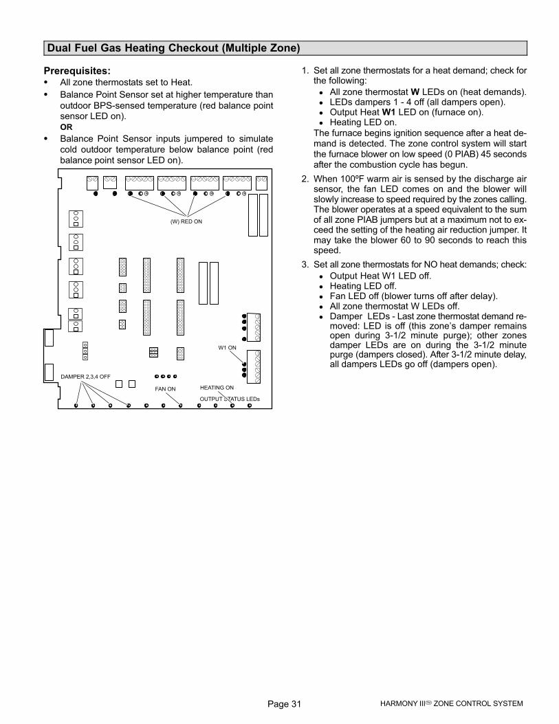
Page 31 HARMONY III� ZONE CONTROL SYSTEM
Dual Fuel Gas Heating Checkout (Multiple Zone)
Prerequisites:� All zone thermostats set to Heat.
� Balance Point Sensor set at higher temperature than
outdoor BPS-sensed temperature (red balance pointsensor LED on).
OR
� Balance Point Sensor inputs jumpered to simulate
cold outdoor temperature below balance point (red
balance point sensor LED on).
OUTPUT STATUS LEDs
DAMPER 2,3,4 OFF
W1 ON
(W) RED ON
HEATING ONFAN ON
1. Set all zone thermostats for a heat demand; check forthe following:
All zone thermostat W LEDs on (heat demands). LEDs dampers 1 − 4 off (all dampers open). Output Heat W1 LED on (furnace on). Heating LED on.
The furnace begins ignition sequence after a heat de-mand is detected. The zone control system will startthe furnace blower on low speed (0 PIAB) 45 secondsafter the combustion cycle has begun.
2. When 100ºF warm air is sensed by the discharge airsensor, the fan LED comes on and the blower willslowly increase to speed required by the zones calling.The blower operates at a speed equivalent to the sumof all zone PIAB jumpers but at a maximum not to ex-ceed the setting of the heating air reduction jumper. Itmay take the blower 60 to 90 seconds to reach thisspeed.
3. Set all zone thermostats for NO heat demands; check:
Output Heat W1 LED off. Heating LED off. Fan LED off (blower turns off after delay). All zone thermostat W LEDs off. Damper�LEDs − Last zone thermostat demand re-
moved: LED is off (this zone’s damper remainsopen during 3−1/2 minute�purge); other zonesdamper LEDs are on during the 3−1/2 minutepurge (dampers closed). After 3−1/2 minute delay,all dampers LEDs go off (dampers open).
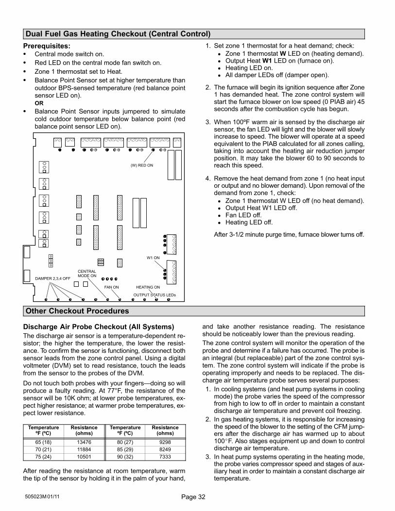
Page 32505023M 01/11
Dual Fuel Gas Heating Checkout (Central Control)
Prerequisites:� Central mode switch on.
� Red LED on the central mode fan switch on.
� Zone 1 thermostat set to Heat.
� Balance Point Sensor set at higher temperature than
outdoor BPS-sensed temperature (red balance pointsensor LED on).
OR
� Balance Point Sensor inputs jumpered to simulate
cold outdoor temperature below balance point (redbalance point sensor LED on).
OUTPUT STATUS LEDs
W1 ON
(W) RED ON
DAMPER 2,3,4 OFF
HEATING ONFAN ON
CENTRALMODE ON
1. Set zone 1 thermostat for a heat demand; check:
Zone 1 thermostat W LED on (heating demand). Output Heat W1 LED on (furnace on). Heating LED on. All damper LEDs off (damper open).
2. The furnace will begin its ignition sequence after Zone1 has demanded heat. The zone control system willstart the furnace blower on low speed (0 PIAB air) 45seconds after the combustion cycle has begun.
3. When 100ºF warm air is sensed by the discharge airsensor, the fan LED will light and the blower will slowlyincrease to speed. The blower will operate at a speedequivalent to the PIAB calculated for all zones calling,taking into account the heating air reduction jumperposition. It may take the blower 60 to 90 seconds toreach this speed.
4. Remove the heat demand from zone 1 (no heat inputor output and no blower demand). Upon removal of thedemand from zone 1, check:
Zone 1 thermostat W LED off (no heat demand). Output Heat W1 LED off. Fan LED off. Heating LED off.
After 3−1/2 minute purge time, furnace blower turns off.
Other Checkout Procedures
Discharge Air Probe Checkout (All Systems)
The discharge air sensor is a temperature-dependent re-sistor; the higher the temperature, the lower the resist-ance. To confirm the sensor is functioning, disconnect bothsensor leads from the zone control panel. Using a digitalvoltmeter (DVM) set to read resistance, touch the leads
from the sensor to the probes of the DVM.
Do not touch both probes with your fingers�doing so willproduce a faulty reading. At 77°F, the resistance of thesensor will be 10K ohm; at lower probe temperatures, ex-pect higher resistance; at warmer probe temperatures, ex-pect lower resistance.
TemperatureºF (ºC)
Resistance(ohms)
TemperatureºF (ºC)
Resistance(ohms)
65 (18) 13476 80 (27) 9298
70 (21) 11884 85 (29) 8249
75 (24) 10501 90 (32) 7333
After reading the resistance at room temperature, warmthe tip of the sensor by holding it in the palm of your hand,
and take another resistance reading. The resistanceshould be noticeably lower than the previous reading.
The zone control system will monitor the operation of the
probe and determine if a failure has occurred. The probe isan integral (but replaceable) part of the zone control sys-tem. The zone control system will indicate if the probe isoperating improperly and needs to be replaced. The dis-charge air temperature probe serves several purposes:
1. In cooling systems (and heat pump systems in coolingmode) the probe varies the speed of the compressorfrom high to low to off in order to maintain a constantdischarge air temperature and prevent coil freezing.
2. In gas heating systems, it is responsible for increasingthe speed of the blower to the setting of the CFM jump-ers after the discharge air has warmed up to about100�F. Also stages equipment up and down to controldischarge air temperature.
3. In heat pump systems operating in the heating mode,the probe varies compressor speed and stages of aux-iliary heat in order to maintain a constant discharge airtemperature.
Page 33 HARMONY III� ZONE CONTROL SYSTEM
Other Checkout Procedures (continued)
Pressure Switch Checkout (Heat Pump Sys-tems Only)
The high pressure switch is a normally closed (N.C.) auto-
reset high pressure switch located in the compressor dis-charge line or on the suction valve service port. The switchis factory set to open when operating pressures rise andclose when the pressure drops (see table 8). The intent ofthe switch is to protect the outdoor unit from abnormallyhigh operating pressures during mild weather heatingdays. The green pressure LED comes on when the HP
pressure switch is closed indicated normal condensingpressures.
Table 8. High Pressure Switch Operation
RefrigerantOpen on
pressure riseClose on
pressure fall
HFC−22 375 275
HFC−410A 550 425
1. Connect refrigerant gauges to the outdoor unit vaporline.
2. Establish a compressor heating demand and allowsystem to begin operating (see heat pump heatingcheckout section for details). Note that the green pres-sure switch LED comes on.
3. Allow system to operate several minutes so refrigerantpressures can balance.
4. Momentarily block the return air opening and observethe high pressure gauge. When hot gas line pressurereaches the �open on" pressure (see table 8) and thegreen pressure switch LED turns off, an error code willbe set in the zone control system, DIAGs 1 and 4 willturn on, and outdoor unit will stage down and turn offif the switch does not close within 90 seconds. After-wards, backup heat will be used to satisfy the demand.
5. Remove the restriction. When hot gas pressure dropsbelow the �close on" pressure, the green pressureswitch LED will turn on and all DIAGs should turn off.
Blower Speed Checkout
The indoor blower speed should vary as zone demandchanges. The fan speed LED varies in brightness as theblower varies in speed. The brighter the LED, the moreCFM being delivered. Blower speed can also be viewed by
attaching an electronic voltmeter between DS and any Cterminal on the zone control panel. While not a precisemeasurement, the voltmeter fluctuation indicates that theblower speed is changing.
1. Connect electronic voltmeter between DS and any Cterminal on the zone control panel. Leave all field wir-ing in place.
2. Select DC volts scale.
3. Start zone heating or cooling checkout procedure.
4. Observe voltages:
22 volts DC = high speed (varies depending on in-put voltage at primary transformer).
11 volts DC (approx.) = medium speed 50% intoadjustment band of blower.
0 volts DC = low speed or off.
All speeds in between are a percentage of 22VDC.
5. Also measure voltage at the indoor unit between DSand C. If the voltage is lower than the voltagemeasured at the Harmony zone panel and/or theblower runs at a minimum fan speed, check and makesure C on the indoor unit is connected to C on the zonepanel transformer connection.
NOTE − G71MPP & SLP98 furnace models are equipped
with an LED on the integrated control which displays blow-
er airflow in all modes of operation. See G71MPP & SLP98
installation instructions for additional information.
NOTE − CBX40UHV and CBX32MV Rev 06 have an LED
display that will indicate the unit air volume. �A" followed by
the number indicates the cfm. For example, �A−2−0−0−5" in-
dicates 2005 cfm.
NOTE − If blower operates only at the minimum cfm or will
not ramp to zone air volume, check and make sure termi-
nal �C" on the indoor unit terminal strip is connected to Har-
mony 24 VAC terminal �C" (see figures 21 through 23).
NOTE − If blower �hunts", check and make sure there is no
connections on Y1 or Y2 on the indoor unit terminals strip
(see figures 21 through 23).
NOTE − Units without a 7−Segment LED will have a �cfm"
LED to indicate blower airflow. One blink of the LED is
equal to approximately 100 cfm; then it pauses and re-
peats. For example if the CFM indicator LED blinks 10
times this indicates approximately 1000 cfm.
NOTE − Make sure DS on the Harmony board is connected
to DS on the furnace/air handler terminal strip.
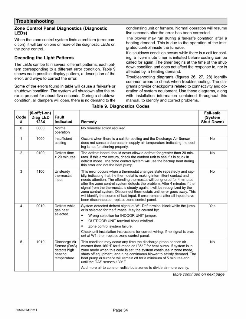
Page 34505023M 01/11
Troubleshooting
Zone Control Panel Diagnostics (DiagnosticLEDs)
When the zone control system finds a problem (error con-dition), it will turn on one or more of the diagnostic LEDs onthe zone control.
Decoding the Light Patterns
The LEDs can be lit in several different patterns, each pat-tern corresponding to a different error condition. Table 9shows each possible display pattern, a description of theerror, and ways to correct the error.
Some of the errors found in table will cause a fail−safe orshutdown condition. The system will shutdown after the er-
ror is present for about five seconds. During a shutdowncondition, all dampers will open, there is no demand to the
condensing unit or furnace. Normal operation will resumefive seconds after the error has been corrected.
The blower may run during a fail−safe condition after aheating demand. This is due to the operation of the inte-grated control inside the furnace.
If a shutdown condition occurs while there is a call for cool-ing, a five−minute timer is initiated before cooling can be
called for again. The timer begins at the time of the shut-down condition and does not affect the response to, nor isaffected by, a heating demand.
Troubleshooting diagrams (figures 26, 27, 28) identifycommon areas to check when troubleshooting. The dia-grams provide checkpoints related to connectivity and op-eration of system equipment. Use these diagrams, along
with installation information contained throughout thismanual, to identify and correct problems.
Table 9. Diagnostics Codes
Code#
(0−off;1−on)Diag LED
1234FaultIndicated Remedy
Fail-safe(System
Shut Down)
0 0000 Normaloperation
No remedial action required.
1 1000 Insufficientcooling
Occurs when there is a call for cooling and the Discharge Air Sensordoes not sense a decrease in supply air temperature indicating the cool-ing is not functioning properly.
No
2 0100 Defrost time > 20 minutes
The defrost board should never allow a defrost for greater than 20 min-utes. If this error occurs, check the outdoor unit to see if it is stuck indefrost mode. The zone control system will use the backup heat duringthis error and not the heat pump.
No
3 1100 Unsteadythermostatinput
This error occurs when a thermostat changes state repeatedly and rap-idly, indicating that the thermostat is making intermittent contact andneeds attention. The offending thermostat will be ignored for 4 minutesafter the zone control system detects the problem. After 4 minutes if thesignal from the thermostat is steady again, it will be recognized by thezone control system. Disconnect thermostats until error goes away. Thiswill identify the source of bad input. If error remains after all inputs havebeen disconnected, replace zone control panel.
No
4 0010 Defrost whilegas heatselected
System detected defrost signal at W1−Def terminal block while the jump-er is selected for the furnace. May be caused by:
� Wrong selection for INDOOR UNIT jumper.
� OUTDOOR UNIT terminal block misfired.
� Zone control system failure.
Check unit installation instructions for correct wiring. If no signal is pres-ent at W1, then replace zone control panel.
Yes
5 1010 Discharge AirSensor (DAS)detects highheatingtemperature
This condition may occur any time the discharge probe senses airwarmer than 160�F for furnace or 135�F for heat pump. If system is inzone mode when this code is set, the system continues in zone mode,shuts off equipment, and runs continuous blower to satisfy demand. Theheat pump or furnace will remain off for a minimum of 5 minutes anduntil the DAS senses 130�F.
Add more air to zone or redistribute zones to divide air more evenly.
No
table continued on next page
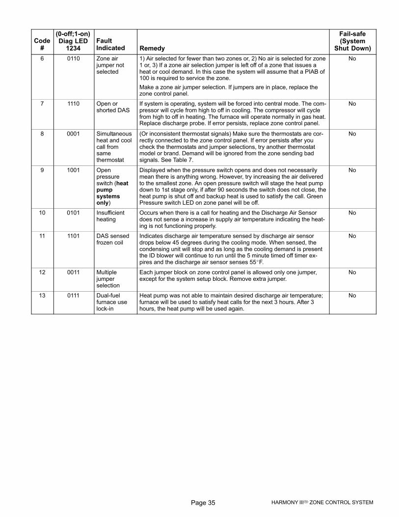
Page 35 HARMONY III� ZONE CONTROL SYSTEM
Code#
Fail-safe(System
Shut Down)RemedyFaultIndicated
(0−off;1−on)Diag LED
1234
6 0110 Zone airjumper notselected
1) Air selected for fewer than two zones or, 2) No air is selected for zone1 or, 3) If a zone air selection jumper is left off of a zone that issues aheat or cool demand. In this case the system will assume that a PIAB of100 is required to service the zone.
Make a zone air jumper selection. If jumpers are in place, replace thezone control panel.
No
7 1110 Open orshorted DAS
If system is operating, system will be forced into central mode. The com-pressor will cycle from high to off in cooling. The compressor will cyclefrom high to off in heating. The furnace will operate normally in gas heat.Replace discharge probe. If error persists, replace zone control panel.
No
8 0001 Simultaneousheat and coolcall fromsamethermostat
(Or inconsistent thermostat signals) Make sure the thermostats are cor-rectly connected to the zone control panel. If error persists after youcheck the thermostats and jumper selections, try another thermostatmodel or brand. Demand will be ignored from the zone sending badsignals. See Table 7.
No
9 1001 Openpressureswitch (heatpumpsystemsonly)
Displayed when the pressure switch opens and does not necessarilymean there is anything wrong. However, try increasing the air deliveredto the smallest zone. An open pressure switch will stage the heat pumpdown to 1st stage only, if after 90 seconds the switch does not close, theheat pump is shut off and backup heat is used to satisfy the call. GreenPressure switch LED on zone panel will be off.
No
10 0101 Insufficientheating
Occurs when there is a call for heating and the Discharge Air Sensordoes not sense a increase in supply air temperature indicating the heat-ing is not functioning properly.
No
11 1101 DAS sensedfrozen coil
Indicates discharge air temperature sensed by discharge air sensordrops below 45 degrees during the cooling mode. When sensed, thecondensing unit will stop and as long as the cooling demand is presentthe ID blower will continue to run until the 5 minute timed off timer ex-pires and the discharge air sensor senses 55�F.
No
12 0011 Multiplejumperselection
Each jumper block on zone control panel is allowed only one jumper,except for the system setup block. Remove extra jumper.
No
13 0111 Dual−fuelfurnace uselock−in
Heat pump was not able to maintain desired discharge air temperature;furnace will be used to satisfy heat calls for the next 3 hours. After 3hours, the heat pump will be used again.
No
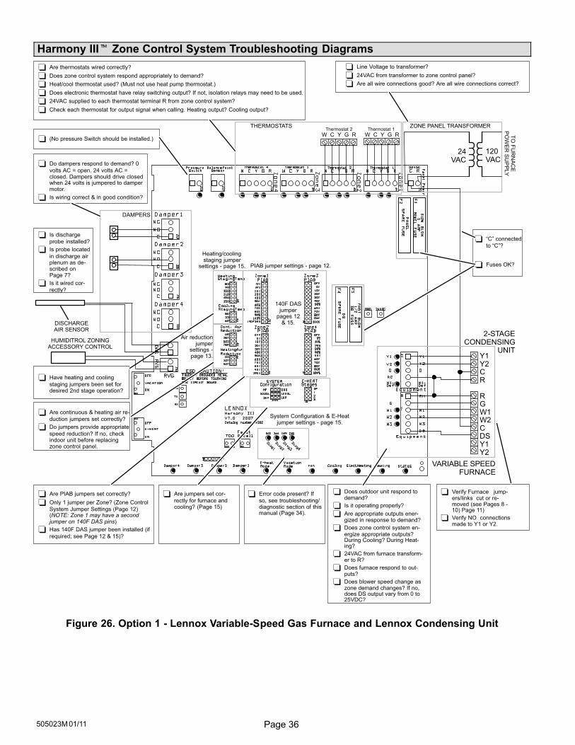
Page 36505023M 01/11
Harmony III� Zone Control System Troubleshooting Diagrams
Do dampers respond to demand? 0
volts AC = open. 24 volts AC =closed. Dampers should drive closedwhen 24 volts is jumpered to dampermotor.
Is wiring correct & in good condition?
Are thermostats wired correctly?
Does zone control system respond appropriately to demand?
Heat/cool thermostat used? (Must not use heat pump thermostat.)
Does electronic thermostat have relay switching output? If not, isolation relays may need to be used.
24VAC supplied to each thermostat terminal R from zone control system?
Check each thermostat for output signal when calling. Heating output? Cooling output?
�C" connected
to �C"?
Fuses OK?
Error code present? If
so, see troubleshooting/diagnostic section of thismanual (Page 34).
Are jumpers set cor-
rectly for furnace andcooling? (Page 15)
Is discharge
probe installed?
Is probe located
in discharge airplenum as de-scribed onPage 7?
Is it wired cor-
rectly?
Does outdoor unit respond todemand?
Is it operating properly?
Are appropriate outputs ener-gized in response to demand?
Does zone control system en-ergize appropriate outputs?During Cooling? During Heat-ing?
24VAC from furnace transform-er to R?
Does furnace respond to out-puts?
Does blower speed change aszone demand changes? If no,does DS output vary from 0 to25VDC?
Line Voltage to transformer?
24VAC from transformer to zone control panel?
Are all wire connections good? Are all wire connections correct?
(No pressure Switch should be installed.)
DAMPERS
System Configuration & E−Heatjumper settings − page 15.
PIAB jumper settings − page 12.
Heating/coolingstaging jumper
settings − page 15.
120VAC
24VAC
Thermostat 2 Thermostat 1
W C Y G R
DISCHARGEAIR SENSOR
THERMOSTATS
Y1Y2CR
R GW1W2CDSY1Y2
VARIABLE SPEEDFURNACE
2-STAGECONDENSING
UNIT
Are PIAB jumpers set correctly?
Only 1 jumper per Zone? (Zone Control
System Jumper Settings (Page 12)(NOTE: Zone 1 may have a secondjumper on 140F DAS pins)
Has 140F DAS jumper been installed (if
required; see Page 12 & 15)?
Are continuous & heating air re-
duction jumpers set correctly?
Do jumpers provide appropriate
speed reduction? If no, checkindoor unit before replacingzone control panel.
Have heating and cooling
staging jumpers been set fordesired 2nd stage operation?
140F DASjumper
pages 12& 15.
W C Y G R
HUMIDITROL ZONINGACCESSORY CONTROL
ZONE PANEL TRANSFORMER
Verify Furnace jump-ers/links cut or re-moved (see Pages 8 −10) Page 11)
Verify NO connectionsmade to Y1 or Y2.
Air reductionjumper
settings −page 13.
TO
FU
RN
AC
EP
OW
ER
SU
PP
LY
Figure 26. Option 1 − Lennox Variable-Speed Gas Furnace and Lennox Condensing Unit
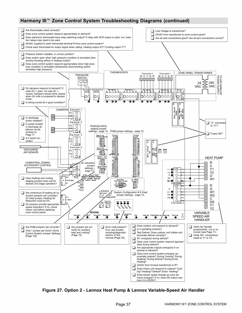
Page 37 HARMONY III� ZONE CONTROL SYSTEM
Harmony III� Zone Control System Troubleshooting Diagrams (continued)
Do dampers respond to demand? 0
volts AC = open. 24 volts AC =closed. Dampers should drive closedwhen 24 volts is jumpered to dampermotor.
Is wiring correct & in good condition?
Are thermostats wired correctly?
Does zone control system respond appropriately to demand?
Does electronic thermostat have relay switching output? If relay with SCR output is used, not, isola-
tion relays may need to be used.
24VAC supplied to each thermostat terminal R from zone control system?
Check each thermostat for output signal when calling. Heating output W1? Cooling output Y1?
Error code present?
If so, see trouble-shooting/diagnosticsection of thismanual (Page 34).
Are jumpers set cor-
rectly for auxiliaryheat and cooling?(Page 15)
Is discharge
probe installed?
Is probe located
in discharge airplenum as de-scribed onPage 7?
Is it wired cor-
rectly?
Does outdoor unit respond to demand?
Is it operating properly?
Test Defrost. Does outdoor unit initiate andterminate defrost correctly?
W1 energized during defrost?
Does zone control system respond appropri-ately during defrost?
Are appropriate outputs energized in re-sponse to demand?
Does zone control system energize ap-propriate outputs? During Cooling? DuringHeating? During Defrost? During Emer.Heating?
24VAC from furnace transformer to R?
Does indoor unit respond to outputs? Cool-
ing? Heating? Defrost? Emer. Heating?
Does blower speed change as zone de-
mand changes? If no, does DS output varyfrom 0 to 25VDC?
Line Voltage to transformer?
24VAC from transformer to zone control panel?
Are all wire connections good? Are all wire connections correct?
Pressure Switch installed. in correct position?
Does switch open when high pressure condition is simulated (tem-
porarily blocking airflow in heating mode)?
Does zone control system respond appropriately when high pres-
sure condition is simulated (temporarily disconnecting switchsimulates high pressure).
DAMPERS
System Configuration & E−Heatjumper settings − page 15.
PIAB jumper settings − page 12.
Heating/coolingstaging jumper
settings − page 15.
240VAC
24VAC
Thermostat 2 Thermostat 1
W C Y G R
DISCHARGEAIR SENSOR
THERMOSTATS
Are PIAB jumpers set correctly?
Only 1 jumper per Zone? (Zone
Control System Jumper Settings[Page 12])
Are continuous & heating air re-
duction jumpers set correctly?On heat pumps, Heating AirReduction must be 0%.
Do jumpers provide appropriate
speed reduction? If no, checkindoor unit before replacingzone control panel.
Have heating and cooling
staging jumpers been set fordesired 2nd stage operation?
PRESSURESWITCH
RCY1Y2OW1
R GW1W2CDSY1Y2
HEAT PUMP
VARIABLESPEED AIRHANDLER
W C Y G R
HUMIDITROL ZONINGACCESSORY CONTROL
Verify Air Handlerjumpers/links cut or re-moved (see Page 11)
Verify NO connectionsmade to Y1 or Y2.
�C" connected
to �C"?
Fuses OK?
Air reductionjumper
settings −page 13.
ZONE PANEL TRANSFORMER
TO
AIR
HA
ND
LE
RP
OW
ER
SU
PP
LY
Figure 27. Option 2 − Lennox Heat Pump & Lennox Variable-Speed Air Handler
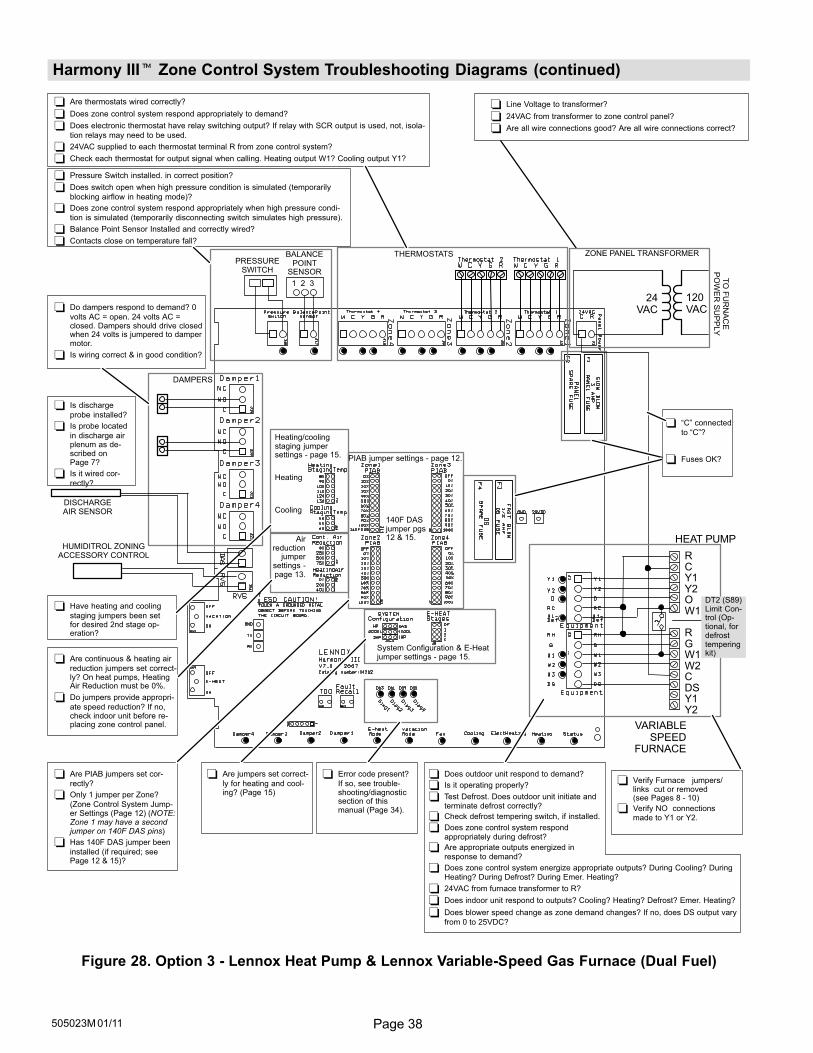
Page 38505023M 01/11
Harmony III� Zone Control System Troubleshooting Diagrams (continued)
Do dampers respond to demand? 0
volts AC = open. 24 volts AC =closed. Dampers should drive closedwhen 24 volts is jumpered to dampermotor.
Is wiring correct & in good condition?
Are thermostats wired correctly?
Does zone control system respond appropriately to demand?
Does electronic thermostat have relay switching output? If relay with SCR output is used, not, isola-
tion relays may need to be used.
24VAC supplied to each thermostat terminal R from zone control system?
Check each thermostat for output signal when calling. Heating output W1? Cooling output Y1?
Error code present?
If so, see trouble-shooting/diagnosticsection of thismanual (Page 34).
Are jumpers set correct-
ly for heating and cool-ing? (Page 15)
Does outdoor unit respond to demand?
Is it operating properly?
Test Defrost. Does outdoor unit initiate and terminate defrost correctly?
Check defrost tempering switch, if installed.
Does zone control system respond appropriately during defrost?
Are appropriate outputs energized in response to demand?
Does zone control system energize appropriate outputs? During Cooling? DuringHeating? During Defrost? During Emer. Heating?
24VAC from furnace transformer to R?
Does indoor unit respond to outputs? Cooling? Heating? Defrost? Emer. Heating?
Does blower speed change as zone demand changes? If no, does DS output vary
from 0 to 25VDC?
Line Voltage to transformer?
24VAC from transformer to zone control panel?
Are all wire connections good? Are all wire connections correct?
Pressure Switch installed. in correct position?
Does switch open when high pressure condition is simulated (temporarily
blocking airflow in heating mode)?
Does zone control system respond appropriately when high pressure condi-
tion is simulated (temporarily disconnecting switch simulates high pressure).
Balance Point Sensor Installed and correctly wired?
Contacts close on temperature fall?
DAMPERS
System Configuration & E−Heatjumper settings − page 15.
Heating/coolingstaging jumpersettings − page 15.
Heating
Cooling
120VAC
24VAC
THERMOSTATS
Are PIAB jumpers set cor-
rectly?
Only 1 jumper per Zone?
(Zone Control System Jump-er Settings (Page 12) (NOTE:Zone 1 may have a secondjumper on 140F DAS pins)
Has 140F DAS jumper been
installed (if required; seePage 12 & 15)?
Are continuous & heating air
reduction jumpers set correct-ly? On heat pumps, HeatingAir Reduction must be 0%.
Do jumpers provide appropri-
ate speed reduction? If no,check indoor unit before re-placing zone control panel.
Have heating and cooling
staging jumpers been setfor desired 2nd stage op-eration?
PRESSURESWITCH
1 2 3
BALANCEPOINT
SENSOR
140F DASjumper pgs12 & 15.
RCY1Y2OW1
R GW1W2CDSY1Y2
HEAT PUMP
VARIABLESPEED
FURNACE
PIAB jumper settings − page 12.
DT2 (S89)Limit Con-trol (Op-tional, fordefrosttemperingkit)
Is discharge
probe installed?
Is probe located
in discharge airplenum as de-scribed onPage 7?
Is it wired cor-
rectly?
DISCHARGEAIR SENSOR
HUMIDITROL ZONINGACCESSORY CONTROL
�C" connected
to �C"?
Fuses OK?
TO
FU
RN
AC
EP
OW
ER
SU
PP
LY
Verify Furnace jumpers/links cut or removed(see Pages 8 − 10)
Verify NO connectionsmade to Y1 or Y2.
Airreduction
jumpersettings −page 13.
ZONE PANEL TRANSFORMER
Figure 28. Option 3 − Lennox Heat Pump & Lennox Variable-Speed Gas Furnace (Dual Fuel)
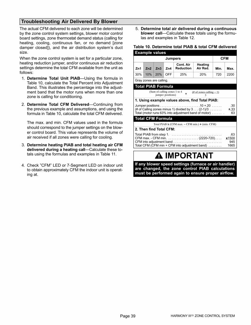
Page 39 HARMONY III� ZONE CONTROL SYSTEM
Troubleshooting Air Delivered By Blower
The actual CFM delivered to each zone will be determinedby the zone control system settings, blower motor controlboard settings, zone thermostat demand status (calling forheating, cooling, continuous fan, or no demand [zonedamper closed]), and the air distribution system’s ductsize.
When the zone control system is set for a particular zone,heating reduction jumper, and/or continuous air reductionsettings determine the total CFM available from the unit asfollows:
1. Determine Total Unit PIAB�Using the formula inTable 10, calculate the Total Percent into AdjustmentBand. This illustrates the percentage into the adjust-ment band that the motor runs when more than onezone is calling for conditioning.
2. Determine Total CFM Delivered�Continuing fromthe previous example and assumptions, and using theformula in Table 10, calculate the total CFM delivered.
The max. and min. CFM values used in the formula
should correspond to the jumper settings on the blow-
er control board. This value represents the volume of
air received if all zones were calling for cooling.
3. Determine heating PIAB and total heating air CFMdelivered during a heating call�Calculate these to-tals using the formulas and examples in Table 11.
4. Check "CFM" LED or 7−Segment LED on indoor unitto obtain approximately CFM the indoor unit is operat-ing at.
5. Determine total air delivered during a continuousblower call�Calculate these totals using the formu-las and examples in Table 12.
Table 10. Determine total PIAB & total CFM delivered
Example values
Jumpers CFM
Zn1 Zn2 Zn3 Zn4
Cont. AirReduction
HeatingAir Red. Min. Max.
30% 10% 20% OFF 25% 20% 720 2200
Gray zones are calling.
Total PIAB Formula
(# of zones calling − 1)3
(Sum of calling zones 1 to 4jumper positions) +
1. Using example values above, find Total PIAB:
Jumper positions .10 +.20 .30. . . . . . . . . . . . . . . . . . . . . . . . . . . . . (# of Calling zones minus 1) divided by 3 (2−1)/3 +.33. . . . . . . . . . Total (motor runs 63% into adjustment band of motor) . 63. . . . . .
Total CFM Formula
Total PIAB x (CFM max. − CFM min.) + (min. CFM)
2. Then find Total CFM:
Total PIAB from step 1. .63. . . . . . . . . . . . . . . . . . . . . . . . . . . . . . CFM max. − CFM min. (2220−720) x1500. . . . . . . . . . . . . . . . . . . . . . CFM into adjustment band 945. . . . . . . . . . . . . . . . . . . . . . . . . . . . . Total CFM (CFM min + CFM into adjustment band) 1665. . . . . . . .
IMPORTANTIf any blower speed settings (furnace or air handler)are changed, the zone control PIAB calculationsmust be performed again to ensure proper airflow.
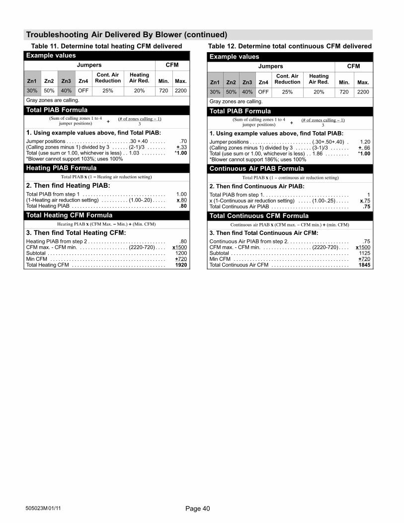
Page 40505023M 01/11
Troubleshooting Air Delivered By Blower (continued)
Table 11. Determine total heating CFM delivered
Example values
Jumpers CFM
Zn1 Zn2 Zn3 Zn4
Cont. AirReduction
HeatingAir Red. Min. Max.
30% 50% 40% OFF 25% 20% 720 2200
Gray zones are calling.
Total PIAB Formula
(# of zones calling − 1)3
(Sum of calling zones 1 to 4jumper positions) +
1. Using example values above, find Total PIAB:
Jumper positions .30 +.40 .70. . . . . . . . . . . . . . . . . . . . . . . . . . . . . (Calling zones minus 1) divided by 3 (2−1)/3 +.33. . . . . . . . . . . . . Total (use sum or 1.00, whichever is less) 1.03 *1.00. . . . . . . . . . . *Blower cannot support 103%; uses 100%
Heating PIAB Formula
Total PIAB x (1 − Heating air reduction setting)
2. Then find Heating PIAB:
Total PIAB from step 1 1.00. . . . . . . . . . . . . . . . . . . . . . . . . . . . . . . (1−Heating air reduction setting) (1.00−.20) x.80. . . . . . . . . . . . . . . Total Heating PIAB .80. . . . . . . . . . . . . . . . . . . . . . . . . . . . . . . . . . .
Total Heating CFM Formula
Heating PIAB x (CFM Max. − Min.) + (Min. CFM)
3. Then find Total Heating CFM:
Heating PIAB from step 2 .80. . . . . . . . . . . . . . . . . . . . . . . . . . . . . CFM max. − CFM min. (2220−720) x1500. . . . . . . . . . . . . . . . . . . . . . Subtotal 1200. . . . . . . . . . . . . . . . . . . . . . . . . . . . . . . . . . . . . . . . . . . . Min CFM +720. . . . . . . . . . . . . . . . . . . . . . . . . . . . . . . . . . . . . . . . . . . Total Heating CFM 1920. . . . . . . . . . . . . . . . . . . . . . . . . . . . . . . . . . .
Table 12. Determine total continuous CFM delivered
Example values
Jumpers CFM
Zn1 Zn2 Zn3 Zn4
Cont. AirReduction
HeatingAir Red. Min. Max.
30% 50% 40% OFF 25% 20% 720 2200
Gray zones are calling.
Total PIAB Formula
(# of zones calling − 1)3
(Sum of calling zones 1 to 4jumper positions) +
1. Using example values above, find Total PIAB:
Jumper positions (.30+.50+.40) 1.20. . . . . . . . . . . . . . . . . . . . . . . . (Calling zones minus 1) divided by 3 (3−1)/3 +. 66. . . . . . . . . . . . . Total (use sum or 1.00, whichever is less) 1.86 *1.00. . . . . . . . . . . *Blower cannot support 186%; uses 100%
Continuous Air PIAB Formula
Total PIAB x (1 − continuous air reduction setting)
2. Then find Continuous Air PIAB:
Total PIAB from step 1. 1. . . . . . . . . . . . . . . . . . . . . . . . . . . . . . . x (1−Continuous air reduction setting) (1.00−.25) x.75. . . . . . . . . . Total Continuous Air PIAB .75. . . . . . . . . . . . . . . . . . . . . . . . . . . . .
Total Continuous CFM Formula
Continuous air PIAB x (CFM max. − CFM min.) + (min. CFM)
3. Then find Total Continuous Air CFM:
Continuous Air PIAB from step 2. .75. . . . . . . . . . . . . . . . . . . . . . CFM max. − CFM min. (2220−720) x1500. . . . . . . . . . . . . . . . . . . . . . Subtotal 1125. . . . . . . . . . . . . . . . . . . . . . . . . . . . . . . . . . . . . . . . . . . . Min CFM +720. . . . . . . . . . . . . . . . . . . . . . . . . . . . . . . . . . . . . . . . . . . Total Continuous Air CFM 1845. . . . . . . . . . . . . . . . . . . . . . . . . . . . .
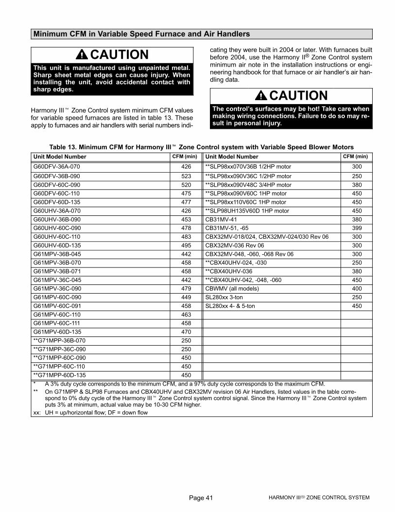
Page 41 HARMONY III� ZONE CONTROL SYSTEM
Minimum CFM in Variable Speed Furnace and Air Handlers
CAUTIONThis unit is manufactured using unpainted metal.Sharp sheet metal edges can cause injury. Wheninstalling the unit, avoid accidental contact withsharp edges.
Harmony III� Zone Control system minimum CFM valuesfor variable speed furnaces are listed in table 13. Theseapply to furnaces and air handlers with serial numbers indi-
cating they were built in 2004 or later. With furnaces builtbefore 2004, use the Harmony II® Zone Control systemminimum air note in the installation instructions or engi-neering handbook for that furnace or air handler’s air han-dling data.
CAUTIONThe control’s surfaces may be hot! Take care whenmaking wiring connections. Failure to do so may re-sult in personal injury.
Table 13. Minimum CFM for Harmony III� Zone Control system with Variable Speed Blower Motors
Unit Model Number CFM (min) Unit Model Number CFM (min)
G60DFV−36A−070 426 **SLP98xx070V36B 1/2HP motor 300
G60DFV−36B−090 523 **SLP98xx090V36C 1/2HP motor 250
G60DFV−60C−090 520 **SLP98xx090V48C 3/4HP motor 380
G60DFV−60C−110 475 **SLP98xx090V60C 1HP motor 450
G60DFV−60D−135 477 **SLP98xx110V60C 1HP motor 450
G60UHV−36A−070 426 **SLP98UH135V60D 1HP motor 450
G60UHV−36B−090 453 CB31MV−41 380
G60UHV−60C−090 478 CB31MV−51, −65 399
G60UHV−60C−110 483 CBX32MV−018/024, CBX32MV−024/030 Rev 06 300
G60UHV−60D−135 495 CBX32MV−036 Rev 06 300
G61MPV−36B−045 442 CBX32MV−048, −060, −068 Rev 06 300
G61MPV−36B−070 458 **CBX40UHV−024, −030 250
G61MPV−36B−071 458 **CBX40UHV−036 380
G61MPV−36C−045 442 **CBX40UHV−042, −048, −060 450
G61MPV−36C−090 479 CBWMV (all models) 400
G61MPV−60C−090 449 SL280xx 3−ton 250
G61MPV−60C−091 458 SL280xx 4− & 5−ton 450
G61MPV−60C−110 463
G61MPV−60C−111 458
G61MPV−60D−135 470
**G71MPP−36B−070 250
**G71MPP−36C−090 250
**G71MPP−60C−090 450
**G71MPP−60C−110 450
**G71MPP−60D−135 450
* A 3% duty cycle corresponds to the minimum CFM, and a 97% duty cycle corresponds to the maximum CFM.
** On G71MPP & SLP98 Furnaces and CBX40UHV and CBX32MV revision 06 Air Handlers, listed values in the table corre-spond to 0% duty cycle of the Harmony III� Zone Control system control signal. Since the Harmony III� Zone Control systemputs 3% at minimum, actual value may be 10−30 CFM higher.
xx: UH = up/horizontal flow; DF = down flow
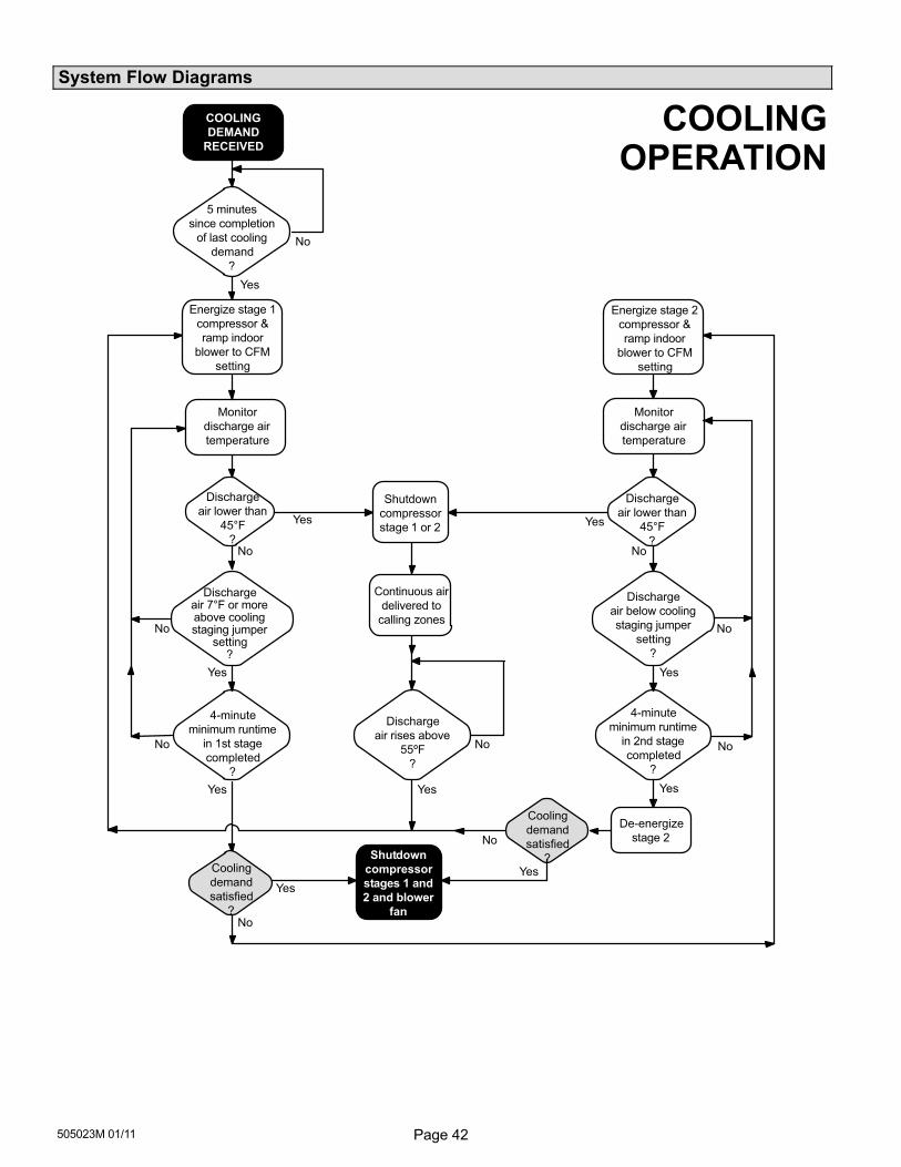
Page 42505023M 01/11
System Flow Diagrams
Shutdown
compressor
stage 1 or 2
De−energize
stage 2
Discharge
air rises above
55ºF
?
Continuous air
delivered to
calling zones
Discharge
air below cooling
staging jumper
setting
?
Dischargeair 7°F or moreabove coolingstaging jumper
setting?
4−minute
minimum runtime
in 1st stage
completed
?
4−minute
minimum runtime
in 2nd stage
completed
?
Energize stage 1
compressor &
ramp indoor
blower to CFM
setting
5 minutes
since completion
of last cooling
demand
?
Shutdown
compressor
stages 1 and
2 and blower
fan
Yes
No
Yes
Energize stage 2
compressor &
ramp indoor
blower to CFM
setting
No
Yes
No
Cooling
demand
satisfied
?
Cooling
demand
satisfied
?
Yes
No
Yes
No
Yes
No
Yes
No
Yes
No
Yes
No
Yes
No
COOLINGOPERATION
Discharge
air lower than
45°F
?
Monitor
discharge air
temperature
Discharge
air lower than
45°F
?
COOLING
DEMAND
RECEIVED
Monitor
discharge air
temperature
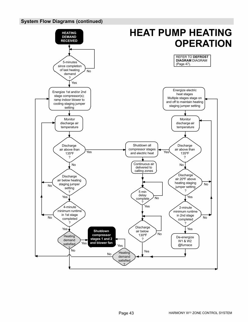
Page 43 HARMONY III� ZONE CONTROL SYSTEM
System Flow Diagrams (continued)
De−energize
W1 & W2
@furnace
Discharge
air below
130ºF
?
Discharge
air above than
135ºF
?
Discharge
air above than
135ºF
?
Discharge
air 20ºF above
heating staging
jumper setting
?
Discharge
air below heating
staging jumper
setting
?
4−minute
minimum runtime
in 1st stage
completed
?
2−minute
minimum runtime
in 2nd stage
completed
?
Energize 1st and/or 2nd
stage compressor(s);
ramp indoor blower to
cooling staging jumper
setting
Energize electric
heat stages
Multiple stages stage on
and off to maintain heating
staging jumper setting
5−minutes
since completion
of last heating
demand
?
HEATING
DEMAND
RECEIVED
Shutdown
compressor
stages 1 and 2
and blower fan
Yes
No
No
Yes
No
Yes
Yes
No
Yes
No
No
Yes
No
Yes
No
Yes
No
Yes
Shutdown all
compressor stages
and electric heat Yes
No
Monitor
discharge air
temperature
HEAT PUMP HEATINGOPERATION
Monitor
discharge air
temperature
REFER TO DEFROSTDIAGRAM DIAGRAM(Page 47).
Heating
demand
satisfied
?
Heating
demand
satisfied
?
Yes
5 mindelay
complete?
No
Continuous airdelivered to
calling zones
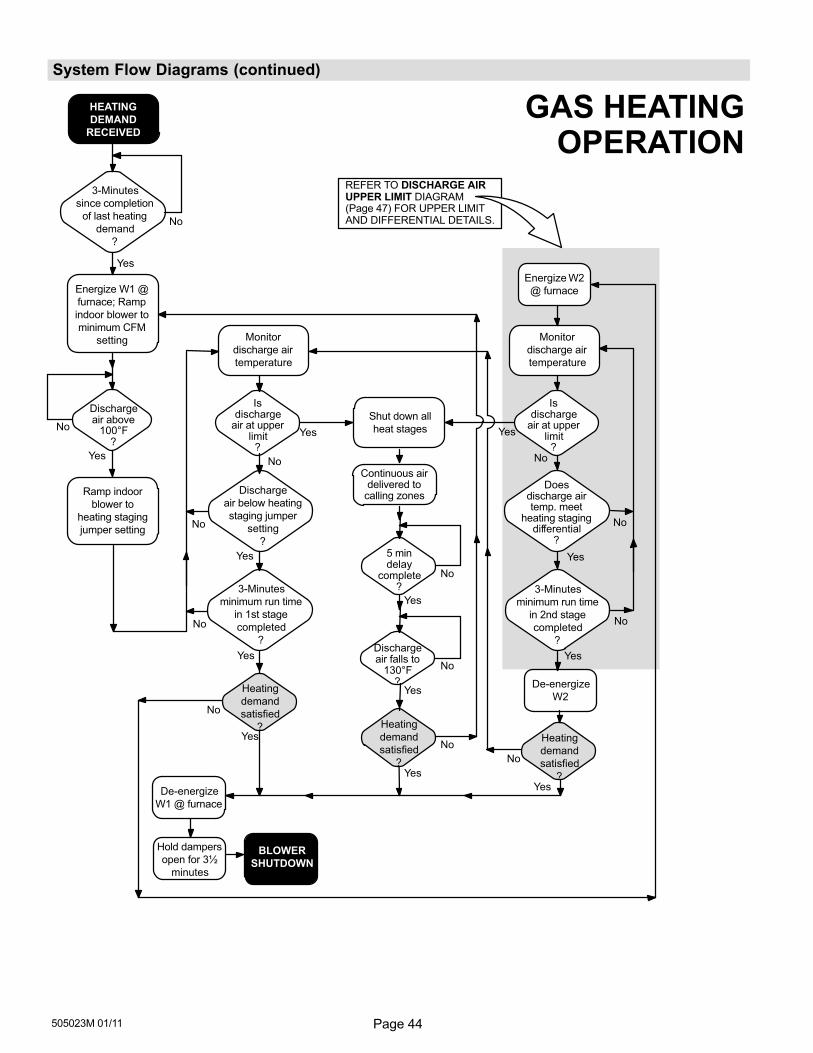
Page 44505023M 01/11
System Flow Diagrams (continued)
3−Minutes
since completion
of last heating
demand
?
Energize W1 @
furnace; Ramp
indoor blower to
minimum CFM
setting
Dischargeair above
100°F?
Discharge
air below heating
staging jumper
setting
?
Ramp indoor
blower to
heating staging
jumper setting
3−Minutes
minimum run time
in 1st stage
completed
?
3−Minutes
minimum run time
in 2nd stage
completed
?
No
Yes
No
Yes
No
No
Yes
Yes Yes
Yes
No
No
No
Yes
Yes
No
GAS HEATINGOPERATION
De−energize
W2
Energize W2
@ furnace
Monitor
discharge air
temperature
HEATING
DEMAND
RECEIVED
BLOWER
SHUTDOWN
Yes
No
Yes
NoYes
No
De−energize
W1 @ furnace
Hold dampers
open for 3½
minutes
Monitor
discharge air
temperature
REFER TO DISCHARGE AIRUPPER LIMIT DIAGRAM(Page 47) FOR UPPER LIMITAND DIFFERENTIAL DETAILS.
Shut down all
heat stages
Isdischarge
air at upperlimit
?
Doesdischarge airtemp. meet
heating stagingdifferential
?
Isdischarge
air at upperlimit
?
Heating
demand
satisfied
? Heating
demand
satisfied
?
Heating
demand
satisfied
?
Dischargeair falls to
130°F?
No
Yes
Continuous airdelivered to
calling zones
Yes
5 mindelay
complete?
No
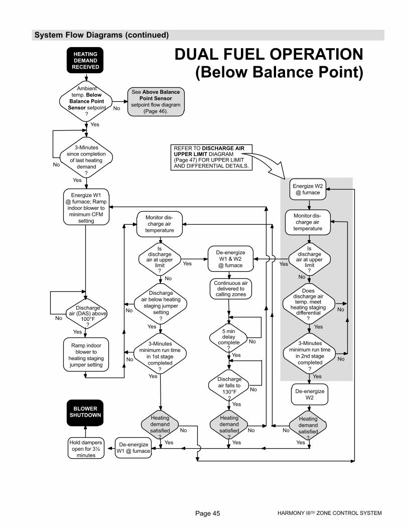
Page 45 HARMONY III� ZONE CONTROL SYSTEM
System Flow Diagrams (continued)
REFER TO DISCHARGE AIRUPPER LIMIT DIAGRAM(Page 47) FOR UPPER LIMITAND DIFFERENTIAL DETAILS.
Energize W1
@ furnace; Ramp
indoor blower to
minimum CFM
setting
Discharge
air below heating
staging jumper
setting
?
Ramp indoor
blower to
heating staging
jumper setting
3−Minutes
minimum run time
in 1st stage
completed
?
3−Minutes
minimum run time
in 2nd stage
completed
?
No
Yes
No
Yes
Yes
Discharge
air falls to
130°F
?
Yes
No
No
No
Yes
No
Yes
HEATING
DEMAND
RECEIVED
3−Minutes
since completion
of last heating
demand
?
Yes
Ambient
temp. Below
Balance Point
Sensor setpoint
?
Yes
No
No
See Above Balance
Point Sensor
setpoint flow diagram
(Page 46).
DUAL FUEL OPERATION(Below Balance Point)
BLOWER
SHUTDOWN
Yes
No
Yes
No
Yes
No
De−energize
W2
Monitor dis-
charge air
temperature
Energize W2
@ furnace
Monitor dis-
charge air
temperature
De−energize
W1 @ furnace
Hold dampers
open for 3½
minutes
Dischargeair (DAS) above
100°F?
No
Yes Yes
No
Isdischarge
air at upperlimit
?
De−energize
W1 & W2
@ furnace
Isdischarge
air at upperlimit
?
Doesdischarge airtemp. meet
heating stagingdifferential
?
Heating
demand
satisfied
?
Heating
demand
satisfied
?
Heating
demand
satisfied
?
Yes
5 mindelay
complete?
No
Continuous airdelivered to
calling zones
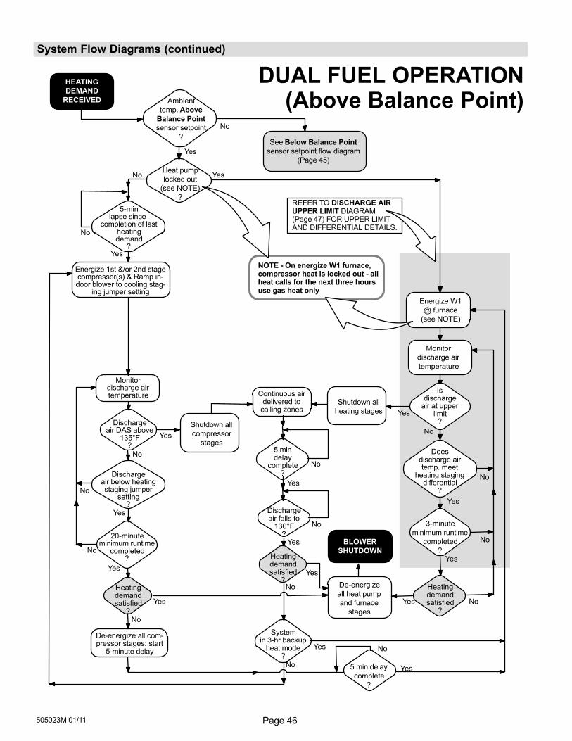
Page 46505023M 01/11
System Flow Diagrams (continued)
REFER TO DISCHARGE AIRUPPER LIMIT DIAGRAM(Page 47) FOR UPPER LIMITAND DIFFERENTIAL DETAILS.
Energize W1
@ furnace
(see NOTE)
No
De−energize
all heat pump
and furnace
stages
Dischargeair falls to
130°F?
Yes
Yes
No
Yes
BLOWER
SHUTDOWN
Heatingdemandsatisfied
?
Yes
Yes
No
No
Yes
No
Energize 1st &/or 2nd stagecompressor(s) & Ramp in-door blower to cooling stag-
ing jumper setting
Dischargeair below heatingstaging jumper
setting?
20−minuteminimum runtime
completed?
No
No
No
Yes
De−energize all com-pressor stages; start
5−minute delay
Shutdown all
compressor
stagesYes
NOTE − On energize W1 furnace,compressor heat is locked out − allheat calls for the next three hoursuse gas heat only
Yes
HEATING
DEMAND
RECEIVED
5−minlapse since-
completion of lastheatingdemand
?Yes
Ambient
temp. Above
Balance Point
sensor setpoint
?
Yes
No
No
See Below Balance Point
sensor setpoint flow diagram
(Page 45)
Monitordischarge airtemperature
Shutdown all
heating stages
Continuous airdelivered to
calling zones
Yes
No
No
Heat pump
locked out
(see NOTE)
?
YesNo
Monitor
discharge air
temperature
5 min delay
complete
?
DUAL FUEL OPERATION(Above Balance Point)
Yes No
Systemin 3−hr backup
heat mode?
Yes
No
Dischargeair DAS above
135°F?
3−minute
minimum runtime
completed
?
Isdischarge
air at upperlimit
?
Doesdischarge airtemp. meet
heating stagingdifferential
?
Heatingdemandsatisfied
?
Yes
5 mindelay
complete?
Heatingdemandsatisfied
?
No
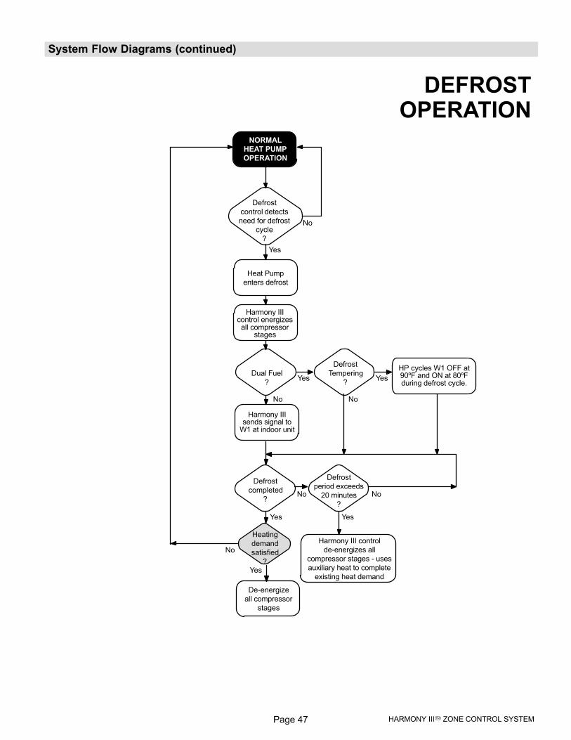
Page 47 HARMONY III� ZONE CONTROL SYSTEM
System Flow Diagrams (continued)
Defrost
control detects
need for defrost
cycle
?
Yes
No
Yes
Harmony IIIcontrol energizesall compressor
stages
Heat Pump
enters defrost
Defrost
completed
?No
Yes
Harmony III control
de−energizes all
compressor stages − uses
auxiliary heat to complete
existing heat demand
Defrost
period exceeds
20 minutes
?
No
DEFROSTOPERATION
De−energize
all compressor
stages
Yes
No
NORMAL
HEAT PUMP
OPERATION
Heating
demand
satisfied
?
Dual Fuel
?Yes
No
Harmony IIIsends signal to
W1 at indoor unit
Defrost
Tempering
?Yes
No
HP cycles W1 OFF at90ºF and ON at 80ºFduring defrost cycle.
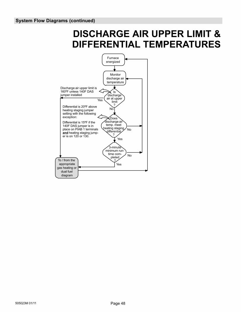
Page 48505023M 01/11
System Flow Diagrams (continued)
Discharge air upper limit is160ºF unless 140F DASjumper installed
To / from the
appropriate
gas heating or
dual fuel
diagram
Furnace
energized
No
Yes
No
Yes
No
Monitor
discharge air
temperature
Isdischarge
air at upperlimit
?
3−minuteminimum run-
time com-pleted
?
Yes
Differential is 20ºF aboveheating staging jumpersetting with the followingexception:
Differential is 15ºF if the 140F DAS jumper is in place on PIAB 1 terminalsand heating staging jump-er is on 120 or 130.
DISCHARGE AIR UPPER LIMIT &DIFFERENTIAL TEMPERATURES
Doesdischarge airtemp. meet
heating stagingdifferential
?
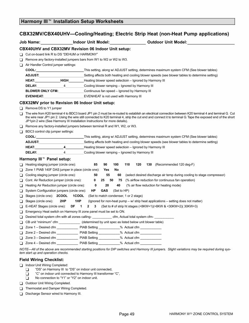
Page 49 HARMONY III� ZONE CONTROL SYSTEM
Harmony III� Installation Setup Worksheets
CBX32MV/CBX40UHV�Cooling/Heating; Electric Strip Heat (non−Heat Pump applications)
Job Name: Indoor Unit Model: Outdoor Unit Model:
CBX40UHV and CBX32MV Revision 06 Indoor Unit setup:
Cut on−board link R to DS �DEHUM or HARMONY"
Remove any factory−installed jumpers bars from W1 to W2 or W2 to W3.
Air Handler Control jumper settings:
COOL: This setting, along w/ ADJUST setting, determines maximum system CFM (See blower tables)
ADJUST: Setting affects both heating and cooling blower speeds (see blower tables to determine setting)
HEAT: HIGH Heating blower speed selectioin – Ignored by Harmony III
DELAY: 4 Cooling blower ramping – Ignored by Harmony III
BLOWER ONLY CFM: Continuous fan speed – Ignored by Harmony III
EVENHEAT: EVENHEAT is not used with Harmony III
CBX32MV prior to Revision 06 Indoor Unit setup:
Remove DS to Y1 jumper
The wire from K20 terminal 4 to BDC3 board JP1 pin 2 must be re−routed to establish an electrical connection between K20 terminal 4 and terminal G. Cutthe wire near JP1 pin 2. Using the wire still connected to K20 terminal 4, strip the cut end and connect it to terminal G. Tape the exposed end of the shortJP1pin 2 wire (See Harmony III Installation Instructions for more details).
Remove any factory−installed jumpers between terminal R and W1, W2, or W3.
BDC3 control clip jumper settings:
COOL: This setting, along w/ ADJUST setting, determines maximum system CFM (See blower tables)
ADJUST: Setting affects both heating and cooling blower speeds (see blower tables to determine setting)
HEAT: 4 Heating blower speed selectioin – Ignored by Harmony III
DELAY: 4 Cooling blower ramping – Ignored by Harmony III
Harmony III� Panel setup:
Heating staging jumper (circle one): 85 90 100 110 120 130 (Recommended 120 deg−F)
Zone 1 PIAB 140F DAS jumper in place (circle one): Yes No
Cooling staging jumper (circle one): 50 55 60 (select desired discharge air temp during cooling to stage compressor)
Cont. Air Reduction jumper (circle one): 0 25 50 75 (% airflow reduction for continuous fan operation)
Heating Air Reduction jumper (circle one): 0 20 40 (% air flow reduction for heating mode)
System Configuration jumpers (circle one): HP GAS (Set to HP)
Stages (circle one): 2COOL 1COOL (Set to match condenser, 1 or 2 stage)
Stages (circle one): 2HP 1HP (Ignored for non−heat pump – w/ strip heat applications – setting does not matter)
E−HEAT Stages (circle one): DF 1 2 3 (Set to # of strip ht stages (<8KW=1)(>8KW & <30KW=2)( 30KW=3)
Emergency Heat switch on Harmony III zone panel must be set to ON.
Desired total system cfm with all zones calling− ___________ cfm, Actual total system cfm− ___________
CB unit �minimum" cfm ____________ (determined by unit spec as listed below unit blower table)
Zone 1 – Desired cfm ____________ PIAB Setting ____________% Actual cfm ____________
Zone 2 – Desired cfm ____________ PIAB Setting ____________% Actual cfm ____________
Zone 3 – Desired cfm ____________ PIAB Setting ____________% Actual cfm ____________
Zone 4 – Desired cfm ____________ PIAB Setting ____________% Actual cfm ____________
NOTE�All of the above are recommended starting positions for DIP switches and Harmony III jumpers. Slight variations may be required during sys-tem start up and operation checks.
Field Wiring Checklist:
Indoor Unit Wiring Completed:
�DS" on Harmony III to �DS" on indoor unit connected,
"C" on indoor unit connected to Harmony III transformer �C",
No connection to �Y1" or �Y2" on indoor unit.
Outdoor Unit Wiring Completed.
Thermostat and Damper Wiring Completed.
Discharge Sensor wired to Harmony III.
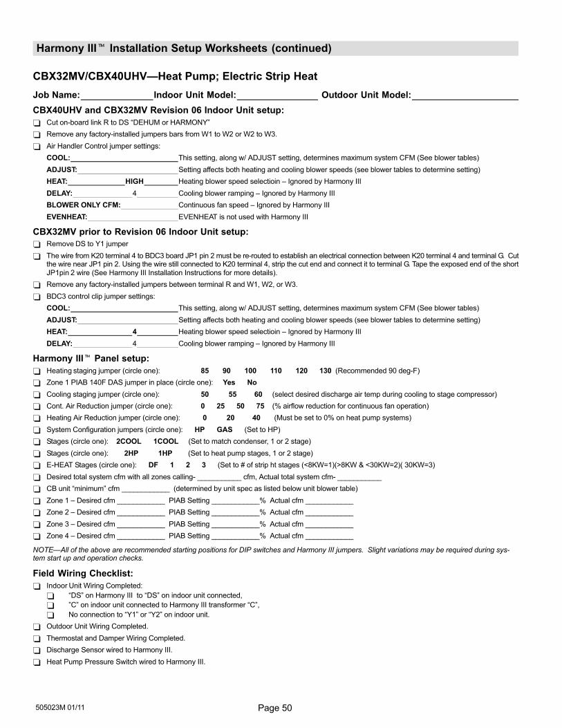
Page 50505023M 01/11
Harmony III� Installation Setup Worksheets (continued)
CBX32MV/CBX40UHV�Heat Pump; Electric Strip Heat
Job Name: Indoor Unit Model: Outdoor Unit Model:
CBX40UHV and CBX32MV Revision 06 Indoor Unit setup:
Cut on−board link R to DS �DEHUM or HARMONY"
Remove any factory−installed jumpers bars from W1 to W2 or W2 to W3.
Air Handler Control jumper settings:
COOL: This setting, along w/ ADJUST setting, determines maximum system CFM (See blower tables)
ADJUST: Setting affects both heating and cooling blower speeds (see blower tables to determine setting)
HEAT: HIGH Heating blower speed selectioin – Ignored by Harmony III
DELAY: 4 Cooling blower ramping – Ignored by Harmony III
BLOWER ONLY CFM: Continuous fan speed – Ignored by Harmony III
EVENHEAT: EVENHEAT is not used with Harmony III
CBX32MV prior to Revision 06 Indoor Unit setup:
Remove DS to Y1 jumper
The wire from K20 terminal 4 to BDC3 board JP1 pin 2 must be re−routed to establish an electrical connection between K20 terminal 4 and terminal G. Cutthe wire near JP1 pin 2. Using the wire still connected to K20 terminal 4, strip the cut end and connect it to terminal G. Tape the exposed end of the shortJP1pin 2 wire (See Harmony III Installation Instructions for more details).
Remove any factory−installed jumpers between terminal R and W1, W2, or W3.
BDC3 control clip jumper settings:
COOL: This setting, along w/ ADJUST setting, determines maximum system CFM (See blower tables)
ADJUST: Setting affects both heating and cooling blower speeds (see blower tables to determine setting)
HEAT: 4 Heating blower speed selectioin – Ignored by Harmony III
DELAY: 4 Cooling blower ramping – Ignored by Harmony III
Harmony III� Panel setup:
Heating staging jumper (circle one): 85 90 100 110 120 130 (Recommended 90 deg−F)
Zone 1 PIAB 140F DAS jumper in place (circle one): Yes No
Cooling staging jumper (circle one): 50 55 60 (select desired discharge air temp during cooling to stage compressor)
Cont. Air Reduction jumper (circle one): 0 25 50 75 (% airflow reduction for continuous fan operation)
Heating Air Reduction jumper (circle one): 0 20 40 (Must be set to 0% on heat pump systems)
System Configuration jumpers (circle one): HP GAS (Set to HP)
Stages (circle one): 2COOL 1COOL (Set to match condenser, 1 or 2 stage)
Stages (circle one): 2HP 1HP (Set to heat pump stages, 1 or 2 stage)
E−HEAT Stages (circle one): DF 1 2 3 (Set to # of strip ht stages (<8KW=1)(>8KW & <30KW=2)( 30KW=3)
Desired total system cfm with all zones calling− ___________ cfm, Actual total system cfm− ___________
CB unit �minimum" cfm ____________ (determined by unit spec as listed below unit blower table)
Zone 1 – Desired cfm ____________ PIAB Setting ____________% Actual cfm ____________
Zone 2 – Desired cfm ____________ PIAB Setting ____________% Actual cfm ____________
Zone 3 – Desired cfm ____________ PIAB Setting ____________% Actual cfm ____________
Zone 4 – Desired cfm ____________ PIAB Setting ____________% Actual cfm ____________
NOTE�All of the above are recommended starting positions for DIP switches and Harmony III jumpers. Slight variations may be required during sys-tem start up and operation checks.
Field Wiring Checklist:
Indoor Unit Wiring Completed:
�DS" on Harmony III to �DS" on indoor unit connected,
"C" on indoor unit connected to Harmony III transformer �C",
No connection to �Y1" or �Y2" on indoor unit.
Outdoor Unit Wiring Completed.
Thermostat and Damper Wiring Completed.
Discharge Sensor wired to Harmony III.
Heat Pump Pressure Switch wired to Harmony III.
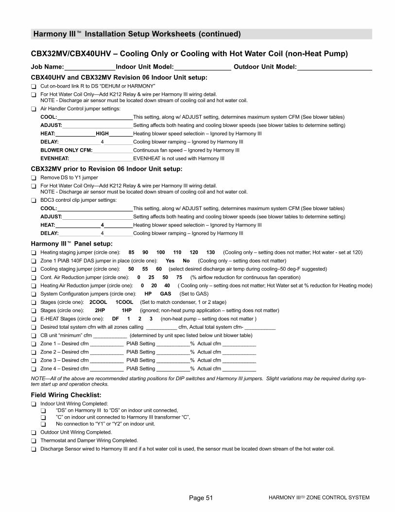
Page 51 HARMONY III� ZONE CONTROL SYSTEM
Harmony III� Installation Setup Worksheets (continued)
CBX32MV/CBX40UHV – Cooling Only or Cooling with Hot Water Coil (non−Heat Pump)
Job Name: Indoor Unit Model: Outdoor Unit Model:
CBX40UHV and CBX32MV Revision 06 Indoor Unit setup:
Cut on−board link R to DS �DEHUM or HARMONY"
For Hot Water Coil Only�Add K212 Relay & wire per Harmony III wiring detail.NOTE − Discharge air sensor must be located down stream of cooling coil and hot water coil.
Air Handler Control jumper settings:
COOL: This setting, along w/ ADJUST setting, determines maximum system CFM (See blower tables)
ADJUST: Setting affects both heating and cooling blower speeds (see blower tables to determine setting)
HEAT: HIGH Heating blower speed selectioin – Ignored by Harmony III
DELAY: 4 Cooling blower ramping – Ignored by Harmony III
BLOWER ONLY CFM: Continuous fan speed – Ignored by Harmony III
EVENHEAT: EVENHEAT is not used with Harmony III
CBX32MV prior to Revision 06 Indoor Unit setup:
Remove DS to Y1 jumper
For Hot Water Coil Only�Add K212 Relay & wire per Harmony III wiring detail.NOTE − Discharge air sensor must be located down stream of cooling coil and hot water coil.
BDC3 control clip jumper settings:
COOL: This setting, along w/ ADJUST setting, determines maximum system CFM (See blower tables)
ADJUST: Setting affects both heating and cooling blower speeds (see blower tables to determine setting)
HEAT: 4 Heating blower speed selectioin – Ignored by Harmony III
DELAY: 4 Cooling blower ramping – Ignored by Harmony III
Harmony III� Panel setup:
Heating staging jumper (circle one): 85 90 100 110 120 130 (Cooling only – setting does not matter; Hot water − set at 120)
Zone 1 PIAB 140F DAS jumper in place (circle one): Yes No (Cooling only – setting does not matter)
Cooling staging jumper (circle one): 50 55 60 (select desired discharge air temp during cooling–50 deg−F suggested)
Cont. Air Reduction jumper (circle one): 0 25 50 75 (% airflow reduction for continuous fan operation)
Heating Air Reduction jumper (circle one): 0 20 40 ( Cooling only – setting does not matter; Hot Water set at % reduction for Heating mode)
System Configuration jumpers (circle one): HP GAS (Set to GAS)
Stages (circle one): 2COOL 1COOL (Set to match condenser, 1 or 2 stage)
Stages (circle one): 2HP 1HP (ignored; non−heat pump application – setting does not matter)
E−HEAT Stages (circle one): DF 1 2 3 (non−heat pump – setting does not matter )
Desired total system cfm with all zones calling ___________ cfm, Actual total system cfm− ___________
CB unit �minimum" cfm ____________ (determined by unit spec listed below unit blower table)
Zone 1 – Desired cfm ____________ PIAB Setting ____________% Actual cfm ____________
Zone 2 – Desired cfm ____________ PIAB Setting ____________% Actual cfm ____________
Zone 3 – Desired cfm ____________ PIAB Setting ____________% Actual cfm ____________
Zone 4 – Desired cfm ____________ PIAB Setting ____________% Actual cfm ____________
NOTE�All of the above are recommended starting positions for DIP switches and Harmony III jumpers. Slight variations may be required during sys-tem start up and operation checks.
Field Wiring Checklist:
Indoor Unit Wiring Completed:
�DS" on Harmony III to �DS" on indoor unit connected,
"C" on indoor unit connected to Harmony III transformer �C",
No connection to �Y1" or �Y2" on indoor unit.
Outdoor Unit Wiring Completed.
Thermostat and Damper Wiring Completed.
Discharge Sensor wired to Harmony III and if a hot water coil is used, the sensor must be located down stream of the hot water coil.
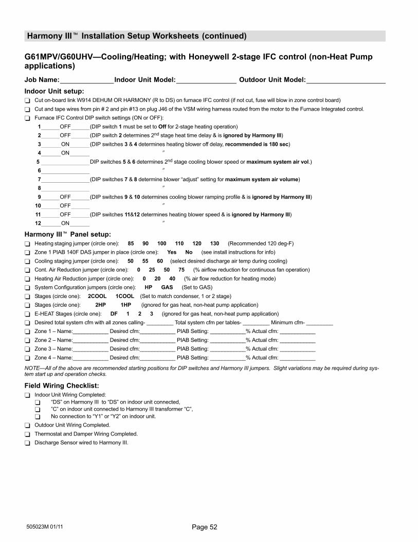
Page 52505023M 01/11
Harmony III� Installation Setup Worksheets (continued)
G61MPV/G60UHV�Cooling/Heating; with Honeywell 2−stage IFC control (non−Heat Pumpapplications)
Job Name: Indoor Unit Model: Outdoor Unit Model:
Indoor Unit setup:
Cut on−board link W914 DEHUM OR HARMONY (R to DS) on furnace IFC control (if not cut, fuse will blow in zone control board)
Cut and tape wires from pin # 2 and pin #13 on plug J46 of the VSM wiring harness routed from the motor to the Furnace Integrated control.
Furnace IFC Control DIP switch settings (ON or OFF):
1 OFF (DIP switch 1 must be set to Off for 2−stage heating operation)
2 OFF (DIP switch 2 determines 2nd stage heat time delay & is ignored by Harmony III)
3 ON (DIP switches 3 & 4 determines heating blower off delay, recommended is 180 sec)
4 ON �
5 DIP switches 5 & 6 determines 2nd stage cooling blower speed or maximum system air vol.)
6 �
7 (DIP switches 7 & 8 determine blower �adjust" setting for maximum system air volume)
8 �
9 OFF (DIP switches 9 & 10 determines cooling blower ramping profile & is ignored by Harmony III)
10 OFF �
11 OFF (DIP switches 11&12 determines heating blower speed & is ignored by Harmony III)
12 ON �
Harmony III� Panel setup:
Heating staging jumper (circle one): 85 90 100 110 120 130 (Recommended 120 deg−F)
Zone 1 PIAB 140F DAS jumper in place (circle one): Yes No (see install instructions for info)
Cooling staging jumper (circle one): 50 55 60 (select desired discharge air temp during cooling)
Cont. Air Reduction jumper (circle one): 0 25 50 75 (% airflow reduction for continuous fan operation)
Heating Air Reduction jumper (circle one): 0 20 40 (% air flow reduction for heating mode)
System Configuration jumpers (circle one): HP GAS (Set to GAS)
Stages (circle one): 2COOL 1COOL (Set to match condenser, 1 or 2 stage)
Stages (circle one): 2HP 1HP (ignored for gas heat, non−heat pump application)
E−HEAT Stages (circle one): DF 1 2 3 (ignored for gas heat, non−heat pump application)
Desired total system cfm with all zones calling− _________ Total system cfm per tables− _________ Minimum cfm− _________
Zone 1 – Name:____________ Desired cfm:____________ PIAB Setting: ____________% Actual cfm: ____________
Zone 2 – Name:____________ Desired cfm:____________ PIAB Setting: ____________% Actual cfm: ____________
Zone 3 – Name:____________ Desired cfm:____________ PIAB Setting: ____________% Actual cfm: ____________
Zone 4 – Name:____________ Desired cfm:____________ PIAB Setting: ____________% Actual cfm: ____________
NOTE�All of the above are recommended starting positions for DIP switches and Harmony III jumpers. Slight variations may be required during sys-tem start up and operation checks.
Field Wiring Checklist:
Indoor Unit Wiring Completed:
�DS" on Harmony III to �DS" on indoor unit connected,
"C" on indoor unit connected to Harmony III transformer �C",
No connection to �Y1" or �Y2" on indoor unit.
Outdoor Unit Wiring Completed.
Thermostat and Damper Wiring Completed.
Discharge Sensor wired to Harmony III.
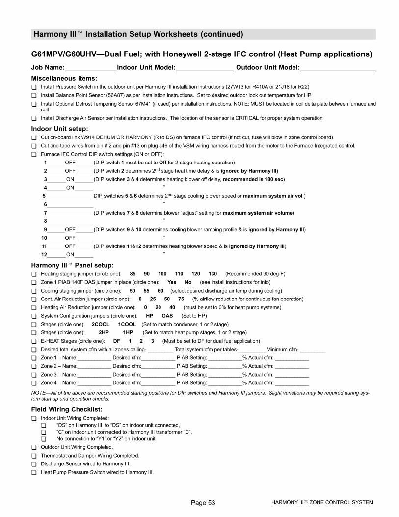
Page 53 HARMONY III� ZONE CONTROL SYSTEM
Harmony III� Installation Setup Worksheets (continued)
G61MPV/G60UHV�Dual Fuel; with Honeywell 2−stage IFC control (Heat Pump applications)
Job Name: Indoor Unit Model: Outdoor Unit Model:
Miscellaneous Items:
Install Pressure Switch in the outdoor unit per Harmony III installation instructions (27W13 for R410A or 21J18 for R22)
Install Balance Point Sensor (56A87) as per installation instructions. Set to desired outdoor lock out temperature for HP
Install Optional Defrost Tempering Sensor 67M41 (if used) per installation instructions. NOTE: MUST be located in coil delta plate between furnace andcoil
Install Discharge Air Sensor per installation instructions. The location of the sensor is CRITICAL for proper system operation
Indoor Unit setup:
Cut on−board link W914 DEHUM OR HARMONY (R to DS) on furnace IFC control (if not cut, fuse will blow in zone control board)
Cut and tape wires from pin # 2 and pin #13 on plug J46 of the VSM wiring harness routed from the motor to the Furnace Integrated control.
Furnace IFC Control DIP switch settings (ON or OFF):
1 OFF (DIP switch 1 must be set to Off for 2−stage heating operation)
2 OFF (DIP switch 2 determines 2nd stage heat time delay & is ignored by Harmony III)
3 ON (DIP switches 3 & 4 determines heating blower off delay, recommended is 180 sec)
4 ON �
5 DIP switches 5 & 6 determines 2nd stage cooling blower speed or maximum system air vol.)
6 �
7 (DIP switches 7 & 8 determine blower �adjust" setting for maximum system air volume)
8 �
9 OFF (DIP switches 9 & 10 determines cooling blower ramping profile & is ignored by Harmony III)
10 OFF �
11 OFF (DIP switches 11&12 determines heating blower speed & is ignored by Harmony III)
12 ON �
Harmony III� Panel setup:
Heating staging jumper (circle one): 85 90 100 110 120 130 (Recommended 90 deg−F)
Zone 1 PIAB 140F DAS jumper in place (circle one): Yes No (see install instructions for info)
Cooling staging jumper (circle one): 50 55 60 (select desired discharge air temp during cooling)
Cont. Air Reduction jumper (circle one): 0 25 50 75 (% airflow reduction for continuous fan operation)
Heating Air Reduction jumper (circle one): 0 20 40 (must be set to 0% for heat pump systems)
System Configuration jumpers (circle one): HP GAS (Set to HP)
Stages (circle one): 2COOL 1COOL (Set to match condenser, 1 or 2 stage)
Stages (circle one): 2HP 1HP (Set to match heat pump stages, 1 or 2 stage)
E−HEAT Stages (circle one): DF 1 2 3 (Must be set to DF for dual fuel application)
Desired total system cfm with all zones calling− _________ Total system cfm per tables− _________ Minimum cfm− _________
Zone 1 – Name:____________ Desired cfm:____________ PIAB Setting: ____________% Actual cfm: ____________
Zone 2 – Name:____________ Desired cfm:____________ PIAB Setting: ____________% Actual cfm: ____________
Zone 3 – Name:____________ Desired cfm:____________ PIAB Setting: ____________% Actual cfm: ____________
Zone 4 – Name:____________ Desired cfm:____________ PIAB Setting: ____________% Actual cfm: ____________
NOTE�All of the above are recommended starting positions for DIP switches and Harmony III jumpers. Slight variations may be required during sys-tem start up and operation checks.
Field Wiring Checklist:
Indoor Unit Wiring Completed:
�DS" on Harmony III to �DS" on indoor unit connected,
"C" on indoor unit connected to Harmony III transformer �C",
No connection to �Y1" or �Y2" on indoor unit.
Outdoor Unit Wiring Completed.
Thermostat and Damper Wiring Completed.
Discharge Sensor wired to Harmony III.
Heat Pump Pressure Switch wired to Harmony III.
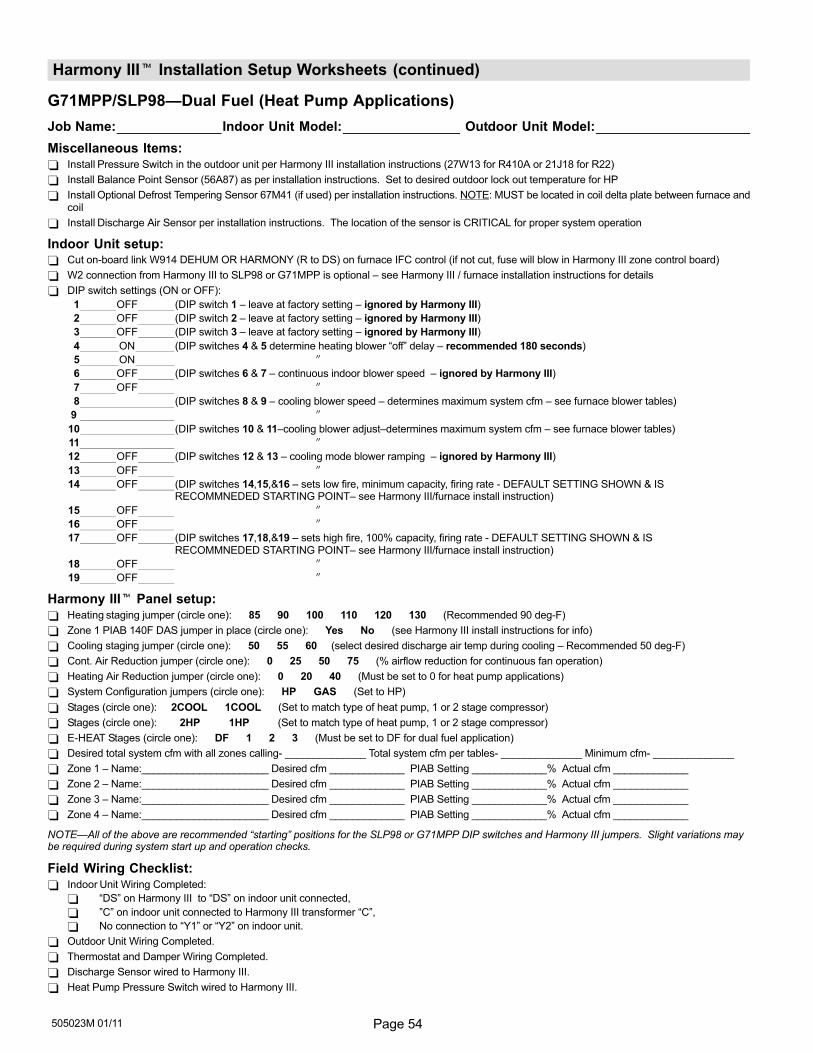
Page 54505023M 01/11
Harmony III� Installation Setup Worksheets (continued)
G71MPP/SLP98�Dual Fuel (Heat Pump Applications)
Job Name: Indoor Unit Model: Outdoor Unit Model:
Miscellaneous Items: Install Pressure Switch in the outdoor unit per Harmony III installation instructions (27W13 for R410A or 21J18 for R22)
Install Balance Point Sensor (56A87) as per installation instructions. Set to desired outdoor lock out temperature for HP
Install Optional Defrost Tempering Sensor 67M41 (if used) per installation instructions. NOTE: MUST be located in coil delta plate between furnace andcoil
Install Discharge Air Sensor per installation instructions. The location of the sensor is CRITICAL for proper system operation
Indoor Unit setup: Cut on−board link W914 DEHUM OR HARMONY (R to DS) on furnace IFC control (if not cut, fuse will blow in Harmony III zone control board)
W2 connection from Harmony III to SLP98 or G71MPP is optional – see Harmony III / furnace installation instructions for details
DIP switch settings (ON or OFF):
1 OFF (DIP switch 1 – leave at factory setting – ignored by Harmony III)
2 OFF (DIP switch 2 – leave at factory setting – ignored by Harmony III)
3 OFF (DIP switch 3 – leave at factory setting – ignored by Harmony III)
4 ON (DIP switches 4 & 5 determine heating blower �off" delay – recommended 180 seconds)
5 ON �
6 OFF (DIP switches 6 & 7 – continuous indoor blower speed – ignored by Harmony III)
7 OFF �
8 (DIP switches 8 & 9 – cooling blower speed – determines maximum system cfm – see furnace blower tables)
9 �
10 (DIP switches 10 & 11–cooling blower adjust–determines maximum system cfm – see furnace blower tables)
11 �
12 OFF (DIP switches 12 & 13 – cooling mode blower ramping – ignored by Harmony III)
13 OFF �
14 OFF (DIP switches 14,15,&16 – sets low fire, minimum capacity, firing rate − DEFAULT SETTING SHOWN & IS RECOMMNEDED STARTING POINT– see Harmony III/furnace install instruction)
15 OFF �
16 OFF �
17 OFF (DIP switches 17,18,&19 – sets high fire, 100% capacity, firing rate − DEFAULT SETTING SHOWN & IS RECOMMNEDED STARTING POINT– see Harmony III/furnace install instruction)
18 OFF �
19 OFF �
Harmony III� Panel setup: Heating staging jumper (circle one): 85 90 100 110 120 130 (Recommended 90 deg−F)
Zone 1 PIAB 140F DAS jumper in place (circle one): Yes No (see Harmony III install instructions for info)
Cooling staging jumper (circle one): 50 55 60 (select desired discharge air temp during cooling – Recommended 50 deg−F)
Cont. Air Reduction jumper (circle one): 0 25 50 75 (% airflow reduction for continuous fan operation)
Heating Air Reduction jumper (circle one): 0 20 40 (Must be set to 0 for heat pump applications)
System Configuration jumpers (circle one): HP GAS (Set to HP)
Stages (circle one): 2COOL 1COOL (Set to match type of heat pump, 1 or 2 stage compressor)
Stages (circle one): 2HP 1HP (Set to match type of heat pump, 1 or 2 stage compressor)
E−HEAT Stages (circle one): DF 1 2 3 (Must be set to DF for dual fuel application)
Desired total system cfm with all zones calling− ______________ Total system cfm per tables− ______________ Minimum cfm− ______________
Zone 1 – Name:______________________ Desired cfm _____________ PIAB Setting _____________% Actual cfm _____________
Zone 2 – Name:______________________ Desired cfm _____________ PIAB Setting _____________% Actual cfm _____________
Zone 3 – Name:______________________ Desired cfm _____________ PIAB Setting _____________% Actual cfm _____________
Zone 4 – Name:______________________ Desired cfm _____________ PIAB Setting _____________% Actual cfm _____________
NOTE�All of the above are recommended �starting" positions for the SLP98 or G71MPP DIP switches and Harmony III jumpers. Slight variations maybe required during system start up and operation checks.
Field Wiring Checklist: Indoor Unit Wiring Completed:
�DS" on Harmony III to �DS" on indoor unit connected,
"C" on indoor unit connected to Harmony III transformer �C",
No connection to �Y1" or �Y2" on indoor unit.
Outdoor Unit Wiring Completed.
Thermostat and Damper Wiring Completed.
Discharge Sensor wired to Harmony III.
Heat Pump Pressure Switch wired to Harmony III.
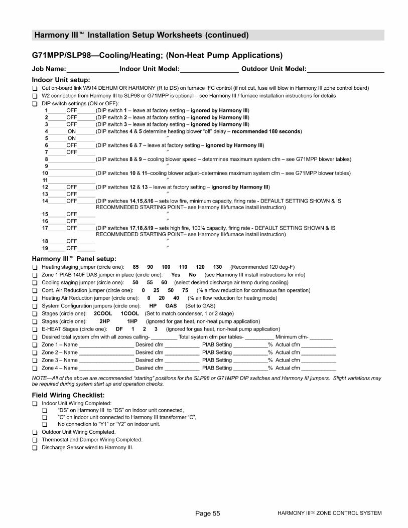
Page 55 HARMONY III� ZONE CONTROL SYSTEM
Harmony III� Installation Setup Worksheets (continued)
G71MPP/SLP98�Cooling/Heating; (Non−Heat Pump Applications)
Job Name: Indoor Unit Model: Outdoor Unit Model:
Indoor Unit setup: Cut on−board link W914 DEHUM OR HARMONY (R to DS) on furnace IFC control (if not cut, fuse will blow in Harmony III zone control board)
W2 connection from Harmony III to SLP98 or G71MPP is optional – see Harmony III / furnace installation instructions for details
DIP switch settings (ON or OFF):
1 OFF (DIP switch 1 – leave at factory setting – ignored by Harmony III)
2 OFF (DIP switch 2 – leave at factory setting – ignored by Harmony III)
3 OFF (DIP switch 3 – leave at factory setting – ignored by Harmony III)
4 ON (DIP switches 4 & 5 determine heating blower �off" delay – recommended 180 seconds)
5 ON �
6 OFF (DIP switches 6 & 7 – leave at factory setting – ignored by Harmony III)
7 OFF �
8 (DIP switches 8 & 9 – cooling blower speed – determines maximum system cfm – see G71MPP blower tables)
9 �
10 (DIP switches 10 & 11–cooling blower adjust–determines maximum system cfm – see G71MPP blower tables)
11 �
12 OFF (DIP switches 12 & 13 – leave at factory setting – ignored by Harmony III)
13 OFF �
14 OFF (DIP switches 14,15,&16 – sets low fire, minimum capacity, firing rate − DEFAULT SETTING SHOWN & IS RECOMMNEDED STARTING POINT– see Harmony III/furnace install instruction)
15 OFF �
16 OFF �
17 OFF (DIP switches 17,18,&19 – sets high fire, 100% capacity, firing rate − DEFAULT SETTING SHOWN & IS RECOMMNEDED STARTING POINT– see Harmony III/furnace install instruction)
18 OFF �
19 OFF �
Harmony III� Panel setup: Heating staging jumper (circle one): 85 90 100 110 120 130 (Recommended 120 deg−F)
Zone 1 PIAB 140F DAS jumper in place (circle one): Yes No (see Harmony III install instructions for info)
Cooling staging jumper (circle one): 50 55 60 (select desired discharge air temp during cooling)
Cont. Air Reduction jumper (circle one): 0 25 50 75 (% airflow reduction for continuous fan operation)
Heating Air Reduction jumper (circle one): 0 20 40 (% air flow reduction for heating mode)
System Configuration jumpers (circle one): HP GAS (Set to GAS)
Stages (circle one): 2COOL 1COOL (Set to match condenser, 1 or 2 stage)
Stages (circle one): 2HP 1HP (ignored for gas heat, non−heat pump application)
E−HEAT Stages (circle one): DF 1 2 3 (ignored for gas heat, non−heat pump application)
Desired total system cfm with all zones calling− _________ Total system cfm per tables− __________ Minimum cfm− ________
Zone 1 – Name ___________________ Desired cfm ____________ PIAB Setting ____________% Actual cfm ____________
Zone 2 – Name ___________________ Desired cfm ____________ PIAB Setting ____________% Actual cfm ____________
Zone 3 – Name ___________________ Desired cfm ____________ PIAB Setting ____________% Actual cfm ____________
Zone 4 – Name ___________________ Desired cfm ____________ PIAB Setting ____________% Actual cfm ____________
NOTE�All of the above are recommended �starting" positions for the SLP98 or G71MPP DIP switches and Harmony III jumpers. Slight variations maybe required during system start up and operation checks.
Field Wiring Checklist: Indoor Unit Wiring Completed:
�DS" on Harmony III to �DS" on indoor unit connected,
"C" on indoor unit connected to Harmony III transformer �C",
No connection to �Y1" or �Y2" on indoor unit.
Outdoor Unit Wiring Completed.
Thermostat and Damper Wiring Completed.
Discharge Sensor wired to Harmony III.
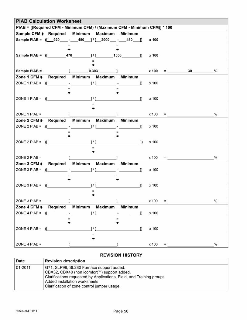
Page 56505023M 01/11
PIAB Calculation Worksheet
PIAB = [(Required CFM − Minimum CFM) / (Maximum CFM − Minimum CFM)] * 100
Sample CFM � Required Minimum Maximum Minimum
Sample PIAB = ([___920 − 450 ] / [ 2000 − 450 ]) x 100
= =� �
Sample PIAB = ([ 470 ] / [ 1550 ]) x 100
=�
Sample PIAB = [ 0.303 ] x 100 = 30 %
Zone 1 CFM � Required Minimum Maximum Minimum
ZONE 1 PIAB = ([ − ] / [ − ]) x 100
= =� �
ZONE 1 PIAB = ([ ] / [ ]) x 100
=�
ZONE 1 PIAB = [ ] x 100 = %
Zone 2 CFM � Required Minimum Maximum Minimum
ZONE 2 PIAB = ([ − ] / [ − ]) x 100
= =� �
ZONE 2 PIAB = ([ ] / [ ]) x 100
=�
ZONE 2 PIAB = [ ] x 100 = %
Zone 3 CFM � Required Minimum Maximum Minimum
ZONE 3 PIAB = ([ − ] / [ − ]) x 100
= =� �
ZONE 3 PIAB = ([ ] / [ ]) x 100
=�
ZONE 3 PIAB = [ ] x 100 = %
Zone 4 CFM � Required Minimum Maximum Minimum
ZONE 4 PIAB = ([ − ] / [ − ]) x 100
= =� �
ZONE 4 PIAB = ([ ] / [ ]) x 100
=�
ZONE 4 PIAB = ( ) x 100 = %
REVISION HISTORY
Date Revision description
01−2011 G71, SLP98, SL280 Furnace support added.CBX32, CBX40 (non icomfort�) support added.Clarifications requested by Applications, Field, and Training groups.Added installation worksheetsClarification of zone control jumper usage.


![INSTALLATION MANUAL - managemylife.com · ,?u2006 Lennox industries ]nc+ Dallas, Texas, USA INSTALLATION MANUAL HSXB15 Series Units CONDENSING UNITS _ Technical 504,710M j_jj …](https://img.pdfslide.us/doc/110x75/5b532e627f8b9a45298b8cbd/installation-manual-u2006-lennox-industries-nc-dallas-texas-usa-installation.jpg)