Embed Size (px)
Citation preview


BRP US Inc.Technical PublicationsP.O. Box 597Sturtevant, Wisconsin 53177 United Stateswww.evinrude.com or www.johnson.com
† AMP, Superseal 1.5, Super Seal, Power Timer, and Pro-Crimper IIare registered trademarks of Tyco International, Ltd.
† Amphenol is a registered trademark of The Amphenol Corporation.† BEP is a registered trademark of Actuant Corporation.† Champion is a registered trademark of Federal-Mogul Corporation.† Deutsch is a registered trademark of The Deutsch Company.† Dexron is a registered trademark of The General Motors Corporation.† Fluke is a registered trademark of The Fluke Corporation† GE is a registered trademark of The General Electric Company.† GM is a registered trademark of The General Motors Corporation.† Locquic and Loctite are registered trademarks of The Henkel Group.† Lubriplate is a registered trademark of Fiske Brothers Refining Company.† NMEA is a registered trademark of the National Marine Electronics Association.† Oetiker is a registered trademark of Hans Oetiker AG Maschinen.† Packard is a registered trademark of Delphi Automotive Systems.† Permatex is a registered trademark of Permatex.† STP is a registered trademark of STP Products Company.† Snap-on is a registered trademark of Snap-on Technologies, Inc.
The following trademarks are the property of BRP US Inc. or its affiliates:
Evinrude ® Twist Grip™
Johnson ® Nut Lock™
Evinrude ® E-TEC ® Screw Lock™
FasTrak™ Ultra Lock™
S.A.F.E.™ Moly Lube™
SystemCheck™ Triple-Guard ® Grease
I-Command™ DPL™ Lubricant
Evinrude ® ICON™ 2+4 ® Fuel Conditioner
Evinrude ® / Johnson ® XD30™ Outboard Oil Carbon Guard™
Evinrude ® / Johnson ® XD50™ Outboard Oil HPF XR™ Gearcase Lubricant
Evinrude ® / Johnson ® XD100™ Outboard Oil HPF PRO™ Gearcase Lubricant
Gel-Seal II™
Printed in the United States.© 2011 BRP US Inc. All rights reserved.TM, ® Trademarks and registered trademarks of Bombardier Recreational Products Inc. or its affiliates.

INSTALLATION & PREDELIVERY
INSTALLATION & PREDELIVERY
TABLE OF CONTENTSBOAT RIGGING
REMOTE CONTROLS CONTROL SYSTEM SELECTION . . . . . . . . . . . . . . . . . . . . . . . . . . . . . . . . . . . . . . . . . . . . . . . . . . . . . . . . . . . . . . . 8CONTROL INSTALLATION . . . . . . . . . . . . . . . . . . . . . . . . . . . . . . . . . . . . . . . . . . . . . . . . . . . . . . . . . . . . . . . . . . . . 9CONTROL CABLE ROUTING . . . . . . . . . . . . . . . . . . . . . . . . . . . . . . . . . . . . . . . . . . . . . . . . . . . . . . . . . . . . . . . . . 10
INFORMATION DISPLAY SYSTEMS . . . . . . . . . . . . . . . . . . . . . . . . . . . . . . . . . . . . . . . . . . . . . . . . . . 11ENGINE MONITOR SYSTEM . . . . . . . . . . . . . . . . . . . . . . . . . . . . . . . . . . . . . . . . . . . . . . . . . . . . . . . . . . . . . . . . . . 11SYSTEMCHECK GAUGES . . . . . . . . . . . . . . . . . . . . . . . . . . . . . . . . . . . . . . . . . . . . . . . . . . . . . . . . . . . . . . . . . . . . 11I-COMMAND DISPLAYS . . . . . . . . . . . . . . . . . . . . . . . . . . . . . . . . . . . . . . . . . . . . . . . . . . . . . . . . . . . . . . . . . . . . . . 11SYSTEMCHECK (MWS) HARNESS CONNECTIONS . . . . . . . . . . . . . . . . . . . . . . . . . . . . . . . . . . . . . . . . . . . . . . . 12I-COMMAND HARNESS CONNECTIONS WITH MECHANICAL REMOTE CONTROL . . . . . . . . . . . . . . . . . . . . . 13EVINRUDE ICON / I-COMMAND HARNESS CONNECTIONS . . . . . . . . . . . . . . . . . . . . . . . . . . . . . . . . . . . . . . . . 14
BATTERY INSTALLATION . . . . . . . . . . . . . . . . . . . . . . . . . . . . . . . . . . . . . . . . . . . . . . . . . . . . . . . . . . 15BATTERY RECOMMENDATIONS . . . . . . . . . . . . . . . . . . . . . . . . . . . . . . . . . . . . . . . . . . . . . . . . . . . . . . . . . . . . . . 15BATTERY CONNECTIONS . . . . . . . . . . . . . . . . . . . . . . . . . . . . . . . . . . . . . . . . . . . . . . . . . . . . . . . . . . . . . . . . . . . 15BATTERY CABLE REQUIREMENTS . . . . . . . . . . . . . . . . . . . . . . . . . . . . . . . . . . . . . . . . . . . . . . . . . . . . . . . . . . . . 16BATTERY SWITCHES AND MULTIPLE BATTERIES . . . . . . . . . . . . . . . . . . . . . . . . . . . . . . . . . . . . . . . . . . . . . . . 16AUXILIARY BATTERY CHARGING . . . . . . . . . . . . . . . . . . . . . . . . . . . . . . . . . . . . . . . . . . . . . . . . . . . . . . . . . . . . . 17BATTERY AND SWITCH WIRING DIAGRAMS . . . . . . . . . . . . . . . . . . . . . . . . . . . . . . . . . . . . . . . . . . . . . . . . . . . . 18
FUEL SYSTEM REQUIREMENTS . . . . . . . . . . . . . . . . . . . . . . . . . . . . . . . . . . . . . . . . . . . . . . . . . . . . 20REGULATIONS AND GUIDELINES . . . . . . . . . . . . . . . . . . . . . . . . . . . . . . . . . . . . . . . . . . . . . . . . . . . . . . . . . . . . . 20PERMANENT FUEL TANKS . . . . . . . . . . . . . . . . . . . . . . . . . . . . . . . . . . . . . . . . . . . . . . . . . . . . . . . . . . . . . . . . . . 20PORTABLE FUEL TANKS . . . . . . . . . . . . . . . . . . . . . . . . . . . . . . . . . . . . . . . . . . . . . . . . . . . . . . . . . . . . . . . . . . . . 20FUEL HOSE . . . . . . . . . . . . . . . . . . . . . . . . . . . . . . . . . . . . . . . . . . . . . . . . . . . . . . . . . . . . . . . . . . . . . . . . . . . . . . . 20FUEL SYSTEM PRIMER . . . . . . . . . . . . . . . . . . . . . . . . . . . . . . . . . . . . . . . . . . . . . . . . . . . . . . . . . . . . . . . . . . . . . . 21FUEL FILTERS . . . . . . . . . . . . . . . . . . . . . . . . . . . . . . . . . . . . . . . . . . . . . . . . . . . . . . . . . . . . . . . . . . . . . . . . . . . . . 21FUEL FLOW REQUIREMENTS . . . . . . . . . . . . . . . . . . . . . . . . . . . . . . . . . . . . . . . . . . . . . . . . . . . . . . . . . . . . . . . . 22
REMOTE OIL TANK INSTALLATION (V4 – V6) . . . . . . . . . . . . . . . . . . . . . . . . . . . . . . . . . . . . . . . . . 23LOCATION . . . . . . . . . . . . . . . . . . . . . . . . . . . . . . . . . . . . . . . . . . . . . . . . . . . . . . . . . . . . . . . . . . . . . . . . . . . . . . . . 23MOUNTING . . . . . . . . . . . . . . . . . . . . . . . . . . . . . . . . . . . . . . . . . . . . . . . . . . . . . . . . . . . . . . . . . . . . . . . . . . . . . . . . 23REMOTE OIL FILL KIT (OPTIONAL) . . . . . . . . . . . . . . . . . . . . . . . . . . . . . . . . . . . . . . . . . . . . . . . . . . . . . . . . . . . . 25
CABLE AND HOSE INSTALLATION . . . . . . . . . . . . . . . . . . . . . . . . . . . . . . . . . . . . . . . . . . . . . . . . . . 26BOAT CABLE AND HARNESS ROUTING . . . . . . . . . . . . . . . . . . . . . . . . . . . . . . . . . . . . . . . . . . . . . . . . . . . . . . . 26PROTECTIVE SLEEVE/CONDUIT . . . . . . . . . . . . . . . . . . . . . . . . . . . . . . . . . . . . . . . . . . . . . . . . . . . . . . . . . . . . . . 27BATTERY CABLES . . . . . . . . . . . . . . . . . . . . . . . . . . . . . . . . . . . . . . . . . . . . . . . . . . . . . . . . . . . . . . . . . . . . . . . . . 27FUEL HOSE . . . . . . . . . . . . . . . . . . . . . . . . . . . . . . . . . . . . . . . . . . . . . . . . . . . . . . . . . . . . . . . . . . . . . . . . . . . . . . . 27OIL SUPPLY HOSE . . . . . . . . . . . . . . . . . . . . . . . . . . . . . . . . . . . . . . . . . . . . . . . . . . . . . . . . . . . . . . . . . . . . . . . . . 27OETIKER CLAMP SERVICING . . . . . . . . . . . . . . . . . . . . . . . . . . . . . . . . . . . . . . . . . . . . . . . . . . . . . . . . . . . . . . . . 28
2

INSTALLATION & PREDELIVERY
OUTBOARD INSTALLATION HULL PREPARATION . . . . . . . . . . . . . . . . . . . . . . . . . . . . . . . . . . . . . . . . . . . . . . . . . . . . . . . . . . . . . . 31TRANSOM MEASURING AND DRILLING . . . . . . . . . . . . . . . . . . . . . . . . . . . . . . . . . . . . . . . . . . . . . . 33LIFTING THE OUTBOARD . . . . . . . . . . . . . . . . . . . . . . . . . . . . . . . . . . . . . . . . . . . . . . . . . . . . . . . . . . 44STEERING SYSTEMS . . . . . . . . . . . . . . . . . . . . . . . . . . . . . . . . . . . . . . . . . . . . . . . . . . . . . . . . . . . . . . 46OUTBOARD MOUNTING . . . . . . . . . . . . . . . . . . . . . . . . . . . . . . . . . . . . . . . . . . . . . . . . . . . . . . . . . . . . 48
OUTBOARD RIGGINGCOMMON PRACTICES – ALL MODELS . . . . . . . . . . . . . . . . . . . . . . . . . . . . . . . . . . . . . . . . . . . . . . . 51
CONTROL CABLE IDENTIFICATION . . . . . . . . . . . . . . . . . . . . . . . . . . . . . . . . . . . . . . . . . . . . . . . . . . . . . . . . . . . 51CABLE RETAINER CLIP INSTALLATION . . . . . . . . . . . . . . . . . . . . . . . . . . . . . . . . . . . . . . . . . . . . . . . . . . . . . . . . 51
EVINRUDE E-TEC 90° V MODELS 200–300 HP . . . . . . . . . . . . . . . . . . . . . . . . . . . . . . . . . . . . . . . . . . 52EVINRUDE E-TEC 60° V MODELS 115–200 HP . . . . . . . . . . . . . . . . . . . . . . . . . . . . . . . . . . . . . . . . . . 58EVINRUDE E-TEC MODELS 40–90 HP . . . . . . . . . . . . . . . . . . . . . . . . . . . . . . . . . . . . . . . . . . . . . . . . . 65EVINRUDE E-TEC MODELS 15–30 HP . . . . . . . . . . . . . . . . . . . . . . . . . . . . . . . . . . . . . . . . . . . . . . . . . 71
FUEL AND OIL PRIMING FUEL REQUIREMENTS . . . . . . . . . . . . . . . . . . . . . . . . . . . . . . . . . . . . . . . . . . . . . . . . . . . . . . . . . . . . . 75FUEL SYSTEM PRIMING . . . . . . . . . . . . . . . . . . . . . . . . . . . . . . . . . . . . . . . . . . . . . . . . . . . . . . . . . . . . 76OIL REQUIREMENTS . . . . . . . . . . . . . . . . . . . . . . . . . . . . . . . . . . . . . . . . . . . . . . . . . . . . . . . . . . . . . . 77
RECOMMENDED LUBRICANTS . . . . . . . . . . . . . . . . . . . . . . . . . . . . . . . . . . . . . . . . . . . . . . . . . . . . . . . . . . . . . . . 77OIL INJECTION RATE . . . . . . . . . . . . . . . . . . . . . . . . . . . . . . . . . . . . . . . . . . . . . . . . . . . . . . . . . . . . . . . . . . . . . . . 77BREAK-IN OILING . . . . . . . . . . . . . . . . . . . . . . . . . . . . . . . . . . . . . . . . . . . . . . . . . . . . . . . . . . . . . . . . . . . . . . . . . . 78
OIL SUPPLY PRIMING . . . . . . . . . . . . . . . . . . . . . . . . . . . . . . . . . . . . . . . . . . . . . . . . . . . . . . . . . . . . . . 79
PREDELIVERY BEFORE START-UP . . . . . . . . . . . . . . . . . . . . . . . . . . . . . . . . . . . . . . . . . . . . . . . . . . . . . . . . . . . . . . . 83RUNNING CHECKS . . . . . . . . . . . . . . . . . . . . . . . . . . . . . . . . . . . . . . . . . . . . . . . . . . . . . . . . . . . . . . . . 84PROPELLERS . . . . . . . . . . . . . . . . . . . . . . . . . . . . . . . . . . . . . . . . . . . . . . . . . . . . . . . . . . . . . . . . . . . . 86WATER TEST AND FINAL ADJUSTMENTS . . . . . . . . . . . . . . . . . . . . . . . . . . . . . . . . . . . . . . . . . . . . . 88
ENGINE MOUNTING HEIGHT AND JACK PLATE ADJUSTMENT . . . . . . . . . . . . . . . . . . . . . . . . . . . . . . . . . . . . 88FUEL SYSTEM VACUUM . . . . . . . . . . . . . . . . . . . . . . . . . . . . . . . . . . . . . . . . . . . . . . . . . . . . . . . . . . . . . . . . . . . . . 88ENGINE WATER PRESSURE . . . . . . . . . . . . . . . . . . . . . . . . . . . . . . . . . . . . . . . . . . . . . . . . . . . . . . . . . . . . . . . . . 88WATER PRESSURE CHART . . . . . . . . . . . . . . . . . . . . . . . . . . . . . . . . . . . . . . . . . . . . . . . . . . . . . . . . . . . . . . . . . . 89TILT LIMIT SWITCH ADJUSTMENT (75 – 300 HP) . . . . . . . . . . . . . . . . . . . . . . . . . . . . . . . . . . . . . . . . . . . . . . . . . 90TRIM SENDING UNIT ADJUSTMENT (75 – 300 HP) . . . . . . . . . . . . . . . . . . . . . . . . . . . . . . . . . . . . . . . . . . . . . . . . 91TRIM SENDING UNIT ADJUSTMENT (25 – 60 HP) . . . . . . . . . . . . . . . . . . . . . . . . . . . . . . . . . . . . . . . . . . . . . . . . . 92TRIM TAB ADJUSTMENT . . . . . . . . . . . . . . . . . . . . . . . . . . . . . . . . . . . . . . . . . . . . . . . . . . . . . . . . . . . . . . . . . . . . 93DUAL-OUTBOARD ALIGNMENT . . . . . . . . . . . . . . . . . . . . . . . . . . . . . . . . . . . . . . . . . . . . . . . . . . . . . . . . . . . . . . . 94
INDEX . . . . . . . . . . . . . . . . . . . . . . . . . . . . . . . . . . . . . . . . . . . . . . . . . . . . . . . . . . . . . . . . . .95
SAMPLE PREDELIVERY CHECKLIST . . . . . . . . . . . . . . . . . . . . . . . . . . . . . . . . . . . . . . . .97
3

INSTALLATION & PREDELIVERY
SAFETY INFORMATION
This publication is written for qualified, factory-trained technicians who are already familiar withthe use of Evinrude/Johnson Special Tools. Theincluded information is not a substitute for workexperience. It is an organized guide for reference,repair, and/or maintenance.
The following symbols and/or signal wordsmay be used in this document:
Indicates an instruction which, ifnot followed, could severely damage enginecomponents or other property.
These safety alert signal words mean:
ATTENTION!BECOME ALERT!YOUR SAFETY IS INVOLVED!
IMPORTANT: Identifies information that controlscorrect assembly and operation of the product.
DO NOT perform any work until you have readand understood these instructions completely.
Torque wrench tightening specifications muststrictly be adhered to.
Should removal of any locking fastener (lock tabs,locknuts, or patch screws) be required, alwaysreplace with a new one.
When replacement parts are required, useEvinrude/Johnson Genuine Parts or parts withequivalent characteristics, including type, strengthand material. Use of substandard parts couldresult in injury or product malfunction.
Always wear EYE PROTECTION AND APPRO-PRIATE GLOVES when using power tools.
Unless otherwise specified, engine must be OFFwhen performing this work.
Always be aware of parts that can move, such asflywheels, propellers, etc.
Some components may be HOT. Always wait forengine to cool down before performing work.
If you use procedures or service tools that are notrecommended in this manual, YOU ALONE mustdecide if your actions might injure people or dam-age the outboard.
This document may be translated into other lan-guages. In the event of any discrepancy, theEnglish version shall prevail.
A DANGER
Indicates a hazardous situation which, ifnot avoided, will result in death or seriousinjury.
A WARNING
Indicates a hazardous situation which, ifnot avoided, could result in death or seri-ous injury
A CAUTION
Indicates a hazardous situation which, ifnot avoided, could result in minor or mod-erate personal injury.
NOTICE
4

INSTALLATION & PREDELIVERY
A DANGER
Contact with a rotating propeller is likely to result in serious injury or death. Assure theengine and prop area is clear of people and objects before starting engine or operating boat.Do not allow anyone near a propeller, even when the engine is off. Blades can be sharp andthe propeller can continue to turn even after the engine is off. Remove propeller before ser-vicing and when running the outboard on a flushing device.
DO NOT run the engine indoors or without adequate ventilation or permit exhaust fumes toaccumulate in confined areas. Engine exhaust contains carbon monoxide which, if inhaled,can cause serious brain damage or death.
A WARNING
Wear safety glasses to avoid personal injury, and set compressed air to less than 25 psi (172kPa).
The motor cover and flywheel cover are machinery guards. Use caution when conductingtests on running outboards. DO NOT wear jewelry or loose clothing. Keep hair, hands, andclothing away from rotating parts.
During service, the outboard may drop unexpectedly. Avoid personal injury; always supportthe outboard’s weight with a suitable hoist or the tilt support bracket during service.
To prevent accidental starting while servicing, disconnect the battery cables at the battery.Twist and remove all spark plug leads.
The electrical system presents a serious shock hazard. DO NOT handle primary or secondaryignition components while outboard is running or flywheel is turning.
Gasoline is extremely flammable and highly explosive under certain conditions. Use cautionwhen working on any part of the fuel system.
Protect against hazardous fuel spray. Before starting any fuel system service, carefullyrelieve fuel system pressure.
Do not smoke, or allow open flames or sparks, or use electrical devices such as cellularphones in the vicinity of a fuel leak or while fueling.
Keep all electrical connections clean, tight, and insulated to prevent shorting or arcing andcausing an explosion.
Always work in a well ventilated area.
Replace any locking fastener (locknut or patch screw) if its locking feature becomes weak.Definite resistance to tightening must be felt when reusing a locking fastener. If replacementis indicated, use only authorized replacement or equivalent.
5

INSTALLATION & PREDELIVERYABBREVIATIONS USED IN THIS MANUAL
ABBREVIATIONS USED IN THIS MANUAL
Units of Measurement List of Abbreviations
A Amperes
amp-hr Ampere hour
fl. oz. fluid ounce
ft. lbs. foot pounds
HP horsepower
in. inch
in. Hg inches of mercury
in. lbs. inch pounds
kPa kilopascals
ml milliliter
mm millimeter
N·m Newton meter
P/N part number
psi pounds per square inch
RPM revolutions per minute
°C degrees Celsius
°F degrees Fahrenheit
ms milliseconds
µs microseconds
Ω Ohms
V Volts
VAC Volts Alternating Current
VDC Volts Direct Current
ABYC American Boat & Yacht Council
ATDC after top dead center
AT air temperature sensor
BPS barometric pressure sensor
BTDC before top dead center
CCA cold cranking amps
CFR Code of Federal Regulations
CPS crankshaft position sensor
EMM Engine Management Module
EPA Environmental Protection Agency
ICOMIA International Council of Marine Industry Associations
ID Inside dimension
MCA marine cranking amps
MWS modular wiring system
NMEA National Marine Electronics Assoc.
ROM read only memory
S.A.F.E. speed adjusting failsafe electronics
SAC start assist circuit
SAE Society of Automotive Engineers
SYNC synchronization
TDC top dead center
TPS throttle position sensor
USCG United States Coast Guard
WOT wide open throttle
WTS water temperature sensor
6

INSTALLATION & PREDELIVERYEMISSION-RELATED INSTALLATION INSTRUCTIONS
EMISSION-RELATED INSTALLATION INSTRUCTIONSFailing to follow these instructions wheninstalling a certified engine in a vessel violatesfederal law (40 CFR 1068.105 (b)), subject tofines or other penalties as described in theClean Air Act.
Maintenance, replacement, or repair of the emis-sion control devices and systems may be per-formed by any marine SI (spark ignition) enginerepair establishment or individual.
Manufacturer’s ResponsibilityBeginning with 1999 model year outboards, man-ufacturers of marine outboards must determinethe exhaust emission levels for each outboardhorsepower family and certify these outboardswith the United States of America EnvironmentalProtection Agency (EPA). An emissions controlinformation label, showing emission levels andoutboard specifications, must be placed on eachoutboard at the time of manufacture.
Dealer’s ResponsibilityWhen performing service on all 1999 and morerecent Evinrude/Johnson outboards that carry anemissions control information label, adjustmentsmust be kept within published factory specifica-tions.
Replacement or repair of any emission relatedcomponent must be executed in a manner thatmaintains emission levels within the prescribedcertification standards.
Dealers are not to modify the outboard in anymanner that would alter the horsepower or allowemission levels to exceed their predeterminedfactory specifications.
Exceptions include manufacturer’s prescribedchanges, such as altitude adjustments, for exam-ple.
Owner’s ResponsibilityThe owner/operator is required to have outboardmaintenance performed to maintain emission lev-els within prescribed certification standards.
The owner/operator is not to, and should not allowanyone to, modify the outboard in any mannerthat would alter the horsepower or allow emis-sions levels to exceed their predetermined factoryspecifications.
Tampering with the fuel system to change horse-power or modify emission levels beyond factorysettings or specifications will void the product war-ranty.
EPA Emission RegulationsAll new 1999 and more recent Evinrude/Johnsonoutboards are certified to the EPA as conformingto the requirements of the regulations for the con-trol of air pollution from new watercraft marinespark ignition outboards. This certification is con-tingent on certain adjustments being set to factorystandards. For this reason, the factory procedurefor servicing the product must be strictly followedand, whenever practical, returned to the originalintent of the design. The responsibilities listedabove are general and in no way a complete list-ing of the rules and regulations pertaining to theEPA requirements on exhaust emissions formarine products. For more detailed information onthis subject, you may contact the following loca-tions:
VIA U.S. POSTAL SERVICE:Office of Mobile SourcesEngine Programs and Compliance DivisionEngine Compliance Programs Group (6403J)401 M St. NWWashington, DC 20460
VIA EXPRESS or COURIER MAIL:Office of Mobile SourcesEngine Programs and Compliance DivisionEngine Compliance Programs Group (6403J)501 3rd St. NWWashington, DC 20001
EPA INTERNET WEB SITE:www.epa.gov
7

BOAT RIGGINGREMOTE CONTROLS
BOAT RIGGING
REMOTE CONTROLSControl System SelectionOutboard remote control systems provide theoperator with tools for:• Starting and stopping the engine• Shifting into Forward, Neutral, or Reverse• Changing engine speed• Changing the tilt/trim angle of the outboard.
The remote control system must include the fol-lowing features:• Shift stroke must be 1.125 to 1.330 in. (28.6 to
33.8 mm) between Neutral and Forward• Throttle stroke must PUSH for open• Start-in-gear prevention• Emergency stop switch with lanyard—multiple-
outboard installations require separate startswitches and a single emergency stop switch
• Connections for engine monitor warning systemRefer to Engine Monitor System on p. 11.
Several remote control options, including bothmechanical and electronic systems, are availablein the Evinrude/Johnson Genuine Parts andAccessories catalog.
Mechanical control systems use push/pullcables to physically move the shift and throttlecomponents on the outboard.
These systems use a Modular Wiring System(MWS) harness to carry start, stop, and trim sig-nals (analog) to the outboard. Specific harnessselection depends on the type of Information Dis-play system being used. Refer to INFORMATIONDISPLAY SYSTEMS on p. 11.
Electronic control systems, such as EvinrudeICON, manage all engine control functionsthrough a low-voltage, digital data network.
These systems can only be used with outboardsequipped for electronic control, including EvinrudeETEC models identified with a “DE” prefix in themodel number.
Conversion kits are available to add electroniccontrol capabilities to standard ETEC models from150 to 300 HP, 2008 and newer.
ICON style multiple start switches with masterpower/emergency stop switch
007875
A WARNING
The remote control used must have start-in-gear prevention. This feature can pre-vent injuries resulting from unexpectedboat movement when the outboard starts.
Always install and recommend use of anemergency stop/key switch. Doing so willreduce the risk of personal injury or deathshould the operator fall away from the con-trols or out of the boat.
Evinrude ICON multi-engine control 007986
8

BOAT RIGGINGREMOTE CONTROLS
1
Control InstallationPlan the installation of remote controls carefully,following all instructions provided with the control.Select an appropriate location based on the boatconfiguration.
IMPORTANT: The mounting location must be aflat surface and must be strong enough to providerigid support. Strengthen mounting surface asnecessary.
Place remote control at proposed location andcheck clearance around remote control lever atfull throttle in FORWARD and then at full throttle inREVERSE. There must be at least 2.5 in. (64 mm)of clearance between the handle and any part ofthe boat throughout the control lever travel.
Use an appropriate drill template to cut mountingholes. Templates are included with the controlinstructions.
Install control with hardware provided.
IMPORTANT: Make sure remote control assem-bly is secure and does not move during operation.
1. Side console2. Center console
005471
1 2
Typical control clearances 007920
1. Template 007922
85.5°
FWD15.0°
15.0°
40.5°
NEUTRAL
REV
2.5 in (64 mm)
1
9
BOAT RIGGINGREMOTE CONTROLS
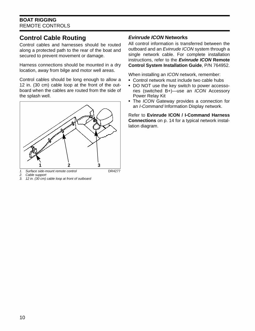
Control Cable RoutingControl cables and harnesses should be routedalong a protected path to the rear of the boat andsecured to prevent movement or damage.
Harness connections should be mounted in a drylocation, away from bilge and motor well areas.
Control cables should be long enough to allow a12 in. (30 cm) cable loop at the front of the out-board when the cables are routed from the side ofthe splash well.
Evinrude ICON NetworksAll control information is transferred between theoutboard and an Evinrude ICON system through asingle network cable. For complete installationinstructions, refer to the Evinrude ICON RemoteControl System Installation Guide, P/N 764952.
When installing an ICON network, remember:• Control network must include two cable hubs• DO NOT use the key switch to power accesso-
ries (switched B+)—use an ICON AccessoryPower Relay Kit
• The ICON Gateway provides a connection foran I-Command Information Display network.
Refer to Evinrude ICON / I-Command HarnessConnections on p. 14 for a typical network instal-lation diagram.
1. Surface side-mount remote control 2. Cable support3. 12 in. (30 cm) cable loop at front of outboard
DR4277
1 2 3
10

BOAT RIGGINGINFORMATION DISPLAY SYSTEMS
1
INFORMATION DISPLAY SYSTEMSEngine Monitor SystemAll remote controlled outboards must be equippedwith an engine monitoring system to warn theoperator of conditions that could damage the out-board.The engine monitor system includes sensors onthe outboard and oil tank, a warning horn, a dash-mounted display, and related wiring.
The outboard’s EMM sends information aboutmonitored functions to:• SystemCheck gauges, or• An I-Command or ICON display.
IMPORTANT: Operating the outboard withoutan engine monitor will void the warranty for fail-ures related to monitored functions.
SystemCheck GaugesSystemCheck gauges are used with mechanicalremote control systems only.
SystemCheck gauges receive monitored informa-tion from the outboard through a Modular WiringSystem (MWS) harness.
Refer to SystemCheck (MWS) Harness Con-nections on p. 12.
I-Command DisplaysI-Command digital displays are designed specifi-cally for NMEA 2000 certified Evinrude E-TECoutboards. These displays provide enhancedengine and boat performance information. Multi-ple functions are integrated into the easy-to-usedisplays. Additional displays and accessories canbe added with the plug and play design.
I-Command information displays can be used witheither a mechanical remote control system or withan Evinrude ICON system. For complete installa-tion instructions, refer to I-Command InstallationGuide.
When installing an I-Command network, remem-ber:• A terminator must be installed at each end of
the network• There should be no open or unused network
device connectors• The network should be grounded at a single
location only• A maximum of 50 devices can be attached to
the network *• The distance between any two points on the
network must not exceed 100 meters (328 ft.).
* The EMM on Evinrude E-TEC outboards has aload equivalency number of 1. Less than 50 mA ofthe network’s power is used by the EMM.
If a mechanical control is used, the I-Commandnetwork receives monitored information throughan I-Command network harness connecteddirectly to the outboard’s EMM. An I-CommandIgnition and Trim harness is required to carry start,stop, and trim signals to the outboard.
Refer to I-Command Harness ConnectionsWith Mechanical Remote Control on p. 13.
If an ICON control is used, the I-Command net-work receives monitored information through theICON control network gateway.
Refer to Evinrude ICON / I-Command HarnessConnections on p. 14.
Typical I-Command and SystemCheck gauges 007988
11
BOAT RIGGINGINFORMATION DISPLAY SYSTEMS
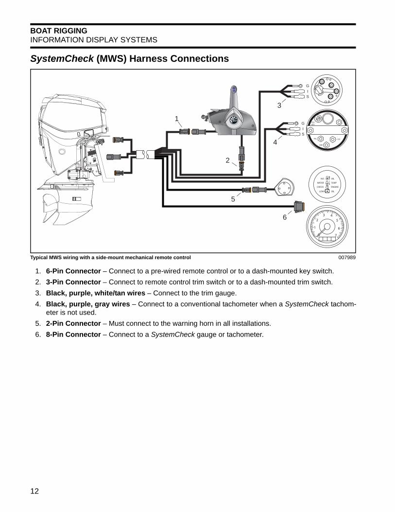
SystemCheck (MWS) Harness Connections
NO OIL
WATER TEMP
CHECK ENGINE
LOW OIL
2
56
43PUL
REV
PUL
GND
+12V
0
2
1
3 45
6
7
1
2
3
4
5
6
GIS
GIS
Typical MWS wiring with a side-mount mechanical remote control 007989
1. 6-Pin Connector – Connect to a pre-wired remote control or to a dash-mounted key switch.
2. 3-Pin Connector – Connect to remote control trim switch or to a dash-mounted trim switch.
3. Black, purple, white/tan wires – Connect to the trim gauge.
4. Black, purple, gray wires – Connect to a conventional tachometer when a SystemCheck tachom-eter is not used.
5. 2-Pin Connector – Must connect to the warning horn in all installations.
6. 8-Pin Connector – Connect to a SystemCheck gauge or tachometer.
12
BOAT RIGGINGINFORMATION DISPLAY SYSTEMS
1
I-Command Harness Connections With Mechanical Remote ControlBUSSBUSS BUSSBUSS
3A
DEV
ICE
DEV
ICE
DEV
ICE
DEV
ICE
DEV
ICE
DEV
ICE
DEV
ICE
DEV
ICE
DEV
ICE
DEV
ICE
BUSSBUSS BUSSBUSS BUSSBUSS
EP- 85 Memory Module
DEV
ICE
DEV
ICE
DEV
ICE
DEV
ICE
BUSS BUSSBUSS BUSSBUSS
MENU
DOWN
UP EXIT
PAGES
ENTER
15 10
5
0
20 25 30
35
40 Water
MPH 15.2
MENU
DOWN
UP EXIT
PAGES
ENTER
30 20 10
0
40 50
60
70 x 100
RPM 3550
1
3 4
2
5 6
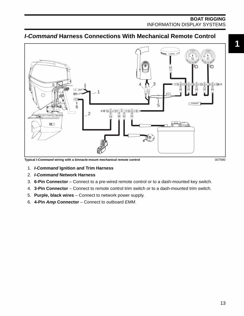
Typical I-Command wiring with a binnacle-mount mechanical remote control 007990
1. I-Command Ignition and Trim Harness
2. I-Command Network Harness
3. 6-Pin Connector – Connect to a pre-wired remote control or to a dash-mounted key switch.
4. 3-Pin Connector – Connect to remote control trim switch or to a dash-mounted trim switch.
5. Purple, black wires – Connect to network power supply.
6. 4-Pin Amp Connector – Connect to outboard EMM.
13

BOAT RIGGINGINFORMATION DISPLAY SYSTEMS
Evinrude ICON / I-Command Harness Connections
FUSE
OFFRUN
BUSS BUSS BUSS BUSS
DEV
ICE
DEV
ICE
DEV
ICE
DEV
ICE
DEV
ICE
DEV
ICE
BUSS BUSSBUSS BUSS
DEV
ICE
DEV
ICE
1020 30 40
5060
700x 100
RPM3550
UP
DOWN
EXIT
PAGES
ENTER
MENU
1020 30 40
5060
700x 100
RPM3550
UP
DOWN
EXIT
PAGES
ENTER
MENU
1020 30 40
5060
700x 100
RPM3550
UP
DOWN
EXIT
PAGES
ENTER
MENU
1020 30 40
5060
700x 100
RPM3550
UP
DOWN
EXIT
PAGES
ENTER
MENU
(+)
(–)
( + )
BUSS BUSS BUSS BUSS
DEV
ICE
DEV
ICE
DEV
ICE
DEV
ICE
BUSS BUSS
DEV
ICE
DEV
ICE
DEV
ICE
DEV
ICE
BUSS BUSSBUSS BUSS
DEV
ICE
DEV
ICE
1020 30 40
5060
700x 100
RPM3550
UP
DOWN
EXIT
PAGES
ENTER
MENU
1020 30 40
5060
700x 100
RPM3550
UP
DOWN
EXIT
PAGES
ENTER
MENU
1020 30 40
5060
700x 100
RPM3550
UP
DOWN
EXIT
PAGES
ENTER
MENU
1020 30 40
5060
700x 100
RPM3550
UP
DOWN
EXIT
PAGES
ENTER
MENU
Port
Center
Accessory Harness and Relay Kit
Starboard
Hub
MainStationControl
GatewayModule
Trim Switch Panel
MasterPowerSwitch
Emergency Stop Switch
Panel
Buss Cable Extension
Start/Stop Switch Panel
Start/Stop Switch Panel
Trim Switch Panel
InformationDisplay
SecondStationControl
Backbone Buss Cable
InformationDisplay
Hub
Buss Cable Extension
Typical Evinrude ICON network for three outboards and two control stations 007978
14
BOAT RIGGINGBATTERY INSTALLATION
1
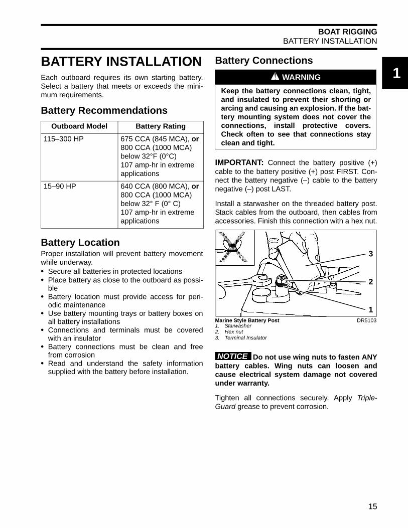
BATTERY INSTALLATIONEach outboard requires its own starting battery.Select a battery that meets or exceeds the mini-mum requirements.Battery Recommendations
Battery LocationProper installation will prevent battery movementwhile underway.• Secure all batteries in protected locations• Place battery as close to the outboard as possi-
ble• Battery location must provide access for peri-
odic maintenance• Use battery mounting trays or battery boxes on
all battery installations• Connections and terminals must be covered
with an insulator• Battery connections must be clean and free
from corrosion• Read and understand the safety information
supplied with the battery before installation.
Battery Connections
IMPORTANT: Connect the battery positive (+)cable to the battery positive (+) post FIRST. Con-nect the battery negative (–) cable to the batterynegative (–) post LAST.
Install a starwasher on the threaded battery post.Stack cables from the outboard, then cables fromaccessories. Finish this connection with a hex nut.
Do not use wing nuts to fasten ANYbattery cables. Wing nuts can loosen andcause electrical system damage not coveredunder warranty.
Tighten all connections securely. Apply Triple-Guard grease to prevent corrosion.
Outboard Model Battery Rating
115–300 HP 675 CCA (845 MCA), or 800 CCA (1000 MCA) below 32°F (0°C)107 amp-hr in extreme applications
15–90 HP 640 CCA (800 MCA), or 800 CCA (1000 MCA) below 32° F (0° C)107 amp-hr in extreme applications
A WARNING
Keep the battery connections clean, tight,and insulated to prevent their shorting orarcing and causing an explosion. If the bat-tery mounting system does not cover theconnections, install protective covers.Check often to see that connections stayclean and tight.
Marine Style Battery Post1. Starwasher2. Hex nut3. Terminal Insulator
DR5103
3
2
1
NOTICE
15

BOAT RIGGINGBATTERY INSTALLATION
Battery Cable RequirementsEvinrude outboards are shipped with strandedcopper battery cables for typical installations inwhich the starting battery is close to the transom.
Specialized outboard installations with extendedlength battery cables require an increased wiresize. Refer to the following table.
IMPORTANT: Inadequate battery cables canaffect the performance of an outboard’s highamperage start circuit and the cranking speed ofthe outboard. DO NOT use aluminum wire cables.Use ONLY AWG stranded copper wire cables.
Battery Switches and Multiple BatteriesA multiple battery setup, including marine batteryselector switches, can provide flexibility in singleand dual outboard installations.
Refer to Battery and Switch Wiring Diagramson p. 18 for battery connection options.
The battery selection function can be used foremergency starting if a primary battery becomesdischarged.
The OFF position of the battery selector switchcan be used to minimize battery discharge duringperiods of non-use.
Typical battery functions
Primary• Used as starting battery under normal operating
conditions.• Red (+) cable connected to battery switch.• Primary battery is charged by connection to
main red (+) outboard battery cable.
Dual outboard installations can utilize the oppos-ing outboard's primary battery as a secondary bat-tery for emergency starting only.
Secondary• Used as back-up starting battery under abnor-
mal operating conditions.• Red (+) cable connected to battery switch.• Secondary battery is charged independently
from primary battery.
Accessory• Not used as starting battery.• Isolated from outboard start function.• No red (+) cable connected to battery switch.
Secondary and accessory batteries are oftencharged by an isolated battery charging circuit.Refer to Auxiliary Battery Charging on p. 17.
Battery Switch RequirementsBattery switches must meet the following require-ments.• The switch must be approved for marine use.• The switch should be a “make before break”
design.• Switch amperage rating should be adequate for
the outboard it will be used on.• Use one battery switch for each outboard
installed.• Use appropriately sized wire and terminals.• Use AWG stranded copper wire.
Battery Switch Location• Locate battery switch as close to the batteries
as possible.• Locate switch so that it cannot be accidently
bumped or switched.• Refer to the battery switch manufacturer’s
installation instructions.• Fasten all battery switches to solid surfaces.• Route wiring as directly as possible.• Support the battery switch as needed to prevent
abrasion.• Use appropriate wiring and connectors.• Seal all connections and terminals with liquid
neoprene to prevent corrosion.
Insulate all battery positive (+) ter-minals to prevent shorting.
15–30 HP 40–300 HP
1 to 10 Ft.(.3 to 3 m)
6 Gauge 4 Gauge
11 to 15 Ft.(3.4 to 4.6 m)
4 Gauge 2 Gauge
16 to 20 Ft.(4.9 to 6.1 m)
2 Gauge 1 Gauge
NOTICE
16

BOAT RIGGINGBATTERY INSTALLATION
1
Battery Switch Operation• Select the primary battery for normal operation.• Secondary batteries should only be selected foremergency starting.• ALL or BOTH switch position is for emergency
starting only.
Provide operator with the documentation sup-plied by the battery switch manufacturer. Makesure that the operator is informed of properbattery switch operation.
The negative (–) terminals of a mul-tiple 12-volt battery installation must be con-nected together.
Auxiliary Battery Charging
EVINRUDE E-TEC V4 – V6 MODELS
Evinrude E-TEC V4–V6 outboards are equippedwith isolated battery charging capability. The iso-lated charge connection must only be used tocharge a single 12-volt battery or two 12-volt bat-teries wired in parallel.
Never connect an external batteryisolator to the stator of an Evinrude E-TEC.
Accessory Charge Lead Kit, P/N 5006253, isrouted from a connector on the outboard’s electri-cal harness to the accessory battery.
The accessory charging kit mustnever be connected to any battery of a 24-voltelectrical system.
EVINRUDE E-TEC 40 – 90HP MODELS
Evinrude E-TEC 40 – 90 HP outboards do nothave a built in isolator feature. Proper methodsmust be used to connect a second battery.
Battery charging output on 40 – 90 HP models is25 Amps. Be sure to follow published standardsfor wire gauge selection. Refer to Battery CableRequirements on p. 16.
If a battery isolator is desired, a battery switch,such as P/N 506161, and a voltage sensitiverelay, such as BEP model 710-125A, can be usedto create a battery isolator/combiner.
The voltage sensitive relay (VSR) regulatescharging of a second battery based on predeter-mined voltage levels of the primary battery.
Never connect an external batteryisolator to the stator of an Evinrude E-TEC.
90° V6 Models1. Accessory battery charge connector
004125
NOTICE
NOTICE
1
60° V4–V6 Models1. Accessory battery charge connector
004944
1
NOTICE
NOTICE
17

BOAT RIGGINGBATTERY INSTALLATION
Battery and Switch Wiring DiagramsSingle outboard
Two outboards: Two starting batteries each
S
BOTH
OFF
1 2
VSR
OFF
ON
+PRIMARY
#1
S
1 2
OFF
BOTH
SECONDARY
+PRIMARY
#1
S
+ #2PRIMARY
#1SECONDARY
#2
1 2 4
3
Positive (+) Battery CableNegative (–) Battery Cable
Accessory charge wire (V models)50 amp fuse
1. Single starting battery with ON/OFF switch2. Two starting batteries with isolator/combiner (15 – 90 HP models)3. Voltage sensitive relay4. Two starting batteries with Auxiliary charging kit (V models)
008056
SECONDARY
+PRIMARY
S
+
1 2
OFF
BOTH
SECONDARY
+PRIMARY
#1
S
+
#2
#1 #1 #2 #2
1 2
OFF
BOTH
Positive (+) Battery CableNegative (–) Battery CableAccessory charge wire (V models)50 amp fuse
008055
18
BOAT RIGGINGBATTERY INSTALLATION
1
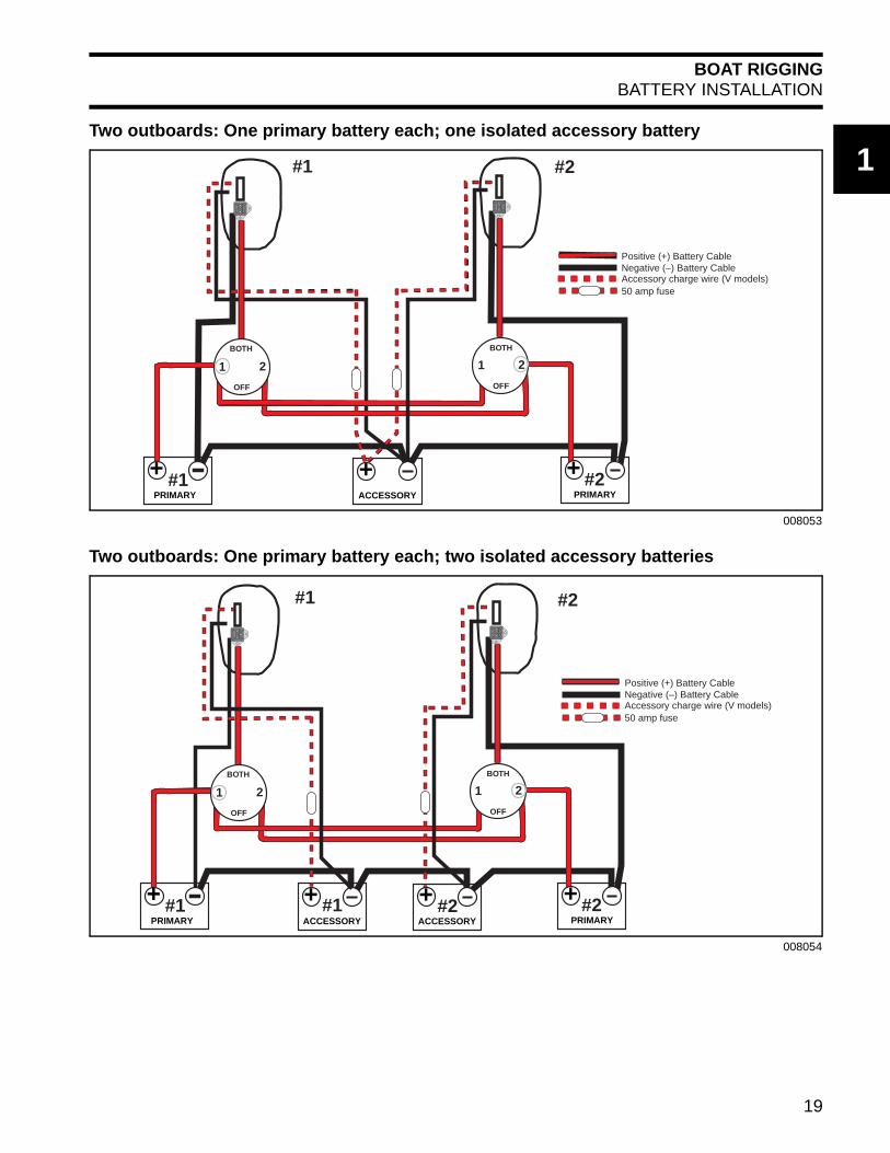
Two outboards: One primary battery each; one isolated accessory batteryTwo outboards: One primary battery each; two isolated accessory batteries
ACCESSORYPRIMARY#1
PRIMARY#2
S
S
++ +
1 2
OFF
BOTH
1 2
OFF
BOTH
#1 #2
Positive (+) Battery CableNegative (–) Battery CableAccessory charge wire (V models)50 amp fuse
008053
ACCESSORYPRIMARY#1
PRIMARY#2#1 #2
S
S
++ +
1 2
OFF
BOTH
1 2
OFF
BOTH
ACCESSORY
+
#1 #2
Positive (+) Battery CableNegative (–) Battery CableAccessory charge wire (V models)50 amp fuse
008054
19

BOAT RIGGINGFUEL SYSTEM REQUIREMENTS
FUEL SYSTEM REQUIREMENTSRegulations and GuidelinesVessel manufacturer, and/or installer of an EPAcertified outboard, must meet minimum specifica-tions for boat fuel systems established by:• U.S. Environmental Protection Agency (EPA)
– 40 CFR 1045.112– 40 CFR 1060
• U.S. Coast Guard (USCG)– 33 CFR 183
• American Boat & Yacht Council (ABYC)– Standard H-24– Standard H-25.
Permanent Fuel TanksPermanent fuel tanks must be properly ventedoutside of the hull.
Remote fuel tank gas fills must be grounded.
Fuel tank pickups should include an anti-siphonvalve to prevent fuel flow if a leak occurs in thefuel distribution system.
Portable Fuel Tanks
Do not use portable fuel tanks foroutboards larger than 115 HP. Inadequate fuelflow to high horsepower outboards can resultin serious powerhead damage.
Fuel HoseAll fuel hoses used for rigging outboards manufac-tured after January 1, 2009 must meet EPA per-meation requirements for evaporative emissions.• Use SAE J30R9, or USCG Type B1-15, fuel
hose in motor well areas.• Use USCG Type A1-15 fuel hose between per-
manent fuel tanks and motor well fittings in inac-cessible routings.
• Compliant hoses are labeled with the applicablespecification.
Permanently installed fuel hoses should be asshort and horizontal as possible.
Use corrosion-resistant metal clamps on perma-nently installed fuel hoses.
Multi-outboard applications require separate fueltank pickups and hoses. (A fuel selector switchmay be used for “kicker” motors as long as it hasenough flow capacity for the larger outboard.)
Use only fuel lines (or copper tubing) that meetthe Fuel Flow Requirements for the outboard.
A WARNING
If engine is equipped with a quick-discon-nect fuel hose, you MUST disconnect thefuel hose from the engine and the fuel tankto prevent fuel leaks:• Whenever the engine is NOT being used• Whenever the engine is being trailered• Whenever the engine is in storage.
NOTE: A small amount of fuel may bereleased when the fuel connector is dison-nected.
Store portable fuel tanks in well-ventilatedareas, away from heat sources and openflames. Close the vent screw of the fueltank cap, if equipped, to prevent escape offuel or fuel vapors which could acciden-tally ignite. Do not allow disconnected fuelhoses to leak fuel.
1. Specification2. Date code
007944
NOTICE
21
20

BOAT RIGGINGFUEL SYSTEM REQUIREMENTS
1
Fuel System PrimerOutboards require a priming system to refill thefuel system after periods of non-use. The mostcommon priming system is a primer bulb in thefuel supply hose.Install the primer bulb as follows:• The primer bulb must meet the same Fuel Flow
Requirements as the fuel hose.• The primer bulb should be easily accessible.• The arrow on the primer bulb must point in the
direction of fuel flow.• The fuel supply hose must allow the primer bulb
to be held with the arrow pointing up duringpriming.
An alternative to a primer bulb is a U.S. CoastGuard approved marine primer pump. Electricprimer pumps offer the convenience of outboardpriming from a dash-mounted momentary switch.
Fuel FiltersBoat-mounted fuel filters and water-separatingfuel filter assemblies must meet the required fuelflow and filter specification. Refer to Fuel FlowRequirements.
The filter must be mounted to a rigid surfaceabove the full level of the fuel tank and accessiblefor servicing.
Fuel Filter Assembly, P/N 174176, meets allrequirements for a water-separating fuel filter.
Avoid using in-line fuel filters exter-nal to the outboard. The filter area and flowcharacteristics may not be adequate for highhorsepower outboards.
1. Arrow indicates direction of fuel flow 000124
1
174176
Typical Fuel Supply Configuration1. Primer bulb2. Water separating fuel filter3. Anti-siphon valve, in fuel pick-up of tank
DRC6797
1 2 3
NOTICE
21

BOAT RIGGINGFUEL SYSTEM REQUIREMENTS
Fuel Flow Requirements
15 – 30 HP 40 – 90 HP 115 – 300 HP
Fuel tank pickup tube 1/4 in. (6.4 mm) min. ID 5/16 in. (7.9 mm) min. ID 3/8 in. (9.5 mm) min. ID
Fuel fittings 5/32 in. (4.1 mm) min. ID 1/4 in. (6.4 mm) min. ID 9/32 in. (7.1 mm) min. ID
Fuel supply hoses 1/4 in. (6.4 mm) min. ID 3/8 in. (9.5 mm) min. ID 3/8 in. (9.5 mm) min. ID
ALL MODELS
Fuel tank pickup screen
100 mesh, 304 grade stainless steel wire, 0.0045 in. wire diameter, 1 in. (25 mm) long
Antisiphon valve 2.5 in. (63.5 mm) Hg maximum pressure drop at 20 gph (76 l/hr) flow
Remote fuel filter 0.4 in. Hg maximum pressure drop at 20 gph (76 l/hr) flow, 150 in.2 (1290 cm2) of filter area
Maximum fuel pump lift height
Fuel pump should not be located more than 30 in. (76.2 cm) above bottom of fuel tank
22

BOAT RIGGINGREMOTE OIL TANK INSTALLATION (V4 – V6)
1
REMOTE OIL TANK INSTALLATION (V4 – V6)LocationConsider the installation location ofthe oil tank carefully. The oil tank is vented tothe atmosphere. To avoid serious powerheaddamage, be sure the oil tank is installed in alocation that does not allow constant expo-sure to sunlight, rain, bilge water or spray.
Select a mounting location that provides:• A solid place to mount the tank• A dry location that prevents exposure to rain or
spraying water• Access for adding oil• Access to oil-primer bulb• Interference-free hose and wire routing to out-
board.
If necessary, the oil tank can be mounted furtherfrom the outboard than the supplied hoses andharness allow. The maximum length of oil supplyhose that can be fitted to the oil tank is 25 ft.(7.6 m).
Do not add hose to an existing oilsupply hose.
If the oil tank requires a longer oil supply hose:• Oil supply hose between the primer bulb and
outboard must be replaced with one continuouslength of 1/4 in. (6.4 mm) I.D. hose.
• Maximum length of hose is 25 ft. (7.6 m).• Replacement hose must be designated for fuel
or oil use and approved for marine use.• Extend wiring harness with 16 gauge AWG
wire.• Protect connections with heat shrink tube.• Maintain wire color and polarity when extending
harness.
An appropriately sized battery box may be used toconceal and protect the oil tank, if desired.
Be sure box includes drain holes soit does not fill with water and contaminate oil.
MountingPlace tank in selected position. Mark one lineunder groove in tank bottom and lines at each endof tank.
Make sure hole locations provide enough clear-ance for fastening screws. Screws should not con-tact or penetrate hull.
NOTICE
NOTICE
000074
1. Center line of oil tank2. Ends of tank
44737
NOTICE
2
1
2
23

BOAT RIGGINGREMOTE OIL TANK INSTALLATION (V4 – V6)
Place floor bracket on center line between endlines. Use the inner bracket holes as guides to drilltwo 5/32 in. (4 mm) pilot holes.
3 GALLON (11.4 L) TANK
Place rods into floor bracket and secure floorbracket with lag bolts.
Place oil tank onto floor bracket. Assemble cross-bar onto hook rods, install flat washers and lock-nuts. Tighten locknuts to securely hold tank.
1.8 GALLON TANK
Place rods into floor bracket and secure floorbracket with lag bolts.
Place oil tank onto floor bracket. If cover is notpre-assembled, route oil supply hose and harnessthrough the cover and position cover on the oiltank. Attach spring-loaded rods to cover.
COB5381
1. Rods2. Lag bolts
22241B
1. Crossbar DRC7418
1
2
1
2
1
1. Rods2. Lag bolts
22149A
48704
1
2
1
2
24

BOAT RIGGINGREMOTE OIL TANK INSTALLATION (V4 – V6)
1
Oil Tank ProfilesRemote Oil Fill Kit (Optional)The remote oil fill kit (P/N 176461) provides adeck-mounted fill tube, cap, a tank-mounted tube,and nut that replace the original oil tank capassembly.
Installation Recommendations• Select a location on the deck of the boat that is
above the oil tank fill cap.• Select a deck location which allows the required
length of 1½ in. I.D. fill hose to route as directlyand as vertically as possible.
• Avoid inappropriate hose routings that coulddistort the fill tube or tank tube.
• Refer to installation instructions provided withremote oil fill kit.
A slanted area of the deck will allowwater to drain away from the fill and is bestsuited for the installation.
Additional Items Required• 1½ in. I.D. fill hose cut to required length. Fill
hose (P/N 123956) is available in 25 ft. (7.6 m)lengths.
• Two corrosion resistant 2 in. (50 mm) hoseclamps.
1.8 Gallon TankP/N 176995
3 Gallon TankP/N 176996
NOTICE
DRC8123
25

BOAT RIGGINGCABLE AND HOSE INSTALLATION
CABLE AND HOSE INSTALLATIONBefore installation, identify all required wiring,cables, and hoses:• Throttle and shift cables• Instrument harnesses• Battery cables and switches• Oil tank sender harness• Fuel supply hose• Primer bulb or primer pump • Oil supply hose.
Determine whether any additional wiring or hoseswill be needed for accessory gauges or batteries:• Speedometer pick-up hose• Mechanical water pressure gauge hose• Accessory battery charging kit• I-Command adapter harnesses• I-Command water pressure sensor kit• I-Command oil level sensor kit.
Boat Cable and Harness Routing
Remote control cables, wiring, and hoses mustfollow a similar path into the lower motor covers.Select the best routing for the specific application.
All cables, wiring, and hoses must be long enoughto provide adequate slack. Check clearances at allpossible combinations of trim angles and steeringpositions.
Typical outboard installation1. Oil tank2. Anti-siphon valve3. Water separating fuel filter4. Starting battery5. Accessory battery6. Flexweave protective sleeve7. Access cover8. Primer bulb9. Battery switch
DRC6487
1 2 3 4 5
6 7 8 9
A WARNING
Improper installation and routing of out-board controls could wear, bind, and dam-age components, causing loss of control.
Typical Small Splash Well DRC7799
Typical Large Splash Well DRC7797
26

BOAT RIGGINGCABLE AND HOSE INSTALLATION
1
Protective Sleeve/ConduitMake sure all cables, wiring, and hoses havebeen identified and fitted to the appropriatelengths. Refer to OUTBOARD RIGGING on p. 51.
Next, bundle the components that route to the out-board with appropriate shielding, such as anexpandable “flexweave” sleeve or a flexible con-duit.
Battery CablesWhen routing battery cables, be sure to:• Route cables through the protective sleeve.• Use the most direct path to route the battery
cables to the battery or battery switch.
Fuel HoseThe fuel hose may be routed outside of the pro-tective sleeve or conduit. Electric primers or man-ual primers may not require this consideration.
Route fuel hoses with enough slack to allow theprimer bulb arrow to point “up” during use.
Install the primer bulb with the arrow pointing inthe direction of fuel flow to the outboard.
Connect the fuel supply hose from the fuel tank tothe fuel supply line at the outboard.
IMPORTANT: Do not permanently fasten thisconnection until the boat's fuel system has beenprimed.
Oil Supply HoseEvinrude E-TEC V4–V6 outboards use a single oilsupply hose connected to the outboard and to theboat-mounted oil tank.• Route the hose from the oil tank to the ¼ in. (6.4
mm) fitting of the oil supply line at the lowermotor cover.
• Install the hose on the fitting using the propersize Oetiker
† clamp.
Typical Engine Bracket DRC7798A
Flexible conduit installation 005138 1. Fuel supply hose and fuel fitting - 3/8 in. (9 mm)2. Oil supply hose and fitting - 1/4 in. (6 mm)
003963
21
27

BOAT RIGGINGCABLE AND HOSE INSTALLATION
Oetiker Clamp Servicing
Clamp IdentificationUse Oetiker clamps for making hose connections.These clamps provide corrosion resistance, mini-mize the potential for abrasion of rigging compo-nents, and provide solid, permanent connections.
The selection and installation of an Oetiker clampis essential in the proper sealing of hose connec-tions. The clamp identification numbers appear onthe side of the clamp, near the top of the ear.Refer to Clamp Selection chart for dimensions.
Clamp SelectionTo select the correct size Oetiker clamp, measurethe outside diameter of the hose when installed onthe fitting.
Chose a clamp so that the outside diameter of thehose is approximately in the middle of the clamp-ing range of the clamp.
A WARNING
DO NOT re-use Oetiker clamps. Fuel leak-age could contribute to a fire or explosion.
1. Clamp identification numbers 000093
1
.D.I
044014
133
613
103
652
832
012
581
071
751
541
041
831
331
311
501
59
mmhcni 1
esoHretemaiD
0
N/P
011253927943
533253
957943
351643
251643
307253
151643
051643
938843
687643
587643
139643
801743
701743
615943
838843
039643
egnaR gnipmalC
51 01 54/1
52 02 2/1 8/3
54 04 4/1-1 4/3
53 03 4/3-1 2/1-1
008458
28

BOAT RIGGINGCABLE AND HOSE INSTALLATION
1
Clamp InstallationA constant stress should be applied to close theear clamps. This method ensures a positive stresson the hose and does not result in excessive com-pression or expansion of the band material.IMPORTANT: Use only Oetiker recommendedtools to close Oetiker stepless clamps.
Oetiker pincers are available in the Evinrude/Johnson Genuine Parts and Accessories Catalog.
• Position correct size clamp over hose.• Install hose on fitting.• Close clamp ear fully with Oetiker pincers (pli-
ers).
Clamp RemovalMethod 1: Position Oetiker pincers across clampear and cut clamp.
Method 2: Lift end of stepless clamp with screw-driver.
Method 3: Use Oetiker pincers (pliers) to gripclamp. Pull clamp off of connection and discard.
DP0886
1. Open clamp2. Closed clamp
000092
1 2
000108
000090
000091
29

BOAT RIGGINGNOTES
NOTESTechnician’s Notes Related Documents
Bulletins
Instruction Sheets
Other
30
OUTBOARD INSTALLATIONHULL PREPARATION
2
OUTBOARD INSTALLATION
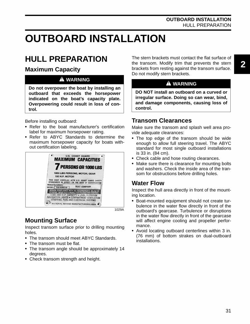
HULL PREPARATIONMaximum Capacity
Before installing outboard:• Refer to the boat manufacturer's certification
label for maximum horsepower rating.• Refer to ABYC Standards to determine the
maximum horsepower capacity for boats with-out certification labeling.
Mounting SurfaceInspect transom surface prior to drilling mountingholes.• The transom should meet ABYC Standards.• The transom must be flat.• The transom angle should be approximately 14
degrees.• Check transom strength and height.
The stern brackets must contact the flat surface ofthe transom. Modify trim that prevents the sternbrackets from resting against the transom surface.Do not modify stern brackets.
Transom ClearancesMake sure the transom and splash well area pro-vide adequate clearances:• The top edge of the transom should be wide
enough to allow full steering travel. The ABYCstandard for most single outboard installationsis 33 in. (84 cm).
• Check cable and hose routing clearances.• Make sure there is clearance for mounting bolts
and washers. Check the inside area of the tran-som for obstructions before drilling holes.
Water FlowInspect the hull area directly in front of the mount-ing location.• Boat-mounted equipment should not create tur-
bulence in the water flow directly in front of theoutboard's gearcase. Turbulence or disruptionsin the water flow directly in front of the gearcasewill affect engine cooling and propeller perfor-mance.
• Avoid locating outboard centerlines within 3 in.(76 mm) of bottom strakes on dual-outboardinstallations.
A WARNING
Do not overpower the boat by installing anoutboard that exceeds the horsepowerindicated on the boat’s capacity plate.Overpowering could result in loss of con-trol.
1029A
A WARNING
DO NOT install an outboard on a curved orirregular surface. Doing so can wear, bind,and damage components, causing loss ofcontrol.
31

OUTBOARD INSTALLATIONHULL PREPARATION
Transom Brackets and Jack PlatesWhen mounting an outboard on a jack plate:• Refer to the manufacturer's recommendations
for maximum weight and horsepower.• The jack plate must provide a rigid, one-piece
mounting assembly—either a solid surface, orsurfaces adequately connected to prevent flex-ing or twisting.
• DO NOT use a jack plate constructed in twoseparate pieces—lack of support can twist thestern brackets, wear tilt tube bushings andthrust rollers, and bend or break components.
IMPORTANT: Damage caused by use of a two-piece jack plate or unstable mounting surface willnot be covered by warranty.
Recommended Designs
Not Recommended
Whenever possible, use mounting hardware sup-plied with the outboard to install jack plate on tran-som. Tighten to a torque of 40 ft. lbs. (54 N·m).
To prevent damage to outboard,check installation frequently for:• Loose mounting bolts and nuts• Loose tilt tube or steering cable nuts• Elongated mounting holes• Bent or deformed washersReplace any hardware that fails to maintaintorque specifications.
Mounting Hardware
Outboard mounting hardware must meet mini-mum specifications for material and strength:• Material: Stainless steel; Group 1,2,3 per
ASTM F593 OR Grade A2 per ISO 3506-1.• Strength: Minimum proof load.
Outboard mounting bolts, backing plates, wash-ers, and nuts are used to attach the outboard tothe shipping pallet. If alternate bolt lengths orreplacement parts are required, use onlyEvinrude/Johnson Genuine Parts.
IMPORTANT: Standard screws offered by localmerchants may not provide the high strengthrequired for outboard installations.
007992 007991
DR5703
A WARNING
Use all mounting hardware supplied withthe outboard to help ensure a secureinstallation. Substituting inferior hardwarecan result in loss of control.
Part Number
Length(inches)
Thread Size
Proof Load Minimum
(lbs.)
327053 3 1/2-13 18,520
318573 3.5 1/2-13 12,771
336676 4.75 1/2-13 12,771
331578 5 1/2-13 18,520
354101 6 1/2-13 18,520
354102 7 1/2-13 18,520
354103 8 1/2-13 18,520
354104 9 1/2-13 18,520
NOTICE
32

OUTBOARD INSTALLATIONTRANSOM MEASURING AND DRILLING
2
TRANSOM MEASURING AND DRILLINGHull CenterlineUse the chines of the boat as reference points tolocate the centerline of the boat transom.
Use a straightedge to draw a line connecting theport and starboard chines.
Use a framing square to accurately place a verti-cal line on the transom. The centerline of the hullshould be in line with the keel, and perpendicularto the midpoint of the line connecting the chines.
Dual-Outboard CenterlinesThe following table lists standard ABYC centerlinespacing between outboards in dual installations:
Some applications may require changes in thisdimension to avoid strakes, to adjust for transomheight, or for performance reasons. Best perfor-mance can be determined only through testing.Refer to boat manufacturer for recommendations.
If the standard spacing does not allow full steeringtravel in a particular installation, it may be neces-sary to increase the spacing.
IMPORTANT: Some steering systems mayrequire additional spacing. Refer to steering sys-tem manufacturer for recommendations.
The top edge of the transom should be more thantwice the width of the dual-outboard centerlinespacing dimension. Bracket installations may notrequire this consideration.
Measure the transom for dual-outboard spacingafter the centerline of the hull is established.
Divide the spacing dimension by two. Use theresulting number to space the outboard center-lines from the hull centerline.
EXAMPLE: A 26 in. (660 mm) dual-outboardspacing would result in two outboard centerlines,each 13 in. (330 mm) from the hull centerline.
1. Chine2. Strake3. Keel4. Hull centerline
DR5568
2 and 3 cylinder 22 in. (559 mm)
V4 and V6 26 in. (660 mm)
1 2 3 4
1. Port centerline2. Hull centerline3. Starboard centerline
DRC5527B
1 2 3
33

OUTBOARD INSTALLATIONTRANSOM MEASURING AND DRILLING
Transom HeightMake sure the transom height matches the lengthof the outboard to be installed.• A 19 to 21 in. (48.3 to 53.3 mm) transom height
uses a 20 in. (50.8 mm) shaft outboard.• The shaft length of the outboard being installed
should come close to matching the transomheight of the boat.
• Refer to SPECIFICATIONS in outboard Opera-tor’s Guide for transom height.
Determine transom height by measuring from thetop edge of the transom, along the centerline.
For dual-outboard installations, transom heightshould be measured at the outboard centerlines.
Use a straightedge as a reference to extend thebottom of the boat.
Position the straightedge along centerline. Thedistance from the top edge of the straightedge tothe top edge of the transom is the actual transomheight.
15–30 HP MODELS
With the outboard installed on the boat:• Generally the anti-ventilation plate of the gear-
case should align with the bottom of the hull.• The anti-ventilation plate should NOT extend
more than 2 in. (5 cm) BELOW the bottom ofthe hull.
Transom Drilling Locations
75–300 HP, ALL MODELS40–60 HP, POWER TRIM MODELS25–30 HP, POWER TRIM MODELS
All models use the standard ABYC 4-Bolt mount-ing pattern.
Use Transom drill fixture, P/N 434367 orP/N 385368, as a guide for correct hole place-ment. If drill fixture is unavailable, refer to Drillingand Hardware Diagrams on p. 36 for measure-ments.
Position drill fixture on top of transom or bracketand align indicator points with centerline.
The indicators are affected by the squareness ofthe top edge of the transom. If either side of thefixture must be raised more than ¼ in. (6 mm)above the transom's top surface to make bothindicators align, the transom must be modified.
IMPORTANT: DO NOT assume that the topedge of the transom is straight. Position the drillfixture based on measurements aligning it to thebottom of the hull.
Maintain at least 1.75 in. (45 mm) oftransom surface above the top mountingbolts.
1. Top edge of transom2. Actual transom height
DR5541
1
2
Transom drill fixture P/N 434367 (heavy duty) 24496
NOTICE
34

OUTBOARD INSTALLATIONTRANSOM MEASURING AND DRILLING
2
Before drilling any mounting holes:• Make sure the hole locations provide enough
clearance for mounting bolts and washers.• Check the inside area of the transom for
obstructions.• Check transom height(s) at centerlines.
Drill four ½ in. (13 mm) mounting holes in theappropriate locations.
IMPORTANT: Be sure to drill the required holesperpendicular to transom surface.
40–65 HP, MANUAL TILT MODELS25–30 HP, MANUAL TILT MODELS15 HP, POWER TILT MODELS
Center the outboard on the transom (or mountingbracket) and tighten clamp screws by hand.
Use each stern bracket’s mounting holes as aguide to drill holes through the transom.• 40–65 HP models require four 5/16 in. (8 mm)
holes• 25–30 HP models require two 5/16 in. (8 mm)
holes• 15 HP models require four 5/16 in. (8 mm)
holes.
40 – 65 HP Models 002215
25 – 30 HP Models 007998
15 HP Models 007999
11
11
11
35

OUTBOARD INSTALLATIONTRANSOM MEASURING AND DRILLING
Drilling and Hardware Diagrams75–300 HP, ALL MODELS; 40–60 HP, POWER TRIM MODELS; 25–30 HP, POWER TRIM MODELS
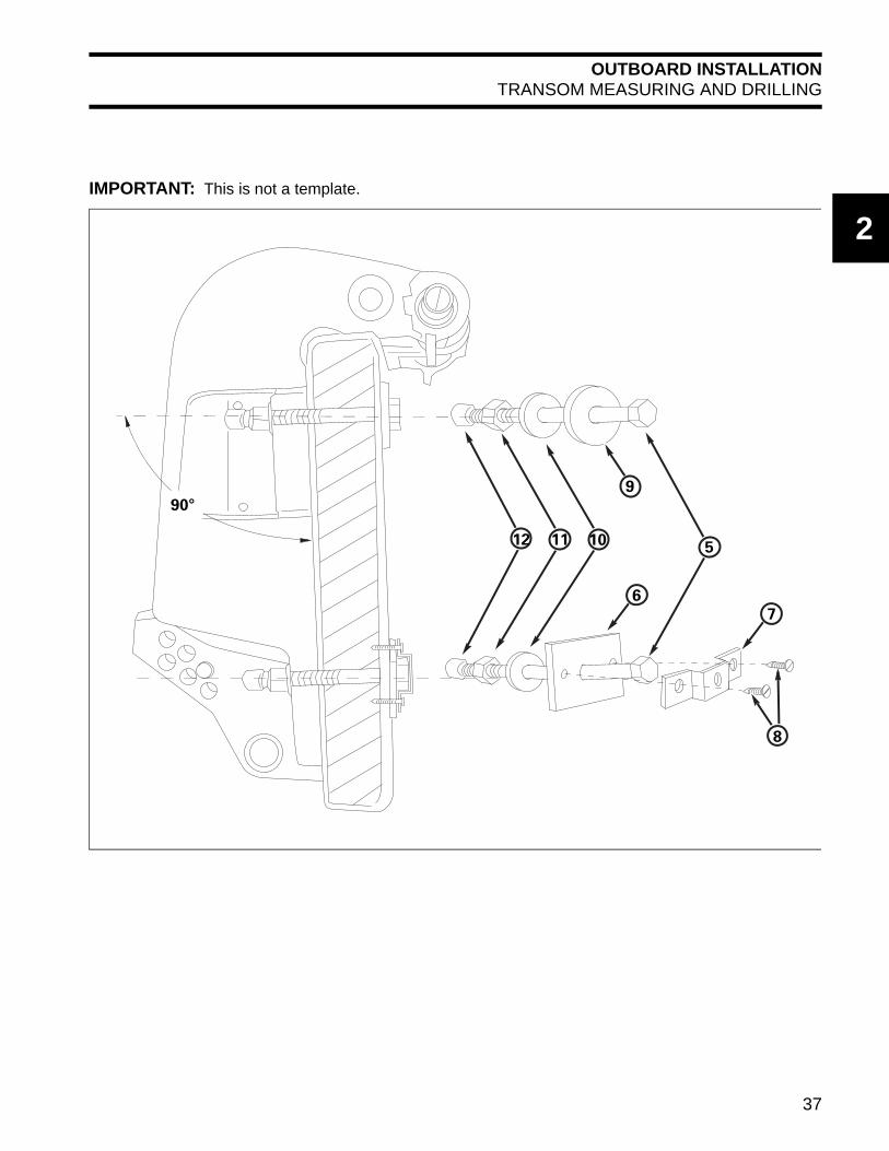
IMPORTANT: This is not a template.
Quantity
1. Center of Transom 5. Bolt * 4 * Choose from the following bolt sizes:
2. Top of Transom 6. 318272 Plate 2 327053 3 in. (76 mm)
3. 1/2” Bolt Hole Locations 7. 318273 Retainer 2 318573 3 1/2 in. (89 mm)
4. Outside of Transom 8. 319886 Screw 4 336676 4 1/2 in. (114 mm)
9. 307238 Washer 2 331578 5 in. (127 mm)
10. 320248 Washer 4 354101 6 in. (152 mm)
11. 313623 Nut 4 354102 7 in. (178 mm)
12. 318572 Cap 4 354103 8 in. (203 mm)
354104 9 in. (229 mm)
3
22
3
1
3 3
1
2 in.(50.8mm)
8 in.(203.2mm)
8 in.(203.2mm)
4 15/16 in.(125.4mm)
4 15/16 in.(125.4mm)
6 7/16 in.(163.5mm)
6 7/16 in.(163.5mm)
2 in.(50.8mm)
36
OUTBOARD INSTALLATIONTRANSOM MEASURING AND DRILLING
2
IMPORTANT: This is not a template.
5101112
9
6
7
8
90°
37

OUTBOARD INSTALLATIONTRANSOM MEASURING AND DRILLING
40–65 HP, MANUAL TILT MODELS
IMPORTANT: This is not a template.
1. Center of Transom
2. Top of Transom
3. 5/16” Bolt Hole Locations
3 3
33
22
1
2.09 in. (53.08 mm)
5.16 in. 131.01 mm)
4.031 in. (4 1/32) (102.4 mm)
4.031 in. (4 1/32) (102.4 mm)
8.99 in. 228.34 mm)
2.09 in. (53.08 mm)
5.16 in. 131.01 mm)
38
OUTBOARD INSTALLATIONTRANSOM MEASURING AND DRILLING
2
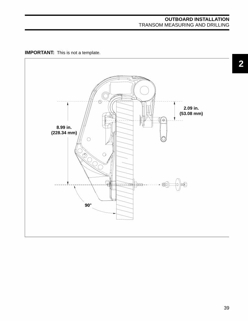
IMPORTANT: This is not a template.
90°
8.99 in.(228.34 mm)
2.09 in.(53.08 mm)
39

OUTBOARD INSTALLATIONTRANSOM MEASURING AND DRILLING
25–30 HP, MANUAL TILT MODELS
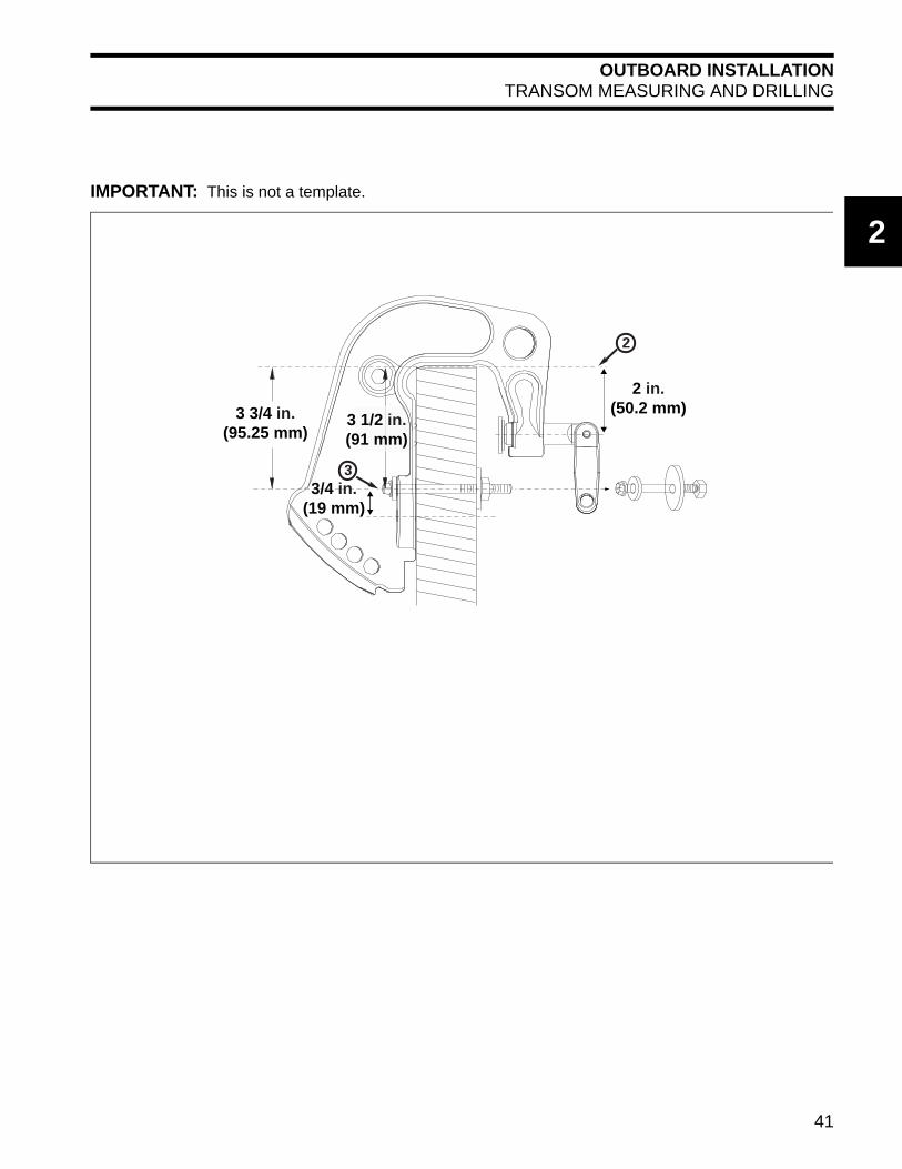
IMPORTANT: This is not a template.
1. Center of Transom
2. Top of Transom
3. 5/16” Bolt Hole Locations
33
21
4 3/4 in.(121.2 mm)
4 3/4 in.(121.2 mm)
5 in.(126.2 mm)
5 in.(126.2 mm)
3/4 in. (19 mm)
40
OUTBOARD INSTALLATIONTRANSOM MEASURING AND DRILLING
2
IMPORTANT: This is not a template.
2
3
2 in. (50.2 mm)
3/4 in. (19 mm)
3 1/2 in. (91 mm)
3 3/4 in.(95.25 mm)
41

OUTBOARD INSTALLATIONTRANSOM MEASURING AND DRILLING
15 HP, POWER TILT MODELS
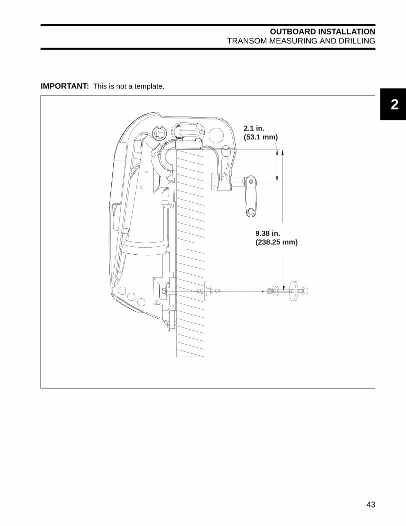
IMPORTANT: This is not a template.
1. Center of Transom
2. Top of Transom
3. 5/16” Bolt Hole Locations
7.39 in. (187.6 mm)
2.1 in. (53.1 mm)
10.25 in. (260.4 mm)
22
1
3
3
3
3
42
OUTBOARD INSTALLATIONTRANSOM MEASURING AND DRILLING
2
IMPORTANT: This is not a template.
9.38 in. (238.25 mm)
2.1 in. (53.1 mm)
43

OUTBOARD INSTALLATIONLIFTING THE OUTBOARD
LIFTING THE OUTBOARDLifting Fixtures
Remove shipping carton.
Use correct Lifting Fixture to lift outboard:
90° V6 MODELS
Position lifting tool on flywheel and seat the threescrews completely.
Fasten appropriate chain hook to eye of tool.Carefully hoist outboard with chain and unbolt out-board mounting brackets from frame.
60° V4 AND V6 MODELS
Position lifting tool on crankshaft and tighten thecenter retaining screw securely using a 1/4 in.Allen wrench.
Fasten appropriate chain hook to eye of tool.Carefully hoist outboard with chain and unbolt out-board mounting brackets from frame.
40–90 HP MODELS
With recoil starter removed, place lifting tool onflywheel and seat the three screws completely.Refer to RECOIL STARTER REMOVAL in thecorrect Service Manual.
Use only the 1 1/8 in. (short)screws, P/N 398067, included with the tool toavoid damage to electronic components underthe flywheel.
Fasten appropriate chain hook to eye of tool.Carefully hoist outboard with chain and unbolt out-board mounting brackets from frame.
A WARNING
To avoid personal injury, make sure the lift-ing capacity of the hoist is at least twicethe weight of the outboard.
DO NOT allow the lift hook or chain fromthe hoist to come in contact with any partof the engine during lifting.
Model Lifting Fixture
90° V6 P/N 396748 with1 3/4 in. screws
60° V4–V6 P/N 342672
40–90 HP P/N 396748 with1 1/8 in. screws
15–30 HP P/N 354717
1. Lifting fixture2. 1 3/4 in. screws
002419
21
1. Center retaining screw 004945
1. Lifting fixture2. 1 1/8 in. screws
002098
1
21
NOTICE
44

OUTBOARD INSTALLATIONLIFTING THE OUTBOARD
2
15–30 HP MODELS
Install Lifting Tool, P/N 354717, on both sides ofthe tilt tube.
Use an appropriate chain, at least 36 inches (91cm) long with two snap hooks, each capable of lift-ing 500 lbs. (227 kg).
Attach hooks to lifting device and attach chain tohoist.
Lift the engine out of the carton.
Remove upper motor cover.
Place clean pad or cardboard on the floor.
Lower outboard onto the pad. Use hoist to care-fully roll the outboard onto its port side.
Remove chain from lifting tool.
Remove lifting tool from outboard.
1. Lifting tool, P/N 354717 007122
A WARNING
To avoid personal injury or outboard dam-age, be sure the lifting tool is fully threadedon both sides of the tilt tube.
A WARNING
Use this tool for horizontal lifting of 30 HPand smaller Evinrude E-TEC models ONLY.
DO NOT use this tool to lift outboardslarger than 30 HP Evinrude E-TEC models.
To avoid personal injury and boat or out-board damage, DO NOT use this tool toinstall or remove outboard from transomas outboard can unexpectedly tip.
1
1. Lifting tool, P/N 354717 007123
A CAUTION
To avoid damage to the outboard, DO NOTallow the outboard to fall unrestrained.
007211
1
45

OUTBOARD INSTALLATIONSTEERING SYSTEMS
Attach chain to lift eye on back of engine block.
Carefully lift engine with hoist.
To avoid damage to the outboard,lift the outboard in one smooth motion. DONOT allow the outboard to bounce.
STEERING SYSTEMSMechanical CablesAll Evinrude outboards equipped with tilt tubes arecompatible with mechanical steering systems thatmeet ABYC Standard P-17. Single-cable mechan-ical steering systems can be used on single ordual-outboard installations if an ABYC-approvedsteering link is used.
Dual-cable mechanical steering helps provide firmsteering control at high speeds.
Extend the steering cable and lubricate the innercore before installation.
IMPORTANT: Install steering cable through tilttube before mounting outboard on transom.Tighten nut securely.
A WARNING
If the chain snap hooks are too large, thecast in lift eye could break causing the out-board to drop suddenly causing personalinjury and damaging the outboard.
1. Lift eye 007212
007213
1
NOTICE
ABYC-approved mechanical steering cable. 5873
A WARNING
DO NOT use cable over pulley steering on40 HP and larger outboards.
46

OUTBOARD INSTALLATIONSTEERING SYSTEMS
2
Manual Hydraulic SteeringManual hydraulic steering systems use hydraulicfluid to transfer motion and load from the helm tothe outboard.
Use only a hydraulic steering system designed forthe specific application. Refer to the steering sys-tem manufacturer’s specifications for recom-mended applications.
IMPORTANT: Some hydraulic steering systemsrequire additional centerline spacing in dual-out-board installations. Refer to steering system man-ufacturer’s recommendations and to Dual-Outboard Centerlines on p. 33.
Drag Links
Use the correct drag link to allow full steeringtravel:
Install cable wiper nut on tilt tube and connectdrag link to the correct location on the steeringarm. For single motor, single cable applications,the drag link should be installed in the rear hole.
Typical manual hydraulic steering 004948
Model Drag Link
90° V6 P/N 175125
60° V4–V6 P/N 175125
75–90 HP P/N 175125
40–60 HP P/N 173699
15–30 HP P/N 173699
1. Drag link connection2. Wiper nut
002097
1. Rear Location (D)–Steering drag link connection2. Middle Location (P)–Power steering connection
(Refer to manufacturer’s instructions for hydraulicsteering systems.)
3. Front Location (T)–Bar connection (multiple out-board installations)
DRC7162
1
2
1
2
3
47

OUTBOARD INSTALLATIONOUTBOARD MOUNTING
OUTBOARD MOUNTINGIMPORTANT: Some rigging components, suchas steering cables, must be fitted to the outboardbefore the outboard is mounted to the transom.Determine what equipment will be installed beforemounting.
Mounting HeightBoat performance depends on outboard mountingheight.
Generally, the anti-ventilation plate of the gear-case should align with the bottom of the hull. Con-ventional V-hulls often perform well with the anti-ventilation plate approximately 1 in. (25 cm) abovethe bottom of the hull.
Boats that exceed 50 MPH may benefit fromhigher outboard heights. Consult the boat manu-facturer for specific outboard mounting heightinformation for a particular hull.
Test outboard and boat performance at differentheights until the best performance is achieved.
Be sure that outboard water pres-sure is not adversely affected by the mountingheight of the outboard.
Mounting Bolt InstallationIMPORTANT: Use a marine sealant rated forabove or below waterline use. RTV silicone is notapproved for below waterline use. Polyurethanesealants are not easily removed and may damageoutboard or boat mounting surfaces.
Apply marine sealer under hex heads of bolts, onthe mounting plates, and to the bolt shanks.
75–300 HP, ALL MODELS40–60 HP, POWER TRIM MODELS25–30 HP, POWER TRIM MODELS
Assemble transom mounting plates on mountingbolts.
Install the mounting bolts through the transomfrom the inside of the boat.
Position the square aluminum transom mountingplates (when applicable) so the retainer holes arehorizontal.
Position hex head of bolt with flats toward holes inthe mounting plates. Install retainer over hex headof the bolt and secure it with screws provided.
Install all washers and nuts. Tighten nuts and boltsto a torque of 40 ft. lbs. (54 N·m).
0078A
NOTICE
DR5536
A WARNING
If either side of the transom deforms orcracks when the bolts are tightened totheir recommended torque, the transomconstruction may not be adequate or maybe deteriorated. Structural failure of thetransom could result in loss of boat controland injury to the occupants.
48
OUTBOARD INSTALLATIONOUTBOARD MOUNTING
2
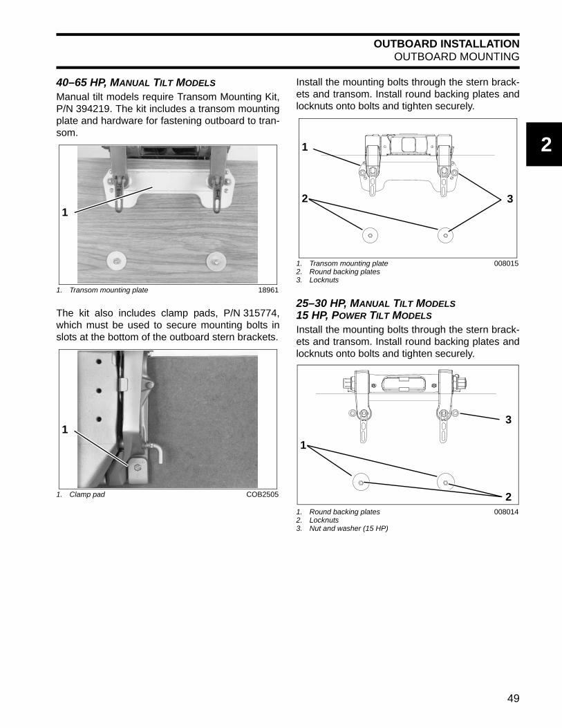
40–65 HP, MANUAL TILT MODELS
Manual tilt models require Transom Mounting Kit,P/N 394219. The kit includes a transom mountingplate and hardware for fastening outboard to tran-som.
The kit also includes clamp pads, P/N 315774,which must be used to secure mounting bolts inslots at the bottom of the outboard stern brackets.
Install the mounting bolts through the stern brack-ets and transom. Install round backing plates andlocknuts onto bolts and tighten securely.
25–30 HP, MANUAL TILT MODELS15 HP, POWER TILT MODELS
Install the mounting bolts through the stern brack-ets and transom. Install round backing plates andlocknuts onto bolts and tighten securely.
1. Transom mounting plate 18961
1. Clamp pad COB2505
1
1
1. Transom mounting plate2. Round backing plates3. Locknuts
008015
1. Round backing plates2. Locknuts3. Nut and washer (15 HP)
008014
3
1
2
3
2
1
49

OUTBOARD INSTALLATIONNOTES
NOTESTechnician’s Notes Related Documents
Bulletins
Instruction Sheets
Other
50

OUTBOARD RIGGINGCOMMON PRACTICES – ALL MODELS
3
OUTBOARD RIGGING
COMMON PRACTICES – ALL MODELSControl Cable Identification
IMPORTANT: Identify control cable functionbefore rigging outboard.
Identify each control cable:• Put the control handle into NEUTRAL position.
The throttle cable casing guide will retract com-pletely and the shift cable casing guide will go tothe midpoint of its travel.
Extend the control cables and lubricate them withTriple-Guard grease.
Cable Retainer Clip InstallationWhen installing retainer clips on control arm link-age pins, clips should be locked and must not bebent or deformed.
For proper installation, review the following steps:• Place washer on pin.• Position retainer clip with straight section on the
bottom and angled section on the top.• Use long nose pliers to insert straight section of
clip into linkage pin hole.
• Push the clip towards the hole while lifting onthe curved end with the pliers.
• Be sure retainer clip fully engages the pin.• Lock the retainer by moving the angled section
behind the straight section.
1. Shift cable casing guide extended to midpoint2. Throttle cable casing guide retracted
DP0811
30501
1
2
1. Straight section2. Angled section
DP0818NDP0817
Locked Retainer Clip1. Angled section behind straight section
DP0817A
1
2
1
51

OUTBOARD RIGGINGEVINRUDE E-TEC 90° V MODELS 200–300 HP
EVINRUDE E-TEC 90° V MODELS 200–300 HPCable, Hose, and Wire Routing
Refer to Control Cable Identification on p. 51.
Remove two screws and bracket that fasten thegrommet to lower motor cover.
Route all hoses, control cables, and wiringthrough a protective sleeve or conduit into theboat and through the grommet.
The fuel hose may be routed through the protec-tive sleeve or through an alternate hole in thelower motor cover grommet.
To route the fuel hose outside the sleeve, trim thematerial covering the alternate fuel hose slot inthe grommet.
Refer to the following diagram to ensure properpositioning of rigging components in grommet.
The main wiring harness, battery cables, oil tanksending unit harness, and any ICON or I-Com-mand network cables should be routed along the
A CAUTION
To prevent accidental starting while servic-ing, disconnect the battery cables at thebattery. Twist and remove all spark plugleads.
1. Grommet retaining bracket 003964
1. Alternate fuel hose location 003970
1
1
1. Fuel supply hose2. Fuel supply hose--alternate location3. Oil supply hose4. Oil tank sending unit harness5. Battery cables6. Main wire harness (MWS)7. Shift cable8. Throttle cable9. Accessory charge wires10. I-Command harness11. Water pressure hose12. Speedometer hose
000095B
1. Alternate fuel hose location 003971
1
52

OUTBOARD RIGGINGEVINRUDE E-TEC 90° V MODELS 200–300 HP
3
same path to the starboard side of the powerhead.Secure all cables with clamps.
After installation, make sure thereis enough clearance for all cables to avoidbinding or chafing through all engine steeringand tilting angles.
Control Cable InstallationRefer to Control Cable Identification on p. 51.
Remove control cable trunnion covers and cableattachment hardware.
Shift Cable Installation and AdjustmentPlace the shift cable on the shift lever pin andinstall the washer and retainer clip. Refer to CableRetainer Clip Installation on p. 51.
IMPORTANT: Do not bend or deform clip.
Make sure the remote control, gearcase, shift link-age, and shift cable are in NEUTRAL.
Hold the shift linkage in NEUTRAL.
Push and pull on the shift cable and observe thecable slack. Hold the casing guide in the center ofthe slack.
Adjust shift cable trunnion to align with center ofthe trunnion block. Place cable trunnion in trun-nion block.
Install trunnion cover and screw. Tighten screw toa torque of 60 to 80 in. lbs. (7 to 9 N·m).
Throttle Cable Installation and AdjustmentWith remote control lever in NEUTRAL, pull firmlyon throttle cable casing to remove slack.
Place throttle cable on throttle lever pin and installwasher and retainer clip. Refer to Cable RetainerClip Installation on p. 51.
003974
1. Trunnion covers 005037
NOTICE
1
1. Shift cable retainer clip and washer2. Shift cable trunnion
005038
1. Throttle cable retainer clip and washer 003967
21
1
53

OUTBOARD RIGGINGEVINRUDE E-TEC 90° V MODELS 200–300 HP
Make sure that idle stop of the throttle lever isagainst the crankcase.
Adjust the throttle cable trunnion to align with thetrunnion block. Place the cable trunnion in thetrunnion block.
IMPORTANT: Move control handle to FOR-WARD and pull back slowly to NEUTRAL. Makesure the engine throttle lever is against the stop. Ifnot, remove slack by adjusting cable trunnion.
Install trunnion cover and screw. Tighten screw toa torque of 60 to 80 in. lbs. (7 to 9 N·m).
Battery Cable ConnectionsInstall battery cables on starter solenoid and mainground stud.
SystemCheck Harness ConnectionsRemove harness connector cover.
Before installing electrical connectors, check thatthe seal is in place. Clean off any dirt from con-nectors. Apply a light coat of Electrical Grease tothe seal only. DO NOT fill connectors with Electri-cal Grease.
1. Throttle lever stop 003968
1. Trunnion cover and screw, throttle cable 005039
1
1
1. Positive (+) battery connection2. Ground (–) connection
003975
003972
1. Seal 42079A
12
1
54

OUTBOARD RIGGINGEVINRUDE E-TEC 90° V MODELS 200–300 HP
3
Connect outboard main wire harness to boat wireharness. Secure connectors in bracket. Refer tothe diagram inside of the electrical cover.
BE SURE all harnesses and wiresare not pinched, cannot contact flywheel, anddo not interfere with moving throttle or shiftlinkages.
Replace harness connector cover.
I-Command Network ConnectionsIf the outboard will be used with I-Command, orother NMEA 2000 compliant CANbus instruments,use the following connections to supply informa-tion to the network:
If using an Evinrude ICON control system, the I-Command Engine Interface Cable, Power SupplyKit, and Ignition and Trim Harness are notrequired. Connect the I-Command networkdirectly to the ICON gateway module. Refer toEvinrude ICON / I-Command Harness Connec-tions on p. 14.
If using a mechanical control system, connect theI-Command Engine Interface Cable to the EMMCANbus connector.
Use an I-Command Ignition and Trim Harness toconnect the outboard to the key switch and trim/tiltcontrol. Seal unused SystemCheck connectorwith 6-Pin Connector Seal, P/N 586076.
If connecting to an existing Deutsch-style I-Com-mand network, connect the purple wires betweenthe I-Command Ignition and Trim Harness and theI-Command Engine Interface Cable. This connec-tion supplies power to the network when the keyswitch is on. Newer, quick connect-style networksdo not use this connection.
Route the harnesses around the starboard side ofthe powerhead along the same path as the batterycables.
1. Harness connections 003973
1
NOTICE
1. EMM CANbus connector 004265
1. I-Command Ignition connector2. Trim/Tilt connector3. SystemCheck connector (with seal)4. Network power supply connector (Deutsch style
networks)
006862
1
2
1
3
4
55

OUTBOARD RIGGINGEVINRUDE E-TEC 90° V MODELS 200–300 HP
For an I-Command oil level display, an accessoryCANbus oil level sender must be installed in theoil tank. Connect the sender to the I-Commandnetwork. Refer to the I-Command Digital Net-work Guide, P/N 355008.
Use Evinrude Diagnostics software to adjust net-work settings in the EMM. From the Settingsscreen, select Engine Options.
ICON Network ConnectionsIf the outboard is equipped for an Evinrude ICONcontrol system, connect the outboard to the net-work as follows.
Refer to Evinrude ICON / I-Command HarnessConnections on p. 14.
Connect the buss cable from the rear network hubto the outboard’s network harness.
IMPORTANT: Do not force connectors or lock-ing rings. Properly aligned connectors assembleeasily.
DO NOT use Electrical Grease on ICON busscable connectors.
To assemble the connectors:• Use the large tabs and small tabs to carefully
align buss cable connectors. • Carefully align pins and sockets of connectors.
Do NOT force connectors together.• Tighten locking rings of buss connectors finger
tight. Do NOT use locking rings to force connec-tors together.
Do not rotate connectors until they align. Thiscould result in a mismatched connection. It is pos-sible for each pin to enter a socket even if the tabsare misaligned. Look at the tabs to ensure con-nector alignment prior to making the connection.
Engine Monitor information is distributed to anICON or I-Command network through the ICONgateway module. Refer to the I-Command DigitalNetwork Guide, P/N 355008.
The ICON Harness and Relay Kit, P/N 765296,must be used to provide power to boat accesso-ries that require switched B+. This kit is used inplace of connecting accessories to the “A” termi-nal of the key switch. Accessories connected tothe accessory power relay should not exceed 7amps.
Do not connect boat accessories tothe key switch of an ICON system. Connectingaccessories to the key switch can cause low
Engine Options Screen 008563
1. ICON network connector 008001
1
1. Large tabs2. Small tabs
007883
1
2
NOTICE
56

OUTBOARD RIGGINGEVINRUDE E-TEC 90° V MODELS 200–300 HP
3
current, resulting in erratic operation of theremote control system.
For more information, refer to the Evinrude ICONRemote Control System Installation Guide,P/N 764952.
Water Pressure GaugeTo display engine water pressure, install a waterpressure hose fitting in the cylinder block asshown.
Use Pipe Sealant with Teflon on the threads of thehose fitting. Refer to installation instructions sup-plied with gauge.
Route the water pressure hose around the star-board side of the powerhead along the same pathas the battery cables.
For an I-Command water pressure display, sev-eral water pressure sensor kits are available.Refer to the Evinrude/Johnson Genuine Partsand Accessories catalog.
To send water pressure data to the EMM, alongwith an I-Command display, install a water pres-sure transducer kit.
Water pressure readings in excess of 40 psi (275kpa) are possible for 90° V6 models at boatspeeds in excess of 50 mph (80 kph/43 kts).
Use 50 psi Water Pressure Transducer Kit,P/N 5008640.
Connect the transducer lead to the engine wiringharness connector.
1. Water pressure hose fitting 005035
11. Water pressure transducer 008131
1. Water pressure transducer lead2. Engine harness connector
004120
1
12
57
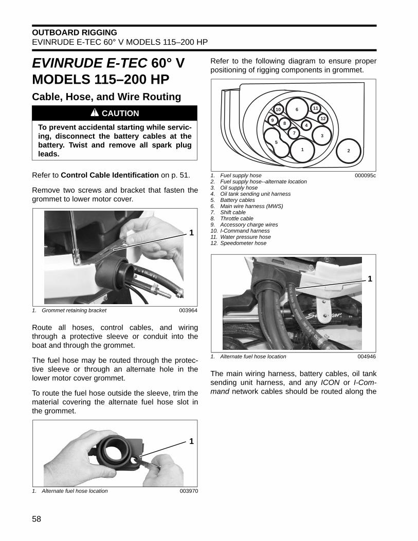
OUTBOARD RIGGINGEVINRUDE E-TEC 60° V MODELS 115–200 HP
EVINRUDE E-TEC 60° V MODELS 115–200 HPCable, Hose, and Wire Routing
Refer to Control Cable Identification on p. 51.
Remove two screws and bracket that fasten thegrommet to lower motor cover.
Route all hoses, control cables, and wiringthrough a protective sleeve or conduit into theboat and through the grommet.
The fuel hose may be routed through the protec-tive sleeve or through an alternate hole in thelower motor cover grommet.
To route the fuel hose outside the sleeve, trim thematerial covering the alternate fuel hose slot inthe grommet.
Refer to the following diagram to ensure properpositioning of rigging components in grommet.
The main wiring harness, battery cables, oil tanksending unit harness, and any ICON or I-Com-mand network cables should be routed along the
A CAUTION
To prevent accidental starting while servic-ing, disconnect the battery cables at thebattery. Twist and remove all spark plugleads.
1. Grommet retaining bracket 003964
1. Alternate fuel hose location 003970
1
1
1. Fuel supply hose2. Fuel supply hose--alternate location3. Oil supply hose4. Oil tank sending unit harness5. Battery cables6. Main wire harness (MWS)7. Shift cable8. Throttle cable9. Accessory charge wires10. I-Command harness11. Water pressure hose12. Speedometer hose
000095c
1. Alternate fuel hose location 004946
1
4
7
11
8
10
9
3
6
12
2
5
1
58

OUTBOARD RIGGINGEVINRUDE E-TEC 60° V MODELS 115–200 HP
3
same path to the starboard side of the powerhead.Secure all cables with clamps.
After installation, make sure thereis enough clearance for all cables to avoidbinding or chafing through all engine steeringand tilting angles.
Control Cable InstallationRefer to Control Cable Identification on p. 51.
Remove control cable trunnion covers and cableattachment hardware.
Shift Cable Installation and AdjustmentPlace the shift cable on the shift lever pin andinstall the washer and retainer clip. Refer to CableRetainer Clip Installation on p. 51.
IMPORTANT: Do not bend or deform clip.
Make sure the remote control, gearcase, shift link-age, and shift cable are in NEUTRAL.
Hold the shift linkage in NEUTRAL.
Push and pull on the shift cable and observe thecable slack. Hold the casing guide in the center ofthe slack.
Adjust shift cable trunnion to align with center ofthe trunnion block. Place cable trunnion in trun-nion block.
Install trunnion cover and screw. Tighten screw toa torque of 60 to 80 in. lbs. (7 to 9 N·m).
Throttle Cable Installation and AdjustmentWith remote control lever in NEUTRAL, pull firmlyon throttle cable casing to remove slack.
Place throttle cable on throttle lever pin and installwasher and retainer clip. Refer to Cable RetainerClip Installation on p. 51.
1. Anchor points 004949
1. Trunnion covers 004955
1
NOTICE
1
1. Shift cable retainer clip and washer2. Shift cable trunnion
004956
1. Throttle cable retainer clip and washer 004957
21
1
59
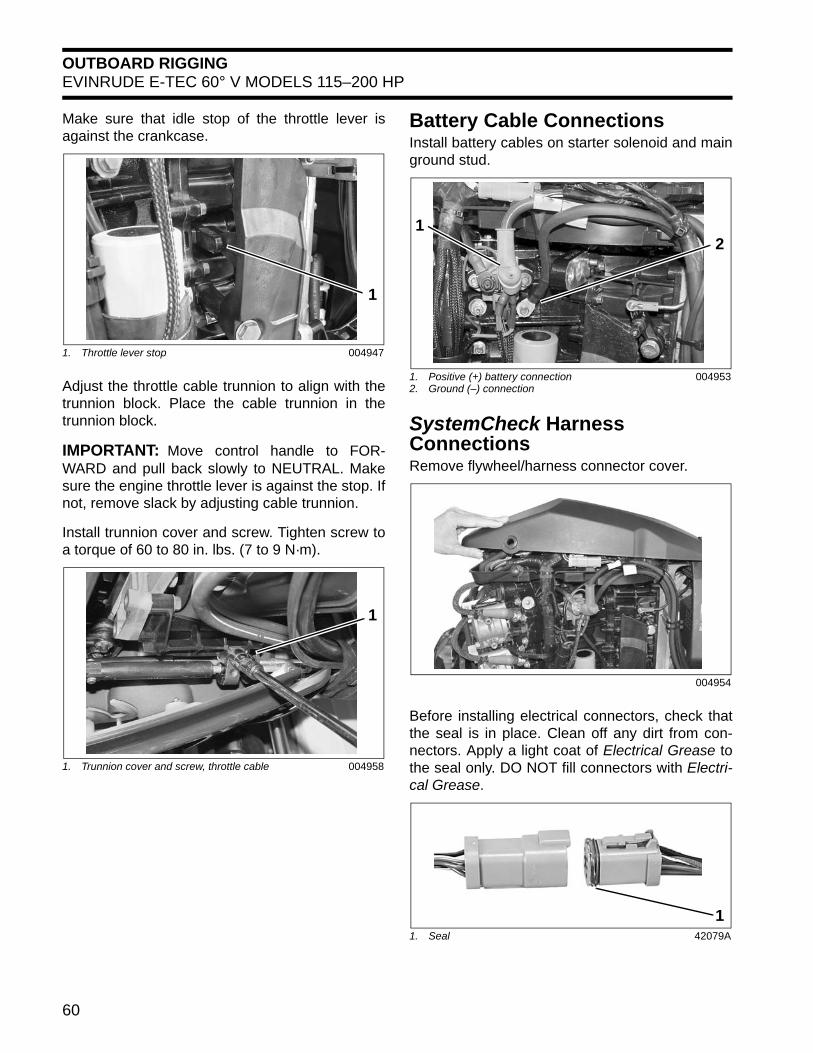
OUTBOARD RIGGINGEVINRUDE E-TEC 60° V MODELS 115–200 HP
Make sure that idle stop of the throttle lever isagainst the crankcase.
Adjust the throttle cable trunnion to align with thetrunnion block. Place the cable trunnion in thetrunnion block.
IMPORTANT: Move control handle to FOR-WARD and pull back slowly to NEUTRAL. Makesure the engine throttle lever is against the stop. Ifnot, remove slack by adjusting cable trunnion.
Install trunnion cover and screw. Tighten screw toa torque of 60 to 80 in. lbs. (7 to 9 N·m).
Battery Cable ConnectionsInstall battery cables on starter solenoid and mainground stud.
SystemCheck Harness ConnectionsRemove flywheel/harness connector cover.
Before installing electrical connectors, check thatthe seal is in place. Clean off any dirt from con-nectors. Apply a light coat of Electrical Grease tothe seal only. DO NOT fill connectors with Electri-cal Grease.
1. Throttle lever stop 004947
1. Trunnion cover and screw, throttle cable 004958
1
1
1. Positive (+) battery connection2. Ground (–) connection
004953
004954
1. Seal 42079A
21
1
60
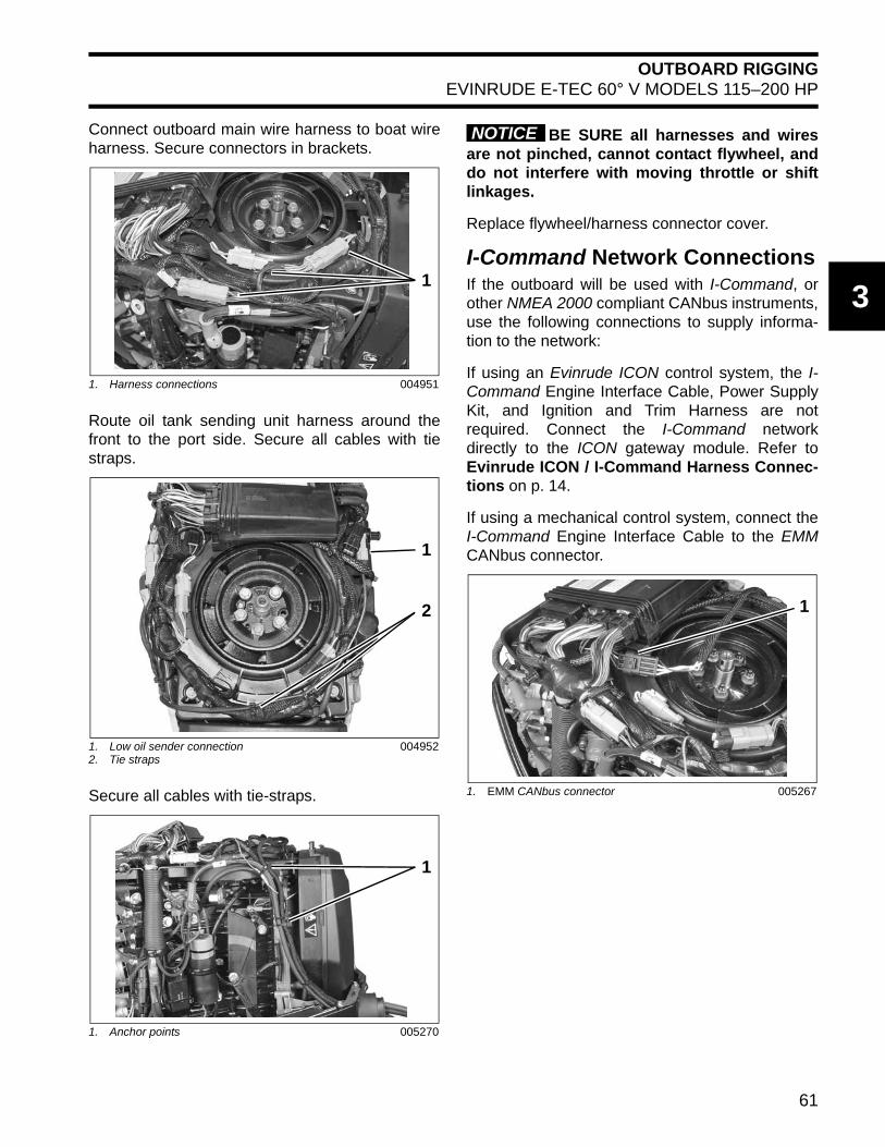
OUTBOARD RIGGINGEVINRUDE E-TEC 60° V MODELS 115–200 HP
3
Connect outboard main wire harness to boat wireharness. Secure connectors in brackets.
Route oil tank sending unit harness around thefront to the port side. Secure all cables with tiestraps.
Secure all cables with tie-straps.
BE SURE all harnesses and wiresare not pinched, cannot contact flywheel, anddo not interfere with moving throttle or shiftlinkages.
Replace flywheel/harness connector cover.
I-Command Network ConnectionsIf the outboard will be used with I-Command, orother NMEA 2000 compliant CANbus instruments,use the following connections to supply informa-tion to the network:
If using an Evinrude ICON control system, the I-Command Engine Interface Cable, Power SupplyKit, and Ignition and Trim Harness are notrequired. Connect the I-Command networkdirectly to the ICON gateway module. Refer toEvinrude ICON / I-Command Harness Connec-tions on p. 14.
If using a mechanical control system, connect theI-Command Engine Interface Cable to the EMMCANbus connector.
1. Harness connections 004951
1. Low oil sender connection2. Tie straps
004952
1. Anchor points 005270
1
1
2
1
1. EMM CANbus connector 005267
NOTICE
1
61
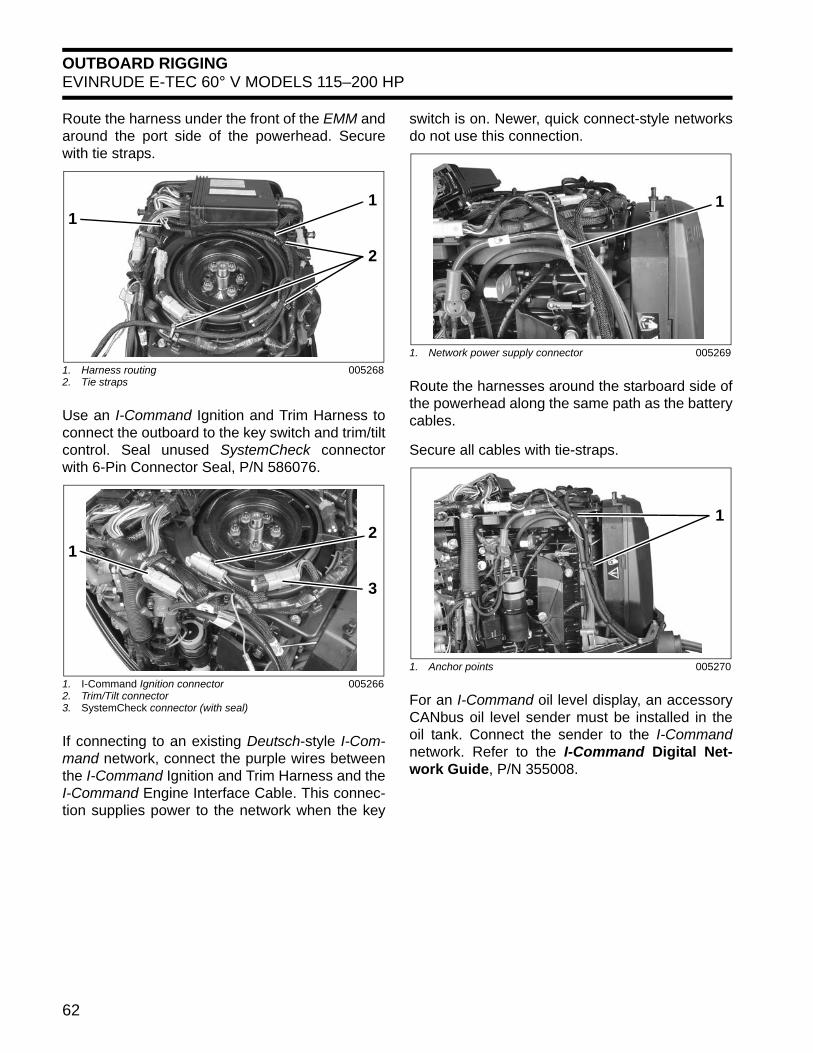
OUTBOARD RIGGINGEVINRUDE E-TEC 60° V MODELS 115–200 HP
Route the harness under the front of the EMM andaround the port side of the powerhead. Securewith tie straps.
Use an I-Command Ignition and Trim Harness toconnect the outboard to the key switch and trim/tiltcontrol. Seal unused SystemCheck connectorwith 6-Pin Connector Seal, P/N 586076.
If connecting to an existing Deutsch-style I-Com-mand network, connect the purple wires betweenthe I-Command Ignition and Trim Harness and theI-Command Engine Interface Cable. This connec-tion supplies power to the network when the key
switch is on. Newer, quick connect-style networksdo not use this connection.
Route the harnesses around the starboard side ofthe powerhead along the same path as the batterycables.
Secure all cables with tie-straps.
For an I-Command oil level display, an accessoryCANbus oil level sender must be installed in theoil tank. Connect the sender to the I-Commandnetwork. Refer to the I-Command Digital Net-work Guide, P/N 355008.
1. Harness routing2. Tie straps
005268
1. I-Command Ignition connector2. Trim/Tilt connector3. SystemCheck connector (with seal)
005266
1
2
1
2
3
1
1. Network power supply connector 005269
1. Anchor points 005270
1
1
62

OUTBOARD RIGGINGEVINRUDE E-TEC 60° V MODELS 115–200 HP
3
Use Evinrude Diagnostics software to adjust net-work settings in the EMM. From the Settingsscreen, select Engine Options.
ICON Network ConnectionsIf the outboard is equipped for an Evinrude ICONcontrol system, connect the outboard to the net-work as follows.
Refer to Evinrude ICON / I-Command HarnessConnections on p. 14.
Connect the buss cable from the rear network hubto the outboard’s network harness.
IMPORTANT: Do not force connectors or lock-ing rings. Properly aligned connectors shouldassemble easily.
Do not use Electrical Grease on ICON buss cableconnectors.
To assemble the connectors:• Use the large tabs and small tabs to carefully
align buss cable connectors. • Carefully align pins and sockets of connectors.
Do NOT force connectors together.• Tighten locking rings of buss connectors finger
tight. Do NOT use locking rings to force connec-tors together.
Do not rotate connectors until they align. Thiscould result in a mismatched connection. It is pos-sible for each pin to enter a socket even if the tabsare misaligned. Look at the tabs to ensure con-nector alignment prior to making the connection.
Engine Monitor information is distributed to anICON or I-Command network through the ICONgateway module. Refer to the I-Command DigitalNetwork Guide, P/N 355008.
The ICON Harness and Relay Kit, P/N 765296,must be used to provide power to boat accesso-ries that require switched B+. This kit is used inplace of connecting accessories to the “A” termi-nal of the key switch. Accessories connected tothe accessory power relay should not exceed 7amps.
Do not connect boat accessories tothe key switch of an ICON system. Connectingaccessories to the key switch can cause lowcurrent, resulting in erratic operation of theremote control system.
For more information, refer to the Evinrude ICONRemote Control System Installation Guide,P/N 764952.
Engine Options Screen 008563
1. ICON network connector 008157
1
1. Large tabs2. Small tabs
007883
1
2
NOTICE
63

OUTBOARD RIGGINGEVINRUDE E-TEC 60° V MODELS 115–200 HP
Water Pressure GaugeTo display engine water pressure, install a waterpressure hose fitting in the cylinder block asshown.
Use Pipe Sealant with Teflon on the threads of thehose fitting. Refer to installation instructions sup-plied with gauge.
Route the water pressure hose around the star-board side of the powerhead along the same pathas the battery cables.
For an I-Command water pressure display, sev-eral water pressure sensor kits are available.Refer to the Evinrude/Johnson Genuine Partsand Accessories catalog.
To send water pressure data to the EMM, alongwith an I-Command display, install a water pres-sure transducer kit. • Use 50 psi Water Pressure Transducer Kit,
P/N 5008640 on 2012 and newer 60° V4/V6models.
• Use 30 psi Water Pressure Transducer Kit,P/N 5008300 on 2011 and older 60° V4/V6models.
Connect the transducer lead to the engine wiringharness connector.1. Water pressure hose fitting 004959
1
1. Water pressure transducer 008129
1. Water pressure transducer lead2. Engine harness connector
004962
1
21
64

OUTBOARD RIGGINGEVINRUDE E-TEC MODELS 40–90 HP
3
EVINRUDE E-TEC MODELS 40–90 HPCable, Hose, and Wire Routing
Refer to Control Cable Identification on p. 51.
Apply soapy water to the inside surfaces of grom-met and install cables and fuel line as shown:
Place the grommet into position in the lowerengine cover.
When grommet is in place and all cables havebeen installed, tighten a tie strap around the out-side of the grommet to form a watertight sealaround the cables.
After installation, make sure thereis enough clearance for all cables to avoidbinding or chafing through all engine steeringand tilting angles.
Control Cable InstallationRefer to Control Cable Identification on p. 51.
Remove cable retainer from anchor block. ApplyTriple-Guard grease to both anchor block pockets.
IMPORTANT: DO NOT secure cables to throttleand shift lever pins until all cables, wires, andhoses have been routed and grommet has beeninstalled in the lower engine cover.
Make sure the remote control is in NEUTRAL, andthrottle is in the IDLE position.
Pull firmly on shift cable casing to remove slack.With outboard in NEUTRAL, place the cable trun-
A CAUTION
To prevent accidental starting while servic-ing, disconnect the battery cables at thebattery. Twist and remove all spark plugleads.
1. Throttle cable2. Shift cable3. Main wiring harness4. Battery cable5. Fuel line
001998
002104
3
45
1
2
1. Cable retainer 002099
NOTICE
1
65
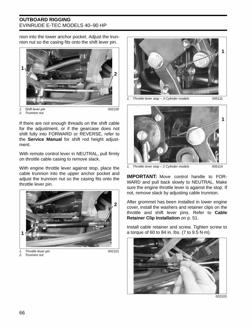
OUTBOARD RIGGINGEVINRUDE E-TEC MODELS 40–90 HP
nion into the lower anchor pocket. Adjust the trun-nion nut so the casing fits onto the shift lever pin.
If there are not enough threads on the shift cablefor the adjustment, or if the gearcase does notshift fully into FORWARD or REVERSE, refer tothe Service Manual for shift rod height adjust-ment.
With remote control lever in NEUTRAL, pull firmlyon throttle cable casing to remove slack.
With engine throttle lever against stop, place thecable trunnion into the upper anchor pocket andadjust the trunnion nut so the casing fits onto thethrottle lever pin.
IMPORTANT: Move control handle to FOR-WARD and pull back slowly to NEUTRAL. Makesure the engine throttle lever is against the stop. Ifnot, remove slack by adjusting cable trunnion.
After grommet has been installed in lower enginecover, install the washers and retainer clips on thethrottle and shift lever pins. Refer to CableRetainer Clip Installation on p. 51.
Install cable retainer and screw. Tighten screw toa torque of 60 to 84 in. lbs. (7 to 9.5 N·m).
1. Shift lever pin2. Trunnion nut
002100
1. Throttle lever pin2. Trunnion nut
002101
21
2
1
1. Throttle lever stop – 3 Cylinder models 005111
1. Throttle lever stop – 2 Cylinder models 005114
002103
1
1
66

OUTBOARD RIGGINGEVINRUDE E-TEC MODELS 40–90 HP
3
SystemCheck Harness ConnectionsPlace the wiring harness through notch in lowermotor cover and route to the recess in the fly-wheel cover. Secure the cable with a tie strap asshown:
Before installing electrical connectors, check thatthe seal is in place. Clean off any dirt from con-nectors. Apply a light coat of Electrical Grease tothe seal only. DO NOT fill connectors with Electri-cal Grease.
Arrange connectors in flywheel cover.
Install electrical cover and secure with screws.
BE SURE all harnesses and wiresare not pinched, cannot contact flywheel, anddo not interfere with moving throttle or shiftlinkages.
1. Recess2. Tie strap
002011
1. Seal 42079A
21
1
001999
002102
NOTICE
67
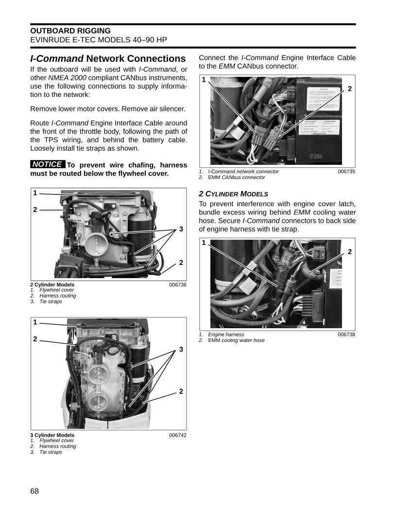
OUTBOARD RIGGINGEVINRUDE E-TEC MODELS 40–90 HP
I-Command Network ConnectionsIf the outboard will be used with I-Command, orother NMEA 2000 compliant CANbus instruments,use the following connections to supply informa-tion to the network:
Remove lower motor covers. Remove air silencer.
Route I-Command Engine Interface Cable aroundthe front of the throttle body, following the path ofthe TPS wiring, and behind the battery cable.Loosely install tie straps as shown.
To prevent wire chafing, harnessmust be routed below the flywheel cover.
Connect the I-Command Engine Interface Cableto the EMM CANbus connector.
2 CYLINDER MODELS
To prevent interference with engine cover latch,bundle excess wiring behind EMM cooling waterhose. Secure I-Command connectors to back sideof engine harness with tie strap.
2 Cylinder Models1. Flywheel cover2. Harness routing3. Tie straps
006736
3 Cylinder Models1. Flywheel cover2. Harness routing3. Tie straps
006742
NOTICE
3
2
1
2
3
2
1
2
1. I-Command network connector2. EMM CANbus connector
006735
1. Engine harness2. EMM cooling water hose
006738
21
21
68
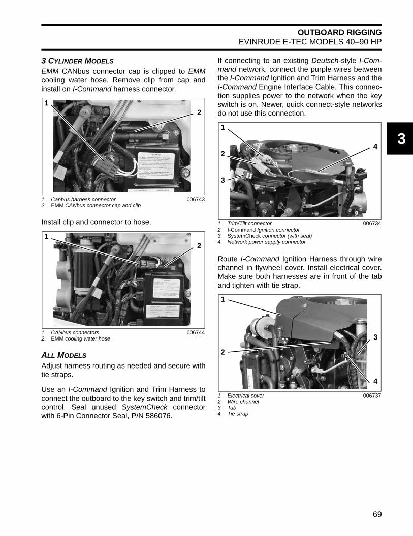
OUTBOARD RIGGINGEVINRUDE E-TEC MODELS 40–90 HP
3
3 CYLINDER MODELS
EMM CANbus connector cap is clipped to EMMcooling water hose. Remove clip from cap andinstall on I-Command harness connector.
Install clip and connector to hose.
ALL MODELS
Adjust harness routing as needed and secure withtie straps.
Use an I-Command Ignition and Trim Harness toconnect the outboard to the key switch and trim/tiltcontrol. Seal unused SystemCheck connectorwith 6-Pin Connector Seal, P/N 586076.
If connecting to an existing Deutsch-style I-Com-mand network, connect the purple wires betweenthe I-Command Ignition and Trim Harness and theI-Command Engine Interface Cable. This connec-tion supplies power to the network when the keyswitch is on. Newer, quick connect-style networksdo not use this connection.
Route I-Command Ignition Harness through wirechannel in flywheel cover. Install electrical cover.Make sure both harnesses are in front of the taband tighten with tie strap.
1. Canbus harness connector2. EMM CANbus connector cap and clip
006743
1. CANbus connectors2. EMM cooling water hose
006744
21
21
1. Trim/Tilt connector2. I-Command Ignition connector3. SystemCheck connector (with seal)4. Network power supply connector
006734
1. Electrical cover2. Wire channel3. Tab4. Tie strap
006737
4
1
2
3
3
4
1
2
69
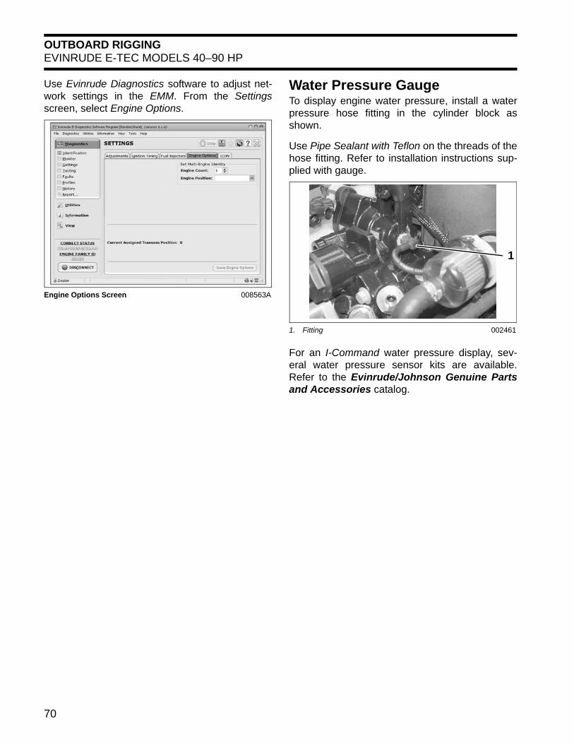
OUTBOARD RIGGINGEVINRUDE E-TEC MODELS 40–90 HP
Use Evinrude Diagnostics software to adjust net-work settings in the EMM. From the Settingsscreen, select Engine Options.
Water Pressure GaugeTo display engine water pressure, install a waterpressure hose fitting in the cylinder block asshown.
Use Pipe Sealant with Teflon on the threads of thehose fitting. Refer to installation instructions sup-plied with gauge.
For an I-Command water pressure display, sev-eral water pressure sensor kits are available.Refer to the Evinrude/Johnson Genuine Partsand Accessories catalog.
Engine Options Screen 008563A
1. Fitting 002461
1
70
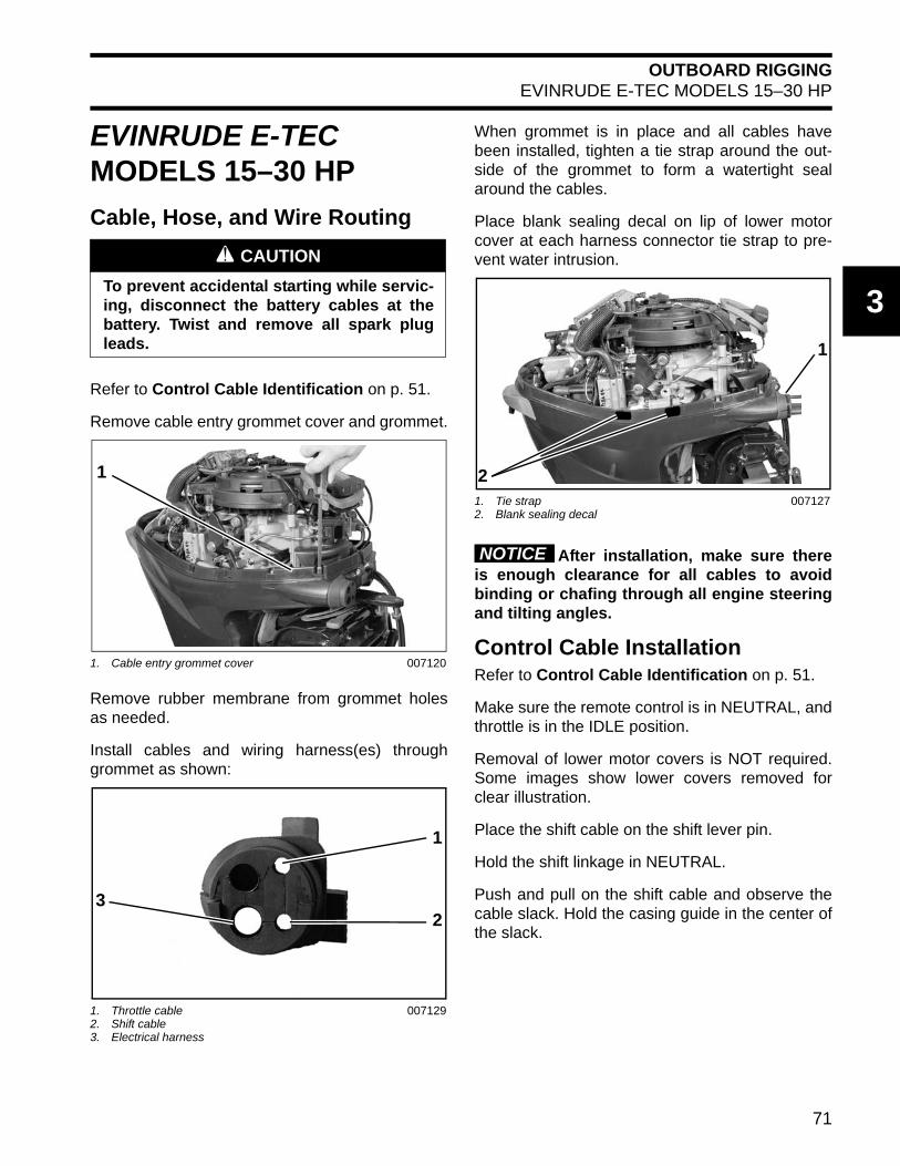
OUTBOARD RIGGINGEVINRUDE E-TEC MODELS 15–30 HP
3
EVINRUDE E-TEC MODELS 15–30 HP
Cable, Hose, and Wire Routing
Refer to Control Cable Identification on p. 51.
Remove cable entry grommet cover and grommet.
Remove rubber membrane from grommet holesas needed.
Install cables and wiring harness(es) throughgrommet as shown:
When grommet is in place and all cables havebeen installed, tighten a tie strap around the out-side of the grommet to form a watertight sealaround the cables.
Place blank sealing decal on lip of lower motorcover at each harness connector tie strap to pre-vent water intrusion.
After installation, make sure thereis enough clearance for all cables to avoidbinding or chafing through all engine steeringand tilting angles.
Control Cable InstallationRefer to Control Cable Identification on p. 51.
Make sure the remote control is in NEUTRAL, andthrottle is in the IDLE position.
Removal of lower motor covers is NOT required.Some images show lower covers removed forclear illustration.
Place the shift cable on the shift lever pin.
Hold the shift linkage in NEUTRAL.
Push and pull on the shift cable and observe thecable slack. Hold the casing guide in the center ofthe slack.
A CAUTION
To prevent accidental starting while servic-ing, disconnect the battery cables at thebattery. Twist and remove all spark plugleads.
1. Cable entry grommet cover 007120
1. Throttle cable2. Shift cable3. Electrical harness
007129
1
1
23
1. Tie strap2. Blank sealing decal
007127
1
2
NOTICE
71
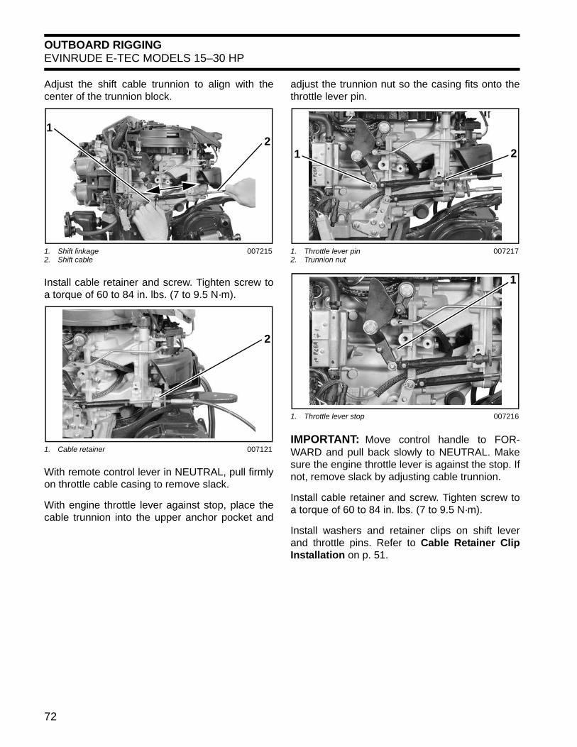
OUTBOARD RIGGINGEVINRUDE E-TEC MODELS 15–30 HP
Adjust the shift cable trunnion to align with thecenter of the trunnion block.
Install cable retainer and screw. Tighten screw toa torque of 60 to 84 in. lbs. (7 to 9.5 N·m).
With remote control lever in NEUTRAL, pull firmlyon throttle cable casing to remove slack.
With engine throttle lever against stop, place thecable trunnion into the upper anchor pocket and
adjust the trunnion nut so the casing fits onto thethrottle lever pin.
IMPORTANT: Move control handle to FOR-WARD and pull back slowly to NEUTRAL. Makesure the engine throttle lever is against the stop. Ifnot, remove slack by adjusting cable trunnion.
Install cable retainer and screw. Tighten screw toa torque of 60 to 84 in. lbs. (7 to 9.5 N·m).
Install washers and retainer clips on shift leverand throttle pins. Refer to Cable Retainer ClipInstallation on p. 51.
1. Shift linkage2. Shift cable
007215
1. Cable retainer 007121
21
2
1. Throttle lever pin2. Trunnion nut
007217
1. Throttle lever stop 007216
21
1
72

OUTBOARD RIGGINGEVINRUDE E-TEC MODELS 15–30 HP
3
SystemCheck Harness ConnectionsBefore installing electrical connectors, check thatthe seal is in place. Clean off any dirt from con-nectors. Apply a light coat of Electrical Grease tothe seal only. DO NOT fill connectors with Electri-cal Grease.
Route electrical harness along the edge of thelower engine cover.
Secure connectors to lower motor cover with twotie straps as shown.
Route trim and tilt connector under air silencer.Use tie strap to secure connector as shown.
Install battery cables and secure with tie strap.
Route battery cable through grommet of portlower motor cover.
BE SURE all harnesses and wiresare not pinched, cannot contact flywheel, anddo not interfere with moving throttle or shiftlinkages.
1. Seal 42079A
1. Key switch connector2. Tachometer connector
007263
1. Wire routing2. Secure with two tie straps
007125
1
2
1
1
2
1. Trim and tilt connector 007264
1. Tie strap 007240
1. Battery cable grommet 008009
1
21
1
NOTICE
73

OUTBOARD RIGGINGNOTES
NOTESTechnician’s Notes Related Documents
Bulletins
Instruction Sheets
Other
74
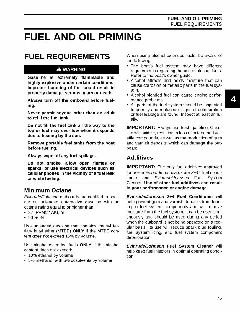
FUEL AND OIL PRIMINGFUEL REQUIREMENTS
4
FUEL AND OIL PRIMING
FUEL REQUIREMENTS
Minimum OctaneEvinrude/Johnson outboards are certified to oper-ate on unleaded automotive gasoline with anoctane rating equal to or higher than:• 87 (R+M)/2 AKI, or• 90 RON
Use unleaded gasoline that contains methyl ter-tiary butyl ether (MTBE) ONLY if the MTBE con-tent does not exceed 15% by volume.
Use alcohol-extended fuels ONLY if the alcoholcontent does not exceed:• 10% ethanol by volume• 5% methanol with 5% cosolvents by volume
When using alcohol-extended fuels, be aware ofthe following:• The boat’s fuel system may have different
requirements regarding the use of alcohol fuels.Refer to the boat’s owner guide.
• Alcohol attracts and holds moisture that cancause corrosion of metallic parts in the fuel sys-tem.
• Alcohol blended fuel can cause engine perfor-mance problems.
• All parts of the fuel system should be inspectedfrequently and replaced if signs of deteriorationor fuel leakage are found. Inspect at least annu-ally.
IMPORTANT: Always use fresh gasoline. Gaso-line will oxidize, resulting in loss of octane and vol-atile compounds, as well as the production of gumand varnish deposits which can damage the out-board.
Additives
IMPORTANT: The only fuel additives approvedfor use in Evinrude outboards are 2+4
® fuel condi-tioner and Evinrude/Johnson Fuel SystemCleaner. Use of other fuel additives can resultin poor performance or engine damage.
Evinrude/Johnson 2+4 Fuel Conditioner willhelp prevent gum and varnish deposits from form-ing in fuel system components and will removemoisture from the fuel system. It can be used con-tinuously and should be used during any periodwhen the outboard is not being operated on a reg-ular basis. Its use will reduce spark plug fouling,fuel system icing, and fuel system componentdeterioration.
Evinrude/Johnson Fuel System Cleaner willhelp keep fuel injectors in optimal operating condi-tion.
A WARNING
Gasoline is extremely flammable andhighly explosive under certain conditions.Improper handling of fuel could result inproperty damage, serious injury or death.
Always turn off the outboard before fuel-ing.
Never permit anyone other than an adultto refill the fuel tank.
Do not fill the fuel tank all the way to thetop or fuel may overflow when it expandsdue to heating by the sun.
Remove portable fuel tanks from the boatbefore fueling.
Always wipe off any fuel spillage.
Do not smoke, allow open flames orsparks, or use electrical devices such ascellular phones in the vicinity of a fuel leakor while fueling.
75

FUEL AND OIL PRIMINGFUEL SYSTEM PRIMING
FUEL SYSTEM PRIMINGVent Line ClampFederal Regulations require that all outboardswith a fuel vapor separator must be shipped with avent line clamp installed. This clamp must beremoved before priming the fuel system or startingthe outboard for the first time.
IMPORTANT: Failure to remove the clamp maycause fuel starvation and poor running qualities.
Priming the Fuel System
40 – 300 HP MODELS
Insert the fuel supply hose from the fuel tank into asuitable container. Squeeze the fuel primer bulb oractivate the boat-mounted electric fuel primer untilfuel flows from the fuel hose.
Once fuel flow is observed, connect fuel supplyhose from fuel tank to hose fitting on outboard.Secure hose with Oetiker clamp.
15 – 65 HP MODELS
Connect the fuel hose connector to the quick con-nect fitting on the outboard.
ALL MODELS
Use the primer to fill the vapor separator.
The high-pressure fuel circuits and injectors willprime as the outboard is cranked with the starter.
Observe all fuel lines, both in the boat and on theoutboard. Repair any fuel leaks.
002552
A WARNING
Fuel vapors are highly flammable. Performthe following procedure in a well venti-lated area. Extinguish all smoking materi-als and make certain no ignition sourcesare present.
A WARNING
Failure to check for fuel leaks could allowa leak to go undetected, resulting in fire orexplosion and may cause personal injuryor property damage.
76

FUEL AND OIL PRIMINGOIL REQUIREMENTS
4
OIL REQUIREMENTSRecommended LubricantsEvinrude/Johnson XD100, XD50, or XD30 out-board oils are recommended for use in EvinrudeE-TEC outboards. If these oils are not available,you must use a TC-W3 certified oil.
Evinrude/Johnson XD100 outboard oil is highlyrecommended for all conditions and applications.
Engine Lubricant Below 32°F (0°C)If the outboard will be operated in temperaturesbelow freezing (32°F, 0°C), use Evinrude/JohnsonXD100.
LOW OIL Warning Test
IMPORTANT: For new outboards, test low oilwarning before filling oil tank.
Turn key switch to ON. The engine monitor warn-ing display should show “LOW OIL.”
Add enough oil to raise level to at least one-quar-ter capacity.
The “LOW OIL” warning should not display.
IMPORTANT: Prime the oil system on EvinrudeE-TEC 15 – 90 HP models to turn OFF the “LOWOIL” warning. Refer to 15 – 90 HP Models onp. 82.
Failure to follow these recommen-dations could void the outboard warranty if alubrication-related failure occurs.
Oil Injection RateThe Engine Management Module (EMM) controlsthe oil injection rate based on engine RPM. Thisrate can be adjusted for the type of oil being used,and also for powerhead break-in. Use EvinrudeDiagnostics software to access these features.
The Set Oil Type option controls the injection ratefor the oil being used and typical operating condi-tions.
The TC-W3 oil type setting is the standard settingfor all outboards. Set TC-W3 for:• Operation with all TC-W3 outboard oils includ-
ing XD30, XD50, or XD100.• Applications requiring maximum lubrication.• Extreme applications (commercial or harsh con-
ditions, racing or other high performance opera-tion).
• Use this setting with XD100 outboard oil inextreme applications
The XD100 setting provides an option to run theoutboard at a reduced oil injection rate. This set-ting REQUIRES the use of Evinrude XD100 out-board lubricant and is not recommended for allapplications.
IMPORTANT: The XD100 setting is not avail-able on all models.
Use the XD100 setting for:• Conventional use (runabouts, cruisers)• Moderate applications
Running an Evinrude E-TEC out-board on other grades of oil while set to theXD100 oil ratio will result in increased enginewear and shortened outboard life.
NOTICE
1. Oil control setting 008580
1
NOTICE
77

FUEL AND OIL PRIMINGOIL REQUIREMENTS
Powerhead oil programming labels are providedto identify EMM oil programming. Install the cor-rect label to alert user to specific oil requirements.
An XD100 Outboard Oil Decal, P/N 352369, isavailable to label boats equipped with outboardsthat have been programmed for the reduced oilinjection ratio.
Install decals in a highly visible location, such asone of the following:• Dashboard/deck of boat, next to key switch• Deck of boat, next to the remote oil fill• Deck of boat, next to oil tank assembly• Oil tank cover• Cover of oil tank compartment• Attach to oil tank or oil fill cap.
IMPORTANT: Make sure the engine label andboat decals match EMM programming.
Break-In OilingIMPORTANT: DO NOT add oil in the fuel tankon Evinrude E-TEC models.
The Engine Management Module (EMM) will auto-matically supply extra oil to the engine as follows:• 90° V6: First two hours above 2000 RPM• 60° V4 & V6: First five hours above 2000 RPM• 40 – 90 HP: First two hours above 2000 RPM• 15 – 30 HP: First two hours above 2000 RPM
Follow these steps for outboard set-up:• Use Evinrude Diagnostics software to make
sure the break-in program has been started.• The oil tank should be filled and the oil level
marked for reference.
The operator must monitor the oiltank level to confirm oil consumption. Thismay require several hours of operation aboveidle.
1. Evinrude/Johnson XD30 outboard lubricant (TC-W3)YELLOW label
2. Evinrude/Johnson XD100 outboard lubricant (Premium) BLUE label (Installed)
004964
XD100 Outboard Oil Decal 355627
21
355627
NOTICEThis outboard has been programmed forthe use of Evinrude ® /Johnson® XD100™outboard oil ONLY. Failure to use Evinrude ®/Johnson®
XD100™ outboard oil may harm engine performance and shorten engine life.
NOTICE
78

FUEL AND OIL PRIMINGOIL SUPPLY PRIMING
4
OIL SUPPLY PRIMING
250 – 300 HP 90° V6 (3.4 L) ModelsOil Hose PrimingInsert the oil supply hose from the oil tank into asuitable container. Squeeze the oil primer bulbuntil oil flows from the oil tank into the container.
Once oil supply hose from the oil tank is filled withoil, connect the hose to the oil supply fitting onoutboard and secure with Oetiker clamp.
Oil Pump PrimingSqueeze the oil primer bulb until oil flows from theoil supply hose, through the oil filter, and into thecrankcase oil pump (front oil pump).
IMPORTANT: Inspect oil filter to make sure it isfilled with oil. All air must be eliminated from the oilfilter during priming procedure.
Continue to squeeze the oil primer bulb until oilflows through the front oil pump, into the oil distri-bution hoses, and to the crankcase fittings.
Use Evinrude Diagnostics software to make surethe EMM is programmed for the type of oil beingused.
Start the outboard. Use the oil priming functions inthe software to make sure the system is com-pletely primed.
IMPORTANT: The outboard should be runningduring the priming procedure to avoid pumpingtoo much oil into the crankcase, which couldcause a hard-starting condition.
Prime the rear oil pump FIRST (cylinder oil pump).
Use the Prime Cylinder Oiler button of theDynamic Test screen to prime the rear oil pump.
With the Prime Cylinder Oiler function activated,continue to squeeze the oil primer bulb until oilflows through the oil distribution hoses of the rearoil pump.
The software priming function mustbe used along with the primer bulb for two rea-sons:• The primer bulb alone will not move oil
through the rear pump assembly unless thepump is running.
• The pump assembly cannot prime itself untilit has been filled with oil.
A WARNING
Always use caution while working aroundmachinery with moving parts. The follow-ing set-up procedures require runningtests that are performed with the out-board’s motor cover removed.
Dynamic Test Screen1. Prime Cylinder Oiler button
008570
1. Rear oil pump2. Oil distribution hoses
008391
1
NOTICE
2
1
79

FUEL AND OIL PRIMINGOIL SUPPLY PRIMING
Prime the front oil pump assembly LAST.
Use the Prime Oil System button of the DynamicTest screen to prime the front oil pump.
Observe oil flow through all oil distribution hoses.Air must be purged during the priming procedure.
Small bubbles are acceptable. Large bubblesmust be eliminated through continued priming.
Repair any fuel or oil leaks.
115 – 200 HP 60° V4/V6 and 200 – 250 HP 90° V6 ModelsOil Hose PrimingInsert the oil supply hose from the oil tank into asuitable container. Squeeze the oil primer bulbuntil oil flows from the oil tank into the container.
Once oil supply hose from the oil tank is filled withoil, connect the hose to the oil supply fitting onoutboard and secure with Oetiker clamp.
Oil Pump PrimingSqueeze the oil primer bulb until oil flows from theoil supply hose, through the oil filter, and into theoil pump assembly.
IMPORTANT: Inspect oil filter to make sure it isfilled with oil. All air must be eliminated from the oilfilter during priming procedure.
IMPORTANT: 60° Models – Arrow on oil filterfaces incoming oil.
Continue to squeeze the oil primer bulb until oilflows through the oil pump, into the oil distributionhoses, and to the crankcase fittings.
Use Evinrude Diagnostics software to make surethe EMM is programmed for the type of oil beingused.
Start the outboard. Use the oil priming function inthe software to make sure the system is com-pletely primed.
Dynamic Test Screen1. Prime Oil System button
008570
1. Crankcase oil pump2. Oil distribution hoses
008392
1. Oil distribution hose2. Small bubbles3. Large bubbles
004398
1
2
1
1
3 2
80

FUEL AND OIL PRIMINGOIL SUPPLY PRIMING
4
Use the Prime Oil System button of the DynamicTest screen to prime the oil pump.
Observe oil flow through all oil distribution hoses.Air must be purged during the priming procedure.
Make sure that oil flows through the rear oil distri-bution manifold to the cylinder block fittings.
Small bubbles are acceptable. Large bubblesmust be eliminated through continued priming.
Repair any fuel or oil leaks.
The oiling system on these models can also beprimed using the Self-Winterizing feature if diag-nostics software is not available. Refer to Opera-tor’s Guide.
Dynamic Test Screen1. Prime Oil System button
008570
90° V6 Models1. Oil distribution hoses
004224
60° V4–V6 Models1. Oil distribution hoses
004965
1
1
1
1. Rear oil distribution manifold 008016
1. Oil distribution hose2. Small bubbles3. Large bubbles
004398
1
1
3 2
81

FUEL AND OIL PRIMINGOIL SUPPLY PRIMING
15 – 90 HP ModelsUse Evinrude Diagnostics software to make surethe EMM is programmed for the type of oil beingused.
Start the outboard. Use the oil priming function inthe software to make sure the system is com-pletely primed.
Use the Prime Oil System button of the DynamicTest screen to prime the oil pump.
If the “LOW OIL” warning was previously tested(see LOW OIL Warning Test on p. 77), the warn-ing should turn OFF during oil system priming.
Observe oil flow through all oil distribution hoses.Air must be purged during the priming procedure.
Small bubbles are acceptable. Large bubblesmust be eliminated through continued priming.
Repair any fuel or oil leaks.
The oiling system on these models can also beprimed using the Self-Winterizing feature if diag-nostics software is not available. Refer to Opera-tor’s Guide.
Dynamic Test Screen1. Prime Oil System button
008570A
40 – 90 HP Models1. Oil distribution hoses
007997
1
1
15 – 30 HP Models1. Oil distribution hoses
007130
1. Oil distribution hose2. Small bubbles3. Large bubbles
004398
11
1
3 2
82

PREDELIVERYBEFORE START-UP
5
PREDELIVERY
BEFORE START-UPGearcase LubricantWith outboard vertical, check the gearcase lubri-cant level:• Remove the lubricant level plug. Lubricant must
be even with the bottom of the threaded hole.• A clean tie strap can be used as a “dip stick” if
the lubricant level is not obvious.• Add HPF PRO gearcase lubricant as needed.
Oil LevelMake sure oil tank contains an adequate supply ofthe correct lubricant for the outboard and that theLOW OIL warning has been tested. Refer to Rec-ommended Lubricants on p. 77.
When starting the outboard for the first time, referto OIL SUPPLY PRIMING on p. 79.
Trim and Tilt Fluid
Make sure trim and tilt reservoir is full before run-ning outboard:• Tilt the outboard and engage the tilt support.• Remove filler cap and check fluid level.• Three Ram System–Add Power Trim/Tilt Fluid
or GM Dexron II, as needed, to bring level to thebottom of the fill plug threads.
1. Gearcase lubricant level 000072
1
A CAUTION
Correct fluid level must be maintained toensure operation of the impact protectionbuilt into the unit.
Three Ram System, 75 - 300 HP1. Filler cap
004277
1
83

PREDELIVERYRUNNING CHECKS
• Single Ram System–Add Evinrude/JohnsonBiodegradable TNT Fluid, as needed, to bringlevel to the bottom of the fill plug threads.
Install the filler cap and tighten to a torque of 45 to55 in. lbs. (5 to 6 N·m).• Disengage tilt support.• Cycle the unit at least five complete cycles to
purge all air from the system. When cycling theunit, hold the trim switch ON an additional 5 to10 seconds after the unit reaches the end of itstravel before activating the switch in the oppo-site direction.
RUNNING CHECKS
Engine Monitoring SystemAttach emergency stop lanyard.
Turn key switch to ON. Warning horn shouldsound for 1/2 second.
All SystemCheck warning lights should turn on atthe same time, then turn off one at a time.
Fuel SystemPerform running checks of the fuel system by fol-lowing these steps:• Squeeze fuel primer bulb until hard or activate
electric primer. Observe all fuel hoses and con-nections. Repair any leaks.
• Start outboard. Inspect all hoses and connec-tions. Repair any leaks or misrouted hosesimmediately.
Single Ram System, 75 - 130 HP1. Filler cap
008017
Single Ram System, 15 - 60 HP1. Filler cap
008018
1
1
A DANGER
DO NOT run the engine indoors or withoutadequate ventilation or permit exhaustfumes to accumulate in confined areas.Engine exhaust contains carbon monoxidewhich, if inhaled, can cause serious braindamage or death.
A WARNING
Contact with a rotating propeller is likely toresult in serious injury or death. Assurethe engine and prop area is clear of peopleand objects before starting engine or oper-ating boat. Do not allow anyone near a pro-peller, even when the engine is off. Bladescan be sharp and the propeller can con-tinue to turn even after the engine is off.
A CAUTION
DO NOT run outboard without a water sup-ply to the outboard’s cooling system. Cool-ing system and/or powerhead damagecould occur.
84
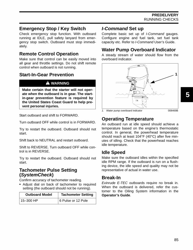
PREDELIVERYRUNNING CHECKS
5
Emergency Stop / Key SwitchCheck emergency stop function. With outboardrunning at IDLE, pull safety lanyard from emer-gency stop switch. Outboard must stop immedi-ately.
Remote Control OperationMake sure that control can be easily moved intoall gear and throttle settings. Do not shift remotecontrol when outboard is not running.
Start-In-Gear Prevention
Start outboard and shift to FORWARD.
Turn outboard OFF while control is in FORWARD.
Try to restart the outboard. Outboard should notstart.
Shift back to NEUTRAL and restart outboard.
Shift to REVERSE. Turn outboard OFF while con-trol is in REVERSE.
Try to restart the outboard. Outboard should notstart.
Tachometer Pulse Setting(SystemCheck)Confirm accuracy of tachometer reading.• Adjust dial on back of tachometer to required
setting (the outboard should not be running).
I-Command Set upComplete basic set up of I-Command gauges.Configure engine and fuel tank, set fuel tankcapacity etc. Refer to I-Command User’s Guide.
Water Pump Overboard IndicatorA steady stream of water should flow from theoverboard indicator.
Operating TemperatureAn outboard run at idle speed should achieve atemperature based on the engine’s thermostaticcontrol. In general, the powerhead temperatureshould reach at least 104°F (40°C) after five min-utes of idling. Check that the powerhead reachesidle temperature.
Idle SpeedMake sure the outboard idles within the specifiedidle RPM range. If the outboard is run on a flush-ing device, the idle speed and quality may not berepresentative of actual in water use.
Break-InEvinrude E-TEC outboards require no break in.When the outboard is delivered, refer the cus-tomer to the Oiling System information in theOperator’s Guide.
A WARNING
Make certain that the starter will not oper-ate when the outboard is in gear. The start-in-gear prevention feature is required bythe United States Coast Guard to help pre-vent personal injuries.
Outboard Model Tachometer Setting
15–300 HP 6 Pulse or 12 Pole
1. Water pump overboard indicator 008469B
1
85
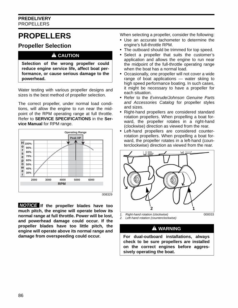
PREDELIVERYPROPELLERS
PROPELLERSPropeller Selection
Water testing with various propeller designs andsizes is the best method of propeller selection.
The correct propeller, under normal load condi-tions, will allow the engine to run near the mid-point of the RPM operating range at full throttle.Refer to SERVICE SPECIFICATIONS in the Ser-vice Manual for RPM range.
If the propeller blades have toomuch pitch, the engine will operate below itsnormal range at full throttle. Power will be lost,and powerhead damage could occur. If thepropeller blades have too little pitch, theengine will operate above its normal range anddamage from overspeeding could occur.
When selecting a propeller, consider the following:• Use an accurate tachometer to determine the
engine’s full-throttle RPM.• The outboard should be trimmed for top speed.• Select a propeller that suits the customer’s
application and allows the engine to run nearthe midpoint of the full-throttle operating rangewhen the boat has a normal load.
• Occasionally, one propeller will not cover a widerange of boat applications — water skiing tohigh speed performance boating. In such cases,it might be necessary to have a propeller foreach situation.
• Refer to the Evinrude/Johnson Genuine Partsand Accessories Catalog for propeller stylesand sizes.
• Right-hand propellers are considered standardrotation propellers. When propelling a boat for-ward, the propeller rotates in a right-hand(clockwise) direction as viewed from the rear.
• Left-hand propellers are considered counter-rotation propellers. When propelling a boat for-ward, the propeller rotates in a left-hand (coun-terclockwise) direction as viewed from the rear.
A CAUTION
Selection of the wrong propeller couldreduce engine service life, affect boat per-formance, or cause serious damage to thepowerhead.
008329
30%
40%
50%
60%
70%
80%
90%
100%
2000 3000 4000 5000 6000
Operating Range
Peak HP
Horsepower
RPM
NOTICE
1. Right-hand rotation (clockwise)2. Left-hand rotation (counterclockwise)
000033
A WARNING
For dual-outboard installations, alwayscheck to be sure propellers are installedon the correct engines before aggres-sively operating the boat.
2 1
86
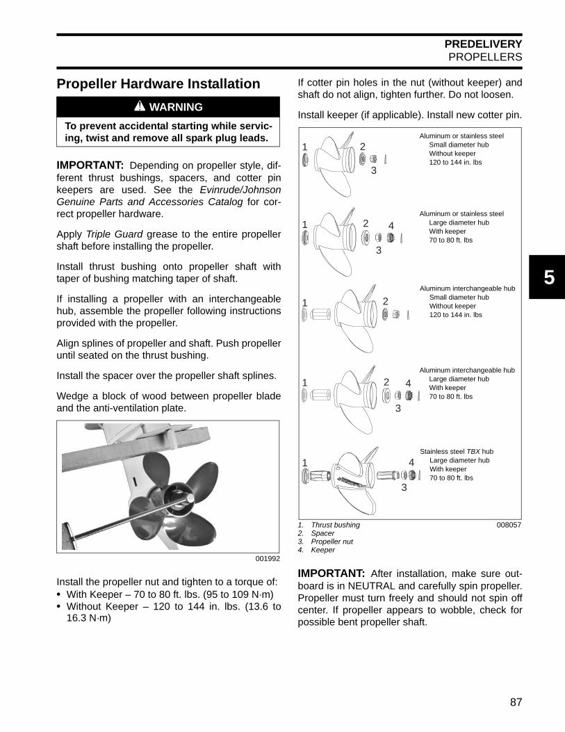
PREDELIVERYPROPELLERS
5
Propeller Hardware Installation
IMPORTANT: Depending on propeller style, dif-ferent thrust bushings, spacers, and cotter pinkeepers are used. See the Evinrude/JohnsonGenuine Parts and Accessories Catalog for cor-rect propeller hardware.
Apply Triple Guard grease to the entire propellershaft before installing the propeller.
Install thrust bushing onto propeller shaft withtaper of bushing matching taper of shaft.
If installing a propeller with an interchangeablehub, assemble the propeller following instructionsprovided with the propeller.
Align splines of propeller and shaft. Push propelleruntil seated on the thrust bushing.
Install the spacer over the propeller shaft splines.
Wedge a block of wood between propeller bladeand the anti-ventilation plate.
Install the propeller nut and tighten to a torque of:• With Keeper – 70 to 80 ft. lbs. (95 to 109 N·m)• Without Keeper – 120 to 144 in. lbs. (13.6 to
16.3 N·m)
If cotter pin holes in the nut (without keeper) andshaft do not align, tighten further. Do not loosen.
Install keeper (if applicable). Install new cotter pin.
IMPORTANT: After installation, make sure out-board is in NEUTRAL and carefully spin propeller.Propeller must turn freely and should not spin offcenter. If propeller appears to wobble, check forpossible bent propeller shaft.
A WARNING
To prevent accidental starting while servic-ing, twist and remove all spark plug leads.
001992
1. Thrust bushing2. Spacer3. Propeller nut4. Keeper
008057
1
1
1
1
1
2
2
2
2
3
3
3
3
4
4
4
Aluminum or stainless steel Small diameter hub Without keeper 120 to 144 in. lbs
Aluminum or stainless steel Large diameter hub With keeper 70 to 80 ft. lbs
Aluminum interchangeable hub Small diameter hub Without keeper 120 to 144 in. lbs
Aluminum interchangeable hub Large diameter hub With keeper 70 to 80 ft. lbs
Stainless steel TBX hub Large diameter hub With keeper 70 to 80 ft. lbs
87

PREDELIVERYWATER TEST AND FINAL ADJUSTMENTS
WATER TEST AND FINAL ADJUSTMENTSAn in the water test is required to make sure theoutboard(s) and boat are rigged correctly, propel-ler selection is correct, and that all accessoriesfunction properly.
Pay special attention to the following, especially ifthe boat is repowered with new outboard(s):• Engine mounting height• Jack plate adjustment• Correct propeller selection and WOT RPM• Fuel system vacuum• Engine water pressure/optional water screens
Make all needed adjustments or repairs and retestbefore delivery.
When ready for delivery, give all instructionsheets, operating instructions and user guidesprovided with accessories to the owner. Advisethe owner of any special operation or mainte-nance information contained in the instructions.
IMPORTANT: Complete the Predelivery Check-list and obtain owner’s signature at the time ofdelivery. The Predelivery Checklist must be kepton file for seven years.
Engine Mounting Height and Jack Plate AdjustmentGoals include:• Engine RPM within the full throttle operating
range• Best acceleration and top speed• No excessive ventilation while boat is coming
onto plane.
Start with the engine lower on the transom. Makea test run, taking note of engine RPM, water pres-sure, trim level and boat speed. Refer to theWater Pressure Chart on p. 89.
Raise the engine or jack plate and repeat the pro-cess until the best acceleration and boat speedare achieved.
Fuel System VacuumTest fuel system vacuum. Refer to the appropriateservice manual. The maximum inlet fuel vacuumshould not exceed 4 in. Hg. (13.5 kPa) at the inletto the fuel lift pump under any operating condi-tions (IDLE to WOT).
A higher vacuum indicates an excessive restric-tion in the fuel supply. Repair as needed.
Engine Water PressureCheck engine water pressure. Confirm adequatewater pressure at all engine speeds and in turns.Refer to the Water Pressure Chart on p. 89.
If water pressure falls below acceptable levels,adjust outboard alignment (multiple engine instal-lations), or consider installing optional high flowwater screens. Refer to appropriate parts catalogfor available water screens.
88
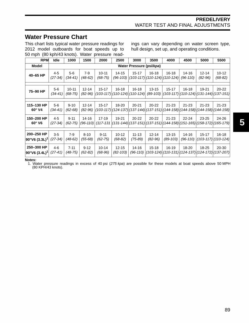
PREDELIVERYWATER TEST AND FINAL ADJUSTMENTS
5
Water Pressure ChartThis chart lists typical water pressure readings for2012 model outboards for boat speeds up to50 mph (80 kph/43 knots). Water pressure read-
ings can vary depending on water screen type,hull design, set up, and operating conditions.
RPM Idle 1000 1500 2000 2500 3000 3500 4000 4500 5000 5500
Model Water Pressure (psi/kpa)
40–65 HP4-5
(27-34)5-6
(34-41)7-9
(48-62)10-11
(68-75)14-15
(96-103)15-17
(103-117)16-18
(110-124)16-18
(110-124)14-16
(96-110)12-14
(82-96)10-12
(68-82)
75–90 HP5-6
(34-41)10-11
(68-75)12-14
(82-96)15-17
(103-117)16-18
(110-124)16-18
(110-124)13-15
(89-103)15-17
(103-117)16-18
(110-124)19-21
(131-144)20-22
(137-151)
115–130 HP60° V4
5-6(34-41)
9-10(62-68)
12-14(82-96)
15-17(103-117)
18-20(124-137)
20-21(137-144)
20-22(137-151)
21-23(144-158)
21-23(144-158)
21-23(144-158)
21-23(144-158)
150–200 HP60° V6
4-5(27-34)
9-11(62-75)
14-16(96-110)
17-19(117-131
19-21(131-144)
20-22(137-151)
20-22(137-151)
21-23(144-158)
22-24(151-165)
23-25(158-172)
24-26(165-179)
200–250 HP
90°V6 (3.3L)13-5
(27-34)7-9
(48-62)8-10
(55-68)9-11
(62-75)10-12
(68-82)11-13
(75-89)12-14
(82-96)13-15
(89-103)14-16
(96-110)15-17
(103-117)16-18
(110-124)
250–300 HP
90°V6 (3.4L)14-6
(27-41)7-11
(48-75)9-12
(62-82)10-14
(68-96)12-15
(82-103)14-16
(96-110)15-18
(103-124)16-19
(110-131)18-20
(124-137)18-25
(124-172)20-30
(137-207)
Notes:1. Water pressure readings in excess of 40 psi (275 kpa) are possible for these models at boat speeds above 50 MPH
(80 KPH/43 knots).
89

PREDELIVERYWATER TEST AND FINAL ADJUSTMENTS
Tilt Limit Switch Adjustment(75 – 300 HP)
Adjust the tilt limit switch on all new outboardinstallations.
Check the clearance between outboard(s) and theboat’s motor well and transom area. Tilt out-board(s) to highest point of clearance and turn thesteering system lock to lock.
If the outboard contacts the boat's motor wellwhen fully tilted, adjust the tilt limit cam to reducefull-tilt position.
The tilt limit cam will not preventthe outboard from overriding the adjustment ifthe outboard is tilted manually.
Place the outboard in normal operating position.
Rotate the LOWER adjustment tab UP to reducethe maximum tilt. Rotate the UPPER adjustmenttab DOWN to increase the maximum tilt position.
Check the adjustment by tilting the outboard fully.
Repeat this procedure until the tilt limit switchstops the outboard's upward travel before it con-tacts the motor well.
To prevent damage to equipment, provide addi-tional motor well clearance when needed. Con-sider either changing the outboard mountingposition or modifying the boat if the possibility forinterference and damage exists.
A WARNING
If the outboard does not clear all boat partswhen tilted fully or turned side to side,safety related parts could be damaged inthe course of such outboard movement.Injuries could result from loss of boat con-trol.
DR3916
NOTICE
1. Lower adjustment tab2. Upper adjustment tab
DR4268
A WARNING
Adjusting the tilt limit cam will NOT pre-vent the outboard from tilting fully andcontacting the motor well if the gearcasehits an object at high speed. Such contactcould damage the outboard and boat andinjure boat occupants.
2
1
90

PREDELIVERYWATER TEST AND FINAL ADJUSTMENTS
5
Trim Sending Unit Adjustment(75 – 300 HP)Tilt the outboard and engage the tilt support.
Temporarily install a thrust rod, P/N 436541, in thenumber 3 hole.
Loosen the sending unit screws, to allow thesending unit to pivot.
Disengage the tilt support. Lower the outboardagainst the thrust rod.
Observe the trim gauge. If the needle does notshow center position, tilt the outboard up andadjust the sending unit by pivoting it up or down.
Lower the outboard against the thrust rod to checkadjustment. Repeat adjustment, if necessary.
After adjustment is correct, tilt the outboard up,tighten the two sending unit screws, and removethe thrust rod.
Trim Limiter RodThe trim limiter rod prevents excessive trim down.
As the engine is trimmed to the full down position,the bow of the boat goes deeper into the water. • If the trim limiter rod is left out, the bow could
plow into the water causing the boat to “bowsteer” resulting in a loss of control.
• If the trim limiter rod is set too far out, the pro-peller could ventilate, resulting in poor accelera-tion when the boat is coming onto plane.
Set the trim limiter rod to prevent excessive trimdown and provide good acceleration. The trim lim-iter rod can be used to prevent the gearcase orspray deflector from contacting the transom.
29072
1. Screws 27339
1
1. Needle at center position 000662
A WARNING
When the outboard is returned to the cus-tomer, the trim limiter rod must beinstalled and in the same location as itwas when the motor was brought in forservice. Leaving the trim limiter rod out, orchanging the adjustment, could allow themotor to unexpectedly trim in too far andcause loss of control.
1
91

PREDELIVERYWATER TEST AND FINAL ADJUSTMENTS
Trim Sending Unit Adjustment(25 – 60 HP)The sending unit eccentric cam must be adjustedso that the gauge needle is aligned with the lowestgauge mark with the outboard trimmed all the wayDOWN.
Check if the gauge needle is above or below thelowest gauge mark. Tilt engine UP and engagetrailering lock.
When the outboard is trimmed all the way DOWN,the sending unit lever touches the eccentric camjust forward of the top of the cam at the contactpoint.
Loosen cam screw and rotate eccentric cam toadjust full down gauge position:• If the needle was above the lowest mark, move
the thick part of the cam TOWARD the contactpoint. Tighten the screw, and recheck the gaugereading.
• If the needle was below the lowest mark, movethe thick part of the cam AWAY from the contactpoint. Tighten the screw, and recheck the gaugereading.
Tighten eccentric cam retaining screw and checkneedle position at full trim DOWN.
1. Lowest gauge mark DR2827
1. Trailering lock 18954
1
1
A WARNING
To avoid personal injury, do not adjust thesending unit eccentric cam while theengine is being tilted.
1. Lever2. Eccentric cam3. Contact point4. Cam screw
DR5090
31
2
4
92

PREDELIVERYWATER TEST AND FINAL ADJUSTMENTS
5
Trim Tab Adjustment
A propeller will generate steering torque when thepropeller shaft is not running parallel to the water’ssurface. The trim tab is adjustable to compensatefor this steering torque.
IMPORTANT: A single trim tab adjustment willrelieve steering effort under only one set of speed,outboard angle and load conditions. No singleadjustment can relieve steering effort under allconditions.
If the boat pulls to the left or right when its load isevenly distributed, adjust the trim tab as follows:• With the remote control in NEUTRAL and the
engine OFF, loosen the trim tab screw.• If the boat pulled to the right, move rear of the
trim tab slightly to the right.• If the boat pulled to the left, move rear of the
trim tab slightly to the left.
Tighten the trim tab screw as follows:• 40 – 300 HP: 35 to 40 ft. lbs. (47 to 54 N·m).• 15 – 30 HP: 60 to 80 in. lbs. (7 to 9 N·m).
Test the boat and, if needed, repeat the procedureuntil steering effort is as equal as possible.
Outboards with High Transom HeightsThe trim tab may be above the surface of thewater when the outboard is trimmed out. Steeringeffort might increase. Lower the trim setting tosubmerge the trim tab and to reduce steeringeffort.
Dual Standard Rotation OutboardsMove both trim tabs equally and in the samedirection.
Dual Outboards, One Counter and OneStandard RotationSet both trim tabs to the center position.
A WARNING
Improper trim tab adjustment can causedifficult steering and loss of control.
40 – 300 HP Models1. Trim tab screw
COA3663
1
15 – 30 HP Models1. Trim tab screw
007044
1
93
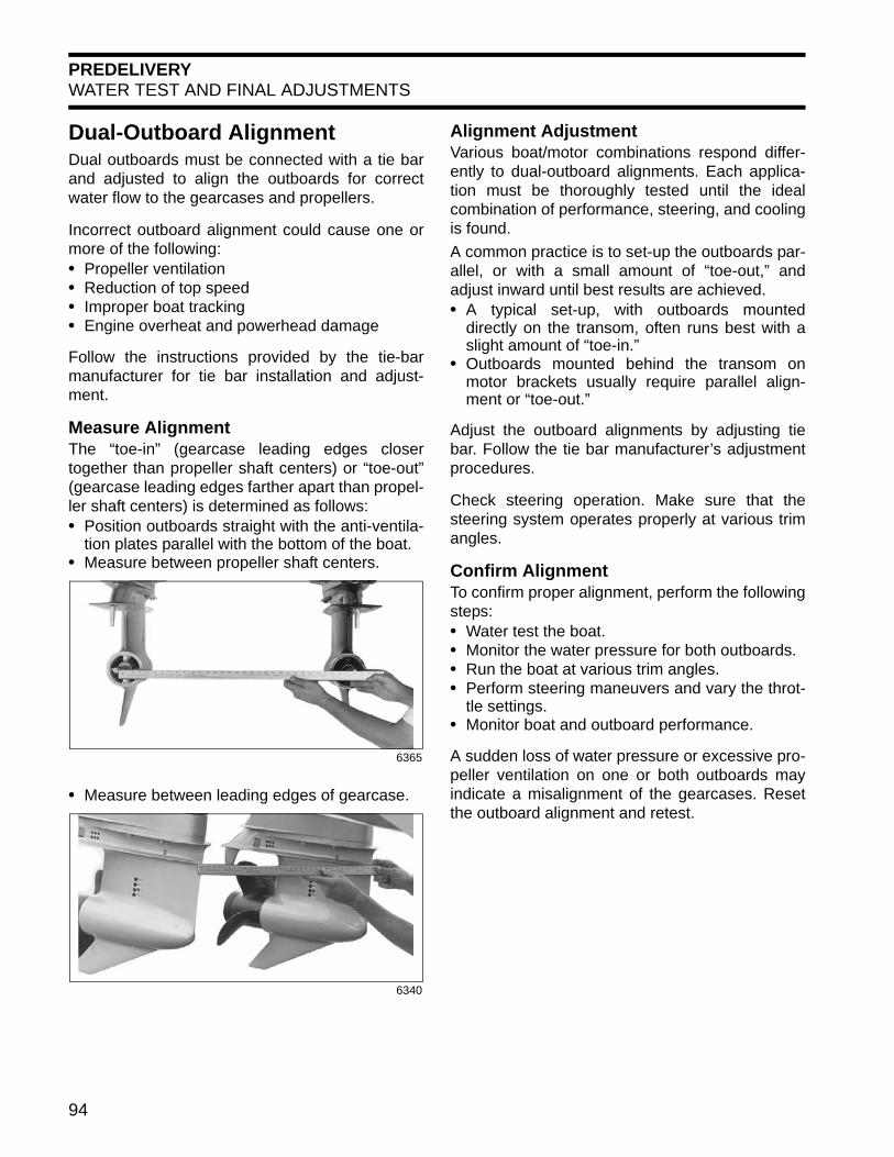
PREDELIVERYWATER TEST AND FINAL ADJUSTMENTS
Dual-Outboard AlignmentDual outboards must be connected with a tie barand adjusted to align the outboards for correctwater flow to the gearcases and propellers.
Incorrect outboard alignment could cause one ormore of the following:• Propeller ventilation• Reduction of top speed• Improper boat tracking• Engine overheat and powerhead damage
Follow the instructions provided by the tie-barmanufacturer for tie bar installation and adjust-ment.
Measure AlignmentThe “toe-in” (gearcase leading edges closertogether than propeller shaft centers) or “toe-out”(gearcase leading edges farther apart than propel-ler shaft centers) is determined as follows:• Position outboards straight with the anti-ventila-
tion plates parallel with the bottom of the boat.• Measure between propeller shaft centers.
• Measure between leading edges of gearcase.
Alignment AdjustmentVarious boat/motor combinations respond differ-ently to dual-outboard alignments. Each applica-tion must be thoroughly tested until the idealcombination of performance, steering, and coolingis found.
A common practice is to set-up the outboards par-allel, or with a small amount of “toe-out,” andadjust inward until best results are achieved.• A typical set-up, with outboards mounted
directly on the transom, often runs best with aslight amount of “toe-in.”
• Outboards mounted behind the transom onmotor brackets usually require parallel align-ment or “toe-out.”
Adjust the outboard alignments by adjusting tiebar. Follow the tie bar manufacturer’s adjustmentprocedures.
Check steering operation. Make sure that thesteering system operates properly at various trimangles.
Confirm AlignmentTo confirm proper alignment, perform the followingsteps:• Water test the boat.• Monitor the water pressure for both outboards.• Run the boat at various trim angles.• Perform steering maneuvers and vary the throt-
tle settings.• Monitor boat and outboard performance.
A sudden loss of water pressure or excessive pro-peller ventilation on one or both outboards mayindicate a misalignment of the gearcases. Resetthe outboard alignment and retest.
6365
6340
94

INDEX
6
INDEX
A nnnnnnnnnnnnnnnnnnnnnnnnnnnnnnnnnnnnnnnnnnnnnnnnnnnnnnnnnnnnnnnnnnnnnnnnnnnnnnnnnnnnnnnnnnnnnnnnnnnnnnnnnnnnnnnnnnnnnnnnnnnnnnnnnnnnnnnnnnnnnnnnnnnnnnnnnnnnnnnnnnnnnnnnnnnnnnnnnnnnnnnnnnnnnnnnnnnnnnnnnnnnnnnnnnnnnnnnnnnnnnnnnnnnnnnnnnnnnnnnnnnnnnnnnnnnnnnnnnnnnnnnnnnnnnnnnnnnnnnnnnnnnnnnnnnnnnnnnnnnnnnnnnnnnnnnnnnnnnnnnnnnnnnnnnnnnnnnnnnnnnnnnnnnnnnnnnnnnnnnnnnnnnnnnnnnnnnnnnnnnnnnnnnnnnnnnnnnAbbreviations 6Accessories
Accessory Charge Kit, P/N 5006253 17Fuel Filter Assembly, P/N 174176 21I-Command Water Pressure Transducer
Kit, P/N 765353 57, 64XD100 Outboard Oil Decal, P/N 352369 78
AdjustmentsControl Cable 53, 59, 65, 71Dual Outboard Alignment 94Tilt Limit Switch 90Trim Sending Unit 91, 92Trim Tab 93
B nnnnnnnnnnnnnnnnnnnnnnnnnnnnnnnnnnnnnnnnnnnnnnnnnnnnnnnnnnnnnnnnnnnnnnnnnnnnnnnnnnnnnnnnnnnnnnnnnnnnnnnnnnnnnnnnnnnnnnnnnnnnnnnnnnnnnnnnnnnnnnnnnnnnnnnnnnnnnnnnnnnnnnnnnnnnnnnnnnnnnnnnnnnnnnnnnnnnnnnnnnnnnnnnnnnnnnnnnnnnnnnnnnnnnnnnnnnnnnnnnnnnnnnnnnnnnnnnnnnnnnnnnnnnnnnnnnnnnnnnnnnnnnnnnnnnnnnnnnnnnnnnnnnnnnnnnnnnnnnnnnnnnnnnnnnnnnnnnnnnnnnnnnnnnnnnnnnnnnnnnnnnnnnnnnnnnnnnnnnnnnnnnnnnnnnnnnnnBatteries
Battery Charge Isolator 17Battery Switches 16Cable Routing 27Cables 16Installation 15Multiple Batteries 16Requirements 15
Break-InEMM Programming 78Oiling 78
C nnnnnnnnnnnnnnnnnnnnnnnnnnnnnnnnnnnnnnnnnnnnnnnnnnnnnnnnnnnnnnnnnnnnnnnnnnnnnnnnnnnnnnnnnnnnnnnnnnnnnnnnnnnnnnnnnnnnnnnnnnnnnnnnnnnnnnnnnnnnnnnnnnnnnnnnnnnnnnnnnnnnnnnnnnnnnnnnnnnnnnnnnnnnnnnnnnnnnnnnnnnnnnnnnnnnnnnnnnnnnnnnnnnnnnnnnnnnnnnnnnnnnnnnnnnnnnnnnnnnnnnnnnnnnnnnnnnnnnnnnnnnnnnnnnnnnnnnnnnnnnnnnnnnnnnnnnnnnnnnnnnnnnnnnnnnnnnnnnnnnnnnnnnnnnnnnnnnnnnnnnnnnnnnnnnnnnnnnnnnnnnnnnnnnnnnnnnnCable, Hose, and Wire Routing 52, 58, 65,
71Control Cable
Adjustments 53, 59, 65, 71Installation 53, 59, 65, 71Routing 10
Cooling SystemOperating Temperatures 85Turbulence 31
D nnnnnnnnnnnnnnnnnnnnnnnnnnnnnnnnnnnnnnnnnnnnnnnnnnnnnnnnnnnnnnnnnnnnnnnnnnnnnnnnnnnnnnnnnnnnnnnnnnnnnnnnnnnnnnnnnnnnnnnnnnnnnnnnnnnnnnnnnnnnnnnnnnnnnnnnnnnnnnnnnnnnnnnnnnnnnnnnnnnnnnnnnnnnnnnnnnnnnnnnnnnnnnnnnnnnnnnnnnnnnnnnnnnnnnnnnnnnnnnnnnnnnnnnnnnnnnnnnnnnnnnnnnnnnnnnnnnnnnnnnnnnnnnnnnnnnnnnnnnnnnnnnnnnnnnnnnnnnnnnnnnnnnnnnnnnnnnnnnnnnnnnnnnnnnnnnnnnnnnnnnnnnnnnnnnnnnnnnnnnnnnnnnnnnnnnnnnnDiagnostic Software
Break-In Programming 78I-Command settings 56, 63, 70Oil Priming 79, 80Oiling Rate 79, 80
Dual-OutboardAlignment 94Centerlines 33I-Command settings 56, 63, 70
E nnnnnnnnnnnnnnnnnnnnnnnnnnnnnnnnnnnnnnnnnnnnnnnnnnnnnnnnnnnnnnnnnnnnnnnnnnnnnnnnnnnnnnnnnnnnnnnnnnnnnnnnnnnnnnnnnnnnnnnnnnnnnnnnnnnnnnnnnnnnnnnnnnnnnnnnnnnnnnnnnnnnnnnnnnnnnnnnnnnnnnnnnnnnnnnnnnnnnnnnnnnnnnnnnnnnnnnnnnnnnnnnnnnnnnnnnnnnnnnnnnnnnnnnnnnnnnnnnnnnnnnnnnnnnnnnnnnnnnnnnnnnnnnnnnnnnnnnnnnnnnnnnnnnnnnnnnnnnnnnnnnnnnnnnnnnnnnnnnnnnnnnnnnnnnnnnnnnnnnnnnnnnnnnnnnnnnnnnnnnnnnnnnnnnnnnnnnnnElectrical Harness
Connections 54, 55, 56, 60, 61, 63, 67, 68, 73
Emergency Stop SwitchInstallation 8
Emissions Information 7Engine Monitor
Operation Check 84Requirement 11
F nnnnnnnnnnnnnnnnnnnnnnnnnnnnnnnnnnnnnnnnnnnnnnnnnnnnnnnnnnnnnnnnnnnnnnnnnnnnnnnnnnnnnnnnnnnnnnnnnnnnnnnnnnnnnnnnnnnnnnnnnnnnnnnnnnnnnnnnnnnnnnnnnnnnnnnnnnnnnnnnnnnnnnnnnnnnnnnnnnnnnnnnnnnnnnnnnnnnnnnnnnnnnnnnnnnnnnnnnnnnnnnnnnnnnnnnnnnnnnnnnnnnnnnnnnnnnnnnnnnnnnnnnnnnnnnnnnnnnnnnnnnnnnnnnnnnnnnnnnnnnnnnnnnnnnnnnnnnnnnnnnnnnnnnnnnnnnnnnnnnnnnnnnnnnnnnnnnnnnnnnnnnnnnnnnnnnnnnnnnnnnnnnnnnnnnnnnnnnn
Fuel FilterRequirements 21
Fuel SystemFilter 21Fuel Requirements 75Minimum Octane 75Priming 76Requirements 20
G nnnnnnnnnnnnnnnnnnnnnnnnnnnnnnnnnnnnnnnnnnnnnnnnnnnnnnnnnnnnnnnnnnnnnnnnnnnnnnnnnnnnnnnnnnnnnnnnnnnnnnnnnnnnnnnnnnnnnnnnnnnnnnnnnnnnnnnnnnnnnnnnnnnnnnnnnnnnnnnnnnnnnnnnnnnnnnnnnnnnnnnnnnnnnnnnnnnnnnnnnnnnnnnnnnnnnnnnnnnnnnnnnnnnnnnnnnnnnnnnnnnnnnnnnnnnnnnnnnnnnnnnnnnnnnnnnnnnnnnnnnnnnnnnnnnnnnnnnnnnnnnnnnnnnnnnnnnnnnnnnnnnnnnnnnnnnnnnnnnnnnnnnnnnnnnnnnnnnnnnnnnnnnnnnnnnnnnnnnnnnnnnnnnnnnnnnn
Gaugessee Information Display Systems 11
Grommet 52, 58, 65, 71
H nnnnnnnnnnnnnnnnnnnnnnnnnnnnnnnnnnnnnnnnnnnnnnnnnnnnnnnnnnnnnnnnnnnnnnnnnnnnnnnnnnnnnnnnnnnnnnnnnnnnnnnnnnnnnnnnnnnnnnnnnnnnnnnnnnnnnnnnnnnnnnnnnnnnnnnnnnnnnnnnnnnnnnnnnnnnnnnnnnnnnnnnnnnnnnnnnnnnnnnnnnnnnnnnnnnnnnnnnnnnnnnnnnnnnnnnnnnnnnnnnnnnnnnnnnnnnnnnnnnnnnnnnnnnnnnnnnnnnnnnnnnnnnnnnnnnnnnnnnnnnnnnnnnnnnnnnnnnnnnnnnnnnnnnnnnnnnnnnnnnnnnnnnnnnnnnnnnnnnnnnnnnnnnnnnnnnnnnnnnnnnnnnnnnnnnnnnnnHoses
Fuel System 20, 27Grommet 65Oiling System 27
95

INDEX
I nnnnnnnnnnnnnnnnnnnnnnnnnnnnnnnnnnnnnnnnnnnnnnnnnnnnnnnnnnnnnnnnnnnnnnnnnnnnnnnnnnnnnnnnnnnnnnnnnnnnnnnnnnnnnnnnnnnnnnnnnnnnnnnnnnnnnnnnnnnnnnnnnnnnnnnnnnnnnnnnnnnnnnnnnnnnnnnnnnnnnnnnnnnnnnnnnnnnnnnnnnnnnnnnnnnnnnnnnnnnnnnnnnnnnnnnnnnnnnnnnnnnnnnnnnnnnnnnnnnnnnnnnnnnnnnnnnnnnnnnnnnnnnnnnnnnnnnnnnnnnnnnnnnnnnnnnnnnnnnnnnnnnnnnnnnnnnnnnnnnnnnnnnnnnnnnnnnnnnnnnnnnnnnnnnnnnnnnnnnnnnnnnnnnnnnnnnnnnnnnnnnnnnI-Command
System settings 56, 63, 70Water Pressure Gauge 57, 64, 70
I-Command NetworkOutboard connections 55, 61, 68
ICON NetworkOutboard connections 56, 63
Information Display SystemsEngine Monitor 11I-Command Displays 11SystemCheck Gauges 11Tachometer Setting 85
J nnnnnnnnnnnnnnnnnnnnnnnnnnnnnnnnnnnnnnnnnnnnnnnnnnnnnnnnnnnnnnnnnnnnnnnnnnnnnnnnnnnnnnnnnnnnnnnnnnnnnnnnnnnnnnnnnnnnnnnnnnnnnnnnnnnnnnnnnnnnnnnnnnnnnnnnnnnnnnnnnnnnnnnnnnnnnnnnnnnnnnnnnnnnnnnnnnnnnnnnnnnnnnnnnnnnnnnnnnnnnnnnnnnnnnnnnnnnnnnnnnnnnnnnnnnnnnnnnnnnnnnnnnnnnnnnnnnnnnnnnnnnnnnnnnnnnnnnnnnnnnnnnnnnnnnnnnnnnnnnnnnnnnnnnnnnnnnnnnnnnnnnnnnnnnnnnnnnnnnnnnnnnnnnnnnnnnnnnnnnnnnnnnnnnnnnnnnnnnnnJack Plates 32
L nnnnnnnnnnnnnnnnnnnnnnnnnnnnnnnnnnnnnnnnnnnnnnnnnnnnnnnnnnnnnnnnnnnnnnnnnnnnnnnnnnnnnnnnnnnnnnnnnnnnnnnnnnnnnnnnnnnnnnnnnnnnnnnnnnnnnnnnnnnnnnnnnnnnnnnnnnnnnnnnnnnnnnnnnnnnnnnnnnnnnnnnnnnnnnnnnnnnnnnnnnnnnnnnnnnnnnnnnnnnnnnnnnnnnnnnnnnnnnnnnnnnnnnnnnnnnnnnnnnnnnnnnnnnnnnnnnnnnnnnnnnnnnnnnnnnnnnnnnnnnnnnnnnnnnnnnnnnnnnnnnnnnnnnnnnnnnnnnnnnnnnnnnnnnnnnnnnnnnnnnnnnnnnnnnnnnnnnnnnnnnnnnnnnnnnnnnnnnnLubrication
Engine Oil 77
M nnnnnnnnnnnnnnnnnnnnnnnnnnnnnnnnnnnnnnnnnnnnnnnnnnnnnnnnnnnnnnnnnnnnnnnnnnnnnnnnnnnnnnnnnnnnnnnnnnnnnnnnnnnnnnnnnnnnnnnnnnnnnnnnnnnnnnnnnnnnnnnnnnnnnnnnnnnnnnnnnnnnnnnnnnnnnnnnnnnnnnnnnnnnnnnnnnnnnnnnnnnnnnnnnnnnnnnnnnnnnnnnnnnnnnnnnnnnnnnnnnnnnnnnnnnnnnnnnnnnnnnnnnnnnnnnnnnnnnnnnnnnnnnnnnnnnnnnnnnnnnnnnnnnnnnnnnnnnnnnnnnnnnnnnnnnnnnnnnnnnnnnnnnnnnnnnnnnnnnnnnnnnnnnnnnnnnnnnnnnnnnnnnnnnnnnnMounting the Engine
Hull Preparation 31Mounting Height 48
O nnnnnnnnnnnnnnnnnnnnnnnnnnnnnnnnnnnnnnnnnnnnnnnnnnnnnnnnnnnnnnnnnnnnnnnnnnnnnnnnnnnnnnnnnnnnnnnnnnnnnnnnnnnnnnnnnnnnnnnnnnnnnnnnnnnnnnnnnnnnnnnnnnnnnnnnnnnnnnnnnnnnnnnnnnnnnnnnnnnnnnnnnnnnnnnnnnnnnnnnnnnnnnnnnnnnnnnnnnnnnnnnnnnnnnnnnnnnnnnnnnnnnnnnnnnnnnnnnnnnnnnnnnnnnnnnnnnnnnnnnnnnnnnnnnnnnnnnnnnnnnnnnnnnnnnnnnnnnnnnnnnnnnnnnnnnnnnnnnnnnnnnnnnnnnnnnnnnnnnnnnnnnnnnnnnnnnnnnnnnnnnnnnnnnnnnnnOetiker Clamp Servicing 28Oil Tank 23Oiling Rate 77Oiling System
Engine Lubricant 77New Engine Set-Up 23, 77Oil Tank 23Priming 79
P nnnnnnnnnnnnnnnnnnnnnnnnnnnnnnnnnnnnnnnnnnnnnnnnnnnnnnnnnnnnnnnnnnnnnnnnnnnnnnnnnnnnnnnnnnnnnnnnnnnnnnnnnnnnnnnnnnnnnnnnnnnnnnnnnnnnnnnnnnnnnnnnnnnnnnnnnnnnnnnnnnnnnnnnnnnnnnnnnnnnnnnnnnnnnnnnnnnnnnnnnnnnnnnnnnnnnnnnnnnnnnnnnnnnnnnnnnnnnnnnnnnnnnnnnnnnnnnnnnnnnnnnnnnnnnnnnnnnnnnnnnnnnnnnnnnnnnnnnnnnnnnnnnnnnnnnnnnnnnnnnnnnnnnnnnnnnnnnnnnnnnnnnnnnnnnnnnnnnnnnnnnnnnnnnnnnnnnnnnnnnnnnnnnnnnnnnnnnnPriming
Fuel System 76Oiling System 79
PropellerInstallation 87Selection 86
R nnnnnnnnnnnnnnnnnnnnnnnnnnnnnnnnnnnnnnnnnnnnnnnnnnnnnnnnnnnnnnnnnnnnnnnnnnnnnnnnnnnnnnnnnnnnnnnnnnnnnnnnnnnnnnnnnnnnnnnnnnnnnnnnnnnnnnnnnnnnnnnnnnnnnnnnnnnnnnnnnnnnnnnnnnnnnnnnnnnnnnnnnnnnnnnnnnnnnnnnnnnnnnnnnnnnnnnnnnnnnnnnnnnnnnnnnnnnnnnnnnnnnnnnnnnnnnnnnnnnnnnnnnnnnnnnnnnnnnnnnnnnnnnnnnnnnnnnnnnnnnnnnnnnnnnnnnnnnnnnnnnnnnnnnnnnnnnnnnnnnnnnnnnnnnnnnnnnnnnnnnnnnnnnnnnnnnnnnnnnnnnnnnnnnnnnnnnnRemote Controls
Cable Adjustment 53, 59, 65, 71Cable routing 10Installation 9Selection 8
S nnnnnnnnnnnnnnnnnnnnnnnnnnnnnnnnnnnnnnnnnnnnnnnnnnnnnnnnnnnnnnnnnnnnnnnnnnnnnnnnnnnnnnnnnnnnnnnnnnnnnnnnnnnnnnnnnnnnnnnnnnnnnnnnnnnnnnnnnnnnnnnnnnnnnnnnnnnnnnnnnnnnnnnnnnnnnnnnnnnnnnnnnnnnnnnnnnnnnnnnnnnnnnnnnnnnnnnnnnnnnnnnnnnnnnnnnnnnnnnnnnnnnnnnnnnnnnnnnnnnnnnnnnnnnnnnnnnnnnnnnnnnnnnnnnnnnnnnnnnnnnnnnnnnnnnnnnnnnnnnnnnnnnnnnnnnnnnnnnnnnnnnnnnnnnnnnnnnnnnnnnnnnnnnnnnnnnnnnnnnnnnnnnnnnnnnnnnnnStart-In-Gear Protection 85Steering System
Steering Torque 93SystemCheck
Outboard connections 54, 60, 67, 73
T nnnnnnnnnnnnnnnnnnnnnnnnnnnnnnnnnnnnnnnnnnnnnnnnnnnnnnnnnnnnnnnnnnnnnnnnnnnnnnnnnnnnnnnnnnnnnnnnnnnnnnnnnnnnnnnnnnnnnnnnnnnnnnnnnnnnnnnnnnnnnnnnnnnnnnnnnnnnnnnnnnnnnnnnnnnnnnnnnnnnnnnnnnnnnnnnnnnnnnnnnnnnnnnnnnnnnnnnnnnnnnnnnnnnnnnnnnnnnnnnnnnnnnnnnnnnnnnnnnnnnnnnnnnnnnnnnnnnnnnnnnnnnnnnnnnnnnnnnnnnnnnnnnnnnnnnnnnnnnnnnnnnnnnnnnnnnnnnnnnnnnnnnnnnnnnnnnnnnnnnnnnnnnnnnnnnnnnnnnnnnnnnnnnnnnnnnnnnnnTachometer
Pulse Setting 85Temperature
Operating 85Operation below freezing 77
Tilt Limit SwitchAdjustment 90
ToolsLifting Tool, P/N 354717 45Oetiker Pincers, P/N 787145 29Transom Drill Fixture, P/N 434367 34
Trim SenderAdjustment 91, 92
W nnnnnnnnnnnnnnnnnnnnnnnnnnnnnnnnnnnnnnnnnnnnnnnnnnnnnnnnnnnnnnnnnnnnnnnnnnnnnnnnnnnnnnnnnnnnnnnnnnnnnnnnnnnnnnnnnnnnnnnnnnnnnnnnnnnnnnnnnnnnnnnnnnnnnnnnnnnnnnnnnnnnnnnnnnnnnnnnnnnnnnnnnnnnnnnnnnnnnnnnnnnnnnnnnnnnnnnnnnnnnnnnnnnnnnnnnnnnnnnnnnnnnnnnnnnnnnnnnnnnnnnnnnnnnnnnnnnnnnnnnnnnnnnnnnnnnnnnnnnnnnnnnnnnnnnnnnnnnnnnnnnnnnnnnnnnnnnnnnnnnnnnnnnnnnnnnnnnnnnnnnnnnnnnnnnnnnnnnnnnnnnnnnnnnnWater Pressure Gauge 57, 64, 70Wiring Harness Connections 55, 61
96

SAMPLE PREDELIVERY CHECKLIST
OB MODEL NUMBER SERIAL NUMBER KEY NUMBER12345 *355441*
PREDELIVERY CHECKLIST
Inspected by: _____________________________________
Dealer name: _____________________________________
Dealer number: ___________________________________
Date Dealer Signature Date Owner / Customer
The dealer named in this document has instructed me on the operation, maintenance, safety features, and warranty policy for my outboard, all of which I understand. I am satisfied with the predelivery set-up and inspection of my outboard. I acknowledge that I have reviewed the on product safety labels and tags. I understand the importance of reading the operator's guide that I have received completely and thoroughly before operating the engine(s). Where not already required by law: I recognize the importance of
following safe boating practices.� I have taken a safe boating course before using the outboard. � I will take a safe boating course before using the outboard.� I will not take a safe boating course before using the outboard.
White Copy (original) - Dealer Yellow Copy - Service Dept. Pink Copy - CustomerVersion A.1 P/N 355441
IMPORTANT: Use this Checklist together with the Evinrude E-TEC Installation and Predelivery Guide. Every Evinrude/Johnson Dealer isresponsible to perform a complete predelivery inspection on all Evinrude E-TEC outboards. If an Evinrude E-TEC outboard was pre-riggedby the boat builder, a complete predelivery inspection is still required. Refer to the current Evinrude E-TEC Installation and PredeliveryGuide for detailed instructions. Dealer predelivery programs should include additional inspections related to boat accessories and trailers.At Time of Sale� Explain to owner all on-product Safety Labels/Tags and the importance of reading the Operator�s Guide before operating engine(s)� Install engine Safety Labels/Tags (language chosen by customer according to availability)� Explain the BRP Limited Warranty� Explain selection of outboard lubricantOwner�s outboard oil selection:� XD100 � XD50 � XD30 � Other � New boat package � Repower�15� �20� �25� �30� transom heightRemote Control (with start-in-gear protection)� EV JO BRP � Other (list brand) ___________________� Mechanical � Electronic (EST)� Single lever binnacle � Dual lever binnacle� Concealed side mount � Surface side mnt � EV JO BRP shift and throttle cables � Other (list brand) ____________________� Key switch with tether cord � MWS harnessesTiller Control � Tiller Handle Kit (15�115HP only) optional BRP Electronic Controls � Gateway module and buss cables � 6 port hubs and protective covers (2)� Master Power/Key Switch� Engine Cut�off Switch Panel 2nd station� Accessory Power Relay Kit � ESM engine identity plugs (multi-engine)Displays, Gauges and Networks� I-Command digital display(s)� Network buss cables and T-connectors � Engine Interface Cable (EMM to NMEA)� Power Supply Kit (NMEA network)� Network and terminators (2) (NMEA network) � Tachometer pulse settingBatteries, Wiring, and SwitchesBatteries: Qty. ______ CCA Rating _______ � Cable size: ____ ga. Length:_____ ft. / m� Connections tight � NO wing nuts!� Battery switch operation optional� Auxiliary Battery Charging optional
Fuel System� Primer bulb EV JO BRP �5/16 �3/8� Other (list brand)____________________� Fuel hose - �SAE J30R9 type� �5/16 �3/8� Fuel hoses installed with Oetiker clamps� Water separating fuel filter kit recommendedOil System� Correct installation of remote oil tank� Oil Hose - 25 ft. [7.6 m] maximum, no splices� Remote oil fill kit (vent not restricted) optionalSteering System� Mechanical - grease/tighten/adjust system� Hydraulic - fill/bleed/check system� Set multi-engine alignment (toe-in/toe-out)Outboard Installation� Mounting height - correct?� Mounting hardware - torqued?� Water pressure device - installed / set up? � ICON Conversion Kit (V6 optional add-on kit)Oil and Fuel Set Up, Check Fluid Levels� Check LOW OIL warning BEFORE filling oil tank� Fill oil tank(s) with outboard lubricant� Check fuel level� Remove blue clamp on vapor separator vent � Prime fuel system� Prime oil system - purge air from system� Check no fuel or oil hoses are kinked� Check gearcase lubricant level� Check power trim and tilt fluid levelEvinrude Diagnostics Software Set Up� Oil �Break-In� set � Set �Tiller Mode� Tiller handle kit installation only� Set Oil Type: � XD100 � TC-W3 install tagICON Set Up (Use Evinrude Diagnostics software)� Update engine software conversion kit only� Calibrate shift/throttle actuators conversion kit� Set station protect optionalI-Command Set Up� Calibrate trim / tilt sending unit (Use Ev Diag)� Set multi-engine identity (Use Ev Diag)� Set �Engine and Fuel Tank Configuration� and �Fuel Tank Capacity� (See User�s Guide)� Set �Engine Data� (See User�s Guide)
Operational Checks� Adjust shift and throttle cables � Check remote control operation� Check start-in-gear prevention� Check key switch and engine cut�off switch� Check display/gauge operation� Check operation of trim and tilt switches� Check tilt limit switch adjustment � Check trim sending unit adjustment� Water pressure / overboard indicator � Check reverse lock/tilt lock operation � Check shallow water drive operation � Trailering bracket check ground clearance� No Fuel, Oil or Water leaksEngine temperature IDLE _____�°F or �°CICON System Checks� Start/Stop Switch(es)� Engine Cut�off Switch (2nd station only)� Neutral Throttle Switch� RPM Switch� Trim Switch Panel (3, 4 or 5 engines only)Propeller(s) � EV JO BRP � Other (list brand) ___________________� Stainless Steel � AluminumDiameter _________ Pitch __________Torque _______ � in.lbs. � ft.lbs. � N·m� Cotter pin keeper and/or cotter pin installedOn the Water Operational ChecksEngine RPM at IDLE (in gear) ___________Engine RPM at WOT __________________Engine temperature WOT______�°F or �°CBoat fuel system vacuum __________ In. Hg.Water pressure at IDLE _________ psi / kPaWater pressure at WOT _________ psi / kPaAdjust multi-engine alignment (toe-in/toe-out)as needed for optimum water pressureAt time of delivery dealer:� Complete electronic warranty registration� Must retain this document with outboard file� Give owner a completed copy of this form