Embed Size (px)
Citation preview

- -
�'k,.._"-;_,�_.:::-----=:=�---�
2011-2014 DURAMAX
LML EGR DELETE

PACKING LIST:
Note: Prior to installation, please compare the parts that you have received with the bill of materials provided on this page to assure that you have all the parts necessary for the installation.
EGR Delete Kit
QTY.14111314
DescriptionBlue Coolant HoseM8 x 25 Hex Head BoltsExhaust Block O� PlateBillet Intake Block O� Plate with (2) O-ringsM10 x 20 Hex Head BoltHose Clamps - Size 10Hose Clamp - Size 8M8 x 20 Cap Head Bolts
A
BC D
E GF
QTY.ABCDEFGH
H
Read all instructions prior to install.

!CAUTION!!! Never work on a hot vehicle. Serious injury in the form of burns can result if the vehicle has been in use. Allow vehicle time to cool prior to installation. Always wear eye protection when working on or under any vehicle.
Note: When working on a used vehicle, we suggest using a penetrating spray lubricant to be applied liberally to all exhaust fasteners. When doing so, allow a signi�cant amount of time for the chemicals to lubricate the threads before attempting to disassemble.
Step 1: Disconnect the negative battery cables from both batteries.
Step 2: Drain the engine coolant by removing the metal retaining clip on the lower radiator line and pulling the line away from the radiator enough to allow the coolant to �ow out. As the �ow of the coolant slows down and the over�ow bottle is empty, reconnect the lower radiator line. (Image 1)
Step 3: Remove the intake resonator that is held in place by two bolts. (Image 2)
Step 4: Loosen the hose clamps on the intake, and disconnect the MAF sensor. (Image 3)
Step 5: Remove the intake tube, air box, and air �lter from the vehicle.
Image 1
Image 2
Image 3
MAF Sensor
Step 6: Remove the electrical connectors on the plastic intercooler tubing and the electrical connector on the throttle valve.
Step 7: Remove the plastic intercooler tube from the throttle valve. The intercooler tube has a twist lock connection at the throttle valve. (Image 4)
Step 8: Remove the green electrical connector from the back of the grid heater. (Image 5)
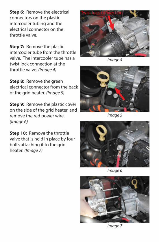
Step 9: Remove the plastic cover on the side of the grid heater, and remove the red power wire. (Image 6)
Step 10: Remove the throttle valve that is held in place by four bolts attaching it to the grid heater. (Image 7)
Twist lock connection
Image 4
Image 5
Image 6
Image 7
Step 11: Remove the one remaining bolt that holds the grid heater to the intake tube. (Image 8)
Step 12: Remove the two bolts securing the dipstick to the intake tube. Remove the plastic clip holding the wireway to the front of the intake tube.
Step 13: Remove the two brackets secured to the intake tube, and remove the electrical connector on top of the intake tube. (Image 9)
Step 14: Remove the intake tube that is held in place by two bolts. (Image 10)
Note: It is important to plug the intake port with a clean rag to avoid any debris from getting into the intake system.
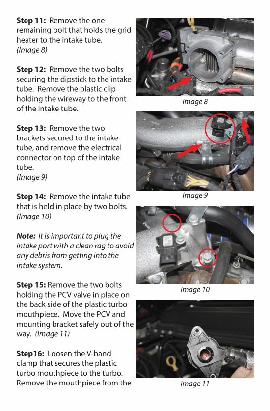
Step 15: Remove the two bolts holding the PCV valve in place on the back side of the plastic turbo mouthpiece. Move the PCV and mounting bracket safely out of the way. (Image 11)
Step16: Loosen the V-band clamp that secures the plastic turbo mouthpiece to the turbo. Remove the mouthpiece from the
Image 8
Image 9
Image 10
Image 11
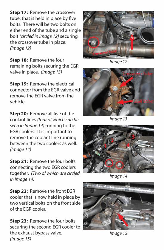
Step 17: Remove the crossover tube, that is held in place by �ve bolts. There will be two bolts on either end of the tube and a single bolt (circled in Image 12) securing the crossover tube in place. (Image 12)
Step 18: Remove the four remaining bolts securing the EGR valve in place. (Image 13)
Step 19: Remove the electrical connector from the EGR valve and remove the EGR valve from the vehicle.
Step 20: Remove all �ve of the coolant lines (four of which can be seen in Image 14) running to the EGR coolers. It is important to remove the coolant line running between the two coolers as well. (Image 14)
Step 21: Remove the four bolts connecting the two EGR coolers together. (Two of which are circled in Image 14)
Step 22: Remove the front EGR cooler that is now held in place by two vertical bolts on the front side of the EGR cooler.
Step 23: Remove the four bolts securing the second EGR cooler to the exhaust bypass valve. (Image 15)
Image 12
Image 13
Image 14
Image 15
A
Crossover Tube
Crossover Tube
EGR Valve
12
34

Step 24: Remove the second EGR cooler that is now held in place by a single vertical bolt near the front of the cooler. (Image 16)
Step 25: Remove the two coolant lines that are running to the exhaust bypass valve. The line running to the EGR cooler will be completely removed from the vehicle. The second line will only be removed from the coolant port on the exhaust bypass valve. (Image 17)
Step 26: Remove the three nuts that connect the up-pipe to the exhaust bypass valve. Remove the bolt on the backside of the exhaust bypass valve that is securing the coolant line.
Step 27: Remove the exhaust bypass valve that is now held in place by two vertical bolts.(Image 18)
Step 28: With the exhaust bypass valve removed, install the new exhaust block o� using the factory gasket and the supplied hardware. Four M8 x 25 hex head bolts will bolt in from the back, and one M10 x 20 hex head bolt will hold the bracket in place. (Image 19)
Image 16
Image 17
Image 18
Image 19
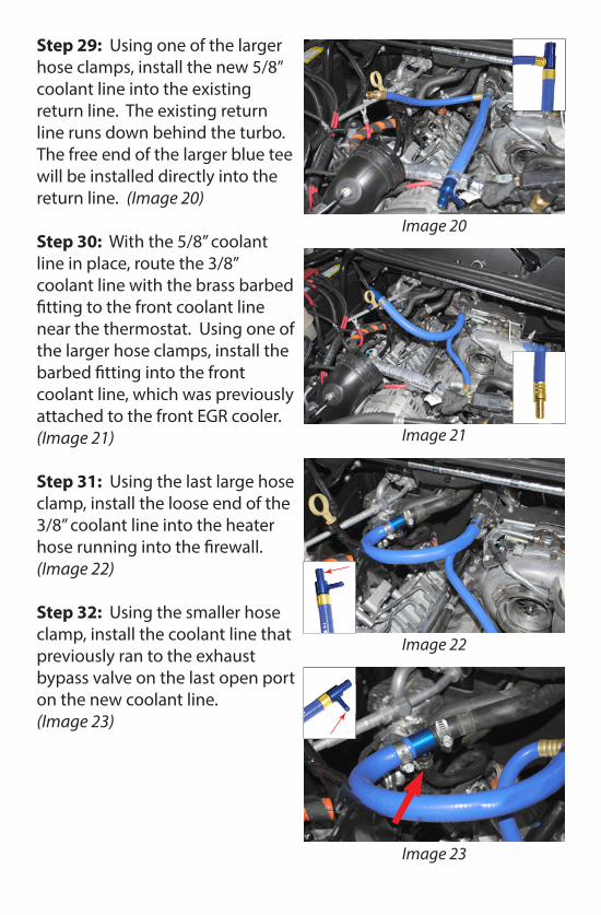
Step 29: Using one of the larger hose clamps, install the new 5/8” coolant line into the existing return line. The existing return line runs down behind the turbo. The free end of the larger blue tee will be installed directly into the return line. (Image 20)
Step 30: With the 5/8” coolant line in place, route the 3/8” coolant line with the brass barbed �tting to the front coolant line near the thermostat. Using one of the larger hose clamps, install the barbed �tting into the front coolant line, which was previously attached to the front EGR cooler. (Image 21)
Step 31: Using the last large hose clamp, install the loose end of the 3/8” coolant line into the heater hose running into the �rewall. (Image 22)
Step 32: Using the smaller hose clamp, install the coolant line that previously ran to the exhaust bypass valve on the last open port on the new coolant line. (Image 23)
Image 20
Image 21
Image 22
Image 23
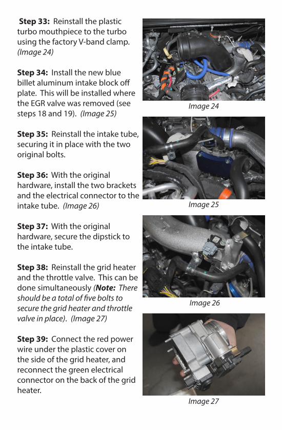
Step 33: Reinstall the plastic turbo mouthpiece to the turbo using the factory V-band clamp. (Image 24)
Step 34: Install the new blue billet aluminum intake block o� plate. This will be installed where the EGR valve was removed (see steps 18 and 19). (Image 25)
Step 35: Reinstall the intake tube, securing it in place with the two original bolts.
Step 36: With the original hardware, install the two brackets and the electrical connector to the intake tube. (Image 26)
Step 37: With the original hardware, secure the dipstick to the intake tube.
Step 38: Reinstall the grid heater and the throttle valve. This can be done simultaneously (Note: There should be a total of �ve bolts to secure the grid heater and throttle valve in place). (Image 27)
Step 39: Connect the red power wire under the plastic cover on the side of the grid heater, and reconnect the green electrical connector on the back of the grid heater.
Image 24
Image 25
Image 26
Image 27

Step 40: Install the plastic intercooler tubing. Remember that the intercooler tube has a twist lock connection at the throttle valve. (Image 28)
Step 41: Reconnect the electrical plug into the throttle valve, and attach all the electrical connectors to the plastic intercooler tube.
Step 42: Reinstall the PCV valve on the back side of the plastic turbo mouthpiece. (Image 29)
Step 43: Reinstall the intake tube, air box and air �lter, and reconnect the MAF sensor. (Image 30)
Step 44: Reinstall the intake resonator on top of the plastic turbo mouthpiece.
Step 45: Reconnect the batteries and re�ll the coolant per factory speci�cations.
Step 46: Start the engine, and let it run for a few minutes. Check for any leaks, and add coolant if necessary.
Note: Check coolant after driving, add coolant as necessary.
Image 28
Image 29
Image 30
Twist lock connection
PCV Valve