Embed Size (px)
Citation preview

2010ECL / 2018ECL / 2018KCL33X Cabinet
Flashing Yellow Arrow Overview
090916© Copyright EDI 2016

Flashing Yellow Arrow
• Need for FYA– FHWA issued Interim Approval for use in March of 2006, dropping
the experimental status– Allows protected-permitted left-turns and lead-lag phasing without
the “Yellow Trap”.– Extremely flexible allowing protected-only or permitted-only by Time
of Day or Queue– Has Good Driver Understanding– The array of phasing and detection combinations allows the
engineer to maximize capacity at an intersection

Flashing Yellow Arrow Milestones
• NCHRP 3-54 Report 2003• First FYA capable monitor deployed in 2005 by EDI• MUTCD formal release in 2009
– Defines Signal operation
• NEMA FYA Amendment #4 November 2012– Defines Equipment operation

Paired Channel Modes
• The 2010ECL, 2018ECL, and 2018KCL monitor series provides for two modes:– FYA standard mode requires no remapping
• Two load switches and two monitor channels per approach• Auxiliary File required to supply channels 9-12
– FYAC (Compact) mode remaps the Ped Yellow outputs• One+ load switch and two monitor channels per approach• Requires CU output remapping capability• Requires Caltrans Ch 9,10 OLP wiring of Ped Yellows• No Aux File needed

• The monitor uses two paired channels to monitor the four outputs of the FYA Signal Output Group.
• Each FYA approach typically requires two load switches and two monitor channels.
• Unused Yellow output of the Protected channel must be disabled if not used to drive a signal head.– Use Yellow Disable jumpers on the Program Card
Paired Channels
Load Switch #BPermissive Channel
Load Switch #AProtected Channel

FYA Mode
FYAMode
Ch:1 3 5 7 9 12 13 16
Protected TurnChannels (Ga)
Opposing Through Channels
Permissive Turn
Channels (Ra, Ya, fYa)
Green Arrow Signal Driver
Source
1 2 9 1 Green3 4 10 3 Green5 6 11 5 Green7 8 12 7 Green
FYA Mode assigns the Protected turn phases to channels 1, 3, 5, and 7, and the Permissive turn overlap phases to channels 9, 10, 11, and 12.
• This mode requires the use of an Aux File to populate load switches for channels 9-12.
• No CU IO mapping is required.

FYA Mode Programming (ECL)• FYAC switch
– OFF: Standard FYA mode is selected• FYA 1-9, 3-10, 5-11, 7-12 switches
– ON: enables a channel pair for FYA monitoring functions• The SSM switch is ON for the Permissive turn channels 9,10,11,12• The SSM switch is OFF for the Protected turn channels 1,3,5,7
– If signal loads are not being driven from the Protected Red and Yellow outputs then the SSM switch for the associated protected turn channel 1,3,5,7 should be OFF and the Yellow Disable jumper IS installed.
– If signal loads are driven from the Protected Red and Yellow outputs (e.g. hardwired right turn overlaps) then the SSM switch for the associated protected turn channel 1,3,5,7 should be ON and the Yellow Disable jumper NOT installed.
Primary Channel Permissive With:1 5, 6, 112 5, 6, 9, 113 7, 8, 124 7, 8, 10, 125 96 9, 117 108 10, 129 11
10 1211 --12 --
Note: This example is for illustrative purposes ONLY. Permissive Programming for an application depends on actual intersection geometry, cabinet wiring, and Controller programming. Ped channels are not included.

FYA Mode Programming (KCL)• FYA Mode (Green Arrow Group 1, 3, 5, 7)
– ON: Standard FYA mode is selected• FYA 1-9, 3-10, 5-11, 7-12 Channel Enable
– ON: Enables a channel pair for FYA monitoring functions• Red Fail
– ENABLED for the Permissive turn channels 9,10,11,12– DISABLED for the Protected turn channels 1, 3, 5, 7
• Dual Indication– G-R, Y-R, & G-Y ENABLED for the Permissive turn channels 9,10,11,12– G-R, Y-R, & G-Y DISABLED for the Protected turn channels 1, 3, 5, 7
• Minimum Yellow Change Clearance– ENABLED for the Permissive turn channels 9,10,11,12– DISABLED for the Protected turn channels 1, 3, 5, 7
• Minimum Yellow Plus Red Clearance– DISABLED for the Permissive turn channels 9,10,11,12
• Yellow Disable– Yellows DISABLED for the Protected turn channels 1, 3, 5, 7
Note: If hardwired Right Turn Overlaps are used then the Protected turn channels 1, 3, 5 , 7 should be configured as standard 3-section vehicle channels (Red Fail, Dual Indication, MYR Clearance ENABLED, and Yellows Enabled).

FYAC (Compact) Mode• FYAC Mode has the Ped-Y
outputs remapped to drive the Protected turn phases.
• FYAC mode would be used when there are not enough load switches, e.g. no Aux File.
FYACMode
Ch:1 3 5 7 9 12 13 16
Protected TurnChannels (Ga)
Opposing Through Channels
Permissive Turn
Channels (Ra, Ya, fYa)
Green Arrow Signal Driver
Source
9 2 1 13 Yellow (Ped)10 4 3 14 Yellow (Ped)11 6 5 15 Yellow (Ped)12 8 7 16 Yellow (Ped)
• This mode provides 8 phases + 4 Peds + 4 FYA with a standard 12 position Output File.
• CU IO mapping is required.• Caltrans Ped Yellow cabinet
wiring is required.
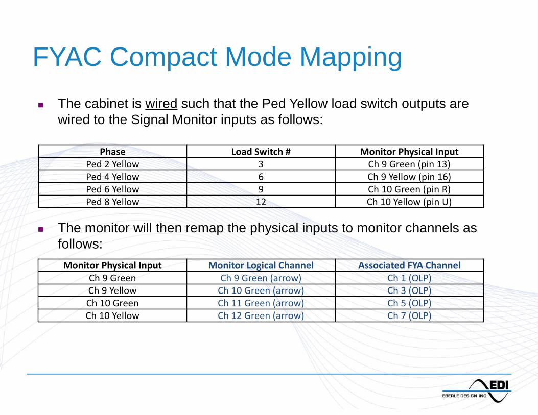
FYAC Compact Mode Mapping
Phase Load Switch # Monitor Physical InputPed 2 Yellow 3 Ch 9 Green (pin 13)Ped 4 Yellow 6 Ch 9 Yellow (pin 16)Ped 6 Yellow 9 Ch 10 Green (pin R)Ped 8 Yellow 12 Ch 10 Yellow (pin U)
Monitor Physical Input Monitor Logical Channel Associated FYA ChannelCh 9 Green Ch 9 Green (arrow) Ch 1 (OLP)Ch 9 Yellow Ch 10 Green (arrow) Ch 3 (OLP)Ch 10 Green Ch 11 Green (arrow) Ch 5 (OLP)Ch 10 Yellow Ch 12 Green (arrow) Ch 7 (OLP)
The cabinet is wired such that the Ped Yellow load switch outputs are wired to the Signal Monitor inputs as follows:
The monitor will then remap the physical inputs to monitor channels as follows:

FYAC (Compact) Mode
In the Compact mode when the CU serves Phase 7 Protected Left turn, the technician will see:
• The CU will drive Load Switch #12 (Ph 8 Ped) Yellow and illuminate the Yellow indicator on the load switch.
• The Monitor will display Channel 12 Green active, remapped from the channel 10 Yellow input.
• All monitor programming should reference the final Protected Turn assignment of channels 9-12.

FYAC Mode Programming (ECL)• FYAC switch
– ON: FYA Compact mode is selected• FYA 1-9, 3-10, 5-11, 7-12 switches
– ON: enables a channel pair for FYA monitoring functions• The SSM switch is ON for the Permissive turn channels 1,3,5,7• The SSM switch is OFF for the Protected turn channels 9,10,11,12
Primary Channel Permissive With1 2, 5, 6, 112 5, 6, 113 4, 7, 8, 124 7, 8, 125 6, 96 97 8, 108 109 11
10 1211 --12 --
Note: This example is for illustrative purposes ONLY. Permissive Programming for an application depends on actual intersection geometry, cabinet wiring, and Controller programming. Ped channels are not included.

FYAC Mode Programming (KCL)• FYAC Mode (Green Arrow Group 9, 10, 11, 12)
– ON: Compact FYAC mode is selected
• FYA 1-9, 3-10, 5-11, 7-12 Channel Enable– ON: Enables a channel pair for FYA monitoring functions
• Red Fail– ENABLED for the Permissive turn channels 1, 3, 5, 7– DISABLED for the Protected turn channels 9, 10, 11, 12
• Dual Indication– G-R, Y-R, & G-Y ENABLED for the Permissive turn channels 1, 3, 5, 7– G-R, Y-R, & G-Y DISABLED for the Protected turn channels 9, 10, 11, 12
• Minimum Yellow Change Clearance– ENABLED for the Permissive turn channels 1, 3, 5, 7– DISABLED for the Protected turn channels 9, 10, 11, 12
• Minimum Yellow Plus Red Clearance– DISABLED for the Permissive turn channels 1, 3, 5, 7

FYAC Mode Alternate Mapping
FYACMode(ALT)
Ch:1 3 5 7 9 12 13 16
Protected Turn
Channels (Ra, Ya, Ga)
Opposing Through Channels
Permissive Turn
Channels (fYa)
Flashing YellowArrow Signal Driver Source
1 2 9 13 Yellow (Ped)3 4 10 14 Yellow (Ped)5 6 11 15 Yellow (Ped)7 8 12 16 Yellow (Ped)
• FYAC Alternate Mapping has the Ped-Y outputs remapped to drive the Permissive turn phases.
• This assignment is used in some brands of CUs. Not recommended but supported.
• The Flash Rate Detect function MUST be Disabled.
• CU IO mapping is required.• Caltrans Ped Yellow cabinet
wiring is required.• Start-up in All Yellow is not
allowed.• TOD Flash in All Yellow is not
allowed.

FYAC Alternate Mode Programming (ECL)
• FYAC switch– ON: FYAC mode is selected
• FYA 1-9, 3-10, 5-11, 7-12 switches– ON: enables a channel pair for FYA monitoring functions
• The SSM switch is OFF for the Permissive turn channels 9,10,11,12• The SSM switch is ON for the Protected turn channels 1,3,5,7• The Flash Rate Detect function is disabled, SEL15 installed
Primary Channel Permissive With:1 5, 6, 112 5, 6, 9, 113 7, 8, 124 7, 8, 10, 125 96 9, 117 108 10, 129 11
10 1211 --12 --
Note: This example is for illustrative purposes ONLY. Permissive Programming for an application depends on actual intersection geometry, cabinet wiring, and Controller programming. Ped channels are not included.

FYAC Alternate Mode Programming (KCL)
• FYAC Mode (Green Arrow Group 9, 10, 11, 12)– ON: Compact FYAC mode is selected
• FYA 1-9, 3-10, 5-11, 7-12 Channel Enable– ON: Enables a channel pair for FYA monitoring functions
• Red Fail– ENABLED for the Protected turn channels 1, 3, 5, 7– DISABLED for the Permissive turn channels 9, 10, 11, 12
• Dual Indication– G-R, Y-R, & G-Y ENABLED for the Protected turn channels 1, 3, 5, 7– G-R, Y-R, & G-Y DISABLED for the Permissive turn channels 9, 10, 11, 12
• Minimum Yellow Change Clearance– ENABLED for the Protected turn channels 1, 3, 5, 7– DISABLED for the Permissive turn channels 9, 10, 11, 12
• Minimum Yellow Plus Red Clearance– DISABLED for the Permissive turn channels 9, 10, 11, 12
• Flash Rate Fault Disable– DISABLED (checked)

FYA Monitoring Functions• Dynamic Clearance Conflict Detection
– During Permissive clearance interval, the solid Y arrow is compatible with the opposing thru phase.
– During Protected clearance interval, the solid Y arrow is conflicting with the opposing thru phase.
• Red Fail– No active signal for Red arrow, Yellow arrow, Flashing Yellow arrow, Green arrow.
• Dual Indication– Red + Yellow, Red + Green, Red + Flashing Yellow,– Green + Yellow, Green + Flashing Yellow– Yellow + Flashing Yellow
• Clearance– Flashing Yellow arrow -> solid Yellow -> Red– Green arrow -> solid Yellow -> Red
• Stuck-On flashing Yellow arrow– Disabled with SEL15 jumper

Flashing Yellow Arrow with theEDI 2010ECL - 2018ECL - 2018KCL
Setting the Standardfor
Quality and Reliability
Eberle Design Inc.www.EDItraffic.com