Embed Size (px)
Citation preview
Proposed Katherine to Gove Gas Pipeline Draft Environmental Impact Statement
Preliminary Risk Assessment – Pipeline Safety
Appendix N
PACIFIC ALUMINIUM
Katherine to Gove - Gas Pipeline Preliminary AS2885 Risk Assessment Report
201001-00367-00-SR-REP-0001
29 April 2013
3 Warabrook Boulevard, Newcastle NSW 2304, Australia Tel: +61 2 4985 0000 Fax: +61 2 4985 0099 www.worleyparsons.com
© Copyright 2013 WorleyParsons
KATHERINE TO GOVE - GAS PIPELINE
PRELIMINARY AS2885 RISK ASSESSMENT REPORT
Document No.: 201001-00367-00-SR-REP-0001 Page iii Revision: 1 - Re-Issued for Use
CONTENTS
1 EXECUTIVE SUMMARY ......................................................................................................... 1
2 INTRODUCTION ..................................................................................................................... 2
2.1 Objective ..................................................................................................................................2
2.2 Background ..............................................................................................................................2
2.3 Abbreviations ...........................................................................................................................3
3 RISK ASSESSMENT PROCESS ............................................................................................ 4
3.1 Methodology ............................................................................................................................4
3.2 Risk Criteria .............................................................................................................................6
4 PIPELINE DESCRIPTION ....................................................................................................... 8
4.1 Pipeline Design ........................................................................................................................8
4.2 Coating and Cathodic Protection .............................................................................................8
4.3 Cover .......................................................................................................................................8
4.4 Valve Stations ..........................................................................................................................9
4.4.1 Procedures And Plans ................................................................................................9
4.4.2 Gas Description...........................................................................................................9
5 RISK IDENTIFICATION ......................................................................................................... 10
5.1 Location Analysis Discussion ................................................................................................10
5.1.1 Measurement Length ................................................................................................10
5.2 Threat Analysis ......................................................................................................................10
6 THE ASSESSMENT TEAM ................................................................................................... 11
7 KEY FINDINGS ...................................................................................................................... 12
7.1 Third Party Interference (TPI) ................................................................................................12
7.2 Earthquake Damage ..............................................................................................................13
7.3 Pipeline Over-Pressurization .................................................................................................13
7.4 Excessive Vehicular Loading .................................................................................................13
7.5 Escalation ..............................................................................................................................13
KATHERINE TO GOVE - GAS PIPELINE
PRELIMINARY AS2885 RISK ASSESSMENT REPORT
Document No.: 201001-00367-00-SR-REP-0001 Page iv Revision: 1 - Re-Issued for Use
7.6 Erosion And Sediment Control ..............................................................................................14
7.7 Loss Of Containment (LOC) – Compressor Station ..............................................................14
7.8 Loss of Containment (LOC) – Gove GLDS ...........................................................................14
7.9 Chemicals – Gove GLDS .......................................................................................................14
7.10 Emergency Evacuation ..........................................................................................................15
7.11 Bush Fires ..............................................................................................................................15
8 CONCLUSIONS ..................................................................................................................... 16
9 REFERENCES ...................................................................................................................... 17
Appendices
APPENDIX 1 LOCATION SPECIFIC THREAT ANALYSIS – KATHERINE TO NHULUNBUY (15.3 MPAG)
APPENDIX 2 AS2885 SAFETY MANAGEMENT STUDY MINUTES
APPENDIX 3 SMS RECOMMENDATIONS
KATHERINE TO GOVE - GAS PIPELINE
PRELIMINARY AS2885 RISK ASSESSMENT REPORT
Document No.: 201001-00367-00-SR-REP-0001 Page 1 Revision: 1 – Re-Issued for Use
1 EXECUTIVE SUMMARY
This report represents the findings of the a preliminary Risk Assessment undertaken for the Katherine to Gove Gas Pipeline (KGGP), in line with the requirements stipulated by AS 2885.1-2012,
undertaken on the 1st February 2013.
This Preliminary Risk Assessment has been carried out to ensure that the route and pipeline design parameters did not involve any risks which could not be made acceptable by either design or procedural measures. It is not to be considered to be a definitive AS2885.1 Risk Assessment for the
final pipeline design but it may be used to build on during the Feasibility and Execution Phases of the project.
Given the diverseness of pipelines, common engineered mitigation measures typically applied to above ground equipment (such as fire and gas detection, automated blowdown etc.) are often
impractical to apply along the pipeline route. Given the reduced capacity to mitigate an event and the potential consequences of a major pipeline release, should the pipeline be compromised, a significant amount of hazard identification centres on prevention of a release (through a detailed threat
identification assessment).
With transporting gas over approximately 603 km, there are many variations in the location classes and types through which the pipeline passes. The intention of the methodology outlined in AS 2885 is to ensure that all possible threats at the different location classes and types are identified, evaluated
and managed at all stages over the life of the pipeline.
The location analysis has noted a series of features along the pipeline route and has identified threats associated with each feature. Where possible, risk has been minimised through route selection. Each threat has been systematically assessed against the Rio Tinto risk matrix and risk mitigation methods
identified. Where risks were classified as Class III or higher, recommendations have been raised which will require addressing in the Feasibility Phase of the project.
A preliminary threat and location analysis for the pipeline has been undertaken (based on initial work undertaken for TTP [Ref. 3]). Each threat was reviewed for applicability to the KGGP pipeline, and
current proposed control measures identified. Above ground stations were also reviewed.
45 threats were assessed. No Class IV risks were identified from the risk assessment, with proposed control and mitigation measures reducing the Residual Risk of threats and hazards to at least Class III risks. In addition, 42 recommendations were raised for further action.
KATHERINE TO GOVE - GAS PIPELINE
PRELIMINARY AS2885 RISK ASSESSMENT REPORT
Document No.: 201001-00367-00-SR-REP-0001 Page 2 Revision: 1 – Re-Issued for Use
2 INTRODUCTION
2.1 Objective
The Aim of this workshop was to:
Review the previously identified hazards and risks along the pipeline which were documented as part of the TTP project [Ref. 3]. Each threat was confirm if they were deemed relevant or changed required;
Identify any additional Pipeline threats that require risk assessment; and
Review the above ground equipment and compressor station hazards, and document these accordingly.
2.2 Background
Pacific Aluminium (a business unit of Rio Tinto) owns and operates a bauxite mine and alumina refinery at Gove, 650 kilometres (km) east of Darwin in north east Arnhem Land, Northern Territory. The Gove mine and refinery produce high grade alumina which is then shipped to other locations for
smelting and further processing.
Power and steam for the Gove Refinery and mining operations are currently generated from imported fuel oil. In order to reduce fuel oil consumption and improve operating costs at the Refinery, it is proposed to provide the facility with natural gas as an alternative fuel source. The lower cost natural
gas will help underpin the long term operating viability of the Refinery.
The Katherine to Gove Gas Pipeline (KGGP) is proposed to deliver natural gas from the existing NT Amadeus Gas Pipeline at a point approximately 20 km south of Katherine, to the Gove Refinery. The KGGP would be a high pressure, steel pipeline approximately 603 km long with a nominal diameter of
300mm and a design operating life of 50 years. It will also include above ground facilities at specific locations along the route such as metering facilities, scraper stations, mainline valves and a compressor station. The supplied gas from the Amadeus Pipeline is sales quality so no additional
processing of gas would be required.
The pipeline would be constructed within a 30 m wide construction corridor and would include supporting infrastructure such as temporary work camps and equipment access tracks to facilitate construction activities.
KATHERINE TO GOVE - GAS PIPELINE
PRELIMINARY AS2885 RISK ASSESSMENT REPORT
Document No.: 201001-00367-00-SR-REP-0001 Page 3 Revision: 1 – Re-Issued for Use
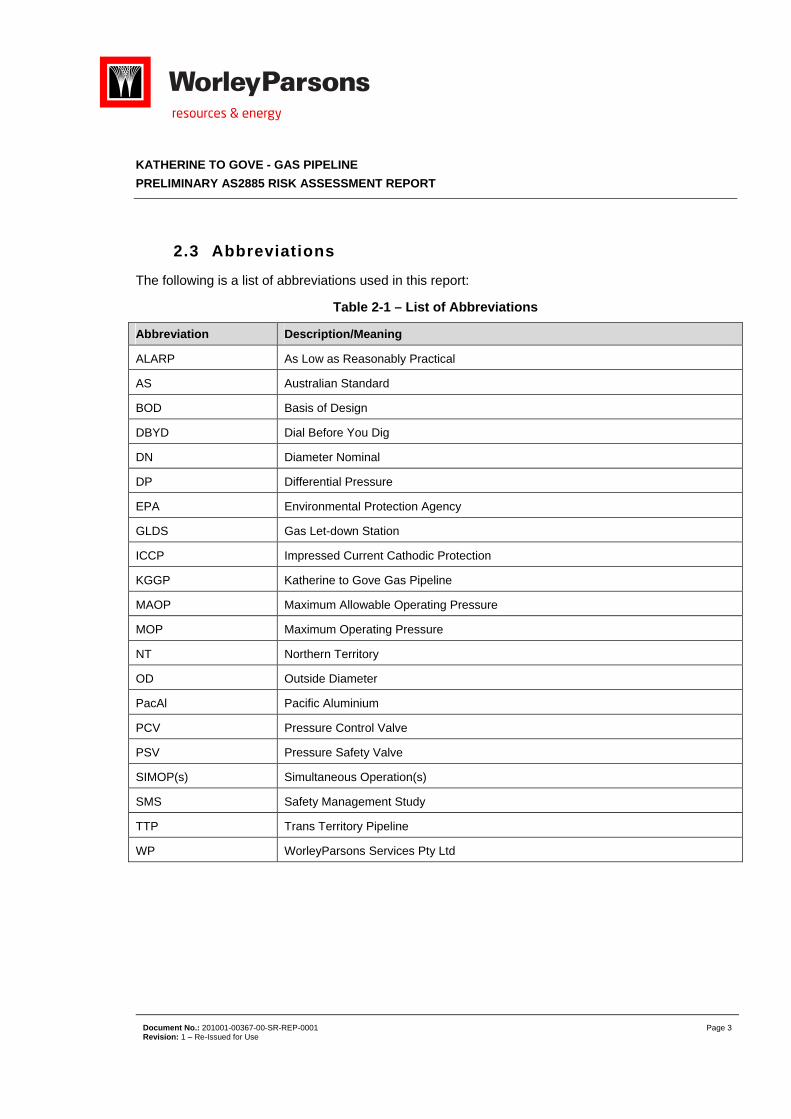
2.3 Abbreviations
The following is a list of abbreviations used in this report:
Table 2-1 – List of Abbreviations
Abbreviation Description/Meaning
ALARP As Low as Reasonably Practical
AS Australian Standard
BOD Basis of Design
DBYD Dial Before You Dig
DN Diameter Nominal
DP Differential Pressure
EPA Environmental Protection Agency
GLDS Gas Let-down Station
ICCP Impressed Current Cathodic Protection
KGGP Katherine to Gove Gas Pipeline
MAOP Maximum Allowable Operating Pressure
MOP Maximum Operating Pressure
NT Northern Territory
OD Outside Diameter
PacAl Pacific Aluminium
PCV Pressure Control Valve
PSV Pressure Safety Valve
SIMOP(s) Simultaneous Operation(s)
SMS Safety Management Study
TTP Trans Territory Pipeline
WP WorleyParsons Services Pty Ltd
KATHERINE TO GOVE - GAS PIPELINE
PRELIMINARY AS2885 RISK ASSESSMENT REPORT
Document No.: 201001-00367-00-SR-REP-0001 Page 4 Revision: 1 – Re-Issued for Use
3 RISK ASSESSMENT PROCESS
The KGGP Risk Assessment was completed by assessing the pipeline for both location specific threats and general threats to the pipeline, their likelihood of occurrence and their effect if they were
to occur. The effects from worst scenario cases of failure were considered with respect to:
Safety of the public
Safety of employees and contractors
Environmental impact
Economic loss
Risk mitigation methods to be employed were also assessed on the basis of reducing risk to ALARP (As Low As Reasonably Practicable) in accordance with Australian Standard 2885.1 requirements, and the Pacific Aluminium specified requirements.
3.1 Methodology
The methodology for this Risk Assessment was based on AS2885.1 which in itself calls on methodologies outlined in AS/NZS ISO 31000: 2009 Risk Management Standards.
The study was conducted in the following stages:
1. Threat Identification
In accordance to AS2885.1 identification shall be made of the threats which could result in hazardous events affecting the station or causing release of natural gas from the station with consequent effects
on the environment or the community. The systematic identification of all inherent threats was made taking an "all risks" approach, identifying all hazards and mishaps without regard to their nature, cause, severity or likelihood.
2. Identify existing controls
For each threat, all technical, procedural and other measures in place or to be undertaken to reduce or mitigate the risk as far as reasonably practicable shall be identified and documented in the workshop Minutes.
3. Estimate Consequences
For each of the postulated threats, the severity of the consequences shall be estimated.
4. Estimate Frequency
For each of the postulated threat, the frequency of the initiating event or cause shall be estimated. The contribution of existing protective mechanisms (human, equipment and procedural) shall be
considered in assigning the frequency of occurrence of the hazardous incident.
KATHERINE TO GOVE - GAS PIPELINE
PRELIMINARY AS2885 RISK ASSESSMENT REPORT
Document No.: 201001-00367-00-SR-REP-0001 Page 5 Revision: 1 – Re-Issued for Use
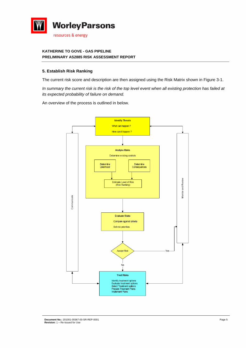
5. Establish Risk Ranking
The current risk score and description are then assigned using the Risk Matrix shown in Figure 3-1.
In summary the current risk is the risk of the top level event when all existing protection has failed at its expected probability of failure on demand.
An overview of the process is outlined in below.
KATHERINE TO GOVE - GAS PIPELINE
PRELIMINARY AS2885 RISK ASSESSMENT REPORT
Document No.: 201001-00367-00-SR-REP-0001 Page 6 Revision: 1 – Re-Issued for Use
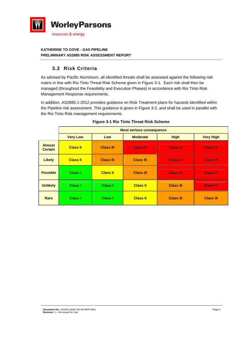
3.2 Risk Criteria
As advised by Pacific Aluminium, all identified threats shall be assessed against the following risk matrix in line with Rio Tinto Threat Risk Scheme given in Figure 3-1. Each risk shall then be
managed (throughout the Feasibility and Execution Phases) in accordance with Rio Tinto Risk Management Response requirements.
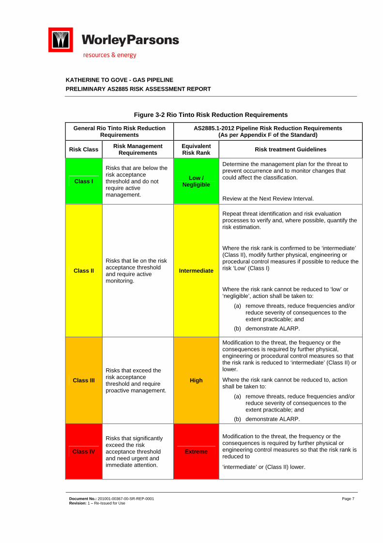
In addition, AS2885.1-2012 provides guidance on Risk Treatment plans for hazards identified within the Pipeline risk assessment. This guidance is given in Figure 3-2, and shall be used in parallel with
the Rio Tinto Risk management requirements.
Figure 3-1 Rio Tinto Threat Risk Scheme
Most serious consequence
Very Low Low Moderate High Very High
Almost Certain
Class II Class III Class IV Class IV Class IV
Likely Class II Class III Class III Class IV Class IV
Possible Class I Class II Class III Class IV Class IV
Unlikely Class I Class I Class II Class III Class IV
Rare Class I Class I Class II Class III Class III
KATHERINE TO GOVE - GAS PIPELINE
PRELIMINARY AS2885 RISK ASSESSMENT REPORT
Document No.: 201001-00367-00-SR-REP-0001 Page 7 Revision: 1 – Re-Issued for Use
Figure 3-2 Rio Tinto Risk Reduction Requirements
General Rio Tinto Risk Reduction Requirements
AS2885.1-2012 Pipeline Risk Reduction Requirements (As per Appendix F of the Standard)
Risk Class Risk Management
Requirements Equivalent Risk Rank
Risk treatment Guidelines
Class I
Risks that are below the risk acceptance threshold and do not require active management.
Low / Negligible
Determine the management plan for the threat to prevent occurrence and to monitor changes that could affect the classification.
Review at the Next Review Interval.
Class II
Risks that lie on the risk acceptance threshold and require active monitoring.
Intermediate
Repeat threat identification and risk evaluation processes to verify and, where possible, quantify the risk estimation.
Where the risk rank is confirmed to be ‘intermediate’ (Class II), modify further physical, engineering or procedural control measures if possible to reduce the risk ‘Low’ (Class I)
Where the risk rank cannot be reduced to ‘low’ or ‘negligible’, action shall be taken to:
(a) remove threats, reduce frequencies and/or reduce severity of consequences to the extent practicable; and
(b) demonstrate ALARP.
Class III
Risks that exceed the risk acceptance threshold and require proactive management.
High
Modification to the threat, the frequency or the consequences is required by further physical, engineering or procedural control measures so that the risk rank is reduced to ‘intermediate’ (Class II) or lower.
Where the risk rank cannot be reduced to, action shall be taken to:
(a) remove threats, reduce frequencies and/or reduce severity of consequences to the extent practicable; and
(b) demonstrate ALARP.
Class IV
Risks that significantly exceed the risk acceptance threshold and need urgent and immediate attention.
Extreme
Modification to the threat, the frequency or the consequences is required by further physical or engineering control measures so that the risk rank is reduced to
‘intermediate’ or (Class II) lower.
KATHERINE TO GOVE - GAS PIPELINE
PRELIMINARY AS2885 RISK ASSESSMENT REPORT
Document No.: 201001-00367-00-SR-REP-0001 Page 8 Revision: 1 – Re-Issued for Use
4 PIPELINE DESCRIPTION
4.1 Pipeline Design
The DN300 ANSI Class 900# pipeline is a welded steel pipeline, which will be operated in accordance with Australian Standard AS 2885- 2012.
The pipeline, as currently selected, shall be constructed from API 5L – X70 pipe and operated at an MAOP of 15.3MPag. Flanges and other connection will be minimised, where practicable, particularly in above ground stations. Standard pipe wall thickness shall be 6.7mm, with heavy walled pipe
(7.6mm) being used in high risk locations, as detailed within the next section [Ref. 4]. A fracture control plan will be drafted in the Feasibility stage of the design. Note: pipe thickness shall also be confirmed within the Feasibility Phase.
4.2 Coating and Cathodic Protection
All line pipe shall be externally coated with a high integrity factory applied coating (dual layer Fusion Bonded Epoxy) coating in accordance with project specifications [Ref. 4].
The coating is the primary corrosion protection, with additional cathodic protection providing secondary protection at any coating defects.
4.3 Cover
The minimum depth of cover for the KGGP pipeline will be in accordance with AS2885.1-2012 and is increased in areas where the potential for a release, or the potential consequences of a release, are likely to be higher.
R1 – Remote Rural: 750mm
R2 – Rural Residential: 750mm
T1 – Residential: 900mm.
Cover will be increased to a minimum of 2000mm below Rivers and Water Courses, 2000mm below the Railway Lines and 1200mm at Road Crossings. In addition heavy walled pipe shall be installed in these locations.
KATHERINE TO GOVE - GAS PIPELINE
PRELIMINARY AS2885 RISK ASSESSMENT REPORT
Document No.: 201001-00367-00-SR-REP-0001 Page 9 Revision: 1 – Re-Issued for Use
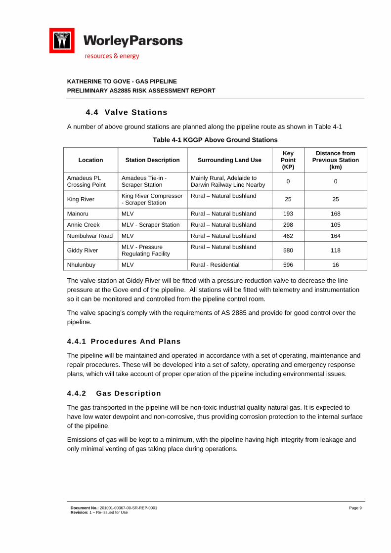
4.4 Valve Stations
A number of above ground stations are planned along the pipeline route as shown in Table 4-1
Table 4-1 KGGP Above Ground Stations
Location Station Description Surrounding Land Use Key
Point (KP)
Distance from Previous Station
(km)
Amadeus PL Crossing Point
Amadeus Tie-in - Scraper Station
Mainly Rural, Adelaide to Darwin Railway Line Nearby
0 0
King River King River Compressor - Scraper Station
Rural – Natural bushland 25 25
Mainoru MLV Rural – Natural bushland 193 168
Annie Creek MLV - Scraper Station Rural – Natural bushland 298 105
Numbulwar Road MLV Rural – Natural bushland 462 164
Giddy River MLV - Pressure Regulating Facility
Rural – Natural bushland 580 118
Nhulunbuy MLV Rural - Residential 596 16
The valve station at Giddy River will be fitted with a pressure reduction valve to decrease the line pressure at the Gove end of the pipeline. All stations will be fitted with telemetry and instrumentation so it can be monitored and controlled from the pipeline control room.
The valve spacing’s comply with the requirements of AS 2885 and provide for good control over the pipeline.
4.4.1 Procedures And Plans
The pipeline will be maintained and operated in accordance with a set of operating, maintenance and repair procedures. These will be developed into a set of safety, operating and emergency response plans, which will take account of proper operation of the pipeline including environmental issues.
4.4.2 Gas Description
The gas transported in the pipeline will be non-toxic industrial quality natural gas. It is expected to have low water dewpoint and non-corrosive, thus providing corrosion protection to the internal surface of the pipeline.
Emissions of gas will be kept to a minimum, with the pipeline having high integrity from leakage and only minimal venting of gas taking place during operations.
KATHERINE TO GOVE - GAS PIPELINE
PRELIMINARY AS2885 RISK ASSESSMENT REPORT
Document No.: 201001-00367-00-SR-REP-0001 Page 10 Revision: 1 – Re-Issued for Use
5 RISK IDENTIFICATION
The AS 2885.1–2012 Risk Assessment Methodology was used for risk identification and evaluation.
5.1 Location Analysis Discussion
The location analysis was performed along the pipeline from a desktop analysis. The location classification for the majority of the pipeline route (KP0- KP591) was R1 – Broad Rural. On approach to Gove (KP591-KP593), the location class is upgraded to R2, with rural residential and corresponding public infrastructure is located beside the pipeline. As the pipeline approaches the
PacAl Gove Refinery (KP593-KP603), the location classification is T1 Residential, with residential and public infrastructure serving the residential use being located within the measurement length (this will be verified within the Feasibility Phase of the project).
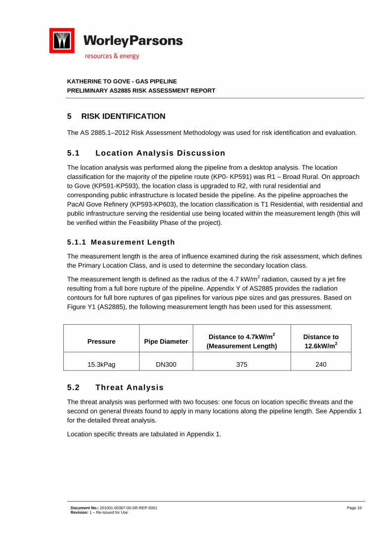
5.1.1 Measurement Length
The measurement length is the area of influence examined during the risk assessment, which defines the Primary Location Class, and is used to determine the secondary location class.
The measurement length is defined as the radius of the 4.7 kW/m2 radiation, caused by a jet fire resulting from a full bore rupture of the pipeline. Appendix Y of AS2885 provides the radiation contours for full bore ruptures of gas pipelines for various pipe sizes and gas pressures. Based on
Figure Y1 (AS2885), the following measurement length has been used for this assessment.
Pressure Pipe Diameter Distance to 4.7kW/m2
(Measurement Length) Distance to 12.6kW/m2
15.3kPag DN300 375 240
5.2 Threat Analysis
The threat analysis was performed with two focuses: one focus on location specific threats and the second on general threats found to apply in many locations along the pipeline length. See Appendix 1 for the detailed threat analysis.
Location specific threats are tabulated in Appendix 1.
KATHERINE TO GOVE - GAS PIPELINE
PRELIMINARY AS2885 RISK ASSESSMENT REPORT
Document No.: 201001-00367-00-SR-REP-0001 Page 11 Revision: 1 – Re-Issued for Use
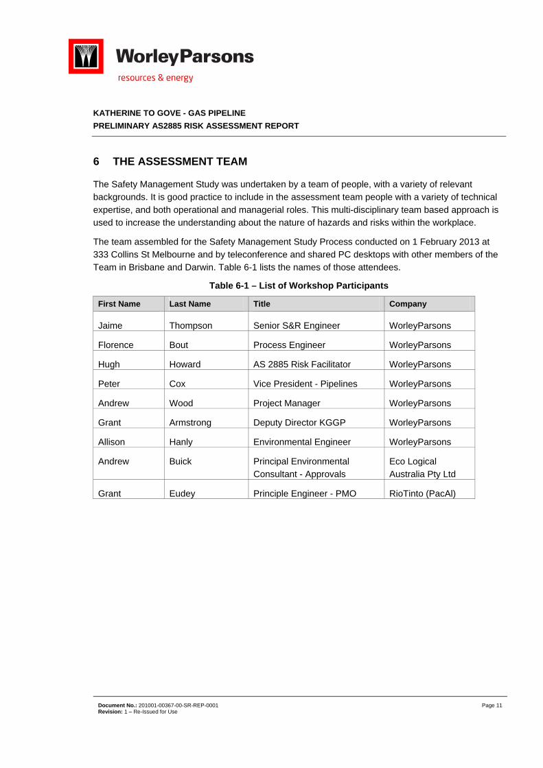
6 THE ASSESSMENT TEAM
The Safety Management Study was undertaken by a team of people, with a variety of relevant backgrounds. It is good practice to include in the assessment team people with a variety of technical
expertise, and both operational and managerial roles. This multi-disciplinary team based approach is used to increase the understanding about the nature of hazards and risks within the workplace.
The team assembled for the Safety Management Study Process conducted on 1 February 2013 at 333 Collins St Melbourne and by teleconference and shared PC desktops with other members of the Team in Brisbane and Darwin. Table 6-1 lists the names of those attendees.
Table 6-1 – List of Workshop Participants
First Name Last Name Title Company
Jaime Thompson Senior S&R Engineer WorleyParsons
Florence Bout Process Engineer WorleyParsons
Hugh Howard AS 2885 Risk Facilitator WorleyParsons
Peter Cox Vice President - Pipelines WorleyParsons
Andrew Wood Project Manager WorleyParsons
Grant Armstrong Deputy Director KGGP WorleyParsons
Allison Hanly Environmental Engineer WorleyParsons
Andrew Buick Principal Environmental Consultant - Approvals
Eco Logical Australia Pty Ltd
Grant Eudey Principle Engineer - PMO RioTinto (PacAl)
KATHERINE TO GOVE - GAS PIPELINE
PRELIMINARY AS2885 RISK ASSESSMENT REPORT
Document No.: 201001-00367-00-SR-REP-0001 Page 12 Revision: 1 – Re-Issued for Use
7 KEY FINDINGS
7.1 Third Party Interference (TPI)
The highest risks identified for the pipeline were with respect to Third Party Interference. The following third party activities were identified has having a Class III level of risk: Farming activities (deep ripping, fence posting)
Public Developments and Maintenance (road and drain maintenance)
Mining Development (including exploration drilling and blasting)
Road / Highway Maintenance
Numerous recommendations were raised for consideration within the Feasibility and Execution Phases of the project. These included: Further threat identification – to investigate the need for extra physical protection measures,
including:
o Liaison with land owners and freehold land owners to get a more comprehensive idea on common activities taking place (potentially around the new pipeline); and
o Establish mining lease locations along the pipeline and liaise with lease holders to determine the level of threat to the pipe from mining activities, including the use of chemicals which
could impact the corrosion protection of the pipeline.
Further procedural measures, including
o The need for a Dial before You Dig System to be implemented; and
o An increased in patrolling level around easily accessible routes of the pipe – particularly those at Gove and Katharine areas.
Private and Rural development in Rural (R1) areas along the pipeline route and potential, future residential developments around Gove were assessed as having a slightly lower level of risk (Class II), as domestic services are generally not installed at a depth witch could impact equipment. It was
determined that penetration resistance calculations – to be undertaken within the Feasibility Phase of the project, would provide the project with additional information on the likelihood of these activities having an impact on the pipe.
KATHERINE TO GOVE - GAS PIPELINE
PRELIMINARY AS2885 RISK ASSESSMENT REPORT
Document No.: 201001-00367-00-SR-REP-0001 Page 13 Revision: 1 – Re-Issued for Use
7.2 Earthquake Damage
The KGGP passes through eleven (11) areas which have the potential to be impacted by forces associated with an earthquake. It was identified that material properties of the pipeline can be
selected to ensure ductility of the pipe (i.e. plastic deformation rather than brittle fracture). This will be investigated further in the Feasibility Phase of the project
It was noted that the Amadeus Pipeline at Tennant Creek was buckled by an earthquake in 1988, and although no loss of containment occurred, the pipeline needed to be shutdown to undertake repairs
on the damaged section. Though this instance of damage is not in the immediate vicinity of the KGGP, it does provide support the need to ensure that any potential seismically active zones are assessed and proper design considerations are taken. A more detailed assessment of fault lines and
seismic activity will be completed during the Feasibility Phase.
7.3 Pipeline Over-Pressurization
Over-pressurisation of the pipeline could potentially occur at the compressor station and at the Gove GLDS inlet, if proposed safeguards failed. The preliminary nature of the design at the compressor
station did not provide adequate detail on overpressure control strategy at this stage of the project. It was recognised that further deign development and HAZOP in the Feasibility Phase of the Project would significantly reduce this risk.
7.4 Excessive Vehicular Loading
Vehicle loading on the pipeline at roads, water and rail crossings are well known and managed via increased wall thickness, or increased depth of cover. It was recognised however, that some sections of the pipeline may be subject to vehicle loads on standard sections of the pipeline (with standard
depth of cover and pipe wall thickness). There is some inherent stress resistance of the pipe, based on the standard burial depth and pipe wall thickness. Stress calculations – to be undertaken within the Feasibility Phase of the project, would provide the project with additional information on the capable
loading on the pipe, in which stress along unprotected sections of the pipe can be assessed).
7.5 Escalation
Upon approach to the PacAl Alumina Refinery (at KP600 onwards); the pipeline is buried with a minimum depth of cover 900mm. The Pipeline route is to the north of the facility, and avoids
equipment as far as practicable. A small section of the pipe, once inside the facility fence line, will be above ground. In order to prevent event escalation to, or from the pipeline and the PacAl Refinery, the pipeline shall be fully welded up to the GLDS, and shall be of heavy walled construction. The above
ground portion of the pipeline is within the Refinery fence line, which is considered a controlled zone. However, it is recognized that a loss of containment from the pipeline could potentially impact the PacAl Alumina Refinery, and further investigation of this scenario is required
KATHERINE TO GOVE - GAS PIPELINE
PRELIMINARY AS2885 RISK ASSESSMENT REPORT
Document No.: 201001-00367-00-SR-REP-0001 Page 14 Revision: 1 – Re-Issued for Use
7.6 Erosion And Sediment Control
Removal of topsoil during construction could result in erosion above or around the pipeline, which could in turn affect the depth of cover. This issue is particularly exacerbated by the Northern Territory
wet season, which could result in some wash away of cover, and also environmental damage. Consequences associated with this risk were Low; however the high likelihood of occurrence has resulted in a Class III risk ranking. It was recommended that previous pipeline experience in NT be
reviewed to ensure adequacy of identified safeguards and mitigation measures
7.7 Loss Of Containment (LOC) – Compressor Station
Accidental releases associated with equipment failure can potentially lead to a Fire / Explosion at the compressor station. Note: other known loss of containment events at the compressor station are
associated with maintenance vents and emergency blowdown / overpressure vents. Both of these scenarios are controlled events, and have standard protection measures in place to ensure the safety of personnel.
A number of protection measures have been put in place at the compressor station to protect both the plant, and any person who may be at the station when the loss of containment occurs. The compressors at the facility shall be provided with some form of shelter, either a pre-engineered rigid metal framed building, or an open weather proof shelter (open on all four sides) – the decision for
either is predominantly based on noise requirements, however both have the potential to cause some level of explosion, and this needs to be investigated in the Feasibility Phase of the project.
7.8 Loss of Containment (LOC) – Gove GLDS
A loss of containment at Gove was identified as a potential Class III risk, particularly given the potential to overpressure downstream equipment should the control valve at the GLDS fail. An Instrumented overpressure protection system is to be provided at this location, although it was noted that the need, and the ability to fit PSVs and associated pipes and vents within the Refinery, was to
be investigated further within the Feasibility Phase.
7.9 Chemicals – Gove GLDS
Caustic and Alumina fallout at Gove has the potential to be released and damage equipment. No aluminium instrumentation has been specified for the project design phase, and additional
requirements for managing Alumina fallout are to be identified within the Feasibility Phase.
KATHERINE TO GOVE - GAS PIPELINE
PRELIMINARY AS2885 RISK ASSESSMENT REPORT
Document No.: 201001-00367-00-SR-REP-0001 Page 15 Revision: 1 – Re-Issued for Use
7.10 Emergency Evacuation
Given the remote location of above ground equipment, the requirements for emergency evacuation need to be considered in line with the environment and diverseness of equipment. The location of the
King River Compressor station has been selected to be within close proximity and access from Katherine. It was recognised that additional consultation with the current operators of the NT pipeline should be considered regarding current practices for evacuation from remote locations. Additional
facilities, such as designated helicopter landing areas, communication requirements etc. shall be considered and implemented into the design.
7.11 Bush Fires
Given the location and placing of above ground station, bush fires near equipment is a common and expected threat. It is anticipated that stations will have a sufficient cleared and gravel area around all above ground equipment, and no combustible material is expected to be stored on any site. There was a need to review the safe buffer distance between equipment and bush to ensure adequate
separation.
KATHERINE TO GOVE - GAS PIPELINE
PRELIMINARY AS2885 RISK ASSESSMENT REPORT
Document No.: 201001-00367-00-SR-REP-0001 Page 16 Revision: 1 – Re-Issued for Use
8 CONCLUSIONS
A Preliminary AS2885.1 Pipeline Risk Assessment and HAZID for the KGGP Project was undertaken in on the 1st Feb 2013, where each identified threat or high level hazard was reviewed, proposed
control measures identified, and risk assessed.
In line with Rio Tinto requirements for risk management, all hazards were assessed for further risk reduction, with specific focus in ensuring further actions were in place to reduce high level risks.
The workshop identified no risks as Class IV, with seventeen risks as classified as Class III.
All Intermediate risks, Class II and Class III, were reviewed, and 42 recommendations were raised for further risk reduction within the stage of the project.
The full list of recommendations is presented in Appendix 3.
These will be assigned to appropriate personnel for closeout within the Feasibility and Execute Phases of the project. Full context for each recommendation may be found by looking at Appendix 2.
KATHERINE TO GOVE - GAS PIPELINE
PRELIMINARY AS2885 RISK ASSESSMENT REPORT
Document No.: 201001-00367-00-SR-REP-0001 Page 17 Revision: 1 – Re-Issued for Use
9 REFERENCES
1. AS 2885.1-2007, Pipelines - Gas and Liquid Petroleum
2. AS/NZS ISO 31000: 2009 Risk Management Standard
3. Trans Territory Pipeline, Appendix E Trans Territory Pipeline - Preliminary Risk Assessment in Accordance with AS2885 for the Trans Territory Pipeline prepared by OSD Energy Services– Draft
Environmental Impact Statement, November 2004
4. Katherine-Gove Gas Pipeline, Process Basis Of Design, 201001-00367-00-PR-BOD-0001
KATHERINE TO GOVE - GAS PIPELINE
PRELIMINARY AS2885 RISK ASSESSMENT REPORT
Document No.: 201001-00367-00-SR-REP-0001 Page 18 Revision: 1 - Re-Issued for Use
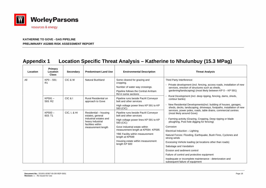
Appendix 1 Location Specific Threat Analysis – Katherine to Nhulunbuy (15.3 MPag)
Location Primary Location
Class Secondary Predominant Land Use Environmental Description Threat Analysis
All KP0 – 591: R1
CIC & W
Natural Bushland Some cleared for grazing and cropping.
Number of water way crossings.
Pipeline follows the Central Arnham Rd in some sections
Third Party Interference:
- Private development (incl. fencing, access roads, installation of new services, erection of structures such as sheds, gardening/landscaping) (most likely between KP 0 – KP 591)
- Rural Development (incl. deep ripping, fencing, dams, sheds, contour banks)
- New Residential Developments(incl. building of houses, garages, sheds, decks, landscaping, driveways, footpaths, installation of new services, power poles, roads, table drains, commercial centres (most likely around Gove)
- Farming activity (Grazing, Cropping, Deep ripping or blade ploughing, Post hole digging for fencing)
Corrosion
Electrical Induction – Lighting
Natural Forces: Flooding, Earthquake, Bush Fires, Cyclones and strong winds
Excessing Vehicle loading (at locations other than roads)
Sabotage and Vandalism
Erosion and sediment control
Failure of control and protective equipment
Inadequate or incomplete maintenance - deterioration and subsequent failure of equipment
KP591 – 593: R2
CIC & I
Rural Residential on approach to Gove
Pipeline runs beside PacAl Conveyor belt and other services
High voltage power lines KP 591 to KP 593 (CIC)
KP593 – 603: T1
CIC, I, & HI Residential – housing estates, general industrial estates and heavy industrial facilities within measurement length
Pipeline runs beside PacAl Conveyor belt and other services
High voltage power lines KP 591 to KP 593 (CIC)
Gove industrial estate within measurement length at KP594- KP595
YBE Facility within measurement length at KP599
Housing estate within measurement length KP 600
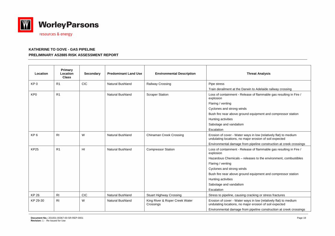
KATHERINE TO GOVE - GAS PIPELINE
PRELIMINARY AS2885 RISK ASSESSMENT REPORT
Document No.: 201001-00367-00-SR-REP-0001 Page 19 Revision: 1 - Re-Issued for Use
Location Primary Location
Class Secondary Predominant Land Use Environmental Description Threat Analysis
KP 0 R1 CIC Natural Bushland Railway Crossing Pipe stress
Train derailment at the Darwin to Adelaide railway crossing
KP0 R1 Natural Bushland Scraper Station Loss of containment - Release of flammable gas resulting in Fire / explosion
Flaring / venting
Cyclones and strong winds
Bush fire near above ground equipment and compressor station
Hunting activities
Sabotage and vandalism
Escalation
KP 6 RI W Natural Bushland Chinaman Creek Crossing Erosion of cover - Water ways in low (relatively flat) to medium undulating locations, no major erosion of soil expected
Environmental damage from pipeline construction at creek crossings
KP25 R1 HI Natural Bushland Compressor Station Loss of containment - Release of flammable gas resulting in Fire / explosion
Hazardous Chemicals – releases to the environment, combustibles
Flaring / venting
Cyclones and strong winds
Bush fire near above ground equipment and compressor station
Hunting activities
Sabotage and vandalism
Escalation
KP 26 RI CIC Natural Bushland Stuart Highway Crossing Stress to pipeline, causing cracking or stress fractures
KP 29-30 RI W Natural Bushland King River & Roper Creek Water Crossings
Erosion of cover - Water ways in low (relatively flat) to medium undulating locations, no major erosion of soil expected
Environmental damage from pipeline construction at creek crossings
KATHERINE TO GOVE - GAS PIPELINE
PRELIMINARY AS2885 RISK ASSESSMENT REPORT
Document No.: 201001-00367-00-SR-REP-0001 Page 20 Revision: 1 - Re-Issued for Use
Location Primary Location
Class Secondary Predominant Land Use Environmental Description Threat Analysis
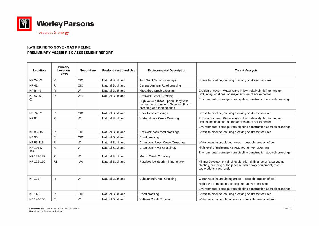
KP 29-32 RI CIC Natural Bushland Two “back” Road crossings Stress to pipeline, causing cracking or stress fractures
KP 41 RI CIC Natural Bushland Central Arnhem Road crossing
KP48-49 RI W Natural Bushland Maranboy Creek Crossing Erosion of cover - Water ways in low (relatively flat) to medium undulating locations, no major erosion of soil expected
Environmental damage from pipeline construction at creek crossings KP 57, 61, 62
RI W, S Natural Bushland Breswick Creek Crossing
High value habitat – particularly with respect to proximity to Gouldian Finch breeding and feeding sites
KP 74, 79 RI CIC Natural Bushland Back Road crossings Stress to pipeline, causing cracking or stress fractures
KP 84 RI W Natural Bushland Water House Creek Crossing Erosion of cover - Water ways in low (relatively flat) to medium undulating locations, no major erosion of soil expected
Environmental damage from pipeline construction at creek crossings
KP 85 - 87 RI CIC Natural Bushland Breswick back road crossings Stress to pipeline, causing cracking or stress fractures
KP 93 RI CIC Natural Bushland Road crossing
KP 95-113 RI W Natural Bushland Chambers River Creek Crossings Water ways in undulating areas - possible erosion of soil
High level of maintenance required at river crossings
Environmental damage from pipeline construction at creek crossings
KP 101 & 104
RI W Natural Bushland Chambers River Crossings
KP 121-132 RI W Natural Bushland Morok Creek Crossing
KP 125-160
R1 N/A Natural Bushland Possible low depth mining activity
Mining Development (incl. exploration drilling, seismic surveying, blasting, crossing of the pipeline with heavy equipment, test excavations, new roads
KP 135 RI W Natural Bushland Bukalorkmi Creek Crossing Water ways in undulating areas - possible erosion of soil
High level of maintenance required at river crossings
Environmental damage from pipeline construction at creek crossings
KP 145 RI CIC Natural Bushland Road crossing Stress to pipeline, causing cracking or stress fractures
KP 149-153 RI W Natural Bushland Velkerri Creek Crossing Water ways in undulating areas - possible erosion of soil
KATHERINE TO GOVE - GAS PIPELINE
PRELIMINARY AS2885 RISK ASSESSMENT REPORT
Document No.: 201001-00367-00-SR-REP-0001 Page 21 Revision: 1 - Re-Issued for Use
Location Primary Location
Class Secondary Predominant Land Use Environmental Description Threat Analysis
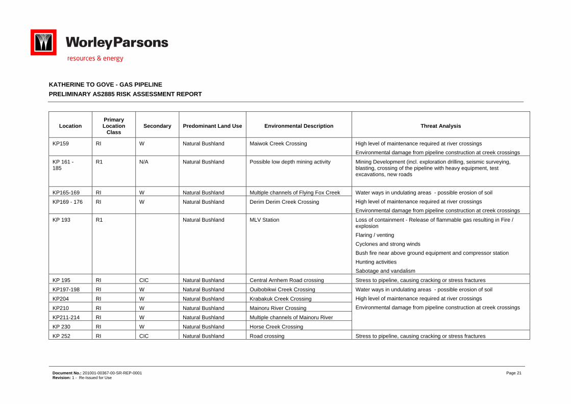
KP159 RI W Natural Bushland Maiwok Creek Crossing High level of maintenance required at river crossings
Environmental damage from pipeline construction at creek crossings
KP 161 - 185
R1 N/A Natural Bushland Possible low depth mining activity
Mining Development (incl. exploration drilling, seismic surveying, blasting, crossing of the pipeline with heavy equipment, test excavations, new roads
KP165-169 RI W Natural Bushland Multiple channels of Flying Fox Creek Water ways in undulating areas - possible erosion of soil
High level of maintenance required at river crossings
Environmental damage from pipeline construction at creek crossings
KP169 - 176 RI W Natural Bushland Derim Derim Creek Crossing
KP 193 R1 Natural Bushland MLV Station Loss of containment - Release of flammable gas resulting in Fire / explosion
Flaring / venting
Cyclones and strong winds
Bush fire near above ground equipment and compressor station
Hunting activities
Sabotage and vandalism
KP 195 RI CIC Natural Bushland Central Arnhem Road crossing Stress to pipeline, causing cracking or stress fractures
KP197-198 RI W Natural Bushland Ouibobikwi Creek Crossing Water ways in undulating areas - possible erosion of soil
High level of maintenance required at river crossings
Environmental damage from pipeline construction at creek crossings
KP204 RI W Natural Bushland Krabakuk Creek Crossing
KP210 RI W Natural Bushland Mainoru River Crossing
KP211-214 RI W Natural Bushland Multiple channels of Mainoru River
KP 230 RI W Natural Bushland Horse Creek Crossing
KP 252 RI CIC Natural Bushland Road crossing Stress to pipeline, causing cracking or stress fractures
KATHERINE TO GOVE - GAS PIPELINE
PRELIMINARY AS2885 RISK ASSESSMENT REPORT
Document No.: 201001-00367-00-SR-REP-0001 Page 22 Revision: 1 - Re-Issued for Use
Location Primary Location
Class Secondary Predominant Land Use Environmental Description Threat Analysis
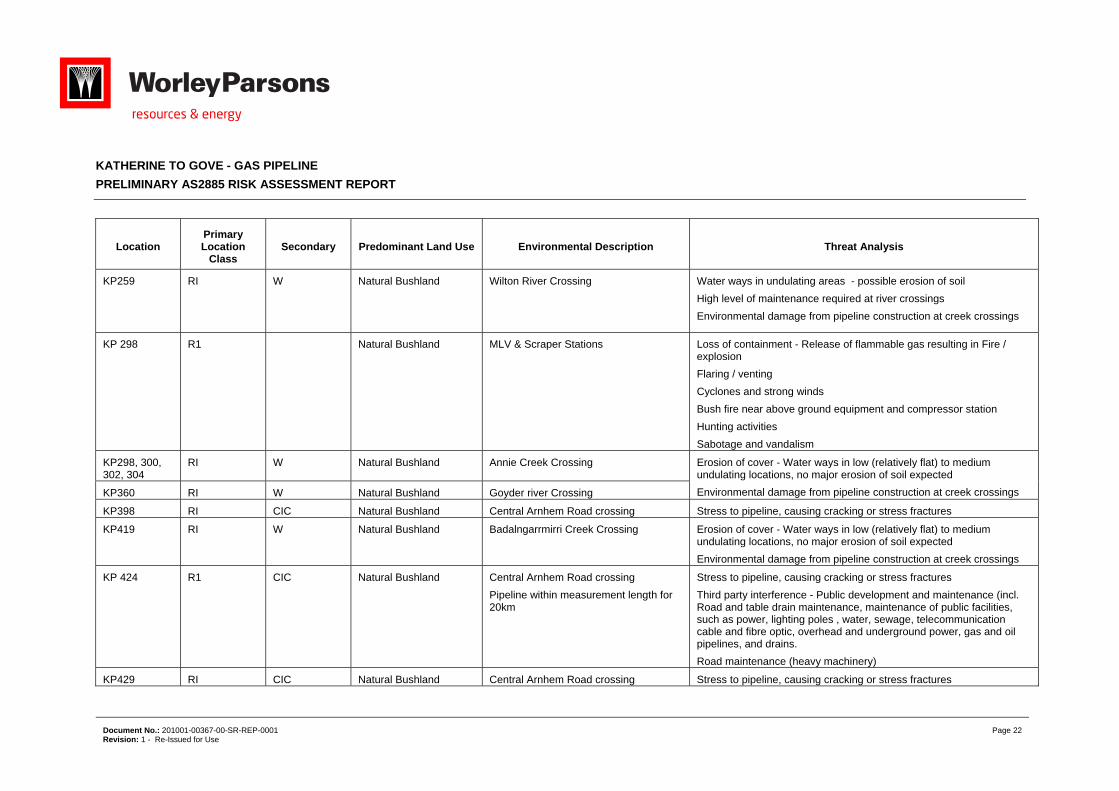
KP259 RI W Natural Bushland Wilton River Crossing Water ways in undulating areas - possible erosion of soil
High level of maintenance required at river crossings
Environmental damage from pipeline construction at creek crossings
KP 298 R1 Natural Bushland MLV & Scraper Stations Loss of containment - Release of flammable gas resulting in Fire / explosion
Flaring / venting
Cyclones and strong winds
Bush fire near above ground equipment and compressor station
Hunting activities
Sabotage and vandalism
KP298, 300, 302, 304
RI W Natural Bushland Annie Creek Crossing Erosion of cover - Water ways in low (relatively flat) to medium undulating locations, no major erosion of soil expected
Environmental damage from pipeline construction at creek crossings KP360 RI W Natural Bushland Goyder river Crossing
KP398 RI CIC Natural Bushland Central Arnhem Road crossing Stress to pipeline, causing cracking or stress fractures
KP419 RI W Natural Bushland Badalngarrmirri Creek Crossing Erosion of cover - Water ways in low (relatively flat) to medium undulating locations, no major erosion of soil expected
Environmental damage from pipeline construction at creek crossings
KP 424 R1 CIC Natural Bushland Central Arnhem Road crossing
Pipeline within measurement length for 20km
Stress to pipeline, causing cracking or stress fractures
Third party interference - Public development and maintenance (incl. Road and table drain maintenance, maintenance of public facilities, such as power, lighting poles , water, sewage, telecommunication cable and fibre optic, overhead and underground power, gas and oil pipelines, and drains.
Road maintenance (heavy machinery)
KP429 RI CIC Natural Bushland Central Arnhem Road crossing Stress to pipeline, causing cracking or stress fractures
KATHERINE TO GOVE - GAS PIPELINE
PRELIMINARY AS2885 RISK ASSESSMENT REPORT
Document No.: 201001-00367-00-SR-REP-0001 Page 23 Revision: 1 - Re-Issued for Use
Location Primary Location
Class Secondary Predominant Land Use Environmental Description Threat Analysis
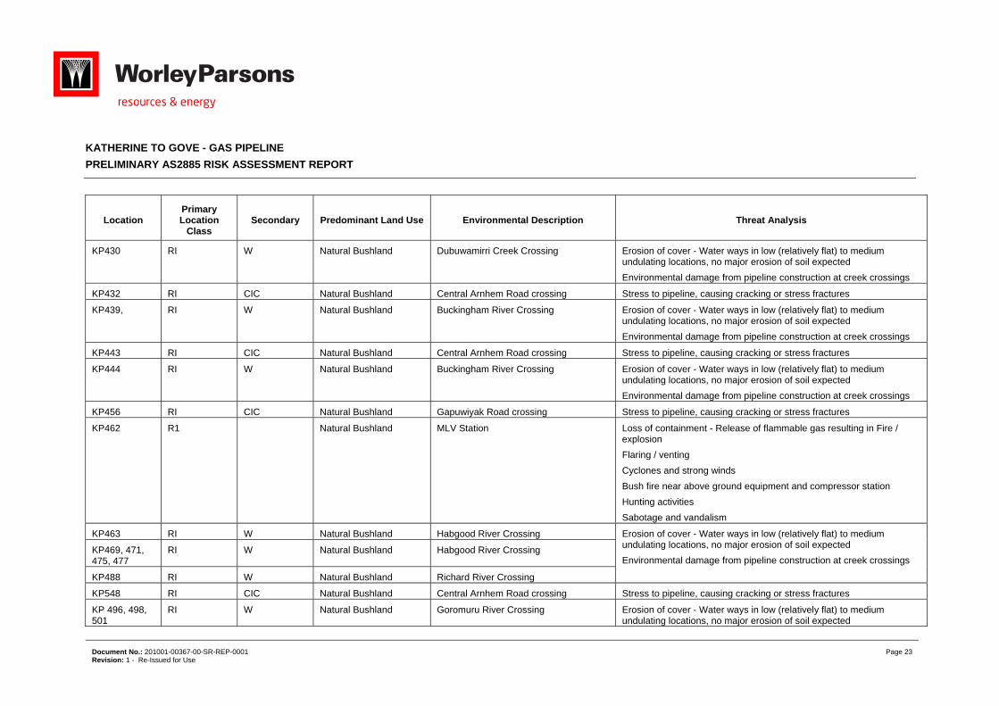
KP430 RI W Natural Bushland Dubuwamirri Creek Crossing Erosion of cover - Water ways in low (relatively flat) to medium undulating locations, no major erosion of soil expected
Environmental damage from pipeline construction at creek crossings
KP432 RI CIC Natural Bushland Central Arnhem Road crossing Stress to pipeline, causing cracking or stress fractures
KP439, RI W Natural Bushland Buckingham River Crossing Erosion of cover - Water ways in low (relatively flat) to medium undulating locations, no major erosion of soil expected
Environmental damage from pipeline construction at creek crossings
KP443 RI CIC Natural Bushland Central Arnhem Road crossing Stress to pipeline, causing cracking or stress fractures
KP444 RI W Natural Bushland Buckingham River Crossing Erosion of cover - Water ways in low (relatively flat) to medium undulating locations, no major erosion of soil expected
Environmental damage from pipeline construction at creek crossings
KP456 RI CIC Natural Bushland Gapuwiyak Road crossing Stress to pipeline, causing cracking or stress fractures
KP462 R1 Natural Bushland MLV Station Loss of containment - Release of flammable gas resulting in Fire / explosion
Flaring / venting
Cyclones and strong winds
Bush fire near above ground equipment and compressor station
Hunting activities
Sabotage and vandalism
KP463 RI W Natural Bushland Habgood River Crossing Erosion of cover - Water ways in low (relatively flat) to medium undulating locations, no major erosion of soil expected
Environmental damage from pipeline construction at creek crossings KP469, 471, 475, 477
RI W Natural Bushland Habgood River Crossing
KP488 RI W Natural Bushland Richard River Crossing
KP548 RI CIC Natural Bushland Central Arnhem Road crossing Stress to pipeline, causing cracking or stress fractures
KP 496, 498, 501
RI W Natural Bushland Goromuru River Crossing Erosion of cover - Water ways in low (relatively flat) to medium undulating locations, no major erosion of soil expected
KATHERINE TO GOVE - GAS PIPELINE
PRELIMINARY AS2885 RISK ASSESSMENT REPORT
Document No.: 201001-00367-00-SR-REP-0001 Page 24 Revision: 1 - Re-Issued for Use
Location Primary Location
Class Secondary Predominant Land Use Environmental Description Threat Analysis
KP512 RI W Natural Bushland Boggy Creek Crossing Environmental damage from pipeline construction at creek crossings
KP540 RI W Natural Bushland Cato River Crossing
KP 547 - 554
R1 CIC Natural Bushland Central Arnhem Road within measurement length
Third party interference
Public development and maintenance (incl. Road and table drain maintenance, maintenance of public facilities, such as power, lighting poles , water, sewage, telecommunication cable and fibre optic, overhead and underground power, gas and oil pipelines, and drains.
Road maintenance (heavy machinery)
KP555 RI W Natural Bushland Wonga Creek Crossing Erosion of cover - Water ways in low (relatively flat) to medium undulating locations, no major erosion of soil expected
Environmental damage from pipeline construction at creek crossings KP572 RI W Natural Bushland Giddy River Crossing
KP575 RI CIC Natural Bushland Central Arnhem Road crossing Stress to pipeline, causing cracking or stress fractures
KP 580 R1 Natural Bushland MLV pressure Regulating Loss of containment - Release of flammable gas resulting in Fire / explosion
Flaring / venting
Cyclones and strong winds
Bush fire near above ground equipment and compressor station
Hunting activities
Sabotage and vandalism
KP581 RI W Natural Bushland Latram River Crossing Erosion of cover - Water ways in low (relatively flat) to medium undulating locations, no major erosion of soil expected
Environmental damage from pipeline construction at creek crossings
KP 591 - 594
R2 CIC, I Rural Residential on approach to Gove
High Voltage Power Lines Power lines parallel to the pipeline capable of inducing an electrical voltage in the pipeline.
KP594 T1 CIC, Natural Bushland Road crossing Stress to pipeline, causing cracking or stress fractures
KATHERINE TO GOVE - GAS PIPELINE
PRELIMINARY AS2885 RISK ASSESSMENT REPORT
Document No.: 201001-00367-00-SR-REP-0001 Page 25 Revision: 1 - Re-Issued for Use
Location Primary Location
Class Secondary Predominant Land Use Environmental Description Threat Analysis
KP594 – KP603
R2/T1 CIC, I & HI Rural Residential on approach to Gove, Residential at Gove – housing estates and industrial estates within measurement length
Gove Industrial, YBE & PacAL within measurement length
Third party interference - Public development and maintenance (incl. Road and table drain maintenance, maintenance of public facilities, such as power, lighting poles , water, sewage, telecommunication cable and fibre optic, overhead and underground power, gas and oil pipelines, and drains.
Road maintenance (heavy machinery)
KP 594 - 603
T1 CIC, I, HI Residential – housing estates, general industrial estates and heavy industrial facilities within measurement length
High Voltage Power Lines Power lines parallel to the pipeline capable of inducing an electrical voltage in the pipeline
KP 596 R2 CIC , Rural Residential on approach to Gove
MLV Station
Loss of containment - Release of flammable gas resulting in Fire / explosion
Flaring / venting
Cyclones and strong winds
Bush fire near above ground equipment and compressor station
Hunting activities
Sabotage and vandalism
KP598-599 T1 CIC, Natural Bushland YBE Access Road crossings Stress to pipeline, causing cracking or stress fractures
KP600-601 T1 CIC, HI Natural Bushland Melville Bay Road crossing
KP 603 T1 CIC, HI Residential – housing estates, general industrial estates and heavy industrial facilities within measurement length
GLDS – scraper station Loss of containment - Release of flammable gas resulting in Fire / explosion
Flaring / venting
Cyclones and strong winds
Bush fire near above ground equipment and compressor station
Hunting activities
Sabotage and vandalism
KATHERINE TO GOVE - GAS PIPELINE
PRELIMINARY AS2885 RISK ASSESSMENT REPORT
Document No.: 201001-00367-00-SR-REP-0001 Page 26 Revision: 1 - Re-Issued for Use
Location Primary Location
Class Secondary Predominant Land Use Environmental Description Threat Analysis
KP601-603
T1 CIC, HI Residential – housing estates, general industrial estates and heavy industrial facilities within measurement length
Pipeline runs Parallel to PacAl Facilities
Escalation of pipe to / from PacAl Facilities
KATHERINE TO GOVE - GAS PIPELINE
PRELIMINARY AS2885 RISK ASSESSMENT REPORT
Document No.: 201001-00367-00-SR-REP-0001 Page 27 Revision: 1 - Re-Issued for Use
Appendix 2 AS2885 Safety Management Study Minutes
KATHERINE TO GOVE - GAS PIPELINE
PRELIMINARY AS2885 RISK ASSESSMENT REPORT
Document No.: 201001-00367-00-SR-REP-0001 Page 28 Revision: 1 - Re-Issued for Use
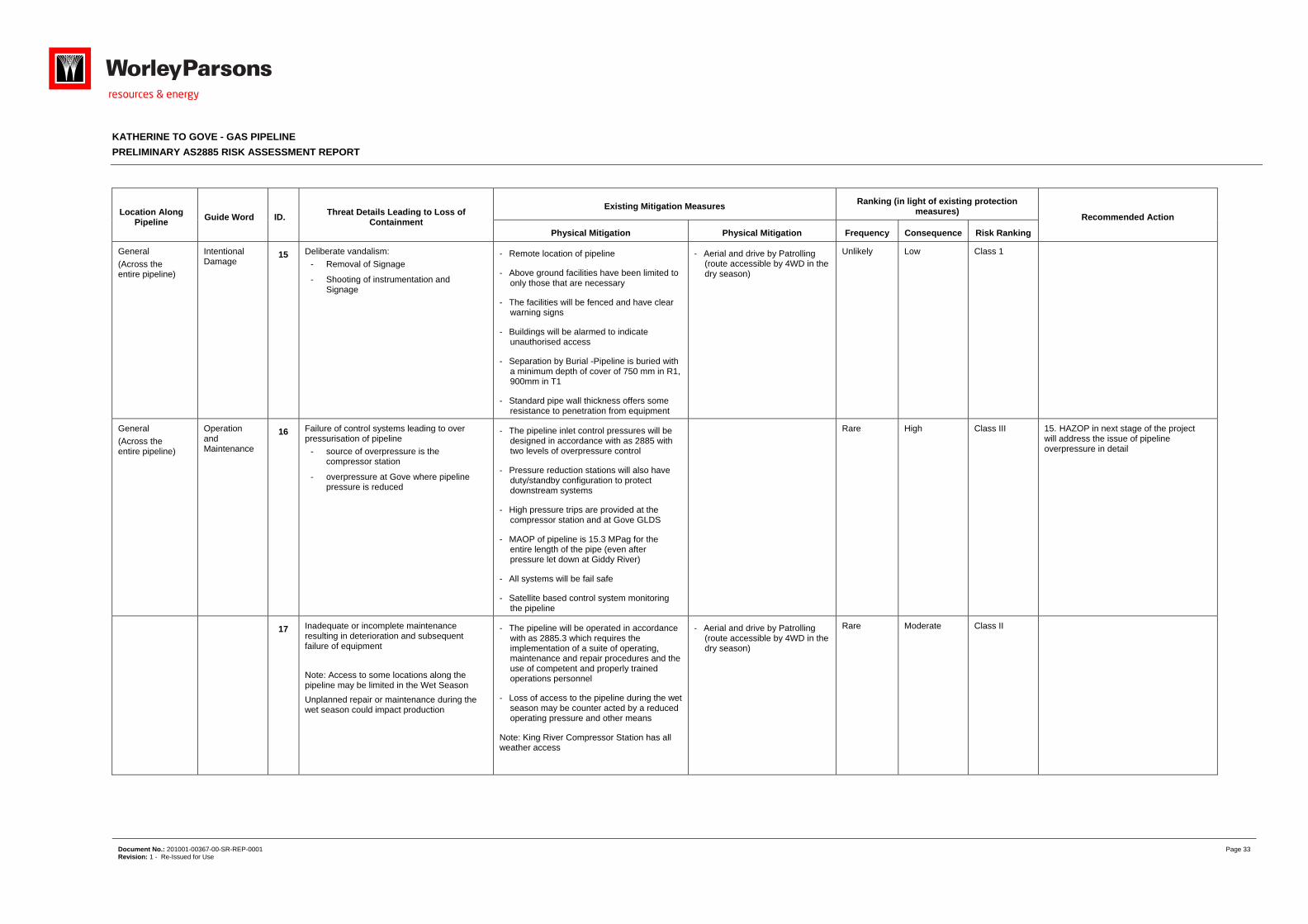
Location Along Pipeline
Guide Word ID. Threat Details Leading to Loss of
Containment
Existing Mitigation Measures Ranking (in light of existing protection
measures) Recommended Action
Physical Mitigation Physical Mitigation Frequency Consequence Risk Ranking
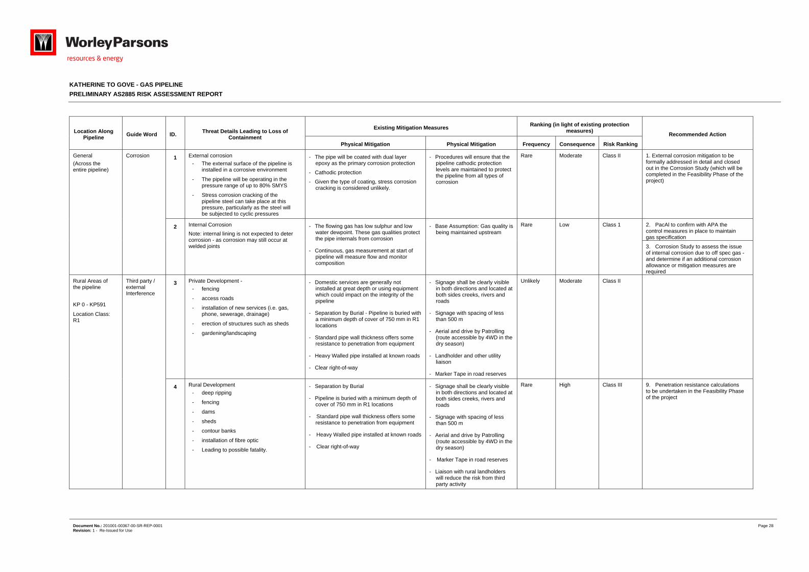
General
(Across the entire pipeline)
Corrosion 1 External corrosion
- The external surface of the pipeline is installed in a corrosive environment
- The pipeline will be operating in the pressure range of up to 80% SMYS
- Stress corrosion cracking of the pipeline steel can take place at this pressure, particularly as the steel will be subjected to cyclic pressures
- The pipe will be coated with dual layer epoxy as the primary corrosion protection
- Cathodic protection
- Given the type of coating, stress corrosion cracking is considered unlikely.
- Procedures will ensure that the pipeline cathodic protection levels are maintained to protect the pipeline from all types of corrosion
Rare Moderate Class II 1. External corrosion mitigation to be formally addressed in detail and closed out in the Corrosion Study (which will be completed in the Feasibility Phase of the project)
2 Internal Corrosion
Note: internal lining is not expected to deter corrosion - as corrosion may still occur at welded joints
- The flowing gas has low sulphur and low water dewpoint. These gas qualities protect the pipe internals from corrosion
- Continuous, gas measurement at start of pipeline will measure flow and monitor composition
- Base Assumption: Gas quality is being maintained upstream
Rare Low Class 1 2. PacAl to confirm with APA the control measures in place to maintain gas specification
3. Corrosion Study to assess the issue of internal corrosion due to off spec gas - and determine if an additional corrosion allowance or mitigation measures are required
Rural Areas of the pipeline
KP 0 - KP591
Location Class: R1
Third party / external Interference
3 Private Development -
- fencing
- access roads
- installation of new services (i.e. gas, phone, sewerage, drainage)
- erection of structures such as sheds
- gardening/landscaping
- Domestic services are generally not installed at great depth or using equipment which could impact on the integrity of the pipeline
- Separation by Burial - Pipeline is buried with a minimum depth of cover of 750 mm in R1 locations
- Standard pipe wall thickness offers some resistance to penetration from equipment
- Heavy Walled pipe installed at known roads
- Clear right-of-way
- Signage shall be clearly visible in both directions and located at both sides creeks, rivers and roads
- Signage with spacing of less than 500 m
- Aerial and drive by Patrolling (route accessible by 4WD in the dry season)
- Landholder and other utility liaison
- Marker Tape in road reserves
Unlikely Moderate Class II
4 Rural Development
- deep ripping
- fencing
- dams
- sheds
- contour banks
- installation of fibre optic
- Leading to possible fatality.
- Separation by Burial
- Pipeline is buried with a minimum depth of cover of 750 mm in R1 locations
- Standard pipe wall thickness offers some resistance to penetration from equipment
- Heavy Walled pipe installed at known roads
- Clear right-of-way
- Signage shall be clearly visible in both directions and located at both sides creeks, rivers and roads
- Signage with spacing of less than 500 m
- Aerial and drive by Patrolling (route accessible by 4WD in the dry season)
- Marker Tape in road reserves
- Liaison with rural landholders will reduce the risk from third party activity
Rare High Class III 9. Penetration resistance calculations to be undertaken in the Feasibility Phase of the project
KATHERINE TO GOVE - GAS PIPELINE
PRELIMINARY AS2885 RISK ASSESSMENT REPORT
Document No.: 201001-00367-00-SR-REP-0001 Page 29 Revision: 1 - Re-Issued for Use
Location Along Pipeline
Guide Word ID. Threat Details Leading to Loss of
Containment
Existing Mitigation Measures Ranking (in light of existing protection
measures) Recommended Action
Physical Mitigation Physical Mitigation Frequency Consequence Risk Ranking
General
Location Class:
-KP0591: R1 (CIC & W)
-KP591593: R2 (CIC & I)
KP593603: T1 (CIC, I, & HI)
Note: New Residential Development is most likely around Gove
Third party / external Interference
5 New Residential Developments
- Building of houses
- Building of garages, sheds, decks
- Landscaping
- Driveways and footpaths
- Installation of new services (i.e. gas, phone, water, sewage, drainage, electricity, etc.)
- Power poles and lighting poles
- Roads and table drains
- Commercial centres
- Location of the pipeline is away from any densely populated area
- Pipeline route is well away from farm buildings
- No private building structures were within 600 m of the pipeline in R1 Location (note: Private homes and business are within measurement length from KP593 onwards)
- Separation by Burial - Pipeline is buried with a minimum depth of cover of 750 mm in R1, 900 mm in T1, & 1,200 mm below known roads
- Standard pipe wall thickness offers some resistance to penetration from equipment
- Heavy wall pipe, to satisfy the requirements for "no rupture pipe", in all T1 location Class
- Clear right-of-way
- Signage shall be clearly visible in both directions and located at both sides creeks, rivers and roads
- Signage with spacing of less than 500 m
- Aerial and drive by Patrolling (route accessible by 4WD in the dry season)
- Landholder and other utility liaison
- Marker Tape in road reserves and in T1 Locations
Unlikely Moderate Class II 4. Town council zone plans shall be reviewed to determine if a higher location class is required on approach to Gove
5. Determine if a Dial before You Dig system is required to be set up, or if there is an existing system which can be informed particularly where the pipeline approaches Gove
6 Farming activities
- Grazing
- Cropping
- Deep ripping or blade ploughing
- Post hole digging for fencing
- Cropping activity should generally be limited to ploughing of the soil to a maximum depth of 300 mm
- Deep ripping or blade ploughing is not anticipated along the pipeline route
- Post hole digging for fencing is likely to be the highest farming threat to the pipeline
- Location of the pipeline is away from any densely populated area
- Pipeline route is well away from farm buildings
- - No private building structures were within 600 m of the pipeline in R1 Location (note: Private homes and business are within measurement length from KP593 onwards)
- Separation by Burial - Pipeline is buried with a minimum depth of cover of 750 mm in R1, 900mm in T1, & 1,200 mm below known roads
- Standard pipe wall thickness offers some resistance to penetration from equipment
- Heavy wall pipe, to satisfy the requirements for "no rupture pipe", in all T1 location Class
- Clear right-of-way
- Signage shall be clearly visible in both directions and located at both sides creeks, rivers and roads
- Signage with spacing of less than 500 m
- Aerial and drive by Patrolling (route accessible by 4WD in the dry season)
- Land agreements will be entered into with landholders to limit their activities to non-threatening activity on the pipeline ROW
Possible Moderate Class III 10. Liaison with agricultural Stations along the pipeline route, and freehold land holders shall be undertaken to identify the level of activity at each location and determine if any additional protection measures are required
KATHERINE TO GOVE - GAS PIPELINE
PRELIMINARY AS2885 RISK ASSESSMENT REPORT
Document No.: 201001-00367-00-SR-REP-0001 Page 30 Revision: 1 - Re-Issued for Use
Location Along Pipeline
Guide Word ID. Threat Details Leading to Loss of
Containment
Existing Mitigation Measures Ranking (in light of existing protection
measures) Recommended Action
Physical Mitigation Physical Mitigation Frequency Consequence Risk Ranking
General
(Across the entire pipeline)
Third Party / External Interference
7 Public Developments and Maintenance
- Road and table drain maintenance (typically utilising 14 G grader or equivalent for resurfacing)
- Maintenance of public facilities, such as power and lighting poles
- Maintenance of public services (water, sewage, telecommunication cable and fibre optic, overhead and underground power, gas and oil pipelines, and drains)
- Installation of new services (water, sewage, telecommunication cable and fibre optic, overhead and underground power, gas and oil pipelines, and drains)
- Location of the pipeline is away from any densely populated area
- Separation by Burial - Pipeline is buried with a minimum depth of cover of 750 mm in R1, 900mm in T1
- Standard pipe wall thickness offers some resistance to penetration from equipment
- Heavy wall pipe, to satisfy the requirements for "no rupture pipe", in all T1 location Class
- Increased depth of cover to 1200 mm, and heavy walled pipe installed below all roads
- Clear right-of-way
- Signage shall be clearly visible in both directions and located at both sides creeks, rivers and roads
- Signage with spacing of less than 500 m
- Aerial and drive by Patrolling (route accessible by 4WD in the dry season)
- Landholder and other utility liaison
- Marker Tape in road reserves and in T1 Locations
Unlikely High Class III 6. Establish increased patrolling plan around easily accessible routes of the pipe and above ground stations (i.e. at Gove and Katharine areas)
General
(Across the entire pipeline)
Third party / external Interference
8 Mining Development
- Exploration drilling
- Seismic surveying
- Blasting
- Crossing of the pipeline with heavy equipment
- Test excavations
- New roads
- Separation by Burial - Pipeline is buried with a minimum depth of cover of 750 mm in R1, 900mm in T1
- Standard pipe wall thickness offers some resistance to penetration from equipment
- Heavy wall pipe, to satisfy the requirements for "no rupture pipe", in all T1 location Class
- Increased depth of cover to 1200 mm, and heavy walled pipe installed below all roads
- Clear right-of-way
- Signage shall be clearly visible in both directions and located at both sides creeks, rivers and roads
- Signage with spacing of less than 500 m
- Aerial and drive by Patrolling (route accessible by 4WD in the dry season)
- Landholder and other utility liaison
- Liaison with Mining Companies
- Regular pipeline route inspections will provide an important measure to minimise the risk
Unlikely High Class III 7. Establish where the mining leases are along the pipeline and determine the additional physical and procedural mitigation measures (including liaison) required
8. Identify any chemicals being used by 3rd party mining companies which could impact the corrosion coating on the pipeline

KATHERINE TO GOVE - GAS PIPELINE
PRELIMINARY AS2885 RISK ASSESSMENT REPORT
Document No.: 201001-00367-00-SR-REP-0001 Page 31 Revision: 1 - Re-Issued for Use
Location Along Pipeline
Guide Word ID. Threat Details Leading to Loss of
Containment
Existing Mitigation Measures Ranking (in light of existing protection
measures) Recommended Action
Physical Mitigation Physical Mitigation Frequency Consequence Risk Ranking
General
(Across the entire pipeline)
Road maintenance
9 Third Party Interference - Heavy machinery maintaining and restoring roads impacts pipeline
- Most road crossings are in Rural - Low populated Areas
- Separation by Burial -Pipeline is buried with a minimum depth of cover of 750 mm in R1, 900mm in T1
- Standard pipe wall thickness offers some resistance to penetration from equipment
- Increased depth of cover to 1200 mm, and heavy walled pipe installed below all roads, offering increased resistance to penetration at high risk areas
- Clear right-of-way
- Concrete slabbing will be installed in table drains
- Signage shall be clearly visible in both directions and located at both sides creeks, rivers and roads
- Signage with spacing of less than 500 m
- Aerial and drive by Patrolling (route accessible by 4WD in the dry season)
- Liaison with other utility providers to educate them on the pipeline's location will be conducted for the life of the pipeline
- Marker Tape in road reserves
Unlikely High Class III
General
(Across the entire pipeline)
Natural Events
10 Electrical Induction caused by Lightning
- Lightning striking the pipeline is capable of inducing significant voltages into the pipeline.
- No other high structures adjacent to the pipeline to attract lightning away from the pipeline.
- Pipeline is buried (Note: there are existing cases of underground pipeline being impacted by lightning )
- Minimal above ground equipment
- Adequate earthing and surge protection at gate station
-
Unlikely Moderate Class II 11. Review the requirements for additional lightning protection for all pipeline equipment
11 Flooding, leading to:
- Erosion of cover
- Floatation of pipe
Note: Wash away areas (location where the cover of the pipeline is lost) are expected along the pipeline route after the wet seasons - this could lead to increase in corrosion in some locations.
- Pipeline shall be buried at least 2,000 mm below rivers and watercourses
- Compressor stations and other above ground facilities will be located on higher areas not subject to flooding
- In areas where pipeline flotation could occur, the pipe will have weight coating or some other means to provide negative buoyancy
- River movement will be investigated, and additional depth of cover will be added to cover the migrating rivers
- Concrete coating on some water crossings may be provided
- Aerial Patrol the pipeline during the Wet season
Unlikely Moderate Class II
KATHERINE TO GOVE - GAS PIPELINE
PRELIMINARY AS2885 RISK ASSESSMENT REPORT
Document No.: 201001-00367-00-SR-REP-0001 Page 32 Revision: 1 - Re-Issued for Use
Location Along Pipeline
Guide Word ID. Threat Details Leading to Loss of
Containment
Existing Mitigation Measures Ranking (in light of existing protection
measures) Recommended Action
Physical Mitigation Physical Mitigation Frequency Consequence Risk Ranking
General
(Across the entire pipeline)
Natural Events
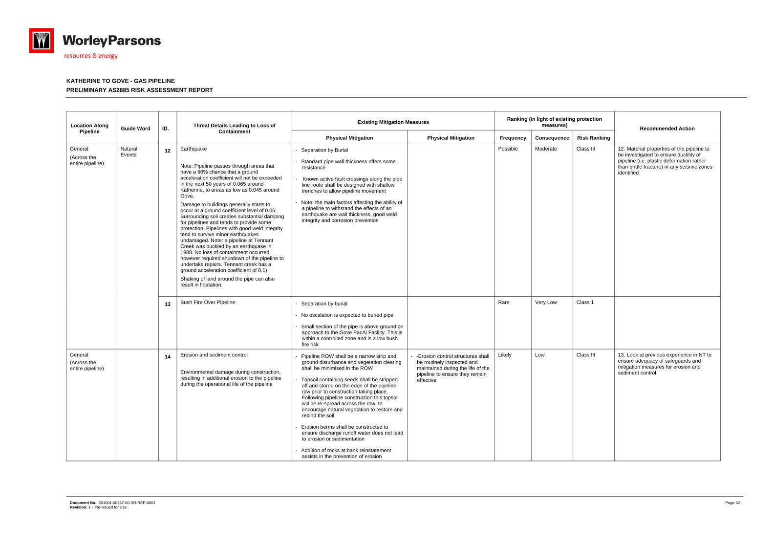
12 Earthquake
Note: Pipeline passes through areas that have a 90% chance that a ground acceleration coefficient will not be exceeded in the next 50 years of 0.065 around Katherine, to areas as low as 0.045 around Gove.
Damage to buildings generally starts to occur at a ground coefficient level of 0.05. Surrounding soil creates substantial damping for pipelines and tends to provide some protection. Pipelines with good weld integrity tend to survive minor earthquakes undamaged. Note: a pipeline at Tennant Creek was buckled by an earthquake in 1988. No loss of containment occurred, however required shutdown of the pipeline to undertake repairs. Tennant creek has a ground acceleration coefficient of 0.1)
Shaking of land around the pipe can also result in floatation.
- Separation by Burial
- Standard pipe wall thickness offers some resistance
- Known active fault crossings along the pipe line route shall be designed with shallow trenches to allow pipeline movement
- Note: the main factors affecting the ability of a pipeline to withstand the effects of an earthquake are wall thickness, good weld integrity and corrosion prevention
Possible Moderate Class III 12. Material properties of the pipeline to be investigated to ensure ductility of pipeline (i.e. plastic deformation rather than brittle fracture) in any seismic zones identified
13 Bush Fire Over Pipeline - Separation by burial
- No escalation is expected to buried pipe
- Small section of the pipe is above ground on approach to the Gove PacAl Facility. This is within a controlled zone and is a low bush fire risk
Rare Very Low Class 1
General
(Across the entire pipeline)
14 Erosion and sediment control
Environmental damage during construction, resulting in additional erosion to the pipeline during the operational life of the pipeline
- Pipeline ROW shall be a narrow strip and ground disturbance and vegetation clearing shall be minimised in the ROW
- Topsoil containing seeds shall be stripped off and stored on the edge of the pipeline row prior to construction taking place. Following pipeline construction this topsoil will be re-spread across the row, to encourage natural vegetation to restore and rebind the soil
- Erosion berms shall be constructed to ensure discharge runoff water does not lead to erosion or sedimentation
- Addition of rocks at bank reinstatement assists in the prevention of erosion
- -Erosion control structures shall be routinely inspected and maintained during the life of the pipeline to ensure they remain effective
Likely Low Class III 13. Look at previous experience in NT to ensure adequacy of safeguards and mitigation measures for erosion and sediment control
KATHERINE TO GOVE - GAS PIPELINE
PRELIMINARY AS2885 RISK ASSESSMENT REPORT
Document No.: 201001-00367-00-SR-REP-0001 Page 33 Revision: 1 - Re-Issued for Use
Location Along Pipeline
Guide Word ID. Threat Details Leading to Loss of
Containment
Existing Mitigation Measures Ranking (in light of existing protection
measures) Recommended Action
Physical Mitigation Physical Mitigation Frequency Consequence Risk Ranking
General
(Across the entire pipeline)
Intentional Damage
15 Deliberate vandalism:
- Removal of Signage
- Shooting of instrumentation and Signage
- Remote location of pipeline
- Above ground facilities have been limited to only those that are necessary
- The facilities will be fenced and have clear warning signs
- Buildings will be alarmed to indicate unauthorised access
- Separation by Burial -Pipeline is buried with a minimum depth of cover of 750 mm in R1, 900mm in T1
- Standard pipe wall thickness offers some resistance to penetration from equipment
- Aerial and drive by Patrolling (route accessible by 4WD in the dry season)
Unlikely Low Class 1
General
(Across the entire pipeline)
Operation and Maintenance
16 Failure of control systems leading to over pressurisation of pipeline
- source of overpressure is the compressor station
- overpressure at Gove where pipeline pressure is reduced
- The pipeline inlet control pressures will be designed in accordance with as 2885 with two levels of overpressure control
- Pressure reduction stations will also have duty/standby configuration to protect downstream systems
- High pressure trips are provided at the compressor station and at Gove GLDS
- MAOP of pipeline is 15.3 MPag for the entire length of the pipe (even after pressure let down at Giddy River)
- All systems will be fail safe
- Satellite based control system monitoring the pipeline
Rare High Class III 15. HAZOP in next stage of the project will address the issue of pipeline overpressure in detail
17 Inadequate or incomplete maintenance resulting in deterioration and subsequent failure of equipment
Note: Access to some locations along the pipeline may be limited in the Wet Season
Unplanned repair or maintenance during the wet season could impact production
- The pipeline will be operated in accordance with as 2885.3 which requires the implementation of a suite of operating, maintenance and repair procedures and the use of competent and properly trained operations personnel
- Loss of access to the pipeline during the wet season may be counter acted by a reduced operating pressure and other means
Note: King River Compressor Station has all weather access
- Aerial and drive by Patrolling (route accessible by 4WD in the dry season)
Rare Moderate Class II
KATHERINE TO GOVE - GAS PIPELINE
PRELIMINARY AS2885 RISK ASSESSMENT REPORT
Document No.: 201001-00367-00-SR-REP-0001 Page 34 Revision: 1 - Re-Issued for Use
Location Along Pipeline
Guide Word ID. Threat Details Leading to Loss of
Containment
Existing Mitigation Measures Ranking (in light of existing protection
measures) Recommended Action
Physical Mitigation Physical Mitigation Frequency Consequence Risk Ranking
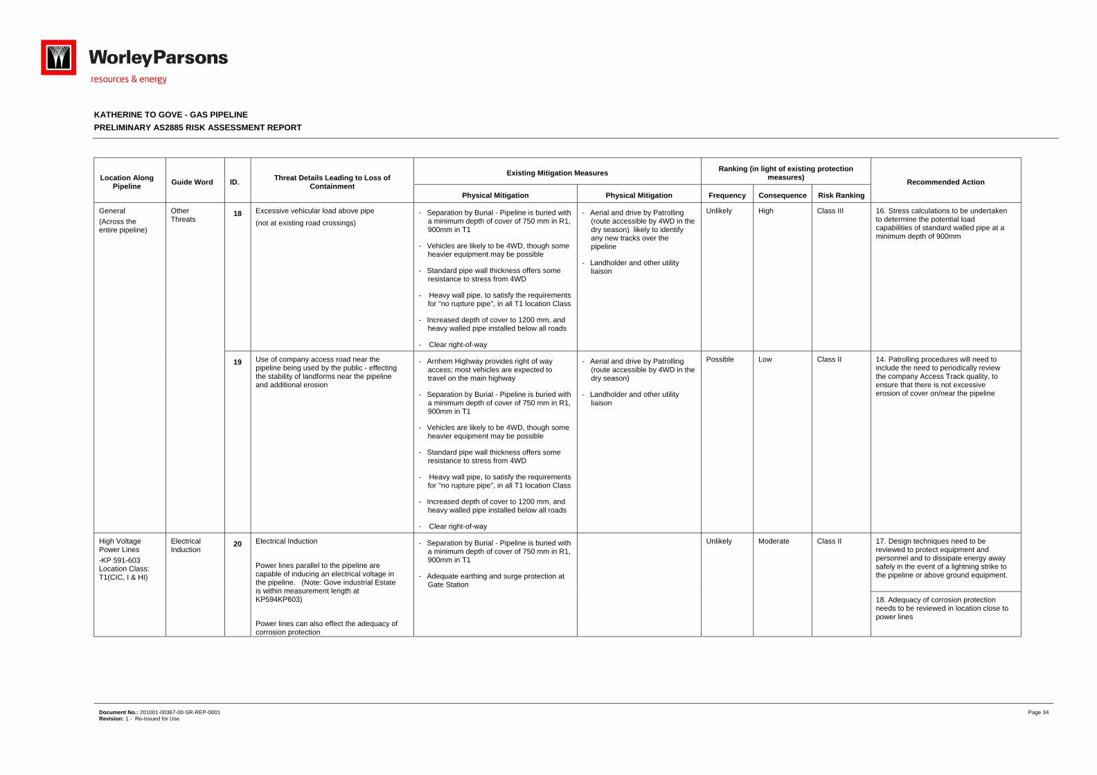
General
(Across the entire pipeline)
Other Threats
18 Excessive vehicular load above pipe
(not at existing road crossings)
- Separation by Burial - Pipeline is buried with a minimum depth of cover of 750 mm in R1, 900mm in T1
- Vehicles are likely to be 4WD, though some heavier equipment may be possible
- Standard pipe wall thickness offers some resistance to stress from 4WD
- Heavy wall pipe, to satisfy the requirements for "no rupture pipe", in all T1 location Class
- Increased depth of cover to 1200 mm, and heavy walled pipe installed below all roads
- Clear right-of-way
- Aerial and drive by Patrolling (route accessible by 4WD in the dry season) likely to identify any new tracks over the pipeline
- Landholder and other utility liaison
Unlikely High Class III 16. Stress calculations to be undertaken to determine the potential load capabilities of standard walled pipe at a minimum depth of 900mm
19 Use of company access road near the pipeline being used by the public - effecting the stability of landforms near the pipeline and additional erosion
- Arnhem Highway provides right of way access; most vehicles are expected to travel on the main highway
- Separation by Burial - Pipeline is buried with a minimum depth of cover of 750 mm in R1, 900mm in T1
- Vehicles are likely to be 4WD, though some heavier equipment may be possible
- Standard pipe wall thickness offers some resistance to stress from 4WD
- Heavy wall pipe, to satisfy the requirements for "no rupture pipe", in all T1 location Class
- Increased depth of cover to 1200 mm, and heavy walled pipe installed below all roads
- Clear right-of-way
- Aerial and drive by Patrolling (route accessible by 4WD in the dry season)
- Landholder and other utility liaison
Possible Low Class II 14. Patrolling procedures will need to include the need to periodically review the company Access Track quality, to ensure that there is not excessive erosion of cover on/near the pipeline
High Voltage Power Lines
-KP 591-603 Location Class: T1(CIC, I & HI)
Electrical Induction
20 Electrical Induction
Power lines parallel to the pipeline are capable of inducing an electrical voltage in the pipeline. (Note: Gove industrial Estate is within measurement length at KP594KP603)
Power lines can also effect the adequacy of corrosion protection
- Separation by Burial - Pipeline is buried with a minimum depth of cover of 750 mm in R1, 900mm in T1
- Adequate earthing and surge protection at Gate Station
Unlikely Moderate Class II 17. Design techniques need to be reviewed to protect equipment and personnel and to dissipate energy away safely in the event of a lightning strike to the pipeline or above ground equipment.
18. Adequacy of corrosion protection needs to be reviewed in location close to power lines
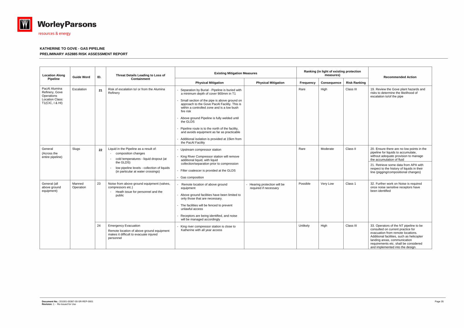
KATHERINE TO GOVE - GAS PIPELINE
PRELIMINARY AS2885 RISK ASSESSMENT REPORT
Document No.: 201001-00367-00-SR-REP-0001 Page 35 Revision: 1 - Re-Issued for Use
Location Along Pipeline
Guide Word ID. Threat Details Leading to Loss of
Containment
Existing Mitigation Measures Ranking (in light of existing protection
measures) Recommended Action
Physical Mitigation Physical Mitigation Frequency Consequence Risk Ranking
PacAl Alumina Refinery, Gove Operations Location Class: T1(CIC, I & HI)
Escalation 21 Risk of escalation to/ or from the Alumina Refinery
- Separation by Burial - Pipeline is buried with a minimum depth of cover 900mm in T1
- Small section of the pipe is above ground on approach to the Gove PacAl Facility. This is within a controlled zone and is a low bush fire risk
- Above ground Pipeline is fully welded until the GLDS
- Pipeline route is to the north of the facility, and avoids equipment as far as practicable
- Additional isolation is provided at 15km from the PacAl Facility
Rare High Class III 19. Review the Gove plant hazards and risks to determine the likelihood of escalation to/of the pipe
General
(Across the entire pipeline)
Slugs 22 Liquid in the Pipeline as a result of:
- composition changes
- cold temperatures - liquid dropout (at the GLDS)
- low pipeline levels - collection of liquids (in particular at water crossings)
- Upstream compressor station
- King River Compressor station will remove additional liquid, with liquid collection/separation prior to compression
- Filter coalescer is provided at the GLDS
- Gas composition
Rare Moderate Class II 20. Ensure there are no low points in the pipeline for liquids to accumulate, without adequate provision to manage the accumulation of fluid
21. Retrieve some data from APA with respect to the history of liquids in their line (pigging/compositional changes)
General (all above ground equipment)
Manned Operation
23 Noise from above ground equipment (valves, compressors etc.)
- Heath issue for personnel and the public
- Remote location of above ground equipment
- Above ground facilities have been limited to only those that are necessary.
- The facilities will be fenced to prevent unlawful access
- Receptors are being identified, and noise will be managed accordingly
- Hearing protection will be required if necessary
Possible Very Low Class 1 32. Further work on Noise is required once noise sensitive receptors have been identified
24 Emergency Evacuation
Remote location of above ground equipment makes it difficult to evacuate injured personnel
- King river compressor station is close to Katherine with all year access
Unlikely High Class III 33. Operators of the NT pipeline to be consulted on current practice for evacuation from remote locations. Additional facilities, such as helicopter landing areas, communication requirements etc. shall be considered and implemented into the design.
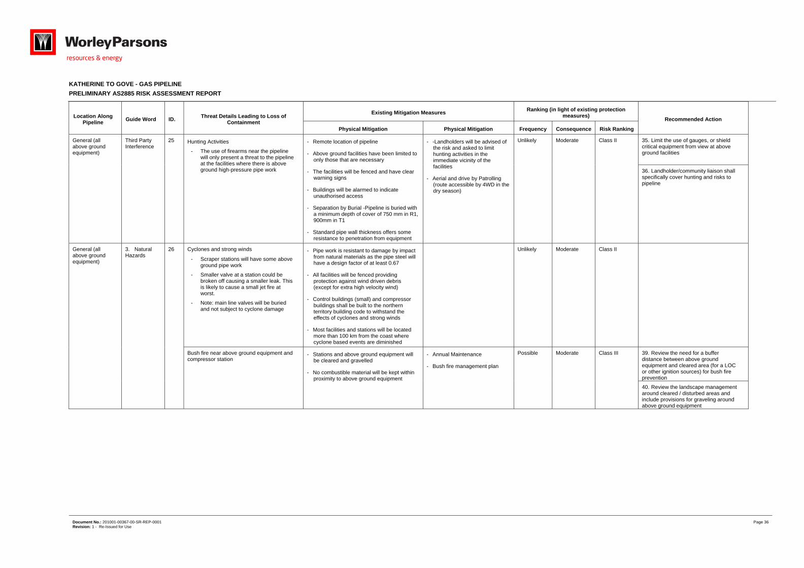
KATHERINE TO GOVE - GAS PIPELINE
PRELIMINARY AS2885 RISK ASSESSMENT REPORT
Document No.: 201001-00367-00-SR-REP-0001 Page 36 Revision: 1 - Re-Issued for Use
Location Along Pipeline
Guide Word ID. Threat Details Leading to Loss of
Containment
Existing Mitigation Measures Ranking (in light of existing protection
measures) Recommended Action
Physical Mitigation Physical Mitigation Frequency Consequence Risk Ranking
General (all above ground equipment)
Third Party Interference
25 Hunting Activities
- The use of firearms near the pipeline will only present a threat to the pipeline at the facilities where there is above ground high-pressure pipe work
- Remote location of pipeline
- Above ground facilities have been limited to only those that are necessary
- The facilities will be fenced and have clear warning signs
- Buildings will be alarmed to indicate unauthorised access
- Separation by Burial -Pipeline is buried with a minimum depth of cover of 750 mm in R1, 900mm in T1
- Standard pipe wall thickness offers some resistance to penetration from equipment
- -Landholders will be advised of the risk and asked to limit hunting activities in the immediate vicinity of the facilities
- Aerial and drive by Patrolling (route accessible by 4WD in the dry season)
Unlikely Moderate Class II 35. Limit the use of gauges, or shield critical equipment from view at above ground facilities
36. Landholder/community liaison shall specifically cover hunting and risks to pipeline
General (all above ground equipment)
3. Natural Hazards
26 Cyclones and strong winds
- Scraper stations will have some above ground pipe work
- Smaller valve at a station could be broken off causing a smaller leak. This is likely to cause a small jet fire at worst.
- Note: main line valves will be buried and not subject to cyclone damage
- Pipe work is resistant to damage by impact from natural materials as the pipe steel will have a design factor of at least 0.67
- All facilities will be fenced providing protection against wind driven debris (except for extra high velocity wind)
- Control buildings (small) and compressor buildings shall be built to the northern territory building code to withstand the effects of cyclones and strong winds
- Most facilities and stations will be located more than 100 km from the coast where cyclone based events are diminished
Unlikely Moderate Class II
Bush fire near above ground equipment and compressor station
- Stations and above ground equipment will be cleared and gravelled
- No combustible material will be kept within proximity to above ground equipment
- Annual Maintenance
- Bush fire management plan
Possible Moderate Class III 39. Review the need for a buffer distance between above ground equipment and cleared area (for a LOC or other ignition sources) for bush fire prevention
40. Review the landscape management around cleared / disturbed areas and include provisions for graveling around above ground equipment
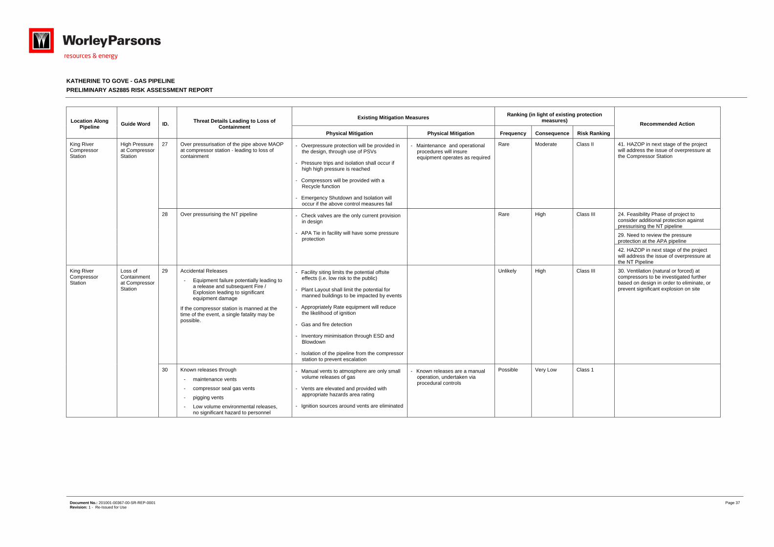
KATHERINE TO GOVE - GAS PIPELINE
PRELIMINARY AS2885 RISK ASSESSMENT REPORT
Document No.: 201001-00367-00-SR-REP-0001 Page 37 Revision: 1 - Re-Issued for Use
Location Along Pipeline
Guide Word ID. Threat Details Leading to Loss of
Containment
Existing Mitigation Measures Ranking (in light of existing protection
measures) Recommended Action
Physical Mitigation Physical Mitigation Frequency Consequence Risk Ranking
King River Compressor Station
High Pressure at Compressor Station
27 Over pressurisation of the pipe above MAOP at compressor station - leading to loss of containment
- Overpressure protection will be provided in the design, through use of PSVs
- Pressure trips and isolation shall occur if high high pressure is reached
- Compressors will be provided with a Recycle function
- Emergency Shutdown and Isolation will occur if the above control measures fail
- Maintenance and operational procedures will insure equipment operates as required
Rare Moderate Class II 41. HAZOP in next stage of the project will address the issue of overpressure at the Compressor Station
28 Over pressurising the NT pipeline - Check valves are the only current provision in design
- APA Tie in facility will have some pressure protection
Rare High Class III 24. Feasibility Phase of project to consider additional protection against pressurising the NT pipeline
29. Need to review the pressure protection at the APA pipeline
42. HAZOP in next stage of the project will address the issue of overpressure at the NT Pipeline
King River Compressor Station
Loss of Containment at Compressor Station
29 Accidental Releases
- Equipment failure potentially leading to a release and subsequent Fire / Explosion leading to significant equipment damage
If the compressor station is manned at the time of the event, a single fatality may be possible.
- Facility siting limits the potential offsite effects (i.e. low risk to the public)
- Plant Layout shall limit the potential for manned buildings to be impacted by events
- Appropriately Rate equipment will reduce the likelihood of ignition
- Gas and fire detection
- Inventory minimisation through ESD and Blowdown
- Isolation of the pipeline from the compressor station to prevent escalation
Unlikely High Class III 30. Ventilation (natural or forced) at compressors to be investigated further based on design in order to eliminate, or prevent significant explosion on site
30 Known releases through
- maintenance vents
- compressor seal gas vents
- pigging vents
- Low volume environmental releases, no significant hazard to personnel
- Manual vents to atmosphere are only small volume releases of gas
- Vents are elevated and provided with appropriate hazards area rating
- Ignition sources around vents are eliminated
- Known releases are a manual operation, undertaken via procedural controls
Possible Very Low Class 1
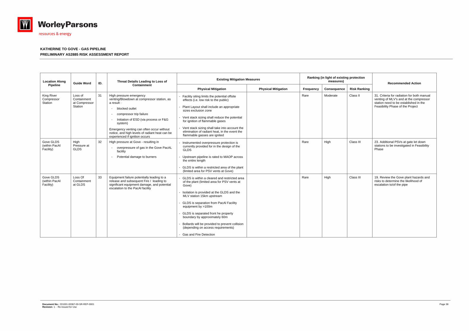
KATHERINE TO GOVE - GAS PIPELINE
PRELIMINARY AS2885 RISK ASSESSMENT REPORT
Document No.: 201001-00367-00-SR-REP-0001 Page 38 Revision: 1 - Re-Issued for Use
Location Along Pipeline
Guide Word ID. Threat Details Leading to Loss of
Containment
Existing Mitigation Measures Ranking (in light of existing protection
measures) Recommended Action
Physical Mitigation Physical Mitigation Frequency Consequence Risk Ranking
King River Compressor Station
Loss of Containment at Compressor Station
31 High pressure emergency venting/Blowdown at compressor station, as a result :
- blocked outlet
- compressor trip failure
- Initiation of ESD (via process or F&G system)
Emergency venting can often occur without notice, and high levels of radiant heat can be experienced if ignition occurs
- Facility siting limits the potential offsite effects (i.e. low risk to the public)
- Plant Layout shall include an appropriate sizes exclusion zone
- Vent stack sizing shall reduce the potential for ignition of flammable gases
- Vent stack sizing shall take into account the elimination of radiant heat, in the event the flammable gasses are ignited
Rare Moderate Class II 31. Criteria for radiation for both manual venting of MLV's and at the compressor station need to be established in the Feasibility Phase of the Project
Gove GLDS (within PacAl Facility)
High Pressure at GLDS
32 High pressure at Gove - resulting in
- overpressure of gas in the Gove PacAL facility
- Potential damage to burners
- Instrumented overpressure protection is currently provided for in the design of the GLDS
- Upstream pipeline is rated to MAOP across the entire length
- GLDS is within a restricted area of the plant (limited area for PSV vents at Gove)
Rare High Class III 23. Additional PSVs at gate let down stations to be investigated in Feasibility Phase
Gove GLDS (within PacAl Facility)
Loss Of Containment at GLDS
33 Equipment failure potentially leading to a release and subsequent Fire / leading to significant equipment damage, and potential escalation to the PacAl facility
- GLDS is within a cleared and restricted area of the plant (limited area for PSV vents at Gove)
- Isolation is provided at the GLDS and the MLV station 15km upstream
- GLDS is separation from PacAl Facility equipment by >100m
- GLDS is separated front he property boundary by approximately 60m
- Bollards will be provided to prevent collision (depending on access requirements)
- Gas and Fire Detection
Rare
High
Class III
19. Review the Gove plant hazards and risks to determine the likelihood of escalation to/of the pipe
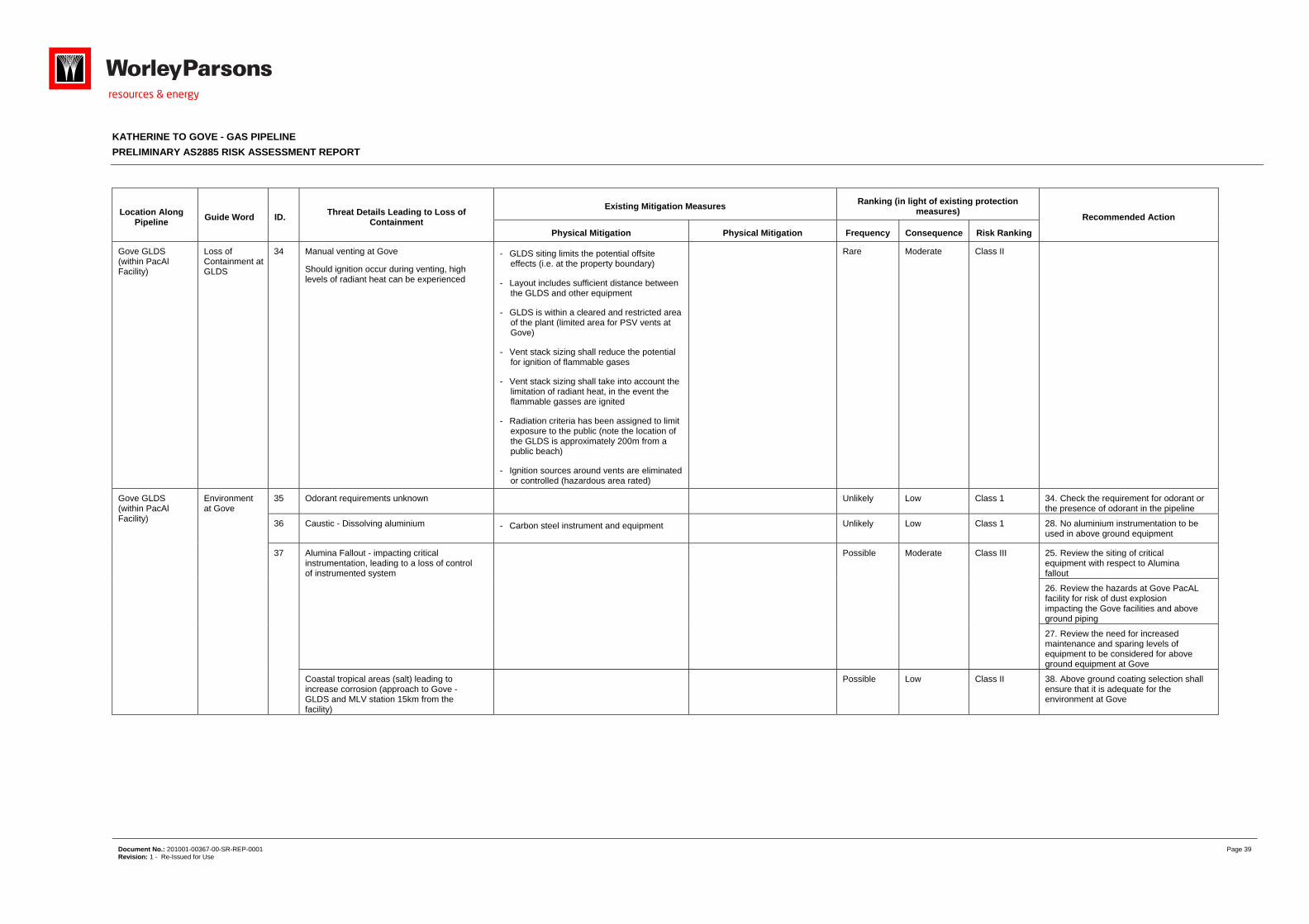
KATHERINE TO GOVE - GAS PIPELINE
PRELIMINARY AS2885 RISK ASSESSMENT REPORT
Document No.: 201001-00367-00-SR-REP-0001 Page 39 Revision: 1 - Re-Issued for Use
Location Along Pipeline
Guide Word ID. Threat Details Leading to Loss of
Containment
Existing Mitigation Measures Ranking (in light of existing protection
measures) Recommended Action
Physical Mitigation Physical Mitigation Frequency Consequence Risk Ranking
Gove GLDS (within PacAl Facility)
Loss of Containment at GLDS
34 Manual venting at Gove
Should ignition occur during venting, high levels of radiant heat can be experienced
- GLDS siting limits the potential offsite effects (i.e. at the property boundary)
- Layout includes sufficient distance between the GLDS and other equipment
- GLDS is within a cleared and restricted area of the plant (limited area for PSV vents at Gove)
- Vent stack sizing shall reduce the potential for ignition of flammable gases
- Vent stack sizing shall take into account the limitation of radiant heat, in the event the flammable gasses are ignited
- Radiation criteria has been assigned to limit exposure to the public (note the location of the GLDS is approximately 200m from a public beach)
- Ignition sources around vents are eliminated or controlled (hazardous area rated)
Rare Moderate Class II
Gove GLDS (within PacAl Facility)
Environment at Gove
35 Odorant requirements unknown Unlikely Low Class 1 34. Check the requirement for odorant or the presence of odorant in the pipeline
36 Caustic - Dissolving aluminium - Carbon steel instrument and equipment Unlikely
Low
Class 1
28. No aluminium instrumentation to be used in above ground equipment
37 Alumina Fallout - impacting critical instrumentation, leading to a loss of control of instrumented system
Possible Moderate Class III 25. Review the siting of critical equipment with respect to Alumina fallout
26. Review the hazards at Gove PacAL facility for risk of dust explosion impacting the Gove facilities and above ground piping
27. Review the need for increased maintenance and sparing levels of equipment to be considered for above ground equipment at Gove
Coastal tropical areas (salt) leading to increase corrosion (approach to Gove - GLDS and MLV station 15km from the facility)
Possible Low Class II 38. Above ground coating selection shall ensure that it is adequate for the environment at Gove
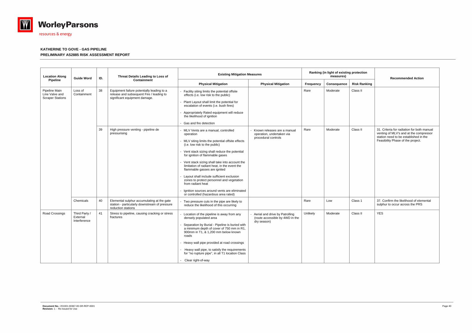
KATHERINE TO GOVE - GAS PIPELINE
PRELIMINARY AS2885 RISK ASSESSMENT REPORT
Document No.: 201001-00367-00-SR-REP-0001 Page 40 Revision: 1 - Re-Issued for Use
Location Along Pipeline
Guide Word ID. Threat Details Leading to Loss of
Containment
Existing Mitigation Measures Ranking (in light of existing protection
measures) Recommended Action
Physical Mitigation Physical Mitigation Frequency Consequence Risk Ranking
Pipeline Main Line Valve and Scraper Stations
Loss of Containment
38 Equipment failure potentially leading to a release and subsequent Fire / leading to significant equipment damage.
- Facility siting limits the potential offsite effects (i.e. low risk to the public)
- Plant Layout shall limit the potential for escalation of events (i.e. bush fires)
- Appropriately Rated equipment will reduce the likelihood of ignition
- Gas and fire detection
Rare Moderate Class II
39 High pressure venting - pipeline de pressurising
- MLV Vents are a manual, controlled operation
- MLV siting limits the potential offsite effects (i.e. low risk to the public)
- Vent stack sizing shall reduce the potential for ignition of flammable gases
- Vent stack sizing shall take into account the limitation of radiant heat, in the event the flammable gasses are ignited
- Layout shall include sufficient exclusion zones to protect personnel and vegetation from radiant heat
- Ignition sources around vents are eliminated or controlled (hazardous area rated)
- Known releases are a manual operation, undertaken via procedural controls
Rare Moderate Class II 31. Criteria for radiation for both manual venting of MLV's and at the compressor station need to be established in the Feasibility Phase of the project.
Chemicals 40 Elemental sulphur accumulating at the gate station - particularly downstream of pressure reduction stations
- Two pressure cuts in the pipe are likely to reduce the likelihood of this occurring
Rare Low Class 1 37. Confirm the likelihood of elemental sulphur to occur across the PRS
Road Crossings Third Party / External Interference
41 Stress to pipeline, causing cracking or stress fractures
- Location of the pipeline is away from any densely populated area
- Separation by Burial - Pipeline is buried with a minimum depth of cover of 750 mm in R1, 900mm in T1, & 1,200 mm below known roads
- Heavy wall pipe provided at road crossings
- Heavy wall pipe, to satisfy the requirements for "no rupture pipe", in all T1 location Class
- Clear right-of-way
- Aerial and drive by Patrolling (route accessible by 4WD in the dry season)
Unlikely Moderate Class II YES
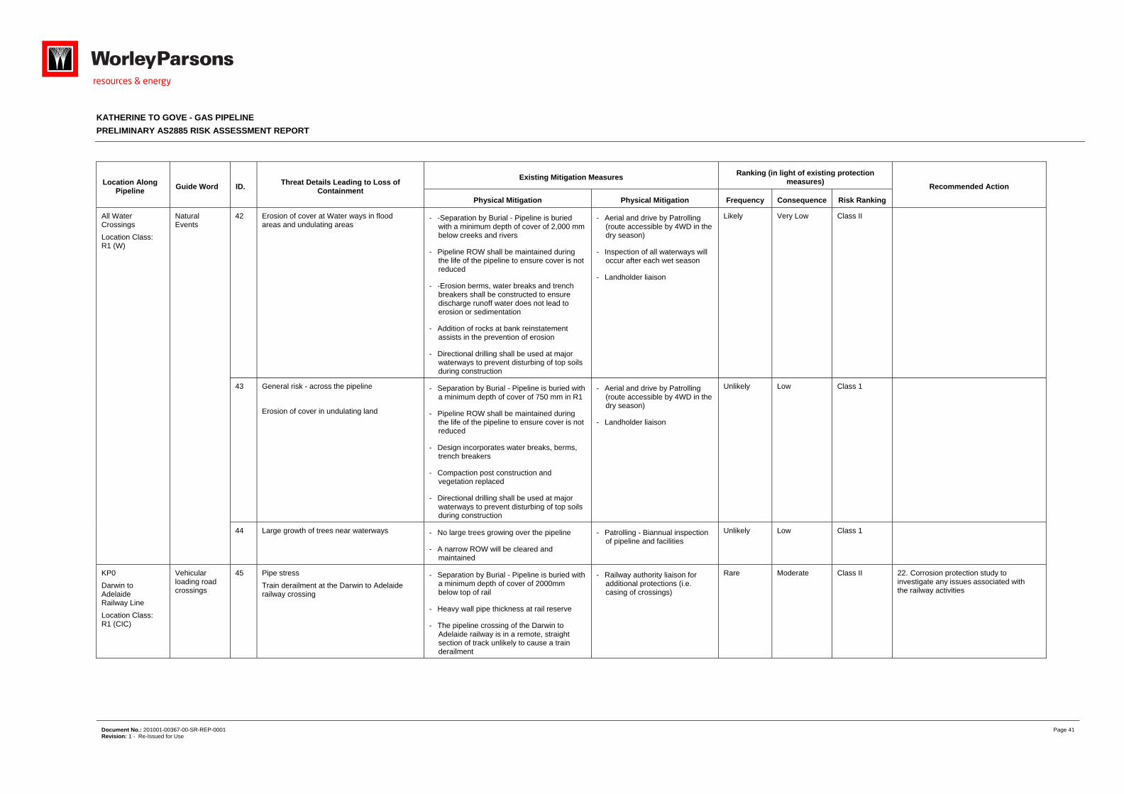
KATHERINE TO GOVE - GAS PIPELINE
PRELIMINARY AS2885 RISK ASSESSMENT REPORT
Document No.: 201001-00367-00-SR-REP-0001 Page 41 Revision: 1 - Re-Issued for Use
Location Along Pipeline
Guide Word ID. Threat Details Leading to Loss of
Containment
Existing Mitigation Measures Ranking (in light of existing protection
measures) Recommended Action
Physical Mitigation Physical Mitigation Frequency Consequence Risk Ranking
All Water Crossings
Location Class: R1 (W)
Natural Events
42 Erosion of cover at Water ways in flood areas and undulating areas
- -Separation by Burial - Pipeline is buried with a minimum depth of cover of 2,000 mm below creeks and rivers
- Pipeline ROW shall be maintained during the life of the pipeline to ensure cover is not reduced
- -Erosion berms, water breaks and trench breakers shall be constructed to ensure discharge runoff water does not lead to erosion or sedimentation
- Addition of rocks at bank reinstatement assists in the prevention of erosion
- Directional drilling shall be used at major waterways to prevent disturbing of top soils during construction
- Aerial and drive by Patrolling (route accessible by 4WD in the dry season)
- Inspection of all waterways will occur after each wet season
- Landholder liaison
Likely Very Low Class II
43 General risk - across the pipeline
Erosion of cover in undulating land
- Separation by Burial - Pipeline is buried with a minimum depth of cover of 750 mm in R1
- Pipeline ROW shall be maintained during the life of the pipeline to ensure cover is not reduced
- Design incorporates water breaks, berms, trench breakers
- Compaction post construction and vegetation replaced
- Directional drilling shall be used at major waterways to prevent disturbing of top soils during construction
- Aerial and drive by Patrolling (route accessible by 4WD in the dry season)
- Landholder liaison
Unlikely Low Class 1
44 Large growth of trees near waterways - No large trees growing over the pipeline
- A narrow ROW will be cleared and maintained
- Patrolling - Biannual inspection of pipeline and facilities
Unlikely Low Class 1
KP0
Darwin to Adelaide Railway Line
Location Class: R1 (CIC)
Vehicular loading road crossings
45 Pipe stress
Train derailment at the Darwin to Adelaide railway crossing
- Separation by Burial - Pipeline is buried with a minimum depth of cover of 2000mm below top of rail
- Heavy wall pipe thickness at rail reserve
- The pipeline crossing of the Darwin to Adelaide railway is in a remote, straight section of track unlikely to cause a train derailment
- Railway authority liaison for additional protections (i.e. casing of crossings)
Rare Moderate Class II 22. Corrosion protection study to investigate any issues associated with the railway activities
KATHERINE TO GOVE - GAS PIPELINE
PRELIMINARY AS2885 RISK ASSESSMENT REPORT
Document No.: 201001-00367-00-SR-REP-0001 Page 42 Revision: 1 - Re-Issued for Use
Appendix 3 SMS Recommendations
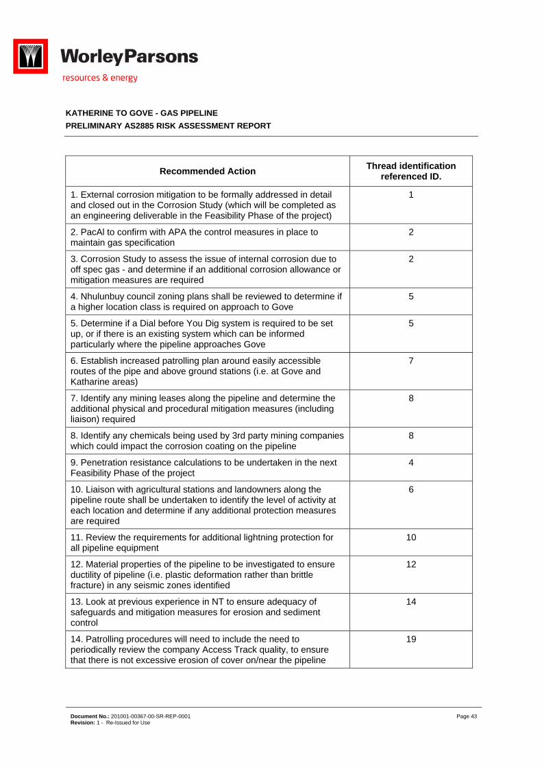
KATHERINE TO GOVE - GAS PIPELINE
PRELIMINARY AS2885 RISK ASSESSMENT REPORT
Document No.: 201001-00367-00-SR-REP-0001 Page 43 Revision: 1 - Re-Issued for Use
Recommended Action Thread identification
referenced ID.
1. External corrosion mitigation to be formally addressed in detail and closed out in the Corrosion Study (which will be completed as an engineering deliverable in the Feasibility Phase of the project)
1
2. PacAl to confirm with APA the control measures in place to maintain gas specification
2
3. Corrosion Study to assess the issue of internal corrosion due to off spec gas - and determine if an additional corrosion allowance or mitigation measures are required
2
4. Nhulunbuy council zoning plans shall be reviewed to determine if a higher location class is required on approach to Gove
5
5. Determine if a Dial before You Dig system is required to be set up, or if there is an existing system which can be informed particularly where the pipeline approaches Gove
5
6. Establish increased patrolling plan around easily accessible routes of the pipe and above ground stations (i.e. at Gove and Katharine areas)
7
7. Identify any mining leases along the pipeline and determine the additional physical and procedural mitigation measures (including liaison) required
8
8. Identify any chemicals being used by 3rd party mining companies which could impact the corrosion coating on the pipeline
8
9. Penetration resistance calculations to be undertaken in the next Feasibility Phase of the project
4
10. Liaison with agricultural stations and landowners along the pipeline route shall be undertaken to identify the level of activity at each location and determine if any additional protection measures are required
6
11. Review the requirements for additional lightning protection for all pipeline equipment
10
12. Material properties of the pipeline to be investigated to ensure ductility of pipeline (i.e. plastic deformation rather than brittle fracture) in any seismic zones identified
12
13. Look at previous experience in NT to ensure adequacy of safeguards and mitigation measures for erosion and sediment control
14
14. Patrolling procedures will need to include the need to periodically review the company Access Track quality, to ensure that there is not excessive erosion of cover on/near the pipeline
19
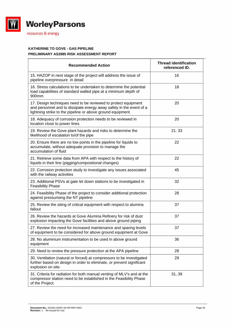
KATHERINE TO GOVE - GAS PIPELINE
PRELIMINARY AS2885 RISK ASSESSMENT REPORT
Document No.: 201001-00367-00-SR-REP-0001 Page 44 Revision: 1 - Re-Issued for Use
Recommended Action Thread identification
referenced ID.
15. HAZOP in next stage of the project will address the issue of pipeline overpressure in detail
16
16. Stress calculations to be undertaken to determine the potential load capabilities of standard walled pipe at a minimum depth of 900mm
18
17. Design techniques need to be reviewed to protect equipment and personnel and to dissipate energy away safely in the event of a lightning strike to the pipeline or above ground equipment
20
18. Adequacy of corrosion protection needs to be reviewed in location close to power lines
20
19. Review the Gove plant hazards and risks to determine the likelihood of escalation to/of the pipe
21. 33
20. Ensure there are no low points in the pipeline for liquids to accumulate, without adequate provision to manage the accumulation of fluid
22
21. Retrieve some data from APA with respect to the history of liquids in their line (pigging/compositional changes)
22
22. Corrosion protection study to investigate any issues associated with the railway activities
45
23. Additional PSVs at gate let down stations to be investigated in Feasibility Phase
32
24. Feasibility Phase of the project to consider additional protection against pressurising the NT pipeline
28
25. Review the siting of critical equipment with respect to alumina fallout
37
26. Review the hazards at Gove Alumina Refinery for risk of dust explosion impacting the Gove facilities and above ground piping
37
27. Review the need for increased maintenance and sparing levels of equipment to be considered for above ground equipment at Gove
37
28. No aluminium instrumentation to be used in above ground equipment
36
29. Need to review the pressure protection at the APA pipeline 28
30. Ventilation (natural or forced) at compressors to be investigated further based on design in order to eliminate, or prevent significant explosion on site.
29
31. Criteria for radiation for both manual venting of MLV's and at the compressor station need to be established in the Feasibility Phase of the Project.
31, 39
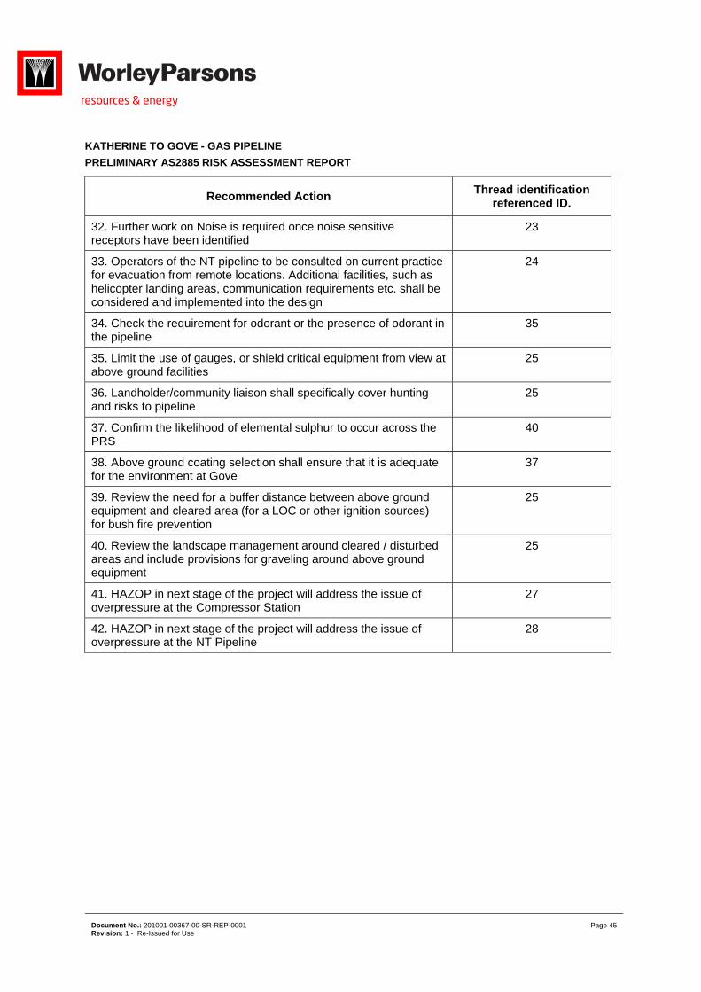
KATHERINE TO GOVE - GAS PIPELINE
PRELIMINARY AS2885 RISK ASSESSMENT REPORT
Document No.: 201001-00367-00-SR-REP-0001 Page 45 Revision: 1 - Re-Issued for Use
Recommended Action Thread identification
referenced ID.
32. Further work on Noise is required once noise sensitive receptors have been identified
23
33. Operators of the NT pipeline to be consulted on current practice for evacuation from remote locations. Additional facilities, such as helicopter landing areas, communication requirements etc. shall be considered and implemented into the design
24
34. Check the requirement for odorant or the presence of odorant in the pipeline
35
35. Limit the use of gauges, or shield critical equipment from view at above ground facilities
25
36. Landholder/community liaison shall specifically cover hunting and risks to pipeline
25
37. Confirm the likelihood of elemental sulphur to occur across the PRS
40
38. Above ground coating selection shall ensure that it is adequate for the environment at Gove
37
39. Review the need for a buffer distance between above ground equipment and cleared area (for a LOC or other ignition sources) for bush fire prevention
25
40. Review the landscape management around cleared / disturbed areas and include provisions for graveling around above ground equipment
25
41. HAZOP in next stage of the project will address the issue of overpressure at the Compressor Station
27
42. HAZOP in next stage of the project will address the issue of overpressure at the NT Pipeline
28