Embed Size (px)
Citation preview
2010 Toyota Prius Repair Manual
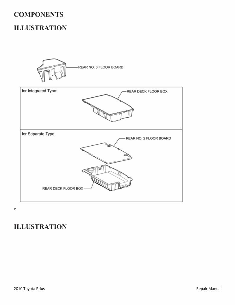
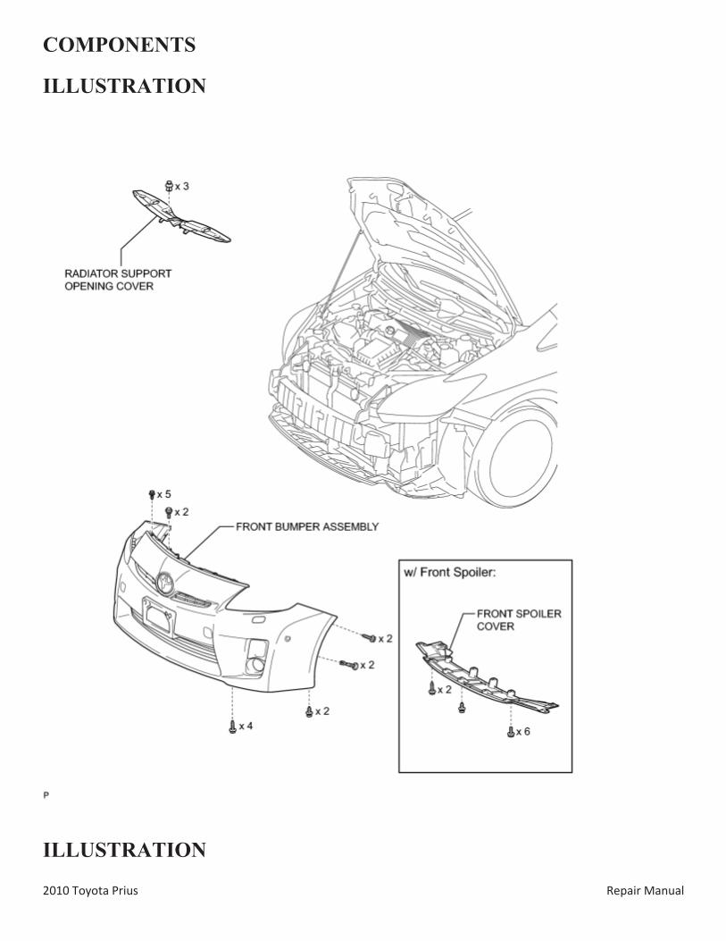
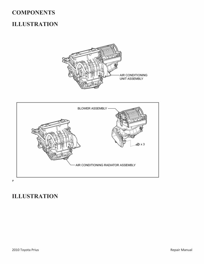
COMPONENTS
ILLUSTRATION
ILLUSTRATION
2010 Toyota Prius Repair Manual
ILLUSTRATION
2010 Toyota Prius Repair Manual
ILLUSTRATION
2010 Toyota Prius Repair Manual
ILLUSTRATION
2010 Toyota Prius Repair Manual
ILLUSTRATION
2010 Toyota Prius Repair Manual
ILLUSTRATION
2010 Toyota Prius Repair Manual
ILLUSTRATION
2010 Toyota Prius Repair Manual
ILLUSTRATION
2010 Toyota Prius Repair Manual
ILLUSTRATION
2010 Toyota Prius Repair Manual
ILLUSTRATION
2010 Toyota Prius Repair Manual
ILLUSTRATION
2010 Toyota Prius Repair Manual
ILLUSTRATION
2010 Toyota Prius Repair Manual
ILLUSTRATION
2010 Toyota Prius Repair Manual
ILLUSTRATION
2010 Toyota Prius Repair Manual
ILLUSTRATION
2010 Toyota Prius Repair Manual
ILLUSTRATION
2010 Toyota Prius Repair Manual
ILLUSTRATION
2010 Toyota Prius Repair Manual
ILLUSTRATION
2010 Toyota Prius Repair Manual
ILLUSTRATION
2010 Toyota Prius Repair Manual
2010 Toyota Prius Repair Manual
REMOVAL 1. PRECAUTION
HINT:
Before disconnecting the cable, set the air conditioning control switch to DEF-MODE. (for Automatic Air Conditioning System)
2. RECOVER REFRIGERANT FROM REFRIGERATION SYSTEM
3. ALIGN FRONT WHEELS STRAIGHT AHEAD
4. REMOVE REAR NO. 2 FLOOR BOARD (for Separate Type)
5. REMOVE REAR DECK FLOOR BOX
6. REMOVE REAR NO. 3 FLOOR BOARD
7. DISCONNECT CABLE FROM NEGATIVE BATTERY TERMINAL
CAUTION:
Wait at least 90 seconds after disconnecting the cable from the negative (-) battery terminal to disable the SRS system.
NOTICE:
When disconnecting the cable, some systems need to be initialized after the cable is reconnected .
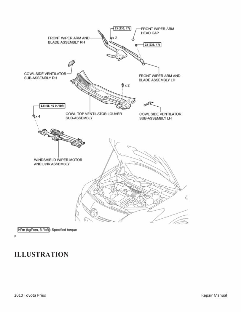
8. REMOVE FRONT WIPER ARM HEAD CAP
9. REMOVE FRONT WIPER ARM AND BLADE ASSEMBLY LH
10. REMOVE FRONT WIPER ARM AND BLADE ASSEMBLY RH
11. REMOVE COWL SIDE VENTILATOR SUB-ASSEMBLY LH
12. REMOVE COWL SIDE VENTILATOR SUB-ASSEMBLY RH
13. REMOVE COWL TOP VENTILATOR LOUVER SUB-ASSEMBLY
14. REMOVE WINDSHIELD WIPER MOTOR AND LINK ASSEMBLY
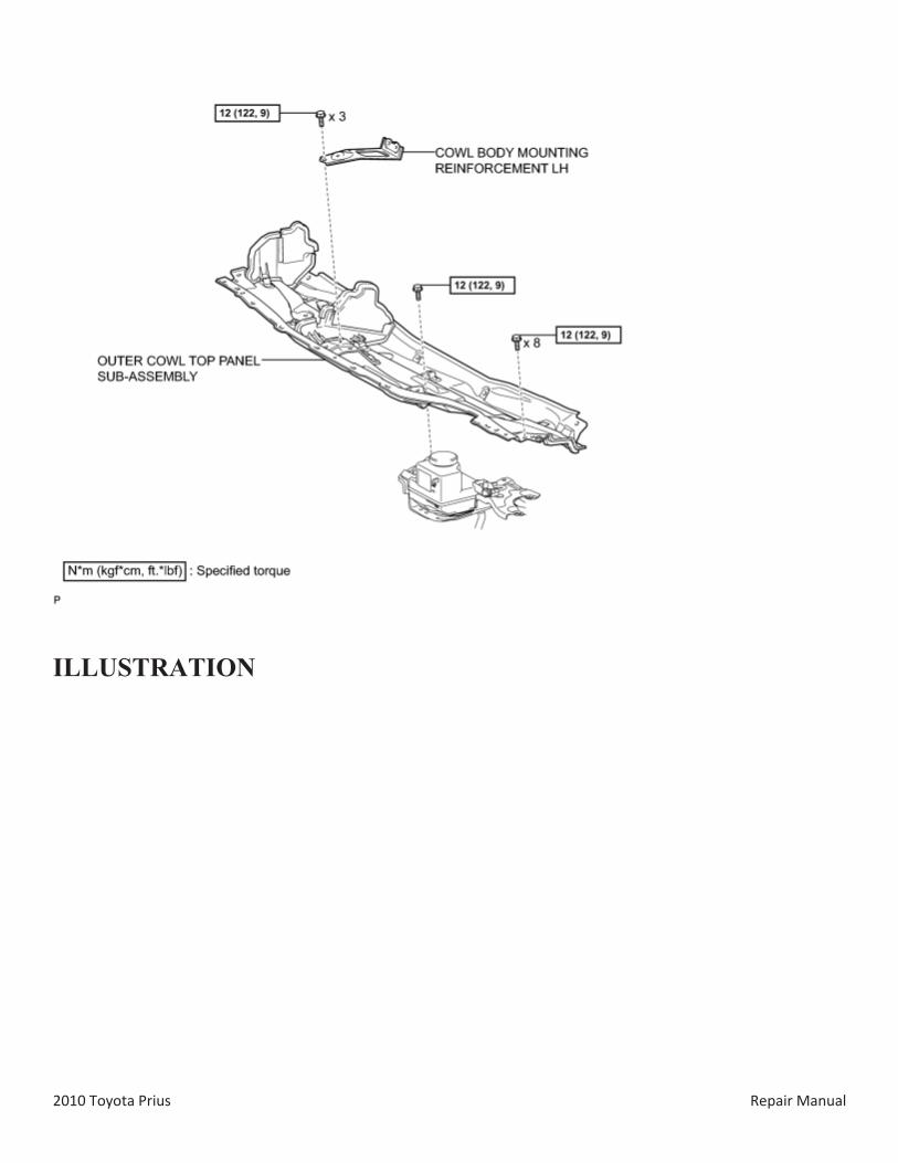
15. REMOVE COWL BODY MOUNTING REINFORCEMENT LH
16. REMOVE OUTER COWL TOP PANEL SUB-ASSEMBLY
2010 Toyota Prius Repair Manual
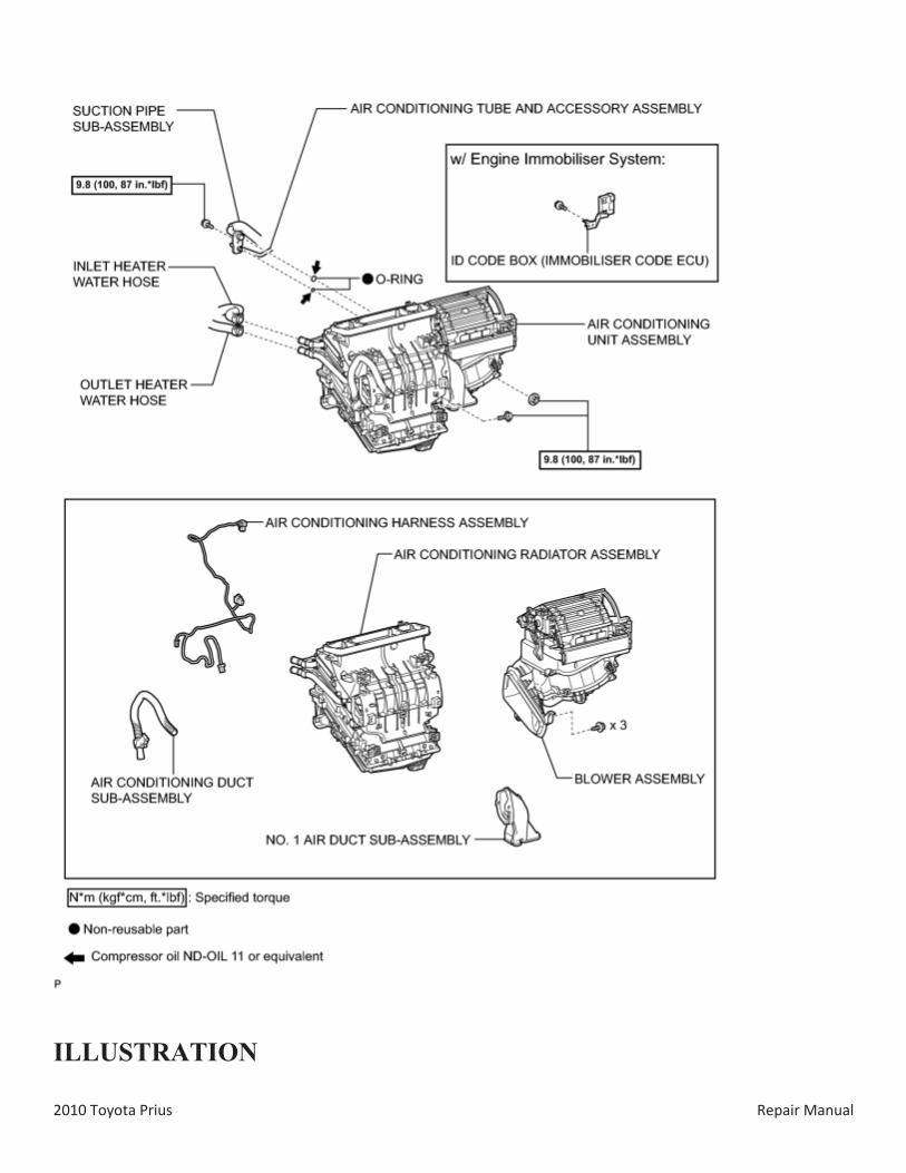
17. DISCONNECT SUCTION PIPE SUB-ASSEMBLY
(a) Remove the bolt and slide the hook connector.
(b) Disconnect the suction pipe assembly.
(c) Remove the O-ring from the suction pipe sub-assembly.
NOTICE:
Seal the openings of the disconnected parts using vinyl tape to prevent entry of moisture and foreign matter.
18. DISCONNECT AIR CONDITIONING TUBE AND ACCESSORY ASSEMBLY
(a) Disconnect the air conditioning tube and accessory assembly.
(b) Remove the O-ring from the air conditioning tube and accessory assembly.
NOTICE:
Seal the openings of the disconnected parts using vinyl tape to prevent entry of moisture and foreign matter.
19. DISCONNECT INLET HEATER WATER HOSE
(a) Using pliers, grip the claws of the clip and slide the clip to disconnect the inlet heater water hose.
Do not apply excessive force to the inlet heater water hose. Prepare a drain pan or cloth in case the coolant leaks.
2010 Toyota Prius Repair Manual
20. DISCONNECT OUTLET HEATER WATER HOSE
(a) Using pliers, grip the claws of the clip and slide the clip to disconnect the outlet heater water hose.
Do not apply excessive force to the outlet heater water hose. Prepare a drain pan or cloth in case the coolant leaks.
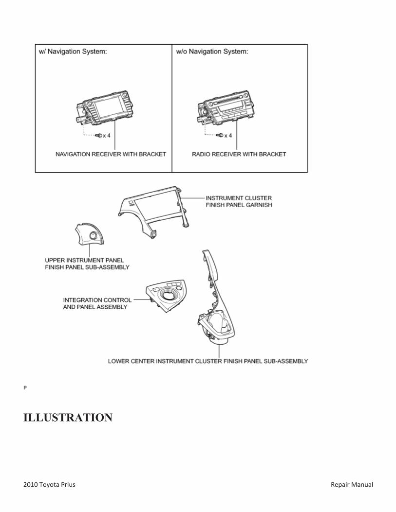
21. REMOVE INTEGRATION CONTROL AND PANEL ASSEMBLY
22. REMOVE LOWER CENTER INSTRUMENT CLUSTER FINISH PANEL SUB-ASSEMBLY
23. REMOVE INSTRUMENT CLUSTER FINISH PANEL GARNISH
24. REMOVE UPPER INSTRUMENT PANEL FINISH PANEL SUB-ASSEMBLY
25. REMOVE RADIO RECEIVER WITH BRACKET (w/o Navigation System)
26. REMOVE NAVIGATION RECEIVER WITH BRACKET (w/ Navigation System)
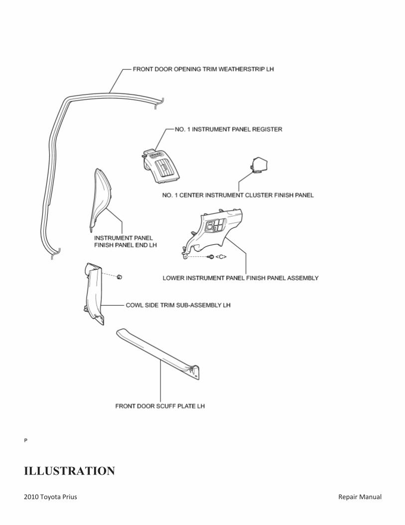
27. REMOVE FRONT DOOR SCUFF PLATE LH
28. REMOVE COWL SIDE TRIM SUB-ASSEMBLY LH
29. REMOVE LOWER INSTRUMENT PANEL FINISH PANEL ASSEMBLY
30. REMOVE NO. 1 INSTRUMENT PANEL REGISTER
31. REMOVE NO. 1 CENTER INSTRUMENT CLUSTER FINISH PANEL
32. DISCONNECT FRONT DOOR OPENING TRIM WEATHERSTRIP LH
33. REMOVE INSTRUMENT PANEL FINISH PANEL END LH
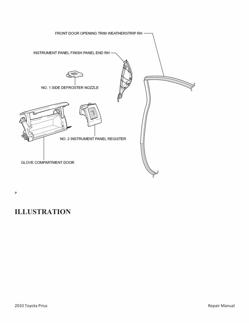
34. REMOVE NO. 1 SIDE DEFROSTER NOZZLE
35. REMOVE NO. 2 INSTRUMENT PANEL REGISTER
36. REMOVE GLOVE COMPARTMENT DOOR
2010 Toyota Prius Repair Manual
37. REMOVE FRONT DOOR OPENING TRIM WEATHERSTRIP RH
HINT:
Use the same procedure for the RH side and LH side.
38. REMOVE INSTRUMENT PANEL FINISH PANEL END RH
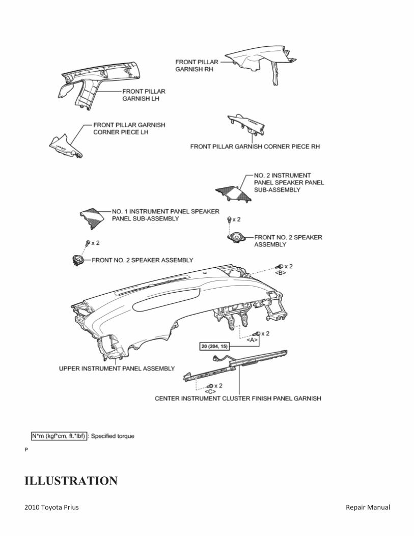
39. REMOVE FRONT PILLAR GARNISH LH
40. REMOVE FRONT PILLAR GARNISH CORNER PIECE LH
41. REMOVE NO. 1 INSTRUMENT PANEL SPEAKER PANEL SUB-ASSEMBLY
42. REMOVE FRONT NO. 2 SPEAKER ASSEMBLY
43. REMOVE FRONT PILLAR GARNISH RH
HINT:
Use the same procedure for the RH side and LH side.
44. REMOVE FRONT PILLAR GARNISH CORNER PIECE RH
45. REMOVE NO. 2 INSTRUMENT PANEL SPEAKER PANEL SUB-ASSEMBLY
46. REMOVE FRONT NO. 2 SPEAKER ASSEMBLY
HINT:
Use the same procedure for the RH side and LH side.
47. REMOVE CENTER INSTRUMENT CLUSTER FINISH PANEL GARNISH
48. DISCONNECT INSTRUMENT PANEL WIRE
49. REMOVE UPPER INSTRUMENT PANEL ASSEMBLY
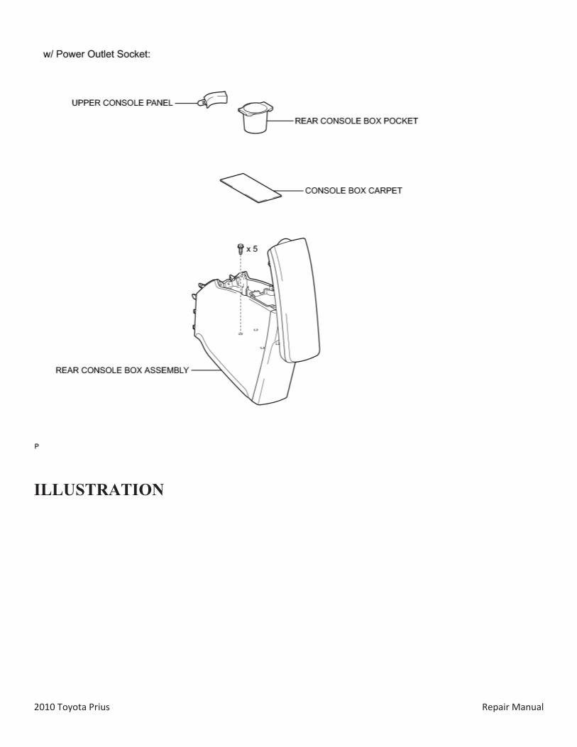
50. REMOVE REAR CONSOLE BOX POCKET (w/ Power Outlet Socket)
51. REMOVE UPPER CONSOLE PANEL (w/ Power Outlet Socket)
52. REMOVE CONSOLE BOX CARPET
53. REMOVE REAR CONSOLE BOX ASSEMBLY (w/ Power Outlet Socket)
54. REMOVE REAR CONSOLE BOX ASSEMBLY (w/o Power Outlet Socket)
55. REMOVE ELECTRICAL KEY OSCILLATOR
2010 Toyota Prius Repair Manual
56. REMOVE NO. 2 CONSOLE BOX MOUNTING BRACKET
57. REMOVE FRONT NO. 1 CONSOLE BOX INSERT
58. REMOVE FRONT NO. 2 CONSOLE BOX INSERT
59. REMOVE BOX BOTTOM MAT
60. SEPARATE CONSOLE BOX ASSEMBLY
61. REMOVE AIR CONDITIONING CONTROL ASSEMBLY
62. REMOVE SHIFT LOCK CONTROL UNIT ASSEMBLY
63. REMOVE UPPER INSTRUMENT PANEL FINISH PANEL ASSEMBLY
64. REMOVE CONSOLE BOX ASSEMBLY
65. REMOVE NO. 1 SWITCH HOLE BASE
66. REMOVE LOWER NO. 3 STEERING WHEEL COVER
67. REMOVE LOWER NO. 2 STEERING WHEEL COVER
68. REMOVE STEERING PAD
69. REMOVE STEERING WHEEL ASSEMBLY
70. REMOVE LOWER STEERING COLUMN COVER
71. REMOVE UPPER STEERING COLUMN COVER
72. REMOVE TURN SIGNAL SWITCH ASSEMBLY WITH SPIRAL CABLE SUB-ASSEMBLY
73. REMOVE NO. 1 INSTRUMENT PANEL UNDER COVER SUB-ASSEMBLY
74. REMOVE DRIVER SIDE KNEE AIRBAG ASSEMBLY
75. REMOVE NO. 2 INSTRUMENT PANEL UNDER COVER SUB-ASSEMBLY
76. REMOVE GLOVE COMPARTMENT DOOR ASSEMBLY
77. REMOVE FRONT DOOR SCUFF PLATE RH
HINT:
Use the same procedure for the RH side and LH side.
78. REMOVE COWL SIDE TRIM BOARD RH
2010 Toyota Prius Repair Manual
HINT:
Use the same procedure for the RH side and LH side.
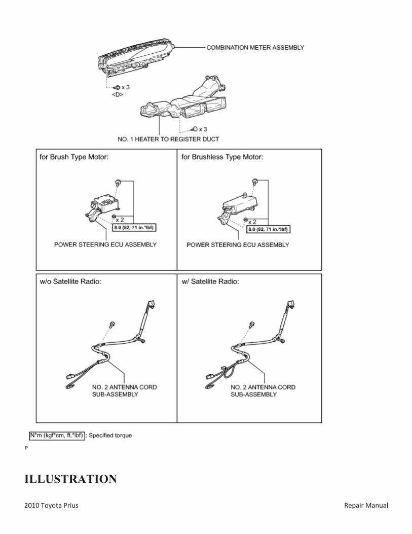
79. REMOVE NO. 1 HEATER TO REGISTER DUCT
80. REMOVE COMBINATION METER ASSEMBLY
81. REMOVE POWER STEERING ECU ASSEMBLY (for Brush Type Motor)
82. REMOVE POWER STEERING ECU ASSEMBLY (for Brushless Type Motor)
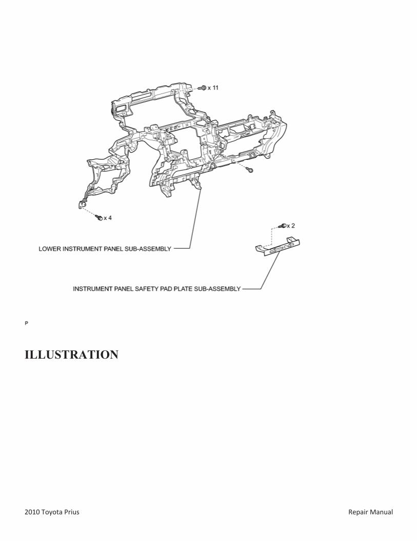
83. REMOVE INSTRUMENT PANEL SAFETY PAD PLATE SUB-ASSEMBLY (for LHD)
84. REMOVE NO. 2 ANTENNA CORD SUB-ASSEMBLY
85. REMOVE LOWER INSTRUMENT PANEL SUB-ASSEMBLY
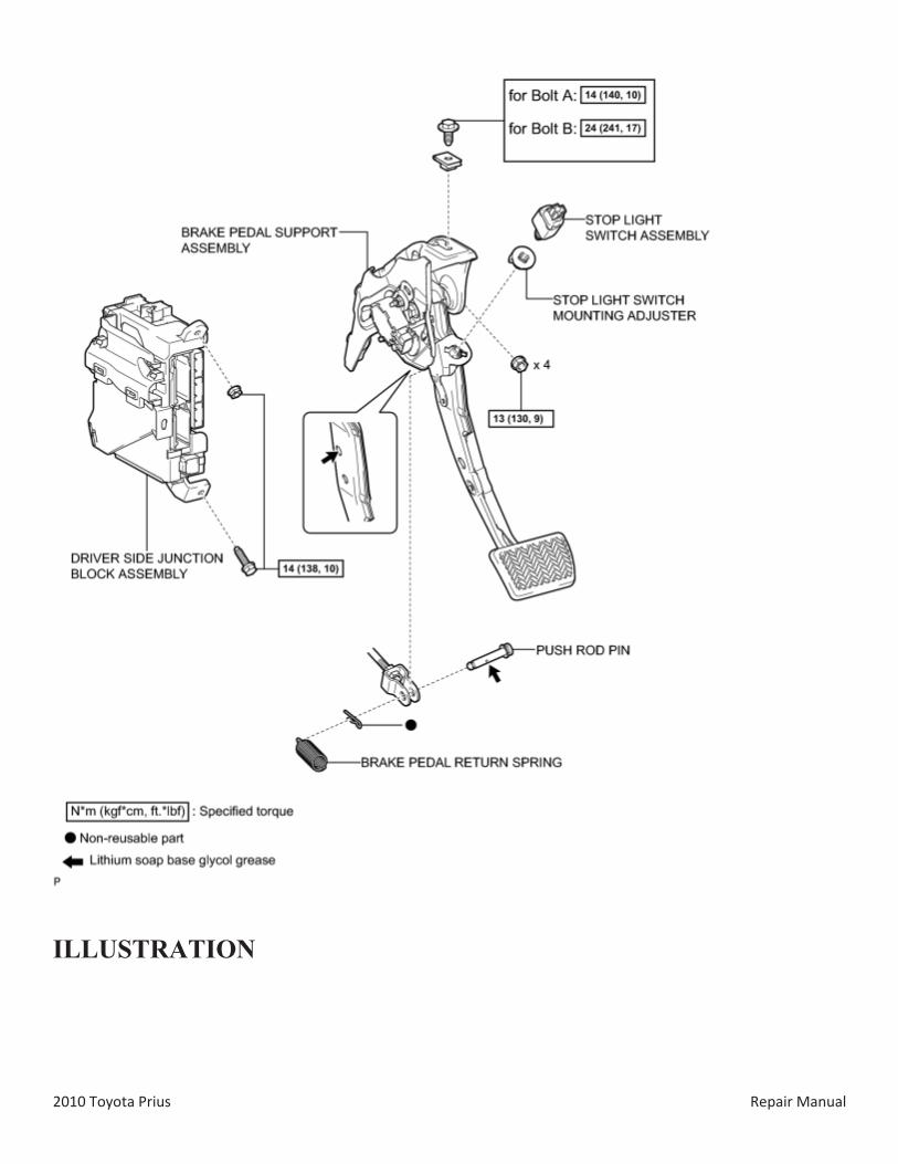
86. REMOVE DRIVER SIDE JUNCTION BLOCK ASSEMBLY
87. REMOVE STOP LIGHT SWITCH ASSEMBLY
88. REMOVE STOP LIGHT SWITCH MOUNTING ADJUSTER
89. REMOVE BRAKE PEDAL RETURN SPRING
90. REMOVE PUSH ROD PIN
91. REMOVE BRAKE PEDAL SUPPORT ASSEMBLY
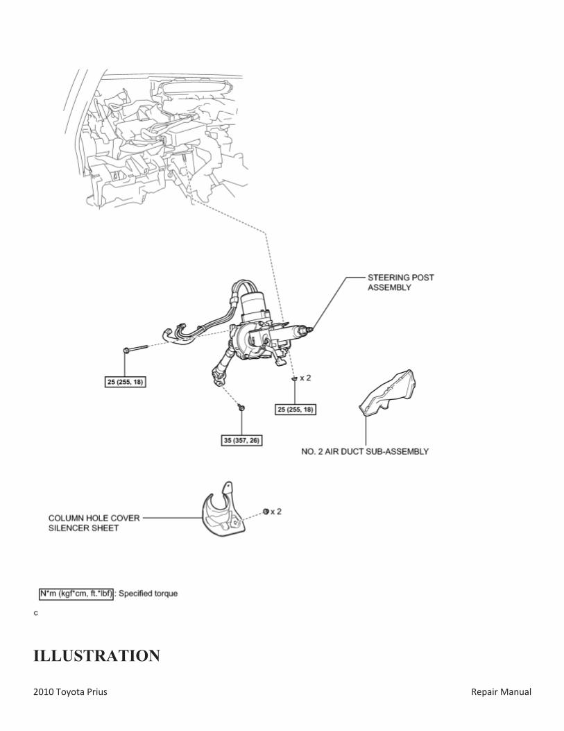
92. REMOVE NO. 2 AIR DUCT SUB-ASSEMBLY
93. REMOVE COLUMN HOLE COVER SILENCER SHEET
94. SEPARATE NO. 2 STEERING INTERMEDIATE SHAFT ASSEMBLY
95. REMOVE STEERING POST ASSEMBLY
for Brush Type Motor:
for Brushless Type Motor:
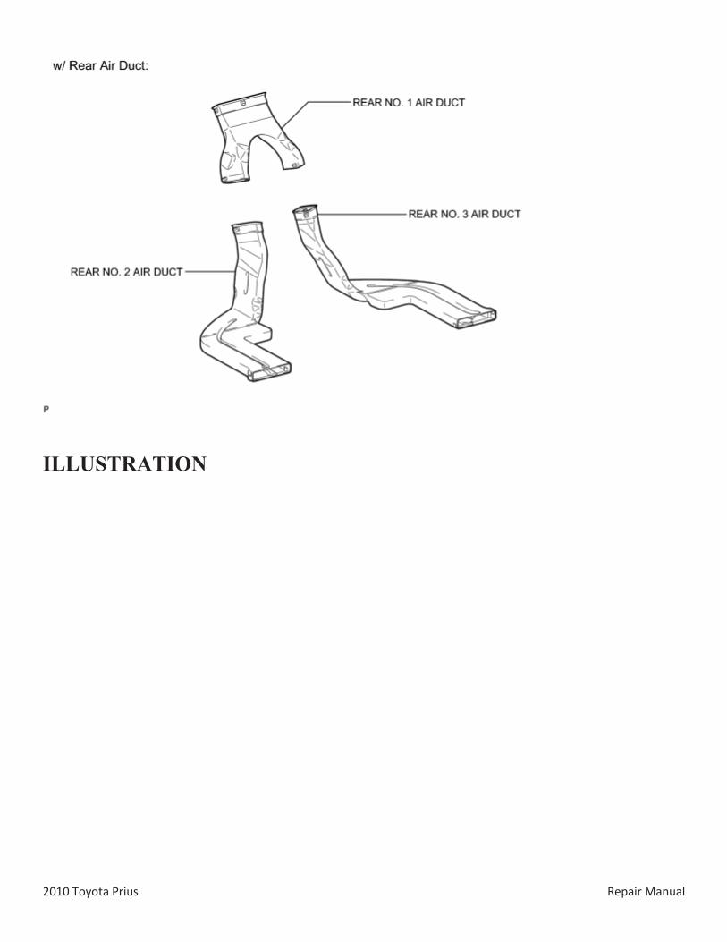
96. REMOVE REAR NO. 2 AIR DUCT (w/ Rear Air Duct)
(a) Disengage each claw to open the 2 door scuff plate clamps as shown in the illustration.
2010 Toyota Prius Repair Manual
(b) Disengage the clip and fastener.
(c) Disengage the 2 claws and turn back the floor carpet as shown in the illustration.
Text in Illustration
*1 Fastener
(d) Disengage the 2 claws and remove the rear No. 2 air duct.
97. REMOVE REAR NO. 3 AIR DUCT (w/ Rear Air Duct)
(a) Disengage each claw to open the 2 door scuff plate clamps as shown in the illustration.
2010 Toyota Prius Repair Manual
(b) Disengage the clip and fastener.
(c) Disengage the 2 claws and turn back the floor carpet as shown in the illustration.
Text in Illustration
*1 Fastener
(d) Disengage the 2 claws and remove the rear No. 3 air duct.
98. REMOVE REAR NO. 1 AIR DUCT (w/ Rear Air Duct)
(a) Disengage the 4 claws and remove the rear No. 1 air duct.
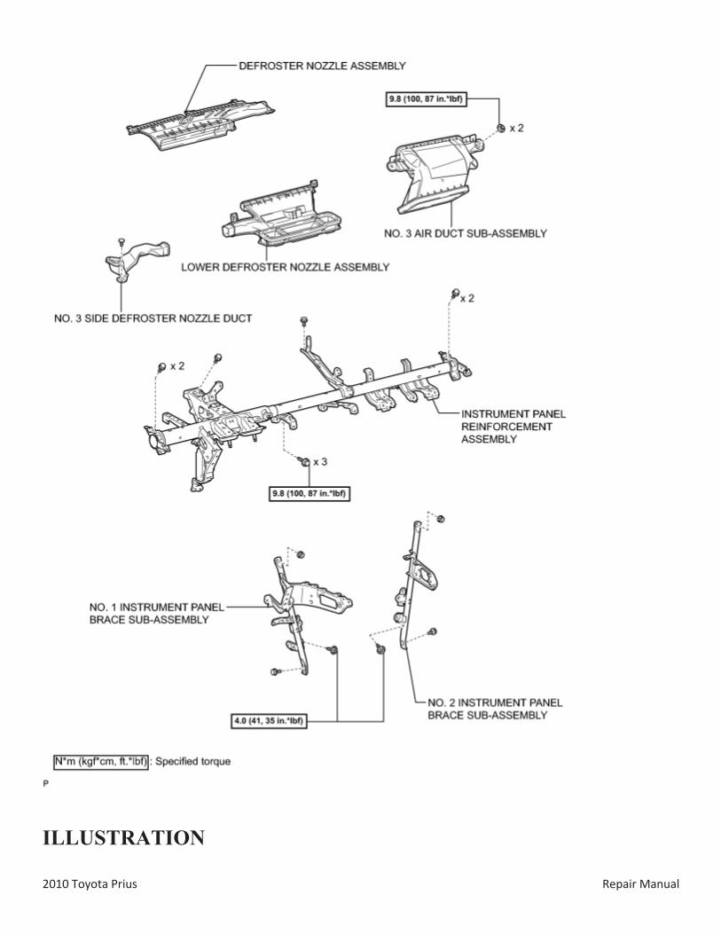
99. REMOVE NO. 3 SIDE DEFROSTER NOZZLE DUCT

2010 Toyota Prius Repair Manual
(a) Remove the clip and No. 3 side defroster nozzle duct.
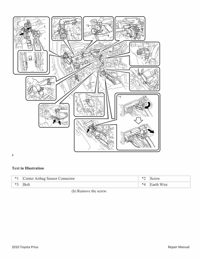
100. REMOVE NO. 1 INSTRUMENT PANEL BRACE SUB-ASSEMBLY
(a) Check that the power switch is off.
(b) Check that the cable is disconnected from the negative (-) battery terminal.
CAUTION:
Wait at least 90 seconds after disconnecting the cable from the negative (-) battery terminal to disable the SRS system.
(c) Disconnect the center airbag sensor connectors from the center airbag sensor assembly as shown in the illustration.
NOTICE:
When disconnecting any airbag connector, take care not to damage the airbag wire harness.
(d) Remove the screw.
(e) Remove the 2 bolts and disconnect the 2 earth wires.
(f) Disconnect each connector.
(g) Disengage each clamp and claw.
2010 Toyota Prius Repair Manual
Text in Illustration
*1 Center Airbag Sensor Connector *2 Screw *3 Bolt *4 Earth Wire
(h) Remove the screw.
2010 Toyota Prius Repair Manual
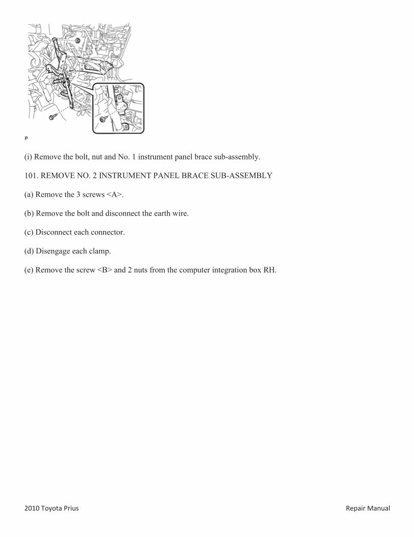
(i) Remove the bolt, nut and No. 1 instrument panel brace sub-assembly.
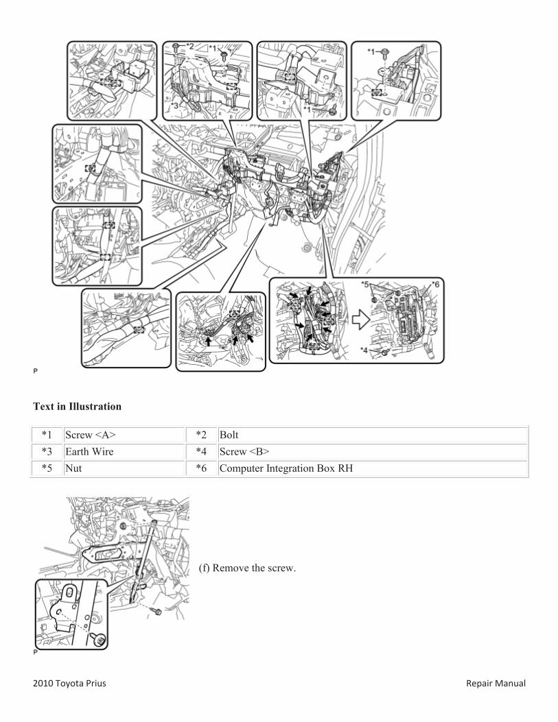
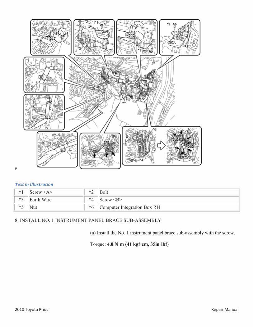
101. REMOVE NO. 2 INSTRUMENT PANEL BRACE SUB-ASSEMBLY
(a) Remove the 3 screws <A>.
(b) Remove the bolt and disconnect the earth wire.
(c) Disconnect each connector.
(d) Disengage each clamp.
(e) Remove the screw <B> and 2 nuts from the computer integration box RH.
2010 Toyota Prius Repair Manual
Text in Illustration
*1 Screw <A> *2 Bolt *3 Earth Wire *4 Screw <B> *5 Nut *6 Computer Integration Box RH
(f) Remove the screw.
2010 Toyota Prius Repair Manual
(g) Remove the bolt, nut and No. 2 instrument panel brace sub-assembly.
102. REMOVE DEFROSTER NOZZLE ASSEMBLY
(a) Disengage the 3 claws.
(b) Remove the defroster nozzle assembly as shown in the illustration.
103. REMOVE LOWER DEFROSTER NOZZLE ASSEMBLY
(a) Disengage the clamp.
(b) Disengage the 6 claws and remove the lower defroster nozzle assembly.
104. REMOVE NO. 3 AIR DUCT SUB-ASSEMBLY
(a) Remove the 2 nuts and No. 3 air duct sub-assembly.
2010 Toyota Prius Repair Manual
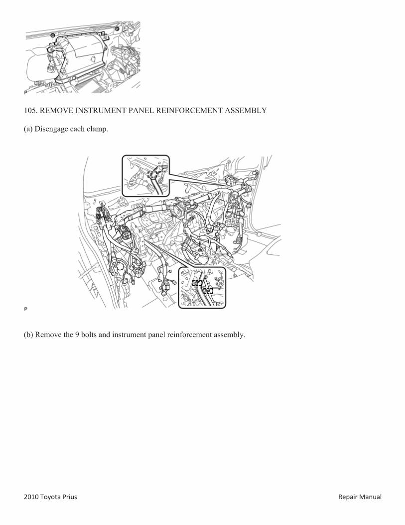
105. REMOVE INSTRUMENT PANEL REINFORCEMENT ASSEMBLY
(a) Disengage each clamp.
(b) Remove the 9 bolts and instrument panel reinforcement assembly.
2010 Toyota Prius Repair Manual
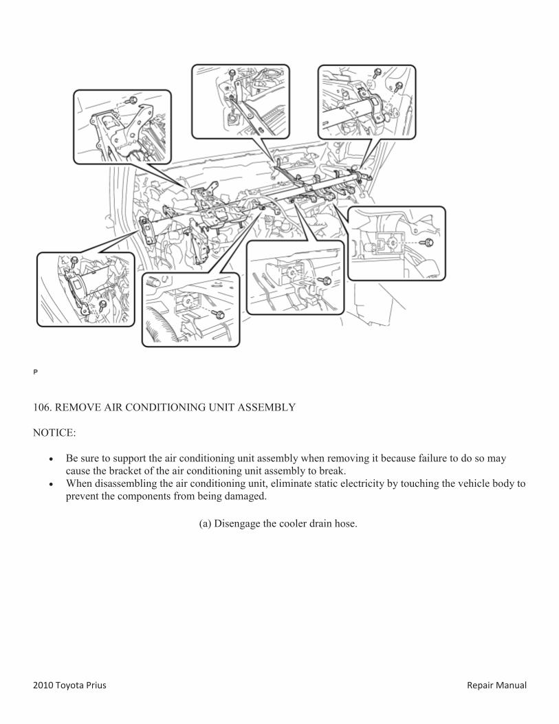
106. REMOVE AIR CONDITIONING UNIT ASSEMBLY
NOTICE:
Be sure to support the air conditioning unit assembly when removing it because failure to do so may cause the bracket of the air conditioning unit assembly to break.
When disassembling the air conditioning unit, eliminate static electricity by touching the vehicle body to prevent the components from being damaged.
(a) Disengage the cooler drain hose.
2010 Toyota Prius Repair Manual
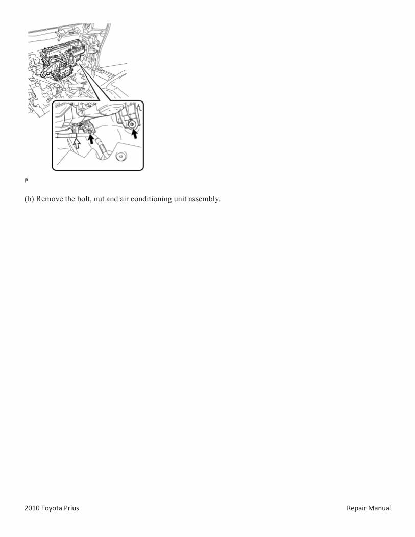
(b) Remove the bolt, nut and air conditioning unit assembly.
2010 Toyota Prius Repair Manual
DISASSEMBLY
1. REMOVE ID CODE BOX (IMMOBILISER CODE ECU) (w/ Engine Immobiliser System)
2. REMOVE BLOWER ASSEMBLY
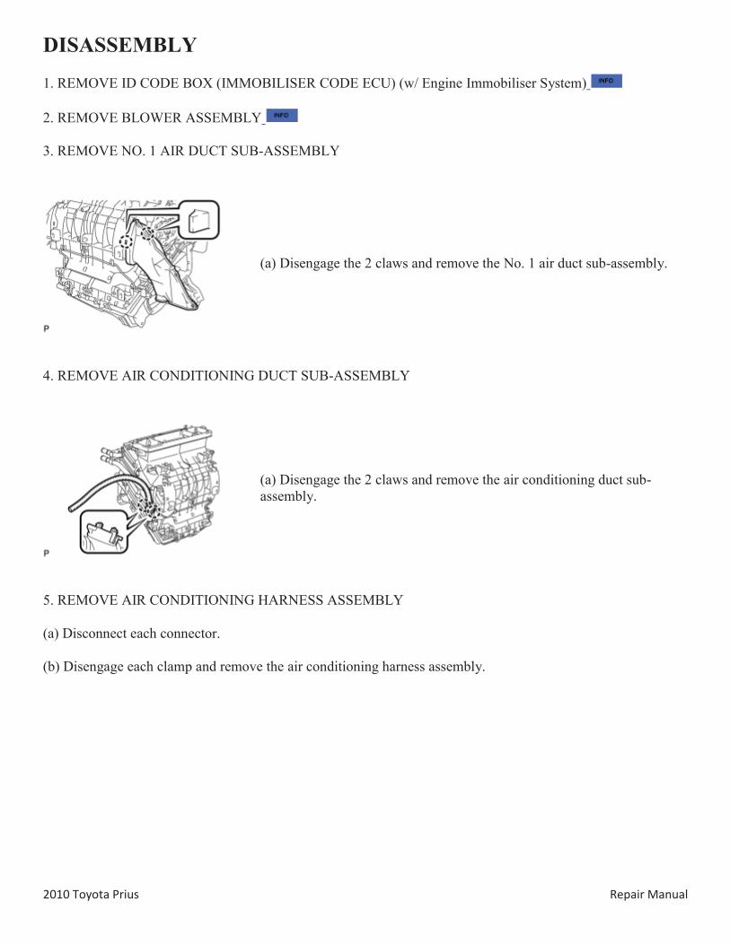
3. REMOVE NO. 1 AIR DUCT SUB-ASSEMBLY
(a) Disengage the 2 claws and remove the No. 1 air duct sub-assembly.
4. REMOVE AIR CONDITIONING DUCT SUB-ASSEMBLY
(a) Disengage the 2 claws and remove the air conditioning duct sub-assembly.
5. REMOVE AIR CONDITIONING HARNESS ASSEMBLY
(a) Disconnect each connector.
(b) Disengage each clamp and remove the air conditioning harness assembly.
2010 Toyota Prius Repair Manual
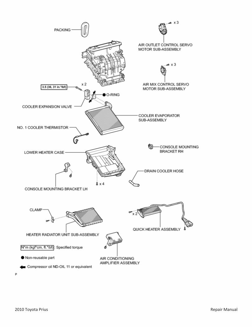
6. REMOVE AIR OUTLET CONTROL SERVO MOTOR SUB-ASSEMBLY
(a) Remove the 3 screws and air outlet control servo motor sub-assembly.
7. REMOVE AIR MIX CONTROL SERVO MOTOR SUB-ASSEMBLY
(a) Remove the 3 screws and air mix control servo motor sub-assembly.
8. REMOVE QUICK HEATER ASSEMBLY
(a) Disengage each clamp.
2010 Toyota Prius Repair Manual
(b) Remove the 2 screws.
(c) Remove the quick heater assembly as shown in the illustration.
9. REMOVE HEATER RADIATOR UNIT SUB-ASSEMBLY
(a) Remove the screw and clamp.
Text in Illustration
*1 Clamp
(b) Remove the heater radiator unit sub-assembly as shown in the illustration.
NOTICE:
Prepare a drain pan or cloth in case the cooling water leaks.
10. REMOVE CONSOLE MOUNTING BRACKET LH
(a) Remove the screw and console mounting bracket LH.
2010 Toyota Prius Repair Manual
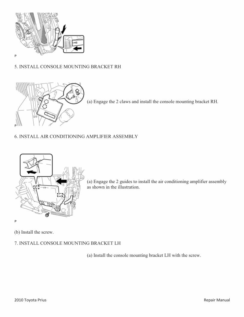
11. REMOVE AIR CONDITIONING AMPLIFIER ASSEMBLY
(a) Remove the screw.
(b) Disengage the 2 guides and remove the air conditioning amplifier assembly as shown in the illustration.
12. REMOVE CONSOLE MOUNTING BRACKET RH
(a) Disengage the 2 claws and remove the console mounting bracket RH.
13. REMOVE DRAIN COOLER HOSE
(a) Remove the drain cooler hose as shown in the illustration.
2010 Toyota Prius Repair Manual
14. REMOVE COOLER EXPANSION VALVE
(a) Using a 4 mm hexagon wrench, remove the 2 hexagon bolts and cooler expansion valve.
15. REMOVE COOLER EVAPORATOR SUB-ASSEMBLY
(a) Remove the packing.
NOTICE:
Remove the packing carefully because it will be reused.
(b) Remove the 4 screws.
2010 Toyota Prius Repair Manual
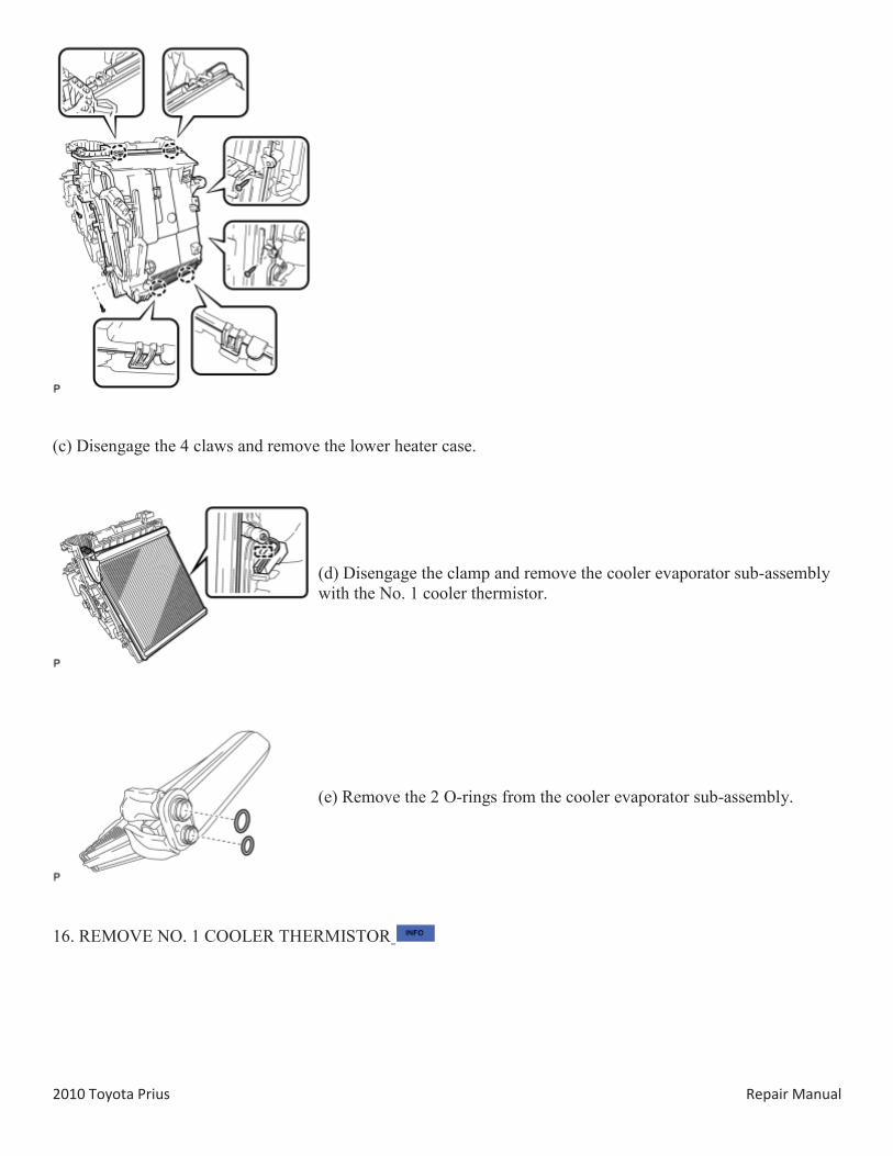
(c) Disengage the 4 claws and remove the lower heater case.
(d) Disengage the clamp and remove the cooler evaporator sub-assembly with the No. 1 cooler thermistor.
(e) Remove the 2 O-rings from the cooler evaporator sub-assembly.
16. REMOVE NO. 1 COOLER THERMISTOR
2010 Toyota Prius Repair Manual
REASSEMBLY
1. INSTALL NO. 1 COOLER THERMISTOR
2. INSTALL COOLER EVAPORATOR SUB-ASSEMBLY
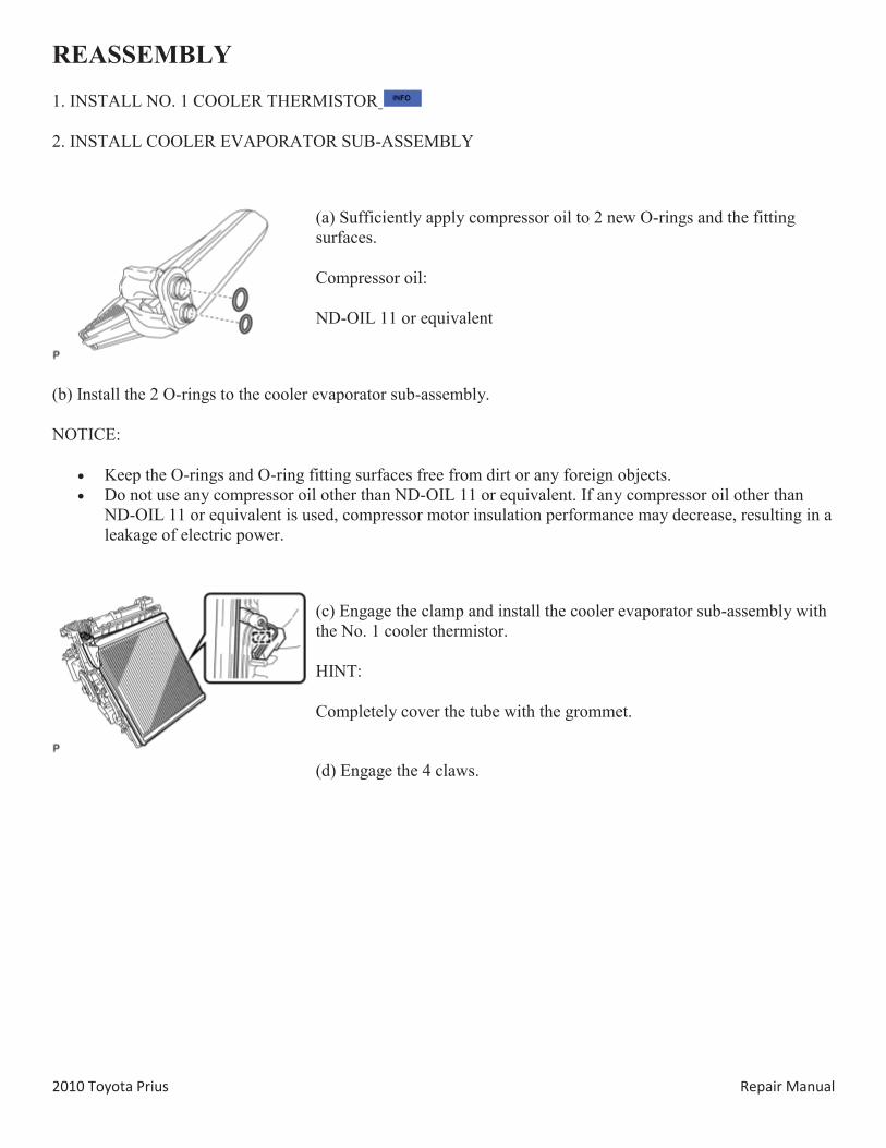
(a) Sufficiently apply compressor oil to 2 new O-rings and the fitting surfaces.
Compressor oil:
ND-OIL 11 or equivalent
(b) Install the 2 O-rings to the cooler evaporator sub-assembly.
NOTICE:
Keep the O-rings and O-ring fitting surfaces free from dirt or any foreign objects. Do not use any compressor oil other than ND-OIL 11 or equivalent. If any compressor oil other than
ND-OIL 11 or equivalent is used, compressor motor insulation performance may decrease, resulting in a leakage of electric power.
(c) Engage the clamp and install the cooler evaporator sub-assembly with the No. 1 cooler thermistor.
HINT:
Completely cover the tube with the grommet.
(d) Engage the 4 claws.
2010 Toyota Prius Repair Manual
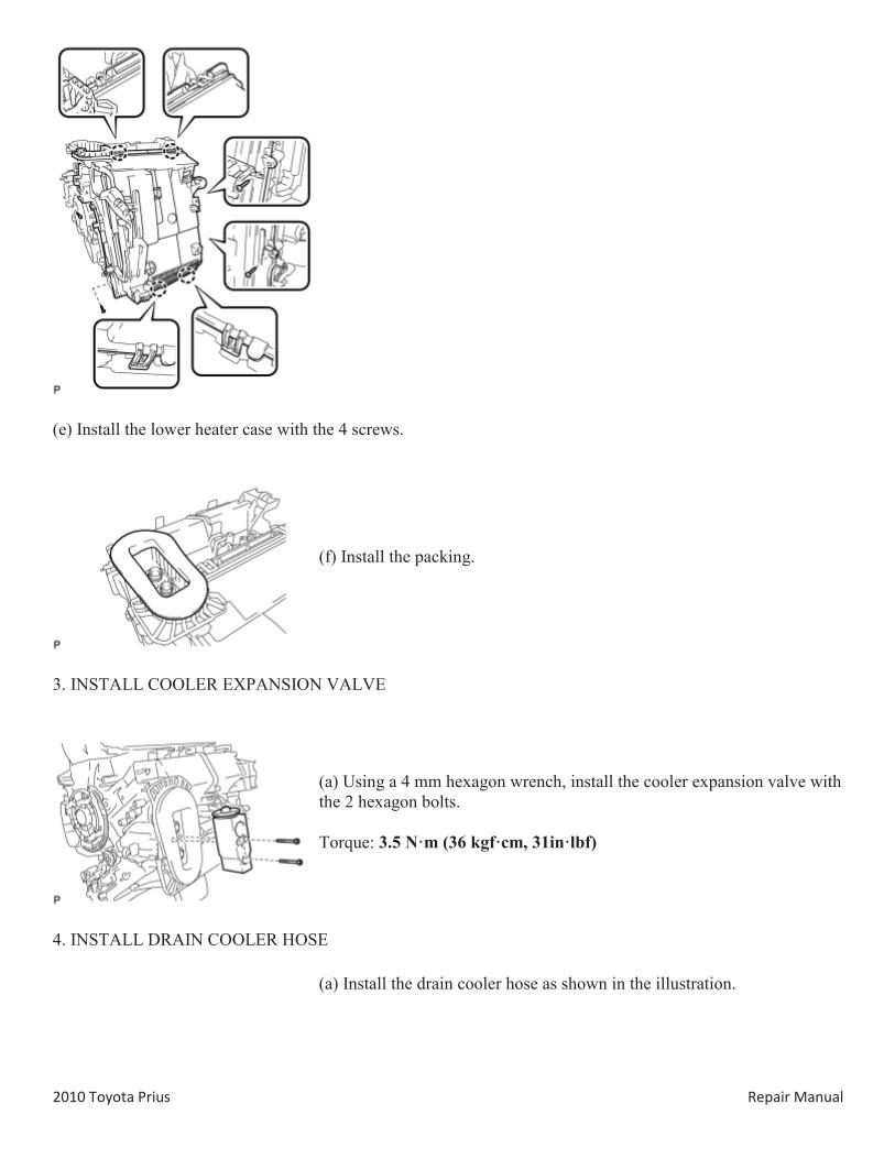
(e) Install the lower heater case with the 4 screws.
(f) Install the packing.
3. INSTALL COOLER EXPANSION VALVE
(a) Using a 4 mm hexagon wrench, install the cooler expansion valve with the 2 hexagon bolts.
Torque: 3.5 N·m (36 kgf·cm, 31in·lbf)
4. INSTALL DRAIN COOLER HOSE
(a) Install the drain cooler hose as shown in the illustration.
2010 Toyota Prius Repair Manual
5. INSTALL CONSOLE MOUNTING BRACKET RH
(a) Engage the 2 claws and install the console mounting bracket RH.
6. INSTALL AIR CONDITIONING AMPLIFIER ASSEMBLY
(a) Engage the 2 guides to install the air conditioning amplifier assembly as shown in the illustration.
(b) Install the screw.
7. INSTALL CONSOLE MOUNTING BRACKET LH
(a) Install the console mounting bracket LH with the screw.
2010 Toyota Prius Repair Manual
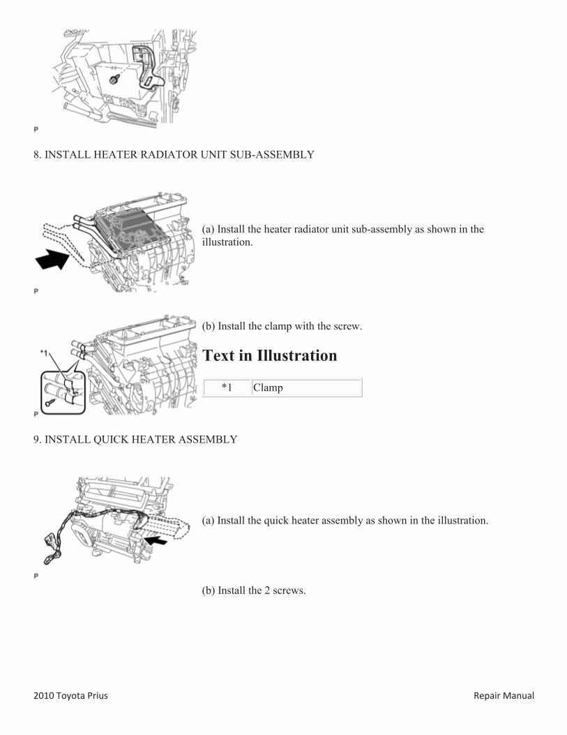
8. INSTALL HEATER RADIATOR UNIT SUB-ASSEMBLY
(a) Install the heater radiator unit sub-assembly as shown in the illustration.
(b) Install the clamp with the screw.
Text in Illustration
*1 Clamp
9. INSTALL QUICK HEATER ASSEMBLY
(a) Install the quick heater assembly as shown in the illustration.
(b) Install the 2 screws.
2010 Toyota Prius Repair Manual
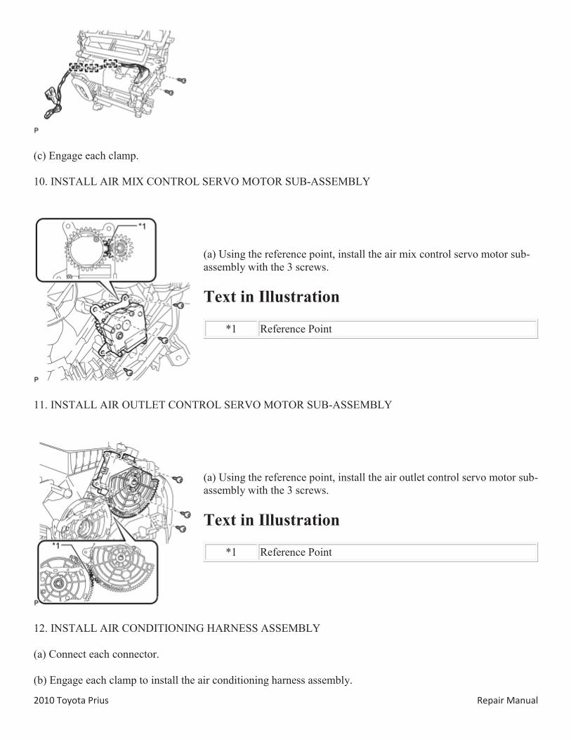
(c) Engage each clamp.
10. INSTALL AIR MIX CONTROL SERVO MOTOR SUB-ASSEMBLY
(a) Using the reference point, install the air mix control servo motor sub-assembly with the 3 screws.
Text in Illustration
*1 Reference Point
11. INSTALL AIR OUTLET CONTROL SERVO MOTOR SUB-ASSEMBLY
(a) Using the reference point, install the air outlet control servo motor sub-assembly with the 3 screws.
Text in Illustration
*1 Reference Point
12. INSTALL AIR CONDITIONING HARNESS ASSEMBLY
(a) Connect each connector.
(b) Engage each clamp to install the air conditioning harness assembly.
2010 Toyota Prius Repair Manual
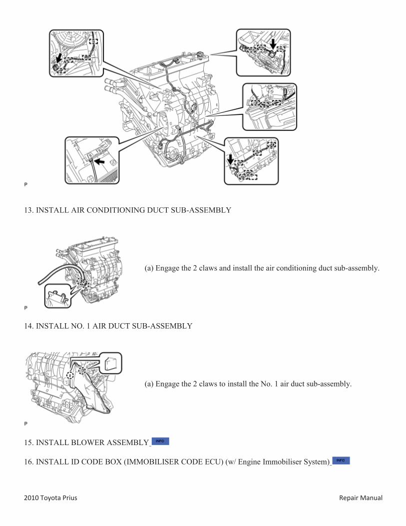
13. INSTALL AIR CONDITIONING DUCT SUB-ASSEMBLY
(a) Engage the 2 claws and install the air conditioning duct sub-assembly.
14. INSTALL NO. 1 AIR DUCT SUB-ASSEMBLY
(a) Engage the 2 claws to install the No. 1 air duct sub-assembly.
15. INSTALL BLOWER ASSEMBLY
16. INSTALL ID CODE BOX (IMMOBILISER CODE ECU) (w/ Engine Immobiliser System)
2010 Toyota Prius Repair Manual
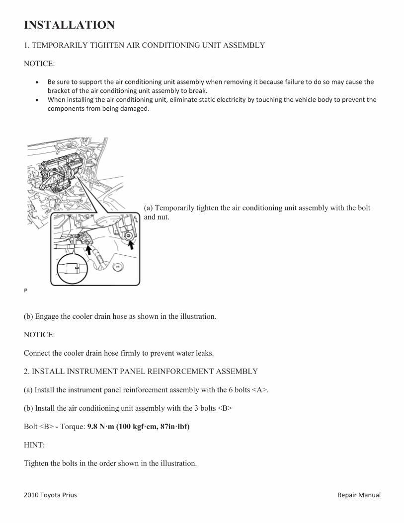
INSTALLATION 1. TEMPORARILY TIGHTEN AIR CONDITIONING UNIT ASSEMBLY
NOTICE:
Be sure to support the air conditioning unit assembly when removing it because failure to do so may cause the bracket of the air conditioning unit assembly to break.
When installing the air conditioning unit, eliminate static electricity by touching the vehicle body to prevent the components from being damaged.
(a) Temporarily tighten the air conditioning unit assembly with the bolt and nut.
(b) Engage the cooler drain hose as shown in the illustration.
NOTICE:
Connect the cooler drain hose firmly to prevent water leaks.
2. INSTALL INSTRUMENT PANEL REINFORCEMENT ASSEMBLY
(a) Install the instrument panel reinforcement assembly with the 6 bolts <A>.
(b) Install the air conditioning unit assembly with the 3 bolts <B>
Bolt <B> - Torque: 9.8 N·m (100 kgf·cm, 87in·lbf)
HINT:
Tighten the bolts in the order shown in the illustration.
2010 Toyota Prius Repair Manual
(c) Engage each clamp.
2010 Toyota Prius Repair Manual
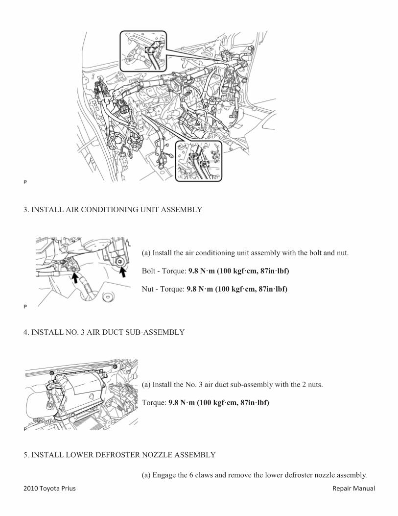
3. INSTALL AIR CONDITIONING UNIT ASSEMBLY
(a) Install the air conditioning unit assembly with the bolt and nut.
Bolt - Torque: 9.8 N·m (100 kgf·cm, 87in·lbf)
Nut - Torque: 9.8 N·m (100 kgf·cm, 87in·lbf)
4. INSTALL NO. 3 AIR DUCT SUB-ASSEMBLY
(a) Install the No. 3 air duct sub-assembly with the 2 nuts.
Torque: 9.8 N·m (100 kgf·cm, 87in·lbf)
5. INSTALL LOWER DEFROSTER NOZZLE ASSEMBLY
(a) Engage the 6 claws and remove the lower defroster nozzle assembly.
2010 Toyota Prius Repair Manual
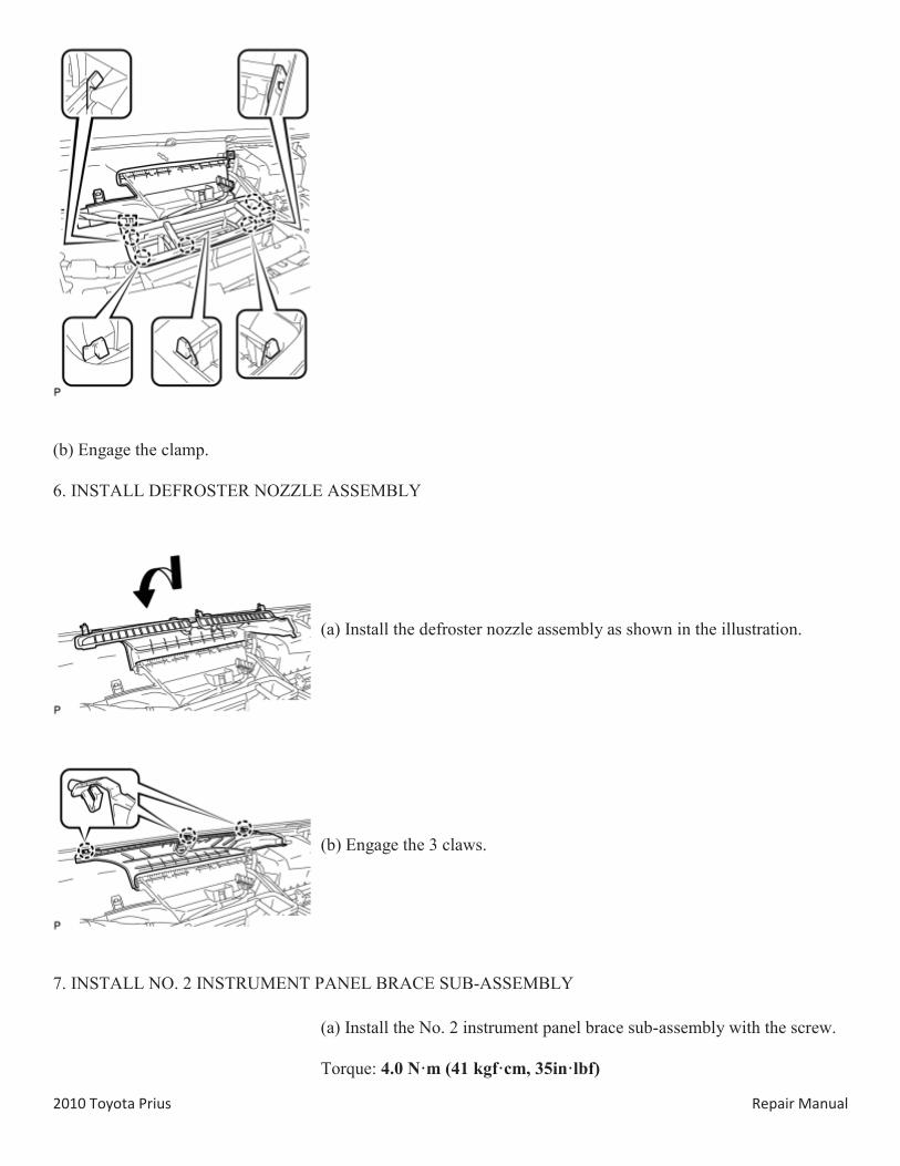
(b) Engage the clamp.
6. INSTALL DEFROSTER NOZZLE ASSEMBLY
(a) Install the defroster nozzle assembly as shown in the illustration.
(b) Engage the 3 claws.
7. INSTALL NO. 2 INSTRUMENT PANEL BRACE SUB-ASSEMBLY
(a) Install the No. 2 instrument panel brace sub-assembly with the screw.
Torque: 4.0 N·m (41 kgf·cm, 35in·lbf)
2010 Toyota Prius Repair Manual
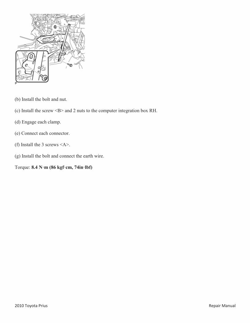
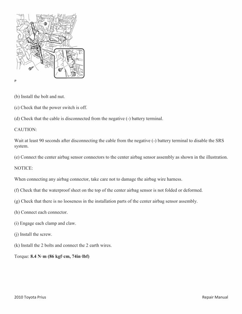
(b) Install the bolt and nut.
(c) Install the screw <B> and 2 nuts to the computer integration box RH.
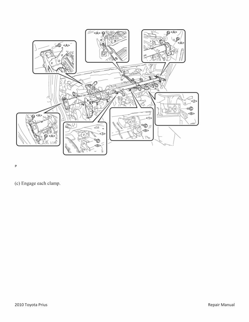
(d) Engage each clamp.
(e) Connect each connector.
(f) Install the 3 screws <A>.
(g) Install the bolt and connect the earth wire.
Torque: 8.4 N·m (86 kgf·cm, 74in·lbf)
2010 Toyota Prius Repair Manual
Text in Illustration
*1 Screw <A> *2 Bolt *3 Earth Wire *4 Screw <B> *5 Nut *6 Computer Integration Box RH
8. INSTALL NO. 1 INSTRUMENT PANEL BRACE SUB-ASSEMBLY
(a) Install the No. 1 instrument panel brace sub-assembly with the screw.
Torque: 4.0 N·m (41 kgf·cm, 35in·lbf)
2010 Toyota Prius Repair Manual
(b) Install the bolt and nut.
(c) Check that the power switch is off.
(d) Check that the cable is disconnected from the negative (-) battery terminal.
CAUTION:
Wait at least 90 seconds after disconnecting the cable from the negative (-) battery terminal to disable the SRS system.
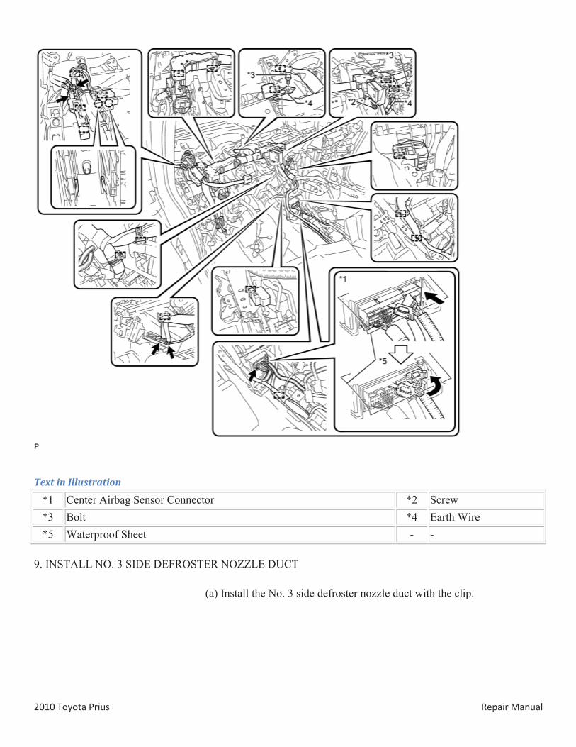
(e) Connect the center airbag sensor connectors to the center airbag sensor assembly as shown in the illustration.
NOTICE:
When connecting any airbag connector, take care not to damage the airbag wire harness.
(f) Check that the waterproof sheet on the top of the center airbag sensor is not folded or deformed.
(g) Check that there is no looseness in the installation parts of the center airbag sensor assembly.
(h) Connect each connector.
(i) Engage each clamp and claw.
(j) Install the screw.
(k) Install the 2 bolts and connect the 2 earth wires.
Torque: 8.4 N·m (86 kgf·cm, 74in·lbf)
2010 Toyota Prius Repair Manual
Text in Illustration
*1 Center Airbag Sensor Connector *2 Screw *3 Bolt *4 Earth Wire *5 Waterproof Sheet - -
9. INSTALL NO. 3 SIDE DEFROSTER NOZZLE DUCT
(a) Install the No. 3 side defroster nozzle duct with the clip.
2010 Toyota Prius Repair Manual
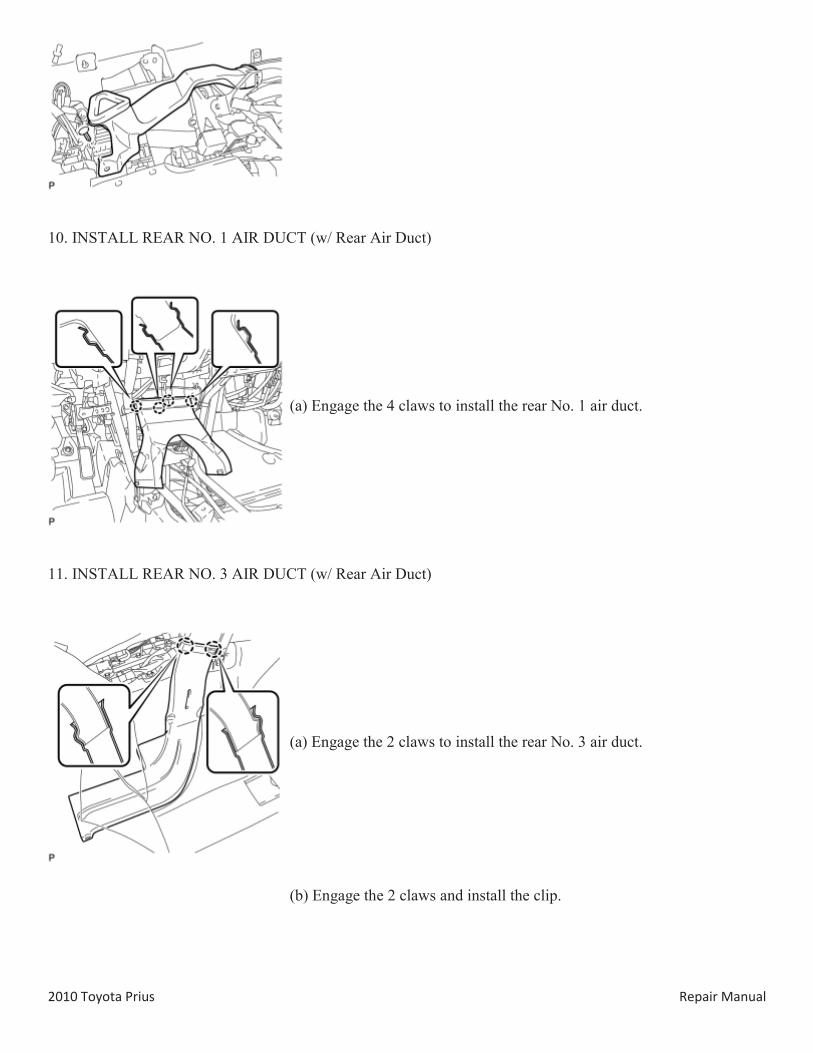
10. INSTALL REAR NO. 1 AIR DUCT (w/ Rear Air Duct)
(a) Engage the 4 claws to install the rear No. 1 air duct.
11. INSTALL REAR NO. 3 AIR DUCT (w/ Rear Air Duct)
(a) Engage the 2 claws to install the rear No. 3 air duct.
(b) Engage the 2 claws and install the clip.
2010 Toyota Prius Repair Manual
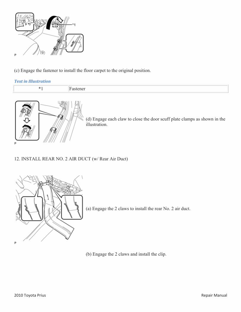
(c) Engage the fastener to install the floor carpet to the original position.
Text in Illustration
*1 Fastener
(d) Engage each claw to close the door scuff plate clamps as shown in the illustration.
12. INSTALL REAR NO. 2 AIR DUCT (w/ Rear Air Duct)
(a) Engage the 2 claws to install the rear No. 2 air duct.
(b) Engage the 2 claws and install the clip.
2010 Toyota Prius Repair Manual
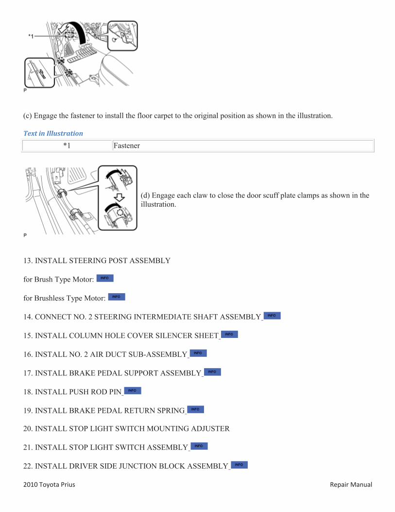
(c) Engage the fastener to install the floor carpet to the original position as shown in the illustration.
Text in Illustration
*1 Fastener
(d) Engage each claw to close the door scuff plate clamps as shown in the illustration.
13. INSTALL STEERING POST ASSEMBLY
for Brush Type Motor:
for Brushless Type Motor:
14. CONNECT NO. 2 STEERING INTERMEDIATE SHAFT ASSEMBLY
15. INSTALL COLUMN HOLE COVER SILENCER SHEET
16. INSTALL NO. 2 AIR DUCT SUB-ASSEMBLY
17. INSTALL BRAKE PEDAL SUPPORT ASSEMBLY
18. INSTALL PUSH ROD PIN
19. INSTALL BRAKE PEDAL RETURN SPRING
20. INSTALL STOP LIGHT SWITCH MOUNTING ADJUSTER
21. INSTALL STOP LIGHT SWITCH ASSEMBLY
22. INSTALL DRIVER SIDE JUNCTION BLOCK ASSEMBLY
2010 Toyota Prius Repair Manual
23. INSTALL LOWER INSTRUMENT PANEL SUB-ASSEMBLY
24. INSTALL NO. 2 ANTENNA CORD SUB-ASSEMBLY
25. INSTALL INSTRUMENT PANEL SAFETY PAD PLATE SUB-ASSEMBLY (for LHD)
26. INSTALL POWER STEERING ECU ASSEMBLY (for Brush Type Motor)
27. INSTALL POWER STEERING ECU ASSEMBLY (for Brushless Type Motor)
28. INSTALL COMBINATION METER ASSEMBLY
29. INSTALL NO. 1 HEATER TO REGISTER DUCT
30. INSTALL COWL SIDE TRIM BOARD RH
HINT:
Use the same procedure for the RH side and LH side.
31. INSTALL FRONT DOOR SCUFF PLATE RH
HINT:
Use the same procedure for the RH side and LH side.
32. INSTALL GLOVE COMPARTMENT DOOR ASSEMBLY
33. INSTALL NO. 2 INSTRUMENT PANEL UNDER COVER SUB-ASSEMBLY
34. INSTALL DRIVER SIDE KNEE AIRBAG ASSEMBLY
35. INSTALL NO. 1 INSTRUMENT PANEL UNDER COVER SUB-ASSEMBLY
36. ALIGN FRONT WHEELS FACING STRAIGHT AHEAD
37. INSTALL TURN SIGNAL SWITCH ASSEMBLY WITH SPIRAL CABLE SUB-ASSEMBLY
38. INSTALL UPPER STEERING COLUMN COVER
39. INSTALL LOWER STEERING COLUMN COVER
40. INSTALL STEERING WHEEL ASSEMBLY
41. INSTALL STEERING PAD
42. INSTALL LOWER NO. 3 STEERING WHEEL COVER
43. INSTALL LOWER NO. 2 STEERING WHEEL COVER
2010 Toyota Prius Repair Manual
44. INSTALL NO. 1 SWITCH HOLE BASE
45. INSTALL UPPER INSTRUMENT PANEL FINISH PANEL ASSEMBLY
46. INSTALL SHIFT LOCK CONTROL UNIT ASSEMBLY
47. INSTALL AIR CONDITIONING CONTROL ASSEMBLY
48. INSTALL CONSOLE BOX ASSEMBLY
49. INSTALL BOX BOTTOM MAT
50. INSTALL FRONT NO. 2 CONSOLE BOX INSERT
51. INSTALL FRONT NO. 1 CONSOLE BOX INSERT
52. INSTALL NO. 2 CONSOLE BOX MOUNTING BRACKET
53. INSTALL ELECTRICAL KEY OSCILLATOR
54. INSTALL REAR CONSOLE BOX ASSEMBLY (w/ Power Outlet Socket)
55. INSTALL REAR CONSOLE BOX ASSEMBLY (w/o Power Outlet Socket)
56. INSTALL CONSOLE BOX CARPET
57. INSTALL UPPER CONSOLE PANEL (w/ Power Outlet Socket)
58. INSTALL REAR CONSOLE BOX POCKET (w/ Power Outlet Socket)
59. INSTALL UPPER INSTRUMENT PANEL ASSEMBLY
60. CONNECT INSTRUMENT PANEL WIRE
61. INSTALL CENTER INSTRUMENT CLUSTER FINISH PANEL GARNISH
62. INSTALL FRONT NO. 2 SPEAKER ASSEMBLY
HINT:
Use the same procedure for the RH side and LH side.
63. INSTALL NO. 2 INSTRUMENT PANEL SPEAKER PANEL SUB-ASSEMBLY
64. INSTALL FRONT PILLAR GARNISH CORNER PIECE RH
65. INSTALL FRONT PILLAR GARNISH RH
HINT:
2010 Toyota Prius Repair Manual
Use the same procedure for the RH side and LH side.
66. INSTALL FRONT NO. 2 SPEAKER ASSEMBLY
67. INSTALL NO. 1 INSTRUMENT PANEL SPEAKER PANEL SUB-ASSEMBLY
68. INSTALL FRONT PILLAR GARNISH CORNER PIECE LH
69. INSTALL FRONT PILLAR GARNISH LH
70. INSTALL INSTRUMENT PANEL FINISH PANEL END RH
71. CONNECT FRONT DOOR OPENING TRIM WEATHERSTRIP RH
72. INSTALL GLOVE COMPARTMENT DOOR
73. INSTALL NO. 2 INSTRUMENT PANEL REGISTER
74. INSTALL NO. 1 SIDE DEFROSTER NOZZLE
75. INSTALL INSTRUMENT PANEL FINISH PANEL END LH
76. CONNECT FRONT DOOR OPENING TRIM WEATHERSTRIP LH
77. INSTALL NO. 1 CENTER INSTRUMENT CLUSTER FINISH PANEL
78. INSTALL NO. 1 INSTRUMENT PANEL REGISTER
79. INSTALL LOWER INSTRUMENT PANEL FINISH PANEL ASSEMBLY
80. INSTALL COWL SIDE TRIM SUB-ASSEMBLY LH
81. INSTALL FRONT DOOR SCUFF PLATE LH
82. INSTALL NAVIGATION RECEIVER WITH BRACKET (w/ Navigation System)
83. INSTALL RADIO RECEIVER WITH BRACKET (w/o Navigation System)
84. INSTALL UPPER INSTRUMENT PANEL FINISH PANEL SUB-ASSEMBLY
85. INSTALL INSTRUMENT CLUSTER FINISH PANEL GARNISH
86. INSTALL LOWER CENTER INSTRUMENT CLUSTER FINISH PANEL SUB-ASSEMBLY
87. INSTALL INTEGRATION CONTROL AND PANEL ASSEMBLY
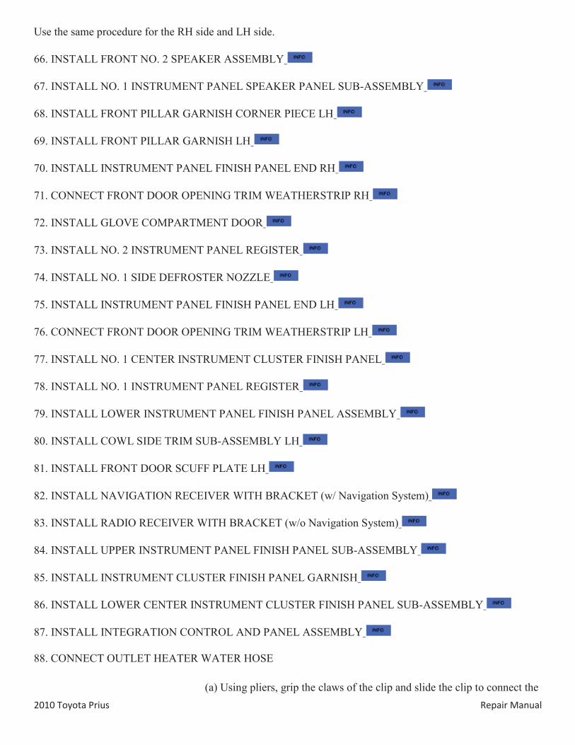
88. CONNECT OUTLET HEATER WATER HOSE
(a) Using pliers, grip the claws of the clip and slide the clip to connect the
2010 Toyota Prius Repair Manual
outlet heater water hose.
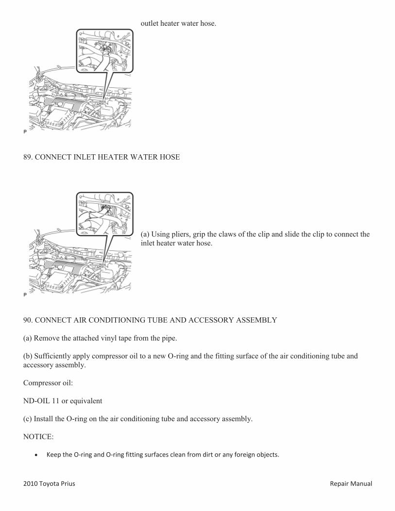
89. CONNECT INLET HEATER WATER HOSE
(a) Using pliers, grip the claws of the clip and slide the clip to connect the inlet heater water hose.
90. CONNECT AIR CONDITIONING TUBE AND ACCESSORY ASSEMBLY
(a) Remove the attached vinyl tape from the pipe.
(b) Sufficiently apply compressor oil to a new O-ring and the fitting surface of the air conditioning tube and accessory assembly.
Compressor oil:
ND-OIL 11 or equivalent
(c) Install the O-ring on the air conditioning tube and accessory assembly.
NOTICE:
Keep the O-ring and O-ring fitting surfaces clean from dirt or any foreign objects.
2010 Toyota Prius Repair Manual
Do not use any compressor oil other than ND-OIL 11 or equivalent. If any compressor oil other than ND-OIL 11 or equivalent is used, compressor motor insulation performance may decrease, resulting in a leakage of electric power.
(d) Install the air conditioning tube and accessory assembly.
91. CONNECT SUCTION PIPE SUB-ASSEMBLY
(a) Remove the attached vinyl tape from the pipe.
(b) Sufficiently apply compressor oil to a new O-ring and the fitting surface of the suction pipe sub-assembly.
Compressor oil:
ND-OIL 11 or equivalent
(c) Install the O-ring on the suction pipe sub-assembly.
NOTICE:
Keep the O-ring and O-ring fitting surfaces clean from dirt or any foreign objects. Do not use any compressor oil other than ND-OIL 11 or equivalent. If any compressor oil other than ND-OIL 11 or
equivalent is used, compressor motor insulation performance may decrease, resulting in a leakage of electric power.
(d) Install the suction pipe sub-assembly.
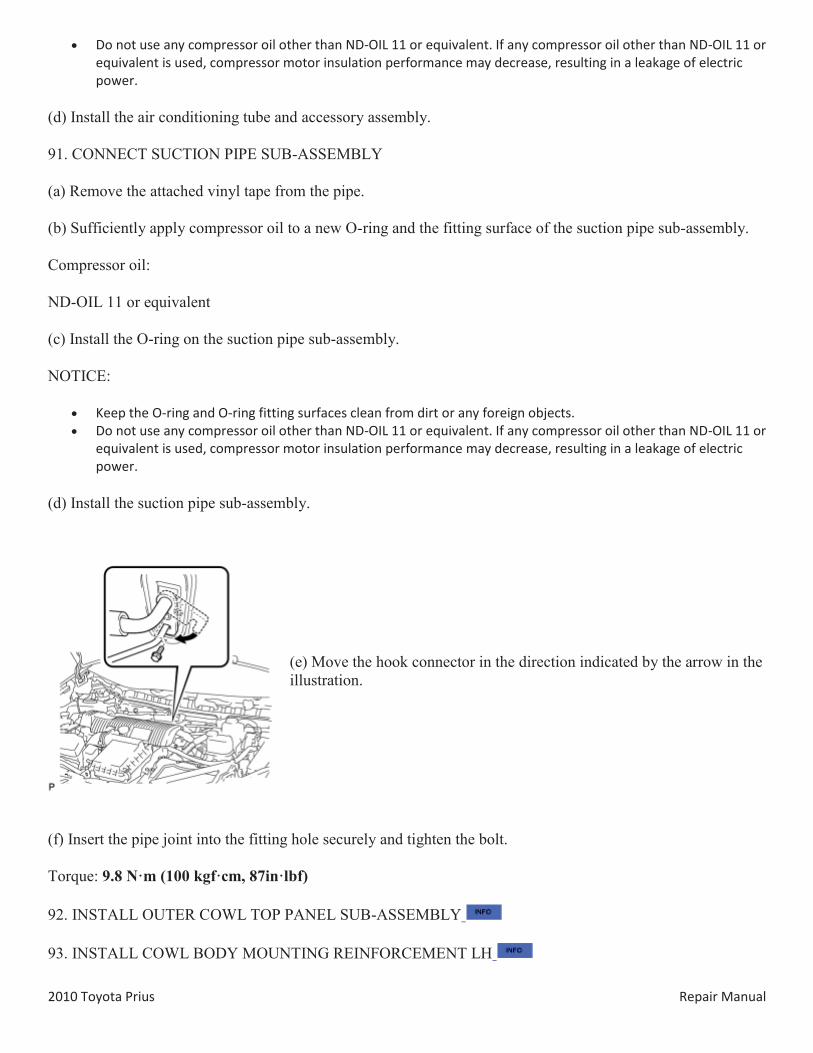
(e) Move the hook connector in the direction indicated by the arrow in the illustration.
(f) Insert the pipe joint into the fitting hole securely and tighten the bolt.
Torque: 9.8 N·m (100 kgf·cm, 87in·lbf)
92. INSTALL OUTER COWL TOP PANEL SUB-ASSEMBLY
93. INSTALL COWL BODY MOUNTING REINFORCEMENT LH
2010 Toyota Prius Repair Manual
94. INSTALL WINDSHIELD WIPER MOTOR AND LINK ASSEMBLY
95. INSTALL COWL TOP VENTILATOR LOUVER SUB-ASSEMBLY
96. INSTALL COWL SIDE VENTILATOR SUB-ASSEMBLY LH
97. INSTALL COWL SIDE VENTILATOR SUB-ASSEMBLY RH
98. INSTALL FRONT WIPER ARM AND BLADE ASSEMBLY RH
99. INSTALL FRONT WIPER ARM AND BLADE ASSEMBLY LH
100. INSTALL FRONT WIPER ARM HEAD CAP
101. CONNECT CABLE TO NEGATIVE BATTERY TERMINAL
NOTICE:
When disconnecting the cable, some systems need to be initialized after the cable is reconnected .
102. INSTALL REAR NO. 3 FLOOR BOARD
103. INSTALL REAR DECK FLOOR BOX
104. INSTALL REAR NO. 2 FLOOR BOARD (for Separate Type)
105. ADD COOLANT (for Engine)
106. CHARGE WITH REFRIGERANT
107. WARM UP COMPRESSOR
108. INSPECT FOR REFRIGERANT LEAK
109. INSPECT FOR COOLANT LEAK (for Engine)
110. INSPECT SHIFT LEVER
111. INSPECT STEERING PAD
(a) Inspect the steering pad .
112. INSPECT SRS WARNING LIGHT
(a) Inspect the SRS warning light .
2010 Toyota Prius Repair Manual
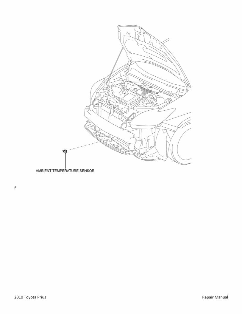
COMPONENTS
ILLUSTRATION
ILLUSTRATION
2010 Toyota Prius Repair Manual
2010 Toyota Prius Repair Manual
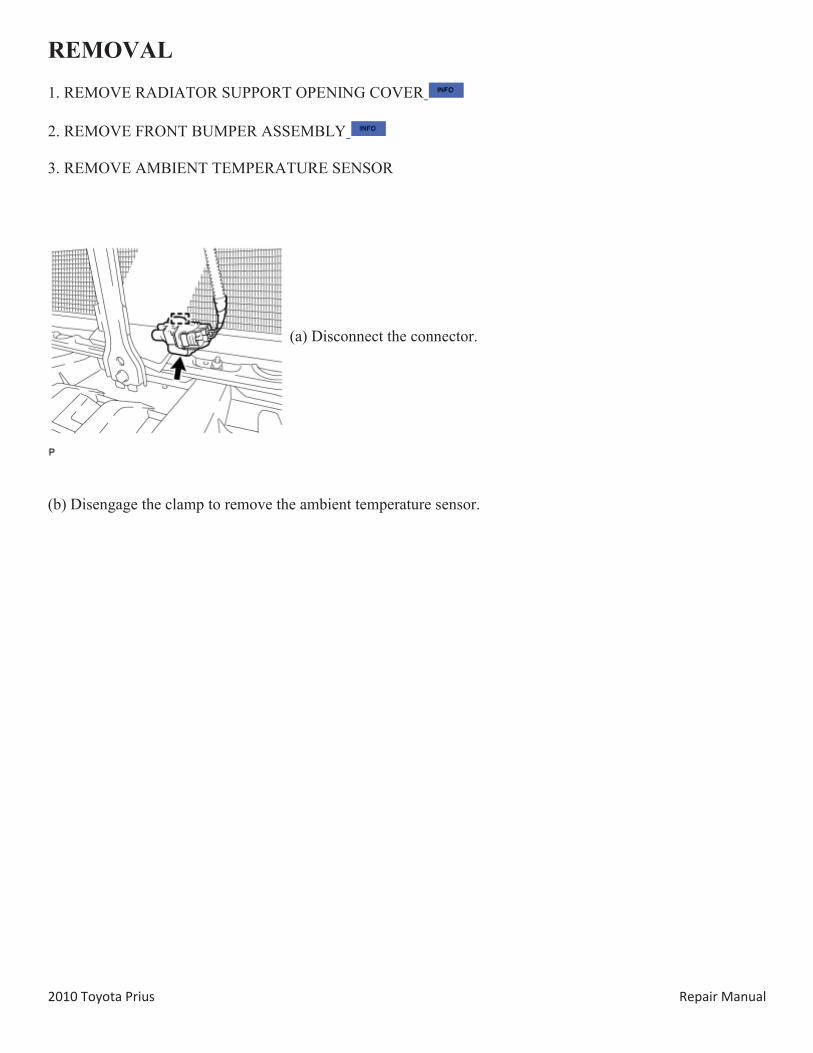
REMOVAL
1. REMOVE RADIATOR SUPPORT OPENING COVER
2. REMOVE FRONT BUMPER ASSEMBLY
3. REMOVE AMBIENT TEMPERATURE SENSOR
(a) Disconnect the connector.
(b) Disengage the clamp to remove the ambient temperature sensor.
2010 Toyota Prius Repair Manual
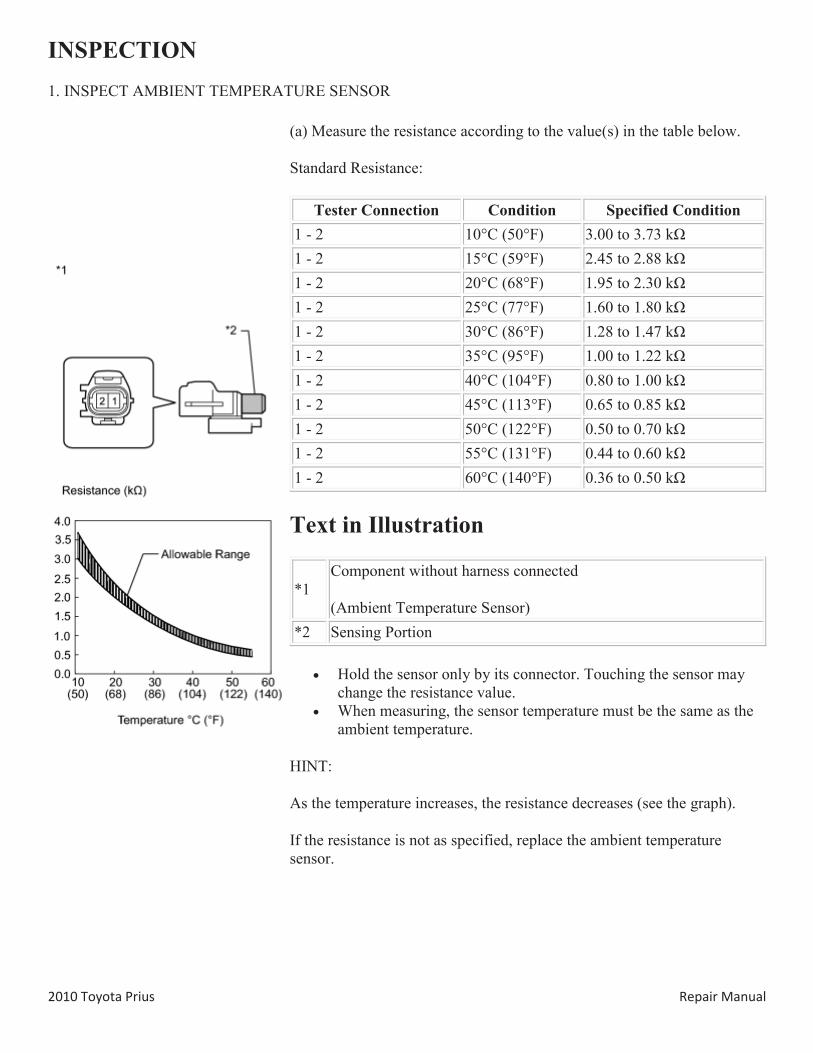
INSPECTION 1. INSPECT AMBIENT TEMPERATURE SENSOR
(a) Measure the resistance according to the value(s) in the table below.
Standard Resistance:
Tester Connection Condition Specified Condition 1 - 2 10°C (50°F) 3.00 to 3.73 kΩ 1 - 2 15°C (59°F) 2.45 to 2.88 kΩ 1 - 2 20°C (68°F) 1.95 to 2.30 kΩ 1 - 2 25°C (77°F) 1.60 to 1.80 kΩ 1 - 2 30°C (86°F) 1.28 to 1.47 kΩ 1 - 2 35°C (95°F) 1.00 to 1.22 kΩ 1 - 2 40°C (104°F) 0.80 to 1.00 kΩ 1 - 2 45°C (113°F) 0.65 to 0.85 kΩ 1 - 2 50°C (122°F) 0.50 to 0.70 kΩ 1 - 2 55°C (131°F) 0.44 to 0.60 kΩ 1 - 2 60°C (140°F) 0.36 to 0.50 kΩ
Text in Illustration
*1 Component without harness connected
(Ambient Temperature Sensor) *2 Sensing Portion
Hold the sensor only by its connector. Touching the sensor may change the resistance value.
When measuring, the sensor temperature must be the same as the ambient temperature.
HINT:
As the temperature increases, the resistance decreases (see the graph).
If the resistance is not as specified, replace the ambient temperature sensor.
2010 Toyota Prius Repair Manual
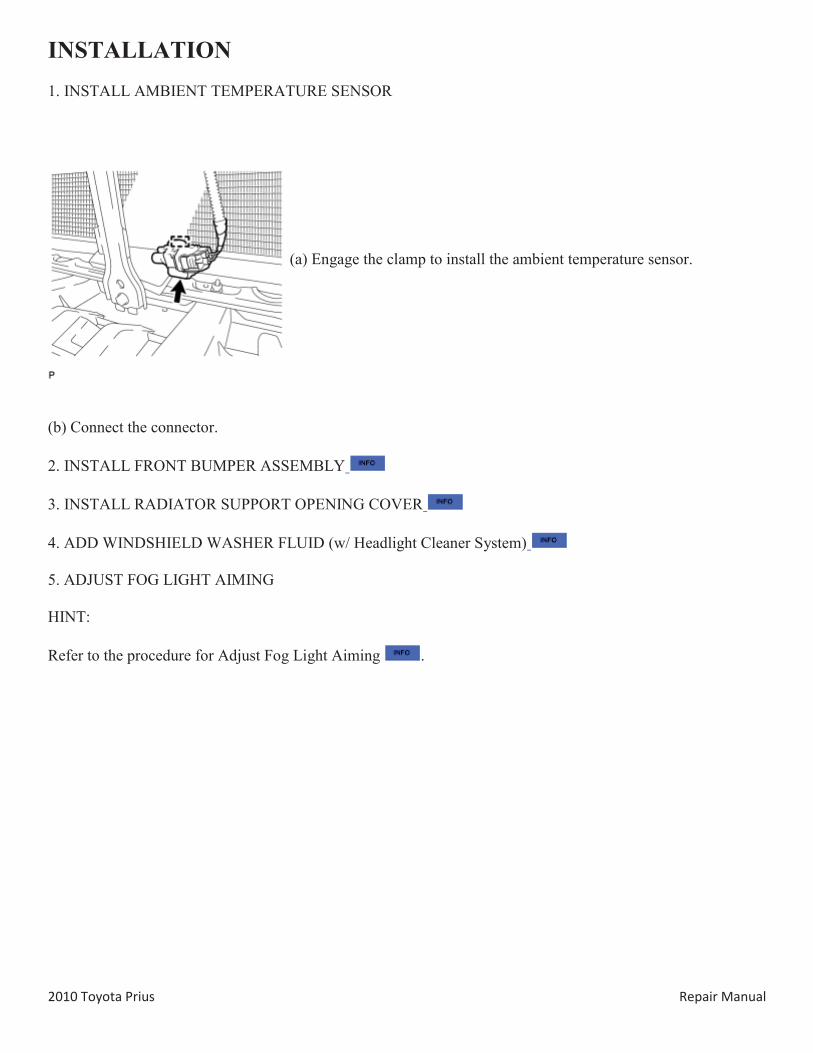
INSTALLATION 1. INSTALL AMBIENT TEMPERATURE SENSOR
(a) Engage the clamp to install the ambient temperature sensor.
(b) Connect the connector.
2. INSTALL FRONT BUMPER ASSEMBLY
3. INSTALL RADIATOR SUPPORT OPENING COVER
4. ADD WINDSHIELD WASHER FLUID (w/ Headlight Cleaner System)
5. ADJUST FOG LIGHT AIMING
HINT:
Refer to the procedure for Adjust Fog Light Aiming .
2010 Toyota Prius Repair Manual
COMPONENTS
ILLUSTRATION
ILLUSTRATION
2010 Toyota Prius Repair Manual
2010 Toyota Prius Repair Manual
REMOVAL 1. REMOVE AIR CONDITIONING UNIT ASSEMBLY
HINT:
Refer to the procedure for Remove Air Conditioning Unit Assembly .
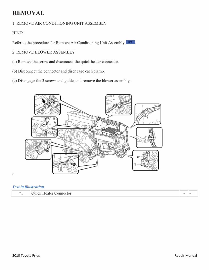
2. REMOVE BLOWER ASSEMBLY
(a) Remove the screw and disconnect the quick heater connector.
(b) Disconnect the connector and disengage each clamp.
(c) Disengage the 3 screws and guide, and remove the blower assembly.
Text in Illustration
*1 Quick Heater Connector - -
2010 Toyota Prius Repair Manual
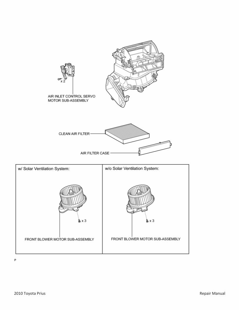
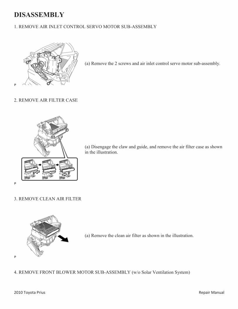
DISASSEMBLY 1. REMOVE AIR INLET CONTROL SERVO MOTOR SUB-ASSEMBLY
(a) Remove the 2 screws and air inlet control servo motor sub-assembly.
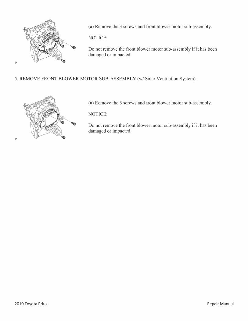
2. REMOVE AIR FILTER CASE
(a) Disengage the claw and guide, and remove the air filter case as shown in the illustration.
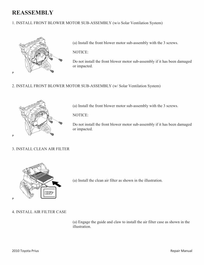
3. REMOVE CLEAN AIR FILTER
(a) Remove the clean air filter as shown in the illustration.
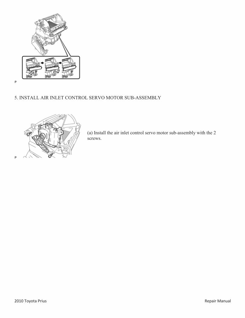
4. REMOVE FRONT BLOWER MOTOR SUB-ASSEMBLY (w/o Solar Ventilation System)
2010 Toyota Prius Repair Manual
(a) Remove the 3 screws and front blower motor sub-assembly.
NOTICE:
Do not remove the front blower motor sub-assembly if it has been damaged or impacted.
5. REMOVE FRONT BLOWER MOTOR SUB-ASSEMBLY (w/ Solar Ventilation System)
(a) Remove the 3 screws and front blower motor sub-assembly.
NOTICE:
Do not remove the front blower motor sub-assembly if it has been damaged or impacted.
2010 Toyota Prius Repair Manual
REASSEMBLY 1. INSTALL FRONT BLOWER MOTOR SUB-ASSEMBLY (w/o Solar Ventilation System)
(a) Install the front blower motor sub-assembly with the 3 screws.
NOTICE:
Do not install the front blower motor sub-assembly if it has been damaged or impacted.
2. INSTALL FRONT BLOWER MOTOR SUB-ASSEMBLY (w/ Solar Ventilation System)
(a) Install the front blower motor sub-assembly with the 3 screws.
NOTICE:
Do not install the front blower motor sub-assembly if it has been damaged or impacted.
3. INSTALL CLEAN AIR FILTER
(a) Install the clean air filter as shown in the illustration.
4. INSTALL AIR FILTER CASE
(a) Engage the guide and claw to install the air filter case as shown in the illustration.
2010 Toyota Prius Repair Manual
5. INSTALL AIR INLET CONTROL SERVO MOTOR SUB-ASSEMBLY
(a) Install the air inlet control servo motor sub-assembly with the 2 screws.
2010 Toyota Prius Repair Manual
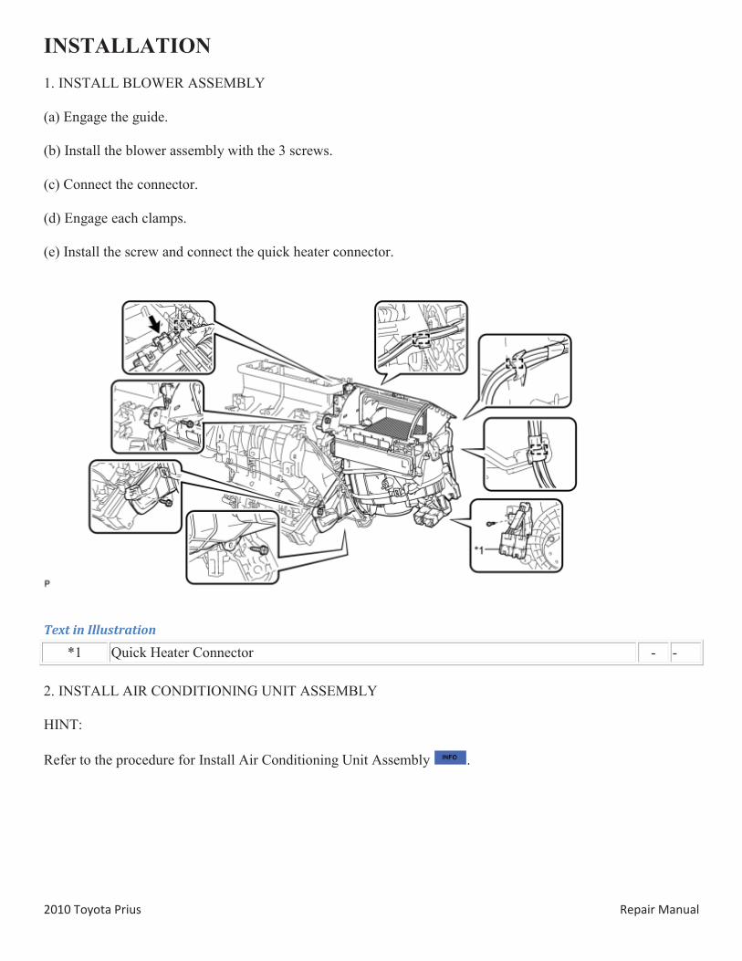
INSTALLATION 1. INSTALL BLOWER ASSEMBLY
(a) Engage the guide.
(b) Install the blower assembly with the 3 screws.
(c) Connect the connector.
(d) Engage each clamps.
(e) Install the screw and connect the quick heater connector.
Text in Illustration
*1 Quick Heater Connector - -
2. INSTALL AIR CONDITIONING UNIT ASSEMBLY
HINT:
Refer to the procedure for Install Air Conditioning Unit Assembly .