Embed Size (px)
Citation preview
7/27/2019 2010 Chalasani TIA-Updated 2012
http://slidepdf.com/reader/full/2010-chalasani-tia-updated-2012 1/35
plantemoran.com
TIA-942: Data Center Standards
Sri Chalasani
Merit 2010 Conference
May 25, 2010

7/27/2019 2010 Chalasani TIA-Updated 2012
http://slidepdf.com/reader/full/2010-chalasani-tia-updated-2012 2/35
Objectives
What are concerns in the datacenter?
Data center standards & bestPractices

7/27/2019 2010 Chalasani TIA-Updated 2012
http://slidepdf.com/reader/full/2010-chalasani-tia-updated-2012 3/35
Data Center Definition
Computer facility designed for continuous use byseveral users, and well equipped with hardware,software, peripherals, power conditioning andbackup, communication equipment,
security systems, etc. – businessdictionary.com
…..It generally includes redundant or backuppower supplies, redundant datacommunications connections,
environmental controls (e.g., airconditioning, fire suppression) and security
devices. – wikipedia.org
P o w e r
c o n d i t i
o n i n g
R e d u n d a n
c y
Notice the common terminology
Levels of implementation set them apart
M o n i t
o r i n g &
C o n t r o l s

7/27/2019 2010 Chalasani TIA-Updated 2012
http://slidepdf.com/reader/full/2010-chalasani-tia-updated-2012 4/35
Why should we care?
DCs house mission-critical data & equipment. In addition to protectingthis…
Challenges… increased demand for:Applications / systems availability / SLA
Complex & heterogeneous systems
Service levels for uptime and responsiveness
Amount of data (live and retention)
Regulatory compliance and security
Changing business demands
Green practices & energy costs

7/27/2019 2010 Chalasani TIA-Updated 2012
http://slidepdf.com/reader/full/2010-chalasani-tia-updated-2012 5/35
Data Center Standards
Without standards… enormous variationin data center designs
Three commonly known tier systems
Uptime Institute (1995)
Syska Hennessy Group
ANSI/TIA-942 or TIA-942 (2005, 2008, 2010)

7/27/2019 2010 Chalasani TIA-Updated 2012
http://slidepdf.com/reader/full/2010-chalasani-tia-updated-2012 6/35
Data Center Standards
Uptime and TIA-942
Neither addresses the challenges
Both provide a framework to alleviate
challenges
TIA-942
Requirements / guidelines for the design
& installation of a data center
Multidisciplinary Design Considerations
Intended Audience

7/27/2019 2010 Chalasani TIA-Updated 2012
http://slidepdf.com/reader/full/2010-chalasani-tia-updated-2012 7/35
TIA-942 Multidisciplinary Design
Design Considerations 1. Design Process
2. Space Planning
3. Redundancy
4. Site Selection
5. Architectural
6. Structural
7. Electrical
8. Mechanical/Cooling
9. Fire Protection
10.Security
11.Building Automation
12.Access Providers
13.Telecom Spaces
14.Cabinets & Racks
15.Cabling Pathways
16.Cabling Systems
17.Cabling Field Testing
18.Telecom Administration
19.Information Technology
20.Commissioning
21.Maintenance
Architectural Design (space, floor, light, security etc.)
Structured Wiring Electrical Cooling
Operations

7/27/2019 2010 Chalasani TIA-Updated 2012
http://slidepdf.com/reader/full/2010-chalasani-tia-updated-2012 8/35
TIA-942 – Discussion Topics
For today’s discussion, focus on…
1. Data Center Spaces.
2. Data Center Cabling
3. Electrical
4. Cooling
5. Tier System

7/27/2019 2010 Chalasani TIA-Updated 2012
http://slidepdf.com/reader/full/2010-chalasani-tia-updated-2012 9/35
Spaces
TIA-942 – 5-key functional areas:
(1) Entrance Room (ER)
(2) Main Distribution Area (MDA)
(3) Horizontal Distribution Area (HDA)
(4) Zone Distribution Area (ZDA), opt.
(5) Equipment Distribution Area (EDA)
Ideally separate rooms but not practicalfor normal organizations; Can beconsolidated with defined areas
Source: Corning – Distribution in the data center

7/27/2019 2010 Chalasani TIA-Updated 2012
http://slidepdf.com/reader/full/2010-chalasani-tia-updated-2012 10/35
Spaces
Source: ADC’s Data Center Optical Distribution Frame: The Data Center’s Main Cross-Connect
(1)(2)(3)(5)
(4)ZDA

7/27/2019 2010 Chalasani TIA-Updated 2012
http://slidepdf.com/reader/full/2010-chalasani-tia-updated-2012 11/35
Spaces
Source: Corning – Distribution in the data center

7/27/2019 2010 Chalasani TIA-Updated 2012
http://slidepdf.com/reader/full/2010-chalasani-tia-updated-2012 12/35
Spaces
Typical Data Center Requirements:Location
Avoid locations that restrictexpansion
Redudnat Access
Delivery of large equipment
Located away from EMI sources
No exterior windows (inc. heat & security risk)
Provide authorized access &
monitoredSize – no magic formula
Sized to meet the knownrequirements of specificequipment
Include projected future as well
as present requirements
Ceiling Height
Min. 8.5’ from finished floor toany obstruction (sprinklers,lighting fixtures, or cameras)
Cooling architecture maydictate higher ceilings
Min. 18” clearance from watersprinkler heads
Flooring / Walls
Anti-static properties
Sealed / painted to minimizedust
Light color to enhance lighting
Min dist floor loading 150 lbf/Sq-ft, Reco. 250 lbf/Sq-ft

7/27/2019 2010 Chalasani TIA-Updated 2012
http://slidepdf.com/reader/full/2010-chalasani-tia-updated-2012 13/35
Spaces
Other Equipment
UPS, power dist. or conditioner
<= 100kVa inside room
> 100kVa in separate room
Lighting
Min. 500 lux in the horizontalplane and 200 lux in thevertical plane
Lighting on separate circuits/panels
Emergency lighting & signs
Doors
3’ wide x 7’ high, no /removable center obstructions
Operational parameters
Dedicated HVAC system preferred(68 – 77 F); measured every10-30 ft at 1.5ft height
HVAC – min. 100 sqft/ton
Max. temp rate of change: 5 F/hr
40% to 55% relative humidity(reduces ESD)
Electrical - Signal reference grid(SRG)
Sprinkler systems must be pre-
action system
Security
Camera monitoring (int./ext.)
100-yr flood plain

7/27/2019 2010 Chalasani TIA-Updated 2012
http://slidepdf.com/reader/full/2010-chalasani-tia-updated-2012 14/35
Spaces – Best Practices
Locate ER outside of the DC for securitypurpose; if inside DC, consolidate ER & MDA
MDA centrally located
Both MDA & HDA require separate racks for
fiber, UTP and coax cable
ZDA is optional, but provides additional flexibility(pre terminated cables)
EDA – contains equipment only
Each space requires same power/cooling req.
ER: Entrance Room, MDA: Main Distribution Area, EDA: EquipmentDistribution Area, ZDA: Zone Distribution Area, DC: Data Center

7/27/2019 2010 Chalasani TIA-Updated 2012
http://slidepdf.com/reader/full/2010-chalasani-tia-updated-2012 15/35
Spaces – Raised vs. Solid Floor
Raised floor a very common notion, but...
Older equipment vs. newerequipment air flow (bottom-upvs. front to back)
Hot aisle – Cold aisle air flowdynamics
Cold air – want to fall, but we
are pushing – requirespressure through perf. tiles
Opening / leaks in flooring hasimpact on pressure
Equip. densities increase ->
higher head load -> higherpressure of cold air throughrestrictive space
What happens to hot air? –flows up, reduces temperature
and begins to fall down again
Only place to go is creep intocold aisle….warmer air atcabinet tops.
Typically see passivecomponents or open spaces
near top of cabinets
Both use anti-static tiles orflooring
Data & electrical cablingrestrictions
New build – more expensive
Have to look at yourenvironment to see if raisedfloor makes sense….do use thisas the rule of thumb!

7/27/2019 2010 Chalasani TIA-Updated 2012
http://slidepdf.com/reader/full/2010-chalasani-tia-updated-2012 16/35
Cabling Systems
Structured vs. Unstructured Cabling
Horizontal cabling
Backbone cabling
Cross-connect in the
entrance room or maindistribution area
Main cross-connect (MC)in the main distributionarea
Horizontal cross-connect(HC) in thetelecommunicationsroom, horizontaldistribution area or maindistribution area
Zone outlet orconsolidation point inthe zone distribution
area; and
Outlet in the equipmentdistribution area

7/27/2019 2010 Chalasani TIA-Updated 2012
http://slidepdf.com/reader/full/2010-chalasani-tia-updated-2012 17/35
Cabling Systems
Source: Corning Cable Systems – Just the Technical Facts

7/27/2019 2010 Chalasani TIA-Updated 2012
http://slidepdf.com/reader/full/2010-chalasani-tia-updated-2012 18/35
Cabling Systems
Reduced Data Center Topology
Consolidated ER/MDA/HAD
Applicable to most enterprises
Source: Orthronics – Standards-Based Data Center Structured Cabling System Design

7/27/2019 2010 Chalasani TIA-Updated 2012
http://slidepdf.com/reader/full/2010-chalasani-tia-updated-2012 19/35
Cabling Systems – Transmission Media
100-ohm twisted-pair copper cable
Category 5e or 6, 6A
10GbE: Cat 6 – 37-55mts, Cat 6A – 100mts
Multimode fiber optic cable62.5/125 µm or 50/125 µm
50/125 µm 850 nm laser optimized mmf
Singlemode optical fiber cable
75-ohm coaxial cable
Type 734 & 735 cable
Type T1.404 coaxial connector

7/27/2019 2010 Chalasani TIA-Updated 2012
http://slidepdf.com/reader/full/2010-chalasani-tia-updated-2012 20/35
Cabling Systems – Overhead / Under floor
Under Floor Cabling
Less expensive if raised floor than overhead
Cabling in cable trays to minimize airflow blocks;consider multilevel trays for fiber/copper
Provide adequate capacity for growth
Separate fiber cords from copper cabling from
power
Typically placed in the hot aisle
Electrical – color coded PDU with lockingreceptacle. Receptacles labeled with PDU/panelID & breaker #
7/27/2019 2010 Chalasani TIA-Updated 2012
http://slidepdf.com/reader/full/2010-chalasani-tia-updated-2012 21/35
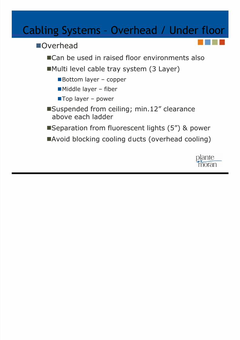
Cabling Systems – Overhead / Under floor
Overhead
Can be used in raised floor environments also
Multi level cable tray system (3 Layer)
Bottom layer – copper
Middle layer – fiber
Top layer – power
Suspended from ceiling; min.12” clearanceabove each ladder
Separation from fluorescent lights (5”) & power
Avoid blocking cooling ducts (overhead cooling)

7/27/2019 2010 Chalasani TIA-Updated 2012
http://slidepdf.com/reader/full/2010-chalasani-tia-updated-2012 22/35
Racks / Cabinets
Placement of racks / cabinets
Hot aisle / Cold aisle - arranged in an alternatingpattern (with fronts facing each other)
Cold aisles are front & Hot aisles are rear of
racks/cabinets –
If there is a raised floor, PDU cables are run incold aisle. Data cable trays for telecom cablingare typically placed in hot aisle.
Common bonding network (CBN) Racks / cabinets individually, cable trays, HVAC,
PDU, panel boards, raised floor structure, columns
Front clearance – min. 3ft, 4ft recommended
Raised Flooring vs. Traditional Flooring

7/27/2019 2010 Chalasani TIA-Updated 2012
http://slidepdf.com/reader/full/2010-chalasani-tia-updated-2012 23/35
Racks / Cabinets
Placement of racks / cabinets
Front rails recessed for wire management
Switch-Panel-Switch arrangement
Front edge of cabinet on edge of tilePerforated tiles at front of cabinets
Provide blank panels in empty spaces

7/27/2019 2010 Chalasani TIA-Updated 2012
http://slidepdf.com/reader/full/2010-chalasani-tia-updated-2012 24/35
Electrical Considerations
Unfortunately no magic bullet!
Manual process for load configuration
APC ‘s “Calculating Total Power Requirements forData Centers” By Richard Sawyer – framework
for calculating req.
Color coded PDU with locking receptacle.Receptacles labeled with PDU/panel ID & breaker #
Best Practices Multiple power grid connects
Sub-breakers per relay rackor lineup
Dual A-B cording
Accommodate growth
Intelligent PDU
Generator capacity to includefor cooling
UPS capacity to includecooling and lights
7/27/2019 2010 Chalasani TIA-Updated 2012
http://slidepdf.com/reader/full/2010-chalasani-tia-updated-2012 25/35
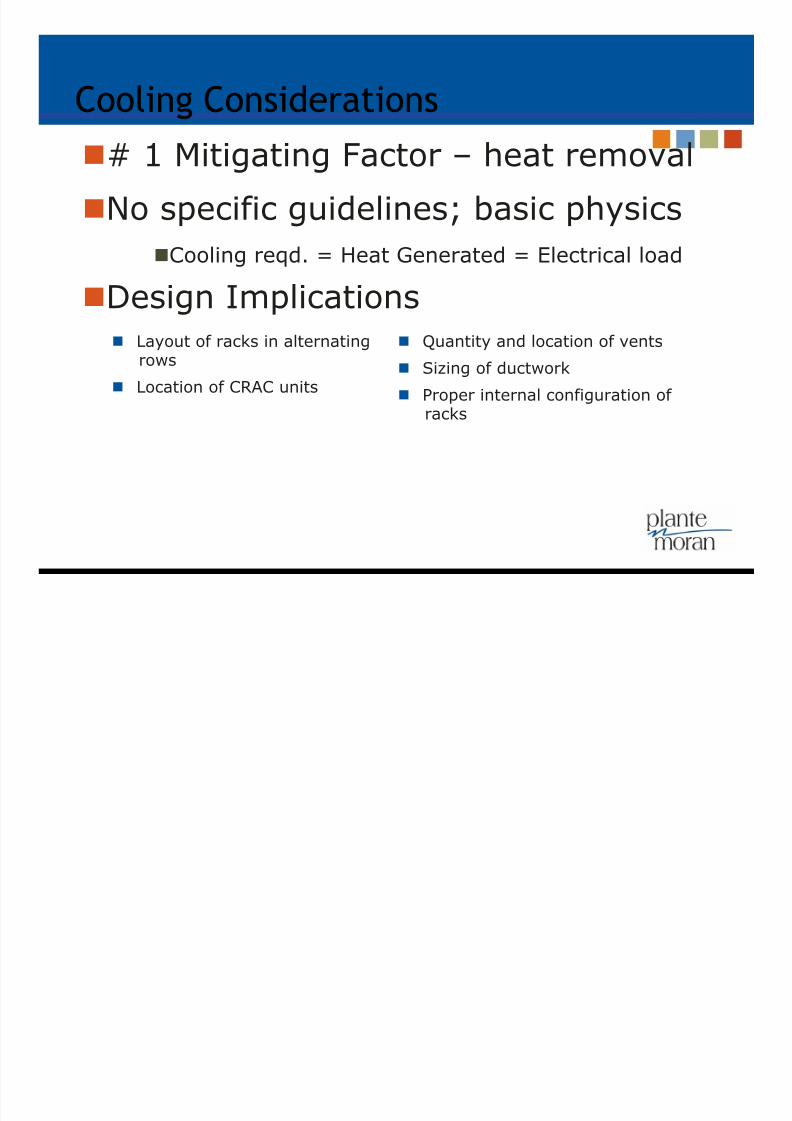
Cooling Considerations
# 1 Mitigating Factor – heat removal
No specific guidelines; basic physics
Cooling reqd. = Heat Generated = Electrical load
Design Implications Layout of racks in alternating
rows
Location of CRAC units
Quantity and location of vents
Sizing of ductwork
Proper internal configuration of
racks

7/27/2019 2010 Chalasani TIA-Updated 2012
http://slidepdf.com/reader/full/2010-chalasani-tia-updated-2012 26/35
Cooling Considerations
Process
Cooling is not enough – airflow required
Determine critical heat load
Establish critical loads - watts-per-RLU
Determine the CFMrequirements per RLU
If possible, divide the roominto cooling zones by RLU
Determine appropriate airconditioner type(s)
Equip. airflow (f->b / s->s)
Determine cooling deliverymethodology(s)
Room, Row, Rack
Blank panels/short circuits Cold air containment
Special Considerations – highBTU
Establish a floor plan
Deploy a comprehensive
monitoring system

7/27/2019 2010 Chalasani TIA-Updated 2012
http://slidepdf.com/reader/full/2010-chalasani-tia-updated-2012 27/35
Cooling Considerations - Airflow
source: apc.com
Supply & ReturnBased

7/27/2019 2010 Chalasani TIA-Updated 2012
http://slidepdf.com/reader/full/2010-chalasani-tia-updated-2012 28/35
Fire Detection and Suppression
Significant risk of electrical fires
A comprehensive fire detection & suppression system is mission-critical
Detection
Both heat and smoke detection
Interconnected with the firesuppression system, localalarms, monitoring system, etc
Installed in accordance withNFPA 72E
Installed below raised floorsand other areas
Airflow patterns determineslocation of detection units
Suppression
Follow NFPA 75 standard firewalls
Sprinkler systems — both floodedand pre-action
Chemical systems or Clean Agent(FM 200, Inergen, Ecaro-25(FE 25),Novec 1230)
Manual systems (Manual pullstations, Portable fire extinguishers

7/27/2019 2010 Chalasani TIA-Updated 2012
http://slidepdf.com/reader/full/2010-chalasani-tia-updated-2012 29/35
Tier System – Uptime & TIA-942
4-Tier System based on
Resilience / Capacity of its MEP systems
16-pages of criteria
Primary Categories Power and cooling delivery
paths
Redundancy in components
Initial & ultimate watts/sqft
Support space to raised floorratio
Raised floor height
Floor loading pounds/sqft
Utility voltage

7/27/2019 2010 Chalasani TIA-Updated 2012
http://slidepdf.com/reader/full/2010-chalasani-tia-updated-2012 30/35
Optimal Criticality – Choosing a tier
C Business characteristics Effect on system design
1• Typically small businesses • Limited online presence
• Low dependence on IT• Perceive downtime as a tolerable
Inconvenience
• Numerous single points of failure in all aspects of design
• No generator if UPS has 8 minutes of backup time• Generally unable to sustain more than a 10 minute
power outage
2• Some online revenue generation• Multiple servers
• Phone system vital to business• Dependent on email
• Some tolerance to scheduled downtime
• Some redundancy in power and cooling systems• Generator backup
• Able to sustain 24 hour power outage• Minimal thought to site selection
• Vapor barrier• Formal data room separate from other areas
3• World-wide presence• Majority of revenue from online business
• VoIP phone system
• High dependence on IT• High cost of downtime• Highly recognized brand
• Two utility paths (active and passive)• Redundant power and cooling systems
• Redundant service providers
• Able to sustain 72-hour power outage• Careful site selection planning• One-hour fire rating• Allows for concurrent maintenance
• Multi-million dollar business• Maj. of rev from electronic transactions
• Business model entirely dependent on IT• Extremely high cost of downtime
• Two independent utility paths• 2N power and cooling systems
• Able to sustain 96 hour power outage• Stringent site selection criteria
• Minimum two-hour fire rating; High phy. security
• 24/7 onsite maintenance staff Balance cost of downtime and TCO
source: apc.com

7/27/2019 2010 Chalasani TIA-Updated 2012
http://slidepdf.com/reader/full/2010-chalasani-tia-updated-2012 31/35
Tier System
Attribute / Statistic Tier I Tier II Tier III Tier IV
Power and CoolingDelivery Paths
1 Active 1 Active 1 Active 1Passive
2 Active
Redundant Components N N + 1 N + 1 2(N + 1)
Support Space to RaisedFloor Ratio
20% 30% 80 – 90% 100%
Initial Watts / sqft 20 – 30 40 – 50 40 – 60 50 – 80
Ultimate Watts / sqft 20 – 30 40 – 50 100 – 150 150+
Raised Floor Height 12” 18” 30 – 36” 30 – 36”
Floor Loading Pounds /sqft
85 100 150 150+
Utility Voltage 208, 480 208, 480 12 – 15 kV 12 – 15 kV
Months to Implement 3 3 – 6 15 – 20 15 – 20
Year First Deployed 1965 1970 1985 1995
Construction $ / sqft $450 $600 $900 $1,100+
Annual IT Downtime Dueto Site
28.8 hrs 22.0 hrs 1.6 hrs 0.4 hrs
Site Availability 99.67% 99.75% 99.98% 100.00%
Source: The Uptime Institute
7/27/2019 2010 Chalasani TIA-Updated 2012
http://slidepdf.com/reader/full/2010-chalasani-tia-updated-2012 32/35
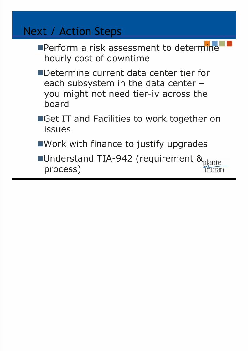
Next / Action Steps
Perform a risk assessment to determinehourly cost of downtime
Determine current data center tier for
each subsystem in the data center –you might not need tier-iv across theboard
Get IT and Facilities to work together on
issues Work with finance to justify upgrades
Understand TIA-942 (requirement & process)

7/27/2019 2010 Chalasani TIA-Updated 2012
http://slidepdf.com/reader/full/2010-chalasani-tia-updated-2012 33/35
Outsourced Data Center
Fits business model - consideroutsourcing
Affordable co-location/hosted DC and99.995% uptime are NOT mutuallyexclusive
Understand levels of redundancy andthe uptime SLA in order to get the best
combination of uptime and affordability
Balance between budget and availability

7/27/2019 2010 Chalasani TIA-Updated 2012
http://slidepdf.com/reader/full/2010-chalasani-tia-updated-2012 34/35
Outsourced Data Center
What to look for….
Claims of Uptime Tiers – III or IV; most
are not certified
Hardened data centerbuildings
Data center power &
cooling redundancy Telecom entrance
redundancy
Availability of multiplecarriers
Physical security
SAS 70 data centercompliance
7/27/2019 2010 Chalasani TIA-Updated 2012
http://slidepdf.com/reader/full/2010-chalasani-tia-updated-2012 35/35
Resources
Useful links Excellent white papers from www.apc.com
TIA - http://www.tiaonline.org/
Green data center efficiency savings calculator
http://cooling.thegreengrid.org/namerica/WEB_APP/calc_index.html
The green grid (thegreengrid.org)
Department of Energy – DC Profiling Tool
http://www1.eere.energy.gov/industry/datacenters/software.html
…. and obviously Google or Bing it.