Embed Size (px)
Citation preview

Seats and Restraint System ............................. 1-1Front Seats ............................................... 1-2Rear Seats ............................................... 1-9Safety Belts ............................................. 1-10Child Restraints ....................................... 1-30Airbag System ......................................... 1-54Restraint System Check ............................ 1-69
Features and Controls ..................................... 2-1Keys ........................................................ 2-2Doors and Locks ....................................... 2-8Windows ................................................. 2-14Theft-Deterrent Systems ............................ 2-16Starting and Operating Your Vehicle ........... 2-20Mirrors .................................................... 2-36OnStar® System ...................................... 2-37Storage Areas ......................................... 2-41Sunroof .................................................. 2-42
Instrument Panel ............................................. 3-1Instrument Panel Overview .......................... 3-4Climate Controls ...................................... 3-18Warning Lights, Gages, and Indicators ........ 3-23Driver Information Center (DIC) .................. 3-39Audio System(s) ....................................... 3-52
Driving Your Vehicle ....................................... 4-1Your Driving, the Road, and the Vehicle ....... 4-2Towing ................................................... 4-30
Service and Appearance Care .......................... 5-1Service ..................................................... 5-3Fuel ......................................................... 5-5Checking Things Under the Hood ............... 5-10Headlamp Aiming ..................................... 5-39Bulb Replacement .................................... 5-41Windshield Wiper Blade Replacement ......... 5-47Tires ...................................................... 5-48Appearance Care ..................................... 5-99Vehicle Identification ............................... 5-106Electrical System .................................... 5-107Capacities and Specifications ................... 5-113
Maintenance Schedule ..................................... 6-1Maintenance Schedule ................................ 6-2
Customer Assistance Information .................... 7-1Customer Assistance and Information ........... 7-2Reporting Safety Defects ........................... 7-14Vehicle Data Recording and Privacy ........... 7-16
Index ................................................................ 1
2009 Pontiac G5 Owner Manual M

GENERAL MOTORS, GM, the GM Emblem, PONTIAC,the PONTIAC Emblem, and the name G5 areregistered trademarks of General Motors Corporation.
This manual includes the latest information at the time itwas printed. GM reserves the right to make changesafter that time without further notice. For vehiclesfirst sold in Canada, substitute the name “GeneralMotors of Canada Limited” for Pontiac Division whereverit appears in this manual.
This manual describes features that may or may not beon your specific vehicle.
Read this manual from beginning to end to learn aboutthe vehicle’s features and controls. Pictures, symbols,and words work together to explain vehicle operation.
Keep this manual in the vehicle for quick reference.
Canadian OwnersA French language copy of this manual can be obtainedfrom your dealer/retailer or from:
Helm, IncorporatedP.O. Box 07130Detroit, MI 48207
1-800-551-4123helminc.com
Propriétaires CanadiensOn peut obtenir un exemplaire de ce guide en françaisauprès de concessionnaire ou à l’adresse suivante:
Helm IncorporatedP.O. Box 07130Detroit, MI 48207
1-800-551-4123helminc.com
IndexTo quickly locate information about the vehicle use theIndex in the back of the manual. It is an alphabeticallist of what is in the manual and the page number whereit can be found.
Litho in U.S.A.Part No. 25776712 A First Printing ©2008 General Motors Corporation. All Rights Reserved.
ii

Safety Warnings and Symbols
A circle with a slashthrough it is a safetysymbol which means“Do Not,” “Do not do this” or“Do not let this happen.”
A box with the word CAUTION is used to tell aboutthings that could hurt you or others if you were to ignorethe warning.
{CAUTION:
These mean there is something that could hurtyou or other people.
Cautions tell what the hazard is and what to do to avoidor reduce the hazard. Read these cautions.
A notice tells about something that can damage thevehicle.
Notice: These mean there is something that coulddamage your vehicle.
Many times, this damage would not be covered by thevehicle’s warranty, and it could be costly. The noticetells what to do to help avoid the damage.
There are also warning labels on the vehicle which usethe same words, CAUTION or Notice.
Vehicle SymbolsThe vehicle has components and labels that use symbolsinstead of text. Symbols are shown along with the textdescribing the operation or information relating to aspecific component, control, message, gage, or indicator.
M : This symbol is shown when you need to see yourowner manual for additional instructions or information.
* : This symbol is shown when you need to see aservice manual for additional instructions or information.
iii

Vehicle Symbol ChartHere are some additional symbols that may be found onthe vehicle and what they mean. For more informationon the symbol, refer to the index.
9 : Airbag Readiness Light
# : Air Conditioning
! : Antilock Brake System (ABS)
g : Audio Steering Wheel Controls or OnStar®
$ : Brake System Warning Light
" : Charging System
I : Cruise Control
B : Engine Coolant Temperature
O : Exterior Lamps
# : Fog Lamps
. : Fuel Gage
+ : Fuses
i : Headlamp High/Low-Beam Changer
j : LATCH System Child Restraints
* : Malfunction Indicator Lamp
: : Oil Pressure
} : Power
/ : Remote Vehicle Start
> : Safety Belt Reminders
7 : Tire Pressure Monitor
F : Traction Control
M : Windshield Washer Fluid
iv

Front Seats ......................................................1-2Manual Seats ................................................1-2Seat Height Adjuster .......................................1-3Manual Lumbar ..............................................1-3Heated Seats .................................................1-4Reclining Seatbacks ........................................1-4Head Restraints .............................................1-7Easy Entry Seat (Coupe) .................................1-8
Rear Seats .......................................................1-9Split Folding Rear Seat ...................................1-9
Safety Belts ...................................................1-10Safety Belts: They Are for Everyone ................1-10How to Wear Safety Belts Properly .................1-15Lap-Shoulder Belt .........................................1-23Safety Belt Use During Pregnancy ..................1-29Safety Belt Extender .....................................1-29
Child Restraints .............................................1-30Older Children ..............................................1-30Infants and Young Children ............................1-33Child Restraint Systems .................................1-37Where to Put the Restraint .............................1-39
Lower Anchors and Tethers forChildren (LATCH) ......................................1-41
Securing a Child Restraint in aRear Seat Position ....................................1-47
Securing a Child Restraint in theRight Front Seat Position ............................1-50
Airbag System ...............................................1-54Where Are the Airbags? ................................1-56When Should an Airbag Inflate? .....................1-58What Makes an Airbag Inflate? .......................1-60How Does an Airbag Restrain? .......................1-60What Will You See After an Airbag Inflates? .....1-60Passenger Sensing System ............................1-62Servicing Your Airbag-Equipped Vehicle ...........1-67Adding Equipment to Your Airbag-Equipped
Vehicle ....................................................1-68Restraint System Check ..................................1-69
Checking the Restraint Systems ......................1-69Replacing Restraint System Parts
After a Crash ............................................1-70
Section 1 Seats and Restraint System
1-1

Front Seats
Manual Seats
{CAUTION:
You can lose control of the vehicle if you try toadjust a manual driver’s seat while the vehicle ismoving. The sudden movement could startle andconfuse you, or make you push a pedal when youdo not want to. Adjust the driver’s seat only whenthe vehicle is not moving.
If the vehicle has a manual seat, it can be movedforward or rearward.
1. Lift the bar to unlockthe seat.
2. Slide the seat to thedesired position andrelease the bar.
Try to move the seat with your body to be sure the seatis locked in place.
1-2

Seat Height Adjuster
The driver’s seat height adjuster is located on theoutboard side of the seat.
To raise the seat, move the lever upward repeatedlyuntil the seat is at the desired height. To lower the seat,move the lever downward repeatedly until the seat isat the desired height.
Manual Lumbar
On vehicles with thisfeature, the knob islocated on the front of thedriver seat lower cushionon the inboard side.
Turn the knob clockwise or counterclockwise to increaseor decrease the lumbar support.
1-3

Heated SeatsYour vehicle may have heated front seats. The switchesare located on the instrument panel above the climatecontrol system.
Press the side of theswitch with the doubleindicator lights to turn onthe heated seat at thehighest setting.
Both indicator lights will be lit to indicate that the settingis on high. Press the side of the switch with the singleindicator light to go to the low setting. The indicator lightwill be lit to indicate that the setting is on low. Returnthe switch to the center to turn off the heated seat.
If your vehicle has been turned off, the last heated seatsetting will be retained when the vehicle is started again.
Reclining Seatbacks
{CAUTION:
You can lose control of the vehicle if you try toadjust a manual driver’s seat while the vehicle ismoving. The sudden movement could startle andconfuse you, or make you push a pedal when youdo not want to. Adjust the driver’s seat only whenthe vehicle is not moving.
{CAUTION:
If either seatback is not locked, it could moveforward in a sudden stop or crash. That couldcause injury to the person sitting there. Alwayspush and pull on the seatbacks to be sure theyare locked.
Driver’s Switch Shown,Passenger’s Switch
Similar
1-4

Your seats have manual reclining seatbacks. The leverused to operate them is located on the outboard side ofthe seats.
To recline the seatback, do the following:1. Lift the recline lever.2. Move the seatback to the desired position, then
release the lever to lock the seatback in place.3. Push and pull on the seatback to make sure it is
locked.To return the seatback to an upright position, do thefollowing:
1. Lift the lever fully without applying pressure to theseatback and the seatback will return to the uprightposition.
2. Push and pull on the seatback to make sure it islocked.
1-5

{CAUTION:
Sitting in a reclined position when the vehicle is inmotion can be dangerous. Even if when buckledup, the safety belts cannot do their job whenreclined like this.
The shoulder belt cannot do its job because it willnot be against your body. Instead, it will be in frontof you. In a crash, you could go into it, receivingneck or other injuries.
The lap belt cannot do its job either. In a crash,the belt could go up over your abdomen. The beltforces would be there, not at your pelvic bones.This could cause serious internal injuries.
For proper protection when the vehicle is inmotion, have the seatback upright. Then sit wellback in the seat and wear the safety belt properly.
Do not have a seatback reclined if your vehicle ismoving.
1-6

Head Restraints
Adjust the head restraint so that the top of the restraintis at the same height as the top of the occupant’s head.This position reduces the chance of a neck injury in acrash.
Pull the head restraint up toraise it. To lower the headrestraint, press the button,located on the top of theseatback, and push therestraint down.
1-7

Easy Entry Seat (Coupe)
{CAUTION:
If the easy entry right front seat is not locked, itcan move. In a sudden stop or crash, the personsitting there could be injured. After you have usedit, be sure to push rearward on an easy entry seatto be sure it is locked.
{CAUTION:
If either seatback is not locked, it could moveforward in a sudden stop or crash. That couldcause injury to the person sitting there. Alwayspush and pull on the seatbacks to be sure theyare locked.
The front passenger seat can be used to easily get inand out of the rear seat.
To use the easy entry seat, do the following:
1. Push down the easy entry seat handle located onthe rear of the seatback on the outboard side torelease the seatback.
2. Tilt the seatback forward completely while pushingthe seat forward.
3. Move the seat rearward until it locks into place aftersomeone gets into the rear seat area.
4. Move the seatback to its original position and makesure the seatback is locked.
1-8
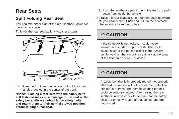
Rear SeatsSplit Folding Rear SeatYou can fold either side of the rear seatback down formore cargo space.To lower the rear seatback, follow these steps:
1. Open the trunk and pull one or both of the smallhandles located in the center of the trunk.
Notice: Folding a rear seat with the safety beltsstill fastened may cause damage to the seat or thesafety belts. Always unbuckle the safety beltsand return them to their normal stowed positionbefore folding a rear seat.
2. Push the seatback open through the trunk, or pull itdown from inside the vehicle.
To raise the rear seatback, lift it up and push rearwarduntil you hear a click. Push and pull on the seatbackto be sure it is locked into place.
{CAUTION:
If the seatback is not locked, it could moveforward in a sudden stop or crash. That couldcause injury to the person sitting there. Alwayspull forward on the top of the seatback at the areaof the latch to be sure it is locked.
{CAUTION:
A safety belt that is improperly routed, not properlyattached, or twisted will not provide the protectionneeded in a crash. The person wearing the beltcould be seriously injured. After raising the rearseatback, always check to be sure that the safetybelts are properly routed and attached, and arenot twisted.
1-9
Safety Belts
Safety Belts: They Are for EveryoneThis section of the manual describes how to usesafety belts properly. It also describes some things notto do with safety belts.
{CAUTION:
Do not let anyone ride where a safety belt cannotbe worn properly. In a crash, if you or yourpassenger(s) are not wearing safety belts, theinjuries can be much worse. You can hit thingsinside the vehicle harder or be ejected from thevehicle. You and your passenger(s) can beseriously injured or killed. In the same crash, youmight not be, if you are buckled up. Always fastenyour safety belt, and check that your passenger(s)are restrained properly too.
{CAUTION:
It is extremely dangerous to ride in a cargo area,inside or outside of a vehicle. In a collision, peopleriding in these areas are more likely to beseriously injured or killed. Do not allow people toride in any area of your vehicle that is notequipped with seats and safety belts. Be sureeveryone in your vehicle is in a seat and using asafety belt properly.
This vehicle has indicators as a reminder to buckle thesafety belts. See Safety Belt Reminders on page 3-26for additional information.
In most states and in all Canadian provinces, the lawrequires wearing safety belts. Here is why:
You never know if you will be in a crash. If you do havea crash, you do not know if it will be a serious one.
A few crashes are mild, and some crashes can be soserious that even buckled up, a person would not survive.But most crashes are in between. In many of them,people who buckle up can survive and sometimes walkaway. Without safety belts, they could have been badlyhurt or killed.
1-10

After more than 40 years of safety belts in vehicles, thefacts are clear. In most crashes buckling up doesmatter... a lot!
Why Safety Belts WorkWhen you ride in or on anything, you go as fast asit goes.
Take the simplest vehicle. Suppose it is just a seat onwheels.
Put someone on it.
1-11
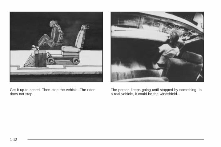
Get it up to speed. Then stop the vehicle. The riderdoes not stop.
The person keeps going until stopped by something. Ina real vehicle, it could be the windshield...
1-12
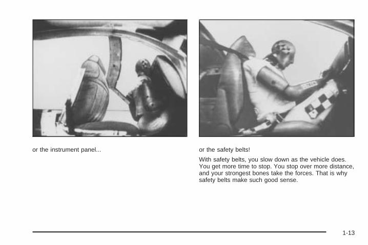
or the instrument panel... or the safety belts!
With safety belts, you slow down as the vehicle does.You get more time to stop. You stop over more distance,and your strongest bones take the forces. That is whysafety belts make such good sense.
1-13
Questions and Answers About SafetyBelts
Q: Will I be trapped in the vehicle after a crash if Iam wearing a safety belt?
A: You could be — whether you are wearing a safetybelt or not. But your chance of being consciousduring and after an accident, so you can unbuckleand get out, is much greater if you are belted.And you can unbuckle a safety belt, even if you areupside down.
Q: If my vehicle has airbags, why should I have towear safety belts?
A: Airbags are supplemental systems only; so theywork with safety belts — not instead of them.Whether or not an airbag is provided, all occupantsstill have to buckle up to get the most protection.That is true not only in frontal collisions, butespecially in side and other collisions.
Q: If I am a good driver, and I never drive far fromhome, why should I wear safety belts?
A: You may be an excellent driver, but if you are in acrash — even one that is not your fault — you andyour passenger(s) can be hurt. Being a gooddriver does not protect you from things beyond yourcontrol, such as bad drivers.
Most accidents occur within 25 miles (40 km) ofhome. And the greatest number of serious injuriesand deaths occur at speeds of less than 40 mph(65 km/h).
Safety belts are for everyone.
1-14
How to Wear Safety Belts ProperlyThis section is only for people of adult size.
Be aware that there are special things to know aboutsafety belts and children. And there are differentrules for smaller children and infants. If a child will beriding in the vehicle, see Older Children on page 1-30 orInfants and Young Children on page 1-33. Followthose rules for everyone’s protection.
It is very important for all occupants to buckle up.Statistics show that unbelted people are hurt more oftenin crashes than those who are wearing safety belts.
Occupants who are not buckled up can be thrown out ofthe vehicle in a crash. And they can strike others inthe vehicle who are wearing safety belts.
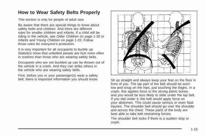
First, before you or your passenger(s) wear a safetybelt, there is important information you should know. Sit up straight and always keep your feet on the floor in
front of you. The lap part of the belt should be wornlow and snug on the hips, just touching the thighs. In acrash, this applies force to the strong pelvic bonesand you would be less likely to slide under the lap belt.If you slid under it, the belt would apply force onyour abdomen. This could cause serious or even fatalinjuries. The shoulder belt should go over the shoulderand across the chest. These parts of the body arebest able to take belt restraining forces.The shoulder belt locks if there is a sudden stop orcrash.
1-15

Q: What is wrong with this?
A: The shoulder belt is too loose. It will not give asmuch protection this way.
{CAUTION:
You can be seriously hurt if your shoulder belt istoo loose. In a crash, you would move forward toomuch, which could increase injury. The shoulderbelt should fit snugly against your body.
1-16
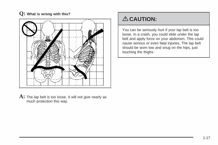
Q: What is wrong with this?
A: The lap belt is too loose. It will not give nearly asmuch protection this way.
{CAUTION:
You can be seriously hurt if your lap belt is tooloose. In a crash, you could slide under the lapbelt and apply force on your abdomen. This couldcause serious or even fatal injuries. The lap beltshould be worn low and snug on the hips, justtouching the thighs.
1-17
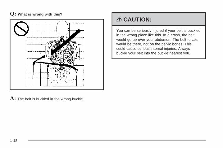
Q: What is wrong with this?
A: The belt is buckled in the wrong buckle.
{CAUTION:
You can be seriously injured if your belt is buckledin the wrong place like this. In a crash, the beltwould go up over your abdomen. The belt forceswould be there, not on the pelvic bones. Thiscould cause serious internal injuries. Alwaysbuckle your belt into the buckle nearest you.
1-18
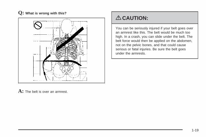
Q: What is wrong with this?
A: The belt is over an armrest.
{CAUTION:
You can be seriously injured if your belt goes overan armrest like this. The belt would be much toohigh. In a crash, you can slide under the belt. Thebelt force would then be applied on the abdomen,not on the pelvic bones, and that could causeserious or fatal injuries. Be sure the belt goesunder the armrests.
1-19

Q: What is wrong with this?
A: The shoulder belt is worn under the arm. It shouldbe worn over the shoulder at all times.
{CAUTION:
You can be seriously injured if you wear theshoulder belt under your arm. In a crash, yourbody would move too far forward, which wouldincrease the chance of head and neck injury. Also,the belt would apply too much force to the ribs,which are not as strong as shoulder bones. Youcould also severely injure internal organs like yourliver or spleen. The shoulder belt should go overthe shoulder and across the chest.
1-20
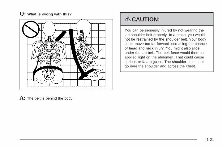
Q: What is wrong with this?
A: The belt is behind the body.
{CAUTION:
You can be seriously injured by not wearing thelap-shoulder belt properly. In a crash, you wouldnot be restrained by the shoulder belt. Your bodycould move too far forward increasing the chanceof head and neck injury. You might also slideunder the lap belt. The belt force would then beapplied right on the abdomen. That could causeserious or fatal injuries. The shoulder belt shouldgo over the shoulder and across the chest.
1-21

Q: What is wrong with this?
A: The belt is twisted across the body.
{CAUTION:
You can be seriously injured by a twisted belt. In acrash, you would not have the full width of the beltto spread impact forces. If a belt is twisted, makeit straight so it can work properly, or ask yourdealer/retailer to fix it.
1-22

Lap-Shoulder BeltAll seating positions in the vehicle have alap-shoulder belt.
The following instructions explain how to wear alap-shoulder belt properly.
1. If the seat has a safety belt guide, and the safetybelt is not routed through the guide, slide the edgeof the belt webbing through the opening on theguide. Be sure the belt is not twisted.
2. Adjust the seat, if the seat is adjustable, so youcan sit up straight. To see how, see “Seats” inthe Index.
3. Pick up the latch plate and pull the belt across you.Do not let it get twisted.The lap-shoulder belt may lock if you pull the beltacross you very quickly. If this happens, let the beltgo back slightly to unlock it. Then pull the beltacross you more slowly.Engaging the child restraint locking feature mayaffect the passenger sensing system. SeePassenger Sensing System on page 1-62 for moreinformation.
1-23

4. Push the latch plate into the buckle until it clicks.Pull up on the latch plate to make sure it is secure.If the belt is not long enough, see Safety BeltExtender on page 1-29.Position the release button on the buckle so thatthe safety belt could be quickly if necessary.
5. If equipped with a shoulder belt height adjuster,move it to the height that is right for you. See“Shoulder Belt Height Adjustment” later in thissection for instructions on use and important safetyinformation.
6. To make the lap part tight, pull up on theshoulder belt.It may be necessary to pull stitching on the safetybelt through the latch plate to fully tighten thelap belt on smaller occupants.
1-24

To unlatch the belt, push the button on the buckle.The belt should return to its stowed position.
Before a door is closed, be sure the safety belt is out ofthe way. If a door is slammed against a safety belt,damage can occur to both the belt and the vehicle.
Shoulder Belt Height Adjuster(Sedan Only)The vehicle has a shoulder belt height adjuster for thedriver and right front passenger position.
Adjust the height so that the shoulder portion of the beltis centered on the shoulder. The belt should be awayfrom the face and neck, but not falling off the shoulder.Improper shoulder belt height adjustment couldreduce the effectiveness of the safety belt in a crash.
Press the releasebutton (A) and move theheight adjuster to thedesired position. Theadjuster can be moved upby pushing up on theshoulder belt guide.
After the height adjuster is set to the desired position,try to move it down without pressing the releasebutton to make sure it has locked into position.
1-25

Safety Belt PretensionersThis vehicle has safety belt pretensioners for frontoutboard occupants. Although the safety beltpretensioners cannot be seen, they are part of thesafety belt assembly. They can help tighten the safetybelts during the early stages of a moderate to severefrontal or near frontal crash if the threshold conditions forpretensioner activation are met. And, if the vehiclehas side impact airbags, safety belt pretensioners canhelp tighten the safety belts in a side crash.
Pretensioners work only once. If the pretensionersactivate in a crash, they will need to be replaced, andprobably other new parts for the vehicle’s safetybelt system. See Replacing Restraint System PartsAfter a Crash on page 1-70.
Rear Safety Belt Comfort GuidesRear shoulder belt comfort guides may provide addedsafety belt comfort for older children who have outgrownbooster seats and for some adults. When installed ona shoulder belt, the comfort guide positions the beltaway from the neck and head.
There is one guide for each outboard passengerposition in the rear seat. Here is how to install a comfortguide to the safety belt:
1. Pull the elastic cord out from between the edge ofthe seatback and the interior body to remove theguide from its storage clip.
1-26

2. Place the guide over the belt and insert thetwo edges of the belt into the slots of the guide.
3. Be sure that the belt is not twisted and it lies flat.The elastic cord must be under the belt and theguide on top.
1-27
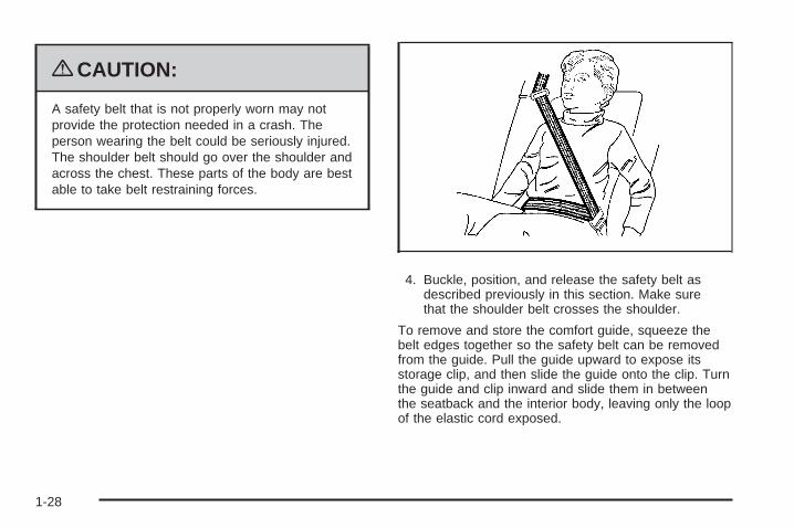
{CAUTION:
A safety belt that is not properly worn may notprovide the protection needed in a crash. Theperson wearing the belt could be seriously injured.The shoulder belt should go over the shoulder andacross the chest. These parts of the body are bestable to take belt restraining forces.
4. Buckle, position, and release the safety belt asdescribed previously in this section. Make surethat the shoulder belt crosses the shoulder.
To remove and store the comfort guide, squeeze thebelt edges together so the safety belt can be removedfrom the guide. Pull the guide upward to expose itsstorage clip, and then slide the guide onto the clip. Turnthe guide and clip inward and slide them in betweenthe seatback and the interior body, leaving only the loopof the elastic cord exposed.
1-28
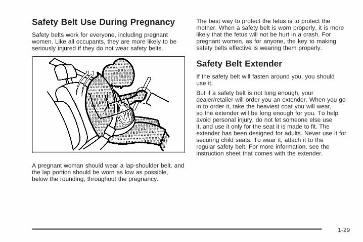
Safety Belt Use During PregnancySafety belts work for everyone, including pregnantwomen. Like all occupants, they are more likely to beseriously injured if they do not wear safety belts.
A pregnant woman should wear a lap-shoulder belt, andthe lap portion should be worn as low as possible,below the rounding, throughout the pregnancy.
The best way to protect the fetus is to protect themother. When a safety belt is worn properly, it is morelikely that the fetus will not be hurt in a crash. Forpregnant women, as for anyone, the key to makingsafety belts effective is wearing them properly.
Safety Belt ExtenderIf the safety belt will fasten around you, you shoulduse it.
But if a safety belt is not long enough, yourdealer/retailer will order you an extender. When you goin to order it, take the heaviest coat you will wear,so the extender will be long enough for you. To helpavoid personal injury, do not let someone else useit, and use it only for the seat it is made to fit. Theextender has been designed for adults. Never use it forsecuring child seats. To wear it, attach it to theregular safety belt. For more information, see theinstruction sheet that comes with the extender.
1-29

Child Restraints
Older Children
Older children who have outgrown booster seats shouldwear the vehicle’s safety belts.
The manufacturer’s instructions that come with thebooster seat state the weight and height limitations forthat booster. Use a booster seat with a lap-shoulder beltuntil the child passes the below fit test:
• Sit all the way back on the seat. Do the knees bendat the seat edge? If yes, continue. If no, return tothe booster seat.
• Buckle the lap-shoulder belt. Does the shoulder beltrest on the shoulder? If yes, continue. If no, tryusing the rear safety belt comfort guide. See “RearSafety Belt Comfort Guides” under Lap-ShoulderBelt on page 1-23 for more information. If theshoulder belt still does not rest on the shoulder,then return to the booster seat.
• Does the lap belt fit low and snug on the hips,touching the thighs? If yes, continue. If no, return tothe booster seat.
• Can proper safety belt fit be maintained for thelength of the trip? If yes, continue. If no, returnto the booster seat.
• If you have the choice, a child should sit in aposition with a lap-shoulder belt and get theadditional restraint a shoulder belt can provide.
1-30

Q: What is the proper way to wear safety belts?
A: An older child should wear a lap-shoulder belt andget the additional restraint a shoulder belt canprovide. The shoulder belt should not cross the faceor neck. The lap belt should fit snugly below the hips,just touching the top of the thighs. This applies beltforce to the child’s pelvic bones in a crash. It shouldnever be worn over the abdomen, which could causesevere or even fatal internal injuries in a crash.
Also see “Rear Safety Belt Comfort Guides” underLap-Shoulder Belt on page 1-23.
According to accident statistics, children and infants aresafer when properly restrained in a child restraint systemor infant restraint system secured in a rear seatingposition.
In a crash, children who are not buckled up can strikeother people who are buckled up, or can be thrownout of the vehicle. Older children need to use safetybelts properly.
{CAUTION:
Never do this.
Never allow two children to wear the same safetybelt. The safety belt can not properly spread theimpact forces. In a crash, the two children can becrushed together and seriously injured. A safetybelt must be used by only one person at a time.
1-31

{CAUTION:
Never do this.
Never allow a child to wear the safety belt with theshoulder belt behind their back. A child can beseriously injured by not wearing the lap-shoulderbelt properly. In a crash, the child would not berestrained by the shoulder belt. The child couldmove too far forward increasing the chance ofhead and neck injury. The child might also slideunder the lap belt. The belt force would then beapplied right on the abdomen. That could causeserious or fatal injuries. The shoulder belt shouldgo over the shoulder and across the chest.
1-32
Infants and Young ChildrenEveryone in a vehicle needs protection! This includesinfants and all other children. Neither the distancetraveled nor the age and size of the traveler changesthe need, for everyone, to use safety restraints. In fact,the law in every state in the United States and inevery Canadian province says children up to someage must be restrained while in a vehicle.
{CAUTION:
Children can be seriously injured or strangled if ashoulder belt is wrapped around their neck andthe safety belt continues to tighten. Never leavechildren unattended in a vehicle and never allowchildren to play with the safety belts.
Airbags plus lap-shoulder belts offer protection foradults and older children, but not for young children andinfants. Neither the vehicle’s safety belt system norits airbag system is designed for them. Every timeinfants and young children ride in vehicles, they shouldhave the protection provided by appropriate childrestraints.
Children who are not restrained properly can strikeother people, or can be thrown out of the vehicle.
1-33

{CAUTION:
Never do this.
Never hold an infant or a child while riding in avehicle. Due to crash forces, an infant or a childwill become so heavy it is not possible to holditduring a crash. For example, in a crash at only25 mph (40 km/h), a 12 lb (5.5 kg) infant willsuddenly become a 240 lb (110 kg) force on aperson’s arms. An infant should be secured in anappropriate restraint.
1-34

{CAUTION:
Never do this.
Children who are up against, or very close to, anyairbag when it inflates can be seriously injured orkilled. Never put a rear-facing child restraint in theright front seat. Secure a rear-facing child restraintin a rear seat. It is also better to secure aforward-facing child restraint in a rear seat. If youmust secure a forward-facing child restraint in theright front seat, always move the front passengerseat as far back as it will go.
1-35

Q: What are the different types of add-on childrestraints?
A: Add-on child restraints, which are purchased by thevehicle’s owner, are available in four basic types.Selection of a particular restraint should take intoconsideration not only the child’s weight, height, andage but also whether or not the restraint will becompatible with the motor vehicle in which it willbe used.
For most basic types of child restraints, there aremany different models available. When purchasing achild restraint, be sure it is designed to be usedin a motor vehicle. If it is, the restraint will have alabel saying that it meets federal motor vehiclesafety standards.
The restraint manufacturer’s instructions that comewith the restraint state the weight and heightlimitations for a particular child restraint. In addition,there are many kinds of restraints available forchildren with special needs.
{CAUTION:
To reduce the risk of neck and head injury duringa crash, infants need complete support. This isbecause an infant’s neck is not fully developedand its head weighs so much compared with therest of its body. In a crash, an infant in arear-facing child restraint settles into the restraint,so the crash forces can be distributed across thestrongest part of an infant’s body, the back andshoulders. Infants should always be secured inrear-facing child restraints.
1-36
{CAUTION:
A young child’s hip bones are still so small thatthe vehicle’s regular safety belt may not remainlow on the hip bones, as it should. Instead, it maysettle up around the child’s abdomen. In a crash,the belt would apply force on a body area that isunprotected by any bony structure. This alonecould cause serious or fatal injuries. To reduce therisk of serious or fatal injuries during a crash,young children should always be secured inappropriate child restraints.
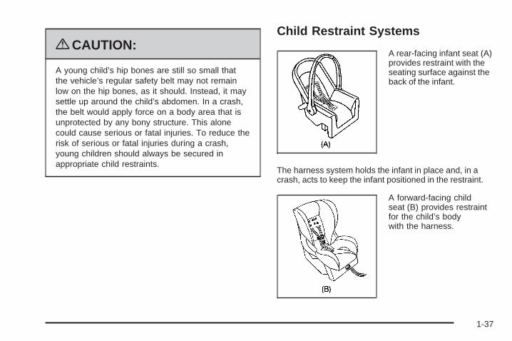
Child Restraint Systems
A rear-facing infant seat (A)provides restraint with theseating surface against theback of the infant.
The harness system holds the infant in place and, in acrash, acts to keep the infant positioned in the restraint.
A forward-facing childseat (B) provides restraintfor the child’s bodywith the harness.
1-37
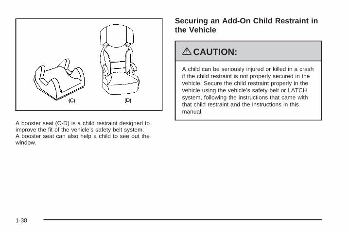
A booster seat (C-D) is a child restraint designed toimprove the fit of the vehicle’s safety belt system.A booster seat can also help a child to see out thewindow.
Securing an Add-On Child Restraint inthe Vehicle
{CAUTION:
A child can be seriously injured or killed in a crashif the child restraint is not properly secured in thevehicle. Secure the child restraint properly in thevehicle using the vehicle’s safety belt or LATCHsystem, following the instructions that came withthat child restraint and the instructions in thismanual.
1-38
To help reduce the chance of injury, the child restraintmust be secured in the vehicle. Child restraint systemsmust be secured in vehicle seats by lap belts or thelap belt portion of a lap-shoulder belt, or by the LATCHsystem. See Lower Anchors and Tethers for Children(LATCH) on page 1-41 for more information. A child canbe endangered in a crash if the child restraint is notproperly secured in the vehicle.
When securing an add-on child restraint, refer to theinstructions that come with the restraint which may be onthe restraint itself or in a booklet, or both, and to thismanual. The child restraint instructions are important, soif they are not available, obtain a replacement copyfrom the manufacturer.
Keep in mind that an unsecured child restraint canmove around in a collision or sudden stop and injurepeople in the vehicle. Be sure to properly secureany child restraint in the vehicle — even when no childis in it.
Securing the Child Within the ChildRestraint
{CAUTION:
A child can be seriously injured or killed in a crashif the child is not properly secured in the childrestraint. Secure the child properly following theinstructions that came with that child restraint.
Where to Put the RestraintAccording to accident statistics, children and infantsare safer when properly restrained in a child restraintsystem or infant restraint system secured in a rearseating position.
We recommend that children and child restraints besecured in a rear seat, including: an infant or a childriding in a rear-facing child restraint; a child riding ina forward-facing child seat; an older child riding ina booster seat; and children, who are large enough,using safety belts.
1-39
A label on the sun visor says, “Never put a rear-facingchild restraint in the front.” This is because the riskto the rear-facing child is so great, if the airbag deploys.
{CAUTION:
A child in a rear-facing child restraint can beseriously injured or killed if the right frontpassenger airbag inflates. This is because theback of the rear-facing child restraint would bevery close to the inflating airbag. A child in aforward-facing child restraint can be seriouslyinjured or killed if the right front passenger airbaginflates and the passenger seat is in a forwardposition.
Even if the passenger sensing system has turnedoff the right front passenger frontal airbag, nosystem is fail-safe. No one can guarantee that anairbag will not deploy under some unusualcircumstance, even though it is turned off.
CAUTION: (Continued)
CAUTION: (Continued)
Secure rear-facing child restraints in a rear seat,even if the airbag is off. If you secure aforward-facing child restraint in the right front seat,always move the front passenger seat as far backas it will go. It is better to secure the child restraintin a rear seat.
See Passenger Sensing System on page 1-62 foradditional information.
When securing a child restraint in a rear seatingposition, study the instructions that came with the childrestraint to make sure it is compatible with thisvehicle.
Wherever a child restraint is installed, be sure to securethe child restraint properly.
Keep in mind that an unsecured child restraint canmove around in a collision or sudden stop and injurepeople in the vehicle. Be sure to properly secureany child restraint in the vehicle — even when nochild is in it.
1-40

Lower Anchors and Tethers forChildren (LATCH)The LATCH system holds a child restraint during drivingor in a crash. This system is designed to make installationof a child restraint easier. The LATCH system usesanchors in the vehicle and attachments on the childrestraint that are made for use with the LATCH system.
Make sure that a LATCH-compatible child restraint isproperly installed using the anchors, or use the vehicle’ssafety belts to secure the restraint, following theinstructions that came with that restraint, and also theinstructions in this manual. When installing a childrestraint with a top tether, you must also use either thelower anchors or the safety belts to properly secure thechild restraint. A child restraint must never be installedusing only the top tether and anchor.
In order to use the LATCH system in your vehicle, youneed a child restraint that has LATCH attachments.The child restraint manufacturer will provide you withinstructions on how to use the child restraint and itsattachments. The following explains how to attach achild restraint with these attachments in your vehicle.
Not all vehicle seating positions or child restraints havelower anchors and attachments or top tether anchorsand attachments.
Lower Anchors
Lower anchors (A) are metal bars built into the vehicle.There are two lower anchors for each LATCH seatingposition that will accommodate a child restraint withlower attachments (B).
1-41
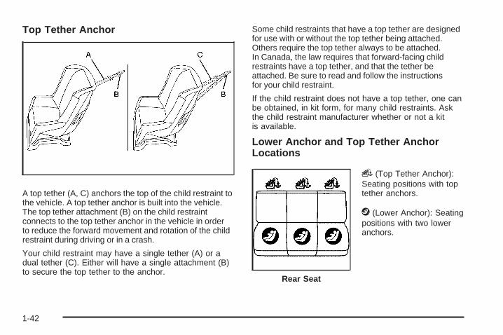
Top Tether Anchor
A top tether (A, C) anchors the top of the child restraint tothe vehicle. A top tether anchor is built into the vehicle.The top tether attachment (B) on the child restraintconnects to the top tether anchor in the vehicle in orderto reduce the forward movement and rotation of the childrestraint during driving or in a crash.
Your child restraint may have a single tether (A) or adual tether (C). Either will have a single attachment (B)to secure the top tether to the anchor.
Some child restraints that have a top tether are designedfor use with or without the top tether being attached.Others require the top tether always to be attached.In Canada, the law requires that forward-facing childrestraints have a top tether, and that the tether beattached. Be sure to read and follow the instructionsfor your child restraint.
If the child restraint does not have a top tether, one canbe obtained, in kit form, for many child restraints. Askthe child restraint manufacturer whether or not a kitis available.
Lower Anchor and Top Tether AnchorLocations
i (Top Tether Anchor):Seating positions with toptether anchors.
j (Lower Anchor): Seatingpositions with two loweranchors.
Rear Seat
1-42
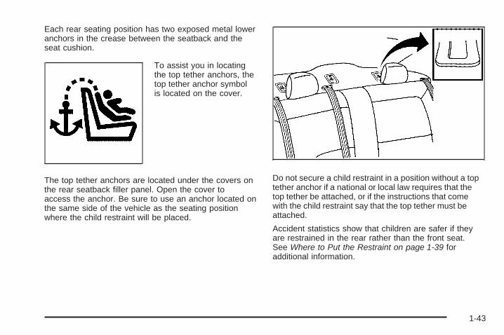
Each rear seating position has two exposed metal loweranchors in the crease between the seatback and theseat cushion.
To assist you in locatingthe top tether anchors, thetop tether anchor symbolis located on the cover.
The top tether anchors are located under the covers onthe rear seatback filler panel. Open the cover toaccess the anchor. Be sure to use an anchor located onthe same side of the vehicle as the seating positionwhere the child restraint will be placed.
Do not secure a child restraint in a position without a toptether anchor if a national or local law requires that thetop tether be attached, or if the instructions that comewith the child restraint say that the top tether must beattached.
Accident statistics show that children are safer if theyare restrained in the rear rather than the front seat.See Where to Put the Restraint on page 1-39 foradditional information.
1-43
Securing a Child Restraint Designed forthe LATCH System
{CAUTION:
If a LATCH-type child restraint is not attached toanchors, the child restraint will not be able toprotect the child correctly. In a crash, the childcould be seriously injured or killed. Install aLATCH-type child restraint properly using theanchors, or use the vehicle’s safety belts to securethe restraint, following the instructions that camewith the child restraint and the instructions in thismanual.
{CAUTION:
Do not attach more than one child restraint to asingle anchor. Attaching more than one childrestraint to a single anchor could cause the anchoror attachment to come loose or even break duringa crash. A child or others could be injured. Toreduce the risk of serious or fatal injuries during acrash, attach only one child restraint per anchor.
{CAUTION:
Children can be seriously injured or strangled if ashoulder belt is wrapped around their neck andthe safety belt continues to tighten. Buckle anyunused safety belts behind the child restraint sochildren cannot reach them. Pull the shoulder beltall the way out of the retractor to set the lock, ifyour vehicle has one, after the child restraint hasbeen installed.
1-44

Notice: Do not let the LATCH attachments rubagainst the vehicle’s safety belts. This may damagethese parts. If necessary, move buckled safetybelts to avoid rubbing the LATCH attachments.
Do not fold the empty rear seat with a safety beltbuckled. This could damage the safety belt orthe seat. Unbuckle and return the safety belt to itsstowed position, before folding the seat.
1. Attach and tighten the lower attachments to thelower anchors. If the child restraint does not havelower attachments or the desired seating positiondoes not have lower anchors, secure the childrestraint with the top tether and the safety belts.Refer to your child restraint manufacturerinstructions and the instructions in this manual.
1.1. Find the lower anchors for the desiredseating position.
1.2. Put the child restraint on the seat.1.3. Attach and tighten the lower attachments on
the child restraint to the lower anchors.
2. If the child restraint manufacturer recommends thatthe top tether be attached, attach and tighten thetop tether to the top tether anchor, if equipped.Refer to the child restraint instructions andthe following steps:
2.1. Find the top tether anchor.2.2. Open the top tether anchor cover to expose
the anchor.2.3. If you have an adjustable headrest or head
restraint, raise the headrest or head restraint.2.4. Route, attach, and tighten the top tether
according to your child restraint instructionsand the following instructions:
If the position you areusing does not have aheadrest or head restraintand you are using asingle tether, route thetether over the seatback.
1-45

If the position you areusing does not have aheadrest or head restraintand you are using adual tether, route the tetherover the seatback.
If the position you are usinghas an adjustable headrestor head restraint and youare using a single tether,raise the headrest or headrestraint and route thetether under the headrestor head restraint and inbetween the headrest orhead restraint posts.
If the position you are usinghas a fixed or adjustableheadrest or head restraintand you are using a dualtether, route the tetheraround the headrest orhead restraint.
3. Push and pull the child restraint in differentdirections to be sure it is secure.
1-46
Securing a Child Restraint in a RearSeat PositionWhen securing a child restraint in a rear seatingposition, study the instructions that came with your childrestraint to make sure it is compatible with this vehicle.
If your child restraint has the LATCH system, see LowerAnchors and Tethers for Children (LATCH) on page 1-41for how to install your child restraint using LATCH. If yousecure a child restraint using a safety belt and it uses atop tether, see Lower Anchors and Tethers for Children(LATCH) on page 1-41 for top tether anchor locations.
Do not secure a child restraint in a position without a toptether anchor if a national or local law requires thatthe top tether be anchored, or if the instructionsthat come with the child restraint say that the top strapmust be anchored.
In Canada, the law requires that forward-facing childrestraints have a top tether, and that the tether beattached.
If your child restraint does not have the LATCH system,you will be using the safety belt to secure the childrestraint in this position. Be sure to follow theinstructions that came with the child restraint. Securethe child in the child restraint when and as theinstructions say.
If you need to install more than one child restraint in therear seat, be sure to read Where to Put the Restrainton page 1-39.
1. Put the child restraint on the seat.
2. Pick up the latch plate, and run the lap and shoulderportions of the vehicle’s safety belt through oraround the restraint. The child restraint instructionswill show you how.
1-47
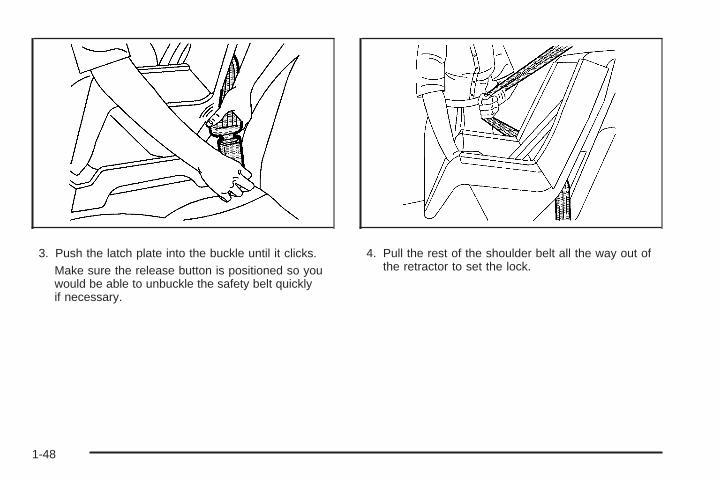
3. Push the latch plate into the buckle until it clicks.Make sure the release button is positioned so youwould be able to unbuckle the safety belt quicklyif necessary.
4. Pull the rest of the shoulder belt all the way out ofthe retractor to set the lock.
1-48
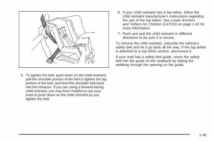
5. To tighten the belt, push down on the child restraint,pull the shoulder portion of the belt to tighten the lapportion of the belt, and feed the shoulder belt backinto the retractor. If you are using a forward-facingchild restraint, you may find it helpful to use yourknee to push down on the child restraint as youtighten the belt.
6. If your child restraint has a top tether, follow thechild restraint manufacturer’s instructions regardingthe use of the top tether. See Lower Anchorsand Tethers for Children (LATCH) on page 1-41 formore information.
7. Push and pull the child restraint in differentdirections to be sure it is secure.
To remove the child restraint, unbuckle the vehicle’ssafety belt and let it go back all the way. If the top tetheris attached to a top tether anchor, disconnect it.
If your seat has a safety belt guide, return the safetybelt into the guide on the seatback by sliding thewebbing through the opening on the guide.
1-49

Securing a Child Restraint in theRight Front Seat PositionThe vehicle has airbags. A rear seat is a safer place tosecure a forward-facing child restraint. See Where toPut the Restraint.
In addition, the vehicle has a passenger sensing systemwhich is designed to turn off the right front passengerfrontal airbag under certain conditions. See PassengerSensing System and Passenger Airbag Status Indicatorfor more information on this, including important safetyinformation.
A label on your sun visor says, “Never put a rear-facingchild seat in the front.” This is because the risk to therear-facing child is so great, if the airbag deploys.
{CAUTION:
A child in a rear-facing child restraint can beseriously injured or killed if the right frontpassenger airbag inflates. This is because theback of the rear-facing child restraint would bevery close to the inflating airbag. A child in aforward-facing child restraint can be seriouslyinjured or killed if the right front passenger airbaginflates and the passenger seat is in a forwardposition.
CAUTION: (Continued)
1-50

CAUTION: (Continued)
Even if the passenger sensing system has turnedoff the right front passenger frontal airbag, nosystem is fail-safe. No one can guarantee that anairbag will not deploy under some unusualcircumstance, even though it is turned off.
Secure rear-facing child restraints in a rear seat,even if the airbag is off. If you secure aforward-facing child restraint in the right front seat,always move the front passenger seat as far backas it will go. It is better to secure the child restraintin a rear seat.
See Passenger Sensing System on page 1-62 foradditional information.
If the child restraint has the LATCH system, see LowerAnchors and Tethers for Children (LATCH) for howand where to install the child restraint using LATCH. If achild restraint is secured using a safety belt and ituses a top tether, see Lower Anchors and Tethers forChildren (LATCH) for top tether anchor locations.
Do not secure a child seat in a position without a toptether anchor if a national or local law requires that thetop tether be anchored, or if the instructions that comewith the child restraint say that the top strap must beanchored.
In Canada, the law requires that forward-facing childrestraints have a top tether, and that the tether beattached.
You will be using the lap-shoulder belt to secure thechild restraint in this position. Follow the instructions thatcame with the child restraint.1. Move the seat as far back as it will go before
securing the forward-facing child restraint.When the passenger sensing system has turned offthe right front passenger frontal airbag, the offindicator on the passenger airbag status indicatorshould light and stay lit when you start the vehicle.See Passenger Airbag Status Indicator.
2. Put the child restraint on the seat.3. If the seat has a safety belt guide, remove the
safety belt from the guide on the head restraintby sliding the webbing through the opening on theguide. Do not secure the child restraint with thesafety belt routed through the guide.
4. Pick up the latch plate, and run the lap and shoulderportions of the vehicle’s safety belt through oraround the restraint. The child restraint instructionswill show you how.
1-51

5. Push the latch plate into the buckle until it clicks.Position the release button on the buckle so thatthe safety belt could be quickly unbuckled ifnecessary.
6. Pull the rest of the shoulder belt all the way out ofthe retractor to set the lock.
1-52

7. To tighten the belt, push down on the child restraint,pull the shoulder portion of the belt to tighten thelap portion of the belt and feed the shoulderbelt back into the retractor. If you are using aforward-facing child restraint, you may find it helpfulto use your knee to push down on the childrestraint as you tighten the belt.
8. Push and pull the child restraint in differentdirections to be sure it is secure.
If the airbag is off, the off indicator in the passengerairbag status indicator will come on and stay on whenthe vehicle is started.
If a child restraint has been installed and on indicator islit, see “If the On Indicator is Lit for a Child Restraint”under Passenger Sensing System on page 1-62for more information.
To remove the child restraint, unbuckle the vehiclesafety belt and let it return to the stowed position.
If your seat has a safety belt guide, insert the safety beltinto the guide on the head restraint by sliding thewebbing through the opening on the guide.
1-53
Airbag SystemThe vehicle has the following airbags:
• A frontal airbag for the driver.
• A frontal airbag for the right front passenger
Your vehicle may also have the following airbags:
• A roof-rail airbag for the driver and the passengerseated directly behind the driver.
• A roof-rail airbag for the right front passenger andthe passenger seated directly behind the rightfront passenger.
All of the airbags in the vehicle will have the wordAIRBAG embossed in the trim or on an attached labelnear the deployment opening.
For frontal airbags, the word AIRBAG will appear on themiddle part of the steering wheel for the driver andon the instrument panel for the right front passenger.
With roof-rail airbags, the word AIRBAG will appearalong the headliner or trim.
Airbags are designed to supplement the protectionprovided by safety belts. Even though today’s airbagsare also designed to help reduce the risk of injuryfrom the force of an inflating bag, all airbags must inflatevery quickly to do their job.
Here are the most important things to know about theairbag system:
{CAUTION:
You can be severely injured or killed in a crash ifyou are not wearing your safety belt — even if youhave airbags. Airbags are designed to work withsafety belts, but do not replace them. Also,airbags are not designed to deploy in every crash.In some crashes safety belts are your onlyrestraint. See When Should an Airbag Inflate? onpage 1-58.
Wearing your safety belt during a crash helpsreduce your chance of hitting things inside thevehicle or being ejected from it. Airbags are“supplemental restraints” to the safety belts.Everyone in your vehicle should wear a safety beltproperly — whether or not there is an airbag forthat person.
1-54
{CAUTION:
Airbags inflate with great force, faster than theblink of an eye. Anyone who is up against, or veryclose to, any airbag when it inflates can beseriously injured or killed. Do not sit unnecessarilyclose to the airbag, as you would be if you weresitting on the edge of your seat or leaning forward.Safety belts help keep you in position before andduring a crash. Always wear your safety belt, evenwith airbags. The driver should sit as far back aspossible while still maintaining control of thevehicle.
Occupants should not lean on or sleep against thedoor or side windows in seating positions withroof-rail airbags.
{CAUTION:
Children who are up against, or very close to, anyairbag when it inflates can be seriously injured orkilled. Airbags plus lap-shoulder belts offerprotection for adults and older children, but not foryoung children and infants. Neither the vehicle’ssafety belt system nor its airbag system isdesigned for them. Young children and infantsneed the protection that a child restraint systemcan provide. Always secure children properly inyour vehicle. To read how, see Older Children onpage 1-30 or Infants and Young Children onpage 1-33.
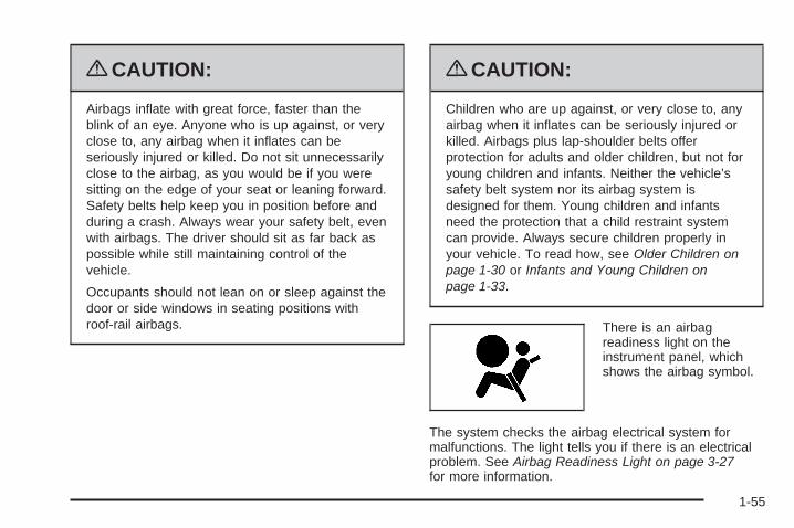
There is an airbagreadiness light on theinstrument panel, whichshows the airbag symbol.
The system checks the airbag electrical system formalfunctions. The light tells you if there is an electricalproblem. See Airbag Readiness Light on page 3-27for more information.
1-55

Where Are the Airbags?
The driver’s frontal airbag is in the middle of thesteering wheel.
The right front passenger’s airbag is in the instrumentpanel on the passenger’s side.
1-56
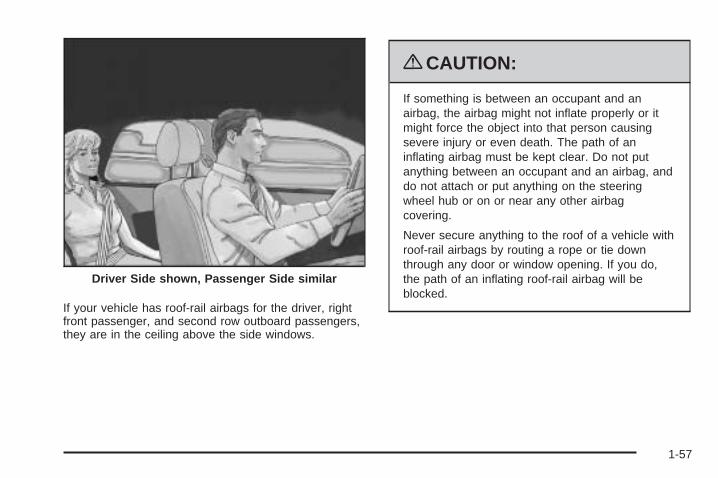
If your vehicle has roof-rail airbags for the driver, rightfront passenger, and second row outboard passengers,they are in the ceiling above the side windows.
{CAUTION:
If something is between an occupant and anairbag, the airbag might not inflate properly or itmight force the object into that person causingsevere injury or even death. The path of aninflating airbag must be kept clear. Do not putanything between an occupant and an airbag, anddo not attach or put anything on the steeringwheel hub or on or near any other airbagcovering.
Never secure anything to the roof of a vehicle withroof-rail airbags by routing a rope or tie downthrough any door or window opening. If you do,the path of an inflating roof-rail airbag will beblocked.
Driver Side shown, Passenger Side similar
1-57
When Should an Airbag Inflate?Frontal airbags are designed to inflate in moderate tosevere frontal or near-frontal crashes to help reduce thepotential for severe injuries mainly to the driver’s orright front passenger’s head and chest. However, theyare only designed to inflate if the impact exceeds apredetermined deployment threshold. Deploymentthresholds are used to predict how severe a crash islikely to be in time for the airbags to inflate andhelp restrain the occupants.
Whether your frontal airbags will or should deploy is notbased on how fast your vehicle is traveling. It dependslargely on what you hit, the direction of the impact,and how quickly your vehicle slows down.
Frontal airbags may inflate at different crash speeds.For example:
• If the vehicle hits a stationary object, the airbagscould inflate at a different crash speed than if thevehicle hits a moving object.
• If the vehicle hits an object that deforms, theairbags could inflate at a different crash speed thanif the vehicle hits an object that does not deform.
• If the vehicle hits a narrow object (like a pole), theairbags could inflate at a different crash speedthan if the vehicle hits a wide object (like a wall).
• If the vehicle goes into an object at an angle, theairbags could inflate at a different crash speedthan if the vehicle goes straight into the object.
1-58

Thresholds can also vary with specific vehicle design.
Frontal airbags are not intended to inflate during vehiclerollovers, rear impacts, or in many side impacts.
In addition, your vehicle has dual-stage frontal airbags.Dual-stage airbags adjust the restraint according tocrash severity. Your vehicle has an electronic frontalsensor, which helps the sensing system distinguishbetween a moderate frontal impact and a more severefrontal impact. For moderate frontal impacts, dual-stageairbags inflate at a level less than full deployment.For more severe frontal impacts, full deploymentoccurs.
Your vehicle may have roof-rail airbags. See AirbagSystem on page 1-54. Roof-rail airbags are intendedto inflate in moderate to severe side crashes. Roof-rail
airbags will inflate if the crash severity is above thesystem’s designed threshold level. The thresholdlevel can vary with specific vehicle design.
Roof-rail airbags are not intended to inflate in frontalimpacts, near-frontal impacts, rollovers, or rear impacts.A roof-rail airbag is intended to deploy on the side ofthe vehicle that is struck.
In any particular crash, no one can say whether anairbag should have inflated simply because of thedamage to a vehicle or because of what the repair costswere. For frontal airbags, inflation is determined bywhat the vehicle hits, the angle of the impact, and howquickly the vehicle slows down. For roof-rail airbags,deployment is determined by the location and severity ofthe side impact.
1-59

What Makes an Airbag Inflate?In a deployment event, the sensing system sends anelectrical signal triggering a release of gas fromthe inflator. Gas from the inflator fills the airbag causingthe bag to break out of the cover and deploy. Theinflator, the airbag, and related hardware are all part ofthe airbag module.
Frontal airbag modules are located inside the steeringwheel and instrument panel. For vehicles with roof-railairbags, there are airbag modules in the ceiling of thevehicle, near the side windows that have occupantseating positions.
How Does an Airbag Restrain?In moderate to severe frontal or near frontal collisions,even belted occupants can contact the steering wheelor the instrument panel. In moderate to severe sidecollisions, even belted occupants can contact the insideof the vehicle.
Airbags supplement the protection provided by safetybelts. Frontal airbags distribute the force of theimpact more evenly over the occupant’s upper body,stopping the occupant more gradually. Roof-rail airbagsdistribute the force of the impact more evenly overthe occupant’s upper body.
But airbags would not help in many types of collisions,primarily because the occupant’s motion is nottoward those airbags. See When Should an AirbagInflate? on page 1-58 for more information.
Airbags should never be regarded as anything morethan a supplement to safety belts.
What Will You See After an AirbagInflates?After the frontal airbags inflate, they quickly deflate,so quickly that some people may not even realizean airbag inflated. Roof-rail airbags may still be atleast partially inflated for some time after they deploy.Some components of the airbag module may be hot forseveral minutes. For location of the airbag modules,see What Makes an Airbag Inflate? on page 1-60.
The parts of the airbag that come into contact with youmay be warm, but not too hot to touch. There maybe some smoke and dust coming from the vents in thedeflated airbags. Airbag inflation does not preventthe driver from seeing out of the windshield or beingable to steer the vehicle, nor does it prevent people fromleaving the vehicle.
1-60

{CAUTION:
When an airbag inflates, there may be dust in theair. This dust could cause breathing problems forpeople with a history of asthma or other breathingtrouble. To avoid this, everyone in the vehicleshould get out as soon as it is safe to do so. Ifyou have breathing problems but cannot get out ofthe vehicle after an airbag inflates, then get freshair by opening a window or a door. If youexperience breathing problems following an airbagdeployment, you should seek medical attention.
The vehicle has a feature that may automatically unlockthe doors, turn the interior lamps on, and turn thehazard warning flashers on when the airbags inflate.You can lock the doors, turn the interior lamps off, andturn the hazard warning flashers off by using thecontrols for those features.
In many crashes severe enough to inflate the airbag,windshields are broken by vehicle deformation.Additional windshield breakage may also occur from theright front passenger airbag.
• Airbags are designed to inflate only once. After anairbag inflates, you will need some new parts forthe airbag system. If you do not get them, the airbagsystem will not be there to help protect you inanother crash. A new system will include airbagmodules and possibly other parts. The servicemanual for the vehicle covers the need to replaceother parts.
• The vehicle has a crash sensing and diagnosticmodule which records information after a crash.See Vehicle Data Recording and Privacy onpage 7-16 and Event Data Recorders on page 7-17.
• Let only qualified technicians work on the airbagsystems. Improper service can mean that anairbag system will not work properly. See yourdealer/retailer for service.
1-61

Passenger Sensing SystemThe vehicle has a passenger sensing system for theright front passenger position. The passenger airbagstatus indicator will be visible on the instrumentpanel when the vehicle is started.
The words ON and OFF, or the symbol for on and off,will be visible during the system check. If you are usingremote start to start the vehicle from a distance, ifequipped, you may not see the system check. When thesystem check is complete, either the word ON or the wordOFF, or the symbol for on or off, will be visible. SeePassenger Airbag Status Indicator on page 3-28.
The passenger sensing system will turn off the rightfront passenger frontal airbag under certain conditions.The driver airbag and roof-rail airbags are not affectedby the passenger sensing system.
The passenger sensing system works with sensors thatare part of the right front passenger seat. The sensorsare designed to detect the presence of a properly-seatedoccupant and determine if the right front passengerfrontal airbag should be enabled (may inflate) or not.
According to accident statistics, children are safer whenproperly secured in a rear seat in the correct childrestraint for their weight and size.
We recommend that children be secured in a rear seat,including: an infant or a child riding in a rear-facingchild restraint; a child riding in a forward-facing childseat; an older child riding in a booster seat; and children,who are large enough, using safety belts.
A label on the sun visor says, “Never put a rear-facingchild seat in the front.” This is because the risk tothe rear-facing child is so great, if the airbag deploys.
United States Canada
1-62
{CAUTION:
A child in a rear-facing child restraint can beseriously injured or killed if the right frontpassenger airbag inflates. This is because theback of the rear-facing child restraint would bevery close to the inflating airbag. A child in aforward-facing child restraint can be seriouslyinjured or killed if the right front passenger airbaginflates and the passenger seat is in a forwardposition.
Even if the passenger sensing system has turnedoff the right front passenger frontal airbag, nosystem is fail-safe. No one can guarantee that anairbag will not deploy under some unusualcircumstance, even though the airbag is turned off.
Secure rear-facing child restraints in a rear seat,even if the airbag is off. If you secure aforward-facing child restraint in the right front seat,always move the front passenger seat as far backas it will go. It is better to secure the child restraintin a rear seat.
The passenger sensing system is designed to turn offthe right front passenger frontal airbag if:
• The right front passenger seat is unoccupied.
• The system determines that an infant is present ina child restraint.
• A right front passenger takes his/her weight off ofthe seat for a period of time.
• Or, if there is a critical problem with the airbagsystem or the passenger sensing system.
When the passenger sensing system has turned off theright front passenger frontal airbag, the off indicatorwill light and stay lit to remind you that the airbag is off.See Passenger Airbag Status Indicator on page 3-28.
The passenger sensing system is designed turn on (mayinflate) the right front passenger frontal airbag anytimethe system senses that a person of adult size issitting properly in the right front passenger seat. Whenthe passenger sensing system has allowed theairbag to be enabled, the on indicator will light and staylit to remind you that the airbag is active.
1-63

For some children, including children in child restraints,and for very small adults, the passenger sensing systemmay or may not turn off the right front passenger frontalairbag, depending upon the person’s seating postureand body build. Everyone in the vehicle who hasoutgrown child restraints should wear a safety beltproperly — whether or not there is an airbag for thatperson.
{CAUTION:
If the airbag readiness light ever comes on andstays on, it means that something may be wrongwith the airbag system. To help avoid injury toyourself or others, have the vehicle serviced rightaway. See Airbag Readiness Light on page 3-27for more information, including important safetyinformation.
If the On Indicator is Lit for a ChildRestraintIf a child restraint has been installed and the onindicator is lit:
1. Turn the vehicle off.
2. Remove the child restraint from the vehicle.
3. Remove any additional items from the seat such asblankets, cushions, seat covers, seat heaters, orseat massagers.
4. Reinstall the child restraint following the directionsprovided by the child restraint manufacturer andrefer to Securing a Child Restraint in the Right FrontSeat Position on page 1-50.
5. If, after reinstalling the child restraint and restartingthe vehicle, the on indicator is still lit, turn the vehicleoff. Then slightly recline the vehicle seatback andadjust the seat cushion, if adjustable, to make surethat the vehicle seatback is not pushing the childrestraint into the seat cushion.Also make sure the child restraint is not trappedunder the vehicle head restraint. If this happens,adjust the head restraint. See Head Restraintson page 1-7.
6. Restart the vehicle.The passenger sensing system may or may not turnoff the airbag for a child in a child restraint dependingupon the child’s seating posture and body build. It isbetter to secure the child restraint in a rear seat.
1-64

If the Off Indicator is Lit for anAdult-Size Occupant
If a person of adult-size is sitting in the right frontpassenger seat, but the off indicator is lit, it could bebecause that person is not sitting properly in the seat.
If this happens, use the following steps to allow thesystem to detect that person and enable the right frontpassenger frontal airbag:
1. Turn the vehicle off.
2. Remove any additional material from the seat, suchas blankets, cushions, seat covers, seat heaters, orseat massagers.
3. Place the seatback in the fully upright position.
4. Have the person sit upright in the seat, centered onthe seat cushion, with legs comfortably extended.
5. Restart the vehicle and have the person remain inthis position for two to three minutes after the onindicator is lit.
1-65
Additional Factors Affecting SystemOperationSafety belts help keep the passenger in position on theseat during vehicle maneuvers and braking, whichhelps the passenger sensing system maintain thepassenger airbag status. See “Safety Belts” and “ChildRestraints” in the Index for additional informationabout the importance of proper restraint use.
A thick layer of additional material, such as a blanket orcushion, or aftermarket equipment such as seatcovers, seat heaters, and seat massagers can affecthow well the passenger sensing system operates.We recommend that you not use seat covers or otheraftermarket equipment except when approved by GM foryour specific vehicle. See Adding Equipment to YourAirbag-Equipped Vehicle on page 1-68 for moreinformation about modifications that can affect how thesystem operates.
A wet seat can affect the performance of the passengersensing system. Here is how:
• The passenger sensing system may turn off thepassenger airbag when liquid is soaked into theseat. If this happens, the off indicator will be lit, andthe airbag readiness light on the instrumentpanel will also be lit.
• Liquid pooled on the seat that has not soaked inmay make it more likely that the passengersensing system will enable (turn on) the passengerairbag while a child restraint or child occupant ison the seat. If the passenger airbag is turned on, theon indicator will be lit.
1-66

If the passenger seat gets wet, dry the seat immediately.If the airbag readiness light is lit, do not install a childrestraint or allow anyone to occupy the seat. See AirbagReadiness Light on page 3-27 for important safetyinformation.
The on indicator may be lit if an object, such as abriefcase, handbag, grocery bag, laptop or otherelectronic device, is put on an unoccupied seat. If this isnot desired, remove the object from the seat.
{CAUTION:
Stowing of articles under the passenger seat orbetween the passenger seat cushion and seatbackmay interfere with the proper operation of thepassenger sensing system.
Servicing Your Airbag-EquippedVehicleAirbags affect how the vehicle should be serviced.There are parts of the airbag system in several placesaround the vehicle. Your dealer/retailer and theservice manual have information about servicing thevehicle and the airbag system. To purchase a servicemanual, see Service Publications Ordering Informationon page 7-15.
{CAUTION:
For up to 10 seconds after the ignition is turned offand the battery is disconnected, an airbag can stillinflate during improper service. You can be injuredif you are close to an airbag when it inflates. Avoidyellow connectors. They are probably part of theairbag system. Be sure to follow proper serviceprocedures, and make sure the person performingwork for you is qualified to do so.
1-67
Adding Equipment to YourAirbag-Equipped Vehicle
Q: Is there anything I might add to or changeabout the vehicle that could keep the airbagsfrom working properly?
A: Yes. If you add things that change the vehicle’sframe, bumper system, height, front end or sidesheet metal, they may keep the airbag system fromworking properly. Changing or moving any partsof the front seats, safety belts, the airbag sensingand diagnostic module, steering wheel, instrumentpanel, roof-rail airbag modules, ceiling headlineror pillar garnish trim, front sensors, or airbag wiringcan affect the operation of the airbag system.
In addition, the vehicle has a passenger sensingsystem for the right front passenger position, whichincludes sensors that are part of the passenger’sseat. The passenger sensing system may notoperate properly if the original seat trim is replacedwith non-GM covers, upholstery or trim, or withGM covers, upholstery or trim designed for adifferent vehicle. Any object, such as an aftermarketseat heater or a comfort enhancing pad or device,installed under or on top of the seat fabric,could also interfere with the operation of the
passenger sensing system. This could eitherprevent proper deployment of the passengerairbag(s) or prevent the passenger sensing systemfrom properly turning off the passenger airbag(s).See Passenger Sensing System on page 1-62.
If you have any questions, call CustomerAssistance. The phone numbers and addresses forCustomer Assistance are in Step Two of theCustomer Satisfaction Procedure in this manual.See Customer Satisfaction Procedure on page 7-2.
Q: Because I have a disability, I have to get myvehicle modified. How can I find out whether thiswill affect my airbag system?
A: If you have questions, call Customer Assistance.The phone numbers and addresses for CustomerAssistance are in Step Two of the CustomerSatisfaction Procedure in this manual. SeeCustomer Satisfaction Procedure on page 7-2.
In addition, your dealer/retailer and the service manualhave information about the location of the airbag sensors,sensing and diagnostic module and airbag wiring.
1-68
Restraint System Check
Checking the Restraint Systems
Safety BeltsNow and then, check the safety belt reminder light,safety belts, buckles, latch plates, retractors, andanchorages are all working properly.
Look for any other loose or damaged safety belt systemparts that might keep a safety belt system from doingits job. See your dealer/retailer to have it repaired. Tornor frayed safety belts may not protect you in a crash.They can rip apart under impact forces. If a belt is tornor frayed, get a new one right away.
Make sure the safety belt reminder light is working.See Safety Belt Reminders on page 3-26 for moreinformation.
Keep safety belts clean and dry. See Care of SafetyBelts on page 5-102.
AirbagsThe airbag system does not need regularly scheduledmaintenance or replacement. Make sure the airbagreadiness light is working. See Airbag Readiness Lighton page 3-27 for more information.
Notice: If an airbag covering is damaged, opened,or broken, the airbag may not work properly. Donot open or break the airbag coverings. If there areany opened or broken airbag covers, have theairbag covering and/or airbag module replaced. Forthe location of the airbag modules, see WhatMakes an Airbag Inflate? on page 1-60. See yourdealer/retailer for service.
1-69
Replacing Restraint System PartsAfter a Crash
{CAUTION:
A crash can damage the restraint systems in yourvehicle. A damaged restraint system may notproperly protect the person using it, resulting inserious injury or even death in a crash. To helpmake sure your restraint systems are workingproperly after a crash, have them inspected andany necessary replacements made as soon aspossible.
If the vehicle has been in a crash, do you need newsafety belts or LATCH system (if equipped) parts?
After a very minor crash, nothing may be necessary.But the safety belt assemblies that were used during anycrash may have been stressed or damaged. See yourdealer/retailer to have the safety belt assembliesinspected or replaced.
If the vehicle has the LATCH system and it was beingused during a crash, you may need new LATCHsystem parts.
New parts and repairs may be necessary even if thesafety belt or LATCH system (if equipped), wasnot being used at the time of the crash.
If an airbag inflates, you will need to replace airbagsystem parts. See the part on the airbag system earlierin this section.
Have the safety belt pretensioners checked if thevehicle has been in a crash, if the airbag readiness lightstays on after the vehicle is started, or while you aredriving. See Airbag Readiness Light on page 3-27.
1-70

Keys ...............................................................2-2Remote Keyless Entry (RKE) System ................2-3Remote Keyless Entry (RKE) System
Operation ...................................................2-3Remote Vehicle Start ......................................2-6
Doors and Locks .............................................2-8Door Locks ....................................................2-8Power Door Locks ..........................................2-9Delayed Locking .............................................2-9Automatic Door Lock .....................................2-10Programmable Automatic Door Unlock .............2-10Rear Door Security Locks (Sedan) ..................2-10Lockout Protection ........................................2-11Trunk ..........................................................2-12
Windows ........................................................2-14Manual Windows ..........................................2-15Power Windows ............................................2-15Sun Visors ...................................................2-16
Theft-Deterrent Systems ..................................2-16Content Theft-Deterrent .................................2-16PASS-Key® III+ Electronic Immobilizer .............2-18PASS-Key® III+ Electronic Immobilizer
Operation .................................................2-19Starting and Operating Your Vehicle ................2-20
New Vehicle Break-In ....................................2-20Ignition Positions ..........................................2-21
Retained Accessory Power (RAP) ...................2-23Starting the Engine .......................................2-24Engine Coolant Heater ..................................2-25Automatic Transmission Operation ...................2-26Manual Transmission Operation ......................2-28Parking Brake ..............................................2-30Shifting Into Park (Automatic Transmission) ......2-31Shifting Out of Park (Automatic Transmission) .....2-33Parking the Vehicle (Manual Transmission) .......2-33Parking Over Things That Burn .......................2-34Engine Exhaust ............................................2-34Running the Vehicle While Parked ..................2-35
Mirrors ...........................................................2-36Manual Rearview Mirror .................................2-36Outside Remote Control Mirror .......................2-36Outside Power Mirrors ...................................2-36Outside Convex Mirror ...................................2-37
OnStar® System .............................................2-37Storage Areas ................................................2-41
Glove Box ...................................................2-41Cupholders ..................................................2-41Center Console Storage .................................2-41Driver Storage Compartment ..........................2-41Convenience Net ..........................................2-41
Sunroof .........................................................2-42
Section 2 Features and Controls
2-1

Keys
{CAUTION:
Leaving children in a vehicle with the ignition keyis dangerous for many reasons, children or otherscould be badly injured or even killed. They couldoperate the power windows or other controls oreven make the vehicle move. The windows willfunction with the keys in the ignition and childrencould be seriously injured or killed if caught in thepath of a closing window. Do not leave the keys ina vehicle with children.
The key can be used for the ignition and all locks.
The key has a bar-coded key tag that the dealer/retaileror qualified locksmith can use to make new keys.Store this information in a safe place, not in your vehicle.
Notice: If you ever lock your keys in the vehicle,you may have to damage the vehicle to get in.Be sure you have spare keys.
If you are locked out of your vehicle, contact RoadsideAssistance. See Roadside Assistance Program onpage 7-7.
2-2

Remote Keyless Entry (RKE)SystemIf this vehicle has the Remote Keyless Entry (RKE)system, it operates on a radio frequency subjectto Federal Communications Commission (FCC) Rulesand with Industry Canada.
This device complies with Part 15 of the FCC Rules.Operation is subject to the following two conditions:
1. This device may not cause interference.
2. This device must accept any interference received,including interference that may cause undesiredoperation of the device.
This device complies with RSS-210 of Industry Canada.Operation is subject to the following two conditions:
1. This device may not cause interference.
2. This device must accept any interference received,including interference that may cause undesiredoperation of the device.
Changes or modifications to this system by other thanan authorized service facility could void authorization touse this equipment.
If there is a decrease in the RKE operating range,try this:
• Check the distance. The transmitter may be too farfrom the vehicle. Stand closer during rainy orsnowy weather.
• Check the location. Other vehicles or objects maybe blocking the signal. Take a few steps to theleft or right, hold the transmitter higher, andtry again.
• Check the transmitter’s battery. See “BatteryReplacement” later in this section.
• If the transmitter is still not working correctly, seeyour dealer/retailer or a qualified technician forservice.
Remote Keyless Entry (RKE)System OperationThe Remote Keyless Entry (RKE) transmitter functionswork up to 195 feet (60 m) away from the vehicle.
There are other conditions which can affect theperformance of the transmitter. See Remote KeylessEntry (RKE) System on page 2-3.
2-3

/ (Remote Vehicle Start): For vehicles with thisfeature, press to operate the remote start feature. SeeRemote Vehicle Start on page 2-6.
Q (Lock): Press to lock all the doors. The interiorlamps turn off after all of the doors are closed. If enabledthrough the Driver Information Center (DIC), the remotelock feedback can be programmed to have the horn chirpand/or the turn signals flash to confirm locking. See“LOCK HORN” and “LIGHT FLASH” under DIC VehiclePersonalization on page 3-47.
Pressing Q may also arm the content theft-deterrentsystem. See Content Theft-Deterrent onpage 2-16.
K (Unlock): Press to unlock the driver door. If K ispressed again within five seconds, all remaining doorsunlock. The interior lamps turn on and stay on for20 seconds or until the ignition is turned on. If enabledthrough the DIC, the remote unlock feedback canbe programmed to have the horn chirp and/or the turnsignals flash to confirm unlocking. See “UNLOCKHORN” and “LIGHT FLASH” under DIC VehiclePersonalization on page 3-47.
The high-beam headlamps, parking lamps, and back-uplamps may turn on when K is pressed. See “EXT(Exterior) LIGHTS” under DIC Vehicle Personalizationon page 3-47.
Pressing K on the RKE transmitter disarms the contenttheft-deterrent system. See Content Theft-Deterrenton page 2-16.
V (Remote Trunk Release): Press and hold forapproximately one second to open the trunk. The trunkwill open using the transmitter when the vehiclespeed is less than 2 mph (3 km/h), when the ignition isoff, or when the vehicle shift lever is in P (Park).
With Remote StartShown, Without Remote
Start Similar
2-4
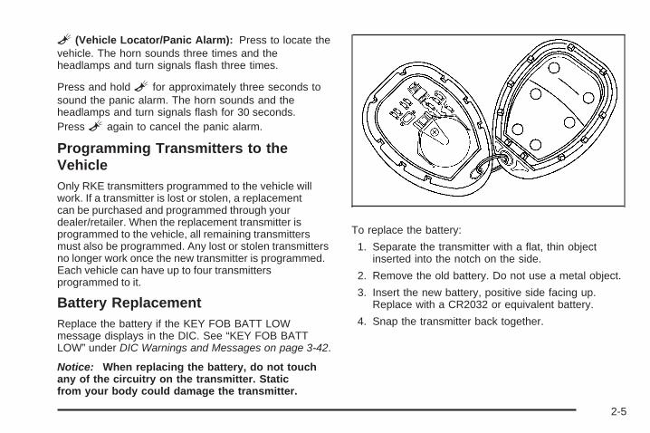
L (Vehicle Locator/Panic Alarm): Press to locate thevehicle. The horn sounds three times and theheadlamps and turn signals flash three times.
Press and hold L for approximately three seconds tosound the panic alarm. The horn sounds and theheadlamps and turn signals flash for 30 seconds.Press L again to cancel the panic alarm.
Programming Transmitters to theVehicleOnly RKE transmitters programmed to the vehicle willwork. If a transmitter is lost or stolen, a replacementcan be purchased and programmed through yourdealer/retailer. When the replacement transmitter isprogrammed to the vehicle, all remaining transmittersmust also be programmed. Any lost or stolen transmittersno longer work once the new transmitter is programmed.Each vehicle can have up to four transmittersprogrammed to it.
Battery ReplacementReplace the battery if the KEY FOB BATT LOWmessage displays in the DIC. See “KEY FOB BATTLOW” under DIC Warnings and Messages on page 3-42.
Notice: When replacing the battery, do not touchany of the circuitry on the transmitter. Staticfrom your body could damage the transmitter.
To replace the battery:
1. Separate the transmitter with a flat, thin objectinserted into the notch on the side.
2. Remove the old battery. Do not use a metal object.
3. Insert the new battery, positive side facing up.Replace with a CR2032 or equivalent battery.
4. Snap the transmitter back together.
2-5

Remote Vehicle StartYour vehicle may have a remote start feature. Thisfeature allows you to start the engine from outside thevehicle. It may also start the vehicle’s heating or airconditioning systems. When you start your vehicle usingthe remote start feature, the climate control system willcome on and adjust the interior to the temperaturesettings that you left it set to when you turned thevehicle off.
Laws in some communities may restrict the use ofremote starters. For example, some laws may require aperson using remote start to have the vehicle in viewwhen doing so. Check local regulations for anyrequirements on remote starting of vehicles.
Do not use the remote start feature if your vehicle is lowon fuel. Your vehicle may run out of fuel.
The remote start feature provides two separate startsper ignition cycle, each with 10 minutes of enginerunning time.
After your vehicle’s engine has been started two timesusing the remote vehicle start button, the vehicle’signition switch must be turned to ON/RUN and then backto LOCK/OFF using the key before the remote startprocedure can be used again. See Ignition Positions onpage 2-21 for information regarding the ignitionpositions on your vehicle.
If your vehicle has the remote start feature, the RKEtransmitter functions will have an increased rangeof operation. However, the range may be less while thevehicle is running.
There are other conditions which can affect theperformance of the transmitter, see Remote KeylessEntry (RKE) System on page 2-3 for additionalinformation.
/ (Remote Start): This button will be on the RKEtransmitter if you have remote start.
To start the vehicle using the remote start feature, dothe following:
1. Aim the transmitter at the vehicle.
2. Press and release the transmitter’s lock button,then immediately press and hold the transmitter’sremote start button until the vehicle’s turn signallamps flash.When the vehicle starts, the parking lamps will turnon and remain on while the engine is running.
3. If it is the first remote start since the vehicle hasbeen driven, repeat these steps, while the engineis running, to extend the time by 10 minutes for theengine to continue to run.
After entering the vehicle after a remote start, insert andturn the key to ON/RUN to drive the vehicle.
2-6

The engine will shut off automatically after 10 minutes,unless a time extension has been done or thevehicle’s key is inserted into the ignition switch andturned to ON/RUN.
To manually shut off a remote start, do any of thefollowing. The parking lamps will turn off to indicate theengine is off.
• Aim the RKE transmitter at the vehicle and pressand release the remote start button.
• Turn on the hazard warning flashers.
• Turn the ignition switch to ON/RUN and thenLOCK/OFF.
Your vehicle’s engine can be started two times, perignition cycle, using the transmitter’s remote startfeature.
If the remote start procedure is used again beforethe first 10 minute time frame has ended, the first10 minutes will immediately expire and the second10 minute time frame will start.
The remote vehicle start feature will not operate if anyof the follow occur:
• The remote start system is disabled throughthe DIC.
• The vehicle’s key is in the ignition.
• The vehicle’s hood is open.
• The hazard warning flashers are on.
• The check engine light is on. See MalfunctionIndicator Lamp on page 3-34.
• The engine coolant temperature is too high.
• The oil pressure is low.
• Two remote vehicle starts have already beenprovided for that ignition cycle.
Vehicles that have the remote vehicle start feature areshipped from the factory with the remote start systemenabled. The system may be enabled or disabledthrough the DIC. See “REMOTE START” under DICVehicle Personalization on page 3-47 for additionalinformation.
2-7
Doors and Locks
Door Locks
{CAUTION:
Unlocked doors can be dangerous.• Passengers, especially children, can easily
open the doors and fall out of a movingvehicle. When a door is locked, the handlewill not open it. You increase the chance ofbeing thrown out of the vehicle in a crash ifthe doors are not locked. So, wear safetybelts properly and lock the doors wheneveryou drive.
CAUTION: (Continued)
CAUTION: (Continued)
• Young children who get into unlocked vehiclesmay be unable to get out. A child can beovercome by extreme heat and can sufferpermanent injuries or even death from heatstroke. Always lock your vehicle wheneveryou leave it.
• Outsiders can easily enter through anunlocked door when you slow down or stopyour vehicle. Locking your doors can helpprevent this from happening.
There are several ways to lock and unlock your vehicle.
To lock the driver’s door from the outside, turn thekey clockwise. To unlock the door, turn the keycounterclockwise.
You can also use the remote keyless entry transmitter,if equipped, to lock and unlock the doors.
From the inside, use the manual lock knobs on eachdoor or the power door lock switch to lock and unlockall doors.
2-8

Power Door Locks
Your vehicle may havepower door locks. Thelocks are located onthe driver’s and frontpassenger’s door armrest.
Press the side of the switch with the lock symbol to lockthe doors. This is the right side for the driver’s switchand the left side for the front passenger’s switch.
Press the side of the switch with the unlock symbol tounlock the doors. This is the left side for the driver’sswitch and the right side for the front passenger’s switch.
Delayed LockingIf your vehicle has power locks, it will have the delayedlocking feature.
This feature will delay the actual locking of the doors forup to five seconds when the power door lock switchor remote keyless entry transmitter is used to lock thevehicle.
If any door is open when locking the vehicle, threechimes will sound signaling that the delayed lockingfeature is active. Five seconds after the last dooris closed, all of the doors will lock and the turn signallamps will flash. To cancel the delay and lock the doorsimmediately, press the lock button a second time.
This feature will not lock the doors if the key is in theignition.
You can disable this function through the DriverInformation Center (DIC). See DIC VehiclePersonalization on page 3-47.
Driver’s Switch shown,Front Passenger’s
Switch similar
2-9

Automatic Door LockOn vehicles with power door locks, the doorsautomatically lock when the shift lever is moved out of(P) Park for a vehicle with an automatic transmission.For a vehicle with a manual transmission, the speedmust be greater than 5 mph (8 km/h).
The automatic door locking feature cannot be disabled.
Programmable Automatic DoorUnlockIf your vehicle has power locks, it has a programmableautomatic door unlock feature.
The doors can be programmed through the DriverInformation Center (DIC) to automatically unlock severalways. See DIC Vehicle Personalization on page 3-47for more information.
Rear Door Security Locks (Sedan)Your vehicle has rear door security locks. These preventpassengers from opening the rear doors from the inside.
The rear door securitylocks are located on theinside edge of eachrear door. You must openthe rear doors to accessthem. The label showinglock and unlock positions islocated near the lock.
Security Lock Labelshown
2-10

To set the locks, do the following:
1. Insert the key into the security lock slot and turn itso the slot is in the horizontal position.
2. Close the door.
When you want to open a rear door when the securitylock is on, do the following:
1. Unlock the door using the remote keyless entrytransmitter, if the vehicle has one, the powerdoor lock switch, or by lifting the rear doormanual lock.
2. Open the door from the outside.
To cancel the rear door security lock, do the following:
1. Unlock the door and open it from the outside.
2. Insert the key into the security lock slot and turn itso the slot is in the vertical position.
Lockout ProtectionIf your vehicle has power door locks, it will have thisfeature. If you press the power door lock switchwhen the key is in the ignition and any door is open, allthe doors will lock and the driver’s door will unlock.Be sure to remove the key from the ignition when lockingyour vehicle.
The lockout protection can be overridden by pressingand holding the power door lock in the lock position forthree seconds.
2-11
TrunkTo release the trunk lid from the outside, use the key orthe remote keyless entry transmitter, if equipped.
{CAUTION:
Exhaust gases may enter the vehicle if it is drivenwith the liftgate, trunk/hatch open, or with anyobjects that pass through the seal between thebody and the trunk/hatch or liftgate. Engineexhaust contains Carbon Monoxide (CO) whichcannot be seen or smelled. It can causeunconsciousness and even death.
CAUTION: (Continued)
CAUTION: (Continued)
If the vehicle must be driven with the liftgate, ortrunk/hatch open:
• Close all of the windows• Fully open the air outlets on or under the
instrument panel• Adjust the Climate Control system to a setting
that brings in only outside air and set the fanspeed to the highest setting. See ClimateControl System in the Index.
• If the vehicle is equipped with a power liftgate,disable the power liftgate function.
For more information about carbon monoxide, seeEngine Exhaust on page 2-34.
2-12
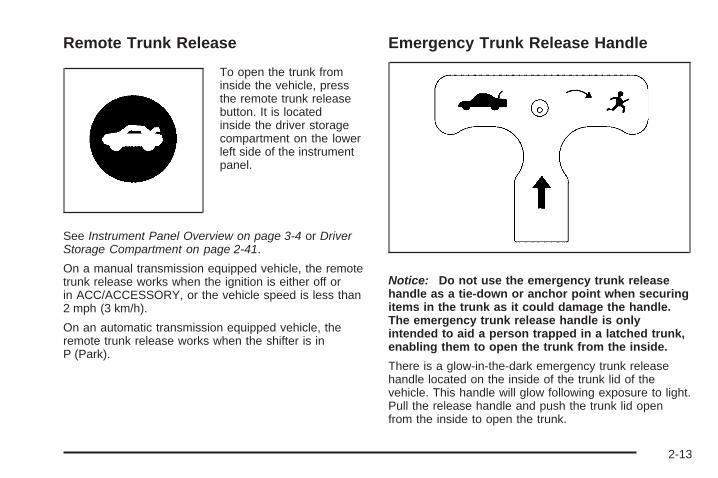
Remote Trunk Release
To open the trunk frominside the vehicle, pressthe remote trunk releasebutton. It is locatedinside the driver storagecompartment on the lowerleft side of the instrumentpanel.
See Instrument Panel Overview on page 3-4 or DriverStorage Compartment on page 2-41.
On a manual transmission equipped vehicle, the remotetrunk release works when the ignition is either off orin ACC/ACCESSORY, or the vehicle speed is less than2 mph (3 km/h).
On an automatic transmission equipped vehicle, theremote trunk release works when the shifter is inP (Park).
Emergency Trunk Release Handle
Notice: Do not use the emergency trunk releasehandle as a tie-down or anchor point when securingitems in the trunk as it could damage the handle.The emergency trunk release handle is onlyintended to aid a person trapped in a latched trunk,enabling them to open the trunk from the inside.
There is a glow-in-the-dark emergency trunk releasehandle located on the inside of the trunk lid of thevehicle. This handle will glow following exposure to light.Pull the release handle and push the trunk lid openfrom the inside to open the trunk.
2-13

Windows
{CAUTION:
Leaving children, helpless adults, or pets in avehicle with the windows closed is dangerous.They can be overcome by the extreme heat andsuffer permanent injuries or even death from heatstroke. Never leave a child, a helpless adult, or apet alone in a vehicle, especially with the windowsclosed in warm or hot weather.
2-14
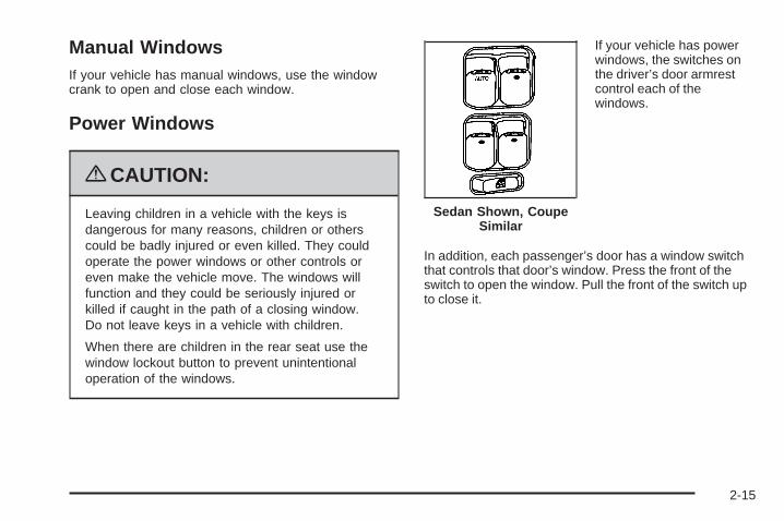
Manual WindowsIf your vehicle has manual windows, use the windowcrank to open and close each window.
Power Windows
{CAUTION:
Leaving children in a vehicle with the keys isdangerous for many reasons, children or otherscould be badly injured or even killed. They couldoperate the power windows or other controls oreven make the vehicle move. The windows willfunction and they could be seriously injured orkilled if caught in the path of a closing window.Do not leave keys in a vehicle with children.
When there are children in the rear seat use thewindow lockout button to prevent unintentionaloperation of the windows.
If your vehicle has powerwindows, the switches onthe driver’s door armrestcontrol each of thewindows.
In addition, each passenger’s door has a window switchthat controls that door’s window. Press the front of theswitch to open the window. Pull the front of the switch upto close it.
Sedan Shown, CoupeSimilar
2-15
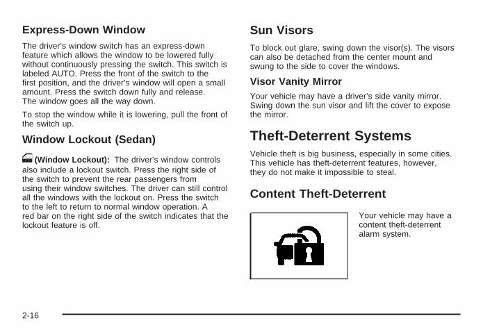
Express-Down WindowThe driver’s window switch has an express-downfeature which allows the window to be lowered fullywithout continuously pressing the switch. This switch islabeled AUTO. Press the front of the switch to thefirst position, and the driver’s window will open a smallamount. Press the switch down fully and release.The window goes all the way down.
To stop the window while it is lowering, pull the front ofthe switch up.
Window Lockout (Sedan)
o (Window Lockout): The driver’s window controlsalso include a lockout switch. Press the right side ofthe switch to prevent the rear passengers fromusing their window switches. The driver can still controlall the windows with the lockout on. Press the switchto the left to return to normal window operation. Ared bar on the right side of the switch indicates that thelockout feature is off.
Sun VisorsTo block out glare, swing down the visor(s). The visorscan also be detached from the center mount andswung to the side to cover the windows.
Visor Vanity MirrorYour vehicle may have a driver’s side vanity mirror.Swing down the sun visor and lift the cover to exposethe mirror.
Theft-Deterrent SystemsVehicle theft is big business, especially in some cities.This vehicle has theft-deterrent features, however,they do not make it impossible to steal.
Content Theft-Deterrent
Your vehicle may have acontent theft-deterrentalarm system.
2-16

Arming the SystemWith the ignition off, you can arm the system bypressing the remote keyless entry transmitter lockbutton.
The system will arm after either of these things occur:
• Thirty seconds after all the doors are closed.
• Sixty seconds with any door open.
If you press the lock button on the transmitter a secondtime while all the doors are closed, the system will armimmediately. The system will still arm in 60 seconds if adoor is open. When the open door is closed, it will alsobecome armed.
The security light, located on the instrument panelcluster, will turn on to indicate that arming has beeninitiated. Once the system is armed, the security light willflash once every three seconds.
If the security light is flashing twice per second, thismeans that a door is open.
If you do not want to arm the system, you may lock thecar with the manual lock knobs, or the power doorlock switch, if equipped, on the doors.
Disarming the SystemYou can disarm the system by doing any one of thefollowing:
• Press the remote keyless entry transmitter unlockbutton.
• Turn the ignition on.
If the system is armed and the trunk is opened using thetrunk release button on the transmitter, the system willtemporarily disarm itself and re-arm when the trunk hasbeen closed. This allows you to exit the vehicle, lock thedoors using the transmitter, and open the trunk using thetransmitter without having to disarm and re-arm thesystem.
Once the system is disarmed, the security light will stopflashing.
How the System Alarm is ActivatedIf the system is armed, it can be activated by either:
• Opening the driver’s door or trunk. This willcause a ten second pre-alarm chirp followed bya thirty second full alarm of horn and lights.
• Opening any other door. This will immediately causea full alarm of horn and lights for thirty seconds.
When an alarm event has finished, the system willre-arm itself automatically.
2-17
How to Turn Off the System AlarmTo turn off the system alarm, do one of the following:
• Press the lock button on the remote keylessentry transmitter. The system will then re-arm itself.
• Press the unlock button on the remote keyless entrytransmitter. This will also disarm the system.
• Insert the key in the ignition and turn it on. This willalso disarm the system.
How to Detect a Tamper ConditionIf you hear three chirps when you press the unlock, lock,or trunk release buttons on the remote keylesstransmitter, it means that the content theft securitysystem alarm was previously activated.
PASS-Key® III+ ElectronicImmobilizerThe PASS-Key III+ system operates on a radiofrequency subject to Federal CommunicationsCommission (FCC) Rules and with Industry Canada.
This device complies with Part 15 of the FCC Rules.Operation is subject to the following two conditions:
1. This device may not cause harmful interference.
2. This device must accept any interference received,including interference that may cause undesiredoperation.
This device complies with RSS-210 of Industry Canada.Operation is subject to the following two conditions:
1. This device may not cause interference.
2. This device must accept any interference received,including interference that may cause undesiredoperation of the device.
Changes or modifications to this system by other thanan authorized service facility could void authorization touse this equipment.
PASS-Key III+ uses a radio frequency transponder inthe key that matches a decoder in the vehicle.
2-18
PASS-Key® III+ ElectronicImmobilizer OperationYour vehicle has PASS-Key® III+ (PersonalizedAutomotive Security System) theft-deterrent system.PASS-Key® III+ is a passive theft-deterrent system.
The system is automatically armed when the keyis removed from the ignition.
You do not have to manually arm or disarm the system.
The security light will come on if there is a problemwith arming or disarming the theft-deterrent system.
When the PASS-Key® III+ system senses that someoneis using the wrong key, it prevents the vehicle fromstarting. Anyone using a trial-and-error method to startthe vehicle will be discouraged because of the highnumber of electrical key codes.
When trying to start the vehicle if the engine does notstart and the security light comes on, there may bea problem with your theft-deterrent system. Turnthe ignition off and try again.
If the engine still does not start, and the key appears tobe undamaged, try another ignition key. At this time,you may also want to check the fuse, see Fusesand Circuit Breakers on page 5-108. If the engine stilldoes not start with the other key, your vehicle needsservice. If your vehicle does start, the first key may befaulty. See your dealer/retailer who can service thePASS-Key® III+ to have a new key made. In anemergency, contact Roadside Assistance. See RoadsideAssistance Program on page 7-7, for more information.
It may be possible for the PASS-Key® III+ decoder to“learn” the transponder value of a new or replacementkey. Up to 10 keys may be programmed for the vehicle.The following procedure is for programming additionalkeys only. If all the currently programmed keys are lost ordo not operate, you must see your dealer/retailer or alocksmith who can service PASS-Key® III+ to have keysmade and programmed to the system.
See your dealer/retailer or a locksmith who can servicePASS-Key® III+ to get a new key blank that is cutexactly as the ignition key that operates the system.
2-19
To program the new key:
1. Verify that the new key has a 1 stamped on it.
2. Insert the already programmed key in the ignitionand start the engine. If the engine will not start,see your dealer/retailer for service.
3. After the engine has started, turn the key toLOCK/OFF, and remove the key.
4. Insert the key to be programmed and turn it to theON/RUN position within five seconds of the originalkey being turned to the LOCK/OFF position.The security light will turn off once the key hasbeen programmed.
5. Repeat Steps 1 through 4 if additional keys are tobe programmed.
If you are ever driving and the security light comes onand stays on, you may be able to restart your engine ifyou turn it off. Your PASS-Key® III+ system, however,is not working properly and must be serviced byyour dealer/retailer. Your vehicle is not protected by thePASS-Key® III+ system at this time.
If you lose or damage your PASS-Key® III+ key, seeyour dealer/retailer or a locksmith who can servicePASS-Key® III+ to have a new key made.
Do not leave the key or device that disarms ordeactivates the theft deterrent system in the vehicle.
Starting and Operating YourVehicle
New Vehicle Break-InNotice: The vehicle does not need an elaboratebreak-in. But it will perform better in the long run ifyou follow these guidelines:
• Do not drive at any one constant speed, fast orslow, for the first 500 miles (805 km). Do notmake full-throttle starts. Avoid downshifting tobrake or slow the vehicle.
• Avoid making hard stops for the first 200 miles(322 km) or so. During this time the new brakelinings are not yet broken in. Hard stopswith new linings can mean premature wear andearlier replacement. Follow this breaking-inguideline every time you get new brake linings.
• Do not tow a trailer during break-in. See Towinga Trailer (Automatic Transmission) on page 4-33or Towing a Trailer (Manual Transmission) onpage 4-40 for the trailer towing capabilitiesof your vehicle and more information.
Following break-in, engine speed and load can begradually increased.
2-20
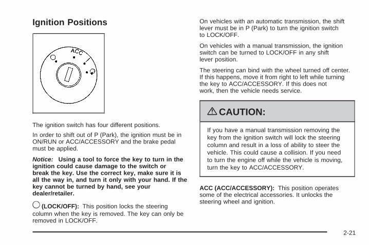
Ignition Positions
The ignition switch has four different positions.
In order to shift out of P (Park), the ignition must be inON/RUN or ACC/ACCESSORY and the brake pedalmust be applied.
Notice: Using a tool to force the key to turn in theignition could cause damage to the switch orbreak the key. Use the correct key, make sure it isall the way in, and turn it only with your hand. If thekey cannot be turned by hand, see yourdealer/retailer.
9 (LOCK/OFF): This position locks the steeringcolumn when the key is removed. The key can only beremoved in LOCK/OFF.
On vehicles with an automatic transmission, the shiftlever must be in P (Park) to turn the ignition switchto LOCK/OFF.
On vehicles with a manual transmission, the ignitionswitch can be turned to LOCK/OFF in any shiftlever position.
The steering can bind with the wheel turned off center.If this happens, move it from right to left while turningthe key to ACC/ACCESSORY. If this does notwork, then the vehicle needs service.
{CAUTION:
If you have a manual transmission removing thekey from the ignition switch will lock the steeringcolumn and result in a loss of ability to steer thevehicle. This could cause a collision. If you needto turn the engine off while the vehicle is moving,turn the key to ACC/ACCESSORY.
ACC (ACC/ACCESSORY): This position operatessome of the electrical accessories. It unlocks thesteering wheel and ignition.
2-21

R (ON/RUN): This is the position in which you canoperate the electrical accessories and to display someinstrument panel cluster warning and indicator lights.The switch stays in this position when the engineis running.
If you leave the key in the ACC/ACCESSORY orON/RUN position with the engine off, the battery couldbe drained. You may not be able to start the vehicleif the battery is allowed to drain for an extended periodof time.
/ (START): This position starts the engine. When theengine starts, release the key. The ignition switchwill return to ON/RUN for driving.
A warning tone will sound when the driver dooris opened, the ignition is in LOCK/OFF orACC/ACCESSORY and the key is in the ignition.
Column Lock ReleaseFor vehicles with an automatic transmission, thefollowing procedure allows the ignition to be turned toLOCK/OFF and ignition key to be removed in case of adead battery or low voltage battery.
1. Make sure the shift lever is in P (Park).
2. Remove the cover from the bottom of the steeringcolumn.
2-22
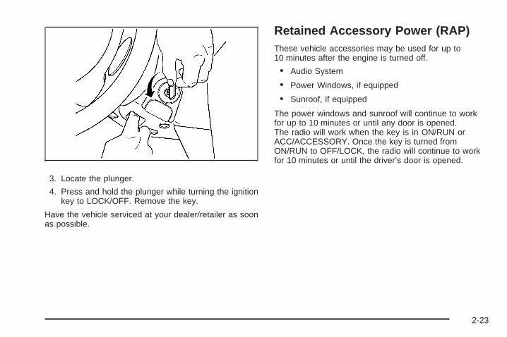
3. Locate the plunger.
4. Press and hold the plunger while turning the ignitionkey to LOCK/OFF. Remove the key.
Have the vehicle serviced at your dealer/retailer as soonas possible.
Retained Accessory Power (RAP)These vehicle accessories may be used for up to10 minutes after the engine is turned off.
• Audio System
• Power Windows, if equipped
• Sunroof, if equipped
The power windows and sunroof will continue to workfor up to 10 minutes or until any door is opened.The radio will work when the key is in ON/RUN orACC/ACCESSORY. Once the key is turned fromON/RUN to OFF/LOCK, the radio will continue to workfor 10 minutes or until the driver’s door is opened.
2-23
Starting the EnginePlace the transmission in the proper gear.
Automatic TransmissionMove the shift lever to P (Park) or N (Neutral). Theengine will not start in any other position. To restart thevehicle when it is already moving, use N (Neutral) only.
Notice: Do not try to shift to P (Park) if the vehicleis moving. If you do, you could damage thetransmission. Shift to P (Park) only when the vehicleis stopped.
Manual TransmissionThe shift lever should be in N (Neutral) and the parkingbrake engaged. Hold the clutch pedal down to thefloor and start the engine. The vehicle will not start if theclutch pedal is not all the way down.
Starting Procedure1. With your foot off the accelerator pedal, turn the
ignition key to START. When the engine starts, let goof the key. The idle speed will go down as the enginewarms. Do not race the engine immediately afterstarting it. Operate the engine and transmissiongently to allow the oil to warm up and lubricate allmoving parts.
The vehicle has a Computer-Controlled CrankingSystem. This feature assists in starting the engineand protects components. If the ignition key is turnedto the START position, and then released when theengine begins cranking, the engine will continuecranking for a few seconds or until the vehicle starts.If the engine does not start and the key is held inSTART for many seconds, cranking will be stoppedafter 15 seconds to prevent cranking motor damage.To prevent gear damage, this system also preventscranking if the engine is already running. Enginecranking can be stopped by turning the ignitionswitch to ACC/ACCESSORY or LOCK/OFF.
Notice: Cranking the engine for long periods oftime, by returning the key to the START positionimmediately after cranking has ended, can overheatand damage the cranking motor, and drain thebattery. Wait at least 15 seconds between each try,to let the cranking motor cool down.
2. If the engine does not start after 5-10 seconds,especially in very cold weather (below 0°F or −18°C),it could be flooded with too much gasoline. Push theaccelerator pedal all the way to the floor and holdingit there as you hold the key in START for a maximumof 15 seconds. Wait at least 15 seconds betweeneach try, to allow the cranking motor to cool. Whenthe engine starts, let go of the key and accelerator.
2-24
If the vehicle starts briefly but then stops again,repeat the procedure. This clears the extra gasolinefrom the engine. Do not race the engine immediatelyafter starting it. Operate the engine and transmissiongently until the oil warms up and lubricates all movingparts.
Notice: The engine is designed to work with theelectronics in the vehicle. If you add electrical partsor accessories, you could change the way theengine operates. Before adding electrical equipment,check with your dealer/retailer. If you do not, theengine might not perform properly. Any resultingdamage would not be covered by the vehiclewarranty.
Engine Coolant HeaterThe engine coolant heater can provide easier startingand better fuel economy during engine warm-up in coldweather condition at or below 0°F (−18°C). Vehicleswith am engine coolant heater should be plugged in atleast four hours before starting. An internal thermostatin the plug-end of the cord may exist which will preventengine coolant heater operation at temperaturesabove 0°F (−18°C).
To Use the Engine Coolant Heater1. Turn off the engine.2. Open the hood and unwrap the electrical cord. The
electrical cord is located on the passenger side ofthe vehicle between the strut and the aircleaner/filter.
3. Plug it into a normal, grounded 110-volt AC outlet.
{CAUTION:
Plugging the cord into an ungrounded outlet couldcause an electrical shock. Also, the wrong kind ofextension cord could overheat and cause a fire.You could be seriously injured. Plug the cord intoa properly grounded three-prong 110-volt ACoutlet. If the cord will not reach, use a heavy-dutythree-prong extension cord rated for at least15 amps.
4. Before starting the engine, be sure to unplug andstore the cord as it was before to keep it awayfrom moving engine parts, and prevent damaged.
The length of time the heater should remain plugged independs on several factors. Ask a dealer/retailer inthe area where you will be parking the vehicle for thebest advice on this.
2-25
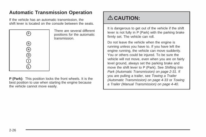
Automatic Transmission OperationIf the vehicle has an automatic transmission, theshift lever is located on the console between the seats.
There are several differentpositions for the automatictransmission.
P (Park): This position locks the front wheels. It is thebest position to use when starting the engine becausethe vehicle cannot move easily.
{CAUTION:
It is dangerous to get out of the vehicle if the shiftlever is not fully in P (Park) with the parking brakefirmly set. The vehicle can roll.
Do not leave the vehicle when the engine isrunning unless you have to. If you have left theengine running, the vehicle can move suddenly.You or others could be injured. To be sure thevehicle will not move, even when you are on fairlylevel ground, always set the parking brake andmove the shift lever to P (Park). See Shifting IntoPark (Automatic Transmission) on page 2-31. Ifyou are pulling a trailer, see Towing a Trailer(Automatic Transmission) on page 4-33 or Towinga Trailer (Manual Transmission) on page 4-40.
2-26

Make sure the shift lever is fully in P (Park) beforestarting the engine. The vehicle has an automatictransmission shift lock control system. You have to fullyapply the regular brakes first and then press the shiftlever button before the vehicle can shift from P (Park)when the ignition key is in ON/RUN. If the vehicle cannotshift out of P (Park), ease pressure on the shift leverand push the shift lever all the way into P (Park) as youmaintain brake application. Then press the shift leverbutton and then move the shift lever into another gear.See Shifting Out of Park (Automatic Transmission)on page 2-33.
Notice: Shifting to R (Reverse) while the vehicle ismoving forward could damage the transmission.The repairs would not be covered by the vehiclewarranty. Shift to R (Reverse) only after the vehicleis stopped.
R (Reverse): Use this gear to back up.
To rock the vehicle back and forth to get out of snow,ice, or sand without damaging the transmission,see If Your Vehicle is Stuck in Sand, Mud, Ice, or Snowon page 4-23.
N (Neutral): In this position, the engine does notconnect with the wheels. To restart the engine when thevehicle is already moving, use N (Neutral) only. Also,use N (Neutral) when the vehicle is being towed.
{CAUTION:
Shifting into a drive gear while the engine isrunning at high speed is dangerous. Unless yourfoot is firmly on the brake pedal, the vehicle couldmove very rapidly. You could lose control and hitpeople or objects. Do not shift into a drive gearwhile the engine is running at high speed.
Notice: Shifting out of P (Park) or N (Neutral) withthe engine running at high speed may damagethe transmission. The repairs would not be coveredby the vehicle warranty. Be sure the engine isnot running at high speed when shifting the vehicle.
D (Drive): This position is for normal driving with theautomatic transmission. It provides the best fueleconomy. If you need more power for passing andyou are:• Going less than about 35 mph (55 km/h), push the
accelerator pedal about halfway down.• Going about 35 mph (55 km/h), push the accelerator
all the way down.
Downshifting the transmission in slippery road conditionscould result in skidding, see “Skidding” under Loss ofControl on page 4-15.
2-27

I (Intermediate): This position is also used for normaldriving. However, it reduces vehicle speed without usingthe brakes for slight downgrades where the vehiclewould otherwise accelerate due to steepness of grade.If constant upshifting or downshifting occurs whiledriving up steep hills, this position can be used toprevent repetitive types of shifts. You might chooseI (Intermediate) instead of D (Drive) when drivingon hilly, winding roads and when towing a trailer, so thatthere is less shifting between gears.
L (Low): This position reduces vehicle speed morethan I (Intermediate) without actually using the brakes.You can use it on very steep hills, or in deep snowor mud. If the shift lever is put in L (Low), thetransmission will not shift into a low gear until thevehicle is going slowly enough.
Notice: Spinning the tires or holding the vehiclein one place on a hill using only the acceleratorpedal may damage the transmission. The repairwill not be covered by the vehicle warranty. If youare stuck, do not spin the tires. When stopping on ahill, use the brakes to hold the vehicle in place.
Manual Transmission Operation
This is the shift pattern.
Here is how to operate the manual transmission:
1 (First): Press the clutch pedal and shift into 1 (First).Then, slowly let up on the clutch pedal as you pressthe accelerator pedal.
You can shift into 1 (First) when the vehicle is travelingless than 20 mph (32 km/h). If you have come to acomplete stop and it is hard to shift into 1 (First), putthe shift lever in N (Neutral) and let up on the clutchpedal. Press the clutch pedal back down. Then shiftinto 1 (First).
2 (Second): Press the clutch pedal as you let up on theaccelerator pedal and shift into 2 (Second). Then,slowly let up on the clutch pedal as you press theaccelerator pedal.
2-28
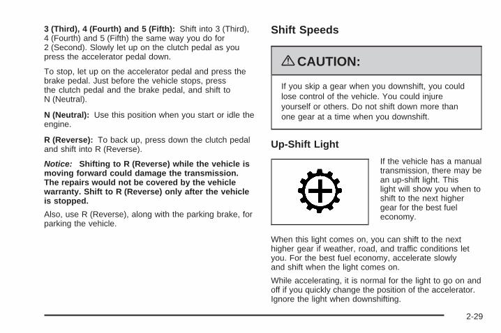
3 (Third), 4 (Fourth) and 5 (Fifth): Shift into 3 (Third),4 (Fourth) and 5 (Fifth) the same way you do for2 (Second). Slowly let up on the clutch pedal as youpress the accelerator pedal down.
To stop, let up on the accelerator pedal and press thebrake pedal. Just before the vehicle stops, pressthe clutch pedal and the brake pedal, and shift toN (Neutral).
N (Neutral): Use this position when you start or idle theengine.
R (Reverse): To back up, press down the clutch pedaland shift into R (Reverse).
Notice: Shifting to R (Reverse) while the vehicle ismoving forward could damage the transmission.The repairs would not be covered by the vehiclewarranty. Shift to R (Reverse) only after the vehicleis stopped.
Also, use R (Reverse), along with the parking brake, forparking the vehicle.
Shift Speeds
{CAUTION:
If you skip a gear when you downshift, you couldlose control of the vehicle. You could injureyourself or others. Do not shift down more thanone gear at a time when you downshift.
Up-Shift Light
If the vehicle has a manualtransmission, there may bean up-shift light. Thislight will show you when toshift to the next highergear for the best fueleconomy.
When this light comes on, you can shift to the nexthigher gear if weather, road, and traffic conditions letyou. For the best fuel economy, accelerate slowlyand shift when the light comes on.
While accelerating, it is normal for the light to go on andoff if you quickly change the position of the accelerator.Ignore the light when downshifting.
2-29
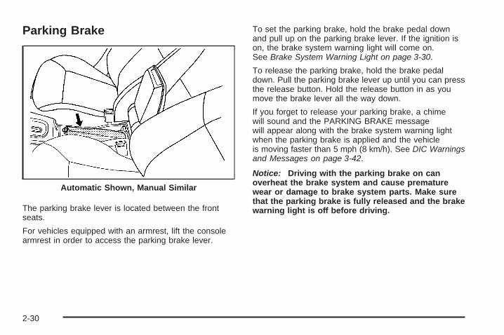
Parking Brake
The parking brake lever is located between the frontseats.
For vehicles equipped with an armrest, lift the consolearmrest in order to access the parking brake lever.
To set the parking brake, hold the brake pedal downand pull up on the parking brake lever. If the ignition ison, the brake system warning light will come on.See Brake System Warning Light on page 3-30.
To release the parking brake, hold the brake pedaldown. Pull the parking brake lever up until you can pressthe release button. Hold the release button in as youmove the brake lever all the way down.
If you forget to release your parking brake, a chimewill sound and the PARKING BRAKE messagewill appear along with the brake system warning lightwhen the parking brake is applied and the vehicleis moving faster than 5 mph (8 km/h). See DIC Warningsand Messages on page 3-42.
Notice: Driving with the parking brake on canoverheat the brake system and cause prematurewear or damage to brake system parts. Make surethat the parking brake is fully released and the brakewarning light is off before driving.
Automatic Shown, Manual Similar
2-30

Shifting Into Park (AutomaticTransmission)
{CAUTION:
It can be dangerous to get out of the vehicle if theshift lever is not fully in P (Park) with the parkingbrake firmly set. The vehicle can roll. If you haveleft the engine running, the vehicle can movesuddenly. You or others could be injured. To besure the vehicle will not move, even when you areon fairly level ground, use the steps that follow. Ifyou are pulling a trailer, see Towing a Trailer(Automatic Transmission) on page 4-33 or Towinga Trailer (Manual Transmission) on page 4-40.
To shift into P (Park), do the following:
1. Hold the brake pedal down and set the parkingbrake. See Parking Brake on page 2-30 for moreinformation.
2. Move the shift lever into P (Park) by holding in thebutton on the shift lever and pushing the lever allthe way toward the front of the vehicle.
3. Turn the ignition key to LOCK/OFF.
4. Remove the key and take it with you. If you canleave the vehicle with the key in your hand, thevehicle is in P (Park).
2-31

Leaving the Vehicle With the EngineRunning (Automatic Transmission)
{CAUTION:
It can be dangerous to leave the vehicle with theengine running. The vehicle could move suddenlyif the shift lever is not fully in P (Park) with theparking brake firmly set. And, if you leave thevehicle with the engine running, it could overheatand even catch fire. You or others could beinjured. Do not leave the vehicle with the enginerunning.
If you have to leave an automatic transmission vehiclewith the engine running, be sure the vehicle is inP (Park) and the parking brake is firmly set before youleave it. After you have moved the shift lever intoP (Park), hold the brake pedal down. Then, see if youcan move the shift lever away from P (Park) without firstpushing the button. If you can, it means that the shiftlever was not fully locked into P (Park).
Torque Lock (Automatic Transmission)If you are parking on a hill and you do not shift intoP (Park) properly, the weight of the vehicle may put toomuch force on the parking pawl in the transmission.You may find it difficult to pull the shift lever out ofP (Park). This is called “torque lock.” To prevent torquelock, set the parking brake and then shift into P (Park)properly before you leave the driver seat. To findout how, see Shifting Into Park (Automatic Transmission)on page 2-31.
Move the shift lever out of P (Park) before you releasethe parking brake.
If torque lock does occur, you may need to haveanother vehicle push yours a little uphill to take some ofthe pressure from the parking pawl in the transmission,so you can pull the shift lever out of P (Park).
2-32

Shifting Out of Park (AutomaticTransmission)This vehicle is equipped with an electronic shift lockrelease system. The shift lock release is designed to:
• Prevent ignition key removal unless the shiftlever is in P (Park) with the shift lever button fullyreleased, and
• Prevent movement of the shift lever out of P (Park)unless the ignition is in ON/RUN orACC/ACCESSORY and the regular brake pedal isapplied.
The shift lock release is always functional except inthe case of a an uncharged or low voltage (less than9 volt) battery.
If the vehicle has an uncharged battery or a battery withlow voltage, try charging or jump starting the battery.See Jump Starting on page 5-34 for more information.
To shift out of P (Park):
1. Apply the brake pedal.
2. Then press the shift lever button.
3. Move the shift lever to the desired position.
If you still are unable to shift out of P (Park):
1. Fully release the shift lever button.
2. While holding down the brake pedal, press the shiftlever button again.
3. Move the shift lever to the desired position.
If you still cannot move the shift lever from P (Park),consult your dealer/retailer or a professional towingservice.
Parking the Vehicle (ManualTransmission)Before leaving the vehicle, fully press the clutch pedaldown, move the shift lever into R (Reverse), and firmlyapply the parking brake. Once the shift lever has beenplaced in R (Reverse) with the clutch pedal presseddown, the ignition key can be turned to LOCK/OFF, thenremove the key and release the clutch pedal. See ManualTransmission Operation on page 2-28.
2-33
Parking Over Things That Burn
{CAUTION:
Things that can burn could touch hot exhaustparts under the vehicle and ignite. Do not parkover papers, leaves, dry grass, or other things thatcan burn.
Engine Exhaust
{CAUTION:
Engine exhaust contains Carbon Monoxide (CO)which cannot be seen or smelled. Exposure to COcan cause unconsciousness and even death.
CAUTION: (Continued)
CAUTION: (Continued)
Exhaust may enter the vehicle if:• The vehicle idles in areas with poor ventilation
(parking garages, tunnels, deep snow thatmay block underbody airflow or tail pipes).
• The exhaust smells or sounds strange ordifferent.
• The exhaust system leaks due to corrosion ordamage.
• The vehicle’s exhaust system has beenmodified, damaged or improperly repaired.
• There are holes or openings in the vehiclebody from damage or after-marketmodifications that are not completely sealed.
If unusual fumes are detected or if it is suspectedthat exhaust is coming into the vehicle:
• Drive it only with the windowscompletely down.
• Have the vehicle repaired immediately.
Never park the vehicle with the engine running inan enclosed area such as a garage or a buildingthat has no fresh air ventilation.
2-34

Running the Vehicle While ParkedIt is better not to park with the engine running. But if youever have to, here are some things to know.
{CAUTION:
Idling a vehicle in an enclosed area with poorventilation is dangerous. Engine exhaust mayenter the vehicle. Engine exhaust contains CarbonMonoxide (CO) which cannot be seen or smelled.It can cause unconsciousness and even death.Never run the engine in an enclosed area that hasno fresh air ventilation. For more information, seeEngine Exhaust on page 2-34.
{CAUTION:
It can be dangerous to get out of the vehicle if theautomatic transmission shift lever is not fully inP (Park) with the parking brake firmly set. Thevehicle can roll. Do not leave the vehicle when theengine is running unless you have to. If you haveleft the engine running, the vehicle can movesuddenly. You or others could be injured. To besure the vehicle will not move, even when you areon fairly level ground, always set the parkingbrake and move the shift lever to P (Park).
Follow the proper steps to be sure the vehicle will notmove. See Shifting Into Park (Automatic Transmission)on page 2-31.
If parking on a hill and pulling a trailer, see Towing aTrailer (Automatic Transmission) on page 4-33 orTowing a Trailer (Manual Transmission) on page 4-40.
2-35

Mirrors
Manual Rearview MirrorHold the inside rearview mirror in the center to move itfor a clearer view of behind your vehicle. Adjust themirror to avoid glare from the headlamps behind you.Push the tab forward for daytime use and pull it fornighttime use.
Vehicles with OnStar® have three additional controlbuttons located at the bottom of the mirror. Seeyour dealer/retailer for more information on the systemand how to subscribe to OnStar®. See OnStar®
System on page 2-37 for more information about theservices OnStar® provides.
If the vehicle has map lamps, press the buttons locatedat the bottom of the mirror to turn them on or off.
Outside Remote Control MirrorAdjust the driver outside mirror with the control leverlocated on the driver door. Adjust the outside mirrors sothat the side of the vehicle can be seen.
Manually fold the mirrors inward to prevent damage whengoing through an automatic car wash. To fold, push themirror toward the vehicle. Push the mirror outward, toreturn it to the original position.
Outside Power Mirrors
Controls for the outsidepower mirrors are locatedon the driver doorarmrest.
To adjust the mirrors:
1. Move the selector switch located below the four-waycontrol pad to the left or right to choose either thedriver or passenger side mirror.
2. Press one of the four arrows located on the controlpad to move the mirror to the desired direction.
3. Adjust each outside mirror so that a little of thevehicle and the area behind it can be seen.
Keep the selector switch in the center position when notadjusting either outside mirror.
Manually fold the mirrors inward to prevent damagewhen going through an automatic car wash. To fold, pushthe mirror toward the vehicle. Push the mirror outward, toreturn it to the original position.
2-36
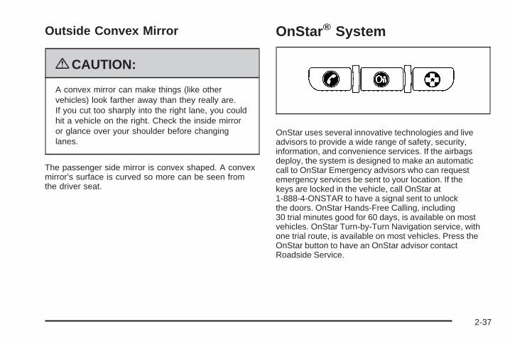
Outside Convex Mirror
{CAUTION:
A convex mirror can make things (like othervehicles) look farther away than they really are.If you cut too sharply into the right lane, you couldhit a vehicle on the right. Check the inside mirroror glance over your shoulder before changinglanes.
The passenger side mirror is convex shaped. A convexmirror’s surface is curved so more can be seen fromthe driver seat.
OnStar® System
OnStar uses several innovative technologies and liveadvisors to provide a wide range of safety, security,information, and convenience services. If the airbagsdeploy, the system is designed to make an automaticcall to OnStar Emergency advisors who can requestemergency services be sent to your location. If thekeys are locked in the vehicle, call OnStar at1-888-4-ONSTAR to have a signal sent to unlockthe doors. OnStar Hands-Free Calling, including30 trial minutes good for 60 days, is available on mostvehicles. OnStar Turn-by-Turn Navigation service, withone trial route, is available on most vehicles. Press theOnStar button to have an OnStar advisor contactRoadside Service.
2-37

OnStar service is provided subject to the OnStar Termsand Conditions included in the OnStar Subscriberglove box literature.
Some services such as Remote Door Unlock or StolenVehicle Location Assistance may not be available untilthe owner of the vehicle registers with OnStar. After thefirst prepaid year, contact OnStar to select a monthly orannual subscription payment plan. If a payment plan isnot selected, the OnStar system and all services,including airbag notification and emergency services,may be deactivated and no longer available. For moreinformation visit onstar.com (U.S.) or onstar.ca (Canada),or press the OnStar button to speak with an advisor.
Not all OnStar services are available on all vehicles.To check if this vehicle is able to provide the servicesdescribed below, or for a full description of OnStarservices and system limitations, see the OnStar Owner’sGuide in the glove box or visit onstar.com (U.S.) oronstar.ca (Canada), contact OnStar at 1-888-4-ONSTAR(1-888-466-7827) or TTY 1-877-248-2080, or press theOnStar button to speak with an OnStar advisor 24 hoursa day, 7 days a week.
OnStar Services Available with theSafe & Sound Plan• Automatic Notification of Airbag Deployment
• Advanced Automatic Crash Notification (AACN)(If equipped)
• Link to Emergency Services
• Roadside Assistance
• Stolen Vehicle Location Assistance
• Remote Door Unlock/Vehicle Alert
• OnStar Vehicle Diagnostic Email
• GM Goodwrench On Demand Diagnostics
• OnStar Hands-Free Calling with 30 trial minutes
• OnStar Virtual Advisor (U.S. Only)
2-38
OnStar Services Included withDirections & Connections Plan• All Safe and Sound Plan Services
• OnStar Turn-by-Turn Navigation (If equipped) orDriving Directions - Advisor delivered
• RideAssist
• Information and Convenience Services
OnStar Hands-Free CallingOnStar Hands-Free Calling allows eligible OnStarsubscribers to make and receive calls using voicecommands. Hands-Free Calling is fully integrated intothe vehicle, and can be used with OnStar Pre-PaidMinute Packages. Most vehicles include 30 trial minutesgood for 60 days. Hands-Free Calling can also belinked to a Verizon Wireless service plan in the U.S. ora Bell Mobility service plan in Canada, dependingon eligibility. To find out more, refer to the OnStarOwner’s Guide in the vehicle’s glove box, visitonstar.com or onstar.ca, or speak with an OnStaradvisor by pressing the OnStar button or calling1-888-4-ONSTAR (1-888-466-7827).
OnStar Turn-by-Turn NavigationVehicles with the OnStar Turn-by-Turn Navigationsystem can provide voice-guided driving directions.Press the OnStar button to have an OnStar advisorlocate a business or address and download drivingdirections to the vehicle. Voice-guided directions to thedesired destination will play through the audio systemspeakers. See the OnStar Owner’s Guide for moreinformation.
OnStar Virtual AdvisorOnStar Virtual Advisor is a feature of OnStar Hands-FreeCalling that uses minutes to access location-basedweather, local traffic reports, and stock quotes. Press thephone button and give a few simple voice commands tobrowse through the various topics. See the OnStarOwner’s Guide for more information. This feature is onlyavailable in the continental U.S.
OnStar Steering Wheel ControlsThis vehicle may have a Talk/Mute button that can beused to interact with OnStar Hands-Free Calling.See Audio Steering Wheel Controls on page 3-85 formore information.
On some vehicles, the mute button can be used to dialnumbers into voice mail systems, or to dial phoneextensions. See the OnStar Owner’s Guide for moreinformation.
2-39
How OnStar Service WorksThe OnStar system can record and transmit vehicleinformation. This information is automatically sent to anOnStar Call Center when the OnStar button is pressed,the emergency button is pressed, or if the airbags orAACN system deploy. This information usually includesthe vehicle’s GPS location and, in the event of a crash,additional information regarding the crash that the vehiclewas involved in (e.g. the direction from which the vehiclewas hit). When the Virtual Advisor feature of OnStarHands-Free Calling is used, the vehicle also sendsOnStar the vehicle’s GPS location so they can provideservices where it is located.
OnStar service cannot work unless the vehicle is in aplace where OnStar has an agreement with a wirelessservice provider for service in that area. OnStar servicealso cannot work unless the vehicle is in a place wherethe wireless service provider OnStar has hired for thatarea has coverage, network capacity and reception whenthe service is needed, and technology that is compatiblewith the OnStar service. Not all services are availableeverywhere, particularly in remote or enclosed areas, orat all times.
Location information about the vehicle is only availableif the GPS satellite signals are unobstructed andavailable.
The vehicle must have a working electrical system,including adequate battery power, for the OnStarequipment to operate. There are other problems OnStarcannot control that may prevent OnStar from providingOnStar service at any particular time or place. Someexamples are damage to important parts of the vehiclein a crash, hills, tall buildings, tunnels, weather orwireless phone network congestion.
Your ResponsibilityIncrease the volume of the radio if the OnStar advisorcannot be heard. If the light next to the OnStar buttons isred, the system may not be functioning properly.Press the OnStar button and request a vehiclediagnostic. If the light appears clear (no light isappearing), your OnStar subscription has expired andall services have been deactivated. Press the OnStarbutton to confirm that the OnStar equipment is active.
2-40

Storage Areas
Glove BoxLift up on the glove box lever to open it.
CupholdersThere are two cupholders located at the front of thecenter console, in front of the shift lever. There arealso cupholders for the rear seat passengers locatedat the rear of the center console.
Center Console StorageFor vehicles with a center console storage area, openwith the lever on the front of the console.
Driver Storage CompartmentThe driver’s storage compartment is located nearthe left side of the steering column on the bottomof the instrument panel. Pull the cover downto open.
Convenience NetUse the convenience net, located in the rear,to store small loads as far forward as possible.The net should not be used to store heavyloads.
2-41

SunroofOn vehicles with a sunroof,the switch that operates it islocated on the headlinerbetween the map lamps.
The sunroof will only operate while the ignition is on, orturned to ACC/ACCESSORY, or if Retained AccessoryPower (RAP) is active. See Retained AccessoryPower (RAP) on page 2-23.
Press the sunroof switch rearward to open the sunroof tothe vent position. If the sunshade is closed, it must beopened manually in the vent position. Press and hold theswitch rearward a second time to open the sunroof. If thesunshade is closed, it will open automatically when thesunroof is opened.
To close the sunroof, press the switch forward and holdit until the sunroof is closed. The sunroof will stop ifthe switch is released. Close the sunshade by hand.
Notice: If you force the sunshade forward ofthe sliding glass panel, damage will occur and thesunroof may not open or close properly. Alwaysclose the glass panel before closing the sunshade.
The sunroof glass panel cannot be opened or closedif the vehicle has an electrical failure.
Do not keep the sunroof open for long periods of time.Debris may collect in the tracks and possibly damagethe sunroof and plug the water draining system.
2-42

Instrument Panel Overview ...............................3-4Hazard Warning Flashers ................................3-6Horn .............................................................3-6Tilt Wheel .....................................................3-6Turn Signal/Multifunction Lever .........................3-7Turn and Lane-Change Signals ........................3-7Headlamp High/Low-Beam Changer ..................3-8Flash-to-Pass .................................................3-8Windshield Wipers ..........................................3-8Windshield Washer .........................................3-9Cruise Control ..............................................3-10Headlamps ..................................................3-12Wiper Activated Headlamps ............................3-13Headlamps on Reminder ................................3-13Daytime Running Lamps (DRL) .......................3-13Fog Lamps ..................................................3-14Instrument Panel Brightness ...........................3-14Dome Lamp .................................................3-15Entry/Exit Lighting .........................................3-15Mirror Reading Lamps ...................................3-15Electric Power Management ...........................3-15Battery Run-Down Protection ..........................3-16Accessory Power Outlet(s) .............................3-16Ashtray(s) and Cigarette Lighter ......................3-17
Climate Controls ............................................3-18Climate Control System .................................3-18Outlet Adjustment .........................................3-21Passenger Compartment Air Filter ...................3-21
Warning Lights, Gages, and Indicators ............3-23Instrument Panel Cluster ................................3-24Speedometer and Odometer ...........................3-25Tachometer .................................................3-25Safety Belt Reminders ...................................3-26Airbag Readiness Light ..................................3-27Passenger Airbag Status Indicator ...................3-28Charging System Light ..................................3-29Up-Shift Light ...............................................3-29Brake System Warning Light ..........................3-30Antilock Brake System (ABS)
Warning Light ...........................................3-31Enhanced Traction System (ETS)
Indicator/Warning Light ...............................3-31Electronic Stability Control (ESC)/Traction
Control System (TCS) Indicator/Warning Light ...........................................3-32
Engine Coolant Temperature Warning Light ........3-33Tire Pressure Light .......................................3-33Malfunction Indicator Lamp .............................3-34
Section 3 Instrument Panel
3-1

Oil Pressure Light .........................................3-37Security Light ...............................................3-38Fog Lamp Light ............................................3-38Highbeam On Light .......................................3-38Fuel Gage ...................................................3-38
Driver Information Center (DIC) .......................3-39DIC Operation and Displays ...........................3-40DIC Warnings and Messages .........................3-42DIC Vehicle Personalization ............................3-47
Audio System(s) .............................................3-52Setting the Clock ..........................................3-53Radio(s) ......................................................3-55Using an MP3 ..............................................3-65XM Radio Messages .....................................3-72Bluetooth® ...................................................3-73Theft-Deterrent Feature ..................................3-84Audio Steering Wheel Controls .......................3-85Radio Reception ...........................................3-86Fixed Mast Antenna ......................................3-87XM™ Satellite Radio Antenna System .............3-87
Section 3 Instrument Panel
3-2

✍ NOTES
3-3

Instrument Panel Overview
3-4

The main components of the instrument panel are the following:
A. Outlet Adjustment on page 3-21.B. Outlet Adjustment on page 3-21.C. Turn Signal/Multifunction Lever on page 3-7.D. Cruise Control on page 3-10 (If Equipped).E. Instrument Panel Cluster on page 3-24.F. Audio Steering Wheel Controls on page 3-85
(If Equipped).G. Hazard Warning Flashers on page 3-6.H. Windshield Wipers on page 3-8 and Windshield
Washer on page 3-9.I. Audio System(s) on page 3-52.J. Fog Lamps on page 3-14 (If Equipped).K. Trunk Release. See Trunk on page 2-12.L. Instrument Panel Brightness on page 3-14.
M. Driver Information Center (DIC) on page 3-39.N. Horn on page 3-6.O. Traction Control System (TCS) on page 4-8
(If Equipped). Electronic Stability Control (ESC) onpage 4-6 (If Equipped).
P. Cigarette Lighter (If Equipped). See Ashtray(s) andCigarette Lighter on page 3-17. Accessory PowerOutlet(s) on page 3-16 (If Equipped).
Q. Shift Lever (Manual Shown). See ManualTransmission Operation on page 2-28 and AutomaticTransmission Operation on page 2-26.
R. Climate Control System on page 3-18.S. Heated Seats on page 1-4 (If Equipped).T. Glove Box on page 2-41.
3-5

Hazard Warning Flashers
| (Hazard Warning Flasher): Press this buttonlocated on the instrument panel, to make the front andrear turn signal lamps flash on and off. This warnsothers that you are having trouble.
Press | again to turn the flashers off.
HornTo sound the horn, press the center pad on the steeringwheel.
Tilt WheelA tilt wheel lets the steering wheel be adjusted beforedriving.
The tilt lever is located on the left side of the steeringcolumn.
To tilt the wheel, pull down the lever. Then move thewheel to a comfortable position, pull up the lever to lockthe wheel in place.
Do not adjust the steering wheel while driving.
3-6

Turn Signal/Multifunction Lever
The lever on the left side of the steering columnincludes the following:
G : Turn and Lane-Change Signals
53: Headlamp High/Low-Beam Changer
O : Exterior Lamp Control
Flash-to-Pass.
Information for these features is on the pages following.
Turn and Lane-Change Signals
An arrow on the instrumentpanel cluster flashes in thedirection of the turn orlane change.
Move the lever all the way up or down to signal a turn.
Raise or lower the lever until the arrow starts to flashto signal a lane change. Hold it there until the lanechange is complete.
The lever returns to its starting position when it isreleased.
If after signaling a turn or a lane change the arrowsflash rapidly or does not come on, a signal bulb may beburned out.
Have the bulbs replaced. If the bulb is not burned out,check the fuse. See Fuses and Circuit Breakers onpage 5-108.
3-7

Headlamp High/Low-Beam ChangerTo change the headlamps from low beam to highbeam, push the turn signal lever away from you.
This indicator light appearson the instrument panelcluster when the highbeams are on.
To change the headlamps from high beam to low beam,pull the turn signal lever toward you.
Flash-to-PassThis feature lets you use your high-beam headlamps tosignal a driver in front of you that you want to pass.
To use it, pull the turn signal/multifunction lever towardyou until the high-beam headlamps come on, thenrelease the lever to turn them off.
Windshield Wipers
The windshield wiper lever is located on the right side ofthe steering wheel.
Move the lever to control the windshield wipers.
9 (Off): Turns off the windshield wipers.
& (Intermittent; Speed Sensitive Wipers): Forintermittent or speed sensitive operation. The amount ofdelay time varies between wiping cycles due to thedelay setting selected or the speed of the vehicle. Asvehicle speed is increased or decreased, the wiperinterval also increases or decreases.
3-8

x (Delay): While the lever is in the intermittentposition, turn the intermittent adjust band with thissymbol on it up or down to select a shorter or longerdelay between wiping cycles. To the left of theadjust band are bars, increasing in size from bottom totop, that indicate the frequency of the wipes. Smallerbars mean the wipers movement is less frequent. Largerbars mean the movement is more frequent.
6 (Low Speed): For steady wiping at low speed.
1 (High Speed): For wiping at a high speed.
8 (Mist): Move the lever all the way down for a singlewiping cycle. Hold it there until the windshield wipersstart; then release. The wipers stop after one wipingcycle. Hold the lever down longer, for more wipe cycles.
Clear ice and snow from the wiper blades beforeusing them.
If the wiper blades are frozen to the windshield, carefullyloosen or thaw them. If they become damaged, installnew blades.
Heavy snow or ice can overload the wiper motor. Acircuit breaker stops the motor until it cools. If the motorgets stuck, turn the wipers off, clear away the snowor ice, and then turn the wipers back on.
As an added safety feature, if the wipers are on formore than 15 seconds, the vehicle’s headlamps turn onautomatically. They turn off 15 seconds after thewipers are turned off.
Windshield WasherPress the button at the end of the windshield wiperlever until the washers begin.
{CAUTION:
In freezing weather, do not use your washer untilthe windshield is warmed. Otherwise the washerfluid can form ice on the windshield, blocking yourvision.
When the button is released, the washers stop, but thewipers continue to wipe about three times or resumethe previous speed.
3-9

Cruise ControlWith cruise control, a speed of about 25 mph (40 km/h)or more can be maintained without keeping your footon the accelerator. Cruise control does not workat speeds below 25 mph (40 km/h).
The brake must be applied at least one time, after thevehicle has been started, before cruise control willfunction.
{CAUTION:
Cruise control can be dangerous where youcannot drive safely at a steady speed. So, do notuse the cruise control on winding roads or inheavy traffic.
Cruise control can be dangerous on slipperyroads. On such roads, fast changes in tire tractioncan cause excessive wheel slip, and you couldlose control. Do not use cruise control on slipperyroads.
Setting Cruise Control
{CAUTION:
If you leave your cruise control on when you arenot using cruise, you might hit a button and gointo cruise when you do not want to. You could bestartled and even lose control. Keep the cruisecontrol switch off until you want to use cruisecontrol.
The cruise control buttonsare located on theoutboard side of thesteering wheel.
J (On/Off): Press to turn the cruise control system onand off.
3-10

RES+ (Resume): Press to resume a set speed and toaccelerate the speed.
SET– (Set): Press to set a speed and to decrease thespeed.
To set a speed do the following:
1. Press J to turn the cruise control on. The indicatorlight on the button will come on.
2. Get to the speed desired.
3. Press the SET– part of the control button andrelease it. The CRUISE ENGAGED messagewill appear on the Driver Information Center (DIC)to show the system is engaged.
4. Take your foot off the accelerator pedal.
Resuming a Set SpeedSuppose the cruise control is set at a desired speed andthen the brake is applied. This disengages the cruisecontrol. To return to the previously set speed, you do notneed to go through the set process again. Once thevehicle is traveling at least 25 mph (40 km/h) or more,press the RES+ part of the button briefly.
The vehicle returns to the previously selected speedand stays there.
Increasing Speed While Using CruiseControlThere are two ways to go to a higher speed.
1. Disengage the cruise control by applying the brakepedal, but do not turn it off. Accelerate to a higherspeed and reset the cruise control.
2. If the cruise control system is already engaged,press the RES+ part of the button. Hold it there untilyou get up to the speed desired, and then releasethe button. To increase the vehicle speed in verysmall amounts, press the RES+ part of the buttonbriefly and then release it. Each time this is done,the vehicle goes about 1 mph (1.6 km/h) faster.
Reducing Speed While Using CruiseControlIf the cruise control system is already engaged,
• Push and hold the SET– part of the button until thelower speed desired is reached, then release it.
• To slow down in very small amounts, push theSET– part of the button briefly. Each time thisis done, the vehicle goes about 1 mph (1.6 km/h)slower.
3-11

Passing Another Vehicle While UsingCruise ControlUse the accelerator pedal to increase the vehicle’sspeed. When you take your foot off the pedal, thevehicle will slow down to the cruise control speed youset earlier.
Using Cruise Control on HillsHow well the cruise control will work on hills dependsupon the vehicle speed, load, and the steepness of thehills. When going up steep hills, you might have tostep on the accelerator pedal to maintain the vehicle’sspeed. When going downhill, you might have to brake orshift to a lower gear to keep the vehicle’s speeddown. Applying the brake will turn off the cruise control.
Ending Cruise ControlThere are two ways to end cruise control:
• Step lightly on the brake pedal or the clutch pedal ifthe vehicle has a manual transmission. This willonly end the current cruise control session.
• Press J to turn the system completely off.
Erasing Speed MemoryThe cruise control set speed memory is erased whenthe cruise control or the ignition is turned off.
Headlamps
The lever on the left side of the steering columnoperates the exterior lamps.The exterior lamp switch has the following four positions:
2 (Headlamps): Turns on the headlamps, parkinglamps, and taillamps.
; (Parking Lamps): Turns on the parking lamps andtaillamps only.
AUTO (Automatic Headlamp System): Automaticallyturns on the Daytime Running Lamps (DRL) duringdaytime, and the headlamps, parking lamps, andtaillamps at night. This position must be selected inorder for the Wiper Activated Headlamps to be activated.See Wiper Activated Headlamps on page 3-13.
3-12

P (Off/On): When operating in AUTO, a momentaryturn of the switch to Off/On will turn the AutomaticHeadlamp System off or back on. For vehicles first soldin Canada, the automatic transmission must be inP (Park) or the manual transmission must have the parkbrake set, before the Automatic Headlamp Systemcan be turned off.
Wiper Activated HeadlampsThe headlamps and parking lamps are activated15 seconds after the windshield wipers are turned on.For this feature to work, automatic lighting must beenabled. See Headlamps on page 3-12 for additionalinformation.
When the ignition is turned off, the wiper-activatedheadlamps will immediately turn off. They also turn off15 seconds after the windshield wiper control isturned off.
Headlamps on ReminderIf the drivers door is opened with the ignition off and thelamps on, a warning chime will sound. This indicatesthat the headlamps are still on.
Daytime Running Lamps (DRL)Daytime Running Lamps (DRL) can make it easier forothers to see the front of your vehicle during theday. DRL can be helpful in many different drivingconditions, but they can be especially helpful in the shortperiods after dawn and before sunset. Fully functionaldaytime running lamps are required on all vehiclesfirst sold in Canada.
The vehicle has a light sensor on top of the instrumentpanel. Make sure it is not covered or the headlampswill come on when you do not need them.
The DRL system will make the headlamps come on atreduced intensity when the following conditions are met:
• The ignition is on.
• The exterior lamp control is turned to AUTO.
• The light sensor detects daytime light.
• The shift lever is not in P (Park).
While the DRL system is on, the taillamps, sidemarkerlamps, and instrument panel lights will not beilluminated.
The DRL system will be off any time the vehicle is inP (Park). The DRL system on U.S. vehicles can also beturned off by using the off/on switch for one ignition cycle.
The regular headlamp system should be used whenneeded.
3-13

Fog LampsFor vehicles with fog lamps, the button is located on theinstrument panel, to the left of the steering wheel.
The ignition must be on to use the fog lamps.
# : Press to turn the fog lamps on off. An indicatorlight on the button comes on when the fog lamps are on.
The parking lamps automatically turn on and off whenthe fog lamps are turned on and off.
The fog lamps will turn off while the high-beamheadlamps are turned on.
Some localities have laws that require the headlamps tobe on along with the fog lamps.
Instrument Panel Brightness
The control for this featureis located on the instrumentpanel to the left of thesteering wheel.
Turn the knob clockwise to brighten the lights orcounterclockwise to dim them.
3-14
Dome LampThe vehicle may have a dome lamp.
Move the lever to the following positions:
9 (Off): Turns the lamp off, even when a door isopened.
1 (Door): Turns the lamp on whenever a door isopened.
+ (On): Turns the dome lamp on.
Entry/Exit LightingThe lamps inside the vehicle will go on when any dooris opened. These lamps fade out about 20 secondsafter all of the doors have been closed or whenthe ignition is turned to ON/RUN. These lamps will alsogo on when pressing the trunk release, unlocksymbol, or the horn symbol button on the RemoteKeyless Entry System (RKE) Transmitter.
After the key is removed from the ignition, the lampsinside the vehicle stay on for about 20 seconds toprovide an illuminated exit.
Mirror Reading LampsThe vehicle may have reading lamps on the rearviewmirror. Press the button to turn the reading lampson and off.
Electric Power ManagementThis vehicle has Electric Power Management (EPM), anadvanced control system. It estimates the battery’stemperature and state of charge and then adjusts thevoltage for best performance and extended life ofthe battery.
When the battery’s state of charge is low, the voltage israised slightly to quickly put the charge back in. Whenthe state of charge is high, the voltage is lowered slightlyto prevent overcharging. If the vehicle has a voltmetergage or voltage display on the Driver Information Center(DIC), you may see the voltage move up or down.This is normal. If there is a problem, an alert will bedisplayed.
The battery can be discharged at idle if the electricalloads are very high. This is true for all vehicles. This isbecause the generator (alternator) may not bespinning fast enough at idle to produce all the powerthat is needed for very high electrical loads.
3-15
A high electrical load occurs when several of thefollowing loads are on: headlamps, high beams, foglamps, rear window defogger, climate control fan at highspeed, heated seats, engine cooling fans, trailerloads, and loads plugged into accessory power outlets.
EPM works to prevent excessive discharge of thebattery. It does this by balancing the generator’s outputand the vehicle’s electrical needs. It can increaseengine idle speed to generate more power, wheneverneeded. It can temporarily reduce the power demands ofsome accessories.
Normally, these actions occur in steps or levels, withoutbeing noticeable. In rare cases at the highest levelsof corrective action, this action may be noticeable to thedriver.
Battery Run-Down ProtectionThe vehicle has a battery saver feature designed toprotect the vehicle’s battery.
When any interior lamp is left on and the ignition isturned off, the battery rundown protection systemautomatically turns the lamp off after 20 minutes. Thisprevents draining of the battery.
Accessory Power Outlet(s)Accessory power outlets can be used to connectelectrical equipment, such as a cellular phone.
The accessory power outlet is located in the centerconsole, rearward of the shift lever.
To use the accessory power outlet, remove the cover.When not in use, always cover the accessory poweroutlet with the protective cap.
Notice: Leaving electrical equipment on forextended periods will drain the battery. Always turnoff electrical equipment when not in use and donot plug in equipment that exceeds the maximumamperage rating of 20 amperes.
Certain electrical accessories may not be compatiblewith the accessory power outlet and could resultin blown vehicle or adapter fuses. If you experience aproblem, see your dealer/retailer for additionalinformation on the accessory power outlet.
3-16
Notice: Adding any electrical equipment to thevehicle can damage it or keep other componentsfrom working as they should. The repairs would notbe covered by the vehicle warranty. Do not useequipment exceeding maximum amperage rating of20 amperes. Check with your dealer/retailer beforeadding electrical equipment.
When adding electrical equipment, be sure to follow theinstallation instructions included with the equipment.
Notice: Improper use of the power outlet can causedamage not covered by the warranty. Do not hangany type of accessory or accessory bracket from theplug because the power outlets are designed foraccessory power plugs only.
Ashtray(s) and Cigarette LighterThe vehicle may have an ashtray and cigarette lighter.To use the lighter, located on the instrument panelbelow the climate controls, push it in all the way and letgo. When it is ready, it will pop back out by itself.
Notice: Holding a cigarette lighter in while it isheating will not allow the lighter to back away fromthe heating element when it is hot. Damage fromoverheating may occur to the lighter or heatingelement, or a fuse could be blown. Do not hold acigarette lighter in while it is heating. Do not useequipment exceeding maximum amperage rating of15 amperes.
To clean the center console ashtray, remove the entireashtray and empty it.
Notice: If papers, pins, or other flammable itemsare put in the ashtray, hot cigarettes or othersmoking materials could ignite them and possiblydamage the vehicle. Never put flammable itemsin the ashtray.
3-17
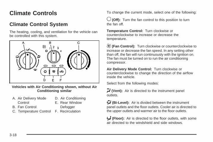
Climate Controls
Climate Control SystemThe heating, cooling, and ventilation for the vehicle canbe controlled with this system.
A. Air Delivery ModeControl
B. Fan ControlC. Temperature Control
D. Air ConditioningE. Rear Window
DefoggerF. Recirculation
To change the current mode, select one of the following:
9 (Off): Turn the fan control to this position to turnthe fan off.
Temperature Control: Turn clockwise orcounterclockwise to increase or decrease thetemperature.
9 (Fan Control): Turn clockwise or counterclockwise toincrease or decrease the fan speed. In any setting otherthan off, the fan will run continuously with the ignition on.The fan must be turned on to run the air conditioningcompressor.
Air Delivery Mode Control: Turn clockwise orcounterclockwise to change the direction of the airflowinside the vehicle.
Select from the following modes:
H (Vent): Air is directed to the instrument paneloutlets.
) (Bi-Level): Air is divided between the instrumentpanel outlets and the floor outlets. Cooler air is directed tothe upper outlets and warmer air to the floor outlets.
6 (Floor): Air is directed to the floor outlets, with someair directed to the windshield and side windows.
Vehicles with Air Conditioning shown, without AirConditioning similar
3-18
- (Defog): This mode clears the windows of fog ormoisture. Air is directed to the windshield, side window,and floor outlets. To defog the windows faster, turn thetemperature control knob clockwise to the warmestsetting. In this mode, the system runs the air conditioningcompressor.
0 (Defrost): This mode removes fog or frost fromthe windshield more quickly. Air is directed to thewindshield, with some air directed to the side windowoutlets and the floor outlets. To defrost the windowsfaster, turn the temperature control knob clockwise tothe warmest setting. In this mode, the system runsthe air conditioning compressor.
For best results, clear all snow and ice from thewindshield before defrosting.
# (Air Conditioning): For vehicles with airconditioning, press this button to turn the air conditioningsystem on or off. An indicator light comes on to showthat the air conditioning is on.
On hot days, open the windows to let hot inside airescape; then close them. This helps to reduce the timeit takes for the vehicle to cool down. It also helps thesystem to operate more efficiently.
For quick cool down on hot days:
1. Select the H mode.
2. Select the h mode.
3. Select # .
4. Select the coolest temperature.
5. Select the highest fan speed.
Using these settings together for long periods of timemay cause the air inside of the vehicle to becometoo dry. To prevent this from happening, after the air inthe vehicle has cooled, turn off the recirculation bypressing the button again.
The air conditioning system removes moisture from theair, so a small amount of water might drip under thevehicle while idling or after turning off the engine. This isnormal.
The air conditioning compressor cannot be turned onwhen the fan is off.
3-19
h (Recirculation): Press to turn the recirculationmode on. An indicator light comes on to show thatrecirculation is on.
This mode recirculates and helps to quickly cool the airinside the vehicle. It can be used to help preventoutside air and odors from entering the vehicle.
The air conditioning compressor also comes on.Recirculation is not available for floor, defog and defrostmodes. If recirculation is selected in any of these modes,the recirculate indicator light flashes five times andoutside air will be delivered. Operation in this modeduring periods of high humidity and cool outsidetemperatures may result in increased windowfogging. If window fogging is experienced, select thedefrost mode.
Outside Air: This mode allows outside air to circulatethrough the vehicle. This mode is automaticallyactive if recirculate is not selected. There is no buttonfor outside air.
Rear Window DefoggerThe rear window defogger uses a warming grid toremove fog from the rear window.
The rear window defogger only works when the ignitionis in ON/RUN.
< (Rear): Press to turn the rear window defogger onor off. Be sure to clear as much snow from the rearwindow as possible. An indicator light comes on to showthat the rear window defogger is on.
The rear window defogger turns off about 15 minutesafter the button is pressed. If turned on again, thedefogger only runs for about seven minutes beforeturning off. If the vehicle is moving faster than 50 mph(80 kph), the rear defogger will stay on. The defoggercan also be turned off by turning off the engine.
Notice: Do not use anything sharp on the inside ofthe rear window. If you do, you could cut or damagethe warming grid, and the repairs would not becovered by the vehicle warranty. Do not attach atemporary vehicle license, tape, a decal or anythingsimilar to the defogger grid.
3-20

Outlet AdjustmentUse the thumbwheels located next to and below the airoutlets to change the direction of the airflow and toopen and close the outlets.
Operation Tips• Clear away any ice, snow or leaves from the air
inlets at the base of the windshield that mayblock the flow of air into the vehicle.
• Use of non-GM approved hood deflectors mayadversely affect the performance of the system.
• Keep the path under the front seats clear of objectsto help circulate the air inside of the vehicle moreeffectively.
Passenger Compartment Air FilterThe filter removes dust and pollen from the air which isdrawn into the vehicle. Airflow reduction is anindication that the filter needs to be replaced.
The filter should be replaced as part of routinescheduled maintenance. See Scheduled Maintenanceon page 6-4 for replacement intervals. To find outwhat type of filter to use, see Maintenance ReplacementParts on page 6-14.
3-21

To access the passenger compartment air filter:
1. Open and empty the glove box.
2. Lower the glove box door by pressing in on eachside and lowering from the track. 3. Pull the tab at the back of the glove box toward you
and open the passenger compartment air filter doordownward.
3-22

4. Pull the filter out toward you.
Install the new air filter with the AIR FLOW arrowpointing downward. Reverse Steps 1 through 3 toreassemble.
Warning Lights, Gages, andIndicatorsWarning lights and gages can signal that somethingis wrong before it becomes serious enough to cause anexpensive repair or replacement. Paying attentionto the warning lights and gages could preventinjury.
Warning lights come on when there may be or is aproblem with one of the vehicle’s functions. Somewarning lights come on briefly when the engine isstarted to indicate they are working.
Gages can indicate when there may be or is a problemwith one of the vehicle’s functions. Often gages andwarning lights work together to indicate a problem withthe vehicle.
When one of the warning lights comes on and stayson while driving, or when one of the gages shows theremay be a problem, check the section that explainswhat to do. Follow this manual’s advice. Waiting todo repairs can be costly and even dangerous.
3-23
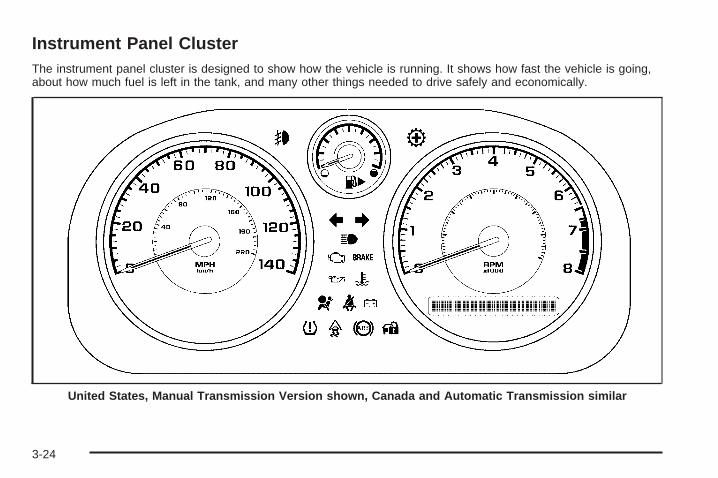
Instrument Panel ClusterThe instrument panel cluster is designed to show how the vehicle is running. It shows how fast the vehicle is going,about how much fuel is left in the tank, and many other things needed to drive safely and economically.
United States, Manual Transmission Version shown, Canada and Automatic Transmission similar
3-24

Speedometer and OdometerThe speedometer shows the speed in both miles perhour (mph) and kilometers per hour (km/h).
The vehicle’s odometer works together with the DriverInformation Center (DIC). Trip A and Trip B can beset on the odometer. See “Trip Information” under DICOperation and Displays on page 3-40.
The vehicle does not have to be running to check theodometer mileage. Simply open the driver’s door and themileage briefly displays.
If the vehicle ever needs a new odometer installed, thenew one will be set to the correct total mileage ofthe old odometer.
Tachometer
The tachometerdisplays the enginespeed in revolutionsper minute (rpm).
Notice: If the engine is operated while thetachometer is in the shaded warning area, thevehicle could be damaged, and the damages wouldnot be covered by the vehicle warranty. Do notoperate the engine with the tachometer in theshaded warning area.
3-25

Safety Belt Reminders
Safety Belt Reminder LightWhen the engine is started, a chime sounds for severalseconds to remind a driver to fasten the safety belt,unless the driver safety belt is already buckled.
The safety belt light comeson and stays on forseveral seconds, thenflashes for several more.
This chime and light are repeated if the driver remainsunbuckled and the vehicle is in motion. If the driversafety belt is already buckled, neither the chime nor thelight comes on.
Passenger Safety Belt Reminder LightSeveral seconds after the engine is started, a chimesounds for several seconds to remind the front passengerto buckle their safety belt. This only occurs if thepassenger airbag is enabled. See Passenger SensingSystem on page 1-62 for more information. Thepassenger safety belt light, located on the instrumentpanel, comes on and stays on for several seconds andthen flashes for several more.
This chime and light arerepeated if the passengerremains unbuckled andthe vehicle is in motion.
If the passenger safety belt is buckled, neither thechime nor the light comes on.
The front passenger safety belt warning light and chimemay turn on if an object is put on the seat such as abriefcase, handbag, grocery bag, laptop or otherelectronic device. To turn off the warning light and orchime, remove the object from the seat or buckle thesafety belt.
3-26

Airbag Readiness LightThe system checks the airbag’s electrical system forpossible malfunctions. If the light stays on it indicatesthere is an electrical problem. The system check includesthe airbag sensor, the pretensioners, the airbag modules,the wiring and the crash sensing and diagnostic module.For more information on the airbag system, see AirbagSystem on page 1-54.
The airbag readiness lightflashes for a few secondswhen the engine isstarted. If the light doesnot come on then, have itfixed immediately.
{CAUTION:
If the airbag readiness light stays on after thevehicle is started or comes on while driving, itmeans the airbag system might not be workingproperly. The airbags in the vehicle might notinflate in a crash, or they could even inflatewithout a crash. To help avoid injury, have thevehicle serviced right away.
If there is a problem with the airbag system, an airbagDriver Information Center (DIC) message can also comeon. See DIC Warnings and Messages on page 3-42for more information.
3-27

Passenger Airbag Status IndicatorThe vehicle has the passenger sensing system.See Passenger Sensing System on page 1-62 forimportant safety information. The instrument panel hasa passenger airbag status indicator.
When the vehicle is started, the passenger airbag statusindicator will light ON and OFF, or the symbol for on andoff, for several seconds as a system check. If you areusing remote start to start the vehicle from a distance, ifequipped, you may not see the system check. Then, afterseveral more seconds, the status indicator will light eitherON or OFF, or either the on or off symbol to let you knowthe status of the right front passenger frontal airbag.
If the word ON or the on symbol is lit on the passengerairbag status indicator, it means that the right frontpassenger frontal airbag is enabled (may inflate).
If the word OFF or the off symbol is lit on the airbagstatus indicator, it means that the passenger sensingsystem has turned off the right front passenger frontalairbag.
If, after several seconds, both status indicator lightsremain on, or if there are no lights at all, there may be aproblem with the lights or the passenger sensingsystem. See your dealer/retailer for service.
{CAUTION:
If the airbag readiness light ever comes on andstays on, it means that something may be wrongwith the airbag system. To help avoid injury toyourself or others, have the vehicle serviced rightaway. See Airbag Readiness Light on page 3-27for more information, including important safetyinformation.
United States Canada
3-28
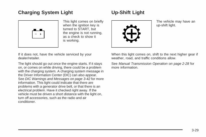
Charging System Light
This light comes on brieflywhen the ignition key isturned to START, butthe engine is not running,as a check to show itis working.
If it does not, have the vehicle serviced by yourdealer/retailer.
The light should go out once the engine starts. If it stayson, or comes on while driving, there could be a problemwith the charging system. A charging system message inthe Driver Information Center (DIC) can also appear.See DIC Warnings and Messages on page 3-42 for moreinformation. This light could indicate that there areproblems with a generator drive belt, or that there is anelectrical problem. Have it checked right away. If thevehicle must be driven a short distance with the light on,turn off accessories, such as the radio and airconditioner.
Up-Shift Light
The vehicle may have anup-shift light.
When this light comes on, shift to the next higher gear ifweather, road, and traffic conditions allow.
See Manual Transmission Operation on page 2-28 formore information.
3-29

Brake System Warning LightThe vehicle’s hydraulic brake system is divided intotwo parts. If one part is not working, the other part canstill work and stop the vehicle. For good brakingboth parts need to be working well.
If the warning light comes on, there is a brake problem.Have the brake system inspected right away.
This light should come on briefly when the engine isstarted. If it does not come on then, have it fixed so itwill be ready to warn if there is a problem.
When the ignition is on, the brake system warning lightalso comes on when the parking brake is set. The lightstays on if the parking brake does not fully release. If itstays on after the parking brake is fully released, it meansthe vehicle has a brake problem.
If the light comes on while driving, pull off the roadand stop carefully. Make sure the parking brake is fullyreleased. The pedal might be harder to push or, the pedalcould go closer to the floor. It can take longer to stop.Try turning off and restarting the vehicle one or two times,if the light is still on, have the vehicle towed for service.See Towing Your Vehicle on page 4-30.
{CAUTION:
The brake system might not be working properly ifthe brake system warning light is on. Driving withthe brake system warning light on can lead to acrash. If the light is still on after the vehicle hasbeen pulled off the road and carefully stopped,have the vehicle towed for service.
United States Canada
3-30

Antilock Brake System (ABS)Warning Light
For vehicles with theAntilock Brake System(ABS), this light comes onbriefly when the engineis started.
If it does not, have the vehicle serviced by yourdealer/retailer. If the system is working normally theindicator light then goes off.
If the ABS light stays on, turn the ignition off. If the lightcomes on while driving, stop as soon as it is safelypossible and turn the ignition off. Then start the engineagain to reset the system. If the ABS light stays on, orcomes on again while driving, the vehicle needs service.If the regular brake system warning light is not on, thevehicle still has brakes, but not antilock brakes. If theregular brake system warning light is also on, the vehicledoes not have antilock brakes and there is a problem withthe regular brakes. See Brake System Warning Light onpage 3-30.
For vehicles with a Driver Information Center (DIC),see DIC Warnings and Messages on page 3-42 forall brake related DIC messages.
Enhanced Traction System (ETS)Indicator/Warning Light
For vehicles with theEnhanced Traction System(ETS), this light servesas an indicator andwarning light.
This light comes on briefly while the engine is started.If it does not, have the vehicle serviced by your dealer/retailer. If the system is working normally the indicatorlight then goes off.
If the indicator/warning light is on and not flashing, theETS system could have been disabled. Check all relatedDriver Information Center (DIC) messages to determinewhether the system has been turned off or if the systemis not working properly and the vehicle requires service.If the ETS has been disabled, wheel spin is not limited.
3-31

If the indicator/warning light is on and flashing, the ETSis actively working. The LOW TRACTION DIC messagealso appears when the system is actively limitingwheel spin.
See Enhanced Traction System (ETS) on page 4-11and DIC Warnings and Messages on page 3-42 for moreinformation.
Electronic Stability Control(ESC)/Traction Control System(TCS) Indicator/Warning Light
For vehicles with theElectronic Stability Control(ESC) system or theTraction Control System(TCS), the indicator/warning light comes onbriefly when the engine isstarted.
If it does not, have the vehicle serviced by thedealer/retailer. If the system is working normally theindicator light goes off.
If this light is on while certain DIC messages display,this indicates that the ESC and TCS are not working orare disabled.
If this light is on and not flashing, the TCS andpotentially the ESC system have been disabled. Checkthe DIC messaging to determine which feature(s) isno longer functioning and whether it is because of thedriver turning off the feature(s), or because the system isnot working properly and the vehicle requires service.
If the TCS is disabled, wheel spin is not limited. Ifthe ESC system is disabled, the system does not aid inmaintaining directional control of the vehicle.
If the indicator/warning light is on and flashing, the TCSor the ESC system is actively working. Check the DICmessaging for details to determine which system isworking. If the LOW TRACTION message appears,the system is limiting wheel spin. If the ESC ACTIVEmessage appears, the system is aiding in maintainingdirectional control of the vehicle.
See Electronic Stability Control (ESC) on page 4-6 andTraction Control System (TCS) on page 4-8 for moreinformation.
See DIC Warnings and Messages on page 3-42 formore information on the messages associated withthis light.
3-32

Engine Coolant TemperatureWarning Light
This light comes on brieflywhile starting the vehicle.
If it does not, have the vehicle serviced by thedealer/retailer. If the system is working normally theindicator light goes off.
Notice: Driving with the engine coolant temperaturewarning light on could cause the vehicle to overheat.See Engine Overheating on page 5-27. The vehicle’sengine could be damaged, and it might not becovered by the vehicle warranty. Never drive withthe engine coolant temperature warning light on.
The engine coolant temperature warning light comes onwhen the engine has overheated.
If this happens pull over and turn off the engine as soonas possible. See Engine Overheating on page 5-27for more information.
Tire Pressure Light
For vehicles with a tirepressure light, this lightcomes on briefly whenthe engine is started andprovides information abouttire pressures and the TirePressure MonitoringSystem.
When the Light is On SteadyThis indicates that one or more of the tires is significantlyunderinflated.
A tire pressure message in the Driver InformationCenter (DIC), can accompany the light. See DICWarnings and Messages on page 3-42 for moreinformation. Stop and check the tires as soon as it issafe to do so. If a tire is underinflated, inflate to theproper pressure. See Tires on page 5-48 for moreinformation.
3-33

When the Light Flashes First and Then isOn SteadyThis indicates that there could be a problem with the TirePressure Monitor System. The light flashes for about aminute and stays on steady for the remainder of theignition cycle. This sequence repeats with every ignitioncycle. See Tire Pressure Monitor System on page 5-57for more information.
Malfunction Indicator Lamp
Check Engine LightA computer system called OBD II (On-BoardDiagnostics-Second Generation) monitors operationof the fuel, ignition, and emission control systems.It ensures that emissions are at acceptable levels forthe life of the vehicle, helping to produce a cleanerenvironment.
This light should come onwhen the ignition is on, butthe engine is not running,as a check to show itis working. If it does not,have the vehicle servicedby your dealer/retailer.
If the check engine light comes on and stays on, whilethe engine is running, this indicates that there is anOBD II problem and service is required.
Malfunctions often are indicated by the system before anyproblem is apparent. Being aware of the light can preventmore serious damage to the vehicle. This system assiststhe service technician in correctly diagnosing anymalfunction.
Notice: If the vehicle is continually driven with thislight on, after a while, the emission controls mightnot work as well, the vehicle’s fuel economy mightnot be as good, and the engine might not run assmoothly. This could lead to costly repairs thatmight not be covered by the vehicle warranty.
Notice: Modifications made to the engine,transmission, exhaust, intake, or fuel system of thevehicle or the replacement of the original tires withother than those of the same Tire PerformanceCriteria (TPC) can affect the vehicle’s emissioncontrols and can cause this light to come on.Modifications to these systems could lead to costlyrepairs not covered by the vehicle warranty. Thiscould also result in a failure to pass a requiredEmission Inspection/Maintenance test. SeeAccessories and Modifications on page 5-3.
3-34
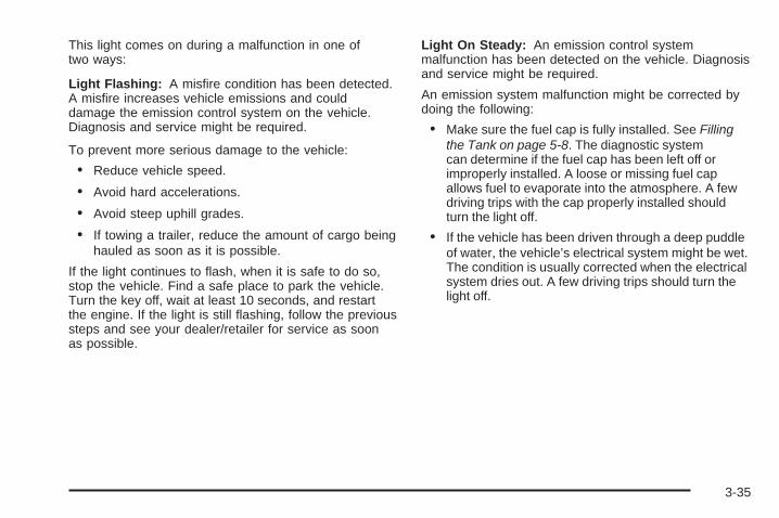
This light comes on during a malfunction in one oftwo ways:
Light Flashing: A misfire condition has been detected.A misfire increases vehicle emissions and coulddamage the emission control system on the vehicle.Diagnosis and service might be required.
To prevent more serious damage to the vehicle:
• Reduce vehicle speed.
• Avoid hard accelerations.
• Avoid steep uphill grades.
• If towing a trailer, reduce the amount of cargo beinghauled as soon as it is possible.
If the light continues to flash, when it is safe to do so,stop the vehicle. Find a safe place to park the vehicle.Turn the key off, wait at least 10 seconds, and restartthe engine. If the light is still flashing, follow the previoussteps and see your dealer/retailer for service as soonas possible.
Light On Steady: An emission control systemmalfunction has been detected on the vehicle. Diagnosisand service might be required.
An emission system malfunction might be corrected bydoing the following:
• Make sure the fuel cap is fully installed. See Fillingthe Tank on page 5-8. The diagnostic systemcan determine if the fuel cap has been left off orimproperly installed. A loose or missing fuel capallows fuel to evaporate into the atmosphere. A fewdriving trips with the cap properly installed shouldturn the light off.
• If the vehicle has been driven through a deep puddleof water, the vehicle’s electrical system might be wet.The condition is usually corrected when the electricalsystem dries out. A few driving trips should turn thelight off.
3-35

• Make sure to fuel the vehicle with quality fuel. Poorfuel quality causes the engine not to run as efficientlyas designed and can cause: stalling after start-up,stalling when the vehicle is changed into gear,misfiring, hesitation on acceleration, or stumbling onacceleration. These conditions might go away oncethe engine is warmed up.
If one or more of these conditions occurs, change thefuel brand used. It will require at least one full tank ofthe proper fuel to turn the light off.See Gasoline Octane on page 5-5.
If none of the above have made the light turn off, yourdealer/retailer can check the vehicle. The dealer/retailerhas the proper test equipment and diagnostic tools tofix any mechanical or electrical problems that might havedeveloped.
Emissions Inspection and MaintenanceProgramsSome state/provincial and local governments have ormight begin programs to inspect the emission controlequipment on the vehicle. Failure to pass this inspectioncould prevent getting a vehicle registration.
Here are some things to know to help the vehicle passan inspection:
• The vehicle will not pass this inspection if the checkengine light is on with the engine running, or if thekey is in ON/RUN and the light is not on.
• The vehicle will not pass this inspection if the OBD II(on-board diagnostic) system determines that criticalemission control systems have not been completelydiagnosed by the system. The vehicle would beconsidered not ready for inspection. This can happenif the battery has recently been replaced or if thebattery has run down. The diagnostic system isdesigned to evaluate critical emission controlsystems during normal driving. This can take severaldays of routine driving. If this has been done and thevehicle still does not pass the inspection for lack ofOBD II system readiness, your dealer/retailer canprepare the vehicle for inspection.
3-36

Oil Pressure Light
{CAUTION:
Do not keep driving if the oil pressure is low. Theengine can become so hot that it catches fire.Someone could be burned. Check the oil as soonas possible and have the vehicle serviced.
Notice: Lack of proper engine oil maintenance candamage the engine. The repairs would not becovered by the vehicle warranty. Always follow themaintenance schedule in this manual for changingengine oil.
This light comes on briefly while starting the engine.If it does not, have the vehicle serviced by yourdealer/retailer. If the system is working normally theindicator light then goes off.
If the light comes on and stays on, it means that oil isnot flowing through the engine properly. The vehiclecould be low on oil and it might have some other systemproblem.
3-37

Security Light
For information regardingthis light and the vehicle’ssecurity system, seeContent Theft-Deterrent onpage 2-16.
Fog Lamp Light
The fog lamp light comeson when the fog lamps arein use.
The light goes out when the fog lamps are turned off.See Fog Lamps on page 3-14 for more information.
Highbeam On Light
This light comes on whenthe high-beam headlampsare in use.
See Headlamp High/Low-Beam Changer on page 3-8for more information.
Fuel Gage
The fuel gage indicateshow much fuel the vehiclehas left.
3-38

An arrow on the fuel gage indicates the side of thevehicle the fuel door is on.
Here are four things that some owners ask about. Noneof these show a problem with the fuel gage:
• At the service station, the gas pump shuts offbefore the gage reads full.
• It takes a little more or less fuel to fill up than thegage indicated. For example, the gage may haveindicated the tank was half full, but it actually took alittle more or less than half the tank’s capacity tofill the tank.
• The gage moves a little while turning a corner orspeeding up.
• The gage does not go back to empty when theignition is turned off.
For the fuel tank capacity, see Capacities andSpecifications on page 5-113.
Driver Information Center (DIC)Your vehicle has a Driver Information Center (DIC).The DIC display gives you the status of many of yourvehicle’s systems. The DIC is also used to display driverpersonalization menu modes and warning/statusmessages. All messages will appear in the DIC display,located at the bottom of the instrument panel cluster.
The DIC buttons arelocated on the left side ofthe steering wheel.
INFO (Information): Press this button to scroll throughthe vehicle information mode displays.
r (Reset): Press this button to reset some vehicleinformation mode displays, select a personalizationmenu mode setting, or acknowledge a warningmessage.
Press and hold the information and reset buttons at thesame time for one second, then release the buttonsto enter the personalization menu. See DIC VehiclePersonalization on page 3-47 for more information.
3-39
DIC Operation and DisplaysThe DIC comes on when the ignition is on. The DIC hasdifferent modes which can be accessed by pressingthe DIC buttons. The button functions are detailed inthe following.
Information Modes
INFO (Information): Press this button to scroll throughthe following vehicle information modes:
Outside Air Temperature and OdometerPress the information button until the outside airtemperature and the odometer display. This mode showsthe temperature outside of the vehicle in either degreesFahrenheit (°F) or degrees Celsius (°C) and the totaldistance the vehicle has been driven in either miles (mi)or kilometers (km). The outside air temperature appearson the left side of the DIC display and the odometerappears on the right side of the display.
To change the DIC display to English or metric units,see “UNITS” under DIC Vehicle Personalization onpage 3-47.
TRIP A or TRIP BPress the information button until TRIP A or TRIP Bdisplay. These modes show the current distancetraveled since the last reset for each trip odometer ineither miles (mi) or kilometers (km). Both odometerscan be used at the same time.
To reset the trip odometer to zero, press and hold thereset button for a few seconds while the desired tripodometer is displayed.
FUEL RANGEPress the information button until FUEL RANGEdisplays. This mode shows the remaining distance youcan drive without refueling in either miles (mi) orkilometers (km). It is based on fuel economy and thefuel remaining in the tank.
When the fuel level is low, FUEL RANGE LOW displays.
The fuel economy data used to determine fuel rangeis an average of recent driving conditions. As yourdriving conditions change, this data is gradually updated.The FUEL RANGE mode cannot be reset.
3-40
MPG (L/100 KM) AVG (Average)Press the information button until MPG (L/100 KM)AVG displays. This mode shows how many miles pergallon (mpg) or liters per 100 kilometers (L/100 km) yourvehicle is getting based on current and past drivingconditions.
To reset the average fuel economy, press and hold thereset button while MPG (L/100 KM) AVG is displayed.Average fuel economy is then calculated startingfrom that point. If the average fuel economy is not reset,it is continually updated each time you drive.
MPG (L/100 KM) INST (Instantaneous)Press the information button until MPG (L/100 KM) INSTdisplays. This mode shows the current fuel economyat a particular moment and changes frequently asdriving conditions change. This mode shows theinstantaneous fuel economy in miles per gallon (mpg)or liters per 100 kilometers (L/100 km). Unlike averagefuel economy, this screen cannot be reset.
AV (Average) SPEEDPress the information button until AV SPEED displays.This mode shows the vehicle’s average speed inmiles per hour (mph) or kilometers per hour (km/h).
To reset the average vehicle speed, press and hold thereset button while AV SPEED is displayed.
OIL LIFEPress the information button until OIL LIFE displays.The engine oil life system shows an estimate of the oil’sremaining useful life. It shows 100% when the systemis reset after an oil change. It alerts you to change the oilon a schedule consistent with your driving conditions.
In addition to the engine oil life system monitoring the oillife, additional maintenance is recommended in theMaintenance Schedule in this manual. See Engine Oilon page 5-13 and Scheduled Maintenance on page 6-4.
Always reset the engine oil life system after an oilchange. See “How to Reset the Engine Oil Life System”under Engine Oil Life System on page 5-16.
COOLANTPress the information button until COOLANT displays.This mode shows the temperature of the engine coolantin either degrees Fahrenheit (°F) or degrees Celsius (°C).
Tire PressureIf your vehicle is equipped with a Tire PressureMonitoring System (TPMS), the pressure for each tirecan be viewed in the DIC. The tire pressure is shown ineither pounds per square inch (psi) or kilopascals (kPa).Press the information button until LF ## PSI (kPa) ## RFdisplays for the front tires. Press the informationbutton again until LR ## PSI (kPa) ## RR displays forthe rear tires.
3-41
If a low tire pressure condition is detected by the systemwhile driving, a message advising you to check the tirepressure appears in the display. See Inflation - TirePressure on page 5-56 and DIC Warnings and Messageson page 3-42 for more information.
DIC Warnings and MessagesThese messages appear if there is a problem detectedin one of your vehicle’s systems.
A message clears when the vehicle’s condition is nolonger present. To acknowledge a message and clear itfrom the display, press and hold any of the DIC buttons.If the condition is still present, the warning messagecomes back on the next time the vehicle is turned off andback on. With most messages, a warning chime soundswhen the message displays. Your vehicle may have otherwarning messages.
AUTO (Automatic) LIGHTS OFFThis message displays if the automatic headlampsystem is disabled with the headlamp switch.
AUTO (Automatic) LIGHTS ONThis message displays if the automatic headlampsystem is enabled with the headlamp switch.
BRAKE FLUIDThis message displays, while the ignition is on, whenthe brake fluid level is low. The brake system warninglight on the instrument panel cluster also comes on.See Brake System Warning Light on page 3-30 for moreinformation. Have the brake system serviced by yourdealer/retailer as soon as possible.
CHANGE OIL SOONThis message displays when the life of the engine oilhas expired and it should be changed.
When this message is acknowledged and cleared fromthe display, the engine oil life system must still be resetseparately. See Engine Oil Life System on page 5-16and Scheduled Maintenance on page 6-4 for moreinformation.
CHECK GAS CAPThis message displays if the fuel cap has not been fullytightened. Recheck the fuel cap to make sure that it is onproperly. A few driving trips with the cap properly installedshould turn the message off.
3-42
CHECK TIRE PRESS (Pressure)If your vehicle is equipped with a Tire PressureMonitoring System (TPMS), this message displays whenthe pressure in one or more of the vehicle’s tires needs tobe checked. If a tire pressure message appears on theDIC, stop as soon as you can. Have the tire pressureschecked and set to those shown on the Tire LoadingInformation label. See Tires on page 5-48, Loading theVehicle on page 4-24, and Inflation - Tire Pressure onpage 5-56. The DIC also shows the tire pressure values.See DIC Operation and Displays on page 3-40. If the tirepressure is low, the low tire pressure warning light comeson. See Tire Pressure Light on page 3-33.
COOLING MODE ONThis message may display on some vehicles. Undersevere conditions, hot ambient temperatures, steepgrades, and towing, your vehicle may experience moretransmission shifting. This is temporary and normal underthese conditions. This does not require engine ortransmission service.
CRUISE ENGAGEDThis message displays when the cruise control systemis active. See Cruise Control on page 3-10 for moreinformation.
DOOR AJARThis message displays if one or more of the vehicle’sdoors are open. Make sure that the door(s) areclosed completely.
ENGINE DISABLEDThis message displays if the starting of the engine isdisabled. Have your vehicle serviced by yourdealer/retailer immediately.
ENG (Engine) PWR (Power) REDUCEDThis message displays to inform you that the vehiclehas reduced engine power to avoid damaging theengine. Reduced engine power can affect the vehicle’sability to accelerate. If this message is on, but thereis no reduction in performance, proceed to yourdestination. The performance may be reduced the nexttime the vehicle is driven. The vehicle may be drivenat a reduced speed while this message is on, butacceleration and speed may be reduced. Anytime thismessage stays on, the vehicle should be taken toyour dealer/retailer for service as soon as possible.
3-43
ESC (Electronic Stability Control) ACTIVEIf your vehicle has Electronic Stability Control (ESC),this message displays and the ESC/TCS light on theinstrument panel cluster flashes when ESC is assistingyou with directional control of the vehicle. You may feel orhear the system working and see this message displayedin the DIC. Slippery road conditions may exist when thismessage is displayed, so adjust your driving accordingly.This message may stay on for a few seconds after ESCstops assisting you with directional control of the vehicle.This is normal when the system is operating. SeeElectronic Stability Control (ESC) on page 4-6 andElectronic Stability Control (ESC)/Traction ControlSystem (TCS) Indicator/Warning Light on page 3-32for more information.
ESC (Electronic Stability Control) NOTREADYIf your vehicle has Electronic Stability Control (ESC),this message may display briefly after starting the vehicleif the system’s sensors are not yet calibrated. The systemis not functional until the message stops displaying.Adjust your driving accordingly. When the message is nolonger displayed, the system is functional. See ElectronicStability Control (ESC) on page 4-6 for more information.
ESC (Electronic Stability Control) OFFIf your vehicle has Electronic Stability Control (ESC),this message displays and the ESC/TCS light on theinstrument panel cluster comes on solid when ESC isturned off. Adjust your driving accordingly. See ElectronicStability Control (ESC) on page 4-6 and ElectronicStability Control (ESC)/Traction Control System (TCS)Indicator/Warning Light on page 3-32 for moreinformation.
ICE POSSIBLEThis message displays when the outside air temperatureis cold enough to create icy road conditions. Adjustyour driving accordingly.
KEY FOB BATT (Battery) LOWThis message displays if the Remote Keyless Entry(RKE) transmitter battery is low. Replace the battery inthe transmitter. See “Battery Replacement” underRemote Keyless Entry (RKE) System Operation onpage 2-3.
LEARN COMPLETEOn vehicles without the Remote Keyless Entry (RKE)system, this message displays when the Tire PressureMonitor System (TPMS) has completed the tire learningprocess. See Tire Pressure Monitor System on page 5-57for more information.
3-44

LOW FUELThis message displays when your vehicle is low on fuel.Refill the fuel tank as soon as possible. See FuelGage on page 3-38, Fuel on page 5-5, and Filling theTank on page 5-8 for more information.
LOW TRACTIONIf your vehicle has the Enhanced Traction System (ETS)or Traction Control System (TCS), this message displaysand the ETS light or the ESC/TCS light on the instrumentpanel cluster flashes when the system is actively limitingwheel spin. Slippery road conditions may exist if thismessage is displayed, so adjust your driving accordingly.This message stays on for a few seconds after thesystem stops limiting wheel spin. See Enhanced TractionSystem (ETS) on page 4-11 or Traction Control System(TCS) on page 4-8 and Enhanced Traction System (ETS)Indicator/Warning Light on page 3-31 or ElectronicStability Control (ESC)/Traction Control System (TCS)Indicator/Warning Light on page 3-32 for moreinformation.
PARKING BRAKEThis message displays if the parking brake is leftengaged. See Parking Brake on page 2-30 for moreinformation.
POWER STEERINGThis message displays if a problem has been detectedwith the electric power steering. Have your vehicleserviced by your dealer/retailer immediately.
SERVICE AIR BAGThis message displays when there is a problem with theairbag system. Have your vehicle serviced by yourdealer/retailer immediately.
SERVICE ESC (ELECTRONIC STABILITYCONTROL)If your vehicle has Electronic Stability Control (ESC),this message displays and a chime sounds if there hasbeen a problem detected with ESC. The ESC/TCSlight also appears on the instrument panel cluster. Thislight stays on solid as long as the detected problemremains present. When this message displays, thesystem is not working. Adjust your driving accordingly.See Electronic Stability Control (ESC) on page 4-6and Electronic Stability Control (ESC)/Traction ControlSystem (TCS) Indicator/Warning Light on page 3-32for more information.If this message turns on while you are driving, pull off theroad as soon as possible and stop carefully. Try resettingthe system by turning the ignition off and then back on.If this message still stays on or turns back on again whileyou are driving, your vehicle needs service. Have theESC inspected by your dealer/retailer as soon aspossible.
3-45
SERVICE TRACTIONIf your vehicle has the Enhanced Traction System (ETS)or Traction Control System (TCS), this message displaysand a chime sounds when the system is not functioningproperly. The ETS light or the ESC/TCS light alsoappears on the instrument panel cluster. This light stayson solid as long as the detected problem remainspresent. When this message displays, the system is notworking. Adjust your driving accordingly. See EnhancedTraction System (ETS) on page 4-11 or Traction ControlSystem (TCS) on page 4-8 and Enhanced TractionSystem (ETS) Indicator/Warning Light on page 3-31 orElectronic Stability Control (ESC)/Traction ControlSystem (TCS) Indicator/Warning Light on page 3-32 formore information. Have the system serviced by yourdealer/retailer as soon as possible.
SVC (Service) TIRE MONITORIf your vehicle is equipped with a Tire PressureMonitoring System (TPMS), this message displays if apart on the TPMS is not working properly. The tirepressure light also flashes and then remains on duringthe same ignition cycle. See Tire Pressure Light onpage 3-33. Several conditions may cause this messageto appear. See Tire Pressure Monitor Operation onpage 5-59 for more information. If the warning comes onand stays on, there may be a problem with the TPMS.See your dealer/retailer.
TIRE LEARN ONIf your vehicle is equipped with a Tire PressureMonitoring System (TPMS) and does not have theRemote Keyless Entry (RKE) system, this messagedisplays when the TPMS is re-learning the tire positionson your vehicle. The tire positions must be re-learnedafter rotating the tires or after replacing a tire or sensor.See Tire Inspection and Rotation on page 5-64,Tire Pressure Monitor System on page 5-57, andInflation - Tire Pressure on page 5-56 for moreinformation.
TRACTION OFFIf your vehicle has the Enhanced Traction System (ETS)or Traction Control System (TCS), this message displaysand the ETS light or the ESC/TCS light on the instrumentpanel cluster comes on solid when the system is turnedoff. Adjust your driving accordingly. See EnhancedTraction System (ETS) on page 4-11 or Traction ControlSystem (TCS) on page 4-8 and Enhanced TractionSystem (ETS) Indicator/Warning Light on page 3-31 orElectronic Stability Control (ESC)/Traction ControlSystem (TCS) Indicator/Warning Light on page 3-32 formore information.
TRUNK AJARThis message displays when the trunk is not closedcompletely. Make sure that the trunk is closedcompletely. See Trunk on page 2-12.
3-46
DIC Vehicle PersonalizationYour vehicle has personalization capabilities that allowyou to program certain features to a preferred setting.All of the features listed may not be available onyour vehicle. Only the features available will bedisplayed on the DIC.
The default settings for the features were set when yourvehicle left the factory, but may have been changedfrom their default state since that time.
To change feature settings, use the following procedure:
Entering Personalization Menu1. Turn the ignition on while the vehicle is stopped.
To avoid excessive drain on the battery, it isrecommended that the headlamps are turned off.
2. Press and hold the information and reset buttons atthe same time for one second, then release to enterthe personalization menu.If the vehicle speed is greater than 2 mph (3 km/h),only the UNITS menu will be accessible.
3. Press the information button to scroll through theavailable personalization menu modes.Press the reset button to scroll through the availablesettings for each mode.If you do not make a selection within ten seconds,the display will go back to the previous informationdisplayed.
Personalization Menu ModesOIL LIFE RESETWhen this feature is displayed, you can reset the engineoil life system. To reset the system, see Engine Oil LifeSystem on page 5-16. See “OIL LIFE” under DICOperation and Displays on page 3-40 for moreinformation.
UNITSThis feature allows you to select the units ofmeasurement in which the DIC will display the vehicleinformation. When UNITS appears on the display, pressand hold the reset button for at least one second to scrollthrough the available settings:
ENGLISH (default in United States): All informationwill be displayed in English units.
METRIC (default in Canada): All information will bedisplayed in metric units.
To select a setting and move on to the next feature,press the information button while the desired setting isdisplayed on the DIC.
3-47
TIRE LEARN?If your vehicle is equipped with a Tire PressureMonitoring System (TPMS), this mode is available onvehicles without the Remote Keyless Entry (RKE)system. After rotating the tires or after replacing a tire orsensor, the TPMS must re-learn the tire positions. Tore-learn the tire positions, see Tire Pressure MonitorSystem on page 5-57. See Tire Inspection and Rotationon page 5-64 and DIC Warnings and Messages onpage 3-42 for more information.
REMOTE STARTIf your vehicle has remote start, this feature allowsremote start to be turned off or on. Remote start allowsyou to start the engine from outside of the vehicleusing your Remote Keyless Entry (RKE) transmitter.When REMOTE START appears on the display, pressand hold the reset button for at least one second toscroll through the available settings:
OFF: The remote start feature will be disabled.
ON (default): The remote start feature will be enabled.
See Remote Vehicle Start on page 2-6 for moreinformation.
To select a setting and move on to the next feature,press the information button while the desired setting isdisplayed on the DIC.
LOCK HORNIf your vehicle has Remote Keyless Entry (RKE), thisfeature, which allows the vehicle’s horn to chirpevery time the lock button on the RKE transmitter ispressed, can be enabled or disabled. When LOCKHORN appears on the display, press and hold the resetbutton for at least one second to scroll through theavailable settings:
OFF (default): The horn will not chirp on the first pressof the lock button on the RKE transmitter. The hornwill still chirp on the second press.
ON: The horn will chirp on the first press of the lockbutton on the RKE transmitter.
See Remote Keyless Entry (RKE) System Operation onpage 2-3 for more information.
To select a setting and move on to the next feature,press the information button while the desired setting isdisplayed on the DIC.
3-48

UNLOCK HORNIf your vehicle has Remote Keyless Entry (RKE), thisfeature, which allows the vehicle’s horn to chirp on thefirst press of the unlock button on the RKE transmitter,can be enabled or disabled. When UNLOCK HORNappears on the display, press and hold the reset buttonfor at least one second to scroll through the availablesettings:
OFF (default): The horn will not chirp when the unlockbutton on the RKE transmitter is pressed.
ON: The horn will chirp on the first press of the unlockbutton on the RKE transmitter.
See Remote Keyless Entry (RKE) System Operation onpage 2-3 for more information.
To select a setting and move on to the next feature,press the information button while the desired setting isdisplayed on the DIC.
LIGHT FLASHIf your vehicle has Remote Keyless Entry (RKE), thisfeature, which allows the vehicle’s exterior hazard/turnsignal lighting to flash every time the lock, unlock, or trunkrelease buttons on the RKE transmitter are pressed, canbe enabled or disabled. When LIGHT FLASH appears onthe display, press and hold the reset button for at leastone second to scroll through the available settings:
OFF: The exterior hazard/turn signal lighting will notflash when the lock, unlock, or trunk release buttons onthe RKE transmitter are pressed.
ON (default): The exterior hazard/turn signal lightingwill flash when the lock, unlock, or trunk release buttonson the RKE transmitter are pressed.
See Remote Keyless Entry (RKE) System Operation onpage 2-3 for more information.
To select a setting and move on to the next feature,press the information button while the desired setting isdisplayed on the DIC.
3-49

DELAY LOCKThis feature, which delays the actual locking of thevehicle, can be enabled or disabled. When DELAY LOCKappears on the display, press and hold the reset buttonfor at least one second to scroll through the availablesettings:
ON (default): The doors will not lock until five secondsafter the last door is closed. You can temporarily overridedelayed locking by pressing the power lock switch or thelock button on the Remote Keyless Entry (RKE)transmitter a second time.
OFF: The doors will lock immediately when pressingthe power lock switch or the lock button on theRKE transmitter.
See Power Door Locks on page 2-9, Delayed Lockingon page 2-9, and Remote Keyless Entry (RKE)System Operation on page 2-3 for more information.
To select a setting and move on to the next feature,press the information button while the desired setting isdisplayed on the DIC.
AUTO UNLK (Unlock)This feature, which allows the vehicle to automaticallyunlock certain doors, can be enabled or disabled. WhenAUTO UNLK appears on the display, press and holdthe reset button for at least one second to scroll throughthe available settings:
ALL (default): All of the doors will automatically unlock.
DRIVER: The driver’s door will automatically unlock.
NONE: None of the doors will automatically unlock. Youwill need to manually unlock the doors.
If you have a manual transmission vehicle, the door(s)will automatically unlock when the ignition is turned off.
If you have an automatic transmission vehicle, you canselect when the automatic unlocking will occur. See“UNLK (Unlock) (Automatic Transmission Only)”following.
See Programmable Automatic Door Unlock on page 2-10for more information.
To select a setting and move on to the next feature,press the information button while the desired setting isdisplayed on the DIC.
3-50
UNLK (Unlock) (AutomaticTransmission Only)This screen displays only if your vehicle has an automatictransmission and DRIVER or ALL is selected for theAUTO UNLK feature. This feature determines when theautomatic door unlocking will occur. When UNLK appearson the display, press and hold the reset button for at leastone second to scroll through the available settings:
KEY OFF: The door(s) will unlock when the key isturned off.
SHIFT TO P (Park) (default): The door(s) will unlockwhen the vehicle is shifted into P (Park).
See Programmable Automatic Door Unlock onpage 2-10 for more information.
To select a setting and move on to the next feature,press the information button while the desired setting isdisplayed on the DIC.
EXT (Exterior) LIGHTSIf your vehicle has Remote Keyless Entry (RKE), thisfeature, which allows the vehicle’s exterior perimeterlighting to turn on each time the unlock button onthe RKE transmitter is pressed, can be enabled ordisabled. When EXT LIGHTS appears on the display,press and hold the reset button for at least one secondto scroll through the available settings:
OFF: The exterior perimeter lighting will not turn onwhen the unlock button on the RKE transmitter ispressed.
ON (default): The exterior perimeter lighting will turn onwhen the unlock button on the RKE transmitter ispressed.
See Remote Keyless Entry (RKE) System Operation onpage 2-3 for more information.
To select a setting and move on to the next feature,press the information button while the desired setting isdisplayed on the DIC.
3-51
LANGUAGEThis feature allows you to select the language in whichthe DIC will display. When LANGUAGE appears onthe display, press and hold the reset button for at leastone second to scroll through the available settings:
ENGLISH (default): All messages will appear inEnglish.
FRENCH: All messages will appear in French.
SPANISH: All messages will appear in Spanish.
GERMAN: All messages will appear in German.
To select a setting and exit out of the personalizationmenu mode, press the information button while thedesired setting is displayed on the DIC.
Exiting Personalization MenuThe personalization menu will be exited when any of thefollowing conditions occur:
• A ten second time period has elapsed.
• The ignition is turned off.
• The end of the personalization menu list is reached.
Audio System(s)Determine which radio the vehicle has and read thefollowing pages to become familiar with its features.
{CAUTION:
Taking your eyes off the road for extended periodscould cause a crash resulting in injury or death toyou or others. Do not give extended attention toentertainment tasks while driving.
This system provides access to many audio and nonaudio listings.
To minimize taking your eyes off the road while driving,do the following while the vehicle is parked:
• Become familiar with the operation and controls ofthe audio system.
• Set up the tone, speaker adjustments, and presetradio stations.
For more information, see Defensive Driving onpage 4-2.
3-52

Notice: Contact your dealer/retailer before addingany equipment.
Adding audio or communication equipment couldinterfere with the operation of the vehicle’s engine,radio, or other systems, and could damage them.Follow federal rules covering mobile radio andtelephone equipment.
Notice: The chime signals related to safety belts,parking brake, and other functions of your vehicleoperate through the radio/entertainment system.If that equipment is replaced or additional equipmentis added to your vehicle, the chimes may notwork. Make sure that replacement or additionalequipment is compatible with your vehicle beforeinstalling it. See Accessories and Modificationson page 5-3.
The vehicle has Retained Accessory Power (RAP). WithRAP, the audio system can be played even after theignition is turned off. See Retained Accessory Power(RAP) on page 2-23 for more information.
Setting the Clock
Without Date Display
AM/FM Base Radio with a Single CDPlayerTo set the time:
1. Turn the ignition key to ACC/ACCESSORY orON/RUN. Press O to turn the radio on.
2. Press H until the hour begins flashing on thedisplay. Press H a second time and the minutebegins flashing on the display.
3. While either the hour or the minute numbers areflashing, turn f to increase or decrease the time.
4. Press H again until the clock display stops flashingto set the currently displayed time; otherwise, theflashing stops after five seconds and the currenttime displayed is automatically set.
To change the time default setting from 12 hour to24 hour, press the H button until 12H or 24H isdisplayed. Once 12H or 24H is displayed, turn thef knob to the desired option to select the setting.Press the H button again to apply the setting, or letthe screen time out.
3-53

With Date Display
Radio with CD (MP3) and USB Port, andRadio with Single CD (MP3) PlayerTo set the time and date:
1. Turn the ignition key to ACC/ACCESSORY orON/RUN. Press O to turn the radio on.
2. Press H and the HR, MIN, MM, DD, YYYY (hour,minute, month, day, and year) displays.
3. Press the softkey located below any one of the tabsthat you want to change.
4. To increase the time or date do one of the following:
• Press the softkey located below the selected tab.
• Press ¨SEEK, or \ FWD.
• Turn f clockwise.
5. To decrease the time or date do one of thefollowing:
• Press ©SEEK or s REV.
• Turn f counterclockwise.
The date does not automatically display. To see thedate press H while the radio is on. The date with displaytimes out after a few seconds and goes back to thenormal radio and time display.
To change the time default setting from 12 hour to24 hour or to change the date default setting frommonth/day/year to day/month/year:
1. Press H and then the softkey located below theforward arrow label. Once the time 12H and 24H,and the date MM/DD/YYYY (month, day, and year)and DD/MM/YYYY (day, month, and year) displays.
2. Press the softkey located below the desired option.
3. Press H again to apply the selected default, orlet the screen time out.
3-54

Radio(s)
The vehicle has one of these radios as its audiosystem.
Radio with CD (Base)
Radio with CD (MP3) and USB Port shown, Radiowith CD (MP3) similar
3-55

Radio Data System (RDS)The radio may have RDS. The RDS feature is availablefor use only on FM stations that broadcast RDSinformation. This system relies upon receiving specificinformation from these stations and only works when theinformation is available. While the radio is tuned to anFM-RDS station, the station name or call letters display.In rare cases, a radio station could broadcast incorrectinformation that causes the radio features to workimproperly. If this happens, contact the radio station.
Playing the Radio
O (Power/Volume): Press to turn the system on andoff. Turn to increase or decrease the volume.
Speed Compensated Volume (SCV): Radioswith the Speed Compensated Volume (SCV) featureautomatically adjust the radio volume to compensate forroad and wind noise as the vehicle speeds up or slowsdown, so that the volume level is consistent.
To activate SCV:
1. Set the radio volume to the desired level.
2. Press MENU to display the radio setup menu.
3. Press the softkey under the AUTO VOLUM tab onthe radio display.
4. Press the softkey under the desired SpeedCompensated Volume setting (OFF, Low, Med, orHigh) to select the level of radio volumecompensation. The display times out afterapproximately 10 seconds. Each higher settingallows for more radio volume compensation at fastervehicle speeds.
Finding a Station
BAND: Press to choose between FM1, FM2, AM, orXM™ (if equipped) on the Radio with CD (Base). Pressto choose between FM, AM, XM (if equipped) on theRadio with CD (MP3) and USB Port or the Radiowith CD (MP3).
f (Tune): Turn to select radio stations.
3-56

©SEEK: Press to seek or scan stations with a strongsignal in the selected band.
• To seek stations, press and release ©SEEK to goto the previous station and stay there.
• To scan stations, press and hold ©SEEK for a fewseconds until the radio beeps once. The radio goesto a station, plays for a few seconds, then goesto the next station. Press ©SEEK again tostop scanning.
• To scan preset stations in the selected band, pressand hold ©SEEK for four seconds until a doublebeep sounds. The radio goes to a stored preset,plays for a few seconds, then goes to the nextstored preset. Press ©SEEK again to stopscanning preset stations.
¨SEEK: Press to seek or scan stations with a strongsignal in the selected band.
• To seek stations, press and release ¨SEEK to goto the next station and stay there.
• To scan stations, press and hold ¨SEEK for a fewseconds until the radio beeps once. The radio goesto a station, plays for a few seconds, then goesto the next station. Press ¨SEEK again tostop scanning.
• To scan preset stations in the selected band, pressand hold ¨SEEK for four seconds until a doublebeep sounds. The radio goes to a stored preset,plays for a few seconds, then goes to the nextstored preset. Press ¨SEEK again to stopscanning preset stations.
4 (Information): For vehicles with the Radio withCD (Base), press to switch the display between theradio station frequency and the time. While the ignitionis off, press 4 to display the time.
For vehicles with XM, MP3, WMA, or RDS features,press 4 to display additional text information related tothe current FM-RDS or XM station; or CD, MP3,WMA song. Song title information will be displayed onthe top line of the display while the artist information willbe displayed on the bottom line, it the information isavailable during XM, CD, MP3, or WMA playback. Wheninformation is not available, “No Info” displays.
Storing Radio StationsDepending on which radio the vehicle has, radiostations are stored as either favorites or presets.
3-57

Storing a Radio Station as a FavoriteRadio that have a FAV button store radio stations asfavorites.
Drivers are encouraged to set up radio station favoriteswhile the vehicle is in P (Park). Tune to favoritestations using the softkeys, favorites button, and steeringwheel controls. See Defensive Driving on page 4-2.
FAV (Favorites): A maximum of 36 stations canbe stored as favorites using the six softkeys locatedbelow the radio station frequency tabs and by using theradio favorites page button (FAV button). Press FAVto go through up to six pages of favorites, each havingsix favorite stations available per page. Each pageof favorites can contain any combination of AM, FM, orXM stations. The current balance/fade and tonesettings are also stored with the favorite stations.
To store a station as a favorite:
1. Tune to the desired radio station and set thebalance/fade and tone settings to the desired levels.
2. Press FAV to display the page where to store thestation.
3. Press and hold one of the six softkeys until a beepsounds.
4. Repeat the steps for each radio station to be storedas a favorite.
To setup the number of favorites pages:
1. Press MENU to display the radio setup menu.
2. Press the softkey located below the FAV 1-6 tab.
3. Select the desired number of favorites pagesby pressing the softkey located below the displayedpage numbers.
4. Press FAV, or let the menu time out, to return tothe original main radio screen showing the radiostation frequency tabs and to begin programmingfavorites.
Auto Text (Satellite Radio Service, CD, MP3, andWMA features): If additional information is availablefor the current song being played, Auto Text willautomatically page/scroll the information everythree seconds above the FAV presets on the radiodisplay. By default, Auto Text is enabled.
To change the Auto Text setting:
1. Press MENU to display the radio setup menu.
2. Press the softkey under AUTO TXT tab on the radiodisplay.
3. Press the softkey under the ON or OFF tab on theradio display.
3-58

If 4 is pressed and the song title or artist informationis longer than what can be displayed, the extrainformation will page every three seconds when AutoText is activated.
Storing a Radio Station as a PresetRadios that have numbered pushbuttons store radiostations as presets.
Up to 18 stations (six FM1, six FM2, and six AM), canbe programmed on the six numbered buttons.
To store preset stations:
1. Tune in the desired station.
2. Press and hold one of the six numbered buttons forthree seconds until a beep sounds.
3. Repeat the Steps 1 and 2 for each numberedbutton.
Setting the Tone(Bass/Midrange/Treble)
BASS/MID/TREB (Bass, Midrange, or Treble): Theradio may display some or all tones such as BASS, MID,and TREB.
To adjust the tone settings on the Radio with CD (Base):
Press f until the tone control labels display, then turn fto change the setting.
To adjust the tone settings on the Radio with CD (MP3)and USB Port or the Radio with CD (MP3):
1. Press f until the tone control tabs display.
2. Press the softkey below the desired tab to beadjusted.
3. To increase the level of the bass, midrange, ortreble:
• Press ¨SEEK, or \ FWD.
• Turn f clockwise.
4. To decrease the level of the bass, midrange, ortreble:
• Press ©SEEK, or s REV.
• Turn f counterclockwise.
The radio may be capable of adjusting bass, midrange, or treble to the middle position by pressing the softkeybelow the BASS, MID, or TREB tab for more thantwo seconds. The radio beeps once and the leveladjusts to the middle position.
The radio may also be capable of adjusting all tone andspeaker controls to the middle position by pressing f formore than two seconds until the radio beeps once.
If a station’s frequency is weak, or has static, decreasethe treble.
3-59

EQ (Equalization): Press this button to select presetequalization settings.
To return to the manual mode, press EQ until Manualdisplays or start to manually adjust the bass, midrange,or treble by pressing f.
Adjusting the Speakers (Balance/Fade)Depending on which radio the vehicle has, theBalance/Fade can be adjusted using f or ` .
To adjust balance or fade using f:
1. Press f until the speaker control tabs display.
2. Press the softkey under the desired tab, or continuepressing f to highlight the desired tab.
3. Turn f to adjust the highlighted setting. Thehighlighted setting can also be adjusted by pressingeither SEEK arrow.
On some radios, \ FWD and s REV can alsobe used to adjust the highlighted level.
To adjust balance or fade using ` :
1. Press ` until the speaker control labels display.
2. Continue pressing ` until the desired speakercontrol label displays.
3. Turn f to adjust the setting. The setting can alsobe adjusted by pressing either SEEK arrow,\ FWD, or s REV.
The radio may be capable of adjusting balance or fadeto the middle position by pressing the softkey belowthe BAL or FADE tab for more than two seconds. Theradio beeps once and the level adjusts to the middleposition.
The radio may also be capable of adjusting all tone andspeaker controls to the middle position by pressing f formore than two seconds until the radio beeps once.
3-60

Finding a Category (CAT) Station(XM Satellite Radio Service Only)
CAT (Category): The radio may have the CAT buttonfeature.
To select and find a desired category:
1. Press BAND until the XM frequency displays.
2. Press CAT to display the category tabs on the radiodisplay. Continue pressing the CAT button until thedesired category name displays.
3. Press either of the two softkeys below the desiredcategory tab to immediately tune to the first XMstation associated with that category.
4. To go to the previous or to the next XM stationwithin the selected category, do one of thefollowing:
• Turn f.
• Press the softkeys below the right or left arrowson the radio display.
• Press ©SEEK or ¨SEEK.
5. To exit the category search mode, press the FAVbutton or BAND button to display the favoritesagain.
Undesired XM categories can be removed through thesetup menu. To remove an undesired category:
1. Press MENU to display the radio setup menu.
2. Press the softkey below the XM CAT tab.
3. Turn f to display the category to be removed.
4. Press the softkey below the Remove tab until thecategory name along with the word Removeddisplays.
5. Repeat the steps to remove additional categories.
Removed categories can be restored by pressing thesoftkey under the Add tab when a removed categorydisplays or by pressing the softkey below the RestoreAll tab.
Categories cannot be removed or added while thevehicle is moving faster than 5 mph (8 km/h).
Radio Messages
Calibration Error: Displays if the radio is no longercalibrated properly for the vehicle. The vehicle must bereturned to your dealer/retailer for service.
Loc or Locked: Displays when the THEFTLOCK®
system has activated. Take the vehicle to yourdealer/retailer for service.
If any error occurs repeatedly or if an error cannot becorrected, contact your dealer/retailer.
3-61

XM Satellite Radio ServiceXM is a satellite radio service that is based in the48 contiguous United States and 10 Canadianprovinces. XM Satellite Radio has a wide varietyof programming and commercial-free music,coast-to-coast, and in digital-quality sound. Duringyour trial or when you subscribe, you will get unlimitedaccess to XM Radio Online for when you are not inthe vehicle. A service fee is required to receive theXM service. For more information, contact XM atxmradio.com or call 1-800-929-2100 in the U.S. andxmradio.ca or call 1-877-438-9677 in Canada.
Radio Messages for XM OnlySee XM Radio Messages on page 3-72 for moreinformation.
Loading a CDInsert a CD partway into the slot, label side up.The player pulls it in and the CD begins playing.
When the CD is inserted, the CD symbol displays. Aseach new track starts to play, the track number displays.
The CD player can play the smaller 3 inch (8 cm)single CDs with an adapter ring. Full-size CDs and thesmaller CDs are loaded in the same manner.
Ejecting a CD
Z EJECT: Press to eject the CD. If the CD is notremoved, after several seconds, the CD automaticallypulls back into the player.
Playing a CDIf the ignition or radio is turned off with a CD in theplayer it stays in the player. When the ignition or radiois turned on, the CD starts to play where it stopped, if itwas the last selected audio source.
f (Tune): Turn to select tracks on the CD currentlyplaying.
©SEEK: Press to go to the start of the current track, ifmore than ten seconds have played. Press and holdor press multiple times to continue moving backwardthrough the tracks on the CD.
¨SEEK: Press to go to the next track. Press and holdor press multiple times to continue moving forwardthrough the tracks on the CD.
s REV (Reverse): Press and hold to reverse playbackquickly within a track. Sound is heard at a reducedvolume and the elapsed time of the track displays.Release to resume playing the track.
3-62

\ FWD (Fast Forward): Press and hold to advanceplayback quickly within a track. Sound is heard at areduced volume and the elapsed time of the trackdisplays. Release to resume playing the track.
RDM (Random): Tracks can be listened to in random,rather than sequential order.
To use random:
1. Press the softkey below RDM tab until RandomCurrent Disc displays.
2. Press the softkey again to turn off random play.
BAND: Press to listen to the radio while a CD isplaying. The CD remains inside the radio for futurelistening.
CD/AUX (CD/Auxiliary): Press to play a CD whilelistening to the radio. The CD icon and a messageshowing the track number displays when a CD is inthe player. Press this button again and the systemautomatically searches for an auxiliary input device, suchas a portable audio player. If a portable audio player isnot connected, No Aux Input Device Found may display.
Playing an MP3 CD-R or CD-RW DiscThe radio may have the ability to play an MP3 CD-R orCD-RW disc. See Using an MP3 on page 3-65 formore information.
CD Messages
CHECK DISC: If an error message displays and/or theCD comes out, it could be for one of the followingreasons:
• The CD player is very hot. When the temperaturereturns to normal, the CD should play.
• The road is very rough. When the road becomessmoother, the CD should play.
• The CD is dirty, scratched, wet, or upside down.
• The air is very humid. If so, wait about an hour andtry again.
• A problem may have occurred while burning the CD.
• The label could be caught in the CD player.
If the CD is not playing correctly, for any other reason,try a known good CD.
If any error occurs repeatedly or if an error cannot becorrected, contact your dealer/retailer. If the radiodisplays an error message, write it down and provide itto your dealer/retailer when reporting the problem.
3-63

Care of CDsStore CD(s) in their original cases or other protectivecases and away from direct sunlight and dust. The CDplayer scans the bottom of the disc. If the bottom ofa CD is damaged it may not play properly or at all.Do not touch the bottom of a CD while handling it.Pick up CDs by grasping the outer edges or the edgeof the hole and the outer edge.
If the surface of a CD is dirty, take a soft, lint free cloth ordampen a clean, soft cloth in a mild, neutral detergentsolution mixed with water, and clean it. Make sure thewiping process starts from the center to the edge.
Care of the CD PlayerDo not add labels to a CD, it could get caught in theCD player. Use a marking pen to write on the top of theCD if a description is needed.
Do not use CD lens cleaners, they could damage theCD player.
Notice: If a label is added to a CD, or more thanone CD is inserted into the slot at a time, or anattempt is made to play scratched or damaged CDs,the CD player could be damaged. While using the
CD player, use only CDs in good condition withoutany label, load one CD at a time, and keep theCD player and the loading slot free of foreignmaterials, liquids, and debris.
If an error displays, see “CD Messages” earlier in thissection.
Using the Auxiliary Input JackThe radio system may have an auxiliary input jacklocated on the lower right side of the faceplate. This isnot an audio output; do not plug the headphone setinto the front auxiliary input jack. An external audiodevice such as an iPod®, laptop computer, MP3 player,CD changer, etc. can be connected to the auxiliaryinput jack for use as another audio source.
Drivers are encouraged to set up any auxiliary devicewhile the vehicle is in P (Park). See Defensive Driving onpage 4-2 for more information on driver distraction.
To use a portable audio player, connect a 3.5 mm(1/8 inch) cable to the radio’s front auxiliary input jack.When a device is connected, press the radio CD/AUXbutton to begin playing audio from the device overthe vehicle speakers.
3-64

O (Power/Volume): Turn to adjust the volume.Additional volume adjustments may have to be madefrom the portable device if the volume is too quiet ornot loud.
BAND: Press to listen to the radio while a portableaudio device is connected to the auxiliary input.The portable audio device continues playing until it isstopped or turned off.
CD/AUX (CD/Auxiliary): Press to play a CD while aportable audio device is connected to the auxiliary input.Press again and the system begins playing audiofrom the connected portable audio player. If a portableaudio player is not connected, No Aux Input Devicemay display.
Using the USB PortRadio’s with a USB port can control a USB storagedevice or an iPod® using the radio buttons and knobs.See Using an MP3 on page 3-65 for informationabout how to connect and control a USB storage deviceor an iPod.
USB SupportThe USB connector is located on the front of the radioand uses the USB 2.0 standard.
USB Supported Devices• USB Flash Drives
• Portable USB Hard Drives
• Fifth generation or later iPod
• First, Second, or Third generation iPod nano
• iPod touch
• iPod classic
Make sure the iPod has the latest firmware from Apple®
for proper operation. iPod firmware can be updatedusing the latest iTunes® application. Seeapple.com/itunes.
Using an MP3
FormatRadios that have the capability of playing MP3’s canplay .mp3 or.wma files that were recorded onto a CD-R orCD-RW disc. Radios that have a USB port can play .mp3and.wma files that are stored on a USB storage device aswell as AAC files that are stored on an iPod®.
3-65

Compressed AudioThe radio can play discs that contain bothuncompressed CD audio and MP3 files. If both formatsare on the disc, the radio reads all MP3 files first,then the uncompressed CD audio files.
CD-R or CD-RW Supported File and FolderStructureThe radio supports:
• Up to 50 folders.
• Up to 8 folders in depth.
• Up to 50 playlists.
• Up to 255 files.
• Playlists with an .m3u or.wpl extension.
• Files with an .mp3, .wma, or .cda file extension.
USB Supported File and Folder StructureThe radio supports:
• Up to 700 folders.
• Up to 8 folders in depth.
• Up to 65,535 files.
• Folder and file names up to 64 bytes.
• Files with an .mp3 or .wma file extension.
• AAC files stored on an iPod.
• FAT16
• FAT32
Root DirectoryThe root directory is treated as a folder. Files are storedin the root directory when the disc or storage devicedoes not contain folders. Files accessed from the rootdirectory of a CD display as F1 ROOT.
Empty FolderFolders that do not contain files are skipped, and theplayer advances to the next folder that contains files.
Order of PlayTracks are played in the following order:
• Play begins from the first track in the first playlistand continues sequentially through all tracks ineach playlist. When the last track of the last playlisthas played, play continues from the first track ofthe first playlist.
• Play begins from the first track in the first folder andcontinues sequentially through all tracks in eachfolder. When the last track of the last folder hasplayed, play continues from the first track of thefirst folder.
3-66
When play enters a new folder, the display does notautomatically show the new folder name unless the foldermode has been chosen as the default display. The newtrack name displays.
File System and NamingThe song name that displays is the song name that iscontained in the ID3 tag. If the song name is not presentin the ID3 tag, then the radio displays the file namewithout the extension (such as .mp3) as the track name.
Track names longer than 32 characters or four pages areshortened. The display does not show parts of words onthe last page of text and the extension of the filename isnot displayed.
Preprogrammed PlaylistsCDs that have preprogrammed playlists that werecreated using WinAmp™, MusicMatch™, or RealJukebox™ software can be accessed, however, there isno playlist editing capability using the radio. Theseplaylists are treated as special folders containingcompressed audio song files.
Playlists that have an .m3u or.pls file extension and arestored on a USB device may be supported by theradio with a USB port.
Playing a CD-R or CD-RW MP3
f (Tune): Turn to select MP3 files on the CD currentlyplaying.
©SEEK: Press to go to the start of the track, if morethan ten seconds have played. Press and hold orpress multiple times to continue moving backwardthrough tracks.
¨SEEK: Press to go to the next track. Press and holdor press multiple times to continue moving forwardthrough tracks.
s REV (Reverse): Press and hold to reverse playbackquickly. Sound is heard at a reduced volume and theelapsed time of the file displays. Release s REVto resume playing.
\ FWD (Fast Forward): Press and hold to advanceplayback quickly. Sound is heard at a reducedvolume and the elapsed time of the file displays.Release \ FWD to resume playing. The elapsed timeof the file displays.
3-67
Sc (Previous Folder): Press the softkey belowSc to go to the first track in the previous folder.
c T (Next Folder): Press the softkey below c T togo to the first track in the next folder.
RDM (Random): MP3 files can be listened to on aCD in random, rather than sequential order. Touse random, press the softkey under the RDM tab untilRandom Current Disc displays to play songs fromthe current CD in random order. Press the same softkeyagain to turn off random play.
h (Music Navigator): Press the softkey below h
to have the files played in order by artist or album.The player scans the disc to sort the files by artist andalbum ID3 tag information. It can take several minutesto scan the disc depending on the number of files on thedisc. The radio may begin playing while it is scanningin the background.
When the scan is finished, the disc begins playing filesin order by artist. The current artist playing is shownon the second line of the display. Once all songs by thatartist are played, the player moves to the next artist inalphabetical order and begins playing files by that artist.
To listen to files by another artist, press the softkeylocated below either arrow tab. The disc goes to the nextor previous artist in alphabetical order. Continuepressing either softkey below the arrow tab until thedesired artist displays.
To change from playback by artist to playback byalbum:
1. Press the softkey located below the Sort By tab.
2. Press one of the softkeys below the album tab fromthe sort screen.
3. Press the softkey below the back tab to return tothe main music navigator screen.
The album name displays on the second line betweenthe arrows and songs from the current album beginsto play. Once all songs from that album have played, theplayer moves to the next album in alphabetical orderon the CD and begins playing MP3 files from that album.
To exit music navigator mode, press the softkeybelow the Back tab to return to normal MP3 playback.
3-68
Connecting a USB Storage Deviceor iPod®
The USB Port can be used to control an iPod or a USBstorage device.
To connect a USB storage device, connect the deviceto the USB port located on the front of the radio.
To connect an iPod, connect one end of the USB cablethat came with the iPod to the iPod’s dock connector andconnect the other end to the USB port located on the frontof the radio. If the vehicle is on and the USB connectionworks, “OK to disconnect” and a GM logo may appear onthe iPod and iPod appears on the radio’s display. TheiPod music appears on the radio’s display and beginsplaying.
The iPod charges while it is connected to the vehicle ifthe vehicle is in the ACC/ACCESSORY or ON/RUNposition. When the vehicle is turned off, the iPodautomatically powers off and will not charge or drawpower from the vehicle’s battery.
If you have an older iPod model that is not supported, itcan still be used by connecting it to the AuxiliaryInput Jack using a standard 3.5 mm (1/8 inch) stereocable. See “Using the Auxiliary Input Jack” earlierfor more information.
Using the Radio to Control a USBStorage Device or iPodThe radio can control a USB storage device or an iPodusing the radio buttons and knobs and display songinformation on the radio’s display.
f (Tune): Turn to select files.
©SEEK: Press to go to the start of the track, if morethan ten seconds have played. Press and hold orpress multiple times to continue moving backwardthrough tracks.
¨SEEK: Press to go to the next track. Press and holdor press multiple times to continue moving forwardthrough tracks.
s REV (Reverse): Press and hold to reverse playbackquickly. Sound is heard at a reduced volume. Releases REV to resume playing. The elapsed time of the filedisplays.
\ FWD (Fast Forward): Press and hold to advanceplayback quickly. Sound is heard at a reduced volume.Release \ FWD to resume playing. The elapsedtime of the file displays.
4 (Information): Press to display additional informationabout the selected track.
3-69

Using Softkeys to Control a USBStorage Device or iPodThe five softkeys below the radio display are used tocontrol the functions listed below.
To use the softkeys:
1. Press the first or fifth softkey below the radiodisplay to display the functions listed below, orpress the softkey below the function if it is currentlydisplayed.
2. Press the softkey below the tab with the function onit to use that function.
j (Pause): Press the softkey below j to pause thetrack. The tab appears raised when pause is being used.Press the softkey below j again to resume playback.
Back: Press the softkey below the back tab to go backto the main display screen on an iPod, or the rootdirectory on a USB storage device.
c (Folder View): Press the softkey below c to viewthe contents of the current folder on the USB drive.To browse and select files:
1. Press the softkey below c .
2. Turn f to scroll through the list of folders.
3. Press f to select the desired folder. If there ismore then one folder, repeat Steps 1 and 2 untilthe desired folder is reached.
4. Turn f to scroll through the files in the selectedfolder.
5. Press f to select the desired file to be played.
To skip through large lists, the five softkeys can be usedto navigate in the following order:
• First softkey, first item in the list.
• Second softkey, 1% through the list each time thesoftkey is pressed.
• Third softkey, 5% through the list each time thesoftkey is pressed.
• Fourth softkey, 10% through the list each time thesoftkey is pressed.
• Fifth softkey, end of the list.
3-70

h (Music Navigator): Press the softkey below h
to view and select a file on an iPod, using the iPod’smenu system. Files are sorted by:
• Playlists
• Artists
• Albums
• Genres
• Songs
• Composers
To select files:
1. Press the softkey below h .
2. Turn f to scroll through the list of menus.
3. Press f to select the desired menu.
4. Turn f to scroll through the folders or files in theselected menu.
5. Press f to select the desired file to be played.
To skip through large lists, the five softkeys can beused to navigate in the following order:
• First softkey, first item in the list.
• Second softkey, 1% through the list each time thesoftkey is pressed.
• Third softkey, 5% through the list each time thesoftkey is pressed.
• Fourth softkey, 10% through the list each time thesoftkey is pressed.
• Fifth softkey, end of the list.
Repeat FunctionalityTo use Repeat:
Press the softkey below " or ' to select betweenRepeat All and Repeat Track.
" (Repeat All): Press the softkey below " to repeatall tracks. The tab appears lowered when Repeat Allis being used. This is the default mode when aUSB storage device or iPod is first connected.
' (Repeat Track): Press the softkey below ' torepeat one track. The tab appears raised when RepeatTrack is being used.
3-71

Shuffle FunctionalityTo use Shuffle:
Press the softkey below > , 2 , < or = to selectbetween Shuffle Off, Shuffle All Songs/Shuffle Songs,Shuffle Album, or Shuffle Folder.
> (Shuffle Off): Press the softkey below 2 to turnshuffle off. This is the default mode when a USB storagedevice or iPod is first connected.
2 (Shuffle All Songs / Shuffle Songs): Press thesoftkey below = or < to shuffle all songs on the USBstorage device or iPod.
< (Shuffle Album): Press the softkey below > toshuffle all songs in the current album on an iPod.
= (Shuffle Folder): Press the softkey below > toshuffle all songs in the current folder on a USB storagedevice.
XM Radio Messages
XL (Explicit Language Channels): These channels, orany others, can be blocked at a customer’s request,by calling 1-800-852-XMXM (9696).
XM Updating: The encryption code in the receiver isbeing updated, and no action is required. This processshould take no longer than 30 seconds.
No XM Signal: The system is functioning correctly, butthe vehicle is in a location that is blocking the XM™signal. When the vehicle is moved into an open area, thesignal should return.
Loading XM: The audio system is acquiring andprocessing audio and text data. No action is needed.This message should disappear shortly.
Channel Off Air: This channel is not currently inservice. Tune in to another channel.
Channel Unauth: This channel is blocked or cannot bereceived with your XM Subscription package.
3-72

Channel Unavail: This previously assigned channel isno longer assigned. Tune to another station. If thisstation was one of the presets, choose another stationfor that preset button.
No Artist Info: No artist information is available at thistime on this channel. The system is working properly.
No Title Info: No song title information is availableat this time on this channel. The system is workingproperly.
No CAT Info: No category information is available atthis time on this channel. The system is workingproperly.
No Information: No text or informational messages areavailable at this time on this channel. The system isworking properly.
CAT Not Found: There are no channels available forthe selected category. The system is working properly.
XM Theftlocked: The XM™ receiver in your vehiclecould have previously been in another vehicle. Forsecurity purposes, XM™ receivers cannot be swappedbetween vehicles. If this message is received afterhaving your vehicle serviced, check with yourdealer/retailer.
XM Radio ID: If tuned to channel 0, this messagealternates with the XM™ Radio 8 digit radio ID label.This label is needed to activate the service.
Unknown: If this message is received when tuned tochannel 0, there could be a receiver fault. Consultwith your dealer/retailer.
Check XM Receivr: If this message does not clearwithin a short period of time, the receiver could have afault. Consult with your dealer/retailer.
XM Not Available: If this message does not clearwithin a short period of time, the receiver could have afault. Consult with your dealer/retailer.
Bluetooth®
Vehicles with a Bluetooth system can use a Bluetoothcapable cell phone with a Hands Free Profile to make andreceive phone calls. The system can be used while thekey is in ON/RUN or ACC/ACCESSORY position. Therange of the Bluetooth system can be up to 30 ft. (9.1 m).Not all phones support all functions, and not all phonesare guaranteed to work with the in-vehicle Bluetoothsystem. See gm.com/bluetooth for more information oncompatible phones.
3-73
Voice RecognitionThe Bluetooth system uses voice recognition to interpretvoice commands to dial phone numbers and name tags.
Noise: Keep interior noise levels to a minimum. Thesystem may not recognize voice commands if there istoo much background noise.
When to Speak: A short tone sounds after the systemresponds indicating when it is waiting for a voicecommand. Wait until the tone and then speak.
How to Speak: Speak clearly in a calm and naturalvoice.
Audio SystemWhen using the in-vehicle Bluetooth system, soundcomes through the vehicle’s front audio system speakersand overrides the audio system. Use the audio systemvolume knob, during a call, to change the volume level.The adjusted volume level remains in memory for latercalls. To prevent missed calls, a minimum volume level isused if the volume is turned down too low.
Bluetooth ControlsUse the buttons located on the steering wheel tooperate the in-vehicle Bluetooth system. See AudioSteering Wheel Controls on page 3-85 for moreinformation.
bg (Push To Talk): Press to answer incoming calls,to confirm system information, and to start speechrecognition.
cx (Phone On Hook): Press to end a call, reject acall, or to cancel an operation.
PairingA Bluetooth enabled cell phone must be paired to thein-vehicle Bluetooth system first and then connected tothe vehicle before it can be used. See the cell phonemanufacturers user guide for Bluetooth functions beforepairing the cell phone. If a Bluetooth phone is notconnected, calls will be made using OnStar® Hands-FreeCalling, if available. Refer to the OnStar owner’s guide formore information.
Pairing Information:
• Up to five cell phones can be paired to the in-vehicleBluetooth system.
• The pairing process is disabled when the vehicle ismoving.
3-74

• The in-vehicle Bluetooth system automatically linkswith the first available paired cell phone in theorder the phone was paired.
• Only one paired cell phone can be connected to thein-vehicle Bluetooth system at a time.
• Pairing should only need to be completed once,unless changes to the pairing information havebeen made or the phone is deleted.
To link to a different paired phone, see Linking to aDifferent Phone later in this section.
Pairing a Phone
1. Press and hold b g for two seconds. The systemresponds with “Ready” followed by a tone.
2. Say “Bluetooth”. The system responds with“Bluetooth ready” followed by a tone.
3. Say “Pair”. The system responds with instructionsand a four digit PIN number. The PIN number willbe used in Step 4.
4. Start the Pairing process on the cell phone that willbe paired to the vehicle. Reference the cell phonemanufacturers user guide for information onthis process.
Locate the device named “General Motors” in thelist on the cellular phone and follow the instructionson the cell phone to enter the four digit PINnumber that was provided in Step 3.
5. The system prompts for a name for the phone. Usea name that best describes the phone. This namewill be used to indicate which phone is connected.The system then confirms the name provided.
6. The system responds with “<Phone name> hasbeen successfully paired” after the pairing processis complete.
7. Repeat Steps 1 through 7 for additional phones tobe paired.
Listing All Paired and Connected Phones
1. Press and hold b g for two seconds. Thesystem responds with “Ready” followed by a tone.
2. Say “Bluetooth”. The system responds with“Bluetooth ready” followed by a tone.
3. Say “List”. The system lists all the paired Bluetoothdevices. If a phone is connected to the vehicle, thesystem will say “Is connected” after the connectedphone.
3-75

Deleting a Paired Phone
1. Press and hold b g for two seconds. The systemresponds with “Ready” followed by a tone.
2. Say “Bluetooth”. The system responds with“Bluetooth ready” followed by a tone.
3. Say “Delete”. The system asks which phone todelete followed by a tone.
4. Say the name of the phone to be deleted. If thephone name is unknown, use the “List” commandfor a list of all paired phones. The system respondswith “Would you like to delete <phone name>?Yes or No” followed by a tone.
5. Say “Yes” to delete the phone. The systemresponds with “OK, deleting <phone name>”.
Linking to a Different Phone1. Press and hold b g for two seconds. The system
responds with “Ready” followed by a tone.
2. Say “Bluetooth”. The system responds with“Bluetooth ready” followed by a tone.
3. Say “Change phone”. The system responds with“Please wait while I search for other phones”.• If another phone is found, the response will be
“<Phone name> is now connected”.• If another phone is not found, the original phone
remains connected.
Storing Name TagsThe system can store up to thirty phone numbers asname tags that are shared between the Bluetooth andOnStar systems.
The system uses the following commands to store andretrieve phone numbers:
• Store
• Digit Store
• Directory
Using the Store CommandThe store command allows a phone number to bestored without entering the digits individually.
1. Press and hold b g for two seconds. The systemresponds with “Ready” followed by a tone.
2. Say “Store”. The system responds with “Store,number please” followed by a tone.
3-76

3. Say the complete phone number to be stored atonce with no pauses.
• If the system recognizes the number it respondswith “OK, Storing” and repeats the phonenumber.
• If the system is unsure it recognizes the phonenumber, it responds with “Store” and repeatsthe number followed by “Please say yes or no”.If the number is correct, say “Yes”. If thenumber is not correct, say “No”. The system willask for the number to be re-entered.
4. After the system stores the phone number, itresponds with “Please say the name tag” followedby a tone.
5. Say a name tag for the phone number. The nametag is recorded and the system responds with“About to store <name tag>. Does that sound OK?”.
• If the name tag does not sound correct, say“No” and repeat Step 5.
• If the name tag sounds correct, say “Yes” andthe name tag is stored. After the number isstored the system returns to the main menu.
Using the Digit Store CommandThe digit store command allows a phone number to bestored by entering the digits individually.
1. Press and hold b g for two seconds. The systemresponds with “Ready” followed by a tone.
2. Say “Digit Store”. The system responds with“Please say the first digit to store” followed bya tone.
3. Say the first digit to be stored. The system willrepeat back the digit it heard followed by a tone.Continue entering digits until the number to bestored is complete.
• If an unwanted number is recognized by thesystem, say “Clear” at any time to clear thelast number.
• To hear all of the numbers recognized by thesystem, say “Verify” at any time and thesystem will repeat them.
4. After the complete number has been entered, say“Store”. The system responds with “Please say thename tag” followed by a tone.
3-77

5. Say a name tag for the phone number. The nametag is recorded and the system responds with“About to store <name tag>. Does that sound OK?”.
• If the name tag does not sound correct, say“No” and repeat Step 5.
• If the name tag sounds correct, say “Yes” andthe name tag is stored. After the number isstored the system returns to the main menu.
Using the Directory CommandThe directory command lists all of the name tags storedby the system. To use the directory command:
1. Press and hold b g for two seconds. The systemresponds with “Ready” followed by a tone.
2. Say “Directory”. The system responds with“Directory” and then plays back all of the storedname tags. When the list is complete, the systemreturns to the main menu.
Deleting Name TagsThe system uses the following commands to deletename tags:
• Delete
• Delete all name tags
Using the Delete CommandThe delete command allows specific name tags to bedeleted.
To use the delete command:
1. Press and hold b g for two seconds. The systemresponds with “Ready” followed by a tone.
2. Say “Delete”. The system responds with “Delete,please say the name tag” followed by a tone.
3. Say the name tag to be deleted. The systemresponds with “Would you like to delete, <nametag>? Please say yes or no”.
• If the name tag is correct, say “Yes” to deletethe name tag. The system responds with“OK, deleting <name tag>, returning to themain menu.”
• If the name tag is incorrect, say “No”. Thesystem responds with “No. OK, let’s try again,please say the name tag.”
3-78
Using the Delete All Name Tags CommandThe delete all name tags command deletes all storedphone book name tags and route name tags for OnStar,if present.
To use the delete all name tags command:
1. Press and hold b g for two seconds. The systemresponds with “Ready” followed by a tone.
2. Say “Delete all name tags”. The system respondswith “You are about to delete all name tags storedin your phone directory and your route destinationdirectory. Are you sure you want to do this? Pleasesay yes or no.”
• Say “Yes” to delete all name tags.
• Say “No” to cancel the function and return to themain menu.
Making a CallCalls can be made using the following commands:
• Dial
• Digit Dial
• Call
• Re-dial
Using the Dial Command
1. Press and hold b g for two seconds. The systemresponds with “Ready” followed by a tone.
2. Say “Dial”. The system responds with “Dial using<phone name>, number please” followed bya tone.
3. Say the entire number without pausing.
• If the system recognizes the number, it respondswith “OK, Dialing” and dials the number.
• If the system does not recognize the number, itconfirms the numbers followed by a tone. If thenumber is correct, say “Yes”. The systemresponds with “OK, Dialing” and dials thenumber. If the number is not correct, say “No”.The system will ask for the number to bere-entered.
Using the Digit Dial Command
1. Press and hold b g for two seconds. The systemresponds with “Ready” followed by a tone.
2. Say “Digit Dial”. The system responds with “Digitdial using <phone name>, please say the first digitto dial” followed by a tone.
3. Say the digit to be dialed one at a time. Followingeach digit, the system will repeat back the digit itheard followed by a tone.
3-79

4. Continue entering digits until the number to bedialed is complete. After the whole number hasbeen entered, say “Dial”. The system responds with“OK, Dialing” and dials the number.
• If an unwanted number is recognized by thesystem, say “Clear” at any time to clear thelast number.
• To hear all of the numbers recognized by thesystem, say “Verify” at any time and thesystem will repeat them.
Using the Call Command
1. Press and hold b g for two seconds. The systemresponds with “Ready” followed by a tone.
2. Say “Call”. The system responds with “Call using<phone name>. Please say the name tag” followedby a tone.
3. Say the name tag of the person to call.
• If the system clearly recognizes the name tag itresponds with “OK, calling, <name tag>” anddials the number.
• If the system is unsure it recognizes the rightname tag, it confirms the name tag followedby a tone. If the name tag is correct, say “Yes”.The system responds with “OK, calling,<name tag>” and dials the number. If the nametag is not correct, say “No”. The system willask for the name tag to be re-entered.
Once connected, the person called will be heardthrough the audio speakers.
Using the Re-dial Command
1. Press and hold b g for two seconds. The systemresponds with “Ready” followed by a tone.
2. After the tone, say “Re-dial”. The system respondswith “Re-dial using <phone name>” and dials thelast number called from the connected Bluetoothphone.
Once connected, the person called will be heardthrough the audio speakers.
3-80

Receiving a CallWhen an incoming call is received, the audio systemmutes and a ring tone is heard in the vehicle.
• Press b g and begin speaking to answer the call.
• Press c x to ignore a call.
Call WaitingCall waiting must be supported on the Bluetooth phoneand enabled by the wireless service carrier to work.
• Press b g to answer an incoming call whenanother call is active. The original call is placedon hold.
• Press b g again to return to the original call.
• To ignore the incoming call, continue with theoriginal call with no action.
• Press c x to disconnect the current call andswitch to the call on hold.
Three-Way CallingThree-Way Calling must be supported on the Bluetoothphone and enabled by the wireless service carrierto work.
1. While on a call press b g . The system respondswith “Ready” followed by a tone.
2. Say “Three-way call”. The system responds with“Three-way call, please say dial or call”.
3. Use the dial or call command to dial the number ofthe third party to be called.
4. Once the call is connected, press b g to link allthe callers together.
Ending a Call
Press c x to end a call.
3-81
Muting a CallDuring a call, all sounds from inside the vehicle can bemuted so that the person on the other end of thecall cannot hear them.
To Mute a call
1. Press b g . The system responds with “Ready”followed by a tone.
2. Say “Mute Call”. The system responds with “Callmuted”.
To Cancel Mute
1. Press b g . The system responds with “Ready”followed by a tone.
2. After the tone, say “Mute Call”. The systemresponds with “Resuming call”.
Transferring a CallAudio can be transferred between the in-vehicleBluetooth system and the cell phone.
To Transfer Audio to the Cell PhoneDuring a call with the audio in the vehicle:
1. Press b g . The system responds with “Ready”followed by a tone.
2. Say “Transfer Call.” The system responds with“Transferring call” and the audio will switch fromthe vehicle to the cell phone.
To Transfer Audio to the In-VehicleBluetooth SystemThe cellular phone must be paired and connected withthe Bluetooth system before a call can be transferred.The connection process can take up to two minutes afterthe key is turned to the ON/RUN or ACC/ACCESSORYposition.
During a call with the audio on the cell phone, pressb g for more than two seconds. The audio switchesfrom the cell phone to the vehicle.
3-82
Voice Pass-ThruVoice Pass-Thru allows access to the voice recognitioncommands on the cell phone. See the cell phonemanufacturers user guide to see if the cell phonesupports this feature. This feature can be used toverbally access contacts stored in the cell phone.
1. Press and hold b g for two seconds. The systemresponds with “Ready” followed by a tone.
2. Say “Bluetooth”. The system responds with“Bluetooth ready” followed by a tone.
3. Say “Voice”. The system responds with “OK,accessing <phone name>”.
• The cell phone’s normal prompt messages willgo through its cycle according to the phone’soperating instructions.
Dual Tone Multi-Frequency (DTMF)TonesThe in-vehicle Bluetooth system can send numbers andnumbers stored as name tags during a call. This isused when calling a menu driven phone system.Account numbers can be programmed into thephonebook for retrieval during menu driven calls.
Sending a Number During a Call
1. Press b g . The system responds with “Ready”followed by a tone.
2. Say “Dial”. The system responds with “Say anumber to send tones” followed by a tone.
3. Say the number to send.
• If the system clearly recognizes the number itresponds with “OK, Sending Number” and thedial tones are sent and the call continues.
• If the system is not sure it recognized thenumber properly, it responds “Dial Number,Please say yes or no?” followed by a tone. If thenumber is correct, say “Yes”. The systemresponds with “OK, Sending Number” and thedial tones are sent and the call continues.
Sending a Stored Name Tag During a Call
1. Press bg . The system responds with “Ready”followed by a tone.
2. Say “Send name tag.” The system respondswith “Say a name tag to send tones” followed bya tone.
3-83

3. Say the name tag to send.
• If the system clearly recognizes the name tag itresponds with “OK, Sending <name tag>” andthe dial tones are sent and the call continues.
• If the system is not sure it recognized the nametag properly, it responds “Dial <name tag>,Please say yes or no?” followed by a tone. If thename tag is correct, say “Yes”. The systemresponds with “OK, Sending <name tag>” andthe dial tones are sent and the call continues.
Clearing the SystemUnless information is deleted out of the in-vehicleBluetooth system, it will be retained indefinitely. Thisincludes all saved name tags in the phonebookand phone pairing information. For information on howto delete this information, see the above sectionson Deleting a Paired Phone and Deleting Name Tags.
Other InformationThe Bluetooth® word mark and logos are owned by theBluetooth® SIG, Inc. and any use of such marks byGeneral Motors is under license. Other trademarks andtrade names are those of their respective owners.
This device complies with Part 15 of the FCC Rules.Operation is subject to the following two conditions:
1. This device may not cause harmful interference.
2. This device must accept any interference received,including interference that may cause undesiredoperation.
This device complies with RSS-210 of Industry Canada.Operation is subject to the following two conditions:
1. This device may not cause interference.
2. This device must accept any interference received,including interference that may cause undesiredoperation of the device.
Changes or modifications to this system by other thanan authorized service facility could void authorization touse this equipment.
Theft-Deterrent FeatureTHEFTLOCK® is designed to discourage theft of thevehicle’s radio by learning a portion of the VehicleIdentification Number (VIN). The radio does not operateif it is stolen or moved to a different vehicle.
3-84
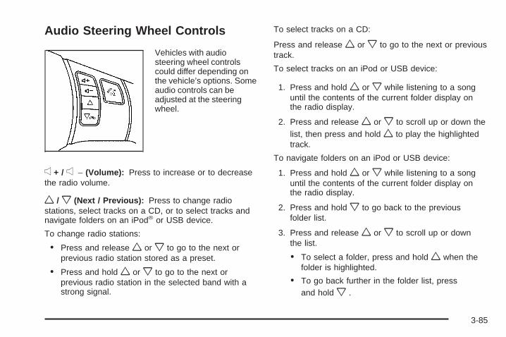
Audio Steering Wheel Controls
Vehicles with audiosteering wheel controlscould differ depending onthe vehicle’s options. Someaudio controls can beadjusted at the steeringwheel.
e + / e − (Volume): Press to increase or to decreasethe radio volume.
w / x (Next / Previous): Press to change radiostations, select tracks on a CD, or to select tracks andnavigate folders on an iPod® or USB device.
To change radio stations:
• Press and release w or x to go to the next orprevious radio station stored as a preset.
• Press and hold w or x to go to the next orprevious radio station in the selected band with astrong signal.
To select tracks on a CD:
Press and release w or x to go to the next or previoustrack.
To select tracks on an iPod or USB device:
1. Press and hold w or x while listening to a songuntil the contents of the current folder display onthe radio display.
2. Press and release w or x to scroll up or down thelist, then press and hold w to play the highlightedtrack.
To navigate folders on an iPod or USB device:
1. Press and hold w or x while listening to a songuntil the contents of the current folder display onthe radio display.
2. Press and hold x to go back to the previousfolder list.
3. Press and release w or x to scroll up or downthe list.
• To select a folder, press and hold w when thefolder is highlighted.
• To go back further in the folder list, pressand hold x .
3-85
c (End): Press to reject an incoming call, or end acurrent call.
bg (Mute / Voice Recognition): Press to silence thevehicle speakers only. Press again to turn the sound on.
For vehicles with OnStar® or Bluetooth systems pressand hold bg for longer than two seconds to interactwith those systems. See OnStar® System on page 2-37and Bluetooth® on page 3-73 for more information.
Radio ReceptionFrequency interference and static can occur duringnormal radio reception if items such as cell phonechargers, vehicle convenience accessories, and externalelectronic devices are plugged into the accessorypower outlet. If there is interference or static, unplug theitem from the accessory power outlet.
AMThe range for most AM stations is greater than for FM,especially at night. The longer range can cause stationfrequencies to interfere with each other. For better radioreception, most AM radio stations boost the power levelsduring the day, and then reduce these levels during thenight. Static can also occur when things like storms andpower lines interfere with radio reception. When thishappens, try reducing the treble on the radio.
FM StereoFM signals only reach about 10 to 40 miles (16 to 65 km).Although the radio has a built-in electronic circuit thatautomatically works to reduce interference, some staticcan occur, especially around tall buildings or hills,causing the sound to fade in and out.
XM™ Satellite Radio ServiceXM Satellite Radio Service gives digital radio receptionfrom coast-to-coast in the 48 contiguous United States,and in Canada. Just as with FM, tall buildings or hills caninterfere with satellite radio signals, causing the sound tofade in and out. In addition, traveling or standing underheavy foliage, bridges, garages, or tunnels may causeloss of the XM signal for a period of time.
3-86

Cellular Phone UsageCellular phone usage may cause interference with thevehicle’s radio. This interference may occur when makingor receiving phone calls, charging the phone’s battery, orsimply having the phone on. This interference causes anincreased level of static while listening to the radio. Ifstatic is received while listening to the radio, unplug thecellular phone and turn it off.
Fixed Mast AntennaThe fixed mast antenna can withstand most car washeswithout being damaged as long as it is securely attachedto the base. If the mast becomes slightly bent, straightenit out by hand. If the mast is badly bent, replace it.
Occasionally check to make sure the antenna istightened to its base. If tightening is required, tightenby hand. until fully seated plus one quarter turn.
XM™ Satellite Radio AntennaSystemThe XM Satellite Radio antenna is located on the roofor the rear of the vehicle. Keep the antenna clearof obstructions for clear radio reception.
3-87

✍ NOTES
3-88

Your Driving, the Road, and the Vehicle ............4-2Driving for Better Fuel Economy .......................4-2Defensive Driving ...........................................4-2Drunk Driving .................................................4-3Control of a Vehicle ........................................4-3Braking .........................................................4-4Antilock Brake System (ABS) ...........................4-5Braking in Emergencies ...................................4-6Electronic Stability Control (ESC) ......................4-6Traction Control System (TCS) .........................4-8Enhanced Traction System (ETS) ....................4-11Steering ......................................................4-13Off-Road Recovery .......................................4-15Passing .......................................................4-15Loss of Control .............................................4-15
Driving at Night ............................................4-17Driving in Rain and on Wet Roads ..................4-18Before Leaving on a Long Trip .......................4-19Highway Hypnosis ........................................4-19Hill and Mountain Roads ................................4-20Winter Driving ..............................................4-21If Your Vehicle is Stuck in Sand, Mud,
Ice, or Snow .............................................4-23Rocking Your Vehicle to Get It Out .................4-24Loading the Vehicle ......................................4-24
Towing ..........................................................4-30Towing Your Vehicle .....................................4-30Recreational Vehicle Towing ...........................4-30Towing a Trailer (Automatic Transmission) ........4-33Towing a Trailer (Manual Transmission) ...........4-40
Section 4 Driving Your Vehicle
4-1

Your Driving, the Road, andthe Vehicle
Driving for Better Fuel EconomyDriving habits can affect fuel mileage. Here are somedriving tips to get the best fuel economy possible.
• Avoid fast starts and accelerate smoothly.
• Brake gradually and avoid abrupt stops.
• Avoid idling the engine for long periods of time.
• When road and weather conditions are appropriate,use cruise control, if equipped.
• Always follow posted speed limits or drive moreslowly when conditions require.
• Keep vehicle tires properly inflated.
• Combine several trips into a single trip.
• Replace the vehicle’s tires with the same TPC Specnumber molded into the tire’s sidewall near the size.
• Follow recommended scheduled maintenance.
Defensive DrivingDefensive driving means “always expect theunexpected.” The first step in driving defensively is towear your safety belt — See Safety Belts: They Are forEveryone on page 1-10.
{CAUTION:
Assume that other road users (pedestrians,bicyclists, and other drivers) are going to becareless and make mistakes. Anticipate what theymight do and be ready. In addition:
• Allow enough following distance between youand the driver in front of you.
• Focus on the task of driving.
Driver distraction can cause collisions resulting ininjury or possible death. These simple defensivedriving techniques could save your life.
4-2
Drunk Driving
{CAUTION:
Drinking and then driving is very dangerous.Your reflexes, perceptions, attentiveness, andjudgment can be affected by even a small amountof alcohol. You can have a serious — or evenfatal — collision if you drive after drinking. Do notdrink and drive or ride with a driver who has beendrinking. Ride home in a cab; or if you are with agroup, designate a driver who will not drink.
Death and injury associated with drinking and driving isa global tragedy.
Alcohol affects four things that anyone needs to drive avehicle: judgment, muscular coordination, vision, andattentiveness.
Police records show that almost 40 percent of all motorvehicle-related deaths involve alcohol. In most cases,these deaths are the result of someone who was drinkingand driving. In recent years, more than 17,000 annualmotor vehicle-related deaths have been associated withthe use of alcohol, with about 250,000 people injured.
For persons under 21, it is against the law in everyU.S. state to drink alcohol. There are good medical,psychological, and developmental reasons forthese laws.
The obvious way to eliminate the leading highwaysafety problem is for people never to drink alcohol andthen drive.
Medical research shows that alcohol in a person’ssystem can make crash injuries worse, especiallyinjuries to the brain, spinal cord, or heart. This meansthat when anyone who has been drinking — driveror passenger — is in a crash, that person’s chance ofbeing killed or permanently disabled is higher than if theperson had not been drinking.
Control of a VehicleThe following three systems help to control the vehiclewhile driving — brakes, steering, and accelerator. Attimes, as when driving on snow or ice, it is easy to askmore of those control systems than the tires and road canprovide. Meaning, you can lose control of the vehicle.See Traction Control System (TCS) on page 4-8,Enhanced Traction System (ETS) on page 4-11, andElectronic Stability Control (ESC) on page 4-6.
Adding non-dealer/non-retailer accessories can affectvehicle performance. See Accessories and Modificationson page 5-3.
4-3

BrakingSee Brake System Warning Light on page 3-30.
Braking action involves perception time and reactiontime. Deciding to push the brake pedal is perceptiontime. Actually doing it is reaction time.
Average reaction time is about three-fourths of a second.But that is only an average. It might be less with onedriver and as long as two or three seconds or more withanother. Age, physical condition, alertness, coordination,and eyesight all play a part. So do alcohol, drugs, andfrustration. But even in three-fourths of a second, avehicle moving at 60 mph (100 km/h) travels 66 feet(20 m). That could be a lot of distance in an emergency,so keeping enough space between the vehicle and othersis important.
And, of course, actual stopping distances vary greatlywith the surface of the road, whether it is pavement orgravel; the condition of the road, whether it is wet, dry, oricy; tire tread; the condition of the brakes; the weight ofthe vehicle; and the amount of brake force applied.
Avoid needless heavy braking. Some people drivein spurts — heavy acceleration followed by heavybraking — rather than keeping pace with traffic. This isa mistake. The brakes might not have time to coolbetween hard stops. The brakes will wear out muchfaster with a lot of heavy braking. Keeping pace with thetraffic and allowing realistic following distanceseliminates a lot of unnecessary braking. That meansbetter braking and longer brake life.
If the engine ever stops while the vehicle is being driven,brake normally but do not pump the brakes. If the brakesare pumped, the pedal could get harder to push down.If the engine stops, there will still be some power brakeassist but it will be used when the brake is applied. Oncethe power assist is used up, it can take longer to stop andthe brake pedal will be harder to push.
Adding non-dealer/non-retailer accessories can affectvehicle performance. See Accessories and Modificationson page 5-3.
4-4

Antilock Brake System (ABS)The vehicle might have the Antilock Brake System(ABS), an advanced electronic braking system that willhelp prevent a braking skid.
If the vehicle has ABS,this warning light on theinstrument panel comes onbriefly when the vehicleis started.
When the engine is started, or when the vehicle beginsto drive away, ABS checks itself. A momentary motoror clicking noise might be heard while this test is goingon, and it might even be noticed that the brake pedalmoves or pulses a little. This is normal.
Let us say the road is wet and you are driving safely.Suddenly, an animal jumps out in front of you. You slamon the brakes and continue braking. Here is whathappens with ABS:
A computer senses that the wheels are slowing down.If one of the wheels is about to stop rolling, the computerwill separately work the brakes at each wheel.
ABS can change the brake pressure to each wheel, asrequired, faster than any driver could. This can helpthe driver steer around the obstacle while braking hard.
As the brakes are applied, the computer keepsreceiving updates on wheel speed and controls brakingpressure accordingly.
Remember: ABS does not change the time needed to geta foot up to the brake pedal or always decrease stoppingdistance. If you get too close to the vehicle in front of you,there will not be enough time to apply the brakes if thatvehicle suddenly slows or stops. Always leave enoughroom up ahead to stop, even with ABS.
4-5

Using ABSDo not pump the brakes. Just hold the brake pedal downfirmly and let antilock work. A slight brake pedal pulsationmight be felt or some noise noticed, but this is normal.
Braking in EmergenciesAt some time, nearly every driver gets into a situationthat requires hard braking.
If the vehicle has ABS, it allows the driver to steer andbrake at the same time. However, if the vehicle does nothave ABS, the first reaction — to hit the brake pedal hardand hold it down — might be the wrong thing to do. Thewheels can stop rolling. Once they do, the vehicle cannotrespond to the driver’s steering. Momentum will carry it inwhatever direction it was headed when the wheelsstopped rolling. That could be off the road, into the verything the driver was trying to avoid, or into traffic.
If the vehicle does not have ABS, use a “squeeze”braking technique. This gives maximum braking whilemaintaining steering control. Do this by pushing onthe brake pedal with steadily increasing pressure.
In an emergency, you will probably want to squeeze thebrakes hard without locking the wheels. If you hear orfeel the wheels sliding, ease off the brake pedal.This helps retain steering control. With ABS, it isdifferent. See Antilock Brake System (ABS) on page 4-5.
In many emergencies, steering can help more thaneven the very best braking.
Electronic Stability Control (ESC)The vehicle may have an Electronic Stability Control(ESC) system which combines antilock brake, andtraction and stability control systems that help the drivermaintain directional control of the vehicle in most drivingconditions.
When the vehicle is started and begins to move, thesystem performs several diagnostic checks to ensurethere are no problems. The system may be heard or feltwhile it is working. This is normal and does not meanthere is a problem with the vehicle. The system shouldinitialize before the vehicle reaches 20 mph (32 km/h).
4-6

If the system fails to turn on or activate, the ESC/TCSlight comes on, and the ESC OFF and/or SERVICE ESCmessage displays.
For more information, see Driver Information Center(DIC) on page 3-39 and Electronic Stability Control(ESC)/Traction Control System (TCS) Indicator/WarningLight on page 3-32.
This light flashes on theinstrument panel clusterwhen the ESC systemis on and activated.
ESC activates when the computer senses a discrepancybetween the intended path and the direction the vehicle isactually travelling. ESC selectively applies brakingpressure at any one of the vehicle’s brakes to help steerthe vehicle in the direction which you are steering.
When the system activates, an ESC ACTIVE messagedisplays on the Driver Information Center. See DICWarnings and Messages on page 3-42. This light alsoflashes on the instrument panel cluster when theESC system is on and activated. A noise may be heardor a vibration felt in the brake pedal. This is normal.Continue to steer the vehicle in the intended direction.
When the light is on solid and the message(s),SERVICE ESC, ESC OFF, or both display, the systemwill not assist the driver in maintaining directionalcontrol of the vehicle. Adjust your driving accordingly.See DIC Warnings and Messages on page 3-42.
The ESC system is automatically enabled whenever thevehicle is started. To assist the driver with vehicledirectional control, especially in slippery road conditions,the system should always be left on. But, ESC canbe turned off if needed.
If cruise control is being used when ESC activates, thecruise control automatically disengages. The cruisecontrol can be reengaged when road conditions allow.See Cruise Control on page 3-10.
4-7

The ESC/TCS button islocated on the instrumentpanel.
The traction control system can be turned off or backon by pressing the ESC/TCS button. To disable bothtraction control and ESC, press and hold the buttonfrom five to ten seconds.
When the ESC system is turned off, the TRACTIONOFF and ESC OFF messages appear, and theESC/TCS light comes on to warn the driver that bothtraction control and ESC are disabled.
It is recommended that the system remain on for normaldriving conditions, but it may be necessary to turn thesystem off if the vehicle is stuck in sand, mud, iceor snow, and you want to “rock” the vehicle to attemptto free it. It may also be necessary to turn off the systemwhen driving in extreme off-road conditions wherehigh wheel spin is required. See If Your Vehicle is Stuckin Sand, Mud, Ice, or Snow on page 4-23.
ESC may also turn off automatically if it determines thata problem exists with the system. The ESC OFF andSERVICE ESC messages and the ESC/TCS light comeson to warn the driver that ESC is disabled and requires
service. If the problem does not clear after restarting thevehicle, see your dealer/retailer for service. See DICWarnings and Messages on page 3-42 for moreinformation.
Adding non-dealer/non-retailer accessories can affectthe vehicle’s performance. See Accessories andModifications on page 5-3 for more information.
Traction Control System (TCS)The vehicle may have a Traction Control System (TCS)that limits wheel spin. This is especially useful in slipperyroad conditions. The system operates only if it sensesthat the front wheels are spinning too much or arebeginning to lose traction. When this happens, thesystem works the front brakes and reduces engine powerby closing the throttle and managing engine spark to limitwheel spin.
This light flashes while thetraction control system islimiting wheel spin.
The system may be heard or felt while it is working.This is normal and does not mean there is a problemwith the vehicle.
4-8
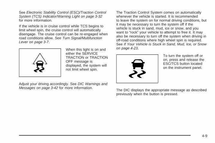
See Electronic Stability Control (ESC)/Traction ControlSystem (TCS) Indicator/Warning Light on page 3-32for more information.
If the vehicle is in cruise control while TCS begins tolimit wheel spin, the cruise control will automaticallydisengage. The cruise control can be re-engaged whenroad conditions allow. See Turn Signal/MultifunctionLever on page 3-7.
When this light is on andeither the SERVICETRACTION or TRACTIONOFF message isdisplayed, the system willnot limit wheel spin.
Adjust your driving accordingly. See DIC Warnings andMessages on page 3-42 for more information.
The Traction Control System comes on automaticallywhenever the vehicle is started. It is recommendedto leave the system on for normal driving conditions, butit may be necessary to turn the system off if thevehicle is stuck in sand, mud, ice or snow, and youwant to “rock” your vehicle to attempt to free it. It mayalso be necessary to turn off the system when driving inoff-road conditions where high wheel spin is required.See If Your Vehicle is Stuck in Sand, Mud, Ice, or Snowon page 4-23.
To turn the system off oron, press and release theESC/TCS button locatedon the instrument panel.
The DIC displays the appropriate message as describedpreviously when the button is pressed.
4-9

Traction Control OperationTraction control limits wheel spin by reducing enginepower to the wheels (engine speed management)and by applying brakes to each individual wheel(brake-traction control) as necessary.
The traction control system is enabled automaticallywhen the vehicle is started, and it will activate and flashthe ESC/TCS light and display the LOW TRACTIONmessage if it senses that either of the front wheels arespinning or beginning to lose traction while driving.For more information on the LOW TRACTION message,see Driver Information Center (DIC) on page 3-39.
Notice: If the wheel(s) of one axle are allowed tospin excessively while the ESC/TCS, ABS and Brakewarning lights and the SERVICE ESC and/orSERVICE TRACTION messages are displayed, thedifferential could be damaged. The repairs would notbe covered by the vehicle warranty. Reduce enginepower and do not spin the wheel(s) excessivelywhile these lights and this message are displayed.
Notice: When traction control is turned off, orCompetitive Driving Mode is active, it is possible tolose traction. If you attempt to shift with the drivewheels spinning with a loss of traction, it is possibleto cause damage to the transmission. Do not attemptto shift when the drive wheels do not have traction.Damage caused by misuse of the vehicle is notcovered. See the warranty book for additionalinformation.
The traction control system may activate on dry orrough roads or under conditions such as heavyacceleration while turning or abrupt upshifts/downshiftsof the transmission. When this happens, a reductionin acceleration may be noticed or a noise or vibrationmay be heard. This is normal.
If the vehicle is in cruise control while the systemactivates, the ESC/TCS light flashes and the cruisecontrol automatically disengages. The cruise control canbe re-engaged when road conditions allow. SeeCruise Control on page 3-10.
Adding non-dealer/non-retailer accessories can affectthe vehicle’s performance. See Accessories andModifications on page 5-3 for more information.
4-10
Enhanced Traction System (ETS)The vehicle may have an Enhanced Traction System(ETS) that limits wheel spin. This is especially useful inslippery road conditions. The system operates only ifit senses that one or both of the front wheels arespinning or beginning to lose traction. When thishappens, the system reduces engine power and mayalso upshift the transmission to limit wheel spin.
If the vehicle has ETS, there is not an ESC/TCS buttonon the instrument panel. To turn the system off, shiftto L (Low) or R (Reverse). There is more informationabout how to turn the system off later in this section.
The ETS indicator/warning light flashes and LOWTRACTION appears on the Driver Information Center(DIC) when the traction control system is actively limitingwheel spin. The system may be heard or felt while itis working, but this is normal. Slippery road conditionsmay exist if this message is displayed, so adjustyour driving accordingly.
If the vehicle is in cruise control when the ETS beginsto limit wheel spin, the cruise control will automaticallydisengage. The cruise control can be re-engagedwhen road conditions allow. See Cruise Control onpage 3-10.
The ETS indicator/warning light may come on for thefollowing reasons:
• The indicator/warning light flashes while the tractioncontrol system is limiting wheel spin.
• If the system is turned off by moving the shift leverto L (Low), the indicator/warning light comes onand stays on. To turn the system back on, move theshift lever back to a position other than L (Low).The indicator/warning light should go off.
• The indicator/warning light will come on when theparking brake is set with the engine running, and itwill stay on if the parking brake does not release fully.If the transmission shift lever is in any position otherthan L (Low) and the indicator/warning light stays onafter the parking brake is fully released, there is aproblem with the system.
• If the traction control system is affected by an enginerelated problem, the system will turn off and theindicator/warning light will come on.
4-11
If the ETS indicator/warning light comes on and stayson for an extended period of time when the transmissionshift lever is in any position other than L (Low), thevehicle may need service.
When this light is on solid, the system will not limitwheel spin. Adjust your driving accordingly.
Check the DIC messaging to determine whether it isbecause of the driver turning off the system, or that thesystem may not be working properly and the vehiclerequires service. When this light is turned on, either theSERVICE TRACTION or TRACTION OFF messagewill be displayed.
See DIC Warnings and Messages on page 3-42 formore information on the messages associated withthis light.
To limit wheel spin, especially in slippery roadconditions, ETS should always be left on. But thesystem can be turned off if needed.
To turn the system off, shift to L (Low) or R (Reverse).
When the system is turned off, the ETS indicator/warninglight will come on and stay on and the TRACTION OFFmessage will be displayed when the gear shift is inL (Low). The indicator/warning light and message will notcome on when the gear shift is in R (Reverse). If the ETSis limiting wheel spin when the transmission is shiftedto L (Low) or R (Reverse) to turn the system off, theindicator/warning light and TRACTION OFF will comeon in L (Low). But the system will not turn off right away.It will wait until there is no longer a current need to limitwheel spin. See DIC Warnings and Messages onpage 3-42 for more information on the messagesassociated with this light.
The system can be turned back on at any time byshifting to D (Automatic Overdive) or I (Intermediate).The ETS indicator/warning light should go off.
Adding non-dealer/non-retailer accessories can affectthe vehicle’s performance. See Accessories andModifications on page 5-3 for more information.
4-12
Steering
Electric Power SteeringIf the engine stalls while driving, the power steeringassist system will continue to operate until you are ableto stop the vehicle. If power steering assist is lostbecause the electric power steering system is notfunctioning, the vehicle can be steered but it will takemore effort.
If you turn the steering wheel in either direction severaltimes until it stops, or hold the steering wheel in thestopped position for an extended amount of time, youmay notice a reduced amount of power steeringassist. The normal amount of power steering assistshould return shortly after a few normal steeringmovements.
The electric power steering system does not requireregular maintenance. If you suspect steering systemproblems and/or the POWER STEERING messagecomes on, contact your dealer/retailer for servicerepairs. See DIC Warnings and Messages on page 3-42.
Steering TipsIt is important to take curves at a reasonable speed.
Traction in a curve depends on the condition of the tiresand the road surface, the angle at which the curve isbanked, and vehicle speed. While in a curve, speed isthe one factor that can be controlled.
If there is a need to reduce speed, do it before enteringthe curve, while the front wheels are straight.
Try to adjust the speed so you can drive through thecurve. Maintain a reasonable, steady speed. Waitto accelerate until out of the curve, and then accelerategently into the straightaway.
4-13

Steering in EmergenciesThere are times when steering can be more effectivethan braking. For example, you come over a hill and finda truck stopped in your lane, or a car suddenly pulls outfrom nowhere, or a child darts out from between parkedcars and stops right in front of you. These problems canbe avoided by braking — if you can stop in time. Butsometimes you cannot stop in time because there is noroom. That is the time for evasive action — steeringaround the problem.
The vehicle can perform very well in emergencies likethese. First apply the brakes — but, unless the vehiclehas antilock brakes, not enough to lock the wheels.See Braking on page 4-4. It is better to remove as muchspeed as possible from a collision. Then steer around theproblem, to the left or right depending on the spaceavailable.
An emergency like this requires close attention and aquick decision. If holding the steering wheel at therecommended 9 and 3 o’clock positions, it can be turneda full 180 degrees very quickly without removing eitherhand. But you have to act fast, steer quickly, and just asquickly straighten the wheel once you have avoided theobject.
The fact that such emergency situations are alwayspossible is a good reason to practice defensive drivingat all times and wear safety belts properly.
4-14

Off-Road RecoveryThe vehicle’s right wheels can drop off the edge of aroad onto the shoulder while driving.
If the level of the shoulder is only slightly below thepavement, recovery should be fairly easy. Ease off theaccelerator and then, if there is nothing in the way, steerso that the vehicle straddles the edge of the pavement.Turn the steering wheel 3 to 5 inches, 8 to 13 cm, (aboutone-eighth turn) until the right front tire contacts thepavement edge. Then turn the steering wheel to gostraight down the roadway.
PassingPassing another vehicle on a two-lane road can bedangerous. To reduce the risk of danger while passing:
• Look down the road, to the sides, and to crossroadsfor situations that might affect a successful pass.If in doubt, wait.
• Watch for traffic signs, pavement markings, andlines that could indicate a turn or an intersection.Never cross a solid or double-solid line on your sideof the lane.
• Do not get too close to the vehicle you want topass. Doing so can reduce your visibility.
• Wait your turn to pass a slow vehicle.
• When you are being passed, ease to the right.
Loss of ControlLet us review what driving experts say about whathappens when the three control systems — brakes,steering, and acceleration — do not have enough frictionwhere the tires meet the road to do what the driver hasasked.
In any emergency, do not give up. Keep trying to steerand constantly seek an escape route or area of lessdanger.
4-15

SkiddingIn a skid, a driver can lose control of the vehicle.Defensive drivers avoid most skids by taking reasonablecare suited to existing conditions, and by not overdrivingthose conditions. But skids are always possible.
The three types of skids correspond to the vehicle’sthree control systems. In the braking skid, the wheels arenot rolling. In the steering or cornering skid, too muchspeed or steering in a curve causes tires to slip and losecornering force. And in the acceleration skid, too muchthrottle causes the driving wheels to spin.
If the vehicle has the Enhanced Traction System (ETS),remember: It helps to avoid only the acceleration skid.See Enhanced Traction System (ETS) on page 4-11.If the vehicle does not have the Enhanced TractionSystem, or if the system is off, then an acceleration skidis best handled by easing your foot off the acceleratorpedal.
If the vehicle starts to slide, ease your foot off theaccelerator pedal and quickly steer the way you wantthe vehicle to go. If you start steering quickly enough,the vehicle may straighten out. Always be ready fora second skid if it occurs.
Of course, traction is reduced when water, snow, ice,gravel, or other material is on the road. For safety, slowdown and adjust your driving to these conditions. It isimportant to slow down on slippery surfaces becausestopping distance will be longer and vehicle control morelimited.
While driving on a surface with reduced traction, tryyour best to avoid sudden steering, acceleration, orbraking, including reducing vehicle speed by shifting toa lower gear. Any sudden changes could cause the tiresto slide. You may not realize the surface is slippery untilthe vehicle is skidding. Learn to recognize warningclues — such as enough water, ice, or packed snow onthe road to make a mirrored surface — and slow downwhen you have any doubt.
If the vehicle has the Antilock Brake System (ABS),remember: It helps avoid only the braking skid. If thevehicle does not have ABS, then in a braking skid, wherethe wheels are no longer rolling, release enough pressureon the brakes to get the wheels rolling again. Thisrestores steering control. Push the brake pedal downsteadily when you have to stop suddenly. As long as thewheels are rolling, you will have steering control.
4-16
Driving at NightNight driving is more dangerous than day drivingbecause some drivers are likely to be impaired — byalcohol or drugs, with night vision problems, or by fatigue.
Night driving tips include:
• Drive defensively.
• Do not drink and drive.
• Reduce headlamp glare by adjusting the insiderearview mirror.
• Slow down and keep more space between you andother vehicles because headlamps can only light upso much road ahead.
• Watch for animals.
• When tired, pull off the road.
• Do not wear sunglasses.
• Avoid staring directly into approaching headlamps.
• Keep the windshield and all glass on your vehicleclean — inside and out.
• Keep your eyes moving, especially during turns orcurves.
No one can see as well at night as in the daytime.But, as we get older, these differences increase.A 50-year-old driver might need at least twice as muchlight to see the same thing at night as a 20-year-old.
4-17
Driving in Rain and on Wet RoadsRain and wet roads can reduce vehicle tractionand affect your ability to stop and accelerate. Alwaysdrive slower in these types of driving conditionsand avoid driving through large puddles anddeep-standing or flowing water.
{CAUTION:
Wet brakes can cause crashes. They might notwork as well in a quick stop and could causepulling to one side. You could lose control of thevehicle.
After driving through a large puddle of water or acar/vehicle wash, lightly apply the brake pedal untilthe brakes work normally.
Flowing or rushing water creates strong forces.Driving through flowing water could cause yourvehicle to be carried away. If this happens, youand other vehicle occupants could drown. Do notignore police warnings and be very cautious abouttrying to drive through flowing water.
HydroplaningHydroplaning is dangerous. Water can build up underyour vehicle’s tires so they actually ride on the water. Thiscan happen if the road is wet enough and you are goingfast enough. When your vehicle is hydroplaning, it haslittle or no contact with the road.
There is no hard and fast rule about hydroplaning.The best advice is to slow down when the road is wet.
Other Rainy Weather TipsBesides slowing down, other wet weather driving tipsinclude:
• Allow extra following distance.
• Pass with caution.
• Keep windshield wiping equipment in good shape.
• Keep the windshield washer fluid reservoir filled.
• Have good tires with proper tread depth. See Tireson page 5-48.
• Turn off cruise control.
4-18

Before Leaving on a Long TripTo prepare your vehicle for a long trip, consider havingit serviced by your dealer/retailer before departing.
Things to check on your own include:
• Windshield Washer Fluid: Reservoir full? Windowsclean — inside and outside?
• Wiper Blades: In good shape?
• Fuel, Engine Oil, Other Fluids: All levels checked?
• Lamps: Do they all work and are lenses clean?
• Tires: Are treads good? Are tires inflated torecommended pressure?
• Weather and Maps: Safe to travel? Haveup-to-date maps?
Highway HypnosisAlways be alert and pay attention to your surroundingswhile driving. If you become tired or sleepy, find asafe place to park your vehicle and rest.
Other driving tips include:
• Keep the vehicle well ventilated.
• Keep interior temperature cool.
• Keep your eyes moving — scan the road aheadand to the sides.
• Check the rearview mirror and vehicle instrumentsoften.
4-19

Hill and Mountain RoadsDriving on steep hills or through mountains is differentthan driving on flat or rolling terrain. Tips for drivingin these conditions include:
• Keep the vehicle serviced and in good shape.
• Check all fluid levels and brakes, tires, coolingsystem, and transmission.
• Going down steep or long hills, shift to alower gear.
{CAUTION:
If you do not shift down, the brakes could get sohot that they would not work well. You would thenhave poor braking or even none going down a hill.You could crash. Shift down to let the engineassist the brakes on a steep downhill slope.
{CAUTION:
Coasting downhill in N (Neutral) or with the ignitionoff is dangerous. The brakes will have to do all thework of slowing down and they could get so hotthat they would not work well. You would thenhave poor braking or even none going down a hill.You could crash. Always have the engine runningand the vehicle in gear when going downhill.
• Stay in your own lane. Do not swing wide or cutacross the center of the road. Drive at speedsthat let you stay in your own lane.
• Top of hills: Be alert — something could be in yourlane (stalled car, accident).
• Pay attention to special road signs (falling rocksarea, winding roads, long grades, passing orno-passing zones) and take appropriate action.
4-20

Winter Driving
Driving on Snow or IceDrive carefully when there is snow or ice between thetires and the road, creating less traction or grip. Wet icecan occur at about 32°F (0°C) when freezing rain beginsto fall, resulting in even less traction. Avoid driving on wetice or in freezing rain until roads can be treated with saltor sand.
Drive with caution, whatever the condition. Accelerategently so traction is not lost. Accelerating too quicklycauses the wheels to spin and makes the surface underthe tires slick, so there is even less traction.
Try not to break the fragile traction. If you accelerate toofast, the drive wheels will spin and polish the surfaceunder the tires even more.
If the vehicle has the Traction Control System (TCS)on page 4-8 or Enhanced Traction System (ETS) onpage 4-11, it improves the ability to accelerate on slippery
roads, but slow down and adjust your driving to the roadconditions. When driving through deep snow, turn off theETS, if equipped, to help maintain vehicle motion at lowerspeeds.
The Antilock Brake System (ABS) on page 4-5 improvesvehicle stability during hard stops on a slippery roads,but whether the vehicle has ABS or not, apply thebrakes sooner than when on dry pavement. WithoutABS, if the vehicle begins to slide, let up on the brakepedal a little and apply steady pedal pressure to get themost traction. On vehicles without ABS, braking sohard that the wheels stop rolling can cause the vehicleto slide — brake so the wheels always keep rollingso you can still steer.
Allow greater following distance on any slippery roadand watch for slippery spots. Icy patches can occur onotherwise clear roads in shaded areas. The surfaceof a curve or an overpass can remain icy whenthe surrounding roads are clear. Avoid sudden steeringmaneuvers and braking while on ice.
Turn off cruise control, if equipped, on slippery surfaces.
4-21

Blizzard ConditionsBeing stuck in snow can be in a serious situation.Stay with the vehicle unless there is help nearby.If possible, use the Roadside Assistance Programon page 7-7. To get help and keep everyone in thevehicle safe:
• Turn on the Hazard Warning Flashers on page 3-6.
• Tie a red cloth to an outside mirror.
{CAUTION:
Snow can trap engine exhaust under the vehicle.This may cause exhaust gases to get inside.Engine exhaust contains carbon monoxide (CO)which cannot be seen or smelled. It can causeunconsciousness and even death.
If the vehicle is stuck in the snow:• Clear away snow from around the base of
your vehicle, especially any that is blockingthe exhaust pipe.
• Check again from time to time to be suresnow does not collect there.
CAUTION: (Continued)
CAUTION: (Continued)
• Open a window about two inches (5 cm) onthe side of the vehicle that is away from thewind to bring in fresh air.
• Fully open the air outlets on or under theinstrument panel.
• Adjust the Climate Control system to a settingthat circulates the air inside the vehicle andset the fan speed to the highest setting. SeeClimate Control System in the Index.
For more information about carbon monoxide, seeEngine Exhaust on page 2-34.
Snow can trap exhaust gases under your vehicle.This can cause deadly CO (carbon monoxide) gasto get inside. CO could overcome you and kill you.You cannot see it or smell it, so you might notknow it is in your vehicle. Clear away snow fromaround the base of your vehicle, especially anythat is blocking the exhaust.
4-22
Run the engine for short periods only as needed tokeep warm, but be careful.
To save fuel, run the engine for only short periods asneeded to warm the vehicle and then shut the engine offand close the window most of the way to save heat.Repeat this until help arrives but only when youfeel really uncomfortable from the cold. Moving about tokeep warm also helps.
If it takes some time for help to arrive, now and thenwhen you run the engine, push the acceleratorpedal slightly so the engine runs faster than the idlespeed. This keeps the battery charged to restartthe vehicle and to signal for help with the headlamps.Do this as little as possible to save fuel.
If Your Vehicle is Stuck in Sand,Mud, Ice, or SnowSlowly and cautiously spin the wheels to free thevehicle when stuck in sand, mud, ice, or snow. SeeRocking Your Vehicle to Get It Out on page 4-24.
If the vehicle has a traction system, it can often help tofree a stuck vehicle. Refer to the vehicle’s tractionsystem in the Index. If stuck too severely for the tractionsystem to free the vehicle, turn the traction system offand use the rocking method.
{CAUTION:
If you let your vehicle’s tires spin at high speed,they can explode, and you or others could beinjured. The vehicle can overheat, causing anengine compartment fire or other damage. Spinthe wheels as little as possible and avoid goingabove 35 mph (55 km/h) as shown on thespeedometer.
For information about using tire chains on the vehicle,see Tire Chains on page 5-72.
4-23

Rocking Your Vehicle to Get It OutTurn the steering wheel left and right to clear the areaaround the front wheels. Shift back and forth betweenR (Reverse) and a forward gear, or with a manualtransmission, between 1 (First) or 2 (Second) andR (Reverse), spinning the wheels as little as possible.To prevent transmission wear, wait until the wheels stopspinning before shifting gears. Release the acceleratorpedal while shifting, and press lightly on the acceleratorpedal when the transmission is in gear. Slowly spinningthe wheels in the forward and reverse directions causes arocking motion that could free the vehicle. If that does notget the vehicle out after a few tries, it might need to betowed out. If the vehicle does need to be towed out, seeTowing Your Vehicle on page 4-30.
Loading the VehicleIt is very important to know how much weightyour vehicle can carry. This weight is called thevehicle capacity weight and includes the weight ofall occupants, cargo and all nonfactory-installedoptions. Two labels on your vehicle show howmuch weight it may properly carry, the Tire andLoading Information label and the Certificationlabel.
{CAUTION:
Do not load the vehicle any heavier than theGross Vehicle Weight Rating (GVWR), oreither the maximum front or rear Gross AxleWeight Rating (GAWR). If you do, parts onthe vehicle can break, and it can change theway your vehicle handles. These could causeyou to lose control and crash. Also,overloading can shorten the life of thevehicle.
4-24

Tire and Loading Information Label
A vehicle specific Tire and Loading Informationlabel is attached to the vehicle’s center pillar(B-pillar). With the driver’s door open, you will find
the label either attached above the door lock postfor a two door vehicle or below the door lock postfor a four door vehicle. The Tire and LoadingInformation label shows the number of occupantseating positions (A), and the maximum vehiclecapacity weight (B) in kilograms and pounds.
The Tire and Loading Information label also showsthe tire size of the original equipment tires (C) andthe recommended cold tire inflation pressures (D).For more information on tires and inflation see Tireson page 5-48 and Inflation - Tire Pressure onpage 5-56.
There is also important loading information on theCertification label. It tells you the Gross VehicleWeight Rating (GVWR) and the Gross Axle WeightRating (GAWR) for the front and rear axle; see“Certification Label” later in this section.Label Example
4-25
Steps for Determining Correct Load Limit1. Locate the statement “The combined weight
of occupants and cargo should never exceedXXX kg or XXX lbs” on your vehicle placard.
2. Determine the combined weight of the driverand passengers that will be riding in yourvehicle.
3. Subtract the combined weight of the driverand passengers from XXX kg or XXX lbs.
4. The resulting figure equals the availableamount of cargo and luggage load capacity.For example, if the “XXX” amount equals1400 lbs and there will be five 150 lbpassengers in your vehicle, the amount ofavailable cargo and luggage load capacity is650 lbs (1400 − 750 (5 x 150) = 650 lbs).
5. Determine the combined weight of luggageand cargo being loaded on the vehicle. Thatweight may not safely exceed the availablecargo and luggage load capacity calculated inStep 4.
6. If your vehicle will be towing a trailer, the loadfrom your trailer will be transferred to yourvehicle. Consult this manual to determine howthis reduces the available cargo and luggageload capacity of your vehicle.If your vehicle can tow a trailer, see Towinga Trailer (Automatic Transmission) onpage 4-33 or Towing a Trailer (ManualTransmission) on page 4-40 for importantinformation on towing a trailer, towing safetyrules, and trailering tips.
4-26

Item Description Total
AVehicle CapacityWeight forExample 1 =
1,000 lbs(453 kg)
BSubtract OccupantWeight 150 lbs(68 kg) × 2 =
300 lbs (136 kg)
C Available Occupantand Cargo Weight = 700 lbs (317 kg)
Item Description Total
AVehicle CapacityWeight forExample 2 =
1,000 lbs(453 kg)
BSubtract OccupantWeight 150 lbs(68 kg) × 5 =
750 lbs (340 kg)
C Available CargoWeight = 250 lbs (113 kg)
Example 1 Example 2
4-27

Item Description Total
AVehicle CapacityWeight forExample 3 =
1,000 lbs(453 kg)
BSubtract OccupantWeight 200 lbs(91 kg) × 5 =
1,000 lbs(453 kg)
C Available CargoWeight = 0 lbs (0 kg)
Refer to your vehicle’s Tire and LoadingInformation label for specific information aboutyour vehicle’s capacity weight and seating
positions. The combined weight of the driver,passengers, and cargo should never exceed yourvehicle’s capacity weight.
Certification Label
A vehicle specific Certification label, found on therear edge of the driver’s door, tells you the grossweight capacity of your vehicle, called the GrossVehicle Weight Rating (GVWR). The GVWRincludes the weight of the vehicle, all occupants,fuel, and cargo. Never exceed the GVWR for yourvehicle, or the Gross Axle Weight Rating (GAWR)for either the front or rear axle.
Example 3
4-28
And, if you do have a heavy load, you shouldspread it out. See “Steps for Determining CorrectLoad Limit” earlier in this section.
{CAUTION:
Do not load the vehicle any heavier than theGross Vehicle Weight Rating (GVWR), oreither the maximum front or rear Gross AxleWeight Rating (GAWR). If you do, parts onthe vehicle can break, and it can changethe way your vehicle handles. These couldcause you to lose control and crash. Also,overloading can shorten the life of thevehicle.
If you put things inside your vehicle — likesuitcases, tools, packages, or anything else — theywill go as fast as the vehicle goes. If you have tostop or turn quickly, or if there is a crash, they willkeep going.
{CAUTION:
Things you put inside the vehicle can strikeand injure people in a sudden stop or turn, orin a crash.
• Put things in the trunk of your vehicle.In a trunk, put them as far forward as youcan. Try to spread the weight evenly.
• Never stack heavier things, likesuitcases, inside the vehicle so that someof them are above the tops of the seats.
• Do not leave an unsecured child restraintin the vehicle.
• When you carry something inside thevehicle, secure it whenever you can.
• Do not leave a seat folded down unlessyou need to.
4-29

Towing
Towing Your VehicleTo avoid damage, the disabled vehicle should be towedwith all four wheels off the ground. Consult yourdealer/retailer or a professional towing service if thedisabled vehicle must be towed. See RoadsideAssistance Program on page 7-7.
To tow the vehicle behind another vehicle forrecreational purposes (such as behind a motorhome),see “Recreational Vehicle Towing” following.
Recreational Vehicle TowingRecreational vehicle towing means towing the vehiclebehind another vehicle – such as behind a motorhome.The two most common types of recreational vehicletowing are known as dinghy towing and dolly towing.Dinghy towing is towing the vehicle with all four wheelson the ground. Dolly towing is towing the vehiclewith two wheels on the ground and two wheels up on adevice known as a dolly.
Here are some important things to consider beforerecreational vehicle towing:
• What is the towing capacity of the towing vehicle?Be sure to read the tow vehicle manufacturer’srecommendations.
• What is the distance that will be travelled? Somevehicles have restrictions on how far and howlong they can tow.
• Is the proper towing equipment going to be used?See your dealer/retailer or trailering professionalfor additional advice and equipmentrecommendations.
• Is the vehicle ready to be towed? Just as preparingthe vehicle for a long trip, make sure the vehicle isprepared to be towed. See Before Leaving on aLong Trip on page 4-19.
4-30
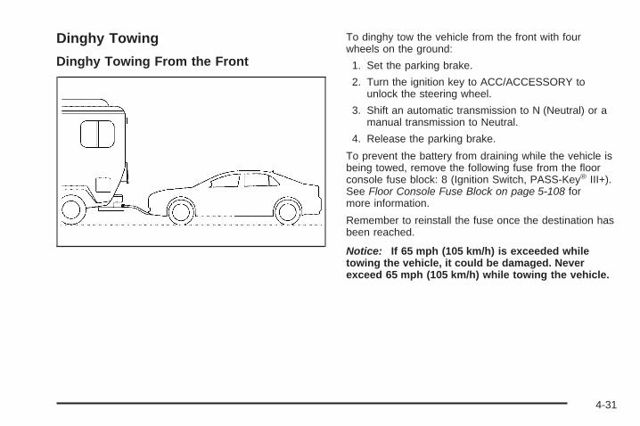
Dinghy Towing
Dinghy Towing From the Front
To dinghy tow the vehicle from the front with fourwheels on the ground:
1. Set the parking brake.
2. Turn the ignition key to ACC/ACCESSORY tounlock the steering wheel.
3. Shift an automatic transmission to N (Neutral) or amanual transmission to Neutral.
4. Release the parking brake.
To prevent the battery from draining while the vehicle isbeing towed, remove the following fuse from the floorconsole fuse block: 8 (Ignition Switch, PASS-Key® III+).See Floor Console Fuse Block on page 5-108 formore information.
Remember to reinstall the fuse once the destination hasbeen reached.
Notice: If 65 mph (105 km/h) is exceeded whiletowing the vehicle, it could be damaged. Neverexceed 65 mph (105 km/h) while towing the vehicle.
4-31

Dinghy Towing From the Rear
Notice: Towing the vehicle from the rear coulddamage it. Also, repairs would not be covered by thewarranty. Never have the vehicle towed from the rear.
Dolly Towing
To dolly tow the vehicle from the front with two wheelson the ground:1. Attach the dolly to the tow vehicle following the
dolly manufacturer’s instructions.
2. Put the front wheels on a dolly.3. Move the shift lever to P (Park) for an automatic
transmission and in Neutral for a manualtransmission.
4. Set the parking brake.5. Clamp the steering wheel in a straight-ahead
position with a clamping device designed for towing.
4-32

6. Remove the key from the ignition.
7. Secure the vehicle to the dolly.
8. Release the parking brake only after the vehiclebeing towed is firmly attached to the towingvehicle.
Towing a Trailer (AutomaticTransmission)
{CAUTION:
The driver can lose control when pulling a trailer ifthe correct equipment is not used or the vehicle isnot driven properly. For example, if the trailer istoo heavy, the brakes may not work well or evenat all. The driver and passengers could beseriously injured. The vehicle may also bedamaged; the resulting repairs would not becovered by the vehicle warranty. Pull a trailer onlyif all the steps in this section have been followed.Ask your dealer/retailer for advice and informationabout towing a trailer with the vehicle.
The vehicle can tow a trailer if it is equipped with theproper trailer towing equipment.
To identify the trailering capacity of the vehicle, readthe information in “Weight of the Trailer” that appearslater in this section.
Trailering is different than just driving the vehicle by itself.Trailering means changes in handling, acceleration,braking, durability and fuel economy. Successful, safetrailering takes correct equipment, and it has to be usedproperly.
The following information has many time-tested,important trailering tips and safety rules. Many of theseare important for your safety and that of your passengers.So please read this section carefully before pulling atrailer.
Load-pulling components such as the engine,transmission, rear axle, wheel assemblies and tires areforced to work harder against the drag of the addedweight. The engine is required to operate at relativelyhigher speeds and under greater loads, generating extraheat. The trailer also adds considerably to windresistance, increasing the pulling requirements.
4-33
Pulling A TrailerHere are some important points:
• There are many different laws, including speed limitrestrictions, having to do with trailering. Make surethe rig will be legal, not only where you live butalso where you will be driving. A good source forthis information can be state or provincial police.
• Do not tow a trailer at all during the first 1,000 miles(1 600 km) the new vehicle is driven. The engine,transmission or other parts could be damaged.
• Then, during the first 500 miles (800 km) that atrailer is towed, do not drive over 50 mph (80 km/h)and do not make starts at full throttle. This helpsthe engine and other parts of the vehicle wear in atthe heavier loads.
• Vehicles can tow in D (Drive). Shift the transmissionto a lower gear if the transmission shifts too oftenunder heavy loads and/or hilly conditions.
• Obey speed limit restrictions when towing a trailer.Do not drive faster than the maximum posted speedfor trailers, or no more than 55 mph (90 km/h), tosave wear on the vehicle’s parts.
• Do not tow when the outside air temperature isabove 100°F (38°C).
• Do not tow more than 1,000 miles (1 600 km)per year.
Three important considerations have to do with weight:
• The weight of the trailer
• The weight of the trailer tongue
• Weight on the vehicle’s tires
Weight of the TrailerHow heavy can a trailer safely be?
It should never weigh more than 1,000 lbs (450 kg).But even that can be too heavy.
It depends on how the rig is used. For example, speed,altitude, road grades, outside temperature and how muchthe vehicle is used to pull a trailer are all important. It candepend on any special equipment on the vehicle, andthe amount of tongue weight the vehicle can carry. See“Weight of the Trailer Tongue” later in this section formore information.
Maximum trailer weight is calculated assuming only thedriver is in the tow vehicle and it has all the requiredtrailering equipment. The weight of additional optionalequipment, passengers and cargo in the tow vehiclemust be subtracted from the maximum trailer weight.
Ask your dealer/retailer for our trailering information oradvice. Also, see Customer Assistance Offices onpage 7-6 for more information.
4-34

Weight of the Trailer TongueThe tongue load (A) of any trailer is an important weightto measure because it affects the total gross weightof the vehicle. The Gross Vehicle Weight (GVW)includes the curb weight of the vehicle, any cargocarried in it, and the people who will be riding in thevehicle. If there are a lot of options, equipment,passengers or cargo in the vehicle, it will reduce thetongue weight the vehicle can carry, which will alsoreduce the trailer weight the vehicle can tow. If towing atrailer, the tongue load must be added to the GVWbecause the vehicle will be carrying that weight, too. SeeLoading the Vehicle on page 4-24 for more informationabout the vehicle’s maximum load capacity.
If using a weight-carrying hitch, the trailer tongue (A)should weigh 10 to 15 percent of the total loaded trailerweight (B).
After loading the trailer, weigh the trailer and then thetongue, separately, to see if the weights are proper.If they are not, adjustments might be made by movingsome items around in the trailer.
4-35

Total Weight on the Vehicle’s TiresBe sure the vehicle’s tires are inflated to the upper limitfor cold tires. These numbers can be found on theCertification label or see Loading the Vehicle onpage 4-24 for more information. Make sure not to goover the GVW limit for the vehicle, or the GAWR,including the weight of the trailer tongue.
HitchesIt is important to have the correct hitch equipment.Crosswinds, large trucks going by and rough roads area few reasons why the right hitch is needed.
• The rear bumper on the vehicle is not intendedfor hitches. Do not attach rental hitches or otherbumper-type hitches to it. Use only a frame-mountedhitch that does not attach to the bumper.
• Will any holes be made in the body of the vehiclewhen the trailer hitch is installed? If so, be sure toseal the holes when the hitch is removed. If theyare not sealed, deadly carbon monoxide (CO) fromthe engine’s exhaust can get into the vehicle. SeeEngine Exhaust on page 2-34. Sealing the holes willalso prevent dirt and water from entering the vehicle.
Safety ChainsAlways attach chains between the vehicle and the trailer.Cross the safety chains under the tongue of the trailer tohelp prevent the tongue from contacting the road if itbecomes separated from the hitch. Instructions aboutsafety chains may be provided by the hitch manufactureror by the trailer manufacturer. Follow the manufacturer’srecommendation for attaching safety chains and do notattach them to the bumper. Always leave just enoughslack so the rig can turn. Never allow safety chains todrag on the ground.
Trailer BrakesDoes the trailer have its own brakes? Be sure to read andfollow the instructions for the trailer brakes so they will beinstalled, adjusted and maintained properly. Do not try totap into the vehicle’s brake system. If you do, both brakesystems will not work well, or at all.
4-36
Driving with a TrailerTowing a trailer requires a certain amount of experience.Get to know the rig before setting out for the open road.Get acquainted with the feel of handling and braking withthe added weight of the trailer. And always keep in mindthat the vehicle you are driving is now longer and not asresponsive as the vehicle is by itself.
Before starting, check all trailer hitch parts andattachments, safety chains, electrical connectors, lamps,tires and mirror adjustments. If the trailer has electricbrakes, start the vehicle and trailer moving and thenapply the trailer brake controller by hand to be sure thebrakes are working. This checks the electrical connectionat the same time.
During the trip, check occasionally to be sure that theload is secure, and that the lamps and any trailer brakesare still working.
Following DistanceStay at least twice as far behind the vehicle ahead asyou would when driving the vehicle without a trailer. Thiscan help to avoid situations that require heavy brakingand sudden turns.
PassingMore passing distance is needed when towing a trailer.Because the rig is longer, it is necessary to go muchfarther beyond the passed vehicle before returning tothe lane.
Backing UpHold the bottom of the steering wheel with one hand.Then, to move the trailer to the left, move that handto the left. To move the trailer to the right, move yourhand to the right. Always back up slowly and, if possible,have someone guide you.
Making Turns
Notice: Making very sharp turns while traileringcould cause the trailer to come in contact with thevehicle. The vehicle could be damaged. Avoidmaking very sharp turns while trailering.
When turning with a trailer, make wider turns thannormal. Do this so the trailer will not strike softshoulders, curbs, road signs, trees or other objects.Avoid jerky or sudden maneuvers. Signal well inadvance.
4-37

Turn Signals When Towing a TrailerThe arrows on the instrument panel flash wheneversignaling a turn or lane change. Properly hooked up, thetrailer lamps also flash, telling other drivers the vehicleis turning, changing lanes or stopping.
When towing a trailer, the arrows on the instrumentpanel flash for turns even if the bulbs on the trailer areburned out. For this reason you may think otherdrivers are seeing the signal when they are not. It isimportant to check occasionally to be sure thetrailer bulbs are still working.
Driving on Grades
Notice: Do not tow on steep continuous gradesexceeding 6 miles (9.6 km). Extended, higherthan normal engine and transmission temperaturesmay result and damage the vehicle. Frequentstops are very important to allow the engine andtransmission to cool.
Reduce speed and shift to a lower gear before startingdown a long or steep downgrade. If the transmission isnot shifted down, the brakes might have to be used somuch that they would get hot and no longer work well.
On a long uphill grade, shift down and reduce thevehicle’s speed to around 45 mph (70 km/h) to reducethe possibility of the engine and the transmissionoverheating.
Vehicles can tow in D (Drive). Shift the transmission toa lower gear if the transmission shifts too often underheavy loads and/or hilly conditions.
Pay attention to the engine coolant gage. If the indicatoris in the red area, turn off the air conditioning to reduceengine load. See Engine Overheating on page 5-27.
When towing under severe conditions such as hotambient temperatures or steep grades, the vehicle mayexperience more transmission shifting. A COOLINGMODE ON message may also appear in the DIC. Thisalerts the driver that the shifting mode is in progressand is aiding engine cooling. See DIC Warningsand Messages on page 3-42 DIC Warnings andMessages for more information.
4-38
Parking on Hills
{CAUTION:
Parking the vehicle on a hill with the trailerattached can be dangerous. If something goeswrong, the rig could start to move. People can beinjured, and both the vehicle and the trailer can bedamaged. When possible, always park the rig on aflat surface.
If parking the rig on a hill:
1. Press the brake pedal, but do not shift into P (Park)yet for an automatic transmission, or into gear for amanual transmission. Turn the wheels into thecurb if facing downhill or into traffic if facing uphill.
2. Have someone place chocks under the trailerwheels.
3. When the wheel chocks are in place, release theregular brakes until the chocks absorb the load.
4. Reapply the regular brakes. Then apply the parkingbrake, and then shift into P (Park) for an automatictransmission or R (Reverse) for a manualtransmission.
5. Release the brake pedal.
4-39

Leaving After Parking on a Hill1. Apply the regular brakes and hold the pedal down
while you:
• Start the engine.
• Shift into a gear.
• Release the parking brake.
2. Let up on the brake pedal.
3. Drive slowly until the trailer is clear of the chocks.
4. Stop and have someone pick up and store thechocks.
Maintenance When Trailer TowingThe vehicle needs service more often when pulling atrailer. See Scheduled Maintenance on page 6-4 for moreon this. Things that are especially important in traileroperation are automatic transmission fluid (do notoverfill), engine oil, drive belt, cooling system and brakesystem.
Each of these is covered in this manual, and the Indexwill help to find them quickly. When trailering, it is a goodidea to review this information before starting the trip.
Check periodically to see that all hitch nuts and bolts aretight.
Engine Cooling When Trailer TowingThe cooling system may temporarily overheat duringsevere operating conditions. See Engine Overheating onpage 5-27.
Towing a Trailer (ManualTransmission)Do not tow a trailer if the vehicle is equipped with amanual transmission.
4-40
Service ............................................................5-3Accessories and Modifications ..........................5-3California Proposition 65 Warning .....................5-4California Perchlorate Materials
Requirements .............................................5-4Doing Your Own Service Work .........................5-4Adding Equipment to the Outside of
the Vehicle .................................................5-5Fuel ................................................................5-5
Gasoline Octane ............................................5-5Gasoline Specifications ....................................5-6California Fuel ...............................................5-6Additives .......................................................5-6Fuels in Foreign Countries ...............................5-7Filling the Tank ..............................................5-8Filling a Portable Fuel Container .....................5-10
Checking Things Under the Hood ....................5-10Hood Release ..............................................5-11Engine Compartment Overview .......................5-12Engine Oil ...................................................5-13Engine Oil Life System ..................................5-16Engine Air Cleaner/Filter ................................5-18Automatic Transmission Fluid .........................5-19Hydraulic Clutch ...........................................5-19Cooling System ............................................5-20Engine Coolant .............................................5-24
Coolant Surge Tank Pressure Cap ..................5-27Engine Overheating .......................................5-27Windshield Washer Fluid ................................5-29Brakes ........................................................5-30Battery ........................................................5-33Jump Starting ...............................................5-34
Headlamp Aiming ...........................................5-39Bulb Replacement ..........................................5-41
Halogen Bulbs ..............................................5-41Headlamps, Front Turn Signal, Sidemarker,
and Parking Lamps ....................................5-42Center High-Mounted Stoplamp (CHMSL) .........5-43Taillamps and Turn Signal Lamps (Coupe) .......5-44Taillamps, Turn Signal, Stoplamps and
Back-up Lamps (Sedan) .............................5-44Back-Up Lamps (Coupe) ................................5-45License Plate Lamp ......................................5-46Replacement Bulbs .......................................5-46
Windshield Wiper Blade Replacement ..............5-47Tires ..............................................................5-48
Tire Sidewall Labeling ...................................5-49Tire Terminology and Definitions .....................5-53Inflation - Tire Pressure .................................5-56Tire Pressure Monitor System .........................5-57Tire Pressure Monitor Operation .....................5-59Tire Inspection and Rotation ...........................5-64
Section 5 Service and Appearance Care
5-1

When It Is Time for New Tires .......................5-65Buying New Tires .........................................5-66Different Size Tires and Wheels ......................5-68Uniform Tire Quality Grading ..........................5-68Wheel Alignment and Tire Balance ..................5-70Wheel Replacement ......................................5-70Tire Chains ..................................................5-72If a Tire Goes Flat ........................................5-73Tire Sealant and Compressor Kit ....................5-74Tire Sealant and Compressor Kit Storage .........5-83Changing a Flat Tire .....................................5-84Removing the Spare Tire and Tools ................5-85Removing the Flat Tire and Installing the
Spare Tire ................................................5-90Storing a Flat or Spare Tire and Tools ................5-95Compact Spare Tire ......................................5-98
Appearance Care ............................................5-99Interior Cleaning ...........................................5-99Fabric/Carpet ..............................................5-100Leather ......................................................5-101Instrument Panel, Vinyl, and Other
Plastic Surfaces .......................................5-101Care of Safety Belts ....................................5-102Weatherstrips .............................................5-102
Washing Your Vehicle ..................................5-102Cleaning Exterior Lamps/Lenses ....................5-103Finish Care ................................................5-103Windshield and Wiper Blades .......................5-104Aluminum or Chrome-Plated Wheels
and Trim ................................................5-104Tires .........................................................5-105Sheet Metal Damage ...................................5-105Finish Damage ...........................................5-105Underbody Maintenance ...............................5-105Chemical Paint Spotting ...............................5-106
Vehicle Identification .....................................5-106Vehicle Identification Number (VIN) ................5-106Service Parts Identification Label ...................5-107
Electrical System ..........................................5-107Add-On Electrical Equipment .........................5-107Headlamp Wiring ........................................5-107Windshield Wiper Fuses ...............................5-107Power Windows and Other
Power Options ........................................5-107Fuses and Circuit Breakers ..........................5-108Floor Console Fuse Block ............................5-108Engine Compartment Fuse Block ...................5-110
Capacities and Specifications ........................5-113
Section 5 Service and Appearance Care
5-2

ServiceFor service and parts needs, visit your dealer/retailer.You will receive genuine GM parts and GM-trained andsupported service people.
Genuine GM parts have one of these marks:
Accessories and ModificationsWhen non-dealer/non-retailer accessories are added tothe vehicle, they can affect vehicle performance andsafety, including such things as airbags, braking, stability,ride and handling, emissions systems, aerodynamics,durability, and electronic systems like antilock brakes,traction control, and stability control. Some of theseaccessories could even cause malfunction or damagenot covered by the vehicle warranty.
Damage to vehicle components resulting from theinstallation or use of non-GM certified parts, includingcontrol module modifications, are not covered under theterms of the vehicle warranty and may affect remainingwarranty coverage for affected parts.
GM Accessories are designed to complement andfunction with other systems on the vehicle. Your GMdealer/retailer can accessorize the vehicle using genuineGM Accessories. When you go to your GM dealer/retailerand ask for GM Accessories, you will know thatGM-trained and supported service technicians willperform the work using genuine GM Accessories.
Also, see Adding Equipment to Your Airbag-EquippedVehicle on page 1-68.
5-3
California Proposition 65 WarningMost motor vehicles, including this one, contain and/oremit chemicals known to the State of California tocause cancer and birth defects or other reproductiveharm. Engine exhaust, many parts and systems(including some inside the vehicle), many fluids, andsome component wear by-products contain and/or emitthese chemicals.
California Perchlorate MaterialsRequirementsCertain types of automotive applications, such as airbaginitiators, seat belt pretensioners, and lithium batteriescontained in remote keyless transmitters, may containperchlorate materials. Special handling may benecessary. For additional information, seewww.dtsc.ca.gov/hazardouswaste/perchlorate.
Doing Your Own Service Work
{CAUTION:
You can be injured and the vehicle could bedamaged if you try to do service work on a vehiclewithout knowing enough about it.
• Be sure you have sufficient knowledge,experience, the proper replacement parts, andtools before attempting any vehiclemaintenance task.
• Be sure to use the proper nuts, bolts, andother fasteners. English and metric fastenerscan be easily confused. If the wrong fastenersare used, parts can later break or fall off. Youcould be hurt.
5-4

If doing some of your own service work, use the properservice manual. It tells you much more about how toservice the vehicle than this manual can. To orderthe proper service manual, see Service PublicationsOrdering Information on page 7-15.
This vehicle has an airbag system. Before attempting todo your own service work, see Servicing YourAirbag-Equipped Vehicle on page 1-67.
Keep a record with all parts receipts and list the mileageand the date of any service work performed. SeeMaintenance Record on page 6-16.
Adding Equipment to the Outside ofthe VehicleThings added to the outside of the vehicle can affect theairflow around it. This can cause wind noise and canaffect fuel economy and windshield washer performance.Check with your dealer/retailer before adding equipmentto the outside of the vehicle.
FuelUse of the recommended fuel is an important part of theproper maintenance of this vehicle. To help keep theengine clean and maintain optimum vehicle performance,we recommend the use of gasoline advertised as TOPTIER Detergent Gasoline.
Gasoline OctaneUse regular unleaded gasoline with a posted octanerating of 87 or higher. If the octane rating is less than 87,you might notice an audible knocking noise when youdrive, commonly referred to as spark knock. If this occurs,use a gasoline rated at 87 octane or higher as soon aspossible. If you are using gasoline rated at 87 octane orhigher and you hear heavy knocking, the engine needsservice.
5-5
Gasoline SpecificationsAt a minimum, gasoline should meet ASTM specificationD 4814 in the United States or CAN/CGSB-3.5 or3.511 in Canada. Some gasolines contain anoctane-enhancing additive called methylcyclopentadienylmanganese tricarbonyl (MMT). We recommendagainst the use of gasolines containing MMT. SeeAdditives on page 5-6 for additional information.
California FuelIf the vehicle is certified to meet California EmissionsStandards, it is designed to operate on fuels that meetCalifornia specifications. See the underhood emissioncontrol label. If this fuel is not available in states adoptingCalifornia emissions standards, the vehicle will operatesatisfactorily on fuels meeting federal specifications, butemission control system performance might be affected.The malfunction indicator lamp could turn on and thevehicle might fail a smog-check test. See MalfunctionIndicator Lamp on page 3-34. If this occurs, return to yourauthorized dealer/retailer for diagnosis. If it is determinedthat the condition is caused by the type of fuel used,repairs might not be covered by the vehicle warranty.
AdditivesTo provide cleaner air, all gasolines in the United Statesare now required to contain additives that help preventengine and fuel system deposits from forming, allowingthe emission control system to work properly. In mostcases, you should not have to add anything to the fuel.However, some gasolines contain only the minimumamount of additive required to meet U.S. EnvironmentalProtection Agency regulations. To help keep fuel injectorsand intake valves clean, or if the vehicle experiencesproblems due to dirty injectors or valves, look for gasolinethat is advertised as TOP TIER Detergent Gasoline.
For customers who do not use TOP TIER DetergentGasoline regularly, one bottle of GM Fuel SystemTreatment PLUS, added to the fuel tank at every engineoil change, can help clean deposits from fuel injectorsand intake valves. GM Fuel System Treatment PLUS isthe only gasoline additive recommended by GeneralMotors.
5-6

Also, your dealer/retailer has additives that will helpcorrect and prevent most deposit-related problems.
Gasolines containing oxygenates, such as ethers andethanol, and reformulated gasolines might be available inyour area. We recommend that you use these gasolines,if they comply with the specifications described earlier.However, E85 (85% ethanol) and other fuels containingmore than 10% ethanol must not be used in vehicles thatwere not designed for those fuels.
Notice: This vehicle was not designed for fuelthat contains methanol. Do not use fuel containingmethanol. It can corrode metal parts in the fuelsystem and also damage plastic and rubber parts.That damage would not be covered under the vehiclewarranty.
Some gasolines that are not reformulated for lowemissions can contain an octane-enhancing additivecalled methylcyclopentadienyl manganese tricarbonyl(MMT); ask the attendant where you buy gasolinewhether the fuel contains MMT. We recommend against
the use of such gasolines. Fuels containing MMT canreduce the life of spark plugs and the performance ofthe emission control system could be affected. Themalfunction indicator lamp might turn on. If this occurs,return to your dealer/retailer for service.
Fuels in Foreign CountriesIf you plan on driving in another country outside theUnited States or Canada, the proper fuel might be hardto find. Never use leaded gasoline or any other fuelnot recommended in the previous text on fuel. Costlyrepairs caused by use of improper fuel would notbe covered by the vehicle warranty.
To check the fuel availability, ask an auto club, orcontact a major oil company that does business in thecountry where you will be driving.
5-7

Filling the Tank
{CAUTION:
Fuel vapor burns violently and a fuel fire cancause bad injuries. To help avoid injuries to youand others, read and follow all the instructions onthe pump island. Turn off the engine when you arerefueling. Do not smoke if you are near fuel orrefueling the vehicle. Do not use cellular phones.Keep sparks, flames, and smoking materials awayfrom fuel. Do not leave the fuel pump unattendedwhen refueling the vehicle. This is against the lawin some places. Do not re-enter the vehicle whilepumping fuel. Keep children away from the fuelpump; never let children pump fuel.
The tethered fuel cap is located behind a hinged fueldoor on the passenger side of the vehicle.
To remove the fuel cap, turn it slowly counterclockwise.The fuel cap has a spring in it; if the cap is releasedtoo soon, it will spring back to the right.
While refueling, hang the tethered fuel cap from thehook on the fuel door.
5-8

{CAUTION:
Fuel can spray out on you if you open the fuel captoo quickly. If you spill fuel and then somethingignites it, you could be badly burned. This spraycan happen if the tank is nearly full, and is morelikely in hot weather. Open the fuel cap slowly andwait for any hiss noise to stop. Then unscrew thecap all the way.
Be careful not to spill fuel. Do not top off or overfill thetank and wait a few seconds after you have finishedpumping before removing the nozzle. Clean fuelfrom painted surfaces as soon as possible. SeeWashing Your Vehicle on page 5-102.
When replacing the fuel cap, turn it clockwise until itclicks. Make sure the cap is fully installed. Thediagnostic system can determine if the fuel cap hasbeen left off or improperly installed. This would allow fuelto evaporate into the atmosphere. See MalfunctionIndicator Lamp on page 3-34.
The CHECK GAS CAP message displays on the DriverInformation Center (DIC) if the fuel cap is not properlyinstalled. See DIC Warnings and Messages onpage 3-42 for more information.
{CAUTION:
If a fire starts while you are refueling, do notremove the nozzle. Shut off the flow of fuel byshutting off the pump or by notifying the stationattendant. Leave the area immediately.
Notice: If you need a new fuel cap, be sure to getthe right type. Your dealer/retailer can get onefor you. If you get the wrong type, it may not fitproperly. This may cause the malfunction indicatorlamp to light and may damage the fuel tank andemissions system. See Malfunction Indicator Lampon page 3-34.
5-9

Filling a Portable Fuel Container
{CAUTION:
Never fill a portable fuel container while it is in thevehicle. Static electricity discharge from thecontainer can ignite the fuel vapor. You can bebadly burned and the vehicle damaged if thisoccurs. To help avoid injury to you and others:
• Dispense fuel only into approved containers.• Do not fill a container while it is inside a
vehicle, in a vehicle’s trunk, pickup bed, or onany surface other than the ground.
• Bring the fill nozzle in contact with the insideof the fill opening before operating the nozzle.Contact should be maintained until the fillingis complete.
• Do not smoke while pumping fuel.• Do not use a cellular phone while
pumping fuel.
Checking Things Underthe Hood
{CAUTION:
An electric fan under the hood can start up andinjure you even when the engine is not running.Keep hands, clothing, and tools away from anyunderhood electric fan.
{CAUTION:
Things that burn can get on hot engine parts andstart a fire. These include liquids like fuel, oil,coolant, brake fluid, windshield washer and otherfluids, and plastic or rubber. You or others couldbe burned. Be careful not to drop or spill thingsthat will burn onto a hot engine.
5-10
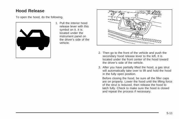
Hood ReleaseTo open the hood, do the following.
1. Pull the interior hoodrelease lever with thissymbol on it. It islocated under theinstrument panel onthe driver’s side of thevehicle.
2. Then go to the front of the vehicle and push thesecondary hood release lever to the left. It islocated under the front center of the hood towardthe driver’s side of the vehicle.
3. After you have partially lifted the hood, a gas strutwill automatically take over to lift and hold the hoodin the fully open position.Before closing the hood, be sure all the filler capsare on properly. Lower the hood until the lifting forceof the strut is reduced, then release the hood tolatch fully. Check to make sure the hood is closedand repeat the process if necessary.
5-11
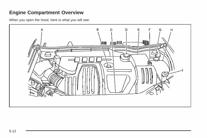
Engine Compartment OverviewWhen you open the hood, here is what you will see:
5-12
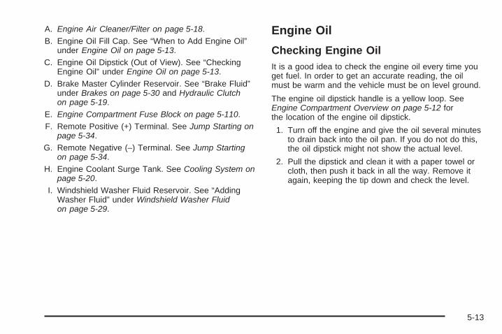
A. Engine Air Cleaner/Filter on page 5-18.B. Engine Oil Fill Cap. See “When to Add Engine Oil”
under Engine Oil on page 5-13.C. Engine Oil Dipstick (Out of View). See “Checking
Engine Oil” under Engine Oil on page 5-13.D. Brake Master Cylinder Reservoir. See “Brake Fluid”
under Brakes on page 5-30 and Hydraulic Clutchon page 5-19.
E. Engine Compartment Fuse Block on page 5-110.F. Remote Positive (+) Terminal. See Jump Starting on
page 5-34.G. Remote Negative (−) Terminal. See Jump Starting
on page 5-34.H. Engine Coolant Surge Tank. See Cooling System on
page 5-20.I. Windshield Washer Fluid Reservoir. See “Adding
Washer Fluid” under Windshield Washer Fluidon page 5-29.
Engine Oil
Checking Engine OilIt is a good idea to check the engine oil every time youget fuel. In order to get an accurate reading, the oilmust be warm and the vehicle must be on level ground.
The engine oil dipstick handle is a yellow loop. SeeEngine Compartment Overview on page 5-12 forthe location of the engine oil dipstick.
1. Turn off the engine and give the oil several minutesto drain back into the oil pan. If you do not do this,the oil dipstick might not show the actual level.
2. Pull the dipstick and clean it with a paper towel orcloth, then push it back in all the way. Remove itagain, keeping the tip down and check the level.
5-13

When to Add Engine Oil
If the oil is below the MIN (minimum) mark, add at leastone quart/liter of the recommended oil. This sectionexplains what kind of oil to use. For engine oil crankcasecapacity, see Capacities and Specifications onpage 5-113.
Notice: Do not add too much oil. If the enginehas so much oil that the oil level gets above theupper mark that shows the proper operating range,the engine could be damaged.
See Engine CompartmentOverview on page 5-12for the location of theengine oil fill cap.
Add enough oil to put the level somewhere in the properoperating range. Push the dipstick all the way back inwhen you are through.
5-14

What Kind of Engine Oil to UseLook for three things:
• GM6094M
Use only an oil that meets GM Standard GM6094M.
• SAE 5W-30
SAE 5W-30 is best for the vehicle. These numberson an oil container show its viscosity, or thickness.Do not use other viscosity oils such as SAE 20W-50.
• American Petroleum Institute (API) starburst symbol
Oils meeting theserequirements should havethe starburst symbol onthe container. This symbolindicates that the oilhas been certified by theAmerican PetroleumInstitute (API).
Notice: Use only engine oil identified as meetingGM Standard GM6094M and showing the AmericanPetroleum Institute Certified For Gasoline Enginesstarburst symbol. Failure to use the recommendedoil can result in engine damage not covered bythe vehicle warranty.
Cold Temperature OperationIf in an area of extreme cold, where the temperaturefalls below −20°F (−29°C), use either an SAE 5W-30synthetic oil or an SAE 0W-30 engine oil. Both provideeasier cold starting for the engine at extremely lowtemperatures. Always use an oil that meets the requiredspecification, GM6094M. See “What Kind of EngineOil to Use” for more information.
5-15
Engine Oil Additives / Engine OilFlushesDo not add anything to the oil. The recommended oilswith the starburst symbol that meet GM StandardGM6094M are all that is needed for good performanceand engine protection.
Engine oil system flushes are not recommended andcould cause engine damage not covered by the vehiclewarranty.
Engine Oil Life System
When to Change Engine OilThis vehicle has the Engine Oil Life System, a computersystem that indicates when to change the engine oiland filter. This is based on engine revolutions andengine temperature, and not on mileage. Based ondriving conditions, the mileage at which an oil change isindicated can vary considerably. For the oil life systemto work properly, the system must be reset everytime the oil is changed.
When the system has calculated that oil life has beendiminished, it indicates that an oil change is necessary.A CHANGE OIL SOON message comes on. See DICWarnings and Messages on page 3-42. Changethe oil as soon as possible within the next 600 miles(1 000 km). It is possible that, if driving under the bestconditions, the oil life system might not indicate thatan oil change is necessary for over a year. However, theengine oil and filter must be changed at least once ayear and at this time the system must be reset.Your dealer/retailer has trained service people who willperform this work using genuine parts and reset thesystem. It is also important to check the oil regularly andkeep it at the proper level.
If the system is ever reset accidentally, the oil must bechanged at 3,000 miles (5 000 km) since the last oilchange. Remember to reset the oil life system wheneverthe oil is changed.
5-16

How to Reset the Engine Oil LifeSystemThe Engine Oil Life System calculates when to changeyour engine oil and filter based on vehicle use. Wheneverthe oil is changed, reset the system so it can calculatewhen the next oil change is required. If a situation occurswhere the oil is changed prior to a CHANGE OIL SOONmessage being turned on, reset the system.
After changing the engine oil, the system must be reset:
1. Turn the ignition to ON/RUN, with the engine off.
2. Press the information and reset buttons on theDriver Information Center (DIC) at the sametime to enter the personalization menu. See DICVehicle Personalization on page 3-47.
3. Press the information button to scroll through theavailable personalization menu modes until theDIC display shows OIL-LIFE RESET.
4. Press and hold the reset button until the DICdisplay shows ACKNOWLEDGED. This will tell youthe system has been reset.
5. Turn the key to LOCK/OFF.
If the CHANGE OIL SOON message comes back onwhen the vehicle is started, the engine oil life systemhas not reset. Repeat the reset procedure.
What to Do with Used OilUsed engine oil contains certain elements that can beunhealthy for your skin and could even cause cancer.Do not let used oil stay on your skin for very long. Cleanyour skin and nails with soap and water, or a goodhand cleaner. Wash or properly dispose of clothing orrags containing used engine oil. See the manufacturer’swarnings about the use and disposal of oil products.
Used oil can be a threat to the environment. If youchange your own oil, be sure to drain all the oil from thefilter before disposal. Never dispose of oil by putting itin the trash, pouring it on the ground, into sewers, or intostreams or bodies of water. Recycle it by taking it to aplace that collects used oil.
5-17

Engine Air Cleaner/Filter
See Engine Compartment Overview on page 5-12 forthe location of the engine air cleaner/filter.
When to Inspect the Engine AirCleaner/FilterInspect the air cleaner/filter at the Maintenance IIintervals and replace it at the first oil change after each50,000 mile (80 000 km) interval. See ScheduledMaintenance on page 6-4 for more information. If youare driving in dusty/dirty conditions, inspect the filterat each engine oil change.
How to Inspect the Engine AirCleaner/FilterTo inspect the air cleaner/filter remove the filter from thevehicle and lightly shake the filter to release loose dustand dirt. If the filter remains caked with dirt, a new filter isrequired. Never use compressed air to clean the filter.
To inspect or replace the filter, remove the screws thathold the cover on and lift off the cover. Be sure toreinstall the cover tightly.
5-18
{CAUTION:
Operating the engine with the air cleaner/filter offcan cause you or others to be burned. The aircleaner not only cleans the air; it helps to stopflames if the engine backfires. If it is not there andthe engine backfires, you could be burned. Do notdrive with it off, and be careful working on theengine with the air cleaner/filter off.
Notice: If the air cleaner/filter is off, a backfire cancause a damaging engine fire. And, dirt can easily getinto the engine, which will damage it. Always havethe air cleaner/filter in place when you are driving.
Automatic Transmission Fluid
How to Check Automatic TransmissionFluidIt is not necessary to check the transmission fluidlevel. A transmission fluid leak is the only reason forfluid loss. If a leak occurs, take the vehicle to thedealer/retailer service department and have it repairedas soon as possible.
Change the fluid and filter at the intervals listed inAdditional Required Services on page 6-6, and be sureto use the fluid listed in Recommended Fluids andLubricants on page 6-12.
Notice: Use of the incorrect automatic transmissionfluid may damage the vehicle, and the damages maynot be covered by the vehicle’s warranty. Alwaysuse the automatic transmission fluid listed inRecommended Fluids and Lubricants on page 6-12.
Hydraulic ClutchThe hydraulic clutch linkage in your vehicle isself-adjusting. This system does not have its ownreservoir. It receives fluid from the brake master cylinderreservoir.
See Brakes on page 5-30 for more information.
5-19

Cooling SystemWhen you decide it is safe to lift the hood, here is whatyou will see:
A. Electric Engine Cooling FanB. Coolant Surge Tank and Pressure Cap
{CAUTION:
An electric engine cooling fan under the hood canstart up even when the engine is not running andcan cause injury. Keep hands, clothing, and toolsaway from any underhood electric fan.
If the coolant inside the coolant surge tank is boiling, donot do anything else until it cools down. The vehicleshould be parked on a level surface.
The coolant level should be at the COLD FILL line.If it is not, you may have a leak at the pressure cap orin the radiator hoses, heater hoses, radiator, waterpump, or somewhere in the cooling system.
5-20
{CAUTION:
Heater and radiator hoses, and other engine parts,can be very hot. Do not touch them. If you do, youcan be burned.
Do not run the engine if there is a leak. If you runthe engine, it could lose all coolant. That couldcause an engine fire, and you could be burned.Get any leak fixed before you drive the vehicle.
If there seems to be no leak, with the engine on,check to see if the electric engine cooling fan is running.If the engine is overheating, the fan should be running.If it is not, your vehicle needs service.
Notice: Engine damage from running the enginewithout coolant is not covered by the warranty.
Notice: Using coolant other than DEX-COOL® cancause premature engine, heater core, or radiatorcorrosion. In addition, the engine coolant couldrequire changing sooner, at 30,000 miles (50 000 km)or 24 months, whichever occurs first. Any repairswould not be covered by the vehicle warranty.Always use DEX-COOL® (silicate-free) coolant inthe vehicle.
5-21

How to Add Coolant to the CoolantSurge TankNotice: This vehicle has a specific coolant fillprocedure. Failure to follow this procedure couldcause the engine to overheat and be severelydamaged.If you have not found a problem yet, check to see ifcoolant is visible in the coolant surge tank. If coolant isvisible but the coolant level is not at the COLD FILLline, add a 50/50 mixture of clean, drinkable water andDEX-COOL® coolant at the coolant surge tank, butbe sure the cooling system, including the coolant surgetank pressure cap, is cool before you do it. SeeEngine Coolant on page 5-24 for more information.If no coolant is visible in the coolant surge tank,add coolant as follows:
{CAUTION:
Steam and scalding liquids from a hot coolingsystem can blow out and burn you badly. They areunder pressure, and if you turn the coolant surgetank pressure cap — even a little — they cancome out at high speed. Never turn the cap when
CAUTION: (Continued)
CAUTION: (Continued)
the cooling system, including the coolant surgetank pressure cap, is hot. Wait for the coolingsystem and coolant surge tank pressure cap tocool if you ever have to turn the pressure cap.
{CAUTION:
Adding only plain water to the cooling system canbe dangerous. Plain water, or some other liquidsuch as alcohol, can boil before the proper coolantmixture will. The vehicle’s coolant warning systemis set for the proper coolant mixture. With plainwater or the wrong mixture, the engine could gettoo hot but you would not get the overheatwarning. The engine could catch fire and you orothers could be burned. Use a 50/50 mixture ofclean, drinkable water and DEX-COOL® coolant.
Notice: In cold weather, water can freeze and crackthe engine, radiator, heater core and other parts.Use the recommended coolant and the propercoolant mixture.
5-22

{CAUTION:
You can be burned if you spill coolant on hotengine parts. Coolant contains ethylene glycol andit will burn if the engine parts are hot enough. Donot spill coolant on a hot engine.
1. You can remove the coolant surge tank pressurecap when the cooling system, including the coolantsurge tank pressure cap and upper radiatorhose, is no longer hot. Turn the pressure cap slowlycounterclockwise about two or two and one-halfturns. If you hear a hiss, wait for that to stop. Thiswill let any pressure still left to be vented outthe discharge hose.
2. Then keep turning thepressure cap slowly,and remove it.
3. Fill the coolant surge tank with the proper mixture,to the COLD FILL line. Wait about five minutes,then check to see if the level is below the COLDFILL line. If the level is below the line, add additionalcoolant to bring the level up to the line. Repeatthis procedure until the level remains constant at theCOLD FILL line for at least five minutes.
5-23

4. With the coolant surge tank pressure cap off, startthe engine and let it run until you can feel the upperradiator hose getting hot. Watch out for theengine cooling fan.By this time, the coolant level inside the coolantsurge tank may be lower. If the level is lower thanthe COLD FILL line, add more of the proper mixtureto the coolant surge tank until the level reachesthe COLD FILL line.
5. Then replace the pressure cap. Be sure thepressure cap is hand-tight and fully seated.See your dealer/retailer, if necessary.
Engine CoolantThe cooling system in your vehicle is filled withDEX-COOL® engine coolant. This coolant is designedto remain in your vehicle for five years or 150,000 miles(240 000 km), whichever occurs first, if you add onlyDEX-COOL® extended life coolant.The following explains your cooling system and how toadd coolant when it is low. If you have a problem withengine overheating, see Engine Overheating onpage 5-27.
A 50/50 mixture of clean, drinkable water andDEX-COOL® coolant will:
• Give freezing protection down to −34°F (−37°C).
• Give boiling protection up to 265°F (129°C).
• Protect against rust and corrosion.
• Help keep the proper engine temperature.
• Let the warning lights and gages work as theyshould.
Notice: Using coolant other than DEX-COOL® cancause premature engine, heater core, or radiatorcorrosion. In addition, the engine coolant mayrequire changing sooner, at the first maintenanceservice after each 30,000 miles (50 000 km) or24 months, whichever occurs first. Any repairs wouldnot be covered by the vehicle warranty. Always useDEX-COOL® (silicate-free) coolant in the vehicle.
5-24

What to UseUse a mixture of one-half clean, drinkable water andone-half DEX-COOL® coolant which will not damagealuminum parts. If you use this coolant mixture, you donot need to add anything else.
{CAUTION:
Adding only plain water to the cooling system canbe dangerous. Plain water, or some other liquidsuch as alcohol, can boil before the proper coolantmixture will. The vehicle’s coolant warning systemis set for the proper coolant mixture. With plainwater or the wrong mixture, the engine could gettoo hot but would not get the overheat warning.The engine could catch fire and you or otherscould be burned. Use a 50/50 mixture of clean,drinkable water and DEX-COOL® coolant.
Notice: If an improper coolant mixture is used,the engine could overheat and be badly damaged.The repair cost would not be covered by the vehiclewarranty. Too much water in the mixture can freezeand crack the engine, radiator, heater core, andother parts.
If you have to add coolant more than four times a year,have your dealer/retailer check your cooling system.
Notice: If extra inhibitors and/or additives are usedin the vehicle’s cooling system, the vehicle couldbe damaged. Use only the proper mixture ofthe engine coolant listed in this manual for thecooling system. See Recommended Fluids andLubricants on page 6-12 for more information.
5-25

Checking Coolant
The coolant surge tank is located in the enginecompartment on the driver’s side of the vehicle. SeeEngine Compartment Overview on page 5-12 for moreinformation on location.
{CAUTION:
Turning the surge tank pressure cap when theengine and radiator are hot can allow steam andscalding liquids to blow out and burn you badly.Never turn the surge tank pressure cap — even alittle — when the engine and radiator are hot.
The vehicle must be on a level surface. When yourengine is cold, the coolant level should be at the COLDFILL line.
5-26

Adding CoolantIf you need more coolant, add the proper DEX-COOL®
coolant mixture at the coolant surge tank, but onlywhen the engine is cool. If the coolant surge tank isempty, a special fill procedure is necessary. See EngineOverheating on page 5-27 for instructions on “How toAdd Coolant to the Coolant Surge Tank.”
{CAUTION:
You can be burned if you spill coolant on hotengine parts. Coolant contains ethylene glycol,and it will burn if the engine parts are hot enough.Do not spill coolant on a hot engine.
When replacing the pressure cap, make sure it ishand-tight and fully seated.
Coolant Surge Tank Pressure CapNotice: If the pressure cap is not tightly installed,coolant loss and possible engine damage mayoccur. Be sure the cap is properly and tightlysecured.
The coolant surge tank pressure cap must be fullyinstalled on the coolant surge tank. See EngineCompartment Overview on page 5-12 for moreinformation on location.
Engine OverheatingYou will find an engine coolant temperature warninglight on your vehicle’s instrument panel. See EngineCoolant Temperature Warning Light on page 3-33 formore information.
5-27

If Steam Is Coming From Your Engine
{CAUTION:
Steam from an overheated engine can burn youbadly, even if you just open the hood. Stay awayfrom the engine if you see or hear steam comingfrom it. Just turn it off and get everyone awayfrom the vehicle until it cools down. Wait untilthere is no sign of steam or coolant before youopen the hood.
If you keep driving when your engine isoverheated, the liquids in it can catch fire. You orothers could be badly burned. Stop your engine ifit overheats, and get out of the vehicle until theengine is cool.
Notice: If the engine catches fire because of beingdriven with no coolant, your vehicle can be badlydamaged. The costly repairs would not be coveredby the vehicle warranty.
If No Steam Is Coming From YourEngineAn engine coolant temperature warning can indicate aserious problem. See Engine Coolant TemperatureWarning Light on page 3-33.
If you get an engine coolant temperature warning, butsee or hear no steam, the problem may not be tooserious. Sometimes the engine can get a little too hotwhen you:
• Climb a long hill on a hot day.
• Stop after high-speed driving.
• Idle for long periods in traffic.
• Tow a trailer.
If you get the engine coolant temperature warning withno sign of steam, try this for a minute or so:
1. If you have an air conditioner and it is on, turn it off.
2. In heavy traffic, let the engine idle in N (Neutral) forautomatic transmission or NEUTRAL for manualtransmission, while stopped. If it is safe to do so, pulloff the road, shift to P (Park) or N (Neutral) and letthe engine idle.
3. Turn on your heater to full hot at the highest fanspeed and open the windows as necessary.
5-28
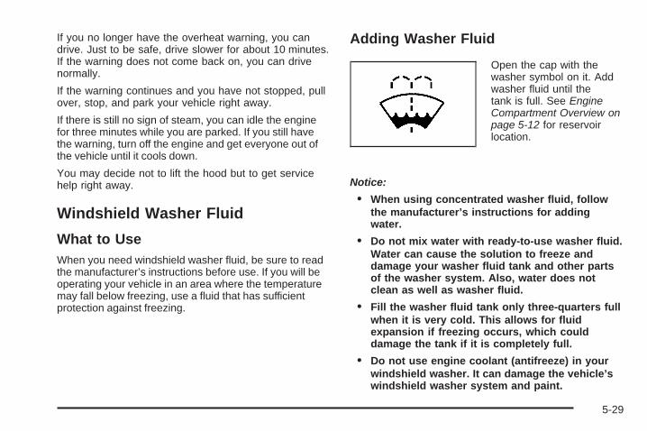
If you no longer have the overheat warning, you candrive. Just to be safe, drive slower for about 10 minutes.If the warning does not come back on, you can drivenormally.
If the warning continues and you have not stopped, pullover, stop, and park your vehicle right away.
If there is still no sign of steam, you can idle the enginefor three minutes while you are parked. If you still havethe warning, turn off the engine and get everyone out ofthe vehicle until it cools down.
You may decide not to lift the hood but to get servicehelp right away.
Windshield Washer Fluid
What to UseWhen you need windshield washer fluid, be sure to readthe manufacturer’s instructions before use. If you will beoperating your vehicle in an area where the temperaturemay fall below freezing, use a fluid that has sufficientprotection against freezing.
Adding Washer Fluid
Open the cap with thewasher symbol on it. Addwasher fluid until thetank is full. See EngineCompartment Overview onpage 5-12 for reservoirlocation.
Notice:
• When using concentrated washer fluid, followthe manufacturer’s instructions for addingwater.
• Do not mix water with ready-to-use washer fluid.Water can cause the solution to freeze anddamage your washer fluid tank and other partsof the washer system. Also, water does notclean as well as washer fluid.
• Fill the washer fluid tank only three-quarters fullwhen it is very cold. This allows for fluidexpansion if freezing occurs, which coulddamage the tank if it is completely full.
• Do not use engine coolant (antifreeze) in yourwindshield washer. It can damage the vehicle’swindshield washer system and paint.
5-29

Brakes
Brake Fluid
The brake mastercylinder and, on manualtransmission vehicles, theclutch hydraulic system usethe same reservoir filledwith DOT-3 brake fluid.
See Engine Compartment Overview on page 5-12 forthe location of the reservoir.
There are only two reasons why the brake fluid level inthe reservoir might go down:
• The brake fluid level goes down because of normalbrake lining wear. When new linings are installed,the fluid level goes back up.
• A fluid leak in the brake and/or clutch hydraulicsystem can also cause a low fluid level. Havethe brake and/or clutch hydraulic system fixed, sincea leak means that sooner or later the brakesand/or clutch will not work well.
Do not top off the brake/clutch fluid. Adding fluid doesnot correct a leak. If fluid is added when the brakelinings are worn, there will be too much fluid when newbrake linings are installed. Add or remove fluid, asnecessary, only when work is done on the brake/clutchhydraulic system.
{CAUTION:
If too much brake fluid is added, it can spill on theengine and burn, if the engine is hot enough. Youor others could be burned, and the vehicle couldbe damaged. Add brake fluid only when work isdone on the brake and/or clutch hydraulic system.
When the brake fluid falls to a low level, the brakewarning light comes on. See Brake System WarningLight on page 3-30.
5-30
What to AddUse only new DOT-3 brake fluid from a sealedcontainer. See Recommended Fluids and Lubricants onpage 6-12.
Always clean the brake fluid reservoir cap and the areaaround the cap before removing it. This helps keepdirt from entering the reservoir.
{CAUTION:
With the wrong kind of fluid in the brake or clutchhydraulic system, the brakes or clutch might notwork well. This could cause a crash. Always usethe proper brake fluid.
Notice:
• Using the wrong fluid can badly damage brakeor clutch hydraulic system parts. For example,just a few drops of mineral-based oil, suchas engine oil, in the brake or clutch hydraulicsystem can damage brake or clutch hydraulicsystem parts so badly that they will haveto be replaced. Do not let someone put in thewrong kind of fluid.
• If brake fluid is spilled on the vehicle’s paintedsurfaces, the paint finish can be damaged. Becareful not to spill brake fluid on the vehicle.If you do, wash it off immediately. See WashingYour Vehicle on page 5-102.
5-31

Brake WearThis vehicle has front disc brakes and could have reardrum brakes or rear disc brakes.
Disc brake pads have built-in wear indicators that makea high-pitched warning sound when the brake padsare worn and new pads are needed. The soundcan come and go or be heard all the time the vehicle ismoving, except when applying the brake pedal firmly.
{CAUTION:
The brake wear warning sound means that soonthe brakes will not work well. That could lead to anaccident. When the brake wear warning sound isheard, have the vehicle serviced.
Notice: Continuing to drive with worn-out brakepads could result in costly brake repair.
Some driving conditions or climates can cause a brakesqueal when the brakes are first applied or lightlyapplied. This does not mean something is wrong withthe brakes.
Properly torqued wheel nuts are necessary to helpprevent brake pulsation. When tires are rotated, inspectbrake pads for wear and evenly tighten wheel nuts inthe proper sequence to torque specifications inCapacities and Specifications on page 5-113.
If the vehicle has rear drum brakes, they do not havewear indicators, but if a rear brake rubbing noise is heard,have the rear brake linings inspected immediately. Rearbrake drums should be removed and inspected each timethe tires are removed for rotation or changing. When thefront brake pads are replaced, have the rear brakesinspected, too.
Brake linings should always be replaced as completeaxle sets.
Brake Pedal TravelSee your dealer/retailer if the brake pedal does notreturn to normal height, or if there is a rapid increase inpedal travel. This could be a sign that brake servicemight be required.
5-32

Brake AdjustmentEvery moderate brake stop, the disc brakes adjust forwear. If rarely making moderate or heavier brake stops,the brakes might not adjust correctly. Very carefullymaking a few moderate brake stops about every1,000 miles (1 600 km) will adjust the brakes properly.
If the vehicle has rear drum brakes and the brake pedalgoes down farther than normal, the rear drum brakesmight need adjustment. Adjust them by backing up andfirmly applying the brakes a few times.
Replacing Brake System PartsThe braking system on a vehicle is complex. Its manyparts have to be of top quality and work well together ifthe vehicle is to have really good braking. The vehiclewas designed and tested with top-quality brake parts.When parts of the braking system are replaced — forexample, when the brake linings wear down and newones are installed — be sure to get new approvedreplacement parts. If this is not done, the brakes might
not work properly. For example, if someone puts in brakelinings that are wrong for the vehicle, the balancebetween the front and rear brakes can change — for theworse. The braking performance expected can change inmany other ways if the wrong replacement brake partsare installed.
BatteryThis vehicle has a maintenance free battery. When it istime for a new battery, see your dealer/retailer forone that has the replacement number shown on theoriginal battery’s label.
The battery is located in the trunk. Access to the batteryis not necessary to jump start the vehicle. See JumpStarting on page 5-34.Warning: Battery posts, terminals, and relatedaccessories contain lead and lead compounds,chemicals known to the State of California to causecancer and reproductive harm. Wash hands afterhandling.
5-33
Vehicle Storage
{CAUTION:
Batteries have acid that can burn you and gas thatcan explode. You can be badly hurt if you are notcareful. See Jump Starting on page 5-34 for tipson working around a battery without getting hurt.
Infrequent Usage: If the vehicle is driven infrequently,remove the black, negative (−) cable from the battery.This helps keep the battery from running down.
Extended Storage: For extended storage of the vehicle,remove the black, negative (−) cable from the battery oruse a battery trickle charger. This helps maintain thecharge of the battery over an extended period of time.
Jump StartingIf the vehicle’s battery has run down, you may want touse another vehicle and some jumper cables to start thevehicle. Be sure to use the following steps to do it safely.
{CAUTION:
Batteries can hurt you. They can be dangerousbecause:
• They contain acid that can burn you.• They contain gas that can explode or ignite.• They contain enough electricity to burn you.
If you do not follow these steps exactly, some orall of these things can hurt you.
Notice: Ignoring these steps could result in costlydamage to the vehicle that would not be coveredby the warranty.
Trying to start the vehicle by pushing or pulling itwill not work, and it could damage the vehicle.
1. Check the other vehicle. It must have a 12-voltbattery with a negative ground system.
5-34

Notice: If the other vehicle’s system is not a 12-voltsystem with a negative ground, both vehicles canbe damaged. Only use vehicles with 12-volt systemswith negative grounds to jump start your vehicle.
2. Get the vehicles close enough so the jumper cablescan reach, but be sure the vehicles are not touchingeach other. If they are, it could cause a groundconnection you do not want. You would not be ableto start the vehicle, and the bad grounding coulddamage the electrical systems.To avoid the possibility of the vehicles rolling, setthe parking brake firmly on both vehicles involved inthe jump start procedure. Put an automatictransmission in P (Park) or a manual transmissionin N (Neutral) before setting the parking brake.
Notice: If you leave the radio or other accessorieson during the jump starting procedure, they could bedamaged. The repairs would not be covered by thewarranty. Always turn off the radio and otheraccessories when jump starting the vehicle.
3. Turn off the ignition on both vehicles. Unplugunnecessary accessories plugged into the cigarettelighter or the accessory power outlet. Turn offthe radio and all lamps that are not needed. Thiswill avoid sparks and help save both batteries. Andit could save the radio!
4. Open the hood on the other vehicle and locate thepositive (+) and negative (−) terminal locations onthat vehicle.You will not see the battery of your vehicle under thehood. It is located in the trunk. You will not need toaccess your battery for jump starting. The vehicle hasa remote positive (+) and a remote negative (−) jumpstarting terminal.
Locate the remotepositive (+) terminal whichis located under a redtethered cap on the enginecompartment fuse block.Lift the cap to accessthe terminal.
5-35

Locate the remotenegative (−) groundterminal, marked GND (−),which is located behindthe engine coolantsurge tank.
See Engine Compartment Overview on page 5-12for more information on the location of thepositive (+) and negative (−) terminals on thevehicle.
{CAUTION:
An electric fan can start up even when the engineis not running and can injure you. Keep hands,clothing and tools away from any underhoodelectric fan.
{CAUTION:
Using a match near a battery can cause batterygas to explode. People have been hurt doing this,and some have been blinded. Use a flashlight ifyou need more light.
Be sure the battery has enough water. You do notneed to add water to the battery installed in yournew vehicle. But if a battery has filler caps, besure the right amount of fluid is there. If it is low,add water to take care of that first. If you don’t,explosive gas could be present.
Battery fluid contains acid that can burn you.Do not get it on you. If you accidentally get it inyour eyes or on your skin, flush the place withwater and get medical help immediately.
5-36

{CAUTION:
Fans or other moving engine parts can injure youbadly. Keep your hands away from moving partsonce the engine is running.
5. Check that the jumper cables do not have loose ormissing insulation. If they do, you could get ashock. The vehicles could be damaged too.Before you connect the cables, here are somebasic things you should know. Positive (+) will go topositive (+) or to a remote positive (+) terminal ifthe vehicle has one. Negative (−) will go to a heavy,unpainted metal engine part or to a remotenegative (−) terminal if the vehicle has one.Do not connect positive (+) to negative (−) or youwill get a short that would damage the batteryand maybe other parts too. And do not connect thenegative (−) cable to the negative (−) terminal onthe dead battery because this can cause sparks.
6. Connect the red positive (+) cable to the positive (+)terminal location on the vehicle with the deadbattery. Use a remote positive (+) terminal if thevehicle has one.
7. Do not let the other end touch metal. Connect it tothe positive (+) terminal of the good battery. Use aremote positive (+) terminal if the vehicle has one.
8. Now connect the black negative (−) cable to thenegative (−) terminal of the good battery. Use aremote negative (−) terminal if the vehicle has one.Do not let the other end touch anything until thenext step. The other end of the negative (−) cabledoes not go to the dead battery. It goes to aheavy, unpainted metal engine part or to a remotenegative (−) terminal on the vehicle with thedead battery.
9. Connect the other end of the negative (−) cable tothe negative (−) terminal location on the vehicle withthe dead battery. Your vehicle has a remotenegative (−) terminal marked GND (−).
10. Now start the vehicle with the good battery and runthe engine for a while.
11. Try to start the vehicle that had the dead battery.If it will not start after a few tries, it probably needsservice.
5-37

Notice: If the jumper cables are connected orremoved in the wrong order, electrical shorting mayoccur and damage the vehicle. The repairs wouldnot be covered by your warranty. Always connectand remove the jumper cables in the correctorder, making sure that the cables do not toucheach other or other metal.
A. Heavy, Unpainted Metal Engine Part or RemoteNegative (−) Terminal (GND)
B. Good Battery or Remote Positive (+) and RemoteNegative (−) Terminals
C. Dead Battery or Remote Positive (+) Terminal
To disconnect the jumper cables from both vehicles:
1. Disconnect the black negative (−) cable fromthe vehicle that had the dead battery.
2. Disconnect the black negative (−) cable from thevehicle with the good battery.
3. Disconnect the red positive (+) cable from thevehicle with the good battery.
4. Disconnect the red positive (+) cable from the othervehicle.
5. Return the positive (+) terminal cover to its originalposition.
Jumper Cable Removal
5-38

Headlamp AimingThe optical headlamp aiming system has been preset atthe factory and should need no further adjustment
However, If the vehicle is damaged, the headlamp aimmay be affected and adjustment may be necessary.
If oncoming vehicles flash their high beams at you, thismay also mean the vertical aim needs to be adjusted.
It is recommended that the vehicle is taken to yourdealer/retailer for service if the headlamps need to bere-aimed. It is possible however, to re-aim theheadlamps as described.
The vehicle should be:
• Placed so the headlamps are 25 ft. (7.6 m) from alight colored wall.
• On a perfectly level surface which is level all theway to the wall.
• Placed so it is at a right angle to the wall.
• Clear of any snow, ice, or mud on it.
• Fully assembled, with the tires properly inflated, andall other work stopped while headlamp aiming isbeing done.
• Normally loaded with a full tank of fuel, with thespare tire in the proper location, and one personor 160 lbs (75 kg) on the driver seat.
Headlamp aiming is done with the vehicle’s low-beamheadlamps. The high-beam headlamps will be correctlyaimed if the low-beam headlamps are aimed properly.
To adjust the vertical aim on the headlamps:
1. Open the hood. See Hood Release on page 5-11.
2. Record the distance from the ground to the aim doton the low-beam headlamp.
5-39

3. At the wall, measure from the ground upward (A) tothe recorded distance from Step 2 and mark it.
4. Draw or tape a horizontal line (B) on the wall thewidth of the vehicle at the height of the mark inStep 3.
Notice: Do not cover a headlamp to improve beamcut-off when aiming. Covering a headlamp maycause excessive heat build-up which may causedamage to the headlamp.
5. Turn on the low-beam headlamps and place apiece of cardboard in front of the headlamp notbeing adjusted. Do not place it directly on theheadlamp. This allows only the beam of light fromthe headlamp being adjusted to be seen on theflat surface.
6. Locate the vertical headlamp aiming screws, whichare under the hood near each headlamp assembly.The adjustment screw can be turned with a 6 mmsocket wrench.
7. Turn the vertical aiming screw until the headlampbeam is aimed to the horizontal tape line. Turn itclockwise or counterclockwise to raise or lower theangle of the beam.
5-40
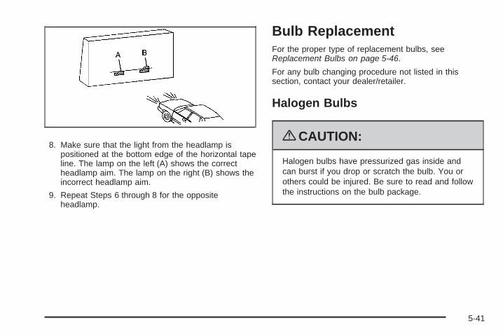
8. Make sure that the light from the headlamp ispositioned at the bottom edge of the horizontal tapeline. The lamp on the left (A) shows the correctheadlamp aim. The lamp on the right (B) shows theincorrect headlamp aim.
9. Repeat Steps 6 through 8 for the oppositeheadlamp.
Bulb ReplacementFor the proper type of replacement bulbs, seeReplacement Bulbs on page 5-46.
For any bulb changing procedure not listed in thissection, contact your dealer/retailer.
Halogen Bulbs
{CAUTION:
Halogen bulbs have pressurized gas inside andcan burst if you drop or scratch the bulb. You orothers could be injured. Be sure to read and followthe instructions on the bulb package.
5-41

Headlamps, Front Turn Signal,Sidemarker, and Parking Lamps
A. Front Turn Signal/Parking LampB. SidemarkerC. Headlamp
To replace one of these bulbs:
1. Open the hood. See Hood Release on page 5-11.
2. Remove the two bolts from the headlamp assembly.
3. Remove the two fasteners from the fascia.Assistance may be needed for Steps 4 and 5.
4. Pull the front fascia back.
5. Pull the headlamp assembly up at an angle andtowards the radiator to remove it.
5-42

6. Disconnect the bulb base from the wiring harnessby lifting the locking tab.
7. Disconnect the wiring harness from the bulb socket.
8. Remove the retainer by turning it counterclockwise.
9. Turn the bulb socket for the headlamp, frontturn signal, or parking lamp counterclockwise.For the sidemarker bulb, use a tool to assistin turning the bulb socket.
10. Pull the old bulb out of the socket.
11. Install a new bulb.
12. Reinstall the bulb assembly by reversing Steps 1through 9.When reinstalling the headlamp assembly, firstmake sure that the wiring harness is in its originalposition. If not, the headlamp assembly will notfit correctly.Align the two tabs on the bottom of the assemblythat fit into two slots in the headlamp assemblybracket.
Center High-Mounted Stoplamp(CHMSL)To replace a CHMSL bulb:1. Open the trunk.2. Press the tabs to release the bulb assembly.
3. Pull the bulb assembly down to access the bulbs.
4. Pull the old bulb straight out.
5. Push the new bulb straight in until it clicks.
6. Align the tabs in the bulb assembly with theassembly in the trunk lid. Push the bulb assemblyback into place until it snaps in. You may needto use a tool to guide the tabs into the assembly.
5-43

Taillamps and Turn Signal Lamps(Coupe)To replace a taillamp or rear turn signal bulb:
1. Open the trunk. See Trunk on page 2-12 for moreinformation.
2. Remove the screw retaining the taillamp assembly.
3. Disconnect the wiring harness by lifting up onthe tab to release and pull it straight out.
4. Hold and turn the bulb socket clockwise and thenrelease it from the lamp housing.
5. Pull the old bulb straight out of the socket.
6. Install a new bulb.
7. Reverse Steps 2 through 4 to reinstall the taillampassembly.
Taillamps, Turn Signal, Stoplampsand Back-up Lamps (Sedan)To replace one of these bulbs:
1. Open the trunk.
2. Remove the trunk trim and pull back fastener.
3. Remove the additional fastener.
4. Remove the outer two screws from the taillampassembly.
5. Lift up on the tab and pull the wiring harnessstraight out.
6. Remove the taillamp assembly from the quarterpanel.
A. SidemarkerB. Stoplamp/Turn Signal/TaillampC. Back-up
7. Turn the bulb socket counterclockwise and pull itstraight out.
8. Pull the old bulb straight out of the socket.
5-44

9. Push the new bulb straight into the socket.10. Push the new bulb into the taillamp assembly and
turn it clockwise to lock it into place.11. Reinstall the taillamp assembly into the quarter
panel.12. Push the wiring harness straight into the taillamp
assembly and push the tab down.13. Reinstall the outer two screws into the taillamp
assembly.14. Reinstall the trunk trim and the fasteners.
Back-Up Lamps (Coupe)To replace a back-up lamp bulb:
1. Remove the two screws from the face of theback-up lamp.
2. Pull the lamp straight out from the fascia pocket.
3. Hold and turn the bulb socket clockwise and thenrelease it from the lamp housing.
4. Pull the old bulb out of the socket.
5. Push the new bulb straight into the bulb socket untilit clicks.
6. Push the bulb socket into the housing and turn itclockwise to lock it into place.
7. Push the lamp straight into the fascia pocket.
8. Reinstall the two screws into the face of theback-up lamp.
5-45

License Plate LampTo replace one of these bulbs:
1. Remove the two screws holding each of the licenseplate lamps.
2. Turn and pull the license plate lamp toward youthrough the opening.
3. Turn the bulb socket counterclockwise and pull thebulb straight out of the socket.
4. Install the new bulb.
5. Push the bulb straight into the socket and turnclockwise to reinstall.
6. Push and turn the license plate lamp away fromyou through the opening.
7. Reinstall the two screws holding the licenseplate lamp.
Replacement Bulbs
Exterior Lamps Bulb NumberBack-Up Lamps 921Center High-MountedStoplamp (CHMSL) 912
Front Parking/Turn Signal Lamps 3157KXHalogen Headlamps,High/Low-Beam 9007 LL
License Plate Lamp andSidemarker 194
Stoplamp, Taillamp and TurnSignal Lamps 3057KX
For replacement bulbs not listed here, contact yourdealer/retailer.
5-46

Windshield Wiper BladeReplacementWindshield wiper blades should be inspected for wearor cracking. See Scheduled Maintenance on page 6-4for more information on wiper blade inspection.
Replacement blades come in different types and areremoved in different ways. For proper type and length,see Maintenance Replacement Parts on page 6-14.
Here is how to remove the wiper blades:
1. Pull the windshield wiper arm away from thewindshield.
2. Push the release lever and slide the wiper assemblytoward the driver side of the vehicle.
3. Install a new blade by reversing Steps 1 and 2.
5-47

TiresYour new vehicle comes with high-quality tiresmade by a leading tire manufacturer. If you everhave questions about your tire warranty and whereto obtain service, see your vehicle Warrantybooklet for details. For additional information referto the tire manufacturer.
{CAUTION:
Poorly maintained and improperly used tiresare dangerous.
• Overloading your vehicle’s tires cancause overheating as a result of toomuch flexing. You could have an air-outand a serious accident. See Loading theVehicle on page 4-24.
CAUTION: (Continued)
CAUTION: (Continued)
• Underinflated tires pose the same dangeras overloaded tires. The resultingaccident could cause serious injury.Check all tires frequently to maintain therecommended pressure. Tire pressureshould be checked when your vehicle’stires are cold. See Inflation - TirePressure on page 5-56.
• Overinflated tires are more likely to becut, punctured, or broken by a suddenimpact — such as when you hit apothole. Keep tires at the recommendedpressure.
• Worn, old tires can cause accidents. Ifthe tire’s tread is badly worn, or if yourvehicle’s tires have been damaged,replace them.
5-48
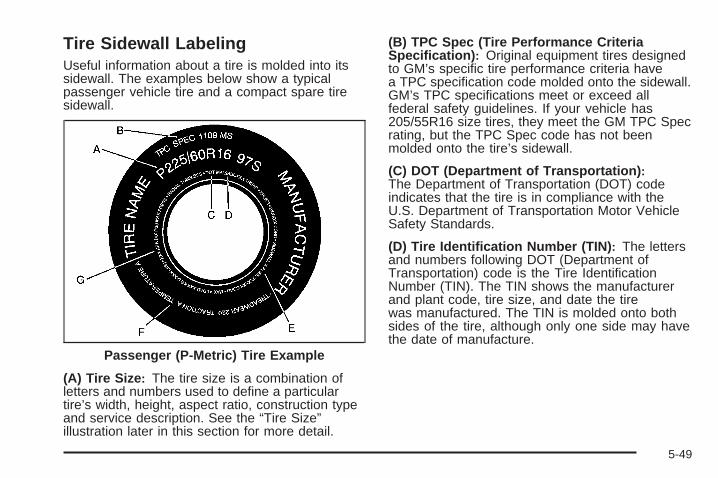
Tire Sidewall LabelingUseful information about a tire is molded into itssidewall. The examples below show a typicalpassenger vehicle tire and a compact spare tiresidewall.
(A) Tire Size: The tire size is a combination ofletters and numbers used to define a particulartire’s width, height, aspect ratio, construction typeand service description. See the “Tire Size”illustration later in this section for more detail.
(B) TPC Spec (Tire Performance CriteriaSpecification): Original equipment tires designedto GM’s specific tire performance criteria havea TPC specification code molded onto the sidewall.GM’s TPC specifications meet or exceed allfederal safety guidelines. If your vehicle has205/55R16 size tires, they meet the GM TPC Specrating, but the TPC Spec code has not beenmolded onto the tire’s sidewall.
(C) DOT (Department of Transportation):The Department of Transportation (DOT) codeindicates that the tire is in compliance with theU.S. Department of Transportation Motor VehicleSafety Standards.
(D) Tire Identification Number (TIN): The lettersand numbers following DOT (Department ofTransportation) code is the Tire IdentificationNumber (TIN). The TIN shows the manufacturerand plant code, tire size, and date the tirewas manufactured. The TIN is molded onto bothsides of the tire, although only one side may havethe date of manufacture.
Passenger (P-Metric) Tire Example
5-49
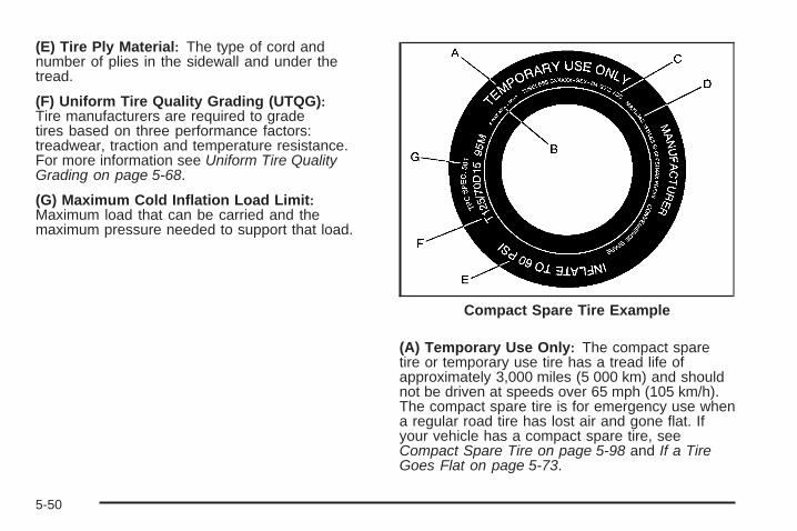
(E) Tire Ply Material: The type of cord andnumber of plies in the sidewall and under thetread.
(F) Uniform Tire Quality Grading (UTQG):Tire manufacturers are required to gradetires based on three performance factors:treadwear, traction and temperature resistance.For more information see Uniform Tire QualityGrading on page 5-68.
(G) Maximum Cold Inflation Load Limit:Maximum load that can be carried and themaximum pressure needed to support that load.
(A) Temporary Use Only: The compact sparetire or temporary use tire has a tread life ofapproximately 3,000 miles (5 000 km) and shouldnot be driven at speeds over 65 mph (105 km/h).The compact spare tire is for emergency use whena regular road tire has lost air and gone flat. Ifyour vehicle has a compact spare tire, seeCompact Spare Tire on page 5-98 and If a TireGoes Flat on page 5-73.
Compact Spare Tire Example
5-50

(B) Tire Ply Material: The type of cord andnumber of plies in the sidewall and under thetread.
(C) Tire Identification Number (TIN): The lettersand numbers following the DOT (Department ofTransportation) code is the Tire IdentificationNumber (TIN). The TIN shows the manufacturerand plant code, tire size, and date the tirewas manufactured. The TIN is molded onto bothsides of the tire, although only one side may havethe date of manufacture.
(D) Maximum Cold Inflation Load Limit:Maximum load that can be carried and themaximum pressure needed to support that load.
(E) Tire Inflation: The temporary use tire orcompact spare tire should be inflated to 60 psi(420 kPa). For more information on tire pressureand inflation see Inflation - Tire Pressure onpage 5-56.
(F) Tire Size : A combination of letters andnumbers define a tire’s width, height, aspect ratio,construction type and service description. Theletter T as the first character in the tire size meansthe tire is for temporary use only.
(G) TPC Spec (Tire Performance CriteriaSpecification): Original equipment tires designedto GM’s specific tire performance criteria havea TPC specification code molded onto the sidewall.GM’s TPC specifications meet or exceed allfederal safety guidelines.
5-51

Tire SizeThe following illustration shows an example of atypical passenger vehicle tire size.
(A) Passenger (P-Metric) Tire: The United Statesversion of a metric tire sizing system. The letter Pas the first character in the tire size means apassenger vehicle tire engineered to standards setby the U.S. Tire and Rim Association. A tire sizewithout the letter P as the first character is certifiedto European standards.
(B) Tire Width: The three-digit number indicatesthe tire section width in millimeters from sidewallto sidewall.
(C) Aspect Ratio: A two-digit number thatindicates the tire height-to-width measurements.For example, if the tire size aspect ratio is 60, asshown in item C of the illustration, it would meanthat the tire’s sidewall is 60 percent as high asit is wide.
(D) Construction Code: A letter code is usedto indicate the type of ply construction in thetire. The letter R means radial ply construction;the letter D means diagonal or bias ply construction;and the letter B means belted-bias ply construction.
(E) Rim Diameter: Diameter of the wheel ininches.
(F) Service Description: These charactersrepresent the load range and speed rating of thetire. The load index represents the load carrycapacity a tire is certified to carry. The load indexcan range from 1 to 279. The speed rating isthe maximum speed a tire is certified to carry aload. Speed ratings range from A to Z.
5-52
Tire Terminology and Definitions
Air Pressure: The amount of air inside thetire pressing outward on each square inch of thetire. Air pressure is expressed in pounds persquare inch (psi) or kilopascal (kPa).
Accessory Weight: This means the combinedweight of optional accessories. Some examples ofoptional accessories are, automatic transmission,power steering, power brakes, power windows,power seats, and air conditioning.
Aspect Ratio: The relationship of a tire’s heightto its width.
Belt: A rubber coated layer of cords that is locatedbetween the plies and the tread. Cords may bemade from steel or other reinforcing materials.
Bead: The tire bead contains steel wires wrappedby steel cords that hold the tire onto the rim.
Bias Ply Tire: A pneumatic tire in which the pliesare laid at alternate angles less than 90 degreesto the centerline of the tread.
Cold Tire Pressure: The amount of air pressure ina tire, measured in pounds per square inch (psi) orkilopascals (kPa) before a tire has built up heatfrom driving. See Inflation - Tire Pressure onpage 5-56.
Curb Weight: The weight of a motor vehicle withstandard and optional equipment including themaximum capacity of fuel, oil, and coolant,but without passengers and cargo.
DOT Markings: A code molded into the sidewallof a tire signifying that the tire is in compliancewith the U.S. Department of Transportation (DOT)motor vehicle safety standards. The DOT codeincludes the Tire Identification Number (TIN),an alphanumeric designator which can also identifythe tire manufacturer, production plant, brand,and date of production.
GVWR: Gross Vehicle Weight Rating. SeeLoading the Vehicle on page 4-24.
GAWR FRT: Gross Axle Weight Rating for thefront axle. See Loading the Vehicle on page 4-24.
GAWR RR: Gross Axle Weight Rating for therear axle. See Loading the Vehicle on page 4-24.
5-53

Intended Outboard Sidewall: The side of anasymmetrical tire, that must always face outwardwhen mounted on a vehicle.
Kilopascal (kPa): The metric unit for air pressure.
Light Truck (LT-Metric) Tire: A tire used onlight duty trucks and some multipurpose passengervehicles.
Load Index: An assigned number ranging from1 to 279 that corresponds to the load carryingcapacity of a tire.
Maximum Inflation Pressure: The maximum airpressure to which a cold tire can be inflated.The maximum air pressure is molded onto thesidewall.
Maximum Load Rating: The load rating for a tireat the maximum permissible inflation pressurefor that tire.
Maximum Loaded Vehicle Weight: The sum ofcurb weight, accessory weight, vehicle capacityweight, and production options weight.
Normal Occupant Weight: The number ofoccupants a vehicle is designed to seat multipliedby 150 lbs (68 kg). See Loading the Vehicle onpage 4-24.
Occupant Distribution: Designated seatingpositions.
Outward Facing Sidewall: The side of anasymmetrical tire that has a particular side thatfaces outward when mounted on a vehicle.The side of the tire that contains a whitewall, bearswhite lettering, or bears manufacturer, brand,and/or model name molding that is higheror deeper than the same moldings on the othersidewall of the tire.
Passenger (P-Metric) Tire: A tire used onpassenger cars and some light duty trucks andmultipurpose vehicles.
Recommended Inflation Pressure: Vehiclemanufacturer’s recommended tire inflationpressure as shown on the tire placard. SeeInflation - Tire Pressure on page 5-56 and Loadingthe Vehicle on page 4-24.
5-54

Radial Ply Tire: A pneumatic tire in which theply cords that extend to the beads are laid at90 degrees to the centerline of the tread.
Rim: A metal support for a tire and upon whichthe tire beads are seated.
Sidewall: The portion of a tire between the treadand the bead.
Speed Rating: An alphanumeric code assigned toa tire indicating the maximum speed at which atire can operate.
Traction: The friction between the tire and theroad surface. The amount of grip provided.
Tread: The portion of a tire that comes intocontact with the road.
Treadwear Indicators: Narrow bands, sometimescalled wear bars, that show across the tread ofa tire when only 1/16 inch (1.6 mm) of treadremains. See When It Is Time for New Tires onpage 5-65.
UTQGS (Uniform Tire Quality GradingStandards): A tire information system thatprovides consumers with ratings for a tire’straction, temperature, and treadwear. Ratingsare determined by tire manufacturers usinggovernment testing procedures. The ratings aremolded into the sidewall of the tire. See UniformTire Quality Grading on page 5-68.
Vehicle Capacity Weight: The number ofdesignated seating positions multiplied by 150 lbs(68 kg) plus the rated cargo load. See Loadingthe Vehicle on page 4-24.
Vehicle Maximum Load on the Tire: Load on anindividual tire due to curb weight, accessoryweight, occupant weight, and cargo weight.
Vehicle Placard: A label permanently attachedto a vehicle showing the vehicle’s capacityweight and the original equipment tire size andrecommended inflation pressure. See “Tireand Loading Information Label” under Loading theVehicle on page 4-24.
5-55
Inflation - Tire PressureTires need the correct amount of air pressure tooperate effectively.
Notice: Do not let anyone tell you thatunder-inflation or over-inflation is all right. It isnot. If your tires do not have enough air(under-inflation), you can get the following:• Too much flexing• Too much heat• Tire overloading• Premature or irregular wear• Poor handling• Reduced fuel economy
If your tires have too much air (over-inflation),you can get the following:• Unusual wear• Poor handling• Rough ride• Needless damage from road hazards
A vehicle specific Tire and Loading Informationlabel is attached to your vehicle. This label showsyour vehicle’s original equipment tires and thecorrect inflation pressures for your tires when theyare cold. The recommended cold tire inflationpressure, shown on the label, is the minimumamount of air pressure needed to supportyour vehicle’s maximum load carrying capacity.
For additional information regarding how muchweight your vehicle can carry, and an example ofthe Tire and Loading Information label, seeLoading the Vehicle on page 4-24. How you loadyour vehicle affects vehicle handling and ridecomfort. Never load your vehicle with more weightthan it was designed to carry.
When to CheckCheck your tires once a month or more. Do notforget to check the compact spare tire, if thevehicle has one. It should be at 60 psi (420 kPa).For additional information regarding the compactspare tire, see Compact Spare Tire on page 5-98.
5-56

How to CheckUse a good quality pocket-type gage to checktire pressure. You cannot tell if your tires areproperly inflated simply by looking at them. Radialtires may look properly inflated even when they areunder-inflated. Check the tire’s inflation pressurewhen the tires are cold. Cold means your vehiclehas been sitting for at least three hours or driven nomore than 1 mile (1.6 km).
Remove the valve cap from the tire valve stem.Press the tire gage firmly onto the valve toget a pressure measurement. If the cold tireinflation pressure matches the recommendedpressure on the Tire and Loading Informationlabel, no further adjustment is necessary. If theinflation pressure is low, add air until you reach therecommended amount.
If you overfill the tire, release air by pushing onthe metal stem in the center of the tire valve.Re-check the tire pressure with the tire gage.
Be sure to put the valve caps back on the valvestems. They help prevent leaks by keeping out dirtand moisture.
Tire Pressure Monitor SystemThe vehicle may have a Tire Pressure Monitor System(TPMS). This system uses radio and sensor technologyto check tire pressure levels. The TPMS sensorsmonitor the air pressure in your vehicle’s tires andtransmit tire pressure readings to a receiver located inthe vehicle.
Each tire, including the spare (if provided), should bechecked monthly when cold and inflated to the inflationpressure recommended by the vehicle manufactureron the vehicle placard or tire inflation pressure label.(If your vehicle has tires of a different size than the sizeindicated on the vehicle placard or tire inflationpressure label, you should determine the proper tireinflation pressure for those tires.)
As an added safety feature, your vehicle has beenequipped with a tire pressure monitoring system (TPMS)that illuminates a low tire pressure telltale when oneor more of your tires is significantly under-inflated.
Accordingly, when the low tire pressure telltaleilluminates, you should stop and check your tires assoon as possible, and inflate them to the properpressure. Driving on a significantly under-inflated tirecauses the tire to overheat and can lead to tire failure.Under-inflation also reduces fuel efficiency and tiretread life, and may affect the vehicle’s handlingand stopping ability.
5-57

Please note that the TPMS is not a substitute for propertire maintenance, and it is the driver’s responsibility tomaintain correct tire pressure, even if under-inflation hasnot reached the level to trigger illumination of theTPMS low tire pressure telltale.
Your vehicle has also been equipped with a TPMSmalfunction indicator to indicate when the system isnot operating properly. The TPMS malfunction indicatoris combined with the low tire pressure telltale. Whenthe system detects a malfunction, the telltale willflash for approximately one minute and then remaincontinuously illuminated. This sequence will continueupon subsequent vehicle start-ups as long as themalfunction exists.
When the malfunction indicator is illuminated, thesystem may not be able to detect or signal low tirepressure as intended. TPMS malfunctions may occur fora variety of reasons, including the installation ofreplacement or alternate tires or wheels on the vehiclethat prevent the TPMS from functioning properly.Always check the TPMS malfunction telltale afterreplacing one or more tires or wheels on your vehicle toensure that the replacement or alternate tires andwheels allow the TPMS to continue to function properly.
See Tire Pressure Monitor Operation on page 5-59for additional information.
Federal Communications Commission(FCC) and Industry and Science CanadaThe Tire Pressure Monitor System (TPMS) operates ona radio frequency and complies with Part 15 of theFCC Rules. Operation is subject to the following twoconditions:
1. This device may not cause harmful interference.
2. This device must accept any interference received,including interference that may cause undesiredoperation.
The TPMS operates on a radio frequency and complieswith RSS-210 of Industry and Science Canada.Operation is subject to the following two conditions:
1. This device may not cause interference.
2. This device must accept any interference received,including interference that may cause undesiredoperation of the device.
Changes or modifications to this system by other thanan authorized service facility could void authorization touse this equipment.
5-58

Tire Pressure Monitor OperationThis vehicle may have a Tire Pressure Monitor System(TPMS). The TPMS is designed to warn the driver when alow tire pressure condition exists. If your vehicle has thisfeature, TPMS sensors are mounted onto each tire andwheel assembly, excluding the spare tire and wheelassembly, if the vehicle has one. The TPMS sensorsmonitor the air pressure in the vehicle’s tires and transmitthe tire pressure readings to a receiver located in thevehicle.
When a low tire pressurecondition is detected, theTPMS turns on the low tirepressure warning lightlocated on the instrumentpanel cluster.
At the same time a message to check the pressure in aspecific tire appears on the Driver Information Center(DIC) display. The low tire pressure warning light and theDIC warning message come on at each ignition cycleuntil the tires are inflated to the correct inflation pressure.Using the DIC, tire pressure levels can be viewed by thedriver. For additional information and details about theDIC operation and displays see DIC Operation andDisplays on page 3-40 and DIC Warnings and Messageson page 3-42.
The low tire pressure warning light may come on in coolweather when the vehicle is first started, and thenturn off as you start to drive. This could be an earlyindicator that the air pressure in the tire(s) are gettinglow and need to be inflated to the proper pressure.
A Tire and Loading Information label shows the size ofyour vehicle’s original equipment tires and the correctinflation pressure for your vehicle’s tires when they arecold. See Loading the Vehicle on page 4-24, for anexample of the Tire and Loading Information label andits location on your vehicle. Also see Inflation - TirePressure on page 5-56.
Your vehicle’s TPMS system can warn you about a lowtire pressure condition but it does not replace normaltire maintenance. See Tire Inspection and Rotationon page 5-64 and Tires on page 5-48.
Notice: Using non-approved tire sealants coulddamage the Tire Pressure Monitor System (TPMS)sensors. TPMS sensor damage caused by usingan incorrect tire sealant is not covered by thevehicle warranty. Always use the GM approved tiresealant available through your dealer/retailer.
Factory-installed Tire Inflator Kits use a GM approvedliquid tire sealant. Using non-approved tire sealantscould damage the TPMS sensors. See Tire Sealant andCompressor Kit on page 5-74 for information regardingthe inflator kit materials and instructions.
5-59
TPMS Malfunction Light and MessageThe TPMS will not function properly if one or more of theTPMS sensors are missing or inoperable. When thesystem detects a malfunction, the low tire warning lightflashes for about one minute and then stays on forthe remainder of the ignition cycle. A DIC warningmessage is also displayed. The low tire warning lightand DIC warning message come on at each ignitioncycle until the problem is corrected. Some of theconditions that can cause the malfunction light and DICmessage to come on are:
• One of the road tires has been replaced with thespare tire, if the vehicle has one. The spare tiredoes not have a TPMS sensor. The TPMSmalfunction light and DIC message should go offonce you re-install the road tire containing theTPMS sensor.
• The TPMS sensor matching process was startedbut not completed or not completed successfullyafter rotating the vehicle’s tires. The DIC messageand TPMS malfunction light should go off oncethe TPMS sensor matching process is performedsuccessfully. See “TPMS Sensor Matching Process”later in this section.
• One or more TPMS sensors are missing ordamaged. The DIC message and the TPMSmalfunction light should go off when the TPMSsensors are installed and the sensor matchingprocess is performed successfully. See yourdealer/retailer for service.
• Replacement tires or wheels do not match yourvehicle’s original equipment tires or wheels.Tires and wheels other than those recommendedfor your vehicle could prevent the TPMS fromfunctioning properly. See Buying New Tires onpage 5-66.
• Operating electronic devices or being near facilitiesusing radio wave frequencies similar to the TPMScould cause the TPMS sensors to malfunction.
If the TPMS is not functioning it cannot detect or signal alow tire condition. See your dealer/retailer for service ifthe TPMS malfunction light and DIC message comes onand stays on.
5-60
TPMS Sensor Matching ProcessEach TPMS sensor has a unique identification code.Any time you replace one or more of the TPMS sensorsor rotate the vehicle’s tires, the identification codesneed to be matched to the new tire/wheel location. Thesensors are matched, to the tire/wheel locations, inthe following order: driver side front tire, passenger sidefront tire, passenger side rear tire, and driver siderear tire using a TPMS diagnostic tool. See yourdealer/retailer for service.
The TPMS sensors can also be matched to eachtire/wheel position by increasing or decreasing the tire’sair pressure. When increasing the tire’s pressure, donot exceed the maximum inflation pressure indicated onthe tire’s sidewall. To decrease the tire’s air-pressureuse the pointed end of the valve cap, a pencil-styleair pressure gage, or a key.
You have two minutes to match each tire and wheelposition. If it takes longer than two minutes to match anytire and wheel position, the matching process stopsand you need to start over.
TPMS Matching Process for Vehicleswith Remote Keyless Entry (RKE)1. Set the parking brake.
2. Turn the ignition switch to ON/RUN with theengine off.
3. Press and hold the Remote Keyless Entry (RKE)transmitter’s lock and unlock buttons, at the sametime, for about five seconds to start the TPMS learnmode. The horn sounds twice indicating theTPMS receiver is ready and in learn mode.
4. Start with the driver side front tire. The driver sidefront turn signal also comes on to indicate thatcorner’s sensor is ready to be learned.
5. Remove the valve cap from the tire’s valve stem.Activate the TPMS sensor by increasing ordecreasing the tire’s air pressure for abouteight seconds. The horn chirp, can take up to30 seconds to sound. It chirps one time and thenall the turn signals flash one time to confirm thesensor identification code has been matched tothe tire/wheel position.
5-61

6. The passenger side front turn signal comes on toindicate that corner sensor is ready to be learned.Proceed to the passenger side front tire andrepeat the procedure in Step 5.
7. The passenger side rear turn signal comes on toindicate that corner sensor is ready to be learned.Proceed to the passenger side rear tire andrepeat the procedure in Step 5.
8. The driver side rear turn signal comes on toindicate that corner sensor is ready to be learned.Proceed to the driver side rear tire, and repeatthe procedure in Step 5.
9. After hearing the single horn chirp for the driverside rear tire, two additional horn chirps sound toindicate the tire learning process is done. Turnthe ignition switch to LOCK/OFF.If no tires are learned after entering the TPMSlearn mode, or if communication with the receiverstops, or if the time limit has expired, turn theignition switch to LOCK/OFF and start overbeginning with Step 2.
10. Set all four tires to the recommended air pressurelevel as indicated on the Tire and LoadingInformation label.
11. Put the valve caps back on the valve stems.
TPMS Matching Process for Vehicleswithout Remote Keyless Entry (RKE)1. Set the parking brake.
2. Turn the ignition switch to ON/RUN with theengine off.
3. Using the Driver Information Center (DIC), pressthe INFO and Set/Reset buttons at the same timefor about one second. Then press and releasethe INFO button until the TIRE LEARN? messagedisplays.
4. Press and hold the Set/Reset DIC button forapproximately three seconds to start the TPMSlearn mode. The horn sounds twice to indicate theTPMS receiver is ready and the TIRE LEARNON message displays. The driver side front turnsignal also comes on to indicate that corner sensoris ready to be learned.
5. Start with the driver side front tire.
5-62

6. Remove the valve cap from the tire’s valve stem.Activate the TPMS sensor by increasing ordecreasing the tire’s air pressure for abouteight seconds. The horn chirp, can take up to30 seconds to sound. It chirps one time and thenall the turn signals flash one time to confirmthe sensor identification code has been matchedto the tire/wheel position.
7. The passenger side front turn signal comes on toindicate that corner sensor is ready to be learned.Proceed to the passenger side front tire andrepeat the procedure in Step 6.
8. The passenger side rear turn signal comes on toindicate that corner sensor is ready to be learned.Proceed to the passenger side rear tire andrepeat the procedure in Step 6.
9. The driver side rear turn signal comes on toindicate that corner sensor is ready to be learned.Proceed to the driver side rear tire, and repeatthe procedure in Step 6.
10. After hearing the single horn chirp for the driverside rear tire, two additional horn chirps soundto indicate the tire learning process is done.The LEARN COMPLETE message displays if allfour tire positions are learned. Turn the ignitionswitch to LOCK/OFF.If no tires are learned after entering the TPMSlearn mode, or if communication with the receiverstops, or if the time limit has expired, the TIRELEARN? message displays on the DIC. Turn theignition switch to LOCK/OFF and start overbeginning with Step 2.
11. Set all four tires to the recommended air pressurelevel as indicated on the Tire and LoadingInformation label.
12. Put the valve caps back on the valve stems.
5-63

Tire Inspection and RotationWe recommend that you regularly inspect thevehicle’s tires, including the spare tire, if thevehicle has one, for signs of wear or damage.See When It Is Time for New Tires on page 5-65for more information.
Tires should be rotated every 5,000 to 8,000 miles(8 000 to 13 000 km). See Scheduled Maintenanceon page 6-4.
The purpose of a regular tire rotation is to achievea uniform wear for all tires on the vehicle. Thiswill ensure that the vehicle continues to performmost like it did when the tires were new.
Any time you notice unusual wear, rotate the tiresas soon as possible and check wheel alignment.Also check for damaged tires or wheels. SeeWhen It Is Time for New Tires on page 5-65 andWheel Replacement on page 5-70.
When rotating the vehicle’s tires, always use thecorrect rotation pattern shown here.
Do not include the compact spare tire, if thevehicle has one, in the tire rotation.
After the tires have been rotated, adjust the frontand rear inflation pressures as shown on the Tireand Loading Information label. See Inflation - TirePressure on page 5-56 and Loading the Vehicle onpage 4-24.
5-64
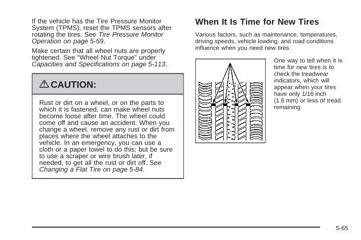
If the vehicle has the Tire Pressure MonitorSystem (TPMS), reset the TPMS sensors afterrotating the tires. See Tire Pressure MonitorOperation on page 5-59.
Make certain that all wheel nuts are properlytightened. See “Wheel Nut Torque” underCapacities and Specifications on page 5-113.
{CAUTION:
Rust or dirt on a wheel, or on the parts towhich it is fastened, can make wheel nutsbecome loose after time. The wheel couldcome off and cause an accident. When youchange a wheel, remove any rust or dirt fromplaces where the wheel attaches to thevehicle. In an emergency, you can use acloth or a paper towel to do this; but be sureto use a scraper or wire brush later, ifneeded, to get all the rust or dirt off. SeeChanging a Flat Tire on page 5-84.
When It Is Time for New TiresVarious factors, such as maintenance, temperatures,driving speeds, vehicle loading, and road conditionsinfluence when you need new tires.
One way to tell when it istime for new tires is tocheck the treadwearindicators, which willappear when your tireshave only 1/16 inch(1.6 mm) or less of treadremaining.
5-65

You need new tires if any of the following statementsare true:
• You can see the indicators at three or more placesaround the tire.
• You can see cord or fabric showing through thetire’s rubber.
• The tread or sidewall is cracked, cut, or snaggeddeep enough to show cord or fabric.
• The tire has a bump, bulge, or split.
• The tire has a puncture, cut, or other damage thatcannot be repaired well because of the size orlocation of the damage.
The rubber in tires degrades over time, even if they arenot being used. This is also true for the spare tire, ifyour vehicle has one. Multiple conditions affect how fastthis aging takes place, including temperatures, loadingconditions, and inflation pressure maintenance. Withproper care and maintenance tires will typically wear outbefore they degrade due to age. If you are unsureabout the need to replace your tires as they get older,consult the tire manufacturer for more information.
Buying New TiresGM has developed and matched specific tires foryour vehicle. The original equipment tires installedon your vehicle, when it was new, were designed tomeet General Motors Tire Performance CriteriaSpecification (TPC Spec) system rating. If you needreplacement tires, GM strongly recommends thatyou get tires with the same TPC Spec rating. Thisway, your vehicle will continue to have tires that aredesigned to give the same performance and vehiclesafety, during normal use, as the original tires.
GM’s exclusive TPC Spec system considers overa dozen critical specifications that impact theoverall performance of your vehicle, includingbrake system performance, ride and handling,traction control, and tire pressure monitoringperformance. GM’s TPC Spec number is moldedonto the tire’s sidewall near the tire size. If thetires have an all-season tread design, theTPC Spec number will be followed by an MS formud and snow. See Tire Sidewall Labeling onpage 5-49 for additional information.
5-66
GM recommends replacing tires in sets of four.This is because uniform tread depth on all tires willhelp keep your vehicle performing most like itdid when the tires were new. Replacing less thana full set of tires can affect the braking andhandling performance of your vehicle. See TireInspection and Rotation on page 5-64 forinformation on proper tire rotation.
{CAUTION:
Mixing tires could cause you to lose controlwhile driving. If you mix tires of differentsizes, brands, or types (radial and bias-beltedtires), the vehicle may not handle properly,and you could have a crash. Using tires ofdifferent sizes, brands, or types may alsocause damage to your vehicle. Be sure touse the correct size, brand, and type of tireson all wheels. It is all right to drive with yourcompact spare temporarily, as it wasdeveloped for use on your vehicle. SeeCompact Spare Tire on page 5-98.
{CAUTION:
If you use bias-ply tires on the vehicle, thewheel rim flanges could develop cracks aftermany miles of driving. A tire and/or wheelcould fail suddenly, causing a crash. Use onlyradial-ply tires with the wheels on the vehicle.
If you must replace your vehicle’s tires with thosethat do not have a TPC Spec number, makesure they are the same size, load range, speedrating, and construction type (radial andbias-belted tires) as your vehicle’s original tires.
Vehicles that have a tire pressure monitoringsystem could give an inaccurate low-pressurewarning if non-TPC Spec rated tires are installedon your vehicle. Non-TPC Spec rated tiresmay give a low-pressure warning that is higher orlower than the proper warning level you wouldget with TPC Spec rated tires. See Tire PressureMonitor System on page 5-57.
Your vehicle’s original equipment tires are listedon the Tire and Loading Information Label.See Loading the Vehicle on page 4-24, for moreinformation about the Tire and Loading InformationLabel and its location on your vehicle.
5-67

Different Size Tires and WheelsIf you add wheels or tires that are a different size thanyour original equipment wheels and tires, this may affectthe way your vehicle performs, including its braking, rideand handling characteristics, stability, and resistance torollover. Additionally, if your vehicle has electronicsystems such as, antilock brakes, traction control, andelectronic stability control, the performance of thesesystems can be affected.
{CAUTION:
If you add different sized wheels, your vehicle maynot provide an acceptable level of performanceand safety if tires not recommended for thosewheels are selected. You may increase thechance that you will crash and suffer seriousinjury. Only use GM specific wheel and tiresystems developed for your vehicle, and havethem properly installed by a GM certifiedtechnician.
See Buying New Tires on page 5-66 and Accessoriesand Modifications on page 5-3 for additional information.
Uniform Tire Quality GradingQuality grades can be found where applicable onthe tire sidewall between tread shoulder andmaximum section width. For example:
Treadwear 200 Traction AATemperature AThe following information relates to the systemdeveloped by the United States National HighwayTraffic Safety Administration (NHTSA), whichgrades tires by treadwear, traction, andtemperature performance. This applies only tovehicles sold in the United States. The grades aremolded on the sidewalls of most passenger cartires. The Uniform Tire Quality Grading (UTQG)system does not apply to deep tread, winter-typesnow tires, space-saver, or temporary use sparetires, tires with nominal rim diameters of10 to 12 inches (25 to 30 cm), or to somelimited-production tires.
While the tires available on General Motorspassenger cars and light trucks may vary withrespect to these grades, they must also conformto federal safety requirements and additionalGeneral Motors Tire Performance Criteria (TPC)standards.
5-68
TreadwearThe treadwear grade is a comparative ratingbased on the wear rate of the tire when testedunder controlled conditions on a specifiedgovernment test course. For example, a tiregraded 150 would wear one and a half (1.5) timesas well on the government course as a tiregraded 100. The relative performance of tiresdepends upon the actual conditions of their use,however, and may depart significantly fromthe norm due to variations in driving habits, servicepractices, and differences in road characteristicsand climate.
Traction – AA, A, B, CThe traction grades, from highest to lowest, areAA, A, B, and C. Those grades represent the tire’sability to stop on wet pavement as measured undercontrolled conditions on specified government testsurfaces of asphalt and concrete. A tire marked Cmay have poor traction performance.
{WARNING:
The traction grade assigned to this tire isbased on straight-ahead braking tractiontests, and does not include acceleration,cornering, hydroplaning, or peak tractioncharacteristics.
5-69

Temperature – A, B, CThe temperature grades are A (the highest), B,and C, representing the tire’s resistance tothe generation of heat and its ability to dissipateheat when tested under controlled conditions on aspecified indoor laboratory test wheel. Sustainedhigh temperature can cause the material of the tireto degenerate and reduce tire life, and excessivetemperature can lead to sudden tire failure.The grade C corresponds to a level of performancewhich all passenger car tires must meet underthe Federal Motor Vehicle Safety StandardNo. 109. Grades B and A represent higher levelsof performance on the laboratory test wheelthan the minimum required by law.
{WARNING:
The temperature grade for this tire isestablished for a tire that is properly inflatedand not overloaded. Excessive speed,underinflation, or excessive loading, eitherseparately or in combination, can cause heatbuildup and possible tire failure.
Wheel Alignment and Tire BalanceThe tires and wheels on your vehicle were aligned andbalanced carefully at the factory to give you the longesttire life and best overall performance. Adjustments towheel alignment and tire balancing will not be necessaryon a regular basis. However, if you notice unusual tirewear or your vehicle pulling to one side or the other, thealignment might need to be checked. If you notice yourvehicle vibrating when driving on a smooth road, the tiresand wheels might need to be rebalanced. See yourdealer/retailer for proper diagnosis.
Wheel ReplacementReplace any wheel that is bent, cracked, or badly rustedor corroded. If wheel nuts keep coming loose, the wheel,wheel bolts, and wheel nuts should be replaced. If thewheel leaks air, replace it (except some aluminumwheels, which can sometimes be repaired). See yourdealer/retailer if any of these conditions exist.
Your dealer/retailer will know the kind of wheel you need.
Each new wheel should have the same load-carryingcapacity, diameter, width, offset, and be mountedthe same way as the one it replaces.
5-70

If you need to replace any of your wheels, wheel bolts,wheel nuts, or Tire Pressure Monitor System (TPMS)sensors, replace them only with new GM originalequipment parts. This way, you will be sure to have theright wheel, wheel bolts, wheel nuts, and TPMS sensorsfor your vehicle.
{CAUTION:
Using the wrong replacement wheels, wheel bolts,or wheel nuts on your vehicle can be dangerous. Itcould affect the braking and handling of yourvehicle, make your tires lose air and make youlose control. You could have a collision in whichyou or others could be injured. Always use thecorrect wheel, wheel bolts, and wheel nuts forreplacement.
Notice: The wrong wheel can also cause problemswith bearing life, brake cooling, speedometer orodometer calibration, headlamp aim, bumper height,vehicle ground clearance, and tire or tire chainclearance to the body and chassis.
See Changing a Flat Tire on page 5-84 for moreinformation.
Used Replacement Wheels
{CAUTION:
Putting a used wheel on the vehicle is dangerous.You cannot know how it has been used or how farit has been driven. It could fail suddenly andcause a crash. If you have to replace a wheel, usea new GM original equipment wheel.
5-71

Tire Chains
{CAUTION:
If your vehicle has P205/55R16 or P205/50R17size tires, do not use tire chains. They candamage your vehicle because there is not enoughclearance.
Tire chains used on a vehicle without the properamount of clearance can cause damage to thebrakes, suspension, or other vehicle parts. Thearea damaged by the tire chains could cause youto lose control of your vehicle and you or othersmay be injured in a crash.
Use another type of traction device only if itsmanufacturer recommends it for use on yourvehicle and tire size combination and roadconditions. Follow that manufacturer’s instructions.
CAUTION: (Continued)
CAUTION: (Continued)
To help avoid damage to your vehicle, driveslowly, readjust, or remove the device if it iscontacting your vehicle, and do not spin yourvehicle’s wheels.
If you do find traction devices that will fit, installthem on the front tires.
Notice: If your vehicle has a tire size other thanP205/55R16 or P205/50R17, use tire chains onlywhere legal and only when you must. Use only SAEClass S-type chains that are the proper size foryour tires. Install them on the front tires and tightenthem as tightly as possible with the ends securelyfastened. Drive slowly and follow the chainmanufacturer’s instructions. If you can hear thechains contacting your vehicle, stop and retightenthem. If the contact continues, slow down untilit stops. Driving too fast or spinning the wheels withchains on will damage your vehicle.
5-72

If a Tire Goes FlatIt is unusual for a tire to blowout while you are driving,especially if you maintain the tires properly. See Tires onpage 5-48. If air goes out of a tire, It is much more likelyto leak out slowly. But if you should ever have a blowout,here are a few tips about what to expect and what to do:
If a front tire fails, the flat tire will create a drag thatpulls the vehicle toward that side. Take your foot off theaccelerator pedal and grip the steering wheel firmly. Steerto maintain lane position, and then gently brake to a stopwell out of the traffic lane.
A rear blowout, particularly on a curve, acts much likea skid and may require the same correction you woulduse in a skid. In any rear blowout, remove your foot fromthe accelerator pedal. Get the vehicle under control bysteering the way you want the vehicle to go. It may bevery bumpy and noisy, but you can still steer. Gentlybrake to a stop, well off the road if possible.
If a tire goes flat, avoid further tire and wheel damageby driving slowly to a level place and stopping.
1. Turn on the hazard warning flashers. See HazardWarning Flashers on page 3-6.
2. Park the vehicle. Set the parking brake firmly andput the shift lever in P (Park).
3. Turn off the engine.
4. Inspect the flat tire.
{CAUTION:
Lifting a vehicle and getting under it to domaintenance or repairs is dangerous without theappropriate safety equipment and training. If a jackis provided with the vehicle, it is designed only forchanging a flat tire. If it is used for anything else,you or others could be badly injured or killed if thevehicle slips off the jack. If a jack is provided withthe vehicle, only use it for changing a flat tire.
This vehicle may come with a jack and spare tire or atire sealant and compressor kit. To use the jack andspare tire, see Changing a Flat Tire on page 5-84.To use the tire sealant and compressor kit, see TireSealant and Compressor Kit on page 5-74.
5-73

Tire Sealant and Compressor Kit
{CAUTION:
Idling a vehicle in an enclosed area with poorventilation is dangerous. Engine exhaust mayenter the vehicle. Engine exhaust contains CarbonMonoxide (CO) which cannot be seen or smelled.It can cause unconsciousness and even death.Never run the engine in an enclosed area that hasno fresh air ventilation. For more information, seeEngine Exhaust on page 2-34.
{CAUTION:
Over-inflating a tire could cause the tire to ruptureand you or others could be injured. Be sure toread and follow the tire sealant and compressor kitinstructions and inflate the tire to its recommendedpressure. Do not exceed the recommendedpressure.
5-74

{CAUTION:
Storing the tire sealant and compressor kit orother equipment in the passenger compartment ofthe vehicle could cause injury. In a sudden stop orcollision, loose equipment could strike someone.Store the tire sealant and compressor kit in itsoriginal location.
If this vehicle has a tire sealant and compressor kit,there may not be a spare tire, tire changing equipment,and on some vehicles there may not be a place tostore a tire.
The tire sealant and compressor can be used totemporarily seal punctures up to 1⁄4 inch (6 mm) in thetread area of the tire. It can also be used to inflatean under inflated tire.
If the tire has been separated from the wheel, hasdamaged sidewalls, or has a large puncture, the tire istoo severely damaged for the tire sealant andcompressor kit to be effective. See Roadside AssistanceProgram on page 7-7.
Read and follow all of the tire sealant and compressorkit instructions.
The kit includes:
A. Air CompressorB. Tire Sealant CanisterC. Power PlugD. On/Off ButtonE. Pressure Gage
F. Air Only Hose(Black)
G. Sealant/Air Hose(Clear)
5-75
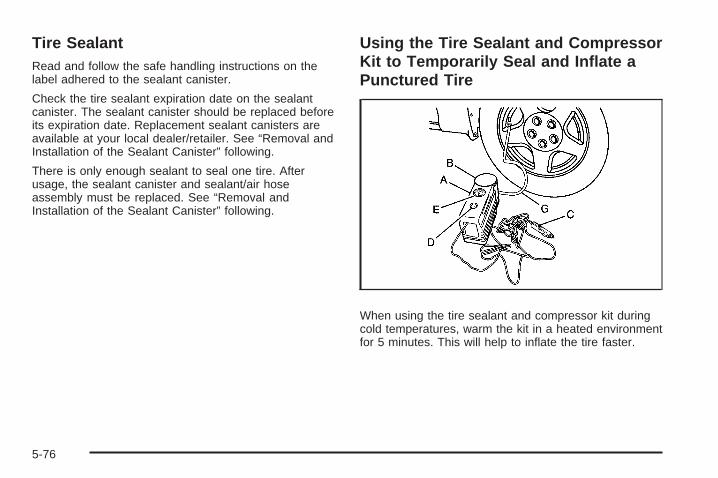
Tire SealantRead and follow the safe handling instructions on thelabel adhered to the sealant canister.
Check the tire sealant expiration date on the sealantcanister. The sealant canister should be replaced beforeits expiration date. Replacement sealant canisters areavailable at your local dealer/retailer. See “Removal andInstallation of the Sealant Canister” following.
There is only enough sealant to seal one tire. Afterusage, the sealant canister and sealant/air hoseassembly must be replaced. See “Removal andInstallation of the Sealant Canister” following.
Using the Tire Sealant and CompressorKit to Temporarily Seal and Inflate aPunctured Tire
When using the tire sealant and compressor kit duringcold temperatures, warm the kit in a heated environmentfor 5 minutes. This will help to inflate the tire faster.
5-76
Always do a safety check first. See If a Tire Goes Flaton page 5-73. Do not remove any objects that havepenetrated the tire.1. Remove the tire sealant and compressor kit from its
storage location. See Tire Sealant and CompressorKit Storage on page 5-83.Make sure the on/off button (D) is in the off (O)position.
2. Unwrap the sealant/air hose (F) and the powerplug (C).
3. Place the kit on the ground.Make sure the tire valve stem is positioned close tothe ground so the hose will reach it.
4. Remove the valve stem cap from the flat tire byturning it counterclockwise.
5. Attach the sealant/air hose (F) onto the tire valvestem. Turn it clockwise until it is tight.
6. Plug the power plug (C) into the accessory poweroutlet in the vehicle. Unplug all items from otheraccessory power outlets. See Accessory PowerOutlet(s) on page 3-16.If the vehicle has an accessory power outlet, do notuse the cigarette lighter.If the vehicle only has a cigarette lighter, use thecigarette lighter.Do not pinch the power plug cord in the door orwindow.
7. Start the vehicle. The vehicle must be running whileusing the air compressor.
8. Press the on/off (D) button to turn the tire sealantand compressor kit on.The compressor will inject sealant and air intothe tire.The pressure gage (E) will initially show ahigh pressure while the compressor pushes thesealant into the tire. Once the sealant is completelydispersed into the tire, the pressure will quickly dropand start to rise again as the tire inflates with air only.
5-77

9. Inflate the tire to the recommended inflation pressureusing the pressure gage (E). The recommendedinflation pressure can be found on the Tire andLoading Information label. See Inflation - TirePressure on page 5-56.The pressure gage (E) may read higher than theactual tire pressure while the compressor is on.Turn the compressor off to get an accurate pressurereading. The compressor may be turned on/offuntil the correct pressure is reached.
Notice: If the recommended pressure cannot bereached after approximately 25 minutes, the vehicleshould not be driven farther. The tire is too severelydamaged and the tire sealant and compressor kitcannot inflate the tire. Remove the power plug fromthe accessory power outlet and unscrew the inflatinghose from the tire valve. See Roadside AssistanceProgram on page 7-7.
10. Press the on/off button (D) to turn the tire sealantand compressor kit off.The tire is not sealed and will continue to leakair until the vehicle is driven and the sealantis distributed in the tire, therefore, Steps 11through 17 must be done immediately afterStep 10.Be careful while handling the tire sealant andcompressor kit as it could be warm after usage.
11. Unplug the power plug (C) from the accessorypower outlet in the vehicle.
12. Turn the sealant/air hose (F) counterclockwise toremove it from the tire valve stem.
13. Replace the tire valve stem cap.
14. Replace the sealant/air hose (F), and the powerplug (C) back in their original location.
15. If the flat tire wasable to inflate to therecommended inflationpressure, removethe maximum speedlabel from the sealantcanister (B) andplace it in a highlyvisible location.
The label is a reminder not to exceed 55 mph(90 km/h) until the damaged tire is repairedor replaced.
5-78
16. Return the equipment to its original storage locationin the vehicle.
17. Immediately drive the vehicle 5 miles (8 km) todistribute the sealant in the tire.
18. Stop at a safe location and check the tire pressure.Refer to Steps 1 through 11 under “Using the TireSealant and Compressor Kit without Sealant toInflate a Tire (Not Punctured).”If the tire pressure has fallen more than 10 psi(68 kPa) below the recommended inflation pressure,stop driving the vehicle. The tire is too severelydamaged and the tire sealant cannot seal the tire.See Roadside Assistance Program on page 7-7.If the tire pressure has not dropped more than10 psi (68 kPa) from the recommended inflationpressure, inflate the tire to the recommendedinflation pressure.
19. Wipe off any sealant from the wheel, tire or vehicle.
20. Dispose of the used sealant canister (B) andsealant/air hose (F) assembly at a localdealer/retailer or in accordance with local statecodes and practices.
21. Replace it with a new canister available from yourdealer/retailer.
22. After temporarily sealing a tire using the tire sealantand compressor kit, take the vehicle to an authorizeddealer/retailer within a 100 miles (161 km) of drivingto have the tire repaired or replaced.
5-79

Using the Tire Sealant and CompressorKit without Sealant to Inflate a Tire(Not Punctured)To use the air compressor to inflate a tire with air onlyand not sealant:
Always do a safety check first. See If a Tire Goes Flaton page 5-73.
1. Remove the tire sealant and compressor kit from itsstorage location. See Tire Sealant and CompressorKit Storage on page 5-83.
2. Unlock the air only hose (F) from the sealantcanister (B) by pulling up on the lever.
3. Pull the air only hose (F) from the sealantcanister (B).
4. Remove the power plug (C) from the aircompressor (A).
5. Place the kit on the ground.Make sure the tire valve stem is positioned close tothe ground so the hose will reach it.
5-80
6. Remove the tire valve stem cap by turning itcounterclockwise.
7. Attach the air only hose (F) onto the tire valve stemand press the lever down to secure it.
8. Plug the power plug (C) into the accessory poweroutlet in the vehicle. Unplug all items from otheraccessory power outlets. See Accessory PowerOutlet(s) on page 3-16.If the vehicle has an accessory power outlet, do notuse the cigarette lighter.If the vehicle only has a cigarette lighter, use thecigarette lighter.Do not pinch the power plug cord in the door orwindow.
9. Start the vehicle. The vehicle must be running whileusing the air compressor.
10. Press the on/off (D) button to turn thecompressor on.The compressor will inflate the tire with air only.
11. Inflate the tire to the recommended inflation pressureusing the pressure gage (E). The recommendedinflation pressure can be found on the Tire andLoading Information label. See Inflation - TirePressure on page 5-56.
The pressure gage (E) may read higher than theactual tire pressure while the compressor is on. Turnthe compressor off to get an accurate reading.The compressor may be turned on/off untilthe correct pressure is reached.
12. Press the on/off button (D) to turn the tire sealantand compressor kit off.Be careful while handling the tire sealant andcompressor kit as it could be warm after usage.
13. Unplug the power plug (C) from the accessorypower outlet in the vehicle.
14. Disconnect the air only hose (F) from the tire valvestem, by turning it counterclockwise, and replacethe tire valve stem cap.
15. Replace the air only hose (F) and the powerplug (C) back in its original location.
16. Place the equipment in the original storage locationin the vehicle.
5-81

Removal and Installation of the SealantCanisterTo remove the sealant canister:
1. Unlock the air only hose (F) from the sealantcanister (B) by pulling up on the lever.
2. Pull the air only hose (F) from the sealantcanister (B).
3. Unwrap the sealant/air hose (F) from thecompressor (A).
4. Turn the sealant canister (B) so the inflator fillinghose is aligned with the slot in the compressor.
5. Lift the sealant canister (B) from the compressorand replace with a new sealant canister. See yourdealer/retailer for more information.
5-82

To install a new sealant canister:
1. Align the sealant/air hose (F) with the slot in the aircompressor.
2. Push the sealant canister (B) down and turn itclockwise.
3. Wrap the sealant/air hose (F) around the aircompressor channel to stow it in its original location.
4. Push the air compressor inflator hose (F) onto thesealant canister inlet and push the lever down.
Tire Sealant and Compressor KitStorageThe tire sealant and compressor kit is located in thetrunk.
1. Open the trunk. See Trunk on page 2-12.
2. Lift the trunk liner.
3. Remove the retainer that holds the tire sealant andcompressor kit.
4. Remove the kit from the foam container.
To store the tire sealant and compressor kit, reverse thesteps.
5-83

Changing a Flat TireIf a tire goes flat, avoid further tire and wheel damage bydriving slowly to a level place. Turn on the hazardwarning flashers. See Hazard Warning Flashers onpage 3-6.
{CAUTION:
Changing a tire can be dangerous. The vehiclecan slip off the jack and roll over or fall on you orother people. You and they could be badly injuredor even killed. Find a level place to change yourtire. To help prevent the vehicle from moving:
1. Set the parking brake firmly.
2. Put an automatic transmission shift lever inP (Park), or shift a manual transmission to1 (First) or R (Reverse).
CAUTION: (Continued)
CAUTION: (Continued)
3. Turn off the engine and do not restart whilethe vehicle is raised.
4. Do not allow passengers to remain in thevehicle.
To be even more certain the vehicle will not move,you should put blocks at the front and rear of thetire farthest away from the one being changed.That would be the tire on the other side, at theopposite end of the vehicle.
When the vehicle has a flat tire (B), use the followingexample as a guide to assist you in the placementof wheel blocks (A).
5-84
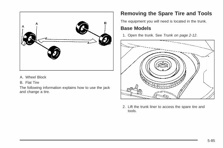
A. Wheel BlockB. Flat TireThe following information explains how to use the jackand change a tire.
Removing the Spare Tire and ToolsThe equipment you will need is located in the trunk.
Base Models1. Open the trunk. See Trunk on page 2-12.
2. Lift the trunk liner to access the spare tire andtools.
5-85

A. CoverB. RetainerC. Spare TireD. Wing NutE. Jack and Wheel WrenchF. Bolt
5-86

3. Remove the retainer (B) that holds down the sparetire. See Compact Spare Tire on page 5-98 formore information.
4. Remove the spare tire (C) by gently pulling it upand out of the trunk.
5. Remove the wing nut (D) that holds the jack andremove the jack and wheel wrench (E).
Uplevel Models1. Open the trunk. See Trunk on page 2-12.
2. Lift the trunk liner to access the spare tire andtools.
5-87

A. RetainerB. Jack and Wheel WrenchC. Spare TireD. Foam SupportE. Bolt
3. Remove the retainer (A) that holds down the jack,wheel wrench (B) and spare tire (C).
4. Remove the spare tire by gently pulling it up andout of the trunk.
5-88

The tools you will be using include the jack (A) andwheel wrench (B).
You will need to turn the plastic wheel nutcounterclockwise to loosen the wheel wrench fromthe jack.
5-89

Press the button and then pull on the end of the wheelwrench to extend the handle.
Removing the Flat Tire andInstalling the Spare Tire1. Do a safety check before preceding. See Changing
a Flat Tire on page 5-84.
2. If your vehicle has plastic wheel covers, use thewheel wrench to loosen the plastic wheel nut caps.Once you have loosened the plastic wheel nut capswith the wheel wrench, you can finish looseningthem with your fingers. The plastic nut caps do notcome off.
3. If necessary, use the flat end of the wheel wrenchto pry along the edge of the wheel cover until itcomes off.Store the wheel cover in the trunk until you havethe flat tire repaired or replaced.
5-90
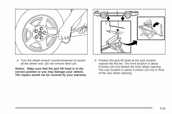
4. Turn the wheel wrench counterclockwise to loosenall the wheel nuts. Do not remove them yet.
Notice: Make sure that the jack lift head is in thecorrect position or you may damage your vehicle.The repairs would not be covered by your warranty.
5. Position the jack lift head at the jack locationnearest the flat tire. The front location is about8 inches (20 cm) behind the front wheel opening.The rear location is about 4 inches (10 cm) in frontof the rear wheel opening.
5-91
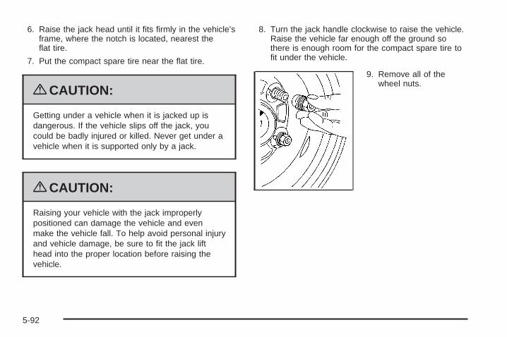
6. Raise the jack head until it fits firmly in the vehicle’sframe, where the notch is located, nearest theflat tire.
7. Put the compact spare tire near the flat tire.
{CAUTION:
Getting under a vehicle when it is jacked up isdangerous. If the vehicle slips off the jack, youcould be badly injured or killed. Never get under avehicle when it is supported only by a jack.
{CAUTION:
Raising your vehicle with the jack improperlypositioned can damage the vehicle and evenmake the vehicle fall. To help avoid personal injuryand vehicle damage, be sure to fit the jack lifthead into the proper location before raising thevehicle.
8. Turn the jack handle clockwise to raise the vehicle.Raise the vehicle far enough off the ground sothere is enough room for the compact spare tire tofit under the vehicle.
9. Remove all of thewheel nuts.
5-92
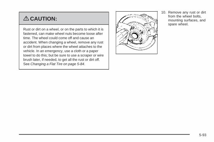
{CAUTION:
Rust or dirt on a wheel, or on the parts to which it isfastened, can make wheel nuts become loose aftertime. The wheel could come off and cause anaccident. When changing a wheel, remove any rustor dirt from places where the wheel attaches to thevehicle. In an emergency, use a cloth or a papertowel to do this; but be sure to use a scraper or wirebrush later, if needed, to get all the rust or dirt off.See Changing a Flat Tire on page 5-84.
10. Remove any rust or dirtfrom the wheel bolts,mounting surfaces, andspare wheel.
5-93
11. Place the compact spare tire on the wheel-mountingsurface.
{CAUTION:
Never use oil or grease on bolts or nuts becausethe nuts might come loose. The vehicle’s wheelcould fall off, causing a crash.
12. Reinstall the wheel nuts with the rounded end ofthe nuts toward the wheel. Tighten each nutclockwise by hand until the wheel is held againstthe hub.
13. Lower the vehicle by turning the jack handlecounterclockwise. Lower the jack completely.
{CAUTION:
Incorrect or improperly tightened wheel nuts cancause the wheel to come loose and even comeoff. This could lead to a crash. If you have toreplace them, be sure to get new originalequipment wheel nuts. Stop somewhere as soonas you can and have the nuts tightened with atorque wrench to the proper torque specification.See Capacities and Specifications on page 5-113for wheel nut torque specification.
Notice: Improperly tightened wheel nuts can leadto brake pulsation and rotor damage. To avoidexpensive brake repairs, evenly tighten the wheelnuts in the proper sequence and to the propertorque specification. See Capacities andSpecifications on page 5-113 for the wheel nuttorque specification.
5-94

14. Tighten the wheel nuts firmly in a crisscrosssequence, as shown.
Notice: Wheel covers will not fit on your vehicle’scompact spare. If you try to put a wheel cover on thecompact spare, the cover or the spare could bedamaged.
Storing a Flat or Spare Tire andTools
{CAUTION:
Storing a jack, a tire, or other equipment in thepassenger compartment of the vehicle couldcause injury. In a sudden stop or collision, looseequipment could strike someone. Store all these inthe proper place.
4-Wheel Nuts 5-Wheel Nuts
5-95
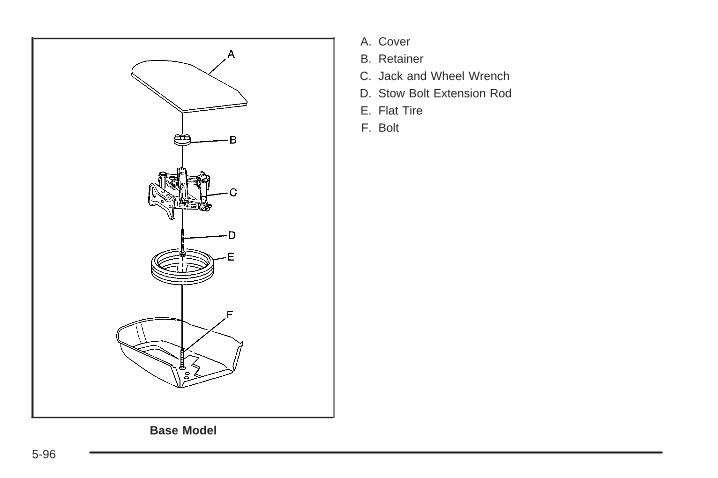
A. CoverB. RetainerC. Jack and Wheel WrenchD. Stow Bolt Extension RodE. Flat TireF. Bolt
Base Model
5-96

A. CoverB. RetainerC. Jack and Wheel WrenchD. Stow Bolt Extension RodE. Flat TireF. Foam SupportG. Bolt
To store a flat tire and tools:
1. Remove the stow bolt extension rod and sleevefrom the jack.
2. Screw the stow bolt extension rod and the sleeveinto the existing spare tire hold-down bolt.
3. If your vehicle has aluminum wheels, first removethe center cap with your hand or the wheel wrench.
4. Place the flat tire face down into the spare tire tub.
5. Re-attach the wheel wrench to the jack.
6. Place the jack into the center of the flat tire, beingcareful not to scratch the inside of the wheel.
7. Remove the plastic sleeve from the stow boltextension rod. Secure the jack and road wheelusing the larger plastic retainer.
8. If used in the vehicle, place the smaller jackretainer nut in a safe place until you are readyto store the compact spare tire in the trunk again.
Uplevel Model
5-97
To store the compact spare tire and tools, follow theprevious procedure without using the stow bolt extensionrod and see Removing the Spare Tire and Tools onpage 5-85 and follow the removal procedure, in reverse,for the proper jack storage instructions for this vehicle.
The compact spare tire is for temporary use only.Replace the compact spare with a full-size tire as soonas possible.
Compact Spare TireThis vehicle may have a compact spare tire. Although thecompact spare tire was fully inflated when the vehiclewas new, it can lose air after a time. Check the inflationpressure regularly. It should be 60 psi (420 kPa).
After installing the compact spare on the vehicle, if thevehicle has one, stop as soon as possible and makesure the spare tire is correctly inflated. The compactspare is made to perform well at speeds up to 65 mph(105 km/h) for distances up to 3,000 miles (5 000 km),so you can finish your trip and have the full-size
tire repaired or replaced at your convenience. Ofcourse, it is best to replace the spare with a full-size tireas soon as possible. The spare tire will last longerand be in good shape in case it is needed again.
Notice: When the compact spare is installed, donot take the vehicle through an automatic car washwith guide rails. The compact spare can getcaught on the rails which can damage the tire,wheel and other parts of the vehicle.
Do not use the compact spare on other vehicles.
And do not mix the compact spare tire or wheel withother wheels or tires. They will not fit. Keep thespare tire and its wheel together.
Notice: Tire chains will not fit the compact spare.Using them can damage the vehicle and can damagethe chains too. Do not use tire chains on thecompact spare.
5-98
Appearance Care
Interior CleaningThe vehicle’s interior will continue to look its best if it iscleaned often. Although not always visible, dust anddirt can accumulate on the upholstery. Dirt can damagecarpet, fabric, leather, and plastic surfaces. Regularvacuuming is recommended to remove particles from theupholstery. It is important to keep the upholstery frombecoming and remaining heavily soiled. Soils should beremoved as quickly as possible. The vehicle’s interiormay experience extremes of heat that could causestains to set rapidly.
Lighter colored interiors may require more frequentcleaning. Use care because newspapers and garmentsthat transfer color to home furnishings may alsotransfer color to the vehicle’s interior.
When cleaning the vehicle’s interior, only use cleanersspecifically designed for the surfaces being cleaned.Permanent damage may result from using cleanerson surfaces for which they were not intended. Use glass
cleaner only on glass. Remove any accidental over-sprayfrom other surfaces immediately. To prevent over-spray,apply cleaner directly to the cleaning cloth.
Notice: Using abrasive cleaners when cleaningglass surfaces on the vehicle, could scratchthe glass and/or cause damage to the rear windowdefogger. When cleaning the glass on the vehicle,use only a soft cloth and glass cleaner.
Many cleaners contain solvents that may becomeconcentrated in the vehicle’s breathing space. Beforeusing cleaners, read and adhere to all safety instructionson the label. While cleaning the vehicle’s interior,maintain adequate ventilation by opening the vehicle’sdoors and windows.
Dust may be removed from small buttons and knobsusing a small brush with soft bristles.
Products that remove odors from the vehicle’supholstery and clean the vehicle’s glass can be obtainedfrom your dealer/retailer.
5-99

Do not clean the vehicle using:
• A knife or any other sharp object to remove a soilfrom any interior surface.
• A stiff brush. It can cause damage to the vehicle’sinterior surfaces.
• Heavy pressure or aggressive rubbing with acleaning cloth. Use of heavy pressure can damagethe interior and does not improve the effectivenessof soil removal.
• Laundry detergents or dishwashing soaps withdegreasers can leave residue that streaks andattracts dirt. For liquid cleaners, about 20 dropsper gallon (3.78 L) of water is a good guide.Use only mild, neutral-pH soaps.
• Too much cleaner that saturates the upholstery.
• Organic solvents such as naptha, alcohol, etc. thatcan damage the vehicle’s interior.
Fabric/CarpetUse a vacuum cleaner with a soft brush attachmentfrequently to remove dust and loose dirt. A canistervacuum with a beater bar in the nozzle may only be usedon floor carpet and carpeted floor mats. For any soil,always try to remove it first with plain water or club soda.Before cleaning, gently remove as much of the soil aspossible using one of the following techniques:
• For liquids: gently blot the remaining soil with a papertowel. Allow the soil to absorb into the paper toweluntil no more can be removed.
• For solid dry soils: remove as much as possible andthen vacuum.
To clean:
1. Saturate a lint-free, clean white cloth with water orclub soda.
2. Wring the cloth to remove excess moisture.
3. Start on the outside edge of the soil and gently rubtoward the center. Continue cleaning, using a cleanarea of the cloth each time it becomes soiled.
4. Continue to gently rub the soiled area until thecleaning cloth remains clean.
5. If the soil is not completely removed, use a mildsoap solution and repeat the cleaning processthat was used with plain water.
5-100

If any of the soil remains, a commercial fabric cleaneror spot lifter may be necessary. When a commercialupholstery cleaner or spot lifter is to be used, testa small hidden area for colorfastness first. If the locallycleaned area gives any impression that a ringformation may result, clean the entire surface.
After the cleaning process has been completed, a papertowel can be used to blot excess moisture from thefabric or carpet.
LeatherA soft cloth dampened with water can be used toremove dust. If a more thorough cleaning is necessary,a soft cloth dampened with a mild soap solution canbe used. Allow the leather to dry naturally. Do not useheat to dry. Never use steam to clean leather. Neveruse spot lifters or spot removers on leather. Manycommercial leather cleaners and coatings that are soldto preserve and protect leather may permanentlychange the appearance and feel of the leather and arenot recommended. Do not use silicone or wax-basedproducts, or those containing organic solvents to cleanthe vehicle’s interior because they can alter theappearance by increasing the gloss in a non-uniformmanner. Never use shoe polish on leather.
Instrument Panel, Vinyl, and OtherPlastic SurfacesA soft cloth dampened with water may be used toremove dust. If a more thorough cleaning is necessary,a clean soft cloth dampened with a mild soap solutioncan be used to gently remove dust and dirt. Never usespot lifters or removers on plastic surfaces. Manycommercial cleaners and coatings that are sold topreserve and protect soft plastic surfaces maypermanently change the appearance and feel of theinterior and are not recommended. Do not use siliconeor wax-based products, or those containing organicsolvents to clean the vehicle’s interior because they canalter the appearance by increasing the gloss in anon-uniform manner.
Some commercial products may increase gloss on theinstrument panel. The increase in gloss may causeannoying reflections in the windshield and even make itdifficult to see through the windshield under certainconditions.
5-101

Care of Safety BeltsKeep belts clean and dry.
{CAUTION:
Do not bleach or dye safety belts. It may severelyweaken them. In a crash, they might not be ableto provide adequate protection. Clean safety beltsonly with mild soap and lukewarm water.
WeatherstripsSilicone grease on weatherstrips will make them lastlonger, seal better, and not stick or squeak. Applysilicone grease with a clean cloth. During very cold,damp weather frequent application may be required. SeeRecommended Fluids and Lubricants on page 6-12.
Washing Your VehicleThe best way to preserve the vehicle’s finish is to keepit clean by washing it often.
Notice: Certain cleaners contain chemicals that candamage the emblems or nameplates on the vehicle.Check the cleaning product label. If it states thatit should not be used on plastic parts, do not use iton the vehicle or damage may occur and it wouldnot be covered by the warranty.
Do not wash the vehicle in direct sunlight. Use a carwashing soap. Do not use cleaning agents thatare petroleum based or that contain acid or abrasives,as they can damage the paint, metal or plastic onthe vehicle. Approved cleaning products can be obtainedfrom your dealer/retailer. Follow all manufacturers’directions regarding correct product usage, necessarysafety precautions and appropriate disposal of anyvehicle care product.
Rinse the vehicle well, before washing and after toremove all cleaning agents completely. If they areallowed to dry on the surface, they could stain.
5-102
Dry the finish with a soft, clean chamois or an all-cottontowel to avoid surface scratches and water spotting.
High pressure car washes may cause water to enter thevehicle. Avoid using high pressure washes closerthan 12 inches (30 cm) to the surface of the vehicle.Use of power washers exceeding 1,200 psi (8 274 kPa)can result in damage or removal of paint and decals.
Cleaning Exterior Lamps/LensesUse only lukewarm or cold water, a soft cloth and a carwashing soap to clean exterior lamps and lenses.Follow instructions under Washing Your Vehicle onpage 5-102.
Finish CareOccasional waxing or mild polishing of the vehicleby hand may be necessary to remove residue from thepaint finish. Approved cleaning products can beobtained from your dealer/retailer.
If the vehicle has a basecoat/clearcoat paint finish, theclearcoat gives more depth and gloss to the coloredbasecoat. Always use waxes and polishes that arenon-abrasive and made for a basecoat/clearcoatpaint finish.
Notice: Machine compounding or aggressivepolishing on a basecoat/clearcoat paint finish maydamage it. Use only non-abrasive waxes andpolishes that are made for a basecoat/clearcoatpaint finish on the vehicle.
Foreign materials such as calcium chloride and othersalts, ice melting agents, road oil and tar, tree sap, birddroppings, chemicals from industrial chimneys, etc.,can damage the vehicle’s finish if they remain on paintedsurfaces. Wash the vehicle as soon as possible. Ifnecessary, use non-abrasive cleaners that are markedsafe for painted surfaces to remove foreign matter.
Exterior painted surfaces are subject to aging, weatherand chemical fallout that can take their toll over aperiod of years. To help keep the paint finish lookingnew, keep the vehicle garaged or covered wheneverpossible.
Protecting Exterior Bright Metal PartsBright metal parts should be cleaned regularly to keeptheir luster. Washing with water is all that is usuallyneeded. However, chrome polish may be used onchrome or stainless steel trim, if necessary.
Use special care with aluminum trim. To avoid damagingprotective trim, never use auto or chrome polish, steam orcaustic soap to clean aluminum. A coating of wax, rubbedto high polish, is recommended for all bright metal parts.
5-103

Windshield and Wiper BladesClean the outside of the windshield with glass cleaner.
Clean the rubber blades using a lint free cloth orpaper towel soaked with windshield washer fluid or amild detergent. Wash the windshield thoroughlywhen cleaning the blades. Bugs, road grime, sap, and abuildup of vehicle wash/wax treatments may causewiper streaking. Replace the wiper blades if they areworn or damaged.
Wipers can be damaged by:
• Extreme dusty conditions
• Sand and salt
• Heat and sun
• Snow and ice, without proper removal
Aluminum or Chrome-Plated Wheelsand TrimThe vehicle may have either aluminum or chrome-platedwheels.
Keep the wheels clean using a soft clean cloth with mildsoap and water. Rinse with clean water. After rinsingthoroughly, dry with a soft clean towel. A wax may thenbe applied.
Notice: Chrome wheels and other chrome trimmay be damaged if the vehicle is not washed afterdriving on roads that have been sprayed withmagnesium, calcium or sodium chloride. Thesechlorides are used on roads for conditions such asice and dust. Always wash the vehicle’s chromewith soap and water after exposure.
Notice: Using strong soaps, chemicals, abrasivepolishes, cleaners, brushes, or cleaners that containacid on aluminum or chrome-plated wheels, coulddamage the surface of the wheel(s). The repairswould not be covered by the warranty. Useonly approved cleaners on aluminum orchrome-plated wheels.
The surface of these wheels is similar to the paintedsurface of the vehicle. Do not use strong soaps,chemicals, abrasive polishes, abrasive cleaners,cleaners with acid, or abrasive cleaning brushes onthem because they could damage the surface. Do notuse chrome polish on aluminum wheels.
Notice: Using chrome polish on aluminum wheelscould damage the wheels. The repairs would notbe covered by the warranty. Use chrome polish onchrome wheels only.
Use chrome polish only on chrome-plated wheels, butavoid any painted surface of the wheel, and buff offimmediately after application.
5-104

Notice: Driving the vehicle through an automaticcar wash that has silicone carbide tire cleaningbrushes, could damage the aluminum orchrome-plated wheels. The repairs would not becovered by the warranty. Never drive a vehicleequipped with aluminum or chrome-plated wheelsthrough an automatic car wash that uses siliconecarbide tire cleaning brushes.
TiresTo clean the tires, use a stiff brush with tire cleaner.
Notice: Using petroleum-based tire dressingproducts on the vehicle may damage the paint finishand/or tires. When applying a tire dressing, alwayswipe off any overspray from all painted surfaceson the vehicle.
Sheet Metal DamageIf the vehicle is damaged and requires sheet metalrepair or replacement, make sure the body repair shopapplies anti-corrosion material to parts repaired orreplaced to restore corrosion protection.
Original manufacturer replacement parts will provide thecorrosion protection while maintaining the vehiclewarranty.
Finish DamageAny stone chips, fractures or deep scratches in thefinish should be repaired right away. Bare metalwill corrode quickly and may develop into major repairexpense.
Minor chips and scratches can be repaired with touch-upmaterials available from your dealer/retailer. Largerareas of finish damage can be corrected in yourdealer’s/retailer’s body and paint shop.
Underbody MaintenanceChemicals used for ice and snow removal and dustcontrol can collect on the underbody. If these are notremoved, corrosion and rust can develop on theunderbody parts such as fuel lines, frame, floor pan,and exhaust system even though they have corrosionprotection.
At least every spring, flush these materials from theunderbody with plain water. Clean any areas where mudand debris can collect. Dirt packed in close areas ofthe frame should be loosened before being flushed.Your dealer/retailer or an underbody car washing systemcan do this.
5-105

Chemical Paint SpottingSome weather and atmospheric conditions can create achemical fallout. Airborne pollutants can fall upon andattack painted surfaces on the vehicle. This damage cantake two forms: blotchy, ring-shaped discolorations,and small, irregular dark spots etched into thepaint surface.
Although no defect in the paint job causes this, we willrepair, at no charge to the owner, the surfaces ofnew vehicles damaged by this fallout condition within12 months or 12,000 miles (20 000 km) of purchase,whichever occurs first.
Vehicle Identification
Vehicle Identification Number (VIN)
This is the legal identifier for your vehicle. It appears ona plate in the front corner of the instrument panel, onthe driver side. It can be seen through the windshieldfrom outside the vehicle. The VIN also appears onthe Vehicle Certification and Service Parts labels andthe certificates of title and registration.
Engine IdentificationThe eighth character in the VIN is the engine code. Thiscode helps identify the vehicle’s engine, specifications,and replacement parts. See “Engine Specifications”under Capacities and Specifications on page 5-113 foryour vehicle’s engine code.
5-106
Service Parts Identification LabelThis label is in the trunk, on the driver side, nearthe spare tire cover. It is very helpful if you ever need toorder parts. The label has the following information:
• Vehicle Identification Number (VIN)
• Model designation
• Paint information
• Production options and special equipment
Do not remove this label from the vehicle.
Electrical System
Add-On Electrical EquipmentNotice: Do not add anything electrical to thevehicle unless you check with your dealer/retailerfirst. Some electrical equipment can damagethe vehicle and the damage would not be coveredby the vehicle’s warranty. Some add-on electricalequipment can keep other components fromworking as they should.
Add-on equipment can drain the vehicle battery, even ifthe vehicle is not operating.
The vehicle has an airbag system. Before attempting toadd anything electrical to the vehicle, see ServicingYour Airbag-Equipped Vehicle on page 1-67.
Headlamp WiringThe headlamp wiring is protected by fuses. Should theheadlamps fail to function, have the headlamp systemchecked right away.
Windshield Wiper FusesThe windshield wiper motor is protected by a circuitbreaker and a fuse. If the motor overheats due to heavysnow, etc., the wiper will stop until the motor cools. Ifthe overload is caused by some electrical problem, haveit fixed.
Power Windows and Other PowerOptionsFuses in the fuse block protect the power windows.When the current load is too heavy, the fuse opensprotecting the circuit until the problem is fixed.
5-107

Fuses and Circuit BreakersThe wiring circuits in the vehicle are protected fromshort circuits by a combination of fuses, circuit breakersand fusible thermal links. This greatly reduces thechance of damage caused by electrical problems.
Look at the silver-colored band inside the fuse. If theband is broken or melted, replace the fuse. Be sure youreplace a bad fuse with a new one of the identicalsize and rating.
If you ever have a problem on the road and do not havea spare fuse, you can “borrow” one that has the sameamperage. Just pick some feature of the vehicle that youcan get along without — like the radio or cigarettelighter — and use its fuse if it is the correct amperage.Replace it as soon as you can.
There are two fuse blocks in the vehicle: the floorconsole fuse block and the engine compartment fuseblock.
There is one additional fuse located in the back of thevehicle near the battery.
Floor Console Fuse Block
The floor console fuse block is located on the passengerside of the floor console behind the forward panel.The panel has three clips. Pull the panel to disconnectthe three clips, and access the fuses. Use the fusepuller to remove fuses.
5-108
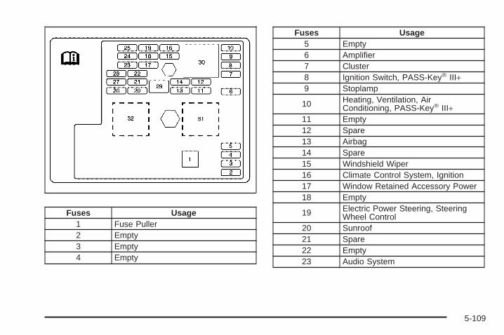
Fuses Usage1 Fuse Puller2 Empty3 Empty4 Empty
Fuses Usage5 Empty6 Amplifier7 Cluster8 Ignition Switch, PASS-Key® III+9 Stoplamp
10 Heating, Ventilation, AirConditioning, PASS-Key® III+
11 Empty12 Spare13 Airbag14 Spare15 Windshield Wiper16 Climate Control System, Ignition17 Window Retained Accessory Power18 Empty
19 Electric Power Steering, SteeringWheel Control
20 Sunroof21 Spare22 Empty23 Audio System
5-109

Fuses Usage24 XM Radio™, OnStar™
25 Engine Control Module,Transmission Control Module
26 Door Locks27 Interior Lights28 Steering Wheel Control Illumination29 Power Windows
Relays Usage30 Climate Control System31 Empty32 Retained Accessory Power (RAP)
Engine Compartment Fuse BlockThe engine compartment fuse block is located on thedriver side of the vehicle. Lift off the cover to check thefuses. See Engine Compartment Overview onpage 5-12 for more information on location.
Notice: Spilling liquid on any electrical componentson the vehicle may damage it. Always keep thecovers on any electrical component.
5-110

Fuses UsageSPARES SparesABS Antilock Brake SystemBlank BlankBlank BlankREAR DEFOG Rear DefoggerCOOL FAN2 Engine Cooling Fan High SpeedCRNK StarterCOOL FAN 1 Engine Cooling Fan Low SpeedBCM3 Body Control Module 3BCM2 Body Control Module 2FOG LAMP Fog LampsHORN HornRT HI BEAM Passenger Side High Beam LampLT HI BEAM Driver Side High Beam LampRT LO BEAM Passenger Side Low Beam LampLT LO BEAM Driver Side Low Beam LampDRL Daytime Running LampsFUEL PUMP Fuel PumpEXH Exhaust EmissionsENG VLV SOL Engine Valve Solenoid
Fuses UsageINJ InjectorsAIR SOL AIR SolenoidBlank Blank
PCM/ECM Powertrain Control Module/EngineControl Module
EPS Electric Power SteeringAIR PUMP AIR PumpPRK LAMP Parking LampsWPR Windshield WiperIP IGN IgnitionA/C CLTCH Air Conditioning ClutchCHMSL Center High Mount Stop LampABS2 Antilock Brake System 2Blank Blank
ECM/TRANS Engine Control Module,Transmission
BCK UP Back-Up LampsTRUNK/ HTDSEATS Trunk, Heated Seats
Blank BlankBlank Blank
5-111

Fuses Usage
SDM Sensing Diagnostic Module(Airbags)
ABS3 Antilock Brake System 3OUTLET Auxiliary Power OutletMIR MirrorsDLC Data Link ConnectorCNSTR VENT Canister Vent
Relays UsageREAR DEFOG Rear DefoggerAIR SOL(TURBO:COOL FAN 2)
AIR Solenoid (L61)/Engine CoolingFan 2 (LNF)
WPR HI/LO Windshield Wiper High/Low SpeedCRNK Starter
Relays UsageCOOL FAN 2(TURBO:COOL FANS)
Engine Cooling Fan (L61,LE5)/Engine Cooling Fans (LNF)
FUEL PUMP Fuel PumpWPR ON/OFF Windshield Wiper On/OffCOOL FAN 1 Engine Cooling Fan 1PWR/TRN PowertrainAIR PUMP AIR PumpA/C CLTCH Air Conditioning ClutchCHMSL Center High Mount Stop LampRUN/CRNK Run, Crank
Misc. UsagePLR Fuse Puller
5-112

Capacities and SpecificationsThe following approximate capacities are given in English and metric conversions. Please refer to RecommendedFluids and Lubricants on page 6-12 for more information.
ApplicationCapacities
English Metric
Air Conditioning Refrigerant R134a
For the air conditioning system refrigerant chargeamount, see the refrigerant caution label locatedunder the hood. See your dealer/retailer for more
information.
Cooling System
2.2L L4 Engine 7.4 qt 7.0 L
Engine Oil with Filter
2.2L L4 Engine 5.0 qt 4.7 L
Fuel Tank
2.2L L4 Engine (with NU6 emissions) 13.5 gal 51.1 L
2.2L L4 Engine (without NU6 emissions) 13.0 gal 49.2 L
5-113
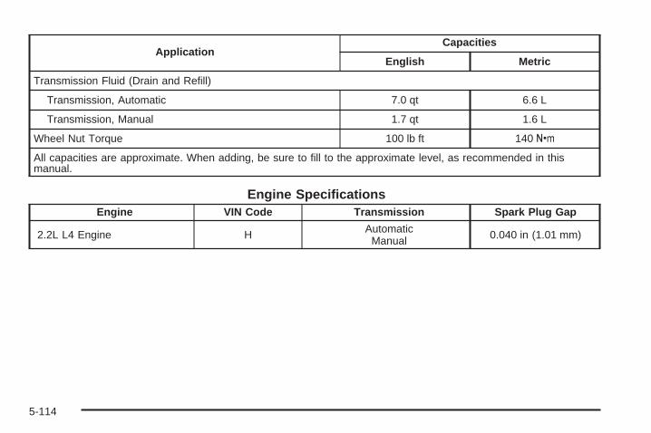
ApplicationCapacities
English Metric
Transmission Fluid (Drain and Refill)
Transmission, Automatic 7.0 qt 6.6 L
Transmission, Manual 1.7 qt 1.6 L
Wheel Nut Torque 100 lb ft 140 Y
All capacities are approximate. When adding, be sure to fill to the approximate level, as recommended in thismanual.
Engine SpecificationsEngine VIN Code Transmission Spark Plug Gap
2.2L L4 Engine H AutomaticManual 0.040 in (1.01 mm)
5-114

Maintenance Schedule ......................................6-2Introduction ...................................................6-2Maintenance Requirements ..............................6-2Your Vehicle and the Environment ....................6-2Using the Maintenance Schedule ......................6-2Scheduled Maintenance ...................................6-4Additional Required Services ............................6-6Maintenance Footnotes ...................................6-7
Owner Checks and Services ............................6-8At Each Fuel Fill ............................................6-9At Least Once a Month ...................................6-9At Least Once a Year ...................................6-10Recommended Fluids and Lubricants ...............6-12Maintenance Replacement Parts .....................6-14Engine Drive Belt Routing ..............................6-15Maintenance Record .....................................6-16
Section 6 Maintenance Schedule
6-1
Maintenance Schedule
IntroductionImportant: Keep engine oil at the proper level andchange as recommended.
Have you purchased the GM Protection Plan? The Plansupplements the vehicle warranties. See the Warrantyand Owner Assistance booklet or your dealer/retailer fordetails.
Maintenance RequirementsNotice: Maintenance intervals, checks, inspections,replacement parts, and recommended fluids andlubricants as prescribed in this manual arenecessary to keep this vehicle in good workingcondition. Any damage caused by failure to followscheduled maintenance might not be covered by thevehicle warranty.
Your Vehicle and the EnvironmentProper vehicle maintenance not only helps to keepthe vehicle in good working condition, but also helpsthe environment. All recommended maintenanceis important. Improper vehicle maintenance can evenaffect the quality of the air we breathe. Improperfluid levels or the wrong tire inflation can increase thelevel of emissions from the vehicle. To help protectthe environment, and to keep the vehicle in goodcondition, be sure to maintain the vehicle properly.
Using the Maintenance ScheduleWe want to help keep this vehicle in good workingcondition. But we do not know exactly how you will driveit. You might drive very short distances only a fewtimes a week. Or you might drive long distances all thetime in very hot, dusty weather. You might use thevehicle in making deliveries. Or you might driveit to work, to do errands, or in many other ways.
Because of all the different ways people use theirvehicles, maintenance needs vary. You might need morefrequent checks and replacements. So please readthe following and note how you drive. If you have anyquestions on how to keep the vehicle in good condition,see your dealer/retailer.
6-2
This schedule is for vehicles that:
• carry passengers and cargo within recommendedlimits on the Tire and Loading Information label.See Loading the Vehicle on page 4-24.
• are driven on reasonable road surfaces within legaldriving limits.
• use the recommended fuel. See Gasoline Octaneon page 5-5.
The services in Scheduled Maintenance on page 6-4should be performed when indicated. See AdditionalRequired Services on page 6-6 and MaintenanceFootnotes on page 6-7 for further information.
{CAUTION:
Performing maintenance work on a vehicle can bedangerous. In trying to do some jobs, you can beseriously injured. Do your own maintenance workonly if you have the required know-how and theproper tools and equipment for the job. If you haveany doubt, see your dealer/retailer to have aqualified technician do the work. See Doing YourOwn Service Work on page 5-4.
Some maintenance services can be complex. So, unlessyou are technically qualified and have the necessaryequipment, have your dealer/retailer do these jobs.
When you go to your dealer/retailer for service, trainedand supported service technicians will perform thework using genuine parts.
To purchase service information, see ServicePublications Ordering Information on page 7-15.
Owner Checks and Services on page 6-8 tells whatshould be checked, when to check it, and whatcan easily be done to help keep the vehicle in goodcondition.
The proper replacement parts, fluids, and lubricants touse are listed in Recommended Fluids and Lubricantson page 6-12 and Maintenance Replacement Partson page 6-14. When the vehicle is serviced, make surethese are used. All parts should be replaced and allnecessary repairs done before you or anyone elsedrives the vehicle. We recommend the use of genuineparts from your dealer/retailer.
6-3
Scheduled MaintenanceWhen the CHANGE OIL SOON message displays,service is required for the vehicle. Have the vehicleserviced as soon as possible within the next 600 miles(1 000 km). It is possible that, if driving under thebest conditions, the engine oil life system may notindicate that vehicle service is necessary for over a year.However, the engine oil and filter must be changed atleast once a year and at this time the system mustbe reset. Your dealer/retailer has trained servicetechnicians who will perform this work using genuineparts and reset the system.
If the engine oil life system is ever reset accidentally,service the vehicle within 3,000 miles (5 000 km)since the last service. Remember to reset the oil lifesystem whenever the oil is changed. See Engine Oil LifeSystem on page 5-16 for information on the EngineOil Life System and resetting the system.
When the CHANGE OIL SOON message appears,certain services, checks, and inspections are required.Required services are described in the following for“Maintenance I” and “Maintenance II.” Generally,it is recommended that the first service beMaintenance I, the second service be Maintenance II,and then alternate Maintenance I and Maintenance IIthereafter. However, in some cases, Maintenance II maybe required more often.
Maintenance I — Use Maintenance I if the CHANGEOIL SOON message displays within 10 months sincethe vehicle was purchased or Maintenance II wasperformed.
Maintenance II — Use Maintenance II if the previousservice performed was Maintenance I. Always useMaintenance II whenever the CHANGE OIL SOONmessage displays 10 months or more since the lastservice or if the message has not come on at all forone year.
6-4
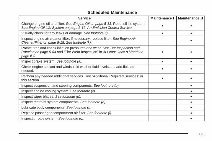
Scheduled MaintenanceService Maintenance I Maintenance II
Change engine oil and filter. See Engine Oil on page 5-13. Reset oil life system.See Engine Oil Life System on page 5-16. An Emission Control Service. • •
Visually check for any leaks or damage. See footnote (j). • •Inspect engine air cleaner filter. If necessary, replace filter. See Engine AirCleaner/Filter on page 5-18. See footnote (k). •
Rotate tires and check inflation pressures and wear. See Tire Inspection andRotation on page 5-64 and “Tire Wear Inspection” in At Least Once a Month onpage 6-9.
• •
Inspect brake system. See footnote (a). • •Check engine coolant and windshield washer fluid levels and add fluid asneeded. • •
Perform any needed additional services. See “Additional Required Services” inthis section. • •
Inspect suspension and steering components. See footnote (b). •Inspect engine cooling system. See footnote (c). •Inspect wiper blades. See footnote (d). •Inspect restraint system components. See footnote (e). •Lubricate body components. See footnote (f). •Replace passenger compartment air filter. See footnote (l). •Inspect throttle system. See footnote (g). •
6-5

Additional Required ServicesThe following services should be performed at the first maintenance service (I or II) after the indicated miles(kilometers) shown for each item.
Additional Required Services
Service and Miles (Kilometers) 25,000(40 000)
50,000(80 000)
75,000(120 000)
100,000(160 000)
125,000(200 000)
150,000(240 000)
Inspect fuel system for damage or leaks. • • • • • •Inspect exhaust system for loose ordamaged components. • • • • • •
Replace engine air cleaner filter. SeeEngine Air Cleaner/Filter on page 5-18. • • •
Change automatic transmission fluidand filter (severe service only).See footnote (h).
• • •
Replace spark plugs. An EmissionControl Service. •
Engine cooling system service (or everyfive years, whichever occurs first).An Emission Control Service.See footnote (i).
•
Inspect engine accessory drive belt.An Emission Control Service.See footnote (m).
•
6-6

Maintenance Footnotes(a) Visually inspect brake lines and hoses for properhook-up, binding, leaks, cracks, chafing, etc. Inspectdisc brake pads for wear and rotors for surfacecondition. Inspect drum brake linings/shoes for wear orcracks. Inspect other brake parts, including drums,wheel cylinders, calipers, parking brake, etc.
(b) Visually inspect front and rear suspension andsteering system for damaged, loose, or missing parts orsigns of wear. Inspect power steering cables forproper hook-up, binding, cracks, chafing, etc.
(c) Visually inspect hoses and have them replaced if theyare cracked, swollen, or deteriorated. Inspect all pipes,fittings and clamps; replace with genuine parts asneeded. To help ensure proper operation, a pressure testof the cooling system and pressure cap and cleaning theoutside of the radiator and air conditioning condenser isrecommended at least once a year.
(d) Inspect wiper blades for wear, cracking, orcontamination. Clean the windshield and wiper blades, ifcontaminated. Replace wiper blades that are worn ordamaged. See Windshield Wiper Blade Replacement onpage 5-47 and Windshield and Wiper Blades onpage 5-104 for more information.
(e) Make sure the safety belt reminder light and safetybelt assemblies are working properly. Look for anyother loose or damaged safety belt system parts. If yousee anything that might keep a safety belt systemfrom doing its job, have it repaired. Have any torn orfrayed safety belts replaced. Also see Checkingthe Restraint Systems on page 1-69.
(f) Lubricate all key lock cylinders, door hinges andlatches, hood hinges and latches and trunk lid hinges andlatches. More frequent lubrication may be required whenexposed to a corrosive environment. Applying siliconegrease on weatherstrips with a clean cloth will makethem last longer, seal better, and not stick or squeak.
6-7
(g) Check system for interference or binding and fordamaged or missing parts. Replace parts as needed.Replace any components that have high effort orexcessive wear. Do not lubricate accelerator or cruisecontrol cables.
(h) Change automatic transmission fluid and filter if thevehicle is mainly driven under one or more of theseconditions:
− In heavy city traffic where the outside temperatureregularly reaches 90°F (32°C) or higher.
− In hilly or mountainous terrain.− When doing frequent trailer towing.− Uses such as found in taxi, police, or delivery
service.
If the vehicle is not used under any of these conditions,the fluid and filter do not require changing.
(i) Drain, flush, and refill cooling system. This service canbe complex; you should have your dealer/retailer performthis service. See Engine Coolant on page 5-24 for what touse. Inspect hoses. Clean radiator, condenser, pressurecap, and filler neck. Pressure test the cooling system andpressure cap.
(j) A fluid loss in any vehicle system could indicate aproblem. Have the system inspected and repaired andthe fluid level checked. Add fluid if needed.
(k) If driving regularly under dusty conditions, inspectthe filter at each engine oil change.
(l) If driving regularly under dusty conditions, the filtermay require replacement more often.
(m) Visually inspect belt for fraying, excessive cracks, orobvious damage. Replace belt if necessary.
Owner Checks and ServicesThese owner checks and services should be performedat the intervals specified to help ensure vehicle safety,dependability, and emission control performance. Yourdealer/retailer can assist with these checks and services.
Be sure any necessary repairs are completed at once.Whenever any fluids or lubricants are added to thevehicle, make sure they are the proper ones, as shownin Recommended Fluids and Lubricants on page 6-12.
6-8

At Each Fuel FillIt is important to perform these underhood checks ateach fuel fill.
Engine Oil Level Check
Notice: It is important to check the engine oilregularly and keep it at the proper level. Failure tokeep the engine oil at the proper level can causedamage to the engine not covered by the vehiclewarranty.
Check the engine oil level and add the proper oil ifnecessary. See Engine Oil on page 5-13.
Engine Coolant Level CheckCheck the engine coolant level and add DEX-COOL®
coolant mixture if necessary. See Engine Coolanton page 5-24.
Windshield Washer Fluid Level CheckCheck the windshield washer fluid level in the windshieldwasher fluid reservoir and add the proper fluid ifnecessary.
At Least Once a Month
Tire Inflation CheckInspect the vehicle’s tires and make sure they are inflatedto the correct pressures. Do not forget to check the sparetire, if the vehicle has one. See Inflation - Tire Pressureon page 5-56. If the vehicle has a spare tire, check tomake sure it is stored securely. See Changing a Flat Tireon page 5-84.
Tire Wear InspectionTire rotation may be required for high mileage highwaydrivers prior to the Engine Oil Life System servicenotification. Check the tires for wear and, if necessary,rotate the tires. See Tire Inspection and Rotation onpage 5-64.
6-9
At Least Once a Year
Starter Switch Check
{CAUTION:
When you are doing this inspection, the vehiclecould move suddenly. If the vehicle moves, you orothers could be injured.
1. Before starting this check, be sure there is enoughroom around the vehicle.
2. Firmly apply both the parking brake and the regularbrake. See Parking Brake on page 2-30.Do not use the accelerator pedal, and be ready toturn off the engine immediately if it starts.
3. For automatic transmission vehicles, try to start theengine in each gear. The vehicle should start only inP (Park) or N (Neutral). If the vehicle starts in anyother position, contact your dealer/retailer for service.For manual transmission vehicles, put the shift leverin Neutral, push the clutch pedal down halfway,and try to start the engine. The vehicle should startonly when the clutch pedal is pushed down all
the way to the floor. If the vehicle starts when theclutch pedal is not pushed all the way down, contactyour dealer/retailer for service.
Automatic Transmission Shift LockControl System Check
{CAUTION:
When you are doing this inspection, the vehiclecould move suddenly. If the vehicle moves, you orothers could be injured.
1. Before starting this check, be sure there is enoughroom around the vehicle. It should be parked on alevel surface.
2. Firmly apply the parking brake. See Parking Brakeon page 2-30.Be ready to apply the regular brake immediately ifthe vehicle begins to move.
3. With the engine off, turn the ignition to ON/RUN,but do not start the engine. Without applying theregular brake, try to move the shift lever outof P (Park) with normal effort. If the shift levermoves out of P (Park), contact your dealer/retailerfor service.
6-10
Ignition Transmission Lock CheckWhile parked, and with the parking brake set, try to turnthe ignition to LOCK/OFF in each shift lever position.• For automatic transmission vehicles, the ignition
should turn to LOCK/OFF only when the shiftlever is in P (Park). The ignition key should comeout only in LOCK/OFF.
• For manual transmission vehicles, the ignition keyshould come out only in LOCK/OFF.
Turn the steering wheel to the left and to the right.It should only lock when turned to the right. Contactyour dealer/retailer if service is required.
Parking Brake and AutomaticTransmission P (Park) MechanismCheck
{CAUTION:
When you are doing this check, the vehicle couldbegin to move. You or others could be injured andproperty could be damaged. Make sure there isroom in front of the vehicle in case it begins to roll.Be ready to apply the regular brake at onceshould the vehicle begin to move.
Park on a fairly steep hill, with the vehicle facingdownhill. Keeping your foot on the regular brake, set theparking brake.
• To check the parking brake’s holding ability: Withthe engine running and transmission in N (Neutral),slowly remove foot pressure from the regularbrake pedal. Do this until the vehicle is held by theparking brake only.
• To check the P (Park) mechanism’s holding ability:With the engine running, shift to P (Park). Thenrelease the parking brake followed by the regularbrake.
Contact your dealer/retailer if service is required.
Underbody Flushing ServiceAt least every spring, use plain water to flush anycorrosive materials from the underbody. Take care toclean thoroughly any areas where mud and other debriscan collect.
Tire Sealant and Compressor KitIf the vehicle has a Tire Sealant and Compressor Kit,check the sealant expiration date printed on theinstruction label of the kit at least once a year.See your dealer/retailer for a replacement canister.
6-11

Recommended Fluids andLubricantsFluids and lubricants identified below by name, partnumber, or specification can be obtained from yourdealer/retailer.
Usage Fluid/Lubricant
Engine Oil
Engine oil which meets GMStandard GM6094M and displaysthe American Petroleum InstituteCertified for Gasoline Enginesstarburst symbol. To determine theproper viscosity for your vehicle’sengine, see Engine Oil onpage 5-13.
Engine Coolant
50/50 mixture of clean, drinkablewater and use only DEX-COOL®
Coolant. See Engine Coolant onpage 5-24.
Usage Fluid/Lubricant
Hydraulic BrakeSystem
Delco® Supreme 11 Brake Fluid orequivalent DOT-3 brake fluid.
HydraulicClutch System
Delco® Supreme 11 Brake Fluid orequivalent DOT-3 brake fluid.
WindshieldWasher Optikleen® Washer Solvent.
Parking BrakeCable Guides
Chassis Lubricant(GM Part No. 12377985,in Canada 88901242) or lubricantmeeting requirements of NLGI #2,Category LB or GC-LB.
ManualTransmission
Manual Transmission Fluid(GM Part No. U.S. 88861800,in Canada 88861801).
AutomaticTransmission
DEXRON®-VI AutomaticTransmission Fluid.
6-12

Usage Fluid/Lubricant
Key LockCylinders
Multi-Purpose Lubricant, Superlube(GM Part No. U.S. 12346241,in Canada 10953474).
ManualTransmissionShift Linkage
Chassis Lubricant(GM Part No. U.S. 12377985,in Canada 88901242) or lubricantmeeting requirements of NLGI #2,Category LB or GC-LB.
ChassisLubrication
Chassis Lubricant(GM Part No. U.S. 12377985,in Canada 88901242) or lubricantmeeting requirements of NLGI #2,Category LB or GC-LB.
Usage Fluid/Lubricant
Hood LatchAssembly,Secondary
Latch, Pivots,Spring Anchor,
andRelease Pawl
Lubriplate Lubricant Aerosol(GM Part No. U.S. 12346293,in Canada 992723) or lubricantmeeting requirements of NLGI #2,Category LB or GC-LB.
Hood and DoorHinges
Multi-Purpose Lubricant, Superlube(GM Part No. U.S. 12346241,in Canada 10953474).
WeatherstripConditioning
Weatherstrip Lubricant(GM Part No. U.S. 3634770,in Canada 10953518) orDielectric Silicone Grease(GM Part No. U.S. 12345579,in Canada 992887).
6-13

Maintenance Replacement PartsReplacement parts identified below by name, part number, or specification can be obtained from your GMdealer/retailer.
Maintenance Replacement PartsPart GM Part Number ACDelco Part Number
Engine Air Cleaner/Filter 22731072 A3054C
Engine Oil Filter 12605566 PF457G
Spark Plugs 12598004 41-103
Passenger Compartment Air Filter 52493319 CF125
Wiper Blades
Driver Side — 22 in (56 cm) 15243233 —
Passenger Side — 17 in (43 cm) 15243232 —
6-14
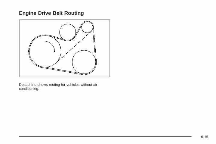
Engine Drive Belt Routing
Dotted line shows routing for vehicles without airconditioning.
6-15

Maintenance RecordAfter the scheduled services are performed, record the date, odometer reading, who performed the service, and thetype of services performed in the boxes provided. See Maintenance Requirements on page 6-2. Any additionalinformation from Owner Checks and Services on page 6-8 can be added on the following record pages. You shouldretain all maintenance receipts.
Maintenance Record
Date OdometerReading Serviced By Maintenance I or
Maintenance II Services Performed
6-16
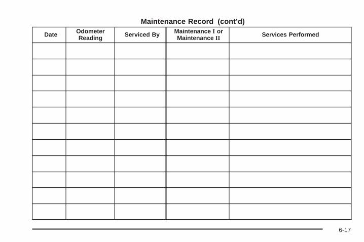
Maintenance Record (cont’d)
Date OdometerReading Serviced By Maintenance I or
Maintenance II Services Performed
6-17
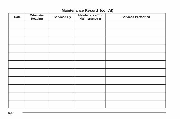
Maintenance Record (cont’d)
Date OdometerReading Serviced By Maintenance I or
Maintenance II Services Performed
6-18

Customer Assistance and Information ...............7-2Customer Satisfaction Procedure ......................7-2Online Owner Center ......................................7-5Customer Assistance for Text Telephone
(TTY) Users ...............................................7-6Customer Assistance Offices ............................7-6GM Mobility Reimbursement Program ................7-7Roadside Assistance Program ..........................7-7Scheduling Service Appointments ....................7-10Courtesy Transportation .................................7-10Collision Damage Repair ................................7-11
Reporting Safety Defects ................................7-14Reporting Safety Defects to the
United States Government ..........................7-14Reporting Safety Defects to the
Canadian Government ................................7-15Reporting Safety Defects to
General Motors .........................................7-15Service Publications Ordering Information .........7-15
Vehicle Data Recording and Privacy ................7-16Event Data Recorders ...................................7-17OnStar® ......................................................7-18Navigation System ........................................7-18Radio Frequency
Identification (RFID) ...................................7-18
Section 7 Customer Assistance Information
7-1

Customer Assistance andInformation
Customer Satisfaction ProcedureYour satisfaction and goodwill are important toyour dealer and to Pontiac. Normally, any concerns withthe sales transaction or the operation of the vehiclewill be resolved by the dealer’s sales or servicedepartments. Sometimes, however, despite the bestintentions of all concerned, misunderstandings canoccur. If your concern has not been resolved to yoursatisfaction, the following steps should be taken:
STEP ONE: Discuss your concern with a member ofdealership management. Normally, concerns can bequickly resolved at that level. If the matter has alreadybeen reviewed with the sales, service, or parts manager,contact the owner of the dealership or the generalmanager.
STEP TWO: If after contacting a member of dealershipmanagement, it appears your concern cannot beresolved by the dealership without further help, in theU.S., call the Pontiac Customer Assistance Centerat 1-800-762-2737. In Canada, call General Motorsof Canada Customer Communication Centre at1-800-263-3777 (English) or 1-800-263-7854 (French).
We encourage you to call the toll-free number inorder to give your inquiry prompt attention. Have thefollowing information available to give the CustomerAssistance Representative:
• Vehicle Identification Number (VIN). This isavailable from the vehicle registration or title, or theplate at the top left of the instrument panel andvisible through the windshield.
• Dealership name and location.
• Vehicle delivery date and present mileage.
When contacting Pontiac, remember that your concernwill likely be resolved at a dealer’s facility. That is why wesuggest you follow Step One first.
7-2
STEP THREE — U.S. Owners: Both General Motorsand your dealer are committed to making sure you arecompletely satisfied with your new vehicle. However, ifyou continue to remain unsatisfied after following theprocedure outlined in Steps One and Two, you can filewith the BBB Auto Line Program to enforce your rights.
The BBB Auto Line Program is an out of court programadministered by the Council of Better Business Bureausto settle automotive disputes regarding vehicle repairs orthe interpretation of the New Vehicle Limited Warranty.Although you may be required to resort to this informaldispute resolution program prior to filing a court action,use of the program is free of charge and your case willgenerally be heard within 40 days. If you do not agreewith the decision given in your case, you may reject it andproceed with any other venue for relief available to you.
You can contact the BBB Auto Line Program using thetoll-free telephone number or write them at the followingaddress:
BBB Auto Line ProgramCouncil of Better Business Bureaus, Inc.4200 Wilson BoulevardSuite 800Arlington, VA 22203-1838
Telephone: 1-800-955-5100www.dr.bbb.org/goauto
This program is available in all 50 states and theDistrict of Columbia. Eligibility is limited by vehicle age,mileage and other factors. General Motors reservesthe right to change eligibility limitations and/ordiscontinue its participation in this program.
7-3

STEP THREE — Canadian Owners: In the event thatyou do not feel your concerns have been addressed afterfollowing the procedure outlined in Steps One and Two,General Motors of Canada Limited wants you to be awareof its participation in a no-charge Mediation/ArbitrationProgram. General Motors of Canada Limited hascommitted to binding arbitration of owner disputesinvolving factory-related vehicle service claims. Theprogram provides for the review of the facts involved byan impartial third party arbiter, and may include aninformal hearing before the arbiter. The program isdesigned so that the entire dispute settlement process,from the time you file your complaint to the final decision,should be completed in approximately 70 days. Webelieve our impartial program offers advantages overcourts in most jurisdictions because it is informal, quick,and free of charge.
For further information concerning eligibility in theCanadian Motor Vehicle Arbitration Plan (CAMVAP), calltoll-free 1-800-207-0685, or call the General MotorsCustomer Communication Centre, 1-800-263-3777(English), 1-800-263-7854 (French), or write to:
Mediation/Arbitration Programc/o Customer Communication CentreGeneral Motors of Canada LimitedMail Code: CA1-163-0051908 Colonel Sam DriveOshawa, Ontario L1H 8P7
Your inquiry should be accompanied by the VehicleIdentification Number (VIN).
7-4

Online Owner Center
Online Owner Center (U.S.) —www.gmownercenter.com/pontiacInformation and services customized for your specificvehicle — all in one convenient place.
• Digital owner manual, warranty information,and more
• Online service and maintenance records
• Find Pontiac dealers for service nationwide
• Exclusive privileges and offers
• Recall notices for your specific vehicle
• OnStar® and GM Cardmember Services Earningssummaries
Other Helpful Links:Pontiac − www.pontiac.com
Pontiac Merchandise — www.pontiacmall.com
Help Center — www.pontiac.com/helpcenter
• FAQ
• Contact Us
My GM Canada (Canada) — www.gm.caMy GM Canada is a password-protected section ofwww.gm.ca where you can save information onGM vehicles, get personalized offers, and use handytools and forms with greater ease.
Here are a few of the valuable tools and services youwill have access to:
• My Showroom: Find and save information onvehicles and current offers in your area.
• My Dealers/Retailers: Save details such as addressand phone number for each of your preferred GMdealers/retailers.
• My Driveway: Access quick links to parts andservice estimates, check trade-in values, orschedule a service appointment by adding thevehicles you own to your driveway profile.
• My Preferences: Manage your profile and use toolsand forms with greater ease.
To sign up, visit the My GM Canada section withinwww.gm.ca.
7-5

Customer Assistance for TextTelephone (TTY) UsersTo assist customers who are deaf, hard of hearing, orspeech-impaired and who use Text Telephones (TTYs),Pontiac has TTY equipment available at its CustomerAssistance Center. Any TTY user in the U.S. cancommunicate with Pontiac by dialing: 1-800-833-PONT(7668). (TTY users in Canada can dial 1-800-263-3830.)
Customer Assistance OfficesPontiac encourages customers to call the toll-freenumber for assistance. However, if a customer wishes towrite or e-mail Pontiac, the letter should be addressed to:
United States — Customer AssistancePontiac Customer Assistance CenterP.O. Box 33172Detroit, MI 48232-5172
www.Pontiac.com1-800-762-2737 or1-800-833-7668 (For Text Telephone devices (TTYs))Roadside Assistance: 1-800-ROADSIDE (762-3743)
From Puerto Rico:1-800-496-9992 (English)1-800-496-9993 (Spanish)
From U.S. Virgin Islands:1-800-496-9994
Canada — Customer AssistanceGeneral Motors of Canada LimitedCustomer Communication Centre, CA1-163-0051908 Colonel Sam DriveOshawa, Ontario L1H 8P7
www.gmcanada.com1-800-263-3777 (English)1-800-263-7854 (French)1-800-263-3830 (For Text Telephone devices (TTYs))Roadside Assistance: 1-800-268-6800
Overseas — Customer AssistancePlease contact the local General Motors Business Unit.
Mexico, Central America and CaribbeanIslands/Countries (Except Puerto Ricoand U.S. Virgin Islands) — CustomerAssistance
General Motors de Mexico, S. de R.L. de C.V.Customer Assistance CenterPaseo de la Reforma #2740Col. Lomas de BezaresC.P. 11910, Mexico, D.F.01-800-508-0000Long Distance: 011-52-53 29 0 800
7-6

GM Mobility ReimbursementProgram
This program, available to qualified applicants, canreimburse you up to $1,000 of the cost of eligibleaftermarket adaptive equipment required for your vehicle,such as hand controls or a wheelchair/scooter lift.
The offer is available for a very limited period of timefrom the date of vehicle purchase/lease. For moredetails, or to determine your vehicle’s eligibility, visitgmmobility.com or call the GM Mobility AssistanceCenter at 1-800-323-9935. Text telephone (TTY) users,call 1-800-833-9935.
General Motors of Canada also has a Mobility Program.Call 1-800-GM-DRIVE (463-7483) for details. TTYusers call 1-800-263-3830.
Roadside Assistance ProgramFor U.S. purchased vehicles, call 1-800-ROADSIDE(762-3743); (Text telephone (TTY): 1-888-889-2438).
For Canadian purchased vehicles, call 1-800-268-6800.
Service is available 24 hours a day, 365 days a year.
Calling for AssistanceWhen calling Roadside Assistance, have the followinginformation ready:
• Your name, home address, and home telephonenumber
• Telephone number of your location
• Location of the vehicle
• Model, year, color, and license plate number of thevehicle
• Odometer reading, Vehicle Identification Number(VIN), and delivery date of the vehicle
• Description of the problem
7-7

CoverageServices are provided up to 5 years/100,000 miles(160 000 km), whichever comes first.
In the U.S., anyone driving the vehicle is covered.In Canada, a person driving the vehicle withoutpermission from the owner is not covered.
Roadside Assistance is not a part of the New VehicleLimited Warranty. Pontiac and General Motors ofCanada Limited reserve the right to make any changesor discontinue the Roadside Assistance program atany time without notification.
Pontiac and General Motors of Canada Limited reservethe right to limit services or payment to an owner ordriver if they decide the claims are made too often, orthe same type of claim is made many times.
Services Provided• Emergency Fuel Delivery: Delivery of enough fuel
for the vehicle to get to the nearest service station.
• Lock-Out Service: Service is provided to unlock thevehicle if you are locked out. A remote unlock maybe available if you have OnStar®. For securityreasons, the driver must present identificationbefore this service is given.
• Emergency Tow From a Public Road or Highway:Tow to the nearest Pontiac dealer for warrantyservice, or if the vehicle was in a crash and cannotbe driven. Assistance is also given when the vehicleis stuck in sand, mud, or snow.
• Flat Tire Change: Service is provided to change aflat tire with the spare tire. The spare tire, if equipped,must be in good condition and properly inflated.It is the owner’s responsibility for the repair orreplacement of the tire if it is not covered by thewarranty.
• Battery Jump Start: Service is provided to jumpstart a dead battery.
• Trip Interruption Benefits and Assistance: If yourtrip is interrupted due to a warranty failure, incidentalexpenses may be reimbursed during the 5 years/100,000 miles (160 000 km) Powertrain warrantyperiod. Items considered are hotel, meals, andrental car.
7-8
Services Not Included in RoadsideAssistance• Impound towing caused by violation of any laws.
• Legal fines.
• Mounting, dismounting or changing of snow tires,chains, or other traction devices.
• Towing or services for vehicles driven on anon-public road or highway.
Services Specific to CanadianPurchased Vehicles• Fuel delivery: Reimbursement is approximately
$5 Canadian. Diesel fuel delivery may be restricted.Propane and other fuels are not provided throughthis service.
• Lock-Out Service: Vehicle registration is required.
• Trip Routing Service: Detailed maps of NorthAmerica are provided when requested either with themost direct route or the most scenic route. There is alimit of six requests per year. Additional travelinformation is also available. Allow three weeks fordelivery.
• Trip Interruption Benefits and Assistance: Mustbe over 250 kilometres from where your trip wasstarted to qualify. General Motors of Canada Limitedrequires pre-authorization, original detailed receipts,and a copy of the repair orders. Once authorizationhas been received, the Roadside Assistance advisorwill help you make arrangements and explain how toreceive payment.
• Alternative Service: If assistance cannot beprovided right away, the Roadside Assistanceadvisor may give you permission to get localemergency road service. You will receive payment,up to $100, after sending the original receipt toRoadside Assistance. Mechanical failures may becovered, however any cost for parts and labor forrepairs not covered by the warranty are the ownerresponsibility.
7-9

Scheduling Service AppointmentsWhen your vehicle requires warranty service, contactyour dealer/retailer and request an appointment.By scheduling a service appointment and advising yourservice consultant of your transportation needs, yourdealer/retailer can help minimize your inconvenience.
If your vehicle cannot be scheduled into the servicedepartment immediately, keep driving it until it can bescheduled for service, unless, of course, the problem issafety-related. If it is, please call your dealership/retailer,let them know this, and ask for instructions.
If the dealer/retailer requests you to bring the vehicle forservice, you are urged to do so as early in the workday as possible to allow for the same day repair.
Courtesy TransportationTo enhance your ownership experience, we andour participating dealers are proud to offer CourtesyTransportation, a customer support program for vehicleswith the Bumper to Bumper (Base Warranty Coverageperiod in Canada) and extended powertrain, and hybridspecific warranty in both the U.S. and Canada.
Several courtesy transportation options are available toassist in reducing your inconvenience when warrantyrepairs are required.
Courtesy Transportation is not a part of the New VehicleLimited Warranty. A separate booklet entitled “Warrantyand Owner Assistance Information” furnished witheach new vehicle provides detailed warranty coverageinformation.
Transportation OptionsWarranty service can generally be completed while youwait. However, if you are unable to wait, GM helpsto minimize your inconvenience by providing severaltransportation options. Depending on the circumstances,your dealer can offer you one of the following:
Shuttle ServiceShuttle service is the preferred means of offeringCourtesy Transportation. Dealers may provide you withshuttle service to get you to your destination with minimalinterruption of your daily schedule. This includes one-wayor round trip shuttle service within reasonable time anddistance parameters of the dealer’s area.
Public Transportation or FuelReimbursementIf your vehicle requires overnight warranty repairs,and public transportation is used instead of the dealer’sshuttle service, the expense must be supported byoriginal receipts and can only be up to the maximumamount allowed by GM for shuttle service.
7-10

In addition, for U.S. customers, should you arrangetransportation through a friend or relative, limitedreimbursement for reasonable fuel expenses may beavailable. Claim amounts should reflect actual costs andbe supported by original receipts. See your dealer forinformation regarding the allowance amounts forreimbursement of fuel or other transportation costs.
Courtesy Rental VehicleYour dealer may arrange to provide you with a courtesyrental vehicle or reimburse you for a rental vehiclethat you obtain if your vehicle is kept for an overnightwarranty repair. Rental reimbursement will be limitedand must be supported by original receipts. Thisrequires that you sign and complete a rental agreementand meet state/provincial, local, and rental vehicleprovider requirements. Requirements vary and mayinclude minimum age requirements, insurance coverage,credit card, etc. You are responsible for fuel usagecharges and may also be responsible for taxes, levies,usage fees, excessive mileage, or rental usagebeyond the completion of the repair.
It may not be possible to provide a like-vehicle as acourtesy rental.
Additional Program InformationAll program options, such as shuttle service, may not beavailable at every dealer. Please contact your dealerfor specific information about availability. All CourtesyTransportation arrangements will be administeredby appropriate dealer personnel.
General Motors reserves the right to unilaterally modify,change or discontinue Courtesy Transportation at anytime and to resolve all questions of claim eligibilitypursuant to the terms and conditions described hereinat its sole discretion.
Collision Damage RepairIf your vehicle is involved in a collision and it is damaged,have the damage repaired by a qualified technician usingthe proper equipment and quality replacement parts.Poorly performed collision repairs diminish yourvehicle’s resale value, and safety performance canbe compromised in subsequent collisions.
7-11
Collision PartsGenuine GM Collision parts are new parts made with thesame materials and construction methods as the partswith which your vehicle was originally built. Genuine GMCollision parts are your best choice to ensure that yourvehicle’s designed appearance, durability, and safety arepreserved. The use of Genuine GM parts can helpmaintain your GM New Vehicle Warranty.
Recycled original equipment parts may also be used forrepair. These parts are typically removed from vehiclesthat were total losses in prior crashes. In most cases,the parts being recycled are from undamaged sectionsof the vehicle. A recycled original equipment GMpart, may be an acceptable choice to maintain yourvehicle’s originally designed appearance and safetyperformance, however, the history of these parts is notknown. Such parts are not covered by your GM NewVehicle Limited Warranty, and any related failuresare not covered by that warranty.
Aftermarket collision parts are also available. These aremade by companies other than GM and may not havebeen tested for your vehicle. As a result, these parts mayfit poorly, exhibit premature durability/corrosion problems,and may not perform properly in subsequent collisions.Aftermarket parts are not covered by your GM NewVehicle Limited Warranty, and any vehicle failure relatedto such parts are not covered by that warranty.
Repair FacilityWe recommend that you choose a collision repairfacility that meets your needs before you ever needcollision repairs. Your dealer/retailer may have acollision repair center with GM-trained technicians andstate of the art equipment, or be able to recommenda collision repair center that has GM-trained techniciansand comparable equipment.
Insuring Your VehicleProtect your investment in your GM vehicle withcomprehensive and collision insurance coverage. Thereare significant differences in the quality of coverageafforded by various insurance policy terms. Manyinsurance policies provide reduced protection to yourGM vehicle by limiting compensation for damage repairsby using aftermarket collision parts. Some insurancecompanies will not specify aftermarket collisionparts. When purchasing insurance, we recommend thatyou assure your vehicle will be repaired with GMoriginal equipment collision parts. If such insurancecoverage is not available from your current insurancecarrier, consider switching to another insurance carrier.If your vehicle is leased, the leasing company mayrequire you to have insurance that assures repairs withGenuine GM Original Equipment Manufacturer (OEM)parts or Genuine Manufacturer replacement parts.Read your lease carefully, as you may be charged atthe end of your lease for poor quality repairs.
7-12

If a Crash OccursHere is what to do if you are involved in a crash.
• Check to make sure that you are all right. If youare uninjured, make sure that no one else in yourvehicle, or the other vehicle, is injured.
• If there has been an injury, call emergency servicesfor help. Do not leave the scene of a crash until allmatters have been taken care of. Move your vehicleonly if its position puts you in danger or you areinstructed to move it by a police officer.
• Give only the necessary and requested informationto police and other parties involved in the crash.Do not discuss your personal condition, mentalframe of mind, or anything unrelated to the crash.This will help guard against post-crash legal action.
• If you need roadside assistance, call GM RoadsideAssistance. See Roadside Assistance Program onpage 7-7 for more information.
• If your vehicle cannot be driven, know where thetowing service will be taking it. Get a card from thetow truck operator or write down the driver’s name,the service’s name, and the phone number.
• Remove any valuables from your vehicle before it istowed away. Make sure this includes your insuranceinformation and registration if you keep these itemsin your vehicle.
• Gather the important information you will need fromthe other driver. Things like name, address, phonenumber, driver’s license number, vehicle licenseplate, vehicle make, model and model year, VehicleIdentification Number (VIN), insurance company andpolicy number, and a general description of thedamage to the other vehicle.
• If possible, call your insurance company from thescene of the crash. They will walk you through theinformation they will need. If they ask for a policereport, phone or go to the police departmentheadquarters the next day and you can get a copy ofthe report for a nominal fee. In some states/provinceswith “no fault” insurance laws, a report may not benecessary. This is especially true if there are noinjuries and both vehicles are driveable.
• Choose a reputable collision repair facility for yourvehicle. Whether you select a dealer/retailer or aprivate collision repair facility to fix the damage,make sure you are comfortable with them.Remember, you will have to feel comfortable withtheir work for a long time.
• Once you have an estimate, read it carefully andmake sure you understand what work will beperformed on your vehicle. If you have a question,ask for an explanation. Reputable shops welcomethis opportunity.
7-13

Managing the Vehicle Damage RepairProcessIn the event that your vehicle requires damage repairs,GM recommends that you take an active role in itsrepair. If you have a pre-determined repair facility ofchoice, take your vehicle there, or have it towed there.Specify to the facility that any required replacementcollision parts be original equipment parts, either newGenuine GM parts or recycled original GM parts.Remember, recycled parts will not be covered by yourGM vehicle warranty.
Insurance pays the bill for the repair, but you mustlive with the repair. Depending on your policy limits,your insurance company may initially value the repairusing aftermarket parts. Discuss this with your repairprofessional, and insist on Genuine GM parts. Rememberif your vehicle is leased you may be obligated to have thevehicle repaired with Genuine GM parts, even if yourinsurance coverage does not pay the full cost.
If another party’s insurance company is paying forthe repairs, you are not obligated to accept a repairvaluation based on that insurance company’s collisionpolicy repair limits, as you have no contractual limits withthat company. In such cases, you can have control ofthe repair and parts choices as long as cost stays withinreasonable limits.
Reporting Safety Defects
Reporting Safety Defects to theUnited States GovernmentIf you believe that your vehicle has a defect whichcould cause a crash or could cause injury ordeath, you should immediately inform the NationalHighway Traffic Safety Administration (NHTSA)in addition to notifying General Motors.
If NHTSA receives similar complaints, it may openan investigation, and if it finds that a safety defectexists in a group of vehicles, it may order a recalland remedy campaign. However, NHTSA cannotbecome involved in individual problems betweenyou, your dealer/retailer, or General Motors.
To contact NHTSA, you may call the VehicleSafety Hotline toll-free at 1-888-327-4236 (TTY:1-800-424-9153); go to safercar.gov; or write to:
Administrator, NHTSA1200 New Jersey Avenue, S.E.Washington D.C., 20590
You can also obtain other information about motorvehicle safety from safercar.gov.
7-14
Reporting Safety Defects to theCanadian GovernmentIf you live in Canada, and you believe that yourvehicle has a safety defect, notify Transport Canadaimmediately, in addition to notifying General Motors ofCanada Limited. Call them at 1-800-333-0510 or write to:
Transport CanadaRoad Safety Branch2780 Sheffield RoadOttawa, Ontario K1B 3V9
Reporting Safety Defects toGeneral MotorsIn addition to notifying NHTSA (or Transport Canada) ina situation like this, please notify General Motors.
Call 1-800-762-2737, or write:
Pontiac Customer Assistance CenterP.O. Box 33172Detroit, MI 48232-5172
In Canada, call 1-800-263-3777 (English) or1-800-263-7854 (French), or write:
General Motors of Canada LimitedCustomer Communication Centre, CA1-163-0051908 Colonel Sam DriveOshawa, Ontario L1H 8P7
Service Publications OrderingInformation
Service ManualsService Manuals have the diagnosis and repairinformation on engines, transmission, axle suspension,brakes, electrical, steering, body, etc.
Service BulletinsService Bulletins give additional technical serviceinformation needed to knowledgeably serviceGeneral Motors cars and trucks. Each bulletin containsinstructions to assist in the diagnosis and service ofyour vehicle.
Owner InformationOwner publications are written specifically for ownersand intended to provide basic operational informationabout the vehicle. The owner manual includes theMaintenance Schedule for all models.
In-Portfolio: Includes a Portfolio, Owner Manual, andWarranty Booklet.
RETAIL SELL PRICE: $35.00 (U.S.) plus processing fee
Without Portfolio: Owner Manual only.
RETAIL SELL PRICE: $25.00 (U.S.) plus processing fee
7-15
Current and Past Model Order FormsTechnical Service Bulletins and Manuals are availablefor current and past model GM vehicles. To requestan order form, specify year and model name ofthe vehicle.
ORDER TOLL FREE: 1-800-551-4123Monday-Friday 8:00 AM - 6:00 PMEastern TimeFor Credit Card Orders Only(VISA-MasterCard-Discover), visit Helm, Inc.on the World Wide Web at: helminc.com
Or you can write to:
Helm, IncorporatedP.O. Box 07130Detroit, MI 48207
Prices are subject to change without notice and withoutincurring obligation. Allow ample time for delivery.
Note to Canadian Customers: All listed prices arequoted in U.S. funds. Canadian residents are to makechecks payable in U.S. funds.
Vehicle Data Recording andPrivacyYour GM vehicle has a number of sophisticatedcomputers that record information about the vehicle’sperformance and how it is driven. For example, yourvehicle uses computer modules to monitor and controlengine and transmission performance, to monitor theconditions for airbag deployment and deploy airbags in acrash and, if so equipped, to provide antilock braking tohelp the driver control the vehicle. These modules maystore data to help your dealer/retailer technician serviceyour vehicle. Some modules may also store dataabout how you operate the vehicle, such as rate of fuelconsumption or average speed. These modules may alsoretain the owner’s personal preferences, such as radiopre-sets, seat positions, and temperature settings.
7-16

Event Data RecordersThis vehicle has an Event Data Recorder (EDR).The main purpose of an EDR is to record, in certaincrash or near crash-like situations, such as an airbagdeployment or hitting a road obstacle, data that will assistin understanding how a vehicle’s systems performed.The EDR is designed to record data related to vehicledynamics and safety systems for a short period of time,typically 30 seconds or less. The EDR in this vehicle isdesigned to record such data as:
• How various systems in your vehicle were operating
• Whether or not the driver and passenger safety beltswere buckled/fastened
• How far, if at all, the driver was pressing theaccelerator and/or brake pedal
• How fast the vehicle was traveling
This data can help provide a better understanding of thecircumstances in which crashes and injuries occur.
Important: EDR data is recorded by your vehicle onlyif a non-trivial crash situation occurs; no data is recordedby the EDR under normal driving conditions and nopersonal data (e.g., name, gender, age, and crashlocation) is recorded. However, other parties, such as lawenforcement, could combine the EDR data with the typeof personally identifying data routinely acquired during acrash investigation.
To read data recorded by an EDR, special equipmentis required, and access to the vehicle or the EDR isneeded. In addition to the vehicle manufacturer, otherparties, such as law enforcement, that have the specialequipment, can read the information if they have accessto the vehicle or the EDR.
GM will not access this data or share it with othersexcept: with the consent of the vehicle owner or, if thevehicle is leased, with the consent of the lessee; inresponse to an official request of police or similargovernment office; as part of GM’s defense of litigationthrough the discovery process; or, as required by law.Data that GM collects or receives may also be used forGM research needs or may be made available to othersfor research purposes, where a need is shown and thedata is not tied to a specific vehicle or vehicle owner.
7-17
OnStar®
If your vehicle has OnStar and you subscribe to theOnStar services, please refer to the OnStar Terms andConditions for information on data collection and use.See also OnStar® System on page 2-37 in this manualfor more information.
Navigation SystemIf your vehicle has a navigation system, use of thesystem may result in the storage of destinations,addresses, telephone numbers, and other tripinformation. Refer to the navigation system operatingmanual for information on stored data and for deletioninstructions.
Radio FrequencyIdentification (RFID)RFID technology is used in some vehicles for functionssuch as tire pressure monitoring and ignition systemsecurity, as well as in connection with conveniencessuch as key fobs for remote door locking/unlocking andstarting, and in-vehicle transmitters for garage dooropeners. RFID technology in GM vehicles does not useor record personal information or link with any otherGM system containing personal information.
7-18
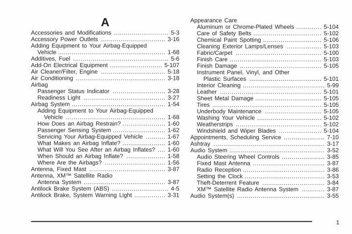
AAccessories and Modifications ............................ 5-3Accessory Power Outlets ................................. 3-16Adding Equipment to Your Airbag-Equipped
Vehicle ....................................................... 1-68Additives, Fuel ................................................. 5-6Add-On Electrical Equipment ........................... 5-107Air Cleaner/Filter, Engine ................................. 5-18Air Conditioning .............................................. 3-18Airbag
Passenger Status Indicator ........................... 3-28Readiness Light .......................................... 3-27
Airbag System ................................................ 1-54Adding Equipment to Your Airbag-Equipped
Vehicle ................................................... 1-68How Does an Airbag Restrain? ...................... 1-60Passenger Sensing System ........................... 1-62Servicing Your Airbag-Equipped Vehicle .......... 1-67What Makes an Airbag Inflate? ...................... 1-60What Will You See After an Airbag Inflates? .... 1-60When Should an Airbag Inflate? .................... 1-58Where Are the Airbags? ............................... 1-56
Antenna, Fixed Mast ....................................... 3-87Antenna, XM™ Satellite Radio
Antenna System .......................................... 3-87Antilock Brake System (ABS) ............................. 4-5Antilock Brake, System Warning Light ................ 3-31
Appearance CareAluminum or Chrome-Plated Wheels ............. 5-104Care of Safety Belts ................................... 5-102Chemical Paint Spotting .............................. 5-106Cleaning Exterior Lamps/Lenses .................. 5-103Fabric/Carpet ............................................ 5-100Finish Care ............................................... 5-103Finish Damage .......................................... 5-105Instrument Panel, Vinyl, and Other
Plastic Surfaces ..................................... 5-101Interior Cleaning .......................................... 5-99Leather .................................................... 5-101Sheet Metal Damage .................................. 5-105Tires ........................................................ 5-105Underbody Maintenance ............................. 5-105Washing Your Vehicle ................................. 5-102Weatherstrips ............................................ 5-102Windshield and Wiper Blades ...................... 5-104
Appointments, Scheduling Service ..................... 7-10Ashtray ......................................................... 3-17Audio System ................................................. 3-52
Audio Steering Wheel Controls ...................... 3-85Fixed Mast Antenna ..................................... 3-87Radio Reception .......................................... 3-86Setting the Clock ......................................... 3-53Theft-Deterrent Feature ................................ 3-84XM™ Satellite Radio Antenna System ............ 3-87
Audio System(s) ............................................. 3-55
1

Automatic Door Lock ....................................... 2-10Automatic Transmission
Fluid .......................................................... 5-19Operation ................................................... 2-26
BBattery .......................................................... 5-33
Electric Power Management .......................... 3-15Run-Down Protection ................................... 3-16
Bluetooth® ..................................................... 3-73Brake
Emergencies ................................................ 4-6Brake Fluid .................................................... 5-30Brakes .......................................................... 5-30
System Warning Light .................................. 3-30Braking ........................................................... 4-4Braking in Emergencies ..................................... 4-6Break-In, New Vehicle ..................................... 2-20Bulb Replacement ........................................... 5-41
Back-Up Lamps ........................................... 5-45Center High-Mounted Stoplamp (CHMSL) ........ 5-43Halogen Bulbs ............................................ 5-41Headlamp Aiming ........................................ 5-39Headlamps, Front Turn Signal, Sidemarker,
and Parking Lamps .................................. 5-42License Plate Lamps .................................... 5-46Replacement Bulbs ...................................... 5-46
Bulb Replacement (cont.)Taillamps and Turn Signal Lamps .................. 5-44Taillamps, Turn Signal, Stoplamps and
Back-up Lamps ........................................ 5-44Buying New Tires ........................................... 5-66
CCalifornia Fuel .................................................. 5-6California Perchlorate Materials Requirements ....... 5-4California Proposition 65 Warning ....................... 5-4Canadian Owners ................................................ iiCapacities and Specifications .......................... 5-113Carbon Monoxide ........................... 2-12, 2-34, 4-21Care of
Safety Belts .............................................. 5-102CD, MP3 ....................................................... 3-65Center Console Storage Area ........................... 2-41Center High-Mounted Stoplamp (CHMSL) ........... 5-43Chains, Tire ................................................... 5-72Charging System Light .................................... 3-29Check
Engine Lamp .............................................. 3-34Checking Things Under the Hood ...................... 5-10Chemical Paint Spotting ................................. 5-106Child Restraints
Child Restraint Systems ............................... 1-37Infants and Young Children ........................... 1-33Lower Anchors and Tethers for Children .......... 1-41
2

Child Restraints (cont.)Older Children ............................................. 1-30Securing a Child Restraint in a
Rear Seat Position ................................... 1-47Securing a Child Restraint in the
Right Front Seat Position .......................... 1-50Where to Put the Restraint ........................... 1-39
Cigarette Lighter ............................................. 3-17Cleaning
Aluminum or Chrome-Plated Wheels ............. 5-104Exterior Lamps/Lenses ................................ 5-103Fabric/Carpet ............................................ 5-100Finish Care ............................................... 5-103Instrument Panel, Vinyl, and Other
Plastic Surfaces ..................................... 5-101Interior ....................................................... 5-99Leather .................................................... 5-101Tires ........................................................ 5-105Underbody Maintenance ............................. 5-105Washing Your Vehicle ................................. 5-102Weatherstrips ............................................ 5-102Windshield and Wiper Blades ...................... 5-104
Climate Control System ................................... 3-18Air Filter, Passenger Compartment ................. 3-21Outlet Adjustment ........................................ 3-21
Clock, Setting ................................................. 3-53Clutch, Hydraulic ............................................. 5-19Collision Damage Repair .................................. 7-11
Compact Spare Tire ........................................ 5-98Compressor Kit
Storing ....................................................... 5-83Compressor Kit, Tire Sealant ............................ 5-74Content Theft-Deterrent .................................... 2-16Control of a Vehicle .......................................... 4-3Convenience Net ............................................ 2-41Coolant
Engine ....................................................... 5-24Engine Temperature Warning Light ................. 3-33Surge Tank Pressure Cap ............................. 5-27
Cooling System .............................................. 5-20Cruise Control ................................................ 3-10Cupholders .................................................... 2-41Customer Assistance Information
Courtesy Transportation ................................ 7-10Customer Assistance for Text Telephone
(TTY) Users .............................................. 7-6Customer Assistance Offices ........................... 7-6Customer Satisfaction Procedure ..................... 7-2GM Mobility Reimbursement Program ............... 7-7Reporting Safety Defects to
General Motors ........................................ 7-15Reporting Safety Defects to the
Canadian Government .............................. 7-15Reporting Safety Defects to the
United States Government ......................... 7-14Roadside Assistance Program ......................... 7-7Service Publications Ordering Information ........ 7-15
3
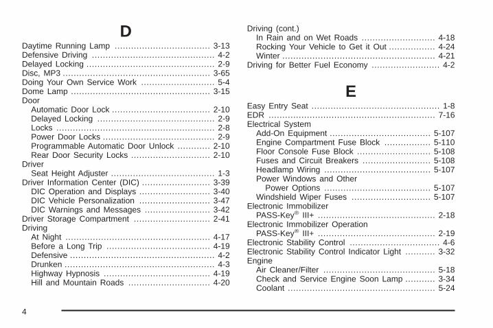
DDaytime Running Lamp ................................... 3-13Defensive Driving ............................................. 4-2Delayed Locking ............................................... 2-9Disc, MP3 ...................................................... 3-65Doing Your Own Service Work ........................... 5-4Dome Lamp ................................................... 3-15Door
Automatic Door Lock .................................... 2-10Delayed Locking ........................................... 2-9Locks .......................................................... 2-8Power Door Locks ......................................... 2-9Programmable Automatic Door Unlock ............ 2-10Rear Door Security Locks ............................. 2-10
DriverSeat Height Adjuster ...................................... 1-3
Driver Information Center (DIC) ......................... 3-39DIC Operation and Displays .......................... 3-40DIC Vehicle Personalization .......................... 3-47DIC Warnings and Messages ........................ 3-42
Driver Storage Compartment ............................ 2-41Driving
At Night ..................................................... 4-17Before a Long Trip ...................................... 4-19Defensive ..................................................... 4-2Drunken ....................................................... 4-3Highway Hypnosis ....................................... 4-19Hill and Mountain Roads .............................. 4-20
Driving (cont.)In Rain and on Wet Roads ........................... 4-18Rocking Your Vehicle to Get it Out ................. 4-24Winter ........................................................ 4-21
Driving for Better Fuel Economy ......................... 4-2
EEasy Entry Seat ............................................... 1-8EDR ............................................................. 7-16Electrical System
Add-On Equipment ..................................... 5-107Engine Compartment Fuse Block ................. 5-110Floor Console Fuse Block ........................... 5-108Fuses and Circuit Breakers ......................... 5-108Headlamp Wiring ....................................... 5-107Power Windows and Other
Power Options ....................................... 5-107Windshield Wiper Fuses ............................. 5-107
Electronic ImmobilizerPASS-Key® III+ ........................................... 2-18
Electronic Immobilizer OperationPASS-Key® III+ ........................................... 2-19
Electronic Stability Control ................................. 4-6Electronic Stability Control Indicator Light ........... 3-32Engine
Air Cleaner/Filter ......................................... 5-18Check and Service Engine Soon Lamp ........... 3-34Coolant ...................................................... 5-24
4
Engine (cont.)Coolant Heater ............................................ 2-25Coolant Temperature Warning Light ................ 3-33Drive Belt Routing ....................................... 6-15Engine Compartment Overview ...................... 5-12Exhaust ..................................................... 2-34Oil ............................................................. 5-13Oil Life System ........................................... 5-16Overheating ................................................ 5-27Starting ...................................................... 2-24
Enhanced Traction System (ETS) ...................... 4-11Enhanced Traction System (ETS) Indicator/
Warning Light ............................................. 3-31Entry/Exit Lighting ........................................... 3-15Event Data Recorders ..................................... 7-17Extender, Safety Belt ....................................... 1-29
FFilter
Engine Air Cleaner ...................................... 5-18Finish Damage ............................................. 5-105Fixed Mast Antenna ........................................ 3-87Flashers, Hazard Warning .................................. 3-6Flash-to-Pass ................................................... 3-8
Flat Tire ........................................................ 5-73Flat Tire, Changing ......................................... 5-84Flat Tire, Storing ............................................. 5-95Fluid
Automatic Transmission ................................ 5-19Windshield Washer ...................................... 5-29
Fog LampFog ........................................................... 3-14
Fog Lamp Light .............................................. 3-38Folding Rear Seat ............................................ 1-9Fuel ............................................................... 5-5
Additives ...................................................... 5-6California Fuel .............................................. 5-6Driving for Better Economy ............................. 4-2Filling a Portable Fuel Container .................... 5-10Filling the Tank ............................................. 5-8Fuels in Foreign Countries .............................. 5-7Gage ......................................................... 3-38Gasoline Octane ........................................... 5-5Gasoline Specifications .................................. 5-6
FusesEngine Compartment Fuse Block ................. 5-110Floor Console Fuse Block ........................... 5-108Fuses and Circuit Breakers ......................... 5-108Windshield Wiper ....................................... 5-107
5

GGage
Fuel .......................................................... 3-38Speedometer .............................................. 3-25Tachometer ................................................. 3-25
GasolineOctane ........................................................ 5-5Specifications ............................................... 5-6
Glove Box ..................................................... 2-41GM Mobility Reimbursement Program .................. 7-7
HHazard Warning Flashers ................................... 3-6Head Restraints ............................................... 1-7Headlamp
Aiming ....................................................... 5-39Headlamp Wiring ........................................... 5-107Headlamps .................................................... 3-12
Bulb Replacement ....................................... 5-41Daytime Running Lamp ................................ 3-13Flash-to-Pass ............................................... 3-8Halogen Bulbs ............................................ 5-41Headlamps, Front Turn Signal, Sidemarker,
and Parking Lamps .................................. 5-42
Headlamps (cont.)High/Low Beam Changer ................................ 3-8On Reminder .............................................. 3-13Wiper Activated ........................................... 3-13
Heated Seats ................................................... 1-4Heater ........................................................... 3-18
Engine Coolant ........................................... 2-25Height Adjuster, Driver Seat ............................... 1-3Highbeam On Light ......................................... 3-38Highway Hypnosis ........................................... 4-19Hill and Mountain Roads .................................. 4-20Hood
Checking Things Under ................................ 5-10Release ..................................................... 5-11
Horn ............................................................... 3-6How to Wear Safety Belts Properly ................... 1-15Hydraulic Clutch ............................................. 5-19
IIgnition Positions ............................................. 2-21Indicator/Warning LIght
Enhanced Traction System (ETS) ................... 3-31Infants and Young Children, Restraints ............... 1-33Inflation - Tire Pressure ................................... 5-56Inflator Kit, Tire ............................................... 5-74
6
Instrument PanelBrightness .................................................. 3-14Cluster ....................................................... 3-24Overview ..................................................... 3-4
JJump Starting ................................................. 5-34
KKeyless Entry System ....................................... 2-3Keys ............................................................... 2-2
LLabeling, Tire Sidewall ..................................... 5-49Lamp
Malfunction Indicator .................................... 3-34Lamps
Dome ........................................................ 3-15Mirror Reading ............................................ 3-15
Lap-Shoulder Belt ........................................... 1-23LATCH System for Child Restraints ................... 1-41License Plate Lamps ....................................... 5-46
LightAirbag Readiness ........................................ 3-27Antilock Brake System (ABS) Warning ............ 3-31Brake System Warning ................................. 3-30Charging System ......................................... 3-29Engine Coolant Temperature Warning ............. 3-33Fog Lamp .................................................. 3-38Highbeam On ............................................. 3-38Oil Pressure ............................................... 3-37Passenger Airbag Status Indicator .................. 3-28Safety Belt Reminders .................................. 3-26Security ..................................................... 3-38Tire Pressure .............................................. 3-33Up-Shift ..................................................... 3-29
LightingEntry/Exit ................................................... 3-15
Lights ............................................................ 3-12Flash-to-Pass ............................................... 3-8High/Low Beam Changer ................................ 3-8On Reminder .............................................. 3-13
Loading Your Vehicle ....................................... 4-24Lockout Protection .......................................... 2-11Locks
Automatic Door Lock .................................... 2-10Delayed Locking ........................................... 2-9Door ........................................................... 2-8Lockout Protection ....................................... 2-11
7
Locks (cont.)Power Door .................................................. 2-9Programmable Automatic Door Unlock ............ 2-10Rear Door Security Locks ............................. 2-10
Loss of Control ............................................... 4-15Lower Anchors and Tethers for Children ............. 1-41Lumbar
Manual Controls ............................................ 1-3
MMaintenance Schedule
Additional Required Services ........................... 6-6At Each Fuel Fill ........................................... 6-9At Least Once a Month .................................. 6-9At Least Once a Year .................................. 6-10Introduction .................................................. 6-2Maintenance Footnotes .................................. 6-7Maintenance Record .................................... 6-16Maintenance Replacement Parts .................... 6-14Maintenance Requirements ............................. 6-2Owner Checks and Services ........................... 6-8Recommended Fluids and Lubricants ............. 6-12Scheduled Maintenance ................................. 6-4Using .......................................................... 6-2Your Vehicle and the Environment ................... 6-2
Malfunction Indicator Lamp ............................... 3-34Manual Lumbar Controls .................................... 1-3Manual Seats ................................................... 1-2
Manual TransmissionOperation ................................................... 2-28
Manual Windows ............................................ 2-15Message
DIC Warnings and Messages ........................ 3-42Mirror Reading Lamps ..................................... 3-15Mirrors
Manual Rearview Mirror ................................ 2-36Outside Convex Mirror ................................. 2-37Outside Power Mirrors .................................. 2-36Outside Remote Control Mirror ...................... 2-36
MP3 ............................................................. 3-65MyGMLink.com ................................................ 7-5
NNavigation System, Privacy .............................. 7-18New Vehicle Break-In ...................................... 2-20
OOdometer ...................................................... 3-25Off-Road Recovery .......................................... 4-15Oil
Engine ....................................................... 5-13Pressure Light ............................................. 3-37
Oil, Engine Oil Life System .............................. 5-16Older Children, Restraints ................................ 1-30Online Owner Center ........................................ 7-5
8

OnStar, Privacy .............................................. 7-18OnStar® System, see OnStar® Manual ............... 2-37Outlet Adjustment ............................................ 3-21Outlets
Accessory Power ......................................... 3-16Outside
Convex Mirror ............................................. 2-37Power Mirrors ............................................. 2-36Remote Control Mirror .................................. 2-36
Owner Checks and Services .............................. 6-8Owners, Canadian ............................................... ii
PPaint, Damage .............................................. 5-105Park
Shifting Into ................................................ 2-31Shifting Out of ............................................ 2-33
Park Brake .................................................... 2-30Parking
Over Things That Burn ................................. 2-34Parking Your Vehicle ....................................... 2-33Passenger Airbag Status Indicator ..................... 3-28Passenger Compartment Air Filter ..................... 3-21Passenger Sensing System .............................. 1-62Passing ......................................................... 4-15PASS-Key® III+ Electronic Immobilizer ............... 2-18PASS-Key® III+ Electronic Immobilizer
Operation ................................................... 2-19
Perchlorate Materials Requirements,California ..................................................... 5-4
PhoneBluetooth® .................................................. 3-73
PowerDoor Locks .................................................. 2-9Electrical System ....................................... 5-107Retained Accessory ..................................... 2-23Windows .................................................... 2-15
Privacy .......................................................... 7-16Event Data Recorders .................................. 7-17Navigation System ....................................... 7-18OnStar ....................................................... 7-18Radio Frequency Identification ....................... 7-18
Programmable Automatic Door Unlock ............... 2-10
RRadio Frequency Identification (RFID),
Privacy ...................................................... 7-18Radio(s) ........................................................ 3-55Radios
Reception ................................................... 3-86Setting the Clock ......................................... 3-53Theft-Deterrent ............................................ 3-84
Rear Door Security Locks ................................ 2-10Rearview Mirrors ............................................. 2-36Reclining Seatbacks .......................................... 1-4Recommended Fluids and Lubricants ................. 6-12
9

Recreational Vehicle Towing ............................. 4-30Remote Keyless Entry (RKE) System .................. 2-3Remote Keyless Entry (RKE) System,
Operation ..................................................... 2-3Remote Vehicle Start ........................................ 2-6Removing the Flat Tire and Installing the
Spare Tire .................................................. 5-90Removing the Spare Tire and Tools ................... 5-85Replacement Bulbs ......................................... 5-46Replacement Parts, Maintenance ...................... 6-14Reporting Safety Defects
Canadian Government .................................. 7-15General Motors ........................................... 7-15United States Government ............................ 7-14
Restraint System CheckChecking the Restraint Systems .................... 1-69Replacing Restraint System Parts
After a Crash .......................................... 1-70Retained Accessory Power ............................... 2-23Roadside
Assistance Program ....................................... 7-7Rocking Your Vehicle to Get it Out .................... 4-24Routing, Engine Drive Belt ............................... 6-15Running the Vehicle While Parked ..................... 2-35
SSafety Belt Reminders ..................................... 3-26Safety Belts
Care of .................................................... 5-102How to Wear Safety Belts Properly ................ 1-15Lap-Shoulder Belt ........................................ 1-23Safety Belt Extender .................................... 1-29Safety Belt Use During Pregnancy ................. 1-29Safety Belts Are for Everyone ....................... 1-10
Safety Warnings and Symbols .............................. iiiScheduled Maintenance ..................................... 6-4Seats
Driver Seat Height Adjuster ............................. 1-3Easy Entry Seat ............................................ 1-8Head Restraints ............................................ 1-7Heated Seats ............................................... 1-4Manual Lumbar ............................................. 1-3Reclining Seatbacks ...................................... 1-4Split Folding Rear Seat .................................. 1-9
Securing a Child RestraintRear Seat Position ...................................... 1-47Right Front Seat Position .............................. 1-50
Security Light ................................................. 3-38
10
Service ........................................................... 5-3Accessories and Modifications ......................... 5-3Adding Equipment to the Outside of the
Vehicle ..................................................... 5-5California Perchlorate Materials
Requirements ............................................ 5-4California Proposition 65 Warning .................... 5-4Doing Your Own Work ................................... 5-4Engine Soon Lamp ...................................... 3-34Publications Ordering Information ................... 7-15
Service, Scheduling Appointments ..................... 7-10Servicing Your Airbag-Equipped Vehicle .............. 1-67Setting the Clock ............................................ 3-53Sheet Metal Damage ..................................... 5-105Shifting Into Park ............................................ 2-31Shifting Out of Park ........................................ 2-33Signals, Turn and Lane-Change .......................... 3-7Spare Tire
Compact .................................................... 5-98Installing .................................................... 5-90Removing ................................................... 5-85Storing ....................................................... 5-95
Specifications, Capacities ............................... 5-113Speedometer .................................................. 3-25Split Folding Rear Seat ..................................... 1-9Start Vehicle, Remote ....................................... 2-6Starting the Engine ......................................... 2-24
Steering ........................................................ 4-13Steering Wheel Controls, Audio ......................... 3-85Steering Wheel, Tilt Wheel ................................. 3-6Storage Areas
Center Console Storage Area ........................ 2-41Convenience Net ......................................... 2-41Cupholders ................................................. 2-41Driver Storage Compartment ......................... 2-41Glove Box .................................................. 2-41
Storing the Tire Sealant and Compressor Kit ...... 5-83Stuck in Sand, Mud, Ice, or Snow ..................... 4-23Sun Visors ..................................................... 2-16Sunroof ......................................................... 2-42
TTachometer .................................................... 3-25Taillamps
Turn Signal Lamps ...................................... 5-44Turn Signal, Stoplamps and Back-up
Lamps .................................................... 5-44Theft-Deterrent, Radio ..................................... 3-84Theft-Deterrent Systems ................................... 2-16
Content Theft-Deterrent ................................ 2-16PASS-Key® III+ Electronic Immobilizer ............ 2-18PASS-Key® III+ Electronic Immobilizer
Operation ................................................ 2-19
11
Tilt Wheel ........................................................ 3-6Time, Setting .................................................. 3-53Tire
Pressure Light ............................................. 3-33Tire Sealant
Storing ....................................................... 5-83Tires ............................................................. 5-48
Aluminum or Chrome-Plated Wheels,Cleaning ............................................... 5-104
Buying New Tires ........................................ 5-66Chains ....................................................... 5-72Changing a Flat Tire .................................... 5-84Cleaning ................................................... 5-105Compact Spare Tire ..................................... 5-98Different Size .............................................. 5-68If a Tire Goes Flat ....................................... 5-73Inflation - Tire Pressure ................................ 5-56Inspection and Rotation ................................ 5-64Installing the Spare Tire ................................ 5-90Pressure Monitor Operation ........................... 5-59Pressure Monitor System .............................. 5-57Removing the Flat Tire ................................. 5-90Removing the Spare Tire and Tools ............... 5-85Storing a Flat or Spare Tire and Tools ............ 5-95Tire Sealant and Compressor Kit ................... 5-74
Tires (cont.)Tire Sidewall Labeling .................................. 5-49Tire Terminology and Definitions .................... 5-53Uniform Tire Quality Grading ......................... 5-68Wheel Alignment and Tire Balance ................. 5-70Wheel Replacement ..................................... 5-70When It Is Time for New Tires ...................... 5-65
TowingRecreational Vehicle ..................................... 4-30Towing a Trailer .................................. 4-33, 4-40Your Vehicle ............................................... 4-30
TractionControl System (TCS) .................................... 4-8Enhanced Traction System (ETS) ................... 4-11
Traction Control System ................................... 3-32Traction System
Enhanced ................................................... 3-31Transmission
Fluid, Automatic ........................................... 5-19Up-Shift Light .............................................. 3-29
Transmission Operation, Automatic .................... 2-26Transmission Operation, Manual ........................ 2-28Trunk ............................................................ 2-12Turn and Lane-Change Signals .......................... 3-7Turn Signal/Multifunction Lever ........................... 3-7
12

UUniform Tire Quality Grading ............................ 5-68Up-Shift Light ................................................. 3-29
VVehicle
Control ........................................................ 4-3Loading ...................................................... 4-24Parking Your ............................................... 2-33Running While Parked .................................. 2-35Symbols ......................................................... iii
Vehicle Data Recording and Privacy .................. 7-16Vehicle Identification
Number (VIN) ............................................ 5-106Service Parts Identification Label .................. 5-107
Vehicle PersonalizationDIC ........................................................... 3-47
Vehicle, Remote Start ....................................... 2-6Ventilation Adjustment ...................................... 3-21Visors ........................................................... 2-16
WWarning Lights, Gages, and Indicators ............... 3-23Warnings
DIC Warnings and Messages ........................ 3-42Hazard Warning Flashers ............................... 3-6Safety and Symbols ......................................... iii
WheelsAlignment and Tire Balance .......................... 5-70Different Size .............................................. 5-68Replacement ............................................... 5-70
Where to Put the Restraint ............................... 1-39Windows ....................................................... 2-14
Manual ...................................................... 2-15Power ........................................................ 2-15
WindshieldWasher ........................................................ 3-9Washer Fluid .............................................. 5-29Wiper Blade Replacement ............................. 5-47
13

Windshield (cont.)Wiper Blades, Cleaning .............................. 5-104Wiper Fuses ............................................. 5-107Wipers ......................................................... 3-8
Winter Driving ................................................ 4-21Wiper Activated Headlamps .............................. 3-13
XXM Radio Messages ....................................... 3-72XM™ Satellite Radio Antenna System ................ 3-87
YYour Vehicle and the Environment ....................... 6-2
14