Embed Size (px)
Citation preview

Seismic Response and Seismic Response and Capacity Evaluation of Exterior Capacity Evaluation of Exterior Sacrificial Shear Keys of Bridge Sacrificial Shear Keys of Bridge
AbutmentsAbutments
Scott A. Ashford, PE, PhDProfessor and School Head
Oregon State UniversityCorvallis, Oregon
2009 Caltrans-PEER Seismic Seminar Series

History of UCSD Work on Abutments• Post-tensioned Abutments (2002)
– Megally, Silva, and Seible
• Sacrificial Shear Keys (2007)– Bozorgzadeh, Bauer, Restrepo, and Ashford
• Abutment Backfill Models (2007)– Bozorgzadeh, Ashford, and Restrepo
– Initially considered diaphragm-type abutments
– Worked with EMI on backfill soil types
– Completed testing on seat-type abutment

AcknowledgmentsAcknowledgments
• The California Department of Transportation (Caltrans) is gratefully acknowledged for the financially support of the experimental research on sacrificial exterior shear keys.
• This research was carried out at UC San Diego. The participation of the UCSD faculty, staff, and students is also acknowledged.
3

Schematic of Exterior Shear Key in Schematic of Exterior Shear Key in Bridge AbutmentsBridge Abutments
4
Wing-wall
Back-wall
Stem wall Footing
Vertical pile
Battered pile
Exteriorshear key
Superstructure

1994 Northridge Earthquake1994 Northridge Earthquake Over half of damaged bridges Over half of damaged bridges
suffered abutment damage suffered abutment damage
5

Experimental WorkExperimental Work
• Five test series, each including two test units were built at a 40% scale.
• Main variables:– Construction joint.
– Amount and configuration of vertical reinforcement.
– Amount and configuration of horizontal reinforcement.
6

Elevation View of Reinforcement Elevation View of Reinforcement Layout of the Proposed ModelLayout of the Proposed Model
7
5A 5B
RoughConstruction Joint
Headed Bars, 14#4
Foam (0.5” thick)
Smooth Construction Joint
Vertical Shear Key Reinforcement,4#4 Vertical Shear Key
Reinforcement,4#4
24”
30 1/2”
16.75”24” 48” 24”

Shear Key Test SpecimensShear Key Test Specimens Under ConstructionUnder Construction
8

Test SetupTest Setup
9
Hydraulic Actuator Guiding FrameLoading Arm

Failure of Exterior Shear Keys of Failure of Exterior Shear Keys of Two Test Series Two Test Series
10
Failure occurred in a diagonal strut in the stem wall.
No sliding at the interface of shear key-abutment stem wall occurred.
Performed as structural fuses with sliding shear failure.
Diagonal cracks formed in the stem wall but the maximum width of cracks were 0.012".
Current Model
Proposed Model
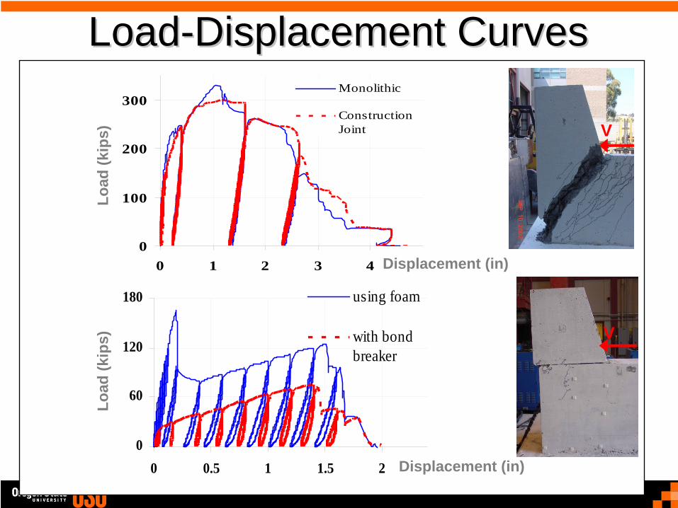
LoadLoad--Displacement CurvesDisplacement Curves
11
0
100
200
300
0 1 2 3 4
Monolithic
ConstructionJoint
0
60
120
180
0 0.5 1 1.5 2
using foam
with bondbreaker
Current Model
ProposedModel
Displacement (in)
Displacement (in)
Load
(kip
s)Lo
ad (k
ips)
V
V

ConclusionsConclusions• A model for evaluation of capacity of shear
keys under lateral force was developed based on Strut-and-Tie models.
• The proposed model showed better agreement with test results than the current shear friction model.
• The current shear friction model underestimates shear key capacity which may lead to damage of abutment wall or supporting piles.
12

ConclusionsConclusions• Based on results of experimental work,
several recommendations were proposed for construction details:
– Using smooth construction joint.– Shear key vertical reinforcement bars should
be the only reinforcement connecting the shear key to the abutment stem wall.
– Headed bars or hanger bars can be used in the stem wall to carry the force transmitted by the shear key.
13

Research results Research results implemented along Iimplemented along I-- 905 in San Diego in 905 in San Diego in September 2007September 2007
Most testing carried out Most testing carried out in 2003/4, final report in 2003/4, final report dated October 2007dated October 2007
Caltrans implements Caltrans implements good results quickly, in good results quickly, in this case before final this case before final report issued.report issued.

Shear Key ConstructionShear Key Construction

Completed KeysCompleted Keys

Results Available at UCSDResults Available at UCSD• SSRP-2001/22, May 2002: “Seismic Response of
Sacrificial Shear Keys in Bridge Abutments,” S.H. Megally, P.F. Silva, F. Seible, 215p.
• SSRP-04/14, October 2007: "Seismic Response and Capacity Evaluation of Exterior Sacrificial Shear Keys in Bridge Abutments,” A. Bozorgzadeh, H.L. Bauer, J.I. Restrepo, S.A. Ashford, 40p.
• SSRP-07/12, May 2007: “Experimental and Analytical Investigation on the Stiffness and Ultimate Capacity of Bridge Abutments,” A. Bozorgzadeh, S. Ashford, and J. Restrepo, 196p.