Embed Size (px)
Citation preview

2009‐2010 Feasibility and Market Research Study For
Commercial Hop Production in New England
September 30, 2010
Prepared by Rosalie J. Wilson Business Development Services
rosaliewilson.com
With funding from:
Vermont Agency of Agriculture, Food, and Markets
Massachusetts Department of Agricultural Resources
Four Star Farms hopyard, photo credit: r.wilson

Page 1
Commercial Feasibility of Local Hops 2010
Table of Contents
Executive Summary............................................................................................................. 2 Background ......................................................................................................................... 3 Methodology....................................................................................................................... 6 Initial findings...................................................................................................................... 7 Market Research Survey Details ....................................................................................... 10 Production Feasibility ....................................................................................................... 18 Other Issues Affecting Growing Capability and Commercial Production......................... 24 Conclusions ....................................................................................................................... 35 Next Steps ......................................................................................................................... 42
Appendix A ‐ Sources of Information Appendix B ‐ List of Persons Consulted Appendix C ‐ Brewer Questionnaire Template Appendix D ‐ Cash Flow Scenarios Appendix E ‐ Sample Hopyard Designs Appendix F ‐ Hopyard Establishment Costs Per Acre Appendix G ‐ Laboratory Analysis Service Providers Appendix H ‐ Expired Hop Harvester Patents Appendix I ‐ Fuji Impulse Nitrogen Flush‐ Vacuum Sealer Product Information

Page 2
Commercial Feasibility of Local Hops 2010
Executive Summary The Vermont Agency of Agriculture Food and Markets and the Massachusetts Department of Agricultural Resources commissioned this research project to study the economic and logistic feasibility of commercial hop production in New England. The goal is to expand opportunities for New England growers to generate a profitable income from their land. This report has determined that is feasible to grow a commercial hop crop in New England:
A. There is sufficient demand from the brewing community to support a minimum of 100 acres in production.
B. There is sufficient price point elasticity to afford producers an ability to generate a profit, and a reasonable time frame for return on investment.
C. The information, technology, and equipment now exist for smaller scale, 1‐10 acre commercial hop operations.
D. Aside from potential limitations of topsoil depth to bedrock, New England’s growing climate and conditions are well suited to hop production.
The four scenarios in which a grower could yield a positive net income from growing hops are as follows:
Scenario 1: Participating in a value‐share growing program with Atlantic Hops Scenario 2: Selling whole hops, minimally processed direct to brewers Scenario 3: Using Atlantic Hops for processing services and selling pelletized
hops direct to brewers Scenario 4: Selling do‐it‐yourself pelletized hops direct to brewers
Income Potential and Return On Investment
Scenario 1 Scenario 2 Scenario 3 Scenario 4 Average Yield Per Acre
1,500 dried lbs 1,500 dried lbs 1,500 dried lbs 1,500 dried lbs
Average Net Income Per Acre
$4,640 $5,090 $5,090 $12,910
Average Return On Investment for 1st Acre
5 years 5 years 6 years 4 years
Level of Individual Risk
Low
Moderate
Moderate
High
assuming a $10/lb price point for whole dried hops, $15/lb for pelletized hops, and $9/lb return from the value‐share program

Page 3
Commercial Feasibility of Local Hops 2010
While the potential to generate net income per acre is highest in scenario four, in which the grower creates the value‐added finished product on site, the ultimate recommendation is to adopt scenario one, in which growers participate in a value‐share growing program with Atlantic Hops. This is because scenario one represents the least risk while still presenting a strong potential for financial return. In all instances, in order to reach a reasonable income and rate of return on investment, a commercial grower will need to utilize mechanical harvesting and sorting. In order to minimize risk from crop failure, and to stagger harvest times for logistical ease, it is highly recommended that the grower also divide the hopyard into thirds and adopt a 3 variety planting.
Background
New England was home to a vibrant hop trade through the beginning of the Twentieth Century. In fact in 1900, New York was the largest producer of American hops, generating 49% of the entire U.S. yield. By the end of Prohibition, however, much of the hop industry had migrated to the Pacific Northwest. This was due to advances in mechanization that made larger scale farming a reality, complementing West Coast geography, and the decimation of the Eastern crops by a disease known as downy mildew. Downy mildew is a crippling disease because it can cause short and long term damage, impacting a specific year’s harvest, and potentially killing the plants themselves.1 The potential to kill the plant is a significant issue with a crop such as hops, because they are a perennial plant and take three to four years to establish. Why is there an interest in the commercial viability of growing New England hops, and why now?
1. The beer industry is a mature industry with demonstrated longevity and stable consumption. This translates into stable market demand for raw ingredients such as hops. Even in the midst of one of the worst recessions in history, 2009 U.S. beer sales only decreased 2.2%.2
2. In the 1970’s a segment of the brewing industry, craft brewing, began to develop
popularity in the Northeast, particularly in New England and Quebec. Craft brewers, originally considered fringe, are now accepted in the mainstream beer
1 Barth, H.J., Klinke, C., Schmidt, C. The Hop Atlas. 1994. Nuremberg, Germany. Joh, Barth & Sohn. pp12‐14. Jason Perrault. Perrault Farms. Guest Speaker. 2010 Winter Hops Conference. UVM Extension. 3/26/2010. 2 http://www.brewersassociation.org/pages/business‐tools/craft‐brewing‐statistics/facts

Page 4
Commercial Feasibility of Local Hops 2010
industry and make up 5% of the total US beer market share.3 Not only does the category now make up a respectable share of overall beer sales, it continues to rise as the shift in consumption trends away from consuming volume quantities of mass‐marketed, low cost beer, to selective, smaller quantities of higher quality products.4
A 2007 report expressed this trend as follows:
The Brewers Association, the trade association that tabulates industry data for craft brewers, reports craft beer sales and growth continue to break records. The volume of craft beer sold in the first half of 2007 rose 11% compared to this same period in 2006 and dollar growth increased 14%. For the first time ever craft beer has exceeded more than a 5% dollar share of total beer sales. Overall, the U.S. beer industry sold one million more barrels in the first half of 2007 compared to 2006, with 400,000 of these new barrels produced by craft breweries. This equates to 3.768 million barrels of craft beer sold in the first two quarters of 2007 compared to 3.368 million barrels sold in the first half of 2006. Scan data from Information Resources, Inc. provide additional data points that confirm strength for the segment. Craft beer sales in the supermarket channel through July 15, 2007 showed a 17.4% increase in dollar sales compared to the same period in 2006. This growth in sales was higher than any other alcohol beverage category. "The 1,400 small, independent and traditional craft brewers in the U.S. have hit their stride," said Paul Gatza, Director of the Brewers Association. "United States craft brewers are making many of the world's best beers, and the marketplace is responding." Coupled with the growth statistics has been a tidal wave of media coverage in the first half of 2007 including NBC's Today Show on July 3 stating, "Beer is the new wine and can go with just about any food." Additionally, Gallup, in its latest poll on alcohol beverages, announced for the second straight year that "Beer Again Edges Out Wine as Americans' Drink of Choice." Julia Herz, Director of Craft Beer Marketing for the Brewers Association, concluded, "Craft beer market share is steadily and consistently growing. A grassroots movement is responsible for this success as appreciators continue to trade up."5
3http://www.thefreelibrary.com/Craft+Beer+Segment+Continues+to+Set+the+Pace+for+the+Beer+Category...‐a0167648025 4 François Biron. Agronomiste. Ministère de l’Agriculture des Pêcheries et de l’Alimentation Québec. Guest Speaker. 2010 Winter Hops Conference. UVM Extension. 3/26/2010. 5http://www.thefreelibrary.com/Craft+Beer+Segment+Continues+to+Set+the+Pace+for+the+Beer+Category...‐a0167648025

Page 5
Commercial Feasibility of Local Hops 2010
To further express this point, while overall beer sales were down 2.2% in 2009, craft beer sales rose 10.3%.6
3. The nature of the craft beer industry is built on product differentiation, tradition,
innovation, quality, integrity, and community.7 These qualities all lend themselves to supporting a local commercial hop production effort. Craft brewers’ desire for freshness and quality, their support of local economies, their interest in uniqueness as opposed to ubiquity all help influence their purchasing decision making, and thus they are not solely buying on price. This support has been researched and quantified through this feasibility study.
4. The size and scale of the micro and craft breweries (they must produce less than
2 million barrels per year8) place them in a position to be able to work with smaller scale local commercial hop production. They can more easily adapt to incorporating local hops into their production and recipes, and their volume needs, or a portion of their volume needs, are of a size and scale that would be feasible for New England producers to attain and supply on a consistent basis.
What has been done to date? In 1988, the Vermont Department of Agriculture initiated hop production trials with Catamount Brewing Co. of Windsor, Vermont. Those trials were expanded by Dr. Leonard Perry at the University of Vermont. Reports on those trials are available at http://www.uvm.edu/~pass/perry/hops.html. In September 2008, a small team from Vermont and Massachusetts traveled to Germany, the Czech Republic and Belgium to learn more about equipment used there for harvesting and processing hops. The team met with numerous farmers who produced, harvested, and processed hops and with manufacturers of hop harvesting and processing equipment.9 In 2009 the Vermont Agency of Agriculture Food and Markets and the Massachusetts Department of Agricultural Resources secured USDA Specialty Crop Block grants for this feasibility study to be conducted and for UVM Extension to develop and establish an organic hopyard trialing 20 hop varieties and different cover cropping techniques.
6 http://www.brewersassociation.org/pages/business‐tools/craft‐brewing‐statistics/facts 7 http://www.brewersassociation.org/pages/business‐tools/craft‐brewing‐statistics/craft‐brewer‐defined 8 http://www.brewersassociation.org/pages/business‐tools/craft‐brewing‐statistics/craft‐brewer‐defined 9 Information provided by Steve Justis, Vermont Agency of Agriculture, Food and Markets, August 2009.
Page 6
Commercial Feasibility of Local Hops 2010
Methodology
To complete the feasibility study, the first step was to research market demand and product specifications for the finished product. Craft brewers, brew pubs and homebrew supply stores in ME, MA, NH, and VT were identified as the direct prospective target market for a New England grown hop. A survey questionnaire was developed (see appendices). The questionnaire was available by Survey Monkey, as an e‐mail attachment, and as a telephone interview. 72 brewers were contacted and requested to participate. Follow up was made by telephone and e‐mail. 47 responses were received, a 65% response rate. The intent of the survey was:
• to determine what varieties of hops these brewers use • what volume of these hops they use • what they pay • how these prices fluctuate • what purchasing relationships they are engaged in • what the parameters or limiting factors of these relationships are • what they would find most valuable in influencing their purchasing decision for
New England hops • what the finished product would need to be for them to consider using a New
England hop • what they would consider a fair price for a New England hop
After conducting the market research, the study turned to hop production feasibility. Could hops grow in New England, what are the bottlenecks to commercial production? Bottlenecks researched included:
• access to and cost of raw materials for hopyard establishment • access to and cost of mechanized harvesting equipment • access to and cost of secondary processing • growing conditions • issues affecting crop yield
Following research on the bottlenecks, production models for a 1 to 10 acre hopyard were explored. Four production models were developed that could present a financially and logistically feasible commercial hop growing venture. The information was then summarized into this final report.

Page 7
Commercial Feasibility of Local Hops 2010
Initial findings
Brewers who responded to this study were universally interested in buying New England hops: 94%, 44 out of 47 respondents indicated an interest in purchasing New England hops. This conclusion is supported by research conducted in 2009 by Duncan Hilchey of New Leaf Publishing and Consulting, Ithaca, NY.10 While the brewers who responded to this feasibility study may not be representative of the entire New England brewing community, their responses did achieve the market research goals of the study which were to
A. Determine if there is sufficient demand to absorb a minimum of 100,000 lbs of dried, New England aroma hops per year, and at what price point
B. Develop a highly qualified prospect list The highly qualified prospect list is composed of those brewers who asked to remain involved as the project as research and development, unfolds. They are highlighted in Bold under the brewers consulted in the appendices. Key purchasing decision making factors
Price Brewers are highly price sensitive. While they are interested in buying local hops, price will be a key factor. The primary price ranges considered as acceptable price points at which brewers would purchase local hops if they met their other requirements were: $5/lb, $8‐10/lb, and $10‐15/lb. At the $5‐10/lb brewers would consider sourcing 100% of their hops from New England producers if the finished product was interchangeable with their existing supply in terms of product deliverable.
Product Quality Making beer is both a science and an art form. There are many nuances that can affect the final product. Because of this, the ultimate achievement of a brewer is when they can consistently produce the same finished product in taste, aroma, appearance, and mouth‐feel, brew after brew, from brewhouse to brewhouse. Because hops create a signature aroma and flavor profile for a beer, hops are a key ingredient in any beer recipe. Because the chemical make up of hops may change from harvest to harvest depending on growing conditions and geographic region, the more the brewer knows about the make up of each
10 Hilchey, D. The Market Potential for Northeastern‐Grown Hops. New Leaf Publishing and Consulting, Inc. 2009.

Page 8
Commercial Feasibility of Local Hops 2010
11lb pouches of vacuum sealed, nitrogen flushed hop pellets. Photo courtesy http://hops‐extracts.com
shipment of hops he receives the more he can adjust his recipe so that the end result will be consistent with prior brews. To meet product quality requirements, New England hops will need to be submitted to a lab for chemical analysis and a chemical analysis will need to accompany each hop shipment. Product Specifications While the brewer can’t control the chemical makeup of a hop from harvest to harvest, he has come to expect his hops to look and perform a certain way. In order to meet product specifications to be considered a viable alternative, a New England hop would need to be pelletized to a T‐90 standard, packaged in Nitrogen flushed, vacuum sealed, foil laminated pouches, and encased in cardboard boxes. There are two standard offerings, four 11lb pouches to a 44 lb box, or one 44lb pouch to a 44lb box.
T‐90 Pellets. Photo courtesy http://hopunion.com

Page 9
Commercial Feasibility of Local Hops 2010
Purchasing Decision Influencers in buying “local” (New England grown) hops
Stable price point Brewers are frustrated and increasingly vulnerable to volatile price points and product scarcity of hops on the spot market. This is especially disconcerting to them as the craft beer category continues to grow and brewers of all scale and size compete for access to hops to meet their growing and existing market demand. Personal relationships Brewers, similar to bakers and chefs, take their craft seriously and personally. They appreciate having connections to those providing their ingredients because they know that the quality of the ingredients will ultimately impact the quality of the finished product. Having growers that they can develop a long lasting, personal relationship with will help supersede price as the ultimate purchasing decision making factor. Environmental awareness New England’s craft brewers are well aware that the majority of the inputs into their products currently originate from the Mid‐West, West Coast, and Europe. Anything they can do to help reduce their carbon foot print by being able to purchase inputs from closer sources would be appreciated. Local economic stimulation New England craft brewers also understand the notion of local economy. Most of our craft brewers are local or regional producers whose products stay in New England, therefore keeping their purchasing dollars in New England further reinforces the likelihood that their own products will be purchased. Marketing Craft brewers often tightly wrap their geographic locations into their corporate identity, leveraging “a sense of place” as a distinguishing attribute in their sales and marketing. By purchasing local ingredients they can further strengthen this marketing message.

Page 10
Commercial Feasibility of Local Hops 2010
Market Research Survey Details
Of the 72 brewers, brew pubs, and home brew supply stores surveyed, 34 responded, for a total response rate of 47%. From the responses given, total barrels (bls) brewed (from 26 respondents) came to 370,970 bls per year, with an average of 14,268 bls per brewery. The smallest brewer claimed 210 bls per year, while the largest brewer cited 100,000 bls per year. Hop Varieties & Volume The most prevalent hop used by the brewers was Cascade, followed by Hallertau, Centennial, Golding, and Willamette, see chart below. Total volume of hops used annually by 21 breweries reporting came to 126,482 lbs of dried hops per year, and 2,600 lbs of wet hops per year.
Number of Brewers

Page 11
Commercial Feasibility of Local Hops 2010
The total volume of Cascade hops used by 30 reporting breweries came to 81,860 lbs per year. Volumes of the next nine most prevalent hops were as follows: Hallertau 6,436 lbs/yr from 15 respondents Centennial 5,400 lbs/yr from 16 respondents Golding 5,250 lbs/yr from 12 respondents Willamette 5,250 lbs/yr from 11 respondents Tettnang 4,850 lbs/yr from 8 respondents Perle 3,950 lbs/yr from 8 respondents Saaz 3,550 lbs/yr from 9 respondents Magnum 3,250 lbs/yr from 5 respondents Nugget: 2,750lbs lbs/yr from 4 respondents Northern Brewer 2,650 lbs/yr from 9 respondents Columbus 2,000 lbs/yr from 8 respondents Glacier 1,850 lbs/yr from 3 respondents In addition to seeking to understand the brewers’ current hop usage and volume, the study asked their preference in what varieties they would be more interested in seeing from a New England source, see chart on page 12. Cascade topped the list with 71%, 22 of 31 respondents, demonstrating an interest in a New England Cascade. Centennial was the next most requested with 39%, 12 of 31 respondents, asking for it. The brewer responses present themselves favorably in terms of the logistical feasibility of being able to meet their variety preferences because Cascade and Centennial happen to be two of the varietals that outperform other varieties in New England.11
11 Information derived from current New England hop growers including Eugene L’Etoile, 1997 UVM Extension Hops Trials, and UVM Extension Grower Survey.

Page 12
Commercial Feasibility of Local Hops 2010
Whole Leaf vs Pelletized Hops 83%, 25 of 30 respondents, said they required pelletized hops. 30%, 9 of 30 respondents, said they use or could use dried whole hops. 23%, 7 of 30 respondents, said they could use wet whole hops. The total volume of wet, whole leaf hops used annually by these 7 respondents came to 2,600lbs. The total volume of dried whole leaf hops used annually by these 8 respondents came to 3,750 lbs, and the total volume of pelletized hops used by the 24 respondents came to 122,732 lbs (see chart on page 13). At these volumes, wet hops could support less than one acre of commercial production, dry whole hops could support up to 4 acres, and pelletized hops could support up to 120 acres.

Page 13
Commercial Feasibility of Local Hops 2010
Aroma vs Bittering The feasibility of commercial hop production in New England will need to focus on aroma hops, or dual purpose hops over bittering hops from New England. This is because:
1. Price: Bittering hops function as their name says, they provide bitterness to a beer, the backbone upon which aroma hops then layer complexity, flavor and aroma. Because of this, bittering hops have evolved into a highly commoditized product with a non‐elastic, price point averaging $1‐3/lb. Only large scale operations focused on efficiencies of scale can compete in this market. Aroma hops, on the other hand, maintain product differentiation capabilities that add value and can command a higher, and more elastic, price point. Aroma hops price points can range as high as $25+/lb.
2. Contracts: Brewers typically lock in multi‐year contracts for bittering hops. While they will also lock in contracts for certain quantities of aroma hops they know they need, they tend to reserve some of their budget for unexpected purchases, enabling them flexibility to experiment and innovate. This opens the door for them to purchase a New England hop.
Num
ber o
f Brewers Re
spon
ding

Page 14
Commercial Feasibility of Local Hops 2010
3. Growing Conditions: Bittering hops are high alpha acid hops which are known to be difficult to grow in New England. Having a high alpha acid content is not a prerequisite to an aroma hop.
4. Craft Brewer Audience: Craft brewers are more likely to explore with new beer offerings, and seek out new, different or unusual aroma hop varieties. Craft brewers are more likely to appreciate the value of terroir, unique traits in a hop that are derived from the region in which it was grown, in an aroma hop.
5. Product Specifications: Because aroma hops can be added at different stages during the brewing process, there are opportunities for non‐pelletized hops so even small scale commercial growers interested in selling whole dried or wet hops could participate.
6. Certain aroma hop varieties are particularly well suited to growing in New England and are also in high demand from the craft brewing community. These include Cascade, Centennial, Willamette, Chinook, and Nugget.
Price Points In terms of pricing the issue is complex. The historical average price for dried hops from 1991‐2006 was $1.80/lb, see chart below. However, in 2007, failed European crops, declining acreage worldwide, a Yakima warehouse fire and other factors conspired to send spot prices soaring from $2 and $3 a pound to $30 or more.12
12 Fayston, J. “The 2007 hops shortage is over, the glut of '09 is here...” The Oregonian.10/28/2009.
(source: NASS)

Page 15
Commercial Feasibility of Local Hops 2010
Brewers reacted by entering into multi‐year contracts at the height of the crisis simply to ensure they would be guaranteed a supply of hops. In some cases this has tied brewers into 3‐5 year contracts at a $15‐30/lb price point, not necessarily including shipping, even though the shortage is now over and the spot market pricing is back down to $5/lb.
Because of the severe volatility in commodity pricing and product shortage that the brewing industry experienced, the majority of brewers surveyed reported that they would elect long term commitments with local growers over commodity contracts and spot market purchasing, and would be willing to pay a consistent price for this to happen even if the price were higher than the spot market price, as long as both parties felt they were being well served. Following is a chart demonstrating what brewers have suggested they would consider a fair price for New England hops. Note that the current spot market price is averaging $5‐8/lb.
Num
ber o
f Brewers

Page 16
Commercial Feasibility of Local Hops 2010
A few of the brewers considered $5/lb a fair price point and believed that was still favorable even though it’s equivalent to current spot market pricing because historically spot market pricing has averaged $1.80/lb and the spot market could easily slip back to this level. The majority felt that $8‐10/lb for New England hops would be reasonable.
Num
ber o
f Brewers

Page 17
Commercial Feasibility of Local Hops 2010
At the price point brewers identified as a price they felt fair for local hops, the study then asked how much of the total percentage of their hop needs they would source locally if it were available. The majority of brewers said they would be interested in sourcing 100% of their hop needs locally if the quality matched their expectations and the price point fell within $5‐10/lb. Above this price point brewers would still consider buying local hops but only as a percentage of their total hop needs.
Percentage of a brewer’s total hop needs they would consider sourcing locally
Num
ber o
f Brewers

Page 18
Commercial Feasibility of Local Hops 2010
Production Feasibility
The first question to ask regarding production feasibility is, “can a New England grower grow what the brewers want?” As noted earlier in the research, the answer to this is: yes. Cascade is the most requested hop, and is a variety that grows well in New England. In addition to Cascade there are several other varieties that could grow well here and would be of interest to the brewing community. Brewers have also expressed an interest in experimenting with any new, unique cultivars the region can come up with. Having a hop unique to our region could strengthen the element of “terroir,” piquing global industry interest, and providing a reason to justify a premium price point. Growing Conditions According to the Hops Atlas13 optimal conditions for growing hops are as follows:
• a latitude between 35‐55 degrees • average temperature from April through September between 10‐19ºC • average precipitation from April through September of 64 ‐569 mm • average daylight during these months between 10‐19 hrs/day
These findings were derived by taking the climate data for top hop growing regions in the world: George, South Africa; Tasmania and Victoria Australia; Rio Negro Argentina; Oregon and Yakima, US; Hallertau, Germany; Saaz, Czech; and Wye England. In addition, the atlas identified well draining sandy loam as the best soil for growing hops. Given these parameters, it looks like New England has every capability to compete for commercial hop growing. From a very basic feasibility capacity, the right growing conditions do exist:
• the average latitude is in the 40's • the average temperature from April through September 15.5ºC (60ºF) • the average precipitation from April through September is 525‐550 mm • the average hours of daylight from April through September is 13.5hrs/day • the Farmland Classifications System for VT Soils highlights Franklin, Addison
and Rutland counties as counties with sandy loam soils. Massachusetts soils in Franklin and Worcester Counties are also known to be well‐drained, sandy loam soils.
13 Barth, Joh Heinrich, Klinke, Christiane, Schmidt, Claus. The Hop Atlas. Joh Barth & Sohn, Nuremberg, Germany. 1994.

Page 19
Commercial Feasibility of Local Hops 2010
A key caveat for growing hops in New England, however, will be the issue of bedrock. To erect the hopyard trellis, the poles need to be seated at least 3‐4’ in the ground, which means one needs 3‐4’ of top soil before hitting bedrock. In much of New England the bedrock lies less than 3’ below the surface. While it is possible to adapt and improve a poor growing medium, it is not so easy or cost effective to blast through bedrock. So care will need to be given to evaluating the bedrock situation for each prospective site prior to any decision being made on desire to establish a hopyard. Now that parameters required for growing hops have been established, what will it cost to build a hopyard and grow hops, and is it cost effective? Infrastructure As commercial hop growing moved West in the early 20th century, infrastructure for value added processing of hops in the Northeast died. In order to develop a resurgence of a commercially viable hop crop, tools, techniques, equipment, and services will be required to help growers establish their hopyards cost effectively, and provide them with the ability to transform their raw hops into the finished product brewers need. At present, there are few hopyard suppliers growers can turn to for small scale commercial operations. Growers are often forced to pay retail prices for supplies such as rhizomes, cables, and the simple thought of being able to source up to one hundred 22‐24’ poles can be daunting. While accessibility is already a weakness, it can be exacerbated by the issue of quality. The sourcing of quality rhizomes in particular can be very difficult, even when buying from supposedly trusted sources. Both local growers and UVM Extension have received hops that were diseased, infested or otherwise of less than ideal quality.14 In addition to the difficulties involved in locating materials and supplies, the cost of establishing a hopyard can vary dramatically based on the design being used. Different designs will require more or less poles, more or less rhizomes, and so on. To provide an example of this, please refer to the appendices for a comparison of the supplies required and cost to establish a sampling of different hopyard designs. Infrastructure Solution Gorst Valley Hops, was established in 2005 in Wisconsin to alleviate barriers to entry for small scale hop growers. The business has focused on identifying and solving the bottlenecks, and developing “best practices” for small scale hop growers to employ so that they can be commercially successful. Gorst Valley Hops has become a reputable source small mid‐west growers interested in commercially growing hops can turn to. 14 Phone conversations with Gene L’Etoile, Four Star Farm, and Rosalie Madden, UVM Extension, August, 2010.

Page 20
Commercial Feasibility of Local Hops 2010
The commercial model Gorst Valley has developed works such that all three parties‐ the brewer, the processor, and the grower‐ benefit.15 The Gorst Valley model is based on a “value‐share” charter grower program, in which the growers agree to send their annual hops harvest to Gorst Valley. In return, Gorst Valley provides them with their researched and tested high density hopyard design, technical assistance to implement it, ongoing technical support during the growing season for the first four years, direct sourcing and wholesale pricing of all the source materials required to establish their hopyard, access to equipment innovations and research and development, and a marketing outlet that strives for a fair and profitable price for 100% of their harvest. In this model Gorst Valley shares the proceeds of the hop sales 60‐40 with 60% going back to the growers. The ability for growers to have access to a replicable, proven design for optimal yield and productivity for a small scale commercial hopyard, complete with access to commercially available source materials at wholesale pricing, with quality assured rhizomes is the first requirement to creating a commercially viable hop crop. To this end, Atlantic Hops, a new venture being launched by Michael Roffman, in partnership with Gorst Valley Hops will be opening in the Northeast in 2011. Atlantic Hops intends to establish a Northeast value‐share grower program and act as a distributor of Gorst Valley products and services to New England commercial hop growers.16 Secondary Processing Even with barriers to entry removed from the growing operation, issues persist. Access to secondary processing is the next hurdle. Brewers are looking for a T‐90 pellet product, packaged in vacuum sealed, nitrogen flushed foil laminated pouches. What is a T‐90 Pellet, how is it made, and how is it packaged?
“T‐90 Pellets (are) a milled and pelletized preparation from whole leaf hops… T‐90 hop pellets are prepared from leaf hops which have been hammer‐milled into a powder and the powder subsequently pelletized by passing through a conventional pellet die. They contain all the vegetative and lupulin material of raw leaf hops and can be used as a full replacement for leaf hops in the brewing process. Baled hops are broken up and passed into an air‐stream which delivers them to a hammer‐mill. Heavy foreign materials drop out and metal fragments are removed using magnets. The cone hops are milled until they pass through a sieve which is commonly of a 9‐12 mm mesh. The powder from many bales is mixed and homogenized in a blender and then conveyed to a pellet die, most commonly 4 or 6 mm in diameter. The pellets are immediately cooled, normally to a temperature of between 1 ‐ 7º C. Cooled pellets pass over a shaker where dust is removed and re‐circulated through the plant. The "clean" pellets are packaged in
15 Phone conversation with James Altwies, founder, Gorst Valley Hops, September 7, 2010. 16 Phone conversation with Michael Roffman, founder, Atlantic Hops, August, 2010.

Page 21
Commercial Feasibility of Local Hops 2010
laminated, plastic/aluminum foil pouches, evacuated and boxed. The packs may be back‐flushed with carbon dioxide or nitrogen gas to produce a soft pack container.”17
While it is possible to conduct this secondary processing on farm, many farms may not be interested in doing more than growing the crop, and many are finding it difficult to source and obtain satisfactory results with their secondary processing equipment.18 Atlantic Hops will provide commercial processing of New England hops that will ensure secondary processing is no longer a barrier to entry, and that New England can produce a consistent, professional grade finished product. Atlantic Hops will offer its value‐share grower program for growers who are simply interested in growing the crop, it will also offers it services for hire to growers who would like to grow and sell their own hops but would like to pay for the secondary processing services. Critical Mass Even if each farm produces its own T‐90 pelletized product that has been chemically analyzed, and packaged in a nitrogen flushed, vacuum sealed foil laminated pouch, the fact remains that most growers will be looking at an average size of a one acre hopyard, at least initially. A one acre hopyard is expected to yield an average of 1,500 dried pounds of finished product. This yield will limit the prospective target market because larger craft brewers will require more product than a single farmer can produce. Given the product of a single varietal will differ from farm to farm, a brewer cannot easily combine them, even if he adapts his recipe. According to Michael Gerhart, head brewer at Otter Creek Brewing, “We try to buy all our hops at one time and from the same crop so we know the information per hops will be standard for the whole crop we are buying and the recipe we will be making for that year.”19 By combining hops from multiple New England farms together, Atlantic Hops will be able to develop critical volume of each varietal it offers so that craft brewers of all size and scale can purchase from a homogeneous product. In combining multiple farms’ hops together, idiosyncrasies from each grower are also minimized, thus creating a product that is more consistently in line with the standard profile for that hop variety. By having critical mass, and a regional product that brands the region first and foremost, Atlantic Hops can attract awareness for the region’s efforts, which in the end will facilitate the marketing efforts of individual producers. 17 http://www.hopunion.com/hoppowderpellets.html 18 Conference Call with Roger Rainville, Borderview Farm and Ag Research Facility, 9/17/2010. 19 Conference Call with Michael Gerhart, Head Brewer, Otter Creek Brewing Company, 7/6/2010.

Page 22
Commercial Feasibility of Local Hops 2010
Cash flow The final requirement is cash flow. Once the infrastructure is in place, can the hopyards operate in a manner that is financially feasible? To assist its growers in becoming financially viable, Gorst Valley Hops, has researched growing and harvesting techniques to optimize yield, and is developing equipment for small scale acreage that optimizes efficiency. In the summer of 2010, for example, Gorst Valley Hops conducted harvesting studies to determine the most advantageous techniques for hand harvesting on a commercial scale. They also began testing a mechanical picker they designed. According to estimates provided by local New England growers, UVM Extension, and a commercial grower in Washington, manual harvesting on average yields 1 lb of dried hops per hour,20 see table below. Manual harvesting estimates given Rick Pedersen, Pedersen Farms, NY 1 lb dried hops (1 bine) per hour (1lb/hr) Jason Perrault, Perrault Farms, Inc, WA 100 people, 30 days, 13 acres (1.08lbs/hr) Gene L’Etoile, Four Star Farm, MA 1 lb dried hops (1 bine) per hour(1lb/hr) Leonard Perry, UVM Extension, VT 24 man hours to pick 5 lbs of dried hops,
(0.21lbs/hour) At a rate of 1 lb of dried hops per hour, it will be near to impossible to generate a positive cash flow for a commercial hop venture. In the Gorst Valley Hops trials, however, they determined that if the grower cut the entire bine but only harvested the top one third of the bine, where 94% of the hop cones resided, the grower would reduce picking time by 42%, to 35 minutes per dried lb. By going a step further and “stripping the bine, and sorting the cones on a mesh screen,” the grower could reduce picking time to 20 minutes per dried lb. Using a mechanized picker and mechanized sorter, the grower can reduce the time to 3 minutes per dried lb, a 95% efficiency gain.21 If a grower were to employ Gorst Valley Hops harvesting techniques, and utilize a mechanical harvester and sorter, the hop feasibility equation can be transformed into a financially rewarding outlook for commercial hop growing in New England. Please refer to the attached cash flows for details.
20 Information provided by Rick Pedersen, Pederson Farm, NY, 3/26/2010, Jason Perrault, Perrault Farms, WA, 3/26/2010, Gene L’Etoile, Four Star Farms, MA, 8/20/2010, and http://www.uvm.edu/~pass/perry/hops.html. 21 E‐mail communication from James Altwies, founder, Gorst Valley Hops, 9/14/2010.

Page 23
Commercial Feasibility of Local Hops 2010
Note that in all four scenarios of sales and distribution (participating in the value‐share program; selling whole dried hops; using Atlantic Hops processing services; or doing on‐farm pelletizing), only the cash flow models that employ “stripping and sorting” and “mechanized harvesting” offer a positive return on investment, and only the mechanized harvesting cash flow models offer the possibility of a substantial annual net income. To develop the cash flows, the study assumed the following: Income price points for dried whole hops: $10/lb price point for pelletized hops: $15/lb income to grower from value‐share program: $9/lb (60% of $15/lb) Expense operating expenses not including labor and processing: $2,500/acre per year22 Infrastructure Expense Growers involved in the value‐share program can expect to pay approximately $10,000 to establish a one acre hopyard. Growers not in the value‐share program can expect to pay approximately $12,000 to establish a one acre hopyard, see appendices for sample hopyard infrastructure budgets. Yield A yield of 1,500 dried pounds per acre was used as the average expected yield. This number was derived from historic average yields from Gorst Valley Hops growers from average yielding varieties.
22 Conservative estimated derived from historic actual data from Gorst Valley Hops growers

Page 24
Commercial Feasibility of Local Hops 2010
Other Issues Affecting Growing Capability and Commercial Production
According to experienced grower, Rick Pedersen, Pedersen Farms, NY, while hops may be a high maintenance crop, this is true of any field crop. In Rick’s experience, hops are similar to field corn. If you know how to grow field corn successfully, you should be able to do well with hops.23 Following are certain specific elements of the operation that can affect the success of commercial hop growers. Disease & Pests Hops have been notorious as a crop that grows well in the wild but whose commercial cultivars tend to be problematic. Hops are easily susceptible to downy mildew, powdery mildew, aphids, and spider mites. A rigorous pest and disease management regime will be a required element of any commercial growing operation. Nutrients Nutrients and soil amendments can both boost a plant’s productivity and alleviate disease and pest pressure. Hops prefer a pH of 6.0‐6.2, or a mildly acidic soil. Growers should test their fields annually and amend their soils to provide the ideal growing medium for their plants. Note that amending soils based on their specific needs is critical because over application of Nitrogen based fertilizer will cause “sappy growth” that is particularly susceptible to disease and pests.24 In addition to amending the soil for fertility, there are also amendments being designed to assist with disease and pest control. A new product from Germany for example, Biplantol Mykos V, is an organic amendment that is absorbed by the capillary root system and fortifies a plant’s resistance to bacteria and fungal infestation including powdery and downy mildew. The result is a healthy and vital plant, which can more readily withstand pest and disease pressure.25 UVM Extension is trialing other soil amendments and ground covers to be able to provide further recommendations for New England hop growers. Irrigation Hops, similar to Cucurbitaceae enjoy, and require, watering, but overhead watering will encourage and spread disease. Therefore installation and use of drip irrigation is recommended for commercial growers. The bines also need good airflow and spacing between them to encourage a dry, disease free environment. Hop roots prefer a well
23 Hopping to It! Conference, Rick Pedersen Presentation, March 26, 2010. 24 Kneen, Rebecca. Small Scale Organic Hop Production. Left Fields BC. 2004. 25 https://www.biplantol.com/produkte.php?content=3

Page 25
Commercial Feasibility of Local Hops 2010
drained soil. If a grower has heavy soil, installing a drainage system will be an important factor to help ensure a successful hopyard. Timing of Events in the Growing Season Hops require specific timely attention to plant pruning, irrigation, and harvesting. Hops must be picked when fully ripe. Early harvesting can hinder lupulin development and lower alpha acid content by up to 20%. Late harvesting can lower them by as much as 10%.26 In essence this is typical of any field crop. Experienced growers learn to understand the nuances of each crop they grow, and with a little experience and effort, especially being able to benefit from the knowledge of other small scale hop growing experts who have undergone recent trial and error such as the growers from Gorst Valley, bringing our New England growers up to speed is possible. Yield Yield can vary greatly by variety, by weather conditions, and by individual farm growing practices, philosophies, and goals. As an example, a plant’s individual yield can vary by as much as 40% depending on what time the irrigation was run prior to harvest. Because of this, James, at Gorst Valley Hops, has found it beneficial for farms to develop production goals and production metrics based on individual plant productivity instead of overall yield per acre. “When farms focus on helping each plant reach its full potential, they see an increase in overall yield because they identified with each plant growth stage, working to maximize the potential at each step, which in turn equates to more consistent yield. When growers measure crop inputs and production based on pounds per acre they tend to overlook the nuances of productivity. At our size and scale, a focus on efficiency over productivity negatively impacts financial return.”27 At Gorst Valley Hops, an average producing hop variety can produce a low yield of 1,000 lbs of dried hops; an average yield of 1,500 lbs of dried hops, and a strong yield of 2,000 lbs of dried hops. Using the Gorst Valley Hops hopyard design and participating in the Atlantic Hops value‐share grower program it is likely New England growers can achieve similar results.28 Existing Northern grower Rick Pedersen, Pedersen Farm, NY averages 800‐1,200 lbs of dried hops per acre (4,000‐6,000 wet hops), however he acknowledged that his growing system is not fully optimized and he has not been able to provide individualized plant attention.29 Gene L’Etoile
26 Virant, Majda, Majer, Dusica. Hop Storage Index – Indication of a Brewing Quality. Institute of Hop Research and Brewing Zalec. January 2006. 27 Email communication with James Altwies, founder, Gorst Valley Hops, 9/27/2010. 28 Conference Call with James Altwies, founder, Gorst Valley Hops, 9/7/2010. 29 Hopping to It! Conference, Rick Pedersen Presentation, March 26, 2010.

Page 26
Commercial Feasibility of Local Hops 2010
harvested 100 lbs of dried hops from 70 plants.30 If this is extrapolated to the 1,283 plants per acre that Gorst Valley Hops recommends, this would extrapolate to a yield of 1,832 dried pounds per acre, which is in line with Gorst Valley Hops yield projections. In estimating wet to dry yields, expect a shrinkage ratio of 1:5, therefore every wet lb harvested will yield 1/5th of a pound of dried hops.31 Time to Maturity When will hop plants reach full maturity? It takes approximately four years for a hop bine to reach full maturity. In the first year expect no harvest, in the second year expect 40% of a full harvest, in the third year expect 90%, and in the 4th year plan on full production.32
1st year = 0% harvest 2nd year = 40% harvest 3rd year = 90% harvest 4th year = 100% harvest
Low Trellis Systems/Curb Appeal Another angle this research was to investigate was the interest or need for growing low trellis hops and the feasibility of doing so. Traditionally grown hops are trained up strands of twine rigged across an 18‐foot‐high trellis system and then hand‐tied at the top to a series of overhead cross wires. Come harvest, the hop‐bearing vines are cut and hauled to picking and cleaning stations. With low trellis systems, plants train themselves up and across plastic mesh, or netting, on a 10‐foot‐high trellis system. Hops are harvested in the field by hand or using a mobile low‐trellis hop picker. The vines are left on the mesh where they die off over the winter and re‐grow the next spring. The potential benefits of a low‐trellis system include:
1. Better “curb appeal” especially for farms located in more urban environments
such as Massachusetts. A low trellis system would be less visible from a distance and, being shorter in height, any spraying activities would draw less attention.
30 Conference Call with Gene L’Etoile, Four Star Farm, 7/13/2010. 31 Hopping to It! Conference, Rick Pedersen Presentation, March 26, 2010. 32 E‐mail correspondence from James Altwies, founder, Gorst Valley Hops, 9/23/2010.

Page 27
Commercial Feasibility of Local Hops 2010
2. Lower operating expenses. Lower trellises eliminate the need for stringing, in which twine is tied to the trellis wires, and training, in which the strongest shoots of each hop plant are trained up the string. They can also be easier to harvest. These changes could reduce annual labor expense by up to 30% per year. 33 Annual supplies expense can also be diminished because the mesh nets remain intact from year to year with a 10 year lifespan, unlike coir twine which needs to be replaced each year at an average cost of $125/acre.34 Low‐trellis production systems also enable growers to apply pesticides with directed or covered sprayers that lower the amount of pesticides required, and they use less fertilizer, further reducing operating costs. 35
3. Environmental benefits. Given the pesticides can be applied in a more targeted and direct effort, a lower amount of pesticides is required, thus lessening the amount of pesticide added to the environment and the risk for pesticide drift.36 Conversely, however, this theory is questioned by Edward Page who notes that higher chemical use is required for tilling and pruning.37
4. Lower start up expenses/easier to establish. It is easier and less expensive to source and install 10‐12’ poles and nylon mesh than to purchase and install 20‐24’ poles and steel cabling. According to Edward Page, who did a cost comparison between high trellis and low trellis, it costs about half as much to set up a low trellis hopyard, $6,000/acre.38
Despite these excellent benefits there are several issues affecting the commercial feasibility of growing low trellis hops in New England at this time.
1. Commercial low trellis harvesting equipment is cost prohibitive, ranging between $200,000‐$400,000 per harvester.
2. Increased incidence of disease. According to Julien Venne, Project Manager at Québec’s Centre de Recherche et de Développement Technologique Agricole de L’Outaouais, there is strong concern that in the Northeast’s rainy, humid, and disease‐prone climate, having bines over‐winter would encourage disease if the spores of fungal diseases over winter on hop crowns and ligneous tissues. This could keep high levels of disease inoculums in the field and exacerbate the disease control process.39 In the Pacific North West they are
33 USDA‐ARS. Lower Hop Trellises for Higher Profits. Crop Management. 21 January 2008. 34 Ward, L. Yakima Herald‐Republic. Some plastic mesh could save state hop farms. New technique has potential for the beer‐making crop. May 30, 2005. 35 USDA‐ARS. Lower Hop Trellises for Higher Profits. Crop Management. 21 January 2008. 36 http://www.ars.usda.gov/is/AR/archive/jan08/hops0108.htm 37 Page, E. B. Hop Trellising & Budgets. 7/26/2008. 38 Page, E. B. Hop Trellising & Budgets. 7/26/2008. 39 Email Communication Julien Venne, Project Manager at Québec’s Centre de Recherche et de Développement Technologique Agricole de L’Outaouais, 5/25/2010.

Page 28
Commercial Feasibility of Local Hops 2010
experimenting with using disease resistant varieties and beating the bines off the mesh once they have frozen over in winter to counter this issue.
3. Limited varieties. Not all hops are suited to low‐trellis management and many of the low trellis varieties that do exist are not in high‐demand by the brewers.40
4. Patents. Many low‐trellis system and hop varieties are patented. This may present more difficulties and expense in sourcing varieties and hopyard supplies.
5. Lower Yields. According to research conducted by Jason Perrault, Godin & Page, and John Henning, hops grown on a low trellis system will have a lower yield than high trellised hops. Yields could range anywhere from 20‐50% less. 4142 Because of this, geneticist John Henning is researching what gene or genes are responsible for shorter growth to aid in selection of hops varieties that may respond more favorably to low trellis systems.43
The conclusion regarding low trellis systems is that while it would be interesting to investigate, the clear path towards an immediate commercially viable hop crop would be to continue down the traditional high trellis hops path. The advent of more commercially available mobile harvesting machinery coupled with more research into low trellis hop varieties and the validation or refutation with respect to disease issues given the overwintering of hop crowns and ligneous tissues in New England winters will help further the discussion on the long term potential of a low trellis system. In the appendices is an expired patent for a mobile, low trellis harvester. On Farm/Do It Yourself Techniques Given growers in New England have had to rely on their own ingenuity, trial and error, and personal expense to grow, harvest, and process hops in recent decades, several do‐it‐yourself, low cost solutions have been developed to solve production bottle necks. Do‐It‐Yourself Hop Pickers At present there are no commercially available hop pickers for 1‐10 acre hopyards. Some farms have tried importing older machines from Eastern Europe, but access to parts and reliability are an issue. Because 1‐ 10 acre commercial hopyards were common in the early twentieth century, Germany alone had 80,000‐100,000 hopyards that were one acre or less, and New York and Oregon operations of the time were
40 Email communication with Rosalie Madden, UVM Extension, 5/25/2010. 41Page, E. B., Godin, R. “Hopyard Construction: Budgeting and Economics.” CSU Ag Exp. Station. 42 Email communication with Rosalie Madden, UVM Extension, 5/25/2010. 43 http://www.ars.usda.gov/is/AR/archive/jan08/hops0108.htm.

Page 29
Commercial Feasibility of Local Hops 2010
comparable in size, yield, and production to these farms,44 several patents for machines do exist for these scale operations. This study researched and re‐circulated these patents in hopes new designs or machinists would be interested in building prototype machines that could be tested, and if effective, replicated and sold today. Copies of these patents are attached as appendices to this report. Three designs did emerge from this effort, two by local fabricator Hugo Gervais, and a third by Jeffery Cox. These designs would range in price from $3,900 to $27,000, the lower cost models handling approximately 1/3 of an acre and the more expensive models being able to handle multiple acres. Gorst Valley Hops is also designing and testing a small scale picker that will be able to manage up to an acre per hop variety, therefore a total of three acres if following the three variety hop planting. They plan to have the hop picker and a hop sorter combination available for sale through Atlantic Hops by 2012 for $15,000 or less. All of these options are well under the $250,000 expense of a picker designed for the large fields out West, and all able to provide a reasonable time frame for return on investment, of 5 years or less. Note: When evaluating hop pickers it is essential to search for a design that will minimize “shatter” or damage to the hop. The average rate of damage experienced during hand harvesting hovers around 2%. Ideally one would want a mechanized picker to equal or improve on that rate. The Gorst Valley Hops picker is currently experiencing a shatter rate of below 2%.45 Do‐It‐Yourself Oasts Oasts can be built economically from materials around the farm. A five gallon pail with a 3” diameter computer fan and a mesh screen can dry up to a half pound of dried hops at a time (~2 hours worth of hand picking). A 30 gallon barrel garbage can with a 6” fan would further increase the volume of drying capacity; and a 16’x24’x8’ rectangle built out of wood or other materials, with an 18” to 2’ fan and a nylon mesh secured midway down could dry up to ¼ of an acre at a time.46 In addition to self‐made options, Atlantic Hops will offer Gorst Valley Hops oast designs and oast kits for New England hop growers. The cost of a Gorst Valley Hops Oast will be highly dependent on the fan size needed as their design uses an inverse blowing technique, rather than blowing air into the hops, it is sucking air through the hops. An oast for a one acre hopyard oast will run approximately $5,000, an oast for 2‐5 acres will run approximately $10,000 and an oast for 5+ acres will run approximately $17,500.
44 Barth, Joh Heinrich, Klinke, Christiane, Schmidt, Claus. The Hop Atlas. Joh Barth & Sohn, Nuremberg, Germany. 1994. 45 Phone Conversation with James Altwies, founder, Gorst Valley Hops, 9/7/2010. 46 Phone Conversation with New England hop grower Jonathan Blumberg, August 8, 2010.

Page 30
Commercial Feasibility of Local Hops 2010
Inside of a home made oast, note the mesh screen installed partway up to allow air to circulate below and above the hops. Note the series of oasts in the background, enabling more volume to be drying simultaneously. Picture of Gene L’Etoile’s Four Star Farms, MA. Photo credit r.wilson
Exterior view of a home made oast. Supplies are simple 2x4’s to create the frame, 1x2’s to affix the screen, a 4’x8’ screen, tyvek to form the walls, and a circular fan. Picture of Gene L’Etoile’s Four Star Farms, MA. Photo credit r.wilson

Page 31
Commercial Feasibility of Local Hops 2010
Do‐It‐Yourself Sorting Sorting mechanisms enable a grower to go from hand picking hops one by one off the bine to stripping them into a pile on a sorting table and quickly extricating the hops from the chaff. Sorting is an area of the harvesting process that can greatly increase a grower’s efficiency. James Altwies, founder of Gorst Valley Hops, notes that to be commercially viable, growers can’t overly concern themselves with removing 100% of the stems and leaves. According to Altwies, the national industry standards allow for up to 2.5% of stem and leaf substance to remain attached to a hop and still be called hops. So one can leave up to an inch of stem attached to a hop and have it still approved as a hop. A homemade sorting system can be achieved through creating a series of sorting tables out of meshed screens affixed to a rectangular frame. A 1” screen would be used first to sort out big leaves, allowing the hops to fall onto a second .25” mesh screen that can then be used to sort out final debris and allow a sorter to remove any excess detritus from a hop before ushering the cones into boxes that can then be sent to dry. For optimal efficiency, mechanizing one’s sorting system is advised. Gorst Valley Hops offers a mechanized, angled, oscillating sorting system that has capacity for one acre per hop variety. The Gorst Valley Hops sorter combined with the Gorst Valley Hops hop picker is expected to be available from Atlantic Hops in 2012 at a total price point of $15,000 or less.47 Do‐It‐Yourself Compacting Ideally hops should be compacted down to 10lbs per cubic foot and bailed. This will make them easier to transport and help retain their storage quality.48 Once compacted and bailed the hops can remain in refrigerated storage until sold or pelletized. At present there are no known commercially available compressors specifically designed for small scale hop growers. Existing growers have suggested using a trash compactor, or pressing down on a bag of hops using a screw auger plate, as relatively effective means to compress their hops.49 Gorst Valley Hops is currently investigating the need for compressing mechanisms for small scale hop growers.
47 Conference call with James Altwies, Founder, Gorst Valley Hops, 9/7/2010. 48 Phone Conversation with New England hop grower Jonathan Blumberg, August 8, 2010. 49 Phone Conversation with New England hop grower Jonathan Blumberg, August 8, 2010.

Page 32
Commercial Feasibility of Local Hops 2010
Do‐It‐Yourself Pelletizing As demonstrated in the market research, an overwhelming number of brewers prefer or can only use pelletized hops. A low cost solution to creating one’s own pellets is to grind hops into a powder using a kitchen meat grinder,50 or ideally, a hammer mill, and sending them into a small scale pellet mill equipped with a ¼” die. A ¼” die will produce the 6mm (T‐90) pellet that brewers are accustomed to. Small sized hammer mills can be purchased for $1,700 or less, and small scale pellet mills can be found for under $2,400, see PelletPros under additional persons consulted for more information. 5152
50 Conference call with Roger Rainville, UVM Extension hop research farm, 9/17/2010. 51 http://www.pleasanthillgrain.com/hammer_mill_pulverizer.aspx; http://www.meadowsmills.com/forsalehm.htm 52 http://www.pelletpros.com/id68.html
Small Scale Pellet Pros Hammermill. 130lb/hr capacity

Page 33
Commercial Feasibility of Local Hops 2010
Note: The key concern to remember when pelletizing is that heat created during the process can damage the hops. Take care to process slowly and stop as often as needed to allow the machines to cool down. The hops and hop pellets should not reach a temperature higher than 112ºF. To keep an eye on the temperature you can use an infrared thermometer, which can be found at most hardware stores, for approximately $20. You can also alleviate how quickly the pellets heat up by pouring fewer hops in at a time. According to Roger Rainville, if you keep the feed slow you can keep the temperature down and process an average of 10 pounds every few minutes.53 Do‐It‐Yourself Chemical Lab Analysis Several laboratories offer chemical analysis services, an in‐exhaustive list is provided in the appendices. At a minimum, growers will need to have an analysis for alpha and beta acids completed on their hops. Information on moisture and oil content, will also be a requirement from some brewers. Gorst Valley also does a physical exam of their hops using the guidelines provided by the American Society of Brewing Chemists and the USDA. A copy of the completed analysis should accompany each package of hops sold.
53 Conference call with Roger Rainville, UVM Extension hop research farm, 9/17/2010.
Small Scale Pellet Pros Pellet Mill. 80lb/hr capacity

Page 34
Commercial Feasibility of Local Hops 2010
Fuji Impulse VG‐402/602 Series Micro‐Computer Controlled Nozzle type Vacuum and Gas Flushing Impulse Sealer.
Indvac nozzle type flushing and sealing machine.
Do‐It‐Yourself Vacuum Seal Packaging While it will be difficult to achieve a nitrogen flush on a budget, one can at a minimum vacuum seal their pelletized and whole dried hops at home with simple tools such as the FoodSaver, home use food grade vacuum seal systems, that cost under $200,54 or by using vacuum seal Space Bags that are a larger solution and could meet the brewers requests for 11 lb and 44 lb packages.55 Note: Packaging and equipment needs to be food safe. Do‐It‐Yourself Nitrogen/CO2 flushing and Vacuum Sealing For a more professional and commercial operation one can invest in a food grade nitrogen flushing, vacuum sealing machine for less than $30,000. Several models of small scale machines that combine flushing with nitrogen and vacuum sealing are available from India, such as the two shown here by Fuji Impulse America56 and Indvac57. The providers of the machines can also supply the foil laminated pouches required for packaging. The Fuji Impulse VG‐602 which can provide up to a 600 mm length seal, ranges from $21,000‐24,000 and a set of 200 foil laminated pouches that would fit 11 lb/pouch run $330/order. The complete product specifications for the Fuji Impulse VG‐402/602 series are located in the appendices.
54 http://www.foodsaver.com/Category.aspx?id=c&cid=87 55 https://www.spacebag.com/10/PriceList.dtm 56 http://fujiimpulseamerica.thomasnet.com/viewitems/impulse‐sealers‐vacuum‐gas‐flush‐sealing‐/‐controlled‐nozzle‐type‐vacuum‐gas‐flushing‐sealer 57 http://www.indvacindia.com/nozzle‐type‐flushing‐sealing‐machines.htm

Page 35
Commercial Feasibility of Local Hops 2010
Do‐It‐Yourself Climate Control Hops need to be kept between 26‐32ºF. This can be achieved through any regular household freezer, or growers can invest in walk‐in freezer/cooler storage units. Growers can also lease space from commercial climate controlled warehouses such as Vermont Refrigerated Storage.58 Conclusions This report has determined that is feasible to grow a commercial hop crop in New England. There is sufficient demand, there is sufficient price elasticity, and there is now the information, technology, supplies, and equipment available to meet the needs of a 1‐10 acre commercial hopyard. There are four ways that appear commercially feasible for growing hops in New England:
Scenario 1: Participating in a value‐share growing program with Atlantic Hops Scenario 2: Selling whole hops, minimally processed direct to brewers Scenario 3: Using Atlantic Hops for processing services and selling pelletized
hops direct to brewers Scenario 4: Selling do‐it‐yourself pelletized hops direct to brewers
In all instances, the best potential for return on investment and net income exists when the grower utilizes mechanical harvesting and sorting.
58 For contact info see Barney Hodges, Vermont Refrigerated Storage, under additional persons consulted.

Page 36
Commercial Feasibility of Local Hops 2010
Income Potential and Return On Investment Scenario 1 Scenario 2 Scenario 3 Scenario 4 Average Yield Per Acre
1,500 dried lbs 1,500 dried lbs 1,500 dried lbs 1,500 dried lbs
Average Net Income Per Acre
$4,640 $5,090 $5,090 $12,910
Average Return On Investment for 1st Acre*
5 years 5 years 6 years 4 years
Level of Individual Risk
Low
Moderate
Moderate
High
While the potential to generate net income per acre is highest in scenario four, in which the grower creates the value‐added finished product on site, the ultimate recommendation is to adopt scenario one, in which growers participate in a value‐share growing program with Atlantic Hops. This is because scenario one represents the least risk while still presenting a strong potential for financial return.
1. Best Solution: Participate in Atlantic Hops value‐share growing program Benefits:
• Least Infrastructure Expense • Unlimited access to Gorst Valley Hops Technical Assistance and Resources • Applicable to All Growers • No secondary processing or sales and marketing required of the grower • Lowest Risk
Encourage growers to participate in the Atlantic Hops value‐share grower program. The Atlantic Hops Value Share Grower program will seek to minimize risk to its growers at every stage in the growing, production, and sales and marketing process by providing them with technical, logistical, and infrastructure support. Farms in the value‐share program will benefit from wholesale pricing on hopyard supplies, complimentary technical assistance, tried and tested hopyard designs and production techniques – these efforts as designed to assist in optimizing production efficiency and yield. Then Atlantic Hops will use its expertise and equipment to process a high quality finished product that meets the product specification and volume needs of the brewing community, and market and sell the product at a price that returns a fair profit to its growers.

Page 37
Commercial Feasibility of Local Hops 2010
Hopyard: Recommend starting with one acre and expanding up to ten acres. Use a 3 variety planting, with 1/3 of hopyard per variety to stagger harvest times and minimize threat to entire crop from weather, pest or disease issues that may affect a particular variety. Economic feasibility: Anticipated hopyard infrastructure expense per acre: $10,000 Anticipated harvesting infrastructure expense:
Oast (Year 2): $5,000 for 1st acre $10,000 for 2‐5 acres
$17,500 for 5+ acres Mechanical Picker (Year 3) $5,000 for up to 3 acres Mechanical Sorter (Year 3) $5,000 for up to 3 acres
Total Infrastructure Expense for First Acre: $25,000
Total Operating Expense Per Acre: $8,860
Total Gross Income at 100% Production: $13,500 (assuming receiving $9/lb for whole dried hops from Atlantic Hops)
Net Income Per Acre: $4,640 Return on Investment for First Acre: 5 years
2. Good Solution: Sell whole hops, minimally processed direct to brewers
Concerns: • Limited access to Gorst Valley Hops knowledge and resources • Market demand can only sustain a few growers • Growers will need outgoing sales personality • Growers will need to make time for sales and marketing • Lack of sufficient climate controlled storage‐ space could be an issue. • Moderate risk
Encourage growers to invest in mechanical harvesting and sorting, use a high hop trellis system, send hops to a lab for chemical analysis and sell dried, whole hops directly to brewers. This solution does present a solid potential for profit and return on investment with minimal secondary processing required. The

Page 38
Commercial Feasibility of Local Hops 2010
issues will be potential issues with quality of the finished product; limited demand for a whole hop product; limited storage space unless the product is compacted, or significant climate controlled warehouse space can be leased; and reliance on the grower’s ability to secure sales of his product. Hopyard: Recommend starting with one acre and expanding up to ten acres. Use a 3 variety planting, with 1/3 of hopyard per variety to stagger harvest times and minimize threat to entire crop from weather, pest or disease issues that may affect a particular variety. Economic feasibility: Anticipated hopyard infrastructure expense per acre: $12,000 Anticipated harvesting infrastructure expense:
Oast (Year 2): $5,000 for 1st acre $10,000 for 2‐5 acres
$17,500 for 5+ acres Mechanical Picker (Year 3) $5,000 for up to 3 acres Mechanical Sorter (Year 3) $5,000 for up to 3 acres
Total Infrastructure Expense for First Acre: $27,000
Total Operating Expense Per Acre: $9,910
Total Gross Income at 100% Production: $15,000 (assuming selling whole dried hops at $10/lb)
Net Income Per Acre: $5,090 Return on Investment for First Acre: 5 years

Page 39
Commercial Feasibility of Local Hops 2010
3. Good Solution: Use Atlantic Hops processing services, sell pelletized hops direct to brewers
Concerns:
• Limited access to Gorst Valley Hops knowledge and resources • Individual farm volume could be a limitation on market demand • Growers will need outgoing sales personality • Growers will need to make time for sales and marketing • Moderate risk
Encourage growers to adopt mechanical harvesting and sorting, utilize a high trellis hops system, and contract processing and packaging of their hops from Atlantic Hops. Retrieve the finished product and sell individual farm hops directly to brewers. In this solution growers can take advantage of processing services to produce the finished product brewers are looking. This enables the grower to focus his attention on his core competency‐ growing the raw product, and engaging others for their core competencies. This helps ensure everyone’s time is best used, and that risk to quality of the finished product is minimized. Hopyard: Recommend starting with one acre and expanding up to ten acres. Use a 3 variety planting, with 1/3 of hopyard per variety to stagger harvest times and minimize threat to entire crop from weather, pest or disease issues that may affect a particular variety. Economic feasibility: Anticipated hopyard infrastructure expense per acre: $12,000 Anticipated harvesting infrastructure expense:
Oast (Year 2): $5,000 for 1st acre $10,000 for 2‐5 acres
$17,500 for 5+ acres Mechanical Picker (Year 3) $5,000 for up to 3 acres Mechanical Sorter (Year 3) $5,000 for up to 3 acres
Anticipated processing infrastructure expense:
2 Chest freezers (Year 2): $2,000 Total Infrastructure Expense for First Acre: $29,000
Total Operating Expense Per Acre: $17,410

Page 40
Commercial Feasibility of Local Hops 2010
Total Gross Income at 100% Production: $22,500 (assuming selling pelletized hops at $15/lb)
Net Income Per Acre: $5,090 Return on Investment for First Acre: 6 years
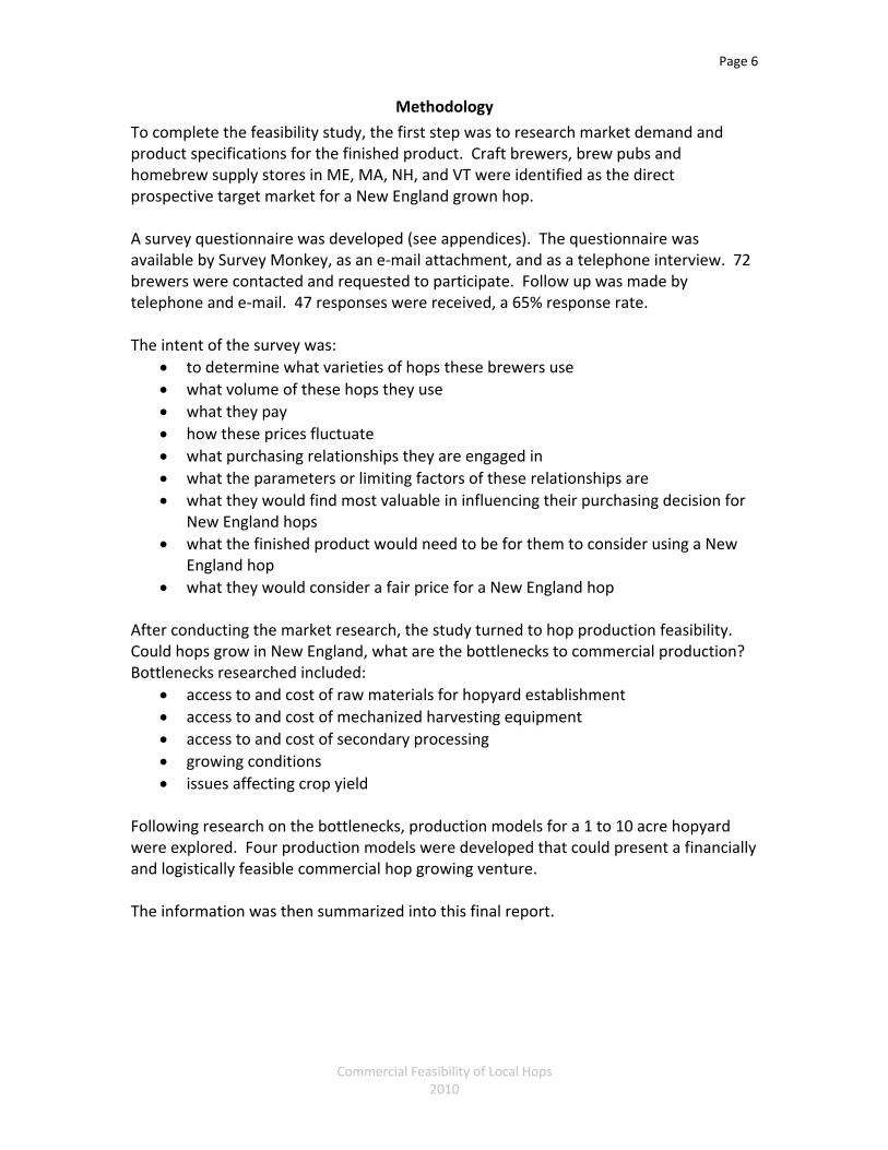
4. Risky Solution: Selling do‐it‐yourself pelletized hops direct to brewers
Concerns:
• Limited access to Gorst Valley Hops knowledge and resources • Issues with processing could impact success • Volume and product quality could be a limitation on market demand • Growers will need outgoing sales personality • Growers will need to make time for processing, sales and marketing • High risk
Encourage growers to adopt mechanical harvesting and sorting, utilize a high trellis hops system, purchase a hammer mill, pellet mill and vacuum, nitrogen flush sealing machine. This solution represents the greatest potential for income and return on investment, and also the greatest risk to the grower. The grower will be on his own for all aspects of growing, harvesting, producing, and selling a finished product that meets the product specifications of the brewing community, at a volume and price point that generates a positive return. If the grower can maintain an average yield of 1,500lbs of dried finished product, achieve the quality standards of the brewing industry, and develop the sales and marketing skills to market the product, the grower can stand to generate up to $12,910 in net income per acre. Hopyard: Recommend starting with one acre and expanding up to ten acres. Use a 3 variety planting, with 1/3 of hopyard per variety to stagger harvest times and minimize threat to entire crop from weather, pest or disease issues that may affect a particular variety. Economic feasibility: Anticipated hopyard infrastructure expense per acre: $12,000 Anticipated harvesting infrastructure expense:
Oast (Year 2): $5,000 for 1st acre $10,000 for 2‐5 acres
$17,500 for 5+ acres Mechanical Picker (Year 3) $5,000 for up to 3 acres
Page 41
Commercial Feasibility of Local Hops 2010
Mechanical Sorter (Year 3) $5,000 for up to 3 acres Anticipated processing infrastructure expense: 2 Chest freezers (Year 2): $2,000
Vacuum‐Nitrogen Flush Sealer (Year 2): $24,000
Pellet Mill (Year 2): $2,400
Hammer Mill (Year 2): $1,700
Total Infrastructure Expense for First Acre: $57,100
Total Operating Expense Per Acre: $9,590
Total Gross Income at 100% Production: $22,500 (assuming selling pelletized hops at $15/lb)
Net Income Per Acre: $12,910 Return on Investment for First Acre: 4 years

Page 42
Commercial Feasibility of Local Hops 2010
Next Steps
It is evident there is strong demand for local hops, and good potential for the ability to grow hops profitably in New England. The infrastructure, which was originally a key barrier to market, is now being developed to support small scale commercial growers in New England.
If producers go through the effort of investing time and capital into starting a commercial hop venture, but lack the support they need to develop their business plan and gain access to necessary technical expertise, the effort may well be lost.
Following is a recommendation for how Vermont Agency of Agriculture, Food and Markets and the Massachusetts Department of Agricultural Resources could ensure that such an endeavor is given its best opportunity for success:
1. Assist Atlantic Hops in establishing its operation.
New England needs the processing capabilities to produce a professional product that will meet market expectations. It also needs access to the equipment, and technical expertise Gorst Valley Hops has already developed and tested for its small scale Mid‐West farmers. Having a processing facility that is willing to process the product and partner with the farms with a mission of providing a good product at a fair value to brewers and returning a fair, profitable income to the producers is a win‐win.
2. Outreach to existing growers/farmers
The agencies will need to reach out to existing growers. Some of the many reasons hops are cited as difficult to grow are because they are being grown by people who don’t grow crops for a living. Most of the basic issues with hops are the same basic issues you will find with any other crop (they need well drained soil, they need fertilizer, they need pest control, they need dedicated timing‐ the harvest is everything…). Producers who grow acres of corn, vegetables, and grains already know and understand the fundamental elements of what it takes to grow a crop successfully. Existing and experienced growers and farmers need to be the target audience if growing hops is to de developed as a commercial enterprise.
3. Business Planning & Coordination with the state Farm Viability Programs.
With each farm, given this is a new venture and unexplored territory for them, and also a new crop for the region, having them go through the business planning process for implementing the new crop and evaluating its impact on the farm business and family quality of life will be essential. This will help ensure that each farm can map out on paper how they would go about implementing

Page 43
Commercial Feasibility of Local Hops 2010
the new crop, understand what it would take on their particular farm, what it would cost, and what the potential return would be. They must be able to understand and evaluate how it might impact other areas of the farm and whether the net return would be better than continuing with their current production or not. It is important that this step be done while still in planning mode, so a decision on whether implementing the plan is in their best interest or not is made before any additional resources, time, and effort have been allocated.
4. Implementation and Business Planning Technical Assistance
Provide ongoing support for the farms for 4 years after initial implementation to help assist with analyzing, planning, and decision making for the new venture and the overall farm operation. This includes business plan review, analysis and updating, and technical expertise specific to areas of concern‐ production, processing, sales and marketing, etc. This third party, objective support will help ensure concerns are addressed proactively thus providing a larger degree of likelihood of success for each farm, and their long term commitment to the project.
Action Items
1. Identify 10 growers in MA & VT who would be interested in participating in Atlantic Hops Value‐Share Grower Program
2. Vet farm sites
a. Conduct a site visit to evaluate the logistical feasibility of each farm. At a minimum the site will need 3’ of top soil before reaching bedrock. Atlantic Hops will also assess each farm’s site for additional attributes such as soil structure, water holding capacity, and seasonal wind loads.
3. Work with the growers to explain the opportunity, and enroll them in the program. This will require a commitment of establishing a one acre hopyard at an expense of $10,000 and the purchase of a picker, sorter, and oast, for an additional expense of $15,000 over years two and three.
4. Potentially finding funding to offset cost of capital infrastructure expense for the first ten growers, or for dairy farmers wishing to participate.
5. Begin Farm Viability business planning and Atlantic Hops Value‐Share Growing Program technical assistance with each farm.
6. Atlantic Hops will provide oversight and guidance with Technical Assistance during establishment of the hopyard, and growing and harvest for first four years.
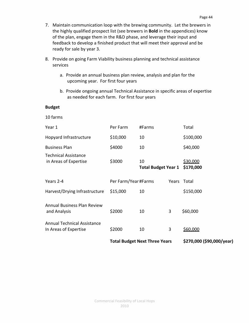
Page 44
Commercial Feasibility of Local Hops 2010
7. Maintain communication loop with the brewing community. Let the brewers in the highly qualified prospect list (see brewers in Bold in the appendices) know of the plan, engage them in the R&D phase, and leverage their input and feedback to develop a finished product that will meet their approval and be ready for sale by year 3.
8. Provide on going Farm Viability business planning and technical assistance services
a. Provide an annual business plan review, analysis and plan for the upcoming year. For first four years
b. Provide ongoing annual Technical Assistance in specific areas of expertise as needed for each farm. For first four years
Budget
10 farms
Year 1 Per Farm #Farms Total
Hopyard Infrastructure $10,000 10 $100,000
Business Plan $4000 10 $40,000
Technical Assistance in Areas of Expertise $3000 10 $30,000 Total Budget Year 1 $170,000
Years 2‐4 Per Farm/Year #Farms Years Total
Harvest/Drying Infrastructure $15,000 10 $150,000
Annual Business Plan Review and Analysis $2000 10 3 $60,000 Annual Technical Assistance In Areas of Expertise $2000 10 3 $60,000 Total Budget Next Three Years $270,000 ($90,000/year)

Appendix A‐ Sources of Information Barth, H.J., Klinke, C., Schmidt, C. The Hop Atlas. 1994. Nuremberg, Germany. Joh, Barth & Sohn. Fayston, J. “The 2007 hops shortage is over, the glut of '09 is here...” The Oregonian. 10/28/2009. Hilchey, D. The Market Potential for Northeastern‐Grown Hops. New Leaf Publishing and Consulting, Inc. 2009. Kneen, Rebecca. Small Scale Organic Hop Production. Left Fields BC. 2004. Neve, R. A. Hops. Champman & Hall. 1991. Page, E. B. Hop Trellising & Budgets. 7/26/2008. Page, E. B., Godin, Ron. “Hopyard Construction: Budgeting and Economics.” CSU Ag Exp. Station. Tomlan, M. Tinged With Gold Hop Culture In The united States. University of Georgia Press. Georgia. 1992 USDA‐ARS. Lower Hop Trellises for Higher Profits. Crop Management. 21 January 2008. Virant, Majda, Majer, Dusica. Hop Storage Index – Indication of a Brewing Quality. Institute of Hop Research and Brewing Zalec. January 2006. Ward, L. Yakima Herald‐Republic. Some plastic mesh could save state hop farms. New technique has potential for the beer‐making crop. May 30, 2005.
Internet Resources
http://www.brewersassociation.org/ http://www.thefreelibrary.com/Craft+Beer+Segment+Continues+to+Set+the+Pace+for+the+Beer+Category...‐a0167648025 http://hops‐extracts.com http://hopunion.com http://www.uvm.edu/~pass/perry/hops.html. http://fujiimpulseamerica.thomasnet.com/viewitems/impulse‐sealers‐vacuum‐gas‐flush‐sealing‐/‐controlled‐nozzle‐type‐vacuum‐gas‐flushing‐sealer http://www.indvacindia.com/nozzle‐type‐flushing‐sealing‐machines.htm

Commercial Feasibility of Local Hops 2010
https://www.biplantol.com/produkte.php?content=3 http://www.ars.usda.gov/is/AR/archive/jan08/hops0108.htm http://www.pleasanthillgrain.com/hammer_mill_pulverizer.aspx; http://www.meadowsmills.com/forsalehm.htm http://www.pelletpros.com/id68.html http://www.foodsaver.com/Category.aspx?id=c&cid=87 https://www.spacebag.com/10/PriceList.dtm http://blog.foothillhops.com/2009/01/01/foothill_hops_20091114521flv.aspx http://www.central‐vt.com/climate/climate.htm http://www.lindemanarchives.com/LA%20History.html http://www.rssweather.com/climate/Vermont/Burlington/ http://maps.google.com/maps/ms?hl=en&ie=UTF8&msa=0&msid=114006202269755079477.00048524ed0b04bf595d6&ll=42.366662,‐71.235352&spn=2.840979,5.767822&z=7&source=embed http://www.massbrewersguild.org/craft‐beer/index.php/member‐breweries/ http://groups.google.com/group/vermont‐hops/topics http://www.indiehops.com/ http://www.freshops.com/ http://www.gorstvalleyhops.com/ http://www.examiner.com/hops‐in‐madison/hops‐growing‐business‐2007‐shortage‐revisited http://www.examiner.com/beer‐in‐national/top‐ten‐hop‐varieties‐used‐by‐american‐craft‐brewers http://vermontbrewers.com/ http://www.lewbryson.com/nyprogress.htm http://www.freepatentsonline.com/ http://www.czhops.cz/tc/bibliography/bibliography10.html http://www.youtube.com/user/cohopsfarmer#p/a http://www.northeasthopalliance.org/ http://www.wolf‐heiztechnik.de/en/pkp/unternehmen/historie.html http://meeting.asbcnet.org/default.cfm

Commercial Feasibility of Local Hops 2010
Appendix B – List of Persons Consulted
Growers and Hop Experts Dwayne Wheeler Claremont, NH (603) 542‐3870 Eugene (Gene) L’Etoile Four Star Farms 496 Pine Meadow Road Northfield, MA (413) 498‐2968 [email protected] Francois Biron Conseiller aménagement, innovation et agroenvironnement Ministère de l'Agriculture, des Pêcheries et de l'Alimentation Centre de services agricoles de Gatineau 999 rue Dollard Gatineau, Québec, CANADA J8L 3E6 (819) 986‐8544 x 236 [email protected] Heather Darby University of Vermont Extension Agronomist and Nutrient Management Specialist 278 S. Main St St. Albans, VT 05478 (802) 524‐6501 x 206 [email protected] James Altwies Gorst Valley Hops 608‐228‐3117 [email protected] Jason Perrault Perrault Farms, Inc. 11051 Lateral “A” Toppenish, WA 98948 (509) 848‐2497

Commercial Feasibility of Local Hops 2010
Jonathan Blumberg 83 South StanleyHill Rd Vassalboro, ME 04989 (207) 923‐3123 Julien Venne Centre de recherche et de développement technologique agricole de l'Outaouais (CRÉDÉTAO) 188, rue Jeanne‐D'Arc, suite 200 Papineauville, Québec, CANADA J0V 1R0 (819) 427‐5511 x 461 [email protected] Larry & Kate Fisher Foothill Hops [email protected] (315) 495‐2451 Michael Roffman Atlantic Hops PO Box 1055 Larchmont, NY 10538 (914) 834‐5130 [email protected] Peter Hingston Jeffrey Cox Cherry Hill Farm 409 Highland Road Springfield, VT 05156 (802) 885‐5088 [email protected] [email protected] Puterbaugh Farms Hops Direct, LLC 686 Green Valley Road Mabton, WA 98935 (888) 972‐3616 http://www.hopsdirect.com/

Commercial Feasibility of Local Hops 2010
Rick Pedersen Pedersen Farms 1798 County Road 4 Seneca Castle, NY (315) 781‐0482 [email protected] Roger Rainville Borderview Farms & Ag Research Facility 146 Line Rd. Alburgh, VT 05440 (802) 796‐3292 [email protected] Rosalie Madden Crops and Soils Technician UVM Extension 278 S. Main St., Suite 2 St. Albans, VT 05478 (802) 524‐6501 x 445 Steve Parks American Brewers Guild Abgbrew.com [email protected] Anthony (Tony) Palmiero Tractor Logging 345 East Church St. East Hardwick, VT 05836 (802) 472‐6503 [email protected]

Commercial Feasibility of Local Hops 2010
Brewers/Brew Pubs/Homebrew Suppliers
MAINE Allagash Brewing Jason Perkins, head brewer 100 Industrial Way Portland, ME 04103 (800) 330‐5385 [email protected] Andrews Brewing Company Andy and Ben, brewers/owners 4975 High St. Lincolnville, ME 04849 (207) 763‐3305 [email protected] Atlantic Brewing Company Doug, brewer 15 Knox Road Bar Harbor, ME 04609 (207) 288‐9513 [email protected] Bar Harbor Brewing Co 8 Mount Desert Street Bar Harbor,ME 04609 (207) 288‐4592 Belfast Bay Brewing Company 100 Searsport Ave. Belfast, ME 04915 (207) 338‐4216 www.belfastbaybrewing.com Black Bear MicroBrewery Tim Gallon, owner/brewer 19 Mill Street, Suite 4 Orono, ME 04473 207‐949‐2880 [email protected]

Commercial Feasibility of Local Hops 2010
Bray's Brewpub & Eatery Rob, brewmaster 678 Roosevelt Trail Naples, ME 04055‐0548 (207) 693‐6806 Casco Bay = Shipyard, see Shipyard Federal Jacks Brewpub & Restaurant 8 Western Avenue Kennebunk, ME 04043 (207) 967.4322 Geary’s Steve Spear, head brewer 38 Evergreen Drive Portland, ME 04103 (207) 878‐2337 Gritty McDuff’s Andrew Heyner & Jake, brewers 396 Fore Street Portland, ME 04101 (207) 772‐BREW Inn on Peak’s Island 33 Island Ave Peaks Island, ME 04108 (207) 766‐5100 Kennebec River Brewery Jim, head brewer Forks Resort Center The Forks, ME 04985 800‐765‐7238 Liberal Cup Public House & Brewery 115 Water St. Hallowell, ME 04347 (207) MAD‐BREW

Commercial Feasibility of Local Hops 2010
Maine Coast Brewing Company 102 Eden Street Bar Harbor, ME 04609 (207) 288‐4914 Peak Organic Brewing Co. Jon Cadoux, owner/brewer 110 Marginal Way #802 Portland, ME 04101 (207) 586‐5586 [email protected] Oak Pond Brewery 101 Oak Pond Rd Skowhegan, ME 04976 (207) 474‐3233 Sea Dog Brewing Co. 26 Front Street Bangor, ME 04401 (207) 947‐8009 Sebago Brewing Company Tom, brewer 48 Sanford Drive Gorham, ME 04038 (207) 856‐2537 Shipyard Brewing Co Alan Puglsey, owner David Hall, head brewer 86 Newbury St. Portland, ME 04101 (207) 761‐0807 [email protected] [email protected] Sunday River Brewery Stu Mason, brewer 1 Sunday River Road Bethel, ME 04217 (207) 824‐4ALE

Commercial Feasibility of Local Hops 2010
Note: call on Mondays MASSACHUSETSS Boston Beer Works Tim Morse, Corporate Brewer 61 Brookline Ave Boston, MA 02215 (617) 896‐2300 Berkshire Brewing Company Inc. Gary A. Bogoff, owner 12 Railroad Street South Deerfield, MA 01373 Tel (413) 665‐6600 [email protected] Blue Hills Brewery Todd, sales 1020 Turnpike Street #3B Canton, MA 02021 (781) 821‐2337 [email protected] The Boston Beer Company Jennifer Granville One Design Center, Suite 850 Boston, MA 02210 (617) 368‐5000 BrewBank Cambridge Brewing Will Meyers, brewmaster 1 Kendall Square, Bldg 100 Cambridge, MA 02139 617‐494‐1994 [email protected] Cambridge Commons Brewery Ginger, owner Cambridge, MA (978) 551‐6477

Commercial Feasibility of Local Hops 2010
Cape Ann Brewing Jeremy Goldberg, brewer 27 Commercial Street Gloucester, MA 01930 (978) 281‐4782 [email protected] Cape Cod Beer Beth & Todd Marcus, owners/brewers 1336 Phinney's Lane Hyannis MA 02601 (508) 790‐4200 [email protected]; [email protected] Cisco Brewers Jay, brewer P.O. Box 2928 Nantucket MA 02584 (508) 325.5929 [email protected] BYOB (Cody) Brewing Company Sean Cody ‐ Brewer/Owner 36 Main St. Amesbury, MA 01913 (978) 378‐3424 [email protected] Gardner Ale House Dave Richardson 7 Parker St. Gardner, MA 01440 (978) 669‐0122 [email protected] Harpoon Brewery Al Marzi, V.P. Operations Sean Cornelius, assistant V.P. Operations 306 Northern Ave. Boston, MA 02210 (888) HAR‐POON [email protected]; [email protected]

Commercial Feasibility of Local Hops 2010
Haverhill Brewery John Curtis, brewer 100 Washington Street Haverhill, MA 01832‐5500 (978) 373‐2337 tapbrewpub.com Mayflower Brewing Company Drew, brewer 12 Resnik Rd Plymouth, MA 02360 (508) 746‐2674 [email protected] Mercury Brewing Company Dan, brewer 23 Hayward St. Ipswich, MA 01938 (978) 356‐3329 [email protected] Northampton Brewery Bar‐Grille (John Harvard's Brew House) Maria Poulinas, brewer 11 Brewster Court Northampton, MA 01060‐3801 (508) 875‐2337 [email protected] Opa Opa Steakhouse & Brewery Themis, owner 169 College Highway Southampton, MA 01073‐9320 (413) 527‐0808 opaopasteakhousebrewery.com Pittsfield Brew Works 34 Depot Street Pittsfield, MA 01201‐5130 (413) 997‐3506 pittsfieldbrewworks.com

Commercial Feasibility of Local Hops 2010
Rock Bottom Restaurant & Brewery Scott Brunelle, brewmaster 115 Stuart Street Boston, MA 02116 (617) 742‐2739 rockbottom.com Note: Best time to call is 9‐10 am. Wachusett Brewing Company Dave Howard, “Howie” head brewer 175 State Road East Westminster, MA 01473 (978) 874‐9965 x 30 [email protected] Watch City Brewing Company Jocelyn and Frank, owners Aaron Mateychuck, brewer 256 Moody Street Waltham, MA 02453 (781) 647‐4000 watchcitybrew.com NEW HAMPSHIRE Granite Cask 6 King's Square Unit A Whitefield, NH 03598 (603) 837‐2224 [email protected] Mount Washington Home Brew Supply A Division of Merrill's Agway 678 Meadow Street Littleton, NH 03561 603‐444‐8803 [email protected] Portsmouth Brewery Tod, brewer 56 Market Street Portsmouth, NH 03801 603‐431‐1115 [email protected]

Commercial Feasibility of Local Hops 2010
Smuttynose Brewing Co David, Executive Brewer 225 Heritage Ave Portsmouth, NH 03801 (603) 436‐4026 Seven Barrel Brewery Plainfield Road Colonial Plaza, Rt 12‐A West Lebanon, NH 03784 (603) 298‐5566 Tuckerman Brewing Company, LLC Kirsten Neves Managing Member PO Box 1058 64 Hobbs Street Conway, NH 03818 (603) 447‐5400 [email protected] White Birch Brewing Bill, brewer/owner 1368 Hooksett Rd, Unit 6 Hooksett, NH 03106 (603) 244‐8593 VERMONT The Alchemist 23 South Main Street Waterbury, VT 05676 (802) 244‐4120 Bobcat Cafe & Brewery Mark Magiera, brewer 5 Main Street Bristol, VT (802) 453‐3311

Commercial Feasibility of Local Hops 2010
Brewery at the Trapp Family Lodge Alan Van Anda, brewer 700 Trapp Hill Road PO Box 1428 Stowe, VT 05672 802‐253‐8511 Hill Farmstead Brewery Shaun Hill, owner/brewer 403A Hill Road Greensboro Bend, VT 05842 (802) 533‐7450 Jasper Murdock's Alehouse/Norwich Inn Patrick Dakin, brewer 325 Main Street P.O. Box 908 Norwich, VT 05055 (802)‐649‐1143 Lawson's Finest Liquids Sean Lawson, owner/brewer Warren, VT 05674 (802) 272‐8436 [email protected]
Long Trail Matt Quinlin, brewmaster 5520 US Route 4 Bridgewater Corners, VT 05035‐9600 (802) 672‐5011 x 207 [email protected] Madison Brewing 428 Main Street Bennington, VT 05201 (802) 442‐7397 Magic Hat Brewing Company Todd Haire, brewer 5 Bartlett Bay Road South Burlington VT 05403 802‐862‐6114 x 2012

Commercial Feasibility of Local Hops 2010
McNeill’s Pub & Brewery Ray McNeill, owner/brewer 90 Elliot Street Brattleboro, VT 05403 (802) 254‐2553; [email protected] Northshire Brewery 108 County Street Bennington, VT 05201 (802) 681‐0201 Otter Creek Brewing Mike Gerhart, brewmaster 793 Exchange Street Middlebury, VT 05753 (802) 388‐0727 [email protected] Rock Art Renee and Matt Nadeau, owners/brewers 234 Wilkens Street Morrisville, VT 05661 (802) 888‐9400 South Royalton Market Scott Russell, homebrew manager 105 Chelsea St South Royalton, VT 05068 (802) 763‐2400 Switchback Brewing Co. Bill Cherry, owner/brewer 160 Flynn Avenue Burlington, VT 05401 (802) 651‐4114 [email protected] The Perfect Pear Adam Colter, owner/brewer 48 South Main Street Bradford, VT 05033 (802) 222‐5912 [email protected]
Commercial Feasibility of Local Hops 2010
The Shed Brewery Jim Conroy, brewer 1859 Mountain Road Stowe, VT 05672 (802) 253‐4364 Three Needs Brewery 207 College Street Burlington, VT 05401 (802) 658‐0889 Trout River Brewery Dan & Laura Gates, owner/brewers Route 5; P.O. Box 165 Lyndonville, VT 05851 (802) 626‐9396 Vermont Homebrew Supply 147 E. Allen Street Winooski, VT 05404 (802) 655‐2070 [email protected] The Vermont Pub & Brewery 144 College Street Burlington, VT 05401 (802) 865‐0500 Zero Gravity Craft Brewery Destiny, brewer 15 St. Paul Street Burlington, VT 05401 (802) 861‐2999

Commercial Feasibility of Local Hops 2010
Additional Persons Consulted
Allen Matthews Center for Sustainable Agriculture 106 High Point Center‐ Room 312 University of Vermont Colchester, VT 05446 (802) 318‐1041 Atul Kant Verma Managing Partner Elegant Engineers, An ISO 9001:2008 Certified Company C‐ 82, Sector ‐ 10, Noida ‐ 201301 (U.P.) INDIA Tel: 91 120 2525503 / 2444892 Mobile: 91 98101 46982 E‐mail: [email protected] [email protected] Website http://www.elegantengineers.com http://www.pouch‐packing.com Barney Hodges III Vermont Refrigerated Storage 1287 North Bingham St. Cornwall, Vermont [email protected] www.sunriseorchardsvt.com (802) 989‐0255 Dauenhauer Manufacturing, Inc. 111‐125 Fifth Street / PO Box1744 Santa Rosa, CA 95402 (707) 546‐0577 www.dmfg.com Enid Wonacott Executive Director NOFA VT PO Box 697 Richmond, VT 05401 (802) 434‐3821 [email protected]

Commercial Feasibility of Local Hops 2010
Hugo Gervais Custom Fabrication [email protected] India Burnett Farmer Program Director Rutland Area Farm and Food Link P.O. Box 561 East Poultney, VT 05741 (802) 417‐7331 [email protected] Jun Sota Fuji Impulse America [email protected] (847) 236‐9190 www.fujiimpulseamerica.com Macy Mullican Shelburne Vineyard The Vermont Food Project, refrigerated warehouse (802) 734‐3431 Pellet Pros, Inc. 4004 W. Kimberly Rd. Suite C Davenport, IA 52806 (563) 386-4300 [email protected] Steve Justis Vermont Agency of Agriculture Food, and Markets 116 State St. Montpelier, VT 05620 (802) 828‐3829

Commercial Feasibility of Local Hops 2010
Appendix C – Brewer Questionnaire Template
What is the name of your brewery? How many barrels do you brew per year? What are the top five hops you use? 1. 2. 3. 4. 5. How much of each do you use per year? (in lbs) 1. 2. 3. 4. 5. How much total aroma hops do you use per year? (in lbs) How much total bittering hops do you use per year? (in lbs) Which varieties of hops (if not listed in the five above) would you like to see available more locally? How do you prefer to use hops (whole, pelletized)? Please describe What are the product specifications and quality requirements we would need to be able to meet for you to consider buying from a local source? Please describe (ie packaging, lab analysis, pelletized vs whole, etc, etc) How do your hops come packaged and shipped?

Commercial Feasibility of Local Hops 2010
Are you under contract for your hops? If so would/could you consider buying local hops and when does your contract come up for renewal? Could you buy local hops even if you are under contract and if so up to how much of your total volume of hop usage? What is your current source for hops? Please list suppliers and state/country. What are you currently paying for your hops? Does this include shipping? If not, what do you pay for shipping? How much of your total hop volume would you be willing to buy locally if it met your quality requirements and product specifications? Would you prefer a stable price for local hops that may or may not reflect the market rate but is a stable price that you and the grower can both depend on? Or would you prefer the hops compete at market rate? If you would prefer to be able to rely on a known price for a known product, what would you see as a fair rate that you would consistently be willing to agree to? If the product were to compete at market rate what would you say is the average rate we should expect to charge (if this differs from the fair rate you list above)? Would you be willing to pay a premium for local hops? If yes, how much would you be willing to pay above what you are currently paying? 10%, 20%, 50%, 100%, etc? If you were willing to pay a premium for local hops, would this change the volume of local hops you would buy (ie if you pay more you might buy less?) Is this so and if so, how would the volume of local hops you purchase change? Why are you interested in buying hops locally? Are you interested in organic hops? What is the best way to communicate with you? Other thoughts/comments/suggestions?

Commercial Feasibility of Local Hops 2010
Appendix D – Cash Flow Scenarios
Scenario 1: Grower participating in the Atlantic Hops Value‐Share Grower Program, Growing 1 Acre
Cash flow 1: demonstrating cash flow if no efficiencies in production are utilized Cash flow 2: demonstrating cash flow if grower harvests only top 1/3 of the bine Cash flow 3: demonstrating cash flow if grower harvests only top 1/3 of the bine, and manually strips and sorts Cash flow 4: demonstrating cash flow if grower harvests only top 1/3 of the bine, and mechanically strips and sorts

Projection Projection Projection ProjectionProduction Information Year 1 Year 2 Year 3 Year 4Number of acres 1 1 1 1Production Level 0% 40% 90% 100%Quantity of dried hops sold (lbs/year) 0 600 1350 1500Pounds of dried hops per acre per year 0 600 1350 1500Average price paid to grower per dried pound 9 9 9 9Return on Investment in Years (2)Annual Net Income at 100% Production (9,610)$
Cash ReceiptsHops Sold -$ 5,400$ 12,150$ 13,500$ TOTAL CASH RECEIPTS -$ 5,400$ 12,150$ 13,500$
Cash ExpensesVariable Expenses: Chemicals -$ -$ -$ -$ Conservation expense -$ -$ -$ -$ Custom hire -$ -$ -$ -$ Trellising supplies- twine, w clips, etc. -$ -$ -$ -$ Fertilizer -$ -$ -$ -$ Fuel and oil -$ -$ -$ -$ Labor hired (incl. FICA, workers comp, etc.) -$ -$ -$ -$ Repairs, maintenance -$ -$ -$ -$
Electricity for drying Supplies -$ -$ -$ -$
Sub total Variable Expenses 2,500$ 2,500$ 2,500$ 2,500$ Labor -$ -$ -$ -$
Spring/Summer Labor 500 hrs/acre @ $10/hr 5,000$ 5,000$ 5,000$ 5,000$ Harvest Labor 1 hr/dried lb 1,500hrs @ $10/hr 15,000$ 15,000$ 15,000$ 15,000$
Sub total Labor 20,000$ 20,000$ 20,000$ 20,000$ Other Variable ExpensesFreight/Shipping estimating 2,000lbs NMFC classification 100 610$ 610$ 610$ 610$
Other: -$ -$ -$ -$ Sub total Other Variable Expenses 610$ 610$ 610$ 610$
Total Variable Expenses: 23,110$ 23,110$ 23,110$ 23,110$
Fixed Expenses: Auto & truck -$ -$ -$ -$ Interest, farm share -$ -$ -$ -$ Insurance, farm share -$ -$ -$ -$ Property tax, farm share -$ -$ -$ -$ Rents paid—land, buildings -$ -$ -$ -$ Rents paid—equipment, livestock -$ -$ -$ -$ Utilities, farm share -$ -$ -$ -$ Other: -$ -$ -$ -$ Other: -$ -$ -$ -$ Other: -$ -$ -$ -$ Other: -$ -$ -$ -$ Total Fixed Expenses -$ -$ -$ -$
TOTAL CASH EXPENSES 23,110$ 23,110$ 23,110$ 23,110$
RECEIPTS MINUS EXPENSES (23,110)$ (17,710)$ (10,960)$ (9,610)$
Plus CAPITAL CONTRIBUTIONSgrants -$ -$ -$ -$ loans -$ -$ -$ -$ off-farm income -$ -$ -$ -$ other -$ -$ -$ -$
Plus CAPITAL SALESequipment -$ -$ -$ -$
Less CAPITAL EXPENSEmechanical harvester -$ -$ -$ -$ sorter -$ -$ -$ -$ oast 1 phase, 3/4 hp -$ 5,000$ -$ -$ one acre hop yard- Atlantic Hops Value-Grower Set Price 10,000$ -$ -$ -$
Total Capital Expense 10,000$ 5,000$ -$ -$
Less DEBT SERVICE List Loan Principal Payments
Plus STARTING CASH -$ (33,110)$ (55,820)$ (66,780)$
NET RETAINED CASH EARNINGS (DEFICIT) $ (33,110) $ (55,820) $ (66,780) $ (76,390)
- Income Taxes (estimate at 33%) -$ -$ -$ Less Family Living -$ -$ -$ -$ - Capital Reserve
NET AFTER CAPITAL RESERVE, FAMILY LIVING AND INCOME TAX ALLOCATION $ (33,110) $ (55,820) $ (66,780) $ (76,390)
Courtesy: Vermont Farm Viability Enhancement Program
CASH FLOW PROJECTION
No Optimization in Harvesting
Scenario: Participating in Atlantic Hops Value Share Grower Program

Projection Projection Projection ProjectionProduction Information Year 1 Year 2 Year 3 Year 4Number of acres 1 1 1 1Production Level 0% 40% 90% 100%Quantity of dried hops sold (lbs/year) 0 600 1350 1500Pounds of dried hops per acre per year 0 600 1350 1500Average price paid to grower per dried pound 9 9 9 9Return on Investment in Years (4)Annual Net Income at 100% Production (3,360)$
Cash ReceiptsHops Sold -$ 5,400$ 12,150$ 13,500$ TOTAL CASH RECEIPTS -$ 5,400$ 12,150$ 13,500$
Cash ExpensesVariable Expenses: Chemicals -$ -$ -$ -$ Conservation expense -$ -$ -$ -$ Custom hire -$ -$ -$ -$ Trellising supplies- twine, w clips, etc. -$ -$ -$ -$ Fertilizer -$ -$ -$ -$ Fuel and oil -$ -$ -$ -$ Labor hired (incl. FICA, workers comp, etc.) -$ -$ -$ -$ Repairs, maintenance -$ -$ -$ -$
Electricity for drying Supplies -$ -$ -$ -$
Sub total Variable Expenses 2,500$ 2,500$ 2,500$ 2,500$ Labor -$ -$ -$ -$
Spring/Summer Labor 500 hrs/acre @ $10/hr 5,000$ 5,000$ 5,000$ 5,000$ Harvest Labor harvesting only top 1/3 of the bine 35 min/lb1,500lbs/acre (875 hrs) @ $10/hr 8,750$ 8,750$ 8,750$ 8,750$
Sub total Labor 13,750$ 13,750$ 13,750$ 13,750$ Other Variable ExpensesFreight/Shipping estimating 2,000lbs NMFC classification 100 610$ 610$ 610$ 610$
Other: -$ -$ -$ -$ Sub total Other Variable Expenses 610$ 610$ 610$ 610$
Total Variable Expenses: 16,860$ 16,860$ 16,860$ 16,860$
Fixed Expenses: Auto & truck -$ -$ -$ -$ Interest, farm share -$ -$ -$ -$ Insurance, farm share -$ -$ -$ -$ Property tax, farm share -$ -$ -$ -$ Rents paid—land, buildings -$ -$ -$ -$ Rents paid—equipment, livestock -$ -$ -$ -$ Utilities, farm share -$ -$ -$ -$ Other: -$ -$ -$ -$ Other: -$ -$ -$ -$ Other: -$ -$ -$ -$ Other: -$ -$ -$ -$ Total Fixed Expenses -$ -$ -$ -$
TOTAL CASH EXPENSES 16,860$ 16,860$ 16,860$ 16,860$
RECEIPTS MINUS EXPENSES (16,860)$ (11,460)$ (4,710)$ (3,360)$
Plus CAPITAL CONTRIBUTIONSgrants -$ -$ -$ -$ loans -$ -$ -$ -$ off-farm income -$ -$ -$ -$ other -$ -$ -$ -$
Plus CAPITAL SALESequipment -$ -$ -$ -$
Less CAPITAL EXPENSEmechanical harvester -$ -$ -$ -$ sorter -$ -$ -$ -$ oast 1 phase, 3/4 hp -$ 5,000$ -$ -$ one acre hop yard- Atlantic Hops Value-Grower Set Price 10,000$ -$ -$ -$
Total Capital Expense 10,000$ 5,000$ -$ -$
Less DEBT SERVICE List Loan Principal Payments
Plus STARTING CASH -$ (26,860)$ (43,320)$ (48,030)$
NET RETAINED CASH EARNINGS (DEFICIT) $ (26,860) $ (43,320) $ (48,030) $ (51,390)
- Income Taxes (estimate at 33%) -$ -$ -$ Less Family Living -$ -$ -$ -$ - Capital Reserve
NET AFTER CAPITAL RESERVE, FAMILY LIVING AND INCOME TAX ALLOCATION $ (26,860) $ (43,320) $ (48,030) $ (51,390)
Courtesy: Vermont Farm Viability Enhancement Program
CASH FLOW PROJECTION
Optimized Manual Harvesting, Harvesting Only Top 1/3 of Bine
Scenario: Participating in Atlantic Hops Value Share Grower Program

Projection Projection Projection ProjectionProduction Information Year 1 Year 2 Year 3 Year 4Number of acres 1 1 1 1Production Level 0% 40% 90% 100%Quantity of dried hops sold (lbs/year) 0 600 1350 1500Pounds of dried hops per acre per year 0 600 1350 1500Average price paid to grower per dried pound 9 9 9 9Return on Investment in Years 38Annual Net Income at 100% Production 390$
Cash ReceiptsHops Sold -$ 5,400$ 12,150$ 13,500$ TOTAL CASH RECEIPTS -$ 5,400$ 12,150$ 13,500$
Cash ExpensesVariable Expenses: Chemicals -$ -$ -$ -$ Conservation expense -$ -$ -$ -$ Custom hire -$ -$ -$ -$ Trellising supplies- twine, w clips, etc. -$ -$ -$ -$ Fertilizer -$ -$ -$ -$ Fuel and oil -$ -$ -$ -$ Labor hired (incl. FICA, workers comp, etc.) -$ -$ -$ -$ Repairs, maintenance -$ -$ -$ -$
Electricity for drying Supplies -$ -$ -$ -$
Sub total Variable Expenses 2,500$ 2,500$ 2,500$ 2,500$ Labor -$ -$ -$ -$
Spring/Summer Labor 500 hrs/acre @ $10/hr 5,000$ 5,000$ 5,000$ 5,000$ Harvest Labor harvesting top 1/3 of the bine, stripping and sorting 20 min/lb 1,500lbs/acre (500 hrs) @ $10/hr 5,000$ 5,000$ 5,000$ 5,000$
Sub total Labor 10,000$ 10,000$ 10,000$ 10,000$ Other Variable ExpensesFreight/Shipping estimating 2,000lbs NMFC classification 100 610$ 610$ 610$ 610$
Other: -$ -$ -$ -$ Sub total Other Variable Expenses 610$ 610$ 610$ 610$
Total Variable Expenses: 13,110$ 13,110$ 13,110$ 13,110$
Fixed Expenses: Auto & truck -$ -$ -$ -$ Interest, farm share -$ -$ -$ -$ Insurance, farm share -$ -$ -$ -$ Property tax, farm share -$ -$ -$ -$ Rents paid—land, buildings -$ -$ -$ -$ Rents paid—equipment, livestock -$ -$ -$ -$ Utilities, farm share -$ -$ -$ -$ Other: -$ -$ -$ -$ Other: -$ -$ -$ -$ Other: -$ -$ -$ -$ Other: -$ -$ -$ -$ Total Fixed Expenses -$ -$ -$ -$
TOTAL CASH EXPENSES 13,110$ 13,110$ 13,110$ 13,110$
RECEIPTS MINUS EXPENSES (13,110)$ (7,710)$ (960)$ 390$
Plus CAPITAL CONTRIBUTIONSgrants -$ -$ -$ -$ loans -$ -$ -$ -$ off-farm income -$ -$ -$ -$ other -$ -$ -$ -$
Plus CAPITAL SALESequipment -$ -$ -$ -$
Less CAPITAL EXPENSEmechanical harvester -$ -$ -$ -$ sorter -$ -$ -$ -$ oast 1 phase, 3/4 hp -$ 5,000$ -$ -$ one acre hop yard- Atlantic Hops Value-Grower Set Price 10,000$ -$ -$ -$
Total Capital Expense 10,000$ 5,000$ -$ -$
Less DEBT SERVICE List Loan Principal Payments
Plus STARTING CASH -$ (23,110)$ (35,820)$ (36,780)$
NET RETAINED CASH EARNINGS (DEFICIT) $ (23,110) $ (35,820) $ (36,780) $ (36,390)
- Income Taxes (estimate at 33%) -$ -$ -$ Less Family Living -$ -$ -$ -$ - Capital Reserve
NET AFTER CAPITAL RESERVE, FAMILY LIVING AND INCOME TAX ALLOCATION $ (23,110) $ (35,820) $ (36,780) $ (36,390)
Courtesy: Vermont Farm Viability Enhancement Program
CASH FLOW PROJECTION
Optimized Manual Harvesting, Harvesting Only Top 1/3 of Bine, Manual Stripping & Sorting
Scenario: Participating in Atlantic Hops Value Share Grower Program

Projection Projection Projection ProjectionProduction Information Year 1 Year 2 Year 3 Year 4Number of acres 1 1 1 1Production Level 0% 40% 90% 100%Quantity of dried hops sold (lbs/year) 0 600 1350 1500Pounds of dried hops per acre per year 0 600 1350 1500Average price paid to grower per dried pound 9 9 9 9
Return on Investment in Years 5Annual Net Income at 100% Production 4,640$
Cash ReceiptsHops Sold -$ 5,400$ 12,150$ 13,500$ TOTAL CASH RECEIPTS -$ 5,400$ 12,150$ 13,500$
Cash ExpensesVariable Expenses: Chemicals -$ -$ -$ -$ Conservation expense -$ -$ -$ -$ Custom hire -$ -$ -$ -$ Trellising supplies- twine, w clips, etc. -$ -$ -$ -$ Fertilizer -$ -$ -$ -$ Fuel and oil -$ -$ -$ -$ Labor hired (incl. FICA, workers comp, etc.) -$ -$ -$ -$ Repairs, maintenance -$ -$ -$ -$
Electricity for drying Supplies -$ -$ -$ -$
Sub total Variable Expenses 2,500$ 2,500$ 2,500$ 2,500$ Labor -$ -$ -$ -$
Spring/Summer Labor 500 hrs/acre @ $10/hr 5,000$ 5,000$ 5,000$ 5,000$ Harvest Labor harvesting only top 1/3 of the bine 3 min/lb- 1 min to pick, 2 min to sort 1,500lbs/acre (75 hrs) @ $10/hr 750$ 750$ 750$ 750$
Sub total Labor 5,750$ 5,750$ 5,750$ 5,750$ Other Variable ExpensesFreight/Shipping estimating 2,000lbs NMFC classification 100 610$ 610$ 610$ 610$
Other: -$ -$ -$ -$ Sub total Other Variable Expenses 610$ 610$ 610$ 610$
Total Variable Expenses: 8,860$ 8,860$ 8,860$ 8,860$
Fixed Expenses: Auto & truck -$ -$ -$ -$ Interest, farm share -$ -$ -$ -$ Insurance, farm share -$ -$ -$ -$ Property tax, farm share -$ -$ -$ -$ Rents paid—land, buildings -$ -$ -$ -$ Rents paid—equipment, livestock -$ -$ -$ -$ Utilities, farm share -$ -$ -$ -$ Other: -$ -$ -$ -$ Other: -$ -$ -$ -$ Other: -$ -$ -$ -$ Other: -$ -$ -$ -$ Total Fixed Expenses -$ -$ -$ -$
TOTAL CASH EXPENSES 8,860$ 8,860$ 8,860$ 8,860$
RECEIPTS MINUS EXPENSES (8,860)$ (3,460)$ 3,290$ 4,640$
Plus CAPITAL CONTRIBUTIONSgrants -$ -$ -$ -$ loans -$ -$ -$ -$ off-farm income -$ -$ -$ -$ other -$ -$ -$ -$
Plus CAPITAL SALESequipment -$ -$ -$ -$
Less CAPITAL EXPENSEmechanical harvester -$ -$ 5,000$ -$ sorter -$ -$ 5,000$ -$ oast -$ 5,000$ -$ -$ one acre hop yard- Atlantic Hops Value-Grower Set Price 10,000$ -$ -$ -$
Total Capital Expense 10,000$ 5,000$ 10,000$ -$
Less DEBT SERVICE List Loan Principal Payments
Plus STARTING CASH -$ (18,860)$ (27,320)$ (34,030)$
NET RETAINED CASH EARNINGS (DEFICIT) $ (18,860) $ (27,320) $ (34,030) $ (29,390)
- Income Taxes (estimate at 33%) -$ -$ -$ Less Family Living -$ -$ -$ -$ - Capital Reserve
NET AFTER CAPITAL RESERVE, FAMILY LIVING AND INCOME TAX ALLOCATION $ (18,860) $ (27,320) $ (34,030) $ (29,390)
Courtesy: Vermont Farm Viability Enhancement Program
CASH FLOW PROJECTION
Optimized Manual Harvesting, Harvesting Only Top 1/3 of Bine, Mechanized Stripping, Picking, & Sorting
Scenario: Participating in Atlantic Hops Value Share Grower Program

Commercial Feasibility of Local Hops 2010
Scenario 2: Grower growing hops to sell as whole dried hops
Cash flow 1: demonstrating cash flow if no efficiencies in production are utilized Cash flow 2: demonstrating cash flow if grower harvests only top 1/3 of the bine Cash flow 3: demonstrating cash flow if grower harvests only top 1/3 of the bine, and manually strips and sorts Cash flow 4: demonstrating cash flow if grower harvests only top 1/3 of the bine, and mechanically strips and sorts

Projection Projection Projection ProjectionProduction Information Year 1 Year 2 Year 3 Year 4Number of acres 1 1 1 1Production Level 0% 40% 90% 100%Quantity of dried hops sold (lbs/year) 0 600 1350 1500Pounds of dried hops per acre per year 0 600 1350 1500Average price per dried pound needed to break even 15.51 16.11 16.11 16.11 Projected Sale Price to Brewers 10.00 10.00 10.00 10.00
Return on Investment in Years (2)Annual Net Income at 100% Production (9,160)$
Cash ReceiptsHops Sold -$ 6,000$ 13,500$ 15,000$ TOTAL CASH RECEIPTS -$ 6,000$ 13,500$ 15,000$
Cash ExpensesVariable Expenses: Chemicals -$ -$ -$ -$ Conservation expense -$ -$ -$ -$ Custom hire -$ -$ -$ -$ Trellising supplies- twine, w clips, etc. -$ -$ -$ -$ Fertilizer -$ -$ -$ -$ Fuel and oil -$ -$ -$ -$ Labor hired (incl. FICA, workers comp, etc.) -$ -$ -$ -$ Repairs, maintenance -$ -$ -$ -$
Electricity for drying Supplies -$ -$ -$ -$
Sub total Variable Expenses 2,500$ 2,500$ 2,500$ 2,500$ Labor -$ -$ -$ -$
Spring/Summer Labor 500 hrs/acre @ $10/hr 5,000$ 5,000$ 5,000$ 5,000$ Harvest Labor 1 hr/dried lb 1,500hrs @ $10/hr 15,000$ 15,000$ 15,000$ 15,000$
Sub total Labor 20,000$ 20,000$ 20,000$ 20,000$ Other Variable ExpensesFreight/Shipping estimating 2,000lbs NMFC classification 100 610$ 610$ 610$ 610$ Chemical Analysis 150$ 150$ 150$ 150$ Processing (pelletizing and packaging) -$ 100$ 100$ 100$ Climate Controlled Storage- rented climate controlled space -$ 700$ 700$ 700$ Sales & Marketing -$ 100$ 100$ 100$
Other: -$ -$ -$ -$ Sub total Other Variable Expenses 760$ 1,660$ 1,660$ 1,660$
Total Variable Expenses: 23,260$ 24,160$ 24,160$ 24,160$
Fixed Expenses: Auto & truck -$ -$ -$ -$ Interest, farm share -$ -$ -$ -$ Insurance, farm share -$ -$ -$ -$ Property tax, farm share -$ -$ -$ -$ Rents paid—land, buildings -$ -$ -$ -$ Rents paid—equipment, livestock -$ -$ -$ -$ Utilities, farm share -$ -$ -$ -$ Other: -$ -$ -$ -$ Other: -$ -$ -$ -$ Other: -$ -$ -$ -$ Other: -$ -$ -$ -$ Total Fixed Expenses -$ -$ -$ -$
TOTAL CASH EXPENSES 23,260$ 24,160$ 24,160$ 24,160$
RECEIPTS MINUS EXPENSES (23,260)$ (18,160)$ (10,660)$ (9,160)$
Plus CAPITAL CONTRIBUTIONSgrants -$ -$ -$ -$ loans -$ -$ -$ -$ off-farm income -$ -$ -$ -$ other -$ -$ -$ -$
Plus CAPITAL SALESequipment -$ -$ -$ -$
Less CAPITAL EXPENSEmechanical harvester -$ -$ -$ -$ sorter -$ -$ -$ -$ oast -$ 5,000$ -$ -$ one acre hop yard 12,000$ -$ -$ -$
Total Capital Expense 12,000$ 5,000$ -$ -$
Less DEBT SERVICE List Loan Principal Payments
Plus STARTING CASH -$ (35,260)$ (58,717)$ (69,674)$
NET RETAINED CASH EARNINGS (DEFICIT) $ (35,260) $ (58,420) $ (69,377) $ (78,834)
- Income Taxes (estimate at 33%) 297$ 297$ 297$ Less Family Living -$ -$ -$ -$ - Capital Reserve
NET AFTER CAPITAL RESERVE, FAMILY LIVING AND INCOME TAX ALLOCATION $ (35,260) $ (58,717) $ (69,674) $ (79,131)
Courtesy: Vermont Farm Viability Enhancement Program
CASH FLOW PROJECTION
No Optimization in Harvesting
Scenario: Selling Direct to Brewer, Whole Hops

Projection Projection Projection ProjectionProduction Information Year 1 Year 2 Year 3 Year 4Number of acres 1 1 1 1Production Level 0% 40% 90% 100%Quantity of dried hops sold (lbs/year) 0 600 1350 1500Pounds of dried hops per acre per year 0 600 1350 1500Average price per dried pound needed to break even 12.51 13.11 13.11 13.11 Projected Sale Price to Brewers 10.00 10.00 10.00 10.00
Return on Investment in Years (4)Annual Net Income at 100% Production (4,660)$
Cash ReceiptsHops Sold -$ 6,000$ 13,500$ 15,000$ TOTAL CASH RECEIPTS -$ 6,000$ 13,500$ 15,000$
Cash ExpensesVariable Expenses: Chemicals -$ -$ -$ -$ Conservation expense -$ -$ -$ -$ Custom hire -$ -$ -$ -$ Trellising supplies- twine, w clips, etc. -$ -$ -$ -$ Fertilizer -$ -$ -$ -$ Fuel and oil -$ -$ -$ -$ Labor hired (incl. FICA, workers comp, etc.) -$ -$ -$ -$ Repairs, maintenance -$ -$ -$ -$
Electricity for drying Supplies -$ -$ -$ -$
Sub total Variable Expenses 2,500$ 2,500$ 2,500$ 2,500$ Labor -$ -$ -$ -$
Spring/Summer Labor 500 hrs/acre @ $10/hr 5,000$ 5,000$ 5,000$ 5,000$ Harvest Labor harvesting only top 1/3 of the bine 35 min/lb1,500lbs/acre @ $10/hr 10,500$ 10,500$ 10,500$ 10,500$
Sub total Labor 15,500$ 15,500$ 15,500$ 15,500$ Other Variable ExpensesFreight/Shipping estimating 2,000lbs NMFC classification 100 610$ 610$ 610$ 610$ Chemical Analysis 150$ 150$ 150$ 150$ Processing (pelletizing and packaging) -$ 100$ 100$ 100$ Climate Controlled Storage- rented climate controlled space -$ 700$ 700$ 700$ Sales & Marketing 100$ 100$ 100$
Other: -$ -$ -$ -$ Sub total Other Variable Expenses 760$ 1,660$ 1,660$ 1,660$
Total Variable Expenses: 18,760$ 19,660$ 19,660$ 19,660$
Fixed Expenses: Auto & truck -$ -$ -$ -$ Interest, farm share -$ -$ -$ -$ Insurance, farm share -$ -$ -$ -$ Property tax, farm share -$ -$ -$ -$ Rents paid—land, buildings -$ -$ -$ -$ Rents paid—equipment, livestock -$ -$ -$ -$ Utilities, farm share -$ -$ -$ -$ Other: -$ -$ -$ -$ Other: -$ -$ -$ -$ Other: -$ -$ -$ -$ Other: -$ -$ -$ -$ Total Fixed Expenses -$ -$ -$ -$
TOTAL CASH EXPENSES 18,760$ 19,660$ 19,660$ 19,660$
RECEIPTS MINUS EXPENSES (18,760)$ (13,660)$ (6,160)$ (4,660)$
Plus CAPITAL CONTRIBUTIONSgrants -$ -$ -$ -$ loans -$ -$ -$ -$ off-farm income -$ -$ -$ -$ other -$ -$ -$ -$
Plus CAPITAL SALESequipment -$ -$ -$ -$
Less CAPITAL EXPENSEmechanical harvester -$ -$ -$ -$ sorter -$ -$ -$ -$ oast -$ 5,000$ -$ -$ one acre hop yard 12,000$ -$ -$ -$
Total Capital Expense 12,000$ 5,000$ -$ -$
Less DEBT SERVICE List Loan Principal Payments
Plus STARTING CASH -$ (30,760)$ (49,717)$ (56,174)$
NET RETAINED CASH EARNINGS (DEFICIT) $ (30,760) $ (49,420) $ (55,877) $ (60,834)
- Income Taxes (estimate at 33%) 297$ 297$ 297$ Less Family Living -$ -$ -$ -$ - Capital Reserve
NET AFTER CAPITAL RESERVE, FAMILY LIVING AND INCOME TAX ALLOCATION $ (30,760) $ (49,717) $ (56,174) $ (61,131)
Courtesy: Vermont Farm Viability Enhancement Program
CASH FLOW PROJECTION
Optimized Manual Harvesting, Harvesting Only Top 1/3 of Bine
Scenario: Selling Direct to Brewer, Whole Hops

Projection Projection Projection ProjectionProduction Information Year 1 Year 2 Year 3 Year 4Number of acres 1 1 1 1Production Level 0% 40% 90% 100%Quantity of dried hops sold (lbs/year) 0 600 1350 1500Pounds of dried hops per acre per year 0 600 1350 1500Average price per dried pound needed to break even 8.84 9.44 9.44 9.44 Projected Sale Price to Brewers 10.00 10.00 10.00 10.00
Return on Investment in Years 26Annual Net Income at 100% Production 840$
Cash ReceiptsHops Sold -$ 6,000$ 13,500$ 15,000$ TOTAL CASH RECEIPTS -$ 6,000$ 13,500$ 15,000$
Cash ExpensesVariable Expenses: Chemicals -$ -$ -$ -$ Conservation expense -$ -$ -$ -$ Custom hire -$ -$ -$ -$ Trellising supplies- twine, w clips, etc. -$ -$ -$ -$ Fertilizer -$ -$ -$ -$ Fuel and oil -$ -$ -$ -$ Labor hired (incl. FICA, workers comp, etc.) -$ -$ -$ -$ Repairs, maintenance -$ -$ -$ -$
Electricity for drying Supplies -$ -$ -$ -$
Sub total Variable Expenses 2,500$ 2,500$ 2,500$ 2,500$ Labor -$ -$ -$ -$
Spring/Summer Labor 500 hrs/acre @ $10/hr 5,000$ 5,000$ 5,000$ 5,000$ Harvest Labor harvesting top 1/3 of the bine, stripping and sorting 20 min/lb 1,500lbs/acre (500 hrs) @ $10/hr 5,000$ 5,000$ 5,000$ 5,000$
Sub total Labor 10,000$ 10,000$ 10,000$ 10,000$ Other Variable ExpensesFreight/Shipping estimating 2,000lbs NMFC classification 100 610$ 610$ 610$ 610$ Chemical Analysis 150$ 150$ 150$ 150$ Processing (pelletizing and packaging) -$ 100$ 100$ 100$ Climate Controlled Storage- rented climate controlled space -$ 700$ 700$ 700$ Sales & Marketing 100$ 100$ 100$
Other: -$ -$ -$ -$ Sub total Other Variable Expenses 760$ 1,660$ 1,660$ 1,660$
Total Variable Expenses: 13,260$ 14,160$ 14,160$ 14,160$
Fixed Expenses: Auto & truck -$ -$ -$ -$ Interest, farm share -$ -$ -$ -$ Insurance, farm share -$ -$ -$ -$ Property tax, farm share -$ -$ -$ -$ Rents paid—land, buildings -$ -$ -$ -$ Rents paid—equipment, livestock -$ -$ -$ -$ Utilities, farm share -$ -$ -$ -$ Other: -$ -$ -$ -$ Other: -$ -$ -$ -$ Other: -$ -$ -$ -$ Other: -$ -$ -$ -$ Total Fixed Expenses -$ -$ -$ -$
TOTAL CASH EXPENSES 13,260$ 14,160$ 14,160$ 14,160$
RECEIPTS MINUS EXPENSES (13,260)$ (8,160)$ (660)$ 840$
Plus CAPITAL CONTRIBUTIONSgrants -$ -$ -$ -$ loans -$ -$ -$ -$ off-farm income -$ -$ -$ -$ other -$ -$ -$ -$
Plus CAPITAL SALESequipment -$ -$ -$ -$
Less CAPITAL EXPENSEmechanical harvester -$ -$ -$ -$ sorter -$ -$ 5,000$ -$ oast -$ 5,000$ -$ -$ one acre hop yard 12,000$ -$ -$ -$
Total Capital Expense 12,000$ 5,000$ 5,000$ -$
Less DEBT SERVICE List Loan Principal Payments
Plus STARTING CASH -$ (25,260)$ (38,717)$ (44,674)$
NET RETAINED CASH EARNINGS (DEFICIT) $ (25,260) $ (38,420) $ (44,377) $ (43,834)
- Income Taxes (estimate at 33%) 297$ 297$ 297$ Less Family Living -$ -$ -$ -$ - Capital Reserve
NET AFTER CAPITAL RESERVE, FAMILY LIVING AND INCOME TAX ALLOCATION $ (25,260) $ (38,717) $ (44,674) $ (44,131)
Courtesy: Vermont Farm Viability Enhancement Program
CASH FLOW PROJECTION
Scenario: Selling Direct to Brewer, Whole Hops
Optimized Manual Harvesting, Harvesting Only Top 1/3 of Bine, Manual Stripping & Sorting
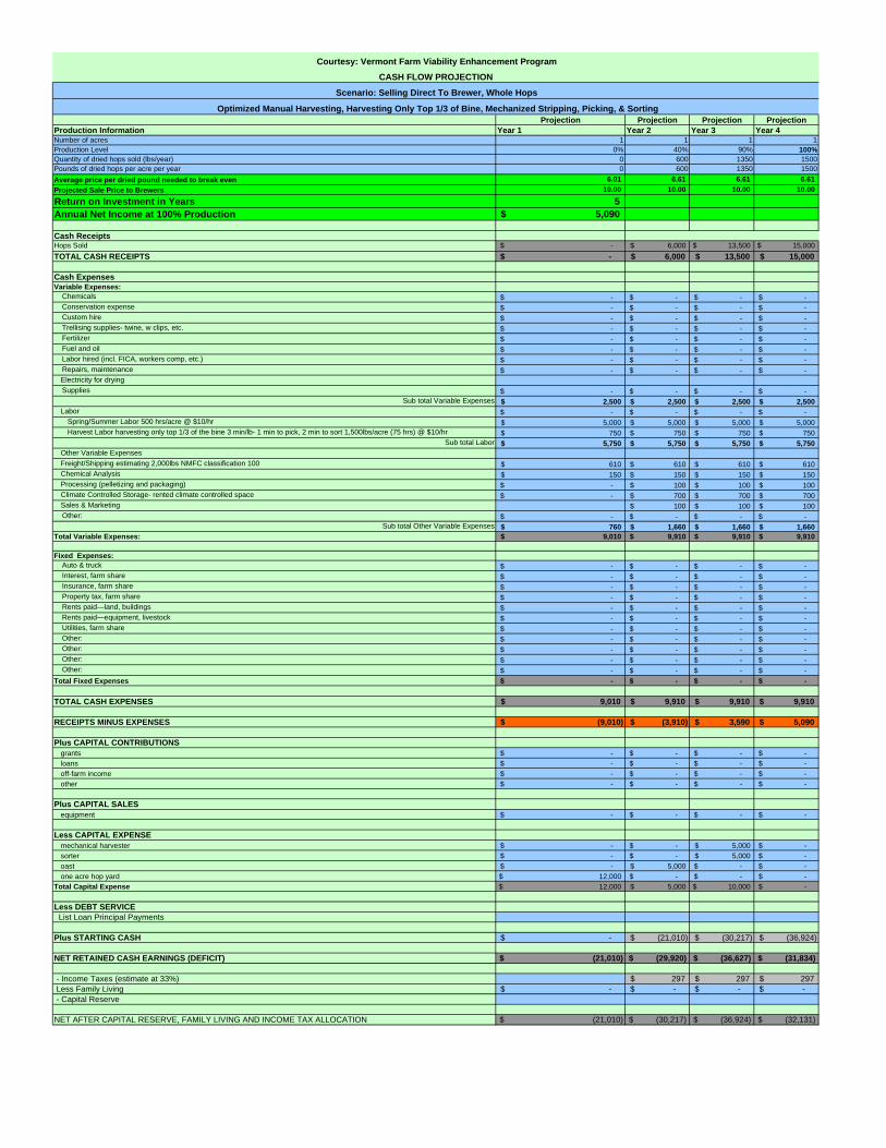
Projection Projection Projection ProjectionProduction Information Year 1 Year 2 Year 3 Year 4Number of acres 1 1 1 1Production Level 0% 40% 90% 100%Quantity of dried hops sold (lbs/year) 0 600 1350 1500Pounds of dried hops per acre per year 0 600 1350 1500Average price per dried pound needed to break even 6.01 6.61 6.61 6.61 Projected Sale Price to Brewers 10.00 10.00 10.00 10.00
Return on Investment in Years 5Annual Net Income at 100% Production 5,090$
Cash ReceiptsHops Sold -$ 6,000$ 13,500$ 15,000$ TOTAL CASH RECEIPTS -$ 6,000$ 13,500$ 15,000$
Cash ExpensesVariable Expenses: Chemicals -$ -$ -$ -$ Conservation expense -$ -$ -$ -$ Custom hire -$ -$ -$ -$ Trellising supplies- twine, w clips, etc. -$ -$ -$ -$ Fertilizer -$ -$ -$ -$ Fuel and oil -$ -$ -$ -$ Labor hired (incl. FICA, workers comp, etc.) -$ -$ -$ -$ Repairs, maintenance -$ -$ -$ -$
Electricity for drying Supplies -$ -$ -$ -$
Sub total Variable Expenses 2,500$ 2,500$ 2,500$ 2,500$ Labor -$ -$ -$ -$
Spring/Summer Labor 500 hrs/acre @ $10/hr 5,000$ 5,000$ 5,000$ 5,000$ Harvest Labor harvesting only top 1/3 of the bine 3 min/lb- 1 min to pick, 2 min to sort 1,500lbs/acre (75 hrs) @ $10/hr 750$ 750$ 750$ 750$
Sub total Labor 5,750$ 5,750$ 5,750$ 5,750$ Other Variable ExpensesFreight/Shipping estimating 2,000lbs NMFC classification 100 610$ 610$ 610$ 610$ Chemical Analysis 150$ 150$ 150$ 150$ Processing (pelletizing and packaging) -$ 100$ 100$ 100$ Climate Controlled Storage- rented climate controlled space -$ 700$ 700$ 700$ Sales & Marketing 100$ 100$ 100$
Other: -$ -$ -$ -$ Sub total Other Variable Expenses 760$ 1,660$ 1,660$ 1,660$
Total Variable Expenses: 9,010$ 9,910$ 9,910$ 9,910$
Fixed Expenses: Auto & truck -$ -$ -$ -$ Interest, farm share -$ -$ -$ -$ Insurance, farm share -$ -$ -$ -$ Property tax, farm share -$ -$ -$ -$ Rents paid—land, buildings -$ -$ -$ -$ Rents paid—equipment, livestock -$ -$ -$ -$ Utilities, farm share -$ -$ -$ -$ Other: -$ -$ -$ -$ Other: -$ -$ -$ -$ Other: -$ -$ -$ -$ Other: -$ -$ -$ -$ Total Fixed Expenses -$ -$ -$ -$
TOTAL CASH EXPENSES 9,010$ 9,910$ 9,910$ 9,910$
RECEIPTS MINUS EXPENSES (9,010)$ (3,910)$ 3,590$ 5,090$
Plus CAPITAL CONTRIBUTIONSgrants -$ -$ -$ -$ loans -$ -$ -$ -$ off-farm income -$ -$ -$ -$ other -$ -$ -$ -$
Plus CAPITAL SALESequipment -$ -$ -$ -$
Less CAPITAL EXPENSEmechanical harvester -$ -$ 5,000$ -$ sorter -$ -$ 5,000$ -$ oast -$ 5,000$ -$ -$ one acre hop yard 12,000$ -$ -$ -$
Total Capital Expense 12,000$ 5,000$ 10,000$ -$
Less DEBT SERVICE List Loan Principal Payments
Plus STARTING CASH -$ (21,010)$ (30,217)$ (36,924)$
NET RETAINED CASH EARNINGS (DEFICIT) $ (21,010) $ (29,920) $ (36,627) $ (31,834)
- Income Taxes (estimate at 33%) 297$ 297$ 297$ Less Family Living -$ -$ -$ -$ - Capital Reserve
NET AFTER CAPITAL RESERVE, FAMILY LIVING AND INCOME TAX ALLOCATION $ (21,010) $ (30,217) $ (36,924) $ (32,131)
Courtesy: Vermont Farm Viability Enhancement Program
CASH FLOW PROJECTION
Scenario: Selling Direct To Brewer, Whole Hops
Optimized Manual Harvesting, Harvesting Only Top 1/3 of Bine, Mechanized Stripping, Picking, & Sorting

Commercial Feasibility of Local Hops 2010
Scenario 3: Grower sending hops to Atlantic Hops for processing
Cash flow 1: demonstrating cash flow if no efficiencies in production are utilized Cash flow 2: demonstrating cash flow if grower harvests only top 1/3 of the bine Cash flow 3: demonstrating cash flow if grower harvests only top 1/3 of the bine, and manually strips and sorts Cash flow 4: demonstrating cash flow if grower harvests only top 1/3 of the bine, and mechanically strips and sorts

Projection Projection Projection ProjectionProduction Information Year 1 Year 2 Year 3 Year 4Number of acres 1 1 1 1Production Level 0% 40% 90% 100%Quantity of dried hops sold (lbs/year) 0 600 1350 1500Pounds of dried hops per acre per year 0 600 1350 1500Average price per dried pound needed to break even 15.00 17.81 20.56 21.11 Projected Sale Price 15.00 15.00 15.00 15.00
Return on Investment in Years (2)Annual Net Income at 100% Production (9,160)$
Cash ReceiptsHops Sold -$ 9,000$ 20,250$ 22,500$ TOTAL CASH RECEIPTS -$ 9,000$ 20,250$ 22,500$
Cash ExpensesVariable Expenses: Chemicals -$ -$ -$ -$ Conservation expense -$ -$ -$ -$ Custom hire -$ -$ -$ -$ Trellising supplies- twine, w clips, etc. -$ -$ -$ -$ Fertilizer -$ -$ -$ -$ Fuel and oil -$ -$ -$ -$ Labor hired (incl. FICA, workers comp, etc.) -$ -$ -$ -$ Repairs, maintenance -$ -$ -$ -$
Electricity for drying Supplies -$ -$ -$ -$
Sub total Variable Expenses 2,500$ 2,500$ 2,500$ 2,500$ Labor -$ -$ -$ -$
Spring/Summer Labor 500 hrs/acre @ $10/hr 5,000$ 5,000$ 5,000$ 5,000$ Harvest Labor 1 hr/dried lb 1,500hrs @ $10/hr 15,000$ 15,000$ 15,000$ 15,000$
Sub total Labor 20,000$ 20,000$ 20,000$ 20,000$ Other Variable ExpensesFreight/Shipping estimating 2,000lbs NMFC classification 100 -$ 610$ 610$ 610$ Chemical Analysis -$ 150$ 150$ 150$ Processing (pelletizing) -$ 3,300$ 7,425$ 8,250$ PackagingClimate Controlled Storage 50$ 50$ 50$ Sales & Marketing 100$ 100$ 100$
Other: -$ -$ -$ -$ Sub total Other Variable Expenses -$ 4,210$ 8,335$ 9,160$
Total Variable Expenses: 22,500$ 26,710$ 30,835$ 31,660$
Fixed Expenses: Auto & truck -$ -$ -$ -$ Interest, farm share -$ -$ -$ -$ Insurance, farm share -$ -$ -$ -$ Property tax, farm share -$ -$ -$ -$ Rents paid—land, buildings -$ -$ -$ -$ Rents paid—equipment, livestock -$ -$ -$ -$ Utilities, farm share -$ -$ -$ -$ Other: -$ -$ -$ -$ Other: -$ -$ -$ -$ Other: -$ -$ -$ -$ Other: -$ -$ -$ -$ Total Fixed Expenses -$ -$ -$ -$
TOTAL CASH EXPENSES 22,500$ 26,710$ 30,835$ 31,660$
RECEIPTS MINUS EXPENSES (22,500)$ (17,710)$ (10,585)$ (9,160)$
Plus CAPITAL CONTRIBUTIONSgrants -$ -$ -$ -$ loans -$ -$ -$ -$ off-farm income -$ -$ -$ -$ other -$ -$ -$ -$
Plus CAPITAL SALESequipment -$ -$ -$ -$
Less CAPITAL EXPENSE2 chest freezers 2,000$ -$ -$ mechanical harvester -$ -$ -$ -$ sorter -$ -$ -$ -$ oast -$ 5,000$ -$ -$ one acre hop yard 12,000$ -$ -$ -$
Total Capital Expense 12,000$ 7,000$ -$ -$
Less DEBT SERVICE List Loan Principal Payments
Plus STARTING CASH -$ (34,500)$ (59,210)$ (69,795)$
NET RETAINED CASH EARNINGS (DEFICIT) $ (34,500) $ (59,210) $ (69,795) $ (78,955)
- Income Taxes Less Family Living -$ -$ -$ -$ - Capital Reserve
NET AFTER CAPITAL RESERVE, FAMILY LIVING AND INCOME TAX ALLOCATION $ (34,500) $ (59,210) $ (69,795) $ (78,955)
Courtesy: Vermont Farm Viability Enhancement Program
CASH FLOW PROJECTION
No Optimization in Harvesting
Scenario: Selling Pelletized Direct To Brewer Using Atlantic Hops Processing Services

Projection Projection Projection ProjectionProduction Information Year 1 Year 2 Year 3 Year 4Number of acres 1 1 1 1Production Level 0% 40% 90% 100%Quantity of dried hops sold (lbs/year) 0 600 1350 1500Pounds of dried hops per acre per year 0 600 1350 1500Average price per dried pound needed to break even 12.51 14.81 17.56 18.11 Projected Sale Price 15.00 15.00 15.00 15.00
Return on Investment in Years (4)Annual Net Income at 100% Production (4,660)$
Cash ReceiptsHops Sold -$ 9,000$ 20,250$ 22,500$ TOTAL CASH RECEIPTS -$ 9,000$ 20,250$ 22,500$
Cash ExpensesVariable Expenses: Chemicals -$ -$ -$ -$ Conservation expense -$ -$ -$ -$ Custom hire -$ -$ -$ -$ Trellising supplies- twine, w clips, etc. -$ -$ -$ -$ Fertilizer -$ -$ -$ -$ Fuel and oil -$ -$ -$ -$ Labor hired (incl. FICA, workers comp, etc.) -$ -$ -$ -$ Repairs, maintenance -$ -$ -$ -$
Electricity for drying Supplies -$ -$ -$ -$
Sub total Variable Expenses 2,500$ 2,500$ 2,500$ 2,500$ Labor -$ -$ -$ -$
Spring/Summer Labor 500 hrs/acre @ $10/hr 5,000$ 5,000$ 5,000$ 5,000$ Harvest Labor harvesting only top 1/3 of the bine 35 min/lb1,500lbs/acre @ $10/hr 10,500$ 10,500$ 10,500$ 10,500$
Sub total Labor 15,500$ 15,500$ 15,500$ 15,500$ Other Variable ExpensesFreight/Shipping estimating 2,000lbs NMFC classification 100 610$ 610$ 610$ 610$ Chemical Analysis 150$ 150$ 150$ 150$ Processing (pelletizing) -$ 3,300$ 7,425$ 8,250$ Packaging -$ -$ -$ -$ Climate Controlled Storage 50$ 50$ 50$ Sales & Marketing 100$ 100$ 100$
Other: -$ -$ -$ -$ Sub total Other Variable Expenses 760$ 4,210$ 8,335$ 9,160$
Total Variable Expenses: 18,760$ 22,210$ 26,335$ 27,160$
Fixed Expenses: Auto & truck -$ -$ -$ -$ Interest, farm share -$ -$ -$ -$ Insurance, farm share -$ -$ -$ -$ Property tax, farm share -$ -$ -$ -$ Rents paid—land, buildings -$ -$ -$ -$ Rents paid—equipment, livestock -$ -$ -$ -$ Utilities, farm share -$ -$ -$ -$ Other: -$ -$ -$ -$ Other: -$ -$ -$ -$ Other: -$ -$ -$ -$ Other: -$ -$ -$ -$ Total Fixed Expenses -$ -$ -$ -$
TOTAL CASH EXPENSES 18,760$ 22,210$ 26,335$ 27,160$
RECEIPTS MINUS EXPENSES (18,760)$ (13,210)$ (6,085)$ (4,660)$
Plus CAPITAL CONTRIBUTIONSgrants -$ -$ -$ -$ loans -$ -$ -$ -$ off-farm income -$ -$ -$ -$ other -$ -$ -$ -$
Plus CAPITAL SALESequipment -$ -$ -$ -$
Less CAPITAL EXPENSE2 chest freezers 2,000$ -$ -$ mechanical harvester -$ -$ -$ sorter -$ -$ -$ oast 5,000$ -$ -$ one acre hop yard 12,000$ -$ -$ -$
Total Capital Expense 12,000$ 7,000$ -$ -$
Less DEBT SERVICE List Loan Principal Payments
Plus STARTING CASH -$ (30,760)$ (52,109)$ (60,693)$
NET RETAINED CASH EARNINGS (DEFICIT) $ (30,760) $ (50,970) $ (58,194) $ (65,353)
- Income Taxes (estimate at 33%) 1,139$ 2,500$ 2,772$ Less Family Living -$ -$ -$ -$ - Capital Reserve
NET AFTER CAPITAL RESERVE, FAMILY LIVING AND INCOME TAX ALLOCATION $ (30,760) $ (52,109) $ (60,693) $ (68,125)
Courtesy: Vermont Farm Viability Enhancement Program
CASH FLOW PROJECTION
Optimized Manual Harvesting, Harvesting Only Top 1/3 of Bine
Scenario: Selling Pelletized Direct To Brewer Using Atlantic Hops Processing Services

Projection Projection Projection ProjectionProduction Information Year 1 Year 2 Year 3 Year 4Number of acres 1 1 1 1Production Level 0% 40% 90% 100%Quantity of dried hops sold (lbs/year) 0 600 1350 1500Pounds of dried hops per acre per year 0 600 1350 1500Average price per dried pound needed to break even 8.84 11.14 13.89 14.44 Projected Sale Price 15.00 15.00 15.00 15.00
Return on Investment in Years 29Annual Net Income at 100% Production 840$
Cash ReceiptsHops Sold -$ 9,000$ 20,250$ 22,500$ TOTAL CASH RECEIPTS -$ 9,000$ 20,250$ 22,500$
Cash ExpensesVariable Expenses: Chemicals -$ -$ -$ -$ Conservation expense -$ -$ -$ -$ Custom hire -$ -$ -$ -$ Trellising supplies- twine, w clips, etc. -$ -$ -$ -$ Fertilizer -$ -$ -$ -$ Fuel and oil -$ -$ -$ -$ Labor hired (incl. FICA, workers comp, etc.) -$ -$ -$ -$ Repairs, maintenance -$ -$ -$ -$
Electricity for drying Supplies -$ -$ -$ -$
Sub total Variable Expenses 2,500$ 2,500$ 2,500$ 2,500$ Labor -$ -$ -$ -$
Spring/Summer Labor 500 hrs/acre @ $10/hr 5,000$ 5,000$ 5,000$ 5,000$ Harvest Labor harvesting top 1/3 of the bine, stripping and sorting 20 min/lb 1,500lbs/acre (500 hrs) @ $10/hr 5,000$ 5,000$ 5,000$ 5,000$
Sub total Labor 10,000$ 10,000$ 10,000$ 10,000$ Other Variable ExpensesFreight/Shipping estimating 2,000lbs NMFC classification 100 610$ 610$ 610$ 610$ Chemical Analysis 150$ 150$ 150$ 150$ Processing (pelletizing) -$ 3,300$ 7,425$ 8,250$ Packaging -$ -$ -$ Climate Controlled Storage 50$ 50$ 50$ Sales & Marketing 100$ 100$ 100$
Other: -$ -$ -$ -$ Sub total Other Variable Expenses 760$ 4,210$ 8,335$ 9,160$
Total Variable Expenses: 13,260$ 16,710$ 20,835$ 21,660$
Fixed Expenses: Auto & truck -$ -$ -$ -$ Interest, farm share -$ -$ -$ -$ Insurance, farm share -$ -$ -$ -$ Property tax, farm share -$ -$ -$ -$ Rents paid—land, buildings -$ -$ -$ -$ Rents paid—equipment, livestock -$ -$ -$ -$ Utilities, farm share -$ -$ -$ -$ Other: -$ -$ -$ -$ Other: -$ -$ -$ -$ Other: -$ -$ -$ -$ Other: -$ -$ -$ -$ Total Fixed Expenses -$ -$ -$ -$
TOTAL CASH EXPENSES 13,260$ 16,710$ 20,835$ 21,660$
RECEIPTS MINUS EXPENSES (13,260)$ (7,710)$ (585)$ 840$
Plus CAPITAL CONTRIBUTIONSgrants -$ -$ -$ -$ loans -$ -$ -$ -$ off-farm income -$ -$ -$ -$ other -$ -$ -$ -$
Plus CAPITAL SALESequipment -$ -$ -$ -$
Less CAPITAL EXPENSE2 chest freezers 2,000$ -$ -$ mechanical harvester -$ -$ -$ sorter -$ -$ 5,000$ -$ oast -$ 5,000$ -$ -$ one acre hop yard 12,000$ -$ -$ -$
Total Capital Expense 12,000$ 7,000$ 5,000$ -$
Less DEBT SERVICE List Loan Principal Payments
Plus STARTING CASH -$ (25,260)$ (41,109)$ (49,193)$
NET RETAINED CASH EARNINGS (DEFICIT) $ (25,260) $ (39,970) $ (46,694) $ (48,353)
- Income Taxes (estimate at 33%) 1,139$ 2,500$ 2,772$ Less Family Living -$ -$ -$ -$ - Capital Reserve
NET AFTER CAPITAL RESERVE, FAMILY LIVING AND INCOME TAX ALLOCATION $ (25,260) $ (41,109) $ (49,193) $ (51,125)
Courtesy: Vermont Farm Viability Enhancement Program
CASH FLOW PROJECTION
Optimized Manual Harvesting, Harvesting Only Top 1/3 of Bine, Manual Stripping & Sorting
Scenario: Selling Pelletized Direct To Brewer Using Atlantic Hops Processing Services

Projection Projection Projection ProjectionProduction Information Year 1 Year 2 Year 3 Year 4Number of acres 1 1 1 1Production Level 0% 40% 90% 100%Quantity of dried hops sold (lbs/year) 0 600 1350 1500Pounds of dried hops per acre per year 0 600 1350 1500Average price per dried pound needed to break even 6.01 8.31 11.06 11.61 Projected Sale Price 15.00 15.00 15.00 15.00
Return on Investment in Years 6Annual Net Income at 100% Production 5,090$
Cash ReceiptsHops Sold -$ 9,000$ 20,250$ 22,500$ TOTAL CASH RECEIPTS -$ 9,000$ 20,250$ 22,500$
Cash ExpensesVariable Expenses: Chemicals -$ -$ -$ -$ Conservation expense -$ -$ -$ -$ Custom hire -$ -$ -$ -$ Trellising supplies- twine, w clips, etc. -$ -$ -$ -$ Fertilizer -$ -$ -$ -$ Fuel and oil -$ -$ -$ -$ Labor hired (incl. FICA, workers comp, etc.) -$ -$ -$ -$ Repairs, maintenance -$ -$ -$ -$
Electricity for drying Supplies -$ -$ -$ -$
Sub total Variable Expenses 2,500$ 2,500$ 2,500$ 2,500$ Labor -$ -$ -$ -$
Spring/Summer Labor 500 hrs/acre @ $10/hr 5,000$ 5,000$ 5,000$ 5,000$ Harvest Labor harvesting only top 1/3 of the bine 3 min/lb- 1 min to pick, 2 min to sort 1,500lbs/acre (75 hrs) @ $10/hr 750$ 750$ 750$ 750$
Sub total Labor 5,750$ 5,750$ 5,750$ 5,750$ Other Variable ExpensesFreight/Shipping estimating 2,000lbs NMFC classification 100 610$ 610$ 610$ 610$ Chemical Analysis 150$ 150$ 150$ 150$ Processing (pelletizing) -$ 3,300$ 7,425$ 8,250$ Packaging -$ -$ -$ -$ Climate Controlled Storage 50$ 50$ 50$ Sales & Marketing 100$ 100$ 100$
Other: -$ -$ -$ -$ Sub total Other Variable Expenses 760$ 4,210$ 8,335$ 9,160$
Total Variable Expenses: 9,010$ 12,460$ 16,585$ 17,410$
Fixed Expenses: Auto & truck -$ -$ -$ -$ Interest, farm share -$ -$ -$ -$ Insurance, farm share -$ -$ -$ -$ Property tax, farm share -$ -$ -$ -$ Rents paid—land, buildings -$ -$ -$ -$ Rents paid—equipment, livestock -$ -$ -$ -$ Utilities, farm share -$ -$ -$ -$ Other: -$ -$ -$ -$ Other: -$ -$ -$ -$ Other: -$ -$ -$ -$ Other: -$ -$ -$ -$ Total Fixed Expenses -$ -$ -$ -$
TOTAL CASH EXPENSES 9,010$ 12,460$ 16,585$ 17,410$
RECEIPTS MINUS EXPENSES (9,010)$ (3,460)$ 3,665$ 5,090$
Plus CAPITAL CONTRIBUTIONSgrants -$ -$ -$ -$ loans -$ -$ -$ -$ off-farm income -$ -$ -$ -$ other -$ -$ -$ -$
Plus CAPITAL SALESequipment -$ -$ -$ -$
Less CAPITAL EXPENSE2 chest freezers 2,000$ -$ -$ mechanical harvester -$ 5,000$ -$ sorter -$ 5,000$ -$ oast 5,000$ -$ -$ one acre hop yard 12,000$ -$ -$ -$
Total Capital Expense 12,000$ 7,000$ 10,000$ -$
Less DEBT SERVICE List Loan Principal Payments
Plus STARTING CASH -$ (21,010)$ (32,609)$ (41,443)$
NET RETAINED CASH EARNINGS (DEFICIT) $ (21,010) $ (31,470) $ (38,944) $ (36,353)
- Income Taxes (estimate at 33%) 1,139$ 2,500$ 2,772$ Less Family Living -$ -$ -$ -$ - Capital Reserve
NET AFTER CAPITAL RESERVE, FAMILY LIVING AND INCOME TAX ALLOCATION $ (21,010) $ (32,609) $ (41,443) $ (39,125)
Courtesy: Vermont Farm Viability Enhancement Program
CASH FLOW PROJECTION
Optimized Manual Harvesting, Harvesting Only Top 1/3 of Bine, Mechanized Stripping, Picking, & Sorting
Scenario: Selling Pelletized Direct To Brewer Using Atlantic Hops Processing Services

Commercial Feasibility of Local Hops 2010
Scenario 4: Grower sells pelletized hops direct to brewer, using Do‐It‐Yourself pelletizing
Cash flow 1: demonstrating cash flow if no efficiencies in production are utilized Cash flow 2: demonstrating cash flow if grower harvests only top 1/3 of the bine Cash flow 3: demonstrating cash flow if grower harvests only top 1/3 of the bine, and manually strips and sorts Cash flow 4: demonstrating cash flow if grower harvests only top 1/3 of the bine, and mechanically strips and sorts

Projection Projection Projection ProjectionProduction Information Year 1 Year 2 Year 3 Year 4Number of acres 1 1 1 1Production Level 0% 40% 90% 100%Quantity of dried hops sold (lbs/year) 0 600 1350 1500Pounds of dried hops per acre per year 0 600 1350 1500Average price per dried pound needed to break even 15.51 15.89 15.89 15.89 Projected Sale Price to Brewers 15.00 15.00 15.00 15.00
Return on Investment in Years (35.15)Annual Net Income at 100% Production (1,340)$
Cash ReceiptsHops Sold -$ 9,000$ 20,250$ 22,500$ TOTAL CASH RECEIPTS -$ 9,000$ 20,250$ 22,500$
Cash ExpensesVariable Expenses: Chemicals -$ -$ -$ -$ Conservation expense -$ -$ -$ -$ Custom hire -$ -$ -$ -$ Trellising supplies- twine, w clips, etc. -$ -$ -$ -$ Fertilizer -$ -$ -$ -$ Fuel and oil -$ -$ -$ -$ Labor hired (incl. FICA, workers comp, etc.) -$ -$ -$ -$ Repairs, maintenance -$ -$ -$ -$
Electricity for drying Supplies -$ -$ -$ -$
Sub total Variable Expenses 2,500$ 2,500$ 2,500$ 2,500$ Labor -$ -$ -$ -$
Spring/Summer Labor 500 hrs/acre @ $10/hr 5,000$ 5,000$ 5,000$ 5,000$ Harvest Labor 1 hr/dried lb 1,500hrs @ $10/hr 15,000$ 15,000$ 15,000$ 15,000$
Sub total Labor 20,000$ 20,000$ 20,000$ 20,000$ Other Variable ExpensesFreight/Shipping estimating 2,000lbs NMFC classification 100 610$ 610$ 610$ 610$ Chemical Analysis 150$ 150$ 150$ 150$ Processing (pelletizing) -$ 100$ 100$ 100$ Packaging 330$ 330$ 330$ Climate Controlled Storage 50$ 50$ 50$ Sales & Marketing 100$ 100$ 100$
Other: -$ -$ -$ -$ Sub total Other Variable Expenses 760$ 1,340$ 1,340$ 1,340$
Total Variable Expenses: 23,260$ 23,840$ 23,840$ 23,840$
Fixed Expenses: Auto & truck -$ -$ -$ -$ Interest, farm share -$ -$ -$ -$ Insurance, farm share -$ -$ -$ -$ Property tax, farm share -$ -$ -$ -$ Rents paid—land, buildings -$ -$ -$ -$ Rents paid—equipment, livestock -$ -$ -$ -$ Utilities, farm share -$ -$ -$ -$ Other: -$ -$ -$ -$ Other: -$ -$ -$ -$ Other: -$ -$ -$ -$ Other: -$ -$ -$ -$ Total Fixed Expenses -$ -$ -$ -$
TOTAL CASH EXPENSES 23,260$ 23,840$ 23,840$ 23,840$
RECEIPTS MINUS EXPENSES (23,260)$ (14,840)$ (3,590)$ (1,340)$
Plus CAPITAL CONTRIBUTIONSgrants -$ -$ -$ -$ loans -$ -$ -$ -$ off-farm income -$ -$ -$ -$ other -$ -$ -$ -$
Plus CAPITAL SALESequipment -$ -$ -$ -$
Less CAPITAL EXPENSE2 chest freezers -$ 2,000$ -$ -$ vacuum, nitrogen flush sealer -$ 24,000$ -$ -$ pellet mill -$ 2,400$ -$ -$ hammer mill -$ 1,700$ -$ -$ mechanical harvester -$ -$ -$ -$ sorter -$ -$ -$ -$ oast -$ 5,000$ -$ -$ one acre hop yard 12,000$ -$ -$ -$
Total Capital Expense 12,000$ 35,100$ -$ -$
Less DEBT SERVICE List Loan Principal Payments
Plus STARTING CASH -$ (35,260)$ (85,391)$ (89,173)$
NET RETAINED CASH EARNINGS (DEFICIT) $ (35,260) $ (85,200) $ (88,981) $ (90,513)
- Income Taxes (estimate at 33%) 191$ 191$ 191$ Less Family Living -$ -$ -$ -$ - Capital Reserve
NET AFTER CAPITAL RESERVE, FAMILY LIVING AND INCOME TAX ALLOCATION $ (35,260) $ (85,391) $ (89,173) $ (90,704)
Courtesy: Vermont Farm Viability Enhancement Program
CASH FLOW PROJECTION
No Optimization in Harvesting
Scenario: Selling Direct to Brewer D-I-Y Pelletized

Projection Projection Projection ProjectionProduction Information Year 1 Year 2 Year 3 Year 4Number of acres 1 1 1 1Production Level 0% 40% 90% 100%Quantity of dried hops sold (lbs/year) 0 600 1350 1500Pounds of dried hops per acre per year 0 600 1350 1500Average price per dried pound needed to break even 12.51 12.89 12.89 12.89 Projected Sale Price to Brewers 15.00 15.00 15.00 15.00
Return on Investment in Years 14.91Annual Net Income at 100% Production 3,160$
Cash ReceiptsHops Sold -$ 9,000$ 20,250$ 22,500$ TOTAL CASH RECEIPTS -$ 9,000$ 20,250$ 22,500$
Cash ExpensesVariable Expenses: Chemicals -$ -$ -$ -$ Conservation expense -$ -$ -$ -$ Custom hire -$ -$ -$ -$ Trellising supplies- twine, w clips, etc. -$ -$ -$ -$ Fertilizer -$ -$ -$ -$ Fuel and oil -$ -$ -$ -$ Labor hired (incl. FICA, workers comp, etc.) -$ -$ -$ -$ Repairs, maintenance -$ -$ -$ -$
Electricity for drying Supplies -$ -$ -$ -$
Sub total Variable Expenses 2,500$ 2,500$ 2,500$ 2,500$ Labor -$ -$ -$ -$
Spring/Summer Labor 500 hrs/acre @ $10/hr 5,000$ 5,000$ 5,000$ 5,000$ Harvest Labor harvesting only top 1/3 of the bine 35 min/lb1,500lbs/acre @ $10/hr 10,500$ 10,500$ 10,500$ 10,500$
Sub total Labor 15,500$ 15,500$ 15,500$ 15,500$ Other Variable ExpensesFreight/Shipping estimating 2,000lbs NMFC classification 100 610$ 610$ 610$ 610$ Chemical Analysis 150$ 150$ 150$ 150$ Processing (pelletizing) -$ 100$ 100$ 100$ Packaging 330$ 330$ 330$ Climate Controlled Storage 50$ 50$ 50$ Sales & Marketing 100$ 100$ 100$
Other: -$ -$ -$ -$ Sub total Other Variable Expenses 760$ 1,340$ 1,340$ 1,340$
Total Variable Expenses: 18,760$ 19,340$ 19,340$ 19,340$
Fixed Expenses: Auto & truck -$ -$ -$ -$ Interest, farm share -$ -$ -$ -$ Insurance, farm share -$ -$ -$ -$ Property tax, farm share -$ -$ -$ -$ Rents paid—land, buildings -$ -$ -$ -$ Rents paid—equipment, livestock -$ -$ -$ -$ Utilities, farm share -$ -$ -$ -$ Other: -$ -$ -$ -$ Other: -$ -$ -$ -$ Other: -$ -$ -$ -$ Other: -$ -$ -$ -$ Total Fixed Expenses -$ -$ -$ -$
TOTAL CASH EXPENSES 18,760$ 19,340$ 19,340$ 19,340$
RECEIPTS MINUS EXPENSES (18,760)$ (10,340)$ 910$ 3,160$
Plus CAPITAL CONTRIBUTIONSgrants -$ -$ -$ -$ loans -$ -$ -$ -$ off-farm income -$ -$ -$ -$ other -$ -$ -$ -$
Plus CAPITAL SALESequipment -$ -$ -$ -$
Less CAPITAL EXPENSE2 chest freezers -$ 2,000$ -$ -$ vacuum, nitrogen flush sealer -$ 24,000$ -$ -$ pellet mill -$ 2,400$ -$ -$ hammer mill -$ 1,700$ -$ -$ mechanical harvester -$ -$ -$ -$ sorter -$ -$ -$ -$ oast -$ 5,000$ -$ -$ one acre hop yard 12,000$ -$ -$ -$
Total Capital Expense 12,000$ 35,100$ -$ -$
Less DEBT SERVICE List Loan Principal Payments
Plus STARTING CASH -$ (30,760)$ (76,391)$ (75,673)$
NET RETAINED CASH EARNINGS (DEFICIT) $ (30,760) $ (76,200) $ (75,481) $ (72,513)
- Income Taxes (estimate at 33%) 191$ 191$ 191$ Less Family Living -$ -$ -$ -$ - Capital Reserve
NET AFTER CAPITAL RESERVE, FAMILY LIVING AND INCOME TAX ALLOCATION $ (30,760) $ (76,391) $ (75,673) $ (72,704)
Courtesy: Vermont Farm Viability Enhancement Program
CASH FLOW PROJECTION
Optimized Manual Harvesting, Harvesting Only Top 1/3 of Bine
Scenario: Selling Direct to Brewer D-I-Y Pelletized

Projection Projection Projection ProjectionProduction Information Year 1 Year 2 Year 3 Year 4Number of acres 1 1 1 1Production Level 0% 40% 90% 100%Quantity of dried hops sold (lbs/year) 0 600 1350 1500Pounds of dried hops per acre per year 0 600 1350 1500Average price per dried pound needed to break even 8.84 9.23 9.23 9.23 Projected Sale Price to Brewers 15.00 15.00 15.00 15.00
Return on Investment in Years 5.44Annual Net Income at 100% Production 8,660$
Cash ReceiptsHops Sold -$ 9,000$ 20,250$ 22,500$ TOTAL CASH RECEIPTS -$ 9,000$ 20,250$ 22,500$
Cash ExpensesVariable Expenses: Chemicals -$ -$ -$ -$ Conservation expense -$ -$ -$ -$ Custom hire -$ -$ -$ -$ Trellising supplies- twine, w clips, etc. -$ -$ -$ -$ Fertilizer -$ -$ -$ -$ Fuel and oil -$ -$ -$ -$ Labor hired (incl. FICA, workers comp, etc.) -$ -$ -$ -$ Repairs, maintenance -$ -$ -$ -$
Electricity for drying Supplies -$ -$ -$ -$
Sub total Variable Expenses 2,500$ 2,500$ 2,500$ 2,500$ Labor -$ -$ -$ -$
Spring/Summer Labor 500 hrs/acre @ $10/hr 5,000$ 5,000$ 5,000$ 5,000$ Harvest Labor harvesting top 1/3 of the bine, stripping and sorting 20 min/lb 1,500lbs/acre (500 hrs) @ $10/hr 5,000$ 5,000$ 5,000$ 5,000$
Sub total Labor 10,000$ 10,000$ 10,000$ 10,000$ Other Variable ExpensesFreight/Shipping estimating 2,000lbs NMFC classification 100 610$ 610$ 610$ 610$ Chemical Analysis 150$ 150$ 150$ 150$ Processing (pelletizing) -$ 100$ 100$ 100$ Packaging 330$ 330$ 330$ Climate Controlled Storage 50$ 50$ 50$ Sales & Marketing 100$ 100$ 100$
Other: -$ -$ -$ -$ Sub total Other Variable Expenses 760$ 1,340$ 1,340$ 1,340$
Total Variable Expenses: 13,260$ 13,840$ 13,840$ 13,840$
Fixed Expenses: Auto & truck -$ -$ -$ -$ Interest, farm share -$ -$ -$ -$ Insurance, farm share -$ -$ -$ -$ Property tax, farm share -$ -$ -$ -$ Rents paid—land, buildings -$ -$ -$ -$ Rents paid—equipment, livestock -$ -$ -$ -$ Utilities, farm share -$ -$ -$ -$ Other: -$ -$ -$ -$ Other: -$ -$ -$ -$ Other: -$ -$ -$ -$ Other: -$ -$ -$ -$ Total Fixed Expenses -$ -$ -$ -$
TOTAL CASH EXPENSES 13,260$ 13,840$ 13,840$ 13,840$
RECEIPTS MINUS EXPENSES (13,260)$ (4,840)$ 6,410$ 8,660$
Plus CAPITAL CONTRIBUTIONSgrants -$ -$ -$ -$ loans -$ -$ -$ -$ off-farm income -$ -$ -$ -$ other -$ -$ -$ -$
Plus CAPITAL SALESequipment -$ -$ -$ -$
Less CAPITAL EXPENSE2 chest freezers -$ 2,000$ -$ -$ vacuum, nitrogen flush sealer -$ 24,000$ -$ -$ pellet mill -$ 2,400$ -$ -$ hammer mill -$ 1,700$ -$ -$ mechanical harvester -$ -$ -$ -$ sorter -$ -$ -$ -$ oast -$ 5,000$ -$ -$ one acre hop yard 12,000$ -$ -$ -$
Total Capital Expense 12,000$ 35,100$ -$ -$
Less DEBT SERVICE List Loan Principal Payments
Plus STARTING CASH -$ (25,260)$ (65,391)$ (59,173)$
NET RETAINED CASH EARNINGS (DEFICIT) $ (25,260) $ (65,200) $ (58,981) $ (50,513)
- Income Taxes (estimate at 33%) 191$ 191$ 191$ Less Family Living -$ -$ -$ -$ - Capital Reserve
NET AFTER CAPITAL RESERVE, FAMILY LIVING AND INCOME TAX ALLOCATION $ (25,260) $ (65,391) $ (59,173) $ (50,704)
Courtesy: Vermont Farm Viability Enhancement Program
CASH FLOW PROJECTION
Optimized Manual Harvesting, Harvesting Only Top 1/3 of Bine, Manual Stripping & Sorting
Scenario: Selling Direct to Brewer D-I-Y Pelletized
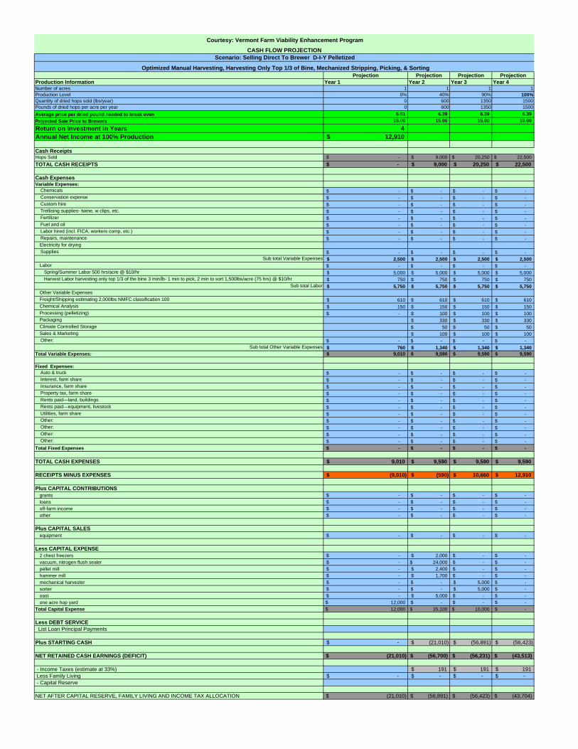
Projection Projection Projection ProjectionProduction Information Year 1 Year 2 Year 3 Year 4Number of acres 1 1 1 1Production Level 0% 40% 90% 100%Quantity of dried hops sold (lbs/year) 0 600 1350 1500Pounds of dried hops per acre per year 0 600 1350 1500Average price per dried pound needed to break even 6.01 6.39 6.39 6.39 Projected Sale Price to Brewers 15.00 15.00 15.00 15.00
Return on Investment in Years 4Annual Net Income at 100% Production 12,910$
Cash ReceiptsHops Sold -$ 9,000$ 20,250$ 22,500$ TOTAL CASH RECEIPTS -$ 9,000$ 20,250$ 22,500$
Cash ExpensesVariable Expenses: Chemicals -$ -$ -$ -$ Conservation expense -$ -$ -$ -$ Custom hire -$ -$ -$ -$ Trellising supplies- twine, w clips, etc. -$ -$ -$ -$ Fertilizer -$ -$ -$ -$ Fuel and oil -$ -$ -$ -$ Labor hired (incl. FICA, workers comp, etc.) -$ -$ -$ -$ Repairs, maintenance -$ -$ -$ -$
Electricity for drying Supplies -$ -$ -$ -$
Sub total Variable Expenses 2,500$ 2,500$ 2,500$ 2,500$ Labor -$ -$ -$ -$
Spring/Summer Labor 500 hrs/acre @ $10/hr 5,000$ 5,000$ 5,000$ 5,000$ Harvest Labor harvesting only top 1/3 of the bine 3 min/lb- 1 min to pick, 2 min to sort 1,500lbs/acre (75 hrs) @ $10/hr 750$ 750$ 750$ 750$
Sub total Labor 5,750$ 5,750$ 5,750$ 5,750$ Other Variable ExpensesFreight/Shipping estimating 2,000lbs NMFC classification 100 610$ 610$ 610$ 610$ Chemical Analysis 150$ 150$ 150$ 150$ Processing (pelletizing) -$ 100$ 100$ 100$ Packaging 330$ 330$ 330$ Climate Controlled Storage 50$ 50$ 50$ Sales & Marketing 100$ 100$ 100$
Other: -$ -$ -$ -$ Sub total Other Variable Expenses 760$ 1,340$ 1,340$ 1,340$
Total Variable Expenses: 9,010$ 9,590$ 9,590$ 9,590$
Fixed Expenses: Auto & truck -$ -$ -$ -$ Interest, farm share -$ -$ -$ -$ Insurance, farm share -$ -$ -$ -$ Property tax, farm share -$ -$ -$ -$ Rents paid—land, buildings -$ -$ -$ -$ Rents paid—equipment, livestock -$ -$ -$ -$ Utilities, farm share -$ -$ -$ -$ Other: -$ -$ -$ -$ Other: -$ -$ -$ -$ Other: -$ -$ -$ -$ Other: -$ -$ -$ -$ Total Fixed Expenses -$ -$ -$ -$
TOTAL CASH EXPENSES 9,010$ 9,590$ 9,590$ 9,590$
RECEIPTS MINUS EXPENSES (9,010)$ (590)$ 10,660$ 12,910$
Plus CAPITAL CONTRIBUTIONSgrants -$ -$ -$ -$ loans -$ -$ -$ -$ off-farm income -$ -$ -$ -$ other -$ -$ -$ -$
Plus CAPITAL SALESequipment -$ -$ -$ -$
Less CAPITAL EXPENSE2 chest freezers -$ 2,000$ -$ -$ vacuum, nitrogen flush sealer -$ 24,000$ -$ -$ pellet mill -$ 2,400$ -$ -$ hammer mill -$ 1,700$ -$ -$ mechanical harvester -$ -$ 5,000$ -$ sorter -$ -$ 5,000$ -$ oast -$ 5,000$ -$ -$ one acre hop yard 12,000$ -$ -$ -$
Total Capital Expense 12,000$ 35,100$ 10,000$ -$
Less DEBT SERVICE List Loan Principal Payments
Plus STARTING CASH -$ (21,010)$ (56,891)$ (56,423)$
NET RETAINED CASH EARNINGS (DEFICIT) $ (21,010) $ (56,700) $ (56,231) $ (43,513)
- Income Taxes (estimate at 33%) 191$ 191$ 191$ Less Family Living -$ -$ -$ -$ - Capital Reserve
NET AFTER CAPITAL RESERVE, FAMILY LIVING AND INCOME TAX ALLOCATION $ (21,010) $ (56,891) $ (56,423) $ (43,704)
Courtesy: Vermont Farm Viability Enhancement Program
CASH FLOW PROJECTION
Optimized Manual Harvesting, Harvesting Only Top 1/3 of Bine, Mechanized Stripping, Picking, & Sorting
Scenario: Selling Direct To Brewer D-I-Y Pelletized
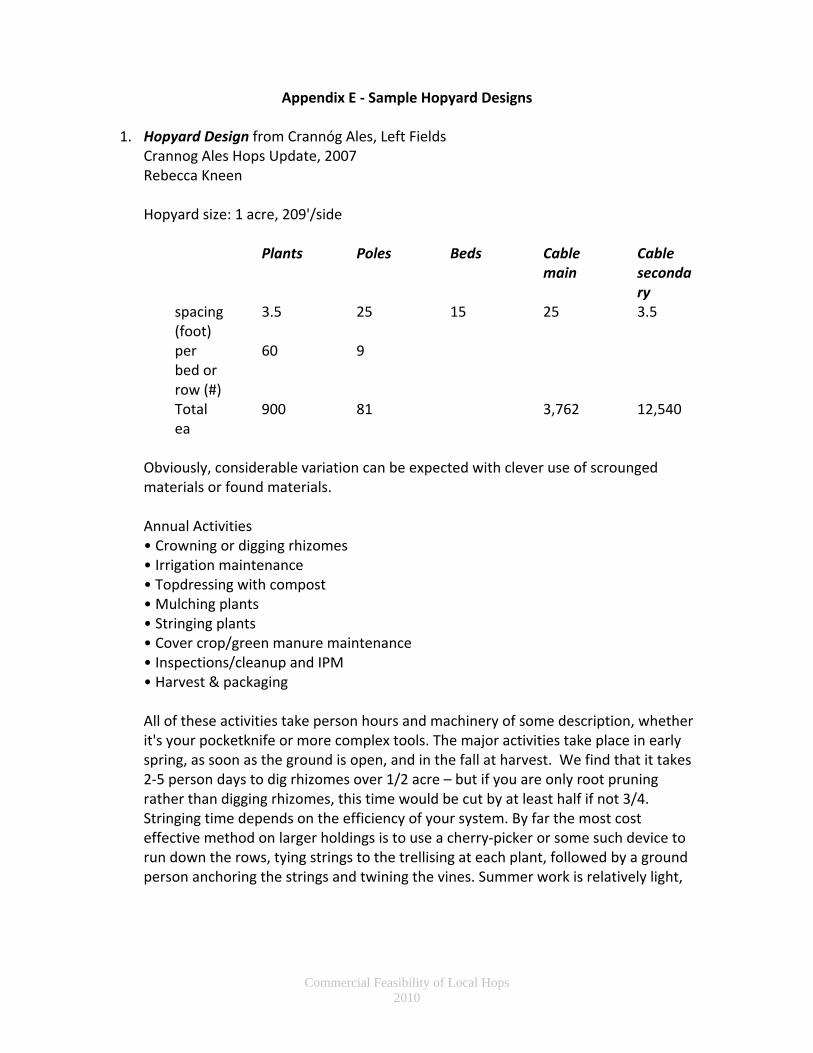
Commercial Feasibility of Local Hops 2010
Appendix E ‐ Sample Hopyard Designs 1. Hopyard Design from Crannóg Ales, Left Fields
Crannog Ales Hops Update, 2007 Rebecca Kneen Hopyard size: 1 acre, 209'/side
Plants Poles Beds Cable main
Cable secondary
spacing (foot)
3.5 25 15 25 3.5
per bed or row (#)
60 9
Total ea
900 81 3,762 12,540
Obviously, considerable variation can be expected with clever use of scrounged materials or found materials. Annual Activities • Crowning or digging rhizomes • Irrigation maintenance • Topdressing with compost • Mulching plants • Stringing plants • Cover crop/green manure maintenance • Inspections/cleanup and IPM • Harvest & packaging All of these activities take person hours and machinery of some description, whether it's your pocketknife or more complex tools. The major activities take place in early spring, as soon as the ground is open, and in the fall at harvest. We find that it takes 2‐5 person days to dig rhizomes over 1/2 acre – but if you are only root pruning rather than digging rhizomes, this time would be cut by at least half if not 3/4. Stringing time depends on the efficiency of your system. By far the most cost effective method on larger holdings is to use a cherry‐picker or some such device to run down the rows, tying strings to the trellising at each plant, followed by a ground person anchoring the strings and twining the vines. Summer work is relatively light,

Commercial Feasibility of Local Hops 2010
depending on your weed‐control methodology and Integrated Pest Management (IPM) use. Harvest and packaging vary widely, with considerations including use of machinery to harvest and to pull plants down, speed of hand pickers and dryer efficiency. It should be clear from this that there is considerable potential in organic hops production. We strongly recommend small scale production for the new grower and direct liaison with your brewery customers. Capital costs can be amortized over the lifetime of the yard, with poles being replaced as needed during that time. A group of small hop growers can also take advantage of group dryers and vacuum sealers, as well as creating a trained and mobile workforce.
2. Hopyard Design from “Hopyard Construction: Budgeting and Economics”
Edward B. Page, Ph.D. CSU Extension Ron Godin, Ph.D. CSU Ag Exp. Station Hopyard • 18’ to 20’ high • Plant spacing 7’x7’ • Population: 889 • 21’ posts • 2’ to 3’ in ground • Various spacings • 14’ x 42’ • 15’x 30’ • 30’ x 30’ • Equilateral triangle at end posts • 15’ base • Poles connected within rows only • Top training wire is free floating • High labor input • High production Methodology ‐ Steel Anchor Embedded in Concrete
New auger type anchors (not for sandy soils) Wire Clamp for Anchor Wire Clamping Cable Corner end with triple anchors Hop Growth on High Trellis • Coir twine is tied to clip placed in soil next to hill • Twine is tied to top wire

Commercial Feasibility of Local Hops 2010
• Trained hop vine winds its way to top • Harvesting: cuts top and bottom and remove for picking & processing
3. Hopyard Design from UVM Extension
Rosalie Madden, Heather Darby, Roger Rainville Per Acre (60’x660’)
1320 bines 33 60’ Rows spaced 20’ apart, 1 row every 10’ on either side of a pole. Then within the row, 2 rhizomes per hill, maintain at least at least 3.5’ between hills, and at least 7’ (15’ is better) between varieties, 40 rhizomes per row x 33 rows. Typical spacing in the Pacific NW is between 42‐50 sq ft per plant, with a spacing of either 3.5’ x 14’, or 7’x7’, for approximately 900 bines/ac.1
110 20‐24’ poles
1 pole every 20 ft 4‐5 plants per pole Note that general pole spacing recommendations are 30’x30’, or 30’x15’, or 14’x42’. UVM spaced theirs at 20’x35’ because it made it easier to delineate between varieties and repetitions for trialing purposes.2
110 post protection plates‐ metal plates to protect the poles Main cable to be strung between poles‐ 2,178’ of 3/8 steel cable (~3 rows of 660’) Anchor, clamps and wire holding poles (2 anchors and 40’ cable per pole) Wire every 10’ between the three rows (3,960’) Hop stringer “trailer” or some mechanism such as a fork lift, bucket loader, back of pick up truck, or ladders, to get people high enough off the ground to string the wire and the coir twine.
1 Information provided by Rosalie Madden, UVM Extension, July 2010. 2 Information provided by Rosalie Madden, UVM Extension, July 2010.

Commercial Feasibility of Local Hops 2010
4. High Density Hopyard Design from Gorst Valley James Altwies
Per Acre
Trellis Materials Irrigation Materials Structure Qty Units Irrigation Tube Qty Units End Poles 22 each Dripline 4235 lin. Ft Line Poles 66 each Valves 2 each Deadmen 26 each Main line 200 lin. Ft Branch line 500 lin. Ft Supplies Qty Units Tees Qty Units
Droplines 1283 each 1.25"x1.25"x1.25
" 1 each Clover 20 lbs 1.25"x0.5"x1.25" 11 each Rhizomes 1283 each Couplers Qty Units 0.5"x0.5" 10 each Hardware Qty Units Turnbuckles 22 each End Caps Qty Units eyebolts 132 each 0.5" 11 each 3/16 GAC 4235 lin. Ft 1/4 GAC 484 lin. Ft Hose Clamps Qty Units 3/16 clips 44 each 0.5"‐1.0" 20 each 1/4 clips 88 each 3/16 thimb 22 each 1/4 thimb 44 each Distrb. & Control Qty Units lowline 4235 lin. Ft Pump 1 each Filter 1 each Controller 1 each Sensors 1 each Shut‐off valve 1 each Check valve 1 each 5 strand wire 250 lin. Ft Valve box 2 each

Commercial Feasibility of Local Hops 2010
Appendix F ‐ Hopyard Establishment Costs Per Acre
Sample budgets from: Crannog Ales Edward B. Page and Glenn Fuller, Colorado Extension University of Vermont Extension Gorst Valley Hops Value‐Share Grower Program

High Density Gorst Valley Hopyard Standard Trellis Establishment Cost per Acre Hopyard Standard Trellis Establishment Cost per Acre Standard Trellis Establishment on 4 Acres UVM Extension Hopyard standardized to 1 acre
Data Courtesy of James Altwies Data Courtesy of Glen Fuller (Colorado) By Edward B. Page, Data Courtesy of Glen Fuller Data Courtesy Rosalie Madden, Roger Rainville # Each SumRhizomes (4’ x 12’) 1040 1.21 $ 1,260 Rhizomes 4160 1.21 $ 5,040 Poles
Structure Qty UnitsMisc. Hardware & Supplies $ 1,260 Potting Soil $ 750
22 ft locust poles 30 42 1,260$
End Poles 22 eachPoles (21’ untreated, lodge pole pine) 52 20.57 $ 1,070 Pots (6” square) 5000 0.46 $ 2,300
22 ft cedar poles 53 25 1,325$
Line Poles 66 each D5 Dozer Work $ 600 Misc. Hardware & Supplies $ 5,026 Sub total Poles 2,585$
Deadmen 26 each Bob Cat & Auger (holes for poles) $ 550 Poles (21’ untreated, lodge pole pine) 210 20.38 $ 4,280 Wire
2,942$ 7‐Strand Wire (carries floating wires) $ 800 D5 Dozer Work $ 2,400 5/16" x 5000 ft 1,733$
Supplies#9 Wire (floating – top wire) $ 250 Bob Cat & Auger (holes for poles) $ 2,150
5/16" x 1000 ft 347$
Droplines 1283 each Hop Twine (coir: coconut husk fiber) $ 140 7‐Strand Wire (carries hop wires) $ 3,146 5/16" x 250 ft 107$
Clover 20 lbs48” Ground Anchors 48 8.33 $ 400 #9 Wire (floating –top wire) $ 997
3/8" x 500 ft 280$
Rhizomes 1283 each Drip Irrigation Materials $ 1,500 Hop Twine (coir: coconut husk fiber) $ 556 3/4"x12 eye/hook turnbuckle 34 15.92 721$
444$ 30 hrs. Tilling $ 300 48” Ground Anchors 188 8.4 $ 1,580
cable cutters 1 66$
Hardware 40 hrs. Pole Setting $ 400 Drip Irrigation Materials $ 5,980 5/16" x 10 pcs forged w/r clips 200 0.64 171$
Turnbuckles 22 each Gallows (for work on top wires) $ 140 30 hrs. Tilling $ 1,200 3/8" x 10 pcs forged w/r clips 50 0.94 63$ eyebolts 132 each Labor $ 3,750 40 hrs. Pole Setting $ 1,600 3/8" x 10 pcs forged w/r clips 50 0.94 25$ 3/16 GAC 4235 lin. Ft Total Establishment Cost $ 12,420 Gallows (for work on top wires) $ 556 5”x46” anchor 40 9 360$
1/4 GAC 484 lin. FtEstablishment Cost Not Including Labor per Acre
$ 8,670 Labor $ 15,000 Earth auger anchor, 5"x46" 40 5 267$
3/16 clips 44 each Total Establishment Cost $ 52,561 Screws 159$ 1/4 clips 88 each Establishment Cost per Acre $ 13,140 2 Haven Grips cable pullers 166$
3/16 thimb 22 eachEstablishment Cost Not Including Labor per Acre $ 9,390
Sub total Wire 4,465$ 1/4 thimb 44 each Supplieslowline 4235 lin. Ft Left Fields Hopyard Standard Trellis Establishment Cost per Acre 10 yards stone 460$
1,394$ Rebecca KneenCrannóg Ales, Left Fields
Qty $/Unit $ TotalRhizomes fresh hops/hops union bulk price
1,778 rhyzomes 2/hill 3 5,334$
Irrigation Materials Poles 81 25 2,025 Drip Irrigation Supplies and Installation ‐$ Irrigation Tube Cabling ‐ Primary 3762 0.4 1,505 Sub total Supplies 5,794$ Dripline 4235 lin. Ft Cable ‐ Secondary 12540 0.26 3,260 LaborValves 2 each String ‐ 2/plant 1800 0.02 36 Dig test holes 3 30$
Main line 200 lin. FtAnchors, cable 26 9 234
Install poles, digging, stone, 2 tractors & loader 18 10 180$ Branch line 500 lin. Ft Cable clamps 194 0.29 56 Install poles, labor 25 10 250$ tees 1.25"x1.25"x1.25" 1 each pass‐throughs (loops) 63 1.5 95 set poles, labor 5 10 50$ tees 1.25"x0.5"x1.25" 11 each Cable eyes 26 0.32 8 tractor and dump wagon 9.5 10 95$
Couplers 0.5"x0.5" 10 each Klein‐Haven Grip 1 160 160 labor 65 10 650$ End caps 0.5" 11 each Rhizomes 900 3.5 3150 tractor and auger to set anchors 4 10 40$ Hose clamps 0.5"-1.0" 20 each Total 10,529 labor to set anchors 2 10 20$ Distrb. & Control tractor and lift 32 10 320$ Pump 1 each till 4 10 40$ Filter 1 each Plant rhyzomes 16 10 160$ Controller 1 each tractor and loader to set poles 13 10 130$ Sensors 1 each Tractor and auger to set anchors 3 10 30$ Shut-off valve 1 each Sub total Labor 1,995$ Check valve 1 each Equipment Rent5 strand wire 250 lin. Ft transport digger 150$ Valve box 2 each rent rototiller 88$
1,274$ rental for pole digger 339$ Plants 2,053$ Sub total Equipment Rent 577$ Labor 150 hrs 1,500$ Total Hop Yard Cost Per Acre 15,416$ Machine Hours 50 hrs 500$ Total Hop Yard Cost Per Acre Not Including Labor 13,421$ Establishment Cost per Acre 10,107$ Total Hop Yard Cost Per Acre Estimating $20/pole and Not Including Labor 12,496$ Establishment Cost Not Including Labor per Acre
8,107$
Sub Total Hardware
Sub Total Supplies
Sub Total Irrigation
Trellis Materials
Sub Total Structure

Commercial Feasibility of Local Hops 2010
Appendix G ‐ Laboratory Analysis Service Providers Brewing and Distilling Analytical Services, LLC (BDAS, LLC) 128 Shady Lane Lexington, KY 40503 Tel: 859‐278‐2533 http://www.alcbevtesting.com/ BDAS partners with Tom Shelhammer at Oregon State University to offer the following analyses
• Oils (Cohumulone and Humulone) HPLC high performance liquid chromatography test $100/sample
• Alpha and Beta Acids toluene extraction test $50/sample
• Reduced Alpha Acids for light struck prevention Light struck prevention test $100/sample (for clear bottled beer, to study hops that might react to light) Corona clear bottles have a skunky smell but Miller clear bottles do not and this is because Miller specially selects hops bred to be light struck reduced
BrewLaboratory J. Frizzell 18223 Crestview Circle Holt, MO 64048 [email protected] BrewLaboratory is offering a High Performance Liquid Chromatographic (HPLC) analysis of your whole leaf or pellet hops for:
• Alpha Acid % (cohumulone and adhumulone + humulone) • Beta Acid % (colupulone and adlupulone + lupulone) • Cohumulone % (% cohumulone contributes of the total Alpha Acid %)
We will analyze your hops for $24.00 per sample. Siebel Institute of Technology Laboratory Services Head Office: 1777 N Clybourn Avenue Chicago, IL 60614 Phone: 312‐255‐0705 Fax: 312‐255‐1312 E‐Mail: laboratory@siebelinstitute com Web: www siebelinstitute com Sample delivery only: Siebel Laboratories 7564 Trade Street

Commercial Feasibility of Local Hops 2010
San Diego, CA 92121, USA (888) 593‐2785 HOP ANALYSES Options Price $ Quantity #3000 Moisture (International method) 22 200 g pellets #3010 Alpha acids (spectrophotometric) 55 200 g pellets #3020 Alpha acids (conductometric) 65 200 g pellets #3030 Alpha and beta acids (HPLC) 131 200 g pellets #3060 Hop Oil Profile (GC) 158 200 g pellets #3070 Hop Tea Flavor Evaluation 89 200 g pellets #3080 Humulene‐2‐ol 110 200 g pellets #3090 Iso, tetra, dihydro, hexa‐ humulones POR 200 g pellets #3100 Nitrate (HPLC) POR 200 g pellets #3110 Total Essential Oils 23 200 g pellets #3120 Variety Profile (trueness to type) POR 200 g pellets All individual analysis / other analysis POR

Commercial Feasibility of Local Hops 2010
Appendix H – Expired Hop Harvester Patents
High Trellis Patents Mobile Patents Low Trellis Patent


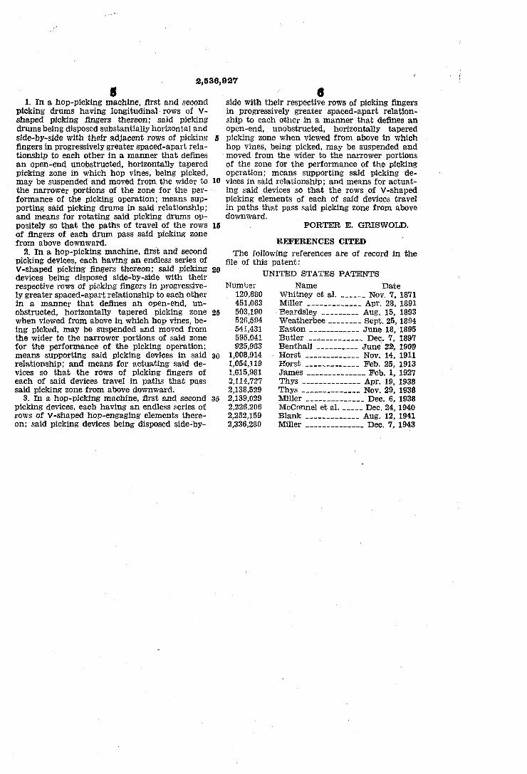


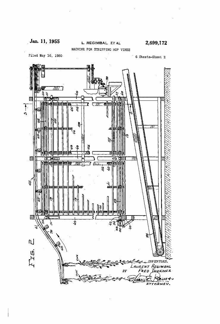


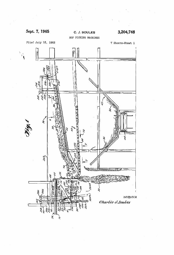

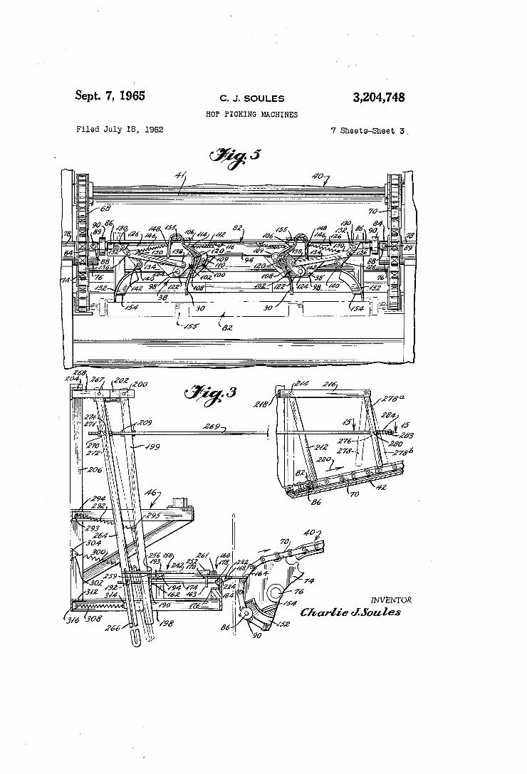
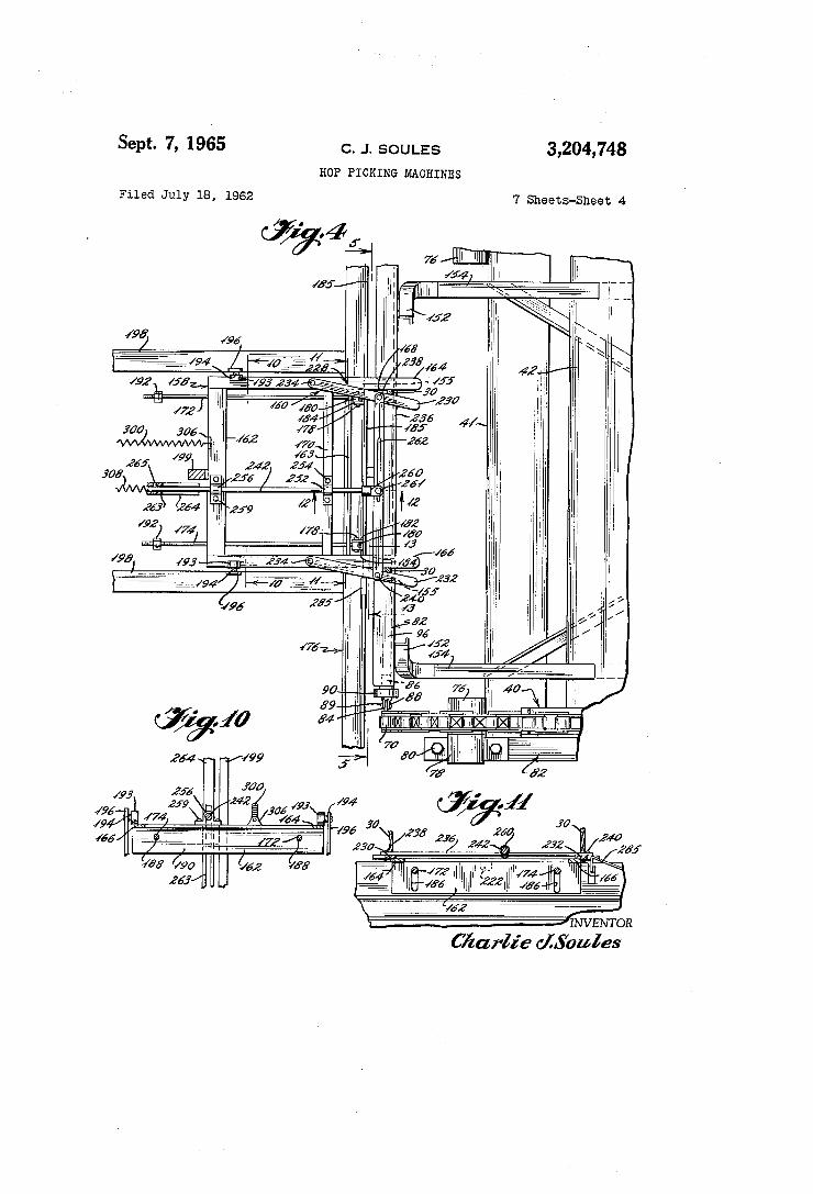


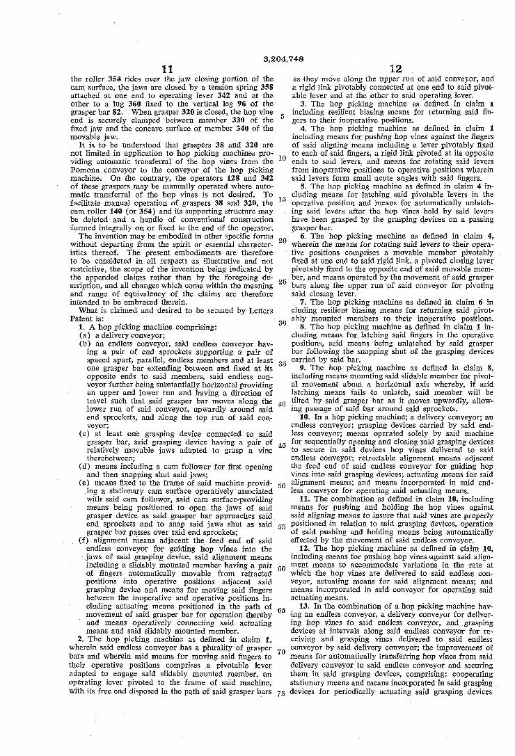


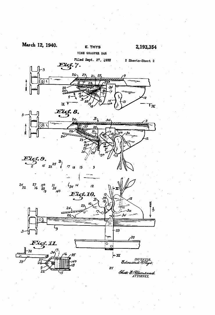


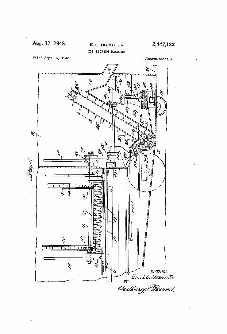


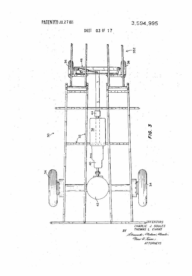

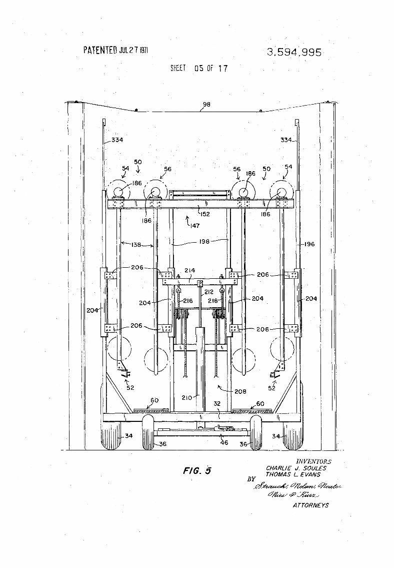
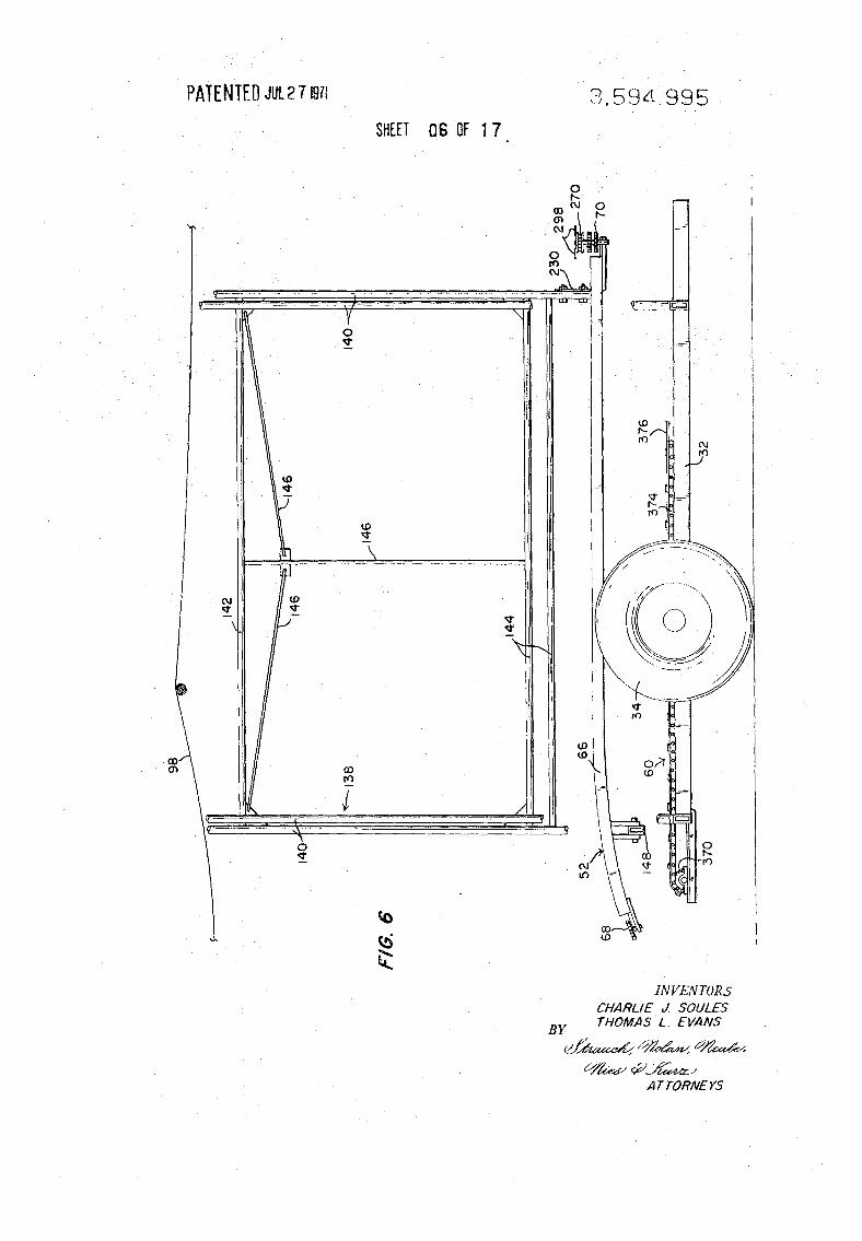


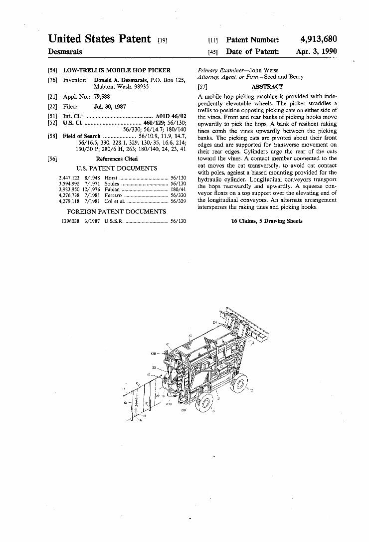

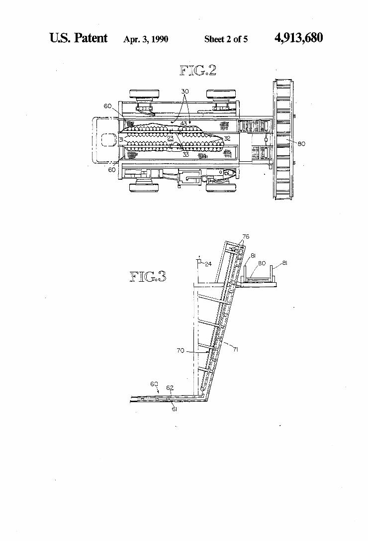


Commercial Feasibility of Local Hops 2010
Appendix I ‐ Fuji Impulse Nitrogen Flush‐ Vacuum Sealer Product Information

110/220V Specification
Operating Instructions
- 602- 402
Printed JUL 2009
3rd Edition 3.02E
Microcomputer-controlledNozzle-type vacuum / gas flushing sealer
VG series

2
VG-602/402 series Operating Instructions Ver. 3.02E
Thank you for your purchasing of VG-602/402 series sealer.
VG-602/402 series sealer is microcomputer controlled.This model has the specification in which various set up is possible.So there are many things that the customer should understand at the beginning of use.
This manual has explanation of terms and reference function like a dictionary.Please utilize the manual, and understand the following matters.
1. Set up the pattern of operation.
Two patterns sealing method is set at the shipping from manufacture's factory.But please set up the sealing condition as you need at first.If set up would not be done, you could not use except standard patterns.Set up is easy if you proceed in according to this manual.
2. Verification and setting of optimum value.
There are various pattern of package material and content in customer's use environment.Please set the optimum value in heating temperature, time, cooling temperature, Vacuum time, degree which matches your needs after the sufficient test and verification.
Please refer to the following table.It shows the temperature of dissolution.But this value is influenced by the environment, thickness of package material and other condition.
Kind of packing material
Temperature of dissolution (OF)
HDPE 266-275HPLDPE 221-248LLDPE 248-266PP 320
Kind of packing material
Temperature of dissolution (OC)
HDPE 130-135HPLDPE 105-120LLDPE 120-130PP 160

3
VG-602/402 series Operating Instructions Ver. 3.02E
Please read all of the safety and operating instructions before operating this machine. Periodic maintenance and proper operation are necessary to ensure safety when using this impulse sealer.Keep this manual on hand when operating the sealer.Set the heating time according to the material and thickness of the film.As a result of research to further improve, some details in the operating instructions may differ from your actual machine. For operating problems or product information, please contact your local dealer or Fuji Impulse.
Foreword
About the warning labelsThe following marks are used in this manual to easily identify the conditions of risks, damages, or some tips for the optimal use of your unit.
Caution Minor injuries or damages to the unit may occur when the instruction is ig-nored.
Warning Severe injuries or fatal accidents may occur when the instruction is ignored.
Danger Critical injuries or fatal accidents will almost certainly occur when the in-struction is ignored.
Attention Important Notes and Restrictions - Read the directions in order to avoid misuse of the unit.
TIPS Great Tips and References when us-ing the unit - Highly recommend read-ing through the information.
SI unitsThe International System of Units (SI) is a consistent system that ordinary people as well as professionals can use. This logical unit system is used in every field from science to industry to education and even daily life.As the SI unit system is gradually replacing the standard pressure unit, this manual primarily uses SI to indicate pressure. (As a reference, however, we have also listed the previous notations.)
This manual is designed to cover machines of various voltages and plug configurationsBefore using, always verify the voltage specification of your particular unit and operate it at the correct voltage.Please note the following:
1) The voltage specification of your unit is listed on the label (or in some cases an aluminum plate) which displays the serial number. This label can be found on the machine body.
2) The explanations and illustrations in this operators' manual utilize the following standard plug configurations most common in Japan. However, due to the various configurations in use worldwide, these may not necessarily correspond with the one attached to your specific unit.
100V15A以下
200V20A
100V20A
200V30A
100V20A、30A
Warning Voltages and plug configurations differ according to various worldwide
specifications.
A verify those of your particular unit
before beginning operation.
Connecting the power cord to an
outlet of a different specification is
extremely hazardous.-0.09(-90)
-0.08(-80)
-0.07(-70)
-0.06(-60)
-0.04(-40)
-0.03(-30)
-0.02(-20)
-0.01(-10)
-0.05(-50)
-0.1(-100)
MPa(kPa)
0
700
Torr
0
100
200
300
400
500
600
760
mmHg
760
700
600
500
400
300
200
100
0

4
VG-602/402 series Operating Instructions Ver. 3.02E
Table of Contents
1 Package contents ................................................................................................ 7
2 Warning-Caution label location and content ..................................................... 8
3 Operating precautions ...................................................................................... 103-1 For safety operating ............................................................................................................................ 10
3-2 For smooth operation .......................................................................................................................... 13
3-3 Other safeguards................................................................................................................................. 13
4 Outline of structure ........................................................................................... 14
5 Purpose usage of the sealer ............................................................................. 14
6 Major parts and function .................................................................................. 15
7 Preparation ......................................................................................................... 167-1 Securing the work place ...................................................................................................................... 16
7-2 Connect the power source ................................................................................................................. 16
7-3 Installing the foot switch ...................................................................................................................... 17
7-4 Adjusting the height and angle of the table ......................................................................................... 17
7-5 Check the dry filter .............................................................................................................................. 18
7-6 Cleaning by the weeping valve ............................................................................................................ 18
7-7 Taking water by the drain hose ............................................................................................................ 18
7-8 Adjusting the nozzle position ............................................................................................................... 18
7-9 Adjusting the angle of sealing area ..................................................................................................... 19
7-10 Emergency stop switch ..................................................................................................................... 20
7-11 Attaching the gas tank and gas adjuster ........................................................................................... 20
8 Proper use of the sealer .................................................................................... 218-1 Operation by the initial set up = Standard operation ........................................................................... 22
● Sealing only ....................................................................................................................................................23
● Vacuum and seal - Operator decide the finish of vacuum by seeing ..............................................................24
● Gas flushing and seal - by initial set up vacuum and gas flushing time .............................................................26
● Two times gas flushing and seal - by initial set up vacuum and gas flushing time .........................................28
8-2 Entry .................................................................................................................................................... 30
● Entry for sealing only ......................................................................................................................................31
● Entry for 1 time vacuum and gas flushing by timer .........................................................................................32
8-3 Explanation of the terms ..................................................................................................................... 33
8-4 Reference ............................................................................................................................................ 34
● For operation ..................................................................................................................................................34
● For set-up .......................................................................................................................................................35
8-5 Operation procedure ........................................................................................................................... 52
● Sealing only ....................................................................................................................................................52
● Vacuum (manual) and Sealing .......................................................................................................................54
● Vacuum (timer) and Sealing ...........................................................................................................................56
● Vacuum (gauge) and Sealing .........................................................................................................................58
● [1 time] Vacuum (manual), Gas flushing and Sealing .....................................................................................60
● [1 time] Vacuum (timer), Gas flushing and Sealing ........................................................................................62

5
VG-602/402 series Operating Instructions Ver. 3.02E
● [1 time] Vacuum (gauge), Gas flushing and Sealing ......................................................................................64
● [n times] Vacuum (manual), Gas flushing and Sealing ...................................................................................66
● [n times] Vacuum (timer), Gas flushing and Sealing .......................................................................................69
● [n times] Vacuum (gauge), Gas flushing and Sealing .....................................................................................72
● [Circulate] Vacuum (manual), Gas flushing and Sealing ................................................................................75
● [Circulate] Vacuum (timer), Gas flushing and Sealing ....................................................................................78
● [Circulate] Vacuum (gauge), Gas flushing and Sealing ..................................................................................81
9 Replacing the routine maintenance parts ...................................................... 849-1 Sliding teflon sheet .............................................................................................................................. 85
9-2 Replacing teflon sheet ......................................................................................................................... 85
9-3 Replacing center-dry tape on the upper lever(object : double side heating model) ............................ 86
9-4 Replacing heating element .................................................................................................................. 87
9-5 Replacing glass tape(19mm width, 25mm width), sarcon sheet .......................................................... 88
9-6 Replacing silicone rubber (object single side heating model) ............................................................. 88
9-7 Replacing silicone rubber (object : double side heating model) .......................................................... 89
9-8 Replacing 50mm width glass tape(object single side heating model) ...................................................... 89
9-9 Connecting and removing tube ........................................................................................................... 90
9-10 Replacing microswitch ...................................................................................................................... 90
9-11 Replacing nozzle ............................................................................................................................... 91
9-12 Replacing temperature sensor for VG-602 series ............................................................................. 92
9-13 Replacing temperature sensor for VG-402 series ............................................................................. 93
10 Specification .................................................................................................... 9410-1 Safety mechanism specifications ...................................................................................................... 94
10-2 Safety mechanism specifications ...................................................................................................... 94
10-3 Appearance dimensions drawing ...................................................................................................... 95
10-4 Combination of vacuum pump and air compressor ........................................................................... 96
10-5 Specifications by the combination of vacuum pump and air compressor .......................................... 97
11 Specifications of accessories ........................................................................ 9811-1 Air parts ............................................................................................................................................. 98
11-2 Electric parts ..................................................................................................................................... 98
12 Regular check and maintenance .................................................................... 9912-1 Regular check ................................................................................................................................... 99
12-2 Cleaning the air filter ....................................................................................................................... 100
13 Electric diagram ............................................................................................. 10213-1 Electric diagram for 110V ................................................................................................................ 102
13-2 Electric diagram for 220V ................................................................................................................ 103
13-3 Electric diagram for 110V (without draining device) ........................................................................ 104
13-4 Electric diagram for 220V (without draining device) ........................................................................ 105

6
VG-602/402 series Operating Instructions Ver. 3.02E
14 Piping diagram ............................................................................................... 10614-1 Piping diagram for VG-602/402 series with air compressor and vacuum pump .............................. 106
14-2 Piping diagram for VG-602/402 series with air compressor and vacuum pump (Air is provided by the
outside compressor) .................................................................................................................................. 107
14-3 Piping diagram for VG-602/402 series with air compressor and vacuum pump (with duct bracket) 108
14-4 Piping diagram for VG-602/402 series with vacuum pump (Air is provided by the outside compressor)
(with duct bracket) ..................................................................................................................................... 109
15 Common problems and solutions ............................................................... 110
16 Exploded view of major parts ....................................................................... 11416-1 Sealing section ................................................................................................................................. 114
16-2 Inside of the frame cover ................................................................................................................. 114
16-3 Nozzle unit section .......................................................................................................................... 115
16-4 Inside of the bottom plate ................................................................................................................ 115
16-5 Inside of the body frame box ........................................................................................................... 116
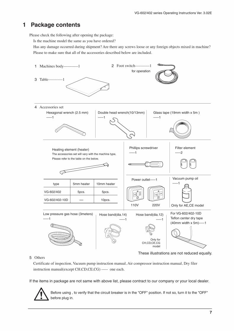
7
VG-602/402 series Operating Instructions Ver. 3.02E
Please check the following after opening the package:Is the machine model the same as you have ordered?Has any damage occurred during shipment? Are there any screws loose or any foreign objects mixed in machine?Please to make sure that all of the accessories described below are included.
1 Package contents
1 Machines body-----------1 2 Foot switch-----------1
3 Table-----------1
4 Accessories set
5 OthersCertificate of inspection, Vacuum pump instruction manual, Air compressor instruction manual, Dry filer instruction manual(except CH,CD,CE,CG) ----- one each.
If the items in package are not same with above list, please contract to our company or your local dealer.
Before using , to verify that the circuit breaker is in the "OFF" position. If not so, turn it to the "OFF"
before plug in.
These illustrations are not reduced equally.
type 5mm heater 10mm heater
VG-602/402 5pcs. 5pcs.
VG-602/402-10D - 10pcs.
Phillips screwdriver-----1
Hexagonal wrench (2.5 mm)-----1
Double head wrench(10/13mm)-----1
Glass tape (19mm width x 5m )-----1
Heating element (heater)The accessories set will vary with the machine type,
Please refer to the table on the below.
For VG-602/402-10D Teflon center dry tape (40mm width x 5m)-----1
110V 220V
Power outlet-----1
Filter element-----2
Low pressure gas hose (3meters)-----1
Hose band(dia.14)-----1
Hose band(dia.12)-----1
Only for CH,CD,CE,CG
model
Vacuum pump oil-----1
Only for AE,CE model
for operation

8
VG-602/402 series Operating Instructions Ver. 3.02E
2 Warning-Caution label location and contentWarning - Caution labels are placed in locations where there is a danger of injury to a person or damage to the machine. Label location details are illustrated below. Please check them before beginning operation. Labels not readily apparent are indicated by dotted lines.
Inside constructionBottom
Inside of machine body
On the upside of body frame
Frame cover
Body
If Warning - Caution labels peel off or are lost, please purchase the proper labels and place
them in the appropriate location.
Don’t change the position of the sensors, otherwise the machine may not work properly, and danger
WARNING
CAUTIONpinching
CAUTIONpinching
CAUTIONhot
CAUTIONjamming

9
VG-602/402 series Operating Instructions Ver. 3.02E
Warning-Caution label location and content
When opening the cover for maintenance
checks, unplug the machine from the wall
outlet or an electric shock may occur.
During packaging, do not place hand or
fingers in the sealing area.
Burns or pinching may occur.
CAUTION NOZZLE
Pay attention to the nozzle
moving forward or
backward during vacuum.
Pinching may occur.
CAUTIONhot
CAUTIONpinching
If Warning - Caution labels peel off or are lost, please purchase the proper labels and place
them in the appropriate location.
Caution
This label indicates very important contents on the maintenance of this sealer.Ref. page 18
Inside construction / top view
Frame cover and pressure lever
WARNINGelectric shock
ExceptCH,CD,CE,CG model

10
VG-602/402 series Operating Instructions Ver. 3.02E
3 Operating precautions
3-1 For safety operating
Warning In an emergency, unplug the power cord immediately.This sealer incorporates a number of safety devices and is carefully designed to prevent fires or other malfunctions. However, should all of the safety devices fail simultaneously, there is a possibility of the teflon catching fire due to a failure of the heating circuit's tripping mechanism that results in the heating element overheating. Should smoke or fire appear from the teflon, immediately turn OFF the power or unplug the power cord from the outlet.
Warning The power consumption varies according to the machine type. Check that the capacity of the outlet is larger than the
power consumption of the sealer, and plug it firmly into the
outlet.
Use of an outlet with a smaller capacity or an extension cord causes a drop in voltage, resulting in malfunction or even fire, be sure to use an appropriate outlet.
Warning Do not use for packaging liquids since machine is not waterproof.
Do not splash water on the machine or use machine for packaging liquids. There is a danger of electrocution or malfunction of the machine.
Warning Do not insert any metal objects into the sealing sectionPlease do not place any metal objects into the sealing section during operation. This could cause electrocution.
Warning When replacing routine parts, unplug the power plugRoutine maintenance parts will wear as you use your sealer. Perform periodical checks of them and set-up an appropriate maintenance schedule. Parts should be replaced in accordance with "Parts Replacement" on the page of instruction manual and perform the steps correctly. Before replacing parts, unplug the machine from the power source otherwise, it may cause electrocution.
110V
specification
220V
specification
110V
specification
220V
specification

11
VG-602/402 series Operating Instructions Ver. 3.02E
Warning Do not modify the machinePlease do not tamper with the machine without the guidance or permission of our engineers. Accidents or damage caused by modification by the customer is the sole responsibility of the customer.
Warning Do not try to use the sealer if the circuit breaker automatically turns to the OFF position.
Trying to use the sealer when the circuit breaker automatically turns to the OFF position may cause electrocution. Do not operate the machine until the cause of the shut down is ascertained and the problem has been addressed.
Caution Be careful of nozzle motionNozzle comes out automatically after several seconds from the finish of operation at the mode except "SEALING ONLY".Please be careful of advance of a nozzle.If you bring face or hand close to the sealing area, you might bump against a nozzle.Or if a bag is left in the front of a seal part, the goods in the bag might be damaged.Please take out a bag soon after pressure lever open (Sealing is finished).
Caution Do not operate machine under high humidity; Do not expose the machine to water vapor; and do not use it for powder
applications or in a dusty location.
To operating the machine in a place with high humidity or water vapor, The machinery parts will become rusty; Electric insulation reduces. Electrocution and malfunction may occur.To operate the machine for powder packaging or use it in a dusty location, The powder and dusty may flow inside the sealer body, Electric insulation reduces. Electrocution and malfunction may occur.
Caution Do not place hands in the sealing section.With prolonged use, the sealing section will retain heat and become hot. If you place your fingers in this area, there is a possibility of burns.Pressing the foot switch applies press to the sealing section. Take sufficient care so that your fingers are not caught while the power is on.An operation by two operators may increase the possibility of your fingers being caught. Take sufficient.

12
VG-602/402 series Operating Instructions Ver. 3.02E
Caution Read the operating instructions carefully and operates sealer correctly.
Accidents or damages caused by misuse of the machine not in accordance with the operating instructions are the sole responsibility of the customer.
Caution Perform sufficient tests headband when you require a particularly strong vacuum seat.
Sealing results vary according to heating, cooling, and pressure. A certain type of film may greatly affect the necessary sealing settings. Perform a number of sealing tests to find the most suitable heating cooling time and pressure setting for your film before start sealing operation.
Caution Socket for the optional printer (FEP-V-N1)There is a socket to install the optional printer (FEP-V-N1) on the top of a sealer.
Don't connect the other electrical appliances to this socket.To start it is very dangerous.

13
VG-602/402 series Operating Instructions Ver. 3.02E
3-2 For smooth operation
Heating time should be set at a minimum
Set sealer so that an acceptable seal is completed in the least amount of heating time. Excessively long heating times (increasing the heat setting unnecessarily) will damage the Teflon, glass tape and other consumables, as well as result in heating element breakage. This will lead to decreased work productivity and unnecessary power consumption.
Allow sufficient cooling time
Cooling temperature is important when using an impulse sealer. After the film is heated, the film must be cooled with the frame and pressure lever in the closed position. If cooling temperature is extremely lower, the working efficiency will come down. So please set the appropriate cooling temperature according with the film.
When abnormalities arise in a temperature sensor
Since the temperature sensor detected the temperature of a heater portion directly and has controlled it, if the tip part of a temperature sensor separates from a heater, an error message "Poor heating" will be displayed on a screen and a lever will return to the initial state.Please be careful to set the temperature sensor exactly after the replacement of parts in the sealing area.
When the teflon, silicone rubber becomes damaged
The teflon, silicone rubber will start to wear with use. Once they are damaged, it will be difficult to achieve smooth and strong seals. Thoroughly read how to replace the parts and be careful when doing so.
Dust in the sealing section
Dust will prevent attainment of a smooth seal. It could also cause damage to heating element and/or other routine maintenance parts. Before using the machine, clean the sealing section.
3-3 Other safeguardsFuji Impulse sealers utilize an impulse heating system, meaning that the heater section does not become hot simply because the power has been turned on.It is programmed so that the heating element is heated only during the heating cycle, after a sensor switch and micro processor have been activated. (Please note, however, the sealing section may become hot after prolonged operation.)

14
VG-602/402 series Operating Instructions Ver. 3.02E
4 Outline of structure
■ VG-602/402 series is an impulse sealer with sponges located on the sealing section to secure the nozzle prior to air removal. The air in a pouch is exhausted by built-in vacuum pump, and after the gas flushing process, sealing starts.
■ Built-in air compressor (another air source for some models) moves each part.
■ The operation process is controlled by control unit and performed just simply by depressing the foot switch.
5 Purpose usage of the sealer1 The impulse sealer is a machine that sends strong electric current quickly to the thin ribbon heater, which
presses against the film and instantly heat-seals the package. Though this machine yields superior quality sealing, it is not compatible with films thicker than that indicated in the diagram below, sponge-like sheets, and materials that are not able to withstand high heat. In addition according to difference of film thickness and martial, the heating temperature is different. Please verify the optimum sealing conditions before operation.
2 Film thickness limits for VG-602/402 series are described below. The machine can't seal films that are thicker than that indicated.
The machine may malfunction if you try to exceed the limits of the machine.
Heating type Heater width Thickness of material (combined total of two sheets)
Single side heating(VG-602 / 402) 5mm Single layer film with thickness of 0.3 mm, or less or thin laminated film
Single side heating(VG-602 / 402) 10mm
Double side heating(VG-602 / 402-10D) 10mm
Thin gusset film with thickness of 0.4 mm or less Laminated film with thickness of 0.4 mm or less
Thin gusset film with thickness of 0.5 mm or less Laminated film with thickness of 0.5 mm or less
1
BagSponges
Sealing section
Nozzle forward
Table
2 VacuumVacuum
4 Sealing
3 Gas flushing
5 Finish
Press
Gas
Nozzle backward
Pressure lever raise up
Nozzle forward

15
VG-602/402 series Operating Instructions Ver. 3.02E
Control (switch) panel
1. POWER BUTTON
2. ENT BUTTON
3. MENU BUTTON
4 5 6 7. ARROW BUTTON
8. LIQUID CRYSTAL DISPLAY
9. VACUUM GAUGE
10. VACUUMING LAMP
11. GAS LAMP
12. HEATING LAMP
13. COOLING LAMP
6 Major parts and function
Frame coverCan be opened for maintenance
Control (switch) panel
Vacuum / Gas-flushing nozzleThis machine is equipped with a nozzle so that a seal can be formed at the top of the bag, and the spacing between the nozzles can be adjusted.
TableAngle of the table can be adjusted.
Air filterStore any foreign objects accidentally taken in though the nozzle in air filter cup.
Dry filterTo prevent any condensation inside the compressor from sealer body. The moisture is discharged from the dry hose.
Foot switchPress the foot switch to perform the operation.
Circuit breaker (with overheat proof circuit)
Any extreme heating time more than the setting will be automatically stop--"OFF".In addition, if electric leakage occur, it automatic turns off.
Circuit breaker is behead of the dry filter, it's no available on this drawing, please refer to "appearance dimension" on page 52.
CockTwo type gas can be used.
Emergency stop switch
Automatic water draining deviceWhen the water draining switch is turned ON, all water, dust, and foreign object will be emptied out.
Angle adjusting handleTurn the handle to change the angle of sealing area.
1
2
3
4 5 6789
10
11
12
13

16
VG-602/402 series Operating Instructions Ver. 3.02E
7 Preparation
7-1 Securing the work place
For safety and efficiently operation, please set the sealer in suitable environment.
Warning Do not use the VG-602/402 on a tilting, uneven, or unstable place. The sealer may
fall and become damaged or cause injuries.
Be sure it uses the sealer on a flat stable
surface.
Warning Do not use the sealer on a wet floor. Do not expose the sealer to water drops or vapor.
This may cause a failure and a short circuit.
Warning To operating the machine in a place with high humidity or water vapor, the
compressor draw the air obtain more
moisture, It's worse to machinery parts. Life
of dry filter will be shorten.
7-2 Connect the power source
Be sure to connect the power plug directly into an outlet with an appropriate capacity, which stated on "10 Specification".Insert the plug fully into the outlet.
Wiring must be performed by an engineer authorized by the electric, power company.(Wiring and 3rd level grounding requires proper qualification.)
Warning The power consumption varies according to the machine type. Check that the capacity
of the outlet is larger than the power
consumption of your machine, and plug it
directly to the outlet.
Using an outlet with a smaller capacity or
an extension cord will cause a drop in
voltage, resulting in malfunction and even
fire because of overheating of the cable and
outlet. Be sure to use an appropriate outlet.
Warning When you have changed the standard plug provided, check the connection.
The wires are connected as shown in the
figure. When the ground wire is not
connected to the correct terminal, a short
on the power source side or an electric
leakage is caused.
220V specification
110V specification
Black
Ground
110V specification 220V specification
Green
White
GroundGreen
White
Black
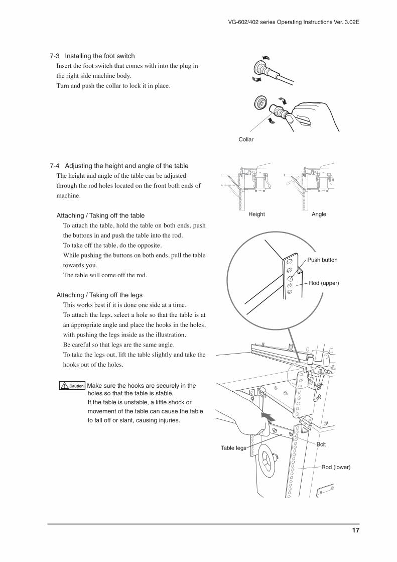
17
VG-602/402 series Operating Instructions Ver. 3.02E
7-3 Installing the foot switch
Insert the foot switch that comes with into the plug in the right side machine body.Turn and push the collar to lock it in place.
7-4 Adjusting the height and angle of the table
The height and angle of the table can be adjusted through the rod holes located on the front both ends of machine.
Attaching / Taking off the table
To attach the table, hold the table on both ends, push the buttons in and push the table into the rod.To take off the table, do the opposite.While pushing the buttons on both ends, pull the table towards you.The table will come off the rod.
Attaching / Taking off the legs
This works best if it is done one side at a time.To attach the legs, select a hole so that the table is at an appropriate angle and place the hooks in the holes, with pushing the legs inside as the illustration.Be careful so that legs are the same angle.To take the legs out, lift the table slightly and take the hooks out of the holes.
Caution Make sure the hooks are securely in the holes so that the table is stable.
If the table is unstable, a little shock or
movement of the table can cause the table
to fall off or slant, causing injuries.
Collar
Rod (upper)
Push button
Rod (lower)
BoltTable legs
Height Angle

18
VG-602/402 series Operating Instructions Ver. 3.02E
7-5 Check the dry filter
Two dry filters on the side of frames need to be exchanged regularly.Especially check the red filter side tube when the beginning and finishing the sealing operation.When the tube becomes cloudy or water-drops is attached inside, please exchange the filter regardless of the standard of exchange.
Standard of exchange
Black filter-----2 years
Red filter----- Half a year
7-6 Cleaning by the weeping valve
(Not necessary at the initial use of the sealer)At the beginning and finishing the sealing operation, clean the filter interior by pushing the weeping valve in and out several times.For details information, refer to " dry filter instruction manual".
Caution If the filter would be left clogging up, the moisture flow into the vacuum pump and
causes damage of pump.
7-7 Taking water by the drain hose
The dry filter is of auto-drain construction.The moisture in the dry filter is mixed with little exhaust air and discharged as drain.It will be released from the underside of the unit frame by the drain hose.Take water from the drain hose by a container (drain tank or empty can).
7-8 Adjusting the nozzle position
Take off the frame cover.
■ Adjusting the height of the nozzle
Turn the screw on the inner left of the nozzle supporter (seen from the table side) by the 2.5mm six angle wrench.To lower = Turn clockwiseTo raise = Turn counterclockwise
Check the red filter side tube
RedBlack
Dry filter
Taking water by a container
Weeping valve
Rear side silver screw
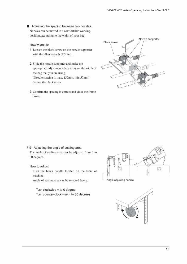
19
VG-602/402 series Operating Instructions Ver. 3.02E
■ Adjusting the spacing between two nozzles
Nozzles can be moved to a comfortable working position, according to the width of your bag.
How to adjust
1 Loosen the black screw on the nozzle supporter with the allen wrench (2.5mm).
2 Slide the nozzle supporter and make the appropriate adjustments depending on the width of the bag that you are using.(Nozzle spacing is max. 157mm, min 57mm)Secure the black screw.
3 Confirm the spacing is correct and close the frame cover.
7-9 Adjusting the angle of sealing area
The angle of sealing area can be adjusted from 0 to 30 degrees.
How to adjust
Turn the black handle located on the front of machine.Angle of sealing area can be selected freely.
Turn clockwise = to 0 degree
Turn counter-clockwise = to 30 degrees
₃₀゚
Black screwNozzle supporter
Angle adjusting handle

20
VG-602/402 series Operating Instructions Ver. 3.02E
7-10 Emergency stop switch
Before operating the machine, press the switch and make sure that it is working.
1 Turn the circuit breaker ON.2 Press the emergency stop switch.3 If the circuit breaker turned OFF, the emergency
stop switch is working normally.
Warning
If the circuit breaker does not shut down, please try
as follows and contact your dealer of our company.
(Ref. the right illustration)
Push the red test button on the circuit breaker.
<Circuit breaker turns OFF>=Emergency stop switch may be damaged.
<Circuit breaker turns ON>=Circuit breaker may be damaged.
7-11 Attaching the gas tank and gas adjuster
Gas tank and adjuster is not attached to the machine. Please attach as necessary.
1 Attach the gas adjuster (with reducing valve and flow meter) to the tank.
2 Attach the gas flow meter to the cock with vinyl hose.When using only one cock, close the other cock certainly. (Both cocks can be connected.)If two types gas are used, attach the another hose to the each cock.When gas flushing process is not necessary, always close the gas cock.
Test button(Red)
Circuit breaker ON
ONOFF
Press the emergencystop switch
Cock

21
VG-602/402 series Operating Instructions Ver. 3.02E
8 Proper use of the sealer
This chapter is composed as follows.
8-1 Operation by the initial set up
= Standard operationPlease get used to this sealer by initial two patterns.
8-2 Entry
Let's enter the new operation pattern.
T I PS Explanations in 8-1 and 8-2 are started after the following operations (1 and 2).
1 Turn the circuit breaker on.
2 Turn the power switch on.
The below message is displayed for 3 seconds.
VG English oF Verx.x
FUJI IMPULSE.CO
VG English oC Verx.x
FUJI IMPULSE.CO
8-3 Explanation of the terms
Explanation about the display message or term in this manual.Please use as dictionary.
8-4 Reference
Explanation of each operations and set-up.
8-5 Operation procedure
Work flow of 13 patterns combination of sealing method.
Please use 8-3 and 8-4 as your dictionary (data file)

22
VG-602/402 series Operating Instructions Ver. 3.02E
8-1 Operation by the initial set up = Standard operation
Four kinds of sealing methods are entered into VG-602/402 series at the shipment from factory.Attention
The following four patterns will be changed when customer set up heating temperature, cooling temperature, vacuum time, gas flushing time etc...If you need the initial patterns, please re-register it.
*At first, get used to the machine by these four patterns.*Terms are explained in page 31, 8-3.*Other sealing methods are shown in page 50, 8-5.
● Seal only (page 21)= Operation No. [01] SEALING ONLYInitial valueHT (Heating Temperature) : 284OF (140OC), CT (Cooling Temperature) : 212OF (100OC)Ref. 8-5-1 (page 50)
● Vacuum and seal - Operator decide the finish of vacuum by seeing (page 22)= Operation No. [02] VAC & SEAL manualInitial valueHT (Heating Temperature) : 284OF (140OC), CT (Cooling Temperature) : 212OF (100OC)Ref. 8-5-2 (page 52)
● Gas flushing and seal - by initial set up vacuum and gas flushing time (page 24)= Operation No. [03] 1-GAS / TimerInitial valueHT (Heating Temperature) : 284OF (140OC), CT (Cooling Temperature) : 212OF (100OC)VT (Vacuuming Time) : 1.0second, GT (Gas flushing Time) : 2.0secondsRef. 8-5-6 (page 60)
● Two times gas flushing and seal - by initial vaccum and gas flushing time (page 26)= Operation No. [04] 2-GAS / TimerInitial valueHT (Heating Temperature) : 284OF (140OC), CT (Cooling Temperature) : 212OF (100OC)1-VT (1st Vacuuming Time) : 1.0second, 2-VT (2nd Vacuuming Time) : 1.0seconds,1- GT (1st Gas flushing Time) : 2.0seconds, 2-GT (2nd Gas flushing Time) : 2.0secondsRef. 8-5-6 (page 60)
Operation No. can be changed by , key on the following display.
SEALING ONLY
Change (number)
Change (item)
COUNTER x x x x x

23
VG-602/402 series Operating Instructions Ver. 3.02E
● Sealing onlyOperation No. [01] SEALINGHT : 284OF (140OC), CT : 212OF (100OC)Ref. 8-5-1
T I PSThe following explanation is for the first use. (by
the initial set-up)
At first, turn the circuit breaker and power switch on. (in page 19, 1 and 2)
3 Operation No. [01] is displayed.
SEALING ONLY
Change (number)
Change (item)
COUNTER x x x x x
4 Check the heating and cooling temperature.When you change the value, please look at 8-4 in page 32.
5 Set a pouch on the sealing position.
6 Step on the foot switch (1st)
Pressure lever descends and fasten a pouch with sponge rubber. (Please keep on stepping until the pressure lever close.)
Attention
If leg is separated from the foot switch in the
middle of downward, the pressure lever will
open for the safe mechanism.
7 Step on the foot switch (2nd)By the second step on the foot switch, the following process (from 7-1 to 7-5) will be performed automatically.
7-1 Sealing starts.
7-2 Heating lamp is turned on.
7-3 After the heating is finished (Heating lamp is turned off), cooling lamp is turned on.
7-4 Cooling is finished.(Cooling lamp is turned off.)
7-5 Sealing process is completed.(Pressure lever open.)
8 Sealing is finished.Please check whether sealing performed certainly.If you will not use for a long time, please work in following order.
1. Shut off the power switch.2. Shut off the circuit breaker.3. Pull out the cord from the wall socket.

24
VG-602/402 series Operating Instructions Ver. 3.02E
● Vacuum and seal - Operator decide the finish of vacuum by seeingOperation No. [02] VAC & SEALHT : 284OF (140OC), CT : 212OF (100OC)Ref. 8-5-2
T I PSThe following explanation is for the first use. (by
the initial set-up)
At first, turn the circuit breaker and power switch on. (in page 19, 1 and 2)
3 Operation No. [01] is displayed.
SEALING ONLY
Change (number)
Change (item)
COUNTER x x x x x
4 Select No. [02]
Operation number is changed by , button.
Select number [02].
VAC&SEAL manual
Change(number)
Change(item)
COUNTER x x x x x
5 Check the heating and cooling temperature.When you change the value, please look at 8-4 in page 32.
6 Step on the foot switch (1st)
Nozzle come forward.
7 Insert the nozzle in a pouch, and set it on the sealing position.
8 Step on the foot switch (2nd)
Pressure lever descends and fasten a pouch with sponge rubber. (Please keep on stepping until the pressure lever close.)
Attention
If leg is separated from the foot switch in the
middle of downward, the pressure lever will
open for the safe mechanism.
9 Step on the foot switch (3rd)Vacuum start. (Vacuum lamp is turned on.)
10 When you could see the sufficient vacuum is done, step on the foot switch (4th).
By fourth step on the foot switch, the following process (from 10-1 to 10-6) will be performed automatically.
10-1 Vacuum finish.(Vacuum lamp is turned off.)
10-2 Nozzle return.

25
VG-602/402 series Operating Instructions Ver. 3.02E
(8-1-2)10-3 Pressure lever fasten a pouch and sealing starts. (Heating lamp is turned on.)
10-4 After the heating is finished (Heating lamp is turned off), cooling lamp is turned on.
10-5 Cooling is finished.(Cooling lamp is turned off.)
10-6 Sealing process is completed.(Pressure lever return and nozzle come forward)
11 Sealing is finished.Please check whether sealing performed certainly.If you will not use for a long time, please work in following order.
1. Shut off the power switch.2. Shut off the circuit breaker.3. Pull out the cord from the wall socket.

26
VG-602/402 series Operating Instructions Ver. 3.02E
● Gas flushing and seal - by initial set up vacuum and gas flushing timeOperation No. [03] 1-GAS / TimerHT : 284OF (140OC), CT : 212OF (100OC), VT : 1.0sec, GT : 2.0secRef. 8-5-6
T I PSThe following explanation is for the first use. (by
the initial set-up)
At first, turn the circuit breaker and power switch on. (in page 19, 1 and 2)
3 Operation No. [01] is displayed.
SEALING ONLY
Change (number)
Change (item)
COUNTER x x x x x
4 Select No. [03]
Operation number is changed by ,
button.Select number [03].
1-GAS timer
Change(number)
Change(item)
COUNTER x x x x x
5 Check the heating and cooling temperature.When you change the value, please look at 8-4 in page 32.
6 Step on the foot switch (1st)
Nozzle come forward.
7 Insert the nozzle in a pouch, and set it on the sealing position.
8 Step on the foot switch (2nd)
Pressure lever descends and fasten a pouch with sponge rubber. (Please keep on stepping until the pressure lever close.)
Attention
If leg is separated from the foot switch in the
middle of downward, the pressure lever will
open for the safe mechanism.
9 Step on the foot switch (3rd)By third step on the foot switch, the following process (from 9-1 to 9-9) will be performed automatically.
9-1 Vacuum start. (Vacuuming lamp is turned on.)
9-2 When set up time is passed, vacuum finish. (Vacuuming lamp is turned off.)
9-3 Gas flushing start.(Gas flushing lamp is turned on.)

27
VG-602/402 series Operating Instructions Ver. 3.02E
(8-1-3)9-4 When set up time is passed, gas flushing finish. (Gas flushing lamp is turned off.)
9-5 Nozzle return.
9-6 Pressure lever fasten a pouch and sealing starts. (Heating lamp is turned on.)
9-7 After the heating is finished (Heating lamp is turned off), cooling lamp is turned on.
9-8 Cooling is finished.(Cooling lamp is turned off.)
9-9 Sealing process is completed.(Pressure lever return and nozzle come forward)
10 Sealing is finished.Please check whether sealing performed certainly.If you will not use for a long time, please work in following order.
1. Shut off the power switch.2. Shut off the circuit breaker.3. Pull out the cord from the wall socket.

28
VG-602/402 series Operating Instructions Ver. 3.02E
● Two times gas flushing and seal - by initial set up vacuum and gas flushing time
Operation No. [04] 2-GAS / TimerHT : 284OF (140OC), CT : 212OF (100OC), 1-VT : 1.0sec, 2-VT : 1.0sec, 1-GT : 2.0sec, 2-GT : 2.0secRef. 8-5-9
T I PSThe following explanation is for the first use. (by
the initial set-up)
At first, turn the circuit breaker and power switch on. (in page 19, 1 and 2)
3 Operation No. [01] is displayed.
SEALING ONLY
Change (number)
Change (item)
COUNTER x x x x x
4 Select No. [04]
Operation number is changed by , button.
Select number [04].
1-GAS timer
Change(number)
Change(item)
COUNTER x x x x x
5 Check the heating and cooling temperature.When you change the value, please look at 8-4 in page 32.
6 Step on the foot switch (1st)
Nozzle come forward.
7 Insert the nozzle in a pouch, and set it on the sealing position.
8 Step on the foot switch (2nd)
Pressure lever descends and fasten a pouch with sponge rubber. (Please keep on stepping until the pressure lever close.)
Attention
If leg is separated from the foot switch in the
middle of downward, the pressure lever will
open for the safe mechanism.
9 Step on the foot switch (3rd)By third step on the foot switch, the following process (from 9-1 to 9-13) will be performed automatically.
9-1 Vacuum start (1st). (Vacuuming lamp is turned on.)
9-2 When set up time is passed, the first vacuum finish.(Vacuuming lamp is turned off.)
9-3 Gas flushing start (1st).(Gas flushing lamp is turned on.)

29
VG-602/402 series Operating Instructions Ver. 3.02E
(8-1-4)9-4 When set up time is passed, the first gas flushing finish.(Gas flushing lamp is turned off.)
9-5 Vacuum start (2nd). (Vacuuming lamp is turned on.)
9-6 When set up time is passed, the second vacuum finish.(Vacuuming lamp is turned off.)
9-7 Gas flushing start (2nd).(Gas flushing lamp is turned on.)
9-8 When set up time is passed, the second gas flushing finish. (Gas flushing lamp is turned off.)
9-9 Nozzle return.
9-10 Pressure lever fasten a pouch and sealing starts. (Heating lamp is turned on.)
9-11 After the heating is finished (Heating lamp is turned off), cooling lamp is turned on.
9-12 Cooling is finished.(Cooling lamp is turned off.)
9-13 Sealing process is completed.(Pressure lever return and nozzle come forward)
10 Sealing is finished.Please check whether sealing performed certainly.If you will not use for a long time, please work in following order.
1. Shut off the power switch.2. Shut off the circuit breaker.3. Pull out the cord from the wall socket.
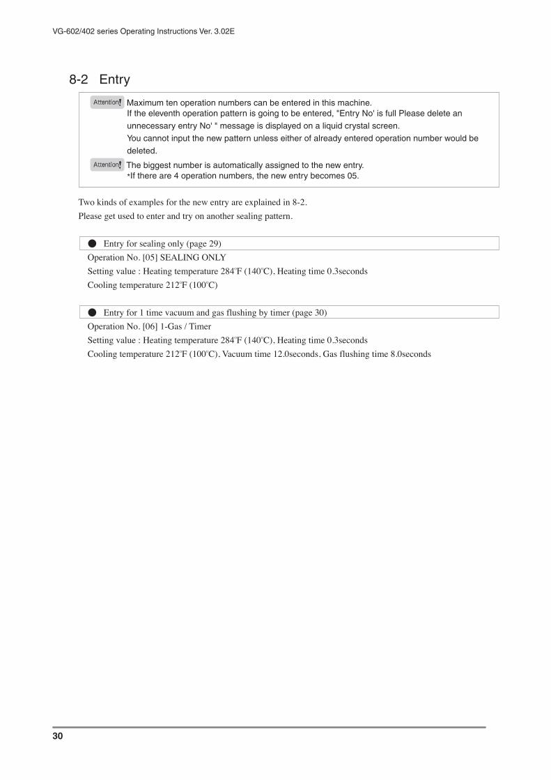
30
VG-602/402 series Operating Instructions Ver. 3.02E
8-2 Entry
Attention Maximum ten operation numbers can be entered in this machine.If the eleventh operation pattern is going to be entered, "Entry No' is full Please delete an
unnecessary entry No' " message is displayed on a liquid crystal screen.
You cannot input the new pattern unless either of already entered operation number would be
deleted.
Attention The biggest number is automatically assigned to the new entry.*If there are 4 operation numbers, the new entry becomes 05.
Two kinds of examples for the new entry are explained in 8-2.Please get used to enter and try on another sealing pattern.
● Entry for sealing only (page 29)Operation No. [05] SEALING ONLYSetting value : Heating temperature 284OF (140OC), Heating time 0.3secondsCooling temperature 212OF (100OC)
● Entry for 1 time vacuum and gas flushing by timer (page 30)Operation No. [06] 1-Gas / TimerSetting value : Heating temperature 284OF (140OC), Heating time 0.3secondsCooling temperature 212OF (100OC), Vacuum time 12.0seconds, Gas flushing time 8.0seconds

31
VG-602/402 series Operating Instructions Ver. 3.02E
● Entry for sealing onlyAttention The following explanation is for the first use. (by the initial set-up)
To register "Sealing only" in operation number [05].Setting value : Heating temperature 284OF (140OC), Heating time 0.3seconds, Cooling temperature 212OF (100OC)
At first, turn the circuit breaker and power switch on. (in page 19, 1 and 2)
3 Operation No. [01] is displayed.
SEALING ONLY
Change (number)
Change (item)
COUNTER x x x x x
4 Push the .
MENU / / MENU=Back
1 Entry 2 Change
3 Delete 4 Circulate
5 Drain 6 Maintain
5 Select "1 Entry" Register by ,
( part is blinking.)
MENU / / ENT=OK
1 Entry 2 Change
3 Delete 4 Circulate
5 Drain 6 Maintain
6 Push , display changes to
METHOD Select
1 SEAL 2 VAC & SEAL
3 1-GAS 4 n-GAS
5 CIRCULATE
(5 CIRCULATE is displayed only in effect)
7 Select "1 SEAL" by ,
( part is blinking.)
METHOD Select
1 SEAL 2 VAC & SEAL
3 1-GAS 4 n-GAS
5 CIRCULATE
8 Push , display changes to
Change Move
HT₁₄₀OF ₀.₀s
( part is blinking.)
Change Move
HT ₆₀OC ₀.₀s CT
( part is blinking.)
9 Set the heating temperature 284OF (140OC).Look at "Set the heating temperature" in page 34.
10 Set the heating time to 0.3seconds by
.
Look at "Set the heating time "in page 34.
11 Set the cooling temperature 212OF
(100OC) by .
Look at "Set the cooling temperature" in page 43.

32
VG-602/402 series Operating Instructions Ver. 3.02E
● Entry for 1 time vacuum and gas flushing by timerAttention The following explanation is for the first use. (by the initial set-up)
To register "1 time vaccum and gas flushing by timer" in operation number [05].Setting value : Heating temperature 284OF (140OC), Heating time 0.3seconds, Cooling temperature 212OF (100OC) Vacuum timer 12.0seconds, Gas flushing time 8.0seconds
At first, turn the circuit breaker and power switch on. (in page 19, 1 and 2)
3 Operation No. [01] is displayed.
SEALING ONLY
Change (number)
Change (item)
COUNTER x x x x x
4 Push the .
MENU / / MENU=Back
1 Entry 2 Change
3 Delete 4 Circulate
5 Drain 6 Maintain
5 Select "1 Entry" Register by ,
( part is blinking.)
MENU / / ENT=OK
1 Entry 2 Change
3 Delete 4 Circulate
5 Drain 6 Maintain
6 Push , display changes to
METHOD Select
1 SEAL 2 VAC & SEAL
3 1-GAS 4 n-GAS
5 CIRCULATE
(5 CIRCULATE is displayed only in effect)
7 Select "3 1-GAS" by ,
( part is blinking.)
METHOD Select
1 SEAL 2 VAC & SEAL
3 1-GAS 4 n-GAS
5 CIRCULATE
8 Push , display changes to
VAC TYPE Select
1-GAS
1 Manual 2 Time 3 Gauge
( part is blinking.)
9 Select "2 Time" by ,
VAC TYPE Select
1-GAS
1 Manual 2 Time 3 Gauge
( part is blinking.)
10 Push , display changes to
( part is blinking.)
Change Move
1VT10.0sec G10.0sec
HT₁₄₀OF ₀.₀s
( part is blinking.)
Change Move
1VT10.0sec G10.0sec
HT ₆₀OC ₀.₀s CT
11 Set the vacuum timer to 12.0seconds.Look at "Set the vacuum time" in page 41.
12 Push , and set the gas flushing timer
to 8.0seconds.Look at "Set the 1 time gas flushing timer"in page 45.
13 Push , and set the heating
temperature 280O
F (140O
C).Look at "Set the heating temperature" in page 34.
14 Push , and set the heating time to
0.3seconds.Look at "Set the heating time "in page 34.
15 Push , and set the cooling
temperature 212O
F (100OC).Look at "Set the cooling temperature" in page 43.

33
VG-602/402 series Operating Instructions Ver. 3.02E
Impulse sealer The machine which carries out the seal of plastic film package is named sealer. The sealer which carries out the seal by heat is called heat sealer.There are four heat sealing technology generally used.1 Impulse sealer, 2 Heat plate sealer3 Ultrasonic sealer, 4 High frequency sealer
Impulse sealer passes large current momentarily at the ribbon-like heating element, and heat up it to the sufficient temperature to seal by heat conduction.Package material is put between sealing parts of machine, pressed by the lever and melted by the heating element. After that, cooling process is needed with pressure kept on.
Temperature sensor It can detect the temperature of sealing part directly.
Vacuum (gauge) Vacuum is performed to the set-up degree by vacuum gauge.
SealSealing
Seal (Sealing) means to adhere the opening part of plastic film package material.The machine which perform "Seal" is called sealer.
Sealing only Only seal is performed. If this pattern is set-up, vacuum or gas flushing function will not work.
Sealing method(on the liquid crystal screen)
"METHOD" appears on the liquid crystal screen of VG-602/402 series when operator select the sealing method.(Sealing only / Vacuum and Seal / Vacuum, Gas flushing and seal)
Sealing method generally means "Impulse style", "Ultrasonic style", "High frequency style" etc...Please understand it as the shortage of expression.
Vacuum (timer) Vacuum is performed to the setting time by timer.
Vacuum (manual) Operator judges the suitable vacuum degree by seeing, and finish the vacuum by stepping on a foot switch.
n-times(Gas flushing)(Vacuum)
In VG-602 / 402 series, gas flushing can be set max.99 times."n" expresses the unspecified number of times which user would choose from 1 time to 99 times.
NC(piping) Circulated vacuum and gas flushing mode is called "NC".When user choose this mode,piping needs to be changed. Piping for circjlated vacuum and gas flushing mode is "NC piping".
8-3 Explanation of the terms
Nozzle comes
forward
Nozzle returns.
Heating starts.
Vacuum nozzleGas nozzle
Vacuum nozzleGas nozzleVacuum nozzle
Gas nozzleVacuum nozzle
Gas nozzle
Vacuum
(by manual, timer, or
gauge)
First gas flushingCirculation
Gas flushing and
vacuum are performed
simultaneously
Second gas flushing

34
VG-602/402 series Operating Instructions Ver. 3.02E
● For operation
8-4 Reference
Starting of use
1 Turn on the circuit breaker.
2 Push the power button (ON).Compressor and cooling fan start.
Finishing of use
1 Push the power button (OFF).Compressor and cooling fan stop.
2 Shut off the circuit breaker.All function is finished.
3 Check the maintenance items.Ex. Cleaning of Filter element.Look at page 97 for periodical maintenance items.
4 Pull out the plug.If machine won't be worked for a long time, pull out the plug from the wall socket.
Foot switch
In VG-602/402 series, sealing process is done by the foot switch.
Attention
Please step on the foot switch certainly.
If not, machine may not work to the next
process.
If leg is separated from the foot switch in the
middle of downward, the pressure lever will
open for the safe mechanism.

35
VG-602/402 series Operating Instructions Ver. 3.02E
● For set-up
Explanation of each button on the control panel
MENU button
= To display the menu mode
1 Entry 2 Change
3 Delete 4 Circulate
5 Drain 6 Maintain
ENT button
= To decide the each setting item
Arrow button / Upward, Downward
= To move the setting display
= To increase or decrease the setting value
Arrow button / Rightward, Leftward
= To move the setting display
= To move the cursor to objective position
Liquid crystal screen
Please refer 8-5

36
VG-602/402 series Operating Instructions Ver. 3.02E
Foreword1 The following explains as the circuit breaker ON and power button ON.2 The numeric position which can be changed is expressed by xx in the illustration.3 The blinking cursor position is expressed by (down side) and (background).4 shows different contents by each operation number.
CounterReset the counter value :Push for 3 seconds on the following initial display.
SEALING ONLY
Change (number)
Change (item)
COUNTER x x x x x
Reduce one count from the counter value :
Push one time.
Set the heating temperature1-1 Change the heating temperature of the current displayed operation number :
Push , display changes to
Change Move
HT xxOF x.xs CT
( part is blinking.)
Change Move
HT xxOC x.xs CT
( part is blinking.)
->Read 2
1-2 Change the heating temperature of another operation number :Refer to "Select the operation number" in page 36.
After select the objective number, push and read 2.
2 Right side of "HT" is blinking.
In this condition, adjust the value by button.
One degree is changed by one time push .
If kept on pushing, numeral change at high speed.(Setting range 140 〜 480OF)(Setting range 60 〜 250OC)
T I PSSuitable temperature is different with each
packing materials.
Please set the lowest temperature which can
seal. Seal speed will increase and useless
consumption of parts can be lost.
Set the heating time1-1 Change the heating time of the current displayed operation number :
Push display changes to
Change Move
HT xxOF x.xs CT
( part is blinking.)
Change Move
HT xxOC x.xs CT
( part is blinking.)
->Read 2
1-2 Change the heating time of the another operation number :Refer to "Select the operation number" in page 36.
After select the objective number, push and read 2.
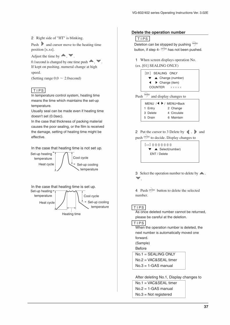
37
VG-602/402 series Operating Instructions Ver. 3.02E
2 Right side of "HT" is blinking.
Push and cursor move to the heating time position [x.xs].
Adjust the time by , .0.1second is changed by one time push , .If kept on pushing, numeral change at high speed.(Setting range 0.0 〜 2.0second)
T I PSIn temperature control system, heating time
means the time which maintains the set-up
temperature.
Usually seal can be made even if heating time
doesn't set (0.0sec).
In the case that thickness of packing material
causes the poor sealing, or the film is received
the damage, setting of heating time might be
effective.
In the case that heating time is not set up.
In the case that heating time is set up.
Delete the operation number
T I PS
Deletion can be stopped by pushing
button, if step 4- has not been pushed.
1 When screen displays operation No.(ex. [01] SEALING ONLY)
SEALING ONLY
Change (number)
Change (item)
COUNTER x x x x x
Push and display changes to
MENU / / MENU=Back
1 Entry 2 Change
3 Delete 4 Circulate
5 Drain 6 Maintain
2 Put the cursor to 3 Delete by , and push to decide. Display changes to
Select(number)
ENT / Delete
3 Select the operation number to delete by , .
4 Push button to delete the selected number.
T I PSAs once deleted number cannot be returned,
please be careful at the deletion.
T I PSWhen the operation number is deleted, the
next number is automatically moved one
forward.
(Sample)
Before
No.1 = SEALING ONLY
No.2 = VAC&SEAL timer
No.3 = 1-GAS manual
After deleting No.1, Display changes to
No.1 = VAC&SEAL timer
No.2 = 1-GAS manual
No.3 = Not registered
Heat cycle
Cool cycle
Heat cycle
Cool cycle
Heating time
Set-up heatingtemperature
Set-up coolingtemperature
Set-up heatingtemperature
Set-up coolingtemperature

38
VG-602/402 series Operating Instructions Ver. 3.02E
T I PSIf the registered number is only [01], you
cannot delete it.
When you try to delete a message "You can
not delete all" is displayed.
Select the operation number1 When screen displays operation No.(ex. [01] SEALING ONLY)
SEALING ONLY
Change (number)
Change (item)
COUNTER x x x x x
Push or button.
Select / Enter / Change the sealing method1 When screen displays operation No.(ex. [01] SEALING ONLY)
SEALING ONLY
Change (number)
Change (item)
COUNTER x x x x x
Push and display changes to
MENU / / MENU=Back
1 Entry 2 Change
3 Delete 4 Circulate
5 Drain 6 Maintain
2-1 Entry : Put the cursor to "1 Entry" by , and push
The next operation is 3.
2-2 Change of contents : Put the cursor to "2
Change" by , and push Display changes to the for selecting the
operation number. Then select the number by , and push .
3 Display changes to
METHOD ENT=OK
1 SEAL 2 VAC & SEAL
3 1-GAS 4 n-GAS
5 CIRCULATE
(5 CIRCULATE is displayed only in effect)
4 Put the cursor on 1 SEALING ONLY, 2 VAC&SEAL, 3 1-GAS, 4 n-GAS or 5
CIRCULATE, by , and push Then display changes to the one for setting heating temperature, time and cooling temperature.
T I PSWhen select 2~4 (except), please refer to
"Select the vacuum pattern" in page 42.

39
VG-602/402 series Operating Instructions Ver. 3.02E
Select the gas circulationProcess 1-3 is necessary only at the first set of gas circulation, or in the state of circulation / off.1 Open the flame cover.
2 Turn the circulation switching knob to the vertical position as following illustration.
3 Close the frame cover to the initial position.
4 When the operation number is displayed,
SEALING ONLY
Change (number)
Change (item)
COUNTER x x x x x
Push the button, display changes to
MENU / / MENU=Back
1 Entry 2 Change
3 Delete 4 Circulate
5 Drain 6 Maintain
5 Put the cursor to "4 Circulate" by , and push .
6 Display changes to the one for selecting the gas circulation.
Put the cursor to "2 ON" by and push .
(Brinking number ( ) is selected now.)
CIRCULATE Select
ENT=Go
1 OFF 2 ON
(At the first set of gas circulation, cursor is under the "1 OFF")
7 Then display changes to the one for selecting the vacuum method.Select to one from 3 pattern :1 Manual, 2 Time,3 Gauge.
VAC TYPE Select
CIRCULATE
1 Manual 2 Time 3 Gauge
8 About the next setting, please refer to the following page
1 Manual : page 382 Time : page 393 Gauge : page 40

40
VG-602/402 series Operating Instructions Ver. 3.02E
Set the gas circulation / vacuum by manual1 Refer "Select the gas circulation" (page 37).After the process of 6, put the cursor to "1
Manual" by and push .
VAC TYPE Select
CIRCULATE
1 Manual 2 Time 3 Gauge
2 Display change to
( part is blinking.)
Change Move
₁V MANUAL G xx.xsec GCT xx.xsec G xx.xsec HT xxOF x.xs CT
( part is blinking.)
Change Move
₁V MANUAL G xx.xsec GCT xx.xsec G xx.xsec HT xxOC x.xs CT
Cursor is under the position for setting the first gas flushing time.
Adjust the value by , .(Setting range : 0.1 〜 99.9seconds)
3 Then set the gas circulating time.
Put the cursor to "GCT xx.xsec" by , and set the time by , .(Setting range : 0.1 〜 99.9seconds)
( part is blinking.)
Change Move
₁V MANUAL G xx.xsec GCT xx.xsec G xx.xsec HT xxOF x.xs CT
( part is blinking.)
Change Move
₁V MANUAL G xx.xsec GCT xx.xsec G xx.xsec HT xxOC x.xs CT
4 Set the second gas flushing time.
Put the cursor to "Gxx.xsec" by and set the time by , .(Setting range : 0.1 〜 99.9seconds)
( part is blinking.)
Change Move
₁V MANUAL G xx.xsec GCT xx.xsec G xx.xsec HT xxOF x.xs CT
( part is blinking.)
Change Move
₁V MANUAL G xx.xsec GCT xx.xsec G xx.xsec HT xxOC x.xs CT

41
VG-602/402 series Operating Instructions Ver. 3.02E
Set the gas circulation / vacuum by timer1 Refer "Select the gas circulation" (page 37).After the process of 6, put the cursor to "2
Time" by and push .
VAC TYPE Select
CIRCULATE
1 Manual 2 Time 3 Gauge
2 Display changes to
( part is blinking.)
Change Move
₁VT xx.xsec G xx.xsec GCT xx.xsec G xx.xsec HT xxOF x.xs CT
( part is blinking.)
Change Move
₁VT xx.xsec G xx.xsec GCT xx.xsec G xx.xsec HT xxOC x.xs CT
Cursor is under the position for setting the vacuum time."1 VT" = 1st Vacuum Time
Adjust the value by , .(Setting range : 0.1 〜 99.9seconds)
3 Then set the first gas flushing time.
Put the cursor to "Gxx.xsec" by and set the time by , .(Setting range : 0.1 〜 99.9seconds)
( part is blinking.)
Change Move
₁VT xx.xsec G xx.xsec GCT xx.xsec G xx.xsec HT xxOF x.xs CT
( part is blinking.)
Change Move
₁VT xx.xsec G xx.xsec GCT xx.xsec G xx.xsec HT xxOC x.xs CT
4 Then set the gas circulating time.
Put the cursor to "GCTxx.xsec" by and set the time by , .(Setting range : 0.1 〜 99.9seconds)
( part is blinking.)
Change Move
₁VT xx.xsec G xx.xsec GCT xx.xsec G xx.xsec HT xxOF x.xs CT
( part is blinking.)
Change Move
₁VT xx.xsec G xx.xsec GCT xx.xsec G xx.xsec HT xxOC x.xs CT
5 Set the second gas flushing time.
Put the cursor to "Gxx.xsec" by and set the time by , .(Setting range : 0.1 〜 99.9seconds)
( part is blinking.)
Change Move
₁VT xx.xsec G xx.xsec GCT xx.xsec G xx.xsec HT xxOF x.xs CT
( part is blinking.)
Change Move
₁VT xx.xsec G xx.xsec GCT xx.xsec G xx.xsec HT xxOC x.xs CT

42
VG-602/402 series Operating Instructions Ver. 3.02E
Set the gas circulation / vacuum by gauge1 Refer "Select the gas circulation" (page 37).After the process of 6, put the cursor to "3 Gauge"
by and push .
VAC TYPE Select
CIRCULATE
1 Manual 2 Time 3 Gauge
2 Display changes to
( part is blinking.)
Change Move
₁VG - xxxkpa G xx.xsec GCT xx.xsec G xx.xsec HT xxOF x.xs CT
( part is blinking.)
Change Move
₁VG - xxxkpa G xx.xsec GCT xx.xsec G xx.xsec HT xxOC x.xs CT
Cursor is under the position for setting the vacuum degree."1VG" = 1st Vacuum Gauge
Adjust the value by , .(Setting range : -1 〜 -100kpa)
3 Then set the first gas flushing time.
Put the cursor to "Gxx.xsec" by and set the time by , .(Setting range : 0.1 〜 99.9seconds)
( part is blinking.)
Change Move
₁VG - xxxkpa G xx.xsec GCT xx.xsec G xx.xsec HT xxOF x.xs CT
( part is blinking.)
Change Move
₁VG - xxxkpa G xx.xsec GCT xx.xsec G xx.xsec HT xxOC x.xs CT
4 Then set the gas circulating time.
Put the cursor to "GCTxx.0sec" by and set the time by , .(Setting range : -1 〜 -100kpa)
( part is blinking.)
Change Move
₁VG - xxxkpa G xx.xsec GCT xx.xsec G xx.xsec HT xxOF x.xs CT
( part is blinking.)
Change Move
₁VG - xxxkpa G xx.xsec GCT xx.xsec G xx.xsec HT xxOC x.xs CT
5 Set the second gas flushing time.
Put the cursor to "Gxx.xsec" by and set the time by , .(Setting range : 0.1 〜 99.9seconds)
( part is blinking.)
Change Move
₁VG - xxxkpa G xx.xsec GCT xx.xsec G xx.xsec HT xxOF x.xs CT
( part is blinking.)
Change Move
₁VG - xxxkpa G xx.xsec GCT xx.xsec G xx.xsec HT xxOC x.xs CT

43
VG-602/402 series Operating Instructions Ver. 3.02E
Reset the gas circulation1 Open the flame cover.
2 Turn the circulation switching knob to the horizontal position as following illustration.
3 Close the frame cover to the initial position.
4 When the operation number is displayed,
SEALING ONLY
Change (number)
Change (item)
COUNTER x x x x x
Push the button, display changes to
MENU / / MENU=Back
1 Entry 2 Change
3 Delete 4 Circulate
5 Drain 6 Maintain
5 Put the cursor to "4 Circulate" by , and push .Display change to
(Brinking number ( ) is selected now.)
CIRCULATE Select
ENT=Go
1 OFF 2 ON
6 Display changes to the one for selecting the gas circulation.
Put the cursor to "1 OFF" by and push .
(Brinking number ( ) is selected now.)
CIRCULATE Select
ENT=Go
1 OFF 2 ON
Set the vacuum degreeRefer to "Select the vacuum pattern" in page 42. Select "2 VAC&SEAL". Put the cursor to
"3 Gauge" and push . Display changes to
Change Move
1VG - xxxkpa
HT xxOF x.xs CT
( part is blinking.)
Change Move
1VG - xxxkpa
HT xxOC x.xs CT
( part is blinking.)
Cursor is under the position of vacuum degree.
Adjust the value by , .(Setting range : -1 〜 -100kpa)
Set the vacuum timeRefer to "Select the vacuum pattern" in page 42, and select "VAC&SEAL".
Put the cursor to "2 Time" and push .Display changes to
Change Move
1VT xx.xsec
HT xxOF x.xs CT
( part is blinking.)
Change Move
1VT xx.xsec
HT xxOC x.xs CT
( part is blinking.)
Adjust the value by , .(Setting range : 0.1 〜 99.9seconds)

44
VG-602/402 series Operating Instructions Ver. 3.02E
Select the vacuum pattern1 When screen displays operation No.(ex. [01] SEALING ONLY)
SEALING ONLY
Change (number)
Change (item)
COUNTER x x x x x
Push and display changes to
MENU / / MENU=Back
1 Entry 2 Change
3 Delete 4 Circulate
5 Drain 6 Maintain
2-1 Entry : Put the cursor to "1 Entry" by , and push .
The next operation is 3.
2-2 Change the contents : Put the cursor to "2
Change" by , and push .
3 Display changes by , to
METHOD ENT=OK
1 SEAL 2 VAC & SEAL
3 1-GAS 4 n-GAS
5 CIRCULATE
(5 CIRCULATE is displayed only in effect)
4 Put the cursor to "2 VAC&SEAL" and .Display changes to
VAC TYPE Select
VAC & SEAL
1 Manual 2 Time 3 Gauge
Select the one from 1Manual, 2 Time, 3 Gauge
by , and decide by .
Then display changes to the one for setting the heating temperature, time, and cooling temperature. Please set them at the suitable value.
Set the drain ON / OFF1 When screen displays operation No.(ex. [01] SEALING ONLY)
SEALING ONLY
Change (number)
Change (item)
COUNTER x x x x x
Push and display changes to
MENU / / MENU=Back
1 Entry 2 Change
3 Delete 4 Circulate
5 Drain 6 Maintain
2 Put the cursor to "5 Drain" by and push to decide.
(Brinking number ( ) is selected now.)
DRAIN Select
ENT=Go
1 OFF 2 ON
3 Put the cursor to 1 OFF or 2ON by and push
to decide.

45
VG-602/402 series Operating Instructions Ver. 3.02E
Select the maintenance mode1 When screen displays operation No.(ex. [01] SEALING ONLY)
SEALING ONLY
Change (number)
Change (item)
COUNTER x x x x x
Push and display changes to
MENU / / MENU=Back
1 Entry 2 Change
3 Delete 4 Circulate
5 Drain 6 Maintain
2 Put the cursor to "6 Maintain" by , .Press and display changes to the one for selecting maintenance mode. ON or OFF.(Initial state OFF as the following illustration.)
(Brinking number ( ) is selected now.)
MAINTENANCE
Select
ENT=Go
1 OFF 2 ON
3 Put the cursor to 2 ON by , and press .
Display changes to maintenance mode.
( means ON means OFF)
MAINTENANCE
X
Y
Refer to page 110 about the message of maintenance mode.
Set the cooling temperature1-1 In the present operation number :
Press display changes to the one for setting each value and read 2.
Change Move
HT xxOF x.xs CT
( part is blinking.)
Change Move
HT xxOC x.xs CT
( part is blinking.)
1-2 In the another operation number :Refer to "Select the operation number" in page 36, and select the number.
Then press and read 2.
2 Right side of "HT" is blinking.
In this condition, push two times.Cursor moves to the right side of "CT" (blinking).
Adjust the value by , .
One degree is changed by one time push.If kept on pushing, numeral change at high speed.(Setting range 100OF 〜 heating temperature)(Setting range 40OC 〜 heating temperature)
T I PSIf cooling temperature is set extremely highly,
strong and beautiful seal cannot be made.
Please set the temperature suitable for the film.
Warning
If the extreme setting is going to be made, the
following warning is displayed on a liquid
crystal screen for 4 seconds.
WARNING!
Set cool temp
low enough

46
VG-602/402 series Operating Instructions Ver. 3.02E
Select the 1 time gas flushing1 When screen displays operation No.(ex. [01] SEALING ONLY)
SEALING ONLY
Change (number)
Change (item)
COUNTER x x x x x
Push and display changes to
MENU / / MENU=Back
1 Entry 2 Change
3 Delete 4 Circulate
5 Drain 6 Maintain
2-1 Entry : Put the cursor to "1 Entry" by and
push .
The next operation is 3.
2-2 Change of contents : Put the cursor to "2
Change" by , and push .
Display changes to the one for selecting the operation number. Then select the number by
, and push .
3 Display changes to
METHOD ENT=OK
1 SEAL 2 VAC & SEAL
3 1-GAS 4 n-GAS
5 CIRCULATE
(5 CIRCULATE is displayed only in effect)
4 Put the cursor to "3 1-GAS" by , and push .
Display changes to
VAC TYPE Select
VAC & SEAL
1 Manual 2 Time 3 Gauge
5 Select the vacuum method from 1 Manual,
2 Time, 3 Gauge by , and push .
Display changes to the one for setting the heating temperature, time and cooling temperature.Please set the suitable value.
T I PSPlease refer "Select the vacuum pattern" in
page 42.

47
VG-602/402 series Operating Instructions Ver. 3.02E
Set the 1 time gas flushing timer1 Refer the explanation in page 44 and select the 1 time gas flushing.Then select the vacuum pattern as the instruction in page 42.
2 Put the cursor to the position for setting the gas flushing time.
2-1 When you select "1 Manual",the cursor is already under the position for setting the gas flushing time.
( part is blinking.)
Change Move
₁V MANUAL G xx.xsec
HT xxOF x.xs CT
( part is blinking.)
Change Move
₁V MANUAL G xx.xsec
HT xxOC x.xs CT
2-2 When you select "2 Time" or "3 Gauge", put the cursor is under the position for setting
the flushing time by , .
In the case of "2 Time"
( part is blinking.)
Change Move
₁VT xx.xsec G xx.xsec
HT xxOF x.xs CT
( part is blinking.)
Change Move
₁VT xx.xsec G xx.xsec
HT xxOC x.xs CT
3 Set the gas flushing time by , .
(Setting range : 0.1 〜 99.9 seconds)
Select the n-times gas flushing1 When screen displays operation No.(ex. [01] SEALING ONLY)
SEALING ONLY
Change (number)
Change (item)
COUNTER x x x x x
Push and display changes to
MENU / / MENU=Back
1 Entry 2 Change
3 Delete 4 Circulate
5 Drain 6 Maintain
2-1 Entry : put the cursor to "1 Entry" by , and push .
The next operation is 3.
2-2 Change of contents : Put the cursor to "2
Change" by , and push .
Display changes to the one for selecting the operation number. Then select the number by
, and push .
3 Display changes to
METHOD ENT=OK
1 SEAL 2 VAC & SEAL
3 1-GAS 4 n-GAS
5 CIRCULATE
(5 CIRCULATE is displayed only in effect)
4 Put the cursor to "4 n-GAS" by , and push .
Display changes to
VAC TYPE Select
n-GAS
1 Manual 2 Time 3 Gauge
5 Select the vacuum method from 1 Manual,
2 Time, 3 Gauge by , and push .
6 About the next setting, please refer "Set the n-time gas flushing timer" in page 45.

48
VG-602/402 series Operating Instructions Ver. 3.02E
Set the n-times gas flushing timer
T I PSTwo pattern's gas flushing time can be set.
1 : from the first time to (n-1) time
2 : n (the last) time
Ex. 5 times gas flushing :
1st and 5th time can be set.
2nd, 3rd, 4th time are same with 1st
1 Refer the explanation in page 45 and select the n-times gas flushing.Then select the vacuum pattern as the instruuction in page 42.
2-1 When you select "1 Manual"2-1-1 Set the 1st (to n-1th) gas flushing time.
( part is blinking.)
Change Move
₁V MANUAL G xx.xsec xxV MANUAL G xx.xsec HT xxOF x.xs CT
( part is blinking.)
Change Move
₁V MANUAL G xx.xsec xxV MANUAL G xx.xsec HT xxOC x.xs CT
Set the gas flushing time by , .
(Setting range : 0.1 〜 99.9 seconds)
2-1-2 Put the cursor (by ), to the position
for setting the number of vacuum and gas flushing times. (the left of VT)
( part is blinking.)
Change Move
₁V MANUAL G xx.xsec xxV MANUAL G xx.xsec HT xxOF x.xs CT
( part is blinking.)
Change Move
₁V MANUAL G xx.xsec xxV MANUAL G xx.xsec HT xxOC x.xs CT
Set the number of vacuum and gas flushing
times by , .
(Setting range : 2 〜 99 times)
2-1-3 Put the cursor (by ), to the position
for setting the n th (last) gas flushing time.
( part is blinking.)
Change Move
₁V MANUAL G xx.xsec xxV MANUAL G xx.xsec HT xxOF x.xs CT
( part is blinking.)
Change Move
₁V MANUAL G xx.xsec xxV MANUAL G xx.xsec HT xxOC x.xs CT
Set the gas flushing time by , .
(Setting range : 0.1 〜 99.9 seconds)
2-2 When you select "2 Time"2-2-1 Set the 1st (to n-1th) vacuum time.
( part is blinking.)
Change Move
₁VT xx.xsec G xx.xsec xxVT xx.xsec G xx.xsec HT xxOF x.xs CT
( part is blinking.)
Change Move
₁VT xx.xsec G xx.xsec xxVT xx.xsec G xx.xsec HT xxOC x.xs CT
Set the vacuum time by , .
(Setting range : 0.1 〜 99.9 seconds)

49
VG-602/402 series Operating Instructions Ver. 3.02E
2-2-2 Set the 1st (to n-1th) vacuum time.
( part is blinking.)
Change Move
₁VT xx.xsec G xx.xsec xxVT xx.xsec G xx.xsec HT xxOF x.xs CT
( part is blinking.)
Change Move
₁VT xx.xsec G xx.xsec xxVT xx.xsec G xx.xsec HT xxOC x.xs CT
Set the gas flushing time by , .
(Setting range : 0.1 〜 99.9 seconds)
2-2-3 Put the cursor (by ), to the position
for setting the n th (last) gas flushing time. (the left of VT)
︵ part is bℓinking.︶
Change Move ₁VT xx.xsec G xx.xsec xxVT xx.xsec G xx.xsec HT xxOF x.xs CT
︵ part is bℓinking.︶
Change Move ₁VT xx.xsec G xx.xsec xxVT xx.xsec G xx.xsec HT xxOC x.xs CT
Set the number of vacuum and gas flushing
times by , .
(Setting range : 2 〜 99 times)
2-2-4 Set the n th vacuum time.
( part is blinking.)
Change Move 1VT xx.xsec G xx.xsec xxVT xx.xsec G xx.xsec HT xxOF x.xs CT xxOF
( part is blinking.)
Change Move
₁VT xx.xsec G xx.xsec xxVT xx.xsec G xx.xsec HT xxOC x.xs CT
Set the vacuum time by , .
(Setting range : 0.1 〜 99.9 seconds)
2-2-5 Set the n th gas flushing time.
( part is blinking.)
Change Move
₁VT xx.xsec G xx.xsec xxVT xx.xsec G xx.xsec HT xxOF x.xs CT
( part is blinking.)
Change Move
₁VT xx.xsec G xx.xsec xxVT xx.xsec G xx.xsec HT xxOC x.xs CT
Set the gas flushing times by , .
(Setting range : 0.1 〜 99.9 seconds)
2-3 When you select "3 Gauge"2-3-1 Set the 1st (to n-1th) vacuum degree.
( part is blinking.)
Change Move
₁VG ︲ xxxkpa G xx.xsec xxVG ︲ xxxkpa G xx.xsec HT xxOF x.xs CT
( part is blinking.)
Change Move
₁VG ︲ xxxkpa G xx.xsec xxVG ︲ xxxkpa G xx.xsec HT xxOC x.xs CT
Set the vacuum degree by , .
(Setting range : -1 〜 -100 kpa)

50
VG-602/402 series Operating Instructions Ver. 3.02E
2-3-2 Set the 1st (to n-1th) gas flushing time.
( part is blinking.)
Change Move
₁VG ︲ xxxkpa G xx.xsec xxVG ︲ xxxkpa G xx.xsec HT xxOF x.xs CT
( part is blinking.)
Change Move
₁VG ︲ xxxkpa G xx.xsec xxVG ︲ xxxkpa G xx.xsec HT xxOC x.xs CT
Set the gas flushing time by , .
(Setting range : -1 〜 -100 kpa)
2-3-3 Put the cursor (by ), to the position
for setting the n th (last) gas flushing time. (the left of VT)
( part is blinking.)
Change Move
₁VG ︲ xxxkpa G xx.xsec xxVG ︲ xxxkpa G xx.xsec HT xxOF x.xs CT
( part is blinking.)
Change Move
₁VG ︲ xxxkpa G xx.xsec xxVG ︲ xxxkpa G xx.xsec HT xxOC x.xs CT
Set the number of vacuum and gas flushing
time by , .
(Setting range : 2 〜 99 times)
2-3-4 Set the n th vacuum degree.
( part is blinking.)
Change Move
₁VG ︲ xxxkpa G xx.xsec xxVG ︲ xxxkpa G xx.xsec HT xxOF x.xs CT
( part is blinking.)
Change Move
₁VG ︲ xxxkpa G xx.xsec xxVG ︲ xxxkpa G xx.xsec HT xxOC x.xs CT
Set the vacuum degree by , .
(Setting range : -1 〜 -100 kpa)
2-3-5 Set the n th gas flushing time.
( part is blinking.)
Change Move
₁VG ︲ xxxkpa G xx.xsec xxVG ︲ xxxkpa G xx.xsec HT xxOF x.xs CT
( part is blinking.)
Change Move
₁VG ︲ xxxkpa G xx.xsec xxVG ︲ xxxkpa G xx.xsec HT xxOC x.xs CT
Set the gas flushing time by , .
(Setting range : 0.0 〜 99.9 seconds)
3 Display change to the one for setting the heating temperature, time and cooling temperature.Please set the suitable value.

51
VG-602/402 series Operating Instructions Ver. 3.02E
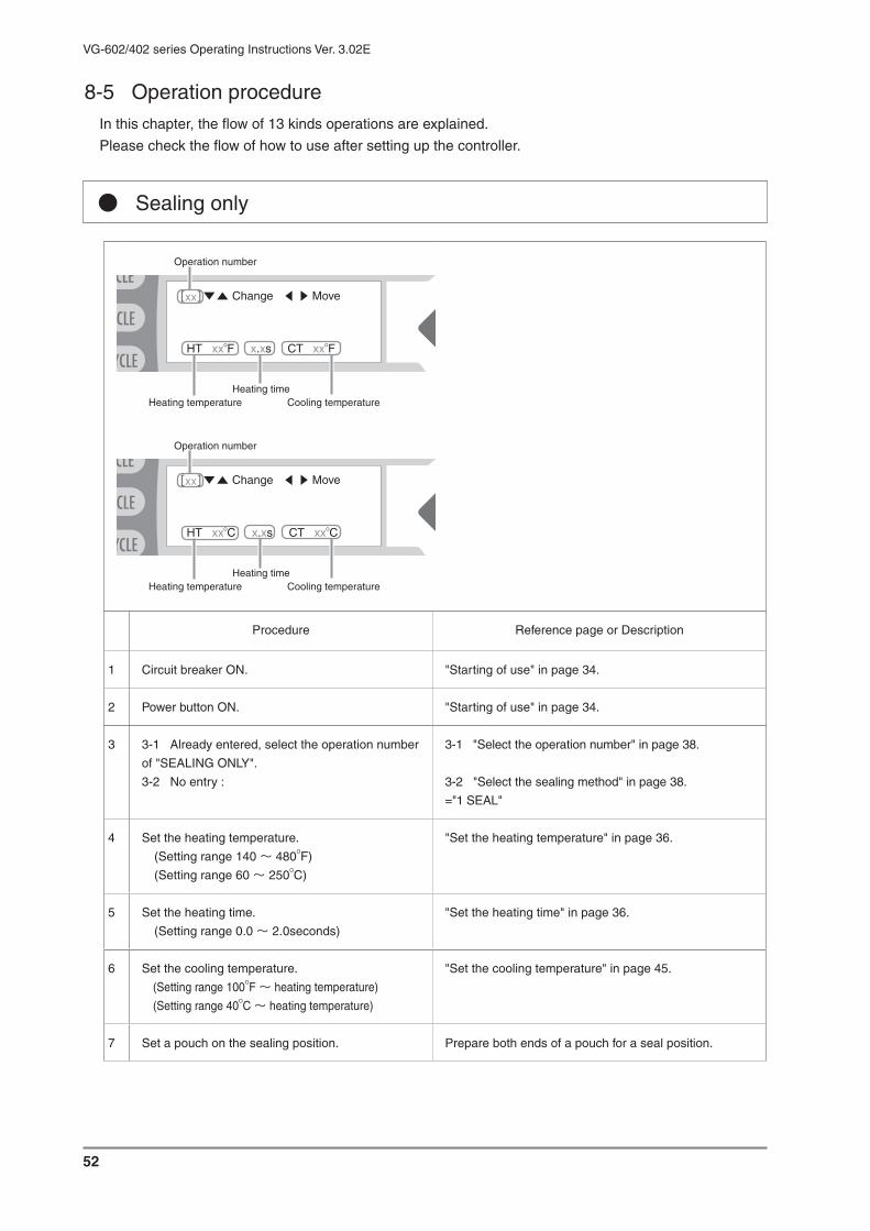
52
VG-602/402 series Operating Instructions Ver. 3.02E
● Sealing only
Operation number
Heating temperatureHeating time
Cooling temperature
Change Move
HT xxOF x.xs CT xxOF
Operation number
Heating temperatureHeating time
Cooling temperature
Change Move
HT xxOC x.xs CT xxOC
Procedure Reference page or Description
1 Circuit breaker ON. "Starting of use" in page 34.
2 Power button ON. "Starting of use" in page 34.
3 3-1 Already entered, select the operation number
of "SEALING ONLY".
3-2 No entry :
3-1 "Select the operation number" in page 38.
3-2 "Select the sealing method" in page 38.
="1 SEAL"
4 Set the heating temperature.
(Setting range 140 〜 480OF)
(Setting range 60 〜 250OC)
"Set the heating temperature" in page 36.
5 Set the heating time.
(Setting range 0.0 〜 2.0seconds)
"Set the heating time" in page 36.
6 Set the cooling temperature.
(Setting range 100OF 〜 heating temperature)
(Setting range 40OC 〜 heating temperature)
"Set the cooling temperature" in page 45.
7 Set a pouch on the sealing position. Prepare both ends of a pouch for a seal position.
8-5 Operation procedureIn this chapter, the flow of 13 kinds operations are explained.
Please check the flow of how to use after setting up the controller.
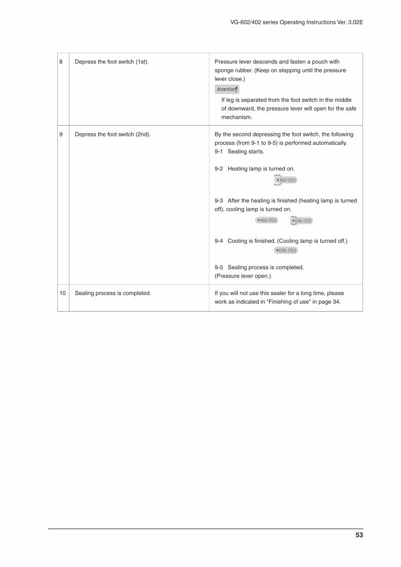
53
VG-602/402 series Operating Instructions Ver. 3.02E
8 Depress the foot switch (1st). Pressure lever descends and fasten a pouch with
sponge rubber. (Keep on stepping until the pressure
lever close.)
Attention
If leg is separated from the foot switch in the middle
of downward, the pressure lever will open for the safe
mechanism.
9 Depress the foot switch (2nd). By the second depressing the foot switch, the following
process (from 9-1 to 9-5) is performed automatically.
9-1 Sealing starts.
9-2 Heating lamp is turned on.
9-3 After the heating is finished (heating lamp is turned
off), cooling lamp is turned on.
9-4 Cooling is finished. (Cooling lamp is turned off.)
9-5 Sealing process is completed.
(Pressure lever open.)
10 Sealing process is completed. If you will not use this sealer for a long time, please
work as indicated in "Finishing of use" in page 34.

54
VG-602/402 series Operating Instructions Ver. 3.02E
● Vacuum (manual) and Sealing
Operation number
Heating temperatureHeating time
Cooling temperature
Vacuum pattern = manual
Change Move
1V MANUAL
HT xxOF x.xs CT xxOF
Operation number
Heating temperatureHeating time
Cooling temperature
Vacuum pattern = manual
Change Move
1V MANUAL
HT xxOC x.xs CT xxOC
Procedure Reference page or Description
1 Circuit breaker ON. "Starting of use" in page 34.
2 Power button ON. "Starting of use" inpage 34.
3 3-1 Already entered, select the operation number
of "VAC&SEAL manual".
3-2 No entry :
3-1 "Select the operation number" in page 38.
3-2 "Select the sealing method" in page 38
= "2 VAC&SEAL"
"Select the vacuum pattern" in page 44.
= "1 Manual"
4 Set the heating temperature.
(Setting range 140 〜 480OF)
(Setting range 60 〜 250OC)
"Set the heating temperature" in page 36.
5 Set the heating time.
(Setting range 0.0 〜 2.0seconds)
"Set the heating time" in page 36.
6 Set the cooling temperature.
(Setting range 100OF 〜 heating temperature)
(Setting range 40OC 〜 heating temperature)
"Set the cooling temperature" in page 45.
7 Depress the foot switch (1st) Nozzle comes forward.
8 Set a pouch on the sealing position. Insert the nozzle in a pouch, and set it on the sealing
position.

55
VG-602/402 series Operating Instructions Ver. 3.02E
9 Depress the foot switch (2nd). Pressure lever descends and fasten a pouch with
sponge rubber. (Keep on stepping until the pressure
lever close.)
Attention
If leg is separated from the foot switch in the middle
of downward, the pressure lever will open for the safe
mechanism.
10 Depress the foot switch (3rd). Vacuum process starts.Vacuum lamp is turned on.
11 When the sufficient vacuum is done, depress the
foot switch (4th).
By the fourth depressing the foot switch, the following
process (from 11-1 to 11-6) will be performed
automatically.
11-1 Vacuum is finished.
11-2 Nozzle returns.
11-3 Pressure lever close and sealing starts.
Heating lamp is turned on.
11-4 After the heating is finished (heating lamp is
turned off), cooling lamp is turned on.
11-5 Cooling is finished. (Cooling lamp is turned off.)
11-6 Sealing process is completed.
(Pressure lever opens and nozzle comes forward.)
12 Sealing process is completed. If you will not use this sealer for a long time, please
work as indicated in "Finishing of use" in page 34.

56
VG-602/402 series Operating Instructions Ver. 3.02E
● Vacuum (timer) and Sealing
Operation number
Heating temperatureHeating time
Cooling temperature
Vacuum pattern = timer
and set-up value
Change Move
1VT xx.xsec
HT xxOF x.xs CT xxOF
Operation number
Heating temperatureHeating time
Cooling temperature
Vacuum pattern = timer
and set-up value
Change Move
1VT xx.xsec
HT xxOC x.xs CT xxOC
Procedure Reference page or Description
1 Circuit breaker ON. "Starting of use" in page 34.
2 Power button ON. "Starting of use" in page 34.
3 3-1 Already entered, select the operation number
of "VAC&SEAL timer".
3-2 No entry :
3-1 "Select the operation number" in page 38.
3-2 "Select the sealing method" in page 38.
= "2 VAC&SEAL"
"Select the vacuum pattern" in page 44.
= "2 Time"
4 Set the vacuum time.
(Setting range 0.1 〜 99.9seconds)
"Set the vacuum time" in page 43.
5 Set the heating temperature.
(Setting range 140 〜 480OF)
(Setting range 60 〜 250OC)
"Set the heating temperature" in page 36.
6 Set the heating time.
(Setting range 0.0 〜 2.0seconds)
"Set the heating time" in page 36.
7 Set the cooling temperature.
(Setting range 100OF 〜 heating temperature)
(Setting range 40OC 〜 heating temperature)
"Set the cooling temperature" in page 45.
8 Depress the foot switch (1st) Nozzle comes forward.
9 Set a pouch on the sealing position. Insert the nozzle in a pouch, and set it on the sealing
position.

57
VG-602/402 series Operating Instructions Ver. 3.02E
10 Depress the foot switch (2nd). Pressure lever descends and fasten a pouch with
sponge rubber. (Keep on stepping until the pressure
lever close.)
Attention
If leg is separated from the foot switch in the middle
of downward, the pressure lever will open for the safe
mechanism.
11 Depress the foot switch (3rd). By the third depressing the foot switch, the following
process (from 11-1 to 11-7) will be performed
automatically.
11-1 Vacuum starts. Vacuum lamp is turned on.
11-2 When the set-up time is passed, vacuum is
finished. Vacuum lamp is turned off.
11-3 Nozzle returns.
11-4 Pressure lever close and sealing starts.
Heating lamp is turned on.
11-5 After the heating is finished (heating lamp is
turned off), cooling lamp is turned on.
11-6 Cooling is finished. (Cooling lamp is turned off.)
11-7 Sealing process is completed.
(Pressure lever opens and nozzle comes forward.)
12 Sealing process is completed. If you will not use this sealer for a long time, please
work as indicated in "Finishing of use" in page 34.

58
VG-602/402 series Operating Instructions Ver. 3.02E
● Vacuum (gauge) and Sealing
Operation number
Heating temperatureHeating time
Cooling temperature
Vacuum pattern = gauge
and set-up value
Change Move
1VG- xxkpa
HT xxOF x.xs CT xxOF
Operation number
Heating temperatureHeating time
Cooling temperature
Vacuum pattern = gauge
and set-up value
Change Move
1VG- xxkpa
HT xxOC x.xs CT xxOC
Procedure Reference page or Description
1 Circuit breaker ON. "Starting of use" in page 34
2 Power button ON. "Starting of use" in page 34.
3 3-1 Already entered, select the operation number
of "VAC&SEAL gauge".
3-2 No entry :
3-1 "Select the operation number" in page 38.
3-2 "Select the sealing method" in page 38.
= "2 VAC&SEAL"
"Select the vacuum pattern" in page 44.
= "3 Gauge"
4 Set the vacuum degree.
(Setting range -1 〜 -100kpa)
"Set the vacuum degree" in page 43.
5 Set the heating temperature.
(Setting range 140 〜 480OF)
(Setting range 60 〜 250OC)
"Set the heating temperature" in page 36
6 Set the heating time.
(Setting range 0.0 〜 2.0seconds)
"Set the heating time" in page 36.
7 Set the cooling temperature.
(Setting range 100OF 〜 heating temperature)
(Setting range 40OC 〜 heating temperature)
"Set the cooling temperature" in page 45.
8 Depress the foot switch (1st) Nozzle comes forward.
9 Set a pouch on the sealing position. Insert the nozzle in a pouch, and set it on the sealing
position.
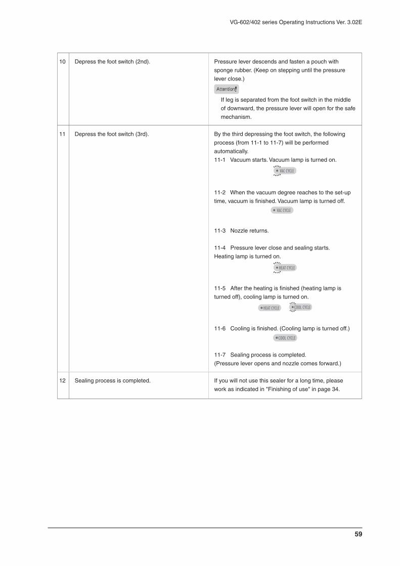
59
VG-602/402 series Operating Instructions Ver. 3.02E
10 Depress the foot switch (2nd). Pressure lever descends and fasten a pouch with
sponge rubber. (Keep on stepping until the pressure
lever close.)
Attention
If leg is separated from the foot switch in the middle
of downward, the pressure lever will open for the safe
mechanism.
11 Depress the foot switch (3rd). By the third depressing the foot switch, the following
process (from 11-1 to 11-7) will be performed
automatically.
11-1 Vacuum starts. Vacuum lamp is turned on.
11-2 When the vacuum degree reaches to the set-up
time, vacuum is finished. Vacuum lamp is turned off.
11-3 Nozzle returns.
11-4 Pressure lever close and sealing starts.
Heating lamp is turned on.
11-5 After the heating is finished (heating lamp is
turned off), cooling lamp is turned on.
11-6 Cooling is finished. (Cooling lamp is turned off.)
11-7 Sealing process is completed.
(Pressure lever opens and nozzle comes forward.)
12 Sealing process is completed. If you will not use this sealer for a long time, please
work as indicated in "Finishing of use" in page 34.

60
VG-602/402 series Operating Instructions Ver. 3.02E
● [1 time] Vacuum (manual), Gas flushing and Sealing
Change Move
1V MANUAL G xx.xsec
HT xxOF x.xs CT xxOF
Operation number
Heating temperatureHeating time
Cooling temperature
Vacuum pattern = manual
Gas flushing time
Operation number
Heating temperatureHeating time
Cooling temperature
Vacuum pattern = manual
Gas flushing time
Change Move
1V MANUAL G xx.xsec
HT xxOC x.xs CT xxOC
Procedure Reference page or Description
1 Circuit breaker ON. "Starting of use" in page 34.
2 Power button ON. "Starting of use" in page 34.
3 3-1 Already entered, select the operation number
of "1-GAS manual".
3-2 No entry :
3-1 "Select the operation number" in page 38.
3-2 "Select the 1 time gas flushing" in page 46.
= "3 1-GAS"
"Select the vacuum pattern" in page 44.
= "1 Manual"
4 Set the gas flushing time.
(Setting range 0.1 〜 99.9seconds)
"Set the 1 time gas flushing timer" in page 47.
5 Set the heating temperature.
(Setting range 140 〜 480OF)
(Setting range 60 〜 250OC)
"Set the heating temperature" in page 36.
6 Set the heating time.
(Setting range 0.0 〜 2.0seconds)
"Set the heating time" in page 36.
7 Set the cooling temperature.
(Setting range 100OF 〜 heating temperature)
(Setting range 40OC 〜 heating temperature)
"Set the cooling temperature" in page 45.
8 Depress the foot switch (1st) Nozzle comes forward.
9 Set a pouch on the sealing position. Insert the nozzle in a pouch, and set it on the sealing
position.

61
VG-602/402 series Operating Instructions Ver. 3.02E
10 Depress the foot switch (2nd). Pressure lever descends and fasten a pouch with
sponge rubber. (Keep on stepping until the pressure
lever close.)
Attention
If leg is separated from the foot switch in the middle
of downward, the pressure lever will open for the safe
mechanism.
11 Depress the foot switch (3rd). Vacuum process starts.Vacuum lamp is turned on.
12 When the sufficient vacuum is done, depress the
foot switch (4th).
By the fourth depressing the foot switch, the following
process (from 12-1 to 12-8) will be performed
automatically.
12-1 Vacuum is finished.Vacuum lamp is turned off.
12-2 Gas flushing starts. Gas flushing lamp is turned on.
12-3 Gas flushing is finished when set-up time is past.
Gas flushing lamp is turned off.
12-4 Nozzle returns.
12-5 Pressure lever close and sealing starts.
Heating lamp is turned on.
12-6 After the heating is finished (heating lamp is
turned off), cooling lamp is turned on.
12-7 Cooling is finished. (Cooling lamp is turned off.)
12-8 Sealing process is completed.
(Pressure lever opens and nozzle comes forward.)
13 Sealing process is completed. If you will not use this sealer for a long time, please work as
indicated in "Finishing of use" in page 34.

62
VG-602/402 series Operating Instructions Ver. 3.02E
● [1 time] Vacuum (timer), Gas flushing and Sealing
Operation number
Heating temperatureHeating time
Cooling temperature
Gas flushing timeVacuum pattern = timer
and set-up value
Change Move
1VT xx.xsec G xx.xsec
HT xxOF x.xs CT xxOF
Operation number
Heating temperatureHeating time
Cooling temperature
Gas flushing timeVacuum pattern = timer
and set-up value
Change Move
1VT xx.xsec G xx.xsec
HT xxOC x.xs CT xxOC
Procedure Reference page or Description
1 Circuit breaker ON. "Starting of use" in page 34.
2 Power button ON. "Starting of use" in page 34.
3 3-1 Already entered, select the operation number
of "1-GAS timer".
3-2 No entry :
3-1 "Select the operation number" in page 38.
3-2 "Select the 1 time gas flushing" in page 46.
= "3 1-GAS"
"Select the vacuum pattern" in page 44.
= "2 Time"
4 Set the vacuum time.
(Setting range 0.1 〜 99.9seconds)
"Set the vacuum time" in page 43.
5 Set the gas flushing time.
(Setting range 0.1 〜 99.9seconds)
"Set the 1 time gas flushing timer" in page 47.
6 Set the heating temperature.
(Setting range 140 〜 480OF)
(Setting range 60 〜 250OC)
"Set the heating temperature" in page 36.
7 Set the heating time.
(Setting range 0.0 〜 2.0seconds)
"Set the heating time" in page 36.
8 Set the cooling temperature.
(Setting range 100OF 〜 heating temperature)
(Setting range 40OC 〜 heating temperature)
"Set the cooling temperature" in page 45.
9 Depress the foot switch (1st) Nozzle comes forward.

63
VG-602/402 series Operating Instructions Ver. 3.02E
10 Set a pouch on the sealing position. Insert the nozzle in a pouch, and set it on the sealing position.
11 Depress the foot switch (2nd). Pressure lever descends and fasten a pouch with sponge rubber. (Keep on stepping until the pressure lever close.)
Attention
If leg is separated from the foot switch in the middle of downward, the pressure lever will open for the safe mechanism.
12 Depress the foot switch (3rd). By the third depressing the foot switch, the following process
(from 12-1 to 12-9) will be performed automatically.
12-1 Vacuum starts. Vacuum lamp is turned on.
12-2 Vacuum is finished when set-up time is past. Vacuum lamp is turned off.
12-3 Gas flushing starts. Gas flushing lamp is turned on.
12-4 Gas flushing is finished when set-up time is past. Gas flushing lamp is turned off.
12-5 Nozzle returns.
12-6 Pressure lever close and sealing starts.Heating lamp is turned on.
12-7 After the heating is finished (heating lamp is turned off), cooling lamp is turned on.
12-8 Cooling is finished. (Cooling lamp is turned off.)
12-9 Sealing process is completed.(Pressure lever opens and nozzle comes forward.)
13 Sealing process is completed. If you will not use this sealer for a long time, please work as indicated in "Finishing of use" in page 34.

64
VG-602/402 series Operating Instructions Ver. 3.02E
● [1 time] Vacuum (gauge), Gas flushing and Sealing
Operation number
Heating temperatureHeating time
Cooling temperature
Gas flushing time
Vacuum pattern = gauge
and set-up value
Change Move
1VG- xxkpa G xx.xsec
HT xxOF x.xs CT xxOF
Operation number
Heating temperatureHeating time
Cooling temperature
Gas flushing time
Vacuum pattern = gauge
and set-up value
Change Move
1VG- xxkpa G xx.xsec
HT xxOC x.xs CT xxOC
Procedure Reference page or Description
1 Circuit breaker ON. "Starting of use" in page 34.
2 Power button ON. "Starting of use" in page 34.
3 3-1 Already entered, select the operation number
of "1-GAS gauge".
3-2 No entry :
3-1 "Select the operation number" in page 38.
3-2 "Select the 1 time gas flushing" in page 46.= "3 1-GAS"
"Select the vacuum pattern" in page 44.= "3 Gauge"
4 Set the vacuum degree.
(Setting range -1 〜 -100kpa)
"Set the vacuum degree" in page 43.
5 Set the gas flushing time.
(Setting range 0.1 〜 99.9seconds)
"Set the 1 time gas flushing timer" in page 47.
6 Set the heating temperature.
(Setting range 140 〜 480OF)
(Setting range 60 〜 250OC)
"Set the heating temperature" in page 36.
7 Set the heating time.
(Setting range 0.0 〜 2.0seconds)
"Set the heating time" in page 36.
8 Set the cooling temperature.
(Setting range 100OF 〜 heating temperature)
(Setting range 40OC 〜 heating temperature)
"Set the cooling temperature" in page 45.
9 Depress the foot switch (1st) Nozzle comes forward.

65
VG-602/402 series Operating Instructions Ver. 3.02E
10 Set a pouch on the sealing position. Insert the nozzle in a pouch, and set it on the sealing
position.
11 Depress the foot switch (2nd). Pressure lever descends and fasten a pouch with
sponge rubber. (Keep on stepping until the pressure
lever close.)
Attention
If leg is separated from the foot switch in the middle
of downward, the pressure lever will open for the safe
mechanism.
12 Depress the foot switch (3rd). By the third depressing the foot switch, the following
process (from 12-1 to 12-9) will be performed
automatically.
12-1 Vacuum starts. Vacuum lamp is turned on.
12-2 Vacuum is finished when set-up time is past.
Vacuum lamp is turned off.
12-3 Gas flushing starts. Gas flushing lamp is turned on.
12-4 Gas flushing finished when set-up time is past.
Gas flushing lamp is turned off.
12-5 Nozzle returns.
12-6 Pressure lever close and sealing starts.
Heating lamp is turned on.
12-7 After the heating is finished (heating lamp is
turned off), cooling lamp is turned on.
12-8 Cooling is finished. (Cooling lamp is turned off.)
12-9 Sealing process is completed.
(Pressure lever opens and nozzle comes forward.)
13 Sealing process is completed. If you will not use this sealer for a long time, please
work as indicated in "Finishing of use" in page 34.

66
VG-602/402 series Operating Instructions Ver. 3.02E
● [n times] Vacuum (manual), Gas flushing and Sealing
Operation number
Heating temperatureHeating time
Cooling temperature
Gas flushing time (from 1st to n-1th)
Gas flushing time (n th)
Vacuum method (n th) = manual
Vacuum pattern (from 1st to n-1th) = manual
Number of times for vacuum and gas flushing
Change Move
1V MANUAL G xx.xsec
xx V MANUAL G xx.xsec
HT xxOF x.xs CT xxOF
Operation number
Heating temperatureHeating time
Cooling temperature
Gas flushing time (from 1st to n-1th)
Gas flushing time (n th)
Vacuum method (n th) = manual
Vacuum pattern (from 1st to n-1th) = manual
Number of times for vacuum and gas flushing
Change Move
1V MANUAL G xx.xsec
xx V MANUAL G xx.xsec
HT xxOC x.xs CT xxOC
Procedure Reference page or Description
1 Circuit breaker ON. "Starting of use" in page 34.
2 Power button ON. "Starting of use" in page 34.
3 3-1 Already entered, select the operation number
of "n-GAS manual".
3-2 No entry :
3-1 "Select the operation number" in page 38.
3-2 "Select the n-times gas flushing" in page 47.
= "4 n-GAS"
"Select the vacuum pattern" in page 44. = "1 Manual"
4 Set the 1st to n-1th gas flushing time.
(Setting range 0.1 〜 99.9seconds)
"Set the n-times gas flushing timer" in page 48.5 Set the number of time for vacuum and gas
flushing.
(Setting range 2 〜 99times)
6 Set the n-th gas flushing time.
(Setting range 0.1 〜 99.9seconds)
7 Set the heating temperature.
(Setting range 140 〜 480OF)
(Setting range 60 〜 250OC)
"Set the heating temperature" in page 36.
8 Set the heating time.
(Setting range 0.0 〜 2.0seconds)
"Set the heating time" in page 36.

67
VG-602/402 series Operating Instructions Ver. 3.02E
9 Set the cooling temperature.
(Setting range 100OF 〜 heating temperature)
(Setting range 40OC 〜 heating temperature)
"Set the cooling temperature" in page 45.
10 Depress the foot switch (1st) Nozzle comes forward.
11 Set a pouch on the sealing position. Insert the nozzle in a pouch, and set it on the sealing
position.
12 Depress the foot switch (2nd). Pressure lever descends and fasten a pouch with
sponge rubber. (Keep on stepping until the pressure
lever close.)
Attention
If leg is separated from the foot switch in the middle
of downward, the pressure lever will open for the safe
mechanism.
13 Depress the foot switch (3rd). Vacuum process starts.Vacuum lamp is turned on.
14 When the sufficient vacuum is done, depress the
foot switch (4th).
By the fourth depressing the foot switch, the following
process (from 14-1 to 14-3) will be performed
automatically.
14-1 Vacuum is finished when set-up time is past.
Vacuum lamp is turned off.
Gas flushing starts. Gas flushing lamp is turned on.
14-2 Gas flushing is finished when set-up time is past.
Gas flushing lamp is turned off.
14-3 The second vacuum starts.Vacuum lamp is turned on.
15 When the sufficient vacuum is done, depress the
foot switch (5th).
Process from 14-1 to 14-3 is repeated n-1 times.
16 Depress the foot switch (n-th). By the n-th depressing the foot switch, the following
process (from 16-1 to 16-7) will be performed
automatically.
16-1 Vacuum is finished when set-up time is past.
Vacuum lamp is turned off.
n-th Gas flushing starts. Gas flushing lamp is turned on.

68
VG-602/402 series Operating Instructions Ver. 3.02E
16 16-2 n-th Gas flushing is finished when set-up time is past.
Gas flushing lamp is turned off.
16-3 Nozzle returns.
16-4 Pressure lever close and sealing starts.
Heating lamp is turned on.
16-5 After the heating is finished (heating lamp is
turned off), cooling lamp is turned on.
16-6 Cooling is finished. (Cooling lamp is turned off.)
16-7 Sealing process is completed.
(Pressure lever opens and nozzle comes forward.)
17 Sealing process is completed. If you will not use this sealer for a long time, please
work as indicated in "Finishing of use" in page 34.

69
VG-602/402 series Operating Instructions Ver. 3.02E
● [n times] Vacuum (timer), Gas flushing and Sealing
Operation number
Heating temperatureHeating time
Cooling temperature
Vacuum pattern (from 1st to n-1th) = timerand set-up value
Gas flushing time (from 1st to n-1th)
Gas flushing time (n th)
Vaccum method (n th) = timer and set-up value
Number of times for vacuum and gas flushing
Change Move
1VT xx.xsec G xx.xsec
xx VT xx.xsec G xx.xsec
HT xxOF x.xs CT xxOF
Operation number
Heating temperatureHeating time
Cooling temperature
Vacuum pattern (from 1st to n-1th) = timerand set-up value
Gas flushing time (from 1st to n-1th)
Gas flushing time (n th)
Vacuum method (n th) = timer and set up value
Number of times for vacuum and gas flushing
Change Move
1VT xx.xsec G xx.xsec
xx VT xx.xsec G xx.xsec
HT xxOC x.xs CT xxOC
Procedure Reference page or Description
1 Circuit breaker ON. "Starting of use" in page 34.
2 Power button ON. "Starting of use" in page 34.
3 3-1 Already entered, select the operation number
of "n-GAS timer".
3-2 No entry :
3-1 "Select the operation number" in page 38.
3-2 "Select the n-times gas flushing" in page 47.
= "4 n-GAS"
"Select the vacuum pattern" in page 44. = "2 Time"
4 Set the 1st to n-1th vacuum time.
(Setting range 0.1 〜 99.9seconds)
"Set the n-times gas flushing timer" in page 48
5 Set the 1st to n-1th gas flushing time.
(Setting range 0.1 〜 99.9seconds)
6 Set the number of times for vacuum and gas flushing
(Setting range 2 〜 99times)
7 Set the n-1th vacuum time.
(Setting range 0.1 〜 99.9seconds)
8 Set the n-1th gas flushing time.
(Setting range 0.0 〜 99.9seconds)
9 Set the heating temperature.
(Setting range 140 〜 480OF)
(Setting range 60 〜 250OC)
"Set the heating temperature" in page 36.

70
VG-602/402 series Operating Instructions Ver. 3.02E
10 Set the heating time.
(Setting range 0.0 〜 2.0seconds)
"Set the heating time" in page 36.
11 Set the cooling temperature.
(Setting range 100OF 〜 heating temperature)
(Setting range 40OC 〜 heating temperature)
"Set the cooling temperature" in page 45.
12 Depress the foot switch (1st) Nozzle comes forward.
13 Set a pouch on the sealing position. Insert the nozzle in a pouch, and set it on the sealing
position.
14 Depress the foot switch (2nd). Pressure lever descends and fasten a pouch with
sponge rubber. (Keep on stepping until the pressure
lever close.)
Attention
If leg is separated from the foot switch in the middle
of downward, the pressure lever will open for the safe
mechanism.
15 Depress the foot switch (3rd). By the third depressing the foot switch, the following
process (from 15-1 to 15-13) will be performed
automatically.
15-1 Vacuum starts (1st). Vacuum lamp is turned on.
15-2 Vacuum is finished when set-up time (for 1st
n-1th vacuum) is past. Vacuum lamp is turned off.
15-3 Gas flushing starts (1st).
Gas flushing lamp is turned on.
15-4 1st gas flushing is finished when set-up time (for
1st n-1th gas flushing) is past.
Gas flushing lamp is turned off.
15-5 Process 15-1 15-4 is repeated n-1 times.
15-6 The last (n-th) vacuum starts.
Vacuum lamp is turned on.

71
VG-602/402 series Operating Instructions Ver. 3.02E
15 15-7 Vacuum is finished when set-up time is past.
Vacuum lamp is turned off and n-th gas flushing starts.
Gas flushing lamp is turned on.
15-8 n-th gas flushing is finished when set-up time is past.
Gas flushing lamp is turned off.
15-9 Nozzle returns.
15-10 Pressure lever close and sealing starts.
Heating lamp is turned on.
15-11 After the heating is finished (heating lamp is
turned off), cooling lamp is turned on.
15-12 Cooling is finished. (Cooling lamp is turned off.)
15-13 Sealing process is completed.
(Pressure lever opens and nozzle comes forward.)
16 Sealing process is completed. If you will not use this sealer for a long time, please
work as indicated in "Finishing of use" in page 34.

72
VG-602/402 series Operating Instructions Ver. 3.02E
● [n times] Vacuum (gauge), Gas flushing and Sealing
Operation number
Heating temperatureHeating time
Cooling temperature
Vacuum pattern (from 1st to n-1th) = gaugeand set-up value
Gas flushing time (from 1st to n-1th)
Gas flushing time (n th)
Vacuum method (n th) = gauge and set-up value
Number of times for vacuum and gas flushing
Change Move
1VG- xxkpa G xx.xsec
xx VG- xxkpa G xx.xsec
HT xxOF x.xs CT xxOF
Operation number
Heating temperatureHeating time
Cooling temperature
Vacuum pattern (from 1st to n-1th) = gaugeand set-up value
Gas flushing time (from 1st to n-1th)
Gas flushing time (n th)
Vacuum method (n th) = gauge and set-up value
Number of times for vacuum and gas flushing
Change Move
1VG- xxkpa G xx.xsec
xx VG- xxkpa G xx.xsec
HT xxOC x.xs CT xxOC
Procedure Reference page or Description
1 Circuit breaker ON. "Starting of use" in page 34.
2 Power button ON. "Starting of use" in page 34.
3 3-1 Already entered, select the operation number
of "n-GAS gauge".
3-2 No entry :
3-1 "Select the operation number" in page 38.
3-2 "Select the 1 time gas flushing" in page 47= "4 n-GAS"
"Select the vacuum pattern" in page 44. = "3 Gauge"
4 Set the 1st 〜 n-1th vacuum degree.
(Setting range -1 〜 -100kpa)
"Set the n-times gas flushing timer" in page 48.
5 Set the 1st 〜 n-1th gas flushing time.
(Setting range 0.1 〜 99.9seconds)
6 Set the number of times for vacuum and gas flushing
(Setting range 2 〜 99times)
7 Set the n-th vacuum degree.
(Setting range -1 〜 -100kpa)
8 Set the n-th gas flushing time.
(Setting range 0.0 〜 99.9seconds)
9 Set the heating temperature.
(Setting range 140 〜 480OF)
(Setting range 60 〜 250OC)
"Set the heating temperature" in page 36.

73
VG-602/402 series Operating Instructions Ver. 3.02E
10 Set the heating time.
(Setting range 0.0 〜 2.0seconds)
"Set the heating time" in page 36.
11 Set the cooling temperature.
(Setting range 100OF 〜 heating temperature)
(Setting range 40OC 〜 heating temperature)
"Set the cooling temperature" in page 45.
12 Depress the foot switch (1st) Nozzle comes forward.
13 Set a pouch on the sealing position. Insert the nozzle in a pouch, and set it on the sealing
position.
14 Depress the foot switch (2nd). Pressure lever descends and fasten a pouch with
sponge rubber. (Keep on stepping until the pressure
lever close.)
Attention
If leg is separated from the foot switch in the middle
of downward, the pressure lever will open for the safe
mechanism.
15 Depress the foot switch (3rd). By the third depressing the foot switch, the following
process (from 15-1 to 15-13) will be performed
automatically.
15-1 Vacuum starts (1st). Vacuum lamp is turned on.
15-2 Vacuum is finished when set-up time (for 1st
n-1th vacuum) is past. Vacuum lamp is turned off.
15-3 Gas flushing starts (1st). Gas flushing lamp is
turned on.
15-4 1st gas flushing finished when set-up time (for 1st
〜 n-1th gas flushing) is past.
Gas flushing lamp is turned off.
15-5 Process 15-1 〜 15-4 is repeated n-1 times.
15-6 The last (n-th) vacuum starts.
Vacuum lamp is turned on.

74
VG-602/402 series Operating Instructions Ver. 3.02E
15 15-7 Vacuum is finished when set-up time is past.
Vacuum lamp is turned off and n-th gas flushing starts.
Gas flushing lamp is turned on.
15-8 n-th gas flushing is finished when set-up time is
past. Gas flushing lamp is turned off.
15-9 Nozzle returns.
15-10 Pressure lever close and sealing starts.
Heating lamp is turned on.
15-11 After the heating is finished (heating lamp is
turned off), cooling lamp is turned on.
15-12 Cooling is finished. (Cooling lamp is turned off.)
15-13 Sealing process is completed.
(Pressure lever opens and nozzle comes forward.)
16 Sealing process is completed. If you will not use this sealer for a long time, please
work as indicated in "Finishing of use" in page 34.

75
VG-602/402 series Operating Instructions Ver. 3.02E
● [Circulate] Vacuum (manual), Gas flushing and Sealing
Operation number
Heating temperatureHeating time
Cooling temperature
Vacuum pattern = manual
1st gas flushing time
2nd gas flushing time
Circulatory gas flushing time Change Move
1V MANUAL G xx.xsec
GCT xx.xsec G xx.xsec
HT xxOF x.xs CT xxOF
Operation number
Heating temperatureHeating time
Cooling temperature
Vacuum pattern = manual
1st gas flushing time
2nd gas flushing time
Circulatory gas flushing time Change Move
1V MANUAL G xx.xsec
GCT xx.xsec G xx.xsec
HT xxOC x.xs CT xxOC
Procedure Reference page or Description
1 Circuit breaker ON. "Starting of use" in page 34.
2 Power button ON. "Starting of use" in page 34.
3 3-1 Already entered, select the operation number
of "Circulation manual".
Caution Check the piping for gas circulation (Switch to NC piping)
3-2 No entry :
3-1 "Select the operation number" in page 38.
3-2 "Select the gas circulation " in page 39.
4 Set the 1st gas flushing time.
(Setting range 0.1 〜 99.9seconds)
"Set the gas circulation / vacuum by manual" in page 40.5 Set the circulate gas flushing
(Setting range 2 〜 99times)
6 Set the 2nd gas flushing time.
(Setting range 0.1 〜 99.9seconds)
7 Set the heating temperature.
(Setting range 140 〜 480OF)
(Setting range 60 〜 250OC)
"Set the heating temperature" in page 36.
8 Set the heating time.
(Setting range 0.0 〜 2.0seconds)
"Set the heating time" in page 36.

76
VG-602/402 series Operating Instructions Ver. 3.02E
9 Set the cooling temperature.
(Setting range 100OF 〜 heating temperature)
(Setting range 40OC 〜 heating temperature)
"Set the cooling temperature" in page 45.
10 Depress the foot switch (1st) Nozzle comes forward.
11 Set a pouch on the sealing position. Insert the nozzle in a pouch, and set it on the sealing
position.
12 Depress the foot switch (2nd). Pressure lever descends and fasten a pouch with
sponge rubber. (Keep on stepping until the pressure
lever close.)
Attention
If leg is separated from the foot switch in the middle
of downward, the pressure lever will open for the safe
mechanism.
13 Depress the foot switch (3rd). Vacuum process starts. Vacuum lamp is turned on.
14 When the sufficient vacuum is done, depress the
foot switch (4th).
By the third depressing the foot switch, the following
process (from 14-1 to 14-12) will be performed
automatically.
14-1 Vacuum is finished. Vacuum lamp is turned off.
14-2 1st gas flushing starts. Gas flushing lamp is turned on.
14-3 1st gas flushing is finished when set-up time is past.
Gas flushing lamp is turned off.
14-4 Circulation starts.
Vacuum lamp and gas flushing lamp are turned on.
14-5 Circulation is finished when set-up time is past.
Vacuum lamp and gas flushing lamp is turned off.
14-6 2nd gas flushing starts. Gas flushing lamp is turned on.

77
VG-602/402 series Operating Instructions Ver. 3.02E
14 14-7 2nd gas flushing is finished when set-up time is past.
Gas flushing lamp is turned off.
14-8 Nozzle returns.
14-9 Pressure lever close and sealing starts.
Heating lamp is turned on.
14-10 After the heating is finished (heating lamp is turned
off), cooling lamp is turned on.
14-11 Cooling is finished. (Cooling lamp is turned off.)
14-12 Sealing process is completed.
(Pressure lever opens and nozzle comes forward.)
15 Sealing process is completed. If you will not use this sealer for a long time, please work
as indicated in "Finishing of use" in page 34.

78
VG-602/402 series Operating Instructions Ver. 3.02E
● [Circulate] Vacuum (timer), Gas flushing and Sealing
Operation number
Heating temperatureHeating time
Cooling temperature
Vacuum pattern = timer and set-up value
1st gas flushing time
2nd gas flushing time
Circulatory gas flushing time Change Move
1VT xx.xsec G xx.xsec
GCT xx.xsec G xx.xsec
HT xxOF x.xs CT xxOF
Operation number
Heating temperatureHeating time
Cooling temperature
Vacuum pattern = timer and set-up value
1st gas flushing time
2nd gas flushing time
Circulatory gas flushing time Change Move
1VT xx.xsec G xx.xsec
GCT xx.xsec G xx.xsec
HT xxOC x.xs CT xxOC
Procedure Reference page or Description
1 Circuit breaker ON. "Starting of use" in page 34.
2 Power button ON. "Starting of use" in page 34.
3 3-1 Already entered, select the operation number of "Circulation timer".
Caution Check the piping for gas circulation (Switch to NC piping)
3-2 No entry :
3-1 "Select the operation number" in page 38.
3-2 "Select the gas circulation " in page 39."
4 Set the vacuum time.(Setting range 0.1 〜 99.9seconds)
"Set the gas circulation / vacuum by timer" in page 41.5 Set the 1st gas flushing time.
(Setting range 0.1 〜 99.9seconds)
6 Set the circulate gas flushing(Setting range 2 〜 99times)
7 Set the 2nd gas flushing time.(Setting range 0.1 〜 99.9seconds)
8 Set the heating temperature.(Setting range 140 〜 480
OF)
(Setting range 60 〜 250OC)
"Set the heating temperature" in page 36.
9 Set the heating time.(Setting range 0.0 〜 2.0seconds)
"Set the heating time" in page 36.

79
VG-602/402 series Operating Instructions Ver. 3.02E
10 Set the cooling temperature.(Setting range 100
OF 〜 heating temperature)
(Setting range 40OC 〜 heating temperature)
"Set the cooling temperature" in page 45.
11 Depress the foot switch (1st) Nozzle comes forward.
12 Set a pouch on the sealing position. Insert the nozzle in a pouch, and set it on the sealing position.
13 Depress the foot switch (2nd). Pressure lever descends and fasten a pouch with sponge rubber. (Keep on stepping until the pressure lever close.)
Attention
If leg is separated from the foot switch in the middle of downward, the pressure lever will open for the safe mechanism.
14 Depress the foot switch (3rd). By the third depressing the foot switch, the following process (from 14-1 to 14-13) will be performed automatically.14-1 Vacuum process starts. Vacuum lamp is turned on.
14-2 Vacuum is finished when set-up time is past.
Vacuum lamp is turned off.
14-3 1st gas flushing starts. Gas flushing lamp is turned on.
14-4 1st gas flushing is finished when set-up time is past.
Gas flushing lamp is turned off.
14-5 Circulation starts.
Vacuum lamp and gas flushing lamp are turned on.
14-6 Circulation is finished when set-up time is past.
Vacuum lamp and gas flushing lamp is turned off.
14-7 2nd gas flushing starts. Gas flushing lamp is turned on.
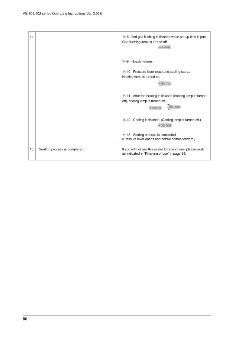
80
VG-602/402 series Operating Instructions Ver. 3.02E
14 14-8 2nd gas flushing is finished when set-up time is past.
Gas flushing lamp is turned off.
14-9 Nozzle returns.
14-10 Pressure lever close and sealing starts.
Heating lamp is turned on.
14-11 After the heating is finished (heating lamp is turned
off), cooling lamp is turned on.
14-12 Cooling is finished. (Cooling lamp is turned off.)
14-13 Sealing process is completed.(Pressure lever opens and nozzle comes forward.)
15 Sealing process is completed. If you will not use this sealer for a long time, please work as indicated in "Finishing of use" in page 34.

81
VG-602/402 series Operating Instructions Ver. 3.02E
● [Circulate] Vacuum (gauge), Gas flushing and Sealing
Operation number
Heating temperatureHeating time
Cooling temperature
Vacuum pattern = gauge and set-up value
1st gas flushing time
2nd gas flushing time
Circulatory gas flushing time Change Move
1VG- xxkpa G xx.xsec
GCT xx.xsec G xx.xsec
HT xxOF x.xs CT xxOF
Operation number
Heating temperatureHeating time
Cooling temperature
Vacuum pattern = gauge and set-up value
1st gas flushing time
2nd gas flushing time
Circulatory gas flushing time Change Move
1VG- xxkpa G xx.xsec
GCT xx.xsec G xx.xsec
HT xxOC x.xs CT xxOC
Procedure Reference page or Description
1 Circuit breaker ON. "Starting of use" in page 34.
2 Power button ON. "Starting of use" in page 34.
3 3-1 Already entered, select the operation number of "xx-Circulation gauge".
Caution Check the piping for gas circulation (Switch to NC piping)
3-2 No entry :
3-1 "Select the operation number" in page 38.
3-2 "Select the gas flushing circulation" in page 39.
4 Set the vacuum degree.(Setting range -1 〜 -100kpa)
"Set the gas circulation / vacuum by gauge" in page 42.5 Set the 1st gas flushing time.
(Setting range 0.1 〜 99.9seconds)
6 Set the circulate gas flushing(Setting range 2 〜 99times)
7 Set the 2nd gas flushing time.(Setting range 0.1 〜 99.9seconds)
8 Set the heating temperature.(Setting range 140 〜 480
OF)
(Setting range 60 〜 250OC)
"Set the heating temperature" in page 36
9 Set the heating time.(Setting range 0.0 〜 2.0seconds)
"Set the heating time" in page 36.

82
VG-602/402 series Operating Instructions Ver. 3.02E
10 Set the cooling temperature.(Setting range 100
OF 〜 heating temperature)
(Setting range 40OC 〜 heating temperature)
"Set the cooling temperature" in page 45.
11 Depress the foot switch (1st) Nozzle comes forward.
12 Set a pouch on the sealing position. Insert the nozzle in a pouch, and set it on the sealing position.
13 Depress the foot switch (2nd). Pressure lever descends and fasten a pouch with sponge rubber. (Keep on stepping until the pressure lever close.)
Attention
If leg is separated from the foot switch in the middle of downward, the pressure lever will open for the safe mechanism.
14 Depress the foot switch (3rd). By the third depressing the foot switch, the following process (from 14-1 to 14-13) will be performed automatically.14-1 Vacuum process starts. Vacuum lamp is turned on.
14-2 Vacuum is finished when set-up time is past.
Vacuum lamp is turned off.
14-3 1st gas flushing starts. Gas flushing lamp is turned on.
14-4 1st gas flushing is finished when set-up time is past.
Gas flushing lamp is turned off.
14-5 Circulation starts.
Vacuum lamp and gas flushing lamp are turned on.
14-6 Circulation is finished when set-up time is past.
Vacuum lamp and gas flushing lamp is turned off.
14-7 2nd gas flushing starts. Gas flushing lamp is turned on.

83
VG-602/402 series Operating Instructions Ver. 3.02E
14 14-8 2nd gas flushing is finished when set-up time is past.Gas flushing lamp is turned off.
14-9 Nozzle returns.
14-10 Pressure lever close and sealing starts.
Heating lamp is turned on.
14-11 After the heating is finished (heating lamp is turned
off), cooling lamp is turned on.
14-12 Cooling is finished. (Cooling lamp is turned off.)
14-13 Sealing process is completed.(Pressure lever opens and nozzle comes forward.)
15 Sealing process is completed. If you will not use this sealer for a long time, please work as indicated in "Finishing of use" in page 34.

84
VG-602/402 series Operating Instructions Ver. 3.02E
9 Replacing the routine maintenance partsReplace parts according to the following directions in order to maintain your machine in optimum operating condition.
Warning Always unplug power plug before replacing any parts. There is a danger of electrocution if conducted with the plug still inserted.
Warning Do not replace parts according to other methods not described in the operating instructions. It is dangerous if incorrect methods are used.
Warning When replacing parts, always use only specified parts sold through Fuji Impulse. Otherwise malfunction may occur.
The sealing section is constructed with parts illustrated in the diagram at left. When replacing parts, be careful to arrange the parts in the same exact order.
Construction of the sealing section
As you use the sealer, the parts wear, sealing result worst., to continues operate with damage part will cause malfunction, so please replace the wear parts on time with space parts always in hands.The routine maintenance parts are selling by the unit described belowOrder from your dealer, specifying the name of your machine, the name and quantity of parts you need.
Routine maintenance parts
1 VG-602/402 sealing section structure 2 VG-602/402-10D sealing section structure
Always unplug power plug from
the wall outlet before
conducting any maintenance.
Parts name Selling unit
Heating element (5mm,10mm) 10pcs. per set / 20pcs. per set
Teflon sheet 2sheets per set
Silicone rubber 2pcs. per set
Glass tape 5M roll or 10M roll
Sarcon sheet 2sheets per set or 5M roll
Plastic nut (white) 5pcs. per set
Teflon center dry tape 5M roll
110V specification 220V specification
Pressure lever
Silicone rubber
Teflon sheetHeating element
Glass tape 25mm
Sarcon sheet
Pressure lever
Silicone rubber
Glass tape 19mm Heating element
Teflon sheet
Temperature sensorGlass tape 25mm
Sarcon sheet
Glass tape 50mm Glass tape 19mm
Teflon center dry tape
Heating elementTemperature sensor

85
VG-602/402 series Operating Instructions Ver. 3.02E
9-1 Sliding teflon sheet[Replace when]
When the teflon sheet is torn, burnt or sealing is dirty[Essential tools]
Scissors
1 Loose the four resin nuts (white) securing the teflon holder and sponge holder.
2 Turn the teflon sheet winding rod. Wind the damaged teflon sheet forward or backward for 15mm.
3 When the teflon sheet is loosen, hold the teflon winding rod and tight the resin nuts to fix the teflon holder and sponges holder. When the teflon sheet is sticking to the heater wire, peel it off before winding. 25 to 30cm of teflon sheet is wound for a space, if the sheet remain a little or consumed, refer "changing the teflon sheet" to change the teflon sheet.
9-2 Replacing teflon sheet[Replace when]
When the teflon sheet is torn, burnt or sealing is dirty[Essential tools]
Scissors
1 Unscrew the resin nuts (white) securing the teflon holder and sponge holder.
2 Remove the teflon holder and sponge holder, then peel off teflon sheet from the teflon winding rod.
3 Strike the new teflon sheet by cellophane tape on teflon sheet.
4 Screw the 4pcs. resin nut (white) lightly. Hold the teflon winding rod by sponge holder and teflon holder.
5 To avoid wrinkles of teflon sheet above the heating element, winding the teflon rod to smooth the teflon sheet.
6 Screw the 4pcs. resin nut (white) to push the teflon holder to fix the teflon winding rod.
Teflon holder
Sponge holder
Plastic nut (white)
Teflon winding rod
Plastic nut (white)
Teflon holder
Sponge holder
Teflon winding rod
Teflon winding rod
Teflon sheet
Cellophane tape
Teflon holder spring

86
VG-602/402 series Operating Instructions Ver. 3.02E
9-3 Replacing center-dry tape on
the upper lever
(object : double side heating model)To change the teflon center dry tape attached on the pressure plate.
1 Take off the frame cover.2 Remove the both right and left side E-ring of the
pressure lever by (minus) screwdriver, and pull out the pin.
3 Raise up the pressure lever and remove the sponge rubber.
4 Remove the teflon center dry tape.Direct paste the new one's adhesive tape to the pressure lever.Insert one side of the center dry tape into the gap that in between the pressure lever and sponge holder.
Attention When you could not paste smoothly, insert thin ruler between the sponge holder and
pressure plate. Then slide the center dry
tape with pushing it on the pressure plate.
5 Cut excess by scissors.
6 Fold the other side of the tape that attached adhesive tape to the opposite side of sponge holder.
Attention Caution when replace the tape:Place the center space of the tape on the
heating element.
If the wrinkles remain on the dry tape, it will
be printed on the seal bag.
Pressure lever
Pin
(Minus) Screw driver
E-ring
Sponge rubber
Sponge holder
Pressure plate

87
VG-602/402 series Operating Instructions Ver. 3.02E
9-4 Replacing heating element[Replace when]
The heating element has burned out. Sealing is dirty or uneven.
[Essential tools]Phillips screwdriver
1 The heating element is covered with the teflon sheet. Remove the teflon sheet, referring to "changing the teflon sheet"
2 The electrode cover is screwed on the side. Loosen the screw with a Phillips screwdriver and pull to remove it.
3 Raise the electrode lever up to loosen the heating element. Loosen the heater securing screw with a Phillips screwdriver.
4 Loosen the screw and remove the wearied heating element.
5 When the electrode lever is raised, insert the new heating element into the groove of electrode, tighten the securing screw to secure the element while pressure the heating element so that it does not slip from the electrode. After tighten the securing screw, push down the electrode lever.
Caution For your safety always reattach the electrode cover after installing the heating
element.
Use a heating element specified for this
model. Using a different element may
cause transformer failure.
When heating element is exchanged to another width
This machine is shipped with 10mm width heating element, and set up to the optimal sealing conditions (heating temperature, heating time, cooling temperature).Since seal conditions change when the width is changed, please set up again, perform a seal test, and adjust to the optimal value.Conversely, when 5mm width is changed into 10mm width, please work similarly.
Heating element
Heater securing screw
Electrode cover
Electrode coversecuring screw
Electrode lever

88
VG-602/402 series Operating Instructions Ver. 3.02E
9-5 Replacing glass tape(19mm
width, 25mm width), sarcon sheet[Replace when]
The heating element is often burnt out. Sealing is dirty [Essential tools]
Phillips screwdriver; Scissors; Alcohol (Ethanol)
Caution If the glass tape or sarcon sheet blow the heating element is burnt, the heater wire
itself may short circuit and melt or proper
seals may not be attained. Inspect them
when replacing heating element, if
necessary change them.
1 Remove the teflon sheet and heating element.2 Peel the glass tape and sarcon sheet located below
the heating element completely off.3 Some adhesive remain will uneven the sealing
surface, and has an adverse effect, please clean the surface thoroughly before applying the glass tape and sarcon sheet.
4 Attaching a new sarcon sheet along the length of sealing section. (One sheet)
5 Attaching a glass tape on the sarcon sheet, the glass tape must be about 5mm longer than the sealing section. (One sheet)
9-6 Replacing silicone rubber
(object single side heating model)[Replace when]
Silicone rubber is uneven[Essential tools]
Alcohol (Ethanol) 1 Remove two glass tape attached on the pressure
lever.2 Remove the silicone rubber. Wipe the adhesive
tape off the pressure lever with alcohol (Ethanol).Attaching the silicone rubber on the top of remained adhesive will has an adverse effect to sealing.
3 The silicone rubber has an adhesive tape on it, peel the paper and attach the new silicone rubber carefully, starting from one end.
4 After attaching the silicone rubber, attach two pieces of glass tape (50mm 19mm width) on it.
lenght of sealing section
about 5mm
about 2mm
about 5mm
about 2mm
ElectrodeSarcon sheet
Glass tape
Pressure lever
Silicone rubber
Glass tape 50mm width
Glass tape 19mm width

89
VG-602/402 series Operating Instructions Ver. 3.02E
9-7 Replacing silicone rubber
(object : double side heating model)[Replace when]
Silicone rubber is uneven[Essential tools]
Alcohol (Ethanol)
1 Remove the center dry tape, heating element, and glass tape according to the each instructions.
2 Remove the silicone rubber, and wipe the adhesive tape off the pressure lever with alcohol (Ethanol).Attaching the new silicone rubber on the remained adhesive tape will has an adverse effect to sealing.
3 The silicone rubber has an adhesive tape on it.Peel the paper and attach the new silicone rubber carefully, starting from one end.
4 After attaching the Silicone rubber, attach on it in order of the sarcon sheet, glass tape (19mm width), heating element and center dry tape.
9-8 Replacing 50mm width glass tape
(object single side heating model)[Replace when]
The heating element is often burn out. Sealing is dirty.[Essential tools]
Scissors1 After attaching the silicone rubber, attach a 50mm
width piece of glass tape on the silicone rubber so that the glass tape extend about 2cm from the end of the pressure lever.
2 Fold this excess upward.3 Fold the corners inward as shown in the figure.4 Attach the tape onto the sides of the pressure
lever.5 Attaching the 19mm width glass tape from above
as shown in the illustration.6 Fold the excess 2mm upward onto the pressure
lever.
Pressure lever
Silicone rubber
Glass tape 19mm width
Heating element
Center dry teflon tape
1
2
3
4
5
6
Pressure lever
Silicone rubber
Glass tape 50mm width
Glass tape 19mm width
Fold upward
Fold the surplus inside
Paste to the pressure lever
Fold upward

90
VG-602/402 series Operating Instructions Ver. 3.02E
9-9 Connecting and removing tubeWhen remove the tube, press the release ring while pushing the tube.
How to remove the tube
If you press the release ring while pushing the tube in at the same time, you can remove the tube quite easily.
How to connect the tube
Insert the tube fully to the tube end of the joint.
Attention To avoid the air leakage, please verify the tube is jointed firmly.
9-10 Replacing microswitch [Essential tools]
Phillips screwdriver
1 Take off the cover on the left side of frame by a Phillips screwdriver.
2 Remove the two screws which fasten the microswitch, and pick up microswitch.
3 Take off the microswitch cover.Remove the wiring with a Phillips screwdriver and exchange the microswitch.
Caution Connect the wiring so that the display on microswitch (COM, NO) accord to the
display on the mark tube of lead wire.
19-21mm
Release ringpress there to remove the tube
V elastic sleeve
Tube
O ring
Body
Nut section
Pay attention to the distance between the release ring and body
NC
NO
COM
COMNO
NO
Release ring
Microswitch
Mark tube
Lead wire
Microswitch cover

91
VG-602/402 series Operating Instructions Ver. 3.02E
9-11 Replacing nozzle[Essential tools]
Spanner
1 Take off the frame cover.
2 Remove the elbow from the nozzle.Push the open ring to horizontal direction with nozzle, then lock will be cancelled.
3 Loosen the bolt on the of nozzle supporter by the spanner.
4 Extract the nozzle from the nozzle supporter.
Nozzle supporter
Elbow
Open ring

92
VG-602/402 series Operating Instructions Ver. 3.02E
9-12 Replacing temperature sensor
for VG-602 series
[Replace when] Temperature sensor is damaged.
[Essential tools] Phillips screwdriver
Temperature sensor is set between glass tape and heating element, and located to the right-hand end of the seal- re-ceiving plate.
1 Remove the teflon sheet.
2 Remove the heating element. (Refer to page 85.)
3 Unfasten the screw A-1, A-2 to remove the tem-perature sensor fixing plate, and unfasten the screw B. Temperature sensor can be removed.
Caution Please take care not to make a slack of sensor between screw A-1 and A-2.
Attention Install the new temperature sensor so that the perception part touches with the center of heating element. (Refer to the right illustra-tion.)
If the perception part is slipped off, tempera-ture could not be detected exactly.
4 Insert the protuberance of sensor fixing plate (screw A-1 side) into the tip (hole) of new tem-perature sensor and seal frame’s hole.
Then fasten screw A-1.
5 Set the other sensor fixing plate and temporarily fasten the screw A-2.
(Refer to the right illustration.)
6 Pull the temperature sensor module lightly to keep the tension of temperature sensor and fix the plate by screw A-2.
Caution If the temperature sensor module would be pulled strongly, sensor might be broken.
7 Fix the temperature sensor module by screw B.
8 Re-attach the heating element. (Refer to page 85.)
Caution If the temperature sensor isn’t installed on the proper position, seal function might not work.
.Position
.Temperature sensor
Proper position of temperature sensor
(Install the sensor under the heating element)
Perception part
Heating element
Perception part
Temp.sensor fixing plate (A-1 side)
Temperature sensor
Temperature sensor module
Temp.sensor fixing plate (A-2 side)
Slack ×
Slack ○
ScrewA-1
ScrewA-2
Temp.sensor fixing plate
ScrewA-2
Temperature sensor module
ScrewA-1

93
VG-602/402 series Operating Instructions Ver. 3.02E
9-13 Replacing temperature sensor
for VG-402 series
[Replace when] Temperature sensor is damaged.
[Essential tools] Phillips screwdriver
Temperature sensor is set between glass tape and heating element, and located to the right-hand end of the seal- re-ceiving plate.
1 Remove the teflon sheet.
2 Remove the heating element. (Refer to page 85.)
3 Unfasten the screw A-1, A-2 to remove the tem-perature sensor fixing plate, and unfasten the screw B. Temperature sensor can be removed.
Caution Please take care not to make a slack of sensor between screw A-1 and A-2.
Attention Install the new temperature sensor so that the perception part touches with the center of heating element. (Refer to the right illustra-tion.)
If the perception part is slipped off, tempera-ture could not be detected exactly.
4 Insert the protuberance of sensor fixing plate (screw A-1 side) into the tip (hole) of new tem-perature sensor and seal frame’s hole.
Then fasten screw A-1.
5 Set the other sensor fixing plate and temporarily fasten the screw A-2.
(Refer to the right illustration.)
6 Pull the temperature sensor module lightly to keep the tension of temperature sensor and fix the plate by screw A-2.
Caution If the temperature sensor module would be pulled strongly, sensor might be broken.
7 Fix the temperature sensor module by screw B.
8 Re-attach the heating element. (Refer to page 85.)
Caution If the temperature sensor isn’t installed on the proper position, seal function might not work.
● Position
● Temperature sensor
Proper position of temperature sensor
(Install the sensor under the heating element)
Perception part
Heating element
Perception part
Temp.sensor fixing plate
Screw A-2
Screw A-1
Temperature sensor
Screw B
Temp.sensor fixing plate (A-1 side)
Temperature sensor
Temperature sensor module
Temp.sensor fixing plate (A-2 side)
Slack ×
Slack ○
ScrewA-1
ScrewA-2

94
VG-602/402 series Operating Instructions Ver. 3.02E
10 Specification
10-2 Safety mechanism specifications
10-1 Safety mechanism specifications
VG-402-xx VG-402-xx-10D VG-602-xx VG-602-xx-10D
Power source 110V 220V 220V 220V
Maximum power 2.0KW (10m heater)2.6KW
3.0KW (10m heater)3.1KW
consumption 1.1KW (5mm heater) 1.9KW (5mm heater)
Power cord CT.2x3x5M 3P 20A125V CT.2x3x5M 3P 20A250V
Vacuum degree -1 -100Kpa
Vacuum method By nozzle (Method can be selected from vacuum gauge, timer or manual.)
Vacuum time 0.1 99.9sec
Gas flushing time 0.1 99.9sec
Driving style Air cylinder
Plug
Sealing style Single heating Dual heating Single heating Dual heating
Sealing length 400mm 600mm
Sealing width 5 or 10mm 10mm 5 or 10mm 10mm
Height of sealing 932mm (from bottom to sealing surface)surface
Sealing angle 0 30 degree
Driving style for sealing Air cylinder 63mm X 2
Sealing heating 140 480OF / 60 250OCtemperature
Sealing heating time 0.0 2.0seconds
Sealing cooling 100OF (40OC) set up heating temperaturetemperature *Note1
Machine weight *Note2 93kg 98kg 100kg 105kg
Outside dimensions
*Note3 W595 X L555 X H1052mm W675 X L555 X H1052mm
Table dimensions W400 X L315mm W600 X L450mm
*Note1 Please set lower value than heating temperature. If it is near the heating temp, cooling process is insufficent and teflon is damaged too much.
*Note2 Machine weight doesn’t contain the one of table and options. (Vacuum pump and air compressor / standard type)
*Note3 When sealing suface is horizontal position.
Overheating proof mechanism a) Circuit breaker automatically turn OFF when heater has been heated over 3.5seconds.
b) When heating temperature doesn’t reach to set-up value within 3seconds, the electricity
is stopped and error message appears on the display.
Lever driving style Spring guides the lever when it is closing ; 63 cylinder guides when sealing.
Reset in emergency The lever opens when foot switch is released while the lever is closing.
Abnormality response In the foreign object (ex. fingers) prevent the sealer to act next movement when lever is
closing, automatically reset the sealer, after 1second the sealer is in initial state.
Emergency stop In emergency stop switch is pushed when abnormality might generate, the circuit breaker
is turned OFF, power supply is intercepted and lever returns to the initial state.
Heating signal Heating when levers closed ; microswitch guides the lever to going down (double safety
structure).

95
VG-602/402 series Operating Instructions Ver. 3.02E
10-3 Appearance dimensions drawing
( ): measurement of VG-602 series.
Max
. hei
ght 1
238
(600)
400
(450
)
350
30o
9210
5
1052
(988)
(675)
595
888
932
Unit ; mm

96
VG-602/402 series Operating Instructions Ver. 3.02E
10-4 Combination of vacuum pump and air compressor
A.MP-40 : Piston typeFor standardPumping speed : 28L/minUsual pressure : 310-330 KPaRelief valve set-up pressureWeigh : 8kg
B.DOA-P108-DB : Diaphragm typeFor clean room(clean degree : about 10,000)Pumping speed : 31L/minUsual pressure : 310-330 KPaRelief valve set-up pressureWeigh : 7kg
C.Air is provided by the out side compressor
Suitable compressor specification 0.75kw (80L/min) above480KPa
H.DOP-80SA : Piston typeFor standardPumping speed : 80L/minUltimate pressure : -96KPaPump weight : 7kg
D. G-50SA : Oil rotation typeFor high vacuum degree (small size pouch)Pumping speed : 50L/minUltimate pressure : -101.3KPaPump weight : 11kg
E.G-100S : Oilrotation typeFor high vacuum degree(large size pouch)Pumping speed : 100L/minUltimate pressure : -101.3KPaPump weight : 22kg
G.DA-60S : Diaphragm typeFor clean room(clean degree : about 10,000)Pumping speed : 60L/minUltimate pressure : -80KPaPump weight : 12kg
ex.
Compressor : MP-40 (called A)
Vacuum pump : DOP-80 (called H)
602 series dual heating type
VG-602-AH-10D
Air compressor / 3 typesVacuum pump / 4 types
VG series sealer is named by the combination
of vacuum pump and air compressor.
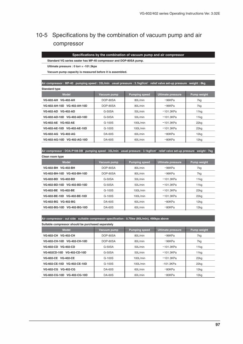
97
VG-602/402 series Operating Instructions Ver. 3.02E
10-5 Specifications by the combination of vacuum pump and air
compressor
Specifications by the combination of vacuum pump and air compressor
Standard VG series sealer has MP-40 compressor and DOP-80SA pump.
Ultimate pressure : 0 torr = -101.3kpa
Vacuum pump capacity is measured before it is assembled.
Air compressor : MP-40 pumping speed : 33L/min usual pressure : 3.1kgf/cm2 relief valve set-up pressure weight : 8kg
Standard type
Model Vacuum pump Pumping speed Ultimate pressure Pump weight
VG-602-AH VG-402-AH DOP-80SA 80L/min -96KPa 7kg
VG-602-AH-10D VG-402-AH-10D DOP-80SA 80L/min -96KPa 7kg
VG-602-AD VG-402-AD G-50SA 50L/min -101.3KPa 11kg
VG-602-AD-10D VG-402-AD-10D G-50SA 50L/min -101.3KPa 11kg
VG-602-AE VG-402-AE G-100S 100L/min -101.3KPa 22kg
VG-602-AE-10D VG-402-AE-10D G-100S 100L/min -101.3KPa 22kg
VG-602-AG VG-402-AG DA-60S 60L/min -80KPa 12kg
VG-602-AG-10D VG-402-AG-10D DA-60S 60L/min -80KPa 12kg
Air compressor : DOA-P108-DB pumping speed : 33L/min usual pressure : 3.1kgf/cm2 relief valve set-up pressure weight : 7kg
Clean room type
Model Vacuum pump Pumping speed Ultimate pressure Pump weight
VG-602-BH VG-402-BH DOP-80SA 80L/min -96KPa 7kg
VG-602-BH-10D VG-402-BH-10D DOP-80SA 80L/min -96KPa 7kg
VG-602-BD VG-402-BD G-50SA 50L/min -101.3KPa 11kg
VG-602-BD-10D VG-402-BD-10D G-50SA 50L/min -101.3KPa 11kg
VG-602-BE VG-402-BE G-100S 100L/min -101.3KPa 22kg
VG-602-BE-10D VG-402-BE-10D G-100S 100L/min -101.3KPa 22kg
VG-602-BG VG-402-BG DA-60S 60L/min -80KPa 12kg
VG-602-BG-10D VG-402-BG-10D DA-60S 60L/min -80KPa 12kg
Air compressor : out side suitable compressor specification : 0.75kw (80L/min), 490kpa above
Suitable compressor should be purchased separately
Model Vacuum pump Pumping speed Ultimate pressure Pump weight
VG-602-CH VG-402-CH DOP-80SA 80L/min -96KPa 7kg
VG-602-CH-10D VG-402-CH-10D DOP-80SA 80L/min -96KPa 7kg
VG-602-CD VG-402-CD G-50SA 50L/min -101.3KPa 11kg
VG-602CD-10D VG-402-CD-10D G-50SA 50L/min -101.3KPa 11kg
VG-602-CE VG-402-CE G-100S 100L/min -101.3KPa 22kg
VG-602-CE-10D VG-402-CE-10D G-100S 100L/min -101.3KPa 22kg
VG-602-CG VG-402-CG DA-60S 60L/min -80KPa 12kg
VG-602-CG-10D VG-402-CG-10D DA-60S 60L/min -80KPa 12kg

98
VG-602/402 series Operating Instructions Ver. 3.02E
11 Specifications of accessories
11-1 Air parts
Other
1 Although life of sealing portion or slide portion in the machine differs by frequency of use, exchange is needed every three or four year.
2 Piping tube discolor and harden by surrounding temperature or humidity.As it cause an air leak, please replace the tube regularly.
3 In addition to the standard life, when surroundings are dusty, please clean or exchange valve and filter.
4 Also about the electric parts, cleaning or exchange is needed with surrounding situation (humidity, dust, or usage) in addition to the standard life.
11-2 Electric parts
Parts name Type Standard life and remarks
Lever cylinder (big) X2pcs Cylinder CDQ2B63-30D-F9BVS 500,000 times or 3 years
Lever cylinder (small) Cylinder CDQ2B32-25 500,000 times or 3 years
Vacuum nozzle cylinder Cylinder CDM2BZ25-75A-H7BS 500,000 times or 3 years
Lever cylinder electro- Valve VK3120-1H-01 500,000 times or 3 years
magnetic valve Valve VK332-1H-01 500,000 times or 3 years
Nozzle cylinder electro- Valve VK3120-1H-01 500,000 times or 3 years
magnetic valve
Gas nozzleelectro- Valve 126E1-21 500,000 times or 3 years
electro-magnetic valve
Air electro-magnetic valve Valve 200E1-21 500,000 times or 3 years
Dry filter Dry filter M-103 (first) : black 2 years
Dry filter M-103 (second) : red Half a year
Name Type and model Standard life and remarks
Circuit breaker with S-6 Circuit breaker GB-2Z 10,000 times (6 times / min)
S-6 safety circuit board 500,000 times or more (relay on board)
SSR-03 relay SSR-03 10 hours or more (on contact)
Relay in micro computer FTR-F3AA024E-HA5A 5,000,000 times or more
Lever lower position MS Microswitch BA-2RQ1-T4-J 100,000 times or more (on contact)
Cooling fan Fan 4715MS-10T-B50 Average life 3,000 hours
(consecutive operation)
Sealing transformer Transformer V-400-5/10 Out of rating
Power cord (110V) CT2X3X5M 3P 20A125V Out of rating
Power cord (220V) CT2X3X5M 3P 20A250V Out of rating
Foot switch Switch OFL-V-SP 500,000 times or more

99
VG-602/402 series Operating Instructions Ver. 3.02E
12 Regular check and maintenance
For longer the sealer life and normally operation, it is necessary to check and maintain the sealer regularly.Please perform the checking and maintenance on time after purchased the sealer.
12-1 Regular check
Checking items for every day
Sealing surface Veryfy that teflon sheet and silicone rubber are not dirty or damaged.
Air filter Remove the filter cup and clean it. (Ref. next page)
Checking items for every week
Teflon sheet If it is damaged or color is changed, slide the teflon or replace with new one.
Heating element If it is damaged or color is changed, replace with new one.
Air filter element If it is dirty, clean by flowing air.
Dry filter If it is dirty, clean the clogging. (Ref. related instruction)
Checking item for every month
Glass tape If it is damaged or color is changed, replace with new one.
Sarcon sheet If it is not damaged or color is changed,replace with new one.
Vacuum tube section Verify that there is no any foreign object in joint and horse.
Checking items per year
Silicone rubber If it is not burned or damaged, replace with new one.
Relief valve Verify the initial pressure setting is 320kpa. If not so, adjust it.
Cylinder Verify the cylinder action is smooth. Otherwise, replace it.
Valve Verify the valve action is smooth. Otherwise, replace it.
Temperature sensor *1 Verify the sensor’s tape color is not changed.
Checking main parts every three years
Air parts Cylinder, Valve, Air tube, Air filter, Relief valve, Speed control valve
Electric parts SSR-03 relay, circuit beaker, electrode
*1 Temperature which sensor recognize is adjusted to the actual heating temperature at the shipment from our
factory. But the error may occur for long time use, so please check it.
Ref. "Replacing the routine maintenance parts in page 82

100
VG-602/402 series Operating Instructions Ver. 3.02E
The air filter is located in-between the nozzle and the vacuum pump, stores any foreign objects accidentally taken in though the nozzle in filter cup.Be sure to check and clean cup everyday before the operation.Only in the case of a liquid (water), it drains automatically if auto-drain system is turned on.This drainage process is performed at each sealing, so cup is not covered with water. However, the amount of suction for one time is about 100ml (about 1/3 of cup). If the foreign objects reaches to 1/3 line (in Figure 1), please exhaust them and clean the cup.
Removing the filter cup
Take off two plastic nut (black) and pull the cup flange downward.Filter cup can be removed.(Filter cup and is stuck to cup flange by o-ring.)
Taking apart and clean the air filter
If the filter element or filter cup becomes dirty, wash them and install again after making them dry fully.Please exchange for the new filter element every three months (on the standard).
Caution If too liquid is taken in, the liquid will overflow the filter element and spill into the
vacuum pump, which may cause damage
of the pump.
Be careful not to take in over 100ml (about
1/3 of cup) at once.
If the overflow might occur, please
exchange the vacuum pump oil.
12-2 Cleaning the air filter
Filter element
Fixing bolt (SUS)
Element cap
Wing nut M4
O-ring
Filter cup
O-ring
Plastic nut (black)
Cup flange
Drain tube
Drain valve
To vacuum pump From nozzle
OpenClose
Figure 1
1/3 line

101
VG-602/402 series Operating Instructions Ver. 3.02E

102
VG-602/402 series Operating Instructions Ver. 3.02E
13 Electric diagram
13-1 Electric diagram for 110VObject : VG-402-xx
Type (xx) : AH, AD, AE, CH, CD, CE
SSR
P
S
A
L
K
AC110V
543
2
1
AA
6
X5
X4
X3
X2
X1
X0
COM
COM
NC
X14
X13
X12
X11
X10
COM
COM
COM
X18
X17
X16
X15
COM
NC
X19
Y5
Y4
Y3
Y2
Y1
Y0
C0
Y14
Y13
Y12
Y11
Y10
C1
C1
C19
Y18
Y17
Y16
Y15
C0
C2
IN30
4IN
403
IN40
4
OUT303OUT401
OUT402 INAC100V
OUTAC100V
GND
AD0
24V
5V
GND
AD5
AD1
VSTC
5V
GND
AD2
AD3
GND
24V
SOL.Y5
SOL.Y1
SOL.Y2
SOL.Y3
SOL.Y4
SOL.Y10
COM
NO
0V
110V
105V
GroundTerminal
Circutbreaker
circuitSafety
Microswitch
Red Lamp
ClearLamp
Transformer
heaterTo Y0
Nozzle Back position
Lever Lower position
Lever Middle position
Lever Upper position
Foot Switch
Vacuum Gauge
Tempraturesensor
Vacuum Valve
Nozzle forward
Lever Hold in lower
Lever Hold in middle
Lever Down
To SSR No.4
AD24
Gas flushing valve open
Safety micro-switch
2A2B
1B 1A
FAN
Compressor
Note) Not used in outside piping type
11 12 13 1 C1
C2
2 4 6 9698
9597
Vacuum pump
Vacuum pumpauxiliary relay
White
Black
Green(Ground)
(Remark1) The shape of power plug 2P20A is:
Tempraturesensor
SOL.Y11Water drainage valve open
3B
3A
4B5B6B7B8B
4A5A6A7A8A
3B
3A
4B5B6B7B8B
4A5A6A7A8A
3B
3A
4B5B6B7B8B
4A5A6A7A8A
3B
3A
4B5B6B7B8B
4A5A6A7A8A
JK
A
CF
PrinterOutlet
FCA
KJ

103
VG-602/402 series Operating Instructions Ver. 3.02E
13-2 Electric diagram for 220VObject : VG-602-xx, VG-602-xx-10W, VG-402-xx-10W
Type (xx) : AH, AD, AE, CH, CD, CE
SSR
P
S
A
L
K
AC220V
543
2
1
AA
6
X5
X4
X3
X2
X1
X0
COM
COM
NC
X14
X13
X12
X11
X10
COM
COM
COM
X18
X17
X16
X15
COM
NC
X19
Y5
Y4
Y3
Y2
Y1
Y0
C0
Y14
Y13
Y12
Y11
Y10
C1
C1
C19
Y18
Y17
Y16
Y15
C0
C2
IN30
4IN
403
IN40
4
OUT303OUT401
OUT402 INAC100V
OUTAC100V
GND
AD0
24V
5V
GND
AD5
AD1
VSTC
5V
GND
AD2
AD3
GND
24V
SOL.Y5
SOL.Y1
SOL.Y2
SOL.Y3
SOL.Y4
SOL.Y10
White
Black
Green(Ground)
COM
NO
0V
220V
105V
( )
GroundTerminal
Circutbreaker
circuitSafety
Microswitch
Red Lamp
ClearLamp
Transformer
heater Tempraturesensor
(In the cace of double)
To Y0
Nozzle Back position
Lever Lower position
Lever Middle position
Lever Upper position
Foot Switch
Vacuum Gauge
Tempraturesensor
Vacuum Valve
Nozzle forward
Lever Hold in lower
Lever Hold in middle
Lever Down
To SSR No.4
AD24
Gas flushing valve open
(Remark1) The shape of power plug 2P20A is:
Safety micro-switch
2A2B
1B 1A
FAN
Compressor
Note) Not used in outside piping type
11 12 13 1 C1
C2
2 4 6 9698
9597
Vacuum pump
Vacuum pumpauxiliary relay
SOL.Y11
Water drainage valve open
3B
3A
4B5B6B7B8B
4A5A6A7A8A
3B
3A
4B5B6B7B8B
4A5A6A7A8A
3B
3A
4B5B6B7B8B
4A5A6A7A8A
3B
3A
4B5B6B7B8B
4A5A6A7A8A
JK
A
CF
PrinterOutlet
FCA
KJ

104
VG-602/402 series Operating Instructions Ver. 3.02E
13-3 Electric diagram for 110V (without draining device)Object : VG-402-xx
Type (xx) : AG, BG, CG
SSR
P
S
A
L
K
AC110V
543
2
1
AA
6
X5
X4
X3
X2
X1
X0
COM
COM
NC
X14
X13
X12
X11
X10
COM
COM
COM
X18
X17
X16
X15
COM
NC
X19
Y5
Y4
Y3
Y2
Y1
Y0
C0
Y14
Y13
Y12
Y11
Y10
C1
C1
C19
Y18
Y17
Y16
Y15
C0
C2
IN30
4IN
403
IN40
4
OUT303OUT401
OUT402 INAC100V
OUTAC100V
GND
AD0
24V
5V
GND
AD5
AD1
VSTC
5V
GND
AD2
AD3
GND
24V
SOL.Y5
SOL.Y1
SOL.Y2
SOL.Y3
SOL.Y4
SOL.Y10
COM
NO
0V
110V
105V
GroundTerminal
Circutbreaker
circuitSafety
Microswitch
Red Lamp
ClearLamp
Transformer
heaterTo Y0
Nozzle Back position
Lever Lower position
Lever Middle position
Lever Upper position
Foot Switch
Vacuum Gauge
Tempraturesensor
Vacuum Valve
Nozzle forward
Lever Hold in lower
Lever Hold in middle
Lever Down
To SSR No.4
AD24
Gas flushing valve open
Safety micro-switch
2A2B
1B 1A
FAN
Compressor
Note) Not used in outside piping type
11 12 13 1 C1
C2
2 4 6 9698
9597
Vacuum pump
Vacuum pumpauxiliary relay
White
Black
Green(Ground)
(Remark1) The shape of power plug 2P20A is:
Tempraturesensor
3B
3A
4B5B6B7B8B
4A5A6A7A8A
3B
3A
4B5B6B7B8B
4A5A6A7A8A
3B
3A
4B5B6B7B8B
4A5A6A7A8A
3B
3A
4B5B6B7B8B
4A5A6A7A8A
JK
A
CF
PrinterOutlet
FCA
KJ

105
VG-602/402 series Operating Instructions Ver. 3.02E
13-4 Electric diagram for 220V (without draining device)Object : VG-602-xx, VG-602-xx-10W, VG-402-xx-10W
Type (xx) : AG, BG, CG
SSR
P
S
A
L
K
AC220V
543
2
1
AA
6
X5
X4
X3
X2
X1
X0
COM
COM
NC
X14
X13
X12
X11
X10
COM
COM
COM
X18
X17
X16
X15
COM
NC
X19
Y5
Y4
Y3
Y2
Y1
Y0
C0
Y14
Y13
Y12
Y11
Y10
C1
C1
C19
Y18
Y17
Y16
Y15
C0
C2
IN30
4IN
403
IN40
4
OUT303OUT401
OUT402 INAC100V
OUTAC100V
GND
AD0
24V
5V
GND
AD5
AD1
VSTC
5V
GND
AD2
AD3
GND
24V
SOL.Y5
SOL.Y1
SOL.Y2
SOL.Y3
SOL.Y4
SOL.Y10
White
Black
Green(Ground)
COM
NO
0V
220V
105V
( )
GroundTerminal
Circutbreaker
circuitSafety
Microswitch
Red Lamp
ClearLamp
Transformer
heater Tempraturesensor
(In the cace of double)
To Y0
Nozzle Back position
Lever Lower position
Lever Middle position
Lever Upper position
Foot Switch
Vacuum Gauge
Tempraturesensor
Vacuum Valve
Nozzle forward
Lever Hold in lower
Lever Hold in middle
Lever Down
To SSR No.4
AD24
Gas flushing valve open
(Remark1) The shape of power plug 2P20A is:
Safety micro-switch
2A2B
1B 1A
FAN
Compressor
Note) Not used in outside piping type
11 12 13 1 C1
C2
2 4 6 9698
9597
Vacuum pump
Vacuum pumpauxiliary relay
3B
3A
4B5B6B7B8B
4A5A6A7A8A
3B
3A
4B5B6B7B8B
4A5A6A7A8A
3B
3A
4B5B6B7B8B
4A5A6A7A8A
3B
3A
4B5B6B7B8B
4A5A6A7A8A
JK
A
CF
PrinterOutlet
FCA
KJ

106
VG-602/402 series Operating Instructions Ver. 3.02E
14 Piping diagram
14-1 Piping diagram for VG-602/402 series with air compressor and vacuum pump
Type : AH, AD, AE
LS.X4
LS.X
2
LS.X3LS.X1
SOL.Y4 SOL.Y1SOL.Y3 SOL.Y2
Vacuum Pump
Gas cock
SOL.Y10
CDM2BZ25-75A-H7BS
CDQ2B63-30DF9BVS
CQ2B32-25CDQ2B63-30DF9BV
PK0802-NC
Filter
SOL.Y11
SOL.Y5VX2330-03-1G
Circulationswitch valve
Nozzle cylinder
Cylinder (big)
Cylinder(sm
all)
Air regulator
Chuck valve
Twinneddry filter
Exhause
Relief valve
Tube Length φ8x2M
SealingsectionNozzle
Tube Length φ12x1.5M
Compressor
Cylinder (big)
Exhause
126E1-21
Rapid exhaust valve
Vacuumgauge
Filter
O
I E
Exhause from substanceVK332-1H-01 x 2
VK3120-1H-01 x 2

107
VG-602/402 series Operating Instructions Ver. 3.02E
14-2 Piping diagram for VG-602/402 series with air compressor and vacuum pump (Air is provided by the outside compressor)
Type : CH, CD, CE
Air control unit
Air source
LS.X4
LS.X
2
LS.X3LS.X1
SOL.Y4 SOL.Y1SOL.Y3 SOL.Y2
Vacuum Pomp
Gas cock
SOL.Y10
CDM2BZ25-75A-H7BS
CDQ2B63-30DF9BVS
CQ2B32-25CDQ2B63-30DF9BV
Draining Water EquipmentPK0802-NC
Filter
SOL.Y11
Circulationswitch valve
Nozzle cylinder
Cylinder (big)
Cylinder(sm
all)
Air regulator
Exhause
Tube Length φ8x2M
SealingsectionNozzle
Tube Length φ12x1.5M
Cylinder (big)
Exhause
126E1-21
AW30-02BDE-R
Vacuumgauge
Filter
Rapid exhaust valve
Exhause from substance
SOL.Y5VX2330-03-1G
O
I E
VK332-1H-01 x 2VK3120-1H-01 x 2

108
VG-602/402 series Operating Instructions Ver. 3.02E
14-3 Piping diagram for VG-602/402 series with air compressor and vacuum pump (with duct bracket)
Type : AG, BG, BH
(STA_B0620E )
LS.X4
LS.X
2
LS.X3LS.X1
SOL.Y4 SOL.Y3 SOL.Y2
Vacuum Pump
Gas cock
SOL.Y10
CDM2BZ25-75A-H7BS
CDQ2B63-30DF9BVS
CQ2B32-25CDQ2B63-30DF9BV
PK0802-NC
Filter
SOL.Y11
Circulationswitch valve
Nozzle cylinder
Cylinder (big)
Cylinder(sm
all)
Air regulator
Chuck valve
Twinneddry filter
ExhauseRelief valve
SealingsectionNozzle
Compressor
Cylinder (big)
126E1-21
Ductbracket
Filter
Vacuumgauge
Rapid exhaust valve
SOL.Y5VX2330-03-1G
SOL.Y1
1
O
I E
A
P
200E1
R(Only BG,BH)
VK332-1H-01 x 2VK3120-1H-01 x 2

109
VG-602/402 series Operating Instructions Ver. 3.02E
14-4 Piping diagram for VG-602/402 series with vacuum pump (Air is provided by the outside compressor) (with duct bracket)
Type (xx) : CG
LS.X4
LS.X
2
LS.X3LS.X1
SOL.Y4 SOL.Y3 SOL.Y2
Vacuum Pomu
Gas cock
SOL.Y10
CDM2BZ25-75A-H7BS
CDQ2B63-30DF9BVS
CQ2B32-25CDQ2B63-30DF9BVS
Filter
Circulationswitch valve
Nozzle cylinder
Cylinder (big)
Cylinder(sm
all)
Air regulator
Exhause
SealingsectionNozzle
Cylinder (big)
126E1-21
Duct bracket
Air control unit
Air source
AW30-02BDE-R
Filter
Vacuumgauge
SOL.Y1
Rapid exhaust valve
SOL.Y5VX2330-03-1G
O
I E
VK332-1H-01 x 2VK3120-1H-01 x 2

110
VG-602/402 series Operating Instructions Ver. 3.02E
110
If you are experiencing problems with the machine, please refer to the chart below.Carefully follow the directions in the operating instructions when replacing parts.Please consult your dealer or Fuji Impulse if after referring to the chart, the problem cannot be resolved. Please refer any questions regarding replacement of parts not listed in the operating instructions or adjustment of such parts to your dealer or Fuji Impulse.Items marked with an asterisk in the Solutions column refer to the fact that these problems should be addressed by an electrician. If there are any problems, please contact your dealer or Fuji Impulse.
When replacing parts, be sure to unplug power cord from the wall outlet.Warning
Service questions should be addressed to your local dealer.
Items marked with an asterisk in the Solutions a column refer to the fact that these problems should be addressed by an electrician. If there are any problems, please contact your dealer or Fuji Impulse.
15 Common problems and solutions
Problems Check SolutionSeal result is unsatisfactory. Heating element, teflon sheet or
silicone rubber (white) is dusty.Wipe with clean cloth.
Teflon sheet is damaged. Slide the teflon sheet.Silicone rubber is damaged. Replace the silicone rubber (white).Glass tape is damaged. Replace the glass tape.Heating temperature is too high. Set the heating temperature to the
lowest in which sealing is possible.Cooling temperature is too high. Lower the cooling temperature.
Seal result is uneven at the right and left sides.
Silicone rubber is damaged. Replace the silicone rubber (white).
Heating element is bent and risen in the center.
Electrode is damaged. * Replace the electrode.Silicone rubber (white) is exhausted and becomes uneven.
Replace the silicone rubber (white).
Heating element is burnt out easily. Heating temperature is too high. Set the heating temperature to the lowest in which sealing is possible.
Cooling temperature is too high. Lower the cooling temperature.Glass tape is damaged. Replace the glass tape.Electrode is damaged. Replace the electrode.
Although the heating lamp is on, heating element does not heat up.
Heating element is broken. Replace the heating element.Electrode does not touch with heating element.
Scour the metal contact part of electrode and heating element with a sand paper.
Electric wire / black (or blue) from the transformer is not connected with electrode.
* Attach the electric wire / black (or blue) to the electrode certainly.
SSR input lamp is off. * Control unit may be damaged.
Replace the control unit.SSR input lamp is on. * SSR may be damaged.
Replace the SSR.Heating continues (heating lamp being on), and heating element and teflon sheet are burnt out.
SSR input lamp is off. * Control unit may be damaged.
Replace the control unit.
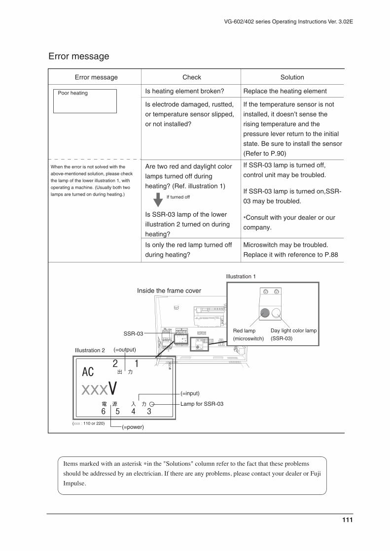
111
VG-602/402 series Operating Instructions Ver. 3.02E
Items marked with an asterisk *in the "Solutions" column refer to the fact that these problems should be addressed by an electrician. If there are any problems, please contact your dealer or Fuji Impulse.
Error message
W₁₇₃
₁
₃₄₅₆入 力 電 源
出 力 ₁₂
xxxVAC
Is heating element broken? Replace the heating element
If the temperature sensor is not
installed, it doesn’t sense the
rising temperature and the
pressure lever return to the initial
state. Be sure to install the sensor
(Refer to P.90)
If SSR-03 lamp is turned off,
control unit may be troubled.
If SSR-03 lamp is turned on,SSR-
03 may be troubled.
*Consult with your dealer or our
company.
Is electrode damaged, rustted,
or temperature sensor slipped,
or not installed?
Are two red and daylight color
lamps turned off during
heating? (Ref. illustration 1)
Is SSR-03 lamp of the lower
illustration 2 turned on during
heating?
Microswitch may be troubled.
Replace it with reference to P.88
Is only the red lamp turned off
during heating?
When the error is not solved with the
above-mentioned solution, please check
the lamp of the lower illustration 1, with
operating a machine. (Usually both two
lamps are turned on during heating.)
Error message Check Solution
Poor heating
If turned off
Day light color lamp
(SSR-03)
Red lamp
(microswitch)
(xxx : 110 or 220)
Inside the frame cover
Illustration 2
Lamp for SSR-03
SSR-03
(=output)
(=input)
(=power)
Illustration 1
₃ ₄ ₅ ₆
₁ ₂
xxxVAC

112
VG-602/402 series Operating Instructions Ver. 3.02E
Error message on display
Error message Problems Solution
NG!
X1 lever-upper
Upper lever position cannot be
recognized
Adjustment or replacemrent of
cylinder sensor is necessary.
Please consult with your local
dealer
NG!
X4 nozzle-back
Nozzle back position cannot be
recognized
NG!
X2 lever
lever sponge position cannot be
recognized
NG!
X3 lever-lower
Lower lever position cannot be
recognized
If the temperature sensor is not
installed exactly, it doesn’t sense
the rising temperautre and the
pressure lever return to the initial
state. Be sure to install the sensor.
(Refer to P.90)
*Transformer may be troubled.
Consult with your dealer or our
company.
If SSR-03 lamp is turned on,
control unit may be troubled.
If SSR-03 lamp is turned off, SSR-
03 may be troubled.
*Consult with your dealer or our
company.
Is SSR-03 lamp in the frame
cover turned on?
Is the temperature sensor
slipped or not installed?
Transformer
If the temperature does not
reach to the setting within 3.5
seconds at heating, this
message is displayed.
Error massge Check Solution
Over heating
Heat contorol can’t function! Don’t operate until it removes a trouble

113
VG-602/402 series Operating Instructions Ver. 3.02E
113
The state of a machine is found by display in the maintenance mode.When the trouble occurs, we recommend to display the maintenance mode.The position of black marked X and Y told operator the trouble pattern.Please tell your dealer or our company the result.(Ref. "Select the maintenance mode" in page 43)Each working of X0---, Y0--- is described in electric diagrams (page 100 103) as IN (X) side and OUT (Y) side.
Recommendation of the maintenance mode
( means ON means OFF)
MAINTENANCE
X
Y
X Y
X5X4X3X2X1X0
Y5Y4Y3Y2Y1Y0

114
VG-602/402 series Operating Instructions Ver. 3.02E
16 Exploded view of major parts16-1 Sealing section
16-2 Inside of the frame cover
Pressure lever
Electrode
Sponge rubber
Sponge holder (lower)
Sponge holder (upper)
FuseSSR-03
Circuit breaker
Vacuum gauge
Control unit
Thermal relay

115
VG-602/402 series Operating Instructions Ver. 3.02E
16-3 Nozzle unit section
16-4 Inside of the bottom plate
Air filter
Vacuum / gas flushing nozzle
Dry filter
Electromagnetic valve for vacuum
Electromagnetic valve for gas
Cylinder (small)
Cylinder (big)
TransformerNozzle cylinder
Auto transformer
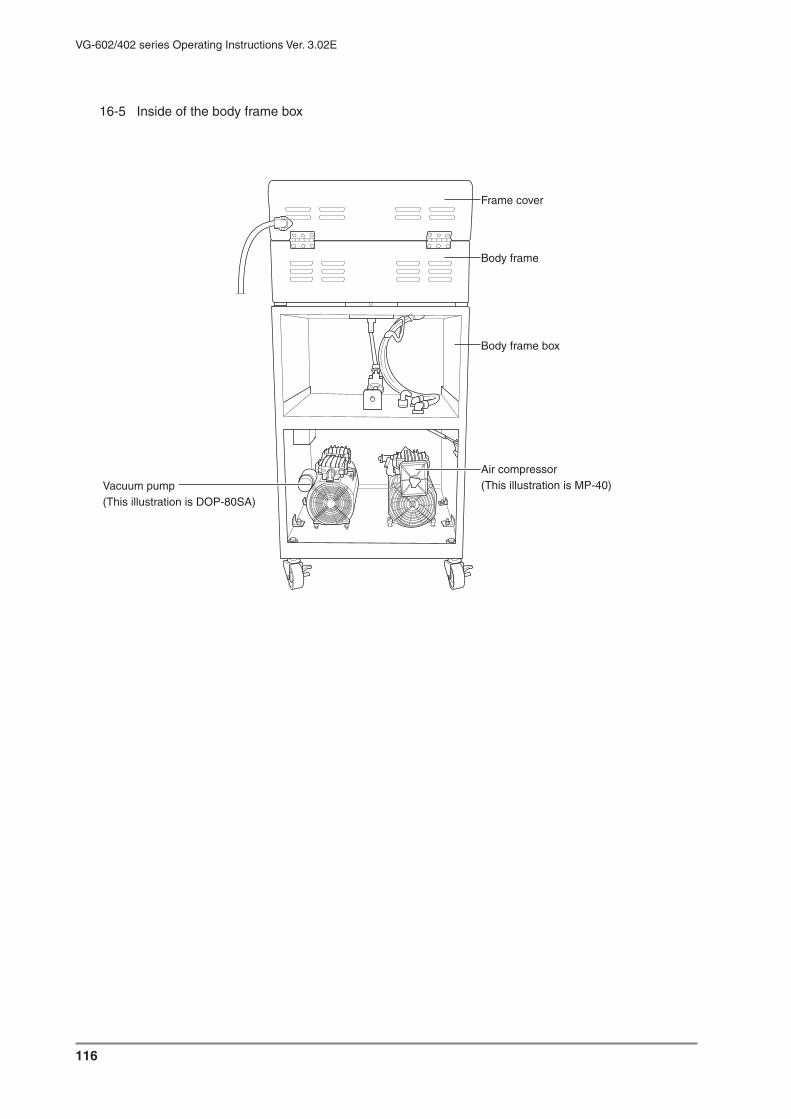
116
VG-602/402 series Operating Instructions Ver. 3.02E
16-5 Inside of the body frame box
Frame cover
Body frame
Body frame box
Air compressor(This illustration is MP-40)Vacuum pump
(This illustration is DOP-80SA)

117
VG-602/402 series Operating Instructions Ver. 3.02E

VG-602/402 series Operating Instructions Ver. 3.02E
Y6575 JUL 2009. 3rd Edition


96
VG-602/402 series Operating Instructions Ver. 3.02E
10-4 Combination of vacuum pump and air compressor
A.MP-40 : Piston typeFor standardPumping speed : 28L/minUsual pressure : 310-330 KPaRelief valve set-up pressureWeigh : 8kg
B.DOA-P108-DB : Diaphragm typeFor clean room(clean degree : about 10,000)Pumping speed : 31L/minUsual pressure : 310-330 KPaRelief valve set-up pressureWeigh : 7kg
C.Air is provided by the out side compressor
Suitable compressor specification 0.75kw (80L/min) above480KPa
H.DOP-80SA : Piston typeFor standardPumping speed : 80L/minUltimate pressure : -96KPaPump weight : 7kg
D. G-50SA : Oil rotation typeFor high vacuum degree (small size pouch)Pumping speed : 50L/minUltimate pressure : -101.3KPaPump weight : 11kg
E.G-100S : Oilrotation typeFor high vacuum degree(large size pouch)Pumping speed : 100L/minUltimate pressure : -101.3KPaPump weight : 22kg
G.DA-60S : Diaphragm typeFor clean room(clean degree : about 10,000)Pumping speed : 60L/minUltimate pressure : -80KPaPump weight : 12kg
ex.
Compressor : MP-40 (called A)
Vacuum pump : DOP-80 (called H)
602 series dual heating type
VG-602-AH-10D
Air compressor / 3 typesVacuum pump / 4 types
VG series sealer is named by the combination
of vacuum pump and air compressor.