Embed Size (px)
Citation preview
2008 Sept. 8 SYSC 2001 - Fall 2008. SYSC2001-Ch2and3.ppt 1
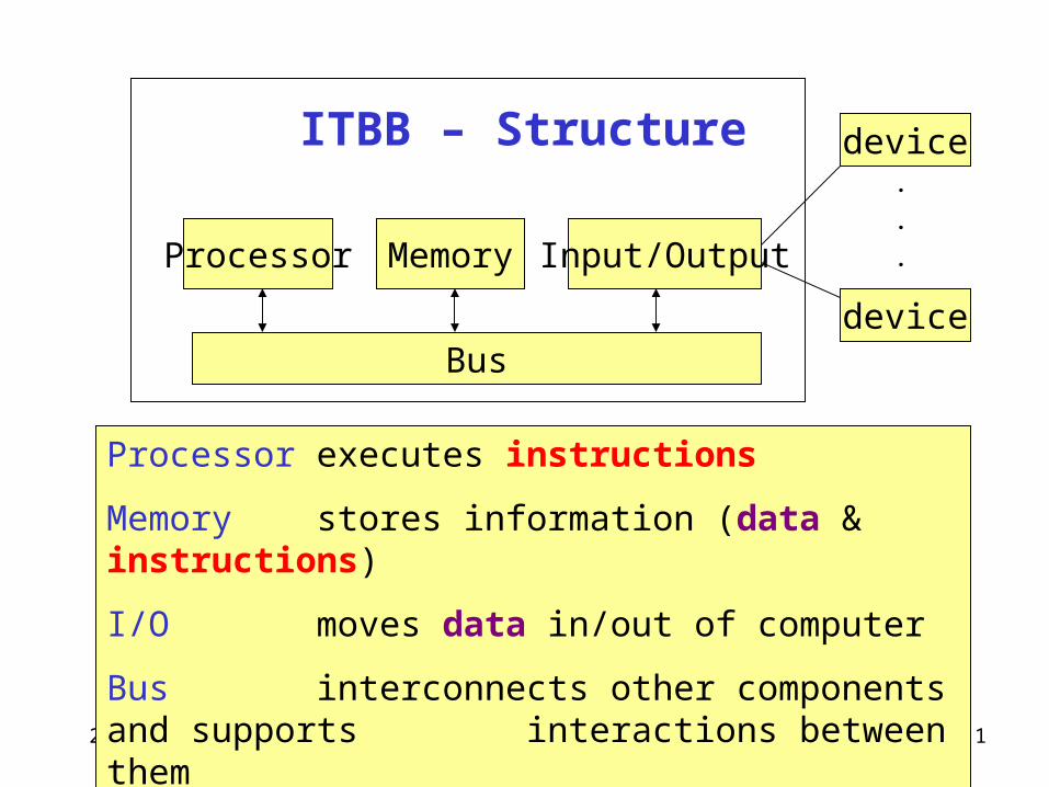
ITBB – Structure
Processor Memory Input/Output
Bus
device
device
.
.
.
Processor executes instructions
Memory stores information (data & instructions)
I/O moves data in/out of computer
Bus interconnects other components and supports interactions between them
2008 Sept. 8 SYSC 2001 - Fall 2008. SYSC2001-Ch2and3.ppt 2
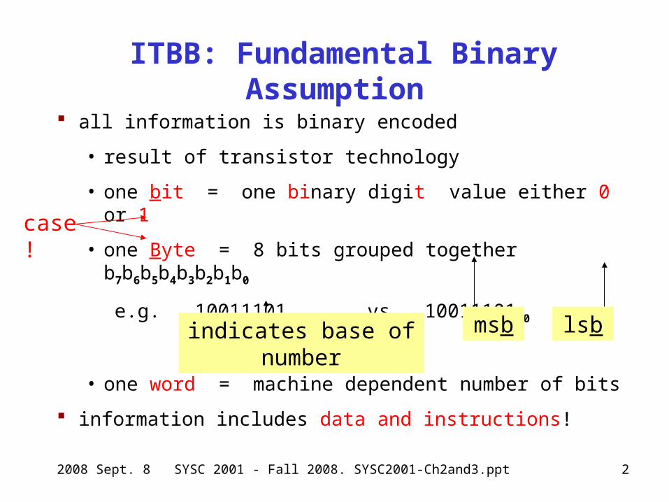
ITBB: Fundamental Binary Assumption
all information is binary encoded
• result of transistor technology
• one bit = one binary digit value either 0 or 1
• one Byte = 8 bits grouped together b7b6b5b4b3b2b1b0
e.g. 100111012 vs. 1001110110
• one word = machine dependent number of bits
information includes data and instructions!
indicates base of number lsbmsb
case!
2008 Sept. 8 SYSC 2001 - Fall 2008. SYSC2001-Ch2and3.ppt 3
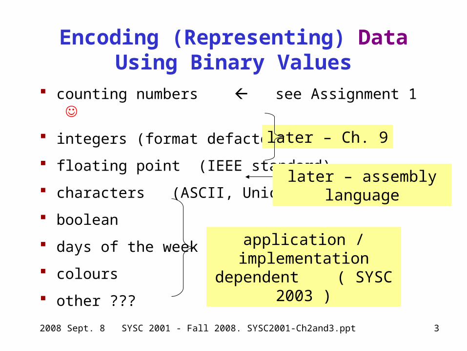
Encoding (Representing) Data Using Binary Values
counting numbers see Assignment 1
integers (format defacto standard)
floating point (IEEE standard)
characters (ASCII, Unicode)
boolean
days of the week
colours
other ???
later – Ch. 9
later – assembly language
application / implementation dependent ( SYSC 2003 )
2008 Sept. 8 SYSC 2001 - Fall 2008. SYSC2001-Ch2and3.ppt 4
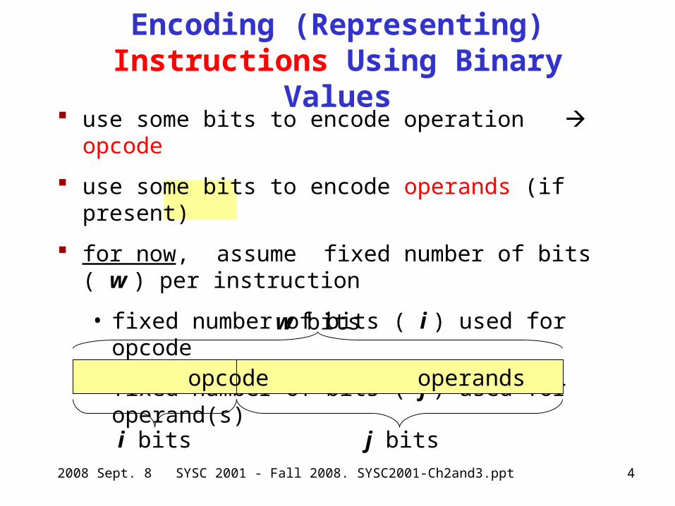
use some bits to encode operation opcode
use some bits to encode operands (if present)
for now, assume fixed number of bits ( w ) per instruction
• fixed number of bits ( i ) used for opcode
• fixed number of bits ( j ) used for operand(s)
Encoding (Representing) Instructions Using Binary Values
opcode operands
i bits j bits
w bits
2008 Sept. 8 SYSC 2001 - Fall 2008. SYSC2001-Ch2and3.ppt 5
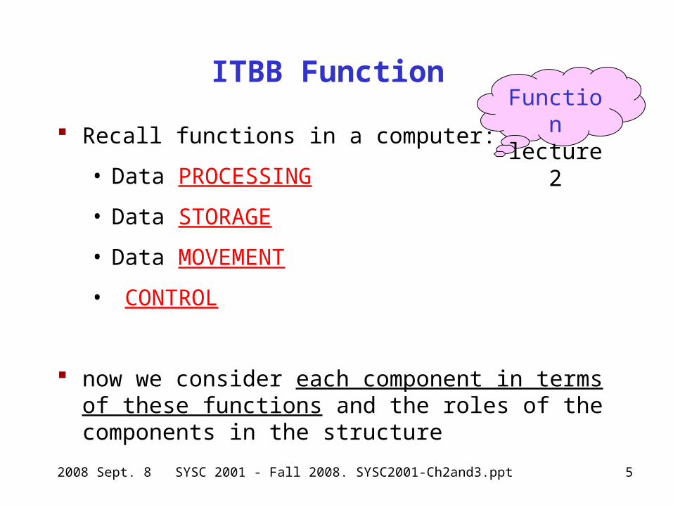
ITBB Function
Recall functions in a computer:
• Data PROCESSING
• Data STORAGE
• Data MOVEMENT
• CONTROL
now we consider each component in terms of these functions and the roles of the components in the structure
Functionlecture 2
2008 Sept. 8 SYSC 2001 - Fall 2008. SYSC2001-Ch2and3.ppt 6
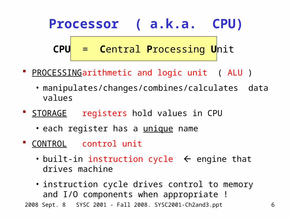
Processor ( a.k.a. CPU)
PROCESSING arithmetic and logic unit ( ALU )
• manipulates/changes/combines/calculates data values
STORAGE registers hold values in CPU
• each register has a unique name
CONTROL control unit
• built-in instruction cycle engine that drives machine
• instruction cycle drives control to memory and I/O components when appropriate !
CPU = Central Processing Unit
2008 Sept. 8 SYSC 2001 - Fall 2008. SYSC2001-Ch2and3.ppt 7
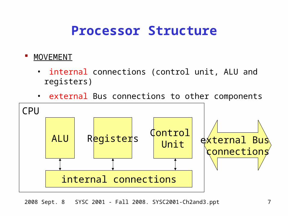
Processor Structure
MOVEMENT
• internal connections (control unit, ALU and registers)
• external Bus connections to other components
ALU RegistersControl
Unit
internal connections
CPU
external Bus connections

2008 Sept. 8 SYSC 2001 - Fall 2008. SYSC2001-Ch2and3.ppt 8
Processor Instruction Cycle
START
fetch instruction( from memory )
execute the instruction
HALT
cycle
may cause more memory
accesses (for operands)
2008 Sept. 8 SYSC 2001 - Fall 2008. SYSC2001-Ch2and3.ppt 9
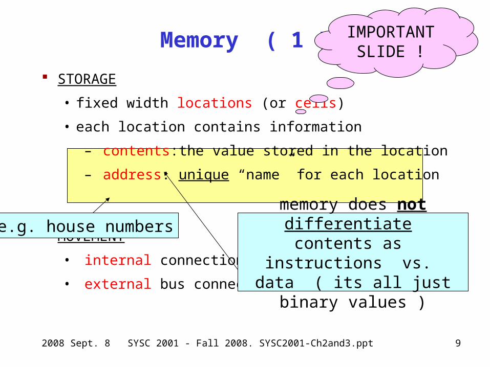
Memory ( 1 )
STORAGE
• fixed width locations (or cells)
• each location contains information
– contents: the value stored in the location
– address: unique “name” for each location
MOVEMENT
• internal connections
• external bus connections
memory does not differentiate contents as instructions vs. data
( its all just binary values )
IMPORTANT SLIDE !
e.g. house numbers
2008 Sept. 8 SYSC 2001 - Fall 2008. SYSC2001-Ch2and3.ppt 10
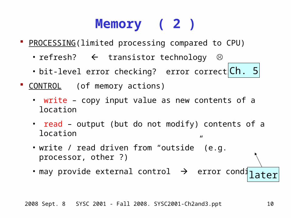
Memory ( 2 ) PROCESSING (limited processing compared to CPU)
• refresh? transistor technology
• bit-level error checking? error correction ?
CONTROL (of memory actions)
• write – copy input value as new contents of a location
• read – output (but do not modify) contents of a location
• write / read driven from “outside” (e.g. processor, other ?)
• may provide external control error condition?
Ch. 5
later
2008 Sept. 8 SYSC 2001 - Fall 2008. SYSC2001-Ch2and3.ppt 11
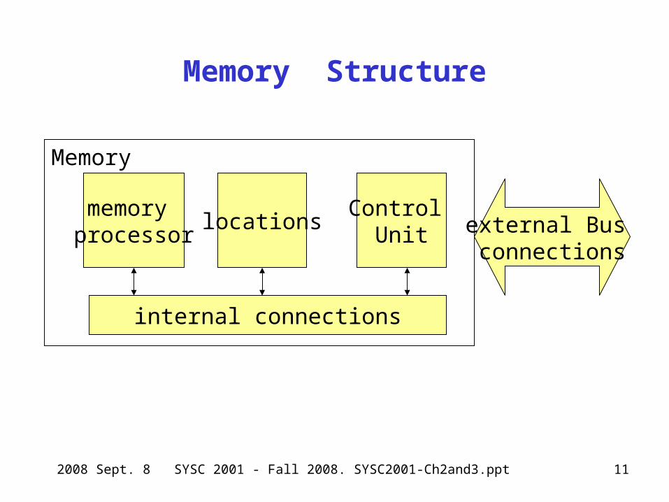
Memory Structure
memory processor
locationsControl
Unit
internal connections
Memory
external Bus connections
2008 Sept. 8 SYSC 2001 - Fall 2008. SYSC2001-Ch2and3.ppt 12
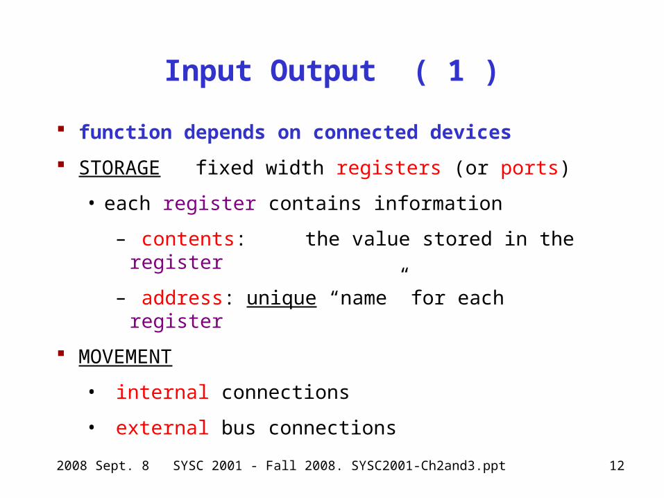
Input Output ( 1 )
function depends on connected devices
STORAGE fixed width registers (or ports)
• each register contains information
– contents: the value stored in the register
– address: unique “name” for each register
MOVEMENT
• internal connections
• external bus connections
2008 Sept. 8 SYSC 2001 - Fall 2008. SYSC2001-Ch2and3.ppt 13
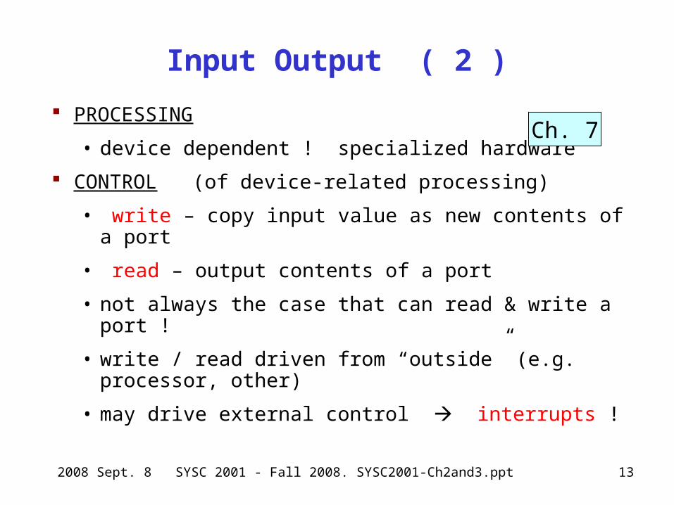
Input Output ( 2 )
PROCESSING
• device dependent ! specialized hardware
CONTROL (of device-related processing)
• write – copy input value as new contents of a port
• read – output contents of a port
• not always the case that can read & write a port !
• write / read driven from “outside” (e.g. processor, other)
• may drive external control interrupts !
Ch. 7
2008 Sept. 8 SYSC 2001 - Fall 2008. SYSC2001-Ch2and3.ppt 14
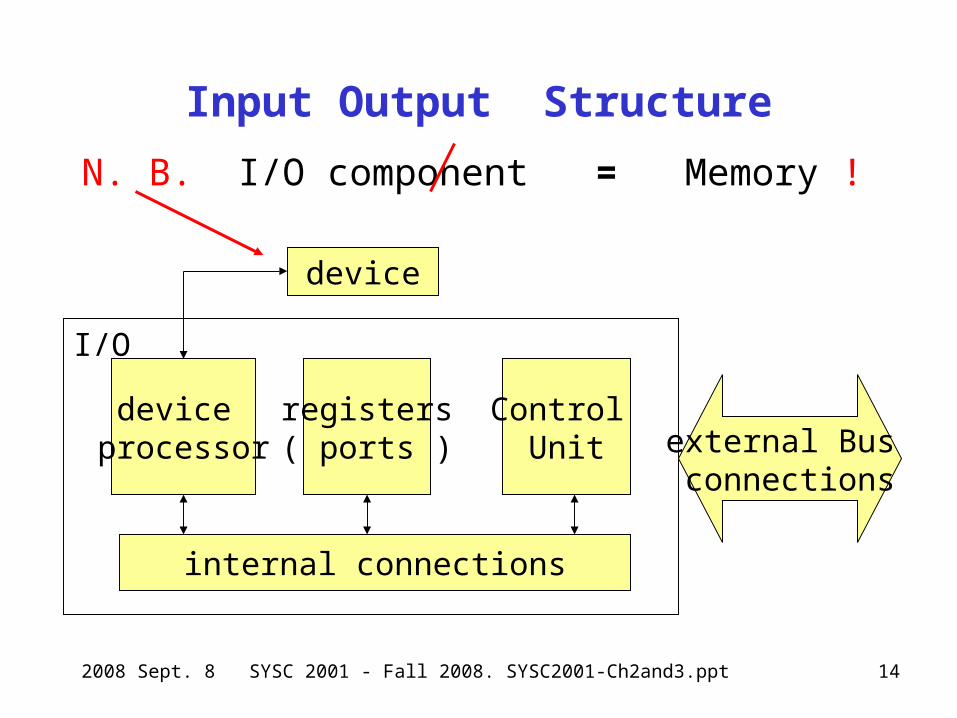
Input Output Structure
N. B. I/O component = Memory !
device processor
registers( ports )
Control Unit
internal connections
I/O
external Bus connections
device
2008 Sept. 8 SYSC 2001 - Fall 2008. SYSC2001-Ch2and3.ppt 15
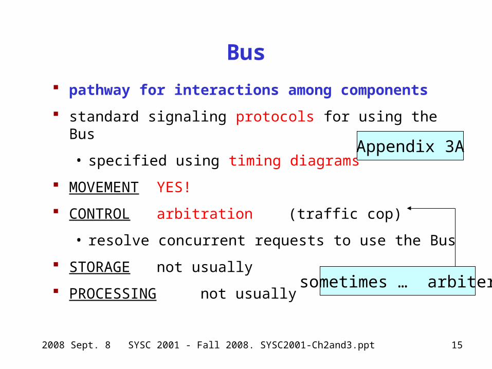
Bus
pathway for interactions among components
standard signaling protocols for using the Bus
• specified using timing diagrams
MOVEMENT YES!
CONTROL arbitration (traffic cop)
• resolve concurrent requests to use the Bus
STORAGE not usually
PROCESSING not usually
Appendix 3A
sometimes … arbiter
2008 Sept. 8 SYSC 2001 - Fall 2008. SYSC2001-Ch2and3.ppt 17
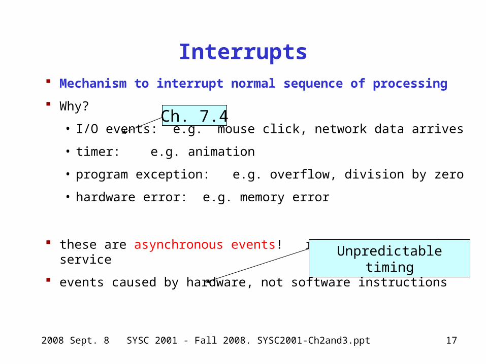
Interrupts Mechanism to interrupt normal sequence of processing
Why?
• I/O events: e.g. mouse click, network data arrives
• timer: e.g. animation
• program exception: e.g. overflow, division by zero
• hardware error: e.g. memory error
these are asynchronous events! require programmed service
events caused by hardware, not software instructions
Ch. 7.4
Unpredictable timing
2008 Sept. 8 SYSC 2001 - Fall 2008. SYSC2001-Ch2and3.ppt 18
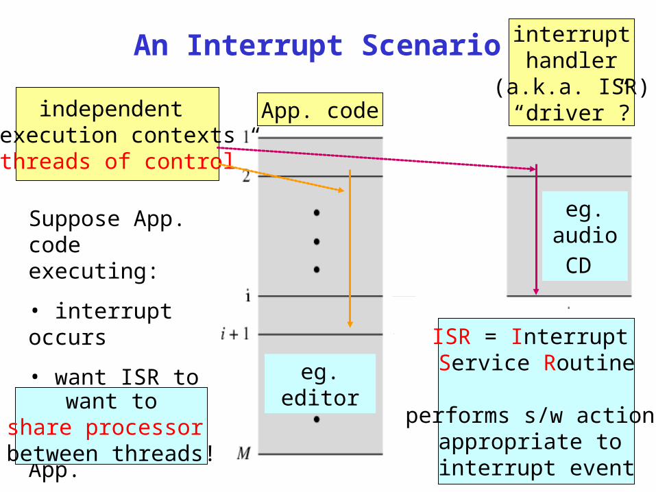
An Interrupt Scenario
App. code
interrupthandler
(a.k.a. ISR)“driver”?independent
execution contexts“threads of control”
ISR = Interrupt Service Routine
performs s/w action appropriate to interrupt event
Suppose App. code executing:
• interrupt occurs
• want ISR to run
• then resume App. eg. editor
eg. audio
CD
want toshare processor between threads!
2008 Sept. 8 SYSC 2001 - Fall 2008. SYSC2001-Ch2and3.ppt 19
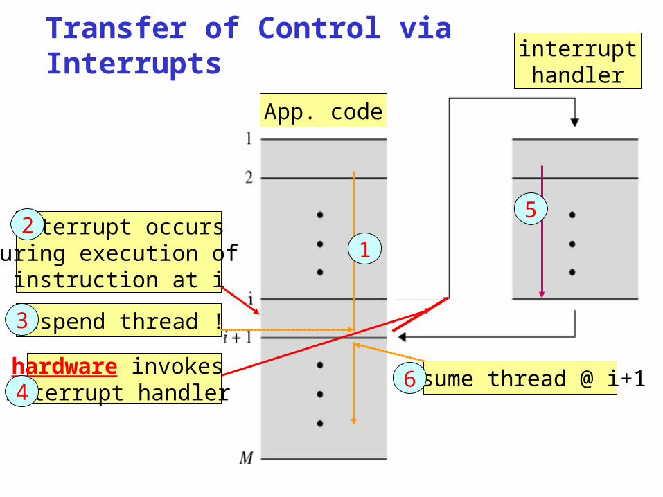
resume thread @ i+1hardware invokes interrupt handler
Transfer of Control via Interrupts
App. code
interrupthandler
suspend thread !
interrupt occursduring execution of
instruction at i1
2
3
4
5
6
2008 Sept. 8 SYSC 2001 - Fall 2008. SYSC2001-Ch2and3.ppt 20
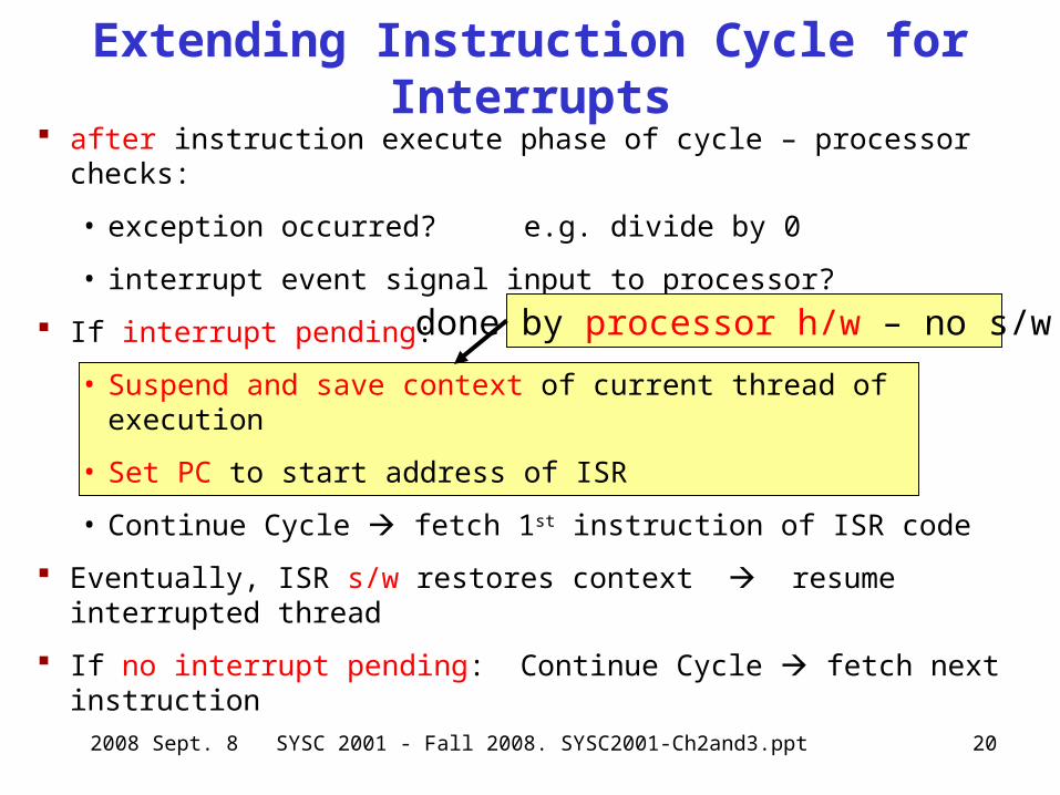
after instruction execute phase of cycle – processor checks:
• exception occurred? e.g. divide by 0
• interrupt event signal input to processor?
If interrupt pending:
• Suspend and save context of current thread of execution
• Set PC to start address of ISR
• Continue Cycle fetch 1st instruction of ISR code
Eventually, ISR s/w restores context resume interrupted thread
If no interrupt pending: Continue Cycle fetch next instruction
Extending Instruction Cycle for Interrupts
done by processor h/w – no s/w !
2008 Sept. 8 SYSC 2001 - Fall 2008. SYSC2001-Ch2and3.ppt 21
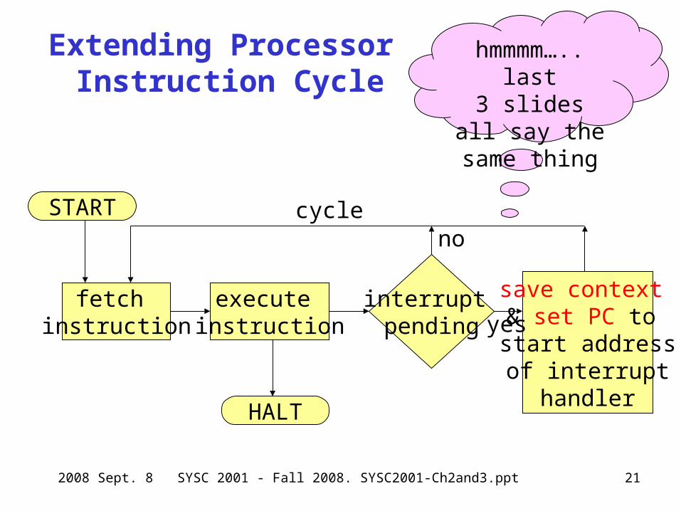
Extending Processor Instruction Cycle
START
fetch instruction
execute instruction
HALT
cycle
interrupt pending
no
save context & set PC to start addressof interrupt
handler
yes
hmmmm….. last3 slides all say the same thing
2008 Sept. 8 SYSC 2001 - Fall 2008. SYSC2001-Ch2and3.ppt 22
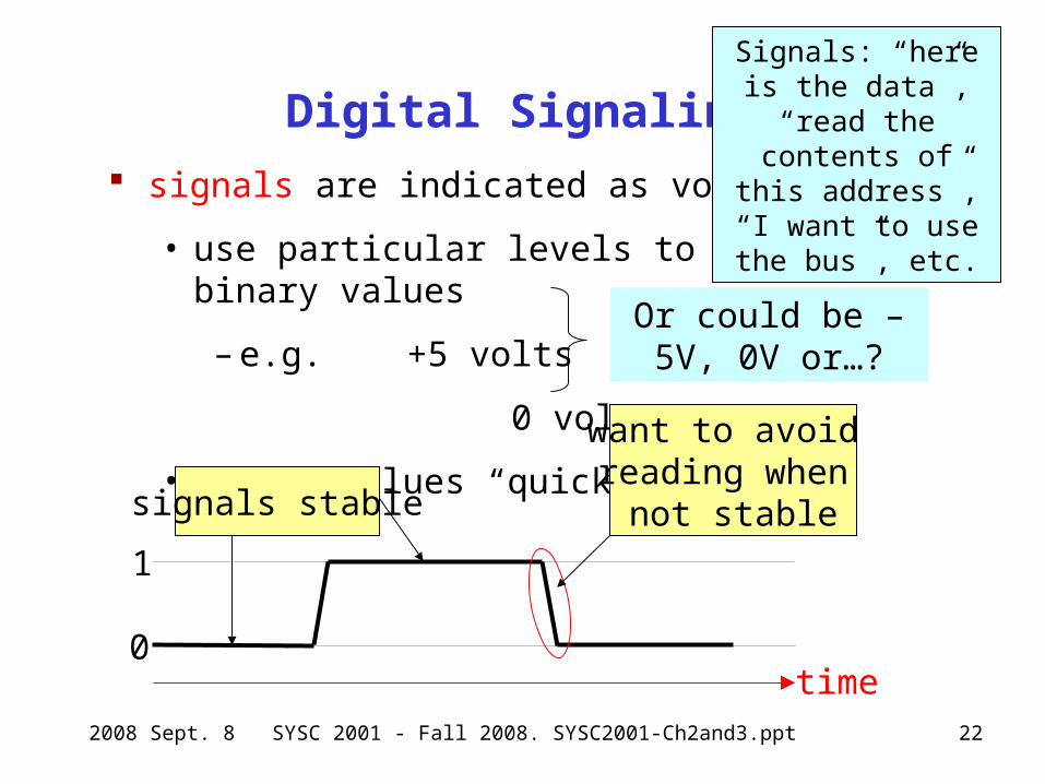
Digital Signaling signals are indicated as voltage levels
• use particular levels to represent binary values
– e.g. +5 volts 1
0 volts 0
• change values “quickly”
1
0time
want to avoid reading when
not stablesignals stable
Signals: “here is the data”, “read the contents of this
address”, “I want to use the bus”, etc.
Or could be –5V, 0V or…?
2008 Sept. 8 SYSC 2001 - Fall 2008. SYSC2001-Ch2and3.ppt 23
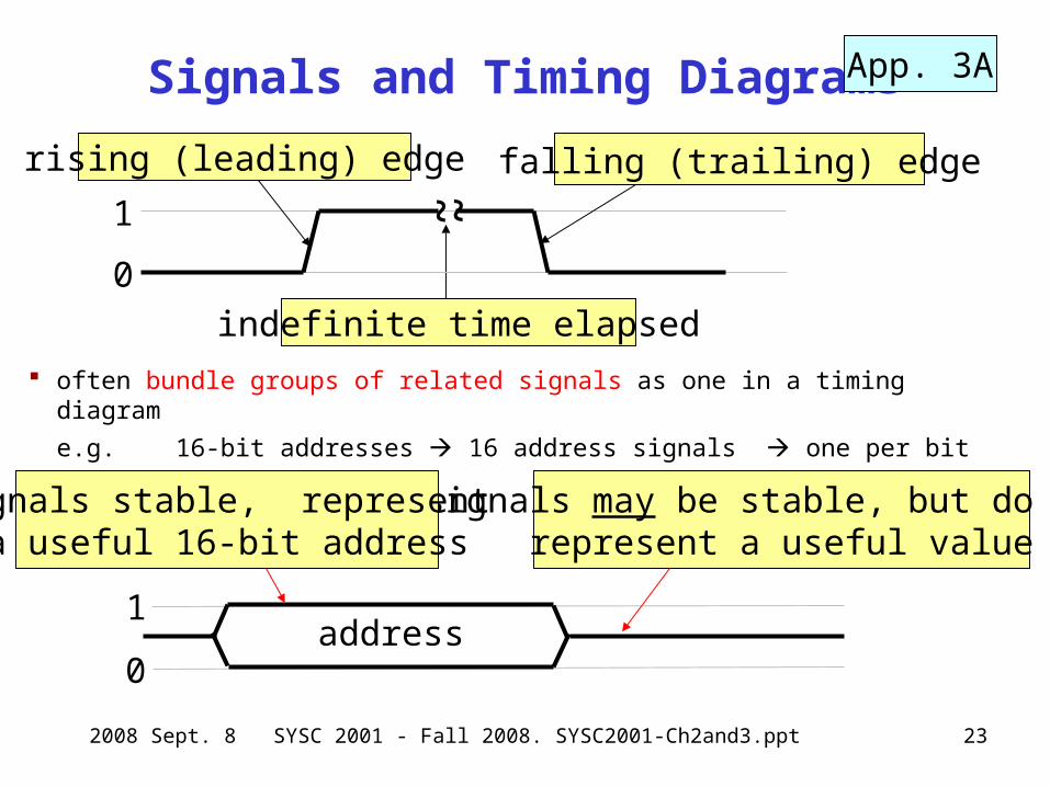
Signals and Timing Diagrams
often bundle groups of related signals as one in a timing diagram
e.g. 16-bit addresses 16 address signals one per bit
1
0
falling (trailing) edgerising (leading) edge
1
0address
signals may be stable, but do not represent a useful value
signals stable, represent a useful 16-bit address
App. 3A
~ ~
indefinite time elapsed
2008 Sept. 8 SYSC 2001 - Fall 2008. SYSC2001-Ch2and3.ppt 24
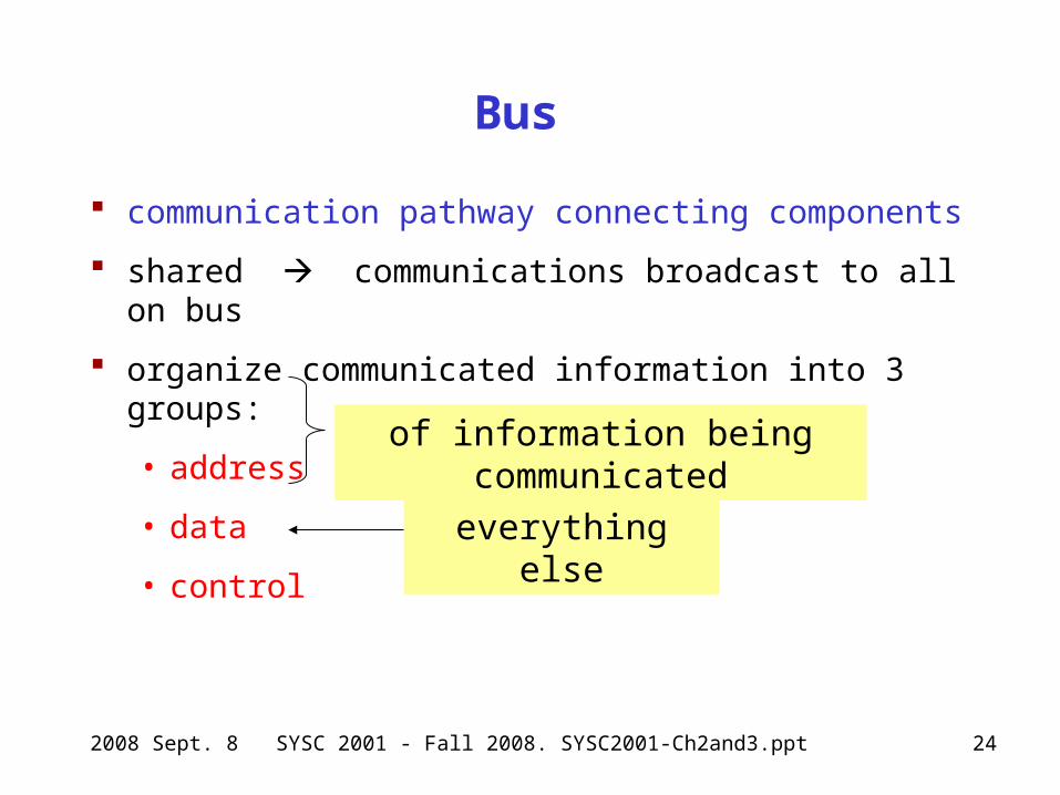
Bus
communication pathway connecting components
shared communications broadcast to all on bus
organize communicated information into 3 groups:
• address
• data
• control
of information being communicated
everything else
2008 Sept. 8 SYSC 2001 - Fall 2008. SYSC2001-Ch2and3.ppt 26
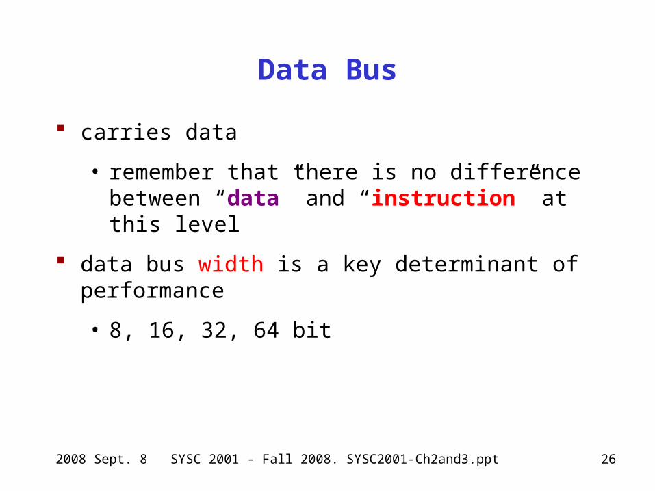
Data Bus
carries data
• remember that there is no difference between “data” and “instruction” at this level
data bus width is a key determinant of performance
• 8, 16, 32, 64 bit
2008 Sept. 8 SYSC 2001 - Fall 2008. SYSC2001-Ch2and3.ppt 27
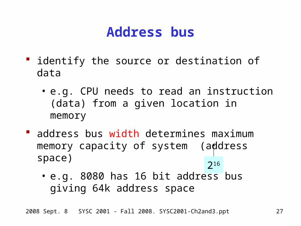
Address bus
identify the source or destination of data
• e.g. CPU needs to read an instruction (data) from a given location in memory
address bus width determines maximum memory capacity of system (address space)
• e.g. 8080 has 16 bit address bus giving 64k address space
216
2008 Sept. 8 SYSC 2001 - Fall 2008. SYSC2001-Ch2and3.ppt 29
Some Common Control Signals
reset – force all components to reset
clock(s) to synchronize communication
destination indicator – usually memory or I/O
acknowledgment from component – info received
interrupts
arbitration“hand shake”
2008 Sept. 8 SYSC 2001 - Fall 2008. SYSC2001-Ch2and3.ppt 30
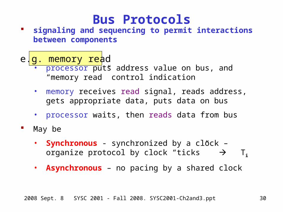
Bus Protocols signaling and sequencing to permit interactions between
components
• processor puts address value on bus, and “memory read” control indication
• memory receives read signal, reads address, gets appropriate data, puts data on bus
• processor waits, then reads data from bus
May be
• Synchronous - synchronized by a clock – organize protocol by clock “ticks” Ti
• Asynchronous – no pacing by a shared clock
e.g. memory read
2008 Sept. 8 SYSC 2001 - Fall 2008. SYSC2001-Ch2and3.ppt 33
Single Bus Problems
lots of devices on one bus leads to:
• propagation delays
– long data paths mean that co-ordination of bus use can adversely affect performance
– if aggregate data transfer approaches bus capacity
most systems use multiple buses to overcome these problems
evolution for performance!


![Ppt1 [Edited]](https://img.pdfslide.us/doc/110x75/545438bfaf795978688b4ce8/ppt1-edited.jpg)